Lexium23A Installation Directions
2014-11-11
: Pdf 121622-Installationsheet 121622-InstallationSheet 785901 Batch12 unilog
Open the PDF directly: View PDF ![]() .
.
Page Count: 466 [warning: Documents this large are best viewed by clicking the View PDF Link!]
Lexium 23A
AC servo drive
Product manual
V1.03, 11.2010
www.schneider-electric.cn

Contents Lexium 23A
ii AC servo drive
This manual is part of the product.
Carefully read this manual and observe all instructions.
Keep this manual for future reference.
Hand this manual and all other pertinent product documentation over to all
users of the product.
Carefully read and observe all safety instructions and the chapter "2. Before
you begin - safety information".
Some products are not available in all countries.
For information on the availability of products, please consult the catalog.
Subject to technical modifications without notice.
All details provided are technical data which do not constitute warranted
qualities.
Most of the product designations are registered trademarks of their
respective owners, even if this is not explicitly indicated.
Important information

AC servo drive iii
Contents
Important information.......................................................................................... ii
About this manual ................................................................................................ vii
Chapter 1 Introduction .............................................................................................................1
1.1 Unpacking Check ..............................................................................................................................2
1.2 Device overview ................................................................................................................................3
1.3 Components and interfaces .........................................................................................................4
1.4 Nameplate information ..................................................................................................................5
1.5 Type code............................................................................................................................................6
1.6 Servo Drive and Servo Motor Combinations............................................................................8
Chapter 2 Before you begin - safety information.............................................................. 9
2.1 Qualification of personnel ...........................................................................................................10
2.2 Intended use ....................................................................................................................................10
2.3 Hazard categories ...........................................................................................................................11
2.4 Basic information ........................................................................................................................... 12
2.5 DC bus voltage measurement....................................................................................................14
2.6 Standards and terminology ........................................................................................................14
Chapter 3 Technical Data....................................................................................................... 15
3.1 Ambient conditions........................................................................................................................16
3.2 Dimensions ......................................................................................................................................18
3.3 Electrical Data................................................................................................................................. 23
3.4 Certifications ...................................................................................................................................41
3.5 Declaration of conformity........................................................................................................... 42

Contents Lexium 23A
iv AC servo drive
Chapter 4 Engineering ........................................................................................................... 45
4.1 Electromagnetic compatibility, EMC ...................................................................................... 46
4.2 Residual current device .............................................................................................................. 49
4.3 Operation in an IT mains ............................................................................................................. 50
4.4 Rating the braking resistor.......................................................................................................... 51
4.5 Logic type ........................................................................................................................................ 59
4.6 Monitoring functions.................................................................................................................... 60
4.7 Configurable inputs and outputs..............................................................................................61
Chapter 5 Installation............................................................................................................. 63
5.1 Mechanical installation ................................................................................................................ 65
5.2 Electrical installation .................................................................................................................... 71
5.3 Standard Connection Example .............................................................................................. 107
Chapter 6 Commissioning.................................................................................................... 113
6.1 Basic information ......................................................................................................................... 114
6.2 Overview ..........................................................................................................................................117
6.3 Integrated HMI Digital Keypad ................................................................................................. 119
6.4 Commissioning software...........................................................................................................124
6.5 Commissioning procedure .......................................................................................................125
Chapter 7 Operation..............................................................................................................151
7.1 Access channels............................................................................................................................152
7.2 General Function Operation .....................................................................................................153
7.3 Control Modes of Operation. ....................................................................................................156
7.4 Other functions. ..........................................................................................................................202
Chapter 8 Motion Control Function ..................................................................................209
8.1 Available Motion Control Functions ...................................................................................... 210
8.2 Servo Drive Information............................................................................................................ 210
8.3 Motion Axis .....................................................................................................................................216
8.4 Pr Mode Introduction ..................................................................................................................217
8.5 Position Command Unit of Pr Mode........................................................................................218

Lexium 23A Contents
AC servo drive v
8.6 Registers of Pr Mode................................................................................................................... 219
8.7 Homing Function of Pr Mode ...................................................................................................220
8.8 DI and DO signals of Pr Mode ....................................................................................................221
8.9 Parameter Settings of Pr Mode ...............................................................................................223
Chapter 9 Communication.................................................................................................. 229
9.1 RS-485 Communication Hardware Interface .....................................................................230
9.2 Communication Parameter Settings .................................................................................... 232
9.3 MODBUS Communication Protocol ......................................................................................236
9.4 Communication Parameter Write-in and Read-out.........................................................245
Chapter 10 Diagnostic and troubleshooting ................................................................... 247
10.1 Status request/status indication............................................................................................248
10.2 Fault Messages Table .................................................................................................................249
10.3 Potential Cause and Corrective Actions...............................................................................254
10.4 Clearing Faults.............................................................................................................................. 273
Chapter 11 Servo Parameters.............................................................................................. 285
11.1 Representation of the parameters ........................................................................................282
11.2 Definition....................................................................................................................................... 283
11.3 Parameter Summary ................................................................................................................ 284
11.4 Detailed Parameter Listings ................................................................................................... 308
Chapter 12 Accessories and spare parts ...........................................................................441
Chapter 13 Service, maintenance and disposal................................................................451
13.1 Service address ........................................................................................................................... 454
13.2 Basic Inspection ...........................................................................................................................455
13.3 Maintenance................................................................................................................................. 456
13.4 Life of Replacement Components ........................................................................................ 456
13.5 Replacing devices........................................................................................................................457
13.6 Changing the motor ...................................................................................................................458
13.7 Shipping, storage, disposal ......................................................................................................458

Contents Lexium 23A
vi AC servo drive

AC servo drive v
About this manual
This manual is valid for LXM23A servo drives and corresponding BCH motors. It
describes the technical data, installation, commissioning and the operating modes
and functions. Chapter 1 "Introduction" lists the type code for these products.
Work steps If work steps must be performed consecutively, this sequence of steps is represented
as follows:
b Special prerequisites for the following work steps
X Step 1
Y Specific response to this work Lexium 23Astep
X Step 2
If a response to a work step is indicated, this allows you to verify that the work step has
been performed correctly.
Unless otherwise stated, the individual steps must be performed in the specified
sequence.
Making work easier Information on making work easier is highlighted by this symbol:
Sections highlighted this way provide supplementary information on making work
easier.
SI units SI units are the original values. Converted units are shown in brackets behind the
original value; they may be rounded.
Example:
Minimum conductor cross section: 1.5 mm2 (AWG 14)

About this manual Lexium 23A
vi AC servo drive

AC servo drive 1
1
Introduction
At a Glance
What's in this
Chapter?
This chapter contains the following topics:
Topic Page
Unpacking Check 2
Device overview 3
Components and interfaces 4
Nameplate information 5
Type code 6
Servo Drive and Servo Motor Combinations 8

1. Introduction Lexium 23A
2AC servo drive
1.1 Unpacking Check
After receiving the AC servo drive, please check for the following:
zEnsure that the product is what you have ordered.
Verify the part number indicated on the nameplate corresponds with the part
number of your order (Please refer to Section1.5 for details about the model
explanation).
zEnsure that the servo motor shaft rotates freely.
Rotate the motor shaft by hand; a smooth rotation will indicate a good motor.
However, a servo motor with an electromagnetic brake can not be rotated
manually.
zCheck for damage.
Inspect the unit to insure it was not damaged during shipment.
zCheck for loose screws.
Ensure that all necessary screws are tight and secure.
If any items are damaged or incorrect, please inform the distributor whom you
purchased the product from or your local Schneider Electric sales representative.
A complete and workable AC servo system should include the following parts:
Part I : Schneider Electric standard supplied parts
(1) Servo drive Lexium 23A
(2) Servo motor Lexium BCH
(3) 5 PIN Terminal Block for L1, L2, R, S, T (available for 100W ~ 1.5kW models)
(4) 3 PIN Terminal Block "motor" for U,V,W (available for 100W ~ 1.5kW models)
(5) 4 PIN Terminal Block "CN5" for PA/+, PBi, PBe,PC/- (available for 100W ~ 1.5kW models)
(6) One operating lever (for wire to terminal block insertion) available for 100W ~1.5kW
models)
(7) One jumper bar (installed at CN5, pins PA/+ and PBi)
(8) Instruction Sheets (Traditional Chinese, Simplified Chinese and English version)
Part II : Optional parts (Refer to chapter 12)
(1) One power cable, which is used to connect servo motor to U, V, W terminals of servo
drive. This power cable includes a green grounding cable. Please connect the green
grounding cable to the ground terminal of the servo drive.
(2) One encoder cable, which is used to connect the encoder of servo motor to the CN2
terminal of servo drive.
(3) CN1 connector: 50 PIN connector, IO interface (3M type)
(4) CN2: 6 PIN connector (IEEE1394 type), motor encoder interface
(5) CN3: RJ45 connector, serial communication interface for drive set-up
(6) CN4: two RJ45 connectors, CANopen and CANmotion interface
Lexium 23A 1. Introduction
AC servo drive 3
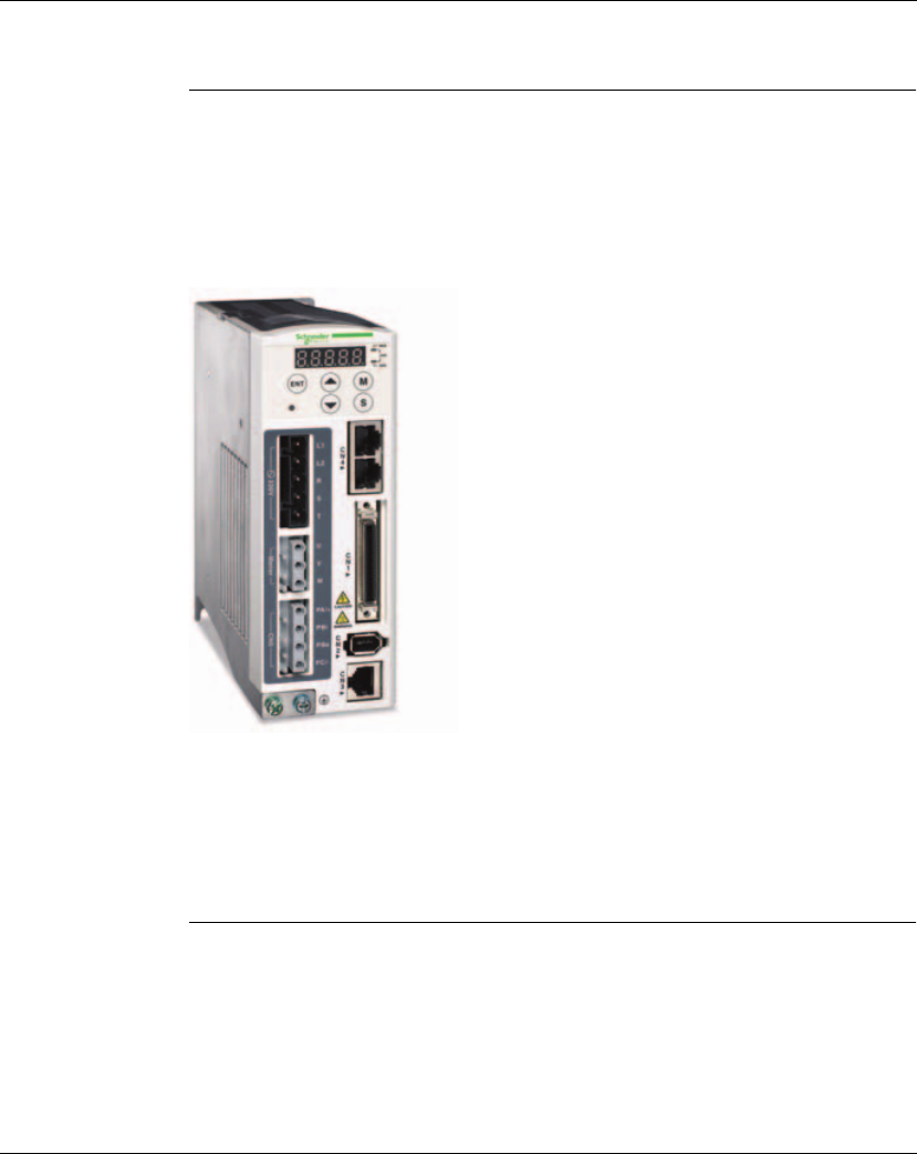
1.2 Device overview
The Lexium 23 Plus product family consists of two servo drive models that cover
different application areas. Together with Lexium BCH servo motors as well as a
comprehensive range of options and accessories, the drives are ideally suited to
implement compact, high-performance drive solutions for a wide range of power
requirements.
Lexium servo
drive LXM23A
This product manual describes the LXM23A servo drive.
Overview of some of the features of the LXM23A servo drive:
zCANopen and CANmotion field bus interface to access all parameters and to
control all operation modes of the servo drive
zThe product is commissioned via the integrated HMI or a PC with commissioning
software.
zOperating modes Jog, Position control mode,Speed Control,Torque
control,Switching mode.
1. Introduction Lexium 23A
4AC servo drive
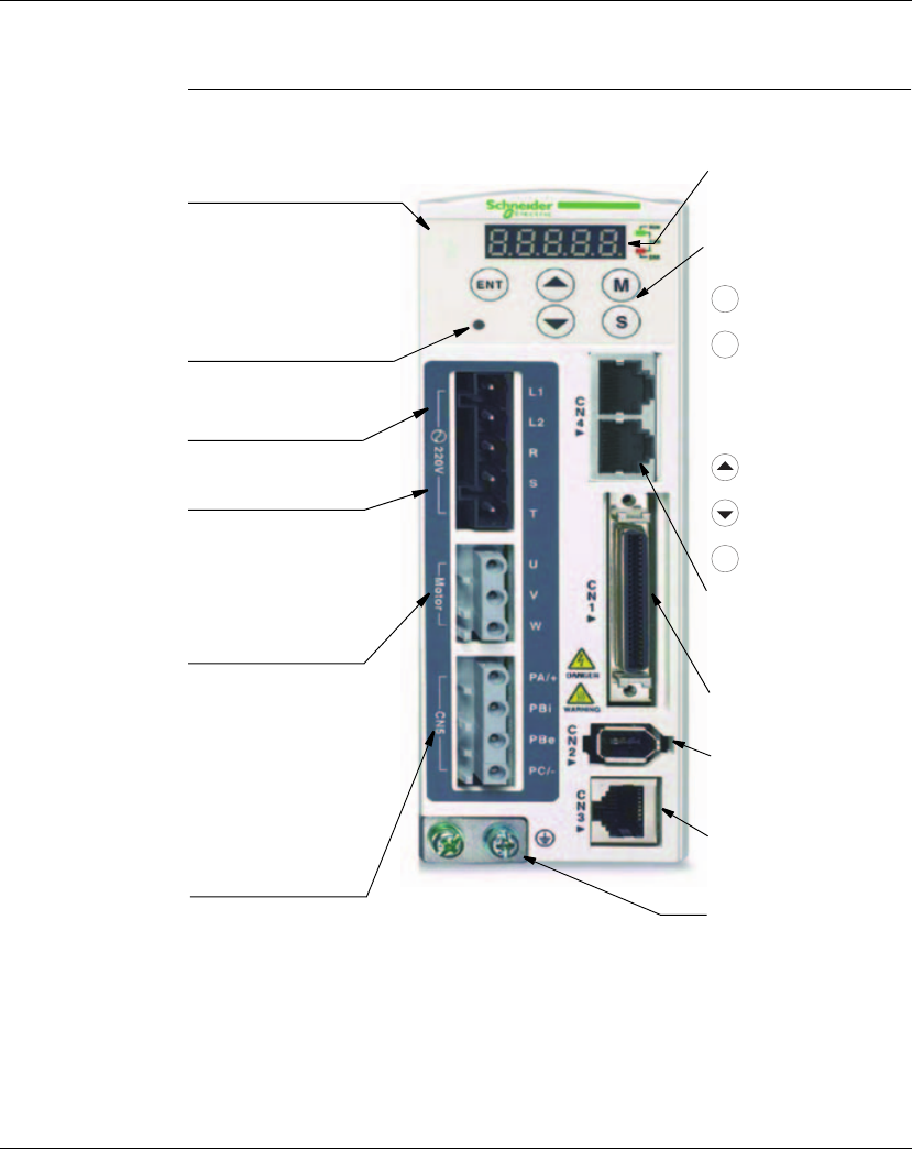
1.3 Components and interfaces
Heatsink
Used to secure servo drive and for
heat dissipation
Charge LED
A lit LED indicates that either power
is connected to the servo drive OR a
residual charge is present in the
drive's internal power components.
DO NOT TOUCH ANY ELECTRICAL
CONNECTIONS WHILE THIS LED IS
LIT. (Please refer to the Safety
Precautions in chapter 2).
Control Circuit Terminal (L1, L2)
Used to connect 200~230Vac,
50/60Hz 1-phase/3-phase VAC
supply.
Main Circuit Terminal (R, S, T)
Used to connect 200~230V, 50/
60Hz commercial power supply
Servo Motor Output (U, V, W)
Used to connect servo motor,
Never connect the output
therminal to main circuit power.
The AC servo drive may be
destroyed beyond repair if
incorrect cables are connected
to the output terminals.
Internal/External Regenerative
Resistor Terminal
1) When using an external
regenerative resistor,
connect PA/+ and PBe to the
regenerative resistor and
ensure that the circuit
between PA/+ and PBi is open.
2) When using theinternal
regenerative resistor, ensure
that the circuit between PA/+
and PBi is closed and the
circuit between PA/+ and
PBe is open.
LED Display
The 5 digit, 7 segment LED displays
the servo status or fault codes
Operation Panel
Used function keys to perform status
display, monitor and diagnostic,
function and parameter setting.
Function Keys:
: Press this key to select/
change mode
: Shift Key has several
functions:
moving the cursor and
indexing through the
parameter groups
Press this key to shift cursor
to the left
: Press this key to increase
values on the display
: Press this key to decrease
values on the display
: Press this key to store data
M
S
ENT
I/O Interface
Used to connect Host Controller
(PLC) or control I/O signal
Encoder Interface
Used to connect Encoder of
Servo Motor
Serial Communication Interface
For RS-485/232 serial
communication for drive set-up.
Used to connect personal
computer or other controllers
Ground Terminal
Field bus communication
interface CANopen and
CANmotion
Lexium 23A 1. Introduction
AC servo drive 5
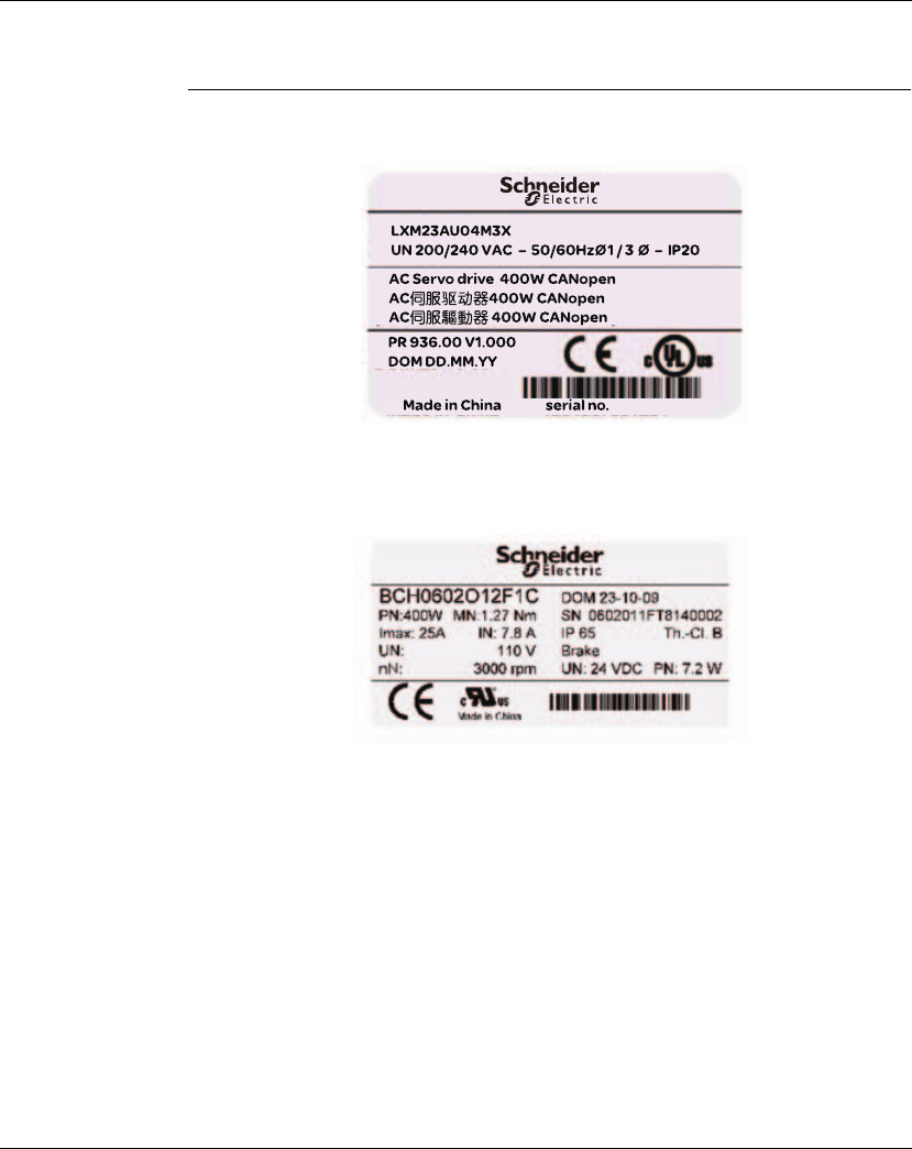
1.4 Nameplate information
Lexium 23 Series Servo Drive
zNameplate Explanation
BCH Series Servo Motor
zNameplate Explanation

1. Introduction Lexium 23A
6AC servo drive
1.5 Type code
Lexium 23 Plus drive commercial reference
L X M 2 3 A U 0 1 M 3 X
LXM = Lexium Servo Drive
23 = Product series
Interface
A = CANopen
D = I/O
Continuous Power
U01 = 0.1 KW
U02 = 0.2 KW
U04 = 0.4 KW
U07 = 0.75 KW
U10 = 1 KW
U15 = 1.5 KW
U20 = 2 KW
U30 = 3.0 kW
U45 = 4.5 kW
U55 = 5.5 kW
U75 = 7.5 kW
Mains voltage
M3X = 200/240VAC 3-phases (or single phase depending on caliber), no EMC filter

Lexium 23A 1. Introduction
AC servo drive 7
BCH motor commercial reference
B C H 0 4 0 1 O 0 2 A 1 C
BCH = BCH servo motor series
Flange size
040 = 40 mm Flange
060 = 60 mm Flange
080 = 80 mm Flange
100 = 100 mm Flange
130 = 130 mm Flange
180 = 180 mm Flange
Length ( Number of stacks)
1 = one stack
2 = two stacks
3 = three stacks
4 = four stacks
5 = five stacks
Speed type
M = Low Speed (1000/1500 rpm)
N = Medium Speed (2000 rpm)
O = High Speed (3000 rpm)
Shaft
0 = w/o key (smooth) :No Oil Seal (IP40 for shaft end)
1 = with key : No Oil Seal (IP40 for shaft end)
2 = w/o key (smooth) : With Oil seal (IP65 for shaft end)
3 = with key: Oil Seal (IP65 for shaft end)
Encoder
2 = High resolution incremental encoder 20 Bits
Brake
A = w/o brake
F = with brake
Connection System
1 = flying leeds (for BCH 040, 060, 080), military connector (for BCH 100, 130, 180)
Mount
C = mechanical mount: Asian standard

1. Introduction Lexium 23A
8AC servo drive
1.6 Servo Drive and Servo Motor Combinations
Lexium 23 Plus servo drive / BCH servo motor combination
BCH
servo
motor
output
power
BCH
servo
motor
inertia
(without
brake)
Rated
torque
Peak
stall
torque
Maximum
speed
Rated
speed
Combination
Servo drive
Reference
Servo motor
Reference
Motor
inertia
type
kW kgcm2Nm Nm rpm rpm
Single phase: 200...255 V a 50/60 Hz or three phase : 170...255 V a 50/60 Hz
0.1 0.037 0.32 0.96 5000 3000 LXM23pU01M3X BCH0401Op2p1C ultra low
0.2 0.177 0.64 1.92 5000 3000 LXM23pU02M3X BCH0601Op2p1C ultra low
0.3 8.17 2.86 8.59 2000 1000 LXM23pU04M3X BCH1301Mp2p1C medium
0.4 0.277 1.27 3.82 5000 3000 LXM23pU04M3X BCH0602Op2p1C ultra low
0.4 0.68 1.27 3.82 5000 3000 LXM23pU04M3X BCH0801Op2p1C low
0.5 8.17 2.39 7.16 3000 2000 LXM23pU04M3X BCH1301Np2p1C medium
0.6 8.41 5.73 17.19 2000 1000 LXM23pU07M3X BCH1302Mp2p1C medium
0.75 1.13 2.39 7.16 5000 3000 LXM23pU07M3X BCH0802Op2p1C low
0.9 11.18 8.59 25.78 2000 1000 LXM23pU10M3X BCH1303Mp2p1C medium
12.65 3.18 9.54 5000 3000 LXM23pU10M3X BCH1001Op2p1C low
1 11.18 4.77 14.32 3000 2000 LXM23pU10M3X BCH1302Np2p1C medium
1.5 11.18 7.16 21.48 3000 2000 LXM23pU15M3X BCH1303Np2p1C medium
Three phase : 170...255 V a 50/60 Hz
24.45 6.37 19.11 5000 3000 LXM23pU20M3X BCH1002Op2p1C low
214.59 9.55 26.65 3000 2000 LXM23pU20M3X BCH1304Np2p1C medium
234.68 9.55 26.65 3000 2000 LXM23pU20M3X BCH1801Np2p1C high
354.95 14.32 42.96 3000 2000 LXM23pU30M3X BCH1802Np2p1C high
354.95 19.10 57.29 3000 1500 LXM23pU30M3X BCH1802Mp2p1C high
3.5 54.8 16.71 50.31 3000 2000 LXM23pU45M3X BCH1803Np2p1C high
4.5 77.75 28.65 71.62 3000 1500 LXM23pU45M3X BCH1803Mp2p1C high
5.5 99.78 35.01 87.53 3000 1500 LXM23pU55M3X BCH1804Mp2p1C high
7.5 142.7 47.74 119.36 3000 1500 LXM23pU75M3X BCH1805Mp2p1C high

AC servo drive 9
2
Before you begin - safety
information
At a Glance
What's in this
Chapter?
This chapter contains the following topics:
Topic Page
Qualification of personnel 10
Intended use 10
Hazard categories 11
Basic information 12
DC bus voltage measurement 14
Standards and terminology 14

2. Before you begin - safety information Lexium 23A
10 AC servo drive
2.1 Qualification of personnel
Only appropriately trained persons who are familiar with and understand the
contents of this manual and all other pertinent product documentation are
authorized to work on and with this product. In addition, these persons must have
received safety training to recognize and avoid hazards involved. These persons
must have sufficient technical training, knowledge and experience and be able to
foresee and detect potential hazards that may be caused by using the product, by
changing the settings and by the mechanical, electrical and electronic equipment of
the entire system in which the product is used.
All persons working on and with the product must be fully familiar with all applicable
standards, directives, and accident prevention regulations when performing such work.
2.2 Intended use
This product is a drive for 3-phase servo motors and intended for industrial use
according to this manual.
The product may only be used in compliance with all applicable safety regulations and
directives, the specified requirements and the technical data.
Prior to using the product, you must perform a risk assessment in view of the planned
application. Based on the results, the appropriate safety measures must be
implemented.
Since the product is used as a component in an entire system, you must ensure the
safety of persons by means of the design of this entire system (for example, machine
design).
Operate the product only with the specified cables and accessories. Use only genuine
accessories and spare parts.
The product must NEVER be operated in explosive atmospheres (hazardous
locations, Ex areas).
Any use other than the use explicitly permitted is prohibited and can result in hazards.
Electrical equipment should be installed, operated, serviced, and maintained only by
qualified personnel.
Lexium 23A 2. Before you begin - safety information
AC servo drive 11
2.3 Hazard categories
Safety instructions to the user are highlighted by safety alert symbols in the manual.
In addition, labels with symbols and/or instructions are attached to the product that
alert you to potential hazards.
Depending on the seriousness of the hazard, the safety instructions are divided into
4 hazard categories.
DANGER indicates an imminently hazardous situation, which, if not avoided, will
result in death or serious injury.
WARNING
WARNING indicates a potentially hazardous situation, which, if not avoided, can
result in death, serious injury, or equipment damage.
CAUTION
CAUTION indicates a potentially hazardous situation, which, if not avoided, can
result in injury or equipment damage.
CAUTION
CAUTION used without the safety alert symbol, is used to address practices not
related to personal injury (e.g. can result in equipment damage).
DANGER

2. Before you begin - safety information Lexium 23A
12 AC servo drive
2.4 Basic information
HAZARD OF ELECTRIC SHOCK, EXPLOSION OR ARC FLASH
• Only appropriately trained persons who are familiar with and understand the
contents of this manual and all other pertinent product documentation and
who have received safety training to recognize and avoid hazards involved
are authorized to work on and with this drive system. Installation,
adjustment, repair and maintenance must be performed by qualified
personnel.
• The system integrator is responsible for compliance with all local and
national electrical code requirements as well as all other applicable
regulations with respect to grounding of all equipment.
• Many components of the product, including the printed circuit board,
operate with mains voltage. Do not touch. Only use electrically insulated
tools.
• Do not touch unshielded components or terminals with voltage present.
• The motor generates voltage when the shaft is rotated. Prior to performing
any type of work on the drive system, block the motor shaft to prevent rotation.
• AC voltage can couple voltage to unused conductors in the motor cable.
Insulate both ends of unused conductors in the motor cable.
• Do not short across the DC bus terminals or the DC bus capacitors.
• Before performing work on the drive system:
- Disconnect all power, including external control power that may be
present.
- Place a "DO NOT TURN ON" label on all power switches.
- Lock all power switches in the open position.
- Wait 10 minutes to allow the DC bus capacitors to discharge. Measure the
voltage on the DC bus as per chapter "DC bus voltage measurement" and
verify the voltage is < 42 Vdc. The DC bus LED is not an indicator of the
absence of DC bus voltage.
• Install and close all covers before applying voltage.
Failure to follow these instructions will result in death or serious injury.
DANGER
Lexium 23A 2. Before you begin - safety information
AC servo drive 13
1) For USA: Additional information, refer to NEMA ICS 1.1 (latest edition), Safety Guidelines for
the Application, Installation, and Maintenance of Solid State Control and to NEMA ICS 7.1
(latest edition), Safety Standards for Construction and Guide for Selection, Installation for
Construction and Operation of Adjustable-Speed Drive Systems.
WARNING
UNEXPECTED MOVEMENT
Drives may perform unexpected movements because of incorrect wiring, incorrect
settings, incorrect data or other errors.
Interference (EMC) may cause unpredictable responses in the system.
• Carefully install the wiring in accordance with the EMC requirements.
• Do NOT operate the product with unknown settings or data.
• Perform a comprehensive commissioning test.
Failure to follow these instructions can result in death or serious injury.
WARNING
LOSS OF CONTROL
• The designer of any control scheme must consider the potential failure
modes of control paths and, for certain critical functions, provide a means to
achieve a safe state during and after a path failure. Examples of critical
control functions are EMERGENCY STOP, overtravel stop, power outage and
restart.
• Separate or redundant control paths must be provided for critical functions.
• System control paths may include communication links. Consideration must
be given to the implication of unanticipated transmission delays or failures
of the link.
• Observe the accident prevention regulations and local safety guidelines. 1)
• Each implementation of the product must be individually and thoroughly
tested for proper operation before being placed into service.
Failure to follow these instructions can result in death or serious injury.

2. Before you begin - safety information Lexium 23A
14 AC servo drive
2.5 DC bus voltage measurement
Disconnect all power prior to starting work on the product.
The DC bus voltage can exceed 800 Vdc. Use a properly rated voltagesensing device
for measuring. Procedure:
X Disconnect all power.
X Wait 10 minutes to allow the DC bus capacitors to discharge.
X Measure the DC bus voltage between the DC bus terminals to verify that the
voltage is < 42 Vdc.
X If the DC bus capacitors do not discharge properly, contact your local Schneider
Electric representative. Do not repair or operate the product.
The Charge LED (DC-bus) is not an indicator of the absence of DC bus voltage.
2.6 Standards and terminology
Technical terms, terminology and the corresponding descriptions in this manual are
intended to use the terms or definitions of the pertinent standards.
In the area of drive systems, this includes, but is not limited to, terms such as "safety
function", "safe state", "fault", "fault reset", "failure", "error", "error message",
"warning", "warning message", etc.
Among others, these standards include:
z IEC 61800 series: "Adjustable speed electrical power drive systems"
z IEC 61800-7 series: "Adjustable speed electrical power drive systems - Part 7-1:
Generic interface and use of profiles for power drive systems - Interface definition"
Also see the glossary at the end of this manual.
HAZARD OF ELECTRIC SHOCK, EXPLOSION OR ARC FLASH
• Only appropriately trained persons who are familiar with and understand the
safety instructions in the chapter "Before you begin - safety information"
may perform the measurement.
Failure to follow these instructions will result in death or serious injury.
DANGER

AC servo drive 15
3
Technical Data
At a Glance
Presentation This chapter contains information on the ambient conditions and on the mechanical
and electrical properties of the product family and the accessories.
What's in this
Chapter?
This chapter contains the following topics:
Topic
Page
Ambient conditions 16
Dimensions 18
Electrical Data 23
Certifications 41
Declaration of conformity 42

3. Technical Data Lexium 23A
16 AC servo drive
3.1 Ambient conditions
Ambient
conditions
transportation
and storage
The environment during transport and storage must be dry and free from dust. The
maximum vibration and shock load must be within the specified limits.
The following relative humidity is permissible during transportation and storage:
Ambient
conditions for
operation
The maximum permissible ambient temperature during operation depends on the
mounting distances between the devices and the required power. Observe the
pertinent instructions in the chapter Installation.
The following relative humidity is permissible during operation:
The following relative humidity is permissible during operation:
The installation altitude is defined as height above sea level.
Temperature [°C] -25 ...65
Relative humidity (non-condensing) [%] 5 to 95
Ambient temperature
(no icing, non-condensing)
[°C] 0 ...55 (if operating
temperature is above specified
range, forced cooling will be
required)
Relative humidity (non-condensing) [%] 5 to 95% RH (without
condensation)
Atmospheric pressure [kPA] 86~106
Installation altitude above mean sea
level without derating
[m] <1000
Installation altitude above mean sea
level when all of the following
conditions are met:
z 45°C max. ambient temperature
z Reduction of the continuous power
by 1% per 100m above 1000m
[m] 1000 ... 2000

Lexium 23A 3. Technical Data
AC servo drive 17
Installation site
and connection
For operation, the device must be mounted in a closed control cabinet. The device
may only be operated with a permanently installed connection.
Pollution degree
and degree
ofprotection
\
Vibration
Pollution degree 2
Degree of protection IP 20
Vibration resistance 3 mm 5m/s2 [2..9 Hz] / 1g
[9..200 Hz] < 20kg
1,5 mm 10m/s2 [2..13 Hz] /
0,6g [13..200 Hz] 20kg ≤
Weight ≤ 100kg
3. Technical Data Lexium 23A
18 AC servo drive
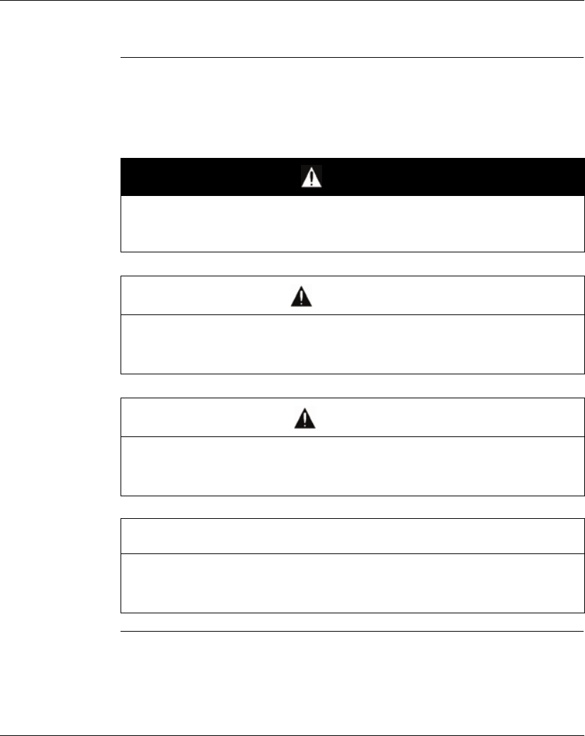
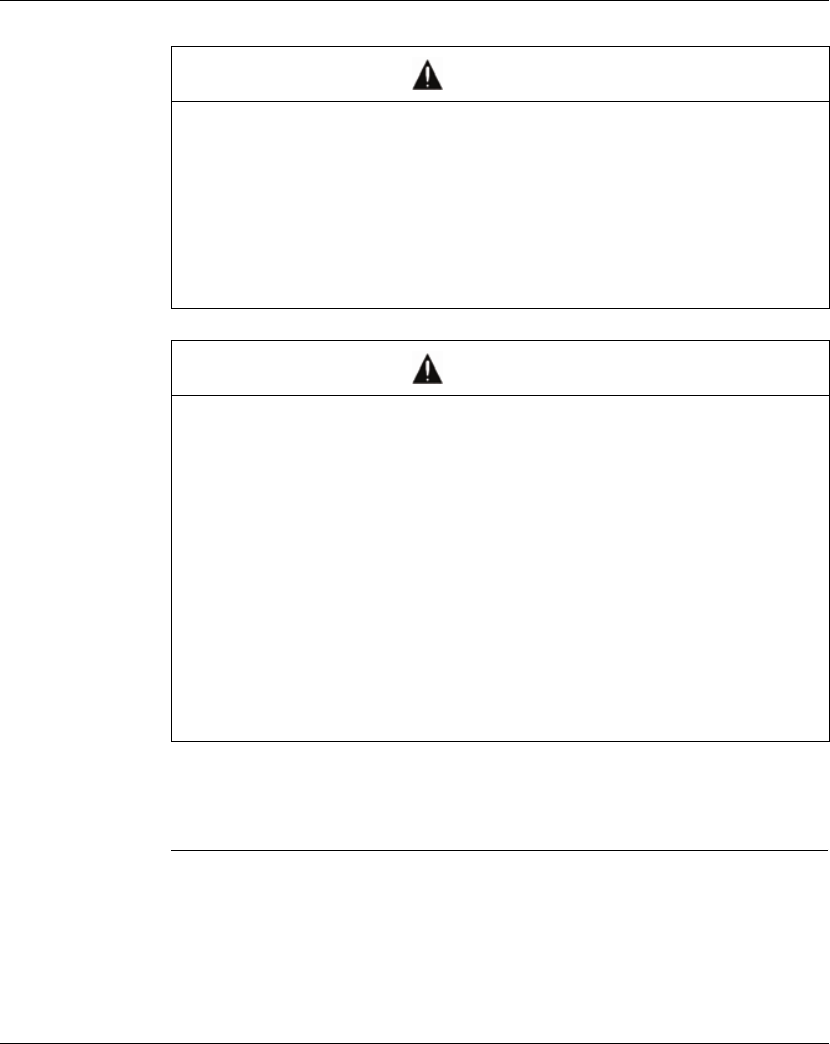
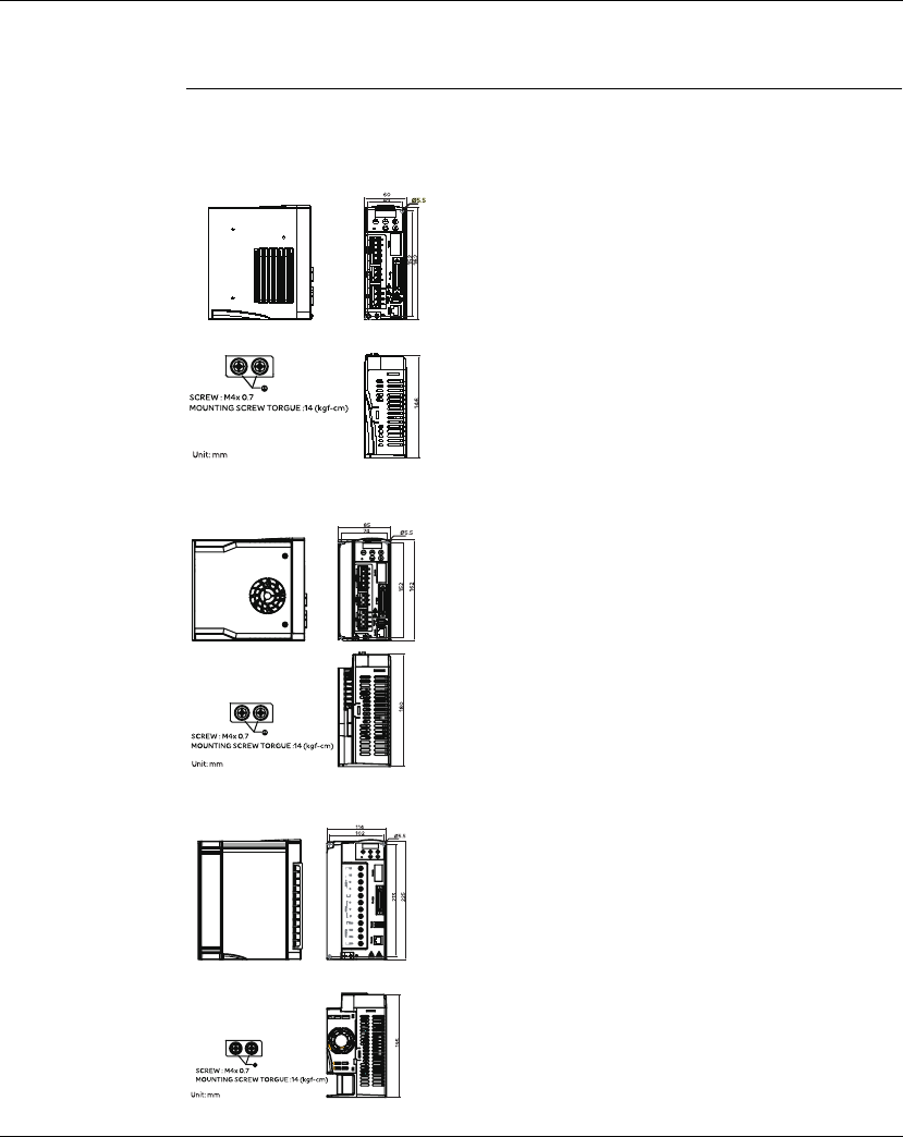
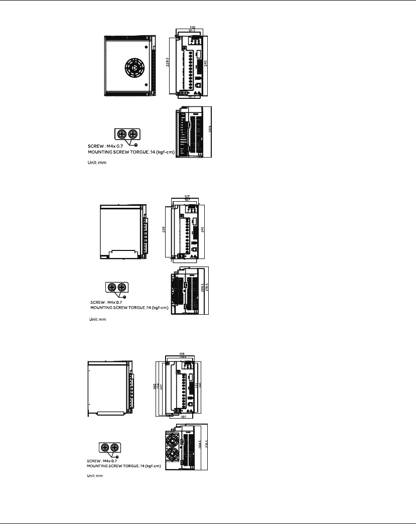
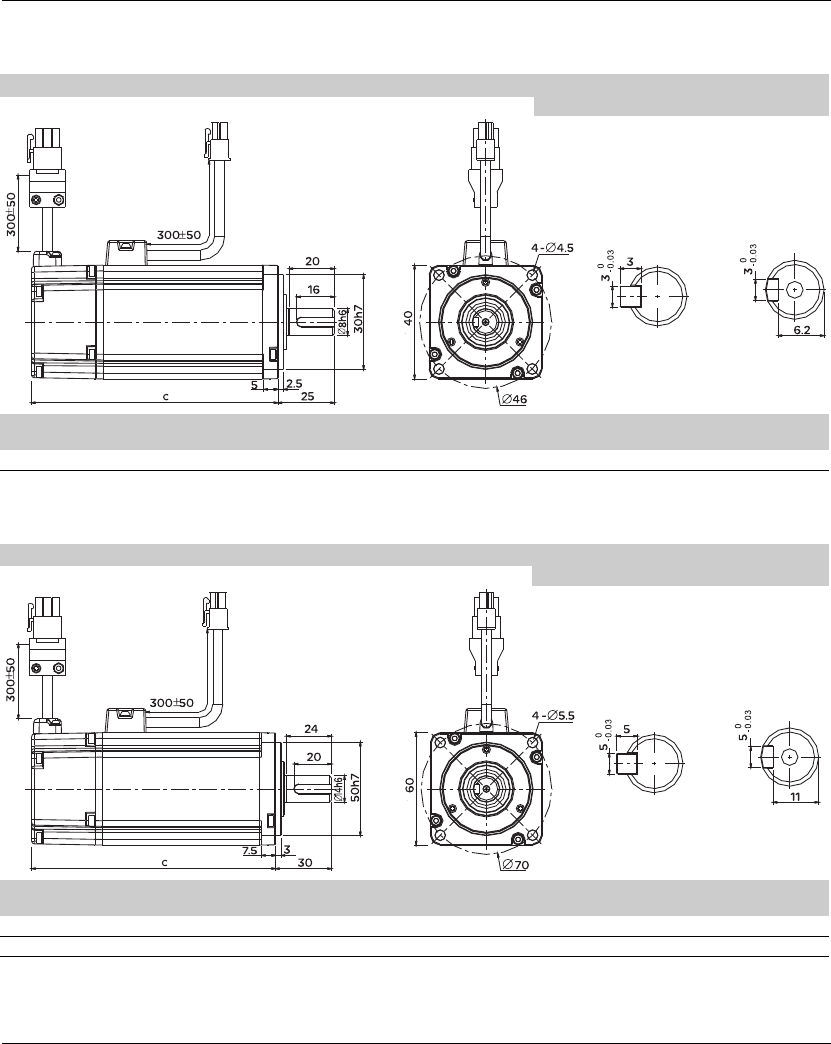
3.2 Dimensions
3.2.1 Dimensions of Servo Drive
LXM23AU01M3X, LXM23AU02M3X, LXM23AU04M3X
LXM23AU07M3X, LXM23AU10M3X, LXM23AU15M3X
LXM23AU20M3X,LXM23AU30M3X
Lexium 23A 3. Technical Data
AC servo drive 19
LXM23AU45M3X
LXM23AU55M3X
LXM23AU75M3X
3. Technical Data Lexium 23A
20 AC servo drive
3.2.2 Dimensions of Servo Motors
BCH040 (Servo motor/brake and Motor Power Connector 1 and Encoder Connector 2)
Key shaft (optional)
c (without
brake)
c (with
brake)
weight (in kg)
(without brake)
weight (in kg)
(with brake)
BCH0401 100.6 -136.6 0.5 0.8
BCH060 (Servo motor/brake and Motor Power Connector 1 and Encoder Connector 2)
Key shaft (optional)
c (without
brake)
c (with
brake)
weight (in kg)
(without brake)
weight (in kg)
(with brake)
BCH0601 105.5 141.6 1.2 1.5
BCH0602 130.7 166.8 1.6 2.0
Lexium 23A 3. Technical Data
AC servo drive 21
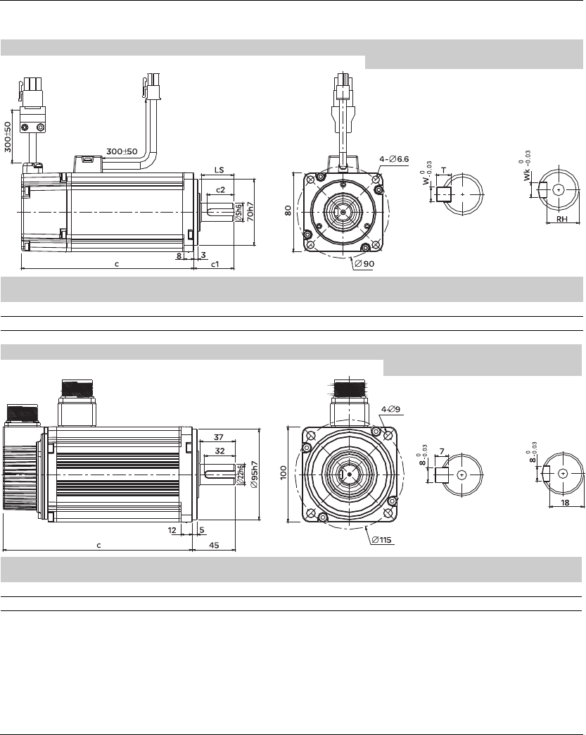
BCH080 (Servo motor/brake and Motor Power Connector 1 and Encoder Connector 2)
Key shaft (optional)
c (without
brake)
c (with
brake)
Sc1 c2 LS RH Wk W T weight (in kg)
(without brake)
weight (in kg)
(with brake)
BCH0801 112.3 152.8 14 30 20 24.5 11 5 5 5 2.1 2.9
BCH0802 138.3 178.0 19 35 25 29.5 15.5 6 6 6 3.0 3.8
BCH100 (Servo motor/brake and Motor Power Connector 1 and Encoder Connector 2)
Key shaft (optional)
c (without
brake)
c (with brake) weight (in kg)
(without brake)
weight (in kg)
(with brake)
BCH1001 153.5 192.5 4.3 4.7
BCH1002 199.0 226.0 6.2 7.2
3. Technical Data Lexium 23A
22 AC servo drive
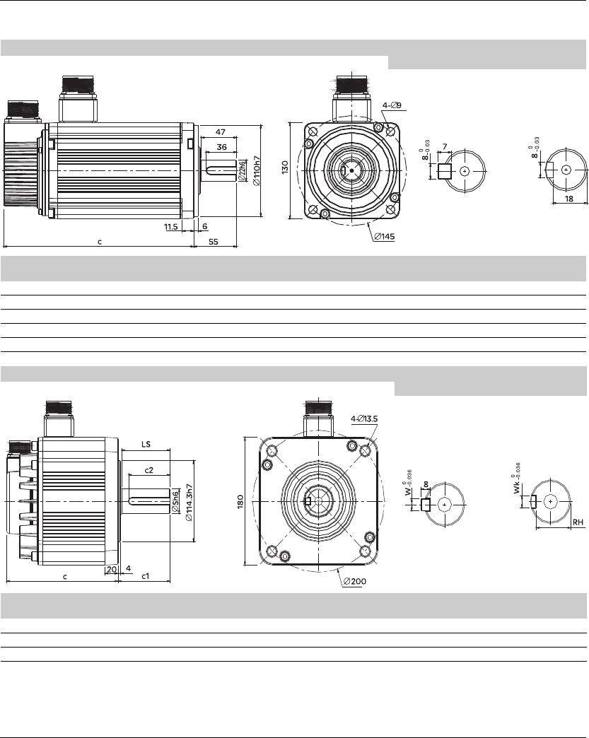
BCH130 (Servo motor/brake and Motor Power Connector 1 and Encoder Connector 2)
Key shaft (optional)
c (without
brake)
c (with brake) weight (in kg)
(without brake)
weight (in kg)
(with brake)
BCH1301 147.5 183.5 6.8 8.2
BCH1302 147.5 183.5 7 8.4
BCH1303M 163.5 198.0 7.5 8.9
BCH1303N 167.5 202.0 7.5 8.9
BCH1304 187.5 216.0 7.8 9.2
BCH180 (Servo motor/brake and Motor Power Connector 1 and Encoder Connector 2)
Key shaft (optional)
c (without
brake)
c (with
brake)
Sc1 c2 LS RH Wk Wweight (in kg)
(without brake)
weight (in kg)
(with brake)
BCH1801 169.0 203.1 35 79 63 73 30 10 10 13.5 17.5
BCH1802N 202.1 235.3 35 79 63 73 30 10 10 18.5 22.5
BCH1802M 202.1 235.3 35 79 63 73 30 10 10 18.5 22.5
Lexium 23A 3. Technical Data
AC servo drive 23
3.3 Electrical Data
The products are intended for industrial use and may only be operated with a
permanently installed connection.
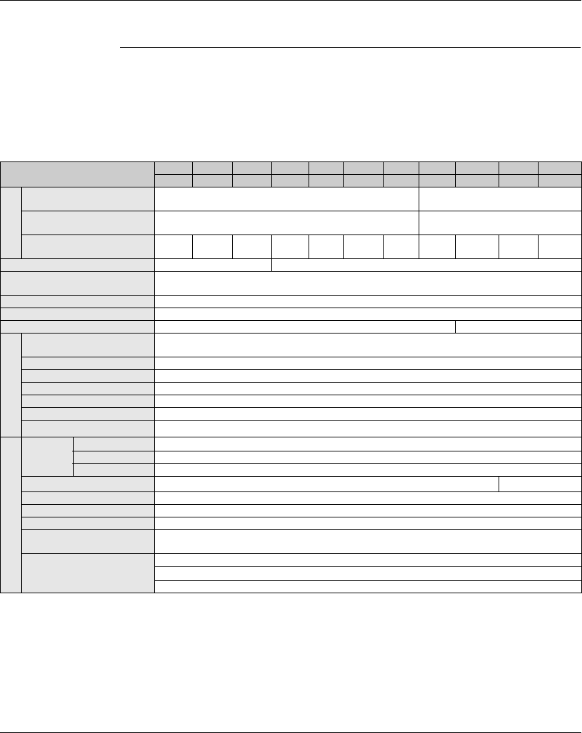
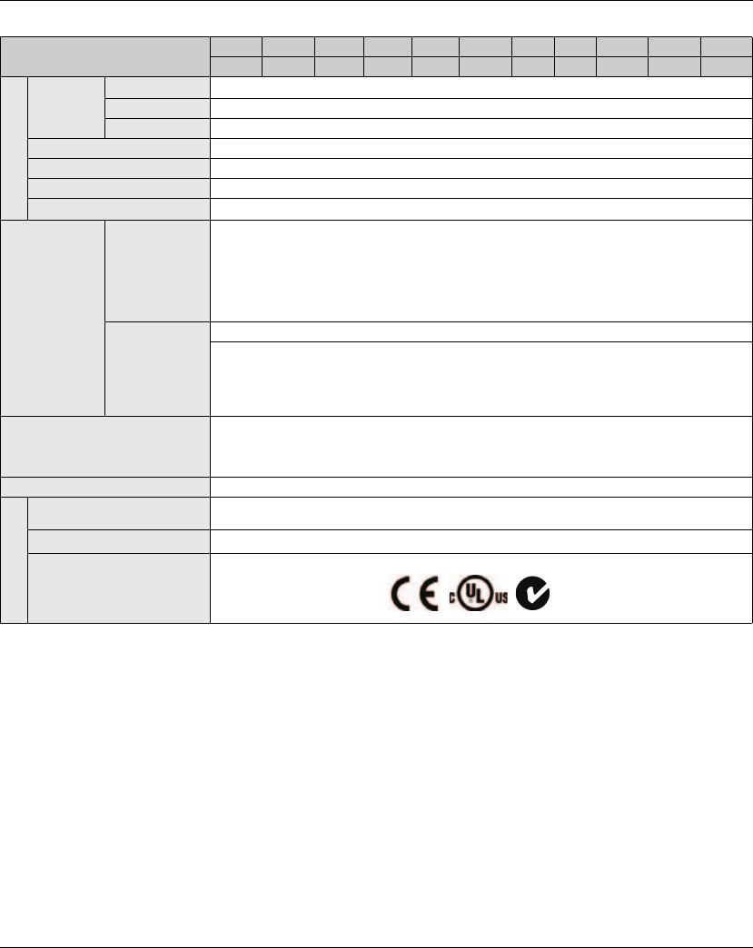
3.3.1 Specifications of Servo Drives (Lexium23 Plus Series)
Lexium23 Plus Series 100W 200W 400W 750W 1kW 1.5kW 2kW 3kW 4.5kW 5.5kW 7.5kW
01 02 04 07 10 15 20 30 45 55 75
Power supply
Phase / Voltage Three-phase or Single-phase: 220 VAC Three-phase
220VAC,
Permissible Voltage Range 170 ~ 255VAC Three-phase , 200 ~ 255VAC single phase 170~255VAC
Three phase
Continuous output current 0.9
Arms
1.55
Arms
2.6
Arms
5.1
Arms
7.3
Arms
8.3
Arms
13.4
Arms
19.4
Arms
32.5
Arms
40
Arms
47.5
Arms
Cooling System Natural Air Circulation Fan Cooling
Encoder Resolution /
Feedback Resolution 20-bit (1 280 000 p/rev)
Control of Main Circuit SVPWM (Space Vector Pulse Width Modulation) Control
Tuning Modes Auto / Manual
Dynamic Brake Built-in External
Position Control Mode
Max. Input Pulse Frequency Max. 500Kpps (Line driver), Max. 200Kpps (Open collector)
Max. 4Mpps (Line receiver)
Pulse Type Pulse + Direction, A phase + B phase, CCW pulse + CW pulse
Command Source External pulse train (Pt mode) / Internal procedures (Pr mode)
Smoothing Strategy Low-pass and P-curve filter
Electronic Gear Electronic gear N/M multiple N: 1~32767, M: 1:32767 (1/50<N/M<25600)
Torque Limit Operation Set by parameters
Feed Forward Compensation Set by parameters
Speed Control Mode
Analog
Input
Command
Voltage Range 0 ~ ±10 VDC
Input Resistance 10KΩ
Time Constant 2.2 μs
Speed Control Range *1 1:5000 1:3000
Command Source External analog signal / Internal parameters
Smoothing Strategy Low-pass and S-curve filter
Torque Limit Operation Set by parameters or via analog input
Frequency Response
Characteristic Maximum 1kHz
Speed Accuracy *2
(at rated rotation speed)
0.01% or less at 0 to 100% load fluctuation
0.01% or less at ±10% power fluctuation
0.01% or less at 0 oC to 50 oC ambient temperature fluctuation
3. Technical Data Lexium 23A
24 AC servo drive
Footnote:
*1 During full load, the speed ratio is defined as min. speed (no go and stop)/rated speed.
*2 When command is rated speed, speed fluctuation rate is defined as (empty load speed -full
load speed)/rated speed.
*3 TN system: A power distribution having one point directly earthed,the exposed conductive
parts of the installation being connected to that points by protective earth conductor.
*4 Please refer to "Chart of load and operating time" in section 3.3.4 "Overload Characteristics".
Lexium23 Plus 100W 200W 400W 750W 1kW 1.5kW 2kW 3kW 4.5kW 5.5kW 7.5kW
01 02 04 07 10 15 20 30 45 55 75
Torque Control Mode
Analog
Input
Command
Voltage Range 0 ~ ±10 VDC
Input Resistance 10KΩ
Time Constant 2.2 μs
Command Source External analog signal / Internal parameters
Smoothing Strategy Low-pass filter
Speed Limit Operation Set by parameters or via analog input
Analog Monitor Output Monitor signal can set by parameters (Output voltage range: ±8V)
Digital
Inputs/Outputs
Inputs
Servo On, Reset, Gain switching, Pulse clear, Zero speed CLAMP, Command input reverse control,
Command triggered, Speed/Torque limit enabled, Position command selection, Motor stop,
Speed Position Selection, Position / Speed mode switching, Speed / Torque mode switching,
Torque / Position mode switching, Pt / Pr command switching, Emergency stop, Forward / Reverse
inhibit limit, Reference "Home" sensor, Forward / Reverse operation torque limit, Move to "Home",
Forward / Reverse JOG input, Event trigger Pr command, Electronic gear ratio (Numerator)
selection and Pulse inhibit input.
Outputs
Encoder signal output (A, B, Z Line Driver and Z Open Collector )
Servo ready, Servo On, At Zero speed, At Speed reached, At Positioning completed, At Torques
limit, Servo alarm (Servo fault) activated, Electromagnetic brake control, Homing completed,
Output overload warning, Servo warning activated, Position command overflow, Forward /
Reverse software limit, Internal position command completed, Capture operation completed
output., Motion control completed output.
Protective Functions
Overcurrent, Overvoltage, Undervoltage, Motor overheated, Regeneration error, Overload,
Overspeed, Abnormal pulse control command, Excessive deviation, Encoder error, Adjustment
error, Emergency stop activated, Reverse/ Forward limit switch error, Serial communication error,
Input power phase loss, Serial communication time out, short circuit protection of U, V, W,
Communication Interface RS-232(for PC) / RS-485 / CANopen /
Environment
Installation Site Indoor location (free from direct sunlight), no corrosive liquid and gas (far away from oil mist,
flammable gas, dust)
Power System TN System*3
Approvals
IEC/EN 61800-5-1, UL 508C, C-tick

Lexium 23A 3. Technical Data
AC servo drive 25
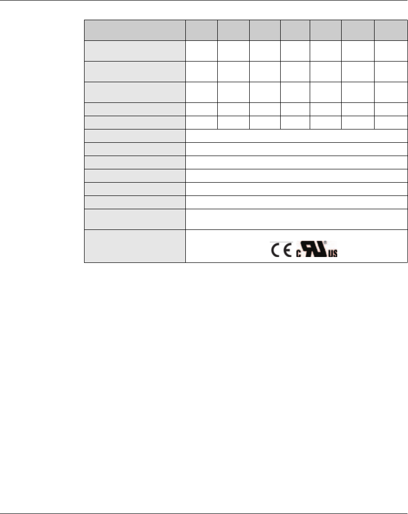
3.3.2 Specifications of Servo Motors
Ultra low/low
Inertia Series
BCH Series BCH
0401O
BCH
0601O
BCH
0602O
BCH
0801O
BCH
0802O
BCH
1001O
BCH
1002O
Rated output power (kW) 0.1 0.2 0.4 0.4 0.75 1.0 2.0
Rated torque (Nm) 0.32 0.64 1.27 1.27 2.39 3.18 6.37
Maximum torque (Nm) 0.96 1.92 3.82 3.82 7.16 9.54 19.11
Rated speed (rpm) 3000
Maximum speed (rpm) 5000
Rated current (A) 0.9 1.55 2.6 2.6 5.1 7.3 12.05
Maximum current (A) 2.7 4.65 7.8 7.8 15.3 21.9 36.15
Power rating (kW/s) 27.7 22.4 57.6 24.0 50.4 38.1 90.6
Rotor moment of inertia
(kg.cm2) (without brake) 0.037 0.177 0.277 0.68 1.13 2.65 4.45
Mechanical time constant (ms) 0.75 0.80 0.53 0.74 0.63 0.74 0.61
Torque constant-KT
(Nm/A) 0.36 0.41 0.49 0.49 0.47 0.43 0.53
Voltage constant-KE
(mV/(rpm)) 13.6 16 17.4 18.5 17.2 16.8 19.2
Armature resistance (Ohm) 9.3 2.79 1.55 0.93 0.42 0.20 0.13
Armature inductance (mH) 21 12.07 6.71 7.39 3.53 1.81 1.50
Electrical time constant (ms) 2.58 4.3 4.3 7.96 8.37 9.3 11.4
Insulation class Class A (UL), Class B (CE)
Insulation resistance >100MΩ, DC 500V
Insulation strength 1500V AC, 60 seconds
Weight (kg) (without brake) 0.5 1.2 1.6 2.1 3.0 4.3 6.2
Weight (kg) (with brake) 0.8 1.5 2.0 2.9 3.8 4.7 7.2
Max. radial shaft load (N) 78.4 196 196 245 245 490 490
Max. thrust shaft load (N) 39.2 68 68 98 98 98 98
Power rating (kW/s)
(with brake) 25.6 21.3 53.8 22.1 48.4 30.4 82
Rotor moment of inertia
(kg.cm2) (with brake) 0.04 0.192 0.30 0.73 1.18 3.33 4.953
3. Technical Data Lexium 23A
26 AC servo drive
BCH Series BCH
0401O
BCH
0601O
BCH
0602O
BCH
0801O
BCH
0802O
BCH
1001O
BCH
1002O
Mechanical time constant (ms)
(with brake) 0.81 0.85 0.57 0.78 0.65 0.93 0.66
Brake holding torque
[Nm (min)] 0.3 1.3 1.3 2.5 2.5 12 12
Brake power consumption
(at 20°C) [W] 7.2 7.2 7.2 8.5 8.5 19.4 19.4
Brake release time [ms (Max)] 5 10 10 10 10 10 10
Brake pull-in time [ms (Max)] 25 70 70 70 70 70 70
Vibration grade (μm) 15
Operating temperature 0 °C to 40°C (32 °F to 104°F)
Storage temperature -10 C to 80C (-14 °F to 176°F)
Operating humidity 20% to 90% RH (non-condensing)
Storage humidity 20% to 90% RH (non-condensing)
Vibration capacity 2.5G
IP Rating IP65 (when waterproof connectors are used, or when an oil seal is
used to be fitted to the rotating shaft (an oil seal model is used))
Approvals

Lexium 23A 3. Technical Data
AC servo drive 27
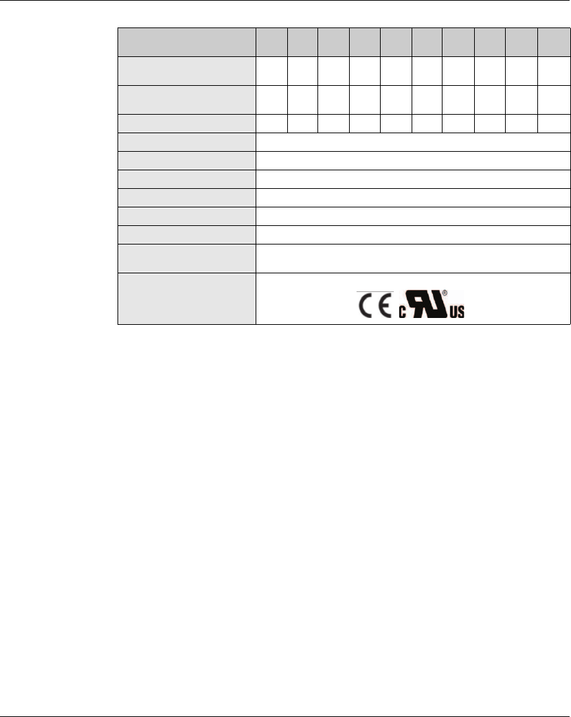
Medium / High
Inertia Series
Medium / High Inertia Series
BCH
1301N
BCH
1302N
BCH
1303N
BCH
1304N
BCH
1801N
BCH
1802N
BCH
1802M
BCH
1301M
BCH
1302M
BCH
1303M
Rated output power (kW) 0.5 1.0 1.5 2.0 2.0 3.0 3.0 0.3 0.6 0.9
Rated torque (Nm) 2.39 4.77 7.16 9.55 9.55
14.32 19.10
2.86 5.73 8.59
Maximum torque (Nm) 7.16 14.3
21.48 28.65 28.65 42.97 57.29
8.59 17.19 21.4
8
Rated speed (rpm) 2000
1500
1000
Maximum speed (rpm) 3000 2000
Rated current (A) 2.9 5.6 8.3 11.01 11.22 16.1 19.4 2.5 4.8 7.5
Maximum current (A) 8.7 16.8 24.9
33.03 33.66
48.3 58.2 7.5 14.4 22.5
Power rating (kW/s) 7.0 27.1 45.9 62.5 26.3 37.3 66.4 10.0 39.0 66.0
Rotor moment of inertia
(kg.cm2) (without brake) 8.17 8.41 11.18
14.59 34.68 54.95 54.95
8.17 8.41 11.18
Mechanical time constant (ms) 1.91 1.51 1.10 0.96 1.62 1.06 1.28 1.84 1.40 1.06
Torque constant-KT (Nm/A) 0.83 0.85 0.87 0.87 0.85 0.89 0.98 1.15 1.19 1.15
Voltage constant-KE
(mV/(rpm)) 30.9 31.9 31.8 31.8 31.4 32 35 42.5 43.8 41.6
Armature resistance (Ohm) 0.57 0.47 0.26 0.174 0.119
0.052 0.077
1.06 0.82 0.43
Armature inductance (mH) 7.39 5.99 4.01 2.76 2.84 1.38 1.27 14.29 11.12 6.97
Electrical time constant (ms)
12.96 12.88 15.31 15.86 23.87 26.39 16.51 13.55 13.50 16.06
Insulation class Class A (UL), Class B (CE)
Insulation resistance >100MΩ, DC 500V
Insulation strength 1500V AC, 60 seconds
Weight (kg) (without brake) 6.8 7 7.5 7.8 13.5 18.5 18.5 6.8 7 7.5
Weight (kg) (with brake) 8.2 8.4 8.9 9.2 17.5 22.5 22.5 8.2 8.4 8.9
Max. radial shaft load (N) 490 490 490 490 1176 1470
1470
490 490 490
Max. thrust shaft load (N) 98 98 98 98 490 490 490 98 98 98
Power rating (kW/s)
(with brake) 6.4 24.9 43.1 59.7 24.1 35.9 63.9 9.2 35.9 62.1
Rotor moment of inertia
(kg.cm2) (with brake) 8.94 9.14
11.90 15.88 37.86 57.06 57.06
8.94 9.14 11.9
Mechanical time constant
(ms) (with brake) 2.07 1.64 1.19 1.05 1.77 1.10 1.33 2.0 1.51 1.13
Brake holding torque
[Nm (min)] 16.5 16.5 16.5 16.5 25 25 25 16.5 16.5 16.5
3. Technical Data Lexium 23A
28 AC servo drive
Medium / High Inertia Series
BCH
1301N
BCH
1302N
BCH
1303N
BCH
1304N
BCH
1801N
BCH
1802N
BCH
1802M
BCH
1301M
BCH
1302M
BCH
1303M
Brake power consumption
(at 20°C) [W] 21.0 21.0 21.0 21.0 31.1 31.1 31.1 21.0 21.0 21.0
Brake release time [ms
(Max)] 5.0 5.0 5.0 5.0 5.0
5.0 5.0
5.0 5.0 5.0
Brake pull-in time [ms (Max)] 25.0 25.0
25.0 25.0 25.0 25.0 25.0
25.0 25.0 25.0
Vibration grade (μm) 15
Operating temperature 0 °C to 40°C (32 °F to 104°F)
Storage temperature -10 °C to 80°C (-14 °F to 176°F)
Operating humidity 20% to 90% RH (non-condensing)
Storage humidity 20% to 90% RH (non-condensing)
Vibration capacity 2.5G
IP Rating IP65 (when waterproof connectors are used, or when an oil seal is
used to be fitted to the rotating shaft (an oil seal model is used))
Approvals
Lexium 23A 3. Technical Data
AC servo drive 29
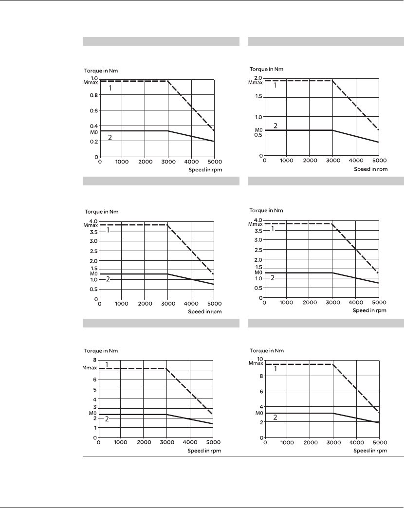
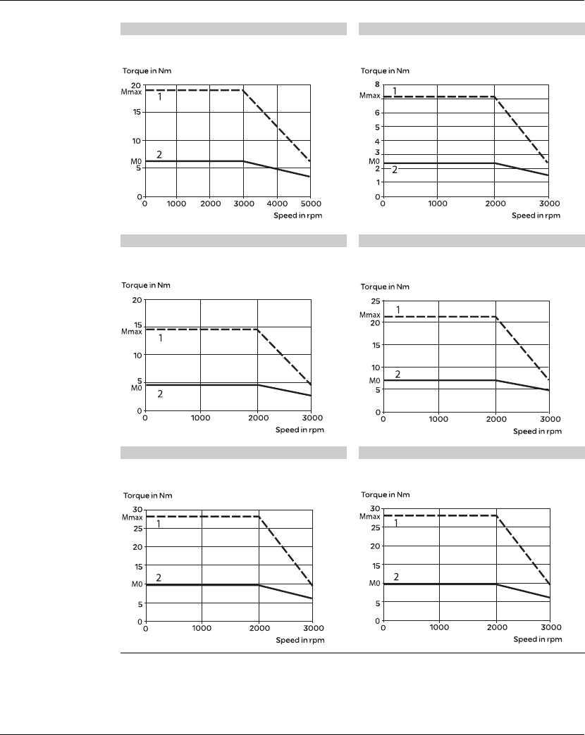
3.3.3 Servo Motor Speed-Torque Curves (T-N Curves)
BCH0401O servo motor BCH0601O servo motor
Control by LXM23pU01M3X servo drive
Single phase 220 V
Control by LXM23pUO2M3X servo drive
Single phase 220 V
BCH0602O servo motor BCH0801O servo motor
Control by LXM23pU04M3X servo drive
Single phase 220 V
Control by LXM23pU04M3X servo drive
Single phase 220 V
BCH0802O servo motor BCH1001O servo motor
Control by LXM23pU07M3X servo drive
Single phase 220 V
Control by LXM23pU10M3X servo drive
Single phase 220 V
1Peak torque
2Continuous torque
3. Technical Data Lexium 23A
30 AC servo drive
BCH1002O servo motor BCH1301N servo motor
Control by LXM23pU20M3X servo drive
Three phase 220 V
Control by LXM23pU04M3X servo drive
Single phase 220 V
BCH1302N servo motor BCH1303N servo motor
Control by LXM23pU10M3X servo drive
Single phase 220 V
Control by LXM23pU15M3X servo drive
Single phase 220 V
BCH1304N servo motor BCH1801N servo motor
Control by LXM23pU20M3X servo drive
Three phase 220 V
Control by LXM23pU20M3X servo drive
Three phase 220 V
1Peak torque
2Continuous torque
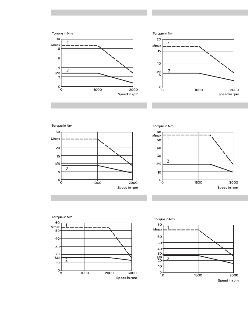
Lexium 23A 3. Technical Data
AC servo drive 31
BCH1301M servo motor BCH1302M servo motor
Control by LXM23pU04M3X servo drive
Single phase 220 V
Control by LXM23pU07M3X servo drive
Single phase 220 V
BCH1303M servo motor BCH1802M servo motor
Control by LXM23pU10M3X servo drive
Single phase 220 V
Control by LXM23pU30M3X servo drive
Three phase 220 V
BCH1802N servo motor BCH1803M servo motor
Control by LXM23pU30M3X servo drive
Three phase 220 V
Control by LXM23pU45M3X servo drive
Three phase 220 V
1Peak torque
2Continuous torque
3. Technical Data Lexium 23A
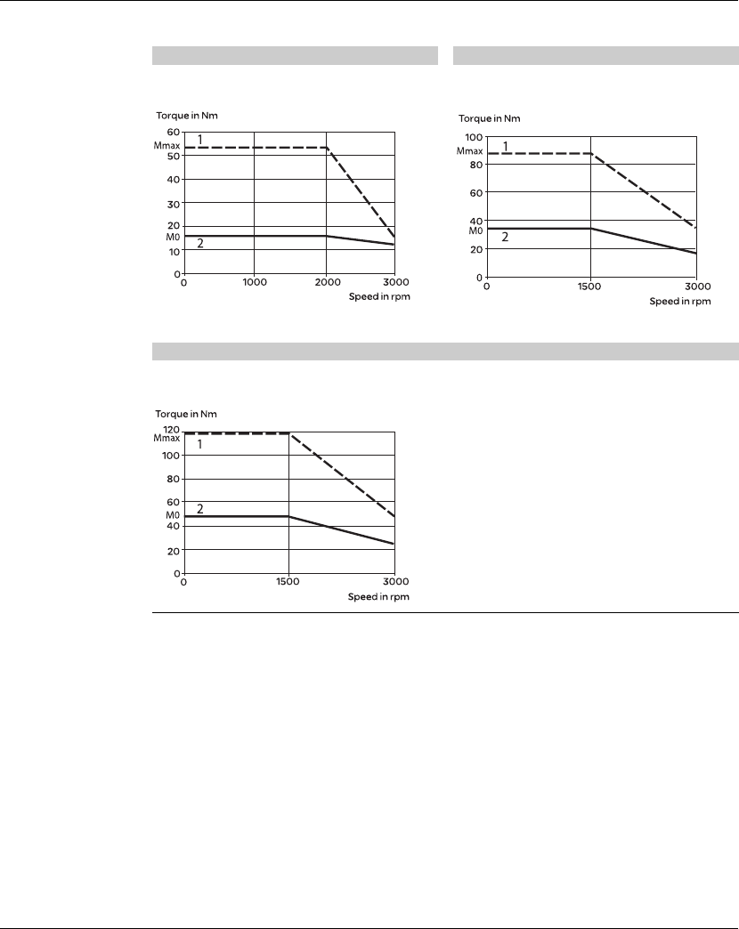
32 AC servo drive
BCH1803N servo motor BCH1804M servo motor
Control by LXM23pU45M3X servo drive
Three phase 220 V
Control by LXM23pU55M3X servo drive
Three phase 220 V
BCH1805M servo motor
Control by LXM23pU75M3X servo drive
Three phase 220 V
1Peak torque
2Continuous torque
Lexium 23A 3. Technical Data
AC servo drive 33
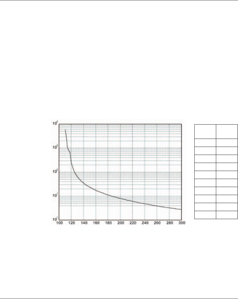
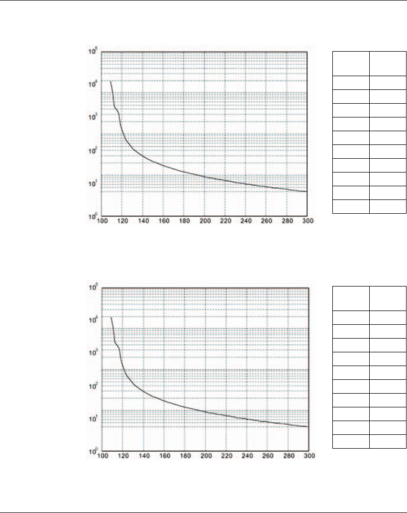
3.3.4 Overload Characteristics
Overload Protection Function
Overload protection is a built-in protective function to prevent a motor from
overheating.
Occasion of Overload
1. Motor was operated for several seconds under a torque exceeding 100% torque.
2. Motor had driven high inertia machine and had accelerated and decelerated at high
frequency.
3. Motor UVW cable or encoder cable was not connected correctly.
4. Servo gain was not set properly and caused motor hunting.
5. Motor holding brake was not released.
Chart of load and operating time
Ultra low/low Inertia Series (BCH0401O, BCH0601O, BCH0602O, BCH0801O,
BCH0802O, BCH1001O, BCH1002O)
Load Operating
Time
120% 263.8s
140% 35.2s
160% 17.6s
180% 11.2s
200% 8s
220% 6.1s
240% 4.8s
260% 3.9s
280% 3.3s
300% 2.8s
3. Technical Data Lexium 23A
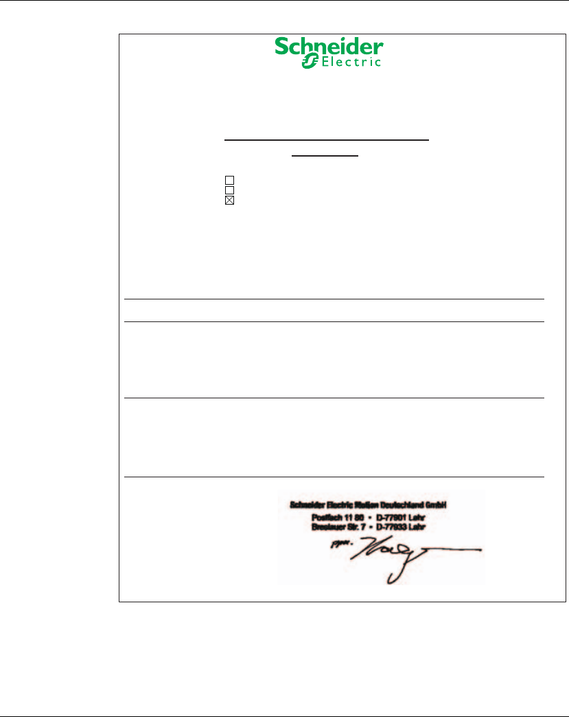
34 AC servo drive
Medium and Medium-High Inertia Series (BCH1301N, BCH1302N, BCH1303N,
BCH1304N, BCH1801N,BCH1802N, BCH1802M)
High Inertia Series (BCH1301M, BCH1302M, BCH1303M)
Load Operating
Time
120% 527.6s
140% 70.4s
160% 35.2s
180% 22.4s
200% 16s
220% 12.2s
240% 9.6s
260% 7.8s
280% 6.6s
300% 5.6s
Load Operating
Time
120% 527.6s
140% 70.4s
160% 35.2s
180% 22.4s
200% 16s
220% 12.2s
240% 9.6s
260% 7.8s
280% 6.6s
300% 5.6s

Lexium 23A 3. Technical Data
AC servo drive 35
3.3.5 DC Bus data
DC bus data for
single-phase
drives
DC bus data for
three-phase
drives
LXM23A,LXM23D(1phase) 100W 200W 400W 759W 1KW 1.5KW
Nominal voltage 1 phase[VAC] 220 220 220 220 220 220
Nominal voltage DC bus[VDC] 311 311 311 311 311 311
Undervoltage limit[VDC]
P
4-24*
2
P
4-24*
2
P
4-24*
2
P
4-24*
2
P
4-24*
2
P
4-24*
2
Voltage limit:activation of error
Reaction in drive (quickstop) 410 410 410 410 410 410
Overvoltage limit[VDC] 410 410 410 410 410 410
Maximum continuous power
via DC BUS[kw] 0.1 0.2 0.4 0.75 1 1.5
Maximum continuous current
Via DC bus 333666
LXM23A,LXM23D(3phase) 2kW 3kW 4.5W 5.5W 7.5KW
Nominal voltage 3 phase[VAC] 220 220 220 220 220
Nominal voltage DC bus[VDC] 311 311 311 311 311
Undervoltage limit[VDC]
P
4-24*
2
P
4-24*
2
P
4-24*
2
P
4-24*
2
P
4-24*
2
Voltage limit:activation of error
Reaction in drive (quickstop) 410 410 410 410 410
Overvoltage limit[VDC] 410 410 410 410 410
Maximum continuous power via
DC BUS[kw] 2 3 4.5 5.5 7.5
Maximum continuous current
Via DC bus 16 16 16 20 20

3. Technical Data Lexium 23A
36 AC servo drive
3.3.6 Additional EMC input filters
Applications When combined with LXM 23pUppM3X servo drives, additional EMC fi lters can be
used to meet more stringent requirements and are designed to reduce conducted
emissions on the line supply below the limits of standard IEC 61800-3, edition 2,
categories C2 and C3.
Use according to
the type of line
supply
These additional fi lters can only be used on TN (neutral connection) and TT (neutral
to earth) type supplies.
The fi lters must not be used on IT (impedance or isolated neutral) type supplies.
Standard IEC/EN 61800-3, appendix D2.1, states that on IT (isolated or impedance
earthed neutral) type supplies, fi lters can adversely affect the operation of the
insulation monitors. In addition, the effectiveness of additional fi lters on this type of
line supply depends on the type of impedance between neutral and earth, and
therefore cannot be predicted.
Note: If a machine is to be installed on an IT supply, one solution is to insert an isolation
transformer in order to re-create a TT system on the secondary side.

Lexium 23A 3. Technical Data
AC servo drive 37
Characteristics of
servo drive/EMC
filter mounting
Conforming to standards EN 133200
Degree of protection IP 41 on the upper part with protective cover in place
IP 20 after removal of the protective cover
Relative humidity According to IEC 60721-3-3, class 3K3, 5% to 85%,
without condensation or dripping water
Ambient air temperature
around the device
Operation °C 0 °C ~ 55 °C (If operating temperature is above 45 °C,
forced cooling will be required)
Storage
°C -20 °C to 65 °C (-4°F to 149°F)
Altitude m1000 m without derating
Up to 2000 m under the following conditions:
p Max. temperature 40°C
p Mounting distance between servo drives > 50 mm
p Protective cover removed
Vibration resistance Conforming
to IEC
60068-2-6
10 Hz to 57 Hz: amplitude 0.075 mm
57 Hz to 150 Hz: 1 g
Shock resistance Conforming
to IEC
60068-2-27
15 gn for 11 ms
Maximum nominal
voltage
Single-phase
50/60 Hz
V120 + 10 %
240 + 10 %
Three-phase
50/60 Hz
V240 + 10 %
Application, category:
EN 61800-3: 2001-02 ; IEC 61800-3, Ed.
2
Description
Category C2 in environment 1 Restricted distribution, for domestic use, sale
conditioned by the competence of the user and the
distributor on the subject of EMC compatibility
Category C3 in environment 2 Use in industrial premises

3. Technical Data Lexium 23A
38 AC servo drive
References
Additional EMC input fi lters
For
servo drive
Maximum servo motor cable length
conforming to
Reference Weight
EN 55011
class A Gr1
EN 55011
class A Gr2
IEC/EN 61800-3
category C2
in environment 1
IEC/EN 61800-3
category C3
in environment 2
m m kg
Single-phase supply voltage
LXM23
p
U07M3X
LXM23
p
U10M3X
LXM23
p
U15M3X
20 40 VW3 A31403 0.775
LXM23
p
U01M3X
LXM23
p
U02M3X
LXM23
p
U04M3X
20 40 VW3 A31401 0.600
Three-phase supply voltage
LXM23
p
U07M3X
LXM23
p
U10M3X
LXM23
p
U15M3X
20 40 VW3 A31404 0.900
LXM23
p
U20M3X
LXM23
p
U30M3X
LXM23
p
U45M3X
LXM23
p
U55M3X
20 40 VW3 A31406 1.350
LXM23
p
U75M3X 20 40 VW3 A31407 3.150

Lexium 23A 3. Technical Data
AC servo drive 39
3.3.7 Protection by circuit breaker
Application The combinations listed below can be used to create a complete motor starter
unitcomprising a circuit breaker, a contactor and a Lexium 23 Plus servo drive.
The circuit breaker provides protection against accidental short-circuits,
disconnection and, if necessary, isolation.The contactor starts up and manages any
safety features, as well as isolating the servo motor on stopping.
The servo drive controls the servo motor, provides protection against short-circuits
between the servo drive and the servo motor and protects the motor cable against
overloads. The overload protection is provided by the motor thermal protection of
the servo drive.
(1)Composition of contactors:
p LC1 K06: 3 poles + 1 "N/O" auxiliary contact
p LC1 D09: 3 poles + 1 "N/O" auxiliary contact + 1 "N/C" auxiliary contact
(2)Usual control circuit voltages, see table below:
Note:
For other voltages between 24 V and 660 V, or for a DC control circuit, please consult
your Regional Sales Office.
Motor starters for Lexium 23 Plus servo drives
Reference Rating
kW A
Single phase 220...255VAC/three phase:170...255VAC
LXM23pU01M3X 0.1 6.3
LXM23pU02M3X 0.2 6.3
LXM23pU04M3X 0.4 10
LXM23pU07M3X 0.7 10
LXM23pU10M3X 114
LXM23pU15M3X 1.5 25
LXM23pU20M3X 230
LXM23pU30M3X 330
LXM23pU45M3X 4.5 60
LXM23pU55M3X 5.5 60
LXM23pU75M3X 7.5 75
AC control circuit
Volts a24 48 110 220 230 240
LC1-K 50/60 Hz B7 E7 F7 M7 P7 U7
Volts a24 48 110 220/230 230 230/240
LC1-D
50 Hz B5 E5 F5 M5 P5 U5
60 Hz B6 E6 F6 M6 -U6
50/60 Hz B7 E7 F7 M7 P7 U7

3. Technical Data Lexium 23A
40 AC servo drive
3.3.8 Protection using fuses
Protection using class fuses(UL standsrd)
Servo drive reference Nominal power Fuse to be placed upstream
kW A
Single phase:200...255/three phase:170...255VAC
LXM23pU01M3X 0.1 5
LXM23pU02M3X 0.2 5
LXM23pU04M3X 0.4 20
LXM23pU07M3X 0.7 20
LXM23pU10M3X 125
LXM23pU15M3X 1.5 40
LXM23pU20M3X 260
LXM23pU30M3X 380
LXM23pU45M3X 4.5 160
LXM23pU55M3X 5.5 160
LXM23pU75M3X 7.5 200

Lexium 23A 3. Technical Data
AC servo drive 41
3.4 Certifications
Product certifications:
Assigned file number Related products Certified by
E198280 LXM23A servo drives,
LXM23D servo drives,
LXM23C servo drives,
LXM23M servo drives
UL
E198273 BCH servo motors UL

3. Technical Data Lexium 23A
42 AC servo drive
3.5 Declaration of conformity
The following declaration of conformity is applicable if the product is used under the
specified conditions and with the cables listed in the Ac-cessories chapter.
SCHNEIDER ELECTRIC MOTION DEUTSCHLAND GmbH
Breslauer Str. 7 D-77933 Lahr
EC DECLARATION OF CONFORMITY
YEAR 2010
according to EC Directive on Machinery 98/37/EC
according to EC Directive EMC 2004/108/EC
according to EC Directive Low Voltage 2006/95/EC
We declare that the products listed below meet the requirements of the mentioned EC
Directives with respect to design, construction and version distributed by us. This
declaration becomes invalid with any modification on the products not authorized by us.
Designation: AC Servo Drive
Type: LXM23xx
Applied
harmonized
standards,
especially:
EN61800-5-1:2007
EN61800-3:2004
Applied
national standards
and technical
specifications,
especially:
UL 508C
Company stamp:
Date/ Signature: January 29, 2010
Name/ Department: Dr. Björn Hagemann / VP Offer Implementation
Lexium 23A 3. Technical Data
AC servo drive 43
SCHNEIDER ELECTRIC MOTION DEUTSCHLAND GmbH
Breslauer Str. 7 D-77933 Lahr
EC DECLARATION OF CONFORMITY
YEAR 2010
according to EC Directive on Machinery 98/37/EC
according to EC Directive EMC 2004/108/EC
according to EC Directive Low Voltage 2006/95/EC
We declare that the products listed below meet the requirements of the mentioned EC
Directives with respect to design, construction and version distributed by us. This
declaration becomes invalid with any modification on the products not authorized by us.
Designation: AC Servo Motor
Type: BCHxx
Applied
harmonized
standards,
especially:
EN61800-5-1:2007
EN60034-1:2004-06
EN60034-5:2001-02;
EN60034-5/A1:2007-01
Applied
national standards
and technical
specifications,
especially:
UL 1004
Company stamp:
Date/ Signature: January 29, 2010
Name/ Department: Dr. Björn Hagemann / VP Offer Implementation

3. Technical Data Lexium 23A
44 AC servo drive

AC servo drive 45
4
Engineering
At a Glance
Presentation This chapter contains information on the application of the product that is vital in the
design phase.
What's in
thisChapter?
This chapter contains the following topics:
Subject
Page
Electromagnetic compatibility, EMC 46
Residual current device 49
Operation in an IT mains 50
Rating the braking resistor 51
Logic type 59
Monitoring functions 60
Configurable inputs and outputs 61
4. Engineering Lexium 23A
46 AC servo drive
4.1 Electromagnetic compatibility, EMC
Limit values This product meets the EMC requirements according to the standard IEC61800-3, if
the measures described in this manual are implemented during installation.
If the selected composition is not designed for category C1, note the following:
An EMC-compliant design is required to meet the specified limit values. Note the
following requirements:
SIGNAL AND DEVICE INTERFERENCE
Signal interference can cause unexpected responses of device.
z Install the wiring in accordance with the EMC requirements.
z Verify compliance with the EMC requirements.
Failure to follow these instructions can result in death, serious injury or
equipment damage.
WARNNG
HIGH-FREQUENCY INTERFERENCE
In a residential environment this product may cause high-frequency interference
that may require interference suppression.
Failure to follow these instructions can result in death or serious injury.
WARNNG

Lexium 23A 4. Engineering
AC servo drive 47
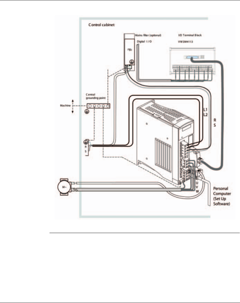
Control cabinet
design
Additional
measures for
EMC improvement
An EMC-compliant design is required to meet the specified limit values. Depending
on the application, better results can be achieved with the following measures:
EMC measures Objective
Use galvanised or chrome-plated mounting plates,
make large contact surface connections for metal
parts, remove paint from contact surfaces
Good conductivity due to
two-dimensional contacts
Ground the control cabinet, door and mounting plate
with ground straps or ground wires with a cross
section greater than 10mm2 (AWG6).
Reduces emissions.
Fit switching devices such as contactors, relays or
solenoid valves with interference suppression
assemblies or arc suppressors (for example, diodes,
varistors, RC circuits).
Reduces mutual
interference
Install power and control components separately. Reduces mutual
interference
EMC measures Objective
Upstream mains reactors Reduces mains
harmonics, prolongs
product service life.
Upstream external mains filters Improves the EMC limit
values.
Particularly EMC-compliant design, e.g. in a closed control
cabinet with 15dB damping of radiated interference
Improves the EMC limit
values.
4. Engineering Lexium 23A
48 AC servo drive
Figure 4.1 EMC measures

Lexium 23A 4. Engineering
AC servo drive 49
4.2 Residual current device
Conditions for use
of residualcurrent
device
Where the installation regulations require upstream protection against direct or
indirect contact by means of a residual current device (RCD) or a residual current
monitor (RCM), a residual current device of "type A" can be used for a singlephase
drive with connection between N and L. In other cases, a "type B" RCD must be used.
Note the following:
z Filtering of high-frequency currents.
z Delayed triggering to avoid triggering as a result of capacitance which may be
present when the unit is switched on. 30 mA residual current devices rarely have a
delay. Use residual current devices which are not sensitive to unintentional
triggering, for example residual current devices with increased immunity.
Use residual current devices that meet the following conditions:
z For single-phase devices, type A: Residual current devices of series s.i
(superimmunized, Schneider Electric).
z For three-phase devices, type B: sensitive to all current types with approval for
frequency inverters
When using residual current devices, consider the leakage currents of connected
consumers.
THIS PRODUCT MAY CAUSE DIRECT CURRENT IN THE PROTECTIVE GROUND
CONDUCTOR
If a residual current device (RCD) is used, conditions must be observed.
Failure to follow these instructions can result in death or serious injury.
WARNNG

4. Engineering Lexium 23A
50 AC servo drive
4.3 Operation in an IT mains
The device is intended for operation in a TT/TN mains. The device is not suitable for
operation in an IT mains.
A transformer grounded at the output turns a TT/TN mains into an IT mains. The
device may be connected to this mains.
Lexium 23A 4. Engineering
AC servo drive 51
4.4 Rating the braking resistor
MOTOR WITHOUT BRAKING EFFECT
An insufficient braking resistor causes overvoltage on the DC bus and switches off
the power stage. The motor is no longer actively decelerated.
zVerify that the braking resistor has a sufficient rating.
zCheck the parameter settings for the braking resistor.
zCheck the I2t value under the most critical condition by performing a test run.
The device switches off at an I2t value of 100%.
zWhen performing the calculation and the test run, take into account the fact
that the DC bus capacitors can absorb less braking energy at higher mains
voltages.
Failure to follow these instructions can result in death, serious injury or
equipment damage.
HOT SURFACES
The braking resistor may heat up to over 250C (480F) during operation.
zAvoid contact with the hot braking resistor.
zDo not allow flammable or heat-sensitive parts in the immediate vicinity of
the braking resistor.
zProvide for good heat dissipation.
zCheck the temperature of the braking resistor under the most critical
condition by performing a test run.
Failure to follow these instructions can result in death, serious injury or
equipment damage.
WARNNG
WARNNG

4. Engineering Lexium 23A
52 AC servo drive
Braking resistors are required for dynamic applications. During deceleration, the
kinetic energy is transformed into electrical energy in the motor. The electrical
energy increases the DC bus voltage. The braking resistor is activated when the
defined threshold value is exceeded. The braking resistor transforms electrical
energy into heat. If highly dynamic deceleration is required, the braking resistor must
be well adapted to the system.
Built-in
Regenerative
Resistor
When the output torque of servo motor in reverse direction of motor rotation speed,
it indicates that there is a regenerative power returned from the load to the servo
drive. This power will be transmitted into the capacitance of DC Bus and result in
rising voltage. When the voltage has risen to some high voltage, the servo system
need to dissipate the extra energy by using a regenerative resistor. Lexium23 Plus
series servo drives provide a built-in regenerative resistor and the users also can
connect to external regenerative resistor if more regenerative capacity is needed.
The following table shows the specifications of the servo drive's built-in regenerative
resistor and the amount of regenerative power (average value) that it can process.
When the regenerative power exceeds the processing capacity of the servo drive,
install an external regenerative resistor. Please pay close attention on the following
notes when using a regenerative resistor.
Built-in Regenerative Resistor Specifications
Servo
Drive (kW)
Resistance (Ohm)
(parameter
P1-52)
Capacity (Watt)
(parameter
P1-53)
Regenerative Power
processed by built-in
regenerative resistor
(Watt) *1
Min. Allowable
Resistance
(Ohm)
0.1 100 60 30 60
0.2 100 60 30 60
0.4 100 60 30 60
0.75 40 60 30 30
140 60 30 30
1.5 40 60 30 30
240 60 30 15
340 60 30 15
4.5 20 100 50 10
5.5 - - - 8
7.5 - - - 6

Lexium 23A 4. Engineering
AC servo drive 53
1. Make sure that the settings of resistance (parameter P1-52) and capacity
(parameter P1-53) is set correctly.
2. When the users want to install an external regenerative resistor, ensure that its
resistance value is the same as the resistance of built-in regenerative resistor. If
combining multiple small-capacity regenerative resistors in parallel to increase the
regenerative resistor capacity, make sure that the resistance value of the regenerative
resistor should comply with the specifications listed in the above table.
3. In general, when the amount of regenerative power (average value) that can be
processed is used at or below the rated load ratio, the resistance temperature will
increase to 120C or higher (on condition that when the regeneration continuously
occurred). For safety reasons, forced air cooling is good way that can be used to reduce
the temperature of the regenerative resistors. We also recommend the users to use
the regenerative resistors with thermal switches. As for the load characteristics of the
regenerative resistors, please check with the manufacturer.
External
Regenerative
Resistor
When using external regenerative resistor, connect it to PA/+ and PBe, and make sure
the circuit between PA/+ and PBi is open. We recommend the users should use the
external regenerative resistor that the resistance value following the above table
(Built-in Regenerative Resistor Specifications). We ignore the dissipative power of
IGBT (Insulated Gate Bipolar Transistor) in order to let the users easily calculate the
capacity of regenerative resistor. In the following sections, we will describe
Regenerative Power Calculation Method and Simple Calculation Method for
calculating the regenerative power capacity of external regenerative resistors.

4. Engineering Lexium 23A
54 AC servo drive
Sizing the braking
resistor
(1) Without Load
When there is no external load torque, if the servo motor repeats operation, the
returned regenerative power generated when braking will transmitted into the
capacitance of DC bus. After the capacitance voltage exceeds some high value,
regenerative resistor can dissipate the remained regenerative power.
Use the table and procedure described below to calculate the regenerative power.
Eo = J x wr2/182 (joule) , Wr : rpm
Servo Drive (kW) Servo Motor
Rotor
Inertia
J (kg.cm2)
Regenerative
power from
empty load
3000rpm to stop
Eo (joule)
Max.
regenerative
power of
capacitance E
c (joule)
Low
Inertia
0.1 BCH0401O 0.037 0.15 3
0.2 BCH0601O 0.177 0.87 4
0.4 BCH0602O 0.277 1.37 8
BCH0801O 0.68 3.36
0.75 BCH0802O 1.13 5.59 14
1.0 BCH1001O 2.65 13.1 18
2.0 BCH1002O 4.45 22.0 21
Medium
Inertia
0.4 BCH1301N 8.17 40.40 8
1.0 BCH1302N 8.41 41.59 18
1.5 BCH1303N 11.18 55.28 18
2.0 BCH1304N 14.59 72.15 21
BCH1801N 34.68 171.50
3.0 BCH1802N 54.95 217.73 28
High
Inertia
0.4 BCH1301M 8.17 40.40 8
0.75 BCH1302M 8.41 41.59 14
1.0 BCH1303M 11.18 55.29 18
3.0 BCH1802M 54.95 217.73 28

Lexium 23A 4. Engineering
AC servo drive 55
If the load inertia is N x motor inertia, the regenerative power will be (N+1) x E0 when
servo motor brakes from 3000 rpm to 0. Then, the regenerative resistor can
dissipate: (N+1) x E0 - Ec (joule). If the time of repeat operation cycle is T sec, then the
regenerative power = 2 x ((N+1) x E0 - Ec) / T. The calculating procedure is as follows:
For example: If we use 400W servo drive, the time of repeat operation cycle is T = 0.4 sec, max.
motor speed is 3000 rpm, the load inertia = 7 x motor inertia, then the necessary the
power of regenerative resistor = 2 x ( (7+1) x 1.68 - 8) / 0.4 = 27.2W. If the calculation
result is smaller than regenerative power, we recommend the users to use the built-
in 60W regenerative resistor. Usually the built-in regenerative resistor provided by
Lexium23 Plus series servo drives can meet the requirement of general application
when the external load inertia is not excessive.
The users can see when the capacity of regenerative resistor is too small, the
accumulated power will be larger and the temperature will also increase. The fault,
AL005 may occur if the temperature is over high. The following figure shows the
actual operation of regenerative resistor.
Step Procedure Equation and Setting Method
1 Set the capacity of regenerative
resistor to the maximum Change the value of P1-53 to maximum
2 Set the operation cycle T Input by the users
3 Set motor speed Wr Input by the users or read via P0-02 Drive
State Display
4 Set load/motor inertia ratio N Input by the users or read via P0-02 Drive
State Display
5 Calculate the max. regenerative
power Eo Eo = Jxwr2/182
6 Set the regenerative power
Ec that can be absorbed Refer to the table above
7 Calculate the required
regenerative power capacity 2 x (N+1) x Eo-Ec) / T
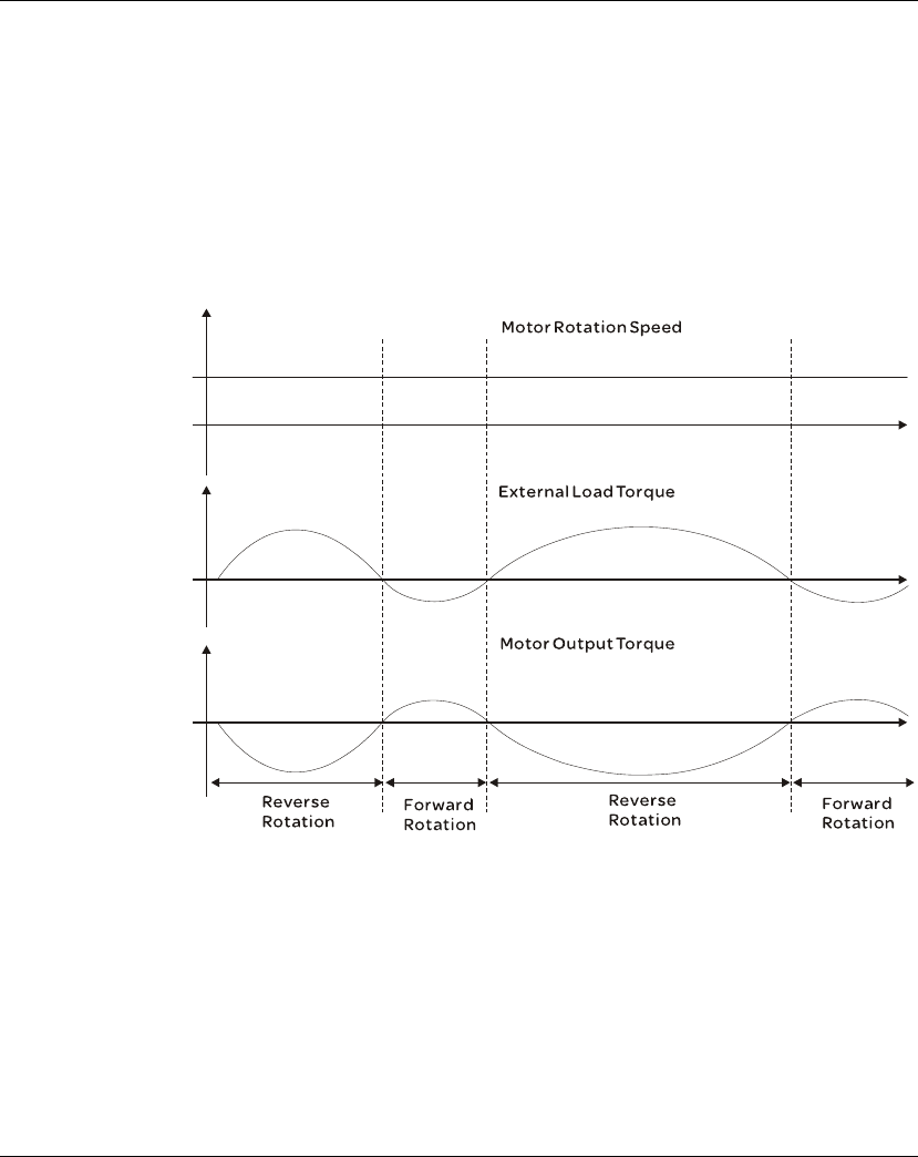
4. Engineering Lexium 23A
56 AC servo drive
(2) With Load
When there is an external load torque, servo motor is in reverse rotation when
external load greater than motor torque. Servo motor is usually in forward rotation
and the motor torque output direction is the same as the rotation direction. However,
there is still some special condition. If the motor output torque is in the reverse
direction of rotation, the servo motor is also in the reverse direction of rotation. The
external power is input into the servo drive through servo motor. The Figure below is
an example. The users can see the motor is in forward rotation at constant speed
when a sudden external load torque change and great power is transmitted to
regenerative resistor rapidly.
External load torque in reverse direction: TL x Wr TL : External load torque
For the safety, we strongly recommend the users should select the proper resistance
value according to the load.

Lexium 23A 4. Engineering
AC servo drive 57
For example:
When external load torque is a +70% rated torque and rotation speed reaches
3000 rpm, if using 400W servo drive (rated torque: 1.27 Nm), then the users need to
connect a external regenerative resistor which power is 2 x (0.7 x 1.27) x (3000 x
2 x π / 60) = 560W, 40Ω.
p Simple Calculation Method W
The users can select the adequate regenerative resistors according to the allowable
frequency required by actual operation and the allowable frequency when the servo
motor runs without load. The allowable frequency when the servo motor run without
load is the maximum frequency that can be operated during continuous operation
when servo motor accelerate from 0 rpm to rated speed and decelerate from rated
speed down to 0 rpm. The allowable frequencies when the servo motor run without
load are summarized in the following table.
When the servo motor runs with load, the allowable frequency will change according
to the changes of the load inertia and rotation speed. Use the following equation to
calculate the allowable frequency.
m = load/motor inertia ratio
The users can select the adequate external regenerative resistors according to the
allowable frequency by referring to the table below:
Allowable frequency when the servo motor run without load (times/min)
and uses built-in regenerative resistor
Motor Capacity
Servo Motor
600W 750W 900W 1.0KW 1.5KW 2.0KW 2.0KW 3.0KW
06 07 09 10 15 20 20 30
BCH....O - 312 - 137 - 83 (F100) -
BCH....N - - - 42 32 24
(F130)
10
(F180) 11
BCH....M 42-31-----
×
Allowable frequency =
Allowable frequency when servo motor run without load
m+1
Rated speed times
Operating speed min.
)( 2
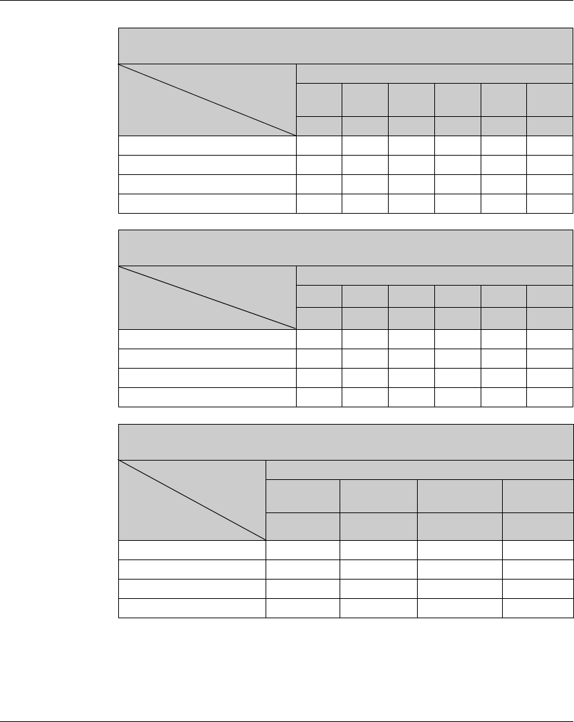
4. Engineering Lexium 23A
58 AC servo drive
When the regenerative resistor capacity is not enough, the users can connect to
multiple the same capacity regenerative resistors in parallel to increase it.
NOTE: Regarding the selection of regenerative resistor, please refer to the table of
regenerative resistor specifications described in section 4.5.
Allowable frequency when the servo motor run without load(times/min) and uses
external regenerative resistor
Motor Capacity BCH....O
Recommended
Regenerative Resistor
Specifications
200W 400W
(F60)
400W
(F80) 750W 1.0KW 2.0KW
02 04 04 07 10 20
400W 80Ω13710 8761 3569 - - -
400W 40Ω---2147 --
500W 40Ω----1145 -
1KW 16Ω-----1363
Allowable frequency when the servo motor run without load(times/min) and uses
external regenerative resistor
Motor Capacity BCH....N
Recommended
Regenerative Resistor
Specifications
0.5KW 1KW 1.5Kw 2.0KW 2.0KW 3.0KW
04 10 15 20 20 30
400W 80Ω291-----
400W 40Ω-289217 - - -
1KW 16Ω- - - 416 175 -
1.5KW 16Ω-----166
Allowable frequency when the servo motor run without load(times/min) and uses
external regenerative resistor
Motor Capacity BCH....M
Recommended
Regenerative Resistor
Specifications
400KW 750KW 1.0KW 3.0KW
(F180)
03 07 10 30
400W 80Ω297 - - -
400W 40Ω-289 - -
1KW 40Ω--543-
1.5KW 16Ω-- -166

Lexium 23A 4. Engineering
AC servo drive 59
4.5 Logic type
The digital inputs and outputs of this product can be wired for sink or source. for
further information please refer to section 5.2.8.4 Wiring Diagrams of I/O Signals
(CN1).
Signal inputs are protected against reverse polarity, outputs are shortcircuit
protected. The inputs and outputs are galvanically isolated.
UNINTENDED OPERATION
If source is used, a ground fault of a signal is detected as an On state.
z Use great care in wiring to exclude the possibility of ground faults.
Failure to follow these instructions can result in death, serious injury or
equipment damage.
WARNNG

4. Engineering Lexium 23A
60 AC servo drive
4.6 Monitoring functions
The monitoring functions in the product can help to guard the system and reduce the
risks involved in a system misoperation. These monitoring functions may not be used
to protect persons.
The following monitoring functions are available:
For a description of the monitoring functions, see chapter 8.2.1 "Monitor Variables".
Monitoring Task
Data link Error response if the link becomes inoperative
Limit switch signals Monitors for permissible range of travel
Following error Monitors for difference between actual motor position and
reference position
Motor overload Monitors for excessively high current in the motor phases
Overvoltage and
undervoltage
Monitors for overvoltage and undervoltage of the supply
voltage
Overtemperature Monitors the device for overtemperature
I2t limitation Power limitation in the case of overloads for the motor, the
output current, the output power and the braking resistor.

Lexium 23A 4. Engineering
AC servo drive 61
4.7 Configurable inputs and outputs
This product has digital inputs and outputs that can be configured. The inputs and
outputs have a defined standard assignment depending on the operating mode. This
assignment can be adapted to the requirements of the customer's installation. See
chapter 5.2.8 "Configuration of the digital signal inputs and signal outputs" for
additional information.
LOSS OF CONTROL
The use of limit switches can provide some protection against hazards (for
example, collision with mechanical stop caused by incorrect reference values).
zIf possible, use the limit switches.
zVerify correct connection of the limit switches.
zVerify the correct installation of the limit switches. The limit switches must be
mounted in a position far enough away from the mechanical stop to allow for an
adequate stopping distance.
zBefore you can use the limit switches, you must enable them.
Failure to follow these instructions can result in death, serious injury or
equipment damage.
WARNNG

4. Engineering Lexium 23A
62 AC servo drive

AC servo drive 63
5
Installation
At a Glance
Presentation An engineering phase is mandatory prior to mechanical and electrical installation. See
chapter4 "Engineering", for basic information.
What's in this
Chapter? This chapter contains the following topics:
Topic Page
Mechanical installation 65
Electrical installation 71
Standard Connection Example 107

5. Installation Lexium 23A
64 AC servo drive
1) For USA: Additional information, refer to NEMA ICS 1.1 (latest edition), Safety Guidelines for the Application,
Installation, and Maintenance of Solid State Control and to NEMA ICS 7.1 (latest edition), Safety Standards
for Construction and Guide for Selection, Installation for Construction and Operation of Adjustable-Speed
Drive Systems.
LOSS OF CONTROL
zThe designer of any control scheme must consider the potential failure
modes of control paths and, for certain critical functions, provide a means to
achieve a safe state during and after a path failure. Examples of critical
control functions are EMERGENCY STOP, overtravel stop, power outage and
restart.
zSeparate or redundant control paths must be provided for critical functions.
zSystem control paths may include communication links. Consideration must
be given to the implication of unanticipated transmission delays or failures
of the link.
zObserve the accident prevention regulations and local safety guidelines. 1)
zEach implementation of the product must be individually and thoroughly
tested for proper operation before being placed into service.
Failure to follow these instructions can result in death or serious injury.
WARNNG
Lexium 23A 5. Installation
AC servo drive 65
5.1 Mechanical installation
ELECTRIC SHOCK CAUSED BY FOREIGN OBJECTS OR DAMAGE
Conductive foreign objects in the product or serious damage may cause parasitic
voltage.
• Do not use damaged products.
• Keep foreign objects such as chips, screws or wire clippings from getting into
the product.
• Do not use products that contain foreign objects.
Failure to follow these instructions will result in death or serious injury.
HOT SURFACES
The heat sink at the product may heat up to over 100C (212F) during operation.
zAvoid contact with the hot heat sink.
zDo not allow flammable or heat-sensitive parts in the immediate vicinity.
zConsider the measures for heat dissipation described.
Failure to follow these instructions can result in death or serious injury.
DANGER
WARNNG

5. Installation Lexium 23A
66 AC servo drive
5.1.1 Installation Notes
Please pay close attention on the following installation notes:
z Do not bend or strain the connection cables between servo drive and motor.
z When mounting the servo drive, make sure to tighten all screws to secure the drive
in place.
z If the servo motor shaft is coupled directly to a rotating device ensure that the
alignment specifications of the servo motor, coupling, and device are followed.
Failure to do so may cause unnecessary loads or premature failure to the servo
motor.
z If the length of cable connected between servo drive and motor is more than 20m,
please increase the wire gauge of the encoder cable and motor connection cable
(connected to U, V, W terminals).
z Make sure to tighten the screws for securing motor.
5.1.2 Storage Conditions
The product should be kept in the shipping carton before installation. In order to
retain the warranty coverage, the AC servo drive should be stored properly when it is
not to be used for an extended period of time. Some storage suggestions are:
z Store in a clean and dry location free from direct sunlight.
z Store within an ambient temperature range of -20C to +65C (-4F to 149F).
z Store within a relative humidity range of 0% to 90% and non-condensing.
z Do not store in a place subjected to corrosive gases and liquids.
z Correctly packaged and placed on a solid surface.

Lexium 23A 5. Installation
AC servo drive 67
5.1.3 Installation Conditions
Operating Temperature
Lexium23 Plus Series Servo Drive : 0•C to 55•C (32•F to 131•F)
BCH Series Servo Motor : 0•C to 40•C (32•F to 104•F)
The ambient temperature of servo drive for long-term reliability should be under
45•C (113•F).
If the ambient temperature of servo drive is greater than 45•C (113•F), please install
the drive in a wellventilated location and do not obstruct the airflow for the cooling
fan.
Caution
The servo drive and motor will generate heat. If they are installed in a control panel,
please ensure sufficient space around the units for heat dissipation.
Pay particular attention to vibration of the units and check if the vibration has
impacted the electric devices in the control panel. Please observe the following
precautions when selecting a mounting location. Failure to observe the following
precautions may void the warranty!
zDo not mount the servo drive or motor adjacent to heat-radiating elements or in
direct sunlight.
zDo not mount the servo drive or motor in a location subjected to corrosive gases,
liquids, or airborne dust or metallic particles.
zDo not mount the servo drive or motor in a location where temperatures and
humidity will exceed specification.
zDo not mount the servo drive or motor in a location where vibration and shock will
exceed specification.
zDo not mount the servo drive or motor in a location where it will be subjected to
high levels of electromagnetic radiation.

5. Installation Lexium 23A
68 AC servo drive
5.1.4 Installation Procedure and Minimum Clearances
Installation Procedure
Incorrect installation may result in a drive malfunction or premature failure of the drive
and or motor. Please follow the guidelines in this manual when installing the servo drive
and motor.
The Lexium23 Plus series servo drive should be mounted perpendicular to the wall or in
the control panel. In order to ensure the drive is well ventilated, ensure that the all
ventilation holes are not obstructed and sufficient free space is given to the servo drive.
Do not install the drive in a horizontal position or malfunction and damage will occur.
Correct Incorrect
Drive Mounting
The Lexium23 Plus series Servo drives must be back mounted vertically on a dry and solid
surface such as a NEMA enclosure. A minimum spacing of two inches must be maintained
above and below the drive for ventilation and heat dissipation. Additional space may be
necessary for wiring and cable connections. Also, as the drive conducts heat away via the
mounting, the mounting plane or surface should not conduct heat into the drive from
external sources.
Motor Mounting
The BCH Servo motors should be mounted firmly to a dry and solid mounting surface to
ensure maximum heat transfer for maximum power output and to provide a good
ground.
For the dimensions and weights specifications of servo drive or motor, please refer to
Chapter 3.3.1 and 3.3.2 "Specifications".
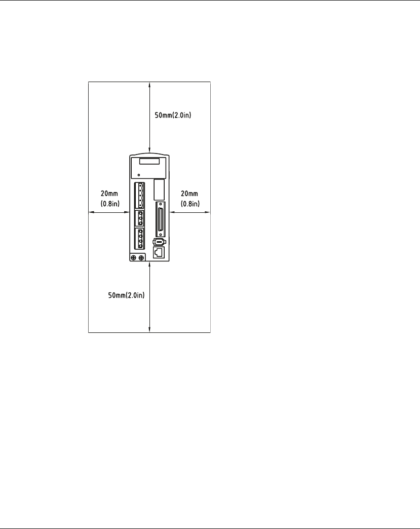
Lexium 23A 5. Installation
AC servo drive 69
Minimum Clearances
Install a fan to increase ventilation to avoid ambient temperatures that exceed the
specification. When installing two or more drives adjacent to each other please follow
the clearances as shown in the following diagram.
z Minimum Clearances
NOTE:
1) The scale of the clearances does not match the dimensions as shown in the drawing
above. In the event of any discrepancy between the clearances and the dimensions,
the dimensions shall prevail.
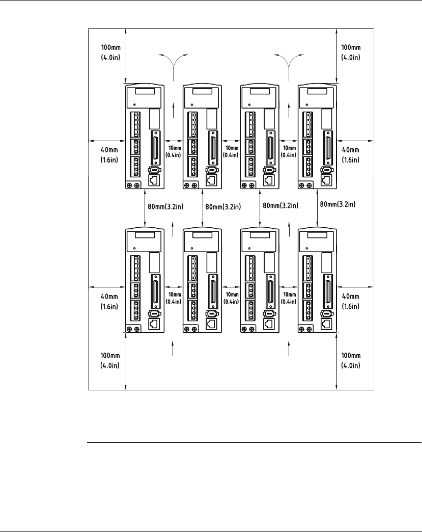
5. Installation Lexium 23A
70 AC servo drive
z Side by Side Installation
NOTE:
1) The scale of the clearances does not match the dimensions as shown in the drawing
above. In the event of any discrepancy between the clearances and the dimensions,
the dimensions shall prevail.
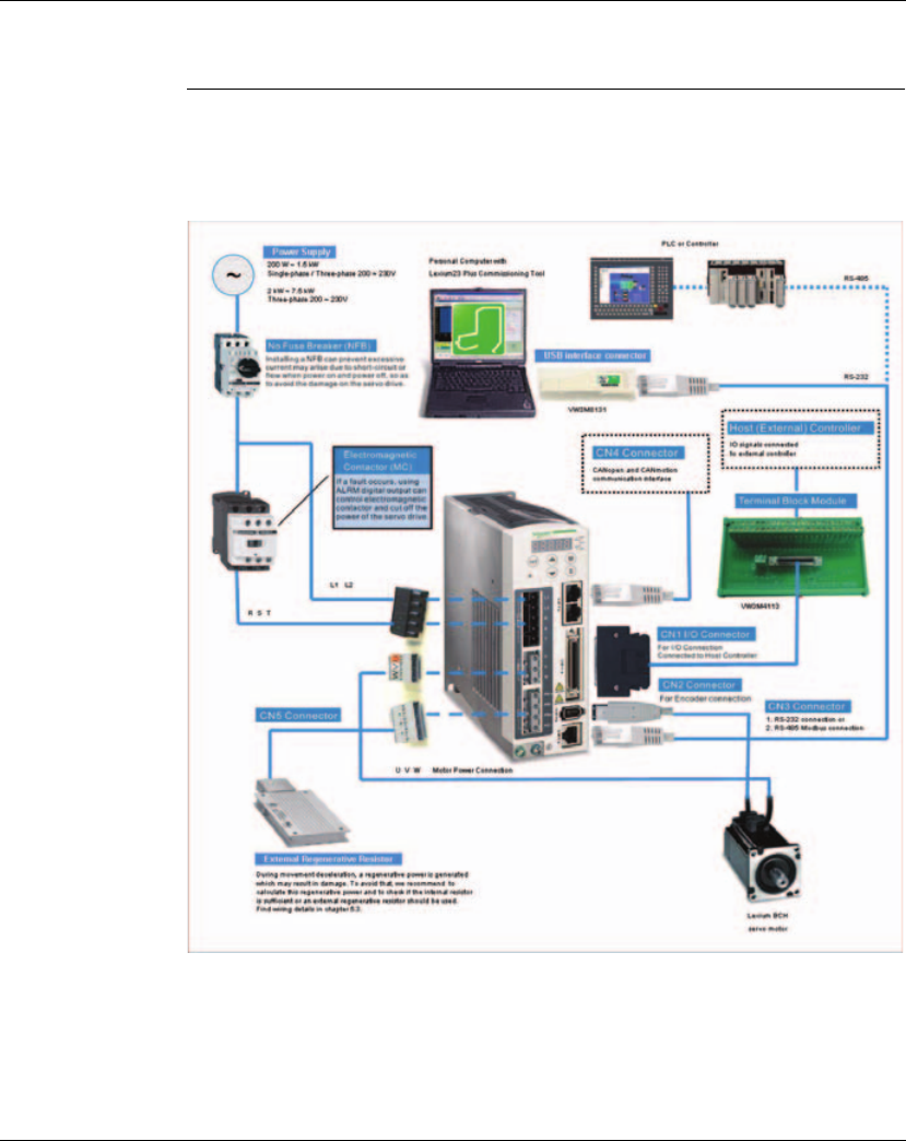
Lexium 23A 5. Installation
AC servo drive 71
5.2 Electrical installation
5.2.1 Connecting to Peripheral Devices
Figure 5.1 Configuration
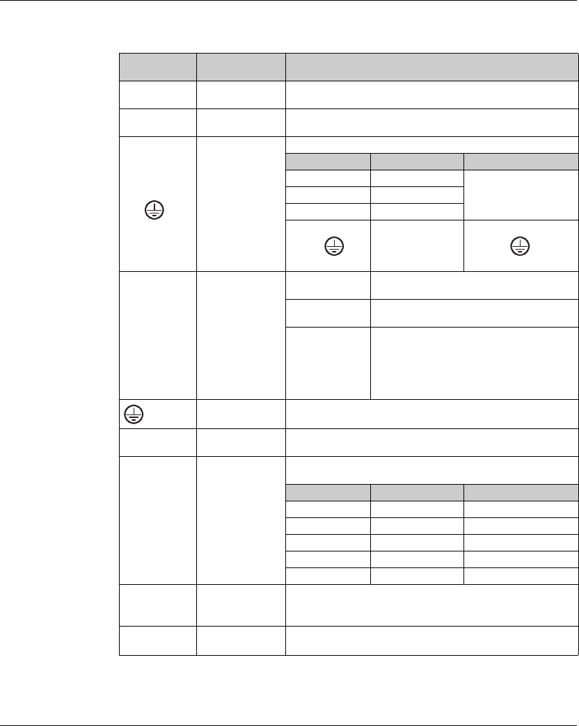
5. Installation Lexium 23A
72 AC servo drive
5.2.2 Servo Drive Connectors and Terminals
Terminal
Identification
Terminal
Description Notes
L1, L2 Control circuit
terminal
Used to connect single-phase AC control circuit power depending
on connecting servo drive model.
R, S, T Main circuit
terminal
Used to connect three-phase AC main circuit power depending on
connecting servo drive model.
U, V, W
FG ( )
Servo motor
output
Used to connect servo motor
Terminal Symbol Wire Color Description
URed
Connecting to
threephase motor main
circuit cable.
VWhite
WBlack
FG ( ) Green
Connecting to ground
terminal ( ) of the
servo drive.
PA/+, PBi, PBe,
PC/-
Regenerative
resistor terminal or
braking unit
Internal resistor Ensure the circuit is closed between PA/+ and PBi,
and the circuit is open between PA/+ and PBe.
External resistor Connect regenerative resistor to PA/+ and PBe,
and ensure an open circuit between PA/+ and PBi.
External braking
unit
Connect braking unit to PA/+ and PC/-, and
ensure an open circuit between PA/+ and PBi,
and PA/+ and PBe.
(N terminal is built in L1, L2, PC/-, and R, S, T.)
PA/+: Connecting to (+) terminal of V_BUS voltage.
PC/-: Connecting to (-) terminal of V_BUS voltage.
two places Ground terminal Used to connect grounding wire of power supply and servo motor.
CN1 I/O connector
(Optional Part)
Used to connect external controllers. Please refer to chapter 5.2.8
for details.
CN2
Encoder
connector
(Optional Part)
Used to connect encoder of servo motor. Please refer to chapter
5.2.9 for details.
Terminal Symbol Wire Color Pin No.
T+ Blue 5
T- Blue/Black 6
n.c. - 3
+5V Red & Red/White 1
GND Black & Black/White 2,4
CN3
Communication
connector
(Optional Part)
Used for RS-485 or RS-232 communication connection.
Please refer to chapter 9 "Communication" for details.
CN4 Communication
connector
Used to connect field bus interface CANopen and CANmotion.
Please refer to chapter 5.2.11 for details.

Lexium 23A 5. Installation
AC servo drive 73
Wiring Notes Please observe the following wiring notes while performing wiring and touching any
electrical connections on the servo drive or servo motor.
1. Ensure to check if the power supply and wiring of the "power" terminals (R, S, T, L1,
L2, U, V, W) is correct.
2. Please use shielded twisted-pair cables for wiring to prevent voltage coupling and
eliminate electrical noise and interference.
3. As a residual hazardous voltage may remain inside the drive, please do not
immediately touch any of the "power" terminals (R, S, T, L1, L2, U, V, & W) and/or the
cables connected to them after the power has been turned off and the charge LED
is lit. (Please refer to the Safety Precautions chapter 2 "Before you begin - safety
information").
4. The cables connected to R, S, T and U, V, W terminals should be placed in separate
conduits from the encoder or other signal cables. Separate them by at least 30cm
(11.8 inches).
5. If the encoder cable (CN2) is too short, please use a twisted-shield signal wire with
grounding conductor. The wire length should be 20m (65.62ft.) or less. For lengths
greater than 20m (65.62ft.), the wire gauge should be doubled in order to lessen
any signal attenuation.
6. As for motor cable selection, please use the 600V PTFE wire and the wire length
should be less than 98.4ft. (30m). If the wiring distance is longer than 30m (98.4ft.),
please choose the adequate wire size according to the voltage.
7. The shield of shielded twisted-pair cables should be connected to the SHIELD end
(terminal marked ) of the servo drive.
8. For the connectors and cables specifications.
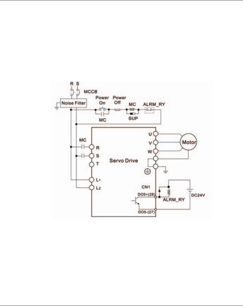
5. Installation Lexium 23A
74 AC servo drive
5.2.3 Wiring Methods
For servo drives from 200W to 1.5kW the input power can be either single or three-
phase. However, single -phase connections are for servo drives 1.5kW and below only.
In the wiring diagram figures 5.2 & 5.3:
Power ON : contact "a" (normally open)
Power OFF /ALRM_RY : contact "b" (normally closed)
MC : coil of electromagnetic contactor, self-holding power, contact of main circuit
power
Figure 5.2 Single-Phase Power Supply Connection (for 1.5kW and below models)
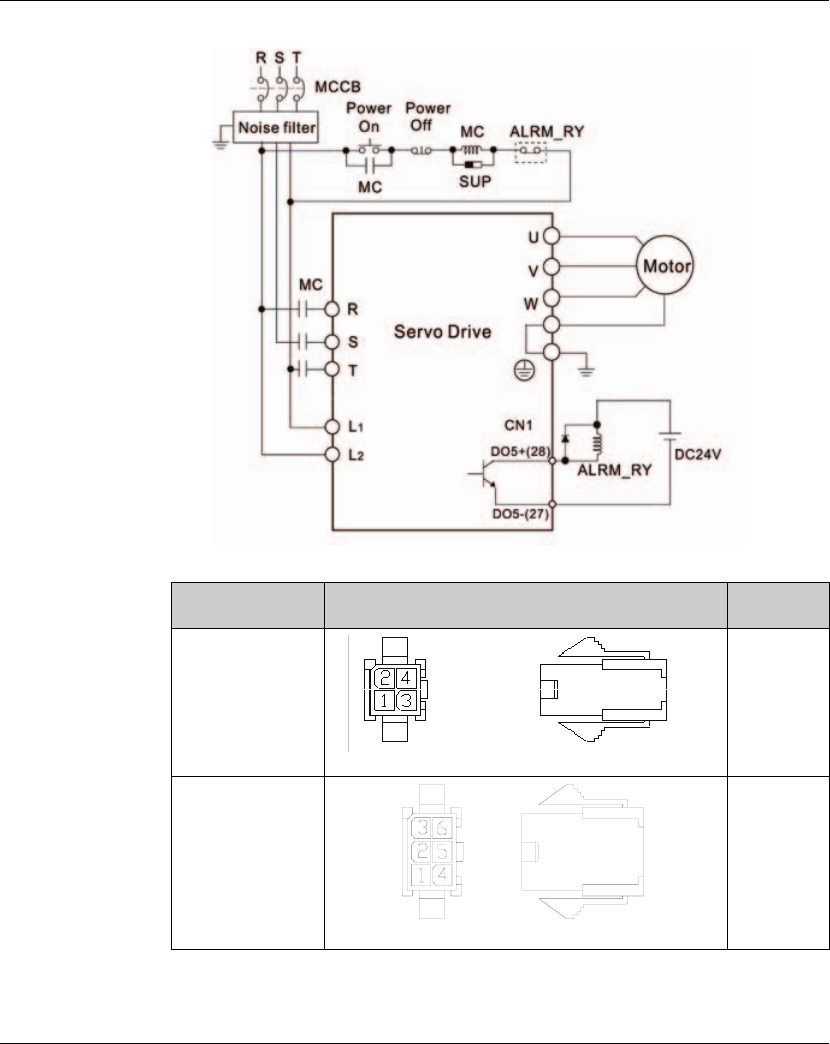
Lexium 23A 5. Installation
AC servo drive 75
Figure 5.3 Three-Phase Power Supply Connection (for 2kW and above models)
5.2.4 Motor Power Cable Connector Specifications
Motor Model Name U, V, W / Electromagnetic Brake Connector Terminal
Identification
BCH0401O (100W)
BCH0601O (200W)
BCH06020 (400W)
BCH0801O (400W)
BCH0802O (750W) VW3M5111
A
BCH0401O (100W)
BCH0601O (200W)
BCH06020 (400W)
BCH0801O (400W)
BCH0801O (750W)
VW3M5112
B
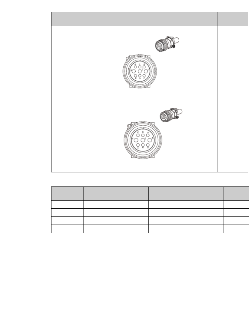
5. Installation Lexium 23A
76 AC servo drive
NOTE:
1) The coil of brake has no polarity. The names of terminal identification are BRAKE1
(Yellow) and BRAKE2 (Blue).
2) The power supply for brake is DC24V. Never use it for VDD, the +24V source
voltage.
Motor Model Name U, V, W / Electromagnetic Brake Connector Terminal
Identification
BCH1301M (300W)
BCH1301N (500W)
BCH1302M (600W)
BCH1303M (900W)
BCH1001O (1000W)
BCH1302N (1000W)
BCH1303N (1500W)
BCH1002O (2000W)
BCH1304N (2000W)
VW3M5121
C
BCH1801N (2000W)
BCH1802N (3500W)
BCH1802M (3000W)
VW3M5131
D
Terminal
Identification
U
(Red)
V
(White)
W
(Black)
CASE GROUND
(Green)
BRAKE1
(Blue)
BRAKE2
(Brown)
A123 4 --
B124 5 36
CFIB E GH
DDEF G AB
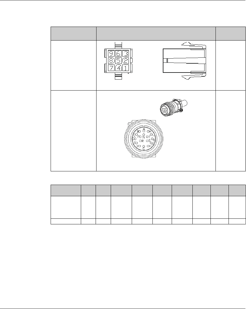
Lexium 23A 5. Installation
AC servo drive 77
5.2.5 Encoder Connector Specifications
Motor Model Name Encoder Connector Terminal
Identification
BCH0401O (100W)
BCH0601O (200W)
BCH06020 (400W)
BCH0801O (400W)
BCH0802O (750W)
VW3M8121
A
BCH1301M (300W)
BCH1301N (500W)
BCH1302M (600W)
BCH1303M (900W)
BCH1001O (1000W)
BCH1302N (1000W)
BCH1303N (1500W)
BCH1002O (2000W)
BCH1304N (2000W)
BCH1801N (2000W)
BCH1802N (3500W)
BCH1802M (3000W) VW3M8122
B
Terminal
Identification T+ T- Reserved Reserved Reserved Reserved DC+5V GND BRAID
SHELD
A1
(Blue)
4
(Blue/
Black)
----
7
(Red &
Red/
White)
8
(Black &
Black/
White)
9
BABCDFGSRL

5. Installation Lexium 23A
78 AC servo drive
5.2.6 Cable Specifications for Servo Drive
Power Cable
Encoder Cable
Note:
1) Please use shielded twisted-pair cables for wiring to prevent voltage coupling and
eliminate electrical noise and interference.
2) The shield of shielded twisted-pair cables should be connected to the SHIELD end
of the servo drive.
3) In order to prevent fire hazard and accidents, please form the wiring by following
the cable specifications outlined above.
Servo Drive and Servo Motor Power Cable - Wire Gauge mm2(AWG)
L1, L2 R, S, T U, V, W
PA/+, PBe
LXM23AU01M3X BCH0401O 1.3 (AWG16) 2.1 (AWG14) 0.82 (AWG18) 2.1 (AWG14)
LXM23AU02M3X BCH0601O 1.3 (AWG16) 2.1 (AWG14) 0.82 (AWG18) 2.1 (AWG14)
LXM23AU04M3X
BCH0602O 1.3 (AWG16) 2.1 (AWG14) 0.82 (AWG18) 2.1 (AWG14)
BCH0801O 1.3 (AWG16) 2.1 (AWG14) 0.82 (AWG18) 2.1 (AWG14)
BCH1301N 1.3 (AWG16) 2.1 (AWG14) 0.82 (AWG18) 2.1 (AWG14)
BCH1301M 1.3 (AWG16) 2.1 (AWG14) 0.82 (AWG18) 2.1 (AWG14)
LXM23AU07M3X BCH0802O 1.3 (AWG16) 2.1 (AWG14) 0.82 (AWG18) 2.1 (AWG14)
BCH1302M 1.3 (AWG16) 2.1 (AWG14) 0.82 (AWG18) 2.1 (AWG14)
LXM23AU10M3X
BCH1001O 1.3 (AWG16) 2.1 (AWG14) 1.3 (AWG16) 2.1 (AWG14)
BCH1302N 1.3 (AWG16) 2.1 (AWG14) 1.3 (AWG16) 2.1 (AWG14)
BCH1303M 1.3 (AWG16) 2.1 (AWG14) 1.3 (AWG16) 2.1 (AWG14)
LXM23AU15M3X BCH1303N 1.3 (AWG16) 2.1 (AWG14) 1.3 (AWG16) 2.1 (AWG14)
LXM23AU20M3X
BCH1002O 1.3 (AWG16) 2.1 (AWG14) 2.1 (AWG14) 2.1 (AWG14)
BCH1304N 1.3 (AWG16) 2.1 (AWG14) 2.1 (AWG14) 2.1 (AWG14)
BCH1801N 1.3 (AWG16) 2.1 (AWG14) 3.3 (AWG12) 2.1 (AWG14)
LXM23AU30M3X BCH1802N 1.3 (AWG16) 3.3 (AWG12) 3.3 (AWG12) 3.3 (AWG12)
BCH1802M 1.3 (AWG16) 3.3 (AWG12) 3.3 (AWG12) 3.3 (AWG12)
LXM23AU45M3X BCH1803M 1.3 (AWG16) 3.3 (AWG12) 8.4 (AWG8) 3.3 (AWG12)
LXM23AU55M3X BCH1804M 1.3 (AWG16) 3.3 (AWG12) 13.3 (AWG6) 3.3 (AWG12)
LXM23AU75M3X BCH1805M 1.3 (AWG16) 5.3 (AWG10) 13.3 (AWG6) 3.3 (AWG12)
Servo Drive Encoder Cable - Wire Gauge mm2 (AWG)
Wire Size Core Number UL Rating Wire Length
LXM23AU01M3X 0.13 (AWG26) 10 core (4 pair) UL2464 3m (9.84ft.)
LXM23AU02M3X 0.13 (AWG26) 10 core (4 pair) UL2464 3m (9.84ft.)
LXM23AU04M3X 0.13 (AWG26) 10 core (4 pair) UL2464 3m (9.84ft.)
LXM23AU07M3X 0.13 (AWG26) 10 core (4 pair) UL2464 3m (9.84ft.)
LXM23AU10M3X 0.13 (AWG26) 10 core (4 pair) UL2464 3m (9.84ft.)
LXM23AU15M3X 0.13 (AWG26) 10 core (4 pair) UL2464 3m (9.84ft.)
LXM23AU20M3X 0.13 (AWG26) 10 core (4 pair) UL2464 3m (9.84ft.)
LXM23AU30M3X 0.13 (AWG26) 10 core (4 pair) UL2464 3m (9.84ft.)
LXM23AU45M3X 0.13 (AWG26) 10 core (4 pair) UL2464 3m (9.84ft.)
LXM23AU55M3X 0.13 (AWG26) 10 core (4 pair) UL2464 3m (9.84ft.)
LXM23AU75M3X 0.13 (AWG26) 10 core (4 pair) UL2464 3m (9.84ft.)
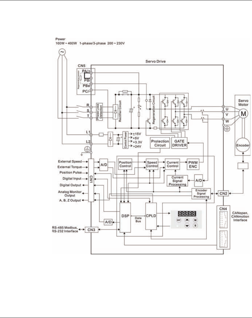
Lexium 23A 5. Installation
AC servo drive 79
5.2.7 Basic Wiring
Figure 5.4 Basic Wiring Schematic of 400W and below models
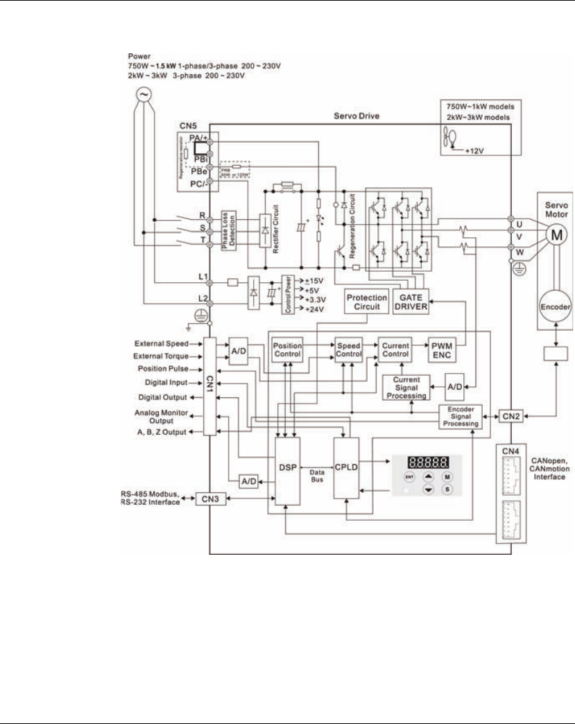
5. Installation Lexium 23A
80 AC servo drive
Figure 5.5 Basic Wiring Schematic of 750W and above models
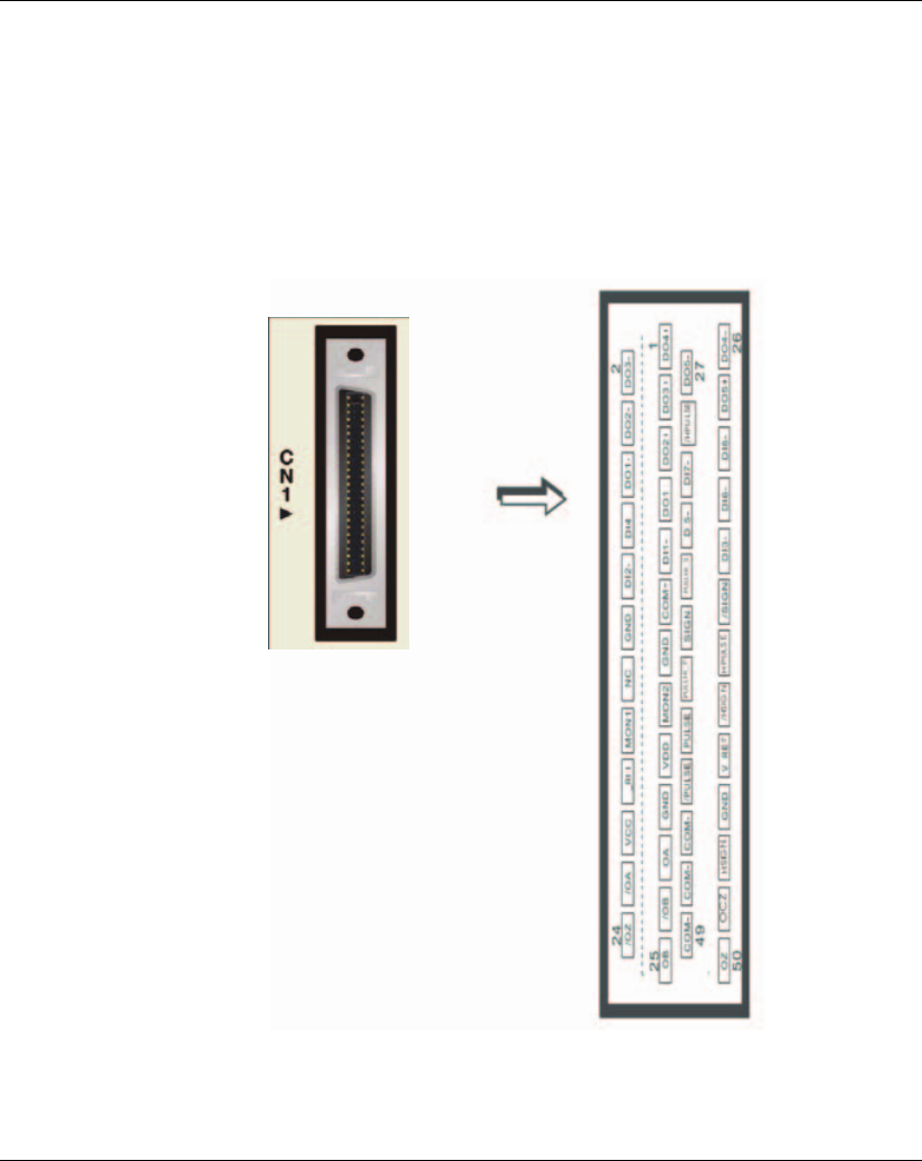
Lexium 23A 5. Installation
AC servo drive 81
5.2.8 Input / Output Interface Connector -CN1
The CN1 Interface Connector provides access to three signal groups:
i General interface for the analog speed and torque control, encoder reference
signal from the motor, pulse / direction inputs, and reference voltages.
ii 8 programmable Digital Inputs (DI), can be set via parameters P2-10 ~ P2-17
iii 5 programmable Digital Outputs (DO), can be set via parameters P2-18 ~ P2-22
A detailed explanation of each group is available in Section 3.3.2, Tables 3.A, 3.B & 3.C.
5.2.8.1 CN1
Terminal
Identification
Figure 5.6 The Layout of CN1 Drive Connector

5. Installation Lexium 23A
82 AC servo drive
Note:
1) The terminal marked "NC" must be left unconnected (No Connection). The NC
terminal is used within the servo drive. Any outside connection to the NC terminal
will result in damage to the drive and void the warranty!
1 DO4+ Digital output 2DO3- Digital output
3 DO3+ Digital output 4 DO2- Digital output
5DO2+ Digital output 6 DO1- Digital output
7 DO1+ Digital output 8 DI4- Digital input
9 DI1- Digital input 10 DI2- Digital input
11 COM+ Power input (12~24V) 12 GND Analog input signal ground
13 GND Analog input signal ground 14 NC No Connection
15 MON2 Analog monitor output 2 16 MON1 Analog monitor output 1
17 VDD +24V power output (for
external I/O)
18 T_REF Analog torque Input
19 GND Analog input signal ground 20 VCC
+12V power output
(for analog command)
21 OA Encoder A pulse output 22 /OA Encoder /A pulse output
23 /OB Encoder /B pulse output 24 /OZ Encoder /Z pulse output
25 OB Encoder B pulse output 26 DO4- Digital output
27 DO5- Digital output 28 DO5+ Digital output
29 /HPULSE High-speed
Pulse input (-)
30 DI8- Digital input
31 DI7- Digital input 32 DI6- Digital input
33 DI5- Digital input 34 DI3- Digital input
35 PULL HI
(SIGN)
Pulse applied power (SIGN) 36 /SIGN Position sign (-)
37 SIGN Position sign (+) 38 HPULSE High-speed
Pulse input (+)
39 PULL
HI_P
(PULSE)
Pulse applied Power
(PULSE)
40 /HSIGN High-speed
position sign (-)
41 PULSE Pulse input (+) 42 V_REF Analog speed input (+)
43 /PULSE Pulse input (-) 44 GND Analog input signal ground
45 COM- VDD(24V) power ground 46 HSIGN High-speed
position sign (+)
47 COM- VDD(24V) power ground 48 OCZ Encoder Z pulse
Open-collector output
49 COM- VDD(24V) power ground 50 OZ Encoder Z pulse
Line-driver output

Lexium 23A 5. Installation
AC servo drive 83
5.2.8.2 Signals
Explanation of
Connector CN1
The Tables 5.A, 5.B, & 5.C detail the three groups of signals of the CN1 interface. Table
3.A details the general signals. Table 5.B details the Digital Output (DO) signals and
Table 5.C details the Digital Input (DI) signals. The General Signals are set by the
factory and can not be changed, reprogrammed or adjusted. Both the Digital Input
and Digital Output signals can be programmed by the users.
Table 5.A General Signals
Signal Pin No. Details
Wiring Diagram
(Refer to
5.2.8.4)
Analog
Signal
Input
V_REF 42
1. Motor speed command: -10V to +10V,
corresponds to -3000 ~ +3000 rpm speed
command (Factory default setting).
2. Motor speed command: -10V to +10V,
corresponds to -3 ~ +3 rotations position
command (Factory default setting).
C1
T_REF 18
Motor torque command: -10V to +10V,
corresponds to -100% to +100% rated torque
command.
C1
Analog
Monitor
Output
MON1
MON2
16
15
Monitor operation status: Motor characteristics
such as speed and current can be represented
by analog voltages. The drive provides two
channels which can be configured with the
parameter P0-03 to output the desired
characteristics.
Please reference the parameter P0-03 for
monitoring commands and P1-04 / P1-05 for
scaling factors.
Output voltage is reference to the power
ground.
C2
Position
Pulse
Input
/PULSE
PULSE
/SIGN
SIGN
43
41
36
37
The drive can accept two different types of
pulse inputs: Line-driver input (max. input
frequency is 500Kpps) and Open-collector
input (max. input frequency is 200Kpps).
Three different pulse commands can be
selected via parameter P1-00. They are A
phase + B phase (Quadrature), CW pulse +
CCW pulse, and Pulse + Direction.
C3/C4
PULL HI_P
PULL HI_S
39
35
When an Open-collector type of pulse is used,
this terminal must be connected to a pull-up
power supply.
C3/C4
Highspeed
Position
Pulse
Input
HSIGN
/HSIGN
HPULSE
/HPULSE
46
40
38
29
The drive can accept two different types of
highspeed pulse inputs: +5V input and Line-
driver input.
The max. input frequency is 4MHz.
Three different pulse commands can be
selected via parameter P1-00. They are A
phase + B phase (Quadrature), CW pulse +
CCW pulse, and Pulse + Direction.
C4-2

5. Installation Lexium 23A
84 AC servo drive
The Digital Input (DI) and Digital Output (DO) have factory default settings which
correspond to the various servo drive control modes. (See section 6.1). However, both
the DI's and DO's can be programmed independently to meet the requirements of
the users.
Detailed in Tables 5.B and 5.C are the DO and DI functions with their corresponding
signal name and wiring schematic. The factory default settings of the DI and DO
signals are detailed in Table 5.G and 5.H.
All of the DI's and DO's and their corresponding pin numbers are factory set and non-
changeable, however, all of the assigned signals and control modes are user
changeable. For Example, the factory default setting of DO5 (pins 28/27) can be
assigned to DO1 (pins 7/6) and vise versa.
The following Tables 5.B and 5.C detail the functions, applicable operational modes,
signal name and relevant wiring schematic of the default DI and DO signals.
Signal Pin No. Details
Wiring Diagram
(Refer to
5.2.8.4)
Position
Pulse
Output
OA
/OA
21
22 Encoder signal output A, B, Z (Line-driver
output).
The motor encoder signals are available
through these terminals.
C13/C14
OB
/OB
25
23
OZ
/OZ
50
24
OCZ 48 Encoder signal output Z (Open-collector output). -
Power
VDD 17 VDD is the +24V source voltage provided by the
drive. Maximum permissible current 500mA.
-
COM+
COM-
11
45
47
49
COM+ is the common voltage rail of the Digital
Input (DI) and Digital Output (DO) signals.
When using VDD, VDD should be connected to
COM+. If not using VDD, the users should add an
external applied power (+12V to +24V). The
positive end of this applied power should be
connected to COM+ and the negative end of
this applied power should be connected to
COM-.
VCC 20
VCC is a +12V power rail provided by the drive. It
is used for providing simple analog command
(analog speed or analog torque command).
Maximum permissible current 100mA.
Power GND 12, 13, 19,
44
The polarity of VCC is with respect to Ground
(GND).
Other NC 14 See previous note for NC terminal description
of CN1 connector on page 3-13.

Lexium 23A 5. Installation
AC servo drive 85
Table 5.B DO Signals
DO
Signal
Assigned
Control
Mode
Pin No.
(Default) Details
Wiring Diagram
(Refer to
5.2.8.4)
+ -
SRDY ALL 7 6
SRDY is activated when the servo drive is
ready to run. All fault and alarm conditions, if
present, have been cleared.
C5/C6/C7/C8
SON Not
assigned --
SON is activated when control power is
applied the servo drive. The drive may or may
not be ready to run as a fault / alarm condition
may exist.
Servo ON (SON) is "ON" with control power
applied to the servo drive, there may be a
fault condition or not. The servo is not ready
to run.
Servo ready (SRDY) is "ON" where the servo is
ready to run, NO fault / alarm exists.
ZSPD ALL 5 4
ZSPD is activated when the drive senses the
motor is equal to or below the Zero Speed
Range setting as defined in parameter P1-38.
For Example, at factory default ZSPD will be
activated when the drive detects the motor
rotating at speed at or below 10 rpm, ZSPD
will remain activated until the motor speed
increases above 10 rpm.
TSPD
ALL
(except
Pt, Pr)
--
TSPD is activated once the drive has detected
the motor has reached the Target Rotation
Speed setting as defined in parameter P1-39.
TSPD will remain activated until the motor
speed drops below the Target Rotation
Speed.
TPOS
Pt, Pr,
Pt-S,Pt-T,
Pr-S, Pr-T
1 26
1. When the drive is in Pt mode, TPOS will be
activated when the position error is equal
and below the setting value of P1-54.
2. When the drive is in Pr mode, TPOS will be
activated when the drive detects that the
position of the motor is in a -P1-54 to +P1-
54 band of the target position. For
Example, at factory default TPOS will
activate once the motor is in -99 pulses
range of the target position, then
deactivate after it reaches +99 pulses
range of the desired position.
TQL Not
assigned --
TQL is activated when the drive has detected
that the motor has reached the torques limits
set by either the parameters P1-12 ~ P1-14 of
via an external analog voltage.
ALRM ALL 28 27
ALRM is activated when the drive has
detected a fault condition. (However, when
Reverse limit error, Forward limit error,
operational stop, Serial communication error,
and Undervoltage these fault occur, WARN is
activated first.)

5. Installation Lexium 23A
86 AC servo drive
DO Signal
Assigned
Control
Mode
Pin No.
(Default) Details(*1) Wiring Diagram
(Refer to
5.2.8.4)
+ -
BRKR ALL 1 26 BRKR is activated actuation of motor brake.
C5/C6/C7/C8
HOME ALL 3 2
HOME is activated when the servo drive has
detected that the "HOME" sensor (ORGP,
digital input 0x24) has been detected.
OLW ALL - -
OLW is activated when the servo drive has
detected that the motor has reached the
output overload level set by the parameter
P1-56.
WARN ALL - -
Servo warning output. WARN is activated
when the drive has detected Reverse limit
error, Forward limit error, operational stop,
Serial communication error, and
Undervoltage these fault conditions.
OVF ALL - -
Position command overflow. OVF is
activated when the servo drive has
detected that a position command
overflows.
SNL
(SCWL) Pr - -
Reverse software limit. SNL is activated
when the servo drive has detected that
reverse software limit is reached.
SPL
(SCCWL) Pr - -
Forward software limit. SPL is activated
when the servo drive has detected that
forward software limit is reached.
CMD_OK Pr - -
Internal position command completed
output.
CMDOK is activated when the servo drive
has detected that the internal position
command has been completed.
CAP_OK Pr - -
Capture operation completed output.
CAP_OK is activated when the servo drive
has detected that capture operation has
been completed.
MC_OK Pr - -
Motion control completed output. MC_OK
is activated when CMD_OK and TPOS are
both ON.
It indicates MC_OK is activated only when
the servo drive has detected that the
position command has been given and the
positioning has been completed also. If
only CMD_OK or TPOS is ON, MC_OK will not
be activated.
SP_OK S, Sz - -
SP_OK will be activated when the speed
error is equal and below the setting value of
P1-47.

Lexium 23A 5. Installation
AC servo drive 87
NOTE:
1) PINS 3 & 2 can either be TSPD or HOME dependent upon control mode selected.
2) The DO signals that do not have pin numbers in Tables 3.B are not default DO
signals. If the users want to use these non-default DO signals, the users need to
change the settings of parameters P2-18 ~ P2-22. The "state" of the output
function may be turned ON or OFF as it will be dependant on the settings of
parameters P2-18 ~ P2-22. Please refer to section 5.2.8.3 for details.
DO Signal
Assigned
Control
Mode
Pin No.
(Default) Details(*1)
Wiring
Diagram
(Refer to
5.2.8.4)
+ -
SDO_0 ALL - - Output the status of bit00 of P4-06.
C5/C6/C7/C8
SDO_1 ALL - - Output the status of bit00 of P4-06.
SDO_2 ALL - - Output the status of bit00 of P4-06.
SDO_3 ALL - - Output the status of bit00 of P4-06.
SDO_4 ALL - - Output the status of bit00 of P4-06.
SDO_5 ALL - - Output the status of bit00 of P4-06.
SDO_6 ALL - - Output the status of bit00 of P4-06.
SDO_7 ALL - - Output the status of bit00 of P4-06.
SDO_8 ALL - - Output the status of bit00 of P4-06.
SDO_9 ALL - - Output the status of bit00 of P4-06.
SDO_A ALL - - Output the status of bit00 of P4-06.
SDO_B ALL - - Output the status of bit00 of P4-06.
SDO_C ALL - - Output the status of bit00 of P4-06.
SDO_D ALL - - Output the status of bit00 of P4-06.
SDO_E ALL - - Output the status of bit00 of P4-06.
SDO_F ALL - - Output the status of bit00 of P4-06.

5. Installation Lexium 23A
88 AC servo drive
Table 5.C DI Signals
DI
Signal
Assigned
Control
Mode
Pin No.
(Default)
Details(*2)
Wiring
Diagram
(Refer to
5.2.8.4)
SON ALL 9 Servo On. Switch servo to "Servo Ready".
C9/C10/C11/
C12
ARST ALL 33
A number of Faults (Alarms) can be cleared
by activating ARST. Please see table 10-3 for
applicable faults that can be cleared with the
ARST command. However, please
investigate Fault or Alarm if it does not clear
or the fault description warrants closer
inspection of the drive system.
GAINUP ALL - Gain switching
CCLR Pt, Pr 10
When CCLR is activated, the setting
parameter P2-50 Pulse Clear Mode is
executed.
ZCLAMP ALL -
When this signal is On and the motor speed
value is lower than the setting value of P1-38,
it is used to lock the motor in the instant
position while ZCLAMP is On.
CMDINV T, S - When this signal is On, the motor is in
reverse rotation.
CTRG Pr, Pr-S,
Pr-T, S, Sz
When the drive is in Pr mode and CTRG is
activated, the drive will command the motor
to move the stored position which
correspond the POS 0 ~ POS 5 settings.
Activation is triggered on the rising edge of
the pulse.
TRQLM S, Sz 10 ON indicates the torque limit command is
valid.
SPDLM T, Tz 10 ON indicates the speed limit command is
valid.
POS0 Pr, Pr-S,
Pr-T 34 When the Pr Control Mode is selected, the 64
stored positions are programmed via a
combination of the POS 0 ~ POS 5
commands.
See table 5.D.
POS1 8
POS2 -
STOP --Motor stop.
SPD0 S, Sz, Pt-S,
Pr-S, S-T
34 Select the source of speed command:
See table 5.E.
SPD1 8
TCM0 Pt, T, Tz,
Pt-T, Pr-T,
S-T
34 Select the source of torque command:
See table 5.F.
TCM1 8
S-P Pt-S, Pr-S 31 Speed / Position mode switching
OFF: Speed, ON: Position
S-T S-T 31 Speed / Torque mode switching
OFF: Speed, ON: Torque
T-P Pt-T, Pr-T 31
Torque / Position mode switching
OFF: Torque, ON: Position "the next closer BSH
motor variant from stock":

Lexium 23A 5. Installation
AC servo drive 89
DI
Signal
Assigned
Control
Mode
Pin No.
(Default) Details(*2)
Wiring
Diagram
(Refer to
5.2.8.4)
Pt-Pr Pt, Pr -
Internal position (Pr) and external pulse (Pt)
mode switching.
OFF: Pt, ON: Pr
C9/C10/C11/
C12
PTAS Pt -
External command source selection: pulse and
analog voltage switching.
OFF: The command source is external pulse.
ON: The command source is external analog
voltage.
PTCMS Pt -
External command source selection: high-
speed / low-speed pulse switching
OFF: The command source is low-speed pulse
(PULSE, /PULSE, SIGN, /SIGN).
ON: The command source is high-speed pulse
(HPULSE, /HPULSE, HSIGN, /HSIGN).
When high-speed pulse is selected, the users
can add an external manual pulse generator
and use this DI signal to switch the command
source.
EMGS ALL 30 It should be contact "b" and normally ON or a
fault (AL013) will display.
NL(CWL) Pt, Pr, S,
T, Sz, Tz 32 Reverse inhibit limit. It should be contact "b"
and normally ON or a fault (AL014) will display.
PL(CCWL) Pt, Pr, S,
T, Sz, Tz 31 Forward inhibit limit. It should be contact "b"
and normally ON or a fault (AL015) will display.
ORGP Pr -
When ORGP is activated, the drive will
command the motor to start to search the
reference "Home" sensor.
TLLM Not
assigned -Reverse operation torque limit (Torque limit
function is valid only when P1-02 is enabled)
TRLM Not
assigned -Forward operation torque limit (Torque limit
function is valid only when P1-02 is enabled)
SHOM Pr - When SHOM is activated, the drive will
command the motor to move to "Home".
JOGU
All modes
excep
t
CAN
-Forward JOG input. When JOGU is activated, the
motor will JOG in forward direction. [see P4-05]
JOGD
All modes
except
CAN
-
Reverse JOG input. When JOGD is activated, the
motor will JOG in reverse direction.
[see P4-05]

5. Installation Lexium 23A
90 AC servo drive
NOTE:
1) The DI signals that do not have pin numbers in Tables 3.C are not default DI signals.
If the users want to use these non-default DI signals, the users need to change the
settings of parameters P2-10 ~ P2-17. The "state" of the output function may be
turned ON or OFF as it will be dependant on the settings of parameters P2-10 ~
P2-17. Please refer to section 5.2.8.3 for details.
Table 5.D Command source of Position (Pr) control mode
DI
Signal
Assigned
Control
Mode
Pin No.
(Default) Details(*2)
Wiring
Diagram
(Refer to
5.2.8.4)
GNUM0
Pt, Pr, Pt-S,
Pr-S
-Electronic gear ratio (Numerator) selection
0. [See P2-60~P2-62]
C9/C10/C11/
C12
GNUM1
Pt, Pr, Pt-S,
Pr-S
-Electronic gear ratio (Numerator) selection 1.
[See P2-60~P2-62]
INHP
Pt, Pt-S
-
Pulse inhibit input. When the drive is in
position mode, if INHP is activated, the
external pulse input command is not valid.
Position Command POS2 POS1 POS0 CTRG Parameters
P1 0 0 0
K
P6-02
P6-03
P2 0 0 1
K
P6-04
P6-05
P3 0 1 0
K
P6-06
P6-07
P4 0 1 1
K
P6-08
P6-09
P5 1 0 0
K
P6-10
P6-11
P6 1 0 1
K
P6-12
P6-13
P7 1 1 0
K
P6-14
P6-15
P8 1 1 1
K
P6-16
P6-17

Lexium 23A 5. Installation
AC servo drive 91
Table 5.E Source of Speed Command
Table 5.F Source of Torque Command
The default DI and DO signals in different control mode are listed in the following
table 5.G and table 5.H. Although the content of the table 5.G and table 5.H do not
provide more information than the table 5.B and table 5.C above, as each control
mode is separated and listed in different row, it is easy for user to view and can avoid
confusion. However, the Pin number of each signal can not be displayed in the table
5.G and table 5.H.
SPD1 SPD0 Parameter
OFF OFF S mode: analog input
Sz mode: 0
OFF ON P1-09
ON OFF P1-10
ON ON P1-11
TCM1 TCM0 Parameter
OFF OFF T mode: analog input
Tz mode: 0
OFF ON P1-12
ON OFF P1-13
ON ON P1-14

5. Installation Lexium 23A
92 AC servo drive
Table 5.G Default DI signals and Control modes
Signal DI
Code Function Pt Pr S T Sz Tz Pt
S
Pt
T
Pr
S
Pr
T
S
TCANopen
SON 0x01 Servo On DI1 DI1 DI1 DI1 DI1 DI1 DI1 DI1 DI1 DI1 DI1
ARST 0x02 Alarm Reset DI5 DI5 DI5 DI5 DI5 DI5
GAINUP 0x03 Gain switching
CCLR 0x04 Pulse clear DI2 DI2 DI2
ZCLAMP 0x05 Low speed CLAMP
CMDINV 0x06 Command input
reverse control
Reserved 0x07 Reserved
CTRG 0x08 Command triggered DI2 DI2 DI2
TRQLM 0x09 Torque limit enabled DI2 DI2
SPDLM 0x10 Speed limit enabled DI2 DI2
POS0 0x11 Position command
selection 0 (1~8) DI3 DI3 DI3
POS1 0x12 Position command
selection 1 (1~8) DI4 DI4 DI4
POS2 0x13 Position command
selection 2 (1~8)
STOP 0x46 Motor stop
SPD0 0x14 Speed command
selection 0 (1~4) DI3 DI3 DI3 DI5 DI3
SPD1 0x15 Speed command
selection 1 (1~4) DI4 DI4 DI4 DI6 DI4
TCM0 0x16 Torque command
selection 0 (1~4) DI3 DI3 DI3 DI3 DI5 DI5
TCM1 0x17 Torque command
selection 0 (1~4) DI4 DI4 DI4 DI4 DI6 DI6
S-P 0x18
Position / Speed
mode switching
(OFF: Speed, ON:
Position)
DI7 DI7
S-T 0x19
Speed / Torque
mode switching
(OFF: Speed, ON:
Torque)
DI7
T-P 0x20
Torque / Position
mode switching
(OFF: Torque, ON:
Position)
DI7 DI7

Lexium 23A 5. Installation
AC servo drive 93
NOTE:
1) For Pin numbers of DI1~DI8 signals, please refer to section 5.2.8.1
Signal DI
Code Function Pt Pr S T Sz Tz Pt
S
Pt
T
Pr
S
Pr
T
S
TCANopen
Pt-Pr 0x2A
Internal position (Pr)
and external pulse
(Pt) mode switching
(OFF: Pt, ON: Pr)
PTAS 0x2B
External command
source selection:
pulse and analog
voltage switching (in
Pt mode only)
PTCMS 0x2C
External command
source selection:
highspeed / low-
speed pulse
switching (in Pt
mode only)
OPST 0x21 Operational stop DI8 DI8 DI8 DI8 DI8 DI8 DI8 DI8 DI8 DI8 DI8 DI8
CWL(NL) 0x22 Reverse inhibit limit DI6 DI6 DI6 DI6 DI6 DI6 DI6
CCWL(PL) 0x23 Forward inhibit limit DI7 DI7 DI7 DI7 DI7 DI7 DI7
ORGP 0x24 Reference "Home"
sensor DI5
TLLM 0x25
Reverse operation
torque limit (torque
limit function is valid
only when P1-02 is
enabled)
TRLM 0x26
Forward operation
torque limit (torque
limit function is valid
only when P1-02 is
enabled)
SHOM 0x27 Move to "Home"
JOGU 0x37 Forward JOG input
JOGD 0x38 Reverse JOG input
GNUM0 0x43
Electronic gear ratio
Numerator)
selection 0
GNUM1 0x44
Electronic gear ratio
Numerator)
selection 1
INHP 0x45 Pulse inhibit input

5. Installation Lexium 23A
94 AC servo drive
Table 5.H Default DO signals and Control modes
Signal DO
Code Function Pt Pr S T Sz Tz Pt
S
Pt
T
Pr
S
Pr
T
S
TCANopen
SRDY 0x01 Servo ready DO1 DO1 DO1 DO1 DO1 DO1 DO1 DO1 DO1 DO1 DO1 DO1
SON 0x02 Servo On
ZSPD 0x03 At Zero speed DO2 DO2 DO2 DO2 DO2 DO2 DO2 DO2 DO2 DO2 DO2
TSPD 0x04 At Speed reached DO3 DO3 DO3 DO3 DO3 DO3 DO3 DO3 DO3
TPOS 0x05 At Positioning
completed DO4 DO4 DO4 DO4 DO4 DO4
TQL 0x06 At Torques limit
ALRM 0x07 Servo alarm (Servo
fault) activated DO5 DO5 DO5 DO5 DO5 DO5 DO5 DO5 DO5 DO5 DO5 DO5
BRKR 0x08 Electromagnetic
brake control DO4 DO4 DO4 DO4
HOME 0x09 Homing completed DO3 DO3
OLW 0x10 Output overload
warning
WARN 0x11 Servo warning
activated
OVF 0x12 Position command
overflow
SCWL
(SNL) 0x13 Reverse software
limit
SCCWL
(SPL) 0x14 Forward software
limit
Cmd_OK
0x15
Internal position
command
completed output
CAP_OK
0x16 Capture operation
completed output
MC_OK 0x17 Motion control
completed output
SP_OK 0x19 Speed reached
output
SDO_0 0x30 Output the status
of bit00 of P4-06.
SDO_1 0x31 Output the status
of bit01 of P4-06.
SDO_2 0x32 Output the status
of bit02 of P4-06.
SDO_3 0x33 Output the status
of bit03 of P4-06.
SDO_4 0x34 Output the status
of bit04 of P4-06.

Lexium 23A 5. Installation
AC servo drive 95
Note:
1) For Pin numbers of DO1~DO5 signals, please refer to section 5.2.8.1.
5.2.8.3 User-
defined DI and DO
signals
If the default DI and DO signals could not be able to fulfill users' requirements, there
are still userdefined DI and DO signals. The setting method is easy and they are all
defined via parameters. The user-defined DI and DO signals are defined via
parameters P2-10 to P2-17 and P2-18 to P2-22.
Please refer to the following Table 5.I for the settings.
Table 5.I User-defined DI and DO signals
Signal DO
Code Function Pt Pr S T Sz Tz Pt
S
Pt
T
Pr
S
Pr
T
S
TCANopen
SDO_5 0x35 Output the status of
bit05 of P4-06.
SDO_6 0x36 Output the status of
bit06 of P4-06.
SDO_7 0x37 Output the status of
bit07 of P4-06.
SDO_8 0x38 Output the status of
bit08 of P4-06.
SDO_9 0x39 Output the status of
bit09 of P4-06.
SDO_A 0x3A Output the status of
bit10 of P4-06.
SDO_B 0x3B Output the status of
bit11 of P4-06.
SDO_C 0x3C Output the status of
bit12 of P4-06.
SDO_D 0x3D Output the status of
bit13 of P4-06.
SDO_E 0x3E Output the status of
bit14 of P4-06.
SDO_F 0x3F Output the status of
bit15 of P4-06.
Signal Name Pin No. Parameter Signal Name Pin No. Parameter
Standard
DI
DI1- Pin 9 of CN1 P2-10
Standard
DO
DO1+ Pin 7 of CN1 P2-18
DI2- Pin 10 of CN1 P2-11 DO1- Pin 6 of CN1
DI3- Pin 34 of CN1 P2-12 DO2+ Pin 5 of CN1 P2-19
DI4- Pin 8 of CN1 P2-13 DO2- Pin 4 of CN1
DI5- Pin 33 of CN1 P2-14 DO3+ Pin 3 of CN1 P2-20
DI6- Pin 32 of CN1 P2-15 DO3- Pin 2 of CN1
DI7- Pin 31 of CN1 P2-16 DO4+ Pin 1 of CN1 P2-21
DI8- Pin 30 of CN1 P2-17 DO4- Pin 26 of CN1
DO5+ Pin 28 of CN1 P2-22
DO5- Pin 27 of CN1
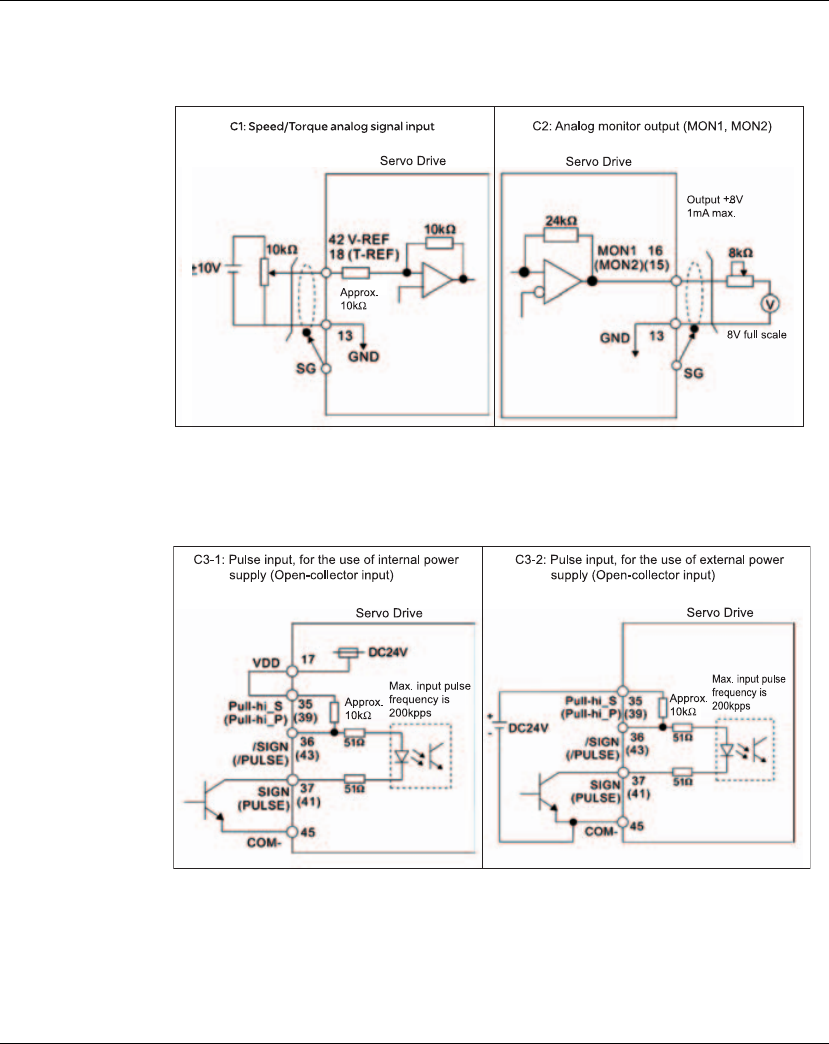
5. Installation Lexium 23A
96 AC servo drive
5.2.8.4 Wiring
Diagrams of I/O
Signals (CN1)
The valid voltage range of analog input command in speed and torque mode is
-10V ~+10V. The command value can be set via relevant parameters. The value of
input impedance is 10kΩ.
There are two kinds of pulse inputs, Line driver input and Open-collector input. Max.
input pulse frequency of Line-driver input is 500kpps and max. input pulse frequency
of Open-collector input is 200kpps.
Caution: Do not use dual power supply. Failure to observe this caution may result in
damage to the servo drive and servo motor.
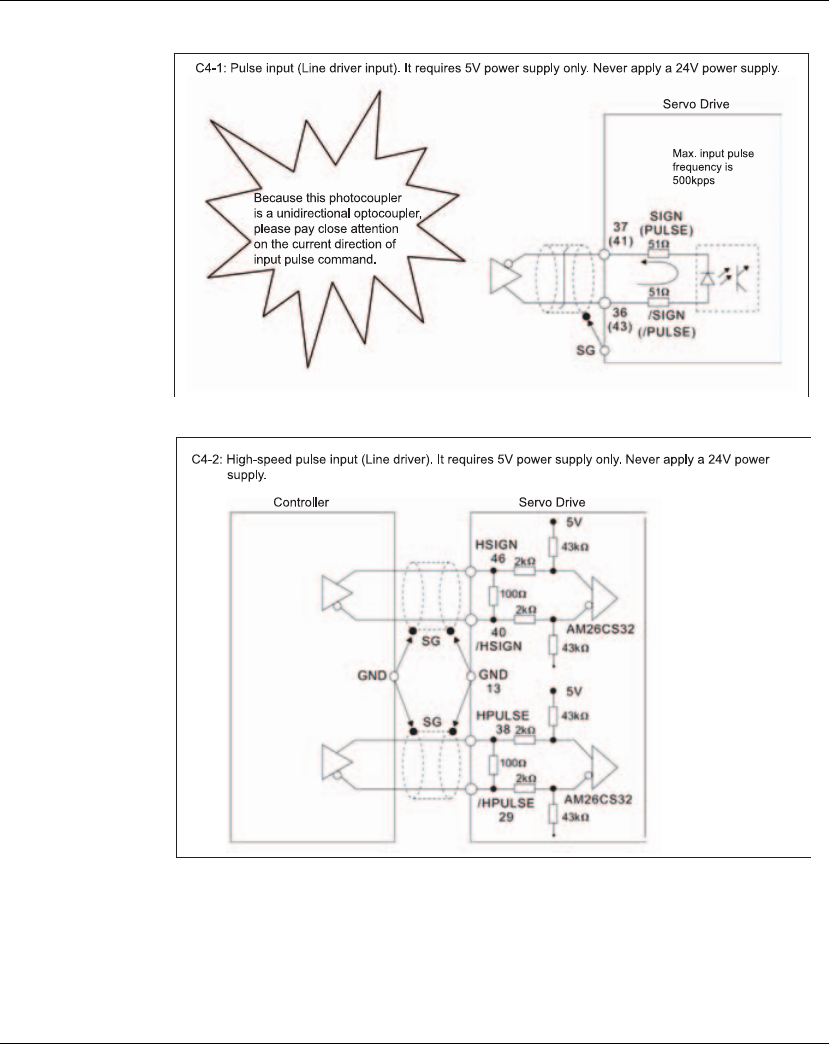
Lexium 23A 5. Installation
AC servo drive 97
Caution: Ensure that the ground terminal of the controller and the servo drive should
be connected to each other.
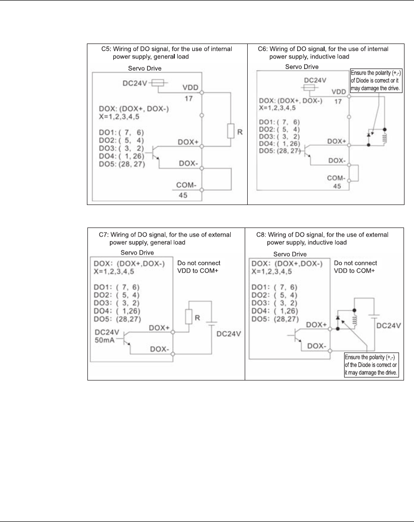
5. Installation Lexium 23A
98 AC servo drive
Be sure to connect a diode when the drive is applied to inductive load.
(Permissible current: 40mA, Instantaneous peak current: max. 100mA)
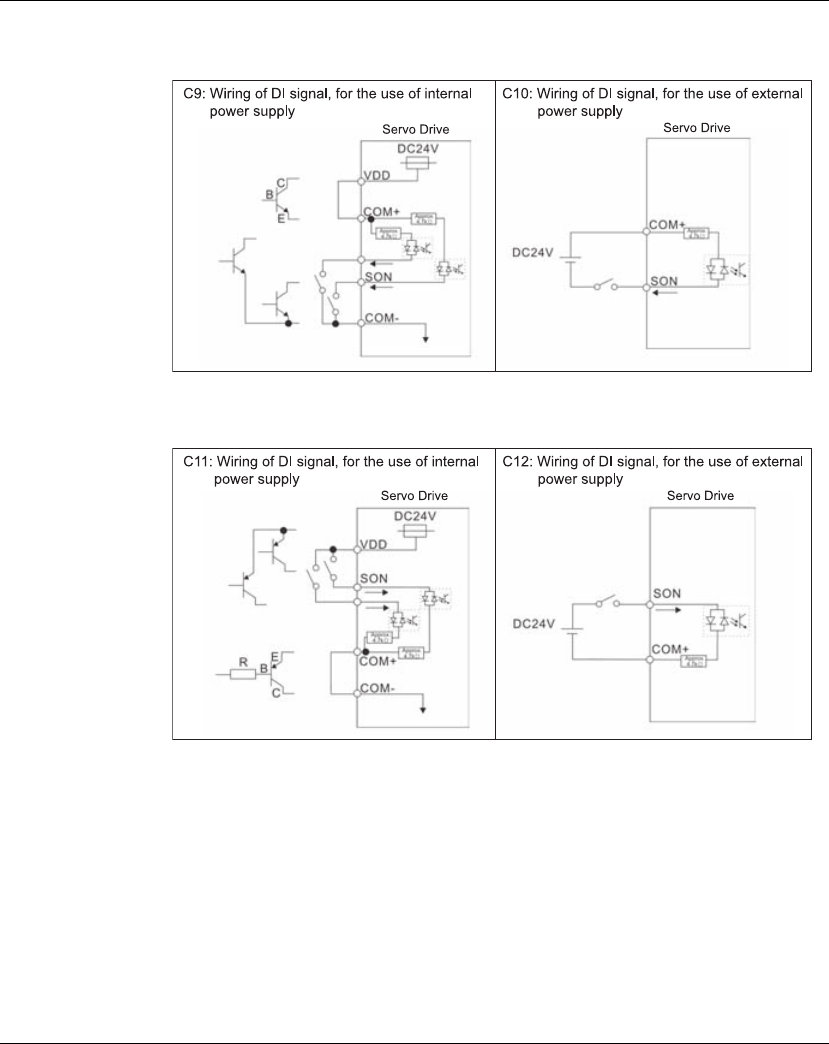
Lexium 23A 5. Installation
AC servo drive 99
Use a relay or open-collector transistor to input signal.
NPN transistor with multiple emitter fingers (SINK Mode)
PNP transistor with multiple emitter fingers (SOURCE Mode)
Caution: Do not use dual power supply. Failure to observe this caution may result in
damage to the servo drive and servo motor.
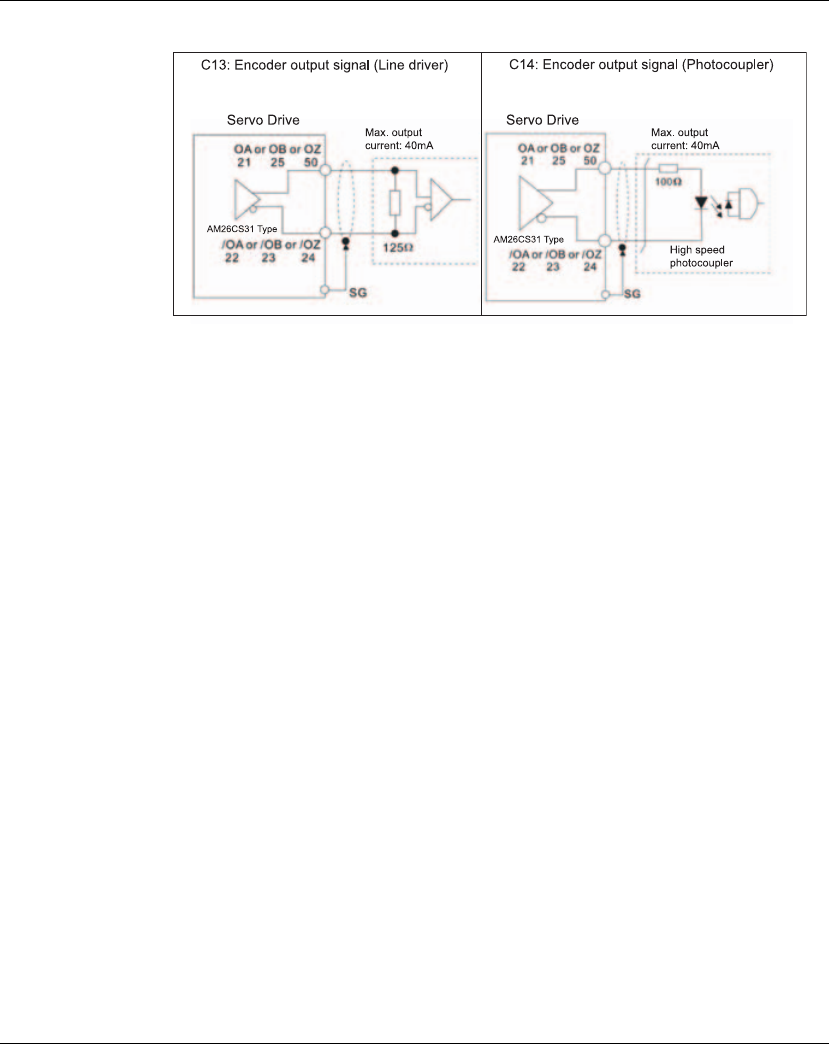
5. Installation Lexium 23A
100 AC servo drive
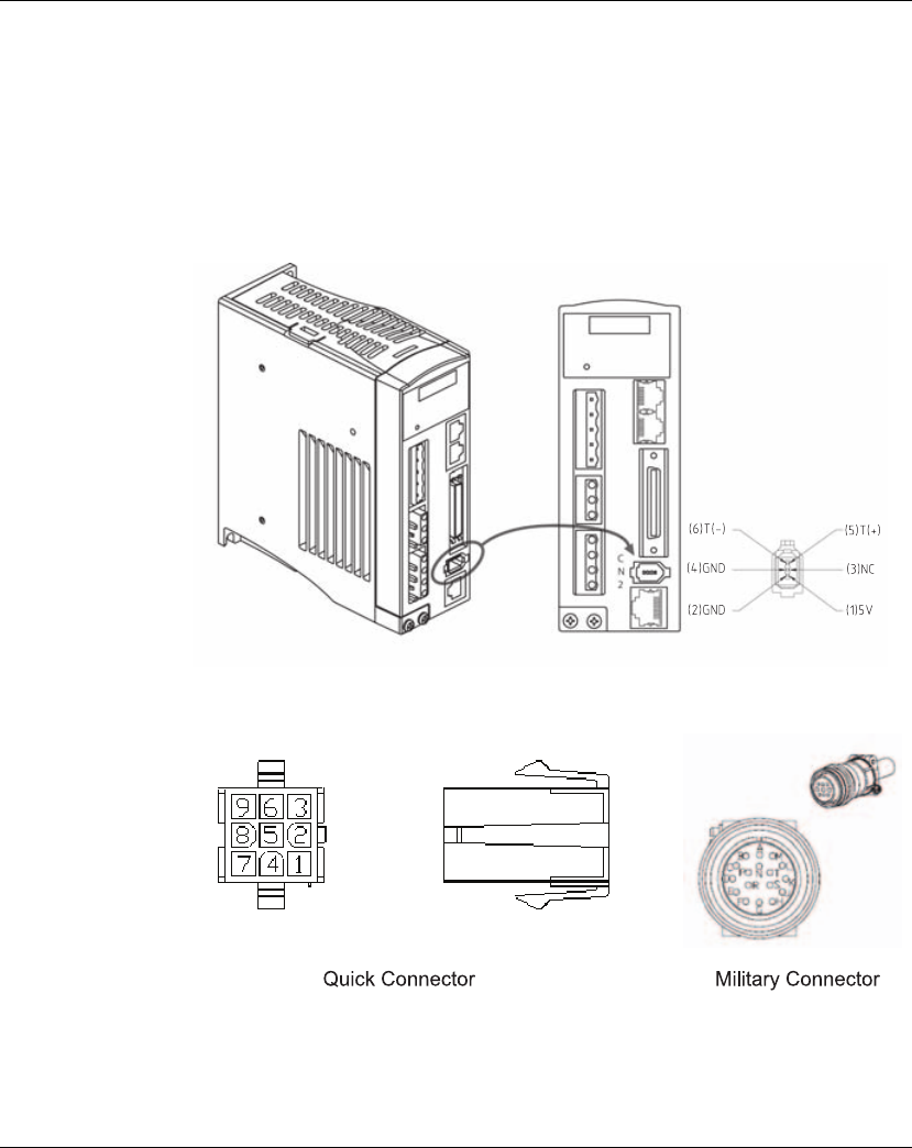
Lexium 23A 5. Installation
AC servo drive 101
5.2.9 Encoder Connector CN2
Feedback to the amplifier of the UVW signals for commutation is via the ABZ encoder
signal wires. Following rotor position sensing the amplifier automatically switches to
encoding for commutation control.
The 20-bit encoder is automatically multiplied to 1280000ppr for increased control
accuracy.
Figure 5.7 The layout of CN2 Drive Connector
Figure 5.8 The layout of CN2 Motor Connector
CN2
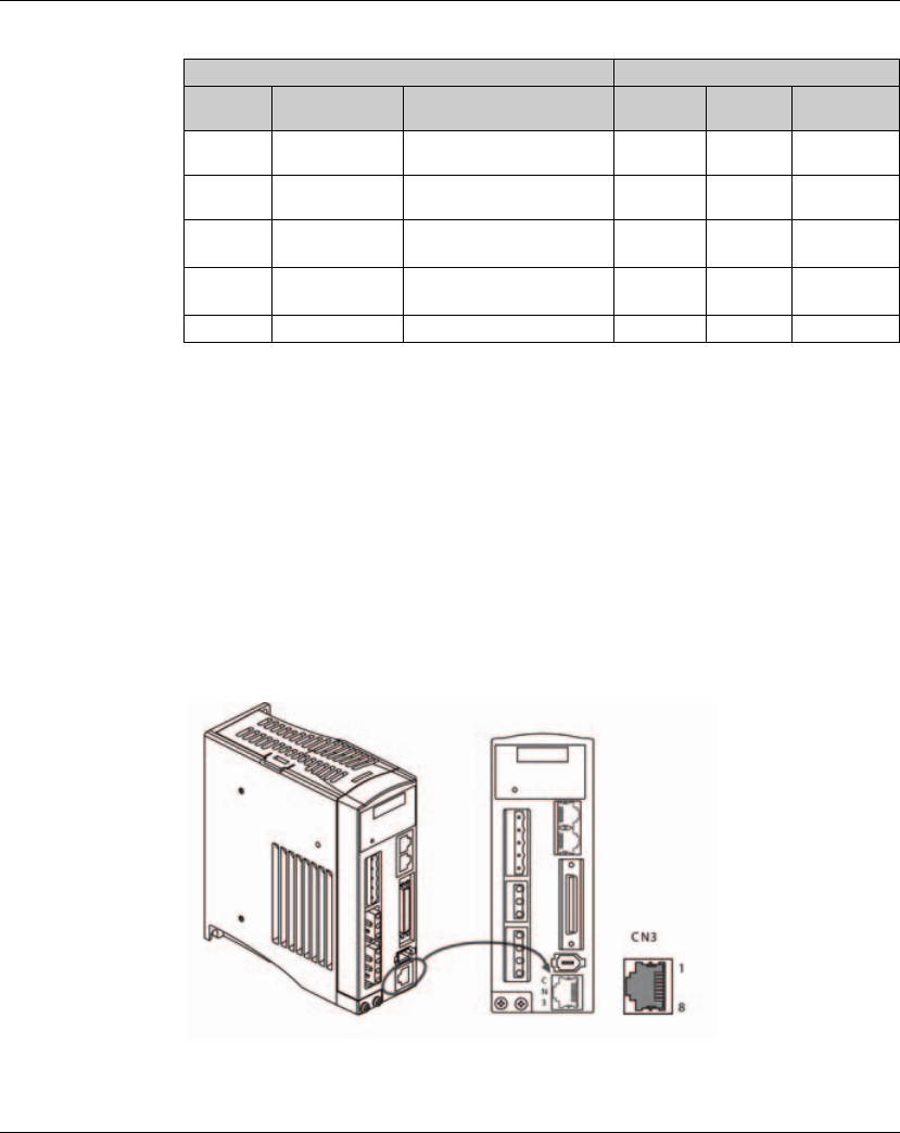
5. Installation Lexium 23A
102 AC servo drive
CN2 Terminal Signal Identification
5.2.10 Serial Communication Connector CN3
CN3 Terminal
Layout and
Identification
The servo drive can be connected to a PC or controller via this serial communication
connector CN3.
The communication connector CN3 of Schneider Electric servo drive can provides
two serial communication interfaces: RS-232 and RS-485 connection. RS-232 is used
for the drive commissioning with the software tool "Lexium23 Plus CT". The
maximum cable length for an RS-232 connection is 15 meters (50 feet). RS-485
connection can be used as host interface, for example to connect a machine
controller or personal computer with one or multiple LXM23 Plus servo drives to be
connected simultaneously.
Figure 5.9 The layout of CN3 Drive Connector
Drive Connector Motor Connector
PIN No. Terminal
Identification Description Military
Connector
Quick
Connector Color
5T+
Serial communication signal
input / output (+) A1Blue
6T-
Serial communication signal
input / output (-) B 4 Blue/Black
1 +5V +5V power supply S 7 Red & Red/
White
2, 4 GND Ground R 8 Black & Black/
White
- - Shielding L 9 -

Lexium 23A 5. Installation
AC servo drive 103
CN3 Terminal Signal Identification
NOTE:
1) For the connection of RS-485, please refer to chapter 9 "Communication".
Connection
between PC and
Connector CN3
To connect a personal computer with the CN3 interface of LXM23 Plus servo drives,
the USB to RJ45 (RS232) interface connector "VW3M8131" and RJ45 cable
"490NTW00002" can be used.
5.2.11 CANopen and CANmotion Communication Interface CN4
Function
The LXM23A device is suitable for connection to CANopen and CANmotion through
interface connector CN4.
A CAN bus connects multiple devices via a bus cable. Each network device can transmit
and receive messages. Data between network devices is transmitted serially.
Each network device must be configured before it can be operated on the network.
The device is assigned a unique node address (node ID) between 1 (0x01) and 127
(0x7F). The node address of a LXM23A device is determined by parameter P3-05
during commissioning. The baud rate must be the same for all devices in the field bus.
For further information on the field bus, see the LXM23A CANopen field bus manual.
There are two communication ports of connector CN4, one is for transmission
(CAN-out) and the other is for receiving (CAN-In), convenient for connecting to more
than one servo drives in serial. Ensure to connect a termination resistor to the last
connected servo drive.
Pin No. Signal Name Terminal
Identification Description
1 RS-232 data transmission RS-232_TX For data transmission of the servo drive.
Connected to the RS-232 interface of PC.
2 RS-232 data receiving RS-232_RX For data receiving of the servo drive.
Connected to the RS-232 interface of PC.
3, 6, 7 - - Reserved
4RS-485 data transmission RS-485(+) For data transmission of the servo drive
(differential line driver + end)
5 RS-485 data transmission RS-485(-) For data transmission of the servo drive
(differential line driver - end)
8 Grounding GND Ground
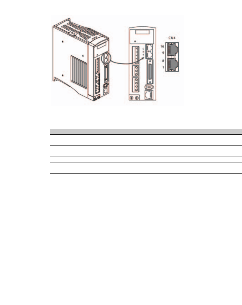
5. Installation Lexium 23A
104 AC servo drive
Figure 5.10 The layout of CN4 Connector
CN4 Interface Signal Identification
Connecting CANopen
p Connect the CANopen cable to CN4 (pins 1, 2 and 3) with an RJ45 connector. Note
the information on using cables with RJ45 connectors.
p Verify that the connector locks snap in properly at the housing.
Pin No. Signal Name Description
1.9 CAN_H CAN_H bus line (dominant high)
2.10 CAN_L CAN_H bus line (dominant low)
3.11 CAN_GND Ground / OV/V-
4.12 - Reserved
5.13 - Reserved
6.14 - Reserved
7.15 CAN_GND Ground / OV/V-
8.16 - Reserved

Lexium 23A 5. Installation
AC servo drive 105
Cable specifications
p se equipotential bonding conductors.
p se pre-assembled cables (see chapter 12 Accessories and spare parts) to reduce
the risk of wiring errors.
Connectors
D-SUB and RJ45
Usually, a cable with D-Sub connectors is used for CAN field bus connection in the
field. Inside control cabinets, connections with RJ45 cables have the benefit of easier
and faster wiring. In the case of CAN cables with RJ45 connectors, the maximum
permissible bus length is reduced by 50%.
Multiple-port taps can be used to connect an RJ45 system inside the control cabinet
to a D-SUB system in the field. The trunk line is connected to the multiple-port tap by
means of screw terminals; the devices are connected by means of pre-assembled
cables. See chapter 12 CANopen cable with connectors, CANopen connectors,
distributors, terminating resistors", multiple-port taps.
Shield: Required, both ends grounded
Twisted Pair: Required
PELV: Required
Cable composition: 2*0.25 mm2, 2* 0.20 mm2,
(2*AWG 22,2* AWG 24)
Max. cable length: See Table 6.3
Maximum length depends on the number of
devices, baud rate, connectors and signal
propagation delay. The higher the baud rate, the
shorter the bus cable needs to be.
Special features: The cable composition relates to cables with D-SUB
connectors. ln the case of cables with RJ45
connectors, the conductor cross section is reduced;
therefore, the maximum bus length is only half as
long as in the case of cables with D-SUB connectors.
Cables with RJ45 connectors may only be used
inside of control cabinets.Multiple-port taps for
trunk lines are available as accessories.

5. Installation Lexium 23A
106 AC servo drive
Maximum bus
length CAN
The maximum bus length depends on the selected baud rate. Table x.x shows the
maximum recommended overall length of the CAN bus in the case of cables with D-
SUB connectors.
1) According to the CANopen specification,the maximum bus length is 4 m. However,
in practice, 20 m have been possible in most cases. External interference may
reduce this length.
Table x.x Maximum bus length for CAN with D-SUB connection
NOTE: If you use cables with RJ45 connectors, the maximum bus length is reduced by 50%.
At a baud rate of 1 Mbit/s, the drop lines are limited to 0.3m. Terminating resistors
Both ends of a CAN bus line must be terminated. A 120 ohm terminating resistor
between CAN_L and CAN_H is used for this purpose. Connectors with integrated
terminating resistors are available as accessories, see chapter 12 "CANopen
connectors, distributors, terminating resistors".
Baud rate [kblt/s] Maxlmum bus length [m]
50 1000
125 500
250 250
500 100
1000 201)
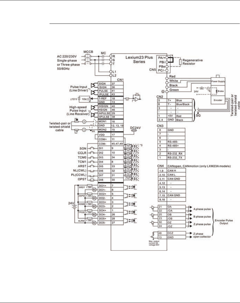
Lexium 23A 5. Installation
AC servo drive 107
5.3 Standard Connection Example
5.3.1 Position control mode wiring diagram (pulse control)
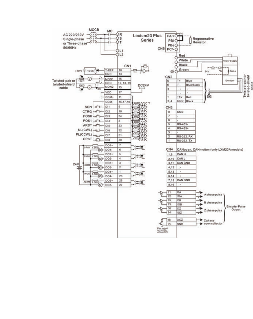
5. Installation Lexium 23A
108 AC servo drive
5.3.2 Position control mode wiring diagram (build-in motion sequence)
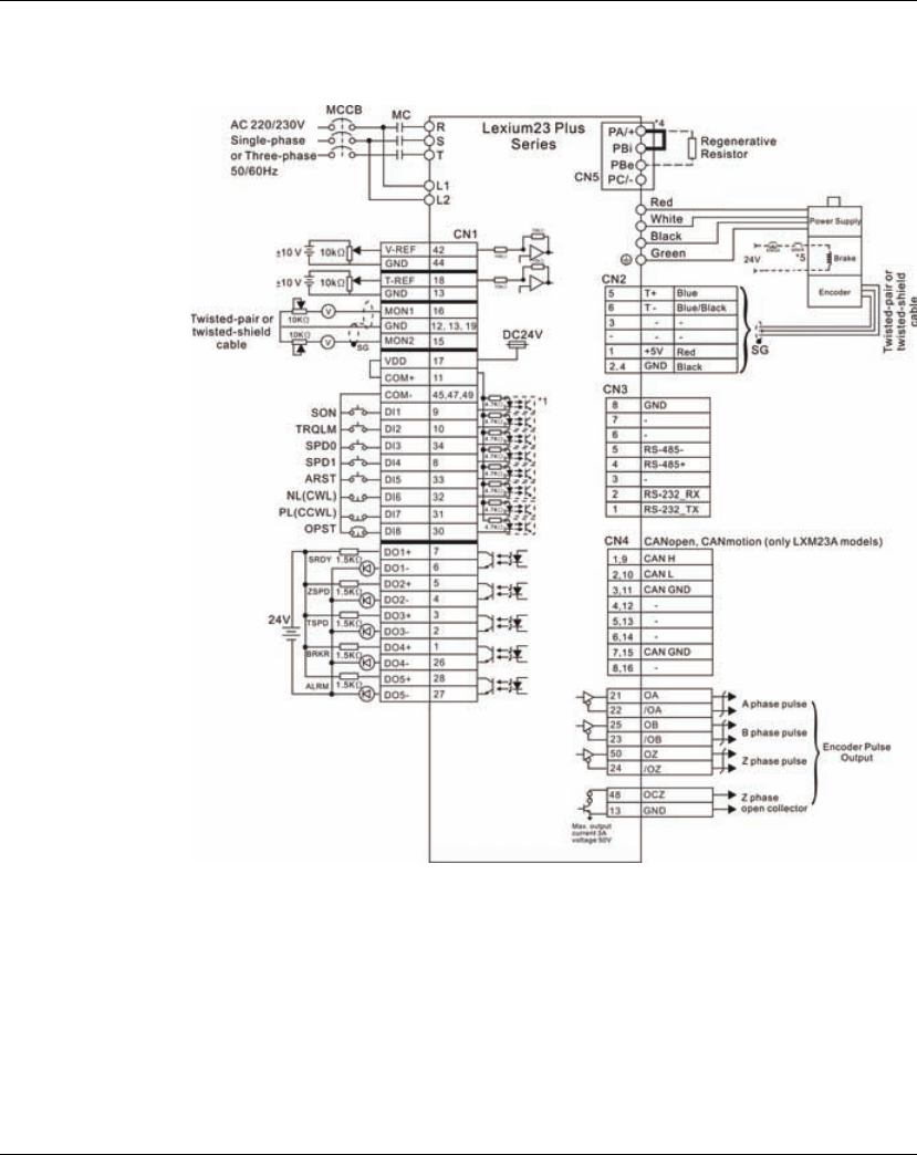
Lexium 23A 5. Installation
AC servo drive 109
5.3.3 Speed control mode wiring diagram
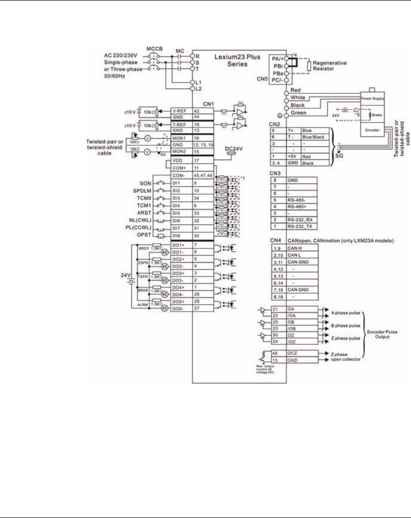
5. Installation Lexium 23A
110 AC servo drive
5.3.4 Torque control mode wiring diagram
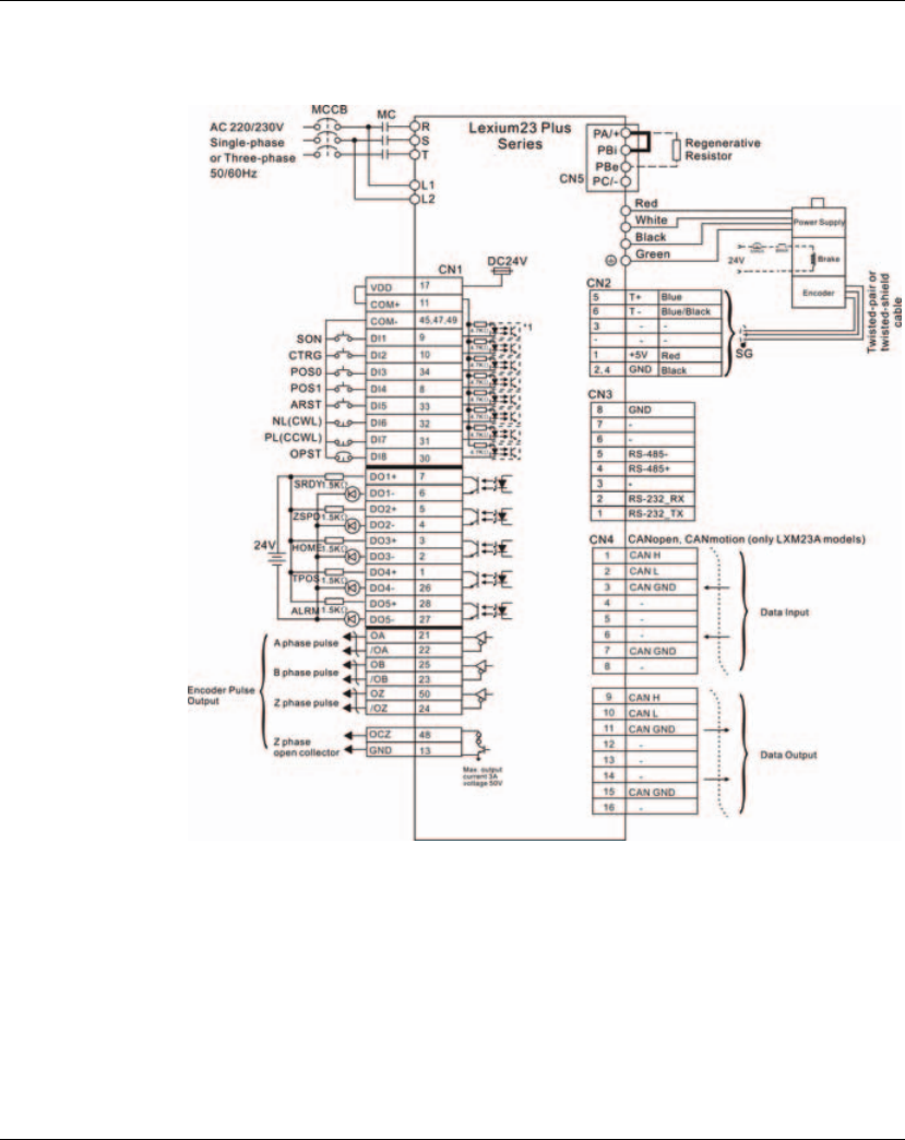
Lexium 23A 5. Installation
AC servo drive 111
5.3.5 CANopen control mode wiring diagram

5. Installation Lexium 23A
112 AC servo drive

AC servo drive 113
6
Commissioning
At a Glance
Presentation This chapter describes the basic operation of the Integrated HMI and the features it
offers.
What's in this
Chapter? This chapter contains the following topics:
Topic Page
Basic information 114
Overview 117
Integrated HMI Digital Keypad 119
Commissioning software 124
Commissioning procedure 125
6. Commissioning Lexium 23A
114 AC servo drive
6.1 Basic information
An overview of the parameters can be found in the chapter "Parameters". The use and
the function of some parameters are explained in more detail in this chapter.
ELECTRIC SHOCK CAUSED BY INCORRECT USE
The DC bus voltage is still present.
• Turn off the mains voltage using an appropriate switch to achieve a voltage-
free condition.
Failure to follow these instructions will result in death or serious injury.
UNINTENDED CONSEQUENCES OF EQUIPMENT OPERATION
When the system is started, the drives are usually out of the opera-tor's view and
cannot be visually monitored.
• Only start the system if there are no persons in the hazardous area.
Failure to follow these instructions will result in death or serious injury.
WARNING
UNINTENDED BEHAVIOR
The behavior of the drive system is governed by numerous stored data or settings.
Unsuitable settings or data may trigger unexpected movements or responses to
signals and disable monitoring functions.
• Do NOT operate the drive system with unknown settings or data.
• Verify that the stored data and settings are correct.
• When commissioning, carefully run tests for all operating states and
potential error situations.
• Verify the functions after replacing the product and also after making
changes to the settings or data.
• Only start the system if there are no persons or obstructions in the
hazardous area.
Failure to follow these instructions can result in death, serious injury or
equipment damage.
DANGER
DANGER
Lexium 23A 6. Commissioning
AC servo drive 115
WARNING
UNINTENDED BEHAVIOR
The behavior of the drive system is governed by numerous stored data or settings.
Unsuitable settings or data may trigger unexpected movements or responses to
signals and disable monitoring functions.
• Do NOT operate the drive system with unknown settings or data.
• Verify that the stored data and settings are correct.
• When commissioning, carefully run tests for all operating states and
potential error situations.
• Verify the functions after replacing the product and also after making
changes to the settings or data.
• Only start the system if there are no persons or obstructions in the
hazardous area.
Failure to follow these instructions can result in death, serious injury or
equipment damage.
WARNING
MOTOR WITHOUT BRAKING EFFECT
If power outage and faults cause the power stage to be switched off, the motor is no
longer stopped by the brake and may increase its speed even more until it reaches a
mechanical stop.
• Verify the mechanical situation.
• If necessary, use a cushioned mechanical stop or a suitable hold-ing brake.
Failure to follow these instructions can result in death, serious injury or
equipment damage.
6. Commissioning Lexium 23A
116 AC servo drive
WARNING
UNEXPECTED MOVEMENT
When the drive is operated for the first time, there is a risk of unex-pected
movements caused by possible wiring errors or unsuitable pa-rameters.
• Perform the first test run without coupled loads.
• Verify that a functioning button for EMERGENCY STOP is within reach.
• Anticipate movements in the incorrect direction or oscillation of the drive.
• Only start the system if there are no persons or obstructions in the
hazardous area.
Failure to follow these instructions can result in death, serious injury or
equipment damage.
WARNING
HOT SURFACES
The heat sink at the product may heat up to over 100C (212F) during operation.
• Avoid contact with the hot heat sink.
• Do not allow flammable or heat-sensitive parts in the immediate vicinity.
• Consider the measures for heat dissipation described.
Failure to follow these instructions can result in death or serious injury.

Lexium 23A 6. Commissioning
AC servo drive 117
6.2 Overview
6.2.1 Commissioning steps
You must also recommission an already configured device if you want to use it under
changed operating conditions.
To be done
To be done ...
Info
Checking the installation Page120
Switching on the device for the first time Page131
Setting basic parameters and limit values Page133
Setting, scaling and checking analog signals Page137
Setting and testing digital signals Page139
Checking the holding brake Page144
Checking the direction of movement of the motor Page145
Setting the braking resistor parameters Page150
Autotuning the device Page152
Manually optimizing the controller settings
- Velocity controller
- Position controller
Page157
Page158
Page164
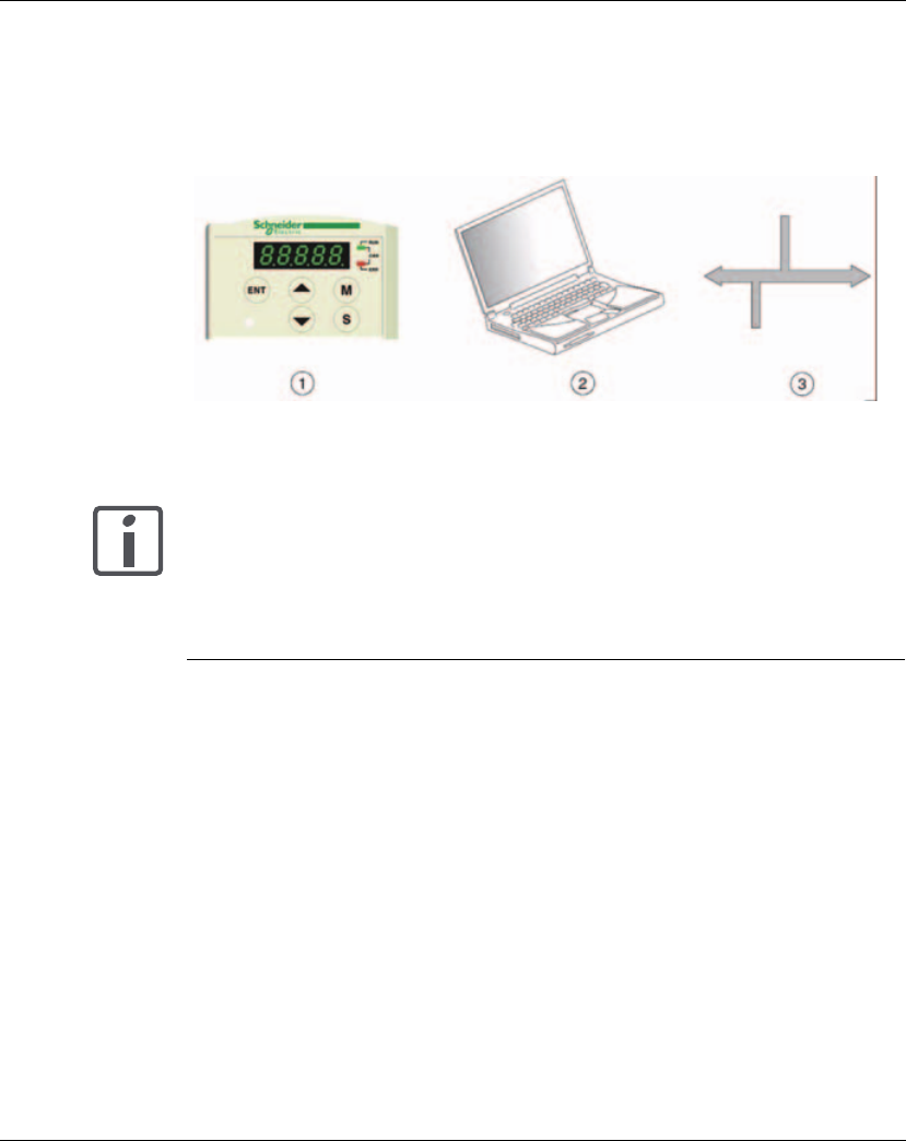
6. Commissioning Lexium 23A
118 AC servo drive
6.2.2 Commissioning tools
Overview The following tools can be used for commissioning, parameterization and
diagnostics:
(1) Integrated HMI
(2) PC with commissioning software
Access to all parameters is possible with the digital keypad or the commissioning
software.
Device settings can be duplicated. Stored device settings can be transferred to a
device of the same type. Duplicating the device settings can be used if multiple
devices are to have the same settings, for example, when devices are replaced.
Figure 6.1 Commissioning tools
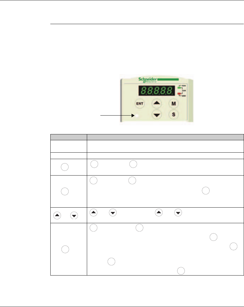
Lexium 23A 6. Commissioning
AC servo drive 119
6.3 Integrated HMI Digital Keypad
6.3.1 Description of the Integrated HMI
The Integrated HMI includes the display panel and function keys. The Figure 6.2
shows all of the features of the Integrated HMI and an overview of their functions.
Figure 6.2 Keypad Features
Charge LED
Name
Function
LCD Display The LCD Display (5-digit, 7-step display panel) shows the monitor codes,
parameter settings and operation values of the AC servo drive.
Charge LED The Charge LED lights to indicate the power is applied to the circuit.
Key Key. Pressing key can enter or exit different parameter groups,
and switch between Monitor mode and Parameter mode.
Key
Key. Pressing key can scrolls through parameter groups. After a
parameter is selected and its value displayed, pressing key can move
the cursor to the left and then change parameter settings (blinking digits) by
using arrow keys.
and Key
and key. Pressing the and key can scroll through and
change monitor codes, parameter groups and various parameter settings.
Key
key. Pressing the key can display and save the parameter groups,
the various parameter settings. In monitor mode, pressing key can
switch decimal or hexadecimal display. In parameter mode, pressing
key can enter into parameter setting mode. During diagnosis operation,
pressing key can execute the function in the last step. (The parameter
settings changes are not effective until the key is pressed.)
M
M M
S
S S
S
ENT
ENT ENT
ENT
ENT
ENT
ENT
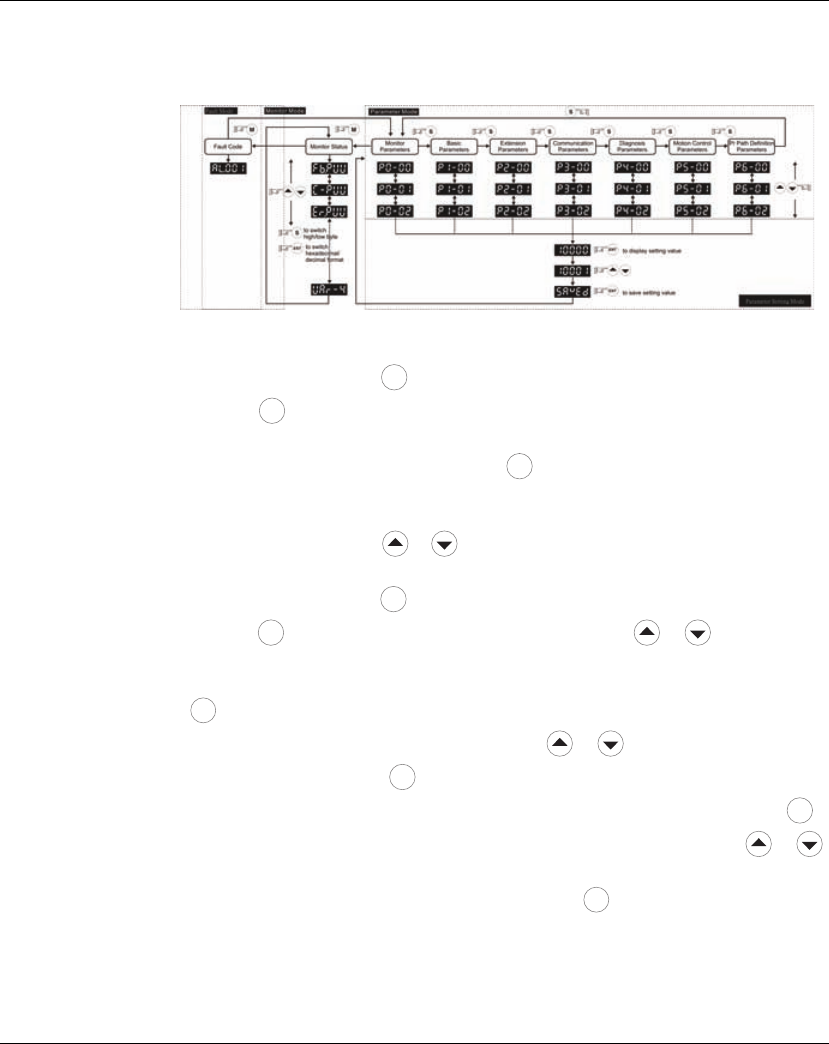
6. Commissioning Lexium 23A
120 AC servo drive
6.3.2 Display Flowchart
Figure 6.3 Keypad Operation
1. When the power is applied to the AC servo drive, the LCD display will show the monitor
function codes for approximately one second, then enter into the monitor mode.
2. In monitor mode, pressing key can enter into parameter mode. In parameter mode,
pressing key can return to monitor mode.
3. No matter working in which mode, when an alarm occurs, the system will enter into fault
mode immediately. In fault mode, pressing key can switch to other modes. In other
modes, if no key is pressed for over 20 seconds, the system will return to fault mode
automatically.
4. In monitor mode, pressing or arrow key can switch monitor parameter code. At
this time, monitor display symbol will display for approximately one second.
5. In monitor mode, pressing key can enter into parameter mode. In parameter mode,
pressing key can switch parameter group and pressing or arrow key can
change parameter group code.
6. In parameter mode, the system will enter into the setting mode immediately after the
key is pressed. The LCD display will display the corresponding setting value of this
parameter simultaneously. Then, users can use or arrow key to change
parameter value or press key to exit and return back to the parameter mode.
7. In parameter setting mode, the users can move the cursor to left by pressing
key and change the parameter settings (blinking digits) by pressing the or
arrow key.
8. After the setting value change is completed, press key to save parameter
settings or execute command.
9. When the parameter setting is completed, LCD display will show the end code
"SAVED" and automatically return back to parameter mode.
M
M
M
M
S
ENT
M
S
ENT
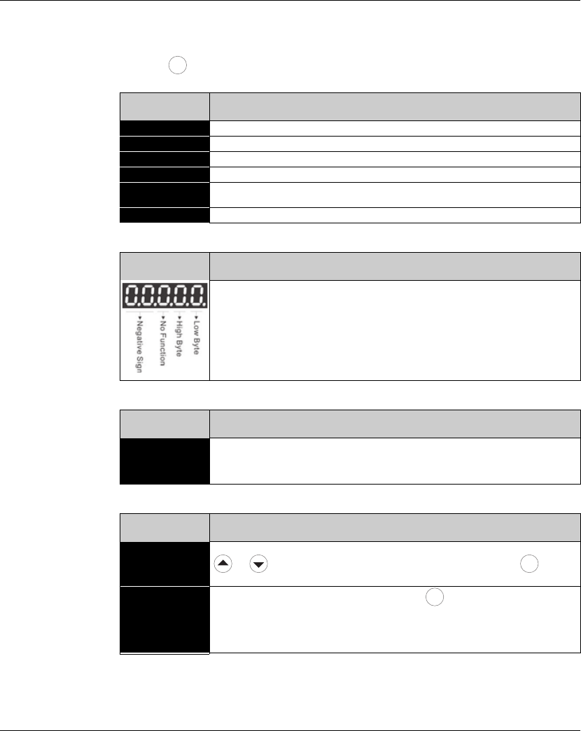
Lexium 23A 6. Commissioning
AC servo drive 121
6.3.3 Status Display
6.3.3.1 Save
Setting Display After the key is pressed, LCD display will show the following display messages for
approx. one second according to different status.
6.3.3.2 Decimal
Point Display
6.3.3.3 Fault
Message Display
6.3.3.4 Polarity
Setting Display
Display
Message Description
;-J1@ The setting value is saved correctly. [Saved)
H!97= This parameter is read only. Write-protected. (Read-Only)
7Ec
K
.@Invalid password or no password was input. (Locked)
9JI!H The setting value is error or invalid. (Out of Range)
;HJ9D The servo system is running and it is unable to accept this setting value to be
changed. (Servo On)
FE!#D This parameter is valid after restarting the drive. (Power On)
ENT
Display
Message Description
High/Low byte display. When the data is a decimal 32-bit data, these two
digits are used to show if the display is high byte or low byte.
Negative value display. When the data is displayed in decimal format, the
most left two digits represent negative sign no matter it is a 16-bit or 32-bit
data. If the data is displayed in hexadecimal format, it is a positive value
always and no negative sign is displayed.
Display
Message Description
-7.DDD
When the AC servo drive has a fault, LCD display will display "ALnnn". "AL"
indicates the alarm and "nnn" indicates the drive fault code. For the list of drive
fault code, please refer to parameter P0-01 in Chapter 11 (Servo Parameters) or
refer to Chapter 10 (Troubleshooting).
Display
Message
Description
#%')+
Positive value display. When entering into parameter setting mode, pressing
or arrow key can increase or decrease the display value. key is
used to change the selected digit (The selected digit will blink).
%.'.)+#
Negative value display. Continuously press key for two seconds and
then the positive(+) or negative(-) sign can be switched. When the setting
value exceeds its setting range, the positive(+) and negative(-) sign can not
be switched. (The negative value display is for a decimal negative value
only. There is no negative value display for a hexadecimal negative value.)
S
S
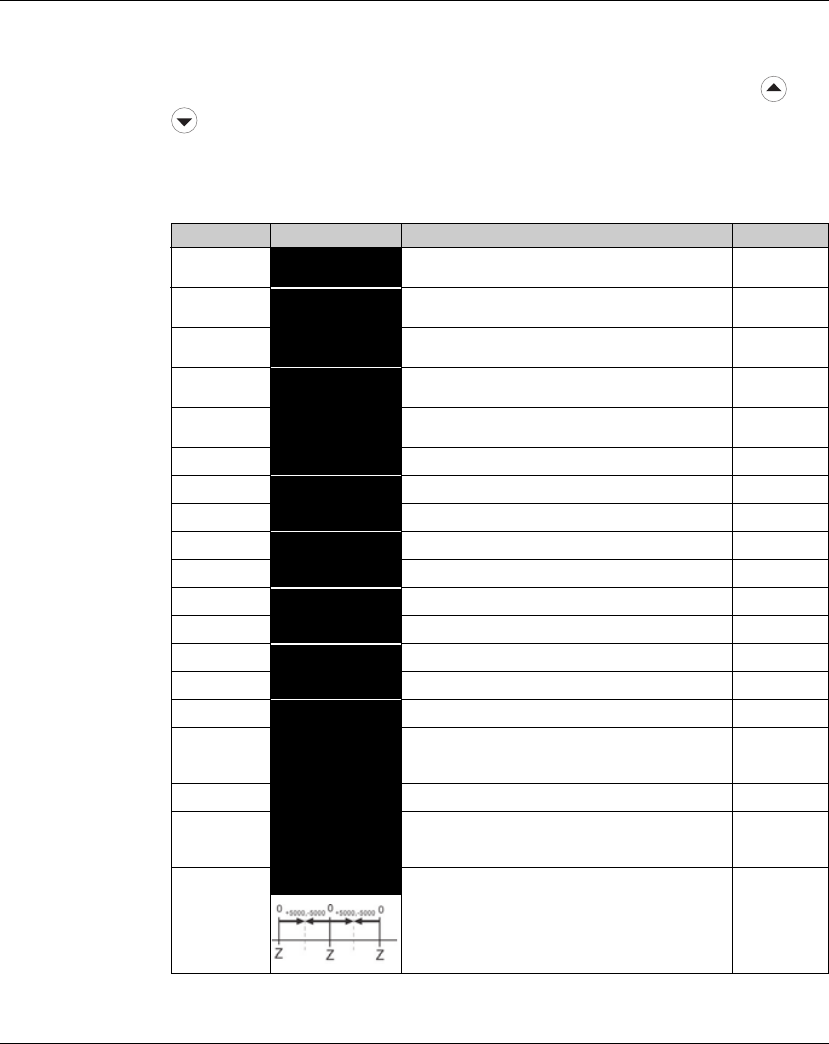
6. Commissioning Lexium 23A
122 AC servo drive
6.3.3.5 Monitor
Setting Display
When the AC servo drive is applied to power, the LCD display will show the monitor
function codes for approximately one second and then enter into the monitor mode.
In monitor mode, in order to change the monitor status, the users can press or
arrow key or change parameter P0-02 directly to specify the monitor status.
When the power is applied, the monitor status depends on the setting value of P0-02.
For example, if the setting value of P0-02 is 4 when the power is applied, the monitor
function will be input pulse number of pulse command, the C-PLS monitor codes will
first display and then the pulse number will display after.
P0-02 Setting
Display Message Description Unit
02>.:<< Motor feedback pulse number (after
electronic gear ratio is set) [user unit]
1/!:<< Input pulse number of pulse command (after
electronic gear ratio is set) [user unit]
21H.:<< Position error counts between control
command pulse and feedback pulse [user unit]
32>.:7; Motor feedback pulse number (encoder unit,
1280000 pulse/rev) [pulse]
4/!:7; Input pulse number of pulse command
(before electronic gear ratio is set) [pulse]
51H.:7; Position error counts [pulse]
6/:!2H Input frequency of pulse command [Kpps]
7;:11@ Motor rotation speed [rpm]
8/;:@5 Speed input command [Volt]
9/;:@% Speed input command [rpm]
10 /!IG5 Torque input command [Volt]
11 /!IG% Torque input command [%]
12 -J3!7 Average load [%]
13 :1!7 Peak load [%]
14 < >J; Main circuit voltage [Volt]
15 6!7 Ratio of load inertia to Motor inertia (Please
note that if the display is 130, it indicates that
the actual inertia is 13.0)
[0.1 times]
16 53>I.IIGBT temperature [oC]
17 H;D.2H Resonance frequency (The low byte is the first
resonance point and the high byte is the
second resonance point.)
[Hz]
18
@522.%Absolute pulse number relative to encoder
(use Z phase as home). The value of Z phase
home point is 0, and it can be the value from
-5000 to +5000 pulses. -

Lexium 23A 6. Commissioning
AC servo drive 123
The following table lists the display examples of monitor value:
Note:
1) Dec. represents Decimal display and Hex. represents Hexadecimal display.
2) The above display methods are both available in monitor mode and parameter
setting mode.
3) All monitor variables are 32-bit data. The users can switch to high byte or low byte
and display format (Dec. or Hex.) freely. Regarding the parameters listed in
Chapter 8, for each parameter, only one kind of display format is available and
cannot be changed.
P0-02 Setting
Display Message Description Unit
19 88-:$ Mapping Parameter 1: Display the content of
parameter P0-25 (mapping target is specified
by parameter P0-35)
-
20 88-:% Mapping Parameter 2: Display the content of
parameter P0-26 (mapping target is specified
by parameter P0-36)
-
21 88-:& Mapping Parameter 3: Display the content of
parameter P0-27 (mapping target is specified
by parameter P0-37)
-
22 88-:' Mapping Parameter 4: Display the content of
parameter P0-28 (mapping target is specified
by parameter P0-38)
-
23 <-H!$ Status Monitor 1: Display the content of
parameter P0-09 (the monitor status is
specified by parameter P0-17)
-
24 <-H!% Status Monitor 2: Display the content of
parameter P0-10 (the monitor status is
specified by parameter P0-18)
-
25 <-H!& Status Monitor 3: Display the content of
parameter P0-11 (the monitor status is
specified by parameter P0-19)
-
26 <-H!' Status Monitor 4: Display the content of
parameter P0-12 (the monitor status is
specified by parameter P0-20)
-
Display Message Description
#$%&' (Dec.) 16-bit
Data
Decimal display. When the actual value is 1234, the
display is 01234.
$%&' (Hex.) Hexadecimal display. When the actual value is
0x1234, the display is 1234.
$%&'.((Dec. High Byte)
32-bit
Data
Decimal display. When the actual value is
1234567890, the display of high byte is 1234.5 and
the display of low byte is 67890.
)*+,#.(Dec. Low Byte)
A$%&' (Hex. High Byte) Hexadecimal display. When the actual value is
0x12345678, the display of high byte is h1234 and
the display of low byte is L5678.
7()*+ (Hex. Low Byte)
$.%.&.'.(.
Negative value display. When the actual value is -12345,
the display is 1.2.345. (The negative value display is
displayed to indicate a decimal negative value. There is no
negative value display for a hexadecimal negative value.)
6. Commissioning Lexium 23A
124 AC servo drive
6.4 Commissioning software
The commissioning software has a graphic user interface and is used for
commissioning, diagnostics and testing settings.
• Tuning of the controller parameters via a graphical user interface
• Comprehensive set of diagnostics tools for optimization and manntenance
• Long-term recording for evaluation of the performance
• Testing the input and output signals
• Tracking signals on the screen
• Archiving of device settings and recordings with export function for further
processing in other applications
See page 256 for details on connecting a PC to the device.
Online help The commissioning software offers help functions, which can be accessed via
"?-Help Topics" or by pressing theF1key.

Lexium 23A 6. Commissioning
AC servo drive 125
6.5 Commissioning procedure
6.5.1 Switching on the device for the first time
Duplicating device
settings
The commissioning software allows you duplicate device settings.
Automatic reading
of the motor data
When the servo drive is switched on and if a BCH motor is connected, the device
automatically reads the motor data from the motor encoder. The data record is
checked by the servo drive. With this data, the BCH motor type is identified by the
LXM23 Plus servo drive.
The record contains motor specific information. The record cannot be changed by
the user.
Preparation If the device is not to be commissioned exclusively via the Integrated HMI, a PC with
the commissioning software must be connected.
Switching on the
device
b The power stage supply voltage is switched off.
X Switch on the controller supply voltage.
Y The device goes through an initialization routine, all LEDs are tested, all segments
of the 7-segment display and the LEDs light up.
After the initialization, the device is ready for operation. The device is in the Pt operating
mode. See chapter 8.3 "Operating modes", page 160 for changing operating modes.
WARNING
LOSS OF CONTROL DUE TO UNSUITABLE PARAMETER VALUES
Unsuitable parameter values may disable monitoring functions and trigger
unexpected movements or responses of signals.
• Prepare a list with the parameters required for the functions used.
• Check the parameters before operation.
• Only start the system if there are no persons or obstructions in the
hazardous area.
Failure to follow these instructions can result in death, serious injury or
equipment damage.
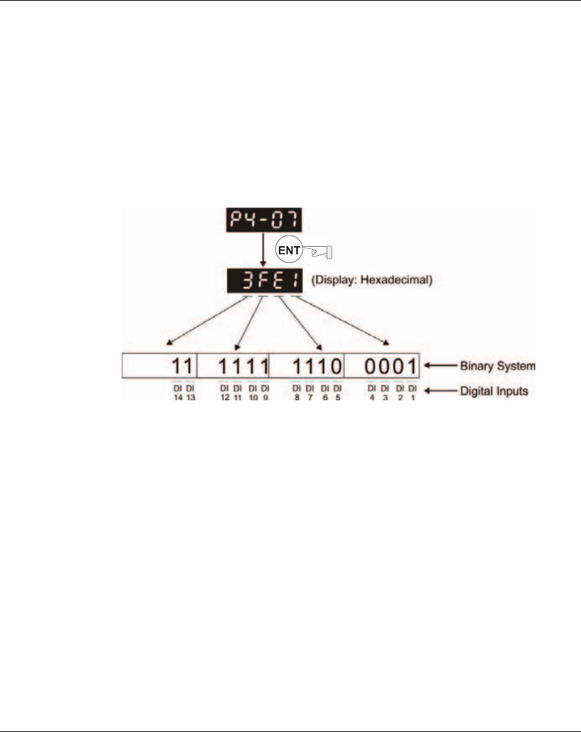
6. Commissioning Lexium 23A
126 AC servo drive
6.5.2 DI Diagnosis Operation
Following the setting method in Figure 6.4 can perform DI diagnosis operation
(parameter P4-07, Input Status). According to the ON and OFF status of the digital
inputs DI1 to DI8, the corresponding status will display on the servo drive LED display.
When the Bit is set to "1", it means that the corresponding digital input signal is ON.
(Please also refer to Figure 6.4)
For example:
Suppose that the servo drive LED display is "3FE1".
"E" is hexadecimal, which is equal to "1110" in binary system, and it means that the
digital inputs DI6 ~ DI8 are ON.
Figure 6.4
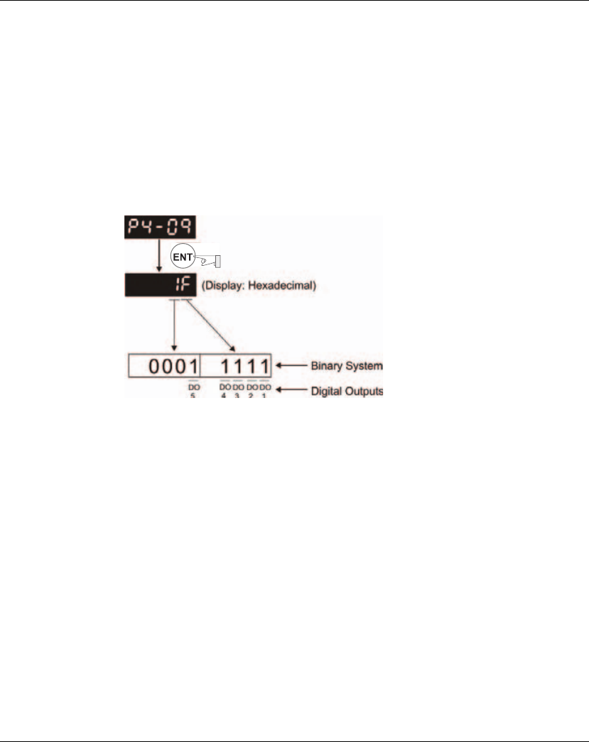
Lexium 23A 6. Commissioning
AC servo drive 127
6.5.3 DO Diagnosis Operation
Following the setting method in Figure 6.5 can perform DO diagnosis operation
(parameter P4-09, Output Status Display). According to the ON and OFF status of the
digital outputs DO1 to DO5, the corresponding status will display on the servo drive
LED display. When the Bit is set to "1", it means that the corresponding digital output
signal is ON. (Please also refer to Figure 6.5)
For example:
Suppose that the servo drive LED display is "1F".
"F" is hexadecimal, which is equal to "1111" in binary system, and it means that the
digital outputs DO1 ~ DO4 are ON.
Figure 6.5
6. Commissioning Lexium 23A
128 AC servo drive
6.5.4 Trial Run and Tuning Procedure
This part, which is divided into two parts, describes trial run for servo drive and motor.
One part is to introduce the trial run without load, and the other part is to introduce
trial run with load. Ensure to complete the trial run without load first before
performing the trial run with load.
6.5.4.1 Inspection
without Load
In order to prevent accidents and avoid damaging the servo drive and mechanical
system, the trial run should be performed under no load condition (no load
connected, including disconnecting all couplings and belts). Do not run servo motor
while it is connected to load or mechanical system because the unassembled parts on
motor shaft may easily disassemble during running and it may damage mechanical
system or even result in personnel injury. After removing the load or mechanical
system from the servo motor, if the servo motor can runs normally following up the
normal operation procedure (when trial run without load is completed), then the
users can connect to the load and mechanical system to run the servo motor.
After power in connected to AC servo drive, the charge LED will light and it indicates
that AC servo drive is ready. Please check the followings before trial run:
1. Inspection before operation (Control power is not applied)
zInspect the servo drive and servo motor to insure they were not damaged.
zEnsure that all wiring terminals are correctly insulated.
zEnsure that all wiring is correct or damage and or malfunction may result.
zVisually check to ensure that there are not any unused screws, metal strips, or any
conductive or inflammable materials inside the drive.
zMake sure control switch is OFF.
zNever put inflammable objects on servo drive or close to the external regenerative
resistor.
zIf the electromagnetic brake is being used, ensure that it is correctly wired.
zIf required, use an appropriate electrical filter to eliminate noise to the servo drive.
zEnsure that the external applied voltage to the drive is correct and matched to the
controller.
In order to prevent accidents, the initial trial run for servo motor should be conducted
under no load conditions (separate the motor from its couplings and belts).
Caution: Please perform trial run without load first and then perform trial run with load
connected. After the servo motor is running normally and regularly without load, then
run servo motor with load connected. Ensure to perform trial run in this order to
prevent unnecessary danger.
DANGER

Lexium 23A 6. Commissioning
AC servo drive 129
2. Inspection during operation (Control power is applied)
zEnsure that the cables are not damaged, stressed excessively or loaded heavily.
When the motor is running, pay close attention on the connection of the cables
and notice that if they are damaged, frayed or over extended.
zCheck for abnormal vibrations and sounds during operation. If the servo motor is
vibrating or there are unusual noises while the motor is running, please contact the
dealer or manufacturer for assistance.
zEnsure that all user-defined parameters are set correctly. Since the characteristics
of different machinery equipment are not the same, in order to avoid accident or
cause damage, do not adjust the parameter abnormally and ensure the parameter
setting is not an excessive value.
zEnsure to reset some parameters when the servo drive is off (Please refer to
Chapter 11). Otherwise, it may result in malfunction.
zIf there is no contact sound or there be any unusual noises when the relay of the
servo drive is operating, please contact your distributor for assistance or contact
with Schneider Electric.
zCheck for abnormal conditions of the power indicators and LED display. If there is
any abnormal condition of the power indicators and LED display, please contact
your distributor for assistance or contact with Schneider Electric.
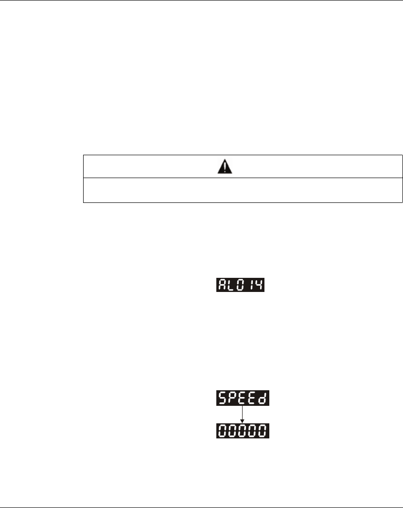
6. Commissioning Lexium 23A
130 AC servo drive
6.5.4.2 Applying
Power to the Drive
The users please observe the following steps when applying power supply to the
servo drive.
1. Please check and confirm the wiring connection between the drive and motor is
correct.
1) Terminal U, V, W and FG (frame ground) must connect to Red, White, Black and
Green cables separately (U: Red, V: White, W: Black, FG: Green). If not connect to
the specified cable and terminal, then the drive cannot control motor. The
motor grounding lead, FG must connect to grounding terminal. For more
information of cables, please refer to section 5.2.
2) Ensure to connect encoder cable to CN2 connector correctly. If the users only
desire to execute JOG operation, it is not necessary to make any connection to
CN1 and CN3 connector. For more information of the connection of CN2
connector, please refer to Section 5.2.
2. Main circuit wiring
Connect power to the AC servo. For three-phase input power connection and
single-phase input power connection, please refer to Section 5.2.3.
3. Turn the Power On
The Power includes control circuit power (L1, L2) and main circuit power (R, S, T).
When the power is on, the normal display should be shown as the following figure:
As the default settings of digital input signal, DI6, DI7 and DI8 are Reverse Inhibit
Limit (NL), Forward Inhibit Limit (PL) and Operational Stop (OPST) respectively, if
the users do not want to use the default settings of DI6 ~ DI8, the users can change
their settings by using parameters P2-15 to P2-17 freely.
When the setting value of parameters P2-15 to P2-17 is 0, it indicates the function of
this DI signal is disabled. For more information of parameters P2-15 to P2-17, please
refer to Chapter 11 "Parameters".
If the parameter P0-02 is set as motor speed (06), the normal display should be
shown as the following figure:
If there is no text or character displayed on the LED display, please check if the
voltage of the control circuit terminal ((L1, L2) is over low.
Do not connect the AC input power (R, S, T) to the (U, V, W) output terminals. This will
damage the AC servo drive.
DANGER
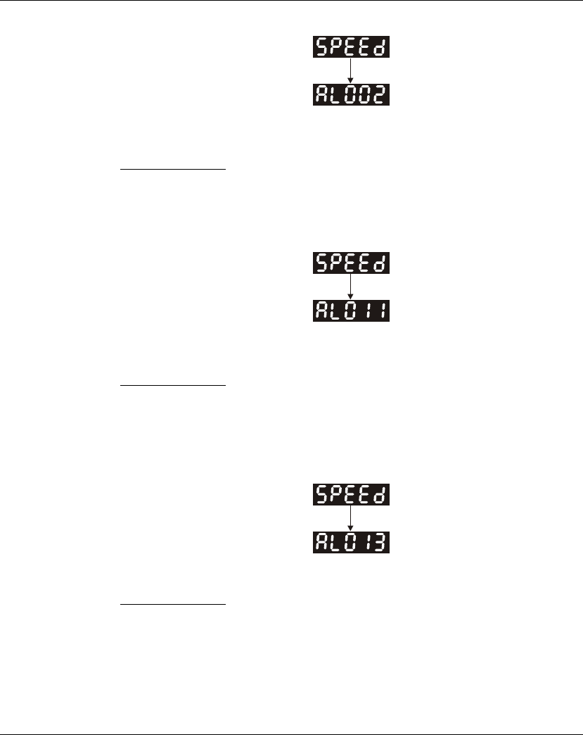
Lexium 23A 6. Commissioning
AC servo drive 131
1) When display shows:
Overvoltage:
The main circuit voltage has exceeded its maximum allowable value or input power is
error (Incorrect power input).
Corrective Actions:
z Use voltmeter to check whether the main circuit input voltage falls within the rated
input voltage.
z Use voltmeter to check whether the input voltage is within the specified limit.
2) When display shows:
Encoder error:
Check if the wiring is correct. Check if the encoder wiring (CN2) of servo motor is loose
or incorrect.
Corrective Actions:
z Check if the users perform wiring recommended in the user manual.
z Examine the encoder connector and cable.
z Inspect whether wire is loose or not.
z Check if the encoder is damaged.
3) When display shows:
Operational stop activated:
Please check if any of digital inputs DI1 ~ DI8 signal is set to "Operational Stop" (OPST).
Corrective Actions:
z If it does not need to use "Operational Stop (OPST)" as input signal, the users only
need to confirm that if all of the digital inputs DI1 ~ DI8 are not set to "Operational
Stop (OPST)". (The setting value of parameter P2-10 to P2-17 is not set to 21.)
z If it is necessary to use "Operational Stop (OPST)" as input signal, the users only
need to confirm that which of digital inputs DI1 ~ DI8 is set to "Operational Stop
(OPST)" and check if the digital input signal is ON (It should be activated).

6. Commissioning Lexium 23A
132 AC servo drive
4) When display shows:
Reverse limit switch error:
Please check if any of digital inputs DI1 ~ DI8 signal is set to "Reverse inhibit limit (NL)"
and check if the signal is ON or not.
Corrective Actions:
z If it does not need to use "Reverse inhibit limit (NL)" as input signal, the users only
need to confirm that if all of the digital inputs DI1 ~ DI8 are not set to "Reverse inhibit
limit (NL)". (The setting value of parameter P2-10 to P2-17 is not set to 22.)
z If it is necessary to use "Reverse inhibit limit (NL)" as input signal, the users only
need to confirm that which of digital inputs DI1 ~ DI8 is set to "Reverse inhibit limit
(NL)" and check if the digital input signal is ON (It should be activated).
5) When display shows:
Forward limit switch error:
Please check if any of digital inputs DI1 ~ DI8 signal is set to "Forward inhibit limit (PL)"
and check if the signal is ON or not.
Corrective Actions:
z If it is no need to use "Forward inhibit limit (PL)" as input signal, the users only need
to confirm that if all of the digital inputs DI1 ~ DI8 are not set to "Forward inhibit limit
(PL)". (The setting value of parameter P2-10 to P2-17 is not set to 23.)
z If it is necessary to use "Forward inhibit limit (PL)" as input signal, the users only
need to confirm that which of digital inputs DI1 ~ DI8 is set to "Forward inhibit limit
(PL)" and check if the digital input signal is ON (It should be activated).

Lexium 23A 6. Commissioning
AC servo drive 133
When "Digital Input 1 (DI1)" is set to Servo On (SON), if DI1 is set to ON (it indicates that
Servo On (SON) function is enabled) and the following fault message shows on the
display:
6) When display shows:
Overcurrent:
Corrective Actions:
z Check the wiring connections between the servo drive and motor.
z Check if the circuit of the wiring is closed.
z Remove the short-circuited condition and avoid metal conductor being exposed.
7) When display shows:
Undervoltage:
Corrective Actions:
z Check whether the wiring of main circuit input voltage is normal.
z Use voltmeter to check whether input voltage of main circuit is normal.
z Use voltmeter to check whether the input voltage is within the specified limit.
NOTE:
1) If there are any unknown fault codes and abnormal display when applying power to
the drive or servo on is activated (without giving any command), please inform the
distributor or contact with Schneider Electric for assistance.

6. Commissioning Lexium 23A
134 AC servo drive
6.5.4.3 JOG Trial
Run without Load
It is very convenient to use JOG trial run without load to test the servo drive and motor
as it can save the wiring. The external wiring is not necessary and the users only need
to connect the Integrated HMI to the servo drive. For safety, it is recommended to set
JOG speed at low speed. Please refer to the following steps to perform JOG trial run
without load.
STEP 1: Turn the drive ON through software. Ensure that the setting value of
parameter P2-30 should be set to 1 (Servo On).
STEP 2: Set parameter P4-05 as JOG speed (unit: rpm). After the desired JOG speed
is set, and then press key, the drive will enter into JOG operation mode
automatically.
STEP 3: The users can press and key to change JOG speed and press key
to adjust the digit number of the displayed value.
STEP 4: Pressing key can determine the speed of JOG operation.
STEP 5: Pressing key and the servo motor will run in P(CCW) direction. After
releasing key, the motor will stop running.
STEP 6: Pressing key and the servo motor will run in N(CW) direction. After
releasing key, the motor will stop running.
N (CW) and P(CCW) Definition:
P (CCW, Counterclockwise): when facing the servo motor shaft, P is running
in counterclockwise direction.
N (CW, Clockwise): when facing the servo motor shaft, N is running in
clockwise direction.
STEP 7: When pressing key, it can exit JOG operation mode.
ENT
S
ENT
M
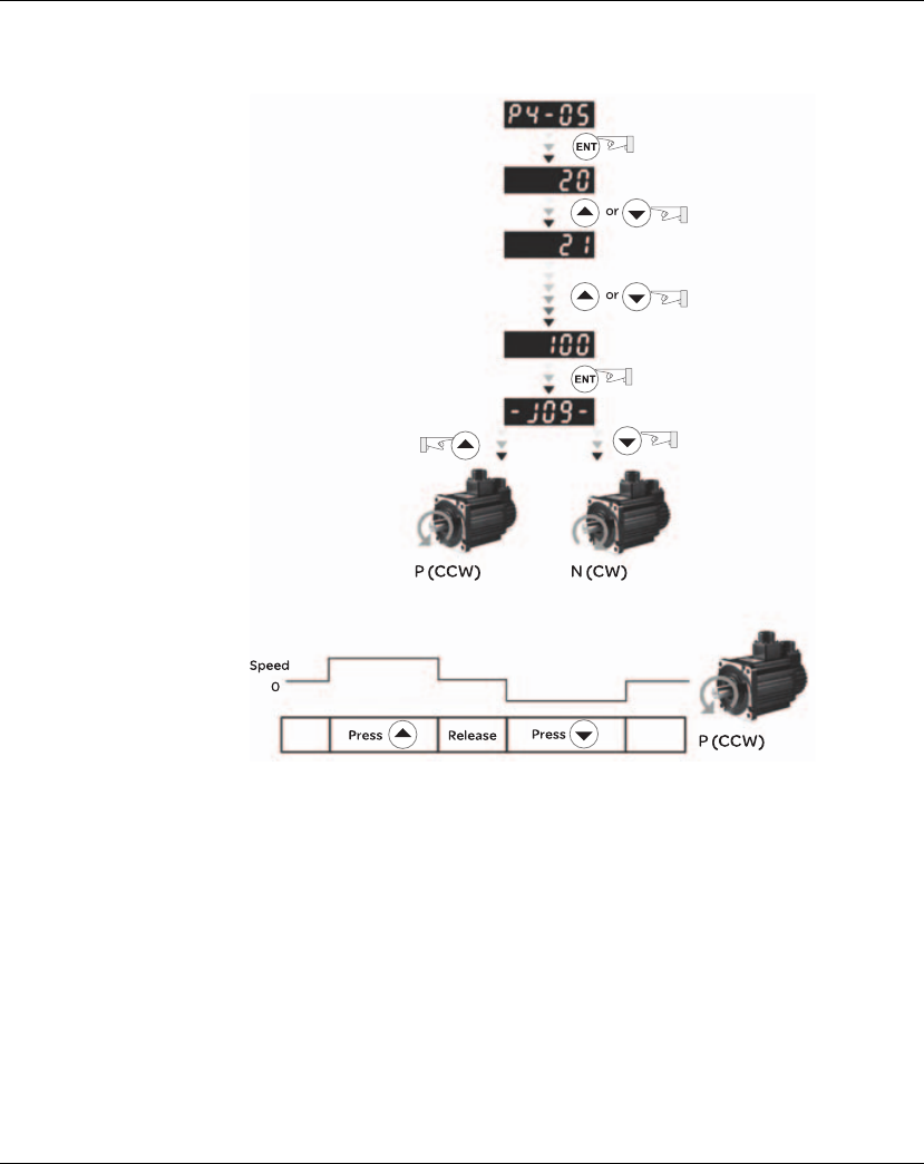
Lexium 23A 6. Commissioning
AC servo drive 135
In the example below, the JOG speed is adjusted from 20rpm (Default setting) to
100 rpm.
If the servo motor does not rotate, please check if the wiring of U, V, W terminals and encoder
is correct or not.
If the servo motor does not rotate properly, please check if the phase of U, V, W cables is
connected correctly.

6. Commissioning Lexium 23A
136 AC servo drive
6.5.4.4 Speed Trial
Run without Load
Before speed trial run, fix and secure the motor as possible to avoid the danger from
the reacting force when motor speed changes.
STEP 1:
Set the value of parameter P1-01 to 02 and it is speed (S) control mode. After
selecting the operation mode as speed (S) control mode, please restart the drive as
P1-01 is effective only after the servo drive is restarted (after switching power off and
on).
STEP 2:
In speed control mode, the necessary Digital Inputs are listed as follows:
By default, DI6 is the function of reverse inhibit limit, DI7 is the function of forward
inhibit limit and DI6 is the function of operational stop (DI8), if the users do not set the
setting value of parameters P2-15 to P2-17 and P2-36 to P2-41 to 0 (Disabled), the
faults (AL013, 14 and 15) will occur (For the information of fault messages, please
refer to Chapter 10). Therefore, if the users do not need to use these three digit
inputs, please set the setting value of parameters P2-15 to P2-17 and P2-36 to P2-41
to 0 (Disabled) in advance.
All the digital inputs of Lexium23 Plus servo drives are user-defined, and the users
can set the DI signals freely.
Ensure to refer to the definitions of DI signals before defining them (For the
description of DI signals, please refer to Table 11.A in Chapter 11). If any alarm code
displays after the setting is completed, the users can restart the drive or set DI5 to be
activated to clear the fault. Please refer to section 6.5.4.2.
Digital Input Parameter Setting
Value Sign Function Description CN1 Pin No.
DI1 P2-10=101 SON Servo On DI1-=9
DI2 P2-11=109 TRQLM Torque limit enabled DI2-=10
DI3 P2-12=114 SPD0 Speed command selection DI3-=34
DI4 P2-13=115 SPD1 Speed command selection DI4-=8
DI5 P2-14=102 ARST Reset DI5-=33
DI6 P2-15=0 Disabled This DI function is disabled -
DI7 P2-16=0 Disabled This DI function is disabled -
DI8 P2-17=0 Disabled This DI function is disabled -

Lexium 23A 6. Commissioning
AC servo drive 137
The speed command is selected by SPD0, SPD1. Please refer to the following table:
0: indicates OFF (Normally Open); 1: indicates ON (Normally Closed)
The range of internal parameter is from -60000 to 60000.
Setting value of speed command = Setting range x unit (0.1 rpm).
For example:
If P1-09 is set to +30000, the setting value of speed command =
+30000 x 0.1 rpm = +3000 rpm.
The settings of speed command:
STEP 3:
1. The users can use DI1 to enable the servo drive (Servo On).
2. If DI3 (SPD0) and DI4 (SPD1) are OFF both, it indicates S1 command is selected. At
this time, the motor is operating according to external analog command.
3. If only DI3 is ON (SPD0), it indicates S2 command (P1-09 is set to +30000) is
selected, and the motor speed is 3000rpm at this time.
4. If only DI4 is ON (SPD1), it indicates S3 command (P1-10 is set to +1000) is selected,
and the motor speed is 100 rpm at this time.
5. If DI3 (SPD0) and DI4 (SPD1) are ON both, it indicates S4 command (P1-11 is set to -
30000) is selected, and the motor speed is -3000rpm at this time.
6. Repeat the action of (3), (4), (5) freely.
7. When the users want to stop the speed trial run, use DI1 to disable the servo drive
(Servo Off).
Speed
Command No.
DI signal of CN1 Command
Source Content Range
SPD1 SPD0
S1 0 0 External analog
command
Voltage between
V-REF and GND -10V ~ +10V
S2 0 1
Internal
parameter
P1-09 -60000 ~ 60000
S3 1 0 P1-10 -60000 ~ 60000
S4 1 1 P1-11 -60000 ~ 60000
P1-09 is set to +30000 Input value command Rotation direction
P1-10 is set to +1000 +N(CW)
P1-11 is set to -30000 - P(CCW)

6. Commissioning Lexium 23A
138 AC servo drive
6.5.4.5 Position
Trial Run without
Load
Before position trial run, fix and secure the motor as possible to avoid the danger
from the reacting force when the motor speed changes.
STEP 1:
Set the value of parameter P1-01 to 01 and it is position (Pr) control mode. After
selecting the operation mode as position (Pr) control mode, please restart the drive
and the setting would be valid.
STEP 2:
In position control mode, the necessary DI setting is listed as follows:
By default, DI6 is the function of reverse inhibit limit, DI7 is the function of forward
inhibit limit and DI6 is the function of operational stop (DI8), if the users do not set the
setting value of parameters P2-15 to P2-17 and P2-36 to P2-41 to 0 (Disabled), the
faults (AL013, 14 and 15) will occur (For the information of fault messages, please
refer to Chapter 10). Therefore, if the users do not need to use these three digit
inputs, please set the setting value of parameters P2-15 to P2-17 and P2-36 to P2-41
to 0 (Disabled) in advance.
All the digital inputs of Schneider Electric Lexium23 Plus servo drives are user-
defined, and the users can set the DI signals freely.
Ensure to refer to the definitions of DI signals before defining them (For the
description of DI signals, please refer to Table 11.A in Chapter 11). If any alarm code
displays after the setting is completed, the users can restart the drive or set DI5 to be
activated to clear the fault. Please refer to section 6.5.4.2.
For the information of wiring diagram, please refer to Section 5.3.2 (Wiring of position
(Pr) control mode).
Because POS2 is not the default DI, the users need to change the value of parameter
P2-14 to 113.
Digital Input
Parameter
Setting
Value
Sign Function Description CN1 Pin
No.
DI1 P2-10=101 SON Servo On DI1-=9
DI2 P2-11=108 CTRG Command trigged DI2-=10
DI3 P2-12=111 POS0 Position command selection DI3-=34
DI4 P2-13=112 POS1 Position command selection DI4-=8
DI5 P2-14=102 ARST Reset DI5-=33
DI6 P2-15=0 Disabled This DI function is disabled -
DI7 P2-16=0 Disabled This DI function is disabled -
DI8 P2-17=0 Disabled This DI function is disabled -

Lexium 23A 6. Commissioning
AC servo drive 139
Please refer to the following table for 8 groups of position commands and position
command selection from POS0 to POS2.
0: indicates OFF (Normally Open); 1: indicates ON (Normally Closed)
The users can set the value of these 8 groups of commands (P6-00 ~p6-17) freely.
The command can be absolute position command as well.
Position Command POS2 POS1 POS0 CTRG Parameters
P1 000
K
P6-02
P6-03
P2 0 0 1
K
P6-04
P6-05
P3 0 1 0
K
P6-06
P6-07
P4 0 1 1
K
P6-08
P6-09
P5 1 0 0
K
P6-10
P6-11
P6 1 0 1
K
P6-12
P6-13
P7 1 1 0
K
P6-14
P6-15
P8 111
K
P6-16
P6-17
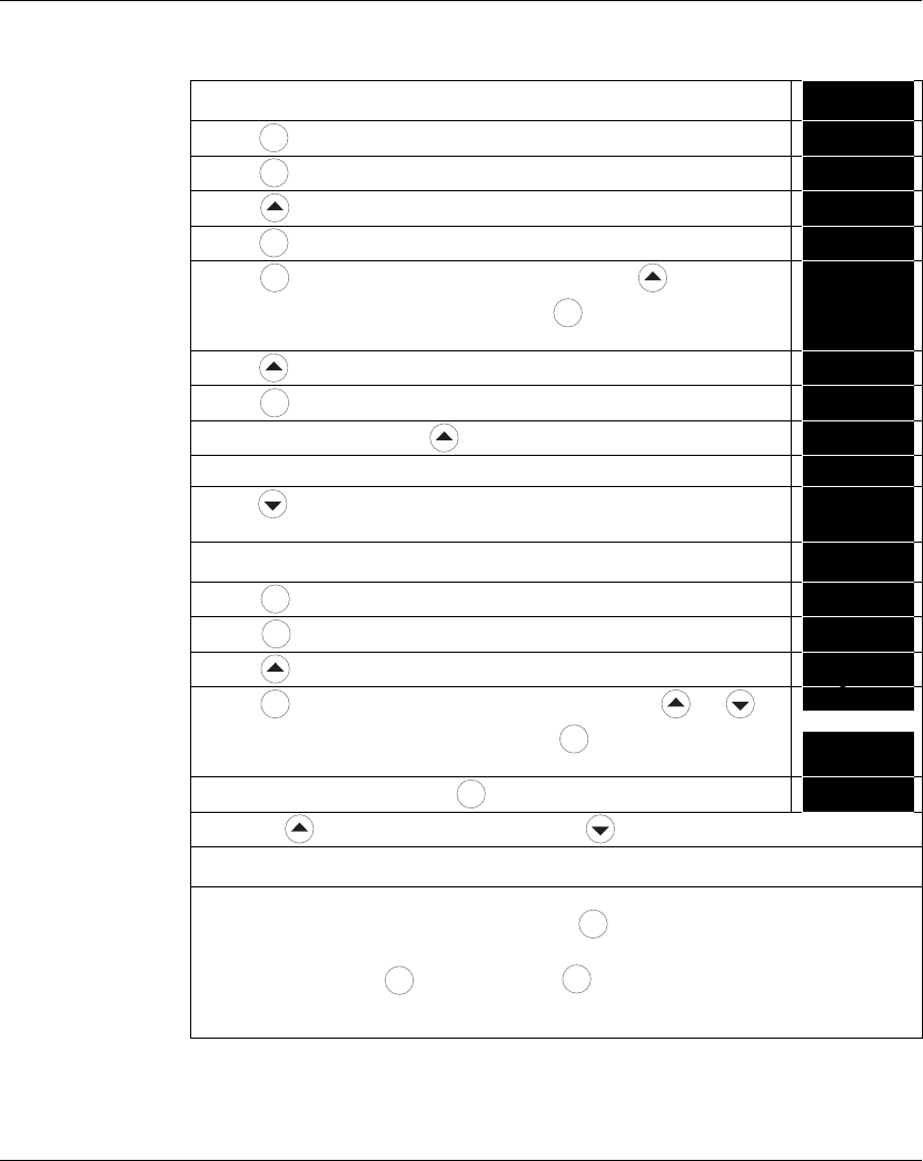
6. Commissioning Lexium 23A
140 AC servo drive
6.5.4.6 Tuning
Procedure
Table 5.A Estimate the ratio of Load Inertia to Servo Motor Inertia (J_load /J_motor):
JOG Mode
1. After wiring is completed, when power in connected to the AC servo drive, the
right side display will show on the LCD display. -71$'
2. Press key to enter into parameter mode. :#!##
3. Press key twice to select parameter group. :%!##
4. Press key to view each parameter and select parameter P2-17. :%!$*
5. Press key to display the parameter value as shown on the right side. %$
6. Press key twice to change the parameter values. Use key to cycle
through the available settings and then press key to determine the
parameter settings.
$%$
7. Press key to view each parameter and select parameter P2-30. :%!&#
8. Press key to display the parameter value as shown on the right side. #
9. Select parameter value 1. Use key to cycle through the available settings. $
10. At this time, the servo drive is ON and the right side display will appear next. #
11. Press key three times to select the ratio of Load Inertia to Servo Motor
Inertia (J_load /J_motor).
67
12. Display the current ratio of Load Inertia to Servo Motor Inertia (J_load /
J_motor). (5.0 is default setting.) (.#
13. Press key to select parameter mode. :%!&#
14. Press key twice to select parameter group. :'!##
15. Press key to select user parameter P4-05. :'!#(
16. Press key and JOG speed 20 rpm will be displayed. Press and key
to increase and decrease JOG speed. To press key one time can add one
digit number.
%#
%##
17.
Select desired JOG speed, press key and it will show the right side display.
!69,!
18. Pressing key is forward rotation and pressing key is reverse rotation.
19. Execute JOG operation in low speed first. After the machine is running smoothly, then execute
JOG operation in high speed.
20. The ratio of Load Inertia to Servo Motor Inertia (J_load /J_motor) cannot be shown in the display
of JOG parameter P4-05 operation. Please press key twice continuously and the users can
see the ratio of Load Inertia to Servo Motor Inertia (J_load /J_motor). Then, execute JOG
operation again, press key once and press key twice to view the display on the keypad.
Check if the value of J_load /J_motor is adjusted to a fixed value and displayed on the keypad
after acceleration and deceleration repeatedly.
M
S
ENT
S
ENT
ENT
M
S
ENT
S
ENT
M
MENT
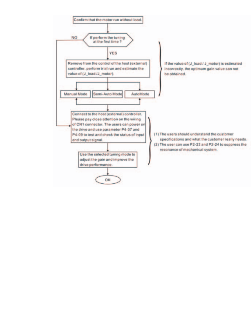
Lexium 23A 6. Commissioning
AC servo drive 141
(1) Tuning Flowchart
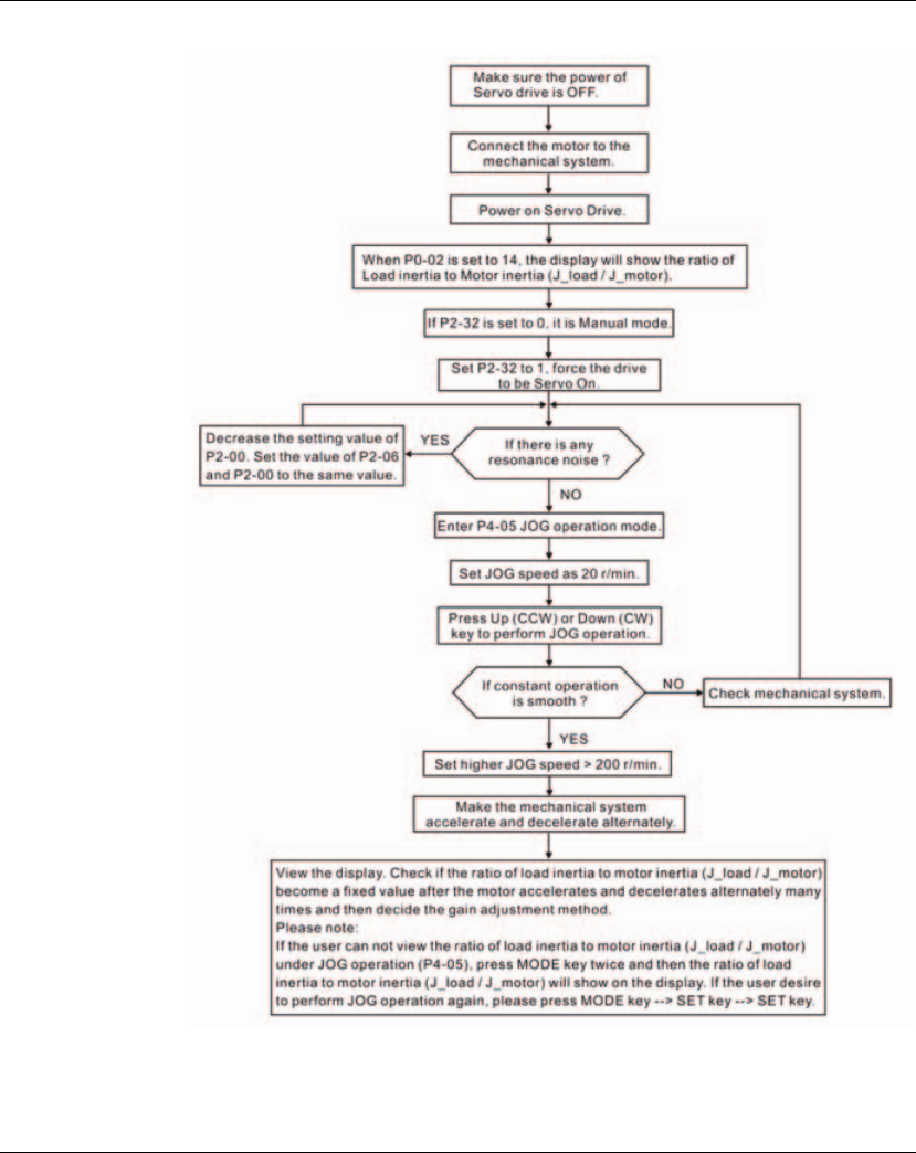
6. Commissioning Lexium 23A
142 AC servo drive
(2) Load Inertia Estimation Flowchart
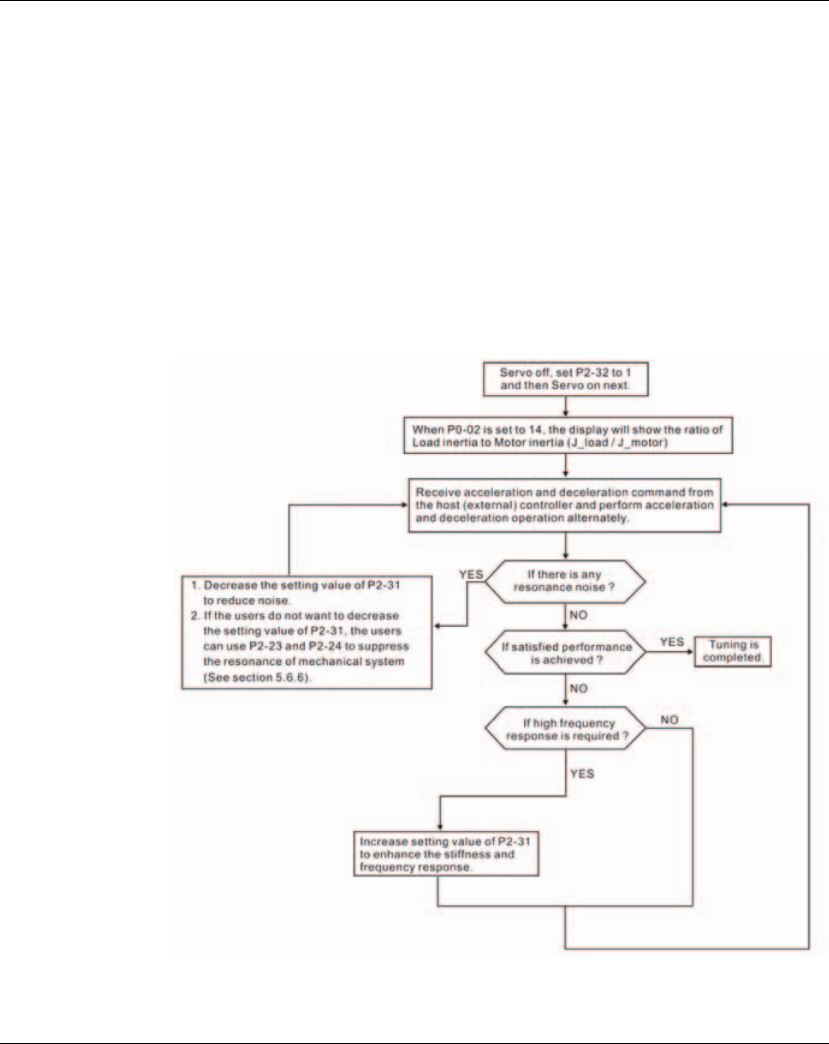
Lexium 23A 6. Commissioning
AC servo drive 143
(3) Auto Mode Tuning Flowchart
Set P2-32 to 1 (1: Auto Mode [Continuous adjustment] )
The servo drive will continuously estimate the system inertia, save the measured load
inertia value automatically and memorized in P1-37 every 30 minutes by referring to
the frequency response settings of P2-31.
P2-31 : Auto Mode Stiffness Setting (Default setting: 80)
In Auto mode and Semi-Auto mode, the speed loop frequency response settings are
as follows:
1 ~ 50Hz : Low stiffness and low frequency response
51 ~ 250Hz : Medium stiffness and medium frequency response
251 ~ 850Hz : High stiffness and high frequency response
851 ~ 1000Hz : Extremely high stiffness and extremely high frequency response
Adjust P2-31: Increase the setting value of P2-31 to enhance the stiffness or reduce
the noise.
Continuously perform the adjustment until the satisfactory performance is achieved.
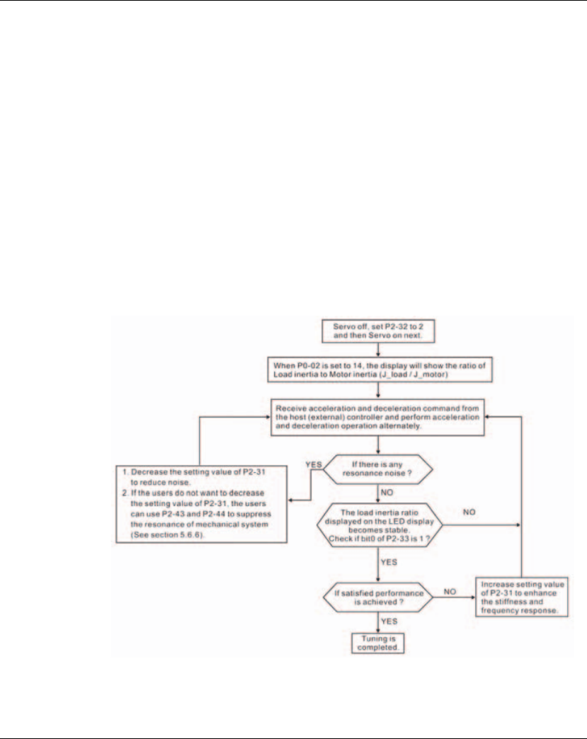
6. Commissioning Lexium 23A
144 AC servo drive
(4) Semi-Auto Mode Tuning Flowchart
Set P2-32 to 2 (2: Semi-Auto Mode [Non-continuous adjustment] )
The servo drive will continuously perform the adjustment for a period of time. After
the system inertia becomes stable, it will stop estimating the system inertia, save the
measured load inertia value automatically, and memorized in P1-37. When switching
from other modes, such as Manual Mode or Auto Mode, to Semi-Auto Mode, the servo
drive will perform continuous adjustment for estimating the load inertia (P1-37)
again. The servo drive will refer to the frequency response settings of P2-31 when
estimating the system inertia.
P2-31 : Auto Mode Stiffness Setting (Default setting: 80)
In Auto mode and Semi-Auto mode, the speed loop frequency response settings are
as follows:
1 ~ 50Hz : Low stiffness and low frequency response
51 ~ 250Hz : Medium stiffness and medium frequency response
251 ~ 850Hz : High stiffness and high frequency response
851 ~ 1000Hz : Extremely high stiffness and extremely high frequency response
Adjust P2-31: Increase the setting value of P2-31 to enhance the frequency response
or reduce the noise.
Continuously perform the adjustment until the satisfactory performance is achieved.
NOTE:
1) When bit0 of P2-33 is set to 1, it indicates that the system inertia estimation of semi-
auto mode has been completed and the measured load inertia value is saved and
memorized in P1-37 automatically.
2) If reset bit0 of P2-33 to 0, it will start estimating the system inertia again.
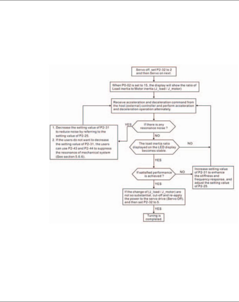
Lexium 23A 6. Commissioning
AC servo drive 145
(5) Limit of Load Inertia Estimation
The accel. / decel. time for reaching 2000 rpm must be below 1 second. The rotation
speed must be above 200 rpm. The load inertia must be 100 multiple or less of motor
inertia. The change of external force and the inertia ratio can not be too much. In Auto
Mode (P2-32 is set to 1), the measured load inertia value will be saved automatically
and memorized in P1-37 every 30 minutes. In Semi-Auto Mode, it will stop estimating
the load inertia after a period of continuous adjustment time when the system inertia
becomes stable. The measured load inertia value will be saved automatically and
memorized in P1-37 when load inertia estimation is stopped.
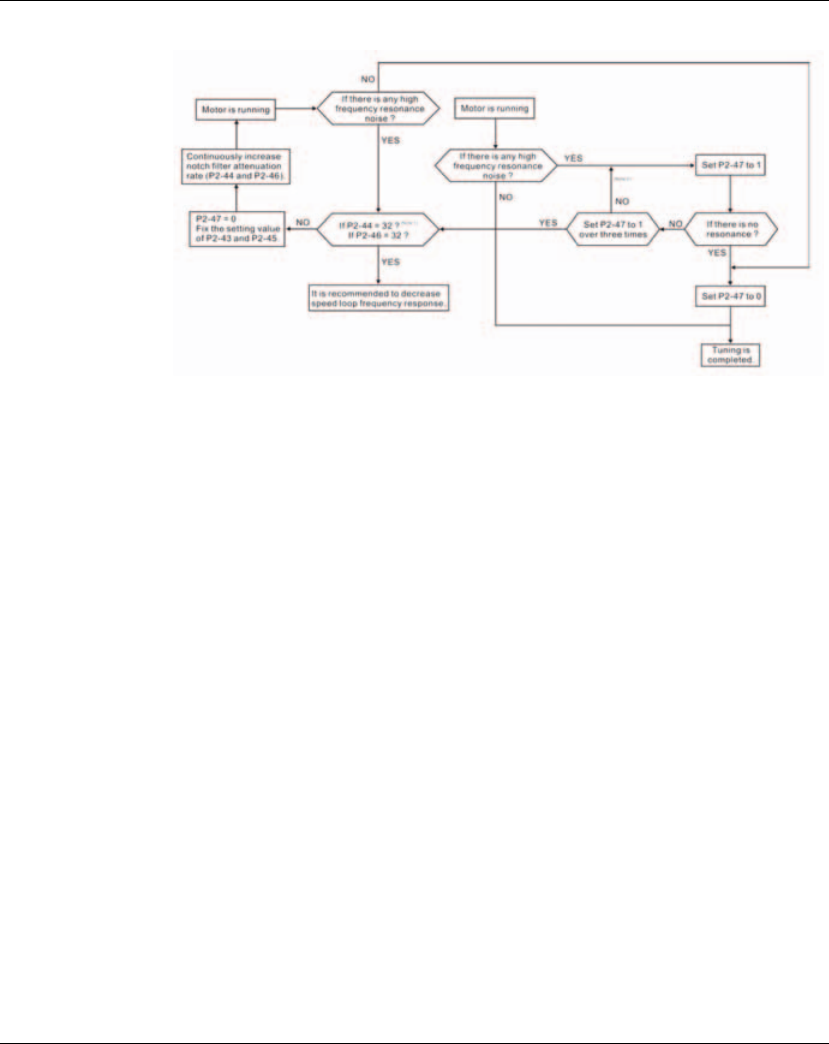
6. Commissioning Lexium 23A
146 AC servo drive
NOTE:
1) Parameters P2-44 and P2-46 are used to set notch filter attenuation rate. If the
resonance can not be suppressed when the setting values of P2-44 and P2-46 are
set to 32bB (the maximum value), please decrease the speed loop frequency
response. After setting P2-47, the users can check the setting values of P2-44 and
P2-46. If the setting value of P2-44 is not 0, it indicates that one resonance
frequency exists in the system and then the users can read P2-43, i.e. the frequency
(unit is Hz) of the resonance point. When there is any resonance point in the
system, its information will be shown in P2-45 and P2-46 as P2-43 and P2-44.
2) If the resonance conditions are not improved when P2-47 is set to 1 for over three
times, please adjust notch filters (resonance suppression parameters) manually to
or eliminate the resonance.
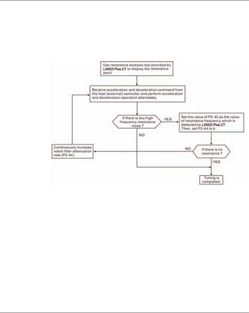
Lexium 23A 6. Commissioning
AC servo drive 147
(6) Mechanical Resonance Suppression Method
In order to suppress the high frequency resonance of the mechanical system,
Lexium23 Plus servo drive provides two notch filters (resonance suppression
parameters) for resonance suppression. This notch filters can be set to suppress the
resonance automatically. If the users do not want to suppress the resonance
automatically, these two notch filter can also be set to or eliminate the resonance
manually.
Please refer to the following flowchart for manual adjustment.

6. Commissioning Lexium 23A
148 AC servo drive
(7) Relationship between Tuning Modes and Parameters
When switching mode #1 to #0, the setting value of P2-00, P2-02, P2-04, P2-06, P2-
25, P2-26 and P2-49 will change to the value that measured in #1 auto-tuning mode.
When switching mode #2 to #0, the setting value of P2-00, P2-02, P2-04, P2-06, P2-
25, P2-26 and P2-49 will change to the value that measured in #2 semi-auto tuning
mode.
Tuning Mode P2-32 AutoSet
Parameter User-defined Parameter Gain Value
Manual Mode
0
(Default
setting)
None
P1-37 (Ratio of Load Inertia to Servo Motor
Inertia [J_load / J_motor])
P2-00 (Proportional Position Loop Gain)
P2-04 (Proportional Speed Loop Gain)
P2-06 (Speed Integral Compensation)
P2-25 (Low-pass Filter Time Constant of
Resonance Suppression)
P2-26 (External Anti-Interference Gain)
Fixed
Auto Mode
[Continuous
Adjustment]
1
P1-37
P2-00
P2-02
P2-04
P2-06
P2-25
P2-26
P2-49
P2-31 (Auto Stiffness and Frequency
response Level)
Continuous
Adjusting
(every 30
minutes)
Semi-Auto Mode
[Non-continuous
Adjustment]
1
P1-37
P2-00
P2-02
P2-04
P2-06
P2-25
P2-26
P2-49
P2-31 (Auto Stiffness and Frequency
response Level)
Non-
continuous
Adjusting
(stop after a
period of
time)
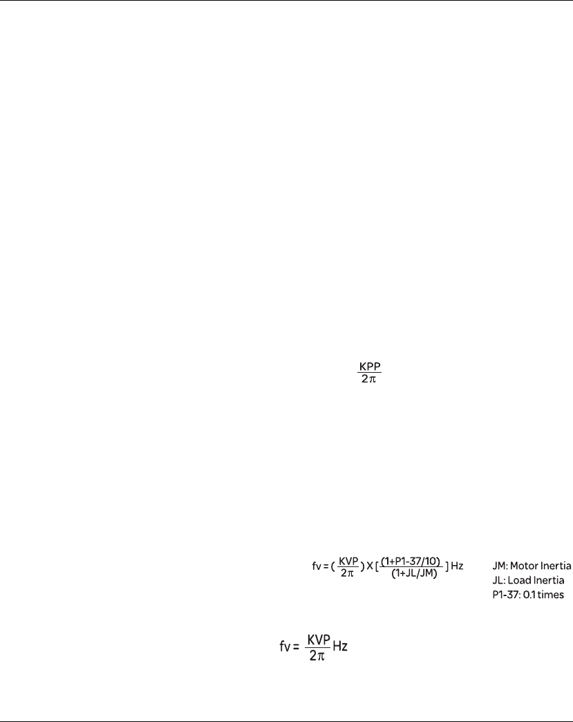
Lexium 23A 6. Commissioning
AC servo drive 149
(8) Gain Adjustment in Manual Mode
The position and speed frequency response selection is depending on and
determined by the the control stiffness of machinery and conditions of applications.
Generally, high reponsiveness is essential for the high frequency positioning control
of mechanical facilities and the applications of high precision process system.
However, the higher frequency response may easily result in the resonance of
machinery system. Therefore, for the applications of high frequency response, the
machinery system with control stiffness is needed to avoid the resonance. Especially
when adjusting the frequency response of unfamiliar machinery system, the users
can gradually increase the gain setting value to improve frequency response untill
the resonance occurs, and then decrease the gain setting value. The relevant
parameters and gain adjusting methods are described as follows:
z KPP, Parameter P2-00 Proportional Position Loop Gain
This parameter is used to determine the frequency response of position loop
(position loop gain). It could be used to increase stiffness, expedite position loop
response and reduce position error.
When the setting value of KPP is higher, the response to the position command is
quicker, the position error is less and the settling time is also shorter. However, if
the setting value is over high, the machinery system may generate vibration or
noise, or even overshoot during positioning. The position loop frequency response
is calculated as follows:
Position Loop Frequency Response (Hz) =
z KVP, Parameter P2-04 Proportional Speed Loop Gain
This parameter is used to determine the frequency response of speed loop (speed
loop gain). It could be used to expedite speed loop response. When the setting
value of KVP is higher, the response to the speed command is quicker. However, if
the setting value is over high, it may result in the resonance of machinery system.
The frequency response of speed loop must be higher than the 4~6 times of the
frequency response of position loop. If frequency response of position loop is
higher than the frequency response of speed loop, the machinery system may
generate vibration or noise, or even overshoot during positioning. The speed loop
frequency response is calculated as follows:
Speed Loop Frequency Response
When the value of P1-37 (no matter it is the measured load inertia value or the set
load inertia value) is equal to the actual load inertia value, the actual speed loop
frequency response will be:
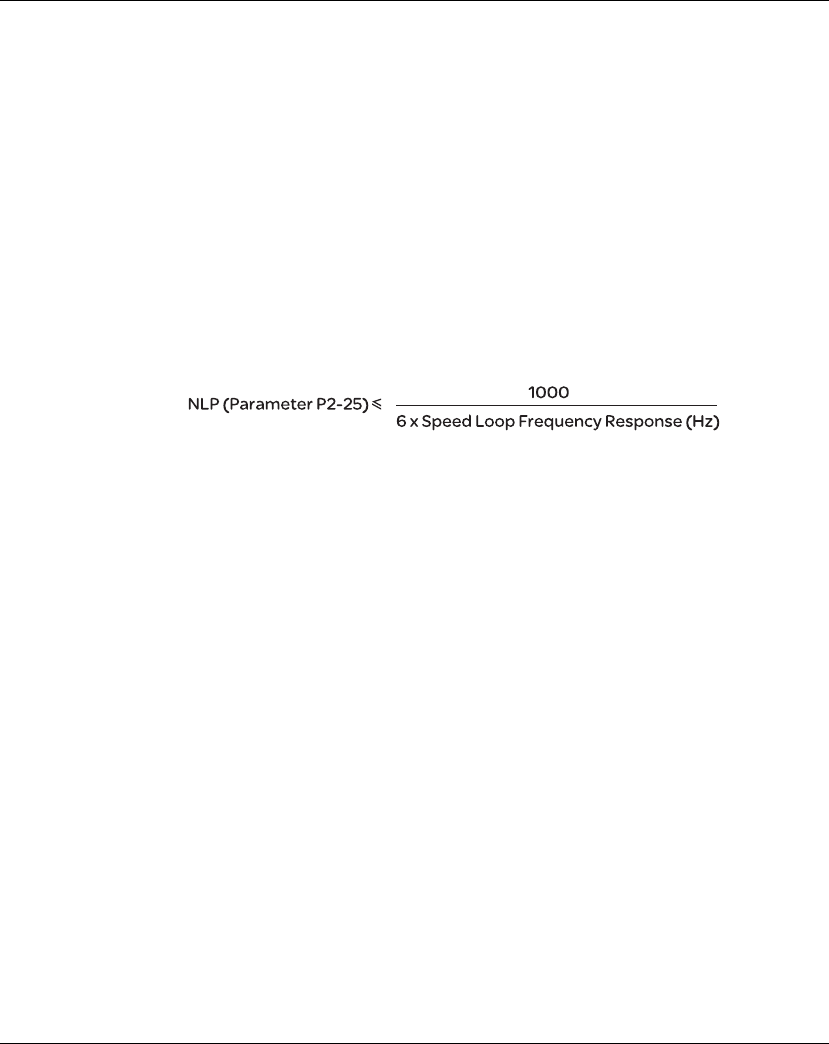
6. Commissioning Lexium 23A
150 AC servo drive
z KVI, Parameter P2-06 Speed Integral Compensation
If the setting value of KVI is higher, the capability of decreasing the speed control
deviation is better. However, if the setting value is over high, it may easily result in
the vibration of machinery system. The recommended setting value is as follows:
KVI (Parameter P2-06) y 1.5 x Speed Loop Frequency Response
z NLP, Parameter P2-25 Low-pass Filter Time Constant of Resonance Suppression
When the value of (J_load / J_motor) is high, the frequency response of speed loop
may decrease. At this time, the users can increase the setting value of KVP (P2-04)
to keep the frequency response of speed loop. However, when increasing the
setting value of KVP (P2-04), it may easily result in the vibration of machinery
system. Please use this parameter to suppress or eliminate the noise of resonance.
If the setting value of NLP is higher, the capability of improving the noise of
resonance is better. However, if the setting value is over high, it may easily lead to
the instability of speed loop and overshoot of machinery system.
The recommended setting value is as follows:
z DST, Parameter P2-26 External Anti-Interference Gain
This parameter is used to enhance the anti-interference capability and reduce the
occurrence of overshoot. The default setting is 0 (Disabled). It is not recommended
to use it in manual mode only when performing a few tuning on the value gotten
through P2-32 Auto Mode.
z PFG, Parameter P2-02 Position Feed Forward Gain
This parameter is used to reduce position error and shorten the positioning settling
time. However, if the setting value is over high, it may easily lead to the overshoot of
machinery system. If the value of electronic gear ratio (P1-44/P1-45) is over than 10,
the machinery system may also easily generate vibration or noise.

AC servo drive 151
7
Operation
At a Glance
What's in this
Chapter? This chapter contains the following topics:
Topic Page
Access channels 152
General Function Operation 153
Control Modes of Operation 156
Other functions 202
7. Operation Lexium 23A
152 AC servo drive
The chapter "Operation" describes the basic operating states, operating modes and
functions of the device.
7.1 Access channels
The product can be addressed via different access channels. Access channels are:
z Integrated HMI
z Commissioning software
z Digital input signals
UNINTENDED BEHAVIOR
The behavior of the drive system is governed by numerous stored data or settings.
Unsuitable settings or data may trigger unexpected movements or responses to
signals and disable monitoring functions.
zDo NOT operate the drive system with unknown settings or data.
zVerify that the stored data and settings are correct.
zWhen commissioning, carefully run tests for all operating states and
potential error situations.
zVerify the functions after replacing the product and also after making
changes to the settings or data.
zOnly start the system if there are no persons or obstructions in the
hazardous area.
Failure to follow these instructions can result in death, serious injury or
equipment damage.
WARNNG
UNEXPECTED BEHAVIOR CAUSED BY UNSUITABLE ACCESS CONTROL
By means of unsuitable use of access channels, for example, commands could be
unintendedly released or locked.
zVerify that incorrect accesses are locked.
zVerify that required accesses are available.
Failure to follow these instructions can result in death, serious injury or
equipment damage.
WARNNG
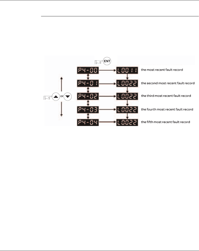
Lexium 23A 7. Operation
AC servo drive 153
7.2 General Function Operation
7.2.1 Fault Code Display Operation
After entering the parameter mode P4-00 to P4-04 (Fault Record), press ENT key to
display the corresponding fault code history for the parameter. Please refer to the Figure 7.1
Figure 7.1
7.2.2 JOG Operation
After entering parameter mode P4-05, the users can follow the following steps to
perform JOG operation. (Please also refer to Figure 7.2).
Step1. Press the ENT key to display the JOG rpm speed. (The default value is 20 rpm).
Step2. Press the UP or DOWN arrow keys to increase or decrease the desired JOG
speed. (This also can be undertaken by using the SHIFT key to move the cursor
to the desired unit column (the effected number will blink) then changed using
the UP and DOWN arrow keys. The example display in Figure 7.2 is adjusted as
100 rpm).
Step3. Press the ENT key when the desired JOG speed is set. The Servo Drive will
display "JOG".
Step4. Press the UP or DOWN arrow keys to jog the motor either N(CW) and P(CCW)
direction. The motor will only rotate while the arrow key is activated.
Step5. To change JOG speed again, press the MODE key. The servo Drive will display
"P4 - 05". Press the ENT key and the JOG rpm speed will displayed again. Refer
back to #2 and #3 to change speed.
NOTE:
1) JOG operation is effective only when Servo On (when the servo drive is enabled).
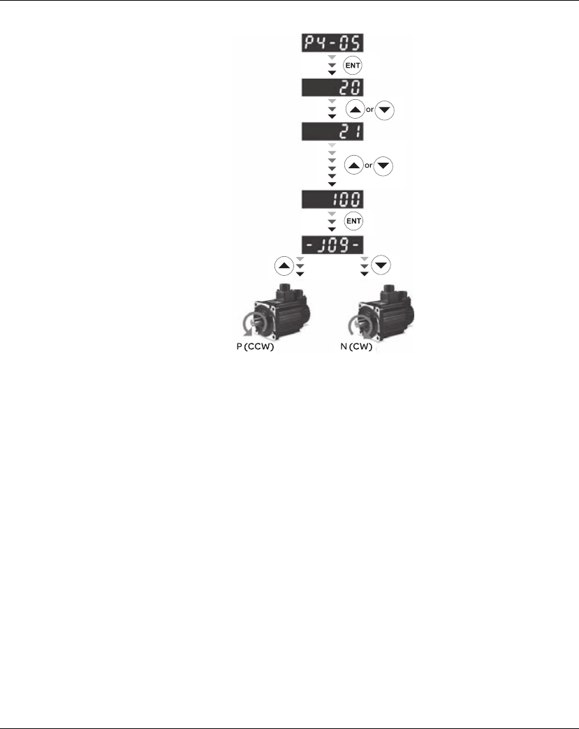
7. Operation Lexium 23A
154 AC servo drive
Figure 7.2
7.2.3 Force Output Control Operation
For testing, the digital outputs can be forced to be activated (ON) or inactivated
(OFF) by using parameter P2-08 and P4-06. First, set P2-08 to 406 to enable the
force output control function and then using P4-06 to force the digital outputs to be
activated. Follow the setting method in Figure 7.3 to enter into Force Output Control
operation mode. When P4-06 is set to 2, the digital output, DO2 is activated. When
P4-06 is set to 5, the digital outputs, DO1 and DO3 are both activated. The parameter
setting value of P4-06 is not retained when power is off. After re-power the servo
drive, all digital outputs will return to the normal status. If P2-08 is set to 400, it also
can switch the Force Output Control operation mode to normal Digital Output (DO)
Control operation mode.
The DO function and status is determined by P2-18 to P2-22. This function is enabled
only when Servo Off (the servo drive is disabled).
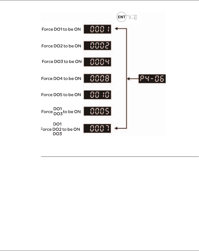
Lexium 23A 7. Operation
AC servo drive 155
Figure 7.3
NOTE: As the display of P4-06 is hexadecimal, 0(zero) of the fifth digit will not show
on the LED display.

7. Operation Lexium 23A
156 AC servo drive
7.3. Control Modes of Operation
7.3.1 Control Modes of Operation
The Lexium23 Plus series can be programmed to provide six single, eight dual modes
and two multiple modes of operation. Their operation and description is listed in the
following table.
Mode Mode Code Description
Single
Mode
External Position
Control Pt 00 Position control for the servo motor is achieved via an
external pulse command.
Internal Position
Control Pr 01
Position control for the servo motor is achieved via by
internal position commands stored within the servo
controller. Execution of the 8 positions is via Digital Input
(DI) signals.
Speed Control S 02
Speed control for the servo motor can be achieved via
parameters set within the controller or from an external
analog -10 ~ +10 Vdc command. Control of the internal
speed parameters is via the Digital Inputs (DI). (A
maximum of three speeds can be stored internally).
Internal Speed
Control Sz 04
Speed control for the servo motor is only achieved via
parameters set within the controller. Control of the
internal speed parameters is via the Digital Inputs (DI).
(A maximum of three speeds can be stored internally).
Torque Control T 03
Torque control for the servo motor can be achieved via
parameters set within the controller or from an external
analog -10 ~ +10 Vdc command. Control of the internal
torque parameters is via the Digital Inputs (DI). (A
maximum of three torque levels can be stored
internally).
Internal Torque
Control Tz 05
Torque control for the servo motor is only achieved via
parameters set within the controller. Control of the
internal torque parameters is via the Digital Inputs (DI).
(A maximum of three torque levels can be stored
internally).
Dual Mode
Pt-S 06 Either Pt or S control mode can be selected via the Digital
Inputs (DI)
Pt-T 07 Either Pt or T control mode can be selected via the Digital
Inputs (DI).
Pr-S 08 Either Pr or S control mode can be selected via the Digital
Inputs (DI).
Pr-T 09 Either Pr or T control mode can be selected via the Digital
Inputs (DI).
S-T 0A Either S or T control mode can be selected via the Digital
Inputs (DI).

Lexium 23A 7. Operation
AC servo drive 157
The steps of changing mode:
(1) Switching the servo drive to Servo Off status. Turning SON signal of digit input to
be off can completethis action.
(2) Using parameter P1-01. (Refer to chapter 11).
(3) After the setting is completed, cut the power off and restart the drive again.
The following sections describe the operation of each control mode, including control
structure, command source and loop gain adjustment, etc.
7.3.2 Position Control Mode
The position control mode (Pt or Pr mode) is usually used for the applications
requiring precision positioning, such as industry positioning machine, indexing table
etc. Lexium23 Plus series servo drives support two kinds of command sources in
position control mode. One is an external pulse train (Pt: Position Terminals,
External Position Control) and the other is internal parameter (Pr: Position Register,
i.e. internal parameters P6-00 to P6-17, Internal Position Control). The external pulse
train with direction which can control the rotation angle of servo motor. The max.
input frequency for the external pulse command is 4MKpps.
In order to provide a convenient position control function, Lexium23 Plus servo drive
provides 8 internal preset parameters for position control. There are two setting
methods of internal parameters, one is to set different position command into these
8 internal parameters before operation and then use POS0~POS2 of DI signals of CN1
to perform positioning control. The other setting method is to use serial
communication to change the setting value of these eight internal parameters.
To make the servo motor and load operate more smoothly, Lexium23 Plus servo drive
also provide complete Position Spine Line (P-curve) profile for position control mode.
For the closed-loop positioning, speed control loop is the principal part and the
auxiliary parameters are position loop gain and feed forward compensation. The
users can also select two kinds of tuning mode (Manual/Auto modes) to perform gain
adjustment. This Section 7.3.2 mainly describes the applicability of loop gain
adjustment and feed forward compensation of Lexium23 Plus servo system.
Mode Mode Code Description
canopen
0B CAN communication control is achieved via the
commands from the host (external) controller.
Reserved
0C Reserved
Multiple Mode
Pt-Pr 0D Either Pt or Pr control mode can be selected via the
Digital Inputs (DI).
Pt-Pr-S 0E Either Pt or Pr or S control mode can be selected via the
Digital Inputs (DI).
Pt-Pr-T 0F Either Pt or Pr or T control mode can be selected via the
Digital Inputs (DI).
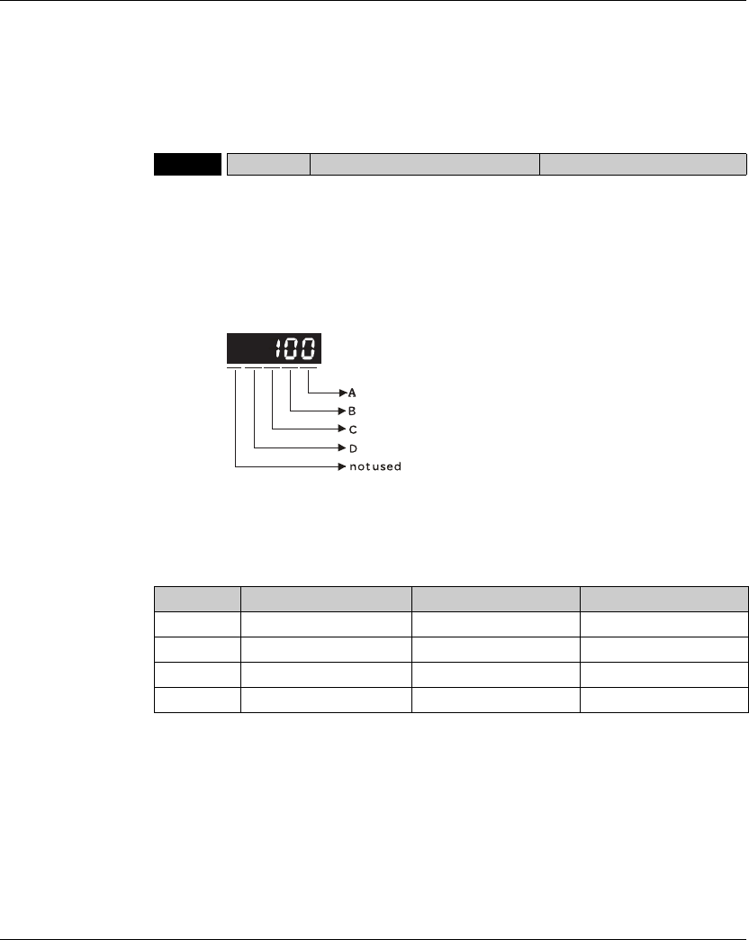
7. Operation Lexium 23A
158 AC servo drive
7.3.2.1 Command
Source of Position
(Pt) Control Mode
The command source of P mode is external pulse train input form terminals. There
are three types of pulse input and each pulse type is with logic type (positive (+),
negative (-)). They all can be set in parameter P1-00. Please refer to the following
relevant parameters:
Relevant Parameter:
B: Input pulse filter
This setting is used to suppress or reduce the chatter caused by the noise, etc.
However, if the instant input pulse filter frequency is over high, the frequency that
exceeds the setting value will be regarded as noise and filtered.
P1-00rPTT External Pulse Input Type Address: 0100H, 0101H
Default: 0x2 Related Section:
Applicable Control Mode: Pt Section 7.3.2.1
Unit: N/A
Range: 0 ~ 1132
Data Size: 16-bit
Display Format: Hexadecimal
Settings:
A: Input pulse type
0: AB phase pulse (4x)
(Quadrature Input)
1: Clockwise (CW) +
Counterclockwise(CCW) pulse
2: Pulse + Direction
BLow Filter Setting Value High Filter
0 1.66Mpps 0 6.66Mpps
1 416Kpps 1 1.66Mpps
2 208Kpps 2 833Kpps
3 104Kpps 3 416Kpps
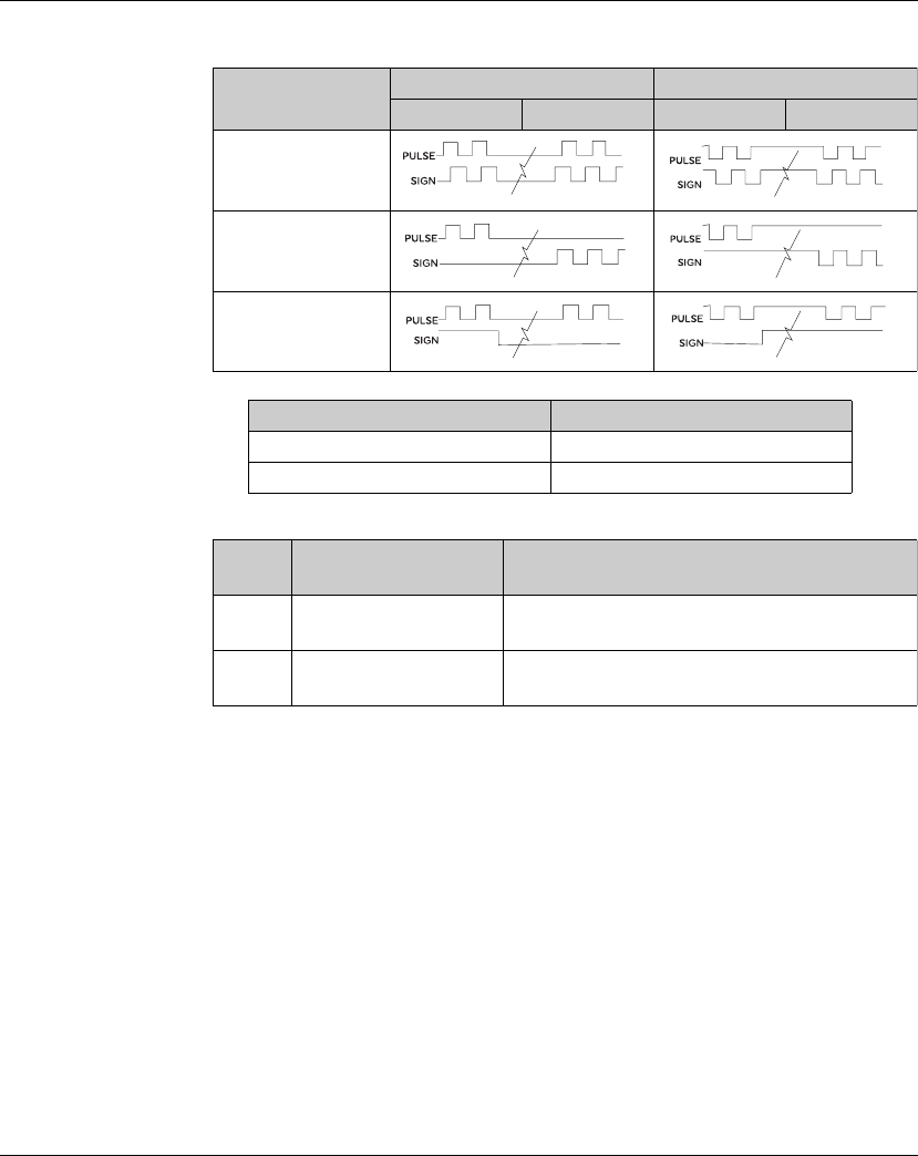
Lexium 23A 7. Operation
AC servo drive 159
C: Input polarity
Position pulse can be input from these terminals, PULSE (43), /PULSE (41), HPULSE
(38), /HPULSE (29), SIGN (36), /SIGN (37) and HSIGN (46), /HSIGN (40). It can be an
open-collector circuit or line driver circuit. For the detail wiring, please refer to 5.3.1.
D: Source of pulse command
Note: The source of pulse command can also be determined by digital input, PTCMS. When the
digital input function is used, the source of pulse command is from digital input.
Pulse Type 0=Positive Logic 1=Negative Logic
Forward Reverse Forward Reverse
AB phase pulse
(Quadrature)
CW + CCW pulse
Pulse + Direction
Input pulse interface Max. input pulse frequency
Line driver/Line receiver 500Kpps/4Mpps
Open collector 200Kpps
Setting
value
Input pulse interface Remark
0 Low-speed pulse CN1 Terminal Identification:
PULSE, SIGN
1 High-speed puls CN1 Terminal Identification:
HPULSE, HSIGN
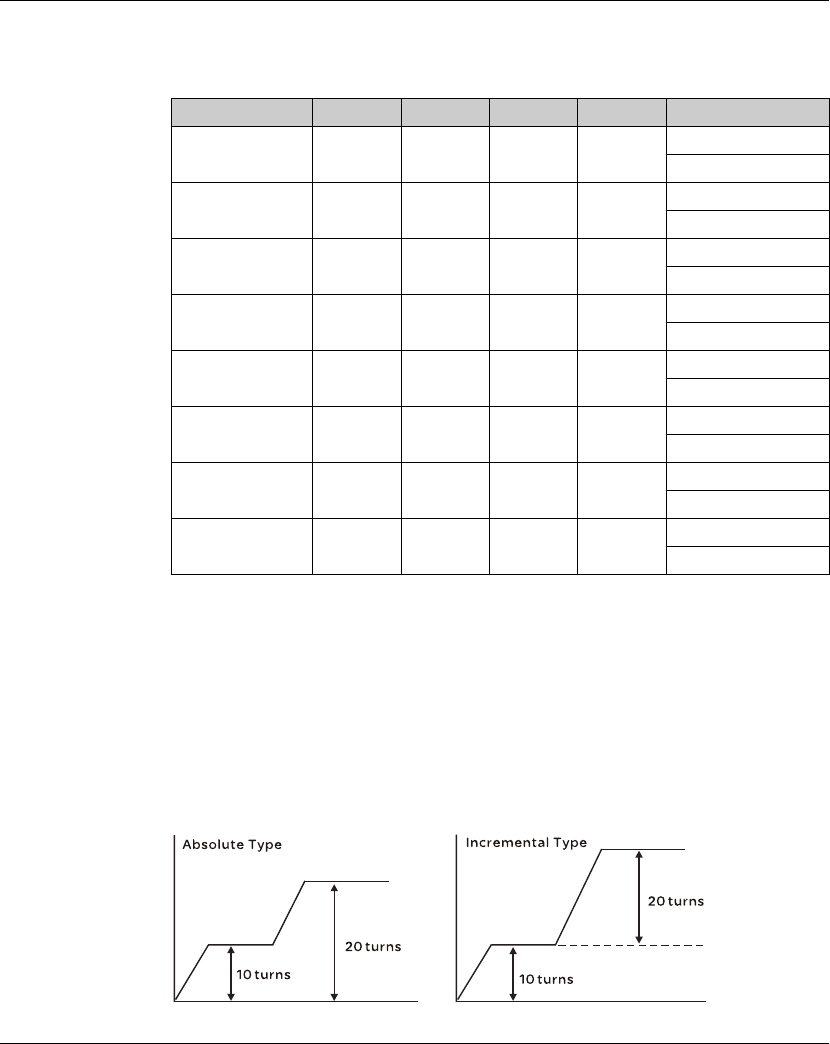
7. Operation Lexium 23A
160 AC servo drive
7.3.2.2 Command
Source of Position
(Pr) Control Mode
The command sources of Pr mode are (P6-00, P6-01) ~ (P6-16, P6-17) these 8 built-in
parameters. Using with external I/O signals (CN1, POS 0 to POS 5 and CTRG) can select one
of the 8 built-in parameters to be position command. Please refer to the table below:
State of POS0~5: 0 indicates the contact is OFF (Normally Open)
1 indicates the contact is ON (Normally Closed)
CTRGA: the instant time when the contact changes from 0 (open) to 1 (closed).
The application of absolute and incremental position control is various and multiple.
This kind of position control is equal to a simple sequence control. Users can easily
complete the cycle running by using the above table. For example, the position
command, P1 is 10 turns and P2 is 20 turns. Give the position command P1 first and
then give the position command P2. The difference between absolute and
incremental position control is shown as the figure below:
Position Command POS2 POS1 POS0 CTRG Parameters
P1 0 0 0
K
P6-02
P6-03
P2 0 0 1
K
P6-04
P6-05
P3 0 1 0
K
P6-06
P6-07
P4 0 1 1
K
P6-08
P6-09
P5 1 0 0
K
P6-10
P6-11
P6 1 0 1
K
P6-12
P6-13
P7 1 1 0
K
P6-14
P6-15
P8 1 1 1
K
P6-16
P6-17
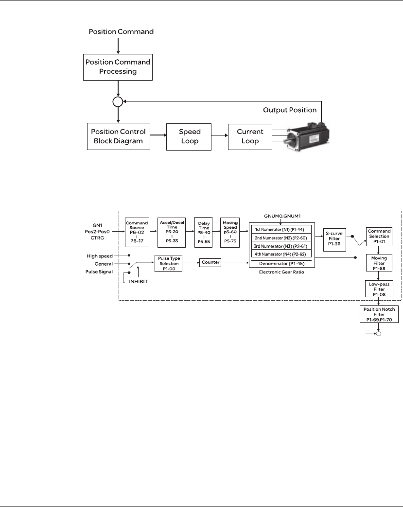
Lexium 23A 7. Operation
AC servo drive 161
7.3.2.3 Structure
of Position Control
Mode
Basic Structure:
In order to pursue the goal of perfection in position control, the pulse signal should be
modified through position command processing and the structure is shown as the
figure below:
Lexium23 Plus Series:
Using parameter can select Pr mode and Pt mode. Electronic gear ratio can be set
in both two modes to set proper position revolution. Lexium23 Plus series servo
drives also provide S-curve and low-pass filter, which are used whenever the
motor and load need to be operated more smoothly. As for the information of
electronic gear ratio, S-curve and low-pass filter, please refer to the following
sections 7.3.2.4, 7.3.2.5 and 7.3.2.6.
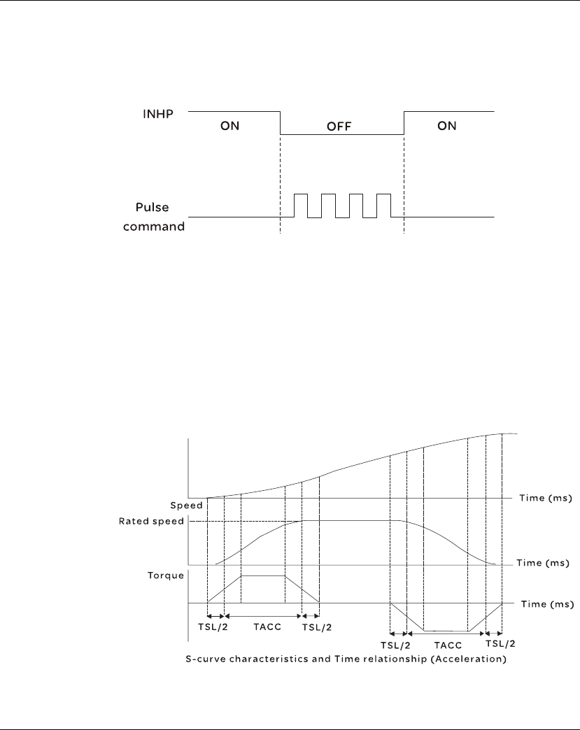
7. Operation Lexium 23A
162 AC servo drive
Pulse Inhibit Input Function (INHIBIT)
This function is activated via digital inputs (Please refer to parameter P2-10 ~ P2-17
and DI INHP in Table 11.A).When the drive is in position mode, if INHP is activated, the
external pulse input command is not valid and the motor will stop (Please note that
only DI8 supports this function).
7.3.2.4 S-curve
Filter for Position
Control
The S-curve filter is for the position smoothing of motion command. Using S-curve filter
can run the servo motor more smoothly in response to a sudden position command.
Since the speed and acceleration curve are both continuous and the time for the servo
motor to accelerate is short, using Scurve filter not only can improve the performance
when servo motor accelerate or decelerate but also can make motor to operate more
smoothly (from mechanical view). When the load is change, the motor usually run not
smoothly when starts to run and stop due to the friction and inertia change. At this
moment, users can increase Accel/Decel S-curve constant (TSL), Accel time constant
(TACC) and Decel time constant (TDEC) to improve the performance. Because the
speed and angle acceleration are continuous when position command is changed to
pulse signal input, so it is not needed to use Scurve filter.
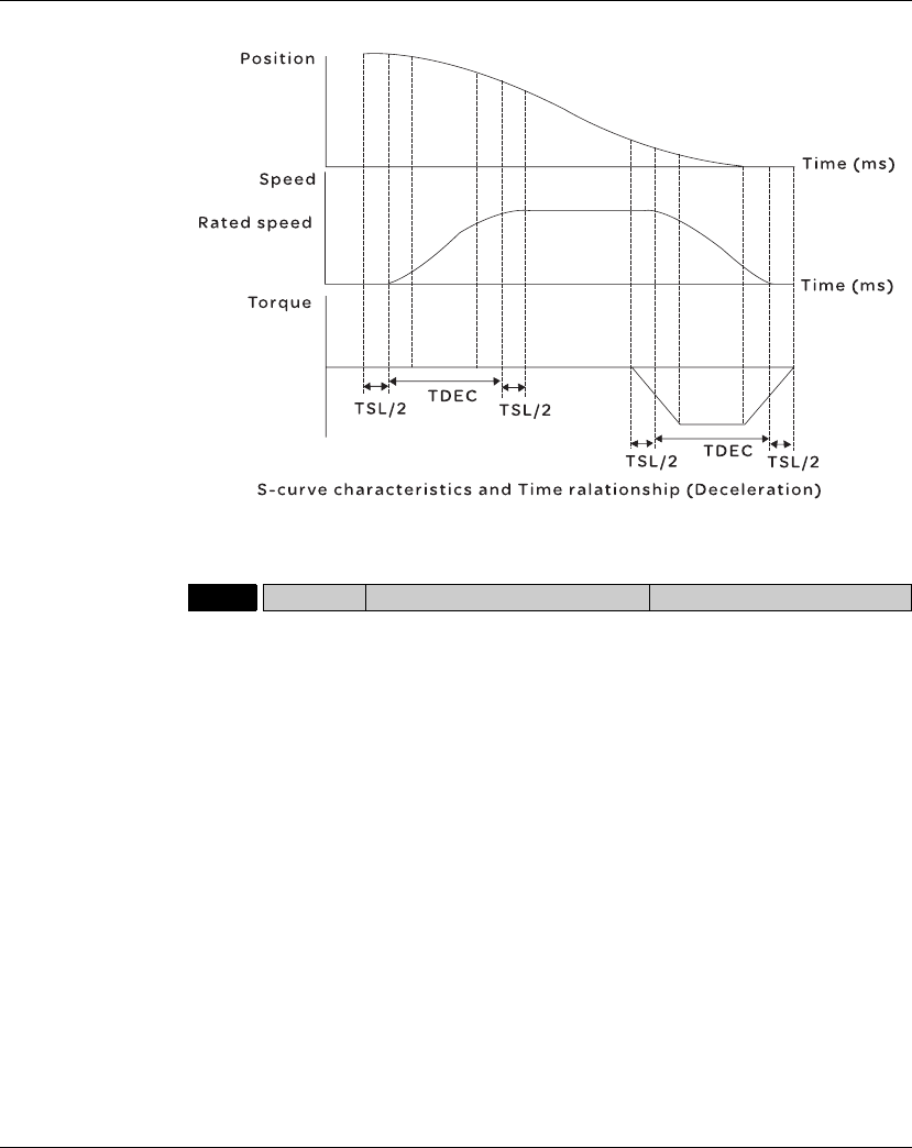
Lexium 23A 7. Operation
AC servo drive 163
Relevant Parameters:
P1-34 TACC Acceleration Time Address: 0144H, 0145H
Default: 200 Related Section:
Applicable Control Mode: S Section 7.3.3.3
Unit: msec
Range: 1 ~ 65500
Data Size: 16-bit
Display Format: Decimal
Settings:
This parameter is used to determine the acceleration time to accelerate from 0 to its
rated motor speed. The functions of parameters P1-34, P1-35 and P1-36 are each
individual. When P1-36 is set to 0 (Disabled), the settings of P1-34, P1-35 are still
effective. It indicates that the parameters P1-34 and P1-35 will not become disabled
even when P1-36 is disabled.
Please note:
1) When the source of speed command is analog command, the maximum setting
value of P1-36 is set to 0, the acceleration and deceleration function will be
disabled.
2) When the source of speed command is analog command, the maximum setting
value of P1-34 is limited to 20000 automatically.
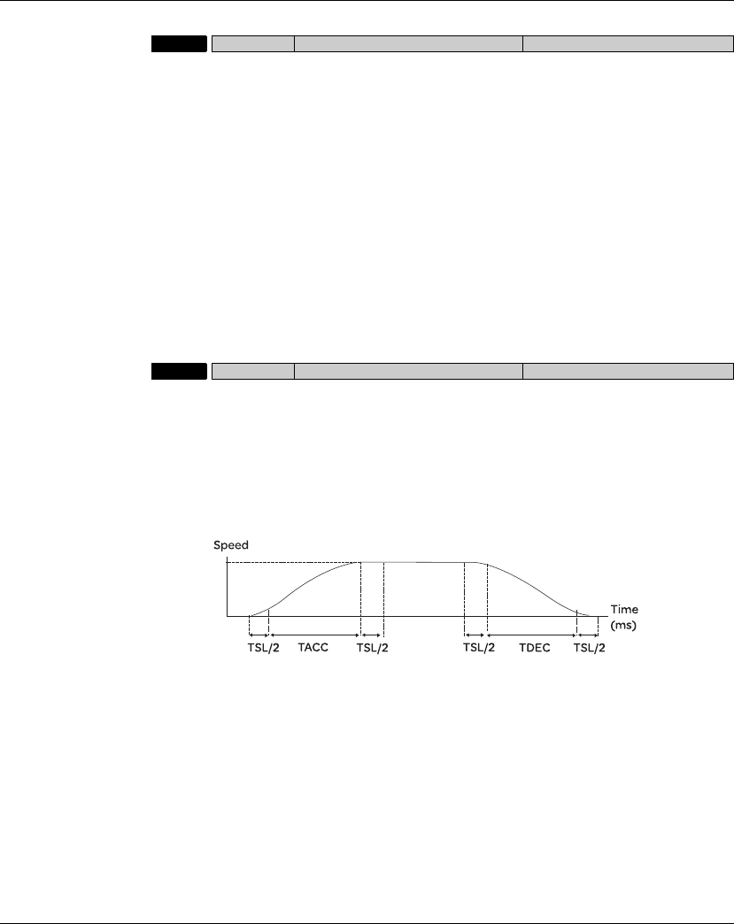
7. Operation Lexium 23A
164 AC servo drive
P1-35 TDEC Deceleration Time Address: 0146H, 0147H
Default: 200 Related Section:
Applicable Control Mode: S Section 7.3.3.3
Unit: msec
Range: 1 ~ 65500
Data Size: 16-bit
Display Format: Decimal
Settings:
This parameter is used to determine the acceleration time to accelerate from 0 to its
rated motor speed. The functions of parameters P1-34, P1-35 and P1-36 are each
individual. When P1-36 is set to 0 (Disabled), the settings of P1-34, P1-35 are still
effective. It indicates that the parameters P1-34 and P1-35 will not become disabled
even when P1-36 is disabled.
Please note:
1 When the source of speed command is analog command, the maximum setting value of
P1-36 is set to 0, the acceleration and deceleration function will be disabled.
2 When the source of speed command is analog command, the maximum setting
value of P1-35 is limited to 20000 automatically.
P1-36 TSL Accel /Decel S-curve Communication Addr.: 0124H
Default: 0 Related Section:
Unit: msec Section 7.3.3.3
Applicable Control Mode: S, Pr
Unit: msec
Range: 0 ~ 65500 (0: Disabled)
Data Size: 16-bit
Display Format: Decimal
Settings:
This parameter is used to make the motor run more smoothly when startup and windup.
Using this parameter can improve the motor running stability.
TACC: P1-34, Acceleration time
TDEC: P1-35, Deceleration time
TSL: P1-36, Accel /Decel S-curve
Total acceleration time = TACC + TSL
Total deceleration time = TDEC + TSL
The functions of parameters P1-34, P1-35 and P1-36 are each individual. When P1-36 is set
to 0 (Disabled), the settings of P1-34, P1-35 are still effective. It indicates that the
parameters P1-34 and P1-35 will not become disabled even when P1-36 is disabled.
Please note:
1 When the source of speed command is analog command, the maximum setting value of
P1-36 is set to 0, the acceleration and deceleration function will be disabled.
2 When the source of speed command is analog command, the maximum setting
value of P1-36 is limited to 10000 automatically.
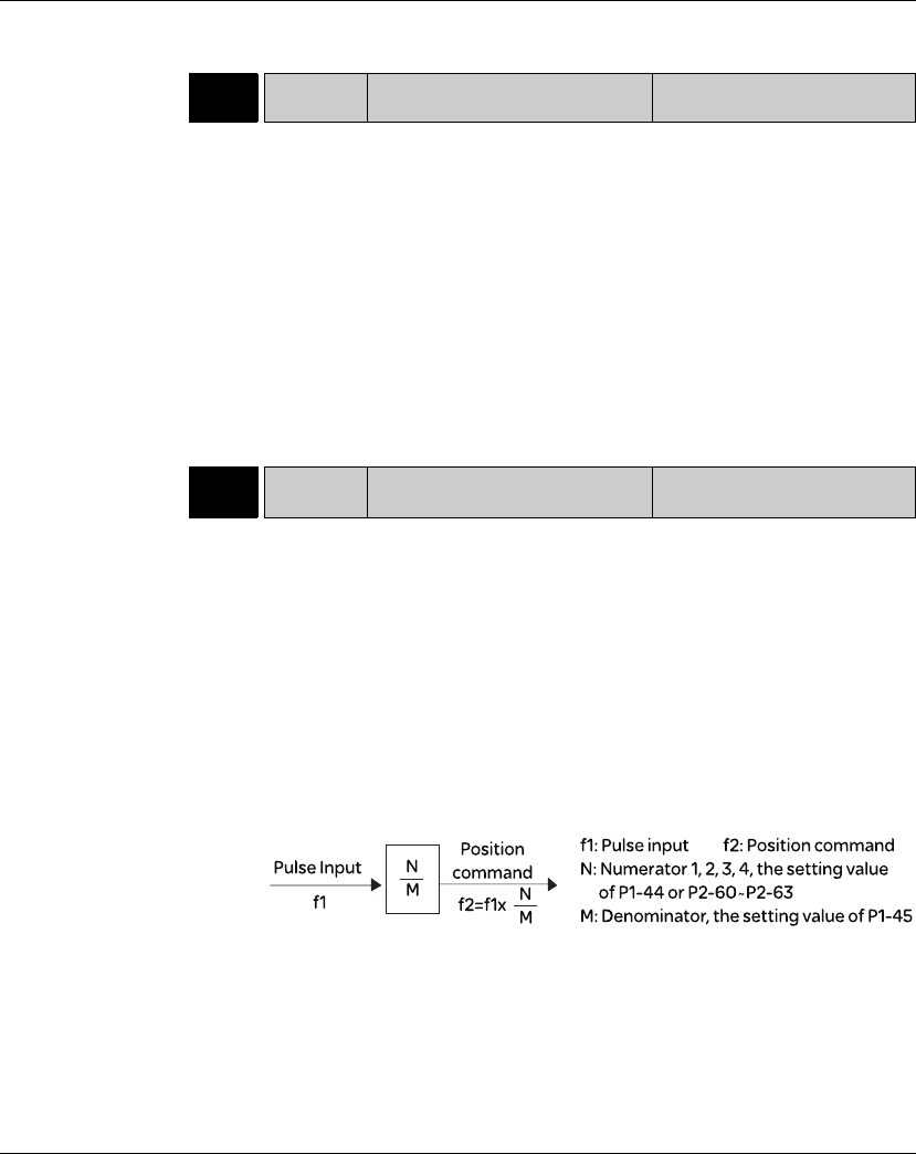
Lexium 23A 7. Operation
AC servo drive 165
7.3.2.5 Electronic
Gear Ratio Relevant parameters:
P1-44rGR1 Electronic Gear Ratio (1st
Numerator) (N1) Address: 0158H, 0159H
Default: 128 Related Section:
Applicable Control Mode: Pt, Pr Section 7.3.2.5
Unit: pulse
Range: 1 ~ (229-1)
Data Size: 32-bit
Display Format: Decimal
Settings:
This parameter is used to set the numerator of the electronic gear ratio. The
denominator of the electronic gear ratio is set by P1-45. P2-60 ~ P2-62 are used to
set the additional numberators. Please note:
1 In Pt mode, the setting value of P1-44 can be changed only when the servo drive is
enabled (Servo On).
2 In Pr mode, the setting value of P1-44 can be changed only when the servo drive is
disabled (Servo Off).
P1-45rGR2 Electronic Gear Ratio
(Denominator) (M) Address: 015AH, 015BH
Default: 10 Related Section:
Applicable Control Mode: Pt, Pr Section 7.3.3.6
Unit: pulse
Range: 1 ~ (231-1)
Data Size: 32-bit
Display Format: Decimal
Settings:
This parameter is used to set the denominator of the electronic gear ratio. The
numerator of the electronic gear ratio is set by P1-44. P2-60 ~ P2-62 are used to set
the additional numberators.
As the wrong setting may cause motor to run chaotically (out of control) and it may lead
to personnel injury, therefore, ensure to observe the following rule when setting P1-44,
P1-45. The electronic gear ratio setting (Please also see P1-44, P2-60 ~ P2-62):
The electronic gear ratio setting range must be within: 1/50<N/M<25600.
Please note:
1 In Pt and Pr mode, the setting value of P1-45 can not be changed when the servo
drive is enabled (Servo On).
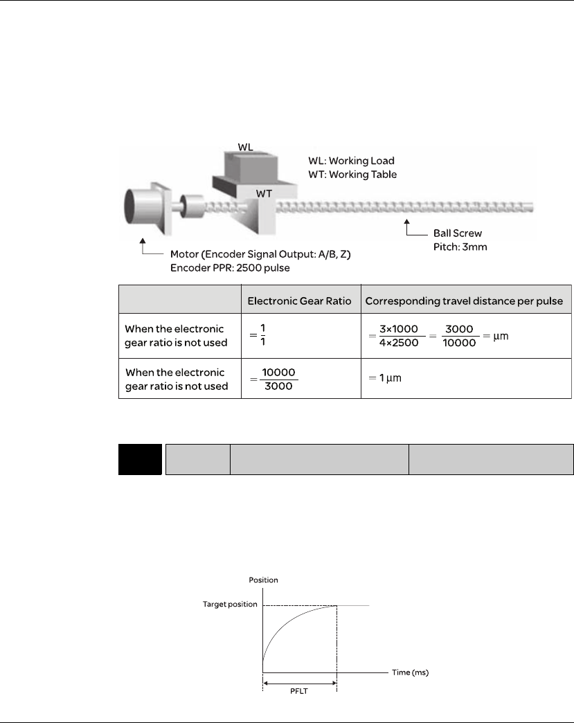
7. Operation Lexium 23A
166 AC servo drive
The electronic gear function provides easy travel distance ratio change. However, the
over high electronic gear ratio will command the motor to move not smoothly. At this
time, the users can use low-pass filter parameter to improve this kind of situation. For
example, assume that the electronic gear ratio is equal to 1 and the encoder pulse per
revolution is 10000ppr, if the electronic gear ratio is changed to 0.5, then the motor
will rotate one pulse when the command from external controller is two pulses.
For example, after the proper electronic gear ratio is set, the reference travel
distance is 1μ m/pulse, the machinery will become easier to be used.
7.3.2.6 Low-pass
Filter
Relevant parameters:
P1-08 PFLT Smooth Constant of Position
Command (Low-pass Filter) Address: 0110H, 0111H
Default: 0 Related Section:
Applicable Control Mode: Pt/Pr Section 7.3.2.6
Unit: 10msec
Range: 0 ~ 1000 (0: Disabled)
Data Size: 16-bit
Display Format: Decimal
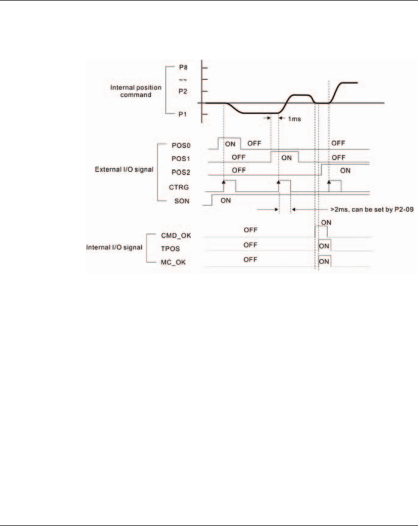
Lexium 23A 7. Operation
AC servo drive 167
7.3.2.7 Timing
Chart of Position
(Pr) Control Mode
In Pr mode, position command source is DI signal from CN1, i.e. selected by
POS0~POS2 and CTRG.
Please refer to 7.3.2.2 to see the relationship between DI signals and parameters. The
following figure is shown the timing chart of Pr mode:
CMD_OK:CMD_OK is activated when the servo drive has detected that Pr command
has been completed
TPOS:TPOS will be activated when the drive detects that the position of the motor is
in a -P1-54 to +P1-54 band of the target position.
MC OK:MC OK is activated when CMD OK and TPOS are both ON.
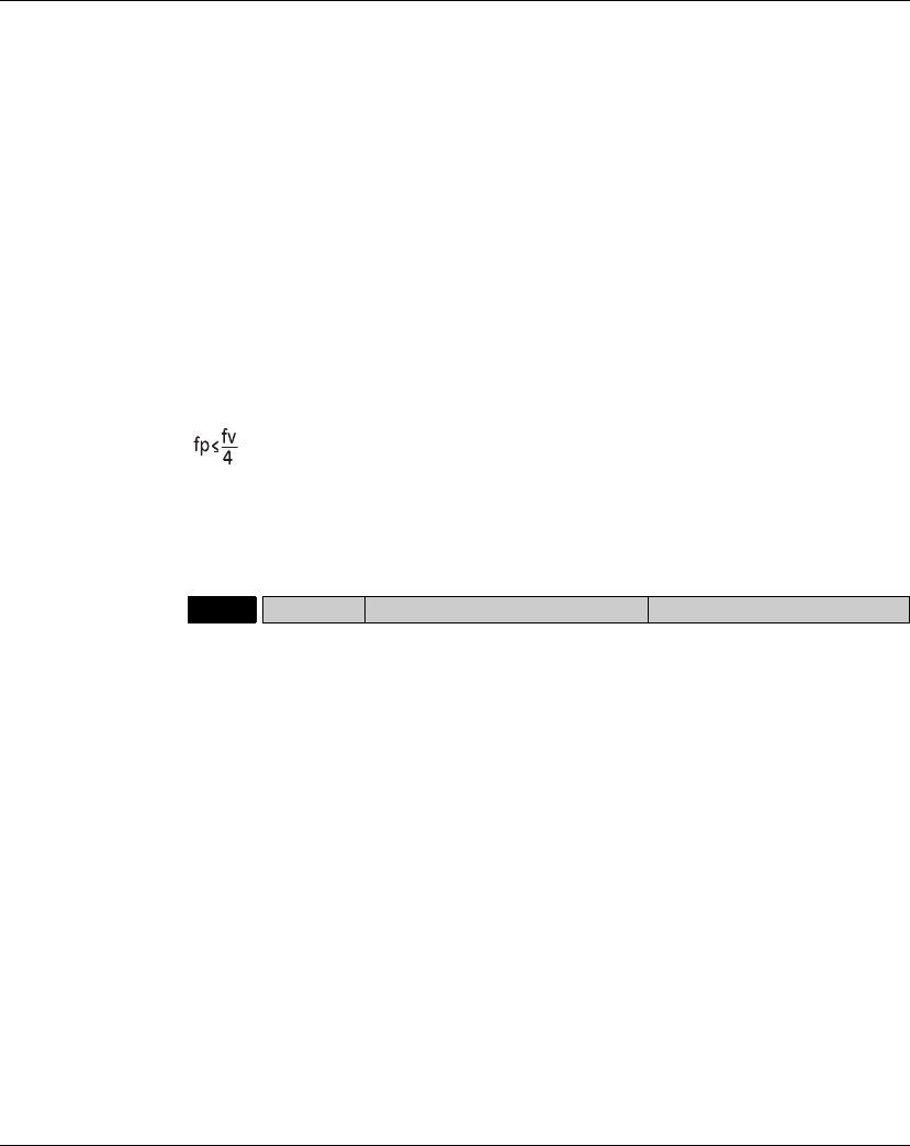
7. Operation Lexium 23A
168 AC servo drive
7.3.2.8 Position
Loop Gain
Adjustment
Before performing position control (setting position control block diagram), the
users should complete the speed control setting by using Manual mode (parameter
P-32) since the position loop contains speed loop. Then, adjust the Proportional
Position Loop Gain, KPP (parameter P2-00) and Position Feed Forward Gain, PFG
(parameter P2-02). Or use Auto mode to adjust the gain of speed and position control
block diagram automatically.
1) Proportional Position Loop Gain: To increase this gain can enhance the position
loop responsiveness.
2) Position Feed Forward Gain: To increase this gain can reduce the position track
error during operation.
The position loop responsiveness cannot exceed the speed loop responsiveness, and
it is recommended that the speed loop responsiveness should be at least four times
faster than the position loop responsiveness. This also means that the setting value
of Proportional Speed Loop Gain, KVP should be at least four times faster than
Proportional Position Loop Gain, KPP.
The equation is shown as follows:
, fv : Speed Loop Responsiveness (Hz), fp : Position Loop Responsiveness (Hz)
KPP = 2 x π x fp.
For example, the desired position loop responsiveness is equal to 20 Hz.
Then, KPP = 2 x π x 20= 125 rad/s.
Relevant parameters:
P2-00 KPP Proportional Position Loop Gain Address: 0200H, 0201H
Default: 35 Related Section:
Applicable Control Mode: Pt, Pr Section 7.3.2.8
Unit: rad/s
Range: 0 ~ 2047
Data Size: 16-bit
Display Format: Decimal
Settings:
This parameter is used to set the position loop gain. It can increase stiffness,
expedite position loop response and reduce position error. However, if the setting
value is over high, it may generate vibration or noise.
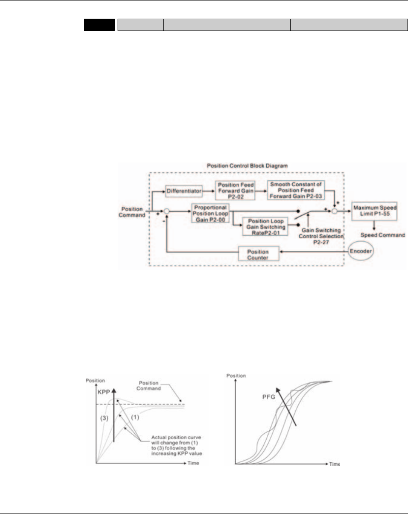
Lexium 23A 7. Operation
AC servo drive 169
When the value of Proportional Position Loop Gain, KPP is too great, the position loop
responsiveness will be increased and it will result in small phase margin. If this
happens, the rotor of motor will oscillate.
At this time, the users have to decrease the value of KPP until the rotor of motor stop
oscillating. When there is an external torque command interrupted, over low KPP
value will let the motor cannot overcome the external strength and fail to meet the
requirement of reasonable position track error demand. Adjust feed forward gain,
PFG (P2-02) to efficiently reduce the dynamic position track error.
P2-02 PFG Position Feed Forward Gain Address: 0204H, 0205H
Default: 50 Related Section:
Applicable Control Mode: Pt, Pr Section 7.3.2.8
Unit: %
Range: 0 ~ 100
Data Size: 16-bit
Display Format: Decimal
Settings:
This parameter is used to set the feed forward gain when executing position control
command.
When using position smooth command, increase gain can improve position track
deviation.
When not using position smooth command, decrease gain can improve the
resonance condition of mechanical system.
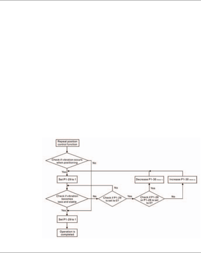
7. Operation Lexium 23A
170 AC servo drive
7.3.2.9 Low-
frequency Vibration
Suppression
If the stiffness of the mechanical system is not sufficient, after the positioning
command has completed, continuous vibration of the mechanical system may occur
still even when the motor has almost stopped. At this time, using low-frequency
vibration suppression function can suppress the low-frequency vibration of
mechanical system. The range of frequency setting is from 1.0 to 100.0Hz. Besides,
two modes (Manual/Auto) of low-frequency vibration suppression function are
available for the users to select.
z Auto Mode
If the users know the point where the low-frequency occurs, we recommend the users
can use this mode to find the low-frequency of the mechanical vibration
automatically. When P1-29 is set to 1, the system will disable the filter function and
find the vibration frequency of low-frequency automatically. After the detected
frequency becomes fixed and stable, the system will set P1-29 to 0, save the first
measured low-frequency value automatically into P1-25 and set P1-26 to 1; then save
the second measured low-frequency value automatically into P1-27 and set P1-28 to
1. If any low-frequency vibration occurs after P1-29 is set to 0 automatically, please
examine if the function of P1-26 or P1-28 is enabled or not. When the setting value of
P1-26 or P1-28 is 0, it indicates that there is no frequency is detected. Please decrease
the setting value of P1-30 (Low-frequency Vibration Detection Level) and set P1-29 to
1 to find the low-frequency again. Please pay close attention on the setting value of
P1-30 as if the setting value of P1-30 is too low, it is easy to regard the interference as
the low-frequency and results in erroneous measurement.

Lexium 23A 7. Operation
AC servo drive 171
Please note:
1) When P1-26 and P1-28 are both set to 0, it indicates that the system could not find the
frequency. Please check the setting value of P1-30 because when the setting value of
P1-30 is too high, it may causes that the frequency becomes difficult to be found.
2) When P1-26 and P1-28 are both set to a non-zero value, if the vibration condition
can not be improved, please check the setting value of P1-30 as the low setting
value of P1-30 may result in erroneous measurement. The system may regard the
interference as a low-frequency.
3) When the vibration still exists and can not be suppressed after using auto low-
frequency vibration suppression function, if the users know the vibration
frequency, please set P1-25 and P1-27 manually to improve the vibration condition.
Relevant parameters:
P1 - 29 AVSM Auto Low-frequency Vibration
Suppression Mode Selection Address: 013AH, 013BH
Default: 0 Related Section:
Applicable Control Mode: Pt/Pr Section 7.3.2.9
Unit: -
Range: 0 ~ 1
Data Size: 16-bit
Display Format: Decimal
Settings:
0: Normal mode (Disable Auto Low-frequency Vibration Suppression Mode).
1: Auto mode (Enable Auto Low-frequency Vibration Suppression Mode).
Explanation:
If P1-29 is set to 0, the setting of low-frequency vibration suppression is fixed and will
not change automatically.
If P1-29 is set to 1, when there is no low-frequency vibration or the low-frequency
vibration becomes less and stable, the system will set P1-29 to 0, save the measured
low-frequency value automatically and memorize it in P1-25.
P1 - 30 VCL Low-frequency Vibration
Detection Level Address: 013CH, 013DH
Default: 500 Related Section:
Applicable Control Mode: Pt/Pr Section 7.3.2.9
Unit: pulse
Range: 1 ~ 8000
Data Size: 16-bit
Display Format: Decimal
Settings:
When P1-29 is set to 1, the system will find this detection level automatically. If the
setting value of P1-30 is too low, the detection of frequency will become sensitive and
result in erroneous measurement. If the setting value of P1-30 is too high, although the
probability of erroneous measurement will decrease, the frequency will become
difficult to be found especially when the vibration of mechanical system is less.

7. Operation Lexium 23A
172 AC servo drive
The setting value of P1-30 indicates the range of vibration frequency. When the
vibration can not be detected (out of range), it indicates that the setting value of P1-30
is too high and we recommend the users can decrease the setting value of P1-30. The
users can also use the Scope function provided in Lexium23 Plus configuration
software to observe the vibration during positioning operation so as to set P1-30
appropriately.
p Manual Mode
There area two groups of low-frequency vibration suppression parameters. The first
group is P1-25 and P1-26 and the second group is P1-27 and P1-28. Using these two
groups of parameters can improve the vibration condition of two different low
frequencies. P1-25 and P1-26 are used to set the occurred vibration frequency and P1-
26 and P1-28 are used to set the frequency response after filter function is used.
When the setting values of P1-26 and P1-28 are higher, the performance of frequency
response will be better. However, if the setting value is over high, it may affect the
motor operation. The default setting of P1-26 and P1-28 are both 0, and it indicates
that the low-frequency vibration suppression function is disabled.
Relevant parameters:
P1 - 25 VSF1 Low-frequency Vibration
Suppression (1) Address: 0132H, 0133H
Default: 100.0 Related Section:
Applicable Control Mode: Pt/Pr Section 7.3.2.9
Unit: Hz
Range: 1.0 ~ 100.0
Data Size: 16-bit
Display Format: Decimal
Settings:
This parameter is used to set the first group of the low-frequency of mechanical
system. It can be used to suppress the low-frequency vibration of mechanical
system. If P1-26 is set to 0, this parameter is disabled.
P1 - 26 VSG1 Low-frequency Vibration
Suppression Gain (1) Address: 0134H, 0135H
Default: 0 Related Section:
Applicable Control Mode: Pt/Pr Section 7.3.2.9
Unit: -
Range: 0 ~ 9 (0: Disable the function of P1-25)
Data Size: 16-bit
Display Format: Decimal
Settings:
This parameter is used to set the vibration suppression gain for P1-25. When the
setting value is higher, the position response is quicker. However, if the setting value
is over high, it may addect the normal operation of servo motor. It is recommended
to set P1-26 as 1.

Lexium 23A 7. Operation
AC servo drive 173
Please note:
1) After the low-frequency vibration is suppressed, the changes of the response may
become excessive. Therefore, please ensure that the machine is able to stop any
time and ensure the safety of personnel working with the machine when execute
low-frequency vibration suppression function.
2) The low-frequency vibration suppression function can be enabled only in position
control mode (Pt, Pr or Pr-Pt mode).
3) When the users use resonance suppression function, the resonance condition can be
improved immediately after the correct resonance frequency is found. However, when
the users use low-frequency vibration suppression function, the vibration of the
mechanical system will not be eliminated immediately. The vibration condition is
improved gradually after the correct frequency is found. This is because the low-
frequency vibration suppression function is not effective for the vibration caused by
external force and the vibration occurred before using suppression function.
4) After the low-frequency vibration suppression function is enabled, it will certainly
affect the original response performance. When the value of the low-frequency is
lower, the effect upon the response performance is greater. At this time, the users
can adjust the setting value of P1-26 to increase the position response. But, please
do not set P1-26 to a higher value. If the setting value of P1-26 is too high, it will
affect the motor operation.
5) n order to avoid that the vibration frequency may not easily to be found when the
commanding time is too fast in Auto mode, we recommend the users can set a longer
command delay time. The command can be given after the vibration frequency is found.
P1 - 27 VSF2 Low-frequency Vibration
Suppression (2) Address: 0136H, 0137H
Default: 100.0 Related Section:
Applicable Control Mode: Pt/Pr Section 7.3.2.9
Unit: Hz
Range: 1.0 ~ 100.0
Data Size: 16-bit
Display Format: Decimal
Settings:
This parameter is used to set the second group of the low-frequency of mechanical
system. It can be used to suppress the low-frequency vibration of mechanical
system. If P1-28 is set to 0, this parameter is disabled.
P1 - 28 VSG2 Low-frequency Vibration
Suppression Gain (2) Address: 0138H, 0139H
Default: 0 Related Section:
Applicable Control Mode: Pt/Pr Section 7.3.2.9
Unit: -
Range: 0 ~ 9 (0: Disable the function of P1-27)
Data Size: 16-bit
Display Format: Decimal
Settings:
This parameter is used to set the vibration suppression gain for P1-27. When the setting
value is higher, the position response is quicker. However, if the setting value is over high, it
may addect the normal operation of servo motor. It is recommended to set P1-28 as 1.

7. Operation Lexium 23A
174 AC servo drive
7.3.3 Speed Control Mode
The speed control mode (S or Sz) is usually used on the applications of precision
speed control, such as CNC machine, etc. Lexium23 Plus series servo drives support
two kinds of command sources in speed control mode. One is external analog signal
and the other is internal parameter. The external analog signal is from external
voltage input and it can control the speed of servo motor. There are two usage of
internal parameter, one is set different speed command in three speed control
parameters before operation and then using SPD0 and SPD1 of CN1 DI signal perform
switching. The other usage is using serial communication to change the setting value
of parameter.
Beside, in order to make the speed command switch more smoothly, Lexium23
Plus series servo drives also provide complete S-curve profile for speed control
mode. For the closed-loop speed control, Lexium23 Plus series servo drives
provide gain adjustment function and an integrated PI or PDFF controller.
Besides, two modes of tuning technology (Manual/Auto) are also provided for
the users to select (parameter P2-32).
There are two turning modes for gain adjustment: Manual and Auto modes.
z Manual Mode: User-defined loop gain adjustment. When using this mode, all auto
and auxiliary function will be disabled.
z Auto Mode: Continuous adjustment of loop gains according to measured inertia,
with ten levels of system bandwidth. The parameter set by user is default value.

Lexium 23A 7. Operation
AC servo drive 175
7.3.3.1 Command
Source of Speed
Control Mode
Speed command Sources:
1) External analog signal: External analog voltage input, -10V to +10V
2) Internal parameter: P1-09 to P1-11
z State of SPD0~1: 0: indicates OFF (Normally Open); 1: indicates ON (Normally
Closed)
z When SPD0 and SPD1 are both = 0 (OFF), if the control mode of operation is Sz, then
the speed command is 0. Therefore, if the users do not use analog voltage as speed
command, the users can choose Sz mode and avoid the zero point drift problem of
analog voltage signal. If the speed control mode is S mode, then the command is
the analog voltage between V-REF and GND. The setting range of the input voltage
is from -10V to +10V and the corresponding motor speed is adjustable (Please see
parameter P1-40).
z When at least one of SPD0 and SPD1 is not 0 (OFF), the speed command is internal
parameter (P1-09 to P1-11). The command is valid (enabled) after either SPD0 or
SPD1 is changed.
z The range of internal parameters is within -60000 ~ +60000 rpm. Setting value =
Range x Unit (0.1 rpm). For example, if P1-09 is set to +30000, the setting value =
+30000 x 0.1 rpm = +3000 rpm.
The speed command that is described in this section not only can be taken as speed
command in speed control mode (S or Sz mode) but also can be the speed limit input
command in torque control mode (T or Tz mode).
Speed
Command
CN1 DI signal Command Source Content Range
SPD1 SPD0
S1 0 0 Mode
S External
analog signal
Voltage
between
V-REF-GND
-10 V ~ +10V
Sz N/A Speed
command is 0 0
S2 0 1
Internal parameter
P1-09 -60000 ~
+60000 rpm
S3 1 0 P1-10
S4 1 1 P1-11
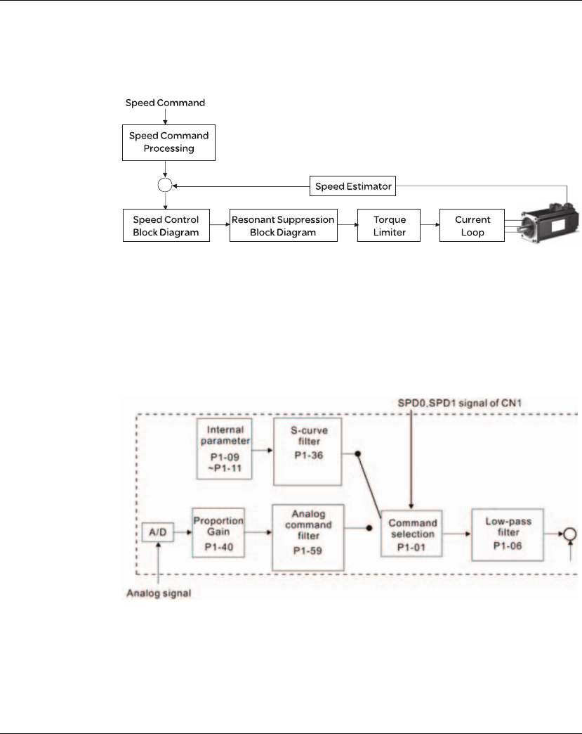
7. Operation Lexium 23A
176 AC servo drive
7.3.3.2 Structure
of Speed Control
Mode
Speed command Sources:
1) External analog signal: External analog voltage input, -10V to +10V
2) Internal parameter: P1-09 to P1-11
Basic Structure:
In the figure above, the speed command processing is used to select the command
source of speed control according to chapter 6.3.1, including proportional gain (P1-
40) and S-curve filter smoothing strategy of speed control. The speed control block
diagram is used to manage the gain parameters of the servo drive and calculate the
current input provided to motor instantaneously. The resonance suppression block
diagram is used to suppress the resonance of mechanical system.
The function and structure of speed command processing is shown as the figure below:
The command source is selected according to the state of SPD0, SPD1 and parameter
P1-01 (S or Sz).
Whenever the command signal needs to be more smoothly, we recommend the users
to use S-curve and low-pass filter.
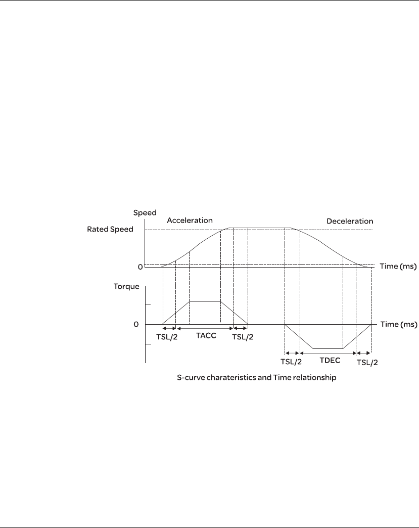
Lexium 23A 7. Operation
AC servo drive 177
7.3.3.3 Smoothing
Strategy of Speed
Control Mode
S-curve Filter
The S-curve filter is a speed smoothing command which provides 3 steps accel / decel
S-curve to smooth the speed command change of the motor during acceleration and
deceleration. Using S-curve filter can let the servo motor run more smoothly in
response to a sudden speed command change.
Since the speed and acceleration curve are both continuous, in order to avoid the
mechanical resonance and noise may occur due to a sudden speed command
(differentiation of acceleration), using S-curve filter not only can improve the
performance when servo motor accelerate or decelerate but also can make the
motor run more smoothly. S-curve filter parameters include P1-34 Acceleration Time
(TACC), P1-35 Deceleration Time (TDEC) and Accel /Decel S-curve (TSL), and the
users can use these three parameters to improve the motor performance during
acceleration, deceleration and operation.
Lexium23 Plus series servo drives also support the time calculation of completing
speed command. T (ms) is the operation (running) time. S (rpm) is absolute speed
command, i.e. the absolute value (the result) after starting speed subtracts the
final speed.

7. Operation Lexium 23A
178 AC servo drive
Relevant parameters:
P1 - 34 TACC Acceleration Time Address: 0144H, 0145H
Default: 200 Related Section:
Applicable Control Mode: S Section 7.3.3.3,
Unit: msec
Range: 1 ~ 65500
Data Size: 16-bit
Display Format: Decimal
Settings:
This parameter is used to determine the acceleration time to accelerate from 0 to its
rated motor speed. The functions of parameters P1-34, P1-35 and P1-36 are each
individual. When P1-36 is set to 0 (Disabled), the settings of P1-34, P1-35 are still
effective. It indicates that the parameters P1-34 and P1-35 will not become disabled
even when P1-36 is disabled.
Please note:
1. When the source of speed command is analog command, the maximum setting
value of P1-36 is set to 0, the acceleration and deceleration function will be
disabled.
2. When the source of speed command is analog command, the maximum setting
value of P1-34 is limited to 20000 automatically.
P1 - 35 TDEC Deceleration Time Address: 0146H, 0147H
Default: 200 Related Section:
Applicable Control Mode: S Section 7.3.3.3,
Unit: msec
Range: 1 ~ 65500
Data Size: 16-bit
Display Format: Decimal
Settings:
This parameter is used to determine the acceleration time to accelerate from 0 to its
rated motor speed. The functions of parameters P1-34, P1-35 and P1-36 are each
individual. When P1-36 is set to 0 (Disabled), the settings of P1-34, P1-35 are still
effective. It indicates that the parameters P1-34 and P1-35 will not become disabled
even when P1-36 is disabled.
Please note:
1. When the source of speed command is analog command, the maximum setting
value of P1-36 is set to 0, the acceleration and deceleration function will be
disabled.
2. When the source of speed command is analog command, the maximum setting
value of P1-35 is limited to 20000 automatically.
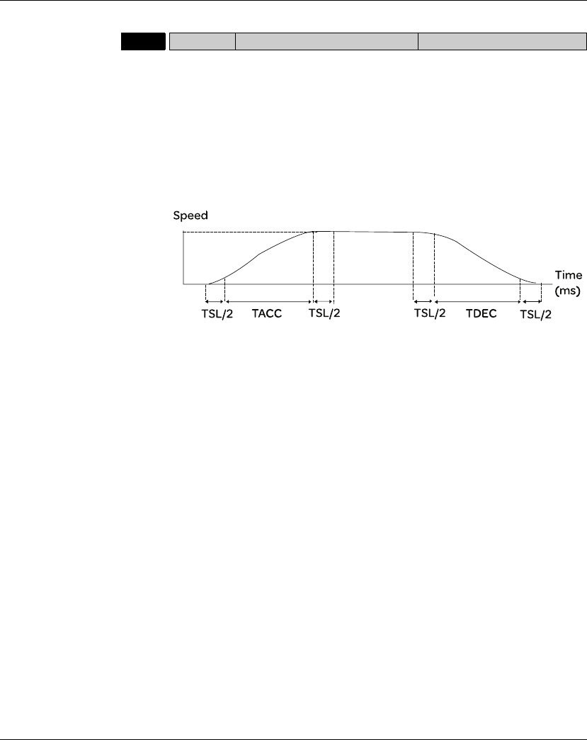
Lexium 23A 7. Operation
AC servo drive 179
P1 - 36 TSL Accel /Decel S-curve Address: 0148H, 0149H
Default: 0 Related Section:
Unit: msec Section 7.3.3.3,
Applicable Control Mode: S, Pr
Unit: msec
Range: 0 ~ 65500 (0: Disabled)
Data Size: 16-bit
Display Format: Decimal
Settings:
This parameter is used to make the motor run more smoothly when startup and
windup. Using this parameter can improve the motor running stability.
TACC: P1-34, Acceleration time
TDEC: P1-35, Deceleration time
TSL: P1-36, Accel /Decel S-curve
Total acceleration time = TACC + TSL
Total deceleration time = TDEC + TSL
The functions of parameters P1-34, P1-35 and P1-36 are each individual. When P1-36 is
set to 0 (Disabled), the settings of P1-34, P1-35 are still effective. It indicates that the
parameters P1-34 and P1-35 will not become disabled even when P1-36 is disabled.
Please note:
1 When the source of speed command is analog command, the maximum setting
value of P1-36 is set to 0, the acceleration and deceleration function will be
disabled.
2 When the source of speed command is analog command, the maximum setting
value of P1-36 is limited to 10000 automatically.
3 If the control of the servo motor is achieved via internal parameters, the command
curve should be defined by the users.
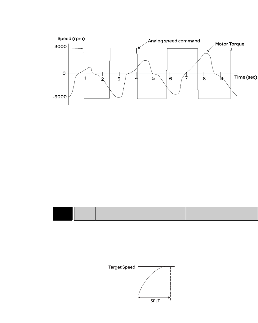
7. Operation Lexium 23A
180 AC servo drive
Analog Speed Command S-curve Filter
Lexium23 Plus series servo drives also provide Analog Speed Command S-curve
Filter for the smoothing in response to a sudden analog input signal.
The analog speed command S-curve filter is for the smoothing of analog input signal
and its function is the same as the S-curve filter. The speed and acceleration curve of
analog speed command S-curve filter are both continuous. The above figure shows
the curve of analog speed command S-curve filter and the users can see the ramp of
speed command is different during acceleration and deceleration. Also, the users can
see the difference of input command tracking and can adjust time setting by using
parameter P1-34, P1-35, P1-36 to improve the actual motor performance according to
actual condition.
Analog Speed Command Low-pass Filter
Analog Speed Command Low-pass Filter is used to eliminate high frequency
response and electrical interference from an analog speed command and it is also
with smoothing function.
Relevant parameters:
P1 - 06 SFLT Accel / Decel Smooth Constant of Analog
Speed Command (Low-pass Filter)
Address: 010CH, 010DH
Default: 0 Related Section:
Applicable Control Mode: S Section 7.3.3.3
Unit: msec
Range: 0 ~ 1000 (0: Disabled)
Data Size: 16-bit
Display Format: Decimal
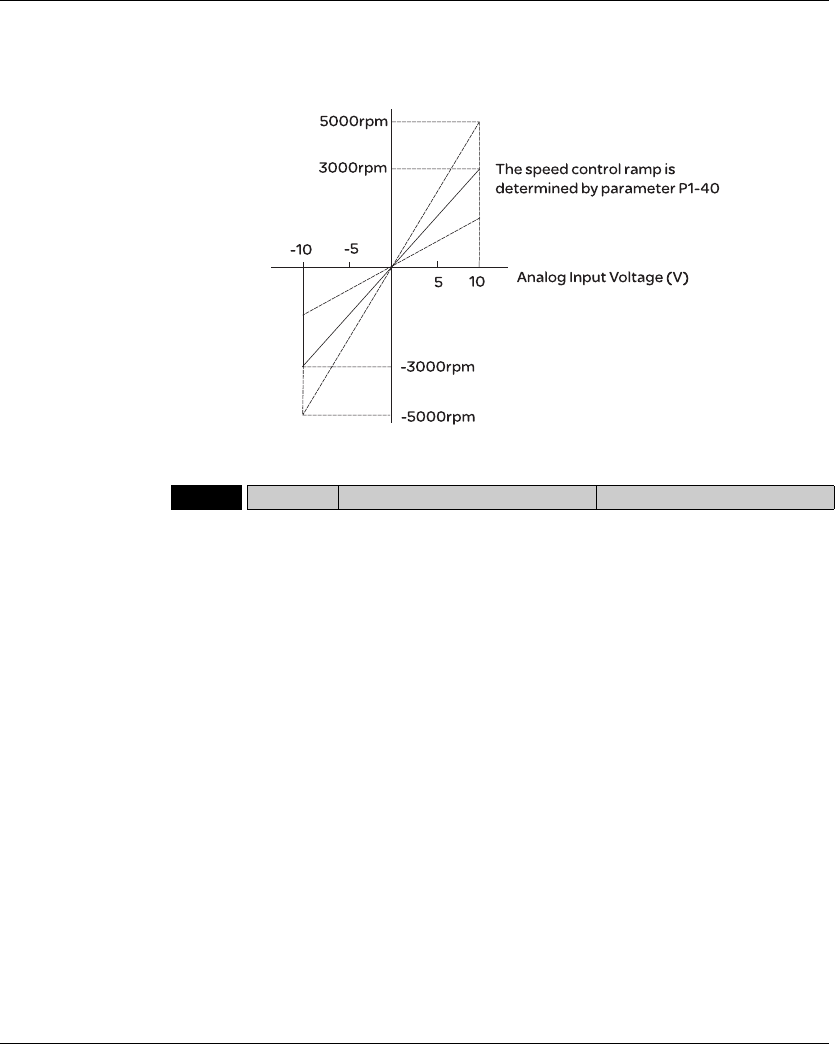
Lexium 23A 7. Operation
AC servo drive 181
7.3.3.4 Analog
Speed Input Scaling
The analog voltage between V_REF and GND determines the motor speed
command. Using with parameter P1-40 (Max. Analog Speed Command) can adjust
the speed control ramp and its range.
Relevant parameters:
P1-40rVCM Max. Analog Speed Command or Limit Address: 0150H, 0151H
Default: rated speed Related Section:
Applicable Control Mode: S, T Section 7.3.3.4
Unit: rpm
Range: 0 ~ 10000
Data Size: 16-bit
Display Format: Decimal
Settings:
In Speed mode, this parameter is used to set the maximum analog speed command
based on the maximum input voltage (10V).
In Torque mode, this parameter is used to set the maximum analog speed limit
based on the maximum input voltage (10V).
For example, in speed mode, if P1-40 is set to 3000 and the input voltage is 10V, it
indicates that the speed command is 3000 rpm. If P1-40 is set to 3000, but the input
voltage is changed to 5V, then the speed command is changed to 1500 rpm.
Speed Command / Limit = Input Voltage Value x Setting value of P1-40 / 10
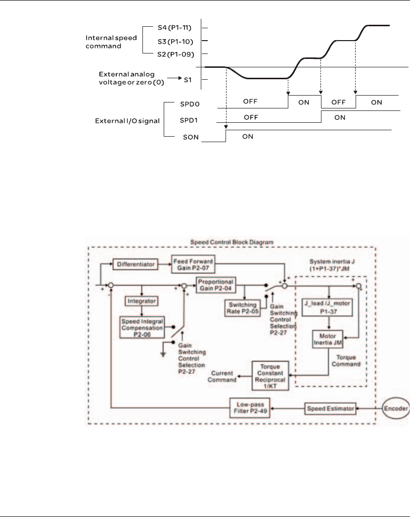
7. Operation Lexium 23A
182 AC servo drive
7.3.3.5 Timing Chart
of Speed Control
Mode
Note:
1) OFF indicates normally open and ON indicates normally closed.
3) When speed control mode is Sz, the speed command S1=0; when speed control mode
is S, the speed command S1 is external analog voltage input (Please refer to P1-01).
3) After Servo ON, the users can select command according to the state of SPD0~1.
7.3.3.6 Speed
Loop Gain
Adjustment
The function and structure of speed control mode is shown as the figure below:
There are two turning modes of gain adjustment: Manual and Auto modes. The gain of
Lexium23 Plus series servo drives can be adjusted by using any one of two tuning modes.
p Manual Mode: User-defined loop gain adjustment. When using this mode, all auto
and auxiliary function will be disabled.
p Auto Mode: Continuous adjustment of loop gains according to measured inertia,
with ten levels of system bandwidth. The parameter set by user is default value.

Lexium 23A 7. Operation
AC servo drive 183
The mode of gain adjustment can be selected by parameter P2-32:
Relevant Parameter:
P2-32rAUT2 Tuning Mode Selection Address: 0240H, 0241H
Default: 0 Related Section:
Applicable Control Mode: ALL Section 5.6, Section 7.3.3.6
Unit: N/A
Range: 0 ~ 2
Data Size: 16-bit
Display Format: Hexadecimal
Settings:
0: Manual mode
1: Auto Mode [Continuous adjustment]
2: Semi-Auto Mode [Non-continuous adjustment]
Explanation of manual mode:
1. When P2-32 is set to mode#0, the setting value of P2-00, P2-02, P2-04,
P2-06, P2-07, P2-25 and P2-26 can be user-defined. When switching
mode #1 or #2 to #0, the setting value of P2-00, P2-02, P2-04, P2-06,
P2-07, P2-25 and P2-26 will change to the value that measured in #1
auto-tuning mode or #2 semi-auto tuning mode.
Explanation of auto-tuning mode:
The servo drive will continuously estimate the system inertia, save the
measured load inertia value automatically and memorized in P1-37 every
30 minutes by referring to the frequency response settings of P2-31.
1. When switching mode #1 or #2 to #0, the servo drive will continuously
estimate the system inertia, save the measured load inertia value
automatically and memorized in P1-37. Then, set the corresponding
parameters according to this measured load inertia value.
2. When switching mode#0 or #1 to #2, enter the appropriate load inertia
value in P1-37.
3. When switching mode#1 to #0, the setting value of P2-00, P2-04 and
P2-06 will change to the value that measured in #1 auto-tuning mode.
Explanation of semi-auto tuning mode:
1. When switching mode #2 to #0, the setting value of P2-00, P2-04, P2-
06, P2-25 and P2-26 will change to the value that measured in #1 auto-
tuning mode.
2. After the system inertia becomes stable (The displau of P2-33 will show 1),
it will stop estimating the system inertia, save the measured load inertia
value automatically, and memorized in P1-37. However, when P2-32 is
set to mode#1 or #2, the servo drive will continuously perform the
adjustment for a period of time.
3. When the value of the system inertia becomes over high, the display of
P2-33 will show 0 and the servo drive will start to adjust the load inertia
value continuously.

7. Operation Lexium 23A
184 AC servo drive
Manual Mode
When Tuning Mode Settings of P2-32 is set to 0, the users can define the proportional
speed loop gain (P2-04), speed integral gain (P2-06) feed forward gain (P2-07) and ratio
of load inertia to servo motor Inertia (1-37). Please refer to the following description:
z Proportional gain: Adjust this gain can increase the position loop responsiveness.
z Integral gain: Adjust this gain can enhance the low-frequency stiffness of speed
loop and eliminate the steady error. Also, reduce the value of phase margin. Over
high integral gain will result in the unstable servo system.
z Feed forward gain: Adjust this gain can decrease the phase delay error
Relevant parameters:
P2-04 KVP Proportional Speed Loop Gain Address: 0208H, 0209H
Default: 500 Related Section:
Applicable Control Mode: ALL Section 7.3.3.6
Unit: rad/s
Range: 0 ~ 8191
Data Size: 16-bit
Display Format: Decimal
Settings:
This parameter is used to set the speed loop gain. When the value of proportional
speed loop gain is increased, it can expedite speed loop response. However, if the
setting value is over high, it may generate vibration or noise.
P2-06 KVI Speed Integral Compensation Address: 020CH, 020DH
Default: 100 Related Section:
Applicable Control Mode: ALL Section 7.3.3.6
Unit: rad/s
Range: 0 ~ 1023
Data Size: 16-bit
Display Format: Decimal
Settings:
This parameter is used to set the integral time of speed loop. When the value of
speed integral compensation is increased, it can improve the speed response ability
and decrease the speed control deviation. However, if the setting value is over high,
it may generate vibration or noise.
P2-07 KVF Speed Feed Forward Gain Address: 020EH, 020FH
Default: 0 Related Section:
Applicable Control Mode: ALL Section 7.3.3.6
Unit: %
Range: 0 ~ 100
Data Size: 16-bit
Display Format: Decimal
Settings:
This parameter is used to set the feed forward gain when executing speed control
command.
When using speed smooth command, increase gain can improve speed track
deviation.
When not using speed smooth command, decrease gain can improve the resonance
condition of mechanical system.
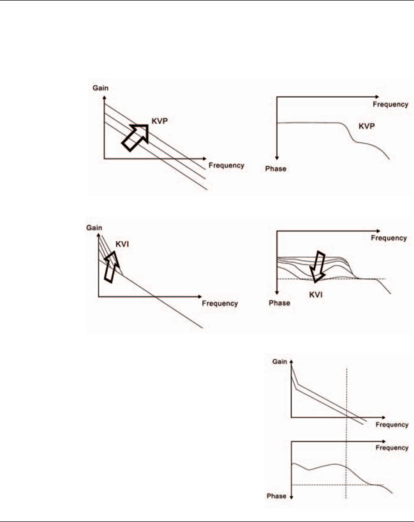
Lexium 23A 7. Operation
AC servo drive 185
In theory, stepping response can be used to explain proportional gain (KVP), integral
gain (KVI) and feed forward gain (KVF). Now we use frequency area and time area
respectively to explain the logic.
Frequency Domain
STEP 1: Set the value of KVI=0, the value of KVF=0 and adjust the value of KVP.
STEP 2: Fix the value of KVP and adjust the value of KVI.
STEP 3: Select the value of KVI, if the value of phase
margin is too small, re-adjust the value of
KVP again to obtain the value, 45deg of
phase margin.
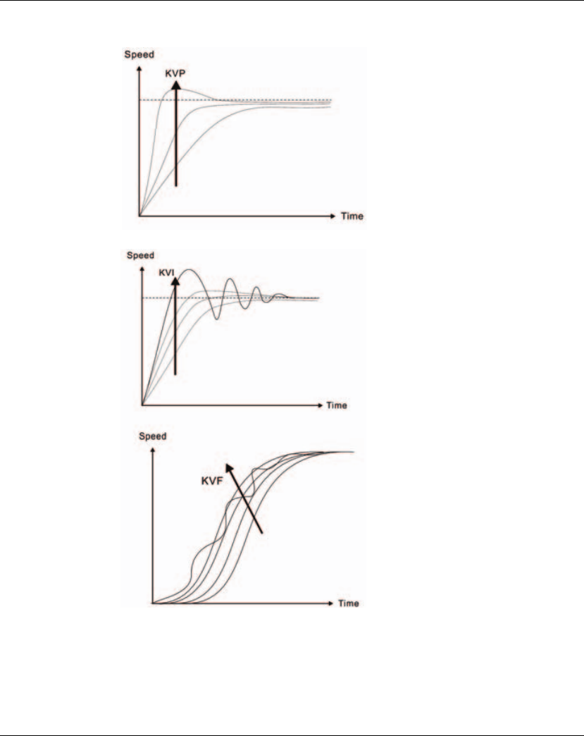
7. Operation Lexium 23A
186 AC servo drive
Time Domain
When the value of KVP is greater, the
value of the responsiveness is also
greater and the raising time is shorter.
However, when the value of phase margin
is over low, it is not helpful to steady error.
But it is helpful to dynamic tracking error.
When the value of KVI is greater, the value
of low-frequency gain is also greater and
the value of steady error is nearly zero
(0).
However, the value of phase margin will
reduce quite substantially. It is helpful to
steady error. But it is not helpful to
dynamic tracking error.
When the value of KVF is nearly to 1 and
the forward compensation is more
complete, then the value of dynamic
tracking error will become very small.
However, when the value of KVF is too
great, it may cause vibration.
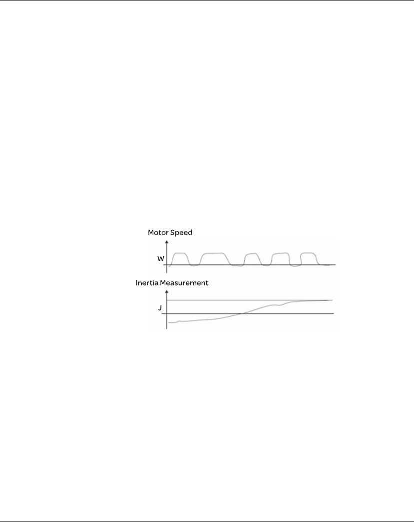
Lexium 23A 7. Operation
AC servo drive 187
In general, the equipment, such as spectrum analyzer is needed and used to analyze
when using frequency domain method and the users also should have this kind of
analysis technology. However, when using time domain method, the users only need
to prepare an oscilloscope. Therefore, the general users usually use time domain
method with the analog DI/DO terminal provided by the servo drive to adjust what is
called as PI (Proportional and Integral) type controller. As for the performance of
torque shaft load, input command tracking and torque shaft load have the same
responsiveness when using frequency domain method and time domain method.
The users can reduce the responsiveness of input command tracking by using input
command low-pass filter.
Auto Mode (Continuous adjustment)
This Auto Mode provides continuous adjustment of loop gains according to
measured inertia automatically. It is suitable when the load inertia is fixed or the load
inertia change is small and is not suitable for wide range of load inertia change. The
period of adjustment time is different depending on the acceleration and
deceleration of servo motor. To change the stiffness and responsiveness, please use
parameter P2-31.

7. Operation Lexium 23A
188 AC servo drive
7.3.3.7 Resonance
Suppression
The resonance of mechanical system may occur due to excessive system stiffness or
frequency response. However, this kind of resonance condition can be improved,
suppressed, even can be eliminated by using low-pass filter (parameter P2-25) and
notch filter (parameters P2-43 ~ P2-46) without changing control parameter.
Relevant parameters:
P2 - 43 NCF1 Notch Filter1
(Resonance Suppression)
Address: 0256H, 0257H
Default: 1000 Related Section:
Applicable Control Mode: ALL Section 7.3.3.7
Unit: Hz
Range: 50 ~ 2000
Data Size: 16-bit
Display Format: Decimal
Settings:
This parameter is used to set second resonance frequency of mechanical system. It
can be used to suppress the resonance of mechanical system and reduce the
vibration of mechanical system. If P2-43 is set to 0, this parameter is disabled.

Lexium 23A 7. Operation
AC servo drive 189
P2 - 44 DPH1 Notch Filter Attenuation Rate 1
(Resonance Suppression) Address: 0258H, 0259H
Default: 0 Related Section:
Applicable Control Mode: ALL Section 7.3.3.7
Unit: dB
Range: 0 ~ 32
Data Size: 16-bit
Display Format: Decimal
Settings:
This parameter is used to set magnitude of the resonance suppression that is set by
parameter P2-43. If P2-44 is set to 0, the parameters P2-43 and P2-44 are both
disabled.
P2 - 45 NCF2 Notch Filter 2
(Resonance Suppression) Address: 025AH, 025BH
Default: 1000 Related Section:
Applicable Control Mode: ALL Section 7.3.3.7
Unit: Hz
Range: 50 ~ 2000
Data Size: 16-bit
Display Format: Decimal
Settings:
This parameter is used to set third resonance frequency of mechanical system. It
can be used to suppress the resonance of mechanical system and reduce the
vibration of mechanical system.
If P2-45 is set to 0, this parameter is disabled.
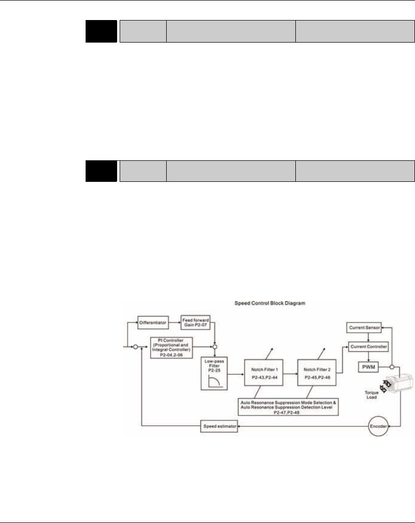
7. Operation Lexium 23A
190 AC servo drive
P2 - 46 DPH2 Notch Filter Attenuation Rate 2
(Resonance Suppression)
Address: 025CH, 025DH
Default: 0 Related Section:
Applicable Control Mode: ALL Section 7.3.3.7
Unit: dB
Range: 0 ~ 32
Data Size: 16-bit
Display Format: Decimal
Settings:
This parameter is used to set magnitude of the resonance suppression that is set by
parameter P2-45. If P2-46 is set to 0, the parameters P2-45 and P2-46 are both
disabled.
P2 - 25 NLP Low-pass Filter Time Constant
(Resonance Suppression) Address: 0232H, 0233H
Default: 2 (1kW and below models) or
5 (other models) Related Section:
Applicable Control Mode: ALL Section 7.3.3.7
Unit: 0.1 msec
Range: 0 ~ 1000
Data Size: 16-bit
Display Format: Decimal
Settings:
This parameter is used to set low-pass filter time constant of resonance
suppression. If P2-25 is set to 0, this parameter is disabled.

Lexium 23A 7. Operation
AC servo drive 191
There are two groups of notch filters provided by Lexium23 Plus series. The first group of
notch filter is P2-43 and P2-44, and the second group of notch filter is P2-45 and P2-46.
When there is resonance, please set P2-47 to 1 or 2 (Auto mode), and then the servo drive
will find resonance frequency and suppress the resonance automatically. After
suppressing the resonance point, the system will memorize the notch filter frequency into
P2-43 and P-45, and memorize the notch filter attenuation rate into P2-44 and P2-46.
When P2-47 is set to 1, the resonance suppression will be enabled automatically. After
the mechanical system becomes stable (approximate 20 minutes), the setting value
of P2-47 will return to 0 (Disable auto resonance suppression function). When P2-47
is set to 2, the system will find the resonance point continuously even after the
mechanical system becomes stable.
When P2-47 is set to 1 or 2, if the resonance conditions can not be eliminated, we
recommend the users to check the settings of P2-44 and P2-46. If either of the
setting value of P2-44 and P2-46 is set to 32, please decrease the speed frequency
response and estimate the resonance point again. If the resonance conditions can
not be eliminated when the setting values of P2-44 and P2-46 are both less than 32,
please set P2-47 to 0 first, and increase the setting value of P2-44 and P2-46
manually. If the resonance exists still after increasing the setting value of P2-44 and
P2-46, please decrease the value of speed frequency response again and then use
the resonance suppression function again.
When increasing the setting value of P2-44 and P2-46 manually, ensure to pay close
attention on the setting value of P2-44 and P2-46. If the value of P2-44 and P2-46 is
greater than 0, it indicates that the corresponding resonance frequency of P2-43 and
P2-45 is found through auto resonance suppression function. If the value of P2-44 and
P2-46 is equal to 0, it indicates that the value of P2-43 and P2-45 will be the default
value 1000 and this is not the frequency found by auto resonance suppression function.
At this time, if the users increase the value of notch filter attenuation rate which does
not exist, the performance of the current mechanical system may deteriorate.
Settings of P2-47
Current Value Desired Value Function
01
Clear the setting value of P2-43 ~ P2-46 and enable auto
resonance suppression function.
02
Clear the setting value of P2-43 ~ P2-46 and enable auto
resonance suppression function.
10
Save the setting value of P2-43 ~ P2-46 and disable auto
resonance suppression function.
11
Clear the setting value of P2-43 ~ P2-46 and enable auto
resonance suppression function.
12
Do not clear the setting value of P2-43 ~ P2-46 and enable auto
resonance suppression function continuously.
20
Save the setting value of P2-43 ~ P2-46 and disable auto
resonance suppression function.
21
Clear the setting value of P2-43 ~ P2-46 and enable auto
resonance suppression function.
22
Do not clear the setting value of P2-43 ~ P2-46 and enable auto
resonance suppression function continuously.
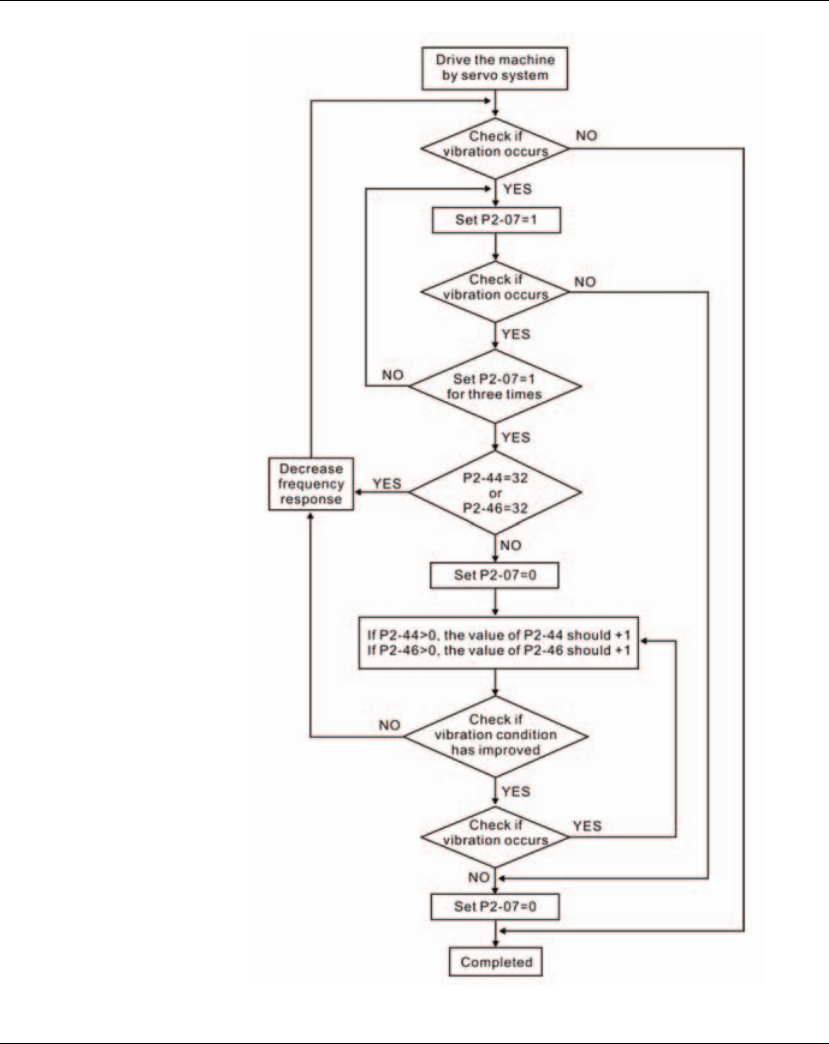
7. Operation Lexium 23A
192 AC servo drive
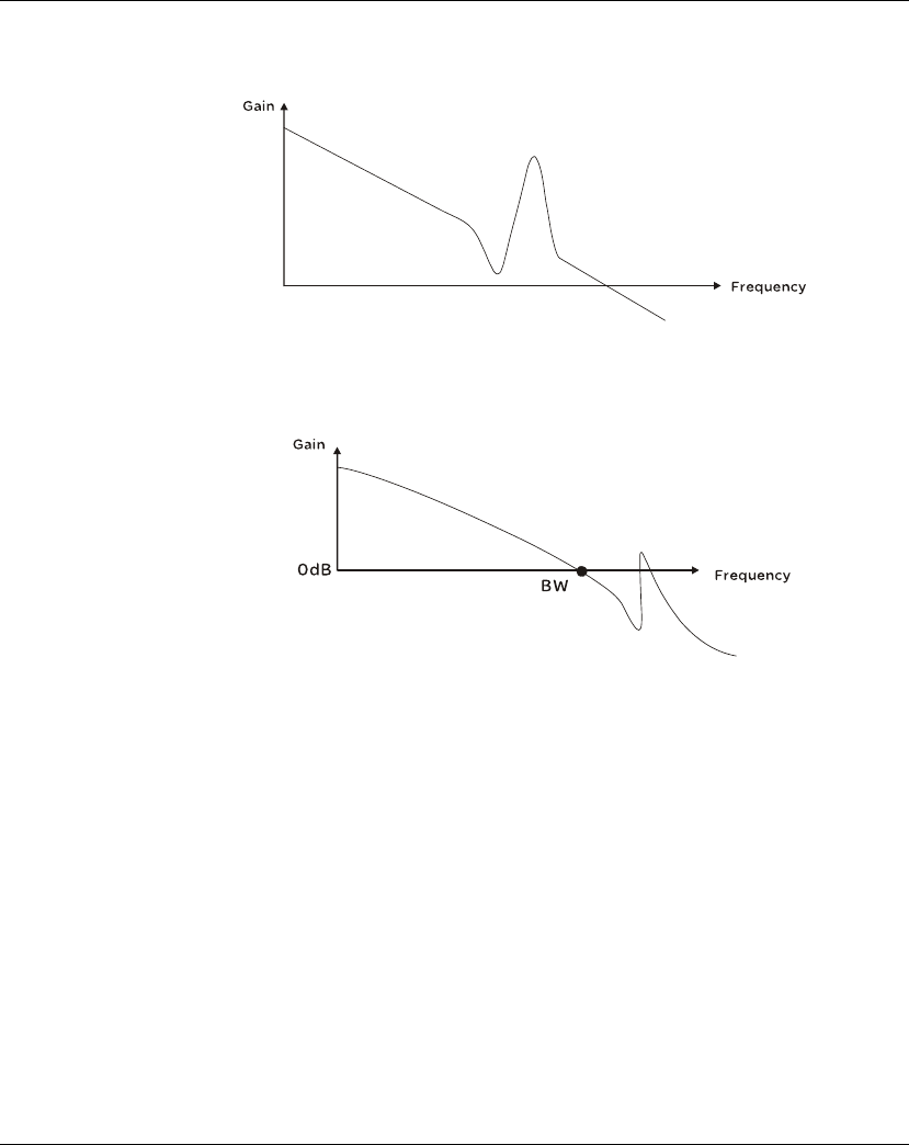
Lexium 23A 7. Operation
AC servo drive 193
Low-pass filter
Please use parameter P2-25. The figure below shows the resonant open-loop gain.
When the low-pass filter (parameter P2-25) is adjusted from 0 to high value, the
value of Low-pass frequency (BW) will become smaller (see the figure below). The
resonant condition is improved and the frequency response and phase margin will
also decrease.
Notch Filter
Usually, if the users know the resonance frequency, we recommend the users can
eliminate the resonance conditions directly by using notch filter (parameter P2-43,
P2-44). However, the range of frequency setting is from 50 to 1000Hz only and the
range of resonant attenuation is 0~32 dB only.
Therefore, if the resonant frequency is out of this range, we recommend the users to
use low-pass filter (parameter P2-25) to improve resonant condition.
Please refer to the following figures and explanation to know how to use notch filter
and low-pass filter to improve resonant condition.
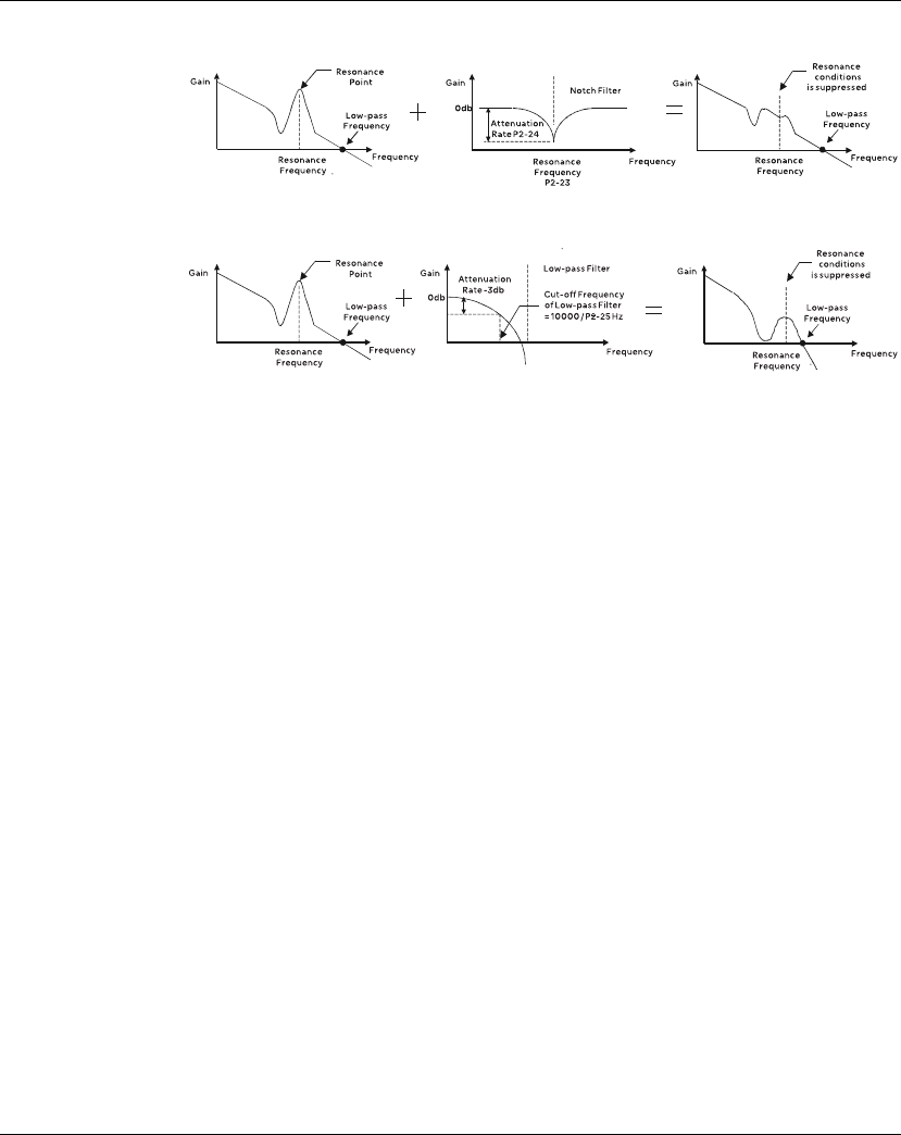
7. Operation Lexium 23A
194 AC servo drive
Use Notch Filter to suppress resonance
Use Low-pass Filter to suppress resonance
When the low-pass filter (parameter P2-25) is adjusted from 0 to high value, the value
of Low-pass frequency will become smaller (see the figure on chapter 7.3.2.6). The
resonant condition is improved but the frequency response and phase margin will
also decrease and the system may become unstable.
Therefore, if the users know the resonance frequency, the users can eliminate the
resonance conditions directly by using notch filter (parameter P2-43, P2-44). Usually,
if the resonant frequency can be recognized, we recommend the users can directly
use notch filter (parameter P2-43, P2-44) to eliminate the resonance. However, if the
resonant frequency will drift or drift out of the notch filter range, we recommend the
users not to use notch filter and use low-pass filter to improve resonant conditions.

Lexium 23A 7. Operation
AC servo drive 195
7.3.4 Torque Control Mode
The torque control mode (T or Tz) is usually used on the applications of torque
control, such as printing machine, spinning machine, twister, etc. Lexium23A series
servo drives support two kinds of command sources in torque control mode. One is
external analog signal and the other is internal parameter. The external analog signal
is from external voltage input and it can control the torque of servo motor. The
internal parameters are from P1-12 to P1-14 which are used to be the torque
command in torque control mode.
7.3.4.1 Command
Source of Torque
Control Mode
Torque command Sources:
1) External analog signal: External analog voltage input, -10V to +10V
2) Internal parameter: P1-12 to P1-14
The command source selection is determined by the DI signal of CN1 connector.
z State of TCM0~1: 0: indicates OFF (Normally Open); 1: indicates ON (Normally Closed)
z When TCM0 and TCM1 are both 0 (OFF), if the control mode of operation is Tz, then
the command is 0. Therefore, if the users do not use analog voltage as torque
command, the users can choose Tz mode to operation torque control to avoid the
zero point drift problem of analog voltage. If the control mode of operation is T,
then the command is the analog voltage between T-REF and GND. The setting
range of the input voltage is from -10V to +10V and the corresponding torque is
adjustable (see parameter P1-41).
z When at least one of TCM0 and TCM1 is not 0 (OFF), the torque command is internal
parameter. The command is valid (enabled) after either TCM0 or TCM1 is changed.
The torque command that is described in this section not only can be taken as torque
command in torque control mode (T or Tz mode) but also can be the torque limit
input command in position mode (P mode) and speed control mode (S or Sz mode).
Torque
Command
DI signal of CN1 Command Source Content Range
TCM1 TCM0
T1 0 0 Mode
TExternal
analog signal
Voltage between
T-REF-GND -10V ~ +10V
Tz None Torque
command is 0 0
T2 0 1
Internal parameter
P1-12 -300% ~
300%
T3 1 0 P1-13
T4 1 1 P1-14
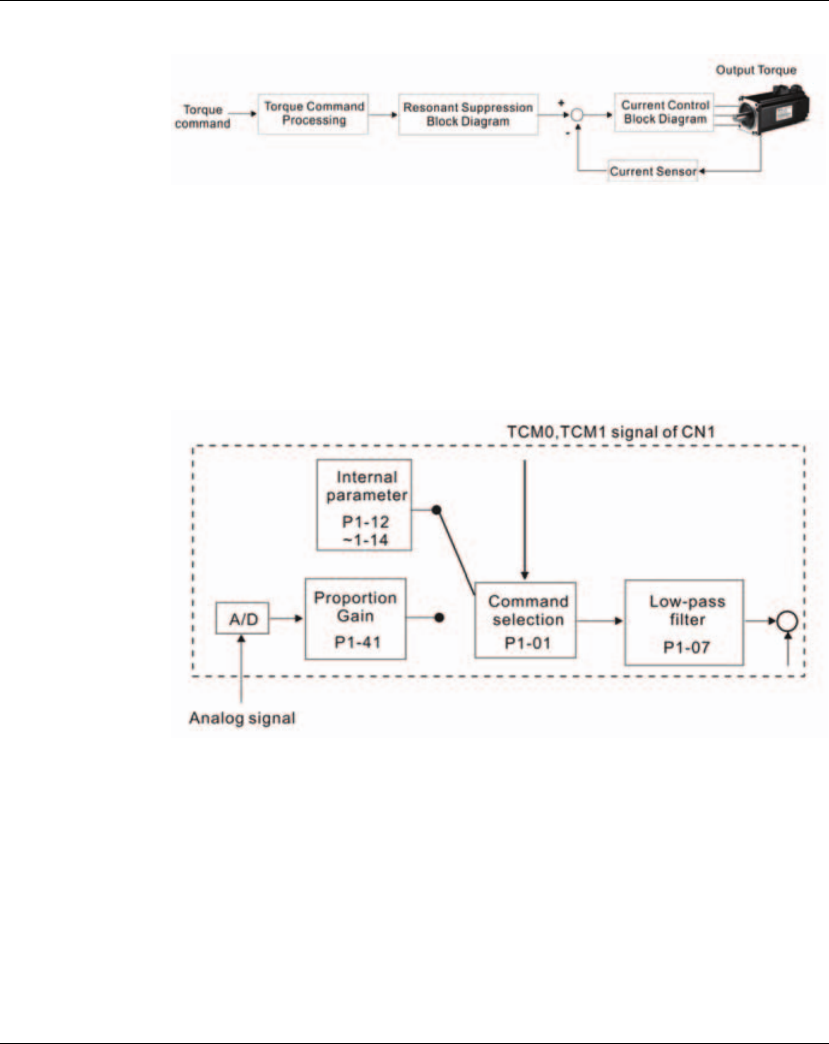
7. Operation Lexium 23A
196 AC servo drive
7.3.4.2 Structure
of Torque Control
Mode
Basic Structure:
The toque command processing is used to select the command source of torque
control according to chapter 6.4.1, including max. analog torque command
(parameter P1-41) and smoothing strategy of torque control mode. The current
control block diagram is used to manage the gain parameters of the servo drive and
calculate the current input provided to motor instantaneously. As the current control
block diagram is too complicated, setting the parameters of current control block
diagram is not allowed.
The function and structure of torque command processing is shown as the figure
below:
The command source is selected according to the state of TCM0, TCM1 and
parameter P1-01 (T or Tz).
Whenever the command signal needs to be more smoothly, we recommend the users
to use proportional gain (scalar) and low-pass filter to adjust torque.
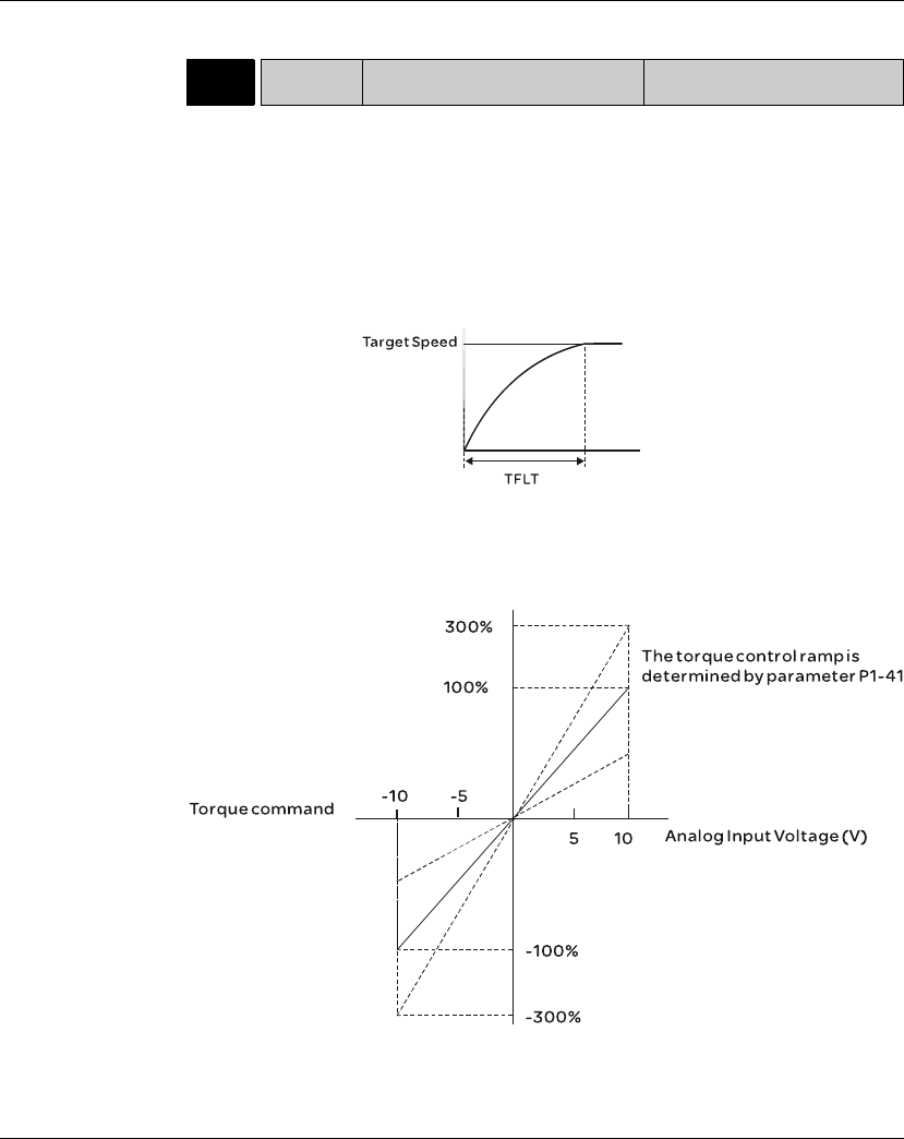
Lexium 23A 7. Operation
AC servo drive 197
7.3.4.3 Smoothing
Strategy of Torque
Control Mode
Relevant parameters:
7.3.4.4 Analog
Torque Input
Scaling
The analog voltage between T_REF and GND controls the motor torque command.
Using with parameter P1-41 can adjust the torque control ramp and its range.
P1 - 07 TFLT Smooth Constant of Analog Torque
Command (Low-pass Filter) Address: 010EH, 010FH
Default: 0 Related Section:
Applicable Control Mode: T Section 7.3.4.3
Unit: msec
Range: 0 ~ 1000 (0: Disabled)
Data Size: 16-bit
Display Format: Decimal
Note: If the setting value of parameter P1-07 is set to 0, it indicates the function of
this parameter is disabled and the command is just By-Pass.
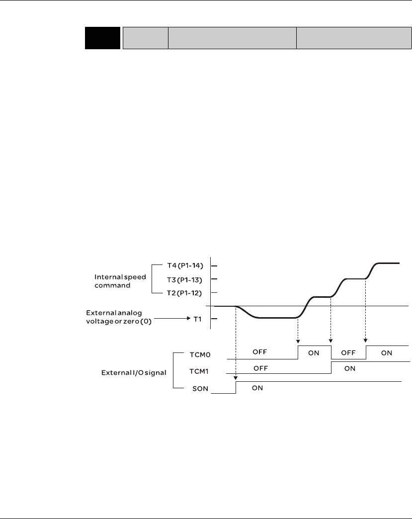
7. Operation Lexium 23A
198 AC servo drive
Relevant parameters:
7.3.4.5 Timing
Chart of Torque
Control Mode
Note:
1) OFF indicates normally open and ON indicates normally closed.
2) When torque control mode is Tz, the torque command T1=0; when torque control
mode is T, the speed command T1 is external analog voltage input (Please refer to
P1-01).
3) After Servo ON, the users can select command according to the state of TCM0~1.
P1-41r TCM Max. Analog Torque Command or
Limit Address: 0152H, 0153H
Default: 100 Related Section:
Applicable Control Mode: ALL Section 7.3.4.4
Unit: %
Range: 0 ~ 1000
Data Size: 16-bit
Display Format: Decimal
Settings:
In Torque mode, this parameter is used to set the maximum analog torque
command based on the maximum input voltage (10V).
In Position (Pt, Pr) and Speed mode, this parameter is used to set the maximum
analog torque limit based on the maximum input voltage (10V).
For example, in torque mode, if P1-41 is set to 100 and the input voltage is 10V, it
indicates that the torque command is 100% rated torque. If P1-41 is set to 100, but
the input voltage is changed to 5V, then the torque command is changed to 50%
rated torque.
Torque Command / Limit = Input Voltage Value x Setting value of P1-41 / 10
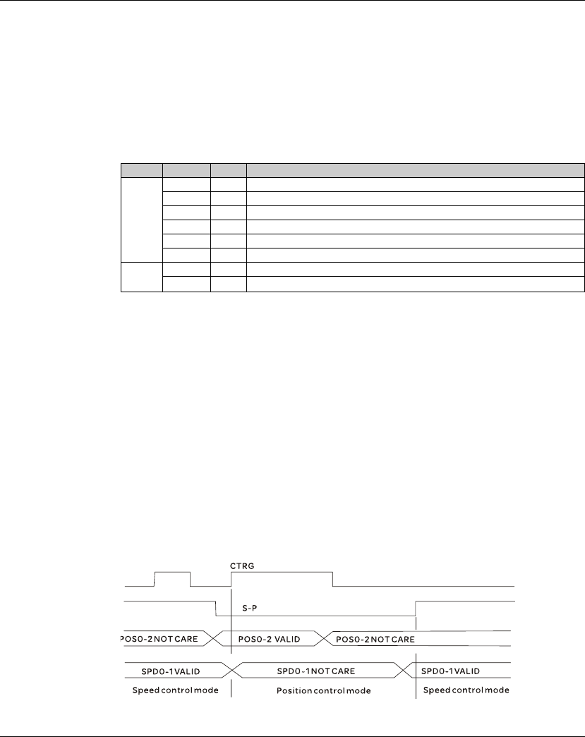
Lexium 23A 7. Operation
AC servo drive 199
7.3.5 Control Modes Selection
Except signal control mode operation, Lexium 23 Plus series servo drives also provide
many dual and multiple modes for the users to select.
1) Speed / Position mode selection: Pt-S, Pr-S, Pt-Pr
2) Speed / Torque mode selection: S-T
3) Torque / Position mode selection: Pt-T, Pr-T
4) Position / Speed multiple mode selection: Pt-Pr-S
5) Position / Torque multiple mode selection: Pt-Pr-T
Sz and Tz mode selection is not provided. In order to avoid using too much DI inputs,
we recommend that the users can use external analog signal as input command in
speed and torque mode to reduce the use of DI inputs (SPD0~1 or TCM0~1). In
position mode, we recommend that the users can use Pt mode to input pulse to
reduce the use of DI inputs (POS0~5).
Please refer to table 3.B and table 3.C in section 3.3.2 to see the default pin number of
DI/DO signal.
7.3.5.1 Speed /
Position Control
Mode Selection
Pt-S Mode / Pr-S Mode:
The command source of Pt-S mode is from external input pulse. The command
source of Pr-S mode is from internal parameters (P6-00 to P6-17). The speed
command can be the external analog voltage or internal parameters (P1-09 to P1-11).
The speed and position mode switching is controlled by the S-P signal. The selection
will be more complicated when the position of Pr-S mode and speed command are
both selected through DI signal.
The timing chart of speed / position control mode selection is shown as the figure below:
Figure 1. : Speed / Position Control Mode Selection
Mode Name Code Description
Dual
Mode
Pt-S 06 Either Pt or S control mode can be selected via the Digital Inputs (DI)
Pt-T 07 Either Pt or T control mode can be selected via the Digital Inputs (DI)
Pr-S 08 Either Pr or S control mode can be selected via the Digital Inputs (DI)
Pr-T 09 Either Pr or T control mode can be selected via the Digital Inputs (DI)
S-T 0A Either S or T control mode can be selected via the Digital Inputs (DI)
Pt-Pr 0D Either Pt or Pr control mode can be selected via the Digital Inputs (DI).
Multipl
e Mode
Pt-Pr-S 0E
Either Pt or Pr or S control mode can be selected via the Digital Inputs (DI).
Pt-Pr-T 0F
Either Pt or Pr or T control mode can be selected via the Digital Inputs (DI).
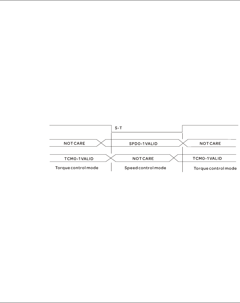
7. Operation Lexium 23A
200 AC servo drive
In speed mode (when S-P is ON), speed command is selected by SPD0~1 and CTRG is
disabled at this time. When switching to the position mode (when S-P is OFF), the
position command is not determined (it needs to wait that CTRG is on the rising
edge), so the motor stop running. Once CTRG is on the rising edge, position
command will be selected according to POS0~5 and the motor will immediately move
to the determined position. After S-P is ON, it will immediately return to speed mode.
For the relationship between DI signal and selected command in each mode, please
refer to the introduction of single mode.
7.3.5.2 Speed /
Torque Control
Mode Selection
S-T Mode:
The speed command can be the external analog voltage or internal parameters (P1-
09 to P1-11) and SPD0~1 is used to select speed command. The same as speed
command, the torque command can be the external analog voltage or internal
parameters (P1-12 to P1-14) and TCM0~1 is used to select torque command. The
speed and torque mode switching is controlled by the S-T signal.
The timing chart of speed / torque control mode selection is shown as the figure
below:
Figure 2. : Speed / Torque Control Mode Selection
In torque mode (when S-T is ON), torque command is selected by TCM0~1. When
switching to the speed mode (when S-T is OFF), the speed command is selected by
SPD0~1, and then the motor will immediately rotate following the command. After S-
T is ON again, it will immediately return to torque mode.
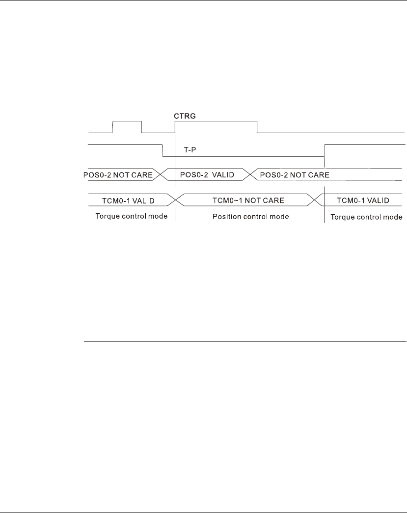
Lexium 23A 7. Operation
AC servo drive 201
7.3.5.3 Torque /
Position Control
Mode Selectionn
Pt-T Mode / Pr-T Mode:
The command source of Pt-T mode is from external input pulse. The command
source of Pr-T mode is from internal parameters (P6-00 to P6-17). The torque
command can be the external input pulse or internal parameters (P1-12 to P1-14). The
torque and position mode switching is controlled by T-P signal. The selection will be
more complicated when the position of Pr-T mode and torque command are both
selected through DI signal.
The timing chart of speed / position control mode selection is shown as the figure
below:
Figure 3. :Torque / Position Control Mode Selection
In torque mode (when T-P is ON), torque command is selected by TCM0~1 and CTRG
is disabled at this time. When switching to the position mode (when T-P is OFF), the
position command is not determined (it needs to wait that CTRG is on the rising
edge), so the motor stop running. Once CTRG is on the rising edge, position
command will be selected according to POS0~5 and the motor will immediately move
to the determined position. After T-P is ON, it will immediately return to torque mode.
For the relationship between DI signal and selected command in each mode, please
refer to the introduction of single mode.
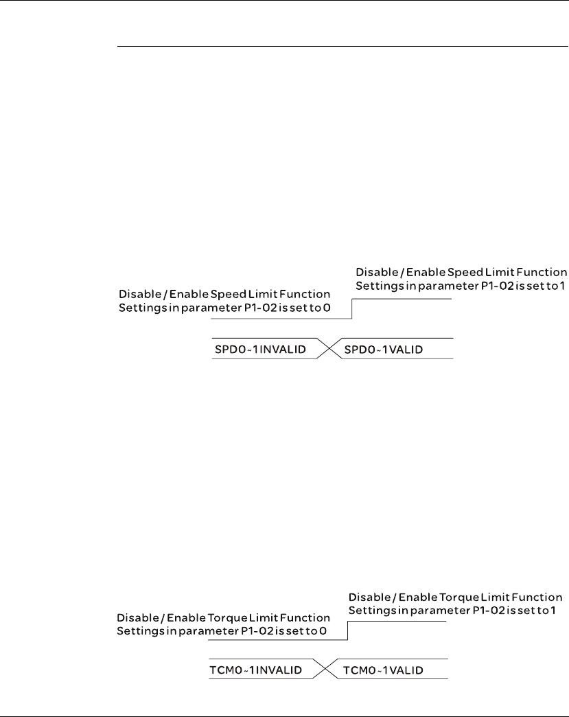
7. Operation Lexium 23A
202 AC servo drive
7.4 Other functions
7.4.1 Speed Limit
The max. servo motor speed can be limited by using parameter P1-55 no matter in
position, speed or torque control mode.
The command source of speed limit command is the same as speed command. It can be
the external analog voltage but also can be internal parameters (P1-09 to P1-11). For more
information of speed command source, please refer to chapter 7.3.3.1.
The speed limit only can be used in torque mode (T mode) to limit the servo motor
speed. When the torque command is the external analog voltage, there should be
surplus DI signal that can be treated as SPD0~1 and be used to select speed limit
command (internal parameter). If there is not enough DI signal, the external voltage
input can be used as speed limit command. When the Disable / Enable Speed Limit
Function Settings in parameter P1-02 is set to 1, the speed limit function is activated.
The timing chart of speed limit is shown as the figure below:
Command Source Selection of Speed Limit
7.4.2 Torque Limit
The command source of torque limit command is the same as torque command. It can be
the external analog voltage but also can be internal parameters (P1-12 to P1-14). For more
information of torque command source, please refer to chapter 7.3.4.1.
The torque limit only can be used in position mode (Pt and Pr mode) and speed mode (S
mode) to limit the output torque of servo motor. When the position command is the
external pulse and speed command is the external analog voltage, there should be
surplus DI signal that can be treated as TCM0~1 used to select torque limit command
(internal parameter). If there is not enough DI signal, the external voltage input can be
used as torque limit command. When the Disable / Enable Torque Limit Function Settings
in parameter P1-02 is set to 1, the torque limit function is activated.
The timing chart of torque limit is shown as the figure below:
Command Source Selection of Torque Limit
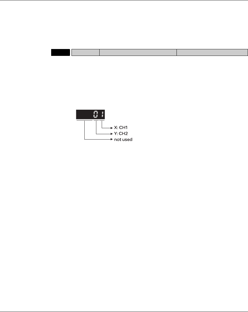
Lexium 23A 7. Operation
AC servo drive 203
7.4.3 Analog Monitor
Users can use analog monitor to observe the required analog voltage signals.
Lexium23 Plus series servo drives provide two analog channels, they are PIN No. 15
and 16 of CN1 connector. The parameters relative to analog monitor are shown below.
Relevant parameters:
P0 - 03 MON Analog Monitor Output Address: 0006H, 0007H
Default: 01 Related Section:
Applicable Control Mode: ALL Section 6.3.3.5
Unit: N/A
Range: 00 ~ 77
Data Size: 16-bit
Display Format: Hexadecimal
Settings:
This parameter determines the functions of the analog monitor outputs.
XY: (X: CH1; Y: CH2)
0: Motor speed (+/-8V / maximum motor speed)
1: Motor torque (+/-8V / maximum torque)
2: Pulse command frequency (+8Volts / 4.5Mpps)
3: Speed command (+/-8Volts / maximum speed command)
4: Torque command (+/-8Volts / maximum torque command)
5: V_BUS voltage (+/-8Volts / 450V)
6: Reserved
7: Reserved
Please note: For the setting of analog output voltage proportion, refer to the P1-04
and P1-05.
Example:
P0-03 = 01(CH1 is speed analog output)
Motor speed = (Max. motor speed x V1/8) x P1-04/100, when the output voltage value
of CH1 is V1.
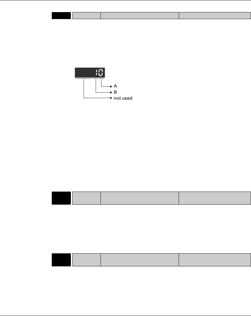
7. Operation Lexium 23A
204 AC servo drive
P1 - 03 AOUT Pulse Output Polarity Setting Address: 0106H, 0107H
Default: 0 Related Section:
Applicable Control Mode: ALL Section 5.2.8.3
Unit: N/A
Range: 0 ~ 13
Data Size: 16-bit
Display Format: Hexadecimal
Settings:
This parameter is used to determine the polarity of analog monitor outputs and
position pulse outputs. The analog monitor outputs can be configured with different
polarity individually, but the position pulse outputs have to be each with the same
polarity.
A: Analog monitor outputs polarity
0: MON1(+), MON2(+)
1: MON1(+), MON2(-)
2: MON1(-), MON2(+)
3: MON1(-), MON2(-)
B: Position pulse outputs polarity
0: Forward output
1: Reverse output
P1 - 04 MON1 Analog Monitor Output
Proportion 1 (CH1) Address: 0108H, 0109H
Default: 100 Related Section:
Applicable Control Mode: ALL Section 7.3.4.4
Unit: % (full scale)
Range: 0 ~ 100
Data Size: 16-bit
Display Format: Decimal
P1 - 05 MON2 Analog Monitor Output
Proportion 2 (CH2) Address: 010AH, 010BH
Default: 100 Related Section:
Applicable Control Mode: ALL Section 7.3.4.4
Unit: % (full scale)
Range: 0 ~ 100
Data Size: 16-bit
Display Format: Decimal
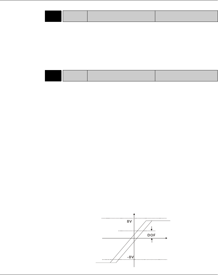
Lexium 23A 7. Operation
AC servo drive 205
For example, when the users want to observe the analog voltage signal of channel 1, if
the monitor output setting range is 8V per 325Kpps, then it is needed to change the
setting value of parameter P1-04 (Analog Monitor Output Proportion 1) to 50
(=325Kpps/Max. input frequency). Other related parameters setting include
parameter P0-03 (A=3) and P1-03 (A=0~3, output polarity setting). In general, when
output voltage value of Ch1 is V1, the pulse command frequency is equal to (Max.
input frequency ×V1/8) × P1-04/100.
Because there is an offset value of analog monitor output voltage, the zero voltage
level of analog monitor output does not match to the zero point of setting value. We
recommend the users can use Analog Monitor Output Drift Adjustment, DOF1
(parameter P4-20) and DOF2 (parameter P4-21) to improve this condition. The
maximum output voltage range of analog monitor output is ±8V. If the output
voltage exceed its limit, it is still limited within the range of ±8V. The revolution
provided by Lexium23 Plus series servo drives is 10bit, approximated to 13mv/LSB.
P4 - 20 DOF1 Analog Monitor Output Drift
Adjustment (CH1) Address: 0428H, 0429H
Default: Factory setting Related Section:
Applicable Control Mode: ALL Section 7.3.4.4
Unit: mV
Range: -800 ~ 800
Data Size: 16-bit
Display Format: Decimal
Settings:
Please note that when P2-08 is set to 10, the users cannot reset this parameter.
P4 - 21 DOF2 Analog Monitor Output Drift
Adjustment (CH2) Address: 042AH, 042BH
Default: Factory setting Related Section: N/A
Applicable Control Mode: ALL Section 7.3.4.4
Unit: mV
Range: -800 ~ 800
Data Size: 16-bit
Display Format: Decimal
Settings:
Please note that when P2-08 is set to 10, the users cannot reset this parameter.
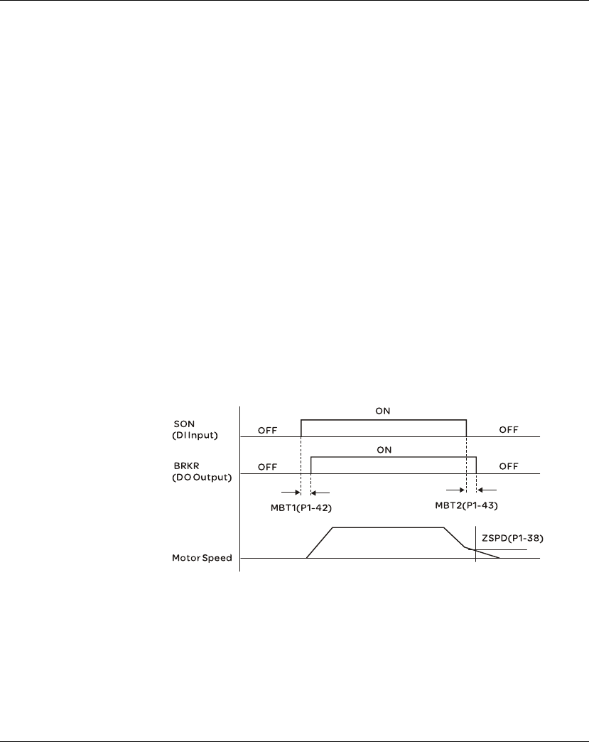
7. Operation Lexium 23A
206 AC servo drive
7.4.4 Electromagnetic Brake
When the servo drive is operating, if the digital output BRKR is set to Off, it indicates
the electromagnetic brake is disabled and motor is stop running and locked. If the
digital output BRKR is set to ON, it indicates electromagnetic brake is enabled and
motor can run freely.
There are two parameters that affect the electromagnetic brake. One is parameter
P1-42 (MBT1) and the other is parameter P1-43 (MBT2). The users can use these two
parameters to set the On and Off delay time of electromagnetic brake. The
electromagnetic brake is usually used in perpendicular axis (Z-axis) direction to
reduce the large energy generated from servo motor. Using electromagnetic brake
can avoid the load may slip since there is no motor holding torque when power is off.
Without using electromagnetic brake may reduce the life of servo motor. To avoid
malfunction, the electromagnetic brake should be activated after servo system is off
(Servo Off).
If the users desire to control electromagnetic brake via external controller, not by the
servo drive, the users must execute the function of electromagnetic brake during the
period of time when servo motor is braking. The braking strength of motor and
electromagnetic brake must be in the same direction when servo motor is braking.
Then, the servo drive will operate normally. However, the servo drive may generate
larger current during acceleration or at constant speed and it may the cause of
overload (servo fault).
Timing chart for using servo motor with electromagnetic brake:
BRKR output timing explanation:
1. When Servo Off (when DI SON is not activated), the BRKR output goes Off
(electromagnetic brake is locked) after the delay time set by P1-43 is reached and
the motor speed is still higher than the setting value of P1-38.
2. When Servo Off (when DI SON is not activated), the BRKR output goes Off
(electromagnetic brake is locked) if the delay time set by P1-43 is not reached and
the motor speed is still lower than the setting value of P1-38.
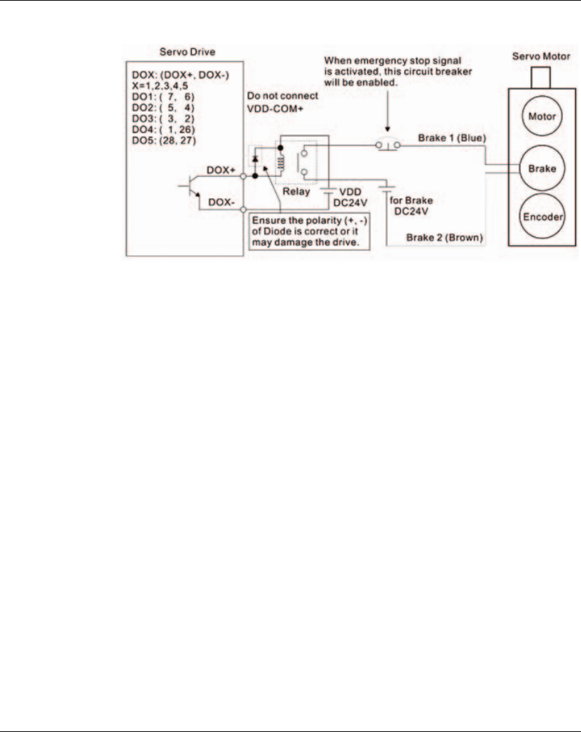
Lexium 23A 7. Operation
AC servo drive 207
Electromagnetic Brake Wiring Diagram
Note:
1) Please refer to Chapter 5 installation for more wiring information.
2) The BRKR signal is used to control the brake operation. The VDD DC24V power
supply of the servo drive can be used to power the relay coil (Relay). When BRKR
signal is ON, the motor brake will be activated.
3) Please note that the coil of brake has no polarity.
4) The power supply for brake is DC24V. Never use it for VDD, the +24V source
voltage.
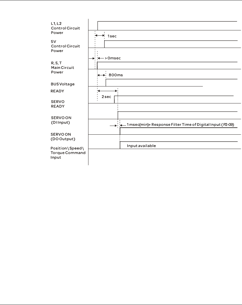
7. Operation Lexium 23A
208 AC servo drive
The timing charts of control circuit power and main circuit power:

AC servo drive 209
8
Motion Control Function
At a Glance
What's in this
Chapter? This chapter contains the following topics:
Topic Page
Available Motion Control Functions 210
Servo Drive Information 210
Motion Axis 216
Pr Mode Introduction 217
Pr mode Comparison 218
Position Command Unit of Pr Mode 218
Registers of Pr Mode 219
Homing Function of Pr Mode 220
DI and DO signals of Pr Mode 221
Parameter Settings of Pr Mode 223

8. Motion Control Function Lexium 23A
210 AC servo drive
8.1 Available Motion Control Functions
Lexium23 Plus servo drives provides the following motion control functions:
1) Pr mode for single-axis motion control
2) CAPTURE / COMPARE functions
8.2 Servo Drive Information
The information of the servo drive includes: 1. Servo Parameters; 2. Monitor Variables.
Servo Parameters Monitor Variables
Usage
Operation mode, important data and
conditions of the servo drive, such as
position/speed/torque control
modes, position/speed loop gain, etc.
Real-time status of the servo drive or
motor, such as motor position, motor
speed and current settings, etc.
Display Method
LED Display: display PX-XX on the
display. Press the ENT key to display
the setting value of parameters. For
the operation of the digital keypad,
please refer to Chapter 6.3.
Set P0-02 directly to enter into monitor
mode and specify the monitor status.
The monitor status depends on the
setting value of P0-02. Press MODE
key on the keypad is to enter into
monitor mode directly. For the
operation of the digital keypad, please
refer to Chapter 6.3.
Access Method Able to read and write (depends on
the settings of parameters) Read only
Data Length 16-bit or 32-bit (depends on the
settings of parameters) 32-bit integer
Communication
Support MODBUS/CANopen Read &
Write, each parameter occupy two
MODBUS addresses.
zMonitoring is accomplished through
CN3 (upon commissioning tool)
zDo not support MODBUS/CANopen
Read & Write directly unless the users
use mapping function to monitor the
specified monitor variable via the
corresponding system parameters.
Mapping
Parameters
P0-25 ~ P0-32, total 8 parameters
(Determined by P0-35 ~ P0-42)
P0-09 ~ P0-13, total 5 parameters
(Determined by P0-17 ~ P0-21)
Remark -
In monitor mode, the users can press UP
or DOWN arrow key to change the
monitor variables in common use (code
0 ~ 26). Please note that not all monitor
variables can be displayed (total 150
kinds of monitor variables).

Lexium 23A 8. Motion Control Function
AC servo drive 211
8.2.1 Monitor Variables
Please refer to the following table for the explanation of monitor variables:
Item Explanation
Variable Code Each monitor variable has one corresponding code. The parameter P0-02 is
used to set this code and monitor the monitor variable.
Format Each monitor variable is saved in 32-bit (long integer) in the servo drive.
Type
There are two types of monitor variables, basic variable and extension
variable:
1. Basic variable: Enter into monitor mode by pressing MODE key on the
digital keypad. In monitor mode, press / arrow keys to find the
available monitor variables (P0-02=0~26).
Extension variable: Other variables are called extension variables except
basic variables (P0-02=27~127).
Monitor
Method
There are two kinds of methods for monitoring the monitor variables, one is
through
LED display of the digital keypad and the other is via mapping parameters:
1. LED display of digital keypad: Monitor the monitor variables through the
LED display of the digital keypad directly.
2. Mapping parameters: The settings of monitor variables will be reflected on
the setting value of the parameters. The users can know the settings of
monitor variables through the corresponding parameters.
Display
1. Press key to switch to monitor mode and then press / arrow
keys to select the desired monitor variables.
2. Set P0-02 directly and then display the settings of the desired monitor
variables.
Press key to switch high/low byte display;
Press key to switch decimal/hexadecimal display.
Mapping
Function
1. The parameters which support mapping function includes: P0-09 ~ P0-13.
(Please refer to section 11.4 "Detailed Parameter Listings" of Chapter 11.
2. Using mapping parameters and read & write monitor variables through
communication.
3. The setting values of P0-09 ~ P0-13 (Status Monitor 1 ~ 5) are the content
of basic variables (17h,18h,19h,1Ah). When the users want to monitor
P0-09, P0-17 must be set first to read the status value (see P0-02). When
reading the drive status through Modbus communication, the system will
read the monitor status which specified by P0-17. When reading the drive
status through the keypad, if P0-02 is set to 23, VAR-1 will quickly show for
about two seconds and then the value of P0-09 will display on the display.
M
S
ENT

8. Motion Control Function Lexium 23A
212 AC servo drive
Attribute of monitor variables:
Attribute Explanation
.
Basic variable. The monitor variables which can be scrolled through by
pressing / keys.
0D Decimal place display.
0$ indicates one decimal place, 0% indicates two decimal place.
e
0? Decimal display only. When pressing key on the keypad, the system can
not switch to hexadecimal display.
ex
4Hexadecimal display only. When pressing key on the keypad, the system
can not switch to decimal display.
ENT
ENT

Lexium 23A 8. Motion Control Function
AC servo drive 213
Explanation of monitor variables:
Code Monitor Variable /
Attribute Explanation
000
(00h)
Feedback position
(PUU) .Motor feedback - current position. Unit is user unit, PUU.
001
(01h)
Position command
(PUU) .
Position command – current position. Unit is user unit, PUU.
Pt mode: it indicates the pulse command received by the servo
drive.
Pr mode: it indicates the absolute position command.
It is equal to the pulse number sent by the host (external)
controller.
002
(02h)
Position error
(PUU) .
Position error counts between position command pulse and
feedback pulse. Unit is user unit, PUU.
003
(03h)
Feedback position
(pulse) .Motor feedback - current position. Unit is encoder unit, pulse.
004
(04h)
Position command
(pulse) .
Position command - current position. Unit is encoder unit, pulse.
It is also the position command after electronic gear ratio is set.
005
(05h)
Position error
(pulse) .
Position error counts between position command pulse and
feedback pulse. Unit is encoder unit, pulse.
006
(06h)
Input frequency of
pulse command .
Input frequency of pulse command received by the servo drive.
Unit is Kpps. Applicable for Pt and Pr mode.
007
(07h)
Feedback speed
. 0$ e0?
Actual motor speed. Unit is 0.1 rpm.
The low-pass filter function is used so the value is more stable.
008
(08h)
Speed input
command (Analog)
. 0% e0?
Analog speed input command. Unit is 0.01Volt.
009
(09h)
Speed command
(Integrated) .
Integrated speed input command. Unit is 1 rpm.
The command source may be from analog command / internal
parameter / position loop.
010
(0Ah)
Torque command
(Analog) . 0% e0? Analog torque input command. Unit is 0.01Volt.
011
(0Bh)
Torque command
(Integrated) .
Integrated torque input command. Unit is Percent (%).
The command source may be from analog command / internal
parameter / position loop.
012
(0Ch) Average load .Average load output by the servo drive. Unit is Percent (%).
013
(0Dh) Peak load .Peak load output by the servo drive. Unit is Percent (%)。
014
(0Eh) DC Bus voltage .Main circuit voltage after rectification. Unit is Volt.
015
(0Fh
Ratio of load inertia
to motor inertia
. 0$ e0?
Ratio of load inertia to motor inertia. Unit is 0.1times.
016
(10h) IGBT temperature .IGBT temperature. Unit is C.

8. Motion Control Function Lexium 23A
214 AC servo drive
Code Monitor Variable /
Attribute Explanation
017
(11h)
Resonance frequency
. e0?
Resonance frequency of the mechanical system.
There are two groups of resonance frequency: F1 and F2
When reading the drive status through the keypad, pressing
key can switch the display of F1 and F2.
F2: no decimal point; F1: display one decimal point
When reading the drive status through the communication,
Low 16-bit (Low Byte) will display frequency F2
High 16-bit (High Byte) will display frequency F1
018
(12h)
Absolute pulse
number
relative to encoder
(use Z phase as
home) . e0?
Absolute pulse number relative to encoder (use Z phase as
home).
The value of Z phase home point is 0, and it can be the value from
-
5000 to +5000 pulses. When the value is higher, the deviation
pulse number is higher too.
019
(13h)
Mapping parameter
#1 .
Display the content of parameter P0-25 (mapping target is
specified by parameter P0-35)
020
(14h)
Mapping parameter
#2 .
Display the content of parameter P0-26 (mapping target is
specified by parameter P0-36).
021
(15h)
Mapping parameter
#3 .
Display the content of parameter P0-27 (mapping target is
specified by parameter P0-37).
022
(16h)
Mapping parameter
#4 .
Display the content of parameter P0-28 (mapping target is
specified by parameter P0-38).
023
(17h) Status monitor #1 .Display the content of parameter P0-09 (the monitor status is
specified by parameter P0-17).
024
(18h) Status monitor #2 .Display the content of parameter P0-10 (the monitor status is
specified by parameter P0-18).
025
(19h) Status monitor #3 .Display the content of parameter P0-11 (the monitor status is
specified by parameter P0-19).
026
(1Ah) Status monitor #4 .Display the content of parameter P0-12 (the monitor status is
specified by parameter P0-20).
039
(27h)
DI status (Integrated)
ex4
Integrated DI status. Each bit corresponds to one channel of
digital input.
The command source may be from DI signal or communication
control (upon software). P3-06 can determine how digital inputs
accept commands.
040
(28h)
DO status (Hardware)
ex4
Actual DO output status. Each bit corresponds to one channel of
digital output.
041
(29h) Drive Status The drive status will display via P0-46. Please refer to P0-46 for
explanation.
043
(2Bh) Capture data The latest captured data by using Capture function.
Note: Using Capture function is able to capture many positions.
049
(31h) Pulse command CNT Pulse counts input by pulse command (CN1).
050
(32h)
Speed command
(Integrated) 0$ e0?
Integrated speed input command. Unit is 0.1 rpm.
The command source may be from analog command / internal
parameter / position loop.
S

Lexium 23A 8. Motion Control Function
AC servo drive 215
Code Monitor Variable /
Attribute Explanation
051
(33h)
Feedback speed
(Instant) 0$ e0? Actual motor speed. Unit is 0.1rpm.
052
(34h)
Feedback speed
(Filter) 0$ e0?
Actual motor speed. Unit is 0.1 rpm.
(The low-pass filter function is used.)
053
(35h)
Torque command
(Integrated) 0$ e0?
Integrated torque command. Unit is 0.1Percent (%).
The command source may be from analog command / internal
parameter / speed loop.
054
(36h)
Feedback Torque
0$ e0? Actual motor torque. Unit is 0.1Percent(%).
055
(37h)
Feedback current
0% e0? Actual motor current. Unit is 0.01ampere (Amp).
056
(38h)
DC Bus voltage
0$ e0? Main circuit voltage after rectification. Unit is 0.1Volt.
064
(40h)
End register of Pr
command. In Pr mode, it is the end of the position command (Cmd_E).
065
(41h)
Output register of Pr
command. In Pr mode, it is the accumulated outputs of position command.
067
(43h)
Target speed of Pr
command.
It is target speed of Pr path command. Unit is PPS (Pulse Per
Second).
068
(44h) S-curve filter (Input)
Input data of S-curve filter which is used to create the effect of
Scurve filter. In Pr mode, it is effective for internal speed
command.
069
(45h) S-curve filter (Output)
Output data of S-curve filter which is used to create the effect of
Scurve filter. In Pr mode, it is effective for internal speed
command.
076
(4Ch)
Speed command of Pr
mode
In Pr mode, it is the terraced speed curve drawn up according to
target speed / accel & decel time / position move (before using
Scurve filter). Unit is PPS (Pulse Per Second).
096
(60h)
Firmware version of
servo drive e0?
Includes 2 versions: DSP and CPLD
When reading the firmware version through the keypad,
pressing key can switch the version display of DSP and
CPLD.
DSP: no decimal place; CPLD: it will display one decimal place.
When reading the firmware version through the communication
(using mapping parameters):
Low 16-bit (Low word) will display DSP firmware version.
High 16-bit (High word) will display CPLD firmware version.
111
(6Fh) Servo fault code Display servo fault code. But it only displays the servo drive fault
code. The fault code for motion control will not be displayed.
123
(7Bh) Keypad monitor value When reading the monitor value through the keypad, it is used to
read the monitor value displayed on the keypad.
S

8. Motion Control Function Lexium 23A
216 AC servo drive
8.3 Motion Axis
Motion axis is a counter within the servo drive which is used to count the data of
absolute position (32-bit integer). The available motion axes are introduced in the
following table.
Axis Name Description Read (R) /
Write (W) Attribute
1. Motor encoder
axis (P5-16)
It indicates the motor absolute feedback position
and the user unit is PUU. RSubstantial
axis
2. Pulse command
axis (P5-18)
It is the pulse counts of the host (external)
controller input from CN1. The pulse type can be
defined by P1-00.
R/W Substantial
axis
3. Capture Axis1
(P5-37) and
Capture Axis2
(P5-57)
It is the motion axis which is used to enable
Capture function. The command source could be
from motor encoder axis and pulse command axis.
Position offset exists between output axis and
substantial axis. After the first point is captured,
the axis position can be defined again.
R/W Output axis
4. Pr command axis Command position defined by Pr path. R Suppositional
axis
5. Internal time axis Internal timer. The value will increase 1 every
1msec. RSuppositional
axis
Please note:
1. Substantial axis: Position value is obtained from the actual terminal signal counts.
2. Output axis: It is the axis output by the substantial axis. The value will be not the same as the source
of substantial axis, but the increasing value will be the same as the increasing value of substantial
axis.
3. Suppositional axis: It is the axis generated by the servo firmware, e.g. Pr command axis. It is unable
to command in real time so it could not be the command axis for Capture function.

Lexium 23A 8. Motion Control Function
AC servo drive 217
8.4 Pr Mode Introduction
Pr mode could be composed of one position command or multiple position
commands, and triggered by DI signal, CTRG. DI signals, POS0 ~ POS2 are used to
specify the desired trigger position.

8. Motion Control Function Lexium 23A
218 AC servo drive
8.5 Position Command Unit of Pr Mode
The position command unit of Pr mode is presented by PUU(Pulse of User Unit). It also
indicates the ratio of position command unit of host (external) controller to internal
position command unit of servo drive, i.e. electronic gear ratio of servo drive.
1) Position command unit of servo drive (pulse): encoder unit, 1280000pulses per
revolution (pulse/rev).
2) User unit (PUU): unit of host (external) controller. If the pulse number per
revolution is P pulses (PUU/rev), then the electronic gear ratio should be set to:
GEAR_NUM(P1-44) / GEAR_DEN(P1-45) = 1280000 / P

Lexium 23A 8. Motion Control Function
AC servo drive 219
8.6 Registers of Pr Mode
1) Position registers of Pr mode: They are indicates as user unit, PUU.
2) Command register (Monitor variable 064): End register of Pr command, Cmd_E. It
indicates the end of the position command.
3) Position output register (Monitor variable 001): Cmd_O. It indicates the current
output absolute position command.
4) Feedback register (Monitor variable 000): Fb_PUU. It indicates the current motor
feedback position.
5) Error register (variable 002): Err_PUU. It indicates the position error counts
between position command pulse and feedback pulse.
6) In Pr mode, at any time (no matter during operation or at stop): Err_PUU =
Cmd_O - Fb_PUU.
The effect from position commands:
Command
Type
When position command is
given =>
=> When position
command is executing=>
=> When position
command is completed
Absolute
position
command
Cmd_E = command data
(absolute)
Cmd_O retain unchanged
DO signal: CMD_OK is OFF
Cmd_E retain unchanged
Cmd_O continuously
output
...
Cmd_E retain unchanged
Cmd_O = Cmd_E
DO signal: CMD_OK is ON
Incremental
position
command
Cmd_E+= command data
(incremental)
Cmd_O retain unchanged
DO signal: CMD_OK is OFF
Cmd_E retain unchanged
Cmd_O continuously
output
...
Cmd_E retain unchanged
Cmd_O = Cmd_E
DO signal: CMD_OK is ON
Stop
command
DI signal,
STP
Cmd_E retain unchanged
Cmd_O continuously
output
DO: CMD_OK output retain
unchanged
Cmd_E retain unchanged
Cmd_O stop in
accordance
with deceleration curve
Cmd_E retain unchanged
Cmd_O = position at stop
DO signal: CMD_OK is ON
Homing
command
Cmd_E retain unchanged
Cmd_O retain unchanged
DO signal: CMD_OK is OFF
DO signal: HOME is OFF
Cmd_E continuously
output
Cmd_O continuously
output
...
...
Cmd_E = Z pulse (absolute
position)
Cmd_O = position at stop
DO signal: CMD_OK is ON
DO signal: HOME is ON
Speed
command
Cmd_E continuously output
Cmd_O continuously output. After speed command is completed, it indicates that the
speed reaches the setting value and the motor will not stop.
DO signal: CMD_OK is OFF
Enter Pr at the first time ( Servo Off ->
Servo On
or other mode for entering Pr mode)
Cmd_O = Cmd_E = current motor feedback position
Note: The incremental position command performs accumulation according to the end of the
position command (Cmd_E). It is irrelevant to current motor position and command timing as well.

8. Motion Control Function Lexium 23A
220 AC servo drive
8.7 Homing Function of Pr Mode
The homing function determines the homing characteristics of servo motors. The
purpose of homing function is used to connect the position of Z pulse of motor
encoder to the internal coordinate of the servo drive. The coordinate value
corresponds to Z pulse can be specified.
After homing operation is completed, the stop position will not locate at the position
of Z pulse. This is
because the motor must accelerate to stop when Z pulse is found. Generally, the
motor stop position will be a little ahead of the position of Z pulse. At this time, Z pulse
is set correctly so it will not affect the position precision.
For example, if the coordinate corresponds to Z pulse is set to 100, after homing
operation is completed, Cmd=300. It indicates that the acceleration distance is equal
to 300-100=200(PUU). Since Cmd_E=100 (absolute position of Z pulse), if the users
want to command the motor to return to the position of Z pulse, just set absolute
position command to 100 or incremental position command to 0.
In Pr mode of Lexium23 Plus servo drives series, after homing operation, it can
execute the specified path and command the motor to return to the position of Z
pulse automatically.
When homing function is executed, the software limit function is disabled.
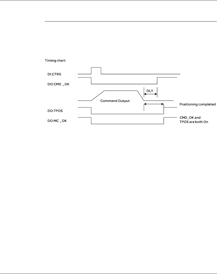
Lexium 23A 8. Motion Control Function
AC servo drive 221
8.8 DI and DO signals of Pr Mode
DI signals:
CTRG, SHOM, STP, POS0 ~ POS2, ORG, PL(CCWL), NL(CWL)
DO signals:
CMD_OK, MC_OK, TPOS, ALRM, CAP_OK

8. Motion Control Function Lexium 23A
222 AC servo drive
Trigger method of Pr command:
There are 8 position settings in Pr mode. Path 0 is homing mode and the others (Path
1 ~ 8) can be userdefined. For the trigger method of Pr command, please refer to the
table below:
Command Source Explanation
Standard
Method
DI signals:
CTRG + POS0 ~ 2
Use DI signals, POS0 ~ 5 to specify the desired trigger path
number, and then use the rising-edge of DI signal, CTRG to
trigger Pr command.
Suitable application: PC or PLC commands the servo drive by
using DI signals
Special
Method DI signals: STP,SHM
DI signal: Set STP from OFF V ON, and the command will stop.
DI signal: Set SHOM from OFF V ON, and the servo drive will
start to perform homing operation.
Software
Setting P5-07
Set P5-07 to the desired trigger path number and it will
trigger the dedicated position command immediately.
P5-07 can be set through the keypad / communication
(RS-485 and CANopen).
Suitable application: PC or PLC commands the servo drive by
using the communication.

Lexium 23A 8. Motion Control Function
AC servo drive 223
8.9 Parameter Settings of Pr Mode
1) Target speed: P5-60 ~ P5-75 (Moving Speed Setting of Position 0 ~ 15), total 16
groups
2) Accel / Decel time: P5-20 ~ P5-35 (Accel / Decel Time 0 ~ 15), total 16 parameters
Note: The acceleration time is used for DO signals, STP/EMS/NL(CWL)/PL(CCWL)
when the users want to stop the motor. The function of P5-07 will refer to this setting
when perform stop positioning as well.
3) Delay time: P5-40 ~ P5-55 (Delay Time 0 ~ 15), total 16 groups.
4) Path parameters: P5-00 ~ P5-09, P6-00 ~ P6-01, total 12 DWORD.
Bit 15 ~ 0
W0 TARGET_SPEED:0.1 ~ 6000.0(rpm)
Bit 15 ~ 0
W0 T_ACC / T_DEC:1 ~ 65500(msec)
Bit 15 ~ 0
W0 IDLE:0 ~ 32767(msec)
32 BIT
P5-00 Reserved
P5-01 Reserved (for internal testing, do not use it)
P5-02 Reserved (for internal testing, do not use it)
P5-03 Deceleration Time of Protectin Function
P5-04 Homing Mode
P5-05 1st Speed Setting of High Speed Homing
P5-06 2nd Speed Setting of Low Speed Homing
P5-07 Trigger Position Command (Pr mode only)
P5-08 Forward Software Limit
P5-09 Reverse Software Limit
P6-00 Homing Definition
P6-01 Homing Definition Value (Z pulse position)

8. Motion Control Function Lexium 23A
224 AC servo drive
5) Path Definition: P6-02 ~ P6-17 (64 BIT), total 8 groups (2N).
Each path occupies two parameters.
OPT:
* It can accept DI signals, STP (Motor Stop), SNL(SCWL, Reverse Software Limit),
SPL(SCCWL, Forward Software Limit).
INS: Interrupt the previous path.
CMD: The calculation method for Cmd_E (End of position command) is described in
the notes below:
Note 1: The end of position command is an absolute position command which is equal
to DATA directly.
Note 2: The end of the position command is an incremental position command which
is equal to the end of the position command (Cmd_E, monitor variable 40h) plus a
designated DATA.
ACC: Acceleration time
DEC1 / DEC2: 1st deceleration time / 2nd deceleration time.
DLY: Delay time
BIT 31 ~ 28 27 ~ 24 23 ~ 20 19 ~ 16 15 ~ 12 11 ~ 8 7 ~ 4 3 ~ 0
DW0 - - DLY SPD DEC ACC OPT 0
DW1 DATA (32 bit): Target Position. Unit: Pulse of User Unit
OPT
Bit 7 Bit 6 Bit 5 Bit 4 Explanation
CMD -INS
00
0-
Absolute position command: Cmd_E = DATA (Note 1)
10 Incremental position command: Cmd_E = Cmd_E +
DATA (Note 2)
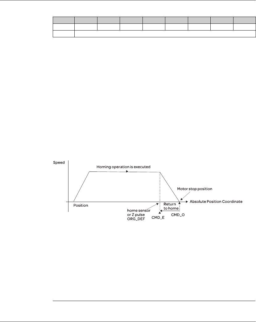
Lexium 23A 8. Motion Control Function
AC servo drive 225
6) Homing Definition: P6-00 ~ P6-01, (64 bits), total 1 group.
PATH: 0 ~8. Path style (4 bits)
0: Stop mode. Motor stops after homing is completed.
1~8: Auto mode. Motor goes the dedicated path 1 ~ 8 after homing is completed.
ACC: Acceleration time
DEC1 / DEC2: 1st deceleration time / 2nd deceleration time..
DLY: Delay time
BOOT: Boot mode. Disable or enable homing function when the servo drive is applied
to power (power on).
0: Disable homing function
1: Enable homing function (when the servo drive is applied to power, first time Servo On)
ORG_DEF: Homing definition value which is determined by the parameter P6-01. The
homing definition value does not necessarily have to be 0.
A. Lexium23 Plus servo drives does not provide the functions that find Z pulse and
regard Z pulse as "Home".
Therefore, it needs to decide if the motor return to Z pulse position when homing
operation is completed.
After home sensor or Z pulse is found, the motor must accelerate to stop. Generally,
the motor stop position will be a little ahead of the position of Z pulse.
Do not return to Z pulse: Set PATH=O
Return to Z pulse: Set PATH= a non-zero value and set absolute position
command=ORG_DEF.
CMD_O:Command Output Position
CMD_E:Command End Position
B. Position offset values are not defined when performing homing operation. After
homing operation, the position offset values can be set as a dedicated Pr path.
For example, if the users want the motor to move a distance S (relative to home senor
or Z pulse), and defined the position coordinate as P, set Pr path as a non-zero value
and set ORG_DEF=P - S.
(P is the absolute position command and S is the incremental position command)
Bit 31 ~ 28 27 ~ 24 23 ~ 20 19 ~ 16 15 ~ 12 11 ~ 8 7 ~ 4 3 ~ 0
DW0 BOOT - DLY DEC2 DEC1 ACC PATH BOOT
DW1 ORG_DEF (32 bit)
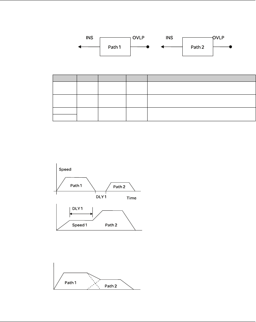
8. Motion Control Function Lexium 23A
226 AC servo drive
8.9.1 Path Order
1) Each path can set to interrupt the previous path (INS) or overlap the next path
(OVLP).
2) The priority of INS is higher than OVLP.
8.9.2 Pr Path
1) Path In Order
2) Path Overlap
PATH 1 PATH 2 Path Order Output Note
OVLP=0 INS=0 In order DLY 1 PATH1 and PATH2 can be speed or position
command
OVLP=1 INS=0 Overlap NO DLY When PATH 2 is a speed command, OVLP
function is disabled,
OVLP=0 INS=1 Interrupt N/A PATH1 and PATH2 can be speed or position
command
OVLP=1
Path 1: AUTO, DLY is set
Path 2: INS is not set
(DLY: Delay time is calculated from the time
when the position command is completed)
Path 1: Speed command, DLY is set
Path 2: Position command
(DLY: Delay time is calculated from the time
when the position command is completed)
Path 1: OVLP is set, DLY can not be set.
Path 2: INS is not set
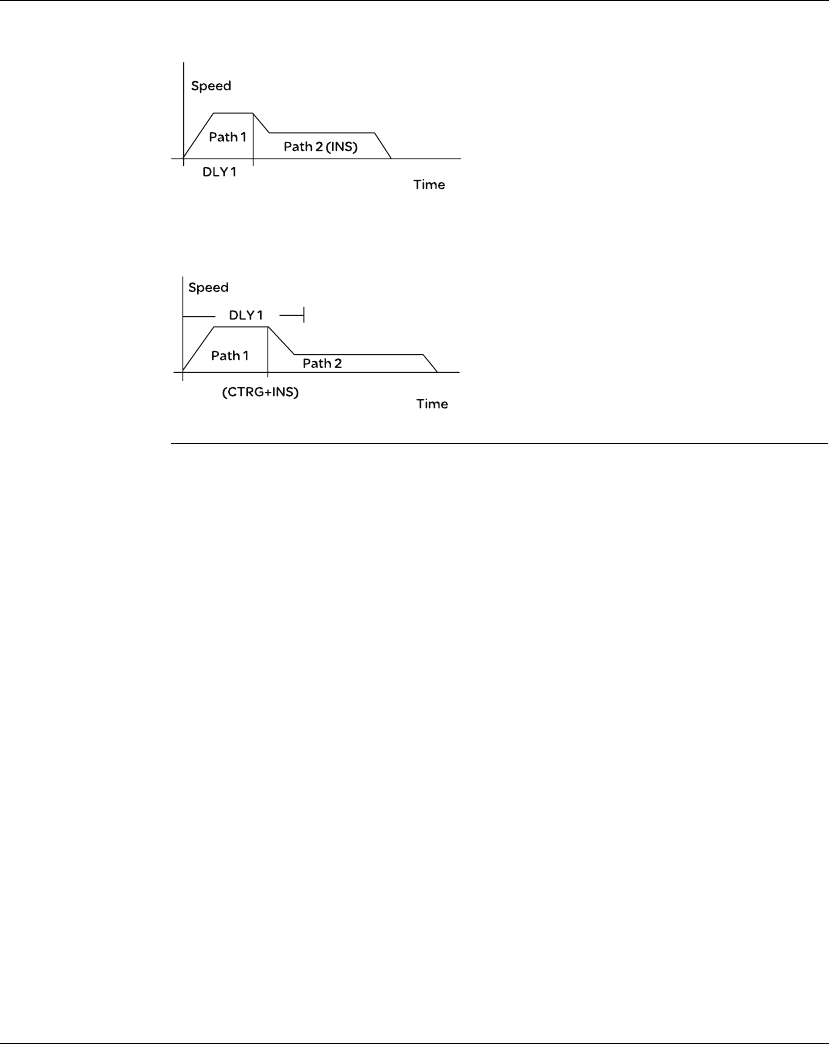
Lexium 23A 8. Motion Control Function
AC servo drive 227
3) Internal Interrupt
4) External Interrupt
Path 1: AUTO, DLY is set
Path 2: INS is set
(DLY is effective for internal interrupt)
This path setting can be used to create
complicated position profile.
Path 1: AUTO or SINGLE, no matter DLY is set
or not.
Path 2: INS is set
(DLY is effective for external interrupt)
This path setting can be used to change
position profile freely.

8. Motion Control Function Lexium 23A
228 AC servo drive

AC servo drive 229
9
Communication
At a Glance
What's in this
Chapter? This chapter contains the following topics:
Topic Page
RS-485 Communication Hardware Interface 230
Communication Parameter Settings 232
MODBUS Communication Protocol 236
Communication Parameter Write-in and Read-out 245
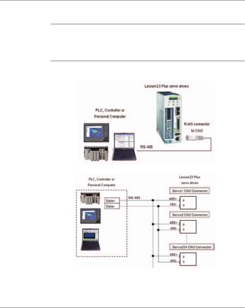
9. Communication Lexium 23A
230 AC servo drive
9.1 RS-485 Communication Hardware Interface
The Lexium23 Plus series servo drives support RS-485 serial communication to
connect a host system such as a PLC or machine controller. All aspects of control,
operation and monitoring as well as programming of the controller can be achieved
via communication.
RS-485 zConfiguration
zCable Connection

Lexium 23A 9. Communication
AC servo drive 231
NOTE:
1) The maximum cable length is 100m (39.37inches) when the servo drive is installed
in a location where there are only a few interferences. Please note, RFI / EME noise
should be kept to a minimum, communication cable should kept apart from high
voltage wires. If a transmission speed of 38400 bps or greater is required, the
maximum length of the communication cable is 15m (50ft.) which will ensure the
correct and desired baud rate.
2) The number shown in the pervious figure indicates the terminal number of each
connector.
3) The power supply should provide a +12V and higher DC voltage.
4) Please use a REPEATER if more than 32 synchronous axes are required. Maximum
254 servo drives can be connected.
5) For the terminal identification of CN3, please refer to Section 5.2.10.
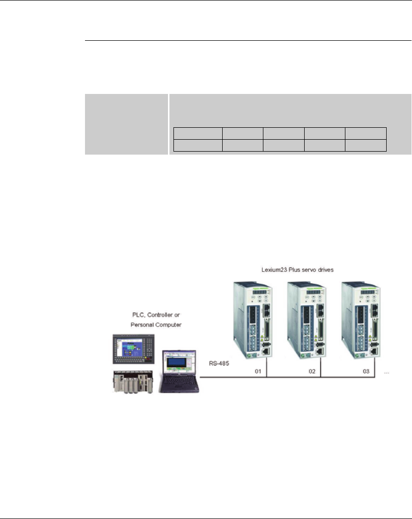
9. Communication Lexium 23A
232 AC servo drive
9.2 Communication Parameter Settings
The following describes the communication addresses for the communication
parameters.
For communication parameters, please refer to the Chapter 9.
When using RS-485 communication, this parameter is used set the communication
address in hexadecimal format. If the AC servo drive is controlled by RS-485
communication, each drive (or device) must be uniquely identified. One servo drive
only can set one address. If the address is duplicate, there will be a communication
fault. This address is an absolute address which represents the servo drive on a RS-
485 network. When the address of host (external) controller is set to 0xFF, it is with
auto-respond function. Then, the servo drive will receive from and respond to host
(external) controller both no matter the address is matching or not. However, the
parameter P3-00 cannot be set to 0xFF.
0300H
0301H
Communication
Address Setting
Default: 0x7F
Range: 0x01 ~ 0x7F
Settings (Hexadecimal):
Display 0 0 Y X
Range - - 0 ~ 7 0 ~ F

Lexium 23A 9. Communication
AC servo drive 233
This parameter is used to set the desired transmission speed between the computer
and AC servo drive.
Users can set this parameter and control transmission speed to reach the maximum
baud rate of 115200 bps.
This parameter is used to set the communication protocol. The alphanumeric
characters represent the following: 7 or 8 is the number of data bits; N, E or O refers to
the parity bit, Non, Even or Odd; the 1 or 2 is the numbers of stop bits.
0302H
0303H
Transmission
Speed
Default: 0x0203
Range: 0x0000 ~ 0x0405
Settings (Hexadecimal):
X: Baud rate setting
0: Baud rate 4800
1: Baud rate 9600
2: Baud rate 19200
3: Baud rate 38400
4: Baud rate 57600
5: Baud rate 115200
Y: Reserved. Must be set to 0.
Z: CANopen Data transmission speed setting.
0: 125K bits / second
1: 250K bits / second
2: 500K bits / second
3: 750K bits / second
4: 1.0M bits / second
Please note:
1. When setting this parameter via CANopen communication, only the
setting of Z (data transmission speed setting) can be configured.
0304H
0305H
Communication
Protocol
Default: 6
Range: 0~8
Settings:
0: Modbus ASCII mode, <7,N,2>
1: Modbus ASCII mode, <7,E,1 >
2: Modbus ASCII mode, <7,O,1>
3: Modbus ASCII mode, <8,N,2 >
4: Modbus ASCII mode, <8,E,1>
5: Modbus ASCII mode, <8,O,1>
6: Modbus RTU mode, <8,N,2>
7: Modbus RTU mode, <8,E,1>
8: Modbus RTU mode, <8,O,1>
Display 0 Z Y X
COM Port - CAN - RS-485
Range 0 0 ~ 4 0 0 ~ 5

9. Communication Lexium 23A
234 AC servo drive
This parameter is used to determine the operating sequence once a communication
fault has been detected. If '1' is selected the drive will stop operating upon detection
the communication fault. The mode of stopping is set by parameter P1-32.
When this parameter is set to any value over 0, it indicates that the timer is enabled.
The value set in this parameter is the communication time and the communication
time out detection should be completed within the time. Otherwise, a communication
error will occur.
For example, if the value set in this parameter is 5, it indicates that the communication
time out detection will be activated once in five seconds or a communication error will
occur.
0306H
0307H
Transmission Fault
Treatment
Default: 0
Range: 0~1
Settings:
0: Display fault and continue operating
1: Display fault and decelerate to stop operating
(deceleration time is determined by parameter P5-03)
0308H
0309H
Communication Time
Out Detection
Watch Dog Timer (It is not recommended to change the factory
default setting if not necessary)
Default: 0
Range: 0~20
The factory default setting is set to 0 and it indicates this function is
disabled.

Lexium 23A 9. Communication
AC servo drive 235
The setting of this parameter determines how the Digital Inputs (DI) accept
commands and signals.
Input commands or signals through the DI can be either from an external source,
through the CN1 interface connector, or via communication (upon software). If this
parameter is set to "0", all commands are external and via CN1; if this parameter is set
to "FFFF"(hexadecimal), all the DI signals are via communication (upon software).
For example, if P3-06 is set to 55 ("binary" display is 01010101), it indicates that Digital
Inputs 1, 3, 5, & 7 are controlled by external commands and Digital Inputs 2, 4, 6, & 8 are
controlled by communication (upon software).
Please see Chapter 4.4.5 DI Signal Display Diagnosis Operation for display layout of
the Digital Signal selection.
The Digital Input Control parameter, P3-06 also works in conjunction with the Digital
Input Status parameter P4-07 which has several functions.
The contents of P4-07 is "read only" via the drive keypad and will display the state on
or off of the eight Digital Inputs which have been set in accordance to P3-06. For E
xample; if P3-06 has been set to "FFFF" (All digital inputs are via communication
(upon software)) and the P4-07 display is 11 ("binary" display is 00010001), it
indicates that the state of Digital Inputs 1 & 5 are on and the state of Digital Inputs 2, 3,
4, 6, 7 & 8 are off.
This parameter is used to delay the communication time that servo drive responds to
host controller (external controller).
When this parameter is set to 0, it indicates that the communication time that servo
drive responds to host controller (external controller) will no be delayed.
030CH
030DH
Digital Input
Communication
Function
Digital Input Control:
Default: 0
Range: 0x0000 ~ 0x3FFF
Bit0 ~ Bit 7 corresponds with DI1 ~ DI8. The least significant bit (Bit0)
shows DI1 status and the most significant bit (Bit7) shows DI8 status.
Bit settings:
0: Digital input is controlled by external command (via CN1)
1: Digital input is controlled by parameter P4-07
For the settings of DI1 ~ DI8, please refer to P2-10 ~ P2-17.
030EH
030FH
Communication
Response Delay
Time
Default: 0
Range: 0~1000

9. Communication Lexium 23A
236 AC servo drive
9.3 MODBUS Communication Protocol
When using RS-485 serial communication interface, each Lexium23 Plus servo drive
has a preassigned communication address specified by parameter "P3-00". The
computer then controls each AC servo drive according to its communication address.
Lexium23 Plus servo drives can be set up to communicate on a MODBUS networks
using on of the following modes: ASCII (American Standard Code for Information
Interchange) or RTU (Remote Terminal Unit). Users can select the desired mode
along with the serial port communication protocol in parameter "P3-02".
Code Description: ASCII Mode:
Each 8-bit data is the combination of two ASCII characters. For example, a 1-byte
data: 64 Hex, shown as '64' in ASCII, consists of '6' (36Hex) and '4' (34Hex).
The following table shows the available hexadecimal characters and their
corresponding ASCII codes.
RTU Mode:
Each 8-bit data is the combination of two 4-bit hexadecimal characters. For example,
a 1-byte data: 64 Hex.
Character ‘0’ ‘1’ ‘2’ ‘3’ ‘4’ ‘5’ ‘6’ ‘7’
ASCII code 30H 31H 32H 33H 34H 35H 36H 37H
Character ‘8’ ‘9’ ‘A’ ‘B’ ‘C’ ‘D’ ‘E’ ‘F’
ASCII code 38H 39H 41H 42H 43H 44H 45H 46H
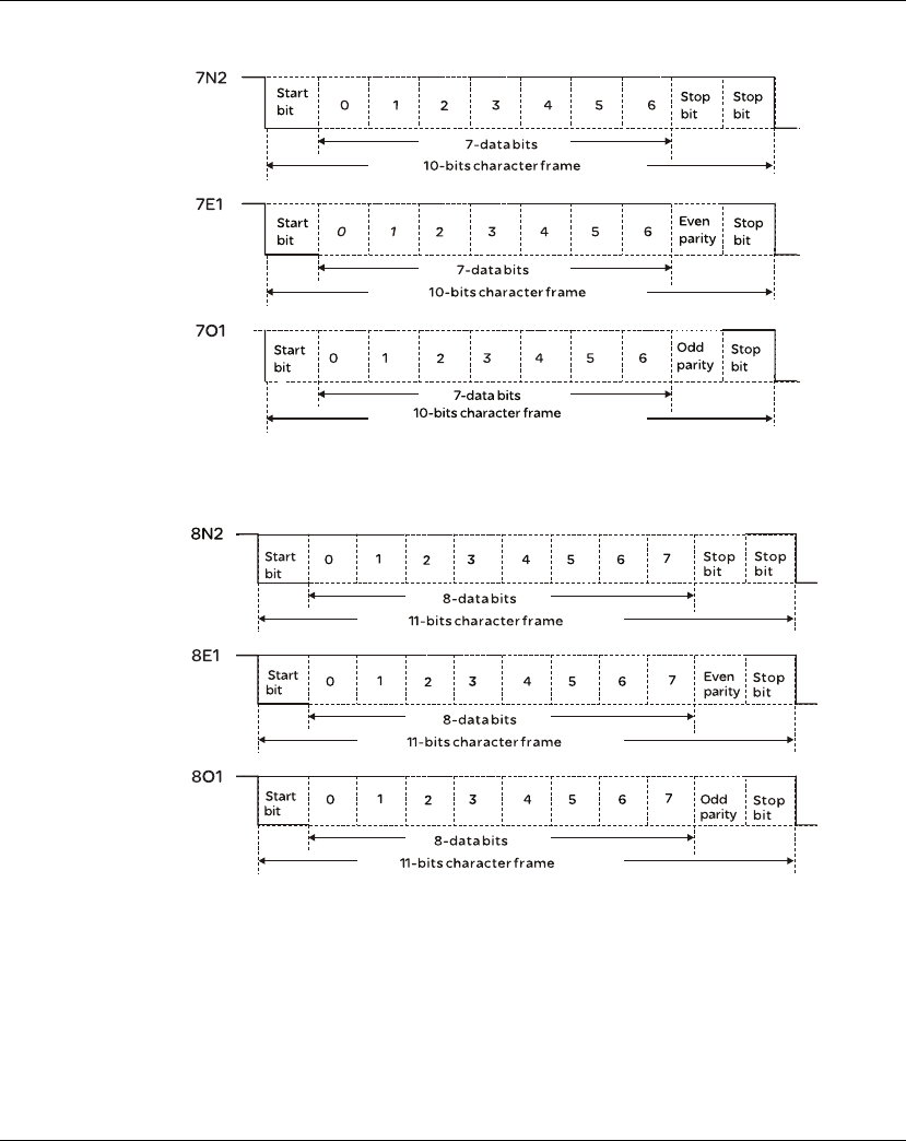
Lexium 23A 9. Communication
AC servo drive 237
Data Format: 10-bit character frame (For 7-bit character)
11-bit character frame (For 8-bit character)

9. Communication Lexium 23A
238 AC servo drive
Communication
Protocol:
ASCII Mode:
RTU Mode:
STX Start character ': ' (3AH)
ADR Communication address: 1-byte consists of 2 ASCII codes
CMD Command code: 1-byte consists of 2 ASCII codes
DATA (n-1)
Contents of data: n word = n x 2-byte consists of n x 4 ASCII codes, n ≤12
……
DATA (0)
LRC Command code: 1-byte consists of 2 ASCII codes
End 1 End code 1: (0DH)(CR)
End 0 End code 0: (0AH)(LF)
STX A silent interval of more than 10ms
ADR Communication address: 1-byte
CMD Command code: 1-byte
DATA(n-1)
Contents of data: n word = n x 2-byte, n ≤12
……
DATA(0)
CRC Command code: 1-byte
End 1 A silent interval of more than 10ms

Lexium 23A 9. Communication
AC servo drive 239
STX (Communication Start)
ASCII Mode: ':' character
RTU Mode: A silent interval of more than 10ms
ADR (Communication Address)
The valid communication addresses are in the range of 1 to 254.
For example, communication to AC servo drive with address 16 decimal:
ASCII Mode: ADR='1', '0'=> '1'=31H, '0'=30H
RTU Mode: ADR = 10H
CMD (Command Codes) and DATA (Data Characters)
The format of data characters depends on the command code. The available
command codes and examples for AC servo drive are described as follows:
Command code: 03H, read N words. The maximum value of N is 10.
For example, reading continuous 2 words from starting address 0200H of AC servo
drive with address 01H.
ASCII Mode:
Command message: Response message:
STX ‘:’
ADR ‘0’
‘1’
CMD ‘0’
‘3’
Starting data
address
‘0’
‘2’
‘0’
‘0’
Number of data
‘0’
‘0’
‘0’
‘2’
LRC Check ‘F’
‘8’
End 1 (0DH) (CR)
End 0 (0AH) (LF)
STX ‘:’
ADR ‘0’
‘1’
CMD ‘0’
‘3’
Number of data
(Count by byte)
‘0’
‘4’
Contents of
starting
data address
0200H
‘0’
‘0’
‘B’
‘1’
Contents of
second
data address
0201H
‘1’
‘F’
‘4’
‘0’
LRC Check ‘E’
‘8’
End 1 (0DH) (CR)
End 0 (0AH) (LF)

9. Communication Lexium 23A
240 AC servo drive
RTU Mode:
Command code: 06H, write 1 word
For example, writing 100 (0064H) to starting data address 0200H of Lexium23 Plus
servo drives with address 01H.
ASCII Mode:
Command message: Response message:
Command message: Response message:
ADR 01H
CMD 03H
Starting data
address
02H (Upper bytes)
00H (Lower bytes)
Number of data
(Count by word)
00H
02H
CRC Check Low C5H (Lower bytes)
CRC Check High B3H (Upper bytes)
ADR 01H
CMD 03H
Number of data
(Count by byte) 04H
Contents of starting
data address
0200H
00H (Upper bytes)
B1H (Lower bytes)
Contents of second
data address
0201H
1FH (Upper bytes)
40H (Lower bytes)
CRC Check Low A3H (Lower bytes)
CRC Check High D4H (Upper bytes)
STX ‘:’
ADR ‘0’
‘1’
CMD ‘0’
‘6’
Starting data
address
‘0’
‘2’
‘0’
‘0’
Content of data
‘0’
‘0’
‘6’
‘4’
LRC Check ‘9’
‘3’
End 1 (0DH) (CR)
End 0 (0AH) (LF)
STX ‘:’
ADR ‘0’
‘1’
CMD ‘0’
‘6’
Starting data
address
‘0’
‘2’
‘0’
‘0’
Content of data
‘0’
‘0’
‘6’
‘4’
LRC Check ‘9’
‘3’
End 1 (0DH) (CR)
End 0 (0AH) (LF)

Lexium 23A 9. Communication
AC servo drive 241
RTU Mode:
LRC (ASCII Mode):
LRC (Longitudinal Redundancy Check) is calculated by summing up, module 256, the
values of the bytes from ADR to last data character then calculating the hexadecimal
representation of the 2's-complement negation of the sum.
01H+03H+02H+01H+00H+01H = 08H, the 2's complement negation of 08H is F8H.
Hence, we can know that LRC CHK is 'F', '8'.
Command message: Response message:
For example, reading 1 word from address 0201H of the Lexium23 Plus servo drive
with address 01H.
ADR 01H
CMD 06H
Starting data
address
02H (Upper bytes)
00H (Lower bytes)
Content of data 00H (Upper bytes)
64H (Lower bytes)
CRC Check Low 89H (Lower bytes)
CRC Check High 99H (Upper bytes)
ADR 01H
CMD 06H
Starting data
address
02H (Upper bytes)
00H (Lower bytes)
Content of data 00H (Upper bytes)
64H (Lower bytes)
CRC Check Low 89H (Lower bytes)
CRC Check High
99H (Upper bytes)
STX ‘:’
ADR ‘0’
‘1’
CMD ‘0’
‘3’
Starting data
address
‘0’
‘2’
‘0’
‘1’
Number of data
‘0’
‘0’
‘0’
‘1’
LRC Check ‘F’
‘8’
End 1 (0DH) (CR)
End 0 (0AH) (LF)

9. Communication Lexium 23A
242 AC servo drive
CRC (RTU Mode):
CRC (Cyclical Redundancy Check) is calculated by the following steps:
Step 1: Load a 16-bit register (called CRC register) with FFFFH.
Step 2: Exclusive OR the first 8-bit byte of the command message with the low order
byte of the 16-bit CRC register, putting the result in the CRC register.
Step 3: Extract and examine the LSB. If the LSB of CRC register is 0, shift the CRC
register one bit to the right. If the LSB of CRC register is 1, shift the CRC
register one bit to the right, then Exclusive OR the CRC register with the
polynomial value A001H.
Step 4: Repeat step 3 until eight shifts have been performed. When this is done, a
complete 8-bit byte will have been processed, then perform step 5.
Step 5: Repeat step 2 to step 4 for the next 8-bit byte of the command message.
Continue doing this until all bytes have been processed. The final contents of
the CRC register are the CRC value.
NOTE:
1) When transmitting the CRC value in the message, the upper and lower bytes of the
CRC value must be swapped, i.e. the lower order byte will be transmitted first.
2) For example, reading 2 words from address 0101H of the AC servo drive with
address 01H. The final content of the CRC register from ADR to last data character
is 3794H, then the command message is shown as follows. What should be noticed
is that 94H have to be transmitted before 37H.
End1, End0 (Communication End)
ASCII Mode:
In ASCII mode, (0DH) stands for character '\r' (carriage return) and (0AH) stands for
character '\n' (new line), they indicate communication end.
RTU Mode:
In RTU mode, a silent interval of more than 10ms indicates communication end.
ARD 01H
CMD 03H
Starting data
address
01H (Upper byte)
01H (Lower bytes)
Number of data
(Count by word)
00H (Upper bytes)
02H (Lower bytes)
CRC Check Low 94H (Lower bytes)
CRC Check High 37H (Upper bytes)

Lexium 23A 9. Communication
AC servo drive 243
The following is an example of CRC generation using C language. The function takes
two arguments:
unsigned char* data;
unsigned char length
The function returns the CRC value as a type of unsigned integer.
unsigned int crc_chk(unsigned char* data, unsigned char length) {
int j;
unsigned int reg_crc=0xFFFF;
while( length-- ) {
reg_crc^= *data++;
for (j=0; j<8; j++ ) {
if( reg_crc & 0x01 ) { /*LSB(bit 0 ) = 1 */
reg_crc = (reg_crc >> 1)^0xA001;
} else {
reg_crc = (reg_crc>>1);
}
}
}
return reg_crc;
}
PC communication program example:
#include<stdio.h>
#include<dos.h>
#include<conio.h>
#include<process.h>
#define PORT 0x03F8 /* the address of COM 1 */
#define THR 0x0000
#define RDR 0x0000
#define BRDL 0x0000
#define IER 0x0001
#define BRDH 0x0001
#define LCR 0x0003
#define MCR 0x0004
#define LSR 0x0005
#define MSR 0x0006
unsigned char rdat[60];
/* read 2 data from address 0200H of LXM23 with address 1 */
unsigned char tdat[60]={':', '0', '1', '0', '3', '0', '2', '0', '0', '0', '0', '0', '2', 'F', '8', '\r', '\n'};
void main() {

9. Communication Lexium 23A
244 AC servo drive
int I;
outportb(PORT+MCR,0x08); /* interrupt enable */
outportb(PORT+IER,0x01); /* interrupt as data in */
outportb(PORT+LCR,( inportb(PORT+LCR) | 0x80 ) );
/* the BRDL/BRDH can be access as LCR.b7 == 1 */
outportb(PORT+BRDL,12);
outportb(PORT+BRDH,0x00);
outportb(PORT+LCR,0x06); /* set prorocol
<7,E,1> = 1AH, <7,O,1> = 0AH
<8,N,2> = 07H <8,E,1> = 1BH
<8,O,1> = 0BH */
for( I = 0; I<=16; I++ ) {
while( !(inportb(PORT+LSR) & 0x20) ); /* wait until THR empty */
outportb(PORT+THR,tdat[I]); /* send data to THR */
}
I = 0;
while( !kbhit() ) {
if( inportb(PORT+LSR)&0x01 ) { /* b0==1, read data ready */
rdat[I++] = inportb(PORT+RDR); /* read data from RDR */
}
}
}

Lexium 23A 9. Communication
AC servo drive 245
9.4 Communication Parameter Write-in and Read-out
There are following 7 groups for parameters:
Group 0: Monitor parameters (example: P0-xx)
Group 1: Basic parameters (example: P1-xx)
Group 2: Extension parameters (example: P2-xx)
Group 3: Communication parameters (example: P3-xx)
Group 4: Diagnosis parameters (example: P4-xx)
Group 5: Motion control parameters (example: P5-xx)
Group 6: Pr path definition parameters (example: P6-xx)
For a complete listing and description of all parameters, refer to Chapter 11.
Communication write-in parameters for Lexium23 Plus servo drives are including:
Group 0: All parameters except P0-00 ~ P0-01, P0-08 ~ P0-13 and P0-46
Group 1: P1-00 ~ P1-76
Group 2: P2-00 ~ P2-67
Group 3: P3-00 ~ P3-11
Group 4: All parameters except P4-00 ~ P4-04 and P4-08 ~ P4-09
Group 5: All parameters except P5-10, P5-16 and P5-76
Group 6: P6-00 ~ P6-17
NOTE:
1) P3-01 After the new transmission speed is set, the next data will be written in new
transmission speed.
2) P3-02 After the new communication protocol is set, the next data will be written
in new communication protocol.
3) P4-05 JOG control of servo motor. For the description, refer to Chapter 11.
4) P4-06 Force output contact control. This parameter is for the users to test if DO
(Digit output) is normal. User can set 1, 2, 4, 8, 16 to test DO1, DO2, DO3,
DO4, DO5, respectively. After the test has been completed, please set this
parameter to 0 to inform the drive that the test has been completed.
5) P4-10 Adjustment function selection. If user desires to change the settings of this
parameter, user has to set the value of the parameter P2-08 to 20
(hexadecimal: 14H) first and then restart. After restarting, the settings of
parameter P4-10 can become modified.

9. Communication Lexium 23A
246 AC servo drive
6) P4-11 ~ P4-21 These parameters are for offset adjustment. Do not change the
factory default setting if not necessary. If the user desires to change
the settings of these parameters, the user has to set the value of the
parameter P2-08 to 22 (hexadecimal: 16H) first and then restart.
After restarting, the settings of parameters P4-11 to P4-21 can
become modified.
Communication read-out parameters for Lexium23 Plus servo drives are
including:
Group 0: P0-00 ~ P0-46
Group 1: P1-00 ~ P1-76
Group 2: P2-00 ~ P2-67
Group 3: P3-00 ~ P3-11
Group 4: P4-00 ~ P4-23
Group 5: P5-00 ~ P5-76
Group 6: P6-00 ~ P6-17

AC servo drive 247
10
Diagnostic and troubleshooting
At a Glance
Presentation This chapter describes the various types of diagnostics and provides
troubleshooting assistance.
What's in this
Chapter? This chapter contains the following topics:
Topic Page
Status request/status indication 248
Fault Messages Table 249
Potential Cause and Corrective Actions 254
Clearing Faults 273

10. Diagnostic and troubleshooting Lexium 23A
248 AC servo drive
10.1 Status request/status indication
Information on the product status are provided by:
zIntegrated HMI
See chapter Fault Message Display
zCommissioning software
For details on how to display the device state see the information provided in the
commissioning software "Lexium23 Plus CT".
zThe error memory also contains a history of the last 5 errors.
The error memory can be found in the Diagnosis Parameter section (P4-00 to P4-
04).The five most recent errors are stored.
See the information provided with the commissioning software for details on how
to read the error memory using the commissioning software.

Lexium 23A 10. Diagnostic and troubleshooting
AC servo drive 249
10.2 Fault Messages Table
Servo Drive Fault
Messages Fault Messages
Display Fault Name Fault Description
AL001 Overcurrent Main circuit current is higher than 1.5 multiple of
motor's instantaneous maximum current value.
AL002 Overvoltage Main circuit voltage has exceeded its maximum
allowable value.
AL003 Undervoltage Main circuit voltage is below its minimum
specified value.
AL004 Motor error The motor does not match the drive. They are
not correctly matched for size (power rating).
AL005 Regeneration error Regeneration control operation is in error.
AL006 Overload Servo motor and drive is overload.
AL007 Overspeed Motor's control speed exceeds the limit of
normal speed.
AL008 Abnormal pulse
control command
Input frequency of pulse command exceeds the
limit of its allowable setting value.
AL009 Excessive deviation Position control deviation value exceeds the
limit of its allowable setting value.
AL011 Encoder error Pulse signal is in error.
AL012 Adjustment error Adjusted value exceeds the limit of its allowable
setting value when perform electrical adjustment.
AL013 Operational stop
activated Operational stop switch is activated.
AL014 Reverse limit switch
error Reverse limit switch is activated.
AL015 Forward limit switch
error Forward limit switch is activated.
AL016 IGBT temperature
error The temperature of IGBT is over high.
AL017 Memory error EE-PROM write-in and read-out is in error.
AL018 Encoder output error The encoder output exceeds the rated output
frequency.
AL020 Serial communication
time out RS-485 communication time out.
AL022 Input power phase
loss One phase of the input power is loss.

10. Diagnostic and troubleshooting Lexium 23A
250 AC servo drive
Fault Messages
Display Fault Name Fault Description
AL023 Pre-overload
warning
To warn that the servo motor and drive is going
to overload. This alarm will display before
ALM06. When the servo motor reach the
setting value of P1-56, the motor will send a
warning to the drive. After the drive has
detected the warning, the DO signal OLW will be
activated and this fault message will display.
AL024 Encoder initial
magnetic field error
The magnetic field of the encoder U, V, W signal
is in error.
AL025 Encoder internal
error
The internal memory of the encoder is in error.
An internal counter error is detected.
AL026 Encoder data error An encoder data error is detected for three times.
AL027 Encoder reset error
An encoder reset error is detected. The
communication between the encoder and the
servo drive are in error.
AL030 Motor protection
error
In order to protect the motor, this alarm will be
activated when the setting value of P1-57 is
reached after a period of time set by P1-58.
AL031 U,V,W wiring error The wiring connections of U, V, W (for servo motor
output) and GND (for grounding) are in error.
AL040 Full closed-loop
excessive deviation
The position control deviation value of full
closed-loop exceeds the specified limit.
AL099 DSP firmware
upgrade
EE-PROM is not reset after the firmware version
is upgraded.
This fault can be cleared after setting P2-08 to
30 first, and then setting P2-08 to 28 next and
restarting the servo drive.

Lexium 23A 10. Diagnostic and troubleshooting
AC servo drive 251
CANopen
Communication
Fault Messages Fault Messages
Display Fault Name Fault Description
AL111
CANopen SDO
receive buffer
overrun
SDO Rx buffer overrun is detected (receive two
or more SDO packets in 1ms).
AL112
CANopen PDO
receive buffer
overrun
PDO Rx buffer overrun is detected (receive two
or more PDO (same COBID) packets in 1ms).
AL121
Index error occurs
when accessing
CANopen PDO object.
The specified Index in the message does not
exist.
AL122
Sub-index error
occurs when
accessing CANopen
PDO object.
The specified Sub-index in the message does
not exist.
AL123
Data type (size) error
occurs when
accessing CANopen
PDO object.
The data length in the message does not match
the specified object.
AL124
Data range error
occurs when
accessing CANopen
PDO object.
The data in the message has exceeded the data
range of the specified object.
AL125
CANopen PDO
object is read-only
and write-
protected.
The specified object in the message is read-
only and write-protected (cannot be changed).
AL126
CANopen PDO
object does not
support PDO.
The specified object in the message does not
support PDO.
AL127
CANopen PDO object
is write-protected
when Servo On.
The specified object in the message is write-
protected (cannot be changed) when Servo On.
AL128
Error occurs when
reading CANopen
PDO object from EE-
PROM.
An error occurs when loading the default
settings from EE-PROM at start-up. All
CANopen objects return to their default
settings automatically.
AL129
Error occurs when
writing CANopen
PDO object into EE-
PROM.
An error occurs when writing the current
settings into EE-PROM.
AL130 EE-PROM invalid
address range
The amount of the data saved in EE-PROM has
exceeded the space determined by the firmware.
Maybe the firmware version has been upgraded,
and it causes that the data of old firmware version
saved in EE-PROM cannot be used.

10. Diagnostic and troubleshooting Lexium 23A
252 AC servo drive
Fault Messages
Display Fault Name Fault Description
AL131 EE-PROM checksum
error
The data saved in EE-PROM has been damaged
and all CANopen objects return to their default
settings automatically.
AL132 Password error
The parameter is password protected when
using CANopen communication to access the
parameter. The users must enter the valid
password to unlock the parameter.
AL180 Life guard error or
heartbeat error
Receive node guarding or heartbeat message or
heartbeat error has timed out.
AL185 CANbus error CANbus off or Error Rx/Tx Counter exceeds 128.
AL201 CANopen data initial
error
An error occurs when loading data from EE-
PROM.
AL235 Command overflow
This fault occurs when position command
counter register overflowed and at this time an
absolute position command is executed.
AL261
Index error occurs
when accessing
CANopen object.
The specified Index in the message does not
exist.
AL263
Sub-index error
occurs when
accessing CANopen
object.
The specified Sub-index in the message does not
exist.
AL265
Data type (size)
error occurs when
accessing CANopen
object.
The data length in the message does not match
the specified object.
AL267
Data range error
occurs when
accessing CANopen
object.
The data in the message has exceeded the data
range of the specified object.
AL269
CANopen object is
read-only and write-
protected.
The specified object in the message is read-only
and write-protected (cannot be changed).
AL26b
CANopen object
does not support
PDO.
The specified object in the message does not
support PDO.
AL26d
CANopen object is
write-protected
when Servo On.
The specified object in the message is write-
protected (cannot be changed) when Servo On.

Lexium 23A 10. Diagnostic and troubleshooting
AC servo drive 253
NOTE:
1) If there is any unknown fault code that is not listed on the above table, please inform
the distributor or contact with Schneider Electric for assistance.
2) For more information about the CANopen objects, please refer to CANopen
Instruction Manual.
Fault Messages
Display Fault Name Fault Description
AL277 Password error
The parameter is password protected when
using CANopen communication to access the
parameter. The users must enter the valid
password to unlock the parameter.
AL283 Forward software
limit
Position command is equal to or more than
forward software limit.
AL285 Reverse software
limit
Position command is equal to or less than
forward software limit.
AL3E1 CANopen SYNC failed The synchronous communication with the
external controller has failed.
AL3E2 CANopen SYNC
signal error The CANopen SYNC signal is received too early.
AL3E3 CANopen SYNC time
out
The CANopen SYNC signal is not received within
the specified time.
AL3E4 CANopen IP
command failed
Internal command of CANopen IP mode cannot
be sent and received.
AL3E5 SYNC period error Object 0x1006 data error. SYNC period 1006h
value is invalid.
AL380
Position deviation
alarm for digital
output, MC_OK
After MC_OK is activated, when the digital
output, TPOS is Off, the digital output, MC_OK
becomes Off.
For more detailed explanation, please refer to
parameter P1-48 in Chapter 8.
AL401 CAN bus error NMT reset or NMT stop command is received
when the servo drive is enabled.

10. Diagnostic and troubleshooting Lexium 23A
254 AC servo drive
10.3 Potential Cause and Corrective Actions
Servo Drive Fault
Messages -7##$ : Overcurrent
Potential Cause Checking Method Corrective Actions
Short-circuit at drive
output (U, V, W)
1. Check the wiring connections
between drive and motor.
2. Check if the wire is short-
circuited.
Repair the short-circuited and
avoid metal conductor being
exposed.
Motor wiring error Check if the wiring steps are all
correct when connecting motor
to drive.
Follow the wiring steps in the
user manual to reconnect
wiring.
IGBT error Heat sink overheated Please contact your distributor
for assistance or contact with
Schneider Electric.
Control parameter
setting error
Check if the setting value
exceeds the factory default
setting.
Set the setting back to factory
default setting and then reset
and adjust the parameter
setting again.
Control command
setting error
Check if the control input
command is unstable
(too much fluctuation).
1. Ensure that input command
frequency is stable (too much
fluctuation).
2. Activate filter function.
-7##% : Overvoltage
Potential Cause Checking Method Corrective Actions
The main circuit voltage
has exceeded its
maximum allowable
value.
Use voltmeter to check whether
the input voltage falls within the
rated input voltage. (For voltage
specification, please refer to
section 3.3.1 in Chapter 3.)
Use correct power supply or
stabilizing power or using series
transformer.
Input power error
(Incorrect power input)
Use voltmeter to check whether
the input voltage is within the
specified limit.
Use correct power supply or
stabilizing power or using series
transformer.
The hardware of the
servo drive is damaged.
Use voltmeter to ensure that the
main circuit input voltage falls
within the specified limit,
If the error does not clear even if
the main circuit input voltage
falls within the specified limit,
please contact your distributor
for assistance or contact with
Schneider Electric.

Lexium 23A 10. Diagnostic and troubleshooting
AC servo drive 255
-7##& : Undervoltage
Potential Cause Checking Method Corrective Actions
The main circuit voltage
is below its minimum
specified value.
Check whether the wiring of
main circuit input voltage is
normal.
Reconfirm voltage wiring.
No input voltage at
main circuit.
Use voltmeter to check whether
input voltage at main circuit is
normal.
Reconfirm power switch.
Input power error
(Incorrect power input)
Use voltmeter to check whether
the input voltage is within the
specified limit.
Use correct power supply or
stabilizing power or using series
transformer.
-7##' : Motor error
Potential Cause Checking Method Corrective Actions
Encoder is damaged. Check the encoder for the
damage.
Replace the motor.
Encoder is loose. Examine the encoder connector. Install the motor again.
The type of the servo
motor is incorrect.
Check if the servo drive and
servo motor are not correctly
matched for size (power rating).
Replace the motor.
-7##( : Regeneration error
Potential Cause Checking Method Corrective Actions
Regenerative resistor is
not connected or the
value of the regenerative
resistor is too low.
Check the wiring connection of
regenerative resistor.
Reconnect regenerative
resistor or calculate the value of
the regenerative resistor.
Regenerative switch
transistor fault
Check if regenerative switch
transistor is shortcircuited.
Please contact your distributor
for assistance or contact with
Schneider Electric.
Parameter setting is in
error
Confirm the parameter settings
of P1-52 and P1-53, and
specifications of regenerative
resistor.
Correctly reset parameter
settings and the specifications
of regenerative resistor again.

10. Diagnostic and troubleshooting Lexium 23A
256 AC servo drive
-7##) : Overload
Potential Cause Checking Method Corrective Actions
The drive has exceeded
its rated load during
continuous operation.
Check if the drive is overloaded.
The users can set parameter P0-
02 (Drive Fault Code) to 11 and
monitor if the value of the
average torque [%] exceeds
100% always.
Increase motor capacity or
reduce load.
Control system
parameter setting is
incorrect.
1. Check if there is mechanical
vibration
2. Accel/Decel time setting is too
fast.
1. Adjust gain value of control
circuit.
2. Decrease Accel/Decel time
setting.
The wiring of drive and
encoder is in error.
Check the wiring of U, V, W and
encoder.
Ensure all wiring is correct.
The encoder of the
motor is damaged.
Please contact your distributor for assistance or contact with
Schneider Electric.
-7##* : Overspeed
Potential Cause Checking Method Corrective Actions
Speed input command is
not stable (too much
fluctuation).
Use signal detector to detect if
input signal is abnormal.
Ensure that input command
frequency is stable (not
fluctuate too much) and
activate filter function.
Over-speed parameter
setting is defective
Check if over-speed parameter
setting value is too low.
Correctly set over-speed
parameter setting
(P2-34).
-7##+ : Abnormal pulse control command
Potential Cause Checking Method Corrective Actions
Pulse command
frequency is higher
than rated input
frequency.
Use pulse frequency detector to
measure input frequency.
Correctly set the input pulse
frequency.

Lexium 23A 10. Diagnostic and troubleshooting
AC servo drive 257
-7##, : Excessive deviation
Potential Cause Checking Method Corrective Actions
Maximum deviation
parameter setting is too
small.
Check the maximum deviation
parameter setting and observe
the position error value when the
motor is running.
Increases the parameter setting
value of P2-35.
Gain value is too small. Check for proper gain value. Correctly adjust gain value.
Torque limit is too low. Check torque limit value. Correctly adjust torque limit
value.
There is an overload. Check for overload condition. Reduce external applied load or
reestimate the motor capacity.
-7#$$ : Encoder error (Position detector fault)
Potential Cause Checking Method Corrective Actions
The wiring of encoder is in
error.
1. Check if all wiring is correct.
2. Check if the users conduct the
wiring by the wiring
information in the user
manual.
Ensure all wiring is correct.
Encoder is loose Examine the encoder connector
(CN2).
Install the motor again.
The wiring of encoder is
defective.
Check if all connections are tight. Conduct the wiring again.
Encoder is damage Check the motor for the damage. Replace the motor.
-7#$% : Adjustment error
Potential Cause Checking Method Corrective Actions
The analog input
contact does not go
back to zero.
Measure if the voltage of the
analog input contact is the same
as the voltage of the ground.
Correctly ground the analog
input contact.
The detection device is
damaged.
damaged. Reset the power
supply.
If the error does not clear after
resetting the power supply,
please contact your distributor
for assistance or contact with
Schneider Electric.

10. Diagnostic and troubleshooting Lexium 23A
258 AC servo drive
-7#$& : Operational stop activated
Potential Cause Checking Method Corrective Actions
Operational stop switch
is activated.
Check if operational stop switch
is On or Off.
Activate operational stop
switch.
-7#$' : Reverse (CWL) limit switch error
Potential Cause Checking Method Corrective Actions
Reverse limit switch is
activated.
Check if reverse limit switch is On
or Off.
Activate reverse limit switch.
Servo system is not
stable.
Check the value of control
parameter setting
and load inertia.
Modify parameter setting and
reestimate
motor capacity.
-7#$( : Forward (CCWL) limit switch error
Potential Cause Checking Method Corrective Actions
Forward limit switch is
activated.
Check if forward limit switch is
On or Off.
Activate forward limit switch.
Servo system is not
stable.
Check the value of control
parameter setting
and load inertia.
Modify parameter setting and
reestimate
motor capacity.
-7#$) : IGBT temperature error
Potential Cause Checking Method Corrective Actions
The drive has
exceeded its rated load
during continuous
operation.
Check if there is overload or the
motor current is too high.
Increase motor capacity or
reduce load.
Short-circuit at drive
output.
Check the drive input wiring. Ensure all wiring is correct.

Lexium 23A 10. Diagnostic and troubleshooting
AC servo drive 259
-7#$* : Memory error
Potential Cause Checking Method Corrective Actions
Parameter data error
when writing into EE
PROM.
Examine the parameter settings.
Please do the following steps:
1. Press SHIFT key on the drive
keypad, and examine the
parameter shown on LED
display.
2. If E320A is displayed (in
hexadecimal format), it
indicates it is parameter P2-10.
Please examine the parameter
settings of P2-10.
3. If E3610 is displayed (in
hexadecimal format), it
indicates it is parameter P6-16.
Please examine the parameter
settings of P6-16.
1. If this fault occurs when power
is applied to the drive, it
indicates that the setting
value of one parameter has
exceeded the specified range.
Correct the setting value of
the parameter to clear the
fault and restart the servo
drive.
2. If this fault occurs during
normal operation, it indicates
that the error occurs when
writing data into EE-PROM.
Turn ARST (DI signal) ON to
clear the fault or restart the
servo drive.
The setting value of
hidden parameter is in
error.
Press SHIFT key on the drive
keypad and examine if E100X is
displayed on LED display.
If this fault occurs when
resetting the parameter
settings, it indicates that the
servo drive type is not set
correctly. Correctly set the
servo drive type again.
Data in EE-PROM is
damaged.
Press SHIFT key on the drive
keypad and examine if E0001 is
displayed on LED display.
If this fault occurs when power is
applied to the drive, it indicates
that the data in EE-RPM is
damaged or there is no data in E
E-PROM.
Please contact your distributor
for assistance or contact with
Schneider Electric.

10. Diagnostic and troubleshooting Lexium 23A
260 AC servo drive
-7#$+ : Encoder output error
Potential Cause Checking Method Corrective Actions
Encoder itself or the
wiring of encoder is in
error.
Check if the recent fault records
(P4-00 ~ P4-05) display on the
drive keypad in accordance with
the fault codes AL011, AL024,
AL025 and AL026.
Perform the corrective actions
as described in AL011, AL024,
AL025 and AL026.
The output frequency
for pulse output may
exceed the limit of its
allowable setting value.
Check if the following conditions
occur:
Condition 1: Motor speed is
above the value set by P1-76.
Condition 2:
P1- 46 x 4 >19.8 x 10
6
Correctly set P1-76 and P1-46.
1. Ensure that the motor speed is
below the value set by P1-76.
2.
P1- 46 x 4 <19.8 x10
6
-7#%# : Serial communication time out
Potential Cause Checking Method Corrective Actions
Setting value in time
out parameter is not
correct.
Check communication time out
parameter setting.
Correctly set P3-07.
Not receiving
communication
command for a long
time.
Check whether communication
cable is loose or broken.
Tighten the communication
cable, make sure the
communication cable is not
damaged and ensure all wiring is
correct.
-7#%% : Input power phase loss
Potential Cause Checking Method Corrective Actions
Control power supply is in
error.
Check the power cable and
connections of R, S, T. Check
whether the power cable is loose
or the possible loss of phase on
input power.
If the fault does not clear even
when the three-phase power is
connected correctly, please
contact your distributor for
assistance or contact with
Schneider Electric.
-7#%& : Pre-overload warning
Potential Cause Checking Method Corrective Actions
The drive is going to
overload.
1. Check the load condition of the
servo motor and drive.
2. Check the setting value of P1-
56. Check whether the setting
value of P1-56 is to small.
1. Please refer to the correction
actions of AL006.
2. Increase the setting value of
P1-56 or set P1-56 to 100 and
above.
Motor Speed
60
Motor Speed
60

Lexium 23A 10. Diagnostic and troubleshooting
AC servo drive 261
-7#%' : Encoder initial magnetic field error
Potential Cause Checking Method Corrective Actions
The magnetic field of
the encoder U, V, W
signal is in error.
1. Check if the servo motor is
properly grounded.
2. Check if the encoder signal
cables are placed in separate
conduits from the cables
connected to R, S, T and U, V, W
terminals to prevent the
interference.
3. Check if the shielded cables
are used when performing
encoder wiring.
If the error does not clear after
each checking is done, please
contact your distributor for
assistance or contact with
Schneider Electric.
-7#%( : Encoder internal error
Potential Cause Checking Method Corrective Actions
The internal memory of
the encoder is in error.
An encoder counter
error occurs.
1. Check if the servo motor is
properly grounded.
2. Check if the encoder signal
cables are placed in separate
conduits from the cables
connected to R, S, T and U, V, W
terminals to prevent the
interference.
3. Check if the shielded cables
are used when performing
encoder wiring.
1. Please connect the grounding
(green color) of U, V, W
terminal to the heatsink of the
servo drive.
2. Ensure that the encoder
signal cables are placed in
separate conduits from the
cables connected to R, S, T and
U, V, W terminals to prevent
the interference.
3. Please use shielded cables for
Encoder wiring.
4. If the error does not clear
after all the above actions are
done, please contact your
distributor for assistance or
contact with Schneider Electric.

10. Diagnostic and troubleshooting Lexium 23A
262 AC servo drive
-7#%) : Encoder data error
Potential Cause Checking Method Corrective Actions
An encoder data error
occurs for three times
1. Check if the servo motor is
properly grounded.
2. Check if the encoder signal
cables are placed in separate
conduits from the cables
connected to R, S, T and U, V, W
terminals to prevent the
interference.
3. Check if the shielded cables
are used when performing
encoder wiring.
1. Please connect the grounding
(green color) of U, V, W
terminal to the heatsink of the
servo drive.
2. Ensure that the encoder
signal cables are placed in
separate conduits from the
cables connected to R, S, T and
U, V, W terminals to prevent
the interference.
3. Please use shielded cables for
Encoder wiring.
4. If the error does not clear
after all the above actions are
done, please contact your
distributor for assistance or
contact with Schneider Electric.
-7#%* : Encoder reset error
Potential Cause Checking Method Corrective Actions
An encoder reset error is
detected. The
communication between
the encoder and the servo
drive are in error.
1. Check if the servo motor is
properly grounded.
2. Check if the encoder signal
cables are placed in separate
conduits from the cables
connected to R, S, T and U, V, W
terminals to prevent the
interference.
3. Check if the shielded cables
are used when performing
encoder wiring.
1. Please connect the grounding
(green color) of U, V, W
terminal to the heatsink of the
servo drive.
2. Ensure that the encoder
signal cables are placed in
separate conduits from the
cables connected to R, S, T and
U, V, W terminals to prevent
the interference.
3. Please use shielded cables for
Encoder wiring.
4. If the error does not clear after
all the above actions are done,
please contact your distributor
for assistance or contact with
Schneider Electric.

Lexium 23A 10. Diagnostic and troubleshooting
AC servo drive 263
-7#&# : Motor protection error
Potential Cause Checking Method Corrective Actions
The setting value of
parameter P1-57 is
reached after a period of
time set by parameter
P1-58.
1. Check if P1-57 is enabled.
2. Check if the setting values of
P1-57 and P1-58 are both too
small.
1. Set P1-57 to 0.
2. Correctly set P1-57 and P1-58.
Please note that the over-low
setting may results in
malfunction, but over-high
setting may let the motor
protection function not
operate.
-7#&$ : U,V,W wiring error
Potential Cause Checking Method Corrective Actions
The wiring connections
of U, V, W (for servo
motor output) and GND
(for grounding) are in
error.
Check if wiring connections of U,
V, W are not correct.
Follow the wiring steps in the
user manual to reconnect the
wiring and ground the servo
drive and motor properly.
-7#'# : Full closed-loop excessive deviation
Potential Cause Checking Method Corrective Actions
The position control
deviation value of
fullclosed loop exceeds
the specified limit.
Maximum deviation
parameter setting is too
small.
1. Check if the setting value of P1-
73 is too small.
2. Check if all connections are
tight and wellconnected to the
mechanical equipment.
1. Increases the parameter
setting value of P1-73.
2. Ensure all connections are
tight and well-connected to
the mechanical
-7#,, : DSP firmware upgrade
Potential Cause Checking Method Corrective Actions
EE-PROM is not reset
after the firmware
version is upgraded.
Check if EE-PROM is reset after
the firmware version is
upgraded.
Set P2-08 to 30 first, and then
28 next, and restart the servo
drive.

10. Diagnostic and troubleshooting Lexium 23A
264 AC servo drive
CANopen
Communication
Fault Messages -7$$$ : CANopen SDO receive buffer overrun
Potential Cause Checking Method Corrective Actions
SDO Rx buffer overrun is
detected (receive two or
more SDO packets in
1ms).
Check if the servo drive (Master)
receives two or more SDO
packets in 1ms.
NMT Maser send "Reset node"
command to its slave or reset
the fault by sending the control
word (0x6040) through CAN
communication (the value of
CANopen object 0x6040 should
be reset)
-7$$% : CANopen PDO receive buffer overrun
Potential Cause Checking Method Corrective Actions
PDO Rx buffer overrun is
detected (receive two or
more PDO packets in
1ms).
Check if the servo drive (Master)
receives two or more PDO (same
COB-ID) packets in 1ms.
NMT Maser send "Reset node"
command to its slave or reset
the fault by sending the control
word (0x6040) through CAN
communication (the value of
CANopen object 0x6040 should
be reset)
-7$%$ : Index error occurs when accessing PDO object
Potential Cause Checking Method Corrective Actions
The specified Index in the
message does not exist.
Check if the Entry index value in
PDO mapping is changed when
accessing PDO object.
NMT Maser send "Reset node"
command to its slave or reset
the fault by sending the control
word (0x6040) through CAN
communication (the value of
CANopen object 0x6040 should
be reset)
-7$%% : Sub-index error occurs when accessing PDO object
Potential Cause Checking Method Corrective Actions
The specified Sub-index
in the message does not
exist.
Check if the Entry Sub-index
value in PDO mapping is
changed when accessing PDO
object.
NMT Maser send "Reset node"
command to its slave or reset
the fault by sending the control
word (0x6040) through CAN
communication (the value of
CANopen object 0x6040 should
be reset)

Lexium 23A 10. Diagnostic and troubleshooting
AC servo drive 265
-7$%& : Data type (size) error occurs when accessing PDO object
Potential Cause Checking Method Corrective Actions
The data length in the
message does not match
the specified object.
Check if the Entry data length in
PDO mapping is changed when
accessing PDO object.
NMT Maser send "Reset node"
command to its slave or reset
the fault by sending the control
word (0x6040) through CAN
communication (the value of
CANopen object 0x6040 should
be reset)
-7$%' : Data range error occurs when accessing PDO object
Potential Cause Checking Method Corrective Actions
The data in the message
has exceeded the data
range of the specified
object.
Check if the write-in data range
in PDO mapping is not correct
when accessing PDO object.
NMT Maser send "Reset node"
command to its slave or reset
the fault by sending the control
word (0x6040) through CAN
communication (the value of
CANopen object 0x6040 should
be reset)
-7$%( : Object is read-only and write-protected
Potential Cause Checking Method Corrective Actions
The specified object in
the message is read-only
and write-protected
(cannot be changed).
Check if the specified object is
set to read-only write-protected
(cannot be changed) when
accessing PDO object.
NMT Maser send "Reset node"
command to its slave or reset
the fault by sending the control
word (0x6040) through CAN
communication (the value of
CANopen object 0x6040 should
be reset)
-7$%) : CANopen PDO object does not support PDO
Potential Cause Checking Method Corrective Actions
The specified object in
the message cannot
support PDO.
Check if the specified object
cannot support PDO when
accessing PDO object.
NMT Maser send "Reset node"
command to its slave or reset
the fault by sending the control
word (0x6040) through CAN
communication (the value of
CANopen object 0x6040 should
be reset)

10. Diagnostic and troubleshooting Lexium 23A
266 AC servo drive
-7$%* : CANopen PDO object is write-protected when Servo On
Potential Cause Checking Method Corrective Actions
The specified object in
the message is write-
protected (cannot be
changed) when Servo On.
Check if the specified object in
the message is write-protected
(cannot be changed) while the
servo drive is enabled (Servo On)
when accessing PDO object.
NMT Maser send "Reset node"
command to its slave or reset
the fault by sending the control
word (0x6040) through CAN
communication (the value of
CANopen object 0x6040 should
be reset)
-7$%+ : Error occurs when reading CANopen PDO object from EE-PROM
Potential Cause Checking Method Corrective Actions
An error occurs when
loading the default
settings from EE-PROM
at start-up. All CANopen
objects return to their
default settings
automatically.
Check if it causes an error when
the specified object reads EE-
PROM when accessing PDO
object.
NMT Maser send "Reset node"
command to its slave or reset
the fault by sending the control
word (0x6040) through CAN
communication (the value of
CANopen object 0x6040 should
be reset)
-7$%, : Error occurs when writing CANopen PDO object into EE-PROM
Potential Cause Checking Method Corrective Actions
An error occurs when
writing the current
settings into EE-PROM.
Check if it causes an error when
the specified object writes EE-
PROM when accessing PDO
object.
NMT Maser send "Reset node"
command to its slave or reset
the fault by sending the control
word (0x6040) through CAN
communication (the value of
CANopen object 0x6040 should
be reset)
-7$&# : EE-PROM invalid address range
Potential Cause Checking Method Corrective Actions
The amount of the data
saved in EE-PROM has
exceeded the space
determined by the
firmware. Maybe the
firmware version has
been upgraded, and it
causes that the data of
old firmware version
saved in EE-PROM
cannot be used.
Check if the specified object lets
the address range of EE-PROM
exceed the specification when
accessing PDO object.
NMT Maser send "Reset node"
command to its slave or reset
the fault by sending the control
word (0x6040) through CAN
communication (the value of
CANopen object 0x6040 should
be reset)

Lexium 23A 10. Diagnostic and troubleshooting
AC servo drive 267
-7$&$ : EE-PROM checksum error
Potential Cause Checking Method Corrective Actions
The data saved in EE-
PROM has been
damaged and all
CANopen objects return
to their default settings
automatically.
Check if the specified object
results in the checksum error of E
E-PROM when accessing PDO
object.
NMT Maser send "Reset node"
command to its slave or reset
the fault by sending the control
word (0x6040) through CAN
communication (the value of
CANopen object 0x6040 should
be reset)
-7$&% : Password error
Potential Cause Checking Method Corrective Actions
The parameter is
password protected
when using CANopen
communication to access
the parameter.
Check if the password for the
specified object is invalid when
accessing PDO object.
NMT Maser send "Reset node"
command to its slave or reset
the fault by sending the control
word (0x6040) through CAN
communication (the value of
CANopen object 0x6040 should
be reset)
-7$+# : Life guard error or heartbeat error
Potential Cause Checking Method Corrective Actions
Receive node guarding or
heartbeat message has
timed out.
Check the settings of node
guarding or heartbeat function.
NMT Maser send "Reset node"
command to its slave. be reset)
-7$+( : CANbus error
Potential Cause Checking Method Corrective Actions
CANbus off or Error Rx/Tx
Counter exceeds 128. 1. Examine CANbus
communication cable.
2. Check if the communication
quality is good quality state.
(It is recommended to use
shielded cables and use
common grounding.)
NMT Maser send "Reset node"
command to its slave or restart
the servo drive.

10. Diagnostic and troubleshooting Lexium 23A
268 AC servo drive
-7%#$ : CANopen data initial error
Potential Cause Checking Method Corrective Actions
An error occurs when
loading data from EE-
PROM.
1. Restart the servo drive to
check if the error can be
cleared.
2. If the error cannot be cleared
after restarting the servo
drive, it indicates that the data
in EE-PROM is damaged and
the users must do the
following actions:
a. If the users want to write
default setting values, set P2-
08 to 30 first and then 28 next,
or use CANopen "0x1011"
object to restore parameters
from non-volatile memory.
b. If the users want to write
current setting values, use
CANopen "0x1010" object to
save parameters in non-
volatile memory.
1. Turn ARST (DI signal) ON to
clear the fault.
2. Use CANopen "0x1011" object
to restore default
parameters.
-7%&( :command overflow
Potential Cause Checking Method Corrective Actions
This fault occurs when
position command
counter register
overflowed and at this
time an absolute position
command is executed.
1. Check if the position command
is executing continuously
toward single direction and
make the feedback position
command counter overflow.
2. Check if the above situation
causes that the correct
position cannot be gauged.
3. Check if an absolute position
command is executed after
the position command counter
register overflowed.
NMT Maser send "Reset node"
command to its slave or reset
the fault by sending the control
word (0x6040) through CAN
communication (the value of
CANopen object 0x6040 should
be reset)
-7%)$ : Index error occurs when accessing CANopen object
Potential Cause Checking Method Corrective Actions
The specified Index in the
message does not exist.
If this fault occurs, please
contact your distributor for
assistance or contact with
Schneider Electric.
NMT Maser send "Reset
node"command to its slave or
reset the fault by sending the
control word (0x6040) through
CAN communication (the value
of CANopen object 0x6040
should be reset)

Lexium 23A 10. Diagnostic and troubleshooting
AC servo drive 269
-7%)& : Sub-index error occurs when accessing CANopen object
Potential Cause Checking Method Corrective Actions
The specified Sub-index
in the message does not
exist.
If this fault occurs, please
contact your distributor for
assistance or contact with
Schneider Electric.
NMT Maser send "Reset node"
command to its slave or reset
the fault by sending the control
word (0x6040) through CAN
communication (the value of
CANopen object 0x6040 should
be reset)
-7%)( : Data type (size) error occurs when accessing CANopen object
Potential Cause Checking Method Corrective Actions
The data length in the
message does not match
the specified object.
If this fault occurs, please
contact your distributor for
assistance or contact with
Schneider Electric.
NMT Maser send "Reset node"
command to its slave or reset
the fault by sending the control
word (0x6040) through CAN
communication (the value of
CANopen object 0x6040 should
be reset)
-7%)* : Data range error occurs when accessing CANopen object
Potential Cause Checking Method Corrective Actions
The data in the message
has exceeded the data
range of the specified
object.
If this fault occurs, please
contact your distributor for
assistance or contact with
Schneider Electric.
NMT Maser send "Reset node"
command to its slave or reset
the fault by sending the control
word (0x6040) through CAN
communication (the value of
CANopen object 0x6040 should
be reset)
-7%), : Object is read-only and write-protected
Potential Cause Checking Method Corrective Actions
The specified object in
the message is read-only
and write-protected
(cannot be changed).
If this fault occurs, please
contact your distributor for
assistance or contact with
Schneider Electric.
NMT Maser send "Reset node"
command to its slave or reset
the fault by sending the control
word (0x6040) through CAN
communication (the value of
CANopen object 0x6040 should
be reset)

10. Diagnostic and troubleshooting Lexium 23A
270 AC servo drive
-7%)> : CANopen object does not support PDO
Potential Cause Checking Method Corrective Actions
The specified object in
the message does not
support PDO.
If this fault occurs, please
contact your distributor for
assistance or contact with
Schneider Electric.
NMT Maser send "Reset node"
command to its slave or reset
the fault by sending the control
word (0x6040) through CAN
communication (the value of
CANopen object 0x6040 should
be reset)
-7%)@ : Object is write-protected when Servo On
Potential Cause Checking Method Corrective Actions
The specified object in
the message is write-
protected (cannot be
changed) when Servo On.
If this fault occurs, please
contact your distributor for
assistance or contact with
Schneider Electric.
NMT Maser send "Reset node"
command to its slave or reset
the fault by sending the control
word (0x6040) through CAN
communication (the value of
CANopen object 0x6040 should
be reset)
-7%** : Password error
Potential Cause Checking Method Corrective Actions
The parameter is
password protected
when using CANopen
communication to access
the parameter.
If this fault occurs, please
contact your distributor for
assistance or contact with
Schneider Electric.
NMT Maser send "Reset node"
command to its slave or reset
the fault by sending the control
word (0x6040) through CAN
communication (the value of
CANopen object 0x6040 should
be reset)
-7%+& : Forward software limit
Potential Cause Checking Method Corrective Actions
Position command is
equal to or more than
forward software limit.
This software limit is determined
according to position command,
not actual feedback position. It
indicates that when this fault is
activated, the actual position
may not exceed the limit. Setting
the proper deceleration time is
able to solve this problem. Please
refer to parameter P5-03.
NMT Maser send "Reset node"
command to its slave or reset
the fault by sending the control
word (0x6040) through CAN
communication (the value of
CANopen object 0x6040 should
be reset)

Lexium 23A 10. Diagnostic and troubleshooting
AC servo drive 271
-7%+( : Reverse software limit
Potential Cause Checking Method Corrective Actions
Position command is
equal to or less than
forward software limit.
This software limit is determined
according to position command,
not actual feedback position. It
indicates that when this fault is
activated, the actual position
may not exceed the limit. Setting
the proper deceleration time is
able to solve this problem. Please
refer to parameter P5-03.
NMT Maser send "Reset node"
command to its slave or reset
the fault by sending the control
word (0x6040) through CAN
communication (the value of
CANopen object 0x6040 should
be reset)
-7&1$ : CANopen SYNC failed
Potential Cause Checking Method Corrective Actions
CAN IP mode error. The
synchronous
communication with the
external controller has
failed.
1. Check if the communication
quality is good quality state.
2. Check if the host (external)
controller has sent SYNC signal.
3. Check if the setting value of
parameter P3-09 is a proper
value (It is recommended to
use default setting).
NMT Maser send "Reset node"
command to its slave or reset
the fault by sending the control
word (0x6040) through CAN
communication (the value of
CANopen object 0x6040 should
be reset)
-7&1% : CANopen SYNC error
Potential Cause Checking Method Corrective Actions
CAN IP mode error. The
SYNC signal is received
too early.
1. Check if the setting of 0x1006
(communication cycle period)
is the same as the setting in
host (external) controller.
2. Check if the setting value of
parameter P3-09 is a proper
value (It is recommended to
use default setting).
3.
Check if the procedure of host
(external) controller is not correct.
NMT Maser send "Reset node"
command to its slave or reset
the fault by sending the control
word (0x6040) through CAN
communication (the value of
CANopen object 0x6040 should
be reset)
-7&1& : CANopen SYNC time out
Potential Cause Checking Method Corrective Actions
CAN IP mode error. The
SYNC signal is not
received with the
specified time.
1. Check if the communication
quality is good quality state.
2. Check if the setting of 0x1006
(communication cycle period)
is the same as the setting in
host (external) controller.
3. Check if the setting value of
parameter P3-09 is a proper
value (It is recommended to
use default setting).
4.
Check if the procedure of host
(external) controller is not correct.
NMT Maser send "Reset node"
command to its slave or reset
the fault by sending the control
word (0x6040) through CAN
communication (the value of
CANopen object 0x6040 should
be reset)

10. Diagnostic and troubleshooting Lexium 23A
272 AC servo drive
-7&1' : CANopen IP command failed
Potential Cause Checking Method Corrective Actions
CAN IP mode error.
Internal command
cannot be sent and
received.
The calculation time of IP mode
is too long. Please disable USB
monitor function.
NMT Maser send "Reset node"
command to its slave or reset
the fault by sending the control
word (0x6040) through CAN
communication (the value of
CANopen object 0x6040 should
be reset)
-7&1( : SYNC period error
Potential Cause Checking Method Corrective Actions
Object 0x1006 Data E
rror. SYNC period 1006h
value is invalid.
Examine the data of 0x1006. The
SYNC period 1006h value should
not be equal to or less than 0 or
this fault will occur.
NMT Maser send "Reset node"
command to its slave or reset
the fault by sending the control
word (0x6040) through CAN
communication (the value of
CANopen object 0x6040 should
be reset)
-7&+# : Position deviation alarm for digital output, MC_OK
Potential Cause Checking Method Corrective Actions
After MC_OK is activated,
when the digital output,
TPOS is Off, the digital
output, MC_OK becomes
Off.
Check if the motor position
changes by external force after
the positioning is completed.
This alarm can be disabled by the
setting of P1-48. Please refer to
the descriptions of parameter
P1-48 for more
detailedexplanation.
1. Turn ARST (DI signal) ON to
clear the fault.
2. Set P0-01 to 0.
-7'#$ : CANopen state error
Potential Cause Checking Method Corrective Actions
NMT reset or NMT stop
command is received
when the servo drive is
enabled.
Check if NMT reset or NMT stop
command is sent when drive is
enabled.
1.Reset the fault by sending the
control word (0x6040)
through CAN communication
(the value of CANopen object
0x6040 should be reset).
2. Reset the fault by triggering
FR of driveCtrl of dmControl
(control data of PLCopen
Profile).

Lexium 23A 10. Diagnostic and troubleshooting
AC servo drive 273
10.4 Clearing Faults
Servo Drive Fault
Messages Display Fault Name Clearing Method
AL001 Overcurrent Turn ARST (DI signal) ON to clear the fault.
AL002 Overvoltage Turn ARST (DI signal) ON to clear the fault.
AL003 Undervoltage
This fault message can be removed
automatically after the voltage has returned
within its specification.
AL004 Motor error This fault message can be removed by
restarting the servo drive.
AL005 Regeneration error Turn ARST (DI signal) ON to clear the fault.
AL006 Overload Turn ARST (DI signal) ON to clear the fault.
AL007 Overspeed Turn ARST (DI signal) ON to clear the fault.
AL008 Abnormal pulse
control command Turn ARST (DI signal) ON to clear the fault.
AL009 Excessive deviation Turn ARST (DI signal) ON to clear the fault.
AL011 Encoder error This fault message can be removed by
restarting the servo drive.
AL012 Adjustment error
This fault message can be removed after the
wiring of CN1 connector (I/O signal
connector) is removed and auto adjustment
function is executed.
AL013 Operational stop
activated
This fault message can be removed
automatically by turning off OPST (DI
signal).
AL014 Reverse limit switch
error
1. Turn ARST (DI signal) ON to clear the fault.
2. This fault message can be removed when
the servo drive is Off (Servo Off).
3. When the servo drive does not reach the
limit, this fault message can be removed
automatically
AL015 Forward limit switch
error
1. Turn ARST (DI signal) ON to clear the fault.
2. This fault message can be removed when
the servo drive is Off (Servo Off).
3. When the servo drive does not reach the
limit, this fault message can be removed
automatically

10. Diagnostic and troubleshooting Lexium 23A
274 AC servo drive
Display Fault Name Clearing Method
AL016 IGBT temperature
error Turn ARST (DI signal) ON to clear the fault.
AL017 Memory error
1. If this fault occurs when power is applied
to the drive, correct the setting value of
the parameter to clear the fault and
restart the servo drive.
2. If this fault occurs during normal
operation, turn ARST (DI signal) ON to
clear the fault.
AL018 Encoder output error Turn ARST (DI signal) ON to clear the fault.
AL020 Serial communication
time out Turn ARST (DI signal) ON to clear the fault.
AL022 Input power phase
loss
Turn ARST (DI signal) ON to clear the fault.
This fault message can be removed
automatically after input power phase lost
problem is solved.
AL023 Pre-overload warning Turn ARST (DI signal) ON to clear the fault.
AL024 Encoder initial
magnetic field error
This fault message can be removed by
restarting the servo drive.
AL025 Encoder internal error This fault message can be removed by
restarting the servo drive.
AL026 Encoder data error This fault message can be removed by
restarting the servo drive.
AL027 Encoder reset error This fault message can be removed by
restarting the servo drive.
AL030 Motor protection error Turn ARST (DI signal) ON to clear the fault.
AL031 U,V,W wiring error This fault message can be removed by
restarting the servo drive.
AL040 Full closed-loop
excessive deviation Turn ARST (DI signal) ON to clear the fault.
AL099 DSP firmware upgrade
This fault message can be removed after
setting P2-08 to 30 first, and then 28 next
and restarting the servo drive.

Lexium 23A 10. Diagnostic and troubleshooting
AC servo drive 275
CANopen
Communication
Fault Messages Display Fault Name Clearing Method
AL111 CANopen SDO receive
buffer overrun
When servo drive is starting in CAN mode,
verify that the CAN master is already active.
NMT Master send "Reset node" command to
its slave or reset the fault by sending the
control word (0x6040) through CAN
communication (the value of CANopen
object 0x6040 should be reset).
AL112 CANopen PDO receive
buffer overrun
NMT Master send "Reset node" command to
its slave or reset the fault by sending the
control word (0x6040) through CAN
communication (the value of CANopen
object 0x6040 should be reset).
AL121
Index error occurs
when accessing
CANopen PDO object.
NMT Master send "Reset node" command to
its slave or reset the fault by sending the
control word (0x6040) through CAN
communication (the value of CANopen
object 0x6040 should be reset).
AL122
Sub-index error
occurs when
accessing CANopen
PDO object.
NMT Master send "Reset node" command to
its slave or reset the fault by sending the
control word (0x6040) through CAN
communication (the value of CANopen
object 0x6040 should be reset).
AL123
Data type (size) error
occurs when
accessing CANopen
PDO object.
NMT Master send "Reset node" command to
its slave or reset the fault by sending the
control word (0x6040) through CAN
communication (the value of CANopen
object 0x6040 should be reset).
AL124
Data range error
occurs when
accessing CANopen
PDO object.
NMT Master send "Reset node" command to
its slave or reset the fault by sending the
control word (0x6040) through CAN
communication (the value of CANopen
object 0x6040 should be reset).
AL125
CANopen PDO object
is read-only and write-
protected.
NMT Master send "Reset node" command to
its slave or reset the fault by sending the
control word (0x6040) through CAN
communication (the value of CANopen
object 0x6040 should be reset).
AL126 CANopen PDO object
does not support PDO.
NMT Master send "Reset node" command to
its slave or reset the fault by sending the
control word (0x6040) through CAN
communication (the value of CANopen
object 0x6040 should be reset).

10. Diagnostic and troubleshooting Lexium 23A
276 AC servo drive
Display Fault Name Clearing Method
AL127
CANopen PDO object
is write-protected
when Servo On.
NMT Master send "Reset node" command to
its slave or reset the fault by sending the
control word (0x6040) through CAN
communication (the value of CANopen
object 0x6040 should be reset).
AL128
Error occurs when
reading CANopen
PDO object from EE-
PROM.
NMT Master send "Reset node" command to
its slave or reset the fault by sending the
control word (0x6040) through CAN
communication (the value of CANopen
object 0x6040 should be reset).
AL129
Error occurs when
writing CANopen PDO
object into EE-PROM.
NMT Master send "Reset node" command to
its slave or reset the fault by sending the
control word (0x6040) through CAN
communication (the value of CANopen
object 0x6040 should be reset).
AL130 EE-PROM invalid
address range.
NMT Master send "Reset node"command to
its slave or reset the fault by sending the
control word (0x6040) through CAN
communication (the value of CANopen
object 0x6040 should be reset).
AL131 EE-PROM checksum
error.
NMT Master send ""Reset node" command
to its slave or reset the fault by sending the
control word (0x6040) through CAN
communication (the value of CANopen
object 0x6040 should be reset).
AL132 Password error
NMT Master send "Reset node" command to
its slave or reset the fault by sending the
control word (0x6040) through CAN
communication (the value of CANopen
object 0x6040 should be reset).
AL180 Life guard error or
heartbeat error
NMT Maser send "Reset node"command to
its slave.
AL185 CANbus error NMT Master send "Reset node"command to
its slave or restart the servo drive.
AL201 CANopen Data Initial E
rror
1. Turn ARST (DI signal) ON to clear the fault.
2. Use CANopen "0x1011” object to restore
default parameters.
AL201 CANopen Data Initial E
rror
1. Turn ARST (DI signal) ON to clear the fault.
2. Use CANopen "0x1011” object to restore
default parameters.

Lexium 23A 10. Diagnostic and troubleshooting
AC servo drive 277
Display Fault Name Clearing Method
AL235 Command Overflow
NMT Maser send "Reset node"
command to its slave or reset the fault
by sending the control word (0x6040)
through CAN communication (the
value of CANopen object 0x6040
should be reset).
AL245 Pr Positioning Time out
NMT Maser send "Reset node"
command to its slave or reset the fault
by sending the control word (0x6040)
through CAN communication (the
value of CANopen object 0x6040
should be reset).
AL249 Invalid Pr Path Number
NMT Maser send "Reset node"
command to its slave or reset the fault
by sending the control word (0x6040)
through CAN communication (the
value of CANopen object 0x6040
should be reset).
AL261
Index error occurs when
accessing CANopen
object.
NMT Maser send "Reset node"
command to its slave or reset the fault
by sending the control word (0x6040)
through CAN communication (the
value of CANopen object 0x6040
should be reset).
AL263
Sub-index error occurs
when accessing CANopen
object.
NMT Maser send "Reset node"
command to its slave or reset the fault
by sending the control word (0x6040)
through CAN communication (the
value of CANopen object 0x6040
should be reset).
AL265
Data type (size) error
occurs when accessing
CANopen object.
NMT Maser send "Reset node"
command to its slave or reset the fault
by sending the control word (0x6040)
through CAN communication (the
value of CANopen object 0x6040
should be reset).
AL267
Data range error occurs
when accessing CANopen
object.
NMT Maser send "Reset node"
command to its slave or reset the fault
by sending the control word (0x6040)
through CAN communication (the
value of CANopen object 0x6040
should be reset).

10. Diagnostic and troubleshooting Lexium 23A
278 AC servo drive
Display Fault Name Clearing Method
AL269 Object is read-only and
write-protected.
NMT Maser send "Reset node"
command to its slave or reset the fault
by sending the control word (0x6040)
through CAN communication (the
value of CANopen object 0x6040
should be reset).
AL26b CANopen object does not
support PDO.
NMT Maser send "Reset node"
command to its slave or reset the fault
by sending the control word (0x6040)
through CAN communication (the
value of CANopen object 0x6040
should be reset).
AL26d
CANopen object is write-
protected when Servo
On.
NMT Maser send "Reset node"
command to its slave or reset the fault
by sending the control word (0x6040)
through CAN communication (the
value of CANopen object 0x6040
should be reset).
AL277 Password error
NMT Maser send "Reset node"
command to its slave or reset the fault
by sending the control word (0x6040)
through CAN communication (the
value of CANopen object 0x6040
should be reset).
AL283 Forward software limit
When the servo drive does not reach
the limit, i.e. the position command is
less than forward software limit, this
fault message can be removed
automatically
AL285 Reverse software limit
When the servo drive does not reach
the limit, i.e. the position command is
more than reverse software limit, this
fault message can be removed
automatically

Lexium 23A 10. Diagnostic and troubleshooting
AC servo drive 279
Display Fault Name Clearing Method
AL3E1 CANopen SYNC failed
NMT Maser send "Reset node"
command to its slave or reset the fault
by sending the control word (0x6040)
through CAN communication (the
value of CANopen object 0x6040
should be reset).
AL3E2 CANopen SYNC signal
error
NMT Maser send "Reset node"
command to its slave or reset the fault
by sending the control word (0x6040)
through CAN communication (the
value of CANopen object 0x6040
should be reset).
AL3E3 CANopen SYNC time out
NMT Maser send "Reset node"
command to its slave or reset the fault
by sending the control word (0x6040)
through CAN communication (the
value of CANopen object 0x6040
should be reset).
AL3E4 CANopen IP command
failed
NMT Maser send :Reset node:
command to its slave or reset the fault
by sending the control word (0x6040)
through CAN communication (the
value of CANopen object 0x6040
should be reset).
AL3E5 SYNC period error
NMT Maser send "Reset node"
command to its slave or reset the fault
by sending the control word (0x6040)
through CAN communication (the
value of CANopen object 0x6040
should be reset).
AL380 Position deviation alarm
1. Turn ARST (DI signal) ON to clear the
fault.
2. Set P0-01 to 0.
AL401 CANopen state error
1. Reset the fault by sending the
control word (0x6040) through CAN
communication (the value of
CANopen object 0x6040 should be
reset).
2. Reset the fault by triggering FR of
driveCtrl of dmControl (control data
of PLCopen Profile).

10. Diagnostic and troubleshooting Lexium 23A
280 AC servo drive
AC servo drive 281
11
Servo Parameters
At a Glance
Presentation This chapter provides an overview of the parameters which can be used for operating
the product.
What's in this
Chapter? This chapter contains the following topics:
Topic Page
Representation of the parameters 282
Definition 283
Parameter Summary 284
Detailed Parameter Listings 308
WARNING
UNINTENDED BEHAVIOR CAUSED BY PARAMETERS
The behavior of the drive system is governed by numerous parame-ters. Unsuitable
parameter values can trigger unintended movements or signals or deactivate
monitoring functions.
• Never change a parameter unless you understand its meaning.
• Only start the system if there are no persons or obstructions in the hazardous area.
• When commissioning, carefully run tests for all operating states and potential
fault situations.
Failure to follow these instructions can result in death, serious injury or
equipment damage.

11. Servo Parameters Lexium 23A
282 AC servo drive
11.1 Representation of the parameters
The way parameters are shown provides information required for unique
identification of a parameter. In addition, information is provided on possible
settings, defaults and parameter properties.
Parameter name The parameter name uniquely identifies a parameter.
Description Short description
The short description contains information on the parameter and a cross reference
to the page that describes the use of the parameter.
Selection values
In the case of parameters which offer a selection of settings, the value to be entered
via commissioning software or the embedded HMI.
Further description and details:
Provides further information on the parameter.
Unit The unit of the value.
Value range The value range between minimum value and maximum value which can be entered.
Default value Factory settings when the product is shipped
Explanation of symbols
(g) Read-only register.
(r) Parameters cannot be changed while Servo On (when the servo drive enabled).
(p) Parameters are effective only after the servo drive is restarted (after switching
power off and on).
(b) Parameters will be restored to their default values when power is off.

Lexium 23A 11. Servo Parameters
AC servo drive 283
11.2 Definition
There are seven groups of drive parameters, which are composed with three parts
and they are the P that stands for Parameter, a single-digit number that represents
for the group number, and a tow-digits number that is the ID code for this parameter.
Group 0: Monitor parameters (example: P0-xx)
Group 1: Basic parameters (example: P1-xx)
Group 2: Extension parameters (example: P2-xx)
Group 3: Communication parameters (example: P3-xx)
Group 4: Diagnosis parameters (example: P4-xx)
Group 5: Motion control parameters (example: P5-xx)
Group 6: Pr path definition parameters (example: P6-xx)
Abbreviation of control modes:
Pt: Position control mode (pulse command from external signal)
Pr: Position control mode (position command from internal profile)
S: Speed control mode
T: Torque control mode
Explanation of symbols (marked after parameters)
(g) Read-only registers, such as P0-00, P0-01 and P4-00.
(r) Parameters cannot be changed while Servo On (when the servo drive is enabled),
such as P1-00, P1-46 and P2-33.
(p) Parameters are effective only after the servo drive is restarted (after switching
power off and on), such as P1-01 and P3-00.
(b) Parameters will be restored to their default values when power is off, such as P2-
30 and P3-06.

11. Servo Parameters Lexium 23A
284 AC servo drive
11.3 Parameter Summary
11.3.1 Parameters
Listed by Group
Group 0: P0-xx
Monitor Parameters
Parameter Name Function Default Unit Control Mode
Pt Pr S T
P0-00gVER Firmware Version
Factory
setting
N/A OOOO
P0-01bALE Drive Fault Code N/A N/A O O O O
P0-02 STS Drive Status (Front Panel Display) 00 N/A O O O O
P0-03 MON Analog Monitor Output 01 N/A O O O O
P0-04 ~
P0-07 Reserved (Do Not Use)
P0-08gTSON Servo Startup Timer 0 Hour O O O O
P0-09gCM1 Status Monitor 1 N/A N/A O O O O
P0-10gCM2 Status Monitor 2 N/A N/A O O O O
P0-11gCM3 Status Monitor 3 N/A N/A O O O O
P0-12gCM4 Status Monitor 4 N/A N/A O O O O
P0-13gCM5 Status Monitor 5 N/A N/A O O O O
P0-14 ~
P0-16 Reserved (Do Not Use)
P0-17 CM1A Status Monitor Selection 1 0 N/A O O O O
P0-18 CM2A Status Monitor Selection 2 0 N/A O O O O
P0-19 CM3A Status Monitor Selection 3 0 N/A O O O O
P0-20 CM4A Status Monitor Selection 4 0 N/A O O O O
P0-21 CM5A Status Monitor Selection 5 0 N/A O O O O
P0-22 ~
P0-24 Reserved (Do Not Use)
P0-25 MAP0 Mapping Parameter 1 N/A N/A O O O O
P0-26 MAP1 Mapping Parameter 2 N/A N/A O O O O
P0-27 MAP2 Mapping Parameter 3 N/A N/A O O O O
P0-28 MAP3 Mapping Parameter 4 N/A N/A O O O O
P0-29 MAP4 Mapping Parameter 5 N/A N/A O O O O
P0-30 MAP5 Mapping Parameter 6 N/A N/A O O O O
P0-31 MAP6 Mapping Parameter 7 N/A N/A O O O O
P0-32 MAP7 Mapping Parameter 8 N/A N/A O O O O
P0-33 ~
P0-34 Reserved (Do Not Use)

Lexium 23A 11. Servo Parameters
AC servo drive 285
Explanation of symbols (marked after parameters)
(g) Read-only register.
(r) Parameters cannot be changed while Servo On (when the servo drive enabled).
(p) Parameters are effective only after the servo drive is restarted (after switching
power off and on).
(b) Parameters will be restored to their default values when power is off.
Monitor Parameters
Parameter Name Function Default Unit Control Mode
Pt Pr S T
P0-35 MAP1A Block Data Read / Write Register 1
(for P0-25)
0x0
N/A O O O O
P0-36 MAP2A Block Data Read / Write Register 2
(for P0-26) 0x0 N/A OOOO
P0-37 MAP3A Block Data Read / Write Register 3
(for P0-27) 0x0 N/A OOOO
P0-38 MAP4A Block Data Read / Write Register 4
(for P0-28) 0x0 N/A OOOO
P0-39 MAP5A Block Data Read / Write Register 5
(for P0-29) 0x0 N/A OOOO
P0-40 MAP6A Block Data Read / Write Register 6
(for P0-30) 0x0 N/A OOOO
P0-41 MAP7A Block Data Read / Write Register 7
(for P0-31) 0x0 N/A OOOO
P0-42 MAP8A Block Data Read / Write Register 8
(for P0-32) 0x0 N/A OOOO
P0-43 Reserved (Do Not Use)
P0-44 PCMN Status Monitor Register
(PC Software Setting) 0x0 N/A OOOO
P0-45 PCMNA Status Monitor Register Selection
(PC Software Setting) 0x0 N/A OOOO
P0-46gSVSTS Servo Output Status Display 0 N/A O O O O

11. Servo Parameters Lexium 23A
286 AC servo drive
Group 1: P1-xx
Basic Parameters
Parameter Name Function Default Unit Control Mode
Pt Pr S T
P1-00 rPTT External Pulse Input Type 0x2 N/A O
P1-01 pCTL Control Mode and Output Direction 0
pulse
rpm
Nm
OOOO
P1-02 rPSTL Speed and Torque Limit 0 N/A
P1-03 AOUTPulse Output Polarity Setting 0 N/A OOOO
P1-04 MON1 Analog Monitor Output Proportion 1
(CH1) 100 % (full
scale) OOOO
P1-05 MON2 Analog Monitor Output Proportion 2
(CH2) 100 % (full
scale) OOOO
P1-06 SFLT Accel / Decel Smooth Constant of Analog
Speed Command (Low-pass Filter) 0Msec O
P1-07 TFLT Smooth Constant of Analog Torque
Command (Low-pass Filter) 0Msec O
P1-08 PFLT Smooth Constant of Position Command
(Low-pass Filter) 0msecO
P1-09~
P1-11 SP1~ 3
1st ~ 3rd Speed Command -60000
~
+60000
rpm O O
1st ~ 3rd Speed Limit
P1-12 ~
P1-14 TQ1 ~ 3 1st ~ 3rd Torque Command -300 ~
+300 %O OO
1st ~ 3rd Torque Limit
P1-15 ~
P1-24 Reserved (Do Not Use)
P1-25 VSF1 Low-frequency Vibration Suppression (1) 100.0 Hz O O
P1-26 VSG1 Low-frequency Vibration Suppression
Gain (1) 0N/AOO
P1-27 VSF2 Low-frequency Vibration Suppression (2) 100.0 Hz O O
P1-28 VSG2 Low-frequency Vibration Suppression
Gain (2) 0N/AOO
P1-29 AVSM Auto Low-frequency Vibration
Suppression Mode Selection 0N/AOO
P1-30 VCL Low-frequency Vibration Detection Level 500 pulse O O
P1-31 Reserved (Do Not Use)
P1-32 LSTP Motor Stop Mode Selection 0 N/A OOOO
P1-33 Reserved (Do Not Use)
P1-34 TACC Acceleration Time 200 msec O
P1-35 TDEC Deceleration Time 200 msec O

Lexium 23A 11. Servo Parameters
AC servo drive 287
Basic Parameters
Parameter Name Function Default Unit Control Mode
Pt Pr S T
P1-36 TSL Accel /Decel S-curve 0 msec O O
P1-37 GDR Ratio of Load Inertia to Servo Motor
Inertia 10 0.1
times OOOO
P1-38 ZSPD Zero Speed Range Setting 100 0.1
rpm OOOO
P1-39 SSPD Target Motor Speed 3000 rpm O O O O
P1-40 rVCM Max. Analog Speed Command or Limit rated
speed rpm O O
P1-41 rTCM Max. Analog Torque Command or Limit 100 % O O O O
P1-42 MBT1 On Delay Time of Electromagnetic Brake 0 msec O O O O
P1-43 MBT2 OFF Delay Time of Electromagnetic Brake -1000 ~
+1000 msecOOOO
P1-44 rGR1 Electronic Gear Ratio (1st Numerator) (N1) 128 pulse O O
P1-45 GR2 Electronic Gear Ratio (Denominator) (M) 10 pulse O O
P1-46 rGR3 Encoder Output Pulse Number 2500 pulse O O O O
P1-47 SPOK Speed Reached Output Range 10 N/A O
P1-48 MCOK Motion Control Completed Output
Selection 0x0000 N/A O
P1-49 ~
P1-51 Reserved (Do Not Use)
P1-52 RES1 Regenerative Resistor Value - Ohm O O O O
P1-53 RES2 Regenerative Resistor Capacity - Watt O O O O
P1-54 PER Positioning Completed Width 12800 pulse O O
P1-55 MSPD Maximum Speed Limit rated
speed rpm O O O O
P1-56 OVW Output Overload Warning Time 120 % O O O O
P1-57 CRSHA Motor Protection Percentage 0 % O O O O
P1-58 CRSHT Motor Protection Time 1 msec O O O O
P1-59 MFLT Analog Speed Linear Filter (Moving Filter) 0 0.1
msec O
P1-60 ~
P1-61 Reserved (Do Not Use)
P1-62 FRCL Friction Compensation Percentage 0 % O O O
P1-63 FRCT Friction Compensation Smooth Constant 0 msec O O O
P1-64 ~
P1-65 Reserved (Do Not Use)
P1-66 PCM Max. Rotation Number of Analog Position
Command (will be available soon) 30 0.1
rotation
O

11. Servo Parameters Lexium 23A
288 AC servo drive
Explanation of symbols (marked after parameters)
(g) Read-only register.
(r) Parameters cannot be changed while Servo On (when the servo drive enabled).
(p) Parameters are effective only after the servo drive is restarted (after switching
power off and on).
(b) Parameters will be restored to their default values when power is off.
Basic Parameters
Parameter Name Function Default Unit Control Mode
Pt Pr S T
P1-67 Reserved (Do Not Use)
P1-68 PFLT2 Position Command Moving Filter 4 msec O O
P1-69 ~
P1-75 Reserved (Do Not Use)
P1-76 AMSPDMax. Rotation Speed of Encoder Output 5500 rpmOOOO

Lexium 23A 11. Servo Parameters
AC servo drive 289
Group 2: P2-xx
Extension Parameters
Parameter Name Function Default Unit Control Mode
Pt Pr S T
P2-00 KPP Proportional Position Loop Gain 35 rad/s O O
P2-01 PPR Position Loop Gain Switching Rate 100 % O O
P2-02 PFG Position Feed Forward Gain 50 % O O
P2-03 PFF Smooth Constant of Position Feed
Forward Gain 5msecOO
P2-04 KVP Proportional Speed Loop Gain 500 rad/s OOOO
P2-05 SPR Speed Loop Gain Switching Rate 100 % OOOO
P2-06 KVI Speed Integral Compensation 100 rad/s OOOO
P2-07 KVF Speed Feed Forward Gain 0 % OOOO
P2-08 bPCTLSpecial Factory Setting 0 N/A OOOO
P2-09 DRTBounce Filter 2 msec OOOO
P2-10 DI1 Digital Input Terminal 1 (DI1) 101 N/A OOOO
P2-11 DI2 Digital Input Terminal 2 (DI2) 104 N/A OOOO
P2-12 DI3 Digital Input Terminal 3 (DI3) 116 N/A OOOO
P2-13 DI4 Digital Input Terminal 4 (DI4) 117 N/A OOOO
P2-14 DI5 Digital Input Terminal 5 (DI5) 102 N/A OOOO
P2-15 DI6 Digital Input Terminal 6 (DI6) 22 N/A OOOO
P2-16 DI7 Digital Input Terminal 7 (DI7) 23 N/A OOOO
P2-17 DI8 Digital Input Terminal 8 (DI8) 21 N/A OOOO
P2-18 DO1Digital Output Terminal 1 (DO1) 101 N/A OOOO
P2-19 DO2Digital Output Terminal 2 (DO2) 103 N/A OOOO
P2-20 DO3Digital Output Terminal 3 (DO3) 109 N/A OOOO
P2-21 DO4Digital Output Terminal 4 (DO4) 105 N/A OOOO
P2-22 DO5Digital Output Terminal 5 (DO5) 7 N/A OOOO
P2-25 NLP Low-pass Filter Time Constant
(Resonance Suppression) 2 or 5 0.1
msec OOOO
P2-26 DSTExternal Anti-Interference Gain 0 0.001 OOOO
P2-27 GCCGain Switching Control Selection 0 N/A OOOO
P2-28 GUTGain Switching Time Constant 10 10msecOOOO
P2-29 GPE Gain Switching Condition
1280000
pulse
Kpps
rpm
OOOO
P2-30 bINH Auxiliary Function 0 N/A OOOO
P2-31 AUT1 Speed Frequency Response Level in Auto
and Semi-Auto Mode 80 Hz OOOO
P2-32 rAUT2Tuning Mode Selection 0 N/A OOOO
P2-33 rINF Semi-Auto Mode Inertia Adjustment
Selection 0 N/A OOOO

11. Servo Parameters Lexium 23A
290 AC servo drive
Explanation of symbols (marked after parameters)
(g) Read-only register.
(r) Parameters cannot be changed while Servo On (when the servo drive enabled).
(p) Parameters are effective only after the servo drive is restarted (after switching
power off and on).
(b) Parameters will be restored to their default values when power is off.
Extension Parameters
Parameter Name Function Default Unit Control Mode
Pt Pr S T
P2-34 SDEV Overspeed Warning Condition 5000 rpm O
P2-35 PDEV Excessive Error Warning Condition
3840000
pulse O O
P2-36~
P2-42 Reserved (Do Not Use)
P2-43 NCF1 Notch Filter 1 (Resonance Suppression) 1000 Hz O O O O
P2-44 DPH1 Notch Filter Attenuation Rate 1
(Resonance Suppression) 0 dB OOOO
P2-45 NCF2 Notch Filter 2 (Resonance
Suppression) 1000 Hz OOOO
P2-46 DPH2 Notch Filter Attenuation Rate 2
(Resonance Suppression) 0 dB OOOO
P2-47 PED Auto Resonance Suppression Mode
Selection 1 N/A OOOO
P2-48 BLAS Auto Resonance Suppression
Detection Level 100 N/A OOOO
P2-49 SJIT Speed Detection Filter and Jitter
Suppression 0 sec OOOO
P2-50 DCLR Pulse Deviation Clear Mode 0 N/A O O
P2-51 ~
P2-52 Reserved (Do Not Use)
P2-53 KPI Position Integral Compensation 0 rad/s O O O O
P2-54 ~
P2-59 Reserved (Do Not Use)
P2-60 GR4 Electronic Gear Ratio (2nd
Numerator) (N2) 128 pulse O
P2-61 GR5 Electronic Gear Ratio (3rd
Numerator) (N3) 128 pulse O
P2-62 GR6 Electronic Gear Ratio (4th
Numerator) (N4) 128 pulse O
P2-63 ~
P2-64 Reserved (Do Not Use)
P2-65 GBIT Special Function 1 0 N/A O O O
P2-66 GBIT2 Special Function 2 0 N/A O O O
P2-67 JSL Stable Inertia Estimating Time 1.5 0.1
times OOO
P2-68 AEAL
140H Auto Enable and Auto Limit Enable 0x0000 N/A O O O O

Lexium 23A 11. Servo Parameters
AC servo drive 291
Group 3: P3-xx
Explanation of symbols (marked after parameters)
(g) Read-only register.
(r) Parameters cannot be changed while Servo On (when the servo drive enabled).
(p) Parameters are effective only after the servo drive is restarted (after switching
power off and on).
(b) Parameters will be restored to their default values when power is off.
Communication Parameters
Parameter Name Function Default Unit Control Mode
Pt Pr S T
P3-00 pADR Modbus Communication Address
Setting 1 N/A OOOO
P3-01 BRT Transmission Speed 0x0203 bps O O O O
P3-02 PTL Communication Protocol 6 N/A O O O O
P3-03 FLT Transmission Fault Treatment 0 N/A O O O O
P3-04 CWD Communication Time Out Detection 0 sec O O O O
P3-05 CADR CANopen Communicaton Address
Setting
0x0000
N/A CANopen mode
P3-06 bSDI Digital Input Communication
Function 0 N/A OOOO
P3-07 CDT Communication Response Delay
Time 0 1 msecOOOO
P3-08 Reserved (Do not use)
P3-09 SYC CANopen Synchronization Setting 0x57A1 N/A CANopen mode
P3-10 PLCEN PLCopen Function Switch 0x0000 N/A CANopen mode
P3-11gPLCTX1 PLCopen TX Packet #1 0x0000 N/A CANopen mode
P3-12gPLCTX2 PLCopen TX Packet #2 0x0000 N/A CANopen mode
P3-13gPLCTX3 PLCopen TX Packet #3 0x0000 N/A CANopen mode
P3-14gPLCTX4 PLCopen TX Packet #4 0x0000 N/A CANopen mode
P3-15gPLCRX1 PLCopen RX Packet #1 0x0000 N/A CANopen mode
P3-16gPLCRX2 PLCopen RX Packet #2 0x0000 N/A CANopen mode
P3-17gPLCRX3 PLCopen RX Packet #3 0x0000
0000 N/A CANopen mode

11. Servo Parameters Lexium 23A
292 AC servo drive
Group 4: P4-xx
Diagnosis Parameters
Parameter Name Function Default Unit Control Mode
Pt Pr S T
P4-00 gASH1 Fault Record (N) 0 N/A O O O O
P4-01 gASH2 Fault Record (N-1) 0 N/A O O O O
P4-02 gASH3 Fault Record (N-2) 0 N/A O O O O
P4-03 gASH4 Fault Record (N-3) 0 N/A O O O O
P4-04 gASH5 Fault Record (N-4) 0 N/A O O O O
P4-05 JOG JOG Operation 20 rpm O O O O
P4-06 rbFOT Force Output Contact Control 0 N/A O O O O
P4-07 bITST Input Status 0 N/A O O O O
P4-08 gPKEY Digital Keypad Input of Servo Drive N/A N/A O O O O
P4-09 gMOT Output Status N/A N/A O O O O
P4-10 bCEN Adjustment Function 0 N/A O O O O
P4-11 SOF1 Analog Speed Input Drift Adjustment 1 Factory
setting N/A O O O O
P4-12 SOF2 Analog Speed Input Drift Adjustment 2 Factory
setting N/A O O O O
P4-13 TOF1 Analog Torque Drift Adjustment 1 Factory
setting N/A O O O O
P4-14 TOF2 Analog Torque Drift Adjustment 2 Factory
setting N/A O O O O
P4-15 COF1 Current Detector Drift Adjustment (V1
phase)
Factory
setting N/A O O O O
P4-16 COF2 Current Detector Drift Adjustment (V2
phase)
Factory
setting N/A O O O O
P4-17 COF3 Current Detector Drift Adjustment
(W1 phase)
Factory
setting N/A O O O O
P4-18 COF4 Current Detector Drift Adjustment
(W2 phase)
Factory
setting N/A O O O O
P4-19 TIGB IGBT NTC Calibration Factory
setting N/A O O O O
P4-20 DOF1 Analog Monitor Output Drift
Adjustment (CH1) 0mVOOOO
P4-21 DOF2 Analog Monitor Output Drift
Adjustment (CH2) 0mVOOOO
P4-22 SAO Analog Speed Input Offset 0 mV O O O O
P4-23 TAO Analog Torque Input Offset 0 mV O O O O
P4-24 LVL Undervoltage Error Level 160 V(rms) O O O O

Lexium 23A 11. Servo Parameters
AC servo drive 293
Group 5: P5-xx
Diagnosis Parameters
Parameter Name Function Default Unit Control Mode
Pt Pr S T
P5-00 ~
P5-02 Reserved (Do Not Use)
P5-03 PDEC Deceleration Time of Protectin
Function
0XE0E
FEEFF N/A OOOO
P5-04 HMOV Homing Mode 0 N/A O
P5-05 HSPD1 1st Speed Setting of High Speed
Homing 100.0 0.1
rpm OOOO
P5-06 HSPD2 2nd Speed Setting of Low Speed
Homing 20.0 0.1
rpm OOOO
P5-07 bPRCM Trigger Position Command
(Pr mode only) 0N/A O
P5-08 SWLP Forward Software Limit 214748
3647 PUU O
P5-09 SWLN Reverse Software Limit -21474
83648 PUU O
P5-10~
P5-14 Reserved (Do Not Use)
P5-15 bPMEM PATH 1 ~ PATH 2 Data Not Retained
Setting 0x0 N/A OOOO
P5-16 bAXENAxis Position: Motor Encoder 0 N/A OOOO
P5-17 Reserved (Do Not Use)
P5-18 AXPC Axis Position: Pulse Command N/A N/A^OOOO
P5-19 Reserved (Do Not Use)
P5-20 ~
P5-33
AC0 ~
AC13 Accel / Decel Time 0 ~ 13 200 ~
8000 msec O

11. Servo Parameters Lexium 23A
294 AC servo drive
Explanation of symbols (marked after parameters)
(g) Read-only register.
(r) Parameters cannot be changed while Servo On (when the servo drive enabled).
(p) Parameters are effective only after the servo drive is restarted (after switching
power off and on).
(b) Parameters will be restored to their default values when power is off.
Diagnosis Parameters
Parameter Name Function Default Unit Control Mode
Pt Pr S T
P5-34 AC14 Accel / Decel Time 14 50 msec O
P5-35 AC15 Accel / Decel Time 15 30 msec O
P5-36 Reserved (Do Not Use)
P5-37 bCAAX CAPTURE: Axis Position CNT 0 PUU O O O O
P5-38 bCANO CAPTURE: Capture Amount 0 N/A O O O O
P5-39 bCACT CAPTURE: Capture Source Setting 0x0000 N/A O O O O
P5-40 ~
P5-55
DLY0 ~
DLY15 Delay Time 0 ~ 15
0 ~ 5500
msec O
P5-56~
P5-57 Reserved (Do Not Use)
P5-58 bCMNO COMPARE: Compare Amount 0 N/A O O O O
P5-59 CMCT COMPARE: Compare Source Setting 0x0000 N/A O O O O
P5-60 ~
P5-75
POV0 ~
POV15 Moving Speed Setting of Position 0 ~ 15 20.0 ~
3000.0 0.1 rpm O
P5-76 gCPRS Capture 1st Position Reset Data 0 N/A O O O O

Lexium 23A 11. Servo Parameters
AC servo drive 295
Group 6: P6-xx
Explanation of symbols (marked after parameters)
(g) Read-only register.
(r) Parameters cannot be changed while Servo On (when the servo drive enabled).
(p) Parameters are effective only after the servo drive is restarted (after switching
power off and on).
(b) Parameters will be restored to their default values when power is off.
Pr Path Definition Parameters
Parameter Name Function Default Unit Control Mode
Pt Pr S T
P6-00 PDEC Homing Definition 0x0000
0000 N/A O
P6-01 ODAT Homing Definition Value 0 N/A O
P6-02,
04,… ~
P6-16
PDEF1
~
PDEF8
Definition of Path 1 ~ 8 0x0000
0000 N/A O
P6-03,
05,… ~
P6-17
PDAT1 ~
PDEF8 Data of Path 1 ~ 8 0 N/A O

11. Servo Parameters Lexium 23A
296 AC servo drive
11.3.2 Parameters
Listed by Function Monitor and General Use
Parameter Name Function Default Unit Control Mode Related
Section
Pt Pr S T
P0-00 gVER Firmware Version Factory
Setting N/AOOOO -
P0-01 bALE Drive Fault Code N/A N/AOOOO
10.2
10.3
10.4
P0-02 STS Drive Status
(Front Panel Display) 00 N/AOOOO 8.2
P0-03 MON Analog Monitor Output 01 N/A O O O O 6.3.3.5
P0-08 gTSON Servo Startup Time 0
Hour
-
P0-09 gCM1 Status Monitor 1 N/A N/A O O O O 6.3.3.5
P0-10 gCM2 Status Monitor 2 N/A N/A O O O O 6.3.3.5
P0-11gCM3 Status Monitor 3 N/A N/A O O O O 6.3.3.5
P0-12 gCM4 Status Monitor 4 N/A N/A O O O O 6.3.3.5
P0-13 gCM5 Status Monitor 5 N/A N/A O O O O 6.3.3.5
P0-17 CM1A Status Monitor Selection 1 0 N/A -
P0-18 CM2A Status Monitor Selection 2 0 N/A -
P0-19 CM3A Status Monitor Selection 3 0 N/A -
P0-20 CM4A Status Monitor Selection 4 0 N/A
P0-21 CM5A Status Monitor Selection 5 0 N/A
P0-25 MAP1 Mapping Parameter 1 N/A N/A O O O O 6.3.3.5
P0-26 MAP2 Mapping Parameter 2 N/A N/A O O O O 6.3.3.5
P0-27 MAP3 Mapping Parameter 3 N/A N/A O O O O 6.3.3.5
P0-28 MAP4 Mapping Parameter 4 N/A N/A O O O O 6.3.3.5
P0-29 MAP5 Mapping Parameter 5 N/A N/A O O O O 6.3.3.5
P0-30 MAP6 Mapping Parameter 6 N/A N/A O O O O 6.3.3.5
P0-31 MAP7 Mapping Parameter 7 N/A N/A O O O O 6.3.3.5
P0-32 MAP8 Mapping Parameter 8 N/A N/A O O O O 6.3.3.5
P0-35
MAP1A
Block Data Read / Write Register
1 (for P0-25) 0x0 N/A O O O O 6.3.3.5
P0-36
MAP2A
Block Data Read / Write Register
2 (for P0-26) 0x0 N/A O O O O 6.3.3.5
P0-37
MAP3A
Block Data Read / Write Register
3 (for P0-27) 0x0 N/A O O O O 6.3.3.5
P0-38
MAP4A
Block Data Read / Write Register
4 (for P0-28) 0x0 N/A O O O O 6.3.3.5

Lexium 23A 11. Servo Parameters
AC servo drive 297
Explanation of symbols (marked after parameters)
(g) Read-only register.
(r) Parameters cannot be changed while Servo On (when the servo drive enabled).
(p) Parameters are effective only after the servo drive is restarted (after switching
power off and on).
(b) Parameters will be restored to their default values when power is off.
Monitor and General Use
Parameter Name Function Default Unit Control Mode Related
Section
Pt Pr S T
P0-39
MAP5A
Block Data Read / Write Register
5 (for P0-29) 0x0 N/A OOOO 6.3.3.5
P0-40
MAP6A
Block Data Read / Write Register
6 (for P0-30) 0x0 N/A OOOO 6.3.3.5
P0-41
MAP7A
Block Data Read / Write Register
7 (for P0-31) 0x0 N/A OOOO 6.3.3.5
P0-42
MAP8A
Block Data Read / Write Register
8 (for P0-32) 0x0 N/A OOOO 6.3.3.5
P0-46 g
SVSTS
Servo Output Status Display 0 N/A O O O O -
P1-04
MON1
Analog Monitor Output
Proportion 1 (CH1) 100 % (full
scale) OOOO 7.3.4.4
P1-05
MON2
Analog Monitor Output
Proportion 2 (CH2) 100 % (full
scale) OOOO 7.3.4.4

11. Servo Parameters Lexium 23A
298 AC servo drive
Smooth Filter and Resonance Suppression
Parameter Name Function Default Unit Control Mode Related
Section
Pt Pr S T
P1-06 SFLT
Accel / Decel Smooth Constant
of Analog Speed Command
(Low-pass Filter)
0 msec O 7.3.3.3
P1-07 TFLT
Smooth Constant of Analog
Torque Command (Low-pass
Filter)
0 msec O 7.3.4.3
P1-08 PFLT Smooth Constant of Position
Command (Low-pass Filter) 010
msec OO 7.3.2.6
P1-25 VSF1 Low-frequency Vibration
Suppression (1) 100.0 Hz O O 7.3.2.9
P1-26 VSG1 Low-frequency Vibration
Suppression Gain (1) 0N/AOO 7.3.2.9
P1-27 VSF2 Low-frequency Vibration
Suppression (2) 100.0 Hz O O 7.3.2.9
P1-28 VSG2 Low-frequency Vibration
Suppression Gain (2) 0N/AOO 7.3.2.9
P1-29 AVSM Auto Low-frequency Vibration
Suppression Mode Selection 0N/AOO 7.3.2.9
P1-30 VCL Low-frequency Vibration
Detection Level 500 pulse O O 7.3.2.9
P1-34 TACC Acceleration Time 200 msec O O 7.3.3.3
P1-35 TDEC Deceleration Time 200 msec O O 7.3.3.3
P1-36 TSL Accel /Decel S-curve 0 msec O O 7.3.3.3
P1-59 MFLT Analog Speed Linear Filter
(Moving Filter) 00.1
msec O-
P1-62 FRCL Friction Compensation
Percentage 0 % OOOO -
P1-63 FRCT Friction Compensation
Smooth Constant 0msecOOOO -
P1-68 PFLT2 Position Command Moving
Filter 0msecOO -
P1-75 FELP Full-closed Loop Low-pass
Filter Time Constant 100 msec O O

Lexium 23A 11. Servo Parameters
AC servo drive 299
Explanation of symbols (marked after parameters)
(g) Read-only register.
(r) Parameters cannot be changed while Servo On (when the servo drive enabled).
(p) Parameters are effective only after the servo drive is restarted (after switching
power off and on).
(b) Parameters will be restored to their default values when power is off.
Smooth Filter and Resonance Suppression
Parameter Name Function Default Unit Control Mode Related
Section
Pt Pr S T
P2-43 NCF1 Notch Filter 1 (Resonance
Suppression) 1000 Hz O O O O 7.3.3.7
P2-44 DPH1 Notch Filter Attenuation Rate 1
(Resonance Suppression) 0 dB O O O O 7.3.3.7
P2-45 NCF2 Notch Filter 2 (Resonance
Suppression) 1000 Hz O O O O 7.3.3.7
P2-46 DPH2 Notch Filter Attenuation Rate 2
(Resonance Suppression) 0 dB O O O O 7.3.3.7
P2-47 ANCF Auto Resonance Suppression
Mode Selection 1 N/A OOOO -
P2-48 ANCL Auto Resonance Suppression
Detection Level 100 N/A OOOO -
P2-25 NLP Low-pass Filter Time Constant
(Resonance Suppression) 2 or 5 0.1
msec O O O O 7.3.3.7
P2-33 rINF Semi-Auto Mode Inertia
Adjustment Selection 0 N/A O O O O 7.3.3.6
P2-49 SJIT Speed Detection Filter and
Jitter Suppression 0 sec OOOO -

11. Servo Parameters Lexium 23A
300 AC servo drive
Explanation of symbols (marked after parameters)
(g) Read-only register.
(r) Parameters cannot be changed while Servo On (when the servo drive enabled).
(p) Parameters are effective only after the servo drive is restarted (after switching
power off and on).
(b) Parameters will be restored to their default values when power is off.
Gain and Switch
Parameter Name Function Default Unit Control Mode Related
Section
Pt Pr S T
P2-00 KPP Proportional Position Loop
Gain 35 rad/s O O 7.3.2.8
P2-01 PPR Position Loop Gain Switching
Rate 100 % O O 7.3.2.8
P2-02 PFG Position Feed Forward Gain 50 % O O 7.3.2.8
P2-03 PFF Smooth Constant of Position
Feed Forward Gain 5msecOO -
P2-04 KVP Proportional Speed Loop Gain 500 rad/sOOOO 7.3.3.6
P2-05 SPR Speed Loop Gain Switching
Rate 100 % OOOO -
P2-06 KVI Speed Integral Compensation 100 rad/s OOOO 7.3.3.6
P2-07 KVF Speed Feed Forward Gain 0 % OOOO 7.3.3.6
P2-26 DST External Anti-Interference Gain 0 0.001OOOO -
P2-27 GCCGain Switching Control Selection 0 N/A OOOO -
P2-28 GUT Gain Switching Time Constant 10 10
msec OOOO -
P2-29 GPE Gain Switching Condition
1280000
pulse
Kpps
rpm
OOOO -
P2-31 bAUT1
Speed Frequency Response
Level in Auto and Semi-Auto
Mode
80 Hz OOOO
6.5.4.6
7.3.3.6
P2-32 rAUT2Tuning Mode Selection 0 N/A OOOO 6.5.4.6
7.3.3.6

Lexium 23A 11. Servo Parameters
AC servo drive 301
Position Control
Parameter Name Function Default Unit Control Mode Related
Section
Pt Pr S T
P1-01 pCTL Control Mode and Output
Direction 0
pulse
rpm
Nm
OOOO 7.3.1
P1-02 rPSTL Speed and Torque Limit 0 N/A O O O O 7.4
P1-12 ~
P1-14 TQ1 ~ 3 1st ~ 3rd Torque Limit -300 ~
+300 % O O O O 7.3.4.1
P1-46 rGR3 Encoder Output Pulse
Number 2500 pulseOOOO -
P1-55 MSPD Maximum Speed Limit rated
speed rpmOOOO -
P2-50 DCLR Pulse Deviation Clear Mode 0 N/A O O -
External Pulse Control Command (Pt mode)
P1-00 rPTT External Pulse Type 0x2 N/A O 7.3.2.1
P1-44 rGR1 Electronic Gear Ratio (1st
Numerator) (N1) 128 pulse O O 7.3.2.5
P1-45 rGR2 Electronic Gear Ratio
(Denominator) (M) 10 pulse O O 7.3.2.5
P2-60 rGR4 Electronic Gear Ratio (2nd
Numerator) (N2) 128 pulse O O -
P2-61 rGR5 Electronic Gear Ratio (3rd
Numerator) (N3) 128 pulse O O -
P2-62 rGR6 Electronic Gear Ratio (4th
Numerator) (N4) 128 pulse O O -
Internal Pulse Control Command (Pr mode)
P6-02 ~
P6-17
PO1 ~
PO8
Definition of Path 1 ~ 8
Data of Path 1 ~ 8 0N/AO 8.10
P5-03 PDEC Deceleration Time of
Protectin Function
0XF00F
FFFF N/A OOOO -
P5-04 HMOV Homing Mode 0 N/A O -

11. Servo Parameters Lexium 23A
302 AC servo drive
Explanation of symbols (marked after parameters)
(g) Read-only register.
(r) Parameters cannot be changed while Servo On (when the servo drive enabled).
(p) Parameters are effective only after the servo drive is restarted (after switching
power off and on).
(b) Parameters will be restored to their default values when power is off.
Position Control
Parameter Name Function Default Unit Control Mode Related
Section
Pt Pr S T
P5-05 HSPD1 1st Speed Setting of High
Speed Homing 100 0.1
rpm OOOO -
P5-06 HSPD2 2nd Speed Setting of Low
Speed Homing 20 0.1
rpm OOOO -
P5-07 bPRCM Trigger Position Command (Pr
mode only) 0N/A O -
P5-20 ~
P5-35
AC0 ~
AC15 Accel / Decel Time 0 ~ 13 200 ~
30 ms O 8.10
P5-40 ~
P5-55
DLY0 ~
DLY15
Delay Time 0 ~ 15 0 ~
5500 ms O 8.10
P5-15 bPMEM PATH 1 ~ PATH 2 Data Not
Retained Setting 0x0 N/A OOOO -
P5-16 bAXEN Axis Position: Motor Encoder 0 N/A O O O O 8.3
P5-18 AXPC Axis Position: Pulse Command N/A N/A O O O O 8.3
P5-08 SWLP Forward Software Limit +231 PUU O -
P5-09 SWLN Reverse Software Limit -231 PUU O -

Lexium 23A 11. Servo Parameters
AC servo drive 303
Explanation of symbols (marked after parameters)
(g) Read-only register.
(r) Parameters cannot be changed while Servo On (when the servo drive enabled).
(p) Parameters are effective only after the servo drive is restarted (after switching
power off and on).
(b) Parameters will be restored to their default values when power is off.
Speed Control
Parameter Name Function Default Unit Control Mode Related
Section
Pt Pr S T
P1-01 pCTL Control Mode and Output
Direction 0
pulse
rpm
Nm
OOOO 7.3.1
P1-02 rPSTL Speed and Torque Limit 0 N/A O O O O 7.4
P1-46 rGR3 Encoder Output Pulse Number 2500 pulse O O O O -
P1-55 MSPD Maximum Speed Limit rated
speed rpm O O O O -
P1-09 ~
P1-11 SP1 ~ 3 1st ~ 3rd Speed Command
-60000
~
+60000
0.1
rpm OO 7.3.3.1
P1-12 ~
P1-14
TQ1 ~
31st ~ 3rd Torque Limit -300 ~
+300 % O O O O 7.4.2
P1-40 rVCM Max. Analog Speed
Command or Limit
rated
speed rpm O O 7.3.3.4
P1-41 rTCM Max. Analog Torque
Command or Limit 100 % OOOO -
P1-76
AMSPD
Max. Rotation Speed of E
ncoder Output 5500 rpm O O O O -

11. Servo Parameters Lexium 23A
304 AC servo drive
Explanation of symbols (marked after parameters)
(g) Read-only register.
(r) Parameters cannot be changed while Servo On (when the servo drive enabled).
(p) Parameters are effective only after the servo drive is restarted (after switching
power off and on).
(b) Parameters will be restored to their default values when power is off.
Torque Control
Parameter Name Function Default Unit Control Mode Related
Section
Pt Pr S T
P1-01 pCTL Control Mode and Output
Direction 0
pulse
rpm
Nm
OOOO 7.3.1
P1-02 rPSTL Speed and Torque Limit 0 N/A O O O O 7.4
P1-46 rGR3 Encoder Output Pulse
Number 2500 pulseOOOO -
P1-55 MSPD Maximum Speed Limit rated
speed rpm OOOO -
P1-09
~
P1-11
SP1~3 1st ~ 3rd Speed Limit
-60000
~
+60000
rpm O O 7.4.1
P1-12
~
P1-14
TQ1~3 1st ~ 3rd Torque Command -300 ~
+300 % OOOO 7.3.4.1
P1-40 rVCM Max. Analog Speed
Command or Limit
rated
speed rpm O O -
P1-41 rTCM Max. Analog Torque
Command or Limit 100 % O O O O 7.3.4.4

Lexium 23A 11. Servo Parameters
AC servo drive 305
Digital I/O and Relative Input Output Setting
Parameter Name Function Default Unit Control Mode Related
Section
Pt Pr S T
P2-09 DRT Bounce Filter 2
msec
OOOO -
P2-10 DI1 Digital Input Terminal 1 (DI1) 101 N/A OOOOTable 11.A
P2-11 DI2 Digital Input Terminal 2 (DI2) 104 N/A OOOOTable 11.A
P2-12 DI3 Digital Input Terminal 3 (DI3) 116 N/A OOOOTable 11.A
P2-13 DI4 Digital Input Terminal 4 (DI4) 117 N/A OOOOTable 11.A
P2-14 DI5 Digital Input Terminal 5 (DI5) 102 N/A OOOOTable 11.A
P2-15 DI6 Digital Input Terminal 6 (DI6) 22 N/A OOOOTable 11.A
P2-16 DI7 Digital Input Terminal 7 (DI7) 23 N/A OOOOTable 11.A
P2-17 DI8 Digital Input Terminal 8 (DI8) 21 N/A OOOOTable 11.A
P2-18 DO1 Digital Output Terminal 1 (DO1) 101 N/A OOOOTable 11.B
P2-19 DO2 Digital Output Terminal 2 (DO2) 103 N/A OOOOTable 11.B
P2-20 DO3 Digital Output Terminal 3 (DO3) 109 N/A OOOOTable 11.B
P2-21 DO4 Digital Output Terminal 4 (DO4) 105 N/A OOOOTable 11.B
P2-22 DO5 Digital Output Terminal 5 (DO5) 7 N/A OOOOTable 11.B
P1-38 ZSPD Zero Speed Range Setting 100 0.1
rpm OOOOTable 11.B
P1-39 SSPD Target Motor Speed 3000 rpm OOOOTable 11.B
P1-42 MBT1 On Delay Time of Electromagnetic
Brake 0 msecOOOO 7.4.4
P1-43 MBT2 OFF Delay Time of E
lectromagnetic Brake 0 msecOOOO 7.4.4
P1-47 SCPD Speed Reached Output Range 10 N/A O Table 11.B
P1-54 PER Positioning Completed Width 12800 pulse O O Table 11.B
P1-56 OVWOutput Overload Warning Time 120 % OOOOTable 11.B

11. Servo Parameters Lexium 23A
306 AC servo drive
Explanation of symbols (marked after parameters)
(g) Read-only register.
(r) Parameters cannot be changed while Servo On (when the servo drive enabled).
(p) Parameters are effective only after the servo drive is restarted (after switching
power off and on).
(b) Parameters will be restored to their default values when power is off.
Communication
Parameter Name Function Default Unit Control Mode Related
Section
Pt Pr S T
P3-00 pADR Modbus Communication
Address Setting 1 N/A OOOO 9.2
P3-01 BRT Transmission Speed 0x0203 bps OOOO 9.2
P3-02 PTL Communication Protocol 6 N/A OOOO 9.2
P3-03 FLT Transmission Fault
Treatment 0 N/A OOOO 9.2
P3-04 CWD Communication Time Out
Detection 0 sec OOOO 9.2
P3-05 CADR CANopen Communication
Address Setting
0x0000
N/A CANopen mode 9.2
P3-06 bSDI Digital Input
Communication Function 0 N/A OOOO 9.2
P3-07 CDT Communication Response
Delay Time 0 1msecOOOO 9.2
P3-08 Reserved (do not use)
P3-09 SYC CANopen Synchronization
Setting 0x57A1 N/A CANopen mode 9.2
P3-10 PLCEN PLCopen Function Switch 0x0000 N/A CANopen mode
P3-11gPLCTX1 PLCopen TX Packet #1 0x0000 N/A CANopen mode
P3-12gPLCTX2 PLCopen TX Packet #2 0x0000 N/A CANopen mode
P3-13gPLCTX3 PLCopen TX Packet #3 0x0000 N/A CANopen mode
P3-14gPLCTX4 PLCopen TX Packet #4 0x0000 N/A CANopen mode
P3-15gPLCRX1 PLCopen RX Packet #1 0x0000 N/A CANopen mode
P3-16gPLCRX2 PLCopen RX Packet #2 0x0000 N/A CANopen mode
P3-17gPLCRX3 PLCopen RX Packet #3 0x0000
0000 N/A CANopen mode

Lexium 23A 11. Servo Parameters
AC servo drive 307
Explanation of symbols (marked after parameters)
(g) Read-only register.
(r) Parameters cannot be changed while Servo On (when the servo drive enabled).
(p) Parameters are effective only after the servo drive is restarted (after switching
power off and on).
(b) Parameters will be restored to their default values when power is off.
Diagnosis
Parameter Name Function Default Unit Control Mode Related
Section
Pt Pr S T
P4-00 gASH1 Fault Record (N) 0 N/A OOOO 7.2.1
P4-01 gASH2Fault Record (N-1) 0 N/A OOOO 7.2.1
P4-02gASH3Fault Record (N-2) 0 N/A OOOO 7.2.1
P4-03gASH4Fault Record (N-3) 0 N/A OOOO 7.2.1
P4-04 gASH5Fault Record (N-4) 0 N/A OOOO 7.2.1
P4-05 JOG JOG Operation 20 rpm O O O O 7.2.2
P4-06 r bFOT Force Output Contact Control 0 N/A O O O O 7.2.3
P4-07 ITST Input Status 0 N/A O O O O 6.5.2
9.2
P4-08 gPKEY Digital Keypad Input of Servo
Drive N/A N/A OOOO -
P4-09 gMOT Output Status N/A N/A O O O O 6.5.3
P4-10 rCEN Adjustment Function 0 N/A O O O O -
P4-11 SOF1 Analog Speed Input Drift
Adjustment 1
Factory
Setting N/A OOOO -
P4-12 SOF2 Analog Speed Input Drift
Adjustment 2
Factory
Setting N/A OOOO -
P4-13 TOF1 Analog Torque Drift
Adjustment 1
Factory
Setting N/A OOOO -
P4-14 TOF2 Analog Torque Drift
Adjustment 2
Factory
Setting N/A OOOO -
P4-15 COF1 Current Detector Drift
Adjustment (V1 phase)
Factory
Setting N/A OOOO -
P4-16 COF2 Current Detector Drift
Adjustment (V2 phase)
Factory
Setting N/A OOOO -
P4-17 COF3 Current Detector Drift
Adjustment (W1 phase)
Factory
Setting N/A OOOO -
P4-18 COF4 Current Detector Drift
Adjustment (W2 phase)
Factory
Setting N/A OOOO -
P4-19 TIGB IGBT NTC Calibration Factory
Setting N/A OOOO -
P4-20 DOF1 Analog Monitor Output Drift
Adjustment (CH1) 0 mV O O O O 7.3.4.4
P4-21 DOF2 Analog Monitor Output Drift
Adjustment (CH2) 0 mV O O O O 7.3.4.4
P4-22 SAO Analog Speed Input Offset 0 mV O -
P4-23 TAO Analog Torque Input Offset 0 mV O -
P4-24 LVL Undervoltage Error Level 160
V(rms)
OOOO -

11. Servo Parameters Lexium 23A
308 AC servo drive
11.4 Detailed Parameter Listings
Group 0: P0-xx Monitor Parameterss
P0-00 gVER Firmware Version Address: 0000H, 0001H
Default: Factory setting
Applicable Control Mode: ALL
Unit: N/A
Range: N/A
Data Size: 16-bit
Display Format: Decimal
Related Section: N/A
P0-01 bALE Drive Fault Code Address: 0002H, 0003H
Default: N/A
Unit: N/A
Range:001 ~ 380
Data Size: 16-bit
Display Format: BCD
Related Section: Chapter 10
Settings:
This parameter shows the current servo drive fault if the servo drive is currently faulted.
The fault code is hexadecimal data but displayed in BCD format (Binary coded decimal).
Servo Drive Fault Codes:
001: Overcurrent
002: Overvoltage
003: Undervoltage (This fault code shows when main circuit voltage is below its minimum
specified value while Servo On, and it will not show while Servo Off. This fault code
can be cleared automatically after the voltage has returned within its specification.)
004: Motor error (The drive and motor are not correctly matched for size (power rating).
005: Regeneration error
006: Overload
007: Overspeed
008: Abnormal pulse control command
009: Excessive deviation
011: Encoder error (The wiring of the encoder is in error and this causes the
communication error between the servo drive and the encoder.)
012: Adjustment error
013: Operational stop activated
014: Reverse limit switch error
015: Forward limit switch error
016: IGBT temperature error
017: Memory error
018: Encoder output error
020: Serial communication time out
022: Input power phase loss
023: Pre-overload warning
024: Encoder initial magnetic field error

Lexium 23A 11. Servo Parameters
AC servo drive 309
025: Encoder internal error
026: Encoder data error
027: Encoder reset error
030: Motor protection error
031: U, V, W wiring error
040: Full-closed loop excessive deviation
099: DSP firmware upgrade
CANopen Communication Fault Codes
111: CANopen SDO receive buffer overrun
112: CANopen PDO receive buffer overrun
121: Index error occurs when accessing CANopen PDO object.
122: Sub-index error occurs when accessing CANopen PDO object.
123: Data type (size) error occurs when accessing CANopen PDO object.
124: Data range error occurs when accessing CANopen PDO object.
125: CANopen PDO object is read-only and write-protected.
126: CANopen PDO object does not support PDO.
127: CANopen PDO object is write-protected when Servo On.
128: Error occurs when reading CANopen PDO object from EE-PROM.
129: Error occurs when writing CANopen PDO object into EE-PROM.
130: EE-PROM invalid address range
131: EE-PROM checksum error
132: Password error
180: Life guard error or heart beat error
185: CANbus error
Motion Control Fault Codes:
201: CANopen data initial error
235: Pr command overflow
261: Index error occurs when accessing CANopen object.
263: Sub-index error occurs when accessing CANopen object.
265: Data type (size) error occurs when accessing CANopen object.
267: Data range error occurs when accessing CANopen object.
269: CANopen object is read-only and write-protected.
26b: CANopen object does not support PDO.
26d: CANopen object is write-protected when Servo On.
277: Password error
283: Forward software limit
285: Reverse software limit
289: Position counter overflow
291: Servo Off error
3E1: CANopen SYNC failed
3E2: CANopen SYNC signal error
3E3: CANopen SYNC time out
3E4: CANopen IP command failed
3E5: SYNC period error
380: Position deviation alarm for digital output, MC_OK (Please refer to P1-48.)
401: NMT reset or NMT stop is received when drive is enabled.

11. Servo Parameters Lexium 23A
310 AC servo drive
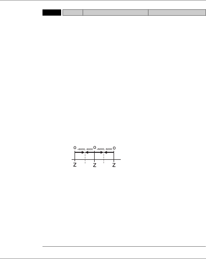
Lexium 23A 11. Servo Parameters
AC servo drive 311
P0-02 STS Drive Status (Front Panel Display) Address: 0004H, 0005H
Default: 00
Applicable Control Mode: ALL
Unit: N/A
Range:00 ~ 127
Data Size: 16-bit
Display Format: Decimal
Related Section: Section 6.3.3.5,
Section 8.2
Settings:
This parameter shows the servo drive status.
00: Motor feedback pulse number (after electronic gear ratio is set) [user unit]
01: Input pulse number of pulse command (after electronic gear ratio is set) [user unit]
02: Position error counts between control command pulse and feedback pulse [user unit]
03: Motor feedback pulse number (encoder unit, 1280000 pulse/rev) [pulse]
04: Input pulse number of pulse command (before electronic gear ratio is set) [pulse]
05: Position error counts [pulse]
06: Input frequency of pulse command [Kpps]
07: Motor rotation speed [rpm]
08: Speed input command [Volt]
09: Speed input command [rpm]
10: Torque input command [Volt]
11: Torque input command [%]
12: Average load [%]
13: Peak load [%]
14: Main circuit voltage [Volt]
15: Ratio of load inertia to Motor inertia [0.1times]
16: IGBT temperature
17: Resonance frequency [Hz]
18: Absolute pulse number relative to encoder (use Z phase as home). The value of Z
phase home point is 0, and it can be the value from -5000 to +5000 pulses.
19: Mapping Parameter 1: Display the content of parameter P0-25 (mapping target is
specified by parameter P0-35)
20: Mapping Parameter 2: Display the content of parameter P0-26 (mapping target is
specified by parameter P0-36)
21: Mapping Parameter 3: Display the content of parameter P0-27 (mapping target is
specified by parameter P0-37)
22: Mapping Parameter 4: Display the content of parameter P0-28 (mapping target is
specified by parameter P0-38)
23: Status Monitor 1: Display the content of parameter P0-09 (the monitor status is
specified by parameter P0-17)
24: Status Monitor 2: Display the content of parameter P0-10 (the monitor status is
specified by parameter P0-18)
25: Status Monitor 3: Display the content of parameter P0-11 (the monitor status is
specified by parameter P0-19)
26: Status Monitor 4: Display the content of parameter P0-12 (the monitor status is
specified by parameter P0-20)
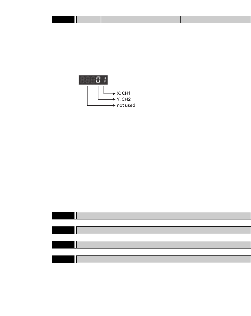
11. Servo Parameters Lexium 23A
312 AC servo drive
P0-03 MON Analog Monitor Output Address: 0006H, 0007H
Default: 01
Unit: N/A
Range: 00 ~ 77
Data Size: 16-bit
Display Format: Hexadecimal
Settings:
This parameter determines the functions of the
analog monitor outputs.
XY: (X: CH1; Y: CH2)
Related Section: Section 6.3.3.5
0: Motor speed (+/-8V / maximum motor speed)
1: Motor torque (+/-8V / maximum torque)
2: Pulse command frequency (+8Volts / 4.5Mpps)
3: Speed command (+/-8Volts / maximum speed command)
4: Torque command (+/-8Volts / maximum torque command)
5: V_BUS voltage (+/-8Volts / 450V)
6: Reserved
7: Reserved
Please note: For the setting of analog output voltage proportion, refer to the P1-
04 and P1-05.
Example:
P0-03 = 01(CH1 is speed analog output)
Motor speed = (Max. motor speed × V1/8) × P1-04/100, when the output voltage
value of CH1 is V1.
P0-04 Reserved (Do Not Use)
P0-05 Reserved (Do Not Use)
P0-06 Reserved (Do Not Use)
P0-07 Reserved (Do Not Use)

Lexium 23A 11. Servo Parameters
AC servo drive 313
P0 - 08gTSON Servo Startup Time Address: 0010H, 0011H
Default: 0
Applicable Control Mode: ALL
Unit: Hour
Range: 0 ~ 65535
Data Size: 16-bit
Display Format: Decimal
Related Section: N/A
P0 - 09gCM1 Status Monitor 1 Address: 0012H, 0013H
Default: N/A
Applicable Control Mode: ALL
Unit: N/A
Range: N/A
Data Size: 32-bit
Display Format: Decimal
Related Section: Section 6.3.3.5
Settings:
This parameter is used to provide the value of one of the status monitoring
functions found in P0-02. The value of P0-09 is determined by P0-17 (desired drive
status) through communication setting or the keypad. The drive status can be read
from the communication address of this parameter via communication port.
For example:
Set P0-17 to 3, then all consequent reads of P0-09 will return the motor feedback
pulse number in pulse.
When reading the drive status through Modbus communication, the system
should read two 16-bit data stored in the addresses of 0012H and 0013H to form a
32-bit data.
(0013H : 0012H) = (high byte : low byte)
When reading the drive ststus through the keypad, if P0-02 is set to 23, VAR-1 will quickly
show for about two seconds and then the value of P0-09 will display on the display.
P0 - 10gCM2 Status Monitor 2 Address: 0014H, 0015H
Default: N/A
Applicable Control Mode: ALL
Unit: N/A
Range: N/A
Data Size: 32-bit
Display Format: Decimal
Related Section: Section 6.3.3.5
Settings:
This parameter is used to provide the value of one of the status monitoring functions
found in P0-02. The value of P0-10 is determined by P0-18 (desired drive status)
through communication setting or the keypad. The drive status can be read from the
communication address of this parameter via communication port.
When reading the drive status through the keypad, if P0-02 is set to 24, VAR-2 will quickly
show for about two seconds and then the value of P0-10 will display on the display.

11. Servo Parameters Lexium 23A
314 AC servo drive
P0 - 11 gCM3 Status Monitor 3 Address: 0016H, 0017H
Default: N/A
Applicable Control Mode: ALL
Unit: N/A
Range: N/A
Data Size: 32-bit
Display Format: Decimal
Related Section: Section 6.3.3.5
Settings:
This parameter is used to provide the value of one of the status monitoring
functions found in P0-02. The value of P0-11 is determined by P0-19 (desired drive
status) through communication setting or the keypad. The drive status can be
read from the communication address of this parameter via communication port.
When reading the drive status through the keypad, if P0-02 is set to 25, VAR-3 will quickly
show for about two seconds and then the value of P0-11 will display on the display.
P0 - 12 gCM4 Status Monitor 4 Address: 0018H, 0019H
Default: N/A
Applicable Control Mode: ALL
Unit: N/A
Range: N/A
Data Size: 32-bit
Display Format: Decimal
Related Section: Section 6.3.3.5
Settings:
This parameter is used to provide the value of one of the status monitoring
functions found in P0-02. The value of P0-12 is determined by P0-20 (desired drive
status) through communication setting or the keypad. The drive status can be read
from the communication address of this parameter via communication port.
When reading the drive status through the keypad, if P0-02 is set to 26, VAR-4 will quickly
show for about two seconds and then the value of P0-12 will display on the display.
P0 - 13 gCM5 Status Monitor 5 Address: 001AH, 001BH
Default: N/A
Applicable Control Mode: ALL
Unit: N/A
Range: N/A
Data Size: 32-bit
Display Format: Decimal
Related Section: Section 6.3.3.5
Settings:
This parameter is used to provide the value of one of the status monitoring functions
found in P0-02. The value of P0-12 is determined by P0-20 (desired drive status)
through communication setting or the keypad. The drive status can be read from the
communication address of this parameter via communication port.

Lexium 23A 11. Servo Parameters
AC servo drive 315
P0 - 14 Reserved (Do Not Use)
P0 - 15 Reserved (Do Not Use)
P0 - 16 Reserved (Do Not Use)
P0 - 17 CM1A Status Monitor Selection 1 Address: 0022H, 0023H
Default: 0
Applicable Control Mode: ALL
Unit: N/A
Range: 0 ~ 127
Data Size: 16-bit
Display Format: Decimal
Related Section: N/A
Settings:
This parameter is used to determine the drive status found in P0-02. The selected
drive status will be displayed by P0-09.
For example:
Set P0-17 to 7, then all consequent reads of P0-09 will return the motor rotation
speed in rpm.
P0 - 18 CM2A Status Monitor Selection 2 Address: 0024H, 0025H
Default: 0
Applicable Control Mode: ALL
Unit: N/A
Range: 0 ~ 127
Data Size: 16-bit
Display Format: Decimal
Related Section: N/A
Settings:
This parameter is used to determine the drive status found in P0-02. The selected
drive status will be displayed by P0-10. Refer to P0-17 for explanation.
P0 - 19 CM3A Status Monitor Selection 3 Address: 0026H, 0027H
Default: 0
Applicable Control Mode: ALL
Unit: N/A
Range: 0 ~ 127
Data Size: 16-bit
Display Format: Decimal
Related Section: N/A
Settings:
This parameter is used to determine the drive status found in P0-02. The selected
drive status will be displayed by P0-11. Refer to P0-17 for explanation.
11. Servo Parameters Lexium 23A
316 AC servo drive
P0 - 20 CM4A Status Monitor Selection 4 Address: 0028H, 0029H
Default: 0
Applicable Control Mode: ALL
Unit: N/A
Range: 0 ~ 127
Data Size: 16-bit
Display Format: Decimal
Related Section: N/A
Settings:
This parameter is used to determine the drive status found in P0-02. The selected
drive status will be displayed by P0-12. Refer to P0-17 for explanation.
P0 - 21 CM5A Status Monitor Selection 5 Address: 002AH, 002BH
Default: 0
Applicable Control Mode: ALL
Unit: N/A
Range: 0 ~ 127
Data Size: 16-bit
Display Format: Decimal
Related Section: N/A
Settings:
This parameter is used to determine the drive status found in P0-02. The selected
drive status will be displayed by P0-13. Refer to P0-17 for explanation.
P0 - 22 Reserved (Do Not Use)
P0 - 23 Reserved (Do Not Use)
P0 - 24 Reserved (Do Not Use)
P0 - 25 MAP1 Mapping Parameter 1 Address: 0032H, 0033H
Default: N/A Related Section: Section 6.3.3.5
Applicable Control Mode: ALL
Unit: N/A
Range: determined by the parameter specified by P0-35
Data Size: 32-bit
Display Format: Hexadecimal
Settings:
The parameters from P0-25 to P0-32 are used to read and write the values of the
parameters those communication addresses are not consecutive. The users can
set P0-35 ~ P0-42 as the desired read and write mapping parameter numbers
through communication setting or the keypad. When reading or writing P0-25 ~
P0-32, the read or write values are equivalent to the values of the parameters
specified by P0-35 ~ P0-42, and vise versa. Refer to P0-35 for explanation.

Lexium 23A 11. Servo Parameters
AC servo drive 317
P0 - 26 MAP2 Mapping Parameter 2 Address: 0034H, 0035H
Default: N/A Related Section: Section 6.3.3.5
Applicable Control Mode: ALL
Unit: N/A
Range: determined by the parameter specified by P0-36
Data Size: 32-bit
Display Format: Hexadecimal
Settings:
Refer to P0-25 and P0-36 for explanation.
P0 - 27 MAP3 Mapping Parameter 3 Address: 0036H, 0037H
Default: N/A Related Section: Section 6.3.3.5
Applicable Control Mode: ALL
Unit: N/A
Range: determined by the parameter specified by P0-37
Data Size: 32-bit
Display Format: Hexadecimal
Settings:
Refer to to P0-25 and P0-37 for explanation.
P0 - 28 MAP4 Mapping Parameter 4 Address: 0038H, 0039H
Default: N/A Related Section: Section 6.3.3.5
Applicable Control Mode: ALL
Unit: N/A
Range: determined by the parameter specified by P0-38
Data Size: 32-bit
Display Format: Hexadecimal
Settings:
Refer to P0-25 and P0-38 for explanation.
P0 - 29 MAP5 Mapping Parameter 5 Address: 003AH, 003BH
Default: N/A Related Section: Section 6.3.3.5
Applicable Control Mode: ALL
Unit: N/A
Range: determined by the parameter specified by P0-39
Data Size: 32-bit
Display Format: Hexadecimal
Settings:
Refer to P0-25 and P0-39 for explanation.

11. Servo Parameters Lexium 23A
318 AC servo drive
P0 - 30 MAP6 Mapping Parameter 6 Address: 003CH, 003DH
Default: N/A Related Section: Section 6.3.3.5
Applicable Control Mode: ALL
Unit: N/A
Range: determined by the parameter specified by P0-40
Data Size: 32-bit
Display Format: Hexadecimal
Settings:
Refer to P0-25 and P0-40 for explanation.
P0 - 31 MAP7 Mapping Parameter 7 Address: 003EH, 003FH
Default: N/A Related Section: Section 6.3.3.5
Applicable Control Mode: ALL
Unit: N/A
Range: determined by the parameter specified by P0-41
Data Size: 32-bit
Display Format: Hexadecimal
Settings:
Refer to P0-25 and P0-41 for explanation.
P0 - 32 MAP8 Mapping Parameter 8 Address: 0040H, 0041H
Default: N/A Related Section: Section 6.3.3.5
Applicable Control Mode: ALL
Unit: N/A
Range: determined by the parameter specified by P0-42
Data Size: 32-bit
Display Format: Hexadecimal
Settings:
Refer to P0-25 and P0-42 for explanation.
P0 - 33 Reserved (Do Not Use)
P0 - 34 Reserved (Do Not Use)
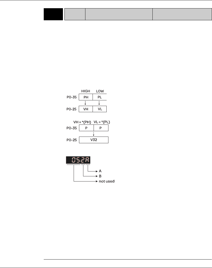
Lexium 23A 11. Servo Parameters
AC servo drive 319
P0 - 35 MAP1A Block Data Read / Write Register 1
(for P0-25) Address: 0046H, 0047H
Default: 0x0 Related Section: Section 6.3.3.5
Applicable Control Mode: ALL
Unit: N/A
Range: determined by the communication address of the designated parameter
Data Size: 32-bit
Display Format: Hexadecimal
Settings:
The parameters from P0-35 to P0-42 are used to designate the desired read and
write parameter numbers for P0-25 to P0-32, and read and write the values of the
parameters those communication addresses are not consecutive through
communication setting or the keypad more efficiently.
The read / write parameter could be one 32-bit parameter or two 16-bit parameters.
The operation of parameter P0-35 is described as follows:
When PH ≠ PL, it indicates that P0-25 includes two 16-bit parameters.
When PH = PL = P, it indicates that the content of P0-25 is one 32-bit parameter.
V32 = *(P). If P = 060Ah (parameter P6-10), the value of V32 is the value of P6-10.
A: Parameter group code in hexadecimal format
B: Parameter number in hexadecimal format
For example:
If the desired read and write parameter number is P2-06, please set P0-35 to
0206. If the desired read and write parameter number is P5-42, please set P0-35
to 052A, and vise versa.
When the users want to read and write the value of the parameter P1-44 (32-bit
parameter) via P0-25, please set P0-35 to 0x012C012C through communication
setting or the keypad. The the value of the parameter P1-44 will be displayed by P0-25.
When the users want to read and write the values of the parameters P2-02
(Position Feed Forward Gain, 16-bit parameter) and P2-04 (Proportional Speed
Loop Gain, 16-bit parameter) via P0-25, please set P0-35 to 0x02040202 through
communication setting or the keypad. The the values of the parameters P2-02 and
P2-04 will be displayed by P0-25.
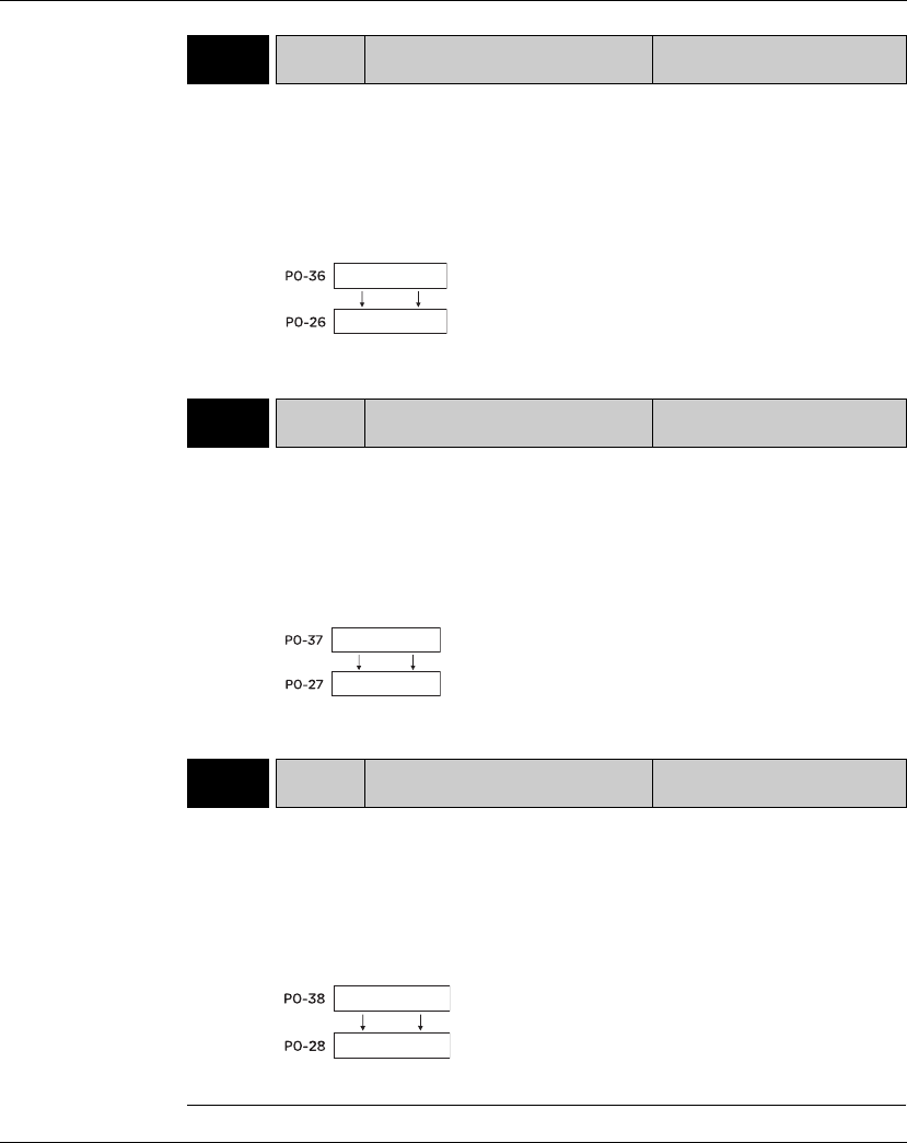
11. Servo Parameters Lexium 23A
320 AC servo drive
P0 - 36 MAP2A Block Data Read / Write Register 2
(for P0-26) Address: 0048H, 0049H
Default: 0x0 Related Section: Section 6.3.3.5
Applicable Control Mode: ALL
Unit: N/A
Range: determined by the communication address of the designated parameter
Data Size: 32-bit
Display Format: Hexadecimal
Settings:
Refer to P0-35 for explanation.
P0 - 37 MAP3A Block Data Read / Write Register 3
(for P0-27) Address: 004AH, 004BH
Default: 0x0 Related Section: Section 6.3.3.5
Applicable Control Mode: ALL
Unit: N/A
Range: determined by the communication address of the designated parameter
Data Size: 32-bit
Display Format: Hexadecimal
Settings:
Refer to P0-35 for explanation.
P0 - 38 MAP4A Block Data Read / Write Register 4
(for P0-28) Address: 004CH, 004DH
Default: 0x0 Related Section: Section 6.3.3.5
Applicable Control Mode: ALL
Unit: N/A
Range: determined by the communication address of the designated parameter
Data Size: 32-bit
Display Format: Hexadecimal
Settings:
Refer to P0-35 for explanation.
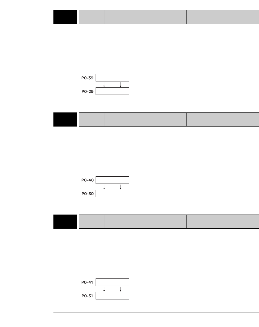
Lexium 23A 11. Servo Parameters
AC servo drive 321
P0 - 39 MAP5A Block Data Read / Write Register 5
(for P0-29) Address: 004EH, 004FH
Default: 0x0 Related Section: Section 6.3.3.5
Applicable Control Mode: ALL
Unit: N/A
Range: determined by the communication address of the designated parameter
Data Size: 32-bit
Display Format: Hexadecimal
Settings:
Refer to P0-35 for explanation.
P0 - 40 MAP6A Block Data Read / Write Register 6
(for P0-30)
Address: 0050H, 0051H
Default: 0x0 Related Section: Section 6.3.3.5
Applicable Control Mode: ALL
Unit: N/A
Range: determined by the communication address of the designated parameter
Data Size: 32-bit
Display Format: Hexadecimal
Settings:
Refer to P0-35 for explanation.
P0 - 41 MAP7A Block Data Read / Write Register 7
(for P0-31) Address: 0052H, 0053H
Default: 0x0 Related Section: Section 6.3.3.5
Applicable Control Mode: ALL
Unit: N/A
Range: determined by the communication address of the designated parameter
Data Size: 32-bit
Display Format: Hexadecimal
Settings:
Refer to P0-35 for explanation.
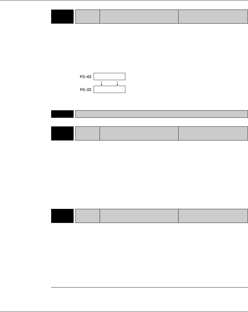
11. Servo Parameters Lexium 23A
322 AC servo drive
P0 - 42 MAP8A Block Data Read / Write Register 8
(for P0-32) Address: 0054H, 0055H
Default: 0x0 Related Section: Section 6.3.3.5
Applicable Control Mode: ALL
Unit: N/A
Range: determined by the communication address of the designated parameter
Data Size: 32-bit
Display Format: Hexadecimal
Settings:
Refer to P0-35 for explanation.
P0 - 43 Reserved (Do Not Use)
P0 - 44 PCMN Status Monitor Register (PC
Software Setting) Address: 0058H, 0059H
Default: 0x0 Related Section: Section 6.3.3.5
Applicable Control Mode: ALL
Unit: N/A
Range: determined by the communication address of the designated parameter
Data Size: 32-bit
Display Format: Decimal
Settings:
The function of this parameter is the same as P0-09 (Please refer to P0-09).
Please note that this pamameter can be set through communication setting only.
P0 - 45 bPCMNA Status Monitor Register Selection
(PC Software Setting) Address: 005AH, 005BH
Default: 0x0 Related Section: Section 6.3.3.5
Applicable Control Mode: ALL
Unit: N/A
Range: 0 ~ 127
Data Size: 16-bit
Display Format: Decimal
Settings:
The function of this parameter is the same as P0-17 (Please refer to P0-17). Please
note that this pamameter can be set through communication setting only.

Lexium 23A 11. Servo Parameters
AC servo drive 323
P0 - 46gSVSTS Servo Output Status Display Address: 005CH, 005DH
Default: 0
Applicable Control Mode: ALL
Unit: N/A
Range: 0x00 ~ 0xFF
Data Size: 16-bit
Display Format: Hexadecimal
Settings:
Related Section: -
This parameter is used to display the digital output signal of the servo drive. The
servo output status display will show in hexadecimal format.
Bit0: SRDY (Servo ready)
Bit1: SON (Servo On)
Bit2: ZSPD (At Zero speed)
Bit3: TSPD (At Speed reached)
Bit4: TPOS (At Positioning completed)
Bit5: TQL (At Torque limit)
Bit6: ALRM (Servo alarm activated)
Bit7: BRKR (Electromagnetic brake control)
Bit8: HOME (Homing completed)
Bit9: OLW (Output overload warning)
Bit10: WARN (Servo warning activated. WARN is activated when the drive has
detected reverse limit error; forward limit error, Operational stop, serial
communication error, and undervoltage these fault conditions.)
Bit11: Reserved
Bit12: Reserved
Bit13: Reserved
Bit14: Reserved
Bit15: Reserved
The servo output status display can be monitored through communication also.
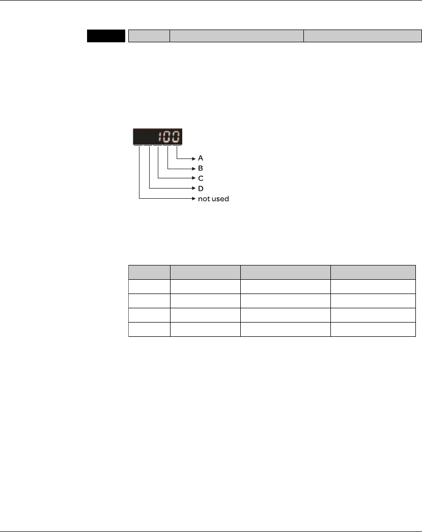
11. Servo Parameters Lexium 23A
324 AC servo drive
Group 1: P1-xx Basic Parameters
P1 - 00rPTT External Pulse Input Type Address: 0100H, 0101H
Default: 0x2
Applicable Control Mode: Pt
Unit: N/A
Range: 0 ~ 1132
Data Size: 16-bit
Display Format: Hexadecimal
Settings:
Related Section: Section 7.3.2.1
A: Input pulse type
0: AB phase pulse (4x)
(Quadrature Input)
1: Clockwise (CW) +
Counterclockwise
(CCW) pulse
2: Pulse + Direction
B: Input pulse filter
This setting is used to suppress or reduce the chatter caused by the noise, etc.
However, if the instant input pulse filter frequency is over high, the frequency
that exceeds the setting value will be regarded as noise and filtered.
BLow Filter Setting Value High Filter
0 1.66Mpps 0 6.66Mpps
1 416Kpps 1 1.66Mpps
2 208Kpps 2 833Kpps
3 104Kpps 3 416Kpps
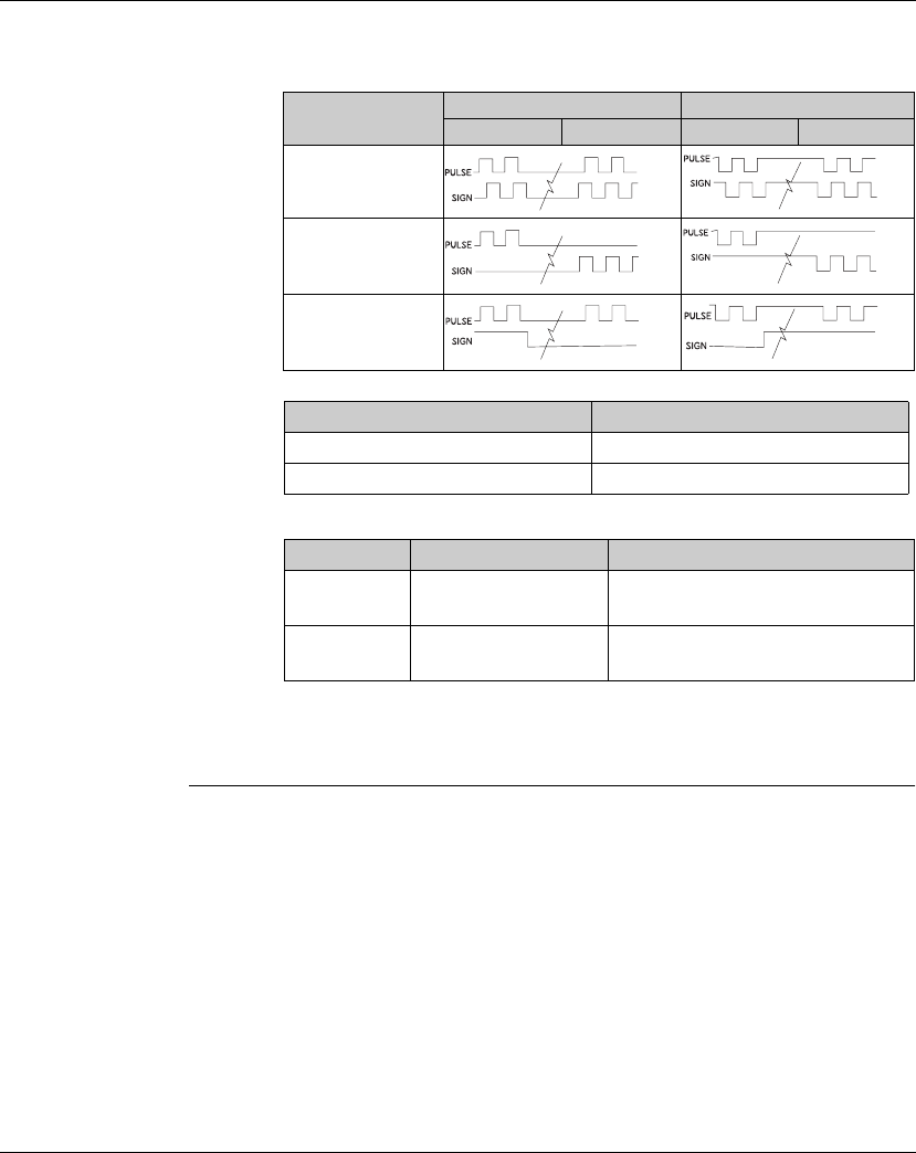
Lexium 23A 11. Servo Parameters
AC servo drive 325
C: Input polarity
D: Source of pulse command
The source of pulse command can also be determined by digital input, PTCMS.
When the digital input function is used, the source of pulse command is from digital
input.
Pulse Type 0=Positive Logic 1=Negative Logic
Forward Reverse Forward Reverse
AB phase pulse
(Quadrature)
CW + CCW pulse
Pulse + Direction
Input pulse interface Max. input pulse frequency
Line driver/Line receiver 500Kpps/4Mpps
Open collector 200Kpps
Setting value Input pulse interface Remark
0 Low-speed pulse CN1 Terminal Identification:
PULSE, SIGN
1 High-speed pulse CN1 Terminal Identification:
HPULSE, HSIGN
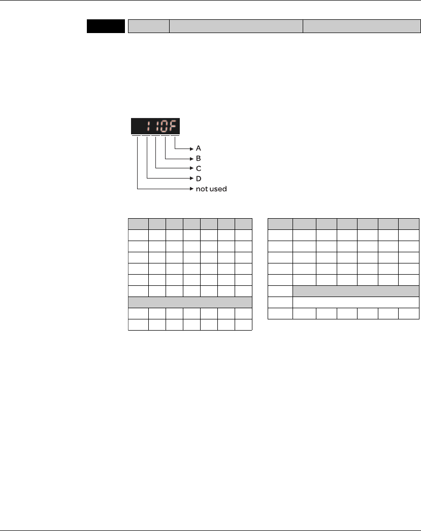
11. Servo Parameters Lexium 23A
326 AC servo drive
P1 - 01pCTL Control Mode and Output Direction Address: 0102H, 0103H
Default: 0
pplicable Control Mode: ALL
Related Section: Section 7.3.1 ,
Table 11.A
Unit: pulse (P mode), rpm (S mode), Nm (T mode)
Range: 00 ~ 110F
Data Size: 16-bit
Display Format: Hexadecimal
Settings:
Pt: Position control mode. The command is from external pulse or analog voltage
(external analog voltage will be available soon). Execution of the command
selection is via DI signal, PTAS.
Pr: Position control mode. The command is from internal signal. Execution of 64
positions is via DI signals (POS0 ~ POS2). A variety of homing control is also
provided.
S: Speed control mode. The command is from external signal or internal signal.
Execution of the command selection is via DI signals, SPD0 and SPD1.
T: Torque control mode. The command is from external signal or internal signal.
Execution of the command selection is via DI signals, TCM0 and TCM1.
Sz: Zero speed / internal speed command
Tz: Zero torque / internal torque command
A/B: Control mode settings
Pt Pr S T Sz Tz Pt Pr S T Sz Tz
00 r06 rr
01 r07 rr
02 r08 rr
03 r09 rr
04 r0A rr
05 rOB CANopen Mode
Multiple Mode OC Reserved
OE rrr OD rr
OF rr r
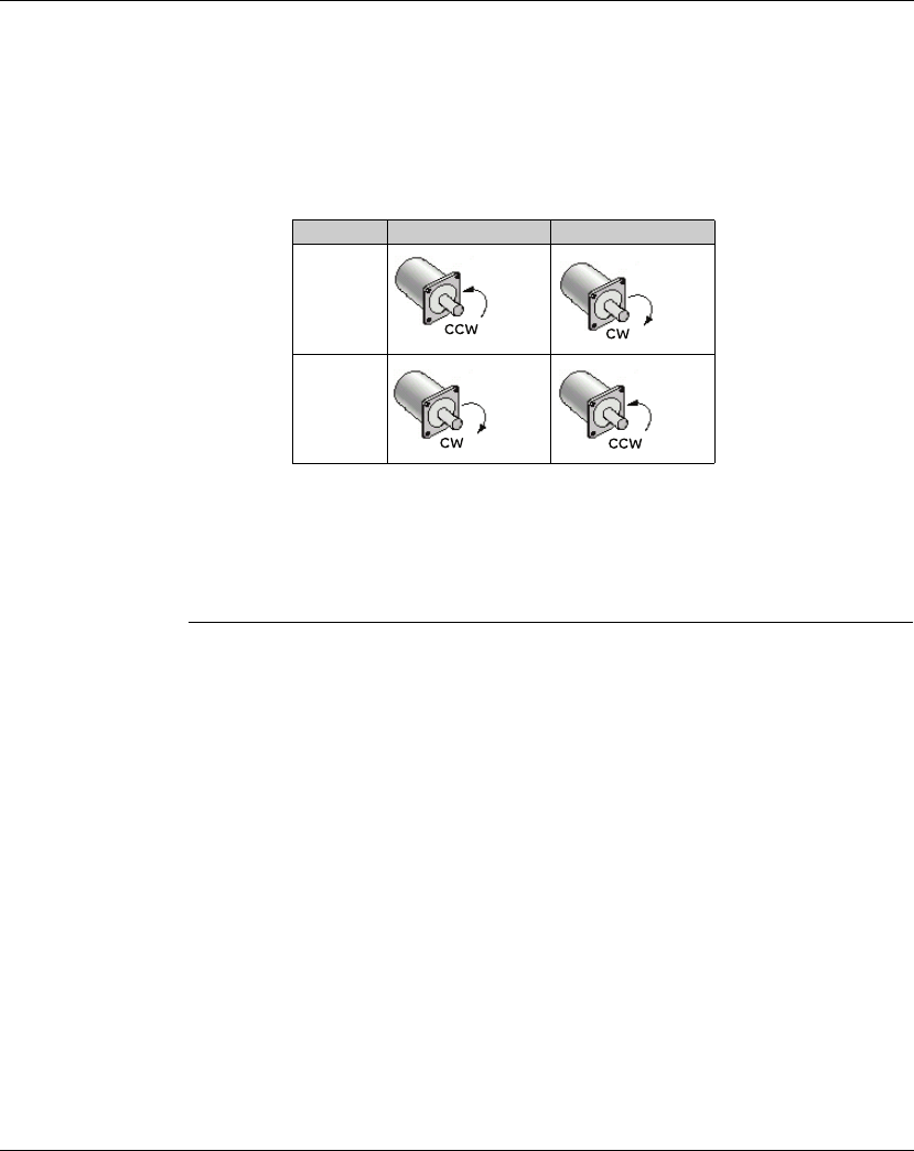
Lexium 23A 11. Servo Parameters
AC servo drive 327
Dual Mode: Control of the mode selection is via DI signals. For example, either Pt or
S control mode can be selected via DI signal, S-P (see Table 11.A).
Multiple Mode: Control of the mode selection is via DI signals. For example, either
Pt or Pr or S control mode can be selected via DI signals, S-P and Pt-
Pr (see Table 11.A).
C: Torque output direction settings
D: Discrete I/O Setting
1: When switching to different mode, digital inputs/outputs (P2-10 ~ P2-22) can
be reset to be the default value of the mode you switch to.
0: When switching to different mode, the setting value of digital inputs/outputs
(P2-10 ~ P2-22) will remain the same and will not be changed.
Direction 0 1
Forward
Reverse
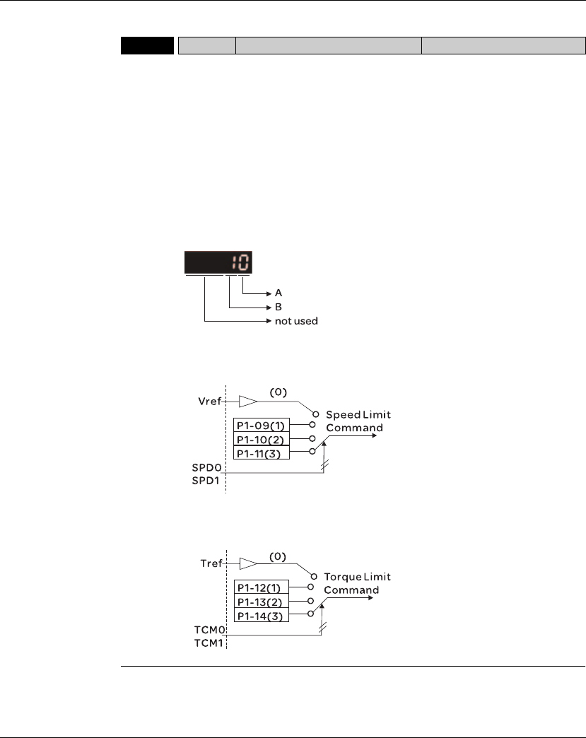
11. Servo Parameters Lexium 23A
328 AC servo drive
P1 - 02rPSTL Speed and Torque Limit Address: 0104H, 0105H
Default: 0
Applicable Control Mode: ALL
Related Section: Section 7.4,
Table 11.A
Unit: N/A
Range: 00 ~ 11
Data Size: 16-bit
Display Format: Hexadecimal
Settings:
This parameter is used to determine that the speed and torque limit functions are
enabled or disabled. If P1-02 is set to 11, it indicates that the speed and torque limit
functions are enabled always. The users can also use DI signals, SPDLM and TRQLM to
enable the speed and torque limit functions. Please note that DI signals, SPD0, SPD1,
TCM0, and TCM1 are used to select the command source of the speed and torque limit.
A: Disable or Enable speed limit function
0: Disable speed limit function
1: Enable speed limit function (It is available in torque mode)
B: Disable or Enable torque limit function
0: Disable torque limit function
1: Enable torque limit function (It is available in position and speed mode)
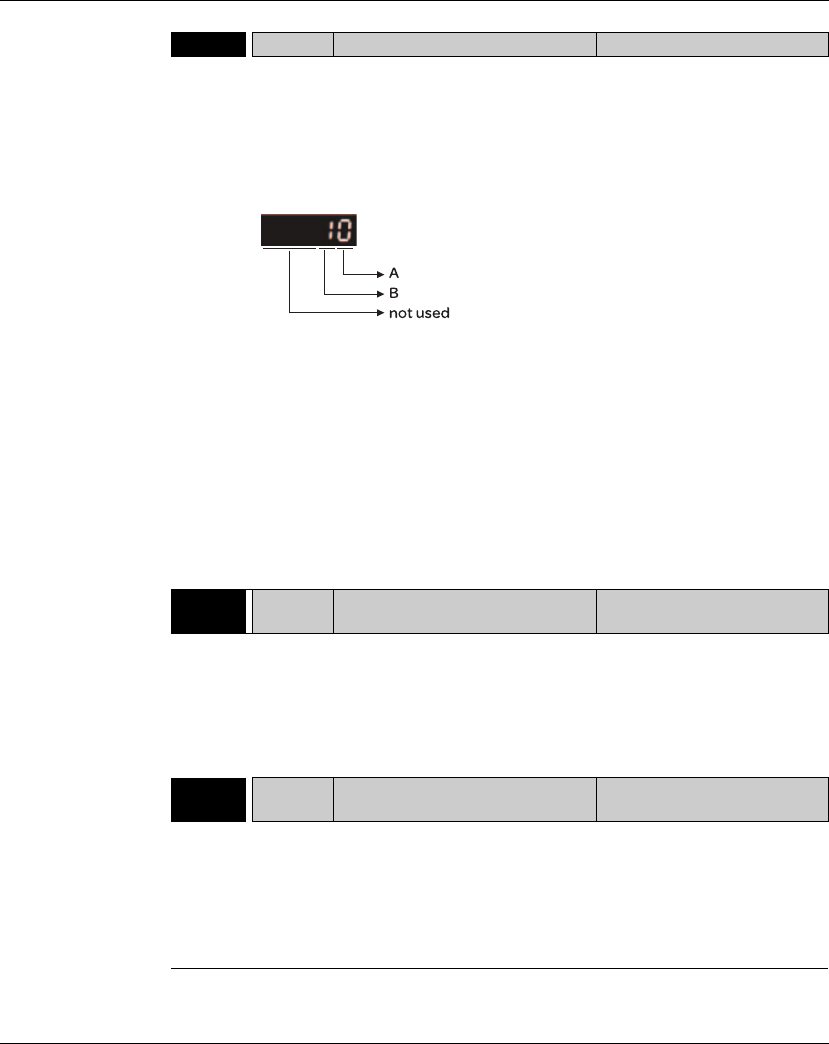
Lexium 23A 11. Servo Parameters
AC servo drive 329
P1 - 03 AOUT Pulse Output Polarity Setting Address: 0106H, 0107H
Default: 0
Applicable Control Mode: ALL
Unit: N/A
Range: 0 ~ 13
Data Size: 16-bit
Display Format: Hexadecimal
Settings:
Related Section: Section 5.2.8.3
his parameter is used to determine the polarity of analog monitor outputs and
position pulse outputs. The analog monitor outputs can be configured with
different polarity individually, but the position pulse outputs have to be each with
the same polarity.
A: Analog monitor outputs polarity
0: MON1(+), MON2(+)
1: MON1(+), MON2(-)
2: MON1(-), MON2(+)
3: MON1(-), MON2(-)
B: Position pulse outputs polarity
0: Forward output
1: Reverse output
P1 - 04 MON1 Analog Monitor Output Proportion 1
(CH1) Address: 0108H, 0109H
Default: 100
Applicable Control Mode: ALL
Unit: % (full scale)
Range: 0 ~ 100
Data Size: 16-bit
Display Format: Decimal
Related Section: Section 7.3.4.4
P1 - 05 MON2 Analog Monitor Output Proportion 2
(CH2) Address: 010AH, 010BH
Default: 100
Applicable Control Mode: ALL
Unit: % (full scale)
Range: 0 ~ 100
Data Size: 16-bit
Display Format: Decimal
Related Section: Section 7.3.4.4

11. Servo Parameters Lexium 23A
330 AC servo drive
P1 - 06 SFLT
Accel / Decel Smooth Constant of
Analog Speed Command (Low-pass
Filter)
Address: 010CH, 010DH
Default: 0
Applicable Control Mode: S
Unit: msec
Range: 0 ~ 1000 (0: Disabled)
Data Size: 16-bit
Display Format: Decimal
Related Section: Section 7.3.3.3
P1 - 07 TFLT Smooth Constant of Analog Torque
Command (Low-pass Filter) Address: 010EH, 010FH
Default: 0
Applicable Control Mode: T
Unit: msec
Range: 0 ~ 1000 (0: Disabled)
Data Size: 16-bit
Display Format: Decimal
Related Section: Section 7.3.4.3
P1 - 08 PFLT Smooth Constant of Position
Command (Low-pass Filter) Address: 0110H, 0111H
Default: 0
Applicable Control Mode: Pt/Pr
Unit: msec
Range: 0 ~ 1000 (0: Disabled)
Data Size: 16-bit
Display Format: Decimal
Related Section: Section 7.3.2.6
P1 - 09 SP1 1st Speed Command or Limit Address: 0112H, 0113H
Default: 1000
Applicable Control Mode: S, T
Unit: 0.1rpm
Range: -60000 ~ +60000
Data Size: 32-bit
Display Format: Decimal
Settings:
Related Section: Section 7.3.3.1
1 st Speed Command
In Speed mode, this parameter is used to set speed 1 of internal speed command.
1st Speed Limit
In Torque mode, this parameter is used to set speed limit 1 of internal speed
command.

Lexium 23A 11. Servo Parameters
AC servo drive 331
P1 - 10 SP2 2nd Speed Command or Limit Address: 0114H, 0115H
Default: 2000
Applicable Control Mode: S, T
Unit: 0.1 rpm
Range: -60000 ~ +60000
Data Size: 32-bit
Display Format: Decimal
Settings:
Related Section: Section 7.3.3.1
2nd Speed Command
In Speed mode, this parameter is used to set speed 2 of internal speed command.
2nd Speed Limit
In Torque mode, this parameter is used to set speed limit 2 of internal speed
command.
P1 - 11 SP3 3rd Speed Command or Limit Address: 0116H, 0117H
Default: 3000
Applicable Control Mode: S, T
Unit: 0.1rpm
Range: -60000 ~ +60000
Data Size: 32-bit
Display Format: Decimal
Settings:
Related Section: Section 7.3.3.1
3rd Speed Command
In Speed mode, this parameter is used to set speed 3 of internal speed command.
3rd Speed Limit
In Torque mode, this parameter is used to set speed limit 3 of internal speed
command.
P1 - 12 TQ1 1st Torque Command or Limit Address: 0118H, 0119H
Default: -300 ~ +300
Applicable Control Mode: T, P&S
Unit: %
Range: -300 ~ +300
Data Size: 16-bit
Display Format: Decimal
Related Section: Section 7.3.4.1
Settings:
1st Torque Command
In Torque mode, this parameter is used to set torque 1 of internal torque
command.
1st Torque Limit
In Position and Speed mode, this parameter is used to set torque limit 1 of internal
torque command.
Digital output signal TQL is activated when the drive has detected that the motor
has reached the torques limits set by either the parameters P1-12 ~ P1-14 of via an
external analog voltage.

11. Servo Parameters Lexium 23A
332 AC servo drive
P1 - 13 TQ2 2nd Torque Command or Limit Address: 011AH, 011BH
Default: -300 ~ +300
Applicable Control Mode: T, P&S
Unit: %
Range: -300 ~ +300
Data Size: 16-bit
Display Format: Decimal
Related Section: Section 7.3.4.1
Settings:
2nd Torque Command
In Torque mode, this parameter is used to set torque 2 of internal torque
command.
2nd Torque Limit
In Position and Speed mode, this parameter is used to set torque limit 2 of internal
torque command.
Digital output signal TQL is activated when the drive has detected that the motor
has reached the torques limits set by either the parameters P1-12 ~ P1-14 of via an
external analog voltage.
P1 - 14 TQ3 3rd Torque Command or Limit Address: 011CH, 011DH
Default: -300 ~ +300
Applicable Control Mode: T, P&S
Unit: %
Range: -300 ~ +300
Data Size: 16-bit
Display Format: Decimal
Related Section: Section 7.3.4.1
Settings:
3 rd Speed Command
In Torque mode, this parameter is used to set torque 3 of internal torque command.
3 rd Speed Limit
In Position and Speed mode, this parameter is used to set torque limit 3 of internal
torque command.
Digital output signal TQL is activated when the drive has detected that the motor has
reached the torques limits set by either the parameters P1-12 ~ P1-14 of via an external
analog voltage.
P1 - 15 Reserved (Do Not Use)
P1 - 16 Reserved (Do Not Use)
P1 - 17 Reserved (Do Not Use)
P1 - 18 Reserved (Do Not Use)

Lexium 23A 11. Servo Parameters
AC servo drive 333
P1 - 19 Reserved (Do Not Use)
P1 - 20 Reserved (Do Not Use)
P1 - 21 Reserved (Do Not Use)
P1 - 22 Reserved (Do Not Use)
P1 - 23 Reserved (Do Not Use)
P1 - 24 Reserved (Do Not Use)
P1 - 25 VSF1 Low-frequency Vibration
Suppression (1) Address: 0132H, 0133H
Default: 100.0
Applicable Control Mode: Pt/Pr
Unit: Hz
Range: 1.0 ~ 100.0
Data Size: 16-bit
Display Format: Decimal
Related Section: Section 7.3.2.9
Settings:
This parameter is used to set the first group of the low-frequency of mechanical
system. It can be used to suppress the low-frequency vibration of mechanical
system. If P1-26 is set to 0, this parameter is disabled.
P1 - 26 VSG1 Low-frequency Vibration
Suppression Gain (1) Address: 0134H, 0135H
Default: 0
Applicable Control Mode: Pt/Pr
Unit: N/A
Range: 0 ~ 9 (0: Disable the function of P1-25)
Data Size: 16-bit
Display Format: Decimal
Related Section: Section 7.3.2.9
Settings:
This parameter is used to set the vibration suppression gain for P1-25. When the
setting value is higher, the position response is quicker. However, if the setting value is
over high, it may addect the normal operation of servo motor. It is recommended to
set P1-26 as 1.

11. Servo Parameters Lexium 23A
334 AC servo drive
P1 - 27 VSF2 Low-frequency Vibration
Suppression (2) Address: 0136H, 0137H
Default: 100.0
Applicable Control Mode: Pt/Pr
Unit: Hz
Range: 1.0 ~ 100.0
Data Size: 16-bit
Display Format: Decimal
Related Section: Section 7.3.2.9
Settings:
This parameter is used to set the second group of the low-frequency of mechanical
system. It can be used to suppress the low-frequency vibration of mechanical system.
If P1-28 is set to 0, this parameter is disabled.
P1 - 28 VSG2 Low-frequency Vibration
Suppression Gain (2) Address: 0138H, 0139H
Default: 0
Applicable Control Mode: Pt/Pr
Unit: N/A
Range: 0 ~ 9 (0: Disable the function of P1-27)
Data Size: 16-bit
Display Format: Decimal
Related Section: Section 7.3.2.9
Settings:
This parameter is used to set the vibration suppression gain for P1-27. When the
setting value is higher, the position response is quicker. However, if the setting
value is over high, it may addect the normal operation of servo motor. It is
recommended to set P1-28 as 1.
P1 - 29 AVSM Auto Low-frequency Vibration
Suppression Mode Selection Address: 013AH, 013BH
Default: 0
Applicable Control Mode: Pt/Pr
Unit: N/A
Range: 0 ~ 1
Data Size: 16-bit
Display Format: Decimal
Related Section: Section 7.3.2.9
Settings:
0: Normal mode (Disable Auto Low-frequency Vibration Suppression Mode).
1: Auto mode (Enable Auto Low-frequency Vibration Suppression Mode).
Explanation:
If P1-29 is set to 0, the setting of low-frequency vibration suppression is fixed and will
not change automatically.
If P1-29 is set to 1, when there is no low-frequency vibration or the low-frequency
vibration becomes less and stable, the system will set P1-29 to 0, save the measured
low-frequency value automatically and memorize it in P1-25.
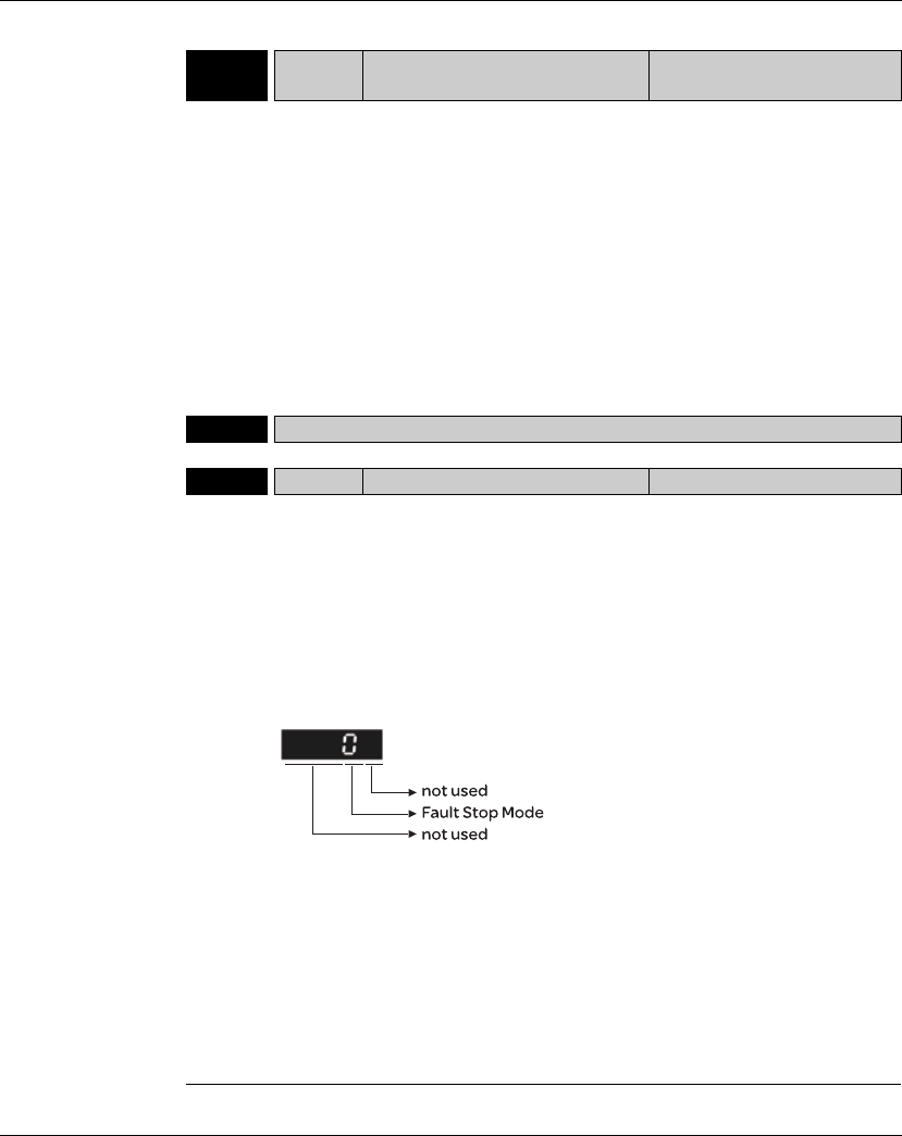
Lexium 23A 11. Servo Parameters
AC servo drive 335
P1 - 30 VCL Low-frequency Vibration Detection
Level Address: 013CH, 013DH
Default: 500
Applicable Control Mode: Pt/Pr
Unit: pulse
Range: 1 ~ 8000
Data Size: 16-bit
Display Format: Decimal
Related Section: Section 7.3.2.9
Settings:
When P1-29 is set to 1, the system will search this detection level automatically. If the
setting value of P1-30 is too low, the dectection of frequency will become sensitive and
result in erroneous measurement. If the setting value of P1-30 is too high, although the
probability of erroneous measurement will decrease, the frequency will become
difficult to be found especially when the vibration of mechanical system is less.
P1 - 31 Reserved (Do Not Use)
P1 - 32 LSTP Motor Stop Mode Selection Address: 0140H, 0141H
Default: 0
Applicable Control Mode: ALL
Unit: N/A
Range: 0 ~ 20
Data Size: 16-bit
Display Format: Hexadecimal
Related Section: N/A
Settings:
This parameter is used to select servo motor stop mode when Servo Off or a fault
(servo alarm, includes OPST (Operational stop)) occurs.
Fault Stop Mode
0: Use dynamic brake
1: Allow servo motor to coast to stop
2: Use dynamic brake first, after the motor speed is below than P1-38, allow servo
motor to coast to stop
When the fault NL(CWL) or PL(CCWL) occurs, please refer to the settings of
parameter P5-03 to determine the deceleration time. If the deceleration time is set to
1msec, the motor will stop instantly.

11. Servo Parameters Lexium 23A
336 AC servo drive
P1 - 33 Reserved (Do Not Use)
P1 - 34 TACC Acceleration Time Address: 0144H, 0145H
Default: 200
Applicable Control Mode: S
Unit: msec
Range: 1 ~ 65500
Data Size: 16-bit
Display Format: Decimal
Related Section: Section 7.3.3.3
Settings:
This parameter is used to determine the acceleration time to accelerate from 0 to
its rated motor speed. The functions of parameters P1-34, P1-35 and P1-36 are
each individual. When P1-36 is set to 0 (Disabled), the settings of P1-34, P1-35 are
still effective. It indicates that the parameters P1-34 and P1-35 will not become
disabled even when P1-36 is disabled.
Please note:
1. When the source of speed command is analog command, the maximum setting
value of P1-36 is set to 0, the acceleration and deceleration function will be
disabled.
2. When the source of speed command is analog command, the maximum setting
value of P1-34 is limited to 20000 automatically.
P1 - 35 TDEC Deceleration Time Address: 0146H, 0147H
Default: 200
Applicable Control Mode: S
Unit: msec
Range: 1 ~ 65500
Data Size: 16-bit
Display Format: Decimal
Related Section: Section 7.3.3.3
Settings:
This parameter is used to determine the acceleration time to accelerate from 0 to its
rated motor speed. The functions of parameters P1-34, P1-35 and P1-36 are each
individual. When P1-36 is set to 0 (Disabled), the settings of P1-34, P1-35 are still
effective. It indicates that the parameters P1-34 and P1-35 will not become disabled
even when P1-36 is disabled.
Please note:
1. When the source of speed command is analog command, the maximum setting
value of P1-36 is set to 0, the acceleration and deceleration function will be disabled.
2. When the source of speed command is analog command, the maximum setting
value of P1-35 is limited to 20000 automatically.
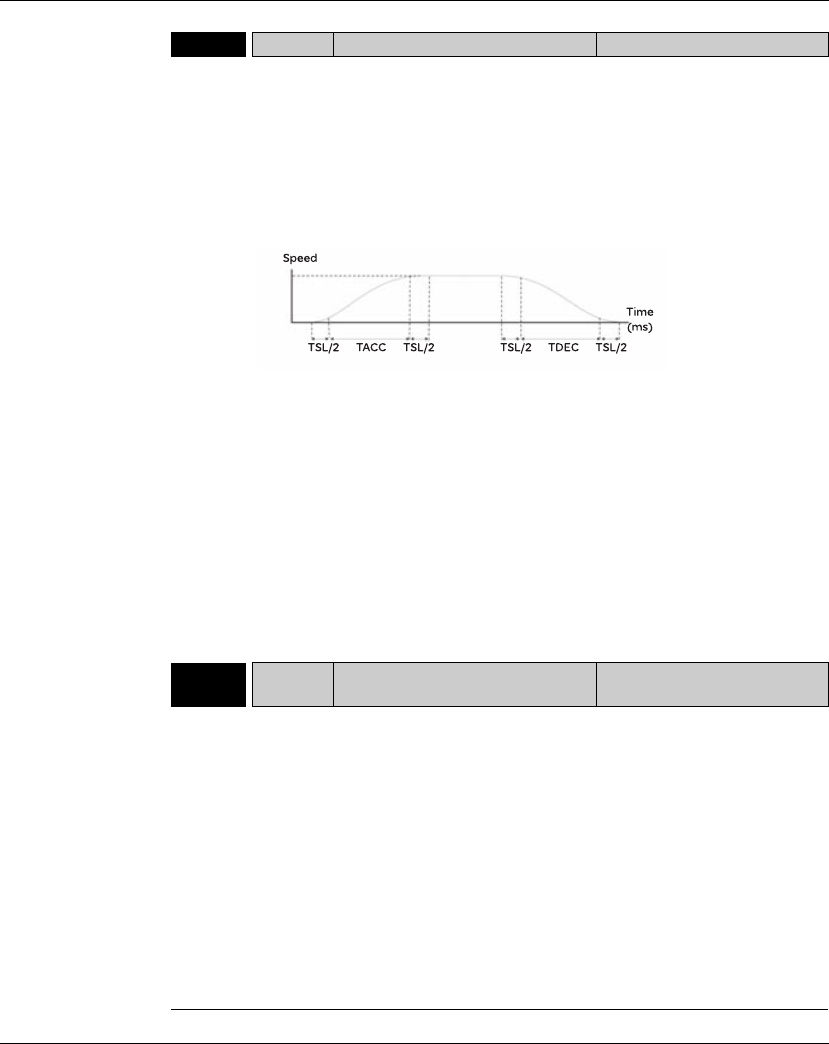
Lexium 23A 11. Servo Parameters
AC servo drive 337
P1 - 36 TSL Accel /Decel S-curve Address: 0148H, 0149H
Default: 0
Applicable Control Mode: S, Pr
Unit: msec
Range: 0 ~ 65500 (0: Disabled)
Data Size: 16-bit
Display Format: Decimal
Related Section: Section 7.3.3.3
Settings:
This parameter is used to make the motor run more smoothly when startup and
windup. Using this parameter can improve the motor running stability.
TACC: P1-34, Acceleration time
TDEC: P1-35, Deceleration time
TSL: P1-36, Accel /Decel S-curve
Total acceleration time = TACC + TSL
Total deceleration time = TDEC + TSL
The functions of parameters P1-34, P1-35 and P1-36 are each individual. When P1-36 is
set to 0 (Disabled), the settings of P1-34, P1-35 are still effective. It indicates that the
parameters P1-34 and P1-35 will not become disabled even when P1-36 is disabled.
Please note:
1. When the source of speed command is analog command, the maximum setting
value of P1-36 is set to 0, the acceleration and deceleration function will be disabled.
2. When the source of speed command is analog command, the maximum setting
value of P1-36 is limited to 10000 automatically.
P1 - 37 GDR Ratio of Load Inertia to Servo Motor
Inertia Address: 014AH, 014BH
Default: 10
Applicable Control Mode: ALL
Unit: 0.1 times
Range: 0 ~ 2000
Data Size: 16-bit
Display Format: Decimal
Related Section: N/A
Settings:
Ratio of load inertia to servo motor inertia (for Rotation Motor): (J_load /J_motor)
J_load: Total equivalent moment of inertia of external mechanical load
J_motor: Moment of inertia of servo motor
Ratio of load weight to servo motor weight (for Linear Motor): (M_load /
M_motor)(not available now but will be available soon)
M_load: Total equivalent weight of external mechanical load
M_motor: Weight of servo motor

11. Servo Parameters Lexium 23A
338 AC servo drive
P1 - 38 ZSPD Zero Speed Range Setting Address: 014CH, 014DH
Default: 100
Applicable Control Mode: ALL
Unit: 0.1 rpm
Range: 0 ~ 2000
Data Size: 16-bit
Display Format: Decimal
Related Section: Table 11.A
Settings:
This parameter is used to set output range of zero speed signal (ZSPD) and
determine whrn zero speed signal (ZSPD) becomes activated. ZSPD is activated
when the drive senses the motor is equal to or below the Zero Speed Range setting
as defined in parameter P1-38.
For Example, at default ZSPD will be activated when the drive detects the motor
rotating at speed at or below 100 rpm. ZSPD will remain activated until the motor
speed increases above 100 rpm.
P1 - 39 SSPD Target Motor Speed Address: 014EH, 014FH
Default: 3000
Applicable Control Mode: ALL
Unit: rpm
Range: 0 ~ 5000
Data Size: 16-bit
Display Format: Decimal
Related Section: Table11.A
Settings:
When target motor speed reaches its preset value, digital output (TSPD) is enabled.
When the forward and reverse speed of servo motor is equal and higher than the setting
value, the motor will reach the target motor speed, and then TSPD signal will output.
TSPD is activated once the drive has detected the motor has reached the Target Motor
Speed setting as defined in parameter P1-39. TSPD will remain activated until the motor
speed drops below the Target Motor Speed.

Lexium 23A 11. Servo Parameters
AC servo drive 339
P1 - 40rVCM Max. Analog Speed Command or
Limit Address: 0150H, 0151H
Default: rated speed
Applicable Control Mode: S, T
Unit: rpm
Range: 0 ~ 10000
Data Size: 16-bit
Display Format: Decimal
Related Section: Section 7.3.3.4
Settings:
In Speed mode, this parameter is used to set the maximum analog speed
command based on the maximum input voltage (10V).
In Torque mode, this parameter is used to set the maximum analog speed limit
based on the maximum input voltage (10V).
For example, in speed mode, if P1-40 is set to 3000 and the input voltage is 10V, it
indicates that the speed command is 3000 rpm. If P1-40 is set to 3000, but the
input voltage is changed to 5V, then the speed command is changed to 1500 rpm.
Speed Command / Limit = Input Voltage Value x Setting value of P1-40 / 10
P1 - 41rTCM Max. Analog Torque Command or
Limit Address: 0152H, 0153H
Default: 100
Applicable Control Mode: ALL
Unit: %
Range: 0 ~ 1000
Data Size: 16-bit
Display Format: Decimal
Related Section: Section 7.3.4.4
Settings:
In Torque mode, this parameter is used to set the maximum analog torque
command based on the maximum input voltage (10V).
In Position (Pt, Pr) and Speed mode, this parameter is used to set the maximum
analog torque limit based on the maximum input voltage (10V).
For example, in torque mode, if P1-41 is set to 100 and the input voltage is 10V, it
indicates that the torque command is 100% rated torque. If P1-41 is set to 100, but
the input voltage is changed to 5V, then the torque command is changed to 50%
rated torque.
Torque Command / Limit = Input Voltage Value x Setting value of P1-41 / 10
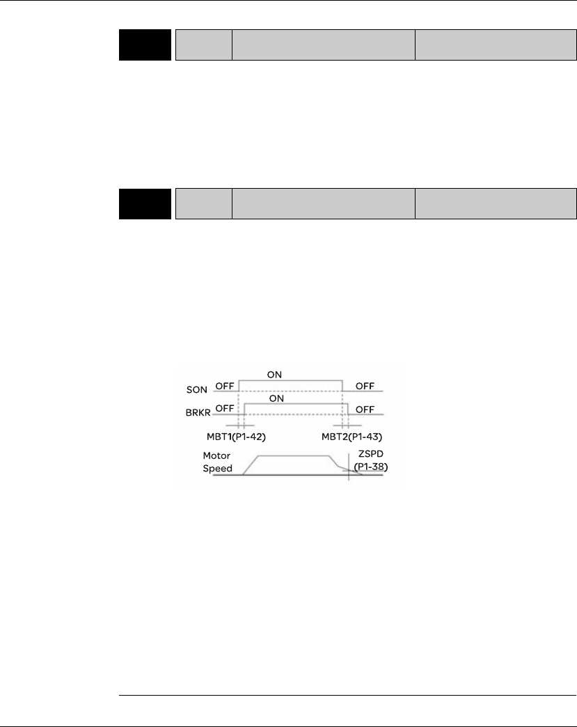
11. Servo Parameters Lexium 23A
340 AC servo drive
P1 - 42 MBT1 On Delay Time of Electromagnetic
Brake Address: 0154H, 0155H
Default: 0
Applicable Control Mode: ALL
Unit: msec
Range: 0 ~ 1000
Data Size: 16-bit
Display Format: Decimal
Related Section: Section 7.4.4,
Table 11.B
Settings:
Used to set the period of time between when the servo drive is On (Servo On) and
when electromagnetic brake output signal (BRKR) is activated.
P1 - 43 MBT2 OFF Delay Time of Electromagnetic
Brake Address: 0156H, 0157H
efault: -1000 ~ +1000
Applicable Control Mode: ALL
Unit: msec
Range: -1000 ~ +1000
Data Size: 16-bit
Display Format: Decimal
Related Section: Section 7.4.4
Table 11.B
Settings:
Used to set the period of time between when the servo drive is Off (Servo
Off) and when electromagnetic brake output signal (BRKR) is inactivated.
Please note:
1. When servo is commanded off and the off delay time set by P1-43 has not
elapsed, if the motor speed is lower than the setting value of P1-38, the
electromagnetic brake will be engaged regardless of the off delay time set by
P1-43.
2. When servo is commanded off and the off delay time set by P1-43 has elapsed, if
the motor speed is higher than the setting value of P1-38, electromagnetic brake
will be engaged regardless of the current motor speed.
3. When the servo drive is disabled (Servo Off) due to a fault (except AL022) or by
OPST (Operational stop)) being activated, if the off delay time set by P1-43 is a
negative value, it will not affect the operation of the motor. A negative value of
the off delay time is equivalent to one with a zero value.
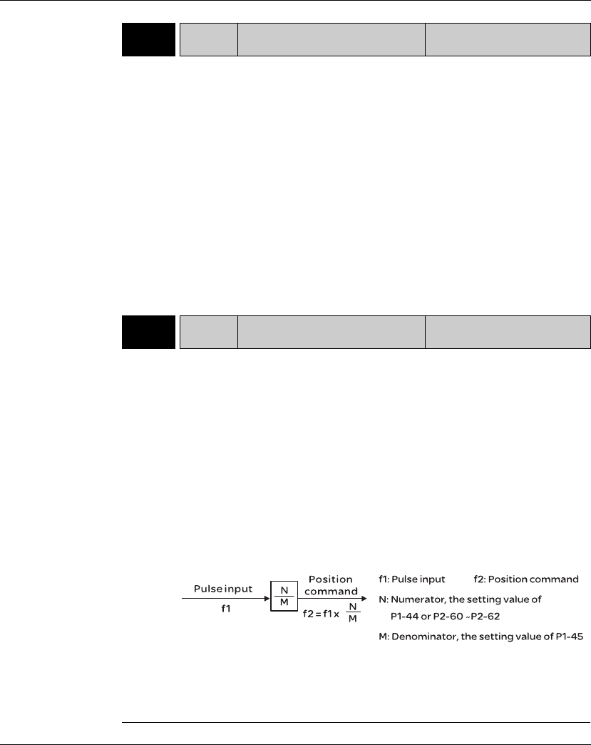
Lexium 23A 11. Servo Parameters
AC servo drive 341
P1 - 44rGR1 Electronic Gear Ratio (1st
Numerator) (N1) Address: 0158H, 0159H
Default: 128
Applicable Control Mode: Pt, Pr
Unit: pulse
Range: 1 ~ (229-1)
Data Size: 32-bit
Display Format: Decimal
Related Section: Section 7.3.2.5
Settings:
This parameter is used to set the numerator of the electronic gear ratio. The
denominator of the electronic gear ratio is set by P1-45. P2-60 ~ P2-62 are used to set
the additional numberators.
Please note:
1. In Pt mode, the setting value of P1-44 can be changed only when the servo drive is
enabled (Servo On).
2. In Pr mode, the setting value of P1-44 can be changed only when the servo drive is
disabled (Servo Off).
P1 - 45rGR2 Electronic Gear Ratio
(Denominator) (M) Address: 015AH, 015BH
Default: 10
Applicable Control Mode: Pt, Pr
Unit: pulse
Range: 1 ~ (231-1)
Data Size: 32-bit
Display Format: Decimal
Related Section: Section 7.3.2.5
Settings:
This parameter is used to set the denominator of the electronic gear ratio. The
numerator of the electronic gear ratio is set by P1-44. P2-60 ~ P2-62 are used to
set the additional numberators.
As the wrong setting may cause motor to run chaotically (out of control) and it may
lead to personnel injury, therefore, ensure to observe the following rule when
setting P1-44, P1-45.
The electronic gear ratio setting (Please also see P1-44, P2-60 ~ P2-62):
The electronic gear ratio setting range must be within: 1/50<N/M<25600.
Please note:
1. In Pt and Pr mode, the setting value of P1-45 can not be changed when the servo
drive is enabled (Servo On).
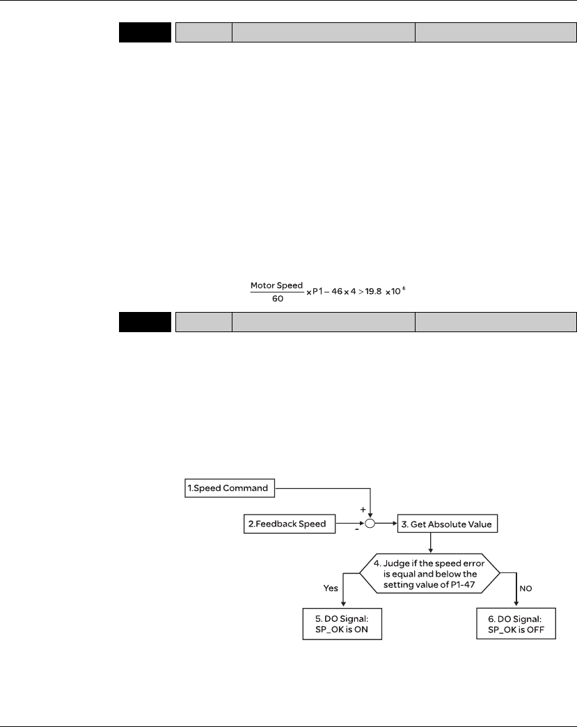
11. Servo Parameters Lexium 23A
342 AC servo drive
P1 - 46rGR3 Encoder Output Pulse Number Address: 015CH, 015DH
Default: 2500
Applicable Control Mode: ALL
Unit: pulse
Range: 20 ~ 320000
Data Size: 32-bit
Display Format: Decimal
Related Section: N/A
Settings:
This parameter is used to set the pulse numbers of encoder outputs per motor
revolution.
Please note:
When the following conditions occur, the output frequency for pulse output may
exceed the specification and cause that the servo drive fault AL018 (Encoder
Output Error) is activated.
Condition 1: Encoder error.
Condition 2: Motor speed is above the value set by parameter P1-76.
Condition 3:
P1 - 47 SPOK Speed Reached Output Range Address: 015EH, 015FH
Default: 10
Applicable Control Mode: S, Sz
Unit: N/A
Range: 0 ~ 300
Data Size: 32-bit
Display Format: Decimal
Related Section: N/A
Settings:
This parameter is used to set the speed reached output range. The DO signal, SP_OK
will be activated when the speed error is equal and below the setting value of P1-47.
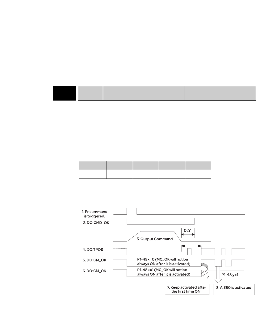
Lexium 23A 11. Servo Parameters
AC servo drive 343
1. Speed Command: It is the speed command input by the users (no Accel/Decel),
not the frond-end command of speed control loop. The source of this command
includes analog voltage and registers.
2. Feedback Speed: It is the actual motor speed which is filtered.
3. Get Absolute Value
4. Judge if the speed error is equal and below the setting value of P1-47: When P1-
47 is set to 0, this digital output will be always off.
5. ON or OFF: When the speed error is equal and below the setting value of P1-47,
SP_OK will be ON; otherwise, SP_OK will be OFF.
P1 - 48 MCOK Motion Control Completed Output
Selection Address: 0160H, 0161H
Default: 0x0000
Applicable Control Mode: Pr
Unit: N/A
Range: 0x0000 ~ 0x0011
Data Size: 16-bit
Display Format: Hexadecimal
Related Section: N/A
Settings: (for firmware version V1.002 and later models only)
This parameter is used to determine the operation after digital output signal, MC_OK
(DO code is 0x17) is activated.
X=0: MC_OK will not be always ON after it is activated.
X=1: MC_OK will be always ON after it is activated.
Y=0: Servo fault. AL380 will not be activated.
Y=1: Servo fault. AL380 will be activated.
Display 0 0 Y Y
Range - - 0 ~ 1 0 ~ 1
11. Servo Parameters Lexium 23A
344 AC servo drive
1. Pr command is triggerred: It indicates that the new Pr command becomes
effective. When the signal 3 starts to output the command, the signals 2, 4 and 5
will be clear simetaneously.
2. CMD_OK: CMD_OK is used to detect if the internal position command, signal 3
has been completed. DLY delay time can also be set.
3. Output Command: Output the internal position command according to desired
acceleration and deceleration.
4. TPOS: It is activated when the position error is equal and below the setting value
of P1-54.
5. MC_OK (P1-48 X=0): It is activated when the position command has output and
the positioning is completed also, i.e. CMD_OK and TPOS are both ON. However,
once TPOS becomes OFF, it will become OFF as well.
6 MC_OK (P1-48 X=1): It is activated when the position command has output and
the positioning is completed also, i.e. CMD_OK and TPOS are both ON. However,
when TPOS becomes OFF, it will not become OFF. It will be always ON
7. The signal 5 and signal 6 cannot be selected simetaneously. This function is
determined by X setting of P1-48.
8. Position deviation alarm (AL380): After signal 7 occurs, if signal 4 or 5 becomes off,
it indicates a position deviation alarm is detected and AL380 can be activated to
provide a alarm signal. This function is determined by Y setting of P1-48.
P1 - 49 Reserved (Do Not Use)
P1 - 50 Reserved (Do Not Use)
P1 - 51 Reserved (Do Not Use)
P1 - 52 RES1 Regenerative Resistor Value Address: 0168H, 0169H
Default: -
Applicable Control Mode: ALL
Unit: Ohm
Range: 10 ~ 750
Data Size: 16-bit
Display Format: Decimal
Related Section: Section 4.5
Settings:
This parameter is used to set the resistance of the applicable regenerative resistor.
Model Default
400W 40Ω
750W ~ 1.5kW 40Ω
2kW ~ 3kW 20Ω
Lexium 23A 11. Servo Parameters
AC servo drive 345
P1 - 53 RES2 Regenerative Resistor Capacity Address: 016AH, 016BH
Default: -
Applicable Control Mode: ALL
Unit: Watt
Range: 30 ~ 3000
Data Size: 16-bit
Display Format: Decimal
Related Section: Section 4.5
Settings:
This parameter is used to set the capacity of the applicable regenerative resistor.
P1 - 54 PER Positioning Completed Width Address: 016CH, 016DH
Default: 12800
Applicable Control Mode: Pt , Pr
Unit:pulse
Range: 0 ~ 1280000
Data Size: 32-bit
Display Format: Decimal
Related Section: Table 11.A
Settings:
In Pt mode, when the error pulse numbers is less than the setting value of parameter P1-
54, TPOS (At positioning completed signal) will be activated.
In Pr mode, when the difference in pulse number between the target position and the
actual position is less than the setting value of parameter P1-54, TPOS (At positioning
completed signal) will be activated.
P1 - 55 MSPD Maximum Speed Limit Address: 016EH, 016FH
Default: rated speed
Applicable Control Mode: ALL
Unit: rpm
Range: 0 ~ Max. speed
Data Size: 16-bit
Display Format: Decimal
Related Section: N/A
Settings:
This parameter is used to set maximum motor speed. The default setting is rated
speed.
Model Default
400W 40W
750W~1.5kW 60W
2kW~3kW 100W

11. Servo Parameters Lexium 23A
346 AC servo drive
P1 - 56 OVW Output Overload Warning Time Address: 0170H, 0171H
Default: 120
Applicable Control Mode: ALL
Unit: %
Range: 0 ~ 120
Data Size: 16-bit
Display Format: Decimal
Related Section: N/A
Settings:
This parameter is used to set output overload time. If the setting value of parameter
P1-56 is set to 0 ~ 100, the function of parameter P1-56 is enabled. When the motor
has reached the output overload time set by parameter P1-56, the motor will send a
warning to the drive. After the drive has detected the warning, the DO signal OLW will
be activated. If the setting value of parameter P1-56 exceeds 100, the function of
parameter P1-56 is disabled.
tOL = Permissible Time for Overload x the setting value of parameter P1-56
When overload accumulated time (continuously overload time) exceeds the value of
tOL, the overload warning signal will output, i.e. DO signal, OLW will be ON. However, if
the accumulated overload time (continuous overload time) exceeds the permissible
time for overload, the overload alarm (AL006) will occur.
For example:
If the setting value of parameter P1-56 (Output Overload Warning Time) is 60%, when
the permissible time for overload exceeds 8 seconds at 200% rated output, the
overload fault (AL006) will be detected and shown on the LED display.
At this time, tOL = 8 x 60% = 4.8 seconds
Result:
When the drive output is at 200% rated output and the drive is continuously
overloaded for 4.8 seconds, the overload warning signal will be ON, i.e. DO signal OLW
will be activated. If the drive is continuously overloaded for 8 seconds, the overload
alarm will be detected and shown on the LED display (AL006). Then, Servo Fault
signal will be ON (DO signal ALRM will be activated).

Lexium 23A 11. Servo Parameters
AC servo drive 347
P1 - 57 CRSHA Motor Protection Percentage Address: 0172H, 0173H
Default: 0
Applicable Control Mode: ALL
Unit: %
Range: 0 ~ 300
Data Size: 16-bit
Display Format: Decimal
Related Section: -
Settings:
This parameter is used to protect the motor in case the motor touchs the
mechanical equipment. If P1-57 is set to 0, the function of P1-57 is disabled. The
function of P1-57 is enabled when the setting value of P1-57 is set to 1 or more. The
fault AL030 will be activated when the setting value of P1-57 is reached after a
period of time set by P1-58.
P1 - 58 CRSHT Motor Protection Time Address: 0174H, 0175H
Default: 1
Applicable Control Mode: ALL
Unit: msec
Range: 0 ~ 1000
Data Size: 16-bit
Display Format: Decimal
Related Section: P1-57
Settings:
This parameter is used to protect the motor in case the motor touchs the
mechanical equipment. The fault AL030 will be activated when the setting value of
P1-57 is reached after a period of time set by P1-58.
Please note that this function is applicable for non-contact applications, such as
electric discharge machines only (P1-37 must be set correctly).
P1 - 59 MFLT Analog Speed Linear Filter (Moving
Filter) Address: 0176H, 0177H
Default: 0
Applicable Control Mode: S
Unit: 0.1msec
Range: 0 ~ 40 (0: Disabled)
Data Size: 16-bit
Display Format: Decimal
Related Section: N/A
Settings:
This parameter is used to eliminate the noise generated during the operation when
the host (external) controller sends the step analog voltage speed
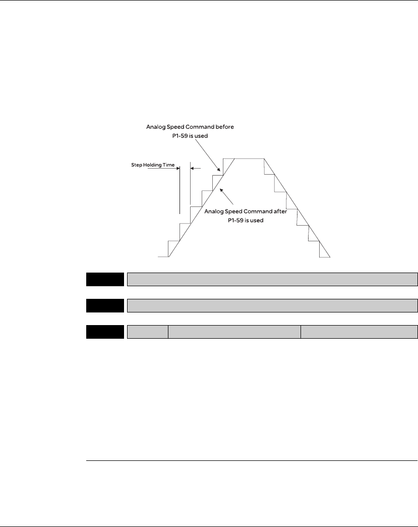
11. Servo Parameters Lexium 23A
348 AC servo drive
command. The parameter P1-06 is Low-pass Filter and parameter P1-59 is Moving
Filter. The differences are that Low-pass Filter is usually used to smooth the end of
the command but Moving Filter can be used to smooth the start and the end of
step analog voltage speed command. Using Moving Filter can facilitate the
smooth operation of the motor very effectively.
Therefore, it is recommended to use P1-06 Low-pass Filter when the speed
command from the external controller is applied for position control loop. If the
command is for speed control only, using Moving Filter P1-59 can achieve better
(smooth) performance.
P1 - 60 Reserved (Do Not Use)
P1 - 61 Reserved (Do Not Use)
P1 - 62 FRCL Friction Compensation Percentage Address: 017CH, 017DH
Default: 0
Applicable Control Mode: Pt, Pr, S
Unit: %
Range: 0 ~ 100
Data Size: 16-bit
Display Format: Decimal
Related Section: N/A
Settings:
This parameter is used to set the torque percentage for friction compensation. If
P1-62 is set to 0, the function of P1-62 is disabled. The function of P1-62 is enabled
when the setting value of P1-62 is set to 1 or more.
Lexium 23A 11. Servo Parameters
AC servo drive 349
P1 - 63 FRCT Friction Compensation Smooth
Constant Address: 017EH, 017FH
Default: 0
Applicable Control Mode: ALL
Unit: msec
Range: 0 ~ 1000
Data Size: 16-bit
Display Format: Decimal
Related Section: N/A
Settings:
This parameter is used to set the smooth constant of friction compensation.
P1 - 64 Reserved (Do Not Use)
P1 - 65 Reserved (Do Not Use)
P1 - 66 PCM
Max. Rotation Number of Analog
Position Command (will be available
soon)
Address: 0184H, 0185H
Default: 30
Applicable Control Mode: Pt
Unit: 0.1 rotation
Range: 0 ~ 10000
Data Size: 16-bit
Display Format: Decimal
Related Section: N/A
Settings:
This parameter is used to set the maximum rotation number of analog position
command based on the maximum input voltage (10V).
For example, if P1-66 is set to 30 and the input voltage is 10V, it indicates that the
position command is +3 rotations. If P1-66 is set to 30, but the input voltage is
changed to 5V, then the position command is +1.5 rotations.
Position Command = Input Voltage Value x Setting value of P1-66 / 10
P1 - 67 Reserved (Do Not Use)
P1 - 68 PFLT2 Position Command Moving Filter Address: 0188H, 0189H
Default: 4
Applicable Control Mode: Pt, Pr
Unit: msec
Range: 0 ~ 100
Data Size: 16-bit
Display Format: Decimal
Related Section: N/A

11. Servo Parameters Lexium 23A
350 AC servo drive
P1 - 69 Reserved (Do Not Use)
P1 - 70 Reserved (Do Not Use)
P1 - 71 Reserved (Do Not Use)
P1 - 72 Reserved (Do Not Use)
P1 - 73 Reserved (Do Not Use)
P1 - 74rReserved (Do Not Use)
P1 - 75 Reserved (Do Not Use)
P1 - 76 AMSPD Max. Rotation Speed of Encoder
Output Address: 0198H, 0199H
Default: 5500
Applicable Control Mode: ALL
Unit: rpm
Range: 0 ~ 6000 (0: Disabled)
Data Size: 16-bit
Display Format: Decimal
Related Section: P1-46
Settings:
This parameter is used to optimize the encoder outputs (OA, OB). When the users
set the actual reached maximum motor speed, the servo drive will equalize the
encoder outputs automatically. When P1-76 is set to 0, it indicates that equalizing
function is not available.

Lexium 23A 11. Servo Parameters
AC servo drive 351
Group 2: P2-xx Extension Parameters
P2 - 00 KPP Proportional Position Loop Gain Address: 0200H, 0201H
Default: 35
Applicable Control Mode: Pt, Pr
Unit: rad/s
Range: 0 ~ 2047
Data Size: 16-bit
Display Format: Decimal
Related Section: Section 7.3.2.8
Settings:
Settings:
This parameter is used to set the position loop gain. It can increase stiffness,
expedite position loop response and reduce position error. However, if the setting
value is over high, it may generate vibration or noise.
P2 - 01 PPR Position Loop Gain Switching Rate Address: 0202H, 0203H
Default: 100
Applicable Control Mode: Pt, Pr
Unit: %
Range: 10 ~ 500
Data Size: 16-bit
Display Format: Decimal
Related Section: Section 7.3.2.8
Settings:
This parameter is used to set the position gain switching rate when the gain switching
condition is satisfied. Please refer to P2-27 for gain switching control selection settings
and refer to P2-29 for gain switching condition settings.
P2 - 02 PFG Position Feed Forward Gain Address: 0204H, 0205H
Default: 50
Applicable Control Mode: Pt, Pr
Unit: %
Range: 0 ~ 100
Data Size: 16-bit
Display Format: Decimal
Related Section: Section 7.3.2.8
Settings:
This parameter is used to set the feed forward gain when executing position control
command. When using position smooth command, increase gain can improve
position track deviation. When not using position smooth command, decrease gain
can improve the resonance condition of mechanical system.

11. Servo Parameters Lexium 23A
352 AC servo drive
P2 - 03 PFF Smooth Constant of Position Feed
Forward Gain Address: 0206H, 0207H
Default: 5
Applicable Control Mode: Pt, Pr
Unit: msec
Range: 2 ~ 100
Data Size: 16-bit
Display Format: Decimal
Related Section: N/A
Settings:
When using position smooth command, increase gain can improve position track
deviation. When not using position smooth command, decrease gain can improve the
resonance condition of mechanical system.
P2 - 04 KVP Proportional Speed Loop Gain Address: 0208H, 0209H
Default: 500
Applicable Control Mode: ALL
Unit: rad/s
Range: 0 ~ 8191
Data Size: 16-bit
Display Format: Decimal
Related Section: Section 7.3.3.6
Settings:
This parameter is used to set the speed loop gain. When the value of proportional
speed loop gain is increased, it can expedite speed loop response. However, if the
setting value is over high, it may generate vibration or noise.
P2 - 05 SPR Speed Loop Gain Switching Rate Address: 020AH, 020BH
Default: 100
Applicable Control Mode: ALL
Unit: %
Range: 10 ~ 500
Data Size: 16-bit
Display Format: Decimal
Related Section: N/A
Settings:
This parameter is used to set the speed gain switching rate when the gain switching
condition is satisfied. Please refer to P2-27 for gain switching control selection settings
and refer to P2-29 for gain switching condition settings.

Lexium 23A 11. Servo Parameters
AC servo drive 353
P2 - 06 KVI Speed Integral Compensation Address: 020CH, 020DH
Default: 100
Applicable Control Mode: ALL
Unit: rad/s
Range: 0 ~ 1023
Data Size: 16-bit
Display Format: Decimal
Related Section: Section 7.3.3.6
Settings:
This parameter is used to set the integral time of speed loop. When the value of speed
integral compensation is increased, it can improve the speed response ability and
decrease the speed control deviation. However, if the setting value is over high, it may
generate vibration or noise.
P2 - 07 KVF Speed Feed Forward Gain Address: 020EH, 020FH
Default: 0
Applicable Control Mode: ALL
Unit: %
Range: 0 ~ 100
Data Size: 16-bit
Display Format: Decimal
Related Section: Section 7.3.3.6
Settings:
This parameter is used to set the feed forward gain when executing speed control
command.
When using speed smooth command, increase gain can improve speed track
deviation.
When not using speed smooth command, decrease gain can improve the
resonance condition of mechanical system.
P2 - 08bPCTL Special Factory Setting Address: 0210H, 0211H
Default: 0
Applicable Control Mode: ALL
Unit: N/A
Range: 0 ~ 65535
Data Size: 16-bit
Display Format: Decimal
Related Section: N/A
Settings:
This parameter can be used to reset all parameters to their original factory settings
and enable some parameters functions.

11. Servo Parameters Lexium 23A
354 AC servo drive
Reset parameters settings:
10: Users can reset all parameter values to factory defaults. All parameter values will
be reset after re-power the servo drive. (Before perform this settings, ensure that
the status of the servo drive is "Servo Off".)
Enable parameters functions:
20: If P2-08 is set to 20, then the parameter P4-10 is enabled.
22: If P2-08 is set to 22, then the parameters P4-11~P4-19 are enabled.
406: If P2-08 is set to 406, then the Digital Output (DO) signal can be forced to be
activated and the drive will enter into Force Output Control operation mode.
400: If P2-08 is set to 400, it can switch the Force Output Control operation mode
to normal Digital Output (DO) Control operation mode.
Users may lock the parameters and protect parameters against change by
unauthorized personnel.
z Parameter Lock (Password Input):
Enter 5-digit password (your password should be at least five characters long).
Confirm your password again and then, the password input is completed. (The
highest digit of your password number should be at least set to 1).
z Set parameters:
Re-start the servo drive and the password protection function is enabled. Enter
correct password, and then you can unlock the parameters and change them.
z Password Decode:
First, enter correct password, and set P2-08 to 0(zero) twice continuously.
P2 - 09 DRT Bounce Filter Address: 0212H, 0213H
Default: 2
Applicable Control Mode: ALL
Unit: msec
Range: 0 ~ 20
Data Size: 16-bit
Display Format: Decimal
Related Section: Section 7.3.3.6
Settings:
For example, if P2-09 is set to 5, the bounce filter time is 5 x 1msec = 5msec.
When there are too much vibration or noises around environment, increasing this
setting value (bounce filter time) can improve reliability. However, if the time is too
long, it may affect the response time.
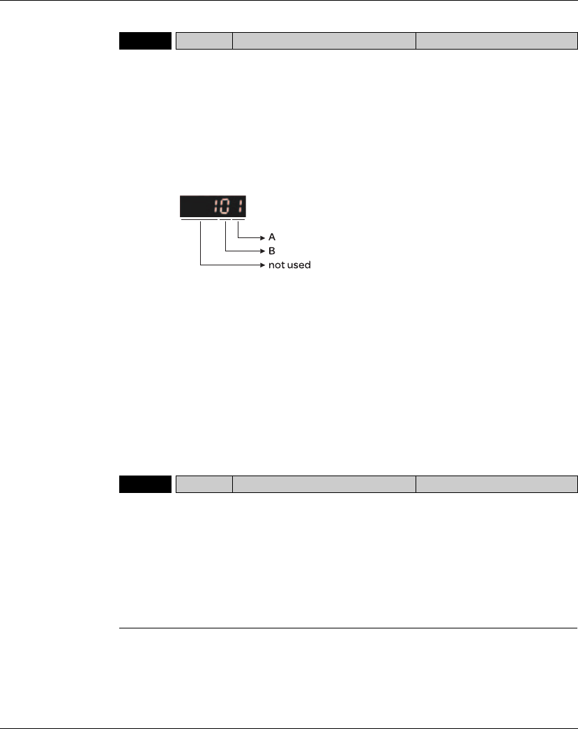
Lexium 23A 11. Servo Parameters
AC servo drive 355
P2 - 10 DI1 Digital Input Terminal 1 (DI1) Address: 0214H, 0215H
Default: 101
Applicable Control Mode: ALL
Unit: N/A
Range: 0 ~ 015Fh
Data Size: 16-bit
Display Format: Hexadecimal
Related Section: Table 11.A
Settings:
The parameters from P2-10 to P2-17 are used to determine the functions and statuses
of DI1 ~ DI8.
A: DI (Digital Input) Function Settings:
For the setting value of P2- 10 ~ P2-17, please refer to Table 11.A.
B: DI (Digital Input) Enabled Status Settings:
0: Normally closed (contact b)
1: Normally open (contact a)
For example, when P2-10 is set to 101, it indicates that the function of DI1 is SON (Servo
On, setting value is 0x01) and it requires a normally open contact to be connected to it.
Please re-start the servo drive after parameters have been changed.
Please note:
The parameter P3-06 is used to set how the Digital Inputs (DI) accept commands and
signals through the external terminals or via the communication which is determined by
parameter P4-07.
P2 - 11 DI2 Digital Input Terminal 2 (DI2) Address: 0216H, 0217H
Default: 104
Applicable Control Mode: ALL
Unit: N/A
Range: 0 ~ 015Fh
Data Size: 16-bit
Display Format: Hexadecimal
Related Section: Table 11.A
Settings:
Refer to P2-10 for explanation.

11. Servo Parameters Lexium 23A
356 AC servo drive
P2 - 12 DI3 Digital Input Terminal 3 (DI3) Address: 0218H, 0219H
Default: 116
Applicable Control Mode: ALL
Unit: N/A
Range: 0 ~ 015Fh
Data Size: 16-bit
Display Format: Hexadecimal
Related Section: Table 11.A
Settings:
Refer to P2-10 for explanation.
P2 - 13 DI4 Digital Input Terminal 4 (DI4) Address: 021AH, 021BH
Default: 117
Applicable Control Mode: ALL
Unit: N/A
Range: 0 ~ 015Fh
Data Size: 16-bit
Display Format: Hexadecimal
Related Section: Table 11.A
Settings:
Refer to P2-10 for explanation.
P2 - 14 DI5 Digital Input Terminal 5 (DI5) Address: 021CH, 021DH
Default: 102
Applicable Control Mode: ALL
Unit: N/A
Range: 0 ~ 015Fh
Data Size: 16-bit
Display Format: Hexadecimal
Related Section: Table 11.A
Settings:
Refer to P2-10 for explanation.
P2 - 15 DI6 Digital Input Terminal 6 (DI6) Address: 021EH, 021FH
Default: 22
Applicable Control Mode: ALL
Unit: N/A
Range: 0 ~ 015Fh
Data Size: 16-bit
Display Format: Hexadecimal
Related Section: Table 11.A
Settings:
Refer to P2-10 for explanation.
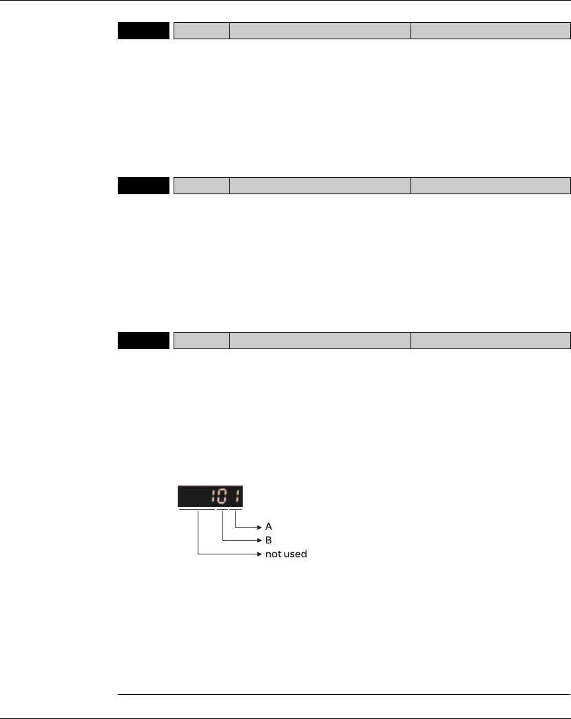
Lexium 23A 11. Servo Parameters
AC servo drive 357
P2 - 16 DI7 Digital Input Terminal 7 (DI7) Address: 0220H, 0221H
Default: 23
Applicable Control Mode: ALL
Unit: N/A
Range: 0 ~ 015Fh
Data Size: 16-bit
Display Format: Hexadecimal
Related Section: Table 11.A
Settings:
Refer to P2-10 for explanation.
P2 - 17 DI8 Digital Input Terminal 8 (DI8) Address: 0222H, 0223H
Default: 21
Applicable Control Mode: ALL
Unit: N/A
Range: 0 ~ 015Fh
Data Size: 16-bit
Display Format: Hexadecimal
Related Section: Table 11.A
Settings:
Refer to P2-10 for explanation.
P2 - 18 DO1 Digital Output Terminal 1 (DO1) Address: 0224H, 0225H
Default: 101
Applicable Control Mode: ALL
Unit: N/A
Range: 0 ~ 013Fh
Data Size: 16-bit
Display Format: Hexadecimal
Related Section: Table 11.B
Settings:
The parameters from P2-18 to P2-22 are used to determine the functions and statuses
of DO1 ~ DO5.
A: DO Function Settings:
For the setting value of P2- 18 ~ P2-22, please refer to Table 11.A.
B: DO Enabled Status Settings:
0: Normally closed (contact b)
1: Normally open (contact a)
For example, when P2-18 is set to 101, it indicates that the function of DO1 is SRDY
(Servo ready, setting value is 0x01) and it requires a normally open contact to be
connected to it.
Please re-start the servo drive after parameters have been changed.

11. Servo Parameters Lexium 23A
358 AC servo drive
P2 - 19 DO2 Digital Output Terminal 2 (DO2) Address: 0226H, 0227H
Default: 103
Applicable Control Mode: ALL
Unit: N/A
Range: 0 ~ 013Fh
Data Size: 16-bit
Display Format: Hexadecimal
Related Section: Table 11.B
Settings:
Refer to P2-18 for explanation.
P2 - 20 DO3 Digital Output Terminal 3 (DO3) Address: 0228H, 0229H
Default: 109
Applicable Control Mode: ALL
Unit: N/A
Range: 0 ~ 013Fh
Data Size: 16-bit
Display Format: Hexadecimal
Related Section: Table 11.B
Settings:
Refer to P2-18 for explanation.
P2 - 21 DO4 Digital Output Terminal 4 (DO4) Address: 022AH, 022BH
Default: 105
Applicable Control Mode: ALL
Unit: N/A
Range: 0 ~ 013Fh
Data Size: 16-bit
Display Format: Hexadecimal
Related Section: Table 11.B
Settings:
Refer to P2-18 for explanation.
P2 - 22 DO5 Digital Output Terminal 5 (DO5) Address: 022CH, 022DH
Default: 7
Applicable Control Mode: ALL
Unit: N/A
Range: 0 ~ 013Fh
Data Size: 16-bit
Display Format: Hexadecimal
Related Section: Table 11.B
Settings:
Refer to P2-18 for explanation.

Lexium 23A 11. Servo Parameters
AC servo drive 359
P2 - 23 Reserved (Do Not Use)
P2 - 24 Reserved (Do Not Use)
P2 - 25 NLP Low-pass Filter Time Constant
(Resonance Suppression) Address: 0232H, 0233H
Default: 2 (1kW and below models) or
5 (other models)
Applicable Control Mode: ALL
Unit: 0.1 msec
Range: 0 ~ 1000
Data Size: 16-bit
Display Format: Decimal
Related Section: Section 7.3.3.7
Settings:
This parameter is used to set low-pass filter time constant of resonance suppression.
If P2-25 is set to 0, this parameter is disabled.
P2 - 26 DST External Anti-Interference Gain Address: 0234H, 0235H
Default: 0
Applicable Control Mode: ALL
Unit: 0.001
Range: 0 ~ 1023
Data Size: 16-bit
Display Format: Decimal
Related Section: N/A
Settings:
If P2-26 is set to 0, this parameter is disabled.
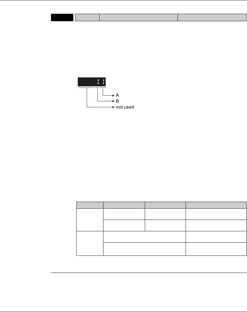
11. Servo Parameters Lexium 23A
360 AC servo drive
P2 - 27 GCC Gain Switching Control Selection Address: 0236H, 0237H
Default: 0
Applicable Control Mode: ALL
Unit: N/A
Range: 0 ~ 4
Data Size: 16-bit
Display Format: Hexadecimal
Related Section: N/A
Settings:
Gain Switching Condition Settings:
A: Gain Switching Condition Settings:
0: Disabled
1: Gain switching DI (Digital Input) signal (GAINUP) is On. (see Table 11.A)
2: In position mode, position deviation is higher than the setting value of P2-29.
3: Position command frequency is higher than the setting value of P2-29.
4: Servo motor speed is higher than the setting value of P2-29.
5: Gain switching DI (Digital Input) signal (GAINUP) is Off. (see Table 11.A)
6: In position mode, position deviation is lower than the setting value of P2-29.
7: Position command frequency is lower than the setting value of P2-29.
8: Servo motor speed is lower than the setting value of P2-29.
B: Gain Switching Control Settings:
0: Gain multiple switching
1: P V PI switching
Setting P mode S mode Status
0
P2-00 x 100%
P2-04 x 100% P2-04 x 100% Before switching
P2-00 x P2-01
P2-04 x P2-05 P2-04 x P2-05 After switching
1
P2-06 x 0%
P2-26 x 0% Before switching
P2-06 x 100%
P2-26 x 100% After switching

Lexium 23A 11. Servo Parameters
AC servo drive 361
P2 - 28 GUT Gain Switching Time Constant Address: 0238H, 0239H
Default: 10
Applicable Control Mode: ALL
Unit: 10msec
Range: 0 ~ 1000
Data Size: 16-bit
Display Format: Decimal
Related Section: N/A
Settings:
This parameter is used to set the time constant when switching the smooth gain.
If P2-28 is set to 0, this parameter is disabled.
P2 - 29 GPE Gain Switching Condition Address: 023AH, 023BH
Default: 1280000
Applicable Control Mode: ALL
Unit: pulse, Kpps, rpm
Range: 0 ~ 3840000
Data Size: 32-bit
Display Format: Decimal
Related Section: N/A
Settings:
This parameter is used to set the value of gain switching condition (pulse error, Kpps,
rpm) selected in P2-27. The setting value will be different depending on the different
gain switching condition.
P2 - 30bINH Auxiliary Function Address: 023CH, 023AH
Default: 0
Applicable Control Mode: ALL
Unit: N/A
Range: -8 ~ +8
Data Size: 16-bit
Display Format: Decimal
Related Section: N/A

11. Servo Parameters Lexium 23A
362 AC servo drive
Settings:
0: Disabled all functions described below.
1: Force the servo drive to be Servo On (upon software)
2: Reserved
3: Reserved
4: Reserved
5: After setting P2-30 to 5, the setting values of all parameters will lost (not remain in
memory) at power-down. When the parameters data are no more needed, using this
mode can allows users not to save parameters data into memory without damaging the
EEPROM. P2-30 should be set to 5 when using communication control function.
6: Reserved
7: Reserved
8: Reserved
- 1, -5: Disable the function of setting value 1 and 5.
- 2, -3, -4,-6, -7, -8: Reserved

Lexium 23A 11. Servo Parameters
AC servo drive 363
P2 - 31 AUT1 Speed Frequency Response Level in
Auto and Semi-Auto Mode Address: 023EH, 023FH
Default: 80
Applicable Control Mode: ALL
Related Section: Section 6.5.4.6,
Section 7.3.3.6
Unit: Hz
Range: 1 ~ 1000
Data Size: 16-bit
Display Format: Hexadecimal
Settings:
This parameter is the base for calculating P2-00, P2-02, P2-04, P2-06, P2-25, and P2-
26 under auto-tuning (P2-32=1) and semi-auto tuning (P2-32=2) modes. The
parameter P2-00, P2-02, P2-04, P2-06, P2-25, and P2-26 will be revised immediately
whenever P2-31 is changed when these two modes applied. The stiffness of a
mechanism and system response are the key factor of considering this parameter as
below:
1 ~ 50Hz: Low stiffness and low frequency response
51 ~ 250Hz: Medium stiffness and medium frequency response
251 ~ 850Hz: High stiffness and high frequency response
851 ~ 1000Hz: Extremely high stiffness and extremely high frequency response
P2 - 32rAUT2 Tuning Mode Selection Address: 0240H, 0241H
Default: 0
Applicable Control Mode: ALL
Related Section: Section 6.5.4.6,
Section 7.3.3.6
Unit: N/A
Range: 0 ~ 2
Data Size: 16-bit
Display Format: Hexadecimal
Settings:
0: Manual mode
1: Auto Mode [Continuous adjustment]
2: Semi-Auto Mode [Non-continuous adjustment]
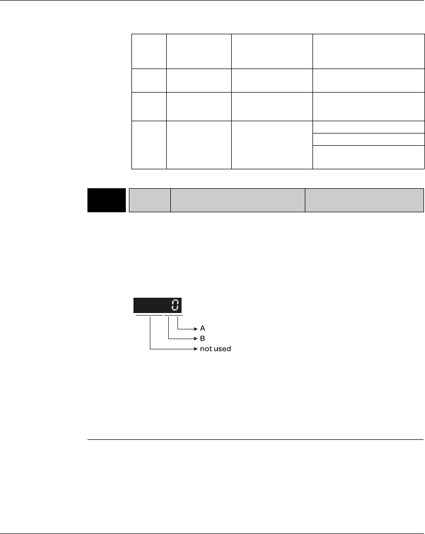
11. Servo Parameters Lexium 23A
364 AC servo drive
P2 - 33rAUT3 Semi-Auto Mode Inertia Adjustment
Selection Address: 0242H, 0243H
Default: 0
Applicable Control Mode: ALL
Unit: N/A
Range: 0 ~ 1
Data Size: 16-bit
Display Format: Decimal
Related Section: N/A
Settings:
When the setting value of A is set to 0 or display is 0, it indicates that the load inertia
estimation of semi-auto tuning mode has been executed but not been completed yet.
When the setting value of A is set to 1, it indicates that the load inertia estimation of semi-
auto tuning mode has been completed. The measured load inertia is memorized in P1-37. If
P2-33 is reset to 0, the servo drive will perform continuous adjustment for estimating the
load inertia (P1-37) again.
B: Reserved.
P2-32 P1-37, Ratio of
Load and Motor
Rotor Inertias
P2-00, P2-02, P2-04,
P2-06, P2-25, P2-26
P2-33 Semi-Auto Mode
Inertia Adjustment Selection
0 Not updated
automatically.
Updated manually. Do not use.
1 Updated every
30 minutes.
Updated when P2-31
changed and P2-32
switched from 0 to 1.
Do not use.
2 Updated when
the level set in
P2-67 reached.
Updated when P2-31
changed and P2-32
switched from 0 to 2.
1: P1-37 evaluated and fixed.
0: P1-37 is under evaluating.
Write 0 to P2-33 for re-
evaluating P1-37.

Lexium 23A 11. Servo Parameters
AC servo drive 365
P2 - 34 SDEV Overspeed Warning Condition Address: 0244H, 0245H
Default: 5000
Applicable Control Mode: S
Unit: rpm
Range: 1 ~ 5000
Data Size: 16-bit
Display Format: Decimal
Related Section: N/A
Settings:
This parameter is used to set the over speed threshold that is used to determine
the over speed fault condition. When the difference in speed between the desired
speed and actual motor speed is over than the setting value of parameter P2-34,
the servo fault, Overspeed (AL007) will be activated.
P2 - 35 PDEV Excessive Error Warning Condition Address: 0246H, 0247H
Default: 3840000
Applicable Control Mode: Pt, Pr
Unit: pulse
Range: 1 ~ 128000000
Data Size: 32-bit
Display Format: Decimal
Related Section: N/A
Settings:
This parameter is used to set the position deviation excessive error threshold that is
used to determine the escessive deviation fault condition. When the difference in
pulse number between the desired position and actual motor position is over than the
setting value of parameter P2-35, the servo fault, Excessive Deviation (AL009) will be
activated.
P2 - 36 Reserved (Do not use)

11. Servo Parameters Lexium 23A
366 AC servo drive
P2 - 38 Reserved (Do Not Use)
P2 - 39 Reserved (Do Not Use)
P2 - 40 Reserved (Do Not Use)
P2 - 41 Reserved (Do Not Use)
P2 - 42 Reserved (Do Not Use)
P2 - 43 NCF1 Notch Filter 1 (Resonance
Suppression) Address: 0256H, 0257H
Default: 1000
Applicable Control Mode: ALL
Unit: Hz
Range: 50 ~ 2000
Data Size: 16-bit
Display Format: Decimal
Related Section: Section 7.3.3.7
Settings:
This parameter is used to set second resonance frequency of mechanical system. It
can be used to suppress the resonance of mechanical system and reduce the vibration
of mechanical system.
If P2-43 is set to 0, this parameter is disabled.

Lexium 23A 11. Servo Parameters
AC servo drive 367
P2 - 44 DPH1 Notch Filter Attenuation Rate 1
(Resonance Suppression) Address: 0258H, 0259H
Default: 0
Applicable Control Mode: ALL
Unit: dB
Range: 0 ~ 32
Data Size: 16-bit
Display Format: Decimal
Related Section: Section 7.3.3.7
Settings:
This parameter is used to set magnitude of the resonance suppression that is set by
parameter P2-43. If P2-44 is set to 0, the parameters P2-43 and P2-44 are both
disabled.
P2 - 45 NCF2 Notch Filter 2 (Resonance
Suppression) Address: 025AH, 025BH
Default: 1000
Applicable Control Mode: ALL
Unit: Hz
Range: 50 ~ 2000
Data Size: 16-bit
Display Format: Decimal
Related Section: Section 7.3.3.7
Settings:
This parameter is used to set third resonance frequency of mechanical system. It can
be used to suppress the resonance of mechanical system and reduce the vibration of
mechanical system.
If P2-45 is set to 0, this parameter is disabled.
P2 - 46 DPH2 Notch Filter Attenuation Rate 2
(Resonance Suppression) Address: 025CH, 025DH
Default: 0
Applicable Control Mode: ALL
Unit: dB
Range: 0 ~ 32
Data Size: 16-bit
Display Format: Decimal
Related Section: Section 7.3.3.7
Settings:
This parameter is used to set magnitude of the resonance suppression that is set by
parameter P2-45. If P2-46 is set to 0, the parameters P2-45 and P2-46 are both
disabled.

11. Servo Parameters Lexium 23A
368 AC servo drive
P2 - 47 ANCF Auto Resonance Suppression Mode
Selection Address: 025EH, 025FH
Default: 1
Applicable Control Mode: ALL
Unit: N/A
Range: 0 ~ 2
Data Size: 16-bit
Display Format: Decimal
Related Section: N/A
Settings:
0: Disable Auto Resonance Suppression Mode.
The setting value of P2-23~P2-24 and P2-43~P2-44 will be fixed and will not be
changed.
1: Auto Resonance Suppression Mode 1 [Non-continuous adjustment]
After the resonance is suppressed, the setting value of P2-23, P2-24, P2-43 and
P2-44 will be fixed and will not be changed.
2: Auto Resonance Suppression Mode 2 [Continuous adjustment]
The servo drive will perform the resonance suppression continuously (will not
stop). The setting value of P2-23, P2-24, P2-43 and P2-44 will not be fixed.
When P2-47 is set to 1, the resonance suppression will be enabled automatically.
After the mechanical system becomes stable, the setting value of P2-47 will return
to 0. When the mechanical system is stable, the resonance suppression point will
be memorized. When the mechanical system is not stable, if the servo drive is
restarted or P2-47 is set to 1, the servo drive will estimate the resonance
suppression point again.
When P2-47 is set to 2, the servo drive will perform the resonance suppression
continuously. When the mechanical system becomes stable, the resonance
suppression point will be memorized. When the mechanical system is not stable, if
the servo drive is restarted, the servo drive will estimate the resonance
suppression point again.
When switching the mode#1 or #2 to #0, the setting values of P2-43 and P2-44 will
be saved automatically.

Lexium 23A 11. Servo Parameters
AC servo drive 369
P2 - 48 ANCF Auto Resonance Suppression
Detection Level Address: 0260H, 0261H
Default: 100
Applicable Control Mode: ALL
Unit: N/A
Range: 1 ~ 300%
Data Size: 16-bit
Display Format: Decimal
Related Section: N/A
Settings:
When the setting value is smaller, the system will become more sensitive to detect
and find the resonance.
When the value of ↑
The setting value of P2-48 ↑, the sensitivity of detecting resonance ↓.
The setting value of P2-48 ↓, the sensitivity of detecting resonance ↑.
P2 - 49 SJIT Speed Detection Filter and Jitter
Suppression Address: 0262H, 0263H
Default: 0
Applicable Control Mode: ALL
Unit: sec
Range: 0 ~ 1F
Data Size: 16-bit
Display Format: Decimal
Related Section: N/A
Settings:
Setting Value of P2-49 Cutoff Frequency of Speed Loop Feedback (Hz)
00 2500
01 2250
02 2100
03 2000
04 1800
05 1600
06 1500
07 1400
08 1300
09 1200
0A 1100
0B 1000
0C 950
0D 900
0E 850
11. Servo Parameters Lexium 23A
370 AC servo drive
P2 - 50 DCLR Pulse Deviation Clear Mode Address: 0264H, 0265H
Default: 0
Applicable Control Mode: Pt, Pr
Unit: N/A
Range: 0 ~ 2
Data Size: 16-bit
Display Format: Hexadecimal
Related Section: N/A
Settings:
For digital input function (DI function), please refer to Table 11.A.
This pulse deviation clear function is enabled when a digital input is set to pulse
clear function (CCLR mode, DI (Digital Input) setting value is 0x04). When this
input is triggered, the position accumulated pulse number will be clear to 0.
(available in Pt and Pr mode only)
0: CCLR is triggered by rising-edge
1: CCLR is triggered bu level
P2 - 51 Reserved (Do Not Use)
P2 - 52 Reserved (Do Not Use)
0F 800
10 750
11 700
12 650
13 600
14 550
15 500
16 450
17 400
18 350
19 300
1A 250
1B 200
1C 175
1D 150
1E 125
1F 100
Lexium 23A 11. Servo Parameters
AC servo drive 371
P2 - 53 KPI Position Integral Compensation Address: 026AH, 026BH
Default: 0
Applicable Control Mode: ALL
Unit: rad/s
Range: 0 ~ 1023
Data Size: 16-bit
Display Format: Decimal
Related Section: Section 7.3.2.8
Settings:
This parameter is used to set the integral time of position loop. When the value of
position integral compensation is increased, it can decrease the position control
deviation. However, if the setting value is over high, it may generate position
overshoot or noise.
P2 - 54 Reserved (Do Not Use)
P2 - 55 Reserved (Do Not Use)
P2 - 56 Reserved (Do Not Use)
P2 - 57 Reserved (Do Not Use)
P2 - 58 Reserved (Do Not Use)
P2 - 59 Reserved (Do Not Use)
P2 - 60 GR4 Electronic Gear Ratio (2nd
Numerator) (N2) Address: 0278H, 0279H
Default: 128
Applicable Control Mode: Pt
Unit: pulse
Range: 1 ~ (229-1)
Data Size: 32-bit
Display Format: Decimal
Related Section: N/A
The electronic gear numerator value can be set via GNUM0, GNUM1 (refer to Table 11.A).
When the GNUM0, GNUM1 are not defined, the default of gear numerator value is
set by P1-44.
When the users wish to set the gear numerator value by using GNUM0, GNUM1,
please set P2-60 ~ P2-62 after the servo motor has been stopped to prevent the
mechanical system vibration.
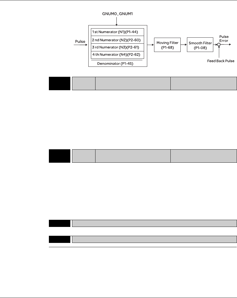
11. Servo Parameters Lexium 23A
372 AC servo drive
P2 - 61 GR5 Electronic Gear Ratio (3rd
Numerator) (N3) Address: 027AH, 027BH
Default: 128
Applicable Control Mode: Pt
Unit: pulse
Range: 1 ~ (229-1)
Data Size: 32-bit
Display Format: Decimal
Settings:
Refer to P2-60 for explanation.
Related Section: N/A
P2 - 62 GR6 Electronic Gear Ratio (4th
Numerator) (N4) Address: 027CH, 027DH
Default: 128
Applicable Control Mode: Pt
Unit: pulse
Range: 1 ~ (229-1)
Data Size: 32-bit
Display Format: Decimal
Settings:
Refer to P2-60 for explanation.
Related Section: N/A
P2 - 63 Reserved (Do Not Use)
P2 - 64 Reserved (Do Not Use)
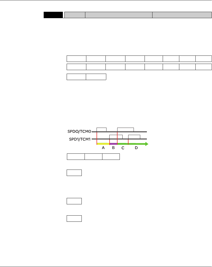
Lexium 23A 11. Servo Parameters
AC servo drive 373
P2 - 65 GBIT Special Function 1 Address: 0282H, 0283H
Default: 0
Applicable Control Mode: Pr, Pt, S
Unit: N/A
Range: 0 ~ 0xFF
Data Size: N/A
Display Format: N/A
Related Section: N/A
Settings:
Bit0: DI SPD0/SPD1 speed command trigger mode
0: by level
1: by rising edge
Bit1: DI TCM0/TCM1 torque command trigger mode
0: by level
1: by rising edge
When the servo drive is rising-edge triggered, the internal commands work as
follows:
A: Execute internal command 1
B: Execute internal command 2
C: Execute internal command 3
D: Execute internal command 3
Bit2 ~ Bit5: Reserved. Must be set to 0.
Bit6: Abnormal pulse command detection
0: enable abnormal pulse command detection
1: disable abnormal pulse command detection
Bit7: Reserved. Must be set to 0.
Bit8: U, V, W wiring error detection
1: enable U, V, W wiring error detection
Bit15 Bit14 Bit13 Bit12 Bit11 Bit10 Bit9 Bit8
Bit7 Bit6 Bit5 Bit4 Bit3 Bit2 Bit1 Bit0
Bit1 Bit0
Bit4 Bit3 Bit2
Bit6
Bit7
Bit8
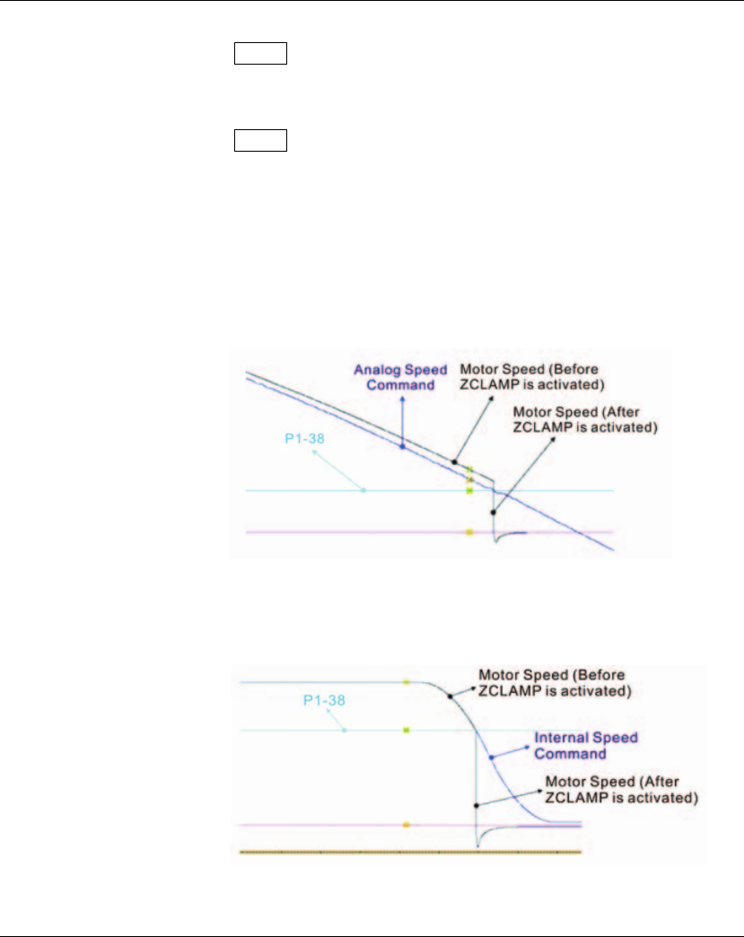
11. Servo Parameters Lexium 23A
374 AC servo drive
Bit9: U, V, W wiring cut-off detection
1: enable U, V, W wiring cut-off detection
Bit10: DI ZCLAMP function selection
When the following conditions are all met, ZCLAMP function will be activated.
Condition1: Speed mode
Condition2: DI ZCLAMP is activated.
Condition3: External analog speed command or internal registers speed
command is less than parameter P1-38.
0: When the command source is an analog speed command, the users can use
ZCLAMP DI signal to stop the motor at the desire position and do not care the
acceleration and deceleration speed curve of the analog speed command. The
motor will be locked at the position when ZCLAMP conditions are satisfied.
0: When the command source is an internal speed command, the users can use
ZCLAMP DI signal to stop the motor at the desire position and keep the the
acceleration and deceleration speed curve of the internal speed command. The
motor will be locked at the position when ZCLAMP conditions are satisfied.
Bit9
Bit10
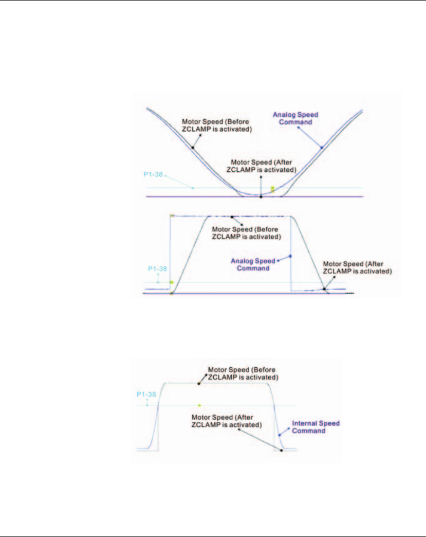
Lexium 23A 11. Servo Parameters
AC servo drive 375
1: When the command source is an analog speed command, the users can use
ZCLAMP DI signal to stop the motor at the desire position and do not care the
acceleration and deceleration speed curve of the internal speed command. When
ZCLAMP conditions are satisfied, the speed command is decreased to 0 rpm.
When ZCLAMP conditions are not satisfied, the speed command will follow the
analog speed command through Accel/Decel S-curve.
1: When the command source is an internal speed command, the users can use
ZCLAMP DI signal to stop the motor at the desire position and keep the
acceleration and deceleration speed curve of the analog speed command. When
ZCLAMP conditions are satisfied, the speed command is forced to 0 rpm directly.

11. Servo Parameters Lexium 23A
376 AC servo drive
Bit11: NL(CWL)/PL(CCWL) pulse input inhibit function
0: Disable NL(CWL)/PL(CCWL) pulse input inhibit function. In Pt mode, no matter NL
or PL exists or not, external position pulse command will be input into the servo drive.
1: Enable NL(CWL)/PL(CCWL) pulse input inhibit function. In Pt mode, if NL exists,
the external NL pulse input into the servo drive will be inhibited and PL pulse input
will be accepted. On the one hand, in Pt mode, if PL exists, the external PL pulse
input into the servo drive will be inhibited and PL pulse input will be accepted.
Please note:
If NL and PL both exist, NL and PL pulse input into the servo drive will be both inhibited.
Bit12: Input power phase loss detection function
0: Enable Input power phase loss (AL022) detection function
1: Disable Input power phase loss (AL022) detection function
Bit13: Encoder output error detection function
0: Enable encoder output error (AL018) detection function
1: Disable encoder output error (AL018) detection function
Bit14 ~ Bit15: Reserved. Must be set to 0.
P2 - 66 GBIT2 Special Function 2 Address: 0284H, 0285H
Default: 0
Applicable Control Mode: ALL
Unit: N/A
Range: 0~20
Related Section:
Section 11.3
Settings:
Bit0 ~ Bit1: Reserved. Must be set to 0.
Bit2: Undervoltage (Servo Drive Fault) clear mode selection
0: The fault, Undervoltage will not be cleared automatically.
1: The fault, Undervoltage will be cleared automatically.
Bit3 ~ Bit7: Reserved. Must be set to 0.
Bit11
Bit12
Bit13
Bit15 Bit14
Bit7 Bit6 Bit5 Bit4 Bit3 Bit2 Bit1 Bit0
Bit1 Bit0
Bit2
Bit7 Bit6 Bit5 Bit4 Bit3
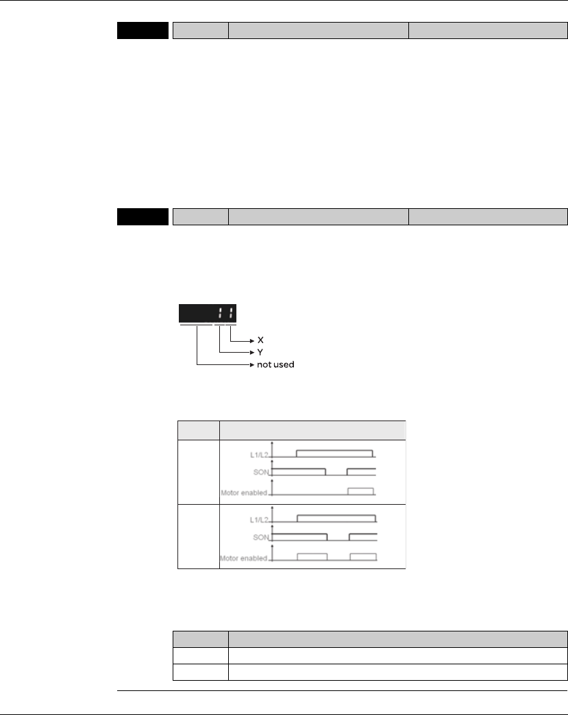
Lexium 23A 11. Servo Parameters
AC servo drive 377
P2 - 67 JSL Inertia Estimating Detection Level Address: 0286H, 0287H
Default: 1.5
Applicable Control Mode: ALL
Unit: 0.1times
Range: 0 ~ 200.0
Data Size: 16-bit
Display Format: Decimal
Related Section: N/A
Settings:
In semi-auto tuning mode, this parameter defines the threshold for a system to re-
evaluate P1-37. For example, P1-37=2 and P2-67=1, the system will re-evaluate its
P1-37 when a value exceeding the range of P1-37=1.5~2.5 (greater than 2.5 or less
than 1.5) detected. If P1-37=1 and P2-67=3, the range should be P1-37=0~2.5 for a
stable acknowledgment.
P2 - 68 pAEAL Auto Enable and Auto Limit Enable Address: 0286H, 0287H
Default: 0x0000
Applicable Control Mode: ALL
Unit: N/A
Range: 0x0000~0x0011
Data Size: 16-bit
Related Section: N/A
Display Format: Hexadecimal
Settings:
X: Auto Enable function switch
If X = 0, user must to re-trigger SON to enable motor.
If X = 1, motor will be enabled once L1/L2 and SON are both active.
Y: Auto Limit Enable function switch
Y Function
0 AL.014/AL.015 will be latched until receives an additional ARST signal.
1 AL.014/AL.015 can be reset without ARST signal.
XFunction
0
1

11. Servo Parameters Lexium 23A
378 AC servo drive

Lexium 23A 11. Servo Parameters
AC servo drive 379
Group 3: P3-xx Communication Parameters
P3 - 00 ADR Modbus Communication Address
Setting Address: 0300H, 0301H
Default: 1 Related Section: Section 9.2
Applicable Control Mode: ALL
Unit: N/A
Range: 0x01 ~ 0x7F
Data Size: 16-bit
Display Format: Hexadecimal
Settings:
This parameter is used to set the Modbus communication slave address in decimal
format. This address is an absolute address which represents the servo drive on a
RS-485 network.
This address is an absolute address which represents the servo drive on a RS-485
network and must be defined uniquely. Duplicate address will cause
communication faults .
Please note:
1. This parameter does not provide broadcast function and doesn,t respond
insecurity.
2. When the address of host (external) controller is set to 0xFF, it is with auto-
respond function.
Then, the servo drive will receive from and respond to host (external) controller
both, no matter if the address is matching or not. However, the parameter P3-00
cannot be set to 0xFF.

11. Servo Parameters Lexium 23A
380 AC servo drive
P3 - 01 BRT Transmission Speed Address: 0302H, 0303H
Default: 0x0203 Related Section: Section 9.2
Applicable Control Mode: ALL
Unit: bps
Range: 0x0000 ~ 0x0405
Data Size: 16-bit
Display Format: Hexadecimal
Settings:
This parameter is used to set the baud rate and data transmission speed of the
RS-485 and CANopen communications.
X: Baud rate setting
0: Baud rate 4800
1: Baud rate 9600
2: Baud rate 19200
3: Baud rate 38400
4: Baud rate 57600
5: Baud rate 115200
Y: Reserved. Must be set to 0.
Z: CANopen Data transmission speed setting.
0: 125K bits / second
1: 250K bits / second
2: 500K bits / second
3: 750K bits / second
4: 1.0M bits / second
Please note:
1.When setting this parameter via CANopen communication, only the setting of Z
(data transmission speed setting) can be configured.
Display 0 Z Y X
COM Port - CAN - RS-485
Range 0 0 ~ 4 0 0 ~ 5

Lexium 23A 11. Servo Parameters
AC servo drive 381
P3 - 02 PTL Communication Protocol Address: 0304H, 0305H
Default: 6 Related Section: Section 9.2
Applicable Control Mode: ALL
Unit: N/A
Range: 0 ~ 8
Data Size: 16-bit
Display Format: Hexadecimal
Settings:
This parameter is used to set the communication protocol. The alphanumeric
characters represent the following: 7 or 8 is the number of data bits; N, E or O
refers to the parity bit, Non, Even or Odd; the 1 or 2 is the numbers of stop bits.
0: Modbus ASCII mode, <7,N,2>
1: Modbus ASCII mode, <7,E,1 >
2: Modbus ASCII mode, <7,O,1>
3: Modbus ASCII mode, <8,N,2 >
4: Modbus ASCII mode, <8,E,1>
5: Modbus ASCII mode, <8,O,1>
6: Modbus RTU mode, <8,N,2>
7: Modbus RTU mode, <8,E,1>
8: Modbus RTU mode, <8,O,1>
P3 - 03 FLT Transmission Fault Treatment Address: 0306H, 0307H
Default: 0 Related Section: Section 9.2
Applicable Control Mode: ALL
Unit: N/A
Range: 0 ~ 1
Data Size: 16-bit
Display Format: Hexadecimal
Settings:
This parameter is used to determine the operating sequence once a
communication fault has been detected. If '1' is selected, the drive will stop
operating upon detection the communication fault. The mode of stopping is set by
parameter P1-32.
0: Display fault and continue operating
1: Display fault and decelerate to stop operating (deceleration time is determined
by parameter P5-03)

11. Servo Parameters Lexium 23A
382 AC servo drive
P3 - 04 CWD Communication Time Out Detection Address: 0308H, 0309H
Default: 0 Related Section: Section 9.2
Applicable Control Mode: ALL
Unit: sec
Range: 0 ~ 20
Data Size: 16-bit
Display Format: Decimal
Settings:
This parameter is used to set the maximum permissible time before detecting a
fault due to communication time out. When P3-04 is set to a value over than 0, it
indicates this parameter is enabled. However, if not communicating with the servo
in this period of time, the servo drive will assume the communication has failed
and show the communication error fault message.
When P3-04 is set to 0, this parameter is disabled.
P3 - 05 CADR
CANopen Communication Address Setting
Address: 030AH, 030BH
Default: 0x0000 Related Section: Section 9.2
Applicable Control Mode: ALL
Unit: N/A
Range: 0 x00~0x7F
Data Size: 16-bit
Display Format: Hexadecimal
Settings:
This parameter is used to set the CAN communication slave address in
hexadecimal format.
This address is an absolute address whlch represents the servo drive on a CAN bus
network and must be defined uniquely. Duplicate address will cause
communication faults.
This parameter is relevant for LXM23A servo drives only.
This parameter will be effective only after restarting drive or NMT Reset_Node
indication. To change this parameter from default (0), restarting drive is
necessary.

Lexium 23A 11. Servo Parameters
AC servo drive 383
P3 - 06bSDI Digital Input Communication Function Address: 030CH, 030DH
Default: 0 Related Section: Section 9.2
Applicable Control Mode: ALL
Unit: N/A
Range: 0x0000 ~ 0x3FFF
Data Size: 16-bit
Display Format: Hexadecimal
The setting of this parameter determines how the Digital Inputs (DI) accept
commands and signals.
Bit0 ~ Bit 7 corresponds with DI1 ~ DI8. The least significant bit (Bit0) shows DI1
status and the most significant bit (Bit7) shows DI8 status.
Bit settings:
0: Digital input is controlled by external command (via CN1)
1: Digital input is controlled by parameter P4-07
For the settings of DI1 ~ DI8, please refer to P2-10 ~ P2-17.
This parameter P3-06 also works in conjunction with the parameter P4-07 which
has several functions. Please see section 9.2 for details.
P3 - 07 CDT Communication Response Delay Time Address: 030EH, 030FH
Default: 0 Related Section: Section 9.2
Applicable Control Mode: ALL
Unit: 1msec
Range: 0 ~ 1000
Data Size: 16-bit
Display Format: Decimal
Settings:
This parameter is used to delay the communication time that servo drive responds
to host controller (external controller via Modbus).
P3 - 08 Reserved (Do Not Use)

11. Servo Parameters Lexium 23A
384 AC servo drive
P3-09 SYC CANopen Synchronization Setting Address: 0312H, 0313H
Default: 0x57A1 Related Section: Section 9.2
Applicable Control Mode: CANopen
Unit: N/A
Range: refer to the description of Settings
Data Size: 16-bit
Display Format: Hexadecimal
Settings:
This parameter is used to set the CANopen slave to be synchronized with the
CANopen master through synchronization signal. Although this parameter allows
the users to execute manual adjustment, if not necessary, we do not recommend
users to change the default setting manually.
M: Clock correction setting, the value must be within the range from 1 through F,
and the unit is usec.
When setting the CANopen slave to be synchronized with the CANopen master,
the clock of the servo drive must be corrected. This function is used to set the
maximum correction every time.
D: Dead zone range, the value must be within the range from 0 through F, and the
unit is usec.
When the difference between actual value and target value of SYNC signal
reach time does not exceed the dead zone range, the clock correction does not
need to be changed.
T: Target value of SYNC signal reach time, the value must be within the range from
0 through 9, and the standard value of SYNC signal reach time is 500 usec.
Target reach time of synchronization signal = 400 + 10 x setting value of T.
For example:
When T is set to 5, the target reach time of synchronization signal = 400 + 10
x 5 = 450
There should be a buffer between the target value and the standard value. The
target value should be less than the standard value. If the target value is above
than the standard value, an error may occur.
E: SYNC error range, the value must be within the range from 1 through 9, and the
unit is 10 usec.
When the difference between actual value and target value of SYNC signal
reach time is below this range, it indicates that the CANopen slave synchronize
with the CANopen master through synchronization signal.
Display E T D M
Function SYNC error
range
Target
value
Dead zone
range
Clock correction
setting
Range 1~9 0~9 0~F 1~F
Lexium 23A 11. Servo Parameters
AC servo drive 385
P3 - 10 PLCEN PLCopen Function Switch Address: 0314H, 0315H
Default: 0x0000 Related Section: N/A
Applicable Control Mode: CANopen Mode
Unit: N/A
Range: 0x0000 ~ 0x0001
Data Size: 16-bit
Display Format: Hexadecimal
Settings:
0: PLCopen Function Disabled
1: PLCopen Function Enabled
P3 - 11gPLCTX1 PLCopen TX Packet #1 Address: 0316H, 0317H
Default: 0x0000 Related Section: N/A
Applicable Control Mode: CANopen Mode
Unit: N/A
Range: Read Only
Data Size: 16-bit
Display Format: Hexadecimal
Settings:
The PLCopen TX Packet (Status Data) consists of 4 words and POTX1 ~ POTX4
represent the following fields:
P3 - 12gPLCTX2 PLCopen TX Packet #2 Address: 0318H, 0319H
Default: 0x0000 Related Section: N/A
Applicable Control Mode: CANopen Mode
Unit: N/A
Range: Read Only
Data Size: 16-bit
Display Format: Hexadecimal
Settings:
Refer to P5-11 for explanation.
Word 1 2 3 4
Function driveStat mfStat motionSt driveInput
Parameter POTX1 POTX2 POTX3 POTX4
11. Servo Parameters Lexium 23A
386 AC servo drive
P3 - 13gPLCTX3 PLCopen TX Packet #3 Address: 031AH, 031BH
Default: 0x0000 Related Section: N/A
Applicable Control Mode: CANopen Mode
Unit: N/A
Range: Read Only
Data Size: 16-bit
Display Format: Hexadecimal
Settings:
Refer to P5-11 for explanation.
P3 - 14gPLCTX4 PLCopen TX Packet #4 Address: 031CH, 031DH
Default: 0x0000 Related Section: N/A
Applicable Control Mode: CANopen Mode
Unit: N/A
Range: Read Only
Data Size: 16-bit
Display Format: Hexadecimal
Settings:
Refer to P5-11 for explanation.
P3 - 15 PLCRX1 PLCopen RX Packet #1 Address: 031EH, 031FH
Default: 0x0000 Related Section: N/A
Applicable Control Mode: CANopen Mode
Unit: N/A
Range: 0x0000 ~ 0xFFFF
Data Size: 16-bit
Display Format: Hexadecimal
Settings:
The PLCopen RX Packet (Control Data) consists of 4 words and PORX1 ~ PORX3
represent the following fields:
Word 1 2 3 4
Function dmCtrl refA16 refB32
Parameter POTX1 POTX2 PORX3

Lexium 23A 11. Servo Parameters
AC servo drive 387
P3 - 16 PLCRX2 PLCopen RX Packet #2 Address: 0320H, 0321H
Default: 0x0000 Related Section: N/A
Applicable Control Mode: CANopen Mode
Unit: N/A
Range:-32768 ~ 32767
Data Size: 16-bit
Display Format: Hexadecimal
Settings:
Refer to P5-15 for explanation.
P3 - 17 PLCRX3 PLCopen RX Packet #3 Address: 0322H, 0323H
Default: 0x00000000 Related Section: N/A
Applicable Control Mode: CANopen Mode
Unit: N/A
Range: -2147483648 ~ +2147483647
Data Size: 32-bit
Display Format: Hexadecimal
Settings:
Refer to P5-15 for explanation.

11. Servo Parameters Lexium 23A
388 AC servo drive
Group 4: P4-xx Diagnosis Parameters
P4 - 00gASH1 Fault Record (N) Address: 0400H, 0401H
Default: 0 Related Section: Section 7.2.1
Applicable Control Mode: ALL
Unit: N/A
Range: N/A
Data Size: 32-bit
Display Format: Hexadecimal
Settings:
This parameter is used to set the most recent fault record.
Display of Low Byte: LXXXX: It indicates the fault code, i.e. alarm code
Display of High Byte: hYYYY: It indicates the corresponding CANopen error code.
P4 - 01gASH2 Fault Record (N-1) Address: 0402H, 0403H
Default: 0 Related Section: Section 7.2.1
Applicable Control Mode: ALL
Unit: N/A
Range: N/A
Data Size: 32-bit
Display Format: Hexadecimal
Settings:
This parameter is used to set the second most recent fault record.
P4 - 02gASH3 Fault Record (N-2) Address: 0404H, 0405H
Default: 0 Related Section: Section 7.2.1
Applicable Control Mode: ALL
Unit: N/A
Range: N/A
Data Size: 32-bit
Display Format: Hexadecimal
Settings:
This parameter is used to set the third most recent fault record.

Lexium 23A 11. Servo Parameters
AC servo drive 389
P4 - 03gASH4 Fault Record (N-3) Address: 0406H, 0407H
Default: 0 Related Section: Section 7.2.1
Applicable Control Mode: ALL
Unit: N/A
Range: N/A
Data Size: 32-bit
Display Format: Hexadecimal
Settings:
This parameter is used to set the fourth most recent fault record.
P4 - 04gASH5 Fault Record (N-4) Address: 0408H, 0409H
Default: 0 Related Section: Section 7.2.1
Applicable Control Mode: ALL
Unit: N/A
Range: N/A
Data Size: 32-bit
Display Format: Hexadecimal
Settings:
This parameter is used to set the fifth most recent fault record.

11. Servo Parameters Lexium 23A
390 AC servo drive
P4 - 05 JOG JOG Operation Address: 040AH, 040BH
Default: 20 Related Section: Section 7.2.2
Applicable Control Mode: ALL
Unit: rpm
Range: 0 ~ 5000
Data Size: 16-bit
Display Format: Decimal
Settings:
JOG operation command:
1. Operation Test
(1)Press the ENT key to display the JOG speed. (The default value is 20 rpm).
(2)Press the UP or DOWN arrow keys to increase or decrease the desired JOG
speed. (This also can be undertaken by using the SHIFT key to move the cursor
to the desired unit column (the effected number will flash) then changed using
the UP and DOWN arrow keys).
(3)Press the SET when the desired JOG speed is displayed. The Servo Drive will
display "JOG".
(4)Press the UP or DOWN arrow keys to jog the motor either P(CCW) or N(CW)
direction. The motor will only rotation while the arrow key is activated.
(5)To change JOG speed again, press the MODE key. The servo Drive will display
"P4 - 05". Press the ENT key and the JOG speed will displayed again. Refer back
to #(2) and #(3) to change speed.
(6)In JOG operation mode, if any fault occurs, the motor will stop running. The
maximum JOG speed is the rated speed of the servo motor.
2.DI Signal Control
Set the value of DI signal as JOGU and JOGD (refer to Table 11.A).
Users can perform JOG run forward and run reverse control.
3. Communication Control
To perform a JOG Operation via communication command, use communication
addresses 040AH and 040BH.
(1)Enter 1 ~ 5000 for the desired JOG speed
(2)Enter 4998 to JOG in the P(CCW) direction
(3)Enter 4999 to JOG in the N(CW) direction
(4)Enter 0 to stop the JOG operation
Please note that when using communication control, please set P2-30 to 5 to
avoid that there are excessive writes to the system flash memory.

Lexium 23A 11. Servo Parameters
AC servo drive 391
P4 - 06
r bFOT Force Output Contact Control Address: 040CH, 040DH
Default: 0 Related Section: Section 7.2.3
Applicable Control Mode: ALL
Unit: N/A
Range: 0 ~ 0xFF
Data Size: 16-bit
Display Format: Hexadecimal
Settings:
The function of Digital Outout (DO) is determined by the DO setting value. The
user can set DO setting value (0x30 ~ 0x3F) via communication and then write the
values into P4-06 to complete the settings.
Bit00 corresponds with DO setting value 0x30
Bit01 corresponds with DO setting value 0x31
Bit02 corresponds with DO setting value 0x32
Bit03 corresponds with DO setting value 0x33
Bit04 corresponds with DO setting value 0x34
Bit05 corresponds with DO setting value 0x35
Bit06 corresponds with DO setting value 0x36
Bit07 corresponds with DO setting value 0x37
Bit08 corresponds with DO setting value 0x38
Bit09 corresponds with DO setting value 0x39
Bit10 corresponds with DO setting value 0x3A
Bit11 corresponds with DO setting value 0x3B
Bit12 corresponds with DO setting value 0x3C
Bit13 corresponds with DO setting value 0x3D
Bit14 corresponds with DO setting value 0x3E
Bit15 corresponds with DO setting value 0x3F
For example:
When P2-18 is set to 0x0130, it indicates that the state of DO1 is the Bit00 state of
P4-06.
This parameter can also be used to force the state of DO signal. Please refer to
P2-18 ~ P2-22 to assign the functions of digital outouts (DO signals) and section
7.2.3 for the Force Outputs Operation.
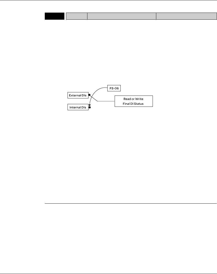
11. Servo Parameters Lexium 23A
392 AC servo drive
P4 - 07bITST Input Status Address: 040EH, 040FH
Default: 0
Applicable Control Mode: ALL
Related Section: Section 6.5.2
Section 9.2
Unit: N/A
Range: 0 ~ 3FFF
Data Size: 16-bit
Display Format: Hexadecimal
Settings:
The control of digital inputs can be determined by the external terminals (DI1 ~
DI8) or by the internal software digital inputs SDI1 ~ SDI8(corresponds to Bit0 ~
Bit13 of P1-47) via communication (upon software). Please refer to P3-06 and
section 9.2 for the setting method.
Read P4-07: Display the final status of DI input signal.
Write P4-07: Write the status of software digital inputs SDI1 ~ SDI8
(No matter the servo drive is controller through Integrated HMI or communication
control, the function of this parameter is the same.)
For example:
External Control: Display the final status of DI input signal
When the read value of P4-07 is 0x0011, it indicates that DI1 and DI5 are ON.
Communication Control (Internal DIs): Read the status of input signal (upon
software).
For example:
When the write value of P4-07 is 0x0011, it indicates that software digital inputs
SDI1 and SDI5 are ON.
Bit0 ~ Bit7 corresponds with DI1 ~ DI8.
For the settings of DI1 ~ DI8, please refer to P2-10 ~ P2-17.

Lexium 23A 11. Servo Parameters
AC servo drive 393
P4 - 08gPKEY Digital Keypad Input of Servo Drive Address: 0410H, 0411H
Default: N/A Related Section: N/A
Applicable Control Mode: ALL
Unit: N/A
Range: Read only
Data Size: 16-bit
Display Format: Hexadecimal
Settings:
This parameter is used to check if MODE, UP, DOWN, SHIFT and ENT keys on the
drive keypad being pressed or not. It is used to examine if these five keys work
normally via communication during production.
P4 - 09gMOT Output Status Address: 0412H, 0413H
Default: N/A Related Section: Section 6.5.3
Applicable Control Mode: ALL
Unit: N/A
Range: 0 ~ 0x1F
Data Size: 16-bit
Display Format: Hexadecimal
Settings:
There is no difference when reading DO output signal via the drive keypad or the
communication. For the status of DO output signal, please refer to P2-18 ~ P2-22.
P4 - 10bCEN Adjustment Function Address: 0414H, 0415H
Default: 0 Related Section: N/A
Applicable Control Mode: ALL
Unit: N/A
Range: 0 ~ 6
Data Size: 16-bit
Display Format: Decimal
Settings:
0: Reserved
1: Execute analog speed input drift adjustment
2: Execute analog torque input drift adjustment
3: Execute current detector (V phase) drift adjustment
4: Execute current detector (W phase) drift adjustment
5: Execute drift adjustment of the above 1~4
6: Execute IGBT NTC calibration
Please note:
1.This adjustment function is enabled after parameter P2-08 is set to 20.
2.When executing any adjustment, the external wiring connected to analog speed
or torque must be removed and the servo system should be off (Servo off).

11. Servo Parameters Lexium 23A
394 AC servo drive
P4 - 11 SOF1 Analog Speed Input Drift Adjustment 1 Address: 0416H, 0417H
Default: Factory setting Related Section: N/A
Applicable Control Mode: ALL
Unit: N/A
Range: 0 ~ 32767
Data Size: 16-bit
Display Format: Decimal
Settings:
The adjustment functions from P4-11 through P4-19 are enabled after parameter
P2-08 is set to 22. Although these parameters allow the users to execute manual
adjustment, we still do not recommend the users to change the default setting
value of these parameters (P4-11 ~ P4-19) manually.
Please note that when P2-08 is set to 10, the users cannot reset this parameter.
P4 - 12 SOF2 Analog Speed Input Drift Adjustment 2 Address: 0418H, 0419H
Default: Factory setting Related Section: N/A
Applicable Control Mode: ALL
Unit: N/A
Range: 0 ~ 32767
Data Size: 16-bit
Display Format: Decimal
Settings:
Refer to P4-11 for explanation.
Please note that when P2-08 is set to 10, the users cannot reset this parameter.
P4 - 13 TOF1 Analog Torque Drift Adjustment 1 Address: 041AH, 041BH
Default: Factory setting Related Section: N/A
Applicable Control Mode: ALL
Unit: N/A
Range: 0 ~ 32767
Data Size: 16-bit
Display Format: Decimal
Settings:
Refer to P4-11 for explanation.
Please note that when P2-08 is set to 10, the users cannot reset this parameter.

Lexium 23A 11. Servo Parameters
AC servo drive 395
P4 - 14 TOF2 Analog Torque Drift Adjustment 2 Address: 041CH, 041DH
Default: Factory setting Related Section: N/A
Applicable Control Mode: ALL
Unit: N/A
Range: 0 ~ 32767
Data Size: 16-bit
Display Format: Decimal
Settings:
Refer to P4-11 for explanation.
Please note that when P2-08 is set to 10, the users cannot reset this parameter.
P4 - 15 COF1 Current Detector Drift Adjustment
(V1 phase) Address: 041EH, 041FH
Default: Factory setting Related Section: N/A
Applicable Control Mode: ALL
Unit: N/A
Range: 0 ~ 32767
Data Size: 16-bit
Display Format: Decimal
Settings:
Refer to P4-11 for explanation.
Please note that when P2-08 is set to 10, the users cannot reset this parameter.
P4 - 16 COF2 Current Detector Drift Adjustment
(V2 phase) Address: 0420H, 0421H
Default: Factory setting Related Section: N/A
Applicable Control Mode: ALL
Unit: N/A
Range: 0 ~ 32767
Data Size: 16-bit
Display Format: Decimal
Settings:
Refer to P4-11 for explanation.
Please note that when P2-08 is set to 10, the users cannot reset this parameter.

11. Servo Parameters Lexium 23A
396 AC servo drive
P4 - 17 COF3 Current Detector Drift
Adjustment (W1 phase) Address: 0422H, 0423H
Default: Factory setting Related Section: N/A
Applicable Control Mode: ALL
Unit: N/A
Range: 0 ~ 32767
Data Size: 16-bit
Display Format: Decimal
Settings:
Refer to P4-11 for explanation.
Please note that when P2-08 is set to 10, the users cannot reset this parameter.
P4 - 18 COF4 Current Detector Drift Adjustment
(W2 phase) Address: 0424H, 0425H
Default: Factory setting Related Section: N/A
Applicable Control Mode: ALL
Unit: N/A
Range: 0 ~ 32767
Data Size: 16-bit
Display Format: Decimal
Settings:
Refer to P4-11 for explanation.
Please note that when P2-08 is set to 10, the users cannot reset this parameter.
P4 - 19 TIGB IGBT NTC Calibration Address: 0426H, 0427H
Default: Factory setting Related Section: N/A
Applicable Control Mode: ALL
Unit: N/A
Range: 1 ~ 4
Data Size: 16-bit
Display Format: Decimal
Settings:
Refer to P4-11 for explanation.
When executing this auto adjustment, please ensure to cool the servo drive to 25C.
Please note that when P2-08 is set to 10, the users cannot reset this parameter.

Lexium 23A 11. Servo Parameters
AC servo drive 397
P4 - 20 DOF1 Analog Monitor Output Drift
Adjustment (CH1) Address: 0428H, 0429H
Default: 0 Related Section: Section 7.3.4.4
Applicable Control Mode: ALL
Unit: mV
Range: -800 ~ 800
Data Size: 16-bit
Display Format: Decimal
Settings:
Please note that when P2-08 is set to 10, the users cannot reset this parameter.
P4 - 21 DOF2 Analog Monitor Output Drift
Adjustment (CH2) Address: 042AH, 042BH
Default: 0 Related Section: Section 7.3.4.4
Applicable Control Mode: ALL
Unit: mV
Range: -800 ~ 800
Data Size: 16-bit
Display Format: Decimal
Settings:
Please note that when P2-08 is set to 10, the users cannot reset this parameter.
P4 - 22 SAO Analog Speed Input Offset Address: 042CH, 042DH
Default: 0 Related Section: N/A
Applicable Control Mode: S
Unit: mV
Range: -5000 ~ 5000
Data Size: 16-bit
Display Format: Decimal
Settings:
In speed mode, the users can use this parameter to add an offset value to analog
speed input.

11. Servo Parameters Lexium 23A
398 AC servo drive
P4 - 23 TAO Analog Torque Input Offset Address: 042EH, 042FH
Default: 0 Related Section: N/A
Applicable Control Mode: T
Unit: mV
Range: -5000 ~ 5000
Data Size: 16-bit
Display Format: Decimal
Settings:
In speed mode, the users can use this parameter to add an offset value to analog
speed input.
P4 - 24 LVL Undervoltage Error Level Address: 0430H, 0431H
Default: 160 Related Section: N/A
Applicable Control Mode: ALL
Unit: V (rms)
Range: 140 ~ 190
Data Size: 16-bit
Display Format: Decimal
Settings:
When DC Bus voltage is lower than the value of P4-24 x 2, the fault, Undervoltage
will occur.
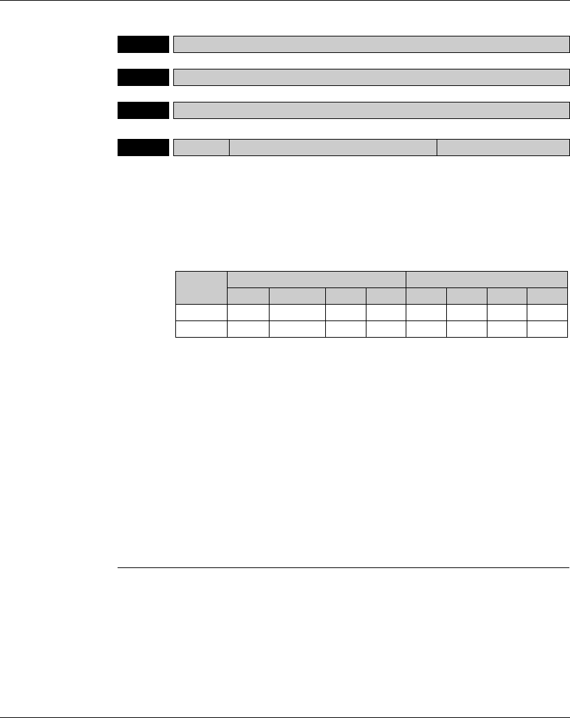
Lexium 23A 11. Servo Parameters
AC servo drive 399
Group 5: P5-xx Motion Control Parameters
P5 - 00 Reserved (Do Not Use)
P5 - 01 Reserved (Do Not Use)
P5 - 02 Reserved (Do Not Use)
P5 - 03 PDEC Deceleration Time of Protectin Function Address: 0506H, 0507H
Default: 0XE0EFEEFF Related Section: N/A
Applicable Control Mode: ALL
Unit: N/A
Range: 0x00000000 ~ 0xF0FFFFFF
Data Size: 32-bit
Display Format: Hexadecimal
Settings:
This parameter is used to set motor deceleration when protection functions, such
as STOP (Motor stop), OVF (Position command overflow), SNL (Reverse software
limit), SPL (Forward software limit), NL (Reverse inhibit limit) or PL (Forward
inhibit limit), etc. are activated.
1.Deceleration time of protection functions include: OVF, CTO(AL020), SPL, SNL,
PL, NL
2.Deceleration time of motor stop command: STP
When entering P5-03, Lower Byte display will show first. After pressing SHIFT key
on the drive keypad, the high byte display will show next.
The values from 0 through F correspond with the setting values from P5-20
through P5-35.
For example, when the setting value X is set to A, it indicates that the motor PL
deceleration time is determined by parameter P5-30.
Display High Byte Low Byte
D C B A W Z Y X
Function STP Reserved CTO OVF SNL SPL NL PL
Range 0 ~ F - 0 ~ F0 ~ F0 ~ F0 ~ F0 ~ F0 ~ F
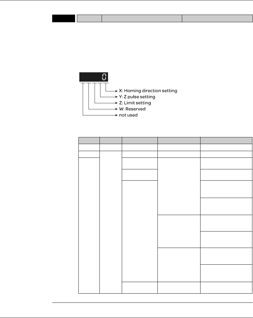
11. Servo Parameters Lexium 23A
400 AC servo drive
P5 - 04 HMOV Homing Mode Address: 0508H, 0509H
Default: 0 Related Section: N/A
Applicable Control Mode: Pr
Unit: N/A
Range: 0 ~ 0x128
Data Size: 16-bit
Display Format: Hexadecimal
Settings:
This parameter is used to determine the homing characteristics of the servo
motor.
Display W Z Y X
Function Reserved Limit setting Z pulse setting Homing direction setting
Range - 0 ~ 1 0 ~ 2 0 ~ 8
Settings -Y=0: Stop and return
to Z pulse.
Y=1: Go forward to Z
pulse.
Y=2: Ingore Z pulse
X=0: Move forward to
PL(CCWL) used as home.
-X=1: Move reverse to
NL(CWL) used as home.
When there is a
limit:
Z=0: After
reaching the
limit, activate the
limit signal.
Z=1: After
reaching the
limit, the motor
will run in the
reverse
direction.
X=2: Move forward to
dedicated home sensor
(ORGP: OFF V ON)
X=3: Move reverse to
dedicated home sensor
(ORGP: OFF V ON)
- X=4: Move forward and
regard Z pulse as home
sensor.
X=5: Move reverse and
regard Z pulse as home
sensor.
Y=0: Stop and return
to Z pulse.
Y=1: Go forward to Z
pulse.
Y=2: Ingore Z pulse
X=6: Move forward to
dedicate home sensor
(ORGP: ON V OFF)
X=7: Move reverse to
dedicated home sensor
(ORGP: ON V OFF)
--
X=8: Regard current
position as home sensor
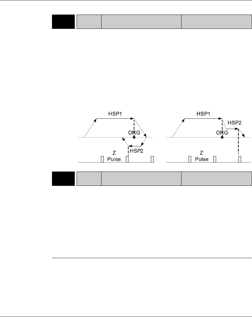
Lexium 23A 11. Servo Parameters
AC servo drive 401
P5 - 05 HSPD1 1st Speed Setting of High Speed
Homing Address: 050AH, 050BH
Default: 100.0 Related Section: N/A
Applicable Control Mode: ALL
Unit: 0.1 rpm
Range: 1 ~ 2000.0
Data Size: 16-bit
Display Format: Decimal
Settings:
This parameter is used to set the initial (high speed) homing speed.
The homing operation of the servo motor involves two homing speed settings.
When homeing is triggered, the servo motor will proceed at a high speed speed
until a home sensor is detected. The servo motor will then move reverse at a low
speed speed until off of the home sensor, and finally will stop at the next Z pulse.
P5 - 06 HSPD2 2nd Speed Setting of Low Speed
Homing Address: 050CH, 050DH
Default: 20.0 Related Section: N/A
Applicable Control Mode: ALL
Unit: 0.1 rpm
Range: 1 ~ 500.0
Data Size: 16-bit
Display Format: Decimal
Settings:
This parameter is used to set the secondary (low speed) homing speed.
Refer to P5-06 for explanation.

11. Servo Parameters Lexium 23A
402 AC servo drive
P5 - 07bPRCM Trigger Position Command (Pr
mode only) Address: 050EH, 050FH
Default: 0 Related Section: N/A
Applicable Control Mode: Pr
Unit: N/A
Range: 0 ~ 1000
Data Size: 16-bit
Display Format: Decimal
Settings:
There are 8 stored positions can be programmed via a combination of the
POS0 ~ POS2 commands. This parameter is used to trigger the dedicated position
command in Pr mode and command the motor to move to the dedicated position
instead of using DI (Digital Input) CTRG and POS0 ~ POS2.
0: Start homing function.
When entering P5-07, the default setting value 0 will display. Pressing ENT key
on the drive keypad, the servo motor will start homing operation.
1 ~ 8: Trigger Position Command (This function is equivalent to the function of DI
CTRG signal + POSn signal).
When P5-07 is set to 1 ~ 8, the dedicated position command can be triggered
and the servo drive will command the motor move to the the dedicated
position. For example, when P5-07 is set to 1, the position command P1 is
triggered and the servo drive will command the motor to move to the position
which correspond the position command P1.
9 ~ 9999: Write inhibit (Invaild setting value)
1000: Stop positioning.
When P5-07 is set to 1000, the motor stop command will be activated. This
function is equivalent to the function of DI STOP signal.
The display value of P5-07:
1. When the motor does not receive the drive command (the motor is not
running), if the users read P5-07 at this time, the display value of P5-07 will be
the setting value of P5-07
2. When the position command is triggered and the motor start runningbut does
not reach the dedicated position (during positioning, the motor is running), if
the users read P5-07 at this time, the display value of P5-07 will be setting value
of P5-07 plus 10000.
3. When the position command is triggered and the motor reachs the dedicated
position (the positioning is completed and the motor stop running), if the users
read P5-07 at this time, the display value of P5-07 will be setting value of P5-07
plus 20000.
For example, when P5-07 is set to 3, it indicates that the position command P3 will
be triggered.
1. If the display value of P5-07 is 3, it indicates that the motor does not receive the
drive command and the motor is not running.
2. If the display value of P5-07 is 100003, it indicates that the position command
is triggered but the positioning is not completed.
3. If the display value of P5-07 is 200003, it indicates that the position command
is triggered and the positioning is completed.
Lexium 23A 11. Servo Parameters
AC servo drive 403
P5 - 08 SWLP Forward Software Limit Address: 0510H, 0511H
Default: 2147483647 Related Section: N/A
Applicable Control Mode: Pr
Unit: PUU
Range: -2147483648 ~ +2147483647
Data Size: 32-bit
Display Format: Decimal
P5 - 09 SWLN Reverse Software Limit Address: 0512H, 0513H
Default: -2147483648 Related Section: N/A
Applicable Control Mode: Pr
Unit: PUU
Range: -2147483648 ~ +2147483647
Data Size: 32-bit
Display Format: Decimal
P5 - 10 Reserved (Do Not Use)
P5 - 11 Reserved (Do Not Use)
P5 - 12 Reserved (Do Not Use)
P5 - 13 Reserved (Do Not Use)
P5 - 14 Reserved (Do Not Use)
11. Servo Parameters Lexium 23A
404 AC servo drive
P5 - 15bPMEM PATH 1 ~ PATH 2 Data Not Retained
Setting Address: 051EH, 051FH
Default: 0x0 Related Section: N/A
Applicable Control Mode: ALL
Unit: N/A
Range: 0x0 ~ 0x0011
Data Size: 16-bit
Display Format: Hexadecimal
Settings:
This parameter is designed for the users who need to change the positioning point
frequently via communication.
X=0: The data of PATH 1 (P6-02 ~P6-03) will be retained (memorized) when the
power goes off.
X=1: The data of PATH 1 (P6-02 ~P6-03) will not be retained (memorized) when the
power goes off.
Y=0: The data of PATH 2 (P6-04 ~P6-05) will be retained (memorized) when the
power goes off.
Y=1: The data of PATH 2 (P6-04 ~P6-05) will not be retained (memorized) when
the power goes off.
Other settings: Reserved
P5 - 16bAXEN Axis Position: Motor Encoder Address: 0520H, 0521H
Default: 0 Related Section: Section 8.3
Applicable Control Mode: ALL
Unit: N/A
Range: -2147483648 ~ +2147483647
Data Size: 32-bit
Display Format: Decimal
Settings:
Read function: This parameter is used to read the actual position of the motor
encoder, i.e. the monitor variable V000 + deviation value.
Write function:
The users can write any value and doing this will no change the value of monitor
variable V000 and will not affect the position coordinate either.
Display 0 0 Y X
Range - - 0 ~ 1 0~ 1
Lexium 23A 11. Servo Parameters
AC servo drive 405
P5 - 17 Reserved (Do not use)
P5 - 18 AXAU Axis Position: Pulse Command Address: 0524H, 0525H
Default: N/A Related Section: Section 8.3
Applicable Control Mode: ALL
Unit: N/A
Range: -2147483648 ~ +2147483647
Data Size: 32-bit
Display Format: Decimal
Settings:
This parameter is used to send back the pulse counts of pulse command.
P5 - 19 Reserved (Do not use)
P5 - 20 ACO Accel / Decel Time 0 Address: 0528H, 0529H
Default: 200 Related Section: Section 8.10
Applicable Control Mode: Pr
Unit: msec
Range: 1 ~ 65500
Data Size: 16-bit
Display Format: Decimal
Settings:
In Pr mode, this parameter is used to set the acceleration and deceleration time,
i.e. the necessary time when the motor reachs the speed of 3000 rpm from 0.

11. Servo Parameters Lexium 23A
406 AC servo drive
P5 - 21 AC1 Accel / Decel Time 1 Address: 052AH, 052BH
Default: 300 Related Section: Section 8.10
Applicable Control Mode: Pr
Unit: msec
Range: 1 ~ 65500
Data Size: 16-bit
Display Format: Decimal
Settings:
Refer to P5-20 for explanation.
P5 - 22 AC2 Accel / Decel Time 2 Address: 052CH, 052DH
Default: 500 Related Section: Section 8.10
Applicable Control Mode: Pr
Unit: msec
Range: 1 ~ 65500
Data Size: 16-bit
Display Format: Decimal
Settings:
Refer to P5-20 for explanation.
P5 - 23 AC3 Accel / Decel Time 3 Address: 052EH, 052FH
Default: 600 Related Section: Section 8.10
Applicable Control Mode: Pr
Unit: msec
Range: 1 ~ 65500
Data Size: 16-bit
Display Format: Decimal
Settings:
Refer to P5-20 for explanation.

Lexium 23A 11. Servo Parameters
AC servo drive 407
P5 - 24 AC4 Accel / Decel Time 4 Address: 0530H, 0531H
Default: 800 Related Section: Section 8.10
Applicable Control Mode: Pr
Unit: msec
Range: 1 ~ 65500
Data Size: 16-bit
Display Format: Decimal
Settings:
Refer to P5-20 for explanation.
P5 - 25 AC5 Accel / Decel Time 5 Address: 0532H, 0533H
Default: 900 Related Section: Section 8.10
Applicable Control Mode: Pr
Unit: msec
Range: 1 ~ 65500
Data Size: 16-bit
Display Format: Decimal
Settings:
Refer to P5-20 for explanation.
P5 - 26 AC6 Accel / Decel Time 6 Address: 0534H, 0535H
Default: 1000 Related Section: Section 8.10
Applicable Control Mode: Pr
Unit: msec
Range: 1 ~ 65500
Data Size: 16-bit
Display Format: Decimal
Settings:
Refer to P5-20 for explanation.
P5 - 27 AC7 Accel / Decel Time 7 Address: 0536H, 0537H
Default: 1200 Related Section: Section 8.10
Applicable Control Mode: Pr
Unit: msec
Range: 1 ~ 65500
Data Size: 16-bit
Display Format: Decimal
Settings:
Refer to P5-20 for explanation.

11. Servo Parameters Lexium 23A
408 AC servo drive
P5 - 28 AC8 Accel / Decel Time 8 Address: 0538H, 0539H
Default: 1500 Related Section: Section 8.10
Applicable Control Mode: Pr
Unit: msec
Range: 1 ~ 65500
Data Size: 16-bit
Display Format: Decimal
Settings:
Refer to P5-20 for explanation.
P5 - 29 AC9 Accel / Decel Time 9 Address: 053AH, 053BH
Default: 2000 Related Section: Section 8.10
Applicable Control Mode: Pr
Unit: msec
Range: 1 ~ 65500
Data Size: 16-bit
Display Format: Decimal
Settings:
Refer to P5-20 for explanation.
P5 - 30 AC10 Accel / Decel Time 10 Address: 053CH, 053DH
Default: 2500 Related Section: Section 8.10
Applicable Control Mode: Pr
Unit: msec
Range: 1 ~ 65500
Data Size: 16-bit
Display Format: Decimal
Settings:
Refer to P5-20 for explanation.
P5 - 31 AC11 Accel / Decel Time 11 Address: 053EH, 053FH
Default: 3000 Related Section: Section 8.10
Applicable Control Mode: Pr
Unit: msec
Range: 1 ~ 65500
Data Size: 16-bit
Display Format: Decimal
Settings:
Refer to P5-20 for explanation.

Lexium 23A 11. Servo Parameters
AC servo drive 409
P5 - 32 AC12 Accel / Decel Time 12 Address: 0540H, 0541H
Default: 5000 Related Section: Section 8.10
Applicable Control Mode: Pr
Unit: msec
Range: 1 ~ 65500
Data Size: 16-bit
Display Format: Decimal
Settings:
Refer to P5-20 for explanation.
P5 - 33 AC13 Accel / Decel Time 13 Address: 0542H, 0543H
Default: 8000 Related Section: Section 8.10
Applicable Control Mode: Pr
Unit: msec
Range: 1 ~ 65500
Data Size: 16-bit
Display Format: Decimal
Settings:
Refer to P5-20 for explanation.
P5 - 34 AC14 Accel / Decel Time 14 Address: 0544H, 0545H
Default: 50 Related Section: Section 8.10
Applicable Control Mode: Pr
Unit: msec
Range: 1 ~ 65500
Data Size: 16-bit
Display Format: Decimal
Settings:
The default setting value of this parameter is smaller and it is for the deceleration
setting when protection function is activated.
P5 - 35 AC15 Accel / Decel Time 15 Address: 0546H, 0547H
Default: 30 Related Section: Section 8.10
Applicable Control Mode: Pr
Unit: msec
Range: 1 ~ 65500
Data Size: 16-bit
Display Format: Decimal
Settings:
The default setting value of this parameter is smaller and it is for the deceleration
setting when the motor stops in high speed.

11. Servo Parameters Lexium 23A
410 AC servo drive
P5 - 36 Reserved (Do Not use)
P5 - 37bCAAX CAPTURE: Axis Position CNT Address: 054AH, 054BH
Default: 0 Related Section: Section 8.11.1
Applicable Control Mode: ALL
Unit: PUU
Range: -2147483648 ~ +2147483647
Data Size: 32-bit
Display Format: Decimal
Settings:
This parameter can be set only when capture operation is stopped (Refer to
P5-39).
Please note:
1. Do not change this parameter when the capture source is the motor encoder.
2. When the capture source is the motor encoder, the value of this parameter is
reset to the motor encoder feedback position (monitor variable is 00h).
P5 - 38bCANO CAPTURE: Capture Amount Address: 054CH, 054DH
Default: 0 Related Section: Section 8.11.1
Applicable Control Mode: ALL
Unit: N/A
Range: 1 ~ (P5-10 ~ P5-36)
Data Size: 16-bit
Display Format: Decimal
Settings:
When the compare function is not enabled, using this parameter can set the
estimated capture amount (able to read and write).
Once the capture function is enabled, everytime when one position is captured,
the setting value of P5-38 will decrease 1. When the setting value of P5-38 is equal
to 0, it indicates that the capture operation has finished.
Please note:
The total amount of COMPARE and CAPTURE data can not exceed the number
of 800.
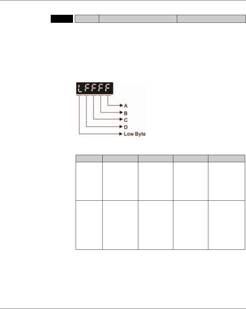
Lexium 23A 11. Servo Parameters
AC servo drive 411
P5 - 39bCACT CAPTURE: Capture Source Setting Address: 054EH, 054FH
Default: 0000 Related Section: Section 8.11.1
Applicable Control Mode: ALL
Unit: N/A
Range: 0x0000 ~ 0xF13F
Data Size: 16-bit
Display Format: Hexadecimal
Settings:
This parameter is used to determine the capture source and enable the capture
function.
A: Capture function settings:
Please refer to the following table and descriptions:
Bit0: When the value of P5-38 is higher than 0, setting Bit0 to 1 will enable the
capture function and the DO signal, CAP_OK is inactivated. Once the capture
function is enabled, everytime when one position is captured, the setting value of
P5-38 will decrease 1. When the setting value of P5-38 is equal to 0, it indicates
that the capture operation has finished. Then, DO signal, CAP_OK will be activated
and the value of Bit0 will be reset to 0 automatically.
Bit 3 2 1 0
Function Execute Pr
command when
capture function
has finished.
After first
position is
captured, the
system will
enable the
compare
function
After first
position is
captured, the
position will be
reset.
Start capture
function
Explanation After capture
function has
finished, execute
Pr #50
command.
The compare
function is
enabled already,
and this setting
will become
ineffective.
When the first
point is captured,
the position
coordinate will be
reset.
Setting Bit0 to 1
will enable the
capture function.
When capture
function has
finished, the value
of Bit0 will be
reset to 0
automatically.

11. Servo Parameters Lexium 23A
412 AC servo drive
When the value of P5-38 is equal to 0, setting Bit0 to 1 will not enable the capture
function, the DO signal, CAP_OK will be inactivated and then the value of Bit0 will
be reset to 0 automatically. If Bit0 is set to 1 already, the new setting value cannot
be 1. The users only can set Bit0 to 0 to disable the capture function.
Bit1: When Bit1 is set to 1, after first position is captured, the system will set the
value of the current position as the value of the parameter P5-76.
Bit2: When Bit2 is set to 1, after first position is captured, the system will enable the
compare function (Bit0 of P5-59 is set to 1 and the value of P5-58 is set to the last
compare amount). If the compare function is enabled already, this setting will
become ineffective.
Bit3: When Bit3 is set to 1, after capture operation is completed (all positions has
been captured), the position command P50 will be triggered immediately.
B: Capture source settings
0: Capture function is disabled.
1: Reserved (Do not use).
2: Pulse command.
3: Motor encoder
C: Activate state settings
0: Normally open (use N.O. contact)
1: Normally closed (use N.C. contact)
D: Trigger time settings (unit: msec)
P5 - 40 DLY0 Delay Time 0 Address: 0550H, 0551H
Default: 0 Related Section: Section 8.10
Applicable Control Mode: Pr
Unit: msec
Range: 0 ~ 32767
Data Size: 16-bit
Display Format: Decimal
P5 - 41 DLY1 Delay Time 1 Address: 0552H, 0553H
Default: 100 Related Section: Section 8.10
Applicable Control Mode: Pr
Unit: msec
Range: 0 ~ 32767
Data Size: 16-bit
Display Format: Decimal

Lexium 23A 11. Servo Parameters
AC servo drive 413
P5 - 42 DLY2 Delay Time 2 Address: 0554H, 0555H
Default: 200 Related Section: Section 8.10
Applicable Control Mode: Pr
Unit: msec
Range: 0 ~ 32767
Data Size: 16-bit
Display Format: Decimal
P5 - 43 DLY3 Delay Time 3 Address: 0556H, 0557H
Default: 400 Related Section: Section 8.10
Applicable Control Mode: Pr
Unit: msec
Range: 0 ~ 32767
Data Size: 16-bit
Display Format: Decimal
P5 - 44 DLY4 Delay Time 4 Address: 0558H, 0559H
Default: 500 Related Section: Section 8.10
Applicable Control Mode: Pr
Unit: msec
Range: 0 ~ 32767
Data Size: 16-bit
Display Format: Decimal
P5 - 45 DLY5 Delay Time 5 Address: 055AH, 055BH
Default: 800 Related Section: Section 8.10
Applicable Control Mode: Pr
Unit: msec
Range: 0 ~ 32767
Data Size: 16-bit
Display Format: Decimal
P5 - 46 DLY6 Delay Time 6 Address: 055CH, 055DH
Default: 1000 Related Section: Section 8.10
Applicable Control Mode: Pr
Unit: msec
Range: 0 ~ 32767
Data Size: 16-bit
Display Format: Decimal

11. Servo Parameters Lexium 23A
414 AC servo drive
P5 - 47 DLY7 Delay Time 7 Address: 055EH, 055FH
Default: 1500 Related Section: Section 8.10
Applicable Control Mode: Pr
Unit: msec
Range: 0 ~ 32767
Data Size: 16-bit
Display Format: Decimal
P5 - 48 DLY8 Delay Time 8 Address: 0560H, 0561H
Default: 2000 Related Section: Section 8.10
Applicable Control Mode: Pr
Unit: msec
Range: 0 ~ 32767
Data Size: 16-bit
Display Format: Decimal
P5 - 49 DLY9 Delay Time 9 Address: 0562H, 0563H
Default: 2500 Related Section: Section 8.10
Applicable Control Mode: Pr
Unit: msec
Range: 0 ~ 32767
Data Size: 16-bit
Display Format: Decimal
P5 - 50 DLY10 Delay Time 10 Address: 0564H, 0565H
Default: 3000 Related Section: Section 8.10
Applicable Control Mode: Pr
Unit: msec
Range: 0 ~ 32767
Data Size: 16-bit
Display Format: Decimal
P5 - 51 DLY11 Delay Time 11 Address: 0566H, 0567H
Default: 3500 Related Section: Section 8.10
Applicable Control Mode: Pr
Unit: msec
Range: 0 ~ 32767
Data Size: 16-bit
Display Format: Decimal

Lexium 23A 11. Servo Parameters
AC servo drive 415
P5 - 52 DLY12 Delay Time 12 Address: 0568H, 0569H
Default: 4000 Related Section: Section 8.10
Applicable Control Mode: Pr
Unit: msec
Range: 0 ~ 32767
Data Size: 16-bit
Display Format: Decimal
P5 - 53 DLY13 Delay Time 13 Address: 056AH, 056BH
Default: 4500 Related Section: Section 8.10
Applicable Control Mode: Pr
Unit: msec
Range: 0 ~ 32767
Data Size: 16-bit
Display Format: Decimal
P5 - 54 DLY14 Delay Time 14 Address: 056CH, 056DH
Default: 5000 Related Section: Section 8.10
Applicable Control Mode: Pr
Unit: msec
Range: 0 ~ 32767
Data Size: 16-bit
Display Format: Decimal
P5 - 55 DLY15 Delay Time 15 Address: 056EH, 056FH
Default: 5500 Related Section: Section 8.10
Applicable Control Mode: Pr
Unit: msec
Range: 0 ~ 32767
Data Size: 16-bit
Display Format: Decimal
P5 - 56 Reserved (Do Not Use)
P5 - 57 Reserved (Do Not Use)
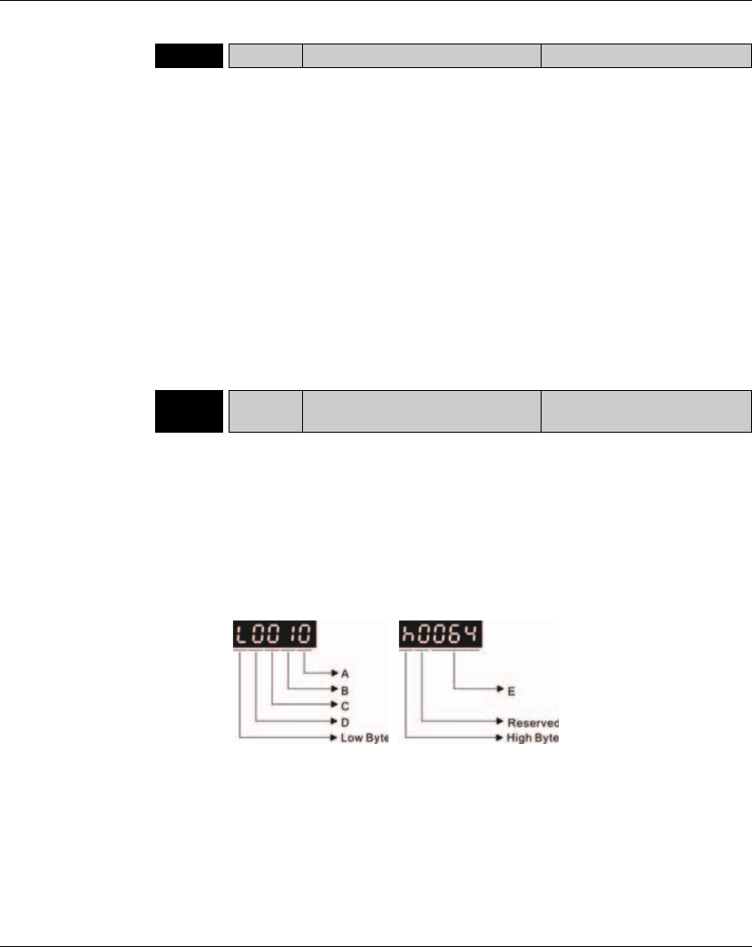
11. Servo Parameters Lexium 23A
416 AC servo drive
P5 - 58bCMNO COMPARE: Compare Amount Address: 0574H, 0575H
Default: 0 Related Section: Section 8.11.2
Applicable Control Mode: ALL
Unit: N/A
Range: 1 ~ (P5-10 ~ P5-56)
Data Size: 16-bit
Display Format: Decimal
Settings:
When the compare function is not enabled, using this parameter can set the
estimated compare amount (able to read and write).
When the compare function is enabled, using this parameter can set the rest
compare amount (read-only). When the setting value of P5-58 is equal to 0, it
indicates that the compare operation has finished.
Please note:
The total amount of COMPARE and CAPTURE data can not exceed the number
of 800.
P5 - 59bCACT COMPARE: Compare Source
Setting Address: 0576H, 0577H
Default: 0x0000 Related Section: Section 8.11.2
Applicable Control Mode: ALL
Unit: N/A
Range: 00010000h ~ 0FFF3137h
Data Size: 32-bit
Display Format: Hexadecimal
Settings:
This parameter is used to determine the compare source and enable the compare
function.

Lexium 23A 11. Servo Parameters
AC servo drive 417
A: Compare function settings:
Bit0: When the value of P5-58 is higher than 0, setting Bit0 to 1 will enable the
compare function. Once the compare function is enabled, everytime when one
position is compared, the setting value of P5-58 will decrease 1. When the setting
value of P5-58 is equal to 0, it indicates that the compare operation has finished
and the value of Bit0 will be reset to 0 automatically.
When the value of P5-58 is equal to 0, setting Bit0 to 1 will not enable the compare
function, and then the value of Bit0 will be reset to 0 automatically. If Bit0 is set to
1 already, the new setting value cannot be 1. The users only can set Bit0 to 0 to
disable the compare function.
Bit1: When Bit1 is set to 1, after the last position is compared, the setting value of
P5-58 will be reset and start the compare operation from the first position again.
The compare operation will not stop and the value of Bit0 will be retained as 1.
Bit2: When Bit2 is set to 1, after the last position is compared, the system will
enable the capture function (Bit0 of P5-39 is set to 1 and the value of P5-38 is set
to the last capture amount). If the capture function is enabled already, this setting
will become ineffective.
Bit3: Reserved.
B: Compare source settings
0: Capture axis.
1: Reserved. Do not use.
2: Pulse command.
3: Motor encoder
C: Activate state settings
0: Normally open (use N.O. contact)
1: Normally closed (use N.C. contact)
E: Length of output pulse (unit: 1 msec)
Bit 3 2 1 0
Function - After the last
position is
compared, the
system will
enable the
capture function
Cycle mode Start compare
function
Explanation - The capture
function is
enabled already,
and this setting
will become
ineffective.
The compare
operation will not
stop.
Setting Bit0 to 1
will enable the
compare function.
When compare
function has
finished, the value
of Bit0 will be
reset to 0
automatically.

11. Servo Parameters Lexium 23A
418 AC servo drive
P5 - 60 POV0 Moving Speed Setting of Position 0 Address: 0578H, 0579H
Default: 20.0 Related Section: Section 8.10
Applicable Control Mode: Pr
Unit: 0.1 rpm
Range: 0.1 ~ 6000.0
Data Size: 16-bit
Display Format: Decimal
P5 - 61 POV1 Moving Speed Setting of Position 1 Address: 057AH, 057BH
Default: 50.0 Related Section: Section 8.10
Applicable Control Mode: Pr
Unit: 0.1 rpm
Range: 0.1 ~ 6000.0
Data Size: 16-bit
Display Format: Decimal
P5 - 62 POV2 Moving Speed Setting of Position 2 Address: 057CH, 057DH
Default: 100.0 Related Section: Section 8.10
Applicable Control Mode: Pr
Unit: 0.1 rpm
Range: 0.1 ~ 6000.0
Data Size: 16-bit
Display Format: Decimal
P5 - 63 POV3 Moving Speed Setting of Position 3 Address: 057EH, 057FH
Default: 200.0 Related Section: Section 8.10
Applicable Control Mode: Pr
Unit: 0.1 rpm
Range: 0.1 ~ 6000.0
Data Size: 16-bit
Display Format: Decimal
P5 - 64 POV4 Moving Speed Setting of Position 4 Address: 0580H, 0581H
Default: 300.0 Related Section: Section 8.10
Applicable Control Mode: Pr
Unit: 0.1 rpm
Range: 0.1 ~ 6000.0
Data Size: 16-bit
Display Format: Decimal

Lexium 23A 11. Servo Parameters
AC servo drive 419
P5 - 65 POV5 Moving Speed Setting of Position 5 Address: 0582H, 0583H
Default: 500.0 Related Section: Section 8.10
Applicable Control Mode: Pr
Unit: 0.1 rpm
Range: 0.1 ~ 6000.0
Data Size: 16-bit
Display Format: Decimal
P5 - 66 POV6 Moving Speed Setting of Position 6 Address: 0584H, 0585H
Default: 600.0 Related Section: Section 8.10
Applicable Control Mode: Pr
Unit: 0.1 rpm
Range: 0.1 ~ 6000.0
Data Size: 16-bit
Display Format: Decimal
P5 - 67 POV7 Moving Speed Setting of Position 7 Address: 0586H, 0587H
Default: 800.0 Related Section: Section 8.10
Applicable Control Mode: Pr
Unit: 0.1 rpm
Range: 0.1 ~ 6000.0
Data Size: 16-bit
Display Format: Decimal
P5 - 68 POV8 Moving Speed Setting of Position 8 Address: 0588H, 0589H
Default: 1000.0 Related Section: Section 8.10
Applicable Control Mode: Pr
Unit: 0.1 rpm
Range: 0.1 ~ 6000.0
Data Size: 16-bit
Display Format: Decimal
P5 - 69 POV9 Moving Speed Setting of Position 9 Address: 058AH, 058BH
Default: 1300.0 Related Section: Section 8.10
Applicable Control Mode: Pr
Unit: 0.1 rpm
Range: 0.1 ~ 6000.0
Data Size: 16-bit
Display Format: Decimal

11. Servo Parameters Lexium 23A
420 AC servo drive
P5 - 70 POV10 Moving Speed Setting of Position 10 Address: 058CH, 058DH
Default: 1500.0 Related Section: Section 8.10
Applicable Control Mode: Pr
Unit: 0.1 rpm
Range: 0.1 ~ 6000.0
Data Size: 16-bit
Display Format: Decimal
P5 - 71 POV11 Moving Speed Setting of Position 11 Address: 058EH, 058FH
Default: 1800.0 Related Section: Section 8.10
Applicable Control Mode: Pr
Unit: 0.1 rpm
Range: 0.1 ~ 6000.0
Data Size: 16-bit
Display Format: Decimal
P5 - 72 POV12 Moving Speed Setting of Position 12 Address: 0590H, 0591H
Default: 2000.0 Related Section: Section 8.10
Applicable Control Mode: Pr
Unit: 0.1 rpm
Range: 0.1 ~ 6000.0
Data Size: 16-bit
Display Format: Decimal
P5 - 73 POV13 Moving Speed Setting of Position 13 Address: 0592H, 0593H
Default: 2300.0 Related Section: Section 8.10
Applicable Control Mode: Pr
Unit: 0.1 rpm
Range: 0.1 ~ 6000.0
Data Size: 16-bit
Display Format: Decimal
P5 - 74 POV14 Moving Speed Setting of Position 14 Address: 0594H, 0595H
Default: 2500.0 Related Section: Section 8.10
Applicable Control Mode: Pr
Unit: 0.1 rpm
Range: 0.1 ~ 6000.0
Data Size: 16-bit
Display Format: Decimal

Lexium 23A 11. Servo Parameters
AC servo drive 421
P5 - 75 POV15 Moving Speed Setting of Position 15 Address: 0596H, 0597H
Default: 3000.0 Related Section: Section 8.10
Applicable Control Mode: Pr
Unit: 0.1 rpm
Range: 0.1 ~ 6000.0
Data Size: 16-bit
Display Format: Decimal
P5 - 76gCPRS Capture 1st Position Reset Data Address: 0598H, 0599H
Default: 0 Related Section: Section 8.10
Applicable Control Mode: ALL
Unit: N/A
Range: -1073741824 ~ +1073741823
Data Size: 32-bit
Display Format: Decimal
Settings:
Refer to P5-39 for explanation.

11. Servo Parameters Lexium 23A
422 AC servo drive
Group 6: P6-xx Pr Path Definition Parameters
P6 - 00 ODEF Homing Definition Address: 0600H, 0601H
Default: 0x00000000 Related Section: Section 8.10
Applicable Control Mode: Pr
Unit: N/A
Range: 0x00000000~0x10FFFF08
Data Size: 32-bit
Display Format: Hexadecimal
Settings:
Homing definition:
PATH: Path style (4 bits)
0: Stop mode. Motor stops after homing is completed.
1~8: Auto mode. Motor goes the dedicated path after homing is completed.
ACC: Acceleration time 0 ~ F, corresponds to P5-20 ~ P5-35.
DEC1 / DEC2: 1st deceleration time / 2nd deceleration time. Deceleration time 0 ~
F, corresponds to P5-20 ~ P5-35.
DLY: Delay time 0 ~ F, corresponds to P5-40 ~ P5-55.
BOOT: Boot mode. Disable or enable homing function when the servo drive is
applied to power (power on).
0: Disable homing function
1: Enable homing function (when the servo drive is applied to power, first time
Servo On)
Other parameters relevant to homing function:
P5-04 (Homing mode)
P5-05 (1st Speed Setting of High Speed Homing)
P5-06 (2nd Speed Setting of Low Speed Homing)
P6-01: ORG_DEF (Homing definition value). P6-01 is used to set the coordinate
value of the current home position for the movement of the coordinate system.
The coordinate value could be a non-zero value.
After detecting "Home" (home sensor or Z pulse), the motor will decelerate to
stop the operation.
If the motor does not return to "Home", just set path number to 0.
If the motor must return to "Home", set path number to a non-zero value and
set the route PABS = ORG_DEF.
When detecting "Home" (home sensor or Z pulse), if the motor has to go
forward for a while (offset value S) and reach the position P, set the path
number to a non-zero value and set ORG_DEF = P - S (the absolute position
command of this route is P).
Bit 31 ~ 28 27 ~ 24 23 ~ 20 19 ~ 16 15 ~ 12 11 ~ 8 7 ~ 4 3 ~ 0
Function BOOT - DLY DEC2 DEC1 ACC PATH
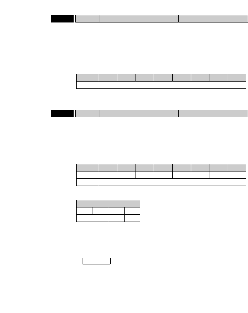
Lexium 23A 11. Servo Parameters
AC servo drive 423
P6 - 01 ODAT Homing Definition Value Address: 0602H, 0603H
Default: 0 Related Section: Section 8.10
Applicable Control Mode: Pr
Unit: N/A
Range: -2147483648 ~ +2147483647
Data Size: 32-bit
Display Format: Decimal
Settings:
Homing definition value:
ORG_DEF: Homing definition value which is determined by the parameter P6-01.
The homing definition value does not necessarily have to be 0.
P6 - 02 PDEF1 Definition of Path 1 Address: 0604H, 0605H
Default: 0x00000000 Related Section: Section 8.10
Applicable Control Mode: N/A
Unit: N/A
Range: 0x00000000 ~ 0xFFFFFFFF
Data Size: 32-bit
Display Format: Decimal
Settings:
OPT:
INS: Interrupt the previous path.
CMD: Refer to Section 7.10 in Chapter 7.
DLY: 0 ~ F. Delay time number (4 bits). The digital output of this path activates
after the delay time. External INS is not effective. The delay time number settings
correspond with the parameter P5-40 ~ P5-55.
Index P5-40 ~ P5-55
Bit 31 ~ 28 27 ~ 24 23 ~ 20 19 ~ 16 15 ~ 12 11 ~ 8 7 ~ 4 3 ~ 0
Function ORG_DEF (32-bit)
Bit 31 ~ 28 27 ~ 24 23 ~ 20 19 ~ 16 15 ~ 12 11 ~ 8 7 ~ 4 3 ~ 0
P6-02 - - DLY - - - OPT
P6-03 DATA (32-bit)
OPT
Bit7 Bit6 Bit5 Bit4
CMD - INS
DLY (4)
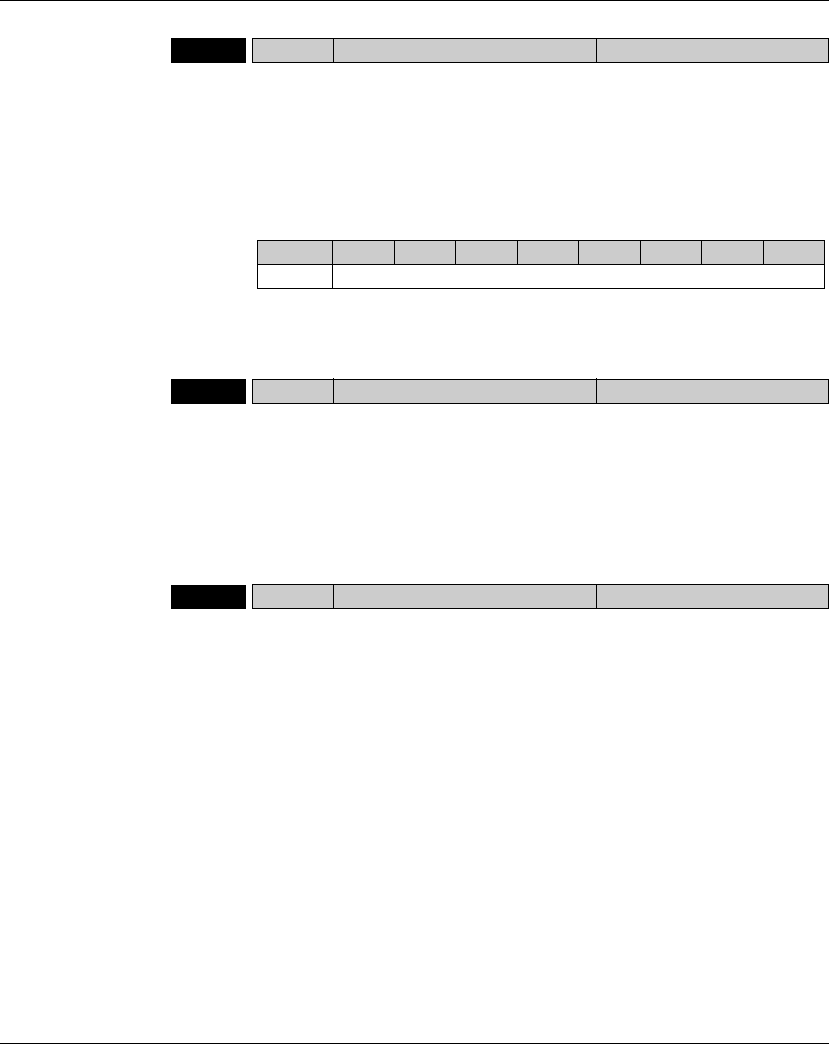
11. Servo Parameters Lexium 23A
424 AC servo drive
P6 - 03 PDAT1 Data of Path 1 Address: 0606H, 0607H
Default: 0 Related Section: Section 8.10
Applicable Control Mode: Pr
Unit: N/A
Range: -2147483648 ~ +2147483647
Data Size: 32-bit
Display Format: Decimal
Settings:
Data of path 1:
The parameter P6-02 is used to determine the attributes of definition of Path 1
and parameter P6-03 is used to set the data (target position or jump path
number) corresponding to P6-02.
P6 - 04 PDEF2 Definition of Path 2 Address: 0608H, 0609H
Default: 0x00000000 Related Section: Section 8.10
Applicable Control Mode: Pr
Unit: N/A
Range: 0x00000000 ~ 0xFFFFFFFF
Data Size: 32-bit
Display Format: Decimal
Settings:
Refer to P6-02 for explanation.
P6 - 05 PDAT2 Data of Path 2 Address: 060AH, 060BH
Default: 0 Related Section: Section 8.10
Applicable Control Mode: Pr
Unit: N/A
Range: -2147483648 ~ +2147483647
Data Size: 32-bit
Display Format: Decimal
Settings:
Refer to P6-03 for explanation.
Bit 31 ~ 28 27 ~ 24 23 ~ 20 19 ~ 16 15 ~ 12 11 ~ 8 7 ~ 4 3 ~ 0
Function DATA (32-bit)

Lexium 23A 11. Servo Parameters
AC servo drive 425
P6 - 06 PDEF3 Definition of Path 3 Address: 060CH, 060DH
Default: 0x00000000 Related Section: Section 8.10
Applicable Control Mode: Pr
Unit: N/A
Range: 0x00000000 ~ 0xFFFFFFFF
Data Size: 32-bit
Display Format: Decimal
Settings:
Refer to P6-02 for explanation.
P6 - 07 PDAT3 Data of Path 3 Address: 060EH, 060FH
Default: 0 Related Section: Section 8.10
Applicable Control Mode: Pr
Unit: N/A
Range: -2147483648 ~ +2147483647
Data Size: 32-bit
Display Format: Decimal
Settings:
Refer to P6-03 for explanation.
P6 - 08 PDEF4 Definition of Path 4 Address: 0610H, 0611H
Default: 0x00000000 Related Section: Section 8.10
Applicable Control Mode: Pr
Unit: N/A
Range: 0x00000000 ~ 0xFFFFFFFF
Data Size: 32-bit
Display Format: Decimal
Settings:
Refer to P6-02 for explanation.
P6 - 09 PDAT4 Data of Path 4 Address: 0612H, 0613H
Default: 0 Related Section: Section 8.10
Applicable Control Mode: Pr
Unit: N/A
Range: -2147483648 ~ +2147483647
Data Size: 32-bit
Display Format: Decimal
Settings:
Refer to P6-03 for explanation.

11. Servo Parameters Lexium 23A
426 AC servo drive
P6 - 10 PDEF5 Definition of Path 5 Address: 0614H, 0615H
Default: 0x00000000 Related Section: Section 8.10
Applicable Control Mode: Pr
Unit: N/A
Range: 0x00000000 ~ 0xFFFFFFFF
Data Size: 32-bit
Display Format: Decimal
Settings:
Refer to P6-02 for explanation.
P6 - 11 PDAT5 Data of Path 5 Address: 0616H, 0617H
Default: 0 Related Section: Section 8.10
Applicable Control Mode: Pr
Unit: N/A
Range: -2147483648 ~ +2147483647
Data Size: 32-bit
Display Format: Decimal
Settings:
Refer to P6-03 for explanation.
P6 - 12 PDEF6 Definition of Path 6 Address: 0618H, 0619H
Default: 0x00000000 Related Section: Section 8.10
Applicable Control Mode: Pr
Unit: N/A
Range: 0x00000000 ~ 0xFFFFFFFF
Data Size: 32-bit
Display Format: Decimal
Settings:
Refer to P6-02 for explanation.
P6 - 13 PDAT6 Data of Path 6 Address: 061AH, 061BH
Default: 0 Related Section: Section 8.10
Applicable Control Mode: Pr
Unit: N/A
Range: -2147483648 ~ +2147483647
Data Size: 32-bit
Display Format: Decimal
Settings:
Refer to P6-03 for explanation.

Lexium 23A 11. Servo Parameters
AC servo drive 427
P6 - 14 PDEF7 Definition of Path 7 Address: 061CH, 061DH
Default: 0x00000000 Related Section: Section 8.10
Applicable Control Mode: Pr
Unit: N/A
Range: 0x00000000 ~ 0xFFFFFFFF
Data Size: 32-bit
Display Format: Decimal
Settings:
Refer to P6-02 for explanation.
P6 - 15 PDAT7 Data of Path 7 Address: 061EH, 061FH
Default: 0 Related Section: Section 8.10
Applicable Control Mode: Pr
Unit: N/A
Range: -2147483648 ~ +2147483647
Data Size: 32-bit
Display Format: Decimal
Settings:
Refer to P6-03 for explanation.
P6 - 16 PDEF8 Definition of Path 8 Address: 0620H, 0621H
Default: 0x00000000 Related Section: Section 8.10
Applicable Control Mode: Pr
Unit: N/A
Range: 0x00000000 ~ 0xFFFFFFFF
Data Size: 32-bit
Display Format: Decimal
Settings:
Refer to P6-02 for explanation.
P6 - 17 PDAT8 Data of Path 8 Address: 0622H, 0623H
Default: 0 Related Section: Section 8.10
Applicable Control Mode: Pr
Unit: N/A
Range: -2147483648 ~ +2147483647
Data Size: 32-bit
Display Format: Decimal
Settings:
Refer to P6-03 for explanation.

11. Servo Parameters Lexium 23A
428 AC servo drive
Table 11.A Input Function Definition
Setting value: 0x01
DI Name DI Function Description Trigger Method Control
Mode
SON Servo On. When this DI is activated, it indicates the
servo drive is enabled. Level Triggered
All
modes
except
CAN
Setting value: 0x02
DI Name DI Function Description Trigger Method Control
Mode
ARST
A number of Faults (Alarms) can be cleared by
activating ARST. Please see table 10-3 for applicable
faults that can be cleared with the ARST command.
However, please investigate Fault or Alarm if it does
not clear or the fault description warrants closer
inspection of the drive system.
Rising-edge
Triggered All
Setting value: 0x03
DI Name DI Function Description Trigger Method Control
Mode
GAINUP
Gain switching in speed and position mode. When
GAINUP is activated (P2-27 is set to 1), the gain is
switched to the gain multiplied by gain switching
rate.
Level Triggered Pt, Pr, S
Setting value: 0x04
DI Name DI Function Description Trigger Method Control
Mode
CCLR
When CCLR is activated, the setting parameter
P2-50 Pulse Clear Mode is executed.
0: After CCLR is activated (ON), the position
accumulated pulse number will be cleared
continuously.
Rising-edge
Triggered,
Level Triggered
Pt
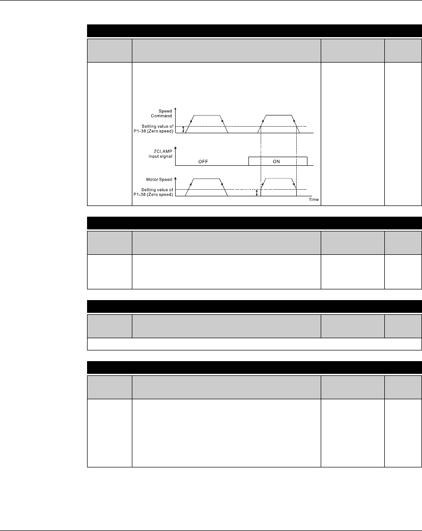
Lexium 23A 11. Servo Parameters
AC servo drive 429
Setting value: 0x05
DI Name DI Function Description Trigger Method Control
Mode
ZCLAMP
When this signal is On and the motor speed value is
lower than the setting value of P1-38, it is used to
lock the motor in the instant position while ZCLAMP
is On.
Level Triggered S
Setting value: 0x06
DI Name DI Function Description Trigger Method Control
Mode
CMDINV
Command input reverse control. When the drive is in
the Speed and Torque mode, and CMDINV is
activated, the motor is in reverse rotation.
Level Triggered S, T
Setting value: 0x07
DI Name DI Function Description Trigger Method Control
Mode
Reserved
Setting value: 0x08
DI Name DI Function Description Trigger Method Control
Mode
CTRG
Command triggered (available in Pr mode only).
When the drive is in Pr mode and CTRG is activated,
the drive will command the motor to move the
stored position which correspond the POS 0 ~ POS 5
settings. Activation is triggered on the rising edge of
the pulse.
Rising-edge
Triggered Pr

11. Servo Parameters Lexium 23A
430 AC servo drive
Setting value: 0x09
DI Name DI Function Description Trigger Method Control
Mode
TRQLM
Torque limit enabled. When the drive is in speed and
position mode, and TRQLM is activated, it indicates
the torque limit command is valid. The torque limit
command source is internal parameter or analog
voltage.
Level Triggered Pt, Pr, S
Setting value: 0x10
DI Name DI Function Description Trigger Method Control
Mode
SPDLM
Speed limit enabled. When the drive is in torque
mode and SPDLM is activated, it indicates the speed
limit command is valid. The speed limit command
source is internal parameter or analog voltage.
Level Triggered T
Setting value: 0x11, 0x12, 0x13
DI Name DI Function Description Trigger Method Control
Mode
POS0
POS1
POS2
Position command selection POS0 ~ POS2 (8
positions)
When the Pr Control Mode is selected, the 8 stored
positions are programmed via a combination of the
POS 0 ~ POS2 commands.
Level Triggered Pr
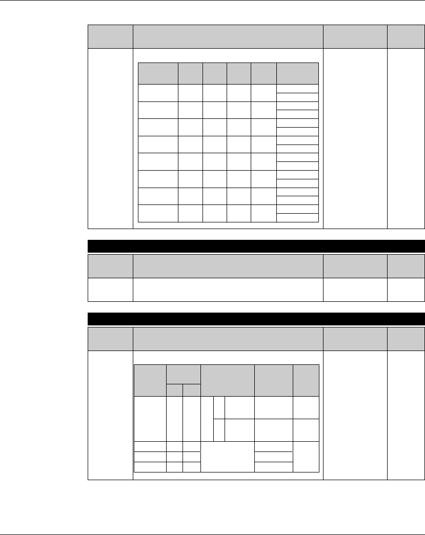
Lexium 23A 11. Servo Parameters
AC servo drive 431
DI Name DI Function Description Trigger Method Control
Mode
POS0
POS1
POS2
Level Triggered Pr
Setting value: 0x46
DI Name DI Function Description Trigger Method Control
Mode
STOP Motor stop. Rising-edge
Triggered Pr
Setting value: 0x14 ~ 0x15
DI Name DI Function Description Trigger Method Control
Mode
SPD0
SPD1
Speed command selection 0 ~ 1 (Command S1 ~ S4)
Level Triggered S
Position
Command POS2 POS1 POS0 CTRG Parameters
P1 0 0 0
A
P6-02
P6-03
P2 0 0 1
A
P6-04
P6-05
P3 0 1 0
A
P6-06
P6-07
P4 0 1 1
A
P6-08
P6-09
P5 1 0 0
A
P6-10
P6-11
P6 1 0 1
A
P6-12
P6-13
P7 1 1 0
A
P6-14
P6-15
P8 1 1 1
A
P6-16
P6-17
Command
No.
DI signal of
CN1 Command Source Content Range
SPD1 SPD0
S1 OFF OFF
Mode
S
External
analog
command
Voltage
between V-
REF and GND
+/-10 V
Sz None
Speed
command
is 0
0
S2 OFF ON
Internal parameter
P1-09 -60000
~
+60000
rpm
S3 ON OFF P1-10
S4 ON ON P1-11
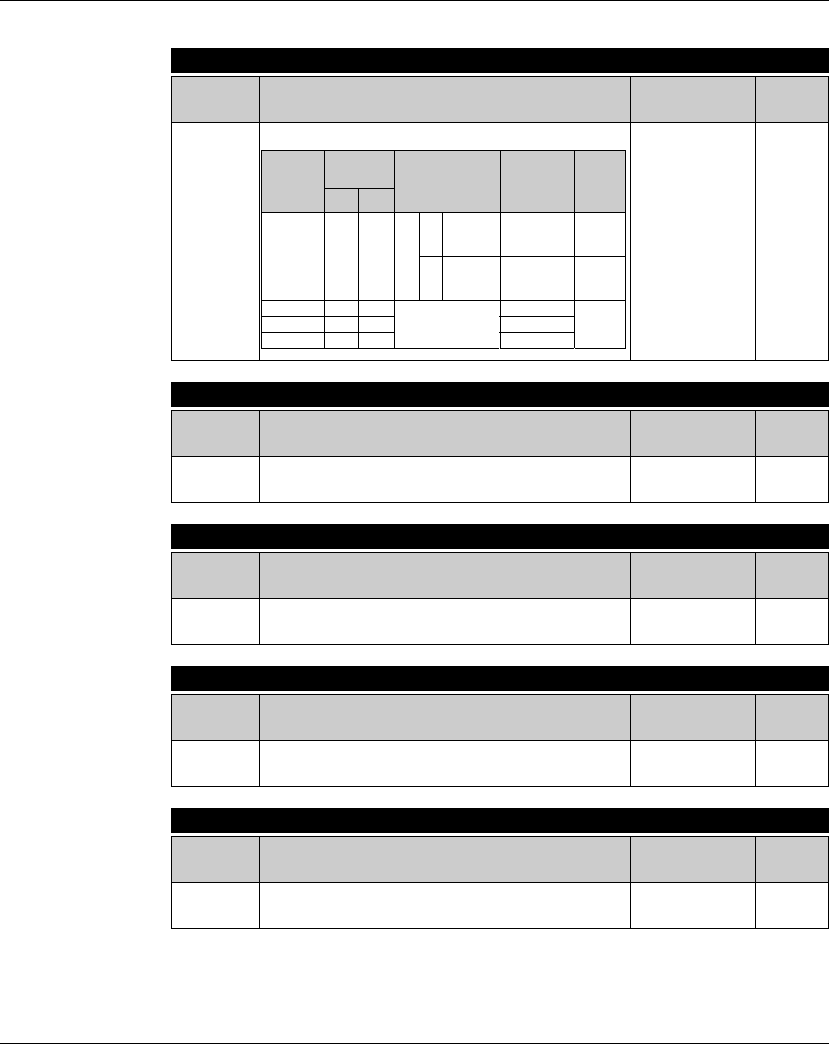
11. Servo Parameters Lexium 23A
432 AC servo drive
Setting value: 0x16 ~ 0x17
DI Name DI Function Description Trigger Method Control
Mode
TCM0
TCM1
Torque command selection 0 ~ 1 (Command T1 ~ T4)
Level Triggered T
Setting value: 0x18
DI Name DI Function Description Trigger Method Control
Mode
S-P Speed / Position mode switching.
OFF: Speed mode, ON: Position mode Level Triggered P, S
Setting value: 0x19
DI Name DI Function Description Trigger Method Control
Mode
S-T Speed / Torque mode switching.
OFF: Speed mode, ON: Torque mode Level Triggered S, T
Setting value: 0x20
DI Name DI Function Description Trigger Method Control
Mode
T-P Torque / Position mode switching.
OFF: Torque mode, ON: Position mode Level Triggered P, T
Setting value: 0x2B
DI Name DI Function Description Trigger Method Control
Mode
Pt-Pr Internal position (Pr) and external pulse (Pt) mode
switching. OFF: Pt, ON: Pr Level Triggered Pt, Pr
Command
No.
DI signal of
CN1 Command Source Content Range
TCM1 TCM0
T1 OFF OFF
Mode
TAnalog
command
Voltage
between V-
REF and GND
+/-10 V
Tz None
Torque
command
is 0
0
T2 OFF ON
Internal parameter
P1-12 -300 ~
+300 %
T3 ON OFF P1-13
T4 ON ON P1-14

Lexium 23A 11. Servo Parameters
AC servo drive 433
Setting value: 0x21
DI Name DI Function Description Trigger Method Control
Mode
OPST Operational stop. It should be contact "b" and
normally ON or a fault (AL013) will display. Level Triggered All
Setting value: 0x22
DI Name DI Function Description Trigger Method Control
Mode
NL(CWL) Reverse inhibit limit. It should be contact "b" and
normally ON or a fault (AL014) will display. Level Triggered All
Setting value: 0x23
DI Name DI Function Description Trigger Method Control
Mode
PL(CCWL) Forward inhibit limit. It should be contact "b" and
normally ON or a fault (AL015) will display. Level Triggered All
Setting value: 0x24
DI Name DI Function Description Trigger Method Control
Mode
ORGP
Reference "Home" sensor. When ORGP is activated,
the drive will command the motor to start to search
the reference "Home" sensor. [see P5-04]
Rising-edge/
Falling-edge
Triggered
Pr
Setting value: 0x25
DI Name DI Function Description Trigger Method Control
Mode
TLLM Torque limit - Reverse operation (Torque limit
function is valid only when P1-02 is enabled) Level Triggered Pt, Pr, S
Setting value: 0x26
DI Name DI Function Description Trigger Method Control
Mode
TRLM Torque limit - Forward operation (Torque limit
function is valid only when P1-02 is enabled) Level Triggered Pt, Pr, S
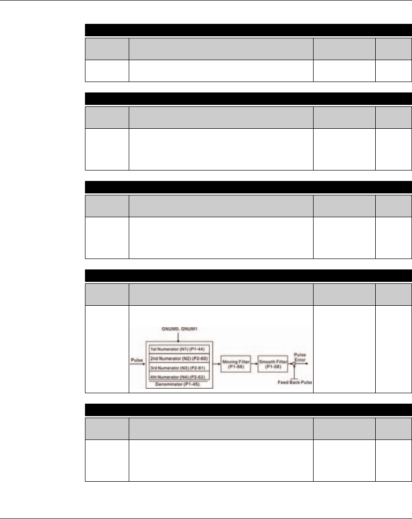
11. Servo Parameters Lexium 23A
434 AC servo drive
Notes:
1)11 ~ 17: Single control mode, 18 ~ 20: Dual control mode
2)When P2-10 to P2-17 is set to 0, it indicates input function is disabled.
Setting value: 0x27
DI Name DI Function Description Trigger Method Control
Mode
SHOM
Move to "Home". When SHOM is activated, the drive will
command the motor to move to "Home". [see P5-04]
Rising-edge
Triggered Pr
Setting value: 0x37
DI Name DI Function Description Trigger Method Control
Mode
JOGU Forward JOG input. When JOGU is activated, the
motor will JOG in forward direction. [see P4-05] Level Triggered
All
modes
except
CAN
Setting value: 0x38
DI Name DI Function Description Trigger Method Control
Mode
JOGD Reverse JOG input. When JOGD is activated, the
motor will JOG in reverse direction. [see P4-05] Level Triggered
All
modes
except
CAN
Setting value: 0x43, 0x44
DI Name DI Function Description Trigger Method Control
Mode
GNUM0
GNUM1
Electronic gear ratio (Numerator) selection 0 ~ 1
[see P2-60 ~ P2-62]
Level Triggered Pt
Setting value: 0x45
DI Name DI Function Description Trigger Method Control
Mode
INHP
Pulse inhibit input. When the drive is in position mode,
if INHP is activated, the external pulse input command
is not valid. (Please use DI8 for INHP signal to ensure
the real-time operation of INHP function.)
Level Triggered Pt

Lexium 23A 11. Servo Parameters
AC servo drive 435
Table 11.B Output Function Definition
Setting value: 0x01
DO Name DO Function Description Trigger Method Control
Mode
SRDY
Servo ready. SRDY is activated when the servo drive
is ready to run. All fault and alarm conditions, if
present, have been cleared.
Level Triggered All
Setting value: 0x02
DO Name DO Function Description Trigger Method Control
Mode
SON
SON is activated when control power is applied the
servo drive. The drive may or may not be ready to
run as a fault / alarm condition may exist.
Servo ON (SON) is "ON" with control power applied
to the servo drive, there may be a fault condition or
not. The servo is not ready to run. Servo ready
(SRDY) is "ON" where the servo is ready to run, NO
fault / alarm exists.
Level Triggered All
Setting value: 0x03
DO Name DO Function Description Trigger Method Control
Mode
ZSPD
ZSPD is activated when the drive senses the motor is
equal to or below the Zero Speed Range setting as
defined in parameter P1-38.
For Example, at factory default ZSPD will be
activated when the drive detects the motor rotating at
speed at or below 10 rpm, ZSPD will remain activated
until the motor speed increases above 10 rpm.
Level Triggered All
Setting value: 0x04
DO Name DO Function Description Trigger Method Control
Mode
TSPD
TSPD is activated once the drive has detected the
motor has reached the Target Rotation Speed
setting as defined in parameter P1-39. TSPD will
remain activated until the motor speed drops below
the Target Rotation Speed.
Level Triggered All
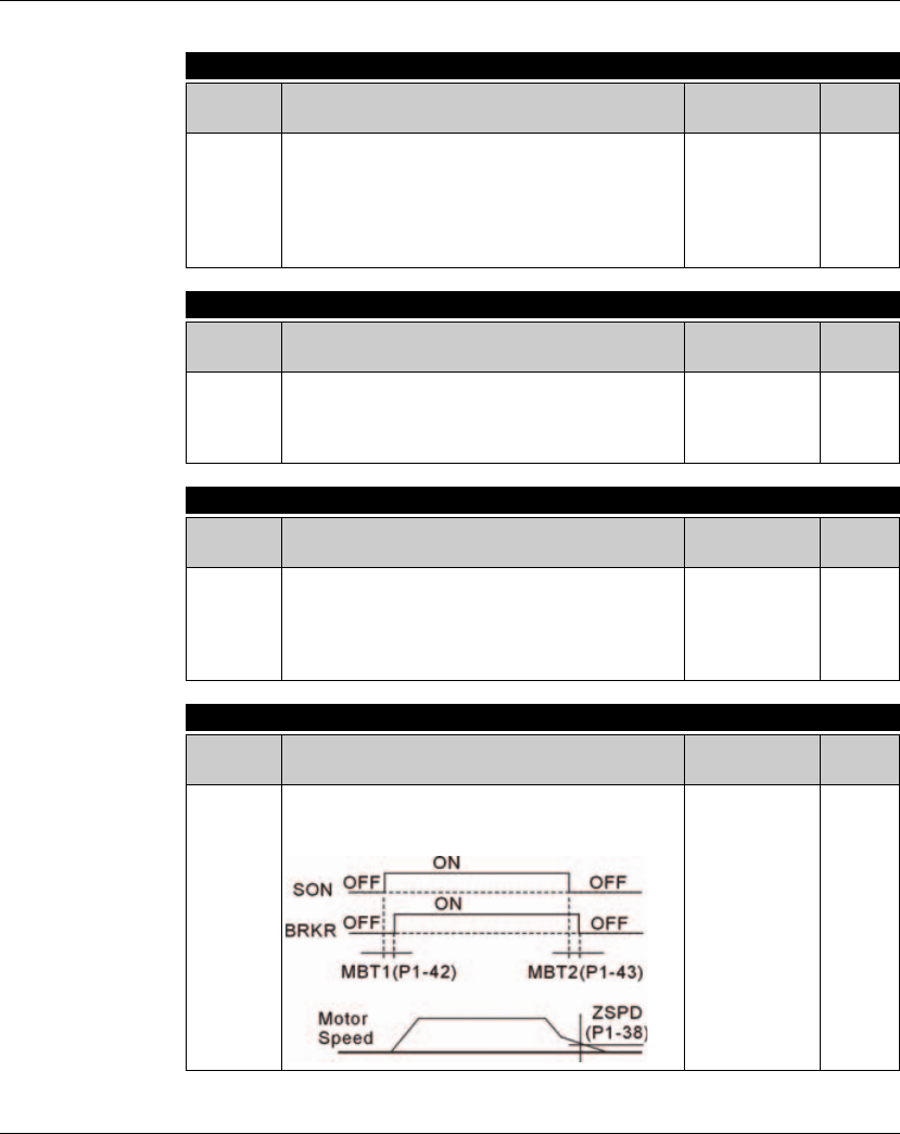
11. Servo Parameters Lexium 23A
436 AC servo drive
Setting value: 0x05
DO Name DO Function Description Trigger Method Control
Mode
TPOS
1.When the drive is in Pt mode, TPOS will be
activated when the position error is equal and below
the setting value of P1-54.
2.When the drive is in Pr mode, TPOS will be activated
when the drive detects that the position of the motor is
in a -P1-54 to +P1-54 band of the target position.
Level Triggered Pt, Pr
Setting value: 0x06
DO Name DO Function Description Trigger Method Control
Mode
TQL
TQL is activated when the drive has detected that
the motor has reached the torques limits set by
either the parameters P1-12 ~ P1-14 of via an external
analog voltage.
Level Triggered
All,
except
T, Tz
Setting value: 0x07
DO Name DO Function Description Trigger Method Control
Mode
ALRM
ALRM is activated when the drive has detected a
fault condition. (However, when Reverse limit error,
Forward limit error, Emergency stop, Serial
communication error, and Undervoltage these fault
occur, WARN is activated first.)
Level Triggered All
Setting value: 0x08
DO Name DO Function Description Trigger Method Control
Mode
BRKR
Electromagnetic brake control. BRKR is activated
(Actuation of motor brake). (Please refer to
parameters P1-42 ~ P1-43)
Level Triggered All

Lexium 23A 11. Servo Parameters
AC servo drive 437
Setting value: 0x09
DO Name DO Function Description Trigger Method Control
Mode
HOME
Homing completed. HOME is activated when the servo
drive has detected that the "HOME" sensor (ORGP,
digital input 0x24) has been detected.
When power to the servo drive at the first time, this DO
signal is OFF. After homing operation is completed, thi
DO signal will be ON and continue being ON when the
motor is running. It becomes OFF until the sytem
detect that a position overflow occurs.
When using Pr command to trigger homing command,
this DI signal will be OFF immediately. After homeing
operation is completed, it becomes ON again.
Level Triggered Pr
Setting value: 0x10
DO Name DO Function Description Trigger Method Control
Mode
OLW
Output overload warning. OLW is activated when the
servo drive has detected that the motor has reached
the output overload time set by parameter P1-56.
tOL = Permissible Time for Overload x setting value
of P1-56
When overload accumulated time (continuously
overload time) exceeds the value of tOL, the
overload warning signal will output, i.e. DO signal,
OLW will be ON. However, if the accumulated
overload time (continuous overload time) exceeds
the permissible time for overload, the overload
alarm (AL006) will occur.
For example:
If the setting value of parameter P1-56 (Output
Overload Warning Time) is 60%, when the
permissible time for overload exceeds 8 seconds at
200% rated output, the overload fault (AL006) will
be detected and shown on the LED display.
At this time, tOL = 8 x 60% = 4.8 seconds
Result:
When the drive output is at 200% rated output and
the drive is continuously overloaded for 4.8
seconds, the overload warning signal will be ON (DO
code is 0x10, i.e. DO signal OLW will be activated). If
the drive is continuously overloaded for 8 seconds,
the overload alarm will be detected and shown on
the LED display (AL006). Then, Servo Fault signal
will be ON (DO signal ALRM will be activated).
Level Triggered Pr

11. Servo Parameters Lexium 23A
438 AC servo drive
Setting value: 0x11
DO Name DO Function Description Trigger Method Control
Mode
WARN
Servo warning activated. WARN is activated when
the drive has detected Reverse limit error. Forward
limit error, Operational stop, Serial communication
error, and Undervoltage these fault conditions.
Level Triggered All
Setting value: 0x12
DO Name DO Function Description Trigger Method Control
Mode
OVF
Position command overflow. OVF is activated when
the servo drive has detected that a position
command overflows.
Level Triggered All
Setting value: 0x13
DO Name DO Function Description Trigger Method Control
Mode
SNL
(SCWL)
Reverse software limit. SNL is activated when the
servo drive has detected that reverse software limit
is reached.
Level Triggered All
Setting value: 0x14
DO Name DO Function Description Trigger Method Control
Mode
SPL
(SCCWL)
Forward software limit. SPL is activated when the
servo drive has detected that forward software limit
is reached.
Level Triggered All
Setting value: 0x15
DO Name DO Function Description Trigger Method Control
Mode
CMD_OK
Internal position command completed output.
CMD_OK is activated when the servo drive has
detected that the internal position command has
been completed.
When excuting Pr command, this DI signal is OFF.
After the execution of Pr command is completed,
this DI signal is ON.
The output is used to indicate the internal position
command has been completed and it does not
indicate that the motor positioning is completed.
For the signal of motor positioning completed,
please refer to DO signal, TPOS.
Level Triggered Pr

Lexium 23A 11. Servo Parameters
AC servo drive 439
Setting value: 0x16
DO Name DO Function Description Trigger Method Control
Mode
CAP_OK
Capture operation completed output. CAP_OK is
activated when the servo drive has detected that
capture operation has been completed.
Level Triggered Pr
Setting value: 0x17
DO Name DO Function Description Trigger Method Control
Mode
MC_OK
Motion control completed output. MC_OK is
activated when CMD_OK and TPOS are both ON. It
indicates MC_OK is activated only when the servo
drive has detected that the position command has
been given and the positioning has been completed
also. If only CMD_OK or TPOS is ON, MC_OK will not
be activated.
Level Triggered Pr
Setting value: 0x19
DO Name DO Function Description Trigger Method Control
Mode
SP_OK
Speed reached output. SP_OK will be activated
when the speed error is equal and below the setting
value of P1-47.
Level Triggered S, Sz
Setting value: 0x30
DO Name DO Function Description Trigger Method Control
Mode
SDO_0 Output the status of bit00 of P4-06. Level Triggered All
Setting value: 0x31
DO Name DO Function Description Trigger Method Control
Mode
SDO_1 Output the status of bit01 of P4-06. Level Triggered All
Setting value: 0x32
DO Name DO Function Description Trigger Method Control
Mode
SDO_2 Output the status of bit02 of P4-06. Level Triggered All

11. Servo Parameters Lexium 23A
440 AC servo drive
Setting value: 0x33
DO Name DO Function Description Trigger Method Control
Mode
SDO_3 Output the status of bit03 of P4-06. Level Triggered All
Setting value: 0x34
DO Name DO Function Description Trigger Method Control
Mode
SDO_4 Output the status of bit04 of P4-06. Level Triggered All
Setting value: 0x35
DO Name DO Function Description Trigger Method Control
Mode
SDO_5 Output the status of bit05 of P4-06. Level Triggered All
Setting value: 0x36
DO Name DO Function Description Trigger Method Control
Mode
SDO_6 Output the status of bit06 of P4-06. Level Triggered All
Setting value: 0x37
DO Name DO Function Description Trigger Method Control
Mode
SDO_7 Output the status of bit07 of P4-06. Level Triggered All
Setting value: 0x38
DO Name DO Function Description Trigger Method Control
Mode
SDO_8 Output the status of bit08 of P4-06. Level Triggered All
Setting value: 0x39
DO Name DO Function Description Trigger Method Control
Mode
SDO_9 Output the status of bit09 of P4-06. Level Triggered All
Setting value: 0x3A
DO Name DO Function Description Trigger Method Control
Mode
SDO_A Output the status of bit10 of P4-06. Level Triggered All
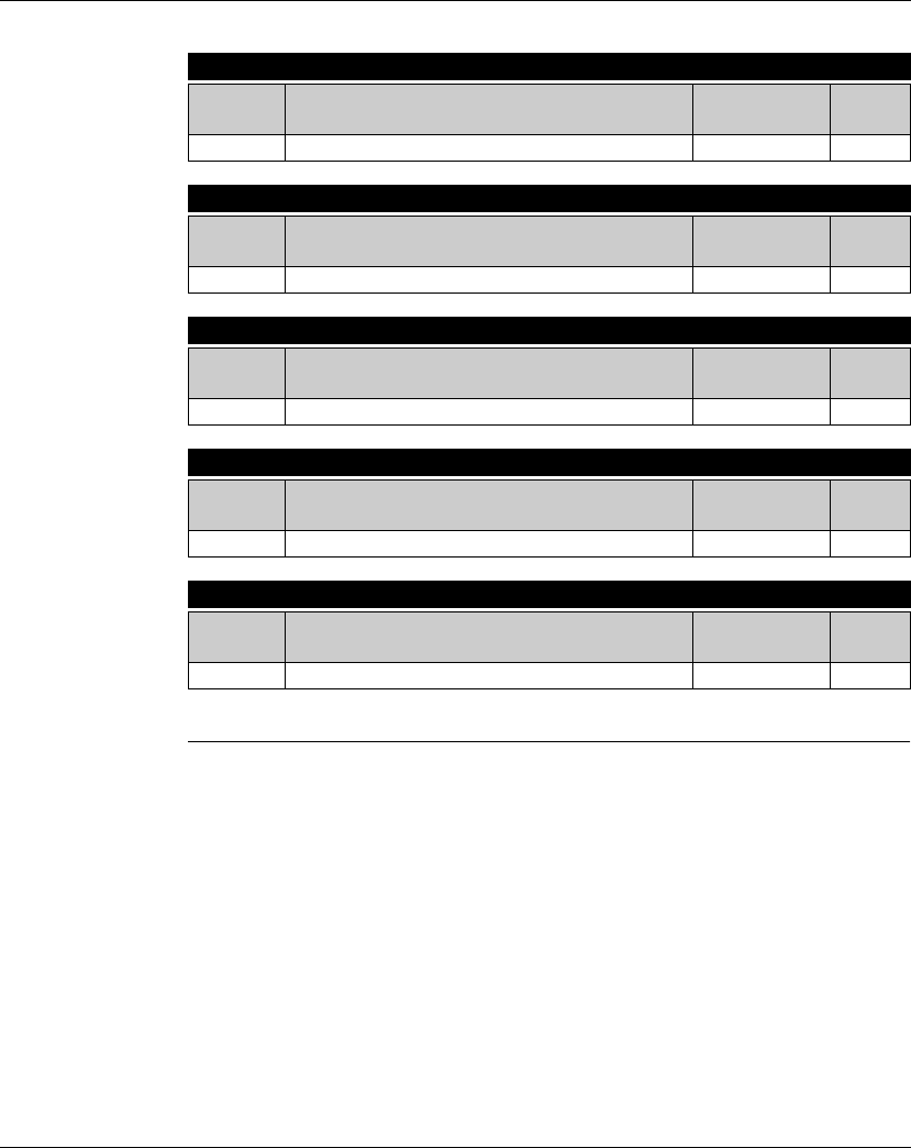
Lexium 23A 11. Servo Parameters
AC servo drive 441
Notes:
1)When P2-18 to P2-22 is set to 0, it indicates output function is disabled.
Setting value: 0x3B
DO Name DO Function Description Trigger Method Control
Mode
SDO_B Output the status of bit11 of P4-06. Level Triggered All
Setting value: 0x3C
DO Name DO Function Description Trigger Method Control
Mode
SDO_C Output the status of bit12 of P4-06. Level Triggered All
Setting value: 0x3D
DO Name DO Function Description Trigger Method Control
Mode
SDO_D Output the status of bit13 of P4-06. Level Triggered All
Setting value: 0x3E
DO Name DO Function Description Trigger Method Control
Mode
SDO_E Output the status of bit14 of P4-06. Level Triggered All
Setting value: 0x3F
DO Name DO Function Description Trigger Method Control
Mode
SDO_F Output the status of bit15 of P4-06. Level Triggered All

11. Servo Parameters Lexium 23A
442 AC servo drive

AC servo drive 443
12
Accessories and spare parts
At a Glance
What's in this
Chapter? This chapter contains the following topics:
Topic Page
Connector and cable 444
Power Connectors 448
I/O Signal Connector (CN1) 449
I/O Terminal Block Module 449
USB to RJ45 connector for CN3 interface 449
Other Accessories 450
CANopen cable with connectors 450
CANopen connectors, distributors, terminating resistors 451
CANopen cables 452
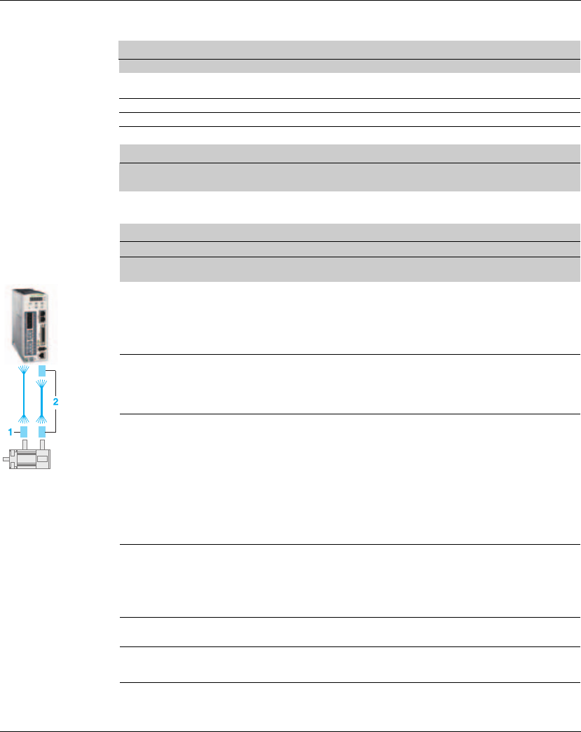
12. Accessories and spare parts Lexium 23A
444 AC servo drive
Connector and
cable
Connector
Name Description Reference
Replacement connector set Power connector set,drive side
(power supply, motor, CN5)
VW3M4121
I/O connector I/O connector of CN1 interface VW3M4112
I/O terminal block module Terminal block module,with 0.5 m cable VW3M4113
Interface adapter USB to RJ45(RS232) converter for CN3 interface VW3M8131
Cable
Name Description Length Reference
m
standard network cable RJ45 connector on both ends 2 490NTW00002
This cable can be used with the converter VW3M8131 to connect it with CN3 interface.
Connection accessory
Connector for power cable
Description For Item
no.
Reference
For motor with flying cable,no
brake
BCH0401Op2A1C 1 VW3M5111
BCH0601Op2A1C
BCH0602Op2A1C
BCH0801Op2A1C
BCH0802Op2A1C
For motor with flying
cable,with brake
BCH0601Op2F1C 1 VW3M5112
BCH0602Op2F1C
BCH0801Op2F1C
BCH0802Op2F1C
Military connector BCH1001Op2p1C 1 VW3M5121
BCH1301Mp2p1C
BCH1301Np2p1C
BCH1302Mp2p1C
BCH1302Np2p1C
BCH1303Mp2p1C
BCH1303Np2p1C
BCH1002Op2p1C
BCH1304Np2p1C
Military connector BCH1801Np2p1C 1 VW3M5131
BCH1802Np2p1C
BCH1802Mp2p1C
BCH1803Np2p1C
BCH1803Mp2p1C
Military connector BCH1804Mp2p1C
BCH1805Mp2p1C
1VW3M5141
Brake connector BCH1804Mp2F1C
BCH1805Mp2F1C
1VW3M7151

Lexium 23A 12. Accessories and spare parts
AC servo drive 445
Connection accessory (continue)
Connector for encoder cable
Description For Item
no.
Reference
For motor with flying cable BCH0401Op2p1C 2 VW3M8121
BCH0601Op2p1C
BCH0602Op2p1C
BCH0801Op2p1C
BCH0802Op2p1C
For motor with military
connector
BCH1001Op2p1C 2 VW3M8122
BCH1301Mp2p1C
BCH1301Np2p1C
BCH1302Mp2p1C
BCH1302Np2p1C
BCH1303Mp2p1C
BCH1303Np2p1C
BCH1002Op2p1C
BCH1304Np2p1C
BCH1801Np2p1C
BCH1802Np2p1C
BCH1802Mp2p1C
BCH1803Np2p1C
BCH1803Mp2p1C
BCH1804Mp2p1C
BCH1805Mp2p1C
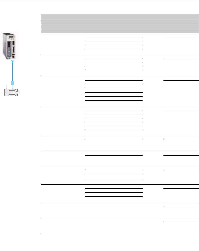
12. Accessories and spare parts Lexium 23A
446 AC servo drive
Connection accessory (continue)
Power cable
Description From servo motor To servo drive
Composition Length
Reference
m
Servo motor side with plastic
connector
Drive side with flying lead,no
brake
BCH0401Op2A1C LXM23pU01M3X 4 X0.82 mm23VW3M5111R30
BCH0601Op2A1C LXM23pU02M3X 5 VW3M5111R50
BCH0602Op2A1C LXM23pU04M3X
BCH0801Op2A1C LXM23pU04M3X
BCH0802Op2A1C LXM23pU07M3X
Servo motor side with plastic
connector
Drive side with flying
lead,with brake
BCH0401Op2F1C LXM23pU01M3X 6 x 0.82
mm2
3VW3M5112R30
BCH0601Op2F1C LXM23pU02M3X 5 VW3M5112R50
BCH0602Op2F1C LXM23pU04M3X
BCH0801Op2F1C LXM23pU04M3X
BCH0802Op2F1C LXM23pU07M3X
Servo motor side with
military connector
Drive side with flying lead,no
brake
BCH1001Op2A1C LXM23pU10M3X 4 x 1.3 mm23VW3M5121R30
BCH1301Mp2A1C LXM23pU04M3X 5 VW3M5121R50
BCH1301Np2A1C LXM23pU04M3X
BCH1302Mp2A1C LXM23pU07M3X
BCH1302Np2A1C LXM23pU10M3X
BCH1303Mp2A1C LXM23pU10M3X
BCH1303Np2A1C LXM23pU15M3X
Servo motor side with
military connector
Drive side with flying
lead,with brake
BCH1001Op2F1C LXM23pU10M3X 6 x 1.3 mm23VW3M5131R30
BCH1301Mp2F1C LXM23pU04M3X 5 VW3M5131R50
BCH1301Np2F1C LXM23pU04M3X
BCH1302Mp2F1C LXM23pU07M3X
BCH1302Np2F1C LXM23pU10M3X
BCH1303Mp2F1C LXM23pU10M3X
BCH1303Np2F1C LXM23pU15M3X
Servo motor side with
military connector
Drive side with flying lead,no
brake
BCH1002Op2A1C LXM23pU20M3X 4 x 2.1 mm23VW3M5122R30
BCH1304Np2A1C LXM23pU20M3X 5 VW3M5122R50
Servo motor side with
military connector
Drive side with flying
lead,with brake
BCH1002Op2F1C LXM23pU20M3X 6 x 2.1 mm23VW3M5132R30
BCH1304Np2F1C LXM23pU20M3X 5 VW3M5132R50
Servo motor side with
military connector
Drive side with flying lead,no
brake
BCH1801Np2A1C LXM23pU20M3X 4 x 3.3 mm23VW3M5123R30
BCH1802Np2A1C LXM23pU30M3X 5 VW3M5123R50
BCH1802Mp2A1C LXM23pU30M3X
BCH1803Np2A1C LXM23pU45M3X
Servo motor side with
military connector
Drive side with flying
lead,with brake
BCH1801Np2F1C LXM23pU20M3X 6 x 3.3 mm23VW3M5133R30
BCH1802Np2F1C LXM23pU30M3X 5 VW3M5133R50
BCH1802Mp2F1C LXM23pU30M3X
BCH1803Np2F1C LXM23pU45M3X
Servo motor side with
military connector
Drive side with flying lead,no
brake
BCH1803Mp2A1C LXM23pU45M3X 4 x 8.4 mm23VW3M5124R30
5VW3M5124R50
Servo motor side with
military connector
Drive side with flying
lead,with brake
BCH1803Mp2F1C LXM23pU45M3X 6x 8.4 mm23VW3M5134R30
5VW3M5134R50
VW3M5 111/121/131
112/122/132/133/124 Rppp
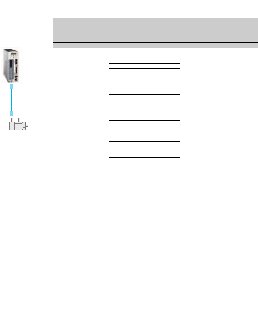
Lexium 23A 12. Accessories and spare parts
AC servo drive 447
(1) without battery box
(2) with battery box, using for absolute position control
Connection accessory (continue)
Encoder cable
Description From servo
motor
To servo drive Composition Length Reference
m
Servo motor side and drive
side with plastic connector
BCH0401Op2p1C LXM23pU01M3X 10X0.13 mm23 VW3M8121R30 (1)
5 VW3M8121R50 (1)
3 VW3M8123R30 (2)
5 VW3M8123R50 (2)
BCH0601Op2p1C LXM23pU02M3X
BCH0602Op2p1C LXM23pU04M3X
BCH0801Op2p1C LXM23pU04M3X
BCH0802Op2p1C LXM23pU07M3X
Servo motor side with
military connector
Drive side with plastic
connector
BCH1001Op2p1C LXM23pU10M3X 10x0.13 mm2
BCH1301Mp2p1C LXM23pU04M3X
BCH1301Np2p1C LXM23pU04M3X
BCH1302Mp2p1C LXM23pU07M3X
BCH1302Np2p1C LXM23pU10M3X
BCH1303Mp2p1C LXM23pU10M3X 3
VW3M8122R30
(1)
BCH1303Np2p1C LXM23pU15M3X 5
VW3M8122R50
(1)
BCH1002Op2p1C LXM23pU20M3X
BCH1304Np2p1C LXM23pU20M3X
BCH1801Np2p1C LXM23pU20M3X 3
VW3M8124R30
(2)
BCH1802Np2p1C LXM23pU30M3X 5
VW3M8124R50
(2)
BCH1802Mp2p1C LXM23pU30M3X
BCH1803Np2p1C LXM23pU45M3X
BCH1803Mp2p1C LXM23pU45M3X
BCH1804Mp2p1C LXM23pU55M3X
BCH1805Mp2p1C LXM23pU75M3X
VW3M8 121/122/123/
124 Rppp
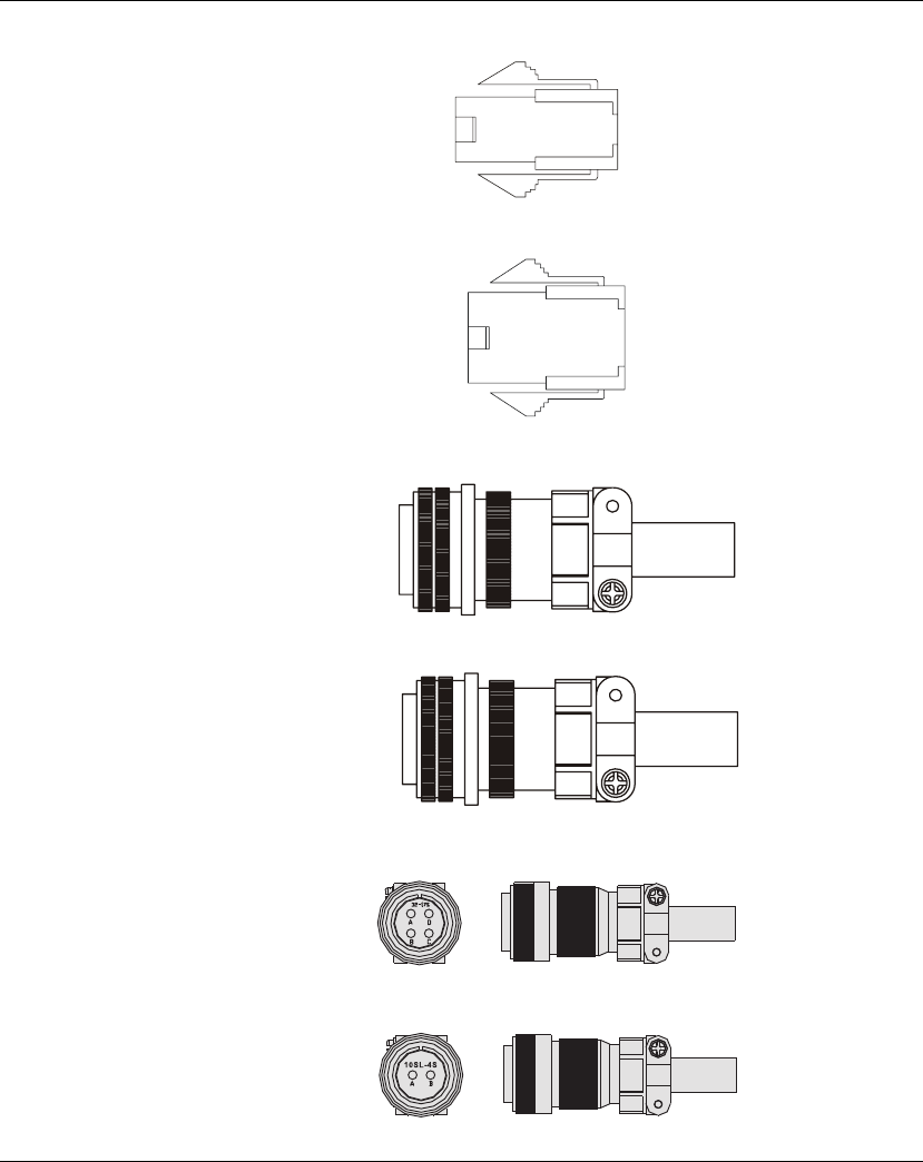
12. Accessories and spare parts Lexium 23A
448 AC servo drive
Power
Connectors
Connectors for power cables, motors without brake: VW3M5111
Connectors for power cables, motors with brake: VW3M5112
Military connector for power cables, motors without brake: VW3M5121
Military connector for power cables, motors with brake: VW3M5131
Military type power connector no brake: VW3M5141
(for BCH motors 5.5kW and 7.5KW)
Motor brake connector :VW3M7151
(for BCH motors 5.5kW and 7.5KW)
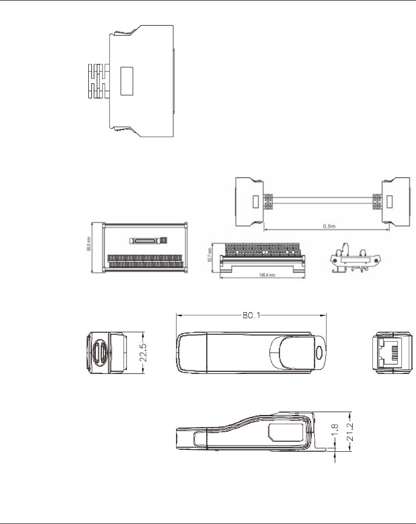
Lexium 23A 12. Accessories and spare parts
AC servo drive 449
I/O Signal
Connector (CN1)
Commercial reference: VW3M4112
I/O Terminal Block
Module
Commercial reference: VW3M4113
USB to RJ45
connector for CN3
interface
Commercial reference: VW3M8131

12. Accessories and spare parts Lexium 23A
450 AC servo drive
Other
Accessories
CANopen cable
with connectors
Other Accessories (for Lexium23 Plus series, all models)
Description Commercial reference
50Pin I/O signal connector (CN1) VW3M4112
I/O Terminal Block Module with 0.5m cable VW3M4113
USB to RJ45 (RS-232) connector for CN3 VW3M8131
Communication Cable between Drive and Computer
(RJ45 plugs) 490NTW00002
Regenerative Resistor 400W 40ΩVW3M7111
Regenerative Resistor 1kW 20ΩVW3M7112
Bag of power connectors
(plugs for power supply, motor, CN5) VW3M4121
Description Order no.
CANopen cable, 0.3 m, 2 x RJ45 VW3CANCARR03
CANopen cable, 1 m, 2 x RJ45 VW3CANCARR1
2 m, 2 x RJ45, shielded twisted pair cable 490NTW00002
5 m, 2 x RJ45, shielded twisted pair cable 490NTW00005
12 m, 2 x RJ45, shielded twisted pair cable 490NTW00012
2 m, 2 x RJ45, shielded twisted pair cable with UL and
CSA 22.1 certification 490NTW00002U
5 m, 2 x RJ45, shielded twisted pair cable with UL and
CSA 22.1 certification 490NTW00005U
12 m, 2 x RJ45, shielded twisted pair cable with UL and
CSA 22.1 certification 490NTW00012U
CANopen cable, 1 m, D9-SUB (female) to RJ45 TCSCCN4F3M1T
CANopen cable, 1 m, D9-SUB (female) with
integrated terminating resistor to RJ45 VW3M3805R010
CANopen cable, 3 m, D9-SUB (female) with
integrated terminating resistor to RJ45 VW3M3805R030
CANopen cable, 0.3 m, 2 x D9-SUB (female), LSZH
standard cable (low-smoke, zero halogen, flame-
retardant, tested as per IEC 60332-1)
TSXCANCADD03
CANopen cable, 1 m, 2 x D9-SUB (female), LSZH
standard cable (low-smoke, zero halogen, flame-
retardant, tested as per IEC 60332-1)
TSXCANCADD1

Lexium 23A 12. Accessories and spare parts
AC servo drive 451
CANopen
connectors,
distributors,
terminating
resistors
Description Order no.
CANopen cable, 3 m, 2 x D9-SUB (female), LSZH
standard cable (low-smoke, zero halogen, flame-
retardant, tested as per IEC 60332-1)
TSXCANCADD3
CANopen cable, 5 m, 2 x D9-SUB (female), LSZH
standard cable (low-smoke, zero halogen, flame-
retardant, tested as per IEC 60332-1)
TSXCANCADD5
CANopen cable, 0.3 m, 2 x D9-SUB (female), flame-
retardant, tested as per IEC 60332-2, UL certification TSXCANCBDD03
CANopen cable, 1 m, 2 x D9-SUB (female), flame-
retardant, tested as per IEC 60332-2, UL cer-
tification
TSXCANCBDD1
CANopen cable, 3 m, 2 x D9-SUB (female), flame-
retardant, tested as per IEC 60332-2, UL cer-
tification
TSXCANCBDD3
CANopen cable, 5 m, 2 x D9-SUB (female), flame-
retardant, tested as per IEC 60332-2, UL cer-
tification
TSXCANCBDD5
Description Order no.
CANopen terminating resistor, 120 Ohm, integrated
in RJ45 connector TCSCAR013M120
CANopen connector with PC interface, D9-SUB
(female), with switchable terminating resistor and
additional D9-SUB (male) to connect a PC to the bus,
PC interface straight, bus cable angled 90°
TSXCANKCDF90TP
CANopen connector, D9-SUB (female), with
switchable terminating resistor, angled 90°TSXCANKCDF90T
CANopen connector, D9-SUB (female), with
switchable terminating resistor, straight TSXCANKCDF180T
Four-port tap, for connection of 4 drop lines to trunk
line, 4 x D9-SUB (male) with switchable ter-minating
resistor
TSXCANTDM4
Two-port tap for connection of 2 drop lines to trunk
line, with additional commissioning interface, 3 x
RJ45 (female), with switchable terminating resistor
VW3CANTAP2

12. Accessories and spare parts Lexium 23A
452 AC servo drive
CANopen cables
Cables with open cable ends are suitable for connection of D-SUB con-nectors.
Observe the cable cross section and the connection cross sec-tion of the required
connector.
Description Order no.
CANopen cable, 50 m, [(2 x AWG 22) + (2 x AWG 24)],
LSZH standard cable (low-smoke, zero halogen,
flame-retardant, tested as per IEC 60332-1), both
cable ends open
TSXCANCA50
CANopen cable, 100 m, [(2 x AWG 22) + (2 x AWG 24)],
LSZH standard cable (low-smoke, zero halogen,
flame-retardant, tested as per IEC 60332-1), both
cable ends open
TSXCANCA100
CANopen cable, 300 m, [(2 x AWG 22) + (2 x AWG
24)], LSZH standard cable (low-smoke, zero halogen,
flame-retardant, tested as per IEC 60332-1), both
cable ends open
TSXCANCA300
CANopen cable, 50 m, [(2 x AWG 22) + (2 x AWG 24)],
flame-retardant, tested as per IEC 60332-2, UL
certification, both cable ends open
TSXCANCB50
CANopen cable, 100 m, [(2 x AWG 22) + (2 x AWG 24)],
flame-retardant, tested as per IEC 60332-2, UL
certification, both cable ends open
TSXCANCB100
CANopen cable, 300 m, [(2 x AWG 22) + (2 x AWG
24)], flame-retardant, tested as per IEC 60332-2, UL
certification, both cable ends open
TSXCANCB300
CANopen cable, 50 m, [(2 x AWG 22) + (2 x AWG 24)],
flexible LSZH HD standard cable (low-smoke, zero
halogen, flame-retardant, tested as per IEC 60332-
1), for heavy-duty or flexible installation, oil-resistant,
both cable ends open
TSXCANCD50
CANopen cable, 100 m, [(2 x AWG 22) + (2 x AWG 24)],
flexible LSZH HD standard cable (low-smoke, zero
halogen, flame-retardant, tested as per IEC 60332-
1), for heavy-duty or flexible installation, oil-resistant,
both cable ends open
TSXCANCD100
CANopen cable, 300 m, [(2 x AWG 22) + (2 x AWG
24)], flexible LSZH HD standard cable (low-smoke,
zero halogen, flame-retardant, tested as per IEC
60332-1), for heavy-duty or flexible installation, oil-
resistant, both cable ends open
TSXCANCD300

AC servo drive 453
13
Service, maintenance and disposal
At a Glance
The product may only be repaired by a Schneider Electric customer service center. No
warranty or liability is accepted for repairs made by unauthorized persons.
What's in this
Chapter?
This chapter contains the following topics:
Topic Page
Service address 454
Basic Inspection 455
Maintenance 456
Life of Replacement Components 456
Replacing devices 457
Changing the motor 458
Shipping, storage, disposal 458

13. Service, maintenance and disposal Lexium 23A
454 AC servo drive
13.1 Service address
If you cannot resolve an error yourself please contact your sales office.
Have the following details available:
z Nameplate (type, identification number, serial number, DOM, ...)
z Type of error (such as LED flash code or error number)
z Previous and concomitant circumstances
z Your own assumptions concerning the cause of the error
Also include this information if you return the product for inspection or repair.
If you have any questions please contact your sales office.
Your sales office staff will be happy to give you the name of a customer service office
in your area.
http://www.schneider-electric.com

Lexium 23A 13. Service, maintenance and disposal
AC servo drive 455
13.2 Basic Inspection
After power is in connected to the AC servo drive, the charge LED will be lit which indicates
that the AC servo drive is ready.
Item Content
General Inspection
zPeriodically inspect the screws of the servo drive, motor shaft, terminal
block and the connection to mechanical system. Tighten screws as
necessary as they may loosen due to vibration and varying temperatures.
zEnsure that oil, water, metallic particles or any foreign objects do not fall
inside the servo drive, motor, control panel or ventilation slots and holes.
As these will cause damage.
zEnsure the correct installation and the control panel. It should be free from
airborne dust, harmful gases or liquids.
zEnsure that all wiring instructions and recommendations are followed;
otherwise damage to the drive and or motor may result.
Inspection during
operation
(Control power is
applied)
zInspect the servo drive and servo motor to insure they were not damaged.
zTo avoid an electric shock, be sure to connect the ground terminal of servo
drive to the ground terminal of control panel.
zBefore making any connection, wait 10 minutes for capacitors to discharge
after the power is disconnected, alternatively, use an appropriate
discharge device to discharge.
zEnsure that all wiring terminals are correctly insulated.
zEnsure that all wiring is correct or damage and or malfunction may result.
zVisually check to ensure that there are not any unused screws, metal strips,
or any conductive or inflammable materials inside the drive.
zNever put inflammable objects on servo drive or close to the external
regenerative resistor.
zMake sure control switch is OFF.
zIf the electromagnetic brake is being used, ensure that it is correctly wired.
zIf required, use an appropriate electrical filter to eliminate noise to the
servo drive.
zEnsure that the external applied voltage to the drive is correct and
matched to the controller.
Inspection during
operation
(Control power is
applied)
zEnsure that the cables are not damaged, stressed excessively or loaded
heavily. When the motor is running, pay close attention on the connection
of the cables and notice that if they are damaged, frayed or over extended.
zCheck for abnormal vibrations and sounds during operation. If the servo
motor is vibrating or there are unusual noises while the motor is running,
please contact the dealer or manufacturer for assistance.
zEnsure that all user-defined parameters are set correctly. Since the
characteristics of various machines are different, in order to avoid
accident or cause damage, do not adjust the parameter abnormally and
ensure the parameter setting is not an excessive value.
zEnsure to reset some parameters when the servo drive is off (Please refer
to Chapter 10 of the user manual). Otherwise, it may result in malfunction.
zIf there is no contact sound or there be any unusual noises when the
relay of the servo drive is operating, please contact your distributor for
assistance or contact with Schneider Electric.
zCheck for abnormal conditions of the power indicators and LED
display. If there is any abnormal condition of the power indicators and
LED display, please contact your distributor for assistance or contact
with Lexium 23 Plus.

13. Service, maintenance and disposal Lexium 23A
456 AC servo drive
13.3 Maintenance
z Use and store the product in a proper and normal environment.
zPeriodically clean the surface and panel of servo drive and motor.
zMake sure the conductors or insulators are corroded and/or damaged.
zDo not disassemble or damage any mechanical part when performing
maintenance.
zClean off any dust and dirt with a vacuum cleaner. Place special emphasis on
cleaning the ventilation ports and PCBs. Always keep these areas clean, as
accumulation of dust and dirt can cause unforeseen failures.
13.4 Life of Replacement Components
z Smooth capacitor
The characteristics of smooth capacitor would be deteriorated by ripple current
affection. The life of smooth capacitor varies according to ambient temperature
and operating conditions. The common guaranteed life of smooth capacitor is ten
years when it is properly used in normal air-conditioned environment.
zRelay
The contacts will wear and result in malfunction due to switching current. The life of
relay varies according to power supply capacity. Therefore, the common
guaranteed life of relay is cumulative 100,000 times of power on and power off.
zCooling fan
The cooling fan life is limited and should be changed periodically. The cooling fan
will reach the end of its life in 2~3 years when it is in continuous operation. However,
it also must be replaced if the cooling fan is vibrating or there are unusual noises.
Lexium 23A 13. Service, maintenance and disposal
AC servo drive 457
13.5 Replacing devices
Prepare a list with the parameters required for the functions used.
Observe the following procedure when replacing devices.
zSave all parameter settings. To do so, save the data to a PC using the commissioning
software, see chapter 6.4 "Commissioning software".
zSwitch off all supply voltages. Verify that no voltages are present (safety instructions).
zLabel all connections and uninstall the product.
zNote the identification number and the serial number shown on the product nameplate
for later identification.
zInstall the new product as per chapter 5 "Installation".
zIf the product to be installed has previously been used in a different system or application,
you must restore the factory settings before commissioning the product.
zCommission the product as per chapter 6 "Commissioning". After the replacement, the
same mechanical position of the motor does not mean that the power stage has the
same position.
UNINTENDED BEHAVIOR
The behavior of the drive system is governed by numerous stored data or settings.
Unsuitable settings or data may trigger unexpected movements or responses to
signals and disable monitoring functions.
zDo NOT operate the drive system with unknown settings or data.
zVerify that the stored data and settings are correct.
zWhen commissioning, carefully run tests for all operating states and
potential error situations.
zVerify the functions after replacing the product and also after making
changes to the settings or data.
zOnly start the system if there are no persons or obstructions in the
hazardous area.
Failure to follow these instructions can result in death, serious injury or
equipment damage.
WARNNG

13. Service, maintenance and disposal Lexium 23A
458 AC servo drive
13.6 Changing the motor
zSwitch off all supply voltages. Verify that no voltages are present (safety instructions).
zLabel all connections and uninstall the product.
zNote the identification number and the serial number shown on the product nameplate
for later identification.
zInstall the new product as per chapter 5 "Installation".
If the connected motor is replaced by another motor, the motor is automatically
recognized by the servo drive.
13.7 Shipping, storage, disposal
Note the ambient conditions on chapter 3.1.
Shipping The product must be protected against shocks during transportation. If possible, use
the original packaging for shipping.
Storage The product may only be stored in spaces where the specified permissible ambient
conditions for room temperature and humidity are met. Protect the product from
dust and dirt.
Disposal The product consists of various materials that can be recycled and must be disposed
of separately. Dispose of the product in accordance with local regulations.
UNEXPECTED MOVEMENT
Drive systems may perform unexpected movements because of incorrect
connection or other errors.
zOperate the device with approved motors only. Even if motors are similar,
different adjustment of the encoder system may be a source of hazards.
zEven if the connectors for power connection and encoder match
mechanically, this does NOT imply that they may be used.
Failure to follow these instructions can result in death, serious injury or
equipment damage.
WARNNG
