135119 Catalog
2014-09-05
: Pdf 135119-Catalog 135119-Catalog 715629 Batch7 unilog
Open the PDF directly: View PDF ![]() .
.
Page Count: 164 [warning: Documents this large are best viewed by clicking the View PDF Link!]

TABLE OF CONTENTS
Connectors & Terminals ...................................................... 3
Terminal Blocks & Barrier Strips ....................................29
Wire Management ..............................................................49
Telecom / Datacom / Coax .............................................65
Identication Solutions .....................................................69
Splices, Taps & Terminations ...........................................83
Tubing & Molded Parts .................................................... 105
Tapes & Sealants ................................................................. 115
Photocontrols, Timers & Switches ................................121
Accessories & Tools .......................................................... 135
Application & Technical Specication ....................... 143
Index ...................................................................................... 159

CONNECTORS & TERMINALS
Crimp Connectors (Solderless)
Ring Terminals 5
Spade Terminals6
Female Disconnects 6
Male Disconnects6
Short Spring Spade Terminals 7
Butt Splices 7
Electrical Maintenance & Repair Kits 8
DuraSeal Heat-Shrink Connectors
Ring Terminals 9
Spade Terminals9
Butt Splices9
Bullet Terminals 10
Pin Terminals10
Male Disconnects10
Female Disconnects 10
SolderGrip Connectors Heat-Activated Solder
Ring Terminals 11
Butt Splices11
Wire Connector Splices 11
Lighting Connectors
LIGHT-N-LOK Ballast Disconnects 12
Poke-In Wire Tap/Splice 13
Compression Connectors
Copper Compression Terminals14
Copper Compression Splices 16
ShearBolt Connectors
Aluminum ShearBolt Connectors 17
Copper ShearBolt Connectors19
Insulation Piercing Connectors
Insulation Displacement Splice Tape Connectors 20
Non-Metallic Cable Splice & Tap Connectors 21
Insulation Piercing Connectors 22
SNAP-N-LOK Wire Connectors 23
Wedge Pressure Connectors
Service Entrance Connector System
MINIWEDGE Connectors24
Gel Cover for use with MINIWEDGE Connectors
GHFC MW Closure 26
SHEAR-LOK Connectors26
Copper Connector Grounding System
WRENCH-LOK Grounding Connector 27
3

4
CONNECTORS & TERMINALS
CONNECTORS & TERMINALS
CONNECTORS & TERMINALS
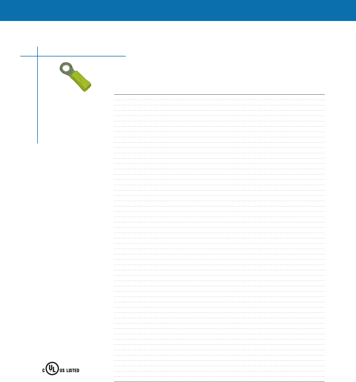
Ring Terminals
Selection information: dimensions shown in inches (millimeters)
Catalog Number Wire Size Stud Size Width Length Type* Std Pack
AMP-0-0036160-0 16-14 AWG #10 Stud 343 (871) 859 (2182) Nylon 1000
CPGI-8-36160-1 16-14 AWG #10 Stud .343 (8.71) .859 (21.82) Nylon 5pk/100
AMPS-0-0031886-0 22-16 AWG #8 Stud 281 (714) 797 (2024) Nylon 1000
CPGI-8-31886-1 22-16 AWG #8 Stud .281 (7.14) .797 (20.24) Nylon 5pk/100
AMPS-0-0031894-0 22-16 AWG 1/4" Stud 469 (1191) 1078 (2738) Nylon 1000
CPGI-8-31894-1 22-16 AWG 1/4" Stud .469 (11.91) 1.078 (27.38) Nylon 5pk/100
AMPS-0-0034142-0 22-16 AWG #6 Stud 218 (554) 684 (1737) Vinyl 1000
CPGI-8-34142-1 22-16 AWG #6 Stud .218 (5.54) .684 (17.37) Vinyl 5pk/100
AMPS-0-0034145-0 22-16 AWG #8 Stud 281 (714) 809 (2055) Vinyl 1000
CPGI-8-34145-1 22-16 AWG #8 Stud .281 (7.14) .809 (20.55) Vinyl 5pk/100
AMPS-0-0034146-0 22-16 AWG #10 Stud 281 (714) 809 (2055) Vinyl 1000
CPGI-8-34146-1 22-16 AWG #10 Stud .281 (7.14) .809 (20.55) Vinyl 5pk/100
AMPS-0-0034150-0 22-16 AWG 1/4" Stud 469 (1191) 1090 (2769) Vinyl 1000
CPGI-8-34150-1 22-16 AWG 1/4" Stud .469 (11.91) 1.090 (27.69) Vinyl 5pk/100
AMPS-0-0034158-0 16-14 AWG #6 Stud 250 (635) 715 (1816) Vinyl 1000
CPGI-8-34158-1 16-14 AWG #6 Stud .250 (6.35) .715 (18.16) Vinyl 5pk/100
AMPS-0-0034160-0 16-14 AWG #8 Stud 343 (871) 871 (2212) Vinyl 1000
CPGI-8-34160-1 16-14 AWG #8 Stud .343 (8.71) .871 (22.12) Vinyl 5pk/50
AMPS-0-0034161-0 16-14 AWG #10 Stud 343 (871) 871 (2212) Vinyl 1000
CPGI-8-34161-1 16-14 AWG #10 Stud .343 (8.71) .871 (22.12) Vinyl 5pk/50
AMPS-0-0034162-0 16-14 AWG 1/4" Stud 469 (1191) 1090 (2769) Vinyl 1000
CPGI-8-34162-1 16-14 AWG 1/4" Stud .469 (11.91) 1.090 (27.69) Vinyl 5pk/50
AMPS-0-0034168-0 12-10 AWG #6 Stud 375 (953) 1098 (2789) Vinyl 500
CPGI-8-34168-2 12-10 AWG #6 Stud .375 (9.53) 1.098 (27.89) Vinyl 5pk/50
AMPS-0-0034853-0 12-10 AWG #8 Stud 375 (953) 1098 (2789) Vinyl 500
CPGI-8-34169-2 12-10 AWG #8 Stud .375 (9.53) 1.098 (27.89) Vinyl 5pk/50
AMPS-0-0034854-0 12-10 AWG #10 Stud 375 (953) 1098 (2789) Vinyl 500
CPGI-8-34170-1 12-10 AWG #10 Stud .375 (9.53) 1.098 (27.89) Vinyl 5pk/50
AMPS-0-0034855-0 12-10 AWG 1/4" Stud 531 (1349) 1327 (3371) Vinyl 500
CPGI-8-34171-2 12-10 AWG 1/4" Stud .531 (13.49) 1.327 (33.71) Vinyl 5pk/50
AMPS-0-0035108-0 12-10 AWG #8 Stud 375 (953) 1083 (2721) Nylon 500
CPGI-8-35108-1 12-10 AWG #8 Stud .375 (9.53) 1.083 (27.21) Nylon 5pk/50
AMPS-0-0035109-0 12-10 AWG #10 Stud 375 (953) 1083 (2751) Nylon 500
CPGI-8-35109-1 12-10 AWG #10 Stud .375 (9.53) 1.083 (27.51) Nylon 5pk/50
AMPS-0-0035110-0 12-10 AWG 1/4" Stud 531 (1349) 1322 (3358) Nylon 500
CPGI-8-35110-1 12-10 AWG 1/4" Stud .531 (13.49) 1.322 (33.58) Nylon 5pk/50
AMPS-0-0035149-0 12-10 AWG #6 Stud 281 (714) 953 (2421) Nylon 500
CPGI-8-35149-2 12-10 AWG #6 Stud .281 (7.14) .953 (24.21) Nylon 5pk/50
AMPS-0-0036152-0 22-16 AWG #6 Stud 281 (714) 797 (2024) Nylon 1000
CPGI-8-36152-1 22-16 AWG #6 Stud .281 (7.14) .797 (20.24) Nylon 5pk/100
AMPS-0-0036154-0 22-16 AWG #10 Stud 312 (792) 844 (2144) Nylon 1000
CPGI-8-36154-1 22-16 AWG #10 Stud .312 (7.92) .844 (21.44) Nylon 5pk/100
AMPS-0-0320565-0 16-14 AWG #8 Stud 343 (871) 859 (2182) Nylon 1000
CPGI-8-320565-1 16-14 AWG #8 Stud .343 (8.71) .859 (21.82) Nylon 5pk/100
AMPS-0-0320619-0 16-14 AWG #6 Stud 250 (635) 703 (1786) Nylon 1000
CPGI-8-320619-1 16-14 AWG #6 Stud .250 (6.35) .703 (17.86) Nylon 5pk/100
AMPS-0-0321045-0 16-14 AWG 1/4" Stud 469 (1191) 1078 (2738) Nylon 1000
CPGI-8-321045-1 16-14 AWG 1/4" Stud .469 (11.91) 1.078 (27.38) Nylon 5pk/50
AMPS-0-0052041-3 8 AWG 1/4" Stud 478 (1214) 1600 (4064) Vinyl 100
AMPS-0-0052042-3 6 AWG 1/4" Stud 500 (1270) 1869 (4747) Vinyl 100
AMPS-0-0052043-2 4 AWG #10 Stud 546 (1387) 1948 (4948) Vinyl 100
AMPS-0-0052043-3 4 AWG 1/4" Stud 546 (1387) 1948 (4948) Vinyl 100
AMPS-0-0052263-1 8 AWG #10 Stud 431 (1095) 1556 (3952) Vinyl 100
AMPS-0-0052265-0 6 AWG #10 Stud 468 (1189) 1719 (4366) Vinyl 100*
Crimp Connectors
5
WIRE CONNECTOR
40CA
E13288 *Note: Vinyl Type possesses a 600 voltage rating and Nylon Type possesses a 300 voltage range.
CONNECTORS & TERMINALS
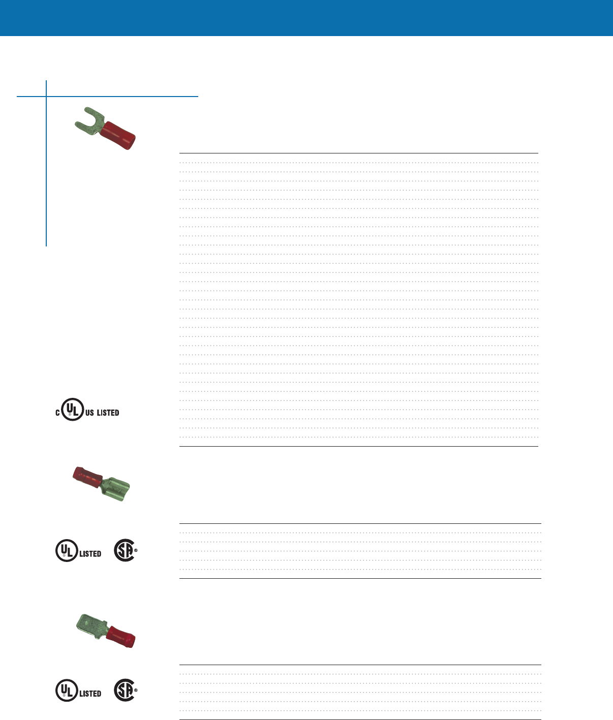
Spade Terminals
Selection information: dimensions shown in inches (millimeters)
Catalog Number Wire Size Stud Size Width Length Type Std. Pack
AMP-0-0035559-0 16-14 AWG #6 Stud 297 (754) 753 (1913) Nylon 1000
CPGI-8-35559-1 16-14 AWG #6 Stud .297 (7.54) .753 (19.13) Nylon 5pk/100
AMPS-0-0032053-0 22-16 AWG #8 Stud 375 (953) 908 (2306) Nylon 1000
CPGI-8-32053-1 22-16 AWG #8 Stud .375 (9.53) .908 (23.06) Nylon 5pk/100
AMPS-0-0032054-0 22-16 AWG #10 Stud 375 (953) 908 (2306) Nylon 1000
CPGI-8-32054-1 22-16 AWG #10 Stud .375 (9.53) .908 (23.06) Nylon 5pk/100
AMPS-0-0032060-0 16-14 AWG #10 Stud 385 (978) 908 (2306) Nylon 1000
CPGI-8-32060-1 16-14 AWG #10 Stud .385 (9.78) .908 (23.06) Nylon 5pk/50
AMPS-0-0032588-0 12-10 AWG #8 Stud 406 (1031) 1095 (2781) Nylon 500
CPGI-8-32588-2 12-10 AWG #8 Stud .406 (10.31) 1.095 (27.81) Nylon 5pk/50
AMPS-0-0032589-0 12-10 AWG #10 Stud 406 (1031) 1095 (2781) Nylon 500
CPGI-8-32589-2 12-10 AWG #10 Stud .406 (10.31) 1.095 (27.81) Nylon 5pk/50
AMPS-0-0034155-0 22-16 AWG #8 Stud 375 (953) 920 (2337) Vinyl 1000
CPGI-8-34155-1 22-16 AWG #8 Stud .375 (9.53) .920 (23.37) Vinyl 5pk/100
AMPS-0-0034156-0 22-16 AWG #10 Stud 375 (953) 920 (2337) Vinyl 1000
CPGI-8-34156-1 22-16 AWG #10 Stud .375 (9.53) .920 (23.37) Vinyl 5pk/100
AMPS-0-0034166-0 16-14 AWG #8 Stud 385 (978) 920 (2337) Vinyl 1000
CPGI-8-34166-1 16-14 AWG #8 Stud .385 (9.78) .920 (23.37) Vinyl 5pk/100
AMPS-0-0034167-0 16-14 AWG #10 Stud 385 (978) 920 (2337) Vinyl 1000
CPGI-8-34167-1 16-14 AWG #10 Stud .385 (9.78) .920 (23.37) Vinyl 5pk/100
AMPS-0-0034176-0 12-10 AWG #10 Stud 406 (1031) 1095 (2781) Vinyl 500
CPGI-8-34176-1 12-10 AWG #10 Stud .406 (10.31) 1.095 (27.81) Vinyl 5pk/50
AMPS-0-0034541-0 22-16 AWG #6 Stud 250 (635) 846 (2149) Nylon 1000
CPGI-8-34541-1 22-16 AWG #6 Stud .250 (6.35) .846 (21.49) Nylon 5pk/100
AMPS-0-0320665-0 22-16 AWG #6 Stud 297 (754) 765 (1943) Vinyl 1000
CPGI-8-320665-1 22-16 AWG #6 Stud .297 (7.54) .765 (19.43) Vinyl 5pk/100
AMPS-0-0321233-0 16-14 AWG #8 Stud 297 (754) 753 (1913) Nylon 1000
CPGI-8-321233-1 16-14 AWG #8 Stud .297 (7.54) .753 (19.13) Nylon 5pk/100
AMPS-0-0322985-0 12-10 AWG #6 Stud 290 (737) 954 (2423) Nylon 500
CPGI-8-322985-2 12-10 AWG #6 Stud .290 (7.37) .954 (24.23) Nylon 5pk/50
AMPS-0-0322994-0 16-14 AWG #6 Stud 297 (754) 765 (1943) Vinyl 1000
CPGI-8-322994-1 16-14 AWG #6 Stud .297 (7.54) .765 (19.43) Vinyl 5pk/100
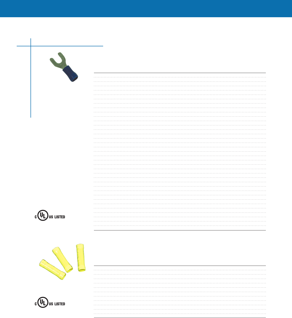
Female Disconnects
Selection information: dimensions shown in inches (millimeters)
Catalog Number Wire Size Series Width Length Type Std. Pack
AMP-0-0640903-1 22-18 AWG 250 x 032 300 (762) 900 (2286) Nylon 1000
CPGI-8-640903-1 22-18 AWG .250 x .032 .300 (7.62) .900 (22.86) Nylon 5pk/50
AMP-0-0640905-1 16-14 AWG 250 x 032 300 (762) 900 (2286) Nylon 1000
CPGI-8-640905-1 16-14 AWG .250 x .032 .300 (7.62) .900 (22.86) Nylon 5pk/50
AMPS-0-0640907-1 12-10 AWG 250 x 032 300 (762) 1012 (2207) Nylon 500
CPGI-8-640907-1 12-10 AWG .250 x .032 .300 (7.62) 1.012 (22.07) Nylon 5pk/50
Male Disconnects
Selection information: dimensions shown in inches (millimeters)
Catalog Number Wire Size Series Type Std. Pack
AMP-0-0066024-2 16-14 AWG 250 x 032 (635 x 081) Nylon 100
CPGI-66024-6 16-14 AWG .250 x .032 (6.35 x 0.81) Nylon 5pk/50
AMPS-0-0066023-2 22-16 AWG 250 x 032 (635 x 081) Nylon 500
CPGI-66023-2 22-16 AWG .250 x .032 (6.35 x 0.81) Nylon 5pk/50
AMPS-0-0066025-2 12-10 AWG 250 x 032 (635 x 081) Nylon 500
CPGI-66025-2 12-10 AWG .250 x .032 (6.35 x 0.81) Nylon 5pk/50
Crimp Connectors
6
WIRE CONNECTOR
40CA
E13288
Certified
LR7189
Quick-Connect Terminal
40CA
E66717
Certified
LR7189
Quick-Connect Terminal
40CA
E66717
*Note: Vinyl Type possesses a 600 voltage rating and Nylon Type possesses a 300 voltage range.
*Note: Vinyl Type possesses a 600 voltage rating and Nylon Type possesses a 300 voltage range.
*Note: Vinyl Type possesses a 600 voltage rating and Nylon Type possesses a 300 voltage range.
CONNECTORS & TERMINALS
CONNECTORS & TERMINALS
Short Spring Spade Terminals
Selection information: dimensions shown in inches (millimeters)
Catalog Number Wire Size Stud Size Width Length Type Std. Pack
AMP-0-0052936-0 16-14 AWG #8 Stud 375 (953) 860 (2124) Nylon 1000
CPGI-8-52936-1 16-14 AWG #8 Stud .375 (9.53) .860 (21.24) Nylon 5pk/50
AMPS-0-0052929-0 22-16 AWG #6 Stud 250 (635) 799 (2029) Nylon 1000
CPGI-8-52929-1 22-16 AWG #6 Stud .250 (6.35) .799 (20.29) Nylon 5pk/50
AMPS-0-0052930-0 22-16 AWG #8 Stud 375 (953) 860 (2184) Nylon 1000
CPGI-8-52930-1 22-16 AWG #8 Stud .375 (9.53) .860 (21.84) Nylon 5pk/50
AMPS-0-0052931-0 22-16 AWG #10 Stud 406 (1031) 908 (2306) Nylon 1000
CPGI-8-52931-1 22-16 AWG #10 Stud .406 (10.31) .908 (23.06) Nylon 5pk/50
AMPS-0-0052935-0 16-14 AWG #6 Stud 250 (635) 799 (2029) Nylon 1000
CPGI-7-52935-1 16-14 AWG #6 Stud .250 (6.35) .799 (20.29) Nylon 5pk/50
AMPS-0-0052937-0 16-14 AWG #10 Stud 406 (1031) 908 (2306) Nylon 1000
CPGI-7-52937-1 16-14 AWG #10 Stud .406 (10.31) .908 (23.06) Nylon 5pk/50
AMPS-0-0052941-0 12-10 AWG #6 Stud 250 (635) 959 (2436) Nylon 500
CPGI-8-52941-2 12-10 AWG #6 Stud .250 (6.35) .959 (24.36) Nylon 5pk/50
AMPS-0-0052942-0 12-10 AWG #8 Stud 375 (953) 1100 (2672) Nylon 500
CPGI-8-52942-1 12-10 AWG #8 Stud .375 (9.53) 1.100 (26.72) Nylon 5pk/50
AMPS-0-0052943-0 12-10 AWG #10 Stud 406 (1031) 1100 (2794) Nylon 500
CPGI-8-52943-1 12-10 AWG #10 Stud .406 (10.31) 1.100 (27.94) Nylon 5pk/50
AMPS-0-0052945-0 12-10 AWG 1/4” Stud 625 (1588) 1225 (3112) Nylon 500
CPGI-8-52945-2 12-10 AWG 1/4” Stud .625 (15.88) 1.225 (31.12) Nylon 5pk/25
AMPS-0-0052949-0 22-16 AWG #6 Stud 250 (635) 811 (2060) Vinyl 1000
CPGI-8-52949-1 22-16 AWG #6 Stud .250 (6.35) .811 (20.60) Vinyl 5pk/80
AMPS-0-0052950-0 22-16 AWG #8 Stud 375 (953) 872 (2215) Vinyl 1000
CPGI-8-52950-1 22-16 AWG #8 Stud .375 (9.53) .872 (22.15) Vinyl 5pk/80
AMPS-0-0052955-0 16-14 AWG #6 Stud 250 (635) 811 (2060) Vinyl 1000
CPGI-8-52955-1 16-14 AWG #6 Stud .250 (6.35) .811 (20.60) Vinyl 5pk/80
AMPS-0-0052956-0 16-14 AWG #8 Stud 375 (953) 872 (2215) Vinyl 1000
CPGI-7-52956-1 16-14 AWG #8 Stud .375 (9.53) .872 (22.15) Vinyl 5pk/80
AMPS-0-0052957-0 16-14 AWG #10 Stud 406 (1031) 920 (2337) Vinyl 1000
CPGI-8-52957-1 16-14 AWG #10 Stud .406 (10.31) .920 (23.37) Vinyl 5pk/80
AMPS-0-0052963-0 12-10 AWG #10 Stud 406 (1031) 1100 (2794) Vinyl 500
CPGI-8-52963-2 12-10 AWG #10 Stud .406 (10.31) 1.100 (27.94) Vinyl 5pk/50
AMPS-0-0053242-1 22-16 AWG #10 Stud 294 (747) 969 (2461) Vinyl 1000
CPGI-8-53242-5 22-16 AWG #10 Stud .294 (7.47) .969 (24.61) Vinyl 5pk/80
AMPS-0-0053247-1 12-10 AWG #8 Stud 312 (792) 1052 (2672) Vinyl 500
CPGI-8-53247-1 12-10 AWG #8 Stud .312 (7.92) 1.052 (26.72) Vinyl 5pk/50
Butt Splices
Selection information: dimensions shown in inches (millimeters)
Catalog Number Wire Size Length Type Std. Pack
AMP-0-0055785-1 16-14 AWG 1065 (2705) Vinyl 1000
CPGI-8-55785-1 16-14 AWG 1.065 (27.05) Vinyl 5pk/50
AMP-0-0055792-1 22-16 AWG 1076 (2733) Vinyl 1000
CPGI-8-55792-1 22-16 AWG 1.076 (27.33) Vinyl 5pk/50
AMP-0-0055793-1 12-10 AWG 1160 (2946) Vinyl 500
CPGI-8-55793-2 12-10 AWG 1.160 (29.46) Vinyl 5pk/25
AMPS-0-0320559-0 22-16 AWG 1265 (3213) Nylon 50
CPGI-8-320559-2 22-16 AWG 1.265 (32.13) Nylon 5pk/50
AMPS-0-0320562-0 16-14 AWG 1265 (3213) Nylon 50
CPGI-8-320562-5 16-14 AWG 1.265 (32.13) Nylon 5pk/50
AMPS-0-0320570-0 12-10 AWG 1656 (4206) Nylon 50
CPGI-8-320570-2 12-10 AWG 1.656 (42.06) Nylon 5pk/25
Crimp Connectors
7
WIRE CONNECTOR
40CA
E13288
WIRE CONNECTOR
40CA
E13288
*Note: Vinyl Type possesses a 600 voltage rating and Nylon Type possesses a 300 voltage range.
*Note: Vinyl Type possesses a 600 voltage rating and Nylon Type possesses a 300 voltage range.
CONNECTORS & TERMINALS
Selection Information: dimensions shown in inches (millimeters)
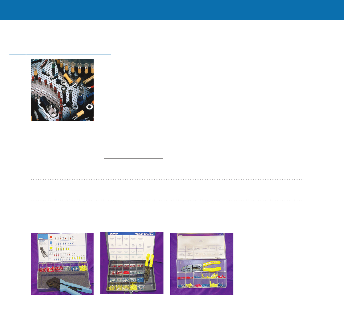
Electrical Maintenance & Repair Kits
Tyco Electronics offers a wide range of electrical maintenance and repair kits containing a selection
of our most popular products, conveniently packaged for on-the-job use
Each kit contains the most popular sizes of PIDG, PLASTI-GRIP, or FASTON terminals and splices
The AMP Mated Tool Terminal Concept
• Carefully engineered application tooling has been developed to ensure uniformly high
quality terminations
• Compression crimping produces crimps for a given size wire and terminal that are alike in
appearance and performance
• Terminal and crimping tool are designed as uniform matched devices PRO-CRIMPER II dies are
precision engineered from the finest hard metal alloys
• Crimping pressure is controlled by a ratchet device on the hand tool
Catalog Dimensions
Connector Kit Name Number L W H Weight Contents
PIDG & PLASTI-GRIP 55823-1 12 7 2 4 lb PRO-CRIMPER II hand tool #58433-3, 225 insulated ring and spade
(280) (180) (50) 094 kg terminals in 12-10, 16-14, and 22-16 AWG (30-50, 13-20, and
03-13mm2) wire sizes
PIDG 608028-1 136 96 21 6 lb SUPER CHAMP IV Hand Tool 604252-1 500 piece kit includes
(345) (240) (50) 272 kg insulated PIDG ring and spade terminals, butt splices, and FASTON
receptacles Wire size 22-10 AWG (03-5mm2) Hinged-top
heavy-duty metal case with storage compartments
PLASTI-GRIP 314974-1 11 7 2 2 lb SUPER CHAMP IV Hand Tool 604252-1
(280) (180) (50) 094 kg Assorted insulated and uninsulated terminals and splices Clear
plastic case with compartments and hinged Top
PIDG Connector Kit
608028-1
PIDG & PLASTI-GRIP
Connector Kit 55823-1
PLASTI-GRIP Connector Kit
314974-1
Mechanical Kits
8
CONNECTORS & TERMINALS
CONNECTORS & TERMINALS
Selection information: dimensions shown in inches (millimeters)
Butt Splice Dimensions Wire Dimensions
A L Insulation O.D. Std.
Catalog Number AWG Color Min. Nom. Max. Min. Pack
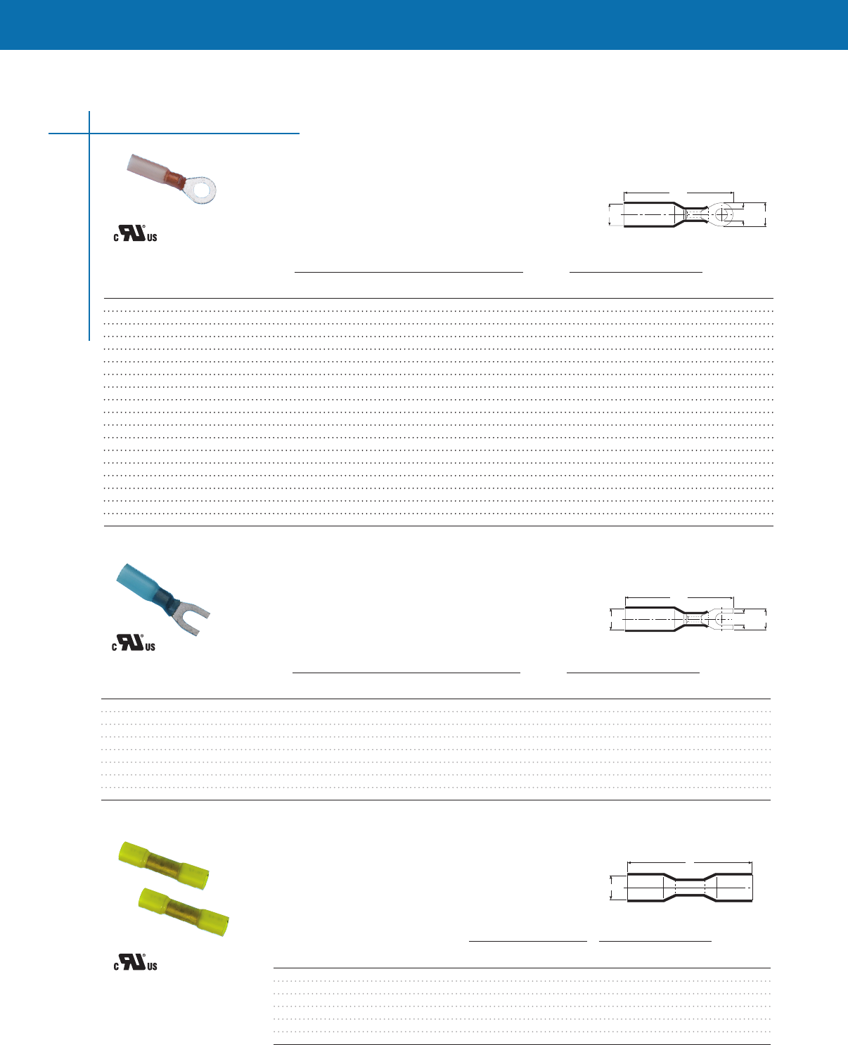
CPGI-D-406-0001-Bulk 22-18 Red 145 (368) 125 (3175) 140 (356) 055 (140) 100/Box
CPGI-D-406-0001-10 22-18 Red .145 (3.68) 1.25 (31.75) .140 (3.56) .055 (1.40) 10/Clam
CPGI-D-406-0002-Bulk 16-14 Blue 180 (457) 125 (3175) 175 (445) 080 (203) 1000/Box
CPGI-D-406-0002-8 16-14 Blue .180 (4.57) 1.25 (31.75) .175 (4.45) .080 (2.03) 8/Clam
CPGI-D-406-0003-Bulk 12-10 Yellow 250 (635) 150 (3810) 245 (622) 279 (110) 500/Box
CPGI-D-406-0003-6 12-10 Yellow .250 (6.35) 1.50 (38.10) .245 (6.22) 2.79 (.110) 6/Clam
Ring Terminal Dimensions Wire Dimensions
A Stud C L Insulation O.D. Std.
Catalog Number AWG Color Min. Size Nom. Max. Max. Min. Pack
CPGI-B-106-1401-BULK 22–18 Red 15 (381) 8 (M4) 31 (788) 126 (320) 150 (381) 055 (140) 1000/Box
CPGI-B-106-1402-BULK 16-14 Blue 18 (457) 8 (M4) 31 (788) 130 (3302) 175 (445) 080 (200) 1000/Box
CPGI-B-106-1403-BULK 12-10 Yellow 25 (635) 8 (M4) 31 (788) 150 (3810) 250 (635) 110 (279) 1000/Box
CPGI-B-106-1501-BULK 22–18 Red 15 (381) 10 (M5) 39 (991) 134 (3404) 150 (381) 055 (140) 1000/Box
CPGI-B-106-1501-6 22–18 Red .15 (3.81) 10 (M5) .39 (9.91) 1.34 (34.04) .150 (3.81) .055 (1.40) 6/Clam
CPGI-B-106-1502-BULK 16-14 Blue 18 (457) 10 (M5) 39 (991) 138 (3505) 175 (445) 080 (200) 1000/Box
CPGI-B-106-1502-5 16-14 Blue .18 (4.57) 10 (M5) .39 (9.91) 1.38 (35.05) .175 (4.45) .080 (2.00) 5/Clam
CPGI-B-106-1503-BULK 12-10 Yellow 25 (635) 10 (M5) 39 (991) 158 (4013) 250 (635) 110 (279) 500/Box
CPGI-B-106-1503-5 12-10 Yellow .25 (6.35) 10 (M5) .39 (9.91) 1.58 (40.13) .250 (6.35) .110 (2.79) 5/Clam
CPGI-B-106-1601-BULK 22–18 Red 15 (381) 1/4 (M6) 142 (3607) 142 (3607) 150 (381) 055 (140) 1000/Box
CPGI-B-106-1602-BULK 16-14 Blue 18 (457) 1/4 (M6) 144 (3658) 144 (3658) 175 (445) 080 (200) 1000/Box
CPGI-B-106-1603-BULK 12-10 Yellow 25 (635) 1/4 (M6) 164 (4166) 164 (4166) 250 (635) 110 (279) 1000/Box
CPGI-B-106-1801-BULK 22–18 Red 15 (381) 5/16 (M8) 55 (1397) 154 (3912) 150 (381) 055 (140) 1000/Box
CPGI-B-106-1802-BULK 16-14 Blue 18 (457) 5/16 (M8) 55 (1397) 158 (4013) 175 (445) 080 (200) 1000/Box
CPGI-B-106-1803-BULK 12-10 Yellow 25 (635) 5/16 (M8) 55 (1397) 178 (4521) 250 (635) 110 (279) 1000/Box
CPGI-B-106-1991-BULK 22–18 Red 15 (381) 3/8 (M10) 70 (1778) 170 (4318) 150 (381) 055 (140) 1000/Box
CPGI-B-106-1992-BULK 16-14 Blue 18 (457) 3/8 (M10) 70 (1778) 173 (4394) 175 (445) 080 (200) 1000/Box
CPGI-B-106-1993-BULK 12-10 Yellow 25 (635) 3/8 (M10) 70 (1778) 185 (4699) 250 (635) 110 (279) 1000/Box
DuraSeal Heat-Shrink Ring Terminals
Selection information: dimensions shown in inches (millimeters)
DuraSeal Heat-Shrink Crimp Connectors
9
WIRE CONNECTOR
E87681
CU ONLY
A min.
L max.
B nom. C nom.
Ring Terminal Dimensions Wire Dimensions
A Stud C L Insulation O.D. Std.
Catalog Number AWG Color Min. Size Nom. Max. Max. Min. Pack
CPGI-B-106-2401-Bulk 22-18 Red 15 (368) 8 (M4) 31 (787) 126 (3200) 150 (381) 055 (140) 1000/Box
CPGI-B-106-2401-6 22-18 Red .15 (3.68) 8 (M4) .31 (7.87) 1.26 (32.00) .150 (3.81) .055 (1.40) 6/Clam
CPGI-B-106-2402-Bulk 16-14 Blue 18 (457) 8 (M4) 31 (787) 138 (3505) 175 (445) 080 (200) 500/Box
CPGI-B-106-2403-Bulk 12-10 Yellow 25 (635) 8 (M4) 31 (787) 150 (3810) 250 (635) 110 (279) 500/Box
CPGI-B-106-2502-Bulk 16-14 Blue 18 (457) 10 (M5) 39 (991) 138 (3505) 175 (445) 080 (200) 1000/Box
CPGI-B-106-2502-5 16-14 Blue .18 (4.57) 10 (M5) .39 (9.91) 1.38 (35.05) .175 (4.45) .080 (2.00) 5/Clam
CPGI-B-106-2503-Bulk 12-10 Yellow 25 (635) 10 (M5) 39 (991) 158 (4015) 250 (635) 110 (279) 500/Clam
CPGI-B-106-2503-5 12-10 Yellow .25 (6.35) 10 (M5) .39 (9.91) 1.58 (40.15) .250 (6.35) .110 (2.79) 5/Clam
DuraSeal Heat-Shrink Spade Terminals
Selection information: dimensions shown in inches (millimeters)
WIRE CONNECTOR
E87681
CU ONLY
A min.
L max.
B nom. C nom.
WIRE CONNECTOR
E87681
CU ONLY
A min.
L
DuraSeal Heat-Shrink Butt Splices
Note: 600 Voltage Rating.
Note: 600 Voltage Rating.
Note: 600 Voltage Rating.
CONNECTORS & TERMINALS
Fig. 1
Fig. 2
A min. B nom.
A min. BC min.
L max.
L max.
Tab Terminal Dimensions Wire Dimensions
CPGI Tab A B C L Insulation O.D. Std.
Catalog No. Size Min. Nom. Nom. Max. Color AWG Max. Min. Pack*
CPGI-B-106-4631-BULK 250 x 032 150 (381) 250 (635) 032 (81) 120 (3048) Red 22–18 150 (381) 055 (140) 1000
CPGI-B-106-4632-BULK 250 x 032 180 (457) 250 (635) 032 (81) 126 (3200) Blue 16–14 175 (445) 080 (200) 1000
Tab Terminal Dimensions Wire Dimensions
CPGI Tab A B C L Insulation O.D. Std.
Catalog No. Size Min. Nom. Nom. Max. Color AWG Max. Min. Pack*
CPGI-B-106-3631-BULK 250 x 032 150 (381) 250 (635) 032 (81) 120 (3048) Red 22–18 150 (381) 055 (140) 1000
CPGI-B-106-3632-BULK 250 x 032 180 (457) 250 (635) 032 (81) 126 (3200) Blue 16–14 175 (445) 080 (200) 1000
CPGI-B-106-3633-BULK 250 x 032 250 (635) 250 (635) 032 (81) 1300 (3302) Yellow 12–10 250 (635) 110 (279) 1000
CPGI-B-106-3281-BULK 110 x 020 150 (381) 110 (279) 020 (51) 900 (2286) Red 22–18 150 (381) 155 (140) 1000
CPGI-B-106-3481-BULK 187 x 020 150 (381) 187 (475) 020 (51) 1200 (3048) Red 22–18 150 (381) 055 (140) 1000
Tab Terminal Dimensions Wire Dimensions
CPGI A B C L Insulation O.D. Std.
Catalog No. Fig.—Type Min. Nom. Nom. Max. Color AWG Max. Min. Pack*
CPGI-B-106-7401-BULK 1—Male 150 (381) 150 (635) — 132 (3353) Red 22–18 150 (381) 055 (140) 1000
CPGI-B-106-7502-BULK 1—Male 180 (457) 200 (508) — 136 (3454) Blue 16–14 175 (445) 080 (200) 1000
CPGI-B-106-8401-BULK 2—Female 150 (381) 150 (635) 220 (559)120 (48) Red 22–18 150 (381) 055 (140) 1000
CPGI-B-106-8502-BULK 2—Female 180 (457) 200 (508) 240 (610) 128 (3251) Blue 16–14 175 (445) 080 (200) 1000
DuraSeal Heat-Shrink Crimp Connectors
10
A min.
B
L max.
B nom.
C nom.
L max.
A min.
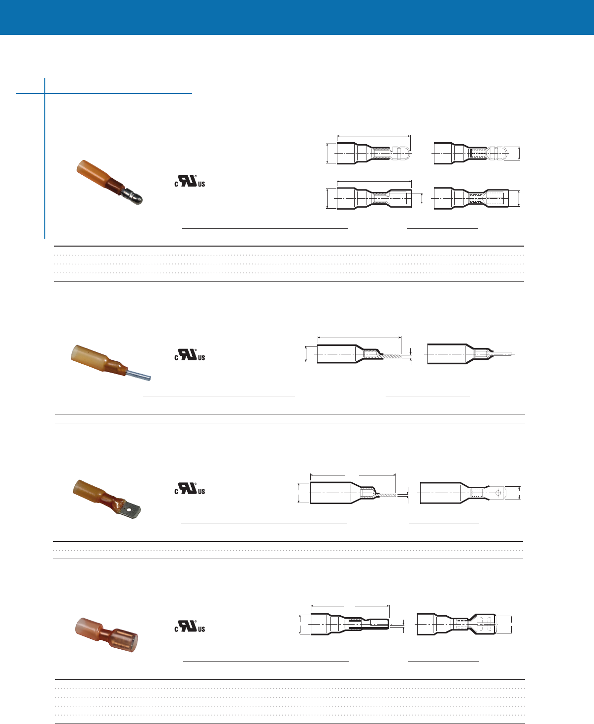
DuraSeal Heat-Shrink Bullet Terminals
Selection information: dimensions shown in inches (millimeters)
DuraSeal Heat-Shrink Pin Terminals
Selection information: dimensions shown in inches (millimeters)
DuraSeal Heat-Shrink Male Disconnects
Selection information: dimensions shown in inches (millimeters)
DuraSeal Heat-Shrink Female Disconnects
Selection information: dimensions shown in inches (millimeters)
L max.
A min.
C nom.
B nom.
Pin Terminal Dimensions Wire Dimensions
CPGI A B L Insulation O.D. Std.
Catalog No. Min. Nom. Max. Color AWG Max. Min. Pack*
CPGI-B-106-6201-BULK 150 (381) 080 (200) 1220 (3099) Red 22–18 150 (381) 055 (140) 1000
WIRE CONNECTOR
E87681
CU ONLY
WIRE CONNECTOR
E87681
CU ONLY
WIRE CONNECTOR
E87681
CU ONLY
WIRE CONNECTOR
E87681
CU ONLY
Note: 600 Voltage Rating.
*Note: Std. Pack consists of 1000/BOX.
Note: 600 Voltage Rating.
*Note: Std. Pack consists of 1000/BOX.
Note: 600 Voltage Rating.
*Note: Std. Pack consists of 1000/BOX.
Note: 600 Voltage Rating.
*Note: Std. Pack consists of 1000/BOX.
CONNECTORS & TERMINALS
CONNECTORS & TERMINALS
Selection information: dimensions shown in inches (millimeters)
Wire Max. CMA/mm2
Size Stud Bundle Wire Range Typical Std.
Catalog Number AWG Size Diameter (Min.- Max.) Length Pack
CPGI-SGRT-2-04-Bulk 22-18 8 (4) — 12-30 (2400-6000) 1 1/2 (38) 100/Box
CPGI-SGRT-2-04-6 22-18 1/4 (6) — 1.2-3.0 (2400-6000) 1 1/2 (38) 6/Clam
CPGI-SGRT-3-06-Bulk 20-12 8 (4) 255 (65) 25-66 (5000-13,200) 1 3/4 (445) 100/Box
CPGI-SGRT-3-06-6 20-12 8 (4) .255 (6.5) 2.5-6.6 (5000-13,200) 1 3/4 (44.5) 6/Clam
CPGI-SGRT-4-06-Bulk 18-10 1/4 (6) 355 (90) 60-112 (12,000-22,400) 1 3/4 (445) 100/Box
CPGI-SGRT-4-06-5 18-10 1/4 (6) .355 (9.0) 6.0-11.2 (12,000-22,400) 1 3/4 (44.5) 5/Clam
CPGI-SGRT-4-08-Bulk 18-10 5/16 (8) — 60-112 (12,000-22,400) 2 (510) 100/Box
CPGI-SGRT-4-08-5 18-10 5/16 (8) — 6.0-11.2 (12,000-22,400) 2 (51.0) 5/Clam
SolderGrip Heat-Shrink Connectors
WIRE CONNECTOR
E87681
CU ONLY
WIRE CONNECTOR
E87681
CU ONLY
WIRE CONNECTOR
E87681
CU ONLY
Selection information: dimensions shown in inches (millimeters)
Wire CMA/mm2
Size Wire Jacket OD Combined Total Number Std.
Catalog Number AWG Min. Max. Min. Max. Pack
CPGI-CWT-9002-Bulk 22-18 005 (13) 0106 (27) 1250 (08) 3500 (02) 100/Box
CPGI-CWT-9002-15 22-18 0.05 (1.3) 0.106 (2.7) 1250 (0.8) 3500 (0.2) 15/Clam
CPGI-CWT-9003-Bulk 16-14 007 (18) 018 (45) 2500 (08) 7200(40) 100/Box
CPGI-CWT-9003-12 16-14 0.07 (1.8) 0.18 (4.5) 2500 (0.8) 7200(4.0) 12/Clam
CPGI-CWT-9004-Bulk 12-10 011 (28) 0236 (60) 6100 (40) 19000 (60) 100/Box
CPGI-CWT-9004-10 12-10 0.11 (2.8) 0.236 (6.0) 6100 (4.0) 19000 (6.0) 10/Clam
CPGI-CWT-9005-Bulk 16-10 0125 (32) 0275 (70) 12000 (60) 25000 (100) 100/Box
CPGI-CWT-9005-8 16-10 0.125 (3.2) 0.275 (7.0) 12000 (6.0) 25000 (10.0) 8/Clam
Selection information: dimensions shown in inches (millimeters)
CMA/mm2
Size Color Wire Range Std.
Catalog Number AWG Code L A (Min. - Max.) Pack
CPGI-SGRS-1-Bulk 22-18 Green 348 (1370) 34 (0130) 07-24 (1400-4800) 100/Box
CPGI-SGRS-1-6 22-18 Green 34.8 (1.370) 3.4 (0.130) 0.7-2.4 (1400-4800) 6/Clam
CPGI-SGRS-2-Bulk 20-12 Red 342 (1350) 48 (0190) 20-40 (4000-8000) 100/Box
CPGI-SGRS-2-6 20-12 Red 34.2 (1.350) 4.8 (0.190) 2.0-4.0 (4000-8000) 6/Clam
CPGI-SGRS-3-Bulk 18-10 Blue 420 (1650) 73 (0290) 35-80 (7000-16000) 100/Box
CPGI-SGRS-3-5 18-10 Blue 42.0 (1.650) 7.3 (0.290) 3.5-8.0 (7000-16000) 5/Clam
CPGI-SGRS-4-Bulk 16-8 Yellow 415 (1630) 91 (0360) 75-120 (15000-24000) 100/Box
CPGI-SGRS-4-4 16-8 Yellow 41.5 (1.630) 9.1 (0.360) 7.5-12.0 (15000-24000) 4/Clam
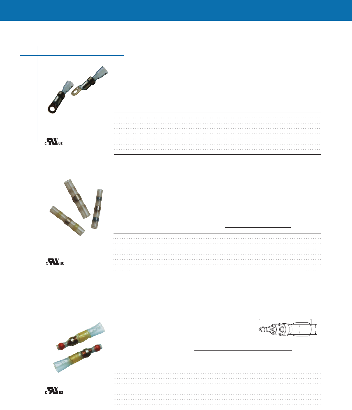
Product Dimensions
L
Sealing insert
A
Insulated and Sealed Closed-End Connectors (SGRS series)
SolderGrip Wire
Connector Splices
SolderGrip Butt Splices
SolderGrip Ring Terminals
Note: 600 Voltage Rating.
Note: Please see Application & Technical Specification (SolderGrip Wire Combination) Section for complete product
use range.
Note: 600 Voltage Rating.
Note: Please see Application & Technical Specification (SolderGrip Wire Combination) Section for complete product
use range.
Note: 600 Voltage Rating.
Note: Please see Application & Technical Specification (SolderGrip Wire Combination) Section for complete product
use range.
11
CONNECTORS & TERMINALS
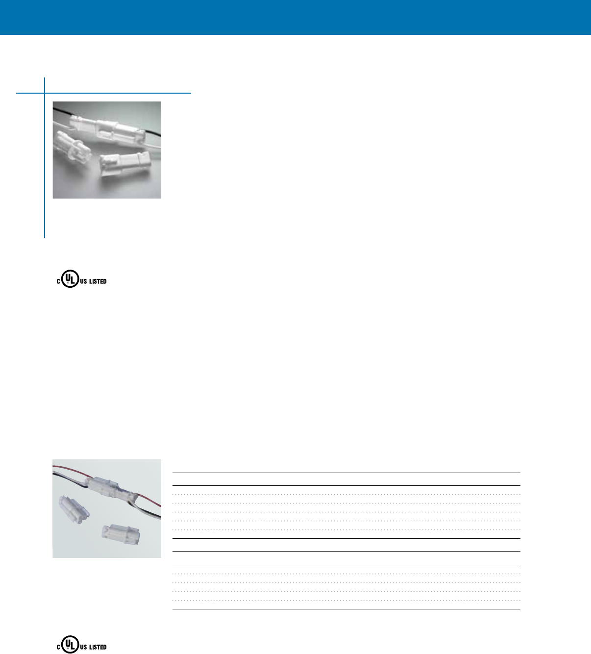
The 2 and 3-position LIGHT-N-LOK ballast disconnects consist of a plug assembly and receptacle
assembly with or without being pre-wired. The assemblies will accept 18 AWG solid copper wire.
“Poke-In Wire Termination” method removes the need for application tooling. Knockout diameter
opening is 5/8" for 2-position and is 7/8" for the 3 position.
LIGHT-N-LOK
Ballast Disconnects
The LIGHT-N-LOK ballast disconnects are hot-pluggable interconnects for fluorescent ballast
applications desgined to meet the 2008 NEC code for section 410.130(G) and Canadian Electrical
Code: 22-1-06-Paragraph 30-308 (4).
These connectors meet UL 2459 Insulated Mult-Pole Splicing Wire Connectors and CSA
Std. C22.2 No. 1823-M1987 with Current Interruption, and it also supports CSA Luminaries
Labeling Requirements.
• Availablein2and3positionconnectors
• Poke-Inwiretermination
• Integralwirestrainrelief(exceeds25lbsretention)
• Squeeze-to-releaselatches
• Snagresistantroundedcorners
• Accepts18AWGsolidwire
• “BallastDisconnect”markinginEnglishandFrench
• Contactsfullyrecessedinhousings
• Compactconnectordesign
• Electricalrating:120-600VAC,5A
• Operatingtemperature:-40˚Cto+105˚C
• Accomodatesstandard&dimmingballasts
• Easy,tool-lessfieldorfactoryinstallation
• Preventsunintentionalconnectordisconnect
• Installerfriendly
• Ballastsideindustrystandard
• Fingersafeinunmatedconfiguration
• UL2459InsulatedMult-PoleSplicingWireConnectors
• CSAStdC22.2No.1823-M1987WithCurrentInterruption
Lighting Connectors
Selection information: dimensions shown in inches (millimeters)
Catalog Number Description Std. Pack
2-Position
CPGI-2008535-1-K2 2-Position with 6" leads 2
CPGI-2008535-1-BULK 2-Position with 6" leads 1500
CPGI-2008144-1-K6 2-Position no leads 6
CPGI-2008144-1-K20 2-Position no leads 20
CPGI-2008144-1-K50 2-Position no leads 50
CPGI-2008144-1-BULK 2-Position no leads 1500
3-Position
CPGI-2008836-2-K2 3-Position with 6" leads 2
CPGI-2008836-2-BULK 3-Position with 6" leads 500
CPGI-2008152-1-K6 3-Position no leads 6
CPGI-2008152-1-K50 3-Position no leads 50
CPGI-2008152-1-BULK 3-Position no leads 500
Multi-Pole Splicing
Wire Connectors
40CA
E-308110
CU Only
Multi-Pole Splicing
Wire Connectors
40CA
E-308110
CU Only
2-Position
3-Position
12
CONNECTORS & TERMINALS
CONNECTORS & TERMINALS
13
Poke-In Wire Tap/Splice Connector
Poke-In connectors combine wire splices with power taps for use in commercial lighting ballast
installations The Insulation Displacement Contacts (IDC) in the splice allow for quick termination
to “run” or power wire connection Installers place the “run” connection in the IDC splice and close
the spice with wire pliers or flat-rock tooling Poke-In connection to the power taps is made with
pre stripped solid wires and installers poke the stripped wire into the taps to complete the circuit
Integrated splice and tap design helps speed the installation process and minimizes the need for
specialized tools or other installation materials
• IDC Poke-In wire tap/ splice products are available in two sizes
• One size accepts “run” connections with 12 AWG solid or stranded wire
• Second size accepts “run” connections with 18 AWG solid wire
• Splice poke-in accommodates two pre-stripped 18 AWG solid wires
• Contact current rating is 7 amps with an operating voltage of 600V maximum
• UL 486C File E13288/ CSA Std C222 No 188
Lighting Connectors
WIRE CONNECTOR
E13288
CU ONLY Selection information
Catalog Number Description Std. Pack
12 AWG
CPGI-1811027-1-Bulk 12 AWG Tap with (2) 18 AWG Poke-Ins 500/Bag
CPGI-1811027-1-K100 12 AWG Tap with (2) 18 AWG Poke-Ins 100/Jar
CPGI-1811027-1-K25 12 AWG Tap with (2) 18 AWG Poke-Ins 25/Clam
CPGI-1811027-1-K6 12 AWG Tap with (2) 18 AWG Poke-Ins 6/Clam
18 AWG
CPGI-1811027-2-Bulk 18 AWG Tap with (2) 18 AWG Poke-Ins 500/Bag
CPGI-1811027-2-K100 18 AWG Tap with (2) 18 AWG Poke-Ins 100/Jar
CPGI-1811027-2-K25 18 AWG Tap with (2) 18 AWG Poke-Ins 25/Clam
CPGI-1811027-2-K6 18 AWG Tap with (2) 18 AWG Poke-Ins 6/Clam

CONNECTORS & TERMINALS
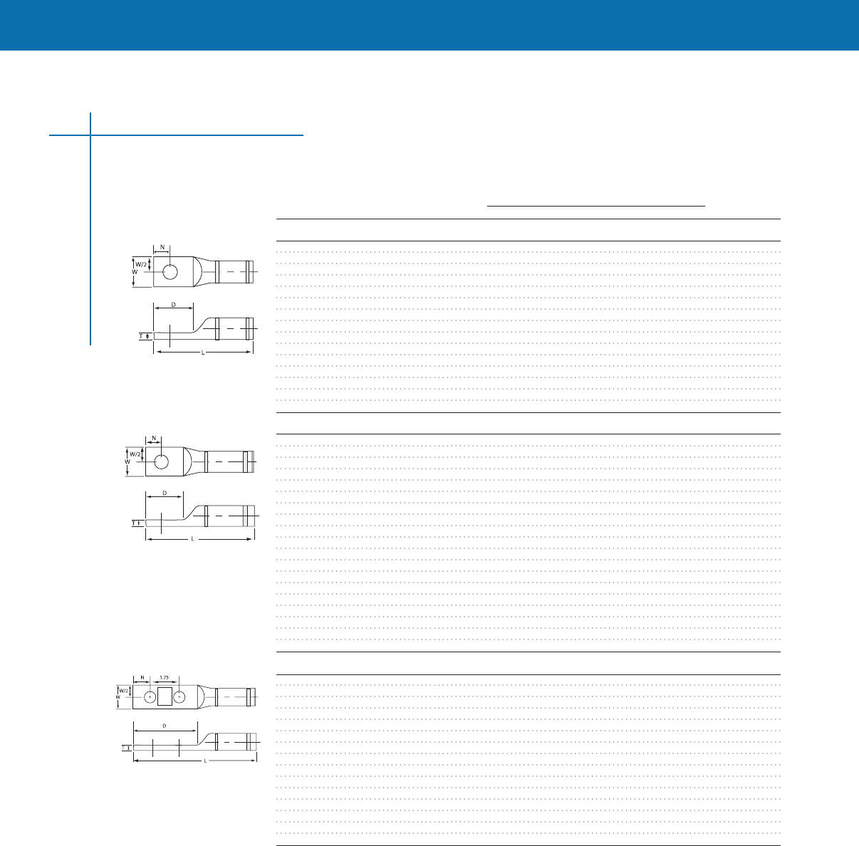
Copper Compression Terminals
• Uses industry-standard tooling for simple installation
• Industry-standard color coding system simplifies die selection
• Chamfered connector end allows cable to be inserted easily
• One-piece, seamless construction from electrolytic tough pitch (ETP) copper for superior
electrical performance and mechanical operation
• Closed barrel transition design for protection from moisture and contaminants
• Tin-plated for corrosion resistance and durability, and tempered for easy crimping
Copper compression terminals are ideally suited for secondary power distribution in buildings, power
plants, electrical equipment, and industrial applications Connectors can be used on applications up to
35 kV, and meet the requirements of UL486A and CSA C222 No 65-95 when applied with approved
die sets (See Instruction Sheet #408-8869 for approved listing of die sets)
Copper compression terminals are available to accommodate a range of cable sizes from 6 AWG
through 1,000 MCM and are designed for terminating concentric, compact, or standard stranded
copper conductors These terminals are offered in one-hole terminals from 6 AWG through 1,000
MCM with either a standard or long barrel A two-hole NEMA terminal with a long barrel is also
available for 4 AWG through 1,000 MCM
Compression crimping forms the terminal barrel and conductor into a strong, almost homogeneous
unit, producing excellent conductivity, low temperature rise, and outstanding resistance to oxidation
and corrosion
Physical and Electrical Properties
Material: ETP copper alloy C11000
Plating: Electro tin plate
Heat treating: Soft tempered
Voltage Rating: For applications up to 35 kV consult shielded cable manufacturers stress
relief instructions
Agency approvals (when crimped with the approved die sets): Listed by Underwriters Laboratories,
Inc File No E13288, Compression terminal connectors comply with the requirements of UL486A and
CSA C222 NO 65-93
Compression Connectors
14
CONNECTORS & TERMINALS
CONNECTORS & TERMINALS
Copper Compression Terminals continues
Selection Information: dimensions shown in inches (millimeters)
Catalog Dimensions Color
Number Conductor Stud Size L W T D N Code
One Hole, Short Barrel
1099898-1 6 STR 1/4 15 045 008 056 027 blue
1099898-2 4 STR 1/4 15 050 009 056 027 gray
1099898-3 3 STR 5/16 16 057 009 070 034 white
1099898-4 2 STR 5/16 16 061 011 070 034 brown
1099898-5 1 STR 1/4 16 068 010 056 027 green
1099898-6 1/0 STR 5/16 17 074 012 070 034 pink
1099898-7 1/0 STR 1/2 21 088 009 108 053 pink
1099898-8 2/0 STR 3/8 19 083 012 083 041 black
1099898-9 3/0 STR 1/2 22 091 013 108 053 orange
1-1099898-0 4/0 STR 1/2 22 102 014 108 053 purple
1-1099898-1 250 MCM 1/2 24 111 016 108 053 yellow
1-1099898-2 350 MCM 1/2 25 127 018 108 053 red
1-1099898-3 500 MCM 1/2 32 154 023 130 065 brown
1-1099898-4 750 MCM 5/8 40 188 027 194 088 black
1-1099898-5 1000 MCM 5/8 49 216 032 212 094 white
One Hole, Long Barrel
1099899-1 6 STR 1/4 19 045 008 056 034 blue
1099899-2 4 STR 1/4 19 050 009 056 038 gray
1099899-3 3 STR 5/16 23 057 009 070 038 white
1099899-4 2 STR 5/16 23 060 011 075 038 brown
1099899-5 1 STR 5/16 24 068 010 075 027 green
1099899-6 1/0 STR 5/16 24 074 012 075 027 pink
1099899-7 1/0 STR 1/2 27 075 011 108 053 pink
1099899-8 2/0 STR 3/8 27 082 012 088 044 black
1099899-9 3/0 STR 1/2 29 091 013 108 053 orange
1-1099899-0 4/0 STR 1/2 30 100 014 108 053 purple
1-1099899-1 250 MCM 1/2 32 109 016 112 056 yellow
1-1099899-2 300 MCM 1/2 36 119 016 112 056 white
1-1099899-3 350 MCM 1/2 37 128 018 112 056 red
1-1099899-4 400 MCM 5/8 42 138 019 150 075 blue
1-1099899-5 500 MCM 5/8 44 152 023 150 075 brown
1-1099899-6 500 MCM 1/2 42 154 023 130 065 brown
1-1099899-7 600 MCM 5/8 52 169 027 175 088 green
1-1099899-8 750 MCM 5/8 54 189 027 194 088 black
1-1099899-9 1000 MCM 5/8 60 217 032 212 094 white
Two-Hole NEMA, Long Barrel
1099939-1 4 STR 1/2 44 083 011 300 062 gray
1099939-2 3 STR 1/2 44 083 011 300 062 white
1099939-3 2 STR 1/2 45 082 011 300 062 brown
1099939-4 1 STR 1/2 47 080 009 300 062 green
1099939-5 1/0 STR 1/2 47 075 012 300 062 pink
1099939-6 2/0 STR 1/2 48 082 012 300 062 black
1099939-7 3/0 STR 1/2 48 090 012 300 062 orange
1099939-8 4/0 STR 1/2 50 100 014 300 062 purple
1099939-9 250 MCM 1/2 50 109 016 300 062 yellow
1-1099939-0 300 MCM 1/2 54 118 016 300 062 white
1-1099939-1 350 MCM 1/2 54 127 018 300 062 red
1-1099939-2 500 MCM 1/2 57 153 023 300 062 brown
1-1099939-3 600 MCM 1/2 62 171 027 300 062 green
1-1099939-4 750 MCM 1/2 65 189 027 300 062 black
1-1099939-5 1000 MCM 1/2 68 216 033 300 062 white
15
Compression Connectors
CONNECTORS & TERMINALS
Selection Information: dimensions shown in inches (millimeters)
Length Outside Color
Catalog Number Conductor (L) (L/2) Diameter(D) Code
Standard Barrel Splice
1443402-1 #6 STR 175 083 0292 Blue
1443402-2 #4 STR 200 096 0340 Gray
1443402-3 #3 STR 209 100 0377 White
1443402-4 #2 STR 209 100 0418 Brown
1443402-5 #1 STR 209 100 0462 Green
1443402-6 1/0 STR 209 100 0515 Pink
1443402-7 2/0 STR 218 105 0583 Black
1443402-8 3/0 STR 232 111 0618 Orange
1443402-9 4/0 STR 232 112 0691 Purple
1-1443402-0 250 MCM 250 119 0753 Yellow
1-1443402-1 300 MCM 250 119 0815 White
1-1443402-2 350 MCM 262 125 0844 Red
1-1443402-3 400 MCM 275 131 0953 Blue
1-1443402-4 500 MCM 315 150 1064 Brown
1-1443402-5 600 MCM 325 155 1185 Green
1-1443402-6 750 MCM 375 180 1302 Black
1-1443402-7 1000 MCM 426 206 1504 White
Long Barrel Splice
1443403-1 #6 STR 241 116 0292 Blue
1443403-2 #4 STR 241 116 0340 Gray
1443403-3 #3 STR 253 122 0377 White
1443403-4 #2 STR 265 128 0418 Brown
1443403-5 #1 STR 291 141 0462 Green
1443403-6 1/0 STR 291 141 0515 Pink
1443403-7 2/0 STR 315 153 0583 Black
1443403-8 3/0 STR 315 153 0618 Orange
1443403-9 4/0 STR 339 163 0691 Purple
1-1443403-0 250 MCM 339 163 0753 Yellow
1-1443403-1 300 MCM 413 200 0815 White
1-1443403-2 350 MCM 413 200 0844 Red
1-1443403-3 400 MCM 438 213 0953 Blue
1-1443403-4 500 MCM 462 223 1064 Brown
1-1443403-5 600 MCM 550 267 1185 Green
1-1443403-6 750 MCM 588 286 1302 Black
1-1443403-7 1000 MCM 612 296 1504 White
Conductor
Part No.
Color
OE Index
L
L2
OD
Conductor
Part No.
Color
OE Index
L
L2
OD
Conductor
Part No.
Color
OE Index
L
L2
OD
Conductor
Part No.
Color
OE Index
L
L2
OD
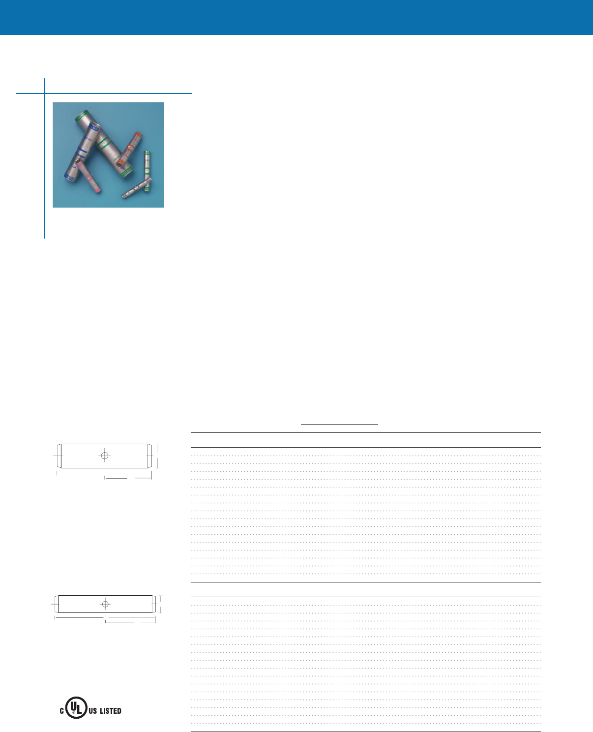
Copper Compression Splices
• Uses industry-standard tooling for simple installation
• Industry-standard color coding system simplifies die selection
• Chamfered connector end allows cable to be inserted easily
• One-piece, seamless construction from electrolytic tough pitch (ETP) copper for superior electrical
performance and mechanical operation
• Tin-plated for corrosion resistance and durability, and tempered for easy crimping
Copper compression splices are ideally suited for secondary power distribution in buildings, power
plants, electrical equipment, and industrial applications Connectors can be used on applications up to
35 kV, and meet the requirements of UL486A and CSA C222 No 65-95 when applied with approved
die sets (See Instruction Sheet #408-8969 for approved listing of die sets)
Copper compression splices are available to accommodate a range of cable sizes from 6 AWG
through 1,000 MCM and are designed for splicing concentric, compact, or standard stranded copper
conductors These splices are offered from 6 AWG through 1,000 MCM with either a standard or
long barrel
Compression crimping forms the splice and conductor into a strong, almost homogeneous unit,
producing excellent conductivity, low temperature rise, and outstanding resistance to oxidation
and corrosion
Physical and Electrical Properties
Material: ETP copper alloy C11000
Plating: Electro tin plate
Heat treating: Soft tempered
Voltage rating: For applications up to 35 kV
Consult shielded cable manufacturers stress relief instructions
Agency approvals (when crimped with the approved die sets): Listed by Underwriters Laboratories,
Inc File No E13288, Compression splice connectors comply with the requirements of UL486A and
CSA C222 NO 65-93
Compression Connectors
16
CONNECTORS & TERMINALS
CONNECTORS & TERMINALS
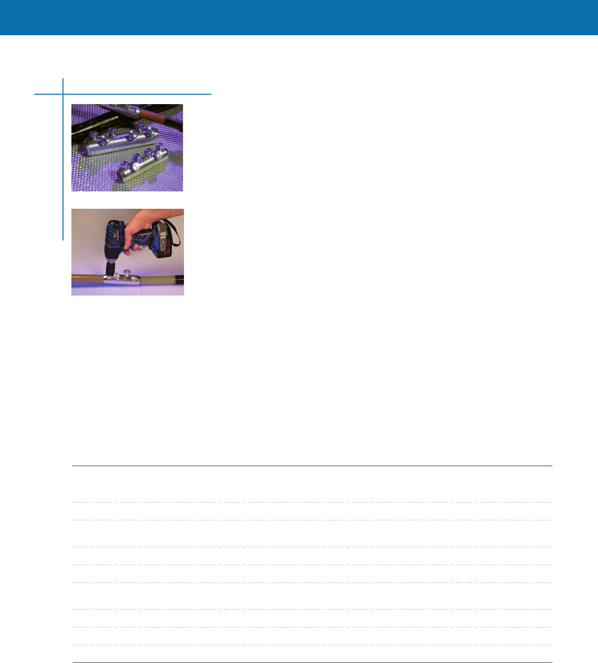
ShearBolt Connectors
Aluminum ShearBolt Connectors
#2 AWG Compact to 1000 kcmil Standard
Tyco Electronics’ new line of Aluminum ShearBolt connectors are range- taking mechanical
connectors Just six connectors will accommodate a wide range of aluminum and copper conductors
from #2 AWG compact stranded to 1000 kcmil standard stranded class B The primary application of
Aluminum ShearBolt connectors is for underground splices up to 35kV
ShearBolt connectors are ideally suited for aluminum to aluminum, aluminum to copper and copper to
copper applications making them the universal connector solution Please refer to test report matrix
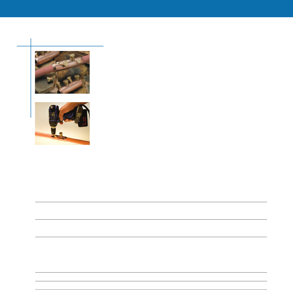
The only tool required to install the connector is a standard ratchet wrench with the appropriate
sized hexagonal sockets The connector design incorporates shear head bolts, which ensures that the
correct torque is applied to each bolt and consequently the optimal contact force is generated to
minimize connection resistance A holding tool is recommended to avoid core bending of conductors
and can be ordered from Tyco Electronics (#188072-000)
The Tyco Electronics cordless impact wrench (#CA7469-000) can also be used to install the
connector This convenient and quick tool has been tested and qualified to install ShearBolt
connectors
The solid center stop (available on certain sizes) inside the connector ensures proper conductor
positioning and eliminates oil leakage when connecting oil impregnated conductors
Two removable inserts in the connector body centralize smaller conductor sizes For larger sizes,
inserts are not required and are easily removed with a standard screwdriver
ShearBolt connectors meet the electrical requirements (Class A) of ANSI C1194-2004 and exceed the
mechanical requirements of a class 3 connector by a large margin of safety
ShearBolt connectors are designed to be compatible with Tyco Electronics’ Raychem brand cable
accessories and insulation products For a complete list of cable accessories please visit our web site,
http://energytycoelectronicscom For other applications, please consult the manufacturer’s
installation instructions for compatibility
Feature Advantage Benefit
Wide Application Range Only six connectors needed to Reduces inventory and prevents accidental use
accommodate all cable sizes of the wrong connector
from #2 AWG compact strand
to 1,000 kcmil standard stranded
Hexagonal Installs with simple Installs easily and quickly in confined areas
shear head bolts ratchet-type socket wrench
No crimp tooling or dies required Installs easily using readily available tools Ease of installation Installation tool is no longer a source
of failure Reduces tool and die inventory, maintenance
and cost
Compact, smooth body design Compatible with Raychem brand An engineered system providing years of
heat-shrink and cold-applied products trouble-free performance
Torque-controlled shear head bolts Sheared head gives positive indication Low contact resistance gives superior electrical
of correct installation performance
Heavy-duty design Connector bodies are made of high Provides long service life under normal operation
strength, tin-plated aluminum alloy conditions with reserve capacity for emergency loading
conditions
Centering inserts for Properly positions small conductors Minimizes voltage stresses at transition from
small diameter conductors for proper connection connector body to cable insulation
Knurled Inner bore Unique profile breaks through oxides Generates low contact resistance and increases
and grips conductor strands conductor pullout rating
Solid center stop Eliminates oil leakage and ensures Accommodates transition applications from
proper conductor position polymeric to oil impregnated conductors
17

CONNECTORS & TERMINALS
ShearBolt Connectors
Application Information
Socket
Catalog Installation Size Test Conductor
Number Instruction Number (inches) Number Combination
ASBS-2-3/0 408-8990 1/2 Note 1 Note 1
ASBS-2-350 408-8990 11/16 502-47292(I) 4/0 kcmil Cu to 350 kcmil AAC
502-47300(I) 350 kcmil AAC to 350 kcmil AAC
502-47340(I) 350 kcmil CU to 350 kcmil CU
ASBS-3/0-500 408-8990 3/4 502-47331(I) 500 kcmil AAC to 500 kcmil AAC
502-47331(I) 500 kcmil CU to 500 kcmil CU
ASBS-350-750 408-8990 7/8 502-47329(I) 750 kcmil AAC to 750 kcmil AAC
ASBS-500-750 408-8990 3/4 502-47288(I) 500 kcmil CU to 750 kcmil CU
502-47294(I) 750 kcmil ACC to 750 kcmil AAC
502-47357(1) 750 kcmil AAC strandfill to 750 kcmil AAC strandfill
ASBS-600-1000 408-8990 7/8 502-47289(I) 750 kcmil CU to 1000 kcmil AAC
502-47344(I) 1000 kcmil CU to 1000 kcmil CU
502-47305(I) 1000 kcmil AAC to 1000 kcmil AAC
Note 1: This part number was not tested, as ANSI C119.4 allows a smaller size connector of the same design to be added without additional testing.
Please contact your Tyco Electronics representative for conductor sizes or types not listed in this catalog.
Catalog Number Conductor Range OD Range Length Connector OD Stop
ASBS-2-3/0 2 AWG compact stranded to 268 - 470 (68 - 119mm) 25 (65mm) 95 (24mm) Disc
3/0 AWG standard stranded
ASBS-2-350 2 AWG compact stranded to 268 - 681 (68 - 173mm) 39 (100mm) 122 (31mm) Solid
350 kcmil standard stranded
ASBS-3/0-500 3/0 AWG compact stranded to 423 - 813 (107 - 206mm) 49 (125mm) 13 (34mm) Disc
500 kcmil standard stranded
ASBS-500-750 500 kcmil compact stranded to 736 - 998 (187 - 253mm) 6 (152mm) 152 (39mm) Solid
750 kcmil standard stranded
ASBS-350-750 350 kcmil compact stranded to 616 - 998 (156 - 253mm) 67 (170mm) 167 (425mm) Solid
750 kcmil standard stranded
ASBS-600-1000 600 kcmil compact stranded to 813 - 1152 (206 - 292 mm) 8 (203mm) 175 (444mm) Solid
1000 kcmil standard stranded
Please request Data Sheet # 1654972 for our line of Copper ShearBolt connectors.
Selection Information: dimensions shown in inches (millimeters)
18
CONNECTORS & TERMINALS
CONNECTORS & TERMINALS
Tyco Electronics’ line of Copper ShearBolt connectors are range-taking, mechanical connectors that
will accommodate a wide range of copper cables from 2/0 AWG compact stranded to 750 kcmil
compact stranded The primary application is for underground splices up to 35 kV
The tool required to install the connector is a standard ratchet wrench with hexagonal sockets The
connector design incorporates shear head bolts, which ensures that the correct torque is applied to
each bolt and consequently to the end of each conductor A holding tool is recommended to avoid
core bending of conductors and can be ordered separately (#188072-000)
The Tyco Electronics cordless impact wrench (#CA7469-000) can also be used to install the
connector This tool offers convenience and speed and has been tested and qualified to install
ShearBolt connectors It eliminates the need for a holding tool Please refer to accessory and tool
section for ordering information
The connector is supplied with two copper inserts assembled into the connector body to center
small conductor sizes For larger sizes, inserts are not required and must be removed with a standard
screwdriver Please see the installation table for details An oxide-inhibiting joint compound is factory-
applied in the barrel of the connector to provide low initial contact resistance, seal out air and
moisture, prevent oxidation/corrosion, and maintain a reliable connection for the life of the installation
The connectors have been electrically tested to the class A requirements of ANSI C1194 and
mechanically rated at a pull out force of 2300 lbs, for the 2/0 AWG to 500 kcmil version and 3000 lbs,
for the 300 kcmil to 750 kcmil version Engineering Test Reports are available upon request
Copper ShearBolt connectors have an impermeable oil block for connecting paper-insulated cables
Copper ShearBolt Connectors
2/0 AWG Compact to 750 kcmil Compact
Catalog Number Cable Range Conductor OD Range Length OD Connector Type
CSBS-20C-500C-SOS 2/0 AWG compact to 376 to 736 4 12 Center cable block,
(solid oil stop) 500 kcmil compact (095 cm to 187 cm) (1010 cm) (305 cm) impermeable to oil,
recommended for oil
impregnated cables
CSBS-300C-750C-SOS 300 kcmil compact to 570 to 945 500 145 Center cable block,
(solid oil stop) 750 kcmil compact (145 cm to 240 cm) (1270 cm) (368 cm) impermeable to oil,
recommended for oil
impregnated cables
Installation
Copper ShearBolt connectors use four brass shear head bolts, two on each side of the center stop A torque wrench is not required The
only tool required is a standard ratchet wrench with a hexagonal socket Refer to the following installation table
Catalog Number Installation Sheet Number Socket Size Application Guide
CSBS-20C-500C-S0S 408 -8894 11/16 Remove inserts for cable sizes equal to or greater
than 300 kcmil compact
CSBS-300C-750C-S0S 408 -8863 3/4 Remove inserts for cable sizes equal to or greater
than 500 kcmil compact
Engineering Test Information
#502-47260 (300 kcmil compact) - CSBS-300C-750C
#502-47257 (750 kcmil compact) - CSBS-300C-750C
#502-47265 (500 kcmil compact) - CSBS-20C-500C
Available upon request
Please contact your Tyco Electronics representative for conductor sizes or types not listed in this catalog.
19
ShearBolt Connectors

CONNECTORS & TERMINALS
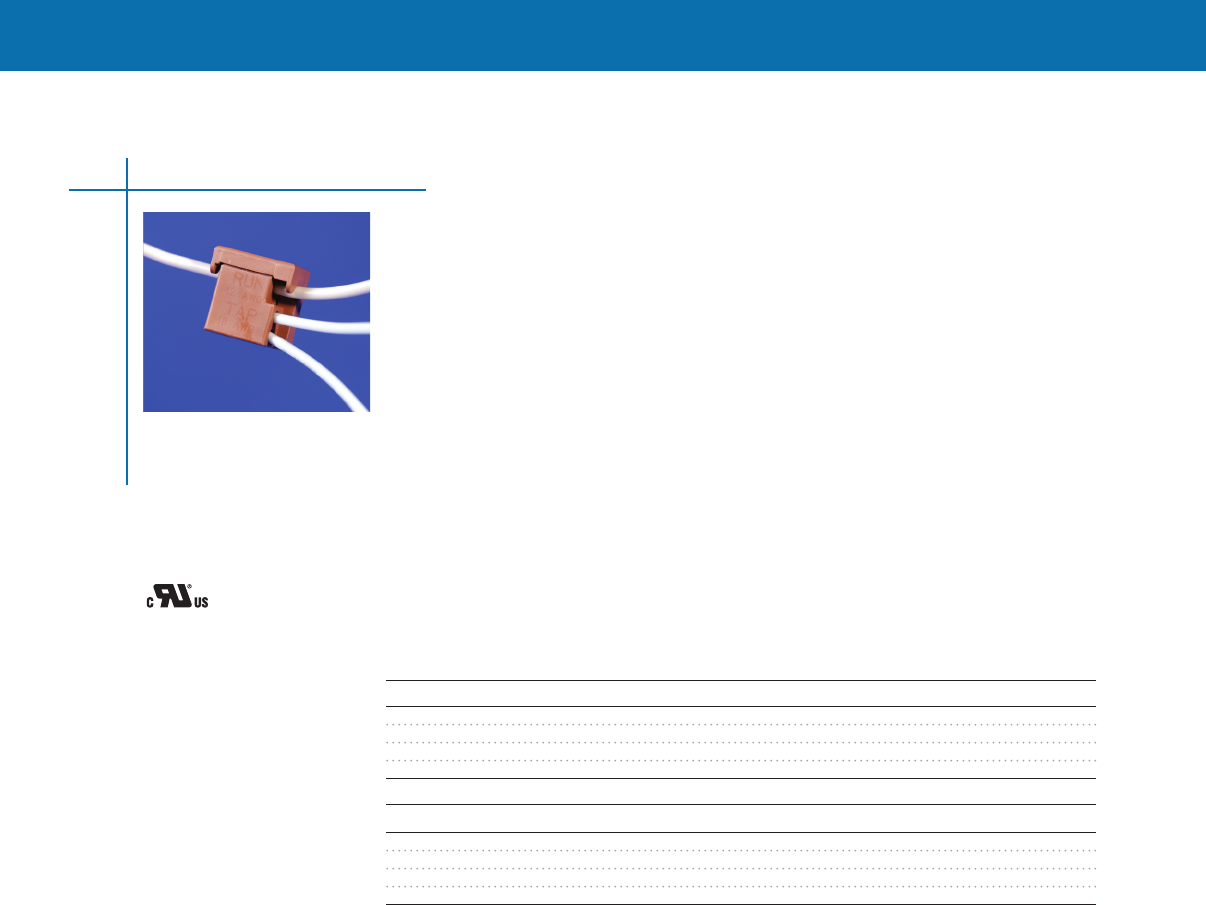
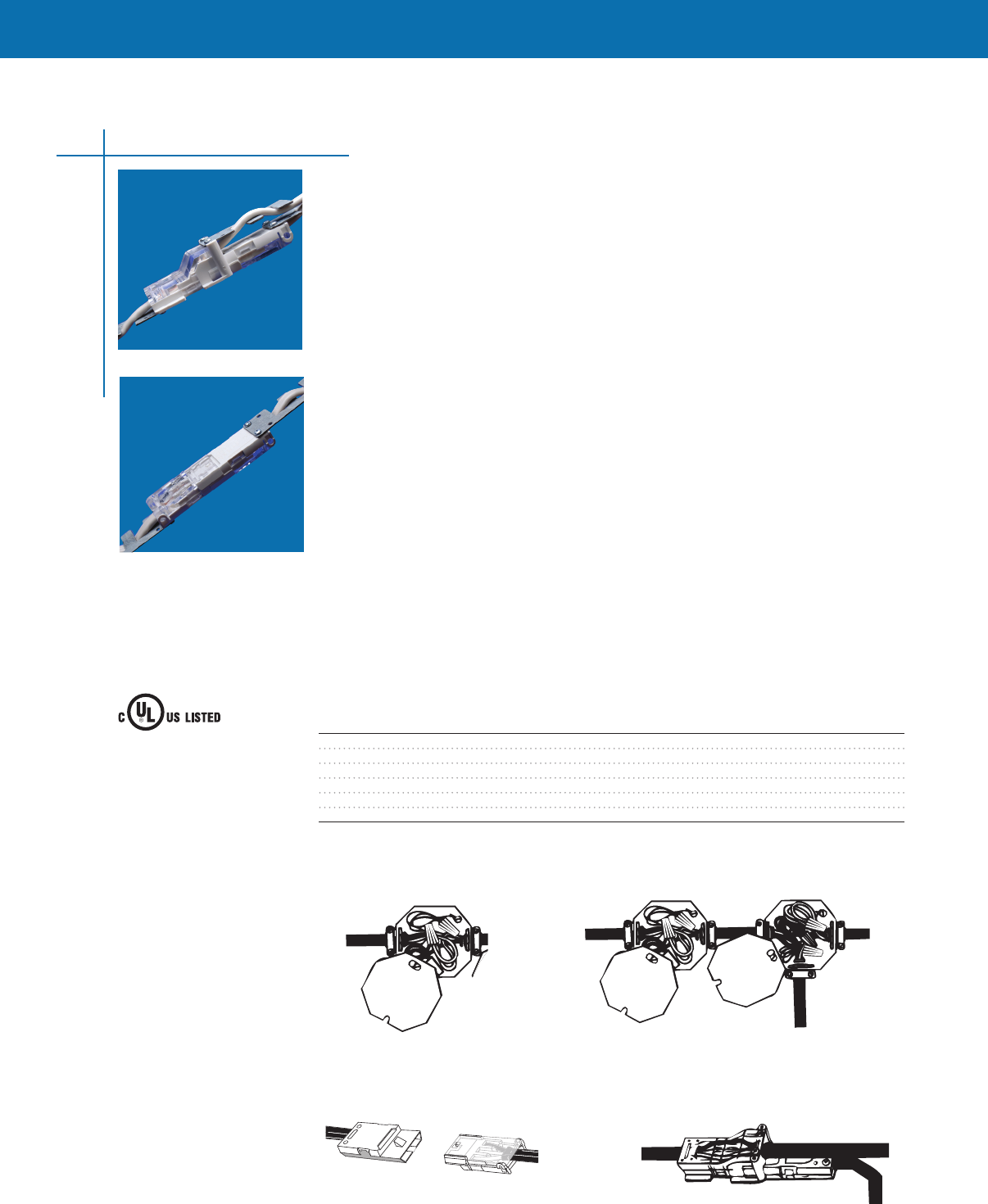
Insulation Displacement Splice Tap Connectors
Insulation displacement splice tap connectors provide a reliable method for making branch and
through wire taps to solid and stranded wires up to 300 volts The splice tap uses insulation
displacement, self-stripping contacts for faster and easier tapping than twist-on or other type splices
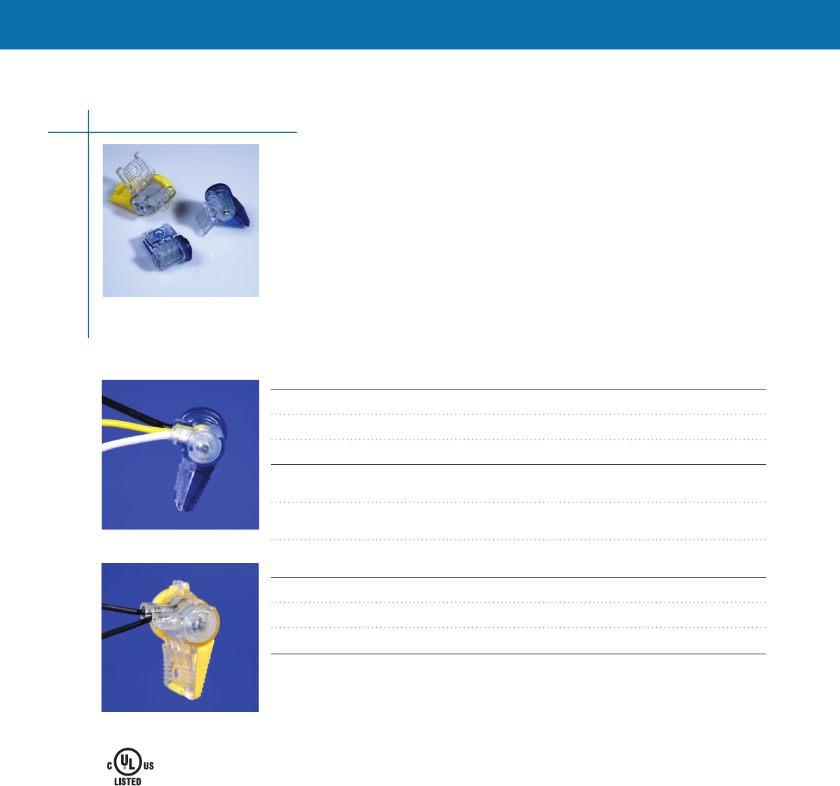
The ELECTRO-TAP connector uses insulation displacement type self-stripping contacts which provide
fast, easy tapping Creates a reliable connection on solid or stranded wires 20-10 AWG (160-195
max insulation diameter) Requires no special tooling; can be installed with ordinary pliers
Each ELECTRO-TAP connector is constructed of durable nylon with self-stripping, tin-plated brass
contacts These connectors have a wide range of wiring applications in low- and high-voltage
environments
Materials
Housing - color-coded nylon
Contact - tin-plated brass
Applications
Control Panels
Low-voltage switching systems
Plant maintenance
Harness Repair
Easy two-step operation
1 Butt tap-wire against wire stop, fold top cover half over to meet base, and squeeze with pliers
until latch locks
2 Lay run-wire in remaining section, fold over to meet base, and squeeze to latch as before
Selection information
Catalog Number Wire Range Std. Pack
CPGI-53440-9 20-18 AWG 5
CPGI-53440-9-Bulk 20-18 AWG 100
CPGI-53440-7 18-14 AWG 5
CPGI-53440-7-Bulk 18-14 AWG 100
CPGI-735411 12-10 AWG 5
CPGI-735411-Bulk 12-10 AWG 100
Insulation Piercing Connectors
20
Certified
LR7189
Wire Connectors
40CA
E13288
CONNECTORS & TERMINALS
CONNECTORS & TERMINALS
Splicing Tapping
Conventional Splicing Method Tapping Method
Non-Metallic Splicing Method Tapping Method
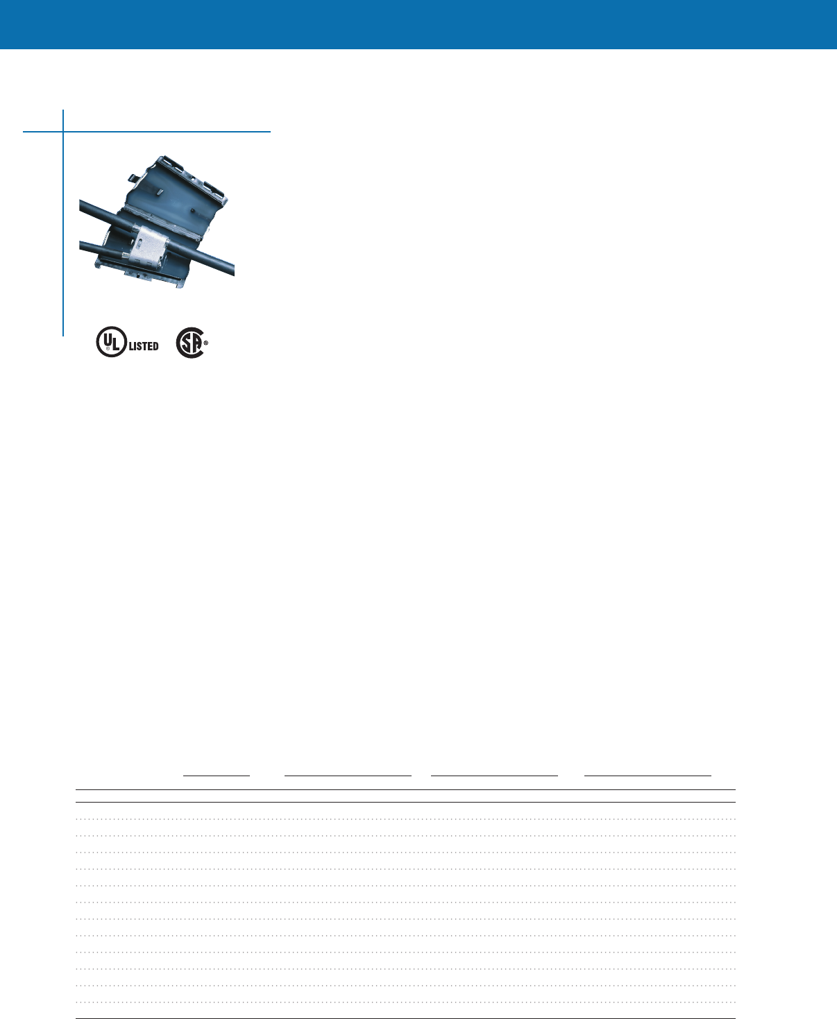
Non-Metallic Cable Splice & Tap Connectors
These splice and tap kits provide a fast and reliable method for splicing or tapping 2 wire w/ground
and splicing 3 wire w/ground non-metallic cables up to 300 volts They are designed and approved
for use in rework within existing structures Splice and Tap Kits also eliminate wire nuts for installation
and replace the conventional method for adding a splice or tap for non-metallic cable without the
need for exposed and unsightly junction boxes NEC compliant-Article 334-40b, 2005 and 2008 NEC
Non-metallic (NM) splice and tap technology provides a fast and reliable way to connect 12 and 14
AWG (331 or 208 mm2) circuits using non-metallic cable
Agency Approvals
Listed by Underwriters Laboratories Inc (UL), File E57250
Meets 2005 and 2008 National Electrical Code (NEC) Articles 334-40 (B), 545-13, 550-15K,
and 551-47 (O)
UL Listed to Canadian safety standards, File E57250
Meets CSA C221-09, "Canadian Electrical Code, Part 1" (CEC), Section 12, Rule 12-522 and Section 70
Features
• Eliminates junction boxes and wire nuts
• Fast and simple to install
• Insulation displacement contacts eliminate stripping individual conductors
• Tap into existing circuits without cutting wire
• No special tools required
• Polarized for proper mating
• Approved for residential and commercial uses
• Clear cover allows visual inspection of termination
Voltage rating: 300 VAC RMS
Temperature rating: 105°C
Current rating: 20 A
Selection information
Catalog Number Wire Range Description Std. Pack
CPGI-1116377-2 12-14 AWG Splice Kit for 2-conductor 5
CPGI-1116377-2-Bulk 12-14 AWG Splice Kit for 2-conductor 100
CPGI-208169-2 12-14 AWG Splice Kit for 3-conductor 5
CPGI-208169-2-Bulk 12-14 AWG Splice Kit for 3-conductor 100
CPGI-1116415-2 12-14 AWG Tap & Splice Kit for 2-conductor 5
CPGI-1116415-2-Bulk 12-14 AWG Tap & Splice Kit for 2-conductor 100
21
Insulation Piercing Connectors
Nonmetallic-Sheathed
Cable Interconnectors
40CA
E57250
Tap & Splice
Splice

CONNECTORS & TERMINALS
Insulation Piercing Connectors
Insulation Piercing Connectors (IPCs) provide electrical connection for aluminum and copper stranded
conductors without stripping and removing insulation from the conductors During installation the
IPC establishes electrical contact, protects, and seals the contact interface, and electrically insulates
the connection, eliminating the need for weatherproofing and re-insulating
Features
• Wide conductor range, bare and insulated cables
• Suitable for aluminum and copper conductors
• Tin-plated copper alloy contacts pierce insulation sheath
• Single bolt application with ring washers provide residual contact force
• Torque-control nut for precise pressure on conductor and insulation
• Operating temperature from -40°C to +55° C
• Quick, reliable, and safe connections on energized conductors (not under load)
Selection information: dimensions show in inches (millimeters)
Main Al/Cu Tap Al/Cu Dimensions Std.
Catalog Number Type Min. AWG Max. AWG Min. AWG Max. AWG Shear Head Weight (g) Pack
SIML-1727742-1 P3X-4/0 4 4/0 Al-2/0 Cu 4 4/0 Al-2/0 Cu 9/16” Install 202 20
(25) (95-70) (25) (95-70) 3/4” Remove
SIML-1-708052-1 KZEP-4/0 6 4/0 14 10 10mm 54 50
(16) (95) (1,5) (6)
Insulation Piercing Connectors
22
CONNECTORS & TERMINALS
CONNECTORS & TERMINALS
Insulation Piercing Connectors
23
SNAP-N-LOK Wire Connectors
The SNAP-N-LOK water-resistant splice and tap connectors are a quick and simple single-piece
solution for underground electrical systems Connectors are pre-filled with a water-resistant
sealant which provides moisture and corrosion protection SNAP-N-LOK connectors do not
require any special tools and their single piece design prevents losing additional pieces These
connectors can be used underground or above grade for lighting, irrigation and/or power splices
and taps up to 300V Re-entry allows the installer to add conductors or change wiring schemata
without cutting the wires Three connector sizes provide cost-effective simple installations ranging
from #20 - #10 AWG solid or stranded wire combinations Please see descriptions below for wire
and package configurations
Selection information
Catalog Number Description Std. Pack
CPGI-SNL-1-20-16-B-K3 SNAP-N-LOK Water-Resistant Connectors-
Any Combination of #16-#20 Solid or Stranded Wire 3/Clam
CPGI-SNL-1-20-16-B-J30 SNAP-N-LOK Water-Resistant Connectors-
Any Combination of #16-#20 Solid or Stranded Wire 30/Jar
CPGI-SNL-1-20-16-B-B100 SNAP-N-LOK Water-Resistant Connectors-
Any Combination of #16-#20 Solid or Stranded Wire 100/Bag
CPGI-SNL-2-18-12-Y-K2 SNAP-N-LOK Water-Resistant Connectors-
#12 and #14 Solid Wire with one #16, #18,
or #20 Solid or Stranded Wire 2/Clam
CPGI-SNL-2-18-12-Y-J15 SNAP-N-LOK Water-Resistant Connectors-
#12 and #14 Solid Wire with one #16, #18,
or #20 Solid or Stranded Wire 15/Jar
CPGI-SNL-2-18-12-Y-B100 SNAP-N-LOK Water-Resistant Connectors-
#12 and #14 Solid Wire with one #16, #18,
or #20 Solid or Stranded Wire 100/Bag
CPGI-SNL-3-18-10-CP-K2 SNAP-N-LOK Water-Resistant Connectors-
2 #10 or #12 Stranded Wires and 1 #16 or #18 2/Clam
CPGI-SNL-3-18-10-CP-J12 SNAP-N-LOK Water-Resistant Connectors-
2 #10 or #12 Stranded Wires and 1 #16 or #18 12/Jar
CPGI-SNL-3-18-10-CP-B100 SNAP-N-LOK Water-Resistant Connectors-
2 #10 or #12 Stranded Wires and 1 #16 or #18 100/Bag
Wire Connector
3NHT
CONNECTORS & TERMINALS
Service Entrance Connector System
MINIWEDGE Connectors
MINIWEDGE connectors incorporate wedge pressure technology to provide an easily applied and
reliable aluminum-to-aluminum/aluminum-to-copper connection for service entrance and street light
applications The color-coded packaging simplifies connector selection for terminating standard
stranded and compacted ACSR, AAAC, AAC and copper conductors
MINIWEDGE connectors are for service entrance applications from #6-to-#2 through 2/0-to-4/0
To enhance the mechanical and electrical performance of the service entrance connector the AMP
GEO-TAC surface is added to the inside of the “C” component during the manufacturing process
The GEO-TAC surface provides superior grip on the conductor to overcome the possibility of failure
due to vibration and also increase the contact surface for greater electrical performance under
changing load conditions
MINIWEDGE connectors are also offered for typical street light applications for a range of sizes to
connect from #14, #12, and #10 street light tap wire up to a 3364 thru conductor The designed
controlled force exerted by the MINIWEDGE connector does not damage the conductor and it can
be easily removed without loss of cable length
MINIWEDGE connectors offer simple installations anytime, anywhere, without the need for special
tools and complicated die selection The aluminum alloy “C” and wedge components are installed
with parallel jaw pliers A quick visual inspection of the locking tab in the inspection window
verifies the connection is complete and ready for installation of the insulated cover, if required
Factory applied inhibitor is applied to all MINIWEDGE connectors to prolong the life of the
connection in its service environment
• No special tools
• Removable without conductor loss or damage
• Unique GEO-TAC surface in “C” provides higher tensile and vibration resistance
• Conductor range #14 AWG to 3364 kcmil
• Service entrance and street light applications
• Separate insulating covers (See GHFC-MW on page 2-30)
• Color-coded for easy connector selection
• Wedge pressure reliability
• Aluminum to aluminum, aluminum to copper
• Suitable for guy, messenger and fence grounding (not for direct burial)
Approvals
• Meets ANSI C1194
• RUS
Note: MINIWEDGE connectors are not recommended for copper-to-copper connections.
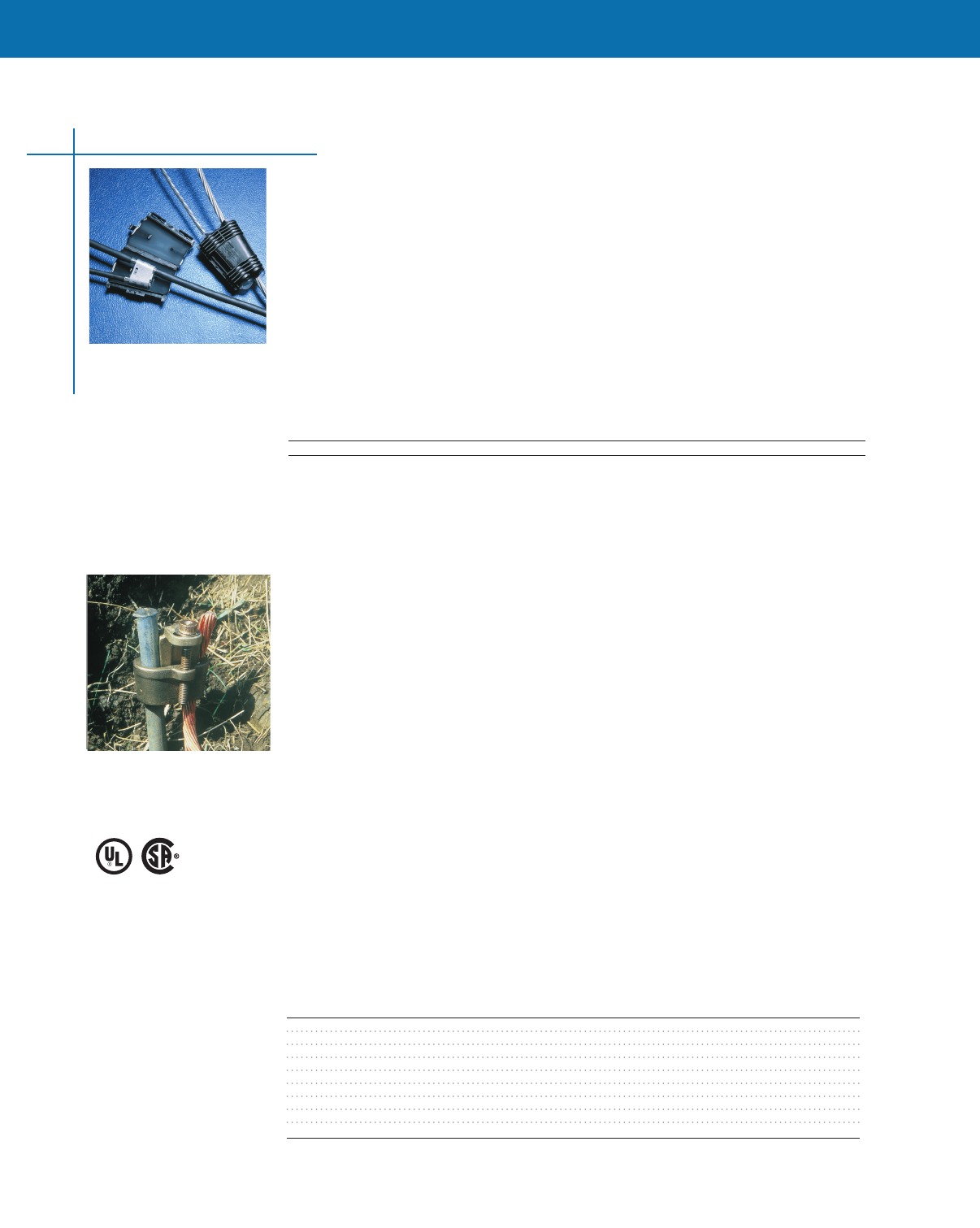
The MINIWEDGE connector with GHFC MW cover is pictured.
Wedge Pressure Connectors
24
MINIWEDGE Connectors - Wire Diameter Limits
Wire Marking
Groove Sum of Diameters Groove 1 Diameter Groove 2 Diameter
Catalog Numbers 1 2 Max. Min. Max. Min. Max. Min.
Core
83592-1 1/0 1/0 796 (2022) 696 (1768) 398 (1011) 315 (800) 398 (1011) 315 (800)
83592-2 1/0 #2 723 (1836) 618 (1570) 398 (1011) 315 (800) 336 (853) 260 (660)
83592-3 1/0 #4 656 (1666) 549 (1394) 398 (1011) 315 (800) 268 (681) 205 (521)
83592-4 1/0 #6 602 (1529) 498 (1265) 398 (1011) 315 (800) 215 (546) 138 (351)
83592-5 #2 #2 650 (1651) 550 (1397) 336 (853) 260 (660) 336 (853) 260 (660)
83592-6 #2 #4 583 (1481) 481 (1222) 336 (853) 260 (660) 268 (681) 205 (521)
83592-7 #2 #6 529 (1344) 429 (1090) 336 (853) 260 (660) 215 (546) 138 (351)
83592-8 #4 #4 516 (1311) 416 (1057) 268 (681) 205 (521) 268 (681) 205 (521)
83592-9 #4 #6 462 (1173) 362 (919) 268 (681) 205 (521) 215 (546) 138 (351)
1-83592-0 #6 #6 408 (1036) 308 (782) 215 (546) 138 (351) 215 (546) 138 (351)
1-83592-1 1/0 SB 1/0 SB 752 (1910) 652 (1656) 398 (1011) 315 (800) 398 (1011) 315 (800)
1-83592-2 1/0 SB #2 SB 670 (1702) 570 (1448) 398 (1011) 315 (800) 336 (853) 260 (660)
1-83592-3 #2 SB #2 SB 600 (1524) 500 (1270) 336 (853) 260 (660) 336 (853) 260 (660)
Certified
LR7189*
*Part Number
Series
83623 & 83630
E13288

CONNECTORS & TERMINALS
CONNECTORS & TERMINALS
Wire Marking
Groove Sum of Diameters Groove 1 Diameter Groove 2 Diameter
Catalog Numbers 1 2 Max. Min. Max. Min. Max. Min.
Service Connectors
83631-1 4/0 #2 888 (2256) 788 (2002) 570 (1448) 473 (1201) 336 (853) 260 (660)
83631-2 4/0 1/0 961 (2441) 861 (2187) 570 (1448) 473 (1201) 398 (1011) 315 (800)
83631-3 4/0 2/0 1010 (2565) 907 (2304) 570 (1448) 473 (1201) 470 (1194) 375 (953)
83631-4 3/0 #2 827 (2101) 731 (1857) 515 (1308) 420 (1067) 336 (853) 260 (660)
83631-5 3/0 1/0 900 (2286) 809 (2055) 515 (1308) 420 (1067) 398 (1011) 315 (800)
83631-6 3/0 2/0 949 (2410) 849 (2156) 515 (1308) 420 (1067) 470 (1194) 375 (953)
83631-7 2/0 #2 772 (1961) 682 (1732) 470 (1194) 375 (953) 336 (853) 260 (660)
83631-8 2/0 1/0 845 (2146) 760 (1930) 470 (1194) 375 (953) 398 (1011) 315 (800)
83631-9 2/0 2/0 894 (2271) 800 (2032) 470 (1194) 375 (953) 470 (1194) 375 (953)
1-83631-1 4/0 SB #2 SB 820 (2083) 720 (1829) 570 (1448) 473 (1201) 336 (853) 260 (660)
1-83631-2 4/0 SB 1/0 SB 901 (2289) 811 (2060) 570 (1448) 473 (1201) 398 (1011) 315 (800)
1-83631-3 4/0 SB 2/0 SB 942 (2393) 851 (2162) 570 (1448) 473 (1201) 470 (1194) 375 (953)
1-83631-4 3/0 SB #2 SB 756 (1920) 660 (1676) 515 (1308) 420 (1067) 336 (853) 260 (660)
1-83631-5 3/0 SB 1/0 SB 837 (2126) 759 (1928) 515 (1308) 420 (1067) 398 (1011) 315 (800)
1-83631-6 3/0 SB 2/0 SB 878 (2230) 799 (2029) 515 (1308) 420 (1067) 470 (1194) 375 (953)
1-83631-7 2/0 SB #2 SB 706 (1793) 620 (1575) 470 (1194) 375 (953) 336 (853) 260 (660)
1-83631-8 2/0 SB 1/0 SB 787 (1999) 700 (1778) 470 (1194) 375 (953) 398 (1011) 315 (800)
1-83631-9 2/0 SB 2/0 SB 828 (2103) 740 (1880) 470 (1194) 375 (953) 470 (1194) 375 (953)
Large Asymmetrical StreetLight
2-83623-0 3364 #4 924 (2347) 822 (2088) 675 (1715) 590 (1499) 268 (681) 205 (521)
1-83623-9 3364 #6 870 (2210) 771 (1958) 675 (1715) 590 (1499) 215 (546) 138 (351)
1-83623-8 3364 #8 828 (2103) 725 (1842) 675 (1715) 590 (1499) 198 (503) 115 (292)
1-83623-7 3364 #10 - #14 782 (1986) 673 (1709) 675 (1715) 590 (1499) 125 (318) 055 (140)
1-83623-6 2668 #4 867 (2202) 788 (2002) 620 (1575) 540 (1372) 268 (681) 205 (521)
1-83623-5 2668 #6 813 (2065) 737 (1872) 620 (1575) 540 (1372) 215 (546) 138 (351)
1-83623-4 2668 #8 771 (1958) 691 (1755) 620 (1575) 540 (1372) 198 (503) 115 (292)
1-83623-3 2668 #10 - #14 725 (1842) 639 (1623) 620 (1575) 540 (1372) 125 (318) 055 (140)
1-83623-2 4/0 #4 821 (2085) 720 (1829) 570 (1448) 473 (1201) 268 (681) 205 (521)
1-83623-1 4/0 #6 767 (1948) 669 (1699) 570 (1448) 473 (1201) 215 (546) 138 (351)
1-83623-0 4/0 #8 725 (1842) 623 (1582) 570 (1448) 473 (1201) 198 (503) 115 (292)
83623-9 4/0 #10 - #14 679 (1725) 571 (1450) 570 (1448) 473 (1201) 125 (318) 055 (140)
83623-8 3/0 #4 760 (1930) 662 (1681) 515 (1308) 420 (1067) 268 (681) 205 (521)
83623-7 3/0 #6 706 (1793) 611 (1552) 515 (1308) 420 (1067) 215 (546) 138 (351)
83623-6 3/0 #8 664 (1687) 565 (1435) 515 (1308) 420 (1067) 198 (503) 115 (292)
83623-5 3/0 #10 - #14 618 (1570) 513 (1303) 515 (1308) 420 (1067) 125 (318) 055 (140)
83623-4 2/0 #4 705 (1791) 613 (1557) 470 (1194) 375 (953) 268 (681) 205 (521)
83623-3 2/0 #6 651 (1654) 562 (1427) 470 (1194) 375 (953) 215 (546) 138 (351)
83623-2 2/0 #8 609 (1547) 516 (1311) 470 (1194) 375 (953) 198 (503) 115 (292)
83623-1 2/0 #10 - #14 563 (1430) 464 (1179) 470 (1194) 375 (953) 125 (318) 055 (140)
Small StreetLight
83630-1 1/0 #10 - #14 514 (1306) 400 (1016) 398 (1011) 315 (800) 125 (318) 055 (140)
83630-2 1/0 #8 560 (1422) 460 (1168) 398 (1011) 315 (800) 198 (503) 115 (292)
83630-3 #2 #10 - #14 441 (1120) 332 (843) 336 (853) 260 (660) 125 (318) 055 (140)
83630-4 #2 #8 487 (1237) 384 (975) 336 (853) 260 (660) 198 (503) 115 (292)
83630-5 #4 #10 - #14 374 (950) 274 (696) 268 (681) 205 (521) 125 (318) 055 (140)
83630-6 #4 #8 420 (1067) 320 (813) 268 (681) 205 (521) 198 (503) 115 (292)
83630-7 #6 #10 - #14 320 (813) 220 (559) 215 (546) 138 (351) 125 (318) 055 (140)
83630-8 #6 #8 366 (930) 266 (676) 215 (546) 138 (351) 198 (503) 115 (292)
83630-9 #8 #10 - #14 278 (706) 178 (452) 198 (503) 115 (292) 125 (318) 055 (140)
1-83630-0 #8 #8 324 (823) 224 (569) 198 (503) 115 (292) 198 (503) 115 (292)
25
Wedge Pressure Connectors
Please Contact Inside Sales Support for Additional Product Selection.
CONNECTORS & TERMINALS
SHEAR-LOK Connectors
Copper Tap/Grounding Connectors
SHEAR-LOK copper tap/grounding connector was developed for applications in the power
utility industry where connectors are required to withstand mid-range (20 kA symmetrical
RMS) magnitudes of fault current The SHEAR-LOK connectors utilize Wedge Pressure
Technology and controlled torque drive bolts to provide easily-applied and
highly-reliable ground rod connections
This family of connectors is ideal for Telco and CATV applications where connections must be
made between conductor and rods, specifically in the range of #10, #6, #4, to both 5/8" and
3/4" copper clad galvanized rods
• Wedge Pressure Technology
• Shear-head bolt—controlled torque
• Removable without conductor damage
• No special tools
• Application not inhibited by disfigured ground rod end
• Taps into existing ground conductors
Typical Applications
• Industrial/residential service grounds
• Pole grounds transmission line grounding
• Telco distribution, CATV grounds
Selection Information: dimensions shown in inches (millimeters)
Catalog Number Conductor Connects Rod To
83000-1 1/0 Str 5/8" Cu Clad Dia 562 [1430] +
80408-2 #6 Sol or Strd or #4 Sol or Strd 5/8" Cu Clad Dia 562 [1430] + *
80408-2 #6 Sol or Strd 5/8" Galv Dia 562 [1588] + *
80408-3 #6 Sol or Strd 3/4" Cu Clad Dia 682 [1732]
80408-4 #4 Sol or Strd 3/4" Cu Clad Dia 682 [1732] + *
80408-4 #6 Sol or Strd 3/4" Galv Dia 750 [1905] + *
80408-5 #4 Sol or Strd 3/4" Galv Dia 750 [1905]
80408-6 1/0 Str 3/4" Cu Clad Dia 682 [1732] +
80408-7 #6 Sol, #8 Sol, Strd or #10 Sol, Strd 5/8" Cu Clad Dia 562 [1430]
+UL Listed File No.E69905 Grounding & Bonding Including Direct Burial
*CSA Certified
Technical Document
Instruction Sheet 408-9921
Certified
LR7189
Grounding
& Bonding
Including
Direct Burial
E69905
Gel Cover for use with MINIWEDGE Connectors
GHFC MW Closure
The GHFC MW closure was specifically designed to provide sealing and corrosion protection for
MINIWEDGE connectors — installed overhead for corrosion protection or in direct buried applications
up to 1000 volts
In either case, it is as easy as simply snapping the closure over the connector
These closures are suitable for aluminum-to-aluminum and aluminum-to-copper connections The
GHFC MW gel closure fits most MINIWEDGE connector applications
Selection Information: dimensions shown in inches (millimeters)
Catalog Std.
Number Description Main Tap Pack
GHFC-MW Gel cover for sealing and insulating #8-4/0 (10-95) #14-2/0 (15-70) 10
Ordering information
1 Package does not contain MINIWEDGE connectors, which must be ordered separately
2 Standard package: 10kits/box
Wedge Pressure Connectors
26

CONNECTORS & TERMINALS
CONNECTORS & TERMINALS
Copper Connector Grounding System
WRENCH-LOK Grounding Connector
The WRENCH-LOK electrical grounding connector system provides a superior, fool-proof connection
while reducing application time dramatically The WRENCH-LOK grounding connector system uses
a specially designed shear-head bolt to drive a tapered wedge into the connector body All that’s
needed to apply it is a common ratchet or socket wrench When the connection is tightened to the
proper torque, the bolt head shears off, giving a positive visual indication of a perfect connection It’s
that simple and sure
WRENCH-LOK grounding connections require no special training, no special tools, no auxiliary power,
and they can be installed in any weather The product line offers options to connect conductor-to-
conductor or conductor-to-ground rod There is no need to change connector styles, molds or tooling
Selection Information:
Catalog Number Description Conductor to
Small Body Standard Round Compacted Ground Rod
83747-1 #2 sol, str - #2 sol, str 2 - #2
83747-2 1/0, 2/0 str - #2 sol, str 1/0, 2/0 - #2 3/8 Clad or Galv - #2
83747-3 1/0, 2/0 str - 1/0 str 1/0, 2/0 - 1/0 3/8 Clad or Galv - 1/0
3/0 str - #2 sol, str 3/0 - #2
83747-4 2/0 str - 2/0 str 2/0 - 2/0 3/8 Clad or Galv - 2/0
3/0 str - 1/0 str 3/0 - 1/0 1/2 Clad or Galv - #2
4/0 str - #2 sol, str 4/0, 250 - #2
83749-1 3/0 str - #2 str 3/0 - 2/0 1/2 Clad or Galv - 1/0
4/0 str - 1/0 str 4/0 - 1/0 5/8 Clad - #2
250 str - #2 sol, str 300 - #2
83749-2 3/0 str - 3/0,str 3/0 - 3/0 1/2 Clad or Galv - 2/0
4/0 str - 2/0 str 4/0, 250 - 2/0 5/8 Clad - 1/0
250 str - 1/0 str 250/300 - 1/0 5/8 Galv - #2
300 str - #2 sol, str 350 - #2
83749-3 4/0 str - 3/0 str 4/0 - 3/0 1/2 Clad or Galv - 3/0
250 str - 2/0 str 300 - 2/0 5/8 Clad - 2/0
300 str - 1/0 str 350 - 1/0 5/8 Galv - 1/0
350 str - #2 sol, str 400, 450 - #2 3/4 Clad - #2
83748-1 4/0 str - 4/0 str 4/0 - 4/0 1/2 Clad or Galv - 4/0
250 str - 3/0 str 250, 300 - 3/0 5/8 Clad - 3/0
300 str - 2/0 str 350 - 2/0 5/8 Galv - 2/0
350 str - 1/0 str 400 - 1/0
83748-2 4/0 str - 4/0 str 250, 300 - 4/0 5/8 Clad - 4/0
300 str - 3/0 str 350 - 3/0 5/8 Galv - 3/0
350 str - 2/0 str 400 - 2/0
83749-4 400, 450 str - #2 sol, str 450 - 1/0 3/4 Clad - 1/0
500 - #2 3/4 Galv - #2
83748-3 350 str - 3/0 str 400 - 3/0 3/4 Clad - 2/0
400 str - 2/0, 1/0 str 450 - 2/0 3/4 Galv - 1/0
450 str - 1/0 str 500 - 1/0
83748-4 300 str - 4/0 str 350 - 4/0, 250 5/8 Galv - 4/0
400 str - 3/0 str 400 - 4/0 5/8 Galv - 250 cmpt
450 str - 2/0 str 450 - 3/0 3/4 Clad - 3/0
500 - 2/0 3/4 Galv - 2/0
83750-1 250 str - 250 str 250, 300 - 250, 300 5/8 Clad - 250 str, cmpt
Wedge Pressure Connectors
27
Wrench-Lok Copper Grounding Connector System continues next page

CONNECTORS & TERMINALS
28
Selection Information:
Catalog Number Description Conductor to
Small Body Standard Round Compacted Ground Rod
83751-1 300 str - 250 str 350, 400 - 300 5/8 Galv - 250 str, —
300 cmpt
350, 400 str - 4/0 str 400 - 250 3/4 Clad - 4/0,250 cmpt
450 str - 3/0 str 450 - 4/0 3/4 Galv - 3/0
500 str - 2/0 str 500 - 3/0
83751-2 300, 350 str - 300 str 350, 400 - 350 5/8 Galv - 350 cmpt,—
300 str
350, 400 str - 250 str 450 - 300, 250 3/4 Clad - 250 str,—
300 cmpt
450 str - 4/0 str 500 - 250 3/4 Galv - 4/0, 250—
cmpt 500 str - 3/0 str
83751-3 350 str - 350 str 400 - 400 3/4 Clad - 300 str, —
cmpt, str, 400 cmpt
400 str - 300 str 450 - 350 3/4 Galv - 250 str, —
300 cmpt
450 str - 250 str 500 - 350, 300
500 str - 4/0 str
83751-4 400 str - 350 str 400, 500 - 400 3/4 Galv - 300 str, —
350 cmpt, 400 cmpt
450 str - 300 str
500 str - 250 str
83750-2 400 str - 400 str 450, 500 - 450 3/4 Galv - 350 str, 450—
450cmpt
450 str - 350 str
500 str - 300 str
Wedge Pressure Connectors
Please Contact Inside Sales Support for Additional Product Selection.
TERMINAL BLOCKS & BARRIER STRIPS
Dual Row Barrier Strips
Double-Row, Dual-Barrier Strips31
Europa Terminal Blocks
8mm (315) Pitch, 30A, with Tunnel Connection Series TSB23033
10mm (394) Pitch, 30A with Tunnel Connection Series TSB500 34
12mm (472) Pitch, 40A Series TSB1000 35
135mm (531) Pitch, 40A Series TSB1500 36
Modular Terminal Blocks
100 Series, High Density Miniature Blocks 37
900 Series, Medium Duty38
200 Series, Heavy Duty 39
200 Series, Heavy-Duty Phenolic Blocks 40
800 Series, Intermediate Heavy Duty 41
400 Series, Ultra Heavy Duty 42
Modular Fuse & Switches
300 Series, Fuse & Switch 44
One-piece Terminal Blocks
B100 Series, One-Piece Phenolic Blocks46
Accessories
Mounting Channels 47
Channel Clamps 47
Jumpers 47
29

30

TERMINAL BLOCKS & BARRIER STRIPS
TERMINAL BLOCKS & BARRIER STRIPS
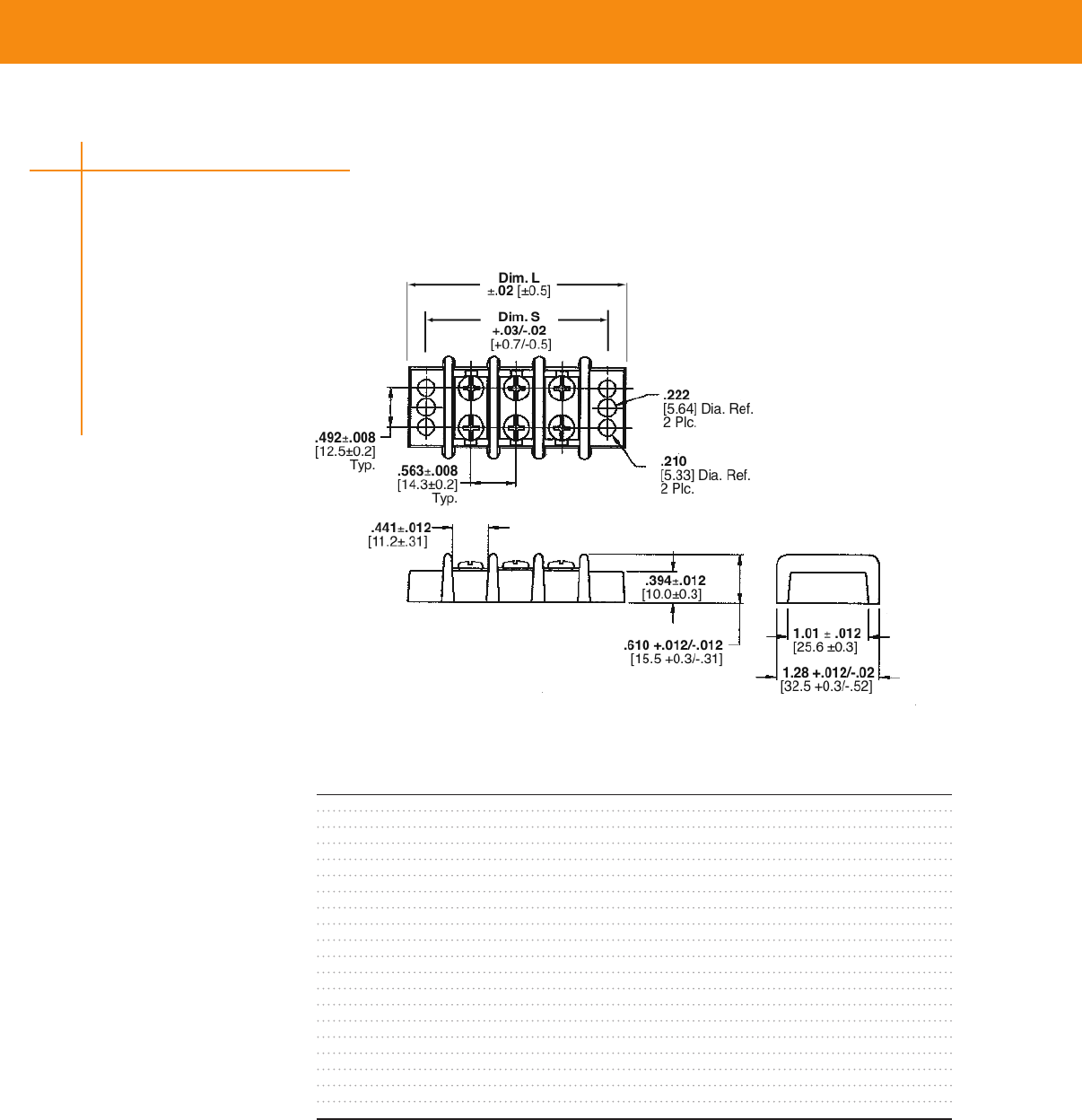
Double-Row, Dual-Barrier Strips
• Double-row, dual-barrier strips for wire-to-wire applications These parts also allow end users to
complete the wiring to a separate screw without disturbing the factory wiring
• Available with either binding head screws or wire clamp
• Increased current-carrying capability
Applications
• Industrial Controls
• Test Equipment
• HVAC
• Power Supplies
• Traffic Signals
• Telecom
Key Features
• Closed bottom design allows for mounting direct to sheet metal panel
• Molded to length
• Accessories such as Quick-Connect Tabs and Jumpers available
• Wire-to-wire termination: - 563 (143) centerline: Up to 18 positions
• RoHS Compliant
Material & Finish
Insulator Body—UL94V-0, thermoplastic, black
Terminals—Brass, tin plated
Screw—M40 steel, nickel plated
Mechanical Properties
Screw Torque—16 in-lb
Electrical Properties
Current Rating—30 A, 300 VAC
Wire Range—10-22 AWG
Withstanding Voltage—2000 VAC min
Environmental Properties
Operating Temperature— -40˚F to +284˚F (-40˚C to +140˚C)
E60677
Dual Row Barrier Strips
31
TERMINAL BLOCKS & BARRIER STRIPS
TERMINAL BLOCKS & BARRIER STRIPS
Part Numbers
No. of Dimension w/Wire w/Binding Head
Positions L S Clamp Screws Screws
2 213 (540) 169 (429) CPGI-BUCH-1546311-2 CPGI-BUCH-1546310-2
3 269 (683) 225 (572) CPGI-BUCH-1546311-3 CPGI-BUCH-1546310-3
4 325 (826) 281 (715) CPGI-BUCH-1546311-4 CPGI-BUCH-1546310-4
4 3.25 (82.6) 2.81 (71.5) CPGI-1546310-4
5 381 (969) 338 (858) CPGI-BUCH-1546311-5 CPGI-BUCH-1546310-5
6 438 (1112) 394 (1001) CPGI-BUCH-1546311-6 CPGI-BUCH-1546310-6
6 4.38 (111.2) 3.94 (100.1) CPGI-1546310-6
7 494 (1255) 450 (1144) CPGI-BUCH-1546311-7 CPGI-BUCH-1546310-7
8 550 (1398) 507 (1287) CPGI-BUCH-1546311-8 CPGI-BUCH-1546310-8
8 5.50 (139.8) 5.07 (128.7) CPGI-1546310-8
9 608 (1541) 563 (1430) CPGI-BUCH-1546311-9 CPGI-BUCH-1546310-9
10 663 (1684) 619 (1573) CPGI-BUCH-1-1546311-0 CPGI-BUCH-1-1546310-0
11 719 (1827) 676 (1716) CPGI-BUCH-1-1546311-1 CPGI-BUCH-1-1546310-1
12 775 (1970) 732 (1859) CPGI-BUCH-1-1546311-2 CPGI-BUCH-1-1546310-2
13 832 (2113) 788 (2002) CPGI-BUCH-1-1546311-3 CPGI-BUCH-1-1546310-3
14 888 (2256) 844 (2145) CPGI-BUCH-1-1546311-4 CPGI-BUCH-1-1546310-4
15 944 (2399) 901 (2288) CPGI-BUCH-1-1546311-5 CPGI-BUCH-1-1546310-5
16 1002 (2545) 957 (2431) CPGI-BUCH-1-1546311-6 CPGI-BUCH-1-1546310-6
17 1057 (2685) 1013 (2574) CPGI-BUCH-1-1546311-7
18 1113 (2828) 1070 (2717) CPGI-BUCH-1-1546311-8 CPGI-BUCH-1-1546310-8
Double-Row, Dual Barrier Strips continued
Selection information (dimensions in inches/millimeters)
32
Dual Row Barrier Strips
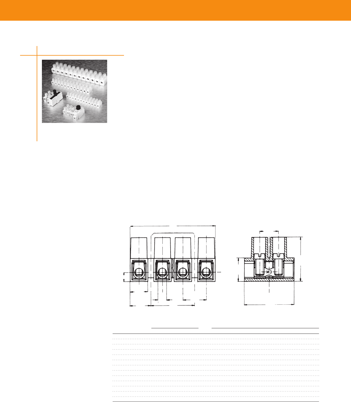
TERMINAL BLOCKS & BARRIER STRIPS
TERMINAL BLOCKS & BARRIER STRIPS
No. of Dimensions Tunnel Connection
Positions A B Part Number Buchanan Number
1 6 (24) — CPGI-BUCH-1776294-1 TSB230 01
2 14 (55) — CPGI-BUCH-1776294-2 TSB230 02
3 22 (87) 8 (31) CPGI-BUCH-1776294-3 TSB230 03
4 30 (118) 16 (63) CPGI-BUCH-1776294-4 TSB230 04
5 38 (150) 24 (94) CPGI-BUCH-1776294-5 TSB230 05
6 46 (181) 32 (126) CPGI-BUCH-1776294-6 TSB230 06
7 54 (213) 40 (157) CPGI-BUCH-1776294-7 TSB230 07
8 62 (244) 48 (189) CPGI-BUCH-1776294-8 TSB230 08
9 70 (276) 56 (220) CPGI-BUCH-1776294-9 TSB230 09
10 78 (307) 64 (252) CPGI-BUCH-1-1776294-0 TSB230 10
11 86 (339) 72 (283) CPGI-BUCH-1-1776294-1 TSB230 11
12 94 (370) 80 (315) CPGI-BUCH-1-1776294-2 TSB230 12
12 94 (3.70) 80 (3.15) CPGI-1-1776294-2 TSB230 12
8mm (.315) Pitch, 30A, with Tunnel Connection
Series TSB230
Material & Finish
Housing Material—Polyamide 6
Flammability—UL94V-2
Color—natural (off white)
Tubular Contact—Brass, tin plated
Screw—Steel, M3
Screw Plating—Zinc with chromate
Mechanical Properties
Pitch (terminal spacing)— 8mm (315)
Wire Strip Length—5mm (020")
Min Wire Pull-Out Force—75lbs
Recommended Tightening Torque—5in- lbs
Recommended Screwdrivers—Stanley 1016, Sears Craftsman 41429, Xcelite R184
Electrical Properties
Maximum Current—30A
Operating Voltage—250V
Wire Range—12-24 AWG
Dielectric Withstand—3000V
Environmental Properties
Continuous Working Temperature— -35˚C to +100˚C (-31˚F to +212˚F)
24
(61)
28
(7)
14
(35)
31
(8) 67
(17)
59
(15)
31
(8)
26
(65)
12
(31)
B
A
Mounting Hole 111(28) Dia
Europa Terminal Blocks
33
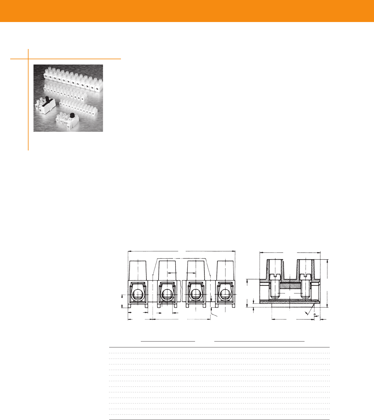
TERMINAL BLOCKS & BARRIER STRIPS
No. of Dimensions Tunnel Connection
Positions A B Part Number Buchanan Number
1 66 (26) — — TSB500 0131
2 166 (65) — CPGI-BUCH-1776297-2 TSB500 0231
3 266 (105) 10 (39) CPGI-BUCH-1776297-3 TSB500 0331
4 366 (144) 20 (79) CPGI-BUCH-1776297-4 TSB500 0431
5 466 (183) 30 (118) CPGI-BUCH-1776297-5 TSB500 0531
6 566 (223) 40 (157) CPGI-BUCH-1776297-6 TSB500 0631
7 666 (262) 50 (197) CPGI-BUCH-1776297-7 TSB500 0731
8 766 (302) 60 (236) CPGI-BUCH-1776297-8 TSB500 0831
9 866 (341) 70 (276) CPGI-BUCH-1776297-9 TSB500 0931
10 966 (380) 80 (315) CPGI-BUCH-1-1776297-0 TSB500 1031
11 1066 (420) 90 (354) CPGI-BUCH-1-1776297-1 TSB500 1131
12 1166 (459) 100 (394) CPGI-BUCH-1-1776297-2 TSB500 1231
12 116.6 (4.59) 100 (3.94) CPGI-1-1776297-2 TSB500 1231
10mm (.394) Pitch, 30A with Tunnel Connection
Series TSB500
Material & Finish
Housing Material—Polyamide 6
Flammability—UL94V-2
Color—Natural (off white)
Tubular Contact—Brass, tin plated
Screw—Steel, M3
Screw Plating—Zinc with chromate
Mechanical Properties
Pitch (terminal spacing)—10mm (394)
Wire Strip Length—5mm (020")
Min Wire Pull-Out Force—75lbs
Recommended Tightening Torque—5 in- lbs
Recommended Screwdrivers—Stanley 1016, Sears Craftsman 41429, Xcelite R184
Electrical Properties
Maximum Current—30A
Operating Voltage—250V
Wire Range—10-22 AWG
Dielectric Withstand—3500V
Environmental Properties
Continuous Working Temperature— -35˚C to +100˚C (-31˚F to +212˚F)
26
(66)
33
(83)
18
(45)
39
(10)
55
(14) 09
(22)
30°
05
(13)
08
(2)
63
(16)
37
(93)
81
(205)
13
(34)
B
M3
A
Mounting Hole 12 (31) Dia
Europa Terminal Blocks
34
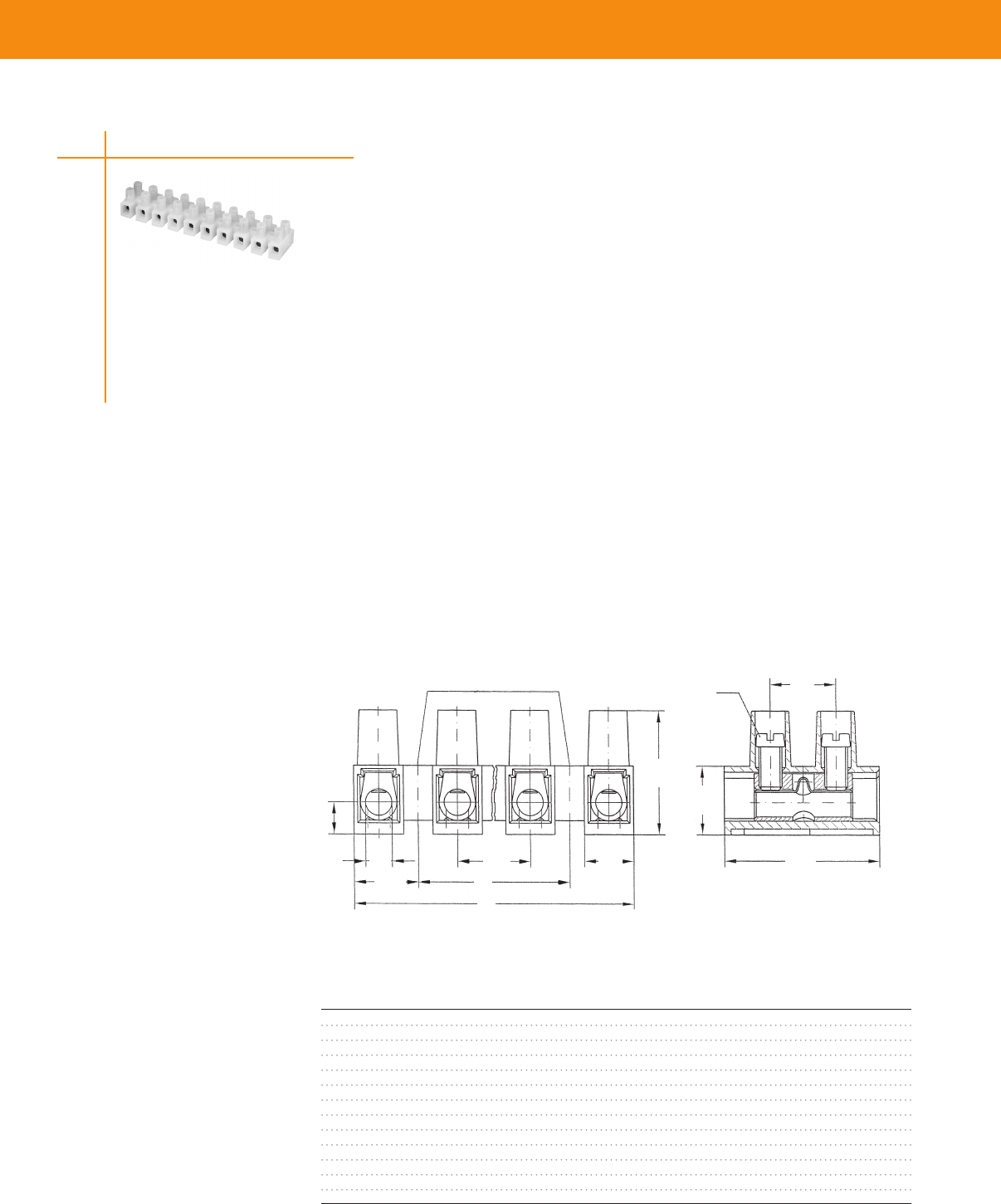
TERMINAL BLOCKS & BARRIER STRIPS
TERMINAL BLOCKS & BARRIER STRIPS
12mm (.472) Pitch, 40A
Series TSB1000
Europa Terminal Blocks
Material & Finish
Housing Material—Polyamide 6
Flammability—UL94V-2
Color—Natural (off white)
Tubular Contact—Brass, tin plated
Screw—Steel, M35
Screw Plating—Zinc with chromate
Wire Protector—Stainless steel
Mechanical Properties
Pitch (terminal spacing)—
12mm [472"]
Wire Strip Length—7mm [28"]
Min Wire Pull-Out Force—125 lbs
Recommended Tightening Torque—10 in- lbs
Recommended Screwdrivers—Stanley 1016, Sears Craftsman 41429, Xcelite R184
Electrical Properties
Maximum Current—40A
Operating Voltage—250V
Wire Range—10-22 AWG
Dielectric Withstand—4500V
Environmental Properties
Continuous Working Temperature - -35˚C to +100˚C [-31˚F to +212˚F]
.16
(4)
.47
(12)
.29
(7.5)
.39
(10)
Mounting Hole Ø .144
(3.6)
.92
(23.5)
.73
(18.5)
.19
(4.8)
M3.5
.38
(9.75) B
A
.41
(10.4)
No. of Dimensions Wire Protector
Positions A B Part Number Buchanan Number
1 75 (30) — CPGI-BUCH-1776319-1 TSB1000 01MDS
2 195 (77) — CPGI-BUCH-1776319-2 TSB1000 02MDS
3 315 (124) 12 (47) CPGI-BUCH-1776319-3 TSB1000 03MDS
4 435 (171) 24 (95) CPGI-BUCH-1776319-4 TSB1000 04MDS
5 555 (219) 36 (142) CPGI-BUCH-1776319-5 TSB1000 05MDS
6 675 (266) 48 (189) CPGI-BUCH-1776319-6 TSB1000 06MDS
7 795 (313) 60 (236) CPGI-BUCH-1776319-7 TSB1000 07MDS
8 915 (360) 72 (283) CPGI-BUCH-1776319-8 TSB1000 08MDS
9 1035 (407) 84 (331) CPGI-BUCH-1776319-9 TSB1000 09MDS
10 1155 (455) 96 (378) CPGI-BUCH-1-1776319-0 TSB1000 10MDS
11 1275 (502) 108 (425) CPGI-BUCH-1-1776319-1 TSB1000 11MDS
12 1395 (549) 120 (472) CPGI-BUCH-1-1776319-2 TSB1000 12MDS
12 139.5 (5.49) 120 (4.72) CPGI-1-1776319-2 -
35
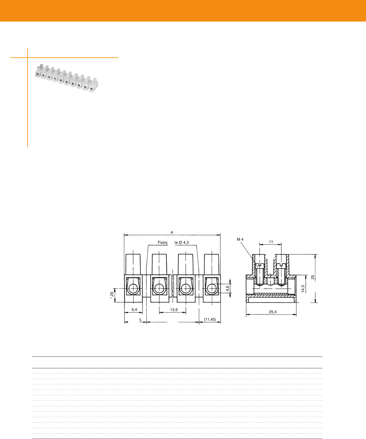
TERMINAL BLOCKS & BARRIER STRIPS
13.5mm (.531) Pitch, 40A
Series TSB1500
Material & Finish
Housing Material—Polyamide 6
Flammability—UL94V-2
Color—Natural (off white)
Tubular Contact—Brass, tin plated
Screw—Steel
Screw Plating—Zinc with chromate
Wire Protector—Stainless steel
Tunnel Connection—Without wire protector
Mechanical Properties
Pitch (terminal spacing)—135mm (531")
Wire Strip Length—8mm (315")
Recommended Tightening Torque—10 in-lbs
Recommended Screwdrivers—Stanley 1016, Sears Craftsman 41429, Xcelite R184
Electrical Properties
Maximum Current—40A (UR); 55A (CSA)
Operating Voltage—300V
Wire Range
Wire Protector—8-18 AWG
Tunnel Connection—8-16 AWG
Environmental Properties
Continuous Working Temperature— -35°C to +100°C (-31°F to +212°F)
B
Tunnel Connection Version shown
45
(1145)
45
(1145)
53
(135)
37
(94)
43
(11)
56
(143)
98
(25)
18
(46)
28
(725)
A
No. of Dimensions Tunnel Connection Wire Protector
Positions A B Part Number Buchanan Number Part Number Buchanan Number
1 94 (37) — CPGI-BUCH-1776310-1 TSB1500 01 CPGI-BUCH-1776311-1 TSB1500 01DS
2 229 (90) — CPGI-BUCH-1776310-2 TSB1500 02 CPGI-BUCH-1776311-2 TSB1500 02DS
3 364 (143) 135 (53) CPGI-BUCH-1776310-3 TSB1500 03 CPGI-BUCH-1776311-3 TSB1500 03DS
4 499 (196) 270 (106) CPGI-BUCH-1776310-4 TSB1500 04 CPGI-BUCH-1776311-4 TSB1500 04DS
5 634 (249) 405 (159) CPGI-BUCH-1776310-5 TSB1500 05 CPGI-BUCH-1776311-5 TSB1500 05DS
6 769 (303) 540 (212) CPGI-BUCH-1776310-6 TSB1500 06 CPGI-BUCH-1776311-6 TSB1500 06DS
7 904 (355) 675 (265) CPGI-BUCH-1776310-7 TSB1500 07 CPGI-BUCH-1776311-7 TSB1500 07DS
8 1039 (409) 810 (319) CPGI-BUCH-1776310-8 TSB1500 08 CPGI-BUCH-1776311-8 TSB1500 08DS
9 1174 (462) 945 (372) CPGI-BUCH-1776310-9 TSB1500 09 CPGI-BUCH-1776311-9 TSB1500 09DS
10 1309 (515) 1080 (425) CPGI-BUCH-1-1776310-0 TSB1500 10 CPGI-BUCH-1-1776311-0 TSB1500 10DS
11 1444 (568) 1215 (478) CPGI-BUCH-1-1776310-1 TSB1500 11 CPGI-BUCH-1-1776311-1 TSB1500 11DS
12 1579 (621) 1350 (531) CPGI-BUCH-1-1776310-2 TSB1500 12 CPGI-BUCH-1-1776311-2 TSB1500 12DS
12 157.9 (6.21) 135.0 (5.31) CPGI-1-1776311-2 TSB1500 12DS
Europa Terminal Blocks
36
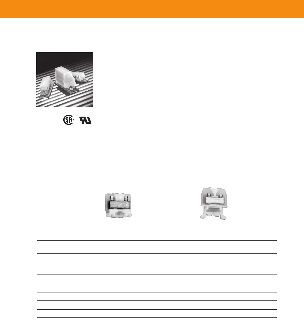
TERMINAL BLOCKS & BARRIER STRIPS
TERMINAL BLOCKS & BARRIER STRIPS
100 Series, High Density Miniature Blocks
• No Wire Crimping Required — tubular clamp contacts hold wire ranging from #30 to #12 AWG
better than crimp-on terminals
• Saves Installation Time and Costs — tubular clamp contacts are supplied with captive screws
backed out
• Nylon housing standard; polypropylene for fire retardant characteristics
• Positive Stop — helps prevent wire from being inserted too far, and helps prevent screw from
being tightened on insulation Easy access contact provides for safe, reliable, and cost-effective
connection
• Quick Installation and Change — additional sections may be added or removed without removing
channel mounting screw
• Choice of Five Mounting Channels:
- Miniature aluminum
- Zinc-plated steel
- Pre-punched aluminum
- Break-away steel
• Single and Double Tier blocks fit all standard Buchanan mounting channels Single Tier blocks fit
both miniature and standard channels
• Choice of Marking Surfaces — matte-finish area for marking directly on block; slide-in vinyl strip
(blank or preprinted) also available
These miniature terminal blocks fit on a much smaller channel to save valuable panel space or can
be surface mounted directly to the panel Miniature blocks accept wire as large as #12 AWG and are
available in four styles: Miniature (nylon), Miniature (polypropylene), Single Tier and Double Tier
LR25557 E63810
Miniature Nylon Single Tier
100 Series High Density Minitaure Blocks
Miniature Part Single Part
Type of Block Nylon Number Tier Number
Standard Block 125-BU
CPGI-BUCH-
2-1437392-3 115-BU
CPGI-BUCH-
1437381-5
Specifications
Housing Material Nylon — Nylon —
Max Service Temperature 125˚C (257˚F) — 125˚C (257˚F) —
Flammability UL94V-2 — UL94V-2 —
Wire Strip Length (in) 5/16 — 5/16 —
Torque, in-lbs 6-9 — 6-9 —
Electrical Characteristics
UL Rating 20 A @ 300V — 20 A @ 600V —
Wire Range (solid & stranded) 30-12 — 30-12 —
Spacing
Pitch 025" — 025" —
Terminals per Foot 48 — 48 —
End Section
End Section (gray) 130-BU
CPGI-BUCH-
2-1437392-5 120
CPGI-BUCH-
2-1437392-1
Modular Terminal Blocks
37
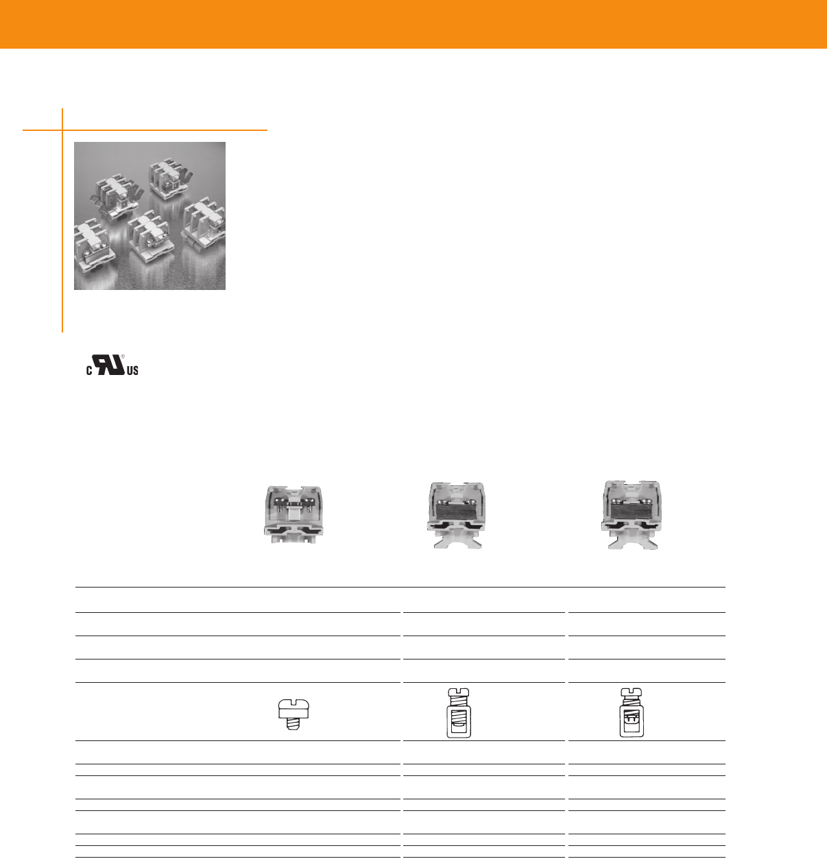
TERMINAL BLOCKS & BARRIER STRIPS
900 Series, Medium Duty
• High circuit density - 183 circuits per 6-foot length, 3/8 inch pitch
• Choice of three contact styles - tubular clamp, tubular screw, strap screw
• Sections snap-fit with Heavy Duty, Intermediate Heavy Duty, and Fuse & Switch blocks
• Readily identify circuits - mark directly on block sections or use removable marking strip
Preprinted marking strips also available
• Rated up to 50 amperes per circuit
• Flat base models mount directly to surfaces or on miniature channel Dovetail base mounts on
standard size channel
• Packaged for rapid handling and assembly - 100 per carton
• Only one end section needed per block assembly
• Fanning strips - interlocking sectional fanning strips allow entire circuit groups to be connected
and disconnected as a single unit
• Factory assembled blocks available, including marking strips and different contact sections
NEMA 900 Series is available in 375"(953) centerline, in direct or channel mount, tubular or
strap versions, and screw, clamp or quick connect configurations Corrosion-resistant versions are
also available
NEMA 900 Series snap fit with the Medium Duty 500, 600 and 700 Series, as well as with the Heavy
Duty, Intermediate Heavy Duty and Fuse & Switch blocks
900 Series, 600V Medium Duty, 0.375” (9.53) Pitch
Strap Tubular Tubular
Type of Block Screw Part Number Screw Part Number Clamp Part Number
Direct Mount (Flat Base)
Standard 921 CPGI-BUCH-1546143-1 924 CPGI-BUCH-1546147-1 925 CPGI-BUCH-1546234-1
Channel Mount (Dovetail Base)
Standard 0921 CPGI-BUCH-1546144-1 0924 CPGI-BUCH-1546148-1 0925 CPGI-BUCH-1546235-1
Contact Type
Specifications
Wire Range (AWG)
Solid & Stranded 10*, 22-14 22-8 22-8
Wire Strip Length (in) — 11/32 11/32
Screw Type 6-32 10-32 10-32
Binding Head Pan Head Slotted Pan Head
Ampacity 35 A*, 15A 50 A 30 A
End Sections
Direct Mount 930 CPGI-BUCH-1546163-1 930 CPGI-BUCH-1546163-1 930 CPGI-BUCH-1546163-1
Channel Mount 0930 CPGI-BUCH-1546164-1 0930 CPGI-BUCH-1546164-1 0930 CPGI-BUCH-1546164-1
Strap Screw Tubular Screw
Tubular Clamp
Modular Terminal Blocks
38
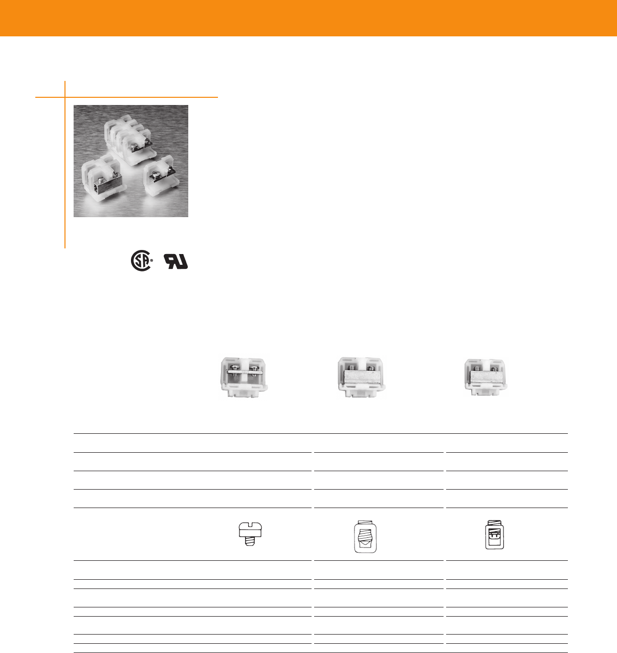
TERMINAL BLOCKS & BARRIER STRIPS
TERMINAL BLOCKS & BARRIER STRIPS
200 Series, Heavy Duty, 600V, 0.50" (1.27) Pitch
Strap Tubular Tubular
Type of Block Screw Part Number Screw Part Number Clamp Part Number
Direct Mount (Flat Base)
Nylon, Unpainted 241 CPGI-BUCH-3-1437390-9 242 CPGI-BUCH-4-1437390-0 243 CPGI-BUCH-4-1437390-1
Channel Mount (Dovetail Base)
Nylon, Painted 0241 CPGI-BUCH-1-1437390-6 0242 CPGI-BUCH-2-1437390-0 0243 CPGI-BUCH-2-1437390-1
Contact Type
Specifications
Wire Range (AWG)
Solid & Stranded 22-10 18-4 18-6
Wire Strip Length (in) — 1/2 1/2
Screw Type 10-32 1/4-28 1/4-28
binding head set screw set screw
Ampacity 35 A 85 A 65 A
End Sections
Direct Mount, Nylon 250 CPGI-BUCH-4-1437390-3 250 CPGI-BUCH-4-1437390-3 250 CPGI-BUCH-4-1437390-3
Channel Mount, Nylon 0250 CPGI-BUCH-2-1437390-5 0250 CPGI-BUCH-2-1437390-5 0250 CPGI-BUCH-2-1437390-5
200 Series, Heavy Duty
• Choose from 5 different contact styles
• 600 volt UL and NEMA rating
• Conservatively rated from 50 to 90 amperes per circuit, depending on which contact style
is selected
• Choose any of three mounting methods — two-way flat base models surface mount directly to the
panel or snap-on miniature channel Dovetail base models mount on standard channel
• Packaged for rapid handling and assembly — snap-fit sections are packed 10 per carton
• Only one end section needed per block assembly
• Readily identify circuits — mark directly on block sections or use removable marking strip Pre-
printed strips are also available
This compact, heavy-duty block line accepts single or combination wires up to #4 AWG, solid or
stranded The compact design allows at least 138 circuits per 6-foot length to be mounted The pitch
of this 600 volt block is 050" (1270) (centerline spacing)
LR25557 E63810
Strap Screw Tubular Screw Tubular Clamp
Modular Terminal Blocks
39
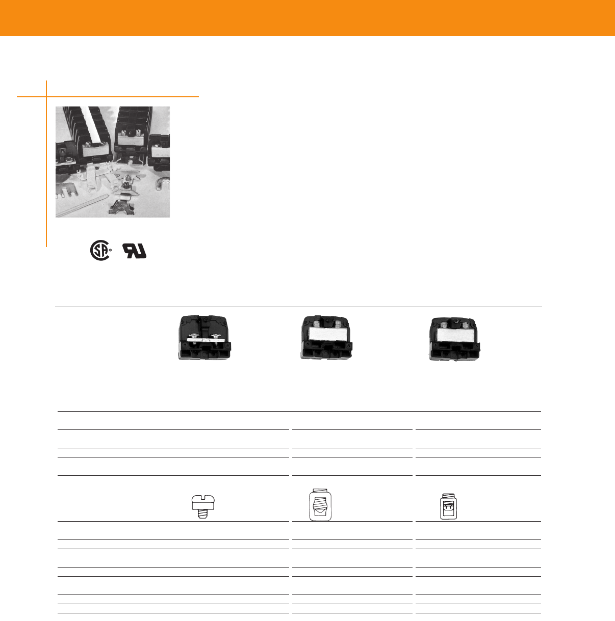
TERMINAL BLOCKS & BARRIER STRIPS
200 Series, Heavy-Duty Phenolic Blocks
• Sturdy Heavy-Duty block accepts single or combinations of wire up to #4 AWG solid or stranded—
at least 122 circuits per 6-foot length, 9/16" center-to-center spacing
• Choose from four different contact styles conservatively rated up to 90 amperes
• 600 volt UL and NEMA rating
• Surface mounted flat base and channel mounted dovetail base models available
• Only one end section needed per block assembly
• Interlocking sectional fanning strips allow entire circuit groups to be connected and disconnected as
a single unit
• Readily identify circuits — available with painted marking surface or use removable marking strip
Pre-printed strips are also available
• Factory assembled blocks available
• Heavy-Duty Phenolic Block Sections Snap-fit with 300 & 600 volt, medium duty phenolic, heavy
duty nylon and polypropylene, and Fuse and Switch blocks
This family of phenolic heavy duty blocks is ideal for high temperature, high current applications The
rugged material withstands temperatures up to 302°F (150°C)
Strap Part Tubular Part Tubular Part
Type of Block Screw Number Screw Number Clamp Number
Direct Mount (Flat Base)
Painted 221 CPGI-BUCH-3-1437390-1 222-BU CPGI-BUCH-3-1437390-3 223-BU CPGI-BUCH-3-1437390-6
Channel Mount (Dovetail Base)
Painted 0221 CPGI-BUCH-1437390-8 0222 CPGI-BUCH-1437390-9 0223 CPGI-BUCH-1-1437390-2
Contact Type
Specifications
Wire Range (AWG)
Solid & Stranded 22-10 18-4 18-6
Wire Strip Length (in) — 1/2 1/2
Screw Type 10-32 1/4-28 1/4-28
binding head set screw set screw
Ampacity 35 A 85 A 65 A
End Sections
Direct Mount 230-BU CPGI-BUCH-1-1437381-7 230-BU CPGI-BUCH-1-1437381-7 230-BU CPGI-BUCH-1-1437381-7
Channel Mount 0230 CPGI-BUCH-1-1437390-4 0230 CPGI-BUCH-1-1437390-4 0230 CPGI-BUCH-1-1437390-4
200 Series Heavy Duty Phenolic, 600 V, 0.56” (14.24) Pitch
Modular Terminal Blocks
LR25557 E63810
Strap Screw Tubular Screw Tubular Clamp
40

TERMINAL BLOCKS & BARRIER STRIPS
TERMINAL BLOCKS & BARRIER STRIPS
Modular Terminal Blocks
800 Series, Intermediate Heavy Duty
• An exceptionally compact block that accepts single or combinations of AWG wire sizes as large as
#1/0 — at least 92 circuits per 6-foot length, 3/4 inch center-to-center spacing
• Tubular screw contact style accepts AWG wire sizes from #12 thru #1/0, solid or stranded
• Same block mounts on surface or channel — two-way mounting base fits standard channel or
mounts directly to flat surfaces
• Packaged for rapid handling and assembly — snap-fit sections packaged 10 per carton
• Contacts conservatively rated at 155 amperes per circuit when used with copper wire
• Only one end section needed per block assembly
• Readily identify circuits — blocks available with painted marking surface or use removable vinyl
marking strip Preprinted marking strips are also available
• Factory assembled blocks available
• Nylon housing material for the most rugged applications
• Allen head screw for aluminum wire — screw tip design helps protect aluminum wire from
overtightening Slotted screw head for copper wire
• Intermediate Heavy-Duty blocks snap-fit with 300 & 600V, Medium Duty phenolic, Heavy-Duty
nylon, polypropylene and phenolic and Fuse and Switch blocks
This line of 600 volt blocks is rated up to 150 A and is available in a standard version and a corrosion
resistant version
800 Series, Intermediate Heavy Duty, 600 V, 0.75" Pitch
Description Part Number Buchanan Number
Tubular Screw, Painted CPGI-BUCH-1437395-3 824-BU
End Section CPGI-BUCH-1-1437395-4 830-BU
Material & Finish
Housing Material—Polyamide type 6/6, unfilled
Max Continuous Temp—125°C (257°F)
Water Absorption (24hrs % wt gain)—15%
Flammability—UL94V-2
Chemical Resistance—Resistant to aromatic hydrocarbons, strong alkalies
Radiation Resistance (ergs g-1 (C)—8 x 10⁷
Color—Translucent white
Electrical Properties
Voltage Rating—Blocks meet 600V clearance and creepage requirements of NEMA, UL, and CSA
standards for general industrial control equipment and panelboards Withstand voltages in excess of
IEEE switchgear standards for 750V
Breakdown Voltage, AC, 60Hz—
Contact-to-Contact: 8,800V
Contact-to-Ground: 9000V
Dielectric Strength — RH 40% @ Sea Level—470-385 Volts/mil thickness per ASTM D149
Operating Voltage—Blocks meet 600V creepage and clearance requirements; withstand voltage
greatly exceeds standards for 750V
UL High Voltage Arc Tracking (in/min)—01-35 (25-889)
Contacts
Standard Contacts
Material—Electrical grade copper conductor
Screws—Steel, zinc plated to resist corrosion in most applications
Duramax Contacts (for highly corrosive atmospheres)
Tubular Screw—Electrical grade copper tube with nickel plating; nickel plated brass screws Nickel
plating exceeds specification QQ-N-290
Class 1, Type VII
Wire Range—#12-1/0 AWG, solid or stranded
Wire Strip Length—11/16" (1746)
Screw Type—7/16" (1111) - 20 slotted headless screw
Independent Testing Service Listing and Recognition
UL Wire Sizes—Solid or Stranded, Tubular Screw
1 — #1/0 AWG, 1 — #1 AWG
1 — #2 AWG, 1 or 2 — #4 AWG
1, 2 or 3 — #6 AWG,
1, 2, 3 or 5 — #8 AWG
1 to 6 — #10 AWG, 1 to 7 — #12 AWG
Same part used for both panel
and channel mounting
LR25557 E63810
41

TERMINAL BLOCKS & BARRIER STRIPS
Modular Terminal Blocks
400 Series, Ultra Heavy Duty
• Compact 2/0 or 250 kcmil (MCM) block - at least 57 circuits per 6- foot length, 1-3/16" (3016)
center-to-center spacing
• High current capacity snap-fit sectional block — tubular contacts accept single or combinations of
wire sizes as large as 250 kcmil (MCM)
• Two contact styles available; rated up to 270 amperes for copper wire
• Allen head screws allow maximum torque when using large wire sizes
• Withstands voltages in excess of IEEE switchgear standards for 750 volts Meets clearance and
creepage spacing specified in UL, CSA, and NEMA Industrial Control Standards for 600 volts
• Same block directly mounts on surface or channel mounts
• Only one end section needed per block assembly
• Readily identify circuits—order blocks with painted marking area or use removable vinyl marking
strip Preprinted marking strips are also available
• Factory assembled blocks available
• Ultra Heavy-Duty phenolic block sections do not snap-fit with other block styles
This Ultra Heavy Duty line includes the 400 Series rated up to 270 A
Material & Finish
Housing Material—Phenolic, filled flame retardant
Flammability—UL94V-1
Color—Black
Contacts
Material—Electrical grade copper conductor; plated steel screws resist corrosion
Tubular Screw Type—
Small: 1/2" (127) - 13 Hex
Large: 3/4" (1905) - 16 Hex socket set screw
Mechanical Properties
Pitch (terminal spacing)—
119” (3023); 9 circuits/foot
Wire Strip Length—
Tubular Screw (small): 1" (254)
Tubular Screw (large): 1" (254)
Electrical Properties
Maximum Current—255A for a single 250MCM wire
Operating Voltage—Blocks meet 600V creepage and clearance requirements; withstand voltage
greatly exceeds standards for 750V
Wire Range—Tubular Screw (small):
#4-#2/0 AWG solid or stranded; Tubular Screw (large): #6 AWG-250 kcmil (MCM) solid or stranded
Dielectric Strength (RH 40% @ sea level)—300 V/mil thickness per ASTM D149
Breakdown Voltage, AC, 60Hz—
Contact-to-Contact: 10,000V
Contact-to-Ground: 10,000V
UL High Voltage Arc Tracking (in/min)—49-58 (1245-1473)
Environmental Properties
Max Continuous Temperature—
150°C (302°F)
Water Absorption (24hrs % wt gain)— 45% per ASTM D149
Chemical Resistance—Resistant to acids, alkalies, and aliphatic hydrocarbons and ketones per
ASTM D543
Radiation Resistance (ergs g-1 (C)—27 x 108
UL Independent Testing Service Recognitions
Tubular Screw: Catalog # 416 & 426-BU
1 #2/0 AWG, 1 #1/0 AWG, 1 #1 AWG,
1 or 2 #2 AWG, 1 to 3 #4 AWG, 1 to 3 #6 AWG,
1 to 4 #8 AWG, 1 to 6 #10 AWG, 2 to 8 #12 AWG,
Tubular Screw: Catalog # 417 & 427-BU
1 #250kcmil (MCM), 1 #4/0 AWG, 1 #3/0 AWG,
1 or 2 #2/0 AWG, 1 or 2 #1/0 AWG, 1 or 2 #1 AWG, 1 to 3 #2 AWG, 1 to 4 #4 AWG, 1 to 5 #6 AWG
LR25557 E63810
42
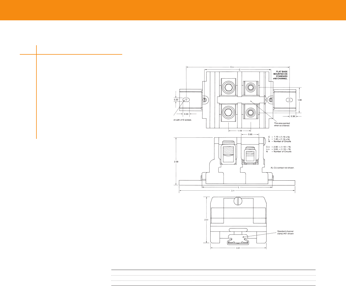
TERMINAL BLOCKS & BARRIER STRIPS
TERMINAL BLOCKS & BARRIER STRIPS
Modular Terminal Blocks
Wire Part Catalog
Description Range Number Number
Tubular Screw, Painted #14-2/0 CPGI-BUCH-1437396-7 426-BU
Tubular Screw, Painted #6-250 kcmil/MCM CPGI-BUCH-1437396-8 427-BU
End Section — CPGI-BUCH-1437396-9 430-BU
Same part used for both panel and
channel mounting
Note: For Direct Mounting, use #10 pan head
screws every six circuits. Recommended torque:
15-20 in.-lbs.
43

TERMINAL BLOCKS & BARRIER STRIPS
Modular Fuses & Switches
300 Series, Fuse & Switch
High Density Blocks
• Fuse and Switch Blocks rated 15A and 300V
• High Density 036" (914) centerline spacing saves panel space; at least 33 circuits per foot
Fuse Blocks
• Provide in-line circuit protection for virtually any circuit or group of circuits — select contacts for
terminated or unterminated wire
• Remove, check, and replace fuses safely and quickly — switch action fuse blocks open circuits
before fuse can be removed or installed
• Contacts conservatively rated to 30 amperes
Switch Blocks
• Quickly and easily interrupt a circuit or group of circuits — insert switch blocks directly in line
Contacts available for terminated or unterminated wire
• Keep circuits open for extended periods — switch blade can be removed entirely from block for
lock-out protection
• Rated to 15 amperes
Common Features of 300 & 0300 Series
• At least 91 circuits per 6-foot length, 3/4 inch center-to-center spacing
• Blocks meet 600 volt clearance and creepage spacings specified in UL, CSA, and NEMA Industrial
Control Standards
• Choose nylon housing material
• Dovetail base fits standard mounting channel — can also be mounted on flat surfaces
• Only one end section needed per block assembly
• Readily identify circuits — mark directly on white, matte-surface puller assembly, marking tab on
block, or use removable marking tape
• Open or close several circuits simultaneously — holes in puller handles allow use of nylon
“ganging” rods
• Fuse and Switch block sections snap-fit with 300 & 600 Volt, phenolic Medium Duty, Heavy Duty,
and Intermediate Heavy Duty blocks
This broad line features High Density Blocks (Series 0135), Nylon & Polypropylene Blocks (Series
0300) and Phenolic Blocks (Series 300)
LR25557 E63810
44
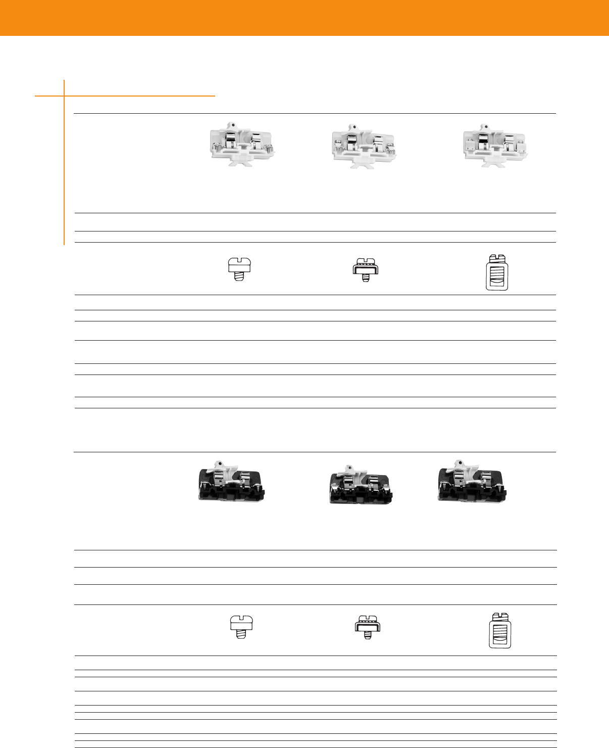
TERMINAL BLOCKS & BARRIER STRIPS
TERMINAL BLOCKS & BARRIER STRIPS
Fuses & Switches - Nylon and Phenolic
Fuse Block Tubular Screw
Strap Part Strap Part Tubular Part
Type of Block Screw Number Clamp Number Screw Number
Direct Mount (Flat Base)
Fuse Block with Puller 351 CPGI-BUCH-2-1437397-8 358 CPGI-BUCH-3-1437397-1 352 CPGI-BUCH-3-1437397-0
Channel Mount (Dovetail Base)
Fuse Block with Puller 0351 CPGI-BUCH-1437397-9 0358 CPGI-BUCH-1-1437397-2 0352 CPGI-BUCH-1-1437397-0
Contact Type
Strap Clamp Tubular Screw
Specifications
Wire Range (AWG)
Solid & Stranded 22-8 18-8 18-8
Wire Strip Length (in) — 1/2 1/2
Screw Type 8-32 8-32 1/4"-28
binding head pan head w/clamp set screw
Ampacity
Fuse Blocks 25A 25A 25A
Switch Blocks 15A 15A 15A
End Sections
No Contact, Flat Base
CPGI-BUCH-
2-14376397-4
CPGI-BUCH-
2-14376397-4
CPGI-BUCH-
2-14376397-4
No Contact, Dovetail Base
CPGI-BUCH-
14376397-5
CPGI-BUCH-
14376397-5
CPGI-BUCH-
14376397-5
Fuse Block Strap Screw Fuse Block Strap Clamp
Fuse Block Part Fuse Block Part Fuse Block Part
Type of Block Strap Screw Number Strap Clamp Number Tubular Screw Number
Channel Mount (Dovetail Base)
Nylon 0311 CPGI-BUCH-1437397-1 0318 CPGI-BUCH-1437397-3 0312 CPGI-BUCH-1437397-2
Contact Type
Specifications
Wire Range (AWG)
Solid & Stranded 22-8 18-8 18-8
Wire Strip Length (in) — 1/2 1/2
Screw Type 10-32 8-32 1/4"-28
binding head pan head w/clamp set screw
Ampacity
25 A 25 A 25 A
End Sections
Channel Mount, Nylon CPGI-BUCH-2-1437397-0 CPGI-BUCH-2-1437397-0 CPGI-BUCH-2-1437397-0
0300 Series - Nylon
Strap Screw
0300 Series - Phenolic
45
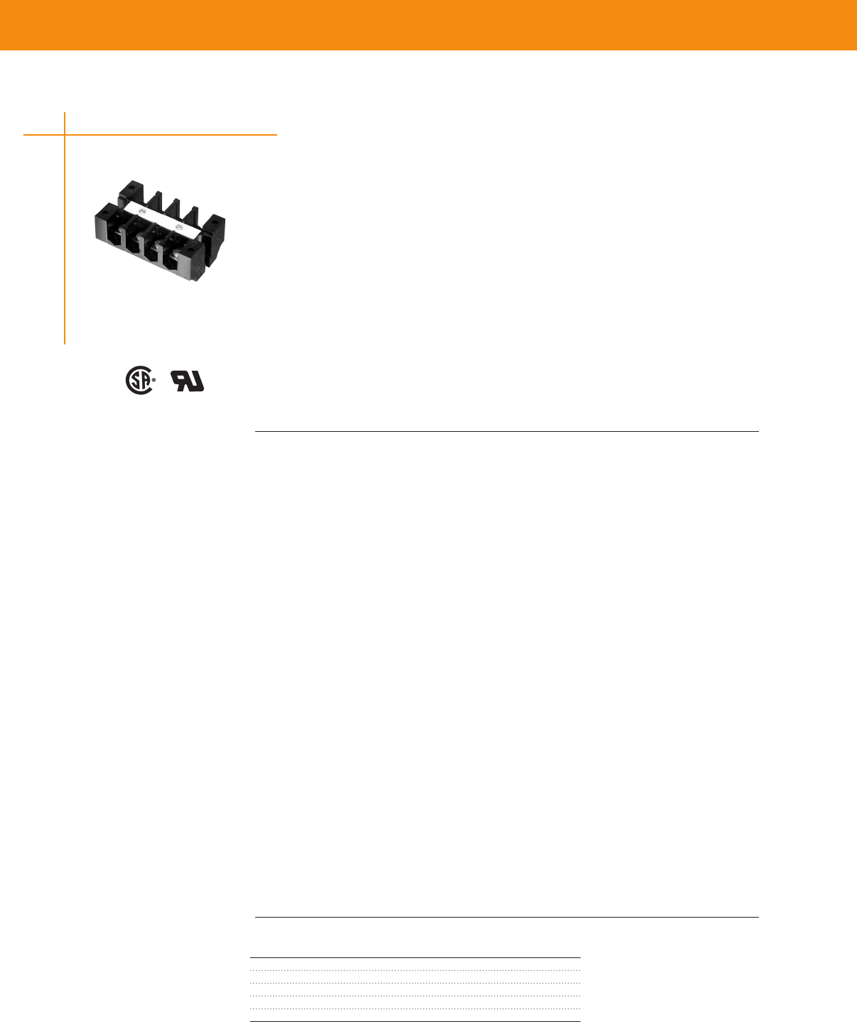
TERMINAL BLOCKS & BARRIER STRIPS
One-Piece Terminal Blocks
B100 Series, One-Piece Phenolic Blocks
• Two, four, six, eight, and twelve circuit models available — 5/8" (1588) center-to-center contact
spacing
• No assembly required — each is a single, easily installed unit
• Three contact styles available —strap screw, captive strap clamp, and moving tubular contact
• Use wire up to #6 AWG with tubular contact Strap screw and strap clamp contacts are available for
#8 and smaller
• Withstand voltages in excess of IEEE standards for 750 volts Meet clearance and creepage spacings
specified in UL, CSA, and NEMA Industrial Control Standards for 600 Volts
• Strap contacts rated at 50 amperes — tubular contact conservatively rated at 70 amperes
• Pilot point screws supplied with strap screw and clamp contacts —speeds installation time
• Plain white marking strip supplied with each block — circuits are easily identified
• Special purpose blocks available—choose from blocks with solder posts, printed circuit board pins,
or nuts on screw posts, removable circuit links, and a shorting bar
Traditionally, these rugged One-Piece Blocks are the standard means of connection for heavy
industrial applications like rail transport, utility, and traffic control industries Ideal for dirty and
vibration prone environments
B100, #B100 Series, One-Piece Blocks, 600 V - Phenolic
Material & Finish
Housing Material—Phenolic, filled flame retardant
Flammability—UL94V-1
Color—Black
Contacts
Standard Material—Electrical grade copper or copper alloy conductor Steel screws plated to resist
corrosion in most industrial applications
Brass Material—For Corrosive Environment (2B100, 4B100 Series) Nickel plated brass straps and
screws Meets specification QQ-N-290A Class 1, Grade G
Wire Range—Strap Screw: #18-8 AWG solid or stranded; Tubular Clamp: #14-6 AWG solid or stranded
Screw Type—Strap Screw: #10-32 Binding Head; Tubular Clamp: #1/4"(635)-28 Set Screw
Strap Screw—7/16" (1111) max lug width
Mechanical Properties
Pitch (terminal spacing)—63" (1600)
Wire Strip Length—Strap Screw: as needed for lugging; Tubular Clamp: 1/2" (121)
Electrical Properties
Maximum Current—70A for a single #6 AWG wire
Operating Voltage—Blocks meet 600V creepage and clearance requirements for general industrial
control equipment and panelboards; greatly exceeds IEEE switchgear standards for 750 volts
Dielectric Strength (RH 40% @ sea level)—300 Volts/mil thickness per ASTM D149
UL High Voltage Arc Tracking (in/min)—49-58 (1245-1473)
Environmental Properties
Max Continuous Temperature—150°C (302°F)
Water Absorption (24hrs % wt gain)—45% per ASTM D570
Chemical Resistance—Resistant to acids, alkalies, and aliphatic hydrocarbons and ketones per
ASTM D543
Radiation Resistance (ergs G-1 (C)—27 x 108 min
UL Independent Testing Service Recognitions
Wire Sizes—Solid or Stranded, Tubular Clamp
1—#6 AWG, 1—#8 AWG, 1or 2 — #10 AWG, 1or 2—#12 AWG, 1 to 3—#14 AWG, 1 —#10 & 1 —#12 AWG
1 — #12 & 1 — #14 AWG
Steel Screw w/ Strap
Standard Part Number
2 CPGI-BUCH-2-1437382-6
4 CPGI-BUCH-3-14373882-0
6 CPGI-BUCH-4-1437382-0
8 CPGI-BUCH-4-1437382-9
12 CPGI-BUCH-5-1437382-9
Steel Screw w/ Strap
LR25557 E63810
46
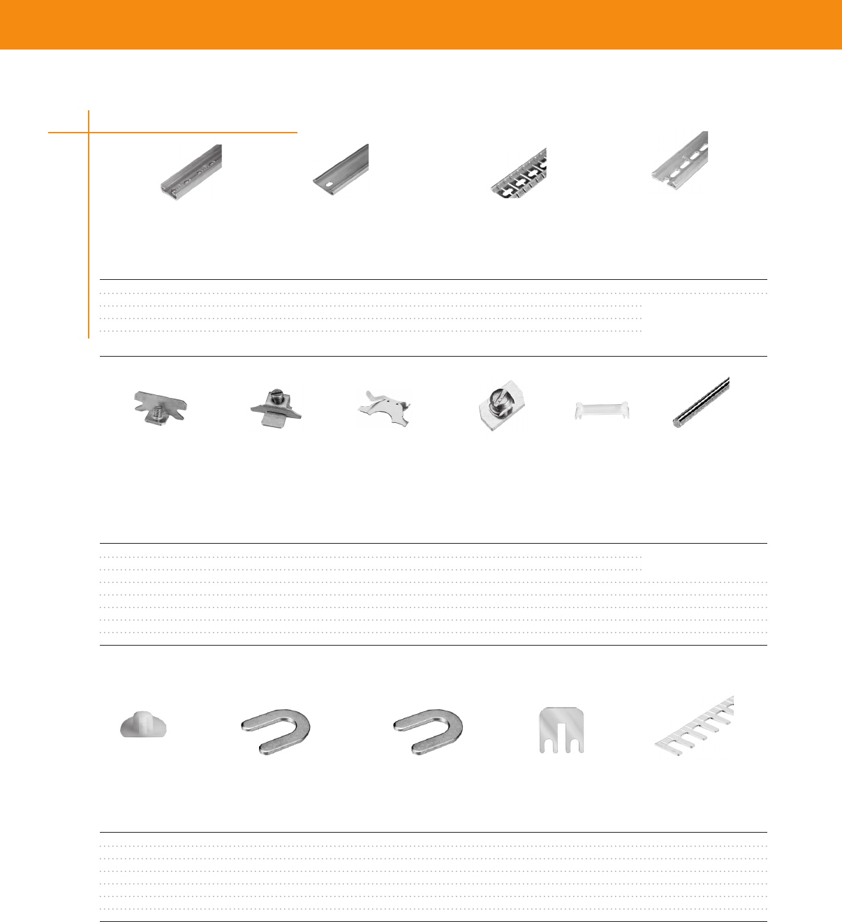
TERMINAL BLOCKS & BARRIER STRIPS
TERMINAL BLOCKS & BARRIER STRIPS
Accessories
Mounting Channels
Description Part Number Buchanan Number Standard Length Series
Miniature (#12) CPGI-BUCH-1437381-8 12 3 feet 100, 900, 200
Steel Channel CPGI-BUCH-9-1437381-1 60 6 feet
CPGI-BUCH-9-1437381-8 63-BU 3 feet 100, 900, 200, 800
Break Away Steel CPGI-BUCH-9-1437381-2 60-B-36 3 feet 400, 300
Pre-Punched Aluminum Channel CPGI-BUCH-9-1437381-9 64 6 feet
CPGI-BUCH-1437382-2 67 3 feet
Channel Clamps
Description Part Number Buchanan Number Standard Length Series
Screw Channel Clamps CPGI-BUCH-9-1437381-5 61 - 100, 900, 200, 800
Universal Clamps CPGI-BUCH-1437382-3 68 - 400, 300
Snap-In Clamps CPGI-BUCH-9-1437381-7 62 -
Miniature for #12 CPGI-BUCH-1437381-4 11 - 100, 900, 200
See-Thru Cover CPGI-BUCH-1-1437381-0 13 - 100
See-Thru Cover CPGI-BUCH-1-1437382-2 71 - 900
See-Thru Cover CPGI-BUCH-1-1437381-6 23-BU - 200
Ganging Rod CPGI-BUCH-3-1437381-9 30-BU 2 feet 900, 200, 800
Jumpers
Description Part Number Buchanan Number Standard Length Series
Nylon Holding Plug CPGI-BUCH-4-1437393-0 65-BU - 900, 200,
Jumper, 2 pole CPGI-BUCH-1437381-1 10 - 100
Jumpers For Tubular Contacts CPGI-BUCH-1437382-6 70 - 900
Jumper For Tubular Contacts CPGI-BUCH-2-1437393-4 42-BU - 200
Jumper For Tubular Contacts CPGI-BUCH-2-1437381-3 41-BU - 200
Jumper for Strap Screw CPGI-BUCH-5-1437381-5 43 - 200
Snap-apart For Tubular Contacts CPGI-BUCH-1-1437382-3 73 - 900
Steel Channel Break Away Steel Pre-Punched
Aluminum
Channel
Screw
Channel
Clamps
Universal
Clamps
Snap-In
Clamps
See-Thru
Cover
Ganging
Rod
Miniature Channel
Minature for
#12 Channel
Jumper for
Tubular Contacts
Snap-Apart for
Tubular Contacts
Nylon Holding Plug Jumper for
Strap Screw
Jumper 2 pole
47

WIRE MANAGEMENT
Cable Ties & Accessories
AMP Cable Ties 51
Mounting Head Ties - Natural and UV Black 52
In-Line Ties - Natural and UV Black 53
Push Mount Ties - Natural and UV Black 53
Plenum Rated - Halar Ties54
Releasable Ties - Natural and UV Black54
Identication & Flag Cable Ties 55
Mounting Pads 55
Low Prole Screw Mounts56
Wall Mounts 56
Screw Mounts 57
Wing Push Mounts & Button Mounts57
Identication Plates 58
Cable Clamps 58
Plastic Wrap
Plastic Cable Wrap SPIRAP 59
Retaining Clips
Exterior Siding Wire Retaining Clips 60
Exterior Masonry Wire Retaining Clips 60
Duct Sealing System
RDSS Sealing System 61
Blank Duct Plugs 63
49

50
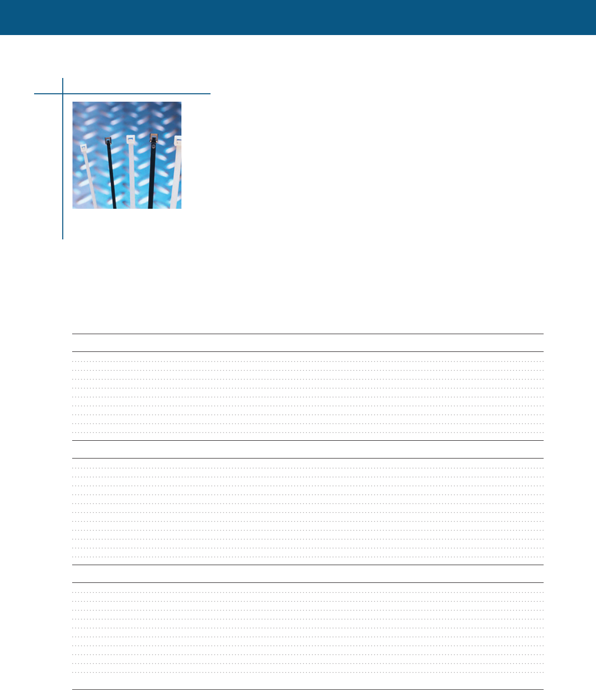
WIRE MANAGEMENT
WIRE MANAGEMENT
WIRE MANAGEMENT
51
Cable Ties & Accessories
AMP Cable Ties
AMP cable ties are available in three grades of Nylon 6/6
• General purpose cable ties (NATURAL) are suitable for use in most practical applications at
continuous temperatures up to 150 degrees Fahrenheit
• UV Stabilized cable ties (BLACK) ties are used in continuous or extended exposure to outdoor
use This nylon cable tie is a weather resistant grade, enduring additional ultraviolet (UV) light
• Heat Stabilized cable ties (BLACK) are used in continuous or extended exposure to high
temperatures (up to 250 degrees Fahrenheit) These cable ties contain specially formulated heat
stabilizers which provide additional thermal endurance Heat stabilized nylons are engineered for
continuous exposure to temperatures above 185 degrees Fahrenheit
The entire AMP cable tie line provides the following features and benefits:
• Faster - low insertion and pull through force
• Stronger - high tensile strength is achieved from one piece, advanced pawl, and teeth design
• Purer - manufactured from filtered nylon reducing particle contamination
• Easier - angled tail provides quicker initial insertion alignment and tail finger grips allow easier
handling and tightening
• Safer - rounded edges provide added safety and eliminates insulation damage
• Consistent - formulated molding processes
Selection information: dimensions in inches (millimeters)
Tensile Mil-spec Qty/ Packs/
Catalog Number Description Length Width Thickness Max Bundle Strength Reference Bag Carton
Miniature (18 lb.) Natural & UV Black
CPGI-CTY-04-18-NAT-C Natural Nylon 4.12 (104.77) .095 (2.413) .042 (1.06) 7/8 (22.22) 18 lbs. MS3367-4 100 10
CPGI-CTY-04-18-NAT-M Natural Nylon 4.12 (104.77) .095 (2.413) .042 (1.06) 7/8 (22.22) 18 lbs. MS3367-4 1000 5
CPGI-CTY-04-18-BLK-C UV Black Nylon 4.12 (104.77) .095 (2.413) .042 (1.06) 7/8 (22.22) 18 lbs. MS3367-4 100 10
CPGI-CTY-04-18-BLK-M UV Black Nylon 4.12 (104.77) .095 (2.413) .042 (1.06) 7/8 (22.22) 18 lbs. MS3367-4 1000 5
CPGI-CTY-06-18-NAT-C Natural Nylon 6.18 (157.14) .095 (2.413) .042 (1.06) 1.5 (38.10) 18 lbs. MS3367-4 100 10
CPGI-CTY-06-18-BLK-C UV Black Nylon 6.18 (157.14) .095 (2.413) .042 (1.06) 1-1/2 (38.10) 18 lbs. MS3367-4 100 10
CPGI-CTY-08-18-NAT-C Natural Nylon 8.1 (206) .094 (2.39) .042 (1.06) 2-3/16 (55.56) 18 lbs. MS3367-4 100 10
CPGI-CTY-08-18-NAT-M Natural Nylon 8.1 (206) .094 (2.39) .042 (1.06) 2-3/16 (55.56) 18 lbs. MS3367-4 1000 5
CPGI-CTY-08-18-BLK-C UV Black Nylon 8.1 (206) .094 (2.39) .042 (1.06) 2-3/16 (55.56) 18 lbs. MS3367-4 100 10
CPGI-CTY-08-18-BLK-M UV Black Nylon 8.1 (206) .094 (2.39) .042 (1.06) 2-3/16 (55.56) 18 lbs. MS3367-4 1000 5
Intermediate (40 lb.) Natural & UV Black
CPGI-CTY-05-40-NAT-C Natural Nylon 5.84 (148.33) .140 (3.56) .049 (1.24) 1-7/16 (36.51) 40 lbs. MS3367-5 100 10
CPGI-CTY-05-40-NAT-M Natural Nylon 5.84 (148.33) .140 (3.56) .049 (1.24) 1-7/16 (36.51) 40 lbs. MS3367-5 1000 5
CPGI-CTY-05-40-BLK-C UV Black Nylon 5.84 (148.33) .140 (3.56) .049 (1.24) 1-7/16 (36.51) 40 lbs. MS3367-5 100 10
CPGI-CTY-05-40-BLK-M UV Black Nylon 5.84 (148.33) .140 (3.56) .049 (1.24) 1-7/16 (36.51) 40 lbs. MS3367-5 1000 5
CPGI-CTY-08-40-NAT-C Natural Nylon 8.88 (225.42) .140 (3.56) .049 (1.24) 2-3/8 (60.33) 40 lbs. MS3367-5 100 10
CPGI-CTY-08-40-NAT-M Natural Nylon 8.88 (225.42) .140 (3.56) .049 (1.24) 2-3/8 (60.33) 40 lbs. MS3367-5 1000 5
CPGI-CTY-08-40-BLK-C UV Black Nylon 8.88 (225.42) .140 (3.56) .049 (1.24) 2-3/8 (60.33) 40 lbs. MS3367-5 100 10
CPGI-CTY-08-40-BLK-M UV Black Nylon 8.88 (225.42) .140 (3.56) .049 (1.24) 2-3/8 (60.33) 40 lbs. MS3367-5 1000 5
CPGI-CTY-11-40-NAT-C Natural Nylon 11.5 (292) .140 (3.56) .058 (1.473) 3-3/8 (85.72) 40 lbs. 100 10
CPGI-CTY-11-40-BLK-C UV Black Nylon 11.5 (292) .140 (3.56) .058 (1.473) 3-3/8 (85.72) 40 lbs. 100 10
CPGI-CTY-14-40-NAT-C Natural Nylon 14.5 (368.30) .140 (3.56) .058 (1.473) 4 (101.60) 40 lbs. 100 10
CPGI-CTY-14-40-BLK-C UV Black Nylon 14.5 (368.30) .140 (3.56) .058 (1.473) 4 (101.60) 40 lbs. 100 10
Standard (50 lb.) Natural, UV Black & Heat Stabilized Black
CPGI-CTY-07-50-NAT-C Natural Nylon 7.56 (192.07) .180 (4.572) .052 (1.32) 1-7/8 (47.63) 50 lbs. MS3367-1 100 10
CPGI-CTY-07-50-NAT-M Natural Nylon 7.56 (192.07) .180 (4.572) .052 (1.32) 1-7/8 (47.63) 50 lbs. MS3367-1 1000 5
CPGI-CTY-07-50-BLK-C UV Black Nylon 7.56 (192.07) .180 (4.572) .052 (1.32) 1-7/8 (47.63) 50 lbs. MS3367-1 100 10
CPGI-CTY-07-50-BLK-M UV Black Nylon 7.56 (192.07) .180 (4.572) .052 (1.32) 1-7/8 (47.63) 50 lbs. MS3367-1 1000 5
CPGI-CTY-07-50-HS-BLK-C Heat Stabilized 7.56 (192.07) .180 (4.572) .052 (1.32) 1-7/8 (47.63) 50 lbs. 100 10
Black Nylon
CPGI-CTY-11-50-NAT-C Natural Nylon 11.25 (285.75) .180 (4.572) .052 (1.32) 3-1/16 (77.79) 50 lbs. MS3367-7-9 100 10
CPGI-CTY-11-50-NAT-D Natural Nylon 11.25 (285.75) .180 (4.572) .052 (1.32) 3-1/16 (77.79) 50 lbs. MS3367-7-9 500 5
CPGI-CTY-11-50-BLK-C UV Black Nylon 11.25 (285.75) .180 (4.572) .052 (1.32) 3-1/16 (77.79) 50 lbs. MS3367-7-9 100 10
CPGI-CTY-11-50-BLK-D UV Black Nylon 11.25 (285.75) .180 (4.572) .052 (1.32) 3-1/16 (77.79) 50 lbs. MS3367-7-9 500 5
CPGI-CTY-11-50-HS-BLK-C Heat Stabilized 11.25 (285.75) .180 (4.572) .052 (1.32) 3-1/16 (77.79) 50 lbs. 100 10
Black Nylon
AMP Cable Ties continues next page
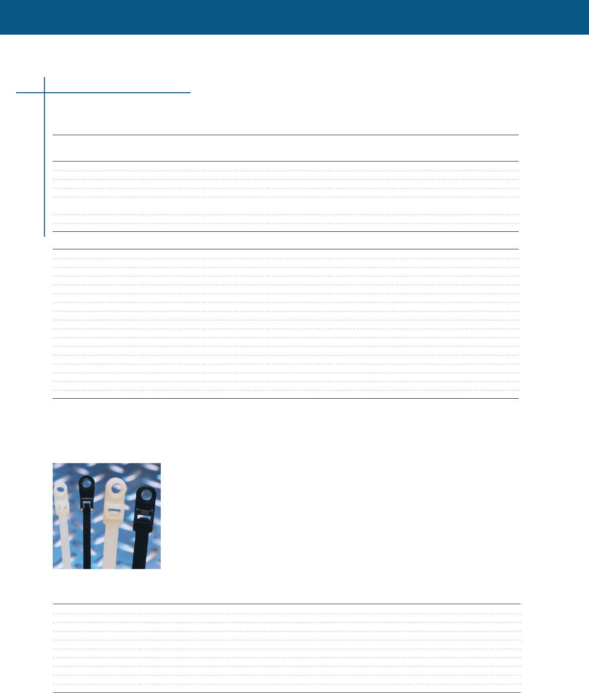
WIRE MANAGEMENT
Mounting Head Ties - Natural and UV Black
• One piece design allows for quicker mechanical mounting and reduced cost
• Secures and positions wire bundles, cables, hoses, etc to panels or other surfaces with one
mechanical fastener
Selection information: dimensions in inches (millimeters)
Tensile Screw Qty/ Packs/
Catalog Number Description Length Width Thickness Max Bundle Strength Size Bag Carton
CPGI-CTY-05-30-MH-NAT-C Natural Nylon 5.8 (149.2) .138 (3.505) .045 (1.143) 1-1/4 (31.75) 30 lbs. No. 8 100 10
CPGI-CTY-05-30-MH-BLK-C UV Black Nylon 5.8 (149.2) .138 (3.505) .045 (1.143) 1-1/4 (31.75) 30 lbs. No. 8 100 10
CPGI-CTY-07-50-MH-NAT-C Natural Nylon 8 (203.2) .177 (4.495) .052 (1.32) 1-3/4 (44.45) 50 lbs. No. 10 100 5
CPGI-CTY-07-50-MH-BLK-C UV Black Nylon 8 (203.2) .177 (4.495) .052 (1.32) 1-3/4 (44.45) 50 lbs. No. 10 100 5
CPGI-CTY-11-50-MH-NAT-C Natural Nylon 11.7 (298.4) .191 (4.851) .061 (1.5459) 3 (76.20) 50 lbs. No. 10 100 5
CPGI-CTY-11-50-MH-BLK-C UV Black Nylon 11.7 (298.4) .191 (4.851) .061 (1.5459) 3 (76.20) 50 lbs. No. 10 100 5
CPGI-CTY-14-50-MH-NAT-C Natural Nylon 14.5 (368.3) .186 (4.724) .060 (1.52) 4 (101.60) 50 lbs. No. 10 100 5
CPGI-CTY-14-50-MH-BLK-C UV Black Nylon 14.5 (368.3) .186 (4.724) .060 (1.52) 4 (101.60) 50 lbs. No. 10 100 5
CPGI-CTY-16-120-MH-NAT-C Natural Nylon 15.7 (398) .298 (7.569) .075 (1.90) 4-1/16 (103.12) 120 lbs. 1/4 100 5
CPGI-CTY-16-120-MH-BLK-C UV Black Nylon 15.7 (398) .298 (7.569) .075 (1.90) 4-1/16 (103.12) 120 lbs. 1/4 100 5
Cable Ties & Accessories
52
AMP Cable Ties (continued)
Tensile Mil-spec Qty/ Packs/
Catalog Number Description Length Width Thickness Max Bundle Strength Refence Bag Carton
Standard (50 lb.) Natural, UV Black & Heat Stabilized Black
CPGI-CTY-14-50-NAT-C Natural Nylon 14.56 (369.87) .180 (4.572) .052 (1.32) 4-1/8 (104.78) 50 lbs. MS3367-2-9 100 10
CPGI-CTY-14-50-NAT-D Natural Nylon 14.56 (369.87) .180 (4.572) .052 (1.32) 4-1/8 (104.78) 50 lbs. MS3367-2-9 500 5
CPGI-CTY-14-50-BLK-C UV Black Nylon 14.56 (369.87) .180 (4.572) .052 (1.32) 4-1/8 (104.78) 50 lbs. MS3367-2-0 100 10
CPGI-CTY-14-50-BLK-D UV Black Nylon 14.56 (369.87) .180 (4.572) .052 (1.32) 4-1/8 (104.78) 50 lbs. MS3367-2-0 500 5
CPGI-CTY-14-50-HS-BLK-C Heat Stabilized 14.56 (369.87) .180 (4.572) .052 (1.32) 4-1/8 (104.78) 50 lbs. 100 10
Black Nylon
CPGI-CTY-17-50-NAT-C Natural Nylon 17.09 (434.16) .187 (4.749) .060 (1.52) 4-3/4 (120.65) 50 lbs. 100 10
CPGI-CTY-17-50-BLK-C UV Black Nylon 17.09 (434.16) .187 (4.749) .060 (1.52) 4-3/4 (120.65) 50 lbs. 100 10
Light Heavy-Duty, Heavy-Duty & Extra Heavy-Duty Natural, UV Black
CPGI-CTY-15-120-NAT-L Natural Nylon 15.09 (383.36) .300 (7.62) .076 (1.930) 4-1/16 (103.18) 120 lbs. MS3367-3 50 10
CPGI-CTY-15-120-BLK-L UV Black Nylon 15.09 (383.36) .300 (7.62) .076 (1.930) 4-1/16 (103.18) 120 lbs. MS3367-3 50 10
CPGI-CTY-18-120-NAT-L Natural Nylon 17.70 (449.58) .305 (7.74) .080 (2.032) 5-1/4 (133.35) 120 lbs. 50 10
CPGI-CTY-18-120-BLK-L UV Black Nylon 17.70 (449.58) .305 (7.74) .080 (2.032) 5-1/4 (133.35) 120 lbs. 50 10
CPGI-CTY-24-120-NAT-L Natural Nylon 24.18 (630.22) .305 (7.74) .080 (2.032) 7 (177.80) 120 lbs. 50 5
CPGI-CTY-24-120-BLK-L UV Black Nylon 24.18 (630.22) .305 (7.74) .080 (2.032) 7 (177.80) 120 lbs. 50 5
CPGI-CTY-28-120-NAT-L Natural Nylon 28.50 (723.9) .305 (7.74) .080 (2.032) 8 (203.20) 120 lbs. 50 5
CPGI-CTY-28-120-BLK-L UV Black Nylon 28.50 (723.9) .305 (7.74) .080 (2.032) 8 (203.20) 120 lbs. 50 5
CPGI-CTY-25-175-NAT-L Natural Nylon 25.25 (641.35) .340 (8.64) .090 (2.29) 7-1/8 (182.56) 175 lbs. MS3367-10 50 5
CPGI-CTY-25-175-BLK-L UV Black Nylon 25.25 (641.35) .340 (8.64) .090 (2.29) 7-1/8 (182.56) 175 lbs. MS3367-10 50 5
CPGI-CTY-37-175-NAT-L Natural Nylon 37.25 (946.15) .340 (8.64) .090 (2.29) 11 (279.40) 175 lbs. MS3367-13 50 5
CPGI-CTY-37-175-BLK-L UV Black Nylon 37.25 (946.15) .340 (8.64) .090 (2.29) 11 (279.40) 175 lbs. MS3367-13 50 5
CPGI-CTY-48-175-NAT-L Natural Nylon 48.50 (1231.9) .340 (8.64) .090 (2.29) 14-1/2 (368.30) 175 lbs. MS3367-16 50 5
CPGI-CTY-48-175-GRY-L Gray Nylon 48.50 (1231.9) .340 (8.64) .090 (2.29) 14-1/2 (368.30) 175 lbs. MS3367-16 50 5
CPGI-CTY-48-175-BLK-L UV Black Nylon 48.50 (1231.9) .340 (8.64) .090 (2.29) 14-1/2 (368.30) 175 lbs. MS3367-16 50 5
CPGI-CTY-22-250-NAT-C Natural Nylon 21.93 (557.19) .494 (12.54) .086 (2.18) 6 (152.40) 250 lbs. 100 5
CPGI-CTY-22-250-BLK-C UV Black Nylon 21.93 (557.19) .494 (12.54) .086 (2.18) 6 (152.40) 250 lbs. 100 5
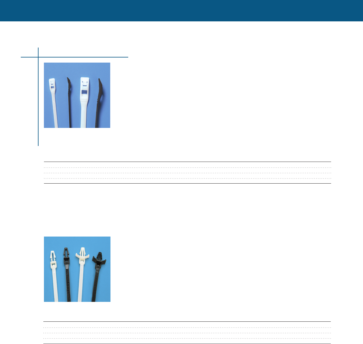
WIRE MANAGEMENT
WIRE MANAGEMENT
Cable Ties & Accessories
53
In-Line Ties - Natural and UV Black
• Reduced head height compared to standard head designs
• Increased safety, eliminates snags, cuts and abrasions to cables, hoses, products, and users
• No sharp tail cutoffs - remaining tail slips back into head of tie leaving no exposed sharp edges
• Quick and safe removal - simply cut and pry top crossbar to release cable tie, eliminating damage to
wires, tubing, etc
• Flexible head design allows the head to easily flex around the total circumference of tubing or
bundled wires
• Tamper proof pawl located under the tie’s head makes it inaccessible when bundled
• Easy handling finger grips on the tail provide a no slip grip during insertion and tensioning
• Ideal applications: wire harnesses, confined spaces, control panels, marine, hoses, playgrounds,
construction, appliances, and safety equipment
Selection information: dimensions in inches (millimeters)
Tensile Mil-Spec Qty/ Packs/
Catalog Number Description Length Width Thickness Max Bundle Strength Reference Bag Carton
CPGI-CTY-07-50-LP-NAT-C Natural Nylon 7.5 (191) .177 (4.495) .053 (1.35) 1-3/4 (44.45) 50 lbs. MS3367-23 100 10
CPGI-CTY-07-50-LP-BLK-C UV Black Nylon 7.5 (191) .177 (4.495) .053 (1.35) 1-3/4 (44.45) 50 lbs. MS3367-23 100 10
CPGI-CTY-16-120-LP-NAT-C Natural Nylon 16 (406.4) .300 (7.62) .075 (1.90) 41/6 (103.18) 120 lbs. 100 5
CPGI-CTY-16-120-LP-BLK-C UV Black Nylon 16 (406.4) .300 (7.62) .075 (1.90) 41/6 (103.18) 120 lbs. 100 5
Push Mount Ties - Natural and UV Black
• Quick mounting one piece-design securely attaches bundle to panel
• Extra stability is created from the tensioning wings
• Thickness variations in materials is easily overcome with tensioning wings
Selection information: dimensions in inches (millimeters)
Tensile Hole Panel Qty/ Packs/
Catalog Number Description Length Width Thickness Max Bundle Strength Diameter Thickness Bag Carton
CPGI-CTY-07-50-PM-NAT-C Natural Nylon 7.9 (203.00) .189 (4.8) .062 (1.574) 1-15/16 (50.00) 50 lbs. 1/4 (6.40) 3/16 (3.55) 100 5
CPGI-CTY-07-50-PM-BLK-C UV Black Nylon 7.9 (203.00) .189 (4.8) .062 (1.574) 1-15/16 (50.00) 50 lbs. 1/4 (6.40) 3/16 (3.55) 100 5
CPGI-CTY-07-50-PMW-NAT-C Natural Nylon 7.8 (200.00) .189 (4.8) .062 (1.574) 1-15/16 (50.00) 50 lbs. 1/4 (6.40) 3/16 (3.55) 100 5
CPGI-CTY-07-50-PMW-BLK-C UV Black Nylon 7.8 (200.00) .189 (4.8) .062 (1.574) 1-15/16 (50.00) 50 lbs. 1/4 (6.40) 3/16 (3.55) 100 5
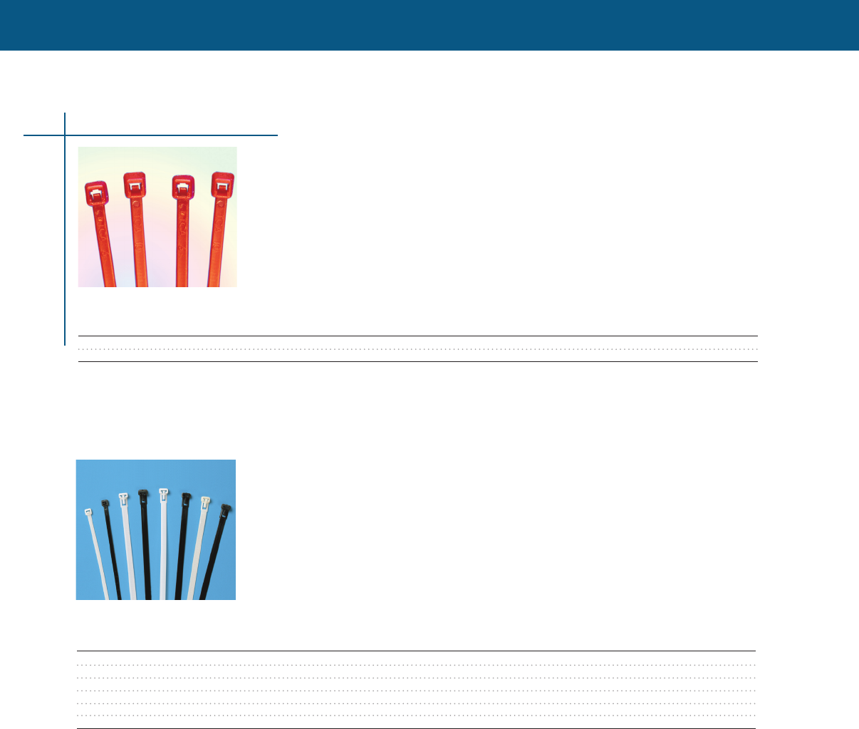
WIRE MANAGEMENT
Cable Ties & Accessories
54
Cable Ties & Accessories
Releasable Ties - Natural and UV Black
• Temporary or Permanent Bundling allows for quick addition or removal of wires or items
• Strap finger release latch allows easy access but reduces snags compared to top latch styles
Selection information: dimensions in inches (millimeters)
Tensile Qty/ Packs/
Catalog Number Description Length Width Thickness Max Bundle Strength Bag Carton
CPGI-CTY-05-50-RL-NAT-C Natural Nylon 5.905 (150.00) .299 (7.60) .050 (1.27) 1-3/8 (35.00) 50 lbs. 100 10
CPGI-CTY-05-50-RL-BLK-C UV Black Nylon 5.905 (150.00) .299 (7.60) .050 (1.27) 1-3/8 (35.00) 50 lbs. 100 10
CPGI-CTY-08-50-RL-NAT-C Natural Nylon 7.87 (200) .299 (7.60) .053 (1.35) 2 (50.00) 50 lbs. 100 10
CPGI-CTY-08-50-RL-BLK-C UV Black Nylon 7.87 (200) .299 (7.60) .053 (1.35) 2 (50.00) 50 lbs. 100 10
CPGI-CTY-12-50-RL-NAT-C Natural Nylon 11.81 (300) .299 (7.60) .053 (1.35) 3 (76.20) 50 lbs. 100 10
CPGI-CTY-12-50-RL-BLK-C UV Black Nylon 11.81 (300.00) .299 (7.60) .053 (1.35) 3 (76.20) 50 lbs. 100 10
Plenum Rated - Halar Ties
• Halar cable ties feature low smoke density and high flame-resistance, and are ideal for plenum
areas where smoke generation is a concern
Selection information: dimensions in inches (millimeters)
Tensile Qty/ Packs/
Catalog Number Description Length Width Thickness Max Bundle Strength Bag Carton
CPGI-CTY-04-18-HL-C Maroon Halar 4.0 (102) .094 (2.4) .042 (1.07) 1/16 - 7/8 18 lbs 100 5
CPGI-CTY-08-50-HL-C Maroon Halar 8.0 (203) .178 (4.5) .053 (1.35) 1/16 - 50 lbs 100 5
Halar is a trademark of Sovay Solexis, Inc
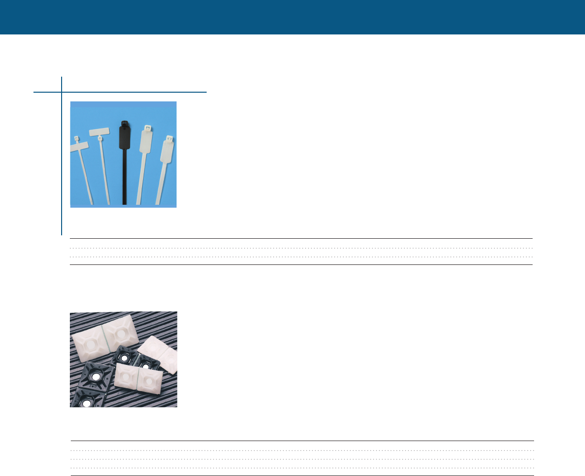
WIRE MANAGEMENT
WIRE MANAGEMENT
Cable Ties & Accessories
55
Identification & Flag Cable Ties
• One easy step to identify and bundle items
• Flat ties extend from bundle to be easily seen when identification is critical
• Identification ties reduce snags while providing support to the bundle
Mounting Pads
• Saves cable tie clinching time - the stay-n-place tab keeps cable tie head from sliding down behind
bundle during applications and maintenance placement during horizontal applications
• Easy insertion of cable ties - lead-n-feature funnels cable ties into position and
countersunk screw hole allows cable ties to easily pass over screw head
• Saves positioning time with the 4 sided entry and center screw hole
Selection information: dimensions in inches (millimeters)
Tensile Qty/ Packs/
Catalog Number Description Length Width Thickness Max Bundle Strength Pad Size Bag Carton
CPGI-CTY-04-18-ID-NAT-C Natural Nylon 4.0 (102) .100 (2.54) .044 (1.12) 7/8 (22.22) 18 lbs. 5/16 x 1 100 5
CPGI-CTY-07-50-ID-NAT-C Natural Nylon 7.8 (200) .181 (4.59) .055 (1.40) 1-7/8 (47.63) 50 lbs. 1/2 x 1.1/8 100 5
CPGI-CTY-14-50-ID-NAT-C Natural Nylon 14.1 (358.10) .187 (4.749) .055 (1.40) 4 (101.60) 50 lbs. 1/2 x 1.1/8 100 5
Selection information: dimensions in inches (millimeters)
Qty/ Packs/
Catalog Number Description Length Height Adhesive Height Width Bag Carton
CPGI-CTY-MP-750-NAT-C Natural Nylon .74 (18.7) .19 (4.8) Rubber .05 (1.2) .20 (5.0) 100 5
CPGI-CTY-MP-750-BLK-C Black Nylon .74 (18.7) .19 (4.8) Rubber .05 (1.2) .20 (5.0) 100 5
CPGI-CTY-MP-1000-NAT-C Natural Nylon .99 (25.1) .20 (5.0) Rubber .06 (1.5) .20 (5.0) 100 5
CPGI-CTY-MP-1000-BLK-C Black Nylon .99 (25.1) .20 (5.0) Rubber .06 (1.5) .20 (5.0) 100 5

WIRE MANAGEMENT
Low Profile Screw Mounts
• Reduces snags allowing bundles closer proximity to mounting material
• Confined spaces & control panels or other areas where space is limited
• Achieve extreme low height when combined with low profile cable ties
Selection information: dimensions in inches (millimeters)
Slot Slot Qty/ Packs/
Catalog Number Description Length Height Width Height Width Bag Carton
CPGI-CTY-LPM1-NAT-C Natural Nylon .75 (19.05) .12 (3.04) .50 (12.70) .062 (1.587) .18 (4.57) 100 5
Cable Ties & Accessories
56
Wall Mounts
• Saves cable tie cinching time - the stay-in-place tab keeps cable tie head from sliding down during
vertical applications and maintains placement during horizontal applications
• Quickly secures and positions wire bundles, cables, hoses, etc to walls
• One piece design allows for quicker mounting with no mechanical fastener, reducing time and cost
Selection information: dimensions in inches (millimeters)
Shaft Head Shaft Head Slot Head Qty/ Packs/
Catalog Number Description Height Height Diameter Width Width Depth Bag Carton
CPGI-CTY-WM-BLK-C Black Nylon 1.45/37.0 .248/6.3 .393/10.0 .50/12.7 .381/9.7 .492/12.5 100 5
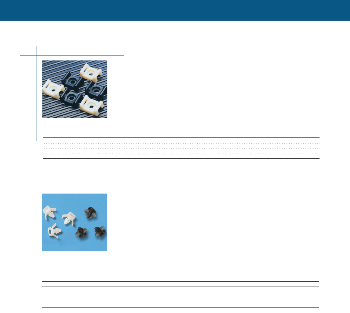
WIRE MANAGEMENT
WIRE MANAGEMENT
Wing Push Mounts & Button Mounts
• One piece design allows for quicker mounting with no mechanical fastener, reducing time and cost
• Quickly secures and positions wire bundles, cables, hoses, etc to panels
• Easy insertion of cable ties through wide entry slot
• Extra stability is created from the push mount tensioning wings
• Saves cable tie cinching time The button mount’s stay-n-place tab keeps cable ties from sliding
during application
Screw Mounts
• Secure support deep cradle design provides maximum support for large bundles and tubing
• Easy insertion of cable ties: deep recessed screw hole allows cable ties to pass over screw head
Selection information: dimensions in inches (millimeters)
Slot Slot Qty/ Packs/
Catalog Number Description Length Height Width Height Width Bag Carton
CPGI-CTY-SM1-NAT-C Natural Nylon .59 (14.98) .27 (6.85) .37 9.39 .062 (1.587) .19 (4.82) 100 5
CPGI-CTY-SM1-BLK-C Black Nylon .59 (14.98) .27 (6.85) .37 9.39 .062 (1.587) .19 (4.82) 100 5
CPGI-CTY-SM2-NAT-C Natural Nylon .87 (22.09) .38 (9.65) .64 16.25 .125 (3.175) .30 (7.62) 100 5
CPGI-CTY-SM2-BLK-C Black Nylon .87 (22.09) .38 (9.65) .64 16.25 .125 (3.175) .30 (7.62) 100 5
Selection information: dimensions in inches (millimeters)
Wing Push Mounts
Wing Head Slot Mount Qty/ Packs/
Catalog Number Description Height Depth Width Width Width Width Bag Carton
CPGI-CTY-PMW-NAT-C Natural Nylon .732 (18.6) .375 (9.5) .79 (20.1) .422 (10.72) .31 (8.1) .244 (6.2) 100 5
Button Mounts
Shaft Button Slot Shaft Qty/ Packs
Catalog Number Description Height Exposed Length Diameter Width Diameter Bag Carton
CPGI-CTY-BM-BLK-C Black Nylon .535 (13.6) .248 (6.3) .287 (7.3) .634 (16.12) .196 (5.0) .299 (7.6) 100 5
Cable Ties & Accessories
57
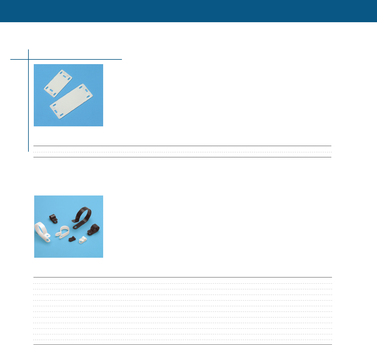
WIRE MANAGEMENT
Cable Clamps
• Designed to secure the routing of cables, harnesses, and hoses
• Radius edges protect against insulation, abrasion, and cutting hoses
• Quick alignment is achieved with bottom oval screw hole
• Accurate selection is made easy with clearly identified diameter sizes
Identification Plates
• Allows larger print when information and visibility is critical
• Increased surface area provides twice the area as conventional identification cable ties
• Orientation variety: apply to bundle vertically or horizontally
• For use with 18 lb, 40 lb, and 50 lb cable ties
Selection information: dimensions in inches (millimeters)
Slot Slot Qty/ Packs/
Catalog Number Description Length Width Thickness Height Width Bag Carton
CPGI-CTY-IDP-1-NAT-C Natural Nylon 1.57 (40.0) .787 (20.0) .039 (1.0) .08 (2.03) .18 (4.57) 100 5
CPGI-CTY-IDP-2-NAT-C Natural Nylon 2.36 (60.0) .984 (25.0) .039 (1.0) .08 (2.03) .18 (4.57) 100 5
Selection information: dimensions in inches (millimeters)
Screw Center to Qty/ Packs/
Catalog Number Description Hole Diameter Width Center Thickness Bag Carton
CPGI-CTY-CCL-125-NAT-C Natural Nylon .181 (4.6) .126 (3.2) .378 (9.6) .374 (9.5) .055 (1.4) 100 5
CPGI-CTY-CCL-125-BLK-C Black Nylon .181 (4.6) .126 (3.2) .378 (9.6) .374 (9.5) .055 (1.4) 100 5
CPGI-CTY-CCL-250-NAT-C Natural Nylon .181 (4.6) .250 (6.3) .394 (10.0) .394 (10.0) .055 (1.4) 100 5
CPGI-CTY-CCL-250-BLK-C Black Nylon .181 (4.6) .250 (6.3) .394 (10.0) .394 (10.0) .055 (1.4) 100 5
CPGI-CTY-CCL2-375-NAT-C Natural Nylon .181 (4.6) .374 (9.5) .472 (12.0) .492 (12.5) .059 (1.5) 100 5
CPGI-CTY-CCL2-375-BLK-C Black Nylon .181 (4.6) .374 (9.5) .472 (12.0) .492 (12.5) .059 (1.5) 100 5
CPGI-CTY-CCL2-500-NAT-C Natural Nylon .181 (4.6) .500 (12.7) .472 (12.0) .598 (15.2) .059 (1.5) 100 5
CPGI-CTY-CCL2-500-BLK-C Black Nylon .181 (4.6) .500 (12.7) .472 (12.0) .598 (15.2) .059 (1.5) 100 5
CPGI-CTY-CCL2-750-NAT-C Natural Nylon .181 (4.6) .764 (19.4) .472 (12.0) .717 1(8.2) .059 (1.5) 100 5
CPGI-CTY-CCL2-750-BLK-C Black Nylon .181 (4.6) .764 (19.4) .472 (12.0) .717 1(8.2) .059 (1.5) 100 5
CPGI-CTY-CCL2-1000-NAT-C Natural Nylon .181 (4.6) 1.00 (25.4) .472 (12.0) .866 (22.0) .071 (1.8) 100 5
CPGI-CTY-CCL2-1000-BLK-C Black Nylon .181 (4.6) 1.00 (25.4) .472 (12.0) .866 (22.0) .071 (1.8) 100 5
Cable Ties & Accessories
58
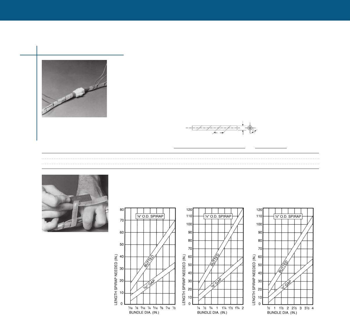
WIRE MANAGEMENT
WIRE MANAGEMENT
Plastic Cable Wrap
SPIRAP Hand Tool
• Provides abrasion protection for wires, cables, tubing, and hoses
• Attractive - makes neat, compact uniform bundles
• Break-out at any point along the bundle
• Moisture resistant - will not hold “cable-rotting” moisture
• Meets military and commercial specifications
• Available in three sizes converting from 1/16-inch (158) to 4-inch (10160) diameter bundles
• Quickly applied by hand or by supplied hand tool
AB
C
SPIRAP Hand Tool Part Number 500901
Furnished with each box, the SPIRAP hand tool increases the spread of application and permits uniform
wrapping along the bundle length The hand tool is slotted for 1/8-inch (318), 1/4-inch (635) and
1/2-inch (1270) SPIRAP tubing
Selection information: dimensions in inches (millimeters)
Max. Bundle Dimensions Length Std.
Catalog Number O.D. Size Dia. Range A B C Ft/Box M/Box Pack
AMPS-0-0500000-1 1/8 (318) 1/16 - 1/2 (159 - 1270) 125 (318) 031 (70) 218 (554) 50 1524 50
AMPS-0-0500001-1 1/4 (635) 3/16 - 2 (476 - 508) 250 (625) 045 (114) 375 (953) 50 1524 50
AMPS-0-0500002-1 1/2 (1270) 3/8 - 4 (953 - 1016) 500 (1270) 062 (157) 500 (1270) 50 1524 50
Plastic Cable Wrap
59
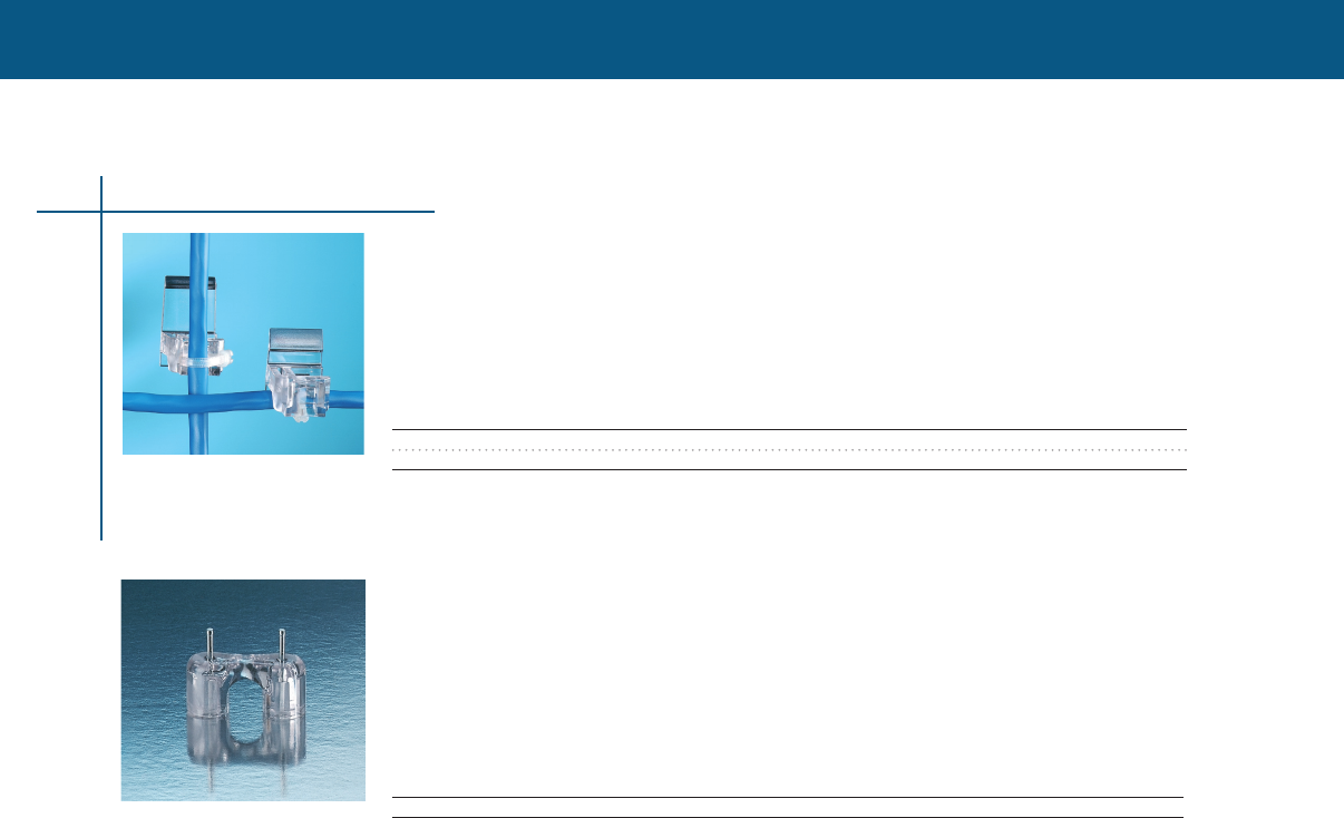
WIRE MANAGEMENT
Exterior Siding Wire Retaining Clips
Exterior siding clips offer a low cost, efficient means of routing and retaining wire on aluminum and
vinyl siding All clips snap under the siding lap joint
Selection information: dimensions in inches (millimeters)
Catalog Number Type Depth Height Width Std. Pack
CPGI-061-0114A Aluminum 0.750 0.750 0.600 5
CPGI-061-0114V Vinyl 0.750 0.980 0.600 5
Exterior Masonry Wire Retaining Clips
Masonry Clips are supplied with pre-inserted hardened, zinc coated nails These masonry clips can
be mounted to cinder block, masonry, and other forms of concrete All siding clips are made from
high-impact flame-retardant polycarbonate and are compatible with current designs of datacom,
CATV, and telecom wire
Selection information: dimensions in inches (millimeters)
Catalog Number Type Opening Dimension Std. Pack
CPGI-063-0020 Masonry 0.500 5
Retaining Clips
60

WIRE MANAGEMENT
WIRE MANAGEMENT
RDSS duct sealing system has been designed for use in conjunction with plastic, concrete, or steel
ducts to provide a watertight duct seal The RDSS duct sealing system seals cable ducts and helps
to prevent flooding in cable vaults, access manholes, substation basements, and customer feeds It
can be installed while the water is flowing - see photograph
Provides watertight seal
The RDSS sealing system consists of an inflatable, sealed bladder of flexible, metallic laminate
material, which has pre installed, high-temperature sealant strips on both sides The bladder is first
inflated to 45 psi (three-bar) internal pressure, and then presses the sealant against the duct wall
and onto the substrate The bag uses a self-sealing gel material to seal the filling hole when the
filling tube is removed
Seals multiple cable ducts
For applications with three or more cables, an RDSS-CLIP is inserted between the cables The
RDSS CLIP is a high-temperature mastic mounted on an installation stick It seals the area between
the cables when used in conjunction with the RDSS inflatable bladder Acceptable to use on
medium voltage cables including unjacketed concentric neutral
Selection information: dimensions in inches (millimeters)
Duct Inner Number of Cables in Duct / Maximum Cable Bundle Diameter
Diameter 0, 1, or 2 Cables 3 or 4 Cables 5, 6, or 7 Cables
125 (32) RDSS-45 05 (13) RDSS-45, 1 RDSS-CLIP-45 03 (8) RDSS-45, 2 RDSS-CLIP-45 01 (3 )
150 (38) RDSS-45 10 (25) RDSS-45, 1 RDSS-CLIP-45 08 (20) RDSS-45, 2 RDSS-CLIP-45 06 (15)
175 (45) RDSS-45 13 (32) RDSS-45, 1 RDSS-CLIP-45 105 (27) RDSS-45, 2 RDSS-CLIP-45 09 (22)
200 (50) RDSS-60 12 (30) RDSS-60, 1 RDSS-CLIP-75 10 (25) RDSS-60, 2 RDSS-CLIP-75 08 (20)
225 (57) RDSS-60 16 (41) RDSS-75, 1 RDSS-CLIP-75 14 (36) RDSS-75, 2 RDSS-CLIP-75 12 (31)
250 (64) RDSS-75 15 (38) RDSS-75, 1 RDSS-CLIP-75 13 (33) RDSS-75, 2 RDSS-CLIP-75 11 (28)
275 (70) RDSS-75 18 (46) RDSS-75, 1 RDSS-CLIP-75 16 (41) RDSS-75, 2 RDSS-CLIP-75 14 (36)
300 (75) RDSS-75 22 (56) RDSS-75, 1 RDSS-CLIP-75 20 (50) RDSS-75, 2 RDSS-CLIP-75 18 (46)
325 (83) RDSS-100 22 (56) RDSS-100, 1 RDSS-CLIP-100 20 (50) RDSS-100, 2 RDSS-CLIP-100 18 (46)
350 (89) RDSS-100 26 (66) RDSS-100, 1 RDSS-CLIP-100 24 (61) RDSS-100, 2 RDSS-CLIP-100 22 (56)
375 (95) RDSS-100 29 (74) RDSS-100, 1 RDSS-CLIP-100 27 (69) RDSS-100, 2 RDSS-CLIP-100 25 (64)
400 (100) RDSS-100 32 (80) RDSS-100, 1 RDSS-CLIP-100 30 (75) RDSS-100, 2 RDSS-CLIP-100 28 (70)
425 (108) RDSS-100 35 (89) RDSS-100, 1 RDSS-CLIP-100 33 (85) RDSS-100, 2 RDSS-CLIP-100 31 (79)
450 (114) RDSS-100 35 (89) RDSS-100, 1 RDSS-CLIP-100 33 (85) RDSS-100, 2 RDSS-CLIP-100 31 (79)
475 (121) RDSS-125 38 (97) RDSS-125, 1 RDSS-CLIP-125 36 (92) RDSS-125, 2 RDSS-CLIP-125 34 (87)
500 (125) RDSS-125 41 (104) RDSS-125, 1 RDSS-CLIP-125 39 (98) RDSS-125, 2 RDSS-CLIP-125 37 (93)
525 (133) RDSS-150† 43 (109) RDSS-150†, 1 RDSS-CLIP-150 41 (104) RDSS-150†, 2 RDSS-CLIP-150 39 (98)
550 (140) RDSS-150† 47 (120) RDSS-150†, 1 RDSS-CLIP-150 45 (114) RDSS-150†, 2 RDSS-CLIP-150 43 (109)
575 (146) RDSS-150† 49 (124) RDSS-150†, 1 RDSS-CLIP-150 47 (119) RDSS-150†, 2 RDSS-CLIP-150 45 (114)
600 (150) RDSS-150† 51 (129) RDSS-150†, 1 RDSS-CLIP-150 49 (124) RDSS-150†, 2 RDSS-CLIP-150 47 (120)
625 (159) RDSS-150† 54 (138) RDSS-150†, 1 RDSS-CLIP-150 52 (133) RDSS-150†, 2 RDSS-CLIP-150 50 (125)
650 - 800 (165 - 210mm) Ducts in this range require the use of RDSS-AD-210 adapter Contact Tyco Electronics for application information
†See Ordering information.
RDSS sealing system continues next page
Duct Sealing System
RDSS Sealing System
Duct Sealing Sytem
61
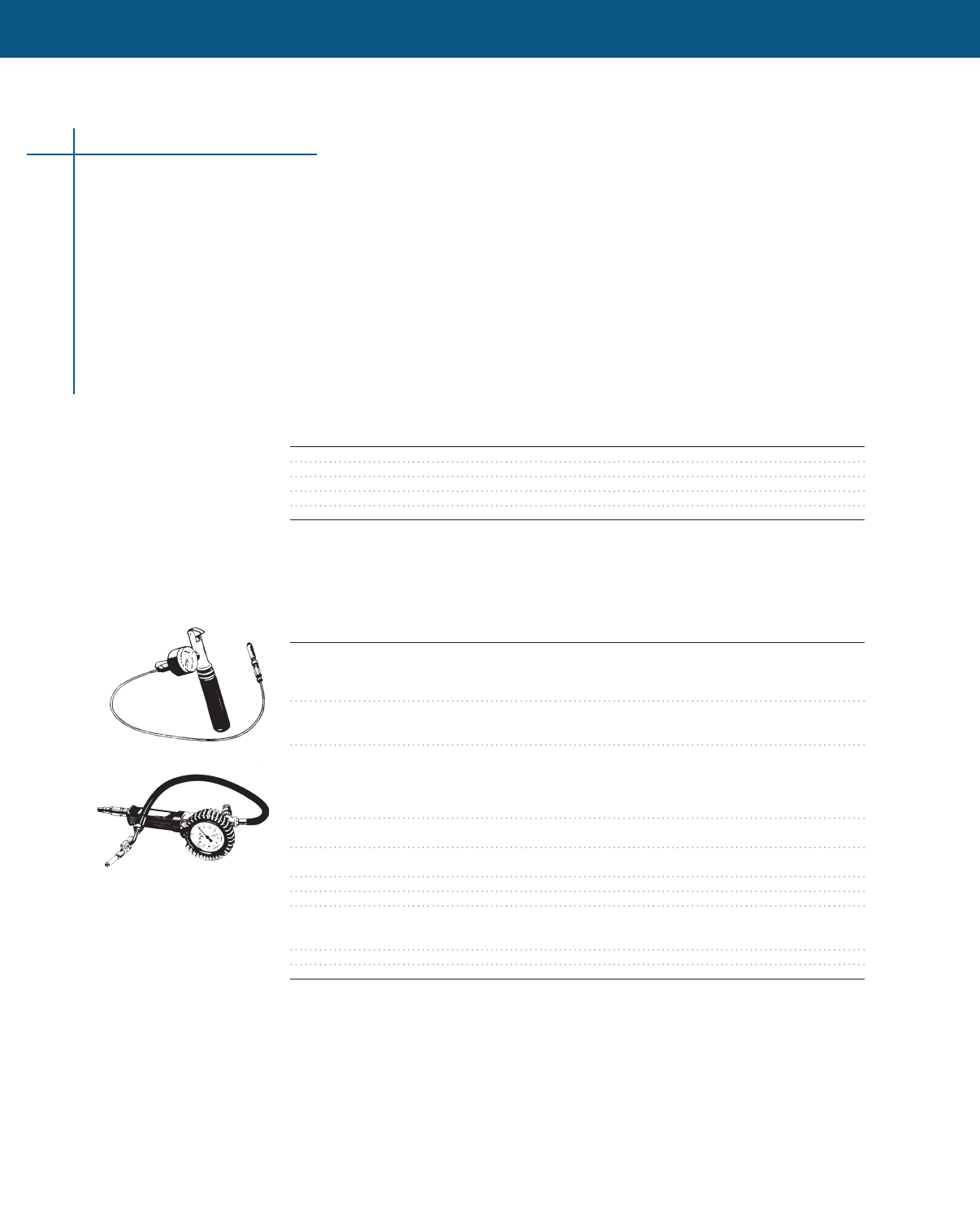
WIRE MANAGEMENT
RDSS Sealing System continues
Ordering information
1 In ducts where the cable/cable bundle is less than 24”(60mm) in diameter, an RDSS-AT/AP-150
device must be used in conjunction with the RDSS-150
2 Standard package: RDSS = 10 kits/box or 3 kits/box RDSS-CLIP = 5 clips/box
RDSS-TOOLS = 1 each/box, CO2 cartridges = 10 each/box,
RDSS-AT/AP-150 = 1 each/box
3 Related test report: EDR-5253
4 S-1278 sealant, used in RDSS-CLIPS, is available separately
RDSS sealing clip
RDSS duct sealing clips are to be used if the duct is occupied by more than two cables The
maximum number of cables sealed with one RDSS-CLIP is four If more cables are to be sealed,
one extra clip is needed for every three additional cables Check with your Tyco Electronics
representative for applications with more than seven cables
Catalog Number Kit Used With
RDSS-CLIP-45 RDSS-45
RDSS-CLIP-75 RDSS-75 and RDSS-60
RDSS-CLIP-100 RDSS-100
RDSS-CLIP-125 RDSS-125
RDSS-CLIP-150 RDSS-150
RDSS Installation Tools
RDSS duct seals can be installed with a variety of inflation tools having the capability of inflating
RDSS to 45±3 psi (3 bar) of pressure The tools Tyco Electronics offers are summarized in the
table below The tool will only accept 16-gr CO2 gas cylinders (listed below)
Catalog Number Description Std. Pack
RDSS-IT-16 Inflation tool designed with an ON/OFF switch and 1 tool/box
an automatic pressure-monitoring system The
required CO2 gas cylinders (E7512-0160) must
be ordered separately
E7512-0160 16-gr CO2 gas cylinders for the RDSS-IT-16 tool 10 cylinders/
Each gas cylinder inflates approximately four box
RDSS-100 duct seals
RDSS-IG-SR-AS Inflation tool designed for use with customer’s own 1 tool/box
source of nitrogen or compressed air Features a
pressure gauge, automatic shutoff, VGF valve
connection, and two alternate connections for
plastic or rubber hoses
E7512-0220 Tube snap assembly 1 each/box
Spare part for RDSS-IT-16 inflation tool
E7512-0240 Spare pressure gauge assembly for 1 each/box
RDSS-IT-16 inflation tool
E7512-0260 Spare delivery pipe for RDSS-IT-16 inflation tool 1 each/box
S-1278-3 x 61 x 7620 RDSS sealant roll 1 25-ft roll/box
RDSS-AT/AP-150 For use with the RDSS-150 in duct 525” or larger 1 each/box
with cable/cable bundles less than 24” (60mm)
in diameter
RDSS-AD-210 Adapter for ducts 65 - 80” (165 - 210mm) diameter 4 each/box
E4540-1250 RDSS-LUBE for installation of RDSS 25 each/box
RDSS-IT-16
RDSS-IG-SR-AS
Duct Sealing Sytem
62
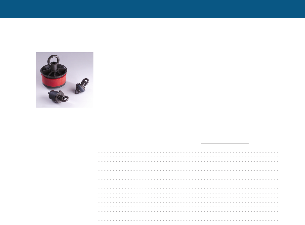
WIRE MANAGEMENT
WIRE MANAGEMENT
Blank Duct Plugs
Duct Plugs / Sealing Ducts
Duct Sealing Sytem
Blank duct plugs effectively seal empty conduits to reduce the cost of cable placement and
maintenance in new underground construction projects and routine work These plugs prevent
the flow of water and the costly sedimentation of duct banks and conduit systems while confining
problems of dangerous vapors to their source
• High-impact plastic components, combined with durable elastic gaskets
• Corrosion proof and effective as long-term or temporary seals
• Water-tight and gas-tight
• Equipped with a rope tie device to allow the securing of pull rope to the plug’s back
compression plate
• Removable and reusable
Selection information: dimensions in inches (millimeters)
63
Catalog Plug Duct ID Range Std.
Number* Diameter Inch mm Pack
CPGI-JM-BLA-07D100U 0700 071 - 083 180 - 211 12
CPGI-JM-BLA-10D104U 1000 096 - 116 244 - 295 12
CPGI-JM-BLA-12D148U 1250 114 - 148 290 - 376 12
CPGI-JM-BLA-12D163U 1375 130 - 163 330 - 414 12
CPGI-JM-BLA-15D183U 1500 149 - 183 378 - 465 12
CPGI-JM-BLA-20D236U 2000 183 - 236 465 - 599 12
CPGI-JM-BLA-25D296U 2500 234 - 296 594 - 752 12
CPGI-JM-BLA-30D346U 3000 299 - 346 759 - 879 12
CPGI-JM-BLA-35D400N 3500 345 - 380 869 - 965 12
CPGI-JM-BLA-35D400U 3500 345 - 380 869 - 965 12
CPGI-JM-BLA-40D402N 4000 394 - 417 1001 - 1059 8
CPGI-JM-BLA-40D402U 4000 394 - 417 1001 - 1059 8
CPGI-JM-BLA-40D402U-C 4000 394 - 417 1001 - 1059 8
CPGI-JM-BLA-50D500U 5000 458 - 502 1163 - 1275 8
CPGI-JM-BLA-50D535U 5000 500 - 535 127 - 1359 8
CPGI-JM-BLA-60D637U 6000 582 - 637 1478 - 1618 8
CPGI-JM-BLA-80D816U 8000 783 - 827 1989 - 2101 8
* T - Temporary Plug, CR - CR Rubber Gasket, C - Custom Gasket, N - Nut Version


TELECOM / DATACOM / COAX
Telecom Datacom
Water-Resistant Telephone/CAT-5 Splice Kits & Covers67
Water-Resistant Drop Wire Splices & Taps67
Coax
Water-Resistant Coax Splice Kits & Covers 68
Water-Resistant Coax Boot Covers 68
65

66
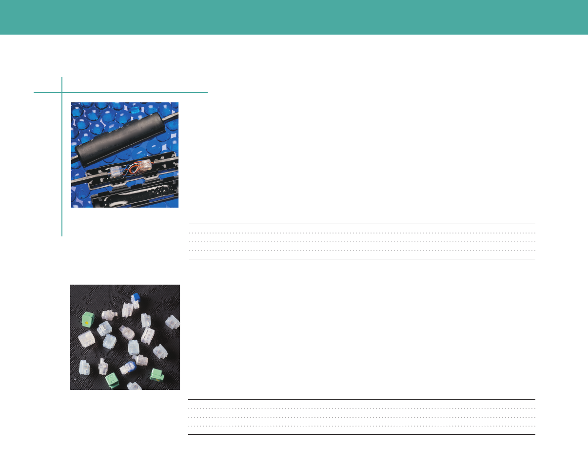
TELECOM / DATACOM / COAX
TELECOM / DATACOM / COAX
Water-Resistant Telephone/CAT-5 Splice Kits & Covers
CERTI-SEAL Aerial Splice Closure
The telephone wire splice kits and covers are designed for direct buried splicing of Telco and Datacom
cables These quickly installed, low-cost splice kits can be used to repair damaged telecom and
datacom cables The water-resistant, gel-filled construction seals out the environment, withstands 14
days immersion without signal degradation, and withstands extreme temperatures One-piece housing
snaps on and requires no special tools
Selection information
Catalog Number Cable Type Connectors Std. Pack
CPGI-1116542-1 Telephone (2 pr.) No 5
CPGI-1116542-1-K Telephone (2 pr.) Yes (4) 5
CPGI-1217204-1 Telephone (2 or 6 pr.) No 5
CPGI-1217204-1-K Telephone (2 or 6 pr.) Yes 5
Telecom/Datacom
Water-Resistant Drop Wire Splices & Taps
Tel-Splice Connectors
Water-resistant insulation displacement, gel-filled splice and tap connectors provide an economical
and reliable means of splicing telephone/CAT-5 cable conductors These tiny splices and taps are
highly durable and resistant to moisture and chemical attack No pre-stripping required reduces
operator preparation
Selection information
Packs/
Catalog Number Cable Type Connectors Pcs./Pack Carton
CPGI-552795-2 Telephone 2-Wire 20 5
CPGI-1-552678-2 Telephone 3-Wire 20 5
CPGI-1-553017-2 Telephone Half-Tap 20 5
CPGI-5-554374-7 Telephone Cap (No Gel) 20 5
67
TELECOM / DATACOM / COAX
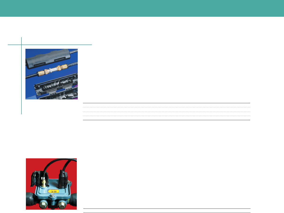
TELECOM / DATACOM / COAX
The VST gel closure system provides corrosion resistant sealing of an F-connector exposed to
the outside environment The housing contains innovative gel material and provides an efficient
moisture block The ease of installation together with the long-term protection makes VST a
cost effective solution
Coax
Water-Resistant Coax Splice Kits & Covers
CERTI-SEAL Coax Splice Closure
Water-Resistant Coax Boot Covers
Gel Closure for Sealing F-Connectors
Coax splice kits and covers are designed for direct buried splicing of Series RG-59 and RG-6 coaxial
cables These quickly installed, low-cost kits and covers can be used to repair damaged coax cable
The water-resistant gel-filled construction seals out environment, withstands 14 days immersion
without signal degradation and withstands extreme temperatures One-piece housing snaps on and
requires no special tools
Selection information
Packs/
Catalog Number Cable Type Connectors Pcs./Pack Carton
CPGI-569224-1 Coax (6/59) No 1 5
CPGI-569224-1-K Coax (6) Yes 1 5
CPGI-569661-1 Coax (7/11) No 1 5
CPGI-569661-1-K Coax (11) Yes 1 5
Selection information
Packs/
Catalog Number Cable Type Connectors Pcs./Pack Carton
CPGI-VST-02/1 Coax No 2 5
68

IDENTIFICATION SOLUTIONS
Heat-Shrink Markers
ShrinkMark Heat-Shrinkable Sleeves 71
Cable Markers
CM-SCE Cable Markers 72
HL Cable Markers 72
HLX-NEL Cable Markers 73
Permark Pre-Printed 316 Stainless Steel Markers 74
Snap-On Markers74
Labels
Self-Laminating Labels75
Pressure Sensitive Polyester Labels 76
ProjectMark Continuous Labels77
Insta-Mark Wire Markers
Pre-Printed Books78
Pre-Printed Dispensers 78
Write-On Books and Dispensers 78
Portable Marker Kit
LM2020 Plus Marking Kit 79
Printers, Software & Accessories
Printers80
Software 80
Ribbons 81
Accessories 81
69

70
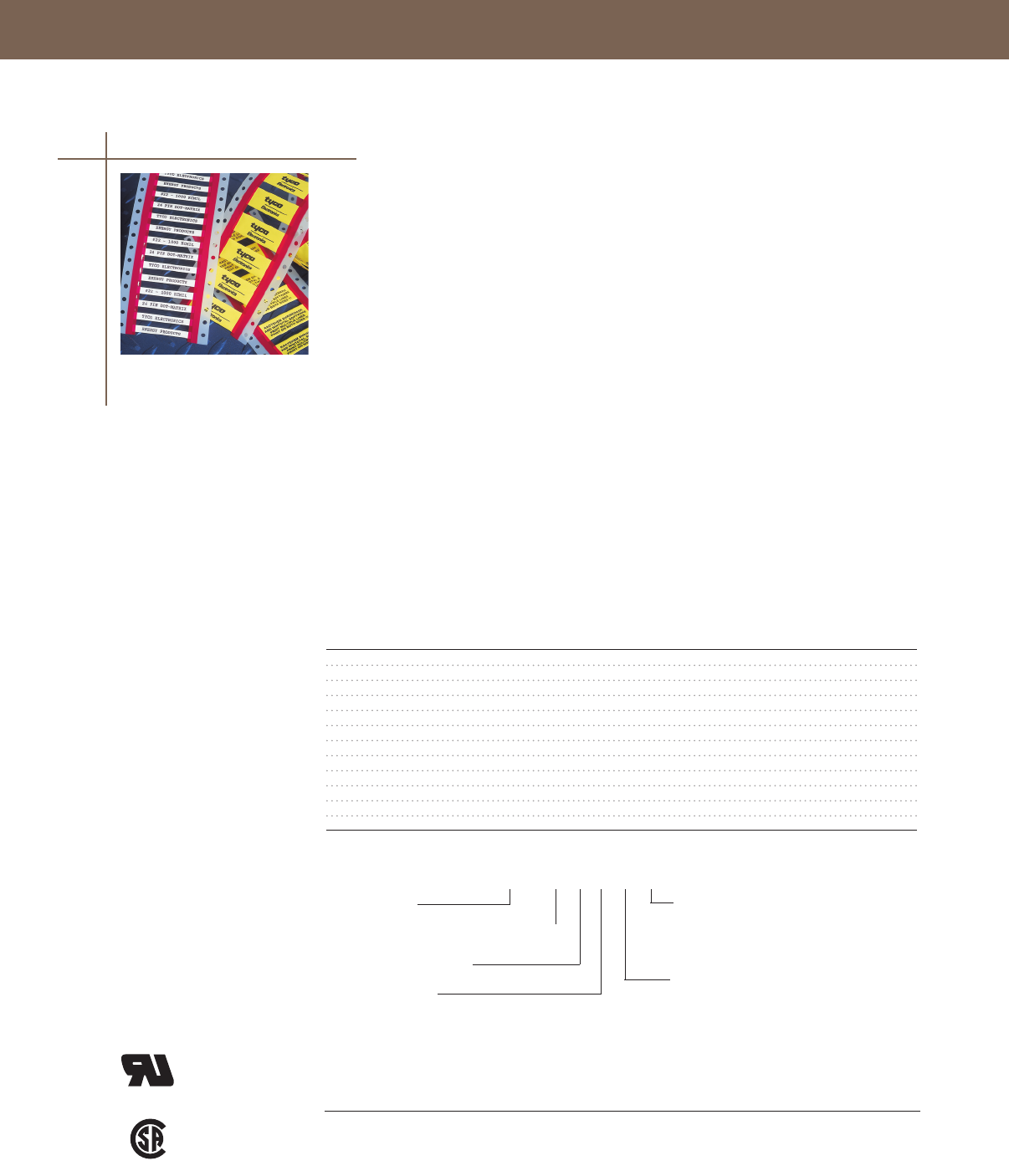
IDENTIFICATION SOLUTIONS
IDENTIFICATION SOLUTIONS
IDENTIFICATION SOLUTIONS
ShrinkMark Heat-Shrinkable Sleeves
ShrinkMark sleeves are suitable for a wide variety of applications Heat-shrinkable sleeves provide
legible identification for all types of cables used by electrical contractors and instrumentation
control manufacturers
Because ShrinkMark sleeves are extruded from Tyco Electronics tubing, they have a low installed
profile with no edges to snag The crosslinked polyolefin construction makes ShrinkMark sleeves
resistant to abrasion, aggressive cleaning solvents, and industrial fluids
ShrinkMark sleeves are ideal for tough industrial environments, including switchgear, motor control
centers, and terminal boxes They shrink faster than conventional thermoplastic tags
• Shrink ratio of 3:1
• Expanded sleeve diameters from 125"(3125mm) to 150" (38mm)
• Sleeves come in 200"(50mm) lengths
• Flame retardant Sleeves meet UL 224
• Print performance to military requirements
• ShrinkMark sleeves can be supplied pre-scored for a more economical use of material
• Several packaging options to choose from: 250, 1,000 or 2,500 pieces per box
• Standard colors are white and yellow
• Elliptical shape leaves un-shrunk sleeves in place
• Temperature Range: -30°C to 105°C
Product Order Code
Replace - 9 with - 4 Nominal Recovered
if Yellow is needed Wire Size Diameter Diameter
ShrinkMark-18-2-9 #22 - #18 0125 (3) 0042 (1)
ShrinkMark-18-2-S1-9 #22 - #18 0125 (3) 0042 (1)
ShrinkMark-12-2-9 #18 - #12 0187 (5) 0062 (2)
ShrinkMark-12-2-S1-9 #18 - #12 0187 (5) 0062 (2)
ShrinkMark-10-2-9 #16 - #10 0250 (6) 0083 (2)
ShrinkMark-10-2-S1-9 #16 - #10 0250 (6) 0083 (2)
ShrinkMark-2-2-9 #10 - #2 0500 (13) 0167 (4)
ShrinkMark-2-2-S1-9 #10 - #2 0500 (13) 0167 (4)
ShrinkMark-250-2-9 #1 - 250 100 (25) 0333 (9)
ShrinkMark-250-2-S1-9 #1 - 250 100 (25) 0333 (9)
ShrinkMark-1000-2-9 350 - 1000 140 (36) 0740 (19)
ShrinkMark-1000-2-S1-9 350 - 1000 140 (36) 0740 (19)
Selection Information: dimensions in inches (millimeters)
ShrinkMark 10 - 2 - S2 - 9 (1K)
Product name
Largest nominal conductor size in range
Sleeve length in inches
Number of scores
Blank = No scores yields 1 each - 2" marker
S1 = One score yields 2 each - 1" markers per sleeve
S2 = Two scores yield 3 each - 5/8" markers per sleeve
S3 = Three scores yield 4 each - 1/2" markers per sleeve
Standard package
Blank = 250 sleeves per box
(1K) = 1,000 sleeves per box
(25K) = 2,500 sleeves per box
Color
4 = Yellow
9 = White
®
UL recognized
to Standard
224
Certified
C222
No 1981
Recommended
Printers Ribbons
IDP-T208M-PRINTER IDP-T208M-RIBBON
IDP-T312M-PRINTER IDP-TMS-RJS-RIBN-4RPSCE
IDP-AM6310-110V-PRINTER IDP-1892BK04-RIBBON
Heat-Shrink Markers
71
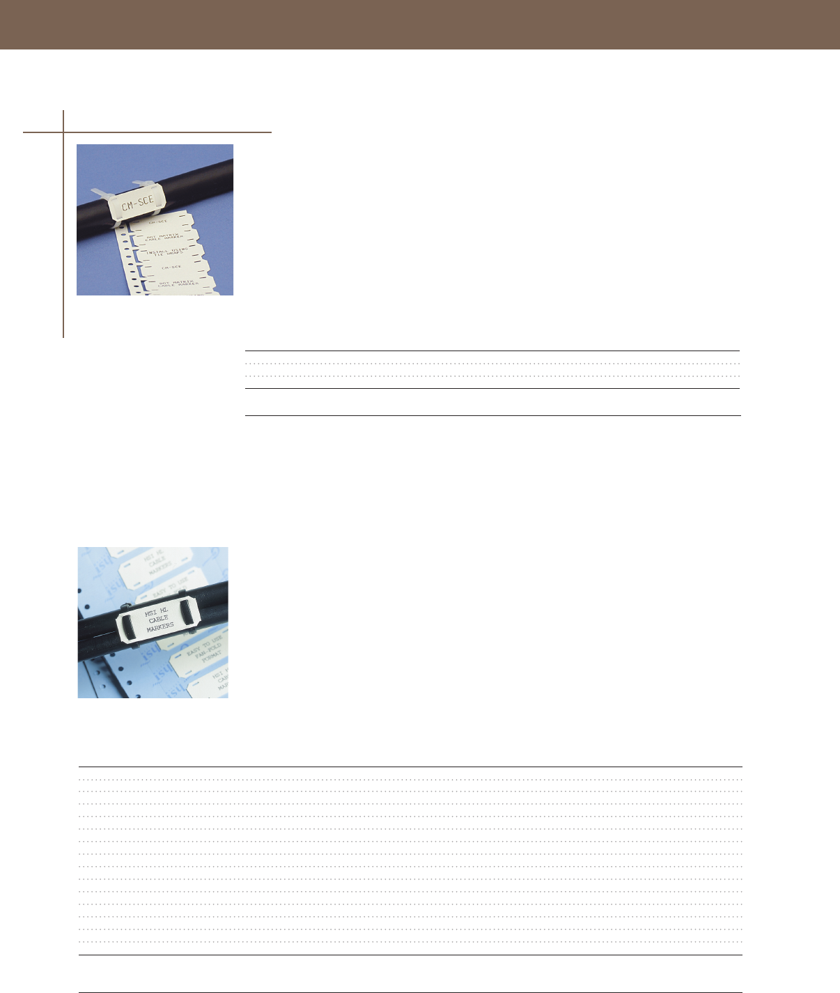
IDENTIFICATION SOLUTIONS
CM-SCE Cable Markers
CM-SCE cable markers provide a reliable method of identification of larger cables and bundles
They can be installed using standard nylon tie wraps
• Cable markers are a standard 2"(55mm) length that come in a 25"(625mm) or 50"(25mm) width
• Flame retardant
• Cable Markers meet UL 224
• Print performance to military requirements
• Standard color is white
• Temperature Range: -55°C to 135°C
Selection Information
Catalog Number Description Std. Pack
IDP-CM-SCE-25-4H-9 1/4" Cable Marker, 4 hole 250
IDP-CM-SCE-50-4H-9 1/2" Cable Marker, 4 hole 250
IDP-CM-SCE-50-6H-9 1/2" Cable Marker, 6 hole 250
HL Cable Markers
HL cable markers are a cost effective way to identify cables already terminated Like CM-SCE
cable markers, cable ties are used to secure the label to cables or bundles
• Easy to use fan-fold format for easy kitting and marker selection
• Cable markers are available in 175"(44mm) – 350" (875mm) lengths and
375" (94mm) – 10" (25mm) widths
• Standard color is white
• Temperature Range: -55°C to 135°C
Selection Information: dimensions in inches (millimeters)
Dimensions Printable Area Pcs/ Std.
Catalog Number W x H W x H Pack Pack
IDP-HL104WE1TS025B 1800 x 0400 (4500 x 1040) 1000 x 0400 (2500 x 1040) 1000 1
IDP-HL104WE1TS033B 2100 x 0400 (5200 x 1040) 1300 x 0400 (3300 x 1040) 1000 1
IDP-HL104WE1TS038B 2300 x 0400 (5800 x 1040) 1500 x 0400 (3800 x 1040) 1000 1
IDP-HL104WE1TS050B 2750 x 0400 (7000 x 1040) 2000 x 0400 (5000 x 1040) 1000 1
IDP-HL104WE1TS070B 3500 x 0400 (9000 x 1040) 2750 x 0400 (7000 x 1040) 1000 1
IDP-HL203WE1TS025B 1800 x 0800 (4500 x 2030) 1000 x 0800 (2500 x 2030) 500 1
IDP-HL203WE1TS033B 2100 x 0800 (5200 x 2030) 1300 x 0800 (3300 x 2030) 500 1
IDP-HL203WE1TS038B 2300 x 0800 (5800 x 2030) 1500 x 0800 (3800 x 2030) 500 1
IDP-HL203WE1TS050B 2750 x 0800 (7000 x 2030) 2000 x 0800 (5000 x 2030) 500 1
IDP-HL203WE1TS070B 3500 x 0800 (9000 x 2030) 2750 x 0800 (7000 x 2030) 500 1
IDP-HL253WE1TS025B 1800 x 1000 (4500 x 2530) 1000 x 1000 (2500 x 2530) 250 1
IDP-HL253WE1TS033B 2100 x 1000 (5200 x 2530) 1300 x 1000 (3300 x 2530) 250 1
IDP-HL253WE1TS038B 2300 x 1000 (5800 x 2530) 1500 x 1000 (3800 x 2530) 250 1
IDP-HL253WE1TS050B 2750 x 1000 (7000 x 2530) 2000 x 1000 (5000 x 2530) 250 1
IDP-HL253WE1TS070B 3500 x 1000 (9000 x 2530) 2750 x 1000 (7000 x 2530) 250 1
Recommended
Printers Ribbons
IDP-T312M-PRINTER IDP-TMS-RJS-RIBN-4RPSCE
Recommended
Printers Ribbons
IDP-AM6310-110V-PRINTER IDP-1892BK04-RIBBON
Cable Markers
72

IDENTIFICATION SOLUTIONS
IDENTIFICATION SOLUTIONS
Tyco Electronics HLX markers are assembled in Narrow Edge Leading (NEL) format for use in the
T208M printer Markers are manufactured from low fire hazard polyolefin material making them ideal
in applications where low smoke, low toxicity and zero halogen are critical
• Ideal for pre- or post- termination assembly
• Attach using standard cable ties
• Available in white and yellow
• Temperature Range: -40°C to 105°C
Marker Number of Markers
Catalog Number Dimensions Printable Area Across Std. Pack
IDP-HLX125WE4NEL60S 315 x 049 (80 x 125) 235 x 04 (60 x 1050) 4 200
IDP-HLX125WE2NEL60S 315 x 049 (80 x 125) 235 x 04 (60 x 1050) 2 200
IDP-HLX125YW4NEL60S 315 x 049 (80 x 125) 235 x 04 (60 x 1050) 4 200
IDP-HLX125YW2NEL60S 315 x 049 (80 x 125) 235 x 04 (60 x 1050) 2 200
Recommended
Printers Ribbons
IDP-T208M-PRINTER IDP-T200-RIBBON-1966
HLX-NEL Cable Markers
Cable Markers
73
Selection Information: dimensions in inches (millimeters)
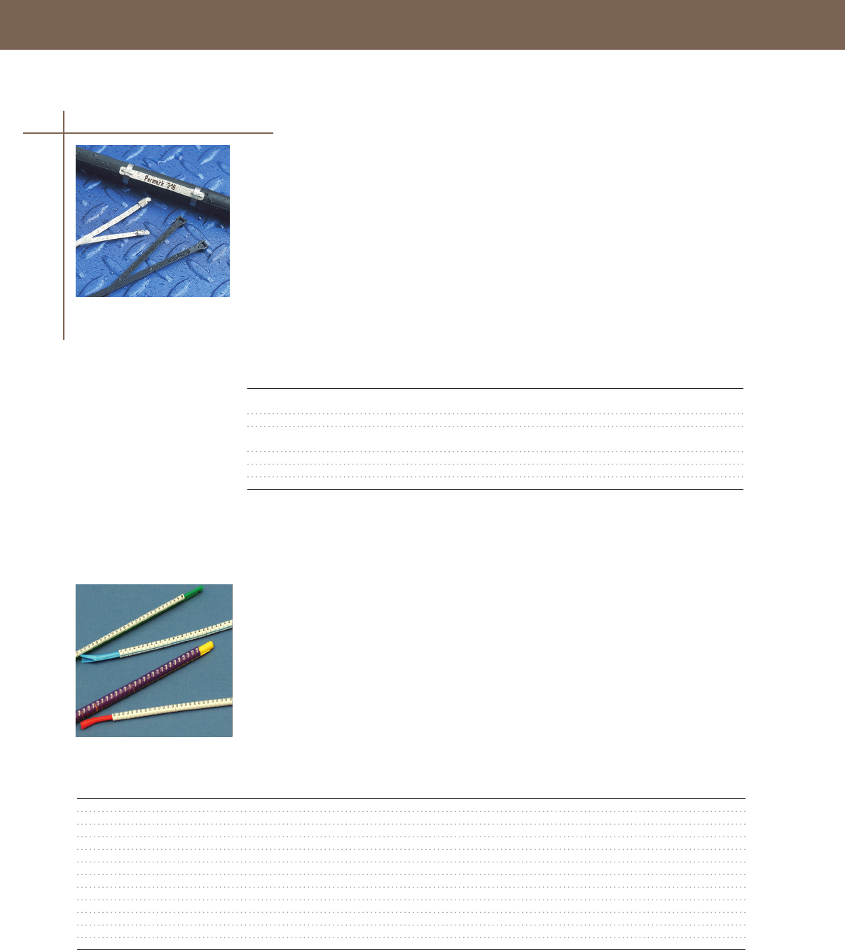
IDENTIFICATION SOLUTIONS
Selection Information: dimensions in inches (millimeters)
Catalog Number Description Std. Pack
IDP-PM09512 Stainless Steel 4mm, 374 x 047 (95 x 12) marker -
Pre-Printed (max 25 characters) 1
IDP-PM09512-BLANK Stainless Steel 4mm, 374 x 047 (95 x 12) marker - Blank 1
IDP-PM07507 Stainless Steel 4mm, 295 x 028 (75 x 7) marker -
Pre-Printed (max 20 characters) 1
IDP-PM07507-BLANK Stainless Steel 4mm, (75 x 70) marker - Blank 1
IDP-SST141-316 SS cable tie 018 x 143 (46 x 360), Ties/ Pack 100 100
IDP-SST71-316 SS cable tie 018 x 79 (46 x 200), Ties/ Pack 100 100
Permark stainless steel markers and identification plates are designed to withstand the most hostile
environments Using state-of-the-art technology and no inks, the marking process produces a
permanent, deep surface mark Permark markers are produced for individual customer requirements
on a fast turn-around basis
• Pre-marked to customer requirements
• Transfer of data files electronically
• Excellent chemical, abrasion, corrosion, and weather resistance
• One-piece, 316 stainless steel construction
• Stainless steel cable ties are also available
• Temperature Range: -80°C to 500°C
Permark Pre-Printed 316 Stainless Steel Markers
Cable Markers
Snap-on markers represent the best snap-on wire marking system available Convenient and easy to
use, these markers are supplied on a “wand” applicator that simplifies and reduces installation time
and saves on the cost of marking
• Perfect way to permanently and rapidly mark cables and wires after installation
• Resistant against oils, cleaning agents, and fuels
• Markers come in white with black print Color-coding options available for markers 0–9
• Temperature Range: -40°C to 106°C
Selection Information: dimensions in inches
Catalog Number Description Wand Color Pcs. / Pack
STD03W-x Cable diameters 0076 - 0104 - 30 markers/wand, 10 wands/pack Green 300
STD06W-x Cable diameters 0104 - 0140 - 30 markers/wand, 10 wands/pack Red 300
STD09W-x Cable diameters 0140 - 0180 - 30 markers/wand, 10 wands/pack Blue 300
STD12W-x Cable diameters 0180 - 0240 - 30 markers/wand, 10 wands/pack Yellow 300
STD15W-x Cable diameters 0232 - 0340 - markers in loose packs, wand separate 50
STD17W-x Cable diameters 0340 - 0460 - markers in loose packs, wand separate 50
STD21W-x Cable diameters 0433 - 0610 - markers in loose packs, wand separate 50
STD24W-x Cable diameters 0590 - 0750 - markers in loose packs, wand separate 50
STD15MO Wand for marker size 15 Orange 1
STD17MO Wand for marker size 17 Orange 1
STD21MO Wand for marker size 21 Gray 1
STD24MO Wand for marker size 24 Gray 1
*Replace “x” in Catalog Number with the number or letter required on the markers.
Snap-On Markers
74

IDENTIFICATION SOLUTIONS
IDENTIFICATION SOLUTIONS
Self-Laminating labels offer a fast and inexpensive way to identify wire and cable Because these
labels wrap over themselves, creating a seal, the printed surface is protected from solvents, oil, water,
and abrasion Self-laminating labels are able to run through various thermal transfer printers
• Self-laminating labels offer a white area for printed or handwritten information and a clear wrap
that winds around and protects the information
• Protects printed information from chemicals and frequent handling
• Designed to withstand exposure to oil, solvents, and water
• Vinyl material with acrylic adhesive
• UL recognized for indoor use
• Temperature Range: -40˚C to 80˚C
Selection Information: dimensions in inches (millimeters)
Maximum Print Area Label
Catalog Number Cable OD Height Width Height Labels/Roll
IDP-SB050100WE10 20 (51) 33 (85) 50 (127) 10 (254) 10,000
IDP-SB050143WE10 30 (76) 50 (127) 50 (127) 1437 (365) 10,000
IDP-SB100143WE5 30 (76) 50 (127) 10 (254) 1437 (365) 5,000
IDP-SB200143WE25 30 (76) 50 (127) 20 (508) 1437 (365) 2,500
IDP-SB080150WE10 30 (76) 50 (127) 80 (203) 150 (381) 10,000
IDP-SB100225WE5 48 (122) 75 (19) 10 (244) 225 (572) 5,000
IDP-SB200225WE25 48 (122) 75 (19) 20 (508) 225 (572) 2,500
IDP-SB100375WE25 88 (224) 10 (254) 10 (254) 375 (953) 2,500
IDP-SB200375WE25 88 (224) 10 (254) 20 (508) 375 (953) 2,500
IDP-SB100594WE1 140 (355) 150 (381) 10 (254) 594 (151) 1,000
IDP-SB190594WE1 140 (355) 150 (381) 190 (483) 594 (151) 1,000
IDP-SB200743WE1 190 (483) 150 (381) 20 (508) 7437 (189) 1,000
These standard labels fit inside the T312M Printer or they can feed into a T208M Printer using the IDP-T200-SPINDLE
T208M Size Rolls
IDP-SB050100WE5-T200 20 (51) 33 (85) 50 (127) 10 (254) 5,000
IDP-SB050143WE5-T200 30 (76) 50 (127) 50 (127) 1437 (365) 5,000
IDP-SB100143WE25-T200 30 (76) 50 (127) 10 (254) 1437 (365) 2,500
IDP-SB080150WE5-T200 30 (76) 50 (127) 80 (203) 150 (572) 5,000
IDP-SB100225WE25-T200 48 (122) 75 (19) 10 (254) 225 (572) 2,500
IDP-SB200225WE1-T200 48 (122) 75 (19) 20 (508) 225 (572) 1,000
IDP-SB100375WE1-T200 88 (224) 10 (254) 10 (254) 375 (953) 1,000
IDP-SB200375WE1-T200 88 (224) 10 (254) 20 (508) 375 (953) 1,000
IDP-SB100594WE05-T200 140 (355) 150 (381) 10 (254) 594 (151) 500
IDP-SB200743WE05-T200 190 (483) 150 (381) 20 (508) 7734 (189) 500
These labels have a smaller core that allows them to fit inside of the T208M Printer. However, these are not recommended
for the T312M Printer.
Recommended
Printers Ribbons
IDP-T208M-PRINTER IDP-T208M-RIBBON
IDP-T312M-PRINTER IDP-TMS-RJS-RIBN-4RPSCE
Self-Laminating Labels
Labels
75

IDENTIFICATION SOLUTIONS
76
Tyco Electronics offers a wide range of label products for thermal transfer printing applications
Several material types and adhesives are available providing guaranteed results for your application
Tyco Electronics is a UL-recognized label supplier
• Labels made of polyester provide the best material for your application
• Permanent acrylic adhesive provides excellent bond to many surfaces: tubing, wiring, cables
or panels
• No heat curing process required
• Excellent for barcode applications
• Multiple die-cut sizes available
• MP – Metalized Polyester
• WP – White Polyester
• Temperature Range: -40˚C to 150˚C
Selection Information: dimensions in inches (millimeters)
Labels per
Catalog Number Width Height Material T208M Roll
IDP-MP-191064-10-8A 75 (19) 25 (64) Metalized Polyester No 10,000
IDP-MP-203127-10-8A 80 (203) 50 (127) Metalized Polyester No 10,000
IDP-MP-254127-10-8A 10 (254) 50 (127) Metalized Polyester Yes 10,000
IDP-MP-254254-10-8A 10 (254) 10 (254) Metalized Polyester Yes 10,000
IDP-MP-381064-10-8A 150 (381) 25 (64) Metalized Polyester Yes 10,000
IDP-MP-381191-5-8A 150 (381) 75 (19) Metalized Polyester No 5,000
IDP-MP-508254-5-8A 20 (508) 10 (254) Metalized Polyester Yes 5,000
IDP-MP-508318-25-8A 20 (508) 125 (318) Metalized Polyester Yes 2,500
IDP-MP-699254-5-8A 275 (70) 10 (254) Metalized Polyester Yes 5,000
IDP-MP-762381-25-8A 30 (762) 150 (381) Metalized Polyester Yes 2,500
IDP-MP-762508-25-8A 30 (762) 20 (508) Metalized Polyester Yes 2,500
IDP-MP-101635-25-8A 40 (1016) 250 (635) Metalized Polyester Yes 2,500
IDP-WP-040040-25-9 157 (4) 157 (4) White Polyester No 25,000
IDP-WP-064064-25-9 25 (64) 25 (64) White Polyester No 25,000
IDP-WP-080080-10-9 315 (8) 315 (8) White Polyester No 10,000
IDP-WP-950950-10-9 375 (95) 375 (95) White Polyester Yes 10,000
IDP-WP-114040-25-9 45 (114) 157 (4) White Polyester No 25,000
IDP-WP-127111-10-9 50 (127) 437 (111) White Polyester Yes 10,000
IDP-WP-165102-10-9 65 (165) 40 (102) White Polyester Yes 10,000
IDP-WP-165051-25-9 65 (165) 20 (51) White Polyester No 25,000
IDP-WP-178095-10-9 70 (178) 375 (95) White Polyester No 10,000
IDP-WP-191064-10-9 75 (19) 25 (64) White Polyester No 10,000
IDP-WP-203127-10-9 80 (203) 50 (127) White Polyester No 10,000
IDP-WP-229364-10-9 90 (229) 25 (64) White Polyester Yes 10,000
IDP-WP-254097-10-9 10 (254) 38 (97) White Polyester Yes 10,000
IDP-WP-254127-10-9 10 (254) 50 (127) White Polyester Yes 10,000
IDP-WP-254254-10-9 10 (254) 10 (254) White Polyester Yes 10,000
IDP-WP-318064-10-9 125 (318) 25 (64) White Polyester Yes 10,000
IDP-WP-381020-10-9 150 (381) 08 (2) White Polyester Yes 10,000
IDP-WP-381064-10-9 150 (381) 25 (64) White Polyester Yes 10,000
IDP-WP-381190-5-9 150 (381) 75 (19) White Polyester No 5,000
IDP-WP-508127-10-9 20 (508) 5 (127) White Polyester Yes 10,000
IDP-WP-508254-5-9 20 (508) 10 (254) White Polyester Yes 5,000
IDP-WP-508318-25-9 20 (508) 125 (318) White Polyester Yes 2,500
IDP-WP-508064-10-9 20 508) 25 (64) White Polyester Yes 10,000
IDP-WP-523841-15-9 206 (523) 331 (841) White Polyester Yes 1,500
IDP-WP-700254-5-9 275 (70) 10 (254) White Polyester Yes 5,000
IDP-WP-762381-25-9 30 (762) 150 (381) White Polyester Yes 2,500
IDP-WP-762508-25-9 30 (762) 20 (508) White Polyester Yes 2,500
IDP-WP-101635-25-9 40 (1016) 250 635) White Polyester Yes 2,500
IDP-WP-101165-085-9 40 (1016) 65 (165) White Polyester Yes 900
* All labels are compatible with T312M-Printer, but only those marked “Yes” in the T208M column are compatible with
T208M Printer.
Recommended
Printers Ribbons
IDP-T208M-PRINTER IDP-1330-0607-T200
IDP-T312M-PRINTER IDP-1330-0607-10
Pressure Sensitive Polyester Labels
Labels

IDENTIFICATION SOLUTIONS
IDENTIFICATION SOLUTIONS
77
Labels
ProjectMark Continuous Labels
ProjectMark (TTPA) is a durable, high strength polyester material that can be used as warning
and service labels, rating plates, and a way to identify cable trays—all of which can be produced
on demand
• High tack acrylic adhesive
• Resistant to moisture/humidity
• 4 printable continuous widths in several colors
• Material comes on a 100' reel and ranges from 10" (25mm) to 40"(100mm) wide
• Standard white ProjectMark labels have a 5–7 year outdoor life
• Apply a UV protection laminate (IDP-NPVF) to provide 15 year protection
• Temperature Range: -40˚C to 150˚C
Standard Colors are White (WE) and Metalized Polyester (MP)
Additional colors include the following: OE = Orange, GN = Green, BE = Blue, RD = Red, BK = Black,
YW = Yellow, CL = Clear
Selection Information: dimensions in inches
Catalog Number Description Std. Pack
IDP-TTPA100WE-10* Continuous Polyester 100 Ft Roll - 1 Wide, White 1
IDP-TTPA100YW-10* Continuous Polyester 100 Ft Roll - 1 Wide, White 1
IDP-TTPA200MP-10 Continuous Polyester 100 Ft Roll - 2 Wide, Metalized Poly 1
IDP-TTPA200WE-10 Continuous Polyester 100 Ft Roll - 2 Wide, White 1
IDP-TTPA300MP-10 Continuous Polyester 100 Ft Roll - 3 Wide, Metalized Poly 1
IDP-TTPA300WE-10 Continuous Polyester 100 Ft Roll - 3 Wide, White 1
IDP-TTPA400MP-10 Continuous Polyester 100 Ft Roll - 4 Wide, Metalized Poly 1
IDP-TTPA400WE-10 Continuous Polyester 100 Ft Roll - 4 Wide, White 1
*1 inch wide rolls are only available in White and Yellow.
Recommended
Printers Ribbons
IDP-T208M-PRINTER* IDP-1330-0607-T200
IDP-T312M-PRINTER IDP-1330-0607-10
* Software adjustments required to use the T208M with ProjectMark. Call 866-374-9655 for support.

IDENTIFICATION SOLUTIONS
Insta-Mark Wire Marker Books and Dispensers offer a portable and convenient pocket-sized solution
of vinyl impregnated cloth tape wire markers and self-laminating labels Each item is packaged for
Point-of-Purchase merchandising and provides an array of letters, numbers, symbols, or colors to
easily identify any type of wire and/or terminal block
Pre-Printed Marker Books (PPMB) contain 10 pages of pre-cut markers 1-1/4" long, totaling 450 wire
markers with 450 matching terminal markers sized 3/16" x 3/16"
Write-On Self-Laminating Marker Books (WOMB) contain 10 pages of pre-cut self laminating markers
made of 004" thick clear vinyl film, using an acrylic adhesive and mounted on a silicone release liner
The service temperature is -40°C to 93°C
Pre-Printed Marker Dispensers (PPMD) are a portable wire marker system Each dispenser contains 10
rolls of marker tape Each roll contains 76 individual markers with a pre-determined length of 1-1/4"
and a width of 1/4" Legends available are 0-9, A-J or the NEMA colors
Write-On Marker Dispensers (WOMD) are a portable and disposable dispenser containing a roll of pre-
cut Self-Laminating Wire Markers Each marker has a white area available for legend inscription using
a pen or pencil The adhesive is an aggressive acrylic that is impervious to oil and water with a service
temperature range of -40°C to 121°C
Std.
Catalog Number Description Pack
CPGI-PPMB-01 Insta-Mark Pre-Printed Marker Book - 0-9 10
CPGI-PPMB-02 Insta-Mark Pre-Printed Marker Book - A-Z, 1-15, +, -, / 10
CPGI-PPMB-03 Insta-Mark Pre-Printed Marker Book - 1-45 10
CPGI-PPMB-04 Insta-Mark Pre-Printed Marker Book - 1, 2, 3 10
CPGI-PPMB-05 Insta-Mark Pre-Printed Marker Book - A, B, C 10
CPGI-PPMB-06 Insta-Mark Pre-Printed Marker Book - T1, T2, T3 10
CPGI-PPMB-07 Insta-Mark Pre-Printed Marker Book - L1, L2, L3 10
CPGI-PPMB-08 Insta-Mark Pre-Printed Marker Book - 46-90 10
CPGI-PPMB-09 Insta-Mark Pre-Printed Marker Book - 10 NEMA COLORS 10
CPGI-PPMB-10 Insta-Mark Pre-Printed Marker Book - AC, DC, POS, NEG, GND, 10
CPGI-PPMB-11 Insta-Mark Pre-Printed Marker Book - Burglar Alarm 10
CPGI-PPMB-12 Insta-Mark Pre-Printed Marker Book - 0-9, L1-L3, T1-T3 10
CPGI-PPMB-13 Insta-Mark Pre-Printed Marker Book - 1-30 10
CPGI-PPMB-14 Insta-Mark Pre-Printed Marker Book - 1-45,+/-, L1-L3, T1-T3, 10
CPGI-PPMB-15 Insta-Mark Pre-Printed Marker Book - 1, 2, 3, A, B, C, L1-L3, T1-T3 10
CPGI-PPMB-16 Insta-Mark Pre-Printed Marker Book - 1-45, 46-90, A-Z, +, -, /, 0 10
CPGI-PPMB-20 Insta-Mark Pre-Printed Marker Book - Circuit Breaker (3 SET) 10
CPGI-PPMB-21 Insta-Mark Pre-Printed Marker Book - Circuit Breaker (1 SET) 10
CPGI-PPMB-22 Insta-Mark Pre-Printed Marker Book - Fire Alarm 10
CPGI-WOMB-B30 Insta-Mark Write-on Marker Book - Label Size 1.0 x 5.0 10
CPGI-WOMB-B50 Insta-Mark Write-on Marker Book - Label Size 0.5 x 1.25 10
CPGI-WOMB-B60 Insta-Mark Write-on Marker Book - Label Size 1.0 x 2.5 10
CPGI-WOMB-B75 Insta-Mark Write-on Marker Book - Label Size .75 x 1.67 10
CPGI-PPMD-0-9 Insta-Mark Preprinted Marker Dispenser 0,1,2,3,4,5,6,7,8,9 5
CPGI-PPMD-A-J Insta-Mark Preprinted Marker Dispenser A,B,C,D,E,F,G,H,I,J 5
CPGI-PPMD-NEMA Preprinted Marker Dispenser NEMA COLORS
(Wht, Yel, Org, Red, Blu, Grn, Vio, Brn, Gry, Blk) 5
CPGI-PPMDRF-0-9 Preprinted Marker Dispenser REFILL 0,1,2,3,4,5,6,7,8,9 5
CPGI-PPMDRF-A-J Preprinted Marker Dispenser REFILL A,B,C,D,E,F,G,H,I,J 5
CPGI-PPMDRF-NEMA Preprinted Marker Dispenser REFILL NEMA COLORS
(Wht, Yel, Org, Red, Blu, Grn, Vio, Brn, Gry, Blk) 5
CPGI-WOMD-13 Insta-Mark Write-on Marker Dispensers - Label Size .75 x3.0 5
CPGI-WOMD-16 Insta-Mark Write-on Marker Dispensers - Label Size .75 x6.0 5
CPGI-WOMD-51 Insta-Mark Write-on Marker Dispensers - Label Size .75 x1.25 5
CPGI-WOMD-52 Insta-Mark Write-on Marker Dispensers - Label Size .75 x1.75 5
Insta-Mark Wire Marker Books & Dispensers
Selection Information: dimensions in inches
Insta-Mark Wire Markers
78

IDENTIFICATION SOLUTIONS
IDENTIFICATION SOLUTIONS
The LM2020 Plus system is an advanced portable thermal label printer It is designed for both labeling
and bar coding The LM2020 Plus system is quick and easy to use in the field, office, or shop The
LM2020 Plus marker material and ribbon are pre-loaded into a snap-in cartridge This allows for
repeatable, error free loading into the printer
Features
• Minimum media width of 0125" (32mm) Maximum media width of 10" (25mm)
• 67 point size ranging from 6 point to 72 point
• 10 resident bar codes
• Alphanumeric sequencing
• Battery-operated or AC power supply-operated
• Product and ribbon comes housed in easy-to-install cartridges
Materials available
• Shrink tube wire and cable markers (White & Yellow)
• Self-laminating wrap-around wire and cable markers
• Industrial labels for tray and pipe identification
Advantages over other portable systems
• No smearing—Ink dries immediately
• One-step loading process—No separate ribbon and markers to load
• 300 dpi thermal print quality—Superior print quality compared to 9-pin dot matrix printers
• Savings—Very affordable portable thermal printing system
Std.
Catalog Number Description Pack
LM2020PLUS-PRINTER-KIT Handheld printer, protective jacket, 6 ni-cad batteries 1
LM2020PLUS-2800MAH-NICAD LM 2020 Rechargeable Batteries 1
LM-CASE LM 2020 Hard Sided Carrying Case 1
LM-1/8-TUBE-WE Shrinktube 1/8" x 100" Cartridge, White #16 - #22 1
LM-1/8-TUBE-YW Shrinktube 1/8" x 100" Cartridge, Yellow #16 - #22 1
LM-3/16-TUBE-WE Shrinktube 3/16" x 100" Cartridge, White #12 - #18 1
LM-3/16-TUBE-YW Shrinktube 3/16" x 100" Cartridge, Yellow #12 - #18 1
LM-1/4-TUBE-WE Shrinktube 1/4" x 100" Cartridge, White #10 - #16 1
LM-1/4-TUBE-YW Shrinktube 1/4" x 100" Cartridge, Yellow #10 - #16 1
LM-1/2-TUBE-WE Shrinktube 1/2" x 100" Cartridge, White #1 - #12 1
LM-1/2-TUBE-YW Shrinktube 1/2" x 100" Cartridge, Yellow #1 - #12 1
LM-1/2-TAPE-BK 05" x 40' Industrial Tape- White on Black
LM-1/2-TAPE-CR 05" x 40' Industrial Tape- Black on Clear 1
LM-1/2-TAPE-WE 05" x 40' Industrial Tape- Black on White 1
LM-1/2-TAPE-YW 05" x 40' Industrial Tape- Black on Yellow 1
LM-1-TAPE-BK 1" x 40' Industrial Tape- White on Black 1
LM-1-TAPE-CR 1" x 40' Industrial Tape- Black on Clear 1
LM-1-TAPE-WE 1" x 40' Industrial Tape- Black on White 1
LM-1-TAPE-YW 1" x 40' Industrial Tape- Black on Yellow 1
LM-1/2-VINYL-CR 05" x 40' Vinyl Industrial Tape- Black on Clear 1
LM-1/2-VINYL-RD 05" x 40' Vinyl Industrial Tape- Black on Red 1
LM-1/2-VINYL-WE 05" x 40' Vinyl Industrial Tape- Black on White 1
LM-1/2-VINYL-YW 05" x 40' Vinyl Industrial Tape- Black on Yellow 1
LM-1-VINYL-CR 1" x 40' Vinyl Industrial Tape- Black on Clear 1
LM-1-VINYL-RD 1" x 40' Vinyl Industrial Tape-Black on Red 1
LM-1-VINYL-SR 1" x 40' Vinyl Industrial Tape-Black on Silver 1
LM-1-VINYL-WE 1" x 40' Vinyl Industrial Tape-Black on White 1
LM-1-VINYL-YW 1" x 40' Vinyl Industrial Tape-Black on Yellow 1
LM-1/2-SL Self-Lam 1" x 50" Print Area 1" x 25" 230 each Fits #16-#22 1
LM-3/4-SL Self-Lam 1" x 75" Print Area 1" x 375" 250 each Fits #10-#16 1
LM-1-SL Self-Lam 1" x 1" Print Area 1" x 375" 200 each Fits #10-#12 1
LM-1-1/4-SL Self-Lam 1" x 125" Print Area 1" x 50" 170 each Fits #8-#12 1
LM-2-1/2-SL Self-Lam 1" x 250" Print Area 1" x 75" 108 each Fits #6-#10 1
LM-4-SL Self-Lam 1" x 4˝ Print Area 1" x 1" 81 each Fits #4-#6 1
LM2020 PLUS Portable Hand-Held Marking Kit
Selection Information: dimensions in inches
Portable Marker Kit
79
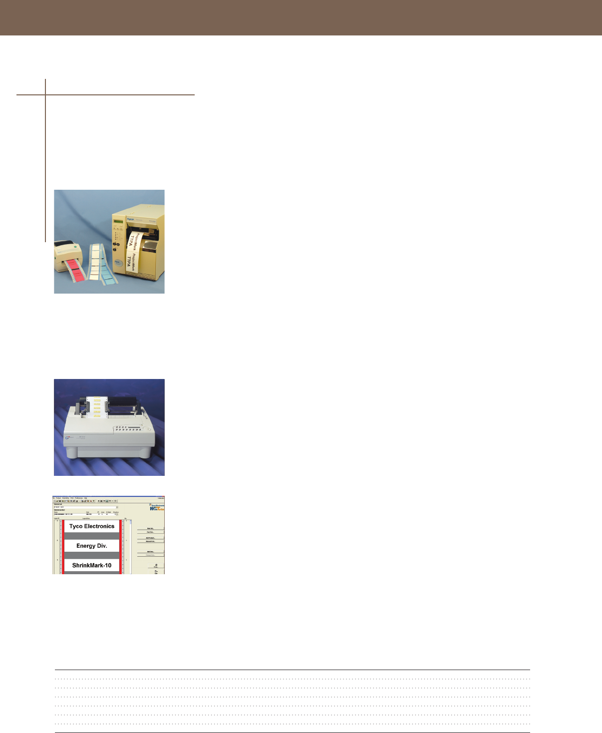
IDENTIFICATION SOLUTIONS
Thermal Transfer Printers
T208M Printer
T208M Printer Kit (Contains T208M-Printer & T208M-Ribbon) medium volume, 200 dpi printer
Lightweight printer with a 41" printhead that can print sleeves and labels Parallel and USB
ports provided
T208M-C-Printer comes with cutter for continuous labels, such as ProjectMark.
T312M Printer
T312M Printer is a high performance, yet cost effective thermal transfer printer with a 41" printhead
Robust, industrial computer-driven thermal transfer printer This 300 dpi printer has been specially
designed to print the full range of Tyco Electronics’ cable identification and labeling products giving
the optimum in flexibility, print quality and permanence With dual 32 bit processors this printer is ideal
for high volume users
T312S-C-Printer comes with optional cutter, ideal for ProjectMark continuous labels, not
recommended for ShrinkMark sleeves.
Dot-Matrix Printer
AM6310 Printer
Specifically designed by Tyco Electronics, the AM6310 is a heavy-duty, industrial dot matrix printer
with a high impact 24-pin print head Automatic media thickness detection and a high impact
print head make the AM6310 the best industrial printer available for heavy gauge wire marker and
tag materials, and the 24-pin print head produces high quality text printing with fast print speeds
Standard AM6310 printer models are designed to print on Tyco Electronics wire marker sleeves and
dot matrix pressure sensitive label and tag products
WinTotal Software
WinTotal software is a powerful Windows based package that makes identification marking quick and
easy The Windows environment gives access to a huge array of font options, including non-English
fonts and also allows simple importing and manipulation of graphics and logos
• Pre-loaded with all of Tyco Electronics identification products
• Powerful import and export functions: reads wire lists from spreadsheets, and text files
• Incremental alpha and numeric fields
• Double-sided marker printing
• Automatic or manual routing to multiple printers
• Network compatible
WinTotal USB Dongle option available - Allows software registration to be purchased once and
shared among different computers simply by plugging the dongle into an available USB port
These printers have been selected to suit a range of identification requirements and offer excellent
legibility and mark permanence An extensive range of ribbons has been designed for use with the
Tyco Electronics identification products These ribbons ensure excellent mark permanence and
legibility to applicable industry specifications
System Printers, Software, & Accessories
Accessories
80
Selection Information
Std.
Catalog Number Description Pack
IDP-T208M-PRINTER Medium Vol Thermal Trans Printer Kit, 4" Print head, 1
IDP-T208M-C-PRINTER Medium Vol Thermal Trans Printer Kit, 4" Print head, with cutter 1
IDP-T312M-PRINTER High Vol Thermal Trans Printer Kit, 4" Print head, 3MB RAM 1
IDP-T312S-C-PRINTER High Vol Thermal Trans Printer Kit, 4" Print head, 3MB RAM, with cutter 1
IDP-AM6310-110V-PRINTER AM-6310 Dot Matrix Printer Kit 1
IDP-WINTOTAL-SWARE WinTotal Software 1
IDP-WINTOTAL-SWARE-DGLUS WinTotal Software with USB Dongle 1
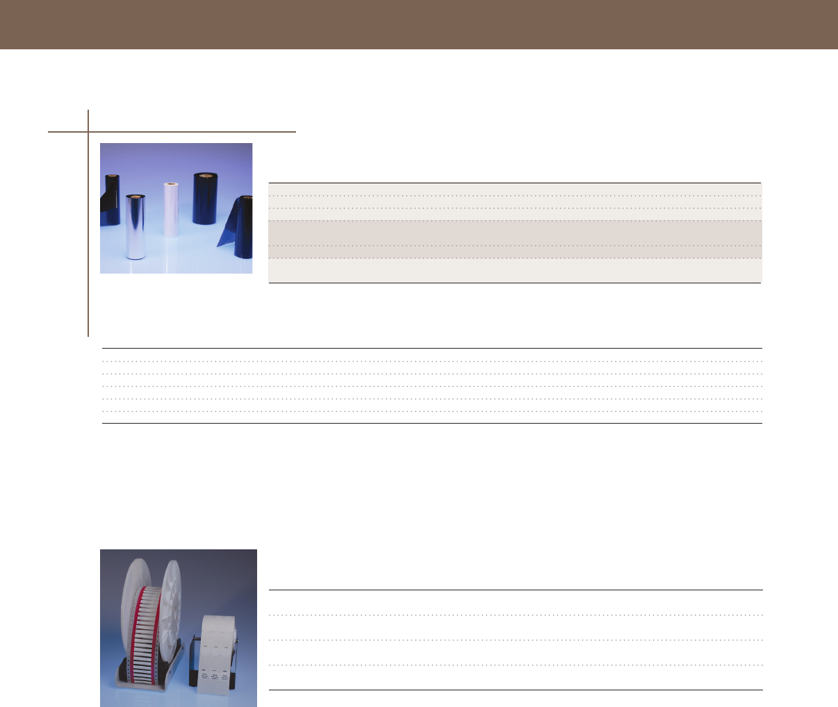
IDENTIFICATION SOLUTIONS
IDENTIFICATION SOLUTIONS
Accessories
Std.
Catalog Number Description Pack
IDP-T208M-RIBBON Ribbon for T208M printer, use with heat-shrink sleeves & SB labels, 242' (74M) 1
IDP-1330-0607-T200 Ribbon for T200 printers, use with TTPA, MP, WP, WV labels, 242' (74M) 1
IDP-T200-RIBBON-1966 Ribbon for T200 printers, use with HLX-NEL cable markers, 242' (74M) 1
IDP-TMS-RJS-RIBN-4RPSCE T300-T400 Series Ribbon for heat-shrink sleeves & SB labels, 433" wide, 984' (300M) 1
IDP-1330-0607-10 T300-T400 Series Ribbon for TTPA, MP, WP, WV labels, 433" wide, 984' (300M) 1
IDP-1892BK04-RIBBON AM-6310-Ribbon designed for heat-shrink sleeves and CM-SCE cable markers 1
Selection Information
Ribbons
Printer Ribbon Print Media
IDP-T208M-PRINTER IDP-T208M-RIBBON ShrinkMark sleeves & SB labels
IDP-1330-0607-T200 TTPA & MP, WP, WV labels
IDP-T200-RIBBON-1966 HLX-NEL cable markers
IDP-T312M-PRINTER IDP-TMS-RJS-RIBN-4RPSCE ShrinkMark sleeves, SB labels,
HL cable markers
IDP-1330-0607-10 TTPA & MP, WP, WV labels
IDP-AM6310-110V-PRINTER IDP-1892BK04-RIBBON ShrinkMark sleeves & CM-SCE
cable markers
81
Accessories
Std.
Catalog Number Description Pack
IDP-T200-SPINDLE Feeds TTPA, MP, WP, SB (standard), and
other labels into T208M 1
IDP-PAYOFF-CRADEL Feeds SHRINKMARK-18/12/10 (25K box) and
-2/250/1000 (1K box) into T208M 1
IDP-T200-CASE Hard-sided gray case with foam interior,
ideal for travel with T208M Printer 1
CPGI-GLOW-GUN Flameless heat gun for shrinking ShrinkMark
sleeves or thin wall tubing 6

IDENTIFICATION SOLUTIONS

SPLICES, TAPS & TERMINATIONS
Low Voltage In-Line Splices (1000 V)
Cold-Applied
GelWrap Splice Closures 85
GILS In-Line Splices 86
RVS Splices86
Heat-Shrink
MWTM Tubing 87
WCSM Tubing 88
FCSM Tubing 90
CRSM Sleeves 91
CRSM CT Cable Tap Splices92
MRS Repair Sleeves 93
ALK Splice Sealing Kit 94
LVSA-3 Splice94
LV-MSK Splice 95
Low Voltage Stub Splices &
Motor Connection Kits (1000 V)
GelCap Splice Covers 96
RVC Splice Cover Kits 97
MCK Motor Connection Kits 98
Low Voltage Taps
GTAP Splices 99
GelCap SL Street Light Splice 100
GHFC H-Frame Closures 101
GelPort Connectors 102
Medium Voltage Terminations (5-15 kV)
TFT-R Terminations (5-15 kV) 103
MOD-3-TFT Modications Kit (5 -15 kV) 104
83

84
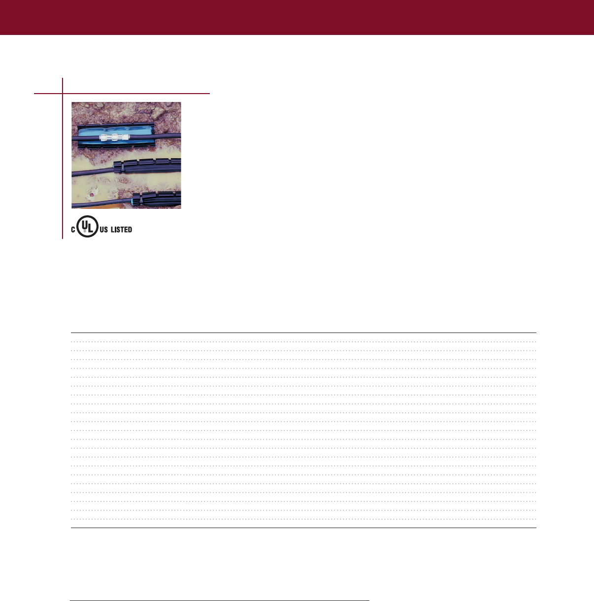
SPLICES, TAPS & TERMINATIONS
SPLICES, TAPS & TERMINATIONS
LOW VOLTAGE SPLICES & TAPS
GelWrap Splice Closures
Water Resistant Wraparound Splice Closures (1000 V)
Tyco Electronics’ GelWrap splice closures quickly and conveniently insulate and seal buried electrical
connections rated up to 1000 volts The robust, yet compact, design is engineered to handle the
harsh environments of direct burial and manhole applications GelWrap splice closures are equally well
suited for insulation and jacket repair GelWrap UF splices include the UF connector
Fast and easy installation
Installers will appreciate the simple wraparound design and dependable gel sealing performance
Simply wrap and snap the closure on any cable in the use range The gel in the closure seals on
contact Installation is literally a snap The GelWrap splice closure can be applied on all common
compression connectors and low-voltage cables Many in-line mechanical connectors can be covered
as well
Dependable performance
The factory cured PowerGel silicone sealant in the GelWrap closure encapsulates the connection
Since the gel is easily stretched and very sticky, it basically forms around the cable and connector
sticking to everything including itself Moisture cannot enter the splice
Selection Information: dimensions in inches (millimeters)
Maximum
Sleeve Connector General Use Std.
Catalog Number Length Conductor Size Opening Diameter Range Pack
GelWrap-18/4-100 40 (100) #12 – 4/0 (4 - 95) 10 (25) 015 – 070 (4 - 18) 6
GelWrap-18/4-150 60 (150) #12 – 4/0 (4 - 95) 30 (75) 015 – 070 (4 - 18) 6
GelWrap-18/4 -200 80 (200) #12 – 4/0 (4 - 95) 50 (125) 015 – 070 (4 - 18) 6
CPGI-GelWrap-18/4-200 8.0 (200) #12 - 4/0 (4 - 95) 5.0 (125) 0.15 - 0.70 (4 - 18) 5
CPGI-GelWrap-18/4-200UL* 8.0 (200) #12 - 4/0 (4 - 95) 4.0 (100 0.15 - 0.70 (4-18) 5
GelWrap-18/4-250 100 (250) #12 – 4/0 (4 - 95) 70 (175) 015 – 070 (4 - 18) 6
CPGI-GelWrap-18/4-250UL* 10 (250) #2 - 4/0 (4 - 95) 6.0 (150) 0.40 - 1.30 (10 - 33) 5
GelWrap-18/4-300 120 (300) #12 – 4/0 (4 - 95) 90 (225) 015 – 070 (4 - 18) 6
GelWrap-33/10-150 60 (150) #2 – 500 (35 - 240) 20 (50) 040 – 130 (10 - 33) 6
CPGI-GelWrap-33/10-250 10.0 (250) #2 - 500 (35 - 240) 6.0 (150) 0.40 - 1.30 (10 - 33) 5
GelWrap-33/10-200 80 (200) #2 – 500 (35 - 240) 40 (100) 040 – 130 (10 - 33) 6
GelWrap-33/10-250 100 (250) #2 – 500 (35 - 240) 60 (150) 040 – 130 (10 - 33) 6
GelWrap-33/10-250-I350M4* 100 (250) #6 – 350 (16 - 180) 5 (125) 040 – 130 (10 - 33) 12
GelWrap-33/10-300 120 (300) #2 – 500 (35 - 240) 80 (200) 040 – 130 (10 - 33) 12
GelWrap-33/10-350 140 (350) #2 – 500 (35 - 240) 100 (250) 040 – 130 (10 - 33) 10
GelWrap-50/20-200 80 (200) 250 – 750 20 (50) 080 – 150 (20 - 38) 12
GelWrap-50/20-250 100 (250) 250 – 750 40 (100) 080 – 150 (20 - 38) 12
GelWrap-50/20-300 120 (300) 250 – 750 60 (150) 080 – 150 (20 - 38) 12
GelWrap-50/20-350 140 (350) 250 – 750 80 (200) 080 – 150 (20 - 38) 12
GelWrap-50/20-400 160 (400) 250 – 750 100 (250) 080 – 150 (20 - 38) 12
CPGI-GelWrap-UF-200 8.0 (200) 14/2 - 8/3 w/ground included connectors 5
CPGI-GelWrap-UF-250UL* 10 (250) 14/2 - 8/3 w/ground included connectors 5
*Notes: Listed for submersible applications
For other sizes or applications, a minimum seal length is required on each side of connector opening or jacket damage:
GelWrap closure 18/4 series 1.5" (38mm)
GelWrap closure 33/10 series 2.0" (51mm)
GelWrap closure 50/20 series 3.0" (75mm)
*Includes mechanical connector
Low Voltage In-Line Splices
85
Ordering Information
1 Selection is based on typical dimensions
for low-voltage insulated cables
2 Related test reports:
EDR-5343 - 18/4;
EDR-5356 - 33/10,
EDR-5367 for 50/20,
EDR-5356 for GelWrap-33/10-250-I350M4
(A four screw connector is included)
Product Performance
Testing Test Conditions
ANSI C1191 – 1986 600 V insulated underground
Chemical Resistance Fluid immersion, 168 hours @ 23°C, 75% elongation
retention minimum
- 10W-40 motor oil
- 10% hydrochloric acid
- 15% sodium chloride
- 20% sodium hydroxide
- ETX 60280 antifreeze (1000 hours)
Accelerated Aging 1000 hours @ 135°C
- 93% retention tensile strength
- 82% retention elongation at break
For connector information refer to the
Connectors and Terminals section of
this catalog.
96J4
Insulating Splice Sleeve for
Underground Conductors
600V
E91151
IDJZ1
Submersible
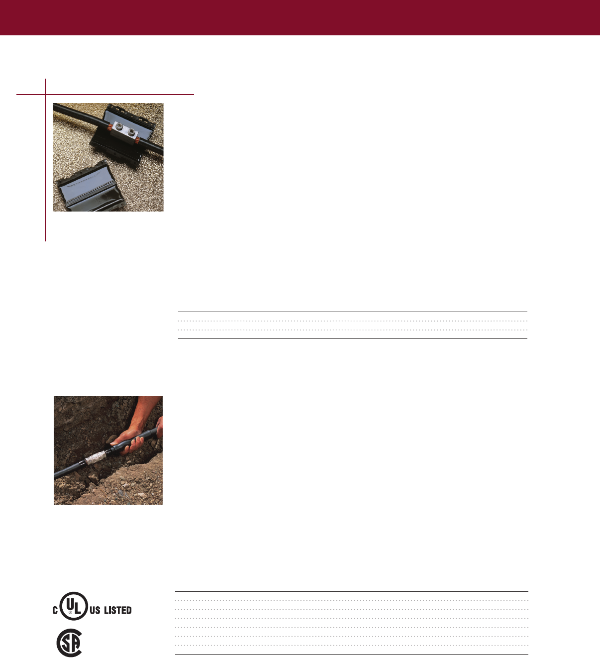
SPLICES, TAPS & TERMINATIONS
GILS In-Line Splices
Water Resistant Splice Kit for Power Cable (1000 V)
The Tyco Electronics’ GILS gel in-line splice kit offers a state-of-the-art sealed splice for underground,
buried, and overhead applications GILS closures offer a fast and simple method for splicing,
insulating, and environmentally sealing low-voltage cable splices
The GILS closure, with its revolutionary PowerGel sealant, covers and seals the splice quickly and
easily, saving both time and effort
Simply install the connector, place on the closure, and snap closed It’s that easy—no tapes, mastic,
tools or mixing are required The splice is ready to bury-no waiting to cure
• Connector accommodates copper and/or aluminum cables
• Qualified to ANSI C1191-1986 for underground splicing
• UV resistant
• Qualified for temperatures from -40°C to 90°C
• Connector included
• RUS accepted connector blocks and splices for secondary Water-tight for use in all locations
Selection Information
Catalog Number Conductor Size (AWG/kcmil) Std. Pack
GILS-4/0 #2 – 4/0 18 or 72 each
CPGI-GILS-4/0 #2 – 4/0 5
GILS-350 1/0 – 350 18
Ordering Information
1 Based on typical dimensions for low-voltage insulated cables
2 Related test reports: EDR-5298, EDR-5394
RVS splice cover kits are the easy “roll-on” way to insulate and seal cable connections up to 1000V
The gripping force of the specially formulated EPDM elastomer combines with the high-performance
sealant to form a water-resistant, insulating sleeve that is UL listed and CSA certified for direct burial
application over in-line compression connectors
RVS splice cover sleeves feature a dual-wall design with an entrapped lubricant, making installation
fast and simple The elastomeric sleeve rolls onto the cable with minimal effort, even at temperatures
below –15°F (–25°C) The cable can be energized immediately It is ideal for use where gas or electric
heating devices are not approved
Qualified to ANSI C1191-1986 CSA certified to C222 No 1982 UL listed in accordance with std UL
486D, RUS listed accept for use as a secondary tap or splice cover For use on standard poly- or
elastomeric-insulated cables Use to insulate and seal in-line compression connectors or to seal
terminal lugs
RVS Splices
“Roll-on” Splices for 1/C Power Cable (1000 V)
Selection Information: dimensions in inches (millimeters)
Maximum
Catalog Conductor Size Cable O.D. Sleeve Connector
Number (AWG/kcmil) (Min. – Max.) Length Length
RVS-11 #8 - 2/0 22 - 68 (6 - 17) 80 (205) 500 (127)
CPGI-RVS-11 #8 - 2/0 .22 - .68 (6 - 17) 8.0 (205) 5.00 (127)
RVS-12 1/0 - 250 050 - 090 (13 - 23) 95 (241) 450 (114)
CPGI-RVS-12 1/0 - 250 0.50 - 0.90 (13 - 23) 9.5 (241) 4.50 (114)
RVS-13 250 - 600 070 - 120 (18 - 30) 120 (305) 700 (178)
CPGI-RVS-13 250 - 600 0.70 - 1.20 (18 - 30) 12.0 (305) 7.00 (178)
RVS-14 600 - 1000 095 - 150 (24 - 38) 140 (356) 900 (229)
For connector information refer to the Connectors and Terminals section of this catalog.
Low Voltage In-Line Splices
86
Ordering Information
1 Select the appropriate catalog number Selections are based on typical dimensions of low-voltage
insulated cable Confirm selection with dimensions to assure proper sizing
2 Kits do not contain connectors The RVS splice cover selection information mentioned above
covers copper and aluminum in-line compression connections
3 Each kit contains one Rayvolve RVS splice cover sleeve and sealant strips
4Standard package: 5 kits/box or 50 kits/box
5Related test report: EDR-5167
®
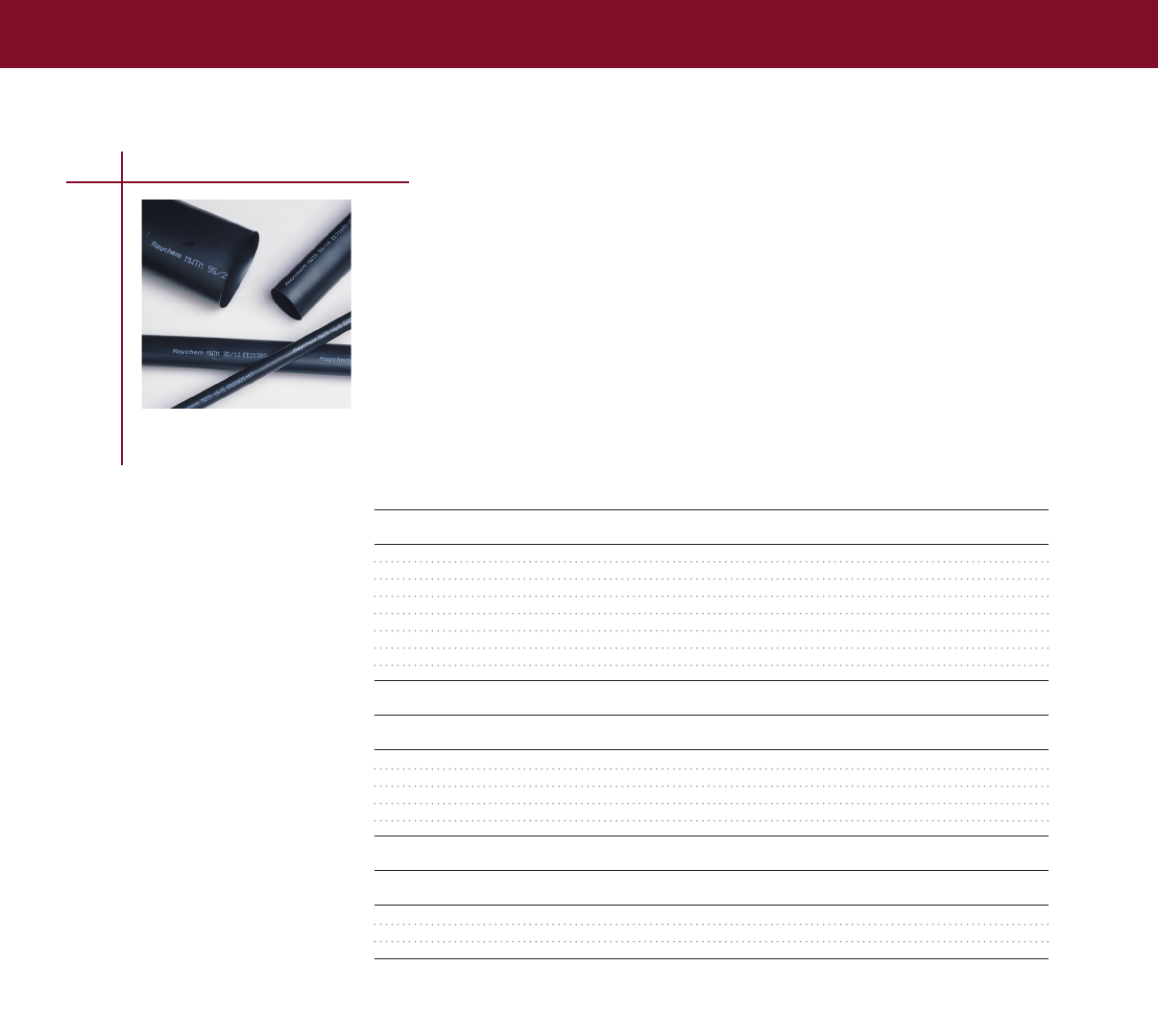
SPLICES, TAPS & TERMINATIONS
SPLICES, TAPS & TERMINATIONS
87
MWTM Tubing
Medium-Wall Sealant-Coated or Uncoated Tubing (600 V)
• Sealant-coated MWTM tubing (-S designation) is for use as insulation/jacket repair up to 600 V
or for general sealing and rejacketing of polymeric- or elastomeric-insulated cables up to 35kV
• RUS accepted as jacket restoration of JCN cable
• Uncoated MWTM tubing (-U or -A/U) is for cable rejacketing only
• 3:1 shrink ratio and an unlimited shelf life when stored under normal conditions
Selection Information: dimensions in inches (millimeters)
Sealant-Coated, Cut-Length Tubing
Cut-Piece Std.
Catalog Number Use Range Min. – Max. Length Pkg /Box
MWTM-10/3-1200-S 013 – 035 (3 – 9) 48 (1200) 25
MWTM-16/5-1200-S 025 – 055 (6 – 14) 48 (1200) 25
MWTM-25/8-1200-S 035 – 085 (9 – 22) 48 (1200) 25
MWTM-35/12-1200-S 050 – 125 (13 – 32) 48 (1200) 25
MWTM-50/16-1200-S 065 – 170 (17 – 43) 48 (1200) 15
MWTM-85/25-1200-S 100 – 290 (25 – 74) 48 (1200) 5
MWTM-115/34-1200-S 140 – 390 (36 – 99) 48 (1200) 5
MWTM-140/42-1200-S 180 – 470 (46 – 119) 48 (1200) 5
Uncoated, Spooled Tubing
Min. Cont. Std. Bulk Option
Catalog Number Use Range Min. – Max. Length Pkg/Spool /Spool
MWTM-10/3-A/U 013 – 035 (3 – 9) 25 (76) 100 (30)
MWTM-16/5-A/U 025 – 055 (6 – 14) 25 (76) 100 (30) 1155 (350)
MWTM-25/8-A/U 035 – 085 (9 – 22) 25 (76) 100 (30) 660 (200)
MWTM-35/12-A/U 050 – 125 (13 – 32) 25 (76) 100 (30) 495 (150)
MWTM-50/16-A/U 065 – 170 (17 – 43) 15 (46) 75 (23) 330 (100)
Uncoated, Cut-Piece Tubing
Cut-Piece Std.
Catalog Number Use Range Min. – Max. Length Pkg/Box
MWTM-85/25-1500/U 100 – 290 (25 – 74) 60 (1500) 5
MWTM-115/34-1500/U 140 – 390 (36 – 99) 60 (1500) 5
MWTM-140/42-1500/U 180 – 470 (46 – 119) 60 (1500) 5
Ordering Information
1 Select the appropriate catalog number Confirm selection with application dimensions to assure
proper sizing
2 MWTM is a general purpose tubing; for sealing applications use MWTM with sealant (-S) or use
uncoated MWTM (-U or -A/U) in combination with S-1052 sealant Order sealants separately
3 For testing information refer to the Technical Data section of this catalog
4 UV resistant test report: EDR-5361
Low Voltage In-Line Splices
For connector information refer to the Connectors and Terminals section of this catalog.

SPLICES, TAPS & TERMINATIONS
WCSM Tubing
Heavy-Wall Sealant Coated or Uncoated Tubing (1000 V)
• For use on standard poly- or elastomeric insulated/jacketed cables or lead-jacketed cables, which
may include aluminum or steel armoring
• Use sealant-coated tubing (-S) as a sealed in-line splice or terminal lug seal for non-flame retardant
applications Use uncoated tubing (-A/U and /U) for cable rejacketing and mechanical protection only
• Sealant-coated WCSM tubing, sizes -9/3 through-70/21 (-S designation) is UL listed per 486D,
qualified to ANSI C1191-1986, and rated to Western Underground Guide 25 Also RUS accepted for
use as a secondary tap or splice cover, and for use as jacket restoration materials on JCN cable
WCSM tubing may be used for jacket repair on cables to 35 kV
• Connectors over 6 inches: Recommended cut length = connector length + 5 inches
Connectors up to 6 inches: Recommended cut length = connector length + 4 inches
• WCSM tubing has a 3:1 shrink ratio and an unlimited shelf life when stored under normal conditions
• Note: UL listing applies to sealant-coated (-S) WCSM-9/3 through -70/21 only WCSM-105/30 and
-130/36 are not UL listed
Selection Information: dimensions in inches (millimeters)
1000-V General
Conductor Size Use Range Cut-Piece Std. Pack
Catalog Number1 (AWG/kcmil) (Min. – Max.) Length2 (Ft/Roll) (Pcs/Box) (Pcs/Pack)
Sealant-Coated Cut-Length Tubing
WCSM-9/3-150-S #14 – #8 015 – 030 (4–8) 6 (150) 50
CPGI-WCSM-9/3-150-S #14 – #8 0.15 – 0.30 (4–8) 6 (150) 3
WCSM-9/3-300-S #14 – #8 015 – 030 (4–8) 12 (300) 50
WCSM-9/3-1200-S #14 – #8 015 – 030 (4–8) 48 (1200) 25
WCSM-13/4-150-S #12 – #6 020 – 045 (5–11) 6 (150) 50
CPGI-WCSM-13/4-150-S #12 – #6 0.20 – 0.45 (5–11) 6 (150) 2
WCSM-13/4-1200-S #12 – #6 020 – 045 (5 – 11) 48 (120) 25
WCSM-20/6-150-S #8 – #2 025 – 070 (6 – 18) 6 (150) 50
CPGI-WCSM-20/6-150-S #8 – #2 0.25 – 0.70 (6 – 18) 6 (150) 2
WCSM-20/6-225-S #8 – #2 025 – 070 (6 – 18) 9 (225) 50
WCSM-20/6-300-S #8 – #2 025 – 070 (6 – 18) 12 (300) 50
WCSM-20/6-1200-S #8 – #2 025 – 070 (6 – 18) 48 (1200) 25
WCSM-33/8-150-S #4 – 4/0 035 – 120 (9 – 30) 6 (150) 50
CPGI-WCSM-33/8-150-S #4 – 4/0 0.35 – 1.20 (9 – 30) 6 (150) 2
WCSM-33/8-225-S #4 – 4/0 035 – 120 (9 – 30) 9 (225) 50
WCSM-33/8-300-S #4 – 4/0 035 – 120 (9 – 30) 12 (300) 50
WCSM-33/8-1200-S #4 – 4/0 035 – 120 (9 – 30) 48 (1200) 25
WCSM-43/12-150-S 1/0 – 400 050 – 155 (13 – 39) 6 (150) 40
WCSM-43/12-225-S 1/0 – 400 050 – 155 (13 – 39) 9 (225) 40
CPGI-WCSM-43/12-225-S 1/0 – 400 0.50 – 1.55 (13 – 39) 9 (225) 1
WCSM-43/12-300-S 1/0 – 400 050 – 155 (13 – 39) 12 (300) 40
WCSM-43/12-1200-S 1/0 – 400 050 – 155 (13 – 39) 48 (1200) 10
WCSM-51/16-100-S 250 – 500 070 – 175 (18 – 44) 4 (100) 100
WCSM-51/16-225-S 250 – 500 070 – 175 (18 – 44) 9 (225) 30
CPGI-WCSM-51/16-225-S 250 – 500 0.70 – 1.75 (18 – 44) 9 (225) 1
WCSM-51/16-300-S 250 – 500 070 – 175 (18 – 44) 12 (300) 30
WCSM-51/16-1200-S 250 – 500 070 – 175 (18 – 44) 48 (1200) 10
WCSM-70/21-300-S 400 – 1000 090 – 245 (23 – 62) 12 (300) 15
WCSM-70/21-450-S 400 – 1000 090 – 245 (23 – 62) 18 (450) 15
WCSM-70/21-600-S 400 – 1000 090 – 245 (23 – 62) 24 (600) 10 or 100
WCSM-70/21-1200-S 400 – 1000 090 – 245 (23 – 62) 48 (1200) 10
WCSM-105/30-300-S 800 – 1250 130 – 370 (33 – 94) 12 (300) 15
WCSM-105/30-1200-S 800 – 1250 130 – 370 (33 – 94) 48 (1200) 5
WCSM-130/36-300-S 1500 – 2500 160 – 420 (41 – 107) 12 (300) 10
WCSM-130/36-450-S 1500 – 2500 160 – 420 (41 – 107) 18 (450) 20
WCSM-130/36-1200-S 1500 – 2500 160 – 420 (41 – 107) 48 (1200) 5
1 Catalog numbers with -S designation are suitable for sealed electrical insulation to 1000 V. Catalog numbers with A/U and /U designations are for
cable rejacketing only.
2Length tolerance to ±2 percent. Can be used for multi-conductor LV splices using different tubings.
Low Voltage In-Line Splices
WCSM-33/8
Direct Burial
Insulation Cover
96J4
E91151
Submersible
88
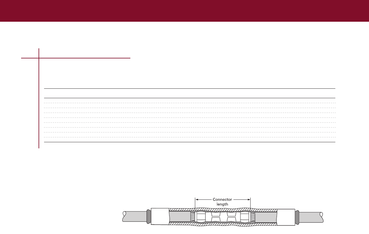
SPLICES, TAPS & TERMINATIONS
SPLICES, TAPS & TERMINATIONS
Ordering Information
1 Select the appropriate catalog number based on typical dimensions for low-voltage insulated cable
Confirm selection with dimensions to assure proper sizing
2 UL listing applies to sealant-coated (-S) WCSM-9/3 through -70/21 only WCSM-105/30 and
-130/36 are not UL listed
3 Package does not contain connectors or lugs Installed connector or lug diameter must be within
use range
4 If sealing is needed with WCSM-A/U uncoated tubing, order S-1052 sealant separately
5 WCSM tubing may be field-cut for shorter requirements
6 Bulk packaging is available for cut lengths Consult your Tyco Electronics representative
for information
7 For testing information refer to the Technical Data section of this catalog
8 Related test report: EDR-5139
9 UV resistant test report: EDR-5361
Selection Information: dimensions in inches (millimeters)
1000-V General
Conductor Size Use Range Cut-Piece Std. Pack
Catalog Number1 (AWG/kcmil) (Min. – Max.) Length2 (Ft/Roll) (Pcs/Box) (Pcs/Pack)
Uncoated Tubing
WCSM-9/3-A/U #14 – #8 015 – 030 (4 – 8) 100
WCSM-13/4-A/U #12 – #6 020 – 045 (5 – 11) 100
WCSM-20/6-A/U #8 – #2 025 – 070 (6 – 18) 100
WCSM-33/8-A/U #4 – 4/0 035 – 120 (9 – 30) 65
WCSM-43/12-A/U 1/0 – 400 050 – 155 (13 – 39) 50
WCSM-51/16-A/U 250 – 500 070 – 175 (18 – 44) 40
WCSM-70/21-A/U 400 – 1000 090 – 245 (23 – 62) 40
WCSM-90/30-1500/U 800 – 1200 130 – 310 (33 – 79) 60 (1500) 5
WCSM-130/36-1500/U 1500 – 2500 160 – 420 (41 – 107) 60 (1500) 5
For connector information refer to the Connectors and Terminals section of this catalog.
Low Voltage In-Line Splices
1 Catalog numbers with -S designation are suitable for sealed electrical insulation to 1000 V. Catalog numbers with A/U and /U designations are for
cable rejacketing only.
2Length tolerance to ±2%. Can be used for multi-conductor LV splices using different tubings.
Note: UL listing applies to sealant-coated (-S) WCSM-9/3 through -70/21 only. WCSM-105/30 and -130/36 are not UL listed.
89

SPLICES, TAPS & TERMINATIONS
90
FCSM Tubing
Heavy-Wall Flame Retardant Tubing (2000 V)
FCSM tubing’s tough, crosslinked polyolefin construction provides mechanical strength and cut-
through resistance equal to, or surpassing, the properties of low-voltage cable jackets
• 3:1 shrink ratio and an unlimited shelf life when stored under normal conditions
• Use sealant-coated tubing (-S) as a sealed in-line splice or terminal lug seal It provides a water-tight
seal for direct-buried applications and wet environments
• Use uncoated tubing (-/U) for cable rejacketing only
• Sealant-coated or uncoated tubing may be used for jacket repair on cable to 35 kV Qualified to
ANSI C1191-1986; also rated to IEEE 383 (Vertical Tray Flame Test) and ICEA S-19-81
• FCSM is also MSHA approved (No P-137-MSHA)
For use on standard poly- or elastomeric- insulated/jacketed cables or lead-jacketed cables, which
may include aluminum or steel armoring
Connectors up to 6 inches: Recommended cut length = connector length + 4 inches
Connectors over 6 inches: Recommended cut length = connector length + 5 inches
Selection Information: dimensions in inches (millimeters)
1000-V Insulated Bulk
Conductor Size General Use Range Tube Std. Pack Option
Catalog Number (AWG/kcmil) (Min.–Max.) Length* Ft.(m)/Roll Pcs/Box Ft.(m)/Roll
In-Line Splice Or Terminal Lug Seal (With Sealant)
FCSM-9/3-1200-S #14 – #8 015 – 030 (4 – 8) 48 (1200) 25
FCSM-19/6-150-S #6 – #2 025 – 065 (6 – 17) 6 (150) 50
FCSM-19/6-1200-S #6 – #2 025 – 065 (6 – 17) 48 (1200) 25
FCSM-28/9-225-S #2 – 4/0 040 – 095 (10 – 24) 9 (225) 50
FCSM-28/9-1200-S #2 – 4/0 040 – 095 (10 – 24) 48 (1200) 25
FCSM-38/12-300-S 1/0 – 350 050 – 130 (13 – 33) 12 (300) 40
FCSM-38/12-1200-S 1/0 – 350 050 – 130 (13 – 33) 48 (1200) 10
FCSM-51/16-300-S 250 – 500 070 – 175 (18 – 44) 12 (300) 30
FCSM-51/16-1200-S 250 – 500 070 – 175 (18 – 44) 48 (1200) 10
FCSM-68/22-1200-S 600 – 1000 095 – 230 (25 – 58) 48 (1200) 10
FCSM-90/30-1200-S 800 – 1200 130 – 310 (33 – 79) 48 (1200) 5
FCSM-120/40-1200-S 1500 – 2500 175 – 410 (44 – 104) 48 (1200) 5
FCSM-177/63 600-S 275 – 605 (70 – 154) 24 (600) 6
FCSM-177/63-1200-S 275 – 605 (70 – 154) 48 (1200) 5
Cable Rejacketing (Without Sealant)
FCSM-9/3-A/U #14 – #8 015 – 030 (4 – 8) 100 (30)
FCSM-19/6-A/U #6 – #2 025 – 065 (6 – 17) 100 (30) 825 (250)
FCSM-28/9-A/U #2 – 4/0 040 – 095 (10 – 24) 65 (20) 495 (150)
FCSM-38/12-A/U 1/0 – 350 050 – 130 (13 – 33) 50 (15) 395 (120)
FCSM-51/16-A/U 250 – 500 070 – 175 (18 – 44) 40 (12) 330 (100)
FCSM-68/22-A/U 600 – 1000 095 – 230 (25 – 58) 80 (24)
FCSM-90/30-1500/U 800 – 1200 130 – 310 (33 – 79) 60 (1500) 5
FCSM-120/40-1500/U 1500 – 2500 175 – 410 (44 – 104) 60 (1500) 5
FCSM-177/63-1500/U 275 – 605 (70 – 154) 60 (1500) 5
*Length tolerance to ±2 percent. Ordering Information
1 Select the appropriate catalog number based on typical dimensions for low-voltage insulated cable
Confirm selection with cable dimensions to assure proper sizing
2 Connectors or lugs not included
3 If sealing is needed with uncoated FCSM tubing (-/U), order S-1052 separately
4 Tubing may be field-cut for shorter requirements
5 Bulk packaging is available for cut-lengths Contact your Tyco Electronics representative for
additional information
6 For testing information refer to the Technical Data section of this catalog
7 Related test reports: EDR-5133, EDR-5134, EDR-5141
MSHA approved
(No. P-137-MSHA)
For connector information refer to the Connectors and Terminals section of this catalog.
Low Voltage In-Line Splices
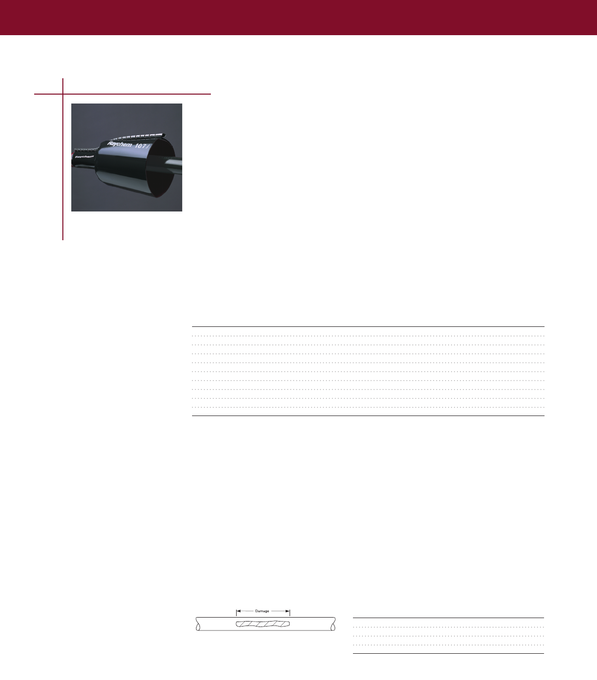
SPLICES, TAPS & TERMINATIONS
SPLICES, TAPS & TERMINATIONS
CRSM Sleeves
Heat-shrink Wraparound Sleeve (1000 V)
CRSM sleeves close easily with a permanent locking system that consist of a raised rail profile and
a stainless steel channel These sleeves are made from crosslinked polyolefin, which equals or exceeds
the material properties of the original cable jacket CRSM sleeves fit a wide range of cable sizes and
have unlimited shelf life, when stored under normal conditions
• Qualified to ANSI C1191-1986, rated to ICEA electrical withstand test for 1000V
RUS accepted for use as jacket restoration materials on JCN cable•
• For use on standard poly- or elastomeric insulated/jacketed cables or lead-jacketed cables, which
may include aluminum or steel armoring
• Use as insulation fro 1/C low-voltage power cable up to 1000V and for jacket repair up to 35kV
or for general sealing applications All CRSM sleeves are sealant-coated
Selection Information: dimensions in inches (millimeters)
Primary Electrical Repair (1000 V)
Cable and Jacket Repair General Sealing
Sleeve Conductor Size Use Range Use Range (0–35 kV) Std.
Catalog Number Length (AWG/kcmil) (Min.–Max.) (Min.–Max.) Pack
CRSM 34/10-200 08 (200) #8 – 2/0 025 – 060 (6 – 15) 025 – 120 (6 – 30) 3
CRSM 34/10-1200 48 (1219) #8 – 2/0 025 – 060 (6 – 15) 025 – 120 (6 – 30) 5
CRSM 53/13-200 08 (200) 3/0 – 400 060 – 095 (15 – 24) 060 – 180 (15 – 46) 10
CRSM 53/13-1200 48 (1219) 3/0 – 400 060 – 095 (15 – 24) 060 – 180 (15 – 46) 5
CRSM 84/20-750 30 (750) 500 – 1000 095 – 140 (24 – 36) 095 – 270 (24 – 69) 10
CRSM 84/20-1200 48 (1219) 500 – 1000 095 – 140 (24 – 36) 095 – 270 (24 – 69) 5
CRSM 107/29-1000 40 (1000) 1000 – 2000 130 – 200 (33 – 51) 130 – 360 (33 – 91) 10
CRSM 107/29-1200 48 (1219) 1000 – 2000 130 – 200 (33 – 51) 130 – 360 (33 – 91) 5
CRSM 143/36-1200 48 (1219) 165 – 495 (42 – 126) 5
CRSM 198/55-1200 48 (1219) 250 – 650 (64 – 165) 5
Ordering Information
1 Select the appropriate catalog number for either primary electrical repair (1000 volts max) or
general sealing applications Electrical repair selections are based on typical dimensions for low-
voltage insulated cable Confirm selection with cable dimensions to assure proper sizing
2 Use the “Primary electrical repair” columns for electrical repair applications (when CRSM is in direct
contact with the conductor)
3 Use the ”General sealing and jacket repair use range” column for general rejacketing or sealing
applications (when CRSM is not in direct contact with the conductor)
4 Package does not contain connectors
5 Kits include a wraparound sleeve and stainless steel channel closure Both can be field-cut for
shorter requirements (see “Reference dimensions” below)
6 Related test report: EDR-5124, EDR-5192
7 UV resistant test report: EDR-5361
8 CRSM 34/20 are available in shorter standard lengths by ordering the corresponding CRSM-CT kits
(The use ranges in the selection information table still apply)
Damage Total Seal Length
<3 (<76) 3 (76)
3 – 12 (76 – 305) 4 (102)
12 – 24 (305 – 610) 6 (152)
>24 (>610) 8 (203)
Cut sleeve length = Damage length + total
seal length
For connector information refer to the Connectors and Terminals section of this catalog.
Low Voltage In-Line Splices
91
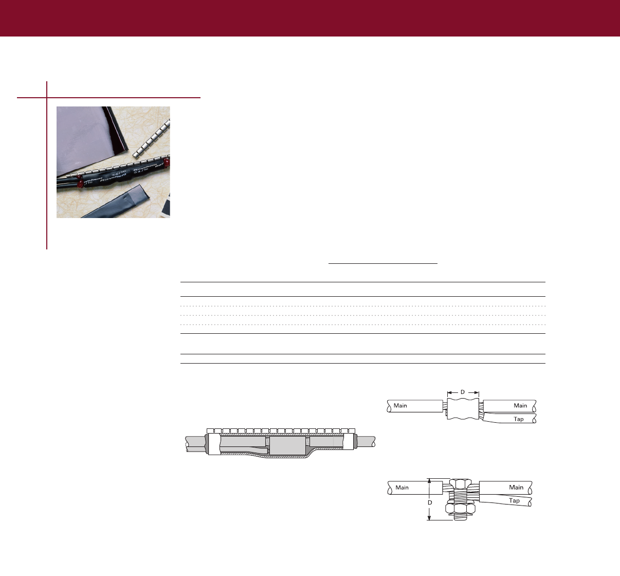
SPLICES, TAPS & TERMINATIONS
Conductor Size (1000 V max.) Connector
Sleeve Main Tap Dimension Std.
Catalog Number Length (AWG/kcmil) (AWG/kcmil) (Max. D) Pack
Compression Connector
CRSM-CT-34/10-150 6 (152) #8 – #2 #10 – #2 2 (51) 10
CPGI-CRSM-CT-34/10-150 6 (152) #8 – #2 #10 – #2 2 (51) 5
CRSM-CT-53/13-200 8 (203) #2 – 4/0 #10 – 4/0 4 (102) 10
CRSM-CT-84/20-250 10 (254) 4/0 – 500 #2 – 500 6 (152) 10
Standard Split-Bolt Connector
CRSM-CT-53/13-200 8 (203) #8 – #2 #14 – #2 1 1/2 (38) 10
For connector information refer to the Connectors and Terminals section of this catalog.
Low Voltage In-Line Splices
92
CRSM CT Cable Tap Splices
Heat-shrink Wraparound Cable Tap Splices (1000 V)
• Use as a wraparound, sealed cable tap splice
• Qualified to ANSI C1191-1986, rated to ICEA electrical withstand test for 1000 volts
• RUS accepted for use with compression and split-bolt connectors
• Sealant-coated
• For use on standard poly- or elastomeric insulated conductors
Compression connector
Split-bolt connector
Selection Information: dimensions in inches (millimeters)
Ordering Information
1 Select the appropriate catalog number based on the main and tap conductor sizes and connector
type for electrical repair (1000 volts max) Selections are based on typical dimensions for low-
voltage insulated cable Confirm selection with cable dimensions to assure proper sizing
2 Kits are capable of insulating and sealing wye (3-wire) or H (4-wire) configurations up to
1000 volts
3 Kits do not contain connectors
4 Kits include insulating sleeve, sealant strip, and stainless steel channel closure
5 Standard package: 10 kits/box
6 Related test report: EDR-5192
7 UV resistant test report: EDR-5361
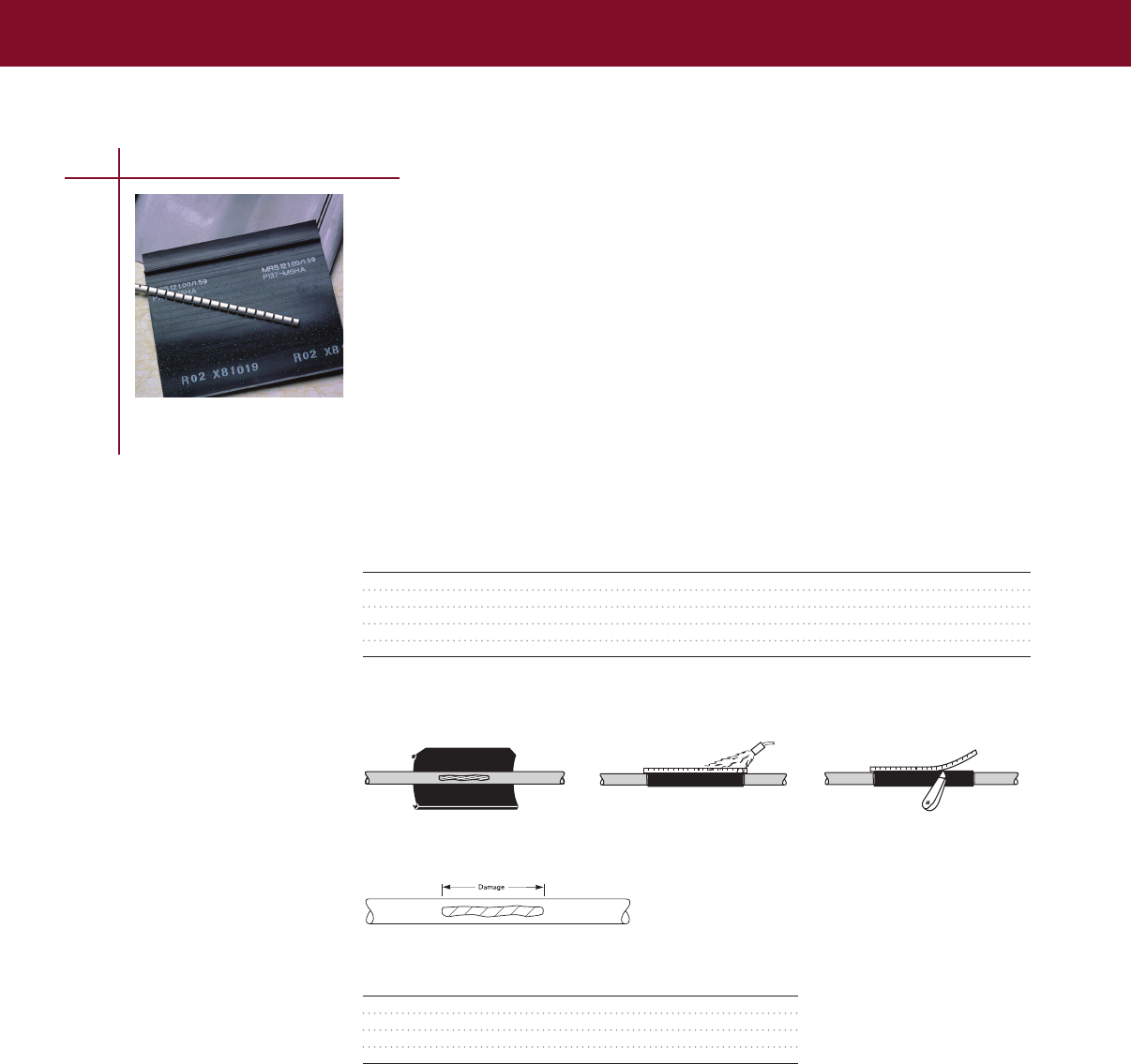
SPLICES, TAPS & TERMINATIONS
SPLICES, TAPS & TERMINATIONS
MRS Repair Sleeves
Heat-shrink Wraparound Flame-Retardant Sleeve (2 kV)
Tyco Electronics’ wraparound mining repair sleeve provides an efficient method of repairing
insulation on flexible cables to 2 kV and repairing jacket damage on high-voltage cable where a
splice is not required
Specially formulated, flame-retardant, flexible wraparound sleeve •
Installs with a low profile quickly and easily, which means the cable can be returned to service•
in minutes
Ideal for use on trailing cable as well as flexible-construction cables and conduits•
MSHA approved (No P-137-MSHA) •
Selection Information: dimensions in inches (millimeters)
Cable use Range Std. Pack
Catalog Number (Min. – Max.) Sleeve Length (Kits/Box)
MRS-12-10 100 – 160 (25 – 41) 10 (254) 20
MRS-12-24 100 – 160 (25 – 41) 24 (610) 10
MRS-34-24 160 – 230 (41 – 58) 24 (610) 10
MRS-34-30 160 – 230 (41 – 58) 30 (762) 10
MRS-56-30 230 – 350 (58 – 89) 30 (762) 10
Kits do not contain connectors.
For connector information refer to the Connectors and Terminals section of this catalog.
Low Voltage In-Line Splices
93
Ordering Information
1 Select the appropriate catalog number based on cable diameter
2 Kits do not contain connectors
3 MRS repair sleeve is precoated with adhesive
4 Kits contain a wraparound sleeve and stainless steel channel closure (removed after
installation) Both can be field-cut for shorter requirements
5 Related test report: EDR-5028
Damage Total Seal Length
<3 (< 76) 3 (76)
3 – 12 (76 – 305) 4 (102)
12 – 24 (305 – 610) 6 (152)
>24 (> 610) 8 (203)
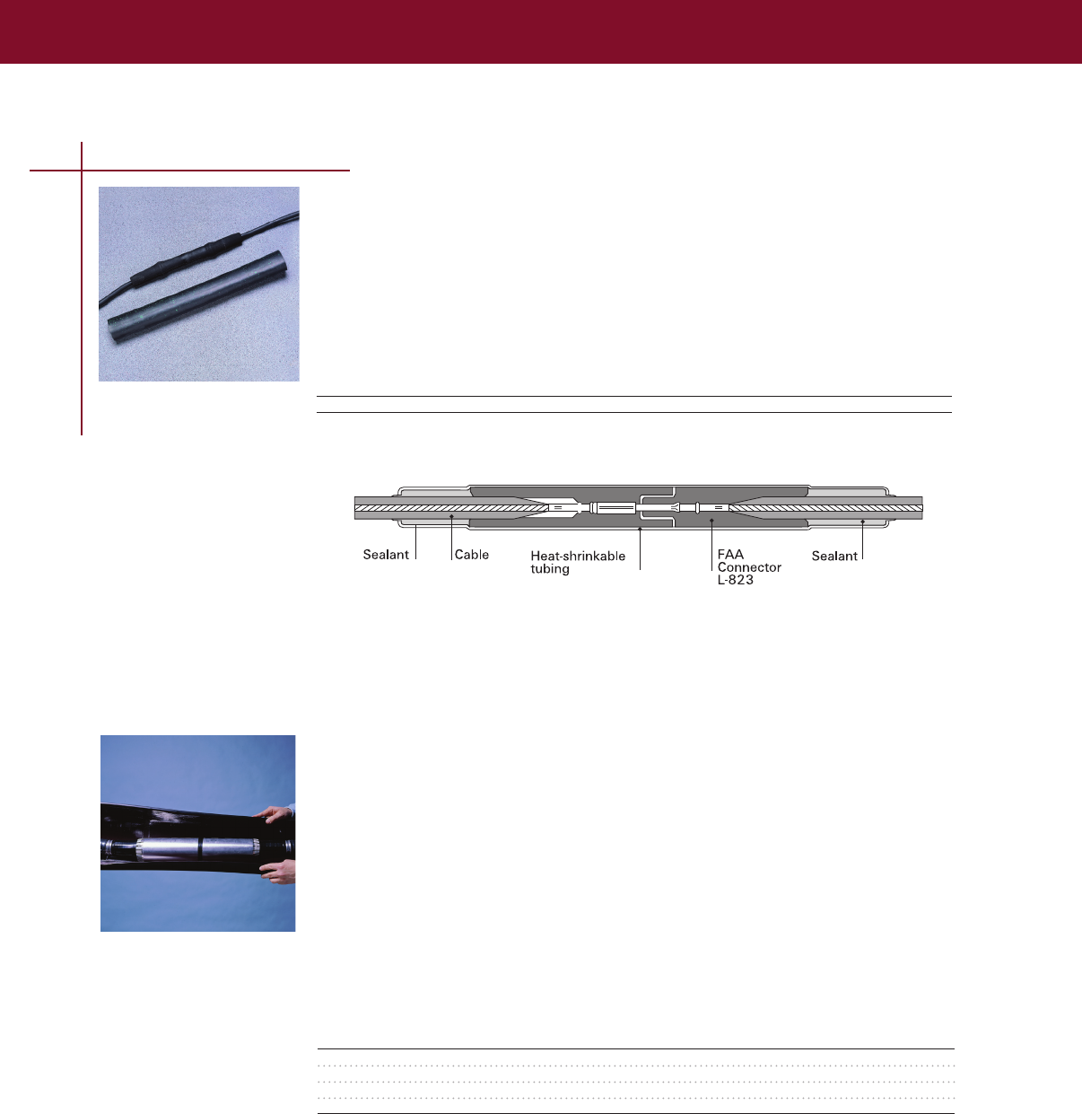
SPLICES, TAPS & TERMINATIONS
94
Low Voltage In-Line Splices
ALK Splice Sealing Kit
Heat-Shrink Airport Lighting Kit
These environmental sealing kits enhance the ability of type L-823 plug and receptacle connectors to
meet FAA specifications
Selection Information: dimensions in inches (millimeters)
Cable/Connector Diameter Std. Pack
Catalog Number (Min. – Max.) (Kits/Box)
ALK-L823 050 – 150 (13 – 38) 10
Kits do not contain connectors.
Suitable for use on FAA-type L-823 connectors.
LVSA-3 Splice
Heat-Shrink Splices for 3/C Armored Cable (1000 V)
Selection Information: dimensions in inches (millimeters)
Conductor Maximum
Catalog Size Range Cable O.D. Connector Std.
Number (AWG/kcmil) (Min.–Max.) Length Pack
LVSA-3-1 #6 – #2 060 – 150 (15 – 38) 350 (89) 1
LVSA-3-2 #1 – 4/0 090 – 220 (23 – 56) 400 (102) 1
LVSA-3-3 250 – 500 120 – 300 (30 – 76) 500 (127) 1
LVSA-3-4 600 – 1000 150 – 380 (38 – 97) 700 (178) 1
Kits do not contain connectors; please order them separately.
The LVSA-3 splice kit features a wraparound, heat-shrinkable, adhesive-coated outer sleeve
that significantly reduces the installation space required and protects the splice from corrosion
and moisture
• Kits include a low-profile wraparound armor case that is simple to install and requires no
compound or resin filling
• Qualified to ANSI C1191-1986 For splicing 3/C polymeric, armored (corrugated or
interlocked-type) power and control cables (600–1000 volts)
For connector information refer to the Connectors and Terminals section of this catalog.
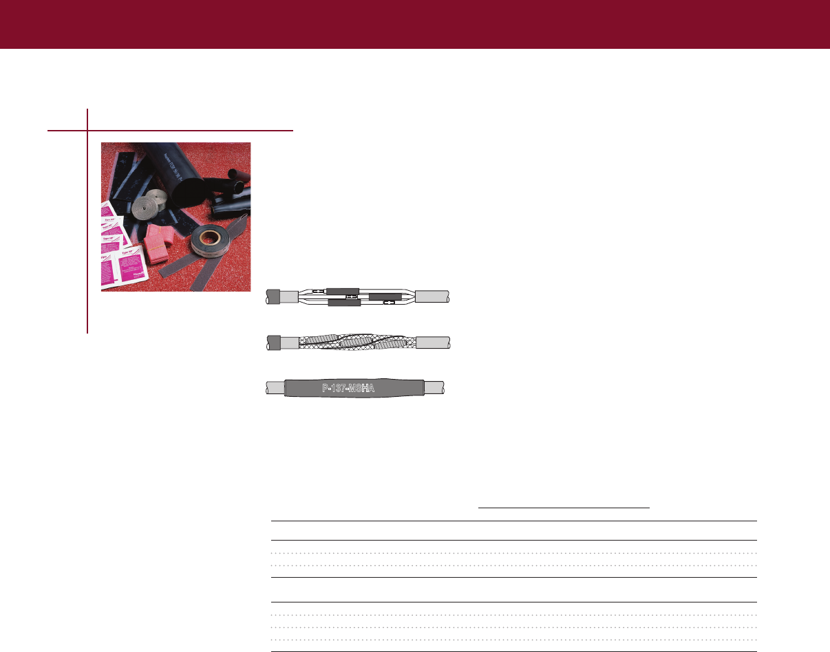
SPLICES, TAPS & TERMINATIONS
SPLICES, TAPS & TERMINATIONS
P-137-MSHA
LV-MSK kits are flame-retardant, in-line and multi-conductor splice kits for use on mining cables and
standard flexible cables up to 2 kV
• MSHA approved to P-137-4-MSHA
• For types G, W, G-GC, and SHD-GC round and flat cables
LV-MSK Splice
Heat-Shrink Flexible Mining Cable (600 V-8 kV)
For connector information refer to the Connectors and Terminals section of this catalog.
Selection Information: dimensions in inches (millimeters)
Cable Power Conductor Size (AWG/kcmil)
Catalog Diameter G or G-GC W or G W Std. Pack
Number (Min.–Max.) 3/C 2/C 4/C (Kits/Box)
LV-MSK (600 V–2 kV) - Flat Cables
LV-MSK-046 085 – 140 (22 – 36) #6 – #2 15
LV-MSK-047 130 – 240 (33 – 61) #6 – #1 #1 – 4/0 #6 – #1 10
LV-MSK-058 160 – 315 (41 – 80) #2– 4/0 #2 – 4/0 5
Round Cables
LV-MSK-045* 085 – 140 (22 – 36) #8 – #6 #8 – #6 20
LV-MSK-046 085 – 140 (22 – 36) #6 – #2 #6 – #4 15
LV-MSK-047 130 – 240 (33 – 61) #2 – 3/0 #3 – 3/0 #6 – 1/0 10
LV-MSK-058 160 – 315 (41 – 80) 2/0 – 500 2/0 – 350 1/0 – 350 5
Ordering Information
1 Kits do not contain connectors; please order separately
2 LV-MSK-045 has a lower profile than LV-MSK-046
3 Standard package: LV-MSK: See selection tables above HV-MSK: One 3/C kit per box
95
Low Voltage In-Line Splices
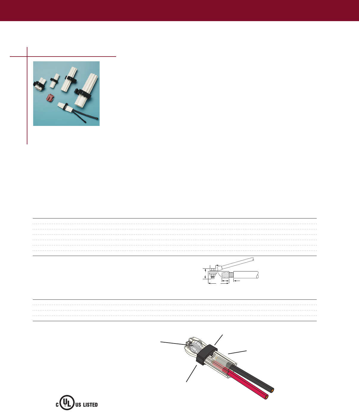
SPLICES, TAPS & TERMINATIONS
GelCap splice cover kits quickly and conveniently insulate, seal, and protect stub splice connections
in motors, street lights, etc up to 1000 volts The robust, yet compact, design was engineered to
handle the harsh environments of motor connections GelCap splice cover kits are equally well suited
for many other connection applications including street light connections The specially formulated
material provides excellent abrasion resistance and insulation value
Each cap size is designed to fit a wide range of cable sizes The expandable design keeps the cap as
small as possible and allows it to expand only as much as needed to fit on large cable
GelCap splice cover kits provide the fastest installation Simply push the cover down over the
connection and snap the clamp closed No extra materials or greases are required The PowerGel
sealant is already in the cap Removal is just as quick and easy as installation
Common uses for GelCap splice cover kits:
• Motor connections
• Street lights
• Over wire nuts for sealing
• Irrigation systems
• HVAC
• Outdoor lighting
Snap-lock feature provides
quick installation and removal
Silicone gel is high dielectric
insulation and provides
constant pressure on cable
and connector to provide
waterseal PowerGel sealant is
specially formulated for high
temperature environments
Molded cover of high abrasion
and impact resistant elastomer
provides rugged protection for
electrical connection
Molded clamp of UV stable, impact resistant
polypropylene secures cover in place
Selection Information: dimensions in inches (millimeters)
Max. Bolt Max. Lug
Catalog Feeder Dimensions Dimensions Barrel Cap length Std.
Number Conductor Size (mm2) Width (A) Length (B) Total Length (C) Length (D) (Nominal) Pack
GelCap 1** #16 – #10 AWG (15 – 5) 375 (10) 500 (13) 100 (25) 05 (13) 28 (71) 5
CPGI-GelCap-1** #16 – #10 AWG (1.5 – 5) .375 (10) .500 (13) 1.00 (25) 0.5 (13) 2.8 (71) 5
GelCap 2 #8 – #2 AWG (8 – 35) 625 (16) 100 (25) 200 (51) 10 (25) 35 (89) 5
CPGI-GelCap-2 #8 – #2 AWG (8 – 35) .625 (16) 1.00 (25) 2.00 (51) 1.0 (25) 3.5 (89) 5
CPGI-GelCap-2-SGL* #8 – #2 AWG (8 – 35) .625 (16) 1.00 (25) 2.00 (51) 1.0 (25) 3.5 (89) 5
GelCap 3 #2 – #4/0 AWG (35 – 105) 850 (22) 130 (33) 300 (76) 15 (38) 60 (152) 5
GelCap 4 250 – 500 kcmil (125 – 250) 1100 (28) 185 (47) 500 (127) 20 (51) 80 (203 5
* CPGI-GelCap-2-SGL kit contains one GelCap cover only.
** For wire sizes #16 – #10, the unique design of the GelCap 1 splice kit saves
space by allowing all three phase connections to be installed in one cover.
• For GelCap splice kits sizes 2-4, one cap per phase is provided.
Product Performance
Testing Test Conditions
Chemical Resistance ASTM D543, Sulfuric acid, Sodium hydroxide and motor oil
Ozone Resistance ASTM D1149, 168 hours @40°C, 50pphm
Accelerated Aging ASTM D2671
Abrasion Resistance 2040 gm wt, 4000 cycles, 2% max thickness loss
Related Product Information: EDR-5435 Test Report
C
D
B
1/4" max.
For connector information refer to the Connectors and Terminals section of this catalog.
Ordering Information
1 Selection based on typical dimensions of low-voltage insulated cables
2 Kits do not contain connectors
GelCap Splice Covers
Water Resistant Stub Splice Cover Kit (1000 V)
96
Low Voltage Stub Splices & Motor Connection Kits
90UF
Insulating Splice Covers
600V/105˚C
E216204
IDJZ1
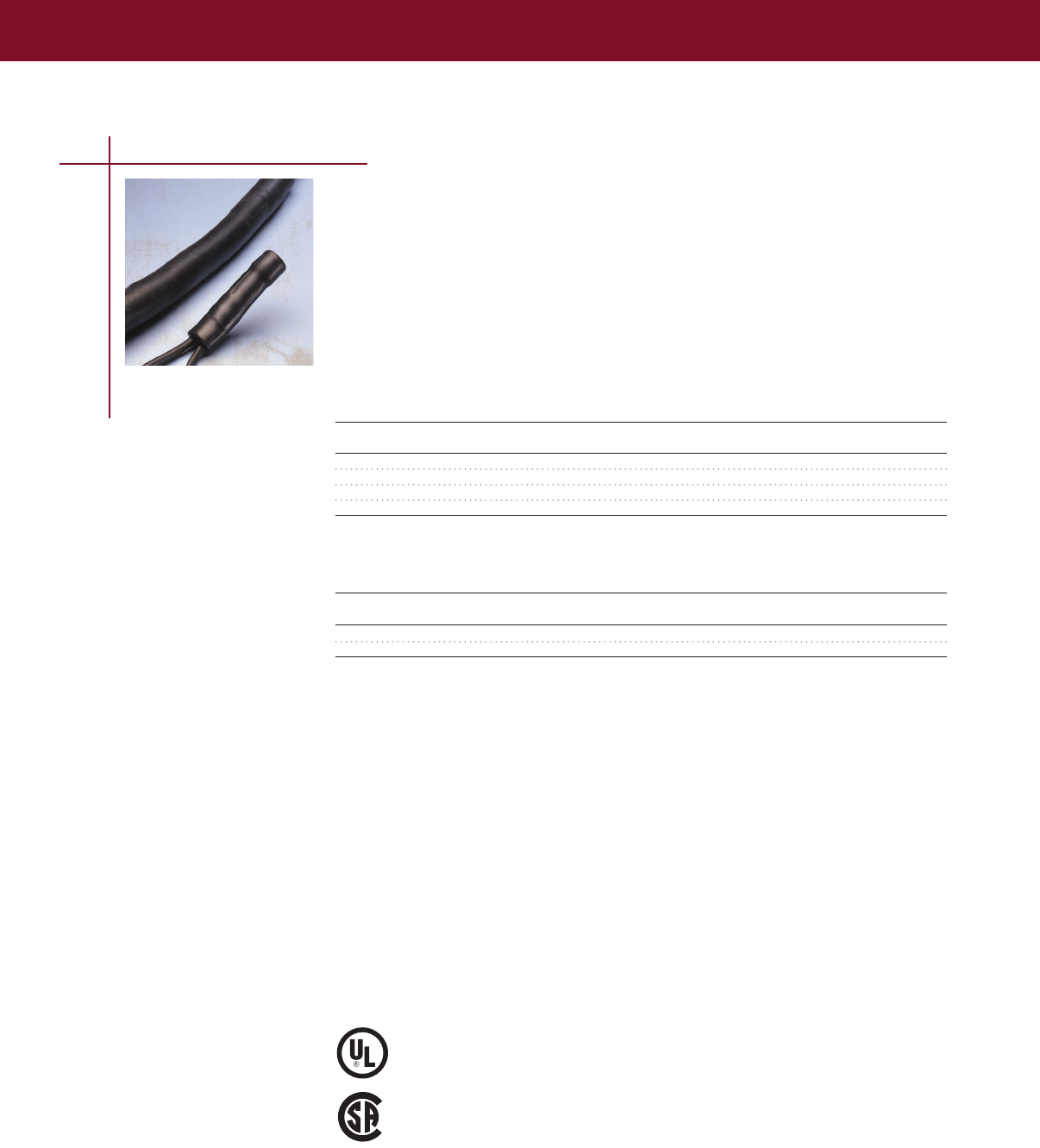
SPLICES, TAPS & TERMINATIONS
SPLICES, TAPS & TERMINATIONS
97
For connector information refer to the Connectors and Terminals section of this catalog.
Low Voltage Stub Splices & Motor Connection Kits
Qualified to ANSI C1191-1986 CSA
certified to C222 No 1982 UL listed per 96J4
(file E91151)
LISTED 96J4
Direct burial insulation
covered for listed
pressure connectors
Certified C222
No 1982
®
RVC Splice Cover Kits
“Roll-on” Stub Connection Insulation Kits (1000 V)
RVC splice cover kits offer the quick and easy “roll-on” way to insulate and seal stub connections in
motors and street lights up to 1000 volts The elastomeric RVC cap splice cover provides the required
insulation thickness, withstands abrasion, and forms a water-resistant seal The tool-free RVC cap is
ideal for installation in cramped motor boxes It slides on easily and will not leak, unravel, or
slip off
Ordering Information
1 Select the appropriate catalog number Selections are based on typical dimensions of low-voltage
insulated cable Confirm selection with dimensions to assure proper sizing
2 Kits do not contain connectors The RVS splice cover selection information above covers copper
and aluminum in-line compression connections
3 Each kit contains one Rayvolve RVS splice cover sleeve and sealant strips
4 Standard package: 5 kits/box
5 Related test report: EDR-5167
Selection Information: dimensions in inches (millimeters)
Feeder Bolt Dimensions Lug Cap
Catalog Size Size Length Length Length Std.
Number (AWG/kcmil) (Max.) (Max.) (Max.) (Nominal) Pack
Motor Connections or Two-Wire Stub Splices
RVC-1V #14 – #4 375 (8) 625 (15) 175 (45) 300 (75) 5
RVC-2V #8 – 2/0 375 (8) 750 (20) 275 (70) 400 (100) 5
RVC-3V #2 – 4/0 500 (12) 100 (25) 300 (75) 525 (130) 5
RVC-4V 250 – 500 625 (16) 150 (35) 500 (125) 750 (190) 5
Insulation
Catalog Conductor Size Cut-Back
Number (AWG/kcmil) (Max.)
Three-Wire Stub Splices
RVC-1V #14 – #8 175 (44)
RVC-2V #6 – #2 275 (70)
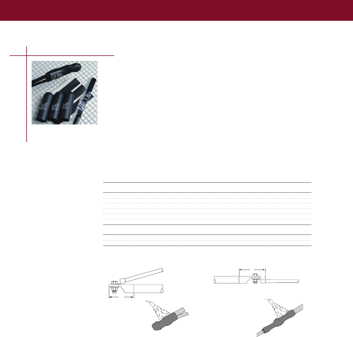
SPLICES, TAPS & TERMINATIONS
For connector information refer to the Connectors and Terminals section of this catalog.
98
MCK Motor Connection Kits
Heat-Shrink Motor Connection Kits for 1/C (2000 V)
• Qualified to ANSI-C1191-1986 and rated to ICEA electrical withstand test for 1000 V
• For use as an in-line or stub splice between 1/C poly feeder cable and motor leads
• Excellent insulation sealing—and resistance to abrasion—in motor connections
Type V
The stub “Type V” kit is designed to splice the stub or butt configuration that is commonly used
where there is insufficient room to make in-line connections
Type L
The In-Line “Type L” kit is used, where space permits, to splice in-line connections
Selection Information: dimensions in inches (millimeters)
Connection
Catalog Motor Feeder Size Bolt Length Length (Max.) Length Std.
Number (AWG/kcmil) (Max.) H (Nominal) Pack
Stub Type V Cap
MCK-1V #14 – #10 5/8 20 (51) 25 (64) 5
CPGI-MCK-1V #14 – #10 5/8 20 (51) 25 (64) 5
MCK-2V #12 – #4 3/4 25 (64) 34 (86) 5
CPGI-MCK-2V #12 – #4 3/4 25 (64) 34 (86) 5
MCK-3V #2 – 4/0 1 35 (89) 45 (114) 5
MCK-4V 250 – 500 1 1/2 55 (140) 65 (165) 5
In-Line Type L Sleeve
MCK-1L #8 – 4/0 1 1/4 50 (127) 90 (229)
MCK-2L 250 – 1000 1 1/2 80 (203) 120 (305)
Notes: MCK motor connection kits are designed for single-hole connectors and include caps and sealant strips for three
connections. Kits do not contain connectors.
H
H
Type V
Stub configuration
Type L
In-line configuration
Low Voltage Stub Splices & Motor Connection Kits
Ordering information
1 Select appropriate catalog number based on the motor feeder cable Motor pigtail leads of the
same size or smaller are suitable MCK selections are based on the typical dimensions of low-
voltage insulated cable MCK selections are based on the typical dimensions of 100%-insulated
cables manufactured in accordance with the data contained in AEIC CS5-1987 and AEIC CS6-1987,
as well as the dimensions of commonly used connectors Nominal insulation thickness (100%):
90 mils For cables manufactured to other specifications, confirm selection with cable and
connector dimensions
2 Shielded cable must be termi nated before installing MCK
3 MCK kits are designed for single-hole connectors and include caps and sealant strips for three
connections Kits do not contain connectors
4 Related test reports: MCK: EDR-5110
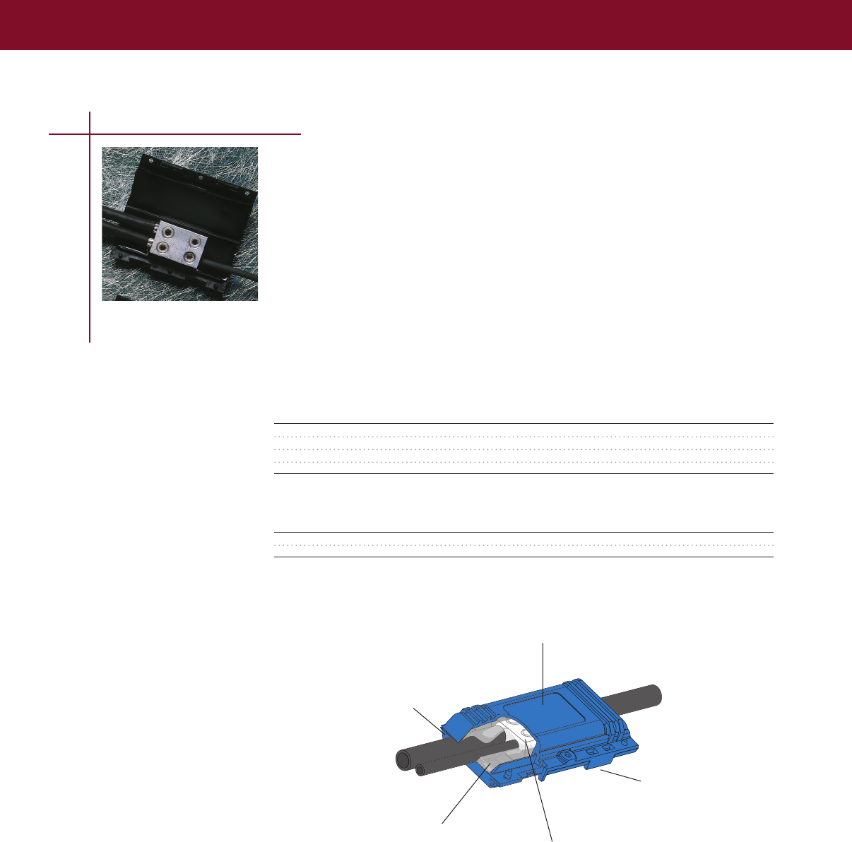
SPLICES, TAPS & TERMINATIONS
SPLICES, TAPS & TERMINATIONS
99
Low Voltage Taps
GTAP Splices
Water Resistant Splice (1000 V)
The GTAP gel tap splice kit provides a fast and simple method for connecting, insulating, and
environmentally sealing low-voltage splices The GTAP splice kit is designed for underground as well
as overhead environments It is especially useful for street lighting applications
• Range-taking mechanical connectors splice a wide range of cables, including copper and aluminum
• Connector’s four port design allows maximum inventory flexibility
• Hinged closure allows for one-step installation
• Can be installed over the connector in seconds by simply snapping the cover shut
• Utilizes Tyco Electronics’ innovative PowerGel sealant to protect the connection from moisture
ingress, corrosion, and pollution
• PowerGel sealant provides additional insulation
Conductor Size
(All Outlets) Std.
Catalog Number AWG (mm2 ) Pack
GTAP-1 #14 – #2 (2 – 35) 18 or 72
CPGI-GTAP-1 #14 – #2 (2 – 35) 5
GTAP-2 #14 – 2/0 (2 – 70) 18 or 72
CPGI-GTAP-2 #14 – 2/0 (2 – 70) 5
Selections are based on typical dimensions for low voltage, insulated cable.
Catalog Number Length Width Height
GTAP-1 2 3/4 (70) 1 5/8 (41) 1 1/16 (27)
GTAP-2 4 1/4 (108) 2 (51) 1 3/16 (30)
Frangible fingers provide
wide cable range
Silicone gel is high dielectric insulation and
provides constant pressure on cable and
connector to provide waterseal PowerGel
sealant is specially formulated for high
temperature environments
Snap-lock ensures that
cover remains closed
Molded cover of UV stable, impact resistant
polypropylene provides rugged protection for
underground or overhead applications
Range-taking mechanical connector made of
aluminum Accepts both copper and aluminum
conductors
Selection Information
Ordering Information
1 Selection based on typical dimensions of low-voltage insulated cables

SPLICES, TAPS & TERMINATIONS
100
GelCap SL Street Light Splice
Water Resistant Cover Kit with Connector (1000 V)
Tyco Electronics’ GelCap SL splice cover kits provide quick installation, dependable performance, and
easy reentry for street lighting connections, but they have many other uses
GelCap SL splice cover kits quickly and conveniently insulate, seal, and protect stub splice connections
up to 1000 volts
PowerGel Sealant Technology
The GelCap SL splice cover kits feature revolutionary PowerGel sealant which provides an excellent
moisture seal over a wide temperature range (-40°C to 105°C)
Innovative Cap Design and Material
The specially formulated material provides excellent abrasion resistance and insulation
Range Taking Connector
The special three wire connector is perfect for street light connections There are two ports that
accept wires from #14-2/0 AWG Use these for the feeder cable There is a single port that accepts
#14-6 AWG Use this port to power the light
Fast and Easy Installation
GelCap SL splice cover kits provide the fastest installation Simply push the cover down over the
connection and snap the clamp closed No extra materials or greases are required The PowerGel
sealant is already in the cap
Easy to Reenter
The GelCap SL splice cover is easy to re-enter because the PowerGel sealant pulls away leaving a
clean connection Re-entry is also safer than other methods because no sharp objects or cutting tools
are required for removal of the cap
Other Common Uses for GelCap Splice Cover Kits
• Irrigation systems
• HVAC
• Outdoor lighting
• Motor connections
Ordering Information
1 Selections are based on typical dimensions of low-voltage insulated cables
2 Kits include UL Listed connectors for use with copper and/or aluminum conductors
3 Each kit contains a gel filled cap, cap clamp, and connector
Hole A Hole B
Recommended Recommended Std.
Catalog Number Wire Range Torque Values Wire Range Torque Values Pack
GelCap-SL-2/0-3 Hole #14 - 2/0 AWG 120 - 180 in–lbs #14 - 6 AWG 120 - 150 in–lbs 10
CPGI-GelCap-SL-2/0-3 Hole #14 - 2/0 AWG 120 - 180 in–lbs #14 - 6 AWG 120 - 150 in–lbs 5
Testing Test Conditions
Chemical Resistance ASTM D543, Sulfuric acid, Sodium Hydroxide and motor oil
Ozone Resistance ASTM D1149, 168 hours @ 40˚C, 50 pphm
Accelerated Aging ASTM D2671
Abrasion Resistance 2040 gm wt, 4000 cycles, 2% max thickness loss
Selection Information
Low Voltage Taps
90UF
Insulating Splice Covers
600V/105˚C
E216204
IDJZ1
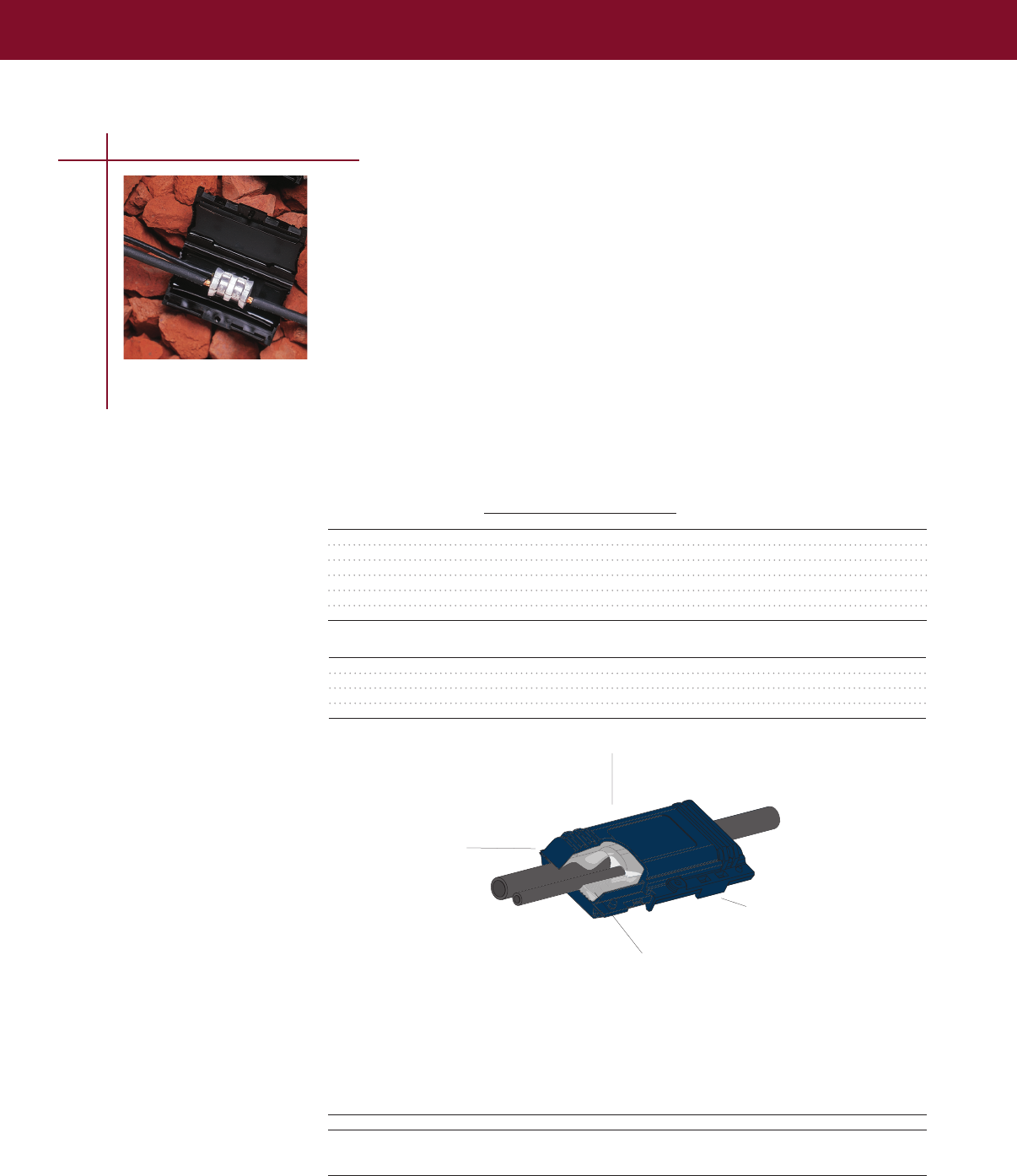
SPLICES, TAPS & TERMINATIONS
SPLICES, TAPS & TERMINATIONS
101
Low Voltage Taps
GHFC H-Frame Closures
Water Resistant Closure for Power Cable (1000 V)
Tyco Electronics’ low-voltage H-frame closures provide a fast and simple method for
insulating and environmentally sealing low-voltage cable-taps and splices made with
H-frame compression connectors
• Utilizes Tyco Electronics’ PowerGel sealant material to seal and protect the connection from
moisture ingress, corrosion, and pollution
• Ideal for both underground and overhead applications and is especially useful for street
lighting applications
• Qualified to ANSI C1191-1986 for underground splicing
• UV resistant
• Qualified for temperatures from –40°C to 90°C
Simply place the connection on the closure and press the closure together It’s that easy—no tapes,
mastics, tools, or mixing are required The closure can be easily installed with one hand
Selection Information: dimensions in inches (millimeters)
Conductor Size (AWG/kcmil) Std.
Catalog Number Main Tap Die Pack
GHFC-1-90 #6 – #2 #14 – #8 “BG” 10 or 100
CPGI-GHFC-1-90 #6 – #2 #14 – #8 “BG” 5
GHFC-2-90 #2 – 2/0 #14 – #6 “O” 10 or 100
CPGI-GHFC-2-90 #2 – 2/0 #14 – #6 “O” 5
GHFC-25-90 1/0 – 4/0 #6 – 3/0 “D” 30 each
GHFC-3-90 350 4/0 “N” 6 or 18
Product Approved connectors
GHFC-1-90 Homac UB214; T&B 63105; Blackburn WR9; Burndy YPC2A8U
GHFC-2-90 Homac OB22, OB44, OB102, OB103; Burndy YHO-1, YHO-2, YHO100, YHO125,
YHO150; Blackburn WR139, WR159, WR179, WR199; ILSCO AH1; T&B 63110;
UTILCO HT1, HT2
3 Standard packs of 100 ea are also available Substitute a (B100) in place of the (B10) in the
catalog number
4 Related test report: GHFC-1-90 and GHFC-2-90 - EDR-5264, GHFC-3-90 - EDR-5326
Frangible fingers provide wide
cable range
Silicone gel is high dielectric insulation and provides constant
pressure on cable and connector to provide waterseal PowerGel
sealant is specially formulated for high temperature environments
Snap-lock ensures that cover
remains closed
Molded cover of UV stable, impact resistant
polypropylene provides rugged protection for
underground or overhead applications
Catalog Number Length Width Height
GHFC-1-90 2 3 /4 (70) 1 5/8 (41) 1 1/16 (27)
GHFC-2-90 4 1/4 (108) 2 (51) 1 3/16 (30)
GHFC-25-90 7 1/8 (181) 2 3/4 (70) 1 4/7 (40)
GHFC-3-90 6 1/4 (159) 3 1/3 (84) 1 15/16 (49)
Ordering Information
1 Select the appropriate catalog number Selections are based on typical dimensions for low-voltage,
insulated cables and connectors
2 Approved connectors (supplied by others) include, but are not limited to:
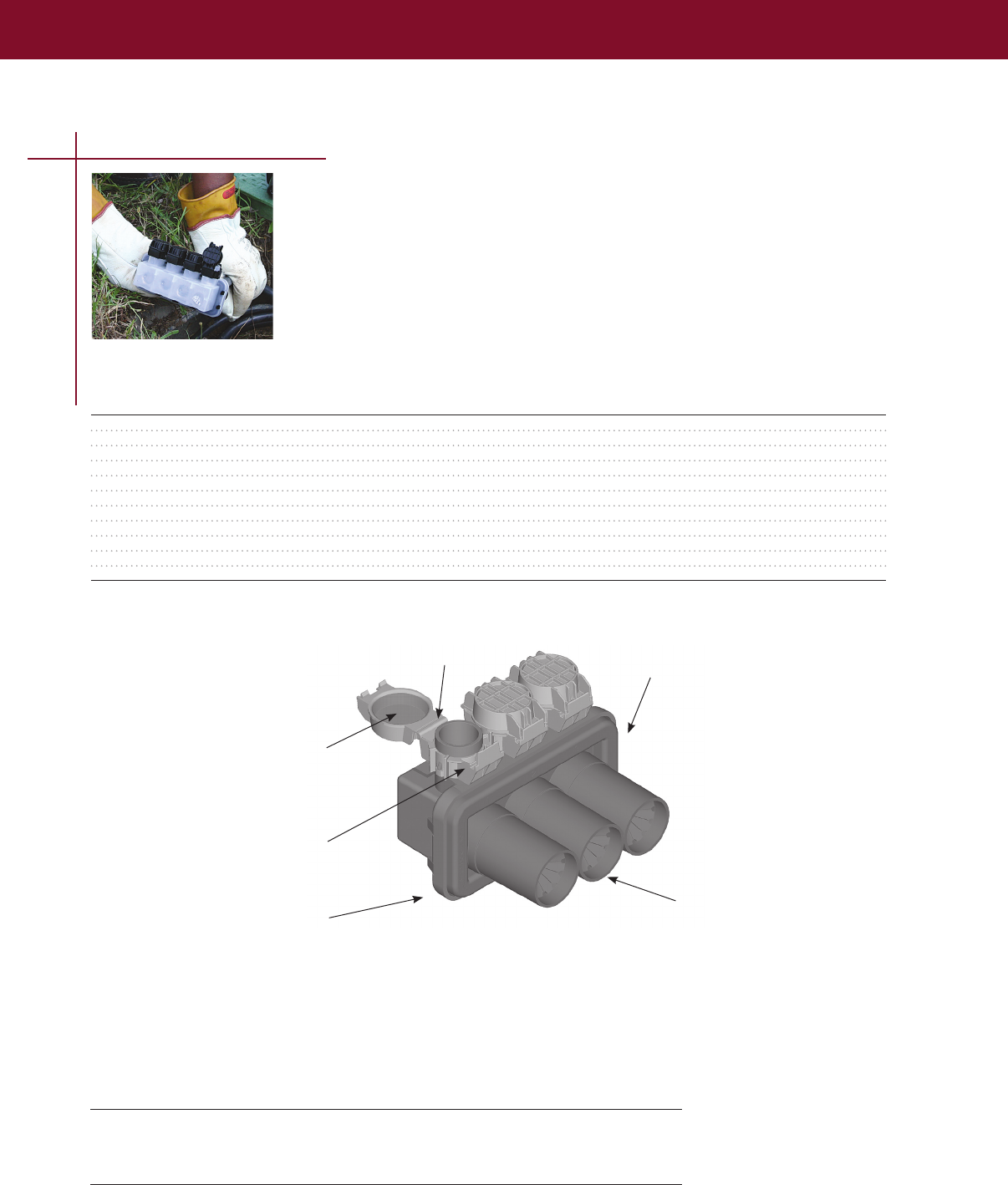
SPLICES, TAPS & TERMINATIONS
102
GelPort Connectors
Submersible Connectors for URD Distribution (1000 V)
• Corrosion resistance
• No loose parts due to one piece housing
• Gel-filled cable entry ports provide a reliable cable seal
• PowerGel sealing gel seals out harsh environments
• Rugged, impact-resistant housing stands up to rough installations
• Clear view back allows for easy positive visual indication of wire position in connector
Clear Number of Conductor Use Length Width Height Std.
Catalog Number View Wire Ports Range (mm2) Inches (mm) Inches (mm) Inches (mm) Pack
GPRT-350-3P -C 3 14 - 350 (2 - 150) 4.60 (117) 3.825 (97) 3.50 (89) 6
GPRT-350-4P -C 4 14 - 350 (2 - 150) 5.85 (149) 3.825 (97) 3.50 (89) 6
GPRT-350-5P -C 5 14 - 350 (2 - 150) 7.10 (180) 3.825 (97) 3.50 (89) 6
GPRT-350-6P -C 6 14 - 350 (2 - 150) 8.35 (212) 3.825 (97) 3.50 (89) 6
GPRT-350-8P -C 8 14 - 350 (2 - 150) 10.85 (276) 3.825 (97) 3.50 (89) 6
GPRT-350/4P-500/1P -C 5 Hybrid 7.10 (180) 3.825 (97) 3.50 (89) 6
4 14 - 350 (2 - 150)
1 6 - 500 (16 - 250)
GPRT-350/6P-500/2P -C 8 Hybrid 10.85 (276) 3.825 (97) 3.50 (89) 6
6 14 - 350 (2 - 150)
2 6 - 500 (16 - 250)
Note: For clear view back, add “-C” to catalog number
Ordering Information
1 Selection based on typical dimensions of low voltage cables
Gel sealed screw port cap
Proven robust latch
design
Gel sealed cable entry port
Tin plated aluminum connector
Qualified to ANSI C1194
Proven tough hinge design
Tough, puncture
resistant, high
impact strength
polypropylene body
and cap
Low Voltage Taps
Product Performance
Testing Test Condition
Complete unit ANSI C1191, 2002, Report: EDR-5379, EDR-5409, EDR-5427
Connector ANSI C1194, 2003, Report: 502-47264, 502-47302, 502-47308
Chemical Resistance ASTM D543 to the following liquids: Sulfuric Acid, Sodium Sulfate,
Sodium Chloride, Sodium Hydroxide, Ethylene Glycol
UV Resistance ASTM G-53-95, ASTM-D-638-95
Selection Information: dimensions in inches (millimeters)
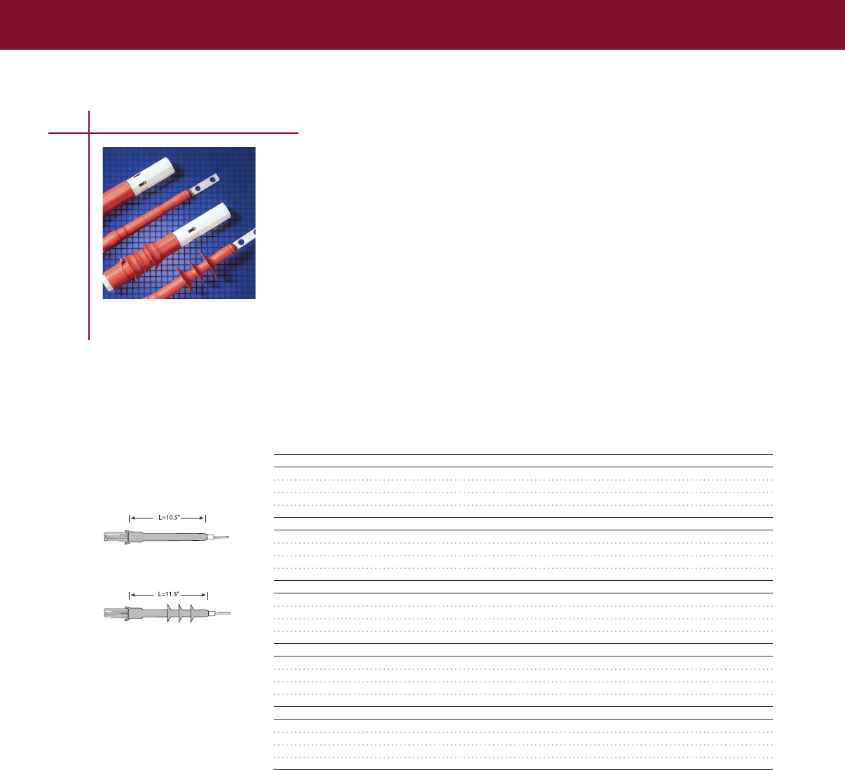
SPLICES, TAPS & TERMINATIONS
SPLICES, TAPS & TERMINATIONS
GelPort Connectors
Submersible Connectors for URD Distribution (1000 V)
Medium Voltage Termination
Selection Information: dimensions in inches (millimeters)
TFT-R and TFT-RG/SG tool-free termination kits have been developed to provide a quick and easy,
cold-applied method of terminating 5-15 kV, single conductor polymeric cables Both the TFT-R and
TFT-R-SG are designed for indoor and outdoor conditions
TFT-R kits are for non-shielded cable applications TFT-R-G kits do not have rain sheds and should be
used for 5/8 kV indoor or outdoor applications and 15 kV indoor only applications
TFT-R and TFT-R-G/SG kits offer the following features and benefits:
• Advanced Metal Oxide Matrix stress control
• Positive placement of stress control patch
• Provided on a crush-resistant core
• Easy installation — allows for repositioning
Rated to IEEE-48-1996, class 1 termination requirements
TFT-R
1/C Terminations for Shielded and Non-Shielded Power Cable (5-15 kV)
Standard
Catalog Cable Range Insulation Diameter Number Package
Number (AWG/kcmil) (Min./Max.) of Skirts (Kits/Box)
TFT-R (Non-Shielded, Indoor/Outdoor) Without Sheds (5 kV)
TFT-50R #2-3/0AWG 053-080 (13-20) 0 3
TFT-51R 1/0-250KCMIL 064-109 (16-28) 0 3
TFT-52R 250-500KCMIL 085-145 (22-37) 0 3
TFT-53R 350-750KCMIL 106-170 (27-43) 0 3
TFT-R-G (Shielded, Indoor/Outdoor) Without Sheds (5 kV)
TFT-150R-G #2-3/0AWG 053-080 (13-20) 0 3
TFT-151R-G 2/0-250KCMIL 064-109 (16-28) 0 3
TFT-152R-G 350-500KCMIL 085-145 (22-37) 0 3
TFT-153R-G 500-750KCMIL 106-170 (27-43) 0 3
TFT-R-G (Shielded, Indoor/Outdoor) Without Sheds (8 kV)
TFT-150R-G #2-3/0AWG 053-080 (13-20) 0 3
TFT-151R-G 1/0-250KCMIL 064-109 (16-28) 0 3
TFT-152R-G 250-500KCMIL 085-145 (22-37) 0 3
TFT-153R-G 500-750KCMIL 106-170 (27-43) 0 3
TFT-R-G (Shielded, Indoor Only) Without Sheds (15 kV)
TFT-150R-G #2-3/0AWG 053-080 (13-20) 0 3
TFT-151R-G #2-250KCMIL 064-109 (16-28) 0 3
TFT-152R-G 4/0-500KCMIL 085-145 (22-37) 0 3
TFT-153R-G 500-750KCMIL 106-170 (27-43) 0 3
TFT-R-SG (Shielded, Indoor/Outdoor) (15 kV)
TFT-151R-SG #2-250KCMIL 064-109 (16-28) 3 3
TFT-152R-SG 4/0-500KCMIL 085-145 (22-37) 3 3
TFT-153R-SG 500-750KCMIL 106-170 (27-43) 3 3
TFT-154R-SG 1000-1250KCMIL 149-220 (38-56) 3 3
Ordering Information
1 All shielded cable kits contain a solder-blocked ground braid and a solderless ground clamp
2 Selections are based on the typical dimensions of 100% insulated cables manufactured in accordance
with the data contained in AEIC CS5-1987 and CS6-1987 as well as the dimensions of commonly used
connectors Nominal insulation thickness (100%): 15 kV: 175 mils
3 For cables manufactured to other specifications, confirm cable dimensions
4 Kits do not contain connectors; order compression or solder connectors separately
5 Related test reports: 15 kV:EDR5302 (outdoor), 15kV:EDR5306 (indoor)
6 Cable mounting brackets are available to accommodate cable diameters from 080-240 (20-61)
7 For three conductor cables, order MOD-3-TFT kits
Installed Length
5/8/15kV (without sheds)
15kV (with sheds)
103

SPLICES, TAPS & TERMINATIONS
Medium Voltage Termination
Use MOD-3-TFT kits in conjunction with three Raychem 1/C tool free terminations (TFT) to seal
and rejacket the cable terminations
MOD-3Z-TFT is for rejacketing of phase conductors MOD-3C-TFT and MOD-3D-TFT provide
rejacketing, plus an environmental crotch sealing boot
Each -3C and -3D kit includes six 15 feet-long pre-stretched tubes on holdouts for the phases (Tubing
can be field-cut to appropriate length) A three-legged cable breakout boot is also pre-stretched on
holdouts and has a domed crown Sealing is insured by pressure sensitive mastic to
be applied under the breakout boot body as well as at the tubing interfaces
The -3Z kit contains three 15 feet long rejacketing tubes
Note: MOD-3-TFT kits should be installed prior to installing Raychem TFT kits
MOD–3–TFT
3/C Modification Kits for Raychem Medium-Voltage Tool Free
Terminations (5–15 kV)
Selection Information: dimensions in inches (millimeters)
Indoor (Without Breakout Boot) Outdoor/Indoor (Includes Breakout Boot)
1/C Termination Indoor MOD-3-TFT Kit 1/C Termination Outdoor MOD-3-TFT Kit
5/8 kV
TFT-50R MOD-3Z-TFT* TFT-50R MOD-3C-TFT*
TFT-51R MOD-3Z-TFT TFT-51R MOD-3C-TFT
TFT-52R MOD-3Z-TFT TFT-52R MOD-3C-TFT
TFT-53R MOD-3Z-TFT TFT-53R MOD-3D-TFT
TFT-150R-G MOD-3Z-TFT* TFT-150R-G MOD-3C-TFT*
TFT-151R-G MOD-3Z-TFT TFT-151R-G MOD-3C-TFT
TFT-152R-G MOD-3Z-TFT TFT-152R-G MOD-3C-TFT
TFT-153R-G MOD-3Z-TFT TFT-153R-G MOD-3D-TFT
15 kV
TFT-150R-G MOD-3Z-TFT* TFT-151R-SG MOD-3C-TFT*
TFT-151R-G MOD-3Z-TFT TFT-152R-SG MOD-3C-TFT
TFT-152R-G MOD-3Z-TFT TFT-153R-SG MOD-3D-TFT
TFT-153R-G MOD-3Z-TFT TFT-154R-SG MOD-3D-TFT
* Refer to Selection information (#3) below this table.
Catalog Insulation Diameter Jacket Diameter Components
Number (Min.–Max.) (Min.–Max.) Jacketing Tubes Breakout Boot
MOD-3Z-TFT 060-172 (15-43) 3 0
MOD-3C-TFT 060-140 (15-35) 130-350 (33 -89) 6 1
MOD-3D-TFT 120-172 (30-43) 270-450 (69 -114) 6 1
Ordering Information
1 Select three TFT single-conductor terminations
2 To select the appropriate modification kit for the TFT terminations, use the MOD-3-TFT selection
table above
3 Use the MOD-3-TFT dimensions table to confirm the insulation and jacket diameters
4 Related installation instructions: MOD-3-TFT
104

TUBINGS & MOLDED PARTS
Heat-Shrink Tubing
RNF-100 Tubing 107
MWTM Tubing 108
WCSM Tubing 109
FCSM Tubing111
LVIT Tubing 112
Molded Parts
ESC Sealing Caps 112
CFTS Seals 113
CBR Breakout Boot113
105

106
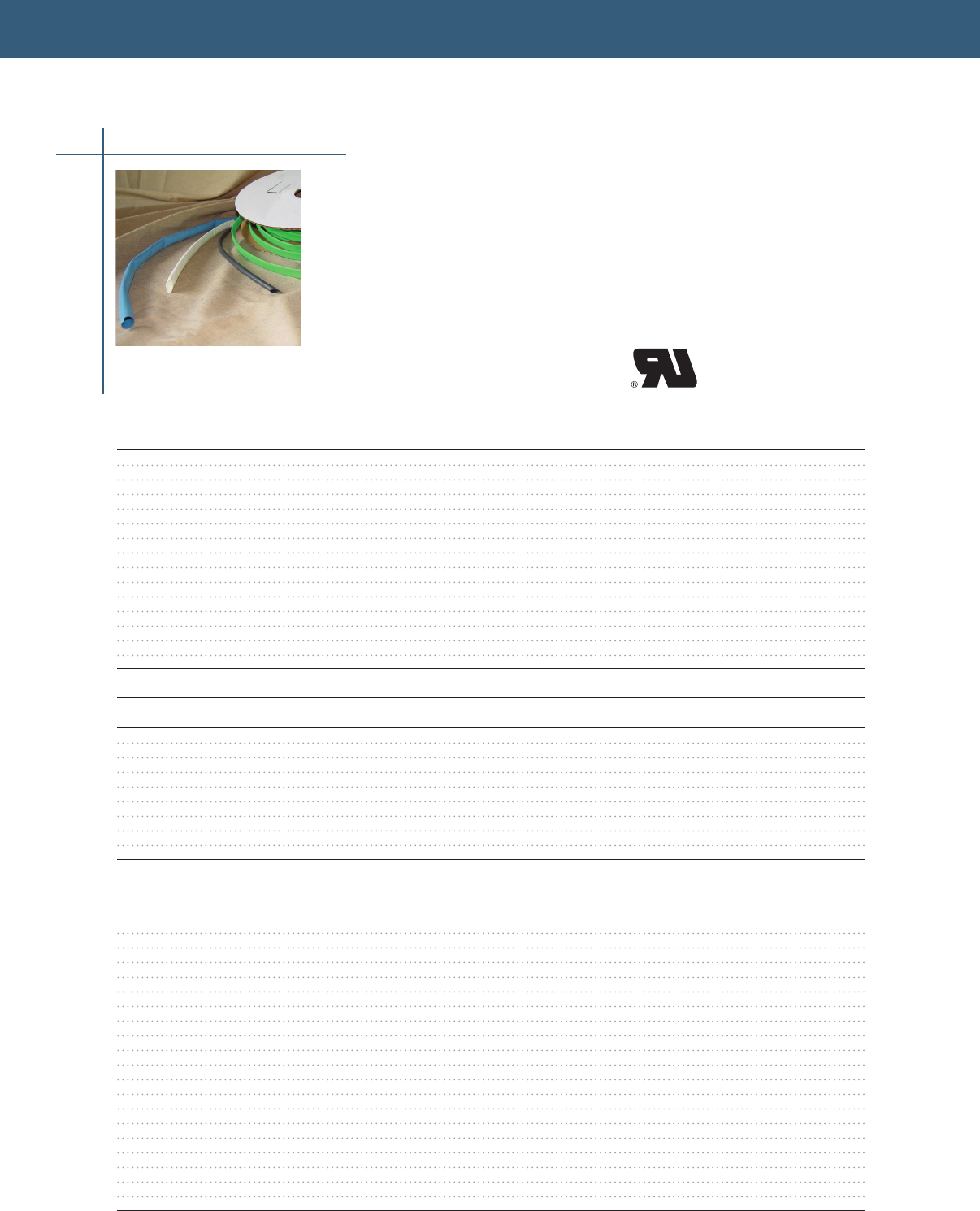
TUBINGS & MOLDED PARTS
TUBINGS & MOLDED PARTS
RNF-100 Tubing
Thin-Wall Tubing, Uncoated
• UL recognized to standard 224 (file E35586)
• Flexible, flame-retardant, thin-wall, general purpose heat-shrinkable polyolefin tubing
• Clear tubing is not flame-retardant
• Ideal for wire jacketing marking and color coding
• Black, white, and colors meet AMS-DTL-23053/5, Class 1 Clear meets AMS-DTL-23053/5, Class 2
• 2:1 shrink ratio and an unlimited shelf life when stored under normal conditions
• Order spools as RNF-100-Size-Spool Length-color
• Other sizes, colors, and packaging are available
Selection Information: dimensions in inches (millimeters)
Spools
Recovered
Inner Diameter Wall Thickness Feet/
Catalog Number as Supplied Recovered (Mils) Color Spool
RNF-100-1/16-25-(color) 063 (16) 031 (08) 17 BLK,WHT,CL 25
RNF-100-3/32-25-(color) 093 (24) 046 (12) 20 BLK,WHT,CL 25
RNF-100-1/8-25-(color) 125 (32) 062 (16) 20 BLK,WHT,CL 25
RNF-100-1/8-500-(color) 125 (32) 062 (16) 20 BLK,WHT,RED 500
RNF-100-3/16-25-(color) 187 (48) 093 (24) 20 BLK,WHT,CL 25
RNF-100-1/4-25-(color) 250 (64) 125 (32) 25 BLK,WHT,CL 25
RNF-100-1/4-250-(color) 250 (64) 125 (32) 25 BLK,WHT,RED 250
RNF-100-3/8-25-(color) 375 (96) 187 (48) 25 BLK,WHT,CL 25
RNF-100-3/8-200-(color) 375 (96) 187 (48) 25 BLK,WHT,RED,GRN,BLUE 200
RNF-100-1/2-25-(color) 500 (13) 250 (64) 25 BLK,WHT,CL 25
RNF-100-1/2-150-(color) 500 (13) 250 (64) 25 BLK,WHT,RED, GRN,BLUE 150
RNF-100-3/4-25-(color) 750 (19) 375 (96) 30 BLK,WHT,CL 25
RNF-100-1-25-(color) 1000 (25) 500 (13) 35 BLK,WHT,CL 25
RNF-100-1 1/2-25-(color) 1500 (38) 750 (19) 40 BLK,WHT,CL 25
RNF-100-2-25-(color) 2000 (51) 100 (25) 45 BLK,WHT,CL 25
4 Foot Sticks
Inner Diameter Cut-Piece Pieces/
Catalog Number as Supplied Recovered Length Colors Carton
CPGI-RNF-100-1/4-48-(color) .250 (6.4) .125 (3.2) 48" Stick BLSK,WHSK,GRSK, RDSK 25
CPGI-RNF-100-3/8-48-(color) .375 (9.6) .187 (4.8) 48" Stick BLSK,WHSK,GRSK, RDSK 25
CPGI-RNF-100-1/2-48-(color) .500 (13) .250 (6.4) 48" Stick BLSK,WHSK,GRSK, RDSK 25
CPGI-RNF-100-3/4-48-(color) .750 (19) .375 (9.6) 48" Stick BLSK,WHSK,GRSK, RDSK 25
CPGI-RNF-100-1-48-(color) 1.000 (25) .500 (13) 48" Stick BLSK,WHSK,GRSK, RDSK 25
CPGI-RNF-100-1/16-48-BLK 1.6 (0.063) 0.8 (0.0031) 48" Stick BLK 50
CPGI-RNF-100-3/32-48-BLK 2.4 (0.093) 1.2 (0.046) 48" Stick BLK 50
CPGI-RNF-100-1/8-48-BLK 3.2 (0.125) 1.6 (0.062) 48" Stick BLK 50
CPGI-RNF-100-3/16-48-BLK 4.8 (0.187) 2.4 (0.093) 48" Stick BLK 50
6 Inch Sticks
Inner Diameter Cut-Piece Pieces/ Packs/
Catalog Number as Supplied Recovered Length Colors Pack Carton
CPGI-RNF-100-1/4-6-(color) .250 (6.4) .125 (3.2) 6" Piece BLK,WHT,GRN, RED 15 5
CPGI-RNF-100-3/8-6-(color) .375 (9.6) .187 (4.8) 6" Piece BLK,WHT,GRN, RED 12 5
CPGI-RNF-100-1/2-6-(color) .500 (13) .250 (6.4) 6" Piece BLK,WHT,GRN, RED 10 5
CPGI-RNF-100-3/4-6-(color) .750 (19) .375 (9.6) 6" Piece BLK,WHT,GRN, RED 8 5
CPGI-RNF-100-1-6-(color) 1.000 (25) .500 (13) 6" Piece BLK,WHT,GRN, RED 8 5
CPGI-RNF-100-1/4-6-ASRT .250 (6.4) .125 (3.2) 6" Piece ASSORTED 15 5
CPGI-RNF-100-3/8-6-ASRT .375 (9.6) .187 (4.8) 6" Piece ASSORTED 12 5
CPGI-RNF-100-1/2-6-ASRT .500 (13) .250 (6.4) 6" Piece ASSORTED 10 5
CPGI-RNF-100-3/4-6-ASRT .750 (19) .375 (9.6) 6" Piece ASSORTED 8 5
CPGI-RNF-100-1-6-ASRT 1.000 (25) .500 (13) 6" Piece ASSORTED 8 5
CPGI-RNF-100-MP-A-BLK: .063 (1.6) .031 (0.8) 6" Piece BLK 12 5
.093 (2.4) .046 (1.2) 6" Piece BLK 12 5
.125 (3.2) .062 (1.6) 6" Piece BLK 12 5
.187 (4.8) .093 (2.4) 6" Piece BLK 12 5
.250 (6.4) .125 (3.2) 6" Piece BLK 12 5
.375 (9.6) .187 (4.8) 6" Piece BLK 12 5
CPGI-RNF-100-MP-B-BLK: .375 (9.6) .187 (4.8) 6" Piece BLK 8 5
0.5 (13) .250 (6.4) 6" Piece BLK 8 5
.750 (19) .375 (9.6) 6" Piece BLK 8 5
1.00 (25) .500 (13) 6" Piece BLK 8 5
UL recognized to Standard 224
600V/125˚
Heat-Shrink Tubing
107
TUBINGS & MOLDED PARTS
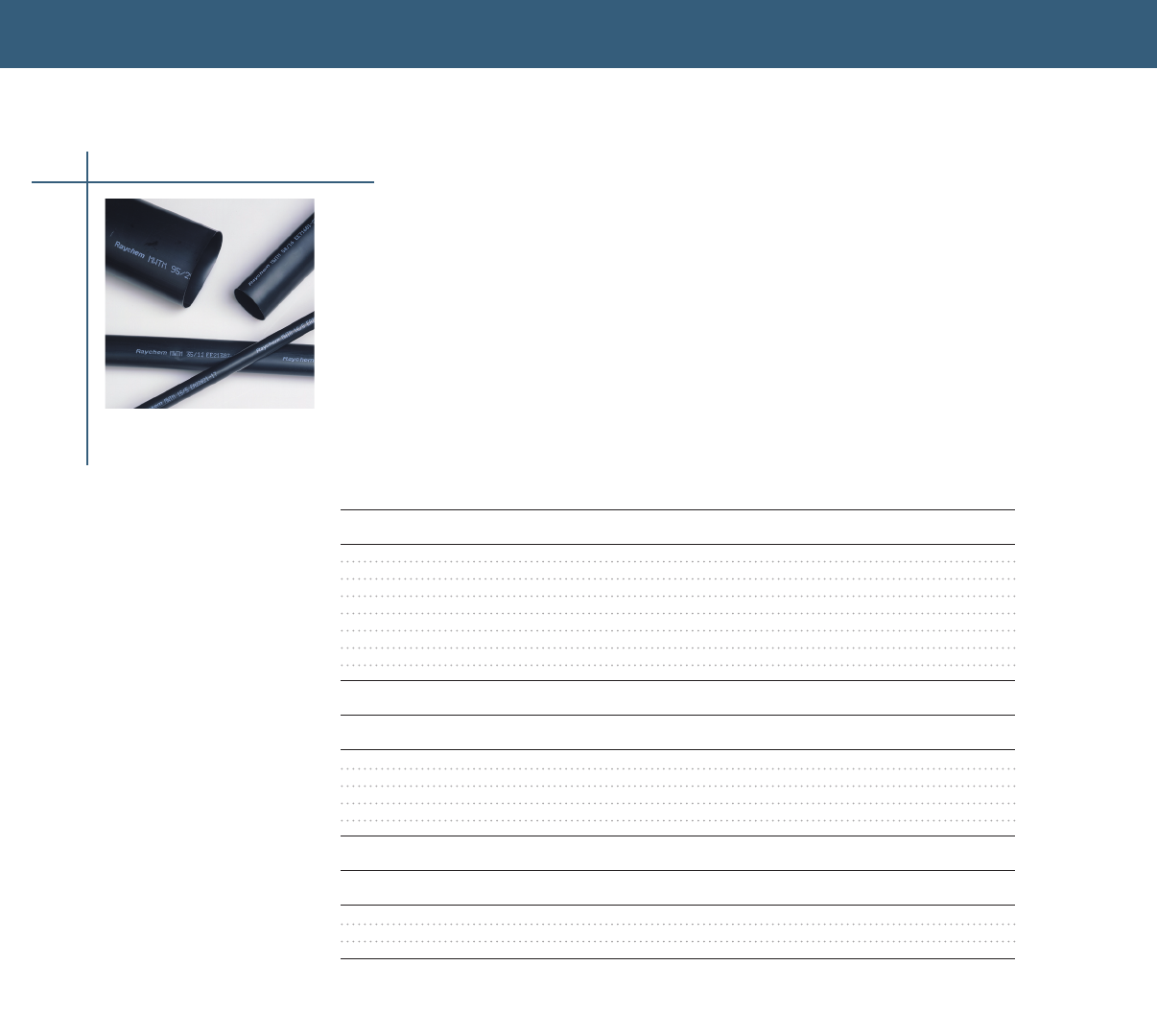
TUBINGS & MOLDED PARTS
MWTM Tubing
Medium-Wall Sealant Coated or Uncoated Tubing (600 V)
• Sealant coated MWTM tubing (-S designation) is for use as insulation/jacket repair up to 600 V
or for general sealing and rejacketing of polymeric- or elastomeric insulated cables up to 35kV
• RUS accepted as jacket restoration of JCN cable
• Uncoated MWTM tubing (-U or -A/U) is for cable rejacketing only
• 3:1 shrink ratio and an unlimited shelf life when stored under normal conditions
Selection Information: dimensions in inches (millimeters)
Sealant-Coated, Cut-Length Tubing
Standard
Catalog Number Use Range Min. – Max. Cut-Piece Length Pkg /Box
MWTM-10/3-1200-S 013 – 035 (3 – 9) 48 (1200) 25
MWTM-16/5-1200-S 025 – 055 (6 – 14) 48 (1200) 25
MWTM-25/8-1200-S 035 – 085 (9 – 22) 48 (1200) 25
MWTM-35/12-1200-S 050 – 125 (13 – 32) 48 (1200) 25
MWTM-50/16-1200-S 065 – 170 (17 – 43) 48 (1200) 15
MWTM-85/25-1200-S 100 – 290 (25 – 74) 48 (1200) 5
MWTM-115/34-1200-S 140 – 390 (36 – 99) 48 (1200) 5
MWTM-140/42-1200-S 180 – 470 (46 – 119) 48 (1200) 5
Uncoated, Spooled Tubing
Standard Bulk Option
Catalog Number Use Range Min. – Max. Min. Cont. Length Pkg/Spool /Spool
MWTM-10/3-A/U 013 – 035 (3 – 9) 25 (76) 100 (30)
MWTM-16/5-A/U 025 – 055 (6 – 14) 25 (76) 100 (30) 1155 (350)
MWTM-25/8-A/U 035 – 085 (9 – 22) 25 (76) 100 (30) 660 (200)
MWTM-35/12-A/U 050 – 125 (13 – 32) 25 (76) 100 (30) 495 (150)
MWTM-50/16-A/U 065 – 170 (17 – 43) 15 (46) 75 (23) 330 (100)
Uncoated, Cut-Piece Tubing
Standard
Catalog Number Use Range Min. – Max. Cut-Piece Length Pkg/Box
MWTM-85/25-1500/U 100 – 290 (25 – 74) 60 (1500) 5
MWTM-115/34-1500/U 140 – 390 (36 – 99) 60 (1500) 5
MWTM-140/42-1500/U 180 – 470 (46 – 119) 60 (1500) 5
Heat-Shrink Tubing
108
Ordering Information
1 Select the appropriate catalog number Confirm selection with application dimensions to assure
proper sizing
2 MWTM is a general purpose tubing; for sealing applications use MWTM with sealant (-S) or use
uncoated MWTM (-U or -A/U) in combination with S-1052 sealant Order sealants separately
3 UV resistant test report: EDR-5361

TUBINGS & MOLDED PARTS
TUBINGS & MOLDED PARTS
WCSM Tubing
Heavy-Wall Sealant-Coated or Uncoated Tubing (1000 V)
• For use on standard poly- or elastomeric -insulated/jacketed cables or lead-jacketed cables, which
may include aluminum or steel armoring
• Use sealant-coated tubing (-S) as a sealed in-line splice or terminal lug seal for non-flame-retardant
applications Use uncoated tubing (-A/U and /U) for cable rejacketing and mechanical protection only
• Sealant-coated WCSM tubing, sizes -9/3 through-70/21 (-S designation) is UL listed per 486D (file
E91151), certified to CSA C222, qualified to ANSI C1191-1986, and rated to Western Underground
Guide 25 Also RUS accepted for use as a secondary tap or splice cover, and for use as jacket
restoration materials on JCN cable WCSM tubing may be used for jacket repair on cables to 35 kV
• Connectors over 6 inches: Recommended cut length = connector length + 5 inches
Connectors up to 6 inches: Recommended cut length = connector length + 4 inches
• WCSM tubing has a 3:1 shrink ratio and an unlimited shelf life when stored under normal conditions
Selection Information: dimensions in inches (millimeters)
1000-V General
Conductor Size Use Range Cut-Piece Std. Pack
Catalog Number1 (AWG/kcmil) (Min. – Max.) Length2 (Ft/Roll) (Pcs/Box) (Pcs/Pack)
Sealant-Coated Cut-Length Tubing
WCSM-9/3-150-S #14 – #8 015 – 030 (4 – 8) 6 (150) 50
CPGI-WCSM-9/3-150-S #14 – #8 0.15 – 0.30 (4 – 8) 6 (150) 3
WCSM-9/3-300-S #14 – #8 015 – 030 (4 – 8) 12 (300) 50
WCSM-9/3-1200-S #14 – #8 015 – 030 (4 – 8) 48 (1200) 25
WCSM-13/4-150-S #12 – #6 020 – 045 (5 – 11) 6 (150) 50
CPGI-WCSM-13/4-150-S #12 – #6 0.20 – 0.45 (5 – 11) 6 (150) 2
WCSM-13/4-1200-S #12 – #6 020 – 045 (5 – 11) 48 (120) 25
WCSM-20/6-150-S #8 – #2 025 – 070 (6 – 18) 6 (150) 50
CPGI-WCSM-20/6-150-S #8 – #2 0.25 – 0.70 (6 – 18) 6 (150) 2
WCSM-20/6-225-S #8 – #2 025 – 070 (6 – 18) 9 (225) 50
WCSM-20/6-300-S #8 – #2 025 – 070 (6 – 18) 12 (300) 50
WCSM-20/6-1200-S #8 – #2 025 – 070 (6 – 18) 48 (1200) 25
WCSM-33/8-150-S #4 – 4/0 035 – 120 (9 – 30) 6 (150) 50
CPGI-WCSM-33/8-150-S #4 – 4/0 0.35 – 1.20 (9 – 30) 6 (150) 2
WCSM-33/8-225-S #4 – 4/0 035 – 120 (9 – 30) 9 (225) 50
WCSM-33/8-300-S #4 – 4/0 035 – 120 (9 – 30) 12 (300) 50
WCSM-33/8-1200-S #4 – 4/0 035 – 120 (9 – 30) 48 (1200) 25
WCSM-43/12-150-S 1/0 – 400 050 – 155 (13 – 39) 6 (150) 40
WCSM-43/12-225-S 1/0 – 400 050 – 155 (13 – 39) 9 (225) 40
CPGI-WCSM-43/12-225-S 1/0 – 400 0.50 – 1.55 (13 – 39) 9 (225) 1
WCSM-43/12-300-S 1/0 – 400 050 – 155 (13 – 39) 12 (300) 40
WCSM-43/12-1200-S 1/0 – 400 050 – 155 (13 – 39) 48 (1200) 10
WCSM-51/16-100-S 250 – 500 070 – 175 (18 – 44) 4 (100) 100
WCSM-51/16-225-S 250 – 500 070 – 175 (18 – 44) 9 (225) 30
CPGI-WCSM-51/16-225-S 250 – 500 0.70 – 1.75 (18 – 44) 9 (225) 1
WCSM-51/16-300-S 250 – 500 070 – 175 (18 – 44) 12 (300) 30
WCSM-51/16-1200-S 250 – 500 070 – 175 (18 – 44) 48 (1200) 10
WCSM-70/21-300-S 400 – 1000 090 – 245 (23 – 62) 12 (300) 15
WCSM-70/21-450-S 400 – 1000 090 – 245 (23 – 62) 18 (450) 15
WCSM-70/21-600-S 400 – 1000 090 – 245 (23 – 62) 24 (600) 10 or 100
WCSM-70/21-1200-S 400 – 1000 090 – 245 (23 – 62) 48 (1200) 10
WCSM-105/30-300-S 800 – 1250 130 – 370 (33 – 94) 12 (300) 15
WCSM-105/30-1200-S 800 – 1250 130 – 370 (33 – 94) 48 (1200) 5
WCSM-130/36-300-S 1500 – 2500 160 – 420 (41 – 107) 12 (300) 10
WCSM-130/36-450-S 1500 – 2500 160 – 420 (41 – 107) 18 (450) 20
WCSM-130/36-1200-S 1500 – 2500 160 – 420 (41 – 107) 48 (1200) 5
Uncoated Tubing
WCSM-9/3-A/U #14 – #8 015 – 030 (4 – 8) 100
WCSM-13/4-A/U #12 – #6 020 – 045 (5 – 11) 100
WCSM-20/6-A/U #8 – #2 025 – 070 (6 – 18) 100
WCSM-33/8-A/U #4 – 4/0 035 – 120 (9 – 30) 65
WCSM-43/12-A/U 1/0 – 400 050 – 155 (13 – 39) 50
WCSM-51/16-A/U 250 – 500 070 – 175 (18 – 44) 40
WCSM-70/21-A/U 400 – 1000 090 – 245 (23 – 62) 40
WCSM-90/30-1500/U 800 – 1200 130 – 310 (33 – 79) 60 5
WCSM-130/36-1500/U 1500 – 2500 160 – 420 (41 – 107) 60 5
Heat-Shrink Tubing
109
1 Catalog numbers with -S designation are suitable for sealed electrical insulation to 1000 V. Catalog numbers with A/U and /U designations are for cable
rejacketing only.
2 Length tolerance to ±2 percent. Can be used for multi-conductor LV splices using different tubings.
Note: UL listing applies to sealant-coated (-S) WCSM-9/3 through -70/21 only. WCSM-105/30 and -130/36 are not UL listed.
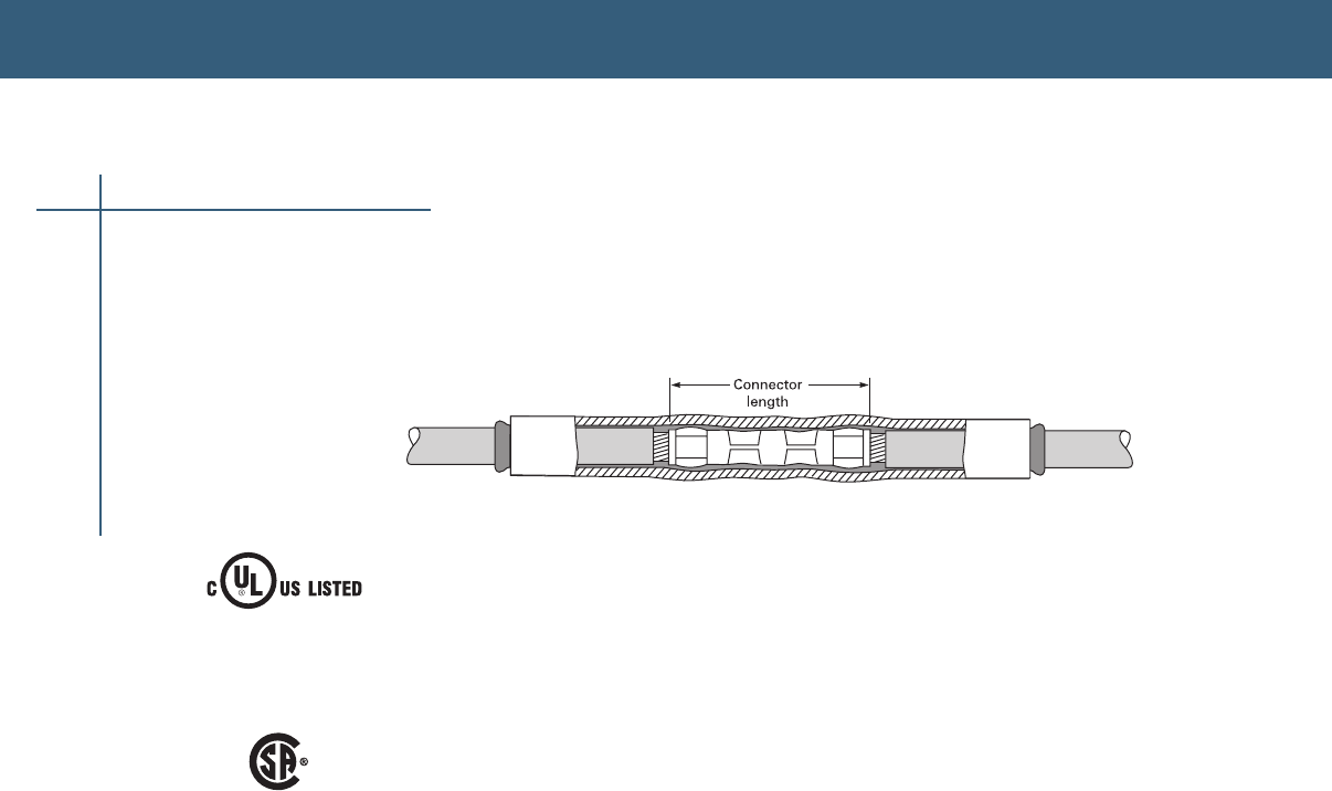
TUBINGS & MOLDED PARTS
Heat-Shrink Tubing
110
Ordering Information
1 Select the appropriate catalog number based on typical dimensions for low-voltage insulated
cable Confirm selection with dimensions to assure proper sizing
2 UL listing applies to sealant-coated (-S) WCSM-9/3 through -70/21 only WCSM-105/30 and
-130/36 are not UL listed
3 Package does not contain connectors or lugs Installed connector or lug diameter must be within
use range
4 If sealing is needed with WCSM-A/U uncoated tubing, order S-1052 sealant separately
5 WCSM tubing may be field-cut for shorter requirements
6 Bulk packaging is available for cut lengths Consult your Tyco Electronics representative
for additional information
7 Related Test Report: EDR-5139
8 UV resistant test report: EDR-5361
WCSM Tubing
Direct Burial
Insulation Covered
for listed pressure
connectors
96J4
E91151
Submersible
Certified
C22.2
No. 198.2
LR27428
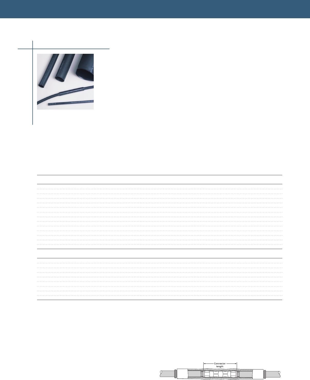
TUBINGS & MOLDED PARTS
TUBINGS & MOLDED PARTS
FCSM Tubing
Heavy-Wall Flame Retardant Tubing (2000 V)
FCSM tubing’s tough, crosslinked polyolefin construction provides mechanical strength and cut-
through resistance equal to, or surpassing, the properties of low-voltage cable jackets
• 3:1 shrink ratio and an unlimited shelf life when stored under normal conditions
• Uses sealant-coated tubing (-S) as a sealed in-line splice or terminal lug seal It provides a watertight
seal for direct-buried applications and wet environments
• Use uncoated tubing (-/U) for cable rejacketing only
• Sealant-coated or uncoated tubing may be used for jacket repair on cable to 35 kV Qualified to
ANSI C1191-1986; also rated to IEEE 383 (Vertical Tray Flame Test) and ICEA S-19-81 FCSM is also
MSHA approved (No P-137-MSHA)
For use on standard poly- or elastomeric- insulated/jacketed cables or lead-jacketed cables, which
may include aluminum or steel armoring
Connectors up to 6 inches: Recommended cut length = connector length + 4 inches
Connectors over 6 inches: Recommended cut length = connector length + 5 inches
Selection Information: dimensions in inches (millimeters)
1000-V Insulated Bulk
Conductor Size General Use Range Tube Std Pack Option
Catalog Number (AWG/kcmil) (Min.–Max.) Length* Ft.(m)/Roll Pcs/Box Ft.(m)/Roll
In-Line Splice Or Terminal Lug Seal (With Sealant)
FCSM-9/3-1200-S #14 – #8 015 – 030 (4 – 8) 48 (1200) 25
FCSM-19/6-150-S #6 – #2 025 – 065 (6 – 17) 6 (150) 50
FCSM-19/6-1200-S #6 – #2 025 – 065 (6 – 17) 48 (1200) 25
FCSM-28/9-225-S #2 – 4/0 040 – 095 (10 – 24) 9 (225) 50
FCSM-28/9-1200-S #2 – 4/0 040 – 095 (10 – 24) 48 (1200) 25
FCSM-38/12-300-S 1/0 – 350 050 – 130 (13 – 33) 12 (300) 40
FCSM-38/12-1200-S 1/0 – 350 050 – 130 (13 – 33) 48 (1200) 10
FCSM-51/16-300-S 250 – 500 070 – 175 (18 – 44) 12 (300) 30
FCSM-51/16-1200-S 250 – 500 070 – 175 (18 – 44) 48 (1200) 10
FCSM-68/22-1200-S 600 – 1000 095 – 230 (25 – 58) 48 (1200) 10
FCSM-90/30-1200-S 800 – 1200 130 – 310 (33 – 79) 48 (1200) 5
FCSM-120/40-1200-S 1500 – 2500 175 – 410 (44 – 104) 48 (1200) 5
FCSM-177/63 600-S 275 – 605 (70 – 154) 24 (600) 6
FCSM-177/63-1200-S 275 – 605 (70 – 154) 48 (1200) 5
Cable Rejacketing (Without Sealant)
FCSM-9/3-A/U #14 – #8 015 – 030 (4 – 8) 100 (30)
FCSM-19/6-A/U #6 – #2 025 – 065 (6 – 17) 100 (30) 825 (250)
FCSM-28/9-A/U #2 – 4/0 040 – 095 (10 – 24) 65 (20) 495 (150)
FCSM-38/12-A/U 1/0 – 350 050 – 130 (13 – 33) 50 (15) 395 (120)
FCSM-51/16-A/U 250 – 500 070 – 175 (18 – 44) 40 (12) 330 (100)
FCSM-68/22-A/U 600 – 1000 095 – 230 (25 – 58) 80 (24)
FCSM-90/30-1500/U 800 – 1200 130 – 310 (33 – 79) 60 (1500) 5
FCSM-120/40-1500/U 1500 – 2500 175 – 410 (44 – 104) 60 (1500) 5
FCSM-177/63-1500/U 275 – 605 (70 – 154) 60 (1500) 5
*Length tolerance to ±2 percent.
Heat-Shrink Tubing
Ordering Information
1 Select the appropriate catalog number based on typical dimensions for low-voltage insulated cable
Confirm selection with cable dimensions to assure proper sizing
2 Connectors or lugs not included
3 If sealing is needed with uncoated FCSM tubing (-/U), order S-1052 separately
4 Tubing may be field-cut for shorter requirements
5 Bulk packaging is available for cut-lengths Contact your Tyco Electronics representative for
additional information
6 Related test reports: EDR-5133, EDR-5134, EDR-5141
111
MSHA approved
(No. P-137-MSHA)
For connector information refer to the Connectors and Terminals section of this catalog.
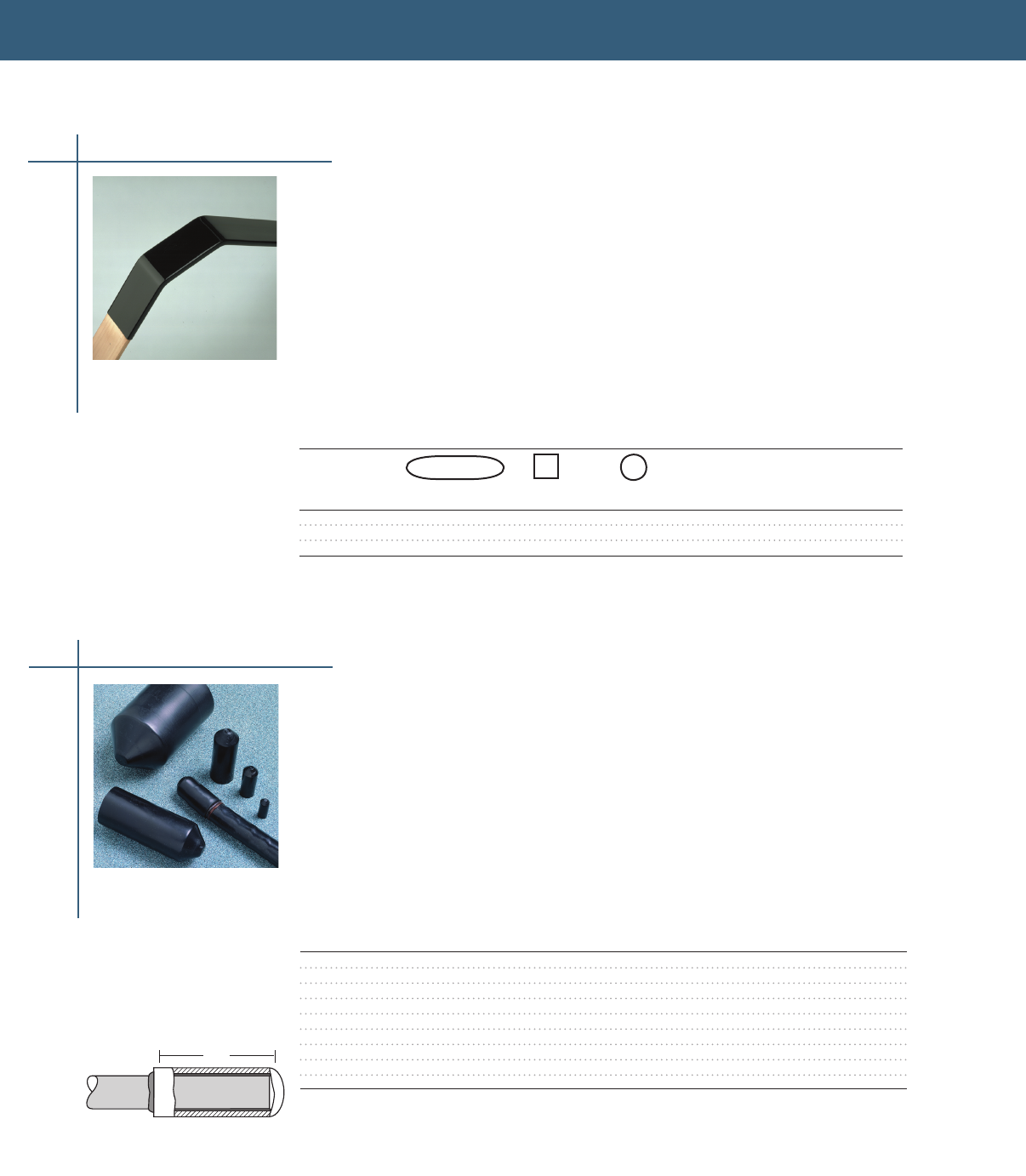
TUBINGS & MOLDED PARTS
112
Heat-Shrink Tubing
LVIT Tubing
Busbar Insulating Tubing (1000 V)
LVIT is a heat-shrinkable medium-wall, flame-retardant, low voltage tubing for insulating straight and
bent busbars during original equipment assembly or in retrofit applications where access to one end
of the busbar is available
When used according to the selection guidelines, LVIT may be used in applications up to 1 kV in
accordance with ANSI/IEEE C3720 specification LVIT tubing may be used in applications up to
36 kV in accordance with IEC specifications
Rated to ANSI/IEEE C37201-1987 UL recognized to Standard 224 (file E137416), 600 V-125°C-VW1
Selection Information: dimensions in inches (millimeters)
Busbar dimensions
LVIT Tubing Dia.
as Supplied &
Catalog Rectangular Bar* Square Bar Round Bar Fully Recovered Std.
Number (Bus Width) (Each Side) (Dia. Min.–Max.) (Min.–Max.) Pack
LVIT-30/10-A/U 050 – 10 (12 – 25) 040 – 10 (11 – 25) 118 – 039 (30 – 10) 200 ft
LVIT-75/25-A/U 20 – 30 (50 – 75) 1 (25) 10 – 20 (25 – 50) 295 – 098 (75 – 25) 100 ft
LVIT-150/50-A/U 40 – 60 (100 – 150) 2 – 3 (50–75) 20 – 40 (50 – 100) 591 – 197 (150 – 50) 100 ft
*Rectangular bus thickness range is 1/4 to 5/8 inch.
ESC Sealing Caps
End Sealing Caps for 1/C Power Cable (1000 V)
• Shrink and compress a hot-melt adhesive on the cable jacket, forming a secure environmental seal
• Fits easily over the cable end and shrinks in seconds, leaving a compact, rugged end seal
• Qualified to ANSI C1191-1986 and rated to ICEA electrical withstand test for 1000 volts
• For use on standard poly- or elastomeric insulated/ jacketed cables or lead-jacketed cables, which
may include aluminum or steel armoring
Use as a live end seal to 1000 volts Use as an end seal for storage and pulling of de-energized cable
Selection Information: dimensions in inches (millimeters)
Primary
Insulation
Conductor (1000 V) General Length Std.
Catalog Size Use Range Use Range as Pack
Number (AWG/kcmil) (Min.–Max.) (Min.–Max.) Supplied (Pcs/Box)
ESC-1/A #12 - #8 017 – 035 (4–9) 015 – 030 (4–8) 10 50
CPGI-ESC-1/A #12 - #8 0.17 – 0.35 (4–9) 0.15 – 0.30 (4–8) 1.0 25
ESC-2/A #6 – 3/0 031 – 071 (8–18) 030 – 070 (8–18) 20 50
CPGI-ESC-2/A #6 – 3/0 0.31 – 0.71 (8–18) 0.30 – 0.70 (8–18) 2.0 25
ESC-3/A 4/0 – 750 065 – 125 (17–32) 065 – 125 (17–32) 35 40
ESC-4/A 750 – 1500 108 – 194 (27–49) 105 – 195 (27–50) 53 20
ESC-5/A 1500 – 2000 138 – 258 (35–66) 130 – 265 (33–67) 67 10
ESC-6/A 194 – 354 (49–90) 185 – 370 (47–94) 56 10
ESC-7/A 302 – 425 (77–108) 295 – 450 (75–114) 54 10
*5 packs, each with 5 pcs. per Point of Purchase Package.
L
Each energized conductor
requires a separate ESC
sealing cap
Ordering information
1 Select the appropriate catalog number based on the conductor size or use range Confirm selection
with dimensions to assure proper sizing
2 Each energized conductor requires a separate ESC sealing cap
3 Bulk options also available Consult your Tyco Electronics representative for information
4 Caps are coated with an adhesive
5 Related test report: EDR-5161
Molded Parts
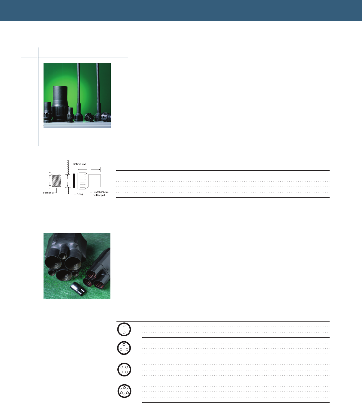
TUBINGS & MOLDED PARTS
TUBINGS & MOLDED PARTS
113
CFTS Seals
Heat-Shrink Cabinet Feed-Through Seals
CFTS seals are heat-shrinkable molded parts for moisture-sealing applications where cable enters
enclosures, such as cabinets or connection boxes
• Suitable for environments that have existing periodic pressure difference and/or
temperature differential
• Precoated with a thermoplastic adhesive that seals around the entering cable The O-ring
creates the water/air seal at the cabinet entry
• Utilizes a rigid plastic that, when inserted through the cabinet wall, protects the entering cable from
abrasion or cut-through
Selection Information: dimensions in inches (millimeters)
A
B
CBR products seal breakouts in multiconductor cables and conduit
These seals are made of tough, crosslinked polyolefin to provide mechanical protection and strain
relief CBR seals have an adhesive-coating on the body and the legs to form a durable watertight seal,
and conform tightly to conduits and cable jackets
For use on standard poly- or elastomeric insulated/jacketed multiconductor cables or cables in metal
or plastic conduits
Selection Information: dimensions in inches (millimeters)
CBR Breakout Boot
Heat-Shrink Cable Breakout Boots
Cross Body Use Range Legs Use Range
Section Catalog Number (Min. – Max.) (Min. – Max.) Std. Pack
CBR-2-1-A 035 – 100 (9 – 25) 015 – 055 (4 – 14) 3
CBR-2-2-A* 125 – 170 (32 – 43) 030 – 075 (8 – 19) 3
CBR-2-3-A 165 – 300 (42 – 76) 065 – 140 (17 – 36) 3
CBR-3-1-A 050 – 135 (13 – 34) 020 – 055 (5 – 14) 3
CBR-3-2-A* 085 – 220 (22 – 56) 035 – 090 (9 – 23) 3
CBR-3-3-A* 110 – 290 (28 – 74) 050 – 125 (13 – 32) 3
CBR-3-4-A 235 – 565 (60 – 144) 120 – 210 (30 – 53) 3
CBR-4-1-A 070 – 125 (18 – 32) 015 – 045 (4 – 11) 3
CBR-4-2-A* 100 – 210 (25 – 53) 035 – 090 (9 – 23) 3
CBR-4-3-A* 120 – 350 (30 – 89) 055 – 140 (14 – 36) 3
CBR-4-4-A 235 – 605 (60 – 154) 090 – 150 (23 – 38) 3
CBR-6-1-A* 145 – 385 (37 – 98) 060 – 150 (15 – 38) phase 3
030 – 075* (8 – 19) ground 3
CBR-6-2-A* 265 – 530 (67 – 135) 090 – 220 (23 – 56) phase 3
040 – 095* (10 – 24) ground 6
CBR-Plug** (for use only with asterisked items above) 6/Box
*CBR-Plugs are for blocking and sealing unused legs of breakouts. The plug will fit those items asterisked
(*) above
Molded Parts
A B
Cable Diameter Length of Clearance (Knockout)
Catalog Number (Min. – Max.) Molded Part Hole Size Std. Pack
CFTS-1 020 – 040 (5–10) 275 (70) 1 (25) 5
CFTS-2 025 – 065 (6–17) 275 (70) 1 (25) 5
CFTS-3 055 – 100 (14–25) 375 (95) 1 3/8 (35) 5
CFTS-4 080 – 145 (20–37) 450 (114) 2 (51) 5
CFTS-5 145 – 240 (37–61) 700 (178) 3 1/2 (89) 5

TUBINGS & MOLDED PARTS

TAPES & SEALANTS
Tapes
CRPS Repair Tape 117
FSTW Splicing Tape 118
LVBT Busbar Tape 119
Sealants
Hot-Melt and Cold-Applied Sealants 120
115

116
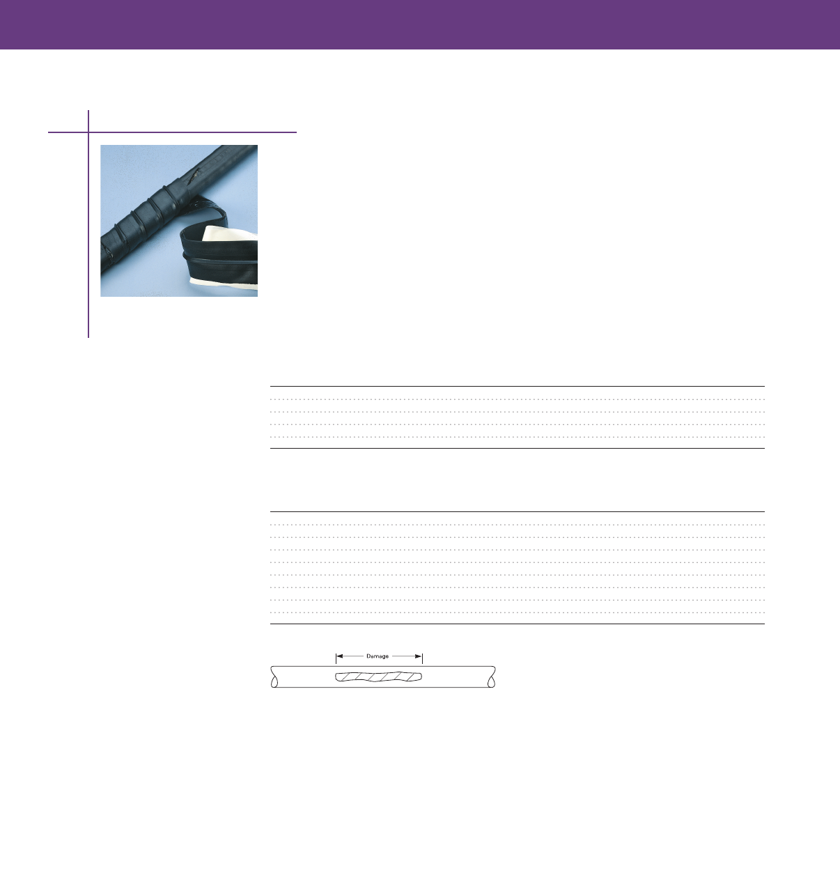
TAPES & SEALANTS
TAPES & SEALANTS
TAPES & SEALANTS
CRPS Repair Tape
Flexible Cable Repair Tape
Tyco Electronics’ CRPS repair strip is a high-quality replacement jacket for low and high voltage
flexible mining cables It is a tool-free, flexible, flame-retardant elastomeric strip that has been
specially formulated to provide excellent resistance to abrasion, tearing, and cutting
• Precoated with a thermoplastic sealant that provides an excellent seal against moisture and
corrosive elements
• MSHA approved (No P-137-13-MSHA)
• Tool-free, flexible, flame-retardant elastomeric strip for jacket repair on mining and other
flexible cables
Std. Pack
Catalog Number Strip Length Strip Width (Strips/Box)
CRPS-248 48 (1219) 2 (51) 20
CPGI-CRPS-248 48 (1219) 2 (51) 5
CRPS-260 60 (1524) 2 (51) 20
CRPS-290 90 (2286) 2 (51) 15
CRPS-2120 120 (3048) 2 (51) 10
Approximate Coverage Length
Cable Diameter CRPS-248 CRPS-260 CRPS-290 CRPS-2120
050 (13) 28 (711) 36 (914) 55 (1397) 73 (1854)
075 (19) 18 (457) 23 (584) 37 (940) 49 (1245)
100 (25) 14 (356) 17 (432) 26 (660) 35 (889)
125 (32) 11 (279) 14 (355) 21 (533) 28 (711)
150 (38) 9 (229) 11 (279) 18 (457) 24 (610)
175 (44) 7 (178) 9 (228) 15 (381) 20 (508)
200 (51) 8 (203) 14 (356) 19 (483)
250 (64) 10 (254) 13 (330)
300 (76) 9 (229) 12 (305)
Selection Information: dimensions in inches (millimeters)
Tapes
117
Recommended coverage area includes 3 inches on either side of damaged area.
Ordering Information
1 Select the appropriate catalog number based on cable diameter and length of cable damage to
be covered (see “Approximate coverage length” chart above) For larger damaged areas, multiple
strips may be used to provide continuous coverage
2 To install, half-lap CRPS repair strip on cable, beginning 3 inches before damage and continuing
3 inches after damage
3 CRPS repair strip is pre coated with a thermoplastic sealant
4 Related test report: EDR-5068

TAPES & SEALANTS
FSTW Splicing Tape
Fast Splicing Tape Wrap
Tyco Electronics’ FSTW is a thermoplastic rubber tape combined with a butyl rubber sealant specially
formulated for underground applications FSTW is ideal for repairing cable jackets, sealing low-voltage
splices, and rejacketing MV cable splices
This tape provides a complete rejacketing solution in one pass as opposed to the multi-layer
construction required when using traditional tape products It’s quick to install There is no need for
separate sealing mastic and tape as it combines sealant and rubber tape in one convenient product
FSTW rubber tape is made 50 mils thick, which offers strong puncture resistance from underground
material and debris FSTW is rated for use on 90°C rated cables, in underground use, in acid or caustic
soils, and saltwater environments It is UV resistant and rated for aerial exposure
Mastic is in contact with cable surface only at ends which allows for easy removal
Splices made with FSTW quality to ANSI C1191
Selection Information: dimensions in feet (meters)
Catalog Number Roll Width Roll Length Std Pk.
CPGI-FSTW-2-1-4 2 (50) 4' (1.2) 5
FSTW-2-1-6 2 (50) 6' (18) 12
118
Tapes
Ordering Information
1 See the approximate coverage length per roll based on cable diameter
2 For repairing cable jackets, install the FSTW tape beginning 2" before the damage and continuing 1"
after the damage
3 FSTW is 2" (50) wide
4 Related test reports: EDR-5431, EDR-5360
Approximate Coverage Length
Catalog Diameter CPGI-FTSW-2-1-4 FTSW-2-1-6
050 (13) 28 (710) 42 (1000)
075 (19) 18 (460) 27 (680)
100 (25) 14 (355) 21 (530)
125 (32) 11 (280) 17 (430)
150 (38) 9 (230) 14 (355)
175 (44) 7 (180) 10 (280)
200 (51) 6 (150) 9 (230)
250 (63) 7 (180)
300 (76) 6 (150)
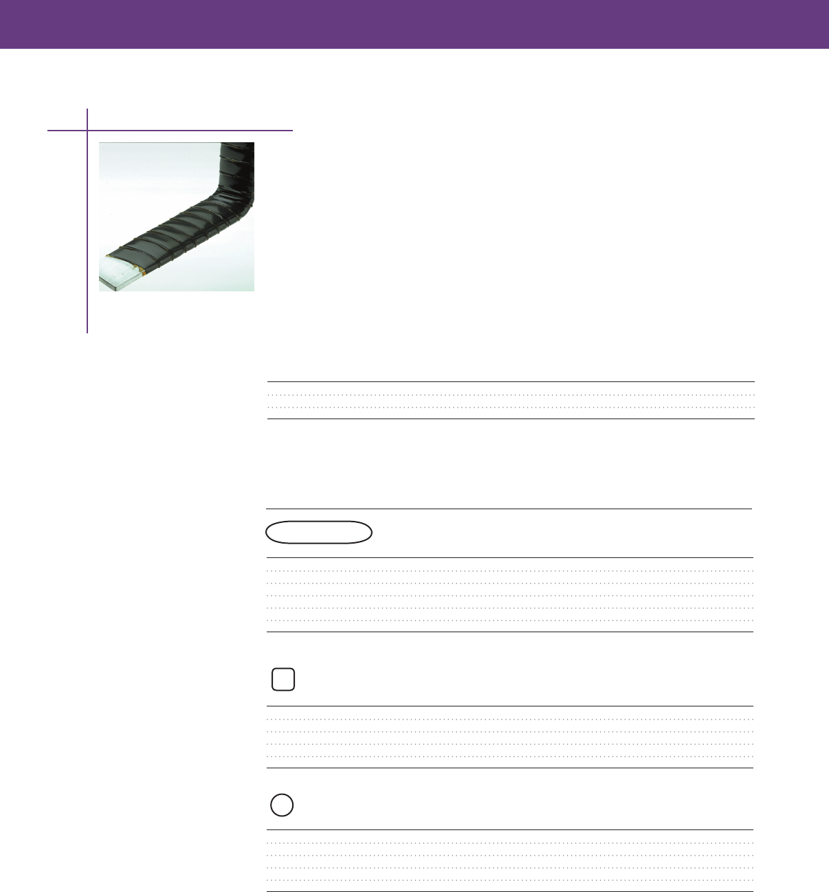
TAPES & SEALANTS
TAPES & SEALANTS
LVBT Busbar Tape
Low-Voltage Busbar Insulating Heat-Shrink Tape (1000 V)
LVBT is an adhesive-coated, low-voltage heat-shrinkable tape One wrap insulates straight and bent
bars in retrofit applications where tubing cannot be used In addition, LVBT easily insulates unusual
connections and geometries in the factory or field
• Adhesive layer fuses the tape layers but does not stick to bus or hardware, providing tough
insulation up to 1 kV in accordance with ANSI C3720–1987 and up to 36 kV in accordance with
IEC specifications
• Rated to ANSI/IEEE C3720-1987
• UL-recognized to Standard 224 (file E137417), 600 V-125°C-VW1
LVBT Tape Dimensions
Catalog Number Roll width Roll Length
LVBT-1-R 1 (25) 25 ft (75 m)
LVBT-2-R 2 (50) 25 ft (75 m)
LVBT-4-R 4 (100) 25 ft (75 m)
Selection Information: dimensions in feet (meters)
Bus Length Rolls/
Bus Width Catalog Number Insulated per Roll Std. Pack
Rectangular Busbar*
1 (25) LVBT-1-R 38 ft (12 m) 8
2 (50) LVBT-2-R 48 ft (15 m) 4
3 (75) LVBT-2-R 35 ft (11 m) 4
4 (100) LVBT-2-R 27 ft (08 m) 4
6 (150) LVBT-2-R 19 ft (06 m) 4
8 (200) LVBT-4-R 29 ft (09 m) 4
*Maximum thickness: 5/8 (15)
Square Busbar
1 (25) LVBT-2-R 625 ft (20 m) 4
2 (50) LVBT-2-R 31 ft (10 m) 4
3 (75) LVBT-2-R 20 ft (06 m) 4
4 (100) LVBT-4-R 31 ft (10 m) 2
6 (150) LVBT-4-R 20 ft (06 m) 2
Round Busbar
05 in (12 mm) LVBT-1-R 80 ft (26 m) 8
10 in (25 mm) LVBT-2-R 80 ft (26 m) 4
20 in (50 mm) LVBT-2-R 40 ft (13 m) 4
30 in (75 mm) LVBT-2-R 26 ft (09 m) 4
40 in (100 mm) LVBT-4-R 40 ft (13 m) 2
Ordering Information
1 LVBT-1-R is best for shorter lengths LVBT-2-R is the most versatile width for general purpose use
LVBT-4-R is useful for long lengths and larger bus sizes
2 If sealing is needed, order the S-1052-6-150 sealant strips
119
Tapes
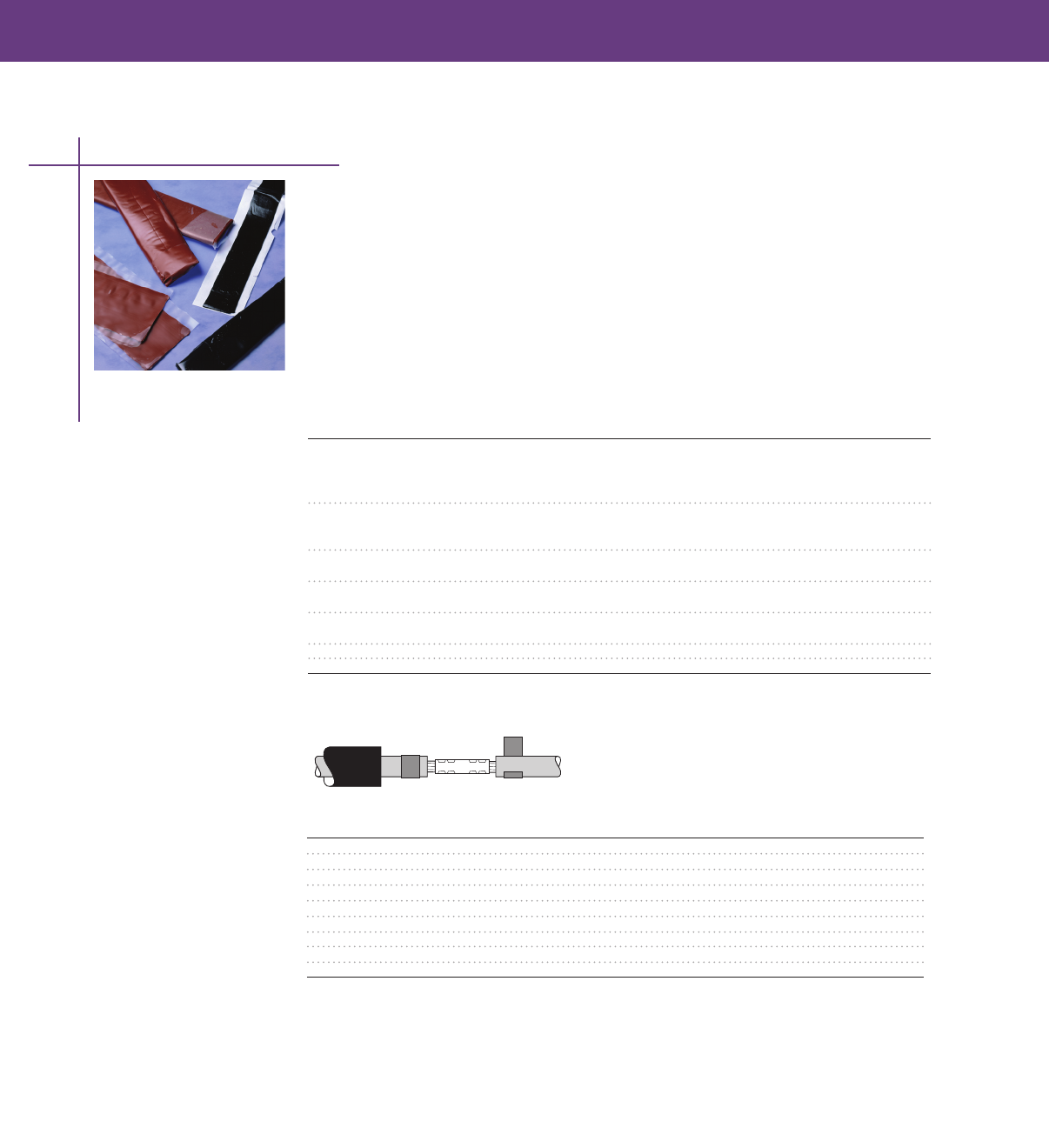
TAPES & SEALANTS
Hot-Melt and Cold-Applied Sealants
These adhesives are to be used for sealing the ends of uncoated tubing or for low-voltage
applications requiring void-filling The hot-melt sealants flow when heated and set when cooled to
provide a superior watertight seal The cold-applied sealants bond to surfaces when placed under
pressure to create a water-tight seal
Use sealants with uncoated tubing and molded parts for sealing applications or as an adhesion
enhancement for specific applications
Sealant Type Description Use with These Products:
S-1052 General purpose WCSM-A/U (uncoated),
low-voltage sealant MWTM-A/U (uncoated),
FCSM-A/U (uncoated),
LVBT, LVIT
S-1085 General purpose HVS (high-voltage splices),
high-voltage sealant HVT (high-voltage terminations),
MCK-5
S-1189 High-temperature, MCK
low-voltage sealant
S-1251 High-voltage BBIT, BPTM, HVBC, HVBT, HVIS
Raysulate electrical insulator sealant
S-1171 Low-voltage LV-MSK, HV-MSK
mining sealant
S-1278 Low-voltage sealant RDSS
GelWrap Pad Low-voltage PowerGel sealing gel GelWrap, GelWrap-RS closure
Selection Information
Ordering Information
1 Select the appropriate catalog number based on the application information in columns two and
three of the above table
2 Use the information in the table below for ordering
3 Sealants are supplied in bulk form with protective release paper
Catalog Number Color Dimensions (W x L x T) Std. Pack
S-1052-3-3000 Black Roll: 15 x 120 x 12 5 rolls/box
S-1171-4-300 Black Strip: 2 x 12 x 10 100 strips/box
S-1174-2-300 Black Strip: 5 x 12 x 09 25 strips/box
S-1174-4-460 Black Strip: 1 x 18 x 19 15 strips/box
S-1251-25-300-4 Red Strip: 1 x 12 x 150 25 strips/box
S-1251-50-300-1 Red Strip: 2 x 12 x 045 25 strips/box
S-1278-3 x 61 x 7620 Gray Roll: 24 x 300 x 12 1 roll/box
GelWrap Pad 2x8 Gray Strip: 2 x 8 x 18 6 strips/box
S-1189-3-600 Yellow
Sealants
120

PHOTOCONTROLS, TIMERS & ACCESSORIES
Thermal Photocontrols
AT Series 123
PT / SPT Series 123
TL Series 124
AA Series 124
LC Series 125
BF Series 125
M Series 126
Electronic Photocontrols
LM 1000 126
2000 Series127
3000 Series128
6000 Series 129
SST Series 130
Screw-In Photocontrols
Incandescent Light 130
Compact Fluorescent130
Time Controls
24 Hour Time Clocks 131
Spring Wound Interval Timers 131
Lighting Accessories
Shorting and Open Caps132
Receptacles AM Series132
Multiple Relays AMR Series132
US-30 Starter 133
121

122
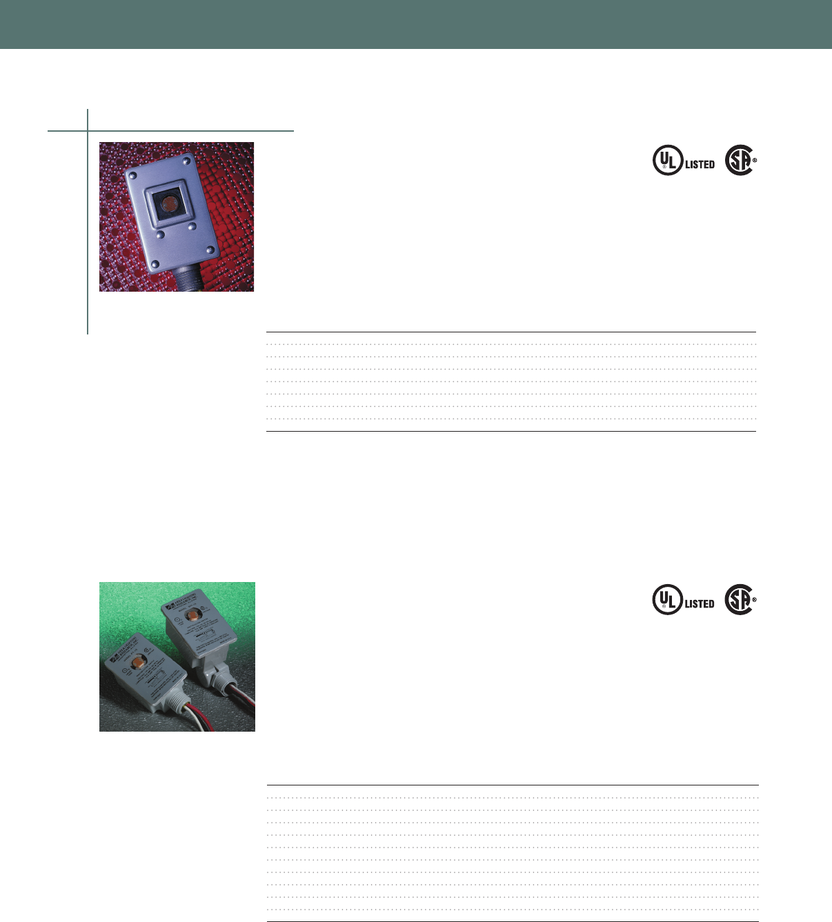
PHOTOCONTROLS, TIMERS & ACCESSORIES
PHOTOCONTROLS, TIMERS & ACCESSORIES
PT/SPT Series
Non-Metallic Housing
• Fixed or Adjustable Swivel Base
• Heavy Duty Thermal Bimetal Swivel
• UL and CSA Listed
• 30 - 45 Second Time Delay
• 2000 Watt Load Rating
• Fail Mode is ON
Selection information
PHOTOCONTROLS, TIMERS & ACCESSORIES
AT Series
Die-Cast Aluminum Housing
• Tough Die-Cast Aluminum Housing
• Heavy-Duty Thermal Bi-Metal Switch
• UL and CSA Listed
• 30-45 Second Time Delay
• 2000 & 3000 Watt Load Ratings
• Fail Mode is ON
Selection information
Load Rating Load Rating
Range Tungsten Ballast Turn ON OFF/ON
Model Rated Volts (Volts) (Watts) (VA) (Fc) Ratio
AT-15 120 105 - 130 2000 1900 15 6 : 1
AT-168 240 185 - 305 2000 1900 15 6 : 1
AT-19* 480 420 - 530 2000 1900 15 6 : 1
AT-20 120/208/240/277 105 - 305 2000 1900 15 6 : 1
AT-30* 120 105 - 130 3000 2900 15 6 : 1
AT-368* 240 180 - 305 3000 2900 15 6 : 1
AT-39* 480 420 - 530 3000 2900 15 6 : 1
Note: 6" Lead Wires
*Not: UL and CSA Listed
Load Load
Rating Rating Turn
Range Tungsten Ballast ON OFF/ON
Model Base Rated Volts (Volts) (Watts) (VA) (Fc) Ratio.
PT-15 Fixed 120 105 - 130 2000 1900 15 5 : 1
CPGI-ALR-PT-15 Fixed 120 105 - 130 2000 1900 1.5 5 : 1
PT-168 Fixed 240 185 - 305 2000 1900 15 5 : 1
PT-20 Fixed 120/208/240/277 105 - 305 2000 1900 15 5 : 1
PT-347** Fixed 347 310 - 380 2000 1900 15 5 : 1
SPT-15 Swivel 120 105 - 130 2000 1900 15 5 : 1
CPGI-ALR-SPT-15 Swivel 120 105 - 130 2000 1900 1.5 5 : 1
SPT-168 Swivel 240 185 - 305 2000 1900 15 5 : 1
SPT-19* Swivel 480 420 - 530 2000 1900 15 5 : 1
SPT-347** Swivel 347 310 - 380 2000 1900 15 5 : 1
Note: 6" Lead Wires
*Not UL Listed and CSA
** CSA Listed only
PT-15 SPT-15
Thermal Photocontrols
123
Certified
LR27428
156D
E45412
IND. CONT. EQ.
43BO
E79618
Certified
LR27428
156D
E45412
IND. CONT. EQ.
43BO
E79618

PHOTOCONTROLS, TIMERS & ACCESSORIES
TL Series
Slim Profile
• Adjustable Swivel Base
• Thinline Profile - Perfect for Tight Spots
• 30 - 45 Second Time Delay
• UL and CSA Listed
• Durable Polycarbonate Housing
• Fail Mode is ON
Selection information
Load Rating Load Rating
Rated Range Tungsten Ballast Turn ON OFF/ON
Model Volts (Volts) (Watts) (VA) (Fc) Ratio
TL-115 120 105 - 130 1800 1100 15 5 : 1
CPGI-ALR-TL-115 120 105 - 130 1800 1100 1.5 5 : 1
TL-1168 240 185 - 305 1200 1100 15 5 : 1
Note: 6" Lead Wires
AA Series
Button Style
• 3/4" Long Threaded Nipple
• 30 - 45 Second Time Delay
• UL and CSA Listed
• Durable Polycarbonate Housing
• 1800 and 1200 Watt Load Rating
• Fail Mode is ON
Selection information
Load Rating Load Rating Surge
Product Rated Range Tungsten Ballast Protection Turn ON OFF/ON
Model Information Volts (Volts) (Watts) (VA) (Joules) (Fc) Ratio
AA-105 120 105 - 130 1800 1100 15 5 : 1
CPGI-ALR-AA-105 120 105 - 130 1800 1100 1.5 5 : 1
AA-105W w/Wall Plate 120 105 - 130 1800 1100 15 5 : 1
CPGI-ALR-AA-105W w/Wall Plate 120 105 - 130 1800 1100 1.5 5 : 1
AA-1068 240 185 - 305 1200 1100 15 5 : 1
AA-1068W w/Wall Plate 240 185 - 305 1200 1100 15 5 : 1
AA-305 120 105 - 130 300 840 15 5 : 1
CPGI-ALR-AA-305 120 105 - 130 300 840 1.5 5 : 1
AA-105M 15" Leads 120 105 - 130 1800 1100 180 15 5 : 1
AA-1068M 15" Leads 240 185 - 305 1200 1100 180 15 5 : 1
AA-105HA High Ambiant 120 105 - 130 1800 1100 15 5 : 1
AA-LS* Light Shield
Note: 6" Lead Wires unless otherwise noted
* Not UL and CSA Listed
Thermal Photocontrols
124
Certified
LR27428
156D
E45412
IND. CONT. EQ.
43BO
E79618
Certified
LR27428
156D
E45412
IND. CONT. EQ.
43BO
E79618
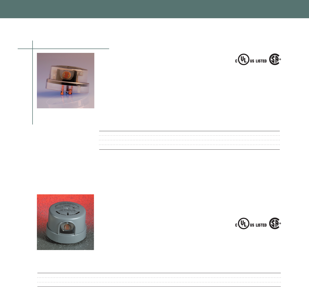
PHOTOCONTROLS, TIMERS & ACCESSORIES
PHOTOCONTROLS, TIMERS & ACCESSORIES
LC Series
Locking Style/Residential Grade
• Heavy-Duty Thermal Bi-Metal Switch
• 30 - 45 Second Time Delay
• UL and CSA Listed
• ANSI C13610 Compliant
• Fail Mode is ON
Selection information
Load Rating Load Rating
Rated Range Tungsten Ballast Turn ON OFF/ON
Model Volts (Volts) (Watts) (VA) (Fc) Ratio
LC-120 120 105 - 130 1000 1800 15 4 : 1
CPGI-ALR-LC-120 120 105 - 130 1000 1800 1.5 4 : 1
LC-208-277 240 185 - 305 1000 1800 15 4 : 1
CPGI-ALR-LC-208-277 240 185 - 305 1000 1800 1.5 4 : 1
BF Series
Locking Style/Industrial/Commercial Grade with Surge Protection
• 180 Joule MOV Surge Protection
• Heavy-Duty Thermal Bi-Metal Switch
• 30 - 45 Second Time Delay
• UL and CSA Listed
• ANSI C13610 Compliant
• Fail Mode is ON
Selection information
Load Rating Load Rating Surge
Range Tungsten Ballast Protection Turn ON OFF/ON
Model Rated Volts (Volts) (Watts) (VA) (Joules) (Fc) Ratio
BF-120 120 105 - 130 1000 1800 180 15 5 : 1
BF-208-277 240 185 - 305 1000 1800 180 15 5 : 1
BF-PV 120 / 208 / 240 / 277 105 - 305 1000 1800 180 15 5 : 1
Thermal Photocontrols
125
Certified
LR27428
128F
PHOTOCONTROL
E66375
Certified
LR27428
128F
PHOTOCONTROL
E66375
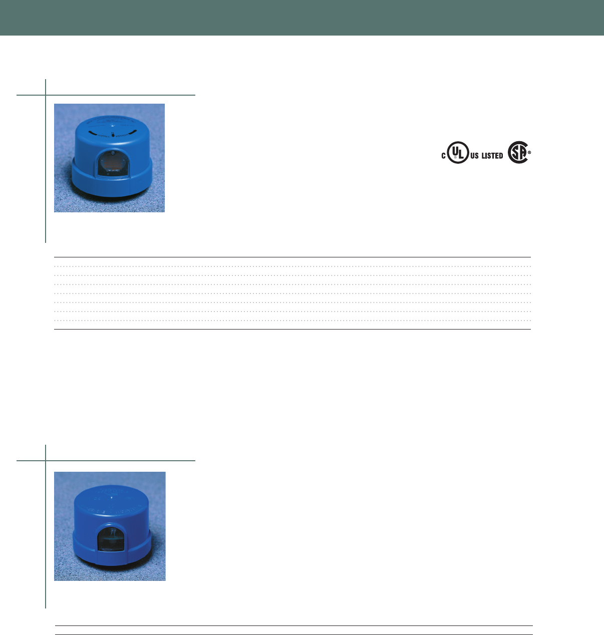
PHOTOCONTROLS, TIMERS & ACCESSORIES
M Series
Locking Style/Industrial Grade with Surge Protection
• Up to 360 Joule MOV Surge Protection
• Heavy-Duty Thermal Bi-Metal Switch
• 30 - 45 Second Time Delay
• UL and CSA Listed
• ANSI C13610 Compliant
• Fail Mode Is ON
Selection information
Load Rating Load Rating Surge
Range Tungsten Ballast Protection Turn ON OFF/ON
Model Rated Volts (Volts) (Watts) (VA) (Joules) (Fc) Ratio
M-120 120 105 - 130 1000 1800 180 15 5 : 1
M-208-277 240 185 - 305 1000 1800 180 15 5 : 1
M-480* 480 420 - 530 1000 1800 180 15 5 : 1
M-PV 120 / 208 / 240 / 277 105 - 305 1000 1800 180 15 5 : 1
M-347** 347 310 - 380 1000 1800 180 15 5 : 1
MH-120* 120 105 - 130 1000 1800 360 15 5 : 1
MH-208-277* 240 185 - 305 1000 1800 360 15 5 : 1
MH-PV* 120 / 208 / 240 / 277 105 - 305 1000 1800 360 15 5 : 1
* Not UL Listed and CSA
** CSA Listed Only
LM 1000
Time Off Lighting Control
• Programmable
• Built-in Daylight Savings Time Adjustment
• Resets Automatically After Power Outages
• 360 Joule MOV Surge Protection
• 2 - 5 Second ON and OFF Time Delay
• Rain-tight / Dust-tight Housing
• ANSI C13610 Compliant
• Fail Mode Is ON
Selection information
Load Rating Load Rating Surge
Range Tungsten Ballast Protection Turn ON OFF/ON
Model Rated Volts (Volts) (Watts) (VA) (Joules) (Fc) Ratio
LM-1000 120 / 208 / 240 / 277 105-305 1000 1800 360 50 15:1
Thermal Photocontrols
Electronic Photocontrols
Certified
LR27428
128F
PHOTOCONTROL
E66375
126

PHOTOCONTROLS, TIMERS & ACCESSORIES
PHOTOCONTROLS, TIMERS & ACCESSORIES
2000 Series
Electronic/Heavy Duty
• Heavy Duty Utility Grade Electronic
• 30 Amp Relay
• 180 or 360 Joule MOV Surge Protection
• 2-4 Second ON and OFF Time Delay
• Non-Drifting Phototransistor
• Rain-tight / Dust-tight Housing
• ANSI C13610 Compliant
• Fail Mode Is ON
• 2100 Series Has Inverse OFF/ON Ratio
2 0 60 - V P S - BK
Series (Fail Mode)
2 = 2000 (ON)
OFF/ON Ratio
0 = 15:1
1 = 06:1
Voltage
48 = 480
60 = 120
72 = 208/240/277
90 = 120/208/240/277
MOV Surge Protection
N = 180J, 320V, 3000A, 14mm
V = 360J, 320V, 10000A, 20mm
Cap Color
(Leave blank if ANSI Standard)
BL = Blue
BK = Black
BR = Brown (Bronze)
GN = Green
GR = Gray
MR = Maroon
YL = Yellow
Turn-On Level
1 = 10 Fc
S = 15 Fc (ANSI Std)
2 = 20 Fc
3 = 26 Fc
Light Sensor
P = Phototransistor
F = IR Filtered Phototransistor
Load Rating Load Rating Surge
Range Tungsten Ballast Protection Turn ON OFF/ON
Model Rated Volts (Volts) (Watts) (VA) (Joules) (Fc) Ratio
2060-NPS 120 105 - 130 1000 1800 180 15 +/- 05 15:1
2060-VPS 120 105 - 130 1000 1800 360 15 +/- 05 15:1
2090-NPS 120 / 208 / 240 / 277 105 - 305 1000 1800 180 15 +/- 05 15:1
CPGI-ALR-2090-NPS 120 / 208 / 240 / 277 105 - 305 1000 1800 180 1.5 +/- 0.5 1.5:1
Note: Custom models can be configured based on chart below.
Selection information
Electronic Photocontrols
ANSI Standard Colors
120V Gray
208 / 240 / 277V Maroon
120 / 208 / 240 / 277V Blue
480V Yellow
127

PHOTOCONTROLS, TIMERS & ACCESSORIES
3000 Series
Electronic/Heavy Duty/N.O. Contact
• Heavy Duty Utility Grade Electronic
• 30 Amp Relay
• 180 or 360 Joule MOV Surge Protection
• 2-4 Second ON and OFF Time Delay
• Non-Drifting Phototransistor
• Rain-tight / Dust-tight Housing
• ANSI C13610 Compliant
• Fail Mode Is OFF
• 3100 Series Has Inverse OFF/ON Ratio
3 0 90 - V P S - BK
Series (Fail Mode)
3 = 3000 (ON)
OFF/ON Ratio
0 = 15:1
1 = 06:1
Voltage
60 = 120
72 = 208/240/277
90 = 120/208/240/277
MOV Surge Protection
N = 180J, 320V, 3000A, 14mm
V = 360J, 320V, 10000A, 20mm
Cap Color
(Leave blank if ANSI Standard)
BL = Blue
BK = Black
BR = Brown (Bronze)
GN = Green
GR = Gray
MR = Maroon
YL = Yellow
Turn-On Level
1 = 10 Fc
S = 15 Fc (ANSI Std)
2 = 20 Fc
26 = 26 Fc
Light Sensor
P = Phototransistor
F = IR Filtered Phototransistor
Load Rating Load Rating Surge
Rated Range Tungsten Ballast Protection Turn ON OFF/ON
Model Volts (Volts) (Watts) (VA) (Joules) (Fc) Ratio
3090-NPS 120 / 208 / 240 /277 105 - 305 1000 1800 180 15 +/- 05 15:1
Note: Custom models can be configured based on chart below.
Selection information
Electronic Photocontrols
ANSI Standard Colors
208 / 240 / 277V Green
120 / 208 / 240 / 277V Blue
128
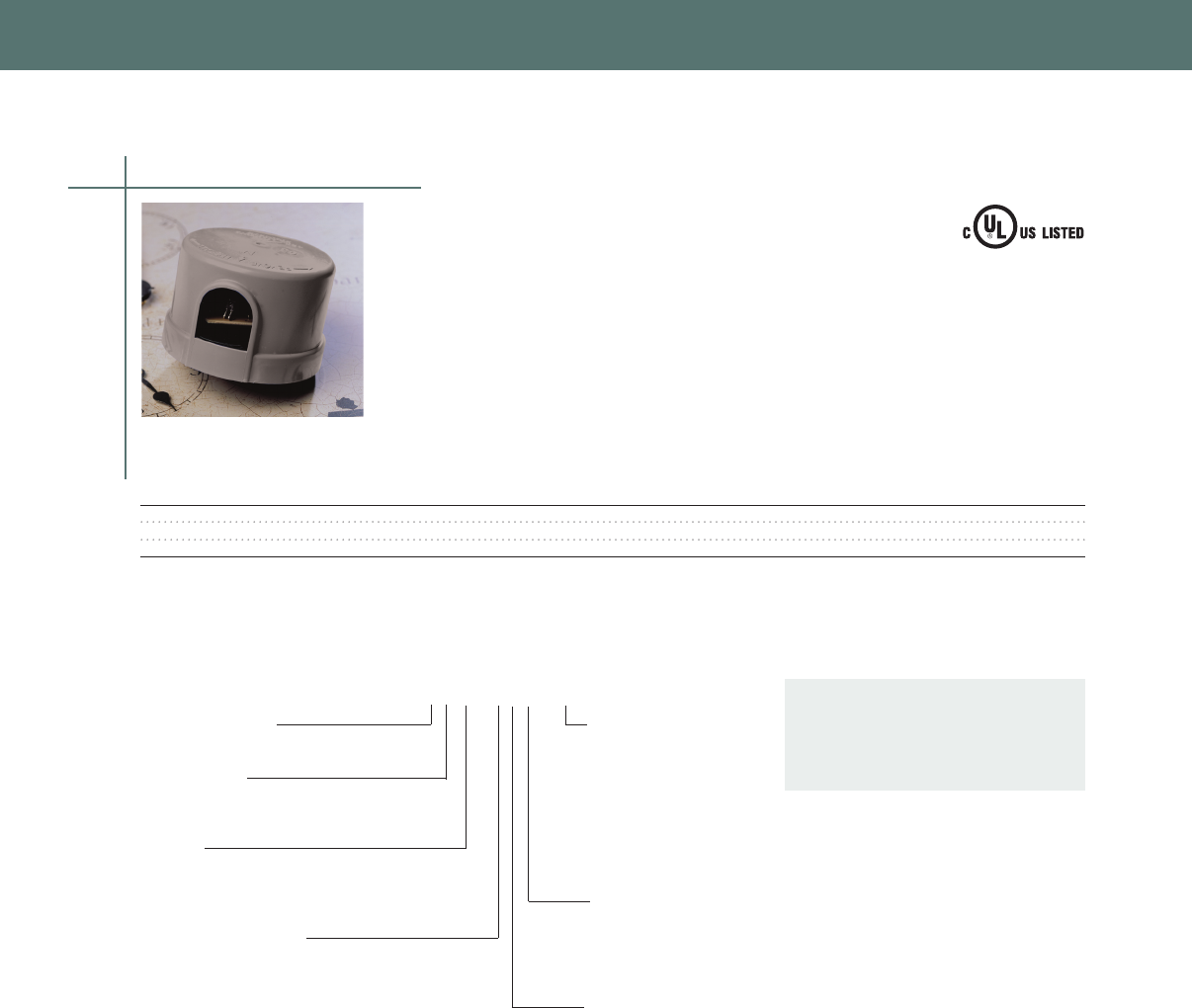
PHOTOCONTROLS, TIMERS & ACCESSORIES
PHOTOCONTROLS, TIMERS & ACCESSORIES
129
6000 Series
Electronic/Heavy Duty/Premium Grade
• 30 Amp Relay
• Long life, High Reliability
• Non-drifting phototransistor
• Instant ON / 2-5 Second OFF Time Delay
• Rain-tight / Dust-tight housing
• ANSI C13610 Compliant
• Fail Mode Is ON
• 6100 Series Has Inverse OFF/ON Ratio
6 0 90 - V P S - BK
Series (Fail Mode)
6 = 6000 (ON)
OFF/ON Ratio
0 = 15:1
1 = 06:1
Voltage
60 = 120
72 = 208/240/277
90 = 120/208/240/277
MOV Surge Protection
N = 180J, 320V, 3000A, 14mm
V = 360J, 320V, 10000A, 20mm
UL V Type= 545J, 510V, 13000A, 20mm
Cap Color
(Leave blank if ANSI Std)
BL = Blue
BK = Black
BR = Brown (Bronze)
GN = Green
GR = Gray
MR = Maroon
YL = Yellow
Turn-On Level
1 = 1.0 Fc
S = 1.5 Fc (ANSI Std)
2 = 2.0 Fc
3 = 2.6 Fc
Light Sensor
P = Phototransistor
F = IR Filtered Phototransistor
Selection information
Load Rating Load Rating Surge
Rated Range Tungsten Ballast Protection Turn ON OFF/ON
Model Volts (Volts) (Watts) (VA) (Joules) (Fc) Ratio
6060-VPS 120 105 -130 2000 1800 360 15 15:1
6090-VPS 120/240/277 105 - 305 2000 1800 360 15 15:1
6090-VPS-UL 120/208/240/277 105 - 305 1000 1800 545 15 15:1
Note: UL indicates a UL listed product
Note: Custom models can be configured based on chart below.
Electronic Photocontrols
ANSI Standard Colors
120V Gray
208 / 240 / 277V Maroon
120 / 208 / 240 / 277V Blue
480V Yellow
128F
PHOTOCONTROL
E66375
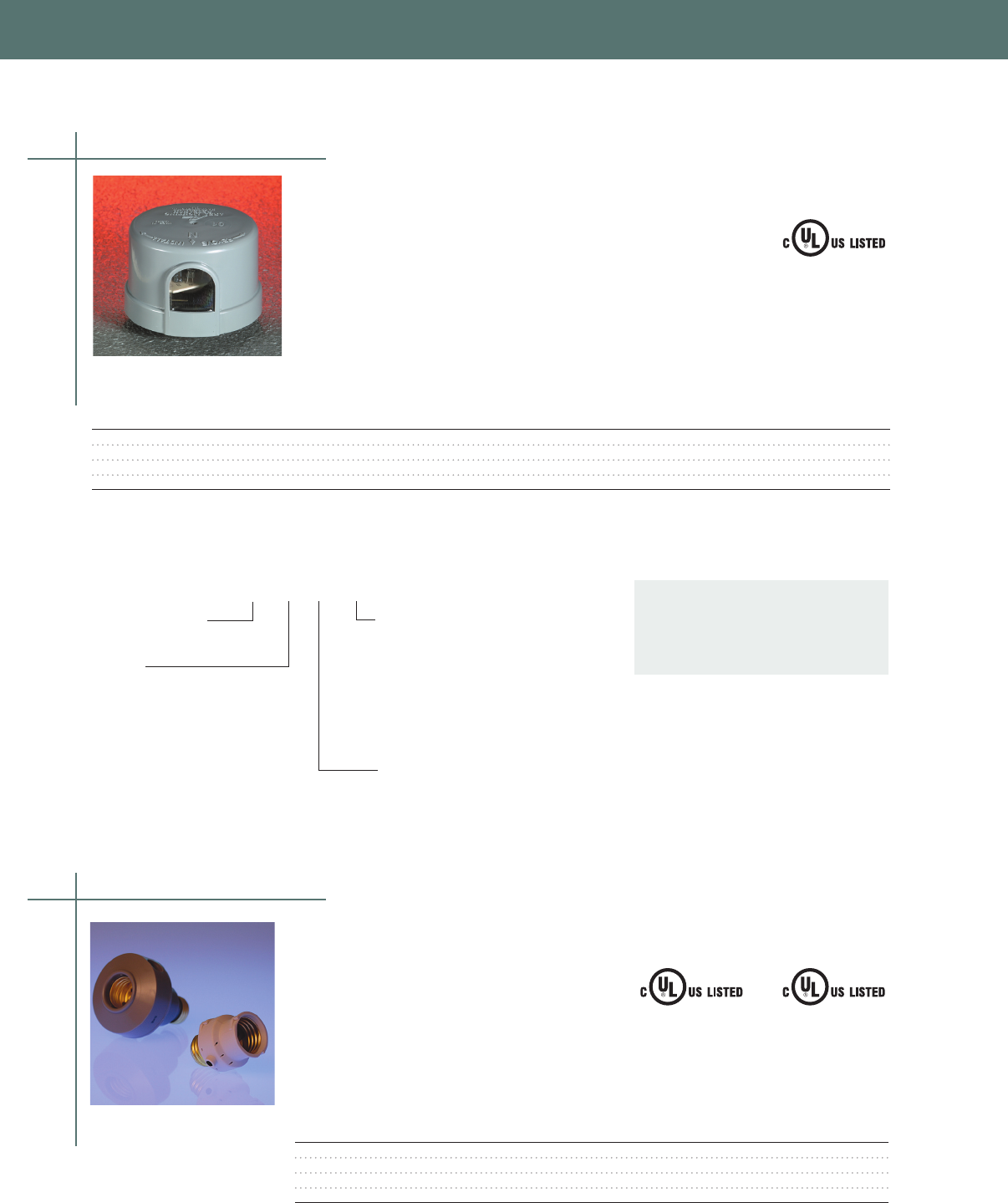
PHOTOCONTROLS, TIMERS & ACCESSORIES
Screw-In Photocontrols
Selection information
Load Rating Load Rating Surge
Range Tungsten Ballast Protection Turn ON OFF/ON
Model Rated Volts (Volts) (Watts) (VA) (Joules) (Fc) Ratio
SST-PV 120 / 208 / 240 / 277 105 - 305 1000 1800 180 15 +/- 05 06 : 1
SST-PV-UL 120 / 208 / 240 / 277 105 - 305 1000 1800 545 15 +/- 05 06 : 1
SST-PV-IES 120 / 208 / 240 / 277 105 - 305 1000 1800 180 30 +/- 05 06 : 1
SST-PV-IES-UL 120 / 208 / 240 / 277 105 - 305 1000 1800 545 30 +/- 05 06 : 1
Note: UL indicates a UL listed product
Note: Custom models can be configured based on chart above
SST Series
Electronic/Heavy Duty with Time Delay
• Energy Saving Inverse OFF/ON Ratio
• 30 Amp Relay / Microprocessor Controlled
• 180 Joule MOV Surge Protection
• Non-Drifting Phototransistor
• 30-45 Second ON and OFF Time Delay
• Rain-tight / Dust-tight Housing
• ANSI C13610 Compliant
• Fail Mode Is ON
SST - PV - IES - BK
Series (Fail Mode)
SST = SST (ON)
Voltage
120 = 120
240 = 240
PV = 120/208/240/277
Cap Color
(Leave blank if ANSI Std)
BL = Blue
BK = Black
BR = Brown (Bronze)
GN = Green
GR = Gray
MR = Maroon
YL = Yellow
Turn-On Level
(Leave blank if ANSI Std)
IES = 30
ANSI Standard Colors
120V Gray
208 / 240 / 277V Maroon
120 / 208 / 240 / 277V Blue
480V Yellow
130
Electronic Photocontrols
128F
PHOTOCONTROL
E66375
Screw-In/Plug-In | Incandescent and Compact
Fluorescent Lighting
Lighting Control
• Fast and simple to install
• Designed For Outdoor and Indoor Use
• Fail Mode is ON
• UL Listed
Selection information
Load Rating
Range Tungsten
Model Rated Volts (Volts) (Watts) Style Type
CPGI-ALR-PL-120S 120 105 - 130 150 Lamp Incandescent Only
CPGI-ALR-OLC-5C 120 105 - 130 150 Flood Incandescent Only
CPGI-ALR-CFL-FL 120 105 - 130 150 Flood Incandescent or CFL
CPGI-ALR-CFL-LP 120 105 - 130 150 Lamp Incandescent or CFL
Note: PL-120S and OLC-SC are not compatible with compact flourescent lamps.
INCANDESCENT
E63785
COMPACT FLUORESCENT
E96455
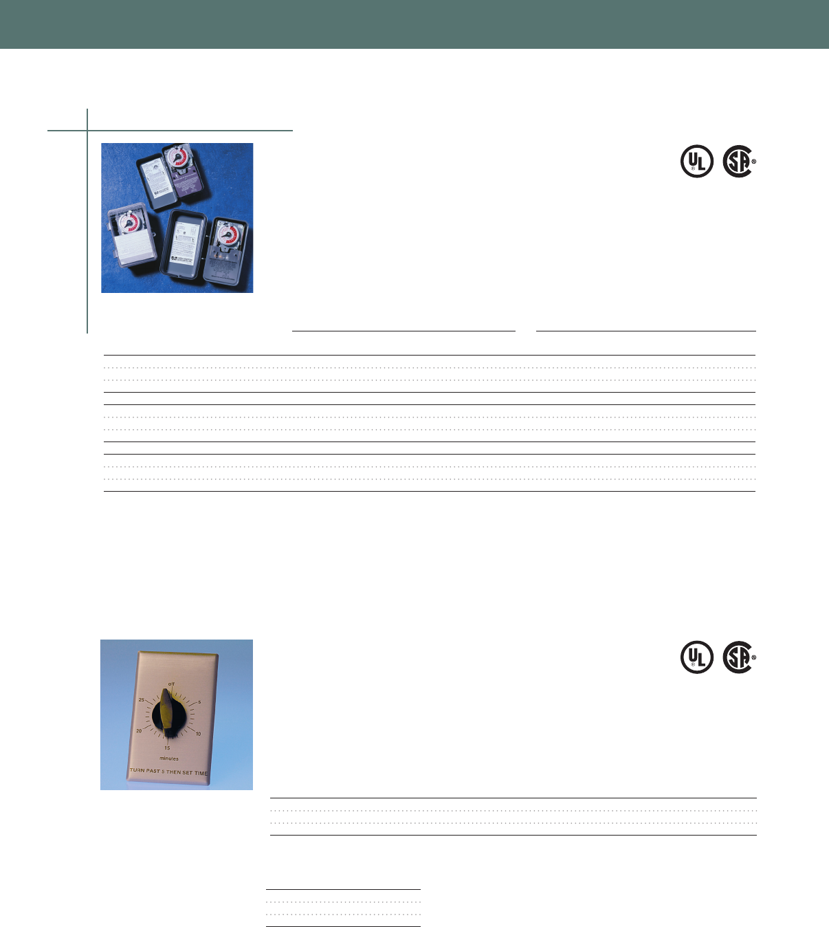
PHOTOCONTROLS, TIMERS & ACCESSORIES
PHOTOCONTROLS, TIMERS & ACCESSORIES
131
Time Clocks
24 Hour
• Tamper Proof Enclosure
• Skip-A-Day Option
• All-Steel Mechanism
• 1-7 ON/OFF Operations per Day
• Manual Override
• UL and CSA Listed
Switch Rating Per Pole Enclosure
Volts Type Height Width Depth
Model Use (60 Hz) Switch Amps Amps T VA HP (NEMA) (inches) (inches) (inches)
TC-101 Indoor 120 SPST 40 40 690 1 1 7-27/32 4-9/64 2-15/16
TC-103 Indoor 120 DPST 40 40 690 1 1 7-27/32 4-9/64 2-15/16
TC-104 Indoor 208-277 DPST 40 40 690 1 1 7-27/32 5-9/64 2-15/16
TC-101R Outdoor 120 SPST 40 40 690 1 3 9-5/8 5-3/8 3-11/16
TC-103R Outdoor 120 DPST 40 40 690 1 3 9-5/8 5-3/8 3-11/16
TC-104R Outdoor 208-277 DPST 40 40 690 1 3 9-5/8 5-3/8 3-11/16
PC-101R Outdoor 120 SPST 40 40 690 1 3R 8-1/2 5-5/8 3-7/8
PC-103R Outdoor 120 DPST 40 40 690 1 3R 8-1/2 5-5/8 3-7/8
PC-104R Outdoor 208-277 DPST 40 40 690 1 3R 8-1/2 5-5/8 3-7/8
Note Trippers Replacement Part X-2772
Interval Timers
Spring Wound
• Easy to Install 2-Wire Design
• 20 Amp Rating at 120 VAC
• UL and CSA Listed
• SPST
Selection information
Cycle NEMA Wall Box
Model Time Style / Color Wall Plate (Depth - inches) Amps Volts (AC)
FC-15M 15 min Brushed Aluminum Included 3 10 250
FC-30M 30 min Brushed Aluminum Included 3 10 277
FC-60M 60 min Brushed Aluminum Included 3 7 125*
* Tungsten
Switch Rating Specifications
Amps Volts (AC)
20 125, 50/60 Hz
10 250, 50/60 Hz
10 277, 50/60 Hz
Selection information
Time Controls
E79611
E79611
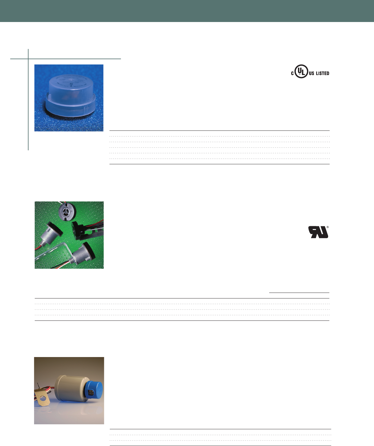
PHOTOCONTROLS, TIMERS & ACCESSORIES
Shorting and Open Caps
• Shorting and Non-Shorting Models
• Optional Surge Protection
• 120-480 VAC
Selection information
Load Rating Load Rating Surge
Cap Tungsten Ballast Protection
Model Circuit Type Color (Watts) (VA) (Joules)
SC-10A* Shorting Clear 1000 1800 -
SC-10ANSI** Shorting Black 1000 1800 -
MC-10 Shorting Black 1000 1800 360
MC-10ANSI** Shorting Black 1000 1800 360
NS-10 Open Maroon 1000 1800 -
NS-10ANSI** Open Red 1000 1800 -
* UL Listed
** ANSI C136.10-2006 Compliant
AM Series
Receptacles
• Phosphor Bronze Contacts
• Thermal-set Phenolic Base
• UL Recognized Component
Load Rating Load Rating Receptacle (inches)
Rates Ballast Ballast Flange Barrel Overall Lead Bracket (inches)
Model (Volts) (VA) (Amps) Diameter Diameter Height Length Width Depth Height
AM-1-A 120 - 480 1800 150 2-9/16 1-3/8 1-1/2 9 20 2-1/2 5-1/2
AM-1-A-NB 120 - 480 1800 150 2-9/16 1-3/8 1-1/2 9 - - -
AM-2-A 120 - 480 1800 150 2-9/16 - 3-1/3 6 1-1/2 3-1/2 5-1/2
AM-2-A-NB 120 - 480 1800 150 2-9/16 - 3-1/4 6 - - -
AMR Series
Multiple Relays
• Perfect for Group Control Applications
• 30 Amp per Pole Relay
• SPDT or DPST Switching
Selection information
Load Rating
Rates Range Ballast Rating Switch
Model (Volts) (Volts) (VA)/Pole (Amps) Switch Contacts
AMR30302-120V 120 105 - 130 3600 30 SPDT 1 NO/1 NC
AMR30303-120V 120 105 - 130 3600 30 DPST 2 NO
AMR30303-240V 240 204 - 260 7200 30 DPST 2 NO
Photocontrol sold separately
Selection information
Photocontrol Accessories
132
128F
PHOTOCONTROL
E66375

PHOTOCONTROLS, TIMERS & ACCESSORIES
PHOTOCONTROLS, TIMERS & ACCESSORIES
133
Lighting Accessories
US-30 Starter
• Universal 3-Wire Design
• Hermetically Sealed Components
• Durable ABS Housing
• Operates With 35 to 400 Watt HPS Ballasts
Selection information
Lamp Lamp
Model Lead Connector Voltage Wattage
US-30 None 50 or 100 35 - 400

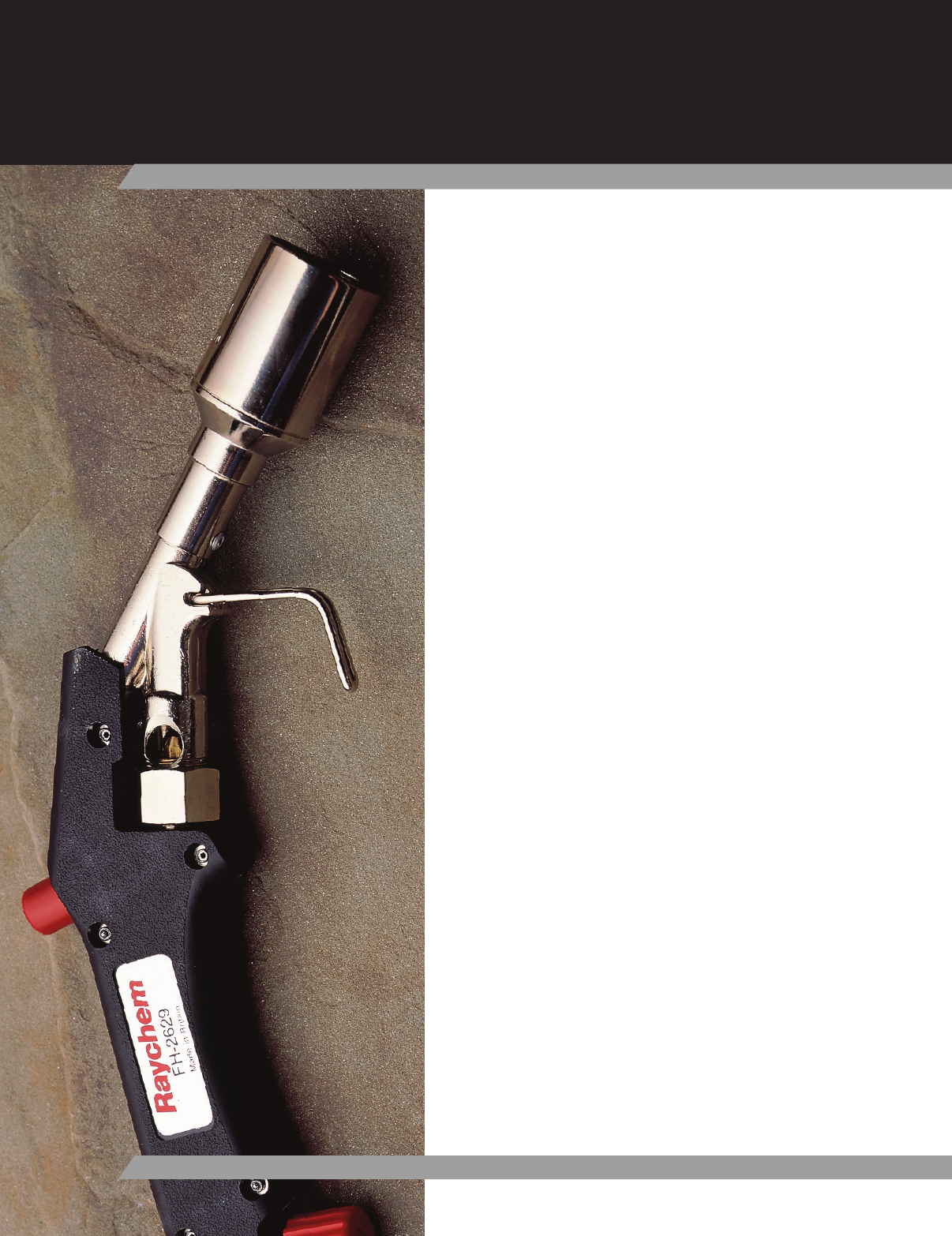
ACCESSORIES & TOOLS
Accessories
Cable Preparation Kit P63137
Heat Guns 137
Torches 137
Torches Accessories 139
Torch Kits139
Tools
Testing Tools 140
Impact Tools 140
Wire Strippers 141
Wire Cutters 141
All-Purpose Tools142
135

136
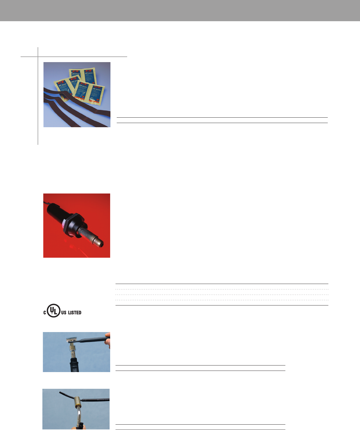
ACCESSORIES & TOOLS
ACCESSORIES & TOOLS
Heat Guns
ACCESSORIES & TOOLS
• P63 cable preparation kits can be used with all Tyco Electronics cable accessories
• Use P63 kits to clean and abrade cable insulation
Selection information
Catalog Number Std. Pack (kits/box)
P63 12
Ordering information
1 One kit contains six solvent wipes, six dry wipes and three strips of abrasive paper
2 For splices, the number of prep kits vary depending upon size of cable and type of splice For
terminations, one prep kit will clean three phases (one 3/C termination or three 1/C terminations)
3 Solvent wipes contain PT Technologies type PF cleaner
Cable Preparation Kit
P63
Accessories
137
• Ideal for shrinking small low-voltage products and identification marking sleeves
• Not recommended for shrinking high-voltage products or thick-wall low-voltage products
FH-PS-2001-Electric-Gun
Primus-Sievert model with increased air flow allows faster shrinking 120V, 1750 watt, 80°F - 1100°F,
Variable air flow: 21 cfm max, double insulated LED read out This heat gun can be used for shrinking
thick-wall low-voltage products
HG-501A-Thermogun 115 V
500°F – 750°F hot-air gun ideal for shrinking ShrinkMark or TMS marking products, and thin-wall
tubing Includes stand Reflector must be ordered separately
HG-751A-C-Thermogun 120 V
750°F – 1000°F hot-air gun for shrinking low-voltage and marking products Includes stand Reflector
must be ordered separately
Heat Gun Accessories
Catalog Number Description Std. Pack
TG-12 Reflector Use on tubing up to 3/4 inch in diameter 1
TG-13 Reflector Use on tubing up to 2 inches in diameter 1
TG-23 Reflector Use on tubing and cable breakouts up to 1 3/4 inches in diameter 1
TG-24 Reflector Use on tubing and cable breakouts up to 3 1/4 inches in diameter 1
• Portable and convenient with a powerful temperature rating
• Hand-held refillable heat gun with standard butane
• Automatic Piezo Electronics Ignition System
• Installs thin wall, dual wall and adhesive lined heat-shrink tubing and sleeves
Catalog Number Description Std. Pack
CPGI-GLOW-GUN Flameless Heat Gun 6
• Lightweight, portable, and ergonomic design
• Provides a wide-flame torch output for instant controlled heating
• Automatic Piezo Electronics Ignition System
• Attaches directly to 1 lb or 2 lb disposable propane bottles
• Installs thin wall, dual wall and adhesive lined heat-shrink tubing and sleeves
Catalog Number Description Std. Pack
CPGI-GLOW-TORCH Wide-Flame Torch 10
Heat Gun 16C6
ACCESSORIES & TOOLS
These clean-burning, efficient, heat-shrinking torches are recommended for shrinking high-voltage
products through low-voltage products
Selection information
Primus-Sievert Siever-Matic Torch Materials
FH-3366-97-PS-HANDLE
• Siever-Matic S auto ignite, auto shut-off torch handle
• Ergonomic design ensures comfortable operation
• Adjustable output
• Piezo ignition
FH-AD-3061-13-PS-REGULATOR
• Works with torch handle FH-3366-97-PS-HANDLE above
• Adjustable from 14-57psi
• Fitting POL, UNF 9/16” LH
• Requires torch hose AD-1432 or AD-1434
FH-AD-3347-91-PS-BURN-1
• Works with torch handle FH-3366-97-PS-HANDLE above
• Recommended especially for low voltage and general purpose products
• Tip diameter 10 inch 20,000BTU/hour
FH-AD-3341-91-PS-BURN1.5
• Works with torch handle FH-3366-97-PS-HANDLE above
• Recommended especially for low voltage products and high voltage terminations
and splices
• Tip diameter 15 inch 40,000BTU/hour
FH-AD-3348-91-PS-BURN-2
• Works with torch handle FH-3366-97-PS-HANDLE above
• Recommended especially for Raysulate products
• Tip diameter 20 inch 90,000BTU/hour
Bullfinch Torch Materials
FH-2629-TORCH ASSY
• Built-in ingnitor recommended for all products
• General purpose, heavy-duty propane torch with comfortable grip
• Provides a clean burning flame for shrinking high-voltage products or thick-wall
low-voltage products
• Output: Approximately 30,000 BTU/Hour
FH-2629-ELECTRODE
• Replacement ignitor for FH-2629 torch
Torches
Accessories
138
ACCESSORIES & TOOLS
ACCESSORIES & TOOLS
AD-1358-LPG-REGW/GAGE
• Propane tank regulator with gauge (0–30 psi)
• Can also be used with Primus-Sievert or BullFinch products
AD-1432-ACD10FT-LPG-HOSE
10-foot LPG hose
AD-1434-ACD30FT-LPG-HOSE
30-foot LPG hose
AD-1460-ACD-HEAT-SHLDGPA
• 12 x 40 pad woven of heat-resistant fabric with corner grommets
• Protects adjacent components from torch heat during installation of heat-shrinkable
products in confined areas
AD-1563-ADAPTER
• Valve to standard hose
• For use with FH-2618A-1 propane torch if disposable cylinders are not used
AD-3015-04
• Adapts Siever-Matic S FH-2649-PS-KIT or FH2629 for use with disposable 141 oz
propane cylinders
• Includes 4-foot hose and regulator preset at 28 psi
Torch Kits
FH-2618A-1
• Light, portable propane torch for installing low-voltage products and smaller,
conductor-sized, high-voltage (up to 15 kV) accessories
• Includes hose, handle assembly, and regulator for disposable propane cylinder
• Operates from disposable 141 oz propane cylinders
• Output: Approximately 20,000 BTU/hour
• Handle and torch head not available separately
• Regulator and hose assembly is product AD-3015-04
FH-2629-Kit
• Includes (AD-1432) 10 foot hose, (AD-1358) adjustable regulator, and
(FH-2629-TORCH-ASSY) torch handle and tip
FH-2640-PS-KIT
• Primus-Sievert torch kit for use with disposable propane bottles
• Includes (FH-3366-97-PS-HANDLE, FH-AD-3341-91-PS-BURN15, & AD-3015-04)
FH-2649-PS-KIT
• Seiver-Matic S auto ignite, auto shut-off torch system
• Recommended especially for Raysulate products and can be used with all products
• Includes ergonomic handle, 30 foot hose, adjustable regulator, and large burner
(3348-91); all in a canvas carrying bag
• Output: Approximately 90,000 BTU/hour
• Smaller burner and adapter for disposable bottles available - includes
FH-3366-97-PS-HANDLE , FH-AD-3348-91-PS-BURN-2, FH-AD-3061-13-PS-REGULAT,
AD-1434-ACD30FT-LPG-HOSE, and a carrying bag
Torch Accessories
Accessories
139
ACCESSORIES & TOOLS
Testing Tools
Tone Tracer 1490533-1
• Permits wire and cable identification without direct metallic contact
• Ergonomic design
• Can be used with any tone generator
• Quick change tips available
• Also available in a Tone Generator/Tracer Kit, 1673606-1
4-Pair Tester 1490530-1
• Test for opens, shorts, mis-wires, reversals, and split pairs
• Auto-on/auto-off
• Battery low indicator
Tone Generator 1490531-1
• Three built-in tones
• Auto-off
• Separate talk battery for increased voltage and power for test sets
• Modular jack allows multiple cord sets to be used for different applications
• Also available in a Tone Generator/Tracer Kit, 1673606-1
Butt Set 1490532-1
• LCD display shows: on-hook voltage, number dialed, off-hook
current, called ID, stored numbers, etc
• Tone and pulse dialing
• Modular cord set attachment
• Auto-off
Impact Tools
Impact Tool 1583608-2
• Non-slip rubber grips on handle
• Blade storage in rear of tool
• Tool with 110 blade: 158608-1
• Replacement 110 Blade: 1583609-1
Premium Impact Tool 1583694-2
• Light system, pick, hook and spudger
• Non-slip rubber grips on handle
• Blade storage in rear of tool
• Adjustable Hi/Lo impact setting
• Accepts all Twist and Lock blades
• Tool with 110 Blade: 1583694-1
Non-Impact Tool 1583236-2
• Rubber palm grip
• Blade storage area in side of tool
• Accepts all Twist and Lock blades
• Replacement 110 Blade: 1583609-1
• Tool with 110 Blade: 1583694-1
Tools
140
ACCESSORIES & TOOLS
ACCESSORIES & TOOLS
Wire Strippers
Coax Stripper 1490490-1
• 3 blades designed to strip RG-6, 58, 59 cable in one step
• Replaceable blade cartridges
Cyclops Cable Stripper 1375317-1
• Outer sheath stripper
• Automatically adjusts to different cable thicknesses
• Works on cable diameters up to 11mm
Automatic Wire Stripper 734185-1
• Strips PVC, THHN, and THHW
• Adjustable wire stop
• Built-in cutter
Wire Cutters
350 MCM Cutter 605744-1
• Steel handles
• Not for steel or ACSR cable
500 MCM Cutter 605742-1
• 21" overall length
• Fiberglass handles
• Not for steel or ACSR cable
Tools
141
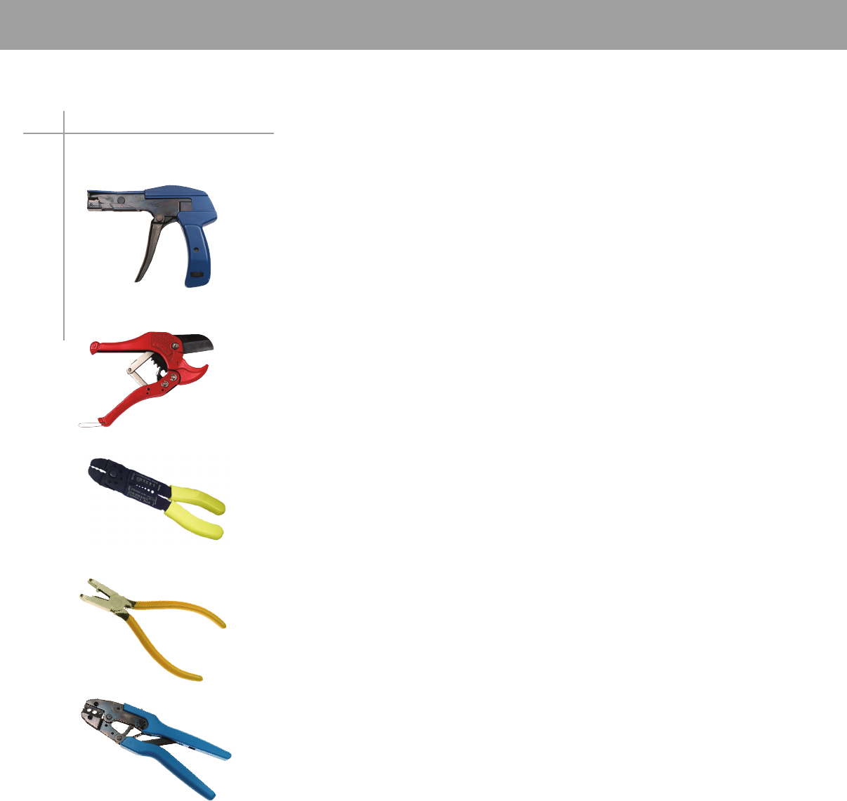
ACCESSORIES & TOOLS
All-Purpose Tools
Cable Tie Gun 734587-1
• For cable ties 33 - 48mm
• Thickness up to 16mm
• Automatic cut-off
• Adjustable tension setting
Raceway Cutting Tool 1375479-1
• Cuts surface mount raceway to length
• Cuts PVC tubing up to 125” in diameter
SUPER CHAMP 696201-1
• Economy Crimper
• Great for bolt cutting, wire stripping
• Convenient for tool boxes and repair kits
Tel-Splice Pliers 790162-1
• Works with all Tel-Splice part numbers
• Rounded nose won’t snag on wires
• Wire cutter built into side
• Yellow handles
• Spring loaded handles
Ratcheted Crimp Tool
• Tool with die: RBY Terminals 1490496-2
Coax Terminals 1490496-3
• Interchangeable with Ideal dies
• Ratchet release lever
• Easy clean plastic handles
Tools
142

APPLICATIONS AND
TECHNICAL SPECIFICATIONS
Technical Data
CMA/mm2 Calculation for Wire Connectors 145
Applications by Cable Type 150
Low Voltage Tubing And Wraparound Sleeves151
Termination 155
143

144
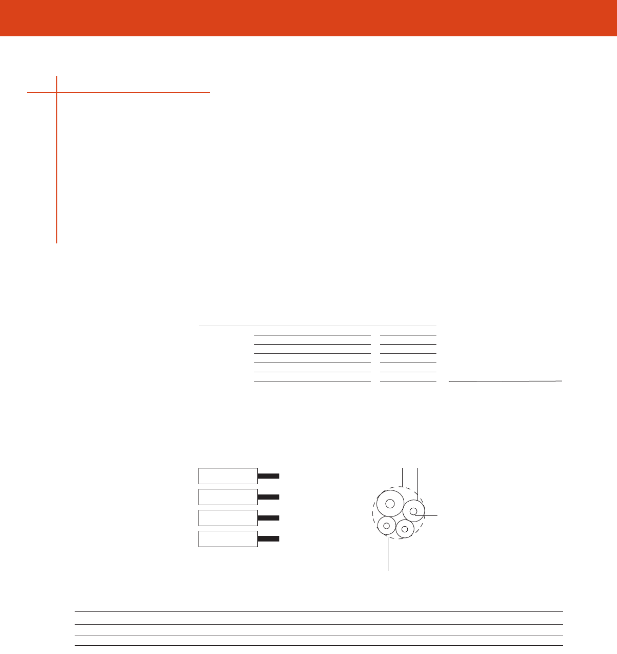
CMA/MM2 Calculation
APPLICATION AND TECHNICAL SPECIFICATIONS
145
CMA (Circular Mil Area) The unit for expressing the cross-sectional area of a conductor Equal to the diameter of a conductor
strand (expressed in mils) squared, times the number of strands
CMA/mm2 Calculation for Wire Connectors
Calculating the total circular mil or mm2 area of the conductors to be terminated in a single splice can
be done by following these steps
Step One
Choose either CMA or mm2 as your unit of measure for selection purposes and continue to use it for
all your selection criteria
Step Two
In the workspace provided below, list the CMA or mm2 for each conductor that will go into the same
splice (to assist you Table A on the bottom of this page provides the CMA of typical conductors)
Step Three
Add together the values listed in the workspace below to obtain the total area
Step Four
From the appropriate product table select the part number recommended for the total CMA or mm2
you have calculated
Wire Number CMA mm2
1
2
3
4
5
Total Part Number:
AWG 30 28 26 24 22 20 18 16 14 12 10 8
CMA 112 177 304 475 754 1216 1900 2426 3831 5874 9354 16983
mm2 0.05 0.09 0.15 0.24 0.38 0.61 0.95 1.21 1.92 2.94 4.74 8.61
Table A.
CMA/mm2 Example
22 AWG/.38
CMA 754
OD Bundle Insulation
Conductor
Bundle diameter must not
exceed 6.0 mm (0.24 in) for
SGRP-2 or 0.18 mm (4.5 in)
for SGRS-2.
To tal CMA= 5834
Total mm2 = 2.92
Correct part number (based on CMA of 5834
or mm
2of 2.92): SGRP-2or SGRS-2
22 AWG/.38
CMA 754
18 AWG/.95
CMA1900
16 AWG/1.21
CMA2426
CMA/mm2 Example
CMA/MM2 Calculation

APPLICATION AND TECHNICAL SPECIFICATIONS
Wire Part Wire Part Wire Part
Combinations Number Combinations Number Combinations Number
1 # 8 SGRT-4-XX 1 # 12 + 1 # 16 + 4 # 18 SGRT-4-XX 1 # 14 + 4 # 20 SGRT-3-XX
1 # 8 + 1 # 16 SGRT-4-XX 1 # 12 + 2 # 16 SGRT-3-XX 1 # 14 + 1 # 18 SGRT-2-XX
2 # 8 + 2 # 16 SGRT-4-XX 1 # 12 + 2 # 16 + 1 # 18 SGRT-3-XX 1 # 14 + 1 # 18 + 1 # 20 SGRT-3-XX
1 # 8 + 1 # 14 SGRT-4-XX 1 # 12 + 2 # 16 + 2 # 18 SGRT-4-XX 1 # 14 + 2 # 18 SGRT-3-XX
1 # 10 SGRT-3-XX 1 # 12 + 3 # 16 SGRT-4-XX 1 # 14 + 3 # 18 SGRT-3-XX
1 # 10 + 1 to 3 # 18 SGRT-3-XX 1 # 12 + 4 # 16 SGRT-4-XX 1 # 14 + 4 # 18 SGRT-3-XX
1 # 10 + 2 # 18 SGRT-3-XX 1 # 12 + 5 # 16 SGRT-4-XX 1 # 14 + 5 # 18 SGRT-4-XX
1 # 10 + 3 # 18 SGRT-4-XX 1 # 12 + 1 # 14 + 1 # 18 SGRT-3-XX 1 # 14 + 1 # 16 SGRT-3-XX
1 # 10 + 1 # 16 SGRT-3-XX 1 # 12 + 1 # 14 + 2 # 18 SGRT-4-XX 1 # 14 + 1 # 16 + 1 # 20 SGRT-3-XX
1 # 10 + 1 # 16 + 1 # 18 SGRT-4-XX 1 # 12 + 1 # 14 + 3 # 18 SGRT-4-XX 1 # 14 + 1 # 16 + 1 # 18 SGRT-3-XX
1 # 10 + 1 # 16 + 2 # 18SGRT-4-XX 1 # 12 + 1 # 14 + 1 # 16 SGRT-3-XX 1 # 14 + 1 # 16 + 2 # 18 SGRT-3-XX
1 # 10 + 2 # 16 SGRT-4-XX 1 # 12 + 1 # 14 + 2 # 16 SGRT-4-XX 1 # 14 + 1 # 16 + 3 # 18 SGRT-3-XX
1 # 10 + 3 # 16 SGRT-4-XX 1 # 12 + 1 # 14 + 3 # 16 SGRT-4-XX 1 # 14 + 1 # 16 + 4 # 18 SGRT-4-XX
1 # 10 + 4 # 16 SGRT-4-XX 1 # 12 + 1 # 14 + 4 # 16 SGRT-4-XX 1 # 14 + 2 # 16 SGRT-3-XX
1 # 10 + 5 # 16 SGRT-4-XX 1 # 12 + 2 # 14 SGRT-4-XX 1 # 14 + 2 # 16 + 1 # 18 SGRT-3-XX
1 # 10 + 1 # 14 SGRT-3-XX 1 # 12 + 2 # 14 + 1 # 18 SGRT-4-XX 1 # 14 + 2 # 16 + 2 # 18 SGRT-3-XX
1 # 10 + 1 # 14 + 1 # 18 SGRT-4-XX 1 # 12 + 2 # 14 + 1 # 16 SGRT-4-XX 1 # 14 + 2 # 16 + 3 # 18 SGRT-4-XX
1 # 10 + 1 # 14 + 1 # 16 SGRT-4-XX 1 # 12 + 2 # 14 + 2 # 16 SGRT-4-XX 1 # 14 + 3 # 16 SGRT-3-XX
1 # 10 + 1 # 14 + 2 # 16 SGRT-3-XX 1 # 12 + 2 # 14 + 3 # 16 SGRT-4-XX 1 # 14 + 3 # 16 + 1 # 18 SGRT-3-XX
1 # 10 + 1 # 14 + 3 # 16 SGRT-4-XX 1 # 12 + 3 # 14 SGRT-4-XX 1 # 14 + 3 # 16 + 2 # 18 SGRT-4-XX
1 # 10 + 2 # 14 SGRT-4-XX 1 # 12 + 3 # 14 + 1 # 16 SGRT-4-XX 1 # 14 + 4 # 16 SGRT-4-XX
1 # 10 + 3 # 14 SGRT-4-XX 1 # 12 + 4 # 14 SGRT-4-XX 1 # 14 + 4 # 16 + 1 # 18 SGRT-4-XX
1 # 10 + 1 # 12 SGRT-4-XX 2 # 12 + 1 # 18 SGRT-4-XX 1 # 14 + 5 # 16 SGRT-4-XX
1 # 10 + 1 # 12 + 1 # 14 SGRT-4-XX 2 # 12 + 1 # 16 SGRT-4-XX 2 # 14 SGRT-3-XX
1 # 10 + 2 # 12 SGRT-4-XX 2 # 12 + 2 # 16 + 1 # 18 SGRT-4-XX 2 # 14 SGRT-3-XX
2 # 10 SGRT-4-XX 2 # 12 + 3 # 16 SGRT-4-XX 2 # 14 SGRT-3-XX
2 # 10 + 1 # 16 SGRT-4-XX 2 # 12 + 1 # 14 + 1 # 18 SGRT-4-XX 2 # 14 SGRT-3-XX
1 # 12 SGRT-3-XX 2 # 12 + 1 # 14 + 1 # 16 SGRT-4-XX 2 # 14 SGRT-3-XX
1 # 12 + 1 # 18 SGRT-3-XX 2 # 12 + 2 # 14 SGRT-4-XX 2 # 14 + 1 # 16 SGRT-3-XX
1 # 12 + 2 # 18 SGRT-3-XX 3 # 12 + 1 # 18 SGRT-4-XX 2 # 14 + 1 # 16 SGRT-3-XX
1 # 12 + 3 # 18 SGRT-3-XX 3 # 12 + 1 # 16 SGRT-4-XX 2 # 14 + 1 # 16 SGRT-3-XX
1 # 12 + 4 # 18 SGRT-4-XX 3 # 12 + 1 # 14 SGRT-4-XX 2 # 14 + 1 # 16 SGRT-3-XX
1 # 12 + 5 # 18 SGRT-4-XX 1 # 14 SGRT-2-XX 2 # 14 + 2 # 16 SGRT-3-XX
1 # 12 + 1 # 16 SGRT-3-XX 1 # 14 + 1 # 22 SGRT-2-XX 2 # 14 + 2 # 16 SGRT-3-XX
1 # 12 + 1 # 16 + 1 # 18 SGRT-3-XX 1 # 14 + 1 # 20 SGRT-2-XX 2 # 14 + 3 # 16 SGRT-4-XX
1 # 12 + 1 # 16 + 2 # 18 SGRT-3-XX 1 # 14 + 2 # 20 SGRT-3-XX 2 # 14 + 4 # 16 SGRT-4-XX
1 # 12 + 1 # 16 + 3 # 18 SGRT-4-XX 1 # 14 + 3 # 20 SGRT-3-XX 3 # 14 SGRT-3-XX
3 # 14 + 1 # 16 SGRT-4-XX 2 # 16 + 4 # 20 SGRT-3-XX 1 # 18 + 1 # 20 + 2 # 22 SGRT-2-XX
3 # 14 + 2 # 16 SGRT-4-XX 2 # 16 + 1 # 18 SGRT-3-XX 1 # 18 + 2 # 20 SGRT-2-XX
3 # 14 + 3 # 16 SGRT-4-XX 2 # 16 + 1 # 18 + 1 # 20 SGRT-3-XX 1 # 18 + 3 # 20 SGRT-2-XX
4 # 14 SGRT-4-XX 2 # 16 + 1 # 18 + 2 # 20 SGRT-3-XX 1 # 18 + 4 # 20 SGRT-3-XX
4 # 14 + 1 # 16 SGRT-4-XX 2 # 16 + 1 # 18 + 3 # 20 SGRT-3-XX 1 # 18 + 5 # 20 SGRT-3-XX
4 # 14 + 2 # 16 SGRT-4-XX 2 # 16 + 2 # 18 SGRT-3-XX 2 # 18 SGRT-2-XX
5 # 14 SGRT-4-XX 2 # 16 + 2 # 18 + 1 # 20 SGRT-3-XX 2 # 18 + 1 # 22 SGRT-2-XX
5 # 14 + 1 # 16 SGRT-4-XX 2 # 16 + 2 # 18 + 2 # 20 SGRT-3-XX 2 # 18 + 1 # 20 SGRT-2-XX
1 # 16 SGRT-2-XX 2 # 16 + 3 # 18 SGRT-3-XX 2 # 18 + 2 # 20 SGRT-3-XX
1 # 16 + 1 # 22 SGRT-2-XX 2 # 16 + 3 # 18 + 1 # 20 SGRT-3-XX 2 # 18 + 3 # 20 SGRT-3-XX
1 # 16 + 2 # 22 SGRT-2-XX 2 # 16 + 4 # 18 SGRT-3-XX 2 # 18 + 4 # 20 SGRT-3-XX
1 # 16 + 3 # 22 SGRT-2-XX 3 # 16 SGRT-3-XX 3 # 18 SGRT-2-XX
1 # 16 + 1 # 20 SGRT-2-XX 3 # 16 + 1 # 20 SGRT-3-XX 3 # 18 + 1 # 20 SGRT-3-XX
1 # 16 + 1 # 20 + 1 # 22 SGRT-2-XX 3 # 16 + 2 # 20 SGRT-3-XX 3 # 18 + 2 # 20 SGRT-3-XX
1 # 16 + 2 # 20 SGRT-2-XX 3 # 16 + 3 # 20 SGRT-3-XX 3 # 18 + 3 # 20 SGRT-3-XX
1 # 16 + 3 # 20 SGRT-3-XX 3 # 16 + 1 # 18 SGRT-3-XX 4 # 18 SGRT-3-XX
1 # 16 + 4 # 20 SGRT-3-XX 3 # 16 + 1 # 18 + 1 # 20 SGRT-3-XX 4 # 18 + 1 # 20 SGRT-3-XX
1 # 16 + 5 # 20 SGRT-3-XX 3 # 16 + 1 # 18 + 2 # 20 SGRT-3-XX 4 # 18 + 2 # 20 SGRT-3-XX
1 # 16 + 1 # 18 SGRT-2-XX 3 # 16 + 2 # 18 SGRT-3-XX 5 # 18 SGRT-3-XX
1 # 16 + 1 # 18 + 1 # 20 SGRT-2-XX 3 # 16 + 2 # 18 + 1 # 20 SGRT-3-XX 5 # 18 + 1 # 20 SGRT-3-XX
1 # 16 + 1 # 18 + 2 # 20 SGRT-3-XX 3 # 16 + 3 # 18 SGRT-3-XX 6 # 18 SGRT-3-XX
1 # 16 + 1 # 18 + 3 # 20 SGRT-3-XX 4 # 16 SGRT-3-XX 1 # 20 + 2 # 22 SGRT-2-XX
1# 16 + 1 # 18 + 4 # 20 SGRT-3-XX 4 # 16 + 1 # 20 SGRT-3-XX 1 # 20 + 3 # 22 SGRT-2-XX
1 # 16 + 2 # 18 SGRT-3-XX 4 # 16 + 2 # 20 SGRT-3-XX 1 # 20 + 4 # 22 SGRT-2-XX
1 # 16 + 2 # 18 + 1 # 20 SGRT-3-XX 4 # 16 + 1 # 18 SGRT-3-XX 2 # 20 SGRT-2-XX
1 # 16 + 2 # 18 + 2 # 20 SGRT-3-XX 4 # 16 + 1 # 18 + 1 # 20 SGRT-3-XX 2 # 20 + 1 # 22 SGRT-2-XX
1 # 16 + 2 # 18 + 3 # 20 SGRT-3-XX 4 # 16 + 2 # 18 SGRT-4-XX 2 # 20 + 2 # 22 SGRT-2-XX
1 # 16 + 3 # 18 SGRT-3-XX 5 # 16 SGRT-3-XX 2 # 20 + 3 # 22 SGRT-2-XX
1 # 16 + 3 # 18 + 1 # 20 SGRT-3-XX 5 # 16 + 1 # 20 SGRT-4-XX 3 # 20 SGRT-2-XX
1 # 16 + 3 # 18 + 2 # 20 SGRT-3-XX 5 # 16 + 1 # 18 SGRT-4-XX 3 # 20 + 1 # 22 SGRT-2-XX
1 # 16 + 4 # 18 SGRT-3-XX 6 # 16 SGRT-4-XX 4 # 20 SGRT-2-XX
SolderGrip Wire Combinations Self-Fixturing Insulated Ring Terminals
SolderGrip Wire Combinations
146
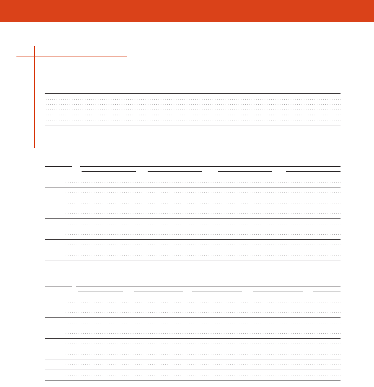
CMA/MM2 Calculation
APPLICATION AND TECHNICAL SPECIFICATIONS
Wire Part Wire Part Wire Part
Combinations Number Combinations Number Combinations Number
SolderGrip Wire Combinations Self-Fixturing Insulated Ring Terminals (Continued)
SolderGrip Wire Combinations SolderSleeve CWT Wire Splices
SolderGrip Wire Combinations
1 # 16 + 4 # 18 + 1 # 20 SGRT-3-XX 1 # 18 + 1 # 22 SGRT-2-XX 5 # 20 SGRT-3-XX
1 # 16 + 5 # 18 SGRT-3-XX 1 # 18 + 2 # 22 SGRT-2-XX 6 # 20 SGRT-3-XX
2 # 16 SGRT-2-XX 1 # 18 + 3 # 22 SGRT-2-XX 4 # 22 SGRT-2-XX
2 # 16 + 1 # 20 SGRT-3-XX 1 # 18 + 1 # 20 SGRT-2-XX 5 # 22 SGRT-2-XX
2 # 16 + 2 # 20 SGRT-3-XX 1 # 18 + 1 # 20 + 1 # 22 SGRT-2-XX 6 # 22 SGRT-2-XX
2 # 16 + 3 # 20 SGRT-3-XX — — — —
147
Side A: Side B: Size and Number of Conductors
Size & No. 26 AWG 26 AWG 22 AWG 20 AWG
of Conductors 1 2 1 2 1 2 1 2
26 AWG 1 CWT-9001 CWT-9001 CWT-9001 CWT-9001 CWT-9001 CWT-9002 CWT-9002 CWT-9002
2 CWT-9001 CWT-9001 CWT-9001 CWT-9002 CWT-9001 CWT-9002 CWT-9002 CWT-9002
24 AWG 1 CWT-9001 CWT-9001 CWT-9001 CWT-9001 CWT-9001 CWT-9002 CWT-9002 CWT-9002
2 CWT-9001 CWT-9002 CWT-9001 CWT-9002 CWT-9002 CWT-9002 CWT-9002 CWT-9002
22 AWG 1 CWT-9001 CWT-9001 CWT-9001 CWT-9002 CWT-9002 CWT-9002 CWT-9002 CWT-9002
2 CWT-9002 CWT-9002 CWT-9002 CWT-9002 CWT-9002 CWT-9002 CWT-9002 CWT-9003
20 AWG 1 CWT-9002 CWT-9002 CWT-9002 CWT-9003 CWT-9002 CWT-9002 CWT-9002 CWT-9003
2 CWT-9002 CWT-9002 CWT-9002 CWT-9002 CWT-9002 CWT-9003 CWT-9003 CWT-9003
18 AWG 1 CWT-9002 CWT-9002 CWT-9002 CWT-9002 CWT-9002 CWT-9002 CWT-9002 CWT-9003
2 CWT-9003 CWT-9003 CWT-9003 CWT-9003 CWT-9003 CWT-9003 CWT-9003 CWT-9003
16 AWG 1 CWT-9002 CWT-9002 CWT-9002 CWT-9002 CWT-9002 CWT-9003 CWT-9003 CWT-9003
2 CWT-9003 CWT-9003 CWT-9003 CWT-9003 CWT-9003 CWT-9003 CWT-9003 CWT-9003
14 AWG 1 CWT-9003 CWT-9003 CWT-9003 CWT-9003 CWT-9003 CWT-9003 CWT-9003 CWT-9003
2 CWT-9004 CWT-9004 CWT-9004 CWT-9004 CWT-9004 CWT-9004 CWT-9004 CWT-9004
12 AWG 1 CWT-9003 CWT-9003 CWT-9003 CWT-9003 CWT-9003 CWT-9003 CWT-9003 CWT-9004
2 CWT-9005 CWT-9005 CWT-9005 CWT-9005 CWT-9005 CWT-9005 CWT-9005 CWT-9005
10 AWG 1 CWT-9005 CWT-9005 CWT-9005 CWT-9005 CWT-9005 CWT-9005 CWT-9005 CWT-9005
Side A: Side B: Size and Number of Conductors
Size & No. 18 AWG 16 AWG 14 AWG 12 AWG 10 AWG
of Conductors 1 2 1 2 1 2 1 2 1
26 AWG 1 CWT-9002 CWT-9003 CWT-9002 CWT-9003 CWT-9003 CWT-9004 CWT-9003 CWT-9005 CWT-9005
2 CWT-9002 CWT-9003 CWT-9002 CWT-9003 CWT-9003 CWT-9004 CWT-9003 CWT-9005 CWT-9005
24 AWG 1 CWT-9002 CWT-9003 CWT-9002 CWT-9003 CWT-9003 CWT-9004 CWT-9003 CWT-9005 CWT-9005
2 CWT-9002 CWT-9003 CWT-9002 CWT-9003 CWT-9003 CWT-9004 CWT-9003 CWT-9005 CWT-9005
22 AWG 1 CWT-9002 CWT-9003 CWT-9002 CWT-9003 CWT-9003 CWT-9004 CWT-9003 CWT-9005 CWT-9005
2 CWT-9002 CWT-9003 CWT-9003 CWT-9003 CWT-9003 CWT-9004 CWT-9003 CWT-9005 CWT-9005
20 AWG 1 CWT-9002 CWT-9003 CWT-9003 CWT-9003 CWT-9003 CWT-9004 CWT-9003 CWT-9005 CWT-9005
2 CWT-9003 CWT-9003 CWT-9003 CWT-9003 CWT-9003 CWT-9004 CWT-9004 CWT-9005 CWT-9005
18 AWG 1 CWT-9003 CWT-9003 CWT-9003 CWT-9003 CWT-9003 CWT-9004 CWT-9004 CWT-9005 CWT-9005
2 CWT-9003 CWT-9003 CWT-9003 CWT-9004 CWT-9003 CWT-9004 CWT-9004 CWT-9005 CWT-9005
16 AWG 1 CWT-9003 CWT-9003 CWT-9003 CWT-9003 CWT-9003 CWT-9004 CWT-9004 CWT-9005 CWT-9005
2 CWT-9003 CWT-9004 CWT-9003 CWT-9004 CWT-9004 CWT-9005 CWT-9004 CWT-9005 CWT-9005
14 AWG 1 CWT-9003 CWT-9003 CWT-9003 CWT-9004 CWT-9003 CWT-9004 CWT-9004 CWT-9005 CWT-9005
2 CWT-9004 CWT-9004 CWT-9004 CWT-9005 CWT-9004 CWT-9005 CWT-9005 CWT-9005 CWT-9005
12 AWG 1 CWT-9004 CWT-9004 CWT-9004 CWT-9004 CWT-9004 CWT-9005 CWT-9004 CWT-9005 CWT-9005
2 CWT-9005 CWT-9005 CWT-9005 CWT-9005 CWT-9005 CWT-9005 CWT-9005 CWT-9005 CWT-9005
10 AWG 1 CWT-9005 CWT-9005 CWT-9005 CWT-9005 CWT-9005 CWT-9005 CWT-9005 CWT-9005 CWT-9005

APPLICATION AND TECHNICAL SPECIFICATIONS
Wire Splash- Wire Splash- Wire Splash-
Combinations proof Sealed Combinations proof Sealed Combinations proof Sealed
1 # 8 + 1 # 12 SGRP-4 SGRS-4 1 # 14 + 3 # 20 SGRP-2 SGRS-2 2 # 16 + 1 # 18 + 3 # 20 SGRP-3 SGRS-3
1 # 8 + 1 # 16 SGRP-4 SGRS-4 1 # 14 + 4 # 20 SGRP-3 SGRS-3 2 # 16 + 1 # 18 + 2 # 20 SGRP-3 SGRS-3
2 # 8 + 2 # 16 SGRP-4 SGRS-4 1 # 14 + 1 # 18 SGRP-2 SGRS-2 2 # 16 + 1 # 18 + 1 # 20 SGRP-2 SGRS-2
1 # 8 + 1 # 14 SGRP-4 SGRS-4 1 # 14 + 1 # 18 + 1 # 20 SGRP-2 SGRS-2 2 # 16 + 1 # 18 SGRP-2 SGRS-2
1 # 8 + 1 # 14 + 1 # 16 SGRP-4 SGRS-4 1 # 14 + 2 # 18 SGRP-2 SGRS-2 2 # 16 + 4 # 20 SGRP-3 SGRS-3
1 # 10 + 1 # 18 SGRP-3 SGRS-3 1 # 14 + 3 # 18 SGRP-3 SGRS-3 2 # 16 + 3 # 20 SGRP-3 SGRS-3
1 # 10 + 2 # 18 SGRP-3 SGRS-3 1 # 14 + 4 # 18 SGRP-3 SGRS-3 2 # 16 + 2 # 20 SGRP-2 SGRS-2
1 # 10 + 3 # 18 SGRP-3 SGRS-3 1 # 14 + 5 # 18 SGRP-3 SGRS-3 2 # 16 + 1 # 20 SGRP-2 SGRS-2
1 # 10 + 1 # 16 SGRP-3 SGRS-3 1 # 14 + 1 # 16 SGRP-2 SGRS-3 2 # 16 SGRP-2 SGRS-2
1 # 10 + 1 # 16 + 1 # 18 SGRP-3 SGRS-3 1 # 14 + 1 # 16 + 1 # 20 SGRP-2 SGRS-2 1 # 16 + 5 # 18 SGRP-3 SGRS-3
1 # 10 + 1 # 16 + 2 # 18 SGRP-3 SGRS-3 1 # 14 + 1 # 16 + 1 # 18 SGRP-3 SGRS-3 1 # 16 + 4 # 18 + 1 # 20 SGRP-3 SGRS-3
1 # 10 + 2 # 16 SGRP-3 SGRS-3 1 # 14 + 1 # 16 + 2 # 18 SGRP-3 SGRS-3 1 # 16 + 4 # 18 SGRP-3 SGRS-3
1 # 10 + 3 # 16 SGRP-4 SGRS-4 1 # 14 + 1 # 16 + 3 # 18 SGRP-3 SGRS-3 1 # 16 + 3 # 18 + 2 # 20 SGRP-3 SGRS-3
1 # 10 + 4 # 16 SGRP-4 SGRS-4 1 # 14 + 1 # 16 + 4 # 18 SGRP-3 SGRS-3 1 # 16 + 3 # 18 + 1 # 20 SGRP-3 SGRS-3
1 # 10 + 5 # 16 SGRP-4 SGRS-4 1 # 14 + 2 # 16 SGRP-3 SGRS-3 1 # 16 + 2 # 18 + 3 # 20 SGRP-3 SGRS-3
1 # 10 + 1 # 14 SGRP-3 SGRS-3 1 # 14 + 2 # 16 + 1 # 18 SGRP-3 SGRS-3 1 # 16 + 2 # 18 + 1 # 20 SGRP-2 SGRS-2
1 # 10 + 1 # 14 + 1 # 18 SGRP-3 SGRS-3 1 # 14 + 2 # 16 + 2 # 18 SGRP-3 SGRS-3 1 # 16 + 2 # 18 SGRP-2 SGRS-2
1 # 10 + 1 # 14 + 1 # 16 SGRP-3 SGRS-3 1 # 14 + 2 # 16 + 3 # 18 SGRP-3 SGRS-3 1 # 16 + 1 # 18 + 4 # 20 SGRP-3 SGRS-3
1 # 10 + 1 # 14 + 2 # 16 SGRP-3 SGRS-3 1 # 14 + 3 # 16 SGRP-3 SGRS-3 1 # 16 + 1 # 18 + 3 # 20 SGRP-2 SGRS-2
1 # 10 + 1 # 14 + 3 # 16 SGRP-4 SGRS-4 1 # 14 + 3 # 16 + 1 # 18 SGRP-3 SGRS-3 1 # 16 + 1 # 18 + 2 # 20 SGRP-2 SGRS-2
1 # 10 + 2 # 14 SGRP-4 SGRS-4 1 # 14 + 3 # 16 + 2 # 18 SGRP-3 SGRS-3 1 # 16 + 1 # 18 + 1 # 20 SGRP-2 SGRS-2
1 # 10 + 3 # 14 SGRP-4 SGRS-4 1 # 14 + 4 # 16 SGRP-3 SGRS-3 1 # 16 + 1 # 18 SGRP-1 SGRS-1
1 # 10 + 1 # 12 SGRP-3 SGRS-3 1 # 14 + 4 # 16 + 1 # 18 SGRP-3 SGRS-3 1 # 16 + 4 # 20 SGRP-2 SGRS-2
1 # 10 + 1 # 12 + 1 # 14 SGRP-4 SGRS-4 1 # 14 + 5 # 16 SGRP-3 SGRS-3 1 # 16 + 3 # 20 SGRP-2 SGRS-2
1 # 10 + 2 # 12 SGRP-4 SGRS-4 2 # 14 SGRP-2 SGRS-2 1 # 16 + 1 # 20 + 1 # 22 SGRP-1 SGRS-1
2 # 10 SGRP-4 SGRS-4 2 # 14 + 1 # 16 SGRP-3 SGRS-3 1 # 16 + 1 # 20 SGRP-1 SGRS-1
2 # 10 + 1 # 16 SGRP-4 SGRS-4 2 # 14 + 1 # 16 SGRP-3 SGRS-3 1 # 16 + 3 # 22 SGRP-1 SGRS-1
1 # 12 + 1 # 18 SGRP-2 SGRS-2 2 # 14 + 1 # 16 SGRP-3 SGRS-3 1 # 16 + 2 # 22 SGRP-1 SGRS-1
1 # 12 + 2 # 18 SGRP-3 SGRS-3 2 # 14 + 1 # 16 SGRP-3 SGRS-3 1 # 16 + 1 # 22 SGRP-1 SGRS-1
1 # 12 + 3 # 18 SGRP-3 SGRS-3 2 # 14 + 2 # 16 SGRP-3 SGRS-3 1 # 18 + 1 # 22 SGRP-1 SGRS-1
1 # 12 + 4 # 18 SGRP-3 SGRS-3 2 # 14 + 2 # 16 SGRP-3 SGRS-3 1 # 18 + 2 # 22 SGRP-1 SGRS-1
1 # 12 + 5 # 18 SGRP-3 SGRS-3 2 # 14 + 3 # 16 SGRP-3 SGRS-3 1 # 18 + 3 # 22 SGRP-1 SGRS-1
1 # 12 + 1 # 16 SGRP-3 SGRS-3 2 # 14 + 4 # 16 SGRP-4 SGRS-4 1 # 18 + 1 # 20 SGRP-1 SGRS-1
1 # 12 + 1 # 16 + 1 # 18 SGRP-3 SGRS-3 3 # 14 SGRP-3 SGRS-3 1 # 18 + 1 # 20 + 1 # 22 SGRP-1 SGRS-1
1 # 12 + 1 # 16 + 2 # 18 SGRP-3 SGRS-3 3 # 14 + 1 # 16 SGRP-3 SGRS-3 1 # 18 + 1 # 20 + 2 # 22 SGRP-1 SGRS-1
1 # 12 + 1 # 16 + 3 # 18 SGRP-3 SGRS-3 3 # 14 + 2 # 16 SGRP-4 SGRS-4 1 # 18 + 2 # 20 SGRP-1 SGRS-1
1 # 12 + 1 # 16 + 4 # 18 SGRP-4 SGRS-4 3 # 14 + 3 # 16 SGRP-4 SGRS-4 1 # 18 + 3 # 20 SGRP-2 SGRS-2
1 # 12 + 2 # 16 SGRP-3 SGRS-3 4 # 14 SGRP-3 SGRS-3 1 # 18 + 4 # 20 SGRP-2 SGRS-2
SolderGrip Wire Combinations Closed End Connector Splices
SolderGrip Wire Combinations
148

CMA/MM2 Calculation
APPLICATION AND TECHNICAL SPECIFICATIONS
Wire Splash- Wire Splash- Wire Splash-
Combinations proof Sealed Combinations proof Sealed Combinations proof Sealed
1 # 12 + 2 # 16 + 1 # 18 SGRP-3 SGRS-3 4 # 14 + 1 # 16 SGRP-4 SGRS-4 1 # 18 + 5 # 20 SGRP-2 SGRS-2
1 # 12 + 2 # 16 + 2 # 18 SGRP-3 SGRS-3 4 # 14 + 2 # 16 SGRP-4 SGRS-4 2 # 18 SGRP-1 SGRS-1
1 # 12 + 3 # 16 SGRP-3 SGRS-3 5 # 14 SGRP-4 SGRS-4 2 # 18 + 1 # 22 SGRP-1 SGRS-1
1 # 12 + 4 # 16 SGRP-3 SGRS-3 5 # 14 + 1 # 16 SGRP-4 SGRS-4 2 # 18 + 1 # 20 SGRP-2 SGRS-2
1 # 12 + 5 # 16 SGRP-4 SGRS-4 1 # 16 + 3 # 18 SGRP-3 SGRS-3 2 # 18 + 2 # 20 SGRP-2 SGRS-2
1 # 12 + 1 # 14 + 1 # 18 SGRP-3 SGRS-3 1 # 16 + 2 # 18 + 2 # 20 SGRP-3 SGRS-3 2 # 18 + 3 # 20 SGRP-2 SGRS-2
1 # 12 + 1 # 14 + 2 # 18 SGRP-3 SGRS-3 1 # 16 + 5 # 20 SGRP-3 SGRS-3 2 # 18 + 4 # 20 SGRP-3 SGRS-3
1 # 12 + 1 # 14 + 3 # 18 SGRP-3 SGRS-3 1 # 16 + 2 # 20 SGRP-2 SGRS-2 3 # 18 SGRP-2 SGRS-2
1 # 12 + 1 # 14 + 1 # 16 SGRP-3 SGRS-3 6 # 16 SGRP-3 SGRS-3 3 # 18 + 1 # 20 SGRP-2 SGRS-2
1 # 12 + 1 # 14 + 2 # 16 SGRP-3 SGRS-3 5 # 16 + 1 # 18 SGRP-3 SGRS-3 3 # 18 + 2 # 20 SGRP-3 SGRS-3
1 # 12 + 1 # 14 + 3 # 16 SGRP-4 SGRS-4 5 # 16 + 1 # 20 SGRP-3 SGRS-3 3 # 18 + 3 # 20 SGRP-3 SGRS-3
1 # 12 + 1 # 14 + 4 # 16 SGRP-4 SGRS-4 5 # 16 SGRP-3 SGRS-3 4 # 18 SGRP-2 SGRS-2
1 # 12 + 2 # 14 SGRP-3 SGRS-3 4 # 16 + 2 # 18 SGRP-3 SGRS-3 4 # 18 + 1 # 20 SGRP-3 SGRS-3
1 # 12 + 2 # 14 + 1 # 18 SGRP-3 SGRS-3 4 # 16 + 1 # 18 + 1 # 20 SGRP-3 SGRS-3 4 # 18 + 2 # 20 SGRP-3 SGRS-3
1 # 12 + 2 # 14 + 1 # 16 SGRP-4 SGRS-4 4 # 16 + 1 # 18 SGRP-3 SGRS-3 5 # 18 SGRP-3 SGRS-3
1 # 12 + 2 # 14 + 2 # 16 SGRP-4 SGRS-4 4 # 16 + 2 # 20 SGRP-3 SGRS-3 5 # 18 + 1 # 20 SGRP-3 SGRS-3
1 # 12 + 2 # 14 + 3 # 16 SGRP-4 SGRS-4 4 # 16 + 1 # 20 SGRP-3 SGRS-3 6 # 18 SGRP-3 SGRS-3
1 # 12 + 3 # 14 SGRP-4 SGRS-4 4 # 16 SGRP-3 SGRS-3 1 # 20 + 1 # 22 SGRP-1 SGRS-1
1 # 12 + 3 # 14 + 1 # 16 SGRP-4 SGRS-4 3 # 16 + 3 # 18 SGRP-3 SGRS-3 1 # 20 + 2 # 22 SGRP-1 SGRS-1
1 # 12 + 4 # 14 SGRP-4 SGRS-4 3 # 16 + 2 # 18 + 1 # 20 SGRP-3 SGRS-3 1 # 20 + 3 # 22 SGRP-1 SGRS-1
2 # 12 SGRP-4 SGRS-4 3 # 16 + 2 # 18 SGRP-3 SGRS-3 1 # 20 + 4 # 22 SGRP-1 SGRS-1
2 # 12 + 1 # 18 SGRP-3 SGRS-3 3 # 16 + 1 # 18 + 2 # 20 SGRP-3 SGRS-3 2 # 20 SGRP-1 SGRS-1
2 # 12 + 1 # 18 SGRP-3 SGRS-3 3 # 16 + 1 # 18 + 1 # 20 SGRP-3 SGRS-3 2 # 20 + 1 # 22 SGRP-1 SGRS-1
2 # 12 + 1 # 16 SGRP-3 SGRS-3 3 # 16 + 1 # 18 SGRP-3 SGRS-3 2 # 20 + 2 # 22 SGRP-1 SGRS-1
2 # 12 + 2 # 16 + 1 # 18 SGRP-4 SGRS-4 3 # 16 + 3 # 20 SGRP-3 SGRS-3 2 # 20 + 3 # 22 SGRP-1 SGRS-1
2 # 12 + 3 # 16 SGRP-4 SGRS-4 3 # 16 + 2 # 20 SGRP-3 SGRS-3 3 # 20 SGRP-1 SGRS-1
2 # 12 + 1 # 14 + 1 # 18 SGRP-4 SGRS-4 3 # 16 + 1 # 20 SGRP-3 SGRS-3 3 # 20 + 1 # 22 SGRP-1 SGRS-1
2 # 12 + 1 # 14 + 1 # 16 SGRP-4 SGRS-4 3 # 16 SGRP-2 SGRS-2 4 # 20 SGRP-2 SGRS-2
3 # 12 + 1 # 14 SGRP-4 SGRS-4 2 # 16 + 4 # 18 SGRP-3 SGRS-3 5 # 20 SGRP-2 SGRS-2
2 # 12 + 2 # 14 SGRP-4 SGRS-4 2 # 16 + 3 # 18 + 1 # 20 SGRP-3 SGRS-3 6 # 20 SGRP-2 SGRS-2
3 # 12 + 1 # 18 SGRP-4 SGRS-4 2 # 16 + 3 # 18 SGRP-3 SGRS-3 3 # 22 SGRP-1 SGRS-1
3 # 12 + 1 # 16 SGRP-4 SGRS-4 2 # 16 + 2 # 18 + 2 # 20 SGRP-3 SGRS-3 4 # 22 SGRP-1 SGRS-1
1 # 14 + 1 # 22 SGRP-1 SGRS-1 2 # 16 + 2 # 18 + 1 # 20 SGRP-3 SGRS-3 5 # 22 SGRP-1 SGRS-1
1 # 14 + 1 # 20 SGRP-2 SGRS-2 2 # 16 + 2 # 18 SGRP-3 SGRS-3 6 # 22 SGRP-1 SGRS-1
1 # 14 + 2 # 20 SGRP-2 SGRS-2 — — — — — —
SolderGrip Wire Combinations Closed End Connector Splices (Continued)
SolderGrip Wire Combinations
149
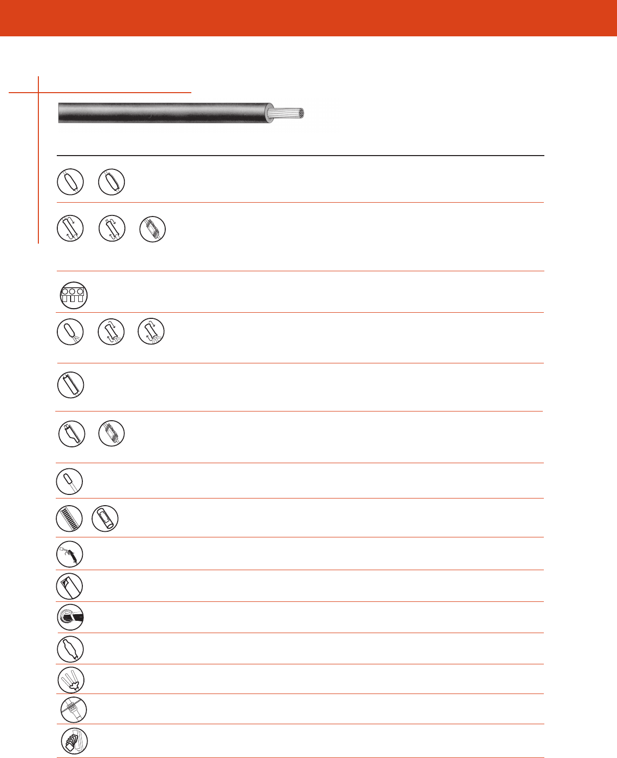
APPLICATION AND TECHNICAL SPECIFICATIONS
150
• Sealed in-line splices
• Terminal lug seals
• Insulation
• Jacket repair
• Sealed in-line splices
• Insulation
• Jacket repair
• Terminal lug seals
• UF underground feeder cable splice
• Submersible secondary
BUS connectors
• Sealed motor connections
• 2- or 3-wire stub splices
• Insulation and jacket repair
• General wraparound sealing
• Wraparound, sealed cable
• Tap splices
• End seals for storage and pulling
• Sealing of live ends (up to 1000V)
• Wire and cable marking
• Labels
• Hardware and Software
• Installation of heat-shrink products
• Sealing of uncoated tubing
• Duct sealing
• Airport lighting kit
• Cable breakout boots
• Network protector sealing
• Cabinet feed through seals
• Cable prep kit
Heat-Shrink Cold-Applied
Application(s)* Product(s) (HS) (CA)
WCSM (HS)
FCSM (HS)
MWTM (HS)
RNF-100 (HS)
GelWrap closure sleeve (CA)
GILS closure (CA)
RVS (CA)
GelWrap UF closure sleeve (CA)
GelPort connector (CA)
MCK (HS)
GelCap splice cover (CA)
GelCap SL splice cover (CA)
RVC (CA)
CRSM (HS)
MBSM (HS)
GelWrap splice cover (CA)
GWRS (CA)
CRSM-CT (HS)
GHFC MW (CA)
GHFC (CA)
GTAP (CA)
ESC (HS)
RVC (CA)
Identification Solutions
Propane torches
Heat guns
Sealing mastics
RDSS
ALK (HS)
CBR (HS)
CBR-NPB (HS)
CFTS (HS)
P-63
Application by Cable Type
1/C Power Cable (Up to 1000V)

LOW VOLTAGE TUBING - TECHNICAL DATA
APPLICATION AND TECHNICAL SPECIFICATIONS
151
General Purpose Cable Accessories (1000 V)
Tyco Electronics offers a complete line of Raychem brand general purpose heat-shrinkable
and cold-applied power cable accessories that consistently provide outstanding mechanical
protection, complete moisture sealing, and excellent electrical insulation for a broad range of
low voltage applications
Heat-Shrink Products
Raychem invented heat-shrinkable products in 1959 and the Raychem brand contiunes to be the
world leader in heat-shrink technology and design With Tyco Electronics, our heat-shrink products
continue to be upgraded and improved to provide the best performance and value possible
Rugged Mechanical Protection—Every Time
The tough, abrasion-resistant, cross-linked polyolefin construction of Tyco Electronics general-purpose
products provides mechanical protection equal to the cable jacket In addition, the one-piece solid
protective layer cannot unravel or slip off
Watertight Seals—Every Time
Most heat-shrinkable products are coated with a high-performance adhesive that melts and flows
when heated, forming a durable bond that seals out water and dirt
General purpose sealants are also available for use with uncoated tubings and other moisture-
sealing applications
Superior Electrical Insulation—Every Time
Heat-shrinkable products not only conform tightly to the connection, but they are also pre-engineered
to shrink consistently to the required insulation thickness
Cold-Applied Products
Cold-applied products offer superior sealing and electrical insulation Our revolutionary PowerGel
sealant provides the best and quickest cold-applied seal By combining the properties of solids and
liquids, PowerGel sealant conforms to intricate shapes to completely seal out water and contaminants
Low-Voltage Tubing and Wraparound Sleeves

TECHNICAL DATA
APPLICATION AND TECHNICAL SPECIFICATIONS
152
Low-Voltage Tubing and Wraparound Sleeves
Material Properties
FCSM
WCSM Heavy Wall, MWTM RNF-100 CRSM
Test Method Heavy Wall Flame-Retardant Medium Wall Thin Wall Wrap-Around
Physical
Tensile strength ASTM D 412 1750 psi min 1750 psi min 2000 psi min 1500 psi min 2450 psi min
Ultimate elongation ASTM D 412 350% min 350% min 350% min 200% min 350% min
Accelerated aging
(168 hrs at 150°±2°C) ASTM D 2671
Tensile strength ASTM D 412 1750 psi min 1600 psi min 2000 psi min 2000 psi min
Ultimate elongation ASTM D 412 350% min 200% min 300% min 300% min
Low-temperature flexibility ASTM D 2671 No cracking No cracking No cracking No cracking No cracking
(4 hrs at temp indicated) (–55°C) (–40°C) (–40°C) (–55°C) (–40°C)
Flammability ASTM D 2671 Self-extinguishing
(60 sec max)
Electrical
Dielectric strength ASTM D 149 430 V/mil min 330 V/mil min 500 V/mil min 500 V/mil min 500 V/mil min
(at 004 inch) (at 010 inch) (at 004 inch) (at 004 inch)
Volume resistivity ASTM D 257 1 x 10¹² 1 x 10¹³ 1 x 10¹² 1 x 10¹⁴ 1 x 10¹²
ohm-cm min ohm-cm min ohm-cm min ohm-cm min ohm-cm min
Chemical
Resistance to liquids ASTM D 543 X X X X
Tensile strength ASTM D 412 1450 psi min 1600 psi min 2000 psi min 1000 psi min 2000 psi min
Ultimate elongation ASTM D 412 300% min 300% min 300% min 300% min
Corrosive effect ASTM D 2671 No corrosion No corrosion
(16 hours at 150°±2°C) at 175°C
Fungus resistance ASTM G 21 Pass rating 1 Pass rating 1 Pass rating 1 Pass rating 1 Pass rating 1
Technical Specifications
ANSI C1191-1986 X X X
UL 486D-1986 X
UL Standard 224 X
CSA 222 X X
Western Underground X
Guide 25
MIL-I-23053/15, X
CIass 1 & 2
Flame-retardant per X
IEEE 383, ICEA-S-19-81
Note: Blank space indicates that property was not measured during product qualification.
LOW VOLTAGE TUBING - TECHNICAL DATA
APPLICATION AND TECHNICAL SPECIFICATIONS
Material Properties
Physical Test Method MCK ESC CBR
Tensile strength ASTM D 412 1450 psi min 1750 psi min 1500 psi min
Ultimate elongation ASTM D 412 300% min 200% min 300% min
Accelerated aging ASTM D 2671
(168 hours at temperature indicated)
Tensile strength ASTM D 412 1000 psi min 1750 psi min 1250 psi min
(175°±2°C) (150°±2°C) (150°±2°C)
Ultimate elongation ASTM D 412 200% min 200% min 100% min
(175°±2°C) (150°±2°C) (150°±2°C)
Low-temperature flexibility ASTM D 2671 No cracking No cracking No cracking
(4 hours at –40°±3°C)
Flammability ASTM D 635 Self-extinguishing
(120 sec max)
Electrical
Dielectric strength (at 075 inch) ASTM D 149 250 V/mil min 200 V/mil min 250 V/mil min
Volume resistivity ASTM D 257 1 x 10¹² 1 x 10¹² 1 x 10¹²
ohm-cm min ohm-cm min ohm-cm min
Chemical
Resistance to liquids, transformer oil
to VDE 0370 (168 hours at 23°±2°C) ASTM D 543
Tensile strength ASTM D 412 1150 psi min 1750 psi min 1250 psi min
Ultimate elongation ASTM D 412 240% min 200% min 240% min
Corrosive effect(16 hours at 175°±2°C) ASTM D 2671 No corrosion
Resistance to fungi ASTM G 21 Pass rating 1 Pass rating 1 Pass rating 1
Technical Specifications
ANSI C1191-1986 X X
Flame-retardant per IEEE 383, X
ICEA-S-19-81
Note: Blank space indicates that property was not measured during product qualification.
Material Properties
Physical Test Method S1052 S1085 S1171 S1174 S1251
Softening point ASTM E 28 70°C min 140°C min 140°C min
Adhesive peel strength:
Polyethylene 1 lb/in min 55 lb/in min 5 lb/in min 6 lb/in min
Steel 2 lb/in min 5 lb/in min
Aluminum 44 lb/in min
Copper 44 lb/in min
Low-temperature ASTM D 2671 No cracking No cracking No cracking No cracking
flexibility (4 hours at (–40°C±3°C) (–30°C±2°C) (–40°C±3°C) (–40°C±3°C)
temperature indicated)
Electrical
Dielectric strength min ASTM D 149 300 V/mil min 200 V/mil min 200 V/mil min 300 V/mil min 300 V/mil
(004 inch)
Volume resistivity ASTM D 257 1 x 10¹² 1 x 10¹² 1 x 10¹² 1 x 10¹² 1 x 10¹²
ohm-cm min ohm-cm min ohm-cm min ohm-cm min ohm-cm min
Tracking and ASTM D 2303 No tracking
erosion resistance or erosion to
top surface or
flame failure after:
1 hr at 200 kV
1 hr at 225 kV
1 hr at 250 kV
Chemical
Corrosive effect ASTM D 2671 No corrosion No corrosion No corrosion
(16 hours at 121°±2°C)
Fungus resistance ASTM G 21 Pass rating 1 Pass rating 1
Note: Blank space indicates that property was not measured during product specification.
153
Low-Voltage Tubing and Wraparound Sleeves
TECHNICAL DATA
APPLICATION AND TECHNICAL SPECIFICATIONS
154
Low-Voltage Tubing and Wraparound Sleeves
Material Properties
Physical Test Method S1052 S1085 S1171 S1174 S1251
Softening point ASTM E 28 70°C min 140°C min 140°C min
Adhesive peel strength:
Polyethylene 1 lb/in min 55 lb/in min 5 lb/in min 6 lb/in min
Steel 2 lb/in min 5 lb/in min
Aluminum 44 lb/in min
Copper 44 lb/in min
Low-temperature ASTM D 2671 No cracking No cracking No cracking No cracking
flexibility (4 hours at (–40°C±3°C) (–30°C±2°C) (–40°C±3°C) (–40°C±3°C)
temperature indicated)
Electrical
Dielectric strength min ASTM D 149 300 V/mil min 200 V/mil min 200 V/mil min 300 V/mil min 300 V/mil
(004 inch)
Volume resistivity ASTM D 257 1 x 10¹² 1 x 10¹² 1 x 10¹² 1 x 10¹² 1 x 10¹²
ohm-cm min ohm-cm min ohm-cm min ohm-cm min ohm-cm min
Tracking and ASTM D 2303 No tracking
erosion resistance or erosion to
top surface or
flame failure after:
1 hr at 200 kV
1 hr at 225 kV
1 hr at 250 kV
Chemical
Corrosive effect ASTM D 2671 No corrosion No corrosion No corrosion
(16 hours at 121°±2°C)
Fungus resistance ASTM G 21 Pass rating 1 Pass rating 1
Note: Blank space indicates that property was not measured during product specification.
PowerGel Testing Test Methods S.I. Units Imperial Units
Dielectric strength
(4 mm/016 inch wall thickness) 40 kV/cm min 100 V/mil min
Volume Resistivity 1 x 10¹² Ohm cm min 1 x 10¹² Ohm cm min
Resistance to Liquids ASTM D543 modified: No visible cracking, No visible cracking,
100 cm x 10 cm x 04 cm, max 2% weight max 2% weight
test bar supported on wire change, 80% retention change, 80% retention
mesh, 24 hours immersion, of elongation and of elongation and
IPA rinse after immersion, tensile strength tensile strength
24 hr drying
Corrosive Effect ASTM D2671 No corrosion No corrosion
Resistance to Fungi ISO 846 Pass rating1 or less Pass rating 1 or less
45 cm diameter x 04 cm
thickness petridish
UV Resistance ISO 4892/3 80% tensile strength 80% tensile strength
100 cm x 10 cm x retention, no visible retention, no visible
04 cm test bar, UVB 313; cracking cracking
250 cycles (2000 hrs); 4 hours
UV at 60°C then 4 hours at
50°C with condensation
Chemicals: 1 N na2SO4
0,1 N NaOH; 0, 1 N NaCl;
0, 1 NH2SO4; Distilled
water; Ethylene Glycol

TERMINATIONS - TECHNICAL DATA
APPLICATION AND TECHNICAL SPECIFICATIONS
155
Reliable, Field-Proven Performance
Independent testing and field experience have repeatedly proven the long-term stability, durability,
and reliability of the Tyco Electronics’ Raychem HVT system, even in highly polluted environments The
nontracking, insulating outer jacket can withstand the rigors of long-term electrical stress and surface
pollution without loss of performance The nontracking material offers the additional benefit of being
maintenance free, with no need for periodic cleaning Extensive load cycle testing verifies the long-term
thermo mechanical compatibility between the termination system and the cable
Ease of Installation
HVT kits can be installed on all cable types without special adapters or accessories No special tooling
or connectors are required since HVT kits accept all common compression or terminal lugs The HVT
installation method also provides generous cable cutback and component positioning tolerances,
further reducing installation variability Heat-shrinking allows the kits to be easily inspected, either
visually or by simple touch, to help ensure proper installation
Always Ready for the Job–Even in Emergencies
HVT kits have an unlimited shelf life They remain ready to use on short notice, so you have no worries
about scrapping aged inventory or being caught with useless products during an emergency or on a
time-critical project
Flexible and Versatile
An HVT system may be installed upright or inverted and can bend to the same bending radius as the
cable Slim and lightweight, the system can also be mounted directly to fuse cutouts or other devices,
eliminating the cost of additional supporting brackets and cross arms
46 and 69 kV
At voltages as high as 69 kV the need for proven stress control is even more important The materials
used in our 46 and 69 kV terminations (as with all lower voltages) are suitable for severely polluted
areas—and for all installation conditions, including top feed installation
The material is designed to be resistant to impact damage from transportation or vandalism, a
typical problem for heavy, inflexible porcelain products Tyco Electronics’ Raychem brand 46/69 kV
terminations also require no compound filling which can leak over time
Cold-Applied Termination System
TFT terminations are designed for customers who want Tyco Electronics material technology in a
cold-applied system The cold-applied terminations also provide positive positioning of the stress
control patch
Tyco Electronics’ Raychem
brand HVT system features a
nontracking, insulating surface
that can withstand long-term
electrical stress and
surface pollution
Tyco Electronics’ proven oil-
sealing technology has been
used for more than 18 years
in medium-voltage transition
joints This technology is
now put to work in our PILC
termination kits
Termination
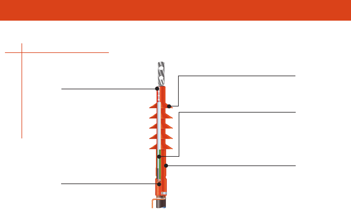
APPLICATION AND TECHNICAL SPECIFICATIONS
156
TFT
Moisture Sealing
• Nontracking, high-voltage sealant
Spring clamp and solder-block ground braid
available for metallic shielded cables
Additional Creepage for Outdoor Applications
Molded skirts:
• Increase surface creepage distance
Electrical Stress Control
Metal Oxide Matrix stress control patch:
• Reduces the electrical stress gradient at the
end of the cable shield to safe operating levels
• Conforms to fit out-of-spec cable
• Provides long-term electrical performance
Nontracking, Termination Body:
• Provides excellent UV stability
• Withstands polluted environments
• Is proven to withstand severe applications
Moisture Sealing
Nontracking, high-voltage sealant:
• Provides a watertight connector seal
• Will not harden or crack
Termination

TERMINATIONS - TECHNICAL DATA
APPLICATION AND TECHNICAL SPECIFICATIONS
157
TFT Testing Data
These terminations are fully qualified per IEEE-48 as Class 1 terminations to provide a long,
trouble-free service life These terminations incorporate Tyco Electronics material technology in a
cold-applied system These terminations have a silicone elastomeric tubing that is formulated for
long-term performance in typical extreme termination environments The non-tracking material is
maintenance-free and does not require periodic cleaning
This series of products feature the latest in advanced stress control systems using Metal Oxide
Matrix technology to provide superior electrical performance
Tyco Electronics Products: Voltage Class
TFT TFT TFT TFT
Test Description (5 - 8 kV) (15 kV)* (25 kV) (35 kV)
AC withstand, 1 minute, (kV) 35 50 65 90
DC withstand, 15 minutes, (kV) 65 75 105 140
Partial discharge (min kV) for 5 pC or less 9 13 215 30
Impulse withstand 12 x 50 µs, crest kV (outdoor) 95 110 150 200
Wet withstand, 10 seconds, kV rms 30 45 60 80
Dry withstand, 6 hours, kV rms 25 35 55 75
*With or without sheds
Termination

APPLICATION AND TECHNICAL SPECIFICATIONS

INDEX
INDEX
1583608-2 140
1099898-1 15
1099898-2 15
1099898-3 15
1099898-4 15
1099898-5 15
1099898-6 15
1099898-7 15
1099898-8 15
1099898-9 15
1099899-1 15
1099899-2 15
1099899-3 15
1099899-4 15
1099899-5 15
1099899-6 15
1099899-7 15
1099899-8 15
1099899-9 15
1099939-1 15
1099939-2 15
1099939-3 15
1099939-4 15
1099939-5 15
1099939-6 15
1099939-7 15
1099939-8 15
1099939-9 15
1-1099898-0 15
1-1099898-1 15
1-1099898-2 15
1-1099898-3 15
1-1099898-4 15
1-1099898-5 15
1-1099899-0 15
1-1099899-1 15
1-1099899-2 15
1-1099899-3 15
1-1099899-4 15
1-1099899-5 15
1-1099899-6 15
1-1099899-7 15
1-1099899-8 15
1-1099899-9 15
1-1099939-0 15
1-1099939-1 15
1-1099939-2 15
1-1099939-3 15
1-1099939-4 15
1-1099939-5 15
1-1443402-0 16
1-1443402-1 16
1-1443402-2 16
1-1443402-3 16
1-1443402-4 16
1-1443402-5 16
1-1443402-6 16
1-1443402-7 16
1-1443403-0 16
1-1443403-1 16
1-1443403-2 16
1-1443403-3 16
1-1443403-4 16
1-1443403-5 16
1-1443403-6 16
1-1443403-7 16
1375317-1 141
1375479-1 142
1443402-1 16
1443402-2 16
1443402-3 16
1443402-4 16
1443402-5 16
1443402-6 16
1443402-7 16
1443402-8 16
1443402-9 16
1443403-1 16
1443403-2 16
1443403-3 16
1443403-4 16
1443403-5 16
1443403-6 16
1443403-7 16
1443403-8 16
1443403-9 16
1490490-1 141
1490496-2 142
1490496-3 142
1490530-1 140
1490531-1 140
1490532-1 140
1490533-1 140
1583236-2 140
1583694-2 140
1-83592-0 24
1-83592-1 24
1-83592-2 24
1-83592-3 24
1-83623-0 25
1-83623-1 25
1-83623-2 25
1-83623-3 25
1-83623-4 25
1-83623-5 25
1-83623-6 25
1-83623-7 25
1-83623-8 25
1-83623-9 25
1-83630-0 25
1-83631-1 25
1-83631-2 25
1-83631-3 25
1-83631-4 25
1-83631-5 25
1-83631-6 25
1-83631-7 25
1-83631-8 25
1-83631-9 25
2060-NPS 127
2060-VPS 127
2090-NPS 127
2-83623-0 25
3090-NPS 128
314974-1 8
350 MCM Cutter 141
4-Pair Tester 140
500 MCM Cutter 141
55823-1 8
605742-1 141
605744-1 141
6060-VPS 129
608028-1 8
6090-VPS 129
6090-VPS-UL 129
696201-1 142
734185-1 141
734587-1 142
790162-1 142
80408-2 26
80408-3 26
80408-4 26
80408-5 26
80408-6 26
80408-7 26
83000-1 26
83592-1 24
83592-2 24
83592-3 24
83592-4 24
83592-5 24
83592-6 24
83592-7 24
83592-8 24
83592-9 24
83623-1 25
83623-2 25
83623-3 25
83623-4 25
83623-5 25
83623-6 25
83623-7 25
83623-8 25
83623-9 25
83630-1 25
83630-2 25
83630-3 25
83630-4 25
83630-5 25
83630-6 25
83630-7 25
83630-8 25
83630-9 25
83631-1 25
83631-2 25
83631-3 25
83631-4 25
83631-5 25
83631-6 25
83631-7 25
83631-8 25
83631-9 25
83747-1 27
83747-2 27
83747-3 27
83747-4 27
83748-1 27
83748-2 27
83748-3 27
83748-4 27
83749-1 27
83749-2 27
83749-3 27
83749-4 27
83750-1 27
83750-2 28
83751-1 28
83751-2 28
83751-3 28
83751-4 28
A
AA-105 124
AA-105HA 124
AA-105M 124
AA-105W 124
AA-1068 124
AA-1068M 124
AA-1068W 124
AA-305 124
AA-LS 124
AD-1358-LPG-REGW/GAGE 139
AD-1432-ACD10FT-LPG-HOSE 139
AD-1434-ACD30FT-LPG-HOSE 139
AD-1460-ACD-HEAT-
SHLDGPA 139
AD-1563-ADAPTER 139
AD-3015-04 139
ALK-L823 94
AM-1-A 132
AM-1-A-NB 132
AM-2-A 132
AM-2-A-NB 132
AMP-0-0035559-0 6
AMP-0-0036160-0 5
AMP-0-0052936-0 7
AMP-0-0055785-1 7
AMP-0-0055792-1 7
AMP-0-0055793-1 7
AMP-0-0066024-2 6
AMP-0-0640903-1 6
AMP-0-0640905-1 6
AMPS-0-0031886-0 5
AMPS-0-0031894-0 5
AMPS-0-0032053-0 6
AMPS-0-0032054-0 6
AMPS-0-0032060-0 6
AMPS-0-0032588-0 6
AMPS-0-0032589-0 6
AMPS-0-0034142-0 5
AMPS-0-0034145-0 5
AMPS-0-0034146-0 5
AMPS-0-0034150-0 5
AMPS-0-0034155-0 6
AMPS-0-0034156-0 6
AMPS-0-0034158-0 5
AMPS-0-0034160-0 5
AMPS-0-0034161-0 5
AMPS-0-0034162-0 5
AMPS-0-0034166-0 6
AMPS-0-0034167-0 6
AMPS-0-0034168-0 5
AMPS-0-0034176-0 6
AMPS-0-0034541-0 6
AMPS-0-0034853-0 5
AMPS-0-0034854-0 5
AMPS-0-0034855-0 5
AMPS-0-0035108-0 5
AMPS-0-0035109-0 5
AMPS-0-0035110-0 5
AMPS-0-0035149-0 5
AMPS-0-0036152-0 5
AMPS-0-0036154-0 5
AMPS-0-0052041-3 5
AMPS-0-0052042-3 5
AMPS-0-0052043-2 5
AMPS-0-0052043-3 5
AMPS-0-0052263-1 5
AMPS-0-0052265-0 5
AMPS-0-0052929-0 7
AMPS-0-0052930-0 7
AMPS-0-0052931-0 7
AMPS-0-0052935-0 7
AMPS-0-0052937-0 7
AMPS-0-0052941-0 7
AMPS-0-0052942-0 7
AMPS-0-0052943-0 7
AMPS-0-0052945-0 7
AMPS-0-0052949-0 7
AMPS-0-0052950-0 7
AMPS-0-0052955-0 7
AMPS-0-0052956-0 7
AMPS-0-0052957-0 7
AMPS-0-0052963-0 7
AMPS-0-0053242-1 7
AMPS-0-0053247-1 7
AMPS-0-0066023-2 6
AMPS-0-0066025-2 6
AMPS-0-0320559-0 7
AMPS-0-0320562-0 7
AMPS-0-0320565-0 5
AMPS-0-0320570-0 7
AMPS-0-0320619-0 5
AMPS-0-0320665-0 6
AMPS-0-0321045-0 5
AMPS-0-0321233-0 6
AMPS-0-0322985-0 6
AMPS-0-0322994-0 6
AMPS-0-0500000-1 59
AMPS-0-0500001-1 59
159

INDEX
160
AMPS-0-0500002-1 59
AMPS-0-0640907-1 6
AMR30302-120V 132
AMR30303-120V 132
AMR30303-240V 132
ASBS-2-3/0 18
ASBS-2-350 18
ASBS-2-350 18
ASBS-3/0-500 18
ASBS-3/0-500 18
ASBS-350-750 18
ASBS-350-750 18
ASBS-500-750 18
ASBS-500-750 18
ASBS-600-1000 18
ASBS-600-1000 18
AT-15 123
AT-168 123
AT-19 123
AT-20 123
AT-30 123
AT-368 123
AT-39 123
Automatic Wire Stripper 141
B
BF-120 125
BF-208-277 125
BF-PV 125
Butt Set 140
C
Cable Tie Gun 142
CBR-2-1-A 113
CBR-2-2-A 113
CBR-2-3-A 113
CBR-3-1-A 113
CBR-3-2-A 113
CBR-3-3-A 113
CBR-3-4-A 113
CBR-4-1-A 113
CBR-4-2-A 113
CBR-4-3-A 113
CBR-4-4-A 113
CBR-6-1-A 113
CBR-6-2-A 113
CBR-Plug 113
CFTS-1 113
CFTS-2 113
CFTS-3 113
CFTS-4 113
CFTS-5 113
Coax Stripper 141
CPGI-061-0114A 60
CPGI-061-0114V 60
CPGI-063-0020 60
CPGI-1116377-2 21
CPGI-1116377-2-Bulk 21
CPGI-1116415-2 21
CPGI-1116415-2-Bulk 21
CPGI-1116542-1 67
CPGI-1116542-1-K 67
CPGI-1-1776294-2 33
CPGI-1-1776297-2 34
CPGI-1-1776311-2 36
CPGI-1-1776319-2 35
CPGI-1217204-1 67
CPGI-1217204-1-K 67
CPGI-1546310-4 32
CPGI-1546310-6 32
CPGI-1546310-8 32
CPGI-1-552678-2 67
CPGI-1-553017-2 67
CPGI-1811027-1-Bulk 13
CPGI-1811027-1-K100 13
CPGI-1811027-1-K25 13
CPGI-1811027-1-K6 13
CPGI-1811027-2-Bulk 13
CPGI-1811027-2-K100 13
CPGI-1811027-2-K25 13
CPGI-1811027-2-K6 13
CPGI-2008144-1-BULK 12
CPGI-2008144-1-K20 12
CPGI-2008144-1-K50 12
CPGI-2008144-1-K6 12
CPGI-2008152-1-BULK 12
CPGI-2008152-1-K50 12
CPGI-2008152-1-K6 12
CPGI-2008535-1-BULK 12
CPGI-2008535-1-K2 12
CPGI-2008836-2-BULK 12
CPGI-2008836-2-K2 12
CPGI-208169-2 21
CPGI-208169-2-Bulk 21
CPGI-53440-7 20
CPGI-53440-7-Bulk 20
CPGI-53440-9 20
CPGI-53440-9-Bulk 20
CPGI-552795-2 67
CPGI-5-554374-7 67
CPGI-569224-1 68
CPGI-569224-1-K 68
CPGI-569661-1 68
CPGI-569661-1-K 68
CPGI-66023-2 6
CPGI-66024-6 6
CPGI-66025-2 6
CPGI-735411 20
CPGI-735411-Bulk 20
CPGI-7-52935-1 7
CPGI-7-52937-1 7
CPGI-7-52956-1 7
CPGI-8-31886-1 5
CPGI-8-31894-1 5
CPGI-8-32053-1 6
CPGI-8-32054-1 6
CPGI-8-320559-2 7
CPGI-8-320562-5 7
CPGI-8-320565-1 5
CPGI-8-320570-2 7
CPGI-8-32060-1 6
CPGI-8-320619-1 5
CPGI-8-320665-1 6
CPGI-8-321045-1 5
CPGI-8-321233-1 6
CPGI-8-322985-2 6
CPGI-8-322994-1 6
CPGI-8-32588-2 6
CPGI-8-32589-2 6
CPGI-8-34142-1 5
CPGI-8-34145-1 5
CPGI-8-34146-1 5
CPGI-8-34150-1 5
CPGI-8-34155-1 6
CPGI-8-34156-1 6
CPGI-8-34158-1 5
CPGI-8-34160-1 5
CPGI-8-34161-1 5
CPGI-8-34162-1 5
CPGI-8-34166-1 6
CPGI-8-34167-1 6
CPGI-8-34168-2 5
CPGI-8-34169-2 5
CPGI-8-34170-1 5
CPGI-8-34171-2 5
CPGI-8-34176-1 6
CPGI-8-34541-1 6
CPGI-8-35108-1 5
CPGI-8-35109-1 5
CPGI-8-35110-1 5
CPGI-8-35149-2 5
CPGI-8-35559-1 6
CPGI-8-36152-1 5
CPGI-8-36154-1 5
CPGI-8-36160-1 5
CPGI-8-52929-1 7
CPGI-8-52930-1 7
CPGI-8-52931-1 7
CPGI-8-52936-1 7
CPGI-8-52941-2 7
CPGI-8-52942-1 7
CPGI-8-52943-1 7
CPGI-8-52945-2 7
CPGI-8-52949-1 7
CPGI-8-52950-1 7
CPGI-8-52955-1 7
CPGI-8-52957-1 7
CPGI-8-52963-2 7
CPGI-8-53242-5 7
CPGI-8-53247-1 7
CPGI-8-55785-1 7
CPGI-8-55792-1 7
CPGI-8-55793-2 7
CPGI-8-640903-1 6
CPGI-8-640905-1 6
CPGI-8-640907-1 6
CPGI-ALR-2090-NPS 127
CPGI-ALR-AA-105 124
CPGI-ALR-AA-105W 124
CPGI-ALR-AA-305 124
CPGI-ALR-CFL-FL 130
CPGI-ALR-CFL-LP 130
CPGI-ALR-LC-120 125
CPGI-ALR-LC-208-277 125
CPGI-ALR-OLC-5C 130
CPGI-ALR-PL-120S 130
CPGI-ALR-PT-15 123
CPGI-ALR-SPT-15 123
CPGI-ALR-TL-115 124
CPGI-B-106-1501-6 9
CPGI-B-106-1501-BULK 9
CPGI-B-106-1502-5 9
CPGI-B-106-1502-BULK 9
CPGI-B-106-1503-5 9
CPGI-B-106-1503-BULK 9
CPGI-B-106-1601-BULK 9
CPGI-B-106-1602-BULK 9
CPGI-B-106-1603-BULK 9
CPGI-B-106-1801-BULK 9
CPGI-B-106-1802-BULK 9
CPGI-B-106-1803-BULK 9
CPGI-B-106-1991-BULK 9
CPGI-B-106-1992-BULK 9
CPGI-B-106-1993-BULK 9
CPGI-B-106-2401-6 9
CPGI-B-106-2401-Bulk 9
CPGI-B-106-2402-Bulk 9
CPGI-B-106-2403-Bulk 9
CPGI-B-106-2502-5 9
CPGI-B-106-2502-Bulk 9
CPGI-B-106-2503-5 9
CPGI-B-106-2503-Bulk 9
CPGI-B-106-3281-BULK 10
CPGI-B-106-3481-BULK 10
CPGI-B-106-3631-BULK 10
CPGI-B-106-3632-BULK 10
CPGI-B-106-3633-BULK 10
CPGI-B-106-4631-BULK 10
CPGI-B-106-4632-BULK 10
CPGI-B-106-6201-BULK 10
CPGI-B-106-7401-BULK 10
CPGI-B-106-7502-BULK 10
CPGI-B-106-8401-BULK 10
CPGI-B-106-8502-BULK 10
CPGI-B-1401-BULK 9
CPGI-B-1402-BULK 9
CPGI-B-1403-BULK 9
CPGI-BUCH-1-1437381-0 47
CPGI-BUCH-1-1437381-6 47
CPGI-BUCH-1-1437381-7 40
CPGI-BUCH-1-1437382-2 47
CPGI-BUCH-1-1437382-3 47
CPGI-BUCH-1-1437390-2 40
CPGI-BUCH-1-1437390-4 40
CPGI-BUCH-1-1437395-4 41
CPGI-BUCH-1-1437397-0 45
CPGI-BUCH-1-1437397-2 45
CPGI-BUCH-1-1546310-0 32
CPGI-BUCH-1-1546310-1 32
CPGI-BUCH-1-1546310-2 32
CPGI-BUCH-1-1546310-3 32
CPGI-BUCH-1-1546310-4 32
CPGI-BUCH-1-1546310-5 32
CPGI-BUCH-1-1546310-6 32
CPGI-BUCH-1-1546310-8 32
CPGI-BUCH-1-1546311-0 32
CPGI-BUCH-1-1546311-1 32
CPGI-BUCH-1-1546311-2 32
CPGI-BUCH-1-1546311-3 32
CPGI-BUCH-1-1546311-4 32
CPGI-BUCH-1-1546311-5 32
CPGI-BUCH-1-1546311-6 32
CPGI-BUCH-1-1546311-7 32
CPGI-BUCH-1-1546311-8 32
CPGI-BUCH-1-1776294-0 33
CPGI-BUCH-1-1776294-1 33
CPGI-BUCH-1-1776294-2 33
CPGI-BUCH-1-1776297-0 34
CPGI-BUCH-1-1776297-1 34
CPGI-BUCH-1-1776297-2 34
CPGI-BUCH-1-1776310-0 36
CPGI-BUCH-1-1776310-1 36
CPGI-BUCH-1-1776310-2 36
CPGI-BUCH-1-1776311-0 36
CPGI-BUCH-1-1776311-1 36
CPGI-BUCH-1-1776311-2 36
CPGI-BUCH-1-1776319-0 35
CPGI-BUCH-1-1776319-1 35
CPGI-BUCH-1-1776319-2 35
CPGI-BUCH-1437381-1 47
CPGI-BUCH-1437381-4 47
CPGI-BUCH-1437381-5 37
CPGI-BUCH-1437381-8 47
CPGI-BUCH-1437382-2 47
CPGI-BUCH-1437382-3 47
CPGI-BUCH-1437382-6 47
CPGI-BUCH-1437390-8 40
CPGI-BUCH-1437390-9 40
CPGI-BUCH-1437395-3 41
CPGI-BUCH-1437396-7 43
CPGI-BUCH-1437396-8 43
CPGI-BUCH-1437396-9 43
CPGI-BUCH-1437397-1 45
CPGI-BUCH-1437397-2 45
CPGI-BUCH-1437397-3 45
CPGI-BUCH-1437397-9 45
CPGI-BUCH-14376397-5 45
CPGI-BUCH-1546143-1 38
CPGI-BUCH-1546144-1 38
CPGI-BUCH-1546147-1 38
CPGI-BUCH-1546148-1 38
CPGI-BUCH-1546163-1 39
CPGI-BUCH-1546164-1 38
CPGI-BUCH-1546234-1 38
CPGI-BUCH-1546235-1 38
CPGI-BUCH-1546310-2 32
CPGI-BUCH-1546310-3 32
CPGI-BUCH-1546310-4 32

INDEX
INDEX
161
CPGI-BUCH-1546310-5 32
CPGI-BUCH-1546310-6 32
CPGI-BUCH-1546310-7 32
CPGI-BUCH-1546310-8 32
CPGI-BUCH-1546310-9 32
CPGI-BUCH-1546311-2 32
CPGI-BUCH-1546311-3 32
CPGI-BUCH-1546311-4 32
CPGI-BUCH-1546311-5 32
CPGI-BUCH-1546311-6 32
CPGI-BUCH-1546311-7 32
CPGI-BUCH-1546311-8 32
CPGI-BUCH-1546311-9 32
CPGI-BUCH-1776294-1 33
CPGI-BUCH-1776294-2 33
CPGI-BUCH-1776294-3 33
CPGI-BUCH-1776294-4 33
CPGI-BUCH-1776294-5 33
CPGI-BUCH-1776294-6 33
CPGI-BUCH-1776294-7 33
CPGI-BUCH-1776294-8 33
CPGI-BUCH-1776294-9 33
CPGI-BUCH-1776297-2 34
CPGI-BUCH-1776297-3 34
CPGI-BUCH-1776297-4 34
CPGI-BUCH-1776297-5 34
CPGI-BUCH-1776297-6 34
CPGI-BUCH-1776297-7 34
CPGI-BUCH-1776297-8 34
CPGI-BUCH-1776297-9 34
CPGI-BUCH-1776310-1 36
CPGI-BUCH-1776310-2 36
CPGI-BUCH-1776310-3 36
CPGI-BUCH-1776310-4 36
CPGI-BUCH-1776310-5 36
CPGI-BUCH-1776310-6 36
CPGI-BUCH-1776310-7 36
CPGI-BUCH-1776310-8 36
CPGI-BUCH-1776310-9 36
CPGI-BUCH-1776311-1 36
CPGI-BUCH-1776311-2 36
CPGI-BUCH-1776311-3 36
CPGI-BUCH-1776311-4 36
CPGI-BUCH-1776311-5 36
CPGI-BUCH-1776311-6 36
CPGI-BUCH-1776311-7 36
CPGI-BUCH-1776311-8 36
CPGI-BUCH-1776311-9 36
CPGI-BUCH-1776319-1 35
CPGI-BUCH-1776319-2 35
CPGI-BUCH-1776319-3 35
CPGI-BUCH-1776319-4 35
CPGI-BUCH-1776319-5 35
CPGI-BUCH-1776319-6 35
CPGI-BUCH-1776319-7 35
CPGI-BUCH-1776319-8 35
CPGI-BUCH-1776319-9 35
CPGI-BUCH-2-1437381-3 47
CPGI-BUCH-2-1437382-6 46
CPGI-BUCH-2-1437392-1 37
CPGI-BUCH-2-1437392-3 37
CPGI-BUCH-2-1437392-5 37
CPGI-BUCH-2-1437393-4 47
CPGI-BUCH-2-1437397-0 45
CPGI-BUCH-2-1437397-8 45
CPGI-BUCH-2-14376397-4 45
CPGI-BUCH-3-1437381-9 47
CPGI-BUCH-3-14373882-0 46
CPGI-BUCH-3-1437390-1 40
CPGI-BUCH-3-1437390-3 40
CPGI-BUCH-3-1437390-6 40
CPGI-BUCH-3-1437390-9 39
CPGI-BUCH-3-1437397-0 45
CPGI-BUCH-3-1437397-1 45
CPGI-BUCH-4-1437382-0 46
CPGI-BUCH-4-1437382-9 46
CPGI-BUCH-4-1437393-0 47
CPGI-BUCH-5-1437381-5 47
CPGI-BUCH-5-1437382-9 46
CPGI-BUCH-9-1437381-1 47
CPGI-BUCH-9-1437381-2 47
CPGI-BUCH-9-1437381-5 47
CPGI-BUCH-9-1437381-7 47
CPGI-BUCH-9-1437381-8 47
CPGI-BUCH-9-1437381-9 47
CPGI-CRPS-248 117
CPGI-CRSM-CT-34/10-150 92
CPGI-CTY-04-18-BLK-C 51
CPGI-CTY-04-18-BLK-M 51
CPGI-CTY-04-18-HL-C 54
CPGI-CTY-04-18-ID-NAT-C 55
CPGI-CTY-04-18-NAT-C 51
CPGI-CTY-04-18-NAT-M 51
CPGI-CTY-05-30-MH-BLK-C 52
CPGI-CTY-05-30-MH-NAT-C 52
CPGI-CTY-05-40-BLK-C 51
CPGI-CTY-05-40-BLK-M 51
CPGI-CTY-05-40-NAT-C 51
CPGI-CTY-05-40-NAT-M 51
CPGI-CTY-05-50-RL-BLK-C 54
CPGI-CTY-05-50-RL-NAT-C 54
CPGI-CTY-06-18-BLK-C 51
CPGI-CTY-06-18-NAT-C 51
CPGI-CTY-07-50-BLK-C 51
CPGI-CTY-07-50-BLK-M 51
CPGI-CTY-07-50-HS-BLK-C 51
CPGI-CTY-07-50-ID-NAT-C 55
CPGI-CTY-07-50-LP-BLK-C 53
CPGI-CTY-07-50-LP-NAT-C 53
CPGI-CTY-07-50-MH-BLK-C 52
CPGI-CTY-07-50-MH-NAT-C 52
CPGI-CTY-07-50-NAT-C 51
CPGI-CTY-07-50-NAT-M 51
CPGI-CTY-07-50-PM-BLK-C 53
CPGI-CTY-07-50-PM-NAT-C 53
CPGI-CTY-07-50-PMW-
BLK-C 53
CPGI-CTY-07-50-PMW-
NAT-C 53
CPGI-CTY-08-18-BLK-C 51
CPGI-CTY-08-18-BLK-M 51
CPGI-CTY-08-18-NAT-C 51
CPGI-CTY-08-18-NAT-M 51
CPGI-CTY-08-40-BLK-C 51
CPGI-CTY-08-40-BLK-M 51
CPGI-CTY-08-40-NAT-C 51
CPGI-CTY-08-40-NAT-M 51
CPGI-CTY-08-50-HL-C 54
CPGI-CTY-08-50-RL-BLK-C 54
CPGI-CTY-08-50-RL-NAT-C 54
CPGI-CTY-11-40-BLK-C 51
CPGI-CTY-11-40-NAT-C 51
CPGI-CTY-11-50-BLK-C 51
CPGI-CTY-11-50-BLK-D 51
CPGI-CTY-11-50-HS-BLK-C 51
CPGI-CTY-11-50-MH-BLK-C 52
CPGI-CTY-11-50-MH-NAT-C 52
CPGI-CTY-11-50-NAT-C 51
CPGI-CTY-11-50-NAT-D 51
CPGI-CTY-12-50-RL-BLK-C 54
CPGI-CTY-12-50-RL-NAT-C 54
CPGI-CTY-14-40-BLK-C 51
CPGI-CTY-14-40-NAT-C 51
CPGI-CTY-14-50-BLK-C 52
CPGI-CTY-14-50-BLK-D 52
CPGI-CTY-14-50-HS-BLK-C 52
CPGI-CTY-14-50-ID-NAT-C 55
CPGI-CTY-14-50-MH-BLK-C 52
CPGI-CTY-14-50-MH-NAT-C 52
CPGI-CTY-14-50-NAT-C 52
CPGI-CTY-14-50-NAT-D 52
CPGI-CTY-15-120-BLK-L 52
CPGI-CTY-15-120-NAT-L 52
CPGI-CTY-16-120-LP-BLK-C 53
CPGI-CTY-16-120-LP-NAT-C 53
CPGI-CTY-16-120-MH-BLK-C 52
CPGI-CTY-16-120-MH-NAT-C 52
CPGI-CTY-17-50-BLK-C 52
CPGI-CTY-17-50-NAT-C 52
CPGI-CTY-18-120-BLK-L 52
CPGI-CTY-18-120-NAT-L 52
CPGI-CTY-22-250-BLK-C 52
CPGI-CTY-22-250-NAT-C 52
CPGI-CTY-24-120-BLK-L 52
CPGI-CTY-24-120-NAT-L 52
CPGI-CTY-25-175-BLK-L 52
CPGI-CTY-25-175-NAT-L 52
CPGI-CTY-28-120-BLK-L 52
CPGI-CTY-28-120-NAT-L 52
CPGI-CTY-37-175-BLK-L 52
CPGI-CTY-37-175-NAT-L 52
CPGI-CTY-48-175-BLK-L 52
CPGI-CTY-48-175-GRY-L 52
CPGI-CTY-48-175-NAT-L 52
CPGI-CTY-BM-BLK-C 57
CPGI-CTY-CCL-125-BLK-C 58
CPGI-CTY-CCL-125-NAT-C 58
CPGI-CTY-CCL2-1000-
BLK-C 58
CPGI-CTY-CCL2-1000-
NAT-C 58
CPGI-CTY-CCL2-375-BLK-C 58
CPGI-CTY-CCL2-375-NAT-C 58
CPGI-CTY-CCL2-500-BLK-C 58
CPGI-CTY-CCL2-500-NAT-C 58
CPGI-CTY-CCL-250-BLK-C 58
CPGI-CTY-CCL-250-NAT-C 58
CPGI-CTY-CCL2-750-BLK-C 58
CPGI-CTY-CCL2-750-NAT-C 58
CPGI-CTY-IDP-1-NAT-C 58
CPGI-CTY-IDP-2-NAT-C 58
CPGI-CTY-LPM1-NAT-C 56
CPGI-CTY-MP-1000-BLK-C 55
CPGI-CTY-MP-1000-NAT-C 55
CPGI-CTY-MP-750-BLK-C 55
CPGI-CTY-MP-750-NAT-C 55
CPGI-CTY-PMW-NAT-C 57
CPGI-CTY-SM1-BLK-C 57
CPGI-CTY-SM1-NAT-C 57
CPGI-CTY-SM2-BLK-C 57
CPGI-CTY-SM2-NAT-C 57
CPGI-CTY-WM-BLK-C 56
CPGI-CWT-9002-15 11
CPGI-CWT-9002-Bulk 11
CPGI-CWT-9003-12 11
CPGI-CWT-9003-Bulk 11
CPGI-CWT-9004-10 11
CPGI-CWT-9004-Bulk 11
CPGI-CWT-9005-8 11
CPGI-CWT-9005-Bulk 11
CPGI-D-406-0001-10 9
CPGI-D-406-0001-Bulk 9
CPGI-D-406-0002-8 9
CPGI-D-406-0002-Bulk 9
CPGI-D-406-0003-6 9
CPGI-D-406-0003-Bulk 9
CPGI-ESC-1/A 112
CPGI-ESC-2/A 112
CPGI-FTSW-2-1-4 118
CPGI-GelCap-1 96
CPGI-GelCap-2 96
CPGI-GelCap-2-SGL 96
CPGI-GelCap-SL-2/0-3
Hole 100
CPGI-GelWrap-18/4-200 85
CPGI-GelWrap-18/4-200UL 85
CPGI-GelWrap-18/4-250UL 85
CPGI-GelWrap-33/10-250 85
CPGI-GelWrap-UF-200 85
CPGI-GelWrap-UF-250UL 85
CPGI-GHFC-1-90 101
CPGI-GHFC-2-90 101
CPGI-GILS-4/0 86
CPGI-GLOW-GUN 137
CPGI-GLOW-TORCH 137
CPGI-GTAP-1 99
CPGI-GTAP-2 99
CPGI-JM-BLA-07D100U 63
CPGI-JM-BLA-10D104U 63
CPGI-JM-BLA-12D148U 63
CPGI-JM-BLA-12D163U 63
CPGI-JM-BLA-15D183U 63
CPGI-JM-BLA-20D236U 63
CPGI-JM-BLA-25D296U 63
CPGI-JM-BLA-30D346U 63
CPGI-JM-BLA-35D400N 63
CPGI-JM-BLA-35D400U 63
CPGI-JM-BLA-40D402N 63
CPGI-JM-BLA-40D402U 63
CPGI-JM-BLA-40D402U-C 63
CPGI-JM-BLA-50D500U 63
CPGI-JM-BLA-50D535U 63
CPGI-JM-BLA-60D637U 63
CPGI-JM-BLA-80D816U 63
CPGI-JM-BLA-HEXNUT 63
CPGI-MCK-1V 98
CPGI-MCK-2V 98
CPGI-PPMB-01 78
CPGI-PPMB-02 78
CPGI-PPMB-03 78
CPGI-PPMB-04 78
CPGI-PPMB-05 78
CPGI-PPMB-06 78
CPGI-PPMB-07 78
CPGI-PPMB-08 78
CPGI-PPMB-09 78
CPGI-PPMB-10 78
CPGI-PPMB-11 78
CPGI-PPMB-12 78
CPGI-PPMB-13 78
CPGI-PPMB-14 78
CPGI-PPMB-15 78
CPGI-PPMB-16 78
CPGI-PPMB-20 78
CPGI-PPMB-21 78
CPGI-PPMB-22 78
CPGI-PPMD-0-9 78
CPGI-PPMD-A-J 78
CPGI-PPMD-NEMA 78
CPGI-PPMDRF-0-9 78
CPGI-PPMDRF-A-J 78
CPGI-PPMDRF-NEMA 78
CPGI-RNF-100-1/16-48-BLK 107
CPGI-RNF-100-1/2-
48-(color) 107
CPGI-RNF-100-1/2-6-
(color) 107
CPGI-RNF-100-1/2-6-ASRT 107
CPGI-RNF-100-1/4-
48-(color) 107
CPGI-RNF-100-1/4-6-
(color) 107
CPGI-RNF-100-1/4-6-ASRT 107
CPGI-RNF-100-1/8-48-BLK 107
CPGI-RNF-100-1-48-(color) 107
CPGI-RNF-100-1-6-(color) 107
CPGI-RNF-100-1-6-ASRT 107
CPGI-RNF-100-3/16-48-
BLK 107
CPGI-RNF-100-3/32-48
-BLK 107
CPGI-RNF-100-3/4-48-
(color) 107

INDEX
CPGI-RNF-100-3/4-6-
(color) 107
CPGI-RNF-100-3/4-6-
ASRT 107
CPGI-RNF-100-3/8-48-
(color) 107
CPGI-RNF-100-3/8-6-
(color) 107
CPGI-RNF-100-3/8-6-
ASRT 107
CPGI-RNF-100-MP-A-BLK: 107
CPGI-RNF-100-MP-B-BLK: 107
CPGI-RVS-11 86
CPGI-RVS-12 86
CPGI-RVS-13 86
CPGI-SGRS-1-6 11
CPGI-SGRS-1-Bulk 11
CPGI-SGRS-2-6 11
CPGI-SGRS-2-Bulk 11
CPGI-SGRS-3-5 11
CPGI-SGRS-3-Bulk 11
CPGI-SGRS-4-4 11
CPGI-SGRS-4-Bulk 11
CPGI-SGRT-2-04-6 11
CPGI-SGRT-2-04-Bulk 11
CPGI-SGRT-3-06-6 11
CPGI-SGRT-3-06-Bulk 11
CPGI-SGRT-4-06-5 11
CPGI-SGRT-4-06-Bulk 11
CPGI-SGRT-4-08-5 11
CPGI-SGRT-4-08-Bulk 11
CPGI-SNL-1-20-16-B-B100 23
CPGI-SNL-1-20-16-B-J30 23
CPGI-SNL-1-20-16-B-K3 23
CPGI-SNL-2-18-12-Y-B100 23
CPGI-SNL-2-18-12-Y-J15 23
CPGI-SNL-2-18-12-Y-K2 23
CPGI-SNL-3-18-10-CP-B100 23
CPGI-SNL-3-18-10-CP-J12 23
CPGI-SNL-3-18-10-CP-K2 23
CPGI-VST-02/1 68
CPGI-WCSM-13/4-150-S 88
CPGI-WCSM-13/4-150-S 109
CPGI-WCSM-20/6-150-S 88
CPGI-WCSM-20/6-150-S 109
CPGI-WCSM-33/8-150-S 88
CPGI-WCSM-33/8-150-S 109
CPGI-WCSM-43/12-225-S 88
CPGI-WCSM-43/12-225-S 109
CPGI-WCSM-51/16-225-S 88
CPGI-WCSM-51/16-225-S 109
CPGI-WCSM-9/3-150-S 88
CPGI-WCSM-9/3-150-S 109
CPGI-WOMB-B30 78
CPGI-WOMB-B50 78
CPGI-WOMB-B60 78
CPGI-WOMB-B75 78
CPGI-WOMD-13 78
CPGI-WOMD-16 78
CPGI-WOMD-51 78
CPGI-WOMD-52 78
CRPS-2120 117
CRPS-248 117
CRPS-260 117
CRPS-290 117
CRSM 107/29-1000 91
CRSM 107/29-1200 91
CRSM 143/36-1200 91
CRSM 198/55-1200 91
CRSM 34/10-1200 91
CRSM 34/10-200 91
CRSM 53/13-1200 91
CRSM 53/13-200 91
CRSM 84/20-1200 91
CRSM 84/20-750 91
CRSM-CT-34/10-150 92
CRSM-CT-53/13-200 92
CRSM-CT-53/13-200 92
CRSM-CT-84/20-250 92
CSBS-20C-500C-S0S 19
CSBS-20C-500C-SOS 19
CSBS-300C-750C-S0S 19
CSBS-300C-750C-SOS 19
Cyclops Cable Stripper 141
E
E4540-1250 62
E7512-0160 62
E7512-0220 62
E7512-0240 62
E7512-0260 62
ESC-1/A 112
ESC-2/A 112
ESC-3/A 112
ESC-4/A 112
ESC-5/A 112
ESC-6/A 112
ESC-7/A 112
F
FC-15M 131
FC-30M 131
FC-60M 131
FCSM-120/40-1200-S 90
FCSM-120/40-1200-S 111
FCSM-120/40-1500/U 90
FCSM-120/40-1500/U 111
FCSM-177/63 600-S 90
FCSM-177/63 600-S 111
FCSM-177/63-1200-S 90
FCSM-177/63-1200-S 111
FCSM-177/63-1500/U 90
FCSM-177/63-1500/U 111
FCSM-19/6-1200-S 90
FCSM-19/6-1200-S 111
FCSM-19/6-150-S 90
FCSM-19/6-150-S 111
FCSM-19/6-A/U 90
FCSM-19/6-A/U 111
FCSM-28/9-1200-S 90
FCSM-28/9-1200-S 111
FCSM-28/9-225-S 90
FCSM-28/9-225-S 111
FCSM-28/9-A/U 90
FCSM-28/9-A/U 111
FCSM-38/12-1200-S 90
FCSM-38/12-1200-S 111
FCSM-38/12-300-S 90
FCSM-38/12-300-S 111
FCSM-38/12-A/U 90
FCSM-38/12-A/U 111
FCSM-51/16-1200-S 90
FCSM-51/16-1200-S 111
FCSM-51/16-300-S 90
FCSM-51/16-300-S 111
FCSM-51/16-A/U 90
FCSM-51/16-A/U 111
FCSM-68/22-1200-S 90
FCSM-68/22-1200-S 111
FCSM-68/22-A/U 90
FCSM-68/22-A/U 111
FCSM-9/3-1200-S 0
FCSM-9/3-1200-S 111
FCSM-9/3-A/U 90
FCSM-9/3-A/U 111
FCSM-90/30-1200-S 90
FCSM-90/30-1200-S 111
FCSM-90/30-1500/U 90
FCSM-90/30-1500/U 111
FH-2618A-1 139
FH-2629-ELECTRODE 138
FH-2629-Kit 139
FH-2640-PS-KIT 139
FH-2649-PS-KIT 139
FH-3366-97-PS-HANDLE 138
FH-AD-3061-13-PS-
REGULATOR 138
FH-AD-3341-91-PS-BURN15 138
FH-AD-3347-91-PS-BURN-1 138
FH-AD-3348-91-PS-BURN-2 138
FH-PS-2001-Electric-Gun 137
FSTW-2-1-6 118
G
GelCap 1 96
GelCap 2 96
GelCap 3 96
GelCap 4 96
GelCap-SL-2/0-3 Hole 100
GelWrap Pad 120
GelWrap Pad 2x8 120
GelWrap-18/4 -200 85
GelWrap-18/4-100 85
GelWrap-18/4-150 85
GelWrap-18/4-250 85
GelWrap-18/4-300 85
GelWrap-33/10-150 85
GelWrap-33/10-200 85
GelWrap-33/10-250 85
GelWrap-33/10-250-
I350M4 85
GelWrap-33/10-300 85
GelWrap-33/10-350 85
GelWrap-50/20-200 85
GelWrap-50/20-250 85
GelWrap-50/20-300 85
GelWrap-50/20-350 87
GelWrap-50/20-400 85
GHFC-1-90 101
GHFC-1-90 101
GHFC-1-90 101
GHFC-25-90 101
GHFC-25-90 101
GHFC-2-90 101
GHFC-2-90 101
GHFC-2-90 101
GHFC-3-90 101
GHFC-3-90 101
GHFC-MW 26
GILS-350 86
GILS-4/0 86
GPRT-350/4P-500/1P 102
GPRT-350/6P-500/2P 102
GPRT-350-3P 102
GPRT-350-4P 102
GPRT-350-5P 102
GPRT-350-6P 102
GPRT-350-8P 102
GTAP-1 99
GTAP-1 99
GTAP-2 99
GTAP-2 99
H
H-2629-TORCH ASSY 138
HG-501A-Thermogun 137
HG-751A-C-Thermogun 137
I
IDP-1330-0607-10 81
IDP-1330-0607-T200 82
IDP-1892BK04-RIBBON 81
IDP-AM6310-110V-PRINTER 80
IDP-AM6310-110V-PRINTER 81
IDP-CM-SCE-25-4H-9 72
IDP-CM-SCE-50-4H-9 72
IDP-CM-SCE-50-6H-9 72
IDP-HL104WE1TS025B 72
IDP-HL104WE1TS033B 72
IDP-HL104WE1TS038B 72
IDP-HL104WE1TS050B 72
IDP-HL104WE1TS070B 72
IDP-HL203WE1TS025B 72
IDP-HL203WE1TS033B 72
IDP-HL203WE1TS038B 72
IDP-HL203WE1TS050B 72
IDP-HL203WE1TS070B 72
IDP-HL253WE1TS025B 72
IDP-HL253WE1TS033B 72
IDP-HL253WE1TS038B 72
IDP-HL253WE1TS050B 72
IDP-HL253WE1TS070B 72
IDP-HLX125WE2NEL60S 73
IDP-HLX125WE4NEL60S 73
IDP-HLX125YW2NEL60S 73
IDP-HLX125YW4NEL60S 73
IDP-MP-101635-25-8A 76
IDP-MP-191064-10-8A 76
IDP-MP-203127-10-8A 76
IDP-MP-254127-10-8A 76
IDP-MP-254254-10-8A 76
IDP-MP-381064-10-8A 76
IDP-MP-381191-5-8A 76
IDP-MP-508254-5-8A 76
IDP-MP-508318-25-8A 76
IDP-MP-699254-5-8A 76
IDP-MP-762381-25-8A 76
IDP-MP-762508-25-8A 76
IDP-PAYOFF-CRADEL 81
IDP-PM07507 74
IDP-PM07507-BLANK 74
IDP-PM09512 74
IDP-PM09512-BLANK 74
IDP-SB050100WE10 75
IDP-SB050100WE5-T200 75
IDP-SB050143WE10 75
IDP-SB050143WE5-T200
IDP-SB080150WE10 75
IDP-SB080150WE5-T200 75
IDP-SB100143WE25-T200 75
IDP-SB100143WE5 75
IDP-SB100225WE25-T200 75
IDP-SB100225WE5 75
IDP-SB100375WE1-T200 75
IDP-SB100375WE25 75
DP-SB100594WE05-T200 75
IDP-SB100594WE1 75
IDP-SB190594WE1 75
IDP-SB200143WE25 75
IDP-SB200225WE1-T200 75
IDP-SB200225WE25 75
IDP-SB200375WE1-T200 75
IDP-SB200375WE25 75
IDP-SB200743WE05-T200 75
IDP-SB200743WE1 75
IDP-SST141-316 74
IDP-SST71-316 74
IDP-T200-CASE 81
IDP-T200-RIBBON-1966 81
162

INDEX
INDEX
IDP-T200-SPINDLE 81
IDP-T208M-C-PRINTER 80
IDP-T208M-PRINTER 80
IDP-T208M-PRINTER 81
IDP-T208M-RIBBON 81
IDP-T312M-PRINTER 80
IDP-T312M-PRINTER 81
IDP-T312S-C-PRINTER 80
IDP-TMS-RJS-RIBN-
4RPSCE 71
IDP-TMS-RJS-RIBN-
4RPSCE 72
IDP-TMS-RJS-RIBN-
4RPSCE 75
IDP-TMS-RJS-RIBN-
4RPSCE 81
IDP-TTPA100WE-10* 77
IDP-TTPA100YW-10* 77
IDP-TTPA200MP-10 77
IDP-TTPA200WE-10 77
IDP-TTPA300MP-10 77
IDP-TTPA300WE-10 77
IDP-TTPA400MP-10 77
IDP-TTPA400WE-10 77
IDP-WINTOTAL-SWARE 80
IDP-WINTOTAL-SWARE-
DGLUS 80
IDP-WP-040040-25-9 76
IDP-WP-064064-25-9 76
IDP-WP-080080-10-9 76
IDP-WP-101165-085-9 76
IDP-WP-101635-25-9 76
IDP-WP-114040-25-9 76
IDP-WP-127111-10-9 76
IDP-WP-165051-25-9 76
IDP-WP-165102-10-9 76
IDP-WP-178095-10-9 76
IDP-WP-191064-10-9 76
IDP-WP-203127-10-9 76
IDP-WP-229364-10-9 76
IDP-WP-254097-10-9 76
IDP-WP-254127-10-9 76
IDP-WP-254254-10-9 76
IDP-WP-318064-10-9 76
IDP-WP-381020-10-9 76
IDP-WP-381064-10-9 76
IDP-WP-381190-5-9 76
IDP-WP-508064-10-9 76
IDP-WP-508127-10-9 76
IDP-WP-508254-5-9 76
IDP-WP-508318-25-9 76
IDP-WP-523841-15-9 76
IDP-WP-700254-5-9 76
IDP-WP-762381-25-9 76
IDP-WP-762508-25-9 76
IDP-WP-950950-10-9 76
Impact Tool 140
In-Line Type L 98
L
LC-120 125
LC-208-277 125
LM-1/2-SL 79
LM-1/2-TAPE-BK 79
LM-1/2-TAPE-CR 79
LM-1/2-TAPE-WE 79
LM-1/2-TAPE-YW 79
LM-1/2-TUBE-WE 79
LM-1/2-TUBE-YW 79
LM-1/2-VINYL-CR 79
LM-1/2-VINYL-RD 79
LM-1/2-VINYL-WE 79
LM-1/2-VINYL-YW 79
LM-1/4-TUBE-WE 79
LM-1/4-TUBE-YW 79
LM-1/8-TUBE-WE 79
LM-1/8-TUBE-YW 79
LM-1000 126
LM-1-1/4-SL 79
LM-1-SL 79
LM-1-TAPE-BK 79
LM-1-TAPE-CR 79
LM-1-TAPE-WE 79
LM-1-TAPE-YW 79
LM-1-VINYL-CR 79
LM-1-VINYL-RD 79
LM-1-VINYL-SR 79
LM-1-VINYL-WE 79
LM-1-VINYL-YW 79
LM2020PLUS-2800MAH-
NICAD 79
LM2020PLUS-PRINTER-KIT 79
LM-2-1/2-SL 79
LM-3/16-TUBE-WE 79
LM-3/16-TUBE-YW 79
LM-3/4-SL 79
LM-4-SL 79
LM-CASE 79
LVBT-1-R 119
LVBT-2-R 119
LVBT-4-R 119
LVIT-150/50-A/U 112
LVIT-30/10-A/U 112
LVIT-75/25-A/U 112
LV-MSK-045 95
LV-MSK-046 95
LV-MSK-046 95
LV-MSK-047 95
LV-MSK-047 95
LV-MSK-058 95
LV-MSK-058 95
LVSA-3-1 94
LVSA-3-2 94
LVSA-3-3 94
LVSA-3-4 94
M
M-120 126
M-208-277 126
M-347 126
M-480 126
MC-10 132
MC-10ANSI 132
MCK-1L 98
MCK-1V 98
MCK-2L 98
MCK-2V 98
MCK-3V 98
MCK-4V 98
MH-120 126
MH-208-277 126
MH-PV 126
MOD-3C-TFT 104
MOD-3D-TFT 104
MOD-3Z-TFT 104
M-PV 126
MRS-12-10 93
MRS-12-24 93
MRS-34-24 93
MRS-34-30 93
MRS-56-30 93
MWTM-10/3-1200-S 87
MWTM-10/3-1200-S 108
MWTM-10/3-A/U 87
MWTM-10/3-A/U 108
MWTM-115/34-1200-S 87
MWTM-115/34-1200-S 108
MWTM-115/34-1500/U 87
MWTM-115/34-1500/U 108
MWTM-140/42-1200-S 87
MWTM-140/42-1200-S 108
MWTM-140/42-1500/U 87
MWTM-140/42-1500/U 108
MWTM-16/5-1200-S 87
MWTM-16/5-1200-S 108
MWTM-16/5-A/U 87
MWTM-16/5-A/U 108
MWTM-25/8-1200-S 87
MWTM-25/8-1200-S 108
MWTM-25/8-A/U 87
MWTM-25/8-A/U 108
MWTM-35/12-1200-S 87
MWTM-35/12-1200-S 108
MWTM-35/12-A/U 87
MWTM-35/12-A/U 108
MWTM-50/16-1200-S 87
MWTM-50/16-1200-S 108
MWTM-50/16-A/U 87
MWTM-50/16-A/U 108
MWTM-85/25-1200-S 87
MWTM-85/25-1200-S 108
MWTM-85/25-1500/U 87
MWTM-85/25-1500/U 108
N
Non-Impact Tool 140
NS-10 132
NS-10ANSI 132
P
P63 137
PC-101R 131
PC-103R 131
PC-104R 131
PIDG 8
PIDG & PLASTI-GRIP 8
PLASTI-GRIP 8
Premium Impact Tool 140
PT-15 123
PT-168 123
PT-20 123
PT-347 123
R
Raceway Cutting Tool 142
Ratcheted Crimp Tool 142
RDSS-100 61
RDSS-125 61
RDSS-150 61
RDSS-45 61
RDSS-60 61
RDSS-75 61
RDSS-AD-210 61
RDSS-AD-210 62
RDSS-AT/AP-150 62
RDSS-CLIP-100 62
RDSS-CLIP-125 62
RDSS-CLIP-150 62
RDSS-CLIP-45 62
RDSS-CLIP-75 62
RDSS-IG-SR-AS 62
RDSS-IT-16 62
RNF-100-1 1/2-25-(color) 107
RNF-100-1/16-25-(color) 107
RNF-100-1/2-150-(color) 107
RNF-100-1/2-25-(color) 107
RNF-100-1/4-25-(color) 107
RNF-100-1/4-250-(color) 107
RNF-100-1/8-25-(color) 107
RNF-100-1/8-500-(color) 107
RNF-100-1-25-(color) 107
RNF-100-2-25-(color) 107
RNF-100-3/16-25-(color) 107
RNF-100-3/32-25-(color) 107
RNF-100-3/4-25-(color) 107
RNF-100-3/8-200-(color) 107
RNF-100-3/8-25-(color) 107
RVC-1V 97
RVC-1V 97
RVC-2V 97
RVC-2V 97
RVC-3V 97
RVC-4V 97
RVS-11 86
RVS-12 86
RVS-13 86
RVS-14 86
S
S-1052 120
S-1052-3-3000 120
S-1085 120
S-1171 120
S-1171-4-300 120
S-1174-2-300 120
S-1174-4-460 120
S-1189 120
S-1189-3-600 120
S-1251 120
S-1251-25-300-4 120
S-1251-50-300-1 120
S-1278 120
S-1278-3 x 61 x 7620 62
S-1278-3 x 61 x 7620 120
SBS-2-3/0 18
SC-10A 132
SC-10ANSI 132
ShrinkMark-1000-2-9 71
ShrinkMark-1000-2-S1-9 71
ShrinkMark-10-2-9 71
ShrinkMark-10-2-S1-9 71
ShrinkMark-12-2-9 71
ShrinkMark-12-2-S1-9 71
ShrinkMark-18-2-9 71
ShrinkMark-18-2-S1-9 71
ShrinkMark-2-2-9 71
ShrinkMark-2-2-S1-9 71
ShrinkMark-250-2-9 71
ShrinkMark-250-2-S1-9 71
SIML-1-708052-1 22
SIML-1727742-1 22
SPT-15 123
SPT-168 123
SPT-19 123
SPT-347 123
SST-PV 130
SST-PV-UL 130
SST-PV-IES 130
SST-PV-IES-UL 130
STD03W-x 74
STD06W-x 74
STD09W-x 74
STD12W-x 74
STD15MO 74
STD15W-x 74
STD17MO 74
STD17W-x 74
STD21MO 74
163

INDEX
STD21W-x 74
STD24MO 74
STD24W-x 74
SUPER CHAMP 142
T
TC-101 131
TC-101R 131
TC-103 131
TC-103R 131
TC-104 131
TC-104R 131
Tel-Splice Pliers 142
TFT-150R-G 103
TFT-151R-G 103
TFT-151R-SG 103
TFT-152R-G 103
TFT-152R-SG 103
TFT-153R-G 103
TFT-153R-SG 103
TFT-154R-SG 103
TFT-50R 103
TFT-51R 103
TFT-52R 103
TFT-53R 103
TG-12 Reflector 137
TG-13 Reflector 137
TG-23 Reflector 137
TG-24 Reflector 137
TL-115 124
TL-1168 124
Tone Generator 140
Tone Tracer 140
U
US-30 133
W
WCSM-105/30-1200-S 88
WCSM-105/30-1200-S 109
WCSM-105/30-300-S 88
WCSM-105/30-300-S 109
WCSM-13/4-1200-S 88
WCSM-13/4-1200-S 109
WCSM-13/4-150-S 88
WCSM-13/4-150-S 109
WCSM-13/4-A/U 89
WCSM-13/4-A/U 109
WCSM-130/36-1200-S 88
WCSM-130/36-1200-S 109
WCSM-130/36-1500/U 89
WCSM-130/36-1500/U 109
WCSM-130/36-300-S 88
WCSM-130/36-300-S 109
WCSM-130/36-450-S 88
WCSM-130/36-450-S 109
WCSM-20/6-1200-S 88
WCSM-20/6-1200-S 109
WCSM-20/6-150-S 88
WCSM-20/6-150-S 109
WCSM-20/6-225-S 88
WCSM-20/6-225-S 109
WCSM-20/6-300-S 88
WCSM-20/6-300-S 109
WCSM-20/6-A/U 89
WCSM-20/6-A/U 109
WCSM-33/8-1200-S 88
WCSM-33/8-1200-S 109
WCSM-33/8-150-S 88
WCSM-33/8-150-S 109
WCSM-33/8-225-S 88
WCSM-33/8-225-S 109
WCSM-33/8-300-S 88
WCSM-33/8-300-S 109
WCSM-33/8-A/U 89
WCSM-33/8-A/U 109
WCSM-43/12-1200-S 88
WCSM-43/12-1200-S 109
WCSM-43/12-150-S 88
WCSM-43/12-150-S 109
WCSM-43/12-225-S 88
WCSM-43/12-225-S 109
WCSM-43/12-300-S 88
WCSM-43/12-300-S 109
WCSM-43/12-A/U 89
WCSM-43/12-A/U 109
WCSM-51/16-100-S 88
WCSM-51/16-100-S 109
WCSM-51/16-1200-S 88
WCSM-51/16-1200-S 109
WCSM-51/16-225-S 88
WCSM-51/16-225-S 109
WCSM-51/16-300-S 88
WCSM-51/16-300-S 109
WCSM-51/16-A/U 89
WCSM-51/16-A/U 109
WCSM-70/21-1200-S 88
WCSM-70/21-1200-S 109
WCSM-70/21-300-S 88
WCSM-70/21-300-S 109
WCSM-70/21-450-S 88
WCSM-70/21-450-S 109
WCSM-70/21-600-S 88
WCSM-70/21-600-S 109
WCSM-70/21-A/U 89
WCSM-70/21-A/U 109
WCSM-9/3-1200-S 88
WCSM-9/3-1200-S 109
WCSM-9/3-150-S 88
WCSM-9/3-150-S 109
WCSM-9/3-300-S 88
WCSM-9/3-300-S 109
WCSM-9/3-A/U 89
WCSM-9/3-A/U 109
WCSM-90/30-1500/U 89
WCSM-90/30-1500/U 109
164
