1408123 509510 CE REPORT
2016-04-11
: Pdf 1408123-509510-Ce Report 1408123-509510-CE_REPORT CertsReports 509510 ProductFiles
Open the PDF directly: View PDF ![]() .
.
Page Count: 67

CERPASS TECHNOLOGY (SUZHOU)CO.,LTD Report No.: DECE1408123
Cerpass Technology (Suzhou) Co., Ltd Issued Date : Oct.31, 2014
TEL: +86-512-6917-5888 FAX: +86-512-6917-5666 Page No. : 1 of 67
EMC TEST REPORT
Authorized under Declaration of Conformity
According to
EN 55022 : 2010 / AC:2011 EN 55024 : 2010
EN 61000-3-2: 2006+A2: 2009 IEC 61000-4-2 : 2008
EN 61000-3-3 : 2008 IEC 61000-4-3 : 2006+A1:2007+A2:2010
IEC 61000-4-4 : 2012
IEC 61000-4-5 : 2005
IEC 61000-4-6 : 2008
IEC 61000-4-8 : 2009
IEC 61000-4-11 : 2004
Applicant : Intracom Asia Co., Ltd
Address : 4F., No.77, Sec.1, Xintai 5th Rd., Xizhi Dist., New Taipei City
221, Taiwan
Equipment : Fast Ethernet PCI Network Card
Model No. : 509510
Trademark : Intellinet
The test result refers exclusively to the test presented test model / sample.
Without written approval of Cerpass Technology (Suzhou) Corp. the test report shall not
be reproduced except in full.
This test report is only applicable to European Community.
The test report must not be used by the clients to claim product certification approval by
NVLAP or any agency of the Government.

CERPASS TECHNOLOGY (SUZHOU)CO.,LTD Report No.: DECE1408123
Cerpass Technology (Suzhou) Co., Ltd Issued Date : Oct.31, 2014
TEL: +86-512-6917-5888 FAX: +86-512-6917-5666 Page No. : 2 of 67
Contents
CERTIFICATE OF COMPLIANCE ....................................................................... 5
1. Summary of Test Procedure and Test Results .................................................... 6
2. Immunity Testing Performance Criteria Definition ................................................ 6
3. Test Configuration of Equipment under Test ...................................................... 7
3.1. Factory ............................................................................................................................................. 7
3.2. Feature of Equipment under Test..................................................................................................... 7
3.3. Test Manner ..................................................................................................................................... 7
3.4. Description of Test System............................................................................................................... 8
3.5. General Information of Test.............................................................................................................. 9
3.6. Measurement Uncertainty ................................................................................................................ 9
4. Test of Conducted Emission........................................................................10
4.1. Test Limit ........................................................................................................................................10
4.2. Test Procedures ............................................................................................................................. 11
4.3. Typical Test Setup .......................................................................................................................... 11
4.4. Measurement equipment ...............................................................................................................12
4.5. Test Data and Result......................................................................................................................13
4.6. Test Photographs ...........................................................................................................................17
5. Test of Radiated Emission .........................................................................19
5.1. Test Limit ........................................................................................................................................19
5.2. Test Procedures ............................................................................................................................. 20
5.3. Typical test Setup........................................................................................................................... 21
5.4. Measurement equipment ...............................................................................................................22
5.5. Test Result and Data (30MHz ~ 1000MHz) ...................................................................................23
5.6. Test Result and Data (1000MHz ~ 6000MHz) ............................................................................... 25
5.7. Test Photographs (30MHz ~ 1000MHz).........................................................................................27
5.8. Test Photographs (1000MHz ~ 6000MHz)..................................................................................... 28
6. Harmonics Test .....................................................................................29
6.1. Limits Of Harmonics Current Measurement................................................................................... 29
6.2. Measurement equipment ...............................................................................................................29
6.3. Test Result and Data......................................................................................................................30
6.4. Test Photographs ...........................................................................................................................34
7. Voltage Fluctuations Test ..........................................................................35
7.1. Test Procedure ............................................................................................................................... 35
7.2. Measurement equipment ...............................................................................................................35
7.3. Test Result and Data......................................................................................................................36
7.4. Test Photographs ...........................................................................................................................38
8. Electrostatic Discharge Immunity Test ...........................................................39
8.1. Test Procedure ............................................................................................................................... 39
8.2. Test Setup for Tests Performed in Laboratory................................................................................ 40
8.3. Test Severity Levels .......................................................................................................................41
8.4. Measurement equipment ...............................................................................................................41
8.5. Test Result and Data......................................................................................................................42

CERPASS TECHNOLOGY (SUZHOU)CO.,LTD Report No.: DECE1408123
Cerpass Technology (Suzhou) Co., Ltd Issued Date : Oct.31, 2014
TEL: +86-512-6917-5888 FAX: +86-512-6917-5666 Page No. : 3 of 67
8.6. Test Photographs ...........................................................................................................................43
9. Radio Frequency electromagnetic field immunity test............................................44
9.1. Test Procedure ............................................................................................................................... 44
9.2. Test Severity Levels .......................................................................................................................45
9.3. Measurement equipment ...............................................................................................................45
9.4. Test Result and Data......................................................................................................................46
9.5. Test Photographs ...........................................................................................................................47
10. Electrical Fast Transient/ Burst Immunity Test .................................................48
10.1. Test Procedure............................................................................................................................ 48
10.2. Test Severity Levels .................................................................................................................... 49
10.3. Measurement equipment ............................................................................................................49
10.4. Test Result and Data...................................................................................................................50
10.5. Test Photographs ........................................................................................................................ 51
11. Surge Immunity Test ...............................................................................52
11.1. Test Procedure............................................................................................................................52
11.2. Test Severity Level...................................................................................................................... 53
11.3. Measurement equipment ............................................................................................................53
11.4. Test Result and Data...................................................................................................................54
11.5. Test Photographs ........................................................................................................................ 55
12. Conduction Disturbances induced by Radio-Frequency Fields....................................56
12.1. Test Procedure............................................................................................................................ 56
12.2. Test Severity Levels .................................................................................................................... 57
12.3. Measurement equipment ............................................................................................................57
12.4. Test Result and Data...................................................................................................................58
12.5. Test Photographs ........................................................................................................................ 59
13. Power Frequency Magnetic Field Immunity Tests ................................................60
13.1. Test Setup .................................................................................................................................60
13.2. Test Severity Levels .................................................................................................................... 60
13.3. Measurement equipment ............................................................................................................60
13.4. Test Result and Data...................................................................................................................61
14. Voltage Dips and Voltage Interruptions Immunity Test Setup ..................................62
14.1. Test Conditions ........................................................................................................................... 62
14.2. Measurement equipment ............................................................................................................62
14.3. Test Result and Data...................................................................................................................63
14.4. Test Photographs ........................................................................................................................ 64
15. Photographs of EUT ................................................................................65
CERPASS TECHNOLOGY (SUZHOU)CO.,LTD Report No.: DECE1408123
Cerpass Technology (Suzhou) Co., Ltd Issued Date : Oct.31, 2014
TEL: +86-512-6917-5888 FAX: +86-512-6917-5666 Page No. : 4 of 67
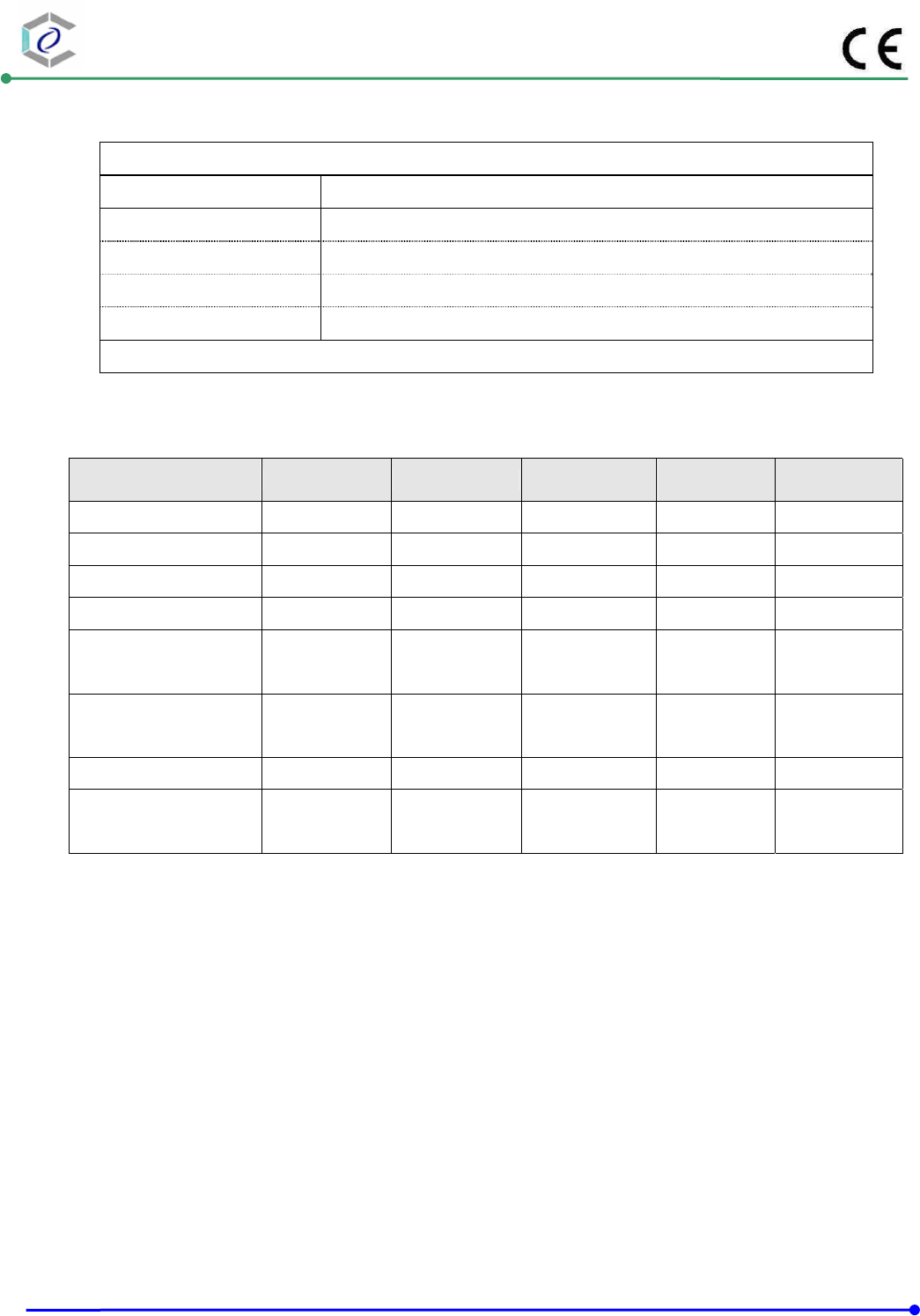
History of this test report
Original
Additional attachment as following record:
Attachment No. Date Description

CERPASS TECHNOLOGY (SUZHOU)CO.,LTD Report No.: DECE1408123
Cerpass Technology (Suzhou) Co., Ltd Issued Date : Oct.31, 2014
TEL: +86-512-6917-5888 FAX: +86-512-6917-5666 Page No. : 5 of 67
CERTIFICATE OF COMPLIANCE
According to
EN 55022 : 2010 / AC:2011 EN 55024 : 2010
EN 61000-3-2: 2006+A2: 2009 IEC 61000-4-2 : 2008
EN 61000-3-3 : 2008 IEC 61000-4-3 : 2006+A1:2007+A2:2010
IEC 61000-4-4 : 2012
IEC 61000-4-5 : 2005
IEC 61000-4-6 : 2008
IEC 61000-4-8 : 2009
IEC 61000-4-11 : 2004
Applicant : Intracom Asia Co., Ltd
Address : 4F., No.77, Sec.1, Xintai 5th Rd., Xizhi Dist., New Taipei City 221,
Taiwan
Equipment : Fast Ethernet PCI Network Card
Model No. : 509510
Trademark : Intellinet
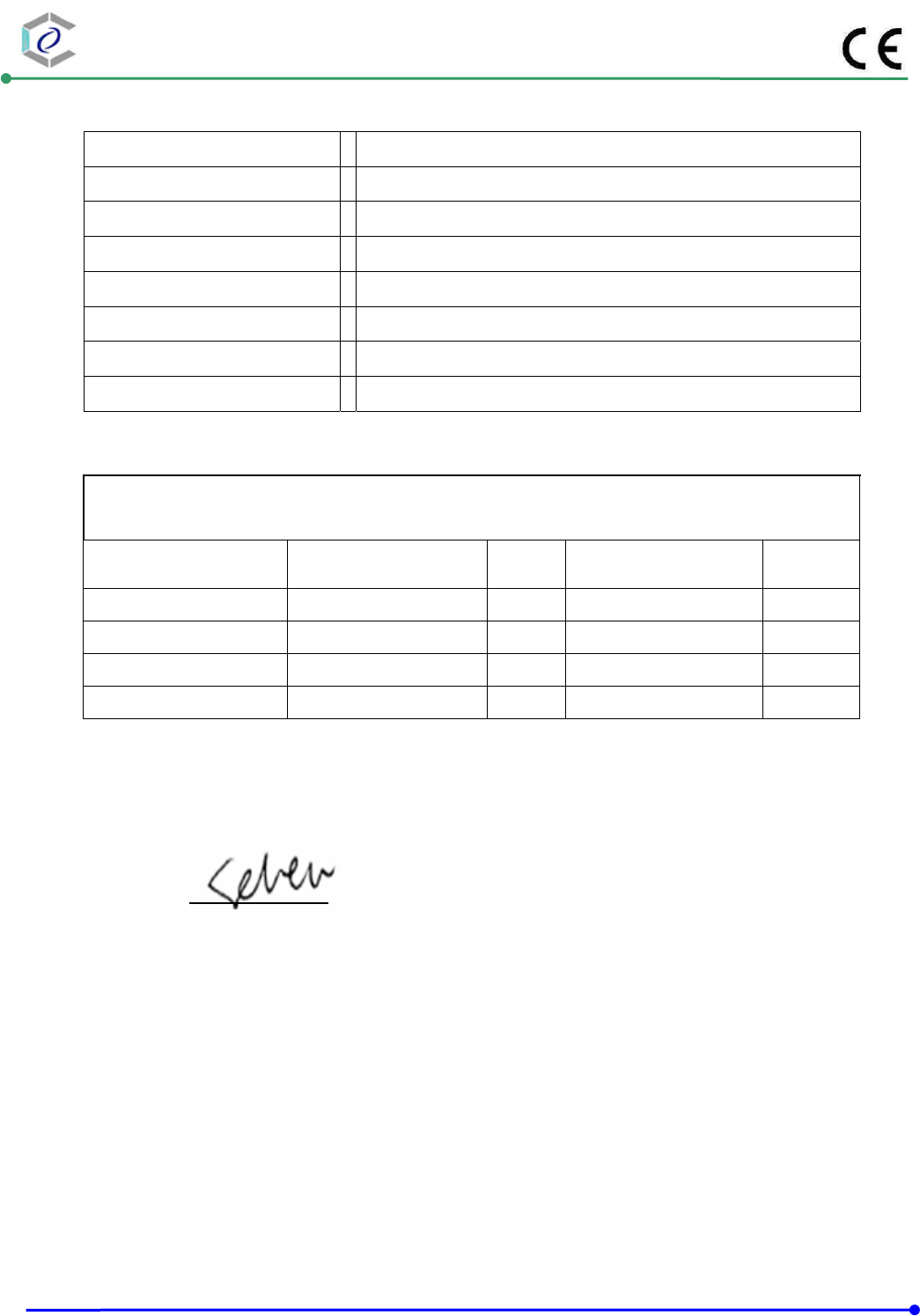
I HEREBY CERTIFY THAT :
The measurements shown in this test report were made in accordance with the procedures
given in EUROPEAN COUNCIL DIRECTIVE 2004/108/EC& 2014/30/EU.
The test was carried out on Oct .23~31, 2014 at Cerpass Technology(Suzhou) Corp.
Signature
Miro Chueh/ Technical director
CERPASS TECHNOLOGY (SUZHOU)CO.,LTD Report No.: DECE1408123
Cerpass Technology (Suzhou) Co., Ltd Issued Date : Oct.31, 2014
TEL: +86-512-6917-5888 FAX: +86-512-6917-5666 Page No. : 6 of 67
1. Summary of Test Procedure and Test Results
Test Item Normative References Test Result
Conducted Emission EN55022:2010/AC:2011 PASS
Radiated Emission EN55022:2010/AC:2011 PASS
Harmonics EN 61000-3-2 : 2006+A2: 2009 PASS
Voltage Fluctuations EN 61000-3-3: 2008 PASS
Electrostatic Discharge Immunity
Test (ESD) IEC 61000-4-2 : 2008 PASS
Radio Frequency electromagnetic
field immunity test (RS) IEC 61000-4-3 : 2006+A1:2007+A2:2010 PASS
Electrical Fast Transient/ Burst
Immunity Test (EFT) IEC 61000-4-4 : 2012 PASS
Surge Immunity Test IEC 61000-4-5 : 2005 PASS
Conduction Disturbances induced
by Radio-Frequency Fields IEC 61000-4-6 : 2008 PASS
Power Frequency Magnetic Field
Immunity Test IEC 61000-4-8 : 2009 N/A
Voltage Dips and Voltage
Interruptions Immunity Test IEC 61000-4-11 : 2004 PASS
2. Immunity Testing Performance Criteria Definition
A. Normal performance within limits specified by the manufacture, requestor or purchaser;
B. Temporary loss of function or degradation of performance which ceases after the disturbance
ceases, and from which the equipment under test recovers its normal performance, without
operator intervention;
C. Temporary loss of function or degradation of performance, the correction of which requires
operation intervention;
D. Loss of function or degradation of performance which is not recoverable, owing to damage to
hardware or software, or loss of data.
CERPASS TECHNOLOGY (SUZHOU)CO.,LTD Report No.: DECE1408123
Cerpass Technology (Suzhou) Co., Ltd Issued Date : Oct.31, 2014
TEL: +86-512-6917-5888 FAX: +86-512-6917-5666 Page No. : 7 of 67
3. Test Configuration of Equipment under Test
3.1. Factory
Intracom Asia Co., Ltd
4F., No.77, Sec.1, Xintai 5th Rd., Xizhi Dist., New Taipei City 221, Taiwan
3.2. Feature of Equipment under Test
Equipment Fast Ethernet PCI Network Card
Model No: 509510
3.3. Test Manner
a During testing, the interface cables and equipment positions were varied according to
Europe Standard.
b The complete test system included auxiliary equipment and EUT for EMI test.
c And then test.
The pre-test modes
Conducted Emission
(Power port) Test Mode 1: Normal Link
Conducted Emission
(Telecom port) ISN RJ45 10Mbps /100Mbps LINK 10%
Radiated Emission
EMS/H-F: Test Mode 1: Normal Link
The worse case was selected as the final test mode and record in the report
Test Mode 1: Normal Link
CERPASS TECHNOLOGY (SUZHOU)CO.,LTD Report No.: DECE1408123
Cerpass Technology (Suzhou) Co., Ltd Issued Date : Oct.31, 2014
TEL: +86-512-6917-5888 FAX: +86-512-6917-5666 Page No. : 8 of 67
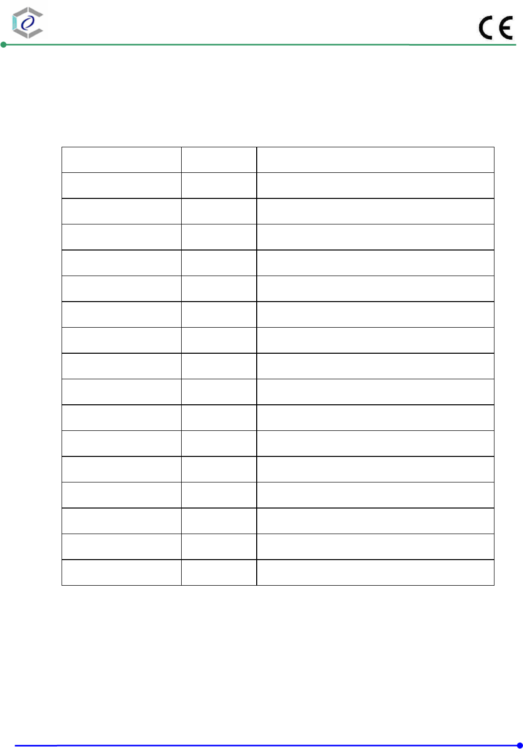
3.4. Description of Test System
No Device Manufacturer Model No. Description
1 PC DELL Dell Optitle 380 N/A
2 Notebook SONY PCG-71811P R33021
3 LCD Monitor DELL U3011T R43004
4 Printer HP DESKJET 400 N/A
5 HDD N/A USB 3.0 HDD N/A
6 USB Mouse DELL OXN967 R41108
7 USB Mouse DELL MG1090 R41108
8 USB Keyboard DELL SK-8115 T3A002
Use Cable:
No. Cable Quantity Description
A RJ45 1 1m Shielded with two core
B VGA Cable 1 1.8 Shielded with two core
C USB Cable 1 1.8 Shielded
D USB Cable 1 0.4 Unshielded
E USB Cable 1 1.8 Unshielded
F USB Cable 1 1.8 Unshielded
G USB Cable 1 1.8 Unshielded
CERPASS TECHNOLOGY (SUZHOU)CO.,LTD Report No.: DECE1408123
Cerpass Technology (Suzhou) Co., Ltd Issued Date : Oct.31, 2014
TEL: +86-512-6917-5888 FAX: +86-512-6917-5666 Page No. : 9 of 67
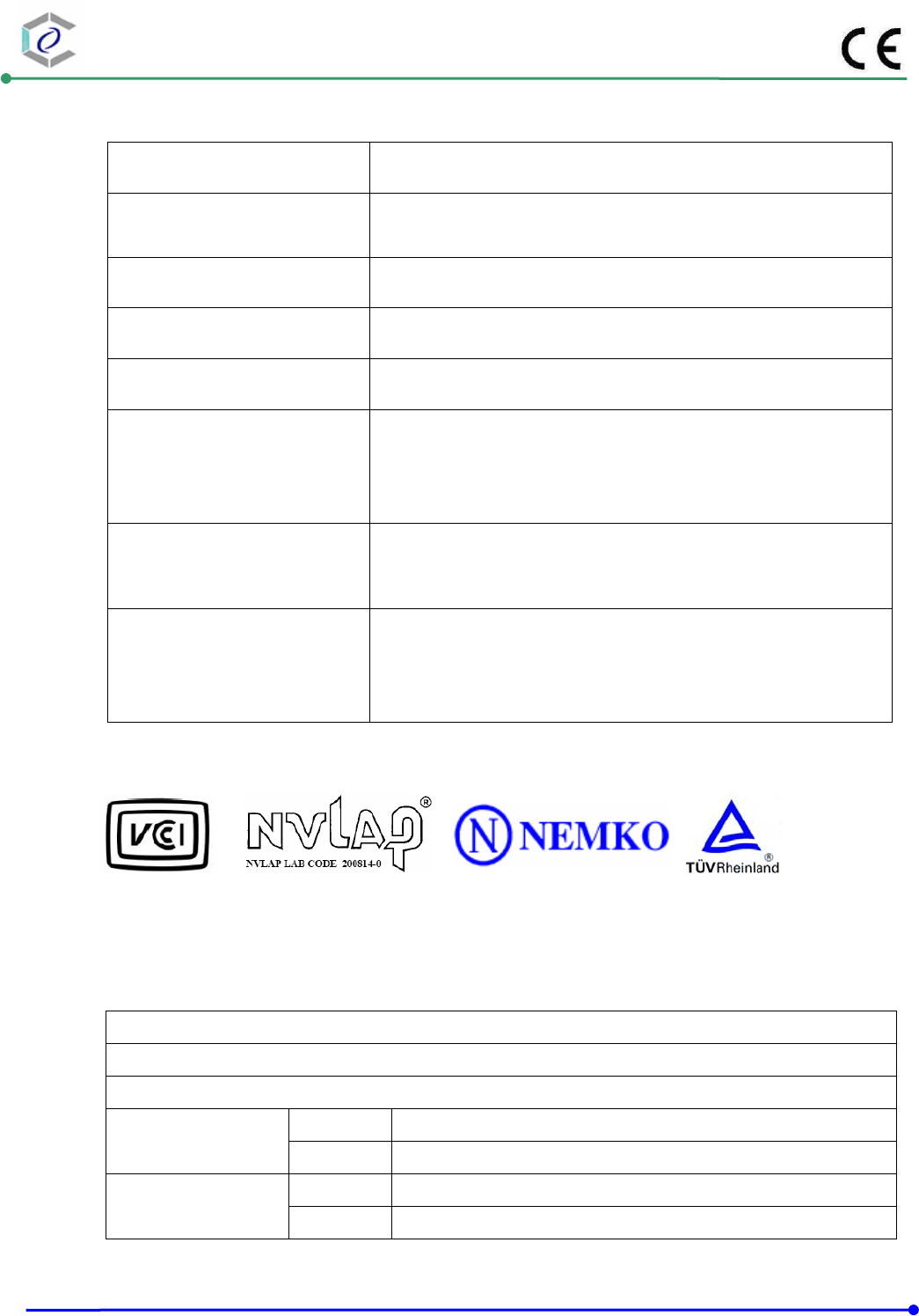
3.5. General Information of Test
Test Site: Cerpass Technology (Suzhou) Co.,Ltd
Test Site Location : No.66,Tangzhuang Road, Suzhou Industrial Park, Jiangsu
215006, China
NVLAP LAB Code : 200814-0
FCC Registration Number : 916572, 331395
IC Registration Number : 7290A-1, 7290A-2
VCCI Registration Number :
T-1945 for Telecommunication Test
C-2919 for Conducted emission test
R-2670 for Radiated emission test below 1GHz
G-227 for Radiated emission test above 1GHz
Frequency Range
Investigated :
Conducted Emission Test: from 150kHz to 30 MHz
Radiated Emission Test: from 30 MHz to 1,000 MHz
Radiated Emission Test: from 1GHz to 6GHz
Test Distance :
The test distance of radiated emission below 1GHz from
antenna to EUT is 10 M.
The test distance of radiated emission above 1GHz from
antenna to EUT is 3 M.
LABORATORY ACCREDIATION
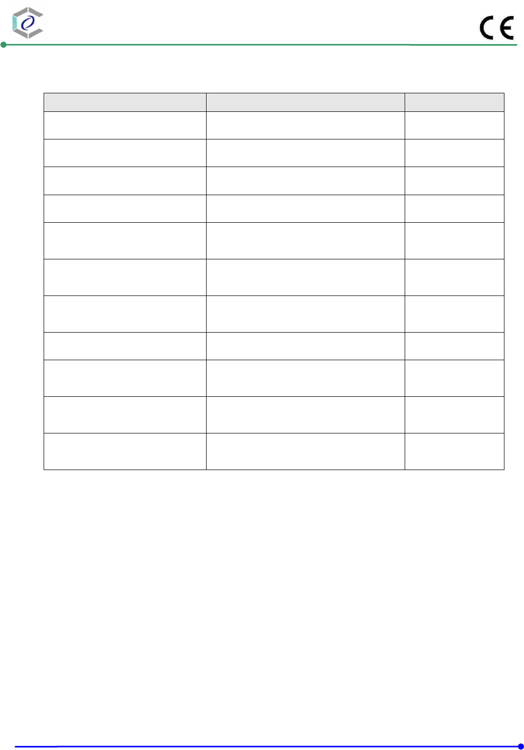
3.6. Measurement Uncertainty
Test results and Measurement uncertainty without any relationship in the test report.
Conducted Emission
The measurement uncertainty is evaluated as ± 2.71 dB.
Radiated Emission
Horizontal The measurement uncertainty is evaluated as ±3.59 dB.
(30MHz -1000MHz) Vertical The measurement uncertainty is evaluated as ± 3.89 dB
Horizontal The measurement uncertainty is evaluated as ± 2.31 dB.
(1G-6GHz) Vertical The measurement uncertainty is evaluated as ± 2.15 dB.
CERPASS TECHNOLOGY (SUZHOU)CO.,LTD Report No.: DECE1408123
Cerpass Technology (Suzhou) Co., Ltd Issued Date : Oct.31, 2014
TEL: +86-512-6917-5888 FAX: +86-512-6917-5666 Page No. : 10 of 67
4. Test of Conducted Emission
4.1. Test Limit
Conducted Emissions were measured from 150 kHz to 30 MHz with a bandwidth of 9 kHz and
return leads of the EUT according to the methods defined in European Standard EN 55022
Clause 9. The EUT was placed on a nonmetallic stand in a shielded room 0.8 meters above
the ground plane as shown in section 5.2. The interface cables and equipment positioning were
varied within limits of reasonable applications to determine the position producing maximum
conducted emissions.
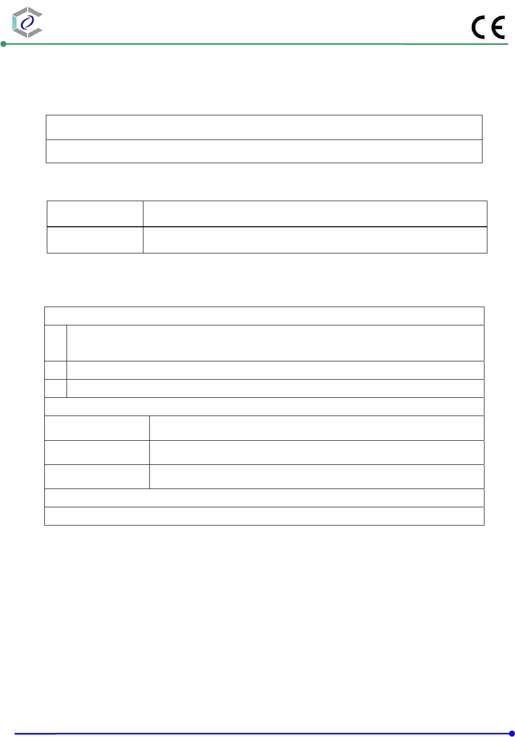
Table 1 Class B Line Conducted Emission Limits:
Limits (dB µ V)
Frequency range
(MHz) Quasi Peak Average
0.15 to 0.50 66 to 56 56 to 46
0.50 to 5 56 46
5. to 30. 60 50
Note 1: The lower limits shall apply at the transition frequencies.
Note 2: The limit decreases linearly with the logarithm of the frequency in the range 0.15 MHz to
0.50MHz.
Table 2 - Limits of conducted common mode (asymmetric mode) disturbance at
telecommunication ports in the frequency range 0.15 MHz to 30 MHz for class B equipment.
Voltage limits
dB(μV)
Current limits
dB(μA)
Frequency range
(MHz) Quasi-peak Average Quasi-peak Average
0.15 to 0.5 84 to 74 74 to 64 40 to 30 30 to 20
0.5 to 30 74 64 30 20
Note 1: The limits decrease linearly with the logarithm of the frequency in the range 0.15 to 0.5 MHz.
Note 2: The current and voltage disturbance limits are derived for use with an impedance stabilization
network (ISN) which presents a common mode (asymmetric mode) impedance of 150Ω to the
telecommunication under test (conversion factor is 20 log10 150/1 = 44dB).
CERPASS TECHNOLOGY (SUZHOU)CO.,LTD Report No.: DECE1408123
Cerpass Technology (Suzhou) Co., Ltd Issued Date : Oct.31, 2014
TEL: +86-512-6917-5888 FAX: +86-512-6917-5666 Page No. : 11 of 67
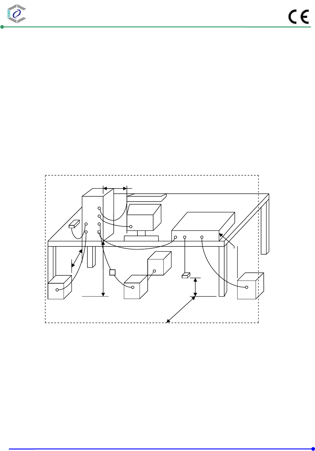
4.2. Test Procedures
a. The EUT was placed on a desk 0.8 meters height from the metal ground plane and 0.4 meter
from the conducting wall of the shielding room and it was kept at least 0.8 meters from any other
grounded conducting surface.
b. Connect EUT to the power mains through a line impedance stabilization network (LISN).
c. All the support units are connecting to the other LISN.
d. The LISN provides 50 ohm coupling impedance for the measuring instrument.
e. The CISPR states that a 50 ohm, 50 micro-Henry LISN should be used.
f. Both sides of AC line were checked for maximum conducted interference.
g. The frequency range from 150 kHz to 30 MHz was searched
h. Set the test-receiver system to Peak Detect Function and Specified Bandwidth with Maximum
Hold Mode.
4.3. Typical Test Setup
10cm
80cm
EUT
80cm
40cm
LISN
80cm
40cm
LISN
ISN
AE
CERPASS TECHNOLOGY (SUZHOU)CO.,LTD Report No.: DECE1408123
Cerpass Technology (Suzhou) Co., Ltd Issued Date : Oct.31, 2014
TEL: +86-512-6917-5888 FAX: +86-512-6917-5666 Page No. : 12 of 67
4.4. Measurement equipment
Instrument/Ancillary Manufacturer Model No. Serial No. Calibration
Date Valid Date.
Test Receiver R&S ESCI 100565 2014.03.24 2015.03.23
AMN R&S ESH2-Z5 100182
2014.09.11 2015.09.10
Two-Line V-Network R&S ENV216 100325 2013.12.04 2014.12.03
ISN FCC FCC-TLISN-T2-02 20379 2014.03.24 2015.03.23
ISN FCC FCC-TLISN-T4-02 20380 2014.03.24 2015.03.23
ISN FCC FCC-TLISN-T8-02 20381 2014.03.24 2015.03.23
ISN TESEQ ISN ST08 30175 2014.03.24 2015.03.23
Current Probe R&S EZ-17 100303 2014.04.04 2015.04.03
Passive Voltage Probe R&S ESH2-Z3 100026 2014.03.24 2015.03.23
Pulse Limiter R&S ESH3-Z2 100529 2014.03.24 2015.03.23
Temperature/ Humidity
Meter Zhicheng ZC1-11 CEP-TH-004 2014.03.31 2015.03.30
CERPASS TECHNOLOGY (SUZHOU)CO.,LTD Report No.: DECE1408123
Cerpass Technology (Suzhou) Co., Ltd Issued Date : Oct.31, 2014
TEL: +86-512-6917-5888 FAX: +86-512-6917-5666 Page No. : 13 of 67
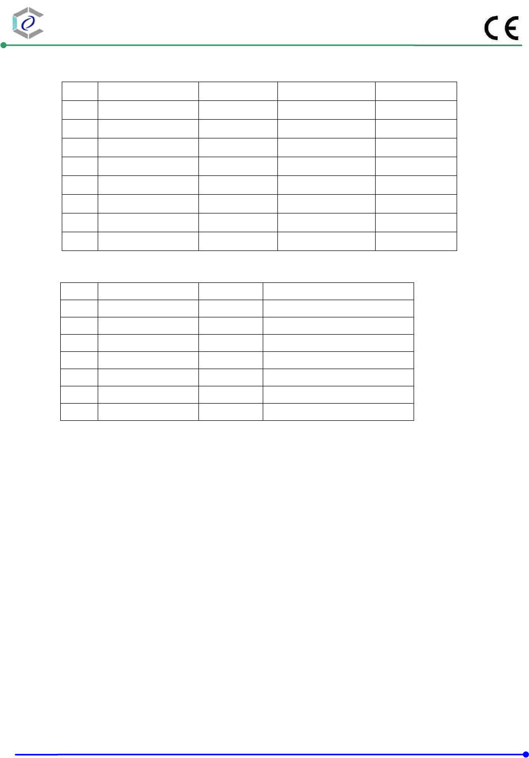
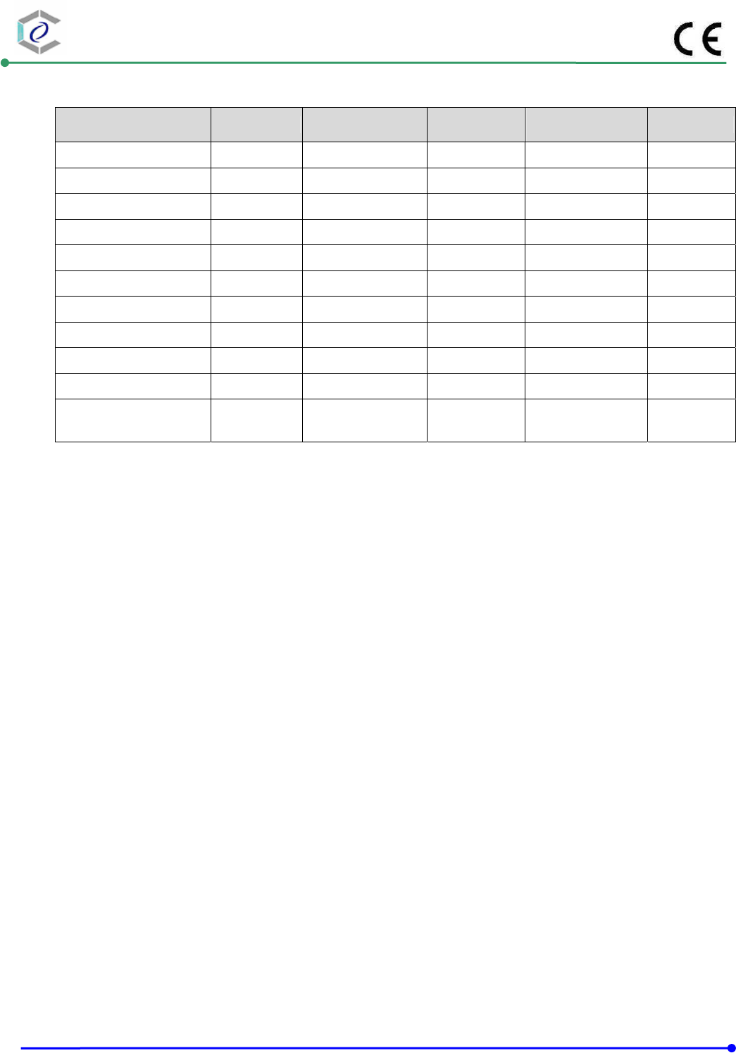
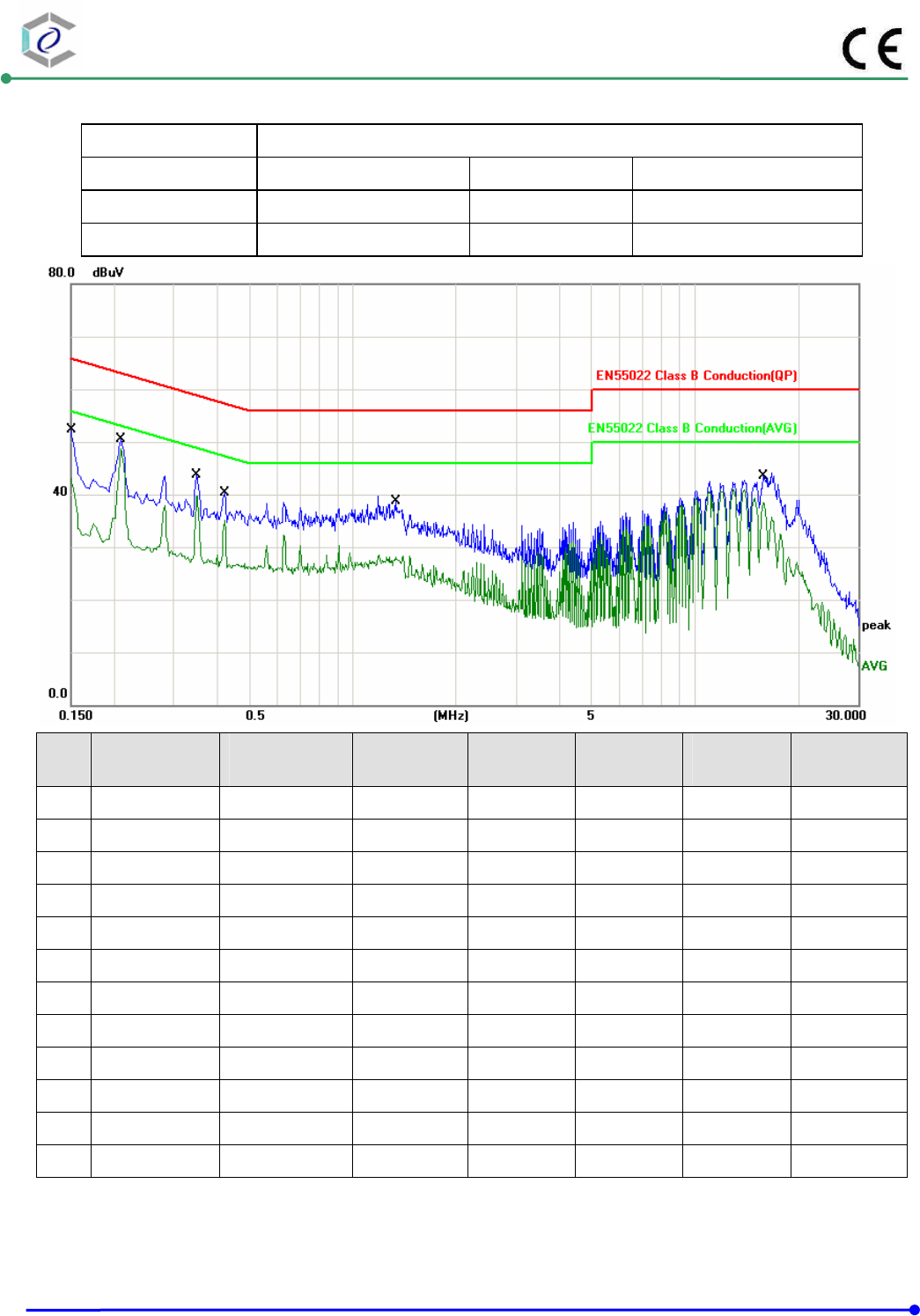
4.5. Test Data and Result
Test Mode : Mode 1: Normal Link
AC Power : AC 230V/50Hz Phase : LINE
Temperature : 22°C Humidity : 50%
Pressure(mbar) : 1002 Date: 2014/10/23
No. Frequency
(MHz)
Factor
(dB)
Reading
(dBuV)
Level
(dBuV)
Limit
(dBuV)
Margin
(dB)
Detector
1 0.1500 9.70 34.97 44.67 65.99 -21.32 QP
2 0.1500 9.70 32.59 42.29 56.00 -13.71 AVG
3 0.2100 9.69 39.67 49.36 63.20 -13.84 QP
4 0.2100 9.69 39.07 48.76 54.28 -5.52 AVG
5 0.3500 9.67 31.75 41.42 58.96 -17.54 QP
6 0.3500 9.67 29.86 39.53 50.28 -10.75 AVG
7 0.4220 9.67 27.83 37.50 57.41 -19.91 QP
8 0.4220 9.67 25.19 34.86 48.23 -13.37 AVG
9 1.3420 9.66 23.75 33.41 56.00 -22.59 QP
10 1.3420 9.66 18.47 28.13 46.00 -17.87 AVG
11 15.8660 10.02 30.06 40.08 60.00 -19.92 QP
12 15.8660 10.02 28.68 38.70 50.00 -11.30 AVG
Note: Measurement Level = Reading Level + Correct Factor+ Attenuator
CERPASS TECHNOLOGY (SUZHOU)CO.,LTD Report No.: DECE1408123
Cerpass Technology (Suzhou) Co., Ltd Issued Date : Oct.31, 2014
TEL: +86-512-6917-5888 FAX: +86-512-6917-5666 Page No. : 14 of 67
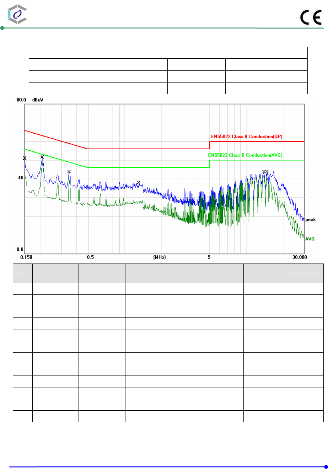
Test Mode : Mode 1: Normal Link
AC Power : AC 230V/50Hz Phase : NEUTRAL
Temperature : 22°C Humidity : 50%
Pressure(mbar) : 1002 Date: 2014/10/23
No. Frequency
(MHz)
Factor
(dB)
Reading
(dBuV)
Level
(dBuV)
Limit
(dBuV)
Margin
(dB)
Detector
1 0.1500 9.70 34.81 44.51 65.99 -21.48 QP
2 0.1500 9.70 32.40 42.10 56.00 -13.90 AVG
3 0.2100 9.69 39.68 49.37 63.20 -13.83 QP
4 0.2100 9.69 39.09 48.78 54.28 -5.50 AVG
5 0.3500 9.67 31.77 41.44 58.96 -17.52 QP
6 0.3500 9.67 29.94 39.61 50.28 -10.67 AVG
7 1.3099 9.66 22.47 32.13 56.00 -23.87 QP
8 1.3099 9.66 17.25 26.91 46.00 -19.09 AVG
9 13.9500 9.95 30.63 40.58 60.00 -19.42 QP
10 13.9500 9.95 30.34 40.29 50.00 -9.71 AVG
11 14.8460 9.98 29.71 39.69 60.00 -20.31 QP
12 14.8460 9.98 29.03 39.01 50.00 -10.99 AVG
Note: Measurement Level = Reading Level + Correct Factor+ Attenuator
CERPASS TECHNOLOGY (SUZHOU)CO.,LTD Report No.: DECE1408123
Cerpass Technology (Suzhou) Co., Ltd Issued Date : Oct.31, 2014
TEL: +86-512-6917-5888 FAX: +86-512-6917-5666 Page No. : 15 of 67
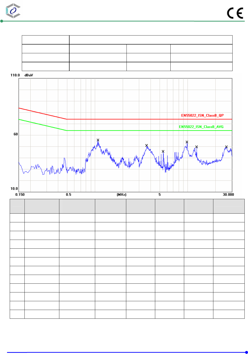
Test Mode : ISN RJ45 10Mbps LINK 10%
AC Power : AC 230V/50Hz Phase : 10M
Temperature : 22°C Humidity : 50%
Pressure(mbar) : 1002 Date: 2014/10/31
No. Frequency
(MHz)
Factor
(dB)
Reading
(dBuV)
Level
(dBuV)
Limit
(dBuV)
Margin
(dB)
Detector
1 1.0820 19.61 29.24 48.85 74.00 -25.15 QP
2 1.0820 19.61 22.91 42.52 64.00 -21.48 AVG
3 3.6380 19.64 26.17 45.81 74.00 -28.19 QP
4 3.6380 19.64 16.70 36.34 64.00 -27.66 AVG
5 5.4660 19.66 3.82 23.48 74.00 -50.52 QP
6 5.4660 19.66 -1.03 18.63 64.00 -45.37 AVG
7 9.9060 19.78 21.51 41.29 74.00 -32.71 QP
8 9.9060 19.78 14.30 34.08 64.00 -29.92 AVG
9 12.5180 19.75 15.74 35.49 74.00 -38.51 QP
10 12.5180 19.75 9.82 29.57 64.00 -34.43 AVG
11 26.3020 19.84 23.44 43.28 74.00 -30.72 QP
12 26.3020 19.84 17.05 36.89 64.00 -27.11 AVG
Note: Measurement Level = Reading Level + Correct Factor+ Attenuator
CERPASS TECHNOLOGY (SUZHOU)CO.,LTD Report No.: DECE1408123
Cerpass Technology (Suzhou) Co., Ltd Issued Date : Oct.31, 2014
TEL: +86-512-6917-5888 FAX: +86-512-6917-5666 Page No. : 16 of 67
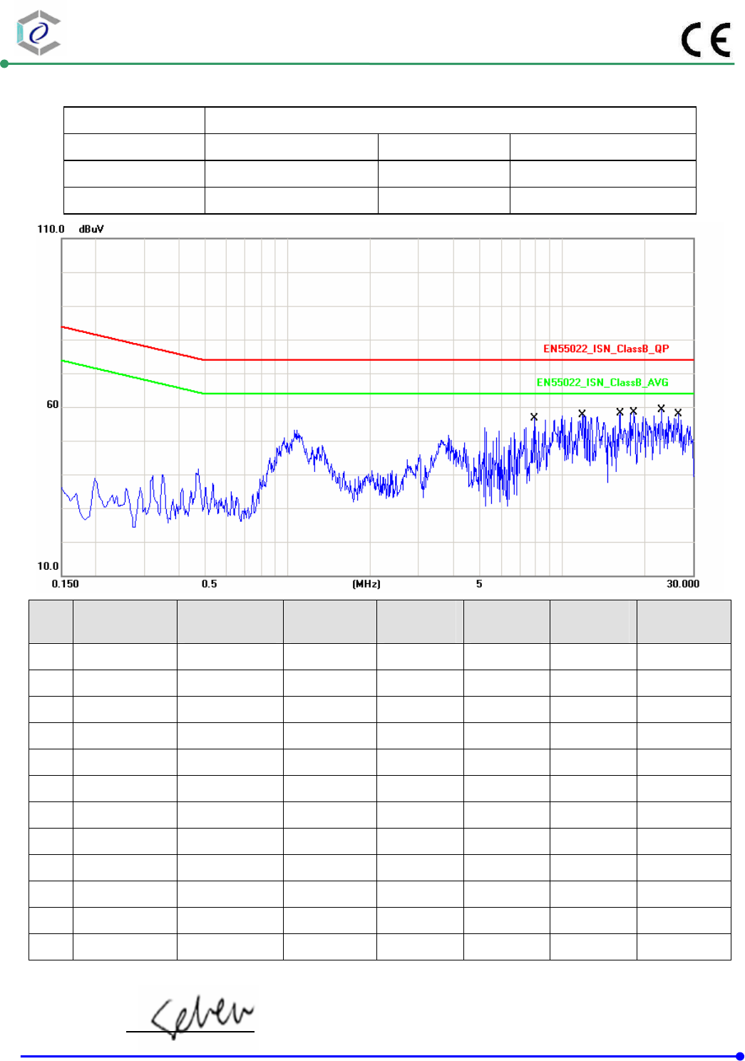
Test Mode : ISN RJ45 100M LINK 10%
AC Power : AC 230V/50Hz Phase : 100M
Temperature : 22°C Humidity : 50%
Pressure(mbar) : 1002 Date: 2014/09/15
No. Frequency
(MHz)
Factor
(dB)
Reading
(dBuV)
Level
(dBuV)
Limit
(dBuV)
Margin
(dB)
Detector
1 7.9260 19.69 35.89 55.58 74.00 -18.42 QP
2 7.9260 19.69 32.62 52.31 64.00 -11.69 AVG
3 11.8940 19.76 35.76 55.52 74.00 -18.48 QP
4 11.8940 19.76 33.34 53.10 64.00 -10.90 AVG
5 16.2300 19.74 35.41 55.15 74.00 -18.85 QP
6 16.2300 19.74 34.38 54.12 64.00 -9.88 AVG
7 18.2500 19.78 36.94 56.72 74.00 -17.28 QP
8 18.2500 19.78 37.12 56.90 64.00 -7.10 AVG
9 23.1340 19.81 37.58 57.39 74.00 -16.61 QP
10 23.1340 19.81 37.78 57.59 64.00 -6.41 AVG
11 26.6180 19.85 36.74 56.59 74.00 -17.41 QP
12 26.6180 19.85 36.45 56.30 64.00 -7.70 AVG
Note: Measurement Level = Reading Level + Correct Factor+ Attenuator
Test engineer:
CERPASS TECHNOLOGY (SUZHOU)CO.,LTD Report No.: DECE1408123
Cerpass Technology (Suzhou) Co., Ltd Issued Date : Oct.31, 2014
TEL: +86-512-6917-5888 FAX: +86-512-6917-5666 Page No. : 17 of 67
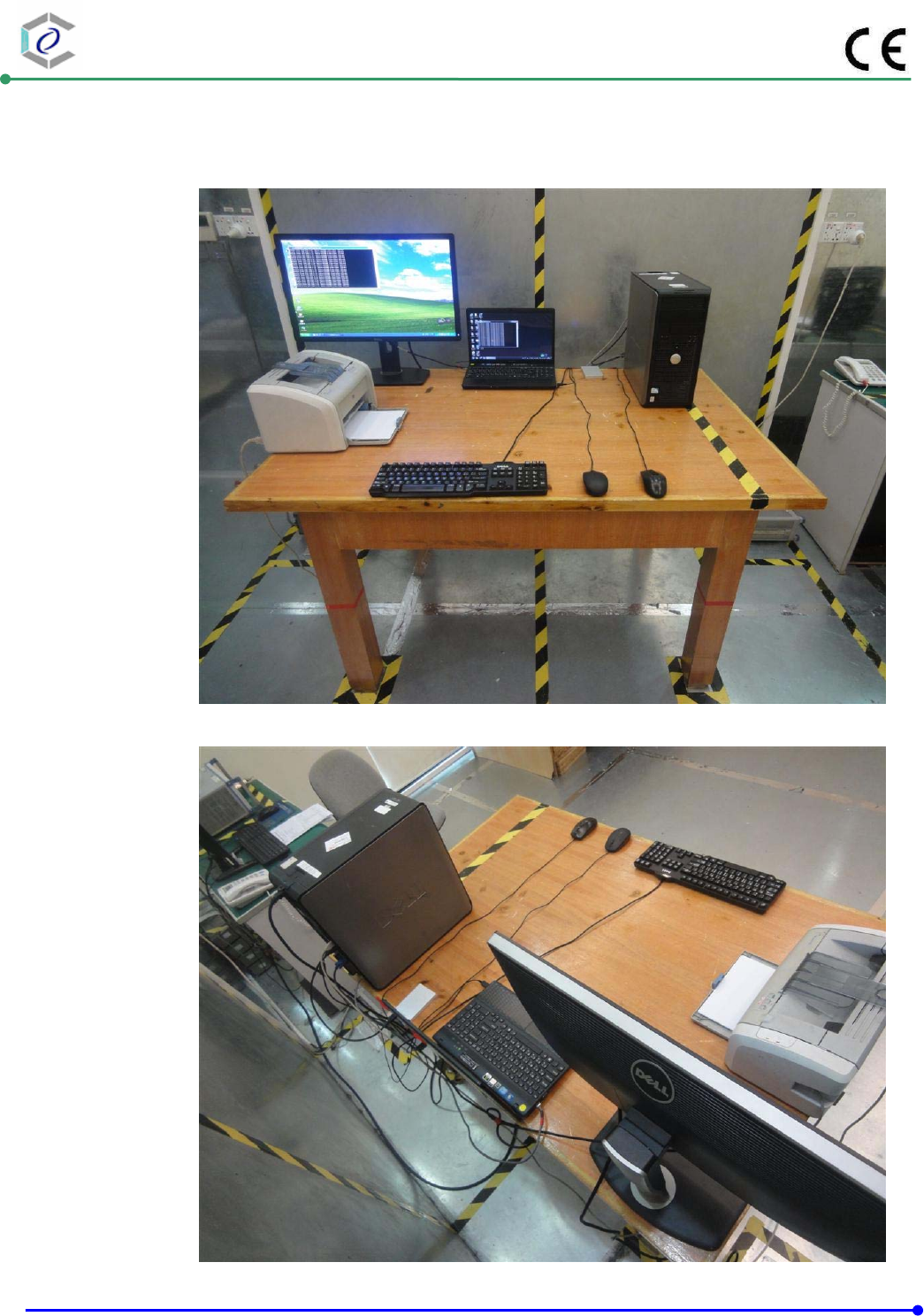
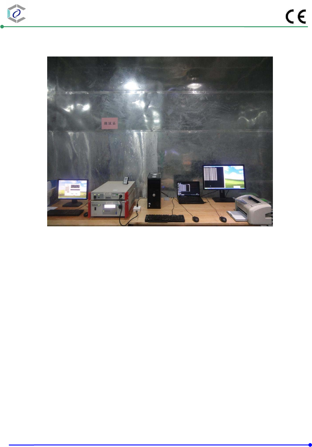
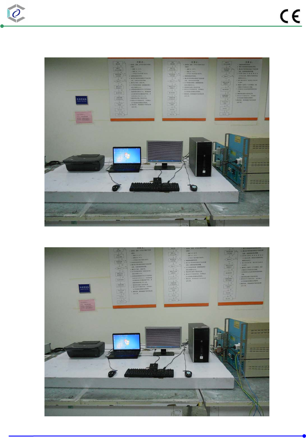
4.6. Test Photographs
Front View
Rear View
CERPASS TECHNOLOGY (SUZHOU)CO.,LTD Report No.: DECE1408123
Cerpass Technology (Suzhou) Co., Ltd Issued Date : Oct.31, 2014
TEL: +86-512-6917-5888 FAX: +86-512-6917-5666 Page No. : 18 of 67
ISN 10M&100M
Front View
Rear View
CERPASS TECHNOLOGY (SUZHOU)CO.,LTD Report No.: DECE1408123
Cerpass Technology (Suzhou) Co., Ltd Issued Date : Oct.31, 2014
TEL: +86-512-6917-5888 FAX: +86-512-6917-5666 Page No. : 19 of 67
5. Test of Radiated Emission
5.1. Test Limit
Table – Limits for radiated disturbance of class B ITE at a measuring distance of 3 m
Frequency range
MHz
Quasi-peak limits
dB(μV/m)
30 to 230 40
230 to 1000 47
NOTE 1 The lower limit shall apply at the transition frequency.
NOTE 2 Additional provisions may be required for cases where interference occurs.
The EUT shall meet the limits of below Table when measured in accordance with the method
described in European Standard EN 55022 Clause 10 and the conditional testing procedure
described below.
Table – Limits for radiated disturbance of class B ITE at a measuring distance of 3 m
Frequency range
GHz
Average limit
dB(μV/m)
Peak limits
dB(μV/m)
1 to 3 50 70
3 to 6 54 74
NOTE The lower limit applies at the transition frequency.
• Conditional testing procedure:
The highest internal source of an EUT is defined as the highest frequency generated or used
within the EUT or on which the EUT operates or tunes.
If the highest frequency of the internal sources of the EUT is less than 108 MHz, the
measurement shall only be made up to 1 GHz.
If the highest frequency of the internal sources of the EUT is between 108 MHz and 500 MHz, the
measurement shall only be made up to 2 GHz.
If the highest frequency of the internal sources of the EUT is between 500 MHz and 1 GHz, the
measurement shall only be made up to 5 GHz.
If the highest frequency of the internal sources of the EUT is above 1 GHz, the measurement
shall be made up to 5 times the highest frequency or 6 GHz, whichever is less.
CERPASS TECHNOLOGY (SUZHOU)CO.,LTD Report No.: DECE1408123
Cerpass Technology (Suzhou) Co., Ltd Issued Date : Oct.31, 2014
TEL: +86-512-6917-5888 FAX: +86-512-6917-5666 Page No. : 20 of 67
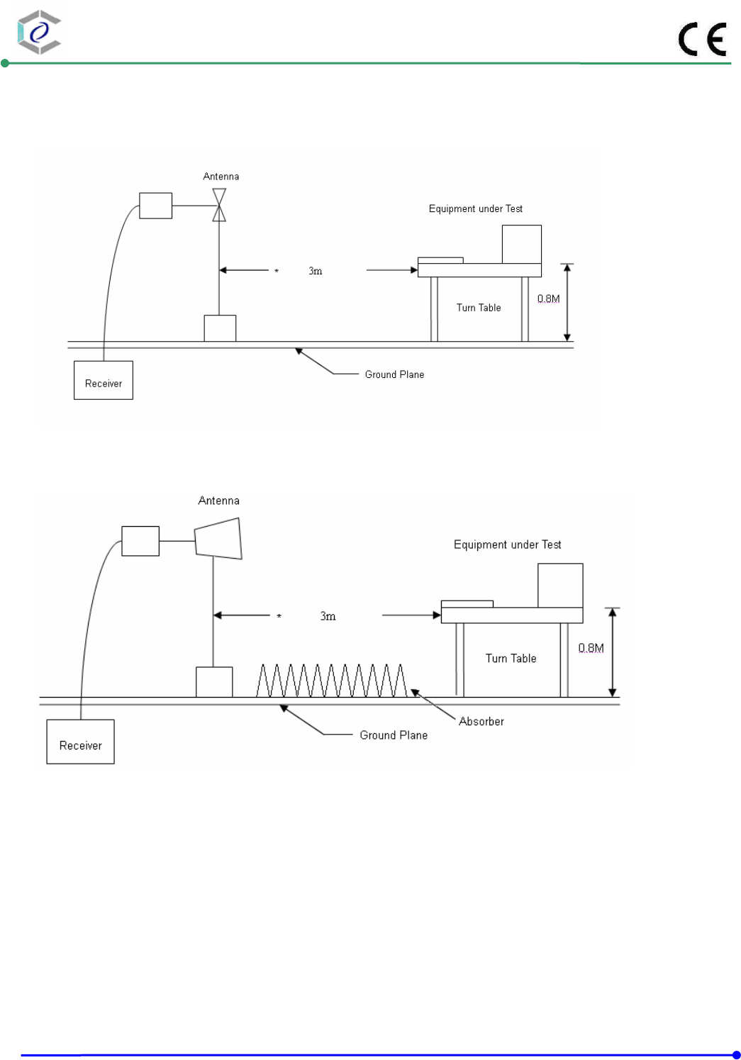
5.2. Test Procedures
a. The EUT was placed on a relatable table top 0.8 meter above ground.
b. The EUT was set 3/10 meters from the interference receiving antenna which was mounted
on the top of a variable height antenna tower.
c. The table was rotated 360 degrees to determine the position of the highest radiation.
d. The antenna is a half wave dipole and its height is varied between one meter and four
meters above ground to find the maximum value of the field strength both horizontal
polarization and vertical polarization of the antenna are set to make the measurement.
e. For each suspected emission the EUT was arranged to its worst case and then tune the
antenna tower (from 1 M to 4 M) and turn table (from 0 degree to 360 degrees) to find the
maximum reading.
f. Set the test-receiver system to Peak Detect Function and specified bandwidth with
Maximum Hold Mode.
g. If the emission level of the EUT in peak mode was 3 dB lower than the limit specified, then
testing will be stopped and peak values of EUT will be reported, otherwise, the emissions
which do not have 3 dB margin will be repeated one by one using the quasi-peak method
and reported.
CERPASS TECHNOLOGY (SUZHOU)CO.,LTD Report No.: DECE1408123
Cerpass Technology (Suzhou) Co., Ltd Issued Date : Oct.31, 2014
TEL: +86-512-6917-5888 FAX: +86-512-6917-5666 Page No. : 21 of 67
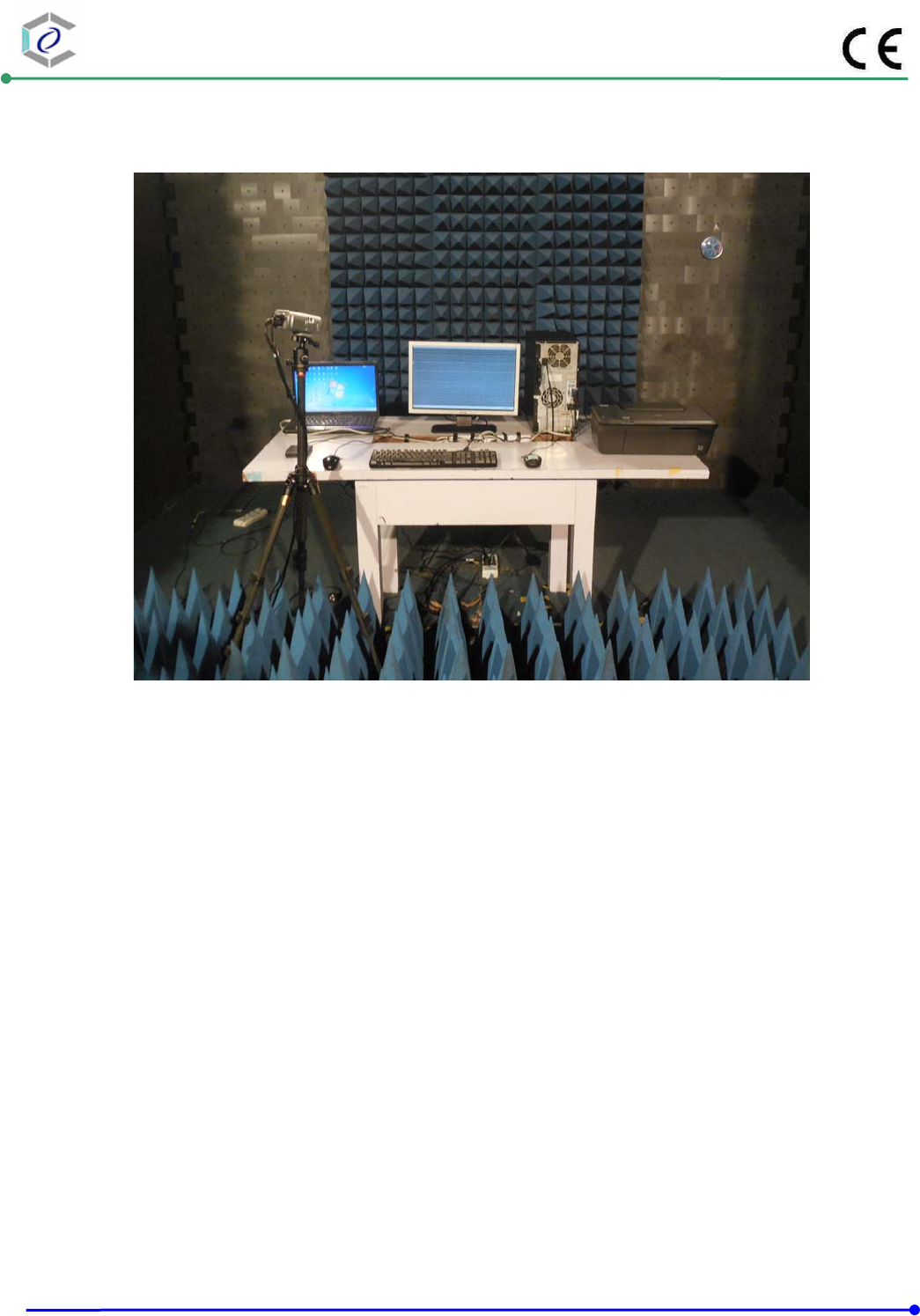
5.3. Typical test Setup
Below 1GHz Test Setup
Above 1GHz Test Setup
CERPASS TECHNOLOGY (SUZHOU)CO.,LTD Report No.: DECE1408123
Cerpass Technology (Suzhou) Co., Ltd Issued Date : Oct.31, 2014
TEL: +86-512-6917-5888 FAX: +86-512-6917-5666 Page No. : 22 of 67
5.4. Measurement equipment
Instrument/Ancillary Manufacturer Model No. Serial No. Calibration
Date Valid Date.
EMI Test Receiver R&S ESCI 100853 2014.03.01 2015.02.28
Preamplifier HP 8447F 3113A05915 2014.03.01 2015.02.28
Preamplifier FIELD
AFS44-00101800
-25-10P-44 1579008 2013.11.27 2014.11.26
Ultra Broadband
Antenna SCHAFFNER CBL6112D 22241 2014.03.04 2015. 03.03
Broad-Band Horn
Antenna Sunol DRH-118 A072913 2014.10.16 2014.10.15
Spectrum Analyzer Agilent E4407B MY45118947 2014.07.18 2015.07.17
Temperature/ Humidity
Meter VICHY CTH-608 N/A 2014.03.04 2015.03.03
CERPASS TECHNOLOGY (SUZHOU)CO.,LTD Report No.: DECE1408123
Cerpass Technology (Suzhou) Co., Ltd Issued Date : Oct.31, 2014
TEL: +86-512-6917-5888 FAX: +86-512-6917-5666 Page No. : 23 of 67
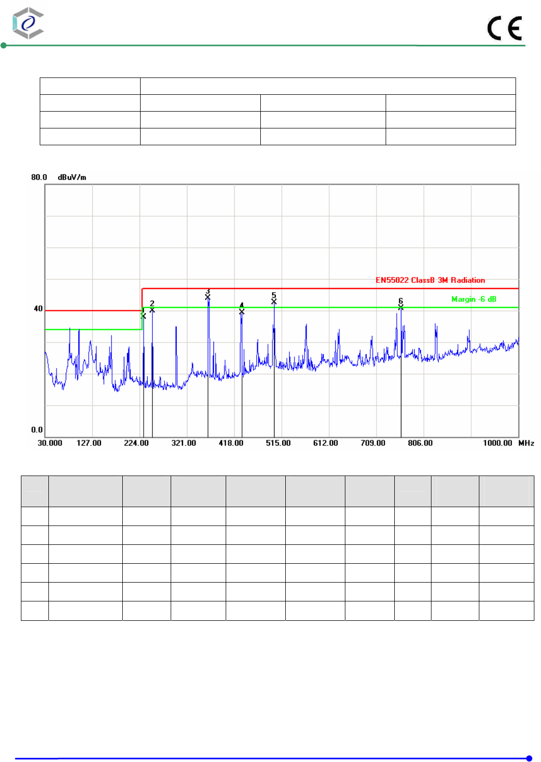
5.5. Test Result and Data (30MHz ~ 1000MHz)
Test Mode : Test Mode 1: Normal Link
AC Power : AC 230V/50Hz Ant. Polarization: Horizontal
Temp : 23 ℃ Humidity : 52%
Pressure(mbar) : 1002 Date : 2014/10/23
No. Frequency
(MHz)
Factor
(dB/m)
Reading
(dBuV)
Level
(dBuV/m)
Limit
(dBuV/m)
Margin
(dB)
Det. Height
(cm)
Azimuth
(deg)
1 232.7300 -9.44 47.29 37.85 47.00 -9.15 peak 100 22
2 250.1900 -8.37 48.37 40.00 47.00 -7.00 peak 100 75
3 364.6500 -4.54 48.50 43.96 47.00 -3.04 peak 200 121
4 433.5200 -4.46 43.69 39.23 47.00 -7.77 peak 200 245
5 500.4500 -2.20 44.66 42.46 47.00 -4.54 peak 200 312
6 760.4100 1.78 39.00 40.78 47.00 -6.22 peak 200 88
Note: Measurement Level = Reading Level + Correct Factor
CERPASS TECHNOLOGY (SUZHOU)CO.,LTD Report No.: DECE1408123
Cerpass Technology (Suzhou) Co., Ltd Issued Date : Oct.31, 2014
TEL: +86-512-6917-5888 FAX: +86-512-6917-5666 Page No. : 24 of 67
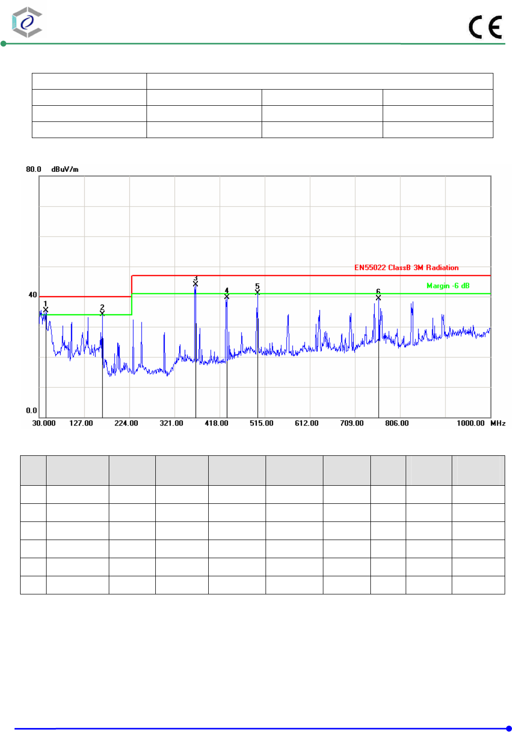
Test Mode : Test Mode 1: Normal Link
AC Power : AC 230V/50Hz Ant. Polarization: Vertical
Temp : 23 ℃ Humidity : 52%
Pressure(mbar) : 1002 Date : 2014/10/23
No. Frequency
(MHz)
Factor
(dB/m)
Reading
(dBuV)
Level
(dBuV/m)
Limit
(dBuV/m)
Margin
(dB)
Det. Height
(cm)
Azimuth
(deg)
1 44.5500 -12.12 47.43 35.31 40.00 -4.69 peak 100 37
2 165.8000 -12.26 46.28 34.02 40.00 -5.98 peak 100 58
3 366.5900 -4.60 48.50 43.90 47.00 -3.10 peak 100 99
4 433.5200 -4.46 44.18 39.72 47.00 -7.28 peak 200 159
5 500.4500 -2.20 43.32 41.12 47.00 -5.88 peak 200 246
6 760.4100 1.78 37.58 39.36 47.00 -7.64 peak 100 6
Note: Measurement Level = Reading Level + Correct Factor
CERPASS TECHNOLOGY (SUZHOU)CO.,LTD Report No.: DECE1408123
Cerpass Technology (Suzhou) Co., Ltd Issued Date : Oct.31, 2014
TEL: +86-512-6917-5888 FAX: +86-512-6917-5666 Page No. : 25 of 67
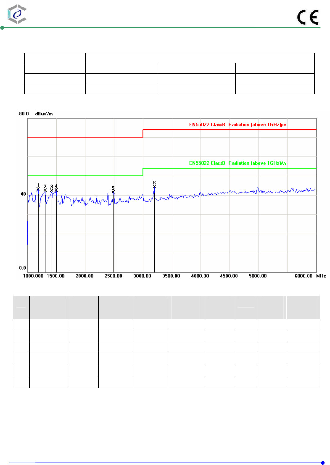
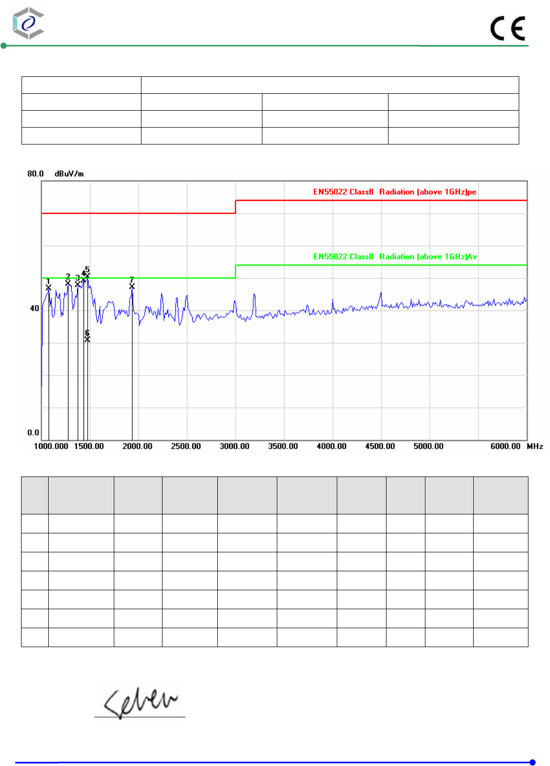
5.6. Test Result and Data (1000MHz ~ 6000MHz)
Test Mode : Test Mode 1: Normal Link
AC Power : AC 230V/50Hz Ant. Polarization: Horizontal
Temp : 23℃ Humidity : 52%
Pressure(mbar) : 1002 Date : 2014/10/30
No. Frequency
(MHz)
Factor
(dB/m)
Reading
(dBuV)
Level
(dBuV/m)
Limit
(dBuV/m)
Margin
(dB)
Det. Height
(cm)
Azimuth
(deg)
1 1187.500 -10.46 53.34 42.88 70.00 -27.12 peak 100 116
2 1312.500 -9.32 51.49 42.17 70.00 -27.83 peak 100 128
3 1425.000 -8.29 50.35 42.06 70.00 -27.94 peak 100 356
4 1500.000 -7.61 49.84 42.23 70.00 -27.77 peak 100 301
5 2487.500 -2.63 44.03 41.40 70.00 -28.60 peak 100 283
6 3200.000 1.82 42.25 44.07 74.00 -29.93 peak 100 140
Note: Measurement Level = Reading Level + Correct Factor
CERPASS TECHNOLOGY (SUZHOU)CO.,LTD Report No.: DECE1408123
Cerpass Technology (Suzhou) Co., Ltd Issued Date : Oct.31, 2014
TEL: +86-512-6917-5888 FAX: +86-512-6917-5666 Page No. : 26 of 67
Test Mode : Test Mode 1: Normal Link
AC Power : AC 230V/50Hz Ant. Polarization: Vertical
Temp : 23℃ Humidity : 52%
Pressure(mbar) : 1002 Date : 2014/10/30
No. Frequency
(MHz)
Factor
(dB/m)
Reading
(dBuV)
Level
(dBuV/m)
Limit
(dBuV/m)
Margin
(dB)
Det. Height
(cm)
Azimuth
(deg)
1 1075.000 -11.49 58.12 46.63 70.00 -23.37 peak 100 101
2 1275.000 -9.66 57.78 48.12 70.00 -21.88 peak 100 230
3 1375.000 -8.75 56.36 47.61 70.00 -22.39 peak 100 194
4 1437.500 -8.18 57.25 49.07 70.00 -20.93 peak 100 62
5 1475.000 -7.84 58.07 50.23 70.00 -19.77 peak 100 155
6 1475.000 -7.84 38.62 30.78 50.00 -19.22 AVG 100 155
7 1937.500 -5.09 52.26 47.17 70.00 -22.83 peak 100 32
Note: Measurement Level = Reading Level + Correct Factor
Test engineer:
CERPASS TECHNOLOGY (SUZHOU)CO.,LTD Report No.: DECE1408123
Cerpass Technology (Suzhou) Co., Ltd Issued Date : Oct.31, 2014
TEL: +86-512-6917-5888 FAX: +86-512-6917-5666 Page No. : 27 of 67
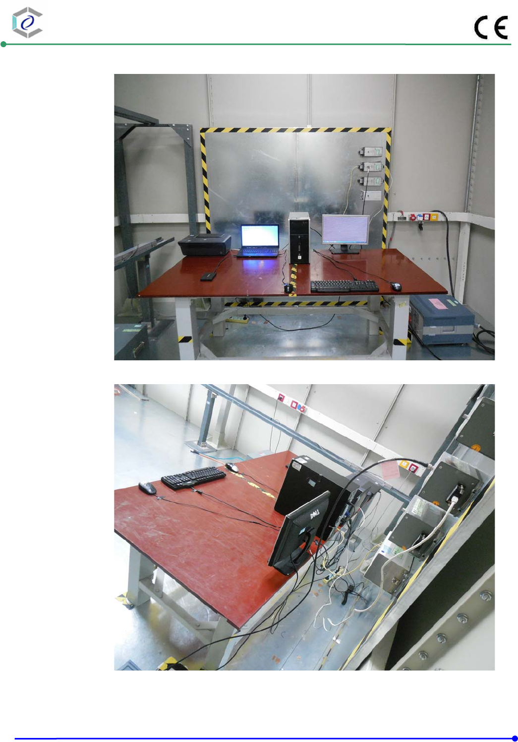
5.7. Test Photographs (30MHz ~ 1000MHz)
Front View
Rear View
CERPASS TECHNOLOGY (SUZHOU)CO.,LTD Report No.: DECE1408123
Cerpass Technology (Suzhou) Co., Ltd Issued Date : Oct.31, 2014
TEL: +86-512-6917-5888 FAX: +86-512-6917-5666 Page No. : 28 of 67
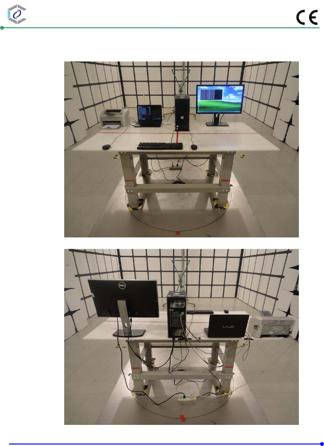
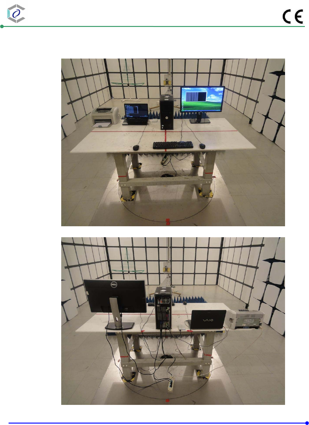
5.8. Test Photographs (1000MHz ~ 6000MHz)
Front View
Rear View
CERPASS TECHNOLOGY (SUZHOU)CO.,LTD Report No.: DECE1408123
Cerpass Technology (Suzhou) Co., Ltd Issued Date : Oct.31, 2014
TEL: +86-512-6917-5888 FAX: +86-512-6917-5666 Page No. : 29 of 67
6. Harmonics Test
6.1. Limits Of Harmonics Current Measurement
NOTE:
i. Class A and Class D are classified according to item section 5 of EN 61000-3-2.
ii. According go section 7 of EN 61000-3-2, the above limits for all equipment except
for lighting equipment are for all applications having a rated power > 75 W and no
limits apply for equipment with a rated power up to and including 75 W.
6.2. Measurement equipment
Instrument/Ancillary Manufacturer Model No. Serial No. Calibration
Date Valid Date.
Power Source TESEQ NSG 1007-3 1330A03972 2014.10.15 2015.10.14
Harmonic & Flicker
Tester TESEQ CCN 1000-1 1330A03972 2014.10.15 2015.10.14
Temperature/
Humidity Meter mingle ETH529 N/A 2014.11.06 2015.11.05
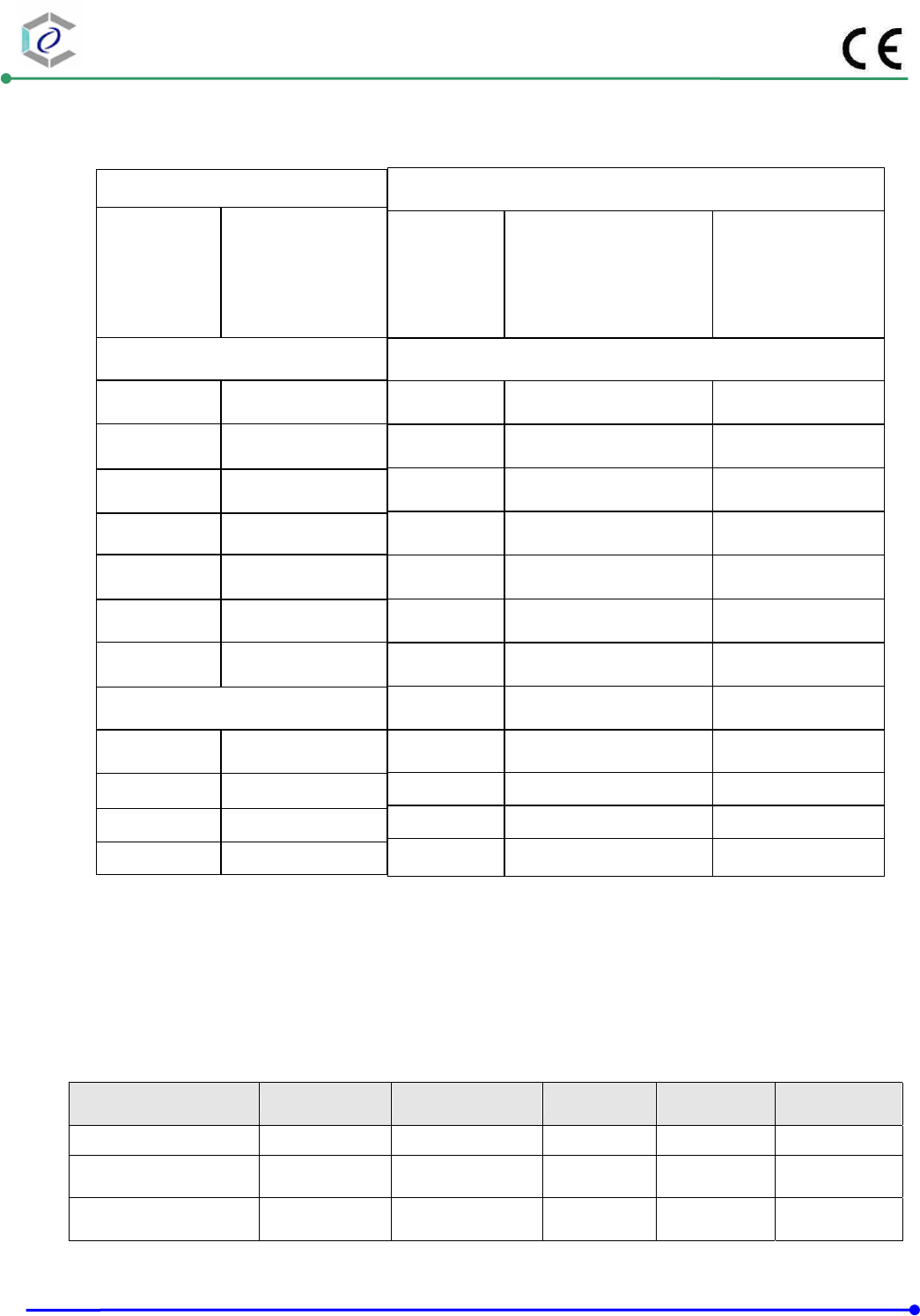
Limits for Class A equipment
Harmonics
Order
n
Max. Permissible
harmonics
current
A
Odd harmonics
3 2.30
5 1.14
7 0.77
9 0.40
11 0.33
13 0.21
15<=n<=39 0.15¯15/n
Even harmonics
2 1.08
4 0.43
6 0.30
8<=n<=40 0.23¯8/n
Limits for Class D equipment
Harmonics
Order
n
Max. Permissible
harmonics current per
watt mA/W
Max. Permissible
harmonics current
A
Odd Harmonics only
3 3.4 2.30
5 1.9 1.14
7 1.0 0.77
9 0.5 0.40
11 0.35 0.33
13 0.30 0.21
15<=n<=39 3.85/n 0.15 x15/n
CERPASS TECHNOLOGY (SUZHOU)CO.,LTD Report No.: DECE1408123
Cerpass Technology (Suzhou) Co., Ltd Issued Date : Oct.31, 2014
TEL: +86-512-6917-5888 FAX: +86-512-6917-5666 Page No. : 30 of 67
6.3. Test Result and Data
Basic Standard : EN 61000-3-2
Final Test Result : PASS
Test Mode : Mode 1: Normal Link
Temperature : 22℃
Humidity : 50 %
Atmospheric Pressure : 100 kPa
Test Data : Oct.25,2014
CERPASS TECHNOLOGY (SUZHOU)CO.,LTD Report No.: DECE1408123
Cerpass Technology (Suzhou) Co., Ltd Issued Date : Oct.31, 2014
TEL: +86-512-6917-5888 FAX: +86-512-6917-5666 Page No. : 31 of 67
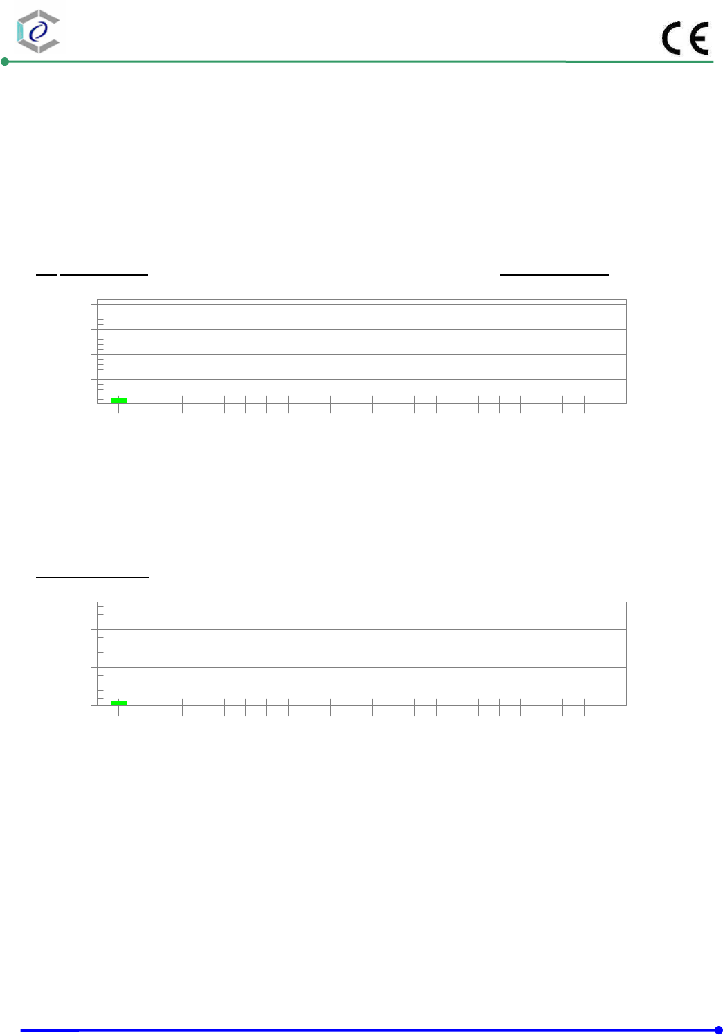
Harmonics – Class-D per Ed. 3.2 (2009)(Run time) incl. inter-harmonics
EUT: Fast Ethernet PCI Network Card Tested by: Wayne
Test category: Class-D per Ed. 3.2 (2009) (European limits) Test Margin: 100
Test date: 2014-10-25 Start time: 16:56:57 End time: 17:12:18
Test duration (min): 15 Data file name: H-010605.cts_data
Comment: 509510
Customer: Intracom Asia Co., Ltd
Test Result: Pass Source qualification: Normal
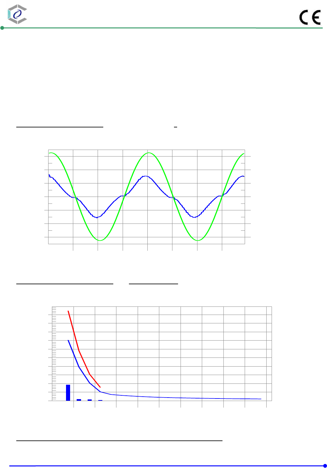
Current & voltage waveforms
-3
-2
-1
0
1
2
3
-300
-200
-100
0
100
200
300
Current (Amps)
Voltage (Volts)
Harmonics and Class D limit line European Limits
0.0
0.1
0.2
0.3
0.4
0.5
0.6
0.7
0.8
0.9
1.0
Current RMS(Amps)
Harmonic #
4 8 12 16 20 24 28 32 36 40
Test result: Pass Worst harmonic was #3 with 25.99% of the limit.

CERPASS TECHNOLOGY (SUZHOU)CO.,LTD Report No.: DECE1408123
Cerpass Technology (Suzhou) Co., Ltd Issued Date : Oct.31, 2014
TEL: +86-512-6917-5888 FAX: +86-512-6917-5666 Page No. : 32 of 67
Current Test Result Summary (Run time)
EUT: Fast Ethernet PCI Network Card Tested by: Wayne
Test category: Class-D per Ed. 3.2 (2009) (European limits) Test Margin: 100
Test date: 2014-10-25 Start time: 16:56:57 End time: 17:12:18
Test duration (min): 15 Data file name: H-010605.cts_data
Comment: 509510
Customer: Intracom Asia Co., Ltd
Test Result: Pass Source qualification: Normal
THC(A): 0.18 I-THD(%): 20.27 POHC(A): 0.000 POHC Limit(A): 0.089
Highest parameter values during test:
V_RMS (Volts): 230.50 Frequency(Hz): 50.00
I_Peak (Amps): 1.844 I_RMS (Amps): 0.932
I_Fund (Amps): 0.913 Crest Factor: 1.985
Power (Watts): 206.8 Power Factor: 0.963
Harm# Harms(avg) 100%Limit %of Limit Harms(max) 150%Limit %of Limit Status
2 0.000
3 0.183 0.703 26.0 0.185 1.044 17.71 Pass
4 0.000
5 0.019 0.393 4.8 0.019 0.582 3.33 Pass
6 0.000
7 0.013 0.207 6.3 0.013 0.308 4.36 Pass
8 0.000
9 0.007 0.103 7.2 0.008 0.155 4.98 Pass
10 0.000
11 0.004 0.072 5.9 0.000 0.000 0.00 Pass
12 0.000
13 0.004 0.062 5.8 0.000 0.000 0.00 Pass
14 0.000
15 0.004 0.054 6.8 0.000 0.000 0.00 Pass
16 0.000
17 0.004 0.048 8.9 0.000 0.000 0.00 Pass
18 0.000
19 0.004 0.042 8.8 0.000 0.000 0.00 Pass
20 0.000
21 0.004 0.038 9.7 0.000 0.000 0.00 Pass
22 0.000
23 0.003 0.035 10.0 0.000 0.000 0.00 Pass
24 0.000
25 0.003 0.032 10.6 0.000 0.000 0.00 Pass
26 0.000
27 0.003 0.030 9.3 0.000 0.000 0.00 Pass
28 0.000
29 0.003 0.027 9.4 0.000 0.000 0.00 Pass
30 0.000
31 0.002 0.026 9.3 0.000 0.000 0.00 Pass
32 0.000
33 0.002 0.024 9.8 0.000 0.000 0.00 Pass
34 0.000
35 0.002 0.023 8.5 0.000 0.000 0.00 Pass
36 0.000
37 0.002 0.022 10.2 0.000 0.000 0.00 Pass
38 0.000
39 0.002 0.020 11.4 0.000 0.000 0.00 Pass
40 0.000
Note: Dynamic limits were applied for this test. The highest harmonics values in the above table may not occur at the same
window as the maximum harmonics/limit ratio.

CERPASS TECHNOLOGY (SUZHOU)CO.,LTD Report No.: DECE1408123
Cerpass Technology (Suzhou) Co., Ltd Issued Date : Oct.31, 2014
TEL: +86-512-6917-5888 FAX: +86-512-6917-5666 Page No. : 33 of 67
Voltage Source Verification Data (Run time)
EUT: Fast Ethernet PCI Network Card Tested by: Wayne
Test category: Class-D per Ed. 3.2 (2009) (European limits) Test Margin: 100
Test date: 2014-10-25 Start time: 16:56:57 End time:17:12:18
Test duration (min): 15 Data file name: H-010605.cts_data
Comment: 509510
Customer: Intracom Asia Co., Ltd
Test Result: Pass Source qualification: Normal
Highest parameter values during test:
Voltage (Vrms): 230.50 Frequency(Hz): 50.00
I_Peak (Amps): 1.844 I_RMS (Amps): 0.932
I_Fund (Amps): 0.913 Crest Factor: 1.985
Power (Watts): 206.8 Power Factor: 0.963
Harm# Harmonics V-rms Limit V-rms % of Limit Status
2 0.078 0.461 16.92 OK
3 0.464 2.074 22.37 OK
4 0.051 0.461 11.13 OK
5 0.021 0.922 2.23 OK
6 0.023 0.461 4.92 OK
7 0.047 0.691 6.79 OK
8 0.018 0.461 3.89 OK
9 0.069 0.461 14.91 OK
10 0.018 0.461 3.85 OK
11 0.034 0.230 14.58 OK
12 0.014 0.230 5.91 OK
13 0.018 0.230 7.86 OK
14 0.004 0.230 1.91 OK
15 0.015 0.230 6.54 OK
16 0.011 0.230 4.92 OK
17 0.010 0.230 4.49 OK
18 0.014 0.230 5.99 OK
19 0.011 0.230 4.56 OK
20 0.013 0.230 5.47 OK
21 0.006 0.230 2.53 OK
22 0.006 0.230 2.68 OK
23 0.008 0.230 3.49 OK
24 0.004 0.230 1.84 OK
25 0.006 0.230 2.57 OK
26 0.004 0.230 1.74 OK
27 0.008 0.230 3.60 OK
28 0.004 0.230 1.59 OK
29 0.007 0.230 3.25 OK
30 0.003 0.230 1.42 OK
31 0.004 0.230 1.92 OK
32 0.002 0.230 1.06 OK
33 0.006 0.230 2.51 OK
34 0.003 0.230 1.35 OK
35 0.005 0.230 1.97 OK
36 0.002 0.230 0.92 OK
37 0.005 0.230 2.18 OK
38 0.002 0.230 1.02 OK
39 0.005 0.230 2.09 OK
40 0.006 0.230 2.68 OK
CERPASS TECHNOLOGY (SUZHOU)CO.,LTD Report No.: DECE1408123
Cerpass Technology (Suzhou) Co., Ltd Issued Date : Oct.31, 2014
TEL: +86-512-6917-5888 FAX: +86-512-6917-5666 Page No. : 34 of 67
6.4. Test Photographs
CERPASS TECHNOLOGY (SUZHOU)CO.,LTD Report No.: DECE1408123
Cerpass Technology (Suzhou) Co., Ltd Issued Date : Oct.31, 2014
TEL: +86-512-6917-5888 FAX: +86-512-6917-5666 Page No. : 35 of 67
7. Voltage Fluctuations Test
7.1. Test Procedure
The equipment shall be tested under the conditions of Clause 5.
The total impedance of the test circuit, excluding the appliance under test, but including the
internal impedance of the supply source, shall be equal to the reference impedance. The
stability and tolerance of the reference impedance shall be adequate to ensure that the overall
accuracy of ±8% is achieved during the whole assessment procedure.
7.2. Measurement equipment
Instrument/Ancillary Manufacturer Model No. Serial No. Calibration
Date Valid Date.
Power Source TESEQ NSG 1007-3 1330A03972 2014.10.15 2015.10.14
Harmonic & Flicker
Tester TESEQ CCN 1000-1 1330A03972 2014.10.15 2015.10.14
Temperature/
Humidity Meter mingle ETH529 N/A 2014.11.06 2015.11.05
CERPASS TECHNOLOGY (SUZHOU)CO.,LTD Report No.: DECE1408123
Cerpass Technology (Suzhou) Co., Ltd Issued Date : Oct.31, 2014
TEL: +86-512-6917-5888 FAX: +86-512-6917-5666 Page No. : 36 of 67
7.3. Test Result and Data
Basic Standard : EN 61000-3-3
Final Test Result : PASS
Test Mode : Mode 1: Normal Link
Temperature : 22℃
Humidity : 50%
Atmospheric Pressure : 100 kPa
Test Data : Oct.25,2014
CERPASS TECHNOLOGY (SUZHOU)CO.,LTD Report No.: DECE1408123
Cerpass Technology (Suzhou) Co., Ltd Issued Date : Oct.31, 2014
TEL: +86-512-6917-5888 FAX: +86-512-6917-5666 Page No. : 37 of 67
Flicker Test Summary per EN/IEC61000-3-3 (Run time)
EUT: Fast Ethernet PCI Network Card Tested by: Wayne
Test category: All parameters (European limits) Test Margin: 100
Test date: 2014-10-25 Start time: 17:20:12 End time: 17:30:33
Test duration (min): 10 Data file name: F-010606.cts_data
Comment: 509510
Customer: Intracom Asia Co., Ltd
Test Result: Pass Status: Test Completed
Psti and limit line European Limits
0.25
0.50
0.75
1.00
Pst
17:30:32
Plt and limit line
0.00
0.25
0.50
Plt
17:30:32
Parameter values recorded during the test:
Vrms at the end of test (Volt): 230.35
Highest dt (%): 0.00 Test limit (%): 3.30 Pass
Time(mS) > dt: 0.0 Test limit (mS): 500.0 Pass
Highest dc (%): 0.00 Test limit (%): 3.30 Pass
Highest dmax (%): 0.00 Test limit (%): 4.00 Pass
Highest Pst (10 min. period): 0.064 Test limit: 1.000 Pass
Highest Plt (2 hr. period): 0.028 Test limit: 0.650 Pass
CERPASS TECHNOLOGY (SUZHOU)CO.,LTD Report No.: DECE1408123
Cerpass Technology (Suzhou) Co., Ltd Issued Date : Oct.31, 2014
TEL: +86-512-6917-5888 FAX: +86-512-6917-5666 Page No. : 38 of 67
7.4. Test Photographs

CERPASS TECHNOLOGY (SUZHOU)CO.,LTD Report No.: DECE1408123
Cerpass Technology (Suzhou) Co., Ltd Issued Date : Oct.31, 2014
TEL: +86-512-6917-5888 FAX: +86-512-6917-5666 Page No. : 39 of 67
8. Electrostatic Discharge Immunity Test
8.1. Test Procedure
a. In the case of air discharge testing the climatic conditions shall be within the following ranges:
- ambient temperature: 15 to 35 ;℃℃
- relative humidity : 30% to 60%;
- atmospheric pressure : 86 KPa (860 hPa) to 106 KPa (1060 hPa).
b. Test programs and software shall be chosen so as to exercise all normal modes of operation of
the EUT. The use of special exercising software is encouraged, but permitted only where it
can be shown that the EUT is being comprehensively exercised.
c. The test voltage shall be increased from the minimum to the selected test severity level, in
order to determine any threshold of failure. The final severity level should not exceed the
product specification value in order to avoid damage to the equipment.
d. The test shall be performed with both air discharge and contact discharge. On reselected
points at least 10 single discharges (in the most sensitive polarity) shall be applied on air
discharge. On reselected points at least 25 single discharges (in the most sensitive polarity)
shall be applied on contact discharge.
e. For the time interval between successive single discharges an initial value of one second is
recommended. Longer intervals may be necessary to determine whether a system failure has
occurred.
f. In the case of contact discharges, the tip of the discharge electrode shall touch the EUT before
the discharge switch is operated.
g. In the case of painted surface covering a conducting substrate, the following procedure shall
be adopted :
If the coating is not declared to be an insulating coating by the equipment manufacturer,
then the pointed tip of the generator shall penetrate the coating so as to make contact with
the conducting substrate.
Coating declared as insulating by the manufacturer shall only be submitted to the air
discharge.
The contact discharge test shall not be applied to such surfaces.
h. In the case of air discharges, the round discharge tip of the discharge electrode shall be
approached as fast as possible (without causing mechanical damage) to touch the EUT . After
each discharge, the ESD generator (discharge electrode) shall be removed from the EUT. The
generator is then retriggered for a new single discharge. This procedure shall be repeated until
the discharges are completed. In the case of an air discharge test, the discharge switch, which
is used for contact discharge, shall be closed.
CERPASS TECHNOLOGY (SUZHOU)CO.,LTD Report No.: DECE1408123
Cerpass Technology (Suzhou) Co., Ltd Issued Date : Oct.31, 2014
TEL: +86-512-6917-5888 FAX: +86-512-6917-5666 Page No. : 40 of 67
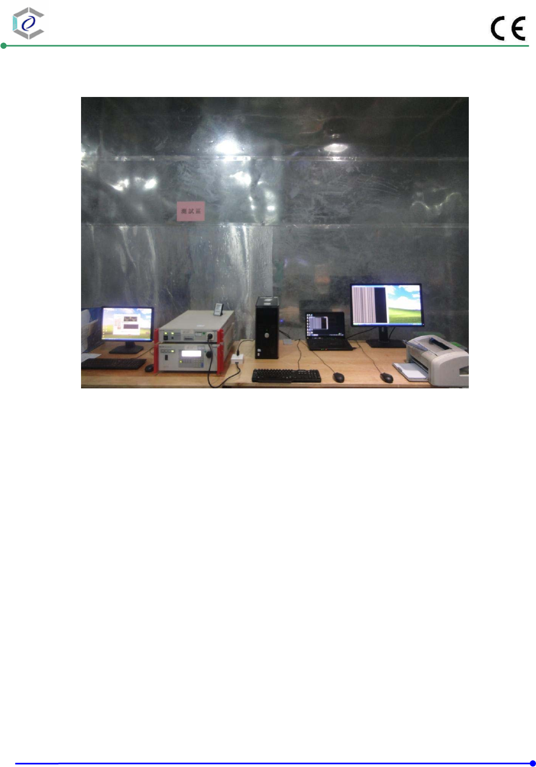
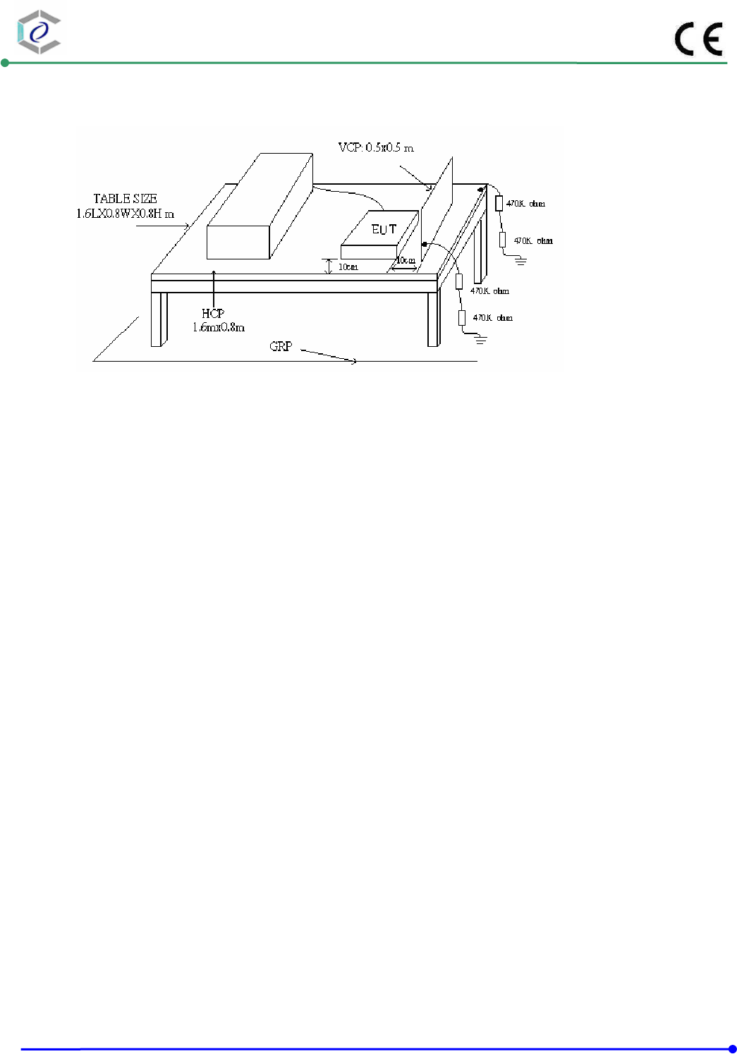
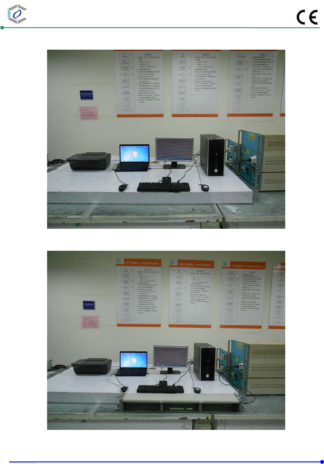
8.2. Test Setup for Tests Performed in Laboratory
The test setup consists of the test generator, EUT and auxiliary instrumentation necessary to
perform DIRECT and INDIRECT application of discharges to the EUT as applicable, in the follow
manner :
a. Contact Discharge to the conductive surfaces and to coupling plane;
b. Air Discharge at insulating surfaces.
The preferred test method is that of type tests performed in laboratories and the only accepted
method of demonstrating conformance with this standard. The EUT was arranged as closely as
possible to arrangement in final installed conditions.
A ground reference plane was provided on the floor of the test site. It was a metallic sheet (copper
or aluminum) of 0.25 mm, minimum thickness; other metallic may be used but they shall have at
least 0.65 mm thickness. In the Exclusive Certification Corp., we provided 1 mm thickness
stainless steel ground reference plane. The minimum size of the ground reference plane is 2.5 m x
2.5 m, the exact size depending on the dimensions of the EUT. It was connected to the protective
grounding system.
The EUT was arranged and connected according to its functional requirements. A distance of 1m
minimum was provided between the EUT and the wall of the lab. and any other metallic structure.
In cases where this length exceeds the length necessary to apply the discharges to the selected
points, the excess length shall, where possible, be placed non-inductively off the ground reference
plane and shall not come closer than 0.2m to other conductive parts in the test setup.
Where the EUT is installed on a metal table, the table was connected to the reference plane via a cable
with a 470k ohm resister located at each end, to prevent a build-up of charge. The test setup was
consist a wooden table, 0.8m high, standing on the ground reference plane. A HCP, 1.6 m x 0.8 m, was
placed on the table. The EUT and cables was isolated from the HCP by an insulating support 0.5 mm
thick. The VCP size, 0.5 m x 0.5 m.
CERPASS TECHNOLOGY (SUZHOU)CO.,LTD Report No.: DECE1408123
Cerpass Technology (Suzhou) Co., Ltd Issued Date : Oct.31, 2014
TEL: +86-512-6917-5888 FAX: +86-512-6917-5666 Page No. : 41 of 67
8.3. Test Severity Levels
Contact Discharge Air Discharge
Level Test Voltage (kV) of
Contact discharge
Level Test Voltage (kV) of
Air Discharge
1 ±2 1 ±2
2 ±4 2 ±4
3 ±6 3 ±8
4 ±8 4 ±15
X Specified X Specified
Remark: “X” is an open level.
8.4. Measurement equipment
Instrument/Ancillary Manufacturer Model No. Serial No. Calibration
Date Valid Date.
ESD Simulator TESEQ NSG437 575 2014.03.03 2015.03. 02
Temperature/
Humidity Meter VICHY CTH-608 N/A 2014.03.04 2015.03.03
CERPASS TECHNOLOGY (SUZHOU)CO.,LTD Report No.: DECE1408123
Cerpass Technology (Suzhou) Co., Ltd Issued Date : Oct.31, 2014
TEL: +86-512-6917-5888 FAX: +86-512-6917-5666 Page No. : 42 of 67
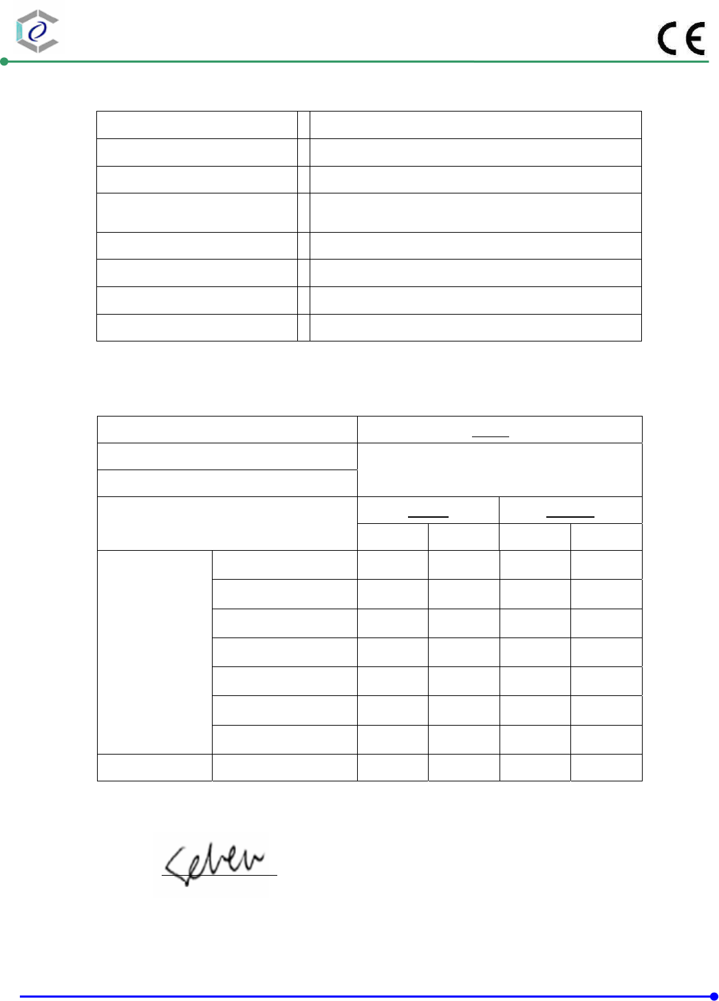
8.5. Test Result and Data
Basic Standard : IEC 61000-4-2
Final Test Result : PASS
Pass performance criteria : B
Test Voltage : ±2 / ±4 / ±8 kV for air discharge,
±2 /
±
4 kV for contact dischar
g
e
Temperature :
20°C
Relative Humidity : 50 %
Atmospheric Pressure : 100 kPa
Test Date : Oct.27,2014
Mode 1: Normal Link
Contact Discharge Air Discharge
25 times / each 10 times / each
Voltage 2 kV 4 kV 6 kV 8 kV 2 kV 4 kV 8 kV 10 kV
Point\Polarity +- + -+-+-+-+- + - +-
HCP A A A A --- --- --- --- --- --- --- --- --- --- --- ---
VCP A A A A --- --- --- --- --- --- --- --- --- --- --- ---
Screw A A A A
--- --- --- --- --- --- --- --- --- --- --- ---
Case A A A A
--- --- --- --- --- --- --- --- --- --- --- ---
NIC Port --- --- --- --- --- --- --- ---AAAA A A
--- ---
Test engineer:
CERPASS TECHNOLOGY (SUZHOU)CO.,LTD Report No.: DECE1408123
Cerpass Technology (Suzhou) Co., Ltd Issued Date : Oct.31, 2014
TEL: +86-512-6917-5888 FAX: +86-512-6917-5666 Page No. : 43 of 67
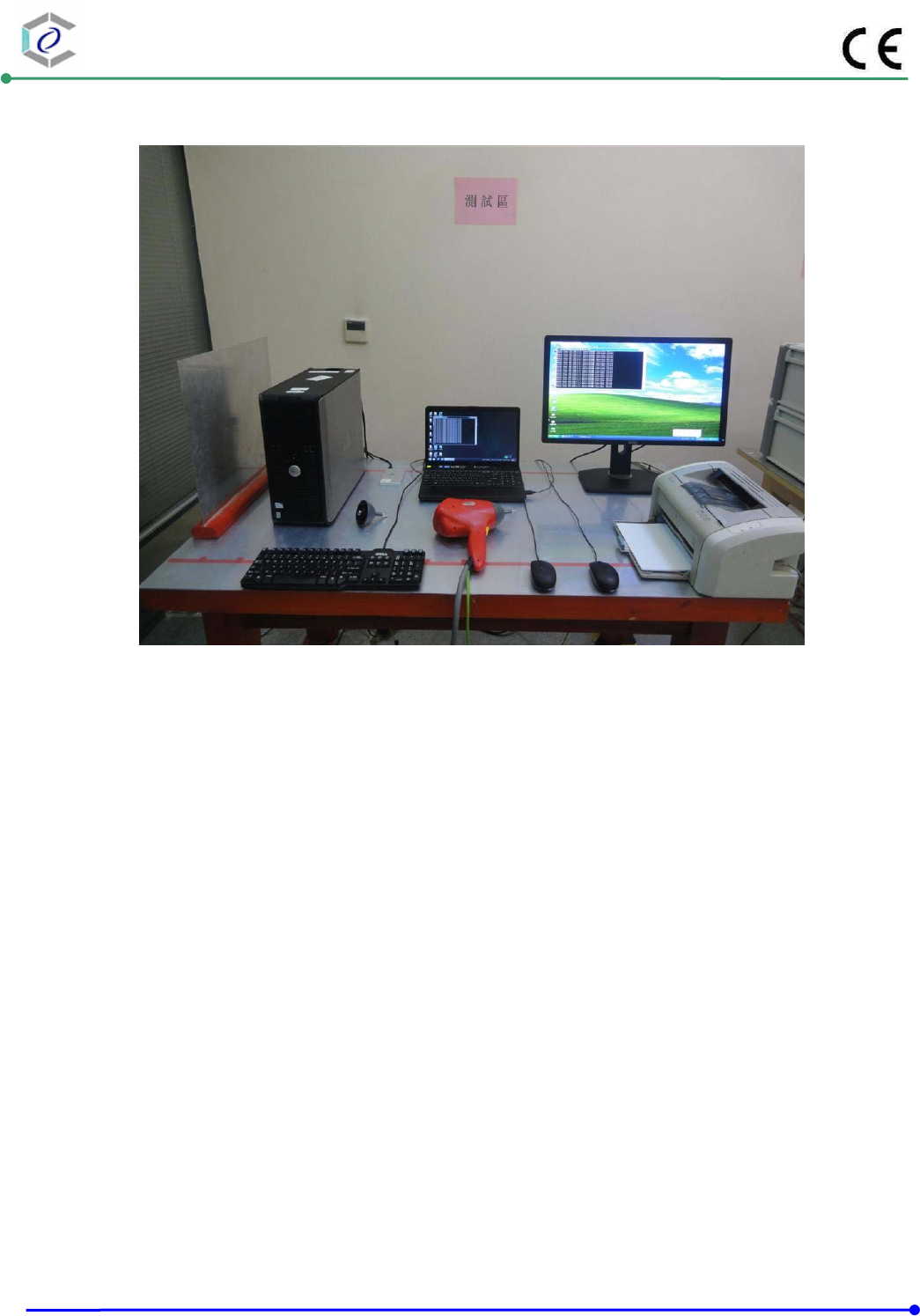
8.6. Test Photographs

CERPASS TECHNOLOGY (SUZHOU)CO.,LTD Report No.: DECE1408123
Cerpass Technology (Suzhou) Co., Ltd Issued Date : Oct.31, 2014
TEL: +86-512-6917-5888 FAX: +86-512-6917-5666 Page No. : 44 of 67
9. Radio Frequency electromagnetic field immunity test
9.1. Test Procedure
a. The equipment to be tested is placed in the center of the enclosure on a wooden table. The
equipment is then connected to power and signal leads according to pertinent installation
instructions.
b. The antenna which is enabling the complete frequency range of 80-1000 MHz is placed
3m away from the equipment. The required field strength is determined by placing the field
strength meter(s) on top of or directly alongside the equipment under test and monitoring
the field strength meter via a remote field strength indicator outside the enclosure while
adjusting the continuous-wave to the applicable antennae.
c. The test is normally performed with the antenna facing the most sensitive side of the EUT.
The polarization of the field generated by the bucolical antenna necessitates testing each
position twice, once with the antenna positioned vertically and again with the antenna
positioned horizontally. The circular polarization of the field from the log-spiral antenna
makes a change of position of the antenna unnecessary.
d. At each of the above conditions, the frequency range is swept 80-1000 MHz, pausing to
adjust the R.F. signal level or to switch oscillators and antenna. The rate of sweep is in the
order of 1.5*10-3 decades/s. The sensitive frequencies or frequencies of dominant interest
may be discretely analyzed.
CERPASS TECHNOLOGY (SUZHOU)CO.,LTD Report No.: DECE1408123
Cerpass Technology (Suzhou) Co., Ltd Issued Date : Oct.31, 2014
TEL: +86-512-6917-5888 FAX: +86-512-6917-5666 Page No. : 45 of 67
9.2. Test Severity Levels
Frequency Band : 80-1000 MHz
Level Test field strength (V/m)
1 1
2 3
3 10
X Specified
Remark: “X” is an open class.
9.3. Measurement equipment
Instrument/Ancillary Manufacturer Model No. Serial No. Calibration
Date Valid Date.
Signal Generator R&S SML03 103287 2014.03.24 2015.03.23
Power Sensor R&S NR P-Z91 100383 2014.03.24 2015.03.23
Power Sensor R&S NRP-Z91 100384 2014.03.24 2015.03.23
Power Meter R&S NRP 101206 2014.03.24 2015.03.23
Power Amplifer BONN BLWA0830-16
0/100/40D 076659 2014.03.24 2015.03.23
Istropic Electric Field
Probe
EST.LINDGRE
N HI-6105 137445 2014.09.03
2015.09.02
EMS Antenna R&S HL046E 100028 N/A N/A
Temperature/
Humidity Meter feiyan N/A 101 2014.03.31 2015.03.30
CERPASS TECHNOLOGY (SUZHOU)CO.,LTD Report No.: DECE1408123
Cerpass Technology (Suzhou) Co., Ltd Issued Date : Oct.31, 2014
TEL: +86-512-6917-5888 FAX: +86-512-6917-5666 Page No. : 46 of 67
9.4. Test Result and Data
Basic Standard : IEC 61000-4-3
Final Test Result : PASS
Pass performance criteria : A
Frequency Range : 80~1000 MHz
Temperature :
22°C
Relative Humidity : 52%
Atmospheric Pressure : 100 kPa
Test Date : Oct.31,2014
Mode 1: Normal Link
Modulation : AM 80% , 1KHz sine wave , Dwell time: 3 S
Frequency Step Size : 1 % of preceding frequency value
Frequency (MHz) Antenna Polarization face Field strength (V/m) Result
80~1000 Horizontal &Vertical Front 3 V/m A
80~1000 Horizontal &Vertical Rear 3 V/m A
80~1000 Horizontal &Vertical Left 3 V/m A
80~1000 Horizontal &Vertical Right 3 V/m A
Test engineer:
CERPASS TECHNOLOGY (SUZHOU)CO.,LTD Report No.: DECE1408123
Cerpass Technology (Suzhou) Co., Ltd Issued Date : Oct.31, 2014
TEL: +86-512-6917-5888 FAX: +86-512-6917-5666 Page No. : 47 of 67
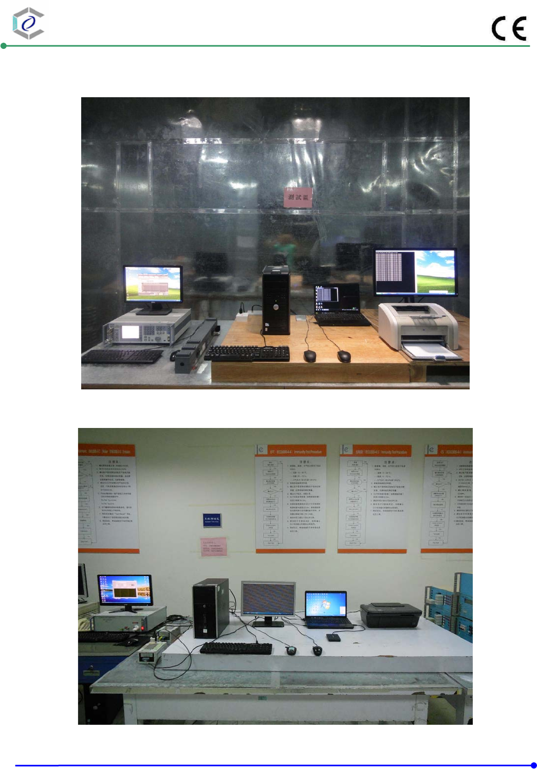
9.5. Test Photographs

CERPASS TECHNOLOGY (SUZHOU)CO.,LTD Report No.: DECE1408123
Cerpass Technology (Suzhou) Co., Ltd Issued Date : Oct.31, 2014
TEL: +86-512-6917-5888 FAX: +86-512-6917-5666 Page No. : 48 of 67
10. Electrical Fast Transient/ Burst Immunity Test
10.1. Test Procedure
a. In order to minimize the effect of environmental parameters on test results, the climatic
conditions when test is carrying out shall comply with the following requirements:
ambient temperature: 15 to 35 ;℃℃
relative humidity : 45% to 75%;
Atmospheric pressure: 86 Kpa (860 hPa) to 106 Kpa (1060 hPa).
b. In order to minimize the effect of environmental parameters on test results, the
electromagnetic environment of the laboratory shall not influence the test results.
c. The variety and diversity of equipment and systems to be tested make it difficult to establish
general criteria for the evaluation of the effects of fast transients/bursts on equipment and
systems.
d. Test on Power Line:
The EFT/B-generator was located on the GRP.. The length from the EFT/B-generator to
the EUT is not exceeding 1 m.
The EFT/B-generator provides the ability to apply the test voltage in a non-symmetrical
condition to the power supply input terminals of the EUT.
e. Test on Communication Lines
The coupling clamp is composed of a clamp unit for housing the cable (length more
than 3 m), and was placed on the GRP.
The coupling clamp provides the ability of coupling the fast transient/bursts to the cable
under test.
f. The test results may be classified on the basic of the operating conditions and the functional
specification of the equipment under test, according to the following performance criteria :
Normal performance within the specification limits.
Temporary degradation or loss of function or performance which is self-recoverable.
Temporary degradation or loss of function or performance which requires operator
intervention or system reset.
Degradation or loss of function which is not recoverable due to damage of equipment
(components).
CERPASS TECHNOLOGY (SUZHOU)CO.,LTD Report No.: DECE1408123
Cerpass Technology (Suzhou) Co., Ltd Issued Date : Oct.31, 2014
TEL: +86-512-6917-5888 FAX: +86-512-6917-5666 Page No. : 49 of 67
10.2. Test Severity Levels
The following test severity levels are recommended for the fast transient/burst test :
Open circuit output test voltage ± 10%
Level On Power Supply On I/O signal, data and control line
1 0.5 kV 0.25 kV
2 1.0 kV 0.50 kV
3 2.0 kV 1.00 kV
4 4.0 kV 2.00 kV
X Specified Specified
Remark : “ X ” is an open level. The level is subject to negotiation between the user and
the manufacturer or is specified by the manufacturer.
10.3. Measurement equipment
Instrument/Ancillary Manufacturer Model No. Serial No. Calibration
Date Valid Date.
TRANSIENT EMCPARTNER TRA2000IN6 901 2014.03.24 2015.03.23
CDN EMCPARTNER CDN2000-06-32 121 2014.03.24 2015.03.23
Coupling clamp EMCPARTNER CN-EFT1000 547 2014.03.24 2015.03.23
Temperature/ Humidity
Meter Zhicheng ZC1-11 CEP-TH-005 2014.03.31 2015.03.30
CERPASS TECHNOLOGY (SUZHOU)CO.,LTD Report No.: DECE1408123
Cerpass Technology (Suzhou) Co., Ltd Issued Date : Oct.31, 2014
TEL: +86-512-6917-5888 FAX: +86-512-6917-5666 Page No. : 50 of 67
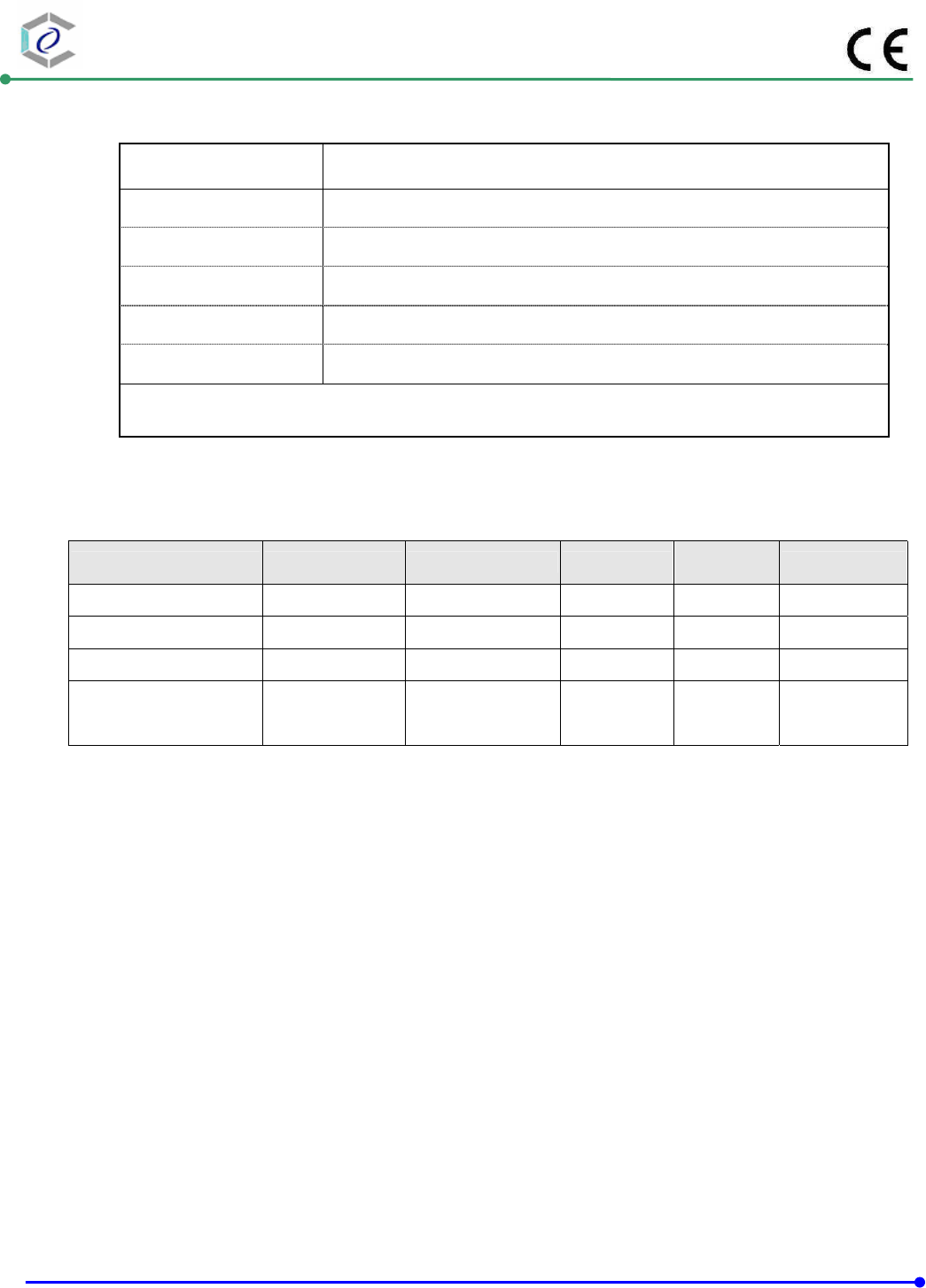
10.4. Test Result and Data
Basic Standard : IEC 61000-4-4
Final Test Result : PASS
Pass performance criteria : B
Test Voltage : On Power Supply -- ±1.0 kV
On I/O signal, data and control line -- ±0.5 kV
Temperature : 21°C
Relative Humidity : 51 %
Atmospheric Pressure : 100 kPa
Test Date : Oct.27,2014
Mode 1: Normal Link
Pulse : 5/50 ns Repetition Rate: 5 kHz
Burst : 15m/300ms
Test time : 1 min/each condition
0.5 kV 1.0 kV
Voltage/ Mode/ Polarity/ Result/ Phase + - + -
L --- --- A A
N --- --- A A
L-N --- --- A A
PE ---
--- A A
L-PE ---
--- A A
N-PE ---
--- A A
Power Line
L-N-PE ---
--- A A
Signal Line RJ 45 A A --- ---
Test engineer:
CERPASS TECHNOLOGY (SUZHOU)CO.,LTD Report No.: DECE1408123
Cerpass Technology (Suzhou) Co., Ltd Issued Date : Oct.31, 2014
TEL: +86-512-6917-5888 FAX: +86-512-6917-5666 Page No. : 51 of 67
10.5. Test Photographs
LAN

CERPASS TECHNOLOGY (SUZHOU)CO.,LTD Report No.: DECE1408123
Cerpass Technology (Suzhou) Co., Ltd Issued Date : Oct.31, 2014
TEL: +86-512-6917-5888 FAX: +86-512-6917-5666 Page No. : 52 of 67
11. Surge Immunity Test
11.1. Test Procedure
a. Climatic conditions
The climatic conditions shall comply with the following requirements :
ambient temperature : 15 to 35 ℃℃
relative humidity : 10 % to 75 %
atmospheric pressure : 86 kPa to 106 kPa ( 860 hPa to 1060 hPa )
b. Electromagnetic conditions
the electromagnetic environment of the laboratory shall not influence the test results.
c. The test shall be performed according the test plan that shall specify the test set-up with
generator and other equipment utilized;
test level ( voltage/current );
generator source impedance;
internal or external generator trigger;
number of tests : at least five positive and five negative at the selected points;
repetition rate : maximum 1/min.
inputs and outputs to be tested;
representative operating conditions of the EUT;
sequence of application of the surge to the circuit;
phase angle in the case of AC. power supply;
actual installation conditions, for example :
AC : neutral earthed,
DC : ( + ) or ( - ) earthed to simulated the actual earthing conditions.
d. If not otherwise specified the surges have to be applied synchronized to the voltage phase
at the zero-crossing and the peak value of the AC. voltage wave ( positive and negative ).
e. The surges have to be applied line to line and line(s) and earth. When testing line to earth,
the test voltage has to be applied successively between each of the lines and earth, if there
is no other specification.
f. The test procedure shall also consider the non-linear current-voltage characteristics of the
equipment under test. Therefore the test voltage has to be increased by steps up to the
test level specified in the product standard or test plan.
g. All lower levels including the selected test level shall be satisfied. For testing the
secondary protection, the output voltage of the generator shall be increased up to the
worst-case voltage breakdown level ( let-through level ) of the primary protection.
h. If the actual operating signal sources are not available, that may be simulated. Under no
circumstances may the test level exceed the product specification. The test shall be carried
out according to a test plan.
i. To find all critical points of the duty cycle of the equipment, a sufficient number of positive
and negative test pulses shall be applied. For acceptance test previously unstressed
equipment shall be used to the protection devices shall be replaced.
CERPASS TECHNOLOGY (SUZHOU)CO.,LTD Report No.: DECE1408123
Cerpass Technology (Suzhou) Co., Ltd Issued Date : Oct.31, 2014
TEL: +86-512-6917-5888 FAX: +86-512-6917-5666 Page No. : 53 of 67
11.2. Test Severity Level
Level Open-circuit test voltage, ± 10%, kV
1 0.5
2 1.0
3 2.0
4 4.0
X Specified
NOTE: “X” is an open class. This level can be specified in the product specification.
11.3. Measurement equipment
Instrument/Ancillary Manufacturer Model No. Serial No. Calibration
Date Valid Date.
TRANSIENT EMCPARTNER TRA2000IN6 901 2014.03.24 2015.03.23
CDN EMCPARTNER CDN-UTP8 021 2014.03.24 2015.03.23
CDN EMCPARTNER CDN2000-06-32 121 2014.03.24 2015.03.23
Temperature/
Humidity Meter Zhicheng ZC1-11 CEP-TH-005 2014.03.31 2015.03.30
CERPASS TECHNOLOGY (SUZHOU)CO.,LTD Report No.: DECE1408123
Cerpass Technology (Suzhou) Co., Ltd Issued Date : Oct.31, 2014
TEL: +86-512-6917-5888 FAX: +86-512-6917-5666 Page No. : 54 of 67
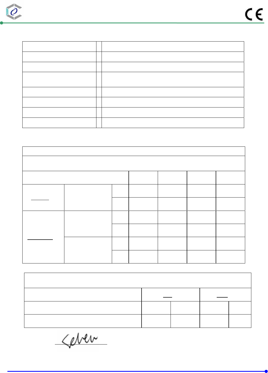
11.4. Test Result and Data
Basic Standard : IEC 61000-4-5
Final Test Result : PASS
Pass performance criteria : B
Test Voltage : Input AC Power Port -- ±0.5/1.0 kV for Line to Line
±0.5/1.0 /2.0kV for Line to Ground
Temperature :
21°C
Relative Humidity : 51 %
Atmospheric Pressure : 100 kPa
Test Date : Oct.27,2014
Power Port
Waveform :10/700μs Repetition rate : 60 sec Time : 5 time/each condition
Voltage 0.5 kV 1 kV
Mode / Polarity / Result + - + -
RJ45 A A B B
Test engineer:
Mode 1: Normal Link
Test Voltage:230V/50Hz
Waveform : 1.2/50μs(8/20μs) Repetition rate : 60 sec Time : 20 time/each condition
/Phase Voltage / Mode / Polarity / Result 0° 90° 180° 270°
+ A A A A
0.5/1.0 kV L-N
- A A A A
+ A A A A
L-PE
- A A A A
+ A A A A
0.5/1.0/2.0kV
N-PE
- A A A A
CERPASS TECHNOLOGY (SUZHOU)CO.,LTD Report No.: DECE1408123
Cerpass Technology (Suzhou) Co., Ltd Issued Date : Oct.31, 2014
TEL: +86-512-6917-5888 FAX: +86-512-6917-5666 Page No. : 55 of 67
11.5. Test Photographs
LAN

CERPASS TECHNOLOGY (SUZHOU)CO.,LTD Report No.: DECE1408123
Cerpass Technology (Suzhou) Co., Ltd Issued Date : Oct.31, 2014
TEL: +86-512-6917-5888 FAX: +86-512-6917-5666 Page No. : 56 of 67
12. Conduction Disturbances induced by Radio-Frequency Fields
12.1. Test Procedure
a. The EUT shall be operated within its intended climatic conditions. The temperature
and relative humidity should be recorded.
b. This test method test can be performed without using a sell shielded enclosure. This is
because the disturbance levels applied and the geometry of the setups are not likely to
radiated a high amount of energy, especially at the lower frequencies. If under certain
circumstances the radiated energy is too high, a shielded enclosure has to be used.
c. The test shall be performed with the test generator connected to each of the coupling
and decoupling devices in turn while the other non-excited RF-input ports of the
coupling devices are terminated by a 50 ohm load resistor.
d. The frequency range is swept from 150 KHz to 80 MHz, using the signal levels
established during the setting process, and with the disturbance signal 80% amplitude
modulated with a 1KHz sign wave, pausing to adjust the RF-signal level or to switch
coupling devices as necessary. The rate of sweep shall no exceed 1.5 x 10⁻³ decades/s.
Where the frequency is swept incrementally, the step size shall no exceed 1% of the
start and thereafter 1% of the preceding frequency value.
e. The dwell time at each frequency shall not be less than the time necessary for the EUT
to be exercised, and able to respond. Sensitive frequencies e.g. clock frequency (ies)
and harmonics or frequencies of dominant interest shall be analyzed separately.
f. An alternative test procedure may be adopted, wherein the frequency range is swept
incrementally, with a step size not exceeding 4% of the start ad thereafter 4% of the
preceding frequency value. The test level should be at least twice the value of the
specified test level.
g. In cases of dispute, the test procedure using a step size not exceeding 1% of the start
and thereafter 1% of preceding frequency value shall take precedence.
h. Attempts should be made to fully exercise the EUT during testing, and to fully
interrogate all exercise modes selected for susceptibility.
i. The use of special exercising programs is recommended.
j. Testing shall be performed according to a Test Plan, which shall be included in the test
report.
k. It may be necessary to carry out some investigatory testing in order to establish some
aspects of the test plan.

CERPASS TECHNOLOGY (SUZHOU)CO.,LTD Report No.: DECE1408123
Cerpass Technology (Suzhou) Co., Ltd Issued Date : Oct.31, 2014
TEL: +86-512-6917-5888 FAX: +86-512-6917-5666 Page No. : 57 of 67
12.2. Test Severity Levels
Level Voltage Level ( EMF ),
1 1 V
2 3 V
3 10 V
x Specified
NOTE - x is an open class. This level can be specified in the product specification.
12.3. Measurement equipment
Instrument/Ancillary Manufacturer Model No. Serial No. Calibration
Date Valid Date.
Conducted immunity
test system FRANKONIA CIT-10/75 102D1294 2014.03.24 2015.03.23
EM Injection clamp FCC F-203I-23MM 536 2014.03.24 2015.03.23
CDN FRANKONIA CDN-T2 A3010029 2014.03.24 2015.03.23
CDN FRANKONIA CDN-T4 A3015017 2014.03.24 2015.03.23
CDN FRANKONIA CDN-T8 A3022010 2014.03.24 2015.03.23
CDN FRANKONIA CDN-M2 A3002037 2014.03.24 2015.03.23
CDN FRANKONIA CDN-M2+M3 A3011102 2014.03.24 2015.03.23
CDN FCC CDN-M5/32 A3013024 2014.03.24 2015.03.23
6 dB Attenuator FRANKONIA N/A N/A 2014.03.24 2015.03.23
Temperature/
Humidity Meter Zhicheng ZC1-11 CEP-TH-005 2014.03.31 2015.03.30
CERPASS TECHNOLOGY (SUZHOU)CO.,LTD Report No.: DECE1408123
Cerpass Technology (Suzhou) Co., Ltd Issued Date : Oct.31, 2014
TEL: +86-512-6917-5888 FAX: +86-512-6917-5666 Page No. : 58 of 67
12.4. Test Result and Data
Basic Standard : IEC 61000-4-6
Final Test Result : PASS
Pass performance criteria : A
Coupling mode :
CDN-(M2+M3) for AC power ports
CDN-T4 for signal ports
EM-Clamp for signal ports
Temperature :
21°C
Relative Humidity : 51%
Atmospheric Pressure : 100 kPa
Test Date : Oct.27,2014
Test Mode 1: Normal Link
Frequency : 0.15~80MHz, Modulation : AM 80%,1KHz sine wave, Dwell time: 2.9s
Frequency Step Size : 1 % of preceding frequency value
Frequency Test mode Voltage(V) Result
0.15 ~ 100MHz Power(M3) 3 A
0.15 ~ 100MHz RJ45 3 A
Test engineer:
CERPASS TECHNOLOGY (SUZHOU)CO.,LTD Report No.: DECE1408123
Cerpass Technology (Suzhou) Co., Ltd Issued Date : Oct.31, 2014
TEL: +86-512-6917-5888 FAX: +86-512-6917-5666 Page No. : 59 of 67
12.5. Test Photographs
LAN
CERPASS TECHNOLOGY (SUZHOU)CO.,LTD Report No.: DECE1408123
Cerpass Technology (Suzhou) Co., Ltd Issued Date : Oct.31, 2014
TEL: +86-512-6917-5888 FAX: +86-512-6917-5666 Page No. : 60 of 67
13. Power Frequency Magnetic Field Immunity Tests
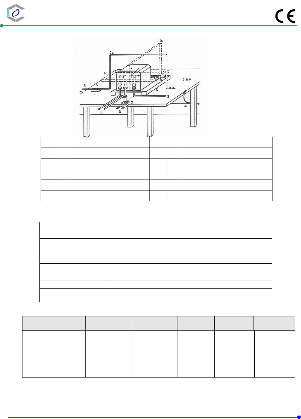
13.1. Test Setup
GPR : Ground plane C1 : Power supply circuit
A : Safety earth C2 : Signal circuit
S : Insulating support L : Communication line
EUT : Equipment under test B : To power supply source
Lc : Induction coil D : To signal source, simulator
E : Earth terminal G : To the test generator
13.2. Test Severity Levels
Level Magnetic field strength
A/m
1 1
2 3
3 10
4 30
5 100
X1) special
NOTE 1 “X” is an open level. This level can be givenin the product specification.
13.3. Measurement equipment
Instrument/Ancillary Manufacturer Model No. Serial No. Calibration
Date Valid Date.
TRANSIENT EMCPARTNER TRA2000IN6 901 2014.03.09 2015.03.08
H-Filed-Loop EMCPARTNER MF1000-1 144 2014.03.09 2015.03.08
Temperature/ Humidity
Meter Zhicheng ZC1-11 CEP-TH-005 2014.03.09 2015.03.08

CERPASS TECHNOLOGY (SUZHOU)CO.,LTD Report No.: DECE1408123
Cerpass Technology (Suzhou) Co., Ltd Issued Date : Oct.31, 2014
TEL: +86-512-6917-5888 FAX: +86-512-6917-5666 Page No. : 61 of 67
13.4. Test Result and Data
Not Applicable
CERPASS TECHNOLOGY (SUZHOU)CO.,LTD Report No.: DECE1408123
Cerpass Technology (Suzhou) Co., Ltd Issued Date : Oct.31, 2014
TEL: +86-512-6917-5888 FAX: +86-512-6917-5666 Page No. : 62 of 67
14. Voltage Dips and Voltage Interruptions Immunity Test Setup
14.1. Test Conditions
1. Source voltage and frequency : 230V / 50Hz, Single phase.
2. Test of interval : 10 sec.
3. Level and duration : Sequence of 3 dips/interrupts.
4. Voltage rise (and fall) time : 1 ∼ 5 μs.
5. Test severity :
Voltage dips and Interrupt reduction (%) Test Duration
(period)
>95% 250
30% 25
>95% 0.5
14.2. Measurement equipment
Instrument/Ancillary Manufacturer Model No. Serial No. Calibration
Date Valid Date.
TRANSIENT EMCPARTNER TRA2000IN6 901 2014.03.24 2015.03.23
Temperature/ Humidity
Meter Zhicheng ZC1-11 CEP-TH-005 2014.03.31 2015.03.30
CERPASS TECHNOLOGY (SUZHOU)CO.,LTD Report No.: DECE1408123
Cerpass Technology (Suzhou) Co., Ltd Issued Date : Oct.31, 2014
TEL: +86-512-6917-5888 FAX: +86-512-6917-5666 Page No. : 63 of 67
14.3. Test Result and Data
Basic Standard : IEC 61000-4-11
Final Test Result : PASS
Pass performance Criteria : C for voltage interruption, B for voltage dips
Required performance Criteria : C for voltage interruption, B/C for voltage dips
Temperature : 21°C
Relative Humidity : 51%
Atmospheric Pressure : 100 kPa
Test Date : Oct.27,2014
Test Mode 1: Normal Link
Voltage(UT): AC 230 V 50 Hz Interval(s) : 10s Times : 3
Phase / Result
Test mod
Test level
UT %
Durations
(period /
ms ) 0 45 90 135 180 225 270 315
Voltage
interruptions
>95% 250 C C C C C C C C
30% 25
B B B B B B B B
Voltage dips >95% 0.5
B B B B B B B B
Test engineer:
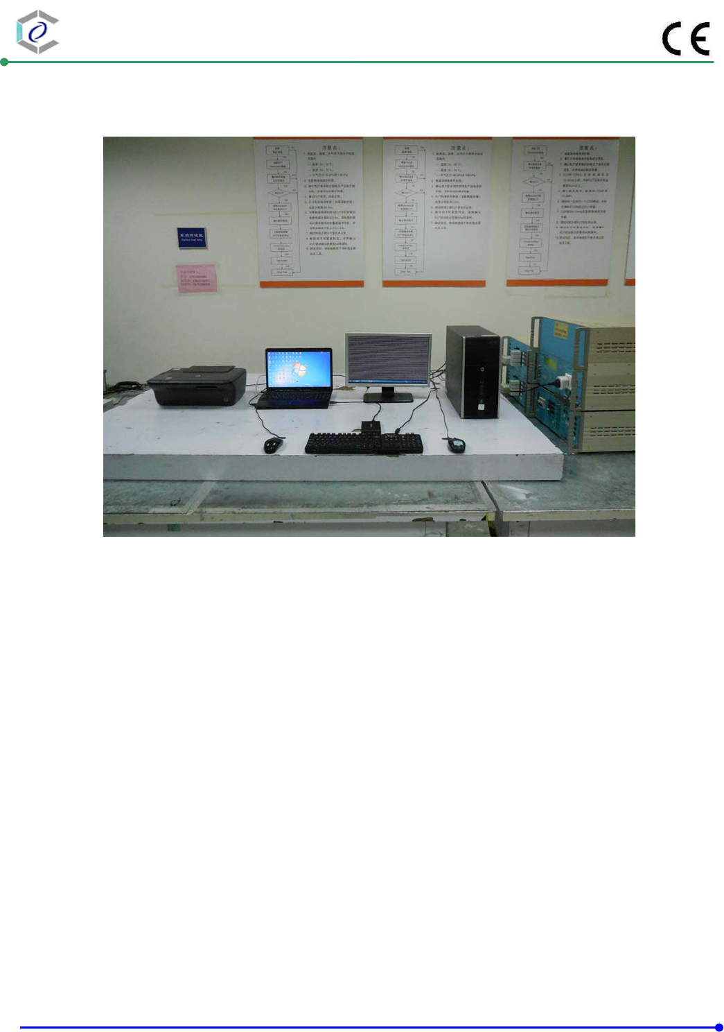
CERPASS TECHNOLOGY (SUZHOU)CO.,LTD Report No.: DECE1408123
Cerpass Technology (Suzhou) Co., Ltd Issued Date : Oct.31, 2014
TEL: +86-512-6917-5888 FAX: +86-512-6917-5666 Page No. : 64 of 67
14.4. Test Photographs
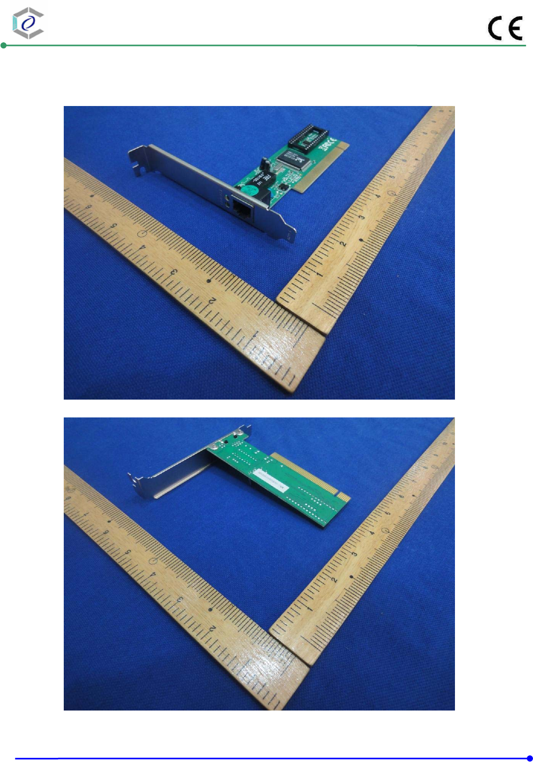
CERPASS TECHNOLOGY (SUZHOU)CO.,LTD Report No.: DECE1408123
Cerpass Technology (Suzhou) Co., Ltd Issued Date : Oct.31, 2014
TEL: +86-512-6917-5888 FAX: +86-512-6917-5666 Page No. : 65 of 67
15. Photographs of EUT
1) EUT Photo
2) EUT Photo
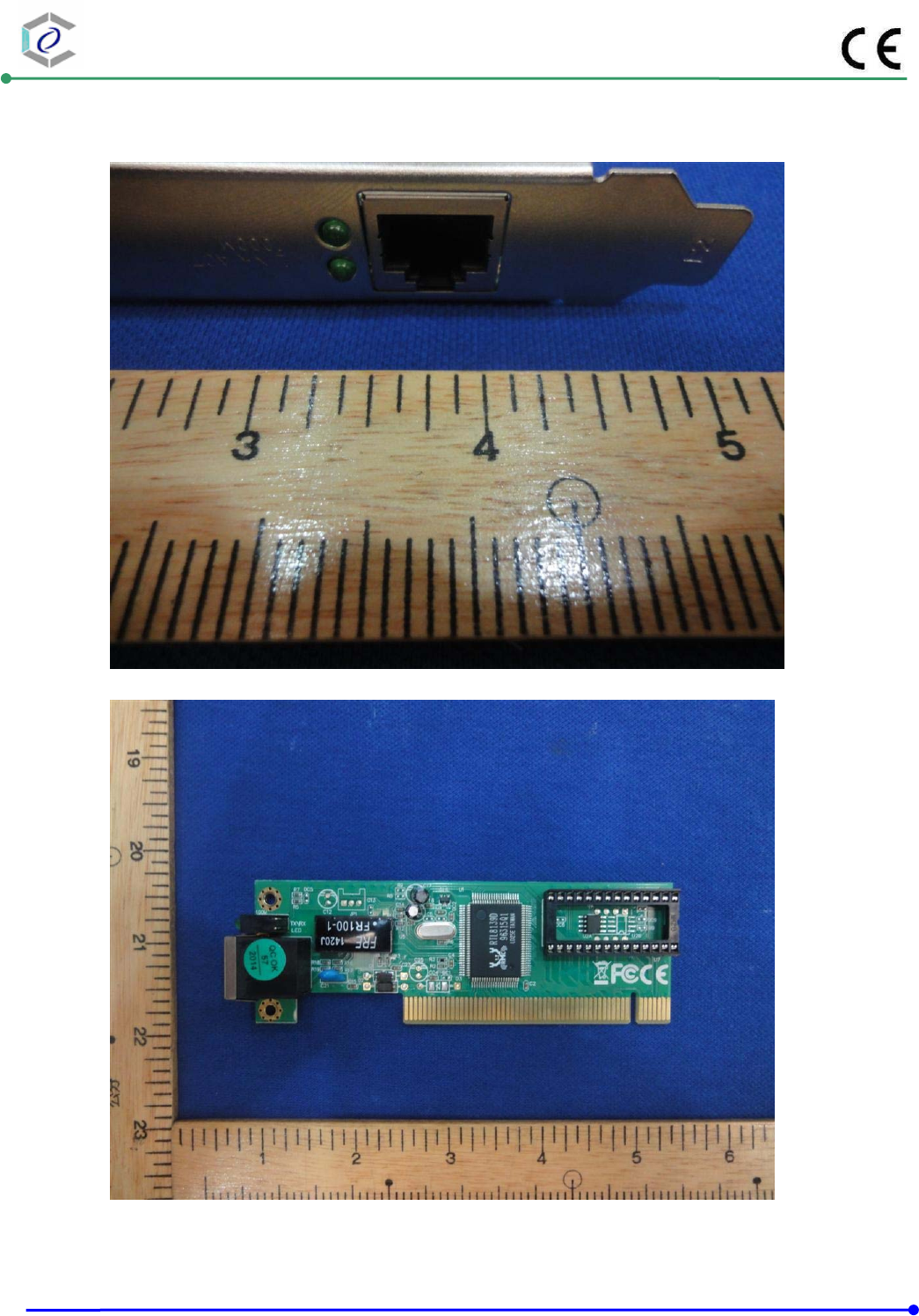
CERPASS TECHNOLOGY (SUZHOU)CO.,LTD Report No.: DECE1408123
Cerpass Technology (Suzhou) Co., Ltd Issued Date : Oct.31, 2014
TEL: +86-512-6917-5888 FAX: +86-512-6917-5666 Page No. : 66 of 67
3) EUT Photo
4) EUT Photo
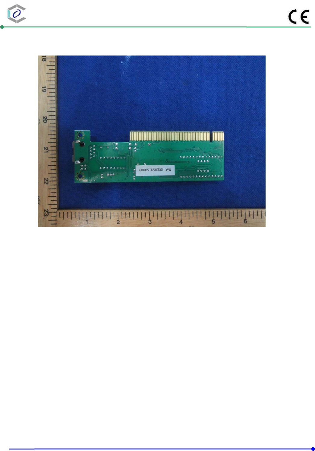
CERPASS TECHNOLOGY (SUZHOU)CO.,LTD Report No.: DECE1408123
Cerpass Technology (Suzhou) Co., Ltd Issued Date : Oct.31, 2014
TEL: +86-512-6917-5888 FAX: +86-512-6917-5666 Page No. : 67 of 67
5) EUT Photo
