Volume 2 Tab Brochure
2016-10-27
: Pdf 141969-Brochure 141969-Brochure B6 unilog
Open the PDF directly: View PDF ![]() .
.
Page Count: 223 [warning: Documents this large are best viewed by clicking the View PDF Link!]

Volume 2—Commercial Distribution CA08100003E—July 2016 www.eaton.com V2-T2-1
2
2
2
2
2
2
2
2
2
2
2
2
2
2
2
2
2
2
2
2
2
2
2
2
2
2
2
2
2
2
Transformers
Dry-Type Transformer Family
2.1 NEMA TP-1 Energy-Efficient Transformers
Product Description. . . . . . . . . . . . . . . . . . . . . . . . . . . . . . . . . . . . . . . V2-T2-2
Application Description . . . . . . . . . . . . . . . . . . . . . . . . . . . . . . . . . . . . V2-T2-2
Features, Benefits and Functions . . . . . . . . . . . . . . . . . . . . . . . . . . . . V2-T2-3
Standards and Certifications . . . . . . . . . . . . . . . . . . . . . . . . . . . . . . . . V2-T2-3
Catalog Number Selection . . . . . . . . . . . . . . . . . . . . . . . . . . . . . . . . . V2-T2-4
Product Selection . . . . . . . . . . . . . . . . . . . . . . . . . . . . . . . . . . . . . . . . V2-T2-4
Accessories . . . . . . . . . . . . . . . . . . . . . . . . . . . . . . . . . . . . . . . . . . . . . V2-T2-50
Technical Data and Specifications . . . . . . . . . . . . . . . . . . . . . . . . . . . . V2-T2-50
2.2 NEMA Premium and E3 Super Efficient Transformers
NEMA Premium® Efficient Transformers . . . . . . . . . . . . . . . . . . . . . . V2-T2-61
E3 Super Efficient Transformers . . . . . . . . . . . . . . . . . . . . . . . . . . . . . V2-T2-66
2.3 Energy-Efficient Harmonic Mitigating Transformers
Product Description. . . . . . . . . . . . . . . . . . . . . . . . . . . . . . . . . . . . . . . V2-T2-71
Features and Benefits . . . . . . . . . . . . . . . . . . . . . . . . . . . . . . . . . . . . . V2-T2-71
Standards and Certifications . . . . . . . . . . . . . . . . . . . . . . . . . . . . . . . . V2-T2-72
Catalog Number Selection . . . . . . . . . . . . . . . . . . . . . . . . . . . . . . . . . V2-T2-72
Product Selection . . . . . . . . . . . . . . . . . . . . . . . . . . . . . . . . . . . . . . . . V2-T2-73
Accessories . . . . . . . . . . . . . . . . . . . . . . . . . . . . . . . . . . . . . . . . . . . . . V2-T2-89
Technical Data and Specifications . . . . . . . . . . . . . . . . . . . . . . . . . . . . V2-T2-89
2.4 General-Purpose Encapsulated Transformers
Product Description. . . . . . . . . . . . . . . . . . . . . . . . . . . . . . . . . . . . . . . V2-T2-93
Application Description . . . . . . . . . . . . . . . . . . . . . . . . . . . . . . . . . . . . V2-T2-93
Features, Benefits and Functions . . . . . . . . . . . . . . . . . . . . . . . . . . . . V2-T2-93
Standards and Certifications . . . . . . . . . . . . . . . . . . . . . . . . . . . . . . . . V2-T2-93
Catalog Number Selection . . . . . . . . . . . . . . . . . . . . . . . . . . . . . . . . . V2-T2-94
Product Selection . . . . . . . . . . . . . . . . . . . . . . . . . . . . . . . . . . . . . . . . V2-T2-94
Accessories . . . . . . . . . . . . . . . . . . . . . . . . . . . . . . . . . . . . . . . . . . . . . V2-T2-109
Technical Data and Specifications . . . . . . . . . . . . . . . . . . . . . . . . . . . . V2-T2-109
2.5 Distribution Transformers
Motor Drive Isolation Transformers. . . . . . . . . . . . . . . . . . . . . . . . . . . V2- T2-111
Mini–Power Centers . . . . . . . . . . . . . . . . . . . . . . . . . . . . . . . . . . . . . . V2-T2-119
Totally Enclosed Non-Ventilated Transformers . . . . . . . . . . . . . . . . . . V2-T2-124
Class I, Division 2, Hazardous Location Transformers . . . . . . . . . . . . . V2-T2-127
Open-Type Core and Coil Assembly Transformers . . . . . . . . . . . . . . . V2-T2-130
Marine Duty Transformers. . . . . . . . . . . . . . . . . . . . . . . . . . . . . . . . . . V2-T2-133
Buck-Boost and Low Voltage Lighting Transformers . . . . . . . . . . . . . . V2-T2-144
Medium Voltage Distribution Transformers. . . . . . . . . . . . . . . . . . . . . V2-T2-173
2.6 Transformer Standards, Technical Data and Accessories
Standards and Certifications . . . . . . . . . . . . . . . . . . . . . . . . . . . . . . . . V2-T2-186
Catalog Number Selection . . . . . . . . . . . . . . . . . . . . . . . . . . . . . . . . . V2-T2-187
Product Selection . . . . . . . . . . . . . . . . . . . . . . . . . . . . . . . . . . . . . . . . V2-T2-189
Options and Accessories. . . . . . . . . . . . . . . . . . . . . . . . . . . . . . . . . . . V2-T2-191
Technical Data and Specifications . . . . . . . . . . . . . . . . . . . . . . . . . . . . V2-T2-195
Glossary of Transformer Terms . . . . . . . . . . . . . . . . . . . . . . . . . . . . . . V2-T2-211
Frequently Asked Questions About Transformers. . . . . . . . . . . . . . . . V2-T2-214
2.7 Dimensions
Dimensions . . . . . . . . . . . . . . . . . . . . . . . . . . . . . . . . . . . . . . . . . . . . . V2-T2-216
V2-T2-2 Volume 2—Commercial Distribution CA08100003E—July 2016 www.eaton.com
2
2
2
2
2
2
2
2
2
2
2
2
2
2
2
2
2
2
2
2
2
2
2
2
2
2
2
2
2
2
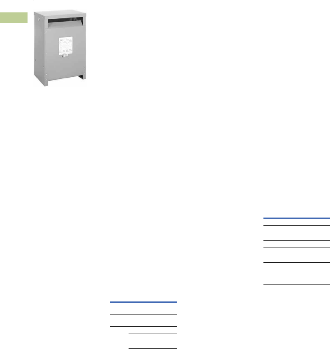
2.1
Transfor mers
NEMA TP-1 Energy-Efficient Transformers
Type DT-3
Contents
Description Page
NEMA TP-1 Energy-Efficient Transformers
Features, Benefits and Functions. . . . . . . . . . . V2-T2-3
Standards and Certifications . . . . . . . . . . . . . . V2-T2-3
Catalog Number Selection . . . . . . . . . . . . . . . . V2-T2-4
Product Selection. . . . . . . . . . . . . . . . . . . . . . . V2-T2-4
Single-Phase Aluminum . . . . . . . . . . . . . . . . V2-T2-4
Single-Phase Copper . . . . . . . . . . . . . . . . . . . V2-T2-6
Single-Phase Shielded Aluminum . . . . . . . . . V2-T2-8
Single-Phase Shielded Copper . . . . . . . . . . . V2-T2-10
Three-Phase Aluminum . . . . . . . . . . . . . . . . . V2-T2-12
Three-Phase Copper . . . . . . . . . . . . . . . . . . . V2-T2-23
Three-Phase Shielded Aluminum . . . . . . . . . V2-T2-34
Three-Phase Shielded Copper . . . . . . . . . . . . V2-T2-42
Accessories . . . . . . . . . . . . . . . . . . . . . . . . . . . V2-T2-50
Technical Data and Specifications . . . . . . . . . . V2-T2-50
K-Factor . . . . . . . . . . . . . . . . . . . . . . . . . . . . . . V2-T2-51
Aluminum . . . . . . . . . . . . . . . . . . . . . . . . . . . V2-T2-52
Copper. . . . . . . . . . . . . . . . . . . . . . . . . . . . . . V2-T2-57
Product Description
Note: The following pages
provide listings for most standard
transformer ratings and catalog
numbers. For other ratings or
catalog numbers not shown,
or for special enclosure types
(including stainless steel), refer
to Eaton.
Types DS-3, DT-3
●Ventilated, NEMA 2
enclosure standard
●Suitable for indoor
applications, outdoors
when weathershields
are also installed
●Upright mounting only
●220ºC insulation system
●150ºC rise standard;
115°C or 80°C rise optional
●Available in single-phase
ratings 15–167 kVA,
600 volts primary (DS-3)
●Available in three-phase
ratings 15–1500 kVA
and up to 600 volts
primary (DT-3)
Application Description
NEMA TP-1-2002 compliant
energy-efficient transformers
are specifically designed to
meet the energy efficiency
standards set forth in NEMA
Standards publication, TP-1-
2002, “Guide for Determining
Energy Efficiency for
Distribution Transformers.”
Surveys have shown that
the average loading of low
voltage dry-type distribution
transformers, over a 24-hour
period, is approximately
35%. NEMA TP-1 compliant
transformers are optimized to
offer maximum efficiency at
35% of nameplate rating.
The range of products covered
by NEMA TP-1-2002 are:
NEMA TP-1-2002
Product Range
Transformers that are
currently specifically excluded
from the scope of NEMA
Standard TP-1-2002 include:
●Liquid-filled transformers
below 10 kVA
●Dry-type transformers
below 15 kVA
●AC and DC drives
transformers
●Rectifier transformers
designed for high
harmonics
●Autotransformers
●Non-distribution
transformers, such as
UPS transformers
●Special impedance or
regulation transformers
●Regulating transformers
●Sealed and non-ventilated
transformers
●Machine tool transformers
●Welding transformers
●Transformers with tap
ranges greater than 15%
●Transformers with a
frequency other than 60 Hz
●Grounding transformers
●Testing transformers
Efficiency levels set forth in
NEMA TP-1-2002.
NEMA TP-1-2002
Efficiency Levels
Rating
Voltage
Class Voltage
Primary
voltage
34.5 kV and
below
Secondary
voltage
600V and
below
Dry-Type
Rating
Single-phase 10–833 kVA
Three-phase 15–2500 kVA
Liquid
Rating
Single-phase 10–833 kVA
Three-phase 15–2500 kVA
Tables of Energy Efficiency
NEMA Class 1 Efficiency Levels
Dry-Type Distribution Transformers—
Low Voltage (600V and below)
Single-Phase Three-Phase
kVA Efficiency kVA Efficiency
15 97.7 15 97.0
25 98.0 30 97.5
37.5 98.2 45 97.7
50 98.3 75 98.0
75 98.5 112.5 98.2
100 98.6 150 98.3
167 98.7 225 98.5
250 98.8 300 98.6
333 98.9 500 98.7
— — 750 98.8
— — 1000 98.9

Volume 2—Commercial Distribution CA08100003E—July 2016 www.eaton.com V2-T2-3
2
2
2
2
2
2
2
2
2
2
2
2
2
2
2
2
2
2
2
2
2
2
2
2
2
2
2
2
2
2
2.1
Transfor mers
NEMA TP-1 Energy-Efficient Transformers
Features, Benefits
and Functions
●60 Hz operation (except
as noted)
●Short-term overload
capability as required
by ANSI
●Meet NEMA ST-20
sound levels
●Meet federal energy
efficiency requirements
for low voltage dry-type
distribution transformers
effective as of
January 1, 2007
Standards and
Certifications
●UL® listed
Industry Standards
All Eaton dry-type distribution
and control transformers are
built and tested in accordance
with applicable NEMA, ANSI
and IEEE Standards. All
600 volt class transformers
are UL listed unless
otherwise noted.
Seismically Qualified
Eaton manufactured dry-type
distribution transformers are
seismically qualified and
exceed requirements of the
Uniform Building Code (UBC),
International Building Code
(IBC) and California Code
Title 24.

V2-T2-4 Volume 2—Commercial Distribution CA08100003E—July 2016 www.eaton.com
2
2
2
2
2
2
2
2
2
2
2
2
2
2
2
2
2
2
2
2
2
2
2
2
2
2
2
2
2
2
2.1
Transfor mers
NEMA TP-1 Energy-Efficient Transformers
Catalog Number Selection
Please refer to Section 2.7 Page V2-T2-187.
Product Selection
Additional Product Selection information begins on Page V2-T2-189.
Single-Phase—Type DS-3 60 Hz NEMA TP-1 Energy-Efficient—Aluminum Windings
208 Volts to 120/240 Volts
240 x 480 Volts to 120/240 Volts
Notes
1Weights subject to change.
21 at +5%, 2 at –5% at 240 volts primary; 2 at +2.5%, 4 at –2.5% at 480 volts primary.
3480 volt primary only.
For other ratings or catalog numbers not shown, or for special enclosure types (including stainless steel), refer to Eaton. Frame drawings/dimensions information begins on Page V2-T2-216.
kVA
Full Capacity Taps
Type
ºC Temp.
Rise Frame
Wiring Diagram
Number
Weight
Lbs (kg) 1Weathershield Catalog NumberFCAN FCBN
15 2 at +2.5% 4 at –2.5% DS-3 150 816 260A 226 (103) WS11 T29M11S15EE
25 2 at +2.5% 4 at –2.5% DS-3 150 818 260A 346 (157) WS11 T29M11S25EE
37.5 2 at +2.5% 4 at –2.5 DS-3 150 818 260A 374 (170) WS11 T29M11S37EE
50 2 at +2.5% 4 at –2.5% DS-3 150 819 260A 545 (247) WS16 T29M11S50EE
75 1 at +5% 2 at –5% DS-3 150 819 551A 568 (258) WS16 T29R11S75EE
100 1 at +5% 2 at –5% DS-3 150 814E 449A 1178 (535) WS13 T29R11S99EE
kVA
Full Capacity Taps
Type
ºC Temp.
Rise Frame
Wiring Diagram
Number
Weight
Lbs (kg) 1Weathershield Catalog NumberFCAN FCBN
15 22 DS-3 150 842 3XA 196 (89) WS45 T20P11S15AEE
25 22 DS-3 150 842 3XA 261 (118) WS45 T20P11S25AEE
37.5 22 DS-3 150 843 3XA 304 (138) WS43 T20P11S37AEE
50 22 DS-3 150 843 3XA 396 (180) WS43 T20P11S50AEE
75 22 DS-3 150 844 3XA 688 (312) WS44 T20P11S75AEE
100 22 DS-3 150 844 3XA 699 (317) WS44 T20P11S99AEE
167 2 at +2.5% 4 at –2.5% DS-3 150 814E 288A 1294 (587) WS13 T48M11S67EE 3
15 22 DS-3 115 816 3XA 246 (112) WS11 T20P11F15EE
25 22 DS-3 115 818 3XA 373 (169) WS11 T20P11F25EE
37.5 22 DS-3 115 818 3XA 380 (173) WS11 T20P11F37EE
50 22 DS-3 115 819 3XA 590 (268) WS16 T20P11F50EE
75 22 DS-3 115 820 3XA 691 (314) WS16 T20P11F75EE
100 22 DS-3 115 821 3XA 844 (383) WS13 T20P11F99EE
15 22 DS-3 80 818 3XA 360 (163) WS11 T20P11B15EE
25 22 DS-3 80 818 3XA 370 (168) WS11 T20P11B25EE
37.5 22 DS-3 80 819 3XA 565 (257) WS16 T20P11B37EE
50 22 DS-3 80 820 3XA 680 (309) WS16 T20P11B50EE
75 22 DS-3 80 821 3XA 900 (409) WS13 T20P11B75EE

Volume 2—Commercial Distribution CA08100003E—July 2016 www.eaton.com V2-T2-5
2
2
2
2
2
2
2
2
2
2
2
2
2
2
2
2
2
2
2
2
2
2
2
2
2
2
2
2
2
2
2.1
Transfor mers
NEMA TP-1 Energy-Efficient Transformers
Single-Phase—Type DS-3 60 Hz NEMA TP-1 Energy-Efficient—Aluminum Windings
277 Volts to 120/240 Volts
208 x 416 Volts to 120/240 Volts
600 Volts to 120/240 Volts
Notes
1Weights subject to change.
2Contact your local Eaton sales office for these details.
31 at +5%, 2 at –5% at 208 volts primary; 2 at +2.5%, 4 at –2.5% at 416 volts primary.
For other ratings or catalog numbers not shown, or for special enclosure types (including stainless steel), refer to Eaton. Frame drawings/dimensions information begins on Page V2-T2-216.
kVA
Full Capacity Taps
Type
ºC Temp.
Rise Frame
Wiring Diagram
Number
Weight
Lbs (kg) 1Weathershield Catalog NumberFCAN FCBN
15 2 at +2.5% 4 at –2.5% DS-3 150 816 262C 220 (100) WS11 T27M11S15EE
25 2 at +2.5% 4 at –2.5% DS-3 150 818 262C 346 (157) WS11 T27M11S25EE
37.5 2 at +2.5% 4 at –2.5% DS-3 150 818 262C 391 (178) WS11 T27M11S37EE
50 2 at +2.5% 4 at –2.5% DS-3 150 819 262C 555 (252) WS16 T27M11S50EE
75 1 at +5% 2 at –5% DS-3 150 819 2568 (258) WS16 T27R11S75EE
100 1 at +5% 2 at –5% DS-3 150 814E 21178 (535) WS13 T27R11S99EE
kVA
Full Capacity Taps
Type
ºC Temp.
Rise Frame
Wiring Diagram
Number
Weight
Lbs (kg) 1Weathershield Catalog NumberFCAN FCBN
15 33 DS-3 150 816 3XF 246 (112) WS11 T18P11S15EE
25 33 DS-3 150 818 3XF 359 (163) WS11 T18P11S25EE
37.5 33 DS-3 150 818 3XF 374 (170) WS11 T18P11S37EE
50 33 DS-3 150 819 3XF 555 (252) WS16 T18P11S50EE
75 33 DS-3 150 820 3XF 665 (302) WS16 T18P11S75EE
100 33 DS-3 150 821 3XF 841 (382) WS13 T18P11S99EE
kVA
Full Capacity Taps
Type
ºC Temp.
Rise Frame
Wiring Diagram
Number
Weight
Lbs (kg) 1Weathershield Catalog NumberFCAN FCBN
15 2 at +2.5% 4 at –2.5% DS-3 150 816 262B 243 (110) WS11 T60M11S15EE
25 2 at +2.5% 4 at –2.5% DS-3 150 818 262B 355 (161) WS11 T60M11S25EE
37.5 2 at +2.5% 4 at –2.5% DS-3 150 818 262B 375 (170) WS11 T60M11S37EE
50 2 at +2.5% 4 at –2.5% DS-3 150 819 262B 594 (270) WS16 T60M11S50EE
75 2 at +2.5% 4 at –2.5% DS-3 150 820 262B 755 (343) WS16 T60M11S75EE
100 2 at +2.5% 4 at –2.5% DS-3 150 821 262B 865 (393) WS13 T60M11S99EE

V2-T2-6 Volume 2—Commercial Distribution CA08100003E—July 2016 www.eaton.com
2
2
2
2
2
2
2
2
2
2
2
2
2
2
2
2
2
2
2
2
2
2
2
2
2
2
2
2
2
2
2.1
Transfor mers
NEMA TP-1 Energy-Efficient Transformers
Single-Phase—Type DS-3 60 Hz NEMA TP-1 Energy-Efficient—Copper Windings
208 Volts to 120/240 Volts
240 x 480 Volts to 120/240 Volts
277 Volts to 120/240 Volts
Notes
1Weights subject to change.
21 at +5%, 2 at –5% at 240 volts primary; 2 at +2.5%, 4 at –2.5% at 480 volts primary.
3480 volt primary only.
4Contact your local Eaton sales office for these details.
For other ratings or catalog numbers not shown, or for special enclosure types (including stainless steel), refer to Eaton. Frame drawings/dimensions information begins on Page V2-T2-216.
kVA
Full Capacity Taps
Type
ºC Temp.
Rise Frame
Wiring Diagram
Number
Weight
Lbs (kg) 1Weathershield Catalog NumberFCAN FCBN
15 2 at +2.5% 4 at –2.5% DS-3 150 816 260A 275 (125) WS11 T29M11S15CUEE
25 2 at +2.5% 4 at –2.5% DS-3 150 818 260A 390 (177) WS11 T29M11S25CUEE
37.5 2 at +2.5% 4 at –2.5% DS-3 150 818 260A 440 (200) WS11 T29M11S37CUEE
50 2 at +2.5% 4 at –2.5% DS-3 150 819 260A 661 (300) WS16 T29M11S50CUEE
75 1 at +5% 2 at –5% DS-3 150 820 551A 805 (365) WS16 T29R11S75CUEE
100 1 at +5% 2 at –5% DS-3 150 821 449A 970 (440) WS13 T29R11S99CUEE
kVA
Full Capacity Taps
Type
ºC Temp.
Rise Frame
Wiring Diagram
Number
Weight
Lbs (kg) 1Weathershield Catalog NumberFCAN FCBN
15 22 DS-3 150 816 3XA 270 (123) WS11 T20P11S15CUEE
25 22 DS-3 150 818 3XA 406 (184) WS11 T20P11S25CUEE
37.5 22 DS-3 150 818 3XA 453 (206) WS11 T20P11S37CUEE
50 22 DS-3 150 819 3XA 657 (298) WS16 T20P11S50CUEE
75 22 DS-3 150 820 3XA 803 (365) WS16 T20P11S75CUEE
100 22 DS-3 150 821 3XA 960 (436) WS13 T20P11S99CUEE
167 2 at +2.5% 4 at –2.5% DS-3 150 814E 288A 1665 (756) WS13 T48M11S67CUEE 3
15 22 DS-3 115 816 3XA 264 (120) WS11 T20P11F15CUEE
25 22 DS-3 115 818 3XA 420 (191) WS11 T20P11F25CUEE
37.5 22 DS-3 115 818 3XA 450 (204) WS11 T20P11F37CUEE
50 22 DS-3 115 819 3XA 703 (319) WS16 T20P11F50CUEE
75 22 DS-3 115 820 3XA 793 (360) WS16 T20P11F75CUEE
100 22 DS-3 115 821 3XA 1085 (493) WS13 T20P11F99CUEE
15 22 DS-3 80 818 3XA 407 (185) WS11 T20P11B15CUEE
25 22 DS-3 80 818 3XA 430 (195) WS11 T20P11B25CUEE
37.5 22 DS-3 80 819 3XA 685 (311) WS16 T20P11B37CUEE
50 22 DS-3 80 820 3XA 799 (363) WS16 T20P11B50CUEE
75 22 DS-3 80 821 3XA 1056 (479) WS13 T20P11B75CUEE
kVA
Full Capacity Taps
Type
ºC Temp.
Rise Frame
Wiring Diagram
Number
Weight
Lbs (kg) 1Weathershield Catalog NumberFCAN FCBN
15 2 at +2.5% 4 at –2.5% DS-3 150 816 262C 275 (125) WS11 T27M11S15CUEE
25 2 at +2.5% 4 at –2.5% DS-3 150 818 262C 390 (177) WS11 T27M11S25CUEE
37.5 2 at +2.5% 4 at –2.5% DS-3 150 818 262C 440 (200) WS11 T27M11S37CUEE
50 2 at +2.5% 4 at –2.5% DS-3 150 819 262C 661 (300) WS16 T27M11S50CUEE
75 1 at +5% 2 at –5% DS-3 150 820 4805 (365) WS16 T27R11S75CUEE
100 1 at +5% 2 at –5% DS-3 150 821 4970 (440) WS13 T27R11S99CUEE

Volume 2—Commercial Distribution CA08100003E—July 2016 www.eaton.com V2-T2-7
2
2
2
2
2
2
2
2
2
2
2
2
2
2
2
2
2
2
2
2
2
2
2
2
2
2
2
2
2
2
2.1
Transfor mers
NEMA TP-1 Energy-Efficient Transformers
Single-Phase—Type DS-3 60 Hz NEMA TP-1 Energy-Efficient—Copper Windings
208 x 416 Volts to 120/240 Volts
600 Volts to 120/240 Volts
Notes
11 at +5%, 2 at –5% at 208 volts primary; 2 at +2.5%, 4 at –2.5% at 416 volts primary.
2Weights subject to change.
For other ratings or catalog numbers not shown, or for special enclosure types (including stainless steel), refer to Eaton. Frame drawings/dimensions information begins on Page V2-T2-216.
kVA
Full Capacity Taps
Type
ºC Temp.
Rise Frame
Wiring Diagram
Number
Weight
Lbs (kg) 2Weathershield Catalog NumberFCAN FCBN
15 11 DS-3 150 816 3XF 275 (125) WS11 T18P11S15CUEE
25 11 DS-3 150 818 3XF 390 (177) WS11 T18P11S25CUEE
37.5 11 DS-3 150 818 3XF 440 (200) WS11 T18P11S37CUEE
50 11 DS-3 150 819 3XF 661 (300) WS16 T18P11S50CUEE
75 11 DS-3 150 820 3XF 805 (365) WS16 T18P11S75CUEE
100 11 DS-3 150 821 3XF 970 (440) WS13 T18P11S99CUEE
kVA
Full Capacity Taps
Type
ºC Temp.
Rise Frame
Wiring Diagram
Number
Weight
Lbs (kg) 2Weathershield Catalog NumberFCAN FCBN
15 2 at +2.5% 4 at –2.5% DS-3 150 816 262B 290 (132) WS11 T60M11S15CUEE
25 2 at +2.5% 4 at –2.5% DS-3 150 818 262B 465 (211) WS11 T60M11S25CUEE
37.5 2 at +2.5% 4 at –2.5% DS-3 150 818 262B 495 (225) WS11 T60M11S37CUEE
50 2 at +2.5% 4 at –2.5% DS-3 150 819 262B 775 (352) WS16 T60M11S50CUEE
75 2 at +2.5% 4 at –2.5% DS-3 150 820 262B 900 (409) WS16 T60M11S75CUEE
100 2 at +2.5% 4 at –2.5% DS-3 150 821 262B 1195 (543) WS13 T60M11S99CUEE

V2-T2-8 Volume 2—Commercial Distribution CA08100003E—July 2016 www.eaton.com
2
2
2
2
2
2
2
2
2
2
2
2
2
2
2
2
2
2
2
2
2
2
2
2
2
2
2
2
2
2
2.1
Transfor mers
NEMA TP-1 Energy-Efficient Transformers
Single-Phase—Type DS-3 60 Hz NEMA TP-1 Energy-Efficient Electrostatically Shielded—Aluminum Windings
208 Volts to 120/240 Volts
240 x 480 Volts to 120/240 Volts
277 Volts to 120/240 Volts
Notes
1Weights subject to change.
21 at +5%, 2 at –5% at 240 volts primary; 2 at +2.5%, 4 at –2.5% at 480 volts primary.
3480 volt primary only.
4Contact your local Eaton sales office for these details.
For other ratings or catalog numbers not shown, or for special enclosure types (including stainless steel), refer to Eaton. Frame drawings/dimensions information begins on Page V2-T2-216.
kVA
Full Capacity Taps
Type
ºC Temp.
Rise Frame
Wiring Diagram
Number
Weight
Lbs (kg) 1Weathershield Catalog NumberFCAN FCBN
15 2 at +2.5% 4 at –2.5% DS-3 150 816 264A 275 (125) WS11 T29M11E15EE
25 2 at +2.5% 4 at –2.5% DS-3 150 818 264A 390 (177) WS11 T29M11E25EE
37.5 2 at +2.5% 4 at –2.5% DS-3 150 818 264A 440 (200) WS11 T29M11E37EE
50 2 at +2.5% 4 at –2.5% DS-3 150 819 264A 661 (300) WS16 T29M11E50EE
75 1 at +5% 2 at –5% DS-3 150 820 450A 805 (366) WS16 T29R11E75EE
100 1 at +5% 2 at –5% DS-3 150 821 450A 970 (440) WS13 T29R11E99EE
kVA
Full Capacity Taps
Type
ºC Temp.
Rise Frame
Wiring Diagram
Number
Weight
Lbs (kg) 1Weathershield Catalog NumberFCAN FCBN
15 22 DS-3 150 816 261A 246 (112) WS11 T20P11E15EE
25 22 DS-3 150 818 261A 359 (163) WS11 T20P11E25EE
37.5 22 DS-3 150 818 261A 374 (170) WS11 T20P11E37EE
50 22 DS-3 150 819 261A 555 (252) WS16 T20P11E50EE
75 22 DS-3 150 820 261A 740 (336) WS16 T20P11E75EE
100 22 DS-3 150 821 261A 841 (382) WS13 T20P11E99EE
167 2 at +2.5% 4 at –2.5% DS-3 150 814E 227A 1294 (587) WS13 T48M11E67EE 3
15 22 DS-3 115 816 261A 246 (112) WS11 T20P11F15EEES
25 22 DS-3 115 818 261A 373 (169) WS11 T20P11F25EEES
37.5 22 DS-3 115 818 261A 380 (173) WS11 T20P11F37EEES
50 22 DS-3 115 819 261A 590 (268) WS16 T20P11F50EEES
75 22 DS-3 115 820 261A 691 (314) WS16 T20P11F75EEES
100 22 DS-3 115 821 261A 844 (383) WS13 T20P11F99EEES
15 22 DS-3 80 818 261A 360 (163) WS11 T20P11B15EEES
25 22 DS-3 80 818 261A 370 (168) WS11 T20P11B25EEES
37.5 22 DS-3 80 819 261A 565 (257) WS16 T20P11B37EEES
50 22 DS-3 80 820 261A 680 (309) WS16 T20P11B50EEES
75 22 DS-3 80 821 261A 900 (409) WS13 T20P11B75EEES
kVA
Full Capacity Taps
Type
ºC Temp.
Rise Frame
Wiring Diagram
Number
Weight
Lbs (kg) 1Weathershield Catalog NumberFCAN FCBN
15 2 at +2.5% 4 at –2.5% DS-3 150 816 4275 (125) WS11 T27M11E15EE
25 2 at +2.5% 4 at –2.5% DS-3 150 818 4390 (177) WS11 T27M11E25EE
37.5 2 at +2.5% 4 at –2.5% DS-3 150 818 4440 (200) WS11 T27M11E37EE
50 2 at +2.5% 4 at –2.5% DS-3 150 819 4661 (300) WS16 T27M11E50EE
75 1 at +5% 2 at –5% DS-3 150 820 4805 (366) WS16 T27R11E75EE
100 1 at +5% 2 at –5% DS-3 150 821 4970 (440) WS13 T27R11E99EE

Volume 2—Commercial Distribution CA08100003E—July 2016 www.eaton.com V2-T2-9
2
2
2
2
2
2
2
2
2
2
2
2
2
2
2
2
2
2
2
2
2
2
2
2
2
2
2
2
2
2
2.1
Transfor mers
NEMA TP-1 Energy-Efficient Transformers
Single-Phase—Type DS-3 60 Hz NEMA TP-1 Energy-Efficient Electrostatically Shielded—Aluminum Windings
208 x 416 Volts to 120/240 Volts
600 Volts to 120/240 Volts
Notes
11 at +5%, 2 at –5% at 208 volts primary; 2 at +2.5%, 4 at –2.5% at 416 volts primary.
2Weights subject to change.
3Contact your local Eaton sales office for these details.
For other ratings or catalog numbers not shown, or for special enclosure types (including stainless steel), refer to Eaton. Frame drawings/dimensions information begins on Page V2-T2-216.
kVA
Full Capacity Taps
Type
ºC Temp.
Rise Frame
Wiring Diagram
Number
Weight
Lbs (kg) 2Weathershield Catalog NumberFCAN FCBN
15 11DS-3 150 816 243H 275 (125) WS11 T43P11E15EE
25 11DS-3 150 818 243H 390 (177) WS11 T43P11E25EE
37.5 11DS-3 150 818 243H 440 (200) WS11 T43P11E37EE
50 11DS-3 150 819 243H 661 (300) WS16 T43P11E50EE
75 11DS-3 150 820 3805 (366) WS16 T43P11E75EE
100 11DS-3 150 821 3970 (440) WS13 T43P11E99EE
kVA
Full Capacity Taps
Type
ºC Temp.
Rise Frame
Wiring Diagram
Number
Weight
Lbs (kg) 2Weathershield Catalog NumberFCAN FCBN
15 2 at +2.5% 4 at –2.5% DS-3 150 816 259A 275 (125) WS11 T60M11E15EE
25 2 at +2.5% 4 at –2.5% DS-3 150 818 259A 390 (177) WS11 T60M11E25EE
37.5 2 at +2.5% 4 at –2.5% DS-3 150 818 259A 440 (200) WS11 T60M11E37EE
50 2 at +2.5% 4 at –2.5% DS-3 150 819 259A 661 (300) WS16 T60M11E50EE
75 1 at +5% 2 at –5% DS-3 150 820 3805 (366) WS16 T60R11E75EE
100 1 at +5% 2 at –5% DS-3 150 821 3970 (440) WS13 T60R11E99EE

V2-T2-10 Volume 2—Commercial Distribution CA08100003E—July 2016 www.eaton.com
2
2
2
2
2
2
2
2
2
2
2
2
2
2
2
2
2
2
2
2
2
2
2
2
2
2
2
2
2
2
2.1
Transfor mers
NEMA TP-1 Energy-Efficient Transformers
Single-Phase—Type DS-3 60 Hz NEMA TP-1 Energy-Efficient Electrostatically Shielded—Copper Windings
208 Volts to 120/240 Volts
240 x 480 Volts to 120/240 Volts
277 Volts to 120/240 Volts
Notes
1Weights subject to change.
21 at +5%, 2 at –5% at 240 volts primary; 2 at +2.5%, 4 at –2.5% at 480 volts primary.
3Contact your local Eaton sales office for these details.
For other ratings or catalog numbers not shown, or for special enclosure types (including stainless steel), refer to Eaton. Frame drawings/dimensions information begins on Page V2-T2-216.
kVA
Full Capacity Taps
Type
ºC Temp.
Rise Frame
Wiring Diagram
Number
Weight
Lbs (kg) 1Weathershield Catalog NumberFCAN FCBN
15 2 at +2.5% 4 at –2.5% DS-3 150 816 264A 270 (123) WS11 T29M11E15CUEE
25 2 at +2.5% 4 at –2.5% DS-3 150 818 264A 423 (192) WS11 T29M11E25CUEE
37.5 2 at +2.5% 4 at –2.5% DS-3 150 818 264A 437 (198) WS11 T29M11E37CUEE
50 2 at +2.5% 4 at –2.5% DS-3 150 819 264A 620 (281) WS16 T29M11E50CUEE
75 1 at +5% 2 at –5% DS-3 150 820 450A 810 (368) WS16 T29R11E75CUEE
100 1 at +5% 2 at –5% DS-3 150 821 450A 980 (445) WS13 T29R11E99CUEE
kVA
Full Capacity Taps
Type
ºC Temp.
Rise Frame
Wiring Diagram
Number
Weight
Lbs (kg) 1Weathershield Catalog NumberFCAN FCBN
15 22DS-3 150 816 261A 270 (123) WS11 T20P11E15CUEE
25 22DS-3 150 818 261A 423 (192) WS11 T20P11E25CUEE
37.5 22DS-3 150 818 261A 437 (198) WS11 T20P11E37CUEE
50 22DS-3 150 819 261A 620 (281) WS16 T20P11E50CUEE
75 22DS-3 150 820 261A 810 (368) WS16 T20P11E75CUEE
100 22DS-3 150 821 261A 980 (445) WS13 T20P11E99CUEE
15 22DS-3 115 816 261A 254 (115) WS11 T20P11F15CUEEES
25 22DS-3 115 818 261A 453 (206) WS11 T20P11F25CUEEES
37.5 22DS-3 115 818 261A 480 (218) WS11 T20P11F37CUEEES
50 22DS-3 115 819 261A 718 (326) WS16 T20P11F50CUEEES
75 22DS-3 115 820 261A 793 (360) WS16 T20P11F75CUEEES
100 22DS-3 115 821 261A 1000 (454) WS13 T20P11F99CUEEES
15 22DS-3 80 818 261A 240 (109) WS11 T20P11B15CUEEES
25 22DS-3 80 818 261A 430 (195) WS11 T20P11B25CUEEES
37.5 22DS-3 80 819 261A 700 (318) WS16 T20P11B37CUEEES
50 22DS-3 80 820 261A 738 (335) WS16 T20P11B50CUEEES
75 22DS-3 80 821 261A 960 (436) WS13 T20P11B75CUEEES
kVA
Full Capacity Taps
Type
ºC Temp.
Rise Frame
Wiring Diagram
Number
Weight
Lbs (kg) 1Weathershield Catalog NumberFCAN FCBN
15 2 at +2.5% 4 at –2.5% DS-3 150 816 3270 (123) WS11 T27M11E15CUEE
25 2 at +2.5% 4 at –2.5% DS-3 150 818 3423 (192) WS11 T27M11E25CUEE
37.5 2 at +2.5% 4 at –2.5% DS-3 150 818 3437 (198) WS11 T27M11E37CUEE
50 2 at +2.5% 4 at –2.5% DS-3 150 819 3620 (281) WS16 T27M11E50CUEE
75 1 at +5% 2 at –5% DS-3 150 820 3810 (368) WS16 T27R11E75CUEE
100 1 at +5% 2 at –5% DS-3 150 821 3980 (445) WS13 T27R11E99CUEE

Volume 2—Commercial Distribution CA08100003E—July 2016 www.eaton.com V2-T2-11
2
2
2
2
2
2
2
2
2
2
2
2
2
2
2
2
2
2
2
2
2
2
2
2
2
2
2
2
2
2
2.1
Transfor mers
NEMA TP-1 Energy-Efficient Transformers
Single-Phase—Type DS-3 60 Hz NEMA TP-1 Energy-Efficient Electrostatically Shielded—Copper Windings
208 x 416 Volts to 120/240 Volts
600 Volts to 120/240 Volts
Notes
11 at +5%, 2 at –5% at 208 volts primary; 2 at +2.5%, 4 at –2.5% at 416 volts primary.
2Weights subject to change.
3Contact your local Eaton sales office for these details.
For other ratings or catalog numbers not shown, or for special enclosure types (including stainless steel), refer to Eaton. Frame drawings/dimensions information begins on Page V2-T2-216.
kVA
Full Capacity Taps
Type
ºC Temp.
Rise Frame
Wiring Diagram
Number
Weight
Lbs (kg) 2Weathershield Catalog NumberFCAN FCBN
15 11 DS-3 150 816 243H 270 (123) WS11 T43P11E15CUEE
25 11 DS-3 150 818 243H 423 (192) WS11 T43P11E25CUEE
37.5 11 DS-3 150 818 243H 437 (198) WS11 T43P11E37CUEE
50 11 DS-3 150 819 243H 620 (281) WS16 T43P11E50CUEE
75 11 DS-3 150 820 3810 (368) WS16 T43P11E75CUEE
100 11 DS-3 150 821 3980 (445) WS13 T43P11E99CUEE
kVA
Full Capacity Taps
Type
ºC Temp.
Rise Frame
Wiring Diagram
Number
Weight
Lbs (kg) 2Weathershield Catalog NumberFCAN FCBN
15 2 at +2.5% 4 at –2.5% DS-3 150 816 259A 270 (123) WS11 T60M11E15CUEE
25 2 at +2.5% 4 at –2.5% DS-3 150 818 259A 423 (192) WS11 T60M11E25CUEE
37.5 2 at +2.5% 4 at –2.5% DS-3 150 818 259A 437 (198) WS11 T60M11E37CUEE
50 2 at +2.5% 4 at –2.5% DS-3 150 819 259A 620 (281) WS16 T60M11E50CUEE
75 1 at +5% 2 at –5% DS-3 150 820 3810 (368) WS16 T60R11E75CUEE
100 1 at +5% 2 at –5% DS-3 150 821 3980 (445) WS13 T60R11E99CUEE

V2-T2-12 Volume 2—Commercial Distribution CA08100003E—July 2016 www.eaton.com
2
2
2
2
2
2
2
2
2
2
2
2
2
2
2
2
2
2
2
2
2
2
2
2
2
2
2
2
2
2
2.1
Transfor mers
NEMA TP-1 Energy-Efficient Transformers
Three-Phase—Type DT-3 60 Hz NEMA TP-1 Energy-Efficient—Aluminum Windings
208 Delta Volts to 208Y/120 Volts
Notes
1Weights subject to change.
For other ratings or catalog numbers not shown, or for special enclosure types (including stainless steel), refer to Eaton. Frame drawings/dimensions information begins on Page V2-T2-216.
kVA
Full Capacity Taps
Type
ºC Temp.
Rise Frame
Wiring Diagram
Number
Weight
Lbs (kg) 1Weathershield Catalog NumberFCAN FCBN
15 2 at +2.5% 4 at –2.5% DT-3 150 912D 280E 218 (99) WS38 V29M28T15EE
30 2 at +2.5% 4 at –2.5% DT-3 150 912D 280E 299 (136) WS38 V29M28T30EE
45 2 at +2.5% 4 at –2.5% DT-3 150 912D 280E 376 (171) WS38 V29M28T45EE
75 2 at +2.5% 4 at –2.5% DT-3 150 914F 280E 564 (256) WS39 V29M28T75EE
112.5 1 at +5% 2 at –5% DT-3 150 916A 324A 930 (422) WS19 V29R28T12EE
150 1 at +5% 2 at –5% DT-3 150 916A 324A 1013 (460) WS19 V29R28T49EE
225 1 at +5% 2 at –5% DT-3 150 918A 324A 1443 (655) WS34 V29R28T22EE
300 1 at +5% 2 at –5% DT-3 150 919E 289D 1697 (770) WS35 V29R28T33EE
500 1 at +5% 2 at –5% DT-3 150 920E 289D 2690 (1221) WS35 V29R28T55EE
15 2 at +2.5% 4 at –2.5% DT-3 115 912D 280E 240 (109) WS38 V29M28F15EE
30 2 at +2.5% 4 at –2.5% DT-3 115 912D 280E 320 (145) WS38 V29M28F30EE
45 2 at +2.5% 4 at –2.5% DT-3 115 912D 280E 396 (180) WS38 V29M28F45EE
75 2 at +2.5% 4 at –2.5% DT-3 115 914F 280E 607 (276) WS39 V29M28F75EE
112.5 1 at +5% 2 at –5% DT-3 115 916A 324A 960 (436) WS19 V29R28F12EE
150 1 at +5% 2 at –5% DT-3 115 916A 324A 1060 (481) WS19 V29R28F49EE
225 1 at +5% 2 at –5% DT-3 115 918A 324A 1500 (681) WS34 V29R28F22EE
300 1 at +5% 2 at –5% DT-3 115 919E 289D 1800 (817) WS35 V29R28F33EE
500 1 at +5% 2 at –5% DT-3 115 920E 289D 2900 (1317) WS35 V29R28F55EE
15 2 at +2.5% 4 at –2.5% DT-3 80 912D 280E 280 (127) WS38 V29M28B15EE
30 2 at +2.5% 4 at –2.5% DT-3 80 912D 280E 350 (159) WS38 V29M28B30EE
45 2 at +2.5% 4 at –2.5% DT-3 80 914F 280E 560 (254) WS39 V29M28B45EE
75 2 at +2.5% 4 at –2.5% DT-3 80 916A 280E 810 (368) WS19 V29M28B75EE
112.5 2 at +2.5% 4 at –2.5% DT-3 80 916A 280E 950 (431) WS19 V29M28B12EE
150 1 at +5% 2 at –5% DT-3 80 918A 324A 1430 (649) WS34 V29R28B49EE
225 1 at +5% 2 at –5% DT-3 80 919E 289D 1750 (795) WS35 V29R28B22EE
300 1 at +5% 2 at –5% DT-3 80 920E 289D 2400 (1090) WS35 V29R28B33EE

Volume 2—Commercial Distribution CA08100003E—July 2016 www.eaton.com V2-T2-13
2
2
2
2
2
2
2
2
2
2
2
2
2
2
2
2
2
2
2
2
2
2
2
2
2
2
2
2
2
2
2.1
Transfor mers
NEMA TP-1 Energy-Efficient Transformers
Three-Phase—Type DT-3 60 Hz NEMA TP-1 Energy-Efficient—Aluminum Windings
208 Delta Volts to 480Y/277 Volts
Notes
1Weights subject to change.
For other ratings or catalog numbers not shown, or for special enclosure types (including stainless steel), refer to Eaton. Frame drawings/dimensions information begins on Page V2-T2-216.
kVA
Full Capacity Taps
Type
ºC Temp.
Rise Frame
Wiring Diagram
Number
Weight
Lbs (kg) 1Weathershield Catalog NumberFCAN FCBN
15 2 at +2.5% 4 at –2.5% DT-3 150 912D 342B 196 (89) WS38 V29M47T15EE
30 2 at +2.5% 4 at –2.5% DT-3 150 912D 342B 296 (134) WS38 V29M47T30EE
45 2 at +2.5% 4 at –2.5% DT-3 150 912D 342B 385 (175) WS38 V29M47T45EE
75 2 at +2.5% 4 at –2.5% DT-3 150 914F 342B 590 (268) WS39 V29M47T75EE
112.5 1 at +5% 2 at –5% DT-3 150 916A 351A 784 (356) WS19 V29R47T12EE
150 1 at +5% 2 at –5% DT-3 150 916A 351A 931 (423) WS19 V29R47T49EE
225 1 at +5% 2 at –5% DT-3 150 918A 333B 1550 (704) WS34 V29R47T22EE
300 1 at +5% 2 at –5% DT-3 150 919E 333B 2274 (1032) WS35 V29R47T33EE
500 1 at +5% 2 at –5% DT-3 150 919E 333B 2869 (1303) WS35 V29R47T55EE
15 2 at +2.5% 4 at –2.5% DT-3 115 912D 342B 215 (98) WS38 V29M47F15EE
30 2 at +2.5% 4 at –2.5% DT-3 115 912D 342B 380 (173) WS38 V29M47F30EE
45 2 at +2.5% 4 at –2.5% DT-3 115 912D 342B 400 (182) WS38 V29M47F45EE
75 2 at +2.5% 4 at –2.5% DT-3 115 914F 342B 585 (266) WS39 V29M47F75EE
112.5 1 at +5% 2 at –5% DT-3 115 916A 351A 800 (363) WS19 V29R47F12EE
150 1 at +5% 2 at –5% DT-3 115 916A 351A 950 (431) WS19 V29R47F49EE
225 1 at +5% 2 at –5% DT-3 115 918A 333B 1591 (722) WS34 V29R47F22EE
300 1 at +5% 2 at –5% DT-3 115 919E 333B 2320 (1053) WS35 V29R47F33EE
500 1 at +5% 2 at –5% DT-3 115 919E 333B 2950 (1339) WS35 V29R47F55EE
15 2 at +2.5% 4 at –2.5% DT-3 80 912D 342B 300 (136) WS38 V29M47B15EE
30 2 at +2.5% 4 at –2.5% DT-3 80 912D 342B 390 (177) WS38 V29M47B30EE
45 2 at +2.5% 4 at –2.5% DT-3 80 914F 342B 550 (249) WS39 V29M47B45EE
75 1 at +5% 2 at –5% DT-3 80 916A 351A 757 (344) WS19 V29R47B75EE
112.5 1 at +5% 2 at –5% DT-3 80 916A 351A 930 (422) WS19 V29R47B12EE
150 1 at +5% 2 at –5% DT-3 80 918A 333B 1550 (704) WS34 V29R47B49EE
225 1 at +5% 2 at –5% DT-3 80 919E 333B 2275 (1033) WS35 V29R47B22EE
300 1 at +5% 2 at –5% DT-3 80 920E 333B 2870 (1303) WS35 V29R47B33EE

V2-T2-14 Volume 2—Commercial Distribution CA08100003E—July 2016 www.eaton.com
2
2
2
2
2
2
2
2
2
2
2
2
2
2
2
2
2
2
2
2
2
2
2
2
2
2
2
2
2
2
2.1
Transfor mers
NEMA TP-1 Energy-Efficient Transformers
Three-Phase—Type DT-3 60 Hz NEMA TP-1 Energy-Efficient—Aluminum Windings
240 Delta Volts to 208Y/120 Volts
Notes
1Weights subject to change.
For other ratings or catalog numbers not shown, or for special enclosure types (including stainless steel), refer to Eaton. Frame drawings/dimensions information begins on Page V2-T2-216.
kVA
Full Capacity Taps
Type
ºC Temp.
Rise Frame
Wiring Diagram
Number
Weight
Lbs (kg) 1Weathershield Catalog NumberFCAN FCBN
15 2 at +2.5% 4 at –2.5% DT-3 150 912D 280C 206 (94) WS38 V24M28T15EE
30 2 at +2.5% 4 at –2.5% DT-3 150 912D 280C 297 (135) WS38 V24M28T30EE
45 2 at +2.5% 4 at –2.5% DT-3 150 912D 280C 332 (151) WS38 V24M28T45EE
75 2 at +2.5% 4 at –2.5% DT-3 150 914F 280C 562 (255) WS39 V24M28T75EE
112.5 2 at +2.5% 4 at –2.5% DT-3 150 916A 280C 760 (345) WS19 V24M28T12EE
150 2 at +2.5% 4 at –2.5% DT-3 150 916A 280C 974 (442) WS19 V24M28T49EE
225 1 at +5% 2 at –5% DT-3 150 917 289A 1460 (663) WS34 V24R28T22EE
300 1 at +5% 2 at –5% DT-3 150 918A 289A 1652 (750) WS34 V24R28T33EE
500 1 at +5% 2 at –5% DT-3 150 919E 289A 2690 (1221) WS35 V24R28T55EE
15 2 at +2.5% 4 at –2.5% DT-3 115 912D 280C 240 (109) WS38 V24M28F15EE
30 2 at +2.5% 4 at –2.5% DT-3 115 912D 280C 389 (177) WS38 V24M28F30EE
45 2 at +2.5% 4 at –2.5% DT-3 115 912D 280C 396 (180) WS38 V24M28F45EE
75 2 at +2.5% 4 at –2.5% DT-3 115 914F 280C 593 (269) WS39 V24M28F75EE
112.5 2 at +2.5% 4 at –2.5% DT-3 115 916A 280C 941 (427) WS19 V24M28F12EE
150 1 at +5% 2 at –5% DT-3 115 916A 280C 1060 (481) WS19 V24R28F49EE
225 1 at +5% 2 at –5% DT-3 115 917 289A 1500 (681) WS34 V24R28F22EE
300 1 at +5% 2 at –5% DT-3 115 918A 289A 1800 (817) WS34 V24R28F33EE
500 1 at +5% 2 at –5% DT-3 115 919E 289A 2900 (1317) WS35 V24R28F55EE
15 2 at +2.5% 4 at –2.5% DT-3 80 912D 280C 280 (127) WS38 V24M28B15EE
30 2 at +2.5% 4 at –2.5% DT-3 80 912D 280C 350 (159) WS38 V24M28B30EE
45 2 at +2.5% 4 at –2.5% DT-3 80 914F 280C 560 (254) WS39 V24M28B45EE
75 2 at +2.5% 4 at –2.5% DT-3 80 916A 280C 883 (401) WS19 V24M28B75EE
112.5 1 at +5% 2 at –5% DT-3 80 916A 280C 950 (431) WS19 V24R28B12EE
150 1 at +5% 2 at –5% DT-3 80 917 289A 1430 (649) WS34 V24R28B49EE
225 1 at +5% 2 at –5% DT-3 80 918A 289A 1750 (795) WS34 V24R28B22EE
300 1 at +5% 2 at –5% DT-3 80 919E 289A 2400 (1090) WS35 V24R28B33EE

Volume 2—Commercial Distribution CA08100003E—July 2016 www.eaton.com V2-T2-15
2
2
2
2
2
2
2
2
2
2
2
2
2
2
2
2
2
2
2
2
2
2
2
2
2
2
2
2
2
2
2.1
Transfor mers
NEMA TP-1 Energy-Efficient Transformers
Three-Phase—Type DT-3 60 Hz NEMA TP-1 Energy-Efficient—Aluminum Windings
240 Delta Volts to 480Y/277 Volts
Notes
1Weights subject to change.
For other ratings or catalog numbers not shown, or for special enclosure types (including stainless steel), refer to Eaton. Frame drawings/dimensions information begins on Page V2-T2-216.
kVA
Full Capacity Taps
Type
ºC Temp.
Rise Frame
Wiring Diagram
Number
Weight
Lbs (kg) 1Weathershield Catalog NumberFCAN FCBN
15 2 at +2.5% 4 at –2.5% DT-3 150 912D 342L 227 (103) WS38 V24M47T15EE
30 2 at +2.5% 4 at –2.5% DT-3 150 912D 342L 306 (139) WS38 V24M47T30EE
45 2 at +2.5% 4 at –2.5% DT-3 150 912D 342L 380 (173) WS38 V24M47T45EE
75 2 at +2.5% 4 at –2.5% DT-3 150 914F 342L 573 (260) WS39 V24M47T75EE
112.5 2 at +2.5% 4 at –2.5% DT-3 150 916A 342L 800 (363) WS19 V24M47T12EE
150 2 at +2.5% 4 at –2.5% DT-3 150 916A 342L 885 (402) WS19 V24M47T49EE
225 1 at +5% 2 at –5% DT-3 150 918A 333A 1612 (732) WS34 V24R47T22EE
300 1 at +5% 2 at –5% DT-3 150 919E 333A 1652 (750) WS35 V24R47T33EE
500 1 at +5% 2 at –5% DT-3 150 919E 333A 2695 (1224) WS35 V24R47T55EE
15 2 at +2.5% 4 at –2.5% DT-3 115 912D 342L 240 (109) WS38 V24M47F15EE
30 2 at +2.5% 4 at –2.5% DT-3 115 912D 342L 389 (177) WS38 V24M47F30EE
45 2 at +2.5% 4 at –2.5% DT-3 115 912D 342L 396 (180) WS38 V24M47F45EE
75 2 at +2.5% 4 at –2.5% DT-3 115 914F 342L 593 (269) WS39 V24M47F75EE
112.5 1 at +5% 2 at –5% DT-3 115 916A 342L 941 (427) WS19 V24R47F12EE
150 1 at +5% 2 at –5% DT-3 115 916A 342L 1060 (481) WS19 V24R47F49EE
225 1 at +5% 2 at –5% DT-3 115 918A 333A 1500 (681) WS34 V24R47F22EE
300 1 at +5% 2 at –5% DT-3 115 919E 333A 1800 (817) WS35 V24R47F33EE
500 1 at +5% 2 at –5% DT-3 115 919E 333A 2900 (1317) WS35 V24R47F55EE
15 2 at +2.5% 4 at –2.5% DT-3 80 912D 342L 280 (127) WS38 V24M47B15EE
30 2 at +2.5% 4 at –2.5% DT-3 80 912D 342L 350 (159) WS38 V24M47B30EE
45 2 at +2.5% 4 at –2.5% DT-3 80 914F 342L 560 (254) WS39 V24M47B45EE
75 2 at +2.5% 4 at –2.5% DT-3 80 916A 342L 883 (401) WS19 V24M47B75EE
112.5 1 at +5% 2 at –5% DT-3 80 916A 342L 950 (431) WS19 V24R47B12EE
150 1 at +5% 2 at –5% DT-3 80 918A 333A 1430 (649) WS34 V24R47B49EE
225 1 at +5% 2 at –5% DT-3 80 919E 333A 1750 (795) WS35 V24R47B22EE
300 1 at +5% 2 at –5% DT-3 80 919E 333A 2400 (1090) WS35 V24R47B33EE

V2-T2-16 Volume 2—Commercial Distribution CA08100003E—July 2016 www.eaton.com
2
2
2
2
2
2
2
2
2
2
2
2
2
2
2
2
2
2
2
2
2
2
2
2
2
2
2
2
2
2
2.1
Transfor mers
NEMA TP-1 Energy-Efficient Transformers
Three-Phase—Type DT-3 60 Hz NEMA TP-1 Energy-Efficient—Aluminum Windings
440 Delta Volts to 220Y/127 Volts
Notes
1Weights subject to change.
Additional voltage combinations are available. Contact your local Eaton sales office for assistance if the voltage you require is not included in this catalog. For other ratings or catalog numbers not
shown, or for special enclosure types (including stainless steel), refer to Eaton. Frame drawings/dimensions information begins on Page V2-T2-216.
kVA
Full Capacity Taps
Type
ºC Temp.
Rise Frame
Wiring Diagram
Number
Weight
Lbs (kg) 1Weathershield Catalog NumberFCAN FCBN
15 2 at +2.5% 4 at –2.5% DT-3 150 912D 280J 204 (93) WS38 V44M31T15EE
30 2 at +2.5% 4 at –2.5% DT-3 150 912D 280J 291 (132) WS38 V44M31T30EE
45 2 at +2.5% 4 at –2.5% DT-3 150 912D 280J 351 (159) WS38 V44M31T45EE
75 2 at +2.5% 4 at –2.5% DT-3 150 914F 280J 553 (251) WS39 V44M31T75EE
112.5 2 at +2.5% 4 at –2.5% DT-3 150 916A 280J 793 (360) WS19 V44M31T12EE
150 2 at +2.5% 4 at –2.5% DT-3 150 916A 280J 913 (415) WS19 V44M31T49EE
225 2 at +2.5% 4 at –2.5% DT-3 150 917 280J 1343 (610) WS34 V44M31T22EE
300 2 at +2.5% 4 at –2.5% DT-3 150 918A 275F 1597 (725) WS34 V44M31T33EE
500 2 at +2.5% 4 at –2.5% DT-3 150 919E 275F 2590 (1176) WS35 V44M31T55EE
15 2 at +2.5% 4 at –2.5% DT-3 115 912D 280J 202 (92) WS38 V44M31F15EE
30 2 at +2.5% 4 at –2.5% DT-3 115 912D 280J 311 (141) WS38 V44M31F30EE
45 2 at +2.5% 4 at –2.5% DT-3 115 912D 280J 418 (190) WS38 V44M31F45EE
75 2 at +2.5% 4 at –2.5% DT-3 115 914F 280J 581 (264) WS39 V44M31F75EE
112.5 2 at +2.5% 4 at –2.5% DT-3 115 916A 280J 829 (376) WS19 V44M31F12EE
150 2 at +2.5% 4 at –2.5% DT-3 115 916A 280J 996 (452) WS19 V44M31F49EE
225 2 at +2.5% 4 at –2.5% DT-3 115 918A 280J 1569 (712) WS34 V44M31F22EE
300 2 at +2.5% 4 at –2.5% DT-3 115 923 280J 1908 (866) WS37 V44M31F33EE
500 2 at +2.5% 4 at –2.5% DT-3 115 920E 275F 3117 (1415) WS35 V44M31F55EE
15 2 at +2.5% 4 at –2.5% DT-3 80 912D 280J 276 (125) WS38 V44M31B15EE
30 2 at +2.5% 4 at –2.5% DT-3 80 912D 280J 350 (159) WS38 V44M31B30EE
45 2 at +2.5% 4 at –2.5% DT-3 80 914F 280J 560 (254) WS39 V44M31B45EE
75 2 at +2.5% 4 at –2.5% DT-3 80 916A 280J 810 (368) WS19 V44M31B75EE
112.5 2 at +2.5% 4 at –2.5% DT-3 80 916A 280J 944 (429) WS19 V44M31B12EE
150 2 at +2.5% 4 at –2.5% DT-3 80 917 280J 1438 (653) WS34 V44M31B49EE
225 2 at +2.5% 4 at –2.5% DT-3 80 923 280J 1746 (793) WS37 V44M31B22EE
300 2 at +2.5% 4 at –2.5% DT-3 80 919E 275F 2400 (1090) WS35 V44M31B33EE

Volume 2—Commercial Distribution CA08100003E—July 2016 www.eaton.com V2-T2-17
2
2
2
2
2
2
2
2
2
2
2
2
2
2
2
2
2
2
2
2
2
2
2
2
2
2
2
2
2
2
2.1
Transfor mers
NEMA TP-1 Energy-Efficient Transformers
Three-Phase—Type DT-3 60 Hz NEMA TP-1 Energy-Efficient—Aluminum Windings
480 Delta Volts to 208Y/120 Volts
Notes
1Weights subject to change.
Additional voltage combinations are available. Contact your local Eaton sales office for assistance if the voltage you require is not included in this catalog. For other ratings or catalog numbers not
shown, or for special enclosure types (including stainless steel), refer to Eaton. Frame drawings/dimensions information begins on Page V2-T2-216.
kVA
Full Capacity Taps
Type
ºC Temp.
Rise Frame
Wiring Diagram
Number
Weight
Lbs (kg) 1Weathershield Catalog NumberFCAN FCBN
15 2 at +2.5% 4 at –2.5% DT-3 150 912D 280B 204 (93) WS38 V48M28T15EE
30 2 at +2.5% 4 at –2.5% DT-3 150 912D 280B 291 (132) WS38 V48M28T30EE
37.5 2 at +2.5% 4 at –2.5% DT-3 150 912D 280B 381 (173) WS38 V48M28T37EE
45 2 at +2.5% 4 at –2.5% DT-3 150 912D 280B 351 (159) WS38 V48M28T45EE
50 2 at +2.5% 4 at –2.5% DT-3 150 914F 280B 531 (241) WS39 V48M28T50EE
75 2 at +2.5% 4 at –2.5% DT-3 150 914F 280B 553 (251) WS39 V48M28T75EE
112.5 2 at +2.5% 4 at –2.5% DT-3 150 916A 280B 793 (360) WS19 V48M28T12EE
150 2 at +2.5% 4 at –2.5% DT-3 150 916A 280B 913 (415) WS19 V48M28T49EE
225 2 at +2.5% 4 at –2.5% DT-3 150 928 657B 1160 (527) WS41 V48M28T22EE
300 2 at +2.5% 4 at –2.5% DT-3 150 929 657B 1415 (642) WS42 V48M28T33EE
500 2 at +2.5% 2 at –2.5% DT-3 150 924 428B 2415 (1097) WS40 V48D28T55EE
750 2 at +2.5% 4 at –2.5% DT-3 150 920E 275A 3340 (1516) WS35 V48M28T77EE
15 2 at +2.5% 4 at –2.5% DT-3 115 912D 280B 202 (92) WS38 V48M28F15EE
30 2 at +2.5% 4 at –2.5% DT-3 115 912D 280B 311 (141) WS38 V48M28F30EE
45 2 at +2.5% 4 at –2.5% DT-3 115 912D 280B 418 (190) WS38 V48M28F45EE
75 2 at +2.5% 4 at –2.5% DT-3 115 914F 280B 581 (264) WS39 V48M28F75EE
112.5 2 at +2.5% 4 at –2.5% DT-3 115 916A 280B 829 (376) WS19 V48M28F12EE
150 2 at +2.5% 4 at –2.5% DT-3 115 916A 280B 996 (452) WS19 V48M28F49EE
225 2 at +2.5% 4 at –2.5% DT-3 115 918A 280B 1569 (712) WS34 V48M28F22EE
300 2 at +2.5% 4 at –2.5% DT-3 115 923 280B 1908 (866) WS37 V48M28F33EE
500 2 at +2.5% 4 at –2.5% DT-3 115 920E 275A 3117 (1415) WS35 V48M28F55EE
15 2 at +2.5% 4 at –2.5% DT-3 80 912D 280B 276 (125) WS38 V48M28B15EE
30 2 at +2.5% 4 at –2.5% DT-3 80 912D 280B 350 (159) WS38 V48M28B30EE
45 2 at +2.5% 4 at –2.5% DT-3 80 914F 280B 560 (254) WS39 V48M28B45EE
75 2 at +2.5% 4 at –2.5% DT-3 80 916A 280B 810 (368) WS19 V48M28B75EE
112.5 2 at +2.5% 4 at –2.5% DT-3 80 916A 280B 944 (429) WS19 V48M28B12EE
150 2 at +2.5% 4 at –2.5% DT-3 80 917 280B 1438 (653) WS34 V48M28B49EE
225 2 at +2.5% 4 at –2.5% DT-3 80 923 280B 1746 (793) WS37 V48M28B22EE
300 2 at +2.5% 4 at –2.5% DT-3 80 919E 275A 2400 (1090) WS35 V48M28B33EE
500 2 at +2.5% 4 at –2.5% DT-3 80 920E 275A 3418 (1552) WS35 V48M28B55EE

V2-T2-18 Volume 2—Commercial Distribution CA08100003E—July 2016 www.eaton.com
2
2
2
2
2
2
2
2
2
2
2
2
2
2
2
2
2
2
2
2
2
2
2
2
2
2
2
2
2
2
2.1
Transfor mers
NEMA TP-1 Energy-Efficient Transformers
Three-Phase—Type DT-3 60 Hz NEMA TP-1 Energy-Efficient—Aluminum Windings
480 Delta Volts to 240 Delta Volts with 120 Volt Lighting Tap on Phase B 1
Notes
1Lighting tap limited to 5% of nameplate full load capacity.
2Weights subject to change.
Additional voltage combinations are available. Contact your local Eaton sales office for assistance if the voltage you require is not included in this catalog. For other ratings or catalog numbers not
shown, or for special enclosure types (including stainless steel), refer to Eaton. Frame drawings/dimensions information begins on Page V2-T2-216.
kVA
Full Capacity Taps
Type
ºC Temp.
Rise Frame
Wiring Diagram
Number
Weight
Lbs (kg) 2Weathershield Catalog NumberFCAN FCBN
15 2 at +2.5% 4 at –2.5% DT-3 150 912D 282B 206 (94) WS38 V48M22T15EE
30 2 at +2.5% 4 at –2.5% DT-3 150 912D 282B 291 (132) WS38 V48M22T30EE
45 2 at +2.5% 4 at –2.5% DT-3 150 912D 282B 378 (172) WS38 V48M22T45EE
75 2 at +2.5% 4 at –2.5% DT-3 150 914F 282B 577 (262) WS39 V48M22T75EE
112.5 2 at +2.5% 4 at –2.5% DT-3 150 916A 282B 790 (359) WS19 V48M22T12EE
150 2 at +2.5% 4 at –2.5% DT-3 150 916A 282B 930 (422) WS19 V48M22T49EE
225 2 at +2.5% 4 at –2.5% DT-3 150 917 291A 1476 (670) WS34 V48M22T22EE
300 2 at +2.5% 4 at –2.5% DT-3 150 923 291A 1898 (862) WS37 V48M22T33EE
500 2 at +2.5% 4 at –2.5% DT-3 150 919E 291A 2590 (1176) WS35 V48M22T55EE
15 2 at +2.5% 4 at –2.5% DT-3 115 912D 282B 206 (94) WS38 V48M22F15EE
30 2 at +2.5% 4 at –2.5% DT-3 115 912D 282B 311 (141) WS38 V48M22F30EE
45 2 at +2.5% 4 at –2.5% DT-3 115 912D 282B 418 (190) WS38 V48M22F45EE
75 2 at +2.5% 4 at –2.5% DT-3 115 914F 282B 581 (264) WS39 V48M22F75EE
112.5 2 at +2.5% 4 at –2.5% DT-3 115 916A 282B 829 (376) WS19 V48M22F12EE
150 2 at +2.5% 4 at –2.5% DT-3 115 916A 282B 1022 (464) WS19 V48M22F49EE
225 2 at +2.5% 4 at –2.5% DT-3 115 918A 282B 1565 (711) WS34 V48M22F22EE
300 2 at +2.5% 4 at –2.5% DT-3 115 923 282B 1795 (815) WS37 V48M22F33EE
500 2 at +2.5% 4 at –2.5% DT-3 115 920E 291A 3120 (1416) WS35 V48M22F55EE
15 2 at +2.5% 4 at –2.5% DT-3 80 912D 282B 278 (126) WS38 V48M22B15EE
30 2 at +2.5% 4 at –2.5% DT-3 80 912D 282B 383 (174) WS38 V48M22B30EE
45 2 at +2.5% 4 at –2.5% DT-3 80 914F 282B 560 (254) WS39 V48M22B45EE
75 2 at +2.5% 4 at –2.5% DT-3 80 916A 282B 810 (368) WS19 V48M22B75EE
112.5 2 at +2.5% 4 at –2.5% DT-3 80 916A 282B 959 (435) WS19 V48M22B12EE
150 2 at +2.5% 4 at –2.5% DT-3 80 917 282B 1287 (584) WS34 V48M22B49EE
225 2 at +2.5% 4 at –2.5% DT-3 80 923 282B 1746 (793) WS37 V48M22B22EE
300 2 at +2.5% 4 at –2.5% DT-3 80 919E 291A 2400 (1090) WS35 V48M22B33EE

Volume 2—Commercial Distribution CA08100003E—July 2016 www.eaton.com V2-T2-19
2
2
2
2
2
2
2
2
2
2
2
2
2
2
2
2
2
2
2
2
2
2
2
2
2
2
2
2
2
2
2.1
Transfor mers
NEMA TP-1 Energy-Efficient Transformers
Three-Phase—Type DT-3 60 Hz NEMA TP-1 Energy-Efficient—Aluminum Windings
480 Delta Volts to 480Y/277 Volts
Notes
1Weights subject to change.
Additional voltage combinations are available. Contact your local Eaton sales office for assistance if the voltage you require is not included in this catalog. For other ratings or catalog numbers not
shown, or for special enclosure types (including stainless steel), refer to Eaton. Frame drawings/dimensions information begins on Page V2-T2-216.
kVA
Full Capacity Taps
Type
ºC Temp.
Rise Frame
Wiring Diagram
Number
Weight
Lbs (kg) 1Weathershield Catalog NumberFCAN FCBN
15 2 at +2.5% 4 at –2.5% DT-3 150 912D 280B 206 (94) WS38 V48M47T15EE
30 2 at +2.5% 4 at –2.5% DT-3 150 912D 280B 281 (128) WS38 V48M47T30EE
45 2 at +2.5% 4 at –2.5% DT-3 150 912D 280B 380 (173) WS38 V48M47T45EE
75 2 at +2.5% 4 at –2.5% DT-3 150 914F 280B 565 (257) WS39 V48M47T75EE
112.5 2 at +2.5% 4 at –2.5% DT-3 150 916A 280B 783 (355) WS19 V48M47T12EE
150 2 at +2.5% 4 at –2.5% DT-3 150 916A 280B 945 (429) WS19 V48M47T49EE
225 2 at +2.5% 4 at –2.5% DT-3 150 917 280B 1413 (642) WS34 V48M47T22EE
300 2 at +2.5% 4 at –2.5% DT-3 150 918A 275A 1910 (867) WS34 V48M47T33EE
500 2 at +2.5% 4 at –2.5% DT-3 150 919E 275A 2673 (1214) WS35 V48M47T55EE
15 2 at +2.5% 4 at –2.5% DT-3 115 912D 280B 240 (109) WS38 V48M47F15EE
30 2 at +2.5% 4 at –2.5% DT-3 115 912D 280B 316 (143) WS38 V48M47F30EE
45 2 at +2.5% 4 at –2.5% DT-3 115 912D 280B 384 (174) WS38 V48M47F45EE
75 2 at +2.5% 4 at –2.5% DT-3 115 914F 280B 670 (304) WS39 V48M47F75EE
112.5 2 at +2.5% 4 at –2.5% DT-3 115 916A 280B 853 (387) WS19 V48M47F12EE
150 2 at +2.5% 4 at –2.5% DT-3 115 916A 280B 982 (446) WS19 V48M47F49EE
225 2 at +2.5% 4 at –2.5% DT-3 115 918A 280B 1559 (708) WS34 V48M47F22EE
300 2 at +2.5% 4 at –2.5% DT-3 115 923 280B 1795 (815) WS37 V48M47F33EE
500 2 at +2.5% 4 at –2.5% DT-3 115 920E 275A 3120 (1416) WS35 V48M47F55EE
15 2 at +2.5% 4 at –2.5% DT-3 80 912D 280B 271 (123) WS38 V48M47B15EE
30 2 at +2.5% 4 at –2.5% DT-3 80 912D 280B 360 (163) WS38 V48M47B30EE
45 2 at +2.5% 4 at –2.5% DT-3 80 914F 280B 563 (256) WS39 V48M47B45EE
75 2 at +2.5% 4 at –2.5% DT-3 80 916A 280B 773 (351) WS19 V48M47B75EE
112.5 2 at +2.5% 4 at –2.5% DT-3 80 916A 280B 954 (433) WS19 V48M47B12EE
150 2 at +2.5% 4 at –2.5% DT-3 80 917 280B 1330 (604) WS34 V48M47B49EE
225 2 at +2.5% 4 at –2.5% DT-3 80 923 280B 1827 (829) WS37 V48M47B22EE
300 2 at +2.5% 4 at –2.5% DT-3 80 919E 275A 2540 (1153) WS35 V48M47B33EE

V2-T2-20 Volume 2—Commercial Distribution CA08100003E—July 2016 www.eaton.com
2
2
2
2
2
2
2
2
2
2
2
2
2
2
2
2
2
2
2
2
2
2
2
2
2
2
2
2
2
2
2.1
Transfor mers
NEMA TP-1 Energy-Efficient Transformers
Three-Phase—Type DT-3 60 Hz NEMA TP-1 Energy-Efficient—Aluminum Windings
600 Delta Volts to 208Y/120 Volts
Notes
1Weights subject to change.
For other ratings or catalog numbers not shown, or for special enclosure types (including stainless steel), refer to Eaton. Frame drawings/dimensions information begins on Page V2-T2-216.
kVA
Full Capacity Taps
Type
ºC Temp.
Rise Frame
Wiring Diagram
Number
Weight
Lbs (kg) 1Weathershield Catalog NumberFCAN FCBN
15 2 at +2.5% 4 at –2.5% DT-3 150 912D 280A 231 (105) WS38 V60M28T15EE
30 2 at +2.5% 4 at –2.5% DT-3 150 912D 280A 309 (140) WS38 V60M28T30EE
45 2 at +2.5% 4 at –2.5% DT-3 150 912D 280A 375 (170) WS38 V60M28T45EE
75 2 at +2.5% 4 at –2.5% DT-3 150 914F 280A 572 (260) WS39 V60M28T75EE
112.5 2 at +2.5% 4 at –2.5% DT-3 150 916A 280A 801 (364) WS19 V60M28T12EE
150 2 at +2.5% 4 at –2.5% DT-3 150 917 280A 1013 (460) WS34 V60M28T49EE
225 2 at +2.5% 4 at –2.5% DT-3 150 918A 280A 1523 (691) WS34 V60M28T22EE
300 2 at +2.5% 4 at –2.5% DT-3 150 919E 280A 1697 (770) WS35 V60M28T33EE
500 2 at +2.5% 4 at –2.5% DT-3 150 920E 280A 2690 (1221) WS35 V60M28T55EE
15 2 at +2.5% 4 at –2.5% DT-3 115 912D 280A 240 (109) WS38 V60M28F15EE
30 2 at +2.5% 4 at –2.5% DT-3 115 912D 280A 320 (145) WS38 V60M28F30EE
45 2 at +2.5% 4 at –2.5% DT-3 115 912D 280A 396 (180) WS38 V60M28F45EE
75 2 at +2.5% 4 at –2.5% DT-3 115 914F 280A 607 (276) WS39 V60M28F75EE
112.5 2 at +2.5% 4 at –2.5% DT-3 115 916A 280A 960 (436) WS19 V60M28F12EE
150 2 at +2.5% 4 at –2.5% DT-3 115 916A 280A 1060 (481) WS19 V60M28F49EE
225 2 at +2.5% 4 at –2.5% DT-3 115 918A 280A 1500 (681) WS34 V60M28F22EE
300 2 at +2.5% 4 at –2.5% DT-3 115 919E 280A 1800 (817) WS35 V60M28F33EE
500 2 at +2.5% 4 at –2.5% DT-3 115 920E 280A 2900 (1317) WS35 V60M28F55EE
15 2 at +2.5% 4 at –2.5% DT-3 80 912D 280A 280 (127) WS38 V60M28B15EE
30 2 at +2.5% 4 at –2.5% DT-3 80 912D 280A 350 (159) WS38 V60M28B30EE
45 2 at +2.5% 4 at –2.5% DT-3 80 914F 280A 560 (254) WS39 V60M28B45EE
75 2 at +2.5% 4 at –2.5% DT-3 80 916A 280A 810 (368) WS19 V60M28B75EE
112.5 2 at +2.5% 4 at –2.5% DT-3 80 916A 280A 950 (431) WS19 V60M28B12EE
150 2 at +2.5% 4 at –2.5% DT-3 80 917 280A 1430 (649) WS34 V60M28B49EE
225 2 at +2.5% 4 at –2.5% DT-3 80 919E 280A 1750 (795) WS35 V60M28B22EE
300 2 at +2.5% 4 at –2.5% DT-3 80 919E 280A 2400 (1090) WS35 V60M28B33EE

Volume 2—Commercial Distribution CA08100003E—July 2016 www.eaton.com V2-T2-21
2
2
2
2
2
2
2
2
2
2
2
2
2
2
2
2
2
2
2
2
2
2
2
2
2
2
2
2
2
2
2.1
Transfor mers
NEMA TP-1 Energy-Efficient Transformers
Three-Phase—Type DT-3 60 Hz NEMA TP-1 Energy-Efficient—Aluminum Windings
600 Delta Volts to 240 Delta Volts with 120 Volt Lighting Tap on Phase B 1
Notes
1Lighting tap limited to 5% of nameplate full load capacity.
2Weights subject to change.
For other ratings or catalog numbers not shown, or for special enclosure types (including stainless steel), refer to Eaton. Frame drawings/dimensions information begins on Page V2-T2-216.
kVA
Full Capacity Taps
Type
ºC Temp.
Rise Frame
Wiring Diagram
Number
Weight
Lbs (kg) 2Weathershield Catalog NumberFCAN FCBN
15 2 at +2.5% 4 at –2.5% DT-3 150 912D 282A 245 (111) WS38 V60M22T15EE
30 2 at +2.5% 4 at –2.5% DT-3 150 912D 282A 313 (142) WS38 V60M22T30EE
45 2 at +2.5% 4 at –2.5% DT-3 150 912D 282A 403 (183) WS38 V60M22T45EE
75 2 at +2.5% 4 at –2.5% DT-3 150 914F 282A 577 (262) WS39 V60M22T75EE
112.5 2 at +2.5% 4 at –2.5% DT-3 150 916A 282A 790 (359) WS19 V60M22T12EE
150 2 at +2.5% 4 at –2.5% DT-3 150 917 282A 1001 (454) WS34 V60M22T49EE
225 2 at +2.5% 4 at –2.5% DT-3 150 918A 282A 1476 (670) WS34 V60M22T22EE
300 2 at +2.5% 4 at –2.5% DT-3 150 919E 282A 1898 (862) WS35 V60M22T33EE
500 2 at +2.5% 4 at –2.5% DT-3 150 920E 282A 2590 (1176) WS35 V60M22T55EE
15 2 at +2.5% 4 at –2.5% DT-3 115 912D 282A 206 (94) WS38 V60M22F15EE
30 2 at +2.5% 4 at –2.5% DT-3 115 912D 282A 311 (141) WS38 V60M22F30EE
45 2 at +2.5% 4 at –2.5% DT-3 115 912D 282A 418 (190) WS38 V60M22F45EE
75 2 at +2.5% 4 at –2.5% DT-3 115 914F 282A 581 (264) WS39 V60M22F75EE
112.5 2 at +2.5% 4 at –2.5% DT-3 115 916A 282A 829 (376) WS19 V60M22F12EE
150 2 at +2.5% 4 at –2.5% DT-3 115 916A 282A 1022 (464) WS19 V60M22F49EE
225 2 at +2.5% 4 at –2.5% DT-3 115 918A 282A 1565 (711) WS34 V60M22F22EE
300 2 at +2.5% 4 at –2.5% DT-3 115 919E 282A 1795 (815) WS35 V60M22F33EE
500 2 at +2.5% 4 at –2.5% DT-3 115 920E 282A 3120 (1416) WS35 V60M22F55EE
15 2 at +2.5% 4 at –2.5% DT-3 80 912D 282A 278 (126) WS38 V60M22B15EE
30 2 at +2.5% 4 at –2.5% DT-3 80 912D 282A 383 (174) WS38 V60M22B30EE
45 2 at +2.5% 4 at –2.5% DT-3 80 914F 282A 560 (254) WS39 V60M22B45EE
75 2 at +2.5% 4 at –2.5% DT-3 80 916A 282A 810 (368) WS19 V60M22B75EE
112.5 2 at +2.5% 4 at –2.5% DT-3 80 916A 282A 959 (435) WS19 V60M22B12EE
150 2 at +2.5% 4 at –2.5% DT-3 80 917 282A 1287 (584) WS34 V60M22B49EE
225 2 at +2.5% 4 at –2.5% DT-3 80 919E 282A 1746 (793) WS35 V60M22B22EE
300 2 at +2.5% 4 at –2.5% DT-3 80 919E 282A 2400 (1090) WS35 V60M22B33EE

V2-T2-22 Volume 2—Commercial Distribution CA08100003E—July 2016 www.eaton.com
2
2
2
2
2
2
2
2
2
2
2
2
2
2
2
2
2
2
2
2
2
2
2
2
2
2
2
2
2
2
2.1
Transfor mers
NEMA TP-1 Energy-Efficient Transformers
Three-Phase—Type DT-3 60 Hz NEMA TP-1 Energy-Efficient—Aluminum Windings
600 Delta Volts to 480Y/277 Volts
Notes
1Weights subject to change.
For other ratings or catalog numbers not shown, or for special enclosure types (including stainless steel), refer to Eaton. Frame drawings/dimensions information begins on Page V2-T2-216.
kVA
Full Capacity Taps
Type
ºC Temp.
Rise Frame
Wiring Diagram
Number
Weight
Lbs (kg) 1Weathershield Catalog NumberFCAN FCBN
15 2 at +2.5% 4 at –2.5% DT-3 150 912D 280A 206 (94) WS38 V60M47T15EE
30 2 at +2.5% 4 at –2.5% DT-3 150 912D 280A 291 (132) WS38 V60M47T30EE
45 2 at +2.5% 4 at –2.5% DT-3 150 912D 280A 382 (173) WS38 V60M47T45EE
75 2 at +2.5% 4 at –2.5% DT-3 150 914F 280A 578 (262) WS39 V60M47T75EE
112.5 2 at +2.5% 4 at –2.5% DT-3 150 916A 280A 811 (368) WS19 V60M47T12EE
150 2 at +2.5% 4 at –2.5% DT-3 150 916A 280A 934 (424) WS19 V60M47T49EE
225 2 at +2.5% 4 at –2.5% DT-3 150 917 280A 1569 (712) WS34 V60M47T22EE
300 2 at +2.5% 4 at –2.5% DT-3 150 923 280A 1997 (907) WS37 V60M47T33EE
500 2 at +2.5% 4 at –2.5% DT-3 150 919E 275C 2641 (1199) WS35 V60M47T55EE
15 2 at +2.5% 4 at –2.5% DT-3 115 912D 280A 206 (94) WS38 V60M47F15EE
30 2 at +2.5% 4 at –2.5% DT-3 115 912D 280A 311 (141) WS38 V60M47F30EE
45 2 at +2.5% 4 at –2.5% DT-3 115 912D 280A 418 (190) WS38 V60M47F45EE
75 2 at +2.5% 4 at –2.5% DT-3 115 914F 280A 581 (264) WS39 V60M47F75EE
112.5 2 at +2.5% 4 at –2.5% DT-3 115 916A 280A 829 (376) WS19 V60M47F12EE
150 2 at +2.5% 4 at –2.5% DT-3 115 916A 280A 1022 (464) WS19 V60M47F49EE
225 2 at +2.5% 4 at –2.5% DT-3 115 917 280A 1565 (7101) WS34 V60M47F22EE
300 2 at +2.5% 4 at –2.5% DT-3 115 923 280A 1795 (815) WS37 V60M47F33EE
500 2 at +2.5% 4 at –2.5% DT-3 115 919E 275C 3120 (1416) WS35 V60M47F55EE
15 2 at +2.5% 4 at –2.5% DT-3 80 912D 280A 278 (126) WS38 V60M47B15EE
30 2 at +2.5% 4 at –2.5% DT-3 80 912D 280A 383 (174) WS38 V60M47B30EE
45 2 at +2.5% 4 at –2.5% DT-3 80 914F 280A 560 (254) WS39 V60M47B45EE
75 2 at +2.5% 4 at –2.5% DT-3 80 916A 280A 810 (368) WS19 V60M47B75EE
112.5 2 at +2.5% 4 at –2.5% DT-3 80 916A 280A 959 (435) WS19 V60M47B12EE
150 2 at +2.5% 4 at –2.5% DT-3 80 917 280A 1287 (584) WS34 V60M47B49EE
225 2 at +2.5% 4 at –2.5% DT-3 80 923 280A 1746 (793) WS37 V60M47B22EE
300 2 at +2.5% 4 at –2.5% DT-3 80 919E 275C 2650 (1203) WS35 V60M47B33EE

Volume 2—Commercial Distribution CA08100003E—July 2016 www.eaton.com V2-T2-23
2
2
2
2
2
2
2
2
2
2
2
2
2
2
2
2
2
2
2
2
2
2
2
2
2
2
2
2
2
2
2.1
Transfor mers
NEMA TP-1 Energy-Efficient Transformers
Three-Phase—Type DT-3 60 Hz NEMA TP-1 Energy-Efficient—Copper Windings
208 Delta Volts to 208Y/120 Volts
Notes
1Weights subject to change.
For other ratings or catalog numbers not shown, or for special enclosure types (including stainless steel), refer to Eaton. Frame drawings/dimensions information begins on Page V2-T2-216.
kVA
Full Capacity Taps
Type
ºC Temp.
Rise Frame
Wiring Diagram
Number
Weight
Lbs (kg) 1Weathershield Catalog NumberFCAN FCBN
15 2 at +2.5% 4 at –2.5% DT-3 150 912D — 236 (107) WS38 V29M28T15CUEE
30 2 at +2.5% 4 at –2.5% DT-3 150 912D — 351 (159) WS38 V29M28T30CUEE
45 2 at +2.5% 4 at –2.5% DT-3 150 912D — 453 (206) WS38 V29M28T45CUEE
75 2 at +2.5% 4 at –2.5% DT-3 150 914F — 687 (312) WS39 V29M28T75CUEE
112.5 1 at +5% 2 at –5% DT-3 150 916A — 930 (422) WS19 V29R28T12CUEE
150 1 at +5% 2 at –5% DT-3 150 916A — 1242 (564) WS19 V29R28T49CUEE
225 1 at +5% 2 at –5% DT-3 150 917 — 1763 (800) WS34 V29R28T22CUEE
300 1 at +5% 2 at –5% DT-3 150 918A — 2300 (1044) WS34 V29R28T33CUEE
500 1 at +5% 2 at –5% DT-3 150 919E — 3590 (1630) WS35 V29R28T55CUEE
15 2 at +2.5% 4 at –2.5% DT-3 115 912D — 265 (120) WS38 V29M28F15CUEE
30 2 at +2.5% 4 at –2.5% DT-3 115 912D — 475 (215) WS38 V29M28F30CUEE
45 2 at +2.5% 4 at –2.5% DT-3 115 912D — 475 (216) WS38 V29M28F45CUEE
75 2 at +2.5% 4 at –2.5% DT-3 115 914F — 700 (318) WS39 V29M28F75CUEE
112.5 1 at +5% 2 at –5% DT-3 115 916A — 935 (424) WS19 V29R28F12CUEE
150 1 at +5% 2 at –5% DT-3 115 916A — 1274 (578) WS19 V29R28F49CUEE
225 1 at +5% 2 at –5% DT-3 115 917 — 1743 (791) WS34 V29R28F22CUEE
300 1 at +5% 2 at –5% DT-3 115 919E — 2350 (1067) WS35 V29R28F33CUEE
500 1 at +5% 2 at –5% DT-3 115 920E — 3690 (1675) WS35 V29R28F55CUEE
15 2 at +2.5% 4 at –2.5% DT-3 80 912D — 381 (173) WS38 V29M28B15CUEE
30 2 at +2.5% 4 at –2.5% DT-3 80 912D — 420 (191) WS38 V29M28B30CUEE
45 2 at +2.5% 4 at –2.5% DT-3 80 912D — 510 (232) WS38 V29M28B45CUEE
75 2 at +2.5% 4 at –2.5% DT-3 80 914F — 940 (427) WS39 V29M28B75CUEE
112.5 2 at +2.5% 4 at –2.5% DT-3 80 916A — 1300 (590) WS19 V29M28B12CUEE
150 1 at +5% 2 at –5% DT-3 80 918A — 1800 (817) WS34 V29R28B49CUEE
225 1 at +5% 2 at –5% DT-3 80 919E — 2400 (1090) WS35 V29R28B22CUEE
300 1 at +5% 2 at –5% DT-3 80 920E — 3800 (1725) WS35 V29R28B33CUEE

V2-T2-24 Volume 2—Commercial Distribution CA08100003E—July 2016 www.eaton.com
2
2
2
2
2
2
2
2
2
2
2
2
2
2
2
2
2
2
2
2
2
2
2
2
2
2
2
2
2
2
2.1
Transfor mers
NEMA TP-1 Energy-Efficient Transformers
Three-Phase—Type DT-3 60 Hz NEMA TP-1 Energy-Efficient—Copper Windings
208 Delta Volts to 480Y/277 Volts
Notes
1Weights subject to change.
For other ratings or catalog numbers not shown, or for special enclosure types (including stainless steel), refer to Eaton. Frame drawings/dimensions information begins on Page V2-T2-216.
kVA
Full Capacity Taps
Type
ºC Temp.
Rise Frame
Wiring Diagram
Number
Weight
Lbs (kg) 1Weathershield Catalog NumberFCAN FCBN
15 2 at +2.5% 4 at –2.5% DT-3 150 912D 342B 236 (107) WS38 V29M47T15CUEE
30 2 at +2.5% 4 at –2.5% DT-3 150 912D 342B 351 (159) WS38 V29M47T30CUEE
45 2 at +2.5% 4 at –2.5% DT-3 150 912D 342B 453 (206) WS38 V29M47T45CUEE
75 2 at +2.5% 4 at –2.5% DT-3 150 914F 342B 687 (312) WS39 V29M47T75CUEE
112.5 2 at +2.5% 4 at –2.5% DT-3 150 916A 351A 930 (422) WS19 V29R47T12CUEE
150 1 at +5% 2 at –5% DT-3 150 916A 351A 1242 (564) WS19 V29R47T49CUEE
225 1 at +5% 2 at –5% DT-3 150 917 333B 1763 (800) WS34 V29R47T22CUEE
300 1 at +5% 2 at –5% DT-3 150 918A 333B 2300 (1044 WS34 V29R47T33CUEE
500 1 at +5% 2 at –5% DT-3 150 919E 333B 3590 (1630) WS35 V29R47T55CUEE
15 2 at +2.5% 4 at –2.5% DT-3 115 912D 342B 265 (120) WS38 V29M47F15CUEE
30 2 at +2.5% 4 at –2.5% DT-3 115 912D 342B 474.6 (215) WS38 V29M47F30CUEE
45 2 at +2.5% 4 at –2.5% DT-3 115 912D 342B 475 (216) WS38 V29M47F45CUEE
75 2 at +2.5% 4 at –2.5% DT-3 115 914F 342B 700 (318) WS39 V29M47F75CUEE
112.5 2 at +2.5% 4 at –2.5% DT-3 115 916A 342B 935 (424) WS19 V29M47F12CUEE
150 1 at +5% 2 at –5% DT-3 115 916A 351A 1274 (578) WS19 V29R47F49CUEE
225 1 at +5% 2 at –5% DT-3 115 917 333B 1743 (791) WS34 V29R47F22CUEE
300 1 at +5% 2 at –5% DT-3 115 919E 333B 2350 (1067) WS35 V29R47F33CUEE
500 1 at +5% 2 at –5% DT-3 115 920E 333B 3690 (1675) WS35 V29R47F55CUEE
15 2 at +2.5% 4 at –2.5% DT-3 80 912D 342B 381 (173) WS38 V29M47B15CUEE
30 2 at +2.5% 4 at –2.5% DT-3 80 912D 342B 420 (191) WS38 V29M47B30CUEE
45 2 at +2.5% 4 at –2.5% DT-3 80 912D 342B 510 (232) WS38 V29M47B45CUEE
75 1 at +5% 2 at –5% DT-3 80 914F 342B 940 (427) WS39 V29R47B75CUEE
112.5 1 at +5% 2 at –5% DT-3 80 916A 342B 1300 (590) WS19 V29R47B12CUEE
150 1 at +5% 2 at –5% DT-3 80 918A 342B 1800 (817) WS34 V29R47B49CUEE
225 1 at +5% 2 at –5% DT-3 80 919E 333B 2400 (1090) WS35 V29R47B22CUEE
300 1 at +5% 2 at –5% DT-3 80 920E 333B 3800 (1725) WS35 V29R47B33CUEE

Volume 2—Commercial Distribution CA08100003E—July 2016 www.eaton.com V2-T2-25
2
2
2
2
2
2
2
2
2
2
2
2
2
2
2
2
2
2
2
2
2
2
2
2
2
2
2
2
2
2
2.1
Transfor mers
NEMA TP-1 Energy-Efficient Transformers
Three-Phase—Type DT-3 60 Hz NEMA TP-1 Energy-Efficient—Copper Windings
240 Delta Volts to 208Y/120 Volts
Notes
1Weights subject to change.
For other ratings or catalog numbers not shown, or for special enclosure types (including stainless steel), refer to Eaton. Frame drawings/dimensions information begins on Page V2-T2-216.
kVA
Full Capacity Taps
Type
ºC Temp.
Rise Frame
Wiring Diagram
Number
Weight
Lbs (kg) 1Weathershield Catalog NumberFCAN FCBN
15 2 at +2.5% 4 at –2.5% DT-3 150 912D 280C 246 (112) — V24M28T15CUEE
30 2 at +2.5% 4 at –2.5% DT-3 150 912D 280C 331 (150) — V24M28T30CUEE
45 2 at +2.5% 4 at –2.5% DT-3 150 912D 280C 289 (131) — V24M28T45CUEE
75 2 at +2.5% 4 at –2.5% DT-3 150 914F 280C 664 (301) — V24M28T75CUEE
112.5 2 at +2.5% 4 at –2.5% DT-3 150 916A 280C — — V24M28T12CUEE
150 2 at +2.5% 4 at –2.5% DT-3 150 916A 280C 1130 (513) — V24M28T49CUEE
225 1 at +5% 2 at –5% DT-3 150 — — — — V24R28T22CUEE
300 1 at +5% 2 at –5% DT-3 150 — — — — V24R28T33CUEE
500 1 at +5% 2 at –5% DT-3 150 — — — — V24R28T55CUEE
15 2 at +2.5% 4 at –2.5% DT-3 115 912D — — — V24M28F15CUEE
30 2 at +2.5% 4 at –2.5% DT-3 115 912D — — — V24M28F30CUEE
45 2 at +2.5% 4 at –2.5% DT-3 115 — — — — V24M28F45CUEE
75 2 at +2.5% 4 at –2.5% DT-3 115 914F 280C 680 (308) — V24M28F75CUEE
112.5 2 at +2.5% 4 at –2.5% DT-3 115 — — — — V24M28F12CUEE
150 1 at +5% 2 at –5% DT-3 115 — — — — V24R28F49CUEE
225 1 at +5% 2 at –5% DT-3 115 — — — — V24R28F22CUEE
300 1 at +5% 2 at –5% DT-3 115 — — — — V24R28F33CUEE
500 1 at +5% 2 at –5% DT-3 115 — — — — V24R28F55CUEE
15 2 at +2.5% 4 at –2.5% DT-3 80 912D 280C 346 (157) — V24M28B15CUEE
30 2 at +2.5% 4 at –2.5% DT-3 80 — — — — V24M28B30CUEE
45 2 at +2.5% 4 at –2.5% DT-3 80 — — — — V24M28B45CUEE
75 2 at +2.5% 4 at –2.5% DT-3 80 — — — — V24M28B75CUEE
112.5 1 at +5% 2 at –5% DT-3 80 — — — — V24R28B12CUEE
150 1 at +5% 2 at –5% DT-3 80 917 289A 1774 (805) — V24R28B49CUEE
225 1 at +5% 2 at –5% DT-3 80 — — — — V24R28B22CUEE
300 1 at +5% 2 at –5% DT-3 80 — — — — V24R28B33CUEE

V2-T2-26 Volume 2—Commercial Distribution CA08100003E—July 2016 www.eaton.com
2
2
2
2
2
2
2
2
2
2
2
2
2
2
2
2
2
2
2
2
2
2
2
2
2
2
2
2
2
2
2.1
Transfor mers
NEMA TP-1 Energy-Efficient Transformers
Three-Phase—Type DT-3 60 Hz NEMA TP-1 Energy-Efficient—Copper Windings
240 Delta Volts to 480Y/277 Volts
Notes
1Weights subject to change.
For other ratings or catalog numbers not shown, or for special enclosure types (including stainless steel), refer to Eaton. Frame drawings/dimensions information begins on Page V2-T2-216.
kVA
Full Capacity Taps
Type
ºC Temp.
Rise Frame
Wiring Diagram
Number
Weight
Lbs (kg) 1Weathershield Catalog NumberFCAN FCBN
15 2 at +2.5% 4 at –2.5% DT-3 150 912D 342L 341 (155) — V24M47T15CUEE
30 2 at +2.5% 4 at –2.5% DT-3 150 912D 342L 436 (198) — V24M47T30CUEE
45 2 at +2.5% 4 at –2.5% DT-3 150 914F 342L 685 (311) — V24M47T45CUEE
75 2 at +2.5% 4 at –2.5% DT-3 150 916A 342L — — V24M47T75CUEE
112.5 2 at +2.5% 4 at –2.5% DT-3 150 — — — — V24M47T12CUEE
150 2 at +2.5% 4 at –2.5% DT-3 150 — — — — V24M47T49CUEE
225 1 at +5% 2 at –5% DT-3 150 — — — — V24R47T22CUEE
300 1 at +5% 2 at –5% DT-3 150 — — — — V24R47T33CUEE
500 1 at +5% 2 at –5% DT-3 150 — — — — V24R47T55CUEE
15 2 at +2.5% 4 at –2.5% DT-3 115 912D — — — V24M47F15CUEE
30 2 at +2.5% 4 at –2.5% DT-3 115 — — — — V24M47F30CUEE
45 2 at +2.5% 4 at –2.5% DT-3 115 — — — — V24M47F45CUEE
75 2 at +2.5% 4 at –2.5% DT-3 115 — — — — V24M47F75CUEE
112.5 1 at +5% 2 at –5% DT-3 115 916A 351C 1009 (458) — V24R47F12CUEE
150 1 at +5% 2 at –5% DT-3 115 — — — — V24R47F49CUEE
225 1 at +5% 2 at –5% DT-3 115 — — — — V24R47F22CUEE
300 1 at +5% 2 at –5% DT-3 115 — — — — V24R47F33CUEE
500 1 at +5% 2 at –5% DT-3 115 — — — — V24R47F55CUEE
15 2 at +2.5% 4 at –2.5% DT-3 80 912D — — — V24M47B15CUEE
30 2 at +2.5% 4 at –2.5% DT-3 80 — — — — V24M47B30CUEE
45 2 at +2.5% 4 at –2.5% DT-3 80 — — — — V24M47B45CUEE
75 2 at +2.5% 4 at –2.5% DT-3 80 — — — — V24M47B75CUEE
112.5 1 at +5% 2 at –5% DT-3 80 — — — — V24R47B12CUEE
150 1 at +5% 2 at –5% DT-3 80 — — — — V24R47B49CUEE
225 1 at +5% 2 at –5% DT-3 80 — — — — V24R47B22CUEE
300 1 at +5% 2 at –5% DT-3 80 — — — — V24R47B33CUEE

Volume 2—Commercial Distribution CA08100003E—July 2016 www.eaton.com V2-T2-27
2
2
2
2
2
2
2
2
2
2
2
2
2
2
2
2
2
2
2
2
2
2
2
2
2
2
2
2
2
2
2.1
Transfor mers
NEMA TP-1 Energy-Efficient Transformers
Three-Phase—Type DT-3 60 Hz NEMA TP-1 Energy-Efficient—Copper Windings
440 Delta Volts to 220Y/127 Volts
Notes
1Weights subject to change.
For other ratings or catalog numbers not shown, or for special enclosure types (including stainless steel), refer to Eaton. Frame drawings/dimensions information begins on Page V2-T2-216.
kVA
Full Capacity Taps
Type
ºC Temp.
Rise Frame
Wiring Diagram
Number
Weight
Lbs (kg) 1Weathershield Catalog NumberFCAN FCBN
15 2 at +2.5% 4 at –2.5% DT-3 150 912D 280J 250 (114) WS38 V44M31T15CUEE
30 2 at +2.5% 4 at –2.5% DT-3 150 912D 280J 350 (159) WS38 V44M31T30CUEE
45 2 at +2.5% 4 at –2.5% DT-3 150 912D 280J 416 (189) WS38 V44M31T45CUEE
75 2 at +2.5% 4 at –2.5% DT-3 150 914F 280J 643 (292) WS39 V44M31T75CUEE
112.5 2 at +2.5% 4 at –2.5% DT-3 150 916A 280J 876 (398) WS19 V44M31T12CUEE
150 2 at +2.5% 4 at –2.5% DT-3 150 916A 280J 1064 (483) WS19 V44M31T49CUEE
225 2 at +2.5% 4 at –2.5% DT-3 150 917 280J 1545 (701) WS34 V44M31T22CUEE
300 2 at +2.5% 4 at –2.5% DT-3 150 923 275F 2050 (931) WS37 V44M31T33CUEE
500 2 at +2.5% 4 at –2.5% DT-3 150 919E 275F 3681 (1671) WS35 V44M31T55CUEE
15 2 at +2.5% 4 at –2.5% DT-3 115 912D 280J 256 (116) WS38 V44M31F15CUEE
30 2 at +2.5% 4 at –2.5% DT-3 115 912D 280J 337 (153) WS38 V44M31F30CUEE
45 2 at +2.5% 4 at –2.5% DT-3 115 912D 280J 446 (202) WS38 V44M31F45CUEE
75 2 at +2.5% 4 at –2.5% DT-3 115 914F 280J 662 (301) WS39 V44M31F75CUEE
112.5 2 at +2.5% 4 at –2.5% DT-3 115 916A 280J 914 (415) WS19 V44M31F12CUEE
150 2 at +2.5% 4 at –2.5% DT-3 115 916A 280J 1132 (514) WS19 V44M31F49CUEE
225 2 at +2.5% 4 at –2.5% DT-3 115 917 280J 2036 (924) WS34 V44M31F22CUEE
300 2 at +2.5% 4 at –2.5% DT-3 115 923 275F 2325 (1056) WS37 V44M31F33CUEE
500 2 at +2.5% 4 at –2.5% DT-3 115 919E 275F 3681 (1671) WS35 V44M31F55CUEE
15 2 at +2.5% 4 at –2.5% DT-3 80 912D 280J 349 (158) WS38 V44M31B15CUEE
30 2 at +2.5% 4 at –2.5% DT-3 80 912D 280J 410 (186) WS38 V44M31B30CUEE
45 2 at +2.5% 4 at –2.5% DT-3 80 912D 280J 504 (229) WS38 V44M31B45CUEE
75 2 at +2.5% 4 at –2.5% DT-3 80 916A 280J 818 (371) WS19 V44M31B75CUEE
112.5 2 at +2.5% 4 at –2.5% DT-3 80 916A 280J 1065 (484) WS19 V44M31B12CUEE
15 2 at +2.5% 4 at –2.5% DT-3 80 917 280J 1410 (640) WS34 V44M31B49CUEE
22 2 at +2.5% 4 at –2.5% DT-3 80 923 280J 2030 (922) WS37 V44M31B22CUEE
300 2 at +2.5% 4 at –2.5% DT-3 80 919E 275F 3041 (1381) WS35 V44M31B33CUEE

V2-T2-28 Volume 2—Commercial Distribution CA08100003E—July 2016 www.eaton.com
2
2
2
2
2
2
2
2
2
2
2
2
2
2
2
2
2
2
2
2
2
2
2
2
2
2
2
2
2
2
2.1
Transfor mers
NEMA TP-1 Energy-Efficient Transformers
Three-Phase—Type DT-3 60 Hz NEMA TP-1 Energy-Efficient—Copper Windings
480 Delta Volts to 208Y/120 Volts
Notes
1Weights subject to change.
For other ratings or catalog numbers not shown, or for special enclosure types (including stainless steel), refer to Eaton. Frame drawings/dimensions information begins on Page V2-T2-216.
kVA
Full Capacity Taps
Type
ºC Temp.
Rise Frame
Wiring Diagram
Number
Weight
Lbs (kg) 1Weathershield Catalog NumberFCAN FCBN
15 2 at +2.5% 4 at –2.5% DT-3 150 912D 280B 250 (114) WS38 V48M28T15CUEE
30 2 at +2.5% 4 at –2.5% DT-3 150 912D 280B 350 (159) WS38 V48M28T30CUEE
37.5 2 at +2.5% 4 at –2.5% DT-3 150 912D 280B 415 (188) WS38 V48M28T37CUEE
45 2 at +2.5% 4 at –2.5% DT-3 150 912D 280B 416 (189) WS38 V48M28T45CUEE
50 2 at +2.5% 4 at –2.5% DT-3 150 914F 280B 647 (294) WS39 V48M28T50CUEE
75 2 at +2.5% 4 at –2.5% DT-3 150 914F 280B 643 (292) WS39 V48M28T75CUEE
112.5 2 at +2.5% 4 at –2.5% DT-3 150 916A 280B 876 (398) WS19 V48M28T12CUEE
150 2 at +2.5% 4 at –2.5% DT-3 150 916A 280B 1064 (483) WS19 V48M28T49CUEE
225 2 at +2.5% 4 at –2.5% DT-3 150 928 657B 1371 (622) WS41 V48M28T22CUEE
300 2 at +2.5% 4 at –2.5% DT-3 150 929 657B 1622 (736) WS42 V48M28T33CUEE
500 2 at +2.5% 2 at –2.5% DT-3 150 924 428B 3681 (1671) WS40 V48D28T55CUEE
750 2 at +2.5% 4 at –2.5% DT-3 150 920E 275A 4891 (2221) WS35 V48M28T77CUEE
15 2 at +2.5% 4 at –2.5% DT-3 115 912D 280B 256 (116) WS38 V48M28F15CUEE
30 2 at +2.5% 4 at –2.5% DT-3 115 912D 280B 337 (153) WS38 V48M28F30CUEE
45 2 at +2.5% 4 at –2.5% DT-3 115 912D 280B 446 (202) WS38 V48M28F45CUEE
75 2 at +2.5% 4 at –2.5% DT-3 115 914F 280B 662 (301) WS39 V48M28F75CUEE
112.5 2 at +2.5% 4 at –2.5% DT-3 115 916A 280B 914 (415) WS19 V48M28F12CUEE
150 2 at +2.5% 4 at –2.5% DT-3 115 916A 280B 1132 (514) WS19 V48M28F49CUEE
225 2 at +2.5% 4 at –2.5% DT-3 115 917 275A 2036 (924) WS34 V48M28F22CUEE
300 2 at +2.5% 4 at –2.5% DT-3 115 923 275A 2325 (1056) WS37 V48M28F33CUEE
500 2 at +2.5% 4 at –2.5% DT-3 115 919 275A 3681 (1671) WS35 V48M28F55CUEE
15 2 at +2.5% 4 at –2.5% DT-3 80 912D 280B 349 (158) WS38 V48M28B15CUEE
30 2 at +2.5% 4 at –2.5% DT-3 80 912D 280B 410 (186) WS38 V48M28B30CUEE
45 2 at +2.5% 4 at –2.5% DT-3 80 912D 280B 504 (229) WS38 V48M28B45CUEE
75 2 at +2.5% 4 at –2.5% DT-3 80 916A 280B 818 (371) WS19 V48M28B75CUEE
112.5 2 at +2.5% 4 at –2.5% DT-3 80 916A 280B 1065 (484) WS19 V48M28B12CUEE
150 2 at +2.5% 4 at –2.5% DT-3 80 917 280B 1410 (640) WS34 V48M28B49CUEE
225 2 at +2.5% 4 at –2.5% DT-3 80 923 275A 2030 (922) WS37 V48M28B22CUEE
300 2 at +2.5% 4 at –2.5% DT-3 80 919E 275A 3041 (1381) WS35 V48M28B33CUEE
500 2 at +2.5% 4 at –2.5% DT-3 80 920E 275A 4696 (2132) WS35 V48M28B55CUEE

Volume 2—Commercial Distribution CA08100003E—July 2016 www.eaton.com V2-T2-29
2
2
2
2
2
2
2
2
2
2
2
2
2
2
2
2
2
2
2
2
2
2
2
2
2
2
2
2
2
2
2.1
Transfor mers
NEMA TP-1 Energy-Efficient Transformers
Three-Phase—Type DT-3 60 Hz NEMA TP-1 Energy-Efficient—Copper Windings
480 Delta Volts to 240 Delta Volts with 120 Volt Lighting Tap on Phase B 1
Notes
1Lighting tap limited to 5% of nameplate full load capacity.
2Weight subject to change.
For other ratings or catalog numbers not shown, or for special enclosure types (including stainless steel), refer to Eaton. Frame drawings/dimensions information begins on Page V2-T2-216.
kVA
Full Capacity Taps
Type
ºC Temp.
Rise Frame
Wiring Diagram
Number
Weight
Lbs (kg) 2Weathershield Catalog NumberFCAN FCBN
15 2 at +2.5% 4 at –2.5% DT-3 150 912D 282B 253 (115) WS38 V48M22T15CUEE
30 2 at +2.5% 4 at –2.5% DT-3 150 912D 282B 352 (160) WS38 V48M22T30CUEE
45 2 at +2.5% 4 at –2.5% DT-3 150 912D 282B 415 (188) WS38 V48M22T45CUEE
75 2 at +2.5% 4 at –2.5% DT-3 150 914F 282B 703 (319) WS39 V48M22T75CUEE
112.5 2 at +2.5% 4 at –2.5% DT-3 150 916A 282B 935 (424) WS19 V48M22T12CUEE
150 2 at +2.5% 4 at –2.5% DT-3 150 916A 282B 1134 (515) WS19 V48M22T49CUEE
225 2 at +2.5% 4 at –2.5% DT-3 150 917 282B 1955 (888) WS34 V48M22T22CUEE
300 2 at +2.5% 4 at –2.5% DT-3 150 923 282B 2450 (1112) WS37 V48M22T33CUEE
500 2 at +2.5% 4 at –2.5% DT-3 150 919E 291A 3547 (1610) WS35 V48M22T55CUEE
15 2 at +2.5% 4 at –2.5% DT-3 115 912D 282B 248 (113) WS38 V48M22F15CUEE
30 2 at +2.5% 4 at –2.5% DT-3 115 912D 282B 410 (186) WS38 V48M22F30CUEE
45 2 at +2.5% 4 at –2.5% DT-3 115 912D 282B 445 (202) WS38 V48M22F45CUEE
75 2 at +2.5% 4 at –2.5% DT-3 115 914F 282B 750 (341) WS39 V48M22F75CUEE
112.5 2 at +2.5% 4 at –2.5% DT-3 115 916A 282B 963 (437) WS19 V48M22F12CUEE
150 2 at +2.5% 4 at –2.5% DT-3 115 916A 282B 1236 (561) WS19 V48M22F49CUEE
225 2 at +2.5% 4 at –2.5% DT-3 115 917 282B 2100 (953) WS34 V48M22F22CUEE
300 2 at +2.5% 4 at –2.5% DT-3 115 923 282B 2600 (1180) WS37 V48M22F33CUEE
500 2 at +2.5% 4 at –2.5% DT-3 115 919E 291A 3700 (1680) WS35 V48M22F55CUEE
15 2 at +2.5% 4 at –2.5% DT-3 80 912D 282B 301 (137) WS38 V48M22B15CUEE
30 2 at +2.5% 4 at –2.5% DT-3 80 912D 282B 460 (209) WS38 V48M22B30CUEE
45 2 at +2.5% 4 at –2.5% DT-3 80 912D 282B 505 (229) WS38 V48M22B45CUEE
75 2 at +2.5% 4 at –2.5% DT-3 80 916A 282B 835 (379) WS19 V48M22B75CUEE
112.5 2 at +2.5% 4 at –2.5% DT-3 80 916A 282B 1050 (477) WS19 V48M22B12CUEE
150 2 at +2.5% 4 at –2.5% DT-3 80 917 282B 2250 (1022) WS34 V48M22B49CUEE
225 2 at +2.5% 4 at –2.5% DT-3 80 923 291A 2900 (1317) WS37 V48M22B22CUEE
300 2 at +2.5% 4 at –2.5% DT-3 80 919E 291A 4000 (1816) WS35 V48M22B33CUEE

V2-T2-30 Volume 2—Commercial Distribution CA08100003E—July 2016 www.eaton.com
2
2
2
2
2
2
2
2
2
2
2
2
2
2
2
2
2
2
2
2
2
2
2
2
2
2
2
2
2
2
2.1
Transfor mers
NEMA TP-1 Energy-Efficient Transformers
Three-Phase—Type DT-3 60 Hz NEMA TP-1 Energy-Efficient—Copper Windings
480 Delta Volts to 480Y/277 Volts
Notes
1Weights subject to change.
For other ratings or catalog numbers not shown, or for special enclosure types (including stainless steel), refer to Eaton. Frame drawings/dimensions information begins on Page V2-T2-216.
kVA
Full Capacity Taps
Type
ºC Temp.
Rise Frame
Wiring Diagram
Number
Weight
Lbs (kg) 1Weathershield Catalog NumberFCAN FCBN
15 2 at +2.5% 4 at –2.5% DT-3 150 912D 280B 257 (117) WS38 V48M47T15CUEE
30 2 at +2.5% 4 at –2.5% DT-3 150 912D 280B 330 (150) WS38 V48M47T30CUEE
45 2 at +2.5% 4 at –2.5% DT-3 150 912D 280B 430 (195) WS38 V48M47T45CUEE
75 2 at +2.5% 4 at –2.5% DT-3 150 914F 280B 675 (306) WS39 V48M47T75CUEE
112.5 2 at +2.5% 4 at –2.5% DT-3 150 916A 280B 900 (409) WS19 V48M47T12CUEE
150 2 at +2.5% 4 at –2.5% DT-3 150 916A 280B 1126 (511) WS19 V48M47T49CUEE
225 2 at +2.5% 4 at –2.5% DT-3 150 917 280B 2038 (925) WS34 V48M47T22CUEE
300 2 at +2.5% 4 at –2.5% DT-3 150 923 280B 2550 (1158) WS37 V48M47T33CUEE
500 2 at +2.5% 4 at –2.5% DT-3 150 919E 275A 3412 (1549) WS35 V48M47T55CUEE
15 2 at +2.5% 4 at –2.5% DT-3 115 912D 280B 258 (117) WS38 V48M47F15CUEE
30 2 at +2.5% 4 at –2.5% DT-3 115 912D 280B 401 (182) WS38 V48M47F30CUEE
45 2 at +2.5% 4 at –2.5% DT-3 115 912D 280B 455 (207) WS38 V48M47F45CUEE
75 2 at +2.5% 4 at –2.5% DT-3 115 914F 280B 678 (308) WS39 V48M47F75CUEE
112.5 2 at +2.5% 4 at –2.5% DT-3 115 916A 280B 676 (307) WS19 V48M47F12CUEE
150 2 at +2.5% 4 at –2.5% DT-3 115 916A 280B 1249 (567) WS19 V48M47F49CUEE
225 2 at +2.5% 4 at –2.5% DT-3 115 917 280B 2107 (957) WS34 V48M47F22CUEE
300 2 at +2.5% 4 at –2.5% DT-3 115 923 280B 2418 (1098) WS37 V48M47F33CUEE
500 2 at +2.5% 4 at –2.5% DT-3 115 919E 275A 3800 (1725) WS35 V48M47F55CUEE
15 2 at +2.5% 4 at –2.5% DT-3 80 912D 280B 369 (168) WS38 V48M47B15CUEE
30 2 at +2.5% 4 at –2.5% DT-3 80 912D 280B 423 (192) WS38 V48M47B30CUEE
45 2 at +2.5% 4 at –2.5% DT-3 80 912D 280B 552 (251) WS38 V48M47B45CUEE
75 2 at +2.5% 4 at –2.5% DT-3 80 916A 280B 920 (418) WS19 V48M47B75CUEE
112.5 2 at +2.5% 4 at –2.5% DT-3 80 916A 280B 1100 (499) WS19 V48M47B12CUEE
150 2 at +2.5% 4 at –2.5% DT-3 80 917 280B 1702 (773) WS34 V48M47B49CUEE
225 2 at +2.5% 4 at –2.5% DT-3 80 923 280B 2313 (1050) WS37 V48M47B22CUEE
300 2 at +2.5% 4 at –2.5% DT-3 80 919E 275A 3100 (1407) WS35 V48M47B33CUEE

Volume 2—Commercial Distribution CA08100003E—July 2016 www.eaton.com V2-T2-31
2
2
2
2
2
2
2
2
2
2
2
2
2
2
2
2
2
2
2
2
2
2
2
2
2
2
2
2
2
2
2.1
Transfor mers
NEMA TP-1 Energy-Efficient Transformers
Three-Phase—Type DT-3 60 Hz NEMA TP-1 Energy-Efficient—Copper Windings
600 Delta Volts to 208Y/120 Volts
Notes
1Weights subject to change.
For other ratings or catalog numbers not shown, or for special enclosure types (including stainless steel), refer to Eaton. Frame drawings/dimensions information begins on Page V2-T2-216.
kVA
Full Capacity Taps
Type
ºC Temp.
Rise Frame
Wiring Diagram
Number
Weight
Lbs (kg) 1Weathershield Catalog NumberFCAN FCBN
15 2 at +2.5% 4 at –2.5% DT-3 150 912D 280A 263 (119) WS38 V60M28T15CUEE
30 2 at +2.5% 4 at –2.5% DT-3 150 912D 280A 368 (167) WS38 V60M28T30CUEE
45 2 at +2.5% 4 at –2.5% DT-3 150 912D 280A 437 (198) WS38 V60M28T45CUEE
75 2 at +2.5% 4 at –2.5% DT-3 150 914F 280A 675 (307) WS39 V60M28T75CUEE
112.5 2 at +2.5% 4 at –2.5% DT-3 150 916A 280A 920 (418) WS19 V60M28T12CUEE
150 2 at +2.5% 4 at –2.5% DT-3 150 916A 280A 1117 (507) WS19 V60M28T49CUEE
225 2 at +2.5% 4 at –2.5% DT-3 150 917 280A 1622 (737) WS34 V60M28T22CUEE
300 2 at +2.5% 4 at –2.5% DT-3 150 923 280A 2153 (977) WS37 V60M28T33CUEE
500 2 at +2.5% 4 at –2.5% DT-3 150 919E 280A 3865 (1755) WS35 V60M28T55CUEE
15 2 at +2.5% 4 at –2.5% DT-3 115 912D 280A 269 (122) WS38 V60M28F15CUEE
30 2 at +2.5% 4 at –2.5% DT-3 115 912D 280A 354 (161) WS38 V60M28F30CUEE
45 2 at +2.5% 4 at –2.5% DT-3 115 912D 280A 468 (213) WS38 V60M28F45CUEE
75 2 at +2.5% 4 at –2.5% DT-3 115 914F 280A 695 (316) WS39 V60M28F75CUEE
112.5 2 at +2.5% 4 at –2.5% DT-3 115 916A 280A 960 (436) WS19 V60M28F12CUEE
150 2 at +2.5% 4 at –2.5% DT-3 115 916A 280A 1189 (540) WS19 V60M28F49CUEE
225 2 at +2.5% 4 at –2.5% DT-3 115 917 280A 2138 (971) WS34 V60M28F22CUEE
300 2 at +2.5% 4 at –2.5% DT-3 115 923 280A 2441 (1108) WS37 V60M28F33CUEE
500 2 at +2.5% 4 at –2.5% DT-3 115 919E 280A 3865 (1755) WS35 V60M28F55CUEE
15 2 at +2.5% 4 at –2.5% DT-3 80 912D 280A 367 (166) WS38 V60M28B15CUEE
30 2 at +2.5% 4 at –2.5% DT-3 80 912D 280A 431 (195) WS38 V60M28B30CUEE
45 2 at +2.5% 4 at –2.5% DT-3 80 912D 280A 529 (240) WS38 V60M28B45CUEE
75 2 at +2.5% 4 at –2.5% DT-3 80 916A 280A 859 (390) WS19 V60M28B75CUEE
112.5 2 at +2.5% 4 at –2.5% DT-3 80 916A 280A 1118 (508) WS19 V60M28B12CUEE
150 2 at +2.5% 4 at –2.5% DT-3 80 917 280A 1481 (672) WS34 V60M28B49CUEE
225 2 at +2.5% 4 at –2.5% DT-3 80 923 280A 2132 (968) WS37 V60M28B22CUEE
300 2 at +2.5% 4 at –2.5% DT-3 80 919E 280A 3193 (1450) WS35 V60M28B33CUEE

V2-T2-32 Volume 2—Commercial Distribution CA08100003E—July 2016 www.eaton.com
2
2
2
2
2
2
2
2
2
2
2
2
2
2
2
2
2
2
2
2
2
2
2
2
2
2
2
2
2
2
2.1
Transfor mers
NEMA TP-1 Energy-Efficient Transformers
Three-Phase—Type DT-3 60 Hz NEMA TP-1 Energy-Efficient—Copper Windings
600 Delta Volts to 240 Delta Volts with 120 Volt Lighting Tap on Phase B 1
Notes
1Lighting tap limited to 5% of nameplate full load capacity.
2Weights subject to change.
For other ratings or catalog numbers not shown, or for special enclosure types (including stainless steel), refer to Eaton. Frame drawings/dimensions information begins on Page V2-T2-216.
kVA
Full Capacity Taps
Type
ºC Temp.
Rise Frame
Wiring Diagram
Number
Weight
Lbs (kg) 2Weathershield Catalog NumberFCAN FCBN
15 2 at +2.5% 4 at –2.5% DT-3 150 912D 282B 263 (119) WS38 V60M22T15CUEE
30 2 at +2.5% 4 at –2.5% DT-3 150 912D 282B 368 (167) WS38 V60M22T30CUEE
45 2 at +2.5% 4 at –2.5% DT-3 150 912D 282B 437 (198) WS38 V60M22T45CUEE
75 2 at +2.5% 4 at –2.5% DT-3 150 914F 282B 675 (307) WS39 V60M22T75CUEE
112.5 2 at +2.5% 4 at –2.5% DT-3 150 916A 282B 920 (418) WS19 V60M22T12CUEE
150 2 at +2.5% 4 at –2.5% DT-3 150 916A 282B 1117 (507) WS19 V60M22T49CUEE
225 2 at +2.5% 4 at –2.5% DT-3 150 917 282B 1622 (737) WS34 V60M22T22CUEE
300 2 at +2.5% 4 at –2.5% DT-3 150 923 282B 2153 (977) WS37 V60M22T33CUEE
500 2 at +2.5% 4 at –2.5% DT-3 150 919E 282B 3865 (1755) WS35 V60M22T55CUEE
15 2 at +2.5% 4 at –2.5% DT-3 115 912D 282B 269 (122) WS38 V60M22F15CUEE
30 2 at +2.5% 4 at –2.5% DT-3 115 912D 282B 354 (161) WS38 V60M22F30CUEE
45 2 at +2.5% 4 at –2.5% DT-3 115 912D 282B 468 (213) WS38 V60M22F45CUEE
75 2 at +2.5% 4 at –2.5% DT-3 115 914F 282B 695 (316) WS39 V60M22F75CUEE
112.5 2 at +2.5% 4 at –2.5% DT-3 115 916A 282B 960 (436) WS19 V60M22F12CUEE
150 2 at +2.5% 4 at –2.5% DT-3 115 916A 282B 1189 (540) WS19 V60M22F49CUEE
225 2 at +2.5% 4 at –2.5% DT-3 115 917 282B 2138 (971) WS34 V60M22F22CUEE
300 2 at +2.5% 4 at –2.5% DT-3 115 923 282B 2441 (1108) WS37 V60M22F33CUEE
500 2 at +2.5% 4 at –2.5% DT-3 115 919E 282B 3865 (1755) WS35 V60M22F55CUEE
15 2 at +2.5% 4 at –2.5% DT-3 80 912D 282B 367 (166) WS38 V60M22B15CUEE
30 2 at +2.5% 4 at –2.5% DT-3 80 912D 282B 431 (195) WS38 V60M22B30CUEE
45 2 at +2.5% 4 at –2.5% DT-3 80 912D 282B 529 (240) WS38 V60M22B45CUEE
75 2 at +2.5% 4 at –2.5% DT-3 80 916A 282B 859 (390) WS19 V60M22B75CUEE
112.5 2 at +2.5% 4 at –2.5% DT-3 80 916A 282B 1119 (508) WS19 V60M22B12CUEE
150 2 at +2.5% 4 at –2.5% DT-3 80 917 282B 1481 (672) WS34 V60M22B49CUEE
225 2 at +2.5% 4 at –2.5% DT-3 80 923 282B 2132 (968) WS37 V60M22B22CUEE
300 2 at +2.5% 4 at –2.5% DT-3 80 919E 282B 3193 (1450) WS35 V60M22B33CUEE

Volume 2—Commercial Distribution CA08100003E—July 2016 www.eaton.com V2-T2-33
2
2
2
2
2
2
2
2
2
2
2
2
2
2
2
2
2
2
2
2
2
2
2
2
2
2
2
2
2
2
2.1
Transfor mers
NEMA TP-1 Energy-Efficient Transformers
Three-Phase—Type DT-3 60 Hz NEMA TP-1 Energy-Efficient—Copper Windings
600 Delta Volts to 480Y/277 Volts
Notes
1Weights subject to change.
For other ratings or catalog numbers not shown, or for special enclosure types (including stainless steel), refer to Eaton. Frame drawings/dimensions information begins on Page V2-T2-216.
kVA
Full Capacity Taps
Type
ºC Temp.
Rise Frame
Wiring Diagram
Number
Weight
Lbs (kg) 1Weathershield Catalog NumberFCAN FCBN
15 2 at +2.5% 4 at –2.5% DT-3 150 912D 280A 283 (128) WS38 V60M47T15CUEE
30 2 at +2.5% 4 at –2.5% DT-3 150 912D 280A 363 (165) WS38 V60M47T30CUEE
45 2 at +2.5% 4 at –2.5% DT-3 150 912D 280A 473 (215) WS38 V60M47T45CUEE
75 2 at +2.5% 4 at –2.5% DT-3 150 914F 280A 743 (337) WS39 V60M47T75CUEE
112.5 2 at +2.5% 4 at –2.5% DT-3 150 916A 280A 990 (449) WS19 V60M47T12CUEE
150 2 at +2.5% 4 at –2.5% DT-3 150 916A 280A 1239 (562) WS19 V60M47T49CUEE
225 2 at +2.5% 4 at –2.5% DT-3 150 917 280A 2242 (1018) WS34 V60M47T22CUEE
300 2 at +2.5% 4 at –2.5% DT-3 150 923 280A 2805 (1273) WS37 V60M47T33CUEE
500 2 at +2.5% 4 at –2.5% DT-3 150 919E 275C 3753 (1704) WS35 V60M47T55CUEE
15 2 at +2.5% 4 at –2.5% DT-3 115 912D 280A 284 (129) WS38 V60M47F15CUEE
30 2 at +2.5% 4 at –2.5% DT-3 115 912D 280A 441 (200) WS38 V60M47F30CUEE
45 2 at +2.5% 4 at –2.5% DT-3 115 912D 280A 501 (227) WS38 V60M47F45CUEE
75 2 at +2.5% 4 at –2.5% DT-3 115 914F 280A 746 (339) WS39 V60M47F75CUEE
112.5 2 at +2.5% 4 at –2.5% DT-3 115 916A 280A 744 (338) WS19 V60M47F12CUEE
150 2 at +2.5% 4 at –2.5% DT-3 115 916A 280A 1374 (624) WS19 V60M47F49CUEE
225 2 at +2.5% 4 at –2.5% DT-3 115 917 280A 2318 (1052) WS34 V60M47F22CUEE
300 2 at +2.5% 4 at –2.5% DT-3 115 923 280A 2660 (1208) WS37 V60M47F33CUEE
500 2 at +2.5% 4 at –2.5% DT-3 115 919E 275C 4180 (1898) WS35 V60M47F55CUEE
15 2 at +2.5% 4 at –2.5% DT-3 80 912D 280A 406 (184) WS38 V60M47B15CUEE
30 2 at +2.5% 4 at –2.5% DT-3 80 912D 280A 465 (211) WS38 V60M47B30CUEE
45 2 at +2.5% 4 at –2.5% DT-3 80 912D 280A 607 (276) WS38 V60M47B45CUEE
75 2 at +2.5% 4 at –2.5% DT-3 80 916A 280A 1012 (459) WS19 V60M47B75CUEE
112.5 2 at +2.5% 4 at –2.5% DT-3 80 916A 280A 1210 (549) WS19 V60M47B12CUEE
150 2 at +2.5% 4 at –2.5% DT-3 80 917 280A 1872 (850) WS34 V60M47B49CUEE
225 2 at +2.5% 4 at –2.5% DT-3 80 923 280A 2544 (1155) WS37 V60M47B22CUEE
300 2 at +2.5% 4 at –2.5% DT-3 80 919E 275C 3410 (1548) WS35 V60M47B33CUEE

V2-T2-34 Volume 2—Commercial Distribution CA08100003E—July 2016 www.eaton.com
2
2
2
2
2
2
2
2
2
2
2
2
2
2
2
2
2
2
2
2
2
2
2
2
2
2
2
2
2
2
2.1
Transfor mers
NEMA TP-1 Energy-Efficient Transformers
Three-Phase—Type DT-3 60 Hz NEMA TP-1 Energy-Efficient Electrostatically Shielded—Aluminum Windings
208 Delta Volts to 208Y/120 Volts
Notes
1Weights subject to change.
For other ratings or catalog numbers not shown, or for special enclosure types (including stainless steel), refer to Eaton. Frame drawings/dimensions information begins on Page V2-T2-216.
kVA
Full Capacity Taps
Type
ºC Temp.
Rise Frame
Wiring Diagram
Number
Weight
Lbs (kg) 1Weathershield Catalog NumberFCAN FCBN
15 2 at +2.5% 4 at –2.5% DT-3 150 912D 283A 220 (100) WS38 V29M28E15EE
30 2 at +2.5% 4 at –2.5% DT-3 150 912D 283A 289 (131) WS38 V29M28E30EE
45 2 at +2.5% 4 at –2.5% DT-3 150 912D 283A 365 (166) WS38 V29M28E45EE
75 2 at +2.5% 4 at –2.5% DT-3 150 914F 283A 570 (259) WS39 V29M28E75EE
112.5 1 at +5% 2 at –5% DT-3 150 916A 287A 930 (422) WS19 V29R28E12EE
150 1 at +5% 2 at –5% DT-3 150 916A 287A 1013 (460) WS19 V29R28E49EE
225 1 at +5% 2 at –5% DT-3 150 918A 287A 1639 (744) WS34 V29R28E22EE
300 1 at +5% 2 at –5% DT-3 150 919E 287A 1697 (770) WS35 V29R28E33EE
500 1 at +5% 2 at –5% DT-3 150 920E 287A 2690 (1221) WS35 V29R28E55EE
15 2 at +2.5% 4 at –2.5% DT-3 115 912D 283A 240 (109) WS38 V29M28F15EEES
30 2 at +2.5% 4 at –2.5% DT-3 115 912D 283A 365 (166) WS38 V29M28F30EEES
45 2 at +2.5% 4 at –2.5% DT-3 115 912D 283A 401 (182) WS38 V29M28F45EEES
75 2 at +2.5% 4 at –2.5% DT-3 115 914F 283A 606 (275) WS39 V29M28F75EEES
112.5 1 at +5% 2 at –5% DT-3 115 916A 287A 960 (436) WS19 V29R28F12EEES
150 1 at +5% 2 at –5% DT-3 115 916A 287A 1060 (481) WS19 V29R28F49EEES
225 1 at +5% 2 at –5% DT-3 115 918A 287A 1500 (681) WS34 V29R28F22EEES
300 1 at +5% 2 at –5% DT-3 115 919E 287A 1800 (817) WS35 V29R28F33EEES
500 1 at +5% 2 at –5% DT-3 115 920E 287A 2900 (1317) WS35 V29R28F55EEES
15 2 at +2.5% 4 at –2.5% DT-3 80 912D 283A 280 (127) WS38 V29M28B15EEES
30 2 at +2.5% 4 at –2.5% DT-3 80 912D 283A 370 (168) WS38 V29M28B30EEES
45 2 at +2.5% 4 at –2.5% DT-3 80 914F 283A 563 (256) WS39 V29M28B45EEES
75 2 at +2.5% 4 at –2.5% DT-3 80 916A 283A 965 (438) WS19 V29M28B75EEES
112.5 2 at +2.5% 4 at –2.5% DT-3 80 916A 283A 950 (431) WS19 V29M28B12EEES
150 1 at +5% 2 at –5% DT-3 80 918A 287A 1430 (649) WS34 V29R28B49EEES
225 1 at +5% 2 at –5% DT-3 80 919E 287A 1750 (795) WS35 V29R28B22EEES
300 1 at +5% 2 at –5% DT-3 80 920E 287A 2400 (1090) WS35 V29R28B33EEES

Volume 2—Commercial Distribution CA08100003E—July 2016 www.eaton.com V2-T2-35
2
2
2
2
2
2
2
2
2
2
2
2
2
2
2
2
2
2
2
2
2
2
2
2
2
2
2
2
2
2
2.1
Transfor mers
NEMA TP-1 Energy-Efficient Transformers
Three-Phase—Type DT-3 60 Hz NEMA TP-1 Energy-Efficient Electrostatically Shielded—Aluminum Windings
208 Delta Volts to 480Y/277 Volts
Notes
1Weights subject to change.
For other ratings or catalog numbers not shown, or for special enclosure types (including stainless steel), refer to Eaton. Frame drawings/dimensions information begins on Page V2-T2-216.
kVA
Full Capacity Taps
Type
ºC Temp.
Rise Frame
Wiring Diagram
Number
Weight
Lbs (kg) 1Weathershield Catalog NumberFCAN FCBN
15 2 at +2.5% 4 at –2.5% DT-3 150 912D 345A 196 (89) WS38 V29M47E15EE
30 2 at +2.5% 4 at –2.5% DT-3 150 912D 345A 296 (134) WS38 V29M47E30EE
45 2 at +2.5% 4 at –2.5% DT-3 150 912D 345A 410 (186) WS38 V29M47E45EE
75 2 at +2.5% 4 at –2.5% DT-3 150 914F 345A 590 (268) WS39 V29M47E75EE
112.5 1 at +5% 2 at –5% DT-3 150 916A 315A 784 (356) WS19 V29R47E12EE
150 1 at +5% 2 at –5% DT-3 150 916A 315A 931 (423) WS19 V29R47E49EE
225 1 at +5% 2 at –5% DT-3 150 918A 315A 1550 (704) WS34 V29R47E22EE
300 1 at +5% 2 at –5% DT-3 150 919E 315A 2274 (1032) WS35 V29R47E33EE
500 1 at +5% 2 at –5% DT-3 150 919E 315A 2869 (1303) WS35 V29R47E55EE
15 2 at +2.5% 4 at –2.5% DT-3 115 912D 345A 215 (98) WS38 V29M47F15EEES
30 2 at +2.5% 4 at –2.5% DT-3 115 912D 345A 380 (173) WS38 V29M47F30EEES
45 2 at +2.5% 4 at –2.5% DT-3 115 912D 345A 400 (182) WS38 V29M47F45EEES
75 2 at +2.5% 4 at –2.5% DT-3 115 914F 345A 585 (266) WS39 V29M47F75EEES
112.5 1 at +5% 2 at –5% DT-3 115 916A 315A 800 (363) WS19 V29R47F12EEES
150 1 at +5% 2 at –5% DT-3 115 916A 315A 950 (431) WS19 V29R47F49EEES
225 1 at +5% 2 at –5% DT-3 115 918A 315A 1591 (722) WS34 V29R47F22EEES
300 1 at +5% 2 at –5% DT-3 115 919E 315A 2320 (1053) WS35 V29R47F33EEES
500 1 at +5% 2 at –5% DT-3 115 919E 315A 2950 (1339) WS35 V29R47F55EEES
15 2 at +2.5% 4 at –2.5% DT-3 80 912D 345A 300 (136) WS38 V29M47B15EEES
30 2 at +2.5% 4 at –2.5% DT-3 80 912D 345A 390 (177) WS38 V29M47B30EEES
45 2 at +2.5% 4 at –2.5% DT-3 80 914F 345A 550 (250) WS39 V29M47B45EEES
75 1 at +5% 2 at –5% DT-3 80 916A 315A 757 (344) WS19 V29R47B75EEES
112.5 1 at +5% 2 at –5% DT-3 80 916A 315A 930 (422) WS19 V29R47B12EEES
150 1 at +5% 2 at –5% DT-3 80 918A 315A 1550 (704) WS34 V29R47B49EEES
225 1 at +5% 2 at –5% DT-3 80 919E 315A 2275 (1033) WS35 V29R47B22EEES
300 1 at +5% 2 at –5% DT-3 80 920E 315A 2870 (1303) WS35 V29R47B33EEES

V2-T2-36 Volume 2—Commercial Distribution CA08100003E—July 2016 www.eaton.com
2
2
2
2
2
2
2
2
2
2
2
2
2
2
2
2
2
2
2
2
2
2
2
2
2
2
2
2
2
2
2.1
Transfor mers
NEMA TP-1 Energy-Efficient Transformers
Three-Phase—Type DT-3 60 Hz NEMA TP-1 Energy-Efficient Electrostatically Shielded—Aluminum Windings
240 Delta Volts to 208Y/120 Volts
Notes
1Weights subject to change.
For other ratings or catalog numbers not shown, or for special enclosure types (including stainless steel), refer to Eaton. Frame drawings/dimensions information begins on Page V2-T2-216.
kVA
Full Capacity Taps
Type
ºC Temp.
Rise Frame
Wiring Diagram
Number
Weight
Lbs (kg) 1Weathershield Catalog NumberFCAN FCBN
15 2 at +2.5% 4 at –2.5% DT-3 150 912D 283G 206 (94) WS38 V24M28E15EE
30 2 at +2.5% 4 at –2.5% DT-3 150 912D 283G 297 (135) WS38 V24M28E30EE
45 2 at +2.5% 4 at –2.5% DT-3 150 912D 283G 332 (151) WS38 V24M28E45EE
75 2 at +2.5% 4 at –2.5% DT-3 150 914F 283G 562 (255) WS39 V24M28E75EE
112.5 2 at +2.5% 4 at –2.5% DT-3 150 916A 283G 760 (345) WS19 V24M28E12EE
150 2 at +2.5% 4 at –2.5% DT-3 150 916A 283G 974 (442) WS19 V24M28E49EE
225 1 at +5% 2 at –5% DT-3 150 917 287B 1460 (663) WS34 V24R28E22EE
300 1 at +5% 2 at –5% DT-3 150 918A 287B 1652 (750) WS34 V24R28E33EE
500 1 at +5% 2 at –5% DT-3 150 919E 287B 2690 (1221) WS35 V24R28E55EE
15 2 at +2.5% 4 at –2.5% DT-3 115 912D 283G 240 (109) WS38 V24M28F15EEES
30 2 at +2.5% 4 at –2.5% DT-3 115 912D 283G 389 (177) WS38 V24M28F30EEES
45 2 at +2.5% 4 at –2.5% DT-3 115 912D 283G 396 (180) WS38 V24M28F45EEES
75 2 at +2.5% 4 at –2.5% DT-3 115 914F 283G 593 (269) WS39 V24M28F75EEES
112.5 2 at +2.5% 4 at –2.5% DT-3 115 916A 283G 941 (427) WS19 V24M28F12EEES
150 1 at +5% 2 at –5% DT-3 115 916A 287B 1060 (481) WS19 V24R28F49EEES
225 1 at +5% 2 at –5% DT-3 115 917 287B 1500 (681) WS34 V24R28F22EEES
300 1 at +5% 2 at –5% DT-3 115 918A 287B 1800 (817) WS34 V24R28F33EEES
500 1 at +5% 2 at –5% DT-3 115 919E 287B 2900 (1317) WS35 V24R28F55EEES
15 2 at +2.5% 4 at –2.5% DT-3 80 912D 283G 280 (127) WS38 V24M28B15EEES
30 2 at +2.5% 4 at –2.5% DT-3 80 912D 283G 350 (159) WS38 V24M28B30EEES
45 2 at +2.5% 4 at –2.5% DT-3 80 914F 283G 560 (254) WS39 V24M28B45EEES
75 2 at +2.5% 4 at –2.5% DT-3 80 916A 283G 883 (401) WS19 V24M28B75EEES
112.5 1 at +5% 2 at –5% DT-3 80 916A 287B 950 (431) WS19 V24R28B12EEES
150 1 at +5% 2 at –5% DT-3 80 917 287B 1430 (649) WS34 V24R28B49EEES
225 1 at +5% 2 at –5% DT-3 80 918A 287B 1750 (795) WS34 V24R28B22EEES
300 1 at +5% 2 at –5% DT-3 80 919E 287B 2400 (1090) WS35 V24R28B33EEES

Volume 2—Commercial Distribution CA08100003E—July 2016 www.eaton.com V2-T2-37
2
2
2
2
2
2
2
2
2
2
2
2
2
2
2
2
2
2
2
2
2
2
2
2
2
2
2
2
2
2
2.1
Transfor mers
NEMA TP-1 Energy-Efficient Transformers
Three-Phase—Type DT-3 60 Hz NEMA TP-1 Energy-Efficient Electrostatically Shielded—Aluminum Windings
240 Delta Volts to 480Y/277 Volts
Notes
1Weights subject to change.
For other ratings or catalog numbers not shown, or for special enclosure types (including stainless steel), refer to Eaton. Frame drawings/dimensions information begins on Page V2-T2-216.
kVA
Full Capacity Taps
Type
ºC Temp.
Rise Frame
Wiring Diagram
Number
Weight
Lbs (kg) 1Weathershield Catalog NumberFCAN FCBN
15 2 at +2.5% 4 at –2.5% DT-3 150 912D 345C 227 (103) WS38 V24M47E15EE
30 2 at +2.5% 4 at –2.5% DT-3 150 912D 345C 312 (142) WS38 V24M47E30EE
45 2 at +2.5% 4 at –2.5% DT-3 150 912D 345C 380 (173) WS38 V24M47E45EE
75 2 at +2.5% 4 at –2.5% DT-3 150 914F 345C 573 (260) WS39 V24M47E75EE
112.5 2 at +2.5% 4 at –2.5% DT-3 150 916A 345C 800 (363) WS19 V24M47E12EE
150 2 at +2.5% 4 at –2.5% DT-3 150 916A 345C 885 (402) WS19 V24M47E49EE
225 1 at +5% 2 at –5% DT-3 150 918A — 1612 (732) WS34 V24R47E22EE
300 1 at +5% 2 at –5% DT-3 150 919E — 1652 (750) WS35 V24R47E33EE
500 1 at +5% 2 at –5% DT-3 150 919E — 2695 (1224) WS35 V24R47E55EE
15 2 at +2.5% 4 at –2.5% DT-3 115 912D 345C 240 (109) WS38 V24M47F15EEES
30 2 at +2.5% 4 at –2.5% DT-3 115 912D 345C 389 (177) WS38 V24M47F30EEES
45 2 at +2.5% 4 at –2.5% DT-3 115 912D 345C 396 (180) WS38 V24M47F45EEES
75 2 at +2.5% 4 at –2.5% DT-3 115 914F 345C 593 (269) WS39 V24M47F75EEES
112.5 1 at +5% 2 at –5% DT-3 115 916A — 941 (427) WS19 V24R47F12EEES
150 1 at +5% 2 at –5% DT-3 115 916A — 1060 (481) WS19 V24R47F49EEES
225 1 at +5% 2 at –5% DT-3 115 918A — 1500 (681) WS34 V24R47F22EEES
300 1 at +5% 2 at –5% DT-3 115 919E — 1800 (817) WS35 V24R47F33EEES
500 1 at +5% 2 at –5% DT-3 115 919E — 2900 (1317) WS35 V24R47F55EEES
15 2 at +2.5% 4 at –2.5% DT-3 80 912D 345C 280 (127) WS38 V24M47B15EEES
30 2 at +2.5% 4 at –2.5% DT-3 80 912D 345C 350 (159) WS38 V24M47B30EEES
45 2 at +2.5% 4 at –2.5% DT-3 80 914F 345C 560 (254) WS39 V24M47B45EEES
75 2 at +2.5% 4 at –2.5% DT-3 80 916A 345C 883 (401) WS19 V24M47B75EEES
112.5 1 at +5% 2 at –5% DT-3 80 916A — 950 (431) WS19 V24R47B12EEES
150 1 at +5% 2 at –5% DT-3 80 918A — 1430 (649) WS34 V24R47B49EEES
225 1 at +5% 2 at –5% DT-3 80 919E — 1750 (795) WS35 V24R47B22EEES
300 1 at +5% 2 at –5% DT-3 80 919E — 2400 (1090) WS35 V24R47B33EEES

V2-T2-38 Volume 2—Commercial Distribution CA08100003E—July 2016 www.eaton.com
2
2
2
2
2
2
2
2
2
2
2
2
2
2
2
2
2
2
2
2
2
2
2
2
2
2
2
2
2
2
2.1
Transfor mers
NEMA TP-1 Energy-Efficient Transformers
Three-Phase—Type DT-3 60 Hz NEMA TP-1 Energy-Efficient Electrostatically Shielded—Aluminum Windings
440 Delta Volts to 220Y/127 Volts
Notes
1Weights subject to change.
For other ratings or catalog numbers not shown, or for special enclosure types (including stainless steel), refer to Eaton. Frame drawings/dimensions information begins on Page V2-T2-216.
kVA
Full Capacity Taps
Type
ºC Temp.
Rise Frame
Wiring Diagram
Number
Weight
Lbs (kg) 1Weathershield Catalog NumberFCAN FCBN
15 2 at +2.5% 4 at –2.5% DT-3 150 912D 283Q 213 (97) WS38 V44M31E15EE
30 2 at +2.5% 4 at –2.5% DT-3 150 912D 283Q 300 (136) WS38 V44M31E30EE
45 2 at +2.5% 4 at –2.5% DT-3 150 912D 283Q 348 (158) WS38 V44M31E45EE
75 2 at +2.5% 4 at –2.5% DT-3 150 914F 283Q 583 (265) WS39 V44M31E75EE
112.5 2 at +2.5% 4 at –2.5% DT-3 150 916A 283Q 807 (366) WS19 V44M31E12EE
150 2 at +2.5% 4 at –2.5% DT-3 150 916A 283Q 950 (431) WS19 V44M31E49EE
225 2 at +2.5% 4 at –2.5% DT-3 150 917 283Q 1364 (619) WS34 V44M31E22EE
300 2 at +2.5% 4 at –2.5% DT-3 150 918A 283Q 1719 (780) WS34 V44M31E33EE
500 2 at +2.5% 4 at –2.5% DT-3 150 919E 283Q 2560 (1162) WS35 V44M31E55EE
15 2 at +2.5% 4 at –2.5% DT-3 115 912D 283Q 204 (93) WS38 V44M31F15EEES
30 2 at +2.5% 4 at –2.5% DT-3 115 912D 283Q 326 (148) WS38 V44M31F30EEES
45 2 at +2.5% 4 at –2.5% DT-3 115 912D 283Q 419 (190) WS38 V44M31F45EEES
75 2 at +2.5% 4 at –2.5% DT-3 115 914F 283Q 560 (254) WS39 V44M31F75EEES
112.5 2 at +2.5% 4 at –2.5% DT-3 115 916A 283Q 805 (365) WS19 V44M31F12EEES
150 2 at +2.5% 4 at –2.5% DT-3 115 916A 283Q 1012 (459) WS19 V44M31F49EEES
225 2 at +2.5% 4 at –2.5% DT-3 115 918A 283Q 1589 (721) WS34 V44M31F22EEES
300 2 at +2.5% 4 at –2.5% DT-3 115 923 283Q 1782 (809) WS37 V44M31F33EEES
500 2 at +2.5% 4 at –2.5% DT-3 115 920E 283Q 3117 (1415) WS35 V44M31F55EEES
15 2 at +2.5% 4 at –2.5% DT-3 80 912D 283Q 294 (133) WS38 V44M31B15EEES
30 2 at +2.5% 4 at –2.5% DT-3 80 912D 283Q 374 (170) WS38 V44M31B30EEES
45 2 at +2.5% 4 at –2.5% DT-3 80 914F 283Q 586 (266) WS39 V44M31B45EEES
75 2 at +2.5% 4 at –2.5% DT-3 80 916A 283Q 807 (366) WS19 V44M31B75EEES
112.5 2 at +2.5% 4 at –2.5% DT-3 80 916A 283Q 1005 (456) WS19 V44M31B12EEES
150 2 at +2.5% 4 at –2.5% DT-3 80 917 283Q 1170 (531) WS34 V44M31B49EEES
225 2 at +2.5% 4 at –2.5% DT-3 80 923 283Q 1764 (801) WS37 V44M31B22EEES
300 2 at +2.5% 4 at –2.5% DT-3 80 919E 283Q 2317 (1052) WS35 V44M31B33EEES

Volume 2—Commercial Distribution CA08100003E—July 2016 www.eaton.com V2-T2-39
2
2
2
2
2
2
2
2
2
2
2
2
2
2
2
2
2
2
2
2
2
2
2
2
2
2
2
2
2
2
2.1
Transfor mers
NEMA TP-1 Energy-Efficient Transformers
Three-Phase—Type DT-3 60 Hz NEMA TP-1 Energy-Efficient Electrostatically Shielded—Aluminum Windings
480 Delta Volts to 208Y/120 Volts
Notes
1Weights subject to change.
For other ratings or catalog numbers not shown, or for special enclosure types (including stainless steel), refer to Eaton. Frame drawings/dimensions information begins on Page V2-T2-216.
kVA
Full Capacity Taps
Type
ºC Temp.
Rise Frame
Wiring Diagram
Number
Weight
Lbs (kg) 1Weathershield Catalog NumberFCAN FCBN
15 2 at +2.5% 4 at –2.5% DT-3 150 912D 283B 213 (97) WS38 V48M28E15EE
30 2 at +2.5% 4 at –2.5% DT-3 150 912D 283B 300 (136) WS38 V48M28E30EE
37.5 2 at +2.5% 4 at –2.5% DT-3 150 912D 283B 345 (157) WS38 V48M28E37EE
45 2 at +2.5% 4 at –2.5% DT-3 150 912D 283B 348 (158) WS38 V48M28E45EE
50 2 at +2.5% 4 at –2.5% DT-3 150 914F 283B 550 (250) WS39 V48M28E50EE
75 2 at +2.5% 4 at –2.5% DT-3 150 914F 283B 583 (265) WS39 V48M28E75EE
112.5 2 at +2.5% 4 at –2.5% DT-3 150 916A 283B 807 (366) WS19 V48M28E12EE
150 2 at +2.5% 4 at –2.5% DT-3 150 916A 283B 950 (431) WS19 V48M28E49EE
225 2 at +2.5% 4 at –2.5% DT-3 150 928 658B 1371 (622) WS41 V48M28E22EE
300 2 at +2.5% 4 at –2.5% DT-3 150 929 658B 1719 (780) WS42 V48M28E33EE
500 2 at +2.5% 2 at –2.5% DT-3 150 924 487A 2560 (1162) WS40 V48D28E55EE
750 2 at +2.5% 4 at –2.5% DT-3 150 920E 292A 3370 (1530) WS35 V48M28E77EE
15 2 at +2.5% 4 at –2.5% DT-3 115 912D 283B 204 (93) WS38 V48M28F15EEES
30 2 at +2.5% 4 at –2.5% DT-3 115 912D 283B 326 (148) WS38 V48M28F30EEES
45 2 at +2.5% 4 at –2.5% DT-3 115 912D 283B 419 (190) WS38 V48M28F45EEES
75 2 at +2.5% 4 at –2.5% DT-3 115 914F 283B 560 (254) WS39 V48M28F75EEES
112.5 2 at +2.5% 4 at –2.5% DT-3 115 916A 283B 805 (365) WS19 V48M28F12EEES
150 2 at +2.5% 4 at –2.5% DT-3 115 916A 283B 1012 (459) WS19 V48M28F49EEES
225 2 at +2.5% 4 at –2.5% DT-3 115 918A 283B 1589 (721) WS34 V48M28F22EEES
300 2 at +2.5% 4 at –2.5% DT-3 115 923 283B 1782 (809) WS37 V48M28F33EEES
500 2 at +2.5% 4 at –2.5% DT-3 115 920E 292A 3117 (1415) WS35 V48M28F55EEES
15 2 at +2.5% 4 at –2.5% DT-3 80 912D 283B 294 (133) WS38 V48M28B15EEES
30 2 at +2.5% 4 at –2.5% DT-3 80 912D 283B 374 (170) WS38 V48M28B30EEES
45 2 at +2.5% 4 at –2.5% DT-3 80 914F 283B 586 (266) WS39 V48M28B45EEES
75 2 at +2.5% 4 at –2.5% DT-3 80 916A 283B 807 (366) WS19 V48M28B75EEES
112.5 2 at +2.5% 4 at –2.5% DT-3 80 916A 283B 1005 (456) WS19 V48M28B12EEES
150 2 at +2.5% 4 at –2.5% DT-3 80 917 283B 1170 (531) WS34 V48M28B49EEES
225 2 at +2.5% 4 at –2.5% DT-3 80 923 283B 1764 (801) WS37 V48M28B22EEES
300 2 at +2.5% 4 at –2.5% DT-3 80 919E 292A 2317 (1052) WS35 V48M28B33EEES
500 2 at +2.5% 4 at –2.5% DT-3 80 920E 292A 3379 (1534) WS35 V48M28B55EEES

V2-T2-40 Volume 2—Commercial Distribution CA08100003E—July 2016 www.eaton.com
2
2
2
2
2
2
2
2
2
2
2
2
2
2
2
2
2
2
2
2
2
2
2
2
2
2
2
2
2
2
2.1
Transfor mers
NEMA TP-1 Energy-Efficient Transformers
Three-Phase—Type DT-3 60 Hz NEMA TP-1 Energy-Efficient Electrostatically Shielded—Aluminum Windings
480 Delta Volts to 240 Delta Volts with 120 Volt Lighting Tap on Phase B 1
Notes
1Lighting tap limited to 5% of nameplate full load capacity.
2Weights subject to change.
For other ratings or catalog numbers not shown, or for special enclosure types (including stainless steel), refer to Eaton. Frame drawings/dimensions information begins on Page V2-T2-216.
kVA
Full Capacity Taps
Type
ºC Temp.
Rise Frame
Wiring Diagram
Number
Weight
Lbs (kg) 2Weathershield Catalog NumberFCAN FCBN
15 2 at +2.5% 4 at –2.5% DT-3 150 912D 284B 220 (100) WS38 V48M22E15EE
30 2 at +2.5% 4 at –2.5% DT-3 150 912D 284B 293 (133) WS38 V48M22E30EE
45 2 at +2.5% 4 at –2.5% DT-3 150 912D 284B 348 (158) WS38 V48M22E45EE
75 2 at +2.5% 4 at –2.5% DT-3 150 914F 284B 554 (252) WS39 V48M22E75EE
112.5 2 at +2.5% 4 at –2.5% DT-3 150 916A 284B 820 (372) WS19 V48M22E12EE
150 2 at +2.5% 4 at –2.5% DT-3 150 916A 284B 940 (427) WS19 V48M22E49EE
225 2 at +2.5% 4 at –2.5% DT-3 150 917 284B 1421 (645) WS34 V48M22E22EE
300 2 at +2.5% 4 at –2.5% DT-3 150 923 284B 1787 (811) WS37 V48M22E33EE
500 2 at +2.5% 4 at –2.5% DT-3 150 919E 293A 2504 (1137) WS35 V48M22E55EE
15 2 at +2.5% 4 at –2.5% DT-3 115 912D 284B 231 (105) WS38 V48M22F15EEES
30 2 at +2.5% 4 at –2.5% DT-3 115 912D 284B 326 (148) WS38 V48M22F30EEES
45 2 at +2.5% 4 at –2.5% DT-3 115 912D 284B 397 (180) WS38 V48M22F45EEES
75 2 at +2.5% 4 at –2.5% DT-3 115 914F 284B 615 (279) WS39 V48M22F75EEES
112.5 2 at +2.5% 4 at –2.5% DT-3 115 916A 284B 805 (365) WS19 V48M22F12EEES
150 2 at +2.5% 4 at –2.5% DT-3 115 916A 284B 1012 (459) WS19 V48M22F49EEES
225 2 at +2.5% 4 at –2.5% DT-3 115 918A 284B 1589 (721) WS34 V48M22F22EEES
300 2 at +2.5% 4 at –2.5% DT-3 115 923 284B 1782 (809) WS37 V48M22F33EEES
500 2 at +2.5% 4 at –2.5% DT-3 115 920E 293A 3117 (1415) WS35 V48M22F55EEES
15 2 at +2.5% 4 at –2.5% DT-3 80 912D 284B 294 (133) WS38 V48M22B15EEES
30 2 at +2.5% 4 at –2.5% DT-3 80 912D 284B 374 (170) WS38 V48M22B30EEES
45 2 at +2.5% 4 at –2.5% DT-3 80 914F 284B 586 (266) WS39 V48M22B45EEES
75 2 at +2.5% 4 at –2.5% DT-3 80 916A 284B 807 (366) WS19 V48M22B75EEES
112.5 2 at +2.5% 4 at –2.5% DT-3 80 916A 284B 1005 (456) WS19 V48M22B12EEES
150 2 at +2.5% 4 at –2.5% DT-3 80 917 284B 1170 (531) WS34 V48M22B49EEES
225 2 at +2.5% 4 at –2.5% DT-3 80 923 284B 1764 (801) WS37 V48M22B22EEES
300 2 at +2.5% 4 at –2.5% DT-3 80 919E 293A 2317 (1052) WS35 V48M22B33EEES

Volume 2—Commercial Distribution CA08100003E—July 2016 www.eaton.com V2-T2-41
2
2
2
2
2
2
2
2
2
2
2
2
2
2
2
2
2
2
2
2
2
2
2
2
2
2
2
2
2
2
2.1
Transfor mers
NEMA TP-1 Energy-Efficient Transformers
Three-Phase—Type DT-3 60 Hz NEMA TP-1 Energy-Efficient Electrostatically Shielded—Aluminum Windings
480 Delta Volts to 480Y/277 Volts
Notes
1Weights subject to change.
For other ratings or catalog numbers not shown, or for special enclosure types (including stainless steel), refer to Eaton. Frame drawings/dimensions information begins on Page V2-T2-216.
kVA
Full Capacity Taps
Type
ºC Temp.
Rise Frame
Wiring Diagram
Number
Weight
Lbs (kg) 1Weathershield Catalog NumberFCAN FCBN
15 2 at +2.5% 4 at –2.5% DT-3 150 912D 283B 220 (100) WS38 V48M47E15EE
30 2 at +2.5% 4 at –2.5% DT-3 150 912D 283B 293 (133) WS38 V48M47E30EE
45 2 at +2.5% 4 at –2.5% DT-3 150 912D 283B 398 (181) WS38 V48M47E45EE
75 2 at +2.5% 4 at –2.5% DT-3 150 914F 283B 554 (252) WS39 V48M47E75EE
112.5 2 at +2.5% 4 at –2.5% DT-3 150 916A 283B 820 (372) WS19 V48M47E12EE
150 2 at +2.5% 4 at –2.5% DT-3 150 916A 283B 940 (427) WS19 V48M47E49EE
225 2 at +2.5% 4 at –2.5% DT-3 150 917 283B 1421 (645) WS34 V48M47E22EE
300 2 at +2.5% 4 at –2.5% DT-3 150 923 283B 1735 (788) WS34 V48M47E33EE
500 2 at +2.5% 4 at –2.5% DT-3 150 919E 292A 2504 (1137) WS35 V48M47E55EE
15 2 at +2.5% 4 at –2.5% DT-3 115 912D 283B 231 (105) WS38 V48M47F15EEES
30 2 at +2.5% 4 at –2.5% DT-3 115 912D 283B 326 (148) WS38 V48M47F30EEES
45 2 at +2.5% 4 at –2.5% DT-3 115 912D 283B 397 (180) WS38 V48M47F45EEES
75 2 at +2.5% 4 at –2.5% DT-3 115 914F 283B 615 (279) WS39 V48M47F75EEES
112.5 2 at +2.5% 4 at –2.5% DT-3 115 916A 283B 805 (365) WS19 V48M47F12EEES
150 2 at +2.5% 4 at –2.5% DT-3 115 916A 283B 1012 (459) WS19 V48M47F49EEES
225 2 at +2.5% 4 at –2.5% DT-3 115 918A 283B 1589 (721) WS34 V48M47F22EEES
300 2 at +2.5% 4 at –2.5% DT-3 115 923 283B 1782 (809) WS37 V48M47F33EEES
500 2 at +2.5% 4 at –2.5% DT-3 115 920E 292A 3117 (1415) WS35 V48M47F55EEES
15 2 at +2.5% 4 at –2.5% DT-3 80 912D 283B 294 (133) WS38 V48M47B15EEES
30 2 at +2.5% 4 at –2.5% DT-3 80 912D 283B 374 (170) WS38 V48M47B30EEES
45 2 at +2.5% 4 at –2.5% DT-3 80 914F 283B 586 (266) WS39 V48M47B45EEES
75 2 at +2.5% 4 at –2.5% DT-3 80 916A 283B 807 (366) WS19 V48M47B75EEES
112.5 2 at +2.5% 4 at –2.5% DT-3 80 916A 283B 1005 (456) WS19 V48M47B12EEES
150 2 at +2.5% 4 at –2.5% DT-3 80 917 283B 1170 (531) WS34 V48M47B49EEES
225 2 at +2.5% 4 at –2.5% DT-3 80 923 283B 1764 (801) WS37 V48M47B22EEES
300 2 at +2.5% 4 at –2.5% DT-3 80 919E 292A 2317 (1052) WS35 V48M47B33EEES

V2-T2-42 Volume 2—Commercial Distribution CA08100003E—July 2016 www.eaton.com
2
2
2
2
2
2
2
2
2
2
2
2
2
2
2
2
2
2
2
2
2
2
2
2
2
2
2
2
2
2
2.1
Transfor mers
NEMA TP-1 Energy-Efficient Transformers
Three-Phase—Type DT-3 60 Hz NEMA TP-1 Energy-Efficient Electrostatically Shielded—Copper Windings
208 Delta Volts to 208Y/120 Volts
Notes
1Weights subject to change.
For other ratings or catalog numbers not shown, or for special enclosure types (including stainless steel), refer to Eaton. Frame drawings/dimensions information begins on Page V2-T2-216.
kVA
Full Capacity Taps
Type
ºC Temp.
Rise Frame
Wiring Diagram
Number
Weight
Lbs (kg) 1Weathershield Catalog NumberFCAN FCBN
15 2 at +2.5% 4 at –2.5% DT-3 150 912D 283A 262 (119) WS38 V29M28E15CUEE
30 2 at +2.5% 4 at –2.5% DT-3 150 912D 283A 351 (159) WS38 V29M28E30CUEE
45 2 at +2.5% 4 at –2.5% DT-3 150 912D 283A 453 (206) WS38 V29M28E45CUEE
75 2 at +2.5% 4 at –2.5% DT-3 150 914F 283A 526 (239) WS39 V29M28E75CUEE
112.5 1 at +5% 2 at –5% DT-3 150 916A 287A 930 (422) WS19 V29R28E12CUEE
150 1 at +5% 2 at –5% DT-3 150 916A 287A 1242 (564) WS19 V29R28E49CUEE
225 1 at +5% 2 at –5% DT-3 150 917 287A 1900 (863) WS34 V29R28E22CUEE
300 1 at +5% 2 at –5% DT-3 150 918A 287A 2300 (1044) WS34 V29R28E33CUEE
500 1 at +5% 2 at –5% DT-3 150 919E 287A 3590 (1630) WS35 V29R28E55CUEE
15 2 at +2.5% 4 at –2.5% DT-3 115 912D 283A 266 (121) WS38 V29M28F15CUEEES
30 2 at +2.5% 4 at –2.5% DT-3 115 912D 283A 476 (215) WS38 V29M28F30CUEEES
45 2 at +2.5% 4 at –2.5% DT-3 115 912D 283A 475 (216) WS38 V29M28F45CUEEES
75 2 at +2.5% 4 at –2.5% DT-3 115 914F 287A 700 (318) WS39 V29M28F75CUEEES
112.5 1 at +5% 2 at –5% DT-3 115 916A 287A 935 (424) WS19 V29R28F12CUEEES
150 1 at +5% 2 at –5% DT-3 115 916A 287A 1274 (578) WS19 V29R28F49CUEEES
225 1 at +5% 2 at –5% DT-3 115 917 287A 1743 (791) WS34 V29R28F22CUEEES
300 1 at +5% 2 at –5% DT-3 115 919E 287A 2350 (1067) WS35 V29R28F33CUEEES
500 1 at +5% 2 at –5% DT-3 115 920E 287A 3690 (1675) WS35 V29R28F55CUEEES
15 2 at +2.5% 4 at –2.5% DT-3 80 912D 283A 381 (173) WS38 V29M28B15CUEEES
30 2 at +2.5% 4 at –2.5% DT-3 80 912D 283A 420 (191) WS38 V29M28B30CUEEES
45 2 at +2.5% 4 at –2.5% DT-3 80 912D 283A 510 (232) WS38 V29M28B45CUEEES
75 2 at +2.5% 4 at –2.5% DT-3 80 914F 283A 940 (427) WS39 V29M28B75CUEEES
112.5 2 at +2.5% 4 at –2.5% DT-3 80 916A 283A 1300 (590) WS19 V29M28B12CUEEES
150 1 at +5% 2 at –5% DT-3 80 918A 287A 1800 (817) WS34 V29R28B49CUEEES
225 1 at +5% 2 at –5% DT-3 80 919E 287A 2400 (1090) WS35 V29R28B22CUEEES
300 1 at +5% 2 at –5% DT-3 80 920E 287A 3800 (1725) WS35 V29R28B33CUEEES

Volume 2—Commercial Distribution CA08100003E—July 2016 www.eaton.com V2-T2-43
2
2
2
2
2
2
2
2
2
2
2
2
2
2
2
2
2
2
2
2
2
2
2
2
2
2
2
2
2
2
2.1
Transfor mers
NEMA TP-1 Energy-Efficient Transformers
Three-Phase—Type DT-3 60 Hz NEMA TP-1 Energy-Efficient Electrostatically Shielded—Copper Windings
208 Delta Volts to 480Y/277 Volts
Notes
1Weights subject to change.
For other ratings or catalog numbers not shown, or for special enclosure types (including stainless steel), refer to Eaton. Frame drawings/dimensions information begins on Page V2-T2-216.
kVA
Full Capacity Taps
Type
ºC Temp.
Rise Frame
Wiring Diagram
Number
Weight
Lbs (kg) 1Weathershield Catalog NumberFCAN FCBN
15 2 at +2.5% 4 at –2.5% DT-3 150 912D 345A 236 (107) WS38 V29M47E15CUEE
30 2 at +2.5% 4 at –2.5% DT-3 150 912D 345A 351 (159) WS38 V29M47E30CUEE
45 2 at +2.5% 4 at –2.5% DT-3 150 912D 345A 453 (206) WS38 V29M47E45CUEE
75 2 at +2.5% 4 at –2.5% DT-3 150 914F 345A 687 (312) WS39 V29M47E75CUEE
112.5 2 at +2.5% 4 at –2.5% DT-3 150 916A 315A 930 (422) WS19 V29R47E12CUEE
150 1 at +5% 2 at –5% DT-3 150 916A 315A 1242 (564) WS19 V29R47E49CUEE
225 1 at +5% 2 at –5% DT-3 150 917 315A 1763 (800) WS34 V29R47E22CUEE
300 1 at +5% 2 at –5% DT-3 150 918A 315A 2300 (1044) WS34 V29R47E33CUEE
500 1 at +5% 2 at –5% DT-3 150 919E 315A 3590 (1630) WS35 V29R47E55CUEE
15 2 at +2.5% 4 at –2.5% DT-3 115 912D 345A 265 (120) WS38 V29M47F15CUEEES
30 2 at +2.5% 4 at –2.5% DT-3 115 912D 345A 475 (215) WS38 V29M47F30CUEEES
45 2 at +2.5% 4 at –2.5% DT-3 115 912D 345A 475 (216) WS38 V29M47F45CUEEES
75 2 at +2.5% 4 at –2.5% DT-3 115 914F 345A 768 (349) WS39 V29M47F75CUEEES
112.5 2 at +2.5% 4 at –2.5% DT-3 115 916A 345A 935 (424) WS19 V29M47F12CUEEES
150 1 at +5% 2 at –5% DT-3 115 916A 315A 1274 (578) WS19 V29R47F49CUEEES
225 1 at +5% 2 at –5% DT-3 115 917 315A 1743 (791) WS34 V29R47F22CUEEES
300 1 at +5% 2 at –5% DT-3 115 919E 315A 2350 (1067) WS35 V29R47F33CUEEES
500 1 at +5% 2 at –5% DT-3 115 920E 315A 3690 (1675) WS35 V29R47F55CUEEES
15 2 at +2.5% 4 at –2.5% DT-3 80 912D 345A 381 (173) WS38 V29M47B15CUEEES
30 2 at +2.5% 4 at –2.5% DT-3 80 912D 345A 420 (191) WS38 V29M47B30CUEEES
45 2 at +2.5% 4 at –2.5% DT-3 80 912D 345A 510 (232) WS38 V29M47B45CUEEES
75 1 at +5% 2 at –5% DT-3 80 914F 315A 940 (427) WS39 V29R47B75CUEEES
112.5 1 at +5% 2 at –5% DT-3 80 916A 315A 1300 (590) WS19 V29R47B12CUEEES
150 1 at +5% 2 at –5% DT-3 80 918A 315A 1800 (817) WS34 V29R47B49CUEEES
225 1at +5% 2 at –5% DT-3 80 919E 315A 2400 (1090) WS35 V29R47B22CUEEES
300 1 at +5% 2 at –5% DT-3 80 920E 315A 3800 (1725) WS35 V29R47B33CUEEES

V2-T2-44 Volume 2—Commercial Distribution CA08100003E—July 2016 www.eaton.com
2
2
2
2
2
2
2
2
2
2
2
2
2
2
2
2
2
2
2
2
2
2
2
2
2
2
2
2
2
2
2.1
Transfor mers
NEMA TP-1 Energy-Efficient Transformers
Three-Phase—Type DT-3 60 Hz NEMA TP-1 Energy-Efficient Electrostatically Shielded—Copper Windings
240 Delta Volts to 208Y/120 Volts
Notes
1Weights subject to change.
For other ratings or catalog numbers not shown, or for special enclosure types (including stainless steel), refer to Eaton. Frame drawings/dimensions information begins on Page V2-T2-216.
kVA
Full Capacity Taps
Type
ºC Temp.
Rise Frame
Wiring Diagram
Number
Weight
Lbs (kg) 1Weathershield Catalog NumberFCAN FCBN
15 2 at +2.5% 4 at –2.5% DT-3 150 912D 283G 262 (119) WS38 V24M28E15CUEE
30 2 at +2.5% 4 at –2.5% DT-3 150 912D 283G 351 (159) WS38 V24M28E30CUEE
45 2 at +2.5% 4 at –2.5% DT-3 150 912D 283G 453 (206) WS38 V24M28E45CUEE
75 2 at +2.5% 4 at –2.5% DT-3 150 914F 283G 526 (239) WS39 V24M28E75CUEE
112.5 2 at +2.5% 4 at –2.5% DT-3 150 916A 283G 930 (422) WS19 V24M28E12CUEE
150 2 at +2.5% 4 at –2.5% DT-3 150 916A 283G 1242 (564) WS19 V24M28E49CUEE
225 1 at +5% 2 at –5% DT-3 150 917 287B 1900 (863) WS34 V24R28E22CUEE
300 1 at +5% 2 at –5% DT-3 150 918A 287B 2300 (1044) WS34 V24R28E33CUEE
500 1 at +5% 2 at –5% DT-3 150 919E 287B 3590 (1630) WS35 V24R28E55CUEE
15 2 at +2.5% 4 at –2.5% DT-3 115 912D 283G 266 (121) WS38 V24M28F15CUEEES
30 2 at +2.5% 4 at –2.5% DT-3 115 912D 283G 475 (215) WS38 V24M28F30CUEEES
45 2 at +2.5% 4 at –2.5% DT-3 115 912D 283G 475 (216) WS38 V24M28F45CUEEES
75 2 at +2.5% 4 at –2.5% DT-3 115 914F 283G 700 (318) WS39 V24M28F75CUEEES
112.5 2 at +2.5% 4 at –2.5% DT-3 115 916A 283G 935 (424) WS19 V24M28F12CUEEES
150 1 at +5% 2 at –5% DT-3 115 916A 287B 1274 (578) WS19 V24R28F49CUEEES
225 1 at +5% 2 at –5% DT-3 115 917 287B 1743 (791) WS34 V24R28F22CUEEES
300 1 at +5% 2 at –5% DT-3 115 918A 287B 2350 (1067) WS34 V24R28F33CUEEES
500 1 at +5% 2 at –5% DT-3 115 919E 287B 3690 (1675) WS35 V24R28F55CUEEES
15 2 at +2.5% 4 at –2.5% DT-3 80 912D 283G 381 (173) WS38 V24M28B15CUEEES
30 2 at +2.5% 4 at –2.5% DT-3 80 912D 283G 420 (191) WS38 V24M28B30CUEEES
45 2 at +2.5% 4 at –2.5% DT-3 80 914F 283G 510 (232) WS39 V24M28B45CUEEES
75 2 at +2.5% 4 at –2.5% DT-3 80 916A 283G 940 (427) WS19 V24M28B75CUEEES
112.5 1 at +5% 2 at –5% DT-3 80 916A 287B 1300 (590) WS19 V24R28B12CUEEES
150 1 at +5% 2 at –5% DT-3 80 917 287B 1800 (817) WS34 V24R28B49CUEEES
225 1 at +5% 2 at –5% DT-3 80 918A 287B 2400 (1090) WS34 V24R28B22CUEEES
300 1 at +5% 2 at –5% DT-3 80 919E 287B 3800 (1725) WS35 V24R28B33CUEEES

Volume 2—Commercial Distribution CA08100003E—July 2016 www.eaton.com V2-T2-45
2
2
2
2
2
2
2
2
2
2
2
2
2
2
2
2
2
2
2
2
2
2
2
2
2
2
2
2
2
2
2.1
Transfor mers
NEMA TP-1 Energy-Efficient Transformers
Three-Phase—Type DT-3 60 Hz NEMA TP-1 Energy-Efficient Electrostatically Shielded—Copper Windings
240 Delta Volts to 480Y/277 Volts
Notes
1Weights subject to change.
For other ratings or catalog numbers not shown, or for special enclosure types (including stainless steel), refer to Eaton. Frame drawings/dimensions information begins on Page V2-T2-216.
kVA
Full Capacity Taps
Type
ºC Temp.
Rise Frame
Wiring Diagram
Number
Weight
Lbs (kg) 1Weathershield Catalog NumberFCAN FCBN
15 2 at +2.5% 4 at –2.5% DT-3 150 912D 345C 262 (119) WS38 V24M47E15CUEE
30 2 at +2.5% 4 at –2.5% DT-3 150 912D 345C 351 (159) WS38 V24M47E30CUEE
45 2 at +2.5% 4 at –2.5% DT-3 150 912D 345C 453 (206) WS38 V24M47E45CUEE
75 2 at +2.5% 4 at –2.5% DT-3 150 914F 345C 526 (239) WS39 V24M47E75CUEE
112.5 2 at +2.5% 4 at –2.5% DT-3 150 916A 345C 930 (422) WS19 V24M47E12CUEE
150 2 at +2.5% 4 at –2.5% DT-3 150 916A 345C 1242 (564) WS19 V24M47E49CUEE
225 1 at +5% 2 at –5% DT-3 150 918A — 1900 (863) WS34 V24R47E22CUEE
300 1 at +5% 2 at –5% DT-3 150 919E — 2300 (1044) WS35 V24R47E33CUEE
500 1 at +5% 2 at –5% DT-3 150 919E — 3590 (1630) WS35 V24R47E55CUEE
15 2 at +2.5% 4 at –2.5% DT-3 115 912D 345C 266 (121) WS38 V24M47F15CUEEES
30 2 at +2.5% 4 at –2.5% DT-3 115 912D 345C 475 (215) WS38 V24M47F30CUEEES
45 2 at +2.5% 4 at –2.5% DT-3 115 912D 345C 475 (216) WS38 V24M47F45CUEEES
75 2 at +2.5% 4 at –2.5% DT-3 115 914F 345C 700 (318) WS39 V24M47F75CUEEES
112.5 1 at +5% 2 at –5% DT-3 115 916A — 935 (424) WS19 V24R47F12CUEEES
150 1 at +5% 2 at –5% DT-3 115 916A — 1274 (578) WS19 V24R47F49CUEEES
225 1 at +5% 2 at –5% DT-3 115 918A — 1743 (791) WS34 V24R47F22CUEEES
300 1 at +5% 2 at –5% DT-3 115 919E — 2350 (1067) WS35 V24R47F33CUEEES
500 1 at +5% 2 at –5% DT-3 115 919E — 3690 (1675) WS35 V24R47F55CUEEES
15 2 at +2.5% 4 at –2.5% DT-3 80 912D 345C 381 (173) WS38 V24M47B15CUEEES
30 2 at +2.5% 4 at –2.5% DT-3 80 912D 345C 420 (191) WS38 V24M47B30CUEEES
45 2 at +2.5% 4 at –2.5% DT-3 80 914F 345C 510 (232) WS39 V24M47B45CUEEES
75 2 at +2.5% 4 at –2.5% DT-3 80 916A 345C 940 (427) WS19 V24M47B75CUEEES
112.5 1 at +5% 2 at –5% DT-3 80 916A — 1300 (590) WS19 V24R47B12CUEEES
150 1 at +5% 2 at –5% DT-3 80 918A — 1800 (817) WS34 V24R47B49CUEEES
225 1 at +5% 2 at –5% DT-3 80 919E — 2400 (1090) WS35 V24R47B22CUEEES
300 1 at +5% 2 at –5% DT-3 80 919E — 3800 (1725) WS35 V24R47B33CUEEES

V2-T2-46 Volume 2—Commercial Distribution CA08100003E—July 2016 www.eaton.com
2
2
2
2
2
2
2
2
2
2
2
2
2
2
2
2
2
2
2
2
2
2
2
2
2
2
2
2
2
2
2.1
Transfor mers
NEMA TP-1 Energy-Efficient Transformers
Three-Phase—Type DT-3 60 Hz NEMA TP-1 Energy-Efficient Electrostatically Shielded—Copper Windings
440 Delta Volts to 220Y/127 Volts
Notes
1Weights subject to change.
For other ratings or catalog numbers not shown, or for special enclosure types (including stainless steel), refer to Eaton. Frame drawings/dimensions information begins on Page V2-T2-216.
kVA
Full Capacity Taps
Type
ºC Temp.
Rise Frame
Wiring Diagram
Number
Weight
Lbs (kg) 1Weathershield Catalog NumberFCAN FCBN
15 2 at +2.5% 4 at –2.5% DT-3 150 912D 283Q 251 (114) WS38 V44M31E15CUEE
30 2 at +2.5% 4 at –2.5% DT-3 150 912D 283Q 353 (160) WS38 V44M31E30CUEE
45 2 at +2.5% 4 at –2.5% DT-3 150 912D 283Q 421 (191) WS38 V44M31E45CUEE
75 2 at +2.5% 4 at –2.5% DT-3 150 914F 283Q 648 (294) WS39 V44M31E75CUEE
112.5 2 at +2.5% 4 at –2.5% DT-3 150 916A 283Q 910 (413) WS19 V44M31E12CUEE
150 2 at +2.5% 4 at –2.5% DT-3 150 916A 283Q 1052 (478) WS19 V44M31E49CUEE
225 2 at +2.5% 4 at –2.5% DT-3 150 917 283Q 1548 (703) WS34 V44M31E22CUEE
300 2 at +2.5% 4 at –2.5% DT-3 150 923 283Q 2029 (921) WS37 V44M31E33CUEE
500 2 at +2.5% 4 at –2.5% DT-3 150 919E 283Q 3680 (1671) WS35 V44M31E55CUEE
15 2 at +2.5% 4 at –2.5% DT-3 115 912D 283Q 239 (109) WS38 V44M31F15CUEEES
30 2 at +2.5% 4 at –2.5% DT-3 115 912D 283Q 363 (165) WS38 V44M31F30CUEEES
45 2 at +2.5% 4 at –2.5% DT-3 115 912D 283Q 442 (201) WS38 V44M31F45CUEEES
75 2 at +2.5% 4 at –2.5% DT-3 115 914F 283Q 676 (307) WS39 V44M31F75CUEEES
112.5 2 at +2.5% 4 at –2.5% DT-3 115 916A 283Q 926 (420) WS19 V44M31F12CUEEES
150 2 at +2.5% 4 at –2.5% DT-3 115 916A 283Q 1246 (566) WS19 V44M31F49CUEEES
225 2 at +2.5% 4 at –2.5% DT-3 115 917 283Q 1692 (768) WS34 V44M31F22CUEEES
500 2 at +2.5% 4 at –2.5% DT-3 115 923 283Q 2325 (1056) WS37 V44M31F33CUEEES
500 2 at +2.5% 4 at –2.5% DT-3 115 919E 283Q 3646 (1655) WS35 V44M31F55CUEEES
15 2 at +2.5% 4 at –2.5% DT-3 80 912D 283Q 331 (150) WS38 V44M31B15CUEEES
30 2 at +2.5% 4 at –2.5% DT-3 80 912D 283Q 390 (177) WS38 V44M31B30CUEEES
45 2 at +2.5% 4 at –2.5% DT-3 80 912D 283Q 545 (247) WS38 V44M31B45CUEEES
75 2 at +2.5% 4 at –2.5% DT-3 80 916A 283Q 956 (434) WS19 V44M31B75CUEEES
112.5 2 at +2.5% 4 at –2.5% DT-3 80 916A 283Q 1045 (474) WS19 V44M31B12CUEEES
150 2 at +2.5% 4 at –2.5% DT-3 80 917 283Q 1425 (647) WS34 V44M31B49CUEEES
225 2 at +2.5% 4 at –2.5% DT-3 80 923 283Q 2082 (945) WS37 V44M31B22CUEEES
300 2 at +2.5% 4 at –2.5% DT-3 80 919E 283Q 3283 (1490) WS35 V44M31B33CUEEES

Volume 2—Commercial Distribution CA08100003E—July 2016 www.eaton.com V2-T2-47
2
2
2
2
2
2
2
2
2
2
2
2
2
2
2
2
2
2
2
2
2
2
2
2
2
2
2
2
2
2
2.1
Transfor mers
NEMA TP-1 Energy-Efficient Transformers
Three-Phase—Type DT-3 60 Hz NEMA TP-1 Energy-Efficient Electrostatically Shielded—Copper Windings
480 Delta Volts to 208Y/120 Volts
Notes
1Weights subject to change.
For other ratings or catalog numbers not shown, or for special enclosure types (including stainless steel), refer to Eaton. Frame drawings/dimensions information begins on Page V2-T2-216.
kVA
Full Capacity Taps
Type
ºC Temp.
Rise Frame
Wiring Diagram
Number
Weight
Lbs (kg) 1Weathershield Catalog NumberFCAN FCBN
15 2 at +2.5% 4 at –2.5% DT-3 150 912D 283B 251 (114) WS38 V48M28E15CUEE
30 2 at +2.5% 4 at –2.5% DT-3 150 912D 283B 353 (160) WS38 V48M28E30CUEE
37.5 2 at +2.5% 4 at –2.5% DT-3 150 912D 283B 415 (188) WS38 V48M28E37CUEE
45 2 at +2.5% 4 at –2.5% DT-3 150 912D 283B 421 (191) WS38 V48M28E45CUEE
50 2 at +2.5% 4 at –2.5% DT-3 150 914F 283B 647 (294) WS39 V48M28E50CUEE
75 2 at +2.5% 4 at –2.5% DT-3 150 914F 283B 648 (294) WS39 V48M28E75CUEE
112.5 2 at +2.5% 4 at –2.5% DT-3 150 916A 283B 910 (413) WS19 V48M28E12CUEE
150 2 at +2.5% 4 at –2.5% DT-3 150 916A 283B 1052 (478) WS19 V48M28E49CUEE
225 2 at +2.5% 4 at –2.5% DT-3 150 928 658B 1548 (703) WS41 V48M28E22CUEE
300 2 at +2.5% 4 at –2.5% DT-3 150 929 658B 1622 (737) WS42 V48M28E33CUEE
500 2 at +2.5% 2 at –2.5% DT-3 150 924 292A 3680 (1671) WS40 V48D28E55CUEE
750 2 at +2.5% 4 at –2.5% DT-3 150 920E 292A 4890 (2220) WS35 V48M28E77CUEE
15 2 at +2.5% 4 at –2.5% DT-3 115 912D 283B 239 (109) WS38 V48M28F15CUEEES
30 2 at +2.5% 4 at –2.5% DT-3 115 912D 283B 363 (165) WS38 V48M28F30CUEEES
45 2 at +2.5% 4 at –2.5% DT-3 115 912D 283B 442 (201) WS38 V48M28F45CUEEES
75 2 at +2.5% 4 at –2.5% DT-3 115 914F 283B 676 (307) WS39 V48M28F75CUEEES
112.5 2 at +2.5% 4 at –2.5% DT-3 115 916A 283B 926 (420) WS19 V48M28F12CUEEES
150 2 at +2.5% 4 at –2.5% DT-3 115 916A 283B 1246 (566) WS19 V48M28F49CUEEES
225 2 at +2.5% 4 at –2.5% DT-3 115 917 292A 1692 (768) WS34 V48M28F22CUEEES
300 2 at +2.5% 4 at –2.5% DT-3 115 923 292A 2325 (1056) WS37 V48M28F33CUEEES
500 2 at +2.5% 4 at –2.5% DT-3 115 919E 292A 3646 (1655) WS35 V48M28F55CUEEES
15 2 at +2.5% 4 at –2.5% DT-3 80 912D 283B 331 (150) WS38 V48M28B15CUEEES
30 2 at +2.5% 4 at –2.5% DT-3 80 912D 283B 390 (177) WS38 V48M28B30CUEEES
45 2 at +2.5% 4 at –2.5% DT-3 80 912D 283B 545 (248) WS38 V48M28B45CUEEES
75 2 at +2.5% 4 at –2.5% DT-3 80 916A 283B 956 (434) WS19 V48M28B75CUEEES
112.5 2 at +2.5% 4 at –2.5% DT-3 80 916A 283B 1045 (474) WS19 V48M28B12CUEEES
150 2 at +2.5% 4 at –2.5% DT-3 80 917 292A 1425 (647) WS34 V48M28B49CUEEES
225 2 at +2.5% 4 at –2.5% DT-3 80 923 292A 2082 (945) WS37 V48M28B22CUEEES
300 2 at +2.5% 4 at– 2.5% DT-3 80 919E 292A 3283 (1490) WS35 V48M28B33CUEEES
500 2 at +2.5% 4 at –2.5% DT-3 80 920E 292A 4800 (2179) WS35 V48M28B55CUEEES

V2-T2-48 Volume 2—Commercial Distribution CA08100003E—July 2016 www.eaton.com
2
2
2
2
2
2
2
2
2
2
2
2
2
2
2
2
2
2
2
2
2
2
2
2
2
2
2
2
2
2
2.1
Transfor mers
NEMA TP-1 Energy-Efficient Transformers
Three-Phase—Type DT-3 60 Hz NEMA TP-1 Energy-Efficient Electrostatically Shielded—Copper Windings
480 Delta Volts to 240 Delta Volts with 120 Volt Lighting Tap on Phase B 1
Notes
1Lighting tap limited to 5% of nameplate full load capacity.
2Weights subject to change.
For other ratings or catalog numbers not shown, or for special enclosure types (including stainless steel), refer to Eaton. Frame drawings/dimensions information begins on Page V2-T2-216.
kVA
Full Capacity Taps
Type
ºC Temp.
Rise Frame
Wiring Diagram
Number
Weight
Lbs (kg) 2Weathershield Catalog NumberFCAN FCBN
15 2 at +2.5% 4 at –2.5% DT-3 150 912D 284B 253 (115) WS38 V48M22E15CUEE
30 2 at +2.5% 4 at –2.5% DT-3 150 912D 284B 352 (160) WS38 V48M22E30CUEE
45 2 at +2.5% 4 at –2.5% DT-3 150 912D 284B 415 (188) WS38 V48M22E45CUEE
75 2 at +2.5% 4 at –2.5% DT-3 150 914F 284B 703 (319) WS39 V48M22E75CUEE
112.5 2 at +2.5% 4 at –2.5% DT-3 150 916A 284B 935 (424) WS19 V48M22E12CUEE
150 2 at +2.5% 4 at –2.5% DT-3 150 916A 284B 1134 (515) WS19 V48M22E49CUEE
225 2 at +2.5% 4 at –2.5% DT-3 150 917 284B 1955 (888) WS34 V48M22E22CUEE
300 2 at +2.5% 4 at –2.5% DT-3 150 923 284B 2450 (1112) WS37 V48M22E33CUEE
500 2 at +2.5% 4 at –2.5% DT-3 150 919E 293A 3547 (1610) WS35 V48M22E55CUEE
15 2 at +2.5% 4 at –2.5% DT-3 115 912D 284B 248 (113) WS38 V48M22F15CUEEES
30 2 at +2.5% 4 at –2.5% DT-3 115 912D 284B 410 (186) WS38 V48M22F30CUEEES
45 2 at +2.5% 4 at –2.5% DT-3 115 912D 284B 445 (202) WS38 V48M22F45CUEEES
75 2 at +2.5% 4 at –2.5% DT-3 115 914F 284B 750 (341) WS39 V48M22F75CUEEES
112.5 2 at +2.5% 4 at –2.5% DT-3 115 916A 284B 963 (437) WS19 V48M22F12CUEEES
150 2 at +2.5% 4 at –2.5% DT-3 115 916A 284B 1236 (561) WS19 V48M22F49CUEEES
225 2 at +2.5% 4 at –2.5% DT-3 115 917 284B 2100 (953) WS34 V48M22F22CUEEES
300 2 at +2.5% 4 at –2.5% DT-3 115 923 284B 2600 (1180) WS37 V48M22F33CUEEES
500 2 at +2.5% 4 at –2.5% DT-3 115 919E 293A 3700 (1680) WS35 V48M22F55CUEEES
15 2 at +2.5% 4 at –2.5% DT-3 80 912D 284B 247 (113) WS38 V48M22B15CUEEES
30 2 at +2.5% 4 at –2.5% DT-3 80 912D 284B 460 (209) WS38 V48M22B30CUEEES
45 2 at +2.5% 4 at –2.5% DT-3 80 912D 284B 505 (229) WS38 V48M22B45CUEEES
75 2 at +2.5% 4 at –2.5% DT-3 80 916A 284B 835 (379) WS19 V48M22B75CUEEES
112.5 2 at +2.5% 4 at –2.5% DT-3 80 916A 284B 1050 (477) WS19 V48M22B12CUEEES
150 2 at +2.5% 4 at –2.5% DT-3 80 917 284B 2250 (1022) WS34 V48M22B49CUEEES
225 2 at +2.5% 4 at –2.5% DT-3 80 923 284B 2900 (1317) WS37 V48M22B22CUEEES
300 2 at +2.5% 4 at –2.5% DT-3 80 919E 293A 4000 (1816) WS35 V48M22B33CUEEES

Volume 2—Commercial Distribution CA08100003E—July 2016 www.eaton.com V2-T2-49
2
2
2
2
2
2
2
2
2
2
2
2
2
2
2
2
2
2
2
2
2
2
2
2
2
2
2
2
2
2
2.1
Transfor mers
NEMA TP-1 Energy-Efficient Transformers
Three-Phase—Type DT-3 60 Hz NEMA TP-1 Energy-Efficient Electrostatically Shielded—Copper Windings
480 Delta Volts to 480Y/277 Volts
Notes
1Weights subject to change.
For other ratings or catalog numbers not shown, or for special enclosure types (including stainless steel), refer to Eaton. Frame drawings/dimensions information begins on Page V2-T2-216.
kVA
Full Capacity Taps
Type
ºC Temp.
Rise Frame
Wiring Diagram
Number
Weight
Lbs (kg) 1Weathershield Catalog NumberFCAN FCBN
15 2 at +2.5% 4 at –2.5% DT-3 150 912D 283B 340 (154) WS38 V48M47E15CUEE
30 2 at +2.5% 4 at –2.5% DT-3 150 912D 283B 340 (154) WS38 V48M47E30CUEE
45 2 at +2.5% 4 at –2.5% DT-3 150 912D 283B 430 (195) WS38 V48M47E45CUEE
75 2 at +2.5% 4 at –2.5% DT-3 150 914F 283B 677 (307) WS39 V48M47E75CUEE
112.5 2 at +2.5% 4 at –2.5% DT-3 150 916A 283B 900 (409) WS19 V48M47E12CUEE
150 2 at +2.5% 4 at –2.5% DT-3 150 916A 283B 1132 (514) WS19 V48M47E49CUEE
225 2 at +2.5% 4 at –2.5% DT-3 150 917 283B 1550 (704) WS34 V48M47E22CUEE
300 2 at +2.5% 4 at –2.5% DT-3 150 923 283B 2550 (1158) WS37 V48M47E33CUEE
500 2 at +2.5% 4 at –2.5% DT-3 150 919E 292A 3412 (1549) WS35 V48M47E55CUEE
15 2 at +2.5% 4 at –2.5% DT-3 115 912D 283B 258 (117) WS38 V48M47F15CUEEES
30 2 at +2.5% 4 at –2.5% DT-3 115 912D 283B 426 (193) WS38 V48M47F30CUEEES
45 2 at +2.5% 4 at –2.5% DT-3 115 912D 283B 446 (202) WS38 V48M47F45CUEEES
75 2 at +2.5% 4 at –2.5% DT-3 115 914F 283B 666 (302) WS39 V48M47F75CUEEES
112.5 2 at +2.5% 4 at –2.5% DT-3 115 916A 283B 912 (414) WS19 V48M47F12CUEEES
150 2 at +2.5% 4 at –2.5% DT-3 115 917 283B 1600 (726) WS19 V48M47F49CUEEES
225 2 at +2.5% 4 at –2.5% DT-3 115 917 283B 2107 (957) WS34 V48M47F22CUEEES
300 2 at +2.5% 4 at –2.5% DT-3 115 923 283B 2418 (1098) WS37 V48M47F33CUEEES
500 2 at +2.5% 4 at –2.5% DT-3 115 919E 292A 3800 (1725) WS35 V48M47F55CUEEES
15 2 at +2.5% 4 at –2.5% DT-3 80 912D 283B 369 (168) WS38 V48M47B15CUEEES
30 2 at +2.5% 4 at –2.5% DT-3 80 912D 283B 430 (195) WS38 V48M47B30CUEEES
45 2 at +2.5% 4 at –2.5% DT-3 80 912D 283B 552 (251) WS38 V48M47B45CUEEES
75 2 at +2.5% 4 at –2.5% DT-3 80 916A 283B 920 (418) WS19 V48M47B75CUEEES
112.5 2 at +2.5% 4 at –2.5% DT-3 80 916A 283B 1210 (549) WS19 V48M47B12CUEEES
150 2 at +2.5% 4 at –2.5% DT-3 80 917 283B 1702 (773) WS34 V48M47B49CUEEES
225 2 at +2.5% 4 at –2.5% DT-3 80 923 283B 2313 (1050) WS37 V48M47B22CUEEES
300 2 at +2.5% 4 at –2.5% DT-3 80 919E 292A 3100 (1407) WS35 V48M47B22CUEEES

V2-T2-50 Volume 2—Commercial Distribution CA08100003E—July 2016 www.eaton.com
2
2
2
2
2
2
2
2
2
2
2
2
2
2
2
2
2
2
2
2
2
2
2
2
2
2
2
2
2
2
2.1
Transfor mers
NEMA TP-1 Energy-Efficient Transformers
Accessories
Please refer to Section 2.7 Page V2-T2-191.
Technical Data and Specifications
Frequency
Eaton standard dry-type
distribution transformers are
designed for 60 Hz operation.
Transformers required for
other frequencies are
available and must be
specifically designed.
Overload Capability
Short-term overload is
designed into transformers as
required by ANSI. Dry-type
distribution transformers will
deliver 200% nameplate load
for one-half hour, 150% load
for one hour and 125% load
for four hours without being
damaged, provided that a
constant 50% load precedes
and follows the overload.
See ANSI C57.96-01.250 for
additional limitations.
Continuous overload capacity
is not deliberately designed
into a transformer because
the design objective is to be
within the allowed winding
temperature rise with
nameplate loading.
Insulation System and
Temperature Rise
Industry standards classify
insulation systems and rise as
shown below:
Insulation System
Classification
The design life of transformers
having different insulation
systems is the same—the
lower-temperature systems
are designed for the same life
as the higher-temperature
systems.
Enclosures
Eaton’s ventilated
transformers, Types DS-3 and
DT-3, use a NEMA 2 rated
(drip-proof) enclosure as
standard, and are rated
NEMA 3R with the addition
of weathershields.
Winding Terminations
Primary and secondary
windings are terminated
in the wiring compartment.
Encapsulated units have
copper leads or stabs
brought out for connections.
Ventilated transformers have
leads brought out to terminals
that are pre-drilled to accept
Cu/Al lugs. Aluminum-wound
transformers have aluminum
terminals; copper-wound
models have copper
terminals. Lugs are not
supplied with these
transformers. Eaton
recommends external cables
be rated 90°C (sized at 75°C
ampacity) for encapsulated
designs and 75°C for
ventilated designs.
Series-Multiple Windings
Series-multiple windings
consist of two similar coils in
each winding that can be
connected in series or parallel
(multiple). Transformers with
series-multiple windings are
designated with an “x” or
“/” between the voltage
ratings, such as voltages of
“120/240” or “240 x 480.”
If the series-multiple winding
is designated by an “x,” the
winding can be connected
only for a series or parallel.
With the “/” designation,
a mid-point also becomes
available in addition to the
series or parallel connection.
As an example, a 120 x 240
winding can be connected
for either 120 (parallel) or
240 (series), but a 120/240
winding can be connected for
120 (parallel), or 240 (series),
or 240 with a 120 mid-point.
For additional information,
please refer to Section 2.7
Page V2-T2-191.
Ambient
+
Winding
Rise
+
Hot
Spot
=
Temp.
Class
40°C 55°C 10°C 105°C
40°C 80°C 30°C 150°C
25°C 135°C 20°C 180°C
40°C 115°C 30°C 185°C
40°C 150°C 30°C 220°C
Sound Levels
All Eaton 600 volt class
general-purpose dry-type
distribution transformers are
designed to meet NEMA
ST-20 sound levels listed
here. These are the sound
levels measured in a
soundproof environment.
Actual sound levels
measured at an installation
will likely be higher (as much
as 15 dB greater) due to
electrical connections and
environmental conditions.
Lower sound levels are
available and should be
specified when the
transformer is going to be
installed in an area where
sound may be a concern.
Average Sound Levels
Note
For other ratings or catalog numbers not shown, or for special enclosure types (including
stainless steel), refer to Eaton.
NEMA ST-20 Average Sound Level, dB
Equivalent Winding
kVA Range
Self-Cooled Ventilated (up to 1.2 kV) Encapsulated
(up to 1.2 kV)K-Factor 1, 4, 9 K-Factor 13, 20
3.00 and below 40 40 45
3.01 to 9.00 40 40 45
9.01 to 15.00 45 45 50
15.01 to 30.00 45 45 50
30.01 to 50.00 45 48 50
50.01 to 75.00 50 53 55
75.01 to 112.50 50 53 55
112.51 to 150.00 50 53 55
150.01 to 225.00 55 58 57
225.01 to 300.00 55 58 57
300.01 to 500.00 60 63 59
500.01 to 700.00 62 65 61
700.01 to 1000.00 64 67 63
Greater than 1000 Consult factory Consult factory Consult factory

Volume 2—Commercial Distribution CA08100003E—July 2016 www.eaton.com V2-T2-51
2
2
2
2
2
2
2
2
2
2
2
2
2
2
2
2
2
2
2
2
2
2
2
2
2
2
2
2
2
2
2.1
Transfor mers
NEMA TP-1 Energy-Efficient Transformers
K-Factor
Product Description
A common industry term for
the amount of harmonics
produced by a given load is
the K-factor. The larger the
K-factor, the more harmonics
are present. Linear loads, for
example, have a K-factor of 1.
Transformers may carry a
K-factor rating to define the
transformer’s ability to
withstand the additional
heating generated by
harmonic currents.
Calculating the K-Factor
All nonlinear waveforms
can be broken down
mathematically into a
fundamental frequency
and its harmonics. IEEE
C57.110 establishes a direct
relationship between these
harmonics and transformer
heating. Underwriters
Laboratories has established
a similar relationship, the
K-factor, which is derived by
summing the square of the
percentage current at a
given harmonic level
multiplied by the square
of the harmonic order.
K = ²(Ih)2(h)2
Ih = Percent Current at
Harmonic h
h = Harmonic Order,
i.e., 3rd, 5th, 7th
For example, a load that is
90% of the fundamental,
30% of the third harmonic,
and 20% of the fifth harmonic
would yield (.9)2(1)2 + (.3)2(3)2
+ (.2)2(5)2 or a K-factor of
2.62. This load would require
an Eaton KT-4 transformer
with a K-factor rating of 4.
Transformers that carry a
K-factor rating define the
transformer’s ability to
withstand a given harmonic
load while operating within
the transformer’s insulation
class.
An analysis of harmonic loads
and a calculation of the
K-factor must be made to
properly apply transformers
in any building or facility.
Note that the calculated
K-factor is not constant
because nonlinear loads
change throughout the day
as equipment and lighting is
turned off and on. These
harmonic loads also change
over the life of the building or
facility as equipment is added
or removed.
Harmonic Currents
Harmonic currents are found
in nonlinear loads. These
currents are generated by
various types of equipment
including switching mode
power supplies that abruptly
switch current on and off
during each line cycle.
Switching mode power
supplies or diode-capacitor
power supplies convert
AC line voltage to low
voltage DC. This process
is accomplished by charging
capacitors during each line
cycle with narrow pluses
of current that are time-
coincident with line voltage
peaks. Examples of this
equipment include electronic
ballasts for fluorescent
lighting, personal computers,
printers, fax machines,
electronic and medical test
equipment, uninterruptible
power supplies, and
solid-state motor drives.
Note: Nonlinear is synonymous
with the term non-sinusoidal.
Harmonic Currents Found in Nonlinear Loads Cause Wave
Shape Distortion and Create Added Stresses on Transformers
Features, Benefits
and Functions
●600 volt class standard
●Three-phase, 480 delta–
208Y/120 volt standard
●Single-phase, 240 x 480
volt–120/240 volt standard
●150°C rise standard, 80°C
and 115ºC available
●Three-phase neutrals sized
for 200% of rated current
●Electrostatic shield
Note: Electrostatic shields
do not reduce harmonic levels.
However, because of the nature
of switching mode loads, these
shields do reduce transient noise
in the system, which may affect
sensitive computer loads.
●Aluminum windings
(copper optional)
●Class 220°C insulation
●Reduced core flux density
Note: Reduced core flux prevents
the core from saturation and
overheating due to voltage
distortions caused by harmonic
currents.
●Indoor enclosures
(weathershields optional,
for outdoor applications)
●Coils designed to minimize
stray losses
●K4, K13 standard
●K9, K20, K30, K40,
K50 optional
●Low sound level (–3 dB,
–5 dB) available as options
●Available with NEMA TP-1
efficiency levels
Standards and Certifications
●UL listed
Industry Standards
All Eaton dry-type distribution
and control transformers are
built and tested in accordance
with applicable NEMA, ANSI
and IEEE Standards. All
600 volt class transformers
are UL listed unless
otherwise noted.
Seismically Qualified
Eaton manufactured dry-type
distribution transformers are
seismically qualified and
exceed requirements of the
Uniform Building Code (UBC),
International Building Code
(IBC) and California Code
Title 24.
Catalog Number Selection
Please refer to Section 2.7
Page V2-T2-187.

V2-T2-52 Volume 2—Commercial Distribution CA08100003E—July 2016 www.eaton.com
2
2
2
2
2
2
2
2
2
2
2
2
2
2
2
2
2
2
2
2
2
2
2
2
2
2
2
2
2
2
2.1
Transfor mers
NEMA TP-1 Energy-Efficient Transformers
Product Selection
Single-Phase—K-Factor Rated 60 Hz NEMA TP-1 Energy-Efficient—Aluminum Windings
K-4 240 x 480 Volts to 120/240 Volts
K-13 240 x 480 Volts to 120/240 Volts
Notes
1Weights subject to change.
21 at +5%, 2 at –5% at 240 volts primary; 2 at +2.5%, 4 at –2.5% at 480 volts primary.
For other ratings or catalog numbers not shown, or for special enclosure types (including stainless steel), refer to Eaton. Frame drawings/dimensions information begins on Page V2-T2-216.
kVA
Full Capacity Taps
Type
ºC Temp.
Rise Frame
Wiring Diagram
Number
Weight
Lbs (kg) 1Weathershield Catalog NumberFCAN FCBN
15 22DS-3 150 816 261A 222 (101) WS11 HT20P11S15EE
25 22DS-3 150 818 261A 360 (163) WS11 HT20P11S25EE
37.5 22DS-3 150 818 261A 365 (166) WS11 HT20P11S37EE
50 22DS-3 150 819 261A 560 (254) WS16 HT20P11S50EE
75 22DS-3 150 820 261A 688 (312) WS16 HT20P11S75EE
15 22DS-3 115 816 261A 229 (104) WS11 HT20P11F15EE
25 22DS-3 115 818 261A 365 (166) WS11 HT20P11F25EE
37.5 22DS-3 115 818 261A 380 (172) WS11 HT20P11F37EE
50 22DS-3 115 819 261A 580 (263) WS16 HT20P11F50EE
75 22DS-3 115 820 261A 700 (318) WS16 HT20P11F75EE
15 22DS-3 80 816 261A — WS11 HT20P11B15EE
25 22DS-3 80 818 261A — WS11 HT20P11B25EE
37.5 22DS-3 80 819 261A — WS16 HT20P11B37EE
50 22DS-3 80 820 261A — WS16 HT20P11B50EE
75 22DS-3 80 821 261A 976 (443) WS13 HT20P11B75EE
kVA
Full Capacity Taps
Type
ºC Temp.
Rise Frame
Wiring Diagram
Number
Weight
Lbs (kg) 1Weathershield Catalog NumberFCAN FCBN
15 22 DS-3 150 816 261A 247 (112) WS11 NT20P11S15EE
25 22 DS-3 150 818 261A 370 (168) WS11 NT20P11S25EE
37.5 22 DS-3 150 819 261A 580 (263) WS16 NT20P11S37EE
50 22 DS-3 150 820 261A 700 (318) WS16 NT20P11S50EE
75 22 DS-3 150 821 261A 924 (419) WS13 NT20P11S75EE
15 22 DS-3 115 816 261A 260 (118) WS11 NT20P11F15EE
25 22 DS-3 115 818 261A 380 (172) WS11 NT20P11F25EE
37.5 22 DS-3 115 819 261A 590 (268) WS16 NT20P11F37EE
50 22 DS-3 115 820 261A 700 (318) WS16 NT20P11F50EE
75 22 DS-3 115 821 261A 970 (440) WS13 NT20P11F75EE
15 22 DS-3 80 816 261A — WS11 NT20P11B15EE
25 22 DS-3 80 818 261A — WS11 NT20P11B25EE
37.5 22 DS-3 80 819 261A — WS16 NT20P11B37EE
50 22 DS-3 80 820 261A — WS16 NT20P11B50EE
75 22 DS-3 80 821 261A — WS13 NT20P11B75EE

Volume 2—Commercial Distribution CA08100003E—July 2016 www.eaton.com V2-T2-53
2
2
2
2
2
2
2
2
2
2
2
2
2
2
2
2
2
2
2
2
2
2
2
2
2
2
2
2
2
2
2.1
Transfor mers
NEMA TP-1 Energy-Efficient Transformers
Three-Phase—K-Factor Rated 60 Hz NEMA TP-1 Energy-Efficient—Aluminum Windings
K-4 480 Delta Volts to 208Y/120 Volts
Notes
1Weights subject to change.
For other ratings or catalog numbers not shown, or for special enclosure types (including stainless steel), refer to Eaton. Frame drawings/dimensions information begins on Page V2-T2-216.
kVA
Full Capacity Taps
Type
ºC Temp.
Rise Frame
Wiring Diagram
Number
Weight
Lbs (kg) 1Weathershield Catalog NumberFCAN FCBN
15 2 at +2.5% 4 at –2.5% DT-3 150 912D 283B 206 (94) WS38 H48M28T15EE
30 2 at +2.5% 4 at –2.5% DT-3 150 912D 283B 311 (141) WS38 H48M28T30EE
45 2 at +2.5% 4 at –2.5% DT-3 150 912D 283B 400 (182) WS38 H48M28T45EE
75 2 at +2.5% 4 at –2.5% DT-3 150 914F 283B 547 (248) WS39 H48M28T75EE
112.5 2 at +2.5% 4 at –2.5% DT-3 150 916A 283B 800 (363) WS19 H48M28T12EE
150 2 at +2.5% 4 at –2.5% DT-3 150 916A 283B 1010 (459) WS19 H48M28T49EE
225 2 at +2.5% 4 at –2.5% DT-3 150 918A 283B 1680 (763) WS34 H48M28T22EE
300 2 at +2.5% 4 at –2.5% DT-3 150 919E 292A 2122 (963) WS35 H48M28T33EE
500 2 at +2.5% 4 at –2.5% DT-3 150 920E 292A 3201 (1453) WS35 H48M28T55EE
15 2 at +2.5% 4 at –2.5% DT-3 115 912D 283B 307 (139) WS38 H48M28F15EE
30 2 at +2.5% 4 at –2.5% DT-3 115 912D 283B 313 (142) WS38 H48M28F30EE
45 2 at +2.5% 4 at –2.5% DT-3 115 912D 283B 400 (182) WS38 H48M28F45EE
75 2 at +2.5% 4 at –2.5% DT-3 115 914F 283B 587 (266) WS39 H48M28F75EE
112.5 2 at +2.5% 4 at –2.5% DT-3 115 916A 283B 947 (430) WS19 H48M28F12EE
150 2 at +2.5% 4 at –2.5% DT-3 115 917 283B 1243 (564) WS34 H48M28F49EE
225 2 at +2.5% 4 at –2.5% DT-3 115 918A 283B 1680 (763) WS34 H48M28F22EE
300 2 at +2.5% 4 at –2.5% DT-3 115 919E 292A 2480 (1126) WS35 H48M28F33EE
500 2 at +2.5% 4 at –2.5% DT-3 115 920E 292A 3280 (1489) WS35 H48M28F55EE
15 2 at +2.5% 4 at –2.5% DT-3 80 912D 283B 378 (172) WS38 H48M28B15EE
30 2 at +2.5% 4 at –2.5% DT-3 80 912D 283B 365 (166) WS38 H48M28B30EE
45 2 at +2.5% 4 at –2.5% DT-3 80 914F 283B 550 (250) WS39 H48M28B45EE
75 2 at +2.5% 4 at –2.5% DT-3 80 916A 283B 774 (351) WS19 H48M28B75EE
112.5 2 at +2.5% 4 at –2.5% DT-3 80 917 283B 1380 (627) WS34 H48M28B12EE
150 2 at +2.5% 4 at –2.5% DT-3 80 918A 283B 1604 (728) WS34 H48M28B49EE
225 2 at +2.5% 4 at –2.5% DT-3 80 919E 292A 2336 (1061) WS35 H48M28B22EE
300 2 at +2.5% 4 at –2.5% DT-3 80 919E 292A 2689 (1221) WS35 H48M28B33EE

V2-T2-54 Volume 2—Commercial Distribution CA08100003E—July 2016 www.eaton.com
2
2
2
2
2
2
2
2
2
2
2
2
2
2
2
2
2
2
2
2
2
2
2
2
2
2
2
2
2
2
2.1
Transfor mers
NEMA TP-1 Energy-Efficient Transformers
Three-Phase—K-Factor Rated 60 Hz NEMA TP-1 Energy-Efficient—Aluminum Windings
K-13 480 Delta Volts to 208Y/120 Volts
Notes
1Weights subject to change.
For other ratings or catalog numbers not shown, or for special enclosure types (including stainless steel), refer to Eaton. Frame drawings/dimensions information begins on Page V2-T2-216.
kVA
Full Capacity Taps
Type
ºC Temp.
Rise Frame
Wiring Diagram
Number
Weight
Lbs (kg) 1Weathershield Catalog NumberFCAN FCBN
15 2 at +2.5% 4 at –2.5% DT-3 150 912D 283B 271 (123) WS38 N48M28T15EE
30 2 at +2.5% 4 at –2.5% DT-3 150 912D 283B 365 (166) WS38 N48M28T30EE
45 2 at +2.5% 4 at –2.5% DT-3 150 914F 283B 545 (247) WS39 N48M28T45EE
75 2 at +2.5% 4 at –2.5% DT-3 150 916A 283B 812 (369) WS19 N48M28T75EE
112.5 2 at +2.5% 4 at –2.5% DT-3 150 916A 283B 920 (418) WS19 N48M28T12EE
150 2 at +2.5% 4 at –2.5% DT-3 150 917 283B 1221 (554) WS34 N48M28T49EE
225 2 at +2.5% 4 at –2.5% DT-3 150 923 283B 1960 (890) WS37 N48M28T22EE
300 2 at +2.5% 4 at –2.5% DT-3 150 919E 292A 2358 (1071) WS35 N48M28T33EE
500 2 at +2.5% 4 at –2.5% DT-3 150 922 292A 4799 (2179) WS36 N48M28T55EE
15 2 at +2.5% 4 at –2.5% DT-3 115 912D 283B 332 (151) WS38 N48M28F15EE
30 2 at +2.5% 4 at –2.5% DT-3 115 912D 283B 390 (177) WS38 N48M28F30EE
45 2 at +2.5% 4 at –2.5% DT-3 115 914F 283B 548 (249) WS39 N48M28F45EE
75 2 at +2.5% 4 at –2.5% DT-3 115 916A 283B 808 (367) WS19 N48M28F75EE
112.5 2 at +2.5% 4 at –2.5% DT-3 115 916A 283B 990 (449) WS19 N48M28F12EE
150 2 at +2.5% 4 at –2.5% DT-3 115 918A 292A 1769 (803) WS34 N48M28F49EE
225 2 at +2.5% 4 at –2.5% DT-3 115 919E 292A 2306 (1047) WS35 N48M28F22EE
300 2 at +2.5% 4 at –2.5% DT-3 115 919E 292A 3291 (1494) WS35 N48M28F33EE
15 2 at +2.5% 4 at –2.5% DT-3 80 912D 283B 315 (143) WS38 N48M28B15EE
30 2 at +2.5% 4 at –2.5% DT-3 80 912D 283B 408 (185) WS38 N48M28B30EE
45 2 at +2.5% 4 at –2.5% DT-3 80 914F 283B 555 (252) WS39 N48M28B45EE
75 2 at +2.5% 4 at –2.5% DT-3 80 916A 283B 838 (380) WS19 N48M28B75EE
112.5 2 at +2.5% 4 at –2.5% DT-3 80 917 283B 1367 (621) WS34 N48M28B12EE
150 2 at +2.5% 4 at –2.5% DT-3 80 918A 292A 1607 (730) WS34 N48M28B49EE
225 2 at +2.5% 4 at –2.5% DT-3 80 919E 292A 2582 (1172) WS35 N48M28B22EE
300 2 at +2.5% 4 at –2.5% DT-3 80 920E 292A 3228 (1466) WS35 N48M28B33EE

Volume 2—Commercial Distribution CA08100003E—July 2016 www.eaton.com V2-T2-55
2
2
2
2
2
2
2
2
2
2
2
2
2
2
2
2
2
2
2
2
2
2
2
2
2
2
2
2
2
2
2.1
Transfor mers
NEMA TP-1 Energy-Efficient Transformers
Three-Phase—K-Factor Rated 60 Hz NEMA TP-1 Energy-Efficient—Aluminum Windings
K-20 480 Delta Volts to 208Y/120 Volts
Notes
1Weights subject to change.
For other ratings or catalog numbers not shown, or for special enclosure types (including stainless steel), refer to Eaton. Frame drawings/dimensions information begins on Page V2-T2-216.
kVA
Full Capacity Taps
Type
ºC Temp.
Rise Frame
Wiring Diagram
Number
Weight
Lbs (kg) 1Weathershield Catalog NumberFCAN FCBN
15 2 at +2.5% 4 at –2.5% DT-3 150 912D 283B 295 (134) WS38 G48M28T15EE
30 2 at +2.5% 4 at –2.5% DT-3 150 912D 283B 367 (167) WS38 G48M28T30EE
45 2 at +2.5% 4 at –2.5% DT-3 150 914F 283B 563 (256) WS39 G48M28T45EE
75 2 at +2.5% 4 at –2.5% DT-3 150 916A 283B 808 (367) WS19 G48M28T75EE
112.5 2 at +2.5% 4 at –2.5% DT-3 150 917 283B 1379 (626) WS34 G48M28T12EE
150 2 at +2.5% 4 at –2.5% DT-3 150 918A 292A 1559 (708) WS34 G48M28T49EE
225 2 at +2.5% 4 at –2.5% DT-3 150 919E 292A 2600 (1180) WS35 G48M28T22EE
300 2 at +2.5% 4 at –2.5% DT-3 150 919E 292A 2968 (1347) WS35 G48M28T33EE
15 2 at +2.5% 4 at –2.5% DT-3 115 912D 283B 300 (136) WS38 G48M28F15EE
30 2 at +2.5% 4 at –2.5% DT-3 115 912D 283B 403 (183) WS38 G48M28F30EE
45 2 at +2.5% 4 at –2.5% DT-3 115 914F 283B 574 (261) WS39 G48M28F45EE
75 2 at +2.5% 4 at –2.5% DT-3 115 916A 283B 911 (414) WS19 G48M28F75EE
112.5 2 at +2.5% 4 at –2.5% DT-3 115 917 283B 1379 (626) WS34 G48M28F12EE
150 2 at +2.5% 4 at –2.5% DT-3 115 918A 292A — WS34 G48M28F49EE
225 2 at +2.5% 4 at –2.5% DT-3 115 919E 292A — WS35 G48M28F22EE
300 2 at +2.5% 4 at –2.5% DT-3 115 919E 292A — WS35 G48M28F33EE
15 2 at +2.5% 4 at –2.5% DT-3 80 912D 283B 340 (154) WS38 G48M28B15EE
30 2 at +2.5% 4 at –2.5% DT-3 80 912D 283B 405 (184) WS38 G48M28B30EE
45 2 at +2.5% 4 at –2.5% DT-3 80 914F 283B 580 (263) WS39 G48M28B45EE
75 2 at +2.5% 4 at –2.5% DT-3 80 916A 283B 930 (422) WS19 G48M28B75EE
112.5 2 at +2.5% 4 at –2.5% DT-3 80 917 283B 1400 (636) WS34 G48M28B12EE
150 2 at +2.5% 4 at –2.5% DT-3 80 918A 292A — WS34 G48M28B49EE
225 2 at +2.5% 4 at –2.5% DT-3 80 919E 292A — WS35 G48M28B22EE
300 2 at +2.5% 4 at –2.5% DT-3 80 919E 292A — WS35 G48M28B33EE

V2-T2-56 Volume 2—Commercial Distribution CA08100003E—July 2016 www.eaton.com
2
2
2
2
2
2
2
2
2
2
2
2
2
2
2
2
2
2
2
2
2
2
2
2
2
2
2
2
2
2
2.1
Transfor mers
NEMA TP-1 Energy-Efficient Transformers
Single-Phase—K-Factor Rated 60 Hz NEMA TP-1 Energy-Efficient—Copper Windings
K-4 240 x 480 Volts to 120/240 Volts
K-13 240 x 480 Volts to 120/240 Volts
Notes
1Weights subject to change.
21 at +5%, 2 at –5% at 240 volts primary; 2 at +2.5%, 4 at –2.5% at 480 volts primary.
For other ratings or catalog numbers not shown, or for special enclosure types (including stainless steel), refer to Eaton. Frame drawings/dimensions information begins on Page V2-T2-216.
kVA
Full Capacity Taps
Type
ºC Temp.
Rise Frame
Wiring Diagram
Number
Weight
Lbs (kg) 1Weathershield Catalog NumberFCAN FCBN
15 22 DS-3 150 816 261A 280 (127) WS11 HT20P11S15CUEE
25 22 DS-3 150 818 261A 431 (195) WS11 HT20P11S25CUEE
37.5 22 DS-3 150 818 261A 437 (198) WS11 HT20P11S37CUEE
50 22 DS-3 150 819 261A 686 (311) WS16 HT20P11S50CUEE
75 22 DS-3 150 820 261A — WS16 HT20P11S75CUEE
15 22 DS-3 115 816 261A 276 (125) WS11 HT20P11F15CUEE
25 22 DS-3 115 818 261A 435 (197) WS11 HT20P11F25CUEE
37.5 22 DS-3 115 818 261A 440 (200) WS11 HT20P11F37CUEE
50 22 DS-3 115 820 261A 700 (318) WS16 HT20P11F50CUEE
75 22 DS-3 115 821 261A — WS13 HT20P11F75CUEE
15 22 DS-3 80 816 261A — WS11 HT20P11B15CUEE
25 22 DS-3 80 818 261A — WS11 HT20P11B25CUEE
37.5 22 DS-3 80 819 261A — WS16 HT20P11B37CUEE
50 22 DS-3 80 820 261A — WS16 HT20P11B50CUEE
75 22 DS-3 80 821 261A — WS13 HT20P11B75CUEE
kVA
Full Capacity Taps
Type
ºC Temp.
Rise Frame
Wiring Diagram
Number
Weight
Lbs (kg) 1Weathershield Catalog NumberFCAN FCBN
15 22DS-3 150 816 261A 283 (128) WS11 NT20P11S15CUEE
25 22DS-3 150 818 261A 420 (191) WS11 NT20P11S25CUEE
37.5 22DS-3 150 818 261A 425 (193) WS11 NT20P11S37CUEE
50 22DS-3 150 820 261A 690 (313) WS16 NT20P11S50CUEE
75 22DS-3 150 821 261A 1056 (479) WS13 NT20P11S75CUEE
15 22DS-3 115 818 261A 411 (186) WS11 NT20P11F15CUEE
25 22DS-3 115 818 261A 427 (194) WS11 NT20P11F25CUEE
37.5 22DS-3 115 819 261A 435 (197) WS16 NT20P11F37CUEE
50 22DS-3 115 820 261A 710 (322) WS16 NT20P11F50CUEE
75 22DS-3 115 821 261A 1100 (499) WS13 NT20P11F75CUEE
15 22DS-3 80 818 261A — WS11 NT20P11B15CUEE
25 22DS-3 80 818 261A — WS11 NT20P11B25CUEE
37.5 22DS-3 80 819 261A — WS16 NT20P11B37CUEE
50 22DS-3 80 820 261A — WS16 NT20P11B50CUEE
75 22DS-3 80 821 261A — WS13 NT20P11B75CUEE

Volume 2—Commercial Distribution CA08100003E—July 2016 www.eaton.com V2-T2-57
2
2
2
2
2
2
2
2
2
2
2
2
2
2
2
2
2
2
2
2
2
2
2
2
2
2
2
2
2
2
2.1
Transfor mers
NEMA TP-1 Energy-Efficient Transformers
Three-Phase—K-Factor Rated 60 Hz NEMA TP-1 Energy-Efficient—Copper Windings
K-4 480 Delta Volts to 208Y/120 Volts
Notes
1Weights subject to change.
For other ratings or catalog numbers not shown, or for special enclosure types (including stainless steel), refer to Eaton. Frame drawings/dimensions information begins on Page V2-T2-216.
kVA
Full Capacity Taps
Type
ºC Temp.
Rise Frame
Wiring Diagram
Number
Weight
Lbs (kg) 1Weathershield Catalog NumberFCAN FCBN
15 2 at +2.5% 4 at –2.5% DT-3 150 912D 283B 251 (114) WS38 H48M28T15CUEE
30 2 at +2.5% 4 at –2.5% DT-3 150 912D 283B 326 (148) WS38 H48M28T30CUEE
45 2 at +2.5% 4 at –2.5% DT-3 150 912D 283B 479 (217) WS38 H48M28T45CUEE
75 2 at +2.5% 4 at –2.5% DT-3 150 914F 283B 463 (210) WS39 H48M28T75CUEE
112.5 2 at +2.5% 4 at –2.5% DT-3 150 916A 283B 977 (444) WS19 H48M28T12CUEE
150 2 at +2.5% 4 at –2.5% DT-3 150 916A 283B 1212 (550) WS19 H48M28T49CUEE
225 2 at +2.5% 4 at –2.5% DT-3 150 917 292A 1815 (824) WS34 H48M28T22CUEE
300 2 at +2.5% 4 at –2.5% DT-3 150 923 283B 2400 (1090) WS37 H48M28T33CUEE
15 2 at +2.5% 4 at –2.5% DT-3 115 912D 283B 256 (116) WS38 H48M28F15CUEE
30 2 at +2.5% 4 at –2.5% DT-3 115 912D 283B 341 (155) WS38 H48M28F30CUEE
45 2 at +2.5% 4 at –2.5% DT-3 115 912D 283B 526 (239) WS38 H48M28F45CUEE
75 2 at +2.5% 4 at –2.5% DT-3 115 914F 283B 759 (345) WS39 H48M28F75CUEE
112.5 2 at +2.5% 4 at –2.5% DT-3 115 916A 283B 1030 (468) WS19 H48M28F12CUEE
150 2 at +2.5% 4 at –2.5% DT-3 115 917 283B 1631 (740) WS34 H48M28F49CUEE
225 2 at +2.5% 4 at –2.5% DT-3 115 918A 292A 1965 (892) WS34 H48M28F22CUEE
300 2 at +2.5% 4 at –2.5% DT-3 115 923 283B 2337 (1061) WS37 H48M28F33CUEE
15 2 at +2.5% 4 at –2.5% DT-3 80 912D 283B 365 (166) WS38 H48M28B15CUEE
30 2 at +2.5% 4 at –2.5% DT-3 80 912D 283B 424 (192) WS38 H48M28B30CUEE
45 2 at +2.5% 4 at –2.5% DT-3 80 914F 283B 653 (296) WS39 H48M28B45CUEE
75 2 at +2.5% 4 at –2.5% DT-3 80 916A 283B 640 (291) WS19 H48M28B75CUEE
112.5 2 at +2.5% 4 at –2.5% DT-3 80 916A 283B 1264 (574) WS19 H48M28B12CUEE
150 2 at +2.5% 4 at –2.5% DT-3 80 917 292A 1685 (765) WS34 H48M28B49CUEE
225 2 at +2.5% 4 at –2.5% DT-3 80 923 292A 2096 (952) WS37 H48M28B22CUEE
300 2 at +2.5% 4 at –2.5% DT-3 80 919E 292A 4600 (2087) WS35 H48M28B33CUEE

V2-T2-58 Volume 2—Commercial Distribution CA08100003E—July 2016 www.eaton.com
2
2
2
2
2
2
2
2
2
2
2
2
2
2
2
2
2
2
2
2
2
2
2
2
2
2
2
2
2
2
2.1
Transfor mers
NEMA TP-1 Energy-Efficient Transformers
Three-Phase—K-Factor Rated 60 Hz NEMA TP-1 Energy-Efficient—Copper Windings
K-13 480 Delta Volts to 208Y/120 Volts
Notes
1Weights subject to change.
For other ratings or catalog numbers not shown, or for special enclosure types (including stainless steel), refer to Eaton. Frame drawings/dimensions information begins on Page V2-T2-216.
kVA
Full Capacity Taps
Type
ºC Temp.
Rise Frame
Wiring Diagram
Number
Weight
Lbs (kg) 1Weathershield Catalog NumberFCAN FCBN
15 2 at +2.5% 4 at –2.5% DT-3 150 912D 283B 346 (157) WS38 N48M28T15CUEE
30 2 at +2.5% 4 at –2.5% DT-3 150 912D 283B 390 (177) WS38 N48M28T30CUEE
45 2 at +2.5% 4 at –2.5% DT-3 150 914F 283B 623 (283) WS39 N48M28T45CUEE
75 2 at +2.5% 4 at –2.5% DT-3 150 916A 283B 848 (385) WS19 N48M28T75CUEE
112.5 2 at +2.5% 4 at –2.5% DT-3 150 916A 283B 1080 (490) WS19 N48M28T12CUEE
150 2 at +2.5% 4 at –2.5% DT-3 150 917 292A 1431 (650) WS34 N48M28T49CUEE
225 2 at +2.5% 4 at –2.5% DT-3 150 923 292A 2129 (967) WS37 N48M28T22CUEE
15 2 at +2.5% 4 at –2.5% DT-3 115 912D 283B 341 (155) WS38 N48M28F15CUEE
30 2 at +2.5% 4 at –2.5% DT-3 115 912D 283B 444 (202) WS38 N48M28F30CUEE
45 2 at +2.5% 4 at –2.5% DT-3 115 914F 283B 598 (271) WS39 N48M28F45CUEE
75 2 at +2.5% 4 at –2.5% DT-3 115 916A 283B 894 (406) WS19 N48M28F75CUEE
112.5 2 at +2.5% 4 at –2.5% DT-3 115 916A 283B 1054 (479) WS19 N48M28F12CUEE
150 2 at +2.5% 4 at –2.5% DT-3 115 917 292A 1399 (635) WS34 N48M28F49CUEE
225 2 at +2.5% 4 at –2.5% DT-3 115 923 292A 2088 (948) WS37 N48M28F22CUEE
15 2 at +2.5% 4 at –2.5% DT-3 80 912D 283B 370 (168) WS38 N48M28B15CUEE
30 2 at +2.5% 4 at –2.5% DT-3 80 912D 283B 490 (222) WS38 N48M28B30CUEE
45 2 at +2.5% 4 at –2.5% DT-3 80 914F 283B 635 (288) WS39 N48M28B45CUEE
75 2 at +2.5% 4 at –2.5% DT-3 80 916A 283B 987 (448) WS19 N48M28B75CUEE
112.5 2 at +2.5% 4 at –2.5% DT-3 80 916A 283B 854 (388) WS19 N48M28B12CUEE
150 2 at +2.5% 4 at –2.5% DT-3 80 918A 283B 1134 (515) WS34 N48M28B49CUEE
225 2 at +2.5% 4 at –2.5% DT-3 80 919 292A 4091 (1857) WS35 N48M28B22CUEE

Volume 2—Commercial Distribution CA08100003E—July 2016 www.eaton.com V2-T2-59
2
2
2
2
2
2
2
2
2
2
2
2
2
2
2
2
2
2
2
2
2
2
2
2
2
2
2
2
2
2
2.1
Transfor mers
NEMA TP-1 Energy-Efficient Transformers
Three-Phase—K-Factor Rated 60 Hz NEMA TP-1 Energy-Efficient—Copper Windings
K-20 480 Delta Volts to 208Y/120 Volts
Notes
1Weights subject to change.
For other ratings or catalog numbers not shown, or for special enclosure types (including stainless steel), refer to Eaton. Frame drawings/dimensions information begins on Page V2-T2-216.
kVA
Full Capacity Taps
Type
ºC Temp.
Rise Frame
Wiring Diagram
Number
Weight
Lbs (kg) 1Weathershield Catalog NumberFCAN FCBN
15 2 at +2.5% 4 at –2.5% DT-3 150 912D 283B 390 (177) WS38 G48M28T15CUEE
30 2 at +2.5% 4 at –2.5% DT-3 150 912D 283B 431 (196) WS38 G48M28T30CUEE
45 2 at +2.5% 4 at –2.5% DT-3 150 914F 283B 639 (290) WS39 G48M28T45CUEE
75 2 at +2.5% 4 at –2.5% DT-3 150 916A 283B 905 (411) WS19 G48M28T75CUEE
112.5 2 at +2.5% 4 at –2.5% DT-3 150 916A 283B 1060 (481) WS19 G48M28T12CUEE
150 2 at +2.5% 4 at –2.5% DT-3 150 917 283B 1808 (821) WS34 G48M28T49CUEE
225 2 at +2.5% 4 at –2.5% DT-3 150 923 283B 2386 (1083) WS37 G48M28T22CUEE
15 2 at +2.5% 4 at –2.5% DT-3 115 912D 283B 400 (182) WS38 G48M28F15CUEE
30 2 at +2.5% 4 at –2.5% DT-3 115 912D 283B 450 (204) WS38 G48M28F30CUEE
45 2 at +2.5% 4 at –2.5% DT-3 115 914F 283B 690 (313) WS39 G48M28F45CUEE
75 2 at +2.5% 4 at –2.5% DT-3 115 916A 283B 1148 (521) WS19 G48M28F75CUEE
112.5 2 at +2.5% 4 at –2.5% DT-3 115 917 283B — WS34 G48M28F12CUEE
150 2 at +2.5% 4 at –2.5% DT-3 115 923 283B — WS37 G48M28F49CUEE
225 2 at +2.5% 4 at –2.5% DT-3 115 919E 292A — WS35 G48M28F22CUEE
15 2 at +2.5% 4 at –2.5% DT-3 80 912D 283B 400 (182) WS38 G48M28B15CUEE
30 2 at +2.5% 4 at –2.5% DT-3 80 912D 283B 441 (200) WS38 G48M28B30CUEE
45 2 at +2.5% 4 at –2.5% DT-3 80 914F 283B 676 (307) WS39 G48M28B45CUEE
75 2 at +2.5% 4 at –2.5% DT-3 80 916A 283B 1140 (518) WS19 G48M28B75CUEE
112.5 2 at +2.5% 4 at –2.5% DT-3 80 917 292A — WS34 G48M28B12CUEE
150 2 at +2.5% 4 at –2.5% DT-3 80 923 292A 2417 (1097) WS37 G48M28B49CUEE

V2-T2-60 Volume 2—Commercial Distribution CA08100003E—July 2016 www.eaton.com
2
2
2
2
2
2
2
2
2
2
2
2
2
2
2
2
2
2
2
2
2
2
2
2
2
2
2
2
2
2
2.1
Transfor mers
NEMA TP-1 Energy-Efficient Transformers
Accessories
Please refer to Section 2.7 Page V2-T2-191.
Technical Data and Specifications
Frequency
Eaton standard dry-type
distribution transformers are
designed for 60 Hz operation.
Transformers required for
other frequencies are available
and must be specifically
designed.
Overload Capability
Short-term overload is
designed into transformers
as required by ANSI. Dry-type
distribution transformers will
deliver 200% nameplate load
for one-half hour, 150% load
for one hour, and 125% load
for four hours without being
damaged, provided that a
constant 50% load precedes
and follows the overload.
See ANSI C57.96-01.250 for
additional limitations.
Continuous overload capacity
is not deliberately designed
into a transformer because
the design objective is to be
within the allowed winding
temperature rise with
nameplate loading.
Insulation System and
Temperature Rise
Industry standards classify
insulation systems and rise as
shown below:
Insulation System
Classification
The design life of transformers
having different insulation
systems is the same—the
lower-temperature systems
are designed for the same life
as the higher-temperature
systems.
Enclosures
Eaton ventilated transformers,
Type KT, use a NEMA 2 rated
(drip-proof) enclosure as
standard, and are rated
NEMA 3R with the addition
of weathershields.
Winding Terminations
Primary and secondary
windings are terminated in
the wiring compartment.
Ventilated transformers
have leads brought out to
aluminum pads that are pre-
drilled to accept Cu/Al lugs.
Lugs are not supplied with
these transformers. Eaton
recommends that external
cables be rated 75°C for
ventilated designs.
Ambient
+
Winding
Rise
+
Hot
Spot
=
Temp.
Class
40°C 55°C 10°C 105°C
40°C 80°C 30°C 150°C
25°C 135°C 20°C 180°C
40°C 115°C 30°C 185°C
40°C 150°C 30°C 220°C
Sound Levels
All Eaton 600 volt class
general-purpose dry-type
distribution transformers are
designed to meet NEMA
ST-20 sound levels listed
here. These are the sound
levels measured in a
soundproof environment.
Actual sound levels
measured at an installation
will likely be higher due to
electrical connections and
environmental conditions.
Lower sound levels are
available and should be
specified when the
transformer is going to be
installed in an area where
sound may be a concern.
For additional information,
please refer to Section 2.7
Page V2-T2-195.
Average Sound Levels
Note
For other ratings or catalog numbers not shown, or for special enclosure types (including
stainless steel), refer to Eaton.
NEMA ST-20 Average Sound Level, dB
Equivalent Winding
kVA Range
Self-Cooled Ventilated (up to 1.2 kV) Encapsulated
(up to 1.2 kV)K-Factor 1, 4, 9 K-Factor 13, 20
3.00 and below 40 40 45
3.01 to 9.00 40 40 45
9.01 to 15.00 45 45 50
15.01 to 30.00 45 45 50
30.01 to 50.00 45 48 50
50.01 to 75.00 50 53 55
75.01 to 112.50 50 53 55
112.51 to 150.00 50 53 55
150.01 to 225.00 55 58 57
225.01 to 300.00 55 58 57
300.01 to 500.00 60 63 59
500.01 to 700.00 62 65 61
700.01 to 1000.00 64 67 63
Greater than 1000 Consult factory Consult factory Consult factory

Volume 2—Commercial Distribution CA08100003E—July 2016 www.eaton.com V2-T2-61
2
2
2
2
2
2
2
2
2
2
2
2
2
2
2
2
2
2
2
2
2
2
2
2
2
2
2
2
2
2
2.2
Transfor mers
NEMA Premium and E3 Super Efficient Transformers
Contents
Description Page
NEMA Premium Efficient Transformers
Features, Benefits and Functions . . . . . . . . . . . V2-T2-62
Standards and Certifications. . . . . . . . . . . . . . . V2-T2-62
Catalog Number Selection . . . . . . . . . . . . . . . . V2-T2-63
Product Selection . . . . . . . . . . . . . . . . . . . . . . . V2-T2-63
E3 Super Efficient Transformers . . . . . . . . . . . . . . V2-T2-66
NEMA Premium® Efficient Transformers
Product Description
Note: The following pages
provide listings for most standard
transformer ratings and catalog
numbers. For other ratings or
catalog numbers not shown,
or for special enclosure types
(including stainless steel), refer
to Eaton.
Types DS-3, DT-3
●Ventilated, NEMA 2
enclosure standard
●Suitable for indoor
applications, outdoors
when weathershields
are also installed
●Upright mounting only
●220ºC insulation system
●150ºC rise standard;
115°C or 80°C rise optional
●Available in single-phase
ratings 15–167 kVA,
600 volts primary (DS-3)
●Available in three-phase
ratings 15–1000 kVA
and up to 600 volts
primary (DT-3)
Application Description
NEMA Premium Efficient
compliant energy-efficient
transformers are specifically
designed to meet the energy
efficiency standards set
forth in NEMA publication
“NEMA Premium Efficiency
Transformer Program
Guidelines.” Surveys have
shown that the average
loading of low voltage
dry-type distribution
transformers, over a 24-hour
period, is approximately 35%.
NEMA Premium compliant
transformers are optimized to
offer maximum efficiency at
35% of nameplate rating.
The range of products
covered by NEMA Premium
Efficient are:
NEMA Premium Efficient
Product Range
Transformers that are
currently specifically excluded
from the scope of NEMA
Premium Program include:
●Liquid-filled transformers
below 10 kVA
●Dry-type transformers
below 15 kVA
●AC and DC drives
transformers
●Rectifier transformers
designed for high
harmonics
●Autotransformers
●Non-distribution
transformers, such as
UPS transformers
●Special impedance or
regulation transformers
●Regulating transformers
●Sealed and non-ventilated
transformers
●Machine tool transformers
●Welding transformers
●Transformers with tap
ranges greater than 15%
●Transformers with a
frequency other than 60 Hz
●Grounding transformers
●Testing transformers
NEMA Premium Efficient
Efficiency Levels
Rating
Voltage
Class Voltage
Dry-Type
Rating
Single-phase 15–333 kVA
Three-phase 15–1000 kVA
Tables of Energy Efficiency
NEMA Premium Efficiency Levels
Dry-Type Distribution Transformers—
Low Voltage (600V and below)
Single-Phase Three-Phase
kVA Efficiency kVA Efficiency
15 98.39 15 97.90
25 98.60 30 98.25
37.5 98.74 45 98.39
50 98.81 75 98.60
75 98.95 112.5 98.74
100 99.02 150 98.81
167 99.09 225 98.95
250 99.16 300 99.02
333 99.23 500 99.09
— — 750 99.16
— — 1000 99.23

V2-T2-62 Volume 2—Commercial Distribution CA08100003E—July 2016 www.eaton.com
2
2
2
2
2
2
2
2
2
2
2
2
2
2
2
2
2
2
2
2
2
2
2
2
2
2
2
2
2
2
2.2
Trans for mers
NEMA Premium and E3 Super Efficient Transformers
Features, Benefits
and Functions
●60 Hz operation (except
as noted)
●Short-term overload
capability as required
by ANSI
●Meet NEMA ST-20
sound levels
●Exceed federal energy
efficiency requirements
for low voltage dry-type
distribution transformers
effective as of
January 1, 2007
Standards and Certifications
●UL listed
Industry Standards
All Eaton dry-type distribution
and control transformers are
built and tested in accordance
with applicable NEMA, ANSI
and IEEE Standards. All
600 volt class transformers
are UL listed unless
otherwise noted.
Seismically Qualified
Eaton manufactured dry-type
distribution transformers are
seismically qualified and
exceed requirements of the
Uniform Building Code (UBC),
International Building Code
(IBC) and California Code
Title 24.

Volume 2—Commercial Distribution CA08100003E—July 2016 www.eaton.com V2-T2-63
2
2
2
2
2
2
2
2
2
2
2
2
2
2
2
2
2
2
2
2
2
2
2
2
2
2
2
2
2
2
2.2
Transfor mers
NEMA Premium and E3 Super Efficient Transformers
Catalog Number Selection
Please refer to Section 2.7 Page V2-T2-187.
Product Selection
Additional Product Selection information begins on Page V2-T2-189.
Three-Phase—Type DT-3 60 Hz NEMA Premium Efficient—Copper Windings
K-1 480 Volts to 208Y/120 Volts
Note
For other ratings or catalog numbers not shown, or for special enclosure types (including stainless steel), refer to Eaton. Frame drawings/dimensions information begins on Page V2-T2-216.
kVA
Full Capacity Taps
Type
ºC Temp.
Rise Frame
Wiring Diagram
Number
Weight
Lbs (kg) Weathershield Catalog NumberFCAN FCBN
15 2 at +2.5% 4 at –2.5% DT-3 150 — 283B — — V48M28T15CUN3
30 2 at +2.5% 4 at –2.5% DT-3 150 — 283B — — V48M28T30CUN3
45 2 at +2.5% 4 at –2.5% DT-3 150 — 283B — — V48M28T45CUN3
75 2 at +2.5% 4 at –2.5% DT-3 150 — 283B — — V48M28T75CUN3
112.5 2 at +2.5% 4 at –2.5% DT-3 150 — 283B — — V48M28T12CUN3
150 2 at +2.5% 4 at –2.5% DT-3 150 — 283B — — V48M28T49CUN3
225 2 at +2.5% 4 at –2.5% DT-3 150 — 283B — — V48M28T22CUN3
300 2 at +2.5% 4 at –2.5% DT-3 150 — 283B — — V48M28T33CUN3
15 2 at +2.5% 4 at –2.5% DT-3 115 — 283B — — V48M28F15CUN3
30 2 at +2.5% 4 at –2.5% DT-3 115 — 283B — — V48M28F30CUN3
45 2 at +2.5% 4 at –2.5% DT-3 115 — 283B — — V48M28F45CUN3
75 2 at +2.5% 4 at –2.5% DT-3 115 — 283B — — V48M28F75CUN3
112.5 2 at +2.5% 4 at –2.5% DT-3 115 — 283B — — V48M28F12CUN3
150 2 at +2.5% 4 at –2.5% DT-3 115 — 283B — — V48M28F49CUN3
225 2 at +2.5% 4 at –2.5% DT-3 115 — 283B — — V48M28F22CUN3
300 2 at +2.5% 4 at –2.5% DT-3 115 — 283B — — V48M28F33CUN3
15 2 at +2.5% 4 at –2.5% DT-3 80 — 283B — — V48M28B15CUN3
30 2 at +2.5% 4 at –2.5% DT-3 80 — 283B — — V48M28B30CUN3
45 2 at +2.5% 4 at –2.5% DT-3 80 — 283B — — V48M28B45CUN3
75 2 at +2.5% 4 at –2.5% DT-3 80 — 283B — — V48M28B75CUN3
112.5 2 at +2.5% 4 at –2.5% DT-3 80 — 283B — — V48M28B12CUN3
150 2 at +2.5% 4 at –2.5% DT-3 80 — 283B — — V48M28B49CUN3
225 2 at +2.5% 4 at –2.5% DT-3 80 — 283B — — V48M28B22CUN3

V2-T2-64 Volume 2—Commercial Distribution CA08100003E—July 2016 www.eaton.com
2
2
2
2
2
2
2
2
2
2
2
2
2
2
2
2
2
2
2
2
2
2
2
2
2
2
2
2
2
2
2.2
Trans for mers
NEMA Premium and E3 Super Efficient Transformers
Three-Phase—Type DT-3 60 Hz NEMA Premium Efficient—Copper Windings
K-9 480 Volts to 208Y/120 Volts
Note
For other ratings or catalog numbers not shown, or for special enclosure types (including stainless steel), refer to Eaton. Frame drawings/dimensions information begins on Page V2-T2-216.
kVA
Full Capacity Taps
Type
ºC Temp.
Rise Frame
Wiring Diagram
Number
Weight
Lbs (kg) Weathershield Catalog NumberFCAN FCBN
15 2 at +2.5% 4 at –2.5% DT-3 150 — 283B — — B48M28T15CUN3
30 2 at +2.5% 4 at –2.5% DT-3 150 — 283B — — B48M28T30CUN3
45 2 at +2.5% 4 at –2.5% DT-3 150 — 283B — — B48M28T45CUN3
75 2 at +2.5% 4 at –2.5% DT-3 150 — 283B — — B48M28T75CUN3
112.5 2 at +2.5% 4 at –2.5% DT-3 150 — 283B — — B48M28T12CUN3
150 2 at +2.5% 4 at –2.5% DT-3 150 — 283B — — B48M28T49CUN3
225 2 at +2.5% 4 at –2.5% DT-3 150 — 283B — — B48M28T22CUN3
300 2 at +2.5% 4 at –2.5% DT-3 150 — 283B — — B48M28T33CUN3
15 2 at +2.5% 4 at –2.5% DT-3 115 — 283B — — B48M28F15CUN3
30 2 at +2.5% 4 at –2.5% DT-3 115 — 283B — — B48M28F30CUN3
45 2 at +2.5% 4 at –2.5% DT-3 115 — 283B — — B48M28F45CUN3
75 2 at +2.5% 4 at –2.5% DT-3 115 — 283B — — B48M28F75CUN3
112.5 2 at +2.5% 4 at –2.5% DT-3 115 — 283B — — B48M28F12CUN3
150 2 at +2.5% 4 at –2.5% DT-3 115 — 283B — — B48M28F49CUN3
225 2 at +2.5% 4 at –2.5% DT-3 115 — 283B — — B48M28F22CUN3
300 2 at +2.5% 4 at –2.5% DT-3 115 — 283B — — B48M28F33CUN3
15 2 at +2.5% 4 at –2.5% DT-3 80 — 283B — — B48M28B15CUN3
30 2 at +2.5% 4 at –2.5% DT-3 80 — 283B — — B48M28B30CUN3
45 2 at +2.5% 4 at –2.5% DT-3 80 — 283B — — B48M28B45CUN3
75 2 at +2.5% 4 at –2.5% DT-3 80 — 283B — — B48M28B75CUN3
112.5 2 at +2.5% 4 at –2.5% DT-3 80 — 283B — — B48M28B12CUN3
150 2 at +2.5% 4 at –2.5% DT-3 80 — 283B — — B48M28B49CUN3
225 2 at +2.5% 4 at –2.5% DT-3 80 — 283B — — B48M28B22CUN3

Volume 2—Commercial Distribution CA08100003E—July 2016 www.eaton.com V2-T2-65
2
2
2
2
2
2
2
2
2
2
2
2
2
2
2
2
2
2
2
2
2
2
2
2
2
2
2
2
2
2
2.2
Transfor mers
NEMA Premium and E3 Super Efficient Transformers
Three-Phase—Type DT-3 60 Hz NEMA Premium Efficient—Copper Windings
K-13 480 Delta Volts to 208Y/120 Volts
Note
For other ratings or catalog numbers not shown, or for special enclosure types (including stainless steel), refer to Eaton. Frame drawings/dimensions information begins on Page V2-T2-216.
kVA
Full Capacity Taps
Type
ºC Temp.
Rise Frame
Wiring Diagram
Number
Weight
Lbs (kg) Weathershield Catalog NumberFCAN FCBN
15 2 at +2.5% 4 at -2.5% DT-3 150 — 283C — — N48M28T15CUN3
30 2 at +2.5% 4 at –2.5% DT-3 150 — 283B — — N48M28T30CUN3
45 2 at +2.5% 4 at –2.5% DT-3 150 — 283B — — N48M28T45CUN3
75 2 at +2.5% 4 at –2.5% DT-3 150 — 283B — — N48M28T75CUN3
112.5 2 at +2.5% 4 at –2.5% DT-3 150 — 283B — — N48M28T12CUN3
150 2 at +2.5% 4 at –2.5% DT-3 150 — 283B — — N48M28T49CUN3
225 2 at +2.5% 4 at –2.5% DT-3 150 — 283B — — N48M28T22CUN3
300 2 at +2.5% 4 at –2.5% DT-3 150 — 292A — — N48M28T33CUN3
15 2 at +2.5% 4 at –2.5% DT-3 115 — 283C — — N48M28F15CUN3
30 2 at +2.5% 4 at –2.5% DT-3 115 — 283B — — N48M28F30CUN3
45 2 at +2.5% 4 at –2.5% DT-3 115 — 283B — — N48M28F45CUN3
75 2 at +2.5% 4 at –2.5% DT-3 115 — 283B — — N48M28F75CUN3
112.5 2 at +2.5% 4 at –2.5% DT-3 115 — 283B — — N48M28F12CUN3
150 2 at +2.5% 4 at –2.5% DT-3 115 — 283B — — N48M28F49CUN3
225 2 at +2.5% 4 at –2.5% DT-3 115 — 283B — — N48M28F22CUN3
300 2 at +2.5% 4 at –2.5% DT-3 115 — 292A — — N48M28F33CUN3
15 2 at +2.5% 4 at –2.5% DT-3 80 — 283B — — N48M28B15CUN3
30 2 at +2.5% 4 at –2.5% DT-3 80 — 283B — — N48M28B30CUN3
45 2 at +2.5% 4 at –2.5% DT-3 80 — 283B — — N48M28B45CUN3
75 2 at +2.5% 4 at –2.5% DT-3 80 — 283B — — N48M28B75CUN3
112.5 2 at +2.5% 4 at –2.5% DT-3 80 — 283B — — N48M28B12CUN3
150 2 at +2.5% 4 at –2.5% DT-3 80 — 283B — — N48M28B49CUN3
225 2 at +2.5% 4 at –2.5% DT-3 80 — 292A — — N48M28B22CUN3

V2-T2-66 Volume 2—Commercial Distribution CA08100003E—July 2016 www.eaton.com
2
2
2
2
2
2
2
2
2
2
2
2
2
2
2
2
2
2
2
2
2
2
2
2
2
2
2
2
2
2
2.2
Trans for mers
NEMA Premium and E3 Super Efficient Transformers
Contents
Description Page
NEMA Premium Efficient Transformers . . . . . . . . V2-T2-61
E3 Super Efficient Transformers
Features, Benefits and Functions. . . . . . . . . . . V2-T2-67
Standards and Certifications . . . . . . . . . . . . . . V2-T2-67
Catalog Number Selection . . . . . . . . . . . . . . . . V2-T2-68
Product Selection. . . . . . . . . . . . . . . . . . . . . . . V2-T2-68
E3 Super Efficient Transformers
Product Description
Note: The following pages
provide listings for most standard
transformer ratings and catalog
numbers. For other ratings or
catalog numbers not shown,
or for special enclosure types
(including stainless steel), refer
to Eaton.
Types DS-3, DT-3
●Ventilated, NEMA 2
enclosure standard
●Suitable for indoor
applications, outdoors
when weathershields
are also installed
●Upright mounting only
●220ºC insulation system
●150ºC rise standard;
115°C or 80°C rise optional
●Available in single-phase
ratings 15–167 kVA,
600 volts primary (DS-3)
●Available in three-phase
ratings 15–1000 kVA
and up to 600 volts
primary (DT-3)
Application Description
E3 CSL3-2007energy-
efficient transformers are
specifically designed to meet
the energy efficiency
guidelines as intended in the
U.S. Department of Energy
10 CFR Parts 430 and 431,
dated October 12, 2007.
Surveys have shown that
the average loading of low
voltage dry-type distribution
transformers, over a 24-hour
period, is approximately 35%.
E3 Efficient transformers are
optimized to offer maximum
efficiency at 35% of
nameplate rating.
Additional clarifications
regarding CSL3-2007 can be
found in NEMA’s whitepaper
“Clarifications on the Use of
Department of Energy
Design—Line 6, 7 and 8
transformers contained
within 10 CFR 430 and 431.”
The range of products
covered by E3 Efficient are:
E3 Efficient Product Range
Transformers that are
excluded from the scope
of E3 Efficient transformers
include:
●Liquid-filled transformers
below 10 kVA
●Dry-type transformers
below 15 kVA
●AC and DC drives
transformers
●Rectifier transformers
designed for high
harmonics
●Autotransformers
●Non-distribution
transformers, such as
UPS transformers
●Special impedance or
regulation transformers
●Regulating transformers
●Sealed and non-ventilated
transformers
●Machine tool transformers
●Welding transformers
●Transformers with tap
ranges greater than 15%
●Transformers with a
frequency other than 60 Hz
●Grounding transformers
●Testing transformers
E3 Efficient
Efficiency Levels
Rating
Voltage
Class Voltage
Dry-Type
Rating
Single-phase 15–333 kVA
Three-phase 15–1000 kVA
Tables of Energy Efficiency
E3 Efficiency Levels Dry-Type
Distribution Transformers—
Low Voltage (600V and below)
Single-Phase Three-Phase
kVA Efficiency kVA Efficiency
15 98.23 15 97.97
25 98.44 30 98.29
37.5 98.59 45 98.45
50 98.69 75 98.64
75 98.64 112.5 98.77
100 98.90 150 98.86
167 99.03 225 98.97
250 99.12 300 99.04
333 99.18 500 99.16
— — 750 99.24
— — 1000 99.29

Volume 2—Commercial Distribution CA08100003E—July 2016 www.eaton.com V2-T2-67
2
2
2
2
2
2
2
2
2
2
2
2
2
2
2
2
2
2
2
2
2
2
2
2
2
2
2
2
2
2
2.2
Transfor mers
NEMA Premium and E3 Super Efficient Transformers
Features, Benefits
and Functions
●60 Hz operation (except
as noted)
●Short-term overload
capability as required
by ANSI
●Meet NEMA ST-20
sound levels
●Meet or exceed federal
energy efficiency
requirements for
low voltage dry-type
distribution transformers
as intended in U.S. DOE
Document 10 CFR
Parts 430 and 431, dated
October 12, 2007.
Standards and Certifications
●UL listed
Industry Standards
All Eaton dry-type distribution
and control transformers are
built and tested in accordance
with applicable NEMA, ANSI
and IEEE Standards. All
600 volt class transformers
are UL listed unless
otherwise noted.
Seismically Qualified
Eaton manufactured dry-type
distribution transformers are
seismically qualified and
exceed requirements of the
Uniform Building Code (UBC),
International Building Code
(IBC) and California Code
Title 24.

V2-T2-68 Volume 2—Commercial Distribution CA08100003E—July 2016 www.eaton.com
2
2
2
2
2
2
2
2
2
2
2
2
2
2
2
2
2
2
2
2
2
2
2
2
2
2
2
2
2
2
2.2
Trans for mers
NEMA Premium and E3 Super Efficient Transformers
Catalog Number Selection
Please refer to Section 2.7 Page V2-T2-187.
Product Selection
Additional Product Selection information begins on Page V2-T2-189.
Three-Phase—Type DT-3 60 Hz E3 Super Energy-Efficient—Copper Windings
K-1 480 Volts to 208Y/120 Volts
Note
For other ratings or catalog numbers not shown, or for special enclosure types (including stainless steel), refer to Eaton. Frame drawings/dimensions information begins on Page V2-T2-216.
kVA
Full Capacity Taps
Type
ºC Temp.
Rise Frame
Wiring Diagram
Number
Weight
Lbs (kg) Weathershield Catalog NumberFCAN FCBN
15 2 at +2.5% 4 at –2.5% DT-3 150 — 283B — — V48M28T15CUE3
30 2 at +2.5% 4 at –2.5% DT-3 150 — 283B — — V48M28T30CUE3
45 2 at +2.5% 4 at –2.5% DT-3 150 — 283B — — V48M28T45CUE3
75 2 at +2.5% 4 at –2.5% DT-3 150 — 283B — — V48M28T75CUE3
112.5 2 at +2.5% 4 at –2.5% DT-3 150 — 283B — — V48M28T12CUE3
150 2 at +2.5% 4 at –2.5% DT-3 150 — 283B — — V48M28T49CUE3
225 2 at +2.5% 4 at –2.5% DT-3 150 — 283B — — V48M28T22CUE3
300 2 at +2.5% 4 at –2.5% DT-3 150 — 283B — — V48M28T33CUE3
15 2 at +2.5% 4 at –2.5% DT-3 115 — 283B — — V48M28F15CUE3
30 2 at +2.5% 4 at –2.5% DT-3 115 — 283B — — V48M28F30CUE3
45 2 at +2.5% 4 at –2.5% DT-3 115 — 283B — — V48M28F45CUE3
75 2 at +2.5% 4 at –2.5% DT-3 115 — 283B — — V48M28F75CUE3
112.5 2 at +2.5% 4 at –2.5% DT-3 115 — 283B — — V48M28F12CUE3
150 2 at +2.5% 4 at –2.5% DT-3 115 — 283B — — V48M28F49CUE3
225 2 at +2.5% 4 at –2.5% DT-3 115 — 283B — — V48M28F22CUE3
300 2 at +2.5% 4 at –2.5% DT-3 115 — 283B — — V48M28F33CUE3
15 2 at +2.5% 4 at –2.5% DT-3 80 — 283B — — V48M28B15CUE3
30 2 at +2.5% 4 at –2.5% DT-3 80 — 283B — — V48M28B30CUE3
45 2 at +2.5% 4 at –2.5% DT-3 80 — 283B — — V48M28B45CUE3
75 2 at +2.5% 4 at –2.5% DT-3 80 — 283B — — V48M28B75CUE3
112.5 2 at +2.5% 4 at –2.5% DT-3 80 — 283B — — V48M28B12CUE3
150 2 at +2.5% 4 at –2.5% DT-3 80 — 283B — — V48M28B49CUE3
225 2 at +2.5% 4 at –2.5% DT-3 80 — 283B — — V48M28B22CUE3

Volume 2—Commercial Distribution CA08100003E—July 2016 www.eaton.com V2-T2-69
2
2
2
2
2
2
2
2
2
2
2
2
2
2
2
2
2
2
2
2
2
2
2
2
2
2
2
2
2
2
2.2
Transfor mers
NEMA Premium and E3 Super Efficient Transformers
Three-Phase—Type DT-3 60 Hz E3 Super Energy-Efficient—Copper Windings
K-9 480 Volts to 208Y/120 Volts
Notes
1Weights subject to change.
For other ratings or catalog numbers not shown, or for special enclosure types (including stainless steel), refer to Eaton. Frame drawings/dimensions information begins on Page V2-T2-216.
kVA
Full Capacity Taps
Type
ºC Temp.
Rise Frame
Wiring Diagram
Number
Weight
Lbs (kg) 1Weathershield Catalog NumberFCAN FCBN
15 2 at +2.5% 4 at –2.5% DT-3 150 912D 283B 330 (150) WS38 B48M28T15CUE3
30 2 at +2.5% 4 at –2.5% DT-3 150 912D 283B 400 (182) WS38 B48M28T30CUE3
45 2 at +2.5% 4 at –2.5% DT-3 150 915F 283B 630 (286) WS39 B48M28T45CUE3
75 2 at +2.5% 4 at –2.5% DT-3 150 915F 283B 865 (393) WS39 B48M28T75CUE3
112.5 2 at +2.5% 4 at –2.5% DT-3 150 917 283B 1520 (690) WS34 B48M28T12CUE3
150 2 at +2.5% 4 at –2.5% DT-3 150 917 283B 1650 (749) WS34 B48M28T49CUE3
225 2 at +2.5% 4 at –2.5% DT-3 150 918A 283B 2090 (949) WS34 B48M28T22CUE3
300 2 at +2.5% 4 at –2.5% DT-3 150 919E 283B 3900 (1771) WS35 B48M28T33CUE3
15 2 at +2.5% 4 at –2.5% DT-3 115 912D 283B 335 (152) WS38 B48M28F15CUE3
30 2 at +2.5% 4 at –2.5% DT-3 115 912D 283B 406 (184) WS38 B48M28F30CUE3
45 2 at +2.5% 4 at –2.5% DT-3 115 915F 283B 635 (288) WS39 B48M28F45CUE3
75 2 at +2.5% 4 at –2.5% DT-3 115 915F 283B 870 (395) WS39 B48M28F75CUE3
112.5 2 at +2.5% 4 at –2.5% DT-3 115 917 283B 1526 (693) WS34 B48M28F12CUE3
150 2 at +2.5% 4 at –2.5% DT-3 115 917 283B 1665 (756) WS34 B48M28F49CUE3
225 2 at +2.5% 4 at –2.5% DT-3 115 918A 283B 2094 (951) WS34 B48M28F22CUE3
300 2 at +2.5% 4 at –2.5% DT-3 115 919E 283B 3900 (1771) WS35 B48M28F33CUE3
15 2 at +2.5% 4 at –2.5% DT-3 80 912D 283B 406 (184) WS38 B48M28B15CUE3
30 2 at +2.5% 4 at –2.5% DT-3 80 915F 283B 635 (288) WS39 B48M28B30CUE3
45 2 at +2.5% 4 at –2.5% DT-3 80 915F 283B 870 (395) WS39 B48M28B45CUE3
75 2 at +2.5% 4 at –2.5% DT-3 80 917 283B 1526 (693) WS34 B48M28B75CUE3
112.5 2 at +2.5% 4 at –2.5% DT-3 80 917 283B 1665 (756) WS34 B48M28B12CUE3
150 2 at +2.5% 4 at –2.5% DT-3 80 918A 283B 2094 (951) WS34 B48M28B49CUE3
225 2 at +2.5% 4 at –2.5% DT-3 80 919E 283B 3900 (1771) WS35 B48M28B22CUE3

V2-T2-70 Volume 2—Commercial Distribution CA08100003E—July 2016 www.eaton.com
2
2
2
2
2
2
2
2
2
2
2
2
2
2
2
2
2
2
2
2
2
2
2
2
2
2
2
2
2
2
2.2
Trans for mers
NEMA Premium and E3 Super Efficient Transformers
Three-Phase—Type DT-3 60 Hz E3 Super Energy-Efficient—Copper Windings
K-13 480 Delta Volts to 208Y/120 Volts
Notes
1Weights subject to change.
For other ratings or catalog numbers not shown, or for special enclosure types (including stainless steel), refer to Eaton. Frame drawings/dimensions information begins on Page V2-T2-216.
kVA
Full Capacity Taps
Type
ºC Temp.
Rise Frame
Wiring Diagram
Number
Weight
Lbs (kg) 1Weathershield Catalog NumberFCAN FCBN
15 2 at +2.5% 4 at -2.5% DT-3 150 912D 283C 325 (148) WS38 N48M28T15CUE3
30 2 at +2.5% 4 at –2.5% DT-3 150 912D 283B 370 (168) WS38 N48M28T30CUE3
45 2 at +2.5% 4 at –2.5% DT-3 150 915F 283B 635 (288) WS39 N48M28T45CUE3
75 2 at +2.5% 4 at –2.5% DT-3 150 915F 283B 870 (395) WS39 N48M28T75CUE3
112.5 2 at +2.5% 4 at –2.5% DT-3 150 917 283B 1526 (693) WS34 N48M28T12CUE3
150 2 at +2.5% 4 at –2.5% DT-3 150 917 283B 1665 (756) WS34 N48M28T49CUE3
225 2 at +2.5% 4 at –2.5% DT-3 150 918A 283B 2094 (951) WS34 N48M28T22CUE3
300 2 at +2.5% 4 at –2.5% DT-3 150 919E 292A 3900 (1771) WS35 N48M28T33CUE3
15 2 at +2.5% 4 at –2.5% DT-3 115 912D 283C 325 (148) WS38 N48M28F15CUE3
30 2 at +2.5% 4 at –2.5% DT-3 115 912D 283B 370 (168) WS38 N48M28F30CUE3
45 2 at +2.5% 4 at –2.5% DT-3 115 915F 283B 635 (288) WS39 N48M28F45CUE3
75 2 at +2.5% 4 at –2.5% DT-3 115 915F 283B 870 (395) WS39 N48M28F75CUE3
112.5 2 at +2.5% 4 at –2.5% DT-3 115 917 283B 1526 (693) WS34 N48M28F12CUE3
150 2 at +2.5% 4 at –2.5% DT-3 115 917 283B 1665 (756) WS34 N48M28F49CUE3
225 2 at +2.5% 4 at –2.5% DT-3 115 918A 283B 2094 (951) WS34 N48M28F22CUE3
300 2 at +2.5% 4 at –2.5% DT-3 115 919E 292A 3900 (1771) WS35 N48M28F33CUE3
15 2 at +2.5% 4 at –2.5% DT-3 80 912D 283B 370 (168) WS38 N48M28B15CUE3
30 2 at +2.5% 4 at –2.5% DT-3 80 915F 283B 635 (288) WS39 N48M28B30CUE3
45 2 at +2.5% 4 at –2.5% DT-3 80 915F 283B 870 (395) WS39 N48M28B45CUE3
75 2 at +2.5% 4 at –2.5% DT-3 80 917 283B 1526 (693) WS34 N48M28B75CUE3
112.5 2 at +2.5% 4 at –2.5% DT-3 80 917 283B 1665 (756) WS34 N48M28B12CUE3
150 2 at +2.5% 4 at –2.5% DT-3 80 918A 283B 2094 (951) WS34 N48M28B49CUE3
225 2 at +2.5% 4 at –2.5% DT-3 80 919E 292A 3900 (1771) WS35 N48M28B22CUE3
Volume 2—Commercial Distribution CA08100003E—July 2016 www.eaton.com V2-T2-71
2
2
2
2
2
2
2
2
2
2
2
2
2
2
2
2
2
2
2
2
2
2
2
2
2
2
2
2
2
2
2.3
Trans for mers
Energy-Efficient Harmonic Mitigating Transformers
Harmonic Mitigating Transformer
Contents
Description Page
Energy-Efficient Harmonic Mitigating Transformers
Standards and Certifications. . . . . . . . . . . . . . . V2-T2-72
Catalog Number Selection . . . . . . . . . . . . . . . . V2-T2-72
Product Selection . . . . . . . . . . . . . . . . . . . . . . . V2-T2-73
NEMA TP-1 Efficient . . . . . . . . . . . . . . . . . . . V2-T2-73
E3 Super Efficient . . . . . . . . . . . . . . . . . . . . . V2-T2-81
Accessories . . . . . . . . . . . . . . . . . . . . . . . . . . . V2-T2-89
Technical Data and Specifications. . . . . . . . . . . V2-T2-89
Product Description
Note: The following pages
provide listings for most standard
transformer ratings and catalog
numbers. For other ratings or
catalog numbers not shown,
or for special enclosure types
(including stainless steel), refer
to Eaton.
The electrical transformer
has been a staple of electrical
power systems for the past
100+ years. While the types
of electrical loads that are
being added to our systems
today have radically changed,
the transformer has stayed
relatively the same in
design during this time frame.
Eaton’s harmonic mitigating
transformer (HMT)
represents the evolution
of the transformer into
something that will best
provide clean, energy-
efficient electricity to
power the loads of today
and tomorrow. The recent
shift of our electrical loads
from predominately AC
consumers (resistive heating
elements, incandescent
lighting, three-phase motor
load) to DC consumers (such
as computers, fax machines,
printers, down to the
“wall-wart” that recharges
the cell phone) requires that
our electrical infrastructure
changes as well. These new
loads now introduce other
currents and frequencies
into our electrical power
systems—commonly known
as “harmonics.” Harmonic
currents can cause additional
heating, which may cause
transformers, generators
and conductors to become
overloaded. Excessive heat is
one of the major reasons that
standard transformers and
conductors fail prematurely.
These harmonic currents
have various other effects
(such as “loss of ride-through
capability,” reduced lifespan
and mysterious misoperation
of equipment) on the
components and loads of an
electrical distribution system.
Eaton’s HMTs, when used
properly within an electrical
system, will help keep the
loads operating the way the
manufacturer designed
them and keep the facility’s
electrical system free from
voltage distortion.
Three-Phase, Type DT-3
HMT, 60 Hz
●Harmonic mitigating
(cancellation) transformers
are a cost-effective
means of treating harmful
harmonics in an electrical
distribution system
●Reducing harmonic
content in electrical
systems can result in a
more reliable electrical
system, lower
maintenance costs,
less downtime, fewer
equipment malfunctions,
and lower cooling
system capacity
●Available in a variety of
phase-shift configurations
that allow flexibility to
target specific families
of harmonics
●Harmonic treatment via
electromagnetic flux
cancellation
●May be installed as a
stand-alone transformer,
or included in IFS™
●Available in three-phase
ratings, 15–500 kVA, up to
600 volts primary
Features and Benefits
●480 volt to 208/120 volt
standard. Additional voltage
combinations available
●150°C, 115°C or 80°C
temperature rise available
●Copper windings and
terminals standard;
aluminum available
●Meet or exceed NEMA
TP-1 energy-efficiency level
●200% rated neutral
●Single electrostatic shield
for attenuation of common
mode and transverse
mode noise
●Approximately 98%
efficient when operated
in systems with 100%
nonlinear load profiles
●220°C insulation system
●Third-party tested for
harmonic performance
and energy efficiency
●Meet NEMA ST-20
sound standards
●Eliminate circulating
harmonic currents in
primary windings of
transformers
●Enclosures are NEMA 2
drip-proof. The addition of
optional weather-shields
makes the enclosure
NEMA 3R rainproof
●Harmonic cancellation
via electromagnetic flux
cancellation. Filters,
capacitors or other such
devices are not used
●Help meet IEEE 519
harmonic limits
V2-T2-72 Volume 2—Commercial Distribution CA08100003E—July 2016 www.eaton.com
2
2
2
2
2
2
2
2
2
2
2
2
2
2
2
2
2
2
2
2
2
2
2
2
2
2
2
2
2
2
2.3
Trans for mers
Energy-Efficient Harmonic Mitigating Transformers
Standards and Certifications
●UL listed Industry Standards
All Eaton dry-type
transformers are built and
tested in accordance with
applicable NEMA, ANSI and
IEEE standards. Harmonic
mitigating transformers are
UL listed.
IEEE 519-1992
Proper use of Eaton’s harmonic
mitigating
transformers
within your electrical system
will help you to meet the
harmonic distortion limits as
proposed by IEEE 519-1992,
“IEEE Recommended
Practices and Requirements
for Harmonic Control in
Electrical Power Systems.”
Seismic Qualified
Eaton dry-type distribution
transformers are seismically
qualified and exceed the
requirements of the Uniform
Building Code (UBC),
International Building Code
(IBC) and California Code
Title 24.
Catalog Number Selection
Energy-Efficient Harmonic Mitigating Transformers
NEMA TP-1-2002
Efficiency Levels
E3 Efficient
Efficiency Levels
Note
1The most common ratings are shown. Contact Eaton for availability of additional ratings.
Secondary Voltage 1
28 = 208/120 three-phase, four-wire
47 = 480/277 three-phase, four-wire
Modifications 1
T= Single thermal sensor (190°C)
TT = Two thermal sensors
(190°C and 175°C)
X= 50/60 Hz
CU = Copper windings (std.)
EE = ENERGY STAR label (std.)
SS = Grade 304 stainless steel
enclosure
E3 = Super efficient
Primary Voltage 1
48 = 480 three-phase, three-wire
60 = 600 three-phase, three-wire
Phase Shift
NON =0º
THR =–30º
POS =+15º
NEG = –15º
kVA Rating
15 = 15
30 = 30
45 = 45
75 = 75
12 = 112.5
49 = 150
22 = 225
33 = 300
55 = 500
Tap Arrangement
M= 2 at +2.5%, 4 at –2.5%
D= 2 at +2.5%, 2 at –2.5%
Temperature Rise
F= 115°C (standard)
T= 150°C
B= 80°C
X 48 M 28 F 30 TCUEE NEG
Tables of Energy Efficiency
NEMA Class 1 Efficiency Levels
Dry-Type Distribution Transformers—
Low Voltage (600V and below)
Three-Phase
kVA Efficiency
15 97.0
30 97.5
45 97.7
75 98.0
112.5 98.2
150 98.3
225 98.5
300 98.6
500 98.7
750 98.8
1000 98.9
Tables of Energy Efficiency
E3 Efficiency Levels Dry-Type
Distribution Transformers—
Low Voltage (600V and below)
Three-Phase
kVA Efficiency
15 97.97
30 98.29
45 98.45
75 98.64
112.5 98.77
150 98.86
225 98.97
300 99.04
500 99.16
750 99.24
1000 99.29

Volume 2—Commercial Distribution CA08100003E—July 2016 www.eaton.com V2-T2-73
2
2
2
2
2
2
2
2
2
2
2
2
2
2
2
2
2
2
2
2
2
2
2
2
2
2
2
2
2
2
2.3
Trans for mers
Energy-Efficient Harmonic Mitigating Transformers
Product Selection
Three-Phase—Type DT-3 60 Hz NEMA TP-1 Energy-Efficient Harmonic Mitigating
480 Volts to 208Y/120 Volts—Aluminum Windings—Type NON 0-Degree Phase Shift
Note
Frame drawings/dimensions information begins on Page V2-T2-216.
kVA
Full Capacity Taps
Type
ºC Temp.
Rise Frame
Wiring Diagram
Number
Weight
Lbs (kg) Weathershield Catalog NumberFCAN FCBN
15 2 at +2.5% 4 at –2.5% DT-3 150 912D 200X 290 (132) WS38 X48M28T15EENON
30 2 at +2.5% 4 at –2.5% DT-3 150 912D 200X 365 (166) WS38 X48M28T30EENON
45 2 at +2.5% 4 at –2.5% DT-3 150 915F 200X 560 (254) WS39 X48M28T45EENON
75 2 at +2.5% 4 at –2.5% DT-3 150 916A 200X 800 (363) WS19 X48M28T75EENON
112.5 2 at +2.5% 4 at –2.5% DT-3 150 917 200X 1380 (627) WS34 X48M28T12EENON
150 2 at +2.5% 4 at –2.5% DT-3 150 918A 200X 1560 (708) WS34 X48M28T49EENON
225 2 at +2.5% 4 at –2.5% DT-3 150 919EX 201X 2400 (1090) WS35 X48M28T22EENON
300 2 at +2.5% 4 at –2.5% DT-3 150 919EX 201X 2970 (1348) WS35 X48M28T33EENON
15 2 at +2.5% 4 at –2.5% DT-3 115 912D 200X 360 (163) WS38 X48M28F15EENON
30 2 at +2.5% 4 at –2.5% DT-3 115 912D 200X 405 (184) WS38 X48M28F30EENON
45 2 at +2.5% 4 at –2.5% DT-3 115 915F 200X 575 (261) WS39 X48M28F45EENON
75 2 at +2.5% 4 at –2.5% DT-3 115 916A 200X 900 (409) WS19 X48M28F75EENON
112.5 2 at +2.5% 4 at –2.5% DT-3 115 917 200X 1380 (627) WS34 X48M28F12EENON
150 2 at +2.5% 4 at –2.5% DT-3 115 918A 200X 1600 (726) WS34 X48M28F49EENON
225 2 at +2.5% 4 at –2.5% DT-3 115 919EX 201X 2600 (1180) WS35 X48M28F22EENON
300 2 at +2.5% 4 at –2.5% DT-3 115 919EX 201X 3100 (1407) WS35 X48M28F33EENON
15 2 at +2.5% 4 at –2.5% DT-3 80 912D 200X 380 (173) WS38 X48M28B15EENON
30 2 at +2.5% 4 at –2.5% DT-3 80 915F 200X 560 (254) WS39 X48M28B30EENON
45 2 at +2.5% 4 at –2.5% DT-3 80 915F 200X 800 (363) WS39 X48M28B45EENON
75 2 at +2.5% 4 at –2.5% DT-3 80 916A 200X 1380 (627) WS19 X48M28B75EENON
112.5 2 at +2.5% 4 at –2.5% DT-3 80 917 200X 1560 (708) WS34 X48M28B12EENON
150 2 at +2.5% 4 at –2.5% DT-3 80 918A 200X 2400 (1090) WS34 X48M28B49EENON
225 2 at +2.5% 4 at –2.5% DT-3 80 919EX 201X 2970 (1348) WS35 X48M28B22EENON
300 2 at +2.5% 4 at –2.5% DT-3 80 919EX 201X 3400 (1544) WS35 X48M28B33EENON

V2-T2-74 Volume 2—Commercial Distribution CA08100003E—July 2016 www.eaton.com
2
2
2
2
2
2
2
2
2
2
2
2
2
2
2
2
2
2
2
2
2
2
2
2
2
2
2
2
2
2
2.3
Trans for mers
Energy-Efficient Harmonic Mitigating Transformers
Three-Phase—Type DT-3 60 Hz NEMA TP-1 Energy-Efficient Harmonic Mitigating
480 Volts to 208Y/120 Volts—Copper Windings—Type NON 0-Degree Phase Shift
Note
Frame drawings/dimensions information begins on Page V2-T2-216.
kVA
Full Capacity Taps
Type
ºC Temp.
Rise Frame
Wiring Diagram
Number
Weight
Lbs (kg) Weathershield Catalog NumberFCAN FCBN
15 2 at +2.5% 4 at –2.5% DT-3 150 912D 200X 335 (152) WS38 X48M28T15CUEENON
30 2 at +2.5% 4 at –2.5% DT-3 150 912D 200X 430 (195) WS38 X48M28T30CUEENON
45 2 at +2.5% 4 at –2.5% DT-3 150 915F 200X 627 (285) WS39 X48M28T45CUEENON
75 2 at +2.5% 4 at –2.5% DT-3 150 916A 200X 926 (420) WS19 X48M28T75CUEENON
112.5 2 at +2.5% 4 at –2.5% DT-3 150 917 200X 1610 (731) WS34 X48M28T12CUEENON
150 2 at +2.5% 4 at –2.5% DT-3 150 918A 200X 1800 (817) WS34 X48M28T49CUEENON
225 2 at +2.5% 4 at –2.5% DT-3 150 919EX 201X 3580 (1625) WS35 X48M28T22CUEENON
300 2 at +2.5% 4 at –2.5% DT-3 150 919EX 201X 3500 (1589) WS35 X48M28T33CUEENON
15 2 at +2.5% 4 at –2.5% DT-3 115 912D 200X 362 (164) WS38 X48M28F15CUEENON
30 2 at +2.5% 4 at –2.5% DT-3 115 912D 200X 430 (195) WS38 X48M28F30CUEENON
45 2 at +2.5% 4 at –2.5% DT-3 115 915F 200X 627 (285) WS39 X48M28F45CUEENON
75 2 at +2.5% 4 at –2.5% DT-3 115 916A 200X 926 (420) WS19 X48M28F75CUEENON
112.5 2 at +2.5% 4 at –2.5% DT-3 115 917 200X 1628 (739) WS34 X48M28F12CUEENON
150 2 at +2.5% 4 at –2.5% DT-3 115 918A 200X 2001 (908) WS34 X48M28F49CUEENON
225 2 at +2.5% 4 at –2.5% DT-3 115 919EX 201X 3596 (1633) WS35 X48M28F22CUEENON
300 2 at +2.5% 4 at –2.5% DT-3 115 919EX 201X 3891 (1767) WS35 X48M28F33CUEENON
15 2 at +2.5% 4 at –2.5% DT-3 80 912D 200X 358 (163) WS38 X48M28B15CUEENON
30 2 at +2.5% 4 at –2.5% DT-3 80 915F 200X 558 (253) WS39 X48M28B30CUEENON
45 2 at +2.5% 4 at –2.5% DT-3 80 915F 200X 630 (286) WS39 X48M28B45CUEENON
75 2 at +2.5% 4 at –2.5% DT-3 80 916A 200X 940 (427) WS19 X48M28B75CUEENON
112.5 2 at +2.5% 4 at –2.5% DT-3 80 917 200X 1628 (739) WS34 X48M28B12CUEENON
150 2 at +2.5% 4 at –2.5% DT-3 80 918A 200X 1800 (817) WS34 X48M28B49CUEENON
225 2 at +2.5% 4 at –2.5% DT-3 80 919EX 201X 3400 (1544) WS35 X48M28B22CUEENON
300 2 at +2.5% 4 at –2.5% DT-3 80 919EX 201X 4377 (1987) WS35 X48M28B33CUEENON

Volume 2—Commercial Distribution CA08100003E—July 2016 www.eaton.com V2-T2-75
2
2
2
2
2
2
2
2
2
2
2
2
2
2
2
2
2
2
2
2
2
2
2
2
2
2
2
2
2
2
2.3
Trans for mers
Energy-Efficient Harmonic Mitigating Transformers
Three-Phase—Type DT-3 60 Hz NEMA TP-1 Energy-Efficient Harmonic Mitigating
480 Volts to 208Y/120 Volts—Aluminum Windings—Type THR 30-Degree Phase Shift
Note
Frame drawings/dimensions information begins on Page V2-T2-216.
kVA
Full Capacity Taps
Type
ºC Temp.
Rise Frame
Wiring Diagram
Number
Weight
Lbs (kg) Weathershield Catalog NumberFCAN FCBN
15 2 at +2.5% 4 at –2.5% DT-3 150 912D 200X 290 (132) WS38 X48M28T15EETHR
30 2 at +2.5% 4 at –2.5% DT-3 150 912D 200X 365 (166) WS38 X48M28T30EETHR
45 2 at +2.5% 4 at –2.5% DT-3 150 915F 200X 560 (254) WS39 X48M28T45EETHR
75 2 at +2.5% 4 at –2.5% DT-3 150 916A 200X 800 (363) WS19 X48M28T75EETHR
112.5 2 at +2.5% 4 at –2.5% DT-3 150 917 200X 1380 (627) WS34 X48M28T12EETHR
150 2 at +2.5% 4 at –2.5% DT-3 150 918A 200X 1560 (708) WS34 X48M28T49EETHR
225 2 at +2.5% 4 at –2.5% DT-3 150 919EX 201X 2400 (1090) WS35 X48M28T22EETHR
300 2 at +2.5% 4 at –2.5% DT-3 150 919EX 201X 2970 (1348) WS35 X48M28T33EETHR
15 2 at +2.5% 4 at –2.5% DT-3 115 912D 200X 360 (163) WS38 X48M28F15EETHR
30 2 at +2.5% 4 at –2.5% DT-3 115 912D 200X 405 (184) WS38 X48M28F30EETHR
45 2 at +2.5% 4 at –2.5% DT-3 115 915F 200X 575 (261) WS39 X48M28F45EETHR
75 2 at +2.5% 4 at –2.5% DT-3 115 916A 200X 900 (409) WS19 X48M28F75EETHR
112.5 2 at +2.5% 4 at –2.5% DT-3 115 917 200X 1380 (627) WS34 X48M28F12EETHR
150 2 at +2.5% 4 at –2.5% DT-3 115 918A 200X 1600 (726) WS34 X48M28F49EETHR
225 2 at +2.5% 4 at –2.5% DT-3 115 919EX 201X 2600 (1180) WS35 X48M28F22EETHR
300 2 at +2.5% 4 at –2.5% DT-3 115 919EX 201X 3100 (1407) WS35 X48M28F33EETHR
15 2 at +2.5% 4 at –2.5% DT-3 80 912D 200X 380 (173) WS38 X48M28B15EETHR
30 2 at +2.5% 4 at –2.5% DT-3 80 915F 200X 560 (254) WS39 X48M28B30EETHR
45 2 at +2.5% 4 at –2.5% DT-3 80 915F 200X 800 (363) WS39 X48M28B45EETHR
75 2 at +2.5% 4 at –2.5% DT-3 80 916A 200X 1380 (627) WS19 X48M28B75EETHR
112.5 2 at +2.5% 4 at –2.5% DT-3 80 917 200X 1560 (708) WS34 X48M28B12EETHR
150 2 at +2.5% 4 at –2.5% DT-3 80 918A 200X 2400 (1090) WS34 X48M28B49EETHR
225 2 at +2.5% 4 at –2.5% DT-3 80 919EX 201X 2970 (1348) WS35 X48M28B22EETHR
300 2 at +2.5% 4 at –2.5% DT-3 80 919EX 201X 3400 (1544) WS35 X48M28B33EETHR

V2-T2-76 Volume 2—Commercial Distribution CA08100003E—July 2016 www.eaton.com
2
2
2
2
2
2
2
2
2
2
2
2
2
2
2
2
2
2
2
2
2
2
2
2
2
2
2
2
2
2
2.3
Trans for mers
Energy-Efficient Harmonic Mitigating Transformers
Three-Phase—Type DT-3 60 Hz NEMA TP-1 Energy-Efficient Harmonic Mitigating
480 Volts to 208Y/120 Volts—Copper Windings—Type THR 30-Degree Phase Shift
Note
Frame drawings/dimensions information begins on Page V2-T2-216.
kVA
Full Capacity Taps
Type
ºC Temp.
Rise Frame
Wiring Diagram
Number
Weight
Lbs (kg) Weathershield Catalog NumberFCAN FCBN
15 2 at +2.5% 4 at –2.5% DT-3 150 912D 203X 335 (152) WS38 X48M28T15CUEETHR
30 2 at +2.5% 4 at –2.5% DT-3 150 912D 203X 450 (204) WS38 X48M28T30CUEETHR
45 2 at +2.5% 4 at –2.5% DT-3 150 915F 203X 627 (285) WS39 X48M28T45CUEETHR
75 2 at +2.5% 4 at –2.5% DT-3 150 916A 203X 855 (388) WS19 X48M28T75CUEETHR
112.5 2 at +2.5% 4 at –2.5% DT-3 150 917 203X 1610 (731) WS34 X48M28T12CUEETHR
150 2 at +2.5% 4 at –2.5% DT-3 150 918A 203X 1800 (817) WS34 X48M28T49CUEETHR
225 2 at +2.5% 4 at –2.5% DT-3 150 919EX 203X 3450 (1566) WS35 X48M28T22CUEETHR
300 2 at +2.5% 4 at –2.5% DT-3 150 919EX 203X 3894 (1768) WS35 X48M28T33CUEETHR
15 2 at +2.5% 4 at –2.5% DT-3 115 912D 203X 362 (164) WS38 X48M28F15CUEETHR
30 2 at +2.5% 4 at –2.5% DT-3 115 912D 203X 450 (204) WS38 X48M28F30CUEETHR
45 2 at +2.5% 4 at –2.5% DT-3 115 915F 203X 610 (277) WS39 X48M28F45CUEETHR
75 2 at +2.5% 4 at –2.5% DT-3 115 916A 203X 868 (394) WS19 X48M28F75CUEETHR
112.5 2 at +2.5% 4 at –2.5% DT-3 115 917 203X 1643 (746) WS34 X48M28F12CUEETHR
150 2 at +2.5% 4 at –2.5% DT-3 115 918A 203X 2001 (908) WS34 X48M28F49CUEETHR
225 2 at +2.5% 4 at –2.5% DT-3 115 919EX 203X 3370 (1530) WS35 X48M28F22CUEETHR
300 2 at +2.5% 4 at –2.5% DT-3 115 919EX 203X 3894 (1768) WS35 X48M28F33CUEETHR
15 2 at +2.5% 4 at –2.5% DT-3 80 912D 203X 358 (163) WS38 X48M28B15CUEETHR
30 2 at +2.5% 4 at –2.5% DT-3 80 915F 203X 558 (253) WS39 X48M28B30CUEETHR
45 2 at +2.5% 4 at –2.5% DT-3 80 915F 203X 630 (286) WS39 X48M28B45CUEETHR
75 2 at +2.5% 4 at –2.5% DT-3 80 916A 203X 940 (427) WS19 X48M28B75CUEETHR
112.5 2 at +2.5% 4 at –2.5% DT-3 80 917 203X 1628 (739) WS34 X48M28B12CUEETHR
150 2 at +2.5% 4 at –2.5% DT-3 80 918A 203X 1800 (817) WS34 X48M28B49CUEETHR
225 2 at +2.5% 4 at –2.5% DT-3 80 919EX 203X 3400 (1544) WS35 X48M28B22CUEETHR
300 2 at +2.5% 4 at –2.5% DT-3 80 919EX 203X 4417 (2005) WS35 X48M28B33CUEETHR

Volume 2—Commercial Distribution CA08100003E—July 2016 www.eaton.com V2-T2-77
2
2
2
2
2
2
2
2
2
2
2
2
2
2
2
2
2
2
2
2
2
2
2
2
2
2
2
2
2
2
2.3
Trans for mers
Energy-Efficient Harmonic Mitigating Transformers
Three-Phase—Type DT-3 60 Hz NEMA TP-1 Energy-Efficient Harmonic Mitigating
480 Volts to 208Y/120 Volts—Aluminum Windings—Type NEG –15-Degree Phase Shift
Note
Frame drawings/dimensions information begins on Page V2-T2-216.
kVA
Full Capacity Taps
Type
ºC Temp.
Rise Frame
Wiring Diagram
Number
Weight
Lbs (kg) Weathershield Catalog NumberFCAN FCBN
15 2 at +2.5% 4 at –2.5% DT-3 150 912D 200X 290 (132) WS38 X48M28T15EENEG
30 2 at +2.5% 4 at –2.5% DT-3 150 912D 200X 365 (166) WS38 X48M28T30EENEG
45 2 at +2.5% 4 at –2.5% DT-3 150 915F 200X 560 (254) WS39 X48M28T45EENEG
75 2 at +2.5% 4 at –2.5% DT-3 150 916A 200X 800 (363) WS19 X48M28T75EENEG
112.5 2 at +2.5% 4 at –2.5% DT-3 150 917 200X 1380 (627) WS34 X48M28T12EENEG
150 2 at +2.5% 4 at –2.5% DT-3 150 918A 200X 1560 (708) WS34 X48M28T49EENEG
225 2 at +2.5% 4 at –2.5% DT-3 150 919EX 201X 2400 (1090) WS35 X48M28T22EENEG
300 2 at +2.5% 4 at –2.5% DT-3 150 919EX 201X 2970 (1348) WS35 X48M28T33EENEG
15 2 at +2.5% 4 at –2.5% DT-3 115 912D 200X 360 (163) WS38 X48M28F15EENEG
30 2 at +2.5% 4 at –2.5% DT-3 115 912D 200X 405 (184) WS38 X48M28F30EENEG
45 2 at +2.5% 4 at –2.5% DT-3 115 915F 200X 575 (261) WS39 X48M28F45EENEG
75 2 at +2.5% 4 at –2.5% DT-3 115 916A 200X 900 (409) WS19 X48M28F75EENEG
112.5 2 at +2.5% 4 at –2.5% DT-3 115 917 200X 1380 (627) WS34 X48M28F12EENEG
150 2 at +2.5% 4 at –2.5% DT-3 115 918A 200X 1600 (726) WS34 X48M28F49EENEG
225 2 at +2.5% 4 at –2.5% DT-3 115 919EX 201X 2600 (1180) WS35 X48M28F22EENEG
300 2 at +2.5% 4 at –2.5% DT-3 115 919EX 201X 3100 (1407) WS35 X48M28F33EENEG
15 2 at +2.5% 4 at –2.5% DT-3 80 912D 200X 380 (173) WS38 X48M28B15EENEG
30 2 at +2.5% 4 at –2.5% DT-3 80 915F 200X 560 (254) WS39 X48M28B30EENEG
45 2 at +2.5% 4 at –2.5% DT-3 80 915F 200X 800 (363) WS39 X48M28B45EENEG
75 2 at +2.5% 4 at –2.5% DT-3 80 916A 200X 1380 (627) WS19 X48M28B75EENEG
112.5 2 at +2.5% 4 at –2.5% DT-3 80 917 200X 1560 (708) WS34 X48M28B12EENEG
150 2 at +2.5% 4 at –2.5% DT-3 80 918A 200X 2400 (1090) WS34 X48M28B49EENEG
225 2 at +2.5% 4 at –2.5% DT-3 80 919EX 201X 2970 (1348) WS35 X48M28B22EENEG
300 2 at +2.5% 4 at –2.5% DT-3 80 919EX 201X 3400 (1544) WS35 X48M28B33EENEG

V2-T2-78 Volume 2—Commercial Distribution CA08100003E—July 2016 www.eaton.com
2
2
2
2
2
2
2
2
2
2
2
2
2
2
2
2
2
2
2
2
2
2
2
2
2
2
2
2
2
2
2.3
Trans for mers
Energy-Efficient Harmonic Mitigating Transformers
Three-Phase—Type DT-3 60 Hz NEMA TP-1 Energy-Efficient Harmonic Mitigating
480 Volts to 208Y/120 Volts—Copper Windings—Type NEG –15-Degree Phase Shift
Note
Frame drawings/dimensions information begins on Page V2-T2-216.
kVA
Full Capacity Taps
Type
ºC Temp.
Rise Frame
Wiring Diagram
Number
Weight
Lbs (kg) Weathershield Catalog NumberFCAN FCBN
15 2 at +2.5% 4 at –2.5% DT-3 150 912D 200X 335 (152) WS38 X48M28T15CUEENEG
30 2 at +2.5% 4 at –2.5% DT-3 150 912D 200X 430 (195) WS38 X48M28T30CUEENEG
45 2 at +2.5% 4 at –2.5% DT-3 150 915F 200X 627 (285) WS39 X48M28T45CUEENEG
75 2 at +2.5% 4 at –2.5% DT-3 150 916A 200X 926 (420) WS19 X48M28T75CUEENEG
112.5 2 at +2.5% 4 at –2.5% DT-3 150 917 200X 1610 (731) WS34 X48M28T12CUEENEG
150 2 at +2.5% 4 at –2.5% DT-3 150 918A 200X 1800 (817) WS34 X48M28T49CUEENEG
225 2 at +2.5% 4 at –2.5% DT-3 150 919EX 200X 3580 (1625) WS35 X48M28T22CUEENEG
300 2 at +2.5% 4 at –2.5% DT-3 150 919EX 200X 3500 (1589) WS35 X48M28T33CUEENEG
15 2 at +2.5% 4 at –2.5% DT-3 115 912D 200X 353 (160) WS38 X48M28F15CUEENEG
30 2 at +2.5% 4 at –2.5% DT-3 115 912D 200X 430 (195) WS38 X48M28F30CUEENEG
45 2 at +2.5% 4 at –2.5% DT-3 115 915F 200X 627 (285) WS39 X48M28F45CUEENEG
75 2 at +2.5% 4 at –2.5% DT-3 115 916A 200X 926 (420) WS19 X48M28F75CUEENEG
112.5 2 at +2.5% 4 at –2.5% DT-3 115 917 200X 1628 (739) WS34 X48M28F12CUEENEG
150 2 at +2.5% 4 at –2.5% DT-3 115 918A 200X 2001 (908) WS34 X48M28F49CUEENEG
225 2 at +2.5% 4 at –2.5% DT-3 115 919EX 200X 3596 (1633) WS35 X48M28F22CUEENEG
300 2 at +2.5% 4 at –2.5% DT-3 115 919EX 200X 3891 (1767) WS35 X48M28F33CUEENEG
15 2 at +2.5% 4 at –2.5% DT-3 80 912D 200X 358 (163) WS38 X48M28B15CUEENEG
30 2 at +2.5% 4 at –2.5% DT-3 80 915F 200X 558 (253) WS39 X48M28B30CUEENEG
45 2 at +2.5% 4 at –2.5% DT-3 80 915F 200X 630 (286) WS39 X48M28B45CUEENEG
75 2 at +2.5% 4 at –2.5% DT-3 80 916A 200X 940 (427) WS19 X48M28B75CUEENEG
112.5 2 at +2.5% 4 at –2.5% DT-3 80 917 200X 1628 (739) WS34 X48M28B12CUEENEG
150 2 at +2.5% 4 at –2.5% DT-3 80 918A 200X 1800 (817) WS34 X48M28B49CUEENEG
225 2 at +2.5% 4 at –2.5% DT-3 80 919EX 200X 3400 (1544) WS35 X48M28B22CUEENEG
300 2 at +2.5% 4 at –2.5% DT-3 80 920EX 200X 4377 (1987) WS35 X48M28B33CUEENEG

Volume 2—Commercial Distribution CA08100003E—July 2016 www.eaton.com V2-T2-79
2
2
2
2
2
2
2
2
2
2
2
2
2
2
2
2
2
2
2
2
2
2
2
2
2
2
2
2
2
2
2.3
Trans for mers
Energy-Efficient Harmonic Mitigating Transformers
Three-Phase—Type DT-3 60 Hz NEMA TP-1 Energy-Efficient Harmonic Mitigating
480 Volts to 208Y/120 Volts—Aluminum Windings—Type POS +15-Degree Phase Shift
Note
Frame drawings/dimensions information begins on Page V2-T2-216.
kVA
Full Capacity Taps
Type
ºC Temp.
Rise Frame
Wiring Diagram
Number
Weight
Lbs (kg) Weathershield Catalog NumberFCAN FCBN
15 2 at +2.5% 4 at –2.5% DT-3 150 912D 200X 290 (132) WS38 X48M28T15EEPOS
30 2 at +2.5% 4 at –2.5% DT-3 150 912D 200X 365 (166) WS38 X48M28T30EEPOS
45 2 at +2.5% 4 at –2.5% DT-3 150 915F 200X 560 (254) WS39 X48M28T45EEPOS
75 2 at +2.5% 4 at –2.5% DT-3 150 916A 200X 800 (363) WS19 X48M28T75EEPOS
112.5 2 at +2.5% 4 at –2.5% DT-3 150 917 200X 1380 (627) WS34 X48M28T12EEPOS
150 2 at +2.5% 4 at –2.5% DT-3 150 918A 200X 1560 (708) WS34 X48M28T49EEPOS
225 2 at +2.5% 4 at –2.5% DT-3 150 919EX 201X 2400 (1090) WS35 X48M28T22EEPOS
300 2 at +2.5% 4 at –2.5% DT-3 150 919EX 201X 2970 (1348) WS35 X48M28T33EEPOS
15 2 at +2.5% 4 at –2.5% DT-3 115 912D 200X 360 (163) WS38 X48M28F15EEPOS
30 2 at +2.5% 4 at –2.5% DT-3 115 912D 200X 405 (184) WS38 X48M28F30EEPOS
45 2 at +2.5% 4 at –2.5% DT-3 115 915F 200X 575 (261) WS39 X48M28F45EEPOS
75 2 at +2.5% 4 at –2.5% DT-3 115 916A 200X 900 (409) WS19 X48M28F75EEPOS
112.5 2 at +2.5% 4 at –2.5% DT-3 115 917 200X 1380 (627) WS34 X48M28F12EEPOS
150 2 at +2.5% 4 at –2.5% DT-3 115 918A 200X 1600 (726) WS34 X48M28F49EEPOS
225 2 at +2.5% 4 at –2.5% DT-3 115 919EX 201X 2600 (1180) WS35 X48M28F22EEPOS
300 2 at +2.5% 4 at –2.5% DT-3 115 919EX 201X 3100 (1407) WS35 X48M28F33EEPOS
15 2 at +2.5% 4 at –2.5% DT-3 80 912D 200X 380 (173) WS38 X48M28B15EEPOS
30 2 at +2.5% 4 at –2.5% DT-3 80 915F 200X 560 (254) WS39 X48M28B30EEPOS
45 2 at +2.5% 4 at –2.5% DT-3 80 915F 200X 800 (363) WS39 X48M28B45EEPOS
75 2 at +2.5% 4 at –2.5% DT-3 80 916A 200X 1380 (627) WS19 X48M28B75EEPOS
112.5 2 at +2.5% 4 at –2.5% DT-3 80 917 200X 1560 (708) WS34 X48M28B12EEPOS
150 2 at +2.5% 4 at –2.5% DT-3 80 918A 200X 2400 (1090) WS34 X48M28B49EEPOS
225 2 at +2.5% 4 at –2.5% DT-3 80 919EX 201X 2970 (1348) WS35 X48M28B22EEPOS
300 2 at +2.5% 4 at –2.5% DT-3 80 919EX 201X 3400 (1544) WS35 X48M28B33EEPOS

V2-T2-80 Volume 2—Commercial Distribution CA08100003E—July 2016 www.eaton.com
2
2
2
2
2
2
2
2
2
2
2
2
2
2
2
2
2
2
2
2
2
2
2
2
2
2
2
2
2
2
2.3
Trans for mers
Energy-Efficient Harmonic Mitigating Transformers
Three-Phase—Type DT-3 60 Hz NEMA TP-1 Energy-Efficient Harmonic Mitigating
480 Volts to 208Y/120 Volts—Copper Windings—Type POS +15-Degree Phase Shift
Note
Frame drawings/dimensions information begins on Page V2-T2-216.
kVA
Full Capacity Taps
Type
ºC Temp.
Rise Frame
Wiring Diagram
Number
Weight
Lbs (kg) Weathershield Catalog NumberFCAN FCBN
15 2 at +2.5% 4 at –2.5% DT-3 150 912D 200X 335 (152) WS38 X48M28T15CUEEPOS
30 2 at +2.5% 4 at –2.5% DT-3 150 912D 200X 430 (195) WS38 X48M28T30CUEEPOS
45 2 at +2.5% 4 at –2.5% DT-3 150 915F 200X 627 (285) WS39 X48M28T45CUEEPOS
75 2 at +2.5% 4 at –2.5% DT-3 150 916A 200X 926 (420) WS19 X48M28T75CUEEPOS
112.5 2 at +2.5% 4 at –2.5% DT-3 150 917 200X 1610 (731) WS34 X48M28T12CUEEPOS
150 2 at +2.5% 4 at –2.5% DT-3 150 918A 200X 1800 (817) WS34 X48M28T49CUEEPOS
225 2 at +2.5% 4 at –2.5% DT-3 150 919EX 201X 3580 (1625) WS35 X48M28T22CUEEPOS
300 2 at +2.5% 4 at –2.5% DT-3 150 919EX 201X 3500 (1589) WS35 X48M28T33CUEEPOS
15 2 at +2.5% 4 at –2.5% DT-3 115 912D 200X 362 (164) WS38 X48M28F15CUEEPOS
30 2 at +2.5% 4 at –2.5% DT-3 115 912D 200X 430 (195) WS38 X48M28F30CUEEPOS
45 2 at +2.5% 4 at –2.5% DT-3 115 915F 200X 627 (285) WS39 X48M28F45CUEEPOS
75 2 at +2.5% 4 at –2.5% DT-3 115 916A 200X 926 (420) WS19 X48M28F75CUEEPOS
112.5 2 at +2.5% 4 at –2.5% DT-3 115 917 200X 1628 (739) WS34 X48M28F12CUEEPOS
150 2 at +2.5% 4 at –2.5% DT-3 115 918A 200X 2001 (908) WS34 X48M28F49CUEEPOS
225 2 at +2.5% 4 at –2.5% DT-3 115 919EX 201X 3596 (1633) WS35 X48M28F22CUEEPOS
300 2 at +2.5% 4 at –2.5% DT-3 115 919EX 201X 3891 (1767) WS35 X48M28F33CUEEPOS
15 2 at +2.5% 4 at –2.5% DT-3 80 912D 200X 358 (163) WS38 X48M28B15CUEEPOS
30 2 at +2.5% 4 at –2.5% DT-3 80 915F 200X 558 (253) WS39 X48M28B30CUEEPOS
45 2 at +2.5% 4 at –2.5% DT-3 80 915F 200X 630 (286) WS39 X48M28B45CUEEPOS
75 2 at +2.5% 4 at –2.5% DT-3 80 916A 200X 940 (427) WS19 X48M28B75CUEEPOS
112.5 2 at +2.5% 4 at –2.5% DT-3 80 917 200X 1628 (739) WS34 X48M28B12CUEEPOS
150 2 at +2.5% 4 at –2.5% DT-3 80 918A 200X 1800 (817) WS34 X48M28B49CUEEPOS
225 2 at +2.5% 4 at –2.5% DT-3 80 919EX 201X 3400 (1544) WS35 X48M28B22CUEEPOS
300 2 at +2.5% 4 at –2.5% DT-3 80 919EX 201X 4377 (1987) WS35 X48M28B33CUEEPOS

Volume 2—Commercial Distribution CA08100003E—July 2016 www.eaton.com V2-T2-81
2
2
2
2
2
2
2
2
2
2
2
2
2
2
2
2
2
2
2
2
2
2
2
2
2
2
2
2
2
2
2.3
Trans for mers
Energy-Efficient Harmonic Mitigating Transformers
Three-Phase—Type DT-3 60 Hz E3 Super Energy-Efficient Harmonic Mitigating
480 Volts to 208Y/120 Volts—Aluminum Windings—Type NON 0-Degree Phase Shift
Note
Frame drawings/dimensions information begins on Page V2-T2-216.
kVA
Full Capacity Taps
Type
ºC Temp
Rise Frame
Wiring Diagram
Number
Weight
Lbs (kg) Weathershield Catalog NumberFCAN FCBN
15 2 at +2.5% 4 at –2.5% DT-3 150 — 200X — — X48M28T15E3NON
30 2 at +2.5% 4 at –2.5% DT-3 150 — 200X — — X48M28T30E3NON
45 2 at +2.5% 4 at –2.5% DT-3 150 — 200X — — X48M28T45E3NON
75 2 at +2.5% 4 at –2.5% DT-3 150 — 200X — — X48M28T75E3NON
112.5 2 at +2.5% 4 at –2.5% DT-3 150 — 200X — — X48M28T12E3NON
150 2 at +2.5% 4 at –2.5% DT-3 150 — 200X — — X48M28T49E3NON
225 2 at +2.5% 4 at –2.5% DT-3 150 — 201X — — X48M28T22E3NON
300 2 at +2.5% 4 at –2.5% DT-3 150 — 201X — — X48M28T33E3NON
15 2 at +2.5% 4 at –2.5% DT-3 115 — 200X — — X48M28F15E3NON
30 2 at +2.5% 4 at –2.5% DT-3 115 — 200X — — X48M28F30E3NON
45 2 at +2.5% 4 at –2.5% DT-3 115 — 200X — — X48M28F45E3NON
75 2 at +2.5% 4 at –2.5% DT-3 115 — 200X — — X48M28F75E3NON
112.5 2 at +2.5% 4 at –2.5% DT-3 115 — 200X — — X48M28F12E3NON
150 2 at +2.5% 4 at –2.5% DT-3 115 — 200X — — X48M28F49E3NON
225 2 at +2.5% 4 at –2.5% DT-3 115 — 201X — — X48M28F22E3NON
300 2 at +2.5% 4 at –2.5% DT-3 115 — 201X — — X48M28F33E3NON
15 2 at +2.5% 4 at –2.5% DT-3 80 — 200X — — X48M28B15E3NON
30 2 at +2.5% 4 at –2.5% DT-3 80 — 200X — — X48M28B30E3NON
45 2 at +2.5% 4 at –2.5% DT-3 80 — 200X — — X48M28B45E3NON
75 2 at +2.5% 4 at –2.5% DT-3 80 — 200X — — X48M28B75E3NON
112.5 2 at +2.5% 4 at –2.5% DT-3 80 — 200X — — X48M28B12E3NON
150 2 at +2.5% 4 at –2.5% DT-3 80 — 200X — — X48M28B49E3NON
225 2 at +2.5% 4 at –2.5% DT-3 80 — 201X — — X48M28B22E3NON
300 2 at +2.5% 4 at –2.5% DT-3 80 — 201X — — X48M28B33E3NON

V2-T2-82 Volume 2—Commercial Distribution CA08100003E—July 2016 www.eaton.com
2
2
2
2
2
2
2
2
2
2
2
2
2
2
2
2
2
2
2
2
2
2
2
2
2
2
2
2
2
2
2.3
Trans for mers
Energy-Efficient Harmonic Mitigating Transformers
Three-Phase—Type DT-3 60 Hz E3 Super Energy-Efficient Harmonic Mitigating
480 Volts to 208Y/120 Volts—Copper Windings—Type NON 0-Degree Phase Shift
Note
Frame drawings/dimensions information begins on Page V2-T2-216.
kVA
Full Capacity Taps
Type
ºC Temp
Rise Frame
Wiring Diagram
Number
Weight
Lbs (kg) Weathershield Catalog NumberFCAN FCBN
15 2 at +2.5% 4 at –2.5% DT-3 150 912D 200X 335 (152) WS38 X48M28T15CUE3NON
30 2 at +2.5% 4 at –2.5% DT-3 150 912D 200X 430 (195) WS38 X48M28T30CUE3NON
45 2 at +2.5% 4 at –2.5% DT-3 150 915F 200X 627 (285) WS39 X48M28T45CUE3NON
75 2 at +2.5% 4 at –2.5% DT-3 150 916A 200X 926 (420) WS19 X48M28T75CUE3NON
112.5 2 at +2.5% 4 at –2.5% DT-3 150 917 200X 1610 (731) WS34 X48M28T12CUE3NON
150 2 at +2.5% 4 at –2.5% DT-3 150 918A 200X 1800 (817) WS34 X48M28T49CUE3NON
225 2 at +2.5% 4 at –2.5% DT-3 150 919EX 201X 3580 (1625) WS35 X48M28T22CUE3NON
300 2 at +2.5% 4 at –2.5% DT-3 150 919EX 201X 3500 (1589) WS35 X48M28T33CUE3NON
15 2 at +2.5% 4 at –2.5% DT-3 115 912D 200X 362 (164) WS38 X48M28F15CUE3NON
30 2 at +2.5% 4 at –2.5% DT-3 115 912D 200X 430 (195) WS38 X48M28F30CUE3NON
45 2 at +2.5% 4 at –2.5% DT-3 115 915F 200X 627 (285) WS39 X48M28F45CUE3NON
75 2 at +2.5% 4 at –2.5% DT-3 115 916A 200X 926 (420) WS19 X48M28F75CUE3NON
112.5 2 at +2.5% 4 at –2.5% DT-3 115 917 200X 1628 (739) WS34 X48M28F12CUE3NON
150 2 at +2.5% 4 at –2.5% DT-3 115 918A 200X 2001 (908) WS34 X48M28F49CUE3NON
225 2 at +2.5% 4 at –2.5% DT-3 115 919EX 201X 3596 (1633) WS35 X48M28F22CUE3NON
300 2 at +2.5% 4 at –2.5% DT-3 115 919EX 201X 3891 (1767) WS35 X48M28F33CUE3NON
15 2 at +2.5% 4 at –2.5% DT-3 80 912D 200X 358 (163) WS38 X48M28B15CUE3NON
30 2 at +2.5% 4 at –2.5% DT-3 80 915F 200X 558 (253) WS39 X48M28B30CUE3NON
45 2 at +2.5% 4 at –2.5% DT-3 80 915F 200X 630 (286) WS39 X48M28B45CUE3NON
75 2 at +2.5% 4 at –2.5% DT-3 80 916A 200X 940 (427) WS19 X48M28B75CUE3NON
112.5 2 at +2.5% 4 at –2.5% DT-3 80 917 200X 1628 (739) WS34 X48M28B12CUE3NON
150 2 at +2.5% 4 at –2.5% DT-3 80 918A 200X 1800 (817) WS34 X48M28B49CUE3NON
225 2 at +2.5% 4 at –2.5% DT-3 80 919EX 201X 3400 (1544) WS35 X48M28B22CUE3NON
300 2 at +2.5% 4 at –2.5% DT-3 80 919EX 201X 4377 (1987) WS35 X48M28B33CUE3NON

Volume 2—Commercial Distribution CA08100003E—July 2016 www.eaton.com V2-T2-83
2
2
2
2
2
2
2
2
2
2
2
2
2
2
2
2
2
2
2
2
2
2
2
2
2
2
2
2
2
2
2.3
Trans for mers
Energy-Efficient Harmonic Mitigating Transformers
Three-Phase—Type DT-3 60 Hz E3 Super Energy-Efficient Harmonic Mitigating
480 Volts to 208Y/120 Volts—Aluminum Windings—Type THR 30-Degree Phase Shift
Note
Frame drawings/dimensions information begins on Page V2-T2-216.
kVA
Full Capacity Taps
Type
ºC Temp.
Rise Frame
Wiring Diagram
Number
Weight
Lbs (kg) Weathershield Catalog NumberFCAN FCBN
15 2 at +2.5% 4 at –2.5% DT-3 150 — 200X — — X48M28T15E3THR
30 2 at +2.5% 4 at –2.5% DT-3 150 — 200X — — X48M28T30E3THR
45 2 at +2.5% 4 at –2.5% DT-3 150 — 200X — — X48M28T45E3THR
75 2 at +2.5% 4 at –2.5% DT-3 150 — 200X — — X48M28T75E3THR
112.5 2 at +2.5% 4 at –2.5% DT-3 150 — 200X — — X48M28T12E3THR
150 2 at +2.5% 4 at –2.5% DT-3 150 — 200X — — X48M28T49E3THR
225 2 at +2.5% 4 at –2.5% DT-3 150 — 201X — — X48M28T22E3THR
300 2 at +2.5% 4 at –2.5% DT-3 150 — 201X — — X48M28T33E3THR
15 2 at +2.5% 4 at –2.5% DT-3 115 — 200X — — X48M28F15E3THR
30 2 at +2.5% 4 at –2.5% DT-3 115 — 200X — — X48M28F30E3THR
45 2 at +2.5% 4 at –2.5% DT-3 115 — 200X — — X48M28F45E3THR
75 2 at +2.5% 4 at –2.5% DT-3 115 — 200X — — X48M28F75E3THR
112.5 2 at +2.5% 4 at –2.5% DT-3 115 — 200X — — X48M28F12E3THR
150 2 at +2.5% 4 at –2.5% DT-3 115 — 200X — — X48M28F49E3THR
225 2 at +2.5% 4 at –2.5% DT-3 115 — 201X — — X48M28F22E3THR
300 2 at +2.5% 4 at –2.5% DT-3 115 — 201X — — X48M28F33E3THR
15 2 at +2.5% 4 at –2.5% DT-3 80 — 200X — — X48M28B15E3THR
30 2 at +2.5% 4 at –2.5% DT-3 80 — 200X — — X48M28B30E3THR
45 2 at +2.5% 4 at –2.5% DT-3 80 — 200X — — X48M28B45E3THR
75 2 at +2.5% 4 at –2.5% DT-3 80 — 200X — — X48M28B75E3THR
112.5 2 at +2.5% 4 at –2.5% DT-3 80 — 200X — — X48M28B12E3THR
150 2 at +2.5% 4 at –2.5% DT-3 80 — 200X — — X48M28B49E3THR
225 2 at +2.5% 4 at –2.5% DT-3 80 — 201X — — X48M28B22E3THR
300 2 at +2.5% 4 at –2.5% DT-3 80 — 201X — — X48M28B33E3THR

V2-T2-84 Volume 2—Commercial Distribution CA08100003E—July 2016 www.eaton.com
2
2
2
2
2
2
2
2
2
2
2
2
2
2
2
2
2
2
2
2
2
2
2
2
2
2
2
2
2
2
2.3
Trans for mers
Energy-Efficient Harmonic Mitigating Transformers
Three-Phase—Type DT-3 60 Hz E3 Super Energy-Efficient Harmonic Mitigating
480 Volts to 208Y/120 Volts—Copper Windings—Type THR 30-Degree Phase Shift
Note
Frame drawings/dimensions information begins on Page V2-T2-216.
kVA
Full Capacity Taps
Type
ºC Temp.
Rise Frame
Wiring Diagram
Number
Weight
Lbs (kg) Weathershield Catalog NumberFCAN FCBN
15 2 at +2.5% 4 at –2.5% DT-3 150 912D 203X 335 (152) WS38 X48M28T15CUE3THR
30 2 at +2.5% 4 at –2.5% DT-3 150 912D 203X 450 (204) WS38 X48M28T30CUE3THR
45 2 at +2.5% 4 at –2.5% DT-3 150 915F 203X 627 (285) WS39 X48M28T45CUE3THR
75 2 at +2.5% 4 at –2.5% DT-3 150 916A 203X 855 (388) WS19 X48M28T75CUE3THR
112.5 2 at +2.5% 4 at –2.5% DT-3 150 917 203X 1610 (731) WS34 X48M28T12CUE3THR
150 2 at +2.5% 4 at –2.5% DT-3 150 918A 203X 1800 (817) WS34 X48M28T49CUE3THR
225 2 at +2.5% 4 at –2.5% DT-3 150 919EX 203X 3450 (1566) WS35 X48M28T22CUE3THR
300 2 at +2.5% 4 at –2.5% DT-3 150 919EX 203X 3894 (1768) WS35 X48M28T33CUE3THR
15 2 at +2.5% 4 at –2.5% DT-3 115 912D 203X 362 (164) WS38 X48M28F15CUE3THR
30 2 at +2.5% 4 at –2.5% DT-3 115 912D 203X 450 (204) WS38 X48M28F30CUE3THR
45 2 at +2.5% 4 at –2.5% DT-3 115 915F 203X 610 (277) WS39 X48M28F45CUE3THR
75 2 at +2.5% 4 at –2.5% DT-3 115 916A 203X 868 (394) WS19 X48M28F75CUE3THR
112.5 2 at +2.5% 4 at –2.5% DT-3 115 917 203X 1643 (746) WS34 X48M28F12CUE3THR
150 2 at +2.5% 4 at –2.5% DT-3 115 918A 203X 2001 (908) WS34 X48M28F49CUE3THR
225 2 at +2.5% 4 at –2.5% DT-3 115 919EX 203X 3370 (1530) WS35 X48M28F22CUE3THR
300 2 at +2.5% 4 at –2.5% DT-3 115 919EX 203X 3894 (1768) WS35 X48M28F33CUE3THR
15 2 at +2.5% 4 at –2.5% DT-3 80 912D 203X 358 (163) WS38 X48M28B15CUE3THR
30 2 at +2.5% 4 at –2.5% DT-3 80 915F 203X 558 (253) WS39 X48M28B30CUE3THR
45 2 at +2.5% 4 at –2.5% DT-3 80 915F 203X 630 (286) WS39 X48M28B45CUE3THR
75 2 at +2.5% 4 at –2.5% DT-3 80 916A 203X 940 (427) WS19 X48M28B75CUE3THR
112.5 2 at +2.5% 4 at –2.5% DT-3 80 917 203X 1628 (739) WS34 X48M28B12CUE3THR
150 2 at +2.5% 4 at –2.5% DT-3 80 918A 203X 1800 (817) WS34 X48M28B49CUE3THR
225 2 at +2.5% 4 at –2.5% DT-3 80 919EX 203X 3400 (1544) WS35 X48M28B22CUE3THR

Volume 2—Commercial Distribution CA08100003E—July 2016 www.eaton.com V2-T2-85
2
2
2
2
2
2
2
2
2
2
2
2
2
2
2
2
2
2
2
2
2
2
2
2
2
2
2
2
2
2
2.3
Trans for mers
Energy-Efficient Harmonic Mitigating Transformers
Three-Phase—Type DT-3 60 Hz E3 Super Energy-Efficient Harmonic Mitigating
480 Volts to 208Y/120 Volts—Aluminum Windings—Type NEG –15-Degree Phase Shift
Note
Frame drawings/dimensions information begins on Page V2-T2-216.
kVA
Full Capacity Taps
Type
ºC Temp.
Rise Frame
Wiring Diagram
Number
Weight
Lbs (kg) Weathershield Catalog NumberFCAN FCBN
15 2 at +2.5% 4 at -2.5% DT-3 150 — 200X — — X48M28T15E3NEG
30 2 at +2.5% 4 at –2.5% DT-3 150 — 200X — — X48M28T30E3NEG
45 2 at +2.5% 4 at –2.5% DT-3 150 — 200X — — X48M28T45E3NEG
75 2 at +2.5% 4 at –2.5% DT-3 150 — 200X — — X48M28T75E3NEG
112.5 2 at +2.5% 4 at –2.5% DT-3 150 — 200X — — X48M28T12E3NEG
150 2 at +2.5% 4 at –2.5% DT-3 150 — 200X — — X48M28T49E3NEG
225 2 at +2.5% 4 at –2.5% DT-3 150 — 201X — — X48M28T22E3NEG
300 2 at +2.5% 4 at –2.5% DT-3 150 — 201X — — X48M28T33E3NEG
15 2 at +2.5% 4 at –2.5% DT-3 115 — 200X — — X48M28F15E3NEG
30 2 at +2.5% 4 at –2.5% DT-3 115 — 200X — — X48M28F30E3NEG
45 2 at +2.5% 4 at –2.5% DT-3 115 — 200X — — X48M28F45E3NEG
75 2 at +2.5% 4 at –2.5% DT-3 115 — 200X — — X48M28F75E3NEG
112.5 2 at +2.5% 4 at –2.5% DT-3 115 — 200X — — X48M28F12E3NEG
150 2 at +2.5% 4 at –2.5% DT-3 115 — 200X — — X48M28F49E3NEG
225 2 at +2.5% 4 at –2.5% DT-3 115 — 201X — — X48M28F22E3NEG
300 2 at +2.5% 4 at –2.5% DT-3 115 — 201X — — X48M28F33E3NEG
15 2 at +2.5% 4 at –2.5% DT-3 80 — 200X — — X48M28B15E3NEG
30 2 at +2.5% 4 at –2.5% DT-3 80 — 200X — — X48M28B30E3NEG
45 2 at +2.5% 4 at –2.5% DT-3 80 — 200X — — X48M28B45E3NEG
75 2 at +2.5% 4 at –2.5% DT-3 80 — 200X — — X48M28B75E3NEG
112.5 2 at +2.5% 4 at –2.5% DT-3 80 — 200X — — X48M28B12E3NEG
150 2 at +2.5% 4 at –2.5% DT-3 80 — 200X — — X48M28B49E3NEG
225 2 at +2.5% 4 at –2.5% DT-3 80 — 201X — — X48M28B22E3NEG
300 2 at +2.5% 4 at –2.5% DT-3 80 — 201X — — X48M28B33E3NEG

V2-T2-86 Volume 2—Commercial Distribution CA08100003E—July 2016 www.eaton.com
2
2
2
2
2
2
2
2
2
2
2
2
2
2
2
2
2
2
2
2
2
2
2
2
2
2
2
2
2
2
2.3
Trans for mers
Energy-Efficient Harmonic Mitigating Transformers
Three-Phase—Type DT-3 60 Hz E3 Super Energy-Efficient Harmonic Mitigating
480 Volts to 208Y/120 Volts—Copper Windings—Type NEG –15-Degree Phase Shift
Note
Frame drawings/dimensions information begins on Page V2-T2-216.
kVA
Full Capacity Taps
Type
ºC Temp.
Rise Frame
Wiring Diagram
Number
Weight
Lbs (kg) Weathershield Catalog NumberFCAN FCBN
15 2 at +2.5% 4 at –2.5% DT-3 150 912D 200X 335 (152) WS38 X48M28T15CUE3NEG
30 2 at +2.5% 4 at –2.5% DT-3 150 912D 200X 430 (195) WS38 X48M28T30CUE3NEG
45 2 at +2.5% 4 at –2.5% DT-3 150 915F 200X 627 (285) WS39 X48M28T45CUE3NEG
75 2 at +2.5% 4 at –2.5% DT-3 150 916A 200X 926 (420) WS19 X48M28T75CUE3NEG
112.5 2 at +2.5% 4 at –2.5% DT-3 150 917 200X 1610 (731) WS34 X48M28T12CUE3NEG
150 2 at +2.5% 4 at –2.5% DT-3 150 918A 200X 1800 (817) WS34 X48M28T49CUE3NEG
225 2 at +2.5% 4 at –2.5% DT-3 150 919EX 200X 3580 (1625) WS35 X48M28T22CUE3NEG
300 2 at +2.5% 4 at –2.5% DT-3 150 919EX 200X 3500 (1589) WS35 X48M28T33CUE3NEG
15 2 at +2.5% 4 at –2.5% DT-3 115 912D 200X 353 (160) WS38 X48M28F15CUE3NEG
30 2 at +2.5% 4 at –2.5% DT-3 115 912D 200X 430 (195) WS38 X48M28F30CUE3NEG
45 2 at +2.5% 4 at –2.5% DT-3 115 915F 200X 627 (285) WS39 X48M28F45CUE3NEG
75 2 at +2.5% 4 at –2.5% DT-3 115 916A 200X 926 (420) WS19 X48M28F75CUE3NEG
112.5 2 at +2.5% 4 at –2.5% DT-3 115 917 200X 1628 (739) WS34 X48M28F12CUE3NEG
150 2 at +2.5% 4 at –2.5% DT-3 115 918A 200X 2001 (908) WS34 X48M28F49CUE3NEG
225 2 at +2.5% 4 at –2.5% DT-3 115 919EX 200X 3596 (1633) WS35 X48M28F22CUE3NEG
300 2 at +2.5% 4 at –2.5% DT-3 115 919EX 200X 3891 (1767) WS35 X48M28F33CUE3NEG
15 2 at +2.5% 4 at –2.5% DT-3 80 912D 200X 358 (163) WS38 X48M28B15CUE3NEG
30 2 at +2.5% 4 at –2.5% DT-3 80 915F 200X 558 (253) WS39 X48M28B30CUE3NEG
45 2 at +2.5% 4 at –2.5% DT-3 80 915F 200X 630 (286) WS39 X48M28B45CUE3NEG
75 2 at +2.5% 4 at –2.5% DT-3 80 916A 200X 940 (427) WS19 X48M28B75CUE3NEG
112.5 2 at +2.5% 4 at –2.5% DT-3 80 917 200X 1628 (739) WS34 X48M28B12CUE3NEG
150 2 at +2.5% 4 at –2.5% DT-3 80 918A 200X 1800 (817) WS34 X48M28B49CUE3NEG
225 2 at +2.5% 4 at –2.5% DT-3 80 919EX 200X 3400 (1544) WS35 X48M28B22CUE3NEG
300 2 at +2.5% 4 at –2.5% DT-3 80 920EX 200X 4377 (1987) WS35 X48M28B33CUE3NEG

Volume 2—Commercial Distribution CA08100003E—July 2016 www.eaton.com V2-T2-87
2
2
2
2
2
2
2
2
2
2
2
2
2
2
2
2
2
2
2
2
2
2
2
2
2
2
2
2
2
2
2.3
Trans for mers
Energy-Efficient Harmonic Mitigating Transformers
Three-Phase—Type DT-3 60 Hz E3 Super Energy-Efficient Harmonic Mitigating
480 Volts to 208Y/120 Volts—Aluminum Windings—Type POS +15-Degree Phase Shift
Note
Frame drawings/dimensions information begins on Page V2-T2-216.
kVA
Full Capacity Taps
Type
ºC Temp.
Rise Frame
Wiring Diagram
Number
Weight
Lbs (kg) Weathershield Catalog NumberFCAN FCBN
15 2 at +2.5% 4 at –2.5% DT-3 150 — 200X — — X48M28T15E3POS
30 2 at +2.5% 4 at –2.5% DT-3 150 — 200X — — X48M28T30E3POS
45 2 at +2.5% 4 at –2.5% DT-3 150 — 200X — — X48M28T45E3POS
75 2 at +2.5% 4 at –2.5% DT-3 150 — 200X — — X48M28T75E3POS
112.5 2 at +2.5% 4 at –2.5% DT-3 150 — 200X — — X48M28T12E3POS
150 2 at +2.5% 4 at –2.5% DT-3 150 — 200X — — X48M28T49E3POS
225 2 at +2.5% 4 at –2.5% DT-3 150 — 201X — — X48M28T22E3POS
300 2 at +2.5% 4 at –2.5% DT-3 150 — 201X — — X48M28T33E3POS
15 2 at +2.5% 4 at –2.5% DT-3 115 — 200X — — X48M28F15E3POS
30 2 at +2.5% 4 at –2.5% DT-3 115 — 200X — — X48M28F30E3POS
45 2 at +2.5% 4 at –2.5% DT-3 115 — 200X — — X48M28F45E3POS
75 2 at +2.5% 4 at –2.5% DT-3 115 — 200X — — X48M28F75E3POS
112.5 2 at +2.5% 4 at –2.5% DT-3 115 — 200X — — X48M28F12E3POS
150 2 at +2.5% 4 at –2.5% DT-3 115 — 200X — — X48M28F49E3POS
225 2 at +2.5% 4 at –2.5% DT-3 115 — 201X — — X48M28F22E3POS
300 2 at +2.5% 4 at –2.5% DT-3 115 — 201X — — X48M28F33E3POS
15 2 at +2.5% 4 at –2.5% DT-3 80 — 200X — — X48M28B15E3POS
30 2 at +2.5% 4 at –2.5% DT-3 80 — 200X — — X48M28B30E3POS
45 2 at +2.5% 4 at –2.5% DT-3 80 — 200X — — X48M28B45E3POS
75 2 at +2.5% 4 at –2.5% DT-3 80 — 200X — — X48M28B75E3POS
112.5 2 at +2.5% 4 at –2.5% DT-3 80 — 200X — — X48M28B12E3POS
150 2 at +2.5% 4 at –2.5% DT-3 80 — 200X — — X48M28B49E3POS
225 2 at +2.5% 4 at –2.5% DT-3 80 — 201X — — X48M28B22E3POS
300 2 at +2.5% 4 at –2.5% DT-3 80 — 201X — — X48M28B33E3POS

V2-T2-88 Volume 2—Commercial Distribution CA08100003E—July 2016 www.eaton.com
2
2
2
2
2
2
2
2
2
2
2
2
2
2
2
2
2
2
2
2
2
2
2
2
2
2
2
2
2
2
2.3
Trans for mers
Energy-Efficient Harmonic Mitigating Transformers
Three-Phase—Type DT-3 60 Hz E3 Super Energy-Efficient Harmonic Mitigating
480 Volts to 208Y/120 Volts—Copper Windings—Type POS +15-Degree Phase Shift
Note
Frame drawings/dimensions information begins on Page V2-T2-216.
kVA
Full Capacity Taps
Type
ºC Temp.
Rise Frame
Wiring Diagram
Number
Weight
Lbs (kg) Weathershield Catalog NumberFCAN FCBN
15 2 at +2.5% 4 at –2.5% DT-3 150 912D 200X 335 (152) WS38 X48M28T15CUE3POS
30 2 at +2.5% 4 at –2.5% DT-3 150 912D 200X 430 (195) WS38 X48M28T30CUE3POS
45 2 at +2.5% 4 at –2.5% DT-3 150 915F 200X 627 (285) WS39 X48M28T45CUE3POS
75 2 at +2.5% 4 at –2.5% DT-3 150 916A 200X 926 (420) WS19 X48M28T75CUE3POS
112.5 2 at +2.5% 4 at –2.5% DT-3 150 917 200X 1610 (731) WS34 X48M28T12CUE3POS
150 2 at +2.5% 4 at –2.5% DT-3 150 918A 200X 1800 (817) WS34 X48M28T49CUE3POS
225 2 at +2.5% 4 at –2.5% DT-3 150 919EX 201X 3580 (1625) WS35 X48M28T22CUE3POS
300 2 at +2.5% 4 at –2.5% DT-3 150 919EX 201X 3500 (1589) WS35 X48M28T33CUE3POS
15 2 at +2.5% 4 at –2.5% DT-3 115 912D 200X 362 (164) WS38 X48M28F15CUE3POS
30 2 at +2.5% 4 at –2.5% DT-3 115 912D 200X 430 (195) WS38 X48M28F30CUE3POS
45 2 at +2.5% 4 at –2.5% DT-3 115 915F 200X 627 (285) WS39 X48M28F45CUE3POS
75 2 at +2.5% 4 at –2.5% DT-3 115 916A 200X 926 (420) WS19 X48M28F75CUE3POS
112.5 2 at +2.5% 4 at –2.5% DT-3 115 917 200X 1628 (739) WS34 X48M28F12CUE3POS
150 2 at +2.5% 4 at –2.5% DT-3 115 918A 200X 2001 (908) WS34 X48M28F49CUE3POS
225 2 at +2.5% 4 at –2.5% DT-3 115 919EX 201X 3596 (1633) WS35 X48M28F22CUE3POS
300 2 at +2.5% 4 at –2.5% DT-3 115 919EX 201X 3891 (1767) WS35 X48M28F33CUE3POS
15 2 at +2.5% 4 at –2.5% DT-3 80 912D 200X 358 (163) WS38 X48M28B15CUE3POS
30 2 at +2.5% 4 at –2.5% DT-3 80 915F 200X 558 (253) WS39 X48M28B30CUE3POS
45 2 at +2.5% 4 at –2.5% DT-3 80 915F 200X 630 (286) WS39 X48M28B45CUE3POS
75 2 at +2.5% 4 at –2.5% DT-3 80 916A 200X 940 (427) WS19 X48M28B75CUE3POS
112.5 2 at +2.5% 4 at –2.5% DT-3 80 917 200X 1628 (739) WS34 X48M28B12CUE3POS
150 2 at +2.5% 4 at –2.5% DT-3 80 918A 200X 1800 (817) WS34 X48M28B49CUE3POS
225 2 at +2.5% 4 at –2.5% DT-3 80 919EX 201X 3400 (1544) WS35 X48M28B22CUE3POS
300 2 at +2.5% 4 at –2.5% DT-3 80 919EX 201X 4377 (1987) WS35 X48M28B33CUE3POS

Volume 2—Commercial Distribution CA08100003E—July 2016 www.eaton.com V2-T2-89
2
2
2
2
2
2
2
2
2
2
2
2
2
2
2
2
2
2
2
2
2
2
2
2
2
2
2
2
2
2
2.3
Trans for mers
Energy-Efficient Harmonic Mitigating Transformers
Accessories
Harmonic mitigating
transformers are available
with the same options and
accessories as general-
purpose ventilated
transformers. Please
refer to Section 2.7
Page V2-T2-191.
Technical Data and Specifications
Frequency
Eaton standard dry-type
distribution transformers are
designed for 60 Hz operation.
Transformers required for
other frequencies are
available and must be
specifically designed.
Overload Capacity
Short-term overload is
designed into transformers as
required by ANSI. Dry-type
distribution transformers will
deliver 200% nameplate load
for one-half hour; 150% load
for one hour and 125% load
for four hours without being
damaged, provided that a
constant 50% load precedes
and follows the overload.
See ANSI C57.96-01.250
for additional limitations.
Continuous overload capacity
is not deliberately designed
into a transformer because
the design objective is to be
within the allowed winding
temperature rise with
nameplate loading.
Insulation System and
Temperature Rise
Industry standards classify
insulation systems and rise as
shown below:
Insulation System
Classification
The design life of transformers
having different insulation
systems is the same—the
lower-temperature systems
are designed for the same life
as the higher-temperature
systems.
Enclosures
Eaton ventilated transformers
Types DS-3 and DT-3 use a
NEMA 2 rated (drip-proof)
enclosure as a standard, and
are rated NEMA 3R with the
addition of weathershields.
Ambient
+
Winding
Rise
+
Hot
Spot
=
Temp.
Class
40°C 55°C 10°C 105°C
40°C 80°C 30°C 150°C
25°C 135°C 20°C 180°C
40°C 115°C 30°C 185°C
40°C 150°C 30°C 220°C
Sound Levels
All Eaton 600 volt class
general-purpose dry-type
distribution transformers
are designed to meet
NEMA ST-20 levels listed
here. Lower sound levels
are available and must be
designed specially.
Average Sound Levels
Note
For other ratings or catalog numbers not shown, or for special enclosure types (including
stainless steel), refer to Eaton.
NEMA ST-20 Average Sound Level, dB
Equivalent Winding
kVA Range
Self-Cooled Ventilated (up to 1.2 kV) Encapsulated
(up to 1.2 kV)K-Factor 1, 4, 9 K-Factor 13, 20
3.00 and below 40 40 45
3.01 to 9.00 40 40 45
9.01 to 15.00 45 45 50
15.01 to 30.00 45 45 50
30.01 to 50.00 45 48 50
50.01 to 75.00 50 53 55
75.01 to 112.50 50 53 55
112.51 to 150.00 50 53 55
150.01 to 225.00 55 58 57
225.01 to 300.00 55 58 57
300.01 to 500.00 60 63 59
500.01 to 700.00 62 65 61
700.01 to 1000.00 64 67 63
Greater than 1000 Consult factory Consult factory Consult factory

V2-T2-90 Volume 2—Commercial Distribution CA08100003E—July 2016 www.eaton.com
2
2
2
2
2
2
2
2
2
2
2
2
2
2
2
2
2
2
2
2
2
2
2
2
2
2
2
2
2
2
2.3
Trans for mers
Energy-Efficient Harmonic Mitigating Transformers
Demystifying Harmonic Mitigating Transformer Myths
Aren’t “power factor corrected”
computer power supplies fixing
all harmonics?
The use of power factor
corrected computer power
supplies is a great first start
to reducing harmonic currents
in your facility. These are
becoming prevalent in server
applications, but have not
“crossed-over” into the laptop
computer/business computer.
Remember also that, once the
computer power supply
harmonics are addressed,
you will still need to address
the harmonic currents coming
from the variety of other
equipment in your facility.
Don’t K-rated transformers
fix harmonics?
The K-rated transformer
was created to address
the additional heat being
produced by standard delta-
wye transformers when
feeding nonlinear loads.
The goal of the K-rated
transformer is to dissipate the
heat produced over a larger
area, thus providing
the illusion of correction.
The K-rated transformer
does nothing to reduce
the root issue of harmonic
currents or correct power
quality issues. Because of
their larger size, they also
consume additional energy
to “do the same work” and
are counter-productive to an
energy-efficient electrical
distribution design.
Don’t you need two HMTs for
any correction to occur?
The design of HMTs allows
them to address different
families of harmonic currents
in different ways. A single
HMT will treat the triplen
(3rd, 9th, 15th and so on)
harmonic currents in its
secondary winding. The 5th,
7th, 17th and 19th harmonic
family is treated on a system
basis through a technique
known as “phase shifting.”
This phase shift does occur
between the Type NON and
Type THR, and the Type POS
and Type NEG harmonic
mitigating transformers—and
this can also occur between
a Type NON and a standard
delta-wye transformer (that
is probably already existing
within your facility). See our
Sample HMT Applications
area for additional information.
The cost of HMTs is too high!
While the initial cost of HMTs
is typically 1.5 to 4 times the
cost of a standard transformer
(due to the additional design,
materials and labor involved
in creating the magnetics
necessary to reduce harmonic
impact)—to not use an HMT in
a harmonic environment will
actually cost you 250% more
energy loss in the transformer.
Due to the relatively long life of
a transformer (20–30 years),
these additional energy costs
easily overshadow the initial
one-time first cost increment.
If I use one HMT, don’t I need to
change all my transformers?
Most facilities have only a
percentage (typically 20–25%)
of their electrical system that
really requires the use of an
HMT. This means in a typical
building that only a few areas
are either critical (meaning
high requirements for
“clean” power) or have high
concentrations of electronic,
nonlinear loads—requiring
the use of the HMT in those
specific areas. The harmonic
mitigating transformer is a
weapon in your arsenal in
providing a complete, properly
designed electrical system for
today and tomorrow.
Transformer Technology Table Explanation
In understanding the product
placement of the HMT, it
becomes useful to have
some “rule of thumb”
understanding to compare
products. Looking at one of
the aspects of an HMT—
price—you can see that,
if a standard delta-wye
transformer had a cost of
one unit, a K-13 transformer
would cost about double and
an HMT would cost 1.5 to
4 times the unit cost. What’s
impressive to compare is the
next column of information—
”Energy Savings.” If the
amount of energy used to
power today’s loads is
compared against a standard
delta-wye transformer (that
was never designed to feed
today’s types of loads), you
can easily see that the HMT
is designed to meet the issue
head-on! Referring to the
table’s information, you can
see that it would take 30%
more energy to power the
same computer loads with
a K-13 transformer, whereas
an HMT would take 25% less
energy to feed those same
computer loads. (This is due
to the fact that the HMT
has a different design
than a standard delta-wye
transformer and addresses
the root issue of harmonic
currents.) A good analogy is
to look at the incandescent
light bulb versus a compact
fluorescent lamp—you might
pay a bit more up front, but
because of the large energy
savings (because of the
harmonic loading), you soon
realize that the upfront cost
pales in comparison to the
potential of energy saved.
Eaton would be happy
to provide you with an
estimation calculator to
help you determine the
amount of payback and return
on investment (ROI) based
on the incremental cost of
the HMT. It’s very typical to
return the price differential
between the HMT and a
standard transformer with a
few years—thus using the
additional 20 to 30 years of
energy savings to add to your
bottom line.
Transformer Technology Comparison 1
Note
1Comparing cost, energy savings and power quality performance between the “commonly
used” transformer types.
Transformer Type Cost Energy Savings Power Quality
Standard delta-wye if 1X if 1X Not designed for harmonics
K-13 1.5–2X –0.3X Bulked up—doesn’t help
HMT 2.5X 2.5X Corrects root issue
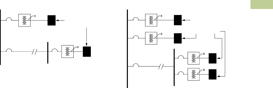
Volume 2—Commercial Distribution CA08100003E—July 2016 www.eaton.com V2-T2-91
2
2
2
2
2
2
2
2
2
2
2
2
2
2
2
2
2
2
2
2
2
2
2
2
2
2
2
2
2
2
2.3
Trans for mers
Energy-Efficient Harmonic Mitigating Transformers
Sample HMT Applications
Typical Application of Type NON Transformer
Installation of a Type NON
transformer provides an
effective treatment of triplen
(3rd, 9th, 15th and so on)
harmonic currents that
are generated by loads
connected to the transformer.
Triplen harmonic currents
are treated in the secondary
windings of the transformer
due to the transformer’s low
zero sequence impedance.
Type NON transformers
do not need to be used in
combination with other
transformers to treat triplen
harmonic currents. A single
Type NON transformer may
be installed, or multiple units
can be applied.
Type NON transformers are
an ideal solution for treating
triplen harmonics generated
by personal computers,
printers, fax machines and
other office equipment,
as well as by single-phase
electronic ballasts, and single-
phase electronic testing or
monitoring devices.
Type NON
Type NON
Long Run
Electrical Bus
Electrical Panel
Feeding Single-Phase
and/or Three-Phase
Nonlinear Loads
Typical Application of Type NON Transformer
with a Standard Delta-Wye Transformer
When a delta-wye transformer
exists in an electrical
distribution system, the
addition of a Type NON
transformer offers an
economical solution for treating
harmonic currents. The 30°
phase-shift created between a
Type NON harmonic mitigating
transformer and a delta-wye
transformer (standard
transformer or K-Factor
transformer) provides
treatment of 5th, 7th, 17th
and 19th harmonic currents.
These harmonic currents are
canceled in the common
electrical bus that feeds the
transformers. Additionally,
triplen (3rd, 9th, 15th and
so on) harmonic currents
generated by the loads
connected to the Type NON
transformer will be treated
in the secondary windings of
the Type NON transformer
due to its low zero sequence
impedance. When using two
or more transformers to treat
harmonics, it is better that the
load be split equally between
the transformers to receive the
maximum benefit.
Note: Triplen currents will still
circulate in the delta-wye
transformer for additional waste.
See figure on Page V2-T2-92 to
correct.
Type NON
-Y Transformer
Type NON
Long Run
-Y Transformer
Electrical Bus
Electrical Panel
Feeding Single-Phase
and/or Three-Phase
Nonlinear Loads
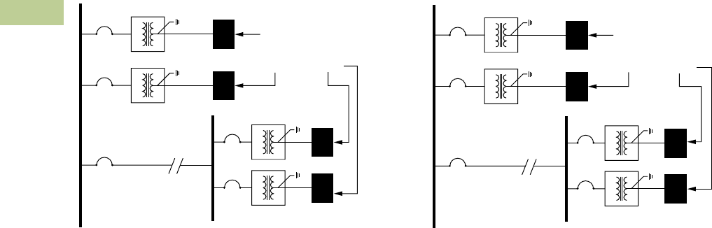
V2-T2-92 Volume 2—Commercial Distribution CA08100003E—July 2016 www.eaton.com
2
2
2
2
2
2
2
2
2
2
2
2
2
2
2
2
2
2
2
2
2
2
2
2
2
2
2
2
2
2
2.3
Trans for mers
Energy-Efficient Harmonic Mitigating Transformers
Optimum Application of Type NON and
Type THR Transformers
When you’re searching for an
optimum harmonic correction
solution in an electrical
distribution system, the
combination of a Type NON
and Type THR transformer
offers a great solution.
The 30° phase shift created
between Type NON and type
THR harmonic mitigating
transformers provides
treatment of 5th, 7th, 17th
and 19th harmonic currents.
These harmonic currents are
canceled in the common
electrical bus that feeds the
transformers. Additionally,
triplen (3rd, 9th, 15th and
so on) harmonic currents
generated by the loads will
be treated in the secondary
windings of HMTs. This will
ensure that these currents
will not circulate in the
primary of the transformer
creating additional heat,
voltage distortion and wasted
energy loss. When using
two or more transformers to
treat harmonics, it is better
that the load be split equally
between the transformers
to receive the
maximum benefit.
Type NON
Type THR
Type NON
Long Run
Type THR
Electrical Bus
Electrical Panel
Feeding Single-Phase
and/or Three-Phase
Nonlinear Loads
Typical Application of Type NEG and
Type POS Transformers
The combination of a Type
POS (+15° phase-shift)
transformer and a Type NEG
(–15° phase-shift) transformer
effectively treats 5th, 7th,
17th and 19th harmonic
currents. These harmonic
currents are canceled in the
common electrical bus that
feeds the transformers.
Additionally, triplen (3rd, 9th,
15th and so on) harmonic
currents generated by the
loads connected to these
transformers will be treated in
their secondary windings due
to their low zero sequence
impedance. When using two
or more transformers to treat
harmonics, it is better that the
load be split equally between
the transformers to receive
the maximum benefit.
Type NEG
Type POS
Type NEG
Long Run
Type POS
Electrical Bus
Electrical Panel
Feeding Single-Phase
and/or Three-Phase
Nonlinear Loads
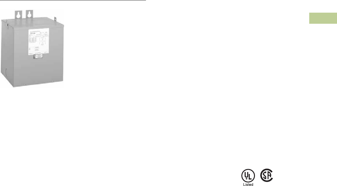
Volume 2—Commercial Distribution CA08100003E—July 2016 www.eaton.com V2-T2-93
2
2
2
2
2
2
2
2
2
2
2
2
2
2
2
2
2
2
2
2
2
2
2
2
2
2
2
2
2
2
2.4
Trans for mers
General-Purpose Encapsulated Transformers
Type EP 3–25 kVA
Contents
Description Page
General-Purpose Encapsulated Transformers
Catalog Number Selection . . . . . . . . . . . . . . . . V2-T2-94
Product Selection . . . . . . . . . . . . . . . . . . . . . . . V2-T2-94
Single-Phase. . . . . . . . . . . . . . . . . . . . . . . . . . V2-T2-94
Three-Phase . . . . . . . . . . . . . . . . . . . . . . . . . V2-T2-100
Accessories . . . . . . . . . . . . . . . . . . . . . . . . . . . V2-T2-109
Technical Data and Specifications. . . . . . . . . . . V2-T2-109
Product Description
Note: The following pages
provide listings for most standard
transformer ratings and catalog
numbers. For other ratings or
catalog numbers not shown,
or for special enclosure types
(including stainless steel), refer
to Eaton.
Type EP and EPT
●Encapsulated design
●Suitable for indoor or
outdoor applications
●Totally enclosed, non-
ventilated enclosures
●Enclosures are
NEMA 3R rated
●Mountable in any position
indoors and upright-only
outdoors
●180ºC insulation system
●115ºC rise standard;
80°C optional
●Available in ratings through
37.5 kVA single-phase;
75 kVA three-phase
Application Description
The basic purpose of a
transformer is voltage
transformation as near as
practically possible to the load
for economy and distribution
of power. Typical loads for
dry-type distribution
transformers include lighting,
heating, air conditioners,
fans and machine tools.
Such loads are found in
commercial, institutional,
industrial and residential
structures.
Features, Benefits
and Functions
●60 Hz operation
(50/60 Hz optional)
●Short-term overload
capability as required
by ANSI
●Meet NEMA ST-20
sound levels
Standards and
Certifications
●UL listed
●CSA certified
Industry Standards
All Eaton dry-type distribution
and control transformers are
built and tested in accordance
with applicable NEMA,
ANSI and IEEE Standards.
All 600 volt class transformers
are UL listed unless otherwise
noted.
Seismically Qualified
Eaton manufactured dry-type
distribution transformers are
seismically qualified and
exceed requirements of
the Uniform Building Code
(UBC), International Building
Code (IBC), and California
Code Title 24.
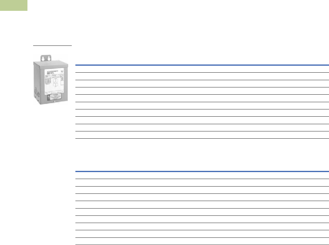
V2-T2-94 Volume 2—Commercial Distribution CA08100003E—July 2016 www.eaton.com
2
2
2
2
2
2
2
2
2
2
2
2
2
2
2
2
2
2
2
2
2
2
2
2
2
2
2
2
2
2
2.4
Trans for mers
General-Purpose Encapsulated Transformers
Catalog Number Selection
Please refer to Section 2.7 Page V2-T2-187.
Product Selection
Additional Product Selection information begins on Page V2-T2-189.
Single-Phase Encapsulated—Type EP, 60 Hz
120 x 240 Volts to 120/240 Volts 1
208 Volts to 120/240 Volts 1
Notes
1 Contact Eaton for availability of 0.05–0.25 kVA designs.
Contact your local Eaton sales office for CE Mark transformer requirements. For other ratings or catalog numbers not shown, or for special enclosure types (including
stainless steel), refer to Eaton. Frame drawings/dimensions information begins on Page V2-T2-216.
kVA
Full Capacity Taps
Type
ºC Temp.
Rise Frame
Wiring Diagram
Number
Weight
Lbs (kg) Weathershield Catalog NumberFCAN FCBN
0.5 — — EP 115 FR57P 3E 16 (7) Indoor–Outdoor S10N11P51P
1 — — EP 115 FR67P 3E 31 (14) Indoor–Outdoor S10N11P01P
1.5 — — EP 115 FR67P 3E 42 (19) Indoor–Outdoor S10N11P16P
2 — — EP 115 FR68P 3E 42 (19) Indoor–Outdoor S10N11P02P
3 — — EP 115 FR176 3E 55 (25) Indoor–Outdoor S10N11S03N
5 — — EP 115 FR177 3E 113 (51) Indoor–Outdoor S10N11S05N
7.5 — — EP 115 FR178 3E 123 (56) Indoor–Outdoor S10N11S07N
10 — — EP 115 FR179 3E 193 (88) Indoor–Outdoor S10N11S10N
15 — — EP 115 FR180 3E 216 (98) Indoor–Outdoor S10N11S15N
25 — — EP 115 FR182 3E 375 (170) Indoor–Outdoor S10N11S25N
kVA
Full Capacity Taps
Type
ºC Temp.
Rise Frame
Wiring Diagram
Number
Weight
Lbs (kg) Weathershield Catalog NumberFCAN FCBN
0.5 — — EP 115 FR57P 26A 16 (7) Indoor–Outdoor S29N11P51P
1 — — EP 115 FR67P 26A 31 (14) Indoor–Outdoor S29N11P01P
1.5 — — EP 115 FR67P 26A 42 (19) Indoor–Outdoor S29N11P16P
2 — — EP 115 FR68P 26A 42 (19) Indoor–Outdoor S29N11P02P
3 — — EP 115 FR176 26A 65 (30) Indoor–Outdoor S29N11S03N
5 — — EP 115 FR177 26A 113 (51) Indoor–Outdoor S29N11S05N
7.5 — — EP 115 FR178 26A 123 (56) Indoor–Outdoor S29N11S07N
10 — — EP 115 FR179 26A 193 (88) Indoor–Outdoor S29N11S10N
15 — — EP 115 FR180 26A 216 (98) Indoor–Outdoor S29N11S15N
25 — — EP 115 FR182 26A 395 (179) Indoor–Outdoor S29N11S25N
Type EP 3–37.5 kVA

Volume 2—Commercial Distribution CA08100003E—July 2016 www.eaton.com V2-T2-95
2
2
2
2
2
2
2
2
2
2
2
2
2
2
2
2
2
2
2
2
2
2
2
2
2
2
2
2
2
2
2.4
Trans for mers
General-Purpose Encapsulated Transformers
Single-Phase Encapsulated—Type EP, 60 Hz
277 Volts to 120/240 Volts 1
240 x 480 Volts to 120/240 Volts
Notes
1Contact Eaton for availability of 0.05–0.25 kVA designs.
21 at +10% FCBN at 240 volts; 2 at –5% FCBN at 480 volts.
32 at +5% FCBN at 240 volts; 4 at –2.5% FCBN at 480 volts.
4Floor-mount only.
Contact your local Eaton sales office for CE Mark transformer requirements. For other ratings or catalog numbers not shown, or for special enclosure types (including stainless steel), refer to Eaton.
Frame drawings/dimensions information begins on Page V2-T2-216.
kVA
Full Capacity Taps
Type
ºC Temp.
Rise Frame
Wiring Diagram
Number
Weight
Lbs (kg) Weathershield Catalog NumberFCAN FCBN
0.5 — — EP 115 FR58AP 524A 26 (12) Indoor–Outdoor S27N11P51P
1 — — EP 115 FR59AP 524A 31 (14) Indoor–Outdoor S27N11P01P
1.5 — — EP 115 FR67P 524A 42 (19) Indoor–Outdoor S27N11P16P
2 — — EP 115 FR176P 524A 65 (30) Indoor–Outdoor S27N11P02P
3 — — EP 115 FR176 524A 55 (25) Indoor–Outdoor S27N11S03N
5 — — EP 115 FR177 524A 113 (51) Indoor–Outdoor S27N11S05N
7.5 — — EP 115 FR178 524A 123 (56) Indoor–Outdoor S27N11S07N
10 — — EP 115 FR179 524A 193 (88) Indoor–Outdoor S27N11S10N
15 — — EP 115 FR180 524A 180 (82) Indoor–Outdoor S27N11S15N
25 — — EP 115 FR182 524A 375 (170) Indoor–Outdoor S27N11S25N
kVA
Full Capacity Taps
Type
ºC Temp.
Rise Frame
Wiring Diagram
Number
Weight
Lbs (kg) Weathershield Catalog NumberFCAN FCBN
0.050 — — EP 115 FR52 3A 7 (3) Indoor–Outdoor S20N11S81N
0.075 — — EP 115 FR54 3A 7 (3) Indoor–Outdoor S20N11S85N
0.100 — — EP 115 FR54 3A 7 (3) Indoor–Outdoor S20N11S82N
0.150 — — EP 115 FR55 3A 8 (4) Indoor–Outdoor S20N11S83N
0.25 — — EP 115 FR57P 3A 12 (5) Indoor–Outdoor S20N11P26P
0.5 — — EP 115 FR57P 3A 16 (7) Indoor–Outdoor S20N11P51P
0.75 — — EP 115 FR58AP 3A 26 (12) Indoor–Outdoor S20N11P76P
1 — — EP 115 FR67P 3A 31 (14) Indoor–Outdoor S20N11P01P
1.5 — — EP 115 FR67P 3A 42 (19) Indoor–Outdoor S20N11P16P
2 — — EP 115 FR68P 3A 42 (19) Indoor–Outdoor S20N11P02P
3 — — EP 115 FR176 3A 65 (30) Indoor–Outdoor S20N11S03N
322EP 115 FR176 3A 65 (30) Indoor–Outdoor S20K11S03N
5 — — EP 115 FR177 3A 113 (51) Indoor–Outdoor S20N11S05N
522EP 115 FR177 9A 105 (48) Indoor–Outdoor S20K11S05N
7.5 — — EP 115 FR178 3A 105 (48) Indoor–Outdoor S20N11S07N
7.5 22EP 115 FR178 9A 123 (56) Indoor–Outdoor S20K11S07N
10 — — EP 115 FR179 3A 193 (88) Indoor–Outdoor S20N11S10N
10 22EP 115 FR179 9A 193 (88) Indoor–Outdoor S20K11S10N
15 — — EP 115 FR180 3A 216 (98) Indoor–Outdoor S20N11S15N
15 33EP 115 FR180 23A 216 (98) Indoor–Outdoor S20L11S15N
25 — — EP 115 FR182 3A 385 (175) Indoor–Outdoor S20N11S25N
25 33EP 115 FR182 23A 375 (170) Indoor–Outdoor S20L11S25N
37.5 33EP 115 FR300A 248A 735 (334) Indoor–Outdoor S20L11S37 4

V2-T2-96 Volume 2—Commercial Distribution CA08100003E—July 2016 www.eaton.com
2
2
2
2
2
2
2
2
2
2
2
2
2
2
2
2
2
2
2
2
2
2
2
2
2
2
2
2
2
2
2.4
Trans for mers
General-Purpose Encapsulated Transformers
Single-Phase Encapsulated—Type EP, 60 Hz
190/200/208/220 x 380/400/416/440 Volts to 110/220 Volts 50/60 Hz—Export Model IP 22 Rated
120/208/240/277 Volts to 120/240 Volts 60 Hz
240 x 480 Volts to 120/240 Volts Stainless Steel 2
Notes
1Refer to your local Eaton sales office.
2NEMA 3R, 304 stainless steel enclosure; 316 stainless steel enclosure available as an option.
Contact your local Eaton sales office for CE Mark transformer requirements. For other ratings or catalog numbers not shown, or for special enclosure types (including stainless steel), refer to Eaton.
Frame drawings/dimensions information begins on Page V2-T2-216.
kVA
Full Capacity Taps
Type
ºC Temp.
Rise Frame
Wiring Diagram
Number
Weight
Lbs (kg) Weathershield Catalog NumberFCAN FCBN
0.5 — — EP 115 FR67 538A 42 (19) Indoor–Outdoor S40N14S51CE
1 — — EP 115 FR67 538A 42 (19) Indoor–Outdoor S40N14S01CE
1.5 — — EP 115 FR176 538A 65 (30) Indoor–Outdoor S40N14S16CE
2 — — EP 115 FR176 538A 65 (30) Indoor–Outdoor S40N14S02CE
3 — — EP 115 FR177 538A 113 (51) Indoor–Outdoor S40N14S03CE
5 — — EP 115 FR178 538A 140 (64) Indoor–Outdoor S40N14S05CE
7.5 — — EP 115 FR179 538A 193 (88) Indoor–Outdoor S40N14S07CE
10 — — EP 115 FR180 538A 216 (98) Indoor–Outdoor S40N14S10CE
15 — — EP 115 FR182 538A 375 (170) Indoor–Outdoor S40N14S15CE
kVA
Full Capacity Taps
Type
ºC Temp.
Rise Frame
Wiring Diagram
Number
Weight
Lbs (kg) Weathershield Catalog NumberFCAN FCBN
1 — — EP 115 FR67P 142 (19) Indoor–Outdoor S54N11P01
1.5 — — EP 115 FR176P 165 (30) Indoor–Outdoor S54N11P16
2 — — EP 115 FR176P 165 (30) Indoor–Outdoor S54N11P02
3 — — EP 115 FR177 1113 (51) Indoor–Outdoor S54N11S03
5 — — EP 115 FR178 1140 (64) Indoor–Outdoor S54N11S05
7.5 — — EP 115 FR179 1193 (88) Indoor–Outdoor S54N11S07
10 — — EP 115 FR180 1216 (98) Indoor–Outdoor S54N11S10
kVA
Full Capacity Taps
Type
ºC Temp.
Rise Frame
Wiring Diagram
Number
Weight
Lbs (kg) Weathershield Catalog NumberFCAN FCBN
3 — — EP 115 FR176 3A 65 (30) Indoor–Outdoor S20N11S03SS
5 — — EP 115 FR177 3A 113 (51) Indoor–Outdoor S20N11S05SS
7.5 — — EP 115 FR178 3A 123 (56) Indoor–Outdoor S20N11S07SS
10 — — EP 115 FR179 3A 193 (88) Indoor–Outdoor S20N11S10SS
15 — — EP 115 FR180 3A 205 (93) Indoor–Outdoor S20N11S15SS
25 — — EP 115 FR182 3A 375 (170) Indoor–Outdoor S20N11S25SS

Volume 2—Commercial Distribution CA08100003E—July 2016 www.eaton.com V2-T2-97
2
2
2
2
2
2
2
2
2
2
2
2
2
2
2
2
2
2
2
2
2
2
2
2
2
2
2
2
2
2
2.4
Trans for mers
General-Purpose Encapsulated Transformers
Single-Phase Encapsulated—Type EP, 60 Hz
480 Volts to 120/240 Volts
480 Volts to 120/240 Volts Stainless Steel, Copper Windings 1
600 Volts to 120/240 Volts
Notes
1NEMA 3R, 304 stainless steel enclosure; 316 stainless steel enclosure available as an option.
Contact your local Eaton sales office for CE Mark transformer requirements. For other ratings or catalog numbers not shown, or for special enclosure types (including stainless steel), refer to Eaton.
Frame drawings/dimensions information begins on Page V2-T2-216.
kVA
Full Capacity Taps
Type
ºC Temp.
Rise Frame
Wiring Diagram
Number
Weight
Lbs (kg) Weathershield Catalog NumberFCAN FCBN
1 — 2 at –5% EP 115 FR67P 2D 31 (14) Indoor–Outdoor S48G11P01P
1.5 — 2 at –5% EP 115 FR67P 2D 42 (19) Indoor–Outdoor S48G11P16P
2 — 2 at –5% EP 115 FR68P 2D 42 (19) Indoor–Outdoor S48G11P02P
3 — 2 at –5% EP 115 FR176 2D 65 (30) Indoor–Outdoor S48G11S03N
3 2 at +2.5% 2 at –2.5% EP 115 FR176 16A 65 (30) Indoor–Outdoor S48D11S03N
5 — 2 at –5% EP 115 FR177 2D 113 (51) Indoor–Outdoor S48G11S05N
5 2 at +2.5% 2 at –2.5% EP 115 FR177 16A 113 (51) Indoor–Outdoor S48D11S05N
7.5 — 2 at –5% EP 115 FR178 2D 123 (56) Indoor–Outdoor S48G11S07N
7.5 2 at +2.5% 2 at –2.5% EP 115 FR178 16A 123 (56) Indoor–Outdoor S48D11S07N
10 — 2 at –5% EP 115 FR179 2D 193 (88) Indoor–Outdoor S48G11S10N
10 2 at +2.5% 2 at –2.5% EP 115 FR179 16A 193 (88) Indoor–Outdoor S48D11S10N
15 — 2 at –5% EP 115 FR180 2D 216 (98) Indoor–Outdoor S48G11S15N
15 2 at +2.5% 2 at –2.5% EP 115 FR180 16A 216 (98) Indoor–Outdoor S48D11S15N
25 — 2 at –5% EP 115 FR182 2D 385 (175) Indoor–Outdoor S48G11S25N
25 2 at +2.5% 4 at –2.5% EP 115 FR132 83A 410 (186) Indoor–Outdoor S48M11S25N
kVA
Full Capacity Taps
Type
ºC Temp.
Rise Frame
Wiring Diagram
Number
Weight
Lbs (kg) Weathershield Catalog NumberFCAN FCBN
10 2 at +2.5% 2 at –2.5% EP 115 FR179 16A 210 (95) Indoor–Outdoor S48D11S10CUSS
15 2 at +2.5% 2 at –2.5% EP 115 FR180 16A 235 (107) Indoor–Outdoor S48D11S15SSCU
25 2 at +2.5% 4 at –2.5% EP 115 FR182 83A 415 (188) Indoor–Outdoor S48M11S25SSCU
kVA
Full Capacity Taps
Type
ºC Temp.
Rise Frame
Wiring Diagram
Number
Weight
Lbs (kg) Weathershield Catalog NumberFCAN FCBN
0.5 — 2 at –5% EP 115 FR57P 2I 16 (7) Indoor–Outdoor S60G11P51P
0.75 — 2 at –5% EP 115 FR58AP 2I 26 (12) Indoor–Outdoor S60G11P76P
1 — 2 at –5% EP 115 FR67P 2I 31 (14) Indoor–Outdoor S60G11P01P
1.5 — 2 at –5% EP 115 FR67P 2I 42 (19) Indoor–Outdoor S60G11P16P
2 — 2 at –5% EP 115 FR68P 2I 42 (19) Indoor–Outdoor S60G11P02P
3 — 2 at –5% EP 115 FR176 2I 65 (30) Indoor–Outdoor S60G11S03N
5 — 2 at –5% EP 115 FR177 2I 105 (48) Indoor–Outdoor S60G11S05N
7.5 — 2 at –5% EP 115 FR178 2I 123 (56) Indoor–Outdoor S60G11S07N
10 — 2 at –5% EP 115 FR179 2I 193 (88) Indoor–Outdoor S60G11S10N
15 — 4 at –2.5% EP 115 FR180 527A 216 (98) Indoor–Outdoor S60J11S15N
25 — 4 at –2.5% EP 115 FR182 527A 385 (175) Indoor–Outdoor S60J11S25N
25 2 at +2.5% 4 at –2.5% EP 115 FR132 83B 395 (180) Indoor–Outdoor S60M11S25N

V2-T2-98 Volume 2—Commercial Distribution CA08100003E—July 2016 www.eaton.com
2
2
2
2
2
2
2
2
2
2
2
2
2
2
2
2
2
2
2
2
2
2
2
2
2
2
2
2
2
2
2.4
Trans for mers
General-Purpose Encapsulated Transformers
Single-Phase Shielded—Type EP, 60 Hz
120 x 240 Volts to 120/240 Volts
120 Volts to 120 Volts
208 Volts to 120/240 Volts
208 Volts to 208 Volts
Note
Contact your local Eaton sales office for CE Mark transformer requirements. For other ratings or catalog numbers not shown, or for special enclosure types (including stainless steel), refer to Eaton.
Frame drawings/dimensions information begins on Page V2-T2-216.
kVA
Full Capacity Taps
Type
ºC Temp.
Rise Frame
Wiring Diagram
Number
Weight
Lbs (kg) Weathershield Catalog NumberFCAN FCBN
3 — — EP 115 FR176 90B 50 (23) Indoor–Outdoor S10N11E03N
5 — — EP 115 FR177 90B 90 (41) Indoor–Outdoor S10N11E05N
7.5 — — EP 115 FR178 90B 123 (56) Indoor–Outdoor S10N11E07N
10 — — EP 115 FR179 90B 210 (95) Indoor–Outdoor S10N11E10N
15 — — EP 115 FR180 90B 205 (93) Indoor–Outdoor S10N11E15N
25 — — EP 115 FR182 90B 375 (170) Indoor–Outdoor S10N11E25N
kVA
Full Capacity Taps
Type
ºC Temp.
Rise Frame
Wiring Diagram
Number
Weight
Lbs (kg) Weathershield Catalog NumberFCAN FCBN
3 — — EP 115 FR176 77A 60 (27) Indoor–Outdoor S12N12E03N
5 — — EP 115 FR177 77A 100 (45) Indoor–Outdoor S12N12E05N
7.5 — — EP 115 FR178 77A 123 (56) Indoor–Outdoor S12N12E07N
10 — — EP 115 FR179 77A 180 (82) Indoor–Outdoor S12N12E10N
15 — — EP 115 FR180 77A 216 (98) Indoor–Outdoor S12N12E15N
25 — — EP 115 FR182 77A 375 (170) Indoor–Outdoor S12N12E25N
kVA
Full Capacity Taps
Type
ºC Temp.
Rise Frame
Wiring Diagram
Number
Weight
Lbs (kg) Weathershield Catalog NumberFCAN FCBN
3 — — EP 115 FR176 578A 60 (27) Indoor–Outdoor S29N11E03N
5 — — EP 115 FR177 578A 135 (61) Indoor–Outdoor S29N11E05N
7.5 — — EP 115 FR178 578A 95 (43) Indoor–Outdoor S29N11E07N
10 — — EP 115 FR179 578A 165 (75) Indoor–Outdoor S29N11E10N
15 — — EP 115 FR180 578A 185 (94) Indoor–Outdoor S29N11E15N
25 — — EP 115 FR182 578A 375 (170) Indoor–Outdoor S29N11E25N
kVA
Full Capacity Taps
Type
ºC Temp.
Rise Frame
Wiring Diagram
Number
Weight
Lbs (kg) Weathershield Catalog NumberFCAN FCBN
3 — — EP 115 FR176 77B 65 (30) Indoor–Outdoor S29N29E03N
5 — — EP 115 FR177 77B 113 (51) Indoor–Outdoor S29N29E05N
7.5 — — EP 115 FR178 77B 123 (56) Indoor–Outdoor S29N29E07N
10 — — EP 115 FR179 77B 195 (89) Indoor–Outdoor S29N29E10N
15 — — EP 115 FR180 77B 216 (98) Indoor–Outdoor S29N29E15N
25 — — EP 115 FR182 77B 375 (170) Indoor–Outdoor S29N29E25N

Volume 2—Commercial Distribution CA08100003E—July 2016 www.eaton.com V2-T2-99
2
2
2
2
2
2
2
2
2
2
2
2
2
2
2
2
2
2
2
2
2
2
2
2
2
2
2
2
2
2
2.4
Trans for mers
General-Purpose Encapsulated Transformers
Single-Phase Shielded—Type EP, 60 Hz
240 Volts to 240 Volts
277 Volts to 120/240 Volts
240 x 480 Volts to 120/240 Volts
Notes
12 at +5% FCBN at 240 volts; 4 at –2.5% FCBN at 480 volts.
Contact your local Eaton sales office for CE Mark transformer requirements. For other ratings or catalog numbers not shown, or for special enclosure types (including stainless steel), refer to Eaton.
Frame drawings/dimensions information begins on Page V2-T2-216.
kVA
Full Capacity Taps
Type
ºC Temp.
Rise Frame
Wiring Diagram
Number
Weight
Lbs (kg) Weathershield Catalog NumberFCAN FCBN
3 — — EP 115 FR176 77C 65 (30) Indoor–Outdoor S24N24E03N
5 — — EP 115 FR177 77C 113 (51) Indoor–Outdoor S24N24E05N
7.5 — — EP 115 FR178 77C 123 (56) Indoor–Outdoor S24N24E07N
10 — — EP 115 FR179 77C 193 (88) Indoor–Outdoor S24N24E10N
15 — — EP 115 FR180 77C 216 (98) Indoor–Outdoor S24N24E15N
25 — — EP 115 FR182 77C 375 (170) Indoor–Outdoor S24N24E25N
kVA
Full Capacity Taps
Type
ºC Temp.
Rise Frame
Wiring Diagram
Number
Weight
Lbs (kg) Weathershield Catalog NumberFCAN FCBN
3 — — EP 115 FR176 513B 65 (30) Indoor–Outdoor S27N11E03N
5 — — EP 115 FR177 513B 113 (51) Indoor–Outdoor S27N11E05N
7.5 — — EP 115 FR178 513B 75 (34) Indoor–Outdoor S27N11E07N
10 — — EP 115 FR179 513B 162 (74) Indoor–Outdoor S27N11E10N
15 — — EP 115 FR180 513B 216 (98) Indoor–Outdoor S27N11E15N
25 — — EP 115 FR182 513B 375 (170) Indoor–Outdoor S27N11E25N
kVA
Full Capacity Taps
Type
ºC Temp.
Rise Frame
Wiring Diagram
Number
Weight
Lbs (kg) Weathershield Catalog NumberFCAN FCBN
0.25 — — EP 115 FR57P 90A 12 (5) Indoor–Outdoor S20N11E26P
0.50 — — EP 115 FR57P 90A 16 (7) Indoor–Outdoor S20N11E51P
0.75 — — EP 115 FR58AP 90A 26 (12) Indoor–Outdoor S20N11E76P
1 — — EP 115 FR67P 90A 31 (14) Indoor–Outdoor S20N11E01P
1.5 — — EP 115 FR67P 90A 42 (19) Indoor–Outdoor S20N11E16P
2 — — EP 115 FR68P 90A 42 (19) Indoor–Outdoor S20N11E02P
3 — — EP 115 FR176 90A 65 (30) Indoor–Outdoor S20N11E03A
5 — — EP 115 FR177 90A 113 (51) Indoor–Outdoor S20N11E05A
7.5 — — EP 115 FR178 90A 123 (56) Indoor–Outdoor S20N11E07A
10 — — EP 115 FR179 90A 166 (75) Indoor–Outdoor S20N11E10A
15 — — EP 115 FR180 90A 216 (98) Indoor–Outdoor S20N11E15A
25 11 EP 115 FR182 526A 375 (170) Indoor–Outdoor S20L11E25A

V2-T2-100 Volume 2—Commercial Distribution CA08100003E—July 2016 www.eaton.com
2
2
2
2
2
2
2
2
2
2
2
2
2
2
2
2
2
2
2
2
2
2
2
2
2
2
2
2
2
2
2.4
Trans for mers
General-Purpose Encapsulated Transformers
Three-Phase Encapsulated—Type EPT, 60 Hz
240 Delta Volts to 208Y/120 Volts
380 Delta Volts to 190Y/110 Volts
380 Delta Volts to 208Y/120 Volts
Notes
1T-T (Scott T) connected secondary.
2Floor-mount only.
Contact your local Eaton sales office for CE Mark transformer requirements. For other ratings or catalog numbers not shown, or for special enclosure types (including stainless steel), refer to Eaton.
Frame drawings/dimensions information begins on Page V2-T2-216.
kVA
Full Capacity Taps
Type
ºC Temp.
Rise Frame
Wiring Diagram
Number
Weight
Lbs (kg) Weathershield Catalog NumberFCAN FCBN
9 — 2 at –5% EPT 115 FR103 70C 190 (86) Indoor–Outdoor Y24G28T09N 1
15 — 2 at –5% EPT 115 FR95 70C 275 (125) Indoor–Outdoor Y24G28T15N 1
30 2 at +2.5% 4 at –2.5% EPT 115 FR243 84C 422 (191) Indoor–Outdoor Y24M28T30N
45 2 at +2.5% 4 at –2.5% EPT 115 FR244 84C 660 (299) Indoor–Outdoor Y24M28T45N
kVA
Full Capacity Taps
Type
ºC Temp.
Rise Frame
Wiring Diagram
Number
Weight
Lbs (kg) Weathershield Catalog NumberFCAN FCBN
3 — 2 at –5% EPT 115 FR201 70F 116 (53) Indoor–Outdoor Y38G19T03A 1
6 — 2 at –5% EPT 115 FR200 70F 165 (75) Indoor–Outdoor Y38G19T06A 1
9 — 2 at –5% EPT 115 FR95 70F 275 (125) Indoor–Outdoor Y38G19T09A 1
15 — 2 at –5% EPT 115 FR95 72R 275 (125) Indoor–Outdoor Y38G19T15A 1
30 2 at +2.5% 4 at –2.5% EPT 115 FR243 84AC 422 (191) Indoor–Outdoor Y38M19T30A
45 2 at +2.5% 4 at –2.5% EPT 115 FR244 84AC 660 (299) Indoor–Outdoor Y38M19T45A
75 2 at +2.5% 4 at –2.5% EPT 115 FR245 84AC 1275 (580) Indoor–Outdoor Y38M19T75A 2
kVA
Full Capacity Taps
Type
ºC Temp.
Rise Frame
Wiring Diagram
Number
Weight
Lbs (kg) Weathershield Catalog NumberFCAN FCBN
3 — 2 at –5% EPT 115 FR201 70D 116 (53) Indoor–Outdoor Y38G28T03A 1
6 — 2 at –5% EPT 115 FR200 70F 165 (75) Indoor–Outdoor Y38G28T06A 1
9 — 2 at –5% EPT 115 FR103 70D 185 (84) Indoor–Outdoor Y38G28T09A 1
15 — 2 at –5% EPT 115 FR95 70D 275 (125) Indoor–Outdoor Y38G28T15A 1
30 2 at +2.5% 4 at –2.5% EPT 115 FR243 84H 422 (191) Indoor–Outdoor Y38M28T30A
45 2 at +2.5% 4 at –2.5% EPT 115 FR244 84R 660 (299) Indoor–Outdoor Y38M28T45A
75 2 at +2.5% 4 at –2.5% EPT 115 FR245 84R 1275 (580) Indoor–Outdoor Y38M28T75A 2

Volume 2—Commercial Distribution CA08100003E—July 2016 www.eaton.com V2-T2-101
2
2
2
2
2
2
2
2
2
2
2
2
2
2
2
2
2
2
2
2
2
2
2
2
2
2
2
2
2
2
2.4
Trans for mers
General-Purpose Encapsulated Transformers
Three-Phase Encapsulated—Type EPT, 60 Hz
380 Delta Volts to 220Y/127 Volts
380 Delta Volts to 220 Delta Volts
380 Delta Volts to 380Y/220 Volts
380 Delta Volts to 480Y/277 Volts
Notes
1T-T (Scott T) connected secondary.
2Floor-mount only.
3Refer to your Eaton sales office.
Contact your local Eaton sales office for CE Mark transformer requirements. For other ratings or catalog numbers not shown, or for special enclosure types (including stainless steel), refer to Eaton.
Frame drawings/dimensions information begins on Page V2-T2-216.
kVA
Full Capacity Taps
Type
ºC Temp.
Rise Frame
Wiring Diagram
Number
Weight
Lbs (kg) Weathershield Catalog NumberFCAN FCBN
3 — 2 at –5% EPT 115 FR201 70F 116 (53) Indoor–Outdoor Y38G31T03A 1
6 — 2 at –5% EPT 115 FR200 70F 165 (75) Indoor–Outdoor Y38G31T06A 1
9 — 2 at –5% EPT 115 FR103 70M 195 (89) Indoor–Outdoor Y38G31T09A 1
15 — 2 at –5% EPT 115 FR95 70F 275 (125) Indoor–Outdoor Y38G31T15A 1
30 2 at +2.5% 4 at –2.5% EPT 115 FR243 84R 422 (191) Indoor–Outdoor Y38M31T30A
45 2 at +2.5% 4 at –2.5% EPT 115 FR244 84R 660 (299) Indoor–Outdoor Y38M31T45A
75 2 at +2.5% 4 at –2.5% EPT 115 FR245 84R 1275 (580) Indoor–Outdoor Y38M31T75A 2
kVA
Full Capacity Taps
Type
ºC Temp.
Rise Frame
Wiring Diagram
Number
Weight
Lbs (kg) Weathershield Catalog NumberFCAN FCBN
3 — 2 at –5% EPT 115 FR201 74K 116 (53) Indoor–Outdoor Y38G25T03A 1
6 — 2 at –5% EPT 115 FR200 74K 180 (82) Indoor–Outdoor Y38G25T06A 1
9 — 2 at –5% EPT 115 FR103 74K 195 (89) Indoor–Outdoor Y38G25T09A 1
15 — 2 at –5% EPT 115 FR95 74K 275 (125) Indoor–Outdoor Y38G25T15A 1
30 2 at +2.5% 4 at –2.5% EPT 115 FR243 3422 (191) Indoor–Outdoor Y38M25T30A
45 2 at +2.5% 4 at –2.5% EPT 115 FR244 3660 (299) Indoor–Outdoor Y38M25T45A
75 2 at +2.5% 4 at –2.5% EPT 115 FR245 31275 (580) Indoor–Outdoor Y38M25T75A 2
kVA
Full Capacity Taps
Type
ºC Temp.
Rise Frame
Wiring Diagram
Number
Weight
Lbs (kg) Weathershield Catalog NumberFCAN FCBN
3 — 2 at –5% EPT 115 FR201 70D 116 (53) Indoor–Outdoor Y38G37T03A 1
6 — 2 at –5% EPT 115 FR200 70D 165 (75) Indoor–Outdoor Y38G37T06A 1
9 — 2 at –5% EPT 115 FR103 70D 180 (82) Indoor–Outdoor Y38G37T09A 1
15 — 2 at –5% EPT 115 FR95 70D 275 (125) Indoor–Outdoor Y38G37T15A 1
30 2 at +2.5% 4 at –2.5% EPT 115 FR243 84H 422 (191) Indoor–Outdoor Y38M37T30A
45 2 at +2.5% 4 at –2.5% EPT 115 FR244 84H 660 (299) Indoor–Outdoor Y38M37T45A
75 2 at +2.5% 4 at –2.5% EPT 115 FR245 84H 1275 (580) Indoor–Outdoor Y38M37T75A 2
kVA
Full Capacity Taps
Type
ºC Temp.
Rise Frame
Wiring Diagram
Number
Weight
Lbs (kg) Weathershield Catalog NumberFCAN FCBN
3 — 2 at –5% EPT 115 FR201 70F 116 (53) Indoor–Outdoor Y38G47T03A 1
6 — 2 at –5% EPT 115 FR200 70F 180 (82) Indoor–Outdoor Y38G47T06A 1
9 — 2 at –5% EPT 115 FR103 70F 166 (75) Indoor–Outdoor Y38G47T09A 1
15 — 2 at –5% EPT 115 FR95 70F 275 (125) Indoor–Outdoor Y38G47T15A 1
30 2 at +2.5% 4 at –2.5% EPT 115 FR243 84AB 422 (191) Indoor–Outdoor Y38M47T30A
45 2 at +2.5% 4 at –2.5% EPT 115 FR244 84AB 660 (299) Indoor–Outdoor Y38M47T45A
75 2 at +2.5% 4 at –2.5% EPT 115 FR245 84AB 1275 (580) Indoor–Outdoor Y38M47T75A 2

V2-T2-102 Volume 2—Commercial Distribution CA08100003E—July 2016 www.eaton.com
2
2
2
2
2
2
2
2
2
2
2
2
2
2
2
2
2
2
2
2
2
2
2
2
2
2
2
2
2
2
2.4
Trans for mers
General-Purpose Encapsulated Transformers
Three-Phase Encapsulated—Type EPT, 60 Hz
416 Delta Volts to 208Y/120 Volts
440 Delta Volts to 220Y/127 Volts
480 Delta Volts to 208Y/120 Volts
480 Delta Volts to 208Y/120 Volts—Copper Windings
Notes
1T-T (Scott T) connected secondary.
2Floor-mount only.
3Not CSA certified.
Contact your local Eaton sales office for CE Mark transformer requirements. For other ratings or catalog numbers not shown, or for special enclosure types (including stainless steel), refer to Eaton.
Frame drawings/dimensions information begins on Page V2-T2-216.
kVA
Full Capacity Taps
Type
ºC Temp.
Rise Frame
Wiring Diagram
Number
Weight
Lbs (kg) Weathershield Catalog NumberFCAN FCBN
3 — 2 at –5% EPT 115 FR201 70V 116 (53) Indoor–Outdoor Y43G28T03A 1
6 — 2 at –5% EPT 115 FR200 70V 175 (79) Indoor–Outdoor Y43G28T06A 1
9 — 2 at –5% EPT 115 FR103 70V 190 (86) Indoor–Outdoor Y43G28T09A 1
15 — 2 at –5% EPT 115 FR95 70V 275 (125) Indoor–Outdoor Y43G28T15A 1
30 2 at +2.5% 4 at –2.5% EPT 115 FR243 84I 422 (191) Indoor–Outdoor Y43M28T30A
45 2 at +2.5% 4 at –2.5% EPT 115 FR244 84I 660 (299) Indoor–Outdoor Y43M28T45A
75 2 at +2.5% 4 at –2.5% EPT 115 FR245 84I 1275 (580) Indoor–Outdoor Y43M28T75A 2
kVA
Full Capacity Taps
Type
ºC Temp.
Rise Frame
Wiring Diagram
Number
Weight
Lbs (kg) Weathershield Catalog NumberFCAN FCBN
3 — 2 at –5% EPT 115 FR201 70G 116 (53) Indoor–Outdoor Y44G31T03A 1
6 — 2 at –5% EPT 115 FR200 70G 165 (75) Indoor–Outdoor Y44G31T06A 1
9 — 2 at –5% EPT 115 FR103 70G 166 (75) Indoor–Outdoor Y44G31T09A 1
15 — 2 at –5% EPT 115 FR95 70G 275 (125) Indoor–Outdoor Y44G31T15A 1
30 2 at +2.5% 4 at –2.5% EPT 115 FR243 84O 422 (191) Indoor–Outdoor Y44M31T30A 2
45 2 at +2.5% 4 at –2.5% EPT 115 FR244 84O 660 (299) Indoor–Outdoor Y44M31T45A
75 2 at +2.5% 4 at –2.5% EPT 115 FR245 84O 1275 (580) Indoor–Outdoor Y44M31T75A 2
kVA
Full Capacity Taps
Type
ºC Temp.
Rise Frame
Wiring Diagram
Number
Weight
Lbs (kg) Weathershield Catalog NumberFCAN FCBN
3 — 2 at –5% EPT 115 FR201 70A 116 (52) Indoor–Outdoor Y48G28T03N 1
6 — 2 at –5% EPT 115 FR200 70A 165 (75) Indoor–Outdoor Y48G28T06N 1
6 2 at +2.5% 2 at –2.5% EPT 115 FR200 72B 165 (75) Indoor–Outdoor Y48D28T06N 1
9 — 2 at –5% EPT 115 FR103 70A 166 (75) Indoor–Outdoor Y48G28T09N 1
9 — 4 at –2.5% EPT 115 FR103 503A 185 (84) Indoor–Outdoor Y48J28T09N 1
9 2 at +2.5% 2 at –2.5% EPT 115 FR103 72B 185 (84) Indoor–Outdoor Y48D28T09N 1
15 — 2 at –5% EPT 115 FR95 70A 275 (125) Indoor–Outdoor Y48G28T15N 1
15 — 4 at –2.5% EPT 115 FR95 503A 275 (125) Indoor–Outdoor Y48J28T15N 1
15 2 at +2.5% 2 at –2.5% EPT 115 FR95 72B 275 (125) Indoor–Outdoor Y48D28T15N 1
30 2 at +2.5% 4 at –2.5% EPT 115 FR243 84A 422 (191) Indoor–Outdoor Y48M28T30N
45 2 at +2.5% 4 at –2.5% EPT 115 FR244 84A 720 (327) Indoor–Outdoor Y48M28T45N
75 2 at +2.5% 4 at –2.5% EPT 115 FR245 84A 1275 (580) Indoor–Outdoor Y48M28T75N 2
kVA
Full Capacity Taps
Type
ºC Temp.
Rise Frame
Wiring Diagram
Number
Weight
Lbs (kg) Weathershield Catalog NumberFCAN FCBN
15 2 at +2.5% 2 at –2.5% EPT 115 FR95 72B 300 (136) Indoor–Outdoor Y48D28T15CU 1
30 2 at +2.5% 4 at –2.5% EPT 115 FR243 84A 505 (230) Indoor–Outdoor Y48M28T30CU
45 2 at +2.5% 4 at –2.5% EPT 115 FR244 84A 810 (368) Indoor–Outdoor Y48M28T45CU
75 2 at +2.5% 4 at –2.5% EPT 115 FR245 84A 1450 (659) Indoor–Outdoor Y48M28T75CU 23

Volume 2—Commercial Distribution CA08100003E—July 2016 www.eaton.com V2-T2-103
2
2
2
2
2
2
2
2
2
2
2
2
2
2
2
2
2
2
2
2
2
2
2
2
2
2
2
2
2
2
2.4
Trans for mers
General-Purpose Encapsulated Transformers
Three-Phase Encapsulated—Type EPT, 60 Hz
480 Delta Volts to 208Y/120 Volts Stainless Steel 1
480 Delta Volts to 208Y/120 Volts Stainless Steel—Copper Windings 1
480 Delta Volts to 220Y/127 Volts
480 Delta Volts to 240 Delta Volts
Notes
1NEMA 3R, 304 stainless steel enclosure; 316 stainless steel enclosure available.
2T-T connected secondary.
3Floor-mount only.
4Do not include 120 volt lighting tap.
Contact your local Eaton sales office for CE Mark transformer requirements. For other ratings or catalog numbers not shown, or for special enclosure types (including stainless steel), refer to Eaton.
Frame drawings/dimensions information begins on Page V2-T2-216.
kVA
Full Capacity Taps
Type
ºC Temp.
Rise Frame
Wiring Diagram
Number
Weight
Lbs (kg) Weathershield Catalog NumberFCAN FCBN
3 — 2 at –5% EPT 115 FR201 70A 116 (53) Indoor–Outdoor Y48G28T03SS 2
6 2 at +2.5% 2 at –2.5% EPT 115 FR200 72B 175 (79) Indoor–Outdoor Y48D28T06SS 2
9 2 at +2.5% 2 at –2.5% EPT 115 FR103 72B 185 (84) Indoor–Outdoor Y48D28T09SS 2
15 2 at +2.5% 2 at –2.5% EPT 115 FR95 72B 275 (125) Indoor–Outdoor Y48D28T15SS 2
30 2 at +2.5% 4 at –2.5% EPT 115 FR243 84A 422 (191) Indoor–Outdoor Y48M28T30SS
45 2 at +2.5% 4 at –2.5% EPT 115 FR244 84A 660 (299) Indoor–Outdoor Y48M28T45SS
75 2 at +2.5% 4 at –2.5% EPT 115 FR245 84A 1275 (580) Indoor–Outdoor Y48M28T75SS 3
kVA
Full Capacity Taps
Type
ºC Temp.
Rise Frame
Wiring Diagram
Number
Weight
Lbs (kg) Weathershield Catalog NumberFCAN FCBN
15 2 at +2.5% 2 at –2.5% EPT 115 FR95 72B 275 (125) Indoor–Outdoor Y48D28T15CUSS 2
30 2 at +2.5% 4 at –2.5% EPT 115 FR243 84A 504 (229) Indoor–Outdoor Y48M28T30CUSS
45 2 at +2.5% 4 at –2.5% EPT 115 FR244 84A 810 (368) Indoor–Outdoor Y48M28T45CUSS
kVA
Full Capacity Taps
Type
ºC Temp.
Rise Frame
Wiring Diagram
Number
Weight
Lbs (kg) Weathershield Catalog NumberFCAN FCBN
3 — 2 at –5% EPT 115 FR201 70K 116 (53) Indoor–Outdoor Y48G31T03A 2
6 — 2 at –5% EPT 115 FR200 70K 175 (79) Indoor–Outdoor Y48G31T06A 2
9 — 2 at –5% EPT 115 FR103 70A 185 (84) Indoor–Outdoor Y48G31T09A 2
15 — 2 at –5% EPT 115 FR95 70A 275 (125) Indoor–Outdoor Y48G31T15A 2
30 2 at +2.5% 4 at –2.5% EPT 115 FR243 84A 422 (191) Indoor–Outdoor Y48M31T30A
45 2 at +2.5% 4 at –2.5% EPT 115 FR244 84A 660 (299) Indoor–Outdoor Y48M31T45A
75 2 at +2.5% 4 at –2.5% EPT 115 FR245 84K 1275 (580) Indoor–Outdoor Y48M31T75A 3
kVA
Full Capacity Taps
Type
ºC Temp.
Rise Frame
Wiring Diagram
Number
Weight
Lbs (kg) Weathershield Catalog NumberFCAN FCBN
3 — 2 at –5% EPT 115 FR201 74A 116 (52) Indoor–Outdoor Y48G24T03N 24
6 — 2 at –5% EPT 115 FR200 74A 165 (75) Indoor–Outdoor Y48G24T06N 24
9 — 4 at –2.5% EPT 115 FR103 73A 185 (84) Indoor–Outdoor Y48J24T09N 24
15 — 4 at –2.5% EPT 115 FR95 73A 275 (125) Indoor–Outdoor Y48J24T15N 24
30 2 at +2.5% 4 at –2.5% EPT 115 FR243 85A 422 (191) Indoor–Outdoor Y48M24T30N 4
45 2 at +2.5% 4 at –2.5% EPT 115 FR244 85A 660 (299) Indoor–Outdoor Y48M24T45N 4

V2-T2-104 Volume 2—Commercial Distribution CA08100003E—July 2016 www.eaton.com
2
2
2
2
2
2
2
2
2
2
2
2
2
2
2
2
2
2
2
2
2
2
2
2
2
2
2
2
2
2
2.4
Trans for mers
General-Purpose Encapsulated Transformers
Three-Phase Encapsulated—Type EPT, 60 Hz
480 Delta Volts to 380Y/220 Volts
480 Delta Volts to 380 Delta Volts
480 Delta Volts to 416Y/240 Volts
480 Delta Volts to 440Y/254 Volts
Notes
1T-T connected secondary.
2Floor-mount only.
Contact your local Eaton sales office for CE Mark transformer requirements. For other ratings or catalog numbers not shown, or for special enclosure types (including stainless steel), refer to Eaton.
Frame drawings/dimensions information begins on Page V2-T2-216.
kVA
Full Capacity Taps
Type
ºC Temp.
Rise Frame
Wiring Diagram
Number
Weight
Lbs (kg) Weathershield Catalog NumberFCAN FCBN
3 — 2 at –5% EPT 115 FR201 70A 116 (53) Indoor–Outdoor Y48G37T03A 1
6 — 2 at –5% EPT 115 FR200 70R 165 (75) Indoor–Outdoor Y48G37T06A 1
9 — 2 at –5% EPT 115 FR103 70R 185 (84) Indoor–Outdoor Y48G37T09A 1
15 — 2 at –5% EPT 115 FR95 70R 275 (125) Indoor–Outdoor Y48G37T15A 1
30 2 at +2.5% 4 at –2.5% EPT 115 FR243 84A 422 (191) Indoor–Outdoor Y48M37T30A
45 2 at +2.5% 4 at –2.5% EPT 115 FR244 84A 660 (299) Indoor–Outdoor Y48M37T45A
75 2 at +2.5% 4 at –2.5% EPT 115 FR245 84A 1275 (580) Indoor–Outdoor Y48M37T75A 2
kVA
Full Capacity Taps
Type
ºC Temp.
Rise Frame
Wiring Diagram
Number
Weight
Lbs (kg) Weathershield Catalog NumberFCAN FCBN
3 — 2 at –5% EPT 115 FR201 74B 116 (53) Indoor–Outdoor Y48G38T03A 1
6 — 2 at –5% EPT 115 FR200 74B 165 (75) Indoor–Outdoor Y48G38T06A 1
9 — 2 at –5% EPT 115 FR103 74B 185 (84) Indoor–Outdoor Y48G38T09A 1
15 — 2 at –5% EPT 115 FR95 74A 275 (125) Indoor–Outdoor Y48G38T15A 1
30 2 at +2.5% 4 at –2.5% EPT 115 FR243 85A 422 (191) Indoor–Outdoor Y48M38T30A
45 2 at +2.5% 4 at –2.5% EPT 115 FR244 85A 660 (299) Indoor–Outdoor Y48M38T45A
75 2 at +2.5% 4 at –2.5% EPT 115 FR245 85A 1275 (580) Indoor–Outdoor Y48M38T75A 2
kVA
Full Capacity Taps
Type
ºC Temp.
Rise Frame
Wiring Diagram
Number
Weight
Lbs (kg) Weathershield Catalog NumberFCAN FCBN
3 — 2 at –5% EPT 115 FR200 70A 165 (75) Indoor–Outdoor Y48G51T03A 1
6 — 2 at –5% EPT 115 FR200 70A 185 (84) Indoor–Outdoor Y48G51T06A 1
9 — 2 at –5% EPT 115 FR103 70S 185 (84) Indoor–Outdoor Y48G51T09A 1
15 — 2 at –5% EPT 115 FR95 70S 275 (125) Indoor–Outdoor Y48G51T15A 1
30 2 at +2.5% 4 at –2.5% EPT 115 FR243 84A 422 (191) Indoor–Outdoor Y48M51T30A
45 2 at +2.5% 4 at –2.5% EPT 115 FR244 84A 660 (299) Indoor–Outdoor Y48M51T45A
75 2 at +2.5% 4 at –2.5% EPT 115 FR245 84A 1275 (580) Indoor–Outdoor Y48M51T75A 2
kVA
Full Capacity Taps
Type
ºC Temp.
Rise Frame
Wiring Diagram
Number
Weight
Lbs (kg) Weathershield Catalog NumberFCAN FCBN
3 — 2 at –5% EPT 115 FR201 70A 116 (53) Indoor–Outdoor Y48G35T03A 1
6 — 2 at –5% EPT 115 FR200 70A 185 (84) Indoor–Outdoor Y48G35T06A 1
9 — 2 at –5% EPT 115 FR103 70A 185 (84) Indoor–Outdoor Y48G35T09A 1
15 — 2 at –5% EPT 115 FR95 70A 275 (125) Indoor–Outdoor Y48G35T15A 1
30 2 at +2.5% 4 at –2.5% EPT 115 FR243 84A 422 (191) Indoor–Outdoor Y48M35T30A
45 2 at +2.5% 4 at –2.5% EPT 115 FR244 84A 660 (299) Indoor–Outdoor Y48M35T45A
75 2 at +2.5% 4 at –2.5% EPT 115 FR245 84A 1275 (580) Indoor–Outdoor Y48M35T75A 2

Volume 2—Commercial Distribution CA08100003E—July 2016 www.eaton.com V2-T2-105
2
2
2
2
2
2
2
2
2
2
2
2
2
2
2
2
2
2
2
2
2
2
2
2
2
2
2
2
2
2
2.4
Trans for mers
General-Purpose Encapsulated Transformers
Three-Phase Encapsulated—Type EPT, 60 Hz
480 Delta Volts to 480Y/277 Volts
600 Delta Volts to 208Y/120 Volts
Three-Phase Shielded—Type EPT, 60 Hz
480 Delta Volts to 208Y/120 Volts
480 Delta Volts to 240 Delta Volts
Notes
1T-T connected secondary.
Contact your local Eaton sales office for CE Mark transformer requirements. For other ratings or catalog numbers not shown, or for special enclosure types (including stainless steel), refer to Eaton.
Frame drawings/dimensions information begins on Page V2-T2-216.
kVA
Full Capacity Taps
Type
ºC Temp.
Rise Frame
Wiring Diagram
Number
Weight
Lbs (kg) Weathershield Catalog NumberFCAN FCBN
9 2 at +2.5% 2 at –2.5% EPT 115 FR103 72C 190 (86) Indoor–Outdoor Y48D47T09N 1
15 2 at +2.5% 2 at –2.5% EPT 115 FR95 72C 275 (125) Indoor–Outdoor Y48D47T15N 1
30 2 at +2.5% 4 at –2.5% EPT 115 FR243 84A 422 (191) Indoor–Outdoor Y48M47T30N
45 2 at +2.5% 4 at –2.5% EPT 115 FR244 84A 660 (299) Indoor–Outdoor Y48M47T45N
kVA
Full Capacity Taps
Type
ºC Temp.
Rise Frame
Wiring Diagram
Number
Weight
Lbs (kg) Weathershield Catalog NumberFCAN FCBN
9 — 2 at –5% EPT 115 FR103 70B 185 (84) Indoor–Outdoor Y60G28T09N 1
15 — 2 at –5% EPT 115 FR95 70B 275 (125) Indoor–Outdoor Y60G28T15N 1
30 2 at +2.5% 4 at –2.5% EPT 115 FR243 84B 422 (191) Indoor–Outdoor Y60M28T30N
45 2 at +2.5% 4 at –2.5% EPT 115 FR244 84B 660 (299) Indoor–Outdoor Y60M28T45N
kVA
Full Capacity Taps
Type
ºC Temp.
Rise Frame
Wiring Diagram
Number
Weight
Lbs (kg) Weathershield Catalog NumberFCAN FCBN
3 2 at +2.5% 2 at –2.5% EPT 115 FR201 86B 116 (52) Indoor–Outdoor Y48D28E03A 1
6 2 at +2.5% 2 at –2.5% EPT 115 FR200 86B 165 (75) Indoor–Outdoor Y48D28E06A 1
9 2 at +2.5% 2 at –2.5% EPT 115 FR103 86B 190 (86) Indoor–Outdoor Y48D28E09N 1
15 2 at +2.5% 2 at –2.5% EPT 115 FR95 86B 275 (125) Indoor–Outdoor Y48D28E15B 1
kVA
Full Capacity Taps
Type
ºC Temp.
Rise Frame
Wiring Diagram
Number
Weight
Lbs (kg) Weathershield Catalog NumberFCAN FCBN
3 — 2 at –5% EPT 115 FR201 88A 116 (52) Indoor–Outdoor Y48G24E03A 1
6 — 2 at –5% EPT 115 FR200 88A 165 (75) Indoor–Outdoor Y48G24E06A 1
9 — 4 at –2.5% EPT 115 FR103 505B 195 (89) Indoor–Outdoor Y48J24E09A 1
15 — 4 at –2.5% EPT 115 FR95 505B 275 (125) Indoor–Outdoor Y48J24E15A 1

V2-T2-106 Volume 2—Commercial Distribution CA08100003E—July 2016 www.eaton.com
2
2
2
2
2
2
2
2
2
2
2
2
2
2
2
2
2
2
2
2
2
2
2
2
2
2
2
2
2
2
2.4
Trans for mers
General-Purpose Encapsulated Transformers
NEMA Type 4X Single-Phase Encapsulated—Type EP, 60 Hz, Grade 304 Stainless Steel 1
240 x 480 Volts to 120/240 Volts—Aluminum Windings
Notes
1Grade 304 stainless steel standard. Grade 316 stainless steel available as an option. Replace suffix “SS” with suffix “S6.”
2Copper windings provided as standard.
31 at +10% FCBN at 240 volts; 2 at –5% FCBN at 480 volts.
42 at +5% FCBN at 240 volts; 4 at –2.5% FCBN at 480 volts.
5Floor-mount only.
Contact your local Eaton sales office for voltage combinations not shown in the above table. Other voltages and custom features are available upon request.
kVA
Full Capacity Taps
Type
ºC Temp.
Rise Frame
Wiring Diagram
Number
Weight
Lbs (kg) Weathershield Catalog NumberFCAN FCBN
0.100 2— — EP 115 FR544X 3A 7 (3) Indoor–Outdoor S20N11S82SS4X
0.015 2— — EP 115 FR554X 3A 9 (4) Indoor–Outdoor S20N11S83SS4X
0.250 2— — EP 115 FR57P4X 3A 15 (7) Indoor–Outdoor S20N11P26SS4X
0.500 2— — EP 115 FR57P4X 3A 14 (6) Indoor–Outdoor S20N11P51SS4X
0.750 2— — EP 115 FR58AP4X 3A 22 (10 ) Indoor–Outdoor S20N11P76SS4X
1 2— — EP 115 FR67P4X 3A 30 (14) Indoor–Outdoor S20N11P01SS4X
1.5 2— — EP 115 FR67P4X 3A 41 (19) Indoor–Outdoor S20N11P16SS4X
2 2— — EP 115 FR68P4X 3A 75 (34) Indoor–Outdoor S20N11P02SS4X
3 — — EP 115 FR1764X 3A 68 (31) Indoor–Outdoor S20N11S03SS4X
333 EP 115 FR1764X 9A 67 (30) Indoor–Outdoor S20K11S03SS4X
5 — — EP 115 FR1774X 3A 107 (49) Indoor–Outdoor S20N11S05SS4X
533 EP 115 FR1774X 9A 105 (48) Indoor–Outdoor S20K11S05SS4X
7.5 — — EP 115 FR1784X 3A 129 (58) Indoor–Outdoor S20N11S07SS4X
7.5 33 EP 115 FR1784X 9A 130 (59) Indoor–Outdoor S20K11S07SS4X
10 — — EP 115 FR1794X 3A 196 (89) Indoor–Outdoor S20N11S10SS4X
10 33 EP 115 FR1794X 9A 198 (90) Indoor–Outdoor S20K11S10SS4X
15 — — EP 115 FR1804X 3A 215 (98) Indoor–Outdoor S20N11S15SS4X
15 33 EP 115 FR1804X 23A 215 (98) Indoor–Outdoor S20L11S15SS4X
25 — — EP 115 FR1824X 3A 393 (178) Indoor–Outdoor S20N11S25SS4X
25 44 EP 115 FR1824X 23A 453 (206) Indoor–Outdoor S20L11S25SS4X
37.5 44 EP 115 FR300A4X 248A 735 (334) Indoor–Outdoor S20L11S37SS4X 5

Volume 2—Commercial Distribution CA08100003E—July 2016 www.eaton.com V2-T2-107
2
2
2
2
2
2
2
2
2
2
2
2
2
2
2
2
2
2
2
2
2
2
2
2
2
2
2
2
2
2
2.4
Trans for mers
General-Purpose Encapsulated Transformers
NEMA Type 4X Single-Phase Encapsulated—Type EP, 60 Hz, Grade 304 Stainless Steel 1
240 x 480 Volts to 120/240 Volts—Copper Windings
Notes
1Grade 304 stainless steel standard. Grade 316 stainless steel available as an option. Replace suffix “SS” with suffix “S6.”
2Copper windings provided as standard.
31 at +10% FCBN at 240 volts; 2 at –5% FCBN at 480 volts.
42 at +5% FCBN at 240 volts; 4 at –2.5% FCBN at 480 volts.
5Floor-mount only.
Contact your local Eaton sales office for voltage combinations not shown in the above table. Other voltages and custom features are available upon request.
kVA
Full Capacity Taps
Type
ºC Temp.
Rise Frame
Wiring Diagram
Number
Weight
Lbs (kg) Weathershield Catalog NumberFCAN FCBN
0.100 2— — EP 115 FR544X 3A 7 (3) Indoor–Outdoor S20N11S82SS4X
0.015 2— — EP 115 FR554X 3A 9 (4) Indoor–Outdoor S20N11S83SS4X
0.250 2— — EP 115 FR57P4X 3A 15 (7) Indoor–Outdoor S20N11P26SS4X
0.500 2— — EP 115 FR57P4X 3A 14 (6) Indoor–Outdoor S20N11P51SS4X
0.750 2— — EP 115 FR58AP4X 3A 22 (10) Indoor–Outdoor S20N11P76SS4X
1 2— — EP 115 FR67P4X 3A 30 (14) Indoor–Outdoor S20N11P01SS4X
1.5 2— — EP 115 FR68P4X 3A 41 (19) Indoor–Outdoor S20N11P02SS4X
2 2— — EP 115 FR68P4X 3A 36 (16) Indoor–Outdoor S20N11P16SS4X
3 — — EP 115 FR1764X 3A 76 (34) Indoor–Outdoor S20N11S03CUSS4X
333EP 115 FR1764X 9A 77 (35) Indoor–Outdoor S20K11S03CUSS4X
5 — — EP 115 FR1774X 3A 135 (61) Indoor–Outdoor S20N11S05CUSS4X
533EP 115 FR1774X 9A 121 (55) Indoor–Outdoor S20K11S05CUSS4X
7.5 — — EP 115 FR1784X 3A 144 (65) Indoor–Outdoor S20N11S07CUSS4X
7.5 33EP 115 FR1784X 9A 146 (66) Indoor–Outdoor S20K11S07CUSS4X
10 — — EP 115 FR1794X 3A 229 (104) Indoor–Outdoor S20N11S10CUSS4X
10 33EP 115 FR1794X 9A 219 (99) Indoor–Outdoor S20K11S10CUSS4X
15 — — EP 115 FR1804X 3A 236 (107) Indoor–Outdoor S20N11S15CUSS4X
15 33EP 115 FR1804X 23A 236 (107) Indoor–Outdoor S20L11S15CUSS4X
25 — — EP 115 FR300A4X 3A 388 (176) Indoor–Outdoor S20N11S25CUSS4X
25 44EP 115 FR300A4X 23A 388 (176) Indoor–Outdoor S20L11S25CUSS4X
37.5 44EP 115 FR300A4X 248A 775 (352) Indoor–Outdoor S20L11S37CUSS4X 5

V2-T2-108 Volume 2—Commercial Distribution CA08100003E—July 2016 www.eaton.com
2
2
2
2
2
2
2
2
2
2
2
2
2
2
2
2
2
2
2
2
2
2
2
2
2
2
2
2
2
2
2.4
Trans for mers
General-Purpose Encapsulated Transformers
NEMA Type 4X Three-Phase Encapsulated—Type EPT, 60 Hz, Grade 304 Stainless Steel 1
480 Delta Volts to 208Y/120 Volts—Aluminum Windings
480 Delta Volts to 208Y/120 Volts—Copper Windings
Notes
1Grade 304 stainless steel standard. Grade 316 stainless steel available as an option. Replace suffix “SS” with suffix “S6.”
2T-T connected (Scott T) secondary winding configuration.
3Floor-mount only.
Contact your local Eaton sales office for voltage combinations not shown in the above table. Other voltages and custom features are available upon request.
kVA
Full Capacity Taps
Type
ºC Temp.
Rise Frame
Wiring Diagram
Number
Weight
Lbs (kg) Weathershield Catalog NumberFCAN FCBN
3 — 2 at –5% EPT 115 FR2014X 70A 125 (57) Indoor–Outdoor Y48G28T03SS4X 2
6 — 2 at –5% EPT 115 FR2004X 70A 165 (75) Indoor–Outdoor Y48G28T06SS4X 2
6 2 at +2.5% 2 at –2.5% EPT 115 FR2004X 72B 171 (78) Indoor–Outdoor Y48D28T06SS4X 2
9 — 2 at –5% EPT 115 FR1034X 70A 180 (82) Indoor–Outdoor Y48G28T09SS4X 2
9 — 4 at –2.5% EPT 115 FR1034X 503A 192 (87) Indoor–Outdoor Y48J28T09SS4X 2
9 2 at +2.5% 2 at –2.5% EPT 115 FR1034X 72B 196 (89) Indoor–Outdoor Y48D28T09SS4X 2
15 2 at +2.5% 2 at –2.5% EPT 115 FR954X 72B 281 (127) Indoor–Outdoor Y48D28T15SS4X 2
15 — 2 at –5% EPT 115 FR954X 70A 269 (122) Indoor–Outdoor Y48G28T15SS4X 2
15 — 4 at –2.5% EPT 115 FR954X 503A 268 (121) Indoor–Outdoor Y48J28T15SS4X 2
30 2 at +2.5% 4 at –2.5% EPT 115 FR2434X 84A 539 (245) Indoor–Outdoor Y48M28T30SS4X
45 2 at +2.5% 4 at –2.5% EPT 115 FR2444X 84A 723 (328) Indoor–Outdoor Y48M28T45SS4X
75 2 at +2.5% 4 at –2.5% EPT 115 FR2454X 84A 1277 (580) Indoor–Outdoor Y48M28T75SS4X 3
kVA
Full Capacity Taps
Type
ºC Temp.
Rise Frame
Wiring Diagram
Number
Weight
Lbs (kg) Weathershield Catalog NumberFCAN FCBN
3 — 2 at –5% EPT 115 FR2014X 70A 139 (63) Indoor–Outdoor Y48G28T03CUSS4X 2
6 — 2 at –5% EPT 115 FR2004X 70A 187 (84) Indoor–Outdoor Y48G28T06CUSS4X 2
6 2 at +2.5% 2 at –2.5% EPT 115 FR2004X 72B 188 (85) Indoor–Outdoor Y48D28T06CUSS4X 2
9 — 2 at –5% EPT 115 FR1034X 70A 226 (103) Indoor–Outdoor Y48G28T09CUSS4X 2
9 — 4 at –2.5% EPT 115 FR1034X 503A 226 (103) Indoor–Outdoor Y48J28T09CUSS4X 2
9 2 at +2.5% 2 at –2.5% EPT 115 FR1034X 72B 231 (105) Indoor–Outdoor Y48D28T09CUSS4X 2
15 2 at +2.5% 2 at –2.5% EPT 115 FR954X 72B 276 (125) Indoor–Outdoor Y48D28T15CUSS4X 2
15 — 2 at –5% EPT 115 FR954X 70A 283 (128) Indoor–Outdoor Y48G28T15CUSS4X 2
15 — 4 at –2.5% EPT 115 FR954X 503A 299 (136) Indoor–Outdoor Y48J28T15CUSS4X 2
30 2 at +2.5% 4 at –2.5% EPT 115 FR2434X 84A 602 (273) Indoor–Outdoor Y48M28T30CUSS4X
45 2 at +2.5% 4 at –2.5% EPT 115 FR2444X 84A 829 (376) Indoor–Outdoor Y48M28T45CUSS4X
75 2 at +2.5% 4 at –2.5% EPT 115 FR2454X 84A 1452 (659) Indoor–Outdoor Y48M28T75CUSS4X 3

Volume 2—Commercial Distribution CA08100003E—July 2016 www.eaton.com V2-T2-109
2
2
2
2
2
2
2
2
2
2
2
2
2
2
2
2
2
2
2
2
2
2
2
2
2
2
2
2
2
2
2.4
Trans for mers
General-Purpose Encapsulated Transformers
Accessories
Please refer to Section 2.7 Page V2-T2-191.
Technical Data and Specifications
Frequency
Eaton standard dry-type
distribution transformers are
designed for 60 Hz operation.
Transformers required for
other frequencies are
available and must be
specifically designed.
Overload Capability
Short-term overload is
designed into transformers as
required by ANSI. Dry-type
distribution transformers will
deliver 200% nameplate load
for one-half hour, 150% load
for one hour and 125% load
for four hours without being
damaged, provided that a
constant 50% load precedes
and follows the overload.
See ANSI C57.96-01.250 for
additional limitations.
Continuous overload capacity
is not deliberately designed
into a transformer because
the design objective is to be
within the allowed winding
temperature rise with
nameplate loading.
Insulation System and
Temperature Rise
Industry standards classify
insulation systems and rise as
shown below:
Insulation System
Classification
The design life of transformers
having different insulation
systems is the same—the
lower-temperature systems
are designed for the same life
as the higher-temperature
systems.
Enclosures
Eaton encapsulated
transformers, Types EP and
EPT, use a NEMA 3R rated
enclosure as standard. NEMA
4X enclosures (grade 304 or
316 stainless steel) are
available as an option.
Winding Terminations
Primary and secondary
windings are terminated in
the wiring compartment.
Encapsulated units have
copper leads or stabs
brought out for connections.
Ventilated transformers
have leads brought out to
aluminum pads that are pre-
drilled to accept Cu/Al lugs.
Lugs are not supplied with
these transformers. Eaton
recommends that external
cables be rated 90°C
(sized at 75°C ampacity) for
encapsulated designs and
75°C for ventilated designs.
Series-Multiple Windings
Series-multiple windings
consist of two similar coils
in each winding that can be
connected in series or parallel
(multiple). Transformers with
series-multiple windings are
designated with an “x” or
“/” between the voltage
ratings, such as voltages of
“120/240” or “240 x 480.”
If the series-multiple winding
is designated by an “x,” the
winding can be connected
only for a series or parallel.
With the “/” designation,
a mid-point also becomes
available in addition to the
series or parallel connection.
As an example, a 120 x 240
winding can be connected
for either 120 (parallel) or
240 (series), but a 120/240
winding can be connected for
120 (parallel), 240 (series) or
240 with a 120 mid-point.
Ambient
+
Winding
Rise
+
Hot
Spot
=
Temp.
Class
40°C 55°C 10°C 105°C
40°C 80°C 30°C 150°C
25°C 135°C 20°C 180°C
40°C 115°C 30°C 185°C
40°C 150°C 30°C 220°C
Sound Levels
All Eaton 600 volt class
general-purpose dry-type
distribution transformers are
designed to meet NEMA
ST-20 sound levels listed
here. These are the sound
levels measured in a
soundproof environment.
Actual sound levels
measured at an installation
will likely be higher due to
electrical connections and
environmental conditions.
Lower sound levels are
available and should be
specified when the
transformer is going to be
installed in an area where
sound may be a concern.
For additional information,
please refer to Section 2.7
Page V2-T2-195.
Average Sound Levels
Note
For other ratings or catalog numbers not shown, or for special enclosure types (including
stainless steel), refer to Eaton.
NEMA ST-20 Average Sound Level, dB
Equivalent Winding
kVA Range
Self-Cooled Ventilated (up to 1.2 kV) Encapsulated
(up to 1.2 kV)K-Factor 1, 4, 9 K-Factor 13, 20
3.00 and below 40 40 45
3.01 to 9.00 40 40 45
9.01 to 15.00 45 45 50
15.01 to 30.00 45 45 50
30.01 to 50.00 45 48 50
50.01 to 75.00 50 53 55
75.01 to 112.50 50 53 55
112.51 to 150.00 50 53 55
150.01 to 225.00 55 58 57
225.01 to 300.00 55 58 57
300.01 to 500.00 60 63 59
500.01 to 700.00 62 65 61
700.01 to 1000.00 64 67 63
Greater than 1000 Consult factory Consult factory Consult factory

V2-T2-110 Volume 2—Commercial Distribution CA08100003E—July 2016 www.eaton.com
2
2
2
2
2
2
2
2
2
2
2
2
2
2
2
2
2
2
2
2
2
2
2
2
2
2
2
2
2
2
2.5
Transfor mers
Distribution Transformers
Contents
Description Page
Distribution Transformers
Motor Drive Isolation Transformers . . . . . . . . . V2-T2-111
Mini–Power Centers . . . . . . . . . . . . . . . . . . . . V2-T2-119
Totally Enclosed Non-Ventilated Transformers . V2-T2-124
Class I, Division 2, Hazardous Location
Transformers . . . . . . . . . . . . . . . . . . . . . . . . . V2-T2-127
Open-Type Core and Coil Assembly
Transformers . . . . . . . . . . . . . . . . . . . . . . . . . V2-T2-130
Marine Duty Transformers . . . . . . . . . . . . . . . . V2-T2-133
Buck-Boost and Low Voltage Lighting
Transformers . . . . . . . . . . . . . . . . . . . . . . . . . V2-T2-144
Medium Voltage Distribution Transformers . . . V2-T2-173

Volume 2—Commercial Distribution CA08100003E—July 2016 www.eaton.com V2-T2-111
2
2
2
2
2
2
2
2
2
2
2
2
2
2
2
2
2
2
2
2
2
2
2
2
2
2
2
2
2
2
2.5
Trans for mers
Distribution Transformers
Type MD
Contents
Description Page
Motor Drive Isolation Transformers
Catalog Number Selection . . . . . . . . . . . . . . . . V2-T2-112
Product Selection . . . . . . . . . . . . . . . . . . . . . . . V2-T2-112
Accessories . . . . . . . . . . . . . . . . . . . . . . . . . . . V2-T2-118
Technical Data and Specifications. . . . . . . . . . . V2-T2-118
Mini–Power Centers . . . . . . . . . . . . . . . . . . . . . . . V2-T2-119
Totally Enclosed Non-Ventilated Transformers. . . . V2-T2-124
Class I, Division 2, Hazardous Location Transformers V2-T2-127
Open-Type Core and Coil Assembly Transformers V2-T2-130
Marine Duty Transformers. . . . . . . . . . . . . . . . . . . V2-T2-133
Buck-Boost and Low Voltage Lighting Transformers V2-T2-144
Medium Voltage Distribution Transformers . . . . . . V2-T2-173
Motor Drive Isolation Transformers
Product Description
Note: The following pages
provide listings for most standard
transformer ratings and catalog
numbers. For other ratings or
catalog numbers not shown,
or for special enclosure types
(including stainless steel), refer
to Eaton.
●Suitable for indoor or
outdoor applications
(with weathershield)
●Ventilated enclosures
●220°C insulation system
●150°C rise standard (self
extinguishing), 115°C or
80°C rise optional
●Available in ratings from 7.5
through 1500 kVA
Application Description
Drive isolation transformers
are specifically designed
for use with AC and DC
adjustable speed drives.
Two winding drive isolation
transformers provide:
●Electrical isolation
between the incoming
line and the drive circuitry
●Voltage conversion of
input line to standard
drive input voltages
●Minimized line
disturbances caused by
SCR (silicon controlled
rectifiers) firing
●Reduced short-circuit
currents and voltage
line transients
Drive isolation transformers
are specifically sized to the
drive kVA requirements and
are braced to withstand the
mechanical stresses of
current reversals and short
circuits associated with
SCR drives.
Features, Benefits and Functions
●60 Hz operation (50/60 Hz
operation available)
●Short-term overload
capability as required
by ANSI
●Primary and secondary
terminals are front
accessible for fast
and easy connection
●Slotted screw mounting
holes in enclosure
and cover reduce
installation time
●Sound dampening pads,
which isolate the core
and coil from the case,
reduce noise levels to
meet NEMA ST-20
●Core laminations of
precision sheared silicon
steel are hand stacked to
ensure quiet operation
●Terminations are
clearly marked for
easy identification
●Three-phase transformers
have one 5% full capacity
tap above and below
nominal voltage for
incoming source
adjustment
●Units are suitable for
continuous o
peration in a
40°C ambient maximum
●Full current neutral
●Thermoguard protection
embedded in coils of three-
phase models to indicate
that high temperatures
(approximately 190°C) are
present. Thermoguards
consist of a set of NO
dry contacts
●Three coil delta-wye
configurations are used
throughout the product line
Standards and Certifications
●ANSI C89.2
●NEMA ST-20
●UL 506
●UL 1561
Seismic Qualified
All Eaton manufactured dry-
type distribution transformers
are seismically qualified and
exceed requirements of the
International Building Code
(IBC) and California Code
Title 24.

V2-T2-112 Volume 2—Commercial Distribution CA08100003E—July 2016 www.eaton.com
2
2
2
2
2
2
2
2
2
2
2
2
2
2
2
2
2
2
2
2
2
2
2
2
2
2
2
2
2
2
2.5
Transfor mers
Distribution Transformers
Catalog Number Selection
Please refer to Section 2.7 Page V2-T2-187.
Product Selection
Additional Product Selection information begins on Page V2-T2-189.
Three-Phase Drive Isolation
208 Delta Volts to 460Y/266 Volts
Notes
1Contact Eaton.
For other ratings or catalog numbers not shown, or for special enclosure types (including stainless steel), refer to Eaton. Frame drawings/dimensions information begins on Page V2-T2-216.
hp kVA
Full Capacity Taps ºC Temp.
Rise Frame
Wiring Diagram
Number
Weight
Lbs (kg) Weathershield Catalog NumberFCAN FCBN
5 7.5 1 at +5% 1 at –5% 150 912D 347B 158 (72) WS38 MD075E86
7.5 11 1 at +5% 1 at –5% 150 912D 347B 176 (80) WS38 MD11E86
10 14 1 at +5% 1 at –5% 150 912D 347B 149 (68) WS38 MD14E86
15 20 1 at +5% 1 at –5% 150 912D 347B 240 (19) WS38 MD20E86
20 27 1 at +5% 1 at –5% 150 912D 347B 231 (15) WS38 MD27E86
25 34 1 at +5% 1 at –5% 150 912D 347B 310 (141) WS38 MD34E86
30 40 1 at +5% 1 at –5% 150 912D 347B 307 (139) WS38 MD40E86
40 51 1 at +5% 1 at –5% 150 914F 347B 480 (218) WS39 MD51E86
50 63 1 at +5% 1 at –5% 150 914F 347B 485 (220) WS39 MD63E86
60 75 1 at +5% 1 at –5% 150 914F 347B 482 (219) WS39 MD75E86
75 93 1 at +5% 1 at –5% 150 915F 347B 600 (272) WS39 MD93E86
100 118 1 at +5% 1 at –5% 150 916A 347B 658 (299) WS19 MD118E86
125 145 1 at +5% 1 at –5% 150 916A 347B 770 (350) WS19 MD145E86
150 175 1 at +5% 1 at –5% 150 918A 321B 1320 (599) WS34 MD175E86
200 220 1 at +5% 1 at –5% 150 918A 321B 1436 (652) WS34 MD220E86
250 275 1 at +5% 1 at –5% 150 918A 321B 1WS34 MD275E86
300 330 1 at +5% 1 at –5% 150 919E 321B 1WS35 MD330E86
400 440 1 at +5% 1 at –5% 150 920E 321B 1WS35 MD440E86

Volume 2—Commercial Distribution CA08100003E—July 2016 www.eaton.com V2-T2-113
2
2
2
2
2
2
2
2
2
2
2
2
2
2
2
2
2
2
2
2
2
2
2
2
2
2
2
2
2
2
2.5
Trans for mers
Distribution Transformers
Three-Phase Drive Isolation
230 Delta Volts to 230Y/133 Volts
230 Delta Volts to 460Y/266 Volts
Notes
1Contact Eaton.
For other ratings or catalog numbers not shown, or for special enclosure types (including stainless steel), refer to Eaton. Frame drawings/dimensions information begins on Page V2-T2-216.
hp kVA
Full Capacity Taps ºC
Temp.
Rise Frame
Wiring
Diagram
Number
Weight
Lbs (kg) Weathershield Catalog NumberFCAN FCBN
5 7.5 1 at +5% 1 at –5% 150 912D 286A 158 (72) WS38 MD075E88
7.5 11 1 at +5% 1 at –5% 150 912D 286A 156 (71) WS38 MD11E88
10 14 1 at +5% 1 at –5% 150 912D 286A 158 (72) WS38 MD14E88
15 20 1 at +5% 1 at –5% 150 912D 286A 216 (98) WS38 MD20E88
20 27 1 at +5% 1 at –5% 150 912D 286A 231 (105) WS38 MD27E88
25 34 1 at +5% 1 at –5% 150 912D 286A 310 (141) WS38 MD34E88
30 40 1 at +5% 1 at –5% 150 912D 286A 310 (141) WS38 MD40E88
40 51 1 at +5% 1 at –5% 150 914F 286A 480 (218) WS39 MD51E88
50 63 1 at +5% 1 at –5% 150 914F 286A 500 (227) WS39 MD63E88
60 75 1 at +5% 1 at –5% 150 914F 286A 538 (244) WS39 MD75E88
75 93 1 at +5% 1 at –5% 150 915F 286A 600 (272) WS39 MD93E88
100 118 1 at +5% 1 at –5% 150 915F 286A 600 (272) WS39 MD118E88
125 145 1 at +5% 1 at –5% 150 916A 286A 868 (394) WS19 MD145E88
150 175 1 at +5% 1 at –5% 150 918A 318D 1320 (599) WS34 MD175E88
200 220 1 at +5% 1 at –5% 150 918A 318D 1332 (605) WS34 MD220E88
250 275 1 at +5% 1 at –5% 150 918A 318D 1350 (613) WS34 MD275E88
300 330 1 at +5% 1 at –5% 150 919E 318D 2336 (1061) WS35 MD330E88
400 440 1 at +5% 1 at –5% 150 920E 318D 1WS35 MD440E88
hp kVA
Full Capacity Taps ºC
Temp.
Rise Frame
Wiring
Diagram
Number
Weight
Lbs (kg) Weathershield Catalog NumberFCAN FCBN
5 7.5 1 at +5% 1 at –5% 150 912D 347A 158 (72) WS38 MD075E89
7.5 11 1 at +5% 1 at –5% 150 912D 347A 158 (72) WS38 MD11E89
10 14 1 at +5% 1 at –5% 150 912D 347A 158 (72) WS38 MD14E89
15 20 1 at +5% 1 at –5% 150 912D 347A 254 (115) WS38 MD20E89
20 27 1 at +5% 1 at –5% 150 912D 347A 231 (105) WS38 MD27E89
25 34 1 at +5% 1 at –5% 150 912D 347A 310 (141) WS38 MD34E89
30 40 1 at +5% 1 at –5% 150 912D 347A 344 (156) WS38 MD40E89
40 51 1 at +5% 1 at –5% 150 914F 347A 480 (218) WS39 MD51E89
50 63 1 at +5% 1 at –5% 150 914F 347A 457 (207) WS39 MD63E89
60 75 1 at +5% 1 at –5% 150 914F 347A 480 (218) WS39 MD75E89
75 93 1 at +5% 1 at –5% 150 915F 347A 600 (272) WS39 MD93E89
100 118 1 at +5% 1 at –5% 150 916A 347A 941 (427) WS19 MD118E89
125 145 1 at +5% 1 at –5% 150 916A 347A 770 (350) WS19 MD145E89
150 175 1 at +5% 1 at –5% 150 917 321A 1326 (602) WS34 MD175E89
200 220 1 at +5% 1 at –5% 150 918A 321A 1332 (605) WS34 MD220E89
250 275 1 at +5% 1 at –5% 150 918A 321A 1350 (613) WS34 MD275E89
300 330 1 at +5% 1 at –5% 150 919E 321A 2400 (1090) WS35 MD330E89
400 440 1 at +5% 1 at –5% 150 920E 321A 1WS35 MD440E89

V2-T2-114 Volume 2—Commercial Distribution CA08100003E—July 2016 www.eaton.com
2
2
2
2
2
2
2
2
2
2
2
2
2
2
2
2
2
2
2
2
2
2
2
2
2
2
2
2
2
2
2.5
Transfor mers
Distribution Transformers
Three-Phase Drive Isolation
460 Delta Volts to 230Y/133 Volts
460 Delta Volts to 400Y/231 Volts
Note
For other ratings or catalog numbers not shown, or for special enclosure types (including stainless steel), refer to Eaton. Frame drawings/dimensions information begins on Page V2-T2-216.
hp kVA
Full Capacity Taps ºC Temp.
Rise Frame
Wiring Diagram
Number
Weight
Lbs (kg) Weathershield Catalog NumberFCAN FCBN
5 7.5 1 at +5% 1 at –5% 150 912D 286D 193 (88) WS38 MD075E91
7.5 11 1 at +5% 1 at –5% 150 912D 286D 158 (72) WS38 MD11E91
10 14 1 at +5% 1 at –5% 150 912D 286D 158 (72) WS38 MD14E91
15 20 1 at +5% 1 at –5% 150 912D 286D 216 (98) WS38 MD20E91
20 27 1 at +5% 1 at –5% 150 912D 286D 231 (105) WS38 MD27E91
25 34 1 at +5% 1 at –5% 150 912D 286D 340 (154) WS38 MD34E91
30 40 1 at +5% 1 at –5% 150 912D 286D 339 (154) WS38 MD40E91
40 51 1 at +5% 1 at –5% 150 914 286D 535 (243) WS39 MD51E91
50 63 1 at +5% 1 at –5% 150 914F 286D 480 (218) WS39 MD63E91
60 75 1 at +5% 1 at –5% 150 914F 286D 469 (213) WS39 MD75E91
75 93 1 at +5% 1 at –5% 150 915F 286D 727 (330) WS39 MD93E91
100 118 1 at +5% 1 at –5% 150 916A 286D 770 (350) WS19 MD118E91
125 145 1 at +5% 1 at –5% 150 916A 286D 770 (350) WS19 MD145E91
150 175 1 at +5% 1 at –5% 150 917 286D 1100 (499) WS34 MD175E91
200 220 1 at +5% 1 at –5% 150 917 286D 1299 (590) WS34 MD220E91
250 275 1 at +5% 1 at –5% 150 918A 286D 1596 (725) WS34 MD275E91
300 330 1 at +5% 1 at –5% 150 919E 318E 2234 (1014) WS35 MD330E91
400 440 1 at +5% 1 at –5% 150 919E 318E 2400 (1090) WS35 MD440E91
hp kVA
Full Capacity Taps ºC Temp.
Rise Frame
Wiring Diagram
Number
Weight
Lbs (kg) Weathershield Catalog NumberFCAN FCBN
5 7.5 1 at +5% 1 at –5% 150 912D 286D 193 (88) WS38 MD075E75
7.5 11 1 at +5% 1 at –5% 150 912D 286D 158 (72) WS38 MD11E75
10 14 1 at +5% 1 at –5% 150 912D 286D 158 (72) WS38 MD14E75
15 20 1 at +5% 1 at –5% 150 912D 286D 216 (98) WS38 MD20E75
20 27 1 at +5% 1 at –5% 150 912D 286D 231 (105) WS38 MD27E75
25 34 1 at +5% 1 at –5% 150 912D 286D 340 (154) WS38 MD34E75
30 40 1 at +5% 1 at –5% 150 912D 286D 339 (154) WS38 MD40E75
40 51 1 at +5% 1 at –5% 150 914F 286D 535 (243) WS39 MD51E75
50 63 1 at +5% 1 at –5% 150 914F 286D 480 (218) WS39 MD63E75
60 75 1 at +5% 1 at –5% 150 914F 286D 469 (213) WS39 MD75E75
75 93 1 at +5% 1 at –5% 150 915F 286D 727 (330) WS39 MD93E75
100 118 1 at +5% 1 at –5% 150 916A 286D 770 (350) WS19 MD118E75
125 145 1 at +5% 1 at –5% 150 916A 286D 770 (350) WS19 MD145E75
150 175 1 at +5% 1 at –5% 150 917 286D 1100 (499) WS34 MD175E75
200 220 1 at +5% 1 at –5% 150 917 286D 1299 (590) WS34 MD220E75
250 275 1 at +5% 1 at –5% 150 918A 286D 1596 (725) WS34 MD275E75
300 330 1 at +5% 1 at –5% 150 919E 318E 2234 (1014) WS35 MD330E75
400 440 1 at +5% 1 at –5% 150 919E 318E 2400 (1090) WS35 MD440E75

Volume 2—Commercial Distribution CA08100003E—July 2016 www.eaton.com V2-T2-115
2
2
2
2
2
2
2
2
2
2
2
2
2
2
2
2
2
2
2
2
2
2
2
2
2
2
2
2
2
2
2.5
Trans for mers
Distribution Transformers
Three-Phase Drive Isolation
460 Delta Volts to 460Y/266 Volts
Note
For other ratings or catalog numbers not shown, or for special enclosure types (including stainless steel), refer to Eaton. Frame drawings/dimensions information begins on Page V2-T2-216.
hp kVA
Full Capacity Taps ºC Temp.
Rise Frame
Wiring Diagram
Number
Weight
Lbs (kg) Weathershield Catalog NumberFCAN FCBN
5 7.5 1 at +5% 1 at –5% 150 912D 286D 164 (74) WS38 MD075E92
7.5 11 1 at +5% 1 at –5% 150 912D 286D 161 (73) WS38 MD11E92
10 14 1 at +5% 1 at –5% 150 912D 286D 173 (79) WS38 MD14E92
15 20 1 at +5% 1 at –5% 150 912D 286D 231 (105) WS38 MD20E92
20 27 1 at +5% 1 at –5% 150 912D 286D 250 (114) WS38 MD27E92
25 34 1 at +5% 1 at –5% 150 912D 286D 310 (141) WS38 MD34E92
30 40 1 at +5% 1 at –5% 150 912D 286D 310 (141) WS38 MD40E92
40 51 1 at +5% 1 at –5% 150 914F 286D 503 (228) WS39 MD51E92
50 63 1 at +5% 1 at –5% 150 914F 286D 535 (243) WS39 MD63E92
60 75 1 at +5% 1 at –5% 150 914F 286D 535 (243) WS39 MD75E92
75 93 1 at +5% 1 at –5% 150 916A 286D 710 (322) WS19 MD93E92
100 118 1 at +5% 1 at –5% 150 916A 286D 770 (350) WS19 MD118E92
125 145 1 at +5% 1 at –5% 150 916A 286D 866 (393) WS19 MD145E92
150 175 1 at +5% 1 at –5% 150 917 286D 1100 (499) WS34 MD175E92
200 220 1 at +5% 1 at –5% 150 917 286D 1100 (499) WS34 MD220E92
250 275 1 at +5% 1 at –5% 150 918A 286D 1469 (667) WS34 MD275E92
300 330 1 at +5% 1 at –5% 150 919E 318E 2587 (1174) WS35 MD330E92
400 440 1 at +5% 1 at –5% 150 919E 318E 2500 (1135) WS35 MD440E92

V2-T2-116 Volume 2—Commercial Distribution CA08100003E—July 2016 www.eaton.com
2
2
2
2
2
2
2
2
2
2
2
2
2
2
2
2
2
2
2
2
2
2
2
2
2
2
2
2
2
2
2.5
Transfor mers
Distribution Transformers
Three-Phase Drive Isolation
480 Delta Volts to 240 Delta Volts
480 Delta Volts to 480 Delta Volts
Note
For other ratings or catalog numbers not shown, or for special enclosure types (including stainless steel), refer to Eaton. Frame drawings/dimensions information begins on Page V2-T2-216.
hp kVA
Full Capacity Taps ºC Temp.
Rise Frame
Wiring Diagram
Number
Weight
Lbs (kg) Weathershield Catalog NumberFCAN FCBN
5 7.5 1 at +5% 1 at –5% 150 912D 300A 193 (88) WS38 MD075E77
7.5 11 1 at +5% 1 at –5% 150 912D 300A 158 (72) WS38 MD11E77
10 14 1 at +5% 1 at –5% 150 912D 300A 158 (72) WS38 MD14E77
15 20 1 at +5% 1 at –5% 150 912D 300A 185 (84) WS38 MD20E77
20 27 1 at +5% 1 at –5% 150 912D 300A 231 (105) WS38 MD27E77
25 34 1 at +5% 1 at –5% 150 912D 300A 329 (149) WS38 MD34E77
30 40 1 at +5% 1 at –5% 150 912D 300A 339 (154) WS38 MD40E77
40 51 1 at +5% 1 at –5% 150 914F 300A 535 (243) WS39 MD51E77
50 63 1 at +5% 1 at –5% 150 914F 300A 480 (218) WS39 MD63E77
60 75 1 at +5% 1 at –5% 150 914F 300A 469 (213) WS39 MD75E77
75 93 1 at +5% 1 at –5% 150 915F 300A 727 (330) WS39 MD93E77
100 118 1 at +5% 1 at –5% 150 916A 300A 770 (350) WS19 MD118E77
125 145 1 at +5% 1 at –5% 150 916A 300A 770 (350) WS19 MD145E77
150 175 1 at +5% 1 at –5% 150 917 300A 1100 (499) WS34 MD175E77
200 220 1 at +5% 1 at –5% 150 917 300A 1299 (590) WS34 MD220E77
250 275 1 at +5% 1 at –5% 150 918A 300A 1596 (725) WS34 MD275E77
300 330 1 at +5% 1 at –5% 150 919E 348D 2234 (1014) WS35 MD330E77
400 440 1 at +5% 1 at –5% 150 919E 348D 2400 (1090) WS35 MD440E77
hp kVA
Full Capacity Taps ºC Temp.
Rise Frame
Wiring Diagram
Number
Weight
Lbs (kg) Weathershield Catalog NumberFCAN FCBN
5 7.5 1 at +5% 1 at –5% 150 912D 300A 193 (88) WS38 MD075E99
7.5 11 1 at +5% 1 at –5% 150 912D 300A 158 (72) WS38 MD11E99
10 14 1 at +5% 1 at –5% 150 912D 300A 158 (72) WS38 MD14E99
15 20 1 at +5% 1 at –5% 150 912D 300A 185 (84) WS38 MD20E99
20 27 1 at +5% 1 at –5% 150 912D 300A 231 (105) WS38 MD27E99
25 34 1 at +5% 1 at –5% 150 912D 300A 329 (149) WS38 MD34E99
30 40 1 at +5% 1 at –5% 150 912D 300A 339 (154) WS38 MD40E99
40 51 1 at +5% 1 at –5% 150 914F 300A 535 (243) WS39 MD51E99
50 63 1 at +5% 1 at –5% 150 914F 300A 480 (218) WS39 MD63E99
60 75 1 at +5% 1 at –5% 150 914F 300A 469 (213) WS39 MD75E99
75 93 1 at +5% 1 at –5% 150 915F 300A 727 (330) WS39 MD93E99
100 118 1 at +5% 1 at –5% 150 916A 300A 770 (350) WS19 MD118E99
125 145 1 at +5% 1 at –5% 150 916A 300A 770 (350) WS19 MD145E99
150 175 1 at +5% 1 at –5% 150 917 300A 1100 (499) WS34 MD175E99
200 220 1 at +5% 1 at –5% 150 917 300A 1299 (590) WS34 MD220E99
250 275 1 at +5% 1 at –5% 150 918A 300A 1596 (725) WS34 MD275E99
300 330 1 at +5% 1 at –5% 150 919E 348D 2234 (1014) WS35 MD330E99
400 440 1 at +5% 1 at –5% 150 919E 348D 2400 (1090) WS35 MD440E99

Volume 2—Commercial Distribution CA08100003E—July 2016 www.eaton.com V2-T2-117
2
2
2
2
2
2
2
2
2
2
2
2
2
2
2
2
2
2
2
2
2
2
2
2
2
2
2
2
2
2
2.5
Trans for mers
Distribution Transformers
Three-Phase Drive Isolation
575 Delta Volts to 460Y/266 Volts
575 Delta Volts to 575Y/332 Volts
Note
For other ratings or catalog numbers not shown, or for special enclosure types (including stainless steel), refer to Eaton. Frame drawings/dimensions information begins on Page V2-T2-216.
hp kVA
Full Capacity Taps ºC Temp.
Rise Frame
Wiring Diagram
Number
Weight
Lbs (kg) Weathershield Catalog NumberFCAN FCBN
5 7.5 1 at +5% 1 at –5% 150 912D 286H 158 (72) WS38 MD075E95
7.5 11 1 at +5% 1 at –5% 150 912D 286H 158 (72) WS38 MD11E95
10 14 1 at +5% 1 at –5% 150 912D 286H 158 (72) WS38 MD14E95
15 20 1 at +5% 1 at –5% 150 912D 286H 272 (123) WS38 MD20E95
20 27 1 at +5% 1 at –5% 150 912D 286H 266 (121) WS38 MD27E95
25 34 1 at +5% 1 at –5% 150 912D 286H 360 (163) WS38 MD34E95
30 40 1 at +5% 1 at –5% 150 912D 286H 310 (141) WS38 MD40E95
40 51 1 at +5% 1 at –5% 150 914F 286H 504 (229) WS39 MD51E95
50 63 1 at +5% 1 at –5% 150 914F 286H 506 (230) WS39 MD63E95
60 75 1 at +5% 1 at –5% 150 914F 286H 524 (238) WS39 MD75E95
75 93 1 at +5% 1 at –5% 150 916A 286H 730 (331) WS19 MD93E95
100 118 1 at +5% 1 at –5% 150 916A 286H 770 (350) WS19 MD118E95
125 145 1 at +5% 1 at –5% 150 916A 286H 770 (350) WS19 MD145E95
150 175 1 at +5% 1 at –5% 150 917 286H 1282 (582) WS34 MD175E95
200 220 1 at +5% 1 at –5% 150 917 286H 1201 (545) WS34 MD220E95
250 275 1 at +5% 1 at –5% 150 923 318F 702 (319) WS37 MD275E95
300 330 1 at +5% 1 at –5% 150 919E 318F 2263 (1027) WS35 MD330E95
400 440 1 at +5% 1 at –5% 150 919E 318F 2400 (1090) WS35 MD440E95
hp kVA
Full Capacity Taps ºC Temp.
Rise Frame
Wiring Diagram
Number
Weight
Lbs (kg) Weathershield Catalog NumberFCAN FCBN
5 7.5 1 at +5% 1 at –5% 150 912D 286H 158 (72) WS38 MD075E96
7.5 11 1 at +5% 1 at –5% 150 912D 286H 158 (72) WS38 MD11E96
10 14 1 at +5% 1 at –5% 150 912D 286H 231 (105) WS38 MD14E96
15 20 1 at +5% 1 at –5% 150 912D 286H 231 (105) WS38 MD20E96
20 27 1 at +5% 1 at –5% 150 912D 286H 231 (105) WS38 MD27E96
25 34 1 at +5% 1 at –5% 150 912D 286H 261 (118) WS38 MD34E96
30 40 1 at +5% 1 at –5% 150 912D 286H 310 (141) WS38 MD40E96
40 51 1 at +5% 1 at –5% 150 914F 286H 480 (218) WS39 MD51E96
50 63 1 at +5% 1 at –5% 150 914F 286H 500 (227) WS39 MD63E96
60 75 1 at +5% 1 at –5% 150 914F 286H 538 (244) WS39 MD75E96
75 93 1 at +5% 1 at –5% 150 916A 286H 600 (272) WS19 MD93E96
100 118 1 at +5% 1 at –5% 150 916A 286H 948 (430) WS19 MD118E96
125 145 1 at +5% 1 at –5% 150 916A 286H 868 (394) WS19 MD145E96
150 175 1 at +5% 1 at –5% 150 917 286H 1320 (599) WS34 MD175E96
200 220 1 at +5% 1 at –5% 150 917 286H 1332 (605) WS34 MD220E96
250 275 1 at +5% 1 at –5% 150 918A 318F 1350 (613) WS34 MD275E96
300 330 1 at +5% 1 at –5% 150 919E 318F 2336 (1061) WS35 MD330E96
400 440 1 at +5% 1 at –5% 150 919E 318F 2500 (1137) WS35 MD440E96

V2-T2-118 Volume 2—Commercial Distribution CA08100003E—July 2016 www.eaton.com
2
2
2
2
2
2
2
2
2
2
2
2
2
2
2
2
2
2
2
2
2
2
2
2
2
2
2
2
2
2
2.5
Transfor mers
Distribution Transformers
Accessories
●Copper windings
●Non-standard voltages
●50/60 Hz designs
●Delta-delta configuration
●80°C or 115°C rise designs
●Encapsulated designs (up
to 34 kVA). Thermoguards
are not available on
encapsulated designs
●Totally enclosed
non-ventilated
●Electrostatic shields
Please refer to Section 2.7
Page V2-T2-191.
Technical Data and Specifications
Frequency
Eaton standard dry-type
distribution transformers are
designed for 60 Hz operation.
Transformers required for
other frequencies are
available and must be
specifically designed.
Overload Capability
Short-term overload is
designed into transformers
as required by ANSI. Dry-type
distribution transformers will
deliver 200% nameplate load
for one-half hour, 150% load
for one hour and 125% load
for four hours without being
damaged, provided that a
constant 50% load precedes
and follows the overload.
See ANSI C57.96-01.250 for
additional limitations.
Continuous overload capacity
is not deliberately designed
into a transformer because
the design objective is to be
within the allowed winding
temperature rise with
nameplate loading.
Insulation System and
Temperature Rise
Industry standards classify
insulation systems and rise as
shown below:
Insulation System
Classification
The design life of transformers
having different insulation
systems is the same—the
lower-temperature systems
are designed for the same life
as the higher-temperature
systems.
Ambient
+
Winding
Rise
+
Hot
Spot
=
Temp.
Class
40°C 55°C 10°C 105°C
40°C 80°C 30°C 150°C
25°C 135°C 20°C 180°C
40°C 115°C 30°C 185°C
40°C 150°C 30°C 220°C
Enclosures
Eaton ventilated transformers,
Type MD, use a NEMA 2
rated (drip-proof) enclosure
as standard, and are rated
NEMA 3R with the addition
of weathershields.
Winding Terminations
Primary and secondary
windings are terminated in
the wiring compartment.
Ventilated transformers
have leads brought out to
aluminum pads that are pre-
drilled to accept Cu/Al lugs.
Lugs are not supplied with
these transformers. Eaton
recommends that external
cables be rated 75°C for
ventilated designs.
Sound Levels
All Eaton 600 volt class
general-purpose dry-type
distribution transformers are
designed to meet NEMA
ST-20 sound levels listed
here. These are the sound
levels measured in a
soundproof environment.
Actual sound levels
measured at an installation
will likely be higher due to
electrical connections and
environmental conditions.
Lower sound levels are
available and should be
specified when the
transformer is going to be
installed in an area where
sound may be a concern.
For additional information,
please refer to Section 2.7
Page V2-T2-195.
Average Sound Levels
Note
For other ratings or catalog numbers not shown, or for special enclosure types (including
stainless steel), refer to Eaton.
NEMA ST-20 Average Sound Level, dB
Equivalent Winding
kVA Range
Self-Cooled Ventilated (up to 1.2 kV) Encapsulated
(up to 1.2 kV)K-Factor 1, 4, 9 K-Factor 13, 20
3.00 and below 40 40 45
3.01 to 9.00 40 40 45
9.01 to 15.00 45 45 50
15.01 to 30.00 45 45 50
30.01 to 50.00 45 48 50
50.01 to 75.00 50 53 55
75.01 to 112.50 50 53 55
112.51 to 150.00 50 53 55
150.01 to 225.00 55 58 57
225.01 to 300.00 55 58 57
300.01 to 500.00 60 63 59
500.01 to 700.00 62 65 61
700.01 to 1000.00 64 67 63
Greater than 1000 Consult factory Consult factory Consult factory

Volume 2—Commercial Distribution CA08100003E—July 2016 www.eaton.com V2-T2-119
2
2
2
2
2
2
2
2
2
2
2
2
2
2
2
2
2
2
2
2
2
2
2
2
2
2
2
2
2
2
2.5
Trans for mers
Distribution Transformers
Contents
Description Page
Motor Drive Isolation Transformers . . . . . . . . . . . . V2-T2-111
Mini–Power Centers
Standards and Certifications. . . . . . . . . . . . . . . V2-T2-120
Catalog Number Selection . . . . . . . . . . . . . . . . V2-T2-121
Product Selection . . . . . . . . . . . . . . . . . . . . . . . V2-T2-121
Accessories . . . . . . . . . . . . . . . . . . . . . . . . . . . V2-T2-123
Technical Data and Specifications. . . . . . . . . . . V2-T2-123
Totally Enclosed Non-Ventilated Transformers. . . . V2-T2-124
Class I, Division 2, Hazardous Location Transformers V2-T2-127
Open-Type Core and Coil Assembly Transformers V2-T2-130
Marine Duty Transformers. . . . . . . . . . . . . . . . . . . V2-T2-133
Buck-Boost and Low Voltage Lighting Transformers V2-T2-144
Medium Voltage Distribution Transformers . . . . . . V2-T2-173
Mini–Power Centers
Product Description
Note: The following pages
provide listings for most standard
transformer ratings and catalog
numbers. For other ratings or
catalog numbers not shown,
or for special enclosure types
(including stainless steel), refer
to Eaton.
●Encapsulated design
●Suitable for indoor or
outdoor applications
●180°C insulation system
●115°C rise standard;
80°C rise optional
Application Description
A mini–power center
combines three individual
components into one NEMA
Type 3R enclosure: a main
breaker, an encapsulated
single-phase (Type EP) or
three-phase (EPT) dry-type
transformer, and a secondary
distribution loadcenter with
main breaker. Interconnecting
wiring is completed at the
factory. Mini–power centers
are used wherever there
is a 480 volt or 600 volt
distribution system and
loads requiring 208Y/120 volt,
three-phase or 120/240 volt
single-phase. Typical
installations include:
●Industrial plant
assembly lines
●Plant expansions
●Test equipment
●Temporary construction
site power
●Sewage disposal plants
●Warehouses
●Car washes
●Parking lots
●Commercial buildings
Features, Benefits and Functions
●60 Hz operation
●Indoor/outdoor, NEMA 3R
●Primary main breaker
●Secondary main breaker
(Type BR plug-in and Type
BAB bolt-on feeder
breakers not included)
●All live parts enclosed
for personnel safety
●Cover is hinged to prevent
removal and can be
padlocked
●
Cores are grounded with
a copper lead
●Ground bar is supplied
to permit grounding of
individual secondary
circuits
●Neutral bar is grounded
to case
●Feeder circuits can be
easily added or changed
using Type BR plug-in
breakers and Type BR plug-
in and Type BAB bolt-on
●Suitable for service
entrance
●Wide range of
configurations available:
●Aluminum windings
and plug-in loadcenter
chassis standard
●Copper windings and
plug-in loadcenter
chassis also available
●Copper windings and
bolt-on loadcenter
chassis available
●Short-term overload
capability as required
by ANSI
●Meet NEMA ST-20
sound levels

V2-T2-120 Volume 2—Commercial Distribution CA08100003E—July 2016 www.eaton.com
2
2
2
2
2
2
2
2
2
2
2
2
2
2
2
2
2
2
2
2
2
2
2
2
2
2
2
2
2
2
2.5
Transfor mers
Distribution Transformers
Standards and Certifications
●UL listed
●CSA® certified
Industry Standards
All Eaton dry-type distribution
and control transformers are
built and tested in accordance
with applicable NEMA,
ANSI and IEEE Standards. All
600 volt class transformers
are UL listed unless
otherwise noted.
Seismically Qualified
Eaton manufactured dry-type
distribution transformers
are seismically qualified
and exceed requirements of
the International Building
Code (IBC) and California
Code Title 24.

Volume 2—Commercial Distribution CA08100003E—July 2016 www.eaton.com V2-T2-121
2
2
2
2
2
2
2
2
2
2
2
2
2
2
2
2
2
2
2
2
2
2
2
2
2
2
2
2
2
2
2.5
Trans for mers
Distribution Transformers
Catalog Number Selection
Please refer to Section 2.7 Page V2-T2-187.
Product Selection
Additional Product Selection information begins on Page V2-T2-189.
Single-Phase
480 Volts to 120/240 Volts
600 Volts to 120/240 Volts
Three-Phase
480 Delta Volts to 208Y/120 Volts
600 Delta Volts to 208Y/120 Volts
Notes
1Primary breakers with higher interrupting capacity available. For HFD breaker, add suffix “H.” For FD breaker, add suffix “F.” For FDC breaker, add suffix “C.”
Main breakers are fixed only.
2Combinations can be selected.
3Feeder breakers not included. Use Eaton’s Type BR.
For 304 grade stainless steel enclosure, replace 10th character of catalog number with an “SS” suffix, e.g., P48G11S03SS, or add “SS” suffix before the addition of “CUB.”
For 316 grade stainless steel enclosure, replace 10th character of catalog number with an “S6” suffix, e.g., P48G11S03S6, or add “S6” suffix before the addition of “CUB.”
For other ratings or catalog numbers not shown, or for special enclosure types (including stainless steel), refer to Eaton. Frame drawings/dimensions information begins on Page V2-T2-216.
kVA
Full Capacity
Taps FCBN Frame
Wiring
Diagram
Number
Weight
Lbs (kg)
Main Circuit Breaker Feeder Breakers Max. Number 23
Max.
Amp
Catalog
NumberPrimary 1Secondary Single-Pole Two-Pole
3 2 at –5% FR283 97A3K 105 (47) EHD2015 BR215 8 4 12 P48G11S03P
5 2 at –5% FR284 110A5K 110 (50) EHD2020 BR225 12 6 20 P48G11S05P
7.5 2 at –5% FR284 109A7K 125 (56) EHD2030 BR230 12 6 30 P48G11S07P
10 2 at –5% FR285 108A10K 180 (82) EHD2040 BR250 12 6 40 P48G11S10P
15 2 at –5% FR286 107A15K 215 (98) EHD2060 BR270 20 10 60 P48G11S15P
25 2 at –5% FR287 106A25K 373 (169) EHD2100 BR2125 26 13 100 P48G11S25P
kVA
Full Capacity
Taps FCBN Frame
Wiring
Diagram
Number
Weight
Lbs (kg)
Main Circuit Breaker Feeder Breakers Max. Number 23
Max.
Amp
Catalog
NumberPrimary 1Secondary Single-Pole Two-Pole
5 2 at –5% FR284 110B5K 110 (50) FDB2015 BR225 12 6 20 P60G11S05P
7.5 2 at –5% FR284 109B7K 125 (56) FDB2030 BR230 12 6 30 P60G11S07P
10 2 at –5% FR285 108B10K 180 (82) FDB2040 BR250 12 6 40 P60G11S10P
15 2 at –5% FR286 107B15K 215 (98) FDB2060 BR270 20 10 60 P60G11S15P
25 2 at –5% FR287 106B25K 373 (169) FDB2100 BR2125 26 13 100 P60G11S25P
kVA
Full Capacity
Taps FCBN Frame
Wiring
Diagram
Number
Weight
Lbs (kg)
Main Circuit Breaker Feeder Breakers Max. Number 23
Max.
Amp
Catalog
NumberPrimary Secondary Single-Pole Two-Pole Three-Pole
15 2 at –5% FR289A 105A15K 320 (145) EHD3040 BR350 18 9 6 40 P48G28T15P
22.5 2 at –5% FR290A 103A21K 565 (256) EHD3070 BR370 18 9 6 60 P48G28T21P
30 2 at –5% FR291A 104A30K 635 (288) EHD3090 BR3100 24 12 8 80 P48G28T30P
kVA
Full Capacity
Taps FCBN Frame
Wiring
Diagram
Number
Weight
Lbs (kg)
Main Circuit Breaker Feeder Breakers Max. Number 23
Max.
Amp
Catalog
NumberPrimary Secondary Single-Pole Two-Pole Three-Pole
15 2 at –5% FR289A 105D15K 320 (145) FDB3030 BR350 18 9 6 40 P60G28T15P
22.5 2 at –5% FR290A 103B21K 565 (256) FDB3050 BR370 18 9 6 60 P60G28T21P
30 2 at –5% FR291A 104B30K 635 (288) FDB3070 BR3100 24 12 8 80 P60G28T30P

V2-T2-122 Volume 2—Commercial Distribution CA08100003E—July 2016 www.eaton.com
2
2
2
2
2
2
2
2
2
2
2
2
2
2
2
2
2
2
2
2
2
2
2
2
2
2
2
2
2
2
2.5
Transfor mers
Distribution Transformers
All Copper, Bolt-On Breaker Designs—Single-Phase
480 Volts to 120/240 Volts
600 Volts to 120/240 Volts
Three-Phase
480 Volts to 208Y/120 Volts
600 Volts to 208Y/120 Volts
Notes
1Primary breakers with higher interrupting capacity available. For HFD breaker, add suffix “H.” For FD breaker, add suffix “F.” For FDC breaker, add suffix “C.”
Main breakers are fixed only. UL Listed only, not CSA.
2Combinations can be selected.
3Feeder breakers not included. Use Eaton’s Type BAB.
For 304 grade stainless steel enclosure, replace 10th character of catalog number with an “SS” suffix, e.g., P48G11S03SS, or add “SS” suffix before the addition of “CUB.”
For 316 grade stainless steel enclosure, replace 10th character of catalog number with an “S6” suffix, e.g., P48G11S03S6, or add “S6” suffix before the addition of “CUB.”
For other ratings or catalog numbers not shown, or for special enclosure types (including stainless steel), refer to Eaton. Frame drawings/dimensions information begins on Page V2-T2-216.
kVA
Full Capacity
Taps FCBN Frame
Wiring
Diagram
Number
Weight
Lbs (kg)
Main Circuit Breaker Feeder Breakers Max. Number 23
Max.
Amp
Catalog
NumberPrimary 1Secondary Single-Pole Two-Pole
3 2 at –5% FR306 97A3K 105 (47) EHD2015L BAB2015 8 4 12 P48G11S03CUB
5 2 at –5% FR307 110A5K 110 (50) EHD2020L BAB2025 12 6 20 P48G11S05CUB
7.5 2 at –5% FR307 109A7K 110 (50) EHD2030L BAB2030 12 6 30 P48G11S07CUB
10 2 at –5% FR308 108A10K 180 (82) EHD2040L BAB2050 12 6 40 P48G11S10CUB
15 2 at –5% FR309 108A15K 215 (98) EHD2060L BAB2070 24 12 60 P48G11S15CUB
25 2 at –5% FR310 106A25K 385 (175) EHD2100L BAB2125 26 13 100 P48G11S25CUB
kVA
Full Capacity
Taps FCBN Frame
Wiring
Diagram
Number
Weight
Lbs (kg)
Main Circuit Breaker Feeder Breakers Max. Number 23
Max.
Amp
Catalog
NumberPrimary 1Secondary Single-Pole Two-Pole
3 2 at –5% FR306 97B3K 105 (47) FDB2015L BAB2015 8 4 12 P60G11S03CUB
5 2 at –5% FR307 110B5K 110 (50) FDB2020L BAB2025 12 6 20 P60G11S05CUB
7.5 2 at –5% FR307 109B7K 110 (50) FDB2030L BAB2030 12 6 30 P60G11S07CUB
10 2 at –5% FR308 108B10K 180 (82) FDB2040L BAB2050 12 6 40 P60G11S10CUB
15 2 at –5% FR309 108B15K 215 (98) FDB2060L BAB2070 24 12 60 P60G11S15CUB
25 2 at –5% FR310 106B25K 385 (175) FDB2100L BAB2125 26 13 100 P60G11S25CUB
kVA
Full Capacity
Taps FCBN Frame
Wiring
Diagram
Number
Weight
Lbs (kg)
Main Circuit Breaker Feeder Breakers Max. Number 23
Max.
Amp
Catalog
NumberPrimary Secondary Single-Pole Two-Pole Three-Pole
15 2 at –5% FR289A 105A15K 320 (145) EHD3040L BAB3050H 18 9 6 40 P48G28T15CUB
22.5 2 at –5% FR290A 103A21K 565 (257) EHD3070L BAB3070H 18 9 6 60 P48G28T21CUB
30 2 at –5% FR291A 104A30K 635 (288) EHD3090L BAB3100H 24 12 8 80 P48G28T30CUB
kVA
Full Capacity
Taps FCBN Frame
Wiring
Diagram
Number
Weight
Lbs (kg)
Main Circuit Breaker Feeder Breakers Max. Number 23
Max.
Amp
Catalog
NumberPrimary Secondary Single-Pole Two-Pole Three-Pole
15 2 at –5% FR289A 105D15K 320 (145) FDB3030L BAB3050H 18 9 6 40 P60G28T15CUB
22.5 2 at –5% FR290A 103B21K 565 (257) FDB3050L BAB3070H 18 9 6 60 P60G28T21CUB
30 2 at –5% FR291A 104B30K 635 (288) FDB3070L BAB3100H 24 12 8 80 P60G28T30CUB

Volume 2—Commercial Distribution CA08100003E—July 2016 www.eaton.com V2-T2-123
2
2
2
2
2
2
2
2
2
2
2
2
2
2
2
2
2
2
2
2
2
2
2
2
2
2
2
2
2
2
2.5
Trans for mers
Distribution Transformers
Accessories
Please refer to Section 2.7
Page V2-T2-191.
Technical Data and Specifications
Frequency
Eaton standard dry-type
distribution transformers are
designed for 60 Hz operation.
Transformers required for
other frequencies must be
specifically designed.
Overload Capability
Short-term overload is
designed into transformers as
required by ANSI. Dry-type
distribution transformers will
deliver 200% nameplate load
for one-half hour, 150% load
for one hour and 125% load
for four hours without being
damaged, provided that a
constant 50% load precedes
and follows the overload.
See ANSI C57.96-01.250 for
additional limitations.
Continuous overload capacity
is not deliberately designed
into a transformer because
the design objective is to be
within the allowed winding
temperature rise with
nameplate loading.
Insulation System and
Temperature Rise
Industry standards classify
insulation systems and rise as
shown below:
Insulation System
Classification
The design life of transformers
having different insulation
systems is the same—the
lower-temperature systems
are designed for the same life
as the higher-temperature
systems.
Winding Terminations
Eaton recommends that
external cables be rated 90°C
(sized at 75°C ampacity) for
encapsulated designs and
75°C for ventilated designs.
Ambient
+
Winding
Rise
+
Hot
Spot
=
Temp.
Class
40°C 55°C 10°C 105°C
40°C 80°C 30°C 150°C
25°C 135°C 20°C 180°C
40°C 115°C 30°C 185°C
40°C 150°C 30°C 220°C
Sound Levels
All Eaton 600 volt class
general-purpose dry-type
distribution transformers are
designed to meet NEMA
ST-20 sound levels listed
here. These are the sound
levels measured in a
soundproof environment.
Actual sound levels
measured at an installation
will likely be higher due to
electrical connections and
environmental conditions.
Lower sound levels are
available and should be
specified when the
transformer is going to be
installed in an area where
sound may be a concern.
Average Sound Levels
Note
For other ratings or catalog numbers not shown, or for special enclosure types (including
stainless steel), refer to Eaton. The following pages provide listings for most standard
transformer ratings and styles. For all-copper and bolt-on-breaker designs, contact Eaton.
NEMA ST-20 Average Sound Level, dB
Equivalent Winding
kVA Range
Self-Cooled Ventilated (up to 1.2 kV) Encapsulated
(up to 1.2 kV)K-Factor 1, 4, 9 K-Factor 13, 20
3.00 and below 40 40 45
3.01 to 9.00 40 40 45
9.01 to 15.00 45 45 50
15.01 to 30.00 45 45 50
30.01 to 50.00 45 48 50
50.01 to 75.00 50 53 55
75.01 to 112.50 50 53 55
112.51 to 150.00 50 53 55
150.01 to 225.00 55 58 57
225.01 to 300.00 55 58 57
300.01 to 500.00 60 63 59
500.01 to 700.00 62 65 61
700.01 to 1000.00 64 67 63
Greater than 1000 Consult factory Consult factory Consult factory
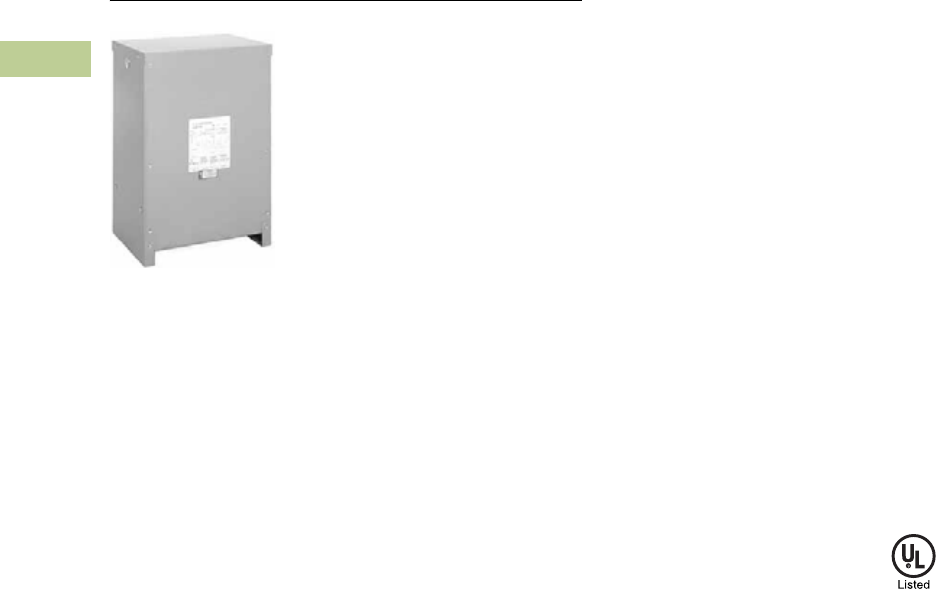
V2-T2-124 Volume 2—Commercial Distribution CA08100003E—July 2016 www.eaton.com
2
2
2
2
2
2
2
2
2
2
2
2
2
2
2
2
2
2
2
2
2
2
2
2
2
2
2
2
2
2
2.5
Transfor mers
Distribution Transformers
Three-Phase Type DT-3E Totally Enclosed Non-Ventilated
Contents
Description Page
Motor Drive Isolation Transformers. . . . . . . . . . . . V2-T2-111
Mini–Power Centers . . . . . . . . . . . . . . . . . . . . . . . V2-T2-119
Totally Enclosed Non-Ventilated Transformers
Catalog Number Selection . . . . . . . . . . . . . . . . V2-T2-125
Product Selection. . . . . . . . . . . . . . . . . . . . . . . V2-T2-125
Accessories . . . . . . . . . . . . . . . . . . . . . . . . . . . V2-T2-126
Technical Data and Specifications . . . . . . . . . . V2-T2-126
Class I, Division 2, Hazardous Location Transformers V2-T2-127
Open-Type Core and Coil Assembly Transformers V2-T2-130
Marine Duty Transformers . . . . . . . . . . . . . . . . . . V2-T2-133
Buck-Boost and Low Voltage Lighting Transformers V2-T2-144
Medium Voltage Distribution Transformers. . . . . . V2-T2-173
Totally Enclosed Non-Ventilated Transformers
Product Description
Note: The following pages
provide listings for most standard
transformer ratings and catalog
numbers. For other ratings or
catalog numbers not shown,
or for special enclosure types
(including stainless steel), refer
to Eaton.
●Suitable for indoor or
outdoor applications
●Totally enclosed, non-
ventilated enclosures
rated NEMA 3R
●220°C insulation system
●150°C rise standard;
115°C or 80°C rise optional
Application Description
Totally enclosed non-
ventilated dry-type
transformers are for special
applications, where because
of adverse atmospheric
conditions it is desirable to
use a dry-type non-ventilated
transformer vs. the ventilated
standard unit, which has
openings in its enclosure
to allow air to flow directly
over the core and coil.
In applications where the
atmosphere contains
conductive, corrosive, or
combustible materials, which
might damage a transformer,
or lint and dust flyings that
might block the ventilation
passages, the non-ventilated
transformer is highly suited.
It has no openings in the
enclosure. Heat is dissipated
by radiating from the surface
area of the enclosure.
Consequently, the enclosures
are larger than those of the
standard ventilated type.
Non-ventilated transformers
are suited for application in
the textile, chemical,
automotive, petrochemical,
foundry, cement, food, paper
and other industries.
Features, Benefits
and Functions
●60 Hz operation (50/60 Hz
operation available)
●Short-term overload
capability as required
by ANSI
●Meet NEMA ST-20
sound levels
Standards and Certifications
●UL listed
Industry Standards
All Eaton dry-type distribution
and control transformers are
built and tested in accordance
with applicable NEMA, ANSI
and IEEE Standards.
Seismically Qualified
Eaton manufactured dry-type
distribution transformers are
seismically qualified and
exceed requirements of the
International Building Code
(IBC) and California Code
Title 24.

Volume 2—Commercial Distribution CA08100003E—July 2016 www.eaton.com V2-T2-125
2
2
2
2
2
2
2
2
2
2
2
2
2
2
2
2
2
2
2
2
2
2
2
2
2
2
2
2
2
2
2.5
Trans for mers
Distribution Transformers
Catalog Number Selection
Please refer to Section 2.7 Page V2-T2-187.
Product Selection
Additional Product Selection information begins on Page V2-T2-189.
Single-Phase—Type DS-3E, 60 Hz 1
240 x 480 Volts to 120/240 Volts +1–5%, –2–5% at 240 Volts Primary; +2–2.5%, –4–2.5% at 480 Volts Primary
Three-Phase—Type DT-3E, 60 Hz 1
480 Delta Volts to 208Y/120 Volts +2–2.5% FCAN, 4–2.5% FCBN Taps
Notes
1Transformers Type EPT 75 kVA and smaller three-phase, and Type EP 37.5 kVA and smaller single-phase, are furnished non-ventilated normally, as standard. See general-purpose transformers.
Contact your local Eaton sales office for availability of additional totally enclosed non-ventilated transformers. Contact your local Eaton sales office for CE Mark transformer requirements. For other
ratings or catalog numbers not shown, or for special enclosure types (including stainless steel), refer to Eaton. Frame drawings/dimensions information begins on Page V2-T2-216.
kVA Type
°C Temp.
Rise Frame
Wiring Diagram
Number
Weight
Lbs (kg)
Catalog
Number
15 DS-3E 150 FR817N 3XA 350 (159) T20P11S15NV
25 DS-3E 150 FR818N 3XA 350 (159) T20P11S25NV
37.5 DS-3E 150 FR820N 3XA 600 (274) T20P11S37NV
50 DS-3E 150 FR820N 3XA 720 (329) T20P11S50NV
kVA Type
°C Temp.
Rise Frame
Wiring Diagram
Number
Weight
Lbs (kg)
Catalog
Number
15 DT-3E 150 FR914FN 280B 480 (217) V48M28T15NV
30 DT-3E 150 FR914FN 280B 480 (217) V48M28T30NV
45 DT-3E 150 FR915FN 280B 600 (272) V48M28T45NV
75 DT-3E 150 FR916AN 280B 760 (344) V48M28T75NV
112.5 DT-3E 150 FR917N 280B 1100 (499) V48M28T12NV
150 DT-3E 150 FR918AN 280B 1300 (589) V48M28T49NV
225 DT-3E 150 FR919EN 275A 2400 (1088) V48M28T22NV
300 DT-3E 150 FR920EN 275A 2900 (1315) V48M28T33NV

V2-T2-126 Volume 2—Commercial Distribution CA08100003E—July 2016 www.eaton.com
2
2
2
2
2
2
2
2
2
2
2
2
2
2
2
2
2
2
2
2
2
2
2
2
2
2
2
2
2
2
2.5
Transfor mers
Distribution Transformers
Accessories
Please refer to Section 2.7 Page V2-T2-191.
Technical Data and Specifications
Frequency
Eaton standard dry-type
distribution transformers are
designed for 60 Hz operation.
Transformers required for
other frequencies are
available and must be
specifically designed.
Overload Capability
Short-term overload is
designed into transformers
as required by ANSI. Dry-type
distribution transformers will
deliver 200% nameplate load
for one-half hour, 150% load
for one hour and 125% load
for four hours without being
damaged, provided that a
constant 50% load precedes
and follows the overload.
See ANSI C57.96-01.250 for
additional limitations.
Continuous overload capacity
is not deliberately designed
into a transformer because
the design objective is to be
within the allowed winding
temperature rise with
nameplate loading.
Insulation System and
Temperature Rise
Industry standards classify
insulation systems and rise as
shown below:
Insulation System
Classification
The design life of transformers
having different insulation
systems is the same—the
lower-temperature systems
are designed for the same life
as the higher-temperature
systems.
Enclosures
Eaton totally enclosed,
non-ventilated transformers,
Types DS-3E and DT-3E,
use a NEMA 3R rated
enclosure as standard.
Winding Terminations
Primary and secondary
windings are terminated
in the wiring compartment.
Totally enclosed non-
ventilated transformers
have leads brought out to
aluminum pads that are
pre-drilled to accept Cu/Al
lugs. Lugs are not supplied
with these transformers.
Eaton recommends external
cables be rated 75°C for
ventilated designs.
Series-Multiple Windings
Series-multiple windings
consist of two similar coils
in each winding that can be
connected in series or parallel
(multiple). Transformers with
series-multiple windings are
designated with an “x” or
“/” between the voltage
ratings, such as voltages of
“120/240” or “240 x 480.”
If the series-multiple winding
is designated by an “x,” the
winding can be connected
only for a series or parallel.
With the “/” designation,
a mid-point also becomes
available in addition to the
series or parallel connection.
As an example, a 120 x 240
winding can be connected
for either 120 (parallel) or
240 (series), but a 120/240
winding can be connected for
120 (parallel), or 240 (series),
or 240 with a 120 mid-point.
Note: The preceding pages
provide listings for most standard
transformer ratings and catalog
numbers. For all-copper and
bolt-on-breaker designs, contact
Eaton. For other ratings or catalog
numbers not shown, or for special
enclosure types (including
stainless steel), refer to Eaton.
Ambient
+
Winding
Rise
+
Hot
Spot
=
Temp.
Class
40°C 55°C 10°C 105°C
40°C 80°C 30°C 150°C
25°C 135°C 20°C 180°C
40°C 115°C 30°C 185°C
40°C 150°C 30°C 220°C
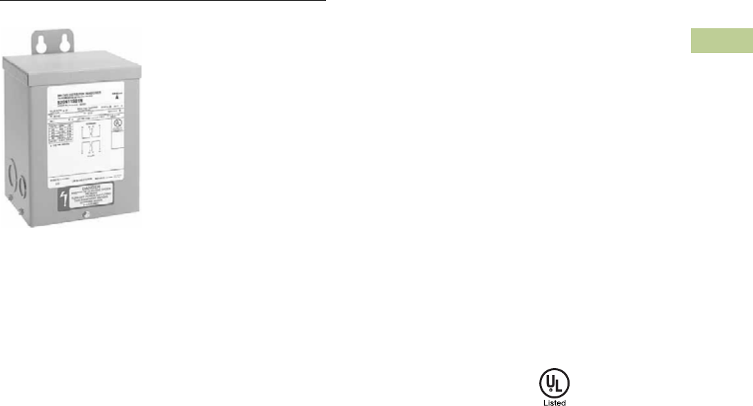
Volume 2—Commercial Distribution CA08100003E—July 2016 www.eaton.com V2-T2-127
2
2
2
2
2
2
2
2
2
2
2
2
2
2
2
2
2
2
2
2
2
2
2
2
2
2
2
2
2
2
2.5
Trans for mers
Distribution Transformers
Single-Phase Type EPZ Encapsulated
Contents
Description Page
Motor Drive Isolation Transformers . . . . . . . . . . . . V2-T2-111
Mini–Power Centers . . . . . . . . . . . . . . . . . . . . . . . V2-T2-119
Totally Enclosed Non-Ventilated Transformers. . . . V2-T2-124
Class I, Division 2, Hazardous Location Transformers
Catalog Number Selection . . . . . . . . . . . . . . . . V2-T2-128
Product Selection . . . . . . . . . . . . . . . . . . . . . . . V2-T2-128
Accessories . . . . . . . . . . . . . . . . . . . . . . . . . . . V2-T2-129
Technical Data and Specifications. . . . . . . . . . . V2-T2-129
Open-Type Core and Coil Assembly Transformers V2-T2-130
Marine Duty Transformers. . . . . . . . . . . . . . . . . . . V2-T2-133
Buck-Boost and Low Voltage Lighting Transformers V2-T2-144
Medium Voltage Distribution Transformers . . . . . . V2-T2-173
Class I, Division 2, Hazardous Location Transformers
Product Description
Note: The following pages
provide listings for most standard
transformer ratings and catalog
numbers. For other ratings or
catalog numbers not shown,
or for special enclosure types
(including stainless steel), refer
to Eaton.
●Encapsulated design
●Suitable for indoor or
outdoor applications
●Totally enclosed, non-
ventilated enclosures
●180°C insulation system
●115°C rise standard;
80°C rise optional
●Mountable in any position
indoors. Upright only
outdoors
●Available in ratings up to
600 volts primary, 25 kVA
single-phase, 75 kVA
three-phase
●Available in NEMA Type 4X
enclosure
Application Description
Type EPZ and EPTZ
transformers are labeled as
“Suitable for use in Class I,
Division 2, Groups A, B, C
and D locations, as defined by
NEC Article 501, with NEC-
recommended installation
procedures for dry-type
transformers rated under
600 volts nominal operation.”
A Class I, Division 2 location
per Section 500 of the NEC is
defined as:
6. A location in which
volatile flammable liquids
or gases are handled,
processed or used, but
that normally will be
confined within closed
containers or systems
from which they can
escape only in case of
accidental rupture or
breakdown of the
container or system.
7. Or, a location where
ignitable concentrations
of gases or vapors are
normally prevented by
positive mechanical
ventilation and that
might become hazardous
through failure of the
ventilation equipment.
8. Or, a location that is
adjacent to a Class I,
Division 1 location and
ignitable concentrations
of gases or vapors might
occasionally enter.
Atmospheres classified by
NEC Section 500 as Group A
includes acetylene. Group B
includes gases such as
hydrogen and formaldehyde.
Group C may contain gases
or vapors such as ethyl ether,
ethylene, or the equivalent.
Atmospheres classified as
Group D may contain gases
or vapors such as acetone,
ammonia, benzene, butane,
cyclopropane, ethanol,
gasoline, hexane, methanol,
methane, natural gas,
naphtha, propane or the
equivalent.
Features, Benefits
and Functions
●NEMA 3R enclosure
●60 Hz operation
●Aluminum windings
(copper optional)
●Short-term overload
capability as required
by ANSI
●Meet NEMA ST-20
sound levels
Standards and Certifications
●UL listed
Industry Standards
All Eaton dry-type distribution
and control transformers are
built and tested in accordance
with applicable NEMA, ANSI
and IEEE Standards.
Seismically Qualified
Eaton manufactured dry-type
distribution transformers are
seismically qualified and
exceed requirements of the
International Building Code
(IBC) and California Code
Title 24.

V2-T2-128 Volume 2—Commercial Distribution CA08100003E—July 2016 www.eaton.com
2
2
2
2
2
2
2
2
2
2
2
2
2
2
2
2
2
2
2
2
2
2
2
2
2
2
2
2
2
2
2.5
Transfor mers
Distribution Transformers
Catalog Number Selection
Please refer to Section 2.7 Page V2-T2-187.
Product Selection
Additional Product Selection information begins on Page V2-T2-189.
Single-Phase—Type EPZ, 60 Hz
480 Volts to 120/240 Volts
Three-Phase—Type EPTZ, 60 Hz
480 Delta Volts to 208Y/120 Volts Three-Phase
480 Delta Volts to 240 Delta Volts with 120 Volt Lighting Tap on B Phase 2
Notes
1Floor-mount only.
2Center Tap capacity limited to 5% of rated kVA.
For 316 grade stainless steel enclosure, replace 10th character of catalog number with an “SS” suffix. Contact your local Eaton sales office for CE Mark transformer requirements. For other ratings or
catalog numbers not shown, or for special enclosure types (including stainless steel), refer to Eaton. Frame drawings/dimensions information begins on Page V2-T2-216.
kVA
Full Capacity Taps
Type
°C Temp.
Rise Frame
Wiring Diagram
Number
Weight
Lbs (kg)
Catalog
NumberFCAN FCBN
0.05 — — EPZ 115 FR57H 524H 13 (6) Z48N11S51A
0.75 — — EPZ 115 FR58H 524H 21 (10) Z48N11S76A
1 — — EPZ 115 FR59H 524H 31 (14) Z48N11S01A
1.5 — — EPZ 115 FR67H 524H 40 (18) Z48N11S16A
2 — — EPZ 115 FR68H 524H 40 (18) Z48N11S02A
3 — — EPZ 115 FR176H 524H 65 (30) Z48N11S03A
5 — — EPZ 115 FR177H 524H 113 (51) Z48N11S05A
7.5 — — EPZ 115 FR178H 524H 123 (56) Z48N11S07A
10 — — EPZ 115 FR179H 524H 193 (88) Z48N11S10A
15 — — EPZ 115 FR180H 524H 216 (98) Z48N11S15A
25 — — EPZ 115 FR182H 524H 375 (170) Z48N11S25A
kVA
Full Capacity Taps
Type
°C Temp.
Rise Frame
Wiring Diagram
Number
Weight
Lbs (kg)
Catalog
NumberFCAN FCBN
3 — 2 at –5% EPTZ 115 FR201H 70A 116 (53) Z48G28T03A
6 — 2 at –5% EPTZ 115 FR200H 70A 143 (65) Z48G28T06A
9 — 2 at –5% EPTZ 115 FR103H 70A 166 (75) Z48G28T09A
15 — 2 at –5% EPTZ 115 FR95H 70A 275 (125) Z48G28T15A
30 — 2 at –5% EPTZ 115 FR243H 66A 422 (191) Z48G28T30A
45 — 2 at –5% EPTZ 115 FR244H 66A 660 (299) Z48G28T45A
75 — 2 at –5% EPTZ 115 FR245H 66A 1275 (580) Z48G28T75A 1
kVA
Full Capacity Taps
Type
°C Temp.
Rise Frame
Wiring Diagram
Number
Weight
Lbs (kg)
Catalog
NumberFCAN FCBN
6 — 2 at –5% EPTZ 115 FR102H 95A 115 (52) Z48G22T06A
9 — 2 at –5% EPTZ 115 FR97H 95A 160 (73) Z48G22T09A
15 — 2 at –5% EPTZ 115 FR195H 95A 340 (155) Z48G22T15A
30 — 2 at –5% EPTZ 115 FR243H 62A 422 (191) Z48G22T30A
45 — 2 at –5% EPTZ 115 FR244H 62A 660 (299) Z48G22T45A

Volume 2—Commercial Distribution CA08100003E—July 2016 www.eaton.com V2-T2-129
2
2
2
2
2
2
2
2
2
2
2
2
2
2
2
2
2
2
2
2
2
2
2
2
2
2
2
2
2
2
2.5
Trans for mers
Distribution Transformers
Accessories
Please refer to Section 2.7 Page V2-T2-191.
Technical Data and Specifications
Frequency
Eaton standard dry-type
distribution transformers are
designed for 60 Hz operation.
Transformers required for
other frequencies are
available and must be
specifically designed.
Overload Capability
Short-term overload is
designed into transformers as
required by ANSI. Dry-type
distribution transformers will
deliver 200% nameplate load
for one-half hour, 150% load
for one hour, and 125% load
for four hours without being
damaged, provided that a
constant 50% load precedes
and follows the overload.
See ANSI C57.96-01.250 for
additional limitations.
Continuous overload capacity
is not deliberately designed
into a transformer because
the design objective is to be
within the allowed winding
temperature rise with
nameplate loading.
Insulation System and
Temperature Rise
Industry standards classify
insulation systems and rise as
shown below:
Insulation System
Classification
The design life of transformers
having different insulation
systems is the same—the
lower-temperature systems
are designed for the same life
as the higher-temperature
systems.
Enclosures
Eaton encapsulated
transformers, Types EPZ
and EPTZ, use a NEMA 3R
rated enclosure.
Sound Levels
All Eaton 600 volt class
general-purpose dry-type
distribution transformers are
designed to meet NEMA
ST-20 sound levels listed
here. These are the sound
levels measured in a
soundproof environment.
Actual sound levels
measured at an installation
will likely be higher due to
electrical connections and
environmental conditions.
Lower sound levels are
available and should be
specified when the
transformer is going to be
installed in an area where
sound may be a concern.
Winding Terminations
Lugs are not supplied with
these transformers. Eaton
recommends that external
cables be rated 90°C
sized at 75°C ampacity) for
encapsulated designs and
75°C for ventilated designs.
Nominal and tap leads come
out of the transformer through
pipe elbows. Connections
should be made to an adjacent
explosion-proof junction box.
Unused tap leads must be
properly insulated prior to
energization. EPZ and EPTZ
transformers are UL and
cUL listed.
Series-Multiple Windings
Series-multiple windings
consist of two similar coils in
each winding that can be
connected in series or parallel
(multiple). Transformers with
series-multiple windings are
designated with an “x” or
“/” between the voltage
ratings, such as voltages of
“120/240” or “240 x 480.”
If the series-multiple winding
is designated by an “x,” the
winding can be connected
only for a series or parallel.
With the “/” designation, a
mid-point also becomes
available in addition to the
series or parallel connection.
As an example, a 120 x 240
winding can be connected
for either 120 (parallel) or
240 (series), but a 120/240
winding can be connected for
120 (parallel), 240 (series) or
240 with a 120 mid-point.
Ambient
+
Winding
Rise
+
Hot
Spot
=
Temp.
Class
40°C 55°C 10°C 105°C
40°C 80°C 30°C 150°C
25°C 135°C 20°C 180°C
40°C 115°C 30°C 185°C
40°C 150°C 30°C 220°C

V2-T2-130 Volume 2—Commercial Distribution CA08100003E—July 2016 www.eaton.com
2
2
2
2
2
2
2
2
2
2
2
2
2
2
2
2
2
2
2
2
2
2
2
2
2
2
2
2
2
2
2.5
Transfor mers
Distribution Transformers
Contents
Description Page
Motor Drive Isolation Transformers. . . . . . . . . . . . V2-T2-111
Mini–Power Centers . . . . . . . . . . . . . . . . . . . . . . . V2-T2-119
Totally Enclosed Non-Ventilated Transformers . . . V2-T2-124
Class I, Division 2, Hazardous Location Transformers V2-T2-127
Open-Type Core and Coil Assembly Transformers
Catalog Number Selection . . . . . . . . . . . . . . . . V2-T2-131
Product Selection. . . . . . . . . . . . . . . . . . . . . . . V2-T2-131
Accessories . . . . . . . . . . . . . . . . . . . . . . . . . . . V2-T2-132
Technical Data and Specifications . . . . . . . . . . V2-T2-132
Marine Duty Transformers . . . . . . . . . . . . . . . . . . V2-T2-133
Buck-Boost and Low Voltage Lighting Transformers V2-T2-144
Medium Voltage Distribution Transformers. . . . . . V2-T2-173
Open-Type Core and Coil Assembly Transformers
Product Description
Note: The following pages
provide listings for most standard
transformer ratings and catalog
numbers. For other ratings or
catalog numbers not shown,
or for special enclosure types
(including stainless steel), refer
to Eaton.
●220°C insulation system;
150°C rise standard;
115°C or 80°C optional
●Aluminum windings
(copper optional)
Application Description
The basic purpose of a
transformer is voltage
transformation as near as
practically possible to the
load for economy and
distribution of power.
Typical loads for dry-type
distribution transformers
include lighting, heating, air
conditioners, fans and
machine tools. Such loads
are found in commercial,
institutional, industrial and
residential structures.
Open core and coil
assemblies are typically
used by panel builders and
equipment OEM customers
who incorporate the entire
transformer into their
structures, making these
assemblies a versatile option
to purchasing a standard,
enclosed transformer and
discarding the unneeded
enclosure parts.
Features, Benefits
and Functions
●60 Hz operation standard,
50/60 Hz operation
available
●Short-term overload
capability as required
by ANSI
●Meet NEMA ST-20
sound levels
Standards and Certifications
●UL recognized
Industry Standards
All Eaton dry-type distribution
and control transformers are
built and tested in accordance
with applicable NEMA, ANSI
and IEEE Standards.
Seismically Qualified
All Eaton manufactured dry-
type distribution transformers
are seismically qualified and
exceed requirements of the
International Building Code
and California Code Title 24.

Volume 2—Commercial Distribution CA08100003E—July 2016 www.eaton.com V2-T2-131
2
2
2
2
2
2
2
2
2
2
2
2
2
2
2
2
2
2
2
2
2
2
2
2
2
2
2
2
2
2
2.5
Trans for mers
Distribution Transformers
Catalog Number Selection
Please refer to Section 2.7 Page V2-T2-187.
Product Selection
Additional Product Selection information begins on Page V2-T2-189.
Single-Phase—Type DS-3C, 60 Hz
240 x 480 Volts to 120/240 Volts
Three-Phase—Type DT-3C, 60 Hz
480 Delta Volts to 208Y/120 Volts
Notes
11 at +5%, 2 at –5% at 240 volts primary; 2 at +2.5%, 4 at –2.5% at 480 volts primary.
Contact your local Eaton sales office for availability of additional open-type core and coil assemblies. Contact your local Eaton sales office for CE Mark transformer requirements. For other ratings or
catalog numbers not shown, refer to Eaton. Frame drawings/dimensions information begins on Page V2-T2-216.
kVA
Full Capacity Taps
Type
°C Temp.
Rise Frame
Wiring Diagram
Number
Weight
Lbs (kg) Catalog NumberFCAN FCBN
15 11 DS-3C 150 CS15G103 3XA 246 (112) T20P11S15EEZZ
25 11 DS-3C 150 CS25E103 3XA 359 (163) T20P11S25EEZZ
37.5 11 DS-3C 150 CS37C103 3XA 374 (170) T20P11S37EEZZ
50 11 DS-3C 150 CS50G103 3XA 555 (252) T20P11S50EEZZ
kVA
Full Capacity Taps
Type
°C Temp.
Rise Frame
Wiring Diagram
Number
Weight
Lbs (kg) Catalog NumberFCAN FCBN
15 2 at +2.5% 4 at –2.5% DT-3C 150 CT15H103 280B 191 (87) V48M28T15EEZZ
30 2 at +2.5% 4 at –2.5% DT-3C 150 CT30E103 280B 251 (114) V48M28T30EEZZ
45 2 at +2.5% 4 at –2.5% DT-3C 150 CT45E103 280B 367 (167) V48M28T45EEZZ
75 2 at +2.5% 4 at –2.5% DT-3C 150 CT75E103 280B 491 (223) V48M28T75EEZZ
112.5 2 at +2.5% 4 at –2.5% DT-3C 150 — 280B 676 (307) V48M28T12EEZZ
150 2 at +2.5% 4 at –2.5% DT-3C 150 — 280B 796 (362) V48M28T49EEZZ

V2-T2-132 Volume 2—Commercial Distribution CA08100003E—July 2016 www.eaton.com
2
2
2
2
2
2
2
2
2
2
2
2
2
2
2
2
2
2
2
2
2
2
2
2
2
2
2
2
2
2
2.5
Transfor mers
Distribution Transformers
Accessories
Please refer to Section 2.7 Page V2-T2-191.
Technical Data and Specifications
Frequency
Eaton standard dry-type
distribution transformers are
designed for 60 Hz operation.
Transformers required
for other frequencies are
available and must be
specifically designed.
Overload Capability
Short-term overload is
designed into transformers
as required by ANSI. Dry-type
distribution transformers will
deliver 200% nameplate load
for one-half hour, 150% load
for one hour, and 125% load
for four hours without being
damaged, provided that a
constant 50% load precedes
and follows the overload.
See ANSI C57.96-01.250
for additional limitations.
Continuous overload capacity
is not deliberately designed
into a transformer because
the design objective is to be
within the allowed winding
temperature rise with
nameplate loading.
Insulation System and
Temperature Rise
Industry standards classify
insulation systems and rise as
shown below:
Insulation System
Classification
The design life of transformers
having different insulation
systems is the same—the
lower-temperature systems
are designed for the same life
as the higher-temperature
systems.
Winding Terminations
Lugs are not supplied with
these transformers. Eaton
recommends that external
cables be rated 90°C
(sized at 75°C ampacity) for
encapsulated designs and
75°C for ventilated designs.
Ambient
+
Winding
Rise
+
Hot
Spot
=
Temp.
Class
40°C 55°C 10°C 105°C
40°C 80°C 30°C 150°C
25°C 135°C 20°C 180°C
40°C 115°C 30°C 185°C
40°C 150°C 30°C 220°C
Series-Multiple Windings
Series-multiple windings
consist of two similar coils in
each winding that can be
connected in series or parallel
(multiple). Transformers with
series-multiple windings are
designated with an “x” or “/”
between the voltage ratings,
such as voltages of “120/240”
or “240 x 480.” If the series-
multiple winding is designated
by an “x,” the winding can
be connected only for a
series or parallel. With the “/”
designation, a mid-point also
becomes available in addition
to the series or parallel
connection. As an example,
a 120 x 240 winding can
be connected for either
120 (parallel) or 240 (series),
but a 120/240 winding can be
connected for 120 (parallel),
240 (series) or 240 with a
120 mid-point.
Sound Levels
All Eaton 600 volt class
general-purpose dry-type
distribution transformers are
designed to meet NEMA
ST-20 sound levels listed
here. These are the sound
levels measured in a
soundproof environment.
Actual sound levels
measured at an installation
will likely be higher due to
electrical connections and
environmental conditions.
Lower sound levels are
available and should be
specified when the
transformer is going to be
installed in an area where
sound may be a concern.
For additional information,
please refer to Section 2.7
Page V2-T2-195.
Average Sound Levels
NEMA ST-20 Average Sound Level, dB
Equivalent Winding
kVA Range
Self-Cooled Ventilated (up to 1.2 kV) Encapsulated
(up to 1.2 kV)K-Factor 1, 4, 9 K-Factor 13, 20
3.00 and below 40 40 45
3.01 to 9.00 40 40 45
9.01 to 15.00 45 45 50
15.01 to 30.00 45 45 50
30.01 to 50.00 45 48 50
50.01 to 75.00 50 53 55
75.01 to 112.50 50 53 55
112.51 to 150.00 50 53 55
150.01 to 225.00 55 58 57
225.01 to 300.00 55 58 57
300.01 to 500.00 60 63 59
500.01 to 700.00 62 65 61
700.01 to 1000.00 64 67 63
Greater than 1000 Consult factory Consult factory Consult factory

Volume 2—Commercial Distribution CA08100003E—July 2016 www.eaton.com V2-T2-133
2
2
2
2
2
2
2
2
2
2
2
2
2
2
2
2
2
2
2
2
2
2
2
2
2
2
2
2
2
2
2.5
Trans for mers
Distribution Transformers
Contents
Description Page
Motor Drive Isolation Transformers . . . . . . . . . . . . V2-T2-111
Mini–Power Centers . . . . . . . . . . . . . . . . . . . . . . . V2-T2-119
Totally Enclosed Non-Ventilated Transformers. . . . V2-T2-124
Class I, Division 2, Hazardous Location Transformers V2-T2-127
Open-Type Core and Coil Assembly Transformers V2-T2-130
Marine Duty Transformers
Catalog Number Selection . . . . . . . . . . . . . . . . V2-T2-134
Product Selection . . . . . . . . . . . . . . . . . . . . . . . V2-T2-134
Accessories . . . . . . . . . . . . . . . . . . . . . . . . . . . V2-T2-143
Technical Data and Specifications. . . . . . . . . . . V2-T2-143
Buck-Boost and Low Voltage Lighting Transformers V2-T2-144
Medium Voltage Distribution Transformers . . . . . . V2-T2-173
Marine Duty Transformers
Product Description
Note: The following pages
provide listings for most standard
transformer ratings and catalog
numbers. For other ratings or
catalog numbers not shown,
or for special enclosure types
(including stainless steel), refer
to Eaton.
Types EP, EPT
●Encapsulated design
●Suitable for indoor or
outdoor applications
●Totally enclosed, non-
ventilated enclosures
●Enclosures are NEMA 3R
rated
●Mountable in any position
indoors and upright-only
outdoors
●180ºC insulation system
●115ºC rise standard; 80°C
rise optional
●Copper windings standard
●Available in single-
phase ratings through
37.5 kVA (EP)
●Available in three-
phase ratings through
75 kVA (EPT)
Types DS-3, DT-3
●Ventilated, NEMA 2
enclosure standard
●Suitable for indoor
applications; outdoors
when weathershields
are also installed
●Upright mounting only
●220ºC insulation system
●115ºC rise standard; 150°C
or 80°C rise optional
●Copper windings standard
●Available in single-phase
ratings 15–167 kVA
and up to 4160 volts
primary (DS-3)
●Available in three-phase
ratings 15–1500 kVA
and up to 4160 volts
primary (DT-3)
Application Description
The basic purpose of a
transformer is voltage
transformation as near as
practically possible to the
load for economy and
distribution of power.
Typical loads for dry-type
distribution transformers
include lighting, heating,
air conditioners, fans and
machine tools. Such loads
are found in commercial,
institutional, industrial and
residential structures.
Features, Benefits
and Functions
●Meets ABS (American
Bureau of Shipping)
specification
●ABS Type Approval
Certificate Number
04-TP517621-X
●60 Hz operation
●115°C temperature
rise standard
●Copper windings standard
●Short-term overload
capability as required
by ANSI
●Meet NEMA ST-20
sound levels
Standards and Certifications
●UL listed
Industry Standards
All Eaton dry-type distribution
and control transformers are
built and tested in accordance
with applicable NEMA, ANSI
and IEEE Standards. All
600 volt class transformers
are UL listed unless
otherwise noted.

V2-T2-134 Volume 2—Commercial Distribution CA08100003E—July 2016 www.eaton.com
2
2
2
2
2
2
2
2
2
2
2
2
2
2
2
2
2
2
2
2
2
2
2
2
2
2
2
2
2
2
2.5
Transfor mers
Distribution Transformers
Catalog Number Selection
Please refer to Section 2.7 Page V2-T2-187.
Product Selection
Additional Product Selection information begins on Page V2-T2-189.
Single-Phase—Type EPM Marine Duty Encapsulated NEMA 3R, 60 Hz
240 x 480 Volts to 120/240 Volts—Copper Windings
Frame drawings/dimensions information begins on Page V2-T2-216.
kVA
Full Capacity Taps
Type
°C Temp.
Rise Frame
Wiring Diagram
Number
Weight
Lbs (kg) Weathershield Catalog NumberFCAN FCBN
0.05 None None EPM 115 FR52 3A050Q 7 (3) — QS20N11S81CU
0.075 None None EPM 115 FR54 3A075Q 7 (3) — QS20N11S85CU
0.1 None None EPM 115 FR54 3A100Q 7 (3) — QS20N11S82CU
0.15 None None EPM 115 FR55 3A150Q 8 (4) — QS20N11S83CU
0.25 None None EPM 115 FR56 3A250Q 12 (5) — QS20N11S26CU
0.5 None None EPM 115 FR57 3A500Q 13 (6) — QS20N11S51CU
0.75 None None EPM 115 FR58A 3A750Q 21 (10) — QS20N11S76CU
1 None None EPM 115 FR59A 3A1Q 31 (14) — QS20N11S01CU
1.5 None None EPM 115 FR67 3A16Q 40 (18) — QS20N11S16CU
2 None None EPM 115 FR68 3A2Q 40 (18) — QS20N11S02CU
3 None None EPM 115 FR176 3A3Q 72 (33) — QS20N11S03CU
5 None None EPM 115 FR177 3A5Q 125 (57) — QS20N11S05CU
7.5 None None EPM 115 FR178 3A7Q 135 (61) — QS20N11S07CU
10 None None EPM 115 FR179 3A10Q 203 (92) — QS20N11S10CU
15 None None EPM 115 FR182 3A15Q 231 (105) — QS20N11S15CU
25 None None EPM 115 FR300A 128A25Q 380 (173) — QS20N11S25CU
37.5 None None EPM 115 FR300A 248A37Q 856 (389) — QS20L11S37CU

Volume 2—Commercial Distribution CA08100003E—July 2016 www.eaton.com V2-T2-135
2
2
2
2
2
2
2
2
2
2
2
2
2
2
2
2
2
2
2
2
2
2
2
2
2
2
2
2
2
2
2.5
Trans for mers
Distribution Transformers
Single-Phase—Type DS-3M Marine Duty 60 Hz NEMA TP-1 Energy-Efficient 1
120 Volts to 120 Volts—Copper Windings
208 Volts to 120/240 Volts—Copper Windings
240 x 480 Volts to 120/240 Volts—Copper Windings
277 Volts to 120/240 Volts—Copper Windings
Notes
1Suitable for installation in onshore, onboard or offshore applications.
21 at +5%, 2 at –5% at 240 volts primary; 2 at +2.5%, 4 at –2.5% at 480 volts primary.
Frame drawings/dimensions information begins on Page V2-T2-216.
kVA
Full Capacity Taps
Type
°C Temp.
Rise Frame
Wiring Diagram
Number
Weight
Lbs (kg) Weathershield Catalog NumberFCAN FCBN
15 2 at +2.5% 4 at –2.5% DS-3M 115 816 56D15R 275 (125) WS11 RT12M12F15CUEE
25 2 at +2.5% 4 at –2.5% DS-3M 115 818 56D25R 440 (200) WS11 RT12M12F25CUEE
37.5 2 at +2.5% 4 at –2.5% DS-3M 115 818 56D37R 480 (218) WS11 RT12M12F37CUEE
50 2 at +2.5% 4 at –2.5% DS-3M 115 819 56D50R 725 (329) WS16 RT12M12F50CUEE
75 2 at +2.5% 4 at –2.5% DS-3M 115 820 56D75R 820 (372) WS16 RT12M11F75CUEE
100 2 at +2.5% 4 at –2.5% DS-3M 115 821 56D100R 1150 (522) WS13 RT12M11F99CUEE
kVA
Full Capacity Taps
Type
°C Temp.
Rise Frame
Wiring Diagram
Number
Weight
Lbs (kg) Weathershield Catalog NumberFCAN FCBN
15 2 at +2.5% 4 at –2.5% DS-3M 115 816 260A15R 275 (125) WS11 RT29M11F15CUEE
25 2 at +2.5% 4 at –2.5% DS-3M 115 818 260A25R 440 (200) WS11 RT29M11F25CUEE
37.5 2 at +2.5% 4 at –2.5% DS-3M 115 818 260A37R 480 (218) WS11 RT29M11F37CUEE
50 2 at +2.5% 4 at –2.5% DS-3M 115 819 260A50R 725 (329) WS16 RT29M11F50CUEE
75 1 at +5% 2 at –5% DS-3M 115 820 260A75R 820 (372) WS16 RT29R11F75CUEE
100 1 at +5% 2 at –5% DS-3M 115 821 260A100R 1150 (522) WS13 RT29R11F99CUEE
kVA
Full Capacity Taps
Type
°C Temp.
Rise Frame
Wiring Diagram
Number
Weight
Lbs (kg) Weathershield Catalog NumberFCAN FCBN
15 22 DS-3M 115 816 3XA15R 264 (120) WS11 RT20P11F15CUEE
25 22 DS-3M 115 818 3XA25R 420 (191) WS11 RT20P11F25CUEE
37.5 22 DS-3M 115 818 3XA37R 450 (204) WS11 RT20P11F37CUEE
50 22 DS-3M 115 819 3XA50R 703 (319) WS16 RT20P11F50CUEE
75 22 DS-3M 115 820 3XA75R 793 (360) WS16 RT20P11F75CUEE
100 22 DS-3M 115 821 3XA100R 1085 (493) WS13 RT20P11F99CUEE
kVA
Full Capacity Taps
Type
°C Temp.
Rise Frame
Wiring Diagram
Number
Weight
Lbs (kg) Weathershield Catalog NumberFCAN FCBN
15 2 at +2.5% 4 at –2.5% DS-3M 115 816 262C15R 275 (125) WS11 RT27M11F15CUEE
25 2 at +2.5% 4 at –2.5% DS-3M 115 818 262C25R 440 (200) WS11 RT27M11F25CUEE
37.5 2 at +2.5% 4 at –2.5% DS-3M 115 818 262C37R 480 (218) WS11 RT27M11F37CUEE
50 2 at +2.5% 4 at –2.5% DS-3M 115 819 262C50R 725 (329) WS16 RT27M11F50CUEE
75 1 at +5% 2 at –5% DS-3M 115 820 262C75R 820 (372) WS16 RT27M11F75CUEE
100 1 at +5% 2 at –5% DS-3M 115 821 262C100R 1150 (522) WS13 RT27M11F99CUEE

V2-T2-136 Volume 2—Commercial Distribution CA08100003E—July 2016 www.eaton.com
2
2
2
2
2
2
2
2
2
2
2
2
2
2
2
2
2
2
2
2
2
2
2
2
2
2
2
2
2
2
2.5
Transfor mers
Distribution Transformers
Single-Phase—Type DS-3M Marine Duty 60 Hz NEMA TP-1 Energy-Efficient 1
208 x 416 Volts to 120/240 Volts—Copper Windings
600 Volts to 120/240 Volts—Copper Windings
Notes
1Suitable for installation in onshore, onboard or offshore applications.
21 at +5%, 2 at –5% at 208 volts primary; 2 at +2.5%, 4 at –2.5% at 416 volts primary.
Frame drawings/dimensions information begins on Page V2-T2-216.
kVA
Full Capacity Taps
Type
°C Temp.
Rise Frame
Wiring Diagram
Number
Weight
Lbs (kg) Weathershield Catalog NumberFCAN FCBN
15 22 DS-3M 115 816 3XF15R 264 (120) WS11 RT18P11F15CUEE
25 22 DS-3M 115 818 3XF25R 420 (191) WS11 RT18P11F25CUEE
37.5 22 DS-3M 115 818 3XF37R 450 (204) WS11 RT18P11F37CUEE
50 22 DS-3M 115 819 3XF50R 703 (319) WS16 RT18P11F50CUEE
75 22 DS-3M 115 820 3XF75R 793 (360) WS16 RT18P11F75CUEE
100 22 DS-3M 115 821 3XF100R 1085 (493) WS13 RT18P11F99CUEE
kVA
Full Capacity Taps
Type
°C Temp.
Rise Frame
Wiring Diagram
Number
Weight
Lbs (kg) Weathershield Catalog NumberFCAN FCBN
15 2 at +2.5% 4 at –2.5% DS-3M 115 816 262B15R 275 (125) WS11 RT60M11F15CUEE
25 2 at +2.5% 4 at –2.5% DS-3M 115 818 262B25R 440 (200) WS11 RT60M11F25CUEE
37.5 2 at +2.5% 4 at –2.5% DS-3M 115 818 262B37R 480 (218) WS11 RT60M11F37CUEE
50 2 at +2.5% 4 at –2.5% DS-3M 115 819 262B50R 725 (329) WS16 RT60M11F50CUEE
75 1 at +5% 2 at –5% DS-3M 115 820 262B75R 820 (372) WS16 RT60M11F75CUEE
100 1 at +5% 2 at –5% DS-3M 115 821 262B100R 1150 (522) WS13 RT60M11F99CUEE

Volume 2—Commercial Distribution CA08100003E—July 2016 www.eaton.com V2-T2-137
2
2
2
2
2
2
2
2
2
2
2
2
2
2
2
2
2
2
2
2
2
2
2
2
2
2
2
2
2
2
2.5
Trans for mers
Distribution Transformers
Three-Phase—Type EPTM Marine Duty Encapsulated NEMA 3R, 60 Hz
480 Delta Volts to 208Y/120 Volts—Copper Windings
480 Delta Volts to 240 Delta Volts—Copper Windings
Three-Phase—Type DT-3M Marine Duty Ventilated NEMA 2, 60 Hz (NEMA 3R with Weathershield Kit Installed)
480 Delta Volts to 208Y/120 Volts—Copper Windings 2
Notes
1T-T (Scott T) connected secondary.
2Not suitable for installation on U.S. or U.S. territory soil. Suitable for offshore or onboard applications.
Frame drawings/dimensions information begins on Page V2-T2-216.
kVA
Full Capacity Taps
Type
°C Temp.
Rise Frame
Wiring Diagram
Number
Weight
Lbs (kg) Weathershield Catalog NumberFCAN FCBN
3 None 2 at –5% EPTM 115 FR201 70A 132 (60) — LY48G28T03CU 1
6 None 2 at –5% EPTM 115 FR200 70A 182 (83) — LY48G28T06CU 1
9 2 at +2.5% 2 at –2.5% EPTM 115 FR103 72B 221 (100) — LY48D28T09CU 1
15 2 at +2.5% 2 at –2.5% EPTM 115 FR95 72B 296 (135) — LY48D28T15CU 1
30 2 at +2.5% 4 at –2.5% EPTM 115 FR243 84A 612 (278) — LY48M28T30CU
45 2 at +2.5% 4 at –2.5% EPTM 115 FR244 84A 808 (367) — LY48M28T45CU
75 2 at +2.5% 4 at –2.5% EPTM 115 FR245 84A 1450 (659) — LY48M28T75CU
kVA
Full Capacity Taps
Type
°C Temp.
Rise Frame
Wiring Diagram
Number
Weight
Lbs (kg) Weathershield Catalog NumberFCAN FCBN
3 None 2 at –5% EPTM 115 FR201 74A 132 (60) — LY48G24T03CU 1
6 None 2 at –5% EPTM 115 FR200 74A 182 (83) — LY48G24T06CU 1
9 None 2 at –5% EPTM 115 FR103 74A 221 (100) — LY48G24T09CU 1
15 2 at +2.5% 2 at –2.5% EPTM 115 FR243 230A 612 (278) — LY48D24T15CU 1
kVA
Full Capacity Taps
Type
°C Temp.
Rise Frame
Wiring Diagram
Number
Weight
Lbs (kg) Weathershield Catalog NumberFCAN FCBN
15 2 at +2.5% 4 at –2.5% DT-3M 115 912D 280B15M 252 (114) WS38 MV48M28F15CU
30 2 at +2.5% 4 at –2.5% DT-3M 115 912D 280B30M 299 (136) WS38 MV48M28F30CU
45 2 at +2.5% 4 at –2.5% DT-3M 115 912D 280B45M 414 (188) WS38 MV48M28F45CU
75 2 at +2.5% 4 at –2.5% DT-3M 115 915F 280B75M 662 (301) WS39 MV48M28F75CU
112.5 2 at +2.5% 4 at –2.5% DT-3M 115 916A 280B112M 927 (421) WS19 MV48M28F12CU
150 2 at +2.5% 4 at –2.5% DT-3M 115 916A 280B49M 994 (451) WS19 MV48M28F49CU
225 2 at +2.5% 4 at –2.5% DT-3M 115 917 280B22M 1839 (835) WS34 MV48M28F22CU
300 2 at +2.5% 4 at –2.5% DT-3M 115 918A 280B33M 2134 (969) WS34 MV48M28F33CU
500 2 at +2.5% 2 at –2.5% DT-3M 115 919E 275A55M 3349 (1520) WS35 MV48M28F55CU
15 2 at +2.5% 4 at –2.5% DT-3M 80 912D 280B15M 295 (134) WS38 MV48M28B15CU
30 2 at +2.5% 4 at –2.5% DT-3M 80 912D 280B30M 367 (167) WS38 MV48M28B30CU
45 2 at +2.5% 4 at –2.5% DT-3M 80 915F 280B45M 585 (266) WS39 MV48M28B45CU
75 2 at +2.5% 4 at –2.5% DT-3M 80 916A 280B75M 903 (410) WS19 MV48M28B75CU
112.5 2 at +2.5% 4 at –2.5% DT-3M 80 916A 280B112M 959 (435) WS19 MV48M28B12CU
150 2 at +2.5% 4 at –2.5% DT-3M 80 917 280B49M 1250 (568) WS34 MV48M28B49CU
225 2 at +2.5% 4 at –2.5% DT-3M 80 918A 280B22M 1861 (845) WS34 MV48M28B22CU
300 2 at +2.5% 4 at –2.5% DT-3M 80 919E 280B33M 3600 (1634) WS19 MV48M28B33CU

V2-T2-138 Volume 2—Commercial Distribution CA08100003E—July 2016 www.eaton.com
2
2
2
2
2
2
2
2
2
2
2
2
2
2
2
2
2
2
2
2
2
2
2
2
2
2
2
2
2
2
2.5
Transfor mers
Distribution Transformers
Three-Phase—Type DT-3M Marine Duty Ventilated NEMA 2, 60 Hz (NEMA 3R with Weathershield Kit Installed)
480 Delta Volts to 240 Delta Volts with 120 Volt Lighting Tap—Copper Windings 1
480 Delta Volts to 120 Delta Volts—Copper Windings 1
Three-Phase—Type DT-3M Marine Duty 60 Hz NEMA TP-1 Energy-Efficient
208 Delta Volts to 208Y/120 Volts—Copper Windings 2
Notes
1Not suitable for installation on U.S. or U.S. territory soil. Suitable for offshore or onboard applications.
2Suitable for installation in onshore, onboard or offshore applications.
Frame drawings/dimensions information begins on Page V2-T2-216.
kVA
Full Capacity Taps
Type
°C Temp.
Rise Frame
Wiring Diagram
Number
Weight
Lbs (kg) Weathershield Catalog NumberFCAN FCBN
15 2 at +2.5% 4 at –2.5% DT-3M 115 912D 282B15M 252 (114) WS38 MV48M22F15CU
30 2 at +2.5% 4 at –2.5% DT-3M 115 912D 282B30M 301 (137) WS38 MV48M22F30CU
45 2 at +2.5% 4 at –2.5% DT-3M 115 912D 282B45M 382 (173) WS38 MV48M22F45CU
75 2 at +2.5% 4 at –2.5% DT-3M 115 915F 282B75M 550 (250) WS39 MV48M22F75CU
112.5 2 at +2.5% 4 at –2.5% DT-3M 115 916A 282B112M 675 (306) WS19 MV48M22F12CU
150 2 at +2.5% 4 at –2.5% DT-3M 115 916A 282B49M 860 (390) WS19 MV48M22F49CU
225 2 at +2.5% 4 at –2.5% DT-3M 115 917 282B22M 1839 (835) WS34 MV48M22F22CU
300 2 at +2.5% 4 at –2.5% DT-3M 115 918A 282B33M 2134 (969) WS34 MV48M22F33CU
500 2 at +2.5% 2 at –2.5% DT-3M 115 919E 293A55M 3349 (1520) WS35 MV48D22F55CU
kVA
Full Capacity Taps
Type
°C Temp.
Rise Frame
Wiring Diagram
Number
Weight
Lbs (kg) Weathershield Catalog NumberFCAN FCBN
15 2 at +2.5% 4 at –2.5% DT-3M 115 912D 295B15M 252 (114) WS38 MV48M12F15CU
30 2 at +2.5% 4 at –2.5% DT-3M 115 912D 295B30M 301 (137) WS38 MV48M12F30CU
45 2 at +2.5% 4 at –2.5% DT-3M 115 912D 295B45M 382 (173) WS38 MV48M12F45CU
75 2 at +2.5% 4 at –2.5% DT-3M 115 915F 295B75M 550 (250) WS39 MV48M12F75CU
kVA
Full Capacity Taps
Type
°C Temp.
Rise Frame
Wiring Diagram
Number
Weight
Lbs (kg) Weathershield Catalog NumberFCAN FCBN
15 2 at +2.5% 4 at –2.5% DT-3M 115 912D 280E15M 265 (120) WS38 MV29M28F15CUEE
30 2 at +2.5% 4 at –2.5% DT-3M 115 912D 280E30M 475 (215) WS38 MV29M28F30CUEE
45 2 at +2.5% 4 at –2.5% DT-3M 115 912D 280E45M 475 (216) WS38 MV29M28F45CUEE
75 2 at +2.5% 4 at –2.5% DT-3M 115 914F 280E75M 700 (318) WS39 MV29M28F75CUEE
112.5 1 at +5% 2 at –5% DT-3M 115 916A 280E112M 935 (424) WS19 MV29M28F12CUEE
150 1 at +5% 2 at –5% DT-3M 115 916A 280E150M 1274 (578) WS19 MV29M28F49CUEE
225 1 at +5% 2 at –5% DT-3M 115 917 280E225M 1743 (791) WS34 MV29M28F22CUEE
300 1 at +5% 2 at –5% DT-3M 115 919E 280E300M 2350 (1067) WS35 MV29M28F33CUEE
500 1 at +5% 2 at –5% DT-3M 115 920E 280E500M 3690 (1675) WS35 MV29M28F55CUEE

Volume 2—Commercial Distribution CA08100003E—July 2016 www.eaton.com V2-T2-139
2
2
2
2
2
2
2
2
2
2
2
2
2
2
2
2
2
2
2
2
2
2
2
2
2
2
2
2
2
2
2.5
Trans for mers
Distribution Transformers
Three-Phase—Type DT-3M Marine Duty 60 Hz NEMA TP-1 Energy-Efficient 1
208 Delta Volts to 480Y/277 Volts—Copper Windings
240 Delta Volts to 208Y/120 Volts—Copper Windings
240 Delta Volts to 480Y/277 Volts—Copper Windings
Notes
1Suitable for installation in onshore, onboard or offshore applications.
Frame drawings/dimensions information begins on Page V2-T2-216.
kVA
Full Capacity Taps
Type
°C Temp.
Rise Frame
Wiring Diagram
Number
Weight
Lbs (kg) Weathershield Catalog NumberFCAN FCBN
15 2 at +2.5% 4 at –2.5% DT-3M 115 912D 342B15M 265 (120) WS38 MV29M47F15CUEE
30 2 at +2.5% 4 at –2.5% DT-3M 115 912D 342B30M 475 (215) WS38 MV29M47F30CUEE
45 2 at +2.5% 4 at –2.5% DT-3M 115 912D 342B45M 475 (216) WS38 MV29M47F45CUEE
75 2 at +2.5% 4 at –2.5% DT-3M 115 914F 342B75M 700 (318) WS39 MV29M47F75CUEE
112.5 2 at +2.5% 4 at –2.5% DT-3M 115 916A 342B112M 935 (424) WS19 MV29M47F12CUEE
150 1 at +5% 2 at –5% DT-3M 115 916A 351A150M 1274 (578) WS19 MV29R47F49CUEE
225 1 at +5% 2 at –5% DT-3M 115 917 333B225M 1743 (791) WS34 MV29R47F22CUEE
300 1 at +5% 2 at –5% DT-3M 115 919E 333B300M 2350 (1067) WS35 MV29R47F33CUEE
500 1 at +5% 2 at –5% DT-3M 115 920E 333B500M 3690 (1675) WS35 MV29R47F55CUEE
kVA
Full Capacity Taps
Type
°C Temp.
Rise Frame
Wiring Diagram
Number
Weight
Lbs (kg) Weathershield Catalog NumberFCAN FCBN
15 2 at +2.5% 4 at –2.5% DT-3M 115 912D 280C15M 265 (120) WS38 MV24M28F15CUEE
30 2 at +2.5% 4 at –2.5% DT-3M 115 912D 280C30M 475 (215) WS38 MV24M28F30CUEE
45 2 at +2.5% 4 at –2.5% DT-3M 115 912D 280C45M 475 (216) WS38 MV24M28F45CUEE
75 2 at +2.5% 4 at –2.5% DT-3M 115 914F 280C75M 700 (318) WS39 MV24M28F75CUEE
112.5 2 at +2.5% 4 at –2.5% DT-3M 115 916A 280C112M 1009 (458) WS19 MV24M28F12CUEE
150 1 at +5% 2 at –5% DT-3M 115 916A 289A150M 1274 (578) WS19 MV24R28F49CUEE
225 1 at +5% 2 at –5% DT-3M 115 917 289A225M 1743 (791) WS34 MV24R28F22CUEE
300 1 at +5% 2 at –5% DT-3M 115 919E 289A300M 2350 (1067) WS35 MV24R28F33CUEE
500 1 at +5% 2 at –5% DT-3M 115 920E 289A500M 3690 (1675) WS35 MV24R28F55CUEE
kVA
Full Capacity Taps
Type
°C Temp.
Rise Frame
Wiring Diagram
Number
Weight
Lbs (kg) Weathershield Catalog NumberFCAN FCBN
15 2 at +2.5% 4 at –2.5% DT-3M 115 912D 342L15M 265 (120) WS38 MV24M47F15CUEE
30 2 at +2.5% 4 at –2.5% DT-3M 115 912D 342L30M 475 (215) WS38 MV24M47F30CUEE
45 2 at +2.5% 4 at –2.5% DT-3M 115 912D 342L45M 475 (216) WS38 MV24M47F45CUEE
75 2 at +2.5% 4 at –2.5% DT-3M 115 914F 342L75M 700 (318) WS39 MV24M47F75CUEE
112.5 1 at +5% 2 at –5% DT-3M 115 916A 351C112M 1009 (458) WS19 MV24R47F12CUEE
150 1 at +5% 2 at –5% DT-3M 115 916A 351C150M 1274 (578) WS19 MV24R47F49CUEE
225 1 at +5% 2 at –5% DT-3M 115 917 333A225M 1743 (791) WS34 MV24R47F22CUEE
300 1 at +5% 2 at –5% DT-3M 115 919E 333A300M 2350 (1067) WS35 MV24R47F33CUEE
500 1 at +5% 2 at –5% DT-3M 115 920E 333A500M 3690 (1675) WS35 MV24R47F55CUEE

V2-T2-140 Volume 2—Commercial Distribution CA08100003E—July 2016 www.eaton.com
2
2
2
2
2
2
2
2
2
2
2
2
2
2
2
2
2
2
2
2
2
2
2
2
2
2
2
2
2
2
2.5
Transfor mers
Distribution Transformers
Three-Phase—Type DT-3M Marine Duty 60 Hz NEMA TP-1 Energy-Efficient 1
440 Delta Volts to 220Y/127 Volts—Copper Windings
480 Delta Volts to 208Y/120 Volts—Copper Windings
480 Delta Volts to 240 Delta Volts with 120 Volt Lighting Tap on Phase B 2—Copper Windings
Notes
1Suitable for installation in onshore, onboard or offshore applications.
2Lighting tap limited to 5% of nameplate full load capacity.
Frame drawings/dimensions information begins on Page V2-T2-216.
kVA
Full Capacity Taps
Type
°C Temp.
Rise Frame
Wiring Diagram
Number
Weight
Lbs (kg) Weathershield Catalog NumberFCAN FCBN
15 2 at +2.5% 4 at –2.5% DT-3M 115 912D 280J15M 256 (116) WS38 MV44M31F15CUEE
30 2 at +2.5% 4 at –2.5% DT-3M 115 912D 280J30M 337 (153) WS38 MV44M31F30CUEE
45 2 at +2.5% 4 at –2.5% DT-3M 115 912D 280J45M 446 (202) WS38 MV44M31F45CUEE
75 2 at +2.5% 4 at –2.5% DT-3M 115 914F 280J75M 662 (301) WS39 MV44M31F75CUEE
112.5 2 at +2.5% 4 at –2.5% DT-3M 115 916A 280J112M 914 (415) WS19 MV44M31F12CUEE
150 2 at +2.5% 4 at –2.5% DT-3M 115 916A 280J150M 1132 (514) WS19 MV44M31F49CUEE
225 2 at +2.5% 4 at –2.5% DT-3M 115 917 280J225M 2036 (924) WS34 MV44M31F22CUEE
300 2 at +2.5% 4 at –2.5% DT-3M 115 923 275F300M 2325 (1056) WS37 MV44M31F33CUEE
500 2 at +2.5% 4 at –2.5% DT-3M 115 919E 275F500M 3681 (1671) WS35 MV44M31F55CUEE
kVA
Full Capacity Taps
Type
°C Temp.
Rise Frame
Wiring Diagram
Number
Weight
Lbs (kg) Weathershield Catalog NumberFCAN FCBN
15 2 at +2.5% 4 at –2.5% DT-3M 115 912D 280B15M 256 (116) WS38 MV48M28F15CUEE
30 2 at +2.5% 4 at –2.5% DT-3M 115 912D 280B30M 337 (153) WS38 MV48M28F30CUEE
45 2 at +2.5% 4 at –2.5% DT-3M 115 912D 280B45M 446 (202) WS38 MV48M28F45CUEE
75 2 at +2.5% 4 at –2.5% DT-3M 115 914F 280B75M 662 (301) WS39 MV48M28F75CUEE
112.5 2 at +2.5% 4 at –2.5% DT-3M 115 916A 280B112M 914 (415) WS19 MV48M28F12CUEE
150 2 at +2.5% 4 at –2.5% DT-3M 115 916A 280B150M 1132 (514) WS19 MV48M28F49CUEE
225 2 at +2.5% 4 at –2.5% DT-3M 115 917 275A225M 2036 (924) WS34 MV48M28F22CUEE
300 2 at +2.5% 4 at –2.5% DT-3M 115 923 275A300M 2325 (1056) WS37 MV48M28F33CUEE
500 2 at +2.5% 4 at –2.5% DT-3M 115 919E 275A500M 3681 (1671) WS35 MV48M28F55CUEE
kVA
Full Capacity Taps
Type
°C Temp.
Rise Frame
Wiring Diagram
Number
Weight
Lbs (kg) Weathershield Catalog NumberFCAN FCBN
15 2 at +2.5% 4 at –2.5% DT-3M 115 912D 282B15M 248 (113) WS38 MV48M22F15CUEE
30 2 at +2.5% 4 at –2.5% DT-3M 115 912D 282B30M 410 (186) WS38 MV48M22F30CUEE
45 2 at +2.5% 4 at –2.5% DT-3M 115 912D 282B45M 445 (202) WS38 MV48M22F45CUEE
75 2 at +2.5% 4 at –2.5% DT-3M 115 914F 282B75M 750 (341) WS39 MV48M22F75CUEE
112.5 2 at +2.5% 4 at –2.5% DT-3M 115 916A 282B112M 963 (437) WS19 MV48M22F12CUEE
150 2 at +2.5% 4 at –2.5% DT-3M 115 916A 282B150M 1236 (561) WS19 MV48M22F49CUEE
225 2 at +2.5% 4 at –2.5% DT-3M 115 917 282B225M 2100 (953) WS34 MV48M22F22CUEE
300 2 at +2.5% 4 at –2.5% DT-3M 115 923 282B300M 2600 (1180) WS37 MV48M22F33CUEE
500 2 at +2.5% 4 at –2.5% DT-3M 115 919E 291A500M 3700 (1680) WS35 MV48M22F55CUEE

Volume 2—Commercial Distribution CA08100003E—July 2016 www.eaton.com V2-T2-141
2
2
2
2
2
2
2
2
2
2
2
2
2
2
2
2
2
2
2
2
2
2
2
2
2
2
2
2
2
2
2.5
Trans for mers
Distribution Transformers
Three-Phase—Type DT-3M Marine Duty 60 Hz NEMA TP-1 Energy-Efficient 1
480 Delta Volts to 480Y/277 Volts—Copper Windings
600 Delta Volts to 208Y/120 Volts—Copper Windings
600 Delta Volts to 240 Delta Volts with 120 Volt Lighting Tap on Phase B 2—Copper Windings
Notes
1Suitable for installation in onshore, onboard or offshore applications.
2Lighting tap limited to 5% of nameplate full load capacity.
Frame drawings/dimensions information begins on Page V2-T2-216.
kVA
Full Capacity Taps
Type
°C Temp.
Rise Frame
Wiring Diagram
Number
Weight
Lbs (kg) Weathershield Catalog NumberFCAN FCBN
15 2 at +2.5% 4 at –2.5% DT-3M 115 912D 280B15M 258 (117) WS38 MV48M47F15CUEE
30 2 at +2.5% 4 at –2.5% DT-3M 115 912D 280B30M 401 (182) WS38 MV48M47F30CUEE
45 2 at +2.5% 4 at –2.5% DT-3M 115 912D 280B45M 455 (207) WS38 MV48M47F45CUEE
75 2 at +2.5% 4 at –2.5% DT-3M 115 914F 280B75M 678 (308) WS39 MV48M47F75CUEE
112.5 2 at +2.5% 4 at –2.5% DT-3M 115 916A 280B112M 676 (307) WS19 MV48M47F12CUEE
150 2 at +2.5% 4 at –2.5% DT-3M 115 916A 280B150M 1249 (567) WS19 MV48M47F49CUEE
225 2 at +2.5% 4 at –2.5% DT-3M 115 917 275A225M 2107 (957) WS34 MV48M47F22CUEE
300 2 at +2.5% 4 at –2.5% DT-3M 115 923 275A300M 2418 (1098) WS37 MV48M47F33CUEE
500 2 at +2.5% 4 at –2.5% DT-3M 115 919E 275A500M 3800 (1725) WS35 MV48M47F55CUEE
kVA
Full Capacity Taps
Type
°C Temp.
Rise Frame
Wiring Diagram
Number
Weight
Lbs (kg) Weathershield Catalog NumberFCAN FCBN
15 2 at +2.5% 4 at –2.5% DT-3M 115 912D 280A15M 269 (122) WS38 MV60M28F15CUEE
30 2 at +2.5% 4 at –2.5% DT-3M 115 912D 280A30M 354 (161) WS38 MV60M28F30CUEE
45 2 at +2.5% 4 at –2.5% DT-3M 115 912D 280A45M 468 (213) WS38 MV60M28F45CUEE
75 2 at +2.5% 4 at –2.5% DT-3M 115 914F 280A75M 695 (316) WS39 MV60M28F75CUEE
112.5 2 at +2.5% 4 at –2.5% DT-3M 115 916A 280A112M 960 (436) WS19 MV60M28F12CUEE
150 2 at +2.5% 4 at –2.5% DT-3M 115 916A 280A150M 1189 (540) WS19 MV60M28F49CUEE
225 2 at +2.5% 4 at –2.5% DT-3M 115 917 280A225M 2138 (971) WS34 MV60M28F22CUEE
300 2 at +2.5% 4 at –2.5% DT-3M 115 923 280A300M 2441 (1108) WS37 MV60M28F33CUEE
500 2 at +2.5% 4 at –2.5% DT-3M 115 919E 280A500M 3865 (1755) WS35 MV60M28F55CUEE
kVA
Full Capacity Taps
Type
°C Temp.
Rise Frame
Wiring Diagram
Number
Weight
Lbs (kg) Weathershield Catalog NumberFCAN FCBN
15 2 at +2.5% 4 at –2.5% DT-3M 115 912D 282B15M 269 (122) WS38 MV60M22F15CUEE
30 2 at +2.5% 4 at –2.5% DT-3M 115 912D 282B30M 354 (161) WS38 MV60M22F30CUEE
45 2 at +2.5% 4 at –2.5% DT-3M 115 912D 282B45M 468 (213) WS38 MV60M22F45CUEE
75 2 at +2.5% 4 at –2.5% DT-3M 115 914F 282B75M 695 (316) WS39 MV60M22F75CUEE
112.5 2 at +2.5% 4 at –2.5% DT-3M 115 916A 282B112M 960 (436) WS19 MV60M22F12CUEE
150 2 at +2.5% 4 at –2.5% DT-3M 115 916A 282B150M 1189 (540) WS19 MV60M22F49CUEE
225 2 at +2.5% 4 at –2.5% DT-3M 115 917 282B225M 2138 (971) WS34 MV60M22F22CUEE
300 2 at +2.5% 4 at –2.5% DT-3M 115 923 282B300M 2441 (1108) WS37 MV60M22F33CUEE
500 2 at +2.5% 4 at –2.5% DT-3M 115 919E 291A500M 3865 (1755) WS35 MV60M22F55CUEE

V2-T2-142 Volume 2—Commercial Distribution CA08100003E—July 2016 www.eaton.com
2
2
2
2
2
2
2
2
2
2
2
2
2
2
2
2
2
2
2
2
2
2
2
2
2
2
2
2
2
2
2.5
Transfor mers
Distribution Transformers
Three-Phase—Type DT-3M Marine Duty 60 Hz NEMA TP-1 Energy-Efficient 1
600 Delta Volts to 480Y/277 Volts—Copper Windings
Notes
1Suitable for installation in onshore, onboard or offshore applications.
Frame drawings/dimensions information begins on Page V2-T2-216.
kVA
Full Capacity Taps
Type
°C Temp.
Rise Frame
Wiring Diagram
Number
Weight
Lbs (kg) Weathershield Catalog NumberFCAN FCBN
15 2 at +2.5% 4 at –2.5% DT-3M 115 912D 280A15M 284 (129) WS38 MV60M47F15CUEE
30 2 at +2.5% 4 at –2.5% DT-3M 115 912D 280A30M 441 (200) WS38 MV60M47F30CUEE
45 2 at +2.5% 4 at –2.5% DT-3M 115 912D 280A45M 501 (227) WS38 MV60M47F45CUEE
75 2 at +2.5% 4 at –2.5% DT-3M 115 914F 280A75M 746 (339) WS39 MV60M47F75CUEE
112.5 2 at +2.5% 4 at –2.5% DT-3M 115 916A 280A112M 744 (338) WS19 MV60M47F12CUEE
150 2 at +2.5% 4 at –2.5% DT-3M 115 916A 280A150M 1374 (624) WS19 MV60M47F49CUEE
225 2 at +2.5% 4 at –2.5% DT-3M 115 917 280A225M 2318 (1052) WS34 MV60M47F22CUEE
300 2 at +2.5% 4 at –2.5% DT-3M 115 923 280A300M 2660 (1208) WS37 MV60M47F33CUEE
500 2 at +2.5% 4 at –2.5% DT-3M 115 919E 280A500M 4180 (1898) WS35 MV60M47F55CUEE

Volume 2—Commercial Distribution CA08100003E—July 2016 www.eaton.com V2-T2-143
2
2
2
2
2
2
2
2
2
2
2
2
2
2
2
2
2
2
2
2
2
2
2
2
2
2
2
2
2
2
2.5
Trans for mers
Distribution Transformers
Accessories
Please refer to Section 2.7 Page V2-T2-191.
Technical Data and Specifications
Frequency
Eaton standard dry-type
distribution transformers are
designed for 60 Hz operation.
Transformers required for
other frequencies are
available and must be
specifically designed.
Overload Capability
Short-term overload is
designed into transformers as
required by ANSI. Dry-type
distribution transformers will
deliver 200% nameplate load
for one-half hour, 150% load
for one hour, and 125% load
for four hours without being
damaged, provided that a
constant 50% load precedes
and follows the overload.
See ANSI C57.96-01.250 for
additional limitations.
Continuous overload capacity
is not deliberately designed
into a transformer because
the design objective is to be
within the allowed winding
temperature rise with
nameplate loading.
Insulation System and
Temperature Rise
Industry standards classify
insulation systems and rise as
shown below:
Insulation System
Classification
The design life of transformers
having different insulation
systems is the same—the
lower-temperature systems
are designed for the same life
as the higher-temperature
systems.
Enclosures
Eaton ventilated transformers
Types DS-3M and DT-3M use
a NEMA 2 rated (drip-proof)
enclosure as standard, and
are rated NEMA 3R with the
addition of weathershields.
Eaton encapsulated
transformers Types EPM
and EPTM use a NEMA 3R
rated enclosure.
Winding Terminations
Primary and secondary
windings are terminated
in the wiring compartment.
Encapsulated units have
copper leads or stabs
brought out for connections.
Ventilated transformers
have leads brought out to
aluminum pads that are pre-
drilled to accept Cu/Al lugs.
Lugs are not supplied with
these transformers. Eaton
recommends that external
cables be rated 90°C
(sized at 75°C ampacity) for
encapsulated designs and
75°C for ventilated designs.
Series-Multiple Windings
Series-multiple windings
consist of two similar coils
in each winding that can be
connected in series or parallel
(multiple). Transformers with
series-multiple windings are
designated with an “x” or “/”
between the voltage ratings,
such as voltages of “120/240”
or “240 x 480.” If the series-
multiple winding is designated
by an “x,” the winding can be
connected only for a series
or parallel. With the “/”
designation, a mid-point also
becomes available in addition
to the series or parallel
connection. As an example,
a 120 x 240 winding can be
connected for either 120
(parallel) or 240 (series), but
a 120/240 winding can be
connected for 120 (parallel),
240 (series) or 240 with
a 120 mid-point.
Ambient
+
Winding
Rise
+
Hot
Spot
=
Temp.
Class
40°C 55°C 10°C 105°C
40°C 80°C 30°C 150°C
25°C 135°C 20°C 180°C
40°C 115°C 30°C 185°C
40°C 150°C 30°C 220°C
Sound Levels
All Eaton 600 volt class
general-purpose dry-type
distribution transformers are
designed to meet NEMA
ST-20 sound levels listed
here. These are the sound
levels measured in a
soundproof environment.
Actual sound levels
measured at an installation
will likely be higher due to
electrical connections and
environmental conditions.
Lower sound levels are
available and should be
specified when the
transformer is going to be
installed in an area where
sound may be a concern.
For additional information,
please refer to Section 2.7
Page V2-T2-195.
Average Sound Levels
NEMA ST-20 Average Sound Level, dB
Equivalent Winding
kVA Range
Self-Cooled Ventilated (up to 1.2 kV) Encapsulated
(up to 1.2 kV)K-Factor 1, 4, 9 K-Factor 13, 20
3.00 and below 40 40 45
3.01 to 9.00 40 40 45
9.01 to 15.00 45 45 50
15.01 to 30.00 45 45 50
30.01 to 50.00 45 48 50
50.01 to 75.00 50 53 55
75.01 to 112.50 50 53 55
112.51 to 150.00 50 53 55
150.01 to 225.00 55 58 57
225.01 to 300.00 55 58 57
300.01 to 500.00 60 63 59
500.01 to 700.00 62 65 61
700.01 to 1000.00 64 67 63
Greater than 1000 Consult factory Consult factory Consult factory
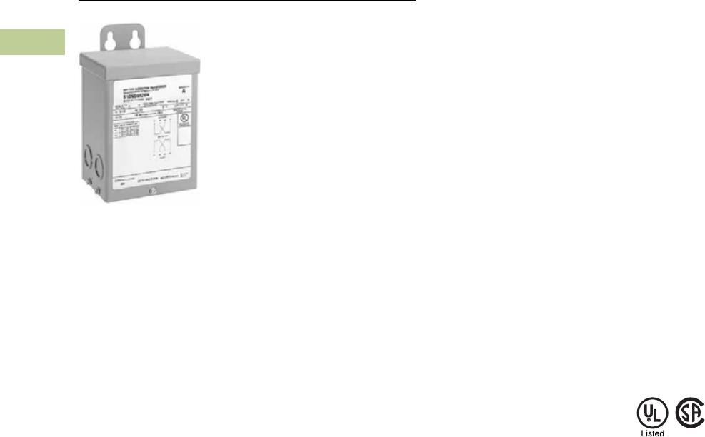
V2-T2-144 Volume 2—Commercial Distribution CA08100003E—July 2016 www.eaton.com
2
2
2
2
2
2
2
2
2
2
2
2
2
2
2
2
2
2
2
2
2
2
2
2
2
2
2
2
2
2
2.5
Transfor mers
Distribution Transformers
Type EP
Contents
Description Page
Motor Drive Isolation Transformers. . . . . . . . . . . . V2-T2-111
Mini–Power Centers . . . . . . . . . . . . . . . . . . . . . . . V2-T2-119
Totally Enclosed Non-Ventilated Transformers . . . V2-T2-124
Class I, Division 2, Hazardous Location Transformers V2-T2-127
Open-Type Core and Coil Assembly Transformers V2-T2-130
Marine Duty Transformers . . . . . . . . . . . . . . . . . . V2-T2-133
Buck-Boost and Low Voltage Lighting Transformers
Product Selection. . . . . . . . . . . . . . . . . . . . . . . V2-T2-145
Accessories . . . . . . . . . . . . . . . . . . . . . . . . . . . V2-T2-171
Technical Data and Specifications . . . . . . . . . . V2-T2-171
Wiring Diagrams . . . . . . . . . . . . . . . . . . . . . . . V2-T2-172
Medium Voltage Distribution Transformers. . . . . . V2-T2-173
Buck-Boost and Low Voltage Lighting Transformers
Product Description
Note: The following pages
provide listings for most standard
transformer ratings and catalog
numbers. For other ratings or
catalog numbers not shown,
or for special enclosure types
(including stainless steel), refer
to Eaton.
Types EP, EPT
●Encapsulated design
●Suitable for indoor or
outdoor applications
●Totally enclosed, non-
ventilated enclosures
●Enclosures are
NEMA 3R rated
●Mountable in any position
indoors and upright-only
outdoors
●180ºC insulation system
●115°C rise standard;
80°C rise optional
●Available in single-phase
ratings through 7.5 kVA
Application Description
A buck-boost transformer is
used to provide an economical
method of correcting a lower
or higher voltage rating more
suitable for efficient operation
of electrical equipment.
Type EP buck-boost
transformers are small kVA,
single-phase transformers
with dual primary and dual
secondary windings, and
are usually connected as
autotransformers by using
one unit for single-phase
applications and either two
or three units banked for three-
phase operation. They are
primarily used for motor
operation and should not be
used for motor control circuits,
to correct fluctuating line
voltage or to obtain a neutral
on a delta system. Buck-boost
transformers are ideally suited
for use with low voltage
lighting systems, such as
outdoor lighting.
Features, Benefits
and Functions
●60 Hz operation
●600 volt class insulation
●Short-term overload
capability as required
by ANSI
●Meet NEMA ST-20
sound levels
Standards and Certifications
●UL listed
●CSA certified
Industry Standards
All Eaton dry-type distribution
and control transformers are
built and tested in accordance
with applicable NEMA, ANSI
and IEEE Standards. All
600 volt class transformers
are UL listed unless
otherwise noted.
Seismically Qualified
Eaton-manufactured dry-type
distribution transformers are
seismically qualified, and
exceed requirements of the
International Building Code
(IBC) and California Code
Title 24.
Catalog Number Selection
Please refer to Section 2.7
Page V2-T2-187.

Volume 2—Commercial Distribution CA08100003E—July 2016 www.eaton.com V2-T2-145
2
2
2
2
2
2
2
2
2
2
2
2
2
2
2
2
2
2
2
2
2
2
2
2
2
2
2
2
2
2
2.5
Trans for mers
Distribution Transformers
Product Selection
For quick selection data,
refer to the tables on this
and the following pages.
Selection Requirements
You should have the following
information before selecting a
buck-boost transformer:
Line Voltage
The voltage that you want
to buck (decrease) or boost
(increase). This can be found
by measuring the supply line
voltage with a voltmeter.
Load Voltage
The voltage at which your
equipment is designed to
operate. This is listed on
the nameplate of the
load equipment.
Load Amperes or Load kVA
You do not need to know
both—one or the other is
sufficient for selection
purposes. This information
usually can be found on the
nameplate of the equipment
that you want to operate.
Frequency
The supply line frequency
must be the same as the
frequency of the equipment
to be operated—Eaton’s
buck-boost transformers
operate at 60 Hz only.
Phase
The supply line should be
the same as the equipment
to be operated—either single-
or three-phase.
Transformer Interconnection
For three-phase applications,
interconnections of
transformers should be
made in a junction box.
Two or three transformers
may be used depending
on an open delta (2) or
wye (3) connection.
5-Step Selector
The tables that follow will
simplify the selection of the
buck-boost transformers.
There are no calculations
needed; simply follow these
five steps:
1. Refer to the table having
the same output voltage
as the equipment you
want to operate. For
example, if you are
installing a 240 volt
6 kVA single-phase
load use selection table
on the page.
2. Select the available line
voltage across the top of
the chart that is closest
to the actual supply
voltage. Therefore, for
example, if the available
line voltage is 213 volts,
use the 212 volt column.
3. Read down the column
until you reach an output
kVA or amps rating equal
to or greater than the
load requirements. Since
6 kVA, in the example, is
not listed, use the next
higher rating, or 7.5 kVA.
4. Read across to the far
left columns for the
catalog number and
quantity of transformers
for your application. In
this case, you will need
one (1) catalog number
S10N06P01P.
5. Connect the buck-boost
transformer(s) you have
selected in accordance
with the connection
diagram specified at the
bottom of the available
line voltage column. In
this example, Diagram
“F” would be used.
Note: For single-phase
connections and three-phase
open delta connections, inputs
and outputs may be reversed.
kVA capacity remains constant.
Additional Product Selection
information begins on
Page V2-T2-189.
120 x 240 Volts to 12/24 Volts
120 x 240 Volts to 16/32 Volts
240 x 480 Volts to 24/48 Volts
Note
Frame drawings/dimensions information begins on Page V2-T2-216.
kVA °C Temp. Rise Frame Weight Lbs (kg) Catalog Number
0.05 115 FR52 7 (3) S10N04A81N
0.10 115 FR54 7 (3) S10N04A82N
0.15 115 FR55 8 (4) S10N04A83N
0.25 115 FR57P 12 (5) S10N04P26P
0.50 115 FR57P 13 (5) S10N04P51P
0.75 115 FR58AP 21 (10) S10N04P76P
1 115 FR67P 31 (14) S10N04P01P
1.5 115 FR67P 40 (18) S10N04P16P
2 115 FR68P 40 (18) S10N04P02P
3 115 FR176 65 (29) S10N04A03N
5 115 FR177 113 (51) S10N04A05N
7.5 115 FR178 123 (55) S10N04A07N
kVA °C Temp. Rise Frame Weight Lbs (kg) Catalog Number
0.05 115 FR52 7 (3) S10N06A81N
0.10 115 FR54 7 (3) S10N06A82N
0.15 115 FR55 8 (4) S10N06A83N
0.25 115 FR57P 12 (5) S10N06P26P
0.50 115 FR57P 13 (5) S10N06P51P
0.75 115 FR58AP 21 (10) S10N06P76P
1 115 FR67P 31 (14) S10N06P01P
1.5 115 FR67P 40 (18) S10N06P16P
2 115 FR68P 40 (18) S10N06P02P
3 115 FR176 65 (29) S10N06A03N
5 115 FR177 113 (51) S10N06A05N
7.5 115 FR178 123 (55) S10N06A07N
kVA °C Temp. Rise Frame Weight Lbs (kg) Catalog Number
0.05 115 FR52 7 (3) S20N08A81N
0.10 115 FR54 7 (3) S20N08A82N
0.15 115 FR55 8 (4) S20N08A83N
0.25 115 FR57P 12 (5) S20N08P26P
0.50 115 FR57P 13 (5) S20N08P51P
0.75 115 FR58AP 21 (10) S20N08P76P
1 115 FR67P 31 (14) S20N08P01P
1.5 115 FR67P 40 (18) S20N08P16P
2 115 FR68P 40 (18) S20N08P02P
3 115 FR176 65 (29) S20N08A03N
5 115 FR177 113 (51) S20N08A05N
7.5 115 FR178 123 (55) S20N08A07N

V2-T2-146 Volume 2—Commercial Distribution CA08100003E—July 2016 www.eaton.com
2
2
2
2
2
2
2
2
2
2
2
2
2
2
2
2
2
2
2
2
2
2
2
2
2
2
2
2
2
2
2.5
Transfor mers
Distribution Transformers
Single-Phase 115 Volt Output Required, 60 Hz
Notes
1Additional wiring trough may be required.
2Refer to Page V2-T2-172 for buck-boost wiring diagrams.
Output voltage for lower input voltage can be found by: x Input Actual Voltage = Output New Voltage.
Output kVA available at reduced input voltage can be found by: x Output kVA = New kVA Rating.
Frame drawings/dimensions information begins on Page V2-T2-216.
Units
Required 1Unit
kVA
Input Available Voltage
Catalog Number
84 91 96 100 102
Output Output Output Output Output
kVA Amps kVA Amps kVA Amps kVA Amps kVA Amps
1 0.05 — — — — 0.24 2.09 — — — — S10N04A81N
1 0.05 0.13 1.14 0.18 1.56 — — 0.31 2.70 0.36 3.13 S10N06A81N
1 0.10 — — — — 0.48 4.17 — — — — S10N04A82N
1 0.10 0.26 2.29 0.36 3.12 — — 0.62 5.41 0.72 6.25 S10N06A82N
1 0.15 — — — — 0.72 6.25 — — — — S10N04A83N
1 0.15 0.39 3.44 0.54 4.69 — — 0.93 8.12 1.08 9.37 S10N06A83N
1 0.25 — — — — 1.2 10.4 — — — — S10N04P26P
1 0.25 0.659 5.73 0.899 7.81 — — 1.56 13.5 1.8 15.6 S10N06P26P
1 0.50 — — — — 2.4 20.8 — — — — S10N04P51P
1 0.50 1.32 11.5 1.8 15.6 — — 3.11 27.1 3.59 31.2 S10N06P51P
1 0.75 — — — — 3.6 31.2 — — — — S10N04P76P
1 0.75 1.98 17.2 2.7 23.4 — — 4.67 40.6 5.39 46.8 S10N06P76P
1 1 ————4.7941.7————S10N04P01P
1 1 2.64 22.9 3.59 31.2 — — 6.23 54.1 7.19 62.5 S10N06P01P
1 1.5————7.262.5————S10N04P16P
1 1.5 3.95 34.4 5.39 46.9 — — 9.34 81.2 10.8 93.7 S10N06P16P
1 2 ————9.5883.3————S10N04P02P
1 2 5.27 45.8 7.19 62.5 — — 12.5 108 14.4 125 S10N06P02P
1 3 ————14.37125.1————S10N04A03N
1 3 7.92 68.7 10.77 93.6 — — 18.69 162.3 21.57 187.5 S10N06A03N
1 5 ————23.95208.5————S10N04A05N
1 5 13.2 115 18 156 — — 31.15 270.5 35.95 312.5 S10N06A05N
1 7.5————36312————S10N04A07N
1 7.5 19.8 172 27 234 — — 46.7 406 53.9 468 S10N06A07N
Connection Diagram 2DBB C A
Rated Output Voltage
Rated Input Voltage
-------------------------------------------------------
Actual Input Voltage
Rated Input Voltage
-----------------------------------------------------

Volume 2—Commercial Distribution CA08100003E—July 2016 www.eaton.com V2-T2-147
2
2
2
2
2
2
2
2
2
2
2
2
2
2
2
2
2
2
2
2
2
2
2
2
2
2
2
2
2
2
2.5
Trans for mers
Distribution Transformers
Single-Phase 115 Volt Output Required, 60 Hz
Notes
1Additional wiring trough may be required.
2Refer to Page V2-T2-172 for buck-boost wiring diagrams.
Output voltage for lower input voltage can be found by: x Input Actual Voltage = Output New Voltage.
Output kVA available at reduced input voltage can be found by: x Output kVA = New kVA Rating.
Frame drawings/dimensions information begins on Page V2-T2-216.
Units
Required 1Unit
kVA
Input Available Voltage
Catalog Number
105 127 130 138 146
Output Output Output Output Output
kVA Amps kVA Amps kVA Amps kVA Amps kVA Amps
1 0.05 0.48 4.17 0.54 4.58 — — 0.29 2.5 — — S10N04A81N
1 0.05 — — — — 0.41 3.54 — — 0.23 1.98 S10N06A81N
1 0.10 0.96 8.33 1.1 9.17 — — 0.58 5.0 — — S10N04A82N
1 0.10 — — — — 0.82 7.08 — — 0.46 3.95 S10N06A82N
1 0.15 1.44 12.5 1.6 13.7 — — 0.87 7.5 — — S10N04A83N
1 0.15 — — — — 1.3 10.6 — — 0.69 5.93 S10N06A83N
1 0.25 2.39 20.8 2.63 22.9 — — 1.44 12.5 — — S10N04P26P
1 0.25 — — — — 2.03 17.7 — — 1.14 9.88 S10N06P26P
1 0.50 4.79 41.6 5.27 45.8 — — 2.87 25 — — S10N04P51P
1 0.50 —— — — — 4.07 35.4 — — 2.27 19.8 S10N06P51P
1 0.75 7.19 62.4 7.9 68.7 — — 4.31 37.5 — — S10N04P76P
1 0.75 — — — — 6.1 53.1 — — 3.41 29.6 S10N06P76P
1 1 9.58 83.3 10.5 91.7 — — 5.75 50 — — S10N04P01P
1 1 — — — — 8.14 70.8 — — 4.55 39.5 S10N06P01P
1 1.5 14.4 125 15.8 137 — — 8.62 75 — — S10N04P16P
1 1.5 — — — — 12.2 106 — — 6.82 59.3 S10N06P16P
1 2 19.2 16.7 21.1 183 — — 11.5 100 — — S10N04P02P
1 2 — — — — 16.3 142 — — 9.10 79.2 S10N06P02P
1 3 28.7 249.9 31.5 275.1 — — 17.3 150 — — S10N04A03N
1 3 — — — — 24.4 212.4 — — 13.6 118.5 S10N06A03N
1 5 47.9 416.5 52.5 458.5 — — 28.7 250 — — S10N04A05N
1 5 — — — — 40.7 354 — — 22.7 197.5 S10N06A05N
1 7.5 71.9 624 79 687 — — 43.1 357 — — S10N04A07N
1 7.5 — — — — 61 531 — — 34.1 296 S10N06A07N
Connection Diagram 2AAA B B
Rated Output Voltage
Rated Input Voltage
-------------------------------------------------------
Actual Input Voltage
Rated Input Voltage
-----------------------------------------------------

V2-T2-148 Volume 2—Commercial Distribution CA08100003E—July 2016 www.eaton.com
2
2
2
2
2
2
2
2
2
2
2
2
2
2
2
2
2
2
2
2
2
2
2
2
2
2
2
2
2
2
2.5
Transfor mers
Distribution Transformers
Single-Phase 120 Volt Output Required, 60 Hz
Notes
1Additional wiring trough may be required.
2Refer to Page V2-T2-172 for buck-boost wiring diagrams.
Output voltage for lower input voltage can be found by: x Input Actual Voltage = Output New Voltage.
Output kVA available at reduced input voltage can be found by: x Output kVA = New kVA Rating.
Frame drawings/dimensions information begins on Page V2-T2-216.
Units
Required 1Unit
kVA
Input Available Voltage
Catalog Number
88 95 100 104 106
Output Output Output Output Output
kVA Amps kVA Amps kVA Amps kVA Amps kVA Amps
1 0.05 — — — — 0.25 2.09 — — — — S10N04A81N
1 0.05 0.14 1.15 0.19 1.56 — — 0.33 2.70 0.38 3.13 S10N06A81N
1 0.10 — — — — 0.50 4.17 — — — — S10N04A82N
1 0.10 0.28 2.29 0.38 3.12 — — 0.65 5.41 0.75 6.25 S10N06A82N
1 0.15 — — — — 0.75 6.25 — — — — S10N04A83N
1 0.15 0.41 3.44 0.56 4.69 — — 0.98 8.12 1.12 9.37 S10N06A83N
1 0.25— —— —1.2510.4— — — — S10N04P26P
1 0.25 0.687 5.73 0.937 7.81 — — 1.62 13.5 1.87 15.6 S10N06P26P
1 0.50————2.520.8————S10N04P51P
1 0.50 1.37 11.5 1.87 15.6 — — 3.25 27.1 3.75 31.2 S10N06P51P
1 0.75— —— —3.7531.2— — — — S10N04P76P
1 0.75 2.06 17.2 2.82 23.4 — — 4.87 40.6 5.62 46.8 S10N06P76P
1 1 ————5 41.7—————S10N04P01P
1 1 2.75 22.9 3.75 31.2 — — 6.5 54.1 7.5 62.5 S10N06P01P
1 1.5————7.562.5————S10N04P16P
1 1.5 4.12 34.4 5.62 46.9 — — 9.75 81.2 11.2 93.7 S10N06P16P
1 2 ————10 83.3————S10N04P02P
1 2 5.5 45.8 7.5 62.5 — — 13 108 15 125 S10N06P02P
1 3 — — — — 15 125.1 — — — — S10N04A03N
1 3 8.25 68.7 11.25 93.6 — — 19.5 162.3 22.5 187.5 S10N06A03N
1 5 — — — — 25 208.5 — — — — S10N04A05N
1 5 13.75 114.5 18.75 156 — — 32.5 270.5 37.5 312.5 S10N06A05N
1 7.5————37.5312————S10N04A07N
1 7.5 20.6 172 28.2 234 — — 48.7 406 56.2 468 S10N06A07N
Connection Diagram 2DBBCA
Rated Output Voltage
Rated Input Voltage
-------------------------------------------------------
Actual Input Voltage
Rated Input Voltage
-----------------------------------------------------

Volume 2—Commercial Distribution CA08100003E—July 2016 www.eaton.com V2-T2-149
2
2
2
2
2
2
2
2
2
2
2
2
2
2
2
2
2
2
2
2
2
2
2
2
2
2
2
2
2
2
2.5
Trans for mers
Distribution Transformers
Single-Phase 120 Volt Output Required, 60 Hz
Notes
1Additional wiring trough may be required.
2Refer to Page V2-T2-172 for buck-boost wiring diagrams.
Output voltage for lower input voltage can be found by: x Input Actual Voltage = Output New Voltage.
Output kVA available at reduced input voltage can be found by: x Output kVA = New kVA Rating.
Frame drawings/dimensions information begins on Page V2-T2-216.
Units
Required 1Unit
kVA
Input Available Voltage
Catalog Number
109 132 136 144 152
Output Output Output Output Output
kVA Amps kVA Amps kVA Amps kVA Amps kVA Amps
1 0.05 0.5 4.17 0.55 4.58 — — 0.3 2.5 — — S10N04A81N
1 0.05 — — — — 0.43 3.54 — — 0.24 1.98 S10N06A81N
1 0.10 1.0 8.33 1.1 9.17 — — 0.6 5.0 — — S10N04A82N
1 0.10 — — — — 0.85 7.08 — — 0.48 3.95 S10N06A82N
1 0.15 1.5 12.5 1.6 13.7 — — 0.9 7.5 — — S10N04A83N
1 0.15 — — — — 1.27 10.6 — — 0.71 5.93 S10N06A83N
1 0.25 2.5 20.8 2.75 22.9 — — 1.5 12.5 — — S10N04P26P
1 0.25 — — — — 2.12 17.7 — — 1.19 9.88 S10N06P26P
1 0.50 5 41.6 5.5 45.8 — — 3 25 — — S10N04P51P
1 0.50 — — — — 4.25 35.4 — — 2.37 19.8 S10N06P51P
1 0.75 7.5 62.4 8.25 68.7 — — 4.5 37.5 — — S10N04P76P
1 0.75 — — — — 6.37 53.1 — — 3.56 29.6 S10N06P76P
1 1 10 83.3 11 91.7 — — 6 50 — — S10N04P01P
1 1 ————8.570.8——4.7539.5S10N06P01P
1 1.5 15 125 16.5 137 — — 9 75 — — S10N04P16P
1 1.5 — — — — 12.7 106 — — 7.12 59.3 S10N06P16P
1 2 20 167 22 183 — — 12 100 — — S10N04P02P
1 2 — — — — 17 142 — — 9.5 79.2 S10N06P02P
1 3 30 249.9 33 275.1 — — 18 150 — — S10N04A03N
1 3 — — — — 25.5 212.4 — — 14.25 118.5 S10N06A03N
1 5 50 416.5 55 458.5 — — 30 250 — — S10N04A05N
1 5 — — — — 42.5 354 — — 23.7 197.5 S10N06A05N
1 7.5 75 624 82.5 687 — — 45 375 — — S10N04A07N
1 7.5 — — — — 63.7 531 — — 35.6 296 S10N06A07N
Connection Diagram 2AAA B B
Rated Output Voltage
Rated Input Voltage
-------------------------------------------------------
Actual Input Voltage
Rated Input Voltage
-----------------------------------------------------

V2-T2-150 Volume 2—Commercial Distribution CA08100003E—July 2016 www.eaton.com
2
2
2
2
2
2
2
2
2
2
2
2
2
2
2
2
2
2
2
2
2
2
2
2
2
2
2
2
2
2
2.5
Transfor mers
Distribution Transformers
Single-Phase 230 Volt Output Required, 60 Hz
Notes
1Additional wiring trough may be required.
2Refer to Page V2-T2-172 for buck-boost wiring diagrams.
Output voltage for lower input voltage can be found by: x Input Actual Voltage = Output New Voltage.
Output kVA available at reduced input voltage can be found by: x Output kVA = New kVA Rating.
Frame drawings/dimensions information begins on Page V2-T2-216.
Units
Required 1Unit
kVA
Input Available Voltage
Catalog Number
199 203 207 209 216
Output Output Output Output Output
kVA Amps kVA Amps kVA Amps kVA Amps kVA Amps
1 0.05 — — — — 0.43 1.88 0.48 2.08 — — S10N04A81N
1 0.05 0.31 1.36 0.36 1.56 — — — — 0.72 3.12 S10N06A81N
1 0.10— — — — 0.863.750.964.17— — S10N04A82N
1 0.10 0.62 2.71 0.72 3.12 — — — — 1.44 6.25 S10N06A82N
1 0.15— — — — 1.295.621.446.25— — S10N04A83N
1 0.15 0.93 4.06 1.08 4.69 — — — — 2.16 9.37 S10N06A83N
1 0.25 — — — — 2.15 9.37 2.39 10.4 — — S10N04P26P
1 0.25 1.55 6.77 1.8 7.81 — — — — 3.59 15.6 S10N06P26P
1 0.50— — — — 4.3118.74.7920.8— — S10N04P51P
1 0.50 3.11 13.5 3.6 15.6 — — — — 7.19 31.2 S10N06P51P
1 0.75— — — — 6.4628.27.1931.2— — S10N04P76P
1 0.75 4.66 20.3 5.4 23.4 — — — — 10.8 46.8 S10N06P76P
1 1 — — — — 8.6237.59.5841.7— — S10N04P01P
1 1 6.23 27.1 7.2 31.2 — — — — 14.4 62.5 S10N06P01P
1 1.5 — — — — 12.9 56.2 14.4 62.5 — — S10N04P16P
1 1.5 9.34 40.6 10.8 46.9 — — — — 21.6 93.7 S10N06P16P
1 2 — — — — 17.2 75 19.2 83.3 — — S10N04P02P
1 2 12.5 54.2 14.4 62.5 — — — — 28.7 125 S10N06P02P
1 3 — — — — 25.8 112.5 28.7 125.1 — — S10N04A03N
1 3 18.6 81.3 21.6 93.6 — — — — 43.2 187.5 S10N06A03N
1 5 — — — — 43.1 187.5 47.9 208.5 — — S10N04A05N
1 5 31.1 135.5 36 156 — — — — 72 312.5 S10N06A05N
1 7.5 — — — — 64.6 282 71.9 312 — — S10N04A07N
1 7.5 46.6 203 54 234 — — — — 108 468 S10N06A07N
Connection Diagram 2GF G F E
Rated Output Voltage
Rated Input Voltage
-------------------------------------------------------
Actual Input Voltage
Rated Input Voltage
-----------------------------------------------------

Volume 2—Commercial Distribution CA08100003E—July 2016 www.eaton.com V2-T2-151
2
2
2
2
2
2
2
2
2
2
2
2
2
2
2
2
2
2
2
2
2
2
2
2
2
2
2
2
2
2
2.5
Trans for mers
Distribution Transformers
Single-Phase 230 Volt Output Required, 60 Hz
Notes
1Additional wiring trough may be required.
2Refer to Page V2-T2-172 for buck-boost wiring diagrams.
Output voltage for lower input voltage can be found by: x Input Actual Voltage = Output New Voltage.
Output kVA available at reduced input voltage can be found by: x Output kVA = New kVA Rating.
Frame drawings/dimensions information begins on Page V2-T2-216.
Units
Required 1Unit
kVA
Input Available Voltage
Catalog Number
219 242 246 253 260
Output Output Output Output Output
kVA Amps kVA Amps kVA Amps kVA Amps kVA Amps
1 0.05 0.96 4.16 1.0 4.38 — — 0.53 2.29 — — S10N04A81N
1 0.05 — — — — 0.77 3.34 — — 0.41 1.77 S10N06A81N
1 0.10 1.92 8.33 2.01 8.75 — — 1.05 4.58 — — S10N04A82N
1 0.10 — — — — 1.53 6.67 — — 0.82 3.54 S10N06A82N
1 0.15 2.87 12.5 3.02 13.1 — — 1.58 6.87 — — S10N04A83N
1 0.15 — — — — 2.3 10.0 — — 1.22 5.31 S10N06A83N
1 0.25 4.79 20.8 5.03 21.9 — — 2.63 11.5 — — S10N04P26P
1 0.25 — — — — 3.83 16.7 — — 2.04 8.85 S10N06P26P
1 0.50 9.58 41.6 10.1 43.7 — — 5.27 22.9 — — S10N04P51P
1 0.50 — — — — 7.67 33.3 — — 4.07 17.7 S10N06P51P
1 0.75 14.4 62.4 15.1 65.6 — — 7.9 34.4 — — S10N04P76P
1 0.75 — — — — 11.5 50 — — 6.11 26.6 S10N06P76P
1 1 19.2 83.3 20.1 87.5 — — 10.5 45.8 — — S10N04P01P
1 1 ————15.366.7——8.1535.4
S10N06P01P
1 1.5 28.7 125 30.2 131 — — 15.8 68.7 — — S10N04P16P
1 1.5 — — — — 23 100 — — 12.2 53.1 S10N06P16P
1 2 38.3 167 40.2 175 — — 21.1 91.7 — — S10N04P02P
1 2 — — — — 30.7 133 — — 16.3 70.8 S10N06P02P
1 3 57.6 249.9 60.3 262.5 — — 31.5 137.4 — — S10N04A03N
1 3 — — — — 45.9 200.1 — — 24.4 106.2 S10N06A03N
1 5 96 416.5 100.5 437.5 — — 52.5 229 — — S10N04A05N
1 5 — — — — 76.5 333.5 — — 40.7 177 S10N06A05N
1 7.5 144 624 151 656 — — 79 344 — — S10N04A07N
1 7.5 — — — — 115 500 — — 61.1 266 S10N06A07N
Connection Diagram 2EEE F F
Rated Output Voltage
Rated Input Voltage
-------------------------------------------------------
Actual Input Voltage
Rated Input Voltage
-----------------------------------------------------

V2-T2-152 Volume 2—Commercial Distribution CA08100003E—July 2016 www.eaton.com
2
2
2
2
2
2
2
2
2
2
2
2
2
2
2
2
2
2
2
2
2
2
2
2
2
2
2
2
2
2
2.5
Transfor mers
Distribution Transformers
Single-Phase 240 Volt Output Required, 60 Hz
Notes
1Additional wiring trough may be required.
2Refer to Page V2-T2-172 for buck-boost wiring diagrams.
Output voltage for lower input voltage can be found by: x Input Actual Voltage = Output New Voltage.
Output kVA available at reduced input voltage can be found by: x Output kVA = New kVA Rating.
Frame drawings/dimensions information begins on Page V2-T2-216.
Units
Required 1Unit
kVA
Input Available Voltage
Catalog Number
208 212 216 218 225
Output Output Output Output Output
kVA Amps kVA Amps kVA Amps kVA Amps kVA Amps
1 0.05 — — — — 0.45 1.88 0.5 2.08 — — S10N04A81N
1 0.05 0.32 1.35 0.38 1.56 — — — — 0.75 3.12 S10N06A81N
1 0.10 — — — — 0.9 3.75 1.0 4.17 — — S10N04A82N
1 0.10 0.65 2.71 0.75 3.12 — — — — 1.5 6.25 S10N06A82N
1 0.15 — — — — 1.35 5.62 1.5 6.25 — — S10N04A83N
1 0.15 0.98 4.06 1.12 4.69 — — — — 2.25 9.37 S10N06A83N
1 0.25 — — — — 2.25 9.37 2.5 10.4 — — S10N04P26P
1 0.25 1.62 6.77 1.87 7.81 — — — — 3.75 15.6 S10N06P26P
1 0.50 — — — — 4.5 18.7 5 20.8 — — S10N04P51P
1 0.50 3.25 13.5 3.75 15.6 — — — — 7.5 31.2 S10N06P51P
1 0.75— — — — 6.7528.27.5 31.2— — S10N04P76P
1 0.75 4.87 20.3 5.62 23.4 — — — — 11.2 46.8 S10N06P76P
1 1 — — — — 9 37.5 10 41.7 — — S10N04P01P
1 1 6.5 27.1 7.5 31.2 — — — — 15 62.5 S10N06A01
1 1.5 — — — — 13.5 56.2 15 62.5 — — S10N04P16P
1 1.5 9.75 40.6 11.2 46.9 — — — — 22.5 93.7 S10N06P16P
1 2 — — — — 18 75 20 83.3 — — S10N04P02P
1 2 13 54.2 15 62.5 — — — — 30 125 S10N06P02P
1 3 — — — — 27 112.5 30 125.1 — — S10N04A03N
1 3 19.5 81.3 22.5 93.6 — — — — 45 187.5 S10N06A03N
1 5 ————45 18750208——S10N04A05N
1 5 32.5 135 37.5 156 — — — — 75 312 S10N06A05N
1 7.5 — — — — 67.5 282 75 312 — — S10N04A07N
1 7.5 48.7 203 56.2 234 — — — — 112 468 S10N06A07N
Connection Diagram 2GF G F E
Rated Output Voltage
Rated Input Voltage
-------------------------------------------------------
Actual Input Voltage
Rated Input Voltage
-----------------------------------------------------

Volume 2—Commercial Distribution CA08100003E—July 2016 www.eaton.com V2-T2-153
2
2
2
2
2
2
2
2
2
2
2
2
2
2
2
2
2
2
2
2
2
2
2
2
2
2
2
2
2
2
2.5
Trans for mers
Distribution Transformers
Single-Phase 240 Volt Output Required, 60 Hz
Notes
1Additional wiring trough may be required.
2Refer to Page V2-T2-172 for buck-boost wiring diagrams.
Output voltage for lower input voltage can be found by: x Input Actual Voltage = Output New Voltage.
Output kVA available at reduced input voltage can be found by: x Output kVA = New kVA Rating.
Frame drawings/dimensions information begins on Page V2-T2-216.
Units
Required 1Unit
kVA
Input Available Voltage
Catalog Number
229 252 256 264 272
Output Output Output Output Output
kVA Amps kVA Amps kVA Amps kVA Amps kVA Amps
1 0.05 1.0 4.16 1.05 4.38 — — 0.55 2.29 — — S10N04A81N
1 0.05 — — — — 0.8 3.33 — — 0.42 1.77 S10N06A81N
1 0.10 2.0 8.33 2.1 8.75 — — 1.1 4.58 — — S10N04A82N
1 0.10 — — — — 1.6 6.67 — — 0.85 3.54 S10N06A82N
1 0.15 3.0 12.5 3.15 13.1 — — 1.65 6.87 — — S10N04A83N
1 0.15 — — — — 2.4 10.0 — — 1.27 5.31 S10N06A83N
1 0.25 5 20.8 5.25 21.9 — — 2.75 11.5 — — S10N04P26P
1 0.25— —— —4 16.7— — 2.128.85S10N06P26P
1 0.50 10 41.6 10.5 43.7 — — 5.5 22.9 — — S10N04P51P
1 0.50 — — — — 8 33.3 — — 4.25 17.7 S10N06P51P
1 0.75 15 62.4 15.7 65.6 — — 8.25 34.4 — — S10N04P76P
1 0.75— —— —12 50 — — 6.3726.6S10N06P76P
1 1 20 83.3 21 87.5 — — 11 45.8 — — S10N04P01P
1 1 ————1666.7——8.535.4S10N06P01P
1 1.5 30 125 31.5 131 — — 16.5 68.7 — — S10N04P16P
1 1.5 — — — — 24 100 — — 12.7 53.1 S10N06P16P
1 2 40 167 42 175 — — 22 91.7 — — S10N04P02P
1 2 — — — — 32 133 — — 17 70.8 S10N06P02P
1 3 60 249.9 63 262.5 — — 33 137.4 — — S10N04A03N
1 3 — — — — 48 200.1 — — 25.5 106.2 S10N06A03N
1 5 100 416.5 105 437.5 — — 55 229 — — S10N04A05N
1 5 — — — — 80 333 — — 42.5 177 S10N06A05N
1 7.5 150 624 157 656 — — 82.5 344 — — S10N04A07N
1 7.5 — — — — 120 500 — — 63.7 266 S10N06A07N
Connection Diagram 2EEE F F
Rated Output Voltage
Rated Input Voltage
-------------------------------------------------------
Actual Input Voltage
Rated Input Voltage
-----------------------------------------------------

V2-T2-154 Volume 2—Commercial Distribution CA08100003E—July 2016 www.eaton.com
2
2
2
2
2
2
2
2
2
2
2
2
2
2
2
2
2
2
2
2
2
2
2
2
2
2
2
2
2
2
2.5
Transfor mers
Distribution Transformers
Three-Phase Open Delta Connection 230 Volt Output Required, 60 Hz
Notes
1Additional wiring trough may be required.
2Refer to Page V2-T2-172 for buck-boost wiring diagrams.
Output voltage for lower input voltage can be found by: x Input Actual Voltage = Output New Voltage.
Output kVA available at reduced input voltage can be found by: x Output kVA = New kVA Rating.
Frame drawings/dimensions information begins on Page V2-T2-216.
Units
Required 1Unit
kVA
Input Available Voltage
Catalog Number
199 203 207 209 216
Output Output Output Output Output
kVA Amps kVA Amps kVA Amps kVA Amps kVA Amps
2 0.05 — — — — 0.75 1.87 0.83 2.08 — — S10N04A81N
2 0.05 0.54 1.35 0.62 1.56 — — — — 1.24 3.12 S10N06A81N
2 0.10 — — — — 1.49 3.75 1.66 4.17 — — S10N04A82N
2 0.10 1.08 2.71 1.24 3.12 — — — — 2.49 6.25 S10N06A82N
2 0.15 — — — — 2.24 5.62 2.49 6.25 — — S10N04A83N
2 0.15 1.62 4.06 1.87 4.69 — — — — 3.73 9.37 S10N06A83N
2 0.25 — — — — 3.3 9.37 4.15 10.4 — — S10N04P26P
2 0.25 2.7 6.77 3.11 7.81 — — — — 6.22 15.6 S10N06P26P
2 0.50 — — — — 7.47 18.7 8.3 20.8 — — S10N04P51P
2 0.50 5.39 13.5 6.22 15.6 — — — — 12.4 31.2 S10N06P51P
2 0.75 — — — — 11.2 28.2 12.4 31.2 — — S10N04P76P
2 0.75 8.09 20.3 9.33 23.4 — — — — 18.7 46.8 S10N06P76P
2 1 — — — — 14.9 37.5 16.6 41.7 — — S10N04P01P
2 1 10.8 27.1 12.4 31.2 — — — — 24.9 62.5 S10N06P01P
2 1.5 — — — — 22.4 56.2 24.9 62.5 — — S10N04P16P
2 1.5 16.2 40.6 18.7 46.9 — — — — 37.3 93.7 S10N06P16P
2 2 — — — — 29.9 75 33.2 83.3 — — S10N04P02P
2 2 21.6 54.2 24.9 62.5 — — — — 49.8 125 S10N06P02P
2 3 — — — — 44.7 112.5 49.8 125.1 — — S10N04A03N
2 3 32.4 81.3 32.7 93.6 — — — — 74.7 187.5 S10N06A03N
2 5 — — — — 74.7 187 83 208 — — S10N04A05N
2 5 53.9 135 62.2 156 — — — — 124 312.5 S10N06A05N
2 7.5 — — — — 112 282 124 312 — — S10N04A07N
2 7.5 80.9 203 93.3 234 — — — — 187 468 S10N06A07N
Connection Diagram 2LKL K I
Rated Output Voltage
Rated Input Voltage
-------------------------------------------------------
Actual Input Voltage
Rated Input Voltage
-----------------------------------------------------

Volume 2—Commercial Distribution CA08100003E—July 2016 www.eaton.com V2-T2-155
2
2
2
2
2
2
2
2
2
2
2
2
2
2
2
2
2
2
2
2
2
2
2
2
2
2
2
2
2
2
2.5
Trans for mers
Distribution Transformers
Three-Phase Open Delta Connection 230 Volt Output Required, 60 Hz
Notes
1Additional wiring trough may be required.
2Refer to Page V2-T2-172 for buck-boost wiring diagrams.
Output voltage for lower input voltage can be found by: x Input Actual Voltage = Output New Voltage.
Output kVA available at reduced input voltage can be found by: x Output kVA = New kVA Rating.
Frame drawings/dimensions information begins on Page V2-T2-216.
Units
Required 1Unit
kVA
Input Available Voltage
Catalog Number
219 242 246 253 260
Output Output Output Output Output
kVA Amps kVA Amps kVA Amps kVA Amps kVA Amps
2 0.05 1.66 4.17 1.74 4.37 — — 0.91 2.29 — — S10N04A81N
2 0.05 — — — — 1.33 3.33 — — 0.70 1.77 S10N06A81N
2 0.10 3.32 8.33 3.48 8.75 — — 1.83 4.58 — — S10N04A82N
2 0.10 — — — — 2.65 6.67 — — 1.41 3.54 S10N06A82N
2 0.15 4.98 12.5 5.23 13.1 — — 2.74 6.87 — — S10N04A83N
2 0.15 — — — — 3.98 10.0 — — 2.12 5.13 S10N06A83N
2 0.25 8.3 20.8 8.71 21.9 — — 4.56 11.5 — — S10N04P26P
2 0.25 — — — — 6.64 16.7 — — 3.52 8.85 S10N06P26P
2 0.50 16.6 41.7 17.4 43.7 — — 9.73 22.9 — — S10N04P51P
2 0.50 — — — — 13.3 33.3 — — 7.05 17.7 S10N06P51P
2 0.75 24.9 62.4 26.1 65.6 — — 13.7 34.4 — — S10N04P76P
2 0.75 — — — — 19.9 50 — — 10.6 26.6 S10N06P76P
2 1 33.2 83.3 34.8 87.5 — — 18.3 45.8 — — S10N04P01P
2 1 ————26.566.7——14.135.4S10N06P01P
2 1.5 49.8 125 52.3 131 — — 27.4 68.7 — — S10N04P16P
2 1.5 — — — — 39.8 100 — — 21.2 53.1 S10N06P16P
2 2 66.4 167 69.7 175 — — 36.5 91.7 — — S10N04P02P
2 2 — — — — 53.1 133 — — 28.2 70.8 S10N06P02P
2 3 99.6 249.9 104.4 262.5 — — 54.9 137.4 — — S10N04A03N
2 3 — — — — 79.5 200 — — 42.3 106.2 S10N06A03N
2 5 166 417 174 437 — — 91.3 229 — — S10N04A05N
2 5 — — — — 133 333 — — 70.5 177 S10N06A05N
2 7.5 249 624 261 656 — — 137 344 — — S10N04A07N
2 7.5————199500——106266S10N06A07N
Connection Diagram 2III KK
Rated Output Voltage
Rated Input Voltage
-------------------------------------------------------
Actual Input Voltage
Rated Input Voltage
-----------------------------------------------------

V2-T2-156 Volume 2—Commercial Distribution CA08100003E—July 2016 www.eaton.com
2
2
2
2
2
2
2
2
2
2
2
2
2
2
2
2
2
2
2
2
2
2
2
2
2
2
2
2
2
2
2.5
Transfor mers
Distribution Transformers
Three-Phase Open Delta Connection 240 Volt Output Required, 60 Hz
Notes
1Additional wiring trough may be required.
2Refer to Page V2-T2-172 for buck-boost wiring diagrams.
Output voltage for lower input voltage can be found by: x Input Actual Voltage = Output New Voltage.
Output kVA available at reduced input voltage can be found by: x Output kVA = New kVA Rating.
Frame drawings/dimensions information begins on Page V2-T2-216.
Units
Required 1Unit
kVA
Input Available Voltage
Catalog Number
208 212 216 218 225
Output Output Output Output Output
kVA Amps kVA Amps kVA Amps kVA Amps kVA Amps
2 0.05 — — — — 0.73 1.87 0.87 2.08 — — S10N04A81N
2 0.05 0.56 1.35 0.65 1.56 — — — — 1.3 3.12 S10N06A81N
2 0.10 — — — — 1.56 3.75 1.73 4.17 — — S10N04A82N
2 0.10 1.13 2.71 1.3 3.12 — — — — 2.6 6.25 S10N06A82N
2 0.15 — — — — 2.34 5.62 2.6 6.25 — — S10N04A83N
2 0.15 1.69 4.06 1.95 4.69 — — — — 3.9 9.37 S10N06A83N
2 0.25——— — — 3.9 9.374.3310.4— — S10N04P26P
2 0.25 2.81 6.77 3.25 7.81 — — — — 6.49 15.6 S10N06P26P
2 0.50— — — — 7.7918.78.6620.8— — S10N04P51P
2 0.50 5.63 13.5 6.5 15.6 —— — — — 13 31.2 S10N06P51P
2 0.75— — — — 11.728.213 31.2— — S10N04P76P
2 0.75 8.44 20.3 9.75 23.4 — — — — 19.5 46.8 S10N06P76P
2 1 — — — — 15.6 37.5 17.3 41.7 — — S10N04P01P
2 1 11.3 27.1 13 31.2 — — — — 26 62.5 S10N06P01P
2 1.5 — — — — 23.4 56.2 26 62.5 — — S10N04P16P
2 1.5 16.9 40.6 19.5 46.9 — — — — 39 93.7 S10N06P16P
2 2 — — — — 31.2 75 34.6 83.3 — — S10N04P02P
2 2 22.5 54.2 26 62.5 — — — — 52 125 S10N06P02P
2 3 — — — — 46.8 112.5 51.9 125.1 — — S10N04A03N
2 3 33.9 81.3 39 93.6 — — — — 78 187.5 S10N06A03N
2 5 — — — — 77.9 187 86.6 208 — — S10N04A05N
2 5 56.3 135 65 156 — — — — 130 312 S10N06A05N
2 7.5 — — — — 117 282 130 312 — — S10N04A07N
2 7.5 84.4 203 97.5 234 — — — — 195 468 S10N06A07N
Connection Diagram 2LKL K I
Rated Output Voltage
Rated Input Voltage
-------------------------------------------------------
Actual Input Voltage
Rated Input Voltage
-----------------------------------------------------

Volume 2—Commercial Distribution CA08100003E—July 2016 www.eaton.com V2-T2-157
2
2
2
2
2
2
2
2
2
2
2
2
2
2
2
2
2
2
2
2
2
2
2
2
2
2
2
2
2
2
2.5
Trans for mers
Distribution Transformers
Three-Phase Open Delta Connection 240 Volt Output Required, 60 Hz
Notes
1Additional wiring trough may be required.
2Refer to Page V2-T2-172 for buck-boost wiring diagrams.
Output voltage for lower input voltage can be found by: x Input Actual Voltage = Output New Voltage.
Output kVA available at reduced input voltage can be found by: x Output kVA = New kVA Rating.
Frame drawings/dimensions information begins on Page V2-T2-216.
Units
Required 1Unit
kVA
Input Available Voltage
Catalog Number
229 252 256 264 272
Output Output Output Output Output
kVA Amps kVA Amps kVA Amps kVA Amps kVA Amps
2 0.05 1.73 4.16 1.82 4.37 — — 0.95 2.29 — — S10N04A81N
2 0.05 — — — — 1.38 3.33 — — 0.74 1.77 S10N06A81N
2 0.10 3.46 8.33 3.64 8.75 — — 1.91 4.58 — — S10N04A82N
2 0.10 — — — — 2.77 6.67 — — 1.47 3.54 S10N06A82N
2 0.15 5.19 12.5 5.45 13.1 — — 2.86 6.87 — — S10N04A83N
2 0.15— — — — 4.1510.0— — 2.215.31S10N06A83N
2 0.25 8.66 20.8 9.09 21.9 — — 4.76 11.5 — — S10N04P26P
2 0.25— — — — 6.9216.7— — 3.688.85S10N06P26P
2 0.50 17.3 41.6 18.2 43.7 — — 9.53 22.9 — — S10N04P51P
2 0.50— — — — 13.833.3— — 7.3617.7S10N06P51P
2 0.75 26 62.4 27.3 65.6 — — 14.3 34.4 — — S10N04P76P
2 0.75 — — — — 20.8 50 — — 11 26.6 S10N06P76P
2 1 34.6 83.3 36.4 87.5 — — 19.1 45.8 — — S10N04P01P
2 1 — — — — 27.7 66.7 — — 14.7 35.4 S10N06P01P
2 1.5 51.9 125 54.5 131 — — 28.6 68.7 — — S10N04P16P
2 1.5 — — — — 41.5 100 — — 22.1 53.1 S10N06P16P
2 2 69.3 167 72.7 175 — — 38.1 91.7 — — S10N04P02P
2 2 — — — — 55.4 133 — — 29.4 70.8 S10N06P02P
2 3 103.8 249.9 109.2 262.5 — — 57.3 137.4 — — S10N04A03N
2 3 — — — — 83.1 200 — — 44.1 106.2 S10N06A03N
2 5 173 416 182 437 — — 95.3 229 — — S10N04A05N
2 5 — — — — 138 333 — — 73.6 177 S10N06A05N
2 7.5 260 624 273 656 — — 143 344 — — S10N04A07N
2 7.5 — — — — 208 500 — — 110 266 S10N06A07N
Connection Diagram 2III KK
Rated Output Voltage
Rated Input Voltage
-------------------------------------------------------
Actual Input Voltage
Rated Input Voltage
-----------------------------------------------------

V2-T2-158 Volume 2—Commercial Distribution CA08100003E—July 2016 www.eaton.com
2
2
2
2
2
2
2
2
2
2
2
2
2
2
2
2
2
2
2
2
2
2
2
2
2
2
2
2
2
2
2.5
Transfor mers
Distribution Transformers
WARNING! Three-phase autotransformers should never be used to obtain four-wire output with three-wire input. Four-wire output
requires four-wire wye input.
Three-Phase Wye Connection 208 Volt Output Required, 60 Hz
Notes
1Additional wiring trough may be required.
2Refer to Page V2-T2-172 for buck-boost wiring diagrams.
Output voltage for lower input voltage can be found by: x Input Actual Voltage = Output New Voltage.
Output kVA available at reduced input voltage can be found by: x Output kVA = New kVA Rating.
Frame drawings/dimensions information begins on Page V2-T2-216.
Units
Required 1Unit
kVA
Input Available Voltage
Catalog Number
152 164 173 180 184
Output Output Output Output Output
kVA Amps kVA Amps kVA Amps kVA Amps kVA Amps
3 0.05————0.752.08————S10N04A81N
3 0.05 0.41 1.15 0.56 1.56 — — 0.98 2.71 1.12 3.12 S10N06A81N
3 0.10————1.504.17————S10N04A82N
3 0.10 0.82 2.29 1.12 3.12 — — 1.95 5.41 2.25 6.25 S10N06A82N
3 0.15————2.256.25————S10N04A83N
3 0.15 1.24 3.44 1.69 4.69 — — 2.92 8.12 3.73 9.37 S10N06A83N
3 0.25————3.7510.4————S10N04P26P
3 0.25 2.06 5.73 2.81 7.81 — — 4.87 13.5 5.62 15.6 S10N06P26P
3 0.50————7.520.8————S10N04P51P
3 0.504.1211.55.6215.6— — 9.7527.111.231.2S10N06P51P
3 0.75————11.231.2————S10N04P76P
3 0.756.1917.28.4423.4— — 14.640.616.846.8S10N06P76P
3 1 ————15 41.7————S10N04P01P
3 1 8.25 22.9 11.2 31.2 — — 19.5 54.1 22.5 62.5 S10N06P01P
3 1.5————22.562.5————S10N04P16P
3 1.5 12.4 34.4 16.9 46.9 — — 29.2 81.2 33.7 93.7 S10N06P16P
3 2 ————30 83.3————S10N04P02P
3 2 16.5 45.8 22.5 62.5 — — 39 108 45 125 S10N06P02P
3 3 ————45 125————S10N04A03N
3 3 24.7 68.7 33.6 93.6 — — 58.5 162.3 67.5 187.5 S10N06A03N
3 5 ————75 208————S10N04A05N
3 5 41.2 115 56.2 156 — — 97.5 271 112 312 S10N06A05N
3 7.5————112312————S10N04A07N
3 7.5 61.9 172 84.4 234 — — 146 406 168 468 S10N06A07N
Connection Diagram 2PNN O M
Rated Output Voltage
Rated Input Voltage
-------------------------------------------------------
Actual Input Voltage
Rated Input Voltage
-----------------------------------------------------

Volume 2—Commercial Distribution CA08100003E—July 2016 www.eaton.com V2-T2-159
2
2
2
2
2
2
2
2
2
2
2
2
2
2
2
2
2
2
2
2
2
2
2
2
2
2
2
2
2
2
2.5
Trans for mers
Distribution Transformers
WARNING! Three-phase autotransformers should never be used to obtain four-wire output with three-wire input. Four-wire output
requires four-wire wye input.
Three-Phase Wye Connection 208 Volt Output Required, 60 Hz
Notes
1Additional wiring trough may be required.
2Refer to Page V2-T2-172 for buck-boost wiring diagrams.
Output voltage for lower input voltage can be found by: x Input Actual Voltage = Output New Voltage.
Output kVA available at reduced input voltage can be found by: x Output kVA = New kVA Rating.
Frame drawings/dimensions information begins on Page V2-T2-216.
Units
Required 1Unit
kVA
Input Available Voltage
Catalog Number
189 229 236 250 264
Output Output Output Output Output
kVA Amps kVA Amps kVA Amps kVA Amps kVA Amps
3 0.05 1.5 4.16 1.65 4.58 — — 0.9 2.5 — — S10N04A81N
3 0.05 — — — — 1.27 3.54 — — 0.71 1.98 S10N06A81N
3 0.10 3.0 8.33 3.3 9.17 — — 1.8 5.0 — — S10N04A82N
3 0.10 — — — — 2.55 7.08 — — 1.42 3.95 S10N06A82N
3 0.15 4.5 12.5 4.95 13.7 — — 2.7 7.5 — — S10N04A83N
3 0.15 — — — — 3.82 10.6 — — 2.14 5.93 S10N06A83N
3 0.25 7.5 20.8 8.25 22.9 — — 4.5 12.5 — — S10N04P26P
3 0.25 — — — — 6.35 17.7 — — 3.56 9.88 S10N06P26P
3 0.50 15 41.6 16.5 45.8 — — 9 25 — — S10N04P51P
3 0.50 — — — — 12.7 35.4 — 7.12 19.3 S10N06P51P
3 0.75 22.5 62.4 24.7 68.7 — — 13.5 37.5 — — S10N04P76P
3 0.75— —— —19 53.1— — 10.729.3S10N06P76P
3 1 30 83.3 33 91.7 — — 18 50 — — S10N04P01P
3 1 ————25.570.8——14.239.5S10N06P01P
3 1.5 45 125 49.5 137 — — 27 75 — — S10N04P16P
3 1.5 — — — — 38.2 106 — — 21.4 59.3 S10N06P16P
3 2 60 167 66 183 — — 361 100 — — S10N04P02P
3 2 ————51142——28.579.2S10N06P02P
3 3 90 249.9 99 275.1 — — 54 150 — — S10N04A03N
3 3 — — — — 76.5 212.4 — — 46.2 118.5 S10N06A03N
3 5 150 416 165 458 — — 90 250 — — S10N04A05N
3 5 — — — — 127 354 — — 71.2 198 S10N06A05N
3 7.5 225 624 274 687 — — 135 375 — — S10N04A07N
3 7.5————190531——107293S10N06A07N
Connection Diagram 2MMM N N
Rated Output Voltage
Rated Input Voltage
-------------------------------------------------------
Actual Input Voltage
Rated Input Voltage
-----------------------------------------------------

V2-T2-160 Volume 2—Commercial Distribution CA08100003E—July 2016 www.eaton.com
2
2
2
2
2
2
2
2
2
2
2
2
2
2
2
2
2
2
2
2
2
2
2
2
2
2
2
2
2
2
2.5
Transfor mers
Distribution Transformers
WARNING! Three-phase autotransformers should never be used to obtain four-wire output with three-wire input. Four-wire output
requires four-wire wye input.
Three-Phase Wye Connection 230 Volt Output Required, 60 Hz
Notes
1Additional wiring trough may be required.
2Refer to Page V2-T2-172 for buck-boost wiring diagrams.
Output voltage for lower input voltage can be found by: x Input Actual Voltage = Output New Voltage.
Output kVA available at reduced input voltage can be found by: x Output kVA = New kVA Rating.
Frame drawings/dimensions information begins on Page V2-T2-216.
Units
Required 1Unit
kVA
Input Available Voltage
Catalog Number
183 192 199 208 218
Output Output Output Output Output
kVA Amps kVA Amps kVA Amps kVA Amps kVA Amps
3 0.05 — — 0.83 2.08 — — 1.65 4.58 1.66 4.17 S10N04A81N
3 0.05 0.62 1.56 — — 0.54 1.35 — — — — S10N06A81N
3 0.10 — — 1.66 4.17 — — 3.3 9.17 3.32 8.35 S10N04A82N
3 0.10 1.25 3.12 — — 1.08 2.71 — — — — S10N06A82N
3 0.15 — — 2.49 6.25 — — 4.95 13.7 4.98 12.5 S10N04A83N
3 0.15 1.87 4.69 — — 1.62 4.06 — — — — S10N06A83N
3 0.25 — — 4.15 10.4 — — 8.2 22.9 8.3 20.9 S10N04P26P
3 0.25 3.11 7.81 — — 2.70 6.77 — — — — S10N06P26P
3 0.50 — — 8.3 20.8 — — 16.5 45.8 16.6 41.7 S10N04P51P
3 0.50 6.22 15.6 — — 5.39 13.5 — — — — S10N06P51P
3 0.75 — — 12.4 31.2 — — 24.7 68.8 24.9 62.6 S10N04P76P
3 0.75 9.33 23.4 — — 8.09 20.3 — — — — S10N06P76P
3 1 — — 16.6 41.7 — — 33 91.7 33.2 83.5 S10N04P01P
3 1 12.5 31.2 — — 10.8 27.1 — — — — S10N06P01P
3 1.5 — — 24.9 62.5 — — 49.5 137 49.8 125 S10N04P16P
3 1.5 18.7 46.9 — — 16.2 40.6 — — — — S10N06P16P
3 2 — — 33.2 83.3 — — 66 183 66.4 167 S10N04P02P
3 2 24.9 62.5 — — 21.6 54.2 — — — — S10N06P02P
3 3 — — 49.8 125.1 — — 99 275 99.6 250.5 S10N04A03N
3 3 37.5 93.6 — — 32.4 81.3 — — — — S10N06A03N
3 5 — — 83 208 — — 165 458 166 417 S10N04A05N
3 5 62.2 156 — — 53.9 135 — — — — S10N06A05N
3 7.5 — — 124 312 — — 247 688 249 626 S10N04A07N
3 7.5 93.3 234 — — 80.9 203 — — — — S10N06A07N
Connection Diagram 2NNS M Q
Rated Output Voltage
Rated Input Voltage
-------------------------------------------------------
Actual Input Voltage
Rated Input Voltage
-----------------------------------------------------

Volume 2—Commercial Distribution CA08100003E—July 2016 www.eaton.com V2-T2-161
2
2
2
2
2
2
2
2
2
2
2
2
2
2
2
2
2
2
2
2
2
2
2
2
2
2
2
2
2
2
2.5
Trans for mers
Distribution Transformers
WARNING! Three-phase autotransformers should never be used to obtain four-wire output with three-wire input. Four-wire output
requires four-wire wye input.
Three-Phase Wye Connection 230 Volt Output Required, 60 Hz
Notes
1Additional wiring trough may be required.
2Refer to Page V2-T2-172 for buck-boost wiring diagrams.
Output voltage for lower input voltage can be found by: x Input Actual Voltage = Output New Voltage.
Output kVA available at reduced input voltage can be found by: x Output kVA = New kVA Rating.
Frame drawings/dimensions information begins on Page V2-T2-216.
Units
Required 1Unit
kVA
Input Available Voltage
Catalog Number
242 245 253 260 265
Output Output Output Output Output
kVA Amps kVA Amps kVA Amps kVA Amps kVA Amps
3 0.05 1.74 4.37 — — 0.91 2.29 — — — — S10N04A81N
3 0.05 — — 1.33 3.33 — — 0.70 1.77 0.62 1.56 S10N06A81N
3 0.10 3.48 8.75 — — 1.83 4.58 — — — — S10N04A82N
3 0.10 — — 2.65 6.67 — — 1.41 3.54 1.25 3.12 S10N06A82N
3 0.15 5.23 13.1 — — 2.74 6.87 — — — — S10N04A83N
3 0.15 — — 3.98 10.0 — — 2.12 5.31 1.87 4.69 S10N06A83N
3 0.25 8.71 21.9 — — 4.56 11.5 — — — — S10N04P26P
3 0.25 — — 6.63 16.7 — — 3.52 8.85 3.11 7.81 S10N06P26P
3 0.50 17.4 43.7 — — 9.31 22.9 — — — — S10N04P51P
3 0.50 — — 13.3 33.3 — — 7.05 17.7 6.22 15.6 S10N06P51P
3 0.75 26.1 65.6 — — 13.7 34.4 — — — — S10N04P76P
3 0.75 — — 19.9 50 — — 10.6 26.6 9.33 23.4 S10N06P76P
3 1 34.8 87.5 — — 18.3 45.8 — — — — S10N04P01P
3 1 — — 26.5 66.7 — — 14.1 35.4 12.5 31.2 S10N06P01P
3 1.5 52.3 131 — — 27.4 68.7 — — — — S10N04P16P
3 1.5 — — 39.8 100 — — 21.2 53.1 18.7 46.9 S10N06P16P
3 2 69.7 175 — — 36.6 91.6 — — — — S10N04P02P
3 2 — — 53.1 133 — — 28.2 70.8 24.9 62.5 S10N06P02P
3 3 104.4 262.5 — — 54.9 137.4 — — — — S10N04A03N
3 3 — — 79.5 200 — — 42.3 106.2 37.5 93.6 S10N06A03N
3 5 174 437 — — 91.3 229 — — — — S10N04A05N
3 5 — — 133 333 — — 70.5 177 62.2 156 S10N06A05N
3 7.5 261 656 — — 137 344 — — — S10N04A07N
3 7.5 — — 199 500 — — 106 266 93.3 234 S10N06A07N
Connection Diagram 2QQR R S
Rated Output Voltage
Rated Input Voltage
-------------------------------------------------------
Actual Input Voltage
Rated Input Voltage
-----------------------------------------------------

V2-T2-162 Volume 2—Commercial Distribution CA08100003E—July 2016 www.eaton.com
2
2
2
2
2
2
2
2
2
2
2
2
2
2
2
2
2
2
2
2
2
2
2
2
2
2
2
2
2
2
2.5
Transfor mers
Distribution Transformers
WARNING! Three-phase autotransformers should never be used to obtain four-wire output with three-wire input. Four-wire output
requires four-wire wye input.
Three-Phase Wye Connection 240 Volt Output Required, 60 Hz
Notes
1Additional wiring trough may be required.
2Refer to Page V2-T2-172 for buck-boost wiring diagrams.
Output voltage for lower input voltage can be found by: x Input Actual Voltage = Output New Voltage.
Output kVA available at reduced input voltage can be found by: x Output kVA = New kVA Rating.
Frame drawings/dimensions information begins on Page V2-T2-216.
Units
Required 1Unit
kVA
Input Available Voltage
Catalog Number
190 200 208 218 228
Output Output Output Output Output
kVA Amps kVA Amps kVA Amps kVA Amps kVA Amps
3 0.05 — — 0.86 2.08 — — 0.86 2.08 1.73 4.17 S10N04A81N
3 0.05 0.65 1.65 — — 1.27 3.05 — — — — S10N06A81N
3 0.10 — — 1.73 4.17 — — 1.73 4.17 3.46 8.34 S10N04A82N
3 0.10 1.3 3.12 — — 2.55 6.12 — — — — S10N06A82N
3 0.15 — — 2.59 6.25 — — 2.59 6.25 5.20 12.5 S10N04A83N
3 0.15 1.95 4.69 — — 3.82 9.16 — — — — S10N06A83N
3 0.25 — — 4.32 10.4 — — 4.32 10.4 8.66 20.9 S10N04P26P
3 0.25 3.25 7.81 — — 6.3 15.1 — — — — S10N06P26P
3 0.50 — — 8.65 20.8 — — 8.65 20.8 17.3 41.7 S10N04P51P
3 0.50 6.5 15.6 — — 12.7 30.4 — — — — S10N06P51P
3 0.75 — — 13 31.2 — — 13 31.2 26 62.6 S10N04P76P
3 0.75 9.75 23.4 — — 19.2 46 — — — — S10N06P76P
3 1 — — 17.3 41.7 — — 17.3 41.7 34.6 83.4 S10N04P01P
3 1 13 31.2 — — 25.5 61.2 — — — — S10N06P01P
3 1.5 — — 25.9 62.5 — — 25.9 62.5 52 125 S10N04P16P
3 1.5 19.5 46.9 — — 38.2 91.6 — — — — S10N06P16P
3 2 — — 34.6 83.3 — — 34.6 83.3 69.3 167 S10N04P02P
3 2 26 62.5 — — 51 122.4 — — — — S10N06P02P
3 3 — — 51.9 125.1 — — 51.9 125.1 103.8 250.2 S10N04A03N
3 3 39 93.6 — — 76.5 183.6 — — — — S10N06A03N
3 5 — — 86.5 208 — — 86.5 208 173 417 S10N04A05N
3 5 65 156 — — 127.2 305.2 — — — — S10N06A05N
3 7.5 — — 130 312 — — 130 312 260 626 S10N04A07N
3 7.5 97.5 234 — — 192 460 — — — — S10N06A07N
Connection Diagram 2NNM R Q
Rated Output Voltage
Rated Input Voltage
-------------------------------------------------------
Actual Input Voltage
Rated Input Voltage
-----------------------------------------------------

Volume 2—Commercial Distribution CA08100003E—July 2016 www.eaton.com V2-T2-163
2
2
2
2
2
2
2
2
2
2
2
2
2
2
2
2
2
2
2
2
2
2
2
2
2
2
2
2
2
2
2.5
Trans for mers
Distribution Transformers
WARNING! Three-phase autotransformers should never be used to obtain four-wire output with three-wire input. Four-wire output
requires four-wire wye input.
Three-Phase Wye Connection 240 Volt Output Required, 60 Hz
Notes
1Additional wiring trough may be required.
2Refer to Page V2-T2-172 for buck-boost wiring diagrams.
Output voltage for lower input voltage can be found by: x Input Actual Voltage = Output New Voltage.
Output kVA available at reduced input voltage can be found by: x Output kVA = New kVA Rating.
Frame drawings/dimensions information begins on Page V2-T2-216.
Units
Required 1Unit
kVA
Input Available Voltage
Catalog Number
252 256 264 272 277
Output Output Output Output Output
kVA Amps kVA Amps kVA Amps kVA Amps kVA Amps
3 0.05 1.85 4.37 — — 0.95 2.29 — — — — S10N04A81N
3 0.05 — — 1.39 3.33 — — 0.74 1.77 0.65 1.56 S10N06A81N
3 0.10 3.64 8.75 — — 1.91 4.58 — — — — S10N04A82N
3 0.10 — — 2.77 6.67 — — 1.47 3.54 1.3 3.12 S10N06A82N
3 0.15 5.46 13.1 — — 2.86 6.87 — — — — S10N04A83N
3 0.15 — — 4.16 10.0 — — 2.21 5.31 1.95 4.69 S10N06A83N
3 0.25 9.09 21.9 — — 4.76 11.5 — — — — S10N04P26P
3 0.25 — — 6.93 16.7 — — 3.68 8.85 3.25 7.81 S10N06P26P
3 0.50 18.2 43.7 — — 9.53 22.9 — — — — S10N04P51P
3 0.50 — — 13.9 33.3 — — 7.36 17.7 6.5 15.6 S10N06P51P
3 0.75 27.3 65.6 — — 14.3 34.4 — — — — S10N04P76P
3 0.75 — — 20.8 50 — — 11 26.6 9.75 23.4 S10N06P76P
3 1 36.4 87.5 — — 19.1 45.8 — — — — S10N04P01P
3 1 — — 27.7 66.7 — — 14.7 35.4 13 31.2 S10N06P01P
3 1.5 54.6 131 — — 28.6 68.7 — — — — S10N04P16P
3 1.5 — — 41.6 100 — — 22.1 53.1 19.5 46.9 S10N06P16P
3 2 72.8 175 — — 38.1 91.7 — — — — S10N04P02P
3 2 — — 55.4 133 — — 29.5 70.8 26 62.5 S10N06P02P
3 3 109.2 262.5 — — 57.3 137.4 — — — — S10N04A03N
3 3 — — 83.1 200 — — 44.1 106.2 39 93.6 S10N06A03N
3 5 182 437 — — 95.3 229 — — — — S10N04A05N
3 5 — — 139 333 — — 73.6 177 65 156 S10N06A05N
3 7.5 273 656 — — 143 344 — — — — S10N04A07N
3 7.5 — — 208 500 — — 110 266 97.5 234 S10N06A07N
Connection Diagram 2QQR R S
Rated Output Voltage
Rated Input Voltage
-------------------------------------------------------
Actual Input Voltage
Rated Input Voltage
-----------------------------------------------------

V2-T2-164 Volume 2—Commercial Distribution CA08100003E—July 2016 www.eaton.com
2
2
2
2
2
2
2
2
2
2
2
2
2
2
2
2
2
2
2
2
2
2
2
2
2
2
2
2
2
2
2.5
Transfor mers
Distribution Transformers
WARNING! Three-phase autotransformers should never be used to obtain four-wire output with three-wire input. Four-wire output
requires four-wire wye input.
Three-Phase Wye Connection 460 Volt Output Required, 60 Hz
Notes
1Additional wiring trough may be required.
2Refer to Page V2-T2-172 for buck-boost wiring diagrams.
Output voltage for lower input voltage can be found by: x Input Actual Voltage = Output New Voltage.
Output kVA available at reduced input voltage can be found by: x Output kVA = New kVA Rating.
Frame drawings/dimensions information begins on Page V2-T2-216.
Units
Required 1Unit
kVA
Input Available Voltage
Catalog Number
406 418 432 438
Output Output Output Output
kVA Amps kVA Amps kVA Amps kVA Amps
3 0.05 — — 1.66 2.08 — — 3.22 4.04 S10N04A81N
3 0.05 1.25 1.57 — — 2.49 3.12 — — S10N06A81N
3 0.10 — — 3.31 4.15 — — 6.62 8.31 S10N04A82N
3 0.10 2.49 3.12 — — 4.97 6.24 — — S10N06A82N
3 0.15 — — 4.97 6.24 — — 9.94 12.48 S10N04A83N
3 0.15 3.73 4.68 — — 7.46 9.36 — — S10N06A83N
3 0.25 — — 8.28 10.39 — — 16.6 20.84 S10N04P26P
3 0.25 6.22 7.81 — — 12.4 15.56 — — S10N06P26P
3 0.50 — — 16.6 20.84 — — 33.2 41.67 S10N04P51P
3 0.50 12.5 15.69 — — 24.69 31.25 — — S10N06P51P
3 0.75 — — 24.8 31.12 — — 49.6 62.25 S10N04P76P
3 0.75 18.7 23.47 — — 37.3 46.82 — — S10N06P76P
3 1 — — 33.1 41.54 — — 66.2 83.09 S10N04P01P
3 1 24.9 31.25 — — 49.7 62.38 — — S10N06P01P
3 1.5 — — 49.7 62.38 — — 99.4 124.75 S10N04P16P
3 1.5 37.3 46.94 — — 74.6 93.63 — — S10N06P16P
3 2 — — 66.3 83.22 — — 133 166.93 S10N04P02P
3 2 49.7 62.38 — — 99.5 124.88 — — S10N06P02P
3 3 — — 99.3 124.64 — — 198.6 249.27 S10N04A03N
3 3 74.6 93.63 — — 149 187.01 — — S10N06A03N
3 5 — — 166 208.35 — — 322 404.16 S10N04A05N
3 5 125 156.89 — — 249 312.53 — — S10N06A05N
3 7.5 — — 248 311 — — 496 622 S10N04A07N
3 7.5 187 235 — — 373 468 — — S10N06A07N
Connection Diagram 2RRQ Q
Rated Output Voltage
Rated Input Voltage
-------------------------------------------------------
Actual Input Voltage
Rated Input Voltage
-----------------------------------------------------

Volume 2—Commercial Distribution CA08100003E—July 2016 www.eaton.com V2-T2-165
2
2
2
2
2
2
2
2
2
2
2
2
2
2
2
2
2
2
2
2
2
2
2
2
2
2
2
2
2
2
2.5
Trans for mers
Distribution Transformers
WARNING! Three-phase autotransformers should never be used to obtain four-wire output with three-wire input. Four-wire output
requires four-wire wye input.
Three-Phase Wye Connection 460 Volt Output Required, 60 Hz
Notes
1Additional wiring trough may be required.
2Refer to Page V2-T2-172 for buck-boost wiring diagrams.
Output voltage for lower input voltage can be found by: x Input Actual Voltage = Output New Voltage.
Output kVA available at reduced input voltage can be found by: x Output kVA = New kVA Rating.
Frame drawings/dimensions information begins on Page V2-T2-216.
Units
Required 1Unit
kVA
Input Available Voltage
Catalog Number
424 436 450
Output Output Output
kVA Amps kVA Amps kVA Amps
3 0.05 — 1.7 2.1 — — — S10N04A81N
3 0.05 1.3 1.56 — — 2.6 3.13 S10N06A81N
3 0.10 — — 3.5 4.2 — — S10N04A82N
3 0.10 2.6 3.12 — — 5.2 6.25 S10N06A82N
3 0.15 — 5.2 6.25 — — S10N04A83N
3 0.15 3.9 4.68 — — 7.8 9.38 S10N06A83N
3 0.25 — — 8.7 10.4 — — S10N04P26P
3 0.25 6.5 7.82 — — 13 15.6 S10N06P26P
30.50——17.420.9——S10N04P51P
3 0.501315.6——2631.2S10N06P51P
30.75——2631.2——S10N04P76P
3 0.75 19.5 23.4 — — 39 46.9 S10N06P76P
31——3542——S10N04P01P
3 1 26 31.2 — — 52 62.5 S10N06P01P
3 1.5 — — 52 62.5 — — S10N04P16P
3 1.5 39 46.8 — — 78 93.8 S10N06P16P
32——6982.9——S10N04P02P
3 2 52 62.5 — — 104 125 S10N06P02P
3 3 — — 104 125 — — S10N04A03N
3 3 78 93.8 — — 156 187.6 S10N06A03N
3 5 — — 174 209.2 — — S10N04A05N
3 5 130 156.3 — — 260 312.7 S10N06A05N
3 7.5 — — 260 312 — — S10N04A07N
3 7.5 195 234 — — 390 469 S10N06A07N
Connection Diagram 2RRQ
Rated Output Voltage
Rated Input Voltage
-------------------------------------------------------
Actual Input Voltage
Rated Input Voltage
-----------------------------------------------------

V2-T2-166 Volume 2—Commercial Distribution CA08100003E—July 2016 www.eaton.com
2
2
2
2
2
2
2
2
2
2
2
2
2
2
2
2
2
2
2
2
2
2
2
2
2
2
2
2
2
2
2.5
Transfor mers
Distribution Transformers
Single-Phase Required, 60 Hz
Single-Phase Required, 60 Hz
Notes
1Additional wiring trough may be required.
2Refer to Page V2-T2-172 for buck-boost wiring diagrams.
Output voltage for lower input voltage can be found by: x Input Actual Voltage = Output New Voltage.
Output kVA available at reduced input voltage can be found by: x Output kVA = New kVA Rating.
Frame drawings/dimensions information begins on Page V2-T2-216.
Units
Required 1Unit
kVA
Input Available Voltage/Output Voltage
Catalog Number
200/240 230/277 346/380 362/380
Output Output Output Output
kVA Amps kVA Amps kVA Amps kVA Amps
1 0.25 1.25 5.2 1.44 5.2 1.98 5.2 3.95 10.4 S20N08P26P
1 0.50 2.50 10.4 2.88 10.4 3.95 10.4 7.90 20.8 S20N08P51P
1 0.75 3.75 15.6 4.32 15.6 5.93 15.6 11.9 31.2 S20N08P76P
1 1 5.00 20.8 5.76 20.8 7.90 20.8 15.8 41.6 S20N08P01P
1 1.5 7.50 31.2 8.64 31.2 11.9 31.2 23.8 62.5 S20N08P16P
1 2 10.0 41.6 11.5 41.6 15.8 41.6 31.6 83.3 S20N08P02P
1 3 15.0 62.5 17.3 62.5 23.8 62.5 47.5 125.0 S20N08A03N
1 5 25.0 104.0 28.8 104.0 39.5 104.0 79.0 208.0 S20N08A05N
1 7.5 37.5 156.0 43.2 156.0 59.3 156.0 118.6 312.0 S20N08A07N
Connection Diagram 2BBFE
Units
Required 1Unit
kVA
Input Available Voltage/Output Voltage
Catalog Number
378/416 416/457 436/480 458/480
Output Output Output Output
kVA Amps kVA Amps kVA Amps kVA Amps
1 0.25 2.16 5.2 2.38 5.2 2.50 5.2 4.99 10.4 S20N08P26P
1 0.50 4.33 10.4 4.76 10.4 4.99 10.4 9.98 20.8 S20N08P51P
1 0.75 6.49 15.6 7.14 15.6 7.49 15.6 15.0 31.2 S20N08P76P
1 1 8.65 20.8 9.52 20.8 9.98 20.8 20.0 41.6 S20N08P01P
1 1.5 13.0 31.2 14.3 31.2 15.0 31.2 30.0 62.5 S20N08P16P
1 2 17.3 41.6 19.0 41.6 20.0 41.6 40.0 83.3 S20N08P02P
1 3 26.0 62.5 28.6 62.5 30.0 62.5 60.0 125.0 S20N08A03N
1 5 43.3 104.0 47.6 104.0 49.9 104.0 99.8 208.0 S20N08A05N
1 7.5 64.9 156.0 71.4 156.0 74.9 156.0 149.8 312.0 S20N08A07N
Connection Diagram 2FFFE
Rated Output Voltage
Rated Input Voltage
-------------------------------------------------------
Actual Input Voltage
Rated Input Voltage
-----------------------------------------------------

Volume 2—Commercial Distribution CA08100003E—July 2016 www.eaton.com V2-T2-167
2
2
2
2
2
2
2
2
2
2
2
2
2
2
2
2
2
2
2
2
2
2
2
2
2
2
2
2
2
2
2.5
Trans for mers
Distribution Transformers
Single-Phase Required, 60 Hz
Notes
1Additional wiring trough may be required.
2Refer to Page V2-T2-172 for buck-boost wiring diagrams.
Output voltage for lower input voltage can be found by: x Input Actual Voltage = Output New Voltage.
Output kVA available at reduced input voltage can be found by: x Output kVA = New kVA Rating.
Frame drawings/dimensions information begins on Page V2-T2-216.
Units
Required 1Unit
kVA
Input Available Voltage/Output Voltage
Catalog Number
277/230 480/456 504/480 528/480
Output Output Output Output
kVA Amps kVA Amps kVA Amps kVA Amps
1 0.25 1.44 6.26 5.23 11.4 5.47 11.4 2.75 5.72 S20N08P26P
1 0.50 2.88 12.5 10.4 22.8 10.9 22.8 5.49 11.4 S20N08P51P
1 0.75 4.33 18.8 15.7 34.2 16.4 34.2 8.24 17.2 S20N08P76P
1 1 5.76 25.0 20.9 45.6 21.8 45.6 11.0 22.9 S20N08P01P
1 1.5 8.64 37.6 31.3 68.4 32.8 68.4 16.5 34.3 S20N08P16P
1 2 11.5 50.1 41.8 91.2 43.7 91.2 22.0 45.8 S20N08P02P
1 3 17.3 75.3 62.7 136.0 65.2 136.0 33.0 68.8 S20N08A03N
1 5 28.8 125.3 104.5 227.0 108.0 227.0 54.9 114.4 S20N08A05N
1 7.5 43.2 187.9 156.8 341.0 163.0 341.0 82.4 171.6 S20N08A07N
Connection Diagram 2BEEF
Rated Output Voltage
Rated Input Voltage
-------------------------------------------------------
Actual Input Voltage
Rated Input Voltage
-----------------------------------------------------

V2-T2-168 Volume 2—Commercial Distribution CA08100003E—July 2016 www.eaton.com
2
2
2
2
2
2
2
2
2
2
2
2
2
2
2
2
2
2
2
2
2
2
2
2
2
2
2
2
2
2
2.5
Transfor mers
Distribution Transformers
Three-Phase Required, 60 Hz
Three-Phase Required, 60 Hz
Notes
1Refer to Page V2-T2-172 for buck-boost wiring diagrams.
2Additional wiring trough may be required.
Output voltage for lower input voltage can be found by: x Input Actual Voltage = Output New Voltage.
Output kVA available at reduced input voltage can be found by: x Output kVA = New kVA Rating.
Frame drawings/dimensions information begins on Page V2-T2-216.
Unit
kVA
Input Available Voltage/Output Voltage
Catalog Number
362/380 346/416 430/473 400/480 436/480
Output Output Output Output Output
kVA Amps kVA Amps kVA Amps kVA Amps kVA Amps
0.25 6.52 10.4 3.75 5.2 4.26 5.2 4.33 5.2 4.33 5.2 S20N08P26P
0.50 13.0 20.8 7.50 10.4 8.52 10.4 8.65 10.4 8.65 10.4 S20N08P51P
0.75 19.6 31.2 11.2 15.6 12.8 15.6 13.0 15.6 13.0 15.6 S20N08P76P
1 26.1 41.6 15.0 20.8 17.0 20.8 17.3 20.8 17.3 20.8 S20N08P01P
1.5 39.1 62.4 22.5 31.2 25.5 31.2 26.0 31.2 26.0 31.2 S20N08P16P
2 52.2 83.2 30.0 41.6 34.1 41.6 34.6 41.6 34.6 41.6 S20N08P02P
3 78.4 125.0 45.0 62.5 51.2 62.5 52.0 62.5 52.0 62.5 S20N08A03N
5 130.4 208.0 75.1 104.0 85.2 104.0 86.6 104.0 86.6 104.0 S20N08A05N
7.5 195.6 312.0 112.6 156.0 127.8 156.0 129.9 156.0 129.9 156.0 S20N08A07N
Connection Diagram 1INKNK
Units Required 223232
Unit
kVA
Input Available Voltage/Output Voltage
Catalog Number
460/483 457/380 504/480 528/480
Output Output Output Output
kVA Amps kVA Amps kVA Amps kVA Amps
0.25 8.7 10.44.126.259.0810.94.765.72S20N08P26P
0.50 17.420.88.2312.518.221.89.5111.4S20N08P51P
0.75 26.131.212.318.827.232.814.317.2S20N08P76P
1 34.841.616.525.036.343.719.022.9S20N08P01P
1.5 52.262.424.737.554.565.528.534.3S20N08P16P
2 69.683.232.950.072.687.438.045.8S20N08P02P
3 104.6 125.0 49.5 75.2 109.7 131.3 57.2 68.8 S20N08A03N
5 174.0 208.0 82.3 125.1 181.6 218.4 95.1 114.4 S20N08A05N
7.5 261.0 312.0 123.5 187.6 272.4 327.6 142.7 171.6 S20N08A07N
Connection Diagram 1INIK
Units Required 22322
Rated Output Voltage
Rated Input Voltage
-------------------------------------------------------
Actual Input Voltage
Rated Input Voltage
-----------------------------------------------------

Volume 2—Commercial Distribution CA08100003E—July 2016 www.eaton.com V2-T2-169
2
2
2
2
2
2
2
2
2
2
2
2
2
2
2
2
2
2
2
2
2
2
2
2
2
2
2
2
2
2
2.5
Trans for mers
Distribution Transformers
Three-Phase Open Delta Connection 480 Volt Output Required, 60 Hz
Notes
1Additional wiring trough may be required.
2On transformers supplied with standard taps, taps must be placed at nominal settings.
3Refer to Page V2-T2-172 for buck-boost wiring diagrams.
Autotransformers can be used only where local electric codes permit and isolation of the two circuits is not required.
Output voltage for lower input voltage can be found by: x Input Actual Voltage = Output New Voltage.
Output kVA available at reduced input voltage can be found by: x Output kVA = New kVA Rating.
Frame drawings/dimensions information begins on Page V2-T2-216.
Units Required 1
Input Available Voltage
Catalog Number 2
600 575 575
Output Output Output
kVA Amps kVA Amps kVA Amps
2 4.35.1————S20N11P51P
2 ————4.14.9S60G11P51P
2 6.57.8————S20N11P76P
2 ————6.27.4S60G11P76P
2 8.6 10.3 — — — — S20N11P01P
2 ————8.39.9S60G11P01P
2 13.0 15.6 — — — — S20N11P16P
2 — — — — 12.4 14.9 S60G11P16P
2 17.2 20.6 — — — — S20N11P02P
2 — — — — 16.5 19.8 S60G11P02P
2 25.831 ————S20N11S03N
2 — — — — 24.8 29.8 S60G11P03P
2 43.2 51.9 — — — — S20N11S05N
2 ————41 49.3S60G11S05N
2 65 78.1 — — — — S20N11S07N
2 ————62 74.5S60G11S07N
2 86 103.4 — — — — S20N11S10N
2——8399.8——S60G11S10N
2 130 156.3 — — — — S20N11S15N
2 — — 124 149.1 — — S60N11S15N
2 216 259.8 — — — — T20P11S25EE
2 — — 207 248.9 — — S60J11S25N
2 324 389.7 — — — — T20P11S37EE
2 432 519.6 — — — — T20P11S50EE
Connection Diagram 3IJT
Rated Output Voltage
Rated Input Voltage
-------------------------------------------------------
Actual Input Voltage
Rated Input Voltage
-----------------------------------------------------

V2-T2-170 Volume 2—Commercial Distribution CA08100003E—July 2016 www.eaton.com
2
2
2
2
2
2
2
2
2
2
2
2
2
2
2
2
2
2
2
2
2
2
2
2
2
2
2
2
2
2
2.5
Transfor mers
Distribution Transformers
Single-Phase 480 Volt Output Required, 60 Hz
Notes
1Additional wiring trough may be required.
2On transformers supplied with standard taps, taps must be placed at nominal settings.
3Refer to Page V2-T2-172 for buck-boost wiring diagrams.
Autotransformers can be used only where local electric codes permit and isolation of the two circuits is not required.
Output voltage for lower input voltage can be found by: x Input Actual Voltage = Output New Voltage.
Output kVA available at reduced input voltage can be found by: x Output kVA = New kVA Rating.
Frame drawings/dimensions information begins on Page V2-T2-216.
Units Required 1
Input Available Voltage
Catalog Number 2
600 575 575
Output Output Output
kVA Amps kVA Amps kVA Amps
1 2.55.2————S20N11P51P
1 ————2.45 S60G11P51P
1 3.77.7————S20N11P76P
1 ————3.67.5S60G11P76P
1 5.010.4————S20N11P01P
1 ————4.810S60G11P01P
1 7.515.6————S20N11P16P
1 ————7.215S60G11P16P
1 1020.8————S20N11P02P
1 ————9.620S60G11P02P
1 1531.2————S20N11S03N
1 — — — — 14.3 29.7 S60G11P03P
1 2552————S20N11S05N
1 ————2450S60G11S05N
1 37.578.1————S20N11S07N
1 ————3675S60G11S07N
1 50104.1————S20N11S10N
1 — — 43 100 — — S60G11S10N
1 75 156.2 — — — — S20N11S15N
1 — — 72 150 — — S60N11S15N
1 125260.4————T20P11S25EE
1 — — 120 250 — — S60J11S25N
1 187389.6————T20P11S37EE
1 250520.8————T20P11S50EE
Connection Diagram 3EHU
Rated Output Voltage
Rated Input Voltage
-------------------------------------------------------
Actual Input Voltage
Rated Input Voltage
-----------------------------------------------------

Volume 2—Commercial Distribution CA08100003E—July 2016 www.eaton.com V2-T2-171
2
2
2
2
2
2
2
2
2
2
2
2
2
2
2
2
2
2
2
2
2
2
2
2
2
2
2
2
2
2
2.5
Trans for mers
Distribution Transformers
Accessories
Please refer to Section 2.7 Page V2-T2-191.
Technical Data and Specifications
Frequency
Eaton buck-boost
transformers are designed
for 60 Hz operation.
Overload Capability
Short-term overload is
designed into transformers as
required by ANSI. Dry-type
distribution transformers will
deliver 200% nameplate load
for one-half hour, 150% load
for one hour, and 125% load
for four hours without being
damaged, provided that a
constant 50% load precedes
and follows the overload.
See ANSI C57.96-01.250
for additional limitations.
Continuous overload capacity
is not deliberately designed
into a transformer because
the design objective is to be
within the allowed winding
temperature rise with
nameplate loading.
Insulation System and
Temperature Rise
Industry standards classify
insulation systems and rise as
shown below:
Insulation System
Classification
The design life of transformers
having different insulation
systems is the same—the
lower-temperature systems
are designed for the same life
as the higher-temperature
systems.
Enclosures
Eaton encapsulated buck-
boost transformers use a
NEMA 3R rated enclosure.
Winding Terminations
Primary and secondary
windings are terminated in
the wiring compartment.
Encapsulated units have
copper leads or stabs brought
out for connections. Lugs
are not supplied with
these transformers. Eaton
recommends that external
cables be rated 90°C
(sized at 75°C ampacity) for
encapsulated designs.
Series-Multiple Windings
Series-multiple windings
consist of two similar coils
in each winding that can be
connected in series or parallel
(multiple). Transformers with
series-multiple windings are
designated with an “x” or
“/” between the voltage
ratings, such as voltages of
“120/240” or “240 x 480.”
If the series-multiple winding
is designated by an “x,” the
winding can be connected
only for a series or parallel.
With the “/” designation,
a mid-point also becomes
available in addition to the
series or parallel connection.
As an example, a 120 x 240
winding can be connected for
either 120 (parallel) or 240
(series), but a 120/240
winding can be connected for
120 (parallel), 240 (series) or
240 with a 120 mid-point.
Ambient
+
Winding
Rise
+
Hot
Spot
=
Temp.
Class
40°C 55°C 10°C 105°C
40°C 80°C 30°C 150°C
25°C 135°C 20°C 180°C
40°C 115°C 30°C 185°C
40°C 150°C 30°C 220°C
Sound Levels
All Eaton 600 volt class
general-purpose dry-type
distribution transformers are
designed to meet NEMA
ST-20 sound levels listed
here. These are the sound
levels measured in a
soundproof environment.
Actual sound levels
measured at an installation
will likely be higher due to
electrical connections and
environmental conditions.
Lower sound levels are
available and should be
specified when the
transformer is going to be
installed in an area where
sound may be a concern.
For additional information,
please refer to Section 2.7
Page V2-T2-195.
Note: When installation is to be
made on a grounded system,
consideration must be given to
the resulting voltage. Thus, on a
208 grounded wye/120 system,
the voltage can be boosted to 240
volts but the voltage to ground
will be 139 volts. If 240/120 volts
with a mid-point ground is
needed, a standard two-winding
transformer must be used.
The following formulas can
be used to calculate specific
requirements.
For single-phase:
For three-phase:
Average Sound Levels
LOAD kVA
Load Voltage x
Full Line Amperes
1000
---------------------------------------------=
LOAD kVA
Line Load Voltage x 1.73 x
Full Load Amperes
1000
------------------------------------------------------------------=
NEMA ST-20 Average Sound Level, dB
Equivalent Winding
kVA Range
Self-Cooled Ventilated (up to 1.2 kV) Encapsulated
(up to 1.2 kV)K-Factor 1, 4, 9 K-Factor 13, 20
3.00 and below 40 40 45
3.01 to 9.00 40 40 45
9.01 to 15.00 45 45 50
15.01 to 30.00 45 45 50
30.01 to 50.00 45 48 50
50.01 to 75.00 50 53 55
75.01 to 112.50 50 53 55
112.51 to 150.00 50 53 55
150.01 to 225.00 55 58 57
225.01 to 300.00 55 58 57
300.01 to 500.00 60 63 59
500.01 to 700.00 62 65 61
700.01 to 1000.00 64 67 63
Greater than 1000 Consult factory Consult factory Consult factory
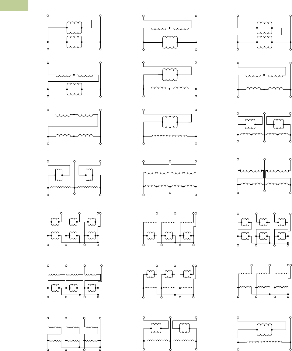
V2-T2-172 Volume 2—Commercial Distribution CA08100003E—July 2016 www.eaton.com
2
2
2
2
2
2
2
2
2
2
2
2
2
2
2
2
2
2
2
2
2
2
2
2
2
2
2
2
2
2
2.5
Transfor mers
Distribution Transformers
Wiring Diagrams
Buck-Boost Transformers Wiring Diagrams
Note
1WARNING! If input is three-wire, “neutral” connection must be isolated and insulated! When used to supply a three-phase, four-wire load, the source must be three-phase, four-wire wye.
H4 H3
H1H2
H4 H3
H1H2
Neutral
H4 H3
H1H2
High Voltage
Low Voltage
X2 X4 X2 X4 X2 X4
X1 X3 X1 X3 X1 X3
Low Voltage Neutral
High Voltage
X3 X4
X1 X2
X3 X4
X1 X2
X3 X4
X1 X2
H3 H1 H3 H1 H3 H1
H2 H4 H2 H4 H2H4
X1
H4 H3
H1H2
H4 H3
H1H2
Neutral
H4 H3
H1H2
X3 X1 X3 X1 X3
Low Voltage
High Voltage
X2 X4 X2 X4 X2 X4
Low Voltage Neutral
High Voltage
X3 X4
X1 X2
H4 H3
H1H2
X3 X4
X1 X2
H4 H3
H1H2
X3 X4
X1 X2
H4 H3
H1H2
X1
Neutral
X2
X3
X4
X1
X2
X3
X4
X1
X2
X3
X4
Low Voltage
High Voltage
H3
H2
H1
H4
H3
H2
H1
H4
H3
H2
H1
H4
High Voltage
Low Voltage
H4 H3 H2 H1 H1 H2 H3 H4
X1 X2 X3 X4 X4 X3 X2 X1
High Voltage
X3 X4
X2X1
H1
H2
Low Voltage
High Voltage
X3 X4
X2X1
H1H2H4 H3
Low Voltage
Low Voltage
High Voltage
X3 X4X2X1
H4 H3
H1H2
Low Voltage
High Voltage
X3 X4
X2X1
H4 H3
H1H2
Low Voltage
X3 X4X2X1
H4 H3
H1H2
High Voltage
Low Voltage
X3 X4X2X1
H1H2H4 H3
High Voltage
Neutral
X2 X4 X2 X4 X2 X4
High Voltage
Low Voltage
H3 H1 H3 H1 H3 H1
H2 H4 H2 H4 H2H4
X1 X3 X1 X3 X1 X3
Low Voltage
X3 X4
X1 X2
H4 H3
H1H2
X3 X4
X1 X2
H4 H3
H1H2
X3 X4
X1 X2
H4 H3
H1H2
Neutral
High Voltage
High Voltage
X3 X4
X2X1
H1
H4
Low Voltage
Low Voltage
X3 X4
X2X1
H4 H3
H1H2
High Voltage
Low Voltage
High Voltage
H4 H3 H2 H1 H1 H2 H3 H4
X4 X3 X2 X1X1 X2 X3 X4
Low Voltage
High Voltage
X3 X4X2X1
H1H2H4 H3
High Voltage
Low Voltage
X4 X3
X1X2
X3 X4
X2X1
H4 H3 H2 H1 H1 H2 H3 H4
High Voltage
Low Voltage
H4 H1 H1 H4
X4 X3
X1X2
X3 X4
X2X1
X4 X3
X3 X4
High Voltage
Low Voltage
H2 H1 H1 H2
X1
X2
X2X1
Diagram A Diagram B Diagram C
Diagram D Diagram E Diagram F
Diagram G Diagram H Diagram I
Diagram J Diagram K Diagram L
Diagram M 1Diagram N 1Diagram O 1
Diagram P 1Diagram Q 1Diagram R 1
Diagram S 1Diagram T Diagram U

Volume 2—Commercial Distribution CA08100003E—July 2016 www.eaton.com V2-T2-173
2
2
2
2
2
2
2
2
2
2
2
2
2
2
2
2
2
2
2
2
2
2
2
2
2
2
2
2
2
2
2.5
Trans for mers
Distribution Transformers
Contents
Description Page
Motor Drive Isolation Transformers . . . . . . . . . . . . V2-T2-111
Mini–Power Centers . . . . . . . . . . . . . . . . . . . . . . . V2-T2-119
Totally Enclosed Non-Ventilated Transformers. . . . V2-T2-124
Class I, Division 2, Hazardous Location Transformers V2-T2-127
Open-Type Core and Coil Assembly Transformers V2-T2-130
Marine Duty Transformers. . . . . . . . . . . . . . . . . . . V2-T2-133
Buck-Boost and Low Voltage Lighting Transformers V2-T2-144
Medium Voltage Distribution Transformers
Features, Benefits and Functions . . . . . . . . . . . V2-T2-174
Standards and Certifications. . . . . . . . . . . . . . . V2-T2-174
Product Description . . . . . . . . . . . . . . . . . . . . . V2-T2-175
Medium Voltage Distribution Transformers
Product Description
Note: The following pages
provide listings for most standard
transformer ratings and catalog
numbers. For other ratings or
catalog numbers not shown,
or for special enclosure types
(including stainless steel), refer
to Eaton.
Single- and Three-Phase
●Ventilated, NEMA 3R
enclosure standard
●Suitable for indoor or
outdoor applications
●Upright mounting only
●220ºC insulation system
●150ºC rise standard;
115°C or 80°C rise optional
●Available in single-phase
ratings 15–333 kVA
●Available in single-phase
ratings 25–167 kVA; in
three-phase ratings
15–1500 kVA
Application Description
U.S. DOE 10 CFR Part 431
compliant energy-efficient
transformers are specifically
designed to meet the energy
efficiency standards set
forth in U.S. DOE 10 CFR Part
431. Compliant transformers
are optimized to offer
maximum efficiency at 50%
of nameplate rating.
Transformers that are
currently specifically excluded
from the scope of DOE 10
CFR Part 431 include:
●Liquid-filled transformers
below 10 kVA
●Dry-type transformers
below 15 kVA
●AC and DC drives
transformers
●Rectifier transformers
designed for high
harmonics
●Autotransformers
●Non-distribution
transformers, such as
UPS transformers
●Special impedance or
regulation transformers
●Regulating transformers
●Sealed and non-ventilated
transformers
●Machine tool transformers
●Welding transformers
●Transformers with tap
ranges greater than 15%
●Transformers with a
frequency other than 60 Hz
●Grounding transformers
●Testing transformers
DOE 10 CFR Part 431
Efficiency Levels
Tables of Energy Efficiency
Dry-Type Distribution Transformers—
20–45 kV BIL
Single-Phase Three-Phase
kVA Efficiency kVA Efficiency
15 98.10 15 97.50
25 98.33 30 97.90
37.5 98.49 45 98.10
50 98.60 75 98.33
75 98.73 112.5 98.49
100 98.82 150 98.60
167 98.96 225 98.73
250 99.07 300 98.82
333 99.14 500 98.96
— — 750 99.07
— — 1000 99.14
— — 1500 99.22

V2-T2-174 Volume 2—Commercial Distribution CA08100003E—July 2016 www.eaton.com
2
2
2
2
2
2
2
2
2
2
2
2
2
2
2
2
2
2
2
2
2
2
2
2
2
2
2
2
2
2
2.5
Transfor mers
Distribution Transformers
Features, Benefits
and Functions
●60 Hz operation (except
as noted)
●Short-term overload
capability as required
by ANSI
●Meet NEMA ST-20
sound levels
●Meet federal energy
efficiency requirements
for dry-type transformers
effective as of
January 1, 2010
Standards and Certifications
●UL listed
Industry Standards
All Eaton dry-type distribution
and control transformers are
built and tested in accordance
with applicable NEMA, ANSI
and IEEE Standards.
Seismically Qualified
Eaton manufactured dry-type
distribution transformers are
seismically qualified and
exceed requirements of the
International Building Code
(IBC) and California Code
Title 24.

Volume 2—Commercial Distribution CA08100003E—July 2016 www.eaton.com V2-T2-175
2
2
2
2
2
2
2
2
2
2
2
2
2
2
2
2
2
2
2
2
2
2
2
2
2
2
2
2
2
2
2.5
Trans for mers
Distribution Transformers
Product Description
Single-Phase—2010 Energy-Efficient
2400 Volts to 120/240 Volts—Aluminum Windings
4160 Volts to 120/240 Volts—Aluminum Windings
Note
Contact your local Eaton sales office for CE Mark transformer requirements. For other ratings or catalog numbers not shown, or for special enclosure types (including stainless steel), refer to Eaton.
Frame drawings/dimensions information begins on Page V2-T2-216.
kVA
Full Capacity Taps ºC Temp.
Rise Frame
Wiring Diagram
Number
Weight
Lbs (kg) Weathershield Catalog NumberFCAN FCBN
25 2 at +2.5% 2 at –2.5% 150 NH6 ——Included T42D11S25E3R
37.5 2 at +2.5% 2 at –2.5% 150 NH3 ——Included T42D11S37E3R
50 2 at +2.5% 2 at –2.5% 150 NH3 ——Included T42D11S50E3R
75 2 at +2.5% 2 at –2.5% 150 NH3 ——Included T42D11S75E3R
100 2 at +2.5% 2 at –2.5% 150 NH4 ——Included T42D11S99E3R
167 2 at +2.5% 2 at –2.5% 150 NJ1 ——Included T42D11S67E3R
25 2 at +2.5% 2 at –2.5% 115 NH6 ——Included T42D11F25E3R
37.5 2 at +2.5% 2 at –2.5% 115 NH3 ——Included T42D11F37E3R
50 2 at +2.5% 2 at –2.5% 115 NH3 ——Included T42D11F50E3R
75 2 at +2.5% 2 at –2.5% 115 NH3 ——Included T42D11F75E3R
100 2 at +2.5% 2 at –2.5% 115 NH4 ——Included T42D11F99E3R
167 2 at +2.5% 2 at –2.5% 115 NJ1 ——Included T42D11F67E3R
25 2 at +2.5% 2 at –2.5% 80 NH3 ——Included T42D11B25E3R
37.5 2 at +2.5% 2 at –2.5% 80 NH3 ——Included T42D11B37E3R
50 2 at +2.5% 2 at –2.5% 80 NH3 ——Included T42D11B50E3R
75 2 at +2.5% 2 at –2.5% 80 NH4 ——Included T42D11B75E3R
100 2 at +2.5% 2 at –2.5% 80 NJ1 ——Included T42D11B99E3R
167 2 at +2.5% 2 at –2.5% 80 NJ1 ——Included T42D11B67E3R
kVA
Full Capacity Taps ºC Temp.
Rise Frame
Wiring Diagram
Number
Weight
Lbs (kg) Weathershield Catalog NumberFCAN FCBN
25 2 at +2.5% 2 at –2.5% 150 NH6 ——Included T46D11S25E3R
37.5 2 at +2.5% 2 at –2.5% 150 NH3 ——Included T46D11S37E3R
50 2 at +2.5% 2 at –2.5% 150 NH3 ——Included T46D11S50E3R
75 2 at +2.5% 2 at –2.5% 150 NH3 ——Included T46D11S75E3R
100 2 at +2.5% 2 at –2.5% 150 NH4 ——Included T46D11S99E3R
167 2 at +2.5% 2 at –2.5% 150 NJ1 ——Included T46D11S67E3R
25 2 at +2.5% 2 at –2.5% 115 NH6 ——Included T46D11F25E3R
37.5 2 at +2.5% 2 at –2.5% 115 NH3 ——Included T46D11F37E3R
50 2 at +2.5% 2 at –2.5% 115 NH3 ——Included T46D11F50E3R
75 2 at +2.5% 2 at –2.5% 115 NH3 ——Included T46D11F75E3R
100 2 at +2.5% 2 at –2.5% 115 NH4 ——Included T46D11F99E3R
167 2 at +2.5% 2 at –2.5% 115 NJ1 ——Included T46D11F67E3R
25 2 at +2.5% 2 at –2.5% 80 NH3 ——Included T46D11B25E3R
37.5 2 at +2.5% 2 at –2.5% 80 NH3 ——Included T46D11B37E3R
50 2 at +2.5% 2 at –2.5% 80 NH3 ——Included T46D11B50E3R
75 2 at +2.5% 2 at –2.5% 80 NH4 ——Included T46D11B75E3R
100 2 at +2.5% 2 at –2.5% 80 NJ1 ——Included T46D11B99E3R
167 2 at +2.5% 2 at –2.5% 80 NJ1 ——Included T46D11B67E3R

V2-T2-176 Volume 2—Commercial Distribution CA08100003E—July 2016 www.eaton.com
2
2
2
2
2
2
2
2
2
2
2
2
2
2
2
2
2
2
2
2
2
2
2
2
2
2
2
2
2
2
2.5
Transfor mers
Distribution Transformers
Single-Phase—2010 Energy-Efficient
2400 Volts to 120/240 Volts—Copper Windings
4160 Volts to 120/240 Volts—Copper Windings
Note
Contact your local Eaton sales office for CE Mark transformer requirements. For other ratings or catalog numbers not shown, or for special enclosure types (including stainless steel), refer to Eaton.
Frame drawings/dimensions information begins on Page V2-T2-216.
kVA
Full Capacity Taps ºC Temp.
Rise Frame
Wiring Diagram
Number
Weight
Lbs (kg) Weathershield Catalog NumberFCAN FCBN
25 2 at +2.5% 2 at –2.5% 150 NH6 ——Included T42D11S25CUE3R
37.5 2 at +2.5% 2 at –2.5% 150 NH3 ——Included T42D11S37CUE3R
50 2 at +2.5% 2 at –2.5% 150 NH3 ——Included T42D11S50CUE3R
75 2 at +2.5% 2 at –2.5% 150 NH3 ——Included T42D11S75CUE3R
100 2 at +2.5% 2 at –2.5% 150 NH4 ——Included T42D11S99CUE3R
167 2 at +2.5% 2 at –2.5% 150 NJ1 ——Included T42D11S67CUE3R
25 2 at +2.5% 2 at –2.5% 115 NH6 ——Included T42D11F25CUE3R
37.5 2 at +2.5% 2 at –2.5% 115 NH3 ——Included T42D11F37CUE3R
50 2 at +2.5% 2 at –2.5% 115 NH3 ——Included T42D11F50CUE3R
75 2 at +2.5% 2 at –2.5% 115 NH3 ——Included T42D11F75CUE3R
100 2 at +2.5% 2 at –2.5% 115 NH4 ——Included T42D11F99CUE3R
167 2 at +2.5% 2 at –2.5% 115 NJ1 ——Included T42D11F67CUE3R
25 2 at +2.5% 2 at –2.5% 80 NH3 ——Included T42D11B25CUE3R
37.5 2 at +2.5% 2 at –2.5% 80 NH3 ——Included T42D11B37CUE3R
50 2 at +2.5% 2 at –2.5% 80 NH3 ——Included T42D11B50CUE3R
75 2 at +2.5% 2 at –2.5% 80 NH4 ——Included T42D11B75CUE3R
100 2 at +2.5% 2 at –2.5% 80 NJ1 ——Included T42D11B99CUE3R
167 2 at +2.5% 2 at –2.5% 80 NJ1 ——Included T42D11B67CUE3R
kVA
Full Capacity Taps ºC Temp.
Rise Frame
Wiring Diagram
Number
Weight
Lbs (kg) Weathershield Catalog NumberFCAN FCBN
25 2 at +2.5% 2 at –2.5% 150 NH6 ——Included T46D11S25CUE3R
37.5 2 at +2.5% 2 at –2.5% 150 NH3 ——Included T46D11S37CUE3R
50 2 at +2.5% 2 at –2.5% 150 NH3 ——Included T46D11S50CUE3R
75 2 at +2.5% 2 at –2.5% 150 NH3 ——Included T46D11S75CUE3R
100 2 at +2.5% 2 at –2.5% 150 NH4 ——Included T46D11S99CUE3R
167 2 at +2.5% 2 at –2.5% 150 NJ1 ——Included T46D11S67CUE3R
25 2 at +2.5% 2 at –2.5% 115 NH6 ——Included T46D11F25CUE3R
37.5 2 at +2.5% 2 at –2.5% 115 NH3 ——Included T46D11F37CUE3R
50 2 at +2.5% 2 at –2.5% 115 NH3 ——Included T46D11F50CUE3R
75 2 at +2.5% 2 at –2.5% 115 NH3 ——Included T46D11F75CUE3R
100 2 at +2.5% 2 at –2.5% 115 NH4 ——Included T46D11F99CUE3R
167 2 at +2.5% 2 at –2.5% 115 NJ1 ——Included T46D11F67CUE3R
25 2 at +2.5% 2 at –2.5% 80 NH3 ——Included T46D11B25CUE3R
37.5 2 at +2.5% 2 at –2.5% 80 NH3 ——Included T46D11B37CUE3R
50 2 at +2.5% 2 at –2.5% 80 NH3 ——Included T46D11B50CUE3R
75 2 at +2.5% 2 at –2.5% 80 NH4 ——Included T46D11B75CUE3R
100 2 at +2.5% 2 at –2.5% 80 NJ1 ——Included T46D11B99CUE3R
167 2 at +2.5% 2 at –2.5% 80 NJ1 ——Included T46D11B67CUE3R

Volume 2—Commercial Distribution CA08100003E—July 2016 www.eaton.com V2-T2-177
2
2
2
2
2
2
2
2
2
2
2
2
2
2
2
2
2
2
2
2
2
2
2
2
2
2
2
2
2
2
2.5
Trans for mers
Distribution Transformers
Three-Phase—2010 Energy-Efficient
2400 Delta Volts to 480Y/277 Volts—Copper Windings
Note
Contact your local Eaton sales office for CE Mark transformer requirements. For other ratings or catalog numbers not shown, or for special enclosure types (including stainless steel), refer to Eaton.
Frame drawings/dimensions information begins on Page V2-T2-216.
kVA
Full Capacity Taps ºC Temp.
Rise Frame
Wiring Diagram
Number
Weight
Lbs (kg) Weathershield Catalog NumberFCAN FCBN
45 2 at +2.5% 2 at –2.5% 150 NH3 ——Included V42D47T45CUE3R
75 2 at +2.5% 2 at –2.5% 150 NH4 ——Included V42D47T75CUE3R
112.5 2 at +2.5% 2 at –2.5% 150 NH4 ——Included V42D47T12CUE3R
150 2 at +2.5% 2 at –2.5% 150 NJ1 ——Included V42D47T49CUE3R
225 2 at +2.5% 2 at –2.5% 150 NJ1 ——Included V42D47T22CUE3R
300 2 at +2.5% 2 at –2.5% 150 NJ1 ——Included V42D47T33CUE3R
500 2 at +2.5% 2 at –2.5% 150 NJ2 ——Included V42D47T55CUE3R
750 2 at +2.5% 2 at –2.5% 150 NJ3 ——Included V42D47T77CUE3R
45 2 at +2.5% 2 at –2.5% 115 NH3 ——Included V42D47F45CUE3R
75 2 at +2.5% 2 at –2.5% 115 NH4 ——Included V42D47F75CUE3R
112.5 2 at +2.5% 2 at –2.5% 115 NH4 ——Included V42D47F12CUE3R
150 2 at +2.5% 2 at –2.5% 115 NJ1 ——Included V42D47F49CUE3R
225 2 at +2.5% 2 at –2.5% 115 NJ1 ——Included V42D47F22CUE3R
300 2 at +2.5% 2 at –2.5% 115 NJ1 ——Included V42D47F33CUE3R
500 2 at +2.5% 2 at –2.5% 115 NJ2 ——Included V42D47F55CUE3R
750 2 at +2.5% 2 at –2.5% 115 NJ3 ——Included V42D47F77CUE3R
45 2 at +2.5% 2 at –2.5% 80 NH4 ——Included V42D47B45CUE3R
75 2 at +2.5% 2 at –2.5% 80 NH4 ——Included V42D47B75CUE3R
112.5 2 at +2.5% 2 at –2.5% 80 NJ1 ——Included V42D47B12CUE3R
150 2 at +2.5% 2 at –2.5% 80 NJ1 ——Included V42D47B49CUE3R
225 2 at +2.5% 2 at –2.5% 80 NJ1 ——Included V42D47B22CUE3R
300 2 at +2.5% 2 at –2.5% 80 NJ2 ——
Included V42D47B33CUE3R
500 2 at +2.5% 2 at –2.5% 80 NJ3 ——Included V42D47B55CUE3R
750 2 at +2.5% 2 at –2.5% 80 NJ3 ——Included V42D47B77CUE3R

V2-T2-178 Volume 2—Commercial Distribution CA08100003E—July 2016 www.eaton.com
2
2
2
2
2
2
2
2
2
2
2
2
2
2
2
2
2
2
2
2
2
2
2
2
2
2
2
2
2
2
2.5
Transfor mers
Distribution Transformers
Three-Phase—2010 Energy-Efficient
4160 Delta Volts to 480Y/277 Volts—Copper Windings
Note
Contact your local Eaton sales office for CE Mark transformer requirements. For other ratings or catalog numbers not shown, or for special enclosure types (including stainless steel), refer to Eaton.
Frame drawings/dimensions information begins on Page V2-T2-216.
kVA
Full Capacity Taps ºC Temp.
Rise Frame
Wiring Diagram
Number
Weight
Lbs (kg) Weathershield Catalog NumberFCAN FCBN
45 2 at +2.5% 2 at –2.5% 150 NH3 ——Included V46D47T45CUE3R
75 2 at +2.5% 2 at –2.5% 150 NH4 ——Included V46D47T75CUE3R
112.5 2 at +2.5% 2 at –2.5% 150 NH4 ——Included V46D47T12CUE3R
150 2 at +2.5% 2 at –2.5% 150 NJ1 ——Included V46D47T49CUE3R
225 2 at +2.5% 2 at –2.5% 150 NJ1 ——Included V46D47T22CUE3R
300 2 at +2.5% 2 at –2.5% 150 NJ1 ——Included V46D47T33CUE3R
500 2 at +2.5% 2 at –2.5% 150 NJ2 ——Included V46D47T55CUE3R
750 2 at +2.5% 2 at –2.5% 150 NJ3 ——Included V46D47T77CUE3R
45 2 at +2.5% 2 at –2.5% 115 NH3 ——Included V46D47F45CUE3R
75 2 at +2.5% 2 at –2.5% 115 NH4 ——Included V46D47F75CUE3R
112.5 2 at +2.5% 2 at –2.5% 115 NH4 ——Included V46D47F12CUE3R
150 2 at +2.5% 2 at –2.5% 115 NJ1 ——Included V46D47F49CUE3R
225 2 at +2.5% 2 at –2.5% 115 NJ1 ——Included V46D47F22CUE3R
300 2 at +2.5% 2 at –2.5% 115 NJ1 ——Included V46D47F33CUE3R
500 2 at +2.5% 2 at –2.5% 115 NJ2 ——Included V46D47F55CUE3R
750 2 at +2.5% 2 at –2.5% 115 NJ3 ——Included V46D47F77CUE3R
45 2 at +2.5% 2 at –2.5% 80 NH4 ——Included V46D47B45CUE3R
75 2 at +2.5% 2 at –2.5% 80 NH4 ——Included V46D47B75CUE3R
112.5 2 at +2.5% 2 at –2.5% 80 NJ1 ——Included V46D47B12CUE3R
150 2 at +2.5% 2 at –2.5% 80 NJ1 ——Included V46D47B49CUE3R
225 2 at +2.5% 2 at –2.5% 80 NJ1 ——Included V46D47B22CUE3R
300 2 at +2.5% 2 at –2.5% 80 NJ2 ——
Included V46D47B33CUE3R
500 2 at +2.5% 2 at –2.5% 80 NJ3 ——Included V46D47B55CUE3R
750 2 at +2.5% 2 at –2.5% 80 NJ3 ——Included V46D47B77CUE3R

Volume 2—Commercial Distribution CA08100003E—July 2016 www.eaton.com V2-T2-179
2
2
2
2
2
2
2
2
2
2
2
2
2
2
2
2
2
2
2
2
2
2
2
2
2
2
2
2
2
2
2.5
Trans for mers
Distribution Transformers
Three-Phase—2010 Energy-Efficient
2400 Delta Volts to 208Y/120 Volts—Copper Windings
Note
Contact your local Eaton sales office for CE Mark transformer requirements. For other ratings or catalog numbers not shown, or for special enclosure types (including stainless steel), refer to Eaton.
Frame drawings/dimensions information begins on Page V2-T2-216.
kVA
Full Capacity Taps ºC Temp.
Rise Frame
Wiring Diagram
Number
Weight
Lbs (kg) Weathershield Catalog NumberFCAN FCBN
45 2 at +2.5% 2 at –2.5% 150 NH3 ——Included V42D28T45CUE3R
75 2 at +2.5% 2 at –2.5% 150 NH4 ——Included V42D28T75CUE3R
112.5 2 at +2.5% 2 at –2.5% 150 NH4 ——Included V42D28T12CUE3R
150 2 at +2.5% 2 at –2.5% 150 NJ1 ——Included V42D28T49CUE3R
225 2 at +2.5% 2 at –2.5% 150 NJ1 ——Included V42D28T22CUE3R
300 2 at +2.5% 2 at –2.5% 150 NJ1 ——Included V42D28T33CUE3R
500 2 at +2.5% 2 at –2.5% 150 NJ2 ——Included V42D28T55CUE3R
750 2 at +2.5% 2 at –2.5% 150 NJ3 ——Included V42D28T77CUE3R
45 2 at +2.5% 2 at –2.5% 115 NH3 ——Included V42D28F45CUE3R
75 2 at +2.5% 2 at –2.5% 115 NH4 ——Included V42D28F75CUE3R
112.5 2 at +2.5% 2 at –2.5% 115 NH4 ——Included V42D28F12CUE3R
150 2 at +2.5% 2 at –2.5% 115 NJ1 ——Included V42D28F49CUE3R
225 2 at +2.5% 2 at –2.5% 115 NJ1 ——Included V42D28F22CUE3R
300 2 at +2.5% 2 at –2.5% 115 NJ1 ——Included V42D28F33CUE3R
500 2 at +2.5% 2 at –2.5% 115 NJ2 ——Included V42D28F55CUE3R
750 2 at +2.5% 2 at –2.5% 115 NJ3 ——Included V42D28F77CUE3R
45 2 at +2.5% 2 at –2.5% 80 NH4 ——Included V42D28B45CUE3R
75 2 at +2.5% 2 at –2.5% 80 NH4 ——Included V42D28B75CUE3R
112.5 2 at +2.5% 2 at –2.5% 80 NJ1 ——Included V42D28B12CUE3R
150 2 at +2.5% 2 at –2.5% 80 NJ1 ——Included V42D28B49CUE3R
225 2 at +2.5% 2 at –2.5% 80 NJ1 ——Included V42D28B22CUE3R
300 2 at +2.5% 2 at –2.5% 80 NJ2 ——
Included V42D28B33CUE3R
500 2 at +2.5% 2 at –2.5% 80 NJ3 ——Included V42D28B55CUE3R
750 2 at +2.5% 2 at –2.5% 80 NJ3 ——Included V42D28B77CUE3R

V2-T2-180 Volume 2—Commercial Distribution CA08100003E—July 2016 www.eaton.com
2
2
2
2
2
2
2
2
2
2
2
2
2
2
2
2
2
2
2
2
2
2
2
2
2
2
2
2
2
2
2.5
Transfor mers
Distribution Transformers
Three-Phase—2010 Energy-Efficient
4160 Delta Volts to 208Y/120 Volts—Copper Windings
Note
Contact your local Eaton sales office for CE Mark transformer requirements. For other ratings or catalog numbers not shown, or for special enclosure types (including stainless steel), refer to Eaton.
Frame drawings/dimensions information begins on Page V2-T2-216.
kVA
Full Capacity Taps ºC Temp.
Rise Frame
Wiring Diagram
Number
Weight
Lbs (kg) Weathershield Catalog NumberFCAN FCBN
45 2 at +2.5% 2 at –2.5% 150 NH3 ——Included V46D28T45CUE3R
75 2 at +2.5% 2 at –2.5% 150 NH4 ——Included V46D28T75CUE3R
112.5 2 at +2.5% 2 at –2.5% 150 NH4 ——Included V46D28T12CUE3R
150 2 at +2.5% 2 at –2.5% 150 NJ1 ——Included V46D28T49CUE3R
225 2 at +2.5% 2 at –2.5% 150 NJ1 ——Included V46D28T22CUE3R
300 2 at +2.5% 2 at –2.5% 150 NJ1 ——Included V46D28T33CUE3R
500 2 at +2.5% 2 at –2.5% 150 NJ2 ——Included V46D28T55CUE3R
750 2 at +2.5% 2 at –2.5% 150 NJ3 ——Included V46D28T77CUE3R
45 2 at +2.5% 2 at –2.5% 115 NH3 ——Included V46D28F45CUE3R
75 2 at +2.5% 2 at –2.5% 115 NH4 ——Included V46D28F75CUE3R
112.5 2 at +2.5% 2 at –2.5% 115 NH4 ——Included V46D28F12CUE3R
150 2 at +2.5% 2 at –2.5% 115 NJ1 ——Included V46D28F49CUE3R
225 2 at +2.5% 2 at –2.5% 115 NJ1 ——Included V46D28F22CUE3R
300 2 at +2.5% 2 at –2.5% 115 NJ1 ——Included V46D28F33CUE3R
500 2 at +2.5% 2 at –2.5% 115 NJ2 ——Included V46D28F55CUE3R
750 2 at +2.5% 2 at –2.5% 115 NJ3 ——Included V46D28F77CUE3R
45 2 at +2.5% 2 at –2.5% 80 NH4 ——Included V46D28B45CUE3R
75 2 at +2.5% 2 at –2.5% 80 NH4 ——Included V46D28B75CUE3R
112.5 2 at +2.5% 2 at –2.5% 80 NJ1 ——Included V46D28B12CUE3R
150 2 at +2.5% 2 at –2.5% 80 NJ1 ——Included V46D28B49CUE3R
225 2 at +2.5% 2 at –2.5% 80 NJ1 ——Included V46D28B22CUE3R
300 2 at +2.5% 2 at –2.5% 80 NJ2 ——
Included V46D28B33CUE3R
500 2 at +2.5% 2 at –2.5% 80 NJ3 ——Included V46D28B55CUE3R
750 2 at +2.5% 2 at –2.5% 80 NJ3 ——Included V46D28B77CUE3R

Volume 2—Commercial Distribution CA08100003E—July 2016 www.eaton.com V2-T2-181
2
2
2
2
2
2
2
2
2
2
2
2
2
2
2
2
2
2
2
2
2
2
2
2
2
2
2
2
2
2
2.5
Trans for mers
Distribution Transformers
Three-Phase—2010 Energy-Efficient
2400 Delta Volts to 480Y/277 Volts—Aluminum Windings
Note
Contact your local Eaton sales office for CE Mark transformer requirements. For other ratings or catalog numbers not shown, or for special enclosure types (including stainless steel), refer to Eaton.
Frame drawings/dimensions information begins on Page V2-T2-216.
kVA
Full Capacity Taps ºC Temp.
Rise Frame
Wiring Diagram
Number
Weight
Lbs (kg) Weathershield Catalog NumberFCAN FCBN
45 2 at +2.5% 2 at –2.5% 150 NH3 ——Included V42D47T45E3R
75 2 at +2.5% 2 at –2.5% 150 NH4 ——Included V42D47T75E3R
112.5 2 at +2.5% 2 at –2.5% 150 NH4 ——Included V42D47T12E3R
150 2 at +2.5% 2 at –2.5% 150 NJ1 ——Included V42D47T49E3R
225 2 at +2.5% 2 at –2.5% 150 NJ1 ——Included V42D47T22E3R
300 2 at +2.5% 2 at –2.5% 150 NJ1 ——Included V42D47T33E3R
500 2 at +2.5% 2 at –2.5% 150 NJ2 ——Included V42D47T55E3R
750 2 at +2.5% 2 at –2.5% 150 NJ3 ——Included V42D47T77E3R
45 2 at +2.5% 2 at –2.5% 115 NH3 ——Included V42D47F45E3R
75 2 at +2.5% 2 at –2.5% 115 NH4 ——Included V42D47F75E3R
112.5 2 at +2.5% 2 at –2.5% 115 NH4 ——Included V42D47F12E3R
150 2 at +2.5% 2 at –2.5% 115 NJ1 ——Included V42D47F49E3R
225 2 at +2.5% 2 at –2.5% 115 NJ1 ——Included V42D47F22E3R
300 2 at +2.5% 2 at –2.5% 115 NJ1 ——Included V42D47F33E3R
500 2 at +2.5% 2 at –2.5% 115 NJ2 ——Included V42D47F55E3R
750 2 at +2.5% 2 at –2.5% 115 NJ3 ——Included V42D47F77E3R
45 2 at +2.5% 2 at –2.5% 80 NH4 ——Included V42D47B45E3R
75 2 at +2.5% 2 at –2.5% 80 NH4 ——Included V42D47B75E3R
112.5 2 at +2.5% 2 at –2.5% 80 NJ1 ——Included V42D47B12E3R
150 2 at +2.5% 2 at –2.5% 80 NJ1 ——Included V42D47B49E3R
225 2 at +2.5% 2 at –2.5% 80 NJ1 ——Included V42D47B22E3R
300 2 at +2.5% 2 at –2.5% 80 NJ2 ——
Included V42D47B33E3R
500 2 at +2.5% 2 at –2.5% 80 NJ3 ——Included V42D47B55E3R
750 2 at +2.5% 2 at –2.5% 80 NJ3 ——Included V42D47B77E3R

V2-T2-182 Volume 2—Commercial Distribution CA08100003E—July 2016 www.eaton.com
2
2
2
2
2
2
2
2
2
2
2
2
2
2
2
2
2
2
2
2
2
2
2
2
2
2
2
2
2
2
2.5
Transfor mers
Distribution Transformers
Three-Phase—2010 Energy-Efficient
4160 Delta Volts to 480Y/277 Volts—Aluminum Windings
Note
Contact your local Eaton sales office for CE Mark transformer requirements. For other ratings or catalog numbers not shown, or for special enclosure types (including stainless steel), refer to Eaton.
Frame drawings/dimensions information begins on Page V2-T2-216.
kVA
Full Capacity Taps ºC Temp.
Rise Frame
Wiring Diagram
Number
Weight
Lbs (kg) Weathershield Catalog NumberFCAN FCBN
45 2 at +2.5% 2 at –2.5% 150 NH3 ——Included V46D47T45E3R
75 2 at +2.5% 2 at –2.5% 150 NH4 ——Included V46D47T75E3R
112.5 2 at +2.5% 2 at –2.5% 150 NH4 ——Included V46D47T12E3R
150 2 at +2.5% 2 at –2.5% 150 NJ1 ——Included V46D47T49E3R
225 2 at +2.5% 2 at –2.5% 150 NJ1 ——Included V46D47T22E3R
300 2 at +2.5% 2 at –2.5% 150 NJ1 ——Included V46D47T33E3R
500 2 at +2.5% 2 at –2.5% 150 NJ2 ——Included V46D47T55E3R
750 2 at +2.5% 2 at –2.5% 150 NJ3 ——Included V46D47T77E3R
45 2 at +2.5% 2 at –2.5% 115 NH3 ——Included V46D47F45E3R
75 2 at +2.5% 2 at –2.5% 115 NH4 ——Included V46D47F75E3R
112.5 2 at +2.5% 2 at –2.5% 115 NH4 ——Included V46D47F12E3R
150 2 at +2.5% 2 at –2.5% 115 NJ1 ——Included V46D47F49E3R
225 2 at +2.5% 2 at –2.5% 115 NJ1 ——Included V46D47F22E3R
300 2 at +2.5% 2 at –2.5% 115 NJ1 ——Included V46D47F33E3R
500 2 at +2.5% 2 at –2.5% 115 NJ2 ——Included V46D47F55E3R
750 2 at +2.5% 2 at –2.5% 115 NJ3 ——Included V46D47F77E3R
45 2 at +2.5% 2 at –2.5% 80 NH4 ——Included V46D47B45E3R
75 2 at +2.5% 2 at –2.5% 80 NH4 ——Included V46D47B75E3R
112.5 2 at +2.5% 2 at –2.5% 80 NJ1 ——Included V46D47B12E3R
150 2 at +2.5% 2 at –2.5% 80 NJ1 ——Included V46D47B49E3R
225 2 at +2.5% 2 at –2.5% 80 NJ1 ——Included V46D47B22E3R
300 2 at +2.5% 2 at –2.5% 80 NJ2 ——
Included V46D47B33E3R
500 2 at +2.5% 2 at –2.5% 80 NJ3 ——Included V46D47B55E3R
750 2 at +2.5% 2 at –2.5% 80 NJ3 ——Included V46D47B77E3R

Volume 2—Commercial Distribution CA08100003E—July 2016 www.eaton.com V2-T2-183
2
2
2
2
2
2
2
2
2
2
2
2
2
2
2
2
2
2
2
2
2
2
2
2
2
2
2
2
2
2
2.5
Trans for mers
Distribution Transformers
Three-Phase—2010 Energy-Efficient
2400 Delta Volts to 208Y/120 Volts—Aluminum Windings
Note
Contact your local Eaton sales office for CE Mark transformer requirements. For other ratings or catalog numbers not shown, or for special enclosure types (including stainless steel), refer to Eaton.
Frame drawings/dimensions information begins on Page V2-T2-216.
kVA
Full Capacity Taps ºC Temp.
Rise Frame
Wiring Diagram
Number
Weight
Lbs (kg) Weathershield Catalog NumberFCAN FCBN
45 2 at +2.5% 2 at –2.5% 150 NH3 ——Included V42D28T45E3R
75 2 at +2.5% 2 at –2.5% 150 NH4 ——Included V42D28T75E3R
112.5 2 at +2.5% 2 at –2.5% 150 NH4 ——Included V42D28T12E3R
150 2 at +2.5% 2 at –2.5% 150 NJ1 ——Included V42D28T49E3R
225 2 at +2.5% 2 at –2.5% 150 NJ1 ——Included V42D28T22E3R
300 2 at +2.5% 2 at –2.5% 150 NJ1 ——Included V42D28T33E3R
500 2 at +2.5% 2 at –2.5% 150 NJ2 ——Included V42D28T55E3R
750 2 at +2.5% 2 at –2.5% 150 NJ3 ——Included V42D28T77E3R
45 2 at +2.5% 2 at –2.5% 115 NH3 ——Included V42D28F45E3R
75 2 at +2.5% 2 at –2.5% 115 NH4 ——Included V42D28F75E3R
112.5 2 at +2.5% 2 at –2.5% 115 NH4 ——Included V42D28F12E3R
150 2 at +2.5% 2 at –2.5% 115 NJ1 ——Included V42D28F49E3R
225 2 at +2.5% 2 at –2.5% 115 NJ1 ——Included V42D28F22E3R
300 2 at +2.5% 2 at –2.5% 115 NJ1 ——Included V42D28F33E3R
500 2 at +2.5% 2 at –2.5% 115 NJ2 ——Included V42D28F55E3R
750 2 at +2.5% 2 at –2.5% 115 NJ3 ——Included V42D28F77E3R
45 2 at +2.5% 2 at –2.5% 80 NH4 ——Included V42D28B45E3R
75 2 at +2.5% 2 at –2.5% 80 NH4 ——Included V42D28B75E3R
112.5 2 at +2.5% 2 at –2.5% 80 NJ1 ——Included V42D28B12E3R
150 2 at +2.5% 2 at –2.5% 80 NJ1 ——Included V42D28B49E3R
225 2 at +2.5% 2 at –2.5% 80 NJ1 ——Included V42D28B22E3R
300 2 at +2.5% 2 at –2.5% 80 NJ2 ——
Included V42D28B33E3R
500 2 at +2.5% 2 at –2.5% 80 NJ3 ——Included V42D28B55E3R
750 2 at +2.5% 2 at –2.5% 80 NJ3 ——Included V42D28B77E3R

V2-T2-184 Volume 2—Commercial Distribution CA08100003E—July 2016 www.eaton.com
2
2
2
2
2
2
2
2
2
2
2
2
2
2
2
2
2
2
2
2
2
2
2
2
2
2
2
2
2
2
2.5
Transfor mers
Distribution Transformers
Three-Phase—2010 Energy-Efficient
4160 Delta Volts to 208Y/120 Volts—Aluminum Windings
Note
Contact your local Eaton sales office for CE Mark transformer requirements. For other ratings or catalog numbers not shown, or for special enclosure types (including stainless steel), refer to Eaton.
Frame drawings/dimensions information begins on Page V2-T2-216.
kVA
Full Capacity Taps ºC Temp.
Rise Frame
Wiring Diagram
Number
Weight
Lbs (kg) Weathershield Catalog NumberFCAN FCBN
45 2 at +2.5% 2 at –2.5% 150 NH3 ——Included V46D28T45E3R
75 2 at +2.5% 2 at –2.5% 150 NH4 ——Included V46D28T75E3R
112.5 2 at +2.5% 2 at –2.5% 150 NH4 ——Included V46D28T12E3R
150 2 at +2.5% 2 at –2.5% 150 NJ1 ——Included V46D28T49E3R
225 2 at +2.5% 2 at –2.5% 150 NJ1 ——Included V46D28T22E3R
300 2 at +2.5% 2 at –2.5% 150 NJ1 ——Included V46D28T33E3R
500 2 at +2.5% 2 at –2.5% 150 NJ2 ——Included V46D28T55E3R
750 2 at +2.5% 2 at –2.5% 150 NJ3 ——Included V46D28T77E3R
45 2 at +2.5% 2 at –2.5% 115 NH3 ——Included V46D28F45E3R
75 2 at +2.5% 2 at –2.5% 115 NH4 ——Included V46D28F75E3R
112.5 2 at +2.5% 2 at –2.5% 115 NH4 ——Included V46D28F12E3R
150 2 at +2.5% 2 at –2.5% 115 NJ1 ——Included V46D28F49E3R
225 2 at +2.5% 2 at –2.5% 115 NJ1 ——Included V46D28F22E3R
300 2 at +2.5% 2 at –2.5% 115 NJ1 ——Included V46D28F33E3R
500 2 at +2.5% 2 at –2.5% 115 NJ2 ——Included V46D28F55E3R
750 2 at +2.5% 2 at –2.5% 115 NJ3 ——Included V46D28F77E3R
45 2 at +2.5% 2 at –2.5% 80 NH4 ——Included V46D28B45E3R
75 2 at +2.5% 2 at –2.5% 80 NH4 ——Included V46D28B75E3R
112.5 2 at +2.5% 2 at –2.5% 80 NJ1 ——Included V46D28B12E3R
150 2 at +2.5% 2 at –2.5% 80 NJ1 ——Included V46D28B49E3R
225 2 at +2.5% 2 at –2.5% 80 NJ1 ——Included V46D28B22E3R
300 2 at +2.5% 2 at –2.5% 80 NJ2 ——
Included V46D28B33E3R
500 2 at +2.5% 2 at –2.5% 80 NJ3 ——Included V46D28B55E3R
750 2 at +2.5% 2 at –2.5% 80 NJ3 ——Included V46D28B77E3R

Volume 2—Commercial Distribution CA08100003E—July 2016 www.eaton.com V2-T2-185
2
2
2
2
2
2
2
2
2
2
2
2
2
2
2
2
2
2
2
2
2
2
2
2
2
2
2
2
2
2
2.6
Trans for mers
Transformer Standards, Technical Data and Accessories
Dry-Type Distribution Transformers
Contents
Description Page
Standards and Certifications . . . . . . . . . . . . . . . . . V2-T2-186
Catalog Number Selection. . . . . . . . . . . . . . . . . . . V2-T2-187
Product Selection . . . . . . . . . . . . . . . . . . . . . . . . . V2-T2-189
Options and Accessories. . . . . . . . . . . . . . . . . . . . V2-T2-191
Technical Data and Specifications . . . . . . . . . . . . . V2-T2-195
Glossary of Transformer Terms . . . . . . . . . . . . . . . V2-T2-211
Frequently Asked Questions About Transformers. V2-T2-214
V2-T2-186 Volume 2—Commercial Distribution CA08100003E—July 2016 www.eaton.com
2
2
2
2
2
2
2
2
2
2
2
2
2
2
2
2
2
2
2
2
2
2
2
2
2
2
2
2
2
2
2.6
Trans for mers
Transformer Standards, Technical Data and Accessories
Standards and Certifications
Eaton dry-type distribution transformers are approved, listed, recognized or may comply with the following standards.
Engineering Standards
Notes
1UL 5085 replaces UL 506.
2Applies to 25–50 kVA.
3Applies to 25 kVA.
4Applies to 15–25 kVA.
5Applies to 37.5 kVA.
6Applies to 3 kVA.
7Applies to 5–9 kVA.
8Applies to 30–75 kVA.
9Applies to 30 kVA.
In addition to the above standards, Eaton
dry-type distribution transformers are also
manufactured in compliance with the
applicable standards listed below.
Not all of the following standards apply
to every transformer.
NEC: National Electrical Code
NEMA ST-1: Specialty Transformers (C89.1)
(control transformers).
NEMA ST-20: General-Purpose
Transformers.
NEMA TP-1: Guide for Determining Energy
Efficiency for Distribution Transformers.
NEMA 250: Enclosures for Electrical
Equipment (1000 volts maximum).
IEEE C57.12.01: General Requirements
for Dry-Type Distribution and Power
Transformers (including those with solid-
cast and/or resin-encapsulated windings).
ANSI C57.12.70: Terminal Markings and
Connections for Distribution and Power
Transformers.
ANSI C57.12.91: Standard Test Code
for Dry-Type Distribution and Power
Transformers.
CSA C22 No. 47-M90: Air-Cooled
Transformers (Dry-Type).
CSA C9-M1981: Dry-Type Transformers.
CSA C22.2 No. 66: Specialty Transformers.
CSA 802-94: Maximum Losses for
Distribution, Power and Dry-Type
Transformers.
NEMA TP-2: Standard Test Method for
Measuring the Energy Consumption of
Distribution Transformers.
NEMA TP-3
Catalog
Product
Name
UL
Standard 1
UL/cUL
File
Number
UL Listed
Control
Number
cUL Energy
Efficiency
File Number
CSA
File
Number
Insulation
System
Temp/ºC
kVA
Single-
Phase
kVA
Three-
Phase
Applicable
IEC
Standard
Industrial Control Transformer
MTE 5085 E46323 702X — LR27533 105 0.025–1.5 N/A 61558
MTK 5085 E46323 702X — LR27533 180 0.05–5 N/A 61558
Encapsulated Transformer
AP 5085 E10156 591H — — 180 3–10 N/A 61558
AP 1561 E78389 591H — — 180 15 N/A 61558
EP 5085 E10156 591H — LR60545 180 0.05–10 N/A 61558
EP 1561 E78389 591H EV157 2LR60545 3180 15–50 N/A 61558 4 / 726 5
EPT 5085 E10156 591H — LR60545 180 N/A 3–9 61558 6 / 726 7
EPT 1561 E78389 591H EV157 8LR60545 9180 N/A 15–75 726
MPC 1062 E53449 591H — LR60546 180 3–25 15–30 —
Ventilated Transformer
DS-3 1561 E78389 591H — — 220 15–167 N/A 60726
DT-3 1561 E78389 591H — — 220 N/A 15–750 60726
KT 1561 E78389 591H — — 220 N/A 9–500 N/A
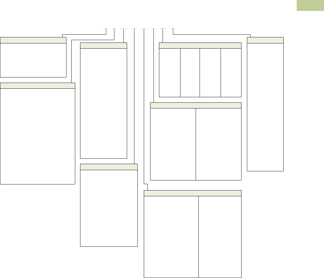
Volume 2—Commercial Distribution CA08100003E—July 2016 www.eaton.com V2-T2-187
2
2
2
2
2
2
2
2
2
2
2
2
2
2
2
2
2
2
2
2
2
2
2
2
2
2
2
2
2
2
2.6
Trans for mers
Transformer Standards, Technical Data and Accessories
Catalog Number Selection
General-Purpose, Energy-Efficient, Mini–Power Center, Shielded Isolation, Nonlinear, Buck-Boost, Marine Duty Transformers—
Example: S20N11S05A
Notes
1Model number is not used on newly
designed/redesigned transformers.
2Copper windings.
3Grade 304 stainless steel enclosure
(does not imply a NEMA 4X rating).
4Open type core and coil assembly.
5Totally enclosed non-ventilated DS-3
or DT-3.
650/60 Hz.
7Low sound design. LS47 indicates low
sound equal to 47 dB; LS42 indicates
42 dB.
8Fungus proof.
9Certified test report of standard
production tests for the specific serial
number to be shipped.
jCertified sound level report.
kCE Marked.
lThermal indicator embedded in center
coil. Suffix “TT” indicates two thermal
indicators of different temperature
ratings, are installed.
mNEMA TP-1 efficient.
n0° phase-shift (used with HMTs).
o+15° phase-shift (used with HMTs).
p–15° phase-shift (used with HMTs).
q–30° phase-shift (used with HMTs).
rCSL3 DOE 2007 energy-efficient.
sNEMA 4X Grade 304 stainless steel
enclosure.
tEasy install base.
BK Grade 316 stainless steel enclosure
(does not imply NEMA 4X rating).
BL Integral 2-inch infrared viewing window.
BM Integral 3-inch infrared viewing window.
BN Integral 4-inch infrared viewing window.
BO NEMA Premium® Efficient.
For Eaton’s industrial control transformers
catalog number selection, see Page
V2-T2-188.
Contact your local Eaton sales office for
voltage combinations not shown. Use table
for catalog number breakdown only.
Do not use to create catalog numbers
because all combinations may not be valid.
Suffix Options
A...Y =1
CU =2
SS =3
ZZ =4
NV =5
X=6
LS_ _ =7
AF =8
TR =9
SR =j
CE =k
T=l
EE =m
NON =n
POS =o
NEG =p
THR =q
E3 =r
SS4X =s
Z=t
S6 =BK
I2 =BL
I3 =BM
I4 =BN
N3 =BO
T S 20 N 11 S 05 A
Prefix Options
C= CSA labeled ventilated transformer
Marine Duty
QS = EPM marine (1-Ph encapsulated)
LY = EPTM Marine (3-Ph encapsulated)
RT = DS-3M marine (1-Ph ventilated)
MV = DT-3M marine (3-Ph ventilated)
Type
S= EP (single-phase encapsulated)
Y= EPT (three-phase encapsulated)
T= DS-3 (single-phase ventilated)
V= DT-3 (three-phase ventilated)
P= Mini–power center
Z= Class 1 Division 2 Groups A, B, C, D
X= Harmonic mitigating
(three-phase ventilated)
Nonlinear
H= KT-4 (three-phase ventilated)
B= KT-9 (three-phase ventilated)
N= KT-13 (three-phase ventilated)
G= KT-20 (three-phase ventilated)
J= KT-30 (three-phase ventilated)
A= KT-40 (three-phase ventilated)
K= KT-50 (three-phase ventilated)
HT = KT-4 (single-phase ventilated)
NT = KT-13 (single-phase ventilated)
GT = KT-20 (single-phase ventilated)
Primary Voltage
13 = 110 x 220
12 =120
10 = 120 x 240
29 =208
72 =200
25 =220
23 =230
24 =240
20 = 240 x 480
27 =277
38 =380
39 =400
43 =416
44 =440
45 =450
48 =480
57 =575
60 =600
42 = 2400
46 = 4160
49 = 4800
40 = Export model
54 = 120/208/240/277
Taps
D= 2 at +2.5%, 2 at –2.5%
E= 1 at +5%, 1 at –5%
F= 1 at –10%
G= 2 at –5%
J= 4 at –2.5%
K= 1 at –10% x 2 at –5%
L= 2 at –5% x 4 at –2.5%
M= 2 at +2.5%, 4 at –2.5%
N=None
R= 1 at +5%, 2 at –5%
P= 1 at +5%, 2 at –5% x
2 at +2.5%, 4 at –2.5%
T= 1 at +4.2%, 1 at –4.2%
U= 1 at +2.5%, 3 at –2.5%
W= 1 at +3.5%, 1 at –3.5%
X= 2 at +3.1%, 2 at –3.1%
Temperature Rise
T= 150°C rise with 220°C
insulation system
(ventilated)
F= 115°C rise with 220°C
insulation system
(ventilated)
B= 80°C rise with 220°C
insulation system
(ventilated)
H= 130°C rise with 200°C
insulation system
(ventilated)
G= 115°C rise with 200°C
insulation system
(ventilated)
J= 80°C rise with 220°C
insulation system
(ventilated)
P= 115°C rise with 130°C
insulation system
(encapsulated)
S= 115°C rise with 180°C
insulation system
(encapsulated and
MPC)
L= 80°C rise with 180°C
insulation system
(encapsulated and
MPC)
kVA
81 =0.05
85 = 0.075
82 =0.10
83 =0.15
26 =0.25
51 =0.50
76 =0.75
01 =1
16 =1.5
02 =2
03 =3
05 =5
06 =6
07 =7.5
09 =9
10 =10
15 =15
21 = 22.5
25 =25
30 =30
37 =37.5
45 =45
50 =50
75 =75
99 =100
12 = 112.5
49 =150
67 =167
22 =225
52 = 250
33 = 300
54 = 333
55 = 500
60 = 600
77 = 750
11 = 1000
14 = 1500
Secondary Voltage
04 = 12/24
06 = 16/32
08 = 24/48
14 = 110/220
12 = 120
10 = 120 x 240
11 = 120/240
54 = 127/254
19 = 190Y/110
28 = 208Y/120
29 = 208
25 = 220 delta
31 = 220Y/127
26 = 220 delta/110 midtap
22 = 240 delta/120 midtap
64 = 240Y/139
24 = 240 delta
20 = 240 x 480
21 = 240/480
27 = 277
38 = 380 delta
37 = 380Y/220
34 = 400Y/231
51 = 416Y/240
35 = 440Y/254
62 = 460Y/266
47 = 480Y/277
48 = 480 delta
60 = 600 delta
61 = 600Y/346
42 = 2400
41 = 4160Y/2400
46 = 4160
49 = 4800
V2-T2-188 Volume 2—Commercial Distribution CA08100003E—July 2016 www.eaton.com
2
2
2
2
2
2
2
2
2
2
2
2
2
2
2
2
2
2
2
2
2
2
2
2
2
2
2
2
2
2
2.6
Trans for mers
Transformer Standards, Technical Data and Accessories
Motor Drive Isolation Transformers—Example: MD145E89B
Notes
1For other tap combinations, contact your local Eaton sales office.
Contact your local Eaton sales office for voltage combinations not shown. Use table for catalog number
breakdown only. Do not use to create catalog numbers because all combinations may not be valid.
Suffix Options
Y= Encapsulated (Type EPT) design
ES = Electrostatic shield
CU= Copper windings
F= 115°C rise
B=80°C rise
X= 50/60 Hz
MD 145 E89 B
Type
MD = DT-3
HD =KT-4
ND =KT-13
kVA
075 =7.5
11 =11
14 =14
20 =20
27 =27
34 =34
40 =40
51 =51
63 =63
75 =75
93 =93
118 =118
145 =145
175 =175
220 =220
275 =275
330 =330
440 =440
550 =550
660 =660
770 =770
880 =880
1000 = 1000
1250 = 1250
1500 = 1500
Voltage
Primary Secondary
82
83
84
85
86
87
88
89
90
91
92
93
94
95
96
97
98
=
=
=
=
=
=
=
=
=
=
=
=
=
=
=
=
=
230 delta
208 delta
240 delta
208 delta
208 delta
208 delta
230 delta
230 delta
230 delta
460 delta
460 delta
460 delta
575 delta
575 delta
575 delta
575 delta
600 delta
208Y/120
208Y/120
480 delta
230Y/133
460Y/266
480 delta
230Y/133
460Y/266
575Y/332
230Y/133
460Y/266
575Y/332
230Y/133
460Y/266
575Y/332
480 delta
480 delta
Taps 1
D=2 at +2.5%, 2 at –2.5%
E=1 at +5%, 1 at –5%

Volume 2—Commercial Distribution CA08100003E—July 2016 www.eaton.com V2-T2-189
2
2
2
2
2
2
2
2
2
2
2
2
2
2
2
2
2
2
2
2
2
2
2
2
2
2
2
2
2
2
2.6
Trans for mers
Transformer Standards, Technical Data and Accessories
Product Selection
Single-Phase Transformers
How to Select Single-Phase Units
1. Determine the primary (source) voltage—the voltage
presently available.
2. Determine the secondary (load) voltage—the voltage
needed at the load.
3. Determine the kVA load:
– If the load is defined in kVA, a transformer can be
selected from the tabulated data
– If the load rating is given in amperes, determine the load
kVA from the chart (below right). To determine kVA when
volts and amperes are known, use the formula:
– If the load is an AC motor, determine the minimum
transformer kVA from the chart at the right
– Select a transformer rating equal to or greater than
the load kVA.
4. Define tap arrangements needed.
5. Define temperature rise.
Using the above procedure, select the transformer from the
listings in this catalog.
Single-Phase AC Motors
Full Load Current in Amperes—Single-Phase Circuits
Notes
1If motors are started more than once per hour, increase minimum transformer kVA by 20%.
When motor service factor is greater than 1, increase full load amperes proportionally.
Example: If service factor is 1.15, increase above ampere values by 15%.
kVA Volts Amperes
1000
----------------------------------------=
Horsepower
Full Load Amperes Minimum
Transformer
kVA 1
115 Volts 208 Volts 220 Volts 230 Volts
1/6 4.4 2.4 2.3 2.2 0.53
1/4 5.8 3.2 3.0 2.9 0.70
1/3 7.2 4.0 3.8 3.6 0.87
1/2 9.8 5.4 5.1 4.9 1.18
3/4 13.8 7.6 7.2 6.9 1.66
1 16 8.8 8.4 8 1.92
1-1/2 20 11.0 10.4 10 2.40
2 24 13.2 12.5 12 2.88
3 34 18.7 17.8 17 4.10
5 56 30.8 29.3 28 6.72
7-1/2 80 44 42 40 9.6
10 100 55 52 50 12.0
kVA
Voltage
120 208 220 240 277 480 600 2400 4160
0.25 2.0 1.2 1.1 1.0 0.9 0.5 0.4 0.10 0.06
0.50 4.2 2.4 2.3 2.1 1.8 1.0 0.8 0.21 0.12
0.75 6.3 3.6 3.4 3.1 2.7 1.6 1.3 0.31 0.18
1 8.3 4.8 4.5 4.2 3.6 2.1 1.7 0.42 0.24
1.5 12.5 7.2 6.8 6.2 5.4 3.1 2.5 0.63 0.36
2 16.7 9.6 9.1 8.3 7.2 4.2 3.3 0.83 0.48
3 25 14.4 13.6 12.5 10.8 6.2 5.0 1.2 0.72
5 41 24.0 22.7 20.8 18.0 10.4 8.3 2.1 1.2
7.5 62 36 34 31 27 15.6 12.5 3.1 1.8
10 83 48 45 41 36 20.8 16.7 4.2 2.4
151257268625431256.23.6
25 208 120 114 104 90 52 41 10.4 6.0
37.5 312 180 170 156 135 78 62 15.6 9.0
50 416 240 227 208 180 104 83 20.8 12.0
75 625 360 341 312 270 156 125 31.3 18.0
100 833 480 455 416 361 208 166 41.7 24.0
167 1391 802 759 695 602 347 278 69.6 40.1

V2-T2-190 Volume 2—Commercial Distribution CA08100003E—July 2016 www.eaton.com
2
2
2
2
2
2
2
2
2
2
2
2
2
2
2
2
2
2
2
2
2
2
2
2
2
2
2
2
2
2
2.6
Trans for mers
Transformer Standards, Technical Data and Accessories
Three-Phase Transformers
How to Select Three-Phase Units
1. Determine the primary (source) voltage—the voltage
presently available.
2. Determine the secondary (load) voltage—the voltage
needed at the load.
3. Determine the kVA load:
– If the load is defined in kVA, a transformer can be
selected from the tabulated data
– If the load rating is given in amperes, determine the load
kVA from the chart (below right). To determine kVA when
volts and amperes are known, use the formula:
– If the load is an AC motor, determine the minimum
transformer kVA from the chart at the right
– Select a transformer rating equal to or greater than
the load kVA
4. Define tap arrangements needed.
5. Define temperature rise.
Using the above procedure, select the transformer from the
listings in this catalog.
Three-Phase AC Motors
Full Load Current in Amperes—Three-Phase Circuits
Notes
1If motors are started more than once per hour, increase minimum transformer kVA by 20%.
When motor service factor is greater than 1, increase full load amperes proportionally.
Example: If service factor is 1.15, increase above ampere values by 15%.
kVA Volts Amperes 1.732
1000
------------------------------------------------------------=
Horsepower
Full Load Amperes Minimum
Transformer
kVA 1
208 Volts 230 Volts 380 Volts 460 Volts 575 Volts
0.5 2.2 2.0 1.2 1.0 0.8 0.9
3/4 3.1 2.8 1.7 1.4 1.1 1.2
1 4.0 3.6 2.2 1.8 1.4 1.5
1.5 5.7 5.2 3.1 2.6 2.1 2.1
2 7.5 6.8 4.1 3.4 2.7 2.7
3 10.7 9.6 5.8 4.8 3.9 3.8
5 16.715.29.2 7.6 6.1 6.3
7.5 242214119 9.2
10 31 28 17 14 11 11.2
15 46 42 26 21 17 16.6
20 59 54 33 27 22 21.6
25 75 68 41 34 27 26.6
30 88 80 48 40 32 32.4
40 114 104 63 52 41 43.2
50 143 130 79 65 52 52
60 170 154 93 77 62 64
75 211 192 116 96 77 80
100 273 248 150 124 99 103
125 342 312 189 156 125 130
150 396 360 218 180 144 150
200 528 480 291 240 192 200
kVA
Voltage
208 240 380 480 600 2400 4160
3
6
9
8.3
16.6
25
7.2
14.4
21.6
4.6
9.1
13.7
3.6
7.2
10.8
2.9
5.8
8.6
0.72
1.4
2.2
0.42
0.83
1.2
15
22.5
30
41.7
62.4
83.4
36.1
54.1
72.3
22.8
34.2
45.6
18.0
27.1
36.1
14.4
21.6
28.9
3.6
5.4
7.2
2.1
3.1
4.2
37.5
45
50
104
124
139
90.3
108
120
57.0
68.4
76
45.2
54.2
60.1
36.1
43.4
48.1
9.0
10.8
12.0
5.2
6.3
6.9
75
112.5
150
208
312
416
180
270
360
114
171
228
90
135
180
72
108
144
18.0
27.1
36.1
10.4
15.6
20.8
225
300
500
624
832
1387
541
721
1202
342
456
760
270
360
601
216
288
481
54.2
72.2
120
31.3
41.6
69.4
750
1000
2084
2779
1806
2408
1140
1519
903
1204
723
963
180
241
104
139

Volume 2—Commercial Distribution CA08100003E—July 2016 www.eaton.com V2-T2-191
2
2
2
2
2
2
2
2
2
2
2
2
2
2
2
2
2
2
2
2
2
2
2
2
2
2
2
2
2
2
2.6
Trans for mers
Transformer Standards, Technical Data and Accessories
Options and Accessories
(Order separately)
Weathershield Kit
A weathershield kit
consisting of a front and rear
cover shield must be installed
on all ventilated dry-type
distribution transformers
when the unit is located
outdoors. The shields
protect the transformer top
ventilation openings against
rain but allow for proper
ventilation. Field installation
hardware is not required.
Refer to specific transformer
listing for selection of
weathershield kit. Proper
installation provides a
NEMA 3R rating.
Note: For 316 stainless steel,
add the suffix ‘S’ to the catalog
number.
Weathershield Kit
Fits Frame Size(s) 1Catalog
Number 2
809, 810, 811, 816, 817, 818 WS11
814, 814E WS13
815 WS15
819, 820 WS16
808, 908, 909, 910, 911, 912, 910A, 911A, 912A WS31
912B, 912Z, 912D WS38
812, 813, 913A, 913B, 914A, 915A, 916, 914B, 915B WS33
914D, 915D, 914F, 915F, 914Z, 915Z WS39
916A, 916B, 912Z WS19
917, 918, 918A WS34
919, 920, 919E, 919EX, 920E, 920EX WS35
922 WS36
923 WS37
842 WS45
843 WS43
844 WS44
939 WS57
940 WS58
942 WS59
943 WS60
944 WS61
945 WS62
Weathershield Kit
Terminal Extension Kit
A terminal extension kit is
used to allow front access
to the rear terminals on most
500 and 750 kVA transformers
(transformers on frames 919
and 920) when insufficient
space is available at the rear
of the transformer. Eaton
recommends a minimum
6-inch clearance from the wall
to maintain proper ventilation.
Terminal Extension Kit
Wall-Mounting Bracket
Wall-mounting brackets are
used to wall-mount ventilated
transformers. This bracket
allows the transformer to
be installed with the proper
clearance, as recommended
by Eaton.
Wall-mounting brackets are
compatible with the following
frames.
Availability Guide Wall-Mounting
Bracket WMB01
Notes
1 Effective June 1, 2001, frame numbers will have a prefix of
FR, e.g., FR819. Dimensions, accessories and so on are still
applicable as if the FR did not exist.
2 For Grade 316 stainless steel weathershields, add the suffix “S”
to a catalog number, e.g., WS31S.
Fits Frame
Size(s) 1Bus
Material
Catalog
Number
919 Aluminum EXT55AL
919 Copper EXT55CU
920 Aluminum EXT77AL
920 Copper EXT77CU
Frame Sizes 1Catalog
Number
Type DS-3 (Single-Phase Compatible)
809, 810, 811, 812, 813, 815, 816, 817,
818, 835, 836, 837, 814A, 842
WMB01
Type DT-3, K-Factor, Drive Isolation
(Three-Phase Compatible)
908, 909, 910, 911, 912, 910A, 911A, 912A,
912B, 912D, 913A, 913B, 914A, 914B, 914D,
915D, 915A, 915B, 914F, 915F, 912Z, 914Z, 915Z
WMB01
939, 940 WMB05
942, 943 WMB04
Wall-Mounting
Bracket

V2-T2-192 Volume 2—Commercial Distribution CA08100003E—July 2016 www.eaton.com
2
2
2
2
2
2
2
2
2
2
2
2
2
2
2
2
2
2
2
2
2
2
2
2
2
2
2
2
2
2
2.6
Trans for mers
Transformer Standards, Technical Data and Accessories
Terminal Lug Kits for Type DT-3 Transformers
Rodent Screens Replacement Parts for Mini–Power Centers
Notes
1Effective June 1, 2001, frame numbers will have a prefix of FR, e.g., FR819. Dimensions,
accessories and so on are still applicable as if the FR did not exist.
Lugs are rated Al/Cu and are suitable for use with either aluminum or copper conductors.
Typical Sizing
Terminal Lugs Hardware
Catalog NumberCable Range Quantity Bolt Size Quantity
15–37.5 kVA single-phase
15–45 kVA three-phase
#14–#2
#6–250 kcmil
8
4
1/4-20 x 3/4 8 LKS1
50–75 kVA single-phase
75–112.5 kVA three-phase
#6–250 kcmil 12 1/4-20 x 3/4
1/4-20 x 1-3/4
8
8
LKS2
100–167 kVA single-phase
150–300 kVA three-phase
#6–250 kcmil
#2–600 kcmil
3
22
1/4-20 x 3/4
3/8-16 x 2
3
16
LKS3
500 kVA three-phase #2–600 kcmil 29 3/8-16 x 2 18 LKS4
Description Frame Size(s) 1Catalog
Number
Rodent screens are used to
discourage entry by birds
or rodents.
908, 909 RS01
910A, 911, 912 RS02
913B, 914B, 915B RS03
916 RS04
917, 918, 918A RS05
919, 920, 919E, 919EX, 920E, 920EX RS06
916A, 916B RS07
922 RS08
923 RS09
814, 821, 814E RS11
815 RS12
816 RS13
817, 818 RS14
819, 820 RS15
842 RS42
843 RS43
844 RS44
912B, 912Z, 912D RS16
914D, 915D, 914F, 915F, 914Z, 915Z RS17
916Z RS07
939 RS57
940 RS58
942 RS59
943 RS60
944 RS61
945 RS62
Frame
Deadfront Cover
(Breaker Cover) Front Cover
283 47-37503 7074C98H04
284 47-37503-2 7074C98H01
285 47-37503-3 7074C98H02
286 47-37503-4 7074C98H02
287 47-37503-5 7074C98H03
289 47-37459 7074C44H01
290 47-37459-2 7074C44H02
291 47-37459-3 7074C44H03
289A 47-42072-1 7074C44H01
290A 47-42072-2 7074C44H02
291A 47-42072-3 7074C44H03

Volume 2—Commercial Distribution CA08100003E—July 2016 www.eaton.com V2-T2-193
2
2
2
2
2
2
2
2
2
2
2
2
2
2
2
2
2
2
2
2
2
2
2
2
2
2
2
2
2
2
2.6
Trans for mers
Transformer Standards, Technical Data and Accessories
Case Parts for Ventilated Units
Notes
1Effective June 1, 2001, frame numbers will have a prefix of FR, e.g., FR819. Dimensions, accessories and so on are still applicable as if the FR did not exist.
Parts listed are for standard catalog listed transformers. Units with modifications may require different parts. (Frame number from transformer nameplate required.) Transformer nameplate and UL label
are not field replaceable.
Frame(s) 1Front Panel
(Upper)
Front Panel
(Lower)
Back Panel
(Upper)
Back Panel
(Lower)
Front or Back
Panel (Cutout
Cover Plate)
Top
Cover
Side Panel
(Two Required
per Transformer) Bottom
Single-Phase
809 7073C16P03 — 7073C16P03 — — 7073C17P01 7073C18P04 7073C14P03
810 7073C16P01 — 7073C16P01 — — 7073C17P01 7073C18P01 7073C14P01
811 7073C16P01 — 7073C16P01 — — 7073C17P01 7073C18P01 7073C14P01
812 7073C16P02 — 7073C16P02 — — 7073C17P02 7073C18P02 7073C14P02
813 7073C16P02 — 7073C16P02 — — 7073C17P02 7073C18P02 7073C14P02
814, 814E 7073C54P01 — 7073C54P01 — — 7073C17P03 7073C18P05 7073C14P04
815 47-39433 — 47-39433 — — 47-39431 47-39430 47-39429
816 47-40452 — 47-40452 — — 47-40453 47-40451 47-40449
817 47-40457 — 47-40457 — — 47-40458 47-40456 47-40454
818 47-40457 — 47-40457 — — 47-40458 47-40456 47-40454
819 47-40574 — 47-40574 — — 47-40575 47-40573 47-40459
820 47-40574 — 47-40574 — — 47-40575 47-40573 47-40459
842 47-54828-2 — 47-54828-2 — — 47-54829-2 47-54827-2 47-55335-2
843 47-54828-4 — 47-54828-4 — — 47-54829-4 47-54827-4 47-55335-3
844 47-54828-5 — 47-54828-5 — — 47-54829-5 47-54827-5 47-55335-5

V2-T2-194 Volume 2—Commercial Distribution CA08100003E—July 2016 www.eaton.com
2
2
2
2
2
2
2
2
2
2
2
2
2
2
2
2
2
2
2
2
2
2
2
2
2
2
2
2
2
2
2.6
Trans for mers
Transformer Standards, Technical Data and Accessories
Case Parts for Ventilated Units, continued
Notes
1Effective June 1, 2001, frame numbers will have a prefix of FR, e.g., FR819. Dimensions, accessories and so on are still applicable as if the FR did not exist.
Parts listed are for standard catalog listed transformers. Units with modifications may require different parts. (Frame number from transformer nameplate required.) Transformer nameplate and UL label
are not field replaceable.
Frame(s) 1Front Panel
(Upper)
Front Panel
(Lower)
Back Panel
(Upper)
Back Panel
(Lower)
Front or Back
Panel (Cutout
Cover Plate)
Top
Cover
Side Panel
(Two Required
per Transformer) Bottom
Three-Phase
908 7073C37P01 — 7073C37P01 — — 1714C45P01 1714C44P03 7073C20P05
909 7073C37P01 — 7073C37P01 — — 1714C45P01 1714C44P03 7073C20P05
910 1714C46P01 — 1714C46P01 — — 1714C45P01 1714C44P01 7073C20P01
911 1714C46P01 — 1714C46P01 — — 1714C45P01 1714C44P01 7073C20P01
912 1714C46P01 — 1714C46P01 — — 1714C45P01 1714C44P01 7073C20P01
916 1714C60P01 — 1714C60P01 — — 1714C58P01 1714C56P01 7073C20P03
917 47-44973-1 — 47-44973-1 — — 1714C67P01 1714C64P01 7073C20P04
918 47-44973-1 — 47-44973-1 — — 1714C67P01 1714C64P01 7073C20P04
919, 919E, 919EX 2D46331P03 2D46331P04 2D46331P03 2D46331P04 2D46331P01 2D46331P02 2D46332P01 2D46331P04
920, 920E, 920EX 2D46331P03 2D46331P04 2D46331P03 2D46331P04 2D46331P01 2D46331P02 2D46332P01 2D46331P04
922 2D46391H06 2D46391H08 2D46391H03 2D46391H08 2D46391H02 2D46392H01 —
923 47-45927-1 — 47-45927-1 — — 47-45926-1 47-45925-1 47-45759-1
910A 47-40592 — 47-40592 — — 1714C45P01 47-40591 47-40589
911A 47-40592 — 47-40592 — — 1714C45P01 47-40591 47-40589
912A 47-40592 — 47-40592 — — 1714C45P01 47-40591 47-40589
912B 47-49323-1 — 47-49323-1 — — 47-49322-1 47-49321-1 47-49320-1
912D 47-55332-2 — 47-55332-2 — — 47-55331-2 47-55329-2 47-55330-1
912DN 47-55332-4 — 47-55332-4 — — 47-55331-2 47-55329-2 47-55330-3
913A 1714C47P03 — 1714C47P03 — — 1714C45P02 1714C44P07 7073C30P02
913B 47-40580 — 47-40580 — — 1714C45P02 47-40578 47-41792
914A 1714C47P03 — 1714C47P03 — — 1714C45P02 1714C44P07 7073C30P02
914B 47-40580 — 47-40580 — — 1714C45P02 47-40578 47-41792
914D 47-49317-1 — 47-49317-1 — — 47-49316-1 47-49315-1 47-49314-1
914F/915F 47-56915-1 — 47-56915-1 — — 47-56916-1 47-56917-1 47-56918-1
915A 1714C47P03 — 1714C47P03 — — 1714C45P02 1714C44P07 7073C30P02
915B 47-40580 — 47-40580 — — 1714C45P02 47-40578 47-41792
915D 47-49317-1 — 47-49317-1 — — 47-49316-1 47-49315-1 47-49314-1
916A 47-41790 — 47-41790 — — 47-41791 47-41789 47-41788
918A 47-41801 — 47-41801 — — 47-41802 47-41800 47-41802
912Z 47-49323-1 — 47-49323-1 — — 47-49322-1 47-49991-1 47-49989-1
915Z 47-49317-1 — 47-49317-1 — — 47-49316-1 47-49994-1 47-49995-1
916Z 47-49992-1 — 47-49992-1 — — 47-41791 47-49988-1 47-49987-1
939 73-5902-1 — 73-5902-1 — — 73-5903-1 73-5900-1 73-5901-1
940 73-5902-2 — 73-5902-2 — — 73-5903-2 73-5900-2 73-5901-2
942 73-5902-3 — 73-5902-3 — — 73-5903-3 73-5900-3 73-5901-3
943 73-5902-4 — 73-5902-4 — — 73-5903-4 73-5900-4 73-5901-4
944 73-5902-5 — 73-5902-5 — — 73-5903-5 73-5900-5 73-5901-5
945 73-5902-6 — 73-5902-6 — — 73-5903-6 73-5900-6 73-5901-6

Volume 2—Commercial Distribution CA08100003E—July 2016 www.eaton.com V2-T2-195
2
2
2
2
2
2
2
2
2
2
2
2
2
2
2
2
2
2
2
2
2
2
2
2
2
2
2
2
2
2
2.6
Trans for mers
Transformer Standards, Technical Data and Accessories
Technical Data and Specifications
Customer-Furnished
Connecting Cables
Eaton recommends that
external cables be rated 90°C
(sized at 75°C ampacity) for
encapsulated designs and
75°C for ventilated designs.
Primary and secondary
terminal lugs are not
included. Lug kits are
available separately.
Overload Capability
Short-term overload capacity is
designed
into transformers as
required by ANSI. Dry-type
distribution transformers will
deliver 200% nameplate load
for one-half hour, 150% load
for one hour and 125% load
for four hours without being
damaged, provided that a
constant 50% load precedes
and follows the overload.
See ANSI C57.96-01.250
for additional limitations.
Continuous overload capacity
is not deliberately designed
into a transformer because
the design objective is to be
within the allowed winding
temperature rise with
nameplate loading.
Seismically Qualified
Eaton manufactured dry-type
distribution transformers are
seismically qualified, and
exceed requirements of the
Uniform Building Code (UBC)
and California Code Title 24.
Taps
Primary taps are available
in most ratings to allow
compensation for source
voltage variations.
Series-Multiple Windings
Series-multiple windings
consist of two similar coils in
each winding that can be
connected in series or parallel
(multiple). Transformers with
series-multiple windings are
designated with a “x” or
“/” between the voltage
ratings, such as voltages of
“120/240” or “240 x 480.”
If the series-multiple winding
is designated by an “x,” the
winding can
be connected
only for a series or parallel.
With the “/” designation,
a midpoint also becomes
available in addition to the
series or parallel connection.
As an example, a 120 x 240
winding can be connected
for either 120 (parallel) or
240 (series), but a 120/240
winding can be connected for
120 (parallel), 240 (series) or
240 with a 120 midpoint.
Enclosures
Eaton’s ventilated
transformers—Types DS-3,
DT-3, MD and KT—use a
NEMA 2 rated (drip-proof)
enclosure as standard, and
are rated NEMA 3R with the
addition of weathershields.
Eaton encapsulated—Types
EP, EPT, EPZ and EPTZ—
and totally enclosed, non-
ventilated (Types DS-3E and
DT-3E) transformers use a
NEMA 3R rated enclosure.
Buck-Boost Transformers
An autotransformer has only
one winding, and is therefore
smaller and more economical
than the conventional two-
winding transformer. In an
autotransformer, the primary
and secondary are electrically
and mechanically connected.
The required secondary
voltage is obtained by
“tapping-off” from the
single winding.
Buck-boost autotransformers
are insulated units with
120 x 240 or 240 x 480 volt
primaries and 12/24, 16/32 or
24/48 volt secondaries, and
provide a very economical
method for minor voltage
adjustments where circuit
isolation is not needed.
Autotransformers can be
used only where local
electrical codes permit,
and isolation of the two
circuits is not required.
Nonlinear Ratings
The transformers shall be
specifically designed to
supply circuits with a
harmonic profile equal to
or less than a K-factor of
4 or 13, as described in the
following table, without
exceeding specified
temperature rise.
Nonlinear Ratings
Sound Levels
All Eaton 600 volt class
general-purpose dry-type
distribution transformers are
designed to meet NEMA
ST-20 sound levels listed
here. These are the sound
levels measured in a
soundproof environment.
Actual sound levels
measured at an installation
will likely be higher (up to
15 dB greater) due to
electrical connections and
environmental conditions.
Lower sound levels are
available and should be
specified when the
transformer is going to be
installed in an area where
sound may be a concern.
All Eaton general-purpose
dry-type distribution
transformers are designed
with sound levels lower than
NEMA ST-20 maximum levels.
However, consideration
should be given to the
specific location of the
transformers and their
installation to minimize
the potential for sound
transmission to surrounding
structures and sound
reflection. It is suggested
that the following installation
methods be included:
1. If possible, mount the
transformer away from
corners of walls or
ceilings. For installation
that must be near a
corner, use sound-
absorbing materials on
the walls and ceilings if
necessary to eliminate
reflection.
2. Provide a solid
foundation for mounting
the transformer and
then use vibration
dampening mounts if
not already provided in
the transformer. (Eaton
encapsulated EP/EPT
designs use a special
encapsulation system
and ventilated DS/DT-3
designs contain a built-in
vibration dampening
system to minimize
and isolate sound
transmission.)
3. Provide flexible conduit
to make the connections
to the transformer.
4. Locate the transformer
as far as possible from
areas where high sound
levels are undesirable.
Average Sound Levels
Harmonic K-4 K-13
Fundamental 100.0% 100.0%
3rd 34.0% 70.0%
5th 22.0% 42.0%
7th 3.0% 5.0%
9th 1.0% 3.0%
11th 0.7% 3.0%
13th 0.5% 1.0%
15th 0.3% 0.7%
17th 0.3% 0.6%
NEMA ST-20 Average Sound Level, dB
Equivalent Winding
kVA Range
Self-Cooled Ventilated (up to 1.2 kV) Encapsulated
(up to 1.2 kV)K-Factor 1, 4, 9 K-Factor 13, 20
3.00 and below 40 40 45
3.01 to 9.00 40 40 45
9.01 to 15.00 45 45 50
15.01 to 30.00 45 45 50
30.01 to 50.00 45 48 50
50.01 to 75.00 50 53 55
75.01 to 112.50 50 53 55
112.51 to 150.00 50 53 55
150.01 to 225.00 55 58 57
225.01 to 300.00 55 58 57
300.01 to 500.00 60 63 59
500.01 to 700.00 62 65 61
700.01 to 1000.00 64 67 63
Greater than 1000 Consult factory Consult factory Consult factory

V2-T2-196 Volume 2—Commercial Distribution CA08100003E—July 2016 www.eaton.com
2
2
2
2
2
2
2
2
2
2
2
2
2
2
2
2
2
2
2
2
2
2
2
2
2
2
2
2
2
2
2.6
Trans for mers
Transformer Standards, Technical Data and Accessories
Typical Data for 600-Volt Class General-Purpose Dry-Type Transformers, Aluminum Wound 1
Type EP 115°C Rise
Ty p e E P T 115°C Rise 3
Notes
1Typical values for aluminum windings. Contact Eaton for values of copper windings. Up-to-date design data is available at www.eaton.com.
2Actual impedance may be ± 7.5%.
3Type EPT transformers 3–15 kVA are T-T connected.
Performance data is based upon 480 volt Delta primary and a 208Y/120 volt secondary for three-phase transformers; 240 x 480 volt primary and a 120/240 volt secondary for single-phase transformers.
All data is subject to future revision. Refer to Eaton for 5 kV class information. All data is subject to future revision.
kVA
Weight Lbs Losses in Watts Efficiency % Regulation % Impedance 2
Sound
Level dBAl Cu
No
Load Total
1/4
Load
1/2
Load
3/4
Load
Full
Load
100%
P.F.
80%
P.F. Min. Max.
0.05 — 7 6 9 65.3 79.6 84.3 85.6 5.9 6.4 5.5 9.5 45
0.075 — 7 7 14 66.0 79.0 82.5 82.8 9.4 9.2 7.5 11.0 45
0.10 — 7 5 15 82.4 86.9 87.7 86.5 10.3 10.6 8.0 12.0 45
0.15 — 8 7 20 83.4 88.2 88.9 87.8 9.0 9.6 8.0 12.0 45
0.25 — 12 14 29 79.0 87.2 89.5 89.6 5.9 7.5 7.5 9.5 45
0.5 — 13 20 47 85.1 90.3 91.4 91.4 5.5 7.0 5.0 7.0 45
0.75 — 20 29 57 86.0 91.3 92.7 92.9 3.9 5.0 4.0 6.0 45
1 — 30 24 60 90.8 93.9 94.5 94.4 3.8 4.9 3.8 5.8 45
1.5 65 40 30 90 92.5 94.7 95.0 94.6 4.1 5.2 2.5 4.5 45
2 113 40 30 100 94.2 95.7 95.8 95.4 3.6 4.7 3.3 5.3 45
3 — 69 61 135 92.0 95.0 95.7 95.7 2.5 3.5 2.5 4.1 45
5 — 120 104 215 91.8 95.0 95.8 95.9 2.3 3.3 2.0 4.6 45
7.5 123 133 129 250 93.2 96.0 96.7 95.9 1.5 2.4 2.4 3.4 45
10 193 208 153 295 93.9 96.3 97.0 97.2 1.5 2.5 2.0 3.3 50
15 216 235 209 435 94.4 96.6 97.1 97.2 1.6 2.8 1.6 3.6 50
25 385 414 191 440 96.8 98.0 98.3 98.4 1.1 2.5 1.6 4.2 50
37.5 735 856 225 370 97.4 98.3 98.5 98.4 1.2 2.6 2.8 4.0 50
kVA
Weight Lbs Losses in Watts Efficiency % Regulation % Impedance 2
Sound
Level dBAl Cu
No
Load Total
1/4
Load
1/2
Load
3/4
Load
Full
Load
100%
P.F.
80%
P.F. Min. Max.
3 116 123 110 165 87.3 92.6 94.3 94.9 2.1 6.1 2.4 8.0 45
6 143 153 145 275 90.9 94.5 95.5 95.7 2.2 3.1 2.9 4.9 45
9 166 178 195 375 91.6 95.0 95.9 96.1 2.0 2.8 2.0 3.6 45
15 275 300 265 545 93.0 95.7 96.5 96.6 1.9 3.1 1.9 3.9 50
30 422 504 250 665 96.5 97.7 98.0 97.9 1.5 2.5 1.8 3.8 50
45 660 745 300 740 97.2 98.2 98.4 98.5 1.0 2.1 1.8 4.0 50
75 1275 1450 400 945 97.7 98.6 98.8 98.8 0.8 1.6 1.7 3.4 55

Volume 2—Commercial Distribution CA08100003E—July 2016 www.eaton.com V2-T2-197
2
2
2
2
2
2
2
2
2
2
2
2
2
2
2
2
2
2
2
2
2
2
2
2
2
2
2
2
2
2
2.6
Trans for mers
Transformer Standards, Technical Data and Accessories
Typical Data for 600-Volt Class General-Purpose Dry-Type Transformers, Aluminum Wound
Type DS-3 150°C Rise NEMA TP-1 Efficient
Type DS-3 115°C Rise NEMA TP-1 Efficient
Type DS-3 80°C Rise NEMA TP-1 Efficient
Type DT-3 150°C Rise NEMA TP-1 Efficient
kVA Weight
Losses in Watts Efficiency (Trise +20º) % Regulation % Imp.
Trise
+20
X
Trise
+20
R
Trise
+20
Sound
Level dB
TP1
Efficiency
Inrush
No
Load
Total at
Rise +20 25% 50% 75%
Full
Load
100%
PF
80%
PF
Absolute
Max.
Practical
Max.
15 196 80 518 97.5 97.7 97.3 96.7 2.0 2.5 3.46 1.9 2.9 45 97.70 910 303
25 261 110 736 98.2 98.2 97.8 97.3 1.6 2.1 2.97 1.6 2.5 45 98.00 1477 492
38 304 132 1141 98.3 98.1 97.7 97.1 1.8 3.8 4.85 4.0 2.7 45 98.20 1056 352
50 396 145 1699 98.4 98.1 97.5 96.8 2.1 4.2 5.32 4.3 3.1 45 98.30 1078 359
75 688 260 1622 98.4 98.6 98.3 97.9 1.5 2.7 3.46 2.9 1.8 50 98.50 3428 1143
100 699 300 2527 98.5 98.4 98.1 97.6 1.9 4.0 5.17 4.7 2.2 50 98.60 2596 865
167 1610 900 3987 68.7 98.7 98.4 98.0 1.4 6.8 9.70 9.5 1.8 55 98.70 1250 416
kVA Weight
Losses in Watts Efficiency (Trise +20º) % Regulation % Imp.
Trise
+20
X
Trise
+20
R
Trise
+20
Sound
Level dB
TP1
Efficiency
Inrush
No
Load
Total at
Rise +20 25% 50% 75%
Full
Load
100%
PF
80%
PF
Absolute
Max.
Practical
Max.
15 246 80 519 97.8 97.8 97.3 96.8 2.1 3.1 3.9 2.6 2.9 45 97.70 773 244
25 373 300 766 97.7 98.1 98.0 97.7 1.4 2.8 3.3 2.8 1.9 45 98.00 1102 367
37.5 380 125 1182 98.2 98.4 98.1 97.8 2.0 3.1 4.1 2.9 2.8 45 98.20 616 205
50 590 300 417 98.4 98.3 97.9 97.4 1.8 4.1 5.2 5.2 0.2 45 98.30 1553 511
75 689 170 2356 98.5 98.2 97.6 97.0 2.7 5.6 6.9 6.3 2.9 50 98.50 1717 572
kVA Weight
Losses in Watts Efficiency (Trise +20º) % Regulation % Imp.
Trise
+20
X
Trise
+20
R
Trise
+20
Sound
Level dB
TP1
Efficiency
Inrush
No
Load
Total at
Rise +20 25% 50% 75%
Full
Load
100%
PF
80%
PF
Absolute
Max.
Practical
Max.
15 360 115 269 97.4 98.3 98.4 98.4 0.8 1.7 2.0 1.8 1.0 45 97.70 1381 460
25 370 120 580 97.8 98.2 98.0 97.8 1.5 3.2 3.9 3.4 1.8 45 98.00 1046 348
37.5 565 150 834 98.1 98.4 98.1 97.8 1.5 3.3 4.1 3.6 1.8 45 98.20 1471 490
50 680 175 1014 98.4 98.5 98.4 98.1 1.5 3.4 4.2 3.9 1.7 45 98.30 1733 577
75 900 260 1387 98.3 98.6 98.5 98.2 1.4 3.5 4.3 4.0 1.5 50 98.50 2423 807
kVA Weight
Losses in Watts Efficiency (Trise +20º) % Regulation % Imp.
Trise
+20
X
Trise
+20
R
Trise
+20
Sound
Level dB
TP1
Efficiency
Inrush
No
Load
Total at
Rise +20 25% 50% 75%
Full
Load
100%
PF
80%
PF
Absolute
Max.
Practical
Max.
15 204 95 778 96.6 96.7 96.0 95.1 4.8 4.0 4.8 1.4 4.6 45 97.00 382 127
30 291 165 1207 97.2 97.3 96.9 96.2 3.7 5.6 4.6 3.0 3.5 45 97.50 479 159
37.5 381 210 1428 97.5 97.5 97.0 96.4 3.5 5.5 4.5 3.1 3.2 45 97.70 484 161
45 351 210 1911 97.5 97.4 96.7 96.0 3.8 6.3 5.1 3.4 3.8 45 97.70 564 188
50 531 270 1316 97.7 98.1 97.9 97.5 2.2 4.0 3.2 2.4 2.1 45 98.00 999 333
75 553 300 2917 97.9 97.7 97.0 96.3 3.6 6.6 5.3 4.0 3.5 50 98.00 561 187
112.5 793 400 3693 98.0 98.0 97.5 96.9 3.2 7.5 6.0 5.2 2.9 50 98.20 1049 350
150 913 490 4923 98.2 98.0 97.5 96.9 3.2 6.5 5.3 4.4 3.0 50 98.30 1518 506
225 1343 650 6476 98.4 98.2 97.8 97.2 2.8 6.3 5.1 4.4 2.6 55 98.50 2204 734
300 1597 750 8239 98.5 98.3 97.9 97.3 2.9 8.9 7.6 7.2 2.5 55 98.60 2097 699
500 2590 1400 9782 98.6 98.7 98.5 98.1 1.9 8.2 7.2 7.0 1.7 60 98.70 3769 1256
750 3340 1800 12,692 98.8 98.9 98.7 98.4 1.8 8.9 8.0 7.9 1.5 64 98.80 4521 1507

V2-T2-198 Volume 2—Commercial Distribution CA08100003E—July 2016 www.eaton.com
2
2
2
2
2
2
2
2
2
2
2
2
2
2
2
2
2
2
2
2
2
2
2
2
2
2
2
2
2
2
2.6
Trans for mers
Transformer Standards, Technical Data and Accessories
Typical Data for 600-Volt Class General-Purpose Dry-Type Transformers, Aluminum Wound
Type DT-3 115°C Rise NEMA TP-1 Efficient
Type DT-3 80°C Rise NEMA TP-1 Efficient
Type KT-4 150°C Rise NEMA TP-1 Efficient
kVA Weight
Losses in Watts Efficiency (Trise +20º) % Regulation % Imp.
Trise
+20
X
Trise
+20
R
Trise
+20
Sound
Level dB
TP1
Efficiency
Inrush
No
Load
Total at
Rise +20 25% 50% 75%
Full
Load
100%
PF
80%
PF
Absolute
Max.
Practical
Max.
15 202 100 743 96.7 96.8 96.2 95.4 4.4 3.9 4.4 1.2 4.3 45 97.00 383 127
30 311 165 1492 97.3 97.1 96.3 95.5 4.5 4.8 4.8 1.8 4.4 45 97.50 411 137
45 418 220 1458 97.8 97.9 97.5 97.0 2.8 5.4 4.6 3.7 2.8 45 97.70 550 183
50 556 270 1211 97.6 98.1 98.0 97.7 1.9 3.7 3.2 2.6 1.9 45 98.00 892 297
75 581 300 2415 97.9 97.9 97.5 96.9 3.0 6.7 5.9 5.1 2.8 50 98.00 758 252
112.5 829 440 3209 98.0 98.1 97.8 97.3 2.6 3.6 3.1 1.9 2.5 50 98.20 1301 433
150 996 530 3781 98.1 98.3 97.9 97.5 2.4 5.8 5.2 4.7 2.2 50 98.30 1534 511
225 1569 720 5205 98.4 98.4 98.1 97.8 2.2 6.8 6.2 5.8 2.0 55 98.50 1875 631
300 1908 830 6926 98.5 98.5 98.2 97.8 2.3 6.0 5.4 4.9 2.0 55 98.60 2678 872
500 3117 1650 6968 98.5 98.9 98.8 98.7 1.2 6.6 6.6 6.5 1.1 60 98.70 3930 1310
750 4884 2000 9335 98.9 99.1 99.0 98.8 1.3 8.7 9.0 8.9 1.0 64 98.80 4458 1486
kVA Weight
Losses in Watts Efficiency (Trise +20º) % Regulation % Imp.
Trise
+20
X
Trise
+20
R
Trise
+20
Sound
Level dB
TP1
Efficiency
Inrush
No
Load
Total at
Rise +20 25% 50% 75%
Full
Load
100%
PF
80%
PF
Absolute
Max.
Practical
Max.
15 276 165 551 96.7 97.4 97.2 96.8 3.4 3.9 3.5 2.3 2.6 45 97.00 358 119
30 350 180 904 97.3 97.8 97.6 97.2 2.5 3.9 3.4 2.5 2.4 45 97.50 337 112
45 540 290 1027 97.7 98.2 98.2 97.9 1.7 3.5 3.3 2.9 1.6 45 97.70 953 317
75 810 360 1782 97.8 98.2 98.0 97.7 0.3 3.5 4.3 3.9 1.9 50 98.00 1006 355
112.5 944 470 2521 98.2 98.4 98.2 97.9 1.9 4.4 4.1 3.7 1.8 50 98.20 1554 518
150 1438 650 2760 98.2 98.6 98.5 98.3 1.5 4.8 4.7 4.5 1.4 50 98.30 1665 555
225 1746 830 4047 98.3 98.6 98.5 98.3 1.6 5.5 5.6 5.4 1.4 55 98.50 2003 667
300 2400 1100 5338 98.6 99.0 99.0 98.9 1.6 5.9 6.1 5.9 1.4 55 98.60 2655 885
500 3418 1800 5858 98.6 99.0 99.0 98.9 0.9 4.9 5.4 5.3 0.8 60 98.70 4462 1487
kVA Weight
Losses in Watts Efficiency (Trise +20º) % Regulation % Imp.
Trise
+20
X
Trise
+20
R
Trise
+20
Sound
Level dB
TP1
Efficiency
Inrush
No
Load
Total at
Rise +20 25% 50% 75%
Full
Load
100%
PF
80%
PF
Absolute
Max.
Practical
Max.
15 206 100 883 96.7 96.5 95.6 94.6 5.5 5.2 5.5 1.8 5.2 45 97.00 375 125
30 311 165 1263 97.2 97.3 96.7 96.0 3.9 7.4 6.0 4.8 3.7 45 97.50 453 151
45 400 220 1554 97.7 97.7 97.3 96.7 3.2 5.9 4.8 3.8 3.0 45 97.70 710 236
75 547 300 2622 97.9 97.8 97.2 96.6 3.3 6.7 5.3 4.4 3.1 50 98.00 995 331
112.5 800 440 3525 98.0 98.0 97.6 97.0 3.0 7.4 6.0 5.3 2.7 50 98.20 1082 360
150 1010 530 4055 98.1 98.2 97.8 97.4 2.6 6.6 5.4 4.8 2.3 50 98.30 1574 524
225 1680 700 5879 98.3 98.3 97.9 97.5 2.6 7.6 6.3 5.9 2.3 55 98.50 1943 647
300 2122 1100 5895 98.4 98.6 98.4 98.1 1.9 6.8 5.9 5.7 1.6 55 98.60 2863 954
500 3201 1800 7054 98.5 98.9 98.8 98.7 1.3 5.9 5.4 5.2 1.1 60 98.70 4588 1529

Volume 2—Commercial Distribution CA08100003E—July 2016 www.eaton.com V2-T2-199
2
2
2
2
2
2
2
2
2
2
2
2
2
2
2
2
2
2
2
2
2
2
2
2
2
2
2
2
2
2
2.6
Trans for mers
Transformer Standards, Technical Data and Accessories
Typical Data for 600-Volt Class General-Purpose Dry-Type Transformers, Aluminum Wound
Type KT-4 115°C Rise NEMA TP-1 Efficient
Type KT-4 80°C Rise NEMA TP-1 Efficient
Type KT-13 150°C Rise NEMA TP-1 Efficient
kVA Weight
Losses in Watts Efficiency (Trise +20º) % Regulation % Imp.
Trise
+20
X
Trise
+20
R
Trise
+20
Sound
Level dB
TP1
Efficiency
Inrush
No
Load
Total at
Rise +20 25% 50% 75%
Full
Load
100%
PF
80%
PF
Absolute
Max.
Practical
Max.
15 307 135 394 96.3 97.5 97.6 97.5 1.8 2.7 2.2 1.4 1.7 45 97.00 491 163
30 313 165 1344 97.4 97.3 96.6 95.9 4.1 5.1 4.6 2.4 3.9 45 97.50 584 194
45 400 220 1463 97.8 97.9 97.5 97.0 3.0 6.1 5.2 4.4 2.8 45 97.70 591 197
75 587 285 2355 97.9 97.9 97.5 97.0 2.9 6.7 5.9 5.2 2.8 50 98.00 823 274
112.5 947 470 2910 97.9 98.1 97.9 97.5 2.4 5.0 4.3 3.7 2.2 50 98.20 1447 482
150 1243 560 4119 98.1 98.2 97.8 97.4 2.5 6.6 5.7 5.2 2.4 50 98.30 1468 489
225 1680 700 5413 98.3 98.3 98.1 97.7 2.3 7.5 7.0 6.7 2.1 55 98.50 1719 573
300 2480 1100 5735 98.4 98.7 98.5 98.2 1.8 6.7 6.3 6.1 1.5 55 98.60 2547 849
kVA Weight
Losses in Watts Efficiency (Trise +20º) % Regulation % Imp.
Trise
+20
X
Trise
+20
R
Trise
+20
Sound
Level dB
TP1
Efficiency
Inrush
No
Load
Total at
Rise +20 25% 50% 75%
Full
Load
100%
PF
80%
PF
Absolute
Max.
Practical
Max.
15 378 165 416 96.4 97.6 97.7 97.6 1.7 2.9 2.5 1.9 1.7 45 97.00 482 160
30 365 188 877 97.2 97.7 97.6 97.2 2.4 3.9 3.5 2.6 2.3 45 97.50 583 194
45 550 285 1055 97.4 98.1 98.0 97.8 1.8 3.7 3.4 2.9 1.7 45 97.70 708 236
75 774 360 1784 97.8 98.2 98.0 97.7 2.0 4.7 4.5 4.0 1.9 50 98.00 986 328
112.5 1380 550 1872 97.9 98.5 98.5 98.4 1.3 4.2 4.2 4.1 1.2 50 98.20 1577 525
150 1604 700 2728 98.0 98.5 98.5 98.3 1.4 4.4 4.5 4.3 1.4 50 98.30 1880 626
225 2336 850 3728 98.4 98.7 98.6 98.4 1.4 5.0 5.2 5.1 1.3 55 98.50 2647 882
300 2689 1100 4589 98.4 98.8 98.7 98.5 1.4 5.5 5.8 5.6 1.2 55 98.60 2610 870
kVA Weight
Losses in Watts Efficiency (Trise +20º) % Regulation % Imp.
Trise
+20
X
Trise
+20
R
Trise
+20
Sound
Level dB
TP1
Efficiency
Inrush
No
Load
Total at
Rise +20 25% 50% 75%
Full
Load
100%
PF
80%
PF
Absolute
Max.
Practical
Max.
15 271 165 604 96.7 97.3 97.0 96.5 3.1 4.2 3.6 2.1 2.9 45 97.00 379 126
30 365 198 977 97.1 97.6 97.3 96.9 2.7 4.3 3.5 2.4 2.6 45 97.50 565 188
45 545 280 1215 97.5 98.0 97.8 97.4 2.2 4.2 3.3 2.6 2.1 45 97.70 890 277
75 812 360 2139 97.7 98.0 97.8 97.4 2.6 5.9 4.9 4.3 2.4 50 98.00 907 302
112.5 920 490 3059 98.0 98.2 97.8 97.4 2.4 5.0 4.1 3.4 2.3 50 98.20 1513 504
150 1221 530 4297 98.1 98.1 97.7 97.2 2.7 6.5 5.3 4.6 2.5 50 98.30 1790 597
225 1960 830 4461 98.3 98.6 98.3 98.0 1.9 6.6 6.1 5.9 1.6 55 98.50 1771 590
300 2358 1100 5931 98.4 98.6 98.4 98.2 1.9 7.2 6.3 6.0 1.6 55 98.60 2543 847

V2-T2-200 Volume 2—Commercial Distribution CA08100003E—July 2016 www.eaton.com
2
2
2
2
2
2
2
2
2
2
2
2
2
2
2
2
2
2
2
2
2
2
2
2
2
2
2
2
2
2
2.6
Trans for mers
Transformer Standards, Technical Data and Accessories
Typical Data for 600-Volt Class General-Purpose Dry-Type Transformers, Aluminum Wound
Type KT-13 115°C Rise NEMA TP-1 Efficient
Type KT-13 80°C Rise NEMA TP-1 Efficient
kVA Weight
Losses in Watts Efficiency (Trise +20º) % Regulation % Imp.
Trise
+20
X
Trise
+20
R
Trise
+20
Sound
Level dB
TP1
Efficiency
Inrush
No
Load
Total at
Rise +20 25% 50% 75%
Full
Load
100%
PF
80%
PF
Absolute
Max.
Practical
Max.
15 332 165 432 96.6 97.6 97.6 97.4 1.9 3.2 2.8 2.2 1.8 45 97.00 409 136
30 390 200 903 97.3 97.8 97.6 97.2 2.5 4.4 3.6 2.8 2.3 45 97.50 420 120
45 548 280 1187 97.5 98.1 98.0 97.7 2.2 — 3.0 2.3 2.0 45 97.70 836 278
75 808 360 1850 97.8 98.1 97.8 97.5 2.4 5.6 4.8 4.3 2.2 50 98.00 805 268
112.5 990 540 2373 97.9 98.3 98.2 98.0 1.8 4.5 4.0 3.6 1.6 50 98.20 1303 434
150 1600 650 2372 98.1 98.5 98.4 98.1 1.3 3.4 3.0 2.8 1.1 50 98.30 1932 644
225 2306 850 4001 98.3 98.7 98.6 98.3 1.6 4.9 5.1 4.9 1.4 55 98.50 2508 836
300 3291 1100 4583 98.4 98.8 98.7 98.5 1.3 6.2 6.3 6.2 1.2 55 98.60 2851 950
kVA Weight
Losses in Watts Efficiency (Trise +20º) % Regulation % Imp.
Trise
+20
X
Trise
+20
R
Trise
+20
Sound
Level dB
TP1
Efficiency
Inrush
No
Load
Total at
Rise +20 25% 50% 75%
Full
Load
100%
PF
80%
PF
Absolute
Max.
Practical
Max.
15 315 165 536 96.4 97.3 97.2 96.9 2.5 3.9 3.6 2.5 2.5 45 97.00 375 125
30 408 188 854 97.4 97.9 97.7 97.3 2.3 4.0 3.6 2.8 2.2 45 97.50 497 166
45 555 280 982 97.6 98.2 98.2 98.0 1.6 3.2 3.0 2.5 1.6 45 97.70 656 218
75 838 400 1289 97.8 98.4 98.5 98.4 1.3 3.0 2.9 2.6 1.2 50 98.00 1624 541
112.5 1367 550 1905 97.9 98.5 98.5 98.4 1.3 4.2 4.4 4.2 1.2 50 98.20 1171 390
150 1607 668 2474 98.2 98.6 98.6 98.4 1.4 4.6 4.7 4.5 1.2 50 98.30 1562 520
225 2582 850 3471 98.3 98.7 98.7 98.5 1.3 5.1 6.3 6.2 1.2 55 98.50 2159 719
300 3228 1100 3978 98.3 98.8 98.8 98.7 1.1 4.2 4.5 4.3 1.0 55 98.60 3255 1085

Volume 2—Commercial Distribution CA08100003E—July 2016 www.eaton.com V2-T2-201
2
2
2
2
2
2
2
2
2
2
2
2
2
2
2
2
2
2
2
2
2
2
2
2
2
2
2
2
2
2
2.6
Trans for mers
Transformer Standards, Technical Data and Accessories
Typical Data for 600-Volt Class General-Purpose Dry-Type Transformers, Copper Wound
Type DS-3 150°C Rise NEMA TP-1 Efficient
Type DS-3 115°C Rise NEMA TP-1 Efficient
Type DS-3 80°C Rise NEMA TP-1 Efficient
Type DT-3 150°C Rise NEMA TP-1 Efficient
kVA Weight
Losses in Watts Efficiency (Trise +20°) % Regulation
%
Imp. X R
Sound
Level dB
TP1
Efficiency
Inrush
No
Load
Total at
Rise +20 25% 50% 75%
Full
Load
100%
PF
80%
PF
Absolute
Max.
Practical
Max.
15 270 80 605 97.6 97.5 96.9 96.3 3.5 4.2 4.2 2.3 3.5 45 97.70 551 183
25 406 115 732 97.9 98.1 97.7 97.3 — — 3.5 2.5 2.5 45 98.00 1379 459
37.5 453 125 1154 98.2 98.1 97.6 97.0 2.7 3.7 4.8 4.0 2.7 45 98.20 1321 440
50 657 160 1159 98.3 98.4 98.1 97.7 2.0 3.3 3.8 3.8 2.0 45 98.30 1321 440
75 803 175 2259 98.5 98.3 97.7 97.1 2.8 4.8 6.5 5.8 2.8 50 98.50 2133 711
100 960 250 2504 98.6 98.4 98.0 97.5 2.3 4.3 5.5 5.0 2.3 50 98.60 2779 926
167 1665 570 3094 98.7 98.8 98.6 98.3 1.5 6.3 9.0 8.8 1.5 50 98.70 2865 955
kVA Weight
Losses in Watts Efficiency (Trise +20°) % Regulation
%
Imp. X R
Sound
Level dB
TP1
Efficiency
Inrush
No
Load
Total at
Rise +20 25% 50% 75%
Full
Load
100%
PF
80%
PF
Absolute
Max.
Practical
Max.
15 264 80 437 97.8 98.1 97.8 97.3 2.4 2.2 3.3 2.2 2.4 45 97.70 718 239
25 420 110 603 97.9 98.2 98.0 97.7 2.0 2.9 3.2 2.6 2.0 45 98.00 862 287
37.5 450 125 1217 98.2 98.0 97.5 96.9 2.9 4.5 5.9 5.1 2.9 45 98.20 1300 433
50 703 300 1409 98.4 98.4 98.0 97.6 2.2 3.8 4.7 4.1 2.2 — 98.30 1498 499
75 793 175 2178 98.5 98.3 97.8 97.2 2.7 4.7 6.2 5.6 2.7 50 98.50 2107 702
kVA Weight
Losses in Watts Efficiency (Trise +20°) % Regulation
%
Imp. X R
Sound
Level dB
TP1
Efficiency
Inrush
No
Load
Total at
Rise +20 25% 50% 75%
Full
Load
100%
PF
80%
PF
Absolute
Max.
Practical
Max.
15 407 115 293 97.3 98.2 98.3 98.2 1.2 1.7 1.8 1.4 1.2 45 97.70 375 125
25 430 300 679 97.9 98.4 98.3 98.1 1.5 2.6 3.0 2.6 1.5 45 98.00 494 164
37.5 685 300 729 98.1 98.6 98.6 98.5 1.1 2.2 2.6 2.3 1.1 45 98.20 617 205
50 799 180 1013 98.3 98.6 98.4 98.1 1.7 2.9 3.4 2.9 1.7 45 98.30 989 329
75 1042 250 1447 98.3 98.6 98.4 98.1 1.6 3.4 3.8 3.5 1.6 50 98.50 1015 338
kVA Weight
Losses in Watts Efficiency (Trise +20°) % Regulation
%
Imp. X R
Sound
Level dB
TP1
Efficiency
Inrush
No
Load
Total at
Rise +20 25% 50% 75%
Full
Load
100%
PF
80%
PF
Absolute
Max.
Practical
Max.
15 250 150 755 98.9 97.0 96.4 95.7 4.2 5.3 4.8 2.6 4.0 45 97.00 321 107
30 350 165 1100 97.3 97.5 97.0 96.5 3.2 4.5 5.2 4.1 3.1 45 97.50 614 204
37.5 415 210 1382 97.5 97.6 97.1 96.5 3.2 4.8 4.0 2.5 3.1 45 97.70 639 213
45 416 215 1786 97.4 97.4 96.9 96.2 3.6 5.5 4.6 3.0 3.5 45 97.70 637 212
50 647 270 1220 97.7 98.2 98.0 97.7 2.0 3.5 2.8 2.0 1.9 45 98.00 1072 357
75 643 320 2903 97.9 97.5 97.1 96.4 3.6 7.4 4.3 2.5 3.4 50 98.00 1015 338
112.5 876 420 3699 97.9 97.9 97.4 96.8 3.0 6.7 5.1 4.2 2.9 50 98.20 1185 395
150 1064 530 4269 98.1 98.2 97.8 97.3 2.7 5.3 4.3 3.5 2.5 50 98.30 1752 584
225 1569 560 7124 98.4 98.1 97.5 97.0 3.2 8.7 7.4 6.8 2.9 55 98.50 2498 832
300 2050 730 7959 98.4 98.3 97.9 97.4 2.6 6.7 5.5 4.9 2.4 55 98.60 2872 964
500 3681 1400 8292 98.8 98.9 98.7 98.4 1.6 7.4 6.8 6.7 1.4 60 98.70 3839 1279

V2-T2-202 Volume 2—Commercial Distribution CA08100003E—July 2016 www.eaton.com
2
2
2
2
2
2
2
2
2
2
2
2
2
2
2
2
2
2
2
2
2
2
2
2
2
2
2
2
2
2
2.6
Trans for mers
Transformer Standards, Technical Data and Accessories
Typical Data for 600-Volt Class General-Purpose Dry-Type Transformers, Copper Wound
Type DT-3 115°C Rise NEMA TP-1 Efficient
Type DT-3 80°C Rise NEMA TP-1 Efficient
Type KT-4 80°C Rise NEMA TP-1 Efficient
kVA Weight
Losses in Watts Efficiency (Trise +20°) % Regulation
%
Imp. X R
Sound
Level dB
TP1
Efficiency
Inrush
No
Load
Total at
Rise +20 25% 50% 75%
Full
Load
100%
PF
80%
PF
Absolute
Max.
Practical
Max.
15 256 95 669 97.7 97.8 97.3 96.7 4.0 5.4 4.8 2.9 3.8 45 97.00 229 76
30 337 180 1077 97.7 97.8 97.3 96.8 3.0 6.2 4.6 3.5 3.0 45 97.50 433 144
45 446 215 1625 97.7 97.7 97.2 96.6 3.2 5.2 4.4 3.1 3.1 45 97.70 658 219
50 630 270 1213 97.8 98.2 98.0 97.7 2.0 3.5 3.0 2.3 1.9 45 98.00 960 320
75 662 320 2346 97.9 98.0 97.6 97.0 2.8 5.4 4.7 3.9 2.7 50 98.00 842 280
112.5 914 400 2953 98.1 98.2 97.9 97.4 2.5 5.7 5.0 4.5 2.3 50 98.20 1036 345
150 1132 530 3364 98.3 98.5 98.2 97.8 2.0 4.8 4.4 4.0 1.9 50 98.30 1605 535
225 2036 650 6445 98.4 98.3 97.8 97.3 2.9 8.8 8.1 7.7 2.6 55 98.50 1572 524
300 2325 830 6038 98.6 98.7 98.4 98.1 2.0 5.7 5.2 4.9 1.7 55 98.60 1860 620
500 3681 1400 7841 98.8 98.9 98.7 98.5 1.4 6.8 6.8 6.6 1.3 60 98.70 4033 1344
kVA Weight
Losses in Watts Efficiency (Trise +20°) % Regulation
%
Imp. X R
Sound
Level dB
TP1
Efficiency
Inrush
No
Load
Total at
Rise +20 25% 50% 75%
Full
Load
100%
PF
80%
PF
Absolute
Max.
Practical
Max.
15 349 135 390 96.6 97.7 97.7 97.6 1.8 2.4 2.1 1.3 1.7 45 97.00 449 150
30 410 210 823 97.3 97.9 97.7 97.4 2.1 3.4 3.0 2.1 2.0 45 97.50 493 164
45 504 200 1308 97.9 98.0 97.7 97.2 2.5 4.5 3.9 3.1 2.5 45 97.70 473 158
75 818 370 1837 97.9 98.2 98.0 97.7 2.0 9.3 4.3 3.8 2.0 50 98.00 937 312
112.5 1065 440 2409 98.1 98.3 98.0 97.6 1.8 3.8 3.3 2.8 1.8 50 98.20 1754 584
150 1410 650 3349 98.3 98.5 98.3 97.9 1.9 3.9 3.7 3.2 1.8 50 98.30 1593 531
225 2030 830 4096 98.4 98.7 98.5 98.3 1.6 5.4 5.4 5.2 1.5 55 98.50 2568 856
300 3041 1100 4646 98.5 98.8 98.7 98.5 1.4 5.6 6.1 6.0 1.2 55 98.60 3753 1251
kVA Weight
Losses in Watts Efficiency (Trise +20°) % Regulation
%
Imp. X R
Sound
Level dB
TP1
Efficiency
Inrush
No
Load
Total at
Rise +20 25% 50% 75%
Full
Load
100%
PF
80%
PF
Absolute
Max.
Practical
Max.
15 251 100 635 96.8 97.1 96.6 96.0 3.7 5.0 4.2 2.1 3.6 45 97.00 265 88
30 326 165 1134 97.4 97.5 97.1 96.5 3.5 5.3 4.3 2.9 3.2 45 97.50 504 168
45 479 220 1505 97.6 97.8 97.3 96.8 3.0 5.6 5.0 4.1 2.9 45 97.70 670 223
75 463 300 2883 97.9 97.7 97.1 96.4 3.6 7.1 5.9 4.7 3.4 50 98.00 975 325
112.5 977 440 2952 98.1 98.2 97.9 97.5 2.6 6.6 5.6 5.1 2.2 50 98.20 1031 344
150 1212 540 3716 98.3 98.4 98.0 97.6 2.4 6.0 5.1 4.6 2.1 50 98.30 1574 524
225 1815 650 5420 98.4 98.5 98.1 97.7 2.4 7.6 6.5 6.2 2.1 55 98.50 1694 565
300 2400 830 6259 98.6 98.6 98.4 98.0 2.2 6.3 5.2 4.9 1.8 55 98.60 2594 864

Volume 2—Commercial Distribution CA08100003E—July 2016 www.eaton.com V2-T2-203
2
2
2
2
2
2
2
2
2
2
2
2
2
2
2
2
2
2
2
2
2
2
2
2
2
2
2
2
2
2
2.6
Trans for mers
Transformer Standards, Technical Data and Accessories
Typical Data for 600-Volt Class General-Purpose Dry-Type Transformers, Copper Wound
Type KT-4 115°C Rise NEMA TP-1 Efficient
Type KT-4 80°C Rise NEMA TP-1 Efficient
Type KT-13 150°C Rise NEMA TP-1 Efficient
Type KT-13 115°C Rise NEMA TP-1 Efficient
kVA Weight
Losses in Watts Efficiency (Trise +20°) % Regulation
%
Imp. X R
Sound
Level dB
TP1
Efficiency
Inrush
No
Load
Total at
Rise +20 25% 50% 75%
Full
Load
100%
PF
80%
PF
Absolute
Max.
Practical
Max.
15 256 95 702 96.7 96.9 96.3 95.6 4.2 5.7 5.0 2.9 4.0 45 97.00 279 93
30 341 165 1007 97.4 97.6 97.3 96.8 3.0 4.8 4.2 3.1 2.8 45 97.50 466 155
45 526 220 1200 97.9 98.1 97.9 97.5 2.3 5.0 4.1 3.5 2.2 50 97.70 633 211
75 759 300 1715 98.1 98.3 98.1 97.8 1.9 5.0 4.5 4.1 1.9 50 98.00 929 309
112.5 1030 470 2735 98.0 98.3 98.0 97.7 2.2 4.4 3.8 3.2 2.0 50 98.20 1171 390
150 1631 650 3076 98.2 98.5 98.3 98.1 1.7 4.9 4.5 4.2 1.6 50 98.30 1250 416
225 1965 690 4434 98.5 98.6 98.4 98.1 1.9 5.6 5.3 5.0 1.7 55 98.50 1979 659
300 2337 830 6127 98.6 98.7 98.4 98.0 2.0 5.2 4.7 4.3 1.8 55 98.60 2187 729
kVA Weight
Losses in Watts Efficiency (Trise +20°) % Regulation
%
Imp. X R
Sound
Level dB
TP1
Efficiency
Inrush
No
Load
Total at
Rise +20 25% 50% 75%
Full
Load
100%
PF
80%
PF
Absolute
Max.
Practical
Max.
15 365 165 371 97.0 98.0 98.1 98.0 1.5 2.3 2.1 1.5 1.4 45 97.00 499 166
30 424 210 787 97.3 97.9 97.8 97.6 2.0 3.2 2.9 2.2 1.9 45 97.50 659 219
45 653 290 977 97.4 98.1 98.1 98.0 1.6 3.1 3.0 2.5 1.5 45 97.70 925 308
75 640 350 1951 97.8 98.1 97.8 97.5 2.2 5.2 4.9 4.4 2.1 50 98.00 854 284
112.5 1264 560 2009 98.2 98.7 98.6 98.4 1.4 4.3 4.2 4.0 1.3 50 98.20 1449 483
150 1825 650 2873 98.5 98.7 98.5 98.2 1.6 6.1 6.4 6.3 1.5 50 98.30 1288 429
225 2096 890 4449 98.3 98.6 98.4 98.1 1.8 6.5 6.6 6.4 1.6 55 98.50 2292 764
kVA Weight
Losses in Watts Efficiency (Trise +20°) % Regulation
%
Imp. X R
Sound
Level dB
TP1
Efficiency
Inrush
No
Load
Total at
Rise +20 25% 50% 75%
Full
Load
100%
PF
80%
PF
Absolute
Max.
Practical
Max.
15 346 165 461 96.2 97.4 97.5 97.3 2.1 3.0 2.5 1.6 2.0 45 97.00 527 176
30 390 190 908 97.2 97.7 97.5 97.1 2.6 4.0 3.3 2.3 2.4 45 97.50 579 193
45 623 235 1328 97.6 97.9 97.6 97.2 2.5 3.2 2.8 1.4 2.4 45 97.70 854 285
75 848 370 2402 97.7 97.9 97.5 97.0 2.8 5.7 4.5 3.6 2.7 50 98.00 1046 348
112.5 1080 455 2991 98.0 98.2 97.9 97.4 2.4 4.3 3.5 2.7 2.3 50 98.20 1180 393
150 1431 600 3686 98.2 98.3 98.1 97.7 2.3 5.1 4.2 3.7 2.1 50 98.30 1250 416
225 2129 830 4250 98.4 98.6 98.4 98.2 2.0 6.3 5.4 5.1 1.5 55 98.50 2771 923
kVA Weight
Losses in Watts Efficiency (Trise +20°) % Regulation
%
Imp. X R
Sound
Level dB
TP1
Efficiency
Inrush
No
Load
Total at
Rise +20 25% 50% 75%
Full
Load
100%
PF
80%
PF
Absolute
Max.
Practical
Max.
15 341 165 378 96.6 97.8 97.9 97.9 1.5 2.4 2.1 1.6 1.4 45 97.00 472 157
30 444 188 824 97.1 97.8 97.6 97.3 2.2 3.6 3.1 2.2 2.1 45 97.50 620 206
45 598 250 1476 97.4 97.7 97.4 96.9 2.8 4.6 4.0 2.9 2.7 45 97.70 939 313
75 894 350 2128 97.9 98.1 97.9 97.5 1.9 5.1 4.6 4.0 2.4 50 98.00 847 282
112.5 1054 460 2612 98.1 98.3 98.1 97.8 2.0 4.3 3.3 2.6 1.9 50 98.20 1375 458
150 1399 600 3185 98.2 98.5 98.3 98.0 2.0 5.9 5.4 5.1 1.7 50 98.30 1379 460
225 2088 890 4382 98.3 98.6 98.4 98.2 1.8 6.1 5.7 5.5 1.6 55 98.50 2490 830

V2-T2-204 Volume 2—Commercial Distribution CA08100003E—July 2016 www.eaton.com
2
2
2
2
2
2
2
2
2
2
2
2
2
2
2
2
2
2
2
2
2
2
2
2
2
2
2
2
2
2
2.6
Trans for mers
Transformer Standards, Technical Data and Accessories
Typical Data for 600-Volt Class General-Purpose Dry-Type Transformers, Copper Wound
Type KT-13 80°C Rise NEMA TP-1 Efficient
Type KT-13 115°C Rise E3 Efficient
Type KT-9 115°C Rise E3 Efficient
kVA Weight
Losses in Watts Efficiency (Trise +20°) % Regulation
%
Imp. X R
Sound
Level dB
TP1
Efficiency
Inrush
No
Load
Total at
Rise +20 25% 50% 75%
Full
Load
100%
PF
80%
PF
Absolute
Max.
Practical
Max.
15 370 165 382 96.7 97.8 97.9 97.8 1.5 2.4 2.2 1.6 1.4 45 97.00 472 157
30 490 188 595 97.4 98.2 98.2 98.1 1.4 3.0 2.8 2.5 1.4 45 97.50 592 197
45 635 290 1189 97.4 97.9 97.8 97.5 2.1 3.9 3.5 2.8 2.0 45 97.70 736 245
75 987 410 1351 97.7 98.9 98.4 98.3 1.4 2.8 2.6 2.3 1.3 50 98.00 1590 530
112.5 854 560 2039 98.1 98.6 98.5 98.3 1.4 4.2 4.3 4.1 1.3 50 98.20 1374 458
150 1807 650 3053 98.0 98.4 98.3 98.0 1.7 4.3 4.0 3.7 1.6 50 98.30 1472 490
225 4091 1200 2364 98.2 98.9 99.1 99.1 0.6 2.7 2.9 2.8 0.5 55 98.50 4321 1440
kVA Weight
Losses in Watts Efficiency (Trise +20°) % Regulation
%
Imp. X R
Sound
Level dB
TP1
Efficiency
Inrush
No
Load
Total at
Rise +20 25% 50% 75%
Full
Load
100%
PF
80%
PF
Absolute
Max.
Practical
Max.
15 3.25 78 359 97.6 98.1 98.0 97.7 2.0 3.7 3.2 2.6 1.9 45 98.00 307 102
30 370 125 636 98.1 98.4 98.3 98.0 1.7 2.7 2.3 1.6 1.7 45 98.30 779 260
45 635 135 1076 98.5 98.5 98.1 97.7 2.2 4.1 3.5 2.8 2.1 45 98.50 617 206
75 870 225 1529 98.5 98.6 98.4 98.0 1.9 4.9 4.4 4.1 1.7 50 98.60 993 331
112.5 1526 350 1768 98.6 98.8 98.7 98.5 1.3 3.5 3.1 2.8 1.3 50 98.80 2447 816
150 1665 350 2419 97.8 98.9 98.7 98.4 1.5 4.5 4.2 3.9 1.4 50 98.90 1976 659
225 2094 650 3650 98.9 98.9 98.8 98.5 1.5 5.4 5.2 5.1 1.3 55 99.00 2686 895
300 3900 750 3731 98.9 99.1 99.0 98.8 1.3 5.2 5.2 5.1 1.0 55 99.04 2990 997
kVA Weight
Losses in Watts Efficiency (Trise +20°) % Regulation
%
Imp. X R
Sound
Level dB
TP1
Efficiency
Inrush
No
Load
Total at
Rise +20 25% 50% 75%
Full
Load
100%
PF
80%
PF
Absolute
Max.
Practical
Max.
15 335 78 353 97.4 98.0 98.0 97.7 2.0 3.7 3.2 2.6 1.8 45 98.00 287 96
30 406 125 670 98.0 98.3 98.1 97.8 1.9 2.7 2.4 1.5 1.8 45 98.30 780 260
45 635 135 1075 98.6 98.5 98.2 97.7 2.3 4.1 3.5 2.8 2.1 45 98.50 603 201
75 870 210 1551 98.5 98.6 98.3 98.0 1.9 4.0 3.6 3.1 1.8 50 98.60 958 319
112.5 1526 350 1583 98.6 98.9 98.8 98.6 1.2 3.0 2.7 2.5 1.1 50 98.80 2480 827
150 1665 350 2463 98.8 98.9 98.7 98.4 1.6 4.5 4.2 4.0 1.4 50 98.90 1930 643
225 2094 650 3766 98.8 98.9 98.7 98.4 1.7 5.5 5.2 5.0 1.4 55 99.00 2778 926

Volume 2—Commercial Distribution CA08100003E—July 2016 www.eaton.com V2-T2-205
2
2
2
2
2
2
2
2
2
2
2
2
2
2
2
2
2
2
2
2
2
2
2
2
2
2
2
2
2
2
2.6
Trans for mers
Transformer Standards, Technical Data and Accessories
Typical Data for 600-Volt Class General-Purpose Dry-Type Transformers, Copper Wound
Type NON HMT 115°C Rise NEMA TP-1 Efficient
Type THR HMT 115°C Rise NEMA TP-1 Efficient
kVA Weight
Losses in Watts Efficiency (Trise +20°) % Regulation
%
Imp. X R
Sound
Level dB
TP1
Efficiency
Inrush
No
Load
Total at
Rise +20 25% 50% 75%
Full
Load
100%
PF
80%
PF
Absolute
Max.
Practical
Max.
15 362 80 527 97.6 97.7 97.3 96.7 3.2 5.9 5.1 4.2 3.0 45 97.00 — —
30 430 100 1040 98.3 98.0 97.4 96.7 3.2 6.2 5.4 4.4 3.1 45 97.50 — —
45 627 170 1368 98.3 98.2 97.7 97.2 2.8 6.0 5.2 4.4 2.7 45 97.70 — —
75 926 250 2096 98.4 98.3 97.9 97.4 2.6 7.0 6.2 5.7 2.5 50 98.00 — —
112.5 1628 400 2515 98.4 98.5 98.3 97.9 2.0 5.5 4.9 4.5 1.9 50 98.20 — —
150 2001 500 2688 98.5 98.7 98.6 98.3 1.6 5.6 5.2 5.0 1.5 50 98.30 — —
225 3596 590 3310 98.8 98.9 98.8 98.6 1.5 6.2 6.0 5.9 1.2 55 98.50 — —
300 3891 800 4854 98.7 98.9 98.7 98.4 1.7 7.1 7.0 6.8 1.4 55 98.60 — —
kVA Weight
Losses in Watts Efficiency (Trise +20°) % Regulation
%
Imp. X R
Sound
Level dB
TP1
Efficiency
Inrush
No
Load
Total at
Rise +20 25% 50% 75%
Full
Load
100%
PF
80%
PF
Absolute
Max.
Practical
Max.
15 — 80 708 97.1 97.0 96.4 95.5 4.3 7.4 6.3 4.7 4.2 45 97.00 — —
30 450 100 1409 98.0 97.4 96.5 95.6 4.7 8.0 6.8 5.2 4.4 45 97.50 — —
45 610 170 1374 98.2 98.1 97.7 97.1 2.8 4.8 4.2 3.2 2.7 45 97.70 — —
75 868 250 2341 98.2 98.1 97.6 97.0 2.9 6.6 5.8 5.0 2.8 50 98.00 — —
112.5 1643 400 2685 98.3 98.4 98.1 97.7 2.2 5.5 5.0 4.6 2.0 50 98.20 — —
150 — 500 3304 98.5 98.6 98.3 97.9 2.0 6.7 6.3 6.0 1.9 50 98.30 — —
225 3370 590 3712 98.7 98.8 98.7 98.4 1.7 6.6 6.4 6.2 1.4 55 98.50 — —
300 3894 800 4688 98.9 99.0 98.8 98.5 1.7 7.4 7.2 7.1 1.3 55 98.60 — —

V2-T2-206 Volume 2—Commercial Distribution CA08100003E—July 2016 www.eaton.com
2
2
2
2
2
2
2
2
2
2
2
2
2
2
2
2
2
2
2
2
2
2
2
2
2
2
2
2
2
2
2.6
Trans for mers
Transformer Standards, Technical Data and Accessories
Typical Specifications—
General-Purpose (1000 kVA and Below)
General
Furnish and install, single-
phase and three-phase
general-purpose individually
mounted dry-type
transformers of the two-
winding type, self-cooled,
with ratings and voltages as
indicated on the drawings.
Transformers shall be
manufactured by Eaton.
Transformers shall be
designed, manufactured and
tested in accordance with all
the latest applicable ANSI,
NEMA and IEEE Standards. All
600-volt class transformers
through 1000 kVA shall be UL
listed and bear the UL label.
Transformers shall be
designed for continuous
operation at rated kVA, for
operation 24 hours a day,
365 days a year, with normal
life expectancy as defined in
ANSI C57.96.
Insulation Systems
Transformers shall be
insulated as follows:
●Type EP or EPT:
0.050 through 75 kVA:
180°C insulation system
●Type DS-3 or DT-3:
15 kVA and above: 220°C
insulation system
Required performance
shall be obtained without
exceeding the above
indicated temperature
rise in a 40°C maximum
ambient, with a 30°C average
over 24 hours.
All insulation materials shall
be flame-retardant and shall
not support combustion as
defined in ASTM Standard
Test Method D635.
Core and Coil Assemblies
Transformer core shall be
constructed with high-grade,
non-aging, silicon steel with
high magnetic permeability,
and low hysteresis and eddy
current losses. Maximum
magnetic flux densities
shall be substantially below
the saturation point. The
transformer core volume shall
allow efficient transformer
operation at 10% above the
nominal tap voltage. The core
laminations shall be tightly
clamped and compressed.
Coils shall be wound of
electrical-grade [aluminum]
[copper] and continuous
wound construction. BIL
(basic impulse level) for all
600-volt class windings shall
be 10 kV.
On encapsulated units
rated [75 kVA and below]
[15 kVA and below] [9 kVA
and below], the core and
coil assembly shall be
completely encapsulated
in a proportioned mixture of
resin or epoxy and aggregate
to provide a moisture-proof,
shock-resistant seal. The
core and coil encapsulation
system shall minimize the
sound level.
On ventilated units rated
[15 kVA and above] [30 kVA
and above] [112.5 kVA
and above], the core and
coil assembly shall be
installed on vibration-
absorbing pads.
Enclosures
The enclosure shall be made
of heavy-gauge steel and
shall be finished using a
continuous process of
degreasing, cleaning and
phosphatizing, followed by
electrostatic deposition of
a thermosetting polyester
powder coating and
subsequent baking. The
coating color shall be ANSI 61
and shall be UL recognized
for outdoor use. The
maximum temperature
on top of the enclosure
shall not exceed 90°C.
On units rated [75 kVA
and below] [15 kVA and
below] [9 kVA and below]
encapsulated, the enclosure
construction shall be totally
enclosed, non-ventilated,
NEMA 3R, with lifting
provisions.
On units rated [15 kVA and
above] [30 kVA and above]
[112.5 kVA and above], the
enclosure construction shall
be ventilated, NEMA 2, drip-
proof, with lifting provisions.
All ventilation openings shall
be protected against falling
dirt. On outdoor units, provide
suitable weathershields over
ventilation openings. To
ensure proper ventilation,
locate the unit at least 6
inches (152.4 mm) from the
adjacent wall or structure.
Tests
The following tests shall be
performed as standard on all
transformers:
1. Ratio tests at the rated
voltage connection and
at all tap connections.
2. Polarity and phase
relation tests on the
rated voltage connection.
3. Applied potential tests.
4. Induced potential test.
5. No-load and excitation
current at rated voltage
on the rated voltage
connection.
Sound Levels
Transformer average sound
levels shall not exceed the
following ANSI and NEMA
levels for self-cooled ratings
measured in accordance with
NEMA ST-20.
Average Sound Levels
NEMA ST-20 Average Sound Level, dB
Equivalent Winding
kVA Range
Self-Cooled Ventilated (up to 1.2 kV) Encapsulated
(up to 1.2 kV)K-Factor 1, 4, 9 K-Factor 13, 20
3.00 and below 40 40 45
3.01 to 9.00 40 40 45
9.01 to 15.00 45 45 50
15.01 to 30.00 45 45 50
30.01 to 50.00 45 48 50
50.01 to 75.00 50 53 55
75.01 to 112.50 50 53 55
112.51 to 150.00 50 53 55
150.01 to 225.00 55 58 57
225.01 to 300.00 55 58 57
300.01 to 500.00 60 63 59
500.01 to 700.00 62 65 61
700.01 to 1000.00 64 67 63
Greater than 1000 Consult factory Consult factory Consult factory

Volume 2—Commercial Distribution CA08100003E—July 2016 www.eaton.com V2-T2-207
2
2
2
2
2
2
2
2
2
2
2
2
2
2
2
2
2
2
2
2
2
2
2
2
2
2
2
2
2
2
2.6
Trans for mers
Transformer Standards, Technical Data and Accessories
Typical Specifications—
Dry-Type Transformers for Nonlinear Loads
General
Furnish and install,
individually mounted dry-type
transformers of the two-
winding type, self-cooled,
with ratings and voltages as
indicated on the drawings.
Transformers shall be
manufactured by Eaton.
Transformers shall be
designed, manufactured
and tested in accordance with
all the latest applicable ANSI,
NEMA and IEEE Standards.
All 600-volt class
transformers through 500
kVA shall be UL listed
as suitable for non-sinusoidal
current loads with K factor
not to exceed [4] [13] [20].
Insulation Systems
Transformers shall be
insulated with a UL
recognized 220°C
insulation system. Winding
temperature rise shall be
[80°C] [115°C] [150°C].
Required performance
shall be obtained without
exceeding the above
indicated temperature rise in
a 40°C maximum ambient,
with a 30°C average.
All insulation materials shall
be flame-retardant and shall
not support combustion as
defined in ASTM Standard
Test Method D635.
Core and Coil Assemblies
Transformer core shall be
constructed with high-grade,
non-aging, silicon steel with
high magnetic permeability,
and low hysteresis and eddy
current losses. Maximum
magnetic flux densities
shall be substantially below
the saturation point. The
transformer core volume shall
allow efficient transformer
operation at 10% above the
nominal tap voltage. The core
laminations shall be tightly
clamped and compressed.
Transformer coils shall be
wound of electrical-grade
[aluminum] [copper]
conductor with continuous
wound construction. An
electrostatic shield consisting
of a single turn of aluminum
shall be placed between the
primary and secondary
winding and grounded to the
transformer core. BIL (basic
impulse level) for all 600-volt
class windings shall be 10 kV.
The core and coil assembly
shall be installed on vibration-
absorbing pads.
The neutral conductor shall
be rated to carry 200% of
normal phase current.
Enclosures
The enclosure shall be made
of heavy gauge steel and
shall be finished utilizing a
continuous process of
degreasing, cleaning and
phosphatizing, followed by
electrostatic deposition of a
polymer polyester powder
coating and baking. The
coating color shall be ANSI 61
and shall be UL recognized
for outdoor use. The
maximum temperature
on top of the enclosure
shall not exceed 90°C.
The enclosure construction
shall be ventilated, NEMA 2,
drip-proof, with lifting
provisions. All ventilation
openings shall be protected
against falling dirt. On
outdoor units, provide
suitable weathershields
over ventilation openings. To
ensure proper ventilation,
locate the unit at least 6
inches (152.4 mm) from the
adjacent wall or structure.
Nonlinear Ratings
The transformers shall be
specifically designed to
supply circuits with a
harmonic profile equal to or
less than a K-factor of 4 or 13
as described below without
exceeding [80°C] [115°C]
[150°C] temperature rise.
Nonlinear Ratings
Tests
The following tests shall be
performed as standard on all
transformers:
1. Ratio tests at the rated
voltage connection and
at all tap connections.
2. Polarity and phase
relation tests on the
rated voltage connection.
3. Applied potential tests.
4. Induced potential test.
5. No-load and excitation
current at rated voltage
on the rated voltage
connection.
Sound Levels
Transformer average sound
levels shall not exceed the
following ANSI and NEMA
levels for self-cooled ratings
measured in accordance with
NEMA ST-20.
Average Sound Levels
Harmonic K-4 K-13
Fundamental 100.0% 100.0%
3rd 34.0% 70.0%
5th 22.0% 42.0%
7th 3.0% 5.0%
9th 1.0% 3.0%
11th 0.7% 3.0%
13th 0.5% 1.0%
15th 0.3% 0.7%
17th 0.3% 0.6%
NEMA ST-20 Average Sound Level, dB
Equivalent Winding
kVA Range
Self-Cooled Ventilated (up to 1.2 kV) Encapsulated
(up to 1.2 kV)K-Factor 1, 4, 9 K-Factor 13, 20
3.00 and below 40 40 45
3.01 to 9.00 40 40 45
9.01 to 15.00 45 45 50
15.01 to 30.00 45 45 50
30.01 to 50.00 45 48 50
50.01 to 75.00 50 53 55
75.01 to 112.50 50 53 55
112.51 to 150.00 50 53 55
150.01 to 225.00 55 58 57
225.01 to 300.00 55 58 57
300.01 to 500.00 60 63 59
500.01 to 700.00 62 65 61
700.01 to 1000.00 64 67 63
Greater than 1000 Consult factory Consult factory Consult factory

V2-T2-208 Volume 2—Commercial Distribution CA08100003E—July 2016 www.eaton.com
2
2
2
2
2
2
2
2
2
2
2
2
2
2
2
2
2
2
2
2
2
2
2
2
2
2
2
2
2
2
2.6
Trans for mers
Transformer Standards, Technical Data and Accessories
Typical Specification—
AC Adjustable Frequency Drive Isolation Transformers
General
Furnish and install, single-
phase and three-phase
general-purpose individually
mounted dry-type
transformers of the two-
winding type, self-cooled,
with ratings and voltages
for input application as
indicated on the drawings.
Transformers shall be
manufactured by Eaton.
Transformers shall be
designed, manufactured and
tested in accordance with all
the latest applicable ANSI,
NEMA and IEEE Standards. All
600-volt class transformers
through 550 kVA shall be UL
listed and bear the UL label.
Transformers shall be
designed for continuous
operation at rated kVA, for
operation 24 hours a day,
365 days a year, with normal
life expectancy as defined in
ANSI C57.96.
Insulation Systems
Transformers shall be
insulated with a UL
recognized 220°C
insulation system.
Required performance
shall be obtained without
exceeding the above
indicated temperature rise
in a 40°C maximum ambient,
with a 30°C average over
24 hours.
All insulation materials shall
be flame-retardant and shall
not support combustion as
defined in ASTM Standard
Test Method D635.
Core and Coil Assemblies
Transformer core shall be
constructed with high-grade,
non-aging, silicon steel with
high magnetic permeability,
and low hysteresis and eddy
current losses. Maximum
magnetic flux densities shall
be substantially below the
saturation point. The
transformer core volume shall
allow efficient transformer
operation at 10% above the
nominal tap voltage. The core
laminations shall be tightly
clamped and compressed.
Coils shall be wound of
electrical-grade [aluminum]
[copper] and continuous
wound construction. BIL
(basic impulse level) for all
600-volt class windings shall
be 10 kV.
A temperature sensing
device shall be imbedded
in the center coil.
The core and coil assembly
shall be installed on vibration-
absorbing pads.
Enclosures
The enclosure shall be made
of heavy-gauge steel and
shall be finished using a
continuous process of
degreasing, cleaning, and
phosphatizing, followed by
electrostatic deposition of
a thermosetting polyester
powder coating and
subsequent baking. The
coating color shall be ANSI 61
and shall be UL recognized
for outdoor use. The
maximum temperature on
top of the enclosure shall
not exceed 90°C.
The enclosure construction
shall be ventilated, NEMA 2,
drip-proof, with lifting
provisions. All ventilation
openings shall be protected
against falling dirt. To e n s u r e
proper ventilation, locate
the unit at least 6 inches
(152.4 mm) from the
adjacent wall or structure.
On outdoor units, provide
suitable weathershields
over ventilation openings.
Sound Levels
Transformer average sound
levels shall not exceed the
following ANSI and NEMA
levels for self-cooled ratings
measured in accordance with
NEMA ST-20.
The following table lists
the recommended kVA
size of the drive isolation
transformer for a specific
horsepower requirement.
Three-Phase
Average Sound Levels
Horsepower
AC Motor
kVA
Minimum
57.5
7.5 11
10 14
15 20
20 27
25 34
30 40
40 51
50 63
60 75
75 93
100 118
125 145
150 175
200 220
250 275
300 330
400 440
500 550
600 660
700 770
NEMA ST-20 Average Sound Level, dB
Equivalent Winding
kVA Range
Self-Cooled Ventilated (up to 1.2 kV) Encapsulated
(up to 1.2 kV)K-Factor 1, 4, 9 K-Factor 13, 20
3.00 and below 40 40 45
3.01 to 9.00 40 40 45
9.01 to 15.00 45 45 50
15.01 to 30.00 45 45 50
30.01 to 50.00 45 48 50
50.01 to 75.00 50 53 55
75.01 to 112.50 50 53 55
112.51 to 150.00 50 53 55
150.01 to 225.00 55 58 57
225.01 to 300.00 55 58 57
300.01 to 500.00 60 63 59
500.01 to 700.00 62 65 61
700.01 to 1000.00 64 67 63
Greater than 1000 Consult factory Consult factory Consult factory

Volume 2—Commercial Distribution CA08100003E—July 2016 www.eaton.com V2-T2-209
2
2
2
2
2
2
2
2
2
2
2
2
2
2
2
2
2
2
2
2
2
2
2
2
2
2
2
2
2
2
2.6
Trans for mers
Transformer Standards, Technical Data and Accessories
Typical Specifications—
Mini–Power Centers (3–30 kVA)
General
Furnish and install, single-
phase and three-phase
general-purpose individually
mounted mini–power centers
of the two-winding type,
self-cooled, with ratings
and voltages as indicated
on the drawings. Mini–
power centers shall be
manufactured by Eaton.
Units shall be designed,
manufactured and tested in
accordance with all the latest
applicable ANSI, NEMA,
IEEE, CSA and UL standards,
and shall be UL listed and
CSA certified and bear the
UL and CSA labels.
Units shall be designed for
continuous operation at
rated kVA, 24 hours a day,
365 days a year, with normal
life expectancy as defined in
ANSI C57.96.
Each mini–power center shall
include a main primary breaker
with an interrupting rating
of 14 kA at 277/480 volts;
an encapsulated dry-type
transformer and a secondary
panelboard with main breaker
rated 10 kA interrupting rating
at 120/240 volts.
1. All interconnecting wiring
between the primary
breaker and transformer,
secondary main breaker
and transformer, and
distribution section shall
be factory installed. Main
primary, secondary and
feeder breakers shall
be enclosed with a
padlockable hinged door.
2. The secondary
distribution section shall
accommodate one-inch,
plug-in breakers with
10 kA interrupting
capacity.
3. On the all-copper, bolt-on
designs, the secondary
distribution section shall
accommodate bolt-on
breakers with 10 kA
interrupting capacity.
Insulation System
Transformers shall be
insulated with a 180°C
insulation system.
Required performance
shall be obtained without
exceeding the above
indicated temperature rise
in a 40°C maximum ambient,
with a 30°C average over
24 hours.
All insulation materials shall
be flame-retardant and shall
not support combustion as
defined in ASTM Standard
Test Method D635.
Core and Coil Assemblies
Transformer core shall be
constructed with high-grade,
non-aging, silicon steel with
high magnetic permeability,
and low hysteresis and eddy
current losses. Maximum
magnetic flux densities shall
be substantially below the
saturation point.
The transformer core
volume shall allow efficient
transformer operation at
10% above the nominal tap
voltage. The core laminations
shall be tightly clamped and
compressed. Coils shall be
wound of electrical-grade
aluminum (copper) with
continuous wound
construction. BIL (basic
impulse level) for all 600-volt
class windings shall be 10 kV.
The core and coil assembly
shall be completely
encapsulated in a
proportioned mixture
of resin or expoxy and
aggregate to provide a
moisture-proof, shock-
resistant seal. The core
and coil encapsulation
system shall minimize the
sound level.
Enclosures
The enclosure shall be made
of heavy-gauge steel and
shall be finished using a
continuous process of
degreasing, cleaning, and
phosphatizing, followed by
electrostatic deposition of
a thermosetting polymer
polyester powder coating
and subsequent baking. The
coating color shall be ANSI 61
and shall be UL recognized
for outdoor use. Mini–power
centers shall be equipped
with a wiring compartment
suitable for conduit entry
and large enough to allow
convenient wiring. The
maximum temperature on
top of the enclosure shall
not exceed 90°C. The core
of the transformer shall be
grounded to the enclosure.
The enclosure shall be totally
enclosed, non-ventilated,
NEMA 3R, with lifting eyes.
Tests
The following tests shall be
performed as standard on all
transformers:
1. Ratio tests at the rated
voltage connection and
at all tap connections.
2. Polarity and phase
relation tests on the
rated voltage connection.
3. Applied potential tests.
4. Induced potential test.
5. No-load and excitation
current at rated voltage
on the rated voltage
connection.
Sound Levels
Transformer average sound
levels shall not exceed the
following ANSI/NEMA levels
for self-cooled ratings
measured in accordance
with NEMA ST-20.
Average Sound Levels 1
Note
1Currently being reviewed and revised
by NEMA.
kVA
NEMA Average
Sound Level in dB
0–9 45
10–30 50

V2-T2-210 Volume 2—Commercial Distribution CA08100003E—July 2016 www.eaton.com
2
2
2
2
2
2
2
2
2
2
2
2
2
2
2
2
2
2
2
2
2
2
2
2
2
2
2
2
2
2
2.6
Trans for mers
Transformer Standards, Technical Data and Accessories
Typical Specification—
NEMA TP-1-2002 Compliant Energy-Efficient Transformers
General
Furnish and install, three-
phase energy-efficient
dry-type transformers that
comply with NEMA Standard
TP-1-2002 and U.S. DOE
10 CFR Parts 430 and 431.
Transformers shall be of the
two-winding type, self-
cooled, with ratings (kVA) as
indicated on the drawings.
Transformer’s losses shall
conform to NEMA TP-1
requirements. Transformers
shall be manufactured
by Eaton.
Transformers shall be
designed, manufactured and
tested in accordance with all
the latest applicable ANSI,
NEMA and IEEE Standards,
and shall be listed by
Underwriters Laboratories
and bear the UL label.
Transformers shall be
designed for continuous
operation at rated kVA, for
24 hours a day, 365 days
a year, with normal life
expectancy as defined in
ANSI C57.96.
Insulation System and
Temperature Rise
Transformers shall be
insulated with a 220°C
insulation system.
Transformers shall be
150°C rise and shall be
capable of carrying a 15%
continuous overload without
exceeding a 150°C rise.
Required performance
shall be obtained without
exceeding the above rise
in a 40°C maximum,
30°C average ambient
temperature.
All insulation materials shall
be flame-retardant and shall
not support combustion as
defined in ASTM Standard
Test Method D635.
Core and Coil Assemblies
Transformer core shall be
constructed with high-grade,
non-aging, silicon steel with
high magnetic permeability,
and low hysteresis and eddy
current losses. Maximum
magnetic flux densities
shall be substantially below
the saturation point.
The transformer core
volume shall allow efficient
transformer operation at
10% above the nominal tap
voltage. The core laminations
shall be tightly clamped and
compressed. Coils shall be
wound of electrical grade
[aluminum] [copper] and
continuous wound
construction. BIL (basic
impulse level) for all 600-volt
class windings shall be 10 kV.
The core and coil assembly
shall be installed on vibration-
absorbing pads.
Enclosures
The enclosure shall be made
of heavy gauge steel and
shall be finished utilizing a
continuous process of
degreasing, cleaning and
phosphatizing, followed by
electrostatic deposition of
a thermosetting polyester
powder coating and
subsequent baking. The
coating color shall be ANSI 61
and shall be UL recognized
for outdoor use.
The enclosure construction
shall be ventilated, NEMA 2,
drip-proof, with lifting
provisions. All ventilation
openings shall be protected
against falling dirt. To e n s u r e
proper ventilation, locate
the unit at least 6 inches
(152.4 mm) from the
adjacent wall or structure.
All transformers shall be
equipped with a wiring
compartment suitable for
conduit entry and large
enough to allow convenient
wiring. The maximum
temperature on top of
the enclosure shall not
exceed 90°C.
Tests
The following tests shall be
performed as standard on all
transformers:
1. Ratio tests at the rated
voltage connection and
at all tap connections.
2. Polarity and phase
relation tests on the
rated voltage connection.
3. Applied potential tests.
4. Induced potential test.
5. No-load and excitation
current at rated voltage
on the rated voltage
connection.
Efficiency
Transformers shall be
energy-efficient with
minimum efficiencies as set
forth per NEMA TP-1-2002
and U.S. DOE 10 CFR Parts
430 and 431 when operated
at 35% of full load capacity.
NEMA TP-1-2002 Efficiency Levels
Sound Levels
Transformer average sound
levels shall not exceed the
following ANSI and NEMA
levels for self-cooled ratings.
Average Sound Levels
Tables of Energy Efficiency
NEMA Class 1 Efficiency Levels
Dry-Type Distribution Transformers—Low Voltage (600 V and below)
Single-Phase Three-Phase
kVA Efficiency kVA Efficiency
15 97.7 15 97.0
25 98.0 30 97.5
37.5 98.2 45 97.7
50 98.3 75 98.0
75 98.5 112.5 98.2
100 98.6 150 98.3
167 98.7 225 98.5
250 98.8 300 98.6
333 98.9 500 98.7
— — 750 98.8
— — 1000 98.9
NEMA ST-20 Average Sound Level, dB
Equivalent Winding
kVA Range
Self-Cooled Ventilated (up to 1.2 kV) Encapsulated
(up to 1.2 kV)K-Factor 1, 4, 9 K-Factor 13, 20
3.00 and below 40 40 45
3.01 to 9.00 40 40 45
9.01 to 15.00 45 45 50
15.01 to 30.00 45 45 50
30.01 to 50.00 45 48 50
50.01 to 75.00 50 53 55
75.01 to 112.50 50 53 55
112.51 to 150.00 50 53 55
150.01 to 225.00 55 58 57
225.01 to 300.00 55 58 57
300.01 to 500.00 60 63 59
500.01 to 700.00 62 65 61
700.01 to 1000.00 64 67 63
Greater than 1000 Consult factory Consult factory Consult factory

Volume 2—Commercial Distribution CA08100003E—July 2016 www.eaton.com V2-T2-211
2
2
2
2
2
2
2
2
2
2
2
2
2
2
2
2
2
2
2
2
2
2
2
2
2
2
2
2
2
2
2.6
Trans for mers
Transformer Standards, Technical Data and Accessories
Glossary of Transformer Terms
Air cooled: A transformer
that is cooled by the natural
circulation of air around, or
through, the core and coils.
Ambient noise level: The
existing or inherent sound
level of the area surrounding
the transformer, prior to
energizing the transformer.
Measured in decibels.
Ambient temperature:
The temperature of the air
surrounding the transformer
into which the heat of the
transformer is dissipated.
Ampacity: The current-
carrying capacity of an
electrical conductor under
stated thermal conditions.
Expressed in amperes.
Ampere: The practical unit
of electric current.
Attenuation: A decrease
in signal power or voltage.
Unit of measure is dB.
Autotransformer:
A transformer in which part
of the winding is common
to both the primary and the
secondary circuits.
Banked: Two or more single-
phase transformers wired
together to supply a three-
phase load. Three single-
phase transformers can be
“banked” together to support
a three-phase load. For
example, three 10 kVA single-
phase transformers “banked”
together will have a 30 kVA
three-phase capacity.
BIL: Basic impulse level.
The ability of a transformer’s
insulation system to
withstand high voltage
surges. All Eaton 600V-class
transformers have a 10 kV
BIL rating.
BTU: British thermal unit.
In North America, the term
“BTU” is used to describe
the heat value (energy
content) of fuels, and also
to describe the power of
heating and cooling systems,
such as furnaces, stoves,
barbecue grills and air
conditioners. When used
as a unit of power, BTU
“per hour” (BTU/h)
is understood, though this
is often abbreviated to
just “BTU.”
Buck-boost: The name
of a standard, single-phase,
two-winding transformer
application with the low
voltage secondary windings
connected as an
autotransformer for boosting
(increasing) or bucking
(decreasing) voltages in small
amounts. Applications can
either be single-phase or
three-phase.
CE: Mark to indicate third-
party approved or self-
certification to specific
requirements of the
European community.
Celsius (centigrade): Metric
temperature measure.
°F = (1.8 x °C) + 32
°C = (°F-32) / 1.8
Center tap: A tap at the mid-
point of a winding. The center
tap on three-phase delta-delta
transformers is called a
lighting tap. It provides 5%
of the transformer’s kVA for
single-phase loads.
Certified tests: Actual values
taken during production tests
and certified as applying to a
given unit shipped on a
specific order. Certified tests
are serial number–specific.
Common mode: Electrical
noise or voltage fluctuation
that occurs between all of the
line leads and the common
ground, or between ground
and line or neutral.
Compensated transformer:
A transformer with a turns
ratio that provides a higher
than nameplate output
(secondary) voltage at no
load, and nameplate output
(secondary) voltage at rated
load. It is common for small
transformers (2 kVA and less)
to be compensated.
Conductor losses: Losses
(expressed in watts) in
a transformer that are
incidental to carrying a load:
coil resistance, stray loss
due to stray fluxes in the
windings, core clamps, and
the like, as well as circulating
currents (if any) in parallel
windings. Also called load
losses.
Continuous rating: The load
that a transformer can handle
indefinitely without
exceeding its specified
temperature rise.
Core losses: Losses
(expressed in watts) caused
by magnetization of the
core and its resistance to
magnetic flux. Also called
no-load losses or excitation
losses. Core losses are
always present when the
transformer is energized.
CSA: Canadian Standards
Association. The Canadian
equivalent of Underwriters
Laboratories (UL).
CSL3: Candidate Standard
Level 3 (CSL3) design
criteria developed by the
U.S. Department of Energy.
This term is used when
considering the maximum,
practical efficiency of a
transformer.
cUL: Mark to indicate
UL Certification to specific
CSA Standards.
Decibel (dB): Unit of
measure used to express
the magnitude of a change
in signal or sound level.
Delta connection: A
standard three-phase
connection with the ends
of each phase winding
connected in series to form a
closed loop with each phase
120 degrees from the other.
Sometimes referred to as
three-wire.
Dielectric tests: Tests that
consist of the application
of a voltage higher than the
rated voltage for a specified
time for the purpose of
determining the adequacy
against breakdowns of
insulating materials and
spacings under normal
conditions.
Dry-type transformer: A
transformer in which the core
and coils are in a gaseous or
dry compound insulating
medium. A transformer that
is cooled by a medium other
than a liquid, normally by the
circulation of air.
E3: Eaton’s version of a CSL3
transformer.
Eddy currents: The currents
that are induced in the body
of a conducting mass by the
time variation of magnetic
flux or varying magnetic field.
Efficiency: The ratio of the
power output from a
transformer to the total
power input. Typically
expressed as a %.
Electrostatic shield: Copper
or other conducting sheet
placed between primary and
secondary windings, and
grounded to reduce electrical
interference and to provide
additional protection from
line-to-line or line-to-ground
noise. Commonly referred to
as “Faraday shield.”
Encapsulated transformer:
A transformer with its coils
either dipped or cast in
an epoxy resin or other
encapsulating substance.
Enclosure: A surrounding
case or housing used to
protect the contained
equipment against external
conditions and prevent
personnel from accidentally
contacting live parts.
Environmentally preferable
product: A product that has
a lesser or reduced negative
effect on human health
and the environment when
compared to competing
products that serve the same
purpose. This comparison
may consider raw materials
acquisition, production,
manufacturing, packaging,
distribution, reuse, operation,
maintenance and disposal
of the product. This term
includes recyclable products,
recycled products and
reusable products.

V2-T2-212 Volume 2—Commercial Distribution CA08100003E—July 2016 www.eaton.com
2
2
2
2
2
2
2
2
2
2
2
2
2
2
2
2
2
2
2
2
2
2
2
2
2
2
2
2
2
2
2.6
Trans for mers
Transformer Standards, Technical Data and Accessories
EPACT: The Energy Policy Act
of 1992 (EPAct) is an
important piece of legislation
for efficiency because it
established minimum
efficiency levels for dry-type
distribution transformers
manufactured or imported
after December 2006. EPAct,
which was based on NEMA
standards, defined a number
of terms, including what
constitutes an energy-
efficient transformer. The
DOE issued a rule that
defines these transformers
and how manufacturers must
comply. DOE EPAct rule
(PDF): Energy Efficiency
Program for Certain
Commercial and Industrial
Equipment: Test Procedures,
Labeling, and the Certification
Requirements for Electric
Motors. Final Rule. 10-CFR
Part 431.
Excitation current: No load
current. The current that
flows in any winding used
to excite the transformer
when all other windings are
open-circuited. It is usually
expressed in percent of the
rated current of a winding in
which it is measured. Also
called magnetizing current.
FCAN: “Full Capacity Above
Nominal” taps. Designates
the transformer will deliver
its rated kVA when
connected to a voltage
source which is higher than
the rated primary voltage.
FCBN: “Full Capacity Below
Nominal” taps. Designates
the transformer will deliver
its rated kVA when
connected to a voltage
source which is lower than
the rated primary voltage.
Frequency: On AC circuits,
designates the number of
times that polarity alternates
from positive to negative and
back again per second, such
as 60 cycles per second.
Typically measured in
Hertz (Hz).
Ground: Connecting one
side of a circuit to the earth
through low resistance or
low impedance paths to help
prevent transmitting electrical
shock to personnel.
Harmonic: A sinusoidal
waveform with a frequency
that is an integral multiple of
the fundamental frequency
(60 Hz).
60 H3 fundamental
120 H3 2nd harmonic
180 H3 3rd harmonic
240 H3 4th harmonic
Harmonic distortion:
Nonlinear distortion of a
system characterized by
the appearance of harmonic
(non-sinusoidal) currents in
the output, when the input
is sinusoidal.
Harmonic distortion, total
(THD): The square root of
the sum of the squares of
all harmonic currents present
in a load, excluding the
fundamental 60 Hz current.
Usually expressed as a
percent of the fundamental.
High voltage windings:
In a two-winding transformer,
the winding intended to
have the greater voltage.
Usually marked with
“H” designations.
HMT: Harmonic Mitigating
Transformer (HMT) is better
able to handle the harmonic
currents present in today’s
electrical power system.
thereby increasing system
capacity, reducing distortion
throughout a facility, help
to minimize downtime and
“mysterious” maintenance
on equipment, and return the
longevity of equipment life
through reduced operational
energy losses, thereby
running cooler.
Hp: Horsepower. The energy
required to raise 33,000
pounds a distance of one foot
in one minute. 1 hp is equal
to 746 watts, or 0.746 kW.
Hi pot: A standard test
on dry-type transformers
consisting of extra-high
potentials (voltages)
connected to the windings.
Used to check the integrity
of insulation materials
and clearances.
Hottest-spot temperature:
The highest temperature
inside the transformer
winding. Is greater than
the measured average
temperature of the coil
conductors, when using the
resistance change method.
Hysteresis: The tendency of
a magnetic substance to
persist in any state of
magnetization.
Impedance: The retarding
forces of current in an AC
circuit; the current-limiting
characteristics of a
transformer. Symbol = Z
Inductance: In electrical
circuits, the opposition
to a change in the flow of
electrical current. Symbol = L
Inducted potential test:
A standard dielectric test
of transformer insulation.
Verifies the integrity of
insulating materials and
electrical clearances.
Inrush current: The initial
high peak of current that
occurs in the first few
cycles of energization, which
can be 30 to 40 times the
rated current.
Insulating transformer:
Another term for an isolating
transformer.
Insulation: Material with a
high electrical resistance.
Insulation materials: Those
materials used to insulate
the transformer’s electrical
windings from each other
and ground.
Integral TVSS or SPD: Major
Standard Change for Surge
Protective Devices (formerly
known as Transient Voltage
Surge Suppressors). The
primary safety standard for
transient voltage surge
suppressors (TVSS) has
undergone major revisions
in the past three years with
mandatory compliance by
manufacturers required by
September 29, 2009. Even
the name of the standard has
changed from UL Standard
for Safety for Transient
Voltage Surge Suppressors,
UL 1449 to UL Standard for
Safety for Surge Protective
Devices, UL 1449. This
means that TVSS listed to
the UL 1449 2nd Edition
standard will no longer be
able to be manufactured after
September 29, 2009. All
Surge Protective Devices
must be designed, tested,
manufactured and listed to
the UL 1449 3rd Edition
standard after this date.
Isolating transformer:
A transformer where the
input (primary) windings
are not connected to the
output (secondary) windings
(i.e., electrically isolated).
K-factor: A common industry
term for the amount of
harmonics produced by a
given load. The larger the
K-factor, the more harmonics
that are present. Also used to
define a transformer’s ability
to withstand the additional
heating generated by
harmonic currents.
kVA: Kilovolt-ampere.
Designates the output that
a transformer can deliver for
a specified time at a rated
secondary voltage and rated
frequency without exceeding
the specified temperature
rise. When multiplied by
the power factor, will give
kilowatts or kW.
1000 VA = 1 kVA
Lamination: Thin sheets
of electrical steel used to
construct the core of a
transformer.
Limiting temperature:
The maximum temperature
at which a component or
material may be operated
continuously with no sacrifice
in normal life expectancy.
Linear load: A load where
the current waveform
conforms to that of the
applied voltage, or a load
where a change in current
is directly proportional to a
change in applied voltage.
Live part: Any component
consisting of an electrically
conductive material that
can be energized under
conditions of normal use.
Load losses: I2R losses
in windings. Also see
conductor losses.

Volume 2—Commercial Distribution CA08100003E—July 2016 www.eaton.com V2-T2-213
2
2
2
2
2
2
2
2
2
2
2
2
2
2
2
2
2
2
2
2
2
2
2
2
2
2
2
2
2
2
2.6
Trans for mers
Transformer Standards, Technical Data and Accessories
Low voltage winding: In a
two-winding transformer, the
winding intended to have
the lesser voltage. Usually
marked with “X”
designations.
Mid-tap: See center tap.
Noise level: The relative
intensity of sound, measured
in decibels (dB). NEMA
Standard ST-20 outlines
the maximum allowable
noise level for dry-type
transformers.
Nonlinear load: A load
where the current waveform
does not conform to that of
the applied voltage, or where
a change in current is not
proportional to a change in
applied voltage.
Non-ventilated transformer:
A transformer where the core
and coil assembly is mounted
inside an enclosure with no
openings for ventilation. Also
referred to as totally enclosed
non-ventilated (TENV).
No load losses: Losses in a
transformer that is excited at
rated voltage and frequency
but that is not supplying a
load. No load losses include
core losses, dielectric losses
and conductor losses in the
winding due to the exciting
current. Also referred to as
excitation losses.
Overload capability: Short-
term overload capacity is
designed into transformers as
required by ANSI. Continuous
overload capacity is not
deliberately designed into
a transformer because the
design objective is to be
within the allowed winding
temperature rise with
nameplate loading.
Percent IR (% resistance):
Voltage drop due to
resistance at rated current
in percent of rated voltage.
Percent IX (% reactance):
Voltage drop due to reactance
at rated current in percent of
rated voltage.
Percent IZ (% impedance):
Voltage drop due to
impedance at rated current
in percent of rated voltage.
Phase: Type of AC electrical
circuit; usually single-phase
two- or three-wire, or three-
phase three- or four-wire.
Polarity test: A standard test
on transformers to determine
instantaneous direction of
the voltages in the primary
compared to the secondary.
Primary taps: Taps added to
the primary (input) winding.
See Tap.
Primary voltage: The input
circuit voltage.
Power factor: The cosine of
the phase angle between a
voltage and a current.
Ratio test: A standard test of
transformers to determine
the ratio of the input (primary)
voltage to the output
(secondary) voltage.
Reactance: The effect of
inductive and capacitive
components of a circuit
producing other than unity
power factor.
Reactor: A single winding
device with an air or iron
core that produces a
specific amount of inductive
reactance into a circuit.
Normally used to reduce
of control current.
Regulation: Usually
expressed as the percent
change in output voltage
when the load goes from
full load to no load.
Scott T connection:
Connection for three-phase
transformers. Instead of
using three sets of coils
for a three-phase load, the
transformer uses only two
sets of coils.
Series/multiple winding:
A winding consisting of two
or more sections that can
be connected for series
operation or multiple (parallel)
operation. Also called series-
parallel winding.
Short circuit: A low
resistance connection,
usually accidental, across
part of a circuit, resulting in
excessive current flow.
Sound levels: All
transformers make some
sound mainly due to the
vibration generated in its
core by alternating flux. All
Eaton general-purpose dry-
type distribution transformers
are designed with sound
levels lower than NEMA
ST-20 maximum levels.
Star connection: Same as a
wye connection.
Step-down transformer:
A transformer where the
input voltage is greater than
the output voltage.
Step-up transformer:
A transformer where the
input voltage is less than
the output voltage.
T-T connection: See Scott T
connection.
Ta p : A connection brought out
of a winding at some point
between its extremities,
usually to permit changing
the voltage or current ratio.
Taps are typically used to
compensate for above or
below rated input voltage,
in order to provide the rated
output voltage. See FCAN
and FCBN.
Temperature class: The
maximum temperature that
the insulation system of a
transformer can continuously
withstand. The common
insulation classes are 105,
150, 180 (also 185) and 220.
Temperature rise: The
increase over ambient
temperature of the windings
due to energizing and loading
the transformer.
Total losses: The sum
of the no-load losses and
load losses.
Totally enclosed non-
ventilated enclosure: The
core and coil assembly is
installed inside an enclosure
that has no ventilation to
cool the transformer. The
transformer relies on heat
to radiate from the enclosure
for cooling.
Transformer tests:
Per NEMA ST-20, routine
transformer production
tests are performed on
each transformer prior to
shipment. These tests are:
Ratio tests on the rated
voltage connection; Polarity
and Phase Relation tests on
the rated connection; No-
Load and Excitation Current
tests at rated voltage on the
rated voltage connection and
Applied Potential and Induced
Potential tests. Special tests
include sound level testing.
Transverse mode: Electrical
noise or voltage disturbance
that occurs between phase
and neutral, or from spurious
signals across metallic hot
line and the neutral
conductor.
Tu r n s r a t i o : The ratio of the
number of turns in the high
voltage winding to that in the
low voltage winding.
Typical test data: Tests that
were performed on similar
units that were previously
manufactured and tested.
UL (Underwriters
Laboratories): An
independent safety
testing organization.
Universal taps: A
combination of six primary
voltage taps consisting of
2 at +2-1/2% FCAN and
4 at -2-1/2% FCBN.
Watt: A unit of electrical
power when the current in a
circuit is one ampere and the
voltage is one volt.
Wye connection: A standard
three-wire transformer
connection with similar
ends of single-phase coils
connected together. The
common point forms the
electrical neutral point and
may be grounded. Also
referred to as three-phase
four-wire. To obtain the line-
to-neutral voltage, divide the
line voltage by .
3 1.732()

V2-T2-214 Volume 2—Commercial Distribution CA08100003E—July 2016 www.eaton.com
2
2
2
2
2
2
2
2
2
2
2
2
2
2
2
2
2
2
2
2
2
2
2
2
2
2
2
2
2
2
2.6
Trans for mers
Transformer Standards, Technical Data and Accessories
Frequently Asked Questions About Transformers
Can 60 Hz transformers be used
at other frequencies?
Transformers rated for 60 Hz
can be applied to circuits with
a higher frequency, as long as
the nameplate voltages are
not exceeded. The higher the
frequency that you apply to
a 60 Hz transformer, the
less voltage regulation you
will have. 60 Hz transformers
may be used at lower
frequencies but only at
reduced voltages
corresponding to the
reduction in frequency. For
example, a 480 to 120 volt
60 Hz transformer can carry
rated kVA at 50 Hz but
ONLY when applied as a
400 to 100 volt transformer
(50/60 x 480 = 400).
Can single-phase transformers
be used on a three-phase
source?
Yes. Any single-phase
transformer can be used
on a three-phase source by
connecting the primary
terminals of the single-phase
transformer to any two wires
of a three-phase system. It
does not matter whether the
three-phase source is three-
phase three-wire or three-
phase four-wire. The output
of the transformer will be
single-phase.
Can transformers be used to
create three-phase power from
a single-phase system?
No. Single-phase
transformers alone cannot
be used to create the phase-
shifts required for a three-
phase system. Phase
shifting devices (reactors
or capacitors) or phase
converters in conjunction
with transformers are
required to change single-
phase power to three-phase.
What considerations need to
be taken into account when
operating transformers at
high altitudes?
At altitudes greater than
3300 feet (1000 meters),
the density of the air is less
than at lower elevations. This
reduces the ability of the air
surrounding a transformer to
cool it, so the temperature
rise of the transformer is
increased. Therefore, when a
transformer is being installed
at altitudes greater than
3300 feet above sea level,
it is necessary to derate the
usable capacity of the
transformer. The table below
lists the derating factors.
As an example, a 75 kVA
480V–208Y/120V transformer
installed at 10,000 feet needs
to be derated by 4%. Instead
of 208A output, the usable
current is only 199A.
What considerations need to
be taken into account when
operating transformers where
the ambient temperature
is high?
Eaton’s dry-type transformers
are designed in accordance
with ANSI standards to
operate in areas where the
average maximum ambient
temperature is 40°C. For
operation in ambient
temperatures above 40°C,
there are two options:
1. Order a custom designed
transformer made for the
specific application.
2. Derate the nameplate
kVA of a standard
transformer by 8% for
each 10°C of ambient
above 40°C.
What is the normal life
expectancy of a transformer?
When a transformer is
operated under ANSI/IEEE
basic loading conditions
ANSI C57.96), its normal life
expectancy is 20 years. The
ANSI/IEEE basic loading
conditions are:
A. The transformer is
continuously loaded
at rated kVA and
rated voltages.
B. The average temperature
of the ambient air during
any 24-hour period is
equal to 30°C and at
no time exceeds 40°C.
C. The altitude where the
transformer is installed
does not exceed
3300 feet (1000 meters).
What are insulation classes?
Insulation classes were
originally used to distinguish
insulating materials operating
at different temperatures. In
the past, letters were used
for the different designations.
Recently, insulation system
temperatures (°C) have
replaced the letters’
designations.
Insulation Classes
How do you know if the
enclosure temperature is
too hot?
UL and CSA standards
strictly regulate the
highest temperature that
an enclosure can reach. For
ventilated transformers, the
temperature of the enclosure
should not increase by more
than 50°C in a 40°C ambient
at full rated current. For
encapsulated transformers,
the temperature of the
enclosure should not increase
by more than 65°C in a
25°C ambient at full rated
current. This means that
it is permissible for the
temperature of the enclosure
to reach 90°C (194°F).
Although this temperature is
very warm to the touch, it is
within the allowed standards.
A thermometer should be
used to measure enclosure
temperatures, not your hand.
Can transformers be reverse-
connected (reverse-fed)?
Yes, with limitations. Eaton
single-phase transformers
rated 3 kVA and larger can be
reverse-connected without
any loss of kVA capacity
or any adverse effects.
Transformers rated 2 kVA
and below, because there is a
turns ratio compensation on
the low voltage winding that
adjusts voltage between no
load and full load conditions,
should not be reverse-fed.
Three-phase transformers
with either delta-delta or
delta-wye configurations
can also be reverse-
connected for step-up
operation. When reverse-
feeding a delta-wye
connected transformer,
there are two important
considerations to take into
account: (1) The neutral is
not connected, only the
three-phase wires of the wye
system are connected, and
(2) the ground strap between
X0 and the enclosure must
be removed. Due to high
inrush currents that may be
created in these applications,
it is recommended that
you do not reverse-feed
transformers rated more
than 75 kVA. The preferred
solution is to purchase an
Eaton step-up transformer
designed specifically for
your application.
Altitude
Feet Meters
Current
Rating
Factor
3300 1000 1.00
4000 1200 0.995
5000 1500 0.99
6000 1800 0.985
7000 2100 0.98
8000 2400 0.97
9000 2700 0.965
10,000 3000 0.96
12,000 3600 0.95
14,000 4200 0.935
15,000 4500 0.93
Previous
Designation
Insulation
System
Rating (°C)
Class A 105
Class B 150
Class F 180
Class H 220
Class R 220

Volume 2—Commercial Distribution CA08100003E—July 2016 www.eaton.com V2-T2-215
2
2
2
2
2
2
2
2
2
2
2
2
2
2
2
2
2
2
2
2
2
2
2
2
2
2
2
2
2
2
2.6
Trans for mers
Transformer Standards, Technical Data and Accessories
Can transformers be connected
in parallel?
Yes, with certain restrictions.
For single-phase transformers
being connected in parallel,
the voltages and impedances
of the transformers must be
equal (impedances must be
within 7.5% of each other).
For three-phase transformers,
the same restrictions apply as
for single-phase transformers,
plus the phase shift of the
transformers must be the
same. For example, a delta-
wye–connected transformer
(30° phase shift) must be
connected in parallel with
another delta-wye–connected
transformer, not a delta-delta
connected–transformer
(0° phase shift).
Why is the impedance of a
transformer important?
The impedance of a
transformer is important
because it is used to
determine the interrupting
rating and trip rating of the
circuit protection devices on
the load or line side of the
transformer. To calculate
the maximum short circuit
current on the load side of
a transformer, use the
following formula:
Maximum Short Circuit =
Load Current (Amps)
Full Load Current (Amps)
Transformer Impedance
Full load current for single-
phase circuits is:
and for three-phase circuits,
the full load current is:
Example: For a standard
three-phase, 75 kVA
transformer, rated 480 volt
delta primary and 208Y/
120 volt secondary (catalog
number V48M28T75J) and
impedance equal to 5.1%,
the full load current is:
The maximum short circuit
load current is:
The circuit breaker or fuse
on the secondary side of this
transformer would have to
have a minimum interrupting
capacity of 4083 amperes at
208 volts. NEMA ST-20 (1992).
A similar transformer with
lower impedance would
require a primary circuit
breaker or fuse with a higher
interrupting capacity.
What clearances are required
around transformers when they
are installed?
All dry-type transformers
depend upon the circulation of
air for cooling; therefore, it is
important that the flow of air
around a transformer not be
impeded. UL 1561 requires
that there be no less than
6 inches (152.4 mm) clearance
between any side transformer
with ventilation openings and
any wall or obstruction.
In compliance with
NEC 450.9, Eaton’s ventilated
transformers have a note on
their nameplates requiring
a minimum of 6 inches
(152.4 mm) clearance from
the ventilation openings and
walls or other obstructions.
This clearance only addresses
the ventilation needs of the
transformer. There may
be additional local codes
and standards that affect
installation clearances.
Transformers should not be
mounted in such a manner
that one unit will contribute
to the additional heating
of another unit, beyond
allowable temperature limits,
for example, where two units
are mounted on a wall one
above the other.
Nameplate Volt-Amps
Load (output) Voltage
------------------------------------------------------
Nameplate Volts-Amps
Load (output) Volts 3
-------------------------------------------------------
75,000 VA
208V 1.732
------------------------------208.2A=
208.2A
0.051
------------------ 4 082.4A,=
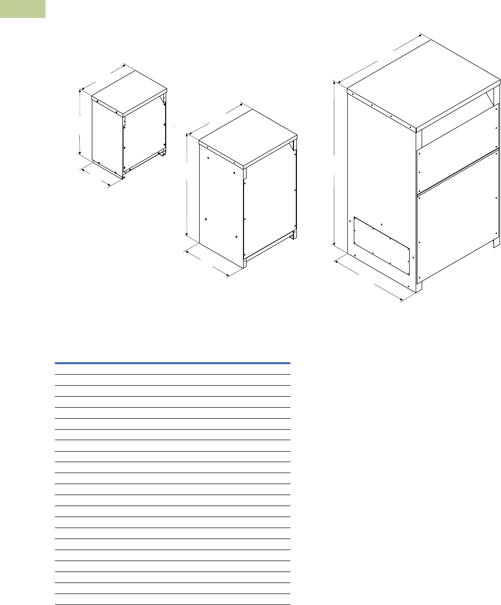
V2-T2-216 Volume 2—Commercial Distribution CA08100003E—July 2016 www.eaton.com
2
2
2
2
2
2
2
2
2
2
2
2
2
2
2
2
2
2
2
2
2
2
2
2
2
2
2
2
2
2
2.7
Trans for mers
Dimensions
Dimensions
Approximate Dimensions in Inches (mm)
Enclosure Dimensional Drawings—Ventilated Transformers
Drawing 3
Drawing 2
Drawing 1
Front
Left
Top
Outside
Length
Outside
Height
Outside
Width
Front
Left
Top
Outside
Width
Outside
Height
Outside
Length
Front
Left
Top
Outside
Width
Outside
Height
Outside
Length
Frame
Drawing
Number
Dimensions
Height Width Length
FR816 1 31.30 (795.0) 22.89 (581.4) 18.39 (467.2)
FR818 1 37.59 (954.8) 22.89 (581.4) 20.36 (517.1)
FR819 2 42.03 (1067.6) 24.22 (615.2) 23.84 (605.5)
FR820 2 42.03 (1067.6) 24.22 (615.2) 23.84 (605.5)
FR814 2 62.91 (1597.9) 29.97 (761.2) 33.97 (862.8)
FR842 1 33.75 (857.3) 22.45 (570.2) 17.40 (442.0)
FR843 1 38.70 (983.0) 23.51 (597.2) 24.38 (619.3)
FR844 2 44.92 (1141.0) 26.27 (667.3) 27.12 (688.8)
FR821 2 62.91 (1597.9) 29.97 (761.2) 33.97 (862.8)
FR912D, FR912D 1 30.00 (762.0) 23.00 (584.2) 16.50 (419.1)
FR914D/FR914F 1 39.00 (990.6) 29.00 (736.6) 22.00 (558.8)
FR915D/FR915F 1 39.00 (990.6) 29.00 (736.6) 22.00 (558.8)
FR916A 2 48.56 (1233.4) 28.22 (716.8) 23.42 (594.9)
FR917 2 56.17 (1426.7) 31.44 (798.6) 24.67 (626.6)
FR918A 2 62.18 (1579.4) 31.44 (798.6) 30.68 (779.3)
FR923 2 57.54 (1461.5) 36.69 (931.9) 32.65 (829.3)
FR924 2 68.37 (1736.6) 44.46 (1129.3) 36.44 (925.6)
FR928 2 56.16 (1426.5) 32.93 (836.4) 27.97 (710.4)
FR929 2 59.56 (1512.8) 36.72 (932.7) 32.50 (825.5)
FR919 3 75.00 (1905.0) 44.20 (1122.7) 36.23 (920.2)
FR920 3 75.00 (1905.0) 44.20 (1122.7) 36.23 (920.2)
FR922 3 90.00 (2286.0) 69.26 (1759.2) 42.65 (1083.3)
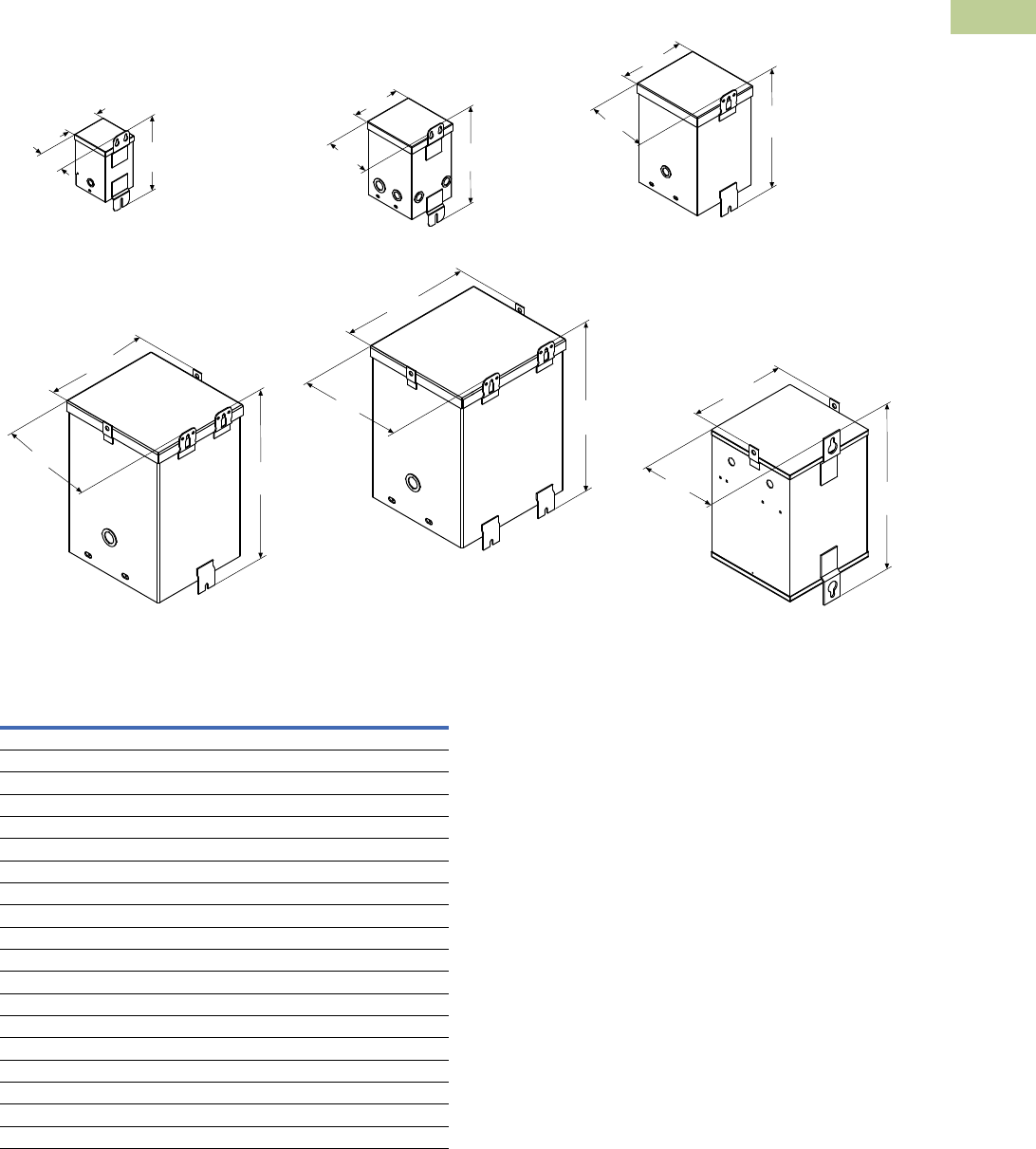
Volume 2—Commercial Distribution CA08100003E—July 2016 www.eaton.com V2-T2-217
2
2
2
2
2
2
2
2
2
2
2
2
2
2
2
2
2
2
2
2
2
2
2
2
2
2
2
2
2
2
2.7
Trans for mers
Dimensions
Approximate Dimensions in Inches (mm)
Enclosure Dimensional Drawings—Encapsulated Transformers (Type EP)
Right
Top
Drawing 10
Top
Back
Right
Drawing 11
Top
Back
Right
Drawing 6
Top
Right Back
Drawing 7
Top
Right Back
Drawing 8
Top
Right Back
Drawing 9
Outside
Width
Outside
Length
Outside
Height
Outside
Width
Outside
Length
Outside
Height
Outside
Width
Outside
Length
Outside
Height
Outside
Width
Outside
Length Outside
Height
Outside
Width
Outside
Length
Outside
Height
Outside
Width
Outside
Length
Outside
Height
Back
Frame
Drawing
Number
Dimensions
Height Width Length
FR52 6 8.91 (226.3) 4.11 (104.4) 4.00 (101.6)
FR54 6 8.91 (226.3) 4.11 (104.4) 4.00 (101.6)
FR55 6 8.91 (226.3) 4.11 (104.4) 4.00 (101.6)
FR56 7 8.97 (227.8) 4.87 (123.7) 4.06 (103.1)
FR57 7 8.97 (227.8) 4.87 (123.7) 4.91 (124.7)
FR58A 7 11.28 (286.5) 5.99 (152.1) 5.75 (146.1)
FR59A 7 11.28 (286.5) 5.99 (152.1) 5.75 (146.1)
FR67 7 13.41 (340.6) 6.37 (161.8) 6.52 (165.6)
FR68 7 13.41 (340.6) 6.37 (161.8) 6.52 (165.6)
FR176 8 14.25 (361.9) 7.69 (195.3) 8.00 (203.2)
FR177 9 16.00 (406.4) 10.38 (263.7) 9.89 (251.2)
FR301 11 22.26 (565.4) 12.71 (322.8) 12.79 (324.9)
FR178 9 16.00 (406.4) 10.38 (263.7) 9.89 (251.2)
FR302 11 25.26 (641.6) 12.71 (322.8) 12.79 (324.9)
FR304 11 25.26 (641.6) 14.72 (373.9) 14.82 (376.4)
FR179 9 19.00 (482.6) 13.38 (339.9) 10.52 (267.2)
FR180 9 19.00 (482.6) 13.38 (339.9) 10.52 (267.2)
FR182 10 23.31 (592.1) 16.35 (415.3) 14.12 (358.6)
FR190 10 26.31 (668.3) 16.35 (415.3) 14.12 (358.6)
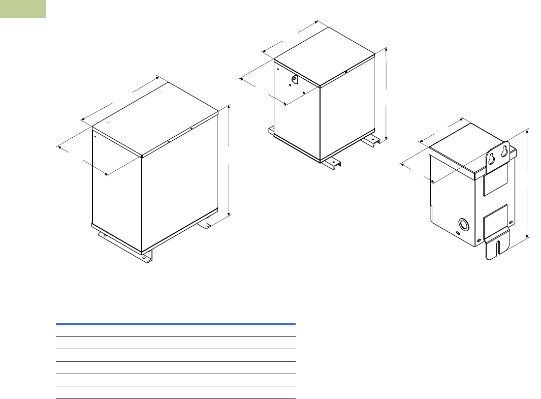
V2-T2-218 Volume 2—Commercial Distribution CA08100003E—July 2016 www.eaton.com
2
2
2
2
2
2
2
2
2
2
2
2
2
2
2
2
2
2
2
2
2
2
2
2
2
2
2
2
2
2
2.7
Trans for mers
Dimensions
Approximate Dimensions in Inches (mm)
Enclosure Dimensional Drawings—Encapsulated Transformers Type EP (Single-Phase), continued
Front
Left
Top
Drawing 13
Front
Left
Top
Drawing 12
Top
Back
Right
Drawing 14
Outside
Width
Outside
Length
Outside
Height
Outside
Width
Outside
Length Outside
Height
Outside
Width
Outside
Length
Outside
Height
Frame
Drawing
Number
Dimensions
Height Width Length
FR132 13 20.67 (525.0) 19.02 (483.1) 13.59 (345.2)
FR300A 12 28.24 (717.3) 22.42 (569.5) 14.06 (357.1)
FR57P 14 9.34 (237.2) 4.45 (113.0) 5.18 (131.6)
FR58AP 14 11.68 (296.7) 4.99 (126.7) 5.99 (152.1)
FR567P 14 13.03 (330.9) 5.74 (145.8) 6.56 (166.6)
FR568P 14 13.78 (350.0) 6.22 (158.0) 6.32 (160.5)
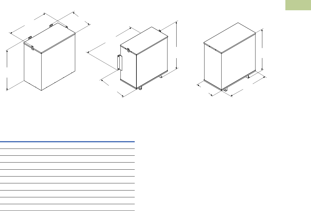
Volume 2—Commercial Distribution CA08100003E—July 2016 www.eaton.com V2-T2-219
2
2
2
2
2
2
2
2
2
2
2
2
2
2
2
2
2
2
2
2
2
2
2
2
2
2
2
2
2
2
2.7
Trans for mers
Dimensions
Approximate Dimensions in Inches (mm)
Enclosure Dimensional Drawings—Encapsulated Transformers (Type EPT)
Front
Drawing 15 Drawing 16 Drawing 17
Left Front
Left
Top
Front
Left
Top
Outside
Width
Outside
Length
Outside
Height
Outside
Length
Top
Outside
Width
Outside
Width
Outside
Length
Outside
Height
Outside
Height
Frame
Drawing
Number
Dimensions
Height Width Length
FR201 15 13.40 (340.4) 15.93 (404.6 8.26 (209.8)
FR102 15 13.12 (333.2) 19.59 (497.6) 7.09 (180.1)
FR103 15 15.90 (403.9) 16.93 (430.0) 10.01 (254.3)
FR200 15 15.90 (403.9) 16.93 (430.0) 10.01 (254.3)
FR97 15 15.19 (385.8) 25.68 (652.3) 8.38 (212.9)
FR95 15 17.38 (441.5) 20.00 (508.0) 10.52 (267.2)
FR243 16 17.38 (441.5) 20.00 (508.0) 10.52 (267.2)
FR96 15 16.19 (411.2) 29.68 (753.9) 9.42 (239.3)
FR244 16 28.15 (715.0) 26.58 (675.1) 14.66 (372.4)
FR245 17 32.06 (814.3) 30.29 (769.4) 15.68 (398.3)
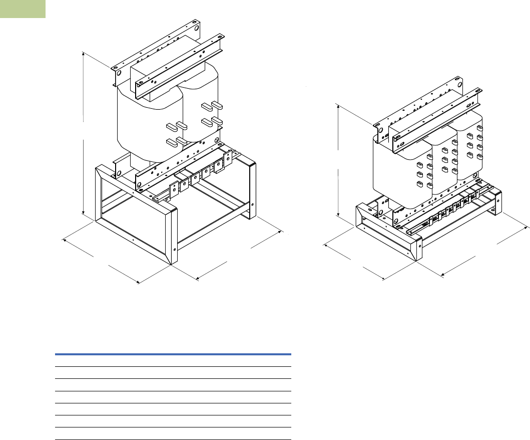
V2-T2-220 Volume 2—Commercial Distribution CA08100003E—July 2016 www.eaton.com
2
2
2
2
2
2
2
2
2
2
2
2
2
2
2
2
2
2
2
2
2
2
2
2
2
2
2
2
2
2
2.7
Trans for mers
Dimensions
Approximate Dimensions in Inches (mm)
Enclosure Dimensional Drawings—Core-Coil Transformers
Top
Top
Outside
Height
Outside
Length
Outside
Width
Left
Front
Left
Front
Drawing 4 Drawing 5
Outside
Height
Outside
Length
Outside
Width
Frame
Drawing
Number
Dimensions
Height Width Length
FR817C 4 39.28 (997.7) 21.62 (549.1) 19.51 (495.6)
FR818C 4 39.28 (997.7) 21.62 (549.1) 19.51 (495.6)
FR912C 5 24.75 (628.7) 19.50 (495.3) 14.00 (355.6)
FR914C 5 29.37 (746.0) 25.12 (638.0) 19.00 (482.6)
FR915C 5 31.38 (1067.6) 25.12 (638.0) 19.00 (482.6)
FR9516C 5 41.43 (1052.3) 25.12 (638.0) 20.00 (508.0)
FR916AC 5 43.40 (1102.4) 27.22 (691.4) 22.82 (579.6)
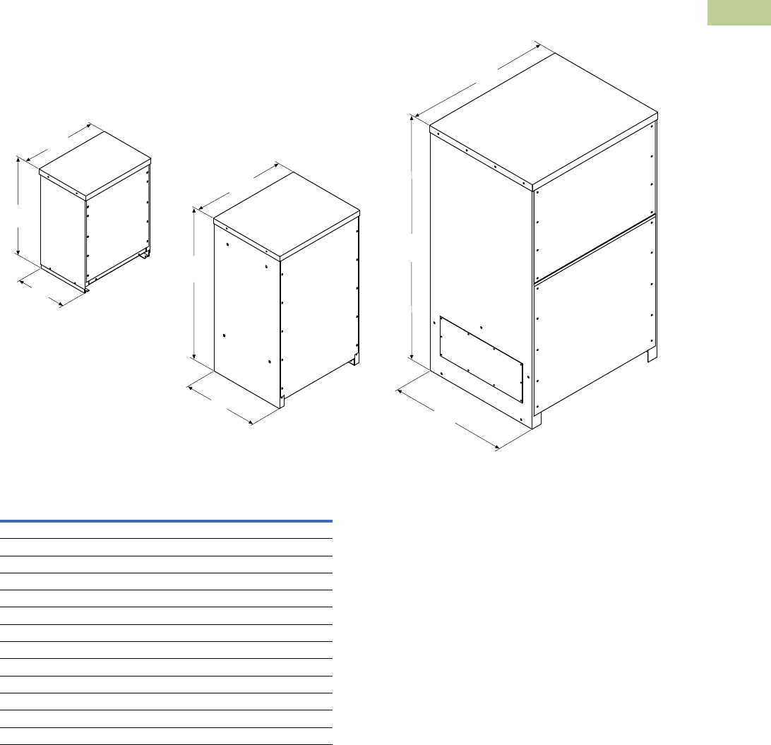
Volume 2—Commercial Distribution CA08100003E—July 2016 www.eaton.com V2-T2-221
2
2
2
2
2
2
2
2
2
2
2
2
2
2
2
2
2
2
2
2
2
2
2
2
2
2
2
2
2
2
2.7
Trans for mers
Dimensions
Approximate Dimensions in Inches (mm)
Enclosure Dimensional Drawings—Totally Enclosed Nonventilated Transformers
Front
Left
Top
Front
Left
Top
Front
Left
Top
Outside
Width
Outside
Length
Outside
Height
Outside
Width
Outside
Width
Outside
Height
Outside
Height
Outside
Length
Outside
Length
Drawing 28
Drawing 27
Drawing 26
Frame
Drawing
Number
Dimensions
Height Width Length
FR818N 26 37.59 (954.8) 22.89 (581.4) 20.36 (517.1)
FR819N 27 42.03 (1067.6) 24.22 (615.2) 23.84 (605.5)
FR820N 27 42.03 (1067.6) 24.22 (615.2) 23.84 (605.5)
FR814N 27 62.91 (1597.9) 29.97 (761.2) 33.97 (862.8)
FR912DN 26 30.00 (762.0) 23.00 (584.2) 16.50 (419.1)
FR914DN/FR914FN 26 39.18 (995.2) 29.00 (736.6) 22.00 (558.8)
FR915DN/FR915FN 26 39.18 (995.2) 29.00 (736.6) 22.00 (558.8)
FR916AN 27 46.58 (1183.1) 28.22 (716.8) 23.42 (594.9)
FR917N 27 56.18 (1427.0) 31.44 (798.6) 24.67 (626.8)
FR918AN 27 62.18 (1579.4) 31.44 (798.6) 30.68 (779.3)
FR923N 27 57.50 (1460.5) 36.69 (931.9) 32.65 (829.3)
FR919N 28 75.00 (1905.0) 44.21 (1122.9) 36.23 (920.2)
FR920N 28 75.00 (1905.0) 44.21 (1122.9) 36.23 (920.2)
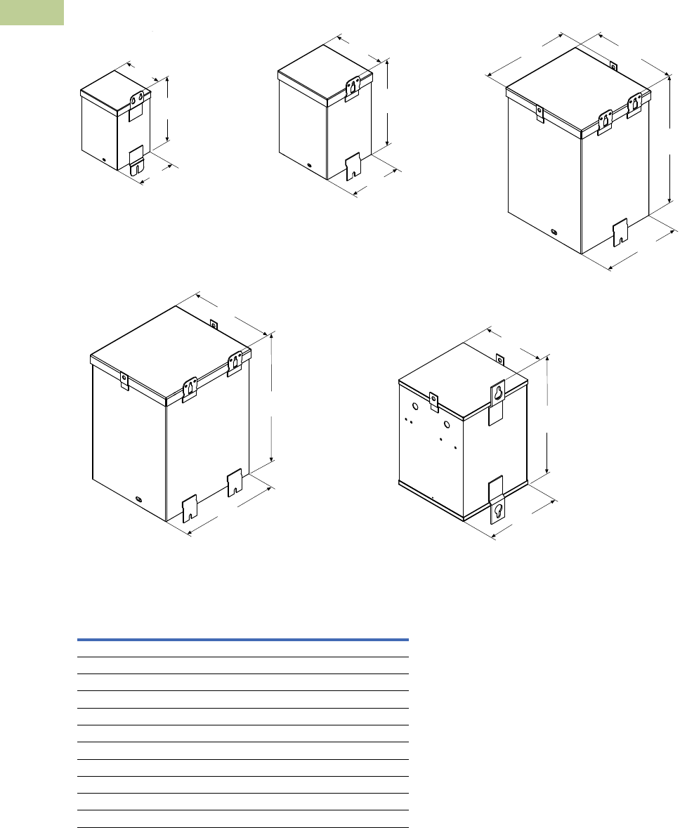
V2-T2-222 Volume 2—Commercial Distribution CA08100003E—July 2016 www.eaton.com
2
2
2
2
2
2
2
2
2
2
2
2
2
2
2
2
2
2
2
2
2
2
2
2
2
2
2
2
2
2
2.7
Trans for mers
Dimensions
Approximate Dimensions in Inches (mm)
Enclosure Dimensional Drawings—Hazardous Location Transformers (Type EPZ)
Back
Right
Top
Drawing 24
Outside
Width
Outside
Length
Outside
Height
Top
Back
Right
Drawing 25
Outside
Width
Outside
Length
Outside
Height
Top
Drawing 23
Back
Right
Outside
Width
Outside
Length
Outside
Height
Outside
Width
Top
Back
Right
Drawing 22
Outside
Length
Outside
Height
Outside
Width
Top
Back
Right
Drawing 21
Outside
Length
Outside
Height
Outside
Width
Frame
Drawing
Number
Dimensions
Height Width Length
FR57H 21 8.97 (227.8) 4.87 (123.7) 4.91 (124.7)
FR58H 22 11.28 (286.5) 5.99 (152.1) 5.75 (146.1)
FR59H 22 11.28 (286.5) 5.99 (152.1) 5.75 (146.1)
FR67H 22 13.41 (340.6) 6.37 (161.8) 6.52 (165.6)
FR68H 22 13.41 (340.6) 6.37 (161.8) 6.52 (165.6)
FR176H 23 14.25 (361.9) 7.69 (195.3) 8.00 (203.2)
FR177H 24 16.00 (406.4) 10.38 (263.7) 9.89 (251.2)
FR178H 24 16.00 (406.4) 10.38 (263.7) 9.89 (251.2)
FR179H 24 19.00 (482.6) 13.38 (339.9) 10.52 (267.2)
FR180H 24 19.00 (482.6) 13.38 (339.9) 10.52 (267.2)
FR182H 25 23.31 (592.1) 16.35 (415.3) 14.12 (358.6)
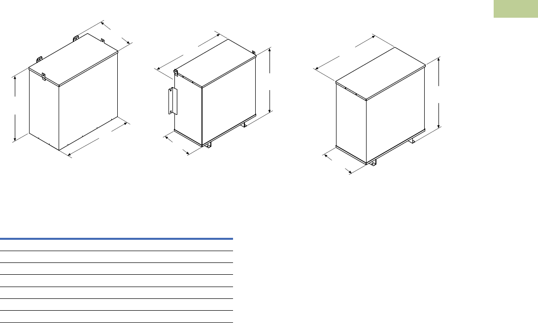
Volume 2—Commercial Distribution CA08100003E—July 2016 www.eaton.com V2-T2-223
2
2
2
2
2
2
2
2
2
2
2
2
2
2
2
2
2
2
2
2
2
2
2
2
2
2
2
2
2
2
2.7
Trans for mers
Dimensions
Approximate Dimensions in Inches (mm)
Enclosure Dimensional Drawings—Hazardous Location Transformers (Type EPTZ)
Front
Left
Top
Front
Left
Top
Front
Drawing 18 Drawing 19 Drawing 20
Left
Top
Outside
Width
Outside
Length
Outside
Height
Outside
Length
Outside
Length
Outside
Width Outside
Width
Outside
Height Outside
Height
Frame
Drawing
Number
Dimensions
Height Width Length
FR201H 18 13.40 (340.4) 15.93 (404.6) 8.26 (209.8)
FR200H 18 15.90 (403.9) 16.93 (430.0) 10.01 (254.3)
FR103H 18 15.90 (403.9) 16.93 (430.0) 10.01 (254.3)
FR95H 18 17.38 (441.5) 20.00 (508.0) 10.52 (267.2)
FR243H 19 17.38 (441.5) 20.00 (508.0) 10.52 (267.2)
FR244H 19 28.15 (715.0) 26.58 (675.1) 14.66 (372.4)
FR245H 20 32.06 (814.3) 30.29 (769.4) 15.68 (398.3)
