Brochure
2016-10-06
: Pdf 145613-Brochure 145613-Brochure B5 unilog
Open the PDF directly: View PDF ![]() .
.
Page Count: 424 [warning: Documents this large are best viewed by clicking the View PDF Link!]
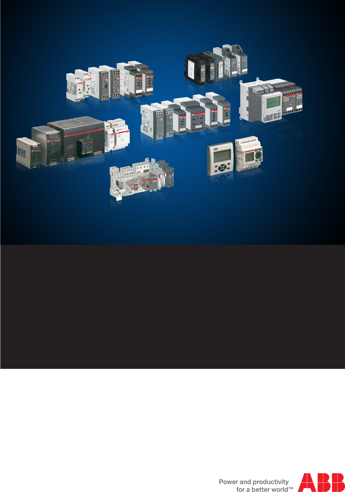
Catalog 2015
Electronic Products and Relays
Catalog | March 2015
2 ABB | Catalog Electronic Products and Relays 2015 | 2CDC 110 004 C0210
2CDC 110 004 C0210 | Catalog Electronic Products and Relays 2015 | ABB 3
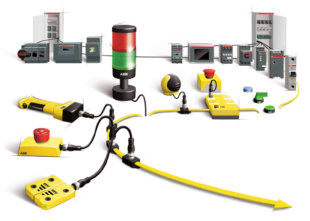
Machine Safety
Jokab Safety products
Productivity and safety go hand in hand
Jokab Safety was acquired by ABB in 2010. This gives us extra strength and a sales network in 120 countries. Our goal is to become
even better at supporting you as a customer through cooperation within ABB Jokab Safety globally and locally. The fact that the leading
power and automation technology company, ABB, and a leader in machine safety, Jokab Safety, have joined forces means a lot more
than just a new organizational chart. ABB has a huge footprint in the industry - from power supply to the control of each individual motor
- and has been delivering reliable solutions for decades that boost productivity in the industry. The acquisition of Jokab Safety means
the last building block is in place. We can now offer our customers tailored, turnkey solutions where machine safety is an integral and
value-enhancing component.
Jokab Safety offering:
–Safety PLC
Pluto, Pluto AS-i, Gateways, Safe Encoder
–Safety controller
Vital and Tina safety systems
–Safety relays
RT series, JSB series, safety timers, expansion relays
–Light curtains, light grids, light beams and scanner
Focus II, Spot, Look
–Sensors, switches and locks
Eden, Sense, MKey, Magne, Dalton, Knox
–Control devices
JSHD4, Safeball, Fox2
–Emergency stop devices
Inca, Smile, EStrong, LineStrong
–Contact rails, bumpers and safety mats
–Fencing systems
Quick-Guard, SafeCad, Roller doors
Further information: „ABB Safety Handbook“ - Order code: 2TLC172001C0202
4 ABB | Catalog Electronic Products and Relays 2015 | 2CDC 110 004 C0210
Electronic Products and Relays
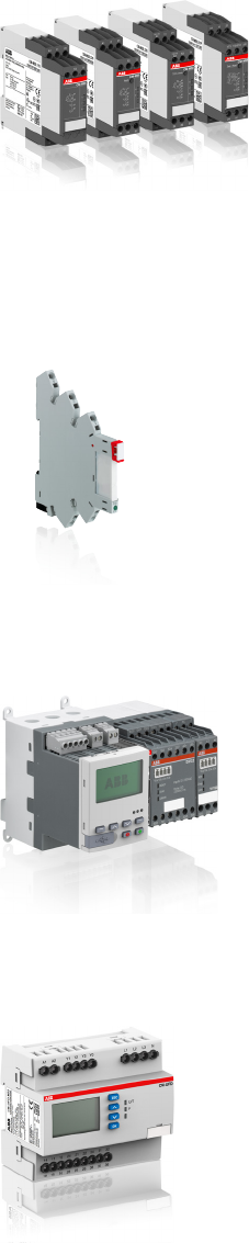
News
Universal Motor Controller UMC100.3 now available
The intelligent ABB Motor Controllers for motor protection, motor control, fieldbus and Eth-
ernet communication and fault diagnosis. Due to the benefits it provides, the UMC is used
worldwide in many segments and in Projects with several thousand motor controllers. Beside
the proven UMC100 the new UMC100.3 offers even more capabilities like 24 V DC or
110-220 V AC/DC supply voltage and fieldbus communication interfaces.
CR-S Range pluggable small interface relays
The pluggable interface relays of the CR-S Range are used for electrical isolation, amplifica-
tion and signal matching between the electronic controlling, e.g. PLC, iPC or field bus systems
and the sensor / actuator level. The CR-S Range combines the flexibility of a modular system
and the ability of switching high currents on a small footprint thus can be used in applications
where space saving is essential.
Thermistor motor protection relays in new housing
The thermistor motor protection relays of the CM-MSS range monitor the winding temperature
of motors which have PTC temperature sensors installed. These sensors are incorporated in
the motor windings thus measuring the motor heat directly. This direct temperature measure-
ment enables the thermistor motor protection relays to evaluate various motor conditions such
as overheating, overload and insufficient cooling. Depending on the product also the ATEX
approval is available for the use in hazardous areas.
The new housing provides two different connection terminals: The proven double-chamber
cage connection terminals and the Easy Connect Technology with Push-in terminals.
Grid feeding monitoring relays from the CM-UFD.Mx range
The multifunctional grid feeding monitoring relays of the CM-UFD range are designed to moni-
tor several grid parameters when feeding energy into the public grid. The intention is to trip a
section switch which is connected between the distributed generation and the public grid in
order to disconnect the distributed generation in case of problems (e.g. unstable grid), faults or
maintenance on the grid. Different monitoring functions such as 10-minutes average value, real
time over- and undervoltage as well as over- and underfrequency are configurable via the front
face display.
– CM-UFD.M22:
Third party certificate confirming accordance with
CEI 0-21: 2012-06 + CEI
0-21; V1: 2012-12 + A70 Terna
– CM-UFD.M31: Third party certificate confirming accordance with VDE-AR-N 4105: 2011-08;
BDEW, June 2008 “Technische Richtlinie – Erzeugungsanlagen am Mittelspannungsnetz”
including supplementary provisions of January 2013
– CM-UFD.M33: Factory certificate
confirming accordance with
Engineering Recommendation
G59 Issue 3 - September 2013; Engineering Recommendation G83 Issue 2 - December 2012

2CDC 110 004 C0210 | Catalog Electronic Products and Relays 2015 | ABB 5
1
5
3
7
2
6
4
Electronic Products and Relays
Table of contents
Electronic timers 1/1
Measuring and monitoring relays 2/1
Primary switch mode power supplies 3/1
Analog signal converters, serial data converters 4/1
Interface relays and optocouplers 5/1
Logic relays 6/1
Index 7/1

6 ABB | Catalog Electronic Products and Relays 2015 | 2CDC 110 004 C0210
Approvals and marks for the world market
Overview
ABB low-voltage switching devices are developed and produced in accordance with the applicable regulations as stated in the international IEC publica-
tions, the European EN specifications and the national VDE standards.
In most countries, low-voltage switching devices are produced according to such regulations under the responsibility of the manufacturers. This is why the
devices are not subject to further approval. However, for those devices which are intended for use in household or for public use our customers can reque-
st test reports of our internal laboratory for presentation to the various qualified local organizations. In other countries, approvals are prescribed by law.
For devices installed in ships, an approval issued by independent shipping companies, such as the GL, are demanded by the maritime insurance
companies.
Marks of conformity and examples of approvals (device-dependent)
International
CB scheme K
The CB (Certification Body) Scheme is a
system designed to facilitate international
trade by establishing mutual acceptance
of test reports among participating safety
certification organizations (the National Cer-
tification Bodies) in more than 30 countries.
The CB Scheme was established by the
International
Electrotechnical Committee for Conformity
Testing to Standards for Electrical
Equipment (IECEE).
Europe
Conformité Européen (CE) a
All devices which comply with the European
low voltage directive and which are intended
for sale within the European Union must
have the CE sign applied. All products in this
catalog are CE marked.
The CE sign must not be confused with a
certificate of quality issued by the EU. It is
solely used to confirm that the respective
product complies with the applicable
European directives *). The CE sign is part
of an administrative procedure to guarantee
free movement of goods within the Europe-
an Community.
*) Directives:
Low Voltage Directive 2006/95/EC
EMC Directive 2004/108/EC
Machinery Directive 98/37/EEC
Verband der Elektrotechnik
Elektronik Informationstechnik
(VDE) J
Applicable for technical instruments covered
by the German Gerätesicherheitsgesetz
(GSG) as well as for single parts and electri-
cal wiring devices.
Berufsgenossenschaft
der Feinmechanik und
Elektrotechnik (BGFE) M
The BG-PRÜFZERT sign is a voluntary
safety mark, awarded by the BGFE following
successful safety testing.
Explosion protection (EX) I
Explosion protection acc. to
Directive 94/9/EG (ATEX 100a)
Swiss insurance institution
(SUVA) Q
Department accident prevention suvaPRO
Germanischer Lloyd (GL) C
Shipping approval
Lloyds Register P
Shipping approval
Russia
In Russia, low-voltage switching devices are
subject to certification and have to be provi-
ded with a sign.
Eurasian Conformity R
EAC certification is mandatory for many pro-
ducts. This certification is based on a safety
test (IEC standards with Russia-
specific deviations) and an EMC test.
Russian Maritime Register of
Shipping RMRS L
Shipping approval
Australia, New Zealand
C-Tick Mark b
The C-Tick Mark certifies compliance with
the Australian EMC requirements. The Mark
is also recognized in New Zealand.
China
CCC (China Compulsory
Certification) E
In China the CCC certification mark is a
compulsory certification mark in the field of
safety and quality for products sold on the
Chinese market.
North America
Canadian and US standards are more or
less equivalent but considerably differ from
the IEC and VDE regulations.
USA
Underwriters Laboratories (UL)
Listing B
Released for installation in systems and for
sale as individual component in the USA.
Recognition G
Released for installation in systems, if the
respective system has been completely
mounted and wired by qualified personnel.
Canada
Canadian Standards
Association (CSA) F
USA and Canada
The combined UL signs for the USA and
Canada are recognized by the authorities of
both countries. Devices with this certificate
meet the requirements of both countries.
Listing A
Recognition H
2CDC 110 004 C0210 | Catalog Electronic Products and Relays 2015 | ABB 7
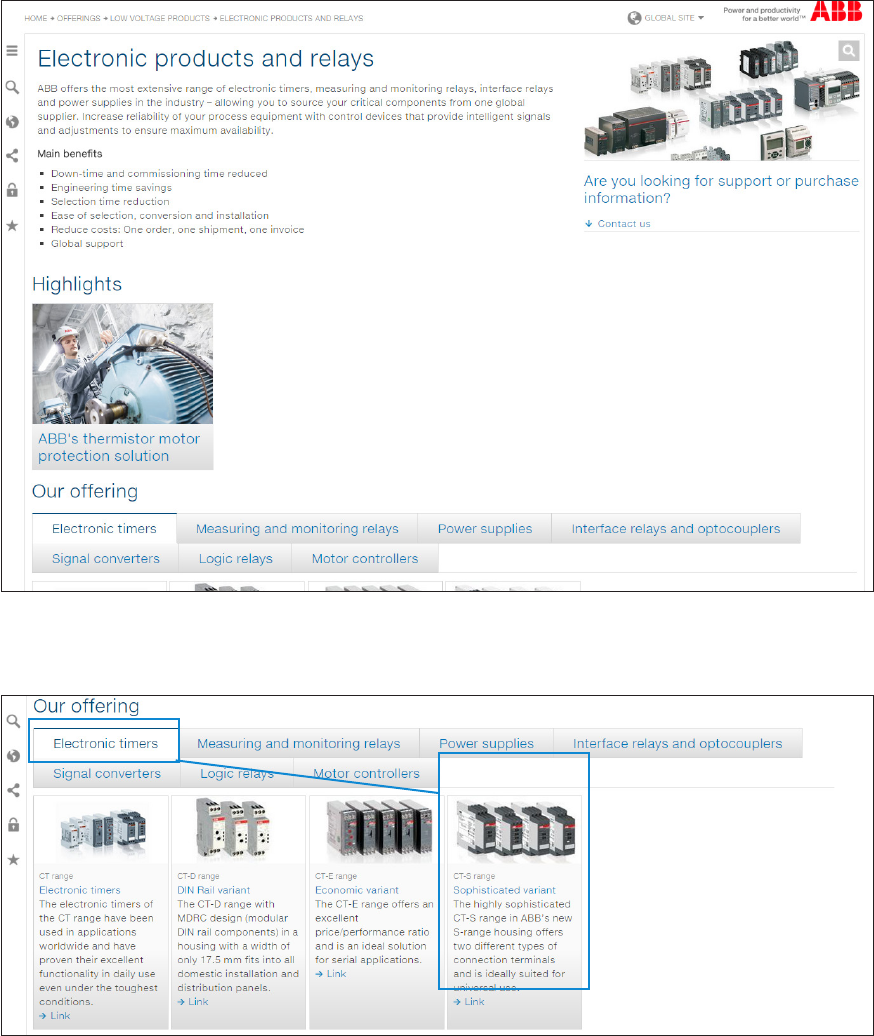
Find Electronic Products and Relays product information and
documentation on our web page
The following steps will guide you to the documentation and product search section of the Electronic Products and Relays portfolio on www.ABB.com.
Enter http://new.abb.com/low-voltage/products/epr in your internet browser.
You will be redirected to the following page:
Latest information about the Electronic Products and Relays product range could be found in the Highlights section.
In the lower area of the web page you can find the Our offering section.
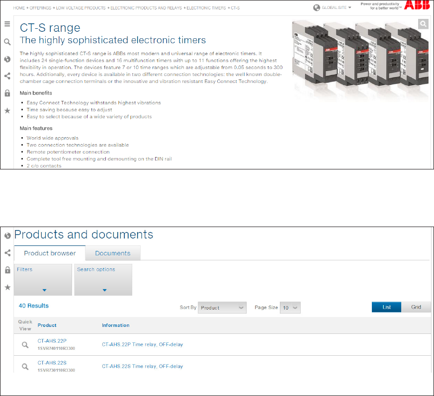
The assortment of the Electronic Products and Relays range is listed here as shown in the screenshot below:
Select the register of the relevant product group to see all the products related to the product group.
Choose a product range from which you want to see the documentation or from which you want to choose a specific product.
In this example the CT-S range from the register Electronic timers has been selected as shown on the screenshot.
8 ABB | Catalog Electronic Products and Relays 2015 | 2CDC 110 004 C0210
Find Electronic Products and Relays product information and
documentation on our web page
You will be redirected to the following page:
Latest information about the Electronic Products and Relays product range could be found in the Highlights sections.
In the lower area of the web page you can find the Products and documents section.
The functions to choose a product or a document are listed here as in the screenshot below:
To search for a product continue on page 9.
To search for documentation continue on page 10.
2CDC 110 004 C0210 | Catalog Electronic Products and Relays 2015 | ABB 9
Find Electronic Products and Relays product information and
documentation on our web page
How to find the right product
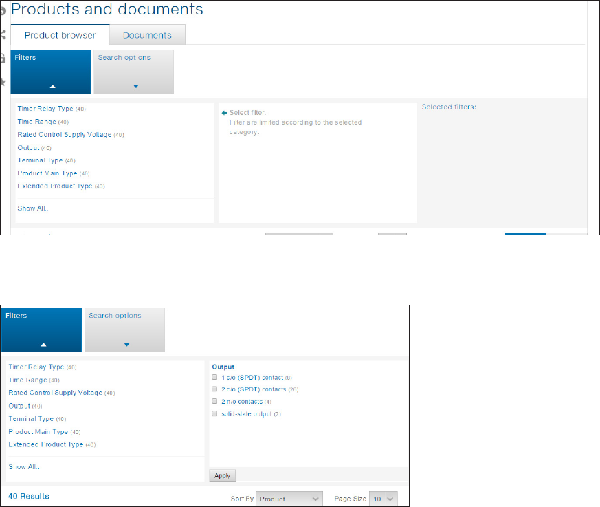
Click on Filters to see the different search attributes for the selected product range.
The filter section will be expanded as shown below.
The different product filters are shown.
Click on the filter attribute to continue the product search process.
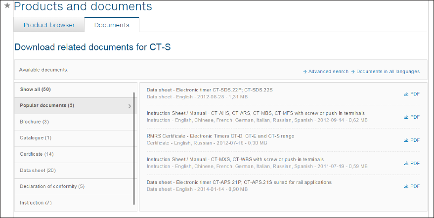
In this example Output has been chosen.
In the right part mark the corresponding check box to narrow down the search. You can also select several check boxes.
Click on Apply to submit your filter.
The search results are now listed according to your selection.
Proceed this approach with different filters until the right product is listed.
Click on the product in the Result section to get the dedicated product information listed in your browser.
10 ABB | Catalog Electronic Products and Relays 2015 | 2CDC 110 004 C0210
Find Electronic Products and Relays product information and
documentation on our web page
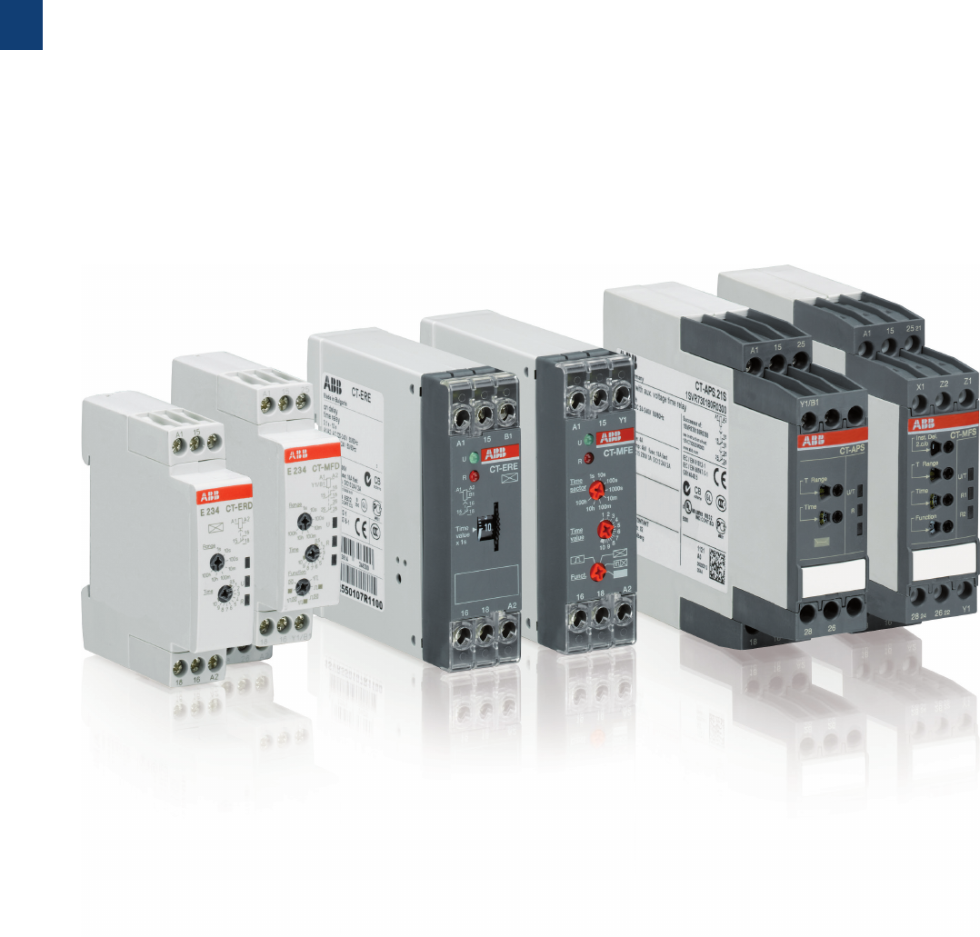
How to find the right documentation
Click on Documents to see the different types of documentation for the product.
The document section will be expanded as shown below.
On the left side select the type of document related to the product. In the example Popular documents has been selected.
In the right area click on the document related to the product.
The document is opened or downloaded, depending on the individual browser settings.

2CDC 110 004 C0210 | Catalog Electronic Products and Relays 2015 | ABB 11
EPR Catalog 2015
Notes
1/1 ABB | Catalog Electronic Products and Relays 2015 | 2CDC 110 004 C0210
1
Electronic timers
Product group picture

2CDC 110 004 C0210 | Catalog Electronic Products and Relays 2015 | ABB 1/2
1
Electronic timers
Table of contents
Electronic timers
Table of contents 1/2
Overview 1/3
Approvals and marks 1/4
CT-D range 1/5
Table of contents 1/6
Benefits and advantages 1/7
Ordering details 1/8
Function diagrams 1/9
Connection diagrams 1/12
Technical data 1/13
Technical data, Technical diagrams 1/15
Wiring notes, Dimensional drawings 1/16
CT-E range 1/17
Table of contents 1/18
Benefits and advantages 1/19
Ordering details 1/20
Function diagrams 1/22
Connection diagrams 1/27
Connection diagrams, Technical diagrams 1/28
Technical data 1/29
Wiring notes, Dimensional drawings 1/31
CT-S range 1/33
Table of contents 1/34
Benefits and advantages 1/35
Ordering details - multifunctional 1/37
Ordering details - singlefunctional 1/38
Ordering details - Accessories 1/39
Function diagrams 1/41
Connection diagrams 1/49
Technical data 1/52
Technical diagrams 1/55
Wiring notes, Dimensional drawings 1/56
1/3 ABB | Catalog Electronic Products and Relays 2015 | 2CDC 110 004 C0210
1
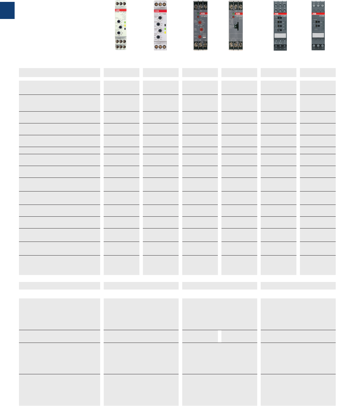
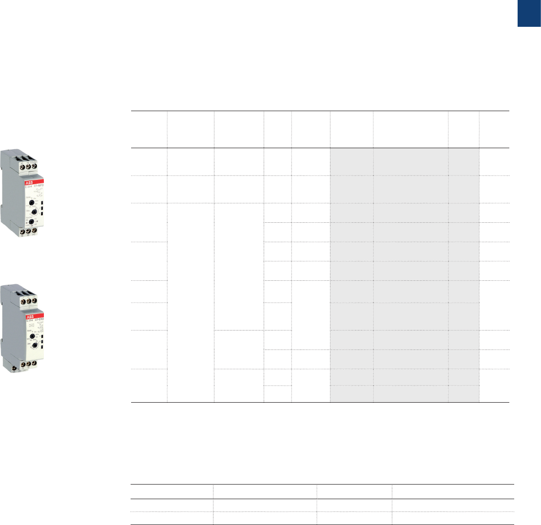
CT-S rangeCT-E rangeCT-D range
Timing function
multifunctional single-functional multifunctional single-functional multifunctional single-functional
A ON-delay CT-MFD CT-ERD CT-MFE,
CT-MKE CT-ERE,
CT-EKE
CT-MVS, CT-MFS,
CT-MBS, CT-WBS
CT-ERS
B OFF-delay CT-MFD CT-AHD CT-MFE CT-AHE,
CT-ARE,
CT-AKE
CT-MVS, CT-MFS,
CT-MBS
CT-APS,
CT-AHS,
CT-ARS
AB ON- and OFF-delay
CT-MVS, CT-MXS,
CT-MFS, CT-MBS
CA Impulse-ON CT-MFD CT-VWD CT-MFE,
CT-MKE CT-VWE
CT-MVS, CT-MFS,
CT-MBS, CT-WBS
CB Impulse-OFF CT-MFD CT-AWE
CT-MVS, CT-MFS,
CT-MBS
CE Impulse-ON and OFF
CT-MXS
DA Flasher starting with ON CT-MFD CT-EBD CT-MFE,
CT-MKE
CT-MFS, CT-MBS,
CT-WBS
DB Flasher staring with OFF CT-MFD CT-MFE,
CT-MKE CT-EBE
CT-MFS, CT-MBS,
CT-WBS
DE Flasher starting with ON or
OFF
CT-MVS
ED Pulse generator starting with
ON or OFF
CT-TGD
CT-MXS
H Pulse former CT-MFD CT-MFE
CT-MVS, CT-MFS,
CT-MBS
F Star-delta change-over CT-SDD,
CT-SAD CT-SDS
FC Star-delta change-over with
impulse
CT-SDE
CT-MVS.2x,
CT-MFS, CT-MBS
FA Star-delta change-over
twice ON-delayed
CT-YDE
A+ AC BC G
further functions
(depending on device)
CT-MVS, CT-MXS,
CT-MFS, CT-MBS,
CT-WBS
Technical data (extract)
Time ranges 7 (0.05 s - 100 h)
CT-SDD, CT-SAD:
4 (0.05 s - 10 min)
Multifunction devices:
8 (0.05 s - 100 h)
Single-function devices:
5 single ranges (0.05-1 s, 0.1-10 s,
0.3-30 s, 3-300 s, 0.3-300 min)
10 (0.05 s - 300 h)
CT-ARS, CT-SDS:
7 (0.05 s- 10 min)
Control supply voltage Wide and multi ranges Wide ranges Single and dual
ranges
Wide, multi and single ranges
Type and number of contacts 1 or 2 c/o contacts
CT-SDD, CT-SAD: 2 n/o contacts
1 c/ o contact
CT-SDE: 1 n/o contact and 1 n/c
contact
CT-MKE, CT-EKE, CT-AKE: 1 thyristor
1 or 2 c/o contacts
CT-MVS.21, CT-MFS, CT-MBS:
2nd c/o contact selectable as inst.
contact
CT-SDS: 2 n/o contacts
Control inputs voltage-related triggering,
polarized, capable of switching a
parallel load
voltage-related triggering, polarized
CT-MFE, CT-AHE, CT-AWE:
with auxiliary voltage
voltage-related triggering, non-
polarized, capable of switching a
parallel load
CT-MFS, CT-MBS, CT-AHS:
volt-free triggering
Electronic timers
Overview
2CDC 110 004 C0210 | Catalog Electronic Products and Relays 2015 | ABB 1/4
1
Electronic timers
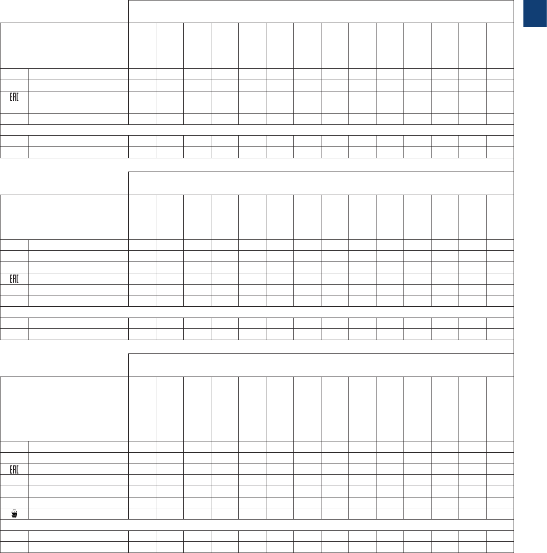
Approvals and marks
J existing
j pending
CT-D
Approvals
CT-MFD.12
CT-MFD.21
CT-ERD.12
CT-ERD .22
CT-AHD.12
CT-AHD.22
CT-VWD.12
CT-EBD.12
CT-TGD.12
CT-TGD.22
CT-SDD.22
CT-SAD.22
A
UL 508, CAN/CSA C22.2 No.14
JJJJJJJJJJJJ
KCB scheme J J J J J J
EAC JJJJJJJJJJJJ
ECCC JJJJJJJJJJJJ
LRMRS JJJJJJJJJJ
Marks
aCE JJJJJJJJJJJJ
bC-Tick JjJjJjJJJjjj
J existing
j pending
CT-E
Approvals
CT-MFE
CT-ERE
CT-AHE
CT-ARE
CT-VWE
CT-AWE
CT-EBE
CT-YDE
CT-SDE
CT-MKE
CT-EKE
CT-AKE
A
UL 508, CAN/CSA C22.2 No.14
JJJJJJJJJJJJ
CGL JJJJJJJJJJJJ
KCB scheme JJJJJJJJJ
EAC JJJJJJJJJJJJ
ECCC JJJJJJJJJ
LRMRS JJJJJJJJJJJJ
Marks
aCE JJJJJJJJJJJJ
bC-Tick JJJJJJJJJJJJ
J existing
j pending
CT-S
Approvals
CT-MVS.12S/P
CT-MVS.2xS/P
CT-MXS.22S/P
CT-MFS.21S/P
CT-MBS.22S/P
CT-WBS.22S/P
CT-ERS.12S/P
CT-ERS.2xS/P
CT-APS.12S/P
CT-APS.2xS/P
CT-AHS.22S/P
CT-ARS.11S/P
CT-ARS.21S/P
CT-SDS.2xS/P
A
UL 508, CAN/CSA C22.2 No.14
JJJJJJJJJJJJJJ
CGL JJJJJJJJJJJjjJ
EAC JJJJJJJJJJJJJJ
KCB scheme JJJJJJJJJJJJJJ
ECCC JJJJJJJJJJJJJJ
LRMRS JJJJJJJJJJJJJJ
Rail applications 1) J J J J J J
Marks
aCE JJJJJJJJJJJJJJ
bC-Tick JJJJJJJJJJJJJJ
1) Applicable in rail application following the latest standards for rail applications. Further information are available in our rail segment brochure 2CDC110084B0201.
1/5 ABB | Catalog Electronic Products and Relays 2015 | 2CDC 110 004 C0210
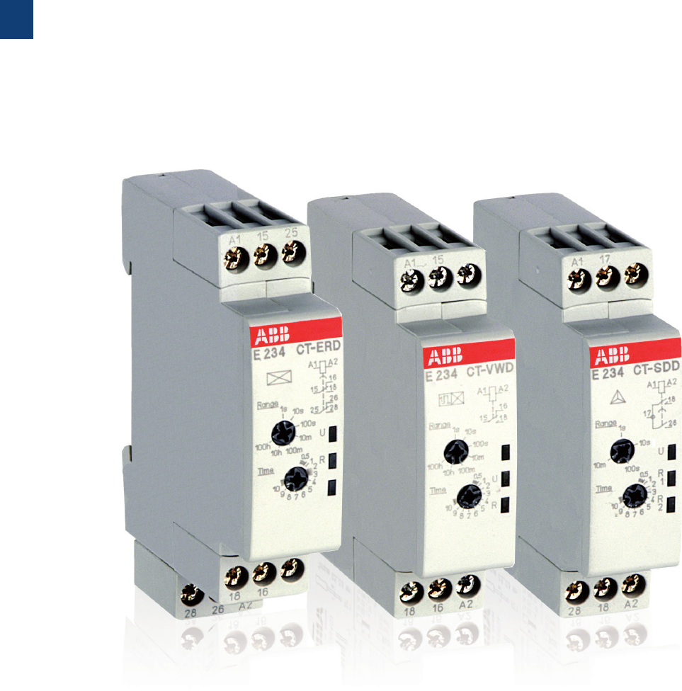
1
CT-D range
Product group picture

2CDC 110 004 C0210 | Catalog Electronic Products and Relays 2015 | ABB 1/6
1
CT-D range
Table of contents
CT-D Range
Benefits and advantages 1/7
Ordering details 1/8
Function diagrams 1/9
Connection diagrams 1/12
Technical data 1/13
Technical data, Technical diagrams 1/15
Wiring notes, Dimensional drawings 1/16
1/7 ABB | Catalog Electronic Products and Relays 2015 | 2CDC 110 004 C0210
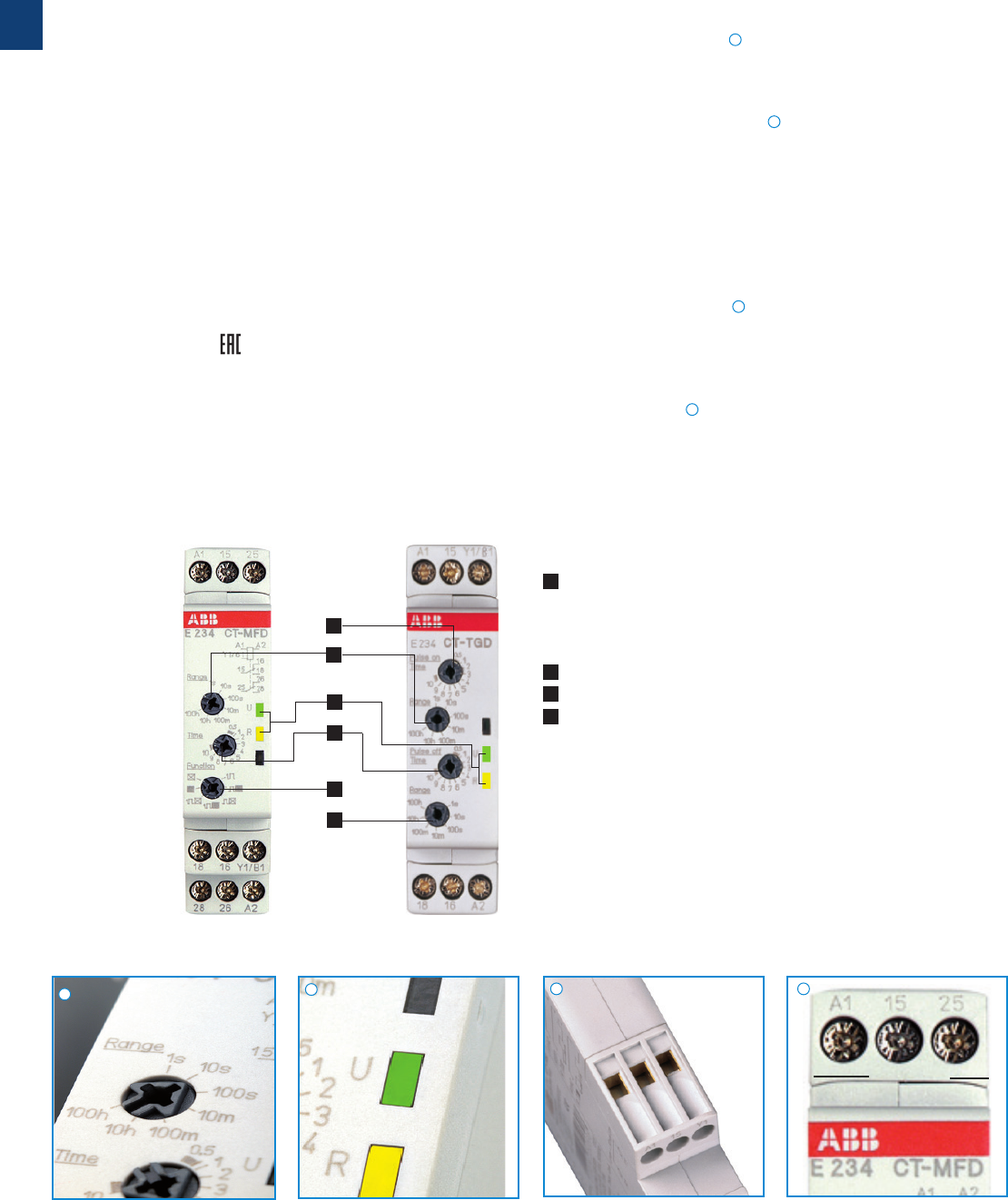
1
CT-D range
Benefits and advantages
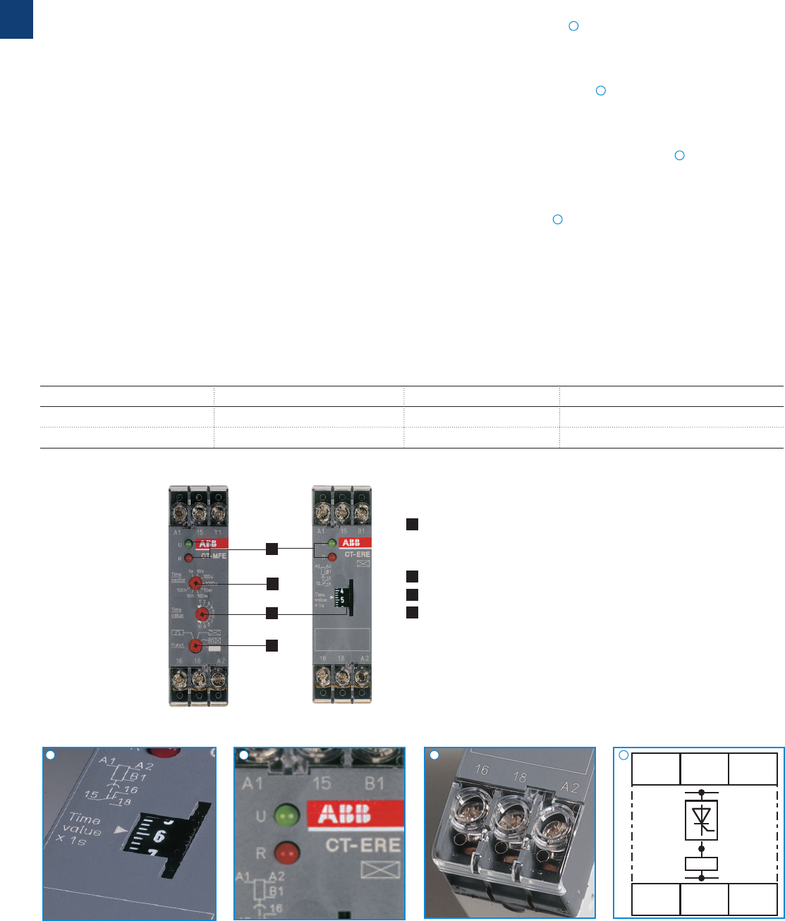
Operating controls
1 LEDs for status indication
U - green LED: V control supply voltage applied
W timing
R, R1, R2 - yellow LED: V output relay energized
2 Time range adjustment
3 Fine adjustment of the time delay
4 Preselection of the timing function
multifunctional single-functional
Direct reading scales
Direct setting of the time delay without any additional
calculation provides accurate time delay adjustment.
LEDs for status indication
All actual operational states are displayed by front-face LEDs,
thus simplifying commissioning and troubleshooting.
Switching currents
The CT-D range timers allow an output load of up to 6 A on
devices with 1 c/o contact and up to 5 A on devices with
2c/o contacts.
Connection terminals
Wide terminal spacing allows connection of wires:
2 x 1.5 mm² (2 x 16 AWG) with wire end ferrules or 2 x 2.5
mm² (2 x 14 AWG) without ferrules.
Width 17.5 mm
With their width of 17.5 mm only, the CT-D range timers are
ideally suited for installation in distribution panels.
17.5 mm
Characteristics
– Diversity:
– 2 multifunction timers
– 10 single-function timers
– Control supply voltages:
– Wide range: 12-240 V AC/DC
– Multi range: 24-48 V DC, 24-240 V AC
– 7 time ranges from 0.05 s to 100 h or
4 time ranges from 0.05 s to 10 min
– Width of only 17.5 mm
– Light-grey housing in RAL 7035
– Devices with:
1 c/o contact (250 V / 6 A) or 2 c/o contacts (250 V / 5 A)
Control input: voltage-related triggering, polarized,
capable of switching parallel loads
– Approvals / Marks (partly pending, details see page 1/4)
– A, K1), E, , L / a, b
1) Only for devices with 1 c/o (SPDT) contact
Benefits
4
2
3
1
2
3
2CDC 253 066 F0006
2CDC 253 132 F0006
2CDC 253 033 F0004
2CDC 253 021 F0004
1
1
2
2
3
3
4
4
2CDC 110 004 C0210 | Catalog Electronic Products and Relays 2015 | ABB 1/8
1
Synonyms
used expression alternative expression(s) used expression alternative expression(s)
1 c/o contact SPDT voltage-related wet / non-floating
2 c/o contacts DPDT volt-free dry / floating
2CDC 251 089 F0006
2CDC 251 091 F0006
CT-MFD.12
CT-ERD.22
A ON-delay
B OFF-delay
CA Impulse-ON
CB Impulse-OFF
DA Flasher starting with ON
DB Flasher staring with OFF
H Pulse former
ED Pulse generator
F Star-delta change-over
CT-D range
Ordering details
1) Functions: ON-delay, OFF-delay with auxiliary voltage, Impulse-ON, Impulse-OFF with auxiliary voltage,
Flasher starting with ON, Flasher starting with OFF, Pulse former
2) ON and OFF times adjustable independently: 2 x 7 time ranges 0.05 s - 100 h
3) Transition time 50 ms fixed
4) Transition time adjustable
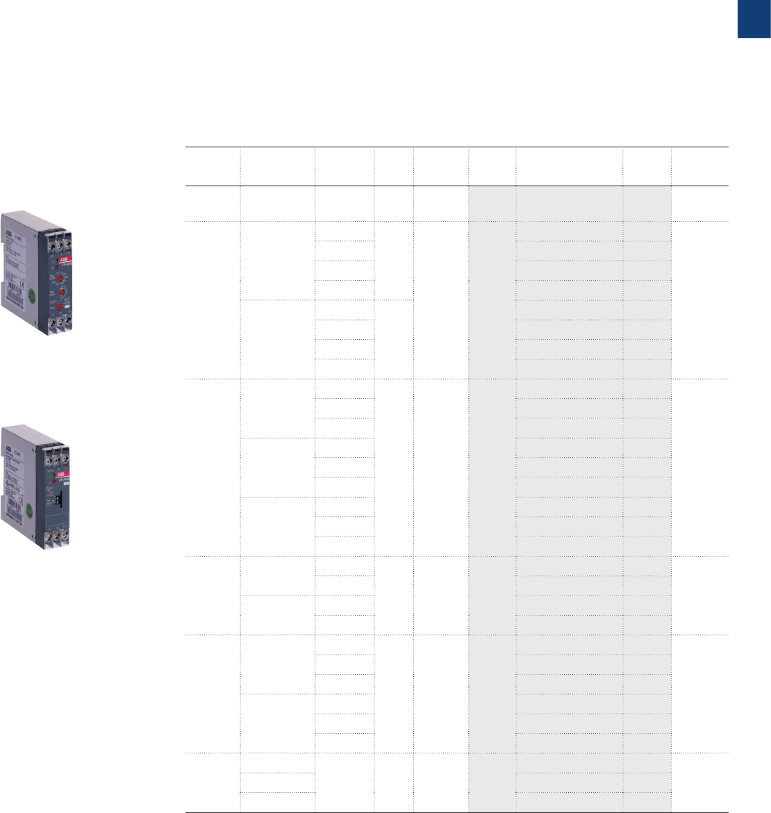
Description
The CT-D range in MDRC design with a width of only 17.5 mm fits into all domestic installation
and distribution panels.
The CT-D range represents a link between industry and the installation types. For maximum
flexibility in operation, 10 single-function as well as 2 multifunction devices with 7 timing
functions are available. The devices offer 4 or 7 time ranges from 0.05 seconds up to 100
hours. Their wide input range allows the use in applications worldwide.
Ordering details
Timing
function
Rated
control
supply
voltage
Time ranges Con-
trol
input
Output Type Order code Price
1 pce
Weight
(1 pce)
kg (lb)
Multifunc-
tional1)
24-240 V AC
24-48 V DC
7 (0.05 s -
100 h) M1 c/o CT-MFD.12 1SVR500020R0000 0.060
(0.132)
Multifunc-
tional1)
12-240
VAC/DC
7 (0.05 s -
100 h) M2 c/o CT-MFD.21 1SVR500020R1100 0.065
(0.14 3)
ON-delay
24-240 V AC
24-48 V DC
7 (0.05 s -
100 h)
-1 c/o CT-ERD.12 1SVR500100R0000 0.060
(0.132)
-2 c/o CT-ERD.22 1SVR500100R0100 0.065
(0.14 3)
OFF-delay
M1 c/o CT-AHD.12 1SVR500110R0000 0.060
(0.132)
M2 c/o CT-AHD.22 1SVR500110R0100 0.065
(0.14 3)
Impulse-
ON -
1 c/o
CT-V W D.12 1SVR500130R0000
0.060
(0.132)
Flasher
starting
with ON
-CT-EBD.12 1SVR500150R0000
Pulse
generator
2×7 (0.05 s -
100 h)
M
CT-TGD.12
2) 1SVR500160R0000 0.060
(0.132)
M2 c/o
CT-TGD.22
2) 1SVR500160R0100 0.065
(0.14 3)
Star-delta
change-
over
4 (0.05 s -
10min)
-
2 c/o
CT-SDD.22
3) 1SVR500211R0100 0.065
(0.14 3)
-
CT-SAD.22
4) 1SVR500210R0100
M
Control input with voltage-related triggering
- no triggering
1/9 ABB | Catalog Electronic Products and Relays 2015 | 2CDC 110 004 C0210
1Remarks
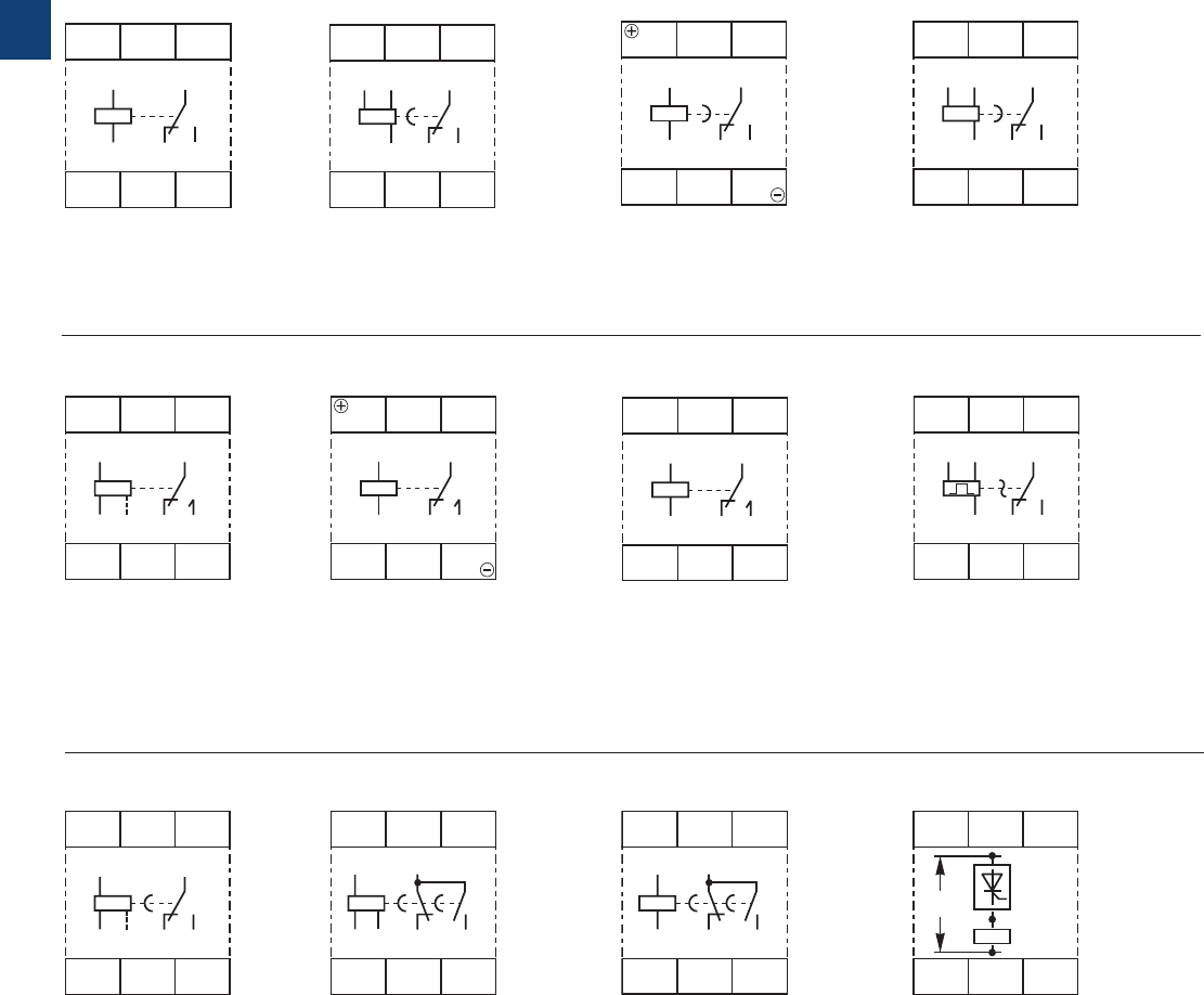
Legend
G Control supply voltage not applied / Output contact open
B Control supply voltage applied / Output contact closed
A1-Y1/B1 Control input with voltage-related triggering
Terminal designations on the device and in the diagrams
The 1st c/o contact is always designated 15-16/18.
The 2nd c/o contact is designated 25-26/28.
The n/o contacts of the star-delta timers are designated with
17-18 and 17-28.
Control supply voltage is always applied to terminals A1-A2.
Function of the yellow LED
The yellow LED R glows as soon as the output relay
energizes and turns off when the output relay de-energizes.
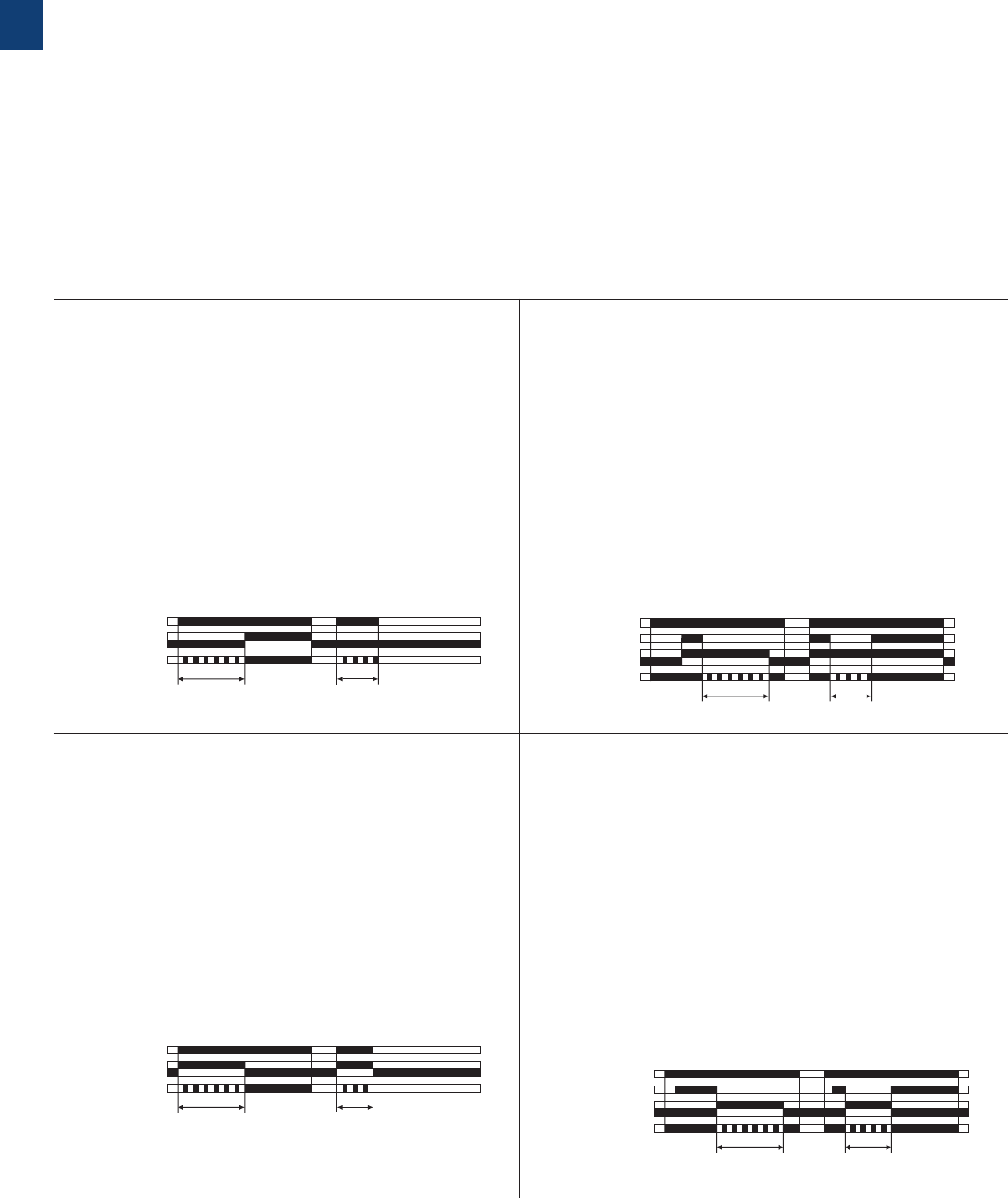
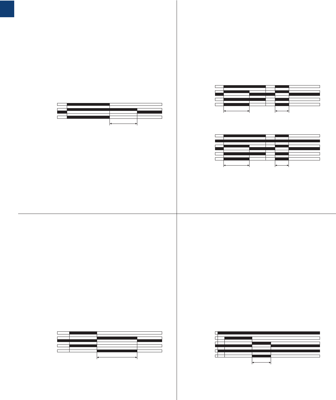
A ON-delay (Delay on make)
CT-ERD, CT-MFD
B OFF-delay with auxiliary voltage (Delay on break)
CT-AHD, CT-MFD
This function requires continuous control supply voltage for
timing.
Timing begins when control supply voltage is applied.
The green LED flashes during timing. When the selected
time delay is complete, the output relay energizes and the
flashing green LED turns steady.
If control supply voltage is interrupted, the output relay de-
energizes and the time delay is reset.
Control input A1-Y1/B1 of the CT-MFD is disabled when this
function is selected.
This function requires continuous control supply voltage for
timing. If control input A1-Y1/B1 is closed, the output relay
energizes immediately. If control input A1-Y1/B1 is opened,
the time delay starts. The green LED flashes during timing.
When the selected time delay is complete, the output relay
de- energizes and the flashing green LED turns steady.
If control input A1-Y1/B1 recloses before the time delay is
complete, the time delay is reset and the output relay does
not change state. Timing starts again when control input
A1-Y1/B1 re-opens.If control supply voltage is interrupted,
the output relay de-energizes and the time delay is reset.
A1-A2
15-16, 25-26
15-18, 25-28
t< t
2CDC 252 106 F0206
green LED
t = adjusted time delay
A1-A2
15-16, 25-26
15-18, 25-28
t
A1-Y1/B1
< t
2CDC 252 107 F0206
green LED
t = adjusted time delay
CT-D range
Function diagrams
CA Impulse-ON (Interval)
CT-VWD, CT-MFD
CB Impulse-OFF with auxiliary voltage
(Trailing edge interval)
CT-MFD
This function requires continuous control supply voltage for
timing. The output relay energizes immediately when control
supply voltage is applied and de-energizes after the set pulse
time is complete. The green LED flashes during timing. When
the selected pulse time is complete, the flashing green LED
turns steady. If control supply voltage is interrupted, the
output relay de-energizes and the time delay is reset. Control
input A1-Y1/B1 of the CT-MFD is disabled when this function
is selected.
This function requires continuous control supply voltage for
timing. If control supply voltage is applied, opening con-
trol input A1-Y1/B1 energizes the output relay immediately
and starts timing. The green LED flashes during timing.
When the selected pulse time is complete, the output relay
de-energizes and the flashing green LED turns steady.
Closing control input A1-Y1/B1, before the time delay is
complete, de-energizes the output relay and resets the time
delay. If control supply voltage is interrupted, the output
relay de-energizes and the time delay is reset.
A1-A2
15-16, 25-26
15-18, 25-28
t< t
2CDC 252 108 F0206
green LED
t = adjusted pulse time
A1-A2
15-16, 25-26
15-18, 25-28
t
A1-Y1/B1
< t
2CDC 252 109 F0206
green LED
t = adjusted pulse time
2CDC 110 004 C0210 | Catalog Electronic Products and Relays 2015 | ABB 1/10
1
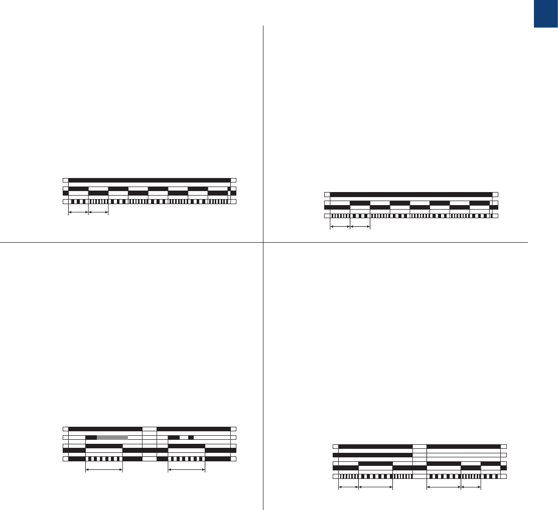
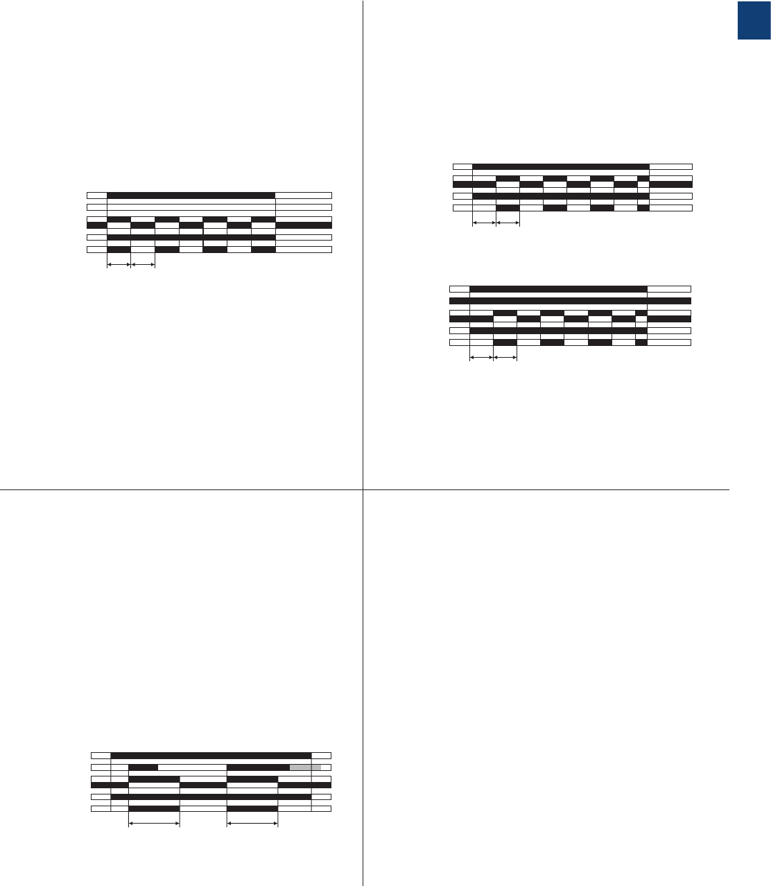
DA Flasher, starting with the ON time
(Recycling equal times, ON first)
CT-EBD, CT-MFD
DB Flasher, starting with the OFF time
(Recycling equal times, OFF first)
CT-MFD
Applying control supply voltage starts timing with symmetrical
ON & OFF times. The cycle starts with an ON time first. The
ON & OFF times are displayed by the flashing green LED,
which flashes twice as fast during the OFF time.
If control supply voltage is interrupted, the output relay
de-energizes and the time delay is reset.
Control input A1-Y1/B1 of the CT-MFD is disabled when this
function is selected.
Applying control supply voltage starts timing with symmetrical
ON & OFF times. The cycle starts with an OFF time first. The
ON & OFF times are displayed by the flashing green LED,
which flashes twice as fast during the OFF time.
If control supply voltage is interrupted, the output relay
de-energizes and the time delay is reset.
Control input A1-Y1/B1 of the CT-MFD is disabled when this
function is selected.
A1-A2
15-16, 25-26
15-18, 25-28
t t
2CDC 252 029 F0206
green LED
t = adjusted flashing time
A1-A2
15-16, 25-26
15-18, 25-28
t t
2CDC 252 030 F0206
green LED
t = adjusted flashing time
CT-D range
Function diagrams
H Pulse former (Single shot)
CT-MFD
E Pulse generator, starting with the ON or OFF time
(Recycling unequal times, ON or OFF first)
CT-TGD
This function requires continuous control supply voltage for
timing.
Closing control input A1-Y1/B1 energizes the output relay
immediately and starts timing. Operating the control contact
switch A1-Y1/B1 during the time delay has no effect. The
green LED flashes during timing. When the selected ON time
is complete, the output relay de-energizes and the flashing
green LED turns steady. After the ON time is complete, it
can be restarted by closing control input A1-Y1/B1.
If control supply voltage is interrupted, the output relay
de-energizes and the time delay is reset.
This function requires continuous control supply voltage for
timing.
Applying control supply voltage, with open control input
A1-Y1/B1, starts timing with an ON time first. Applying
control supply voltage, with closed control input A1-Y1/B1,
starts timing with an OFF time first. The ON & OFF times are
displayed by the flashing green LED, which flashes twice as
fast during the OFF time.
The ON & OFF times are independently adjustable.
If control supply voltage is interrupted, the output relay
de-energizes and the time delay is reset.
A1-A2
15-16, 25-26
15-18, 25-28
tt
A1-Y1/B1
2CDC 252 110 F0206
green LED
t = adjusted pulse time
A1-A2
A1-Y1/B1
15-16, 25-26
15-18, 25-28
t1t1
t2t2
2CDC 252 111 F0206
green LED
t1 = adjusted OFF time
t2 = adjusted ON time
1/11 ABB | Catalog Electronic Products and Relays 2015 | 2CDC 110 004 C0210
1
K1T
K1T
K3
K3
YN
K2
K2
K2
L1
N
F3
F2
95
96
21
22
22
21
A1
A2
A1
A2
A1
A2
A1
A2
22
21
13
14
17
18
17
28
13
14
13
14
53
54
S1
0
I
S2
K1
K1
K1
2CDC 252 128 F0b0
6
-K1-K3
L1
-F1
1
2
95
96
97
98
L2
3
4
L3
5
6
1
2
3
4
5
6
1
2
3
4
5
6
-K2
-F2
1
2
3
4
5
6
1
3
5
2
4
6
M
3 ~
W2
V2
U2
W1
V1
U1
-M1
2CDC 252 012 F0b0
7
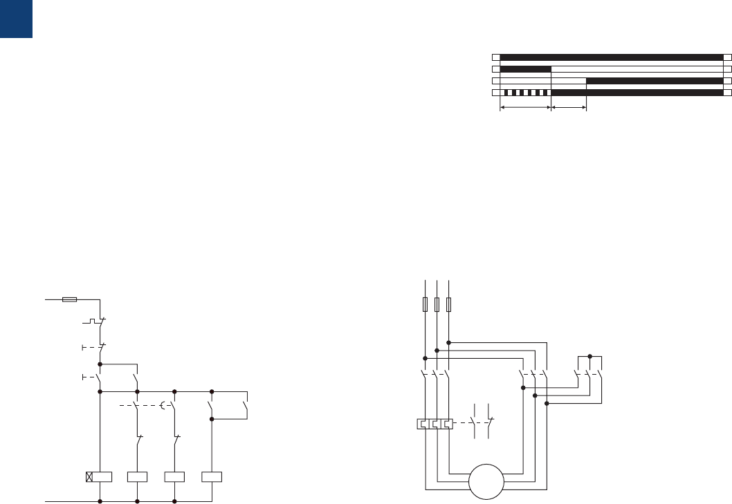
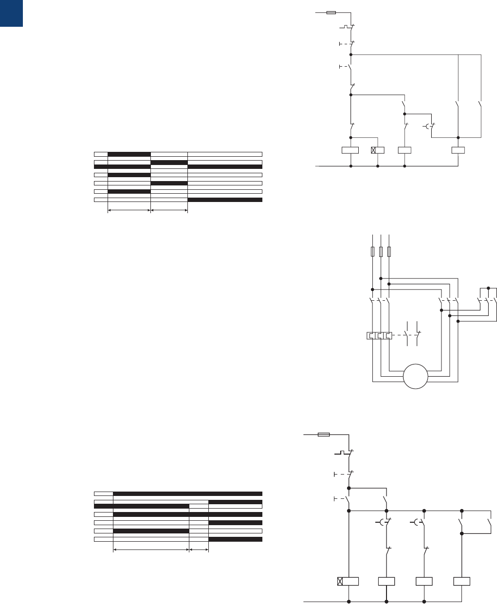
F Star-delta change-over
(Star-delta starting)
CT-SDD, CT-SAD
This function requires continuous control supply voltage for
timing.
Applying control supply voltage to terminals A1-A2,
energizes the star contactor connected to terminals 17-18
and begins the set starting time t1. The green LED flashes
during timing. When the starting time is complete, the first
output contact de-energizes the star contactor.
Now, the transition time t2 starts. When the transition time
is complete, the second output contact energizes the
delta contactor connected to terminals 17-28. The delta
contactor remains energized as long as control supply
voltage is applied to the unit.
A1-A2
t1t2
2CDC 252 112 F0206
green LED
t1 = adjusted starting time
t2 = transition time
CT-SDD: t2 = 50 ms
CT-SAD: t2 adjustable
17-18
17-28
Power circuit diagramControl circuit diagram
CT-D range
Function diagrams
2CDC 110 004 C0210 | Catalog Electronic Products and Relays 2015 | ABB 1/12
1
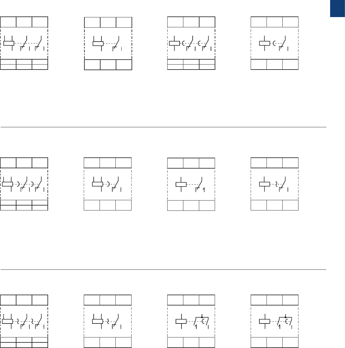
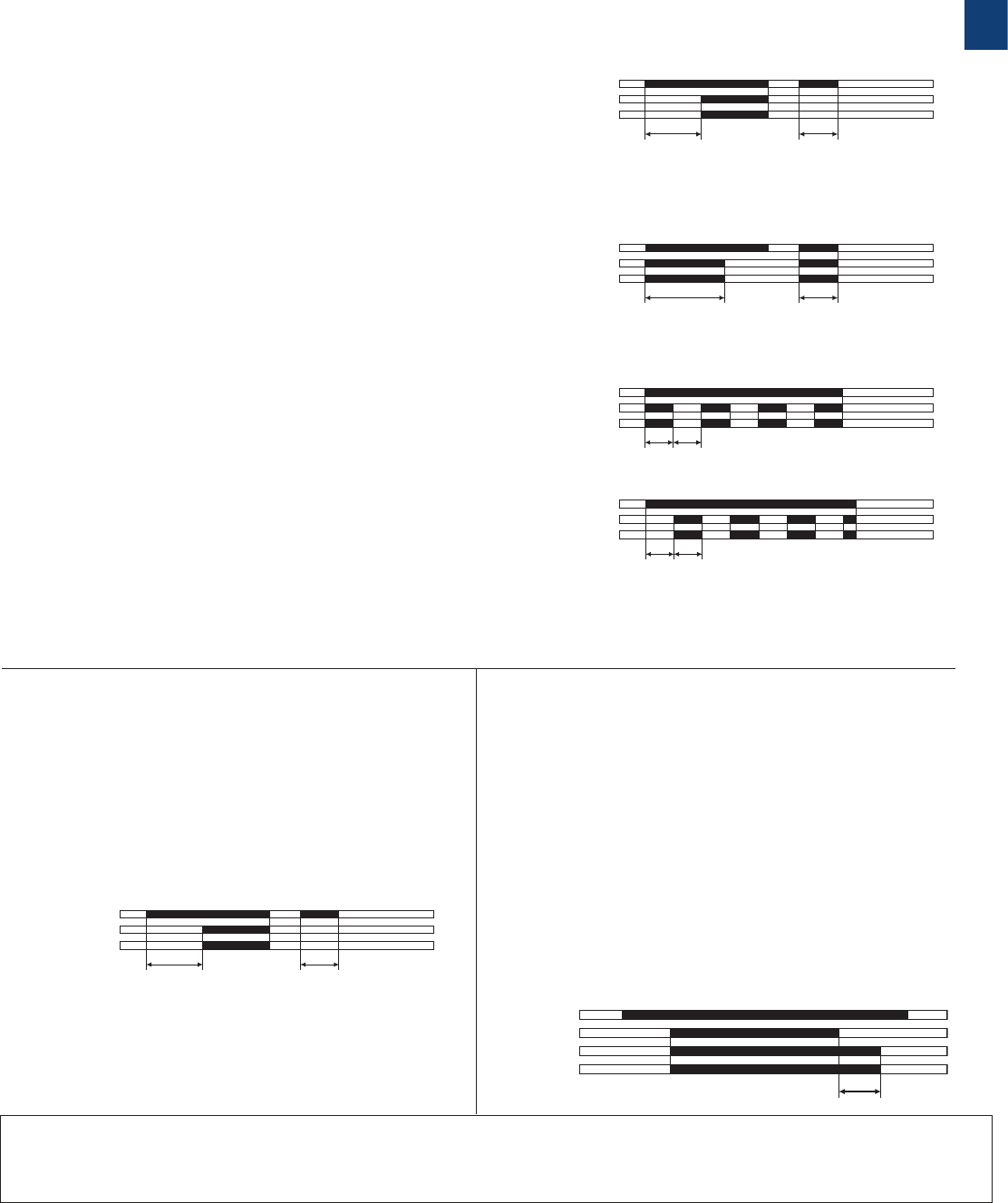
CT-MFD.21 CT-MFD.12 A CT-ERD.12
B CT-AHD.22
A1
A1
28
28
26
26
A2
18 16 Y1/B1
A2
15
25
1816
15
25
Y1/
B1
2CDC 252 113 F0b06
A1
A1
28
28
26
26
A2
18 16 Y1/B1
A2
15
25
1816
15
25
Y1/
B1
2CDC 252 116 F0b06
A1
A1
28
28
26
26
A2
18 16
A2
15 25
25
1816
15
2CDC 252 115 F0b06
A CT-ERD.22
B CT-AHD.12 CA CT-VWD.12 DA CT-EBD.12
ED CT-TGD.22
A1
A1
28
18
26
16
A2
18 16 Y1/B1
A2
15
15
2826
25
25
Y1/
B1
2CDC 252 118 F0b06
A1
A1
A2 18 28
17
17
28 18 A2
2CDC 252 160 F0b0
6
ED CT-TGD.12 F CT-SDD.22 F CT-SAD.22
A1
A1
18
18
16
16
A2
A2
15
15
Y1/B1
Y1/
B1
2CDC 252 114 F0b06
A1
A1
18
18
16
16
A2
A2
15
15
2CDC 252 177 F0b05
A1
A1
18
18
16
16
A2
A2
15
15
Y1/B1
Y1/
B1
2CDC 252 117 F0b06
A1
A1
18
18
16
16
A2
A2
15
15
2CDC 252 179 F0b05
A1
A1
18
18
16
16
A2
A2
15
15
2CDC 252 180 F0b0
5
A1
A1
18
18
16
16
A2
A2
15
15
Y1/B1
Y1/
B1
2CDC 252 119 F0b06
A1
A1
A2 18 28
17
17
28 18 A2
2CDC 252 160 F0b0
6
CT-D range
Connection diagrams
A1-A2 Supply:
12-240 V AC/DC
A1-Y1/B1 Control input
15-16/18 1. c/o contact
25-26/28 2. c/o contact
A1-A2 Supply:
24-48 V DC or
24-240 V AC
A1-Y1/B1 Control input
15-16/18 1. c/o contact
A1-A2 Supply:
24-48 V DC or
24-240 V AC
A1-Y1/B1 Control input
15-16/18 1. c/o contact
A1-A2 Supply:
24-48 V DC or
24-240 V AC
A1-Y1/B1 Control input
15-16/18 1. c/o contact
A1-A2 Supply:
24-48 V DC or
24-240 V AC
15-16/18 1. c/o contact
25-26/28 2. c/o contact
A1-A2 Supply:
24-48 V DC or
24-240 V AC
A1-Y1/B1 Control input
15-16/18 1. c/o contact
25-26/28 2. c/o contact
A1-A2 Supply:
24-48 V DC or
24-240 V AC
A1-Y1/B1 Control input
15-16/18 1. c/o contact
25-26/28 2. c/o contact
A1-A2 Supply:
24-48 V DC or
24-240 V AC
17-18 1. n/o contact
(star contactor)
17-28 2. n/o contact
(delta contactor)
A1-A2 Supply:
24-48 V DC or
24-240 V AC
17-18 1. n/o contact
(star contactor)
17-28 2. n/o contact
(delta contactor)
A1-A2 Supply:
24-48 V DC or
24-240 V AC
15-16/18 1. c/o contact
A1-A2 Supply:
24-48 V DC or
24-240 V AC
15-16/18 1. c/o contact
A1-A2 Supply:
24-48 V DC or
24-240 V AC
15-16/18 1. c/o contact

1/13 ABB | Catalog Electronic Products and Relays 2015 | 2CDC 110 004 C0210
1
CT-D range
Technical data
Data at Ta = 25 °C and rated values, unless otherwise indicated
CT-D with 1 c/o
contact
CT-D with 2 c/o
contacts
CT-MFD.21
Input circuit - Supply circuit
Rated control supply voltage Us24-240 V AC / 24-48 V DC 12-240 V AC/DC
Rated control supply voltage US tolerance -15...+10 %
Rated frequency DC or 50/60 Hz
Frequency range AC 47-63 Hz
Typical current / power consumption see data sheet
Power failure buffering time min. 20 ms
Release voltage > 10 % of the minimum rated control supply voltage Us
Input circuit - Control circuit
Control input, control function A1-Y1/B1 start timing external
Kind of triggering voltage-related triggering
Resistance to reverse polarity yes
Parallel load / polarized yes / yes
Maximum cable length to the control inputs 50 m - 100 pF/m
Minimum control pulse length 20 ms
Control voltage potential see rated control supply voltage
Current consumption of the control input see data sheet
Timing circuit
Time ranges 7 time ranges 0.05 s - 100 h 1.) 0.05-1 s 2.) 0.5-10 s 3.) 5-100 s 4.) 0.5-10 min
5.) 5-100 min 6.) 0.5-10 h 7.) 5-100 h
4 time ranges 0.05 s - 10 min (CT-SDD, CT-SAD) 1.) 0.05-1 s 2.) 0.5-10 s 3.) 5-100 s 4.) 0.5-10 min
Recovery time < 50 ms
Accuracy within the rated control supply voltage tolerance it < 0.005 % / V
Accuracy within the temperature range it < 0.06 % / °C
Repeat accuracy (constant parameters) it < ± 0.5 %
Setting accuracy of time delay IEC/EN 61812-1 ± 10% of full-scale value
Star-delta transition time CT-SDD / CT-SAD fixed 50 ms /
adjustable: 20 ms, 30 ms, 40 ms, 50 ms, 60 ms, 80 ms or 100 ms
Star-delta transition time tolerance CT-SDD / CT-SAD ±3 ms
Indication of operational states
Control supply voltage / timing U: green LED V: control supply voltage applied
W: timing
Relay energized (1 c/o contact /
2 c/o contacts or inst. contact) R: yellow LED V: output relay energized
Operating elements and controls
Adjustment of the time range front-face rotary switch, direct reading scales
Fine adjustment of the time value front-face potentiometer
Preselection of the timing function at multifunction devices front-face rotary switch, direct reading scales
Adjustment of the transition time CT-SAD front-face potentiometer
Output circuit
Kind of output 15-16/18 Relay, 1 c/o contact -
15-16/18; 25-26/28 -Relay, 2 c/o contacts
17-18; 17-28 Relay, 2 n/o contacts (CT-SDD, CT-SAD)
Contact material AgNi alloy, Cd free
Rated operational voltage Ue250 V
Minimum switching voltage / minimum switching current 12 V / 100 mA
Maximum switching voltage / maximum switching current 250 V AC / 6 A 250 V AC / 5 A
Rated operational current Ie
(IEC/EN 60947-5-1 ) AC-12 (resistive) at 230 V 6 A 5 A
AC-15 (inductive) at 230 V 3 A 3 A n/o: 3 A n/c: 0.75 A
DC-12 (resistive) at 24 V 6 A 5 A
DC-13 (inductive) at 24 V 2 A 2 A 1 A
AC rating (UL 508) utilization category (Control Circuit Rating Code) B 300 n/o: B 300 n/c: C 300
max. rated operational voltage 300 V AC
Maximum continuous thermal current at B300 5 A n/o: 5 A
Maximum continuous thermal current at C300 -n/c: 2.5 A
max. making/breaking apparent power at B300 3600 VA / 360 VA n/o: 3600/360 VA
max. making/breaking apparent power at C300 -n/c: 1800/180 VA
Mechanical lifetime 30 x 106 switching cycles
Electrical lifetime 0.1 x 10⁶ switching cycles
Max. fuse rating to achieve short-circuit protection
(IEC/EN 60947-5-1) n/c contact 6 A fast-acting
n/o contact 10 A fast-acting 6 A fast-acting

2CDC 110 004 C0210 | Catalog Electronic Products and Relays 2015 | ABB 1/14
1
CT-D range
Technical data
CT-D with 1 c/o
contact
CT-D with 2 c/o
contacts
CT-MFD.21
General data
Mean time between failures (MTBF) on request
Duty time 100%
Dimensions (W x H x D) 17.5 x 70 x 58 mm
(0.69 x 2.76 x 2.28 in) 17.5 x 80 x 58 mm
(0.69 x 3.15 x 2.28 in)
Weight see ordering details
Mounting DIN rail (IEC/EN 60715), snap-mounting without any tool
Mounting position any
Minimum distance to other units horizontal / vertical no / no
Degree of protection housing / terminals IP50 / IP20
Electrical connection
Wire size
fine-strand with(out) wire end ferrule
2 x 0.5-1.5 mm2 (2 x 20-16 AWG)
1 x 0.5-2.5 mm2 (1 x 20-14 AWG)
rigid 2 x 0.5-1.5 mm2 (2 x 20-16 AWG)
1 x 0.5-4 mm2 (1 x 20-12 AWG)
Stripping length 7 mm (0.28 in)
Tightening torque 0.5-0.8 Nm (4.43-7.08 lb.in)
Environmental data
Ambient temperature range operation / storage -20 ... +60 °C / -40 ... +85 °C
Climatic class IEC/EN 60068-2-30 3K3
Relative humidity range 25-85%
Shock (half-sine) IEC/EN 60068-2-27 150 m/s2, 11 ms
Isolation data
Rated impulse withstand voltage Uimp
between all isolated circuits IEC/EN 60664-1 type test: 4 kV; 1.2/50 µs
Pollution category IEC/EN 60664-1 3
Overvoltage category IEC/EN 60664-1 III
Rated insulation voltage Uiinput circuit / output circuit 300 V
output circuit 1 / output circuit 2 not available 300 V 300 V
Basic insulation (IEC/EN 61140) input circuit / output circuit 300 V
Protective separation
(IEC/EN 61140, EN 50178) input circuit / output circuit 250 V
Power-frequency withstand voltage test
(test voltage) between all isolated circuits routine test: 2.5 kV; 50 Hz; 1 s
type test: 2.5 kV; 50 Hz; 60 s
Standards
Product standard IEC/EN 61812-1
Low Voltage Directive 2006/95/EC
EMC Directive 2004/108/EC
RoHS Directive 2011/65/EC
Electromagnetic compatibility
Interference immunity to IEC/EN 61000-6-1, IEC/EN 61000-6-2
electrostatic discharge
IEC/EN 61000-4-2
Level 3 (6 kV / 8 kV)
radiated, radio-frequency, electromagnetic field
IEC/EN 61000-4-3
Level 3 (10 V / m)
electrical fast transient / burst
IEC/EN 61000-4-4
Level 3 (2 kV / 5 kHz)
surge
IEC/EN 61000-4-5
Level 4 (2 kV L-L)
conducted disturbances, induced by radio-frequency fields IEC/EN 61000-4-6
Level 3 (10 V)
Interference emission IEC/EN 61000-6-3, IEC/EN 61000-6-4
high-frequency radiated IEC/CISPR 22, EN 55022 Class B
high-frequency conducted IEC/CISPR 22, EN 55022 Class B
„Approvals and marks“ see page 1/4.
1/15 ABB | Catalog Electronic Products and Relays 2015 | 2CDC 110 004 C0210
1
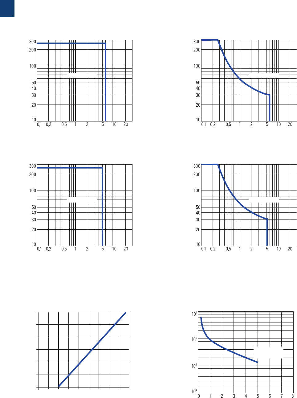
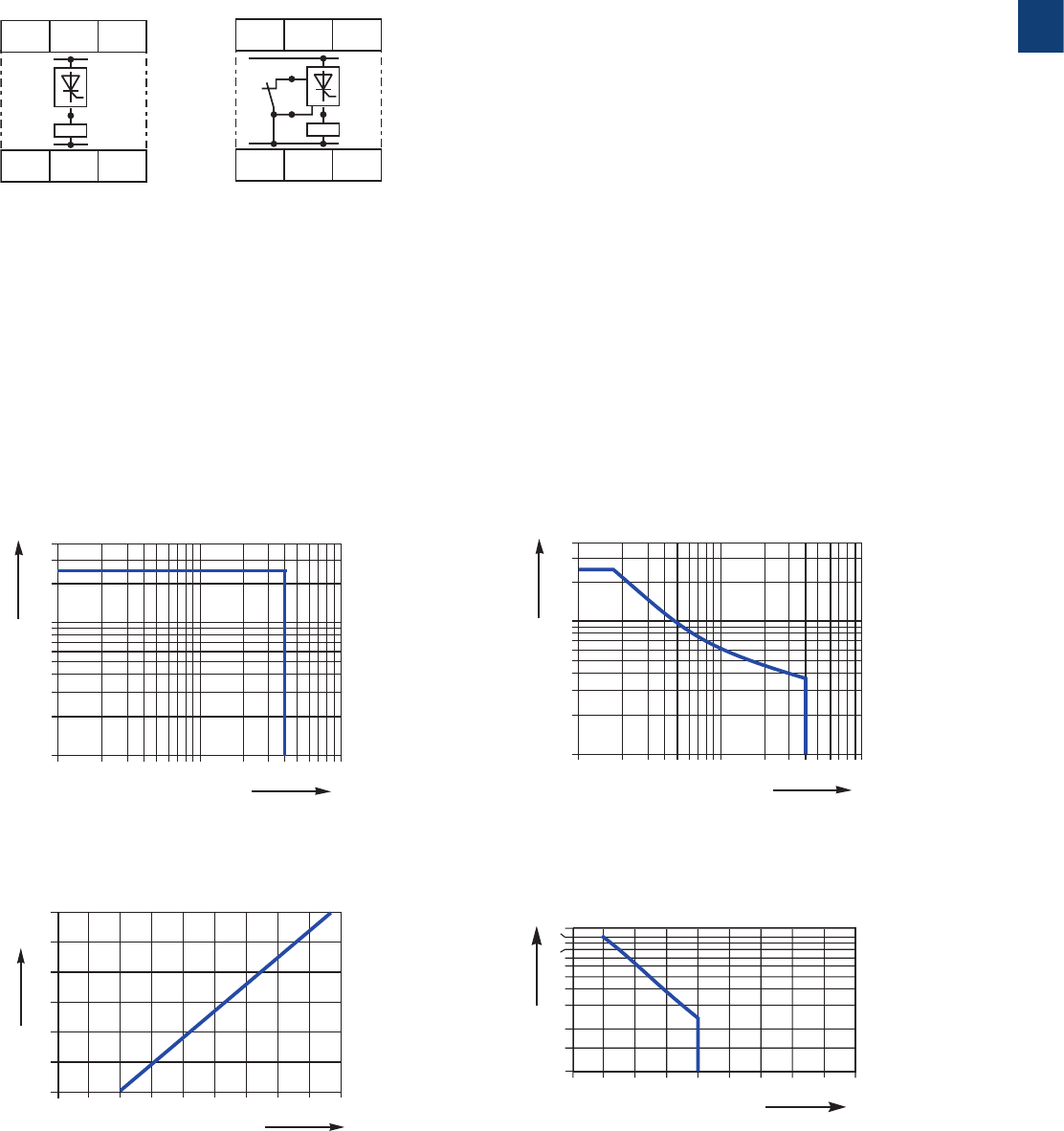
CT-D range
Technical data, Technical diagrams
CT-D.2x CT-D.2x
Derating factor F
for inductive AC load
Contact lifetime
DC current [A]
resistive load
DC voltage [V]
2CDC 252 121 F0206
AC current [A]
resistive load
AC voltage [V]
2CDC 252 122 F0206
Switching current [A]
250 V
resistive load
Switching cycles
2CDC 252 123 F0206
cos ϕ
0.5
0.1 0.2 0.3 0.40.5 0.60.7 0.80.9 1.0
0.6
0.7
0.8
0.9
1.0
Derating factor F
2CDC 252 124 F0206
CT-D.1x CT-D.1x
AC load (resistive) DC load (resistive)
Technical diagrams
Load limit curves
DC current [A]
resistive load
DC voltage [V]
2CDC 252 045 F0207
AC current [A]
resistive load
AC voltage [V]
2CDC 252 044 F0207
2CDC 110 004 C0210 | Catalog Electronic Products and Relays 2015 | ABB 1/16
1
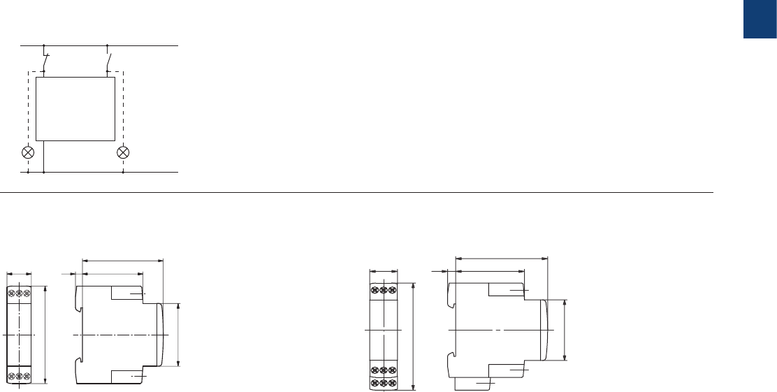
CT-D range
Wiring notes, Dimensional drawings
0.69“
2.76“
0.2“
2.28“
1.71“
1.77“
17,5
70
5
58
43,4
45
2CDC 252 131 F0b06
0.69“
17,5
3.15“80
0.2“
5
2.28“
1.71“
58
43,4
1.77“45
2CDC 252 130 F0b06
CT-D devices with 1 c/o contact or 2 n/o contacts CT-D devices with 2 c/o contacts
Dimensional drawings
L(+)
N(-)
A1 Y1/B1
A2
2CDC 252 102 F0b06
Wiring notes for devices with control input
A parallel load to the control input is possible
dimensions in mm
1/17 ABB | Catalog Electronic Products and Relays 2015 | 2CDC 110 004 C0210
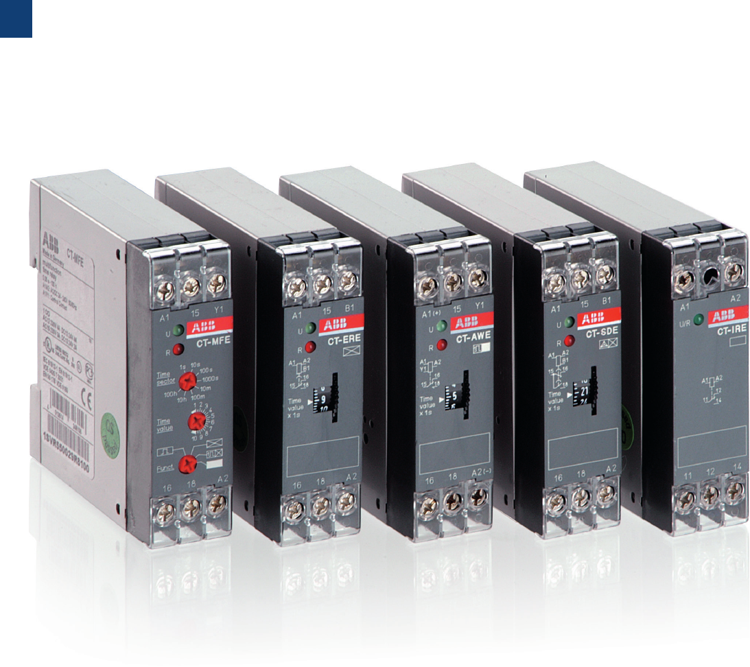
1
CT-E range
Product group picture

2CDC 110 004 C0210 | Catalog Electronic Products and Relays 2015 | ABB 1/18
1
CT-E range
Table of contents
CT-E Range
Product group picture 1/17
Table of contents 1/18
Benefits and advantages 1/19
Ordering details 1/20
Function diagrams 1/22
Connection diagrams 1/27
Connection diagrams, Technical diagrams 1/28
Technical data 1/29
Wiring notes, Dimensional drawings 1/31
Notes 1/32
1/19 ABB | Catalog Electronic Products and Relays 2015 | 2CDC 110 004 C0210
1
CT-E range
Benefits and advantages
Characteristics
– Diversity:
– 2 multifunction timers
– 56 single-function timers
– Control supply voltages:
– Dual range: 24 V AC/DC
– Single range: 110-130 V AC, 220-240 V AC
– Wide range: 24-240 V AC/DC (CT-MFE)
– Time ranges
– 5 single ranges: 0.05-1 s, 0.1-10 s, 0.3-30 s, 3-300 s,
0.3-30 min
– 8 time ranges: 0.05 s - 100 h (CT-MFE)
– Devices with 1 c/o (SPDT) contact (250 V / 4 A) or
solid-state output for high switching frequencies (thyristor
0.8 A)
– Approvals / Marks (details see page 1/4)
– A, C, R, K, E, L / a, b
1 LEDs for status indication
U - green LED: V control supply voltage applied
R2: red LED: V output relay energized
2 Time range adjustment (only multifunctional devices)
3 Fine adjustment of the time delay
4 Preselection of the timing function (only multifunctional devices)
Operating controls
Direct reading scales
Direct setting of the time delay without any additional
calculation provides accurate time delay adjustment.
LEDs for status indication
All actual operational states are displayed by front-face LEDs,
thus simplifying commissioning and troubleshooting.
Connection screws in M3 (Pozidrive 1)
Easy and fast tightening and release of the connection screws
with pozidrive, pan- or crosshead screwdriver.
Solid-state output
Devices with solid-state output are the perfect solution for
high operation cycles.
4
1
2
3
Benefits
2CDC 252 166 F0005
ALA1
A1
AL
1SVC 110 000 F0508
1SVC 110 000 F0500
1SVC 110 000 F0506
2CDC 252 166 F0005
1
1
2
2
3 4
4
3
Synonyms
used expression alternative expression(s) used expression alternative expression(s)
1 c/o contact SPDT voltage-related wet / non-floating
2 c/o contacts DPDT volt-free dry / floating
2CDC 110 004 C0210 | Catalog Electronic Products and Relays 2015 | ABB 1/20
1
1SVR 550 029 F81001SVR 550 111 F1100
CT-MFE
CT-AHE
A ON-delay
B OFF-delay
CA Impulse-ON
CB Impulse-OFF
DA Flasher starting with ON
DB Flasher staring with OFF
H Pulse former
CT-E range
Ordering details
1) Functions: ON-delay, OFF-delay with auxiliary voltage, Impulse-ON, Flasher starting with ON, Flasher starting with OFF,
Pulse former
2) without auxiliary voltage, True Off-delay timer
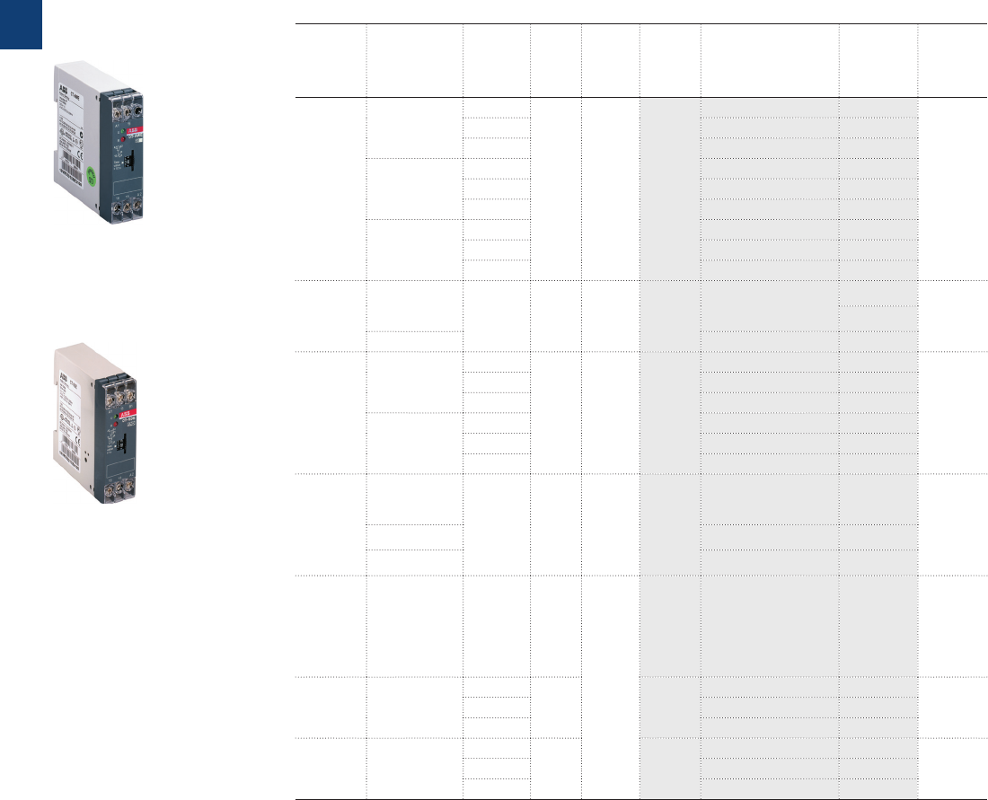
Description
The CT-E range with its excellent price/performance ratio offers an ideal solution for serial
applications. 56 single-function devices with 5 different time ranges as well as 2 multifunction
timers with 6 functions and 8 time ranges offer the highest possible flexibility for almost every
application. For high operating cycles, contact-free CT-E timers with solid-state output are
available.
Ordering details
Timing
function
Rated con-
trol supply
voltage
Time
ranges
Con-
trol
Input
Output Type Order code Price
1 pce
Weight
(1 pce)
kg (lb)
Multifunc-
tional 1) 24-240 VAC/DC 8 (0.05 s -
100 h) M1 c/o CT-MFE 1SVR550029R8100 0.08 (0.18)
ON-delay
24 V AC/DC,
220-240 V AC
0.1-10 s
-
1 c/o CT-ERE
1SVR550107R1100
0.08 (0.18)
0.3-30 s 1SVR550107R4100
3-300 s 1SVR550107R2100
0.3-30 min 1SVR550107R5100
110-130 V AC
0.1-10 s
-
1SVR550100R1100
0.3-30 s 1SVR550100R4100
3-300 s 1SVR550100R2100
0.3-30 min 1SVR550100R5100
OFF-delay
24 VAC/DC
0.1-10 s
M1 c/o CT-AHE
1SV R 550118R110 0
0.08 (0.18)
0.3-30 s 1SVR550118R4100
3-300 s 1SVR550118R2100
110-130 V AC
0.1-10 s 1SV R 550110 R110 0
0.3-30 s 1SVR550110R4100
3-300 s 1SVR550110R2100
220-240 V AC
0.1-10 s 1SV R 550111R110 0
0.3-30 s 1SV R 550111R410 0
3-300 s 1SV R 550111R210 0
OFF-delay2)
24 V AC/DC,
220-240 V AC
0.1-10 s
-1 c/o CT-ARE
1SVR550127R1100
0.08 (0.18)
0.3-30 s 1SVR550127R4100
110-130 V AC 0.1-10 s 1SVR550120R1100
0.3-30 s 1SVR550120R4100
Impulse-ON
24 V AC/DC,
220-240 V AC
0.1-10 s
-1 c/o CT-V WE
1SVR550137R1100
0.08 (0.18)
0.3-30 s 1SVR550137R4100
3-300 s 1SVR550137R2100
110-130 V AC
0.1-10 s 1SVR550130R1100
0.3-30 s 1SVR550130R4100
3-300 s 1SVR550130R2100
Impulse-
OFF2)
24VAC/DC
0.0 5-1 s -1 c/o CT-AWE
1SVR550158R3100
0.08 (0.18)110-130 V AC 1SVR550150R3100
220-240 V AC 1SVR550151R3100
M
Control input with voltage-related triggering
- no triggering
1/21 ABB | Catalog Electronic Products and Relays 2015 | 2CDC 110 004 C0210
1
CT-E range
Ordering details
2CDC 251 125 F00042CDC 251 059 F0003
CT-AWE
CT-SDE
A ON-delay
B OFF-delay
CA Impulse-ON
CB Impulse-OFF
DA Flasher starting with ON
DB Flasher staring with OFF
H Pulse former
FA Star-delta change-over twice
ON-delayed
FC Star-delta change-over with
impulse
DE Pulse generator starting
with ON or OFF
1) without auxiliary voltage
2) with fixed transition time
3) solid-state output, functions and time range selection via external jumpers
4) symetric ON & OFF times
5) common contact
6) Functions: ON-delay (AC/DC), Impuls-ON (AC only), Flasher starting with OFF (AC only)
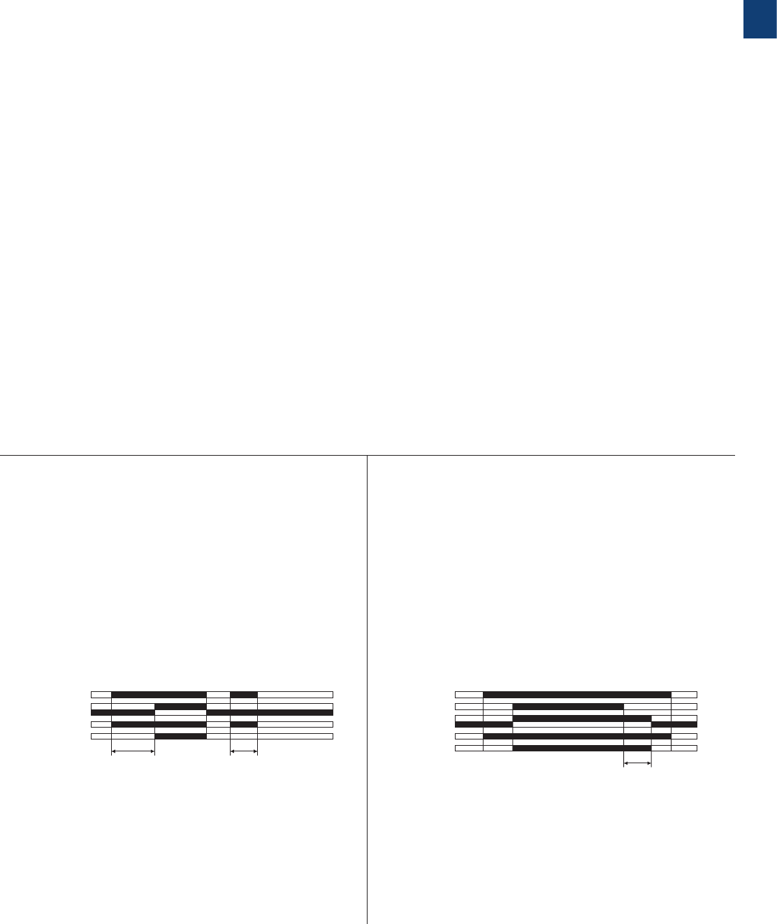
Notice
CT-...KE are solid-state timers with thyristor output for 2-wire applications. They are connected
directly in series with the control coil of contactors or relays. Voltage should not be applied
without a load connected, because there is no current limiting in the unit.
Bestellangaben
Timing
function
Rated con-
trol supply-
voltage
Time
ranges
Con-
trol
Input
Output Type Order code Price
1 pce
Weight
(1 pce)
kg (lb)
Impulse-
OFF
24VAC/DC
0.1-10 s
M1 c/o CT-AWE
1SVR550148R1100
0.08 (0.18)
0.3-30 s 1SVR550148R4100
3-300 s 1SVR550148R2100
110-130 V AC
0.1-10 s 1SVR550140R1100
0.3-30 s 1SVR550140R4100
3-300 s 1SVR550140R2100
220-240 V AC
0.1-10 s 1SVR550141R1100
0.3-30 s 1SVR550141R4100
3-300 s 1SVR550141R2100
Flasher
staring with
OFF
24 V AC/DC,
220-240 V AC 0.1-10 s -1 c/o CT-EBE 4) 1SVR550167R1100 0.08 (0.18)
110-130 V AC 1SVR550160R1100
Star-delta
change-
over twice
ON-delayed
24 V AC/DC,
220-240 V AC
0.1-10 s
-1 c/o CT-YDE
1) 2)
1SVR550207R1100
0.08 (0.18)
0.3-30 s 1SVR550207R4100
3-300 s 1SVR550207R2100
110-130 V AC
0.1-10 s 1SVR550200R1100
0.3-30 s 1SVR550200R4100
3-300 s 1SVR550200R2100
Star-delta
change-over
with impuls
24 V AC/DC,
220-240 V AC
0.3-30 s -1 n/o +
1 n/c
CT-SDE
2) 5)
1SVR550217R4100
0.08 (0.18)
110-130 V AC 1SVR550210R4100
380-415 V AC 1SVR550212R4100
Multifunc-
tional 8) 24-240VAC/DC 0.1-10 s,
3-300 s -
solide-
state
CT-MKE
3) 6) 1SVR550019R0000 0.08 (0.18)
ON-delay 24-240 VAC/DC
0.1-10 s
-CT-EKE
1SVR550509R1000
0.08 (0.18)0.3-30 s 1SVR550509R4000
3-300 s 1SVR550509R2000
OFF-delay 24-240 V AC
0.1-10 s
-CT-AKE
1SVR550519R1000
0.08 (0.18)0.3-30 s 1SVR550519R4000
3-300 s 1SVR550519R2000
M
Control input with voltage-related triggering
- no triggering
2CDC 110 004 C0210 | Catalog Electronic Products and Relays 2015 | ABB 1/22
1
CT-E range
Function diagrams
A ON-delay (Delay on make)
CT-ERE, CT-MFE
B OFF-delay, with auxiliary voltage (Delay on break)
CT-AHE, CT-MFE
t = adjusted time delay
t = adjusted time delay
Minimum control pulse length: 20 ms
< t
A1-A2/B1
15-18
15-16
t
2CDC 252 130 F0205
green LED
red LED
A1-A2
A1-Y1
15-16
15-18
t
2CDC 252 132 F0205
green LED
red LED
Applying control supply voltage starts timing. When the
selected time delay is complete, the output relay energizes.
If control supply voltage is interrupted, the output relay
de-energizes and the time delay is reset. Interrupting control
supply voltage before the time delay is complete, resets the
time delay. The output relay does not energize.
This function requires continuous control supply voltage for
timing.
Timing is controlled by control input A1-Y1. If the control input
is closed, the output relay energizes. If control input A1-Y1 is
opened, the selected time delay starts. When the time delay
is complete, the output relay de-energizes. If control input A1-
Y1 is closed before the time delay is complete, the time delay
is reset. Timing starts again when the control input re-opens.
Remarks
Legend
G Control supply voltage not applied / Output contact open
B Control supply voltage applied / Output contact closed
A1-Y1/B1: Control input with voltage-related triggering
Terminal designations on the device and in the diagrams
The c/o contact is always designated 15-16/18.
The n/o contacts are designated with 15-16 and 15-18.
Control supply voltage is always applied to terminals
A1-A2/B1.
Function of the red LED
The red LED R glows as soon as the output relay energizes
and turns off when the output relay de-energizes.
1/23 ABB | Catalog Electronic Products and Relays 2015 | 2CDC 110 004 C0210
1
CA Impulse-ON (Interval)
CT-VWE, CT-MFE
B OFF-delay, without auxiliary voltage
(true delay on break) CT-ARE
t = adjusted time delay
A1-A2/B1
15-18
15-16
t
2CDC 252 133 F0205
green LED
This function requires continuous control supply voltage
for timing. Timing is controlled by control input A1-Y1. If
the control input is opened, the output relay energizes and
timing begins. When the selected time delay is complete,
the output relay de-energizes. Interrupting control supply
voltage or closing control input A1-Y1, before the time delay
is complete, de-energizes the output relay and resets the time
delay.
The Impulse-OFF function without auxiliary voltage does not
require continuous control supply voltage for timing.
If control supply voltage is interrupted, the output relay
energizes and the OFF time starts. When timing is complete,
the output relay de-energizes. If control supply voltage is
re-applied before the time delay is complete, the time delay is
reset and the output relay de-energizes.
Control supply voltage must be applied for the minimum
energizing time (200 ms), for proper operation.
t = adjusted pulse time
t = adjusted pulse time
A1-A2
A1-Y1
15-16
15-18
t
2CDC 252 137 F0205
green LED
red LED
A1-A2
15-16
15-18
t
2CDC 252 138 F0205
green LED
red LED
The output relay energizes immediately when control sup-
ply voltage is applied and de-energizes after the selected
time delay is complete. If control supply voltage is inter-
rupted before the time delay is complete, the output relay
de-energizes and the time delay is reset.
Control input A1-Y1 has to be jumpered, when this timing
function is selected.
The OFF-delay function without auxiliary voltage does not
require continuous control supply voltage for timing.
Applying control supply voltage, energizes the output relay.
If control supply voltage is interrupted, the OFF-delay starts.
When timing is complete, the output relay de-energizes. If
control supply voltage is re-applied before the time delay is
complete, the time delay is reset and the output relay remains
energized.
Control supply voltage must be applied for the minimum
energizing time (200 ms), for proper operation.
CB Impulse-OFF, with auxiliary voltage
(Trailing edge interval) CT-AWE
CB Impulse-OFF, without auxiliary voltage
(True trailing edge interval) CT-AWE
t = adjusted pulse time
t = adjusted pulse time
A1-A2/B1
15-18
15-16
< tt
2CDC 252 134 F0205
green LED
red LED
A1-A2
15-18
15-16
< tt
A1-Y1
2CDC 252 135 F0205
green LED
red LED
CT-E range
Function diagrams
CT-VWE:
CT-MFE:
2CDC 110 004 C0210 | Catalog Electronic Products and Relays 2015 | ABB 1/24
1
DA Flasher starting with ON
(Recycling equal times, ON first) CT-MFE
t = adjusted flashing time
DB Flasher starting with OFF
(Recycling equal times, OFF first) CT-EBE, CT-MFE
t = adjusted flashing time
H Pulse former (Single shot)
CT-MFE
t = adjusted pulse time
A1-A2
A1-Y1
15-16
15-18
tt
2CDC 252 136 F0205
green LED
red LED
Closing the control input A1-Y1, with control supply voltage
applied, energizes the output relay for the selected ON time.
Operating the control input during timing has no effect. When
the ON time is complete, the output relay de-energizes.
Timing can be restarted by re-closing control input A1-Y1. If
control supply voltage is interrupted during timing, the output
relay de-energizes and the ON time is reset.
Applying control supply voltage starts timing with symmetrical
ON & OFF times. The cycle starts with an ON time first.
If control supply voltage is interrupted, the output relay
de-energizes and the time delay is reset.
Control input A1-Y1 has to be open, when this timing function
is selected.
Applying control supply voltage starts timing with symmetrical
ON & OFF times. The cycle starts with an OFF time first.
If control supply voltage is interrupted, the output relay
de-energizes and the time delay is reset.
Control input A1-Y1 has to be jumpered, when this timing
function is selected.
A1-A2
A1-Y1
15-16
15-18
t t
2CDC 252 026 F020
9
green LED
red LED
A1-A2/B1
15-16
15-18
tt
2CDC 252 140 F0205
green LED
red LED
15-16
15-18
15-16
15-18
tt
A1-A2
A1-Y1
2CDC 252 023 F0209
green LED
red LED
t = adjusted flashing time
CT-E range
Function diagrams
CT-EBE:
CT-MFE:
1/25 ABB | Catalog Electronic Products and Relays 2015 | 2CDC 110 004 C0210
1
-K1-K3
L1
-F1
1
2
95
96
97
98
L2
3
4
L3
5
6
1
2
3
4
5
6
1
2
3
4
5
6
-K2
-F2
1
2
3
4
5
6
1
3
5
2
4
6
M
3 ~
W2
V2
U2
W1
V1
U1
-M1
2CDC 253 009 F0012
K1
K3
K3
YN
K2
K2
K2
L1
N
F3
F2
95
96
21
22
21
22
21
22
A1
A2
A1
A2
A1
A2
A1
A2
21
22
16
15
13
14
43
44
13
14
13
14
S1
0
I
S2
K1
K1T
K1T
K1
K1
2CDC 253 002 F0013
2CDC 253 009 F0012
K1T
K1T K1T
K3
K3
YN
K2
K2
K2
L1
N
F3
F2
95
96
21
22
22
21
A1B1
A2
A1
A2
A1
A2
A1
A2
22
21
13
14
15
16
15
18
13
14
53
54
53
54
S1
0
I
S2
K1
K1
K1
2CDC 253 001 F0013
FC Star-delta change-over
CT-SDE
FA Star-delta change-over
CT-YDE
Power circuit diagram
Control circuit diagram
Control circuit diagram
A1-A2/B1
15-16
15-18
t1t2
2CDC 252 133 F0206
Star contactor
Delta contactor
green LED
red LED
t1 = adjustable starting time
t2 = fixed transition time of 50 ms
A1-A2/B1
15-16
15-18
t1t2
2CDC 252 134 F0206
Star contactor
Delta contactor
green LED
red LED
t1 = adjustable starting time
t2 = fixed transition time of 30 ms
Applying control supply voltage energizes the star contactor
(K1) and the line contactor (K2) and begins the set starting
time. When the starting time is complete, contact 15-16
de-energizes the star contactor (K1) Now, the fix transition
time starts. When the transition time is complete, contact
15-16 energizes the delta contactor (K3).
Applying control supply voltage energizes the star contactor
(K1) and the line contactor (K2) and begins the set starting
time. When the starting time is complete, contact 15-16
de-energizes the star contactor (K1). Now, the fix transition
time starts. When the transition time is complete, contact
15-18 energizes the delta contactor (K3).
CT-E range
Function diagrams
2CDC 110 004 C0210 | Catalog Electronic Products and Relays 2015 | ABB 1/26
1
2CDC 252 001 F0213
A1-A2
t< t
Thyristor A1-A2
2CDC 252 146 F0205
red LED
A1-A2
t< t
Thyristor A1-A2
2CDC 252 147 F0205
red LED
A1-A2
Thyristor A1-A2
tt
2CDC 252 148 F0205
red LED
A1-A2
tt
Thyristor A1-A2
2CDC 252 149 F0205
red LED
t = adjusted time delay
t = adjusted pulse time
t = adjusted flashing time
t = adjusted flashing time
A ON-delay (Delay on make)
CT-EKE
t = adjusted time delay
B OFF-delay, with auxiliary voltage (Delay on break)
CT-AKE
t = adjusted time delay
Multifunction timer CT-MKE
Functions and time ranges are programmed by simply plugging in external wire jumpers.
Notice:
CT-...KE are solid-state timers with thyristor output for 2-wire applications. They are connected directly in series with the control coil
of contactors or relays. Voltage should not be applied without a load connected, because there is no current limiting in the unit.
A ON-delay (Delay on Make)
Without external connection. Timing begins when control supply voltage
is applied to terminal A1 and the load connected in series with A2. When
the selected time delay is complete, the load energizes. If control supply
voltage is interrupted, the load de-energizes and the time delay is reset.
Interrupting supply voltage before the time delay is complete, resets the
time delay. The load does not energize.
CA Impulse-ON (Interval)
External connection X1-X4 required. The load energizes and timing
starts when control supply voltage is applied to terminal A1 and the load
connected in series with A2. When the selected time delay is complete,
the load de-energizes. Interrupting control supply voltage before the time
delay is complete, de-energizes the load and resets the time delay.
DA Flasher, starting with ON
External connection X1-X4 and X2-X4 required. When control supply
voltage is applied to terminal A1 and the load connected in series with
A2, the load energizes and de-energizes with the selected ON & OFF
times. The ON & OFF times are equal. The cycle starts with an ON time
first (load energized). If control supply voltage is interrupted, the load
de-energizes and the time delay is reset.
DB Flasher, starting with OFF
External connection X2-X4 required. When control supply voltage is
applied to terminal A1 and the load connected in series with A2, the
load energizes and de-energizes with the selected ON & OFF times.
The ON & OFF times are equal. The cycle starts with an OFF time first
(load de-energized). If control supply voltage is interrupted, the load
de-energizes and the time delay is reset.
A1-AL
t< t
Thyristor A1-AL
2CDC 252 150 F0205
green LED
A1-AL
t
Y2-A2
Thyristor A1-AL
green LED
Timing begins when control supply voltage is applied to
terminal A1 and the load connected in series with AL. When
the selected time delay is complete, the load energizes. The
green LED glows as long as the load is energized.
If control supply voltage is interrupted, the load de-energizes
and the time delay is reset. Interrupting control supply voltage
before the time delay is complete, resets the time delay. The
load does not energize.
The OFF-delay function with auxiliary voltage requires
continuous control supply voltage at terminal A1, and the
load connected in series with AL, for timing.
Timing is controlled by control input Y2-A2. When the
control input is closed, the load energizes. If the control
input is opened, the selected time delay starts (minimum
control pulse length is 20 ms). The green LED glows as long
as the load is energized. When the selected time delay is
complete, the load de-energizes. If control input Y2-A2 is
closed before the time delay is complete, the time delay is
reset and the load remains energized. Timing starts again
when the control input is re-opened. Interrupting control
supply voltage resets the time delay and de-energizes the
load.
CT-E range
Function diagrams
Programming the time ranges
X3-X4 jumpered: 0.1-10 s
X3-X4 open: 3-300 s
1/27 ABB | Catalog Electronic Products and Relays 2015 | 2CDC 110 004 C0210
1
2CDC 252 152 F0005
A1
A1
A2
15
15
16
16 18 A2
18
Y1
2CDC 252 153 F0005
A1 B1
16 18 A2
A2 16 18
A1 15
15
B1
2CDC 252 154 F0005
A1
A1
A2 16 18
15
15 Y1
16 18 A2
2CDC 252 155 F0005
A1
A2 16 18
B1 15
15A1 B1
1816 A2
CT-MFE A CT-ERE B CT-ARE
B CT-AHE 1)
15 A1
A1
A2 B1 16 18
15
B1
18 16 A2
2CDC 252 156 F0b05
15 A1
A1
A2 16 18
15
18 16 A2
2CDC 252 157 F0b05
15 Y1 A1
A1
A2 16 18
15
18 16 A2
2CDC 252 158 F0b05
CA CT-VWE CB CT-AWE CB CT-AWE 1)
2CDC 252 159 F0005
15 B1A1
A1 B1 15
1816
A2 16 18
A2
DB CT-EBE
FA CT-YDE FC CT-SDE FC CT-SDE
2CDC 252 160 F0005
15 B1A1
A1
A2 B1 16 18
15
1816 A2
2CDC 252 161 F0005
15 B1A1
A1
A2 B1 16 18
15
1816 A2
2CDC 252 162 F0005
15A1
A1
A2 16 18
15
1816 A2
2CDC 252 165 F0005
X2
A1
A2
U
X1A1
X4X3 A2
CT-MKE
Device without aux. voltage Device with aux. voltage
Device: 1SVR 550 217 R4100 Devices: 1SVR 550 210 R4100,
1SVR 550 212 R4100
CT-E range
Connection diagrams
A1-A2 Supply:
24-240VAC/DC
A1-Y1 Control input
15-16/18 c/o contact
A1-A2 Supply: 220-240 V AC
or 110-130 V AC
A1-B1 Supply: 24 V AC/DC
15-16/18 c/o contact
A1-A2 Supply: 220-240 V AC
A1-B1 Supply: 24 V AC/DC
15-16 n/c contact
15-18 n/o contact
with common contact
A1-A2 Supply: 110-130 V AC
or 380-415 V AC
15-16 n/c contact
15-18 n/o contact
with common contact
A1-A2 Supply: 220-240 V AC
or 110-130 V AC
A1-B1 Supply: 24 V AC/DC
15-16/18 c/o contact
A1-A2 Supply: 220-240 V AC
or 110-130 V AC
A1-B1 Supply: 24 V AC/DC
15-16/18 c/o contact
A1-A2 Supply: 220-240 V AC
or 110-130 V AC
A1-B1 Supply: 24 V AC/DC
15-16/18 c/o contact
A1-A2 Supply: 220-240 V AC or
110-130 V AC
A1-B1 Supply: 24 V AC/DC
15-16/18 c/o contact
A1-A2 Supply: 24-240 V AC/DC
A1-A2 Thyristor
X1-X4 Timing function adjustment
X2-X4 Timing function adjustment
X3-X4 Time range adjustment
(Details see function diagrams)
A1-A2 Supply: 24 V AC/DC
or 110-240 V AC or
220-240 VAC
A1-Y1 Control input
15-16/18 c/o contact
A1-A2 Supply: 24 V AC/DC
or 110-240 V AC or
220-240 VAC
A1-Y1 Control input
15-16/18 c/o contact
A1(+)-A2(-) Supply: 24 V AC/DC
or 110-240 V AC or
220-240 VAC
15-16/18 c/o contact
1) “„Wiring notes, Dimensional drawings“ see page 1/31.
2CDC 110 004 C0210 | Catalog Electronic Products and Relays 2015 | ABB 1/28
1
2CDC 252 166 F0005
ALA1
A1
AL
2CDC 252 167 F0005
ALA1
A1
Y2
A2 AL
A2Y2
A CT-EKE B CT-AKE
220 V 50 Hz AC1
360 cycles/h
300
200
100
80
60
50
40
30
20
10
1 2 4 6 10
I A
V
U
2CDC 252 193 F0205
0,1 0,2 0,5
cos ϕ
F
2CDC 252 192 F0205
0,5
0,1 0,2 0,3 0,4 0,5 0,6 0,7 0,8 0,9 1,0
0,6
0,7
0,8
0,9
1,0
300
200
100
80
60
50
40
30
20
10
1 2 4 6 10
I A
V
U
2CDC 252 194 F0205
0,1 0,2 0,5
4 3 2 1
105
2
3
4
N
I A
5
8
9
106
5 6 7 8
2CDC 252 034 F0208
AC load (resistive) DC load (resistive)
Technical diagrams
Load limit curves
Derating factor F for inductive AC load Contact lifetime
CT-E range
Connection diagrams, Technical diagrams
A1-AL Supply: 24-240
V AC/DC
A1-AL Thyristor
A1-AL Supply: 24-240 V AC
A1-AL Thyristor
Y2-A2 Control input

1/29 ABB | Catalog Electronic Products and Relays 2015 | 2CDC 110 004 C0210
1
CT-E range
Technical data
Technical data
Data at Ta = 25 °C and rated values, unless otherwise indicated
CT-E (relays) CT-E (solid-state)
Input circuit - Supply circuit
Rated control supply voltage UsA1-A2, A1-AL 24-240 V AC/DC
A1-A2, A1-AL 24-240 V AC
A1-A2 110-130 V AC -
A1-A2 220-240 V AC -
A1-A2 380-415 V AC -
A1-B1 24 V AC/DC -
Rated control supply voltage Us tolerance -15...+10 %
Rated frequency AC/DC versions DC or 50/60 Hz
AC versions 50/60 Hz
Typical current / power consumption 24-240 V AC/DC, 24-240 V AC approx. 1.0-2.0 VA/W
110-130 V AC, 220-240 V AC approx. 2.0 VA -
380-415 V AC approx. 3.0 VA -
24 V AC/DC approx. 1.0 VA/W -
Minimum energizing time
CT-ARE, CT-AWE w/o aux. voltage
200 ms -
Current consumption while timing -≤ 2 mA (24-60 V AC/DC)
≤ 8 mA (60-240 V AC/DC)
(CT-AKE only AC)
Input circuit - Control circuit
Kind of triggering voltage-related triggering -
Control input, Control function A1-Y1 start timing external -
Parallel load / polarized no / yes 1) -
Minimum control pulse length 20 ms -
Control voltage potential see rated control supply voltage -
Timing circuit
Time ranges
1 of 5 time ranges per single-function device
0.05-1 s / 0.1-10 s / 0.3-30 s / 3-300 s / 0.3-30 min
8 time ranges 0.05 s - 100 h (CT-MFE) 1.) 0.05-1 s
3.) 5-100 s
5.) 0.5-10 min
7.) 0.5-10 h
2.) 0.5-10 s
4.) 50-1000 s
6.) 5-100 min
8.) 5-100 h
-
2 time ranges 0.1-300 s (CT-MKE) -1.) 0.1-10 s
2.) 3-300 s
Recovery time <50 ms
CT-ARE: <200 ms
CT-AWE, CT-SDE: <400 ms
CT-YDE: <500 ms
CT-EKE: <50 ms
CT-MKE: <100 ms
CT-AKE: <300 ms
Accuracy within the rated control supply voltage tolerance it < 0.5 % / V
Accuracy within the temperature range it < 0.1 % / °C
CT-MFE: it <0.06 % / °C -
Repeat accuracy (constant parameters) it < 1 %
Star-delta transition time CT-YDE / CT-SDE 50 ms / 30 ms -
Output circuit
Kind of output 15-16/18 Relay, 1 c/o contact -
CT-SDE: 15-16, 15-18 1 n/c, 1 n/o contact with common
contact
A1-A2. A1-AL -Thyristor
Contact material AgCdO -
Rated operational voltage UeIEC/EN 60947-1 250 V
Maximum switching voltage 250 V AC, 250 V DC
Rated operational current Ie
(IEC/EN 60947-5-1) AC-12 (resistive) at 230 V 4 A -
AC-15 (inductive) at 230 V 3 A -
DC-12 (resistive) at 24 V 4 A -
DC-13 (inductive) at 24 V 2 A -
1) CT-MFE: yes / no

2CDC 110 004 C0210 | Catalog Electronic Products and Relays 2015 | ABB 1/30
1
CT-E (relays) CT-E (solid-state)
AC rating (UL 508) Utilization category (Control Circuit Rating Code) B 300 -
max. rated operational voltage 300 V AC -
Maximum continuous thermal current at B300 5 A -
max. making/breaking apparent power at B300 3600 VA / 360 VA -
Mechanical lifetime 30 x 106 switching cycles -
Electrical lifetime at AC-12, 230 V, 4 A 0.1 x 10⁶ switching cycles -
Max. fuse rating to achieve short-circuit
protection (IEC/EN 60947-5-1) n/c contact 10 A fast-acting, CT-ARE: 5 A -
n/o contact 10 A fast-acting, CT-ARE: 5 A -
Minimum load current -CT-MKE: 20 mA
CT-EKE, CT-AKE: 10 mA
Maximum load current -CT-MKE: 0.8 A at Ta = 20 °C
CT-EKE, CT-AKE: 0.7 A
Load current reduction / Derating -10 mA/°C
Maximum surge current -CT-MKE: ≤ 20 A for t ≤ 20 ms
CT-EKE, CT-AKE: ≤ 15 A
Voltage drop in connected state -≤ 3 V
Cable length between solid-state timer
and connected load at 50 Hz and a
cable capacity of 100 pF/m :
at 24 V AC -220 m / 22 nF
at 42 V AC -100 m / 10 nF
at 60 V AC -65 m / 6.5 nF
at 110 V AC -50 m / 5 nF
at 240 V AC -22 m / 2.2 nF
General data
Duty time 100%
Dimensions (W x H x D) 22.5 x 78 x 78.5 mm (0.886 x 3.07 x 3.09 in)
Weight approx. 80 g (0.176 lb)
Mounting DIN rail (IEC/EN 60715)
Mounting position any
Minimum distance to other units horizontal / vertical no / no
Degree of protection housing / terminals IP50 / IP20
Electrical connection
Wire size fine-strand with wire end ferrule 2 x 0.75-1.5 mm2 (2 x 18-16 AWG)
fine-strand without wire end ferrule 2 x 1-1.5 mm2 (2 x 18-16 AWG)
rigid 2 x 0.75-1.5 mm2 (2 x 18-16 AWG)
Stripping length 10 mm (0.39 in)
Tightening torque 0.6-0.8 Nm (5.31-7.08 lb.in)
Environmental data
Ambient temperature ranges operation / storage -20...+60 °C / -40...+85 °C
Damp heat IEC/EN 60068-2-30 24 h cycle, 55 °C, 93 % rel., 96 h
Operational reliability IEC/EN 60068-2-6 6 g
Mechanical resistance IEC/EN 60068-2-6 10 g
Isolation data
Rated impulse withstand voltage Uimp
between all isolated circuits IEC/EN 60664-1 type test: 4 kV; 1.2/50 µs -
Pollution category IEC/EN 60664-1 3
Overvoltage category IEC/EN 60664-1 III
Power-frequency withstand voltage (test
voltage) between all isolated circuits routine test: 2.5 kV; 50 Hz; 1 s
type test: 2.5 kV; 50 Hz; 60 s -
Basic insulation (IEC/EN 61140) input circuit / output circuit 300 V -
Rated insulation voltage Uiinput circuit / output circuit 300 V (supply up to 240 V) -
500 V (supply up to 440 V) -
Test voltage between all isolated circuits routine test 2.5 kV, 50 Hz, 1 s -
Standards
Product standard IEC 61812-1, EN 61812-1 + A11, DIN VDE 0435 Teil 2021
Low Voltage Directive 2006/95/EC
EMC Directive 2004/108/EC
Electromagnetic compatibility
Interference immunity to IEC/EN 61000-6-2
electrostatic discharge
IEC/EN 61000-4-2
Level 3 (6 kV / 8 kV)
radiated, radio-frequency
electromagnetic field
IEC/EN 61000-4-3
Level 3 (10 V/m)
electrical fast transient / burst
IEC/EN 61000-4-4
Level 3 (2 kV / 5 kHz)
surge
IEC/EN 61000-4-5
Level 4 (2 kV L-L)
conducted disturbances, induced by radio-
frequency fields
IEC/EN 61000-4-6
Level 3 (10 V)
Interference emission IEC/EN 61000-6-4
„Approvals and marks“ see page 1/4.
CT-E range
Technical data
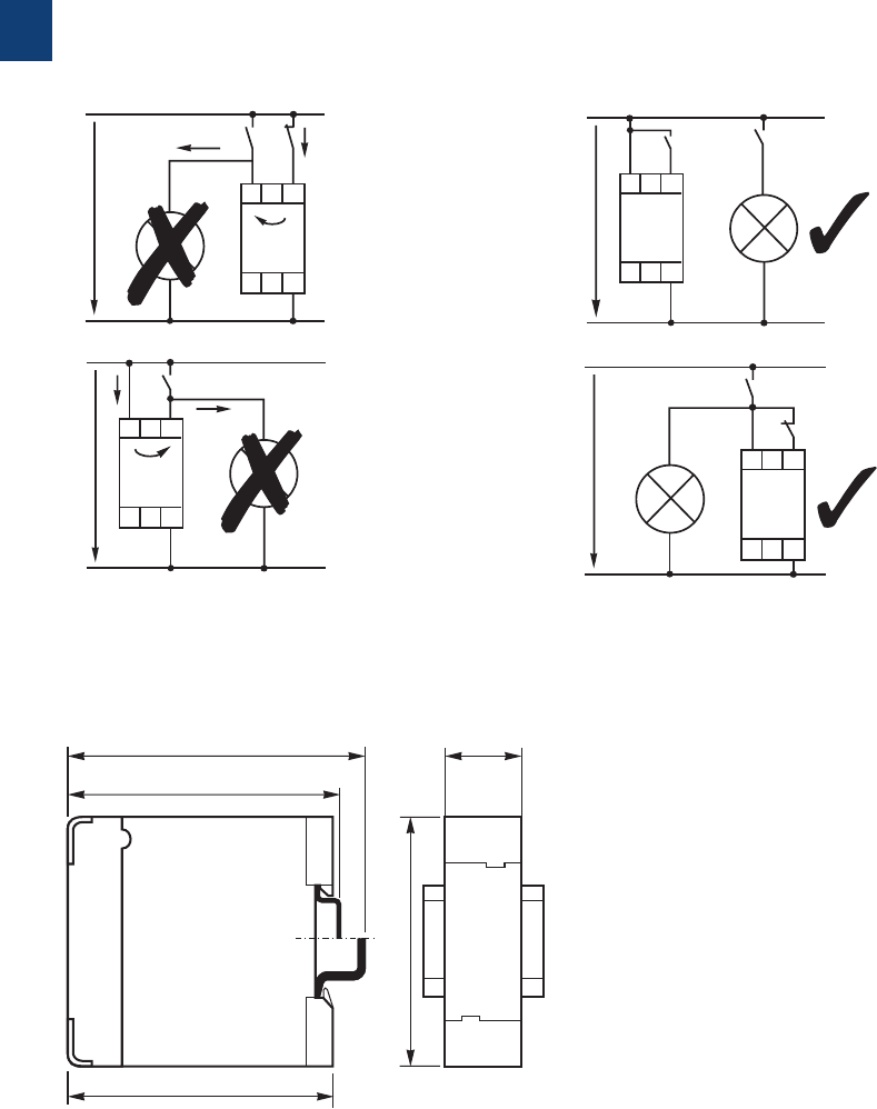
1/31 ABB | Catalog Electronic Products and Relays 2015 | 2CDC 110 004 C0210
1
CT-E range
Wiring notes, Dimensional drawings
3.48“
3.19“
3.09“
.886“
3.07“
88,5
81
78,5
78
22,5
2CDC 252 189 F0b05
A1 Y1
A2
I
I
I
2CDC 252 200 F0b05
U
A1
A2
Y1
2CDC 252 199 F0b05
U
Dimensional drawing Dimensions in mm
Wiring notes
for single-function devices with control contact (CT-AHE, CT-AWE with auxiliary voltage)
I
I
A1
A2
Y1
I
2CDC 252 198 F0b05
U A1 Y1
A2
2CDC 252 201 F0b05
U

2CDC 110 004 C0210 | Catalog Electronic Products and Relays 2015 | ABB 1/32
1
CT-E range
Notes
1/33 ABB | Catalog Electronic Products and Relays 2015 | 2CDC 110 004 C0210
1
CT-S range
Product group picture

2CDC 110 004 C0210 | Catalog Electronic Products and Relays 2015 | ABB 1/34
1
CT-S range
Table of contents
CT-S Range
Product group picture 1/33
Table of contents 1/34
Benefits and advantages 1/35
Ordering details - multifunctional 1/37
Ordering details - singlefunctional 1/38
Ordering details - Accessories 1/39
Ordering details - Accessories 1/40
Function diagrams 1/41
Connection diagrams 1/49
Technical data 1/52
Technical diagrams 1/55
Wiring notes, Dimensional drawings 1/56
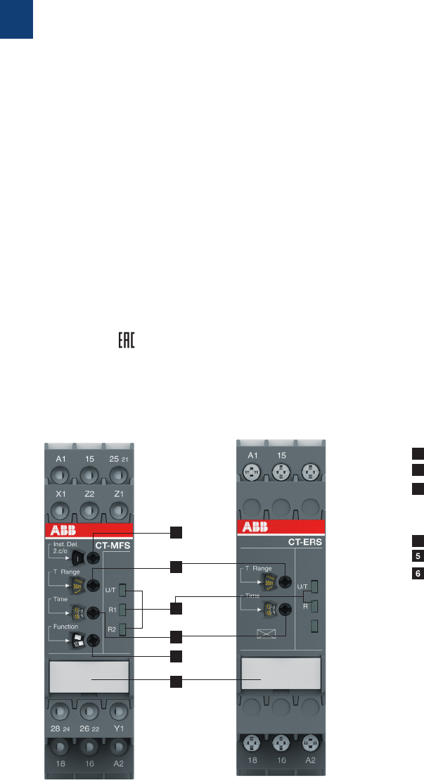
1/35 ABB | Catalog Electronic Products and Relays 2015 | 2CDC 110 004 C0210
1
CT-S range
Benefits and advantages
Characteristics
– Diversity:
– 8 multifunction timers
– 13 single-function timers
– Control supply voltages:
– Multi range: 24-48 V DC, 24-240 V AC
– Wide range: 24-240 V AC/DC
– Single range: 380-440 V AC
– Innovative connection technology
– Double-chamber cage connection terminals
– Easy Connect Technology
– Devices with:
– 1 or 2 c/o (SPDT) contacts
– 2nd c/o contact can be selected as instantaneous contact 1)
– Remote potentiometer connection 1)
– Control input with volt-free or voltage-related triggering e.g. to start timing, pause timing
– Extended operating temperature range down to -40 °C 1)
– Sealable transparent cover for protection against unauthorized changes of time values
– Integrated marker label
– Approvals / Marks (partly pending, details see page 1/4)
– A, C, , E, K, L / a, b
1) selected devices
1 2nd contact as an instantaneous contact
2 Preselection of the time range
3 Indication of operational states
U/T: V control supply voltage applied / W timing
R: V Output relay energized
4 Fine adjustment of time delay
4 Preselection of timing function
Marker label
Operating controls
4
1
2
3
5
6
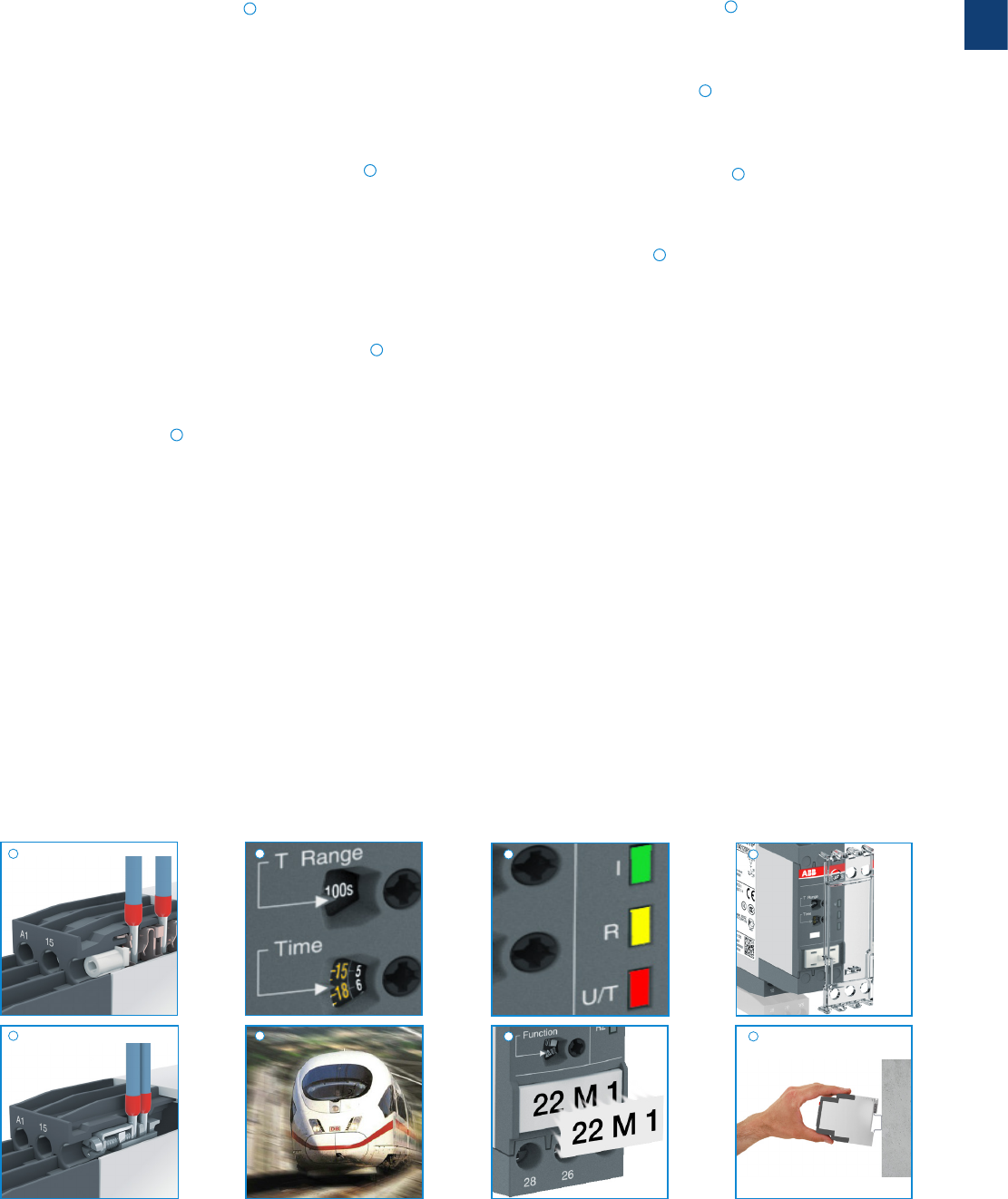
2CDC 110 004 C0210 | Catalog Electronic Products and Relays 2015 | ABB 1/36
1
LEDs for status indication
All actual operational states are displayed by front-face LEDs,
thus simplifying commissioning and troubleshooting.
Integrated marker label
Integrated marker labels allow the product to be marked
quickly and simply. No additional marker labels are required.
Sealable transparent cover
Protection against unauthorized changes of time and
threshold values. Available as an accessory.
Snap-On housing
Tool-free DIN rail installation and deinstallation of the
electronic timer.
CT-S range
Benefits and advantages
Easy Connect Technology
Tool-free wiring and excellent vibration resistance. Push-in
terminals provide connection of wires up to 2 x 0.5 - 1.5 mm²
(2 x 20 -16 AWG), rigid or fine-strand with or without wire
end ferrules. The extended type designators for products with
push-in terminals are indicated by a P following the extended
type designator e.g. CT-xxS.xxP.
Double-chamber cage connection terminals
Double-chamber cage connection terminals provide
connection of wires up to 2 x 0.5-2.5 mm² (2 x 20-14 AWG)
rigid or fine-strand, with or without wire end ferrules. Potential
distribution does not require additional terminals. The
extended type designators for products with double-chamber
cage connection terminals are indicated by a S following the
extended type designator e.g. CT-xxS.xxS.
Time range preselection and fine adjustment
Direct assignment of the preselected time range to the fine
adjustment potentiometer scale by multicolor scales.
Higher utility class
The Easy Connect Technology provides excellent vibra-
tion resistance with gas tight push-in terminals – the right
solution for harsh environment. Selected products of the
electronic timers and measuring and monitoring relays comply
to the latest rail standards NF F 16-101/102, EN 45545, EN
50155 and more standards which are relevant for railway
applications. Find more inforamtion in the rail brochure
2CDC110084B0201.
1
2
3
4
6
5
7
8
4
2CDC 253 035 F0011
2CDC 253 026 F0011
2CDC 253 025 F0011
2CDC 252 006 F0012
2CDC 255 006 S0011
2CDC 253 007 F0012
2CDC 253 013 F0013
2
1 3 7
6 8
5
1/37 ABB | Catalog Electronic Products and Relays 2015 | 2CDC 110 004 C0210
1
CT-S range
Ordering details - multifunctional
2CDC 251 024 V0011
CT-MVS.21P
2CDC 251 023 V0011
CT-MBS.22P
Description
The highly sophisticated CT-S range in ABB’s new S-range housing offers two different
types of connection terminals and is ideally suited for universal use. Two different connection
technologies are available:
– Double-chamber cage connection terminals
– Easy Connect Technology
Accessories:
The CT-S range offers the possibility of using accessories such as a remote potentiometer to
adjust the time delay or a sealable, transparent cover to protect against unauthorized changes.
of time and threshold values.
Ordering details
A(+) ON-delay (accumulative)
B OFF-delay without aux. voltage
CA Impulse-ON
CB Impulse-OFF
AB Symmetrical ON-delay and
OFF-delay
DA Flasher starting with ON
DB Flasher staring with OFF
DE Pulse generator starting
FC Star-delta change-over with
impulse
H Pulse former
G ON/OFF-function
FA Star-delta change-over twice
ON-delayed
with ON or OFF
ED Pulse generator starting with
ON or OFF
EC Single-pulse generator
CE Impulse-ON/OFF
DA Flasher starting with ON
DB Flasher starting with OFF
AC fixed impulse with adjustable
time delay
BC Adjustable impulse with fixed
time delay
Timing
function
Rated
control
supply volt-
age
Time
ranges
Control
input
Output Type Order code Price
1 pce
Weight
(1 pce)
kg (lb)
Multifunc-
tional 5)
24- 240 VAC/DC
10 (0.05 -
300 h) M2 c/o
CT-MVS.21S
1) 2) 3) 1SVR730020R0200 0.148
(0.326)
CT-MVS.21P
1) 2) 3) 1SVR740020R0200 0.136
(0.30)
24-48 VDC,
24-240 VAC
CT-MVS.22S 1SVR730020R3300 0.142
(0.313)
CT-MVS.22P 1SVR740020R3300 0.131
(0.289)
380-440 VAC
CT-MVS.23S 1SVR730021R2300 0.144
(0.317)
CT-MVS.23P 1SVR740021R2300 0.133
(0.293)
Multifunc-
tional 6)
24-48 VDC,
24-240 VAC
10 (0.05 s -
300 h) M1 c/o
CT-MVS.12S 1SVR730020R3100 0.107
(0.236)
CT-MVS.12P 1SVR740020R3100 0.102
(0.225)
Multifunc-
tional 7)
24-48 VDC,
24-240 VAC
2×10 (0.05 s -
300 h) M2 c/o
CT- MXS.22S 4)1SVR730030R3300 0.142
(0.313)
CT-MXS.22P 4) 1SVR740030R3300 0.131
(0.289)
Multifunc-
tional 8)
24- 240 VAC/DC 10 (0.05 s -
300 h) n / n2 c/o
CT-MFS.21S
1) 2) 3) 1SVR730010R0200 0.145
(0.32)
CT-MFS.21P
1) 2) 3) 1SVR740010R0200 0.133
(0.293)
24-48 V DC,
24-240 V AC
10 (0.05 s -
300 h) n / n2 c/o
CT-MBS.22S 2) 3) 1SVR730010R3200 0.14
(0.309)
CT-MBS.22P 2) 3) 1SVR740010R3200 0.129
(0.284)
Multifunc-
tional 9)
24-48 V DC,
24-240 V AC
10 (0.05 s -
300 h) -2 c/o
CT-WBS.22S 1SVR730040R3300 0.123
(0.271)
CT-WBS.22P 1SVR740040R3300 0.115
(0.254)
1) Extended temperature range -40 °C
2) Remote potentiometer connection
3) 2nd c/o contact selectable as instantaneous contact
4) 2 remote potentiometer connections
5) Functions: ON-delay, OFF-delay with auxiliary voltage, Impulse-ON, Impulse-OFF with auxiliary voltage, Symmetrical ON- and
OFF-delay, Flasher starting with ON or OFF, Star-delta change-over with impulse, Pulse former, Accumulative ON-delay, ON/
OFF-function
6) Functions: ON-delay, OFF-delay with auxiliary voltage, Impulse-ON, Impulse-OFF with auxiliary voltage, Symmetrical ON- and
OFF-delay, Flasher starting with ON or OFF, Pulse former, Accumulative ON-delay, ON/OFF-function
7) Functions: Select function via DIP switches behind the marker label on the front of the unit, asymmetrical ON- and OFF-delay,
Impulse-ON/OFF, Pulse generator starting with ON or OFF, Single pulse generator, ON/OFF-function
8) Functions: ON-delay, OFF-delay with auxiliary voltage, Impulse-ON, Impulse-OFF with auxiliary voltage, Symmetrical ON- and
OFF-delay, Flasher starting with ON, Flasher starting with OFF, Star-delta change-over with impulse, Pulse former, ON/OFF-
function
9) Functions: Flasher starting with ON, Flasher starting with OFF, Impulse-ON, ON-delay, fixed impulse with adjustable time delay,
Adjustable impulse with fixed time delay, ON/OFF-function
M
Control input with voltage-related triggering
m
Control input with volt-free triggering
m
/
m
two control input with volt-free triggering
- no triggering
S: screw connection
P: push-in / easy connect
2CDC 110 004 C0210 | Catalog Electronic Products and Relays 2015 | ABB 1/38
1
CT-S range
Ordering details - singlefunctional
Timing
function
Rated con-
trol supply
voltage
Time
ranges
Con-
trol
input
Output Type Order code Price
1 pce
Weight
(1 pce)
kg (lb)
ON-delay
24-240 VAC/DC
10 (0.05 s -
300 h)
-2 c/o
CT-ERS.21S1) 1SVR730100R0300 0.13
(0.287)
CT-ERS.21P1) 1SVR740100R0300 0.121
(0.267)
24-48 V DC,
24-240 V AC
CT-ERS.22S 1SVR730100R3300 0.121
(0.267)
CT-ERS.22P 1SVR740100R3300 0.113
(0.249)
24-48 V DC,
24-240 V AC -1 c/o
CT-ERS .12S 1SVR730100R3100 0.10 6
(0.234)
CT-ERS .12P 1SVR740100R3100 0.101
(0.222)
OFF-delay
24-240 V AC/DC
10 (0.05 s -
300 h)
M2 c/o
CT-APS.21S1) 1SVR730180R0300 0.146
(0.322)
CT-APS.21P1) 1SVR740180R0300 0.125
(0.276)
24-48 V DC,
24-240 V AC
CT-APS.22S 1SVR730180R3300 0.13 8
(0.304)
CT-APS.22P 1SVR740180R33 0 0 0.127
(0.28)
M1 c/o
CT-APS.12S 1SVR730180R3100 0.109
(0.24)
CT-APS.12P 1SVR740180R310 0 0.10 3
(0.227)
24-48 V DC,
24-240 V AC
10 (0.05 s -
300 h) M2 c/o
CT-AHS.22S 1SVR730110R3300 0.13 6
(0.30)
CT-AHS.22P 1SVR740110 R 330 0 0.125
(0.276)
OFF-delay5) 24-240
VAC/DC
7 (0.05 s -
10 min)
-1 c/o
CT-ARS .11S 1SVR730120R3100 0.10 6
(0.234)
CT-ARS .11P 1SVR740120R310 0 0.10
(0.22)
-2 c/o
CT-ARS.21S 1SVR730120R3300 0.124
(0.273)
CT-ARS.21P 1SVR740120 R 3300 0.115
(0.254)
Star-delta
change-over6)
24-48 V DC,
24-240 V AC
7 (0.05 s -
10 min) -2 n/o
CT-SDS.22S 1SVR730210R3300 0.114
(0.251)
CT-SDS.22P 1SVR740 210 R 330 0 0.108
(0.238)
380-440 V AC
CT-SDS.23S 1SVR730211R2300 0.118
(0.26)
CT-SDS.23P 1SVR740211R2300 0.112
(0.247)
2CDC 251 030 V0011
CT-ERS.21P
2CDC 251 033 V0011
CT-AHS.22P
2CDC 251 040 V0011
CT-SDS.23P
1) Extended temperature range -40 °C
2) Remote potentiometer connection
3) 2nd c/o contact selectable as instantaneous contact
4) 2 remote potentiometer connections
5) Without auxiliary voltage
6) 50 ms transition time
A(+) ON-delay (accumulative)
B OFF-delay without aux.voltage
CA Impulse-ON
DA Flasher starting with ON
DB Flasher staring with OFF
CE Impulse-ON/OFF
DA Flasher starting with ON
DB Flasher starting with OFF
AC fixed impulse with adjustable
time delay
BC Adjustable impulse with fixed
time delay
F Star-delta change-over
S: screw connection
P: push-in / easy connect
M
Control input with voltage-related triggering
m
Control input with volt-free triggering
m
/
m
two control input with volt-free triggering
- no triggering
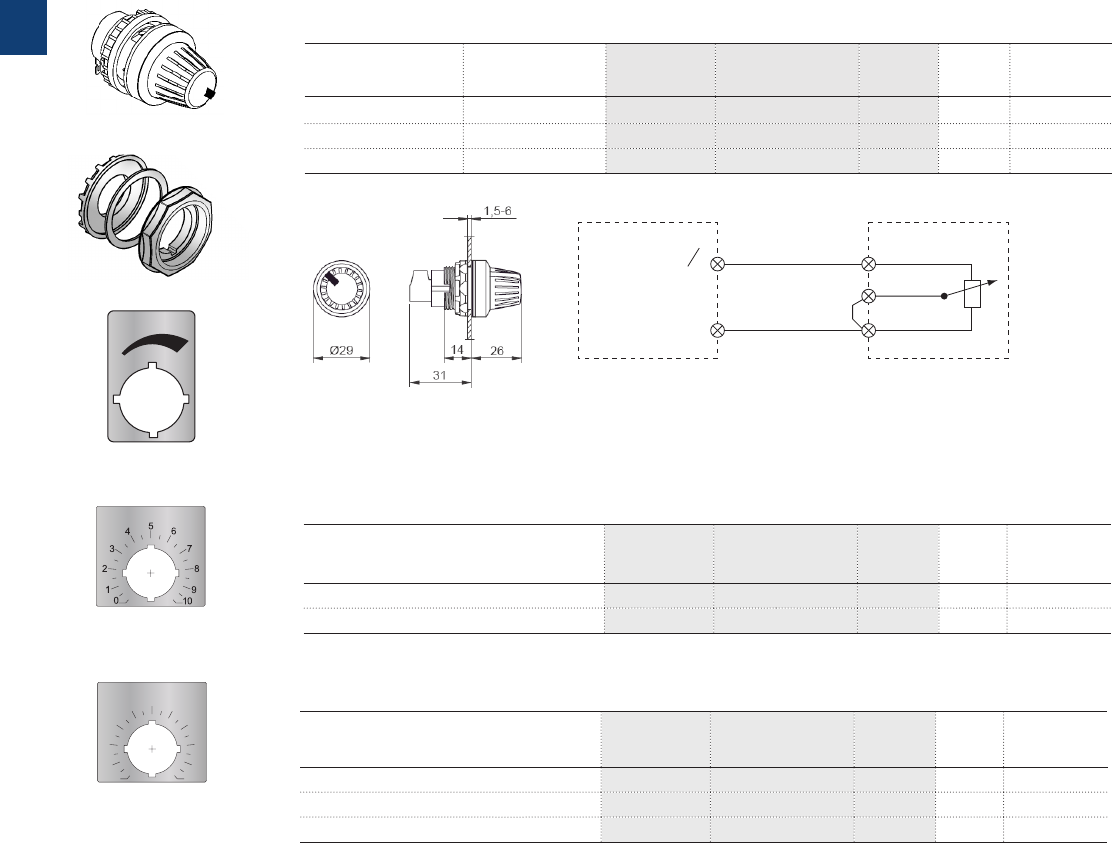
1/39 ABB | Catalog Electronic Products and Relays 2015 | 2CDC 110 004 C0210
1
Marker label 29.6 x 44.5 mm
Marker label with scale 0-10
48.5 x 44.5 mm
Marker label with scale 0-30
48.5 x 44.5 mm
30
15
12
9
6
3
18
27
21
24
0
MT-x50B
30 mm adapters
2CDC 252 041 F0009
2CDC 252 042 F0009
2CDC 252 043 F02092CDC 252 044 F02092CDC 252 045 F0209
CT-S time relay Potentiometers
Z2
Z3
Z1
Note: The connections of the potentiometer
are not marked.
Remote potentiometer
50 kq ±20 % - 0.2 q, degree of protection IP66
Material Diameter
in mm
Type Order code Price
1 piece
Pack.-
unit
pieces
Weight
1piece
g / oz
Plastic, black 22.5 MT-150B 1SFA611410R1506 10.040
Plastic, chrome 22.5 MT-250B 1S FA611410 R 25 0 6 10.040
Metal, chrome 22.5 MT-350B 1SFA611410R350 6 10.048
30 mm adapter for attaching the potentiometer 22 mm in 30 mm mounting hole
Marker label
Material Type Order code Price
1 piece
Pack.-
unit
pieces
Weight
1piece
g / oz
Plastic, black K A1- 8029 1SFA616920R8029 1
Metal, chrome KA1-8030 1SFA616920R8030 1
Caption Type Order code Price
1 piece
Pack.-
unit
pieces
Weight
1piece
g / oz
Symbol (see illustration)
SK 615 562-87 GJD6155620R0087
10.002
Scale 0 - 10
SK 615 562-88 GJD6155620R0088
10.002
Scale 0 - 30
MA16 -1060 1SFA611940R1060
10.002
Note: Technical specifications see data sheet
2CDC 252 039 F0009
2CDC 252 040 F0209
CT-S range
Ordering details - Accessories
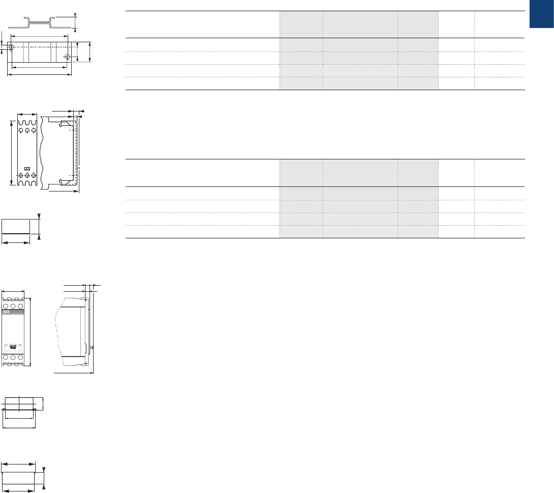
2CDC 110 004 C0210 | Catalog Electronic Products and Relays 2015 | ABB 1/40
1
2CDC 252 008 F0010
CT-S range
Ordering details - Accessories
6.5
62.5
60
10 11.5
20
0.256”
2.461”
2.362”
70 2.756”
0.394”
0.787”
0.453”
2CDC 252 185 F0005
22,5
68,5
7
3,5
.886”
2.70 ”
.138”
.275”
front-to-back
size 107
22.5 0.89”
68 2.68”
110.5 4.31”
8 0.32”
4.8 0.19”
front to back
20
3A11
8
0.315”
0.787”
21
18
8
0.314“
0.709“
0.827“
4T22
19.9
4T22
7.85
0.309”
0.783”
22.2
0.874”
ADP.01
COV.01
COV.11
MAR.01
MAR.02
MAR.12
2CDC 252 010 F0011
2CDC 252 186 F0005
2CDC 252 010 F00102CDC 252 020 F0010
Accessories for CT-S in new housing (1SVR7...)
Description Type Order code Price
1 piece
Pack.-
unit
pieces
Weight
1piece
g / oz
Adapter for screw mounting A D P. 01 1SVR430029R0100 10.018 (0.040)
Sealable transparent cover COV.11 1SVR730005R0100 10.004 (0.009)
Marker label for devices w/o DIP switches MAR.01 1SVR366017R0100 10 0.001 (0.002)
Marker label for devices with DIP switches MAR.12 1SVR730006R0000 10 0.001 (0.002)
Accessories for CT-S in old housing (1SVR4...)
Description Type Order code Price
1 piece
Pack.-
unit
pieces
Weight
1piece
g / oz
Adapter for screw mounting A D P. 01 1SVR430029R0100 10.018 (0.040)
Sealable transparent cover COV.01 1SVR430005R0100 10.004 (0.009)
Marker label for devices w/o DIP switches MAR.01 1SVR366017R0100 10 0.001 (0.002)
Marker label for devices with DIP switches MAR.02 1SVR430043R0000 10 0.001 (0.002)
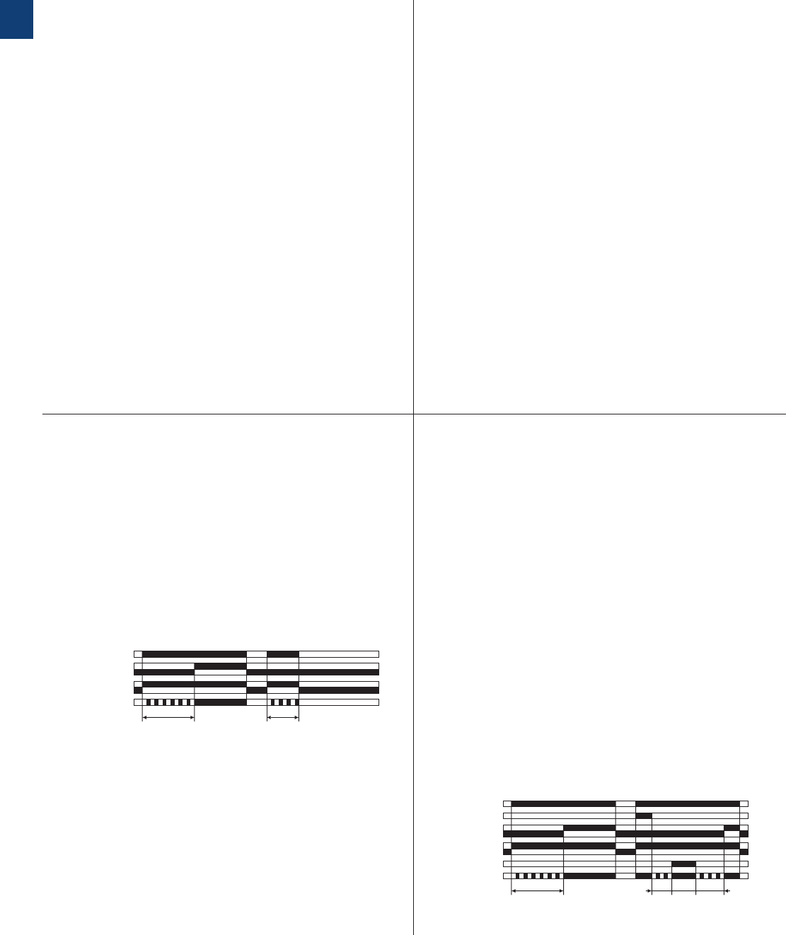
1/41 ABB | Catalog Electronic Products and Relays 2015 | 2CDC 110 004 C0210
1
CT-S range
Function diagrams
A ON-delay
(Delay on make)
CT-MVS, CT-ERS, CT-WBS
A ON-delay
(Delay on make)
CT-MFS, CT-MBS
A1-A2
15-16, 25-26
21-24
21-22
15-18, 25-28
t < t
2CDC 252 017 F0206
green LED
t = adjusted time delay
A1-A2
15-16, 25-26
21-24
21-22
15-18, 25-28
t1t3t2
t
X1-Z2
Y1-Z2
2CDC 252 018 F0206
green LED
t = adjusted time delay t1 + t2 = t
t3 = pause timing
This function requires continuous control supply voltage for
timing.
Timing begins when control supply voltage is applied. The
green LED flashes during timing. When the selected time
delay is complete, the output relay energizes and the flash-
ing green LED turns steady.
If control supply voltage is interrupted, the output relay de-
energizes and the time delay is reset.
This function requires continuous control supply voltage for
timing.
If control input Y1-Z2 is open, timing begins when control
supply voltage is applied. Or, if control supply voltage is
already applied, opening control input Y1-Z2 also starts tim-
ing. The green LED flashes during timing. When the selected
time delay is complete, the output relay energizes and the
flashing green LED turns steady.
If control input Y1-Z2 closes before the time delay is com-
plete, the time delay is reset and the output relay remains
de-energized.
Pause timing / Accumulative ON-delay (CT-MFS):
Timing can be paused by closing control input X1-Z2. The
elapsed time t1 is stored and continues from this time value
when X1-Z2 is re-opened. This can be repeated as often as
required.
If control supply voltage is interrupted, the output relay de-
energizes and the time delay is reset.
Remarks
Legend
G Control supply voltage not applied / Output contact open
B Control supply voltage applied / Output contact closed
A1-Y1/B1 Control input with voltage-related triggering
Y1-Z2 Control input with volt-free triggering
X1-Z2 Control input with volt-free triggering
Remote potentiometer connection:
When an external potentiometer is connected to the remote
potentiometer connection (terminals Z1-Z2, Z3-Z2 respective-
ly), the internal, front-face potentiometer is disabled and the
time adjustment is made via the external potentiometer.
2nd c/o contact selectable as instantaneous contact:
When switch position Inst. “I” is selected, the functionality of
the 2nd c/o contact changes to an instantaneous contact.
It acts like the c/o contacts of a switching relay, i.e. apply-
ing or interrupting the control supply voltage energizes or
de-energizes the c/o contact. The designation of the 2nd c/o
contact changes from 25-26/28 to 21-22/24, when selected
as instantaneous contact.
Terminal designations on the device and in the diagrams:
The 1st c/o contact is always designated 15-16/18.
The 2nd c/o contact is designated 25-26/28, if it responds to
the time delay.
If the 2nd c/o contact is selected as an instantaneous con-
tact, the designation 25-26/28 is replaced by 21-22/24.
Control supply voltage is always applied to terminals A1-A2.
Function of the yellow LEDs:
On devices without the function ‘2nd c/o contact selectable
as instantaneous contact’, the yellow LED R glows as soon as
the output relay energizes and turns off when the output relay
de-energizes.
Devices with the function ‘2nd c/o contact selectable as
instantaneous contact’ have two yellow LEDs, designated R1
and R2. LED R1 shows the status of the 1st c/o contact (15-
16/18) and LED R2 shows the status of the 2nd c/o contact
(25-26/28, 21-22/24 resp.). LED R1 or R2 glow as soon as
the corresponding output relay energizes and turns off when
the corresponding output relay de-energizes.
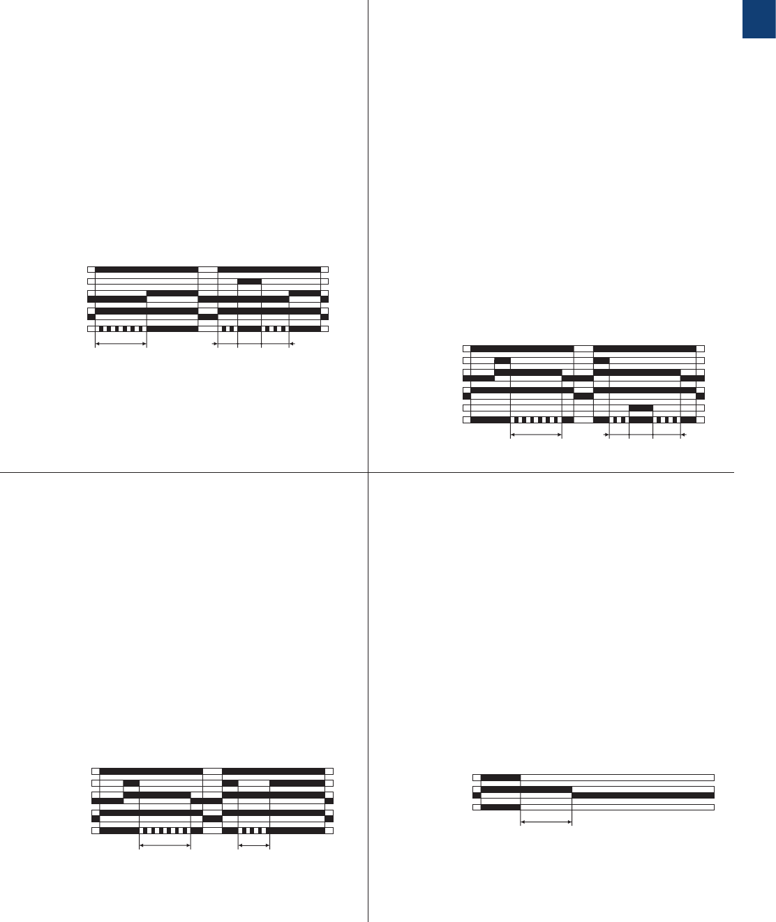
2CDC 110 004 C0210 | Catalog Electronic Products and Relays 2015 | ABB 1/42
1
CT-S range
Function diagrams
B OFF-delay with auxiliary voltage
(Delay on break)
CT-MFS, CT-MBS, CT-AHS
A1-A2
15-16, 25-26
21-24
21-22
15-18, 25-28
t1t3t2
t
X1-Z2
Y1-Z2
2CDC 252 019 F0206
green LED
t = adjusted time delay t1 + t2 = t
t3 = pause timing
A+ Accumulative ON-delay
(Accumulative delay on make)
CT-MVS
A1-A2
15-16, 25-26
21-24
21-22
15-18, 25-28
t1t3t2
t
A1-Y1/B1
2CDC 252 043 F0206
green LED
t = adjusted time delay t1 + t2 = t
t3 = pause timing
This function requires continuous control supply voltage for
timing.
Timing begins when control supply voltage is applied. The
green LED flashes during timing. When the selected time
delay is complete, the output relay energizes and the flashing
green LED turns steady.
Timing can be paused by closing control input A1-Y1/B1. The
elapsed time t1 is stored and continues from this time value
when A1-Y1/B1 is re-opened.
This can be repeated as often as required.
If control supply voltage is interrupted, the output relay de-
energizes and the time delay is reset.
This function requires continuous control supply voltage for
timing.
If control input Y1-Z2 is closed, the output relay energizes
immediately. If control input Y1-Z2 is opened, the time delay
starts. The green LED flashes during timing. When the se-
lected time delay is complete, the output relay de- energizes
and the flashing green LED turns steady.
If control input Y1-Z2 closes before the time delay is com-
plete, the time delay is reset and the output relay does not
change state. Timing starts again when control input Y1-Z2
re-opens.
Pause timing / Accumulative OFF-delay (CT-MFS):
Timing can be paused by closing control input X1-Z2. The
elapsed time t1 is stored and continues from this time value
when X1-Z2 is re-opened.
This can be repeated as often as required.
If control supply voltage is interrupted, the output relay de-
energizes and the time delay is reset.
B OFF-delay with auxiliary voltage
(Delay on break)
CT-MVS, CT-APS
A1-A2
15-16, 25-26
21-24
21-22
15-18, 25-28
t
A1-Y1/B1
< t
2CDC 252 020 F0206
green LED
t = adjusted time delay
B OFF-delay without auxiliary voltage
(True delay on break)
CT-ARS
A1-A2
15-16, 25-26
15-18, 25-28
t
2CDC 252 021 F0206
green LED
t = adjusted time delay
This function requires continuous control supply voltage for
timing.
If control input A1-Y1/B1 is closed, the output relay energizes
immediately. If control input A1-Y1/B1 is opened, the time
delay starts. The green LED flashes during timing. When the
selected time delay is complete, the output relay de-energizes
and the flashing green LED turns steady.
If control input A1-Y1/B1 recloses before the time delay is
complete, the time delay is reset and the output relay does
not change state. Timing starts again when control input A1-
Y1/B1 re-opens.
If control supply voltage is interrupted, the output relay de-
energizes and the time delay is reset.
The OFF-delay function without auxiliary voltage does not
require continuous control supply voltage for timing. After a
storage time of several months without any voltage, a format-
ting time of about 5 minutes is necessary.
Applying control supply voltage energizes the output relay
immediately. Applied control supply voltage is displayed by
the glowing green LED. If control supply voltage is interrupted,
the OFF-delay starts and the LED turns off. When timing is
complete, the output relay de-energizes.
For correct operation of the unit, it is necessary to complete
the minimum energizing time. As soon as timing starts, the
LED turns off.
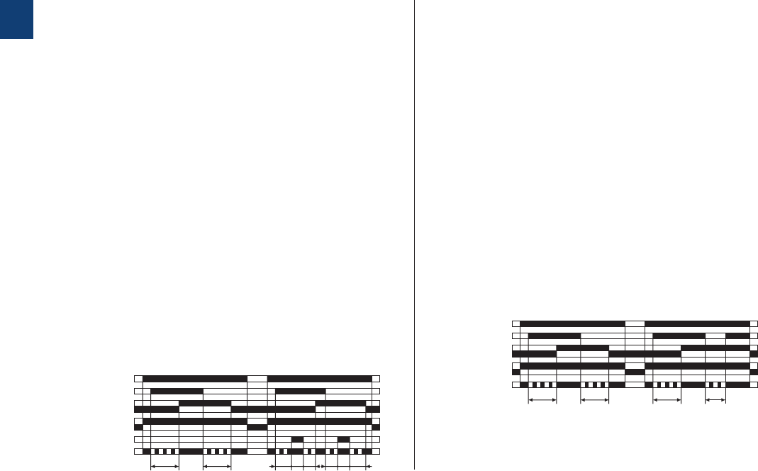
1/43 ABB | Catalog Electronic Products and Relays 2015 | 2CDC 110 004 C0210
1
AB Symmetrical ON-delay and OFF-delay
(Symmetrical delay on make and delay on break)
CT-MFS, CT-MBS
A1-A2
15-16, 25-26
21-24
21-22
15-18, 25-28
t1a t3t1b
t1
X1-Z2
Y1-Z2
t2t2a t3t2b
2CDC 252 022 F0206
green LED
t1 = adjusted ON-delay
t2 = adjusted OFF-delay
t1 = t2
t1a + t1b = t1
t2a + t2b = t2
t3 = pause timing
AB Symmetrical ON-delay and OFF-delay
(Symmetrical delay on make and delay on break)
CT-MVS
A1-A2
15-16, 25-26
21-24
21-22
15-18, 25-28
t1
A1-Y1/B1
t2t1< t2
2CDC 252 023 F0206
green LED
t1 = adjusted ON-delay
t2 = adjusted OFF-delay
t1 = t2
This function requires continuous control supply voltage for
timing.
Closing control input Y1-Z2 starts the ON-delay t1. When tim-
ing is complete, the output relay energizes. Opening control
input Y1-Z2 starts the OFF-delay t2. Both timing functions are
displayed by the flashing green LED. When the OFF-delay t2 is
complete, the output relay de-energizes.
If control input Y1-Z2 opens before the ON-delay t1 is com-
plete, the time delay is reset and the output relay remains de-
energized. If control input Y1-Z2 closes before the OFF-delay
t2 is complete, the time delay is reset and the output relay
remains energized.
Pause timing / Accumulative, symmetrical ON-delay and
OFF-delay (CT-MFS): Timing can be paused by closing control
input X1-Z2. The elapsed time t1a or t2a is stored and contin-
ues from this time value when X1-Z2 is re-opened. This can
be repeated as often as required.
If control supply voltage is interrupted, the output relay de-
energizes and the time delay is reset.
This function requires continuous control supply voltage for
timing.
Closing control input A1-Y1/B1 starts the ON-delay t1. When
timing is complete, the output relay energizes. Opening
control input A1-Y1/B1 starts the OFF-delay t2. Both timing
functions are displayed by the flashing green LED. When the
OFF-delay t2 is complete, the output relay de-energizes.
If control input A1-Y1/B1 opens before the ON-delay t1 is
complete, the time delay is reset and the output relay re-
mains de-energized. If control input A1-Y1/B1 closes before
the OFF-delay t2 is complete, the time delay is reset and the
output relay remains energized.
If control supply voltage is interrupted, the output relay de-
energizes and the time delay is reset.
CT-S range
Function diagrams
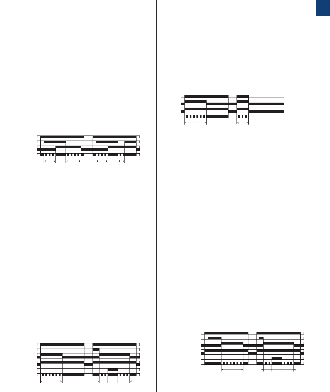
2CDC 110 004 C0210 | Catalog Electronic Products and Relays 2015 | ABB 1/44
1
CA Impulse-ON
(Interval)
CT-MVS, CT-WBS
A1-A2
15-16, 25-26
21-24
21-22
15-18, 25-28
t < t
2CDC 252 024 F0206
green LED
t = adjusted pulse time
AB Asymmetrical ON-delay and OFF-delay
(Asymmetrical delay on make and delay on break)
CT-MXS
A1-A2
15-16, 25-26
15-18, 25-28
t1
A1-Y1/B1
t2t1< t2
2CDC 252 038 F0206
green LED
t1 = adjusted ON-delay
t2 = adjusted OFF-delay
t1 and t2 independently adjustable
This function requires continuous control supply voltage for
timing.
Closing control input A1-Y1/B1 starts the ON-delay t1. When
timing is complete, the output relay energizes. Opening
control input A1-Y1/B1 starts the OFF-delay t2. When the
OFF-delay is complete, the output relay de-energizes. Both
timing functions are displayed by the flashing green LED. The
ON-delay and OFF-delay are independently adjustable.
If control input A1-Y1/B1 opens before the ON-delay is com-
plete (<t1), the time delay is reset and the output relay remains
de-energized.
If control input A1-Y1/B1 closes before the OFF-delay is com-
plete (<t2), the time delay is reset and the output relay remains
energized.
If control supply voltage is interrupted, the output relay de-
energizes and the time delay is reset.
This function requires continuous control supply voltage for
timing.
The output relay energizes immediately when control supply
voltage is applied and de-energizes after the set pulse time
is complete. The green LED flashes during timing. When
the selected pulse time is complete, the flashing green LED
turns steady.
If control supply voltage is interrupted, the output relay de-
energizes and the time delay is reset.
CA Impulse-ON
(Interval)
CT-MFS, CT-MBS
CB Impulse-OFF with auxiliary voltage
(Trailing edge interval)
CT-MFS, CT-MBS
A1-A2
15-16, 25-26
21-24
21-22
15-18, 25-28
t1t3t2
t
X1-Z2
Y1-Z2
2CDC 252 025 F0206
green LED
t = adjusted pulse time t1 + t2 = t
t3 = pause timing
A1-A2
15-16, 25-26
21-24
21-22
15-18, 25-28
t1t3t2
t
X1-Z2
Y1-Z2
2CDC 252 026 F0206
green LED
t = adjusted pulse time t1 + t2 = t
t3 = pause timing
This function requires continuous control supply voltage for
timing.
The output relay energizes immediately when control supply
voltage is applied and de-energizes after the set pulse time is
complete. If control input Y1-Z2 is open, timing begins when
control supply voltage is applied. Or, if control supply voltage
is already applied, opening control input Y1-Z2 starts timing.
The green LED flashes during timing. When the selected pulse
time is complete, the output relay de-energizes and the flash-
ing green LED turns steady.
Closing control input Y1-Z2, before the pulse time is com-
plete, de-energizes the output relay and resets the pulse time.
Pause timing / Accumulative impulse-ON (CT-MFS):
Timing can be paused by closing control input X1-Z2. The
elapsed time t1 is stored and continues from this time value
when X1-Z2 is re-opened.
This can be repeated as often as required.
If control supply voltage is interrupted, the output relay de-
energizes and the time delay is reset.
This function requires continuous control supply voltage for
timing.
If control supply voltage is applied, opening control input Y1-
Z2 energizes the output relay immediately and starts timing.
The green LED flashes during timing. When the selected pulse
time is complete, the output relay de-energizes and the flash-
ing green LED turns steady.
Closing control input Y1-Z2, before the pulse time is com-
plete, de-energizes the output relay and resets the pulse time.
Pause timing / Accumulative impulse-OFF (CT-MFS):
Timing can be paused by closing control input X1-Z2. The
elapsed time t1 is stored and continues from this time value
when X1-Z2 is re-opened.
This can be repeated as often as required.
If control supply voltage is interrupted, the output relay de-
energizes and the time delay is reset.
CT-S range
Function diagrams
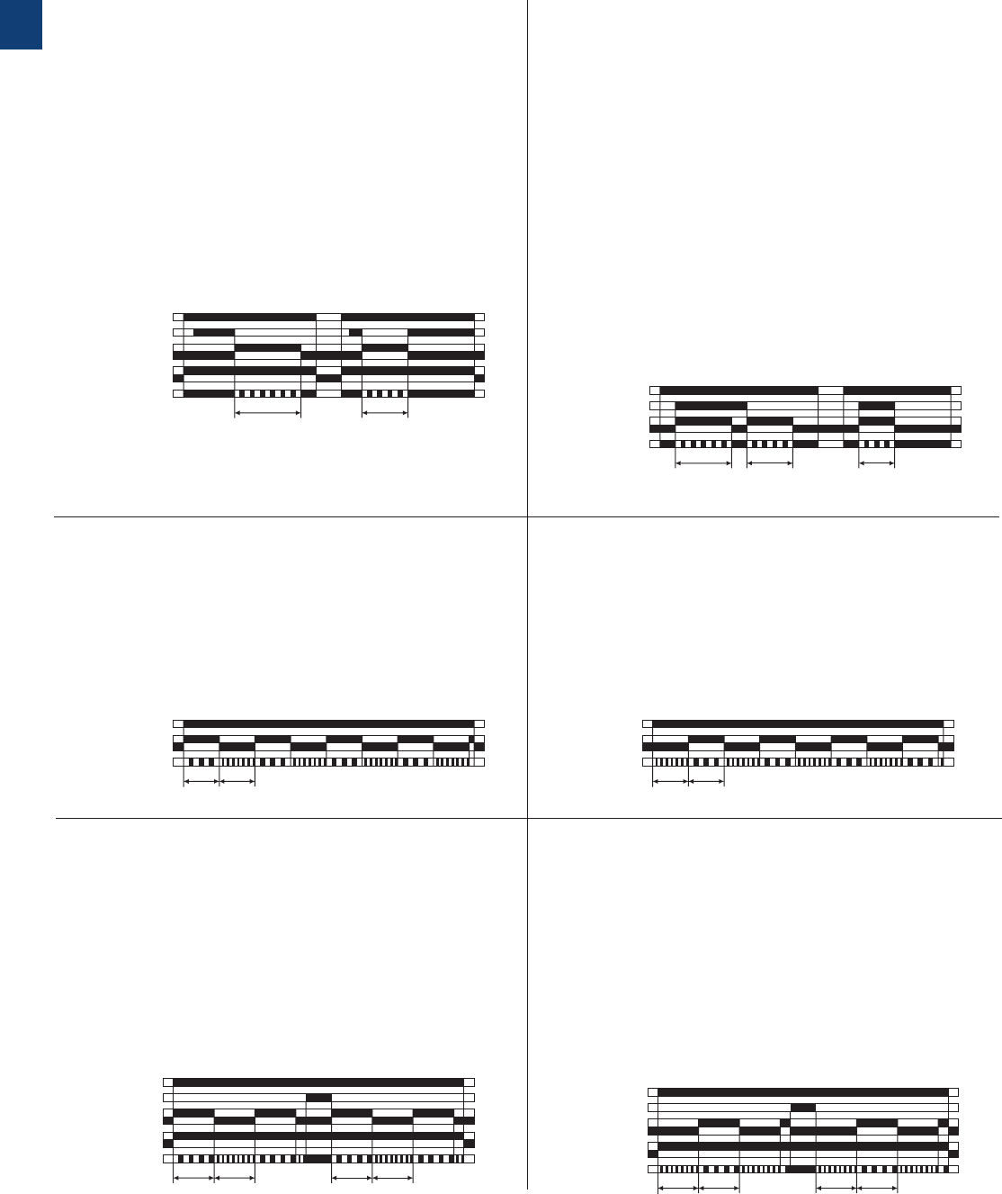
1/45 ABB | Catalog Electronic Products and Relays 2015 | 2CDC 110 004 C0210
1
DB Flasher, starting with the OFF time
(Recycling equal times, OFF first)
CT-WBS
DA Flasher, starting with the ON time
(Recycling equal times, ON first)
CT-WBS
A1-A2
15-16, 25-26
15-18, 25-28
t t
2CDC 252 029 F0206
green LED
t = adjusted flashing time
A1-A2
15-16, 25-26
15-18, 25-28
t t
2CDC 252 030 F0206
green LED
t = adjusted flashing time
Applying control supply voltage starts timing with symmetrical
ON & OFF times. The cycle starts with an ON time first. The
ON & OFF times are displayed by the flashing green LED,
which flashes twice as fast during the OFF time.
If control supply voltage is interrupted, the output relay de-
energizes and the time delay is reset.
Applying control supply voltage starts timing with symmetri-
cal ON & OFF times. The cycle starts with an OFF time first.
The ON & OFF times are displayed by the flashing green
LED, which flashes twice as fast during the OFF time.
If control supply voltage is interrupted, the output relay de-
energizes and the time delay is reset.
CB Impulse-OFF with auxiliary voltage
(Trailing edge interval)
CT-MVS
CE Impulse-ON and impulse-OFF
(Interval and trailing edge interval)
CT-MXS
A1-A2
15-16, 25-26
21-24
21-22
15-18, 25-28
t
A1-Y1/B1
< t
2CDC 252 027 F0206
green LED
t = adjusted pulse time
A1-A2
15-16, 25-26
15-18, 25-28
t1< t1
t2
A1-Y1/B1
2CDC 252 028 F0206
green LED
t1 = adjusted pulse time 1
t2 = adjusted pulse time 2
This function requires continuous control supply voltage for
timing.
If control supply voltage is applied, opening control input A1-
Y1/B1 energizes the output relay immediately and starts tim-
ing. The green LED flashes during timing. When the selected
pulse time is complete, the output relay de-energizes and the
flashing green LED turns steady.
Closing control input A1-Y1/B1, before the pulse time is com-
plete, de-energizes the output relay and resets the pulse time.
If control supply voltage is interrupted, the output relay de-
energizes and the time delay is reset.
This function requires continuous control supply voltage for
timing. If control supply voltage is applied, closing control
input A1-Y1/B1 energizes the output relay immediately and
starts the pulse time t1. The green LED flashes during timing.
When t1 is complete, the output relay de-energizes and the
flashing green LED turns steady. Re-opening control input
A1-Y1/B1 energizes the output relay immediately and starts
the pulse time t2. The green LED flashes during timing. When
t2 is complete, the output relay de-energizes and the flashing
green LED turns steady. t1 and t2 are independently adjust-
able. If control input A1-Y1/B1 changes state before the pulse
time is complete, the output relay de-energizes and the pulse
time is reset. If control input A1-Y1/B1 changes state again,
the interrupted pulse time restarts. If control supply voltage is
interrupted, the output relay de-energizes and the time delay
is reset.
CT-S range
Function diagrams
DB Flasher with reset, starting with the OFF time
(Recycling equal times with reset, OFF first)
CT-MFS, CT-MBS
A1-A2
Y1-Z2
15-16, 25-26
15-18, 25-28
21-22
21-24
tt tt
2CDC 252 032 F0206
green LED
t = adjusted flashing time
Applying control supply voltage starts timing with symmetri-
cal ON & OFF times. The cycle starts with an OFF time first.
The ON & OFF times are displayed by the flashing green LED,
which flashes twice as fast during the OFF time.
The time delay can be reset by closing control input Y1-Z2.
Opening control input Y1-Z2 starts the timer pulsing again
with symmetrical ON & OFF times.
If control supply voltage is interrupted, the output relay de-
energizes and the time delay is reset.
DA Flasher with reset, starting with the ON time
(Recycling equal times with reset, ON first)
CT-MFS, CT-MBS
A1-A2
Y1-Z2
15-16, 25-26
15-18, 25-28
21-22
21-24
tt tt
2CDC 252 031 F0206
green LED
t = adjusted flashing time
Applying control supply voltage starts timing with symmetrical
ON & OFF times. The cycle starts with an ON time first. The
ON & OFF times are displayed by the flashing green LED,
which flashes twice as fast during the OFF time.
The time delay can be reset by closing control input Y1-Z2.
Opening control input Y1-Z2 starts the timer pulsing again
with symmetrical ON & OFF times.
If control supply voltage is interrupted, the output relay de-
energizes and the time delay is reset.
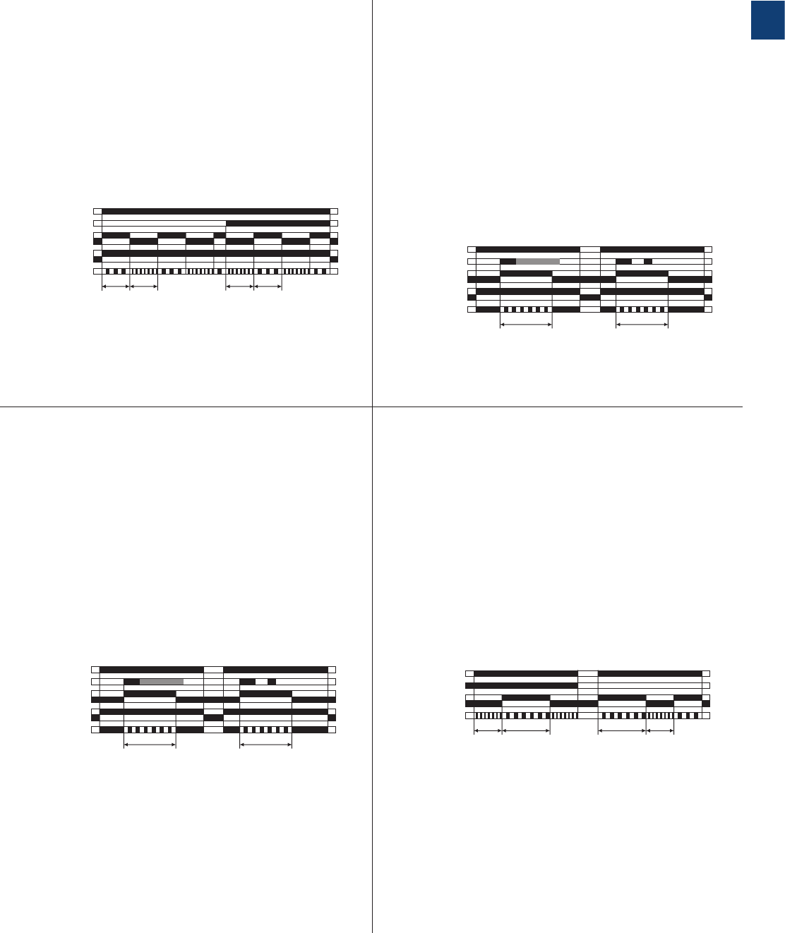
2CDC 110 004 C0210 | Catalog Electronic Products and Relays 2015 | ABB 1/46
1
DE Flasher, starting with the ON or OFF time
(Recycling equal times, ON or OFF first)
CT-MVS
H Pulse former
(Single shot)
CT-MFS, CT-MBS
A1-A2
A1-Y1/B1
15-16, 25-26
15-18, 25-28
21-22
21-24
t t t t
2CDC 252 033 F0206
green LED
t = adjusted flashing time
A1-A2
15-16, 25-26
21-24
21-22
15-18, 25-28
t t
Y1-Z2
2CDC 252 034 F0206
green LED
t = adjusted pulse time
Applying control supply voltage starts timing with symmetri-
cal ON & OFF times. The cycle starts with an ON time first.
Closing control input A1-Y1/B1, with control supply voltage
applied, starts the cycle with an OFF time first. The ON &
OFF times are displayed by the flashing green LED, which
flashes twice as fast during the OFF time.
If control supply voltage is interrupted, the output relay de-
energizes and the time delay is reset.
This function requires continuous control supply voltage for
timing.
Closing control input Y1-Z2 energizes the output relay im-
mediately and starts timing. Operating the control contact
switch Y1-Z2 during the time delay has no effect. The green
LED flashes during timing. When the selected ON time is
complete, the output relay de-energizes and the flashing
green LED turns steady. After the ON time is complete, it
can be restarted by closing control input Y1-Z2.
If control supply voltage is interrupted, the output relay de-
energizes and the time delay is reset.
CT-S range
Function diagrams
H Pulse former
(Single shot)
CT-MVS
A1-A2
15-16, 25-26
21-24
21-22
15-18, 25-28
t t
A1-Y1/B1
2CDC 252 035 F0206
green LED
t = adjusted pulse time
This function requires continuous control supply voltage for
timing.
Closing control input A1-Y1/B1 energizes the output relay
immediately and starts timing. Operating the control contact
switch A1-Y1/B1 during the time delay has no effect. The
green LED flashes during timing. When the selected ON time
is complete, the output relay de-energizes and the flashing
green LED turns steady. After the ON time is complete, it
can be restarted by closing control input A1-Y1/B1.
If control supply voltage is interrupted, the output relay de-
energizes and the time delay is reset.
ED Pulse generator, starting with the ON or OFF time
(Recycling unequal times, ON or OFF first)
CT-MXS
A1-A2
A1-Y1/B1
15-16, 25-26
15-18, 25-28
t1t1
t2t2
2CDC 252 075 F0207
green LED
t1 = adjusted OFF time
t2 = adjusted ON time
This function requires continuous control supply voltage for
timing.
Applying control supply voltage, with open control input
A1-Y1/B1, starts timing with an ON time t2 first. Applying
control supply voltage, with closed control input A1-Y1/B1,
starts timing with an OFF time t1 first. The ON & OFF times
are displayed by the flashing green LED, which flashes twice
as fast during the OFF time.
The ON & OFF times are independently adjustable.
If control supply voltage is interrupted, the output relay de-
energizes and the time delay is reset.
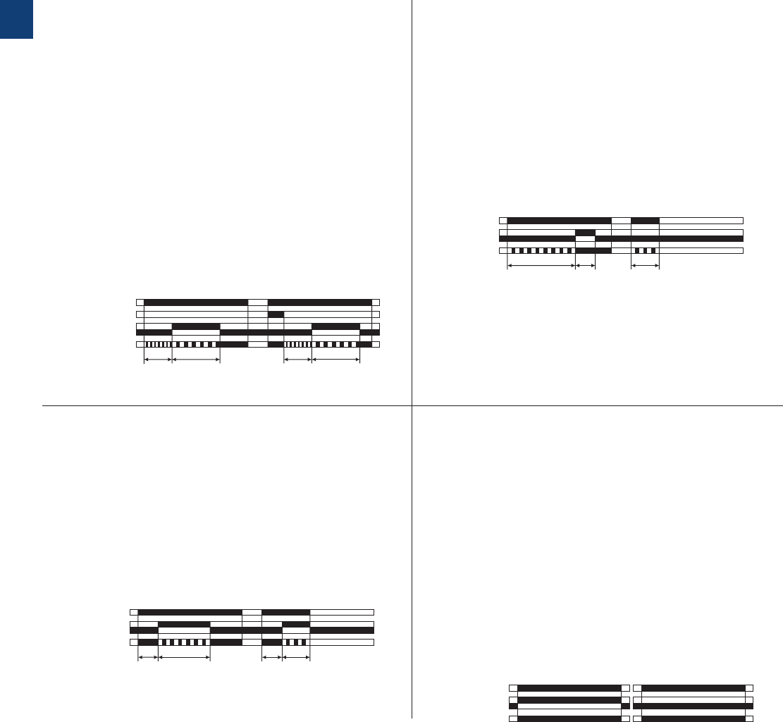
1/47 ABB | Catalog Electronic Products and Relays 2015 | 2CDC 110 004 C0210
1
EC Single-pulse generator, starting with the OFF time
(Delay on make with interval output)
CT-MXS
AC Fixed impulse with adjustable time delay
(Delayed pulse output)
CT-WBS
A1-A2
A1-Y1/B1
15-16, 25-26
15-18, 25-28
t1t2t2
t1
2CDC 252 037 F0206
green LED
t1 = adjusted OFF time
t2 = adjusted ON time
t1 and t2 independently adjustable
A1-A2
t1< t1
t2
15-18, 25-28
15-16, 25-26
2CDC 252 041 F0206
green LED
t1 = adjusted time delay
t2 = pulse time fixed 500 ms
This function requires continuous control supply voltage for
timing.
Applying control supply voltage, or, if control supply voltage is
already applied, opening control input A1-Y1/B1 energizes the
output relay after the OFF time t1 is complete. When the fol-
lowing ON time t2 is complete, the output relay de-energizes.
The ON & OFF times are displayed by the flashing green LED,
which flashes twice as fast during the OFF time.
The ON & OFF times are independently adjustable.
Closing control input A1-Y1/B1, with control supply voltage
applied, de-energizes the output relay and resets the time
delay.
If control supply voltage is interrupted, the output relay de-
energizes and the time delay is reset.
This function requires continuous control supply voltage for
timing.
The time delay t1 starts when control supply voltage is ap-
plied. The green LED flashes during timing. When t1 is com-
plete, the output relay energizes for the fixed impulse time t2
of 500 ms and the flashing green LED turns steady.
If control supply voltage is interrupted, the time delay is reset.
The output relay does not change state.
CT-S range
Function diagrams
BC Adjustable impulse with fixed time delay
(Delayed Interval) CT-WBS
G ON/OFF-Function
CT-MFS, CT-MBS, CT-MVS, CT-MXS, CT-WBS
A1-A2
t2t2< t1
t1
15-18, 25-28
15-16, 25-26
2CDC 252 042 F0206
green LED
t1 = adjusted pulse time
t2 = time delay fixed 500 ms
A1-A2
15-16, 25-26
15-18, 25-28
2CDC 252 044 F0206
green LED
Time sector ≠ 300 h Time sector = 300 h
This function requires continuous control supply voltage for
timing.
Applying control supply voltage starts the fixed time delay t2 of
500 ms. When t2 is complete, the output relay energizes and
the selected pulse time t1 starts. The green LED flashes dur-
ing timing. When t1 is complete, the output relay de-energizes
and the flashing green LED turns steady.
If control supply voltage is interrupted, the pulse time is reset.
The output relay does not change state.
This function is used for test purposes during commissioning
and troubleshooting.
If the selected max. value of the time range is smaller than
300 h (front-face potentiometer “Time sector” ≠ 300 h), apply-
ing control supply voltage energizes the output relay imme-
diately and the green LED glows. Interrupting control supply
voltage, de-energizes the output relay.
If the selected max. value of the time range is 300 h (front-
face potentiometer “Time sector” = 300 h) and control supply
voltage is applied, the green LED glows, but the output relay
does not energize.
Time settings and operating of the control inputs have no ef-
fect on the operation.
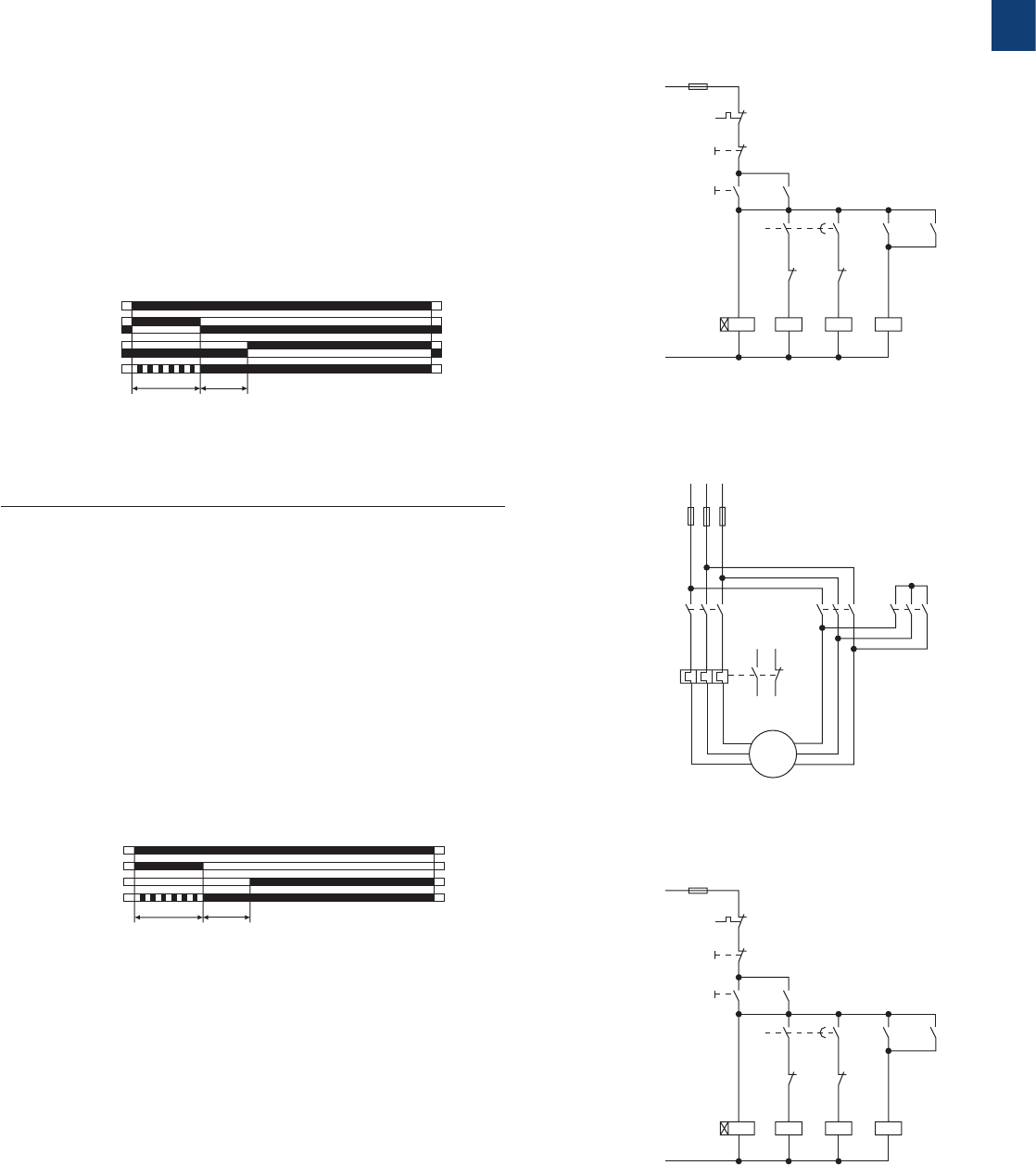
2CDC 110 004 C0210 | Catalog Electronic Products and Relays 2015 | ABB 1/48
1
K1T
K1T
K3
K3
YN
K2
K2
K2
L1
N
F3
F2
95
96
21
22
22
21
A1
A2
A1
A2
A1
A2
A1
A2
22
21
13
14
17
18
17
28
13
14
13
14
53
54
S1
0
I
S2
K1
K1
K1
2CDC 252 128 F0b0
6
-K1-K3
L1
-F1
1
2
95
96
97
98
L2
3
4
L3
5
6
1
2
3
4
5
6
1
2
3
4
5
6
-K2
-F2
1
2
3
4
5
6
1
3
5
2
4
6
M
3 ~
W2
V2
U2
W1
V1
U1
-M1
2CDC 253 009 F0012
K1T
K1T
K3
K3
YN
K2
K2
K2
L1
N
F3
F2
95
96
21
22
22
21
A1
A2
A1
A2
A1
A2
A1
A2
22
21
13
14
15
18
25
28
13
14
13
14
53
54
S1
0
I
S2
K1
K1
K1
2CDC 252 129 F0b0
6
F Star-delta change-over
(Star-delta starting)
CT-SDS
A1-A2
t1t2
2CDC 252 040 F0206
green LED
t1 = adjusted starting time
t2 = transition time (50 ms)
17-18
17-28
This function requires continuous control supply voltage for timing.
Applying control supply voltage to terminals A1-A2, energizes the
star contactor connected to terminals 17-18 and begins the set
starting time t1. The green LED flashes during timing. When the
starting time is complete, the first output contact de-energizes the
star contactor.
Now, the fixed transition time t2 of 50 ms starts. When the transi-
tion time is complete, the second output contact energizes the
delta contactor connected to terminals 17-28. The delta contactor
remains energized as long as control supply voltage is applied to
the unit.
Power circuit diagram
Control circuit diagram
Control circuit diagram
CT-S range
Function diagrams
FC Star-delta change-over with impulse function
(Star-delta starting, interval/delay on make)
CT-MFS, CT-MBS, CT-MVS.2x
A1-A2
15-16
25-26
t1t2
2CDC 252 039 F0206
green LED
t1 = adjusted starting time
t2 = transition time (50 ms)
15-18
25-28
This function requires continuous control supply voltage for timing.
Applying control supply voltage to terminals A1-A2, energizes the
star contactor connected to terminals 15-18 and begins the set
starting time t1. The green LED flashes during timing. When the
starting time is complete, the first c/o contact de-energizes the star
contactor.
Now, the fixed transition time t2 of 50 ms starts. When the transition
time is complete, the second c/o contact energizes the delta con-
tactor connected to terminals 25-28. The delta contactor remains
energized as long as control supply voltage is applied to the unit.
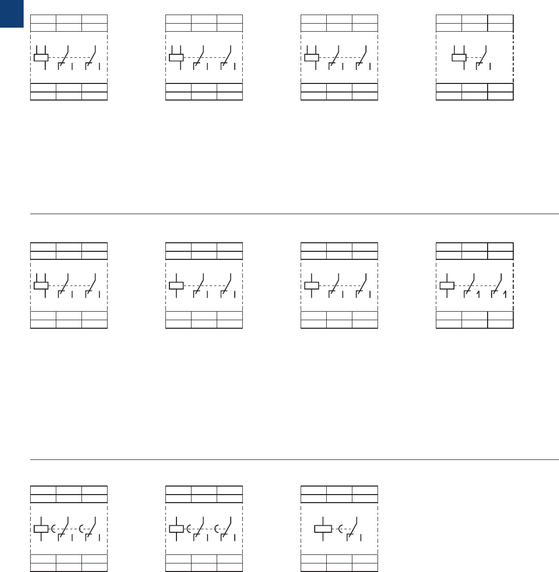
1/49 ABB | Catalog Electronic Products and Relays 2015 | 2CDC 110 004 C0210
1
CT-MVS.21 CT-MVS.22 CT-MVS.12
CT-MXS.22
2CDC 252 002 F0b06
A1
A1
Y1/
B1 15
A2 16 18
15
Z2
18 16 A2
Y1/B1 Z1
25 21
28 24 26 22
21
25
26 28
22 24
A1
A1
Y1/
B1 15 25
A2 16 18 26 28
15
28 26
25
18 16 A2
Y1/B1
2CDC 252 003 F0b06
A1
A1
Y1/
B1 15
A2 16 18
15 Y1/B1
18 16 A2
2CDC 252 004 F0b06
A1
A1
Y1/
B1 15 25
A2 16 18 26 28
15
Z2
28 26 Y1/B1
25
18 16 A2
Z3 Z1
2CDC 252 005 F0b06
A1
A1
Y1/
B1 15 25
A2 16 18 26 28
15
28 26
25
18 16 A2
Y1/B1
2CDC 252 003 F0b06
CT-MVS.23
A1
A1 15 21
25
A2 16 18 26 28
22 24
15
Z2
28 26
24 22 Y1
Z1
18 16 A2
X1
25 21
2CDC 252 006 F0b06
A1
A1 15 21
25
A2 16 18 26 28
22 24
15
Z2
28 26
24 22 Y1
Z1
18 16 A2
25 21
2CDC 252 007 F0b06
A1
A1 15 25
A2 16 18 26 28
15
28 26
25
18 16 A2
2CDC 252 008 F0b06
CT-MFS.21 CT-MBS.22 CT-WBS.22
A CT-ERS.21
A1
A1 15
A2 16 18
15
18 16
28 26
A2
25
25
26 28
2CDC 252 009 F0b06
A1
A1
A2 16 18
15
15
18 16 A2
2CDC 252 010 F0b06
A CT-ERS.22 A CT-ERS.12
A1
A1 15
A2 16 18
15
18 16
28 26
A2
25
25
26 28
2CDC 252 009 F0b06
CT-S range
Connection diagrams
A1-A2 Supply: 24-240 VAC/DC
A1-Y1/B1 Control input
15-16/18 1. c/o contact
25-26/28 2. c/o contact
21-22/24 2. c/o contact as
instantaneous contact
Z1-Z2 Remote potentiometer
connection
A1-A2 Supply: 24-240 VAC/DC
15-16/18 1. c/o contact
25-26/28 2. c/o contact
21-22/24 2. c/o contact as
instantaneous contact
Y1-Z2 Control input
X1-Z2 Control input
Z1-Z2 Remote potentiometer
connection
A1-A2 Supply: 24-48 V DC
or 24-240 V AC
15-16/18 1. c/o contact
25-26/28 2. c/o contact
21-22/24 2. c/o contact as
instantaneous
contact
Y1-Z2 Control input
Z1-Z2 Remote
potentiometer
connection
A1-A2 Supply: 24-48 V DC
or 24-240 V AC
15-16/18 1. c/o contact
25-26/28 2. c/o contact
A1-A2 Supply: 24-240 VAC/DC
15-16/18 1. c/o contact
25-26/28 2. c/o contact
A1-A2 Supply: 24-48 V DC
or 24-240 V AC
15-16/18 1. c/o contact
25-26/28 2. c/o contact
A1-A2 Supply: 24-48 V DC
or 24-240 V AC
15-16/18 1. c/o contact
A1-A2 Supply: 24-48 V DC
or 24-240 V AC
A1-Y1/B1 Control input
15-16/18 1. c/o contact
25-26/28 2. c/o contact
Z1-Z2 Remote
potentiometer
connection
Z3-Z2 Remote
potentiometer
connection
A1-A2 Supply: 224-48 VDC
or 24-240 V AC
A1-Y1/B1 Control input
15-16/18 1. c/o contact
25-26/28 2. c/o contact
A1-A2 Supply: 380-440VAC
A1-Y1/B1 Control input
15-16/18 1. c/o contact
25-26/28 2. c/o contact
A1-A2 Supply: 24-48 V DC
or 24-240 V AC
A1-Y1/B1 Control input
15-16/18 1. c/o contact
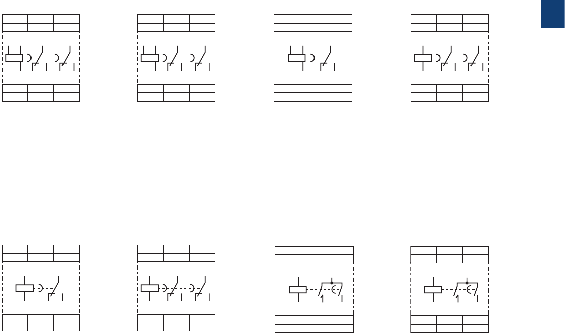
2CDC 110 004 C0210 | Catalog Electronic Products and Relays 2015 | ABB 1/50
1
B CT-APS.21 B CT-APS.22 B CT-AHS.22
B CT-ARS.11
A1
Y1/
B1 A1 15 25
A2 16 18 26 28
15
Y1/B1
2628
25
18 16 A2
2CDC 252 011 F0b06
A1
A1 15 25
A2 16 18 26 28
15
Z2
2628
25
18 16 A2
Y1
2CDC 252 013 F0b06
15A1
A1
A2 16 18
15
18 16 A2
2CDC 252 014 F0b06
A1
Y1/
B1 A1
A2 16 18
15
15 Y1/B1
18 16 A2
2CDC 252 012 F0b06
B CT-APS.12
A1
A1 15 25
A2 16 18 26 28
15
2628
25
18 16 A2
2CDC 252 015 F0b06
B CT-ARS.21 F CT-SDS.22
A1
A1
A2 18 28
17
17
18 28 A2
2CDC 252 016 F0b06
F CT-SDS.23
A1
Y1/
B1 A1 15 25
A2 16 18 26 28
15
Y1/B1
2628
25
18 16 A2
2CDC 252 011 F0b06
A1
A1
A2 18 28
17
17
18 28 A2
2CDC 252 016 F0b06
CT-S range
Connection diagrams
A1-A2 Supply: 24-240 V AC/DC
A1-Y1/B1 Control input
15-16/18 1. c/o contact
25-26/28 2. c/o contact
A1-A2 Supply: 24-240 V AC/DC
15-16/18 1. c/o contact
25-26/28 2. c/o contact
A1-A2 Supply: 24-48 V DC or
24-240 V AC
17-18 1. n/o contact
17-28 2. n/o contact
A1-A2 Supply: 380-440 V AC
17-18 1. n/o contact
17-28 2. n/o contact
A1-A2 Supply: 24-48 V DC or
24-240 V AC
A1-Y1/B1 Control input
15-16/18 1. c/o contact
25-26/28 2. c/o contact
A1-A2 Supply: 24-48 V DC or
24-240 V AC
A1-Y1/B1 Control input
15-16/18 1. c/o contact
A1-A2 Supply: 24-240 V AC/DC
15-16/18 1. c/o contact
A1-A2 Supply: 24-48 V DC or
24-240 V AC
Y1-Z2 Control input
15-16/18 1. c/o contact
25-26/28 2. c/o contact

1/51 ABB | Catalog Electronic Products and Relays 2015 | 2CDC 110 004 C0210
1
Data at Ta = 25 °C and rated values, unless otherwise indicated
CT-S
Input circuit - Supply circuit
Rated control supply voltage UsCT-xxx.x1 24-240 V AC/DC
CT-xxx.x2 24-48 V DC, 24-240 V AC
CT-xxx.x3 380-440 V AC
CT-xxx.x4 110-240 V AC
CT-xxx.x5 220-240 V AC
CT-xxx.x6 24 V AC/DC
CT-xxx.x7 100-127 V AC or 110 V DC
CT-xxx.x8 200-240V AC/DC
Rated control supply voltage US tolerance -15...+10 %
Rated frequency DC or 50/60 Hz
Frequency range AC 47-63 Hz
Typical current / power consumption depending on device, see data sheet
Power failure buffering time 24 V DC min. 15 ms
230/400 V AC min. 20 ms
Input circuit - Control circuit
Kind of triggering CT-MVS, CT-MXS, CT-APS voltage-related triggering
Control input, Control function A1-Y1/B1 start timing external
Parallel load / polarized yes / no
Maximum cable length to the control input 50 m - 100 pF/m
Minimum control pulse length 20 ms
Control voltage potential see rated control supply voltage
Current consumption of the control input 24 V DC 1.2 mA
230 V AC 8 mA
400 V AC 6 mA
Kind of triggering CT-MFS, CT-MBS, CT-AHS volt-free triggering
Control input, Control function Y1-Z2 start timing external
X1-Z2 pause timing / accumulative functions (CT-MFS)
Maximum switching current in the control circuit 1 mA
Maximum cable length to the control input 50 m - 100 pF/m
Minimum control pulse length 20 ms
No-load voltage at the control inputs 10-40 V DC
Remote potentiometer
Remote potentiometer connections, Resistance value Z1-Z2 50 kΩ (CT-MFS, CT-MBS, CT-MVS.21, CT-MXS)
Z3-Z2 50 kΩ (CT-MXS)
Maximum cable length to remote potentiometer 2 x 25 m, shielded with 100 pF/m
Shield connection Z2
Timing circuit
Time ranges 10 time ranges 0.05 s - 300 h
1.) 0.05-1 s 2.) 0.15-3 s 3.) 0.5-10 s 4.) 1.5-30 s 5.) 5-100 s
6.) 15-300 s 7.) 1.5-30 min 8.) 15-300 min 9.) 1.5-30 h 10.) 15-300 h
7 time ranges 0.05 s - 10 min (CT-SDS,
CT-ARS) 1.) 0.05-1 s 2.) 0.15-3 s 3.) 0.5-10 s
4.) 1.5-30 s 5.) 5-100 s 6.) 15-300 s 7.) 0.5-10 min
Recovery time 24-240 V AC/DC < 50 ms
24-48 V DC, 24-240 V AC < 80 ms
380-440 V AC < 60 ms
Accuracy within the rated control supply voltage tolerance it < 0.004 % / V
Accuracy within the temperature range it < 0.03 % / °C
Repeat accuracy (constant parameters) < ±0.2 %
Star-delta transition time fixed 50 ms (CT-SDS, CT-MBS, CT-MFS, CT-MVS.2x)
Star-delta transition time tolerance ±2 ms
Minimum energizing time 100 ms (CT-ARS)
Formatting time 1) 5 min (CT-ARS)
CT-S range
Technical data
1) prior to first commisioning and after a six-month stop in operation

2CDC 110 004 C0210 | Catalog Electronic Products and Relays 2015 | ABB 1/52
1
CT-S range
Technical data
Indication of operational states
Control supply voltage / timing U/T: green LED V: control supply voltage applied / W: timing
Control supply voltage U: green LED V: control supply voltage applied
Relay state R, R1, R2: yellow LED V: output relay energized
Output circuit
Kind of output 15-16/18 relay, 1 c/o contact
15-16/18; 25-26/28 relay, 2 c/o contacts
15-16/18; 25(21)-26(22)/28(24) relay, 2 c/o contacts, 2nd c/o contact selectable as inst. contact
17-18; 17-28 relay, 2 n/o contacts (CT-SDS)
Contact material Cd-free, on request
Rated operational voltage UeIEC/EN 60947-1 250 V
Minimum switching voltage / minimum switching current 12 V / 10 mA
Maximum switching voltage / maximum switching current see load limit curves
Rated operational current Ie
(IEC/EN 60947-5-1 ) AC-12 (resistive) at 230 V 4 A
AC-15 (inductive) at 230 V 3 A
DC-12 (resistive) at 24 V 4 A
DC-13 (inductive) at 24 V 2 A (CT-ARS; 1.5 A)
AC rating (UL 508) Utilization category (Control Circuit Rating Code) B 300
max. rated operational voltage 300 V AC
Maximum continuous thermal current at B300 5 A
max. making/breaking apparent power at B300 3600 VA / 360 VA
Mechanical lifetime 30 x 106 switching cycles
Electrical lifetime at AC-12, 230 V, 4 A 0.1 x 10⁶ switching cycles
Max. fuse rating to achieve short-circuit protection
(IEC/EN 60947-5-1) n/c contact 6 A fast-acting
n/o contact 10 A fast-acting
General data 2)
MTBF on request
Duty time 100%
Dimensions (W x H x D) product dimensions 22.5 x 85.6 x 103.7 mm (0.89 x 3.37 x 4.08 in)
packaging dimensions 97 x 109 x 30 mm (3.82 x 4.29 x 1.18 in)
Weight depending on device, see ordering details
Mounting DIN rail (IEC/EN 60715), snap-on mounting without any tool
Mounting position any
Minimum distance to other units vertical / horizontal not necessary / not necessary
Material of housing UL 94 V-0
Degree of protection housing / terminals IP50 / IP20
Electrical connection 2)
Screw connection technology Easy Connect Technology
(Push-in)
Wire size fine-strand with(out) wire end
ferrule 1 x 0.5-2.5 mm2 (1 x 20-14 AWG)
2 x 0.5-1.5 mm2 (2 x 20-16 AWG) 2 x 0.5-1.5 mm2 (2 x 20-16 AWG)
rigid 1 x 0.5-4 mm2 (1 x 20-12 AWG)
2 x 0.5-2.5 mm2 (2 x 20-14 AWG) 2 x 0.5-1.5 mm2 (2 x 20-16 AWG)
Stripping length 8 mm (0.32 in)
Tightening torque 0.6-0.8 Nm (5.31-7.08 lb.in) -
2) Data for all references 1SVR 730 xxx xxx and 1SVR 740 xxx xxx. For devices with 1SVR 430 xxx xxx please refer to the data sheet.

1/53 ABB | Catalog Electronic Products and Relays 2015 | 2CDC 110 004 C0210
1
CT-S range
Technical data
Environmental data
Ambient temperature ranges operation / storage -25...+60 °C / -40...+85 °C,
-40...+60 °C / -40...+85 °C (CT-MVS.21, CT-MFS.21, CT-ERS.21,
CT-APS.21)
Damp heat (cyclic) (IEC/EN 60068-2-30) 6 x 24 h cycle, 55 °C, 95 % RH
Vibration, sinusoidal (IEC/EN 60068-2-6) functioning 40 m/s2, 10-58/60-150 Hz
resistance 60 m/s2, 10-58/60-150 Hz, 20 cycles
Vibration, seismic (IEC/EN 60068-3-3) functioning 20 m/s2
Shock, half-sine (IEC/EN 60068-2-27) functioning 100 m/s2, 11 ms, 3 shocks/direction
resistance 300 m/s2 , 11 ms, 3 shocks/direction
Isolation data CT-S with 1 c/o CT-S with 2 c/o
Rated insulation voltage Uiinput circuit / output circuit 500 V
output circuit 1 / output circuit 2 not available 300 V
Rated impulse withstand voltage Uimp
between all isolated circuits IEC/EN 60664-1 type test: 4 kV; 1.2/50 µs
Power-frequency withstand voltage (test voltage) between all isolated
circuits routine test: 2.0 kV; 50 Hz; 1 s
type test: 2.0 kV; 50 Hz; 60 s
Basic insulation (IEC/EN 61140) input circuit / output circuit 500 V
Protective separation
(IEC/EN 61140; EN 50178) input circuit / output circuit 250 V
Pollution degree IEC/EN 60664-1 3
Overvoltage category IEC/EN 60664-1 III
Standards
Product standard IEC 61812-1, EN 61812-1 + A11, DIN VDE 0435 part 2021
Low Voltage Directive 2006/95/EC
EMC Directive 2004/108/EC
RoHS Directive 2011/65/EC
Electromagnetic compatibility
Interference immunity to IEC/EN 61000-6-1, IEC/EN 61000-6-2
electrostatic discharge IEC/EN 61000-4-2 Level 3, 6 kV / 8 kV
radiated, radio-frequency
electromagnetic field IEC/EN 61000-4-3 Level 3, 10 V/m (1 GHz) 3 V/m (2 GHz) 1 V/m (2.7 GHz)
electrical fast transient / burst IEC/EN 61000-4-4 Level 3, 2 kV / 5 kHz
surge IEC/EN 61000-4-5 Level 4, 2 kV A1-A2
conducted disturbances, induced by
radio-frequency fields IEC/EN 61000-4-6 Level 3, 10 V
harmonics and interharmonics IEC/EN 61000-4-13 Class 3
Interference emission IEC/EN 61000-6-3, IEC/EN 61000-6-4
high-frequency radiated IEC/CISPR 22, EN 55022 Class B
high-frequency conducted IEC/CISPR 22, EN 55022 Class B
„Approvals and marks“ see page 1/4.
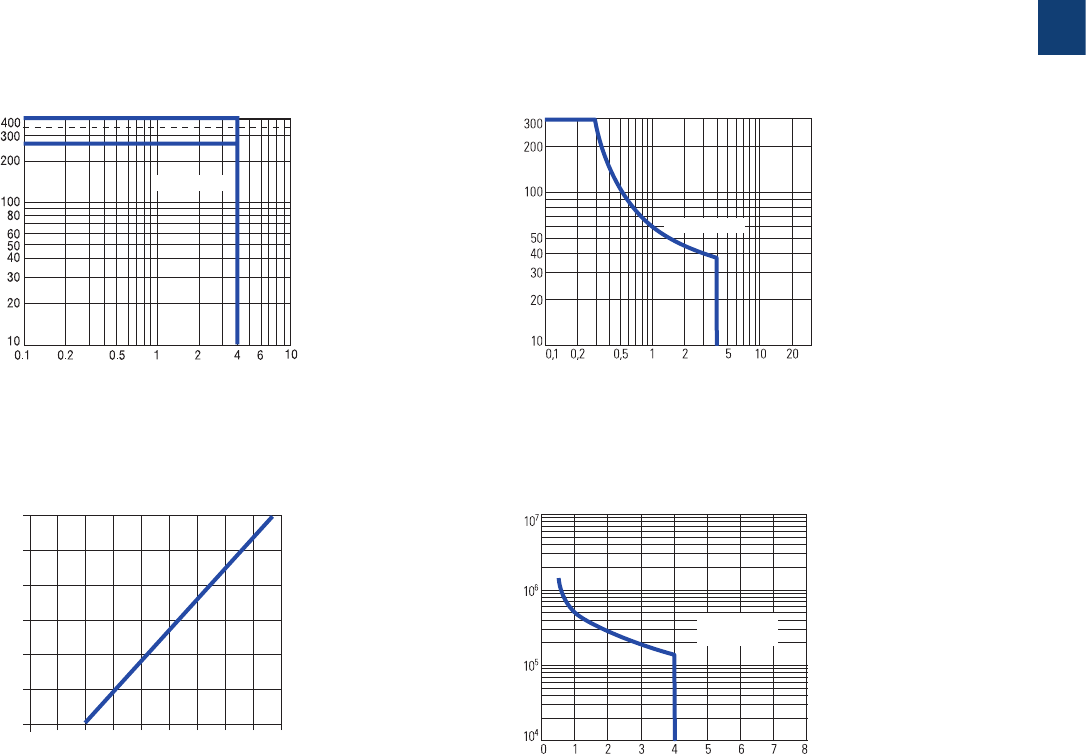
2CDC 110 004 C0210 | Catalog Electronic Products and Relays 2015 | ABB 1/54
1
CT-S range
Technical diagrams
AC load (resistive) DC load (resistive)
Technical diagrams
Load limit curves
Derating factor F for inductive AC load Contact lifetime
DC current [A]
resistive load
DC voltage [V]
2CDC 252 150 F0206
cos ϕ
0.5
0.1 0.2 0.3 0.40.5 0.60.7 0.80.9 1.0
0.6
0.7
0.8
0.9
1.0
Derating factor F
2CDC 252 124 F0206
AC current [A]
resistive load
AC voltage [V]
2CDC 252 149 F0206
Switching current [A]
250 V
resistive load
Switching cycles
2CDC 252 148 F0206
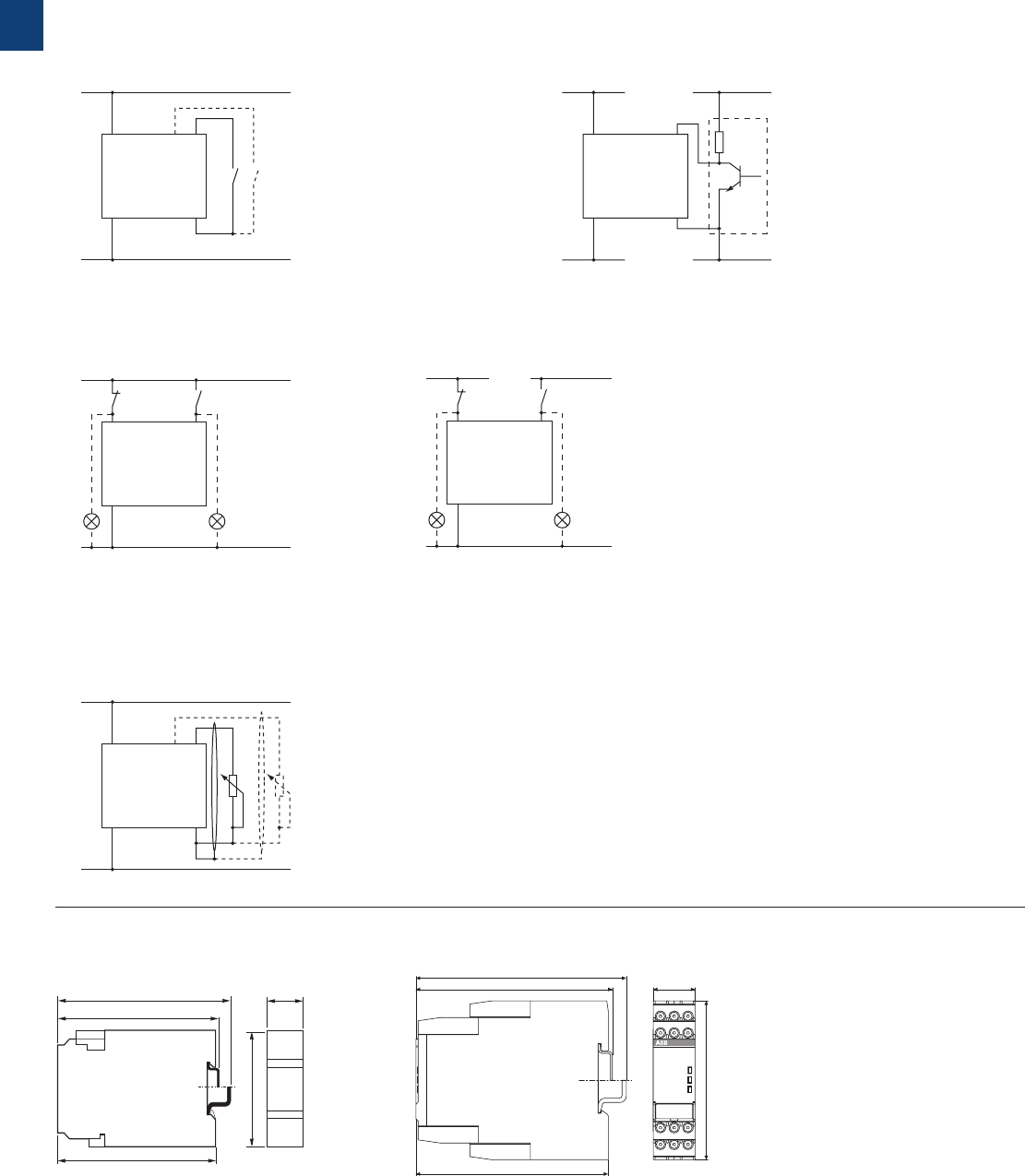
1/55 ABB | Catalog Electronic Products and Relays 2015 | 2CDC 110 004 C0210
1
CT-S range
Wiring notes, Dimensional drawings
2CDC 252 188 F0b05
100
102
109,5 4.31“ 22,5
.886“
78 3.07“
4.02“
3.94“
L(+)
N(-)
A1 Y1
Z2
X1
A2
2CDC 252 101 F0b06
L(+)
N(-)
A1 Y1/B1
A2
2CDC 252 102 F0b06
L(+)
L(+)
N(-)
L(-)
A1 Y1/B1
A2
2CDC 252 103 F0b06
L(+)
N(-)
A1 Z1
Z2
Z3
A2
2CDC 252 104 F0b06
L(+)
+V
N(-)
0 V
A1 Y1
Z2A2
2CDC 252 105 F0b06
Wiring notes
Remote potentiometer
Control inputs
(volt-free triggering)
Control inputs
(voltage-related triggering)
Triggering of the control inputs (volt-free)
with a proximity switch (3 wire)
The control input Y1/B1 is triggered with electric potential against A2. It is pos-
sible to use the control supply voltage from terminal A1 or any other voltage
within the rated control supply voltage range.
113.4 4.47”
22.5 0.89”
85.6 3.37”
103.7 4.08”
105.9 4.17”
2CDC 252 009 F0011
1SVR 430 xxx xxx 1SVR 730 xxx xxx, 1SVR 740 xxx xxx
Dimensional drawing Dimensions in mm

2CDC 110 004 C0210 | Catalog Electronic Products and Relays 2015 | ABB 1/56
1
Electronic timers
Notes
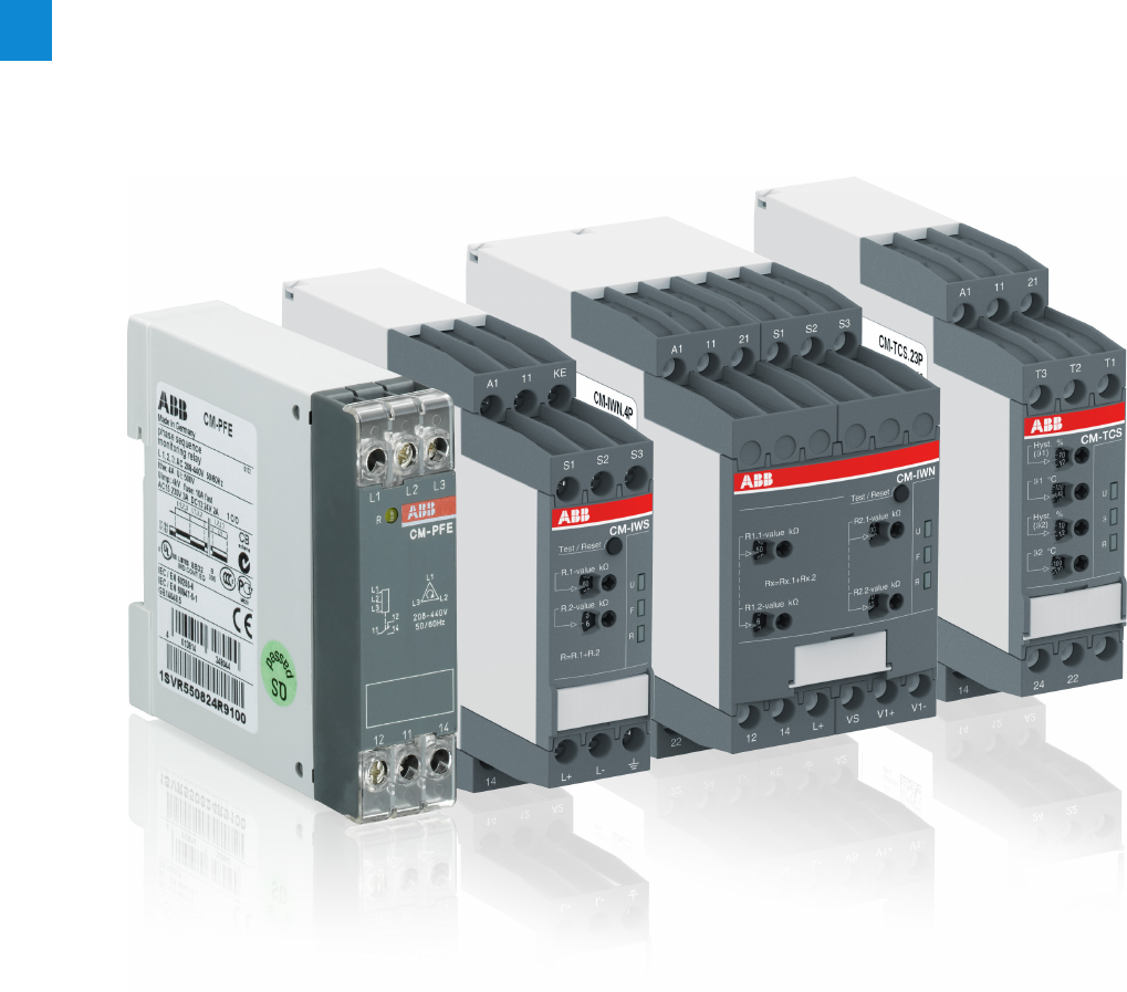
2/1 ABB | Catalog Electronic Products and Relays 2015 | 2CDC 110 004 C0210
2
Measuring and monitoring relays
Product group picture

2CDC 110 004 C0210 | Catalog Electronic Products and Relays 2015 | ABB 2/2
2
Measuring and monitoring relays
Table of contents
Measuring and monitoring relays
Benefits and advantages 2/3
Monitoring features and application ranges 2/5
Approvals and marks 2/7
Current and voltage monitoring relays, single-phase ........................... 2/9
Three-phase monitoring relays ........................................................ 2/27
Grid feeding monitoring relays -
Voltage and frequency monitoring functions ..................................... 2/49
Insulation monitoring relays for unearthed supply systems ................ 2/59
Motor load monitoring relays ........................................................... 2/73
Motor control and protection ........................................................... 2/79
Thermistor motor protection relays .................................................. 2/85
Temperature monitoring relays ......................................................... 2/97
Liquid level monitors and controls.................................................. 2/109
General technical data, Accessories, Current transformers ............. 2/123
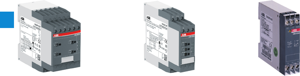
2/3 ABB | Catalog Electronic Products and Relays 2015 | 2CDC 110 004 C0210
2
Measuring and monitoring relays
Benefits and advantages
–
Only 22.5 mm wide housing
– Output contacts: 1 c/o
contact or 1 n/o contact
– One supply voltage range
– One monitoring function
– Cost-efficient solution for
OEM applications
– Preset monitoring ranges
– Only 22.5 mm wide housing
– Output contacts: 1 or 2 c/o (SPDT) con-
tacts
– One supply voltage range or supplied by
measuring circuit
– Setting and operation via front-face
operating controls
– Adjustment of threshold values and
switching hysteresis via direct reading
scale
– Integrated and snap-fitted front-face
marker
– Snap-on housing: The relays can be
placed on a DIN rail tool-free - just snap
it on or remove it tool-free
– Sealable transparent cover (accessory)
– 45 mm wide housing
– Output contacts: 2 c/o (SPDT) contacts
– Continuous voltage range (24-240 V AC/DC)
or single-supply
– Setting and operation via front-face operat-
ing controls
– Adjustment of threshold values and switch-
ing hysteresis via direct reading scale
– Adjustable time delays
– Integrated and snap-fitted front-face marker
label
– Sealable transparent cover (accessory)
CM-N range: Multifunctional CM-S range:
Universal and multifunctional
CM-E range: Economy
ABB‘s measuring and monitoring relays in a new housing
Easy Connect Technology
New options:
Additionally to the existing well established screw connections
a new innovative connection technology can be offered: Easy
Connect Technology with push-in terminals.
Tool-free wiring:
The push-in terminals can be wired with rigid or fine stranded
wires with wire end ferrules totally tool-free. The connection
direction is exactly the same as the screw version.
Higher utility class:
The Easy Connect Technology provides excellent vibration
resistance with gas tight push-in terminals – the right solution
for harsh environment.
Extended features
Flammability:
The plastic housing material used meets the requirements for
the highest flammability class. (UL94 V-0 rated)
Look and feel:
The new housing fits perfectly with ABB’s control products
offer.
Benefits at a glance
2CDC 110 004 C0210 | Catalog Electronic Products and Relays 2015 | ABB 2/4
2
Double-chamber cage connection terminals
Double-chamber cage connection terminals provide connec-
tion of wires up to 2 x 0.5-2.5 mm² (2 x 20-14 AWG) rigid or
fine-strand, with or without wire end ferrules. Potential dis-
tribution does not require additional terminals. The extended
type designators for products with double-chamber cage con-
nection terminals are indicated by a S following the extended
type designator e.g. CM-xxS.xxS.
LED‘s for status indication
All actual operational states are displayed by front-face LEDs,
thus simplifying commissioning and troubleshooting.
Integrated marker label
Integrated marker labels allow the product to be marked
quickly and simply. No additional marker labels are required.
Sealable transparent cover
Protection against unauthorized changes of time and thresh-
old values. Available as an accessory.
Snap-On housing
Tool-free DIN rail installation and deinstallation of the monitor-
ing relay.
Measuring and monitoring relays
Benefits and advantages
2CDC 253 011 F0003 1SVC 110 000 F0506
2CDC 253 026 F0011
2CDC 253 025 F0011
2CDC 252 006 F0012
2CDC 255 006 S0011
2CDC 253 007 F0012
Higher utility class
The Easy Connect Technology provides excellent vibration
resistance with gas tight push-in terminals – the right solu-
tion for harsh environment. Selected products of the elec-
tronic timers and measuring and monitoring relays comply
to the latest rail standards NF F 16-101/102, EN 45545,
EN 50155 and more standards which are relevant for rail-
way applications. Find more inforamtion in the rail brochure
2CDC110084B0201.
Safety
The „real distance“ is hidden.
The clearance and the creepage distances of our products
exceed international standards and substantially increase the
safety of our products.
Easy Connect Technology
Tool-free wiring and excellent vibration resistance. Push-in
terminals provide connection of wires up to 2 x 0.5 - 1.5 mm²
(2 x 20 -16 AWG), rigid or fine-strand with or without wire
end ferrules. The extended type designators for products with
push-in terminals are indicated by a P following the extended
type designator e.g. CM-xxS.xxP.
1
1
3
3
4
4
5 7
7
5
68
6
2
2
8
2CDC 253 013 F0013
8
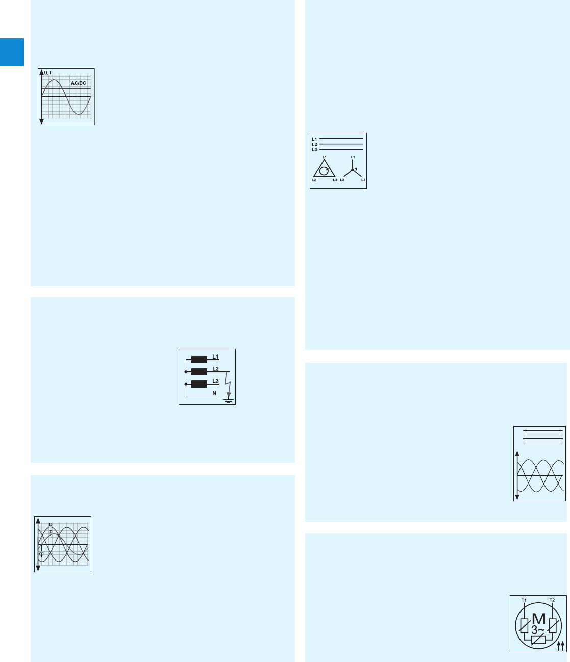
2/5 ABB | Catalog Electronic Products and Relays 2015 | 2CDC 110 004 C0210
2
Measuring and monitoring relays
Monitoring features and application ranges
v
Single-phase current and voltage monitoring
– Over- or undercurrent monitoring CM-SRS and CM-SRS.M
– Over- and undercurrent monitoring CM-SFS
– Over- or undervoltage monitoring CM-ESS and CM-ESS.M
– Over- and undervoltage monitoring CM-EFS
Three-phase monitoring
– Phase failure CM-PBE
– Over- and undervoltage CM-PVE
– Phase sequence and phase failure CM-PFE and CM-PFS
– Phase sequence and phase failure, over- and undervoltage
CM-PSS.xx and CM-PVS.xx
– Phase sequence and phase failure, unbalance CM-PAS.xx
– Phase sequence and phase failure, unbalance, over- and
undervoltage CM-MPS.xx and CM-MPN.xx
–
Over- and undervoltage, over- and underfrequency CM-UFS.1
Motor load monitoring
CM-LWN monitoring relays load states of single- and three-
phase asynchronous motors.
Current monitoring
– Monitoring of motor current consumption
– Monitoring of lighting installations and heating circuits
– Monitoring of hoisting gear and transportation equipment
overload
– Monitoring of locking devices, electromechanical brake
gear and locked rotor
Voltage monitoring
– Speed monitoring of DC motors
– Monitoring of battery voltages and other supply networks
– Monitoring of upper and lower voltage threshold values
Three-phase voltage monitoring
– Voltage monitoring of mobile three-phase equipment
– Protection of personnel and installations against phase
reversal
– Monitoring of the supply voltage to machines and installa-
tions
– Protection of equipment against damage caused by un-
stable supply voltage
– Switching to emergency or auxiliary supply
– Protection of motors against damage caused by unbal-
anced phase voltages and phase loss
– Automatic connection & disconnection of decentralised
power stations to the grid
Insulation monitoring
– For electrically isolated AC systems: CM-IWS.2
– For electrically isolated AC, DC and mixed AC/DC systems:
CM-IWS.1, CM-IWN.1 and especially for solar applications:
m 500 µF: CM-IWN.4
m 1000 µF: CM.IWN.5
m 2000 µF: CM-IWN.6
– Monitoring of electrically isolated supply mains for insula-
tion resistance failure
– Detection of initial faults
– Protection against earth faults
– Detection of V-belt breaking
– Motor protection against overload
– Monitoring of filters for clogging
– Protection of pumps against dry running
– Detection of high pressure in conduit systems
–
Monitoring for dulling blades in sawing and cutting machines
ϑ
Thermistor motor protection
CM-MSS provide full protection of motors with integrated
PTC resistor sensors.
Grid feeding monitoring relays
The CM-UFx range monitors all voltage and frequency pa-
rameters in a grid and ensures the safe feeding of decentral
produced eletrical energy into the grid.
– Monitoring of the voltage with up to 2 thresholds for over-
and undervoltage
– Monitoring of the frequency with up to 2
thresholds for over- and underfrequency
– Optional ROCOF (rate of change of frequency)
and vector shift
– Acc. to national grid feeding standards such
as CEI 0-21, VDE AR-N 4105 etc.
– Protection of motors against thermal over-
load, e. g. caused by insufficient cooling,
heavy load starting conditions, undersized
motors, etc.
V, f
L1
L2
L3
N
2CDC 110 004 C0210 | Catalog Electronic Products and Relays 2015 | ABB 2/6
2
– Protection of pumps against dry running
– Protection against container overflow
– Control of liquid levels
– Detection of leaks
– Control of mixing ratios
Liquid level monitoring and control
CM-ENE, CM-ENS and CM-ENN for control and regulation of
liquid levels and ratios of mixtures of conductive fluids.
ϑ
Temperature monitoring
– Motor and system protection
– Control panel temperature monitoring
– Frost monitoring
– Temperature limits for process variables, e.g. in the
packing or electroplating industry
– Control of systems and machines like heating,
air-conditioning and ventilation systems, solar collectors,
heat pumps or hot water supply systems
– Monitoring of servomotors with KTY sensors
– Bearing and gear oil monitoring
– Coolant monitoring
Acquisition, messaging and regulation of temperatures of
solid, liquid and gaseous media in processes and machines
– with CM-TCS via PT100 sensor
– with C512 and C513 with PT100, PT1000
KTY83, KTY84 or NTC sensors
Measuring and monitoring relays
Monitoring features and application ranges
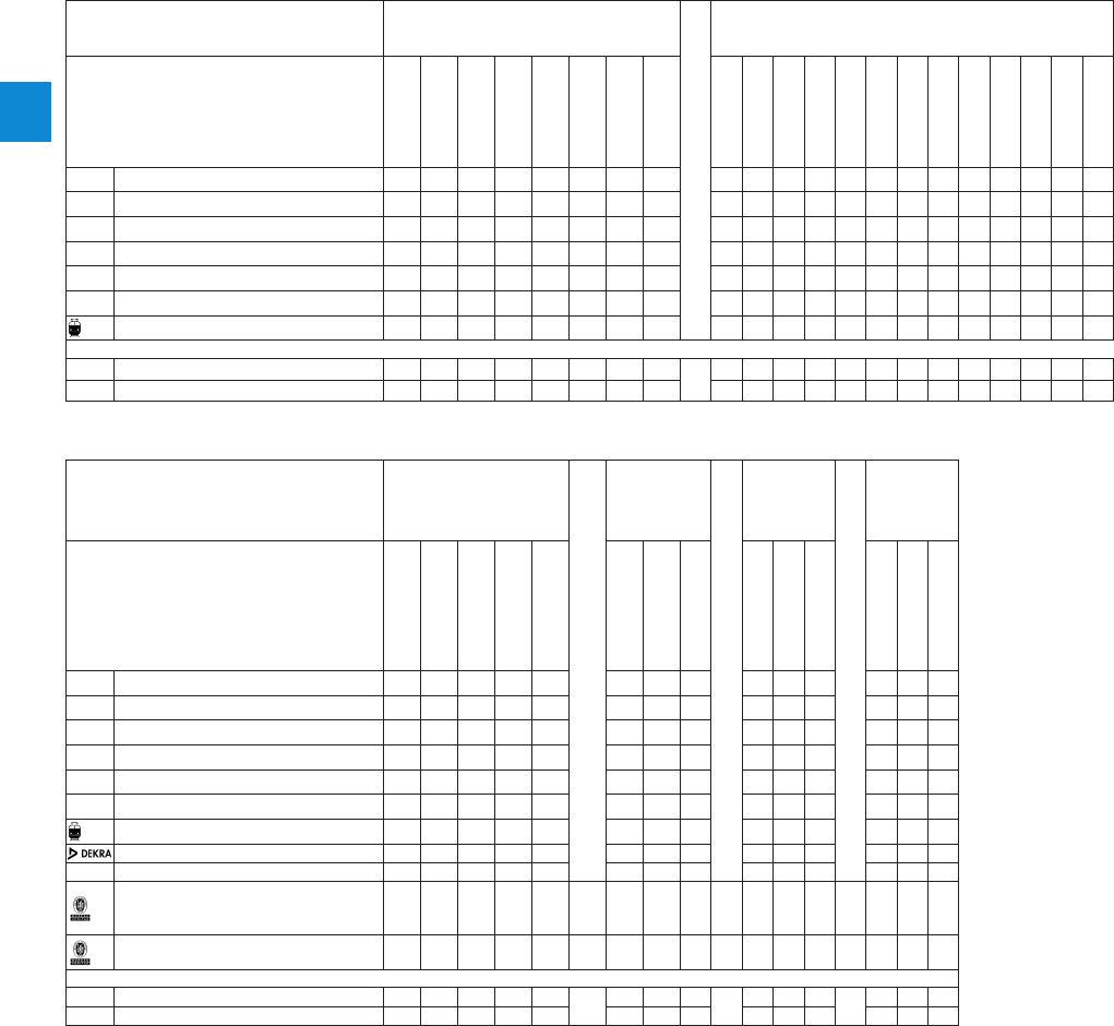
2/7 ABB | Catalog Electronic Products and Relays 2015 | 2CDC 110 004 C0210
2
Measuring and monitoring relays
Approvals and marks
J existing
j pending
Current and voltage monitoring,
single-phase Three-phase monitoring
Approvals
CM-SRS.1xS/P
CM-SRS.2xS
CM.SRS.MS/P
CM-SFS.2S/P
CM-ESS.1xS/P
CM-ESS.2xS
CM-ESS.MS/P
CM- EFS.2S/P
CM-PBE
CM-PVE
CM-PFE
CM-PFS.S/P
CM-PSS.x1S/P
CM-PVS.x1S/P
CM-PVS.81S/P
CM-PAS.x1S/P
CM-MPS.x1S/P
CM-MPS.x3S/P
CM-MPN.52S/P
CM-MPN.62S/P
CM-MPN.72S/P
AUL 508, CAN/CSA C22.2 No.14 J J J J J J J J J J J J J J J J J J J J
CGL J J J J J J J J J J J J J J J J J J
REAC J J J J J J J J J J J J J J J J J J J J J
KCB scheme J J J J J J J J J J J J J J J J J J J J J
ECCC J J J J J J J J J J J J J J J J J J J J J
LRMRS J J J J J J J J J J J J J J J J J J J J
Rail applications 1) J J J J J J J J J
Marks
aCE J J J J J J J J J J J J J J J J J J J J
bC-Tick J J J J J J J J J J J J J J J J J J J J
J existing
j pending
Insulation monitoring
relays for ungrounded
supply mains
Motor load
monitoring
Tempera-
ture
monitoring
Grid
feeding
monitoring
relays
Approvals
CM-IWS.2S/P
CM-IWS.1S/P
CM-IWN.1S/P
CM-IWN.4,5,6.S/P
CM-IVN.S/P
CM-LWN
CM-TCS.xS/P
C512
C513
CM-UFD.M22
CM-UFD.M31
CM-UFD.M33
AUL 508, CAN/CSA C22.2 No.14 J J J J J J J J J J
CGL J J J J J j
REAC J J J J J J J
KCB scheme J J J J J J J
ECCC J J J J J J J
LRMRS J J J J J
Rail applications 1) J J J
CEI 0-21 J
G59/3 LV + G83/2, G59/3 HV J
VDE-AR-N 4105
„Erzeugungsanlagen am
Niederspannungsnetz“ J
BDEW „Erzeugungsanlagen am
Mittelspannungsnetz“ J
Marks
aCE J J J J J J J J J J J J
bC-Tick J J J J J J J
1) Applicable in rail application following the latest standards for rail applications: NF F 16-101/102 (I2/F2 classified), EN 45545 (Hazard Level 3), DIN 5510, EN 50155,
IEC 60571. Further information is available in our rail segment brochure 2CDC110084B0201.

2CDC 110 004 C0210 | Catalog Electronic Products and Relays 2015 | ABB 2/8
2
Measuring and monitoring relays
Approvals and marks
J existing
j pending Thermistor motor protection Liquid level
monitoring
Approvals
CM-MSE
CM-MSS.x1
CM-MSS.12
CM-MSS.13
CM-MSS.22
CM-MSS.23
CM-MSS.32
CM-MSS.32
CM-ENE MIN
CM-ENE MAX
CM-ENS
CM-ENS UP/...
CM-ENN
AUL 508, CAN/CSA C22.2 No.14 J J J J J J J J J J J J J
CGL J J J J J J J J1) J
REAC J J J J J J J J J J J J J
III (2) G D, PTB 02 ATEX 3080
KCB scheme J J J J J J J J J J J J J
ECCC J J J J J J J J J J J J J
LRMRS J J J J J J
IATEX J J J
Marks
aCE J J J J J J J J J J J J J
bC-Tick J J J J J J J J J J J J J
1) Version with protective separation without C approval
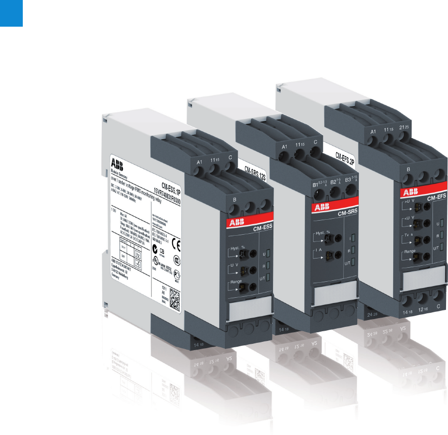
2/9 ABB | Catalog Electronic Products and Relays 2015 | 2CDC 110 004 C0210
2
Current and voltage monitoring relays, single-phase
Product group picture

2CDC 110 004 C0210 | Catalog Electronic Products and Relays 2015 | ABB 2/10
2
Current and voltage monitoring relays, single-phase
Table of contents
Current and voltage monitoring relays, single-phase
Benefits and advantages 2/11
Operating controls 2/12
Selection table - Current monitoring relays 2/13
Selection table - Voltage monitoring relays 2/14
Ordering details - Current monitoring relays 2/15
Ordering details - Voltage monitoring relays 2/16
Function diagrams 2/17
Connection diagrams, DIP switches 2/20
Technical data - Current monitoring relays 2/22
Technical data - Voltage monitoring relays 2/24
2/11 ABB | Catalog Electronic Products and Relays 2015 | 2CDC 110 004 C0210
2
Current and voltage monitoring relays, single-phase
Benefits and advantages
Characteristics current and voltage monitoring relays
– Monitoring of DC and AC currents: 3 mA to 15 A 1)
– Monitoring of DC and AC voltages from 3-600 V
– TRMS measuring principle
– One device includes 3 measuring ranges
– One device includes 4 measuring ranges: 3-30 V; 6-60 V;
30-300 V; 60-600 V
– Over- and undercurrent monitoring1)
– Over- and undervoltage monitoring1)
– ON or OFF-delay configurable1)
– Open- or closed-circuit principle configurable1)
– Threshold values for >U and/or <U adjustable1)
– Latching function configurable1)
– Thresholds for >I and/or <I adjustable1)
– Fixed hysteresis of 5 %1)
– Start-up delay Tv adjustable 0; 0.1-30 s1)
– Tripping delay Tv adjustable 0; 0.1-30 s1)
– 1 x 2 c/o contacts (common signal) or 2 x 1 c/o contact
(separate signals for >I and <I) configurable 1)
– 1 x 2 c/o contacts (common signal) or 2 x 1 c/o contact
(separate signals for >U and <U) configurable1)
– 22.5 mm width
– 3 LEDs for the indication of operational states
– Approvals / Marks
A C R K E L 2) / a b
1) depending on device
2) Applicable in rail application following the latest standards for rail applications:
NF F 16-101/102 (I2/F2 classified), EN 45545 (Hazard Level 3), DIN 5510, EN 50155, IEC 60571.
Further information is available in our rail segment brochure 2CDC110084B0201.
Current monitoring, single-phase
The ABB current monitoring relays CM-SRS.xx
reliably monitor the occurence of currents that
exceed or fall below the selected threshold value.
The functions overcurrent or undercurrent monitor-
ing can be preselected. Single- and multifunction
devices for the monitoring of direct or alternating
currents from 3 mA to 15 A are available.
Current window monitoring (Imin, Imax)
The window monitoring relay CM-SFS.2x is avail-
able if the application requires the simultaneous
monitoring of over- and undercurrents.
Voltage monitoring, single-phase
The ABB voltage monitoring relays CM-SRS.xx
are used to monitor direct and alternating voltages
within a range of 3-600 V. Over- or undervoltage
detection can be preselected.
Voltage window monitoring (Umin, Umax)
For the simultaneous detection of over- and under-
voltages, the window monitoring relay CM-EFS.2
can be used.
2CDC 251 056 V0011
2CDC 251 059 V0011
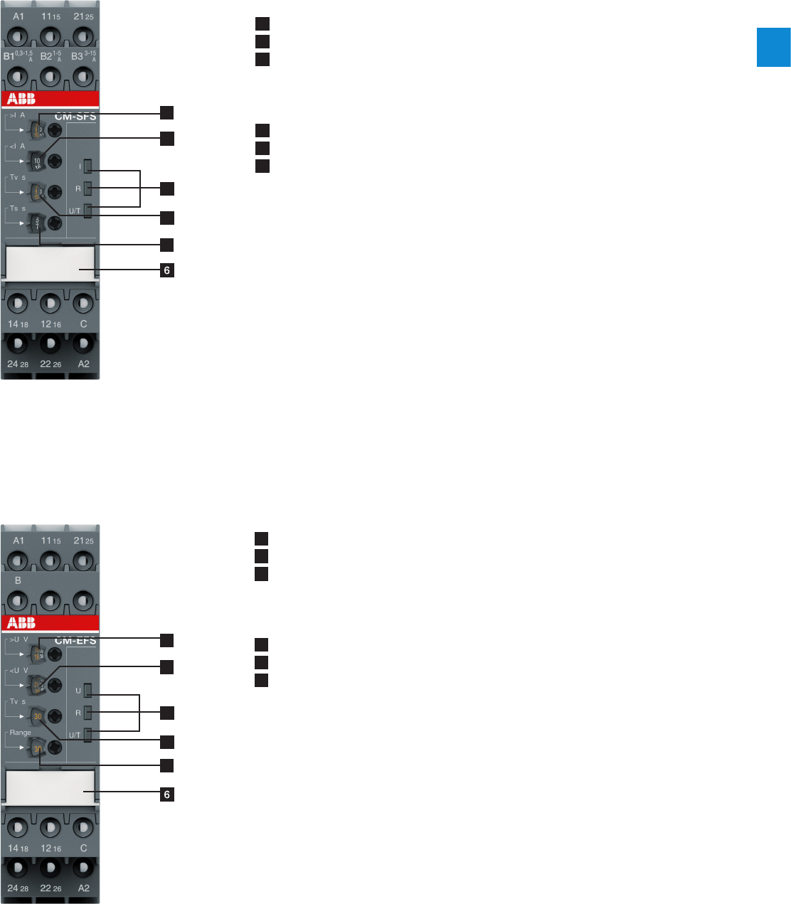
2CDC 110 004 C0210 | Catalog Electronic Products and Relays 2015 | ABB 2/12
2
Current and voltage monitoring relays, single-phase
Operating controls
2CDC 253 018 F00132CDC 253 014 F0013
4
1
2
3
5
1 Adjustment of the threshold value >I for overcurrent
2 Adjustment of the threshold value <I for undercurrent
3 Indication of operational states
U/T: green LED – control supply voltage/timing
R: yellow LED – relay status
I: red LED – over- / undercurrent
4 Adjustment of the tripping delay TV
5 Adjustment of the start-up delay TS
6 DIP switches (see DIP switch functions on page 2/20)
A ON-delay
B OFF-delay
g Closed-circuit principle
h Open-circuit principle
f Latching function activated
e Latching function not activated
i 2x1 c/o (SPDT) contact
j 1x2 c/o (SPDT) contacts
1 Adjustment of the threshold value >U for overvoltage
2 Adjustment of the threshold value <U for undervoltage
3 Indication of operational states
U/T: green LED – control supply voltage/timing
R: yellow LED – relay status
U: red LED – over- / undervoltage
4 Adjustment of the tripping delay TV
5 Adjustment of the measuring range
6 DIP switches (see DIP switch functions on page 2/20)
A ON-delay
B OFF-delay
g Closed-circuit principle
h Open-circuit principle
f Latching function activated
e Latching function not activated
i 2x1 c/o (SPDT) contact
j 1x2 c/o (SPDT) contacts
4
1
2
3
5
Current monitoring relays
Voltage monitoring relays
2/13 ABB | Catalog Electronic Products and Relays 2015 | 2CDC 110 004 C0210
2
Current and voltage monitoring relays, single-phase
Selection table - Current monitoring relays
Order number
1SVR730840R0200
1SVR740840R0200
1SVR730841R0200
1SVR740841R0200
1SVR730841R1200
1SV R74 0 8 41R120 0
1SVR730840R0300
1SVR730841R0300
1SVR730841R1300
1SVR730840R0400
1SVR740840R0400
1SVR730841R0400
1SVR740841R0400
1SVR730841R1400
1SVR740841R1400
1SVR730840R0500
1SVR730841R0500
1SVR730841R1500
1SVR730840R0600
1SVR740840R0600
1SVR730840R0700
1SVR730760R0400
1SVR740760R0400
1SVR730760R0500
Type
CM-SRS.11S
CM-SRS.11P
CM-S R S.11S
CM-S R S.11P
CM-S R S.11S
CM-S R S.11P
CM-S R S.12S
CM-SRS.21S
CM-SRS.21P
CM-SRS.21S
CM-SRS.21P
CM-SRS.21S
CM-SRS.21P
CM-SRS.22S
CM-SRS.M1S
CM-SRS.M1P
CM-SRS.M2S
CM-SFS.21S
CM-SFS.21P
CM-SFS.22S
Rated control supply voltage Us
24 - 240 V AC/DC J J J J J J J J J J J J
110 - 130 V AC J J J J J J
220 - 240 V AC J J J J J J
Measuring ranges AC/DC
3 - 30 mA J J J J J J J J J J J J J J J J
10 - 100 mA JJJJJJ JJJJJJ JJ JJ
0.1 - 1 A J J J J J J J J J J J J J J J J
0.3 - 1.5 A J J J J J J J J
1 - 5 A J J J J J J J J
3 - 15 A J J J J J J J J
Monitoring function
Over- or undercurrent JJJJJJJJJJJJJJJJJJJJJ
Windows current monitoring J J J
Latching sel sel sel sel sel sel
Open circuit or closed circuit principle sel sel sel sel sel sel
Timing functions for tripping delay
ON delay, 0 or 0. 1 - 30 s adj adj adj adj adj adj adj adj adj adj adj adj
ON or OFF delay sel sel sel
Output
c/o contact 111111111222222222222222
Connection type
Push-in terminals J J J J J J J J
Double-chamber cage connection
terminals J J J J J J J J J J J J J J J J
adj: adjustable
sel: selectable
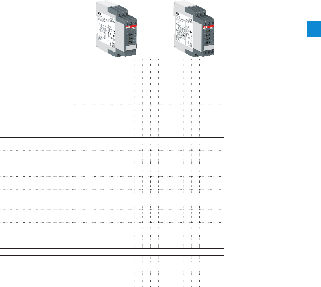
2CDC 110 004 C0210 | Catalog Electronic Products and Relays 2015 | ABB 2/14
2
Current and voltage monitoring relays, single-phase
Selection table - Voltage monitoring relays
Order number
1SVR730830R0300
1SVR740830R0300
1SVR730831R0300
1SVR740831R0300
1SVR730831R1300
1SVR740831R1300
1SVR730830R0400
1SVR740830R0400
1SVR730831R0400
1SVR740831R0400
1SVR730831R1400
1SVR740831R1400
1SVR730830R0500
1SVR740830R0500
1SVR730750R0400
1SVR740750R0400
Type
CM-ESS.1S
CM-ESS.1P
CM-ESS.1S
CM-ESS.1P
CM-ESS.1S
CM-ESS.1P
CM-ESS.2S
CM-ESS.2P
CM-ESS.2S
CM-ESS.2P
CM-ESS.2S
CM-ESS.2P
CM-ESS.MS
CM-ESS.MP
CM-EFS.2S
CM-EFS.2P
Rated control supply voltage Us
24 - 240 V AC/DC J J J J J J J J
110 - 130 V AC J J J J
220 - 240 V AC J J J J
Measuring ranges AC/DC
3 - 30 V J J J J J J J J J J J J J J J J
6 - 60 V J J J J J J J J J J J J J J J J
30 - 300 V J J J J J J J J J J J J J J J J
60 - 600 V J J J J J J J J J J J J J J J J
Monitoring function
Over- or undervoltage J J J J J J J J J J J J J J
Windows voltage monitoring J J
Latching sel sel sel sel
Open circuit or closed circuit principle sel sel sel sel
Timing functions for tripping delay
ON delay, 0 or 0.1 - 30 s adj adj adj adj adj adj adj adj
ON or OFF delay sel sel
Output
c/o contact 1 1 1 1 1 1 2 2 2 2 2 2 2 2 2 2
Connection type
Push-in terminals J J J J J J J J
Double-chamber cage connection
terminals J J J J J J J J
adj: adjustable
sel: selectable
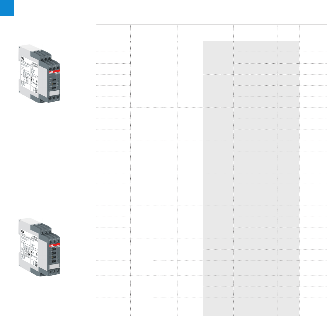
2/15 ABB | Catalog Electronic Products and Relays 2015 | 2CDC 110 004 C0210
2
Current and voltage monitoring relays, single-phase
Ordering details - Current monitoring relays
Description
The CM range current monitoring relays protect single-phase mains (DC or AC) from over- and
undercurrent from 3 mA to 15 A. Two different terminal versions are available. You can choose
between the proven screw connection technology (double-chamber cage connecting termi-
nals) and the completely tool-free Easy Connect Technology (push-in terminals).
Ordering details
Rated control
supply voltage
Function Tripping
delay TV
Measuring
range
Type Order code Price
1 pce
Weight
(1 pce)
kg (lb)
24-240 V AC/DC
b
awithout
3-30mA,
10-100mA,
0.1-1A
CM-S R S.11S
1SVR730840R0200 0.145 (0.320)
110-130 V AC 1SVR730841R0200 0.161 (0.355)
220-240 V AC 1SVR730841R1200 0.161 (0.355)
24-240 V AC/DC
CM-S R S.11P
1SVR740840R0200 0.137 (0.302)
110-130 V AC 1SVR740841R0200 0.153 (0.337)
220-240 V AC 1SV R74 0 8 41R120 0 0.153 (0.337)
24-240 V AC/DC
b
awithout
0.3-1.5A,
1-5A,
3-15A
CM-S R S.12S
1SVR730840R0300 0.137 (0.302)
110-130 V AC 1SVR730841R0300 0.168 (0.370)
220-240 V AC 1SVR730841R1300 0.168 (0.370)
24-240 V AC/DC
b
a
adjustable
0 or 0.1-30 s
3-30mA,
10-100mA,
0.1-1A
CM-SRS.21S
1SVR730840R0400 0.152 (0.335)
110-130 V AC 1SVR730841R0400 0.179 (0.395)
220-240 V AC 1SVR730841R1400 0.179 (0.395)
24-240 V AC/DC
CM-SRS.21P
1SVR740840R0400 0.141 (0.311)
110-130 V AC 1SVR740841R0400 0.168 (0.370)
220-240 V AC 1SVR740841R1400 0.168 (0.370)
24-240 V AC/DC
b
a
adjustable
0or 0.1-30 s
0.3-1.5A,
1-5A,
3-15A
CM-SRS.22S
1SVR730840R0500 0.144 (0.399)
110-130 V AC 1SVR730841R0500 0.181 (0.399)
220-240 V AC 1SVR730841R1500 0.181 (0.399)
24-240 V AC/DC b
e
a
f
adjustable
0or 0.1-30 s
3-30mA,
10-100mA,
0.1-1A
CM-SRS.M1S 1SVR730840R0600 0.153 (0.337)
CM-SRS.M1P 1SVR740840R0600 0.142 (0.313)
24-240 V AC/DC adjustable
0or 0.1-30 s
0.3-1.5A,
1-5A,
3-15A
CM-SRS.M2S 1SVR730840R0700 0.155 (0.342)
24-240 V AC/DC b
e
a
f
j
i
adjustable
0or 0.1-30 s
3-30mA,
10-100mA,
0.1-1A
CM-SFS.21S 1SVR730760R0400 0.150 (0.331)
CM-SFS.21P 1SVR740760R0400 0.139 (0.306)
24-240 V AC/DC adjustable
0or 0.1-30 s
0.3-1.5A,
1-5A,
3-15A
CM-SFS.22S 1SVR730760R0500 0.158 (0.348)
2CDC 251 054 V00112CDC 251 056 V0011
CM-SRS.22S
CM-SFS.22P
b Overcurrent monitoring
a Undercurrent monitoring
e Without latching
f With latching
j 1x2 c/o (SPDT) contacts
i 2x1 c/o (SPDT) contact
S: screw connection
P: push-in / easy connect
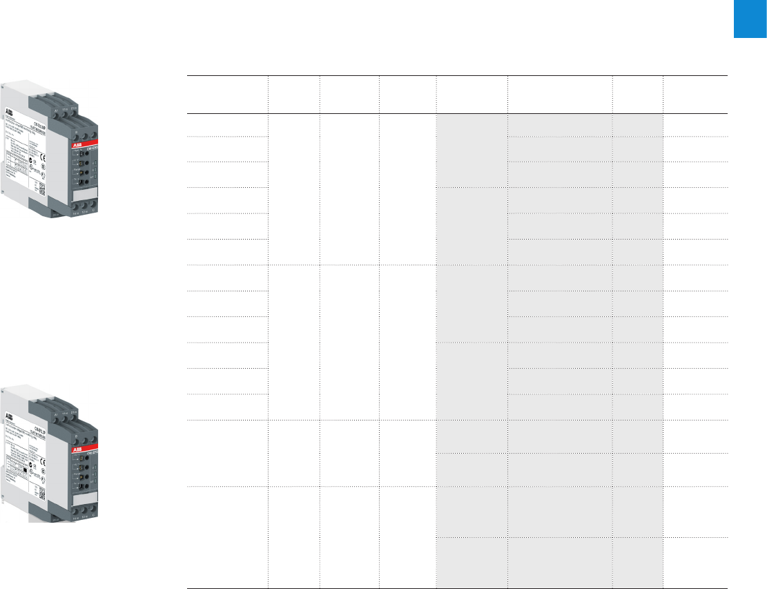
2CDC 110 004 C0210 | Catalog Electronic Products and Relays 2015 | ABB 2/16
2
Current and voltage monitoring relays, single-phase
Ordering details - Voltage monitoring relays
Description
The CM range voltage monitoring relays provide reliable monitoring of voltages as well as de-
tection of phase loss in single-phase mains.
All devices are available with two different terminal versions. You can choose between the
proven screw connection technology (double-chamber cage connecting terminals) and the
completely tool-free Easy Connect Technology (push-in terminals).
Ordering details
Rated control
supply voltage
Function Tripping
delay TV
Measur-
ing range
AC/DC
Type Order code Price
1 pce
Weight
(1 pce)
kg (lb)
24-240 V AC/DC
d
cwithout
3-30V,
6-60V,
30-300V,
60-600V
CM-ESS.1S
1SVR730830R0300 0.135 (0.298)
110-130 V AC 1SVR730831R0300 0.164 (0.362)
220-240 V AC 1SVR730831R1300 0.164 (0.362)
24-240 V AC/DC
CM-ESS.1P
1SVR740830R0300 0.126 (0.278)
110-130 V AC 1SVR740831R0300 0.155 (0.342)
220-240 V AC 1SVR740831R1300 0.155 (0.342)
24-240 V AC/DC
d
c
adjustable
0 or 0.1-30 s
3-30V,
6-60V,
30-300V,
60-600V
CM-ESS.2S
1SVR730830R0400 0.153 (0.337)
110-130 V AC 1SVR730831R0400 0.181 (0.399)
220-240 V AC 1SVR730831R1400 0.181 (0.399)
24-240 V AC/DC
CM-ESS.2P
1SVR740830R0400 0.142 (0.313)
110-130 V AC 1SVR740831R0400 0.170 (0.375)
220-240 V AC 1SVR740831R1400 0.170 (0.375)
24-240 V AC/DC
de
ce
df
cf
adjustable
0 or 0.1-30 s
3-30V,
6-60V,
30-300V,
60-600V
CM-ESS.MS 1SVR730830R0500 0.154 (0.340)
CM-ESS.MP 1SVR740830R0500 0.143 (0.320)
24-240 V AC/DC
b
e
a
f
j
i
adjustable
0 or 0.1-30 s
3-30V,
6-60V,
30-300V,
60-600V
CM-EFS.2S 1SVR730750R0400 0.157 (0.346)
CM-EFS.2P 1SVR740750R0400 0.146 (0.322)
2CDC 251 060 V00112CDC 251 059 V0011
CM-ESS.MP
CM-EFS.2
b Overcurrent monitoring
a Undercurrent monitoring
e Without latching
f With latching
j 1x2 c/o (SPDT) contacts
i 2x1 c/o (SPDT) contact
S: screw connection
P: push-in / easy connect
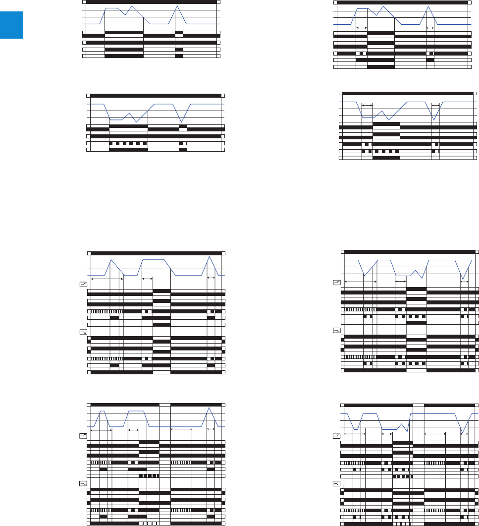
2/17 ABB | Catalog Electronic Products and Relays 2015 | 2CDC 110 004 C0210
2
Function diagrams - CM-SRS.1
Overcurrent monitoring b
Undercurrent monitoring a
Function diagrams - CM-SRS.2
Overcurrent monitoring b
Undercurrent monitoring a
A1-A2
11-14 (15-18)
11-12 (15-16)
Threshold
Hysteresis
Measured value
green LED
red LED
yellow LED
2CDC 252 208 F0205
A1-A2
11-14 (15-18)
11-12 (15-16)
Threshold
Hysteresis
Measured value
green LED
red LED
yellow LED
2CDC 252 209 F0205
A1-A2
11-14 (15-18)
11-12 (15-16)
21-24 (25-28)
21-22 (25-26)
Threshold
Hysteresis
Measured value
green LED
red LED
yellow LED
2CDC 252 210 F0205
TV < TV
A1-A2
11-14 (15-18)
11-12 (15-16)
21-24 (25-28)
21-22 (25-26)
Threshold
Hysteresis
Measured value
green LED
red LED
yellow LED
2CDC 252 211 F0205
TV < TV
Function diagrams - CM-SRS.M
Overcurrent monitoring b without latching e
Overcurrent monitoring b with latching f
Undercurrent monitoring a without latching e
Undercurrent monitoring b with latching f
A1-A2
11-14 (15-18)
11-12 (15-16)
21-24 (25-28)
21-22 (25-26)
11-14 (15-18)
11-12 (15-16)
21-24 (25-28)
21-22 (25-26)
closed
open
Threshold
Hysteresis
Measured value
green LED
red LED
yellow LED
2CDC 252 212 F0205
TS
green LED
red LED
yellow LED
Open-circuit principle
Closed-circuit principle
TV < TV
A1-A2
11-14 (15-18)
11-12 (15-16)
21-24 (25-28)
21-22 (25-26)
11-14 (15-18)
11-12 (15-16)
21-24 (25-28)
21-22 (25-26)
open
closed
Threshold
Hysteresis
Measured value
green LED
red LED
yellow LED
2CDC 252 214 F0205
TS
green LED
red LED
yellow LED
Open-circuit principle
Closed-cir
cuit principle
TV < TV
TS
Reset
A1-A2
11-14 (15-18)
11-12 (15-16)
21-24 (25-28)
21-22 (25-26)
11-14 (15-18)
11-12 (15-16)
21-24 (25-28)
21-22 (25-26)
closed
open
Threshold
Hysteresis
Measured value
green LED
red LED
yellow LED
2CDC 252 213 F0205
TS
green LED
red LED
yellow LED
Open-circuit principle
Closed-circuit principle
TV < TV
A1-A2
11-14 (15-18)
11-12 (15-16)
21-24 (25-28)
21-22 (25-26)
11-14 (15-18)
11-12 (15-16)
21-24 (25-28)
21-22 (25-26)
closed
open
Threshold
Hysteresis
Measured value
green LED
red LED
yellow LED
2CDC 252 215 F0205
TS
green LED
red LED
yellow LED
Open-circuit principle
Closed-cir
cuit principle
TV < TV
TS
Reset
If the measured value exceeds resp. drops below the adjusted threshold value, the output relay(s) energize(s): on the CM-SRS.1
immediately, on the CM-SRS.2 after the set tripping delay TV. If the measured value exceeds resp. drops below the threshold
value plus resp. minus the adjusted hysteresis, the output relay(s) de-energize(s). The hysteresis is adjustable within a range of
3-30 % of the threshold value.
If the measured value exceeds resp. drops below the adjusted threshold value before the set start-up delay TS is complete, the
output relays do not change their actual state. If the measured value exceeds resp. drops below the adjusted threshold value
when TS is complete, the tripping delay TV starts. If TV is complete and the measured value is still exceeding resp. below the
threshold value plus resp. minus the set hysteresis, the output relays energize h / de-energize g.
If the measured value exceeds resp. drops below the threshold value minus resp. plus the set hysteresis and the latching func-
tion is not activated e, the output relays de-energize h / energize g. With activated latching function f the output relays
remain energized h and de-energize only, when the supply voltage is interrupted / the output relays remain de-energized g
and energize only, when the supply voltage is switched off and then again switched on = Reset.
The hysteresis is adjustable within a range of 3-30 % of the threshold value.
Current and voltage monitoring relays, single-phase
Function diagrams
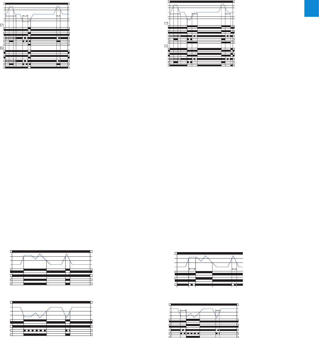
2CDC 110 004 C0210 | Catalog Electronic Products and Relays 2015 | ABB 2/18
2
Current and voltage monitoring relays, single-phase
Function diagrams
Function diagrams - CM-ESS.1
Overvoltage monitoring d
Undervoltage monitoring c
Function diagrams - CM-ESS.2
Overvoltage monitoring d
Undervoltage monitoring c
A1-A2
11-14 (15-18)
11-12 (15-16)
Threshold
Hysteresis
Measured value
green LED
red LED
yellow LED
2CDC 252 208 F0205
A1-A2
11-14 (15-18)
11-12 (15-16)
Threshold
Hysteresis
Measured value
green LED
red LED
yellow LED
2CDC 252 209 F0205
A1-A2
11-14 (15-18)
11-12 (15-16)
21-24 (25-28)
21-22 (25-26)
Threshold
Hysteresis
Measured value
green LED
red LED
yellow LED
2CDC 252 210 F0205
TV < TV
A1-A2
11-14 (15-18)
11-12 (15-16)
21-24 (25-28)
21-22 (25-26)
Threshold
Hysteresis
Measured value
green LED
red LED
yellow LED
2CDC 252 211 F0205
TV < TV
OFF-delayed B current window monitoring with parallel
switching c/o contacts j:
If the measured value exceeds resp. drops below the adjusted
threshold value when the set start-up delay TS is complete,
the output relays energize h / de-energize g, when B is
configured, and remain in this position during the set tripping
delay TV. If the measured value exceeds resp. drops below the
threshold value plus resp. minus the fixed hysteresis (5%) and
the latching function is not activated e, the tripping delay TV
starts. After completion of TV, the output relays de-energize
h / energize g, provided that the latching function is not
activated e. With activated latching function f the out-
put relays remain energized h and de-energize only, when
the supply voltage is interrupted / the output relays remain
de-energized g and energize only, when the supply voltage
is switched off and then again switched on = Reset. When
i is adjusted on the device, the functionality is equivalent
to the one described above. There is only to consider that in
this case, instead of both output relays, only one output relay
each will be switched.
“>I“ = 1115-1216/1418 ; “<I“ = 2125-2226/2428
Function diagrams - CM-SFS.2
Current window monitoring 1x2 c/o contact j
ON-delayed A without latching f
Current window monitoring 1x2 c/o contact j
OFF-delayed B without latching e
Further function diagrams see data sheet.
A1-A2
11-14 (15-18)
11-12 (15-16)
21-24 (25-28)
21-22 (25-26)
11-14 (15-18)
11-12 (15-16)
21-24 (25-28)
21-22 (25-26)
open
closed
Thresholdmax
Hysteresis
green LED
red LED
yellow LED
2CDC 252 216 F0205
TS
green LED
red LED
yellow LED
Open-circuit principle
Closed-circuit principle
TV < TV
Hysteresis
Measured value
Thresholdmin
A1-A2
11-14 (15-18)
11-12 (15-16)
21-24 (25-28)
21-22 (25-26)
11-14 (15-18)
11-12 (15-16)
21-24 (25-28)
21-22 (25-26)
open
closed
Thresholdmax
Hysteresis
green LED
red LED
yellow LED
2CDC 252 217 F0205
TS
green LED
red LED
yellow LED
Open-circuit principle
Closed-circuit principle
TV TV
Hysteresis
Measured value
Thresholdmin
ON-delayed A current window monitoring with parallel
switching c/o contacts j:
If the measured value exceeds resp. drops below the adjusted
threshold value before the set start-up delay TS is complete,
the output relays do not change their actual state.
If the measured value exceeds resp. drops below the adjusted
threshold value when TS is complete, the tripping delay TV
starts, when A is configured. If TV is complete and the mea-
sured value is still exceeding resp. below the threshold value
minus resp. plus the fixed hysteresis (5%), the output relays
energize h /de-energize g.
If the measured value exceeds resp. drops below the thresh-
old value plus resp. minus the hysteresis and the latching
function is not activated f, the output relays de-energize h
/ energize g. With activated latching function e the output
relays remain energized h and de-energize only, when the
supply voltage is interrupted / the output relays remain de-
energized g and energize only, when the supply voltage is
switched off and then again switched on = Reset.
Depending on the configuration, the voltage monitoring relays CM-ESS.1 and CM-ESS.2 can be used for over- d or undervolt-
age monitoring c in single-phase AC and/or DC systems. The voltage to be monitored (measured value) is applied to terminals
B-C. The devices work according the open-circuit principle. If the measured value exceeds resp. drops below the adjusted
threshold value, the output relay(s) energize(s): on the CM-ESS.1 immediately, on the CM-ESS.2 after the set tripping delay
TV. If the measured value exceeds resp. drops below the threshold value plus resp. minus the adjusted hysteresis, the output
relay(s) de-energize(s). The hysteresis is adjustable within a range of 3-30 % of the threshold value.
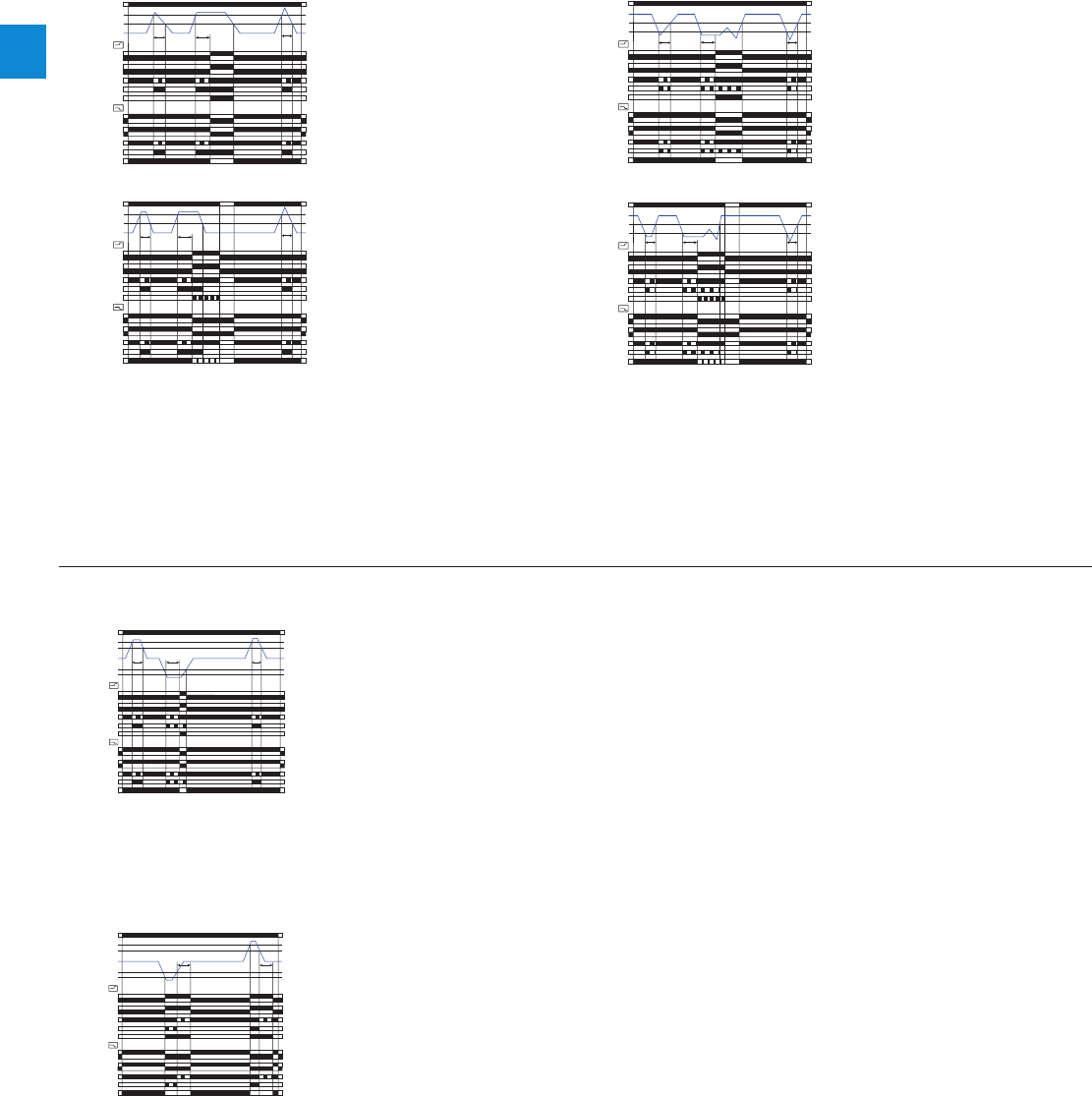
2/19 ABB | Catalog Electronic Products and Relays 2015 | 2CDC 110 004 C0210
2
If the measured value exceeds resp. drops below the adjusted threshold value, the tripping delay TV starts. If TV is complete
and the measured value is still exceeding resp. below the threshold value plus resp. minus the set hysteresis, the output relays
energize h / de-energize g.
If the measured value exceeds resp. drops below the threshold value plus resp. minus the set hysteresis and the latching func-
tion is not activated e, the output relays de-energize h / energize g. With activated latching function f the output relays
remain energized h and de-energize only, when the supply voltage is interrupted / the output relays remain de-energized g
and energize only, when the supply voltage is switched off and then again switched on = Reset. The hysteresis is adjustable
within a range of 3-30 % of the threshold value.
Function diagrams - CM-ESS.M
Overvoltage monitoring d without latching eUndervoltage monitoring c without latching e
Undervoltage monitoring c without latching f
A1-A2
11-14 (15-18)
11-12 (15-16)
21-24 (25-28)
21-22 (25-26)
11-14 (15-18)
11-12 (15-16)
21-24 (25-28)
21-22 (25-26)
open
closed
Threshold
Hysteresis
Measured value
green LED
red LED
yellow LED
2CDC 252 228 F0205
< TV
green LED
red LED
yellow LED
Open-circuit principle
Closed-cir
cuit principle
TV < TV
A1-A2
11-14 (15-18)
11-12 (15-16)
21-24 (25-28)
21-22 (25-26)
11-14 (15-18)
11-12 (15-16)
21-24 (25-28)
21-22 (25-26)
open
closed
Threshold
Hysteresis
Measured value
green LED
red LED
yellow LED
2CDC 252 230 F0205
green LED
red LED
yellow LED
Open-circuit principle
Closed-cir
cuit principle
TV < TV
Reset
< TV
A1-A2
11-14 (15-18)
11-12 (15-16)
21-24 (25-28)
21-22 (25-26)
11-14 (15-18)
11-12 (15-16)
21-24 (25-28)
21-22 (25-26)
closed
open
Threshold
Hysteresis
Measured value
green LED
red LED
yellow LED
2CDC 252 229 F0205
green LED
red LED
yellow LED
Open-circuit principle
Closed-cir
cuit principle
TV < TV
< TV
A1-A2
11-14 (15-18)
11-12 (15-16)
21-24 (25-28)
21-22 (25-26)
11-14 (15-18)
11-12 (15-16)
21-24 (25-28)
21-22 (25-26)
closed
open
Threshold
Hysteresis
Measured value
green LED
red LED
yellow LED
2CDC 252 231 F0205
green LED
red LED
yellow LED
Open-circuit principle
Closed-cir
cuit principle
TV < TV
Reset
< TV
ON-delayed A voltage window monitoring with parallel switching c/o contacts j:
If the measured value exceeds resp. drops below the adjusted threshold value, the tripping de-
lay TV starts, when A is configured. If TV is complete and the measured value is still exceeding
resp. below the threshold value minus resp. plus the fixed hysteresis (5%), the output relays
energize h /de-energize g.
If the measured value exceeds resp. drops below the threshold value plus resp. minus the
hysteresis and the latching function is not activated e, the output relays de-energize h /
energize g. With activated latching function e the output relays remain energized h and
de-energize only, when the supply voltage is interrupted / the output relays remain de-ener-
gized g and energize only, when the supply voltage is switched off and then again switched
on = Reset.
Voltage window monitoring 1x2 c/o contact j
ON-delayed A without latching e
Voltage window monitoring 1x2 c/o contact j
OFF-delayed B without latching e
Further function diagrams see data sheet.
A1-A2
11-14 (15-18)
11-12 (15-16)
21-24 (25-28)
21-22 (25-26)
11-14 (15-18)
11-12 (15-16)
21-24 (25-28)
21-22 (25-26)
open
closed
Threshold
max
Hysteresis
green LED
red LED
yellow LED
2CDC 252 232 F0205
green LED
red LED
yellow LED
Open-circuit principle
Closed-circuit principle
T
V
< T
V
Hysteresis
Measured value
Threshold
min
< T
V
A1-A2
11-14 (15-18)
11-12 (15-16)
21-24 (25-28)
21-22 (25-26)
11-14 (15-18)
11-12 (15-16)
21-24 (25-28)
21-22 (25-26)
closed
open
Thresholdmax
Hysteresis
green LED
red LED
yellow LED
2CDC 252 233 F0205
green LED
red LED
yellow LED
Open-circuit principle
Closed-cir
cuit principle
TV TV
Hysteresis
Measured value
Thresholdmin
Current and voltage monitoring relays, single-phase
Function diagrams
OFF-delayed B voltage window monitoring with parallel switching c/o contacts j:
If the measured value exceeds resp. drops below the adjusted threshold value, the output
relays energize h / de-energize g, when B is configured, and remain in this position during
the set tripping delay TV.
If the measured value exceeds resp. drops below the threshold value plus resp. minus the
fixed hysteresis (5%) and the latching function is not activated e, the tripping delay TV starts.
After completion of TV, the output relays de-energize h / energize g, provided that the latch-
ing function is not activated e. With activated latching function e the output relays remain
energized h and de-energize only, when the supply voltage is interrupted / the output relays
remain de-energized g and energize only, when the supply voltage is switched off and then
again switched on = Reset.
When i is adjusted on the device, the functionality is equivalent to the one described above.
There is only to consider that in this case, instead of both output relays, only one output relay
each will be switched.
“>U“ = 1115-1216/1418 ; “<U“ = 2125-2226/2428
Overvoltage monitoring d with latching f
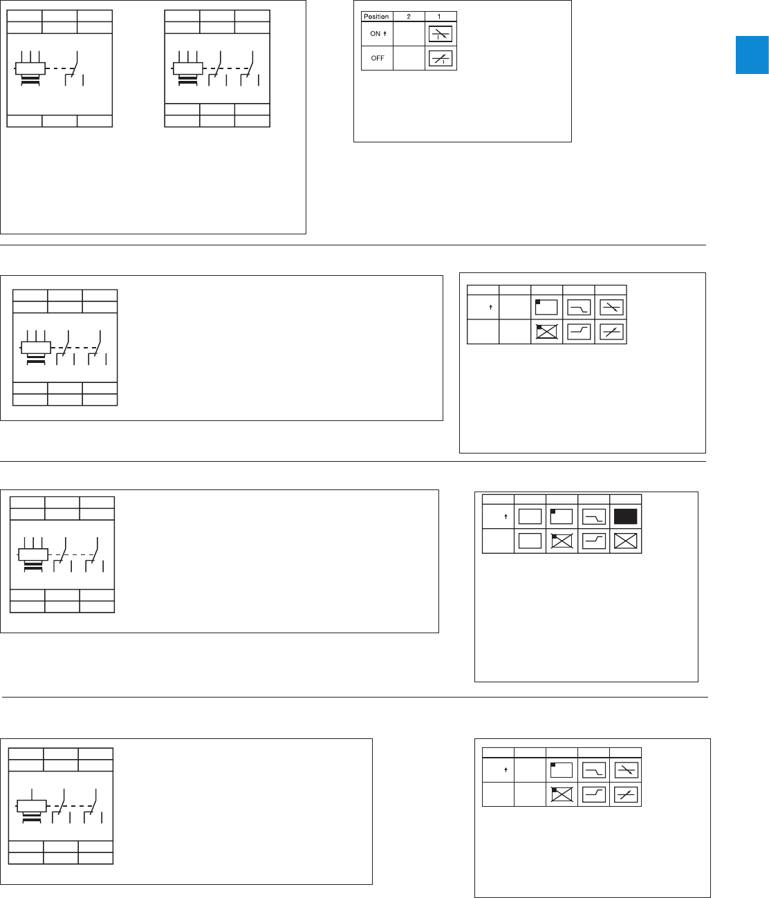
2CDC 110 004 C0210 | Catalog Electronic Products and Relays 2015 | ABB 2/20
2
A1 A2
A1 11
15
B1 B2 B3
A2
1115
1216 1418
14
18
12
16
C
B1 B2 B3
C
2CDC 252 204 F0005
Connection diagram CM-SRS.1, CM-SRS.2
A1 A2
2125
2226 2428
A1 11
15
21
25
B1 B2 B3
24
28
22
26
A2
1115
1216 1418
1418 1216 C
B1 B2 B3
C
2CDC 252 205 F0005
A1 A2
2125
2226 2428
A1 11
15
21
25
B1 B2 B3
2428 2226 A2
1115
1216 1418
1418 1216 C
B1 B2 B3
C
2CDC 252 205 F0005
Connection diagram CM-SRS.M
A1 A2
2125
2226 2428
A1 1115 2125
B1 B2 B3
2428 2226 A2
1115
1216 1418
1418 1216 C
B1 B2 B3
C
2CDC 252 205 F0005
Connection diagram CM-SFS.2
2CDC 252 272 F0005
DIP switch functions CM-SRS.1, CM-SRS.2
1ON
OFF Undercurrent monitoring
Overcurrent monitoring
OFF = Default
closed
open
Position
41
23
ON
OFF
I
I
2CDC 252 273 F0005
DIP switch functions CM-SRS.M
closed
open
2x1 c/o
1x2 c/o
Position
41
23
ON
OFF
2CDC 252 274 F0005
DIP switch function CM-SFS.2
closed
open V
V
Position
41
23
ON
OFF
2CDC 252 276 F0005
DIP switch functions CM-ESS.M
A1 A2
2125
2226 2428
A1 1115 2125
B
24
28
22
26
A2
1115
1216 1418
1418 1216 C
B
C
2CDC 252 207 F0005
Connection diagram CM-ESS.M
Current and voltage monitoring relays, single-phase
Connection diagrams, DIP switches
A1-A2 Control supply voltage
B1-C Measuring range 1: 3-30 mA or 0.3-1.5 A
B2-C Measuring range 2: 10-100 mA or 1-5 A
B3-C Measuring range 3: 0.1-1 A or 3-15 A
1115-1216/1418
2125-2226/2428
Output contacts - open-circuit principle
A1-A2 Control supply voltage
B1-C Measuring range 1: 3-30 mA or 0.3-1.5 A
B2-C Measuring range 2: 10-100 mA or 1-5 A
B3-C Measuring range 3: 0.1-1 A or 3-15 A
1115-1216/1418
2125-2226/2428
Output contacts - open- or
closed circuit principle
A1-A2 Control supply voltage
B1-C Measuring range 1: 3-30 mA or 0.3-1.5 A
B2-C Measuring range 2: 10-100 mA or 1-5 A
B3-C Measuring range 3: 0.1-1 A or 3-15 A
1115-1216/1418
2125-2226/2428
Output contacts - open- or
closed circuit principle
A1-A2 Control supply voltage
B-C Measuring ranges AC/DC:
3-30 V; 6-60 V
30-300 V; 60-600 V
1115-1216/1418
2125-2226/2428
Output contacts - open- or
closed circuit principle
1ON
OFF Undercurrent monitoring
Overcurrent monitoring
2ON
OFF Closed-circuit principle
Open-circuit principle
3ON
OFF Latching function activated
Latching function not activated
OFF = Default
1ON
OFF Undervoltage monitoring
Overvoltage monitoring
2ON
OFF Closed-circuit principle
Open-circuit principle
3ON
OFF Latching function activated
Latching function not activated
OFF = Default
1ON
OFF OFF-delay
ON-delay
2ON
OFF Closed-circuit principle
Open-circuit principle
3ON
OFF Latching function activated
Latching function not activated
4ON
OFF 2x1 c/o contact
1x2 c/o contacts
OFF = Default
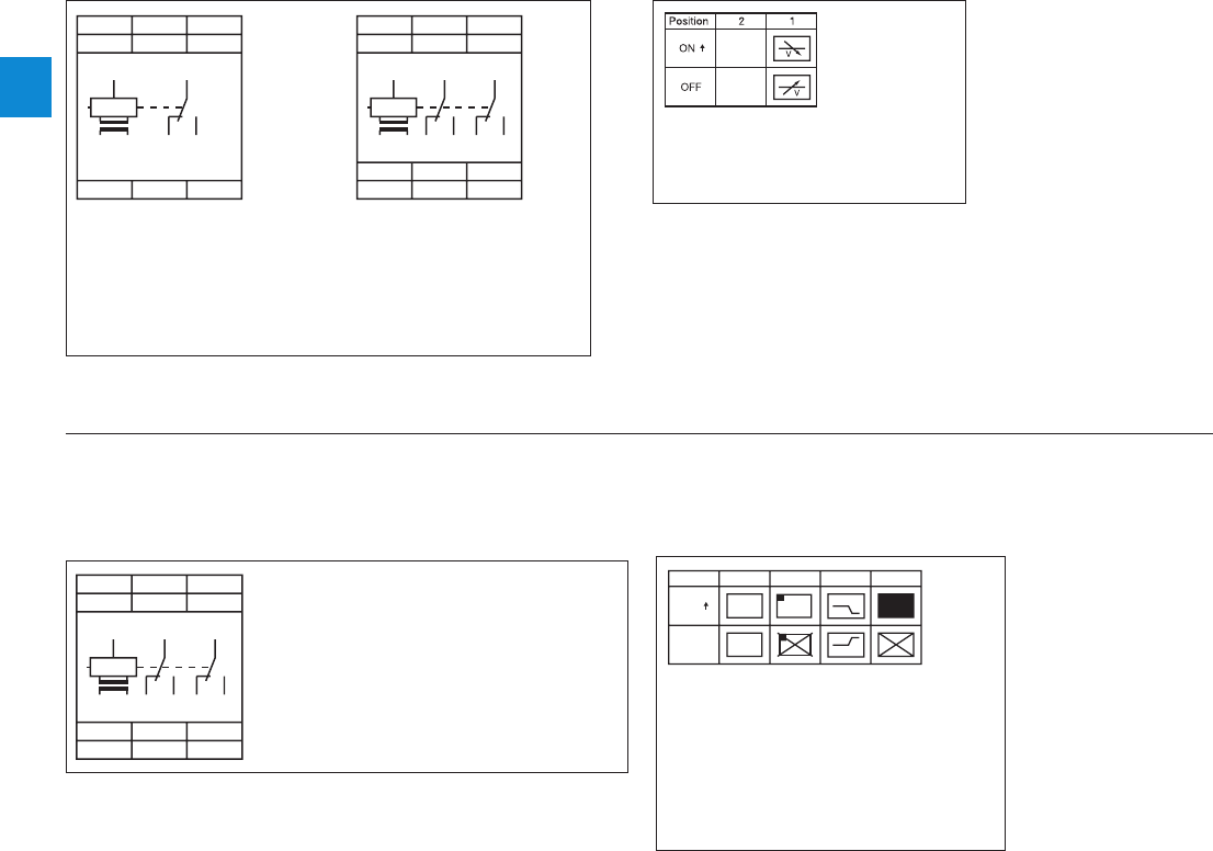
2/21 ABB | Catalog Electronic Products and Relays 2015 | 2CDC 110 004 C0210
2
closed
open
2x1 c/o
1x2 c/o
Position 4123
ON
OFF
2CDC 252 274 F0005
DIP switch functions CM-EFS.2
A1 A2
2125
2226 2428
A1 1115 2125
B
24
28
22
26
A2
1115
1216 1418
1418 1216 C
B
C
2CDC 252 207 F0005
Connection diagram CM-EFS.2
A1 A2
A1 11
15
B
A2
1115
1216 1418
14
18
12
16
C
B
C
2CDC 252 206 F0005
Connection diagram CM-ESS.1, CM-ESS.2
A1 A2
2125
2226 2428
A1 11
15
21
25
B
24
28
22
26
A2
1115
1216 1418
1418 1216 C
B
C
2CDC 252 207 F0005
2CDC 252 275 F0005
DIP switch functions CM-ESS.1, CM-ESS.2
Current and voltage monitoring relays, single-phase
Connection diagrams, DIP switches
A1-A2 Control supply voltage
B-C Measuring ranges AC/DC:
3-30 V; 6-60 V; 30-300 V; 60-600 V
1115-1216/1418
2125-2226/2428
Output contacts - open-circuit principle
A1-A2 Control supply voltage
B-C Measuring ranges AC/DC:
3-30 V; 6-60 V; 30-300 V;
60-600 V
1115-1216/1418
2125-2226/2428
Output contacts - open-
or closed circuit principle
1ON
OFF Undervoltage monitoring
Overvoltage monitoring
OFF = Default
1ON
OFF ON-delay
OFF-delay
2ON
OFF Closed-circuit principle
Open-circuit principle
3ON
OFF Latching function activated
Latching function not activated
4ON
OFF 2x1 c/o contact
1x2 c/o contacts
OFF = Default

2CDC 110 004 C0210 | Catalog Electronic Products and Relays 2015 | ABB 2/22
2
Current monitoring relays, single-phase
Technical data - Current monitoring relays
Type CM-SRS.1 CM-SRS.2 CM-SRS.M CM-SFS.2
Input circuit - Supply circuit A1-A2
Rated control supply voltage UsA1-A2 110-130 V AC
A1-A2 220-240 V AC
A1-A2 24-240 V AC/DC
Rated control supply voltage Us tolerance -15...+10 %
Rated frequency AC versions 50/60 Hz
AC/DC versions 50/60 Hz or DC
Current / power consumption see data sheets
Power failure buffering time 20 ms
Transient overvoltage protection Varistors
Input circuit - Measuring circuit B1/B2/B3-C
Monitoring function over- or undercurrent monitoring
configurable over- and under-
current monitoring
Measuring method True RMS measuring principle
Measuring inputs CM-SxS.x1 CM-SxS.x2
Terminal connection B1-C B2-C B3-C B1-C B2-C B3-C
Measuring ranges AC/DC 3-30 mA 10-100 mA 0.1-1 A 0.3-1.5 A 1-5 A 3-15 A 2)
Input resistance 3.3 q1 q0.1 q0.05 q0.01 q0.0025 q
Pulse overload capacity t < 1 s 500 mA 1 A 10 A 15 A 50 A 100 A
Continous capacity 50 mA 150 mA 1.5 A 2 A 7 A 17 A
Threshold value(s) adjustable within the indicated measuring range
Setting accuracy of threshold value 10 %
Hysteresis related to the threshold value 3-30 % adjustable 5 % fixed
Measuring signal frequency range DC / 15 Hz - 2 kHz
Rated measuring signal frequency range DC / 50-60 Hz
Maximum response time AC: 80 ms / DC: 120 ms
Accuracy within the control supply voltage tolerance U m 0.5 %
Accuracy within the temperature range U m 0.06 % / °C
Timing circuit
Start-up delay TSnone 0 or 0.1-30 s adjustable
Tripping delay TVnone 0 or 0.1-30 s adjustable
Repeat accuracy (constant parameters) w0.07 % of full scale
Accuracy within the control supply voltage tolerance -t m 0.5 %
Accuracy within the temperature range -t m 0.06 % / °C
Indication of operational states
Control supply voltage U/T: green LED V: control supply voltage applied,
X: start-up delay TS active,
W: tripping delay TV active
Measured value I: red LED V: overcurrent,
W: undercurrent
Relay status R: yellow LED V: relay energized, no latching function
Z: relay energized, active latching function
Y: relay de-energized, active latching function
Output circuits 11(15)-12(16)/14(18), 21(25)-22(26)/24(28) - Relays
Kind of output 1 c/o contact 2 c/o contacts 1x2 c/o contacts
or 2x1 c/o contact
configurable
Operating principle open-circuit principle 1)
open- or closed-circuit principle configurable
1)
Contact material AgNi
Rated operational voltage UeIEC/EN 60947-1 250 V
Minimum switching voltage / minimum switching current 24 V / 10 mA
Maximum switching voltage / maximum switching current 250 V AC / 4 A AC
Rated operational current Ie
(IEC/EN 60947-5-1) AC-12 (resistive) at 230 V 4 A
AC-15 (inductive) at 230 V 3 A
DC-12 (resistive) at 24 V 4 A
DC-13 (inductive) at 24 V 2 A
AC rating
(UL 508) Utilization category
(Control Circuit Rating Code) B 300
max. rated operational voltage 300 V AC
max. continuous thermal current at B 300 5 A
max. making/breaking apparent power
(Make/Break) at B 300 3600/360 VA
Mechanical lifetime 30x106 switching cycles
Electrical lifetime (AC-12, 230 V, 4 A) 0.1x10⁶ switching cycles
Max. fuse rating to achieve short-circuit
protection n/c contact 6 A fast-acting 10 A fast-acting 6 A fast-acting
n/o contact 10 A fast-acting
1) Open-circuit principle: output relay energizes if the measured value exceeds b / falls below a the adjusted threshold value
Closed-circuit principle: output relay de-energizes if measured value exeeds b / falls below a the adjusted threshold value
2) In case of measured currents > 10 A, lateral spacing has to be min. 10 mm

2/23 ABB | Catalog Electronic Products and Relays 2015 | 2CDC 110 004 C0210
2
Type CM-SRS.1 CM-SRS.2 CM-SRS.M CM-SFS.2
General data
MTBF on request
Duty time 100%
Dimensions
(W x H x D) product dimensions 22.5 x 85.6 x 103.7 mm (0.89 x 3.37 x 4.08 in)
packaging dimensions 97 x 109 x 30 mm (3.82 x 4.29 x 1.18 in)
Weight net weight depending on device, see ordering details
gross weight depending on device, see ordering details
Mounting DIN rail (IEC/EN 60715), snap-on mounting without any tool
Mounting position any
Minimum distance to other units 10 mm (0.39 in) at measured current > 10 A 2)
Material of housing UL 94 V-0
Degree of protection housing / terminals IP50 / IP20
Electrical connection
Wire size Screw connection technology Easy Connect Technology (Push-in)
fine-strand with(out) wire end ferrule 1 x 0.5-2.5 mm2 (1 x 20-14 AWG)
2 x 0.5-1.5 mm2 (2 x 20-16 AWG) 2 x 0.5-1.5 mm2 (2 x 20-16 AWG)
rigid 1 x 0.5-4 mm2 (1 x 20-12 AWG)
2 x 0.5-2.5 mm2 (2 x 20-14 AWG) 2 x 0.5-1.5 mm2 (2 x 20-16 AWG)
Stripping length 8 mm (0.32 in)
Tightening torque 0.6-0.8 Nm (5.31-7.08 lb.in) -
Environmental data
Ambient temperature range operation /
storage -20...+60 °C / -40...+85 °C
Damp heat (IEC 60068-2-30) 55 °C, 6 cycles
Vibration (sinusoidal) (IEC/EN 60255-21-1) Class 2
Shock (IEC/EN 60255-21-2) Class 2
Isolation data
Rated insulation voltage
(VDE 0110, IEC 60947-1,
IEC/EN 60255-5)
supply /
measuring circuit / output 600 V
supply / output 1/2 250 V
Rated impulse withstand
voltage Uimp (IEC/EN 60947-1,
IEC/EN 60255-5)
supply /measuring
circuit / output 6 kV 1.2/50 µs
supply / output 1/2 4 kV 1.2/50 µs
Pollution degree (VDE 0110, IEC 664, IEC/EN 60255-5) 3
Overvoltage category (VDE 0110, IEC 664, IEC/EN 60255-5) III
Standards
Product standard IEC/EN 60255-1, IEC/EN 60255-27, EN 50178
Low Voltage Directive 2006/95/EC
EMC Directive 2004/108/EC
Electromagnetic compatibility
Interference immunity to IEC/EN 61000-6-2
electrostatic discharge IEC/EN 61000-4-2 Level 3
radiated, radio-frequency,
electromagnetic field IEC/EN 61000-4-3 Level 3
electrical fast transient / burst IEC/EN 61000-4-4 Level 3
surge IEC/EN 61000-4-5 Level 3
conducted disturbances, induced by
radio-frequency fields IEC/EN 61000-4-6 Level 3
Interference emission IEC/EN 61000-6-3
high-frequency radiated IEC/CISPR 22; EN 55022 Class B
high-frequency conducted IEC/CISPR 22; EN 55022 Class B
Current monitoring relays, single-phase
Technical data - Current monitoring relays

2CDC 110 004 C0210 | Catalog Electronic Products and Relays 2015 | ABB 2/24
2
Voltage monitoring relays, single-phase
Technical data - Voltage monitoring relays
Type CM-ESS.1 CM-ESS.2 CM-ESS.M CM-EFS.2
Input circuit - Supply circuit A1-A2
Rated control supply voltage UsA1-A2 110-130 V AC
A1-A2 220-240 V AC
A1-A2 24-240 V AC/DC
Rated control supply voltage Us tolerance -15...+10 %
Rated frequency AC versions 50/60 Hz
AC/DC versions 50/60 Hz or DC
Current / power consumption see data sheet
Power failure buffering time 20 ms
Transient overvoltage protection Varistors
Input circuit - Measuring circuit B-C
Monitoring function over- or undervoltage monitoring
configurable over- and
undervoltage
monitoring
configurable
Measuring method True RMS measuring principle
Measuring
inputs CM-ExS
Terminal connection B-C B-C B-C B-C
Measuring range AC/DC 3-30 V 6-60 V 30-300 V 60-600 V
Input resistance 600 kq600 kq600 kq600 kq
Pulse overload capacity t < 1 s 800 V 800 V 800 V 800 V
Continous capacity 660 V 660 V 660 V 660 V
Threshold value(s) adjustable within the indicated measuring range
Setting accuracy of threshold value 10 %
Hysteresis related to the threshold value 3-30 % adjustable 5 % fixed
Measuring signal frequency range DC / 15 Hz - 2 kHz
Rated measuring signal frequency range DC / 50-60 Hz
Maximum response time AC: 80 ms / DC: 120 ms
Accuracy within the control supply voltage tolerance U m 0.5 %
Accuracy within the temperature range U m 0.06 % / °C
Transient overvoltage protection Varistors
Timing circuit
Delay time TVnone 0 or 0.1-30 s adjustable
Repeat accuracy (constant parameters) w0.07 % of full scale
Accuracy within the control supply voltage tolerance -t m 0.5 %
Accuracy within the temperature range -t m 0.06 % / °C
Indication of operational states
Control supply voltage U/T: green LED V: control supply voltage applied
W: tripping delay TV active
Measured value U: red LED V: overvoltage,
W: undervoltage
Relay status R: yellow LED V: relay energized, no latching function
Z: relay energized, active latching function
Y: relay de-energized, active latching function
Output circuits
Kind of output 1 c/o contact 2 c/o contacts 1x2 c/o contacts or
2x1 c/o contact
configurable
Operating principle open-circuit principle 1) open- or closed-circuit principle
configurable 1)
Contact material AgNi
Rated operational voltage UeIEC/EN 60947-1 250 V
Minimum switching voltage / minimum switching current 24 V / 10 mA
Maximum switching voltage / maximum switching current 250 V AC / 4 A AC
Rated operational current
Ie (IEC/EN 60947-5-1) AC-12 (resistive) at 230 V 4 A
AC-15 (inductive) at 230 V 3 A
DC-12 (resistive) at 24 V 4 A
DC-13 (inductive) at 24 V 2 A
AC rating
(UL508)
Utilization category (Control Circuit Rating Code)
B 300
max. rated operational voltage 300 V AC
max. continuous thermal current at B 300 5 A
max. making/breaking apparent power
(Make/Break) at B 300 3600/360 VA
Mechanical lifetime 30x106 switching cycles
Electrical lifetime AC-12, 230 V, 4 A 0.1x10⁶ switching cycles
Max. fuse rating to achieve short-
circuit protection n/c contact 6 A fast-acting 10 A fast-acting 6 A fast-acting
n/o contact 10 A fast-acting

2/25 ABB | Catalog Electronic Products and Relays 2015 | 2CDC 110 004 C0210
2
Voltage monitoring relays, single-phase
Technical data - Voltage monitoring relays
1) Open-circuit principle: output relay energizes if the measured value exceeds d / falls below c the adjusted threshold value
Closed-circuit principle: output relay de-energizes if measured value exeeds d / falls below c the adjusted threshold value
Type CM-ESS.1 CM-ESS.2 CM-ESS.M CM-EFS.2
General data
MTBF on request
Duty time 100%
Dimensions (W x H x D) product dimensions 22.5 x 85.6 x 103.7 mm (0.89 x 3.37 x 4.08 in)
packaging dimensions 97 x 109 x 30 mm (3.82 x 4.29 x 1.18 in)
Weight net weight depending on device, see ordering details
gross weight depending on device, see ordering details
Mounting DIN rail (IEC/EN 60715), snap-on mounting without any tool
Mounting position any
Minimum distance to other units vertical / horizontal not necessary / not necessary
Material of housing UL 94 V-0
Degree of protection housing / terminals IP50 / IP20
Environmental data
Ambient temperature ranges operation -20...+60 °C
storage -40...+85 °C
Damp heat, cyclic (IEC/EN 60068-2-30) 55 °C, 6 cycle
Vibration, sinusoidal (IEC/EN 60255-21-1) Class 2
Shock (IEC/EN 60255-21-2) Class 2
Electrical connection
Wire size Screw connection technology Easy Connect Technology (Push-in)
fine-strand with(out) wire end ferrule 1 x 0.5-2.5 mm2 (1 x 20-14 AWG)
2 x 0.5-1.5 mm2 (2 x 20-16 AWG) 2 x 0.5-1.5 mm2 (2 x 20-16 AWG)
rigid 1 x 0.5-4 mm2 (1 x 20-12 AWG)
2 x 0.5-2.5 mm2 (2 x 20-14 AWG) 2 x 0.5-1.5 mm2 (2 x 20-16 AWG)
Stripping length 8 mm (0.32 in)
Tightening torque 0.6-0.8 Nm (5.31-7.08 lb.in) -
Isolation data
Rated insulation voltage
(VDE 0110, IEC 60947-1, IEC/EN
60255-5)
supply / measuring
circuit / output 600 V
supply / output 1/2 250 V
Rated impulse withstand voltage Uimp
(IEC/EN 60947-1, IEC/EN 60255-5) supply / measuring
circuit / output 6 kV 1.2/50 µs
supply / output 1/2 4 kV 1.2/50 µs
Pollution degree (VDE 0110, IEC 664, IEC/EN 60255-5) 3
Overvoltage category (VDE 0110, IEC 664, IEC/EN 60255-5) III
Standards
Product standard IEC/EN 60255-1, IEC/EN 60255-27, EN 50178
Low Voltage Directive 2006/95/EC
EMC Directive 2004/108/EC
Electromagnetic compatibility
Interference immunity to IEC/EN 61000-6-2
electrostatic discharge IEC/EN 61000-4-2 Level 3
radiated, radio-frequency,
electromagnetic field IEC/EN 61000-4-3 Level 3
electrical fast transient / burst IEC/EN 61000-4-4 Level 3
surge IEC/EN 61000-4-5 Level 3
conducted disturbances, induced by
radio-frequency fields IEC/EN 61000-4-6 Level 3
Interference emission IEC/EN 61000-6-3
high-frequency radiated IEC/CISPR 22; EN 55022 Class B
high-frequency conducted IEC/CISPR 22; EN 55022 Class B

2
2CDC 110 004 C0210 | Catalog Electronic Products and Relays 2015 | ABB 2/26
Current and voltage monitoring relays, single-phase
Notes
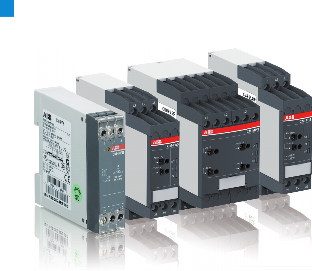
2/27 ABB | Catalog Electronic Products and Relays 2015 | 2CDC 110 004 C0210
2
Three-phase monitoring relays
Product group picture

2CDC 110 004 C0210 | Catalog Electronic Products and Relays 2015 | ABB 2/28
2
Three-phase monitoring relays
Table of contents
Three-phase monitoring relays
Benefits and advantages, Applications 2/29
Operating controls 2/30
Selection table singlefunctional 2/31
Selection table multifunctional 2/32
Ordering details - Singlefunctional 2/33
Ordering details - Multifunctional 2/34
Function diagrams 2/35
Connection diagrams 2/39
DIP switches, Rotary switches 2/40
Technical data 2/41

2/29 ABB | Catalog Electronic Products and Relays 2015 | 2CDC 110 004 C0210
2
Extended functionality
ABB’s new generation of three-phase monitoring relays feature
additional functions making the application field for the de-
vices considerably larger.
Selectable phase sequence monitoring
The phase sequence monitoring can be switched off by
means of a rotary switch or a DIP switch. This enables moni-
toring of three-phase mains where phase sequence is not
relevant for the application, for example in case of motors with
forward and reverse rotation, heating applications, etc.
Automatic phase sequence correction
The automatic phase sequence correction is activated by
means of a DIP switch. With activated phase sequence
correction, it is ensured that for any non-fixed or portable
equipment, e.g. construction machinery, the correct phase
sequence is always applied to the input terminals of the load.
For details regarding the wiring, please see function descrip-
tion / diagrams.
Structure of the type designation
CM-_ _ x.yz
x: width of enclosure
y: Control supply voltage / measuring range
1110, 115, 120, 127 V supply systems (phase-
neutral)
2220, 230, 240 V supply systems (phase-neutral)
3200, 208, 220, 230, 240, 257, 260 V supply sys-
tems (phase-phase)
4440, 460 V supply systems (phase-phase)
5480, 500 V supply systems (phase-phase)
6575, 600 V supply systems (phase-phase)
7660, 690 V supply systems (phase-phase)
8200, 400 V supply systems (phase-phase)
z: Rated frequency / output circuit
150/60 Hz – 1x2 c/o
250/60 Hz – 1x2 or 2x1 c/o
350/60/400 Hz – 1x2 oder 2x1 c/o
Three-phase monitoring relays
Benefits and advantages, Applications
Phase unbalance monitoring
If the supply by the three-phase system is unbalanced due to
uneven distribution of the load, the motor will convert a part of
the energy into reactive power. This energy gets lost unex-
ploited; also the motor is exposed to higher thermal stress.
Other thermal protection devices fail to dete ct continuing
unbalances which can lead to damage or destruction of the
motor. The CM range three-phase monitors with phase unbal-
ance monitoring can reliably detect this critical situation.
Phase sequence
Changing the phase sequence during operation or a wrong
phase sequence prior to startup causes a change of the rota-
tional direction of the connected device. Generators, pumps
or fans rotate in the wrong direction and the installation is no
longer working properly. Especially for moveable equipment,
such as construction machinery, phase sequence detection
prior to the startup process is highly reasonable.
Phase loss
In case of phase loss, undefined stats of the installation are
likely to occur. E.g. the startup process of motors is disturbed.
All three-phase monitors of the ABB CM range detect a phase
loss as soon as the voltage of one phase drops below 60% of
its nominal value.
Voltage monitoring
All electric devices can be damaged when operated continu-
ously in a network with out-of-range voltages. For example,
safe starting is not ensured in case of undervoltage. Also,
the switching state of a contactor is not clearly defined when
operated in a „forbidden“ voltage range. This can lead to un-
defined states of the installtion and cause damage or destruc-
tion of valuable parts.
Characteristics of the CM range three-phase monitors
– Adjustable phase unbalance threshold value 1)
– Adjustable ON-delay/OFF-delay time 1)
– Dual frequency measuring 50/60 Hz
– Powered by the measuring circuit
– 1 n/o contact, 1 or 2 c/o contacts
– LEDs for the indication of operational states
– Multifunctional and single-functional devices
– Phase failure detection
– Phase sequence monitoring 1)
– Over- and undervoltage monitoring (fixed or adjustable)1)
–
Wide-range operating voltage guarantees world-wide operation
–
Approvals / Marks
A C R K E 2) / a b
1) depending on device type
2) Applicable in rail application following the latest standards for rail applications: NF
F 16-101/102 (I2/F2 classified), EN 45545 (Hazard Level 3), DIN 5510, EN 50155,
IEC 60571. Further information is available in our rail segment brochure
2CDC110084B0201.
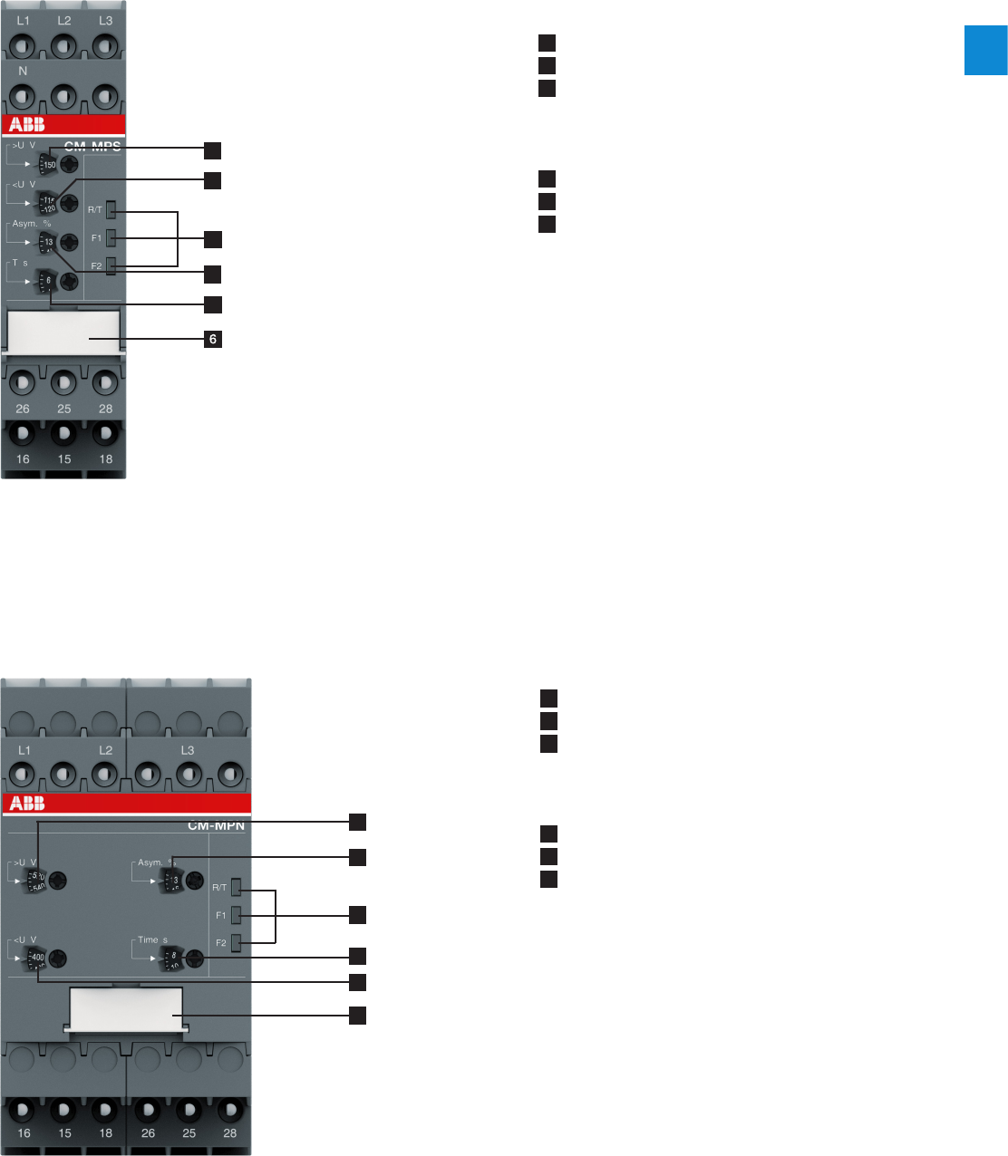
2CDC 110 004 C0210 | Catalog Electronic Products and Relays 2015 | ABB 2/30
2
Three-phase monitoring relays
Operating controls
4
1
2
3
5
1 Adjustment of the hysteresis >U for overvoltage
2 Adjustment of the threshold value <U for undervoltage
3 Indication of operational states
R/T: red LED – Relay status / timing
F1: yellow LED – Fault message
F2: yellow LED – Fault message
4 Adjustment of the threshold value Asym. for phase unbalance
5 Adjustment of the tripping delay Tv
6 DIP switches (see DIP switch functions on page 2/40)
A ON-delay
B OFF-delay
l Phase sequence monitoring deactivated
k Phase sequence monitoring activated
m Phase sequence correction activated
n Phase sequence correction deactivated
i 2x1 c/o (SPDT) contact
j 1x2 c/o (SPDT) contacts
1 Adjustment of the hysteresis >U for overvoltage
2 Adjustment of the threshold value Asym. for phase unbalance
3 Indication of operational states
R/T: red LED – Relay status / timing
F1: yellow LED – Fault message
F2: yellow LED – Fault message
4 Adjustment of the tripping delay Tv
5 Adjustment of the hysteresis <U for undervoltage
6 DIP switches (see DIP switch functions on page 2/40)
A ON-delay
B OFF-delay
l Phase sequence monitoring deactivated
k Phase sequence monitoring activated
m Phase sequence correction activated
n Phase sequence correction deactivated
i 2x1 c/o (SPDT) contact
j 1x2 c/o (SPDT) contacts
1
3
2
4
5
6
S-Range Housing
N-Range Housing
2CDC 253 017 F00132CDC 253 016 F0013
2/31 ABB | Catalog Electronic Products and Relays 2015 | 2CDC 110 004 C0210
2
Three-phase monitoring relays
Selection table singlefunctional
Order number
1SVR550881R9400
1SVR550882R9500
1SVR550870R9400
1SVR550871R9500
1SVR550824R9100
1SVR730824R9300
1SVR740824R9300
1SVR730784R2300
1SVR740784R2300
1SVR730784R3300
1SVR740784R3300
1SVR730794R1300
1SVR730794R3300
1SVR740794R3300
1SVR730794R2300
1SVR740794R2300
1SVR730774R1300
1SV R74 0774R13 0 0
1SVR730774R3300
1SV R74 0774R3300
Rated control supply voltage Us
Type
CM-PBE
CM-PBE
CM-PVE
CM-PVE
CM-PFE
CM-PFS.S
CM-PFS.P
CM-PSS.31S
CM-PSS.31P
CM-PSS.41S
CM-PSS.41P
CM-PVS.31S
CM-PVS.41S
CM-PVS.41P
CM-PVS.81S
CM-PVS.81P
CM-PAS.31S
CM-PAS.31P
CM-PAS.41S
CM-PAS.41P
Phase to Phase
160-300 V AC J J J
200-400 V AC J J
200-500 V AC J J
208-440 V AC J
300-500 V AC J J J J
320-460 V AC J J
350-580 V AC
380 V AC J J
380-440 V AC J J
400 V AC J J
Phase to Neutral
185-265 V AC J
220-240 V AC J
Rated frequency
50/60 Hz JJJJJJJJJJJJJJJJJJJJ
Suitable for monitoring
Single-phase mains J J
Three-phase mains JJJJJJJJJJJJJJJJJJJJ
Monitoring function
Phase failure JJJJJJJJJJJJJJJJJJJJ
Phase sequence JJJsel sel sel sel sel sel sel sel sel J J J J
Automatic phase sequence correction
Overvoltage JJ JJJJJJJJJ
Undervoltage JJ JJJJJJJJJ
Unbalance J J J J
Neutral 1) J J
Thresholds fix fix fix fix fix fix fix fix fix fix fix fix adj adj adj adj adj adj adj adj
Timing functions for tripping delay
ON delay fix fix sel sel sel sel
On and OFF delay fix fix fix fix fix adj adj adj adj adj adj adj adj adj
Connection type
Push-in terminals J J J J J J
Double-chamber cage connection
terminals
J J J J J J J
adj: adjustable
sel: selectable
1) The external conductor voltage towards the neutral conductor is measured.
2CDC 110 004 C0210 | Catalog Electronic Products and Relays 2015 | ABB 2/32
2
Three-phase monitoring relays
Selection table multifunctional
adj: adjustable
sel: selectable
adj: adjustable
sel: selectable
Order number
1SVR730885R1300
1SV R74 0 8 85R1300
1SVR730885R3300
1SV R74 0 8 85R 3 30 0
1SVR730884R1300
1SVR740884R1300
1SVR730884R3300
1SVR740884R3300
1SVR730885R4300
1SVR740885R4300
1SVR730884R4300
1SVR740884R4300
1SVR750487R8300
1SVR760487R8300
1SVR750488R8300
1SVR760488R8300
1SVR750489R8300
1SVR760489R8300
Rated control supply voltage Us
Type
CM-M P S.11S
CM-M P S.11P
CM-MPS.21S
CM-MPS.21P
CM-MPS.31S
CM-MPS.31P
CM-MPS.41S
CM-MPS.41P
CM-MPS.23S
CM-MPS.23P
CM-MPS.43S
CM-MPS.43P
CM-MPN.52S
CM-MPN.52P
CM-MPN.62S
CM-MPN.62P
CM-MPN.72S
CM-MPN.72P
Phase to Phase
160-300 V AC J J
300-500 V AC J J J J
350-580 V AC J J
450-720 V AC J J
530-820 V AC J J
Phase to Neutral
90-170 V AC J J
180-280 V AC J J J J
Rated frequency
50/60 Hz J J J J J J J J J J J J J J
50/60/400 Hz JJJJ
Suitable for monitoring
Single-phase mains J J J J J J
Three-phase mains J J J J J J J J J J J J J J J J J J
Monitoring function
Phase failure JJJJJ J J J JJJJJJJJJJ
Phase sequence sel sel sel sel sel sel sel sel adj adj adj adj adj adj adj adj adj adj
Automatic phase sequence correction adj adj adj adj adj adj adj adj adj adj
Overvoltage JJJJJ J J J JJJJJJJJJJ
Undervoltage JJJJJ J J J JJJJJJJJJJ
Unbalance JJJJJ J J J JJJJJJJJJJ
Neutral 1) J2) J2) J2) J2) J2) J2)
Thresholds adj adj adj adj adj adj adj adj adj adj adj adj adj adj adj adj adj adj
Timing functions for tripping delay
On and OFF delay adj adj adj adj adj adj adj adj adj adj adj adj adj adj adj adj adj adj
Connection type
Push-in terminals J J J J J J J J J
Double-chamber cage connection
terminals
J J J J J J J J J
1) The external conductor voltage towards the neutral conductor is measured.
2) Interrupted neutral monitoring
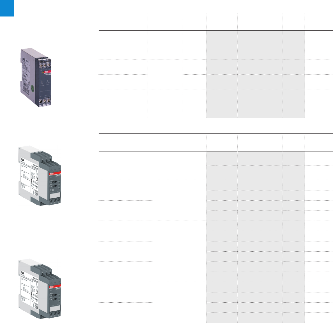
2/33 ABB | Catalog Electronic Products and Relays 2015 | 2CDC 110 004 C0210
2
Three-phase monitoring relays
Ordering details - Singlefunctional
Description
Only reliable and continuous monitoring of a three-phase network guarantees the trouble-free
and economic operation of machines and installations.
Ordering details
Rated control supply
voltage = measuring
voltage
Monitoring
function
Neutral
monitor-
ing
Type Order code Price
1 pce
Weight
(1 pce)
kg (lb)
3x380-440 V AC,
220-240VC Phase failure
detection
(Single- and
three-phase)
nCM-PBE 1) 1SVR550881R9400 0.08 (0.17)
3x380-440 V AC CM-PBE 1SVR550882R9500 0.08 (0.17)
3x320-460 V AC,
185-265VAC
Over- / under-
voltage and
phase failure
detection
(Single- and
three-phase)
nCM-PVE 1) 1SVR550870R9400 0.08 (0.17)
3x320-460 V AC CM-PVE 1SVR550871R9500 0.08 (0.17)
3x208-440 V AC
Phase sequence
monitoring and
phase failure
detection (Three-
phase)
CM-PFE 2) 1SVR550824R9100 0.08 (0.17)
2CDC 251 063 V0011 2CDC 251 064 V0011
2CDC 251 064 V0011
CM-PAS.31P
CM-PSS.41P
CM-PBE
1) The version with neutral monitoring is also suitable for monitoring single-phase mains. For this, all three external conductors
(L1,L2,L3) have to be jumpered and connected as one single conductor.
2) For applications where a reverse fed voltage >60% is expected, we recommend to use our three-phase monitoring relays for
unbalance CM-PAS.xx
Ordering details
Rated control
supply voltage =
measuring voltage
Monitoring function Type Order code Price
1 pce
Weight
(1 pce)
kg (lb)
3x200-500 V AC
Phase sequence monitoring
and phase failure detection
(Three-phase)
CM-PFS.S 1SVR730824R9300 0.127 (0.280)
CM-PFS.P 1SVR740824R9300 0.119 (0. 262)
3x380 V AC
Over- / undervoltage with
fixed threshold values
±10 %
CM-PSS.31S 1SVR730784R2300 0.132 (0.291)
CM-PSS.31P 1SVR740784R2300 0.123 (0.271)
3x400 V AC
CM-PSS.41S 1SVR730784R3300 0.132 (0.291)
CM-PSS.41P 1SVR740784R3300 0.123 (0.271)
3x160-300 V AC
Over- and undervoltage
with adjustable threshold
values (Three-phase)
CM-PVS.31S 1SVR730794R1300 0.141 (0.311)
CM-PVS.31P 1SVR740794R1300 0.132 (0.291)
3x300-500 V AC
CM-PVS.41S 1SVR730794R3300 0.139 (0.306)
CM-PVS.41P 1SVR740794R3300 0.131 (0.289)
3x200-400 V AC
CM-PVS.81S 1SVR730794R2300 0.136 (0.300)
CM-PVS.81P 1SVR740794R2300 0.128 (0.282)
3x160-300 V AC
Phase unbalance (Three-
phase)
CM-PAS.31S 1SVR730774R1300 0.133 (0.293)
CM-PAS.31P 1SVR740774R1300 0.124 (0.273)
3x300-500 V AC
CM-PAS.41S 1SVR730774R3300 0.132 (0.291)
CM-PAS.41P 1SV R74 0774R3300 0.123 (0.271)
S: screw connection
P: push-in / easy connect
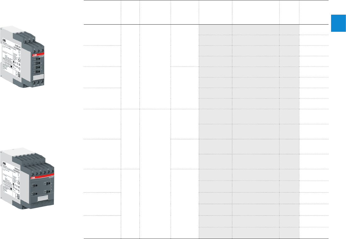
2CDC 110 004 C0210 | Catalog Electronic Products and Relays 2015 | ABB 2/34
2
Three-phase monitoring relays
Ordering details - Multifunctional
Ordering details
Rated control
supply voltage
= measuring
voltage
DIP
switch
Monitoring
function
Neutral
monitoring
Type Order code Price
1 pce
Weight
(1 pce)
kg (lb)
90-170 V AC
A
B
k
l
Multifunctional
(Three-phase
phase failure
detection,
Phase
sequence
monitoring,
overvoltage,
undervoltage,
Phase
unbalance)
n
CM-M P S.11S 1SVR730885R1300 0.148 (0.326)
CM-M P S.11P 1SV R740 8 8 5R13 0 0 0.137 (0.302)
180-280 V AC
CM-MPS.21S 1SVR730885R3300 0.146 (0.322)
CM-MPS.21P 1SV R74 0 885R 330 0 0.135 (0.298)
3x160-300 V AC
CM-MPS.31S 1SVR730884R1300 0.142 (0.313)
CM-MPS.31P 1SVR740884R1300 0.133 (0.293)
3x300-500 V AC
CM-MPS.41S 1SVR730884R3300 0.140 (0.309)
CM-MPS.41P 1SVR740884R3300 0.132 (0.291)
180-280 V AC A
B
k
l
m
n
i
j
Multifunctional
(Three-phase
phase failure
detection,
Phase
sequence
monitoring,
overvoltage,
undervoltage,
Phase
unbalance)
n
CM-MPS.23S 1SVR730885R4300 0.149 (0.328)
CM-MPS.23P 1SVR740885R4300 0.138 (0.304)
3x300-500 V AC
CM-MPS.43S 1SVR730884R4300 0.148 (0.327)
CM-MPS.43P 1SVR740884R4300 0.137 (0.302)
3x350-580 V AC
A
B
k
l
m
n
i
j
CM-MPN.52S 1SVR750487R8300 0.230 (0.507)
CM-MPN.52P 1SVR760487R8300 0.226 (0.498)
3x450-720 V AC
CM-MPN.62S 1SVR750488R8300 0.229 (0.505)
CM-MPN.62P 1SVR760488R8300 0.225 (0.496)
3x530-820 V AC
CM-MPN.72S 1SVR750489R8300 0.224 (0.494)
CM-MPN.72P 1SVR760489R8300 0.220 (0.485)
2CDC 251 065 V0011
2CDC 251 062 V0011
CM-MPS.23P
CM-MPN.52P
A ON-delayed
B OFF-delayed
k Phase sequence
monitoring activated
l Phase sequence
monitoring deactivated
m Phase sequence
correction activated
n Phase sequence
correction deactivated
i 2x1 c/o (SPDT) contacts
j 1x2 c/o (SPDT) contacts
S: screw connection
P: push-in / easy connect
S: screw connection
P: push-in / easy connect
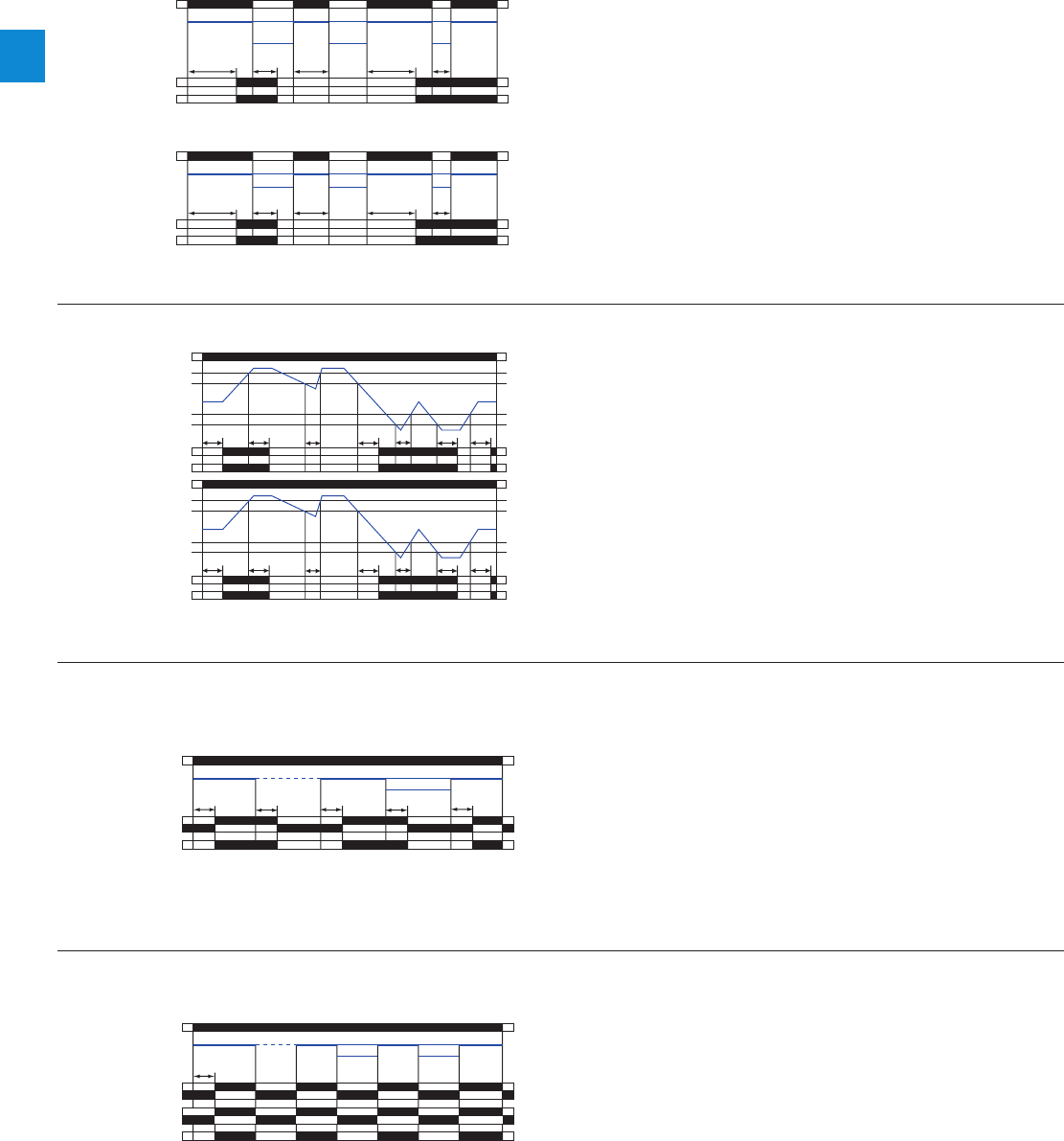
2/35 ABB | Catalog Electronic Products and Relays 2015 | 2CDC 110 004 C0210
2
Three-phase monitoring relays
Function diagrams
L1, L2, L3, N
13-14
L1, L2, L3, N L1, L2, L3, NL1, L2, L3, NL1, L2, L3, NL1, L2
L3
N
ts
L1, L2, N
L3
tv
L2, L3, N
L1
<tsts<tv
2CDC 252 045 F0203
R: yellow LED
Measuring value
ts = Start-up delay fixed 500 ms
tv = Tripping delay fixed 150 ms
L1, L2, L3
13-14
L1, L2, L3 L1, L2, L3 L1, L2, L3 L1, L2, L3L1, L2
L3
ts
L1, L2
L3
tv
L1, L2
L3
<tsts<tv
2CDC 252 046 F0203
R: yellow LED
Measuring value
ts = Start-up delay fixed 500 ms
tv = Tripping delay fixed 150 ms
Function diagrams - Phase failure detection CM-PBE
with
neutral
without
neutral
Function diagrams - Phase failure, under- / overvoltage detection CM-PVE
with
neutral
without
neutral
L1, L2, L3, N
13-14
Umax
Umax - 5 %
Umin + 5 %
Umin
tststs
tvtv
<ts<tv
2CDC 252 047 F0203
R: yellow LED
Measuring value
ts = Start-up delay fixed 500 ms
tv = Tripping delay fixed 500 ms
L1, L2, L3
13-14
Umax
Umax - 5 %
Umin + 5 %
Umin
tsts
ts
tvtv
<ts<tv
2CDC 252 048 F0203
R: yellow LED
Measuring value
ts = Start-up delay fixed 500 ms
tv = Tripping delay fixed 500 ms
If all phases (and the neutral) are present, the output relay
energizes after the start-up delay ts is complete. If a phase
failure occurs, the tripping delay tv starts. When timing is com-
plete, the output relay de-energizes. As soon as the voltage
returns to the tolerance range, timing of ts starts. When timing
is complete, the output relay re-energizes automatically. The
yellow LED glows when the output relay is energized.
If all phases (and the neutral) are present with correct voltage,
the output relay energizes after the start-up delay ts is com-
plete. If the voltage exceeds or falls below the fixed threshold
value or if a phase failure occurs, the tripping delay tv starts.
When timing is complete, the output relay de-energizes. As
soon as the voltage returns to the tolerance range, timing of
ts starts. When timing is complete, the output relay re-ener-
gizes automatically. The yellow LED glows when the output
relay is energized.
Function diagram - Phase failure detection, phase sequence monitoring CM-PFE
L1, L2, L3
11-12
11-14
L1, L2, L3 L1, L2, L3 L1, L2, L3L1, L3, L2 L1, L2
L3
tstvtstvts
2CDC 252 061 F0208
R: yellow LED
Measuring value
ts = Start-up delay fixed 500 ms
tv = Tripping delay fixed 500 ms
If all phases are present with the correct phase sequence, the
output relay energizes after the start-up delay ts is complete. If
a phase failure or a phase sequence error occurs, the trip-
ping delay tv starts. When timing is complete, the output relay
de-energizes. The yellow LED glows when the output relay is
energized.
In case of motors which continue running with only two
phases, the CM-PFE detects phase failure if the reverse fed
voltage is less than 60 % of the originally applied voltage.
ATTENTION
If several CM-PFS units are placed side by side and the control supply voltage is higher than 415 V, spacing of at least 10 mm has to be kept
between the individual units.
Function diagram - Phase failure detection, phase sequence monitoring CM-PFS
L1, L2, L3
11-12
11-14
21-22
21-24
L1, L2, L3 L1, L2, L3 L1, L2, L3 L1, L2, L3L1, L3, L2 L1, L2 L1
L3 L2, L3ts
2CDC 252 013 F0208
R: yellow LED
Measuring value
ts = start-up delay fixed 500 ms
If all phases are present with the correct phase sequence, the
output relay energizes after the start-up delay ts is complete. If
a phase failure or a phase sequence error occurs, the output
relay de-energizes instantaneous. The yellow LED glows when
the output relay is energized.
In case of motors which continue running with only two
phases, the CM-PFS detects phase failure if the reverse fed
voltage is less than 60 % of the originally applied voltage.
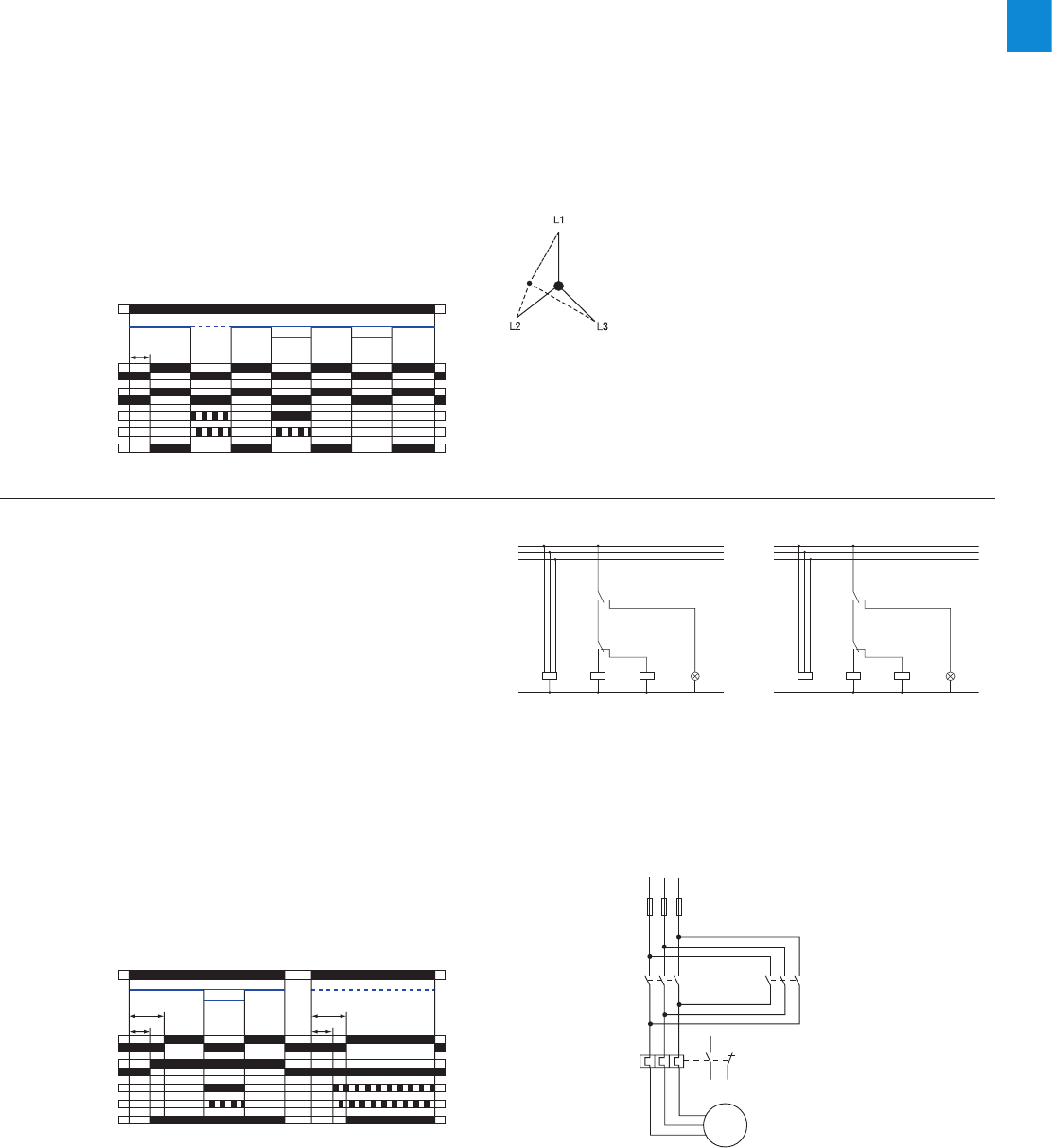
2CDC 110 004 C0210 | Catalog Electronic Products and Relays 2015 | ABB 2/36
2
Three-phase monitoring relays
Function diagrams
K1
K1
K1
K3 H1
L1
L2
L3
N
16
28
A1
25
26
15
18
K2
A2
A1
A2
K1
K1
K1
K3 H1
L1
L2
L3
N
16
28
A1
25
26
15
18
K2
A2
A1
A2
-K3
L1
-F1
1
2
95
96
97
98
L2
3
4
L3
5
6
1
2
3
4
5
6
-K2
-F2
1
2
3
4
5
6
1
3
5
2
4
6
M
3 ~
W1
V1
U1
-M1
2CDC 252 087 F0b0
7
CM-PSS.xx, CM-PVS.xx, CM.PAS.xx, CM-MPS.xx, CM-MPN.xx
Phase sequence monitoring and phase failure detection
Applying control supply voltage begins the fixed start-up delay
tS. When tS is complete and all phases are present with cor-
rect voltage, the output relays energize and the yellow LED
R/T glows.
Phase sequence monitoring
If phase sequence monitoring is activated, the output relays
de- energize as soon as a phase sequence error occurs. The
fault is displayed by alternated flashing of the LEDs F1 and
F2. The output relays re-energize automatically as soon as the
phase sequence is correct again.
Phase failure detection
The output relays de-energize instantaneous if a phase failure
occurs. The fault is indicated by lightning of LED F1 and flash-
ing of LED F2. The output relays re-energize automatically as
soon as the voltage returns to the tolerance range.
25-26
25-28
L1, L2, L3
15-16
15-18
L1, L2, L3 L1, L2, L3 L1, L2, L3 L1, L2, L3L1, L3, L2 L1, L2 L1
L3 L2, L3ts
2CDC 252 094 F0207
F1: red LED
F2: red LED
R/T: yellow LED
Measuring value
ts = start-up delay fixed 200 ms
L1, L2, L3
15-16
15-18
tS2
tS1 tS1
L1, L2, L3L1, L2, L3 L1, L3, L2L1, L2
L3
25-26
25-28
tS2
2CDC 252 085 F0207
F1: red LED
F2: red LED
R/T: yellow LED
Measuring value
tS1 = start-up delay of R1 fixed 250 ms
t
S2
= start-up delay of R2 fixed 200 ms
CM-MPS.x3, CM-MPN.x2
Automatic phase sequence correction
This function can be selected only if phase sequence moni-
toring is activated k and operating mode 2x1 c/o (SPDT)
contact j is selected.
Applying control supply voltage begins the fixed start-up
delay tS1. When tS1 is complete and all phases are present with
correct voltage, output relay R1 energizes. Output relay R2
energizes when the fixed start-up delay tS2 is complete and all
phases are present with correct phase sequence. Output relay
R2 remains de-energized if the phase sequence is incorrect.
If the voltage to be monitored exceeds or falls below the set
threshold values for phase unbalance, over- or undervoltage
or if a phase failure occurs, output relay R1 de-energizes and
the LEDs F1 and F2 indicate the fault.
Output relay R2 is responsive only to a false phase sequence.
In conjunction with a reversing contactor combination, this
enables an automatic correction of the rotation direction. See
circuit diagrams on the right.
CM-MPS.11, CM-MPS.21, CM-MPS.23
Interrupted neutral monitoring
The interruption of the neutral in the main to be monitored is
detected by means of phase unbalance evaluation.
Determined by the system, in case of unloaded neutral, i.e.
symmetrical load between all three phases, it may happen
that an interruption of the neutral will not be detected.
If the star point is displaced by asymmetrical load in the
three-phase main, an interrupted neutral will be detected.
Control circuit diagram
(K1 = CM-MPS.23)
Control circuit diagram
(K1 = CM-MPS.43 or CM-MPN.xx)
Power circuit diagram
Displacement of the star point
2CDC 253 008 F0014
2CDC 253 009 F0014
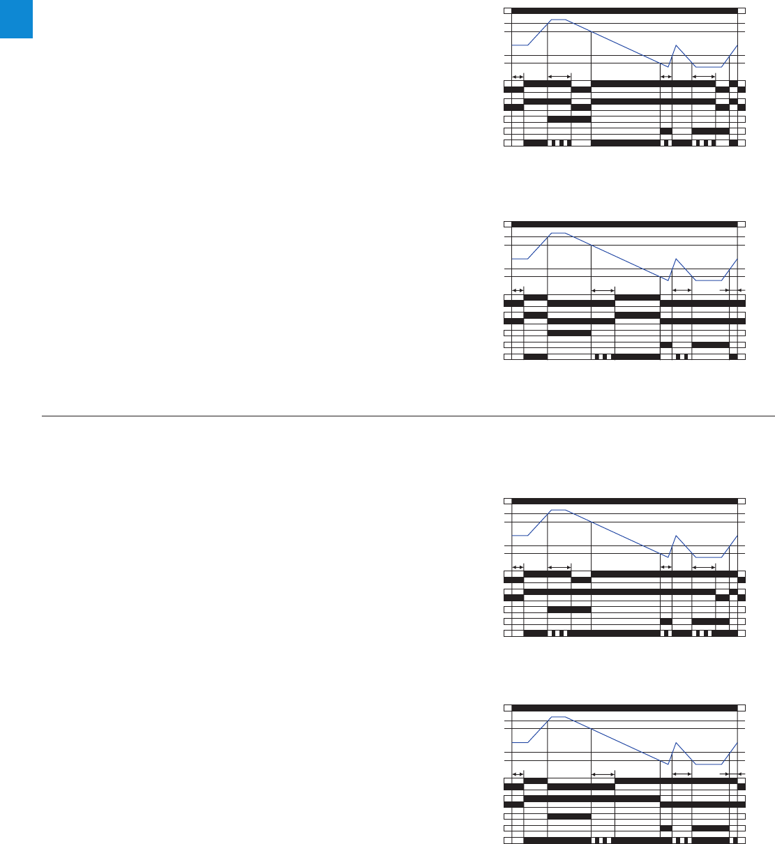
2/37 ABB | Catalog Electronic Products and Relays 2015 | 2CDC 110 004 C0210
2
ON-delay A, 2x1 c/o contact i
OFF-delay B, 2x1 c/o contact i
OFF-delay B, 1x2 c/o contacts j
ON-delay A, 1x2 c/o contacts j
CM-PSS.xx1), CM-PVS.xx2), CM-MPS.xx2), CM-MPN.xx2)
Over- and undervoltage monitoring j
Applying control supply voltage begins the fixed start-up
delay tS. When tS is complete and all phases are present with
correct voltage and with correct phase sequence, the output
relays energize and the yellow LED R/T glows.
Type of tripping delay = ON-delay
If the voltage to be monitored exceeds or falls below the
fixed1) or set2) threshold value, the output relays de-energize
after the set tripping delay tV is complete. The LED R/T flashes
during timing and turns off as soon as the output relays de-
energize.
The output relays re-energize automatically as soon as the
voltage returns to the tolerance range, taking into account a
fixed hysteresis of 5 % and the LED R/T glows.
Type of tripping delay = OFF-delay
If the voltage to be monitored exceeds or falls below the
fixed1) or set2) threshold value, the output relays de-energize
instantaneously and the LED R/T turns off.
As soon as the voltage returns to the tolerance range, tak-
ing into account a fixed hysteresis of 5 %, the output relays
re-energize automatically after the set tripping delay tV is
complete. The LED R/T flashes during timing and turns steady
when timing is complete.
L1, L2, L3
15-16
15-18
25-26
25-28
> U
> U - 5 %
< U + 5 %
< U
ts<tv
<tv
tv
2CDC 252 007 F0207
F1: red LED
F2: red LED
R/T: yellow LED
Measuring value
ts = start-up delay fixed 200 ms
tv = adjustable tripping delay
L1, L2, L3
15-16
15-18
25-26
25-28
> U
> U - 5 %
< U + 5 %
< U
tstvtv
<tv
2CDC 252 006 F0207
F1: red LED
F2: red LED
R/T: yellow LED
Measuring value
ts = start-up delay fixed 200 ms
tv = adjustable tripping delay
CM-MPS.x3, CM-MPN.x2
Over- and undervoltage monitoring i
Applying control supply voltage begins the fixed start-up
delay tS. When tS is complete and all phases are present with
correct voltage and with correct phase sequence, the output
relays energize. The yellow LED R/T glows as long as at least
one output relay is energized.
Type of tripping delay = ON-delay
If the voltage to be monitored exceeds or falls below the set
threshold value, output relay R1 (overvoltage) or output relay
R2 (undervoltage) de-energizes after the set tripping delay tV
is complete. The LED R/T flashes during timing.
The corresponding output relay re-energizes automatically as
soon as the voltage returns to the tolerance range, taking into
account a fixed hysteresis of 5 %.
Type of tripping delay = OFF-delay
If the voltage to be monitored exceeds or falls below the set
threshold value, output relay R1 (overvoltage) or output relay
R2 (undervoltage) de-energizes instantaneously.
As soon as the voltage returns to the tolerance range, taking
into account a fixed hysteresis of 5 %, the corresponding out-
put relay re-energizes automatically after the set tripping delay
tV is complete. The LED R/T flashes during timing.
L1, L2, L3
15-16
15-18
> U
> U - 5 %
< U + 5 %
< U
tstvtv
<tv
25-26
25-28
2CDC 252 090 F0207
F1: red LED
F2: red LED
R/T: yellow LED
Measuring value
ts = start-up delay fixed 200 ms
tv = adjustable tripping delay
25-26
25-28
L1, L2, L3
15-16
15-18
> U
> U - 5 %
< U + 5 %
< U
ts<tv
<tv
tv
2CDC 252 091 F0207
F1: red LED
F2: red LED
R/T: yellow LED
Measuring value
ts = start-up delay fixed 200 ms
tv = adjustable tripping delay
Three-phase monitoring relays
Function diagrams
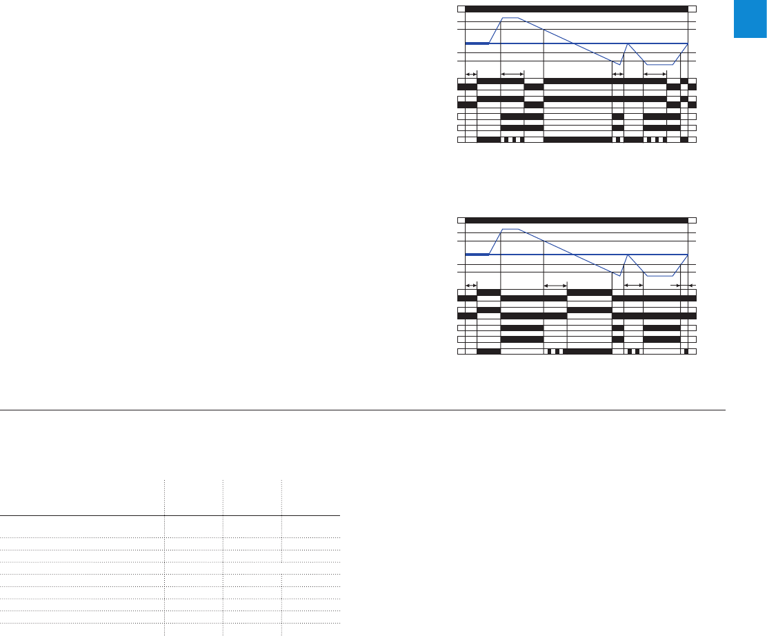
2CDC 110 004 C0210 | Catalog Electronic Products and Relays 2015 | ABB 2/38
2
Three-phase monitoring relays
Function diagrams
CM-PAS.xx, CM-MPS.xx, CM-MPN.xx
Phase unbalance monitoring
Applying control supply voltage begins the fixed start-up
delay tS. When tS is complete and all phases are present with
correct voltage and with correct phase sequence, the output
relays energize and the yellow LED R/T glows.
Type of tripping delay = ON-delay
If the voltage to be monitored exceeds or falls below the
set phase unbalance threshold value, the output relays de-
energize after the set tripping delay tV is complete. The LED
R/T flashes during timing and turns off as soon as the output
relays de-energize.
The output relays re-energize automatically as soon as the
voltage returns to the tolerance range, taking into account a
fixed hysteresis of 20 % and the LED R/T glows.
Type of tripping delay = OFF-delay
If the voltage to be monitored exceeds or falls below the set
phase unbalance threshold value, the output relays de-ener-
gize instantaneously and the LED R/T turns off.
As soon as the voltage returns to the tolerance range, taking
into account a fixed hysteresis of 20 %, the output relays
re-energize automatically after the set tripping delay tV is
complete. The LED R/T flashes during timing and turns steady
when timing is complete. 25-26
25-28
L1, L2, L3
15-16
15-18
ts<tv
<tv
tv
L1, L2, L3 L1, L2
L3
2CDC 252 093 F0207
F1: red LED
F2: red LED
R/T: yellow LED
Measuring value
Unbalance
Unbalance - Hysteresis
Unbalance + Hysteresis
Unbalance
ts = start-up delay fixed 200 ms
tv = adjustable tripping delay
L1, L2, L3
15-16
15-18
L1, L2, L3 L1, L2
L3
tstvtv
<tv
25-26
25-28
2CDC 252 092 F0207
F1: red LED
F2: red LED
R/T: yellow LED
Measuring value
Unbalance
Unbalance - Hysteresis
Unbalance + Hysteresis
Unbalance
ts = start-up delay fixed 200 ms
tv = adjustable tripping delay
OFF-delay B
ON-delay A
CM-PSS.xx, CM-PSV.xx, CM-PAS.xx, CM-MPS.xx, CM-MPN.xx
LED functions
Function
R/ T:
yellow LED
F1:
red LED
F2:
red LED
Control supply voltage applied,
output relay energized V- -
Tripping delay tV active W- -
Phase failure -V W
Phase sequence -W alternating
Overvoltage -V-
Undervoltage - - V
Phase unbalance -V V
Interruption of the neutral -V W
Adjustment error 1) W W W
1) Possible misadjustments of the front-face operating controls:
Overlapping of the threshold values: An overlapping of the threshold values is
given, if the threshold value for overvoltage is set to a smaller value than the
threshold value for undervoltage.
DIP switch 3 = OFF and DIP switch 4 = ON: Automatic phase sequence
correction is activated and selected operating mode is 1x2 c/o contacts
DIP switch 2 and 4 = ON: Phase sequence detection is deactivated and the
automatic phase sequence correction is actived
CM-PSS.xx, CM-PSV.xx, CM-PAS.xx, CM-MPS.xx, CM-MPN.xx
Type of tripping delay
The type of tripping delay A / B can be adjusted via a
rotary (CM-PxS.xx) or a DIP switch (CM-MPx.xx).
Switch position ON-delay A:
In case of a fault, the de-energizing of the output relays and
the respective fault message are suppressed for the adjusted
tripping delay tV.
Switch position OFF-delay B:
In case of a fault, the output relays de-energize instanta-
neously and a fault message is displayed and stored for the
length of the adjusted tripping delay tV. Thereby, also momen-
tary undervoltage conditions are recognized.
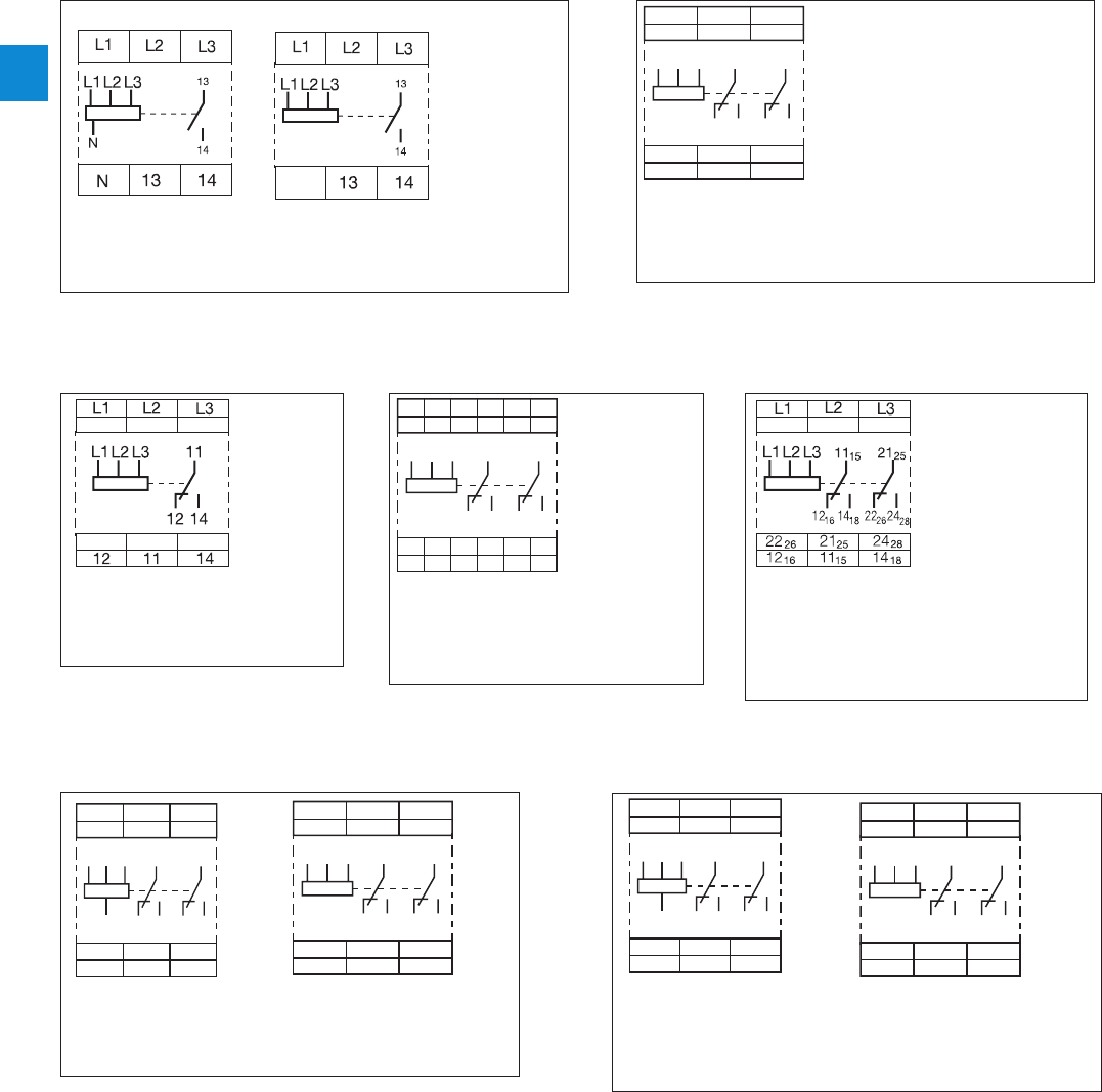
2/39 ABB | Catalog Electronic Products and Relays 2015 | 2CDC 110 004 C0210
2
Three-phase monitoring relays
Connection diagrams
1SVC 110 000 F0117
Connection diagram CM-PFE Connection diagram CM-PFS
L1 L2
282526
18
L3
L3 15
16 18 26 28
25L2L1
16 15
2CDC 252 037 F0b08
Connection diagram CM-PVS.x1, CM-PSS.x1, CM-PAS.x1
L1 L2
282615 25
L3
L3 15
16 18 26 28
25L2L1
16 18
2CDC 252 038 F0b08
Connection diagram CM-MPN.x2
1SVC 110 000 F 0118
L1, L2, L3, (N) Control supply voltage = Measuring voltage
13-14 Output contact - closed-circuit principle
L1, L2, L3, (N) Control supply voltage = Measuring voltage
15-16/18
25-26/28 Output contact - closed-circuit principle
L1, L2, L3 Control supply voltage =
Measuring voltage
1115-1216 /1418
2125-2226/2428
Output contact - closed-
circuit principle
L1, L2, L3, (N) Control supply voltage = Measuring voltage
15-16/18
25-26/28 Output contact - closed-circuit principle
L1, L2, L3, (N) Control supply voltage = Measuring voltage
15-16/18
25-26/28 Output contact - closed-circuit principle
L1, L2, L3 Control supply voltage =
Measuring voltage
15-16/18
25-26/28 Output contact - closed-
circuit principle
L1, L2, L3 Control supply voltage =
Measuring voltage
11-12 /14 Output contact - closed-
circuit principle
Connection diagrams CM-PBE, CM-PVE
with neutral without neutral
L1
N
L2
282526
18
L3
L3 15
16 18 26 28
25L2
N
L1
16 15
2CDC 252 036 F0b08
L1
L2
282526
18
L3
L3 15
16 18 26 28
25L2L1
16 15
2CDC 252 037 F0b08
Connection diagram CM-MPS.x3
L1
N
L2
282526
18
L3
L3 15
16 18 26 28
25L2
N
L1
16 15
2CDC 252 036 F0b08
L1 L2
282526
18
L3
L3 15
16 18 26 28
25L2L1
16 15
2CDC 252 037 F0b08
Connection diagram CM-MPS.x1
2CDC 252 038 F0b08
2CDC 252 036 F0b08
2CDC 252 037 F0b08
2CDC 252 037 F0b08
1SVC 110 000 F 0112
1SVC 110 000 F 0113
2CDC 252 037 F0b08
2CDC 252 036 F0b08
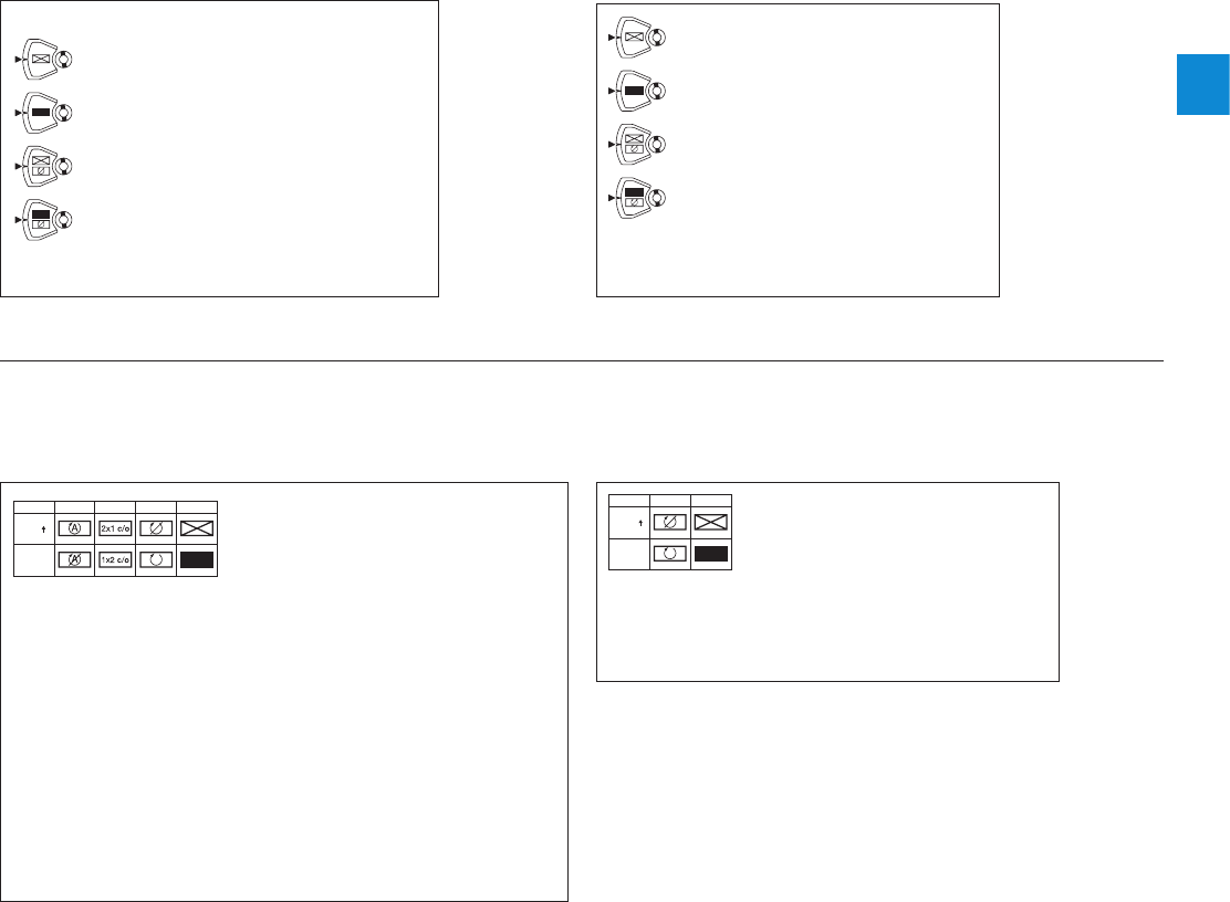
2CDC 110 004 C0210 | Catalog Electronic Products and Relays 2015 | ABB 2/40
2
Three-phase monitoring relays
DIP switches, Rotary switches
Rotary switch "Function" CM-PSS
ON-delay
with phase sequence monitoring
OFF-delay
with phase sequence monitoring
ON-delay
without phase sequence monitoring
OFF-delay
without phase sequence monitoring
Rotary switch "Function" CM-PVS
ON-delay
with phase sequence monitoring
OFF-delay
with phase sequence monitoring
ON-delay
without phase sequence monitoring
OFF-delay
without phase sequence monitoring
Position 1 2
ON
OFF
2CDC 252 040 F0b08
Position 4 1 2 3
ON
OFF
2CDC 252 041 F0b0
8
DIP switch functions
CM-MPS.x3 and CM-MPN.x2
1Timing function 2Phase sequence monitoring
ON
OFF ON-delayed
OFF-delayed
ON
OFF
deactivated
activated
3Operating principle of output 4Phase sequence correction
ON
OFF 2x1 c/o contact
1x2 c/o contact ON
OFF activated
deactivated
DIP switch functions
CM-MPS.x1
1Timing function 2Phase sequence monitoring
ON
OFF ON-delayed
OFF-delayed ON
OFF deactivated
activated
Output relay R1 is responsive to overvoltage, output relay R2 is responsive
to undervoltage. In case of other faults, both output relays react
synchronously.

2/41 ABB | Catalog Electronic Products and Relays 2015 | 2CDC 110 004 C0210
2
Three-phase monitoring relays
Technical data
Type CM-PBE 1) CM-PBE CM-PVE 1) CM-PVE CM-PFE CM-PFS
Supply circuit = measuring circuit L1-L2-L3-N L1-L2-L3 L1-L2-L3-N L1-L2-L3 L1-L2-L3
Rated control supply voltage US = measuring voltage 3x380-
440 V AC,
220-240
VAC
3x380-
440 V AC 3x320-
460 V AC,
185-265
VAC
3x320-
460 V AC 3x208-
440 V AC 3x200-
500 V AC
Power consumption approx. 15 VA
Rated control supply voltage US tolerance -15...+15 % -15...+10 % -10...+10 % -15...+10 %
Rated frequency 50/60 Hz 50/60 Hz (-10...+10 %) 50/60 Hz
Duty time 100 %
Measuring circuit L1-L2-L3-N L1-L2-L3 L1-L2-L3-N L1-L2-L3 L1-L2-L3
Monitoring functions phase failure JJJJJJ
phase sequence ----J J
over- / undervoltage - - JJ- -
neutral J-J---
Measuring ranges 3x380-440
V AC, 220-
240 V AC
3x380-
440 V AC 3x320-
460 V AC,
185-265
VAC
3x320-
460 V AC 3x208-
440 V AC 3x200-
500 V AC
Thresholds Umin 0.6 x UN fixed
185 V /
320 V
fixed
320 V 0.6 x UN
Umax fixed
265 V /
460 V
fixed
460 V
Hysteresis related to the threshold value fixed 5 %
(release value = 0.65 x UN)fixed 5 % -
Measuring voltage frequency 50/60 Hz (-10 %...+10 %) 50/60 Hz
Response time 40 ms 80 ms 500 ms
Accuracy within the rated control supply voltage tolerance -U m 0.5 %
Accuracy within the temperature range -U m 0.06 % / °C
Timing circuit
Start-up delay tSfixed 500 ms (w20 %) fixed 500 ms
Tripping tVfixed 150 ms
(w20 %) at over-/ undervoltage
fixed 500 ms (w20 %) fixed 500
ms -
Indication of operational states
Relay status R: yellow LED V Output relay energized
Fault message F: red LED Only CM-PFS: V Phase failure / V Phase sequence error
Output circuits 13-14 11-12 /14
1115-1216 / 1418,
2125-2226 / 2428
Kind of output 1 n/o contact 1 c/o
contact 2 c/o
contacts
Operating principle closed-circuit principle 2)
Contact material AgCdO AgNi allow,
Cd free
Rated operational voltage Ue IEC/EN 60947-1 250 V 250 V AC
Minimum switching voltage / Minimum switching current - / -
Maximum switching voltage 250 V AC, 250 V DC
Rated operational current Ie
(IEC/EN 60947-5-1) AC-12 (resistive) 230 V 4 A
AC-15 (inductive) 230 V 3 A
DC-12 (resistive) 24 V 4 A
DC-13 (inductive) 24 V 2 A
Mechanical lifetime 30 x 106 switching cycles
Electrical lifetime (AC-12, 230 V, 4 A) 0.1 x 10⁶ switching cycles
Max. fuse rating to achieve
short-circuit protection n/c contact 10 A fast-acting 6 A fast-
acting
n/o contact 10 A fast-acting
AC rating
(UL 508) Utilization category (Control Circuit Rating Code) B 300, CM-PFS: B300, pilot duty general purpose (250 V, 4 A, cos phi 0.75)
max. rated operational voltage 300 V AC
max. continuous thermal current at B 300 5 A
max. making/breaking apparent power at B 300 3600/360 VA
1) Device with neutral monitoring: The external conductor voltage towards the neutral conductor is measured.
2) Closed-circuit principle: Output relay is de-energized if the measured value exceeds/drops below the adjusted threshold.

2CDC 110 004 C0210 | Catalog Electronic Products and Relays 2015 | ABB 2/42
2
Type CM-PBE 1) CM-PBE CM-PVE 1) CM-PVE CM-PFE CM-PFS
General data
Dimensions (W x H x D) 22.5 x 78 x 78.5 mm (0.89 x 3.07 x 3.09 in)
CM-PFS: 22.5 x 78 x 100 mm (0.89 x 3.07 x 3.94 in)
Weight see data sheet
Mounting DIN rail (IEC/EN 60715)
Mounting position any
Degree of protection housing / terminals IP50 / IP20
Electrical connection
Wire size fine-strand with wire end ferrule 2 x 0.75-1.5 mm² (2 x 18-16 AWG)
Same as
CM-PSS.31,
see page 2/44.
fine-strand without wire end ferrule 2 x 1-1.5 mm² (2 x 18-16 AWG)
rigid 2 x 0.75-1.5 mm² (2 x 18-16 AWG)
Stripping length 10 mm (0.39 in)
Same as
CM-PSS.31,
see page 2/44.
Tightening torque 0.6-0.8 Nm
Environmental data
Ambient temperature range operation / storage -20..+60 °C / -40...+85 °C
Environmental testing (IEC 68-2-30) 24 h cycle time, 55 °C, 93 % rel., 96 h -
Operational reliability (IEC 68-2-6) 6 g -
Mechanical resistance (IEC 68-2-6) 10 g -
Climatic category IEC/EN 60721-3-3 -3K3
Damp heat, cyclic IEC/EN 60068-2-30 CM-PFS: 6 x 24 h cycle, 55 °C, 95 % RH
Vibration, sinusoidal IEC/EN 60255-21-1 -Class 2
Shock IEC/EN 60255-21-2 -Class 2
Isolation data
Rated insulation voltage Ui
(IEC/EN 60947-1, IEC/EN 60664-1) between supply,
measuring and output
circuits
400 V -
supply circuit /
output circuit -600 V
output circuit 1 /
output circuit 2 -300 V
Rated impulse withstand voltage Uimp
between all isolated circuits
(VDE 0110, IEC 664)
4 kV / 1.2 - 50 µs -
supply circuit / output
circuit -6 kV
output circuit 1 /
output circuit 2 -4 kV
Basic insulation for rated control
supply voltage (IEC/EN 60664-1) supply circuit / output
circuit -600 V AC
Protective seperation
(IEC/EN 61140, EN 50178) supply circuit / output
circuit -n/a
Test voltage (routine test) 2.5 kV, 50 Hz, 1 min. -
supply circuit /
output circuit -2.5 kV, 50
Hz, 1 min.
output circuit 1 /
output circuit 2 -2.5 kV, 50
Hz, 1 min.
Pollution degree (IEC/EN 60664-1) 3
Overvoltage category (IEC/EN 60664-1) III
Standards
Product standard IEC 255-6, EN 60255-6, CM-PFS: IEC/EN 60255-1, IEC/EN 60255-27, EN 50178
Low Voltage Directive 2006/95/EC
EMC Directive 2004/108/EC
RoHS Directive CM-PFS: 2011/65/EC
Electromagnetic compatibility
Interference immunity to EN 61000-6-2, CM-PFS: EN 61000-6-1, EN 61000-6-2
electrostatic discharge IEC/EN 61000-4-2 Level 3 - 6 kV/ 8 kV
radiated, radio-frequency,
electromagnetic field IEC/EN 61000-4-3 Level 3 - 10 V/m (1 GHz) / 3 V/m (2 GHz) / 1 V/m (2.7 GHz)
electrical fast transient / burst IEC/EN 61000-4-4 Level 3 - 2 kV / 5 kHz
surge IEC/EN 61000-4-5 Level 4 - 2 kVL-L
conducted disturbances, induced
by radio-frequency fields IEC/EN 61000-4-6 Level 3 - 10 V
voltage dips, short interruptions
and voltage variations IEC/EN 61000-4-11 -Class 3
harmonics and interharmonics IEC/EN 61000-4-13 -Class 3
Interference emission EN 61000-6-4, CM-PFS: EN 61000-6-3, EN 61000-6-4
high-frequency radiated
IEC/CISPR 22, EN 55022
Class B
high-frequency conducted
IEC/CISPR 22, EN 55022
Class B
1) Device with neutral monitoring: The external conductor voltage towards the neutral conductor is measured.
Three-phase monitoring relays
Technical data

2/43 ABB | Catalog Electronic Products and Relays 2015 | 2CDC 110 004 C0210
2
Three-phase monitoring relays
Technical data
Type CM-PSS.31 CM-PSS.41 CM-PVS.31 CM-PVS.41 CM-PVS.81 CM-PAS.31
CM-PAS.41
Input circuit = Measuring circuit L1, L2, L3
Rated control supply voltage US = measuring voltage 3x380 V AC 3x400 V AC 3x160-
300V AC 3x300-
500V AC 3x200-
400V AC 3x160-
300VAC 3x300-
500 V AC
Rated control supply voltage US tolerance -15...+10 %
Rated frequency 50/60 Hz
Frequency range 45-65 Hz
Typical current / power consumption 25 mA /
18VA
(380 V AC)
25 mA /
18VA
(400 V AC)
25 mA /
10VA
(230 V AC)
25 mA /
18VA
(400 V AC)
19 mA /
10VA
(300 V AC)
25 mA /
10VA
(230 V AC)
25 mA
/18VA
(400 V AC)
Measuring circuit L1, L2, L3
Monitoring functions Phase failure JJJJJJJ
Phase sequence can be switched off J J
Automatic phase sequence
correction -------
Over- / undervoltage JJJJJ- -
Phase unbalance -----J J
Neutral -------
Measuring range Overvoltage 3x418 V AC 3x440 V AC 3x220-
300 V AC 3x420-
500 V AC 3x300-
400 V AC - -
Undervoltage 3x342 V AC 3x360 V AC 3x160-
230 V AC 3x300-
380 V AC 3x210-
300 V AC - -
Phase
unbalance -----2-25 % of average
of phase voltages
Thresholds Overvoltage fixed adjustable within measuring range - -
Undervoltage fixed adjustable within measuring range - -
Phase unbalance
(switch-off value) -----adjust. within meas.
range
Hysteresis related to
the threshold value Over- / undervoltage fixed 5 % -
Phase unbalance -----fixed 20 %
Rated frequency of the measuring signal 50/60 Hz
Frequency range of the measuring signal 45-65 Hz
Maximum measuring cycle time 100 ms
Accuracy within the rated control supply voltage tolerance
U m 0.5 %
Accuracy within the temperature range U m 0.06 % / °C
Measuring method True RMS
Timing circuit
Start-up delay tSfixed 200 ms
Tripping delay tVON- or OFF-delay
0; 0.1-30 s adjustable ON- delay
0; 0.1-30 s adjustable
Repeat accuracy (constant parameters) ----< w 0.2 % - -
Accuracy within the rated control supply voltage tolerance
t m 0.5 %
Accuracy within the temperature range t m 0.06 % / °C
Indication of operational states 1 yellow LED, 2 red LED's
Details see function
description / -diagrams Details see operating mode and
function description / -diagrams Details see function
description / -diagrams
Output circuits 15-16/18, 25-26/28
Kind of output relay, 2 x 1 c/o contact
Operating principle closed-circuit principle 1)
Contact material AgNi alloy, Cd free
Rated operational voltage Ue IEC/EN 60947-1 250 V
Minimum switching power 24 V / 10 mA
Maximum switching voltage see „Load limit curves“ on page 127
1) Closed-circuit principle: Output relay(s) de-energize(s) if measured value exceeds or falls below the adjusted threshold value

2CDC 110 004 C0210 | Catalog Electronic Products and Relays 2015 | ABB 2/44
2
Three-phase monitoring relays
Technical data
Type CM-PSS.31 CM-PSS.41 CM-PVS.31 CM-PVS.41 CM-PVS.81 CM-PAS.31
CM-PAS.41
Rated operational current Ie
(IEC/EN 60947-5-1)
AC-12 (resistive)
230 V 4 A
AC-15 (inductive) 230 V
3 A
DC-12 (resistive) 24 V 4 A
DC-13 (inductive) 24 V
2 A
AC rating (UL 508) Utilization category (Control
Circuit Rating Code) B 300
max. rated operational voltage 300 V AC
max. continuous thermal
current at B 300 5 A
max. making/breaking
apparent power at B 300 3600/360 VA
Mechanical lifetime 30 x 106 switching cycles
Electrical lifetime (AC-12, 230 V, 4 A) 0.1 x 10⁶ switching cycles
Max. fuse rating to achieve
short-circuit protection n/c contact 6 A fast-acting
n/o contact 10 A fast-acting
General data
MTBF on request
Duty time 100%
Dimensions
(W x H x D) product dimensions 22.5 x 85.6 x 103.7 mm (0.89 x 3.37 x 4.08 in)
packaging dimensions 97 x 109 x 30 mm (3.82 x 4.29 x 1.18 in)
Weight depending on device, see ordering details
Mounting DIN rail (IEC/EN 60715), snap-on mounting without any tool
Mounting position any
Minimum distance to other
units horizontal 10 mm (0.39 in) in case of continuous measuring voltages
> 400 V > 400 V > 220 V > 400 V -> 220 V > 400 V
Material of housing UL 94 V-0
Degree of protection housing / terminals IP50 / IP20
Electrical connection
Wire size Screw connection technology Easy Connect Technology (Push-in)
fine-strand with(out) wire end
ferrule 1 x 0.5-2.5 mm2 (1 x 20-14 AWG)
2 x 0.5-1.5 mm2 (2 x 20-16 AWG) 2 x 0.5-1.5 mm2 (2 x 20-16 AWG)
rigid 1 x 0.5-4 mm2 (1 x 20-12 AWG)
2 x 0.5-2.5 mm2 (2 x 20-14 AWG) 2 x 0.5-1.5 mm2 (2 x 20-16 AWG)
Stripping length 8 mm (0.32 in)
Tightening torque 0.6-0.8 Nm (5.31-7.08 lb.in) -
Environmental data
Ambient temperature ranges operation / storage -25...+60 °C / -40...+85 °C
Damp heat (IEC 60068-2-30) 55 °C, 6 cycles
Climatic category 3K3
Vibration (sinusoidal) (IEC/EN 60255-21-1) Class 2
Shock (IEC/EN 60255-21-2) Class 2
Isolation data
Rated insulation
voltage Ui
input circuit / output circuit 600 V
output circuit 1 / output circuit 2
300 V
Rated impulse withstand voltage
Uimp (VDE 0110, IEC/EN 60664) input circuit 6 kV; 1.2/50 µs
output circuit 4 kV; 1.2/50 µs
Test voltage between all isolated circuits (routine test)
2.5 kV, 50 Hz, 1 s
Basic insulation input circuit / output circuit 600 V
Protective separation (VDE 0106
part 101 and 101/A, IEC/EN 1140) input circuit /
output circuit -
Pollution degree (VDE 0110, IEC/EN 60664) 3
Overvoltage category (VDE 0110, IEC 60664) III
Standards
Product standard IEC/EN 60255-6, EN 50178
Low Voltage Directive 2006/95/EC
EMC directive 2004/108/EC
RoHS directive 2011/65/EC
Electromagnetic compatibility
Interference immunity to EN 61000-6-1, EN 61000-6-2
electrostatic discharge IEC/EN 61000-4-2 Level 3 (6 kV / 8 kV)
radiated, radio-frequency,
electromagnetic field IEC/EN 61000-4-3 Level 3 (10 V/m)
electrical fast transient /
burst IEC/EN 61000-4-4 Level 3 (2 kV / 2 kHz)
surge IEC/EN 61000-4-5 Level 4 (2 kV L-L)
conducted disturbances,
induced by radio-
frequency fields
IEC/EN 61000-4-6 Level 3 (10 V)
Interference emission EN 61000-6-3, EN 61000-6-4
high-frequency radiated
IEC/CISPR 22, EN 55022
Class B
high-frequency conducted
IEC/CISPR 22, EN 55022
Class B

2/45 ABB | Catalog Electronic Products and Relays 2015 | 2CDC 110 004 C0210
2
Three-phase monitoring relays
Technical data
Type CM -MPS.11 CM-MPS.21 CM-MPS.31 CM-MPS.41
Input circuit = Measuring circuit L1, L2, L3, N L1, L2, L3
Rated control supply voltage US = measuring voltage 3x90-170 V AC 3x180-280 V AC 3x160-300 V AC 3x300-500 V AC
Rated control supply voltage US tolerance -15...+10 %
Rated frequency 50/60 Hz
Frequency range 45-65 Hz
Typical current / power consumption 25 mA / 10 VA
(115 V AC) 25 mA / 18 VA
(230 V AC) 25 mA / 10 VA
(230 V AC) 25 mA / 18 VA
(400 V AC)
Measuring circuit L1, L2, L3, N L1, L2, L3
Monitoring functions Phase failure J J J J
Phase sequence can be switched off
Automatic phase sequence correction - - - -
Over- / undervoltage J J J J
Phase unbalance J J J J
Interrupted neutral J J - -
Measuring range Overvoltage 3x120-170 V AC 3x240-280 V AC 3x220-300 V AC 3x420-500 V AC
Undervoltage 3x90-130 V AC 3x180-220 V AC 3x160-230 V AC 3x300-380 V AC
Phase unbalance 2-25 % of average of phase voltages
Thresholds Overvoltage adjustable within measuring range
Undervoltage adjustable within measuring range
Phase unbalance (switch-off value) adjustable within measuring range
Hysteresis related to the
threshold value Over- / undervoltage fixed 5 %
Phase unbalance fixed 20 %
Rated frequency of the measuring signal 50/60 Hz
Frequency range of the measuring signal 45-65 Hz
Maximum measuring cycle time 100 ms
Accuracy within the rated control supply voltage tolerance U m 0.5 %
Accuracy within the temperature range U m 0.06 % / °C
Measuring method True RMS
Timing circuit
Start-up delay tSfixed 200 ms
Tripping delay tVON- or OFF-delay 0; 0.1-30 s adjustable
Accuracy within the rated control supply voltage tolerance t m 0.5 %
Accuracy within the temperature range t m 0.06 % / °C
Indication of operational states Details see function description / -diagrams
Output circuits 15-16/18, 25-26/28
Kind of output relay, 1 x 2 c/o contacts
Operating principle closed-circuit principle 1)
Contact material AgNi alloy, Cd free
Rated operational voltage Ue (IEC/EN 60947-1) 250 V
Minimum switching power 24 V / 10 mA
Maximum switching voltage see „Load limit curves“ on page 127
Rated operational current Ie
(IEC/EN 60947-5-1) AC-12 (resistive) 230 V 4 A
AC-15 (inductive) 230 V 3 A
DC-12 (resistive) 24 V 4 A
DC-13 (inductive) 24 V 2 A
AC rating (UL 508) Utilization category
(Control Circuit Rating Code) B 300
max. rated operational voltage 300 V AC
max. continuous thermal current at B 300
5 A
max. making/breaking
apparent power at B 300
3600/360 VA
Mechanical lifetime 30 x 106 switching cycles
Electrical lifetime (AC-12, 230 V, 4 A) 0.1 x 10⁶ switching cycles
Max. fuse rating to achieve short-circuit
protection n/c contact 6 A fast-acting
n/o contact 10 A fast-acting
1) Closed-circuit principle: Output relay(s) de-energize(s) if measured value exceeds or falls below the adjusted threshold value

2CDC 110 004 C0210 | Catalog Electronic Products and Relays 2015 | ABB 2/46
2
Type CM -MPS.11 CM-MPS.21 CM-MPS.31 CM-MPS.41
General data
MTBF on request
Duty time 100%
Dimensions (W x H x D) product dimensions 22.5 x 85.6 x 103.7 mm (0.89 x 3.37 x 4.08 in)
packaging dimensions 97 x 109 x 30 mm (3.82 x 4.29 x 1.18 in)
Weight Screw connection technology Easy Connect Technology (Push-in)
net weight depending on device, see ordering details
gross weight depending on device, see ordering details
Mounting DIN rail (IEC/EN 60715), snap-on mounting without any tool
Mounting position any
Minimum distance to other units horizontal 10 mm (0.39 in) in case of continuous measuring voltages
> 120 V > 240 V > 220 V > 400 V
Material of housing UL 94 V-0
Degree of protection housing / terminals IP50 / IP20
Electrical connection
Wire size Screw connection technology Easy Connect Technology (Push-in)
fine-strand with(out) wire end ferrule 1 x 0.5-2.5 mm2 (1 x 20-14 AWG)
2 x 0.5-1.5 mm2 (2 x 20-16 AWG) 2 x 0.5-1.5 mm2 (2 x 20-16 AWG)
rigid 1 x 0.5-4 mm2 (1 x 20-12 AWG)
2 x 0.5-2.5 mm2 (2 x 20-14 AWG) 2 x 0.5-1.5 mm2 (2 x 20-16 AWG)
Stripping length 8 mm (0.32 in)
Tightening torque 0.6-0.8 Nm (5.31-7.08 lb.in) -
Environmental data
Ambient temperature ranges operation / storage -25...+60 °C / -40...+85 °C
Damp heat (IEC 60068-2-30) 55 °C, 6 cycles
Climatic category 3K3
Vibration (sinusoidal) (IEC/EN 60255-21-1) Class 2
Shock (IEC/EN 60255-21-2) Class 2
Isolation data
Rated insulation voltage
Ui
input circuit / output circuit 600 V
output circuit 1 / output circuit 2 300 V
Rated impulse withstand voltage Uimp
(VDE 0110, IEC/EN 60664) input circuit 6 kV; 1.2/50 µs
output circuit 4 kV; 1.2/50 µs
Test voltage between all isolated circuits (routine test) 2.5 kV, 50 Hz, 1 s
Basic insulation input circuit / output circuit 600 V
Protective separation (VDE 0106 part
101 and 101/A, IEC/EN 61140) input circuit / output
circuit yes -
Pollution degree (VDE 0110, IEC/EN 60664) 3
Overvoltage category (VDE 0110, IEC 60664) III
Standards
Product standard IEC/EN 60255-1, EN 50178
Low Voltage Directive 2006/95/EC
EMC directive 2004/108/EC
RoHS directive 2011/65/EC
Electromagnetic compatibility
Interference immunity to EN 61000-6-1, EN 61000-6-2
electrostatic discharge IEC/EN 61000-4-2 Level 3 (6 kV / 8 kV)
radiated, radio-frequency,
electromagnetic field IEC/EN 61000-4-3 Level 3 (10 V/m)
electrical fast transient / burst IEC/EN 61000-4-4 Level 3 (2 kV / 2 kHz)
surge IEC/EN 61000-4-5 Level 4 (2 kV L-L)
conducted disturbances,
induced by radio-frequency fields IEC/EN 61000-4-6 Level 3 (10 V)
harmonics and interharmonics IEC/EN 61000-4-13 Class 3
Interference emission EN 61000-6-3, EN 61000-6-4
high-frequency radiated
IEC/CISPR 22, EN 55022
Class B
high-frequency conducted
IEC/CISPR 22, EN 55022
Class B
Three-phase monitoring relays
Technical data

2/47 ABB | Catalog Electronic Products and Relays 2015 | 2CDC 110 004 C0210
2
Three-phase monitoring relays
Technical data
Type CM-MPS.23 CM-MPS.43 CM-MPN.52 CM-MPN.62 CM-MPN.72
Input circuit = Measuring circuit L1, L2, L3, N L1, L2, L3
Rated control supply voltage US = measuring voltage 3x180-280
V AC 3x300-500
V AC 3x350-580
V AC 3x450-720
V AC 3x530-820
V AC
Rated control supply voltage US tolerance -15...+10 %
Rated frequency 50/60/400 Hz 50/60 Hz
Frequency range 45-440 Hz 45-65 Hz
Typical current / power consumption 5 mA / 4 VA
(230 V AC) 5 mA / 4 VA
(400 V AC) 29 mA / 41 VA
(480 V AC) 29 mA / 52 VA
(600 V AC) 29 mA / 59 VA
(690 V AC)
Measuring circuit L1, L2, L3, N L1, L2, L3
Monitoring functions Phase failure JJJJJ
Phase sequence can be switched off
Automatic phase sequence correction configurable
Over- / undervoltage JJJJJ
Phase unbalance JJJJJ
Interrupted neutral J- - - -
Measuring range Overvoltage 3x240-280
V AC 3x420-500
V AC 3x480-580
V AC 3x600-720
V AC 3x690-820
V AC
Undervoltage 3x180-220
V AC 3x300-380
V AC 3x350-460
V AC 3x450-570
V AC 3x530-660
V AC
Phase unbalance 2-25 % of average of phase voltages
Thresholds Overvoltage adjustable within measuring range
Undervoltage adjustable within measuring range
Phase unbalance (switch-off value) adjustable within measuring range
Hysteresis related to
the threshold value Over- / undervoltage fixed 5 %
Phase unbalance fixed 20 %
Rated frequency of the measuring signal 50/60/400 Hz 50/60 Hz
Frequency range of the measuring signal 45-440 Hz 45-65 Hz
Maximum measuring cycle time 100 ms
Accuracy within the rated control supply voltage tolerance U m 0.5 %
Accuracy within the temperature range U m 0.06 % / °C
Measuring method True RMS
Timing circuit
Start-up delay tS and tS2 fixed 200 ms
Start-up delay tS1 fixed 250 ms
Tripping delay tVON- or OFF-delay 0; 0.1-30 s adjustable
Accuracy within the rated control supply voltage tolerance t m 0.5 %
Accuracy within the temperature range t m 0.06 % / °C
Indication of operational states Details see function description / -diagrams
Output circuits 15-16/18, 25-26/28
Kind of output relay, 2 x 1 or 1 x 2 c/o contacts configurable
Operating principle closed-circuit principle 1)
Contact material AgNi alloy, Cd free
Rated operational voltage Ue IEC/EN 60947-1 250 V
Minimum switching power 24 V / 10 mA
Maximum switching voltage see „Load limit curves“ on page 127
Rated operational current Ie
(IEC/EN 60947-5-1) AC-12 (resistive) 230 V 4 A
AC-15 (inductive) 230 V 3 A
DC-12 (resistive) 24 V 4 A
DC-13 (inductive) 24 V 2 A
AC rating (UL 508) Utilization category
(Control Circuit Rating Code) B 300
max. rated operational voltage 300 V AC
max. continuous thermal current at B 300 5 A
max. making/breaking apparent power at B 300
3600/360 VA
Mechanical lifetime 30 x 106 switching cycles
Electrical lifetime (AC-12, 230 V, 4 A) 0,1 x 10⁶ switching cycles
Max. fuse rating to achieve short-
circuit protection n/c contact 6 A fast-acting 10 A fast-acting
n/o contact 10 A fast-acting
1) Closed-circuit principle: Output relay(s) de-energize(s) if measured value exceeds or falls below the adjusted threshold value

2CDC 110 004 C0210 | Catalog Electronic Products and Relays 2015 | ABB 2/48
2
Three-phase monitoring relays
Technical data
Type CM-MPS.23 CM-MPS.43
CM-MPN.52
CM-MPN.62 CM-MPN.72
General data
MTBF on request
Duty time 100%
Dimensions (W x H x D) product dimensions 22.5 x 85.6 x 103.7 mm (0.89 x 3.37 x 4.08 in)
packaging dimensions 97 x 109 x 30 mm (3.82 x 4.29 x 1.18 in)
Weight depending on device, see ordering details
Mounting DIN rail (IEC/EN 60715), snap-on mounting without any tool
Mounting position any
Minimum distance to other units vertical / horizontal not necessary / not necessary
Material of housing UL 94 V-0
Degree of protection housing / terminals IP50 / IP20
Electrical connection
Wire size Screw connection technology Easy Connect Technology (Push-in)
fine-strand with(out) wire end ferrule 1 x 0.5-2.5 mm2 (1 x 20-14 AWG)
2 x 0.5-1.5 mm2 (2 x 20-16 AWG) 2 x 0.5-1.5 mm2 (2 x 20-16 AWG)
rigid 1 x 0.5-4 mm2 (1 x 20-12 AWG)
2 x 0.5-2.5 mm2 (2 x 20-14 AWG) 2 x 0.5-1.5 mm2 (2 x 20-16 AWG)
Stripping length 8 mm (0.32 in)
Tightening torque 0.6-0.8 Nm (5.31-7.08 lb.in) -
Environmental data
Ambient temperature ranges operation / storage -25...+60 °C / -40...+85 °C
Damp heat (IEC 60068-2-30) 55 °C, 6 cycles
Climatic category 3K3
Vibration (sinusoidal) (IEC/EN 60255-21-1) Class 2
Shock (IEC/EN 60255-21-2) Class 2
Isolation data
Rated insulation voltage Uiinput circuit / output
circuit 600 V 1000 V
output circuit 1 / 2 300 V
Rated impulse withstand voltage Uimp
(VDE 0110, IEC/EN 60664) input circuit 6 kV; 1.2/50 µs 8 kV; 1.2/50 µs
output circuit 4 kV; 1.2/50 µs
Test voltage (routine
test) between isolated output circuits 2.5 kV, 50 Hz, 1 s
input circuit and isolated output circuits 2.5 kV, 50 Hz, 1 s 4 kV, 50 Hz, 1 s
Basic insulation input circuit / output circuit 600 V 1000 V
Protective separation (VDE 0106 part
101 and 101/A, IEC/EN 61140) input circuit /
output circuit -
Pollution degree (VDE 0110, IEC/EN 60664) 3
Overvoltage category (VDE 0110, IEC 60664) III
Standards
Product standard IEC/EN 60255-1, EN 50178
Low Voltage Directive 2006/95/EC
EMC directive 2004/108/EC
RoHS directive 2011/65/EC
Electromagnetic compatibility
Interference immunity to EN 61000-6-1, EN 61000-6-2
electrostatic discharge IEC/EN 61000-4-2 Level 3 (6 kV / 8 kV)
radiated, radio-frequency,
electromagnetic field IEC/EN 61000-4-3 Level 3 (10 V/m)
electrical fast transient / burst IEC/EN 61000-4-4 Level 3 (2 kV / 2 kHz)
surge IEC/EN 61000-4-5 Level 4 (2 kV
L- N ) Level 4 (2 kV L-L)
conducted disturbances, induced by
radio-frequency fields IEC/EN 61000-4-6 Level 3 (10 V)
harmonics and interharmonics IEC/EN 61000-4-13 Class 3
Interference emission EN 61000-6-3, EN 61000-6-4
high-frequency radiated IEC/CISPR 22, EN 55022 Class B
high-frequency conducted IEC/CISPR 22, EN 55022 Class B
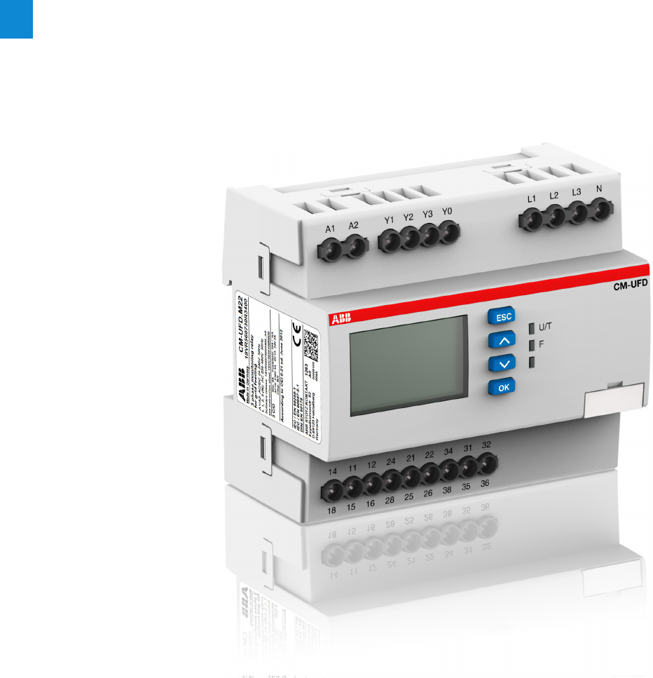
2/49 ABB | Catalog Electronic Products and Relays 2015 | 2CDC 110 004 C0210
2
Grid feeding monitoring relays -
Voltage and frequency monitoring functions
Product group picture

2CDC 110 004 C0210 | Catalog Electronic Products and Relays 2015 | ABB 2/50
2
Grid feeding monitoring relays -
Voltage and frequency monitoring functions
Table of contents
Grid feeding monitoring relays - Voltage and frequency
monitoring functions
Benefits and advantages, operating controls 2/51
Applications 2/52
Applications, connection diagram 2/53
Ordering and selection 2/54
Technical data - CM-UFD.Mxx 2/55
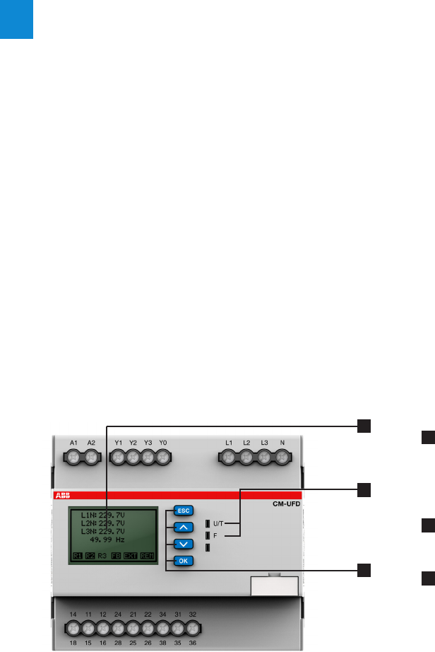
2/51 ABB | Catalog Electronic Products and Relays 2015 | 2CDC 110 004 C0210
2
Grid feeding monitoring relays -
Voltage and frequency monitoring functions
Benefits and advantages, operating controls
Characteristics for all CM-UFD devices
– Monitoring of voltage and frequency in single- and three-
phase mains 2-wire, 3-wire or 4-wire
– Over- and undervoltage, 10 minutes average value as well
as over- and underfrequency monitoring
– Two-level threshold settings for over-/undervoltage and
frequency
– Multiline, backlit LCD display
– All threshold values adjustable as absolute values
– True RMS measuring principle
– High measurement accuracy
– 3 control inputs for remote trip, feedback signal, and exter-
nal signal
– Tripping delay for each threshold adjustable
– Interrupted neutral detection
– Error memory for up to 99 entries (incl. cause of error, mea-
sured value, relative timestamp)
– Test function
– Password setting protection
– 3 c/o (SPDT) contacts
– LEDs for the indication of operational states
Characteristics CM-UFD.M22
– ROCOF
(rate of change of frequency) monitoring, configurable
– Third party certificate confirming accordance with CEI 0-21
– Pre-setting according to CEI 0-21
Characteristics CM-UFD.M31
– ROCOF (rate of change of frequency) monitoring and vec-
tor shift detection, configurable
– Third party certificate confirming accordance with
VDE-AR-N 4105 and BDEW
– Pre-settings according to VDE-AR-N 4105 and BDEW
Characteristics CM-UFD.M33
– ROCOF (rate of change of frequency) monitoring and vec-
tor shift detection, configurable
– Factory certificate confirming accordance with Engineering
Recommendation G59 Issue 3 - September 2013; Engi-
neering Recommendation G83 Issue 2 - December 2012
– Pre-setting according to G59/3 LV + G83/2 HV
– UL 508, CAN/CSA C22.2 No.14
1
2
3
1 Display
R1 R2 R3 - relay status; in this case R3 is de-energized
FB - status feedback loop Y0-Y1; in this case FB is closed
EXT – status input external signal; in this case input is closed
REM – status remote trip input; in this case input is closed
2 Indication of operational states
U/T: green LED – supply voltage applied / flashing = timing active
F: red LED - failure
3 Keypad
ESC: escape / return to previous menu
^: up / value increase
∨: down / value decrease
OK: enter / confirm selection
CM-UFD.Mxx
2CDC 253 020 F0013
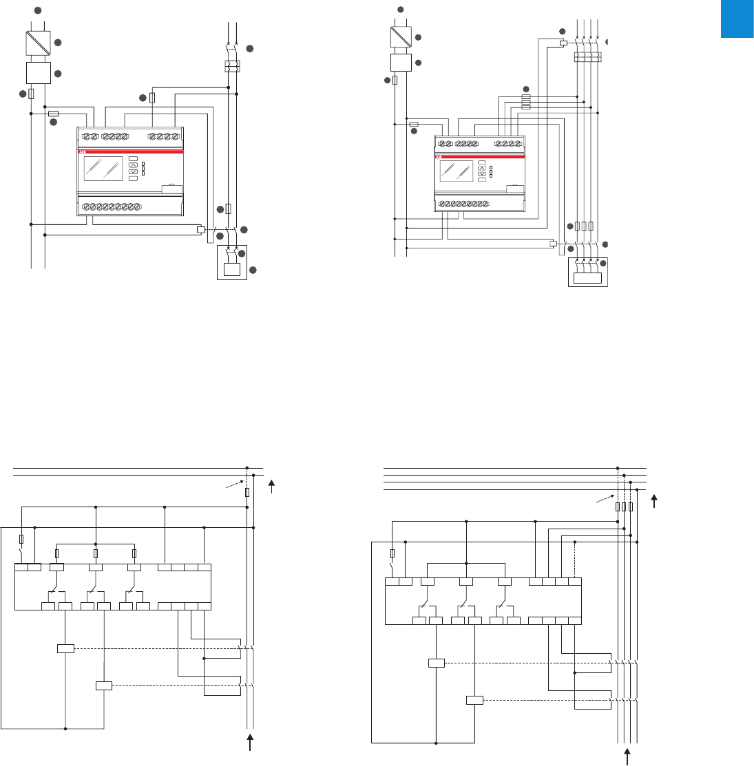
2CDC 110 004 C0210 | Catalog Electronic Products and Relays 2015 | ABB 2/52
2
Grid feeding monitoring relays -
Voltage and frequency monitoring functions
Applications
Example of single-phase application - CM-UFD.M31
L1
N
K1
6 A
10 A 10 A 10 A
K2
Y0
Y2
3438 Y3
3236
2428
2226
1418
1216 Y1
A2
A1 2125
1115 3135 L3L2L1 N
Public grid
Inverter(s)
Generator(s)
Control input 1, feedback loop for switching device 1
Control input 2, feedback loop for switching device 2
Control input 3 (e.g. for remote trip)
Switching device 1 of the section switch
Switching device 2 of the section switch
where applicable,
a transformer
2CDC 252 006 F0213
Example of three-phase application - CM-UFD.M31
L1
L2
L3
N
K1
6 A
K2
Y0
Y2
3438 Y3
3236
2428
2226
1418
1216 Y1
A2
A1 2125
1115 3135 L3L2L1 N
Public grid
Inverter(s)
Generator(s)
Control input 1, feedback loop for switching device 1
Control input 2, feedback loop for switching device 2
Control input 3 (e.g. for remote trip)
Switching device 1 of the section switch
Switching device 2 of the section switch
where applicable,
a transformer
2CDC 252 007 F0213
Example of three-phase application CM-UFD.M22
A1
14 11 12 24 21 22 34 31 32
18 15 16 28 25 26 38 35 36
A2 Y1 L1 L2 L3 NY2 Y3 Y0
ESC
OK
CM-UFD
U/T
F
230 V AC
24 V DC
24 V DC
LN
L1 N
L+
L+IN L-IN
L+OUTL-OUT
L-
CP-E 24/X
CP-B 24/X
L1 L2 L3 N
G
1
8
7
9
11
12
13
10
4
2
3
6
5
Example of single-phase application CM-UFD.M22
A1
14 11 12 24 21 22 34 31 32
18 15 16 28 25 26 38 35 36
A2 Y1 L1 L2 L3 NY2 Y3 Y0
ESC
OK
CM-UFD
U/T
F
230 V AC
24 V DC
24 V DC
LN LN
L1 N
L+
L+IN L-IN
L+OUTL-OUT
L-
CP-E 24/X
CP-B 24/X
G
13
12
11
9
7
10
1
4
2
3
6
5
2CDC 252 004 F0014
2CDC 252 003 F0014
1. Main circuit breaker DG or DGL
2. DDI: Automatic circuit breaker or contactor equipped with low voltage coil and
motor for automatic closure
3. Auxiliary contact of DDI, necessary for realizing the feedback function (compul-
sory for CM-UFD.M22)
4. DDI short-circuit protection
5. Generator and/or inverter
6. Generator (DDG)
7. Protection fuse for the measuring circuit of the CM-UFD.M22 (optional)
8. Shunt trip coil for feedback function (P>20 kW). This coil can control DG/DGL or
DDG devices
9. Control supply voltage for CM-UFD.M22 (SPI) and tripping device (DDI)*
10. Device protection fuse for the CM-UFD.M22
11. Primary switch mode power supply unit CP-E (230 V AC / 24 V DC) for the buf-
fer module CP-B*
12. Ultra-capacitor based buffer module CP-B (24 V DC in/out)
13. Wire protection fuse for the output of the buffer module CP-B
* In accordance to CEI 0-21 regulation, in case of loss of control supply voltage it’s asked to guarantee, at least for 5 seconds, the functionality
of the CM-UFD.M22, the operability of the DDI and when present the command coil for operating the redundancy device. This function has to
be realized by external buffer or UPS devices.
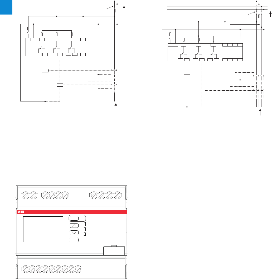
2/53 ABB | Catalog Electronic Products and Relays 2015 | 2CDC 110 004 C0210
2
Grid feeding monitoring relays -
Voltage and frequency monitoring functions
Applications, connection diagram
Example of single-phase application - CM-UFD.M33
L1
N
K1
6 A
10 A 10 A 10 A
K2
Y0
Y2
3438 Y3
3236
2428
2226
1418
1216 Y1
A2
A1 2125
1115 3135 L3L2L1 N
2CDC 252 005 F0014
Example of three-phase application - CM-UFD.M33
L1
L2
L3
N
K1
6 A
K2
10 A 10 A 10 A
Y0
Y2
3438 Y3
3236
2428
2226
1418
1216 Y1
A2
A1 2125
1115 3135 L3L2L1 N
2CDC 252 006 F0014
1 Control input 1, feedback loop for switching device 1
2 Control input 2, feedback loop for switching device 2
3 Control input 3 (e.g. for remote trip)
4 Switching device 1 of the section switch
5 Switching device 2 of the section switch
6 Inverter(s) / generator(s)
7 Transformer (if applicable)
8 Public grid
1
1
1
1
6
7
7
8
8
2
2
3
3
2
2
4
4
5
5
A1 A2 Y1 Y2 Y3 Y0 L1 L2 L3 N
24 21 22121114
28 25 26 38 35 36161518
CM-UFD
U/T
F
34 31 32
ESC
OK
Test
2CDC 253 007 F0014
A1-A2
L1, L2, L3, N
Y1-Y0
Y2-Y0
Y3-Y0
1115-1216/1418
2125-2226/2428
3135-3236/3438
Control supply voltage Us
Measuring inputs
Control input 1: Feedback from switching device 1
Control input 2: Feedback from switching device 2
Control input 3: Remote trip, suppress Y1, suppress Y2
,
suppress Y1/Y2 or suppress vector shift detection
Output relay 1: Relay for tripping switching device 1
of the section switch, closed-circuit principle
Output relay 2: Relay for tripping switching device 2
of the section switch, closed-circuit principle
Output relay 3: Closing command for circuit breaker
motor, configuration possibilities: closed-circuit
principle, open-circuit principle, disabled or
synchronous with R1/R2
Electrical connection - CM-UFD.Mxx
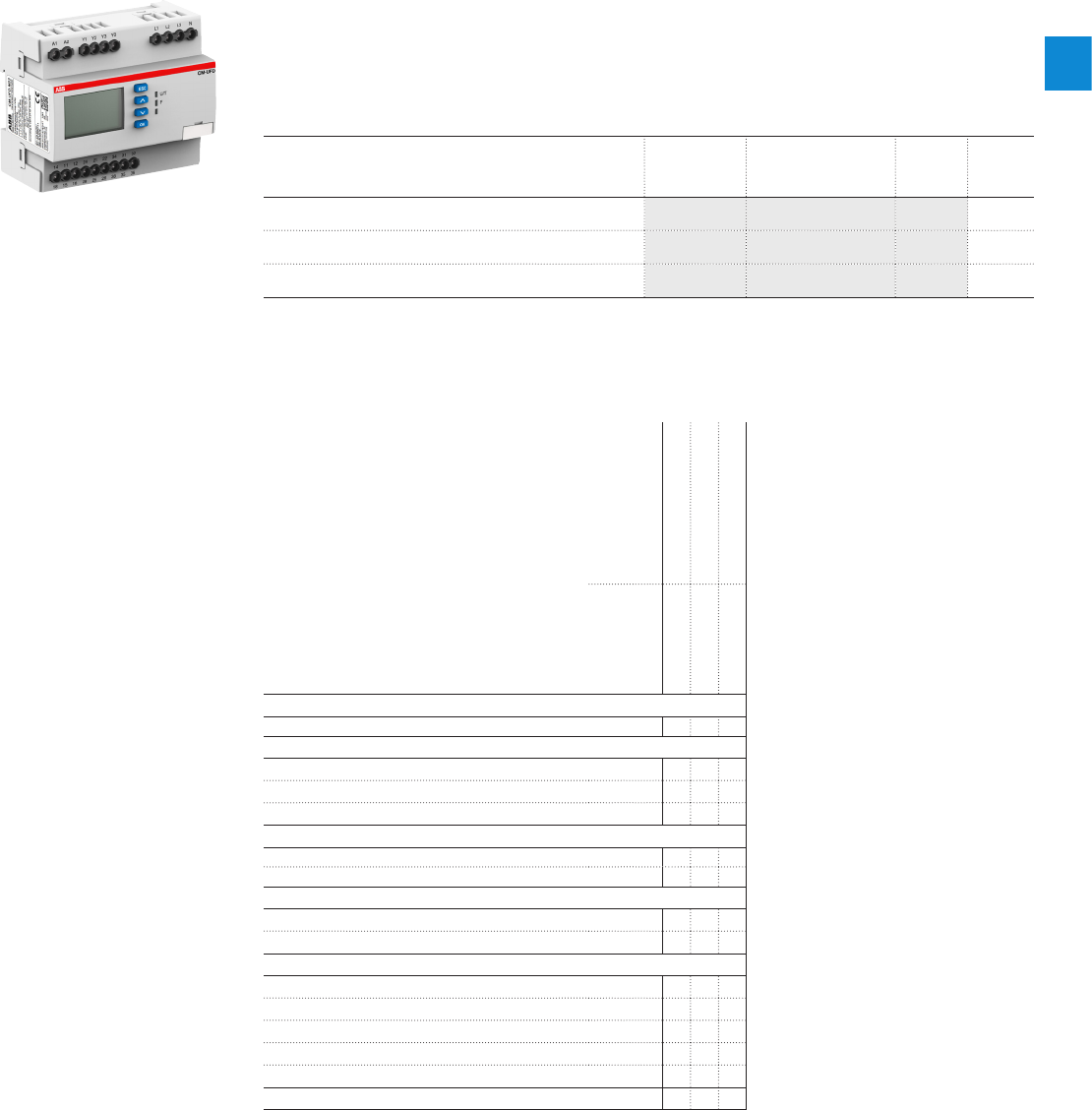
2CDC 110 004 C0210 | Catalog Electronic Products and Relays 2015 | ABB 2/54
2
2CDC 251 005 S0013
CM-UFD.Mxx
Grid feeding monitoring relays -
Voltage and frequency monitoring functions
Ordering and selection
Description
Only reliable and continuous monitoring of a three-phase network guarantees the trouble-free
and economic operation of machines and installations.
Ordering details
Rated control supply voltage =
measuring voltage
Type Order code Price
1 pce
Weight
(1 pce)
kg (lb)
24-240 VAC/DC CM-UFD.M22 1SVR510730R0300 0.225
(0.496)
24-240 VAC/DC CM-UFD.M31 1SVR510730R0300 0.225
(0.496)
24-240 VAC/DC CM-UFD.M33 1SVR560730R3400 0.304
(0.670)
Order number
1SVR560730R3400
1SVR560730R3401
1SVR560730R3402
Type
CM-UFD.M22
CM-UFD.M31
CM-UFD.M33
Rated control supply voltage Us
24-240 V AC/DC JJJ
Standard
VDE AR-N 4105, BDEW J
G59/3 J
CEI 0-21 J
Rated frequency
DC or 50 Hz J J
DC or 50/60 Hz J
Suitable for monitoring
Single-phase mains J J J
Three-phase mains J J J
Monitoring function
Over-/undervoltage J J J
Over-/underfrequency JJ J
ROCOF (rate of change of frequency) JJ J
10 minutes average value J J J
Vector shift J J
Thresholds adj adj adj
2/55 ABB | Catalog Electronic Products and Relays 2015 | 2CDC 110 004 C0210
2
Grid feeding monitoring relays -
Voltage and frequency monitoring functions
Technical data - CM-UFD.Mxx
Technical data
Data at Ta = 25 °C and rated values, unless otherwise indicated
Type CM-UFD.M22 CM-UFD.M31 CM-UFD.M33
Input circuit - Supply circuit
Rated control supply voltage Us 24-240 V AC/DC
Rated control supply voltage Us tolerance -15…+10 %
Rated frequency DC or 50 Hz
Frequency range AC 40-60 Hz 40-70 Hz
Typical current / power consumption 24 V DC 64 mA / 1.5 W
230 V AC 6.4 mA / 1.5 VA
External fusing (necessary) 6 A gG (gL) or cirucit breaker 6 A with B characteristic or 6 A Class CC
(acc. to UL-requirements)
Power failure buffering time 200 ms, according to LVFRT (Low Voltage Fault Ride Through)
Measuring circuit
Monitoring functions overvoltage 10-min average (>UAV) adjustable,
1.00-1.30 * Us
in 0.01*Us steps
threshold adjustable, 1.000-1.300 * Un
in 0.005 * Un steps
overvoltage (>U1) adjustable,
1.00-1.20 * Us
in 0.01*Us steps
threshold adjustable, 1.000-1.300 * Un
in 0.005 * Un steps
overvoltage (>U2) -threshold adjustable, 1.000-1.300 * Un
in 0.005 * Un steps
undervoltage (<U1) adjustable,
0.05-1.00 * Us
in 0.01*Us steps
threshold adjustable, 0.100-1.000 * Un
in 0.005 * Un steps
undervoltage (<U2) adjustable,
0.05-1.00 * Us
in 0.01*Us steps
threshold adjustable, 0.100-1.000 * Un
in 0.005 * Un steps
overfrequency (>F1) adjustable,
50.0-54.0 Hz
in 0.1 Hz steps
threshold adjustable, 50.00-65.00 Hz
in 0.01 Hz steps
underfrequency (<F2) adjustable,
46.0-50.0 Hz
in 0.1 Hz steps
threshold adjustable, 50.00-65.00 Hz
in 0.01 Hz steps
overfrequency (>F1) adjustable,
50.0-54.0 Hz
in 0.1 Hz steps
threshold adjustable, 45.00-60.00 Hz
in 0.01 Hz steps
underfrequency (<F2) adjustable,
46.0-50.0 Hz
in 0.1 Hz steps
threshold adjustable, 45.00-60.00 Hz
in 0.01 Hz steps
ROCOF adjustable,
0.1-1.0 Hz /s,
in 0.1 Hz/s steps
threshold adjustable, 0.100-5.000 Hz
in 0.005 Hz steps
vector shift threshold adjustable, 2.0-40.0 ° in 0.1 ° steps
interrupted neutral conductor enabled if a measuring principle with interrupted neutral conductor is
selected
Measuring ranges voltage (4-wire system L1, L2, L3-N) 0-312 V AC 0-317 V AC
(3-wire system L1,L2,L3) 0-540 V AC 0-550 V AC
(2-wire system L-N) 0-312 V AC 0-317 V AC
frequency 40-60 Hz 40-70 Hz
Rated frequency of the measuring signal 50 Hz 50/60 Hz
Accuracy of measurements voltage ≤ 2 % ≤ 0.5 % ± 0.5 V
frequency ± 20 mHz ± 20 mHz
delay times ≤ 5 % ± 20 ms ≤ 0.1 % ± 20 ms
Accuracy within the temperature range ΔU ≤ 0.02 %/°C
Hysteresis related to the
threshold value overvoltage 10-min average -adjustable, 0.1-10.0 % in 0.1 % steps
Overvoltage 0.95-0.97 * Usadjustable, 0.5-10.0 % in 0.1 % steps
Undervoltage 1.03-1.05 * Usadjustable, 0.5-10.0 % in 0.1 % steps
Overfrequency 0.997-0.999 * fnadjustable, 0.05-4.00 Hz in 0.01 Hz steps
underfrequency 1.001-1.003 * fnadjustable, 0.05-4.00 Hz in 0.01 Hz steps
Measuring cycle of ROCOF -4-50 periods
Reaction time acc. CEI 0-21 chapter A.4.3 CM-UFD.M22: adjustable, 0.05-600.00 s in 0.05 s steps, ±3 % ±20 ms
for: Overvoltage 2, Undervoltage 1, Undervoltage 2, Overfrequency 1,
Overfrequency 2, Underfrequency 1, Underfrequency 2
Measuring cycle at 50 Hz ROCOF 640 ms adjustable, 4-50 periods

2CDC 110 004 C0210 | Catalog Electronic Products and Relays 2015 | ABB 2/56
2
Grid feeding monitoring relays -
Voltage and frequency monitoring functions
Technical data - CM-UFD.Mxx
Type CM-UFD.M22 CM-UFD.M31 CM-UFD.M33
Control circuits
Number 3
Type of triggering volt-free triggering, signal source Y0
Function of the control inputs Y1-Y0 Control input 1 DDI feedback, trip and
release monitoring
times adjustable
feedback from switching device 1
Y2-Y0 Control input 2 External signal feedback from switching device 2
Y3-Y0 Control input 3 Remote trip remote trip; suppression of Y1, Y2, Y1/Y2 or
vector shift detect.
Electrical isolation from supply voltage yes
from the measuring circuit no
from the relay outputs yes
Max. switching current in the control circuit 6 mA
No-load voltage at the control inputs (V0-V1, V2, V3) 22-26 V DC
Minimum control pulse length 20 ms
Max. cable length at the control inputs (unshielded) 10 m
Timing functions
Start-up delay, R1 (prior to first grid connection or re-connection after
interruption)
adjustable,
1.00-600.00 s
in 0.05 s steps
-
Restart delay, R1
adjustable,
0.05-600.00 s
in 0.05 s steps
-
Start-up delay, R2 (prior to first grid connection or re-connection after
interruption) 1 s, fixed -
ON-delay, R3 adjustable,
0.00-10.00 s
in 0.05 s steps
-
ON-time, R3 adjustable,
0.05-10.00 s
in 0.05 s steps
-
Trip window, feedback loop Y1 adjustable,
0.05-0.50 s
in 0.05 s steps
-
Release window, feedback loop Y1 adjustable,
0.50-600.00 s
in 0.05 s steps
-
Tripping delays adjustable,
0.05-600.00 s
in 0.05 s steps
-
ROCOF error time -
Switch-on delay (prior to first grid connection or reconnection after
interruption) -adjustable, 0.05-600.00 s in 0.01 s steps
Tripping delay overvoltage 10-min average (>UAV) - < 3 s
overvoltage (>U1, >U2) -adjustable, 0.00-600.00 s in 0.01 s steps;
+50 ms / -0 ms
undervoltage (<U1, <U2)
overfrequency (>F1, >F2)
underfrequency (<F1, <F2)
ROCOF
vector shift -< 50 ms
interrupted neutral conductor < 150 ms
Error time ROCOF -adjustable, 0.5-600.00s in 0.01 s steps
vector shift -adjustable, 0.5-600.00s in 0.01 s steps
Trip window (feedback loops Y1-Y0, Y2-Y0) -adjustable, 0.05-0.50 s in 0.01 s steps
Release window (feedback loops Y1-Y0, Y2-Y0) -adjustable, 0.50-600.00 s in 0.01 s steps
Time error within the temperature range -Δt ≤ 0.01 %
User interface - Indication of operational states
Control supply voltage applied / timing U/T LED green on / flashing
Fault message FLED red on
For details see the message on the display
User interface - Display
Back light on press any button
off switch-off delay adjustable, 10-600 s (default 10 s)
Operating temperature range of the display clearly visible -20…+60 °C
Resolution 112 x 64 pixel
Display size 36 x 22 mm
User interface - Operating elements
4 push-buttons for menu navigation, setting and entering

2/57 ABB | Catalog Electronic Products and Relays 2015 | 2CDC 110 004 C0210
2
Grid feeding monitoring relays -
Voltage and frequency monitoring functions
Technical data - CM-UFD.Mxx
Type CM-UFD.M22 CM-UFD.M31 CM-UFD.M33
Output circuits
Kind of outputs 11-12/14 (15-16/18) 1st c/o (SPDT) contact, tripping relay for switching device 1 (DDI)
21-22/24 (25-26/28) 2nd c/o (SPDT) contact, tripping relay for switching device 2 (DG)
31-32/34 (35-36/38) 3rd c/o (SPDT) contact, closing command for breaker motor
Operating principle 11-12 /14 closed-circuit principle
21-22/24 open- or closed-circuit
principle configurable closed-circuit principle
31-32/34 open-circuit, closed-circuit, disabled or
synchronous with R1/R2 configurable
Contact material AgNi alloy, Cd-free
Rated operational voltage UeIEC/EN 60947-1 250 V 300 V
Minimum switching voltage / minimum switching current 24 V / 10 mA
Maximum switching voltage / maximum switching current see load limit curves
Rated operational current Ie
(IEC/EN 60947-5-1) AC-12 (resisitive) at 230 V 4 A
AC-15 (inductive) at 230 V 3 A
DC-12 (resistive) at 24 V 4 A
DC-13 (inductive) at 24 V 2 A
Mechanical lifetime 30 x 106 switching cycles
Electrical lifetime at AC12, 230 V AC, 4 A 50 x 103 switching cycles
Maximum fuse rating to achieve short-circuit protection n/c contact 10 A fast-acting 10 A fast-acting or circuit breaker 10 A with B
characteristic
n/o contact 10 A fast-acting 10 A fast-acting or circuit breaker 10 A with B
characteristic
Maximum closing current (short time) t < 20 ms 30 A
t < 80 ms 17 A
Conventional thermal current Ith IEC/EN 60947-1 5 A
General data
MTBF on request
Repeat accuracy (constant parameters) < ±0.5 %
Duty time 100 %
Dimensions (W x H x D) product dimensions 108 x 90 x 67 mm (4.25 x 3.54 x 2.64 in)
packaging dimensions 121 x 99 x 71 mm (4.76 x 3.90 x 2.80 in)
Weight net weight 0.306 kg (0.675 lb)
gross weight 0.360 kg (0.794 lb)
Material of housing PA666FR
Mounting DIN rail (IEC/EN 60715) TH 35-7.5 and TH 35-15, snap-on mounting
without any tool
Mounting position any
Minimum distance to other units horizontal / vertical not necessary
Degree of protection housing / terminals IP20
Electrical connection
Wire size fine-strand with wire end ferrulle 1 x 0.25-4 mm² (1 x 24-12 AWG), 2 x 0.25-0.75 mm² (2 x 24-18 AWG)
fine-strand without wire end ferrule
1 x 0.2-4 mm² (1 x 24-12 AWG), 2 x 0.2-1.5 mm² (2 x 24-16 AWG)
rigid 1 x 0.2-6 mm² (1 x 24-10 AWG), 2 x 0.2-1.5 mm² (2 x 24-16 AWG)
Stripping length 8 mm (0.31 in)
Tightening torque 0.5-0.6 Nm (4.4 -5.3 lb.in)
Environmental data
Ambient temperature ranges operation -20...+60 °C
storage -20...+80 °C
Climatic class (EN 50178) 3K5 (w/o condensation, w/o icing)
Damp heat, cyclic (IEC/EN 60068-2-30) 6 x 24 h cycle, 55 °C, 95 % RH
Vibration, sinusoidal (IEC/EN 60255-21-1) Class 2
Shock (IEC/EN 60255-21-2) Class 2

2CDC 110 004 C0210 | Catalog Electronic Products and Relays 2015 | ABB 2/58
2
Grid feeding monitoring relays -
Voltage and frequency monitoring functions
Technical data - CM-UFD.Mxx
Type CM-UFD.M22 CM-UFD.M31 CM-UFD.M33
Isolation data
Rated insulation voltage Ui
(IEC/EN 60947-1, IEC/EN 60664-1) supply/measuring/output circuits 600 V
output 1/output 2/output 3 300 V
Rated impulse withstand voltage Uimp
(IEC/EN 60947-1, IEC/EN 60664-1) supply/measuring/output circuits 6 kV; 1.2/50 μs
output 1/output 2/output 3 4 kV; 1.2/50 μs
Basic insulation acc. rated control
supply voltage (IEC/EN 60664-1) supply/measuring/output circuits 600 V
output 1/output 2/output 3 300 V
Protective separation acc. rated
voltage (IEC/EN 61140) supply/measuring/output circuits 250 V
output 1/output 2/output 3 250 V
Test voltage, routine test
(IEC/EN 60255-5, IEC/EN 61010-1) supply/measuring/output circuits 2.2 kV, 50 Hz, 1 s
output 1/output 2/output 3 2.2 kV, 50 Hz, 1 s
Test voltage, type test (CEI 0-21) supply/measuring /output circuits 5 kV, 50 Hz, 1 s
output 1/output 2/output 3 4 kV, 50 Hz, 1 s
Pollution degree (IEC/EN 60664-1) 3
Overvoltage category (IEC/EN 60664-1) III
Overvoltage category according to CEI 0-21 IV -
Standard
Product standard IEC/EN 60255-1
Electrical safety - - UL 508, CAN/CSA
C22.2 No.14
Application standards
CEI 0-21: 2012-06 + CEI
0-21; V1: 2012-12 + A70
Terna
VDE-AR-N 4105: 2011-08;
BDEW, June 2008
“Technische Richtlinie –
Erzeugungsanlagen am
Mittelspannungsnetz”
including supplementary
provisions of January 2013
Engineering
Recommendation G59 Issue
3 - September 2013;
Engineering
Recommendation G83 Issue
2 - December 2012
Low Voltage Directive 2006/95/EC
EMC Directive 2004/108/EC
RoHS Directive 2011/65/EC
Electromagnetic compatibility
Interference immunity to IEC/EN 61000-6-1, IEC/EN 61000-6-2
electrostatic discharge IEC/EN 61000-4-2 Level 3 (6 kV / 8 kV)
radiated, radio-frequency, electromagnetic
field IEC/EN 61000-4-3 Level 3, 10 V/m
electrical fast transient/burst IEC/EN 61000-4-4 Level 3, 2 kV / 5 kHz
surge IEC/EN 61000-4-5 Level 3, installation class 3, supply and
measuring input 1 kV L-L, 2 kV L-earth
conducted disturbances, induced by radio-
frequency fields IEC/EN 61000-4-6 Level 3, 10 V
voltage dips, short interruptions and
voltage variations IEC/EN 61000-4-11 Class 3
harmonics and interharmonics IEC/EN 61000-4-13 Class 3
Interference emission IEC/EN 61000-6-3, IEC/EN 61000-6-4
high-frequency radiated
IEC/CISPR 22, EN 55022
Class B
high-frequency conducted
IEC/CISPR 22, EN 55022
Class B
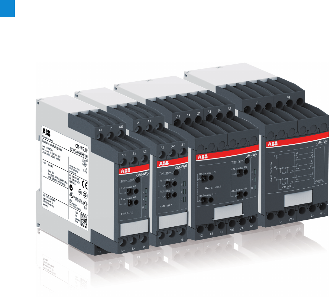
2/59 ABB | Catalog Electronic Products and Relays 2015 | 2CDC 110 004 C0210
2
Insulation monitoring relays for unearthed supply systems
Product group picture

2CDC 110 004 C0210 | Catalog Electronic Products and Relays 2015 | ABB 2/60
2
Insulation monitoring relays for unearthed supply systems
Table of contents
Insulation monitoring relays for unearthed supply systems
Benefits and advantages 2/61
Benefits and advantages, Applications 2/62
Operating controls 2/63
Insulation monitoring in IT systems 2/64
Selection table 2/65
Ordering details 2/66
Operating state indication, Connection diagrams, DIP switches 2/67
Technical data 2/68
Technical data CM-IVN 2/71
2/61 ABB | Catalog Electronic Products and Relays 2015 | 2CDC 110 004 C0210
2
Insulation monitoring relays for unearthed supply systems
Benefits and advantages
Insulation monitoring relays for unearthed pure AC
systems:
Characteristics
– For monitoring the insulation resistance of unearthed IT
systems:
up to Un = 400 V AC
– According to IEC/EN 61557-8 "Electrical safety in low volt-
age distribution systems up to 1000 V AC and 1500VDC:
Equipment for testing, measuring or monitoring of protec-
tive measures – Part 8: Insulation monitoring devices for IT
systems"
– Rated control supply voltage 24–240 V AC/DC
– Superimposed DC signal
– One measuring range 1–100 kW
– Precise adjustment of the threshold value in 1 kW steps
– Interrupted wire detection
– Fault storage/latching configurable by control input
– 1 c/o (SPDT) contact, closed-circuit principle
– 22.5 mm [0.89 in] width
– 3 LEDs for status indication
Characteristics
– For monitoring the insulation resistance of unearthed IT
systems up to Un= 250 V AC and 300 V DC or Un= 400 V
AC and 600 V DC
– According to IEC/EN 61557-8 "Electrical safety in low volt-
age distribution systems up to 1000 V AC and 1500VDC:
Equipment for testing, measuring or monitoring of protec-
tive measures – Part 8: Insulation monitoring devices for IT
systems"1)
– CM-IWN.4,5,6: Specifically for applications with high
system leakage capacitances, for example in photovoltaic
environments
– Rated control supply voltage 24-240 V AC/DC
– Prognostic measuring principle with superimposed square
wave signal
–
1 or 2 measuring ranges (1-100 k
W
or 1-100 k
W
+ 2-200 k
W
)
–
1 or 2 (configurable) c/o contacts
1)
–
Precise adjustmemt of the measuring value in 1 or 2 k
W
steps
–
(non-volatile) fault storage, configurable latching, interrupted
wire protection, open- or closed-circuit principle selectable
1)
– 22.5 or 45 mm width
– 3 LEDs for status indication
1) depending on devices
Additional characteristics for CM-IWN.1,4,5,6:
– One (1 x 2 c/o) or two (2 x 1 c/o) threshold values Ran1/R11)
(final switch-off) and Ran2/R22) (prewarning) configurable3)
– Precise adjustment of the threshold values in 1 kΩ steps
(R1) and 2kΩ steps (R2)
– Interrupted wire detection configurable
– Non-volatile fault storage configurable
– Open- or closed-circuit principle configurable
1) CM-IWN.6 does not meet the requirements of IEC/EN 61557-8 regarding the
response time tan.
2) term acc. to IEC/EN 61557-8
3) R2 only active with 2 x 1 c/o configuration
Insulation monitoring relays for unearthed AC, DC
or mixed AC/DC systems:
2CDC 251 017 V0012
2CDC 251 009 V0012
2CDC 251 020 V0012
CM-IWS.2 CM-IWS.1 CM-IWN.1

2CDC 110 004 C0210 | Catalog Electronic Products and Relays 2015 | ABB 2/62
2
Insulation monitoring relays for unearthed supply systems
Benefits and advantages, Applications
Application / monitoring function CM-IWx
The CM-IWx serve to monitor insulation resistance in accor-
dance with IEC 61557-8 in unearthed IT AC systems, IT AC
sytems with galvanically connected DC circuits, or unearthed
IT DC systems. The insulation resistance between system
lines and system earth is measured. If this falls below the
adjustable threshold values, the output relay(s) energize or de-
energize. The CM-IWS.x can monitor control circuits (single-
phase) and main circuits (3-phase). Supply systems with volt-
ages Un= 0-400 V AC (45-65 Hz), Un=0-250 V AC (15-400 Hz)
or 0-300 V DC can be directly connected. For systems with
voltages above 400 V AC the insulation monitoring relay with
or without the coupling unit CM-IVN can be used.
Application / monitoring function CM-IWN.x
The CM-IWN.x serves to monitor insulation resistance in
accordance with IEC 61557-8 in unearthed IT AC systems,
IT AC systems with galvanically connected DC circuits, or
unearthed IT DC systems. The insulation resistance between
system lines and system earth is measured. If this falls below
the adjustable threshold values, the output relays switch into
the fault state. The device can monitor control circuits (single-
phase) and main circuits (3-phase). Supply systems with
voltages Un = 0-400 V AC (15-400 Hz) or 0-600 V DC can be
directly connected to the measuring inputs and their insulation
resistance being monitored. For systems with voltages above
400 V AC and 600 V DC the coupling unit CM-IVN can be
used for the expansion of the CM-IWN.x voltage range.
Expansion of assortment for the requirements of
decentral eletrical energy sources
ABB‘s insulation monitoring relays from the CM-IWN range
provide higher system leakage capacitances which are neces-
sary especially for solar applications. This expanded product
range covers the requirements of decentral eletrical sources
(e.g. photovoltaic systems).
The range of system leakage capacitances is 20 - 2000 µF.
Application / monitoring function CM-IVN
The coupling unit CM-IVN is designed to extend the nominal
voltage range of the insulation monitoring relay CM-IWN.1
up to 690 V AC and 1000 V DC. The coupling unit can be
connected to the system to be monitored by means of the
terminals VL+ and VL-. The terminal Vw has to be connected
to the earth potential. The terminals L+, V1+, L-, V1-, VS and
VE have to be connected to the CM-IWN.1 as shown in the
connection diagrams below. Supply systems with voltages Un
= 0-690 V AC (15-400 Hz) or 0-1000 V DC can be connected.
Measuring principle CM-IWS.2
A superimposed DC measuring signal is used for measure-
ment. From the superimposed DC measuring voltage and its
resultant current the value of the insulation resistance of the
system to be monitored is calculated.
Measuring principle CM-IWN.x, CM-IWS.1
A pulsating measuring signal is fed into the system to be
monitored and the insulation resistance is calculated. This
pulsating measuring signal alters its form depending on the
insulation resistance and system leakage capacitance. From
this altered form the change in the insulation resistance is
forecast. When the forecast insulation resistance corresponds
to the insulation resistance calculated in the next measure-
ment cycle and is smaller than the set threshold value, the
output relay de-energizes. This measuring princiiple is also
suitable for the detection of symmetrical insulation faults.
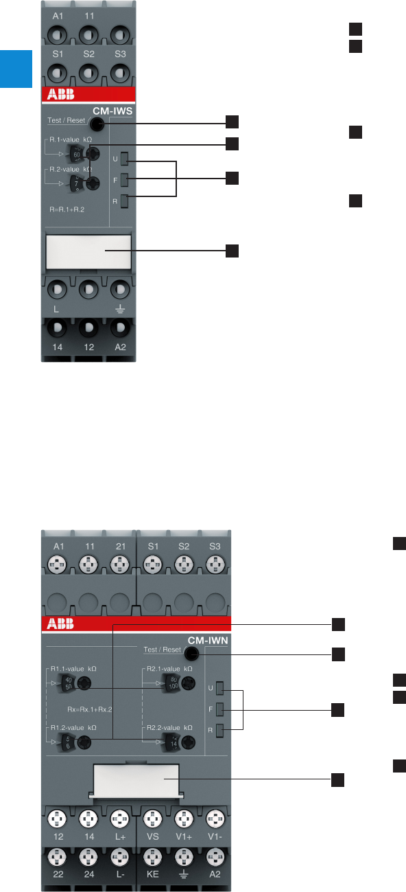
2/63 ABB | Catalog Electronic Products and Relays 2015 | 2CDC 110 004 C0210
2
Insulation monitoring relays for unearthed supply systems
Operating controls
4
1
2
3
1 Test and reset button
2 Configuration and setting
Front-face rotary switches for threshold value adjustment:
R.1 for R1 tens figures:
0, 10, 20, 30, 40, 50, 60, 70, 80, 90 kΩ in ten kΩ steps
R.2 for R1 units figures:
1, 2, 3, 4, 5, 6, 7, 8, 9, 10 kΩ in one kΩ steps
3 Indication of operational states
U: green LED - control supply voltage
F: red LED - fault message
R: yellow LED - relay status
4 Marker label for devices without DIP switches
1 Front-face rotary switches to adjust the threshold value:
R1.1 for R1 tens figure:
0, 10, 20, 30, 40, 50, 60, 70, 80, 90 kΩ in ten kΩ steps
R1.2 for R1 units figure:
1, 2, 3, 4, 5, 6, 7, 8, 9, 10 kΩ in one kΩ steps
R2.1 for R2 tens figure:
0, 20, 40, 60, 80, 100, 120, 140, 160, 180 kΩ in twenty kΩ steps
R2.2 for R2 units figure:
2, 4, 6, 8, 10, 12, 14, 16, 18, 20 kΩ in two kΩ steps
2 Test and reset button
3 Indication of operational states
U: green LED – control supply voltage
F1: red LED – fault message
F2: yellow LED – relay status
4 DIP switches (see DIP switch functions)
1
2
3
4
2CDC 253 021 F00132CDC 253 015 F0013
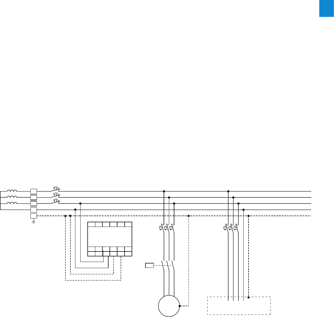
2CDC 110 004 C0210 | Catalog Electronic Products and Relays 2015 | ABB 2/64
2
Insulation monitoring relays for unearthed supply systems
Insulation monitoring in IT systems
L1
L2
L3
N
PE
M
A1 11 S2 S3
21 S1
L+ V
12 14
A2
V1-
V1+
22 24 L- K
Consumer
3~
w
CM-IWN.x
In electricity supply systems, an earthing system defines the electrial potential of the conductors relative to that of
the earth’s conductive surface. The choice of earthing system has implications for the safety and electromagnetic
compatibility of the power supply. Note that regulations for earthing (grounding) systems vary considerably among
different countries.
The international standard IEC 60364 distinguishes three families of earthing arrangements, using the two-letter codes TN, TT
and IT.
The first letter indicates the connection between earth and the power-supply equipment (generator or transformer):
T: direct connection of a point with earth (Latin: terra)
I: no point is connected with earth (insulation), except perhaps via a high impendance
The second letter indicates the connection between earth and the electrical device being supplied:
T: direct connection of a point with earth
N: direct connection to neutral at the origin of installation,
which is connected to the earth
IT supply systems
The IT system is supplied either by an isolation transformer or a voltage source, such as battery or a generator.
In this system no active conductor is directly connected to earth potential. The advantage of this is that only a small fault cur-
rent can flow in case of an insulation fault. This current is essentially caused by the leakage capacitance of the system.
The fuse of the system or MCB does not respond, thus maintaining the voltage supply and therefore operation even in case of
a phase-to-earth fault.
The high reliability of an IT system is guaranteed thanks to continous insulation monitoring.
The insulation monitoring device recognizes insulation faults as they develop, and immediately reports that the value has fallen
below the minimum. This prevents operational interruptions caused by a second more severe insulation fault.
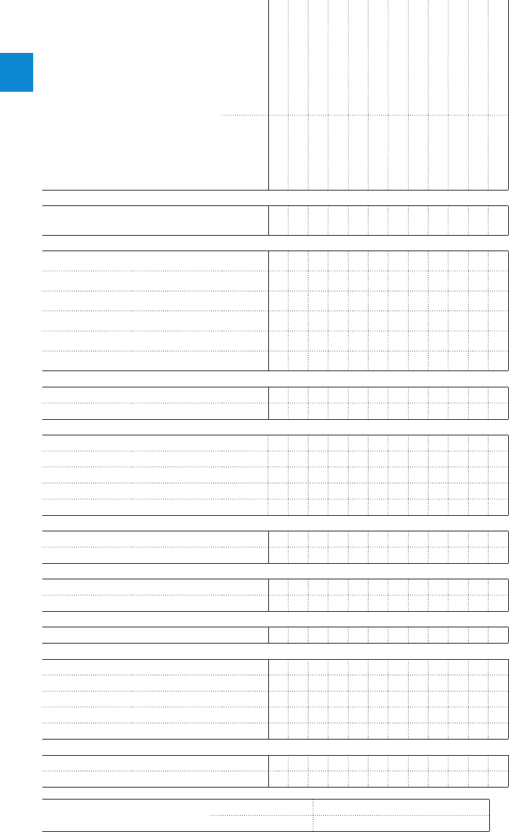
2/65 ABB | Catalog Electronic Products and Relays 2015 | 2CDC 110 004 C0210
2
Insulation monitoring relays for unearthed supply systems
Selection table
Order number
1SVR730670R0200
1SV R74 0 670 R 0 200
1SVR730660R0100
1SV R74 0 6 6 0 R 010 0
1SVR750660R0200
1SVR760660R0200
1SVR750660R0300
1SVR760660R0300
1SVR750660R0400
1SVR760660R0400
1SVR750660R0500
1SVR760660R0500
Type
CM-IWS.2S
CM-IWS.2P
CM-IWS.1S
CM-IWS.1P
CM-IWN.1S
CM-IWN.1P
CM-IWN.4S
CM-IWN.4P
CM-IWN.5S
CM-IWN.5P
CM-IWN.6S
CM-IWN.6P
Rated control supply voltage Us
24 - 240 VAC/DC JJJJJJJJJJJJ
Measuring voltages
250 V AC (L-PE) J J
400 V AC (L-PE) JJ JJJJJJJJ
690 V AC (L-PE) J1) J1) J1) J1) J1) J1) J1) J1)
300 V DC (L-PE) J J
600 V DC (L-PE) JJJJJJJJ
1000 V DC (L-PE) J1) J1) J1) J1) J1) J1) J1) J1)
Measuring range
1 - 100 kΩ JJJJJJJJJJJJ
2 - 200 kΩ JJJJJJJJ
System leakage capacitance, max.
10 μF J J J J
20 μF J J
500 μF J J
1000 μF J J
2000 μF J J
Output
1 c/o J J J J
1 x 2 c/o or 2 x 1 c/o JJJJJJJJ
Operating principle
Open-circuit principle J J J J
Open- or closed-circuit principle adjustable JJJJJJJJ
Test
Front-face button or control input JJJJJJJJJJJJ
Reset
Front-face button or control input JJJJJJJJJJJJ
Fault storage / latching configurable JJJJJJJJJJJJ
Non volatile storage configurable JJJJJJJJJJJJ
Interrupted wire detection JJJJJJJJ
Threshold values configurable 111122222222
Connection type
Push-in terminals J J J J J J
Double-chamber cage connection terminals J J J J J J
1) With coupling unit CM-IVN screw version CM-IVN.S: 1SVR750669R9400
push-in version CM-IVN.P: 1SVR760669R9400
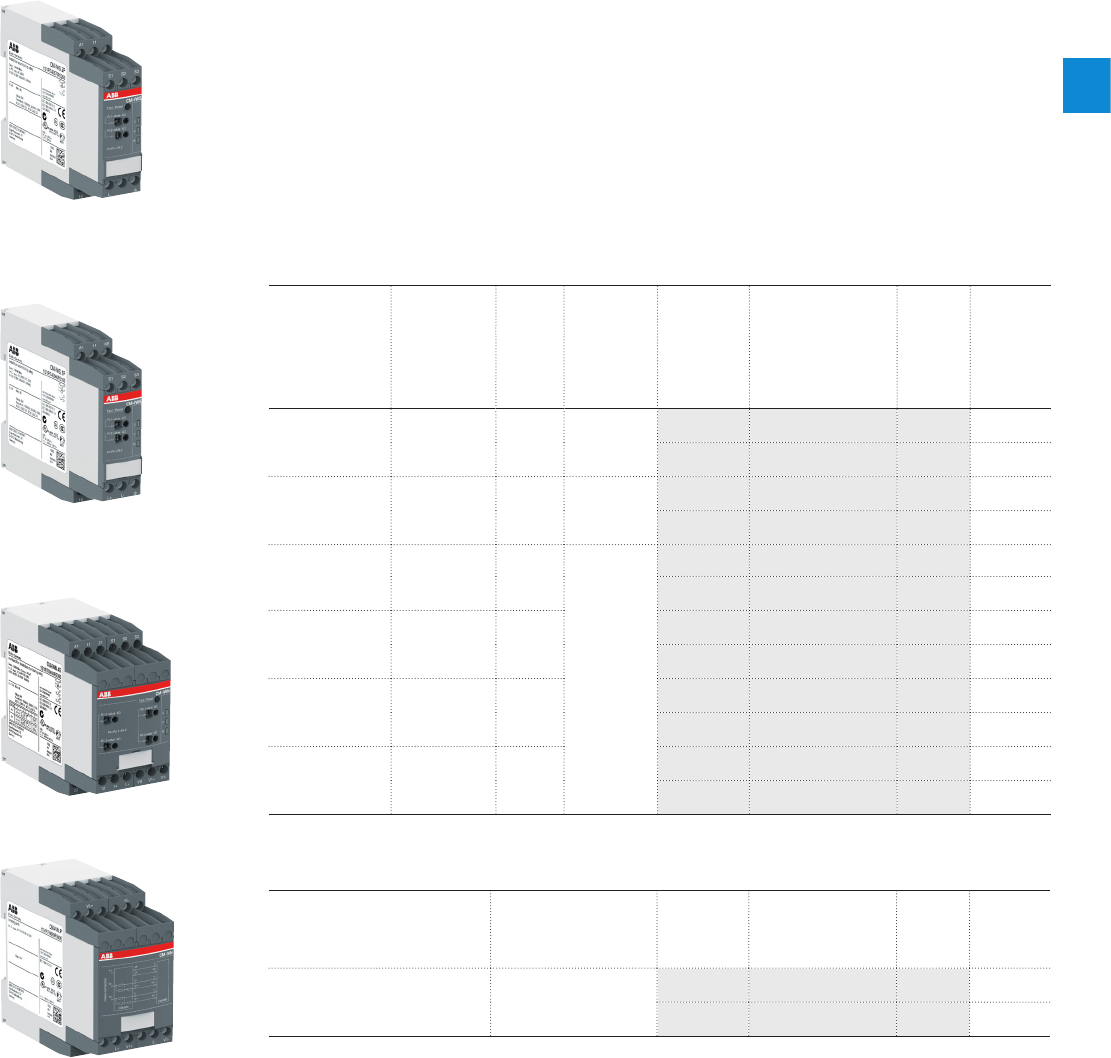
2CDC 110 004 C0210 | Catalog Electronic Products and Relays 2015 | ABB 2/66
2
Insulation monitoring relays for unearthed supply systems
Ordering details
Description
The high reliability of an IT system is guaranteed thanks to continuous insulation monitoring.
An insulation monitoring device recognizes insulation faults as they develop, and immediately
reports that the value has fallen below the minimum. This prevents operational interruption
caused by a second, more severe insulation fault.
ABB developed a totally new range of insulation monitors for AC, DC or mixed AC/DC IT Sys-
tems up to 690 VAC or 1000 VDC. With only 4 devices most standard applications can be
served. Additionally a version for solar applications with increased earth leakage capacitance
has been added.
Ordering details
Rated control
supply voltage
= measuring
voltage
Nominal
voltage
Un of the
distribution
system to be
monitored
System
leakage
capaci-
tance,
max.
Adjust-
ment range
of the
specified
response
value Ran
(threshold)
Type Order code Price
1 pce
Weight
(1 pce)
kg (lb)
24-240 VAC/DC 0-250 VAC /
0-300 VDC 10 µF 1-100 kW
CM-I WS.1S 1SVR730660R0100 0.148 (0.326)
CM-I WS.1P 1SV R74 0 6 6 0 R 010 0 0.137 (0.302)
24-240 VAC/DC 0-400 VAC 10 µF 1-100 kW
CM-IWS.2S 1SVR730670R0200 0.141 (0.311)
CM-IWS.2P 1SV R74 0 670 R 0 200 0.130 (0.287)
24-240 VAC/DC 0-400 VAC /
0-600 VDC 20 µF
1-100kW
2-200kW
(activated /
de-activated
by
DIP-switch)
CM-I W N.1S 1SVR750660R0200 0.241 (0.531)
CM-I W N.1P 1SVR760660R0200 0.217 (0.478)
24-240 VAC/DC 0-400 VAC /
0-600 VDC 500 µF
CM-IWN.4S 1SVR750660R0300 0.241 (0.531)
CM-IWN.4P 1SVR760660R0300 0.217 (0.478)
24-240 VAC/DC 0-400 VAC /
0-600 VDC 1000 µF
CM-IWN.5S 1SVR750660R0400 0.241 (0.531)
CM-IWN.5P 1SVR760660R0400 0.217 (0.478)
24-240 VAC/DC 0-400 VAC /
0-600 VDC 2000 µF
CM-IWN.6S 1SVR750660R0500 0.241 (0.531)
CM-IWN.6P 1SVR760660R0500 0.217 (0.478)
Ordering details - Coupling unit
Rated control supply voltage
= measuring voltage
Nominal voltage
Un of the distribu-
tion system to be
monitored
Type Order code Price
1 pce
Weight
(1 pce)
kg (lb)
Passive device, no control supply
voltage needed
0-690 VAC /
0-1000 VDC
CM-IVN.S 1SVR750669R9400 0.179 (0.395)
CM-IVN.P 1SVR760669R9400 0.165
(0.364)
2CDC 251 017 V00122CDC 251 009 V0012
2CDC 251 020 V0012
2CDC 252 027 V0012
CM-IWS.2
CM-IWS.1
CM-IWN.1
CM-IVN
S: screw connection
P: push-in / easy connect
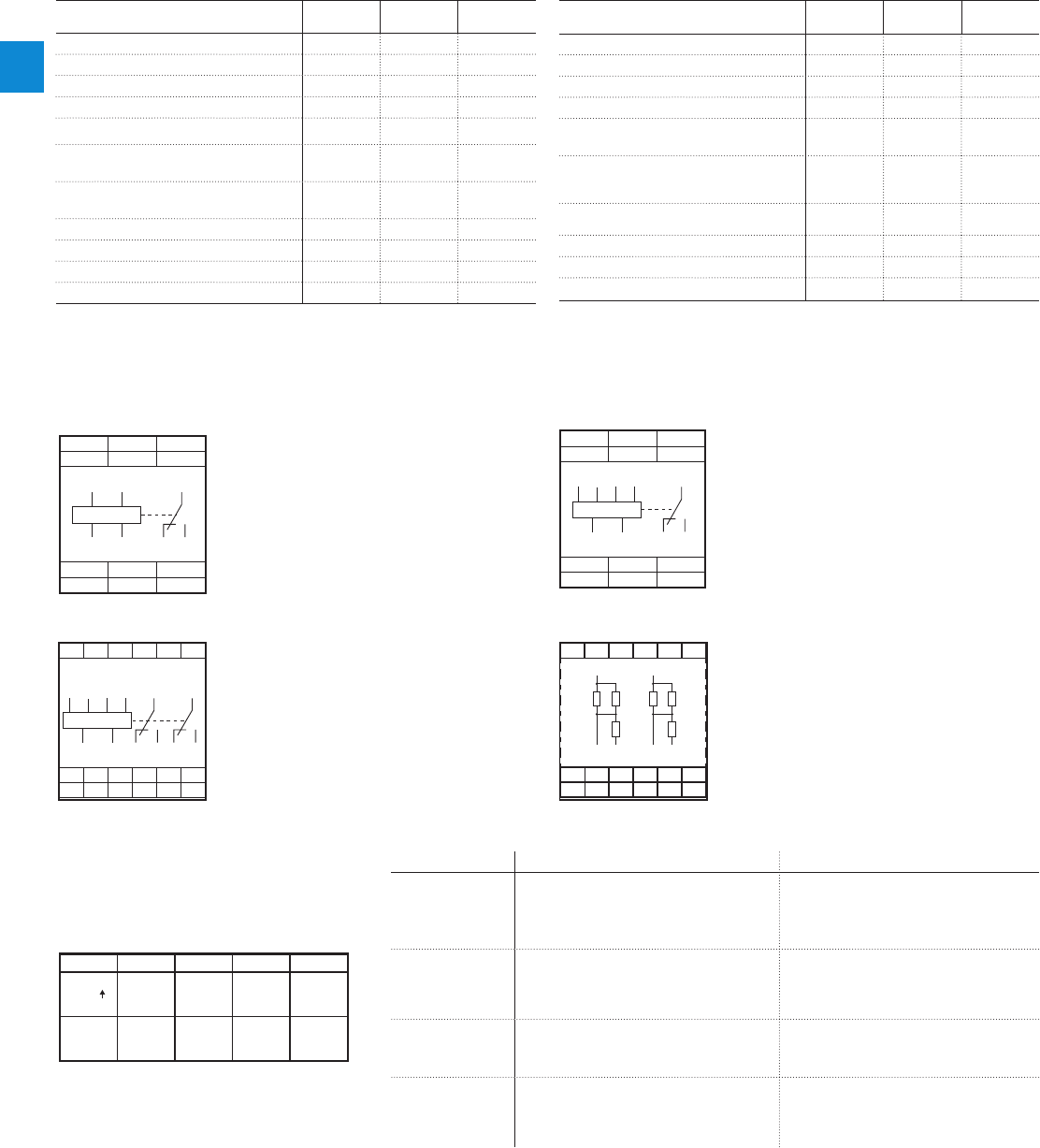
2/67 ABB | Catalog Electronic Products and Relays 2015 | 2CDC 110 004 C0210
2
Operational state LED U
(green)
LED F
(red)
LED R
(yellow)
Start-up WOFF OFF
No fault VOFF 1)
Prewarning V W W
Insulation fault (below threshold value)
V V 1)
KE/w wire interruption V U 1)
L+/L- wire interruption during
system start-up / test function W
/ X T1)
System leakage capacitance too
high / invalid measurement result V T 1)
Internal system fault 1) X1)
Setting fault 2) W W W
Test function XOFF 1)
No fault after fault storage 3) V4) X
Operational state LED U
(green)
LED F
(red)
LED R
(yellow)
Start-up WOFF OFF
No fault VOFF V
Insulation fault (below threshold value)
VVOFF
Invalid measuring result VTOFF
KE/w wire interruption (only
CM-IWS.1) VUOFF
CM-IWS.1: System leakage
capacitance too high / invalid
measurement result XXOFF
CM-IWS.2: Invalid measurement
result VTOFF
Internal system fault OFF XOFF
Test function XOFF OFF
No fault after fault storage 3) V4) X
LEDs, status information and fault messages CM-IWN.x LEDs, status information and fault messages CM-IWS.x
Insulation monitoring relays for unearthed supply systems
Operating state indication, Connection diagrams, DIP switches
Connection diagram CM-IWS.2
A1
S1 S2 S3
11
w
L
A2
w
A1
R < w
A2
L
14 12
12 14
11
2CDC 252 102 F0009
Connection diagram CM-IWS.1
Connection diagram CM-IWN.1, 4, 5, 6 Connection diagram CM-IVN
A1
S1 S2 S3
KE11
w
L-L+
A2
KE
w
L-
A1
R <
w
A2
L+
14 12
12 14
11
2CDC 252 103 F0009
VE Connection to CM-IWN.x - w
VS Connection to CM-IWN.x - VS
L+ Connection to CM-IWN.x - L+
V1+ Connection to CM-IWN.x - V1+
L- Connection to CM-IWN.x - L-
V1- Connection to CM-IWN.x - V1-
VL+
VL-
Measuring circuit / Measuring input
Connection to the system
VwMeasuring circuit / Measuring input
Connection to earth
A1-A2
Control supply voltage
S1-S3
Remote test
S2-S3
Remote reset
L+, L–
Measuring circuit/input, system connection
w, KE
Measuring circuit/input, earth connections
1-12/14
Output relay, closed-circuit principle
A1-A2
Control supply voltage
S1-S3
Remote test
S2-S3
Remote reset
L
Measuring circuit/input, system connection
w
Measuring circuit/input, earth connections
11-12/14
Output relay, closed-circuit principle
A1-A2 Control supply voltage
S1-S3 Remote test
S2-S3 Remote reset
L+, L–
Measuring circuit/input, system connection
w, KE
Measuring circuit/input, earth connections
VS, V1+, V1
Connections for the coupling unit (if used)
11-12/14
Output relay 1, open- or closed-circuit principle
21-22/24
Output relay 2, open- or closed-circuit principle
2CDC 252 104 F0009
2CDC 252 010 F0013
A1 11 S2 S3
21 S1
w
L+ VS
12 14
A2
V1-
V1+
KE w
L-
A1
R < w
A2
L+
22 24 L- KE
12 14
11
22 24
21
VL
+
VL
-
VL
-
VL+
V
w
L-
L+
L+
VE
V1-
L-
V1-
V1+
V1+
VS
ON OFF (default)
DIP switch 1
Operating
principle of the
output relays
Closed-circuit principle g
If closed-circuit principle is selected, the output relays de-
energize in case a fault is occuring. In non-fault state the
relays are energized.
Open-circuit principle h
If open-circuit principle is selected, the output relays
energize in case a fault is occuring. In non-fault state the
relays are de-energized.
DIP switch 2
Non-volatile fault
storage
Fault storage activated (latching) f
If the fault storage function is activated, the output relays
remain in tripped position until a reset is done either by the
front-face button or by the remote reset connection S2-S3.
This function is non-volatile.
Fault storage de-activated (non latching) e
If the fault storage function is de-activated, the output
relays switch back to their original position as soon as the
insulation fault no longer exists.
DIP switch 3
Interrupted wire
detection
Interrupted wire detection activated u
With this configuration, the CM-IWN.1 monitoring relays
the wires connected to w and KE for interruptions.
Interrupted wire detection de-activated v With this
configuration the interrupted wire detection is de-
activated.
DIP switch 4
2 x 1 c/o,
1 x 2 c/o
2 x 1 c/o (SPDT) contact i
If operating principle 2 x 1 c/o contact is selected, the
output relay R1 (11-12/14) reacts to threshold value R1
(final switch-off) and the output relay R2 (21-22/24) reacts
to threshold value R2 (prewarning)
1 x 2 c/o (SPDT) contacts j
If operating principle 1 x 2 c/o contacts is selected, both
output relays R1 (11-12/14) and R2 (21-22/24) react
synchronously to threshold value R1. Settings of the
threshold value R2 have no effect on the operation.
2CDC 252 050 F0b09
Position 4123
ON
OFF
iufg
he
v
j
DIP switches of
CM-IWN.1, 4, 5, 6
1) Depending on the configuration.
2) Possible faulty setting: The threshold value for final switch-off is set at a higher value than the threshold value for prewarning
3) The device has triggered after an insulation fault. The fault has been stored and the insulation resistance has returned to a higher value than the threshold value plus hysteresis.
4) Depending on the fault

2CDC 110 004 C0210 | Catalog Electronic Products and Relays 2015 | ABB 2/68
2
Insulation monitoring relays for unearthed supply systems
Technical data
*in combination with CM-IVN ±1.5 kh
Data at Ta = 25 °C and rated values, unless otherwise indicated
CM-IWS.2 CM-IWS.1 CM-IWN.1, 4, 5, 6
Input circuit - Supply circuit A1 - A2
Rated control supply voltage Us24-240 V AC/DC
Rated control supply voltage tolerance -15...+10 %
Typical current / power consumption 24 V DC 30 mA / 0.7 VA 35 mA / 0.9 VA 55 mA / 1.3 VA
115 V AC 12 mA / 1.4 VA 17 mA / 2.0 VA 20 mA / 2.3 VA
230 V AC 12 mA / 2.8 VA 14 mA / 3.2 VA 15 mA / 3.5 VA
Rated frequency fsDC or 15-400 Hz
Frequency range AC 13.5-440 Hz
Power failure buffering time min. 20 ms
Input circuit - Measuring circuit L, wL+, L-, w, KE L+, L-, w, KE
Monitoring function insulation resistance monitoring of IT systems (IEC/EN 61557-8)
Measuring principle superimposed DC
voltage prognostic measuring principle with
superimposed square wave signal
Nominal voltage Un of the distribution system to be monitored 0-400 V AC 0-250 V AC /
0-300 V DC 0-400 V AC /
0-600 V DC
Voltage range of the distribution system to be monitored 0-460 V AC
(tolerance +15 %) 0-287.5 V AC /
0-345 V DC
(tolerance +15 %)
0-460 V AC /
0-690 V DC
(tolerance +15 %)
Rated frequency fN of the distribution system to be monitored 50-60 Hz DC or 15-400 Hz DC or 15-400 Hz
System leakage capacitance Cemax. 10 µF CM-IWN.1: 20 µF
CM-IWN.4: 500 µF
CM-IWN.5 1000 µF
CM-IWN.6: 2000 µF
Tolerance of the rated frequency fN45-65 Hz 13.5-440 Hz 13.5-440 Hz
Extraneous DC voltage Ufg (when connected to an AC system) max. none 290 V DC 460 V DC
Number of possible response / threshold values 1 2
Adjustment range of the specified response value Ran
(threshold) min.-max. 1-100 h–
min.-max. R1 –1-100 kh
min.-max. R2 –2-200 kh (activated /
de-activated by DIP-
switch)
Adjustment resolution 1 kh
R1 1 kh1 kh
R2 –2 kh
Tolerance of the adjusted threshold value /
Relative percentage uncertainty A
at -5...+45 °C, Un = 0-115 %, Us = 85-110 %, fN, fs, Ce = 1µF
at 1-10 k
W
R
F±0.5 kh–
at 10-100 k
W
R
F±6 % –
at 1-15 k
W
R
F–±1 kh*
at 15-200 k
W
R
F–±8 %
Hysteresis related to the threshold value 25 %; min. 2 kh
Internal impedance Ziat 50 Hz 135 kh100 kh155 kh
Internal DC resistance Ri185 kh115 k h185 kh
Measuring voltage Um15 V 22 V 24 V
Tolerance of measuring voltage Um+10 %
Measuring current Immax. 0.1 mA 0.3 mA 0.15 m A
Response time tan
pure AC system 0.5 x Ran and Ce = 1 µF max. 10 s
DC system or AC system with connected rectifiers –max. 15 s
Repeat accuracy (constant parameters) < 0.1 % of full scale
Accuracy of R
a
(measured value) within the rated control supply voltage tolerance
< 0.05 % of full scale
Accuracy of Ra (measured value) within the
operation temperature range at 1-10 kh RF5 W / K
at 10-100 kh RF0.05 % / K –
at 10-200 kh RF–0.05 % / K
Transient overvoltage protection (w - terminal) Z-diode avalanche diode
Input circuit - Control circuits S1 - S2 - S3
Control inputs - volt free S1-S3 remote test
S2-S3 remote reset
Maximum switching current in the control circuit 1 mA
Maximum cable length to the control inputs 50 m - 100 pF/m [164 ft - 30.5 pF/ft]
Minimum control pulse length 150 ms
No-load voltage at the control input ≤ 24 V ± 5 % ≤ 24 V DC
Indication of operational states
Control supply voltage LED U (green)
Fault message LED F (red)
Relay status LED R (yellow)

2/69 ABB | Catalog Electronic Products and Relays 2015 | 2CDC 110 004 C0210
2
Insulation monitoring relays for unearthed supply systems
Technical data
CM-IWS.2 CM-IWS.1 CM-IWN.1, 4, 5, 6
Output circuits
Kind of output relay, 1 c/o (SPDT) contact 2 x 1 or 1 x 2 c/o
(SPDT) contacts
configurable
Operating principle closed-circuit principle 1) open- or closed
circuit principle 1)
configurable
Contact material AgNi alloy, Cd free
Rated voltage (VDE 0110, IEC 60947-1) 250 V AC / 300 V DC
Min. switching voltage / Min. switching current 24 V / 10 mA
Max. switching voltage / Max. switching current see data sheet
Rated operational current Ie (IEC/EN 60947-
5-1) AC-12 (resistive) at 230 V 4 A
AC-15 (inductive) at 230 V 3 A
DC-12 (resistive) at 24 V 4 A
DC-13 (inductive) at 24 V 2 A
AC rating (UL 508) Utilization category
(Control Circuit Rating Code) B 300, pilot duty general purpose (250 V, 4 A, cos φ 0.75)
max. rated operational voltage
250 V AC
max. continuous thermal
current at B 300 4 A
max. making/breaking
apparent power at B 300 3600/360 VA
Mechanical lifetime 30 x 106 switching cycles
Electrical lifetime (AC-12, 230 V, 4 A) 0.1 x 10⁶ switching cycles
Max. fuse rating to achieve short-circuit protection n/c contact 6 A fast-acting
n/o contact 10 A fast-acting
Conventional thermal current Ith (IEC/EN 60947-1) 4 A
General data
Duty time 100 %
Dimensions (W x H x D)
product dimension 22.5 x 85.6 x 103.7 mm
(0.89 x 3.37 x 4.08 in) 45 x 85.6 x 103.7 mm
(0.89 x 3.37 x 4.08 in)
packaging dimenesion 97 x 109 x 30 mm (3.82 x 4.29 x 1.18 in) 97 x 109 x 30 mm
(3.82 x 4.29 x 1.18 in)
Weight net weight CM-IWS.2P:
0.130 kg (0.287 lb)
CM-IWS.2S:
0.141 kg (0.311 lb)
CM-IWS.1P:
0.137 kg (0.302 lb)
CM-IWS.1S:
0.148 kg (0.326 lb)
CM-IWN.xP:
0.217 kg (0.478 lb)
CM-IWN.xS:
0.241 kg (0.531 lb)
gross weight CM-IWS.2P:
0.155 kg (0.342 lb)
CM-IWS.2S:
0.166 kg (0.366 lb)
CM-IWS.1P:
0.162 kg (0.357 lb)
CM-IWS.1S:
0.173 kg (0.381 lb)
CM-IWN.xP:
0.246 kg (0.542 lb)
CM-IWN.xS:
0.270 kg (0.595 lb)
Mounting DIN rail (IEC/EN 60715), snap-on mounting without any tool
Mounting position any
Minimum distance to other units vertical not necessary
horizontal 10 mm (0.39 in)
at Un > 240 V not necessary 10 mm (0.39 in)
at Un > 400 V
Material of housing UL 94 V-0
Degree of protection housing / terminal IP50 / IP20
Electrical connection
Screw connection technology Easy Connect Technology
(Push-in)
Wire size fine-strand with(out) wire end
ferrule 1 x 0.5-2.5 mm2 (1 x 20-14 AWG)
2 x 0.5-1.5 mm2 (2 x 20-16 AWG) 2 x 0.5-1.5 mm2 (2 x 20-16 AWG)
rigid 1 x 0.5-4 mm2 (1 x 20-12 AWG)
2 x 0.5-2.5 mm2 (2 x 20-14 AWG) 2 x 0.5-1.5 mm2 (2 x 20-16 AWG)
Stripping length 8 mm (0.32 in)
Tightening torque 0.6-0.8 Nm (5.31-7.08 lb.in)
Environmental data
Ambient temperature ranges
operation / storage / transport
-25...+60 °C/-40...+85 °C/-40...+85 °C
Climatic category IEC/EN 60721-3-3 3K5 (no condensation, no ice formation)
Damp heat, cyclic IEC/EN 60068-2-30 6 x 24 h cycle, 55 °C, 95 % RH
Vibration, sinusoidal IEC/EN 60255-21-1 Class 2
Shock, half-sine IEC/EN 60255-21-2 Class 2
1) Closed-circuit principle: Output relay(s) de-energize(s) if a fault is occuring
Open-circuit principle: Output relay(s) energize(s) if a fault is occuring

2CDC 110 004 C0210 | Catalog Electronic Products and Relays 2015 | ABB 2/70
2
Insulation monitoring relays for unearthed supply systems
Technical data
CM-IWS.2 CM-IWS.1 CM-IWN.1, 4, 5, 6
Isolation data
Rated impulse withstand voltage Uimp between
all isolated circuits
(IEC/EN 60947-1, IEC/EN 60664-1, VDE 0110-1)
supply / measuring circuit 6 kV
supply / output circuit 6 kV
measuring / output circuit 6 kV
output 1 / output circuit 2 4 kV
Pollution degree (IEC/EN 60664-1, VDE 0110-1)
3
Overvoltage category (IEC/EN 60664-1, VDE 0110-1) III
Rated insulation voltage Ui
(IEC/EN 60947-1, IEC/EN 60664-1, VDE 0110-1)
supply / measuring circuit 400 V 300 V 600 V
supply / output circuit 300 V
supply / measuring circuit 400 V 300 V 600 V
output 1 / output circuit 2 --300 V
Basis isolation for rated control supply voltage
(IEC/EN 60664-1, VDE 0110-1) supply / measuring circuit 400 V AC / 300 V DC 250 V AC / 300 V DC 400 V AC / 600 V DC
supply / output circuit 250 V AC / 300 V DC
measuring / output circuit 400 V AC / 300 V DC 250 V AC / 300 V DC 400 V AC / 600 V DC
output 1 / output 2 250 V AC / 300 V DC
Protective separation (IEC/EN 61140) supply / output circuit 250 V AC / 250 V DC
supply / measuring circuit 250 V AC / 250 V DC
measuring / output circuit 250 V AC / 250 V DC
Test voltage between all isolated circuits,
routine test (IEC/EN 60255-5, IEC/EN 61010-1) supply / output circuit 2.32 kV, 50 Hz, 2 s
supply / measuring circuit 2.32 kV, 50 Hz, 2 s
measuring / output circuit 2.2 kV, 50 Hz, 1 s 2.53 kV, 50 Hz, 1 s
Standards
Product standard IEC/EN 61557-1, IEC/EN 61557-8, IEC/EN 60255-1, EN 50178
Other standards EN 50178
Low Voltage Directive 2006/95/EC
EMC Directive 2004/108/EC
RoHS Directive 2011/65/EC
Electromagnetic compability
Interference immunity to IEC/EN 61000-6-1, IEC/EN 61000-6-2, IEC/EN 61326-2-4
electrostatic discharge IEC/EN 61000-4-2 Level 3, 6 kV / 8 kV
radiated, radio-frequency, electromagnetic field
IEC/EN 61000-4-3 Level 3, 10 V/m (1 GHz) / 3 V/m (2 GHz) / 1 V/m (2.7 GHz)
electrical fast transient/burst IEC/EN 61000-4-4 Level 3, 2 kV / 5 kHz
surge IEC/EN 61000-4-5 Level 3, installation class 3, supply circuit and measuring circuit
1 kV L-L, 2 kV L-earth
conducted disturbances, induced by
radio-frequency fields IEC/EN 61000-4-6 Level 3, 10 V
voltage dips, short interruptions and
voltage variations IEC/EN 61000-4-11 Class 3
harmonics and interharmonics IEC/EN 61000-4-13 Class 3
Interference emissions IEC/EN 61000-6-3, IEC/EN 61000-6-4
high-frequency radiated IEC/CISPR 22, EN 55022 Class B
high-frequency conducted IEC/CISPR 22, EN 55022 Class B

2/71 ABB | Catalog Electronic Products and Relays 2015 | 2CDC 110 004 C0210
2
Insulation monitoring relays for unearthed supply systems
Technical data CM-IVN
Input circuit - Measuring circuit VL+, VL-, Vw
Function
expansion of the nominal voltage range of the insulation monitoring relay
CM-IWN to 690 V AC or 1000 V DC, max. length of connection cable 40 cm
Measuring principle see CM-IWN
Nominal voltage Un of the distribution system to be monitored 0-690 V AC / 0-1000 V DC
Voltage range of the distribution system to be monitored 0-793.5 V AC / 0-1150 V DC (tolerance +15 %)
Rated frequency fN of the distribution system to be monitored DC or 15-400 Hz
Tolerance of the rated frequency fN13.5-440 Hz
System leakage capacitance Cemax. identical to that of the insulation monitoring relay used
Extraneous DC voltage Ufg (when
connected to an AC system) max. 793.5 V DC
Tolerance of the adjusted threshold value /
Relative percentage uncertainty A at
-5...+ 45 °C, U
n
= 0-115 %, U
s
= 85-110 %, f
N
, f
s
, C
e
= 1 μF
at 1-15 kΩ RF±1.5 kΩ
at 15-200 kΩ RF±8 %
Internal impedance Ziat 50 Hz 195 kΩ
Internal DC resistance Ri200 kΩ
Measuring voltage Um24 V
Tolerance of measuring voltage Um +10 %
Measuring current Im0.15 m A
General data
MTBF on request
Duty time 100 %
Dimensions (W x H x D) 45 x 78 x 100 mm (1.78 x 3.07 x 3.94 in)
Weight gross weight 0.200 kg (0.441 lb)
net weight 0.169 kg (0.373 lb)
Mounting DIN rail (IEC/EN 60715), snap-on mounting without any tool
Mounting position any
Minimum distance to other units vertical not necessary
horizontal 10 mm (0.39 in) at Un > 600 V
Degree of protection IP50 / IP20
Electrical connection
Wire size fine-strand with(out) wire
end ferrule 2 x 0.75-2.5 mm² (2 x 18-14 AWG)
rigid 2 x 0.5-4 mm² (2 x 20-12 AWG)
Stripping length 7 mm (0.28 in)
Tightening torque 0.6-0.8 Nm (5.31-7.08 lb.in)
Max. length of connection cable to CM-IWN 40 cm
Environmental data
Ambient temperature ranges operation / storage / transport -25...+60 °C / -40...+85 °C / -40...+85 °C
Climatic category IEC/EN 60721-3-3 3K5 (no condensation, no ice formation)
Damp heat, cyclic IEC/EN 60068-2-30 6 x 24 h cycle, 55 °C, 95 % RH
Vibration, sinusoidal IEC/EN 60255-21-1 Class 2
Shock, half-sine IEC/EN 60255-21-2 Class 2
Isolation data
Rated impulse withstand voltage Uimp between all
isolated circuits
(IEC/EN 60947-1, IEC/EN 60664-1,VDE 0110-1)
input circuit / PE 8 kV
Pollution degree (IEC/EN 60664-1, VDE 0110-1) 3
Overvoltage category (IEC/EN 60664-1, VDE 0110-1) III
Rated insulation voltage Ui
(IEC/EN 60947-1, IEC/EN 60664-1,VDE 0110-1) input circuit / PE 1000 V
Test voltage between all isolated circuits, routine test
(IEC/EN 60255-5, IEC/EN 61010-1) input circuit / PE 3.3 kV, 50 Hz, 1 s
Standards
Product standard IEC/EN 61557-1, IEC/EN 61557-8, IEC/EN 60255-1, EN 50178
Other standards EN 50178
Low Voltage Directive 2006/95/EC
EMC Directive 2004/108/EC
RoHS Directive 2011/65/ EC
Electromagnetic compability
Interference immunity to IEC/EN 61000-6-1, IEC/EN 61000-6-2, IEC/EN 61326-2-4
electrostatic discharge IEC/EN 61000-4-2 Level 3, 6 kV / 8 kV
radiated, radio-frequency,
electromagnetic field IEC/EN 61000-4-3 Level 3, 10 V/m (1 GHz) / 3 V/m (2 GHz) / 1 V/m (2.7 GHz)
electrical fast transient/burst IEC/EN 61000-4-4 Level 3, 2 kV / 5 kHz
surge IEC/EN 61000-4-5 Level 3, installation class 3, supply circuit
and measuring circuit 1 kV L-L, 2 kV L-earth
conducted disturbances, induced by
radio-frequency fields IEC/EN 61000-4-6 Level 3, 10 V
voltage dips, short interruptions and
voltage variations IEC/EN 61000-4-11 Level 3
harmonics and interharmonics IEC/EN 61000-4-13 Level 3
Interference emission IEC/EN 61000-6-3, IEC/EN 61000-6-4
high-frequency radiated IEC/CISPR 22, EN 50022 Class B
high-frequency conducted IEC/CISPR 22, EN 50022 Class B

2
2CDC 110 004 C0210 | Catalog Electronic Products and Relays 2015 | ABB 2/72
Insulation monitoring relays for unearthed supply systems
Notes
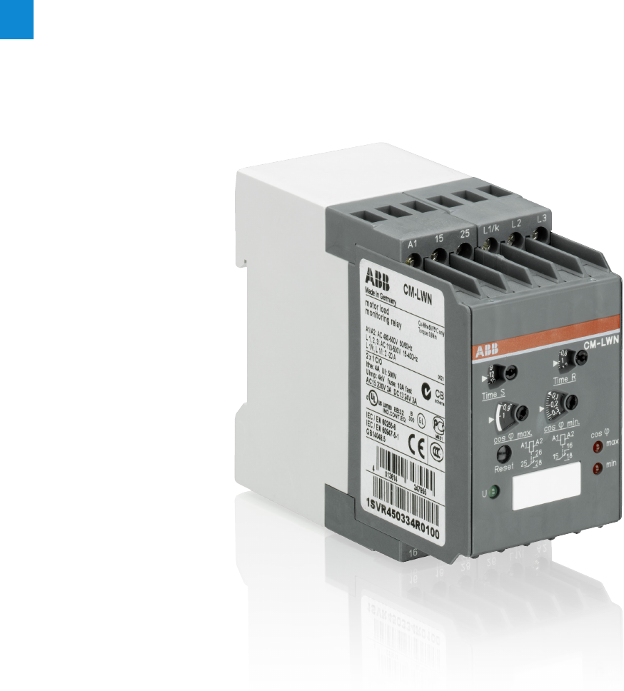
2/73 ABB | Catalog Electronic Products and Relays 2015 | 2CDC 110 004 C0210
2
Motor load monitoring relays
Product picture

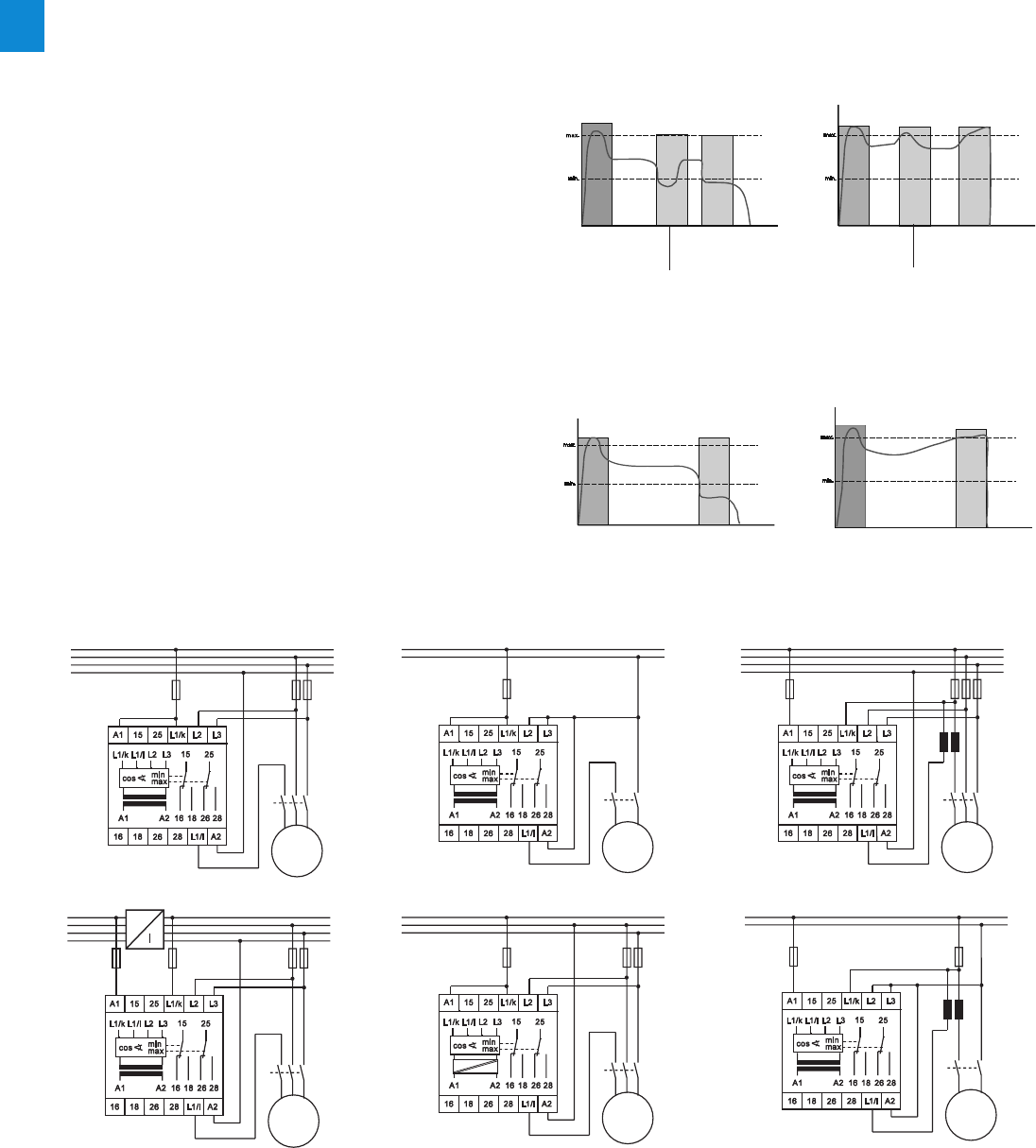
2/75 ABB | Catalog Electronic Products and Relays 2015 | 2CDC 110 004 C0210
2
Motor load monitoring relays
Fields of application
N
L3
L2
L1
K1
UVW
M 3~
50-60 Hz
N
L1
K1
U1 U2
M 1~
50-60 Hz
N
L3
L2
L1
K1
UVW
M 3~
~
~
50-60 Hz 110-500 V, 15-400 Hz
N
L3
L2
L1
K1
UVW
M 3~
l
k
L
K
50-60 Hz
N
L1
K1
U1 U2
M 1~
l
k
L
K
50-60 Hz
L3
L2
L1
K1
UVW
M 3~
DC AC
110-240 V 15-400 Hz
The motor load monitor relay monitors the load states of
single-phase and three-phase asynchronous motors.
The evaluation of the phase angle between current and volt-
age allows a very precise monitoring of the load states.
Compared with other conventional measuring principles
Main applications
– Pump monitoring
– Dry-running protection (underload)
– Closed valves (overload)
– Pipe break (overload)
– Heating, air-conditioning, ventilation
– Monitoring of filter pollution
– V-belt breakage (underload)
– Closed shutters/valves (overload)
– Air ventilating volume
– Agitating machines
– High consistency within the tank (overload)
– Pollution of the tank (overload)
– Transport/Conveyance
– Congested conveyor belts (overload)
– Jamming of belts (overload)
– Material accumulation in spiral conveyors (overload)
– Lifting platforms
– Machine installation
– Wear of tools, e.g. worn saw blades in circular saws,
etc. (overload)
– Tool breakage (underload)
– V-belt drives (breakage underload)
(e.g. pressure transducers, current measurement), cos ϕ
monitoring is a more precise and economical alternative.
The motor is used as a sensor for its own load status.
Wiring examples (for motor currents m 20 A)
Filter pollution
V-belt monitoring
Dry-running protection
Pump control
Ventilator monitoring
Filter pollution
Wiring examples (for motor
currents 20 A)
1SVC 110 000 F 0131
1SVC 110 000 F 0132
1SVC 110 000 F 0133
1SVC 110 000 F 01311SVC 110 000 F 0132
1SVC 110 000 F 0133
1SVC 110 000 F 0470
1SVC 110 000 F 0473 1SVC 110 000 F 0471
1SVC 110 000 F 0472
Detected fault - installation is
switched off
Starting time delay
Detected fault - installation is
switched off
Starting time delay
Starting time delay Detected fault - installation is
switched off
Starting time delay Detected fault - installation is
switched off
Response delay Response delay
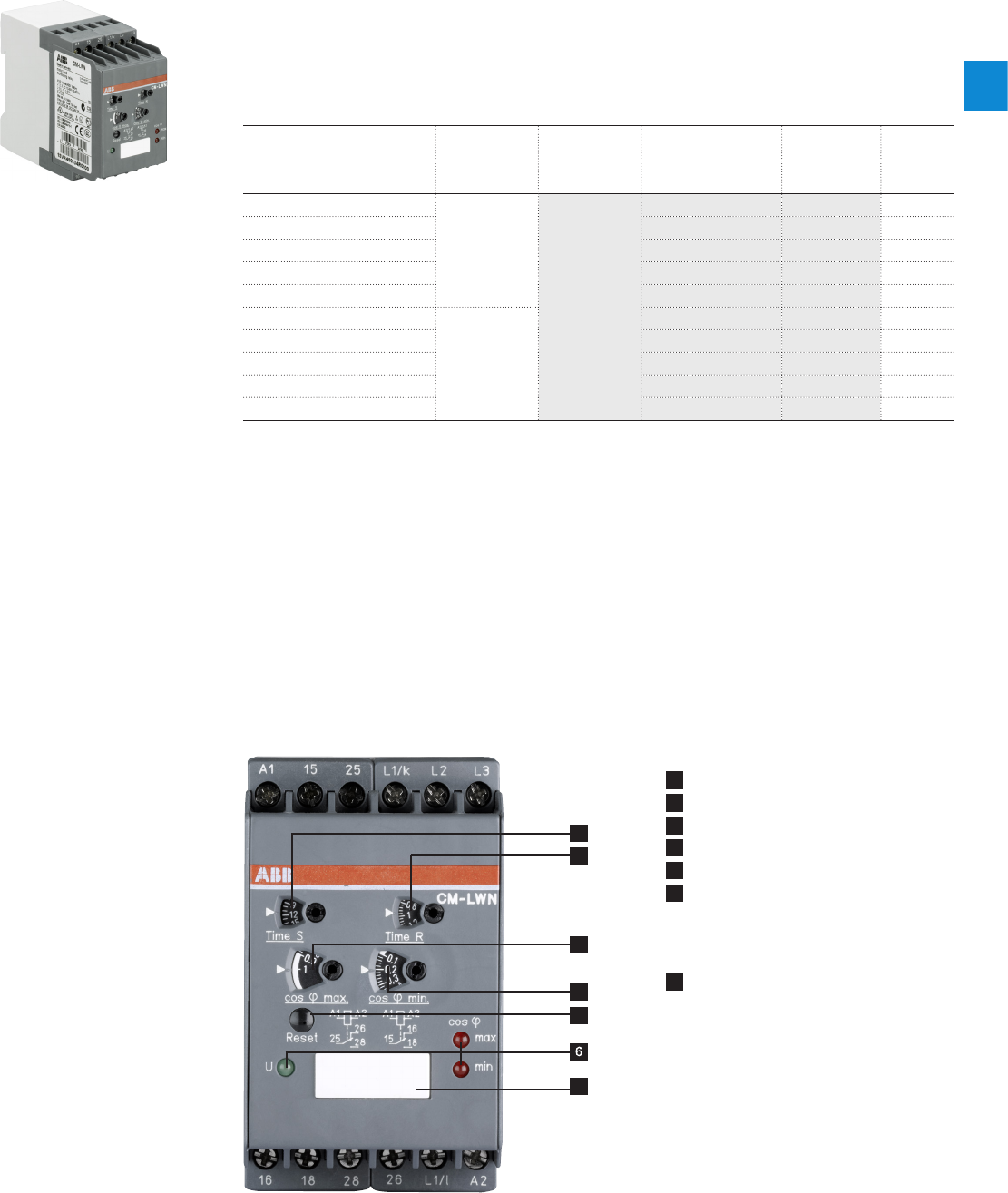
2CDC 110 004 C0210 | Catalog Electronic Products and Relays 2015 | ABB 2/76
2
Motor load monitoring relays
Ordering details
Description
The motor load monitor CM-LWN monitors the load of single-phase and three-phase asyn-
chronous motors. The evaluation of the phase angle between current and voltage (cos ϕ
monitoring) allows a very precise monitoring of the load status.
Ordering details
Rated control supply voltage
= measuring voltage
Current range Type Order code Price
1 pce
Weight
(1 pce)
kg (lb)
24-240 VAC/DC
0.5-5 A
CM-LWN
1SVR450335R0000 0.30 (0.66)
110-130 VAC 1SVR450330R0000 0.30 (0.66)
220-240 VAC 1SVR450331R0000 0.30 (0.66)
380-440 VAC 1SVR450332R0000 0.30 (0.66)
480-500 VAC 1SVR450334R0000 0.30 (0.66)
24-240 VAC/DC
2-20 A
1SVR450335R0100 0.30 (0.66)
110-130 VAC 1SVR450330R0100 0.30 (0.66)
220-240 VAC 1SVR450331R0100 0.30 (0.66)
380-440 VAC 1SVR450332R0100 0.30 (0.66)
480-500 VAC 1SVR450334R0100 0.30 (0.66)
1SVR 450 335 F0100
CM-LWN
Current transformers see „General technical data, Accessories, Current transformers“ on page 128.
Characteristics
– Pump monitoring
– Under- and overload monitoring cos ϕ in one unit
– Adjustable starting delay 0.3-30 s
– Direct measurement of currents up to 20 A
– Adjustable response time delay 0.2-2 s
– Single-phase or three-phase monitoring
– 2 x 1 c/o contact, closed-circuit principle
– 3 LEDs for status indication
4
1
2
3
5
7
1 Starting delay „Time S“
2 Response delay „Time R“
3 Threshold for load limit cos ϕmax
4 Threshold for load limit cos ϕmin
5 Reset button
6 Indication of operational states
U: green LED – control supply voltage
cos ϕmax: red LED – cos ϕmax exceeded
cos ϕmin: red LED – below cos ϕmin
7 Marker label
2CDC 253 010 F0013
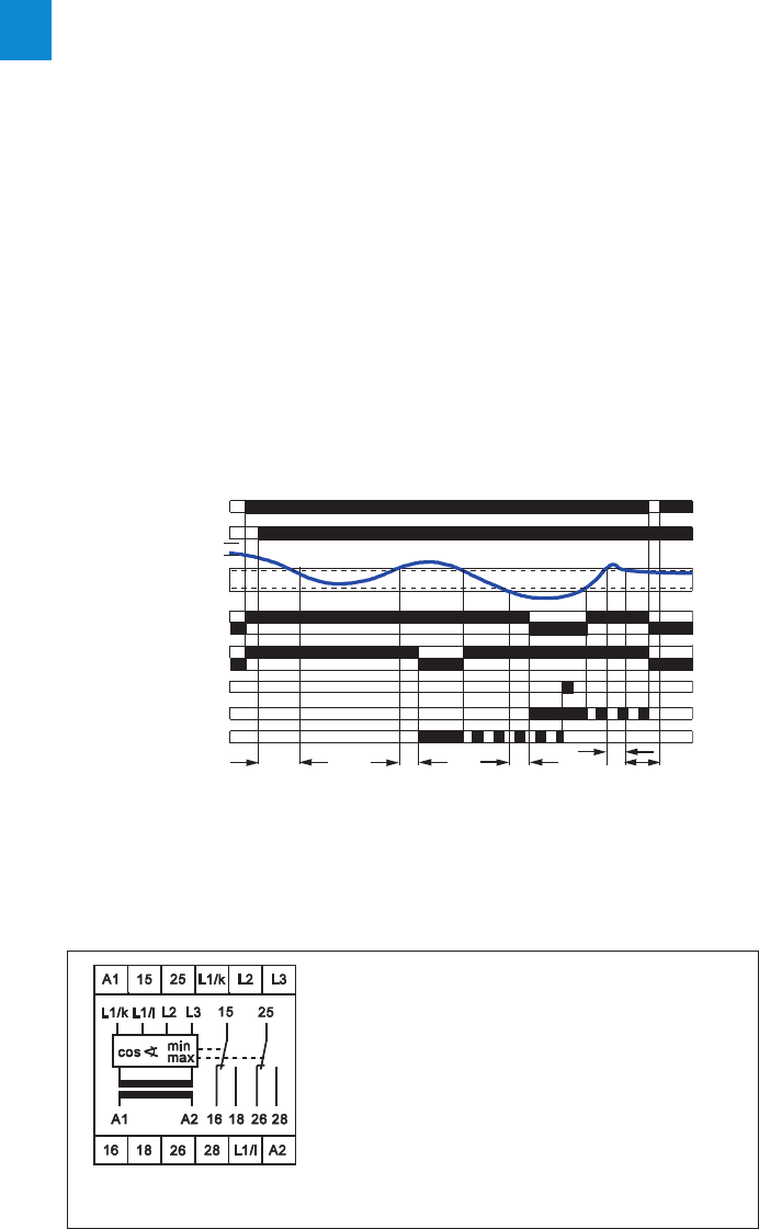
2/77 ABB | Catalog Electronic Products and Relays 2015 | 2CDC 110 004 C0210
2
Motor load monitoring relays
Technical information
The CM-LWN module monitors the load status of inductive loads.
The primary application is the monitoring of single- or three-phase asynchronous motors (squirrel cage) under varying load
conditions. The measuring principle is based on the evaluation of the phase shift (ϕ) between the voltage and the current in one
phase.
The phase difference is nearly inversely proportional to the load. Therefore, cos ϕ, measured relatively from 0 to 1, measures
the relationship of effective power to apparent power. A value towards 0 indicates low load and a value towards 1 indicates
high load.
Threshold values can be set individually for cos ϕmax and cos ϕmin If the set threshold value is reached, a LED lights up and the
relay is de-energized.
If cos ϕ returns to the acceptable limits (taking into account the hysteresis), the relay is reset to its original state and the LED
flashes permanently to indicate the occurrence of the trip event. This message can be deleted using the reset button or by
switching off the supply.
A time delay (Time S) of 0.3 to 30 s can be set for the starting phase of the motor. It is also possible to set a response delay
time (Time R) of 0.2 to 2 s to suppress unwanted tripping due to unavoidable short load changes during normal operation.
To guarantee correct operation of the response delay (Time R), the adjusted value for cos ϕmax has to be higher than the value
for cos ϕmin plus the hysteresis. Consequently, the overload and underload indication must not be active at the same time.
Due to the internal electrical isolation of the supply circuit and the measuring circuit, it is also possible to use the device in sys-
tems with different supply voltages.
TSTS
TRTRTR
Function diagram - CM-LWN
A1-A2 Rated control supply voltage
L1/K-L1/L Measuring current
L1/K-L2-L3 Measuring voltage
15-16/18 Output contacts - underload (cos ϕmin)
25-26/28 Output contacts - overload (cos ϕmax)
closed-circuit principle
Connection diagram CM-LWN
1SVC 110 000 F0130
2CDC 252 105 F0004
A1-A2
Current in L1
con ϕmax
hysteresis
con ϕmin
15-18
15-16
25-28
25-26
Reset button
Red LED - cos ϕmin
Red LED - cos ϕmax

2CDC 110 004 C0210 | Catalog Electronic Products and Relays 2015 | ABB 2/78
2
Motor load monitoring relays
Technical data
Type CM-LWN
Input circuit - Supply circuit A1-A2
Rated control supply voltage Us - power
consumption A1-A2 24-240 V AC/DC approx. 8.4 VA/W
A1-A2 110-130 V AC approx. 3.6 VA
A1-A2 220-240 V AC approx. 3.6 VA
A1-A2 380-440 V AC approx. 3.6 VA
A1-A2 480-500 V AC approx. 3.6 VA
Rated control supply voltage Us tolerance -15 %...+10 %
Rated frequency AC versions 50-60 Hz
AC/DC versions 15-400 Hz or DC
Duty time 100 %
Measuring circuit L1/L-L1/K-L2-L3
Monitoring function Motor load monitoring by cos ϕ
Voltage range L1/K-L2-L3 110-500 V AC single-phase or three-phase
Current range L1/L-L1/K 0.5-5 A version 2-20 A version
Permissible overload of current input 25 A for 3 s 100 A for 3 s
Thresholds cos ϕmin and cos ϕmax adjustable from 0 to 1
Hysteresis (related to phase angle ϕ in °) 4°
Frequency of measuring voltage 15-400 Hz
Response time 300 ms
Timing circuits indication of over- and undervoltage fault
Start-up time (Time S) 0.3-30 s, adjustable
Response delay (Time R) 0.2-2 s, adjustable
Accuracy within the rated control supply voltage tolerance t m 0.5 %
Accuracy within the temperature range t m 0.06 % / °C
Indication of operational states
Control supply voltage U: green LED
below cos ϕmin cos ϕmin: red LED
cos ϕmax exceeded cos ϕmax: red LED
Output circuits 15-16/18, 25-26/28
Kind of output 2 x 1 c/o contact
Operational principle closed-circuit principle 1)
Contact material AgCdO
Rated voltage (VDE 0110, IEC 664-1, IEC 947-1) 250 V
Max. switching voltage 400 V AC, 300 V DC
Rated operational current Ie (IEC/EN 60947-1) AC-12 (resistive) 230 V 4 A
AC-15 (inductive) 230 V 3 A
DC-12 (resistive) 24 V 4 A
DC-13 (inductive) 24 V 2 A
AC rating (UL 508) Utilization category (Control Circuit Rating Code) B 300
max. rated operational voltage 300 V AC
max. continuous thermal current at B 300 5 A
max. making/breaking apparent power at B 300 3600/360 VA
Mechanical lifetime 30 x 106 switching cycles
Electrical lifetime at AC-12, 230 V, 4 A 0.1 x 10⁶ switching cycles
Max. fuse rating to achieve short-circuit
protection n/c / n/o contact 10 A fast-acting / 10 A fast-acting
General data
Dimensions (W x H x D) 45 mm x 78 mm x 100 mm (1.77 inch x 3.07 inch x 3.94 inch)
Mounting position any
Degree of protection housing / terminals IP50 / IP20
Ambient temperature range operation / storage -25...+65 °C / -40...+85 °C
Mounting DIN rail (IEC/EN 60715)
Electrical connection
Wire size fine-strand with wire end ferrule 2 x 2.5 mm2 (2 x 14 AWG)
Standards
Product standard IEC 255-6, EN 60255-6
Low Voltage Directive 2006/95/EC
EMC Directive 2004/108/EC, 91/263/EEC, 92/31/EEC, 93/68/EEC, 93/67/EEC
Electromagnetic compatibility EN 61000-6-2, EN 61000-6-4
electrostatic discharge IEC/EN 61000-4-2 Level 3 (6 kV / 8 kV)
radiated, radio-frequency, electromagnetic field IEC/EN 61000-4-3 Level 3 (10 V/m)
electrical fast transient / burst IEC/EN 61000-4-4 Level 3 (2 kV / 5 kHz)
surge IEC/EN 61000-4-5 Level 4 (2 kV L-L)
conducted disturbances, induced by radio-frequency fields
IEC/EN 61000-4-6 Level 3 (10 V)
Operational reliability (IEC 68-2-6) 5 g
Mechanical resistance (IEC 68-2-6) 10 g
Environmental testing (IEC 68-2-30) 24 h cycle time, 55 °C, 93 % rel., 96 h
Isolation data
Rating (HD 625.1 S1, VDE 0110, IEC 664-1, IEC 60255-5)
Rated insulation voltage between supply- , measuring- and output circuit 250 V, 400 V, 500 V depending on the version
Rated impulse withstand voltage between all isolated circuits 4 kV / 1.2 - 50 µs
Test voltage between all isolated circuits 2,5 kV, 50 Hz, 1 min.
Pollution category 3
Overvoltage category III
1) Open-circuit principle: Output relay is energized if the measured value exceeds/drops below the adjusted threshold.
Closed-circuit principle: Output relay is de-energized if the measured value exceeds/drops below the adjusted threshold.
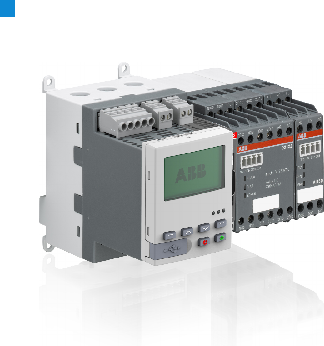
2/79 ABB | Catalog Electronic Products and Relays 2015 | 2CDC 110 004 C0210
2
Motor control and protection
Product group picture


2/81 ABB | Catalog Electronic Products and Relays 2015 | 2CDC 110 004 C0210
2
Motor control and protection
Benefits and advantages
Motor protection
– Overload, underload
– Overvoltage, undervoltage
– Blocked rotor, low / high current
– Phase failure, imbalance, phase sequence
– Earth leakage
– Thermistor protection
– Limitation of starts per time
– One single version with integrated measuring system cov-
ers the rated motor current from 0.24 to 63 A
Motor control
– Integrated and easy to parametrize motor starter functions
like direct, reverse, star-delta,...
– Additionally free programmable logic for application spe-
cific control functions
– Expansion modules DX111, DX122 for more I/Os
– Expansion modules VI150, VI155 for 3-phase voltage
measuring
– Analog and temperature module AI111
Motor diagnostics
– Quick and comprehensive access to all relevant data via
fieldbus and/or operator panel
– Current, thermal load
– Phase voltages
– Power factor
– Energy
Communication
– Communication-independent basic device
– Freely selectable fieldbus protocol with FieldBusPlug
– Profibus DP
– DeviceNet
– Modbus RTU
– Ethernet Modbus TCP
– Profinet
Typical application segments
– Oil & gas
– Cement
– Paper
– Mining
– Steel
– Chemical industry
UMC100.3 is a flexible, modular and expandable motor management system for constant-speed low-voltage range motors.
It's most important tasks include motor protection, prevention of plant standstills and the reduction of down time. This is made
possible by early information relating to possible motor problems which avoids unplanned plant standstills. Even if a motor
trips, quick diagnosis of the cause of the fault serves to reduce downtime.
UMC100.3 combines in a very compact unit:
Further information
UMC Catalog 2CDC 190 022 C0206
UMC Brochure 2CDC 135 011 B0203
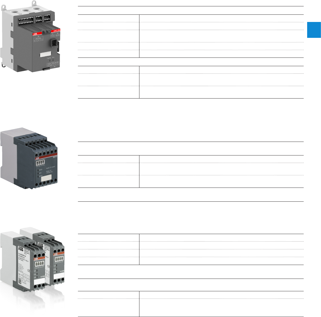
2CDC 110 004 C0210 | Catalog Electronic Products and Relays 2015 | ABB 2/82
2
Motor control and protection
Technical data
Basic device UMC100.3
Main power
Voltage max 1000 V AC
Frequency 45…65 Hz
Rated motor current 0.24…63 A, without accessories
Higher currents with external transformer
Tripping classes 5E, 10E, 20E, 30E, 40E in accordance with EN/IEC 60947-4-1
Short-circuit protection Separate fuse on network side
Control unit
Supply voltage 24 V DC, 110-240 V AC/DC
Inputs 6 digital inputs 24 V DC
1 PTC input
Outputs 3 digital relay outputs
1 digital transistor output
Expansion modules
The UMC100.3 can be expanded with maximum 4 expanstion modules: One digital expansion module DX111 or
DX122, one module VI150 or VI155 and 2 analog modules AI111.
Communication takes place via a simple two-wire line. The maximum distance allowed between the UMC100.3
and the expansion module is 3m.
Digital expansion modules DX111 / DX122
Expands the UMC100.3 to include additional digital inputs and outputs and an analog output
Supply voltage 24 V DC
Inputs DX111: 8 digital inputs 24 V DC
DX122 8 digital inputs 110/230 V AC
Outputs 4 digital relay outputs
1 analog output, 0/4…20 mA, / 0…10 V configurable
Voltage modules VI150/VI155
Voltage modules for determining phase voltages, power factor (cos j), active power, apparent power, energy,
harmonic content (THD)
VI150 for use in grounded networks
VI155 for use in grounded and ungrounded networks
Supply voltage 24 V DC
Voltage inputs L1, L2, L3
Rated voltage range 150 … 690 V AC
Outputs 1 digital relay output
Analog module AI111
Expand the UMC100.3 with analog and temperature inputs
Supply voltage 24 V DC
Inputs 0-10 V, 0/4-20 mA
PT100, PT1000, 2- or 3-wire connection
KTY83, KTY84, NTC
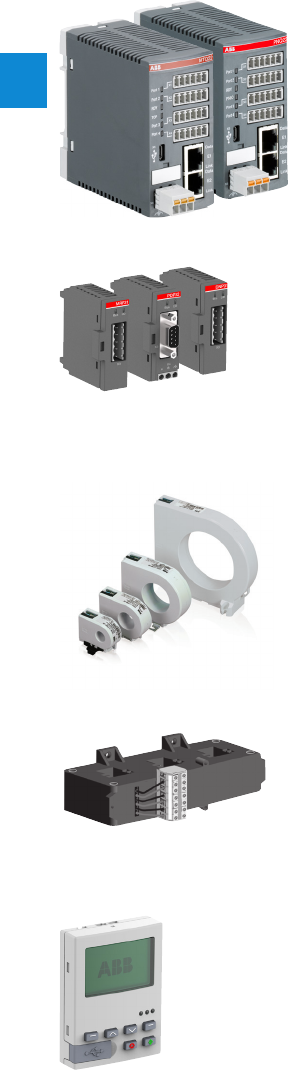
2/83 ABB | Catalog Electronic Products and Relays 2015 | 2CDC 110 004 C0210
2
Motor control and protection
Technical data
Ethernet communication interfaces
Mounted in the MCC cable chamber; connection of 1 to 4 motor controllers UMC100.3 via simple cables
MTQ22 for Modbus TCP
PNQ22 for Profinet IO
Fieldbus communication interfaces
Can be mounted direct on the UMC100.3 or separate in the cable chamber of the MCC.
Connection for standard fieldbus cables with 9-pole Sub-D (Profibus DP) or terminal blocks
PDP32 for Profibus DP
DNP31 for DeviceNet
MRP31 for Modbus RTU
CEM11 earth leakage sensors
Summation current transformer for connecting to a digital input
Mounting with bracket on DIN busbar or wall
Models
CEM11-FBP.20 80 – 1,700 mA 20 mm Ø
CEM11-FBP.35 100 – 3,400 mA 35 mm Ø
CEM11-FBP.60 120 – 6,800 mA 60 mm Ø
CEM11-FBP.120 300 – 13,600 mA 120 mm Ø
Current transformer CT4L / CT5L
Only required for rated motor currents >63 A
Linear transformer, 3-phase with terminal block, designed for connecting leads Cu 2.5 mm2
UMC100-PAN control panel
Installation on the device or on the switching cabinet door
Graphics-enabled and backlit display, 3 LEDs for status indication
Freely configurable error messages
USB port for PC connection
Multilingual: German, English, French, Italian, Polish, Portuguese, Spanish, Russian

2
2CDC 110 004 C0210 | Catalog Electronic Products and Relays 2015 | ABB 2/84
Motor control and protection
Notes
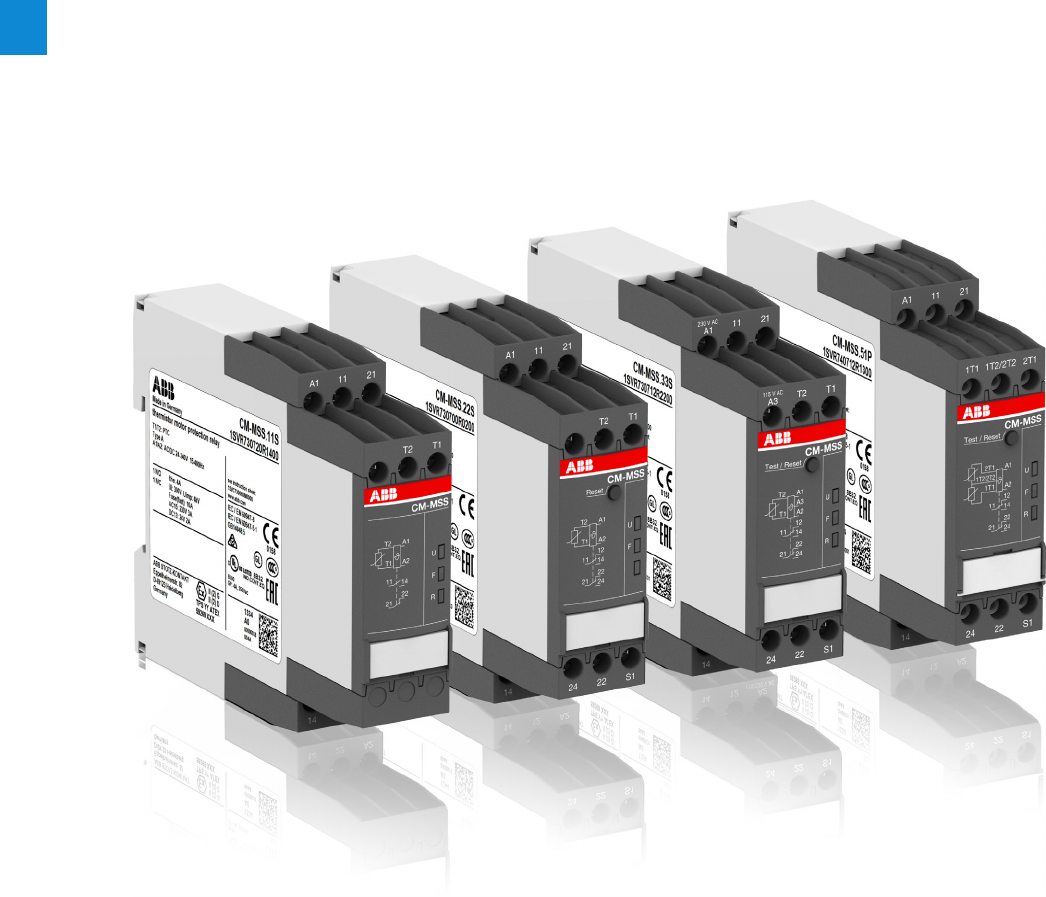
2/85 ABB | Catalog Electronic Products and Relays 2015 | 2CDC 110 004 C0210
2
Thermistor motor protection relays
Product group picture

2CDC 110 004 C0210 | Catalog Electronic Products and Relays 2015 | ABB 2/86
2
Thermistor motor protection relays
Table of contents
Thermistor motor protection relays
Benefits and advantages, Applications 2/87
Operating controls 2/88
Selection table CM-MSS range 2/89
Ordering details 2/90
Ordering details - PTC temperature sensors C011 2/91
Technical data 2/92
Connection diagrams 2/95
Circuit diagram 2/96

2/87 ABB | Catalog Electronic Products and Relays 2015 | 2CDC 110 004 C0210
2
Thermistor motor protection relays
Benefits and advantages, Applications
Direct temperature measuring
Generally, motor damages caused by overload or overheating
situations can be prevented in different ways. Compared to
the indirect temperature measuring which monitors the motor
current, the temperature inside the motor can be measured by
direct temperature measuring.
This enables direct control and evaluation of the following
operating conditions like:
– Heavy duty starting
– Increased switching frequency
– Single phase operation
– Phase unbalance
– High ambient temperature
– Insufficient cooling
– Breaking operation
Therefore the consequences from overheating like abrasion as
well as electrical failures can be prevented.
The direct measuring principle is carried out by a combination
of the thermistor motor protection relay and 3 PTC sensors
which are installed directly in the motor by the manufac-
turer. Those 3 PTC sensors are placed directly at the thermal
hotspots, the motor windings.
The thermistor motor protection relays of the CM-MSx range protect motors with
PTC sensors against high temperature. These sensors are incorporated in the
motor windings thus measuring the motor heat directly.
Monitoring the motor
The thermistor motor protection relay measures the resistance
of the PTC sensors which reflects the internal motor tempera-
ture permanently.
If the temperature in the motor windings rises excessively and
reaches the nominal response temperature (NRT), the therm-
istor motor protection relay detects this situation and the
output relay switches off.
By doing so the motor contactor gets triggered and switches
off the motor.
CM-MSS functionality video
Characteristics CM-MSS1)
– Different types of contacts available
– 1 x 2 c/o (SPDT) contacts
– 2 x 1 c/o (SPDT) contact
– 1 n/o and 1 n/c contact
– 1 or 2 measuring circuits
– Different types of reset functions
– Automatic
– Manual
– Remote
– Rated control supply voltages
– 24 V AC/DC
– 24-240 V AC/DC
– 110-130 V AC, 220-240 V AC
– Approvals / Marks
A C R K E I1) / a b
Characteristics CM-MSE
– Auto reset
– Connection of several sensors (max. 6 sensors
connected in series)
– Monitoring of bimetals
– 1 n/o contact
– Excellenct cost / performance ratio
Features 1)
– Additional functions:
– Dynamic interrupted wire detection
– Short-circuit monitoring of the sensor circuit
– Non-volatile fault storage
– Single or sum evaluation
– Easy configuration via DIP switches
– LEDs to distinguish between different failure causes
– Screw connection technology or EasyConnectTechnology
available
– Test/Reset button available
1) Depending on device the characteristics vary, for detailled overview see „Selection
table CM-MSx range“ on page 89.
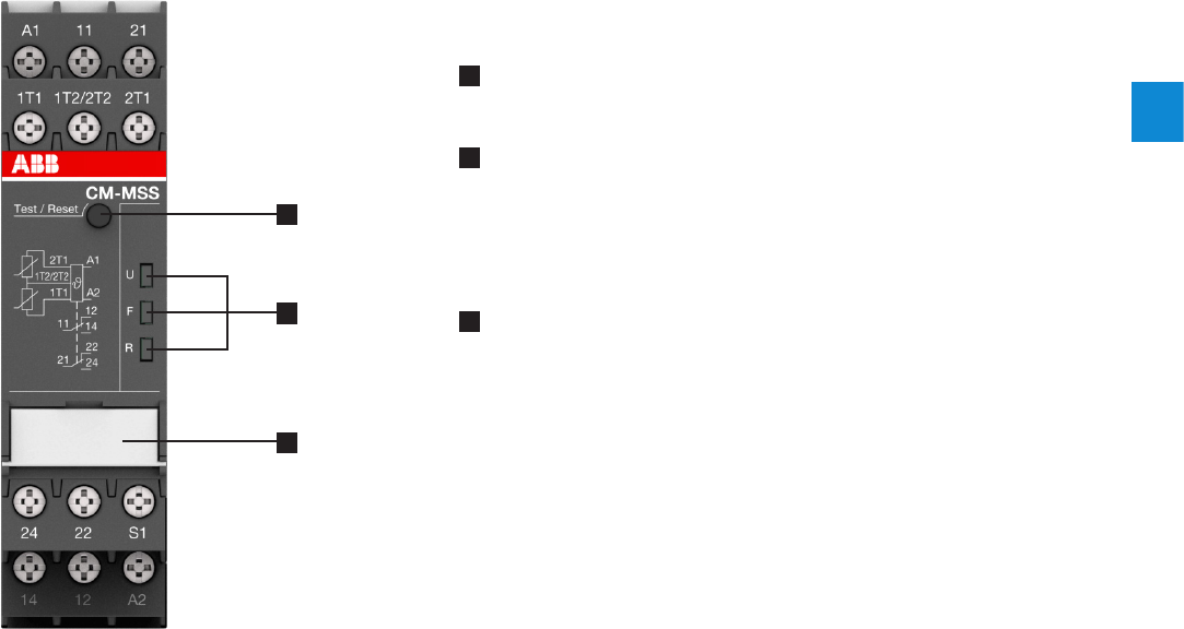
2CDC 110 004 C0210 | Catalog Electronic Products and Relays 2015 | ABB 2/88
2
Thermistor motor protection relays
Operating controls
1 Test / Reset button
Reset - only possible if measured value < switch-on resistance
2 Indication of operational states with LEDs
U: green LED - Status indication of control supply voltage V
Control supply voltage applied
F: red LED - Fault message
R: yellow LED - Status indication of the output relay
3 DIP switches
i Single evaluation 2 x 1 c/o (SPDT) contact
j Accumulative evaluation 1 x 2 c/o (SPDT) contacts
y Short-circuit detection de-activated
x Short-circuit detection activated
f Non-volatile fault storage activated
e Non-volatile fault storage de-activated
1
3
2
2CDC 253 001 F0015

2/89 ABB | Catalog Electronic Products and Relays 2015 | 2CDC 110 004 C0210
2
Thermistor motor protection relays
Selection table CM-MSx range
Order code
1SVR550805R9300
1SVR550800R9300
1SVR550801R9300
1SVR740720R1400
1SVR730720R1400
1SVR740700R0100
1SVR730700R0100
1SVR740700R2100
1SVR730700R2100
1SVR740722R1400
1SVR730722R1400
1SVR740700R0200
1SVR730700R0200
1SVR740700R2200
1SVR730700R2200
1SVR740712R1400
1SVR730712R1400
1SV R74 0712R0200
1SVR730712R0200
1SV R74 0712R2200
1SVR730712R2200
1SVR740712R1200
1SVR730712R1200
1SV R74 0712R1300
1SVR730712R1300
Type
CM-MSE
CM-MSE
CM-MSE
CM-M SS.11P
CM-M SS.11S
CM-MSS.12P
CM-MSS.12S
CM-MSS.13P
CM-MSS.13S
CM-MSS.21P
CM-MSS.21S
CM-MSS.22P
CM-MSS.22S
CM-MSS.23P
CM-MSS.23S
CM-MSS.31P
CM-MSS.31S
CM-MSS.32P
CM-MSS.32S
CM-MSS.33P
CM-MSS.33S
CM-MSS.41P
CM-MSS.41S
CM-MSS.51P
CM-MSS.51S
Characteristics
ATEX approval nn nn nnnnnnnnnn
Number of sensor circuits 1111111111111111111111122
Single or sum evaluation n n
Number of LEDs 3322223322223333333333
Contacts
1 c/o (SPDT) contact n n n n
2 c/o (SPDT) contacts n n n n n n n n n n
1 n/o n n n
1 n/c and 1 n/o n n n n n n
2 x 1 c/o or 1 x 2 c/o contacts, configurable n n
Reset
Manual nnnnnnnnnnnnnn
Remote nnnnnnnnnnnnnn
Auto nnnnnnnnnnnn1) n1) n1) n1) n1) n1) n1) n1) n1) n1) n1) n1) n2) n2)
Test button nnnnnnnnnn
Functions
Short-circuit detection nn nnnnnn
Short-circuit detection, configurable n n n n
Dynamic interrupted wire detection nn nn nnnnnnnnnn
Non-volatile fault storage n n n n n n
Non-volatile fault storage, configurable n n n n
Rated control supply voltage US
24 V AC n
110-130 V AC n
220-240 V AC n
24-240 V AC/DC n n n n n n n n n n
24 V AC/DC n n n n n n
110-130 V AC, 220-240 V AC n n n n n n
Connection type
Push-in terminals nnnnnnnnnnn
Double-chamber cage connection terminals nnnnnnnnnnn
1) For automatic reset, connect terminals S1 to T2.
2) For automatic reset, connect terminals S1 to 1T2/2T2.
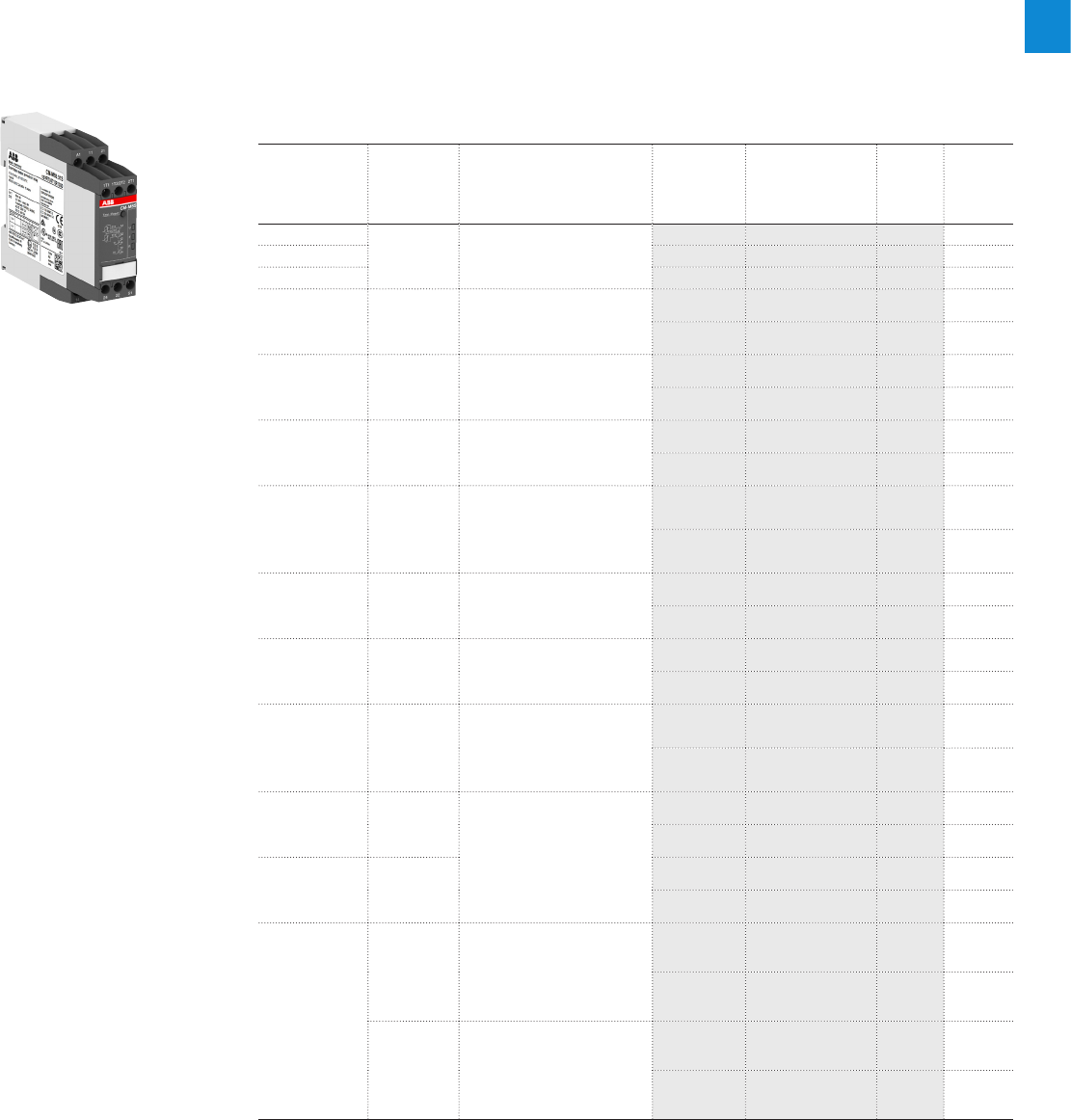
2CDC 110 004 C0210 | Catalog Electronic Products and Relays 2015 | ABB 2/90
2
Thermistor motor protection relays
Ordering details
Description
The thermistor motor protection relays CM-MSx are used to control motors equipped with
PTC temperature sensors. The PTC temperature sensors are incorporated in the motor wind-
ings to measure the motor heating. This enables direct control and evaluation of various oper-
ating conditions. Depending on the products also ATEX approvals for use in hazardous areas
are availabe.
ABB also offers PTC temperature sensors C011 (according to DIN 44081) which are suitable
for embedding in motor windings.
Ordering details CM-MSx
Rated control
supply
voltage
Output Function Type Order code Price
1 pce
Weight
(1 pce)
kg (lb)
24 V AC
1 n/o Autoreset
CM-MSE 1SVR550805R9300 0.11 (0.24)
110-130 V AC CM-MSE 1SVR550800R9300 0.11 (0.24)
220-240 V AC CM-MSE 1SVR550801R9300 0.11 (0. 24)
24-240VAC/DC 1n/c, 1n/o
Autoreset, dynamic
interrupted wire detection,
non-volatile fault storage,
ATEX approval
CM-M S S.11P 1SVR740720R1400 0.119
(0.263)
CM-M S S.11S 1SVR730720R1400 0.127
(0.280)
24 V AC/DC 1 c/o (SPDT) Autoreset
CM-MSS.12P 1SVR740700R0100 0.105
(0.231)
CM-MSS.12S 1SVR730700R0100 0.113
(0.249)
110-130VAC,
220-240VAC 1 c/o (SPDT) Autoreset
CM-MSS.13P 1SVR740700R2100 0.147
(0.324)
CM-MSS.13S 1SVR730700R2100 0.155
(0.342)
24-240VAC/DC 1n/c, 1n/o
Autoreset, dynamic
interrupted wire detection,
non-volatile fault storage,
short-circuit detection,
ATEX approval
CM-MSS.21P 1SVR740722R1400 0.118
(0.260)
CM-MSS.21S 1SVR730722R1400 0.126
(0.278)
24 V AC/DC 2 c/o (SPDT) Auto, manual or remote reset
CM-MSS.22P 1SVR740700R0200 0.121
(0.267)
CM-MSS.22S 1SVR730700R0200 0.132
(0.291)
110-130VAC,
220-240VAC 2 c/o (SPDT) Auto, manual or remote reset
CM-MSS.23P 1SVR740700R2200 0.163
(0.359)
CM-MSS.23S 1SVR730700R2200 0.174
(0.384)
24-240VAC/DC 1n/c, 1n/o
Auto, manual or remote reset,
dynamic interrupted wire
detection, non-volatile fault
storage, short-circuit detection,
ATEX approval
CM-MSS.31P 1SVR740712R1400 0.120
(0.265)
CM-MSS.31S 1SVR730712R140 0 0.128
(0.282)
24 V AC/DC 2 c/o (SPDT) Auto, manual or remote
reset, dynamic interrupted
wire detection, short-circuit
detection, ATEX approval
CM-MSS.32P 1SVR740712R 020 0 0.120
(0.265)
CM-MSS.32S 1SVR730712R0200 0.13 0
(0.287)
110-130VAC,
220-240VAC 2 c/o (SPDT)
CM-MSS.33P 1SV R74 0712R2 20 0 0.162
(0.357)
CM-MSS.33S 1SVR730712R2200 0.172
(0.379)
24-240VAC/DC
2 c/o (SPDT)
Auto, manual or remote reset,
dynamic interrupted wire
detection, non-volatile fault
storage, short-circuit detection,
ATEX approval
CM-MSS.41P 1SVR740712R1200 0.13 0
(0.287)
CM-MSS.41S 1SVR730712R1200 0.141
(0.311)
2x1c/o or,
1x2c/o
Auto, manual or remote reset,
dynamic interrupted wire
detection, non-volatile fault
storage, short-circuit detection,
accumulative evaluation,
ATEX approval
CM-MSS.51P 1SVR740712R13 0 0 0.135
(0.298)
CM-MSS.51S 1SVR730712R1300 0.145
(0.320)
2CDC 251 014 V0014
CM-MSS.51S
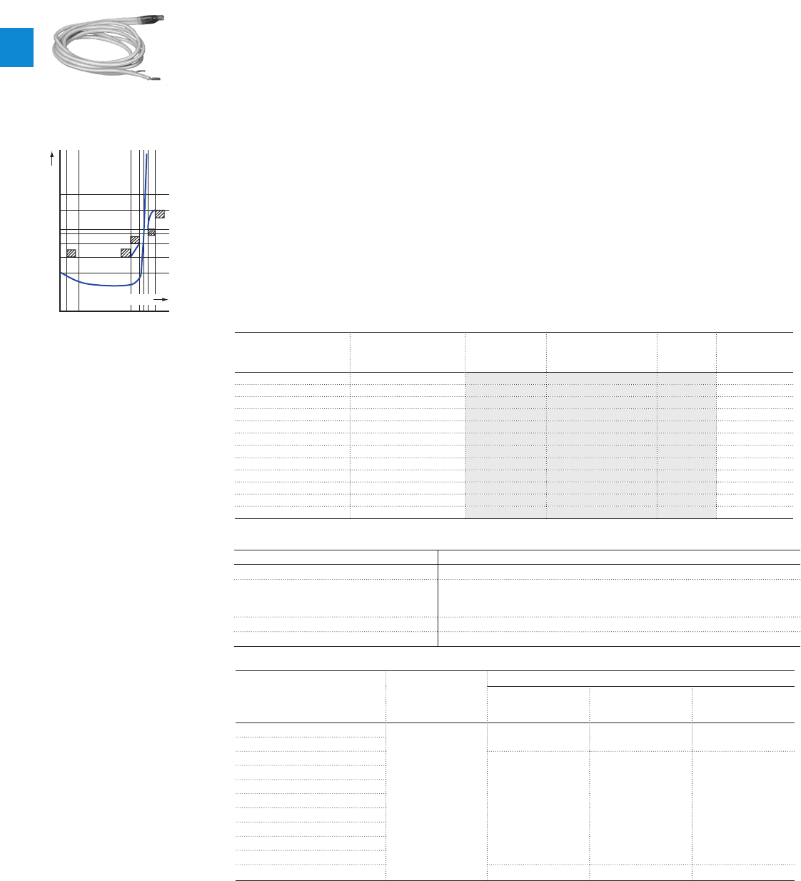
2/91 ABB | Catalog Electronic Products and Relays 2015 | 2CDC 110 004 C0210
2
Thermistor motor protection relays
Ordering details - PTC temperature sensors C011
1SVC 110 000 F0531
Temperature sensor characteristics
Technical data
Characteristic data Sensor type C011
Cold-state resistance 50 -100 q at 25 °C
Warm-state resistance ± 5 up to 6 K
of rated
response temperature TNF 10 000 q
Thermal time constant, sensor open 1) < 5 s
Permitted ambient temperature +180 °C
Rated response tempera-
ture w tolerance TNF w TNF
PTC resistance R
from -20 °C to TNF
- 20 K
PTC resistance R2) at PTC temperatures of:
TNF - TNF
(UPTC m 2.5 V)
TNF + TNF
(UPTC m 2.5 V)
TNF + 15 K
(UPTC m 7. 5 V )
70 w5 °C
m 100 q
m 570 q 570 q-
80 w5 °C
90 w5 °C
m 550 q 1330 q 4000 q
100 w5 °C
110 w5 °C
120 w5 °C
130 w5 °C
140 w5 °C
150 w5 °C
160 w5 °C
170 w7 °C m 570 q 570 q-
1) Not embedded in windings.
2) For triple temperature sensor take values x 3.
-20 °C
101
102
103
104
TNF - 20 K
TNF - 5 K
TNF
TNF + 5 K
T
NF + 15 K
R
PTC
[]
TPTC [°C]
2CDC 252 068 F0208
Ordering details
Rated response
temperature TNF
Color coding Type Order code Price
1 pce
Weight
(1 pce)
kg (lb)
70 °C white-brown C011-701) GHC0110003R0001 0.02 (0.044)
80 °C white-white C011- 8 01) GHC0110003R0002 0.02 (0.044)
90 °C green-green C011-9 01) GHC0110003R0003 0.02 (0.044)
100 °C red-red C 011-10 01) GHC0110003R0004 0.02 (0.044)
110 °C brown-brown C011-1101) GHC0110003R0005 0.02 (0.044)
120 °C gray-gray C 011-1201) GHC0110003R0006 0.02 (0.044)
130 °C blue-blue C011-1301) GHC0110003R0007 0.02 (0.044)
140 °C white-blue C011-14 01) GHC0110003R0011 0.02 (0.044)
150 °C black-black C011-1501) GHC0110003R0008 0.02 (0.044)
160 °C blue-red C 011-16 01) GHC0110003R0009 0.02 (0.044)
170 °C white-green C 011-1701) GHC0110003R0010 0.02 (0.044)
150 °C black-black C011-3-15 02) GHC0110033R0008 0.05 (0.11)
1) Temperature sensor C011, standard
version acc. to DIN 44081
2) Triple temperature sensor C011-3
Description
The PTC temperature sensors (temperature-dependent with positive temperature coefficient)
are selected by the manufacturer of the motor depending on:
– the motor insulation class according to IEC/EN 60034-11,
– the special characteristics of the motor, such as the conductor cross-section of the wind-
ings, the permissible overload factor etc.
– special conditions prescribed by the user, such as the permissible ambient temperature,
risks resulting from locked rotor, extent of permitted overload etc.
One temperature sensor must be embedded in each phase winding. For instance, in case of
three-phase squirrel cage motors, three sensors are embedded in the stator windings. For
pole-changing motors with one winding (Dahlander connection), 3 sensors are also sufficient.
Pole-changing motors with two windings, however, require The sensors are suitable for em-
bedding in motor windings with rated operating voltages of up to 600 V AC. Conductor length:
500 mm per sensor. A 14 V varistor can be connected in parallel to protect the sensors from
overvoltage. Due to their characteristics, the thermistor motor protection relays can also be
used with PTC temperature sensors of other manufacturers which comply with DIN 44 081
and DIN 44 082 6 sensors.
If an additional warning is required before the motor is switched off, separate sensors for a
correspon dingly lower temperature must be embedded in the winding. They have to be con-
nected to a second control unit.

2CDC 110 004 C0210 | Catalog Electronic Products and Relays 2015 | ABB 2/92
2
Thermistor motor protection relays
Technical data
Technical data
Data at Ta = 25 °C and rated values, unless otherwise indicated
Supply circuit - Input circuit CM-MSS.x1 CM-MSS.x2 CM-MSS.x3
Rated control supply voltage Us A1-A2 24-240 V AC/DC 24 V AC/DC 220-240 V AC
A2-A3 --110-130 V AC
Rated control supply voltage Us tolerance -15...+10 %
Rated frequency 15-400 Hz 50-60 Hz
Electrical insulation between supply circuit and measuring circuit yes no yes
Power failure buffering time 20 ms
Supply circuit - Measuring circuit / Sensor circuit
Number of circuits 1 (CM-MSS.51: 2)
Sensor type PTC type A (DIN/EN 44081, DIN/EN 44082)
Max. total resistance of sensors connected in series, cold state < 750 W
Overtemperature
monitoring switch-off resistance (relay de-energizes) 2.83 kW w 1% (CM-MSS.12 /.13 /.22 /.23: 2.7 kW w 5%)
switch-on resistance (relay energizes) 1.1 kW w 1% (CM-MSS.12 /.13 /.22 /.23: 1.2 kW w 5%)
Maximum voltage in sensor circuit 1.33 kW2.5 V
4 kW3.7 V
y kW5.5 V
Maximum current in sensor circuit 3.7 mA
Maximum sensor cable length 2 x 100 m at 0.75 mm2, 2 x 400 m at 2.5 mm2
Accuracy within the rated control supply voltage tolerance 0.50 % (CM-MSS.12 /.13 /.22 /.23: 5 %)
Accuracy within the temperature range 0.01 %/K (CM-MSS.12 /.13 /.22 /.23: 0.5 %/K)
Repeat accuracy (constant parameters) on request
Reaction time of the safety function < 100 ms
Hardware fault tolerance (HFT) 0
Control circuit
Control function see „Selection table CM-MSx range“ on page 89
Maximum no-load voltage 5.5 V
Max. current 0.6 mA (CM-MSS.12 /.13 /.22 /.23: 1.2 mA)
Maximum cable length 2 x 100 m at 0.75 mm², 2 x 400 m at 2.5 mm²
Indication of operational states
Control supply voltage ULED green
Relay status RLED yellow
Fault message FLED red
Output circuit
Kind of output see „Selection table CM-MSx range“ on page 89
Operating principle closed-circuit principle
Contact material AgNi alloy, Cd free
Rated operational voltage Ue (IEC/EN 60947-1) 250 V AC
Minimum switching voltage / Minimum switching current 24 V / 10 mA
Maximum switching voltage / Maximum switching current see data sheet
Rated operating current Ie
(IEC/EN 60947-5-1) AC-12 (resistive) at 230 V 4 A
AC-15 (inductive) at 230 V 3 A
DC-12 (resistive) at 24 V 4 A
DC-13 (inductive) at 24 V 2 A
AC Rating (UL 508)
utilization category (Control Circuit Rating Code)
B 300
maximum rated operational voltage
250 V AC
maximum continuous thermal current at B 300
4 A
maximum making/breaking apparent power at B 300
3600/360 VA
Mechanical lifetime 30 x 106 switching cycles
Electrical lifetime at AC12, 230 V AC, 4 A 0.1 x 10⁶ switching cycles
Maximum fuse rating to achieve short-circuit
protection
n/c contact 10 A fast-acting (CM-MSS.12, CM-MSS.13, CM-MSS.51: 6 A)
n/o contact 10 A fast-acting

2/93 ABB | Catalog Electronic Products and Relays 2015 | 2CDC 110 004 C0210
2
Thermistor motor protection relays
Technical data - CM-MSS
General data
MTBF on request
Duty time 100 %
Dimensions (W x H x D) product dimensions 22.5 x 85.6 x 103.7 mm (0.89 x 3.37 x 4.08 in)
packaging dimensions 97 x 109 x 30 mm (3.82 x 4.29 x 1.18 in)
Weight see „Ordering details“ on page 90
Mounting DIN rail (IEC/EN 60715), snap-on mounting without any tool
Mounting position any
Minimum distance to other units vertical 10 mm (0.394 in) if switching current > 2 A
horizontal 10 mm (0.394 in) if switching current > 2 A
Material of housing UL 94 V-0
Degree of protection housing IP50
terminals IP20
Electrical connection Screw connection technology Easy Connect Technology (push-in)
Wire size fine-strand with(out) wire end
ferrule 1 x 0.5-2.5 mm2 (1 x 20-14 AWG)
2 x 0.5-1.5 mm2 (2 x 20-16 AWG) 2 x 0.5-1.5 mm2 (2 x 20-16 AWG)
rigid 1 x 0.5-4 mm2 (1 x 20-12 AWG)
2 x 0.5-2.5 mm2 (2 x 20-14 AWG) 2 x 0.5-1.5 mm2 (2 x 20-16 AWG)
Stripping length 8 mm (0.32 in)
Tightening torque 0.6-0.8 Nm (5.31-7.08 lb.in) -
Wire end ferrule according to DIN 46228-1-A,
DIN 46228-4-E -
Environmental data
Ambient temperature ranges operation -25 °C...+60 °C
storage -40 °C...+85 °C
Damp heat, cyclic (IEC/EN 60068-2-30) 6 x 24 h cycle, 55 °C, 95 % RH
Climatic category (IEC/EN 60721-3-3) 3K5 (no condensation, no ice formation)
Vibration, sinusoidal (IEC/EN 60255-21-1) Class 2
Shock (IEC/EN 60255-21-2) Class 2
Isolation data
Rated insulation voltage
Ui (IEC/EN 60947-1,
IEC/EN 60664-1)
Supply circuit / Measuring circuit1) 300 V AC (CM-MSS.x2: n/a)
Supply circuit / Output circuits 300 V AC
Measuring circuit1) / Output circuits 300 V AC
Output circuit 1 / Output circuit 2 300 V AC
Rated impulse
withstand voltage
Uimp (IEC/EN 60947-1,
IEC/EN 60664-1)
Supply circuit / Measuring circuit1) 4 kV / 6 kV (CM-MSS.x2: n/a)
Supply circuit / Output circuits 4 kV / 6 kV
Measuring circuit1) / Output circuits 4 kV / 6 kV
Output circuit 1 / Output circuit 2 4 kV
Basic insulation
(IEC/EN 60664-1) Supply circuit / Measuring circuit1) 600 V AC (CM-MSS.x2: n/a)
Supply circuit / Output circuits 600 V AC
Measuring circuit1) / Output circuits 600 V AC
Output circuit 1 / Output circuit 2 300 V AC
Test voltage, routine
test (IEC/EN 60255-27,
IEC/EN 61010-1)
Supply circuit / Measuring circuit1) 2.5 kV, 50 Hz, 1 min. (CM-MSS.x2: n/a)
Supply circuit / Output circuits 2.5 kV, 50 Hz, 1 min.
Measuring circuit1) / Output circuits 2.5 kV, 50 Hz, 1 min.
Test voltage, type test
(IEC/EN 60255-27) Supply circuit / Measuring circuit1) 6 kV / 1.2 - 50 μs (CM-MSS.x2: n/a)
Supply circuit / Output circuits 6 kV / 1.2 - 50 μs
Measuring circuit1) / Output circuits 6 kV / 1.2 - 50 μs
Output circuit 1 / Output circuit 2 6 kV / 1.2 - 50 μs
Protective separation
(IEC/EN 61140,
IEC/EN 50178)
Supply circuit / Measuring circuit1) yes, up to 300 V
Supply circuit / Output circuits yes (CM-MSS.x2: n/a)
Measuring circuit1) / Output circuits yes
Output circuit 1 / Output circuit 2 no
Pollution degree (IEC/EN 60664-1) 3
Overvoltage category (IEC/EN 60664-1) III
1) Potential of measuring circuit = Potential of control circuit

2CDC 110 004 C0210 | Catalog Electronic Products and Relays 2015 | ABB 2/94
2
Thermistor motor protection relays
Technical data - CM-MSS
Standards
Product standard IEC/EN 60255-1; IEC/EN 60947-8
Low Voltage Directive 2006/95/EC
EMC directive 2004/108/EC
ATEX directive 94/9/EC (only ATEX variants „Selection table CM-MSx range“ on page 89)
RoHS directive 2011/65/EC
Electromagnetic compatibility
Interference immunity to IEC/EN 61000-6-1, IEC/EN 61000-6-2
electrostatic discharge IEC/EN 61000-4-2 Level 3, 6 kV contact discharge, 8 kV air discharge
radiated, radio-frequency,
electromagnetic field IEC/EN 61000-4-3 Level 3, 10 V/m (1 GHz), 3 V/m (2 GHz), 1 V/m (2.7 GHz)
electrical fast transient / burst IEC/EN 61000-4-4 Level 3, 2 kV / 5 kHz
surge IEC/EN 61000-4-5 Level 3, Installation class 3, supply circuit and measuring circuit 1 kV L-L,
2 kV L-N
conducted disturbances,
induced by radio-frequency
fields
IEC/EN 61000-4-6 Level 3, 0.15-80 MHz, 10 V, 80 % AM (1kHz)
voltage dips, short
interruptions and voltage
variations
IEC/EN 61000-4-11 Class 3
harmonics and interharmonics IEC/EN 61000-4-13 Class 3
Additional interference immunity according to product standard EN
60255-1 (reference on EN 60255-26_2011)
radiated, radio-frequency,
electromagnetic field IEC/EN 61000-4-3 10 V/m (80 MHz - 3 GHz)
conducted disturbances,
induced by radio-frequency
fields
IEC/EN 61000-4-6 10 V at stated frequencies
damped oscillatory waves IEC/EN 61000-4-18 Signal lines, symmetric coupling: 1 kV peak voltage
Power supply, asymmetric coupling: 2.5 kV peak voltage
Interference emissions IEC/EN 61000-6-3, IEC/EN 61000-6-4
high-frequency radiated IEC/CISPR 22, EN 55022 Class B
high-frequency conducted IEC/CISPR 22, EN 55022 Class B
high-frequency radiated Germanischer Lloyd increased requirements in the emergency call frequency band

2/95 ABB | Catalog Electronic Products and Relays 2015 | 2CDC 110 004 C0210
2
Thermistor motor protection relays
Technical data - CM-MSE
Technical data
Data at Ta = 25 °C and rated values, unless otherwise indicated
Supply circuit - Input circuit CM-MSE
Rated control supply voltage Us power consumption 1SVR550805R9300 24 V AC approx. 1.5 A
1SVR550800R9300 110-130 V AC approx. 1.5 A
1SVR550801R9300 220-240 V AC approx. 1.5 A
Rated control supply voltage Us tolerance -15...+10 %
Rated frequency 50-60 Hz
Measuring circuit
Monitoring function T1-T2 temperature monitoring by means of PTC sensors
Number of sensor circuits 1
Sensor circuit
Temperature threshold (relay de-energizes) 2.7-3.7 kW
Temperature hysteresis (relay energizes) 1.7-2.3 kW
Short-circuit threshold (relay de-energizes) <18 W
Short-circuit hysteresis (relay energizes) >45 W
Maximum total resistance of sensors connected in series (cold state) m1.5 kW
Maximum sensor cable length for short-circuit detection 2 x 100 m at 0.75 mm2, 2 x 400 m at 2.5 mm2
Response time <100 ms
Output circuit
Kind of output 13-14 1 n/o contact
Operational principle closed-circuit principle (output relay de-energizes if the measured
value exceeds/drops below the adjusted threshold)
Contact material AgCdO
Rated voltage VDE 0110, IEC 664-1, IEC 60947-1 250 V
Maximum switching voltage 250 V
Rated operating current Ie
(IEC/EN 60947-5-1) AC-12 (resistive) at 230 V 4 A
AC-15 (inductive) at 230 V 3 A
DC-12 (resistive) at 24 V 4 A
DC-13 (inductive) at 24 V 2 A
AC Rating (UL 508) utilization category (Control Circuit Rating Code) B 300
maximum rated operational voltage 300 V AC
maximum continuous thermal current at B 300 5 A
maximum making/breaking apparent power at B 300
3600/360 VA
Mechanical lifetime 30 x 106 switching cycles
Electrical lifetime at AC12, 230 V AC, 4 A 0.1 x 10⁶ switching cycles
Maximum fuse rating to achieve short-circuit
protection n/c contact 10 A fast-acting
n/o contact 10 A fast-acting
General data
Dimensions (W x H x D) 22.5 x 78 x 78.5 mm (0.89 x 3.07 x 3.09 in)
Duty time 100 %
Weight approx. 0.11 kg (0.24 lb)
Mounting position any
Degree of protection housing / terminals IP50 / IP20
Ambient temperature range operation -20...+60 °C
storage -40...+85 °C
Mounting DIN rail (IEC/EN 60715)
Electrical connection
Wire size fine strand with wire end ferrule 2 x 1.5 mm2 (2 x 16 AWG)
fine strand without wire end ferrule 2 x 0.75-1.5 mm2 (2 x 18-16 AWG)
rigid 2 x 1-1.5 mm2 (2 x 18-16 AWG)
Stripping length 2 x 0.75-1.5 mm2 (2 x 18-16 AWG)
Tightening torque 0.6-0.8 Nm (5.31-7.08 lb.in)
Standards
Product standard IEC 255-6, EN 60255-6
Low Voltage Directive 2006/95/EC
EMC Directive 2004/108/EC, 91/263/EEC, 92/31/EEC, 93/68/EEC, 93/67/EEC
Electromagnetic compatibility
electrostatic discharge IEC/EN 61000-4-2 Level 3 (6 kV / 8 kV)
radiated, radio-frequency, electromagnetic field
IEC/EN 61000-4-3 Level 3 (10 V/m)
electrical fast transient /burst IEC/EN 61000-4-4 Level 3 (2 kV / 5 kHz)
surge IEC/EN 61000-4-5 Level 3/4 (1/2 kV)
conducted disturbances, induced by radio-
frequency fields IEC/EN 61000-4-6 Level 3 (10 V)
Operational reliability (IEC 68-2-6) 6 g
Resistance to vibration (IEC 68-2-6) 10 g
Environmental testing (IEC 68-2-30) 24 h cycle time, 55 °C, 93 % rel., 96 h
Electromagnetic compatibility
Rated voltage between supply, measuring and output circuit 250 V
Rated impulse withstand voltage between all isolated circuits 4 kV / 1.2 - 50 μs
Test voltage between all isolated circuits 2.5 kV, 50 Hz, 1 min.
Pollution degree 3
Overvoltage category III

2
2CDC 110 004 C0210 | Catalog Electronic Products and Relays 2015 | ABB 2/96
Thermistor motor protection relays
Notes
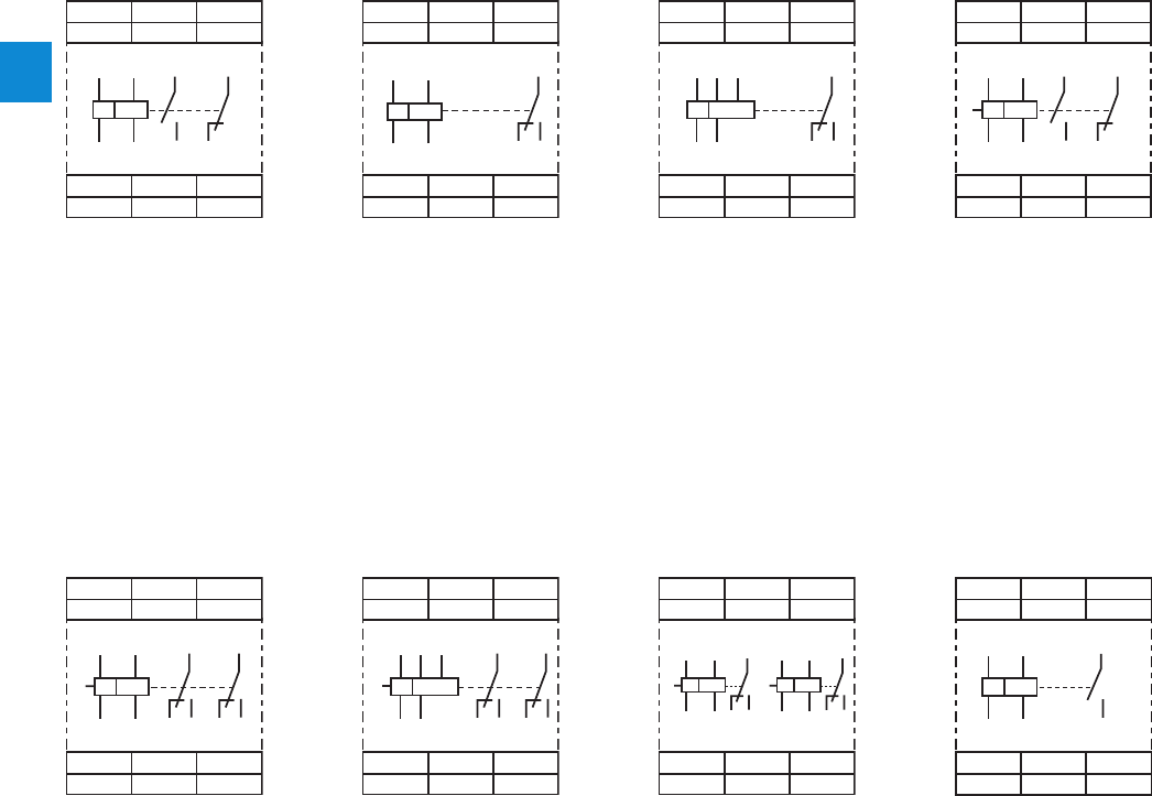
2/97 ABB | Catalog Electronic Products and Relays 2015 | 2CDC 110 004 C0210
2
Thermistor motor protection relays
Connection diagrams
A1 13 21
T2 T1
14 22 A2
ϑ
T2
T1 A1 14
13 21
22
A2
A1 11 21
T2 T1
24 22 S1
14 12 A2
ϑ
T2
S1
T1 A1
A2 12
11 21
14 22 24
A1 11
T2 T1
14 12 A2
T2
T1 A1
A2 12
11
14
ϑ
A1
A3
11 21
T2 T1
14 12
24 22 S1
A2
S1
ϑ
T2
T1 A1 A3
A2 22
21
2412
11
14
A1
A3
11
T2 T1
14 12 A2
ϑ
T2
T1 A1 A3
A2 12
11
14
A1 11 21
1T1 1T2/2T2 2T1
24 22 S1
14 12 A2
ϑ ϑ
S1 S1
A1 11
12 14
21
22 24A2
1T1 A12T1
1T2/2T2 A21T2/2T2
A1
13
T2T1
14 A2
ϑ
T2
T1 A1
14
13
A2
A1 13 21
T2S1 T1
14 22 A2
ϑ
T2
T1 A1 14
13 21
22
A2
S1
CM-MSS.11, CM-MSS.21 CM-MSS.12 CM-MSS.13 CM-MSS.31
CM-MSS.22, CM-MSS.32,
CM-MSS.41
CM-MSS.23, CM-MSS.33 CM-MSS.51 CM-MSE
A1 – A2 Control supply voltage
13 – 14 n/o contact
21 – 22 n/c contact
T1 – T2 Measuring circuit
A1 – A2 Control supply voltage
220-240 V AC
A2 – A3 Control supply voltage
110-130 V AC
11 – 12/14 c/o contact
T1 – T2 Measuring circuit
A1 – A2 Control supply voltage
13 – 14 n/o contact
21 – 22 n/c contact
S1 – T2
(jumpered)
Automatic reset
T1 – T2 Measuring circuit
A1 – A2 Control supply
voltage 24 V AC/DC
11 – 12/14 1st c/o (SPDT)
contact
21 – 22/24 2nd c/o (SPDT)
contact
S1 – T2
(jumpered) Automatic reset
T1 – T2 Measuring circuit
A1 – A2 Control
supply voltage
220-240 V AC
A2 – A3 Control supply
voltage 110-130
V AC
11 – 12/14 1st c/o (SPDT)
contact
21 – 22/24 2nd c/o (SPDT)
contact
S1 – T2
(jumpered) Automatic reset
T1 – T2 Measuring
circuit
A1 – A2 Control
supply voltage
220-240 V AC
11 – 12/14 1st c/o (SPDT)
contact
21 – 22/24 2nd c/o (SPDT)
contact
S1 – 1T2/2T2
(jumpered)
Automatic reset
1T1 – 1T2/2T2 Measuring circuit 1
2T1 – 1T2/2T2 Measuring circuit 2
A1 – A2 Control supply voltage
24 V AC
T1-T2 Sensor circuit
13-14 Output contact -
Closed circuit principle
A1 – A2 Control supply voltage
11 – 12/14 c/o contact
T1 – T2 Measuring circuit
2CDC 252 018 F00142CDC 252 019 F0014
2CDC 252 021 F0014
2CDC 252 017 F0014
1SVC 110 000 F0140
2CDC 252 022 F0014
2CDC 252 020 F0014
2CDC 252 047 F0014
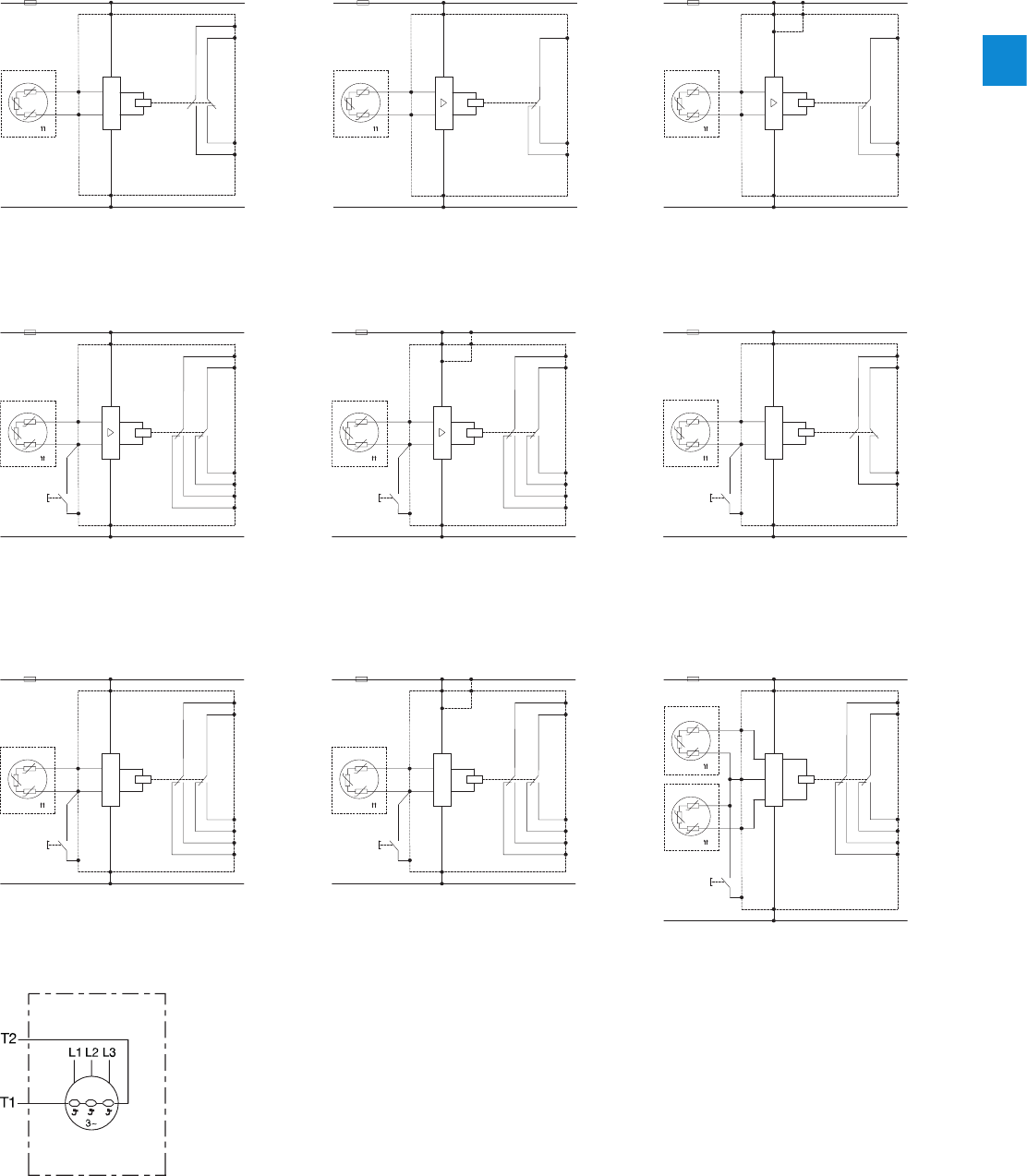
2CDC 110 004 C0210 | Catalog Electronic Products and Relays 2015 | ABB 2/98
2
Thermistor motor protection relays
Circuit diagram
M 3~
V+
T2
T1
A1
µC
V-
t
A2
21
14
22
13
M 3~
V
+
T2
T1
A1
V-
t
A2
14
11
12
M 3~
V+
T2
T1
A1 or A3
V-
t
A2
14
11
12
M 3~
V+
T2
T1
A1
µC
V-
t
A2
S1
21
14
22
Test /
Reset
13
M 3~
V+
T2
T1
A1 or A3
V-
t
A2
S1
24
11
21
22
14
12
Reset
M 3~
V+
T2
T1
A1
V-
t
A2
S1
24
11
21
22
14
12
Reset
M 3~
V+
T2
T1
A1
µC
V-
t
A2
S1
24
11
21
22
14
12
Test /
Reset
M 3~
V+
T2
T1
A1 or A3
µC
V-
t
A2
S1
24
11
21
22
14
12
Test /
Reset
M 3~
M 3~
V+
1T2/
2T2
2T1
1T1
A1
µC
V-
t
t
A2
S1
24
11
21
22
14
12
Test /
Reset
CM-MSS.11, CM-MSS.21
CM-MSS.31CM-MSS.23CM-MSS.22
CM-MSS.12 CM-MSS.13
CM-MSS.32, CM-MSS.41
CM-MSE
CM-MSS.33 CM-MSS.51
2CDC 253 023 F0014
2CDC 253 026 F00142CDC 253 015 F0014
1SVC 110 000 F0141
2CDC 253 029 F0014
2CDC 253 016 F0014
2CDC 253 027 F0014
2CDC 253 028 F0014
2CDC 253 024 F0014
2CDC 253 025 F0014
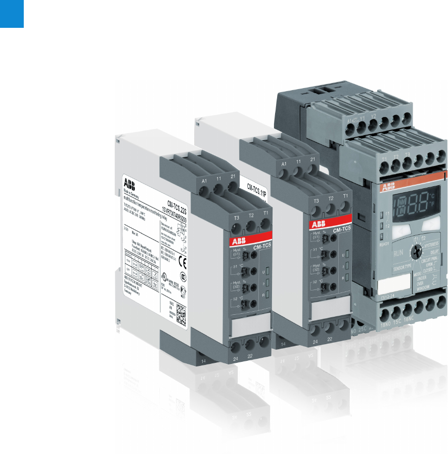
2/99 ABB | Catalog Electronic Products and Relays 2015 | 2CDC 110 004 C0210
2
Temperature monitoring relays
Product group picture

2CDC 110 004 C0210 | Catalog Electronic Products and Relays 2015 | ABB 2/100
2
Temperature monitoring relays
Table of contents
Temperature monitoring relays
Benefits and advantages, Applications 2/99
Operating controls 2/100
Selection 2/101
Ordering details 2/102
Function diagrams 2/103
Overview, Functional description and diagrams 2/104
Connection diagrams, Resistance thermometer sensors 2/105
Technical data - CM-TCS.xx 2/106
Technical data - C51x 2/108

2/101 ABB | Catalog Electronic Products and Relays 2015 | 2CDC 110 004 C0210
2
Temperature monitoring relays
Benefits and advantages, Applications
Characteristics CM-TCS
– Adjustable sensor type: PT100
– Functionality like overtemperature monitoring, under-
temperature monitoring, temperature window monitoring
configurable
– All configurations and adjustments by front-face operating
elements
– Precise adjustment with direct reading scales
– One or two threshold values
– Hysteresis 2...20 % adjustable
– Operating temperature range -40...+60 °C
– 1 x 2 c/o or 2 x 1 c/o configurable
– Open- or closed-circuit principle configurable
– Short-circuit monitoring and interrupted wire detection
– 22.5 mm (0.89 in) width
– LEDs for status indication
Characteristics C512 + C513
– Adjustable sensor types: PT100, PT1000, KTY83, KTY84,
NTC-B57227-K333-A1
– Measuring principle for 2-wire and 3-wire sensors
– Temperature monitor for 1-3 sensor circuits
– Adjustable over-, undertemperature monitoring or range
monitoring function
– 2 thresholds
– Hysteresis for both thresholds (1-99 Kelvin)
– Adjustable time delay from 0-999 s affects to both thresh-
olds
– Storage function selectable via external signal (Y1-Y2)
– Non volatile storage of parameter settings
– 1 n/o (for wire-break and short-circuit detection) and 2 c/o
– Multifunctional digital display
– 3 LEDs for status indication
– Open- or closed-circuit principle selectable
– 45 mm wide housing with 24 terminals
C513
– Temperature monitor for 1-3 sensor circuits
– In the 3-sensor version the status of the single sensors
is displayed if the temperature exceeds or falls below the
threshold. This way it can be easily determined which one
of the connected sensors has exceeded or dropped below
either one or both threshold values.
C512
– Temperature monitor for 1 sensor circuit
Functional description
The temperature monitoring relays CM-TCS monitor overtem-
perature, undertemperature, or temperatures between two
threshold values (window monitoring) with PT100 sensor. As
soon as the temperature falls below or exceeds the threshold
value the output relays change their positions according to
the configured functionality and the front-face LEDs display
the current status. Regardless of the selected configuration,
the device is monitoring its measuring circuit for interrupted
wires or short-circuits.
Overview
The temperature monitoring relays can be used for tempera-
ture measurement in solid, liquid and gaseous media. The
temperature is acquired by the sensor in the medium, evalu-
ated by the device and monitored to determine whether it is
within an operating range (range monitoring function) or has
exceeded or fallen below a threshold.
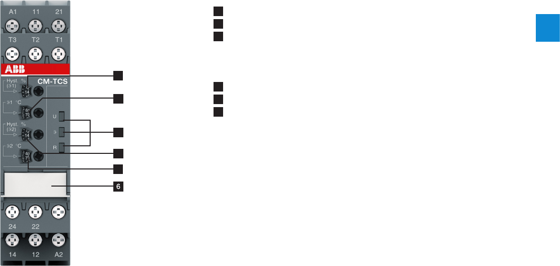
2CDC 110 004 C0210 | Catalog Electronic Products and Relays 2015 | ABB 2/102
2
Temperature monitoring relays
Operating controls
4
1
2
3
5
1 Adjustment of the hysteresis for threshold value t1
2 Adjustment of the threshold value t1
3 Indication of operational states
U: green LED – status indication of control supply voltage
t: red LED – fault message, state of measuring input
R: yellow LED – status indication of the output relays
4 Adjustment of the hysteresis for threshold value t2
5 Adjustment of the threshold value t2
6 DIP switch functions / marker label (on page 2/104)
p Overtemperature monitoring
q Undertemperature monitoring
r Temperature window monitoring activated
s Temperature window monitoring de-activated
g Closed-circuit principle
h Open-circuit principle
i 2 x 1 c/o (SPDT) contact
j 1 x 2 c/o (SPDT) contacts
2CDC 253 019 F0013
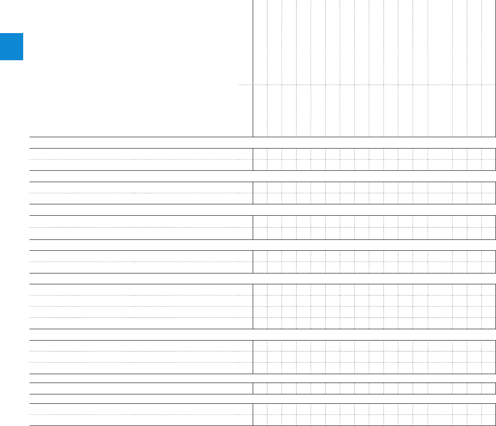
2/103 ABB | Catalog Electronic Products and Relays 2015 | 2CDC 110 004 C0210
2
Temperature monitoring relays
Selection
Order number
1SVR 730 740 R9100
1SVR 740 740 R9100
1SVR 730 740 R0100
1SVR 740 740 R0100
1SVR 730 740 R9200
1SVR 740 740 R9200
1SVR 730 740 R0200
1SVR 740 740 R0200
1SVR 730 740 R9300
1SVR 740 740 R9300
1SVR 730 740 R0300
1SVR 740 740 R0300
1SAR 700 100 R0005
1SAR 700 110 R0010
1SAR 700 110 R0010
Type
CM-TCS.21S
CM-TCS.21P
CM-TC S.11S
CM-TC S.11P
CM-TCS.22S
CM-TCS.22P
CM-TC S.12S
CM-TC S.12P
CM-TCS.23S
CM-TCS.23P
CM-TC S.13S
CM-TC S.13P
C512-24
C512-W
C513-W
Rated control supply voltage Us
24 V AC/DC J J J J J J J
24-240 V AC/DC J J J J J J J J
Technology
analogue J J J J J J J J J J J J
digital J J J
Sensor circuits (2 or 3 wire)
number of temperature sensors 1 1 1 1 1 1 1 1 1 1 1 1 1 1 3
number of thresholds 2 2 2 2 2 2 2 2 2 2 2 2 2 2 3
Sensor type
PT100 J J J J J J J J J J J J J J J
PT100, KTY83, KTY84, NTC, PT1000 J J J
Measuring temperature range
-50...+50 °C J J J J
0...+100 °C J J J J
0...+200 °C J J J J
-50...+500 °C J J J
Monitoring function
overtemperature J J J J J J J J J J J J J J J
undertemperature J J J J J J J J J J J J J J J
window temperature J J J J J J J J J J J J J J J
Operating principle
open or closed principle J J J J J J J J J J J J J J J
Output contacts
n/o
1 1 1
c/o
2 2 2 2 2 2 2 2 2 2 2 2 2 2 2
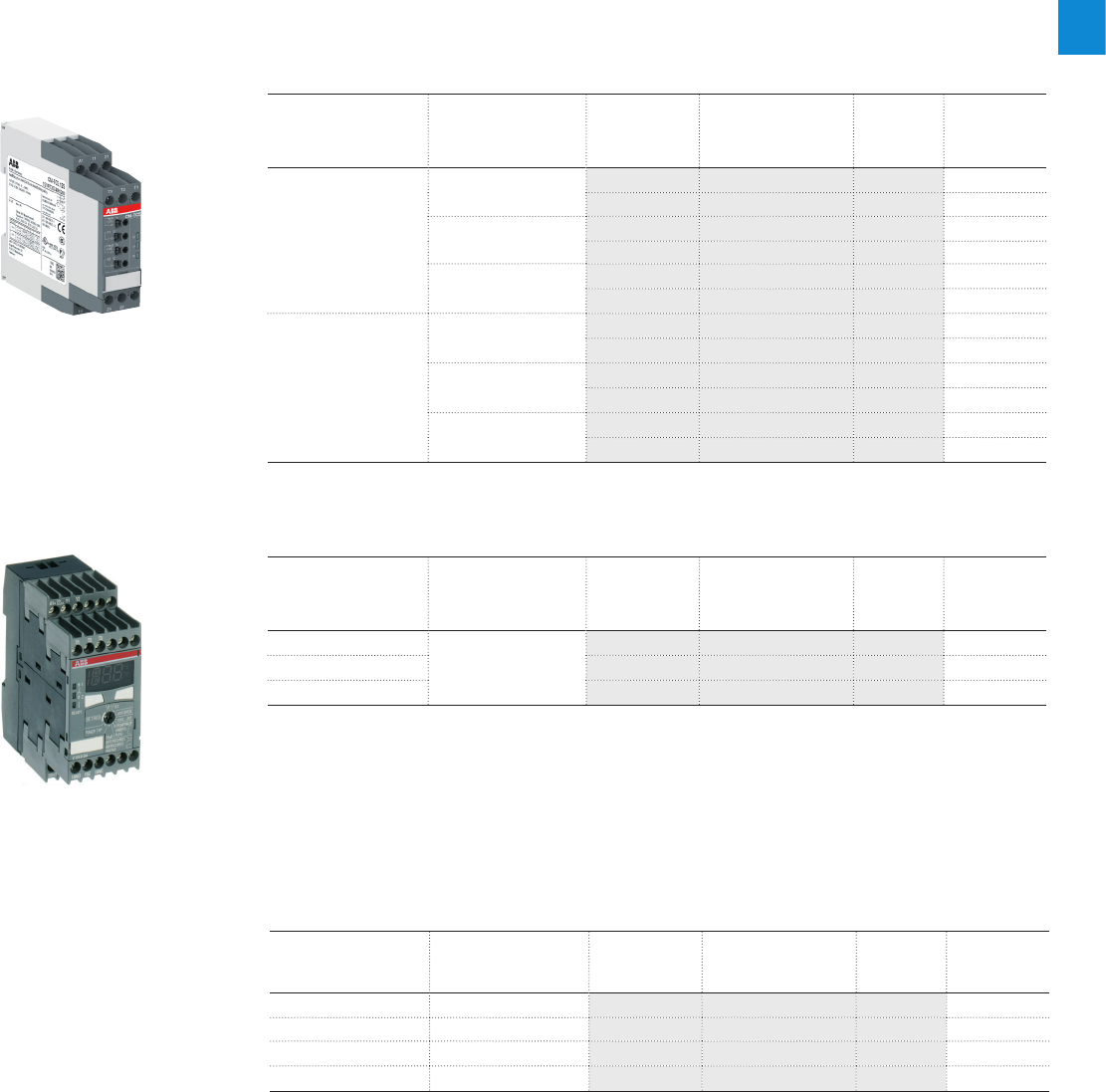
2CDC 110 004 C0210 | Catalog Electronic Products and Relays 2015 | ABB 2/104
2
Temperature monitoring relays
Ordering details
Description
Acquisition, messaging and regulation of temperatures of solid, liquid and gaseous media in
processes and machines via PT100, PT1000, KTY83, KTY84 or NTC sensors.
ABB offers different temperature monitoring relays to meet the needs of your application:
Ordering details - Temperature monitoring relays C51x range with display and digital setup
Rated control
supply voltage
Measuring
range
Type 2) Order code Price
1 pce
Weight
(1 pce)
kg (lb)
24 VAC/DC
-50...+500 °C 1)
C512-24 1SAR700100R0005 0.32 (0.71)
24-240 VAC/DC C512-W 1SAR700100R0010 0.33 (0.73)
24-240 VAC/DC C513-W 1SAR700110R0010 0.34 (0.75)
Ordering details - Replaceable cover marking for digital devices
Use for Language Type Order code Price
5 pces
Weight
(1 pce)
kg (lb)
C512 German C512-D 1SVR700101R0100
C512 English C512-E 1SVR700102R0100
C513 German C513-D 1SV R70 0111R010 0
C513 English C513-E 1SVR700112R0100
2CDC 251 031 V00121SVC 110 000 F0557
CM-TCS
C512, C513
1) The measuring range depends on the used sensor type:
PT100: -50...+500 °C
PT1000: -50...+500 °C
NTC: +80...+160 °C
(Typ Siemens Matsushita B57272-A333-A1 - 100 °C: 1.8 kW, 25 °C: 32.762 kW)
KTY84: -40...+300 °C
KTY83: -50...+175 °C
Ordering details - Temperature monitoring relays PT100 sensors, 2 or 3 wire connection,
2 thresholds adjustable
Rated control
supply voltage
Measuring
range
Type Order code Price
1 pce
Weight
(1 pce)
kg (lb)
24-240 VAC/DC
-50...+50 °C C M -TC S.11S 1SVR730740R0100 0.151 (0.333)
CM-TC S.11P 1SVR74074 0 R 010 0 0.140 (0.309)
0...+100 °C C M -TCS.12S 1SVR730740 R 0 200 0.151 (0.333)
CM-TC S.12P 1SVR740740R0200 0.140 (0.309)
0...+200 °C C M -TCS.13S 1SVR730740R0300 0.151 (0.333)
CM-TC S.13P 1SVR740740R03 0 0 0.140 (0.309)
24 VAC/DC
-50...+50 °C CM-TCS.21S 1SV R73074 0 R 910 0 0.138 (0.304)
CM-TCS.21P 1SVR74074 0 R 910 0 0.127 (0.280)
0...+100 °C CM-TCS.22S 1SVR730740R9200 0.138 (0.304)
CM-TCS.22P 1SVR740740R9200 0.127 (0.280)
0...+200 °C CM-TCS.23S 1SVR730740R9300 0.138 (0.304)
CM-TCS.23P 1SV R74 0740R9300 0.127 (0.280)
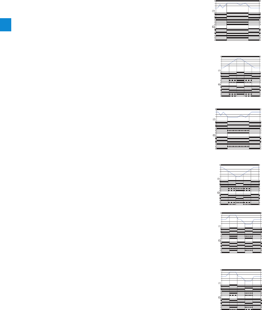
2/105 ABB | Catalog Electronic Products and Relays 2015 | 2CDC 110 004 C0210
2
Temperature monitoring relays
Function diagrams
CM-TCS - Overtemperature monitoring, 1 x 2 c/o contacts j
Undertemperature monitoring, 1 x 2 c/o contacts j
Temperature window monitoring, 1 x 2 c/o contacts j
Temperature window monitoring, 2 x 1 c/o contact i
Undertemperature monitoring, 2 x 1 c/o contact i
Overtemperature monitoring, 2 x 1 c/o contact i
A1-A2
11-14
11-12
21-24
21-22
11-14
11-12
21-24
21-22
closed
open
Threshold ϑ1
Hysteresis
Measured value
U: green LED
ϑ: red LED
R: yellow LED
U: green LED
ϑ: red LED
R: yellow LED
Open-circuit principle
Closed-cir
cuit principle
A1-A2
11-14
11-12
21-24
21-22
11-14
11-12
21-24
21-22
closed
open
Hysteresis
Measured value
U: green LED
ϑ: red LED
R: yellow LED
U: green LED
ϑ: red LED
R: yellow LED
Open-circuit principle
Closed-cir
cuit principle
Threshold ϑ2
A1-A2
11-14
11-12
21-24
21-22
11-14
11-12
21-24
21-22
closed
open
Threshold ϑ1
Hysteresis
Measured value
Threshold ϑ2
Hysteresis
Open-circuit principle
U: green LED
ϑ: red LED
R: yellow LED
Closed-cir
cuit principle
U: green LED
ϑ: red LED
R: yellow LED
A1-A2
11-14
11-12
21-24
21-22
11-14
11-12
21-24
21-22
closed
open
Threshold ϑ1
Hysteresis
Measured value
Threshold ϑ2
Hysteresis
Open-circuit principle
U: green LED
ϑ: red LED
R: yellow LED
Closed-cir
cuit principle
U: green LED
ϑ: red LED
R: yellow LED
A1-A2
11-14
11-12
21-24
21-22
11-14
11-12
21-24
21-22
closed
open
Threshold ϑ1
Hysteresis
Measured value
Hysteresis
Threshold ϑ2
Open-circuit principle
U: green LED
ϑ: red LED
R: yellow LED
Closed-cir
cuit principle
U: green LED
ϑ: red LED
R: yellow LED
A1-A2
11-14
11-12
21-24
21-22
11-14
11-12
21-24
21-22
closed
open
Threshold ϑ1
Hysteresis
Measured value
Hysteresis
Threshold ϑ2
Open-circuit principle
U: green LED
ϑ: red LED
R: yellow LED
Closed-cir
cuit principle
U: green LED
ϑ: red LED
R: yellow LED
With this configuration, settings via t2 have no influence on the operating function (t2 disabled).
Open-circuit principle:
If the measured value is correct, the output relays remain de-energized when control supply voltage is applied. If the
measured value exceeds the adjusted threshold value t1, the output relays energize. If the measured value drops
again below the adjusted threshold value t1 minus the adjusted hysteresis, the output relays de-energize.
Closed-circuit principle:
The behavior is inverse to the one with open-circuit principle.
Open-circuit principle:
If the measured value is correct, the output relays remain de-energized when control supply voltage is applied. If the
measured value exceeds the adjusted threshold value t2, output relay R2 (prewarning) energizes. If the measured
value exceeds the adjusted threshold value t1, output relay R1 (final switch-off) energizes.
If the measured value drops again below the adjusted threshold value t1 minus the adjusted hysteresis, output relay
R1 (final switch-off) de-energizes. If the measured value drops below the adjusted threshold value t2 minus the
adjusted hysteresis, output relay R2 (prewarning) de-energizes.
Closed-circuit principle:
The behavior is inverse to the one with open-circuit principle.
2CDC 252 008 F0209
2CDC 252 009 F0209
With this configuration, settings via t1 have no influence on the operating function (t1 disabled).
Open-circuit principle:
If the measured value is correct, the output relays remain de-energized when control supply voltage is applied. If
the measured value drops below the adjusted threshold value t2, the output relays energize. If the measured value
exceeds again the adjusted threshold value t2 plus the adjusted hysteresis, the output relays de-energize.
Closed-circuit principle:
The behavior is inverse to the one with open-circuit principle.
Open-circuit principle:
If the measured value is correct, the output relays remain de-energized when control supply voltage is applied. If the
measured value drops below the adjusted threshold value t1, output relay R1 (prewarning) energizes. If the measured
value drops below the adjusted threshold value t2, output relay R2 (final switch-off) energizes.
If the measured value exceeds again the adjusted threshold value t2 plus the adjusted hysteresis, output relay R2
(final switch-off) de-energizes. If the measured value exceeds the adjusted threshold value t1 plus the adjusted
hysteresis, output relay R1 (prewarning) de-energizes.
Closed-circuit principle:
The behavior is inverse to the one with open-circuit principle.
2CDC 252 010 F02092CDC 252 011 F0209
Open-circuit principle:
If the measured value is correct, the output relays remain de-energized when control supply voltage is applied. If
the measured value exceeds the adjusted threshold value t1 or drops below the adjusted threshold value t2, the
output relays energize. If the measured value drops again below the adjusted threshold value t1 minus the adjusted
hysteresis or exceeds again the adjusted threshold value t2 plus the adjusted hysteresis, the output relays de-
energize.
Closed-circuit principle:
The behavior is inverse to the one with open-circuit principle.
Open-circuit principle:
If the measured value is correct, the output relays remain de-energized when control supply voltage is applied.
If the measured value exceeds the adjusted threshold value t1 or drops below the adjusted threshold value t2, output
relay R1 (> t1) or R2 (< t2) respectively energizes.
If the measured value drops again below the adjusted threshold value t1 minus the adjusted hysteresis or exceeds
again the adjusted threshold value t2 plus the adjusted hysteresis, output relay R1 (>t1) or R2 (<t2) respectively de-
energizes.
Closed-circuit principle:
The behavior is inverse to the one with open-circuit principle.
2CDC 252 012 F0209
2CDC 252 013 F0209
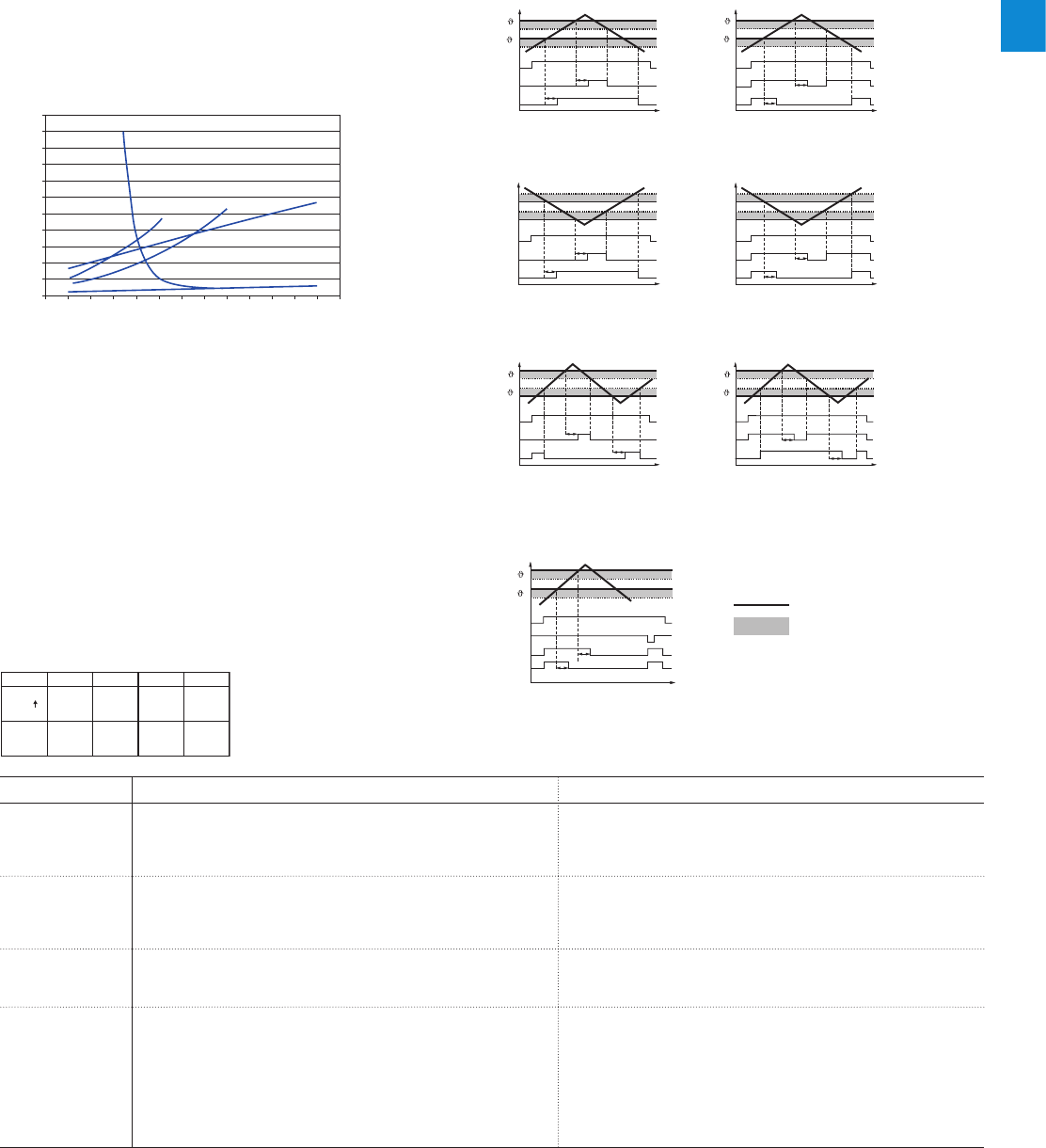
2CDC 110 004 C0210 | Catalog Electronic Products and Relays 2015 | ABB 2/106
2
DIP switches CM-TCS
Position 4 1 2 3
ON
OFF
igrp
qs
h
j
ON OFF (default)
DIP switch 1
Monitoring
principle
Overtemperature monitoring p
If overtemperature monitoring is selected, the CM-TCS recognizes
temperatures above the selected threshold and trips the output relay
according to the selected operating principle.
Undertemperature monitoring q
If undertemperature monitoring is selected, the CM-TCS recognizes
temperatures below the selected threshold and trips the output relay
according to the selected operating principle.
DIP switch 2
Temperature
window
monitoring
Temperature window monitoring activated r
If temperature window monitoring is selected, the CM-TCS monitors
over- and undertemperature. If temperature window monitoring is
activated, DIP switch 1 is disabled.
Temperature window monitoring de-activated s
Temperature window monitoring is de-selected.
DIP switch 3
Operating principle
of the output relays
Closed-circuit principle g
If closed-circuit principle is selected, the output relays are energized.
They de-energize if a fault is occuring.
Open-circuit principle h
If open-circuit principle is selected, the output relays are deenergized.
They energize if a fault is occuring.
DIP switch 4
2 x 1 c/o contact,
1 x 2 c/o contacts
2 x 1 c/o (SPDT) contact i
If operating principle 2 x 1 c/o contact is selected, the output relay R1
(11-12/14) reacts to threshold value t1 and the output relay R2 (21-
22/24) reacts to threshold value t2.
1 x 2 c/o (SPDT) contacts j
If operating principle 1 x 2 c/o contacts is selected, both output relays
R1 (11-12/14) and R2 (21-22/24) react synchronously to one threshold
value.
Overtemperature monitoring: Settings of the threshold value t2 have
no effect on the operation.
Undertemperature monitoring: Settings of the threshold values t2
have no effect on the operation.
Characteristic curves of resistance sensors
-100 0 100 200 300 400 500
5000
4000
3000
2000
1000
0
NTC
KTY83 KTY84 PT1000
PT100
Resistance in
Temperature in °C
2CDC 252 076 F0207
t
t
t
Us
K1
K2
1
2
t
tt
Us
K1
K2
1
2
t
t
t
Us
K2
K1
1
J
2
J
t
t
t
Us
K1
K2
1
2
t
t
t
Us
K1
K2
1
2
t
t
Us
-Y1 Y2
K1
t
K2
1
2
1SVC 110 000 F0191
1SVC 110 000 F0192
1SVC 110 000 F0195
1SVC 110 000 F0196
t
tt
Us
K2
K1
1
J
2
J
1SVC 110 000 F0193
1SVC 110 000 F0194
1SVC 110 000 F0197
Function principle with storage function - C512/C513
using overtemperature with closed-circuit principle as an
example
Range monitoring - C512/C513
Overtemperature - C512/C513
Undertemperature - C512/C513
Temperature monitoring relays
Overview, Functional description and diagrams
Functional description
Digital tripping devices
Once the temperature has reached the set threshold of υ1,
output relay K1 changes its switching state after the set
time delay t has elapsed (K2 reacts in the same way for υ2).
Function diagrams
Open-circuit principle
Open-circuit principle
Open-circuit principle
Closed-circuit principle
Closed-circuit principle
Closed-circuit principle
absolute limit
hysteresis
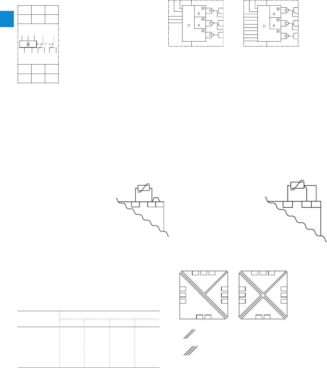
2/107 ABB | Catalog Electronic Products and Relays 2015 | 2CDC 110 004 C0210
2
2-wire measurement
When using 2-wire temperature sensors the sensor resis-
tance and the wire resistance are added together.
The resulting systematic errors must be taken into account
when adjusting the tripping device.
A jumper must be connected between
the terminals T2 and T3.
The following table can be used for
PT100 sensors to determine the
temperature errors caused by the line
length.
When using resistance sensors with
two-wire connection a bridge must be
inserted between terminals T2 and T3.
Temperature monitoring relays
Connection diagrams, Resistance thermometer sensors
A2
A1
K1 15
16
18
K2 25
28
K3 33
34
26
Y2Y1
1T1
1T2
1T3
2T1
2T2
2T3
3T1
3T2
3T3
Memory
Ready
1
2
A2
A1
T1
K1 15
16
T2
T3
18
K2 25
28
K3 33
34
26
Y2Y1
Memory
Ready
1
2
2CDC 252 025 F0010
1SVC 110 000 F0202
1SVC 110 000 F0201
CM-TCS
C512 C513
Connection diagrams
Connection of resistance thermometer sensors
A1-A2 Control supply voltage
11-12/14 Output relay R1
21-22/24 Output relay R2
T1, T2, T3 Measuring input, connection PT100
A1-A2 Rated control suppy
voltage
15-16/18 Output contacts
25-26/28
33-34
T1-T3 Sensor connection
Y1-Y2 Connection for
storage bridge
A1-A2 Rated control suppy
voltage
15-16/18 Output contacts
25-26/28
33-34
1T1-1T3 Sensor connection 1
2T1-2T3 Sensor connection 2
3T1-3T3 Sensor connection 3
Y1-Y2 Connection for
storage bridge
A 11
12
1
T3
24
T2 T1
22
14 12 A2
T1 T2 T3 11 21
A1 A2 12 14 22 24
T2
PT100
T3
T1
Temperature error
(depending on the line length and conductor cross section
for PT100 sensors at an ambient temperature of 20 °C, in K)
Error caused by the line
The error resulting from the line resistance amounts to ap-
prox. 2.5 Kelvin/Ohm. If the resistance of the line is not
known and it is not possible to measure it, the error caused
by the line can be estimated using the following table.
3-wire measurement
To minimize the influence of the wire resistance, a three-wire
connection is usually used. By means of the additional wire
two measuring circuits are created.
One of these two circuits is used
for reference. This way, the tripping
device can calculate and take into
account the wire resistance auto-
matically.
Electrical isolation
Line length in m Wire size mm2
0.50 0.75 11.5
0
10
25
50
75
100
200
500
0.0
1.8
4.5
9.0
13.6
18.1
36.3
91.6
0.0
1.2
3.0
6.0
9.0
12.1
24.2
60.8
0.0
0.9
2.3
4.5
6.8
9.0
18.1
45.5
0.0
0.6
1.5
3.0
4.5
6.0
12.1
30.2
12 1411
T1
T2
T3
21
22
24
A1 A2
24 V AC/DC
2CDC 252 019 F0010
12 1411
T1
T2
T3
21
22
24
A1 A2
24-240 V AC/DC
2CDC 252 020 F0010
Electrical isolation
Protective searation acc. to IEC/EN 61140; EN 50178
T2
PT100
T3
T1

2CDC 110 004 C0210 | Catalog Electronic Products and Relays 2015 | ABB 2/108
2
Temperature monitoring relays
Technical data - CM-TCS.xx
Type CM-TCS.11/12/13 CM-TCS.21/22/23
Input circuit
Rated control supply voltage UsA1-A2 24-240 V AC/DC 24 V AC/DC
Rated control supply voltage Us tolerance -15...+10 %
Typical current / power / consumption
24 V DC 33 mA / 0.8 VA 18 mA / 0.45 VA
115 V AC 12.5 mA / 1.5 VA n/a
230 V AC 13 mA / 2.9 VA n/a
Rated frequency AC 15-400 Hz 50/60 Hz
Frequency range AC 13.5-440 Hz 45-65 Hz
Power failure buffering time min. 20 ms
Measuring circuit T1, T2, T3
Sensor type PT100
Connection of the sensor 2-wire yes, jumper between T2-T3
3-wire yes, use terminal T1, T2, T3
Monitoring function overtemperature, undertemperature or window monitoring
Threshold values adjustable within the measuring
range CM-TCS.x1 -50…+50 °C
CM-TCS.x2 0…+10 0 °C
CM-TCS.x3 0…+200 °C
Number of possible thresholds 2
Tolerance of the adjusted threshold value typ. ±5 % of the range end value
Hysteresis related to the threshold value 2-20 % of threshold value, min. 1 °C
Measuring principle continuous current
Typical current in the sensor circuit 0.8 mA
Maximum current in sensor circuit 0.9 mA
Interrupted wire detection yes, indicated via LED status
Short-circuit detection yes, indicated via LED status
Accuracy within the rated control supply voltage tolerance < 0.2 °C / or < 0.01 %/K
Accuracy within the temperature range < 0.2 °C / or < 0.01 %/K
Repeat accuracy (constant parameters) < 0.2 % of full scale
Maximum measuring cycle 320 ms
Output circuit
Kind of output 2 x 1 or 1 x 2 c/o (SPDT) contacts configurable
Operating principle open- or closed-circuit principle configurable 1)
Contact material AgNi alloy, Cd free
Rated operational voltage (IEC/EN 60947-1) 250 V AC / 300 V DC
Minimum switching voltage / Minimum switching current 24 V / 10 mA
Maximum switching voltage / Maximum switching current see ‘Load limit curves'
Rated operating current Ie
(IEC/EN 60947-1-5) AC-12 (resistive) 230 V 4 A
AC-15 (inductive 230 V 3 A
DC-12 (resistive) 24 V 4 A
DC-13 (inductive) 24 V 2 A
AC Rating (UL508) utilization category B 300, pilot duty general purpose (250 V, 4 A, cos ϕ 0.75)
maximum rated operational voltage 250 V AC
maximum continuous thermal current at B 300 4 A
maximum making/breaking apparent power at
B 300 3600/360 VA
Mechanical lifetime 30 x 106 switching cycles
Electrical lifetime (AC-12, 230 V, 4 A) 0.1 x 10⁶ switching cycles
Maximum fuse rating to achieve short-circuit
protection n/c contact 6 A fast-acting
n/o contact 10 A fast-acting
Conventional thermal current Ith acc. IEC/EN 60947-1 4 A
General data
Dimensions (W x H x D) 22.5 x 85.6 x 103.7 mm (0.89 x 3.37 x 4.08 in)
Mounting position any
Screw connection technology Easy Connect Technology (push-in)
Weight net weight CM-TCS.1x 0.151 kg (0.333 lb) 0.140 kg (0.309 lb)
CM-TCS.2x 0.138 kg (0.304 lb) 0.127 kg (0.280 lb)
gross weight CM-TCS.1x 0.176 kg (0.388 lb) 0.165 kg (0.364 lb)
CM-TCS.2x 0.163 kg (0.360 lb) 0.152 kg (0.335 lb)
Degree of protection enclosure /
terminals IP50 / IP20
Ambient temperature range operation -40...+60 °C
storage/transport -40...+85 °C
Mounting DIN rail (IEC/EN 60715), snap-on mounting without any tool
1) Closed-circuit principle: Output relay(s) de-energize(s) if measured value exceeds or falls below the adjusted threshold value

2/109 ABB | Catalog Electronic Products and Relays 2015 | 2CDC 110 004 C0210
2
Temperature monitoring relays
Technical data - CM-TCS.xx
Type CM-TCS.11/12/13 CM-TCS.21/22/23
Electrical connection
Wire size Screw connection technology Easy Connect Technology (Push-in)
fine-strand without
wire end ferrule A1, A2, 11, 12, 14, 21,
22, 24 1 x 0.5-2.5 mm² (1 x 20-14 AWG)
2 x 0.5-1.5 mm² (2 x 20-16 AWG) 2 x 0.5-1.5 mm² (2 x 20-16 AWG)
connection with lever
T1, T2, T3 1 x 0.2-2.5 mm² (1 x 24-14 AWG)
2 x 0.2-1.5 mm² (2 x 24-16 AWG) 2 x 0.2-1.5 mm² (2 x 24-16 AWG)
connection with lever
fine-strand with
wire end ferrule A1, A2, 11, 12, 14, 21,
22, 24 1 x 0.5-2.5 mm² (1 x 20-14 AWG)
2 x 0.5-1.5 mm² (2 x 20-16 AWG) 2 x 0.5-1.5 mm² (2 x 20-16 AWG)
connection: push-in
T1, T2, T3 1 x 0.2-2.5 mm² (1 x 24-14 AWG)
2 x 0.2-1.5 mm² (2 x 24-16 AWG) 2 x 0.2-1.5 mm² (2 x 24-16 AWG)
insulated ferrule (DIN 46228-4-E):
connection: push-in
ferrule (DIN 46228-1-A):
< 0.5 mm², connection with lever
0.5 mm², connection: push-in
rigid A1, A2, 11, 12, 14, 21,
22, 24 1 x 0.5-4 mm² (1 x 20-12 AWG)
2 x 0.5-2.5 mm² (2 x 20-14 AWG) 2 x 0.5-1.5 mm² (2 x 20-16 AWG)
connection: push-in
T1, T2, T3 1 x 0.2-4 mm² (1 x 24-12 AWG)
2 x 0.2-2.5 mm² (2 x 24-14 AWG) 2 x 0.2-1.5 mm² (2 x 24-16 AWG)
< 0.5 mm², connection with lever
0.5 mm², connection: push-in
Stripping length 8 mm (0.32 in)
Tightening torque < 0.5 mm² 0.5 Nm (4.43 lb.in) -
0.5 mm² 0.6 - 0.8 Nm (5.31 - 7.08 lb.in) -
Standards
Product standard IEC/EN 60255-1, IEC/EN 60255-27, EN 50178
Low Voltage Directive 2006/95/EC
EMC Directive 2004/108/EC
RoHS Directive 2011/65/EC
Environmental data
Ambient temperature ranges
operation/storage/ transport
-40...+60°C/-40...+85°C/-40...+85°C
Climatic category 3K5 (no condensation, no ice formation)
Damp heat, cyclic 6 x 24 h cycle, 55 °C, 95 % RH
Vibration, sinusoidal Class 2
Shock Class 2
Isolation data
Rated impulse withstand voltage
Uimp between all isolated circuits
(IEC/EN 60947-1, IEC/EN 60664-1)
supply circuit / measuring circuit
4 kV -
supply circuit / output circuits
4 kV
measuring circuit / output circuits
4 kV
output circuit 1 / output circuit 2
4 kV
Pollution degree (IEC/EN 60664-1) 3
Overvoltage category (IEC/EN 60664-1) III
Rated insulation voltage Ui
(IEC/EN 60947-1, IEC/EN 60664-1)
supply circuit / measuring circuit
300 V -
supply circuit / output circuits
300 V
measuring circuit / output circuits
300 V
output circuit 1 / output circuit 2
300 V
Basis isolation for rated control supply
voltage
(IEC/EN 60664-1)
supply circuit / measuring circuit
250 V AC / 300 V DC -
supply circuit / output circuits
250 V AC / 300 V DC
measuring circuit / output circuits
250 V AC / 300 V DC
output circuit 1 / output circuit 2
250 V AC / 300 V DC
Protective separation (IEC/EN 61140,
EN 50178)
supply circuit / measuring circuit
250 V AC / 250 V DC -
supply circuit / output circuits
250 V AC / 300 V DC 250 V AC / 250 V DC
measuring circuit / output circuits
250 V AC / 300 V DC 250 V AC / 250 V DC
Test voltage between all isolated
circuits, routine test (IEC/EN 60255-5,
IEC/EN 61010-1)
supply circuit / measuring circuit
2.0 kV, 50 Hz, 1 s -
supply circuit / output circuits
2.0 kV, 50 Hz, 1 s
measuring circuit / output circuits
2.0 kV, 50 Hz, 1 s
Test voltage between all isolated circuits,
type test
(IEC/EN 60255-5)
supply circuit / measuring circuit
4.0 kV, 50 Hz, 1 s -
supply circuit / output circuits
4.0 kV, 50 Hz, 1 s
measuring circuit / output circuits
4.0 kV, 50 Hz, 1 s
Electromagnetic compatibility
Interference immunity to IEC/EN 61000-6-1, IEC/EN 61000-6-2, IEC/EN 61326-2-4
electrostatic discharge IEC/EN 61000-4-2 Level 3, 6 kV / 8 kV
radiated, radio-frequency, electromagnetic
field
IEC/EN 61000-4-3 Level 3, 10 V/m (1 GHz) / 3 V/m (2 GHz) / 1 V/m (2.7 GHz)
electrical fast transient/burst IEC/EN 61000-4-4 Level 3, 2 KV / 5 kHz
surge IEC/EN 61000-4-5 Level 3, installation class 3, supply circuit and measuring circuit 1 kV L-L, 2
kV L-earth
conducted disturbances, induced by
radio-frequency fields IEC/EN 61000-4-6 Level 3, 10 V
voltage dips, short interruptions and
voltage variations IEC/EN 61000-4-11 Class 3
harmonics and interharmonics IEC/EN 61000-4-13 Class 3
Interference emission EN 61000-6-3, EN 61000-6-4
high-frequency radiated IEC/CISPR 22, EN 55022 Class B
high-frequency conducted IEC/CISPR 22, EN 55022 Class B

2CDC 110 004 C0210 | Catalog Electronic Products and Relays 2015 | ABB 2/110
2
Temperature monitoring relays
Technical data - C51x
Type C512 C513
Input circuit
Rated control supply voltage UsA1-A2 24 V AC/DC -
A1-A2 24-240 V AC/DC
Power consumption
AC < 7 VA
DC < 4 W
Rated control supply voltage US tolerance -15...+10 %
Rated frequency AC
Sensor circuit
Sensor type PT100, PT1000, KTY83, KTY84, NTC
Sensor current PT100 typ. 1 mA
PT1000, KTY83, KTY84, NTC typ. 0.2 mA
Wire-break detection yes (not for NTC)
Short-circuit detection yes
3-wire connection yes (2-wire connection of sensors with terminals T2 and T3 bridged)
Measuring circuit
Setting accuracy at Ta = 20 °C (T20)< ±2 K ± 1 digit
Accuracy within the temperature range 0.05 °C / °C deviation from T20
Response time 500 ms
Hysteresis settings temperature 1 1-99 kelvin
temperature 2 1-99 kelvin
Tripping delay 0-999 s
Output circuit
Kind of output 2 c/o + 1n/o 2 c/o + 1 n/o
Rated operating current Ie
(IEC/EN 60947-1-5)
AC-12 (resistive) 230 V n/a
AC-15 (inductive) 230 V 3 A
DC-12 (resistive) 24 V 1 A
DC-13 (inductive) 24 V 0.1 A
Mechanical lifetime 30 x 106 switching cycles
Electrical lifetime (AC-15 at 3 A) 0.1 x 10⁵ switching cycles
Max. fuse rating to achieve short-circuit protection 4 A, operating class gL/gG
General data
Dimensions (W x H x D) 45 x 105.9 x 86 mm (1.77 x 4.17 x 3.39 in)
Tightening torque 0.8-1.2 Nm
Mounting position any
Degree of protection enclosure / terminals IP 40 / IP 20
Ambient temperature range operation -25...+60 °C
storage -40...+80 °C
Mounting DIN rail (IEC/EN 60715)
Electrical connection
Wire size rigid 1 x 4 mm² (1 x 12 AWG), 2 x 2.5 mm² (2 x 14 AWG)
fine-strand with wire end ferrule
1 x 2.5 mm² (1 x 14 AWG), 2 x 1.5 mm² (2 x 16 AWG)
Standards
Environmental conditions IEC 60721-3-3
Low Voltage Directive IEC 60947-5-1, VDE 0660
Electromagnetic compatibility Interference immunity EN 61000-6-2
Interferenece emission EN 61000-6-4
Vibration resistance (IEC 68-2-6) 5-26 Hz / 0.75 mm
Shock resistance (IEC 68-2-27) 15 g / 11 ms
Isolation data
Rated insulation voltage 300 V AC
Pollution degree 3
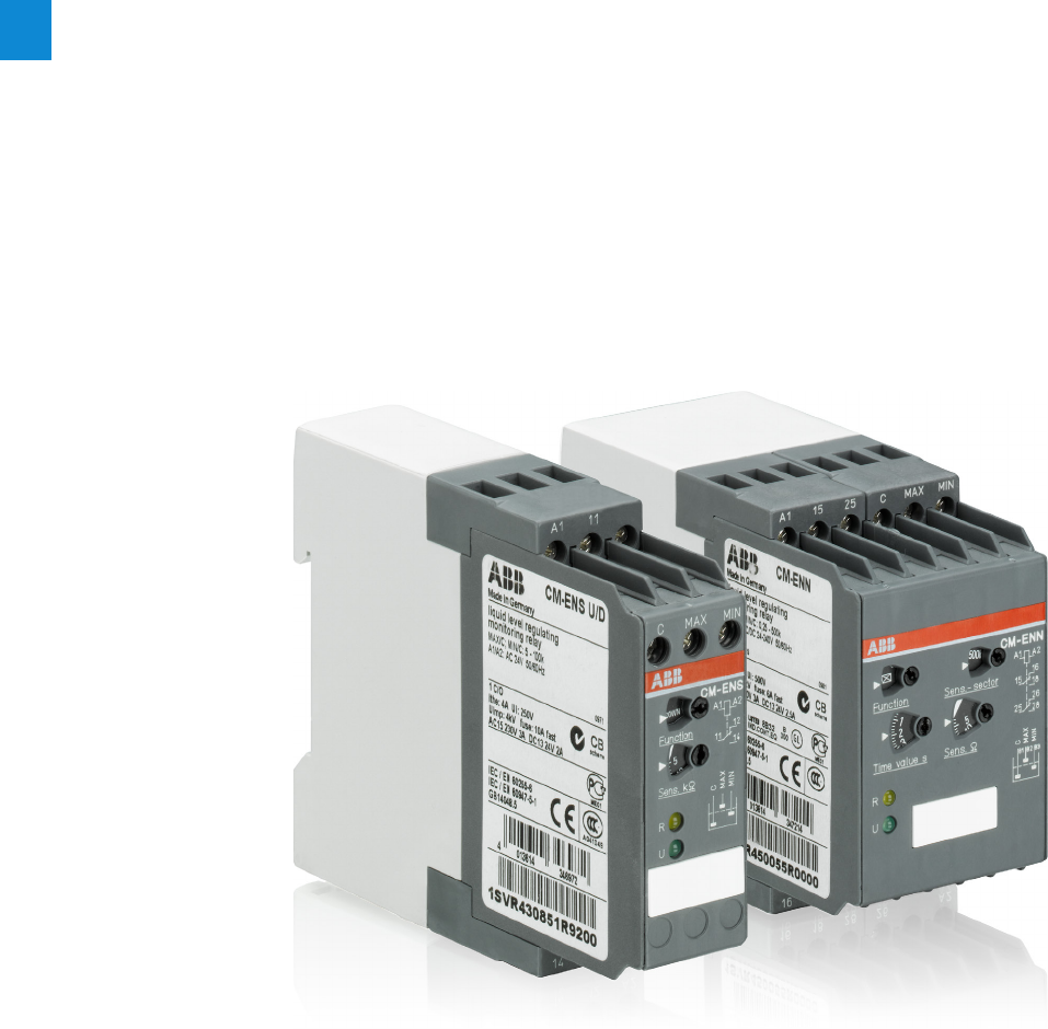
2/111 ABB | Catalog Electronic Products and Relays 2015 | 2CDC 110 004 C0210
2
Liquid level monitors and controls
Product group picture

2CDC 110 004 C0210 | Catalog Electronic Products and Relays 2015 | ABB 2/112
2
Liquid level monitors and controls
Table of contents
Liquid level monitors and controls
Benefits and advantages 2/111
Operating controls 2/112
Ordering details 2/113
Ordering details - Accessories 2/114
Function diagrams 2/115
Connection diagrams 2/117
Application examples 2/118
Technical data 2/120

2/113 ABB | Catalog Electronic Products and Relays 2015 | 2CDC 110 004 C0210
2
Liquid level monitors and controls
Benefits and advantages
– Monitoring of pump systems for dry running (ENE MIN) and overflow (ENE MAX)
– Connection of 2 electrodes possible at C and MIN/MAX
– 3 supply voltage versions
– Optimal price/performance ratio
– 1 n/o contact: Open-circuit principle for CM-ENE MIN, Closed-circuit principle for CM-ENE MAX
– LED for status indication
– Monitoring and control of liquid levels (when draining or filling liquids in tanks)
– Monitoring and control of mixture ratios (conductivity of liquids)
– Adjustable response sensitivity 5-100 kq
– 4 supply voltage versions 24-240 V AC
– Version with protective separation acc. to VDE 0160 J
– Cascadable
– 1 c/o contact or 1 n/o and 1 n/c contact
– 2 LEDs for status indication
– Monitoring and control of liquid levels
– Selectable function "fill" or "drain"
– Adjustable response sensitivity 5-100 kq
– Cascadable
– 1 c/o contact
– 2 LEDs for status indication
– Monitoring and control of liquid levels (when emptying or filling liquids in tanks)
– Monitoring and control of mixture ratios (conductivity of liquids)
– 3 response sensitivities from 250 q - 500 kq in one unit
– 5 supply voltage versions 24 V AC/DC - 415 V AC
– Selectable ON- or OFF-delay 0.1-10 s
– 2 c/o contacts
– 2 LEDs for status indication
CM-ENE MIN/MAX
CM-ENN
CM-ENS
CM-ENS UP/DOWN
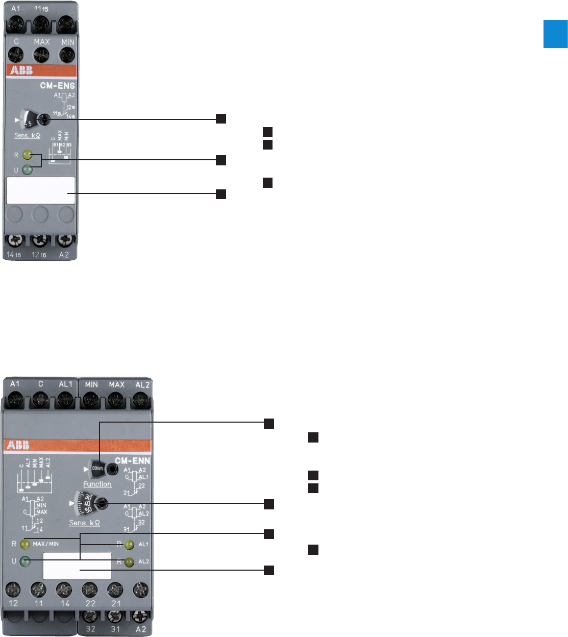
2CDC 110 004 C0210 | Catalog Electronic Products and Relays 2015 | ABB 2/114
2
Liquid level monitors and controls
Operating controls
4
1
1
2
2
3
3
CM-ENS
CM-ENN
1 „Sens.“ - sensitivity potentiometer for adjusting the response sensitivity
2 Indication of operational states
R: yellow LED - relay status
U: green LED -control supply voltage
3 Marker label
1 „Function.“ - function selector switch:
„UP“- fill
„DOWN“ - drain
2 „Sens.“ - potentiometer for adjusting the response sensitivity
3 Indication of operational states
R: MIN/MAX: yellow LED - relay status MIN/MAX
U: green LED - control supply voltage
R AL1: yellow LED - relay status AL1
R AL2: yellow LED - relay status AL2
4 Marker label
2CDC 253 026 F00132CDC 253 012 F0013
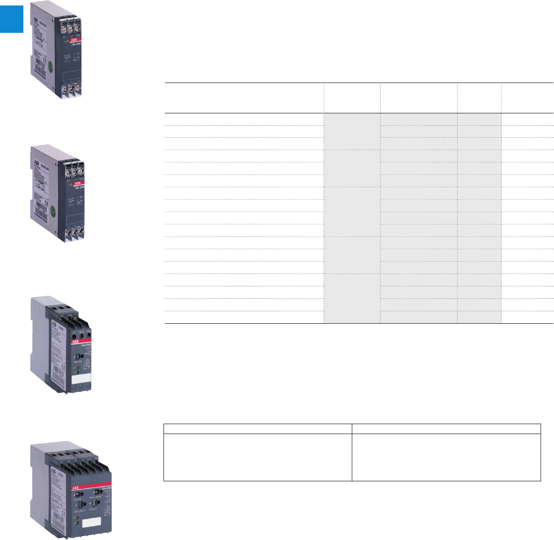
2/115 ABB | Catalog Electronic Products and Relays 2015 | 2CDC 110 004 C0210
2
Liquid level monitors and controls
Ordering details
Description
ABB‘s liquid level monitoring relays for regulation and control of liquid levels and ratios of mix-
tures of conductive fluids.
The assortment includes single function and multifunction monitoring relays which can be
used for overflow and dry-running protection, for filling and draining applications, for max and
min alarm or any combination of such functions. Furthermore a wide range of accessories is
available
Ordering details
Rated control supply voltage Type Order code Price
1 pce
Weight
(1 pce)
kg (lb)
24 VAC
CM-ENE MIN
1SVR550855R9500 0.15 (0.33)
110-130 VAC 1SVR550850R9500 0.15 (0.33)
220-240 VAC 1SVR550851R9500 0.15 (0.33)
24 VAC
CM-ENE MAX
1SVR550855R9400 0.15 (0.33)
110-130 VAC 1SVR550850R9400 0.15 (0.33)
220-240 VAC 1SVR550851R9400 0.15 (0.33)
24 VAC
CM-ENS
1SVR430851R9100 0.15 (0.33)
110-130 VAC 1SVR430851R0100 0.15 (0.33)
220-240 VAC 1SVR430851R1100 0.15 (0.33)
220-240 VAC 1) 1SVR430851R1300 0.15 (0.33)
24 VAC
CM-ENS
UP/DOWN
1SVR430851R9200 0.15 (0.33)
110-130 VAC 1SVR430851R0200 0.15 (0.33)
220-240 VAC 1SVR430851R1200 0.15 (0.33)
24-240 VAC/DC
CM-ENN
1SVR450055R0000 0.30 (0.66)
24 VAC 1SVR450059R0000 0.30 (0.66)
110-130 VAC 1SVR450050R0000 0.30 (0.66)
220-240 VAC 1SVR450051R0000 0.30 (0.66)
1SVR 550 851 F9500
1SVR550 851 F9400
1SVR 430 851 F1100
1SVR 450 055 F0000
CM-ENE MIN
CM-ENE MAX
CM-ENS
CM-ENN
1) Version with protective separation acc. to VDE 0160, 1 n/o, 1 n/c
Suitable for Not suitable for
spring water acids, bases chemically pure water ethylene glycol
drinking water liquid fertilizers fuel concentrated alcohol
sea water milk, beer, coffee oils paraffin
sewage non-concentrated
alcohol explosive areas (liquid
gas) lacquers
Liquid level monitors are
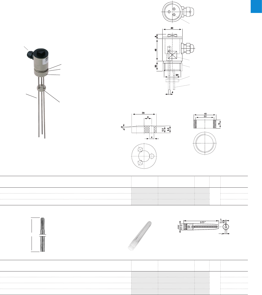
2CDC 110 004 C0210 | Catalog Electronic Products and Relays 2015 | ABB 2/116
2
Liquid level monitors and controls
Ordering details - Accessories
127
6.8
0.268
1SVC 110 000 F0478
1SVR 450 056 F6000
Compact support CM-KH-3 for 3 bar electrodes
Suspension electrode CM-HE
– Ideally suited for use with liquid level relays CM-ENS and CM-ENN
– Wire connection by screw terminals
– Pull relief by M16 screwed cable glands
– Temperature range up to 90 °C
– Food safe material (PPH)
– Screw-in electrodes (M4 thread)
– Distance plate (CM-AH-3) and locking nut (CM-GM-1) optionally
available as an accessory
Technical data compact support
Screw-in bar electrodes for compact support CM-KH-3
Description Type Order code Price Pkg
qty
Weight (1 pce)
kg (lb)
Compact support for 3 bar electrodes CM-KH-3 1SVR450056R6000
1
0.06 (0.132)
Distance plate for 3 bar electrodes CM-AH-3 1SVR450056R7000 0.06 (0.132)
Counter nut for 1“ thread CM-GM-1 1SVR450056R8000 0.06 (0.132)
Lenght Type Order code Price Pkg
qty
Weight (1 pce)
kg (lb)
300 mm CM-SE-300 1SVR450056R0000
1
0.08 (0.176)
600 mm CM-SE-600 1SVR450056R0100 0.08 (0.176)
1000 mm CM-SE-1000 1SVR450056R0200 0.08 (0.176)
CM-HE CM-HE 1SVR402902R0000 0.08 (0.176)
1SVC 110 000 F 0477
spanner size 36
electrodes
distance plate CM-AH-3
counter nut CM-GM-1
M4 thread
1SVC 110 000 F 0476
1SVC 110 000 F 0475
1" thread
sealing ring
1" counter nut CM-GM-1 (order code: 1SVR 450 056 R8000)
(optional)
distance plate CM-AH-3 (order code: 1SVR 4 450 056 R7000)
(optional)
M16 screwed cable gland
screw-in bar electrodes with M4 thread
(available as an option, see below)
Type of mounting: G 1" thread
Mounting position: any
Enclosure material: PPH
Sealing: NBR 70
Temperature range: 90 °C max.
Pressure: 10 bar max. (60 °C)
1SVC 110 000 F 0479
Steel electrode (X14CrMoS17) with
sleeve (Hostalen GC 7260) suitable up
to 60°C max.
Thread M4
Material: stainless steel 304, high-grade
steel 14301
During project engineering the compatibility of the electrode material with the medium to be supervised is to be examined!
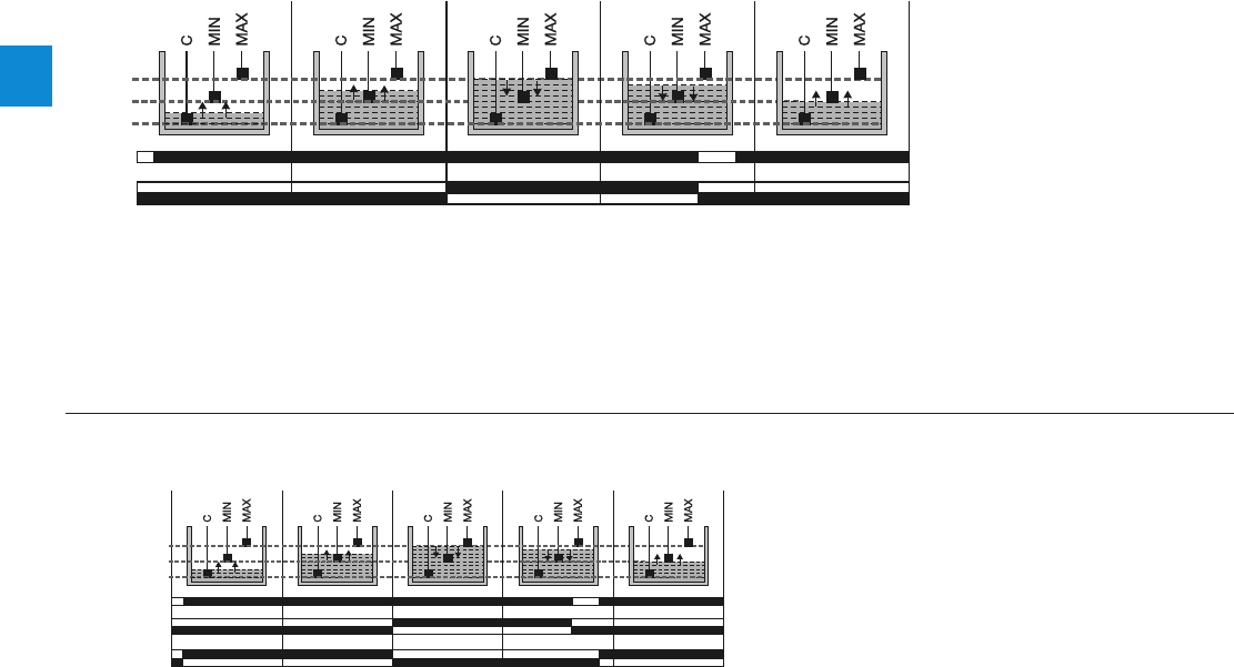
2/117 ABB | Catalog Electronic Products and Relays 2015 | 2CDC 110 004 C0210
2
Liquid level monitors and controls
Function diagrams
Function diagram - CM-ENS UP/DOWN
The CM-ENS monitors levels of conductive liquids and is used for example for liquid level control in pump systems. It can be used for filling or draining tanks for
example. It is also suitable for monitoring the conductivity of liquids. The measuring principle is based on the resistance change sensed by single-pole electrodes.
After the supply voltage is applied to the terminals A1 and A2, the output relay is de-energized. The probes must be connected to C, MAX, MIN. The output relay
energizes if the liquid exceeds the maximum level (C and MAX wet) and de-energizes if the liquid level is below the minimum level (MAX and MIN dry). Basedau m
on the measuring circuit there will be a response delay of approx. 250 ms at maximum sensitivity. Different levels in one tank can be controlled by up to 5 CM-ENS
without interfering with each other.
Function diagram - CM-ENS
The CM-ENS UP/DOWN monitors levels of conductive liquids and other media, and is used e.g. for liquid level control in pump systems.
The measuring principle is based on the resistance change sensed by single-pole electrodes. The output relay functions fill (UP) or drain (DOWN) can be selected
on a front-face selector switch. If the "UP" function is selected, the output relay is energized until the MAX electrode becomes wet. Then it is de-energized and
not re-energized until the MIN electrode becomes dry. If the "DOWN" function is selected, the output relay is energized as soon as the MAX electrode becomes
wet. It remains energized until the liquid level has dropped below the MIN electrode. The electrodes can be connected to more than one CM-ENS unit without
interference.
1SVC 110 000 F 0155
Max.
Min.
C
11-14
11-12
A1-A2
1SVC 110 000 F 0164
"DOWN"
"UP"
11-14
11-12
Max.
Min.
C
11-14
11-12
A1-A2
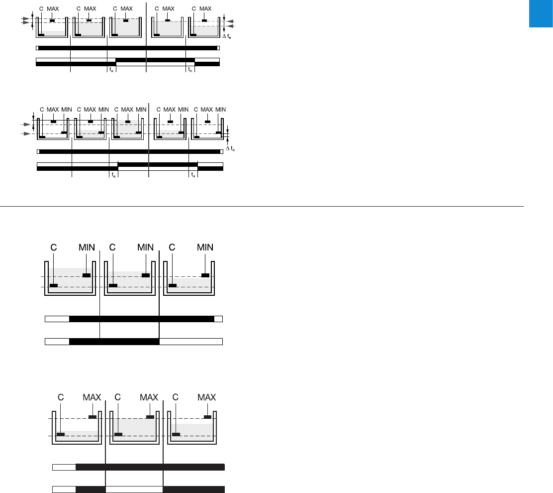
2CDC 110 004 C0210 | Catalog Electronic Products and Relays 2015 | ABB 2/118
2
Liquid level monitors and controls
Function diagrams
Function diagram - CM-ENE MIN
A1-A2
13-14
MIN
C
Function diagram CM-ENE MAX
A1-A2
13-14
MIN
C
Circuit with 2 electrodes
Circuit with 3 electrodes
Function diagrams - CM-ENN
The liquid level relays CM-ENE MIN and CM-ENE MAX are used to monitor
levels of conductive liquids, for example in pump control systems for dry-
running or overflow monitoring.
The measuring principle is based on the occurring resistance change when
moisting single-pole electrodes. The single-pole electrodes (see also section
Accessories) are connected to the terminals C and MIN or MAX.
If the supply voltage is applied to A1-A2 and the electrodes are wet, the output
relay of the CM-ENE MIN is energized and the output relay of the CM-ENE MAX
is de-energized.
The output relay of the CM-ENE MIN de-energizes if the electrodes are no
longer wet. The output relay of the CM-ENE MAX energizes if the electrodes are
no longer wet.
The CM-ENN monitors levels of conductive liquids and is used for example
for liquid level monitoring in pump control systems, for dry-running protection
of submersible pumps or overflow monitoring of tanks. It is also suitable for
conductivity monitoring of liquids. The measuring principle is based on the
resistance change sensed by single-pole electrodes (wet or dry).
Instead of electrodes, other sensors or transducers can also be used if their
output quantities are different resistance values. The measuring, output and
supply circuits are electrically isolated for potential separation and to prevent
electrical interference.
Due to the integrated ON- or OFF-delay, it is possible to set up time-dependent
liquid controls using only two electrodes (C, MAX). Different liquid levels in
one tank can be controlled by up to 5 CM-ENN (AC version) without mutual
interference.
1SVC 110 000 F 01671SVC 110 000 F 0168
MAX
MIN
C
tA = ON-delay, tR = OFF-delay
15/18
15/16
A1-A2
MAX
MIN
C
15/18
15/16
A1-A2
1SVC 110 000 F 01511SVC 110 000 F 0152
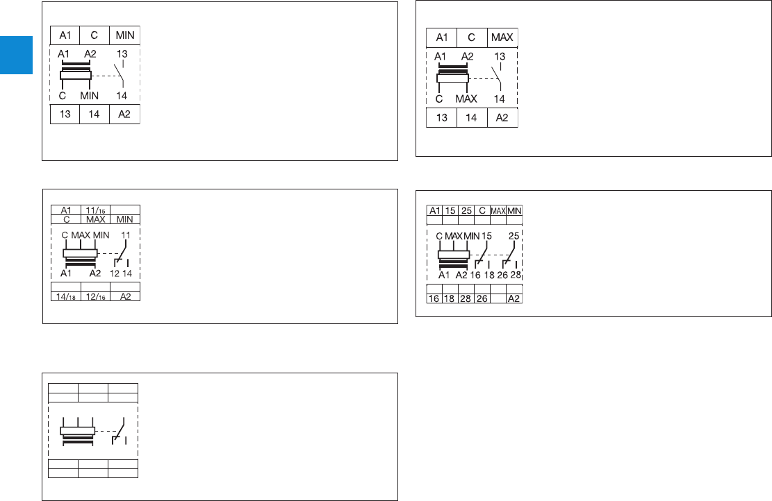
2/119 ABB | Catalog Electronic Products and Relays 2015 | 2CDC 110 004 C0210
2
Liquid level monitors and controls
Connection diagrams
Connection diagram CM-ENS
1214 A2
C
A1
MAX
11
MIN
MIN 11MAXC
A2A1 12 14
Connection diagram CM-ENS UP/DOWN
Connection diagram CM-ENN
Connection diagram CM-ENE MIN Connection diagram CM-ENE MAX
1SVC 110 000 F 0158
2CDC 252 042 F0003
1SVC 110 000 F 0169
1SVC 110 000 F 0153
1SVC 110 000 F 0154
A1-A2 Rated control supply voltage
CGround reference electrode
MIN Minimum level
13-14 Output contact -open-circuit
principle
A1-A2 Rated control supply voltage
CGround reference electrode
MAX Maximum level
MIN Minimum level
1115-1216/1418 Output contact -open-circuit
principle
A1-A2 Rated control supply voltage
CGround reference electrode
MAX Maximum level
MIN Minimum level
11-12 /14 Output contacts - open-
circuit or closed-circuit
principle selectable
A1-A2 Rated control supply voltage
CGround reference electrode
MAX Maximum level electrode
MIN Minimum level electrode
1115-1216/1418 Output contact -open-circuit
principle
A1-A2 Rated control supply voltage
CGround reference electrode
MIN Maximum level
13-14 Output contact -open-circuit
principle
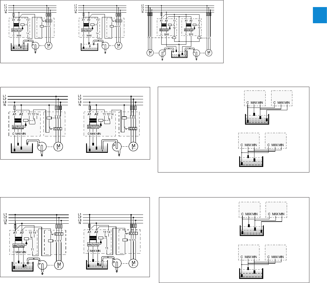
2CDC 110 004 C0210 | Catalog Electronic Products and Relays 2015 | ABB 2/120
2
Application examples CM-ENE MIN/MAX
CM-ENE MIN CM-ENE MAX CM-ENE MIN und CM-ENE MAX
Liquid level monitors and controls
Application examples
Cascading
The electrode inputs can be
interconnected as required, which
ensures simple monitoring of
different liquid levels.
Redundancy
Redundant liquid level monitoring
or control can be implemented by
connecting the electrodes to two
units.
Application examples CM-ENS
fill drain
Liquid level control - fill - switch
position "UP"
Liquid level control - drain -
switch position "DOWN"
Application examples CM-ENS UP/DOWN
Cascading of electrodes
The electrode inputs can be
interconnected as required, which
ensures simple monitoring of
different liquid levels.
Redundancy
Redundant liquid level monitoring
or control can be implemented by
connecting the electrodes to two
units.
1SVC 110 000 F 0494
1SVC 110 000 F 0495
1SVC 110 000 F 0496
1SVC 110 000 F 01591SVC 110 000 F 0160
1SVC 110 000 F 0156
1SVC 110 000 F 0157
1SVC 110 000 F 0159
1SVC 110 000 F 0160
1SVC 110 000 F 0161
1SVC 110 000 F 0162
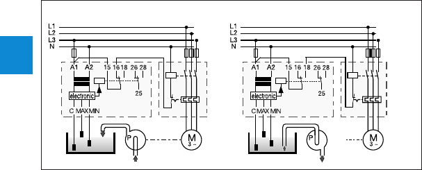
2/121 ABB | Catalog Electronic Products and Relays 2015 | 2CDC 110 004 C0210
2
Liquid level monitors and controls
Application examples
fill drain
Application examples CM-ENN
For commissioning, set both potentiometers (response sensitivity = R value and ON-delay = time value) to the minimum value
(5) and select a suitable resistance range (sector). After all electrodes have been wetted by the liquid being monitored, turn the
sensitivity potentiometer towards maximum value (100) until the relay energizes. If the relay does not energize, select a higher
q value (sector) on the device and proceed as before. Then it has to be checked if the relay de-energizes properly as soon as
the electrodes C and MIN are no longer wet. Liquid levels higher than the maximum level electrode can be obtained by setting
an ON-delay (TA = 0.1...10 s).
Liquid levels lower than the minimum level electrode can be obtained by setting an OFF-delay time (TR = 0.1...10 s), e.g. for
emptying tanks.
1SVC 110 000 F 0165
1SVC 110 000 F 0166

2CDC 110 004 C0210 | Catalog Electronic Products and Relays 2015 | ABB 2/122
2
Liquid level monitors and controls
Technical data
Type CM-ENE MIN CM-ENE MAX
Supply circuit
Rated control supply voltage US -
power consumption A1-A2 24 V AC approx. 1.5 VA
A1-A2 110-130 V AC approx. 1.2 VA
A1-A2 220-240 V AC approx. 1.4 VA
Rated control supply voltage US tolerance -15...+15 %
Rated frequency 50-60 Hz
Duty time 100 %
Measuring circuit MIN-C, MAX-C
Monitoring function dry-running protection overflow protection
Response sensitivity 0-100 kq, not adjustable
Maximum electrode voltage 30 V AC
Maximum electrode current 1.5 mA
Electrode supply line max. cable capacity 3 nF
max. cable length 30 m
Timing circuit
Time delay -
Tripping delay fixed approx. 200 ms
Indication of operational states
Output relay energized R: yellow LED
Output circuits 13-14
Kind of output 1 n/o contact
Operational principle 1) open-circuit principle closed-circuit principle
Contact material AgCdO
Rated operational voltage Ue (IEC/EN 60947-1) 250 V
Mininimum switching voltage / minimum switching current - / -
Maximum switching voltage 250 V
Rated operational current Ie
(IEC/EN 60947-5-1) AC-12 (resistive) 230 V 4 A
AC-15 (inductive) 230 V
3 A
DC-12 (resistive) 24 V 4 A
DC-13 (inductive) 24 V 2 A
AC rating (UL 508)
Utilization category (Control Circuit Rating Code)
B 300
max. rated operational voltage 300 V AC
max. continuous thermal current at B 300 5 A
max. making/breaking apparent power at B 300
3600/360 VA
Mechanical lifetime 30 x 106 switching cycles
Electrical lifetime (AC-12, 230 V, 4 A) 0.3 x 10⁶ switching cycles
Max. fuse rating to achieve short-circuit
protection n/c contact -
n/o contact 10 A fast-acting
General data
Dimensions (W x H x D) 22.5 x 78 x 78.5 mm (0.89 x 3.07 x 3.09 in)
Mounting position any
Degree of protection enclosure / terminals IP50 / IP20
Ambient temperature range operation / storage -20...+60 °C / -40...+85 °C
Mounting DIN rail (IEC/EN 60715)
Electrical connection
Wire size fine-strand with wire-end ferrule 2 x 0.75-1.5 mm2 (2 x 18-16 AWG)
fine-strand without wire-end ferrule 2 x 1-1.5 mm2 (2 x 18-16 AWG)
rigid 2 x 0.75-1.5 mm2 (2 x 18-16 AWG)
Stripping length 10 mm (0.39 inch)
Tightening torque 0.6-0.8 Nm
Standards
Product standard IEC 255-6, EN 60255-6
Low Voltage Directive 2006/95/EC
EMC Directive 2004/108/EC
Electromagnetic compatibility EN 61000-6-2, EN 61000-6-4
electrostatic discharge IEC/EN 61000-4-2 Level 3 (6 kV / 8 kV)
radiated, radio-frequency, electromagnetic field
IEC/EN 61000-4-3 Level 3 (10 V/m)
electrical fast transient / burst IEC/EN 61000-4-4 Level 3 (2 kV / 5 kHz)
surge IEC/EN 61000-4-5 Level 4 (2 kV L-L)
conducted disturbances, induced by radio-
frequency fields IEC/EN 61000-4-6 Level 3 (10 V)
Resistance to vibration (IEC 68-2-6) 6 g
Mechanical resistance (IEC 68-2-6) 10 g
Isolation data
Rat. insulation volt. betw. supply, meas. & output circuit (VDE 0110, IEC 60947)
250 V
Rated impulse withstand voltage between all isolated circuits
(VDE 0110, IEC 664) 4 kV / 1.2-50 µs
Test voltage between all isolated circuits 2.5 kV, 50 Hz, 1 min.
Pollution category (VDE 0110, IEC 664, IEC 255-5) 3 / C
Overvoltage category (VDE 0110, IEC 664, IEC 255-5) III / C
Environmental testing (IEC 68-2-30) 24 h cycle time, 55 °C, 93 % rel., 96 h
1) Open-circuit principle: Output relay energizes if the measured value exceeds/drops below the adjusted threshold.
Closed-circuit principle: Output relay de-energizes if the measured value exceeds/drops below the adjusted threshold.

2/123 ABB | Catalog Electronic Products and Relays 2015 | 2CDC 110 004 C0210
2
Liquid level monitors and controls
Technical data
Type CM-ENS CM ENS UP/DOWN
Supply circuit
Rated control supply voltage US -
power consumption A1-A2 24 V AC 24 V AC
A1-A2 110-130 V AC approx. 1.5 VA 110-130 V AC approx. 4 VA
A1-A2 220-240 V AC approx. 1.5 VA 220-240 V AC approx. 4 VA
A1-A2 380-415 V AC approx. 1.5 VA
Rated control supply voltage US tolerance -15...+10 %
Rated frequency 50-60 Hz
Duty time 100 %
Measuring circuit MAX-MIN-C
Monitoring function liquid level control
Response sensitivity 5-100 kW, adjustable
Maximum electrode voltage 30 V AC
Maximum electrode current 1 mA
Electrode supply line max. cable capacity 10 nF
max. cable length 100 m
Timing circuit
Time delay -
Tripping delay approx. 250 ms
Indication of operational states
Control supply voltage U: green LED
Output relay energized R MAX/MIN: yellow LED
Alarm relay AL1 -R AL1: yellow LED
Alarm relay AL2 -R AL2: yellow LED
Output circuits 11-12/14, 21-22, 31-32
Kind of output 1 c/o contact, 1 n/o + 1 n/c contact 2)
Operational principle 1) open-circuit principle open- and closed-circuit principle
Contact material AgCdo
Rated operational voltage Ue (IEC/EN 60947-1) 250 V
Minimum switching voltage / minimum switching current - / -
Maximum switching voltage 250 V
Rated operational current Ie (IEC/EN 60947-5-1) AC-12 (resistive) 230 V 4 A
AC-15 (inductive) 230 V
3 A
DC-12 (resistive) 24 V 4 A
DC-13 (inductive) 24 V
2 A
AC rating (UL 508) Utilization category (Control Circuit Rating Code) B 300
max. rated operational voltage 300 V AC
max. continuous thermal current at B 300 5 A
max. making/breaking apparent power at B 300 3600/360 VA
Mechanical lifetime 30 x 106 switching cycles
Electrical lifetime (AC-12, 230 V, 4 A) 0.3 x 10⁶ switching cycles
Max. fuse rating to achieve short-circuit protection
n/c / n/o contact 10 A fast-acting / 10 A fast-acting
General data
Dimensions (W x H x D) 22.5 x 70 x 100 mm (0.89 x 3.07 x 3.94 in)
Mounting position any
Degree of protection enclosure / terminals IP50 / IP20
Ambient temperature range operation / storage -20...+60 °C / -40...+85 °C
Mounting DIN rail (IEC/EN 60715)
Electrical connection
Wire size fine-strand with wire end ferrule 2 x 2.5 mm2 (2 x 14 AWG)
Standards
Product standard IEC 255-6, EN 60255-6
Low Voltage Directive 2006/95/EC
EMC Directive 2004/108/EC
Electromagnetic compatibility -
electrostatic discharge IEC/EN 61000-4-2 Level 3 (6 kV / 8kV)
radiated, radio-frequency, electromagnetic field IEC/EN 61000-4-3 Level 3 (10 V/m)
electrical fast transient / burst IEC/EN 61000-4-4 Level 3 (2 kV / 5 kHz)
surge IEC/EN 61000-4-5 Level 4 (2 kV L-L)
conducted disturbances, induced by radio-
frequency fields IEC/EN 61000-4-6 Level 3 (10 V)
Resistance to vibration (IEC 68-2-6) 4 g
Mechanical resistance (IEC 68-2-6) 6 g
Isolation data
Rated insulation voltage between supply, measuring and output circuit
(VDE 0110, IEC 60947) 250 V
Rated impulse withstand voltage between all isolated circuits
(VDE0 110, IEC 664) 4 kV / 1.2 - 50 µs
Test voltage between all isolated circuits 2,5 kV, 50 Hz, 1 min.
Pollution category (VDE 0110, IEC 664, IEC 255-5) 3 / C
Overvoltage category (VDE 0110, IEC 664, IEC 255-5) III / C
Environmental testing (IEC 68-2-30) 24 h cycle time, 55 °C, 93 % rel., 96 h
1) Open-circuit principle: Output relay energizes if the measured value exceeds/drops below the adjusted threshold.
Closed-circuit principle: Output relay de-energizes if the measured value exceeds/drops below the adjusted threshold.
2) 1SVR 430 851 R1300 (version with safe isolation)

2CDC 110 004 C0210 | Catalog Electronic Products and Relays 2015 | ABB 2/124
2
Type CM-ENN
Supply circuit
Rated control supply voltage US - power
consumption A1-A2 24 V AC
A1-A2 110-130 V AC approx. 2.5 VA
A1-A2 220-240 V AC approx. 3 VA
A1-A2 24-240 V AC/DC approx. 2 VA/W
Rated control supply voltage US tolerance -15...+10 %
Rated frequency 50-60 Hz oder DC
Duty time 100 %
Measuring circuit MAX-MIN-C
Monitoring function liquid level control
Response sensitivity adjustable
250 q - 5 kq2.5-50 kq25-500 kq
Maximum electrode voltage 20 V AC
Maximum electrode current 8 mA 2 mA 0.5 mA
Electrode supply line max. cable capacity 200 nF 20 nF 4 nF
max. cable length 1000 m 100 m 20 m
Timing circuit
Time delay 0.1-10 s, adjustable, ON- or OFF-delay
Indication of operational states
Control supply voltage U: green LED
Output relay energized R: yellow LED
Output circuits 15-16/18, 25-26/28
Kind of output 2 c/o contacts
Operational principle 1) closed-circuit principle
Contact material AgCdO
Rated operational voltage Ue IEC/EN 60947-1 400 V
Minimum switching voltage / minimum switching current - / -
Maximum switching voltage 400 V
Rated operational current Ie (IEC/EN 60947-
5-1) AC-12 (resistive) 230 V 5 A
AC-15 (inductive) 230 V
3 A
DC-12 (resistive) 24 V 5 A
DC-13 (inductive) 24 V 2.5 A
AC rating (UL 508)
Utilization category (Control Circuit Rating Code)
B 300
max. rated operational voltage 300 V AC
max. continuous thermal current at B 300 5 A
max. making/breaking apparent power at B 300
3600/360 VA
Mechanical lifetime 30 x 106 switching cycles
Electrical lifetime (AC-12, 230 V, 4 A) 0.1 x 10⁶ switching cycles
Max. fuse rating to achieve short-circuit
protection n/c / n/o contact 4 A fast-acting / 6 A fast-acting
General data
Diemensions (W X H X D) 45 x 78 x 100 mm (1.77 x 3.07 x 3.94 in)
Mounting position any
Degree of protection enclosure / terminals IP50 / IP20
Ambient temperature range operation / storage -25...+65 °C / -40...+85 °C
Mounting DIN rail (IEC/EN 60715)
Electrical connection
Wire size fine-strand with wire end ferrule 2 x 2.5 mm2 (2 x 14 AWG)
Standards
Product standard IEC 255-6, EN 60255-6
Low Voltage Directive 2006/95/EC
EMC Directive 2004/108/EC
Electromagnetic compatibility -
electrostatic discharge IEC/EN 61000-4-2 Level 3 (6 kV / 8kV)
radiated, radio-frequency, electromagnetic field
IEC/EN 61000-4-3 Level 3 (10 V/m)
electrical fast transient / burst IEC/EN 61000-4-4 Level 3 (2 kV / 5 kHz)
surge IEC/EN 61000-4-5 Level 4 (2 kV L-L)
conducted disturbances, induced by radio-
frequency fields IEC/EN 61000-4-6 Level 3 (10 V)
Resistance to vibration (IEC 68-2-6) 5 g
Mechanical resistance (IEC 68-2-6) 10 g
Isolation data
Rated insulation voltage between supply, measuring and output circuit
(VDE 0110, IEC 60947) 500 V
Rated impulse withstand voltage between all isolated circuits (VDE 0110, IEC 664)
4 kV / 1.2 - 50 µs
Test voltage between all isolated circuits 2,5 kV, 50 Hz, 1 min.
Pollution category (VDE 0110, IEC 664, IEC 255-5) 3 / C
Overvoltage category (VDE 0110, IEC 664, IEC 255-5) III / C
Environmental testing (IEC 68-2-30) 24 h cycle time, 55 °C, 93 % rel., 96 h
1) Open-circuit principle: Output relay energizes if the measured value exceeds/drops below the adjusted threshold.
Closed-circuit principle: Output relay de-energizes if the measured value exceeds/drops below the adjusted threshold.
Liquid level monitors and controls
Technical data

2
2/125 ABB | Catalog Electronic Products and Relays 2015 | 2CDC 110 004 C0210
General technical data, Accessories, Current transformers
Notes

2CDC 110 004 C0210 | Catalog Electronic Products and Relays 2015 | ABB 2/126
2
General technical data, Accessories, Current transformers
Table of contents
General technical data, Accessories, Current transformers
Technical diagrams - CM-range 2/125
Dimensional drawings 2/127
Ordering details - CM-range accessories 2/128
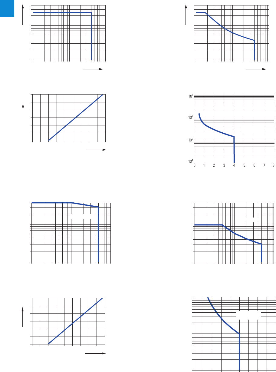
2/127 ABB | Catalog Electronic Products and Relays 2015 | 2CDC 110 004 C0210
2
DC load (resistive)AC load (resistive)
Contact lifetime
Derating factor F for inductive AC load
DC load (resistive)AC load (resistive)
CM-N (45 mm)
Load limit curves
CM-S (22.5 mm), CM-E (22.5 mm), CM-UFD.M22
Contact lifetimeDerating factor F for inductive AC load
cos ϕ
F
2CDC 252 192 F0205
0.5
0.1 0.2 0.3 0.4 0.5 0.6 0.7 0.8 0.9 1.0
0.6
0.7
0.8
0.9
1.0
300
200
100
80
60
50
40
30
20
10
1 2 4 6 10
I A
V
2CDC 252 193 F0205
V
0.1 0.2 0.5
300
200
100
80
60
50
40
30
20
10
1 2 4 6 10
I A
V
2CDC 252 194 F0205
V
0.1 0.2 0.5
cos ϕ
F
2CDC 252 192 F0205
0.5
0.1 0.2 0.3 0.4 0.5 0.6 0.7 0.8 0.9 1.0
0.6
0.7
0.8
0.9
1.0
1246 10
10
20
30
40
50
60
80
100
200
300
400
AC current [A]
resistive load
AC voltage [V]
2CDC 252 157 F0206
0.1 0.2 0.5
4321
10
5
10
4
10
6
5678
2CDC 252 156 F0206
Switching current [A]
Switching cycles
250 V AC
resistive load
Switching current [A]
250 V
resistive load
Switching cycles
2CDC 252 148 F0206
1246 10
10
20
30
40
50
60
80
100
200
300
400
0.1 0.2 0.5
AC current [A]
resistive load
AC voltage [V]
2CDC 252 158 F0206
General technical data, Accessories, Current transformers
Technical diagrams - CM-range
2CDC 252 194 F0205
2CDC 252 193 F02052CDC 252 148 F02062CDC 252 158 F0206
2CDC 252 192 F02052CDC 252 157 F02062CDC 252 192 F0205
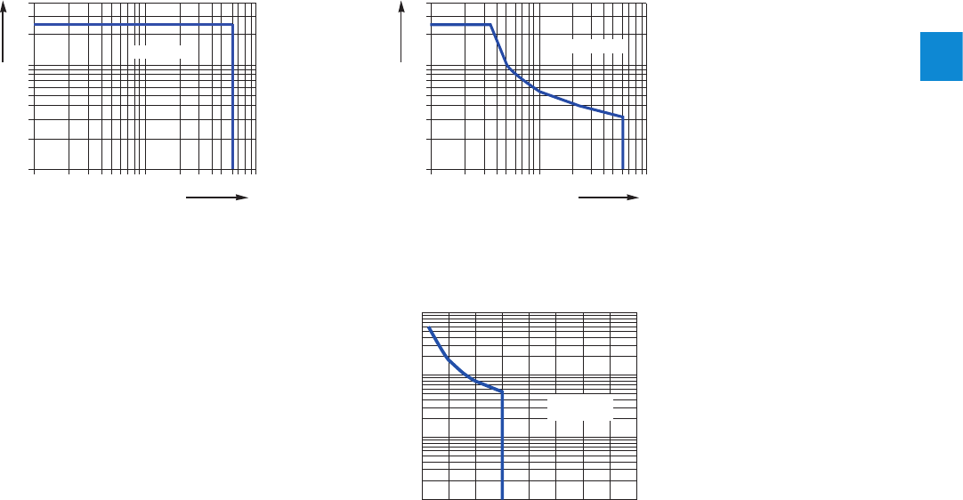
2CDC 110 004 C0210 | Catalog Electronic Products and Relays 2015 | ABB 2/128
2
General technical data, Accessories, Current transformers
Technical diagrams - CM-range
Load limit curves CM-UFD.M21
300
200
100
80
60
50
40
30
20
10
1 2 4 6 10
I A
V
U
0.1 0.2 0.5
resistive load
2CDC 252 010 F0212
AC load (resistive)
300
200
100
80
60
50
40
30
20
10
1 2 510
I A
V
U
0.1 0.2 0.5
resistive load
2CDC 252 011 F0212
DC load (resistive)
104
246810 12 14 16
105
106
107
Switching current [A]
250 V AC
resistive load
Switching cycles
2CDC 252 012 F0212
Contact lifetime
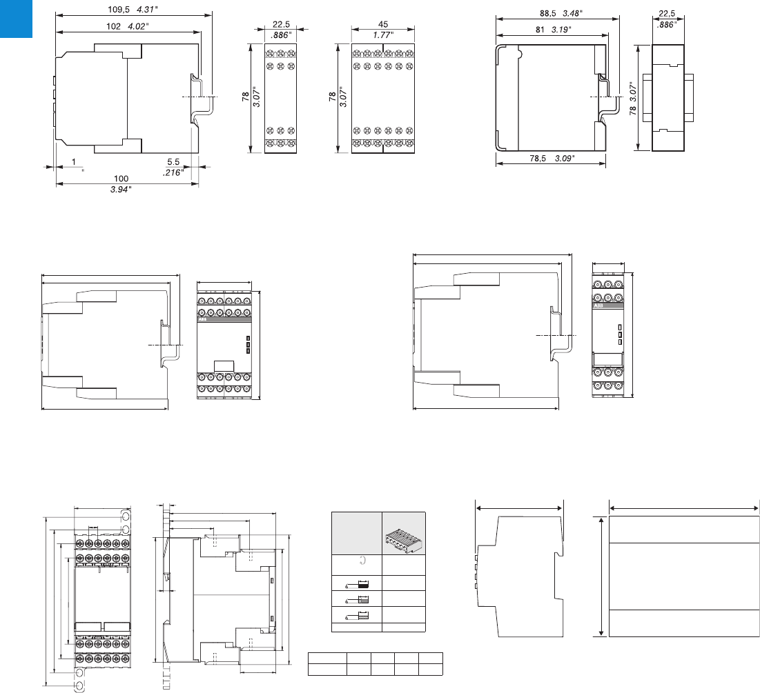
2/129 ABB | Catalog Electronic Products and Relays 2015 | 2CDC 110 004 C0210
2
Dimensional drawing CM-UFD.Mxx
2CDC 252 008 F0013
90
3.54”
108 4.25”67 2.64”
General technical data, Accessories, Current transformers
Dimensional drawings
0.039
1SVC 110 000 F 0177
C512
C513
5 ... 6 mm / PZ2
0,8 ... 1,2 Nm
7 ... 10.3 lb·in
1 x 0,5 ... 4,0 mm²
2 x 0,5 ... 2,5 mm²
2 x 0,5 ... 1,5 mm²
1 x 0,5 ... 2,5 mm²
—
AWG2 x 20 ... 14
10
10
10
abcd
C512, C513 65 36 82,6 105,9
6
b
a
86
28,8
c
d
201
6
45
7,2
2,86
5,19
73x5,811
73x5,831
2CDC 252 288 F0005
1SVC 110 000 F0423
CM-S
22.5 mm
CM-N
45 mm
CM-E
22.5 mm
Measuring and monitoring relays CM range old housing
Measuring and monitoring relays CM range new housing
C512/C513
45 mm
CM-xxN 1SVR 750 xxx xxx, 1SVR 760 xxx xxx
45 mm
CM-xxS 1SVR 730 xxx xxx, 1SVR 740 xxx xxx
22.5 mm
Dimensions in mm
Temperature monitoring relays
2CDC 252 022 F0011
2CDC 252 010 F0011
114.5 4.51”
45.0 1.77”
85.6 3.37”
104.8 4.13”
107.0 4.21”
113.4 44.65”
22.5 0.89”
85.6 33.70”
103.7 40.83”
105.9 41.69”
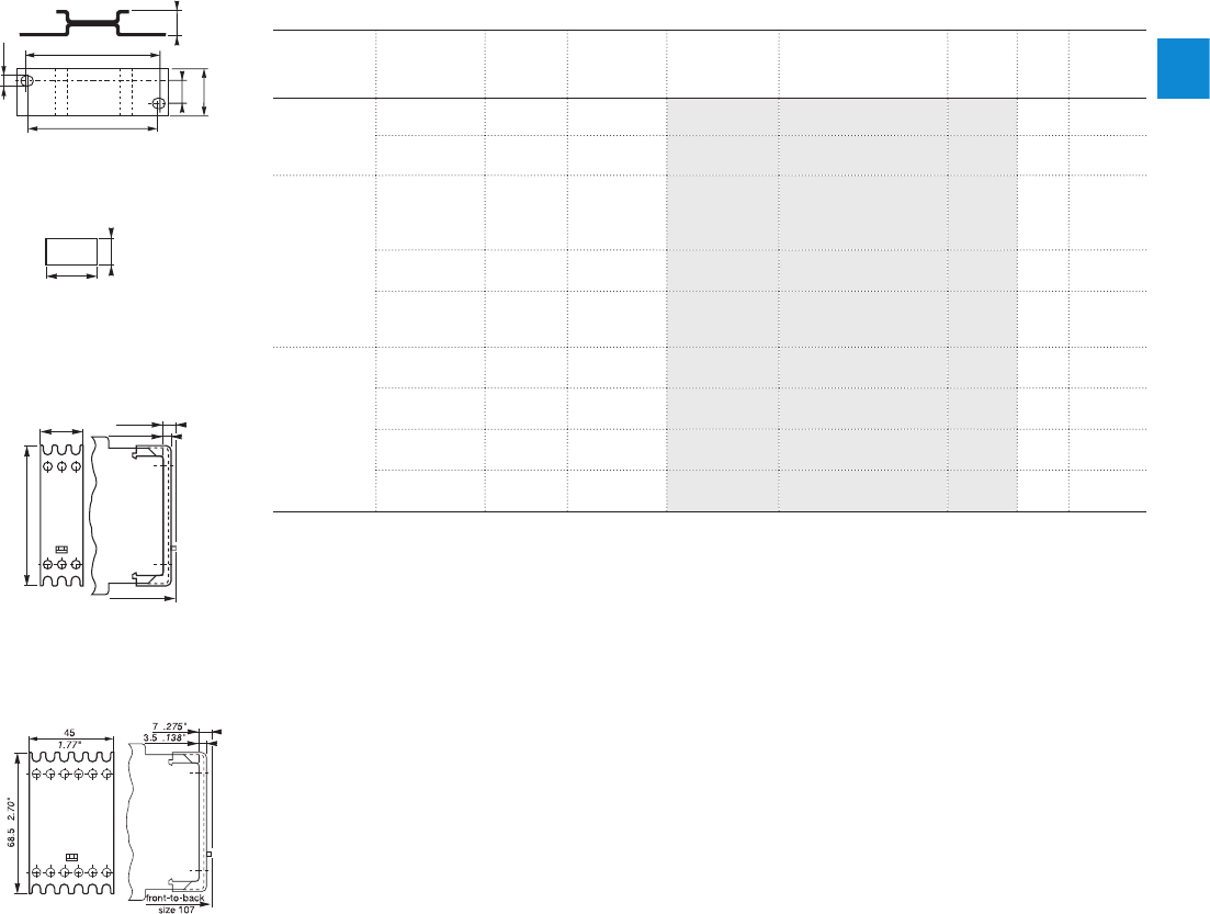
2CDC 110 004 C0210 | Catalog Electronic Products and Relays 2015 | ABB 2/130
2
2CDC 252 187 F0005
4,5
62,5
60
10 11,5
22,5
.177”
2.46”
2.36”
.394”
.886”
.453”
20
3A11
8
.315”
.787”
2CDC 252 186 F000
5
2CDC 252 185 F0005
22,5
68,5
7
3,5
.886”
2.70 ”
.138”
.275”
front-to-back
size 107
1SVC 110 000 F 0180
ADP.01
MAR.01
Sealable cover
COV.01
Sealable cover
COV.02
Accessories
General technical data, Accessories, Current transformers
Ordering details - CM-range accessories
Ordering details
Descrip-
tion
For type Width in
mm
for devices Type Order code Price
pce
Pkg
qty
Weight
(1 pce)
g (oz)
Adapter
for screw
mounting
CM-S
CM-S.S/P 22.5 A D P. 01 1SVR430029R0100 118.4 (0.65)
CM-N
CM-N.S/P 45 A D P. 0 2 1SVR440029R0100 136.7 (1.30)
Marker label
CM-S, CM-N
CM-S.S/P
CM-N.S/P
without DIP
switches MAR.01 1SVR366017R0100 10 0.19
(0.007)
CM-S, CM-N with DIP
switches MAR.02 1SVR430043R0000 10 0.13
(0.005)
CM-S.S/P
CM-N.S/P
with DIP
switches MA R.12 1SVR730006R0000 10 0.152
(0.335)
Sealable
transparent
cover
CM-S 22.5 COV.01 1SVR430005R0100 15.2 (0.18)
CM-N 45 COV.02 1SVR440005R0100 17.7 ( 0. 27 )
CM-S.S/P 22.5 COV.11 1SVR730005R0100 14.0 (0.129)
CM-N.S/P 45 C OV.12 1SVR750005R0100 17 (0.247)
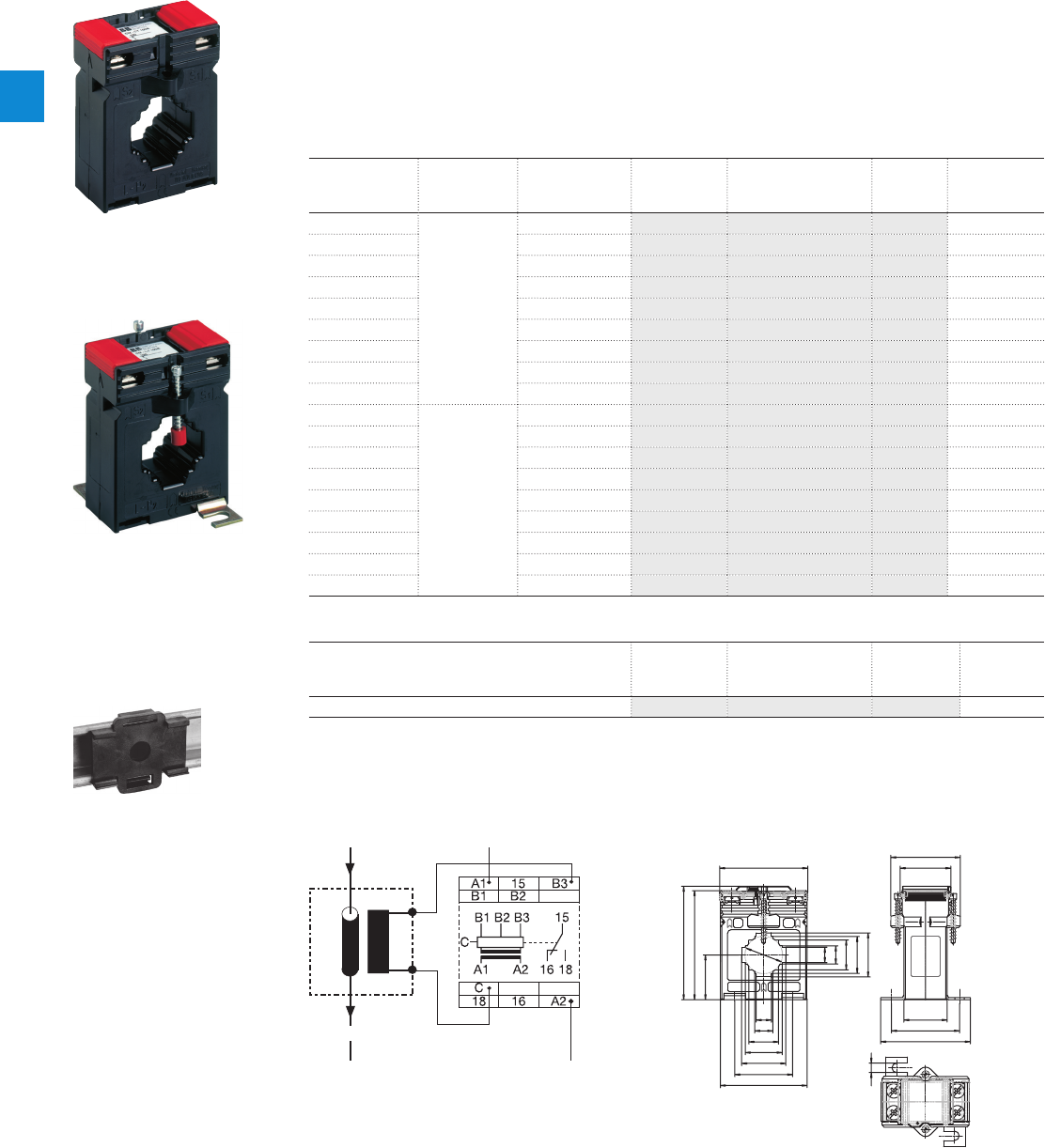
2/131 ABB | Catalog Electronic Products and Relays 2015 | 2CDC 110 004 C0210
2
General technical data, Accessories, Current transformers
Ordering details - CM-range accessories
2CDC 251 002 F0005
2CDC 251 003 F0005
CM-CT
k
l
K-P
1
26
a
a
b
c
d
e
10,5 mm
12,5 mm
20,5 mm
25,5 mm
30,5 mm
0.41 inch
0.49 inch
0.81 inch
1.00 inch
1.20 inch
31 1.22“
6,5 0.26“
75,5 2.97“
78,5 3.09“
61 2.36“
48 1.89“
35 1.38“
a
b
c
d
e
b
c
d
e
40 1.57“
30 1.18“
47 1.85“
62 2.40“
60 2.36“
2CDC 252 153 F0b06
2CDC 251 159 F0b06
CM-CT
with mounted accessories
Plug-in current transformers CM-CT
– Without primary conductor though with foot angle, insulating protective cap and bar
fastening screws
– Primary / rated current from 50 A to 600 A
– Secondary current of 1 A or 5 A
– Class 1
Operating principle / circuit diagram Dimensional drawing
K/P1 k/S1
l/S2L/P2
load
2CDC 252 001 F0206
CM-CT-A
mounted on DIN rail
Ordering details
Rated primary
current
Secondary
current
Burden class Type Order code Price
pce
Weight
(1 pce)
g (oz)
50 A
1 A
1 VA / 1 CM-CT 50/1
1SVR450116R1000
0.31 (0.683)
75 A 1.5 VA / 1 CM-CT 75/1
1SV R450116R110 0
0.31 (0.683)
100 A 2.5 VA / 1 CM-CT 100/1
1SVR450116R1200
0.276 (0.608)
150 A 2.5 VA / 1 CM-CT 150/1
1SVR450116R1300
0.32 (0.705)
200 A 2.5 VA / 1 CM-CT 200/1
1SVR450116R1400
0.222 (0.489)
300 A 5 VA / 1 CM-CT 300/1
1SV R450117R110 0
0.29 (0.639)
400 A 5 VA / 1 CM-CT 400/1
1SV R450117R120 0
0.27 (0.595)
500 A 5 VA / 1 CM-CT 500/1
1SV R450117R1300
0.29 (0.639)
600 A 5 VA / 1 CM-CT 600/1
1SV R450117R14 0 0
0.24 (0.529)
50 A
5 A
1 VA / 1 CM-CT 50/5
1SVR450116R5000
0.3 (0.661)
75 A 1.5 VA / 1 CM-CT 75/5
1SVR450116R5100
0.31 (0.683)
100 A 2.5 VA / 1 CM-CT 100/5
1SVR450116R5200
0.31 (0.683)
150 A 2.5 VA / 1 CM-CT 150/5
1SVR450116R5300
0.28 (0.617)
200 A 5 VA / 1 CM-CT 200/5
1SVR450116R5400
0.29 (0.639)
300 A 5 VA / 1 CM-CT 300/5
1SV R450117R 510 0
0.252 (0.556)
400 A 5 VA / 1 CM-CT 400/5
1SVR450117R5200
0.26 (0.573)
500 A 5 VA / 1 CM-CT 500/5
1SV R450117R 5 30 0
0.208 (0.459)
600 A 5 VA / 1 CM-CT 600/5
1SV R450117R 5 40 0
0.21 (0.463)
Ordering details - Accessories
Description Type Order code Price
10 pces
Weight
(1 pce)
g (oz)
Snap-on fastener for DIN rail mounting of CM-CT CM-CT A 1SVR450118R1000 0.009 (0.02)

2
2CDC 110 004 C0210 | Catalog Electronic Products and Relays 2015 | ABB 2/132
General technical data, Accessories, Current transformers
Notes
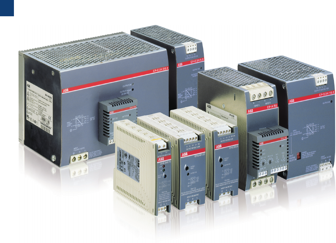
3
3/1 ABB | Catalog Electronic Products and Relays 2015 | 2CDC 110 004 C0210
Primary switch mode power supplies
Product group picture

3
2CDC 110 004 C0210 | Catalog Electronic Products and Relays 2015 | ABB 3/2
Primary switch mode power supplies
Table of contents
Primary switch mode power supplies
Overview 3/3
Approvals and marks 3/4
Selection table - Single-phase 3/5
Selection table - Three-phase, CP-ASI 3/6
CP-D range ...................................................................................... 3/7
Benefits and advantages 3/9
Ordering details 3/10
Technical data 3/11
Technical diagrams 3/15
Dimensional drawings 3/16
CP-E range .................................................................................... 3/17
Benefits and advantages 3/19
Ordering details 3/20
Technical data 3/21
Technical diagrams, Wiring instructions 3/29
Technical diagrams, Dimensional drawings 3/30
CP-T range .................................................................................... 3/31
Benefits and advantages 3/33
Ordering details 3/34
Technical data 3/35
Technical diagrams, Dimensional drawings 3/39
Technical diagrams 3/40
CP-S and CP-C .............................................................................. 3/41
Benefits and advantages 3/43
Operating control 3/44
Ordering details 3/45
Technical data 3/46
Technical diagrams, Dimensional drawings 3/50
Redundancy units ........................................................................... 3/51
Ordering details 3/51
Technical data 3/52
Dimensional drawings 3/56
CP-ASI range ................................................................................. 3/57
Benefits and advantages 3/59
Ordering details 3/60
Technical data 3/61
Technical diagrams 3/63
Dimensional drawings 3/64
CP-B range .................................................................................... 3/65
Benefits and advantages 3/67
Ordering details 3/68
Technical data 3/69
Technical data, Technical diagrams 3/70
Dimensional drawings 3/71
Technical data 3/72
Electronic protection devices EPD24 ............................................... 3/73
Ordering details 3/75
Technical data 3/76
Technical information 3/78
Approvals, Safety instructions 3/79
Installation guidelines 3/80

3
3/3 ABB | Catalog Electronic Products and Relays 2015 | 2CDC 110 004 C0210
Primary switch mode power supplies
Overview
Application manual
For today’s applications, e.g. in control engineering, it is es-
sential to make the right decision regarding the selection and
planning of the power supply unit. Incorrect dimensioning or
incorrect connection of a power supply unit can seriously af-
fect the safety and/or availability of the entire installation.
ABB’s “Power Supply Units” application manual provides a
general overview of switch mode power supply units, thus
helping you to choose the ideal power supply unit and avoid
problems during engineering and commissioning. The manual
generally shows and explains the fundamental characteristics
of and the differences between power supply units, and pro-
vides a detailed introduction to the ABB product range on the
basis of the selection criteria. Finally, it describes and explains
application examples for engineering.
CP-D
The CP-D range of power supply units in MDRC design
(modular DIN rail components) fits into all domestic installation
and distribution panels.
CP-E
The CP-E range offers enhanced functionality while the num-
ber of different types has been considerably reduced. Now all
power supply units can be operated at an ambient tempera-
ture of up to +70 °C.
CP-T
The CP-T range of three-phase power supply units is ABB’s
youngest member of the power supply family.
CP-S
The CP-S range is ABB’s standard range, a high-end power
supply unit optimised for serial applications.
CP-C
The CP-C range’s pluggable function modules adapt these
power supply units exactly to your application’s needs. Of
course, all ABB power supply units feature primary switch
mode technology – environmentally sound and cost-efficiency.
This represents the highest level of innovative industrial elec-
tronics.
The manual is available in English and German.
English Version: 2CDC 114 048 M0203
German Version: 2CDC 114 048 M0103
Modern power supply units are a vital component in most areas of energy management and automation technology. ABB as
your global partner in these areas pays the utmost attention to the resulting requirements. Innovation is the key to a substantial
enlargement of our power supply product program:
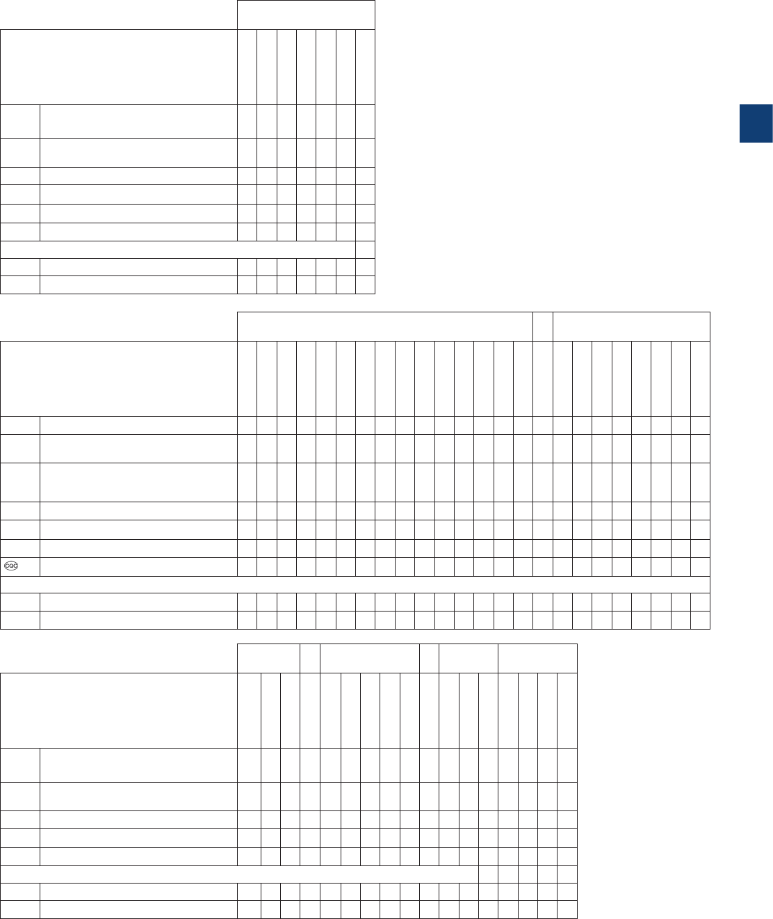
3
2CDC 110 004 C0210 | Catalog Electronic Products and Relays 2015 | ABB 3/4
J existing
j pending CP-D
Approvals
CP-D 12/0.83
CP-D 12 /2.1
CP-D 24/0.42
CP-D 24/1.3
CP-D 24/2.5
CP-D 24/4.2
CP-D RU
AUL 508, CAN/CSA C22.2
No.107.1 J1) J1) J1) J1) J1) J1)
HUL 1310, CAN/CSA C22.2 No.223
(Class 2 Power Supply) J1) J1) J1) J1) J1)
HUL 60950, CAN/CSA C22.2 No.60950 J1) J1) J1) J1) J1) J1)
KCB Scheme J1) J1) J1) J1) J1) J1)
REAC J1) J1) J1) J1) J1) J1)
ECCC J1) J1) J1) J1) J1) J1)
Marks
aCE JJJJJJJ
bC-Tick JJJJJJJ
J existing
j pending CP-E CP-T
Approvals
CP-E 5/3.0
CP-E 12/2.5
CP-E 12/10.0
CP-E 24/0.75
CP-E 24/1.25
CP-E 24/2.5
CP-E 24/5.0
CP-E 24/10.0
CP-E 24/20.0
CP-E 48/0.62
CP-E 48/1.25
CP-E 48/5.0
CP-E 48/10.0
CP-RUD
CP-T 24/5.0
CP-T 24/10.0
CP-T 24/20.0
CP-T 24/40.0
CP-T 48/5.0
CP-T 48/10.0
CP-T 48/20.0
AUL 508, CAN/CSA C22.2 No.107.1 J1) J1) J1) J1) J1) J1) J1) J1) J1) J1) J1) J1) J1) J1) J1) J1) J1) J1) J1) J1)
HUL 1310, CAN/CSA C22.2 No.223
(Class 2 Power Supply) J J J J J J J
HANSI/ISA-12.12 (Class I, Div. 2,
hazardous locations) CAN/CSA C22.2
No. 213
JJJJJJJJJJJJJ JJJJ JJJ
HUL 60950, CAN/CSA C22.2 No.60950 J1) J1) J1) J1) J1) J1) J1) J1) J1) J1) J1) J1) J1) J1) J1) J1) J1) J1) J1) J1)
REAC JJJJJJJJJJJJJ JJJJ JJJ
ECCC J1) J1) J1) J1) J1) J1) J1) J1) J1) J1) J1) J1) J1)
GB4943, GB9254, GB17625.1 J J J J J J J
Marks
aCE JJJJJJJJJJJJJ J JJJJ JJJ
bC-Tick JJJJJJJJJJJJJ J jjjj jjj
J existing
j pending CP-S CP-C CP-A CP-B
Approvals
CP-S 24/5.0
CP-S 24/10.0
CP-S 24/20.0
CP-C 24/5.0
CP-C 24/10.0
CP-C 24/20.0
CP-C MM
CP-A RU
CP-A CM
CP-B 24/3.0
CP-B 24/10.0
CP-B 24/20.0
CP-B E X T.2
AUL 508, CAN/CSA C22.2
No.107.1 J1) J1) J1) J1) J1) J1) J J J J
AUL 1604 (Class I, Div. 2, hazardous
locations), CAN/CSA C22.2 No.213 J1) J1) J1) J1) J1) J1)
HUL 60950, CAN/CSA C22.2 No.60950 J1) J1) J1) J1) J1) J1) J1) J1)
REAC J J J J J J J J J J J J J
KCB scheme J J J J J J J J
Marks
aCE J J J J J J J J J J J J J
bC-Tick J J J J J J J J j
1) Approvals refer to the rated input voltage Uin.
Primary switch mode power supplies
Approvals and marks

3
3/5 ABB | Catalog Electronic Products and Relays 2015 | 2CDC 110 004 C0210
Order number
1SVR427041R1000
1SVR427043R1200
1SVR427041R0000
1SVR427043R0100
1SVR427044R0200
1SVR427045R0400
1SVR427033R3000
1SVR427032R1000
1SVR427035R1000
1SVR427030R0000
1SVR427031R0000
1SVR427032R0000
1SVR427034R0000
1SVR427035R0000
1SVR427036R0000
1SVR427030R2000
1SVR427031R2000
1SVR427034R0000
1SVR427035R2000
1SVR427014R0000
1SVR427015R0100
1SVR427016R0100
1SVR427024R0000
1SVR427025R0000
1SVR427026R0000
Single phase
CP-D CP-E CP-S CP-C
Rated output voltage 5 V DC J
12 V DC J J J J
24 V DC J J J J J J J J J J J J J J J J
48 V DC JJJJ
Rated output current 0.42 A J
0.625 A J
0.75 A J
0.83 A J
1.25 A J J
1.3 A J
2.1 A J
2.5 A J J J
3 A J
4.2 A J
5 A J J J J
10 A J J J J J
20 A J J J
Rated output power 10 W J J
15 W J
18 W J
30 W J J J J J
60 W J J J
100 W J
120 W J J J J
240 W J J J J
480 W J J J J
Rated input
voltage
100 - 240 V AC J J J J J J J J J J J J J
115/230 V AC auto select
J J J J
115 - 230 V AC J J
110 - 240 V AC J J J J
110 - 120 V AC J J
220 - 240 V AC J J
DC input
voltage range
120 - 370 V DC J J J J J J J J J J
90 - 375 V DC J J J J J
210 - 370 V DC J J J J
100 - 350 V DC J J J J
220 - 350 V DC J J
Features Power reserve design J J J J J J
Adjustable output voltage
J J J J J J J J J J J J J J J J J J J J
Integrated input fuse J J J J J J J J J J J J J J J J J J J J J J J J J
Short circuit stable J J J J J J J J J J J J J J J J J J J J J J J J J
Fold forward behavior (U/I)
JJJJJJ JJ JJJJJJJJJ JJ J JJJ
Fold back behavior (hiccup)
J J
Power factor correction
pas pas pas act pas act act act act
Ambient temp. rating
-25°C (-40°C) to 70°C
J J J J J J J J J J J J J J J J J J J J J J J J J
Parallel connection J J 3J J J 333JJ3 3 5 5 5 5 5 5
Serial connection J J J J J J J J 2J J J 222JJ2 2 J J J J J J
Primary switch mode power supplies
Selection table - Single-phase

3
2CDC 110 004 C0210 | Catalog Electronic Products and Relays 2015 | ABB 3/6
Order number
1SVR427054R0000
1SVR427055R0000
1SVR427056R0000
1SVR427057R0000
1SVR427054R2000
1SVR427055R2000
1SVR427056R2000
1SVR427090R0280
1SVR427090R0400
1SVR427095R0400
1SVR427090R0800
Three phase AS-Interface
CP-T CP-ASI
Rated output voltage 24 V DC J J J J
30.5 V DC J J J J
48 V DC J J J
Rated output current 2.8 A J
3 A J J
5 A J J
8 A J
10 A J J
20 A J J
40 A J
Rated output power 85 W J
120 W J
122 W J J
240 W J J
244 W J
480 W J J
960 W J J
Rated input
voltage
85-132 V AC, 184-264 V AC
J J J
3 x 400 - 800 V AC J J J J J J J
DC input
voltage range
18-32.4 V DC J
480 - 820 V DC J J J J J J J
Features Adjustable output voltage J J J J J J J
Integrated input fuse J J J J J J J
Short circuit stable J J J J J J J
Fold forward behavior (U/I)
J J J J J
Fold back behavior (hiccup)
J J J J J J J
Power factor correction
Ambient temp. rating
-25°C (-40°C) to 70°C
J J J J J J J
Serial connection 2 2 2 2 2 2
Suited for AS-Interfaces J J J J
Primary switch mode power supplies
Selection table - Three-phase, CP-ASI
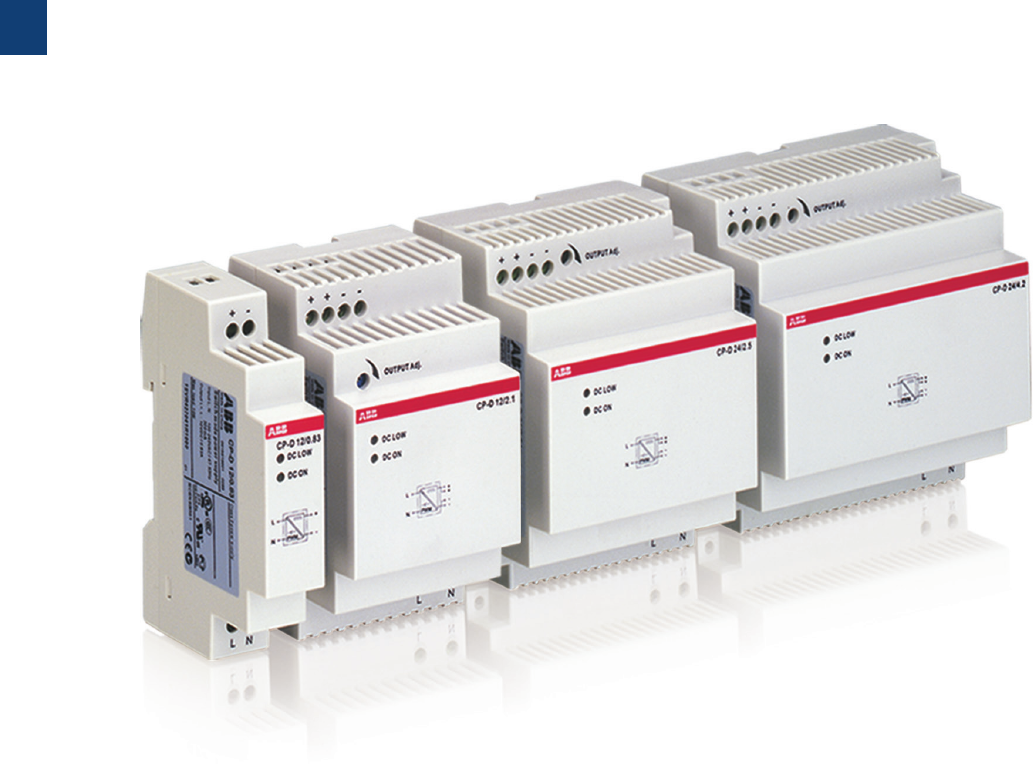
3
3/7 ABB | Catalog Electronic Products and Relays 2015 | 2CDC 110 004 C0210
CP-D range
Product group picture

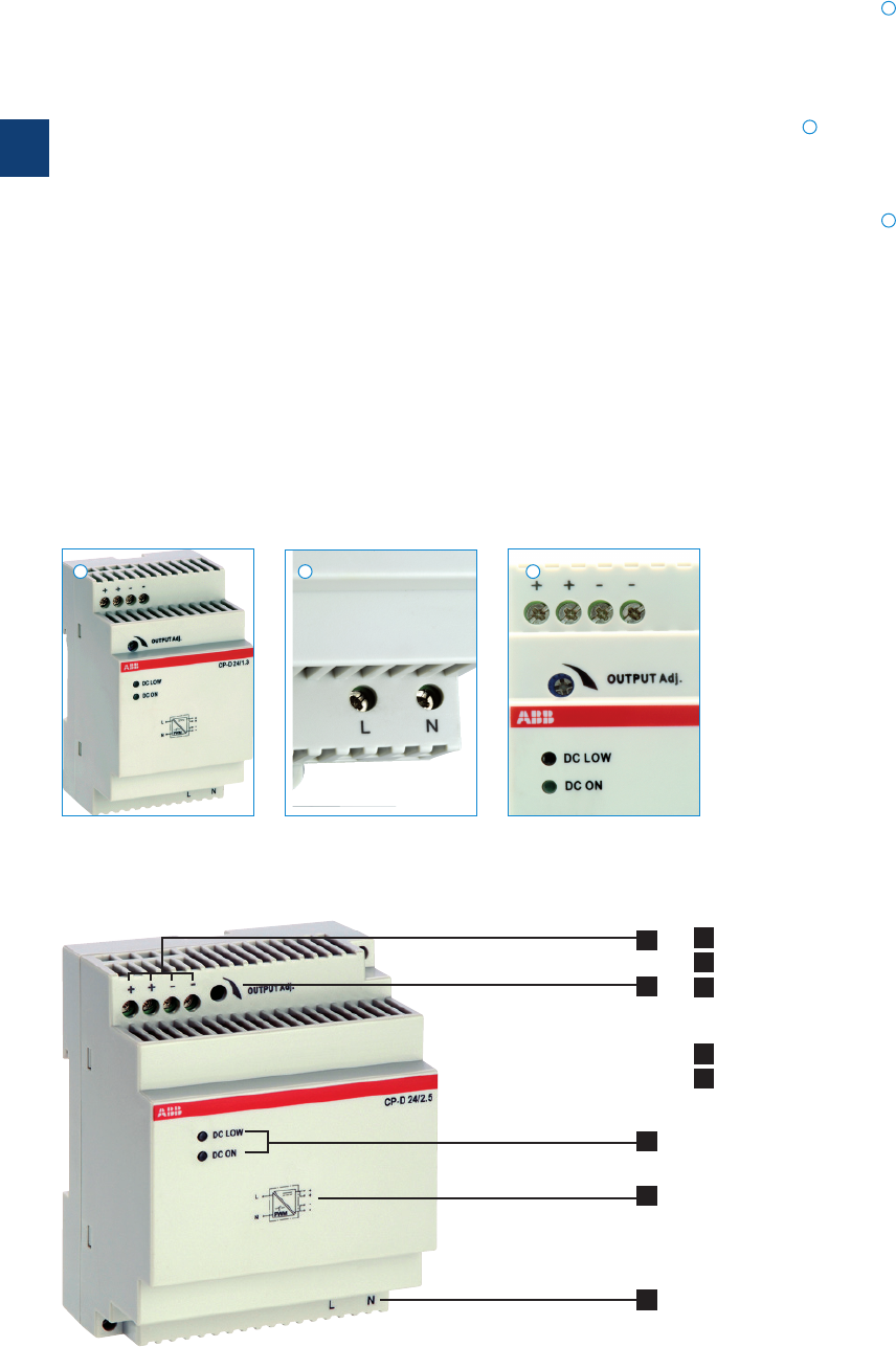
3
3/9 ABB | Catalog Electronic Products and Relays 2015 | 2CDC 110 004 C0210
2CDC 271 027 F0007
2CDC 276 032 F0007
2CDC 276 033 F0007
Characteristics
– Output voltages 12 V, 24 V DC
– Adjustable output voltages (devices > 10 W)
– Output currents
0.42 A / 0.83 A / 1.3 A / 2.1 A / 2.5 A / 4.2 A
– Power range 10 W, 30 W, 60 W, 100 W
–
Wide range input 100-240 V AC (90-264 V AC, 120-375 V DC)
– High efficiency of up to 89 %
– Low power dissipation and low heating
– Free convection cooling (no forced cooling with ventilators)
– Ambient temperature range during operation
-40 °C...+70 °C
– Open-circuit, overload and short-circuit stable
– Integrated input fuse
– U/I characteristic (fold-forward behaviour at overload – no
switch-off)
– LEDs for status indication
– Light-grey housing in RAL 7035
– Approvals / Marks (depending on device, partly pending):
A, H, R, E / a, b
Width and structural form
With their width between 18 to 90 mm only, the CP-D range
switch mode power supplies are ideally suited for installation
in distribution panels.
Wide range input
Optimised for world-wide applications: The CP-D power sup-
plies can be supplied with 90-264 V AC or 120-375 V DC.
Adjustable output voltage
The CP-D range types > 10 W feature a continuously adjust-
able output voltage. Thus, they can be optimally adapted to
the application, e.g. compensating the voltage drop caused
by a long line length.
Benefits
1
1
2
2
3
3
CP-D range
Benefits and advantages
4
1
2
3
5
1 OUTPUT ++/--: terminals - output
2 INPUT L, N: terminals - input
3 Indication of operational states
DC ON: green LED - output voltage applied
DC LOW: red LED - output voltage too low
4 Circuit diagram
5 OUTPUT Adjust: potentiometer - adjustment of output voltage
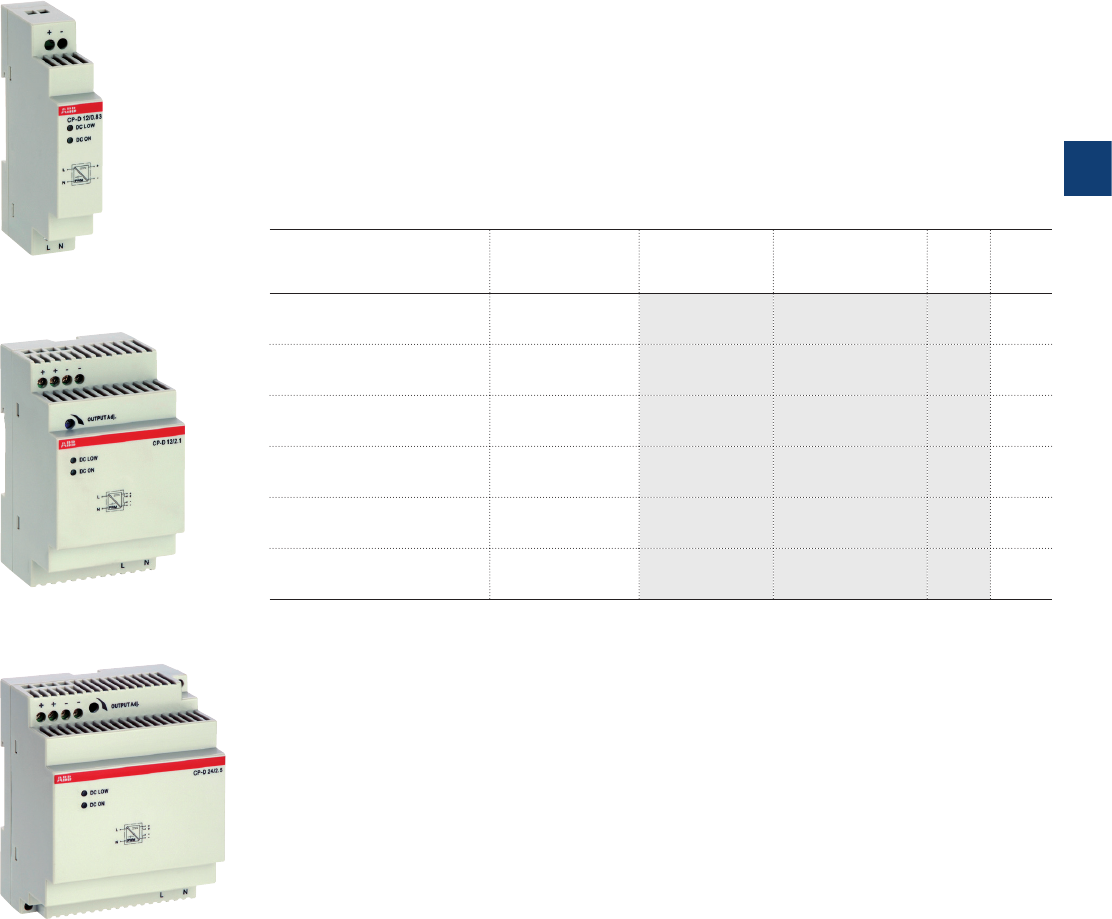
3
2CDC 110 004 C0210 | Catalog Electronic Products and Relays 2015 | ABB 3/10
Description
The CP-D range of modular power supply units in MDRC design (modular DIN rail compo-
nents) is ideally suited for installation in distribution panels. This range offers devices with
output voltages of 12 V DC and 24 V DC at output currents of 0.42 A to 4.2 A. Thanks to a
high thermal efficiency corresponding to low power and heat dissipation, the devices can be
operated without forced cooling. All devices feature the U/I output characteristic (fold forward
behaviour). All power supply units in the CP-D range are approved according to all relevant
international standards.
Ordering details
Input voltage range Rated
output voltage /
current
Type Order code Price
1 pce
Weight
(1 pce)
kg (lb)
90-264 V AC/ 120-375 V DC 12 V DC / 0.83 A CP-D 12/0.83 1SVR427041R1000 0.06
(0.13)
90-264 V AC/ 120-375 V DC 12 V DC / 2.1 A C P- D 12/2.1 1SVR427043R1200 0.19
(0.41)
90-264 V AC/ 120-375 V DC 24 V DC / 0.42 A CP-D 24/0.42 1SVR427041R0000 0.06
(0.13)
90-264 V AC/ 120-375 V DC 24 V DC / 1.3 A CP-D 24/1.3 1SVR427043R0100 0.19
(0.41)
90-264 V AC/ 120-375 V DC 24 V DC / 2.5 A CP-D 24/2.5 1SVR427044R0200 0.25
(0.56)
90-264 V AC/ 120-375 V DC 24 V DC / 4.2 A CP-D 24/4.2 1SVR427045R0400 0.32
(0.71)
2CDC 271 024 F0007
2CDC 271 025 F0007
2CDC 271 028 F0007
CP-D 12/0.83, CP-D 24/0.42
CP-D 12/2.1, CP-D 24/1.3
CP-D 24/2.5
CP-D range
Ordering details

3
3/11 ABB | Catalog Electronic Products and Relays 2015 | 2CDC 110 004 C0210
Data at Ta = 25 °C, Uin = 230 V AC and rated values, unless otherwise indicated
Type CP-D 12/0.83 CP-D 12 /2.1
Input circuit - supply circuit L, N
Rated input voltage Uin 100-240 V AC
Input voltage range 90-264 V AC / 120-375 V DC
Frequency range AC 47- 63 Hz
Typical input current /
typical power consumption
at 110 V AC 200 mA / 12.68 W 502 mA / 31.14 W
at 230 V AC 128.3 mA / 13.01 W 277 mA / 31.2 W
Inrush current limiting at 230 V AC 30 A (max. 3 ms) 50 A (max. 3 ms)
Power failure buffering time min. 30 ms
Internal input fuse 1 A slow-acting / 250 V AC 2 A slow-acting / 250 V AC
Power factor correction (PFC) no
Indication of operational states
Output voltage DC ON: green LED V: output voltage applied
DC LOW: red LED V: output voltage too low
Output circuit +, - ++, --
Rated output voltage 12 V DC
Tolerance of the output voltage ±1 %
Adjustment range of the output voltage -12-14 V DC
Rated output power 10 W 25 W
Rated output current IrTa m 60 °C 0.83 A 2.1 A
Derating of the output current 60 °C < Ta m 70 °C 2.5 %/°C
Maximum
deviation
with
load change statical max. 1 %
change of output voltage within the input voltage range max. 1 %
Control time < 1 ms
Starting time after applying the supply
voltage
at Ir1000 ms
Rise time at rated load typ. 1 ms
Residual ripple and switching peaks BW = 20 MHz 50 mV
Parallel connection yes, using CP-D RU
Series connection yes, to increase voltage
Resistance to reverse feed 18 V / 1 s
Output circuit - No-load, overload and short-circuit behaviour
Characteristic curve of output U/I characteristic curve
Short-circuit protection continuous short-circuit stability
Short-circuit behaviour continuation with output power limiting
Current limiting at short circuit typ. 1.4 A typ. 5.9 A
Overload protection output power limiting
Overvoltage protection 15-16.5 V DC
No-load protection continuous no-load stability
Starting of capacitive loads unlimited
General data
Efficiency typ. 78 % typ. 82 %
Duty time 100 %
Dimensions (W x H x D) 18 x 91 x 57.5 mm
(0.71 x 3.58 x 2.26 in)
53 x 91 x 57.5 mm
(2.09 x 3.58 x 2.26 in)
Weight 0.066 kg (0.13 lb) 0.196 kg (0.41 lb)
Material of housing plastic
Mounting DIN rail (IEC/EN 60715), snap-on mounting without any tool
Mounting position horizontal
Minimum distance to other units horizontal / vertical 25 mm / 25 mm (0.98 in / 0.98 in)
Degree of protection housing / terminals IP20 / IP20
Protection class II
CP-D range
Technical data

3
2CDC 110 004 C0210 | Catalog Electronic Products and Relays 2015 | ABB 3/12
Data at Ta = 25 °C, Uin = 230 V AC and rated values, unless otherwise indicated
Type CP-D 12/0.83 CP-D 12 /2.1
Electrical connection - Input circuit / Output circuit
Wire size fine-strand with wire end ferrule 0.2-1.5 mm2 (24-16 AWG) 0.2-2.5 mm2 (24-14 AWG)
rigid 0.2-2.5 mm2 (26-12 AWG) 0.2-2.5 mm2 (24-12 AWG)
Stripping length 4-5 mm (0.16-0.2 in) 7 mm (0.28 in)
Tightening torque 0.6 Nm (5 lb.in) 0.7 Nm (6 lb.in)
Environmental data
Ambient temperature range operation -40…+70 °C
rated load -40…+60 °C
storage -40…+85 °C
Damp heat (cyclic) (IEC/EN 60068-2-30) 4 x 24 cycles, 40 °C, 95 % RH
Vibration (sinusoidal) (IEC/EN 60068-2-6) 50 m/s2, 10 Hz - 2 kHz
Shock (half-sine) (IEC/EN 60068-2-27) 40 m/s2, 22 ms
Isolation data
Rated insulation voltage Uiinput circuit / output circuit 3 kV AC
Pollution degree 2
Overvoltage category (UL/IEC/EN 60950-1) ll
Standards
Product standard EN 61204
Low Voltage Directive 2006/95/EC
EMC Direcitve 2004/108/EC
Electrical safety UL 508, UL 60950-1, EN 60950-1
Protective low voltage SELV (EN 60950-1)
Electromagnetic compatibility
Interference immunity to EN 61000-6-2
electrostatic discharge IEC/EN 61000-4-2 Level 4 (4 kV / 8 kV) Level 4 (4 kV / 15 kV)
radiated, radio-frequency, electromagnetic field IEC/EN 61000-4-3 Level 3 (10 V/m)
electrical fast transient/burst IEC/EN 61000-4-4 Level 4 (4 kV)
surge IEC/EN 61000-4-5 Level 3 (2 kV L-L)
conducted disturbances, induced by radio-
frequency fields
IEC/EN 61000-4-6 Level 3 (10 V)
Interference emission EN 61000-6-3
high-frequency radiated IEC/CISPR 22, EN 55022 Class B
high-frequency conducted IEC/CISPR 22, EN 55022 Class B
„Approvals and marks“ on page 3/4.
CP-D range
Technical data

3
3/13 ABB | Catalog Electronic Products and Relays 2015 | 2CDC 110 004 C0210
CP-D range
Technical data
Data at Ta = 25 °C, Uin = 230 V AC and rated values, unless otherwise indicated
Type CP-D 24/0.42 CP-D 24/1.3 CP-D 24/2.5 CP-D 24/4.2
Input circuit - supply circuit L, N
Rated input voltage Uin 100-240 V AC
Input voltage range 90-264 V AC /120-375 V DC
Frequency range AC 47- 63 Hz
Typical input current /
typical power consumption
at 110 V AC
184 mA / 11.62 W 600 mA / 37.92 W 1120 mA / 69.3 W 1800 mA / 117.3 W
at 230 V AC 120.6 mA / 12 W
344 mA / 38.16 W
660 mA / 70.1 W
900 mA / 114.4 W
Inrush current limiting at 230 V AC 30 A (max. 3 ms) 50 A (max. 3 ms) 60 A (max. 3 ms)
Power failure buffering time min. 30 ms min. 60 ms
Internal input fuse 1 A slow-acting
/ 250 V AC
2 A slow-acting /
250 V AC
3.15 A slow-acting
/ 250VAC
Power factor correction (PFC) no
Indication of operational states
Output voltage DC ON: green LED V: output voltage applied
DC LOW: red LED V: output voltage too low
Output circuit +, - ++, --
Rated output voltage 24 V DC
Tolerance of the output voltage ±1 %
Adjustment range of the output voltage -24-28 V DC
Rated output power 10 W 30 W 60 W 100 W
Rated output current Ir
T
a
m
60 °C: 0.42 A T
a
m
60 °C: 1.3 A T
a
m
55 °C: 2.5 A T
a
m
60 °C: 4.2 A
Derating of the output current
60 °C < T
a
m
70 °C:
2.5 %/°C
60 °C < T
a
m
70 °C:
2.5 %/°C
55 °C < T
a
m
70 °C:
2.5 %/°C
60 °C < T
a
m
70 °C:
2.5 %/°C
Maximum
deviation
with
load change statical max. 1 %
change of output voltage within the input voltage range max. 1 %
Control time < 1 ms
Starting time after applying the supply voltage at Ir1000 ms
Rise time at rated load typ. 1 ms
Residual ripple and switching peaks BW = 20 MHz 50 mV
Parallel connection yes, using CP-D RU
Series connection yes, to increase voltage
Resistance to reverse feed 35 V / 1 s
Output circuit - No-load, overload and short-circuit behaviour
Characteristic curve of output U/I characteristic curve
Short-circuit protection continuous short-circuit stability
Short-circuit behaviour continuation with output power limiting
Current limiting at short circuit typ. 0.78 A typ. 4.2 A typ. 6.05 A typ. 11.5 A
Overload protection output power limiting
Overvoltage protection 30-33 V DC
No-load protection continuous no-load stability
Starting of capacitive loads unlimited
General data
Efficiency typ. 80 % typ. 83 % typ. 86 % typ. 89 %
Duty time 100 %
Dimensions (W x H x D)
18 x 91 x 57.5 mm
(0.71 x 3.58 x
2.26 in)
53 x 91 x 57.5 mm
(2.09 x 3.58 x
2.26 in)
71 x 91 x 57.5 mm
(2.80 x 3.58 x
2.26 in)
89.9 x 91 x 57,5 mm
(3.54 x 3.58 x
2.26 in)
Weight
0.066 kg (0.13 lb) 0.196 kg (0.41 lb) 0.252 kg (0.55 lb) 0.386 kg / (0.72 lb)
Material of housing plastic
Mounting DIN rail (IEC/EN 60715), snap-on mounting without any tool
Mounting position horizontal
Minimum distance to other units horizontal / vertical 25 mm / 25 mm (0.98 in / 0.98 in)
Degree of protection housing / terminals IP20 / IP20
Protection class II

3
2CDC 110 004 C0210 | Catalog Electronic Products and Relays 2015 | ABB 3/14
CP-D range
Technical data
Data at Ta = 25 °C, Uin = 230 V AC and rated values, unless otherwise indicated
Type CP-D 24/0.42 CP-D 24/1.3 CP-D 24/2.5 CP-D 24/4.2
Electrical connection - Input circuit / Output circuit
Wire size fine-strand with wire end ferrule 0.2-1.5 mm2
(24-16 AWG)
0.2-2.5 mm2 (24-14 AWG)
rigid 0.2-2.5 mm2
(26-12 AWG)
0.2-2.5 mm2 (24-12 AWG)
Stripping length 4-5 mm (0.16-0.2 in) 7 mm (0.28 in)
Tightening torque 0.6 Nm (5 lb.in) 0.7 Nm (6 lb.in)
Environmental data
Ambient temperature range operation -40…+70 °C
rated load -40…+60 °C -40…+55 °C -40…+60 °C
storage -40…+85 °C
Damp heat (cyclic) (IEC/EN 60068-2-30) 4 x 24 cycles, 40 °C, 95 % RH
Vibration (sinusoidal) (IEC/EN 60068-2-6) 50 m/s2, 10 Hz - 2 kHz
Shock (half-sine) (IEC/EN 60068-2-27) 40 m/s2, 22 ms
Isolation data
Rated insulation voltage Uiinput circuit / output circuit 3 kV AC 4 kV AC 3 kV AC
Pollution degree 2
Overvoltage category (UL/IEC/EN 60950-1) ll
Standards
Product standard EN 61204
Low Voltage Directive 2006/95/EC
EMC Direcitve 2004/108/EC
Electrical safety UL 508, UL 60950-1, EN 60950-1
Protective low voltage SELV (EN 60950-1)
Electromagnetic compatibility
Interference immunity to EN 61000-6-2
electrostatic discharge IEC/EN 61000-4-2 Level 4
(4 kV / 8 kV)
Level 4
(4 kV / 15 kV)
Level 4
(4 kV / 8 kV)
radiated, radio-frequency, electromagnetic field IEC/EN 61000-4-3 Level 3 (10 V/m)
electrical fast transient/burst IEC/EN 61000-4-4 Level 4 (4 kV)
surge IEC/EN 61000-4-5 Level 3 (2 kV L-L)
conducted disturbances, induced by radio-
frequency fields
IEC/EN 61000-4-6 Level 3 (10 V)
Interference emission EN 61000-6-3
high-frequency radiated
IEC/CISPR 22, EN 55022
Class B
high-frequency conducted
IEC/CISPR 22, EN 55022
Class B
„Approvals and marks“ on page 3/4.
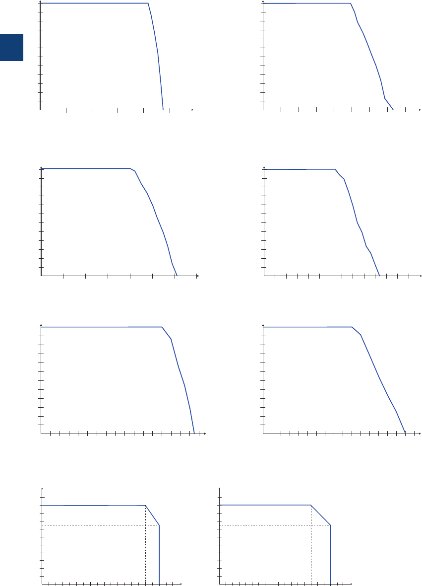
3
3/15 ABB | Catalog Electronic Products and Relays 2015 | 2CDC 110 004 C0210
CP-D range
Technical diagrams
CP-D except CP-D 24/2.5 CP-D 24/2.5
CP-D 12/0.83 CP-D 12/2.1
CP-D 24/0.42 CP-D 24/1.3
CP-D 24/2.5 CP-D 24/4.2
Characteristic curve of output at Ta = 25 °C
-10 010203040506070
10
20
30
40
50
60
70
80
90
100
2CDC 272 018 F0207
P
out
[%]
T
a
[°C]
-10 010203040506070
10
20
30
40
50
60
70
80
90
100
P
out
[%]
T
a
[°C]
2CDC 272 018 F0207
0
1
0
2
3
4
5
6
7
8
9
10
11
12
2CDC 272 019 F0207
Uout [V]
Iout [A]
0.50.25 0.751 1.25
0
1
0
2
3
4
5
6
7
8
9
10
11
12
2CDC 272 020 F0207
U
out
[V]
Iout [A]
0.5 11.5 22.5
34
3.5
0
2
0
4
6
8
10
12
14
16
18
20
22
24
2CDC 272 021 F0207
U
out
[V]
I
out
[A]
0.125 0.25 0.5 0.6250.375 0.8750.750
2
0
4
6
8
10
12
14
16
18
20
22
24
2CDC 272 022 F0207
U
out
[V]
I
out
[A]
0.5 11.5 22.5 3
0
2
0
4
6
8
10
12
14
16
18
20
22
24
2CDC 272 023 F0207
U
out
[V]
I
out
[A]
0.5 11.5 22.5 343.5
0
2
0
4
6
8
10
12
14
16
18
20
22
24
123456 87
2CDC 272 030 F0207
U
out
[V]
Iout [A]
Characteristic curve of temperature at rated output voltage
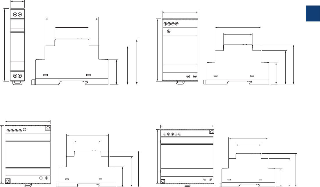
3
2CDC 110 004 C0210 | Catalog Electronic Products and Relays 2015 | ABB 3/16
CP-D range
Dimensional drawings
CP-D 24/4.2
CP-D 12/2.1, CP-D 24/1.3
CP-D 24/2.5
CP-D 12/0.83, CP-D 24/0.42
Dimensional drawings dimensions in mm
18,0 [0.71”]
67,0 [2.64”]
44,5 [1.75”]
91,0 [3.58”]
32,1 [1.26”]
57,5 [2.26”]
49,0 [1.93”]
2CDC 272 011 F0b07
67,0 [2.64”]
44,5 [1.75”]
32,1 [1.26”]
57,5 [2.26”]
49,0 [1.93”]
91,0 [3.58”]
53,0 [2.09”]
2CDC 272 012 F0b07
67,0 [2.64”]
44,5 [1.75”]
32,1 [1.26”]
57,5 [2.26”]
49,0 [1.93”]
91,0 [3.58”]
71,0 [2.80”]
2CDC 272 013 F0b07
67,0 [2.64”]
44,5 [1.75”]
32,1 [1.26”]
57,5 [2.26”]
49,0 [1.93”]
91,0 [3.58”]
89,9 [3.54”]
2CDC 272 014 F0b07
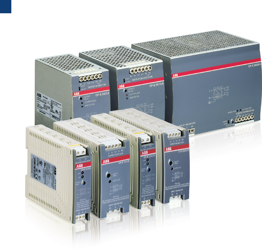
3
3/17 ABB | Catalog Electronic Products and Relays 2015 | 2CDC 110 004 C0210
CP-E range
Product group picture

3
2CDC 110 004 C0210 | Catalog Electronic Products and Relays 2015 | ABB 3/18
CP-E range
Table of contents
CP-E range
Product group picture 3/17
Table of contents 3/18
Benefits and advantages 3/19
Ordering details 3/20
Technical data 3/21
Technical diagrams, Wiring instructions 3/29
Technical diagrams, Dimensional drawings 3/30
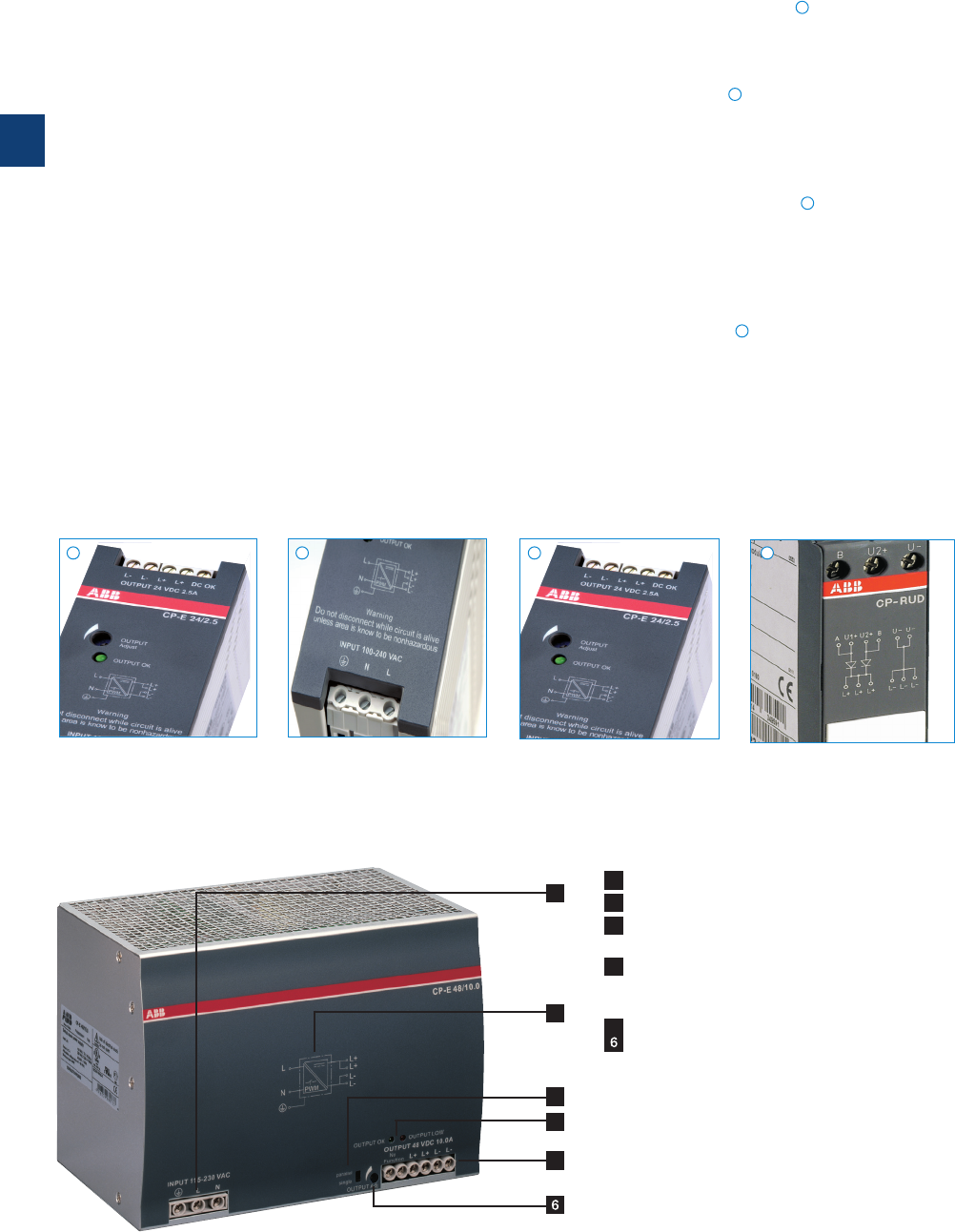
3
3/19 ABB | Catalog Electronic Products and Relays 2015 | 2CDC 110 004 C0210
2CDC 276 008 F0006
2CDC 276 008 F0006
2CDC 271 006 F0003
2CDC 276 009 F0006
Characteristics
– Output voltages 5 V, 12 V, 24 V, 48 V DC
– Adjustable output voltages
– Output currents 0.625 A / 0.75 A / 1.25 A / 2.5 A / 3 A /
5 A / 10 A / 20 A
– Power range 15 W, 18 W, 30 W, 60 W, 120 W, 240 W, 480 W
– High efficiency of up to 90 %
– Low power dissipation and low heating
– Free convection cooling (no forced cooling with ventilators)
– Ambient temperature range during operation -40...+70 °C
– Open-circuit, overload and short-circuit stable
– Integrated input fuse
– U/I characteristic curve on devices > 18 W
(fold-forward behaviour at overload – no switch-off)
– Redundancy units offering true redundancy
– LED(s) for status indication
– Signalling output/contact for output voltage OK
Transistor on 24 V devices > 18 W and < 120 W
– Solid-state on 24 V devices M 120 W
– Approvals / Marks
(depending on device, partly pending):
–A, H, R, E / a, b
Signalling output/contact
The CP-E range 24 V devices > 18 W offer an output/contact
for monitoring of the output voltage and remote diagnosis.
Wide range input
Optimised for world-wide applications: The CP-E power
supplies can be supplied within a wide range of AC or DC
voltage.
Adjustable output voltage
The CP-E range types feature a continuously adjustable
output voltage. Thus, they can be optimally adapted to the
application, e.g. compensating the voltage drop caused by a
long line length.
Redundancy units
For decoupling of parallelized power supply units m 40 V.
Thus, true redundancy can be achieved.
Further information about redundancy unit on page 51.
Benefits
1
1
2
2
3
3
4
4
CP-E range
Benefits and advantages
4
1
2
3
5
1 INPUT L, N, PE: terminals - input
2 Circuit diagram
3 single/parallel: sliding switch - adjustment of single
or parallel operation
4 Indication of operational states
DC ON: green LED - green LED - output voltage OK
DC LOW: red LED - output voltage too low
5 OUTPUT L+, L+, L-, L-: terminals - output
OUTPUT Adjust: potentiometer - adjustment of output voltage
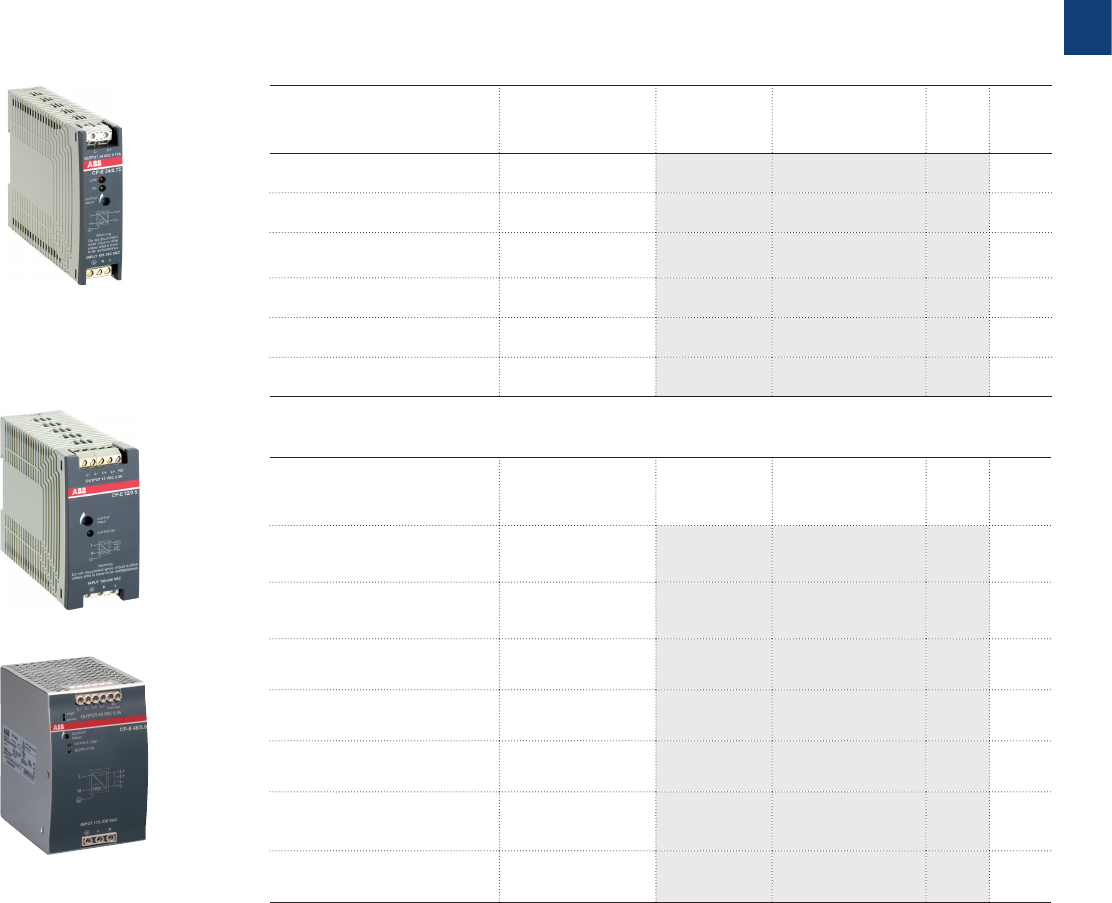
3
2CDC 110 004 C0210 | Catalog Electronic Products and Relays 2015 | ABB 3/20
Description
This range offers types with output voltages from 5 V DC to 48 V DC at output currents of
0.625 A to 20 A. The high thermal efficiency of up to 90 %, corresponding to very low power
and heat dissipation, allows operation without forced cooling. The functionality has been en-
hanced while the number of different types has been considerably reduced.
Of course all power supplies of the CP-E range are approved in accordance with all relevant
international standards.
Ordering details - CP-E < 100 W
Input voltage range Rated output
voltage / current
Type Order code Price
1 pce
Weight
(1 pce)
kg (lb)
90-264 V AC / 120-375 V DC 5 V DC / 3 A CP-E 5/3.0 1SVR427033R3000 0.15
(0.33)
85-264 V AC / 90-375 V DC 12 V DC / 2.5 A CP-E 12/2.5 1SVR427032R1000 0.29
(0.64)
90-132 V AC, 180-264 V AC /
210-375 V DC 12 V DC / 10 A CP-E 12/10.0 1SVR427035R1000 1.00
(2.20)
90-264 V AC / 120-375 V DC 24 V DC / 0.75 A CP-E 24/0.75 1SVR427030R0000 0.15
(0.33)
85-264 V AC / 90-375 V DC 24 V DC / 1.25 A CP-E 24/1.25 1SVR427031R0000 0.29
(0.64)
85-264 V AC / 90-375 V DC 24 V DC / 2.5 A CP-E 24/2.5 1SVR427032R0000 0.36
(0.79)
Ordering details - CP-E M 120 W
Input voltage range Rated output
voltage / current
Type Order code Price
1 pce
Weight
(1 pce)
kg (lb)
90-132 V AC, 180-264 V AC /
210-375VDC 24 V DC / 5 A CP-E 24/5.0 1SVR427034R0000 1.00
(2.20)
90-132 V AC, 180-264 V AC /
210-375VDC 24 V DC / 10 A CP-E 24/10.0 1SVR427035R0000 1.36
(3.01)
90-264 V AC / 120-375 V DC 24 V DC / 20 A CP-E 24/20.0 1SVR427036R0000 1.90
(4.18)
85-264 V AC / 90-375 V DC 48 V DC / 0.625 A CP-E 48/0.62 1SVR427030R2000 0.29
(0.64)
85-264 V AC / 90-375 V DC 48 V DC / 1.25 A CP-E 48/1.25 1SVR427031R2000 0.36
(0.79)
90-132 V AC, 180-264 V AC /
210-375VDC 48 V DC / 5 A CP-E 48/5.0 1SVR427034R2000 1.36
(3.01)
90-264 V AC / 120-375 V DC 48 V DC / 10 A CP-E 48/10.0 1SVR427035R2000 1.90
(4.19)
2CDC 271 013 F0006
2CDC 271 028 F0008
2CDC 271 017 F0006
CP-E 12/2.5
CP-E 48/5.0
CP-E 24/0.75
CP-E range
Ordering details

3
3/21 ABB | Catalog Electronic Products and Relays 2015 | 2CDC 110 004 C0210
CP-E range
Technical data
Data at Ta = 25 °C, Uin = 230 V AC and rated values, unless otherwise indicated
Type CP-E 5/3.0 CP-E 12/2.5 CP-E 12/10.0
Input circuit L, N
Rated input voltage Uin 100-240 V AC 115 / 230 V AC
auto select
Input voltage range 90-264 V AC /
120-375 V DC
85-264 V AC /
90-375 V DC
90-132 V AC,
180-264 V AC /
210-375 V DC
Frequency range AC 47- 63 Hz
Typical input current at 115 V AC 335 mA 560 mA 2.2 A
at 230 V AC 210 mA 330 mA 0.83 A
Typical power consumption 19.8 W 35.9 W 143 W
Inrush current limiting at 115 V AC 10 A (max. 3 ms) 20 A (max. 3 ms) 24 A (max. 5 ms)
at 230 V AC 18 A (max. 3 ms) 40 A (max. 3 ms) 48 A (max. 5 ms)
Discharge current input / output 0.25 mA
input / PE 3.5 mA
Power failure buffering time at 115 V AC min. 20 ms min. 20 ms min. 25 ms
at 230 V AC min. 75 ms min. 30 ms min. 30 ms
Internal input fuse 2 A slow-acting / 250 V AC 3.15 A slow-acting /
250 V AC
Power factor correction (PFC) no yes, passive, 0.7
Indication of operational states
Output voltage green LED OK: V:
output voltage OK
OUTPUT OK: V:
output voltage OK
OUTPUT OK: V:
output voltage OK
red LED LOW: V:
output voltage too low
-
OUTPUT LOW:
V
:
output voltage too low
Output circuit L+,L- L+, L+, L-, L-
Rated output voltage 5 V DC 12 V DC
Tolerance of the output voltage 0...+1 %
Adjustment range of the output voltage 4.5-5.75 V DC 12-14 V DC 11.4-14.5 V DC
Rated output power 15 W 30 W 120 W
Rated output current IrTa m 60 °C 3.0 A 2.5 A 10 A
Derating of the output current 60 °C < Ta m 70 °C 2.5 %/°C 2.5 %/°C
Maximum deviation with load change statical ±2 % ±0.5 % ±1 % (single mode)
±5 % (parallel mode)
change of output voltage within the
input voltage range
±1 % ±0.5 % ±0.5 %
Control time < 2 ms
Starting time after applying the supply voltage at Irmax. 1 s
with 3500 µF -max. 2 s -
with 7000 µF max. 1.5 s -max. 1.5 s
Rise time at rated load max. 150 ms
with 3500 µF -max. 500 ms -
with 7000 µF max. 500 ms -max. 500 ms
Fall time max. 150 ms
Residual ripple and switching peaks BW = 20 MHz 50 mV
Parallel connection yes, to enable redundancy configurable, to
increase power,up to 3
devices,
min. 0.1 Ir - max. 0.9 Ir
Series connection yes, to increase voltage yes, to increase
voltage, max. 2
devices
Resistance to reverse feed 1 s - max. 7.5 V DC 1 s - max.18 V DC max. 18 V DC
Output circuit - No-load, overload and short-circuit behaviour
Characteristic curve of output Hiccup-mode U/I characteristic curve
Short-circuit protection continuous short-circuit proof
Short-circuit behaviour Hiccup-mode continuation with output power limiting
Overload protection output power limiting
No-load protection continuous no-load stability
Starting of capacitive loads 7000 µF 3500 µF 7000 µF

3
2CDC 110 004 C0210 | Catalog Electronic Products and Relays 2015 | ABB 3/22
CP-E range
Technical data
Data at Ta = 25 °C, Uin = 230 V AC and rated values, unless otherwise indicated
Type CP-E 5/3.0 CP-E 12/2.5 CP-E 12/10.0
General data
Power dissipation typ. 5 W typ. 5.6 W typ. 24 W
Efficiency typ. 75 % typ. 84 % typ. 84 %
Duty time 100 %
Dimensions (W x H x D) 22.5 x 90 x 114 mm
(0.89 x 3.54 x 4.49 in)
40.5 x 90 x 114 mm
(1.59 x 3.54 x 4.49 in)
63.2 x 123.6 x 123.6 mm
(2.49 x 4.87 x 4.87 in)
Weight 0.144 kg (0.317 lb) 0.287 kg (0.633 lb) 0.888 kg (1.958 lb)
Material of housing Plastic Metal
Mounting DIN rail (IEC/EN 60715), snap-on mounting without any tool
Mounting position horizontal
Minimum distance to other units horizontal / vertical 25 mm / 25 mm (0.98 in / 0.98 in)
Degree of protection housing / terminals IP20 / IP20
Protection class I
Electrical connection - input circuit / output circuit
Wire size fine-strand with wire end ferrule 0.2-2.5 mm2 (24-14 AWG)
0.2-4 mm² (24-11 AWG)
fine-strand without wire end ferrule
0.2-6 mm² (24-10 AWG)
rigid
Stripping length 6 mm (0.24 in) 8 mm (0.31 in)
Tightening torque input / output 0.6 Nm (5 lb.in) 1.0 Nm (9 lb.in) /
0.62 Nm (5.5 lb.in)
Environmental data
Ambient temperature range operation -20…+70 °C -40…+70 °C -35…+70 °C
rated load -20...+60 °C -40...+60 °C -35...+60 °C
storage -20…+85 °C -40…+85 °C -40…+85 °C
Damp heat (cyclic) (IEC/EN 60068-2-30) 95 RH, % without condensation
Vibration (sinusoidal) (IEC/EN 60068-2-6) 10-500 Hz, 2 G, along X, Y, Z each axis, 60 min. for each axis
Shock (half-sine) (IEC/EN 60068-2-27) 15 G, 11 ms, 3 axes, 6 faces, 3 times for each face
Isolation data
Rated insulation voltage Uiinput circuit / output circuit 3 kV AC
input / PE 1.5 kV AC
output / PE 0.5 kV AC; 0.71 kV DC
Pollution degree 2
Overvoltage category (UL/IEC/EN 60950-1) II
Standards
Product standard EN 61204-3
Low Voltage Directive 2006/95/EC
EMC directive 2004/108/EC
RoHS directive 2011/65/ EC
Electrical safety EN 60950-1,
UL 60950-1, UL 508
EN 60950-1, UL 60950-1, UL 508,
EN 61558-1, EN 61558-2-17; EN 60204-1
Protective low voltage SELV (EN 60950)
Electromagnetic compatibility
Interference immunity to IEC/EN 61000-6-2
electrostatic discharge IEC/EN 61000-4-2 Level 4 (air discharge 15 kV / contact discharge 8 kV)
radiated, radio-frequency, electromagnetic
field
IEC/EN 61000-4-3 Level 3 (10 V/m)
electrical fast transient/burst IEC/EN 61000-4-4 Level 4 (4 kV / 2,5 kHz) Level 4 (4 kV / 5 kHz)
surge IEC/EN 61000-4-5 L-L Level 3 (2 kV) / L-PE Level 4 (4 kV)
conducted disturbances, induced by radio-
frequency fields
IEC/EN 61000-4-6 Level 3 (10 V)
power frequency magnetic fields IEC/EN 61000-4-8 Level 4 (30 A/m)
voltage dips, short interruptions and voltage
variations
IEC/EN 61000-4-11 dip: >95 % 10 ms / >30 % 500 ms
interruptions: >95 % 5000 ms
Interference emission IEC/EN 61000-6-3
high-frequency radiated IEC/CISPR 22, EN 55022 Class B
high-frequency conducted IEC/CISPR 22, EN 55022 Class B
limits for harmonic current emissions IEC/EN 61000-3-2 Class D Class A Class D
„Approvals and marks“ on page 3/4.

3
3/23 ABB | Catalog Electronic Products and Relays 2015 | 2CDC 110 004 C0210
CP-E range
Technical data
Data at Ta = 25 °C, Uin = 230 V AC and rated values, unless otherwise indicated
Type CP-E 24/0.75 CP-E 24/1.25 CP-E 24/2.5
Input circuit L, N
Rated input voltage Uin 100-240 V AC
Input voltage range 90-264 V AC /
120-375 V DC
85-264 V AC /
90-375 V DC
Frequency range AC 47- 63 Hz
Typical input current at 115 V AC 335 mA 560 mA 1060 mA
at 230 V AC 210 mA 330 mA 590 mA
Typical power consumption 22.8 W 36.7 W 69.2 W
Inrush current limiting at 115 V AC 10 A (max. 3 ms) 20 A (max. 3 ms) 20 A (max. 3 ms)
at 230 V AC 18 A (max. 3 ms) 40 A (max. 3 ms) 40 A (max. 3 ms)
Discharge current input / output 0.25 mA
input / PE 3.5 mA
Power failure buffering time at 115 V AC min. 20 ms min. 20 ms
at 230 V AC min. 75 ms min. 30 ms
Internal input fuse 2 A slow-acting / 250 V AC
Power factor correction (PFC) no
Indication of operational states
Output voltage green LED OK: V:
output voltage OK
OUTPUT OK: V: output voltage OK
red LED LOW: V:
output voltage too low
- -
Output circuit L+,L- L+, L+, L-, L-
Rated output voltage 24 V DC
Tolerance of the output voltage 0 ... +1 %
Adjustment range of the output voltage 21.6-28.8 V DC 24-28 V DC
Rated output power 18 W 30 W 60 W
Rated output current IrTa m 60 °C 0.75 A 1.25 A 2.5 A
Derating of the output current 60 °C < Ta m 70 °C 2.5 %/°C
Signalling output for output voltage OK DC OK -transistor
Maximum deviation with load change statical ±2 % ±0.5 %
change of output voltage within the
input voltage range
±1 % ±0.5 %
Control time < 2 ms
Starting time after applying the supply voltage at Irmax. 1 s
with 3500 µF -max. 2 s -
with 7000 µF max. 1.5 s -max. 1.5 s
Rise time at rated load max. 150 ms
with 3500 µF -max. 500 ms -
with 7000 µF max. 500 ms -max. 500 ms
Fall time max. 150 ms
Residual ripple and switching peaks BW = 20 MHz 50 mV
Parallel connection yes, to enable redundancy
Series connection yes, to increase voltage
Resistance to reverse feed 1 s - max. 35 V DC
Output circuit - No-load, overload and short-circuit behaviour
Characteristic curve of output Hiccup-mode U/I characteristic curve
Short-circuit protection continuous short-circuit proof
Short-circuit behaviour Hiccup-mode continuation with output power limiting
Overload protection output power limiting
No-load protection continuous no-load stability
Starting of capacitive loads 7000 µF 3500 µF 7000 µF

3
2CDC 110 004 C0210 | Catalog Electronic Products and Relays 2015 | ABB 3/24
CP-E range
Technical data
Data at Ta = 25 °C, Uin = 230 V AC and rated values, unless otherwise indicated
Type CP-E 24/0.75 CP-E 24/1.25 CP-E 24/2.5
General data
Power dissipation typ. 4.45 W typ. 5.5 W typ. 8.8 W
Efficiency typ. 77 % typ. 86 % typ. 89 %
Duty time 100 %
Dimensions (W x H x D) 22.5 x 90 x 114 mm
(0.89 x 3.54 x 4.49 in)
40.5 x 90 x 114 mm
(1.59 x 3.54 x 4.49 in)
Weight 0.143 kg (0.315 lb) 0.270 kg (0.60 lb) 0.331 kg (0.73 lb)
Material of housing Plastic
Mounting DIN rail (IEC/EN 60715), snap-on mounting without any tool
Mounting position horizontal
Minimum distance to other units horizontal / vertical 25 mm / 25 mm (0.98 in / 0.98 in)
Degree of protection housing / terminals IP20 / IP20
Protection class I
Electrical connection - input circuit / output circuit
Wire size fine-strand with wire end ferrule 0.2-2.5 mm2 (24-14 AWG)
fine-strand without wire end ferrule
rigid
Stripping length 6 mm (0.24 in)
Tightening torque input / output 0.6 Nm (5 lb.in)
Environmental data
Ambient temperature range operation -20…+70 °C -40…+70 °C
rated load -20…+60 °C -40…+60 °C
storage -20…+85 °C -40…+85 °C
Damp heat (cyclic) (IEC/EN 60068-2-30) 95 % RH, without condensation
Vibration (sinusoidal) (IEC/EN 60068-2-6) 10-500 Hz, 2 G, along X, Y, Z each axis, 60 min. for each axis
Shock (half-sine) (IEC/EN 60068-2-27) 15 G, 11 ms, 3 axes, 6 faces, 3 times for each face
Isolation data
Rated insulation voltage Uiinput circuit / output circuit 3 kV AC
input / PE 1.5 kV AC
output / PE 0.5 kV AC; 0.71 kV DC
Pollution degree 2
Overvoltage category (UL/IEC/EN 60950-1) II
Standards
Product standard EN 61204-3
Low Voltage Directive 2006/95/EC
EMC directive 2004/108/EC
RoHS directive 2011/65/ EC
Electrical safety
EN 50178, EN 60950-1,
UL 60950-1, UL 508
EN 60950-1, UL 60950-1, UL 508, EN 61558-1,
EN 61558-2-17; EN 60204-1
Protective low voltage SELV (EN 60950)
Electromagnetic compatibility
Interference immunity to IEC/EN 61000-6-2
electrostatic discharge IEC/EN 61000-4-2 Level 4 (air discharge 15 kV / contact discharge 8 kV)
radiated, radio-frequency, electromagnetic field IEC/EN 61000-4-3 Level 3 (10 V/m)
electrical fast transient/burst IEC/EN 61000-4-4 Level 4 (4 kV / 2.5 kHz) Level 4 (4 kV / 5 kHz)
surge IEC/EN 61000-4-5 L-L Level 3 (2 kV) / L-PE Level 4 (4 kV)
conducted disturbances, induced by radio-
frequency fields
IEC/EN 61000-4-6 Level 3 (10 V)
power frequency magnetic fields IEC/EN 61000-4-8 Level 4 (30 A/m)
voltage dips, short interruptions and voltage
variations
IEC/EN 61000-4-11 dip: >95 % 10 ms / >30 % 500 ms, interruptions: >95 % 5000 ms
Interference emission IEC/EN 61000-6-3
high-frequency radiated IEC/CISPR 22, EN 55022 Class B
high-frequency conducted IEC/CISPR 22, EN 55022 Class B
limits for harmonic current emissions IEC/EN 61000-3-2 Class D Class A
„Approvals and marks“ on page 3/4.

3
3/25 ABB | Catalog Electronic Products and Relays 2015 | 2CDC 110 004 C0210
CP-E range
Technical data
Data at Ta = 25 °C, Uin = 230 V AC and rated values, unless otherwise indicated
Type CP-E 24/5.0 CP-E 24/10.0 CP-E 24/20.0
Input circuit L, N
Rated input voltage Uin 115 / 230 V AC auto select 115-230 V AC
Input voltage range 90-132 V AC,
180-264 V AC /
210-375 V DC
90-132 V AC,
180-264 V AC /
210-375 V DC
90-264 V AC,
120-375 V DC
Frequency range AC 47- 63 Hz
Typical input current at 115 V AC 2.2 A 4.0 A 4.9 A
at 230 V AC 0.83 A 1.55 A 2.5 A
Typical power consumption 140 W 270 W 539 W
Inrush current limiting at 115 V AC 24 A (max. 5 ms) 30 A (max. 5 ms) 25 A (max. 5 ms)
at 230 V AC 48 A (max. 5 ms) 60 A (max. 5 ms) 50 A (max. 5 ms)
Discharge current input / output 0.25 mA
input / PE 3.5 mA
Power failure buffering time at 115 V AC min. 25 ms
at 230 V AC min. 30 ms
Internal input fuse 3.15 A slow-acting /
250 V AC
6.3 A slow-acting /
250 V AC
10 A slow-acting /
250VAC
Power factor correction (PFC) yes, passive, 0.7 yes, active
115 V AC: 0.99
230 V AC: 0.97
Indication of operational states
Output voltage green LED OUTPUT OK: V: output voltage OK
red LED OUTPUT LOW: V: output voltage too low
Output circuit L+, L+, L-, L-
Rated output voltage 24 V DC
Tolerance of the output voltage 0...+1 %
Adjustment range of the output voltage 22.5-28.5 V DC
Rated output power 120 W 240 W 480 W
Rated output current IrTa m 60 °C 5 A 10 A -
Ta m 55 °C --20 A
Derating of the output current
60 °C < T
a
m
70 °C
2.5 %/°C -
55 °C < T
a
m
70 °C
--2.5 %/°C
Signalling contact for output voltage OK 13-14 solid-state (max. 60 V DC, 0.3 A)
Minimum fuse rating to achieve short-circuit protection 13 -14 M 60 V DC, m 0.3 A fast-acting
Maximum deviation with load change statical ±1 % (single mode), ±5 % (parallel mode)
change of output voltage within
the input voltage range
±0.5 %
Control time < 2 ms
Starting time after applying the supply voltage at Irmax. 1 s
with 3500 µF max. 1.5 s - -
with 7000 µF -max. 1.5 s
Rise time at rated load max. 150 ms
with 3500 µF max. 500 ms - -
with 7000 µF -max. 500 ms
Fall time max. 150 ms
Residual ripple and switching peaks BW = 20 MHz 50 mV 100 mV
Parallel connection configurable, to increase power, up to 3 devices, min. 0.1 Ir - max. 0.9 Ir
Series connection yes, to increase voltage, max. 2 devices
Resistance to reverse feed max. 35 V DC
Output circuit - No-load, overload and short-circuit behaviour
Characteristic curve of output U/I characteristic curve
Short-circuit protection continuous short-circuit proof
Short-circuit behaviour continuation with output power limiting
Overload protection output power limiting
No-load protection continuous no-load stability
Starting of capacitive loads 3500 µF 7000 µF

3
2CDC 110 004 C0210 | Catalog Electronic Products and Relays 2015 | ABB 3/26
CP-E range
Technical data
Data at Ta = 25 °C, Uin = 230 V AC and rated values, unless otherwise indicated
Type CP-E 24/5.0 CP-E 24/10.0 CP-E 24/20.0
General data
Power dissipation typ. 20 W typ. 35 W typ. 63 W
Efficiency typ. 86 % typ. 89 % typ. 89 %
Duty time 100 %
Dimensions (W x H x D)
63.2 x 123.6 x 123.6 mm
(2.49 x 4.87 x 4.87 in)
83 x 123.6 x 123.6 mm
(3.27 x 4.87 x 4.87 in)
175 x 123.6 x 123.6 mm
(6.89 x 4.87 x 4.87 in)
Weight 0.882 kg (1.945 lb) 1.334 kg (2.941 lb) 1.850 kg (4.079 lb)
Material of housing Metal
Mounting DIN rail (IEC/EN 60715), snap-on mounting without any tool
Mounting position horizontal
Minimum distance to other units horizontal / vertical 25 mm / 25 mm (0.98 in / 0.98 in)
Degree of protection housing / terminals IP20 / IP20
Protection class I
Electrical connection - input circuit / output circuit
Wire size fine-strand with wire end ferrule 0.2-4 mm² (24-11 AWG)
fine-strand without wire end
ferrule
0.2-6 mm² (24-10 AWG)
rigid
Stripping length 8 mm (0.31 in)
Tightening torque input / output 1.0 Nm (9 lb.in) / 0.62 Nm (5.5 lb.in)
Environmental data
Ambient temperature range operation -35…+70 °C -40…+70 °C
rated load -35…+60 °C -40…+60 °C -40…+55 °C
storage -40…+85 °C -40…+85 °C
Damp heat (cyclic) (IEC/EN 60068-2-30) 95 %RH, without condensation
Vibration (sinusoidal) (IEC/EN 60068-2-6) 10-500 Hz, 2 G, along X, Y, Z each axis, 60 min. for each axis
Shock (half-sine) (IEC/EN 60068-2-27) 15 G, 11 ms, 3 axes, 6 faces, 3 times for each face
Isolation data
Rated insulation voltage Uiinput circuit / output circuit 3 kV AC
input / PE 1.5 kV AC
output / PE 0.5 kV AC; 0.71 kV DC
signalling contact / PE 0.5 kV DC
Pollution degree 2
Overvoltage category (UL/IEC/EN 60950-1) II
Standards
Product standard EN 61204-3
Low Voltage Directive 2006/95/EC
EMC directive 2004/108/EC
RoHS directive 2011/65/ EC
Electrical safety EN 60950-1, UL 60950-1, UL 508, EN 61558-1, EN 61558-2-17; EN
60204-1
Protective low voltage SELV (EN 60950)
Electromagnetic compatibility
Interference immunity to IEC/EN 61000-6-2
electrostatic discharge IEC/EN 61000-4-2 Level 4 (air discharge 15 kV / contact discharge 8 kV)
radiated, radio-frequency, electromagnetic
field
IEC/EN 61000-4-3 Level 3 (10 V/m)
electrical fast transient/burst IEC/EN 61000-4-4 Level 4 (4 kV / 5 kHz) Level 4 (4 kV / 2.5 kHz)
surge IEC/EN 61000-4-5 L-L Level 3 (2 kV) / L-PE Level 4 (4 kV)
conducted disturbances, induced by radio-
frequency fields
IEC/EN 61000-4-6 Level 3 (10 V)
power frequency magnetic fields IEC/EN 61000-4-8 Level 4 (30 A/m)
voltage dips, short interruptions and voltage
variations
IEC/EN 61000-4-11 dip: >95 % 10 ms / >30 % 500 ms
interruptions: >95 % 5000 ms
Interference emission IEC/EN 61000-6-3
high-frequency radiated IEC/CISPR 22, EN 55022 Class B
high-frequency conducted IEC/CISPR 22, EN 55022 Class B
limits for harmonic current emissions Class D
„Approvals and marks“ on page 3/4.

3
3/27 ABB | Catalog Electronic Products and Relays 2015 | 2CDC 110 004 C0210
CP-E range
Technical data
Data at Ta = 25 °C, Uin = 230 V AC and rated values, unless otherwise indicated
Type CP-E 48/0.62 CP-E 48/1.25 CP-E 48/5.0 CP-E 48/10.0
Input circuit L, N
Rated input voltage Uin 100-240 V AC 115 / 230 V AC
auto select 115-230 V AC
Input voltage range 85-264 V AC /
90-375 V DC
90-132 V AC,
180-264 V AC /
210-375 V DC
90-264 V AC,
120-375 V DC
Frequency range AC 47- 63 Hz
Typical input current at 115 V AC 560 mA 1060 mA 4.0 A 4.9 A
at 230 V AC 330 mA 590 mA 1.55 A 2.5 A
Typical power consumption 35.7 W 69.0 W 267 W 528 W
Inrush current limiting at 115 V AC 20 A (max. 3 ms) 20 A (max. 3 ms) 30 A (max. 5 ms) 25 A (max. 5 ms)
at 230 V AC 40 A (max. 3 ms) 40 A (max. 3 ms) 60 A (max. 5 ms) 50 A (max. 5 ms)
Discharge current input / output 0.25 mA
input / PE 3.5 mA
Power failure buffering time at 115 V AC min. 20 ms min. 25 ms min. 25 ms
at 230 V AC min. 30 ms
Internal input fuse 2 A slow-acting /
250 V AC
6.3 A slow-
acting /
250 V AC
10 A slow-
acting /
250 V AC
Power factor correction (PFC)
no yes, passive, 0.7
yes, active
115 V AC: 0.99
230 V AC: 0.97
Indication of operational states
Output voltage green LED OUTPUT OK: V: output voltage OK
red LED - - OUTPUT LOW: V:
output voltage too low
Output circuit L+, L+, L-, L-
Rated output voltage 48 V DC
Tolerance of the output voltage 0...+1 %
Adjustment range of the output voltage 48-55 V DC 47-56 V DC
Rated output power 30 W 60 W 240 W 480 W
Rated output current IrTa m 60 °C 0.625 A 1.25 A 5 A -
Ta m 55 °C ---10 A
Derating of the output current 60 °C < Ta m 70 °C 2.5 %/°C -
55 °C < Ta m 70 °C ---2.5 %/°C
Signalling output for output voltage OK DC OK - - - -
Maximum deviation with load change statical ±0.5 % ±1 % (single mode)
±5 % (parallel mode)
change of output voltage within
the input voltage range ±0.5 % ±0.5 %
Control time < 2 ms
Starting time after applying the supply voltage at Irmax. 1 s
with 3500 µF max. 2 s - - -
with 7000 µF -max. 1.5 s max. 1.5 s
Rise time at rated load max. 150 ms
with 3500 µF max. 500 ms - - -
with 7000 µF -max. 500 ms max. 500 ms
Fall time max. 150 ms
Residual ripple and switching peaks BW = 20 MHz 50 mV 100 mV
Parallel connection
yes, to enable redundancy
configurable, to increase power,
up to 3 devices,
min. 0.1 Ir - max. 0.9 Ir
Series connection yes, to increase voltage yes, to increase voltage,
max. 2 devices
Resistance to reverse feed 1 s - max. 63 V DC
Output circuit - No-load, overload and short-circuit behaviour
Characteristic curve of output U/I characteristic curve
Short-circuit protection continuous short-circuit proof
Short-circuit behaviour continuation with output power limiting
Overload protection output power limiting
No-load protection continuous no-load stability
Starting of capacitive loads 3500 µF 7000 µF unlimited 7000 µF

3
2CDC 110 004 C0210 | Catalog Electronic Products and Relays 2015 | ABB 3/28
CP-E range
Technical data
Data at Ta = 25 °C, Uin = 230 V AC and rated values, unless otherwise indicated
Type CP-E 48/0.62 CP-E 48/1.25 CP-E 48/5.0 CP-E 48/10.0
General data
Power dissipation typ. 4.9 W typ. 7.8 W typ. 32 W typ. 60 W
Efficiency typ. 86 % typ. 89 % typ. 90 %
Duty time 100 %
Dimensions (W x H x D)
40.5 x 90 x 114 mm
(1.59 x 3.54 x 4.49 in)
83 x 123.6 x
123.6 mm
(3.27 x 4.87 x
4.87 in)
175 x 123.6 x
123.6 mm
(6.89 x 4.87 x
4.87 in)
Weight
0.264 kg (0.582 lb) 0.316 kg (0.697 lb) 1.322 kg (2.915 lb) 1.839 kg (4.054 lb)
Material of housing Plastic Metal
Mounting DIN rail (IEC/EN 60715), snap-on mounting without any tool
Mounting position horizontal
Minimum distance to other units horizontal / vertical 25 mm / 25 mm (0.98 in / 0.98 in)
Degree of protection housing / terminals IP/20 / IP20
Protection class I
Electrical connection - input circuit / output circuit
Wire size fine-strand with wire end ferrule
0.2-2.5 mm² (24-14 AWG)
0.2-4 mm² (24-11 AWG)
fine-strand without wire end ferrule 0.2-6 mm² (24-10 AWG)
rigid
Stripping length 6 mm (0.24 in) 8 mm (0.31 in)
Tightening torque input / output 0.6 Nm (5 lb.in) 1.0 Nm (9 lb.in) / 0.62 Nm (5.5 lb.in)
Environmental data
Ambient temperature range operation -40…+70 °C
rated load -40…+60 °C -40…+55 °C
storage -40…+85 °C
Damp heat (cyclic) (IEC/EN 60068-2-30) 95 % RH, without condensation
Vibration (sinusoidal) (IEC/EN 60068-2-6) 10-500 Hz, 2 G, along X, Y, Z each axis, 60 min. for each axis
Shock (half-sine) (IEC/EN 60068-2-27) 15 G, 11 ms, 3 axes, 6 faces, 3 times for each face
Isolation data
Rated insulation voltage Uiinput circuit / output circuit 3 kV AC
input / PE 1.5 kV AC
output / PE 0.5 kV AC; 0.71 kV DC
Pollution degree 2
Overvoltage category (UL/IEC/EN 60950-1) II
Standards
Product standard EN 61204-3
Low Voltage Directive 2006/95/EC
EMC directive 2004/108/EC
RoHS directive 2011/65/ EC
Electrical safety
EN 60950-1, UL 60950-1, UL 508, EN 61558-1, EN 61558-2-17; EN 60204-1
Protective low voltage SELV (EN 60950)
Electromagnetic compatibility
Interference immunity to IEC/EN 61000-6-2
electrostatic discharge IEC/EN 61000-4-2 Level 4 (air discharge 15 kV / contact discharge 8 kV)
radiated, radio-frequency, electromagnetic
field
IEC/EN 61000-4-3 Level 3 (10 V/m)
electrical fast transient/burst IEC/EN 61000-4-4 Level 4 (4 kV / 5 kHz) Level 4 (4 kV / 2.5 kHz)
surge IEC/EN 61000-4-5 L-L Level 3 (2 kV) / L-PE Level 4 (4 kV)
conducted disturbances, induced by radio-
frequency fields
IEC/EN 61000-4-6 Level 3 (10 V/m)
power frequency magnetic fields IEC/EN 61000-4-8 Level 4 (30 A/m)
voltage dips, short interruptions and voltage
variations
IEC/EN 61000-4-11 dip: >95 % 10 ms / >30 % 500 ms, interruptions: >95 % 5000 ms
Interference emission IEC/EN 61000-6-3
high-frequency radiated IEC/CISPR 22, EN 55022 Class B
high-frequency conducted IEC/CISPR 22, EN 55022 Class B
limits for harmonic current emissions Class A Class D
„Approvals and marks“ on page 3/4.
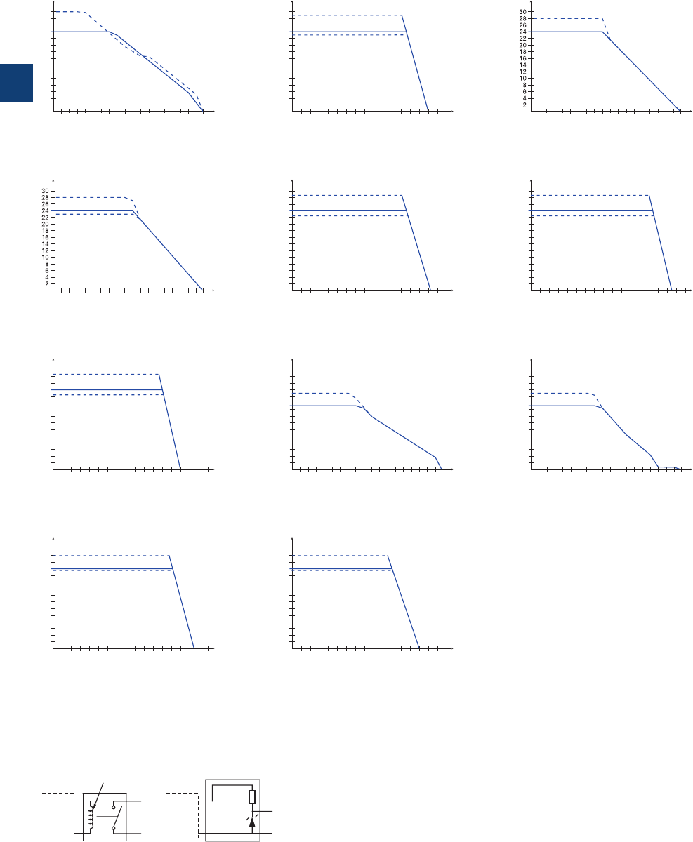
3
3/29 ABB | Catalog Electronic Products and Relays 2015 | 2CDC 110 004 C0210
CP-E range
Technical diagrams, Wiring instructions
Uout [V]
I
out
[A]
1.25 1.35 1.45 1.55 1.65 1.75 1.85 1.95 2.05 2.15
2CDC 272 006 F0b07
U
out
[V]
Iout [A]
2.75 2.85 2.95 3.05 3.15 3.25 3.35 3.45 3.55 3.65
2CDC 272 007 F0b07
Uout [V]
I
out
[A]
2.8 2.9 3.0 3.1 3.2 3.3 3.4 3.5 3.6 3.7
1
3
5
7
9
11
13
15
2CDC 272 008 F0b07
U
out
[V]
Iout [A]
1.73 1.81 1.89 1.97 2.051.33 1.41 1.49 1.57 1.65
10
20
30
40
50
60
70
2CDC 272 010 F0b07
CP-E 24/1.25
CP-E 24/2.5
CP-E 12/2.5
CP-E 48/0.62 CP-E 48/1.25
U
out
[V]
Iout [A]
0.865 0.905 0.945 0.985 1.0250.6650.705 0.745 0.785 0.825
10
20
30
40
50
60
70
2CDC 272 009 F0b07
Uout [V]
I
out
[A]
46810141612
2
2
4
6
8
10
12
14
2CDC 272 005 F0b08
CP-E 12/10.0
U
out
[
V
]
Iout [A]
2345 786
1
4
8
12
16
20
24
28
2CDC 272 006 F0b08
CP-E 24/5.0
U
out
[
V
]
Iout [A]
46810141612
2
4
8
12
16
20
24
28
2CDC 272 007 F0b08
CP-E 24/10.0
U
out
[V]
Iout [A]
81216 20 28 3224
4
4
8
12
16
20
24
28
2CDC 272 008 F0b08
CP-E 24/20.0
CP-E 48/10.0CP-E 48/5.0
U
out
[V]
Iout [A]
2345 786
1
8
16
24
32
40
48
56
2CDC 272 009 F0b08
U
out
[
V
]
Iout [A]
46810141612
2
8
16
24
32
40
48
56
2CDC 272 010 F0b08
CP-E 24/1.25, CP-E 24/2.5
Output curve at Ta = 25 °C
Wiring instructions
DC OK
L-L-
DC OK
2CDC 272 017 F0207
Relay
RL > 700
5 V Signal
2.2 k
0.5 W
5.1 V
0.3 W
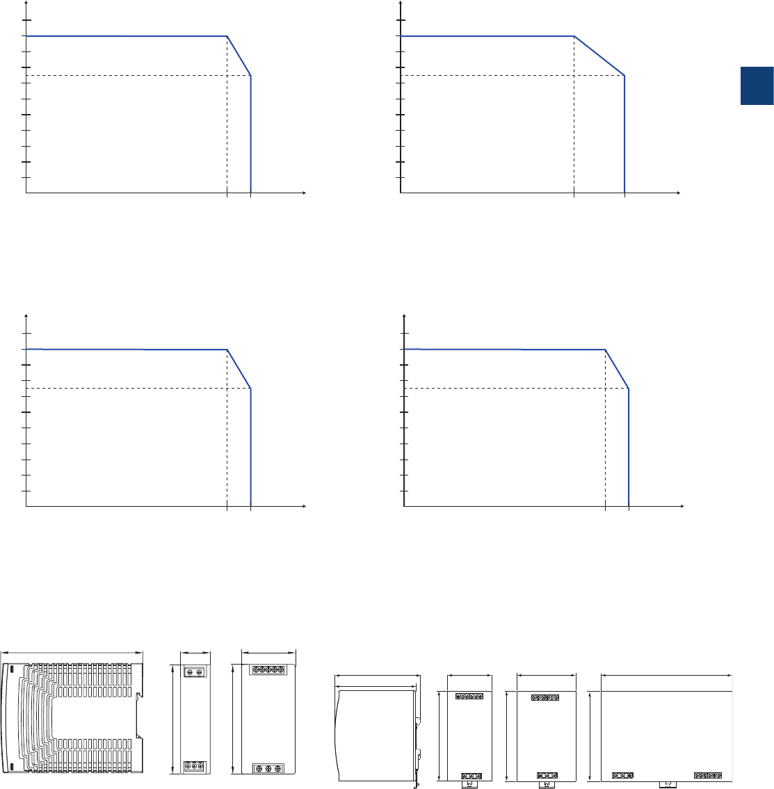
3
2CDC 110 004 C0210 | Catalog Electronic Products and Relays 2015 | ABB 3/30
Temperature behaviour at Ta = 25 °C
CP-E range
Technical diagrams, Dimensional drawings
CP-E 12/10.0, CP-E 24/5.0
CP-E 5/3.0, CP-E 24/0.75 CP-E 12/2.5, CP-E 24/1.25, CP-E 48/0.62,
CP-E 24/2.5, CP-E 48/1.25, CP-E 24/10.0, CP-E 48/5.0
CP-E 24/20.0, CP-E 48/10.0
2CDC 272 015 F02112CDC 272 016 F0211
2CDC 272 017 F0211
2CDC 272 018 F0211
-35 60 70
10
20
30
40
50
60
70
80
90
100
P
out
[%]
Ta [°C]
-20 60 70
10
20
30
40
50
60
70
80
90
100
P
out
[%]
T
a
[°C]
-40 60 70
10
20
30
40
50
60
70
80
90
100
P
out
[%]
T
a
[°C]
-40 55 70
10
20
30
40
50
60
70
80
90
100
P
out
[%]
Ta [°C]
CP-E 5/3.0,
CP-E 24/0.75
CP-E 12/2.5,
CP-E 24/1.25,
CP-E 24/2.5,
CP-E 48/0.62,
CP-E 48/1.25
CP-E 12/10.0,
CP-E 24/5.0
CP-E 24/20.0,
CP-E 48/10.0
CP-E 24/10.0,
CP-E 48/5.0
175,0 [6.89“]
123,6 [4.87“]
116,6 [4.59“]
123,6 [4.87“] 83,0 [3.27“]
123,6 [4.87“]
63,2 [2.49“]
123,6 [4.87“]
2CDC 272 013 F0b08
22.5 0.89“
114 4.49“
90 3.54“
40.5 1.59”
90 3.54”
2CDC 272 021 F0011
2CDC 272 013 F008
Dimensional drawings dimensions in mm
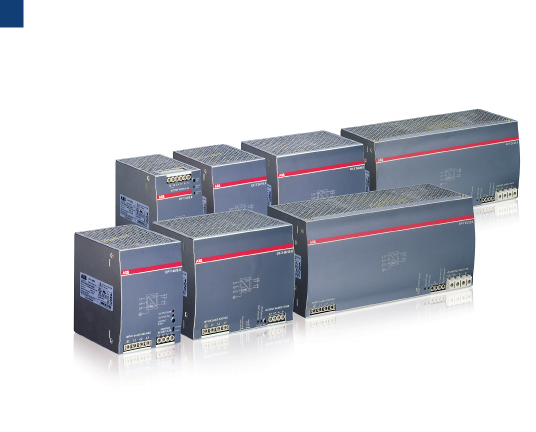
3
3/31 ABB | Catalog Electronic Products and Relays 2015 | 2CDC 110 004 C0210
CP-T range
Product group picture

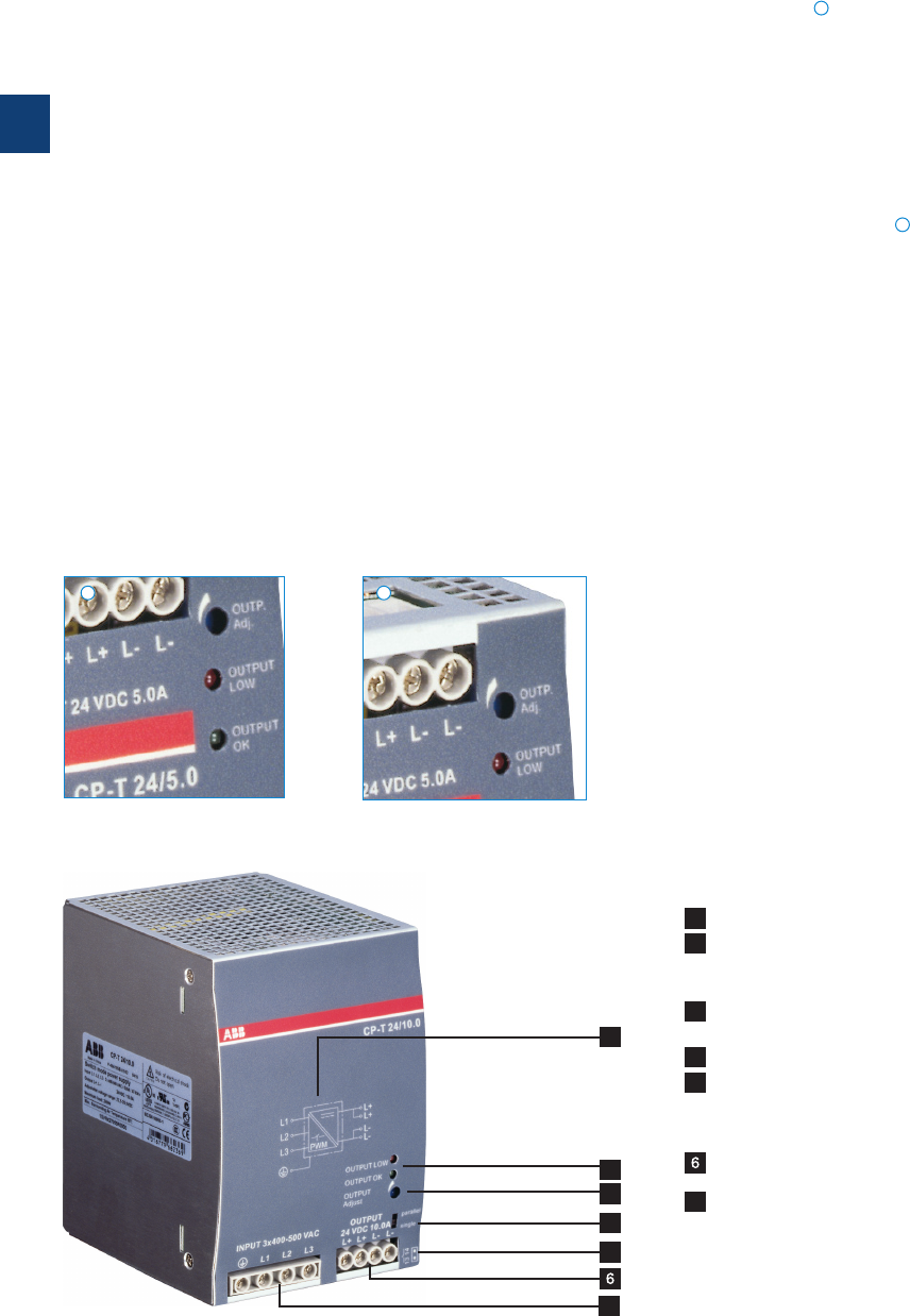
3
3/33 ABB | Catalog Electronic Products and Relays 2015 | 2CDC 110 004 C0210
CP-T range
Benefits and advantages
Characteristics
– Rated output voltages 24 V, 48 V DC
– Output voltage adjustable via front-face rotary potentiom-
eter “OUTPUT Adjust”
– Rated output currents 5 A, 10 A, 20 A, 40 A
– Rated output powers 120 W, 240 W, 480 W, 960 W
– Three-phase operation (see derating note)
–
Two-phase operation (25 % derating possible, see derating note)
– Supply range 3x400–500 V AC (3x340–575VAC,
480–820 V DC)
– Typical efficiency of 93 %
– Low power dissipation and low heating
– Free convection cooling (no forced cooling with ventilators)
– Ambient temperature range during operation -40...+70 °C 1)
– Open-circuit, overload and short-circuit stable
– Integrated input fuse
– Redundancy unit CP-A RU offering true redundancy, avail-
able as accessory
– LEDs for status indication
– Signalling contact "13-14" (solid state) for output voltage
OK
– Approvals / marks (depending on device, partly pending):
–A, H, R, E / a , b
1) 480 W variants: -30...+70°C
Signalling output
The devices of the CP-T series offer a solid state output for
function monitoring and remote diagnostics.
Wide input range
Wide range input optimized for world-wide applications:
The CP-T power supplies can be used in 340 - 575 V AC or
480 - 820 V DC supply systems.
Adjustable output voltage
The CP-T range feature a continuously adjustable output volt-
age. Thus, they can be optimally adapted to the application,
e.g. compensating the voltage drop caused by a long line
length.
Benefits
1
1
2
2
2CDC 271 043 S0009
2CDC 271 043 S0009
4
1
2
3
5
1 Circuit diagram
2 Indication of operational states
DC ON: green LED - green LED - output voltage OK
DC LOW: red LED - output voltage too low
3 single/parallel: sliding switch - adjustment
of single or parallel operation
4 Configuration of single or parallel operation
5 Signalling contact
OUTPUT 13-14: terminals - signalling contact
A solid-state output indicates the error-free operation of the
output voltage.
OUTPUT L+, L+, L-, L-: terminals - output
7INPUT L1, L2, L3, PE: terminals - input
7
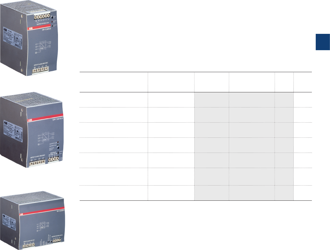
3
2CDC 110 004 C0210 | Catalog Electronic Products and Relays 2015 | ABB 3/34
CP-T range
Ordering details
2CDC 271 043 S0009
2CDC 271 045 S0009
2CDC 271 047 S0009
CP-T 24/5.0
CP-T 24/10.0, CP-T 48/5.0
CP-T 24/20.0, CP-T 48/10.0
Description
The CP-T range of three-phase power supply units is the youngest member of ABB‘s power
supply family. In terms of design and functionality, the new range perfectly supplements the ex-
isting products and extends the range appropriately. The devices can be supplied with a three-
phase voltage as well as with two-phase mains. Here, ABB offers power supply units with 24 V
DC and 48 V DC outputs with 5 A, 10 A, 20 A and 40 A and efficiency of up to 92%. As in the
case of all products, they are designed for an ambient temperature of up to 70°C. All prod-
ucts can be supplied within an AC supply voltage range between 340 to 575VAC and a DC
supply voltage range between 480 to 820 V DC.
Ordering details
Input voltage range Rated
output voltage /
current
Type Order code Price
1 pce
Weight
(1 pce)
kg (lb)
340-575 V AC / 480-820 V DC 24 V DC / 5 A CP-T 24/5.0 1SVR427054R0000 0.80
(1.77)
340-575 V AC / 480-820 V DC 24 V DC / 10 A CP-T 24/10.0 1SVR427055R0000 1.05
(2.31)
340-575 V AC / 480-820 V DC 24 V DC / 20 A CP-T 24/20.0 1SVR427056R0000 1.75
(3.86)
340-575 V AC / 480-820 V DC 24 V DC / 40 A CP-T 24/40.0 1SVR427057R0000 3.20
( 7. 0 5 )
340-575 V AC / 480-820 V DC 48 V DC / 5 A CP-T 48/5.0 1SVR427054R2000 1.05
(2.31)
340-575 V AC / 480-820 V DC 48 V DC / 10 A CP-T 48/10.0 1SVR427055R2000 1.75
(3.86)
340-575 V AC / 480-820 V DC 48 V DC / 20 A CP-T 48/20.0 1SVR427056R2000 3.40
( 7. 5 0 )

3
3/35 ABB | Catalog Electronic Products and Relays 2015 | 2CDC 110 004 C0210
CP-T range
Technical data
Data at Ta = 25 °C, Uin = 3 x 400 V AC and rated values, unless otherwise indicated
Type CP-T 24/5.0 CP-T 24/10.0 CP-T 24/20.0 CP-T 24/40.0
Input circuit L1, L2, L3
Rated input voltage Uin 3 x 400-500 V AC
Input voltage range 340-575 V AC
480-820 V DC
Frequency range AC 47- 63 Hz
Typical input current 0.36 A 0.65 A 1.1 A 1.72 A
Typical power consumption 135 W 270 W 538 W 1058 W
Inrush current limiting 10 A 20 A 30 A
Power failure buffering time min. 20 ms min. 15 ms
Internal input fuse per phase 2 A / 600 V AC
T 3.15 A / 500 V AC
T 5 A / 500 V AC
Recommended backup fuse 3 pole miniature circuit breaker ABB Type S203
Power factor correction (PFC) Yes, passive
Discharge current towards PE < 3.5 mA
input / output < 0.25 mA
Indication of operational states
Output voltage OUTPUT OK: green LED output voltage OK
OUTPUT LOW: red LED output voltage too low
Output circuit L+, L+, L-, L-
Rated output voltage 24 V DC
Tolerance of the output voltage 0...+1 %
Adjustment range of the output voltage 22.5-28.5 V DC
Rated output power 120 W 240 W 480 W 960 W
Rated output current Ir Ta ≤ 60 °C 5 A 10 A 20 A 40 A
Derating of the output current 60 °C < Ta ≤ 70 °C 2.5 %/°C 3.5 %/°C
Signalling contact
for output voltage OK
13-14 solid state (max. 60 V DC, 0.3 A)
Threshold 17.6 -19.4 V
Insulation voltage 500 V DC
Mininum fuse rating to achieve short-circuit protection 13-14 M 60 V DC, m 0.3 A fast-acting
Maximum deviation with load change statical ±1 % ±1 % (single mode)
-±5 % (parallel mode)
change of output voltage
within the input voltage range
± 0.5 %
Control time at nominal load < 2 ms
Starting time after applying
the supply voltage
at Irmax. 1 s
with 3500 µF max. 1.5 s
Rise time at nominal load max. 150 ms
with 3500 µF max. 500 ms
Fall time max. 150 ms
Residual ripple and switching peaks BW = 20 MHz 100 mV 80 mV
Parallel connection not supported configurable, to increase power, up
to 2 devices, min. 0.1 Ir - max 0.9 Ir)
to increase power,
up to 2 devices,
min. 0.1 I
r
- max.
0.9 I
r
use active
current balancing
Series connection not supported yes, to increase voltage, max. 2 devices
Resistance to reverse feed approx. 35 V
Output circuit - No-load, overload and short-circuit behaviour
Characteristic curve of output combined U/I characteristic curve
and hiccup mode
U/I- or Hiccup-
mode adjustable
hiccup / fold
back behavior
Short-circuit protection continuous short-circuit proof
Short-circuit behaviour current limiting
Overload protection hiccup mode
No-load protection continuous no-load stability
Overtemperature protection yes, automatic recovery after temperature went down
Starting of capacitive loads 3500 µF 7000 µF 7000 µF 7000 µF

3
2CDC 110 004 C0210 | Catalog Electronic Products and Relays 2015 | ABB 3/36
CP-T range
Technical data
Data at Ta = 25 °C, Uin = 3 x 400 V AC and rated values, unless otherwise indicated
Type CP-T 24/5.0 CP-T 24/10.0 CP-T 24/20.0 CP-T 24/40.0
General data
Efficiency typ. 89 % typ. 90 % typ. 92 %
Duty time 100%
Dimensions (W x H x D) 74.3 x 124 x
118.8 mm
(2.92 x 4.88 x
4.68 in)
89 x 124 x 118.8
mm
(3.5 x 4.88 x
4.68 in)
150 x 124 x
118.8 mm
(5.91 x 4.88 x
4.68 in)
275.8 x 124 x
118.8 mm
(10.86 x 4.88 x
4.68 in)
Weight 0.78 kg (1.72 lb)
1.045 kg (2.30 lb) 1.657 kg (3.653 lb) 3.275 kg (7.220 lb)
Material of housing Metal
Mounting DIN rail (IEC EN 60715), snap-on mounting without any tool
Mounting position horizontal
Minimum distance to other units horizontal / vertical 25 mm / 25 mm (0.98 in / 0.98 in)
Degree of protection housing / terminals IP20 / IP20
Protection class I
Electrical connection - input circuit / output circuit / signalling circuit
Wire size fine-strand with wire end ferrule 0.2-4 mm² (24-11 AWG)
fine-strand without wire end ferrule 0.2-6 mm² (24-10 AWG)
rigid 0.2-6 mm² (24-10 AWG)
Stripping length 8 mm (0.31 in)
Tightening torque input / output 1 Nm (9 lb.in) / 0.6 Nm (5.5 lb.in) 1 Nm (9 lb.in) /
1.8 Nm (15.6 lb.in)
Environmental data
Ambient temperature range operation -40...+70 °C -30…+70 °C -40...+70 °C
rated load -40...+60 °C -30…+60 °C -40...+60 °C
storage -40…+85 °C
Damp heat (cyclic) (IEC/EN 60068-2-30) 95 % without condensation
Vibration (sinusoidal) (IEC/EN 60068-2-6) 2 g, 10-500 Hz, 2G, each along X, Y, Z axes 60 min / cycle
Shock (half-sine) (IEC/EN 60068-2-27) 15 g, 11 ms, 3 axes, 6 faces, 3 times for each face
Isolation data
Rated insulation voltage Uiinput circuit / output circuit 3 kV AC
input / PE 1.5 kV AC
output / PE 0.5 kV AC; 0.71 kV DC
signalling output / PE 0.5 kV DC
Pollution degree 2
Standards
Product standard EN 61204-3
Low Voltage Directive 2006/95/EC
EMC directive 2004/108/EC
RoHS directive 2011/65/ EC
Electrical safety
EN 60950-1, UL 60950-1, UL 508, EN 61558-1, EN 61558-2-17; EN 60204-1
Protective low voltage SELV
Electromagnetic compatibility
Interference immunity to IEC/EN 61000-6-2
electrostatic discharge IEC/EN 61000-4-2 Level 4 (air discharge 15 kV / contact discharge 8 kV)
radiated, radio-frequency, electromagnetic
field
IEC/EN 61000-4-3 Level 3 (10 V/m)
electrical fast transient/burst IEC/EN 61000-4-4 Level 4
(4 kV / 2.5 kHz)
Level 4 (4 kV / 5 kHz)
surge IEC/EN 61000-4-5 L-L Level 3 (2 kV) / L-PE Level 4 (4 kV)
conducted disturbances, induced by radio-
frequency fields
IEC/EN 61000-4-6 Level 3 (10 V)
power frequency magnetic fields IEC/EN 61000-4-8 Level 4 (30 A/m)
voltage dips, short interruptions and voltage
variations
IEC/EN 61000-4-11 dips: >95 % 0.5 ms / >30 % 0.5 ms, interruptions: >95 % 250 ms
Interference emission IEC/EN 61000-6-3
high-frequency radiated IEC/CISPR 22, EN 55022 Class B
high-frequency conducted IEC/CISPR 22, EN 55022 Class B
limits for harmonic current emissions IEC/EN 61000-3-2 Class A
„Approvals and marks“ on page 3/4.

3
3/37 ABB | Catalog Electronic Products and Relays 2015 | 2CDC 110 004 C0210
CP-T range
Technical data
Data at Ta = 25 °C, Uin = 3 x 400 V AC and rated values, unless otherwise indicated
Type CP-T 48/5.0 CP-T 48/10.0 CP-T 48/20.0
Input circuit L1, L2, L3
Rated input voltage Uin 3 x 400-500 V AC
Input voltage range 340-575 V AC
480-820 V DC
Frequency range AC 47- 63 Hz
Typical input current 0.65 A 1.1 A 1.72 A
Typical power consumption 264 W 535 W 1050 W
Inrush current limiting 20 A 30 A
Power failure buffering time min. 20 ms min. 15 ms
Internal input fuse per phase 2 A / 600 V AC T3.15 A / 500 V AC T 5 A / 500 V AC
Power factor correction (PFC) yes, passive
Discharge current towards PE < 3.5 mA
input / output < 0.25 mA
Indication of operational states
Output voltage OUTPUT OK: green LED output voltage OK
OUTPUT LOW: red LED output voltage too low
Output circuit L+, L+, L-, L-
Rated output voltage 48 V DC
Tolerance of the output voltage 0...+1 %
Adjustment range of the output voltage 47-56 V DC
Rated output power 240 W 480 W 960 W
Rated output current Ir Ta m 60 °C 5 A 10 A 20 A
Derating of the output current 60 °C < Ta m 70 °C 2.5 %/°C 3.5 %/°C
Maximum deviation with load change statical ±1 % (single mode)
± 5 % (parallel mode)
change of output voltage within the
input voltage range
±0.5 %
Control time at rated load < 2 ms
Starting time after applying the supply voltage at Irmax. 1 s
with 7000 µF max. 1.5 s
Rise time at rated load max. 150 ms
with 7000 µF max. 500 ms
Fall time max. 150 ms
Residual ripple and switching peaks BW = 20 MHz 100 mV 80 mV
Parallel connection configurable, to increase
power, up to 2 devices,
min. 0.1 Ir - max 0.9 Ir)
to increase power, up
to 2 devices, min. 0.1 Ir
- max. 0.9 Ir use active
current balancing
Series connection yes, to increase voltage, max. 2 devices
Resistance to reverse feed approx. 35 V approx. 63 V approx. 63 V
Output circuit - No-load, overload and short-circuit behaviour
Characteristic curve of output combined U/I and
hiccup mode
U/I or hiccup mode,
configurable
hiccup mode /
fold back behavior
Short-circuit protection continuous short-circuit proof
Short-circuit behaviour current limiting
Overload protection hiccup mode
No-load protection continuous no-load stability
Over temperature protection yes, automatic recovery after temperature went down
Starting of capacitive loads 7000 µF

3
2CDC 110 004 C0210 | Catalog Electronic Products and Relays 2015 | ABB 3/38
CP-T range
Technical data
Data at Ta = 25 °C, Uin = 3 x 400 V AC and rated values, unless otherwise indicated
Type CP-T 48/5.0 CP-T 48/10.0 CP-T 48/20.0
General data
Efficiency typ. 91 % typ. 93 %
Duty time 100%
Dimensions (W x H x D) 89 x 124 x 118.8 mm
(3.5 x 4.88 x 4.68 in)
150 x 124 x 118.8 mm
(5.91 x 4.88 x 4.68 in)
275.8 x 124 x 118.8 mm
(10.86 x 4.88 x 4.68 in)
Weight 1.045 kg (2.30 lb) 1.657 kg (3.653 lb) 3.275 kg (7.22 lb)
Material of housing Metal
Mounting DIN rail (IEC EN 60715), snap-on mounting without any tool
Mounting position horizontal
Minimum distance to other units horizontal / vertical 25 mm / 25 mm (0.98 in / 0.98 in)
Degree of protection housing / terminals IP20 / IP20
Protection class I
Electrical connection - input circuit / output circuit
Wire size fine-strand with wire end ferrule 0.2-4 mm² (24-11 AWG) 0.2-4 mm² (24-11
AWG) / 0.5-10 mm²
(20-8 AWG)
fine-strand without wire end ferrule 0.2-6 mm² (24-10 AWG)
rigid
Stripping length 8 mm (0.31 in)
Tightening torque input / output 1 Nm (9 lb.in) / 0.6 Nm (5.5 lb.in) 1 Nm (9 lb.in) /
1.8 Nm (15.6 lb.in)
Environmental data
Ambient temperature range operation -40…+70 °C -30…+70 °C -40…+70 °C
rated load -40…+60 °C -30…+60 °C -40…+60 °C
storage -40…+85 °C -40…+85 °C -40…+85 °C
Damp heat (cyclic) (IEC/EN 60068-2-30) 95 % without condensation
Vibration (sinusoidal) (IEC/EN 60068-2-6) 10-500 Hz, 2G, each along X, Y, Z axes 6 min / cycle
Shock (half-sine) (IEC/EN 60068-2-27) 15G, 11 ms, 3 axes, 6 Faces, 3 times for each face
Isolation data
Rated insulation voltage Uiinput circuit / output circuit 3 kV AC
input / PE 1.5 kV AC
output / PE 0.5 kV AC; 0.71 kV DC
Pollution degree 2
Standards
Product standard EN 61204-3
Low Voltage Directive 2006/95/EC
EMC directive 2004/108/EC
RoHS directive 2011/65/ EC
Electrical safety EN 60950-1, UL 60950-1, UL 508, EN 61558-1, EN 61558-2-16;
EN 60204-1
Protective low voltage SELV
Electromagnetic compatibility
Interference immunity to IEC/EN 61000-6-2
electrostatic discharge IEC/EN 61000-4-2 Level 4 (air discharge 15 kV / contact discharge 8 kV)
radiated, radio-frequency, electromagnetic
field
IEC/EN 61000-4-3 Level 3 (10 V/m)
electrical fast transient/burst IEC/EN 61000-4-4 Level 4 (4 kV / 5 kHz)
surge IEC/EN 61000-4-5 L-L Level 3 (2 kV) / L-PE Level 4 (4 kV)
conducted disturbances, induced by radio-
frequency fields
IEC/EN 61000-4-6 Level 3 (10 V)
power frequency magnetic fields IEC/EN 61000-4-8 Level 4 (30 A/m)
voltage dips, short interruptions and voltage
variations
IEC/EN 61000-4-11 dips: >95 % 0.5 ms / >30 % 0.5 ms
interruptions: >95 % 250 ms
Interference emission IEC/EN 61000-6-3
high-frequency radiated IEC/CISPR 22, EN 55022 Class B
high-frequency conducted IEC/CISPR 22, EN 55022 Class B
limits for harmonic current
emissions
IEC/EN 61000-3-2 Class A
„Approvals and marks“ on page 3/4.
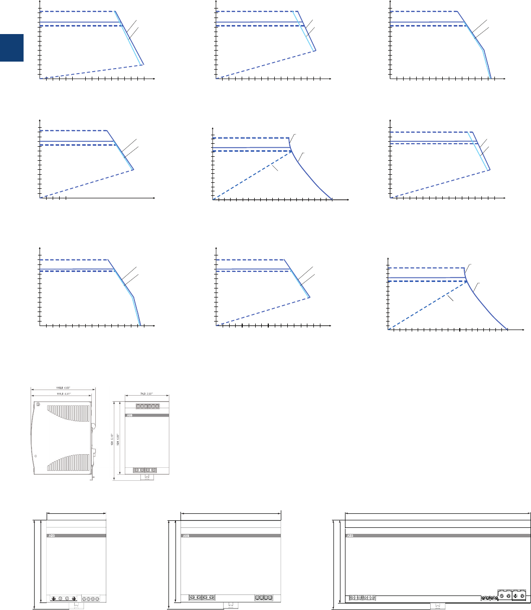
3
3/39 ABB | Catalog Electronic Products and Relays 2015 | 2CDC 110 004 C0210
CP-T range
Technical diagrams, Dimensional drawings
CP-T 24/5.0
CP-T 24/20.0 Hiccup mode
CP-T 48/10.0 U/I curve
CP-T 24/10.0
CP-T 24/40.0
CP-T 48/10.0 Hiccup mode
CP-T 24/20.0 U/I curve
CP-T 48/5.0
CP-T 48/20.0
CP-T 24/20.0, CP-T 48/10.0CP-T 24/10.0, CP-T 48/5.0 CP-T 24/40.0, CP-T 48/20.0
Output curve at Ta = 25 °C
CP-T 24/5.0
Dimensional drawings dimensions in mm
2CDC 272 032 F0x092CDC 272 035 F0x092CDC 272 038 F0x09
2CDC 272 033 F0x092CDC 272 027 F02112CDC 272 039 F0x09
2CDC 272 034 F0x092CDC 272 037 F0x092CDC 272 028 F0211
12345678
4
8
12
16
20
24
28
U
out
[V]
Iout [A]
Hiccup mode
@ 3 x 400V supply
@ 3 x 500V supply
4812 16 20 24 28 32
4
8
12
16
20
24
28
U
out
[V]
Iout [A]
@ 3 x 400V supply
@ 3 x 500V supply
Hiccup mode
246810 12 14 16
8
16
24
32
40
48
56
U
out
[V]
Iout [A]
@ 3 x 400V supply
@ 3 x 500V supply
246810 12 14 16
4
8
12
16
20
24
28
U
out
[V]
Iout [A]
Hiccup mode
@ 3 x 400V supply
@ 3 x 500V supply
816 24 32 40 48 56 64
4
8
12
16
20
24
28
U
out
in V
72 80
Iout in A
Hiccup mode
after 2-5 s overload
U/I
@ 3 x 400 V supply
246810 12 14 16
8
16
24
32
40
48
56
U
out
[V]
Iout [A]
@ 3 x 400V supply
@ 3 x 500V supply
Hiccup mode
4812 16 20 24 28 32
4
8
12
16
20
24
28
U
out
[V]
Iout [A]
@ 3 x 400V supply
@ 3 x 500V supply
12345678
8
16
24
32
40
48
56
U
out
[V]
Iout [A]
Hiccup mode
@ 3 x 400V supply
@ 3 x 500V supply
4812 16 20 24 28 32
8
16
24
32
40
48
56
U
out
in V
36 40
Iout in A
Hiccup mode
after 2-5 s overload
U/I
@ 3 x 400 V supply
2CDC 272 021 F0009
2CDC 272 022 F0009
118,8 4,68‘‘
111,9 4,41‘‘
89 3,5‘‘
131 5,16‘‘
124 4,88‘‘
2CDC 272 023 F0009
118,8 4,68‘‘
111,9 4,41‘‘
150 5,91‘‘
131 5,16‘‘
124 4,88‘‘
2CDC 272 024 F0009
118.8 4.68‘‘
111.9 4.41‘‘
131 5.16‘‘
275.8 10.86‘‘
124 4.88‘‘
Technical diagrams, dimensions in mm
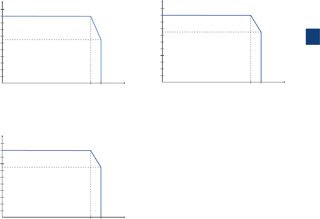
3
2CDC 110 004 C0210 | Catalog Electronic Products and Relays 2015 | ABB 3/40
CP-T range
Technical diagrams
CP-T 24/40.0, CP-T 48/20.0 CP-T 24/20.0, CP-T 48/10.0
CP-T 24/5.0, CP-T 24/10.0, CP-T 48/5.0
Temperature curve at rated load
2CDC 272 026 F0211
2CDC 272 030 F0211
2CDC 272 025 F0211
-40 60 70
10
20
30
40
50
60
70
80
90
100
P
out
[%]
T
a
[°C]
-30 60 70
10
20
30
40
50
60
70
80
90
100
P
out
[%]
T
a
[°C]
-40 60 70
10
20
30
40
50
60
70
80
90
100
P
out
[%]
T
a
[°C]
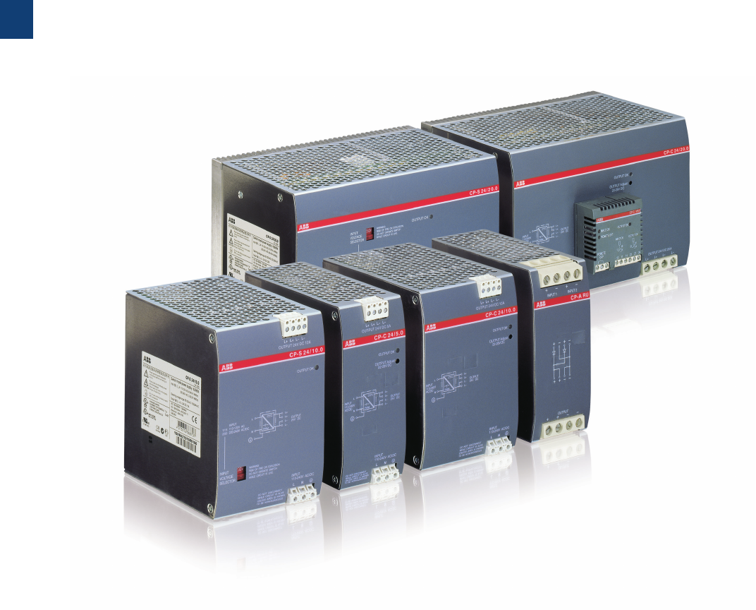
3
3/41 ABB | Catalog Electronic Products and Relays 2015 | 2CDC 110 004 C0210
CP-S and CP-C
Product group picture

3
2CDC 110 004 C0210 | Catalog Electronic Products and Relays 2015 | ABB 3/42
CP-S and CP-C
Table of contents
CP-S and CP-C range
Product group picture 3/41
Table of contents 3/42
Benefits and advantages 3/43
Operating control 3/44
Ordering details 3/45
Technical data 3/46
Technical diagrams, Dimensional drawings 3/50

3
3/43 ABB | Catalog Electronic Products and Relays 2015 | 2CDC 110 004 C0210
CP-S and CP-C
Benefits and advantages
2CDC 273 056 F0004
2CDC 273 046 F0004
2CDC 273 058 F0004
2CDC 273 057 F0004
Characteristics
CP-S and CP-C range
– Output current 5 A, 10 A and 20 A
– Integrated power reserve of up to 50 %
–
5 A and 10 A devices with pluggable connecting terminals
– Approvals / marks
(depending on device, partly pending)
–A, H, R, K, / a, b
CP-S range
– 10 A and 20 A device with front-face selector switch to
adjust rated input voltage range:
110-120VAC or 220-240VAC
– Output voltage fixed at 24 V DC
– Parallel operation for redundancy
CP-C range
–
Wide range input 110-240 V AC (85-264 V AC, 100-350 V DC)
– Output voltage adjustable within a range of 22-28 V DC
– Parallel operation for increased capacity and redundancy
– Power factor correction (PFC) acc. to EN 61000-3-2
– Function module pluggable onto the front side
Messaging module CP-C MM:
– LED for status indication
– Relay outputs "Input OK" and "Output OK"
– REMOTE ON/OFF function to switch on and off the
power supply externally
– Output voltage monitoring is only possible in decoupled
parallel operation
Integrated power reserve
The new CP-S and CP-C range power supplies feature an in-
tegrated power reserve of up to 50 %. No oversized electricity
supply is needed, especially under heavy load conditions.
Pluggable connecting terminals
Extended flexibility in operation due to pluggable connecting
terminals (this feature is not offered on all devices).
Adjustable output voltage
The CP-C range types feature a continuously adjustable
output voltage from 22 to 28 V. Thus, they can be optimally
adapted to the application, e.g. compensating the voltage
drop caused by long line length.
Pluggable function modules
The CP-C range power supplies can be equipped with plug-
gable modules to add additional functions (e.g. messaging
module). Thus, the power supplies can be ideally adapted to
the relevant application.
Benefits
1
1
2
2
3
3
4
4
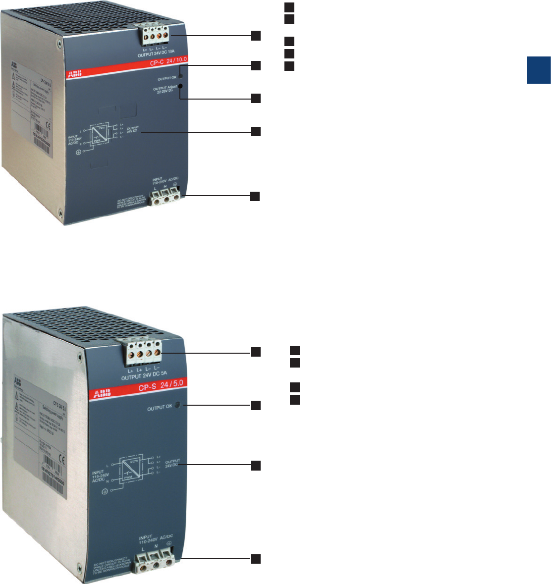
3
2CDC 110 004 C0210 | Catalog Electronic Products and Relays 2015 | ABB 3/44
CP-S and CP-C
Operating control
4
4
1
1
2
2
3
3
5
1 OUTPUT L+, L-: terminals - output
2 Indication of operational states
OUTPUT OK: green LED - output voltage OK
3 OUTPUT Adj.: rotary potentiometer - adjustment of output voltage
4 Circuit diagram
5 INPUT L, N, PE: terminals - input
1 OUTPUT L+, L-: terminals - output
2 Indication of operational states
OUTPUT OK: green LED - output voltage OK
3 Circuit diagram
4 INPUT L, N, PE: terminals - input
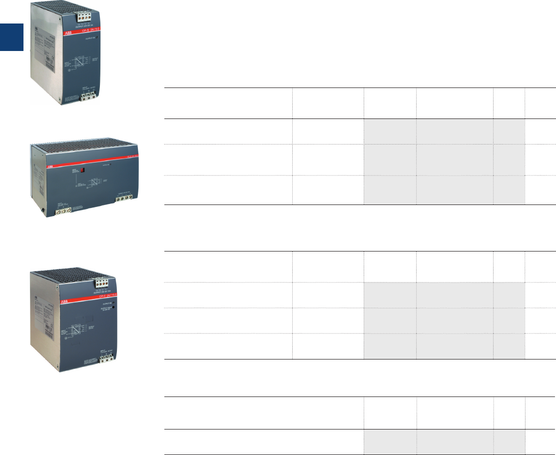
3
3/45 ABB | Catalog Electronic Products and Relays 2015 | 2CDC 110 004 C0210
CP-S and CP-C
Ordering details
Description
The power supply units in the CP-S and CP-C range are ABB’s high-end solutions. Designed
with an integrated 50 % power reserve and an efficiency of approximately 89 % these are the
perfect products for all complex, highly reliable applications. All the devices cover the U-I out-
put characteristic and are built with thermal protection which switches off in case of overheat-
ing. In particular, the devices of the CP-C range feature a much broader functionality, including
active power factor correction and pluggable function modules.
These products are designed to trip MCB‘s in the 24VDC output circuit. Coordination tables
are available.
Ordering details - CP-S
Input voltage range Rated output
voltage / current
Type Order code Price
1 pce
Weight
(1 pce)
kg (lb)
85-264 V AC / 110-350 V DC 24 V DC / 5 A CP-S 24/5.0 1SVR427014R0000 0.96
(2.11)
85-132 V AC, 184-264 V AC /
220-350 V DC 24 V DC / 10 A CP-S 24/10.0 1SVR427015R0100 1.07
(2.35)
85-132 V AC, 184-264 V AC /
220-350 V DC 24 V DC / 20 A CP-S 24/20.0 1SVR427016R0100 2.83
(6.23)
Ordering details - CP-C
Input voltage range Rated output
voltage / current
Type Order code Price
1 pce
Weight
(1 pce)
kg (lb)
85-264 V AC / 110-350 V DC 24 V DC / 5 A CP-C 24/5.0 1SVR427024R0000 0.96
(2.11)
85-264 V AC / 110-350 V DC 24 V DC / 10 A CP-C 24/10.0 1SVR427025R0000 1.34
(2.95)
85-264 V AC / 110-350 V DC 24 V DC / 20 A CP-C 24/20.0 1SVR427026R0000 3.15
(6.94)
2CDC 271 061 F0004
2CDC 271 065 F0004
2CDC 271 063 F0004
CP-S 24/5.0
CP-C 24/10.0
CP-S 24/20.0
Description Type Order code Price
1 pce
Weight
(1 pce)
kg (lb)
Messaging module for CP-C range power supplies CP-C MM 1SVR427081R0000 0.065
(0.14)

3
2CDC 110 004 C0210 | Catalog Electronic Products and Relays 2015 | ABB 3/46
CP-S and CP-C
Technical data
Data at Ta = 25 °C, Uin = 230 V AC and rated values, unless otherwise indicated
Type CP-C 24/5.0
CP-S 24/5.0
CP-C 24/10.0
CP-S 24/10.0
CP-C 24/20.0
CP-S 24/20.0
Input circuit - supply circuit L, N
Rated input voltage Uin CP-C 110-240 V AC
CP-S switch position 115 110-240 V AC 110-120 V AC
switch position 230 220-240 V AC
Input voltage range CP-C 85-264 V AC / 100-350 V DC 1)
CP-S switch position 115 85-264 V AC / 100-
350VDC 1)
85-132 V AC
switch position 230 184-264 V AC / 220-350 V DC 1)
Frequency range AC 47- 63 Hz
Typical input current CP-S and CP-C at 110-240 V AC 2.2-1.2 A 2.6 -1.2 A 5.5-2.5 A
CP-S at 110-120 V AC -4.2-4.0 A 9.0-8.0 A
CP-S at 220-240 V AC -2.4-2.2 A 4.5-4.0 A
Typ. power consumption 135 W 269 W 538 W
Inrush current limiting / I2t ( cold start) CP-C < 23 A / approx.
0.9A2s
< 33 A / approx. 0.2 A
2
s< 40 A / approx. 1.9 A
2
s
CP-S
< 40 A / approx. 1.8 A
2
s< 70 A / approx. 8 A
2
s
Power failure buffering time min. 100 ms min. 40 ms min. 40 ms
Transient overvoltage protection varistors
Internal input fuse (apparatus protection, not accessible) 4 A (slow-acting) 6.3 A (slow-acting) 12 A (fast-acting)
Power factor correction (PFC) CP-C yes, active
CP-S no
Indication of operational states
Output voltage OUTPUT OK: green LED V: output voltage OK
Output circuit L+, L+, L-, L- : short-circuit, no-load and overload proof
Rated output voltage 24 V DC
Tolerance of the output voltage CP-C ±1 %
CP-S -1...+5 %
Adjustment range of the output
voltage
CP-C 22-28 V DC, default setting 24 V ±0.5 %
CP-S fixed
Rated output power 120 W 240 W 480 W
Rated output current Ta m 60 °C 5 A 10 A 20 A
Peak output current (power reserve) Ta m 40 °C typ. m 7. 25 A typ. m 12.25 A typ. m 22.5 A
Derating 60 °C < Ta m 70 °C 2.5 % per Kelvin temperature increase
Deviation with
CP-C load change statical 10-90 %
typ. < ±0.05 %
CP-S load change statical 10-90 %
typ. < ±0.1 %
load change dynamical 10-90 %
typ. < ±3 %
change of the input voltage of ±10 %
typ. < ±0.05 %
Control time typ. < 1 ms
Starting time after applying
supply voltage
CP-C < 200 ms < 200 ms typ. < 200 ms
CP-S < 250 ms typ. < 300 ms
Rise time 10-90 % CP-C typ. < 30 ms typ. < 4 ms typ. < 12 ms
CP-S typ. < 5 ms typ. < 15 ms
Residual ripple and switching peaks BW = 20 MHz typ. < 50 mVPP
Parallel connection yes, up to 5 devices, to enable redundancy and to increase
power, current not symmetrical (CP-S only redundancy)
Series connection yes, to increase voltage, for decoupling refer to the application manual
Resistance to reverse feed approx. 35 V DC
Output circuit - No-load, overload and short-circuit behaviour see also U/I- and I/T-characteristic curves
Characteristic curve of output U/I characteristic curve with power reserve
Current limiting at short circuit approx. 11 A approx. 19 A approx. 25 A
Short-circuit protection continuous short-circuit stability
Overload protection thermal protection
Starting of capacitive loads unlimited
General data
Power dissipation typ. < 15 W typ. < 29 W typ. < 58 W
Efficiency typ. 89 %
Discharge current for PE < 3.5 mA
MTBF CP-C 500.000 h
CP-S 350.000 h
Dimensions (W x H x D)
56.5 (60 2)) x 130 x 135.5
mm (2.22 (2.36 2)) x 5.12 x
5.35 in)
90 (93.5 2)) x 130 x 135.5
mm (3.54 (3.68 2)) x 5.12 x
5.35 in)
200 (203.5 2)) x 130 x 135.5
mm (7.87 (8.01 2)) x 5.12 x
5.35 in)
Weight CP-C
approx. 0.96 kg (2.12 lb) approx. 1.34 kg (2.95 lb) approx. 3.15 kg (6.94 lb)
CP-S
approx. 1.07 kg (2.36 lb) approx. 2.83 kg (6.23 lb)
Minimum distance to other units horizontal / vertical 10 mm / 80 mm (0.39 in / 3.15 in)
Degree of protection housing / terminals IP20 / IP20
Material of housing housing shell / cover aluminium / zinc-coated sheet steel
Protection class (EN 61140) I
Mounting DIN rail (IEC/EN 60715), snap-on mounting
Mounting position horizontal

3
3/47 ABB | Catalog Electronic Products and Relays 2015 | 2CDC 110 004 C0210
CP-S and CP-C
Technical data
Data at Ta = 25 °C, Uin = 230 V AC and rated values, unless otherwise indicated
Type CP-C 24/5.0
CP-S 24/5.0
CP-C 24/10.0
CP-S 24/10.0
CP-C 24/20.0
CP-S 24/20.0
Electrical connection - Input circuit 3) 3) -
Wire size fine-strand with wire end ferrule 0.2-2.5 mm2 (24-14 AWG)
2.5-10 mm
2
(14-8 AWG)
fine-strand without wire end ferrule
0.5-10 mm
2
(20-8 AWG)
rigid
0.5-16 mm
2
(20-6 AWG)
Stripping length 7 mm (0.28 in) 12 mm (0.47 in)
Tightening torque 0.4 Nm 1.2-1.5 Nm
Electrical connection - Output circuit 3) 3) -
Wire size fine-strand with wire end ferrule 0.12-2.5 m m2 (26 -14 AWG)
2.5-10 mm
2
(14-8 AWG)
fine-strand without wire end ferrule
0.5-10 mm
2
(20-8 AWG)
rigid
0.5-16 mm
2
(20-6 AWG)
Stripping length 8 mm (0.31 in) 12 mm (0,47 in)
Tightening torque 0.4 Nm 1.2-1.5 Nm
Environmental data
Ambient temperature range operation -25...+70 °C
rated load 0...+60 °C (without derating)
storage -40...+85 °C
Damp heat (IEC/EN 60068-2-3) 93 % at +40 °C, no condensation
Climatic category (IEC/EN 60721) 3K3
Vibration (IEC/EN 60068-2-6)
Shock (IEC/EN 60068-2-27)
Isolation data
Rated insulation voltage Ui between all isolated circuits
(IEC/EN 60950-1; EN 50178)
input / output 300 V
input / PE 300 V
output / PE 50 V
Rated impulse withstand voltage Uimp between all isolated
circuits (IEC/EN 60950-1; EN 50178)
input / output 4 kV; 1.2/50 µs
input / PE 2.5 kV; 1.2/50 µs
output / PE 500 V; 1.2/50 µs
Power-frequency withstand voltage test (test voltage)
(routine test / type test)
input / output 1.5 kV AC / 3.0 kV AC
input / PE 1.5 kV AC / 3.0 kV AC
output / PE 500 V DC / 500 V DC
Pollution degree (IEC/EN 60950-1; EN 50178) 2
Overvoltage category (IEC/EN 60950-1; EN 50178) II
Standards
Product standard IEC/EN 61204
Low Voltage Directive 2006/95/EC
EMC Directive 2004/108/EC
Electrical safety EN 50178, EN 60950, UL 60950, UL 508
Protective low voltage SELV (EN 60950)
Electromagnetic compatibility
Interference immunity to IEC/EN 61000-6-2
electrostatic discharge IEC/EN 61000-4-2 Level 4 (8 kV / 15 kV)
radiated, radio-frequency, electromagnetic field IEC/EN 61000-4-3 Level 3 (10 V/m)
electrical fast transient / burst IEC/EN 61000-4-4 Level 4 (4 kV)
surge IEC/EN 61000-4-5 Level 4 (2 kV symmetrical, level 3 - 3 kV asymmetrical)
conducted disturbances, induced by radio-
frequency fields
IEC/EN 61000-4-6 Level 3 (10 V)
Interference emission IEC/EN 61000-6-3
high-frequency radiated IEC/CISPR 22; EN 55022 Class B
high-frequency conducted IEC/CISPR 22; EN 55022 Class B
1) at U > 264 V use additionally an appropriate external fuse
2) with lateral screw
3) pluggable connecting terminals, actuate only when power is off
„Approvals and marks“ on page 3/4.

3
2CDC 110 004 C0210 | Catalog Electronic Products and Relays 2015 | ABB 3/48
CP-S and CP-C
Technical data
Data at Ta = 25 °C, Uin = 230 V AC and rated values, unless otherwise indicated
Type CP-C MM
Input circuit - Supply circuit
Rated input voltage Uin 110-240 V AC / 100-350 V DC
Input voltage range 70-264 V AC / 80-350 V DC
Power consumption 2.5 VA / 1.5 W
Input circuit - Control circuit
Kind of triggering volt-free triggering
Control input, control function Remote OFF remote off
Threshold "Switching-off power supply unit" R m 1 k
Threshold "Switching-on power supply unit" R M 10 k
Input current typ. 1 mA (200 mA for 200 µs)
Maximum cable length to the control input 25 m - 100 pF/m
Measuring circuit - INPUT powered by the input circuit of the power supply unit
Monitoring function undervoltage monitoring of input voltage of the power supply
unit
Thresholds 85 V AC / 90 V DC
Hysteresis, related to the threshold value AC: typ. -8 % / DC -30 %
Accuracy, tolerance -5 % at AC and DC
Maximum measuring cycle typ. < 50 ms
Measuring circuit - OUTPUT powered by the output circuit of the power supply unit
Monitoring function undervoltage monitoring of output voltage of the power supply
unit
Thresholds 20 V DC
Hysteresis, related to the threshold value typ. 5 %
Accuracy, tolerance ±1 %
Maximum measuring cycle typ. < 10 ms
Indication of operational states
Remote off REMOTE OFF: green LED V: „REMOTE OFF“ input R m 1k
Status of power supply input Input OK: green LED V: relay „INPUT OK“ energized
Status of power supply output OUTPUT OK: green LED V: relay „OUTPUT OK“ energized
Output circuits 11-12/14, 21-22/24
Kind of output relays, 2 x 1 c/o contacts
Operating principle closed-circuit principle
Contact material AgNi
Rated voltage (VDE 0110, IEC/EN 60947-1) 250 V
Minimum switching voltage / Minimum switching current 24 V / 10 mA
Maximum switching voltage / Maximum switching current 250 V / 1 A
Rated operating current Ie (IEC/EN 60947-1) AC-12 (resistive) at 230 V 1 A
AC-15 (inductive) at 230 V
1 A
DC-12 (resistive) at 24 V 1 A
DC-13 (inductive) at 24 V 1 A
Mechanical lifetime 30 x 106 switching cycles
Electrical lifetime 0.1 x 10⁶ switching cycles
Short circuit proof,
maximum fuse rating
n/c contact 2 A, gL
n/o contact 2 A, gL
General data
Duty time 100 %
Dimensions (W x H x D, when mounted) 56.5 x 54 x 24 mm (2.22 x 2.13 x 0.94 in)
Weight 0.065 kg (0.14 lb)
Degree of protection housing / terminals IP20 / IP20
Material of housing Plastic
Protection class (EN 61140) II
Mounting snap-on mounting, without any tool
Mounting position plugged onto the power supply unit
Electrical connection
Wire size fine-strand with wire end ferrule 0.2-2.5 mm2 (24-14 AWG)
fine-strand without wire end ferrule
rigid 0.2-4 mm2 (24-12 AWG)
Stripping length 7.5 mm (0.3 inch)
Tightening torque 0.4-0.6 Nm

3
3/49 ABB | Catalog Electronic Products and Relays 2015 | 2CDC 110 004 C0210
CP-S and CP-C
Technical data
Data at Ta = 25 °C, Uin = 230 V AC and rated values, unless otherwise indicated
Type CP-C MM
Environmental data
Ambient temperature range operation -25...+70 °C
storage -40...+85 °C
Damp heat (IEC/EN 60068-2-3) 93 % at +40 °C, no condensation
Climatic category (IEC/EN 60721) 3K3
Vibration (IEC/EN 60068-2-6)
Shock (IEC/EN 60068-2-27)
Isolation data
Rated insulation voltage Ui (IEC/EN 60974-1, EN 50178, VDE 0160) 250 V
Protective separation (EN 50178, EN 60950) supply / measuring circuits / relay
outputs yes
Rated impulse withstand voltage Uimp between all isolated circuits (IEC 664, VDE
0110) 4 kV; 1.2/50 µs
Test voltage between all circuits (type test) 2.5 kV AC
Pollution degree (EN 60950) 2
Overvoltage category (EN 60950) II
Standards
Product standard IEC/EN 61204
Low Voltage Directive 2006/95/EC
EMC Directive 2004/108/EC
Electrical safety EN 50178, EN 60950, UL 60950, UL 508
Elektromagnetic compatibility
Interference immunity to IEC/EN 61000-6-2
electrostatic discharge IEC/EN 61000-4-2 Level 3 and 4 (6 kV / 8 kV)
radiated, radio-frequency, electromagnetic field IEC/EN 61000-4-3 Level 3 (10 V/m)
electrical fast transient / burst IEC/EN 61000-4-4 Level 4 and 2 (4 kV power input / 1 kV control input)
surge IEC/EN 61000-4-5 Level 3 and 2 (4 kV symmetrical power input / 1 kV control
input)
conducted disturbances, induced by radio-frequency
fields
IEC/EN 61000-4-6 Level (10 V)
Interference emission IEC/EN 61000-6-3
high-frequency radiated IEC/CISPR 22; EN 55022 Class B
high-frequency conducted IEC/CISPR 22; EN 55022 Class B
„Approvals and marks“ on page 3/4.
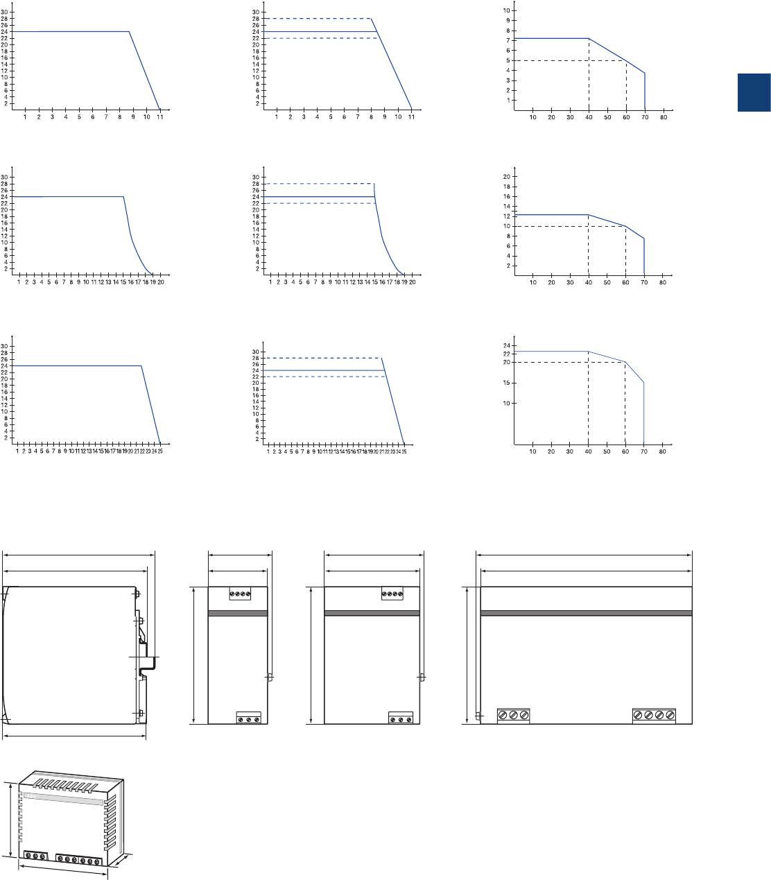
3
2CDC 110 004 C0210 | Catalog Electronic Products and Relays 2015 | ABB 3/50
CP-S and CP-C
Technical diagrams, Dimensional drawings
U
out
[
V
]
I
out
[A]
2CDC 272 003 F0b04
U
out
[
V
]
I
out
[A]
2CDC 272 004 F0b04
U
out
[
V
]
I
out
[A]
2CDC 272 005 F0b04
CP-S 24/5.0 CP-S 24/5.0, CP-C 24/5.0CP-C 24/5.0
CP-S 24/10.0 CP-S 24/10.0, CP-C 24/10.0CP-C 24/10.0
CP-S 24/20.0 CP-S 24/20.0, CP-C 24/20.0CP-C 24/20.0
U
out
[
V
]
I
out
[A]
2CDC 272 026 F0b04
U
out
[
V
]
I
out
[A]
2CDC 272 027 F0b04
U
out
[
V
]
I
out
[A]
2CDC 272 028 F0b04
144,5 [5.69”] 60,0 [2.36”]
137,0 [5.39”]
130,0 [5.12”]
130,0 [5.12”]
56,5 [2.22”]
93,5 [3.68”]
90,0 [3.54”]
203,5 [8.01”]
200,0 [7.87”]
135,5 [5.33”]
130,0 [5.12”]
2CDC 272 015 F0b07
CP-S 24/5.0 CP-S 24/10.0 CP-S 24/20.0
CP-C 24/5.0 CP-C 24/10.0 CP-C 24/20.0
CP-A RU
Technical diagrams
Output curve at 25 °C Temperature curve at Uout = 24 V DCOutput curve at 25 °C
I
out
[A]
Ta [°C]
2CDC 272 075 F0204
I
out
[
A
]
T
a
[°C]
2CDC 272 006 F0204
I
out
[A]
T
a
[°C]
2CDC 272 088 F0204
Dimensional drawings dimensions in mm
CP-C MM
54 [2.13”]
56,5 [2.
22”]
24 [0.94”]
2CDC 272 016 F0b07
3
3/51 ABB | Catalog Electronic Products and Relays 2015 | 2CDC 110 004 C0210
Redundancy units
Ordering details
Ordering details
Description suitable for decoupling of
two CP-24 V DC power
supply units or suitable
for decoupling of CP-E
power supply units
Type Order code Price
1 pce
Weight
(1 pce)
kg (lb)
2 inputs each up to 20 A and 1
output up to 40 A m 40 V and M 5 A CP-A RU 1SVR427071R0000 0.89
(1.96)
Control module for CP-A RU
redundancy units -CP-A CM 1SVR427075R0000 0.063
(0.14)
2 inputs each up to 2.5 A and 1
output up to 5 A m 35 V and < 5 A CP-RUD 1SVR423418R9000 0.15
(0.33)
2CDC 271 003 F0005
CP-A RU + CP-A CM
CP-A RU
CP-RUD
CP-D RU
2CDC 271 010 F0006
2CDC 271 006 F00032CDC 271 010 F0006
Ordering details - CP-D RU for decoupling of two CP-D power supply units
Input voltage
range
Rated input
current
Rated output voltage /
current
Type Order code Price Weight
(1 pce)
kg (lb)
9-35 V DC 2 x 5 A 24 V DC /
1 x 10 A CP-D RU 1SVR427049R0000 0.075
(0.165)

3
2CDC 110 004 C0210 | Catalog Electronic Products and Relays 2015 | ABB 3/52
Redundancy units
Technical data
Type CP-A RU CP-A RU
in combination with CP-A CM
Input circuit - Supply circuit (+/ -, +/ -)
Rated input voltage Uin 24 V DC
Input voltage range per channel 10-28 V DC 13-28 V DC
Rated input current Iin per channel 1-20 A
Maximum input current per channel 30 A for 300 s
Transient overvoltage protection yes
Output circuit (++/--)
Rated output voltage Uout 24 V DC
Voltage drop typ. 0.6 V, max. 0.9 V
Rated output current Iout 1-40 A
Output ratings per channel Ta = 60 °C 10-28 V DC / 40 A 13-28 V DC / 40 A
Ta = 70 °C 10-28 V DC / 30 A 13-28 V DC / 30 A
Derating 60 °C < Ta m 70 °C 2.5 % per Kelvin temperature increase
Peak output current 60 A for 300 s
Resistance to reverse feed < 40 V
General data
Dimensions (W x H x D) 56.5 (60 1)) x 130 x 135.5 mm; (2.22 (2.36 1)) x 5.12 x 5.35 in)
Weight 0.89 kg (1.96 lb)
Minimum distance to other units horizontal / vertical 10 mm / 50 mm (0.39 in / 1.97 in)
Degree of protection housing / terminals IP20 / IP20
Material of housing housing shell / cover aluminium / zinc-coated sheet steel
Protection class III 2)
Mounting DIN rail (IEC/EN 60715)
Mounting position horizontal
Electrical connection - Input circuit / Output circuit
Wire size fine-strand with wire end ferrule 2.5-10 mm2 (14-8 AWG)
fine-strand without wire end ferrule 0.5 -10 mm2 (20-8 AWG)
rigid 0.5-16 m m2 (20-6 AWG)
Stripping length 12 mm (0.47 in)
Tightening torque 1.2-1.5 Nm
Environmental data
Ambient temperature range operation -25...+70 °C
rated load -25...+60 °C (without derating)
storage -40...+85 °C
Damp heat (IEC/EN 60068-2-3) 93 % at 40 °C, no condensation
Climatic category (IEC/EN 60721) 3K3
Vibration (IEC/EN 60068-2-6)
Shock (IEC/EN 60068-2-27)
Isolation data
Insulation voltage between input / output / housing 500 V AC (routine test)
Pollution degree (EN 50178) 2
Standards
Product standard IEC/EN 61204
Low Voltage Directive 2006/95/EC
EMC Directive 2004/108/EC
Electrical safety EN 50178, EN 60950, UL 60950, UL 508
Electromagnetic compatibility
Interference immunity to IEC/EN 61000-6-2
electrostatic discharge IEC/EN 61000-4-2 Level 3 (air discharge ±8 kV, contact discharge ±6 kV)
radiated, radio-frequency, electromagnetic field IEC/EN 61000-4-3 Level 3 (10 V/m)
electrical fast transient / burst IEC/EN 61000-4-4 Level 3 (±2 kV)
surge IEC/EN 61000-4-5 Level 1 (±0.5 kV)
conducted disturbances, induced by radio-
frequency fields
IEC/EN 61000-4-6 Level 3 (10 V)
Interference emission IEC/EN 61000-6-3
high-frequency radiated IEC/CISPR 22 / EN 55022 Class B
high-frequency conducted IEC/CISPR 22 / EN 55022 Class B
1) incl. lateral screw
2) This device is designed for connection to a safety extra-low voltage source. If no safety extra-low voltage is used at the input side, the lateral screw can be used for grounding
of the housing (protection class I).
„Approvals and marks“ on page 3/4.

3
3/53 ABB | Catalog Electronic Products and Relays 2015 | 2CDC 110 004 C0210
Type CP-A CM
Input circuit - Supply circuit
Rated input voltage Uin 24 V DC
Input voltage range 13-28 V DC
Rated input current at rated sense load and 24 V DC 120 mA
Power consumption at 24 V DC approx. 1 W
Measuring circuit 11-12/14, 21-22/24
Monitoring function undervoltage monitoring
Measuring voltage rated operational voltage
Thresholds 14-28 V
Hysteresis, related to the threshold value fix: 3-5 %
Accuracy, tolerance 10 % of full-scale value
Maximum measuring cycle 6 ms
Indication of operational states
Status of input 1 IN 1: green LED
: voltage at input 1 > than threshold 1 = no faults present
Status of input 2 IN 2: green LED
: voltage at input 2 > than threshold 2 = no faults present
Output status OUT: green LED : UOUT > 3 V = no faults present
Output circuit +, +, -
Kind of output relays, 2 x 1 c/o contact
Contact material AgNi
Operating principle closed-circuit principle
Rated operational voltage Ue (IEC/EN 60947-1, VDE 0110) 250 V
Minimum switching voltage / Minimum switching current 24 V / 10 mA
Maximum switching voltage / Maximum switching current 250 V / 1 A
Rated operational current Ie
(IEC/EN 60947-5-1)
AC-12 (resistive) at 230 V 1 A
AC-15 (inductive) at 230 V 1 A
DC-12 (resistive) at 24 V 1 A
DC-13 (inductive) at 24 V 1 A
Mechanical lifetime 30 x 106 switching cycles
Electrical lifetime 0.1 x 10⁶ switching cycles
Rating according UL 508 General purpose (GP) 250 V AC 1 A
Maximum fuse rating to achieve
short-circuit protection
n/o contact 2 A, gL
n/c contact 2 A, gL
Sense output (+, +, -) 1 SVR 427 075 R0000
Sense output voltage 13-28 V DC
Sense output current 0.1 A
Maximum fuse rating For applications acc. UL the sense output shall be provided
with a listed DC fuse 3 A
General data
Duty time 100 %
Dimensions (W x H x D, when mounted) 56.5 x 54 x 24 mm (2.22 x 2.13 x 0.94 in)
Material of housing plastic
Weight 0.063 kg (0.14 lb)
Degree of protection housing / terminals IP20 / IP20
Protection class II
Mounting snap-on mounting, without any tool
Mounting position plugged onto the redundancy unit CP-A RU
Electrical conection
Wire size fine-strand with wire end ferrule 0.2-2.5 mm2 (24-14 AWG)
fine-strand without wire end ferrule
rigid 0.2-4 mm2 (24-12 AWG)
Stripping length 7.5 mm (0.3 in)
Tightening torque 0.4-0.6 Nm
Isolation data
Rated insulation voltage Ui (IEC/EN 60947-1, EN 50178, VDE 0160) 250 V
Rated impulse withstand voltage Uimp (type test) between all circuits
(IEC 664, VDE 0110)
2.5 kV
Power-frequency withstand voltage test (routine test) between all circuits 1.2 kV AC
Protective separation (EN 50178) between input and output yes
Pollution degree 2
Overvoltage category II
Environmental data
Ambient temperature range operation -25...+70 °C
storage -40...+85 °C
Damp heat (IEC/EN 60068-2-3) 93 %at 40 °C, no condensation
Climatic category (IEC/EN 60721) 3K3
Vibration (IEC/EN 60068-2-6)
Shock (IEC/EN 60068-2-27)
Redundancy units
Technical data

3
2CDC 110 004 C0210 | Catalog Electronic Products and Relays 2015 | ABB 3/54
Type CP-RUD
Input circuit - Supply circuit A: U1+/-U ; B: U2+/-U
Rated input voltage Uin 24 V DC
Input voltage range 5-35 V DC
Rated input current Iin per channel 0.5-2.5 A
Maximum input current per channel 10 A for 300 s
Transient overvoltage protection no
Output circuit L+, L+, L+, L-, L-, L-
Rated output voltage Uout 24 V DC
Voltage drop typ. 0.6 V, max. 0.7 V
Rated output current Iout 0.5-5 A
Peak output current 20 A for 150 s
Resistance to reverse feed < 35 V
General data
Dimensions (W x H x D) 22.5 x 78 x 100 mm (0.89 x 3.07 x 4.02 in)
Weight 0.135 kg (0.30 lb)
Minimum distance to other units horizontal / vertical 10 mm / 10 mm (0.39 in / 0.39 in)
Degree of protection housing / terminals IP20 / IP20
Material of housing housing shell / cover plastic / plastic
Protection class -
Mounting DIN rail (IEC/EN 60715)
Mounting position horizontal
Electrical connection - Input circuit / Output circuit
Wire size fine-strand with wire end ferrule 2 x 0.75-2.5 mm2 (2 x 18-14 AWG)
fine-strand without wire end ferrule
rigid 2 x 0.5-4 mm2 (2 x 20-12 AWG)
Stripping length 7 mm (0.28 in)
Tightening torque 0.6-0.8 Nm
Environmental data
Ambient temperature range operation -20...+60 °C
rated load -20...+60 °C
storage -40...+85 °C
Damp heat (IEC/EN 60068-2-3) 93 % at 40 °C, no condensation
Climatic category (IEC/EN 60721) -
Vibration (IEC/EN 60068-2-6)
Shock (IEC/EN 60068-2-27)
Isolation data
Insulation voltage between input / output / housing -
Pollution degree (EN 50178) 2
Standards
Product standard
Low Voltage Directive 2006/95/EC
EMC Directive 2004/108/EC
Electrical safety EN 50178
Electromagnetic compatibility
Interference immunity to IEC/EN 61000-6-2
electrostatic discharge IEC/EN 61000-4-2 Level 3 (air discharge ±8 kV, contact discharge ±6 kV)
radiated, radio-frequency, electromagnetic field IEC/EN 61000-4-3 Level 3 (10 V/m)
electrical fast transient/burst IEC/EN 61000-4-4 Level 3 (w2 kV)
surge IEC/EN 61000-4-5 Level 1 (w0.5 kV)
conducted disturbances, induced by radio-
frequency fields
IEC/EN 61000-4-6 Level 3 (10 V)
Interference emission IEC/EN 61000-6-3
high-frequency radiated
IEC/CISPR 22 / EN 55022
Class B
high-frequency conducted
IEC/CISPR 22 / EN 55022
Class B
1) incl. lateral screw
2) This device is designed for connection to a safety extra-low voltage source. If no safety extra-low voltage is used at the input side, the lateral screw can be used for grounding
of the housing (protection class I).
Redundancy units
Technical data

3
3/55 ABB | Catalog Electronic Products and Relays 2015 | 2CDC 110 004 C0210
Type CP-D RU
Input circuit - Supply circuit IN 1 + + -, IN 2 + + -
Rated input voltage Uin 24 V DC
Input voltage range 9-35 V DC
Rated input current Iin per channel 5 A
Maximum input current per channel 10 A for 300 s
Transient overvoltage protection no
Output circuit OUT + + +, - - -
Rated output voltage Uout 24 V DC
Voltage drop typ. 0.5 V
Rated output current Iout 10 A
Resistance to reverse feed < 35 V
General data
MTBF on request
Duty time 100 %
Dimensions (W x H x D) product dimensions 35 x 91 x 56.5 mm (1.38 x 3.58 x 2.22 in)
packaging dimensions 134 x 94 x 48 mm (5.28 x 3.70 x 1.89 in)
Weight net weight 0.075 kg (0.165 lb)
gross weight 0.130 kg (0.286 lb)
Material of housing plastic
Mounting DIN rail, snap-on mounting without any tool
Mounting position horizontal
Minimum distance to other units horizontal / vertical 25 mm (0.98 in) / 25 mm (0.98 in)
Electrical connection - Input circuit / Output circuit
Wire size fine-strand with (out)wire end ferrule 0.2-2.5 mm2 (24-14 AWG)
rigid 0.2-2.5 mm2 (24-12 AWG)
Stripping length 7.0 mm (0.28 in)
Tightening torque 0.67 Nm (6 Ib.in)
Environmental data
Ambient temperature range operation -40...+70 °C
storage -40...+85 °C
Relative humidity RH at 40 °C 20-95 %, no condensation
Vibration (IEC/EN 60068-2-6) Mounting by rail:
10-500 Hz, 2 G, along X, Y, Z each axis, 60 min for each axis
Shock (IEC/EN 60068-2-27) 15 G, 11 ms, 3 axis, 6 faces, 3 times for each face
Standards
Product standard IEC/EN 61204-3
Low Voltage Directive 2006/95/EC
EMC Directive 2004/108/EC
RoHS Directive 2011/65/ EC
Electromagnetic compatibility
Interference immunity to EN 55024
electrostatic discharge IEC/EN 61000-4-2 Level 3, air discharge 8 kV, contact discharge 4 kV
radiated, radio-frequency, electromagnetic field IEC/EN 61000-4-3 Level 3, 10 V/m
electrical fast transient/burst IEC/EN 61000-4-4 Level 3, 2 kV / 5 kHz
conducted disturbances, induced by radio-frequency fields IEC/EN 61000-4-6 Level 3, 10 V
Interference emission EN 55022
high-frequency radiated IEC/CISPR 22 / EN 55022 Class B
high-frequency conducted IEC/CISPR 22 / EN 55022 Class B
Redundancy units
Technical data
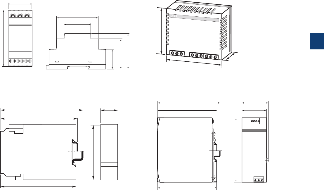
3
2CDC 110 004 C0210 | Catalog Electronic Products and Relays 2015 | ABB 3/56
CP-A CM
54 [2.13”]
56,5 [2.
22”]
24 [0.94”]
2CDC 272 016 F0b07
2CDC 252 188 F0b05
100
102
109,5 [4.31“] 22,5
[.886“]
78 [3.07“]
[4.02“]
[3.94“]
CP-RUD
144,5 [5.69”] 60,0 [2.36”]
137,0 [5.39”]
130,0 [5.12”]
130,0 [5.12”]
56,5 [2.22”]
93,5 [3.68”]
90,0 [3.54”]
203,5 [8.01”]
200,0 [7.87”]
135,5 [5.33”]
130,0 [5.12”]
2CDC 272 015 F0b07
CP-A RU
144,5 [5.69”] 60,0 [2.36”]
137,0 [5.39”]
130,0 [5.12”]
130,0 [5.12”]
56,5 [2.22”]
93,5 [3.68”]
90,0 [3.54”]
203,5 [8.01”]
200,0 [7.87”]
135,5 [5.33”]
130,0 [5.12”]
2CDC 272 015 F0b07
2CDC272033F0010
CP-D RU
67.0 2.64”
44.5 1.75”
32.1 1.26”
57.5 2.26”
49.0 1.93”
91.0 3.58”
35.0 1.38”
+++---
O U T
+--+++
IN1IN2 IN2IN1
Redundancy units
Dimensional drawings
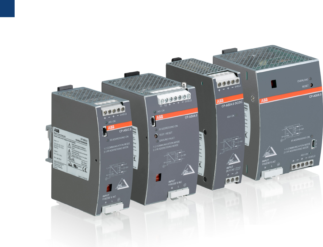
3
3/57 ABB | Catalog Electronic Products and Relays 2015 | 2CDC 110 004 C0210
CP-ASI range
Product group picture

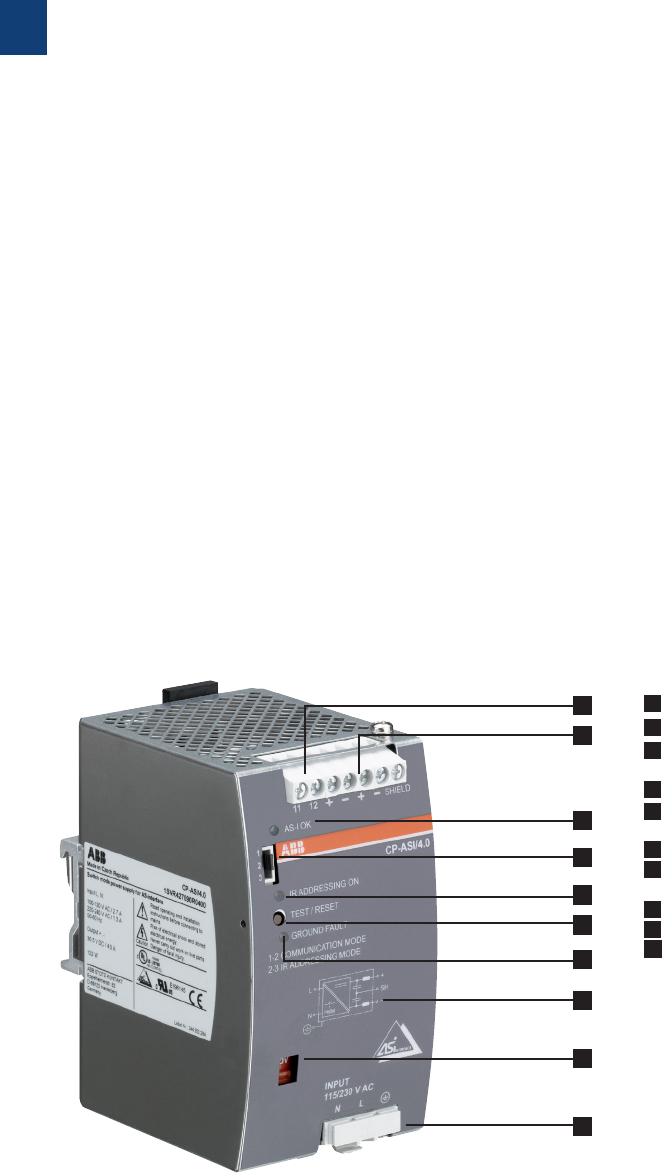
3
3/59 ABB | Catalog Electronic Products and Relays 2015 | 2CDC 110 004 C0210
CP-ASI range
Benefits and advantages
Characterics
– Rated output voltage 30.5 V DC for ASI-bus
– Rated output current up to 8.0 A
– High efficiency of up to 92 % 1)
– Infrared addressing mode 2)
– Low power dissipation and low heating
– Free convection cooling (no forced cooling with ventilators)
– Ambient temperature range during operation -10…70 °C 3)
– Open-circuit, overload and short-circuit stable
– Integrated input fuse
– Tool-free mounting on DIN rail as well as demounting
– LEDs for the indication of operational states
– Approval4): A /Mark: a
1) Efficiency is depending on device
2) Except CP-ASI/4.0 DC/DC
3) Ambient temperature range CP-ASI/4.0 DC/DC -25…70°C
4) Approvals are related to rated input voltage Uin
4
1
2
3
1 Output +, -, +, -, SHIELD: output terminals
2 Signalling contact 11-12: ground fault signalling terminals
3 Indication of operational states
AS-I OK: green LED - output voltage OK
4 Configuration of operation mode Jumper
5 Indication of operational states
IR ADDRESSING ON: red LED - infrared addressing mode active
6 Test and reset button
7 Indication of operational states
GROUND FAULT: red LED - ground fault detected
8 Circuit diagram
9 Input voltage selector Adjustment of input voltage
10
Input L, N, PE: input terminals
5
6
7
8
9
10
3
2CDC 110 004 C0210 | Catalog Electronic Products and Relays 2015 | ABB 3/60
CP-ASI range
Ordering details
Description
The CP-ASI power supply range is specifically designed with integrated data decoupling for
the supply of AS-Interface systems.
Up to 62 slaves (binary I/O devices) can be supplied with a single two-conductor cable.
The configurable IR addressing mode allows the easy assign of new ID addresses by means of
an external infrared programming unit.
Ordering details
Input Voltage Range Rated
Output
Voltage
Rated
Output
Current
Type Order code Price
1 pce
Weight
(1 pce)
kg (lb)
85-132 V AC, 184-264 V AC 30.5 V DC 2.8 A CP-ASI/2.8 1SVR427090R0280 0.495 (1.091)
85-132 V AC, 184-264 V AC 30.5 V DC 4.0 A CP-ASI/4.0 1SVR427090R0400 0.653 (1.440)
18-32.4 V DC 30.5 V DC 4.0 A CP-ASI/4.0 DC/DC 1SVR427095R0400 0.488 (1.076)
85-132 V AC, 184-264 V AC 30.5 V DC 8.0 A CP-ASI/8.0 1SVR427090R0800 0.897 (1.978)
2CDC 271 002 S00122CDC 271 003 S0012
2CDC 271 004 S0012
2CDC 271 005 S0012
CP-ASI/2.8
CP-ASI/4.0 DC/DC
CP-ASI/4.0
CP-ASI/8.0

3
3/61 ABB | Catalog Electronic Products and Relays 2015 | 2CDC 110 004 C0210
CP-ASI range
Technical data
Data at Ta = 25 °C, Uin = 230 V AC and rated values, unless otherwise indicated
Type CP-ASI/2.8 CP-ASI/4.0 CP-ASI/8.0 CP-ASI/4.0 DC/DC
Input circuit - Supply circuit L, N
Rated input voltage Uin -24 V DC
switch position 115 V 100-120 V AC -
switch position 230 V 220-240 V AC -
Input voltage range -18.0-32.4 V DC
switch position 115 V 85-132 V AC -
switch position 230 V 184-264 V AC 184-264 V AC /
240-300 V DC
184-264 V AC -
Frequency range AC 47- 6 3 Hz
Typical input current -5.6 A
switch position 115 V 2.0 A 2.7 A 6.0 A -
switch position 230 V 0.9 A 1.3 A 2.8 A -
Allowed voltage between input and earth (ground) CP-ASI/4.0 DC/DC: max. 60 V DC / 42.4 V AC
Allowed input ripple voltage CP-ASI/4.0 DC/DC: max. 5 Vpp, 47 Hz - 40 kHz
Continuous input voltage with no damage to the DC/DC converter
-max. 36.0 V DC
Turn-on voltage -typ. 17.5 V DC
Shut-down voltage -typ. 14.0 V DC
-typ. 35 V DC
Typical power consumption 94 W 135 W 261 W 132 W
Inrush current limiting / I²t (cold start) < 20 A (132 V AC) /
approx. 1.5 A²/s
< 44.7 A (120 V AC)
/ approx. 3.7 A²/s
< 12 A (100 V AC) /
approx. 1.0 A²/s
< 1.8 A / approx.
1.0 A²/s
< 38 A (264 V AC) /
approx. 1.8 A²/s
< 49.3 A (132 V AC)
/ approx. 4.6 A²/s
< 14 A (120 V AC) /
approx. 1.5 A²/s
-
-< 49.7 A (230 V AC)
/ approx. 2.5 A²/s
< 24 A (220 V AC) /
approx. 1.4 A²/s
-
-< 57.5 A (264 V AC)
/ approx. 3.3 A²/s
< 27 A (240 V AC) /
approx. 1.6 A²/s
-
Discharge current towards PE < 3.5 mA -
Power failure buffering time -max. 0.5 ms
at 115 V AC min. 35 ms min. 40 ms min. 20 ms -
at 230 V AC min. 40 ms min. 30 ms -
Transient overvoltage protection varistors
Reverse input polarity protection CP-ASI/4.0 DC/DC: included, unit does not start at reversed polarity
Internal input fuse 8 A slow acting /
250 V AC
3.15 A slow acting /
250 V AC
8 A slow acting /
250 V AC
10 A slow acting
External fusing (not necessary, but recommended) circuit breaker with C characteristic min 6 A, or alternatively
10 A with B characteristic
-
Power factor correction (PFC) at 115 V AC 0.58 0.53 -
at 230 V AC 0.53 0.48 -
Indication of operational states
Output voltage AS-I OK LED green
IR addressing mode IR ADDRESSING ON LED red -
Overload OVERLOAD LED red -
Output circuit +,-
Rated output voltage 30.5 V DC
Rated output power 85 W 122 W 244 W 122 W
Tolerance of the output voltage ± 3 %
Adjustment range of the output voltage - - -
Rated output current IrTa m 60 °C 2.8 A 4.0 A 8.0 A 4.0 A
Derating of the output current 60 °C < Ta m 70 °C 2.5 %/°C
Signalling contact for ground fault CP-ASI/4.0: max. 25 V AC or 60 V DC, 0.5 A
Control time < 2 ms
Starting time after applying the supply voltage max. 400 ms max. 700 ms max. 500 ms
max. 1 s (typ. 650 ms)
Rise time max. 100 ms -
at rated load -typ. 100 ms
with 5 mF -typ. 200 ms
Residual ripple BW = 500 kHz typ. < 50 mVpp
Switching peaks BW = 20 MHz typ. < 100 mVpp
Output circuit - No-load, overload and short-circuit behaviour
Characteristic curve of output U/I characteristic curve Combined U/I
characteristic
curve and hiccup
mode
U/I characteristic
curve
Short-circuit protection continuous short-circuit stability temporary short-
circuit stability
continuous short-
circuit stability
Short-circuit behaviour continuation with output power limiting -continuation with
output power
limiting
Current limiting at short circuit min / max 3.2 A / 4.6 A 4.2 A / 6.5 A
12 A / 25 A (max. 5 s)
5.0 A / 9.0 A
Overload protection output power limiting temporary output
power limiting
output power
limiting
Overtemperature, overload and short circuit behaviour
CP-ASI/8.0: at 8.4 A < I
max
< 12 A continuous current for 2-5 s, afterwards safety switch-off
Overtemperature protection CP-ASI/4.0 DC/DC: yes, automatic recovery after temperature went down
No-load protection continuous no-load stability

3
2CDC 110 004 C0210 | Catalog Electronic Products and Relays 2015 | ABB 3/62
CP-ASI range
Technical data
Type CP-ASI/2.8 CP-ASI/4.0 CP-ASI/8.0 CP-ASI/4.0 DC/DC
General data
MTBF on request
Power dissipation typ. < 9.1 W
(230VAC, 2.8 A)
typ. < 13.5 W
(230VAC, 4.0 A)
typ. < 21.2 W
(230VAC, 8.0 A)
typ. < 12.7 W
(24VDC, 4.0 A)
Efficiency typ. 90.5 % typ. 90 % typ. 92.0 % typ. 90.5 %
Duty time 100 %
Dimensions (W x H x D) product dimensions
49 x 131 x 107 mm
(1.93x 5.16 x 4.21 in)
73 x 131 x 107 mm
(2.87x 5.16 x 4.21 in)
91 x 131 x 107 mm
(3.58x 5.16 x 4.21 in)
40 x 131 x 107 mm
(1.58x 5.16 x 4.21 in)
packaging dimensions
151 x 65 x 140 mm
(5.94 x 2.56 x 5.51 in)
151 x 98 x 140 mm
(5.94 x 3.86 x 5.51 in)
151 x 120 x 140 mm
(5.94 x 4.72 x 5.51 in)
151 x 65 x 140 mm
(5.94 x 2.56 x 5.51 in)
Weight net weight 0.495 kg (1.019 lb) 0.653 kg (1.440 lb) 0.897 kg (1.997 lb) 0.488 kg (1.076 lb)
gross weight 0.568 kg (1.252 lb) 0.750 kg (1.653 lb) 1.015 kg (2.238 lb) 0.750 kg (1.287 lb)
Material of housing metal
Mounting DIN rail (IEC/EN 60715), snap-on mounting without any tool
Mounting position horizontal
Minimum distance to other units horizontal / vertical 15 mm / 25 mm (0.59 / 0.99 in)
Degree of protection housing / terminals IP20 / IP20
Protection class I
Electrical connection
Wire size fine-strand with wire end ferrule 0.5-4 mm² (20-12 AWG)
fine-strand without wire end ferrule
0.5-4 mm² (20-12 AWG)
rigid 0.5-6 mm² (20-10 AWG)
Stripping length 7 mm (0.28 in)
Tightening torque 0.8 Nm (7.08 lb.in)
Environmental data
Ambient temperature range operation -10...+70 °C -25...+70 °C
rated load -10...+60 °C -25...+60 °C
storage -25...+85 °C -40...+85 °C
Vibration (sinusoidal)
(IEC/EN60068-2-6)
2-17.8 Hz, amplitude ± 1.6 mm
sinusoidal (IEC/EN 60068-2-6)
17.8 Hz - 500 Hz, 2 g
random (IEC 60068-2-64)
2-800 Hz 0.5 s² (s³)
Shock (half-sine) (IEC/EN 60068-2-27) 15 g (6 ms), 10 g (11 ms)
Isolation data
Rated insulation voltage Ui
(IEC/EN 60950-1, EN 50178)
input circuit / output circuit
300 V 50 V
input / PE 300 V 50 V
output / PE 50 V
shield / output 50 V
shield / PE 50 V
Rated impulse withstand voltage Uimp
(EN 50178)
input / output 6 kV 1.2/50 μs 1.5 kV 1.2/50 μs
input / PE 4 kV 1.2/50 μs 0.8 kV 1.2/50 μs
output / PE 500 V 1.2/50 μs 500 V 1.2/50 μs
Power-frequency withstand voltage
test (test voltage) (routine test /
typetest)
input / output 2.5 kV AC / 3.0 kV AC 1.5 kV AC /
1.5kVAC
input / PE 2.5 kV AC / 2.5 kV AC 1.5 kV AC /
1.5kVAC
output / PE 500 V AC / 500 V AC
Pollution degree (IEC/EN 60950-1) 2
Overvoltage category (UL/IEC/EN 60950-1) input II (IEC/EN 60950-1), III (EN 50178)
output II (IEC/EN 60950-1), II (EN 50178)
Standards
Low Voltage Directive 2006/95/EC
EMC directive 2004/108/EC
RoHS directive 2 011/65 /EC
Electrical safety IEC/EN 60950-1
Protective low voltage SELV (IEC/EN 60950-1), PELV
Electromagnetic compatibility
Interference immunity to IEC/EN 61000-6-2
electrostatic discharge IEC/EN 61000-4-2 Level 4 (8 kV / 15 kV)
radiated, radio-frequency,
electromagnetic field
IEC/EN 61000-4-3 Level 3 (10 V/m)
electrical fast transient/burst IEC/EN 61000-4-4 input circuit: Level 4 (4 kV) input circuit:
Level3 (2 kV)
output circuit: Level 3 (2 kV) output circuit:
Level2 (1 kV)
surge IEC/EN 61000-4-5 input circuit: L-L Level 3 (2 kV) / L-PE Level 4 (4 kV)
input circuit: L-L Level 2
(1 kV) / L-PE Level 3 (2 kV)
output circuit: Level 1 (0.5 kV) output circuit:
Level 1 (0.5 kV)
conducted disturbances, induced by
radio-frequency fields
IEC/EN 61000-4-6 Level 3 (10 V, 150 kHz - 80 MHz) Level 3 (10 V, 150
kHz - 80 MHz)
voltage dips, short interruptions and
voltag variations
IEC/EN 61000-4-11 Class 3
Interference emission IEC/EN 61000-6-3 IEC/EN 61000-6-4 IEC/EN 61000-6-3
high-frequency radiated
IEC/CISPR 22, EN 55022
Class B
high-frequency conducted
IEC/CISPR 22, EN 55022
Class B
limits for harmonic current emissions IEC/EN 61000-3-2 Class A - -
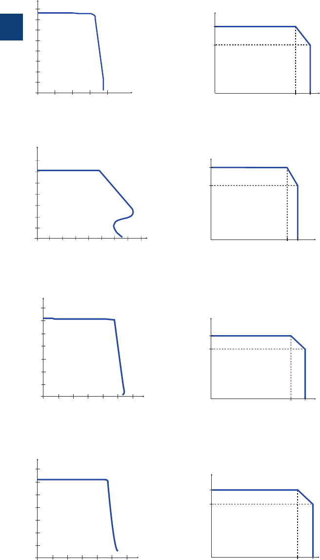
3
3/63 ABB | Catalog Electronic Products and Relays 2015 | 2CDC 110 004 C0210
CP-ASI range
Technical diagrams
12
16
20
24
28
32
8
4
001234
U
out
[V]
Iout [A]
15
20
25
30
35
10
5
0012345
U
out
[V]
678 Iout [A]
15
20
25
30
35
10
5
001
2345
U
out
[V]
6 Iout [A]
15
20
25
30
35
10
5
002
46810
U
out
[V]
12 Iout [A]
-10 60 70 T
a [°C]
I
out
[A]
2.
8
2.1
-25 60 70 Ta
[°C]
I
out
[A]
4
3
-10 60 70 T
a [°C]
I
out
[A]
4
3
-10
60 70 T
a [°C]
I
out
[A]
8
6
Output behaviour
Output behaviour
Output behaviour
Output behaviour
Characteristic curve of temperature at rated load
Characteristic curve of temperature at rated load
Characteristic curve of temperature at rated load
Characteristic curve of temperature at rated load
CP-ASI 2.8
CP-ASI 4.0 DC/DC
CP-ASI 4.0
CP-ASI 8.0
Characteristic curve at Ta = 25°C
2CDC 272 007 F0012
2CDC 272 011 F00122CDC 272 009 F0012
2CDC 272 013 F0012
2CDC 272 006 F02122CDC 272 010 F0212
2CDC 272 008 F0212
2CDC 272 012 F0212
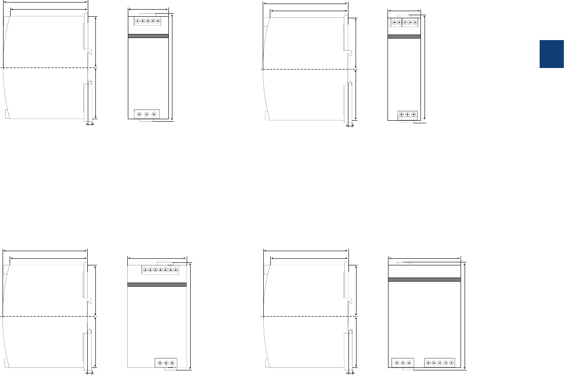
3
2CDC 110 004 C0210 | Catalog Electronic Products and Relays 2015 | ABB 3/64
CP-ASI range
Dimensional drawings
102 4.02”
49 1.93”
62 2.44”
131 5.16”
5 0.20”
94 3.78”
62 2.44”
102 4.02”
62 2.44”
5 0.20”
94 3.78”
62 2.44”
73 2.87”
131 5.16”
102 4.02”
62 2.44”
5 0.20”
94 3.78”
62 2.44”
40 1.58”
131 5.16”
102 4.02”
62 2.44”
5 0.20”
94 3.78”
62 2.44”
91 3.58”
131 5.16”
CP-ASI 2.8
CP-ASI 4.0
CP-ASI 4.0 DC/DC
CP-ASI 8.0
2CDC 272 014 F0012
2CDC 272 015 F0012
2CDC 272 016 F0012
2CDC 272 017 F0012
Dimensions in mm/inch
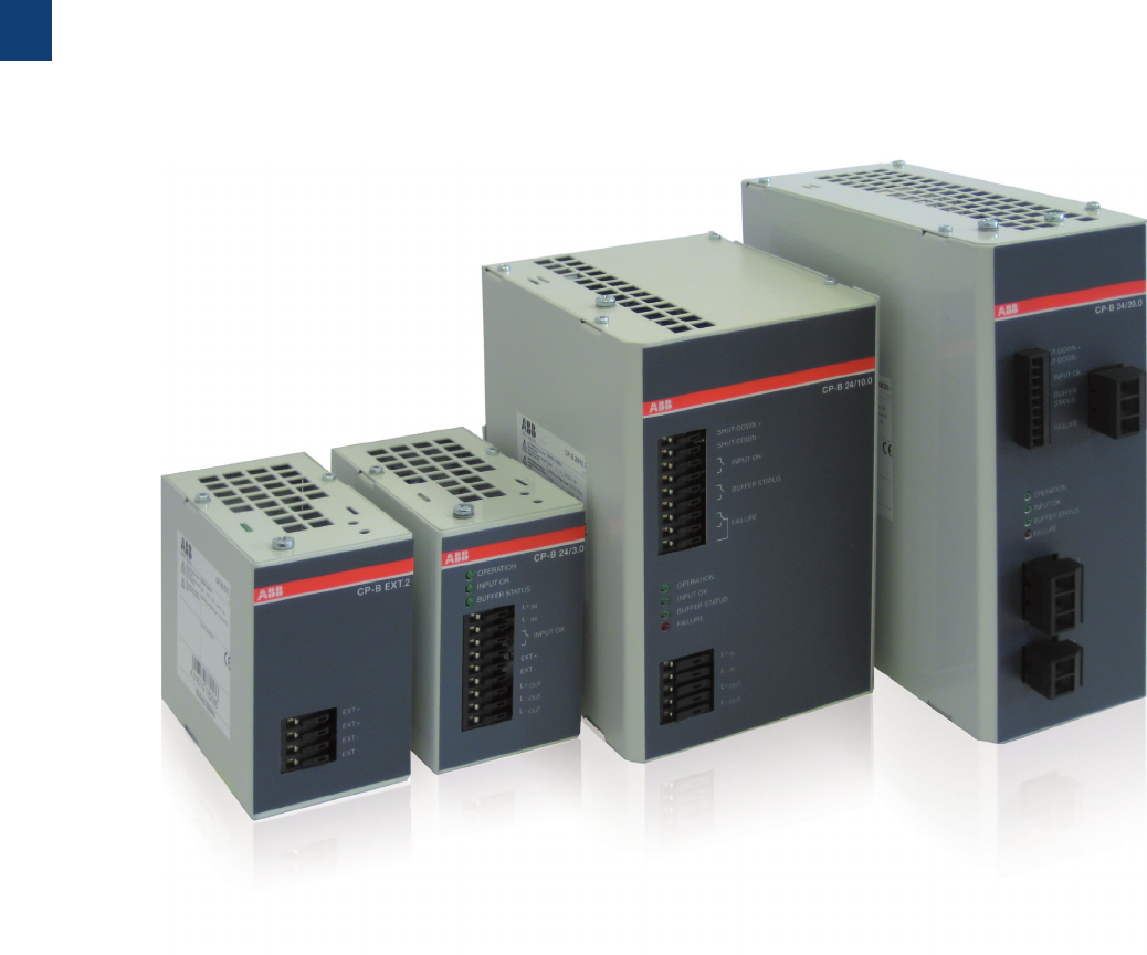
3
3/65 ABB | Catalog Electronic Products and Relays 2015 | 2CDC 110 004 C0210
CP-B range
Product group picture

3
2CDC 110 004 C0210 | Catalog Electronic Products and Relays 2015 | ABB 3/66
CP-B range
Table of contents
CP-B
Product group picture 3/65
Table of contents 3/66
Benefits and advantages 3/67
Ordering details 3/68
Technical data 3/69
Technical data, Technical diagrams 3/70
Dimensional drawings 3/71
Technical data 3/72
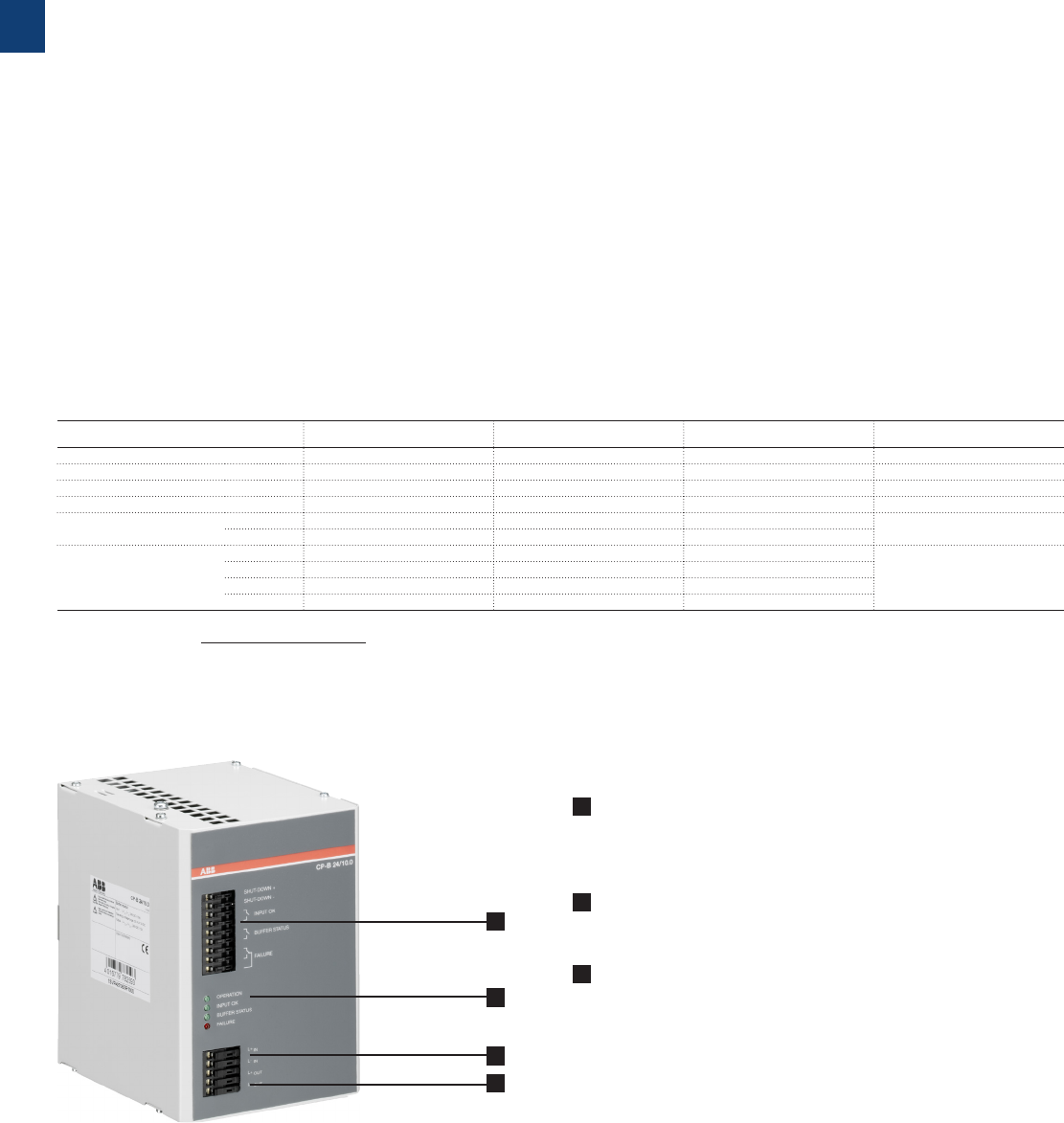
3
3/67 ABB | Catalog Electronic Products and Relays 2015 | 2CDC 110 004 C0210
1 Input terminals
SHUT-DOWN+, SHUT-DOWN-: Input signal terminals
INPUT OK, BUFFER STATUS, FAILURE: Signalling contact – terminals
L+IN, L-IN: Input voltage terminals
2 Indication of operational states
OPERATION: Buffer module in operation (standby or buffering)
INPUT OK: Input voltage applied
3 Output terminals
L+OUT, L-OUT, L-OUT: Output voltage terminals
CP-B range
Benefits and advantages
CP-B 24/3.0 CP-B 24/10.0 CP-B 24/20.0 CP-B EXT. 2
Order code 1SVR427060R0300 1SVR427060R1000 1SVR427060R2000 1SVR427065R0000
Rated input voltage 24 V DC 24 V DC 24 V DC –
Rated current 3 A DC 10 A DC 20 A DC 3 A DC
Energy storage (min.) 1.000 Ws 10.000 Ws 8.000 Ws 2.000 Ws
Typical charging time
at load current
100 % 65 s 134 s 135 s
0 % 56 s 82 s 62 s
Typical
buffering time1)
at load current
100 % 13 s 38 s 15 s
50 % 28 s 76 s 30 s
25 % 66 s 140 s 60 s
10 % 148 s 380 s 150 s
1) buffering time ≈
Power supply systems have to be highly reliable in most areas of
energy management and automation technology.
Often batteries are used for supporting the supply system in
case of mains failures. Batteries have limited lifetimes depending
on environmental parameters and have to be maintained regu-
larly, which causes efforts and costs.
Using the latest ultra-capacitor technology, ABB offers an in-
novative and completely maintenance free new product for
buffering the 24VDC supply in case of interrupted mains on the
primary side of the switch mode power supply.
The CP-B range is an ultra-capacitor buffer energy storage for
power supply units which ensures a short term uninterrupted
power supply system. In case of a power loss, the energy stored
in the capacitor guarantees that the load is continually provided
up to several hundred seconds depending on the load current.
Characteristics
– 3 buffer modules for buffering 24 V DC:
CP-B 24/3.0 (3 A / 1 kWs1))
CP-B 24/10.0 (10 A / 10 kWs1))
CP-B 24/20.0 (20 A / 8 kWs1))
– CP-B 24/3.0 and CP-B 24/20.0 expandable
with additional extension module(s) CP-B EXT.2
(2 kWs1))
– LEDs for status indication
– Relay contacts for status messaging
– Very high backup times (e.g. with CP-B 24/10.0
up to 8 minutes at 1 A load current)
– Short charging times
– High efficiency, higher than 90%
– Wide temperature range
– DIN rail mountable, compact housing
Advantages in comparison to battery buffers:
– Maintenance free
– No deep discharge
– Temperature resistant
–A (UL508, CSA22.2 No 14), R approvals
1) internal energy buffer
energy storage x 0.9
current x output voltage
1
1
2
3
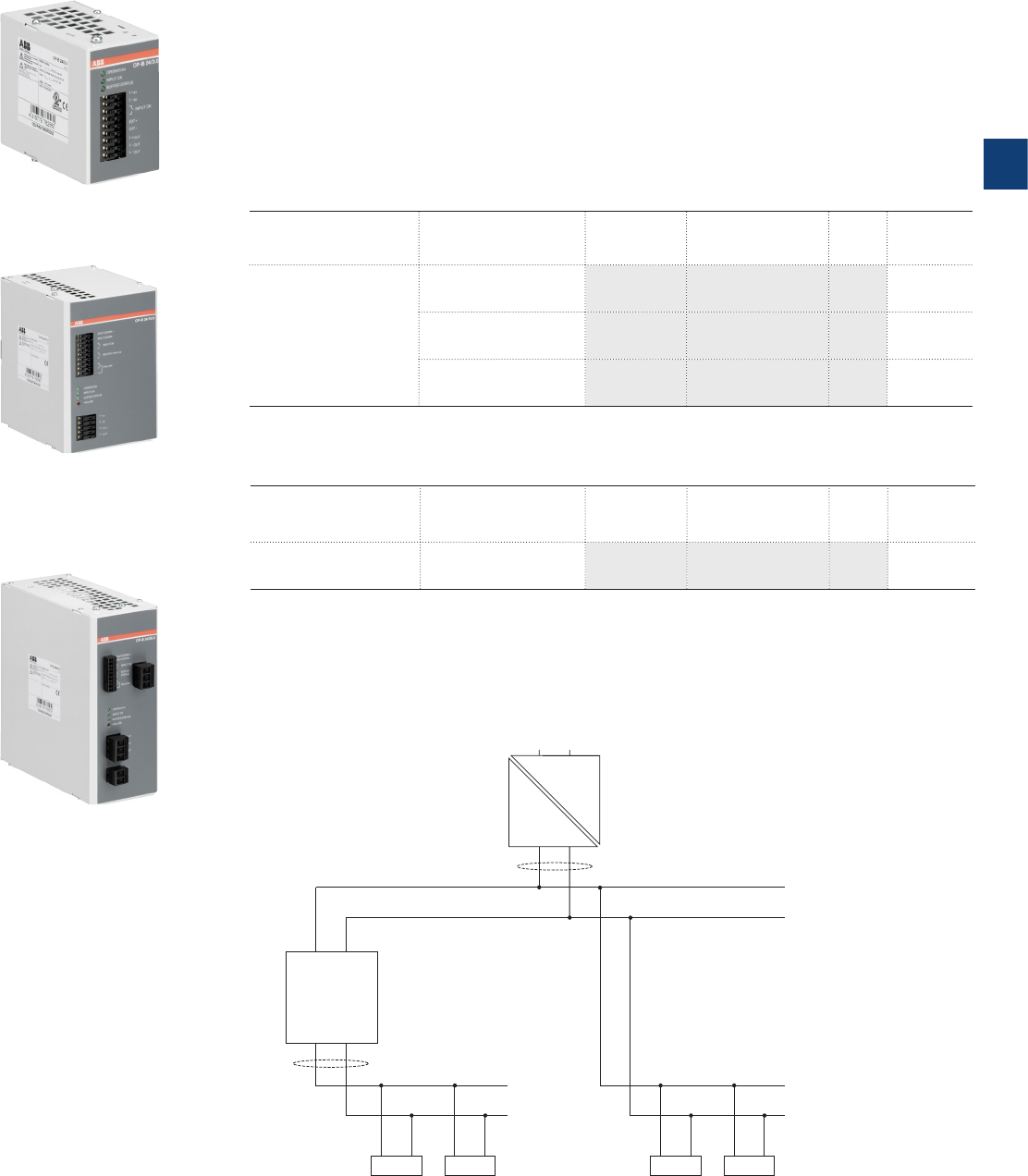
3
2CDC 110 004 C0210 | Catalog Electronic Products and Relays 2015 | ABB 3/68
CP-B range
Ordering details
Description
Ultra capacitor based buffer units of the CP-B range offer highest reliability also in harsh
enivronment. Due to the ultra-cap based technology the units are maintenance free, there will
be no deep discharge and these products offer a very wide operational ambient temperature
range.
CP-B range buffer units are an excellent solution to avoid voltage drops, for example in solar
applications.
Ordering details
Rated input voltage Rated current Type Order code Price
1 pce
Weight
(1 pce)
kg (lb)
24 V DC
3 A DC CP-B 24/3.0 1SVR427060R0300 0.55 (1.21)
10 A DC CP-B 24/10.0 1SVR427060R1000 2.10 (4.63)
20 A DC CP-B 24/20.0 1SVR427060R2000 2.20 (4.85)
2CDC 271 001 S00102CDC 271 002 S00102CDC 271 003 S0010
CP-B 24/3.0
CP-B 24/10.0
CP-B 24/20.0
Ordering details - Extension unit for CP-B 24/3.0 and CP-B 24/20.0
Rated voltage Voltage range Type Order code Price
1 pce
Weight
(1 pce)
kg (lb)
24 V DC 0-26.4 V DC CP-B E X T.2 1SVR427065R0000 1.00 (2.20)
CP-B 24/10.0
L+IN L
-
IN
L+OUT L
-
OUT
max. 20 A
CP-C 24/20.0
LN
L+ L
-
max. 10
A
... ...
L+
L
-
L+
L
-
buffered unbuffered
load 1load nload 1load n
Example of application

3
3/69 ABB | Catalog Electronic Products and Relays 2015 | 2CDC 110 004 C0210
CP-B range
Technical data
Type CP-B 24/3.0 CP-B 24/10.0 CP-B 24/20.0
Input circuit - Supply circuit L+IN L-IN
Rated input voltage Uin 24 V DC
Input voltage range 23.7-26.4 V DC 23.9-27 V DC 23.4-27.4 V DC
Minimum charging potential 23.7 V DC 23.9 V DC 23.4 V DC
Rated input current 3 A DC 10 A DC 20 A DC
Inrush current limiting 50 A / 1 ms 35 A / 2 ms 35 A / 2 ms
Transient overvoltage protection suppressor diode
varistor / suppressor diode varistor / suppressor diode
Internal input fuse (apparatus protection, not accessible) 4 A slow acting 15 A (FK2) 30 A (FK2)
Internal fuse capacitors circuit (not accessible) 25 A (FK2)
Kind of input SHUT-DOWN -control input control input
rated voltage -24 V DC 24 V DC
voltage range -6-45 V DC 6-45 V DC
Output circuit L+OUT L-OUT L-OUT
Rated output power 69 W 240 W 480 W
Rated output voltage Uout 24 V DC
Output voltage (buffer mode) 23.0 V DC 23.2 V DC 23.2 V DC
Tolerance of the output voltage +2...-10 %
Rated output current Ir Ta m 60 °C 3 A DC 10 A DC 20 A DC
Peak output current (fully loaded capacitors
required)
Ta m 60 °C 6 A DC (min. 1.5 s)
20 A DC (10 A power supply
+ 10 A CP-B, min. 1.5 s)
40 A DC (min. 1.5 s)
Control of limiting current -10.3 A DC w0.1A -
Shut-down if limiting current is exceeded -after 1.5 s -
Short-circuit protection (only via external fuse) no continuous short-circuit stability
Internal output fuse (not accessible) -15 A (FK2) -
Required external fuse 3.15 A slow acting 10 A slow acting 25 A slow acting
Current limiting at output circuit -1.05...1.2 x Ir-
Breaking capacity of output circuit t= 2.5 ms -24 V DC, 10 A -
Power failure buffering time 1) load-dependent, min.
13 s at 100 % load
load-dependent, min.
38 s at 100 % load
load-dependent, min.
15 s at 100 % load
Overload protection thermal protection
Kind of output INPUT OK n/o contact
BUFFER STATUS -n/o contact
FAILURE -c/o contact
Contact material Ag + Au-clad
Minimum switching voltage / Minimum switching current 5 V DC / 1 mA
Maximum switching voltage / Maximum switching current 50 V AC / 1.0 A, 30 V DC / 0.5 A
Mechanical lifetime 5 x 10⁶ switching cycles
Electrical lifetime 0.1 x 10⁶ switching cycles
Maximum fuse rating to achieve short-circuit protection
n/o or n/c contact 1.0 A AC / 0.5 A DC
General data
Maximum internal power consumption 7 W 20 W 40 W
Power consumption with unloaded output 0.75 W 3 W 1.6 W
Energy storage (min.) 1000 Ws 10000 Ws 8000 Ws
Typical charging time at load current 100 % 65 s 134 s 135 s
0 % 56 s 82 s 62 s
Typical buffering time at load current1) 100 % 13 s 38 s 15 s
50 % 28 s 76 s 30 s
25 % 66 s 140 s 60 s
10 % 148 s 380 s 150 s
Efficiency greater than 90 %
Dimensions (W x H x D) product dimensions 60 x 99 x 120 mm
(2.36 x 3.90 x 4.72 in)
116 x 170 x 147 mm
(4.57 x 6.69 x 5.79 in)
84 x 197 x 213 mm
(3.31 x 7.76 x 8.39 in)
Weight net weight 0.55 kg (1.21 lb) 2.1 kg (4.63 lb) 2.2 kg (4.85 lb)
Material cover / housing shell steel sheet powdered
Mounting DIN rail (IEC/EN 60715), snap-on mounting without any tool
Mounting position horizontal
Minimum distance to other units horizontal not necessary
vertical 40 mm (1.58 in) 80 mm (3.15 in)
Pollution degree 2
Degree of protection housing / terminal IP20
Protection class (IEC/EN 61140) III SELV / PELV (condition: power supply fulfills class III)
Electrical connection - Input circuit / Output circuit pull spring terminals pull spring terminals
pluggable screw type terminals
Wire size fine-strand with(out) wire end ferrule 0.08-1.0 mm²
(28-18 AWG)
0.0 8-1.5 mm²
(28-18 AWG)
0.2-4.0 mm²
(24-12 AWG)
rigid 0.08-1.5 mm²
(28-16 AWG)
0.08-4.0 mm²
(28-16 AWG)
0.2-6.0 mm²
(24-10 AWG)
Stripping length 6.0 mm (0.24 in) 7.0 mm (0.28 in)
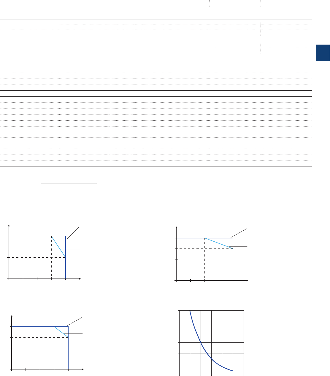
3
2CDC 110 004 C0210 | Catalog Electronic Products and Relays 2015 | ABB 3/70
CP-B range
Technical data, Technical diagrams
Type CP-B 24/3.0 CP-B 24/10.0 CP-B 24/20.0
Input circuit - Supply circuit L+IN L-IN
Signalling circuit
Wire size fine-strand with(out) wire end ferrule 0.08-1.0 mm² (28-18 AWG)
0.14-1.0 mm² (26-16 AWG)
rigid 0.08-1.5 mm² (28-16 AWG)
0.14-1.5 mm² (28-16 AWG)
Stripping length 6.0 mm (0.24 in) 7.0 mm (0.28 in)
Environmental data
Ambient temperature operation -40...+60 °C -20...+60 °C
storage -40...+60 °C -20...+60 °C
Standards
Product standard EN 50178
Low Voltage Directive 2006/95/EC
EMC Directive 2004/108/EC
RoHS Directive 2011/65/ EC
Electrical safety EN 50178, EN 60950, UL 508
Electromagnetic compatibility
Interference immunity to IEC/EN 61000-6-1, IEC/EN 61000-6-2
electrostatic discharge IEC/EN 61000-4-2 Level 3, 6 kV / 8 kV
radiated, radio-frequency, electromagnetic field IEC/EN 61000-4-3 Level 3, 10 V/m (27-1000 MHz) / Level 2, 3 V/m (1400-2700 MHz)
electrical fast transient/burst IEC/EN 61000-4-4 Level 3, 2(1) kV / 5 kHz
surge IEC/EN 61000-4-5 Level 1, 0.5 kV
conducted disturbances, induced by radio-
frequency fields
IEC/EN 61000-4-6 Level 3, 10 V (150 kHz-80 MHz)
voltage dips, short interruptions and voltage
variations
IEC/EN 61000-4-11 buffered by ultra-capacitors
Interference emission EN 61000-6-3, EN 61000-6-4
high-frequency radiated DIN EN 55011 B/C1
high-frequency conducted DIN EN 55011 B/C1
„Approvals and marks“ on page 3/4.
1) buffering time ≈ energy storage x 0.9
load current x output voltage
CP-B 24/3.0 CP-B 24/20.0
CP-B 24/10.0
Technical diagrams
Output curve at Ta = 25 °C
Caracteristic curve of the temperature at rated load Capacitor's life span over temperature
Iout [A]
0204060
-40
Ta [°C]
1.5
3.0
Normal application (up to
50 % buffer mode, 5 char
ging
and discharging cycles in
direct series)
Continuous charging and
discharging in direct series.
As this is not typical of a real
application, this should
be considered as theoretical
indication
I
out
[A]
0204060
-40
Ta [°C]
Normal application (up to
50 % buffer mode, 5 char
ging
and discharging cycles in
direct series)
Continuous charging and
discharging in direct series.
As this is not typical of a real
application, this should
be considered as theoretical
indication
5.0
7.5
10.0
I
out
[A]
0204060
-20
10
15
20
Ta [°C]
Normal application (up to
50 % buffer mode, 5 char
ging
and discharging cycles in
direct series)
Continuous charging and
discharging in direct series.
As this is not typical of a real
application, this should
be considered as theoretical
indication
302010
0
10
20
30
40
50
60
60
70
40 50
Temperature [°C]
Years
2CDC 272 028 F0210
2CDC 272 030 F0210
2CDC 272 029 F0210
2CDC 272 031 F0210
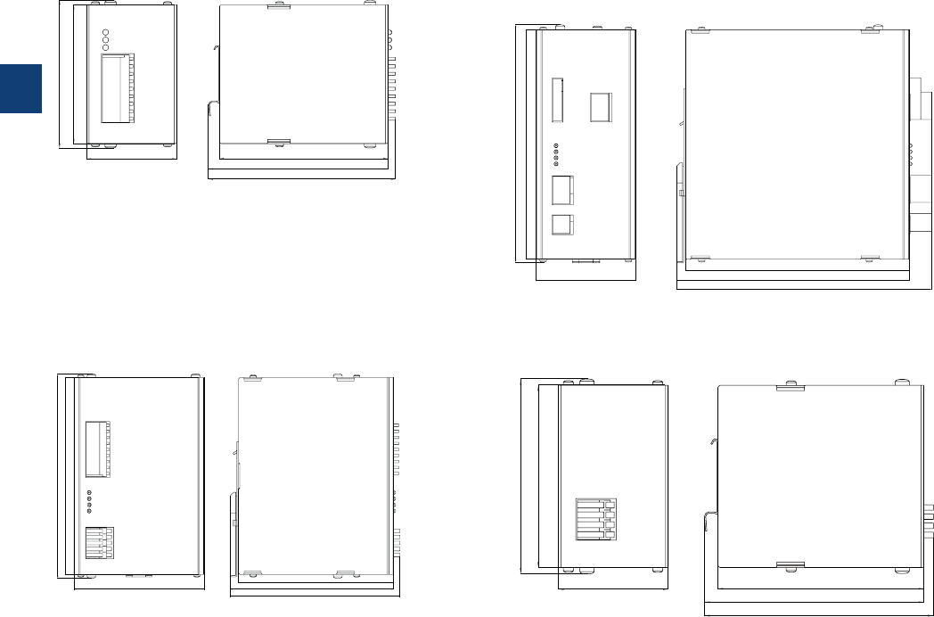
3
3/71 ABB | Catalog Electronic Products and Relays 2015 | 2CDC 110 004 C0210
CP-B range
Dimensional drawings
Dimensions in mm and inches
CP-B 24/3.0
93 3.66
‘‘
60 2.36
‘‘
112
4.41
‘‘
119
4.69
‘‘
120
4.72
‘‘
99 3.90
‘‘
CP-B EXT.2
CP-B 24/10.0
93 3.66
‘‘
99 3.90
‘‘
60 2.36
‘‘
112
4.41
‘‘
119
4.69
‘‘
120
4.72
‘‘
163 6.42
‘‘
116 4.57
‘‘
170 6.69
‘‘
138 5.43
‘‘
147 5.79
‘‘
146 5.75
‘‘
CP-B 24/20.0
193 7.60
‘‘
196 7.72
‘‘
188 7.40
‘‘
213 8.39
‘‘
84 3.31
‘‘
197 7.76
‘‘
2CDC 272 037 F0010
2CDC 272 039 F0010
2CDC 272 036 F0010
2CDC 272 038 F0010

3
2CDC 110 004 C0210 | Catalog Electronic Products and Relays 2015 | ABB 3/72
CP-B range
Technical data
Data at Ta = 25 °C and rated values, unless otherwise indicated
Type CP-B EXT 2.0
Extension circuit EXT+ EXT+ EXT- EXT-
Rated voltage 24 V DC
Voltage range 0-26.4 V DC
Rated current 3 A DC
Internal input fuse (apparatus protection, not accessible) 4 A slow acting (PTC)
Short-circuit protection via internal 3 A fuse
Overload protection only in combination with CP-B 24/3.0 or CP-B 24/20.0
Indication of operational states
status information and fault messages of the buffer module
apply
General data
Power consumption without load 0.5 W
Energy storage (min.) 2000 Ws
Dimensions (W x H x D) product dimensions 60 x 99 x 120 mm (2.36 x 3.90 x 4.72 in)
packaging dimensions 85 x 220 x 170 mm (3.35 x 8.66 x 6.69 in)
Weight net weight 1.00 kg (0.20 lb)
Material cover / housing shell steel sheet powdered
Mounting DIN rail (IEC/EN 60715), snap-on mounting without any tool
Mounting position horizontal
Minimum distance to other units horizontal not necessary
vertical 40 mm (1.58 in)
Pollution degree 2
Degree of protection housing / terminal IP20
Protection class (IEC/EN 61140) III SELV / PELV (condition: power supply fulfills class III)
Electrical connection - Extension circuit
Wire size fine-strand with(out) wire end ferrule 0.08-1.0 mm² (28-18 AWG)
rigid 0.08-1.5 mm² (28-16 AWG)
Stripping length 6.0 mm (0.24 in)
Signalling circuit
Wire size fine-strand with(out) wire end ferrule 0.08-1.0 mm² (28-18 AWG)
rigid 0.08-1.5 mm² (28-16 AWG)
Stripping length 6.0 mm (0.24 in)
Environmental data
Ambient temperature operation -40...+60 °C
storage -40...+60 °C
Vibration, sinusoidal based on IEC/EN 60068-2-6 1.5 mm, 3-57.55 Hz; 2 g, 57.55-500 Hz, 10 cycles
Shock, half-sine based on IEC/EN 60068-2-27 15 g, 11 ms, 3 axes, 6 faces, 3 times for each face
Standards
Product standard EN 50178
Low Voltage Directive 2006/95/EC
EMC Directive 2004/108/EC
RoHS Directive 2011/65/ EC
Electrical safety EN 50178, EN 60950, UL 508
Electromagnetic compatibility
Interference immunity to IEC/EN 61000-6-1, IEC/EN 61000-6-2
electrostatic discharge IEC/EN 61000-4-2 Level 3, 6 kV / 8 kV
radiated, radio-frequency, electromagnetic field IEC/EN 61000-4-3
Level 3, 10 V/m (27-1000 MHz) / Level 2, 3 V/m (1400-2700 MHz)
electrical fast transient/burst IEC/EN 61000-4-4 Level 3, 2(1) kV / 5 kHz
surge IEC/EN 61000-4-5 Level 1, 0.5 kV
conducted disturbances, induced by radio-frequency
fields
IEC/EN 61000-4-6 Level 3, 10 V (150 kHz-80 MHz)
voltage dips, short interruptions and voltage variations IEC/EN 61000-4-11 buffered by ultra-capacitors
Interference emission EN 61000-6-3, EN 61000-6-4
high-frequency radiated DIN EN 55011 B/C1
high-frequency conducted DIN EN 55011 B/C1
„Approvals and marks“ on page 3/4.
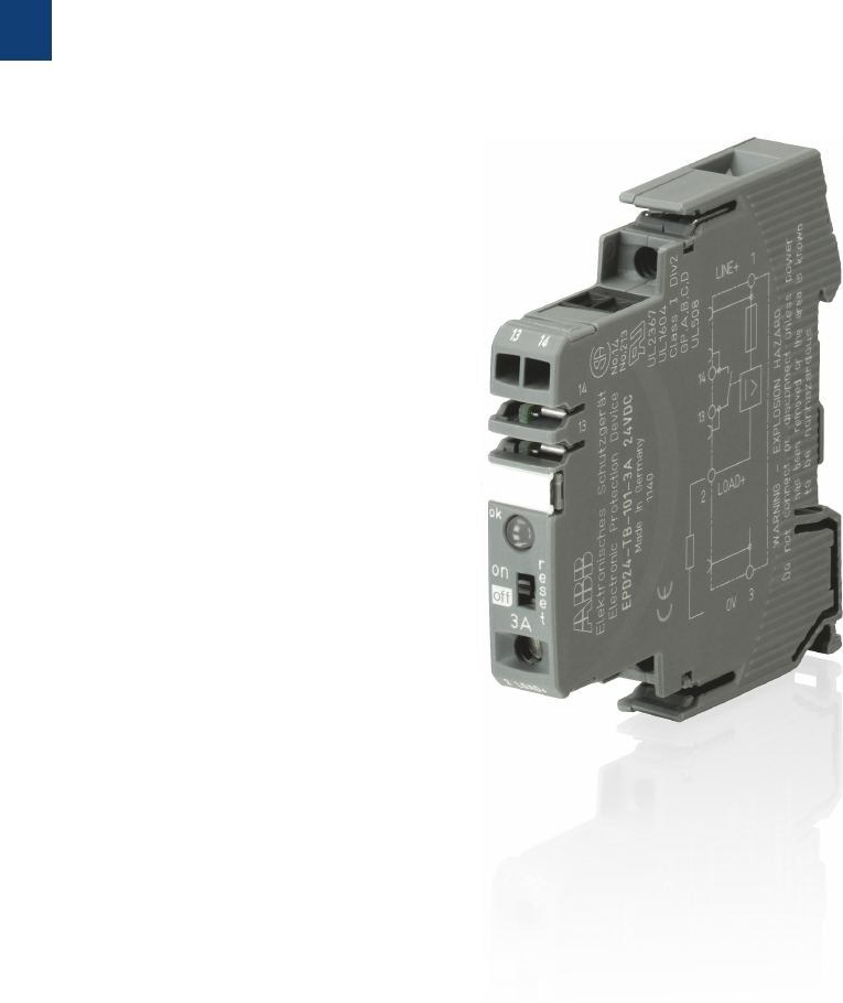
3
3/73 ABB | Catalog Electronic Products and Relays 2015 | 2CDC 110 004 C0210
Electronic protection devices EPD24
Product group picture

3
2CDC 110 004 C0210 | Catalog Electronic Products and Relays 2015 | ABB 3/74
Electronic protection devices EPD24
Table of contents
Electronic protection devices EPD24
Product group picture 3/73
Table of contents 3/74
Ordering details 3/75
Technical data 3/76
Technical information 3/78
Approvals, safety instructions 3/79
Installation guidelines 3/80
3
3/75 ABB | Catalog Electronic Products and Relays 2015 | 2CDC 110 004 C0210
Electronic protection devices EPD24
Ordering details
The protection devices EPD24 extend the ABB product range of Modular DIN rail components by
electronic overcurrent protection modules for selective protection of 24 V DC load circuits.
This protection is achieved by a combination of active electronic current limitation in the case of a
short circuit and an overload deactivation from 1.1 x In upwards.
If a fault occurs in a load circuit, the protection device EPD24 will detect this rapidly and reliably,
disable the power output transistor and hence interrupt the current flow in the defective circuit. The
maximum possible overcurrent is always limited to 1.3…1.8 times the selected rated current. An
activation of capacitive loads up to 20,000 μF is possible, deactivation only occurring in the case of
overloads or short circuits. Selective deactivation of the defective current circuit means undefined
error states and a complete system stop are prevented.
Features
– Selective load protection, one electronic tripping characteristic.
– Active current limitation for safe connection of capacitive loads up to 20,000 µF and on
overload/short circuit.
– Current ratings 0.5 A...12 A.
– Reliable overload disconnection with 1.1 x IN
– Manual ON/OFF button
– Clear status and failure indication through LED and integrated auxiliary contact.
– Integral fail-safe element adjusted to current rating.
– Width per unit only 12.5 mm.
– Rail mounting
– Ease of wiring through busbar LINE+ and 0 V as well as signal bars.
– UL- and CSA-approvals allow international use of the devices.
Ordering details
Ratedcurrent IN
A
bbn 40 16779 EAN Type Order code Price Pkg
qty
Weight
(1 pce)
kg (lb)
0.5 829960 EPD24-TB-101-0.5A 2CDE601101R2905 40.065
(1.433)
1829984 EPD24-TB-101-1A 2CDE601101R2001 40.065
(1.433)
2830003 EPD24-TB-101-2 A 2CDE601101R2002 40.065
(1.433)
3830027 EPD24-TB-101-3A 2CDE601101R2003 40.065
(1.433)
4830041 EPD24-TB-101-4A 2CDE601101R2004 40.065
(1.433)
6830065 EPD24-TB-101-6A 2CDE601101R2006 40.065
(1.433)
8830089 EPD24-TB-101-8A 2CDE601101R2008 40.065
(1.433)
10 830102 EPD24-TB-101-10A 2CDE601101R2010 40.065
(1.433)
12 830126 EPD24-TB-101-12A 2CDE601101R2012 40.065
(1.433)
Ordering details
Description bbn 40
16779 EAN
Type Order code Price Pkg
qty
Weight
(1 pce)
kg (lb)
Busbars for LINE+ and 0 V,
grey insulation, length 500 mm 1) 830140 EPD-BB500 2CDE605100R0500 10 0.2
(0.441)
Signal Bars for aux. contacts, grey
insulation, length 21 mm 830164 EPD-SB21 2CDE605200R0021 10 0.4
(0.882)
1) Max. load with one line entry Imax = 50 A (recommended: mid line entry)
Max. load with two line entries Imax = 63 A
2CDC 051 001 S0010
EPD24-TB-101-3A
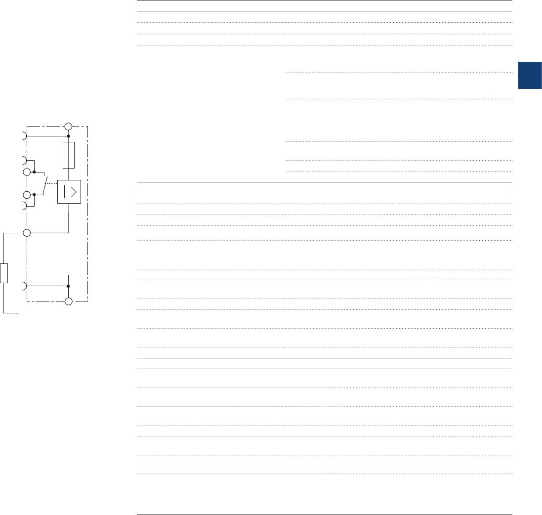
3
2CDC 110 004 C0210 | Catalog Electronic Products and Relays 2015 | ABB 3/76
Electronic protection devices EPD24
Technical data
www.e-t-a.com
Elektronischer Sicherungsautomat ESX10-T
Installations- und Sicherheitshinweise
08/09(200110)
5- 47
5
LINE+ 1
LOAD+
2
0V 3
ESX10-TA-100
Ohne Signaleingang/-Ausgang
LINE+ 1
SF 23
IN 21
2LOAD+
0V 3
ESX10-TB-114
Mit Steuereingang IN+
(+DC 24 V)
Mit Statusausgang SF
(+24 V = Lastausgang EIN)
Normalzustand: SF +24 V = OK
Fehlerzustand: SF 0 V
LINE+ 1
SF 23
RE 22
2LOAD+
0V 3
ESX10-TB-124
Mit Reseteingang RE
(+DC 24 V ↓)
Mit Statusausgang SF
(+24 V = Lastausgang EIN)
Normalzustand: SF +24 V = OK
Fehlerzustand: SF 0 V
LINE+ 1
14
13
2LOAD+
0V 3
ESX10-TB-101
Ohne Signaleingang
Mit Meldeausgang F
(Einzelsignal, Schließer)
Normalzustand: 13-14 geschlossen
Fehlerzustand: 13-14 geöffnet
LINE+ 1
12
11
2LOAD+
0V 3
ESX10-TB-102
Ohne Signaleingang
Mit Meldeausgang F
(Einzelsignal, Öffner)
Normalzustand: 11-12 geöffnet
Fehlerzustand: 11-12 geschlossen
LINE+ 1
SF 23
RE 22
2LOAD+
0V 3
ESX10-TB-127
Mit Reseteingang RE
(+DC 24 V ↓)
Mit Statusausgang SF invertiert
(0 V = Lastausgang EIN)
Normalzustand: SF 0 V = OK
Fehlerzustand: SF +24 V
ESX10-T Signaleingänge / -ausgänge (Anschlussdiagramme)
Die Signalkontakte werden im Aus- oder Fehlerzustand gezeigt
ESX10-T Signaleingänge/-ausgänge (Anschlussdiagramme)
Wiring diagramm
EPD24-TB-101
without signal input
with signal output F
(Single signal, N/O)
Operating condition: 13-14 closed
Fault condition: 13-14 open
Operating data
Operating voltage UB24 V DC (18...32 V)
Current rating INfixed current ratings: 0.5, 1, 2, 3, 4, 6, 8, 10, 12 A
Closed current I0ON condition: typically 20...30 mA depending on signal output
Staus indication by means of Green:
unit is ON
load circuit / Power-MOSFET is switched on
Orange:
in the event of overload or short circuit until electronic
disconnection
Red:
unit electronically disconnected
load circuit/Power-MOSFET OFF
undervoltage (UB < 8 V)
after switch-on till the end of the delay period
OFF:
manually switched off or device is dead
potential-free auxiliary contact F
ON/OFF/ condition of switch
Load circuit
Load output Power-MOSFET switching output (high slide switch)
Overload disconnection typically 1.1 x IN (1.05...1.35 x IN)
Short-circuit current IK active current limitation
Trip time see time/current characteristics
For electronic disconnection typically 3 s at ILoad > 1.1 x IN
typically 100 ms...3 s at ILoad > 1.8 x IN
(or 1.5 x IN/1.3 x IN, )
Temperature disconnection internal temperature monitoring with electronic disconnection
Low voltage monitoring load output with hysteresis, no reset required:
load »OFF« at UB< 8 V
Starting delay tStart typically 0.5 sec after every switch-on and after applying UB
Disconnection of
load circuit
electronic disconnection
Free-wheeling circuit suitable external free-wheeling circuit to be used with inductive
load
Several load outputs must not be connected in parallel
Signal output
Electrical data potential-free auxiliary contact
max. 30 V DC/0.5 A, min. 10 V DC/10 mA
ON condition LED green voltage UB applied, switch is in ON position
no overload, no short circuit
OFF condition LED off device switched off (switch is in OFF position)
no voltage UB applied
Fault condition LED orange overload condition > 1.1 x IN up to electronic disconnection
Fault condition LED red electronic disconnection upon overload or short circuit
Device switched off with control signal (switch is in ON position)
Aux. contact single signal, make contact
contact open, terminal 13-14
Fault signal output fault conditions
no operating voltage UB
ON/OFF switch is in OFF position
red LED lighted (electronic disconnection)

3
3/77 ABB | Catalog Electronic Products and Relays 2015 | 2CDC 110 004 C0210
Electronic protection devices EPD24
Technical data
General data
Fail-Safe element backup fuse for EPD24 not required because of the integral
redundant fail-safe element
Housing material moulded
Mounting symmetrical rail to EN 50022-35x7.5
Ambient temperature 0...+50 °C (without condensation, see EN 60204-1)
Storage temperature -20...+70 °C
Humidity 96 hrs/95 % RH/40 °C to IEC 60068-2-78, test Cab. climate class
3K3 to EN 60721
Vibration 3 g, test to IEC 60068-2-6 test Fc
Degree of protection housing: IP20 DIN 40050
terminals: IP20 DIN 40050
EMC
(EMC directive, CE logo)
emission: EN 61000-6-3
susceptibility: EN 61000-6-2
Isolations coordination
(IEC 60934)
0.5 kV/pollution degree 2
reinforced insulation in operating area
Dielectric strength max. 32 V DC (load circuit)
Isolation resistance (OFF condition) n/a, only electronic disconnection
Approvals/Declarations of conformity
UL 2367 Solid State Overcurrent Protectors
UL 1604, (class I, division 2, groups A, B, C, D)
UL 508
CSA C22.2 No. 213 (class I, division 2)
CSA C22.2 No. 142
CE logo
Dimensions (B x H x T) 12.5 x 80 x 83 mm
Weight approx. 65 g
Terminals Line+/LOAD+/0V
Screw terminals M4
Max. cable cross section flexible with wire end ferrule w/wo plastic sleeve 0.5 – 10 mm2
Multi-lead connection (2 identical cables) rigid/flexible 0.5 – 4 mm2
Flexible with wire end ferrule without plastic sleeve 0.5 – 2.5 mm2
Flexible with TWIN wire end ferrule with plastic sleeve 0.5 – 6 mm2
Wire stripping length 10 mm
Tightening torque (EN 60934) 1.5 – 1.8 Nm
Terminals aux. contacts
Screw terminals M3
Max. cable cross section flexible
with wire end ferrule w/wo plastic sleeve 0.25 - 2.5 mm2
Wire stripping length 8 mm
Tightening torque (EN 60934) 0.5 Nm
Table 1: voltage drop, current limitation, max. load current
current rating typically voltage drop active current max. load current at 100 % ON duty
INUON at INlimitation (typically) Tambient = 40 °C Tambient = 40 °C
0.5 A 70 mV 1.8 x IN0.5 A 0.5 A
1 A 80 mV 1.8 x IN1 A 1 A
2 A 130 mV 1.8 x IN2 A 2 A
3 A 80 mV 1.8 x IN3 A 3 A
4 A 100 mV 1.8 x IN4 A 4 A
6 A 130 mV 1.8 x IN6 A 5 A
8 A 120 mV 1.5 x IN8 A 7 A
10 A 150 mV 1.5 x IN10 A 9 A
12 A 180 mV 1.3 x IN12 A 10.8 A
Attention: when mounted side-by-side without convection the ERD24 should not carry more than 80 % of its rated load with 100 % ON duty due
to thermal effects.
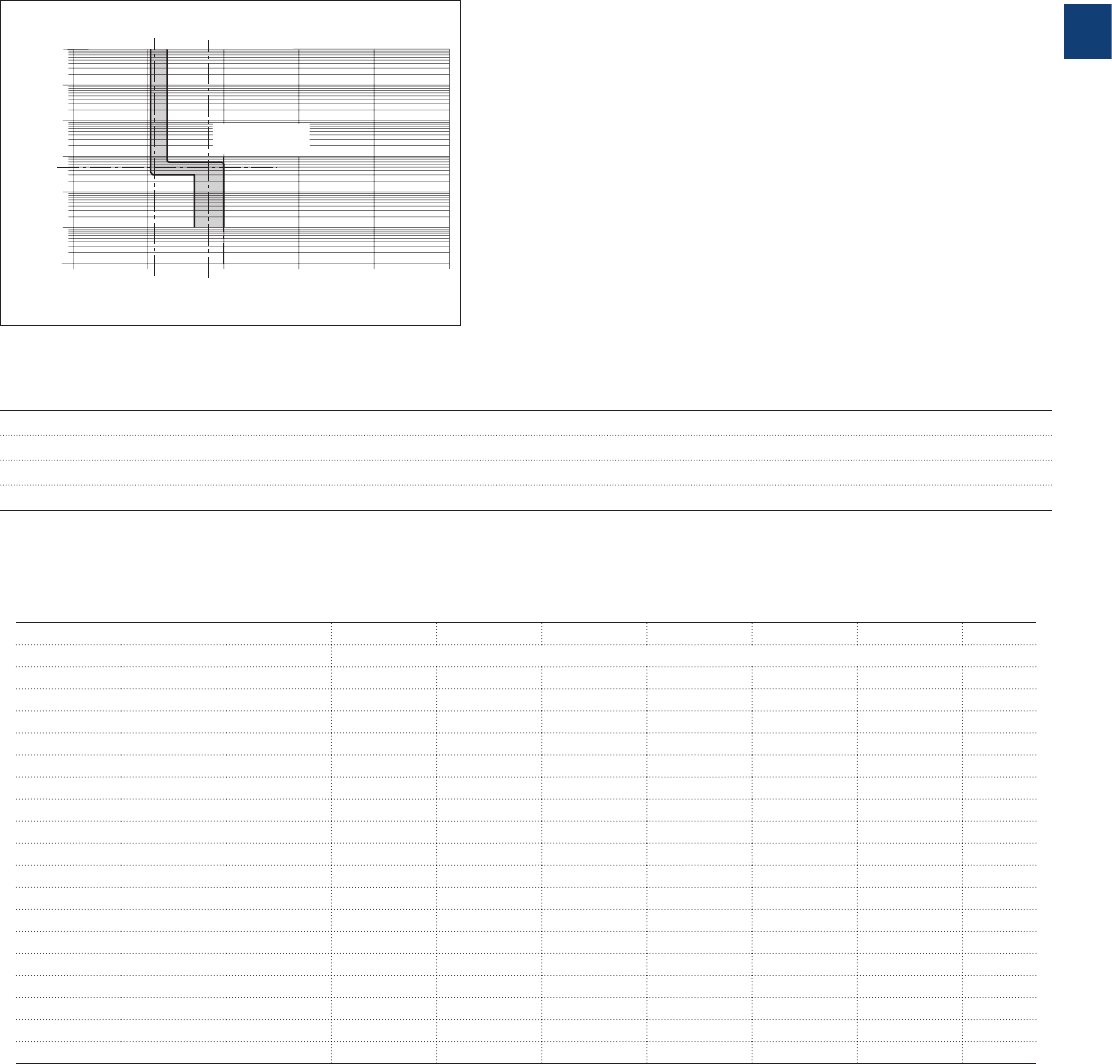
3
2CDC 110 004 C0210 | Catalog Electronic Products and Relays 2015 | ABB 3/78
Electronic protection devices EPD24
Technical information
Time/Current characteristic curve (Tambient = 25 °C)
The trip time is typically 3 s in the range between 1.1 and 1.8 x IN
1)
.
Electronic current limitation occurs at typically 1.8 x IN
1) which means that under all overload conditions (independent of the power sup-
ply and the resistance of the load circuit) the max. overload before disconnection will not exceed 1.8 x IN
1) times the current rating. Trip
time is between 100 ms and 3 sec (depending on overload or at short circuit).
Without this current limitation a considerably higher overload current would flow in the event of an overload or short circuit.
disconnection
typically 1.1 x IN
current limitation
typically 1.8 x IN
1)
IK
10000
1000
124
trip time in seconds
...times rated current
100
10
1
0.1
0.01
35
0
1.8 x IN1)
5
1) Current limitation typically 1.8 x IN at IN = 0.5 A...6 A
Current limitation typically 1.5 x IN at IN = 8 A or 10 A
Current limitation typically 1.3 x IN at IN = 12 A
Maximum cable lenghts
EPD24 reliably trips from 0 Ω up to max. circuit resistance Rmax.
Calculation of Rmax
Selected rating IN (A) 3 6
Operating voltage US (V DC) (= 80 % of 24 V) 2) 19.2 19.2
Trip current Iab = 1.25 x IN (A) (EPD24 trips after 3 s) 3.75 7.5 0
Rmax (Ω) = (UB/Iab) -0.050 5.07 2.51
2) Voltage drop of EPD24 and tolerance of trip point (typically 1.1 x IN = 1.05 ... 1.35 x IN) have been taken into account
Selection table for the incoming cable lengths with different cable cross-sections
Cable cross section A (mm2) 0.14 0.25 0.34 0.5 0.75 1.00 1.50
Cable length L (m) (= single length) cable resistance (Ω) = (ρ0 x 2 x L) / A 3)
5 1.27 0.71 0.52 0.36 0.24 0.18 0.12
10 2.54 1.42 1.05 0.71 0.47 0.36 0.24
15 3.81 2.14 1.57 1.07 0.71 0.53 0.36
20 5.09 2.85 2.09 1.42 0.95 0.71 0.47
25 6.36 3.56 2.62 1.78 1.19 0.89 0.59
30 7. 6 3 4.27 3.14 2.14 1.42 1.07 0.71
35 8.90 4.98 3.66 2.49 1.66 1.25 0.83
40 10.17 5.70 4.19 2.85 1.90 1.42 0.95
45 11.44 6.41 4.71 3.20 2.14 1.60 1.07
50 12.71 7.12 5.24 3.56 2.37 1.78 1.19
75 19.07 10.68 7. 8 5 5.34 3.56 2.67 1.78
100 25.34 14.24 10.47 7.12 4.75 3.56 2.37
125 31.79 17. 8 0 13.09 8.90 5.93 4.45 2.97
150 38 .14 21.36 15.71 10.68 7.12 5.34 3.56
175 44.50 24.92 18.32 12.46 8.31 6.23 4.15
200 50.86 28.48 20.94 14.24 9.49 7.12 4.75
225 57. 21 32.04 23.56 16.02 10.68 8.01 5.34
250 63.57 35.60 26.18 17.8 0 11.87 8.90 5.93
3) Resistivity of copper ρ0 = 0.0178 (Ω x mm2)/m
Example 1: max. length for 1.5 mm2 and 3 A: 214 m
Example 2: max. length for 1.5 mm2 and 6 A: 106 m
Example 3: mixed wiring: (Control cabinet --- sensor/actuator level)
R1 = 40 m for 1.5 mm2 and R2 = 5 m for 0.25 mm2:
R1 = 0.95 Ω, R2 = 0.71 Ω, total (R1 + R2) = 1.66 Ω

3
3/79 ABB | Catalog Electronic Products and Relays 2015 | 2CDC 110 004 C0210
Electronic protection devices EPD24
Approvals, Safety instructions
Please note
The user must ensure that the cable cross sections of the relevant load circuit are suitable for the current rating of the EPD24
used. Automatic start-up of machinery after shut down must be prevented (Machinery Directive 98/37/EG and EN 60204-1).
In the event of a short circuit or overload the load circuit will be disconnected electronically by the EPD24.
Information on UL approvals/CSA approvals
UL1604
UL File # E 339238
CSA C22.2 No. 213 (Class I, Division 2)
CSA File # 2305929
Operating Temperature Code T5
– This equipment is suitable for use in Class I, Division 2, Groups A, B, C and D or non-hazardous locations only
WARNING:
– Exposure to some chemicals may degrade the sealing properties of materials used in the following device: relay
Sealant Material:
– Generic Name: Modified diglycidyl ether of bisphenol A
– Supplier: Fine Polymers Corporation
– Type: Epi Fine 4616L-160PK
– Casing Material:
– Generic Name: Liquid Crystal Polymer
– Supplier: Sumitomo Chemical
– Type: E4008, E4009, or E6008
RECOMMENDATION:
– Periodically inspect the device named above for any degradation of properties and replace if degradation is found
WARNING – EXPLOSION HAZARD:
– Do not disconnect equipment unless power has been removed or the area is known to be non-hazardous
– Substitution of any components may impair suitability for Class I, Division 2
UL2367
Non-hazardous use - UL File # E 339236
UL 508
Non-hazardous use - UL File # E 149922
CSA C22.2 No. 14
CSA C22.2 No. 142 - CSA File # E 2305929
Class 2
Meets requirement for Class 2 current limitation (EPD24 ... -0,5 A/1 A/2 A/3 A)
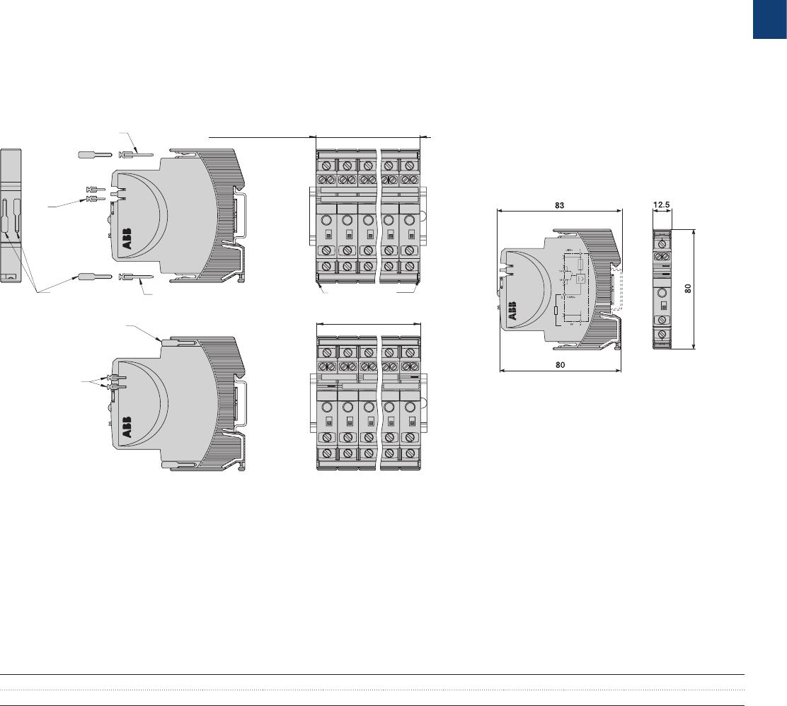
3
2CDC 110 004 C0210 | Catalog Electronic Products and Relays 2015 | ABB 3/80
Electronic protection devices EPD24
Installation guidelines
The EPD24 features an integral power distribution system.
The following wiring modes are possible with various pluggable current and signal busbars:
– LINE+ (24 V DC)
– 0 V
Caution: The electronic devices EPD24 require a 0 V connection
– Auxiliary contacts
Mounting procedure
Before wiring insert busbars into protector block. A maximum of 10 connection cycles are permissible using connecting bus-
bars.
Recommendation
After 10 units the busbars should be interrupted and receive a new entry live.
Table of length for busbars
(Order code 2CDE605100R0500)
No. of units 2345678910
Length of busbar (mm) ± 0.5 mm 22 34.5 47 59.5 72 84.5 97 109.5 122
12.5 x n = width of protector block
e. g. 12.5 x 5 = 62.5
insert busbars
and protection slides
to be flush with housing sides
insert signal
bars to be flush with
housing and place them
centrally over the contacts
LINE+ busbar
2CDE605100R0500
0 V busbar
2CDE605100R0500
signal bar
2CDE605200R0021
remove protection against
brush contact from bottom side
(12.5 x n)-3 = length of busbars ± 0.5
e. g. (12.5 x 5)-3 = 59.5 ± 0.5
insert protection against
brush contact
continuous busbar
500 mm length, cut
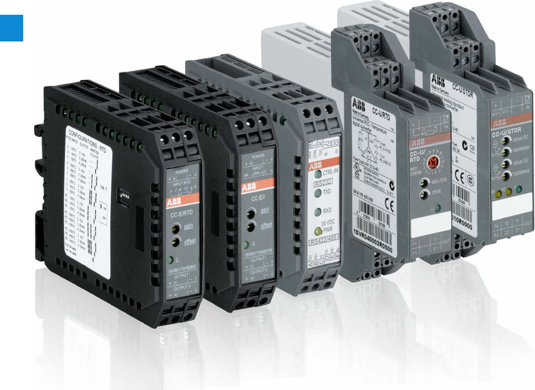
4
4/1 ABB | Catalog Electronic Products and Relays 2015 | 2CDC 110 004 C0210
Analog signal converters, Serial data converters
Product group picture

4
2CDC 110 004 C0210 | Catalog Electronic Products and Relays 2015 | ABB 4/2
Analog signal converters, Serial data converters
Table of contents
Analog signal converters, serial data converters
Overview 4/3
Analog signal converters - CC-E range .............................................. 4/5
Table of contents 4/6
Benefits and advantages 4/7
Ordering details - Standard signal converters 4/8
Ordering details - RTD converters 4/9
Ordering details - Thermocouple converters 4/10
Ordering details - Measuring converters 4/11
DIP switch settings, Dimensional drawings 4/12
Wiring instructions 4/13
Technical data 4/14
Analog signal converters - CC-U range ............................................ 4/17
Table of contents 4/18
Overview 4/19
Ordering details 4/21
Ordering details - Accessories 4/22
DIP switch settings 4/23
Wiring instructions 4/25
Technical information 4/26
Technical data 4/29
Technical diagr., Connection diagr., Dimensional drawings 4/32
Serial data converters ..................................................................... 4/33
Table of contents 4/34
Benefits and advantages 4/35
Selection table 4/36
Ordering details 4/37
Technical information 4/38
Technical data 4/46
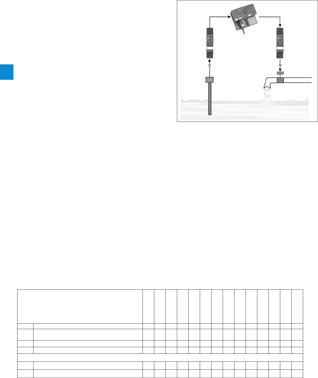
4
4/3 ABB | Catalog Electronic Products and Relays 2015 | 2CDC 110 004 C0210
Analog signal converters, Serial data converters
Overview
Applications for analog signal processing and correct
solution using CC-E and CC-U converters
Nearly every process includes a control system that receives
data by means of analog signals and then evaluates the data
and sets the respective parameters correspondingly.
When transmitting analog signals numerous problems may
arise which can disturb or even block an ideal behavior of the
process.
Below we have listed some processing problems together
with the respective solutions to solve these problems:
Signal conversion
Sometimes the available signals cannot be processed by the
controller or the actuator. In this case, signal converters are
required to convert the input signal (or different input signals)
to the desired output signal.
Signal amplification
If long lines or high burdens have to be operated, it may be
necessary to amplify the signal. CC analog signal converters
require only low input power and provide high output power.
Thus, there are no restrictions for the converter's position on
the line, i.e. it can be used
– for signal refreshing (1) at the end of the line (low input
power)
– or for signal amplification (2) at the beginning of the line
(high output power).
Signal filtering
Particularly on long lines or in rough industrial environments
the signals are exposed to high electromagnetic interferenc-
es. The frequency of the coupled interference signals may be
in the range of the common mains frequency (50 Hz) or even
much higher (in case of frequency converters). According to
the specific requirements, analog signal converters are avail-
able which provide reliable suppression of those interferences
by means of an input low-pass filter.
Signal separation
– Protection against overvoltage
The increased use of micro-electronics make controls
much more sensitive against overvoltages, resulting from
lightning discharges or switching processes. Suppression
diodes are incorporated in the input of the CC analog
signal converters which enable the converters to arrest
overvoltages with low energy level (resulting from switch-
ing processes) by themselves. The products furthermore
provide electrical isolation between input, output and
supply circuit for protection of the controller connected to
the output.
– Protection against ground loops
If components are used which refer to ground, the mea-
suring signals can be falsified by a so-called ground loop.
In this case, certain parts of the signal are transmitted
via earth and not via the analog transmission line, thus
causing incorrect evaluation of the signal. The electrical
isolation between the input and the output disconnects
these ground loops and thus enables correct signal
transmission.
J existing
G existing for some devices
j pending
Approvals
CC-E/STD
CC-E I/I
CC-U/STD
CC-U/STDR
CC-E/RTD
CC-U/RTD
CC-U/RTDR
CC-E/TC
CC-U/TC
CC-U/TCR
CC-E/I
CC-E IAC/ILPO
CC-U/I
CC-U/V
AUL 508, CAN/CSA C22.2 No.14 J J J J J J J J J J J J J J
AUL 1604 (Class I, Div 2, hazardous locations),
CAN/CSA C22.2 No.213 G J G J G J G J J
KCB scheme J J J
ECCC JJJ
Marks
aCE J J J J J J J J J J J J J J
bC-Tick J J J J J J J J J J J J J J
0-10 V0-10 V
100 m 0-20 mA 100 m 4-20 mA
2CDC 282 013 F0206
Controller
e.g. AC500
Measuring sensor
Actuator
1.
Analog signal converter
(e.g. CC-E or CC-U)
2.
Analog signal converter
(e.g. CC-E or CC-U)
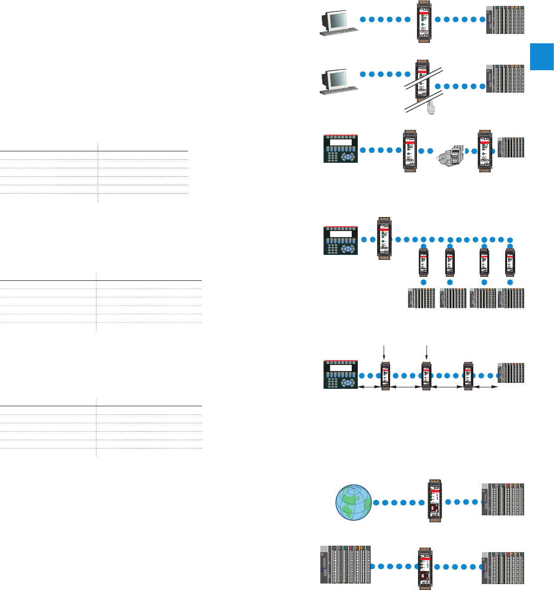
4
2CDC 110 004 C0210 | Catalog Electronic Products and Relays 2015 | ABB 4/4
Analog signal converters, Serial data converters
Overview
RS-232
RS-232
RS-485
RS-485
RS-232
RS-232
RS-232
RS-232
RS-422 RS-422
RS-422 RS-422
RS-232 RS-232 RS-232 RS-232
RS-232
15 m
max.
1.2 km
max.
1.2 km
max.
15 m
max.
TCP RS-232
RS-485
Modbus /
RTU
Modbus /
TCP
In the field of industrial data transmission, various processes of data transmission and interfaces are used today. Already existing systems need to be updated
or connected to new devices for continuity of process. When new communication functions are not build-in, ABB propose a range of converters to be able to
use from the standard RS232 or RS485, to the Ethernet open products or the Optical Fiber.
Ethernet communication is now one of the main features need in open communication, ABB propose the e-ILPH to connect the serial devices to the web
world.
Uses
Adaptation
The use of converters allows the connection of two devices using differ-
ent interfaces. To add new equipment to existing installations.
Electrical Isolation
To protect sensitive equipment it is sometimes necessary to use convert-
ers which allow electrical isolation.
To cross a disturbed environment
Some interfaces are more sensitive to noise. Electrically, it is preferable,
in some cases, to change the interface or support.
Type of connection Immunity to noise
RS232 Low
RS422 High
RS485 High
CL High
OF Very high
Ethernet High
Multipoint connections
Some equipments are only designed to communicate in RS232 point to
point connection. To communicate with several devices it is then nec-
essary to use converters RS232 to RS422, RS485, CL or OF to reach
multipoint mode.
Type of connection Connection
RS232 Point to point
RS422 12 points
RS485 32 points
CL 5-6 points
OF 32 points
Ethernet Point to point or multipoint
Increase in the transmission and amplification distances of the
signals
Every connection has its own limits, to increase the communication dis-
tances you only have to change the type of link (converter) or amplify the
signal (Repeater) using an ILPH.
Type of connection Max. distances 1)
RS232 15 m
RS422 1.2km
RS485 1.2km
CL 300-500m
OF 4 km
Ethernet 100 m with CAT5 cable
1) Depending on transmission speed
Example :
Example :
Example :
Example :
Example :
Example :
Example :
Line 1
Line 2
Power
Converter Repeater
Noisy
elements
RS-485 2-/4 wires
"World Wide" communication
Communication is more and more used with Ethernet support. The
interests are to have a distant access, to use an already existing network
and to upload information and data on a supervisor or a computer. The
conversions from serial to Ethernet protocol are used to connect local
network to Ethernet.
Protocol conversion
Modbus is one of the main protocols used in the industrial networks.
The creation of Modbus/TCP allows an adapted access to the Ethernet
network. So, the conversion between these 2 protocols is necessary.
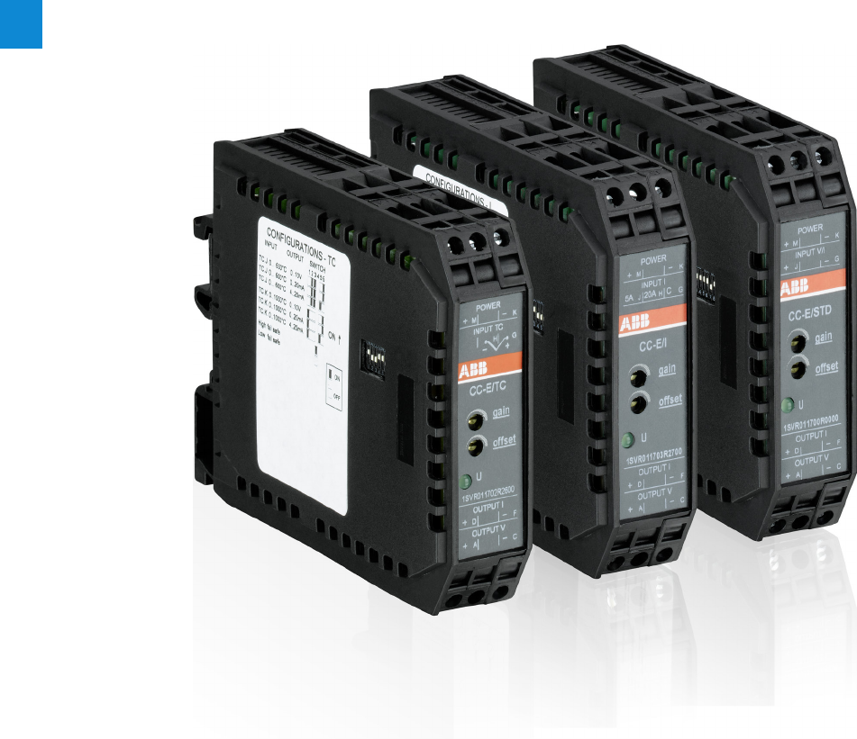
4
4/5 ABB | Catalog Electronic Products and Relays 2015 | 2CDC 110 004 C0210
Analog signal converters - CC-E range
Product group picture

4
2CDC 110 004 C0210 | Catalog Electronic Products and Relays 2015 | ABB 4/6
Analog signal converters - CC-E range
Table of contents
Analog signal converters - CC-E range
Benefits and advantages 4/7
Ordering details - Standard signal converters 4/8
Ordering details - RTD converters 4/9
Ordering details - Thermocouple converters 4/10
Ordering details - Measuring converters 4/11
DIP switch settings, Dimensional drawings 4/12
Wiring instructions 4/13
Technical data 4/14
Technical data 4/15
Technical data 4/16
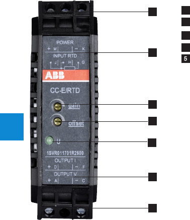
4
4/7 ABB | Catalog Electronic Products and Relays 2015 | 2CDC 110 004 C0210
Analog signal converters - CC-E range
Benefits and advantages
CC-E/STD analog signal converter with 3-way electrical
isolation
– 2 universally configurable devices (type CC-E/STD)
– 2x10 single-function devices
– "Plug and Work", no adjustment of single-function devices
required
CC-E/RTD temperature signal converter for RTD sensors,
linearized with 3-way electrical isolation
– 2 universally configurable devices (type CC-E/RTD)
– 2x12 single-function devices
– Plug and Work", no adjustment of single-function devices
required
– Temperature signal converter for PT100 sensors
– 2- or 3-wire connection
CC-E/TC analog signal converter for thermocouple signals
of the types J and K with 3-way electrical isolation
– 2 universally configurable devices (type CC-E/TC)
– 2x6 single-function devices
– "Plug and Work", no adjustment of single-function devices
required
– Integrated cold-junction compensation
CC-E/I measuring converter for current signals 0-5 A, 0-20
A, AC/DC with 3-way electrical isolation
– 2 universally configurable devices (type CC-E/I)
– 2x6 single-function devices
– "Plug and Work", no adjustment of single-function devices
required
CC-E IAC/ILPO measuring converter without auxiliary
power for sinusoidal currents 0-1 A, 0-5 A, output 4-20
mA
– Measuring converter for sinusoidal currents (0-1 A, 0-5 A)
– Measuring range selection by front-face sliding switch
– 4-20 mA output current in proportion to input current
– no additional power supply required
CC-E range
– Universally configurable devices and single-function de-
vices
– Adjustment and operating elements on the front side
– Safe operation by electrical 3-way isolation
– Unambiguous and clear connecting terminal markings
Conversion, measurement and separation of
– Standard signals (0-5 V, 0-10 V, 0-20 mA, 4-20 mA)
– Temperature signals of RTD sensors (PT 100)
– Thermocouple signals (types J and K)
– Current measurement signals (0-5 A, 0-20 A AC/DC)
Characteristics of single-function devices
– No adjustment or balancing necessary.
Characteristics of universal devices
– The required input and output ranges can be configured by
means of directly accessible DIP switches positioned on
the side
– Gain adjustment of ±5 % by means of an adjustment po-
tentiometer on the front-side
– Offset adjustment of ±5 % by means of adjustment potenti-
ometers on the front-side
Loop-powered current/current isolator without external
power supply for analog current signals of 0-20 mA and
4-20 mA
– Electrical isolation between input and output
– Very low internal voltage drop 2.5 V
– Available with one or two independent channels
– Width only 18 mm (1 and 2 channels)
4
1
1
2
2
3
5
1 Terminals M, K, J, H, G
2 Terminal explanation
3 Adjustment of gain
4 Adjustment of offset
4 Indication of operational states
U - control supply voltage applied
4
2CDC 110 004 C0210 | Catalog Electronic Products and Relays 2015 | ABB 4/8
Analog signal converters - CC-E range
Ordering details - Standard signal converters
1) B 1604 Class I, Div.2 (universal device)
2) CC-E-I/I-1 has 1 channel, CC-E-I/I-2 has 2 channels
Ordering details - Standard signal converters
Supply
voltage range
Input signal Output signal Type Order code Price
1 pce
Weight
(1 pce)
kg (lb)
24 V DC
0-5 V, 0-10V,
0-20mA,
4-20mA
0-5 V, 0-10 V,
0-20mA, 4-20 mA CC-E/STD1) 1SVR011700R0000 0.088
(0.194)
0-10 V
0-10 V CC-E V/V 1SVR011710R2100 0.083
(0.183)
0-20 mA CC-E V/I 1SV R 011711R16 0 0 0.084
(0.185)
4-20 mA CC-E V/I 1SVR011712R1700 0.084
(0.187)
0-20 mA
0-10 V CC-E I/V 1SVR011713R1000 0.082
(0.181)
0-20 mA CC-E I/I 1SVR011714R110 0 0.084
(0.187)
4-20 mA CC-E I/I 1SVR011715R1200 0.084
(0.185)
4-20 mA
0-10 V CC-E I/V 1SVR011716R1300 0.084
(0.185)
0-20 mA CC-E I/I 1SVR011717R1400
4-20 mA CC-E I/I 1SVR011718R2500 0.084
(0.187)
-10...+10 V -10...+10 V CC-E V/V 1SVR011719R2600 0.082
(0.181)
110-240 V AC
0-5 V, 0-10V,
0-20 mA,
4-20mA
0-5 V, 0-10 V,
0-20mA, 4-20 mA CC-E/STD 1SVR01170 5R210 0 0.090
(0.198)
0-10 V
0-10 V CC-E V/V 1SVR011720R2300 0.096
(0.212)
0-20 mA CC-E V/I 1SVR011721R1000 0.087
(0.192)
4-20 mA CC-E V/I 1SVR011722R110 0 0.091
(0.200)
0-20 mA
0-10 V CC-E V/V 1SVR011723R1200 0.091
(0.200)
0-20 mA CC-E I/I 1SVR011724R1300 0.088
(0.194)
4-20 mA CC-E I/I 1SVR011725R1400
4-20 mA
0-10 V CC-E V/V 1SVR011726R1500 0.096
(0.212)
0-20 mA CC-E I/I 1SVR011727R1600 0.087
(0.192)
4-20 mA CC-E I/I 1SVR011728R 270 0 0.088
(0.194)
loop powered
-10...+10 V -10...+10 V CC-E V/V 1SVR011729R2000 0.086
(0.19 0)
0-20 mA,
4-20mA 0-20 mA, 4-20 mA
CC-E I/I-12) 1SVR010200R1600 0.038
(0.084)
CC-E I/I-22) 1SVR010201R0300 0.044
(0.097)
2CDC 281 010 F00032CDC 281 001 F0003
2CDC 281 041 F0003
CC-E/I
CC-E V/V
CC-E I/I-2
4
4/9 ABB | Catalog Electronic Products and Relays 2015 | 2CDC 110 004 C0210
Analog signal converters - CC-E range
Ordering details - RTD converters
2CDC 281 004 F0003
CC-E/RTD
Ordering details - RTD converters
Supply
voltage range
Input signal Output signal Type Order code Price
1 pce
Weight
(1 pce)
kg (lb)
24 V DC
refer to table 0-10 V, 0-20 mA,
4-20mA CC-E/RTD1) 1SVR011701R2500 0.091
(0.200)
PT100
0...100°C
0-10 V CC-E RTD/V 1SVR011730R2500 0.084
(0.185)
0-20 mA CC-E RTD/I 1SVR011731R12 0 0 0.086
(0.19 0)
4-20 mA CC-E RTD/I 1SVR01173 2R130 0
PT100
-50...+50°C
0-10 V CC-E RTD/V 1SVR011733R1400 0.083
(0.183)
0-20 mA CC-E RTD/I 1SVR011734R1500 0.084
(0.185)
4-20 mA CC-E RTD/I 1SVR01173 5R16 0 0 0.084
(0.187)
PT100
0...300°C
0-10 V CC-E RTD/V 1SVR011736R1700 0.084
(0.185)
0-20 mA CC-E RTD/I 1SVR011737R1000 0.084
(0.187)
4-20 mA CC-E RTD/I 1SVR01173 8 R 210 0 0.101
PT100
-50...+250°C
0-10 V CC-E RTD/V 1SVR011739R2200 0.084
(0.185)
0-20 mA CC-E RTD/I 1SVR011740R0700 0.084
(0.187)
4-20 mA CC-E RTD/I 1SVR011741R 2400
110-240 V AC
refer to table 0-10 V, 0-20 mA,
4-20mA CC-E/RTD 1SVR011706R2200 0.093
(0.205)
PT100
0...100°C
0-10 V CC-E RTD/V 1SVR011788R2400 0.086
(0.19 0)
0-20 mA CC-E RTD/I 1SVR011789R2500 0.088
(0.194)
4-20 mA CC-E RTD/I 1SVR011790R220 0 0.089
(0.19 6)
PT100
-50...+50°C
0-10 V CC-E RTD/V 1SVR011791R170 0 0.087
(0.192)
0-20 mA CC-E RTD/I 1SVR011792R1000 0.089
(0.19 6)
4-20 mA CC-E RTD/I 1SVR011793 R110 0
PT100
0...300°C
0-10 V CC-E RTD/V 1SVR011794R1200 0.087
(0.192)
0-20 mA CC-E RTD/I 1SVR011795 R13 0 0 0.089
(0.19 6)
4-20 mA CC-E RTD/I 1SVR011796R1400
PT100
-50...+250°C
0-10 V CC-E RTD/V 1SVR011797R1500 0.086
(0.19 0)
0-20 mA CC-E RTD/I 1SVR011798R2600 0.089
(0.19 6)
4-20 mA CC-E RTD/I 1SVR011799R2700 0.088
(0.194)
1) B 1604 Class I, Div.2 (universal device)
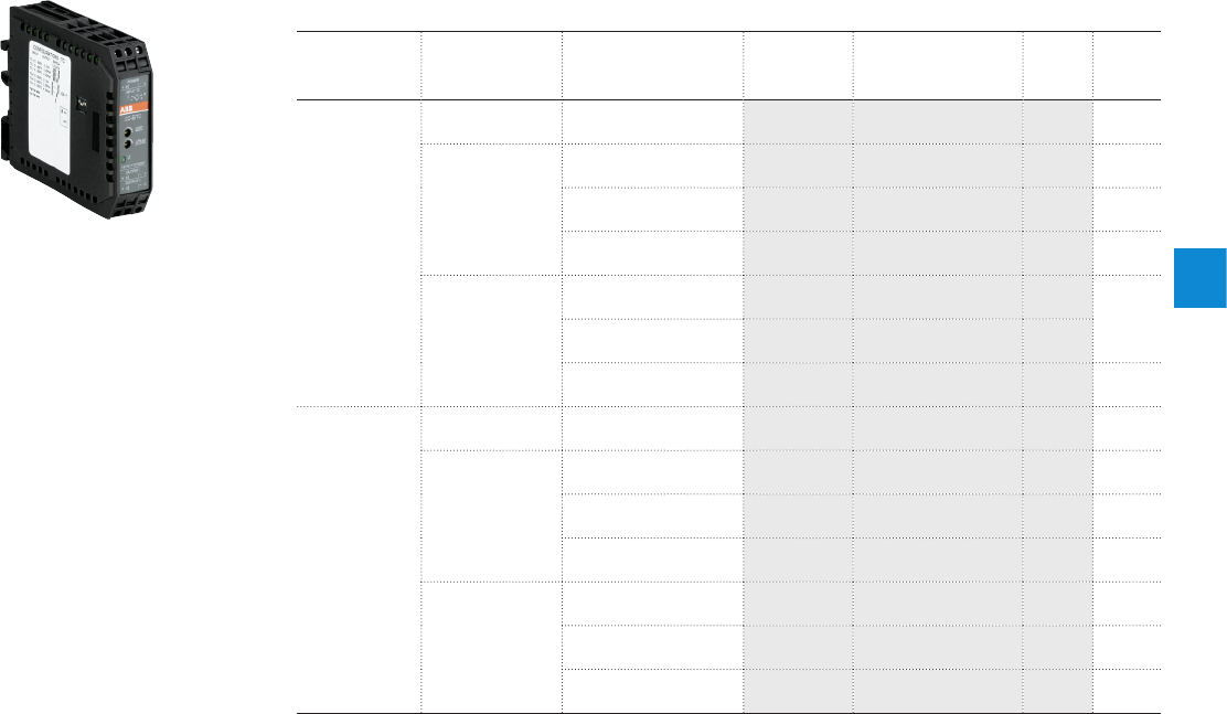
4
2CDC 110 004 C0210 | Catalog Electronic Products and Relays 2015 | ABB 4/10
Analog signal converters - CC-E range
Ordering details - Thermocouple converters
2CDC 281 007 F0003
CC-E TC
Ordering details - Thermocouple Converters
Supply
voltage range
Input signal Output signal Type Order code Price
1 pce
Weight
(1 pce)
kg (lb)
24 V DC
thermocouple
types J and K 0-10 V, 0-20 mA,
4-20mA CC-E/TC1) 1S VR 01170 2R 260 0 0.089
(0.19 6)
type J
0...600°C
0-10 V CC-E TC/V 1SVR011750R0100 0.087
(0.192)
0-20 mA CC-E TC/I 1SVR011751R26 0 0 0.084
(0.187)
4-20 mA CC-E TC/I 1SVR011752R270 0 0.102
type K
0...1000°C
0-10 V CC-E TC/V 1SVR011753R2000 0.084
(0.185)
0-20 mA CC-E TC/I 1SVR011754R2100
4-20 mA CC-E TC/I 1SVR011755R2200 0.086
(0.19 0)
110-240 V AC
thermocouple
types J and K 0-10 V, 0-20 mA,
4-20mA CC-E/TC 1SVR011707R2300 0.088
(0.194)
type J
0...600°C
0-10 V CC-E TC/V 1SVR011760R0300 0.084
(0.187)
0-20 mA CC-E TC/I 1SVR011761R2000 0.088
(0.194)
4-20 mA CC-E TC/I 1SVR011762R 210 0 0.1
(0.220)
type K
0...1000°C
0-10 V CC-E TC/V 1SVR011763R2200 0.086
(0.19 0)
0-20 mA CC-E TC/I 1SVR011764R2300 0.088
(0.194)
4-20 mA CC-E TC/I 1SVR01176 5R240 0 0.086
(0.19 0)
1) B 1604 Class I, Div.2 (universal device)
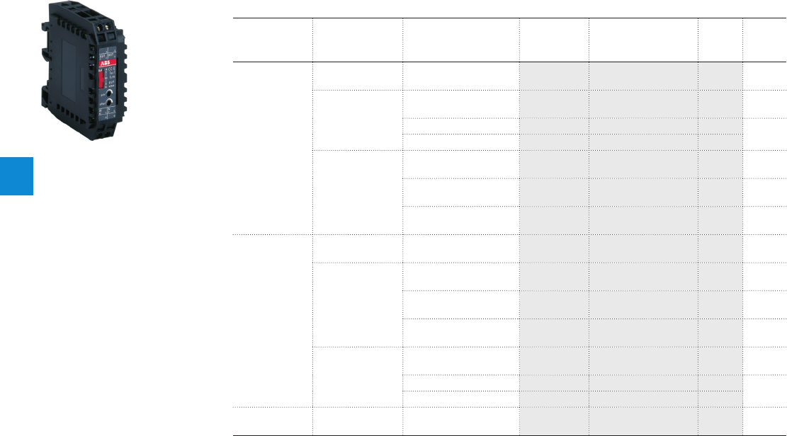
4
4/11 ABB | Catalog Electronic Products and Relays 2015 | 2CDC 110 004 C0210
Ordering details - Measuring Converters
Supply
voltage range
Input signal Output signal Type Order code Price
1 pce
Weight
(1 pce)
kg (lb)
24 V DC
0-5A, 0-20A,
AC/DC
0-10 V, 0-20 mA,
4-20mA CC-E/I1) 1SVR011703R2700 0.096
(0.212)
0-5 A, 0-20 A,
AC
0-10 V CC-E IAC/V 1SVR011770R0500 0.090
(0.198)
0-20 mA CC-E IAC/I 1SVR011771R2200 0.092
(0.203)
4-20 mA CC-E IAC/I 1SVR011772R2300
0-5 A, 0-20 A,
DC
0-10 V
CC-E I
DC
/V
1SV R 011773R 2400 0.092
(0.207)
0-20 mA CC-E IDC/I 1SVR011774R2500 0.091
(0.200)
4-20 mA CC-E IDC/I 1SVR011775R 260 0 0.093
(0.205)
110-240 V AC
0-5A, 0-20A,
AC/DC
0-10 V, 0-20 mA,
4-20mA CC-E/I 1SVR011708R0400 0.099
(0.218)
0-5 A, 0-20 A,
AC
0-10 V CC-E IAC/V 1SVR01178 0 R1100 0.092
(0.203)
0-20 mA CC-E IAC/I 1SVR011781R0600 0.092
(0.207)
4-20 mA CC-E IAC/I 1SVR011782R0700 0.095
(0.209)
0-5 A, 0-20 A,
DC
0-10 V
CC-E I
DC
/V
1SVR011783R0000 0.093
(0.205)
0-20 mA
CC-E I
DC
/I
1SVR011784R0100 0.095
(0.209)
4-20 mA
CC-E I
DC
/I
1SV R 011785R110 0
loop powered 0-1 A, 0-5 A, AC 4-20 mA
CC-E I
AC
/ILPO
2) 1SVR010203R0500 0.052
(0.115)
2CDC 281 018 F0004
CC-E IAC/ILPO
1) B 1604 Class I, Div.2 (universal device)
2) for sinusoidal currents
Analog signal converters - CC-E range
Ordering details - Measuring converters
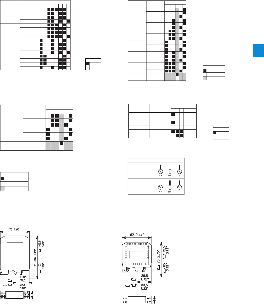
4
2CDC 110 004 C0210 | Catalog Electronic Products and Relays 2015 | ABB 4/12
Analog signal converters - CC-E range
DIP switch settings, Dimensional drawings
812 43 567
0...5 V
0...10 V
0...20 mA
4...20 mA
0...5 V
0...10 V
0...20 mA
4...20 mA
0...5 V
0...10 V
0...20 mA
4...20 mA
0...5 V
0...10 V
0...20 mA
4...20 mA
0...5 V
0...10 V
0...20 mA
4...20 mA
2CDC 282 001 F0204
Input Output Switch
2CDC 282 002 F0204
ON
Legend
OFF
CC-E/STD, CC-E x/x (universal devices)
2CDC 282 003 F0204
OFF
Legend
no influence
ON
12 4356
0...300 °C
0...100 °C
0...500 °C
-50...+50 °C
-50...+250 °C
-50...+450 °C
High fail safe
Low fail safe
0...10 V
0-20 mA
4-20 mA
0-10 V
0-20 mA
4-20 mA
0-10 V
0-20 mA
4-20 mA
0-10 V
0-20 mA
4-20 mA
0-10 V
0-20 mA
4-20 mA
0-10 V
0-20 mA
4-20 mA
2CDC 282 006 F0208
Input Output
Switch
CC-E/RTD
2CDC 282 003 F0204
OFF
Legend
no influence
ON
12 4356
TC-J:
0...600 °C
TC-K:
0...1000 °C
High fail safe
Low fail safe
0...10 V
0...20 mA
4...20 mA
0...10 V
0...20 mA
4...20 mA
2CDC 282 007 F0208
Input Output Switch
CC-E/TC CC-E/I
Dimensional drawings
2CDC 282 002 F0204
ON
Legend
OFF
12 4356
I - DC
I - AC
I - AC
I - DC
I - AC
I - DC
0...10 V
0...20 mA
4...20 mA
2CDC 282 005 F0208
Input Output Switch
2CDC 282 011 F0204
Select input range by terminals
Input range 5 A
Connected lines
Used terminals
Terminal marking
Input range 20 A
Connected lines
Used terminals
Terminal marking
Input range selection - CC-E/I
CC-E/x CC-E IAC/ILPO, CC-E I/I
22.5
0,88 "
2CDC 282 011 F0b06
18
0.71"
2CDC 282 012 F0b06
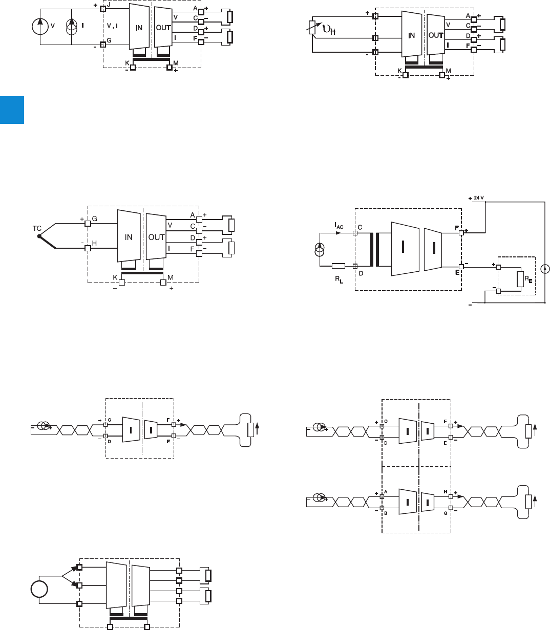
4
4/13 ABB | Catalog Electronic Products and Relays 2015 | 2CDC 110 004 C0210
CC-E/STD, CC-E x/x (universal devices)
2CDC 282 006 F0206
Burden
R 1.0 k
Burden
R 500
supply
CC-E/RTD
J
H
G
2CDC 282 007 F0206
Burden
R 1.0 k
Burden
R 500
supply
CC-E/TC
2CDC 282 008 F0206
Burden
R 1.0 k
Burden
R 500
supply
RL 500
UL
C
D
F
E
IN
IN
OUT
OUT
2CDC 282 003 F0205
Channel 1
input
0-20 mA or
4-20 mA
Channel 1
output
0-20 mA or
4-20 mA
J
H
G
20 A
5 A
A
C
D
F
V
I
K
-
M
+
+
-
+
-
IN OUT
I
2CDC 282 008 F0208
Burden
R 1.0 k
Burden
R 500
supply
RL 500
RL 500
UL
UL
C
D
F
E
A
B
H
G
IN
IN
IN
IN
OUT
OUT
OUT
OUT
2CDC 282 004 F0205
Channel 1
input
0-20 mA or
4-20 mA
Channel 2
input
0-20 mA or
4-20 mA
Channel 1
output
0-20 mA or
4-20 mA
Chanel 2
output
0-20 mA or
4-20 mA
CC-E I/I-1
CC-E I/I
2CDC 282 010 F0b06
CC-E IAC/ILPO
Analog signal converters - CC-E range
Wiring instructions
CC-E I/I-2

4
2CDC 110 004 C0210 | Catalog Electronic Products and Relays 2015 | ABB 4/14
Analog signal converters - CC-E range
Technical data
Type CC-E/STD / CC-E x/x CC-E/RTD 3) CC-E/TC
Input circuits - Analog inputs J-G-H Current Voltage Temperature sensors Thermocouples
(IEC 584-1 and 2)
Input signal Standard signals PT100 TC.K, TC.J
Rated input range 0...20 mA /
4...20 mA 0...5 V /
0...10 V /
-10...+10 V
-50...+500 °C TC.K: 0...1000 °C,
TC.J: 0...600 °C
Limitation of input signals +55 mA ± 11 V
Influence of line resistance -< 0.01 %/< 0.5 % / 100
Gain adjustment range ± 5 % (universal devices)
Offset adjustment range ± 5 % (universal devices)
Input impedance 50 1 M- -
Suppression at 50 Hz - - > 35 dB
Common-mode rejection -100 dB
Output circuits - Analog outputs D - F, A- C Current Voltage
Output signal 0-20 mA, 4-20 mA 0-5 V, 0-10 V
Output burden 500 1.0 K
Accuracy 1) ± 0.5 % of full-scale
Residual ripple < 0.5 %
Response time 200 µs 10 ms
Transmission frequency 2 kHz 80 Hz 2 Hz (up to -3 dB)
Reaction to input circuit interruption High fail safe: Output voltage > 115 % of
measuring range 2)
Low fail safe: Output voltage < -0.6 V, output
current = 0 mA
Supply circuits K-M DC versions AC versions
Supply voltage 24 V DC
110-240 V AC - 50/60 Hz
Supply voltage tolerance -15...+15 % -15...+10 %
Power consumption 1.5 W typ. 1.5 VA typ.
Indication of operational states
Rated control supply voltage USU: green LED
General data
Ambient temperature range operation / storage 0...+60 °C / -20...+80 °C
Temperature coefficient ± 500 ppm/°C
Degree of protection (DIN 40050) IP20
Mounting position ventilation slots on top and bottom
Mounting DIN rail (IEC/EN 60715), snap-on mounting
Electrical connection
Wire size rigid 0.2-4 mm2 (24-12 AWG)
fine-strand with(out) wire end ferrule 0.2-2.5 mm2 (24-14 AWG)
Stripping length 7 mm (0.28 inch)
Tightening torque 0.5 Nm (4.4 lb.in)
Electromagnetic compatibility
Interference immunity EN 61000-6-2
electrostatic discharge (ESD) IEC/EN 61000-4-2 Level 3 (±6 kV / ±8 kV)
electromagnetic field(HF radiation
resistance) IEC/EN 61000-4-3 10 V/m
fast transients (Burst) IEC/EN 61000-4-4 Level 3 (±2 kV / 5 kH)
powerful impulses (Surge) IEC/EN 61000-4-5 ±2 kV / ±1 kV
HF line emission IEC/EN 61000-4-6 10 V
Interference emission EN 61000-6-4 Class B
Isolation data
Test voltage between all isolated circuits 2.5 kV AC
Rated insulation voltage ---
1) Includes non-linearity and factory setting, influenced by supply voltage and output load.
2) Only -/RTD and -/TC: Single-function devices respond with Low fail safe to input signal interruptions.
3) When connecting a 2-wire sensor, the terminals J and H have to be jumpered.
Approvals on page 4/4.

4
4/15 ABB | Catalog Electronic Products and Relays 2015 | 2CDC 110 004 C0210
Type CC-E I/I-1 / CC-E I/I-2
Input circuits - Analog inputs Current
Input current IIN 0-20 mA, 4-20 mA
Min. input current < 100 µA
Max. input current 50 mA1) (VIN < 18 V)
Input voltage UIN < 2.5 V + (IIN x RL)
Input voltage drop Ui< 2.5 V (20 mA, RL = 0 )
Max. input voltage 18 V1) (IIN < 50 mA)
Output circuits
Output current IOUT 0-20 mA, 4-20 mA
Output load RL0-500
Output voltage UOUT IOUT x RL
Residual ripple < 20 mVpp (500 , 20 mA)
Response time (0-100 %) < 15 ms (0-500 , 20 mA),
< 5 ms (500 q, 20 mA, 25 °C)
Accuracy 0.1 % of full-scale (20 mA)
Load influence (0-500 ) 0.05 % / 100 ,
-0.1 % / 100 (25 °C)
General data
Width of the enclosure 18 mm
Weight 1 channel approx. 0.037 kg (0.082 (0.181) lb)
2 channel approx. 0.044 (0.097) kg (0.097 lb)
Mounting position any
Degree of protection enclosure / terminals IP20 / IP20
Ambient temperature range operation / storage -25...+60 °C / -40...+85 °C
Temperature coefficient < 50 ppm / °C
Mounting DIN rail (IEC/EN 60715)
Electrical connection
Wire size rigid 0.2-4 mm2 (24-12 AWG)
fine-strand with(out) wire end ferrule 0.2-2.5 mm2 (24-14 AWG)
Stripping length 7 mm (0,28 inch)
Tightening torque 0.5 Nm (4.4 lb.in)
Standards
Product standard EN 50178
Low Voltage Directive 2006/95/EC
EMC Directive 2004/108/EC
Electromagnetic compatibility
Interference immunity EN 61000-6-2
electrostatic discharge (ESD) EN 61000-4-2 Level 3 (±6 kV / ±8 kV)
electromagnetic field (HF radiation
resistance) EN 61000-4-3 10 V/m
fast transients (Burst) EN 61000-4-4 Level 3 (±2 kV / 5 kH)
powerful impulses (Surge) EN 61000-4-5 ±2 kV / ±1 kV
HF line emission EN 61000-4-6 10 V
magnetic fields EN 61000-4-8 30 A/m
Interference emission EN 61000-6-4
Radiated noise EN 55011 Class B
Operational reliability (EN 68-2-6) 4 g
Mechanical resistance (EN 68-2-6) 10 g
Environmental testing (IEC 68-2-30 Db) 24 h cycle, 55 °C, 93 % rel., 96 h
Isolation data
Insulation voltage input / output 500 Veff / 50 Hz
Insulation voltage between channels 5 kVeff / 50 Hz (device with 2 channels)
Pollution category 2
Overvoltage category II
1) The input parameters have to be limited to the indicated maximum values.
Approvals on page 4/4.
Analog signal converters - CC-E range
Technical data

4
2CDC 110 004 C0210 | Catalog Electronic Products and Relays 2015 | ABB 4/16
Analog signal converters - CC-E range
Technical data
Type CC-E/I CC-E IAC/ILPO
Input circuits - Analog inputs
J-G-H C-D
AC current DC current 2 meas. ranges selectable
Rated input range 0-5 A / 0-20 A 0-5 A / 0-20 A 0-1 A / 0-5 A / sinusoidal
Measuring frequency 50/60 Hz
Overload capacity of inputs input range 1 10 x INom (50 A) for max. 1 s 10 x INom (50 A) for max. 2 s
input range 2 10 x INom (200 A) for max. 1 s 10 x INom (200 A) for max. 2 s
Gain adjustment range ±5 % (universal devices) -
Offset adjustment range ±5 % (universal devices) -
Input impedance / resistance 5A : 65 m20 A : 2.5 m5 m
Output circuits - Analog outputs D-F Current A-C Voltage F-E passive current output in pro-
portion to input current
Output signal 0-20 mA /
4-20mA 0-10 V 4-20 mA
Output burden / load
500 1.0
12 V DC: 150 ,
24 V DC: 750
30 V DC: 1050
Accuracy 1) ± 2 % of full-scale
Offset adjustment range ±5 % (universal device) ± 5 %
Gain adjustment range ±5 % (universal device) ± 20 %
Residual ripple < 0.5 %
Response time 0.5 s 0.6 s
Transmission frequency DC or 50/60 Hz AC: 50/60 Hz
Reaction to input circuit interruption Low fail safe: output voltage
<200mV, output current < 400 µA -
Supply circuits K-M DC versions AC versions
Supply voltage 24 V DC 110-240 V AC
50/60 Hz 12-30 V DC
Supply voltage tolerance -15...+15 % -15...+10 % -
Power consumption typ 1.5 W typ 1.5 VA -
Indication of operational states
Supply voltage U: green LED -
General data
Ambient temperature range operation / storage 0...+60 °C / -20...+80 °C -20...+60 °C / -40...+80 °C
Temperature coefficient ± 500 ppm/°C 300 ppm/°C
Degree of protection (DIN 40050) IP20
Mounting position ventilation slots on top and bottom
Mounting DIN rail (IEC/EN 60715), snap-on mounting
Electrical connection
Wire size rigid 0.2-4 mm² (24-12 AWG)
fine-strand with(out) wire end ferrule 0.2-2.5 mm² (24-14 AWG)
Stripping length 7 mm (0.28 inch)
Tightening torque 0.5 Nm (4.4 lb.in)
Electromagnetic compatibility
Interference immunity EN 61000-6-2
electrostatic discharge (ESD) IEC/EN 61000-4-2 Level 3 (±6 kV / ±8 kV)
electromagnetic field (HF radiation resistance) IEC/EN 61000-4-3 10 V/m
fast transients (Burst) IEC/EN 61000-4-4 Level 3 (±2 kV / 5 kH)
powerful impulses (Surge) IEC/EN 61000-4-5 ±2 kV / ±1 kV
HF line emission IEC/EN 61000-4-6 10 V
Interference emission EN 61000-6-4 Class B
Isolation data
Test voltage (between all isolated circuits) 2.5 kV AC
Rated insulation voltage -250 V AC
1) Includes non-linearity and factory setting, influenced by supply voltage and output load.
Approvals on page 4/4.
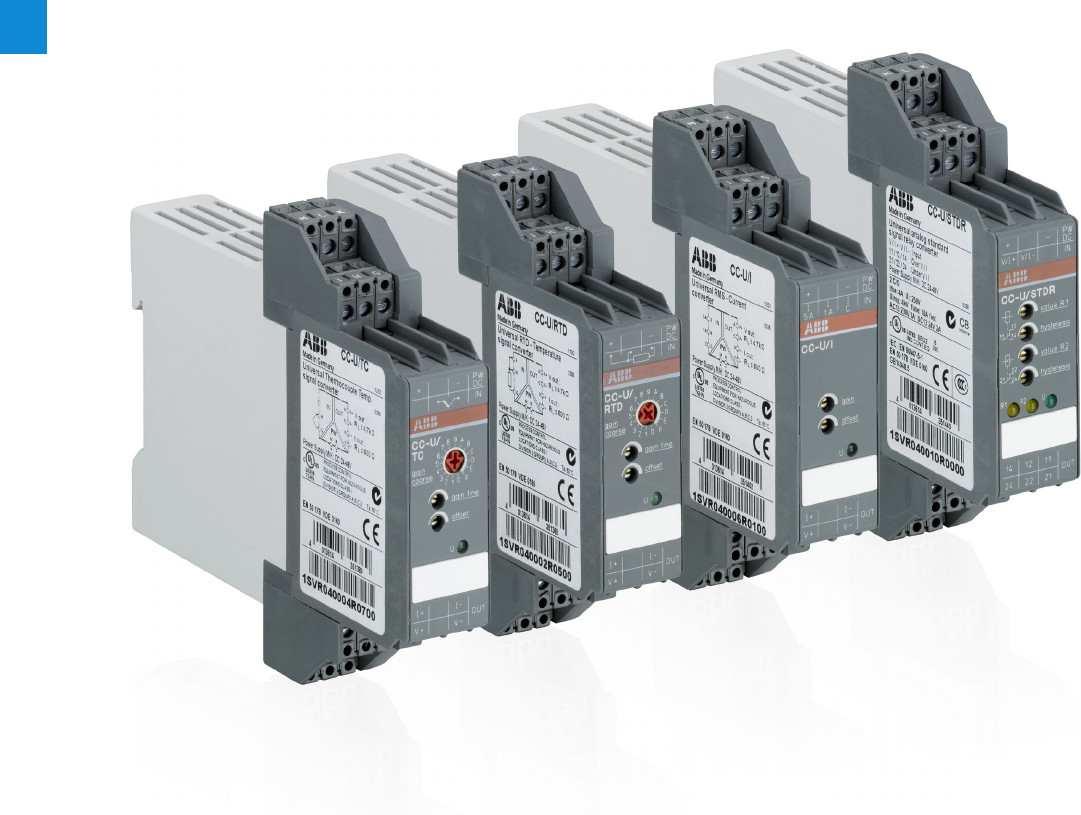
4
4/17 ABB | Catalog Electronic Products and Relays 2015 | 2CDC 110 004 C0210
Analog signal converters - CC-U range
Product group picture

4
2CDC 110 004 C0210 | Catalog Electronic Products and Relays 2015 | ABB 4/18
Analog signal converters - CC-U range
Table of contents
Analog signal converters - CC-U range
Overview 4/19
Ordering details 4/21
Ordering details - Accessories 4/22
DIP switch settings 4/23
Wiring instructions 4/25
Technical information 4/26
Technical data 4/29
Technical diagr., Connection diagr., Dimensional drawings 4/32
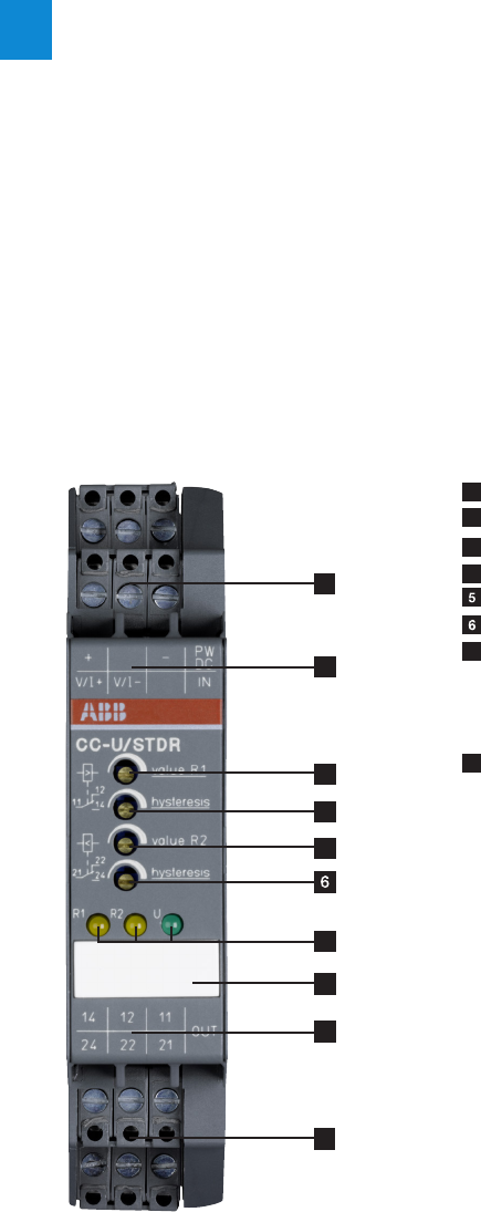
4
4/19 ABB | Catalog Electronic Products and Relays 2015 | 2CDC 110 004 C0210
Analog signal converters - CC-U range
Overview
CC-U range
– 8 different standard signal outputs on one device
– Input and output side universally configurable
– Also available with 2 threshold relay outputs
– Adjustment and operating elements on the front side
– Safe operation by electrical 3-way isolation
– Plug-in connecting terminals, unambiguously and clearly
marked
Conversion, measurement and separation of
– Standard signals
– Signals of RTD sensors (PT10, PT100, PT1000)
– Thermocouple signals
– TRMS values of currents and voltages
Characteristics
– The required input and output ranges can be configured
for all devices by means of directly accessible DIP switches
positioned on the side.
– Due to the wide input range of the gain and offset stages
all input signals between the minimum and the maximum
input value can be universally converted to all common
output signals.
– Devices for DC or AC (50/60 Hz) supply available.
4
1
1
2
2
3
5
1 Terminals +, V/I+, V/I-, PW DC, IN, -
2 Terminal explanation
3 Adjustment of resistance value R1
4 Adjustment of hysteresis
4 Adjustment of resistance value R2
Adjustment of hysteresis
7 Indication of operational states
R1 yellow LED - resistance value R1
R2 yellow LED - resistance value R2
U green LED - supply voltage
8 Marker label
7
8

4
2CDC 110 004 C0210 | Catalog Electronic Products and Relays 2015 | ABB 4/20
Analog signal converters - CC-U range
Overview
CC-U/STD universal signal converter with 3-way electrical
isolation
– More than 120 configurations possible
– Configurable output signal response on input voltage signal
interruption (low fail safe / high fail safe)
– Adjustment and operating elements on the front
– Short-circuit proof signal outputs
– Plug-i connecting terminals for inputs, outputs and supply
– Very fast signal transmission enables use in control sys-
tems
CC-U/STDR universal signal converter for standard
signals, with 2 threshold relay outputs and with 3-way
electrical isolation
– Standard signal converter with 7 setting ranges
– 2 threshold relay outputs with one c/o contact each
(threshold and respective hysteresis can be
adjusted independently from each other)
– Open-circuit or closed-circuit principle configurable by
means of a DIP switch
– 2 yellow LEDs for clear status indication of the output
relays
– Plug-in connecting terminals for inputs, outputs and supply
CC-U/RTD universal signal converter for PT10, PT100,
PT1000 temperature sensors (acc. to IEC 751 and JIS C
16041), linearized with 3-way electrical isolation)
– Configurable output signal response on input signal inter-
ruption (low / high fail safe)
– Adjustment and operating elements on the front-side
– Short-circuit proof signal outputs
– Plug-in connecting terminals for inputs, outputs and supply
– 2- or 3-wire connection
CC-U/RTDR universal signal converter for temperature
and resistance signals, with 2 threshold relay outputs and
3-way electrical isolation
– Temperature signal converter for PT100 signals (5 ranges up
to 800 °C) and variable resistances from 0-380
– 2 threshold relay outputs with one c/o contact each (thresh-
old and respective hysteresis can be adjusted independently
from each other)
– Open-circuit or closed-circuit principle configurable by
means of a DIP switch
– 2 yellow LEDs for clear status indication of the output relays
– Plug-in connecting terminals for inputs, outputs and supply
– 2- or 3-wire connection
CC-U/TC universal signal converter for thermocouples
with 3-way electrical isolation
– Temperature signal converter for thermo-couples of the
types K, J, T, S, E, N, R, B
– Continuously adjustable voltage signal input 0-10 mV and
0-50 mV
– Differential temperature meas. possible (see wiring instruc-
tions page 4/17)
– Configurable output signal response on input signal inter-
ruption (low fail safe / high fail safe)
– Adjustment and operating elements on the front-side
– Short-circuit proof signal outputs
– Plug-in connecting terminals for inputs, outputs and supply
– Cold-junction compensation selectable
CC-U/TCR universal signal converter for thermocouples,
with 2 threshold relay outputs and 3-way electrical
isolation
– Temperature signal converter for thermocouples of the
types K, J, T, S
– 2 threshold relay outputs with one change-over contact
each (threshold and respective hysteresis can be
adjusted independently from each other)
– Open-circuit or closed-circuit principle configurable by
means of a DIP switch
– 2 yellow LEDs for clear status indication of the output
relays
– Plug-in connecting terminals for inputs, outputs and supply
– Integrated cold-junction compensation
CC-U/I universal measuring converter for RMS values of
0-1 A and 0-5 A, with 3-way electrical isolation
– RMS converter for current signals up to 1 A and up to 5
A of any wave form (DC, DC with superimposed
AC components, pure sinusoidal, triangular, phase-angle
controlled, etc. in a measuring range of 0-600 Hz)
– Adjustment and operating elements on the front
– Short-circuit proof signal outputs
– Plug-in connecting terminals for inputs, outputs and supply
CC-U/V universal measuring converter for RMS values of
0-600 V, with 3-way electrical isolation
– RMS converter for voltage signals up to 600 V of any wave
form (DC, DC with superimposed AC components, pure
sinusoidal, triangular, phase-angle controlled, etc. in a
measuring range of 0-600 Hz)
– Adjustment and operating elements on the front
– Short-circuit proof signal outputs
– Plug-in connecting terminals for inputs, outputs and supply
1) Japanese standard
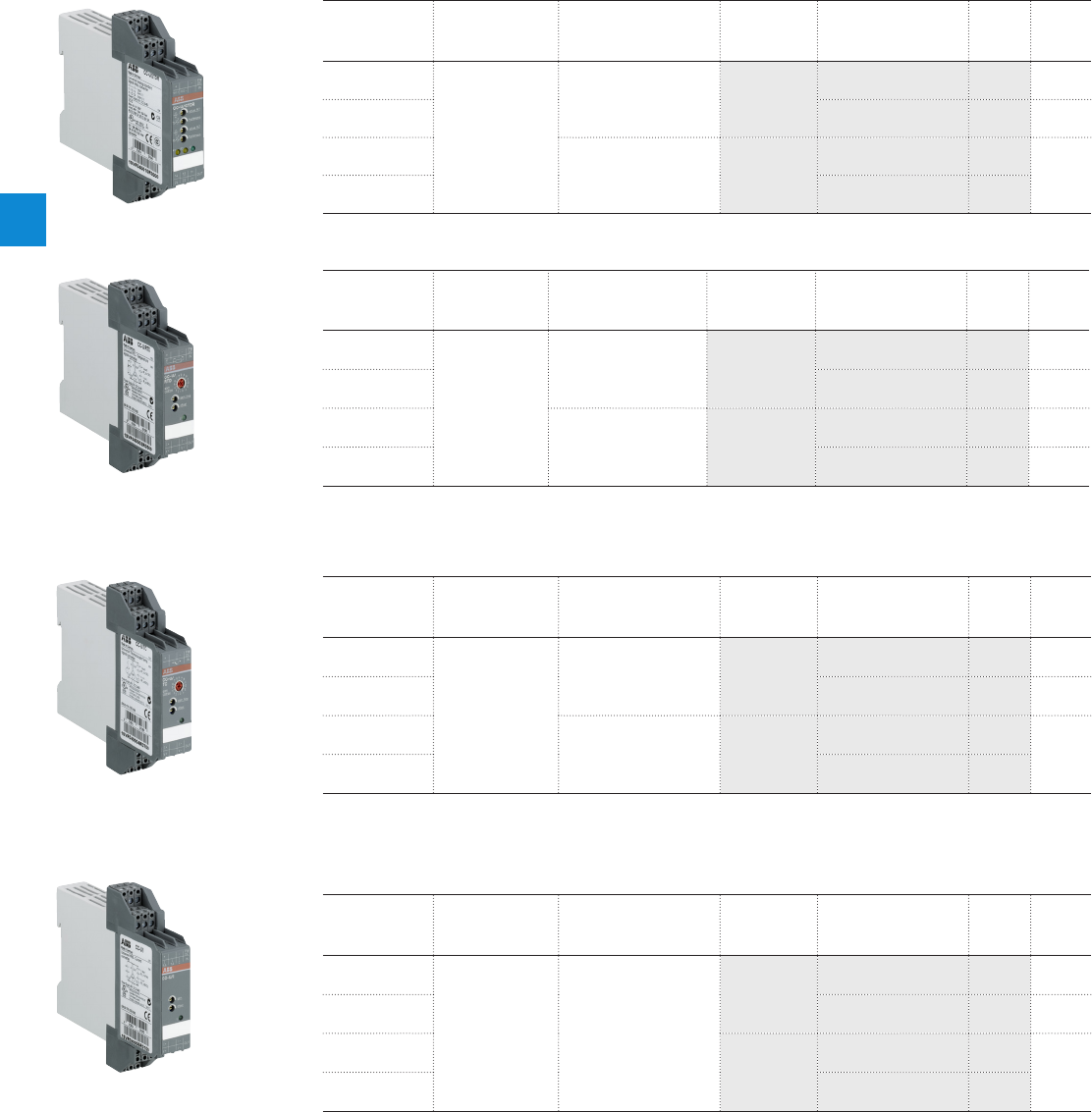
4
4/21 ABB | Catalog Electronic Products and Relays 2015 | 2CDC 110 004 C0210
Analog signal converters - CC-U range
Ordering details
1) with relay output
2) for current RMS values
3) for voltage RMS values
Ordering details - RTD Converters
Supply
voltage range
Input signal Output signal Type Order code Price
1 pce
Weight
(1 pce)
kg (lb)
24-48 V DC,
24VAC
refer to table
refer to table CC-U/RTD
1SVR040002R0500 0.126
(0.278)
110-240VAC,
100-300VDC 1SVR040003R0600 0.128
(0.282)
24-48 V DC,
24V AC 2 c/o CC-U/RTDR1)
1SVR040012R2600 0.146
(0.322)
110-240 V AC,
100-300 V DC 1SVR040013R2700 0.148
(0.326)
Ordering details - Standard Signal Converters
Supply
voltage range
Input signal Output signal Type Order code Price
1 pce
Weight
(1 pce)
kg (lb)
24-48 V DC,
24VAC
refer to table
refer to table CC-U/STD
1SVR040000R1700 0.125
(0.276)
110-240 V AC,
100-300 V DC 1SVR040001R0400 0.126
(0.278)
24-48 V DC,
24V AC 2 c/o CC-U/
STDR1)
1SVR040010R0000 0.142
(0.313)
110-240 V AC,
100-300 V DC 1SVR040011R2500
2CDC 281 003 F0003
2CDC 281 005 F00032CDC 281 008 F00032CDC 281 012 F0003
CC-U/STDR
CC-U/RTD
CC-U/TC
CC-U/I
Ordering details - Thermocouple Converters
Supply
voltage range
Input signal Output signal Type Order code Price
1 pce
Weight
(1 pce)
kg (lb)
24-48 V DC,
24V AC
refer to table
refer to table CC-U/TC
1SVR040004R0700 0.13 0
(0.287)
110-240 V AC,
100-300 V DC 1SVR040005R0000 0.128
(0.282)
24-48 V DC,
24V AC 2 c/o CC-U/TCR1)
1SVR040014R2000 0.14 5
(0.320)
110-240 V AC,
100-300 V DC 1SVR040015R2100
Ordering details - Measuring Converters
Supply
voltage range
Input signal Output signal Type Order code Price
1 pce
Weight
(1 pce)
kg (lb)
24-48 V DC,
24V AC
refer to table refer to table
CC-U/I2)
1SVR040006R0100 0.128
(0.282)
110-240 V AC,
100-300 V DC 1SVR040007R0200 0.127
(0.280)
24-48 V DC,
24V AC CC-U/V3)
1SVR040008R1300 0.128
(0.282)
110-240 V AC,
100-300 V DC 1SVR040009R1400
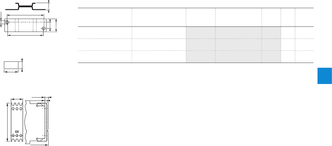
4
2CDC 110 004 C0210 | Catalog Electronic Products and Relays 2015 | ABB 4/22
Ordering details - Accessories
For type Width in mm Type Order code Price Pkg
qty
Weight
(1 pce)
g (oz)
CC-U 22.5 A D P. 01 1SVR430029R0100 118.4
(0.65)
CC-U MAR.01 1SVR366017R0100 10 0.19
(0.007)
CC-U 22.5 COV.01 1SVR430005R0100 15.2
(0.18)
Analog signal converters - CC-U range
Ordering details - Accessories
2CDC 252 187 F0005
4,5
62,5
60
10 11,5
22,5
.177”
2.46”
2.36”
.394”
.886”
.453”
2CDC 252 185 F0005
22,5
68,5
7
3,5
.886”
2.70 ”
.138”
.275”
front-to-back
size 107
ADP.01
20
3A11
8
.315”
.787”
2CDC 252 186 F000
5
MAR.01
Sealable cover - COV.01
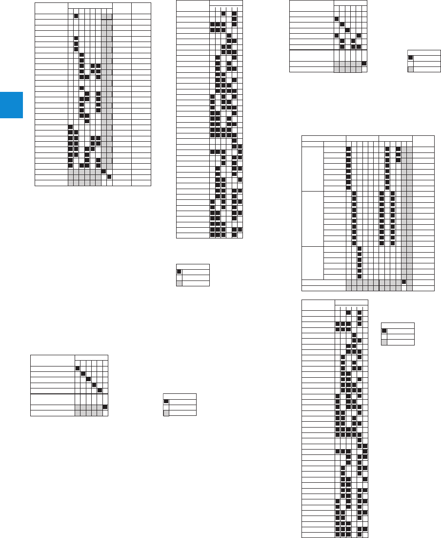
4
4/23 ABB | Catalog Electronic Products and Relays 2015 | 2CDC 110 004 C0210
Analog signal converters - CC-U range
DIP switch settings
*) Detection of input voltage signal
interruptions:
If the input signal circuit is inter-
rupted, the output signal changes
to the adjusted minimum value (low
fail safe) or maximum value (high fail
safe).
If "No fail safe" is configured,
input signal interruptions are not
detected.
43215876
0...8 V
0...20 mA
4...20 mA
10...50 mA
20...4 mA
20...0 mA
0...50 mV
0...100 mV
0...250 mV
0...500 mV
0...1 V
0...5 V
-10...+10 V
0...125 mV
1...5 V
0...10 V
2... 10 V
-11...+11 V
10...0 V
100...0 mV
0...1 mA
-55...+55 mA
3...4
2...4
4...5
0...1
4...5
4...2
A...D
4...5
0...1
7...9
3...4
5...7
0
3...4
7...9
2
2...4
0
2
4...5
A...D
4...6
3
3
4
1
4
3
C
5
1
8
3
6
0
3
8
2
3
0
2
5
B
5
6
4
0
0
D
D
0
0
B...F
5...7
3...4
-
-
-
-
-
-
B...F
2CDC 282 019 F0203
Switch 1
Input
2.5...7.5 V
3.33...9.99 V
High fail safe *)
Gain Coarse
Type
Potentiometer
0...2.5 V
-22.5...+22.5 mV
-0.45...+0.45 mA
Low faile safe *)
No fail safe *)
12 4356
-10...-2 V
-5...-1 V
-8...0 V
-4...0 V
0...1 mA
0...20 mA
4...20 mA
0...10 mA
0...800 µA
0...8 mA
0...400 µA
125...625 µA
166...833 µA
2...10 mA
100...500 µA
0...666 µA
0...16 mA
0...5 V
0...10 V
1...5 V
2...10 V
-10...+10 V
-5...+5 V
-10...0 V
-5...0 V
0...8 V
0...4 V
2CDC 282 020 F0203
Switch 2
Output
1.25...6.25 V
0...6.66 V
-10...+3.33 V
-5...+1.66 V
-7.5...+2.5 V
-3.75...+1.25 V
1.66...8.33 V
-6.66...+6.66 V
-3.33...+3.33 V
0...0.5 mA
0...13.33 mA
2.5...12.5 mA
3.33...16.66 mA
0.2...1 mA
2CDC 282 003 F0204
OFF
Legend
no influence
ON
CC-U/STD CC-U/STDR with relay output
2CDC 282 003 F0204
OFF
Legend
no influence
ON
12 4356
0...10 V
0...5 V
0...1 V
-10...+10 V
1...5 V
0...20 mA
4...20 mA
2CDC 282 005 F0204
Switch
Input
Output
Closed-circuit principle
Open-circuit principle
*) Detection of input signal
interruptions:
If the input signal circuit
is interrupted, the output
signal changes to the
adjusted minimum value
(low fail safe) or maximum
value (high fail safe).
CC-U/RTD
2CDC 282 003 F0204
OFF
Legend
no influence
ON
12 4356124356
PT10
PT100
PT1000
0...500 °C
0...550 °C
0...600 °C
0...650 °C
0...700 °C
0...750 °C
0...800 °C
0...850 °C
0...50 °C
0...60 °C
0...70 °C
0...80 °C
0...90 °C
0...100 °C
0...200 °C
0...400 °C
0...300 °C
0...500 °C
0...10 °C
0...20 °C
0...30 °C
0...40 °C
0...50 °C
0...60 °C
F
E
D
C
B
A
9
8
F
E
B
A
9
8
3
1
2
0
8
3
2
1
0
0
-
-
2CDC 282 023 F0203
Type Range
Switch 1 Switch 2Input
Low fail safe *)
High fail safe *)
Gain
Coarse
12 4356
-10...-2 V
-5...-1 V
-8...0 V
-4...0 V
0...1 mA
0...20 mA
4...20 mA
0...10 mA
0...800 µA
0...8 mA
0...400 µA
125...625 µA
166...833 µA
2...10 mA
100...500 µA
0...666 µA
0...16 mA
0...5 V
0...10 V
1...5 V
2...10 V
-10...+10 V
-5...+5 V
-10...0 V
-5...0 V
0...8 V
0...4 V
2CDC 282 024 F0203
Switch 3
Output
1.25...6.25 V
0...6.66 V
-10...+3.33 V
-5...+1.66 V
-7.5...+2.5 V
-3.75...+1.25 V
1.66...8.33 V
-6.66...+6.66 V
-3.33...+3.33 V
0...0.5 mA
0...13.33 mA
2.5...12.5 mA
3.33...16.66 mA
0.2...1 mA
CC-U/RTDR with relay output
2CDC 282 003 F0204
OFF
Legend
no influence
ON
12 4356
0...100 °C
0...200 °C
0...400 °C
0...600 °C
0...800 °C
2CDC 282 007 F0204
Switch
Input PT100
Output
Closed-circuit principle
Open-circuit principle
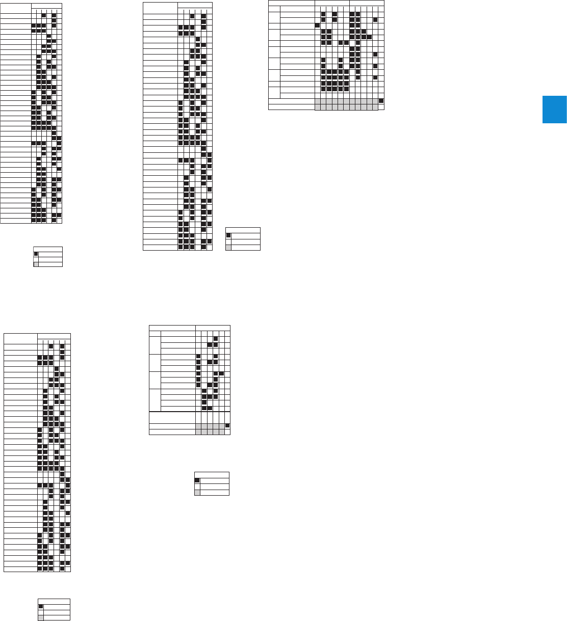
4
2CDC 110 004 C0210 | Catalog Electronic Products and Relays 2015 | ABB 4/24
Analog signal converters - CC-U range
DIP switch settings
CC-U/I
2CDC 282 003 F0204
OFF
Legend
no influence
ON
12 4356
-10...-2 V
-5...-1 V
-8...0 V
-4...0 V
0...1 mA
0...20 mA
4...20 mA
0...10 mA
0...800 µA
0...8 mA
0...400 µA
125...625 µA
166...833 µA
2...10 mA
100...500 µA
0...666 µA
0...16 mA
0...5 V
0...10 V
1...5 V
2...10 V
-10...+10 V
-5...+5 V
-10...0 V
-5...0 V
0...8 V
0...4 V
2CDC 282 029 F0203
Switch
Output
1.25...6.25 V
0...6.66 V
-10...+3.33 V
-5...+1.66 V
-7.5...+2.5 V
-3.75...+1.25 V
1.66...8.33 V
-6.66...+6.66 V
-3.33...+3.33 V
0...0.5 mA
0...13.33 mA
2.5...12.5 mA
3.33...16.66 mA
0.2...1 mA
CC-U/V
2CDC 282 003 F0204
OFF
Legend
no influence
ON
12 4356
-10...-2 V
-5...-1 V
-8...0 V
-4...0 V
0...1 mA
0...20 mA
4...20 mA
0...10 mA
0...800 µA
0...8 mA
0...400 µA
125...625 µA
166...833 µA
2...10 mA
100...500 µA
0...666 µA
0...16 mA
0...5 V
0...10 V
1...5 V
2...10 V
-10...+10 V
-5...+5 V
-10...0 V
-5...0 V
0...8 V
0...4 V
2CDC 282 029 F0203
Switch
Output
1.25...6.25 V
0...6.66 V
-10...+3.33 V
-5...+1.66 V
-7.5...+2.5 V
-3.75...+1.25 V
1.66...8.33 V
-6.66...+6.66 V
-3.33...+3.33 V
0...0.5 mA
0...13.33 mA
2.5...12.5 mA
3.33...16.66 mA
0.2...1 mA
*) Detection of input signal
interruptions:
If the input signal circuit is interrupted, the output
signal changes to the adjusted minimum value (low
fail safe) or maximum value (high fail safe).
CC-U/TC
12 4356
-10...-2 V
-5...-1 V
-8...0 V
-4...0 V
0...1 mA
0...20 mA
4...20 mA
0...10 mA
0...800 µA
0...8 mA
0...400 µA
125...625 µA
166...833 µA
2...10 mA
100...500 µA
0...666 µA
0...16 mA
0...5 V
0...10 V
1...5 V
2...10 V
-10...+10 V
-5...+5 V
-10...0 V
-5...0 V
0...8 V
0...4 V
2CDC 282 017 F0208
Switch 3
Output
1.25...6.25 V
0...6.66 V
-10...+3.33 V
-5...+1.66 V
-7.5...+2.5 V
-3.75...+1.25 V
1.66...8.33 V
-6.66...+6.66 V
-3.33...+3.33 V
0...0.5 mA
0...13.33 mA
2.5...12.5 mA
3.33...16.66 mA
0.2...1 mA
2CDC 282 003 F0204
OFF
Legend
no influence
ON
12 4356124356
R
B
mV
N
K
J
T
S
E
0-100...900 °C
0-250...1350 °C
0-100...750 °C
0-100...400 °C
-150-0...400 °C
0-250...1550 °C
0-100...700 °C
0-200...1000 °C
0-100...650 °C
0-200...1300 °C
0-250...1350 °C
0-450...1700 °C
0-700...1750 °C
0-2...10 mV
0-10...50 mV
2CDC 282 010 F0204
Type Range
Switch 1 Switch 2Input
Low fail safe *)
High fail safe *)
CC-U/TCR with relay output
2CDC 282 003 F0204
OFF
Legend
no influence
ON
12 4356
S
J
K
T
0...240 °C
0...480 °C
0...1200 °C
0...250 °C
0...500 °C
0...1350 °C
-150...+120 °C
0...220 °C
0...400 °C
0...210 °C
0...380 °C
0...860 °C
0...1550 °C
2CDC 282 004 F0204
Type Range
SwitchInput
Output
Closed-circuit principle
Open-circuit principle
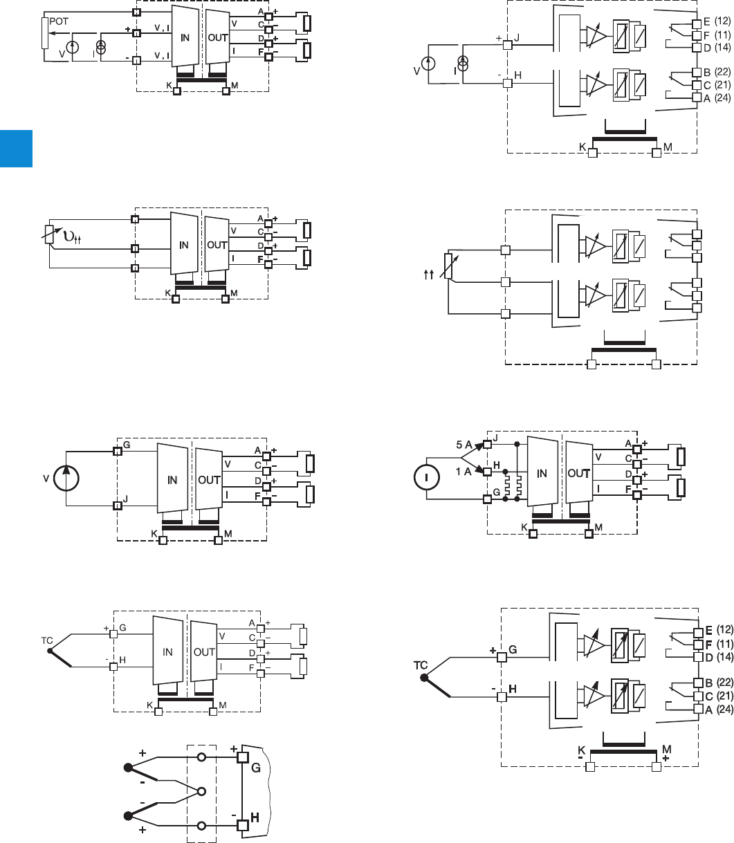
4
4/25 ABB | Catalog Electronic Products and Relays 2015 | 2CDC 110 004 C0210
Pot.
G
H
J
2CDC 282 015 F0206
Burden
R 4.7 k
Burden
R 600
supply
+ 2.5 V
CC-U/STD
Analog signal converters - CC-U range
Wiring instructions
2CDC 282 016 F0206
Value R1
Value R2
Threshold Hysteresis
supply
CC-U/STDR with relay output
J
H
G
2CDC 282 017 F0206
Burden
R 4.7 k
Burden
R 600
supply
CC-U/RTD
υ
G
J
H
KM
B (22)
C (21)
A (24)
E (12)
F (11)
D (14)
R1
R2
2CDC 282 045 F0203
Value R1
Value R2
Threshold Hysteresis
supply
CC-U/RTDR with relay output
2CDC 282 022 F0206
Burden
R 4.7 k
Burden
R 600
supply
CC-U/V
2CDC 282 021 F0206
Burden
R 4.7 k
Burden
R 600
supply
CC-U/I
2CDC 282 019 F0206
without cold-junction compensation:
switch SW2.2 = OFF
2CDC 282 018 F0206
Burden
R 4.7 k
Burden
R 600
supply
CC-U/TC
2CDC 282 020 F0206
Value R1
Value R2
Threshold Hysteresis
supply
CC-U/TCR with relay output
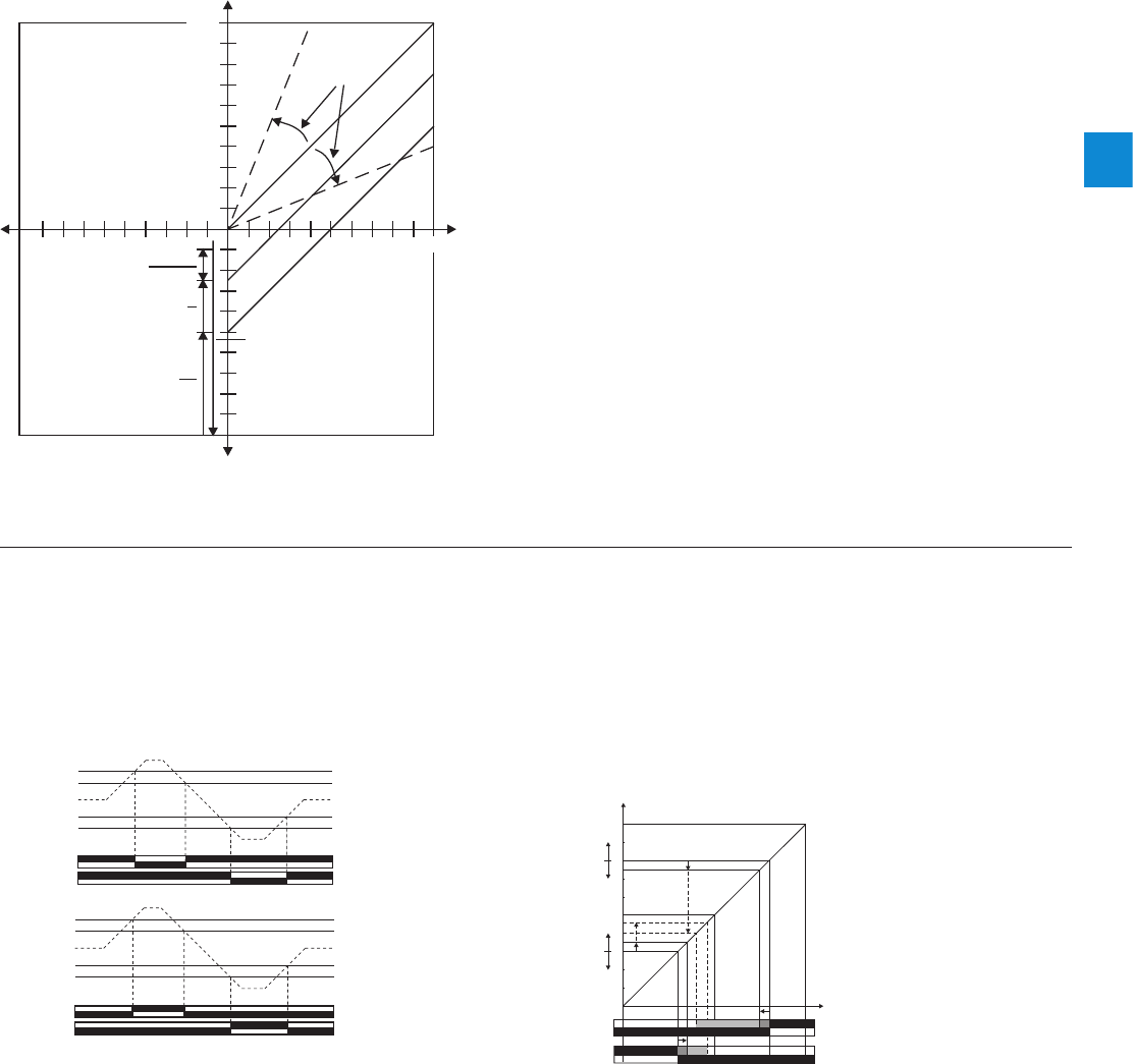
4
2CDC 110 004 C0210 | Catalog Electronic Products and Relays 2015 | ABB 4/26
Adjustment range
OUT [%]
IN [%]
SW1.4 = +100 %
SW1.5 = +50 %
100
90
80
70
60
50
40
30
20
10
10 20 30 40 50 60 70 80 90 100
2CDC 282 018 F0203
Offset remote poti
SW1.6 = +22.5 %
Gain
“gain-coarse”
and
“gain-fine”
CC-U/STD
Analog signal converters - CC-U range
Technical information
Function diagrams
Switching points of the output relay depending on the input range,
configuration open-circuit principle
OUT
11-14
11-12
21-24
21-22
R1
R2
IN [%]
100
90
80
70
60
50
40
30
20
10
0
2CDC 282 021 F0203
Hysteresis R1
5-50 % of
threshold
value R1
Thr
eshold value R1
2-100 %
of input range
Thr
eshold value R2
2-100 %
of input range
Hysteresis R2
5-50 % of
threshold
value R2
Actual value
Switching points
21-24
21-22
11-14
11-12
R2
R1
2CDC 282 044 F0203
R1 Threshold value
R1 Hysteresis
R2 Hysteresis
R2 Threshold value
Input
Closed-circuit principle
21-24
21-22
11-14
11-12
R2
R1
2CDC 282 046 F0203
R1 Threshold value
R1 Hysteresis
R2 Hysteresis
R2 Threshold value
Input
Open-circuit principle
CC-U/STDR with relay output
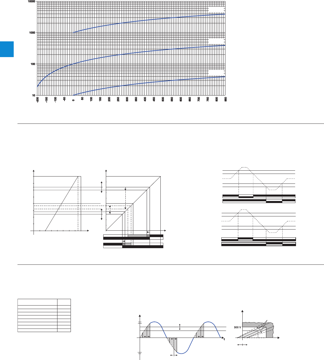
4
4/27 ABB | Catalog Electronic Products and Relays 2015 | 2CDC 110 004 C0210
Resistance of PT10, PT100 and PT1000 sensors depending on the temperature
PT1000
PT100
PT10
2CDC 282 022 F0203
Resistance []
Temperature [°C]
Characteristic curves
Analog signal converters - CC-U range
Technical information
CC-U/RTD
Switching points of the output relay depending on the input range,
configuration open-circuit principle
OUT
11-14
11-12
21-24
21-22
R1
R2
100
90
80
70
60
50
40
30
20
10
0
IN [%]
800
700
600
500
400
300
200
100
50 100 150 200 250 300 350 400
2CDC 282 025 F0203
Resistance []
Temperature υ [°C]
Hysteresis R1
5-50 % of
threshold
value R1
Threshold value R1
2-100 %
of input range
Threshold value R2
2-100 %
of input range
Hysteresis R2
5-50 % of
threshold
value R2
Actual value
Switching points Function diagrams
21-24
21-22
11-14
11-12
R2
R1
2CDC 282 044 F0203
R1 Threshold value
R1 Hysteresis
R2 Hysteresis
R2 Threshold value
Input
Closed-circuit principle
21-24
21-22
11-14
11-12
R2
R1
2CDC 282 046 F0203
R1 Threshold value
R1 Hysteresis
R2 Hysteresis
R2 Threshold value
Input
Open-circuit principle
CC-U/RTDR with relay output
0...100 V
0...150 V
0...250 V
0...300 V
0...400 V
0...600 V
0...450 V
0...550 V
1
2
3
4
5
8
6
7
2CDC 282 012 F0204
Switch
position
Selecting input range by
front-face rotary switch
U(t) [V]
IN
Ueff
[V]
OUT [%]
0 50 100
300
0
-300
2CDC 282 030 F0203
Offset 20 %
Gain 15 %
resulting
RMS value
operating angle
Example of application
CC-U/V
Input range selection
RMS measurement and conversion of a phase-angle controlled voltage signal L1 = 230 V
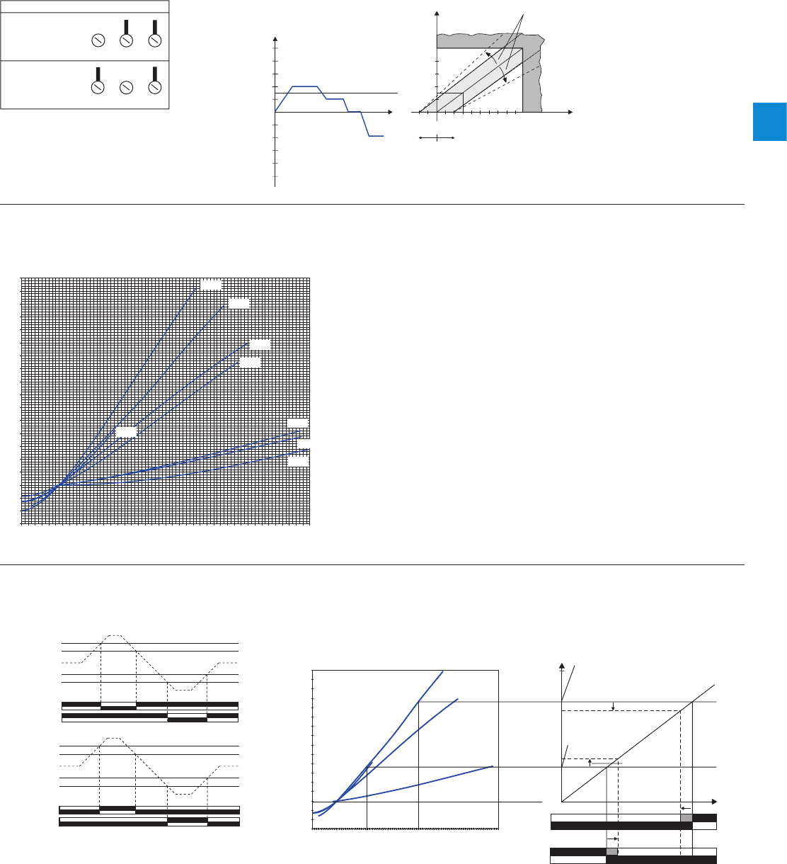
4
2CDC 110 004 C0210 | Catalog Electronic Products and Relays 2015 | ABB 4/28
Analog signal converters - CC-U range
Technical information
JHG
JHG
5 A1 AC
5 A1 AC
2CDC 282 033 F0203
Select input range by terminals
Input range 1 A
Connected lines
Used terminals
Terminal marking
Input range 5 A
Connected lines
Used terminals
Terminal marking
Input range selection
RMS measurement and conversion of a current signal
I(t) [A]
IN [%]
OUT [%]
0 50 100
t
5
4
3
2
1
0
-1
-2
-3
-4
-5
2CDC 282 028 F0203
Offset 20 %
Gain
15 %
resulting
RMS value
Example of application
CC-U/I
Thermocouple voltages depending on the temperature
Typ T
Typ N
Typ K
Typ J
Typ E
Typ R
Typ S
Typ B
-250
-200
-150
-100
-50
0
50
100
150
200
250
300
350
400
450
500
550
600
650
700
750
800
850
900
950
1000
1050
1100
1150
1200
1250
1300
1350
1400
1450
1500
1550
1600
1650
1700
1750
1800
80000
75000
70000
65000
60000
55000
50000
45000
40000
35000
30000
25000
20000
15000
10000
5000
0
-5000
-10000
-15000
2CDC 282 026 F010
3
Temperatur [°C]
Thermoelement-Spannung [µV]
Characteristic curve
CC-U/TC
CC-U/TCR with relay output
Function diagrams
21-24
21-22
11-14
11-12
R2
R1
2CDC 282 044 F0203
R1 Threshold value
R1 Hysteresis
R2 Hysteresis
R2 Threshold value
Input
Closed-circuit principle
21-24
21-22
11-14
11-12
R2
R1
2CDC 282 046 F0203
R1 Threshold value
R1 Hysteresis
R2 Hysteresis
R2 Threshold value
Input
Open-circuit principle
Switching points of the output relay depending on the
input range, configuration open-circuit principle
Typ T
Typ J
Typ K
Typ S
IN [%]
100
0OUT
11-14
11-12
21-24
21-22
R1
R2
7000
6500
6000
5500
5000
4500
4000
3500
3000
2500
2000
1500
1000
500
0
-500
-1000
-1500
-275
-175
-75
25
125
225
325
425
525
625
725
825
925
1025
1125
1225
1325
1425
1525
1625
1725
1825
2CDC 282 027 F0203
Temperature [°C]
Thermocouple voltage [µV]
Threshold value
R2 = 400 °C
Release hysteresis
Threshold value
R1 = 1000 °C
Release hysteresis
Switching points

4
4/29 ABB | Catalog Electronic Products and Relays 2015 | 2CDC 110 004 C0210
Analog signal converters - CC-U range
Technical data
Type CC-U/STD CC-U/RTD 3) CC-U/TC
Input circuits - Analog inputs J-G-H Current Voltage Potentio-
meter
Temperature sen-
sors
Thermocouples
(IEC 584-1 and 2)
Input signal 0-20 mA
4-20 mA
10-50 mA
0-1 mA
0-100 mV
0-1 V
0-5 V
1-5 V
0-10 V
2-10 V
± 10 V
470
-1M 2)
PT10, PT100,
PT1000
(IEL 751 and JICC
1604)
TC.K
TC.T
TC.E
TC.R
TC.J
TC.S
TC.N
TC.B
Limitation of input signals ± 55 mA ± 11 V - -
Rated input range - - -
Max. temperature
adjustable:
6-60 °C for PT1000
50-500 °C for PT100
500-850 °C for PT10
refer to
temperature
specs. of individual
thermocouples
Influence of line resistance ---0.015 °C/< 0.01 % / 100
Gain adjustment range
(universal devices)
0.9-
110 mA 45 mV -
22 V -see DIP switch settings
Offset adjustment range (universal devices) -137.5...+62.5 % ± 5 % ± 10 %
Input impedance for different ranges - -
without detection of input signal interruption 51 6 M3 G- -
with detection of input signal interruption 51 3.5 M9.5 G- -
Suppression at 50 Hz - - - - > 40 dB
Common-mode rejection ---120 dB 105 dB
Output circuits - Analog outputs D-F, A -C Current Voltage
Output signal 0-20 mA, 4-20 mA
0-5 V, 1-5 V, 0-10 V, 2-10 V, ± 10 V
Output burden 600 4.7 K
Accuracy 1) ±0.1 % of full-scale ±0.2 % of full-scale ±0.1 % of full-scale
Residual ripple -< 0.15 % -
Response time 200 µs 10 ms 200 ms
Transmission frequency 1 kHz 80 Hz 2 Hz (to -3 dB)
Supply circuits K-M DC versions AC versions
Rated supply voltage 24-48 V DC 110-240 V AC
Supply voltage range 24-48 V DC / 24 V AC 110-240 V AC / 100-300 V DC
Supply voltage tolerance DC: -15...+15 % AC: -15...+10 %
Rated frequency 0 Hz or 50/60 Hz
Power consumption 2 W at 24 V DC 4.5 VA at 230 V AC
Indication of operational states
Supply voltage U: green LED
General data
Ambient temperature range operation / storage -20...+60 °C / -40...+80 °C
Temperature coefficient ±150 ppm/°C ±250 ppm/°C ±200 ppm/°C at
min. offset
±400 ppm/°C at
max. offset
Mounting position any
Mounting
DIN rail (IEC/EN 60715), snap-on mounting / screw mounting with adapter
Electrical connection
Wire size rigid plug-connector with screw terminals 0.2-2.5 mm2 (24-12 AWG)
fine-strand with(out) wire end ferrule plug-connector with screw terminals 0.2-2.5 mm2 (24-12 AWG)
Stripping length 7 mm (0.28 inch)
Tightening torque 0.4 Nm (3.5 ib.in)
Electromagnetic compatibility
Interference immunity EN 61000-6-2
electrostatic discharge (ESD) IEC/EN 61000-4-2 Level 3 (±6 kV / ±8 kV)
electromagnetic field (HF radiation resistance) IEC/EN 61000-4-3 10 V/m
fast transients (Burst) IEC/EN 61000-4-4 Level 3 (±2 kV / 5 kH)
powerful impulses (Surge) IEC/EN 61000-4-5 ±2 kV / ±1 kV
HF line emission IEC/EN 61000-4-6 10 V
Interference emission EN 61000-6-4 Class B
Isolation data
Isolation test (between all isolated circuits) 1.5 kV
Test voltage (between all isolated circuits) 1.5 kV / 50 Hz
1) Includes non-linearity and factory setting, influenced by supply voltage and output load.
2) Detection of an input signal break (fail safe) and resistance > 10 k results in a linearity of 0.2 %.
3) When connecting a 2-wire sensor, the terminals J and H have to be jumpered.
Approvals on page 4/4.

4
2CDC 110 004 C0210 | Catalog Electronic Products and Relays 2015 | ABB 4/30
Analog signal converters - CC-U range
Technical data
Type CC-U/STDR CC-U/RTDR 1) CC-U/TCR
Input circuits - Analog inputs J-H Current Voltage Temperature sensors Thermocouples
(IEC584-1 and 2)
Measuring signal / input range 0-20 mA
4-20 mA 0-1 V /
1-5 V
0-10 /
±10 V
PT100 TC.K, TC.J
TC.T, TC.S
Input resistance approx.
50
approx.
1.5 M
Adjustable threshold 2-100 % of selected input range
Adjustable hysteresis 5-50 % of threshold
Repeat accuracy (constant parameters) ±0.5 % of full-scale
Output circuits - Relay outputs E-D-F, B-C-A Relay, 2 c/o contacts
Rated switching voltage 250 V AC
Rated switching current AC-12 (resistive) 230 V 4 A
AC-15 (inductive) 230 V 3 A
DC-12 (resistive) 24 V 4 A
DC-13 (inductive) 24 V 2 A
AC rating
(UL 508)
Utilization category (Control Circuit Rating Code)
B 300
max. rated operational voltage 300 V AC
max. continuous thermal current at B 300 5 A
max. making/breaking apparent power at B 300
3600/360 VA
Minimum switching voltage 12 V
Minimum switching current / power 10 mA / 0.6 VA (W)
Response time 10 ms
Mechanical lifetime 30 x 106 switching cycles
Electrical lifetime at AC-12, 230 V, 4 A 0.1 Mio. switching cycles
Supply circuits K-M DC versions AC versions
Rated supply voltage 24-48 V DC 110-240 V AC
Supply voltage range 24-48 V DC / 24 V AC 110-240 V AC / 100-300 V DC
Supply voltage tolerance DC: -15...+15 % AC: -15...+10 %
Rated frequency 0 Hz or 50/60 Hz
Power consumption 2 W at 24 V DC 4.5 VA at 230 V AC
Indication of operational states
Supply voltage U: green LED
1st / 2nd output relay energized R1: yellow LED / R2: yellow LED
General data
Ambient temperature range operation / storage -20...+60 °C / -40...+80 °C
Temperature coefficient ±300 ppm/°C
Mounting position any
Mounting
DIN rail (IEC/EN 60715), snap-on mounting / screw mounting with adapter
Electrical connection
Wire size rigid plug-connector with screw terminals 0.2-2.5 mm2 (24-12 AWG)
fine-strand with(out) wire end ferrule plug-connector with screw terminals 0.2-2.5 mm2 (24-12 AWG)
Stripping length 7 mm (0.28 inch)
Tightening torque 0.4 Nm (3.5 ib.in)
Electromagnetic compatibility
Interference immunity EN 61000-6-2
electrostatic discharge (ESD) IEC/EN 61000-4-2 Level 3 (±6 kV / ±8 kV)
electromagnetic field (HF radiation resistance) IEC/EN 61000-4-3 10 V/m
fast transients (Burst) IEC/EN 61000-4-4 Level 3 (±2 kV / 5 kH)
powerful impulses (Surge) IEC/EN 61000-4-5 ±2 kV / ±1 kV
HF line emission IEC/EN 61000-4-6 10 V
Interference emission EN 61000-6-4 Class B
Isolation data
Insulation voltage (between all isolated circuits) 2.5 kV
Test voltage (between all isolated circuits) 2.5 kV
1) When connecting a 2-wire sensor, the terminals J and H have to be jumpered.
Approvals on page 4/4.

4
4/31 ABB | Catalog Electronic Products and Relays 2015 | 2CDC 110 004 C0210
Analog signal converters - CC-U range
Technical data
Type CC-U/I CC-U/V
Input circuits - Analog inputs J-G-H any current signals,
RMS measurement
any voltage signals,
RMS measurement
Rated input range 0-1 A
0-5 A 0-100 V, 0-150V, 0-250 V
0-300 V, 0-400 V, 0-450 V
0-550 V, 0-600 V
Measuring frequency 0-600 Hz
Overload capacity of inputs input range 1 10 x INom (10 A) for max. 2 s -
input range 2 10 x INom (50 A) for max. 2 s -
Gain adjustment range ±15 %
Offset adjustment range ±20 %
Input impedance / resistance 1A: 60 m,
5 A: 12 m
> 800 k
Output circuits - Analog outputs D-F, A -C Current Voltage
Output signal 0-20 mA, 4-20 mA 0-5 V, 1-5 V, 0-10 V, 2-10 V, ± 10 V
Output load 600 4.7 K
Accuracy1) ±0.5 % of full-scale
Temperature coefficient ±250 ppm/°C max. ±300 ppm/°C max.
Residual ripple < 0.15 %
Response time 150 ms
Supply circuits K-M DC versions AC versions
Rated supply voltage 24-48 V DC 110-240 V AC
Supply voltage range 24-48 V DC, 24 V AC 110-240 V AC, 100-300 V DC
Supply voltage tolerance DC: -15...+15 % AC: -15...+10 %
Rated frequency 0 Hz or 50/60 Hz
Power consumption 2 W at 24 V DC 4.5 VA at 230 V AC
Indication of operational states
Supply voltage U: green LED
General data
Ambient temperature range operation / storage -20...+60 °C / -40...+80 °C
Mounting position any
Mounting
DIN rail (IEC/EN 60715), snap-on mounting / screw mounting with adapter
Electrical connection
Wire size rigid plug-connector with screw terminals 0.2-2.5 mm2 (24-12 AWG)
fine-strand with(out) wire end ferrule plug-connector with screw terminals 0.2-2.5 mm2 (24-12 AWG)
Stripping length 7 mm (0.28 inch)
Tightening torque 0.4 Nm (3.5 lb.in)
Standards
Product standard -
Low Voltage directive 2006/95/EC
EMC directive 2004/108/EC
RoHS directive 2011/65/EC
Electromagnetic compatibility
Interference immunity EN 61000-6-2
electrostatic discharge (ESD) IEC/EN 61000-4-2 Level 3 (±6 kV / ±8 kV)
electromagnetic field (HF radiation resistance) IEC/EN 61000-4-3 10 V/m
fast transients (Burst) IEC/EN 61000-4-4 Level 3 (±2 kV / 5 kH)
powerful impulses (Surge) IEC/EN 61000-4-5 ±2 kV / ±1 kV
HF line emission IEC/EN 61000-4-6 10 V
Interference emission EN 61000-6-4 Class B
Isolation data
Insulation voltage (between all isolated circuits) 1.5 kV
Test voltage (between all isolated circuits) 1.5 kV / 50 Hz
1) Includes non-linearity and factory setting, influenced by supply voltage and output load.
Approvals on page 4/4.
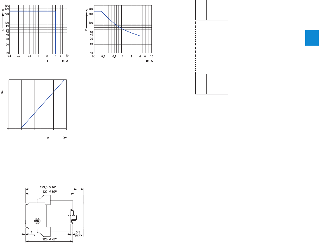
4
2CDC 110 004 C0210 | Catalog Electronic Products and Relays 2015 | ABB 4/32
Analog signal converters - CC-U range
Technical diagr., Connection diagr., Dimensional drawings
.039
2CDC 282 024 F0b06
J
DF
G
M
H
LK
AC
E
B
2CDC 282 023 F0b06
CC-U/x , CC-U/xR
2CDC 282 025 F0b0
6
1.0
0.9
0.8
0.7
0.6
0.5
F
0.1 0.2 0.3 0.4 0.5 0.6 0.7 0.8 0.9 1.0
cos
2CDC 282 014 F0b06
2CDC 282 026 F0b0
6
Dimensional drawings Dimensions in mm and inches
Connection diagram CC-U/x
Width 22.5 mm (0.89 in)
Technical diagrams
Load limit curves CC-U/xxR
Resistive AC load Resistive DC load
Derating curve
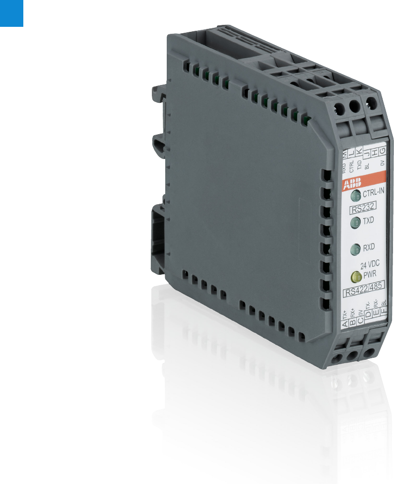
4
4/33 ABB | Catalog Electronic Products and Relays 2015 | 2CDC 110 004 C0210
Serial data converters
Product picture


4
4/35 ABB | Catalog Electronic Products and Relays 2015 | 2CDC 110 004 C0210
ILPH RS 232 - 485 / Ethernet
– Electrical isolation between power supply and input/output
– RS232 on SUBD 9 points or screw connectors
– RS485 on removable screw connectors
– Ethernet 10/100 Mbit/s, RJ45 connector
– Power supply 10-34 VDC and 10-24 VAC
– Possible to have a redundant 10-34 VDC power supply
– Economic with low consumption
– Up to 100m with CAT5 cable without Hub or Switch
– Good EMC characteristics
– Up to 2 Modbus®\TCP Masters
Available modes:
– Modbus®\TCP to Modbus® RTU
– Transparent Client or Server mode
– SMTP mode (Mail mode)
Standards: TPC/IP, TELNET, DHCP, FTP
– Specifics functions in Modbus® protocol:
– Concentrator (Asynchronous mode) up to 1200 words
– AC31 programming
Modbus® Easy Net mode : this mode could be used to
exchange data without a Modbus®/TCP master. The data
are logged in a table and could be distributed to one or all
the others e-ILPH participants on Ethernet.
ILPH RS 232 / RS 422 - 485
RS 232 to RS 422-485 serial link with or without electrical
isolation
– Baudrate up to 38.4 kbit/s
– Transmission distance up to 1200 m
– RS 485 1 or 2 pair handling
– Usable in "noisy" environments
– 24 V DC power supply
– CE marked
ILPH RS 232 / RS 422 - 485
– Electrical isolation between power supply and input/output
– RS 485 switch on 2 or 4 wires
– Baudrate up to 38.4 kbit/s
– Transmission distance up to 1200 m
– RS 485 1 or 2 pair handling
– Usable in "noisy" environments
– 24...48 V DC and 115...230 V AC power supply
– CE marked
ILPH RS 232 / RS 232
3 way electrical isolator between RS 232 serial interface and
another RS 232 serial interface.
– Ensures triple insulation between the 2 serial interfaces and
between each and power supply
–
Baudrate up to 19.2 kbit/s (up to 64 kbit/s depending on cable)
– Transmission distance up to 15 m
– Can be used in "noisy" environments
– Power supply from 24...48 V DC and 115...230 V AC CE
marking
ILPH RS 422 - 485 / RS 422 - 485
Electrical isolated connection between an RS 422-485 (1 or 2
pairs) and an RS 422 485 (1 or 2 pairs) serial link. It amplifies
the signal beyond the 1200 m limit distance of the RS 422-
485 and only needs a minimum of 1.5 character delay time to
switch off the RS 485 drivers.
– Electrical isolation between power supply/output and input/
output
– Baudrate up to 500 kbit/s (up to 200 m)
– Transmission distance up to 1200m at 38.4 kbit/s
– Usable in "noisy" environments
– 2/4 wires automatic handling
– 24 V DC power supply
– CE marked
ILPH RS 232 / FO
– Converter for RS 232 to fiber optical serial link glass.
– Electrical isolation between power supply and input/output
– Baud rate up to 115.2 kbit/s
– Transmission distance up to 4 km
– Usable in "very noisy" environments
– 20...42 V AC/DC power supply
– CE marked
ILPH RS 485 / FO
Converter for RS 485 (1 pair) to optical fiber serial link glass.
– Electrical isolation between power supply and input/output
– Baud rate up to 1.5 Mbit/s
– Transmission distance up to 4 km
– Usable in "very noisy" environments
– 20...42 V AC/DC power supply
– CE marked
ILPH CL / RS 422 - 485
Electrical isolated converter for current loop to RS 422-485 (1
or 2 pairs) serial link.
– Electrical isolation between power supply/current loop and
RS 422-485/current loop
– Active/passive 0...20 mA / 4...20 mA selectable
Positive or negative logic selectable
– Baudrate up to 38.4 kbit/s (up to 2400 m)
Transmission distance up to 2400 m (1200 m RS 485 and
1200 m current loop)
– Usable in "noisy" environments
– 24 V DC power supply
– CE marked
ILPH RS 232 / CL
Electrical isolated Converter for RS 232 to current loop serial
link.
– Electrical isolation between power supply/current loop and
RS 232/current loop
– Active/Passive 0...20 mA / 4...20 mA selectable
Positive or negative logic selectable
– Baudrate up to 38.4 kbit/s
– Transmission distance up to 1200 m
– Usable in "noisy" environments
– 24 V DC power supply
– CE marked
Serial data converters
Benefits and advantages

4
2CDC 110 004 C0210 | Catalog Electronic Products and Relays 2015 | ABB 4/36
Serial data converters
Selection table
RS 232 - EIA-232 / V.24 / V.28
– Point-to-point connection
– Max. 15 m transmission distance
– Rate up to 19.2 kbit/s
– Full-duplex
RS 422 - EIA-422 / V.11
– Point-to-point connection
– (1 Transmitter - 10 Receivers)
– Differential voltage transmission
– Full-duplex
– Up to 1200 m/ 10 Mbit/s
– Good EMC characteristics
Current loop(TTY)
– Point-to-point / multi-point connection
– Active or passive current loop
– Full-duplex
– Up to 1200 m/19.2 kBit/s
– Good EMC characteristics
RS 485 - ISO/IEC/EIA-485
– Multi-point connection up to 32 units
– Differential voltage transmission
– Half-duplex on 1 pair
– Full-duplex on 2 pairs
– Up to 1200 m / 10 Mbit/s
– Good EMC characteristics
Optical fiber interface
– Point-to-point connection
– Full-duplex
– From 40 m up to 4km transmission distance
– Excellent EMC characteristics
Ethernet Interface
– Point to point connexion or multipoint connection.
– Up to 100 m using CAT5 cable without Hub or Switch
– 10/100 Mbit/s
– Good EMC characteristics
RS 232
RS 422 / RS 485
CL
FO-S
Ethernet
24 V DC
24-48 V DC
110-240 V AC
24-42 V AC/DC
10-34 VDC, 10-24 VAC
Insulation
IN=Input
PS=Power supply
Out=Output
Wi=Without
insulation Part numbers
RS 232 In-Ps-Out 1SNA 684 234 R2000
Wi 1SNA 684 231 R2500
In-Out 1SNA 684 233 R2700
In-Ps-Out 1SNA 684 333 R2300
In-Ps-Out 1SNA 684 334 R2400
In-Out 1SNA 684 202 R0100
In-Ps-Out 1SNA 684 236 R2200
RS 422/RS485 In-Out 1SNA 684 212 R2200
In-Out 1SNA 684 232 R2600
RS 485 In-Ps-Out 1SNA 684 246 R0400
RS 232 / RS 485 In-Ps-Out 1SNA 684 252 R0200
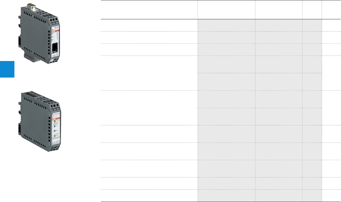
4
4/37 ABB | Catalog Electronic Products and Relays 2015 | 2CDC 110 004 C0210
Serial data converters
Ordering details
Ordering details
Description Type Order code Price Weight
(1 pce)
kg (lb)
Serial data converter e-ILPH ILPH RS 232-RS 485 /
Ethernet 1SNA684252R0200 0.12
(0.265)
Serial link interface without electrical isolation ILPH RS 232 /
RS 422-485 1SNA684231R2500 0.1
(0.220)
Serial link interface with electrical isolation ILPH RS 232 /
RS 422-485 1SNA684233R2700 0.1
(0.220)
Serial link interface 3 way electrical isolation
ILPH RS 232 / RS 422-
485 (24-48 V DC
power supply)
1SNA684333R2300
0.1
(0.220)
ILPH RS 232 / RS 422-
485 (115-230 V AC
power supply)
1SNA684334R2400
Serial link interface 3 way electrical isolation
ILPH RS 232 / RS 232
(24-48 V DC power sup-
ply)
1SNA684234R2000
0.1
(0.220)
ILPH RS 232 / RS 232
(115-230 V AC power
supply)
1SNA684234R0200
Serial link interface with electrical isolation
ILPH RS 422 - 485 / RS
422 - 485 (24 V DC power
supply)
1SNA684212R2200 0.1
(0.220)
Serial link interface 3 way electrical isolation
ILPH RS 232 / FO-S
(24...42 V AC/DC power
supply)
1SNA684236R2200 0.15
(0.331)
Serial link interface 3 way electrical isolation
ILPH RS 485 / FO-S
(24...42 V AC/DC power
supply)
1SNA684246R0400 0.15
(0.331)
Serial link interface with electrical isoaltion ILPH BdC /RS 422 - 485
(24 V DC power supply) 1SNA684232R2600 0.1
(0.220)
Serial link interface with electrical isolation ILPH RS 232 (24 V DC
power supply) 1SNA684202R0100 0.1
(0.220)
2CDC 281 003 F0013
2CDC 281 001 S0013
ILPH RS 232-RS 485 / Ethernet
ILPH RS 232 / RS 422-485
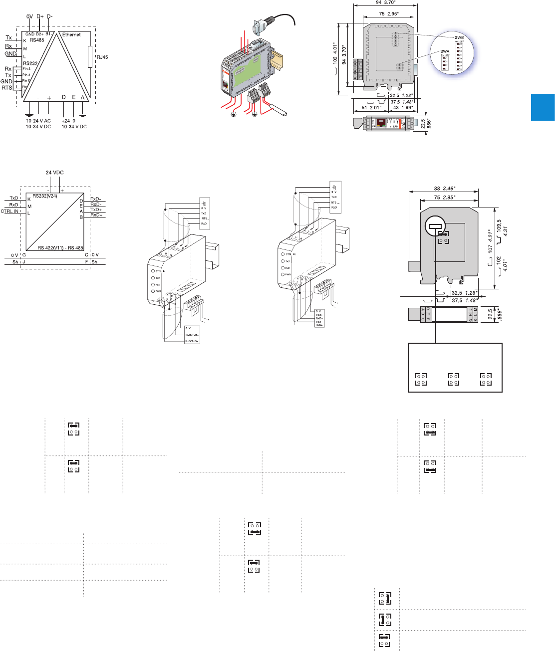
4
2CDC 110 004 C0210 | Catalog Electronic Products and Relays 2015 | ABB 4/38
Serial data converters
Technical information
ILPH RS 232 - 485 Ethernet
1SNA684252R0200
+24V
0V
24V
TXTX
GND
RXRX
B1+
B2-
M
JHG
M
L
K
D
E
A
GND
RX TX
Ethernet
LINK
TXD
RXD
e-ILPH
SPEED
PWR
ACTIVITY
M
L
K
JHG
M
L
K
4
3
2
1
ON
4
3
2
1
ON
5678
K
L
D
EA
SubD9
connector
pin 2 = RX
pin 3 = TX
pin 5 = GND
pin 7 = RTS
center of rail
ILPH RS 232 / RS 422-485 (without isolation)
1SNA684231R2500
*CAUTION:
When the RTS Signal is not activated,
M terminal (RxD ILPH) has to be
connected to L terminal (CTRL IN).
RS 422 - RS 485
SERIAL LINK (2 wires)
Product RS 232
Connector J1
24 V DC
power supply
Product RS 422-RS 485
** CAUTION :
To be connected to 2 wired RS 485
only (not possible for 4 wired RS 422).
When the RTS Signal is not activated,
M terminal (RxD ILPH) has to be
connected to L terminal (CTRL IN).
RS 422 - RS 485
SERIAL LINK (4 wires)
Product RS 232
Connector J1
24 V DC
power supply
Product RS 422-RS 485
RS 485 LINK ON ONE PAIR
without
isolation
RR ON/
OFF Jumper
R in
position
RON/OFF
EE ON/
OFF Jumper
E in
position
EON/OFF
The Receiver and the Transmitter are activated
alternately (never at the same time) depending on
the status of the CTRL IN signal.
CTRL IN STATUS ACTION ON RS 485
0 logic
(+3V U +25V) Transmitter active /
Receiver inactive
1 logic
(-25VU-3V) Transmitter inactive /
Receiver active
High impedance Transmitter inactive /
Receiver active
NOTE : For RS 232 products running the RTS
(REQUEST TO SEND) signal, connect RTS to CTRL
IN. Otherwise, connect M (RxD ILPH) to L (CTRL
IN).
RS422 LINK ON TWO PAIRS
without
isolation
RR ON Jumper
R in
position
RON
EE ON Jumper
E in
position
EON
The Transmitter and Receiver are both permanently
active.
ADAPTING THE RS 422 - RS 485 LINE
The line must always be adapted to the level of
the reception channel of each subscriber forming
the end of the bus. The ILPH is used to adapt the
reception channel by setting the jumper Rt correctly
:
Rt
* Line adaptation, Rt = 120 Ω
(general case )
* Line adaptation, Rt = 220 Ω
* No line adaptation, Rt = ∝
POLARIZATION OF THE
RS422-RS485LINE
The line must always be polarized.
The ILPH is used to polarize the reception channel :
Connection by 1 wire P+ (J1.1) with 5V
(J1.4)
Connection by 1 wire P- (J1.2) with 0V
(J1.3)
RS 485 LINK ON TWO PAIRS
without
isolation
RR ON Jumper
R in
position
RON
EE ON/
OFF Jumper
E in
position
EON/OFF
Receiver permanently active
Transmitter controlled by the signal CTRL IN (see
table for Transmitter operation as a function of
CTRL IN)
Configuration of the jumper
Rt R E
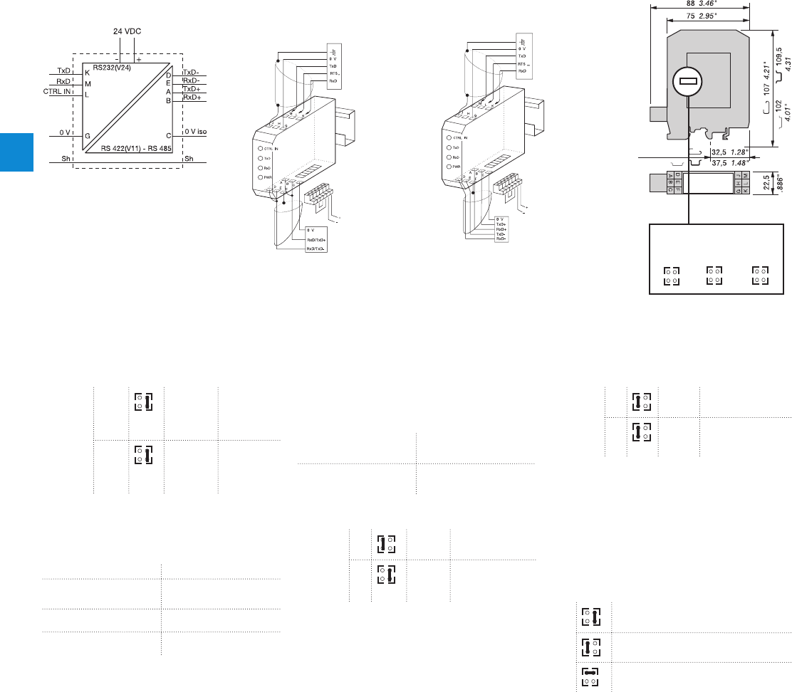
4
4/39 ABB | Catalog Electronic Products and Relays 2015 | 2CDC 110 004 C0210
ILPH RS 232 / RS 422-485 (with isolation)
1SNA684233R2700
Serial data converters
Technical information
** CAUTION :
Only to be connected for RS 485 two
pairs (of no use for RS 422 two pairs).
If the RTS signal is not generated,
connect M (RxD ILPH) to L (CTRL IN).
* CAUTION :
If the RTS signal is not generated,
connect M (RxD ILPH) to L (CTRL IN).
RS 422 - RS 485
WIRESERIALLINKS
RS 422 - RS 485
WIRESERIALLINKS
Connector J1
24 V DC
power supply
RS 422-RS 485
product
RS 232 product
Connector J1
24 V DC
power supply
RS 422-RS 485
product
RS 232 product
Configuration of the jumper
Rt R E
RS 485 LINK ON ONE PAIR
Isolated
RR ON/
OFF Jumper
R in
position
RON/OFF
EE ON/
OFF Jumper
E in
position
EON/OFF
The Receiver and the Transmitter are activated
alternately (never at the same time) depending on
the status of the CTRL IN signal.
CTRL IN STATUS ACTION ON RS 485
0 logic
(+3V U +25V) Transmitter active /
Receiver inactive
1 logic
(-25VU-3V) Transmitter inactive /
Receiver active
High impedance Transmitter inactive /
Receiver active
NOTE : For RS 232 products running the RTS
(REQUEST TO SEND) signal, connect RTS to CTRL
IN. Otherwise, connect M (RxD I LPH) to L (CTRL
IN).
RS422 LINK ON TWO PAIRS
Isolated
RR ON Jumper R in
position RON
EE ON Jumper E in
position EON
The Transmitter and Receiver are both permanently
active.
ADAPTING THE RS 422 - RS 485 LINE
The line must always be adapted to the level of t
he reception channel of each subscriber forming
the end of the bus. The ILPH is used to adapt the
reception channel by setting the jumper
Rt correctly :
Rt
* Line adaptation, Rt = 120 Ω
(general case )
* Line adaptation, Rt = 220 Ω
* No line adaptation, Rt = ∝
POLARIZATION OF THE
RS422-RS485LINE
The line must always be polarized.
The ILPH is used to polarize the reception channel :
Connection by 1 wire P+ (J1.1) with 5V
(J1.4)
Connection by 1 wire P- (J1.2) with 0V
(J1.3)
RS 485 LINK ON TWO PAIRS
Isolated
RR ON Jumper R in
position RON
EE ON/
OFF Jumper E in
position EON/
OFF
Receiver permanently active
Transmitter controlled by the signal CTRL IN (see
table for Transmitter operation as a function of
CTRL IN)
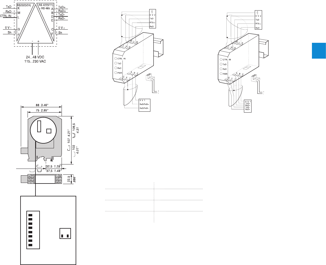
4
2CDC 110 004 C0210 | Catalog Electronic Products and Relays 2015 | ABB 4/40
Serial data converters
Technical information
Configuration of the jumper
SW1
SW1
SW2
SW2
ILPH RS 232 / RS 422 - 485 (eletrical isolated)
1SNA684333R2300, 1SNA684334R2400
RS 422 - RS 485
2 WIRE SERIAL LINK
**CAUTION :
Only to be connected for RS 485 two pairs (of no
use for RS 422 two pairs).
If the RTS signal is not generated, set SW2-1 in
position ON.
*CAUTION :
When the RTS signal is not generated, set SW2-1
in position ON.
RS 422 - RS 485
4 WIRE SERIAL LINKS
Product RS 232
Connector J1
Power
supply
Product
RS 422 - RS 485
Product RS 232
Connector J1
Power
supply
Product
RS 422 - RS 485
RS 485 LINK ON ONE PAIR
Set SW1-1, SW1-3, SW1-6, SW1-7 and SW1-8
to position ON. The receiver and the transmitter
are activated alternately (never at the same time),
depending on the status of the CTRL IN signal.
CTRL IN STATUS Action on RS 485
0 Logic
(3VU+25V) Transmitter active /
Receiver inactive
1 Logic
(-25VU-3V) Transmitter inactive /
Receiver active
High impedance Transmitter inactive /
Receiver active
CAUTION : For RS 232 products running the RTS
signal (REQUEST TO SEND), connect RTS to CTRL
IN.
Otherwise, set SW2-1 to position ON.
RS 485 LINK ON TWO PAIRS
Set SW1-1, SW1-3, SW1-7 in position OFF.
Set SW1-6, SW1-8 in position ON.
The receiver is permanently active.
The transmitter is controlled by the signal CTRL IN
(see table for transmitter operation as a fonction of
CTRL IN).
RS 422 LINK ON TWO PAIRS
Set SW1-1, SW1-3, SW1-7 and SW1-8 in position
OFF.
Set SW1-6 in position ON.
Transmitter and receiver are both permanently
active.
POLARIZATION OF THE RS 422 - RS
485 LINE
The line must always be polarized.
The ILPH is used to polarize the reception channel.
Set SW1-4 and SW1-5 in position ON.
ADAPTING THE RS 422 - RS 485 LINE
The line must always be adapted to the level of the
reception channel of each subscriber forming the
end of the bus.
The ILPH is used to adapt the reception channel by
setting the jumper SW1-2 correctly :
SW1-2 in position ON ⇒ line adaptation
Rt = 120 Ω (standard)
SW1-2 in position OFF ⇒ no line adaptation
Rt = ∝
1
1
2
2
OFF ON
ON
OFF
345678
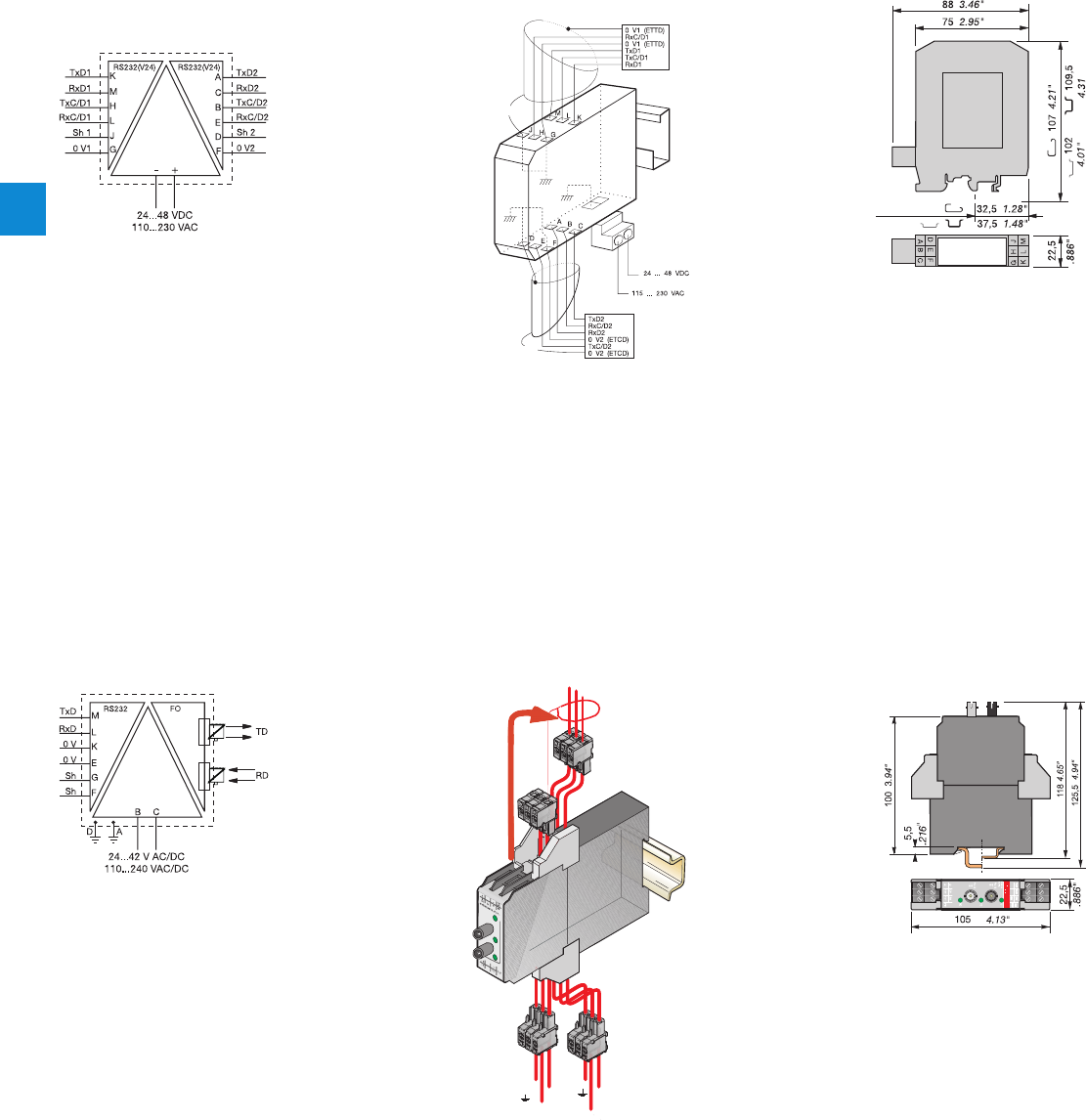
4
4/41 ABB | Catalog Electronic Products and Relays 2015 | 2CDC 110 004 C0210
ILPH RS 232 / RS 232 (eletrical isolated)
1SNA684234R2000, 1SNA684244R0200
Serial data converters
Technical information
Connection not advised
according to EIA/TIA 232E
standard
or
Connection not advised
according to EIA/TIA
232E standard (to be connected)
Terminal equipment for ETTD (DTE)
data processing
Data transmission end
equipment ETCD (DCE)
center of rail
ILPH RS 232 / FO
1SNA684236R2200
RxD
OV
TxD
OV
←
→
~
+
~
-
(L)
(K)
(M)
(J H
G)
(E)
(F)
(D)
(B)
(C)
(A)
Shielding
FO Sending
FO Receiving
Shielding
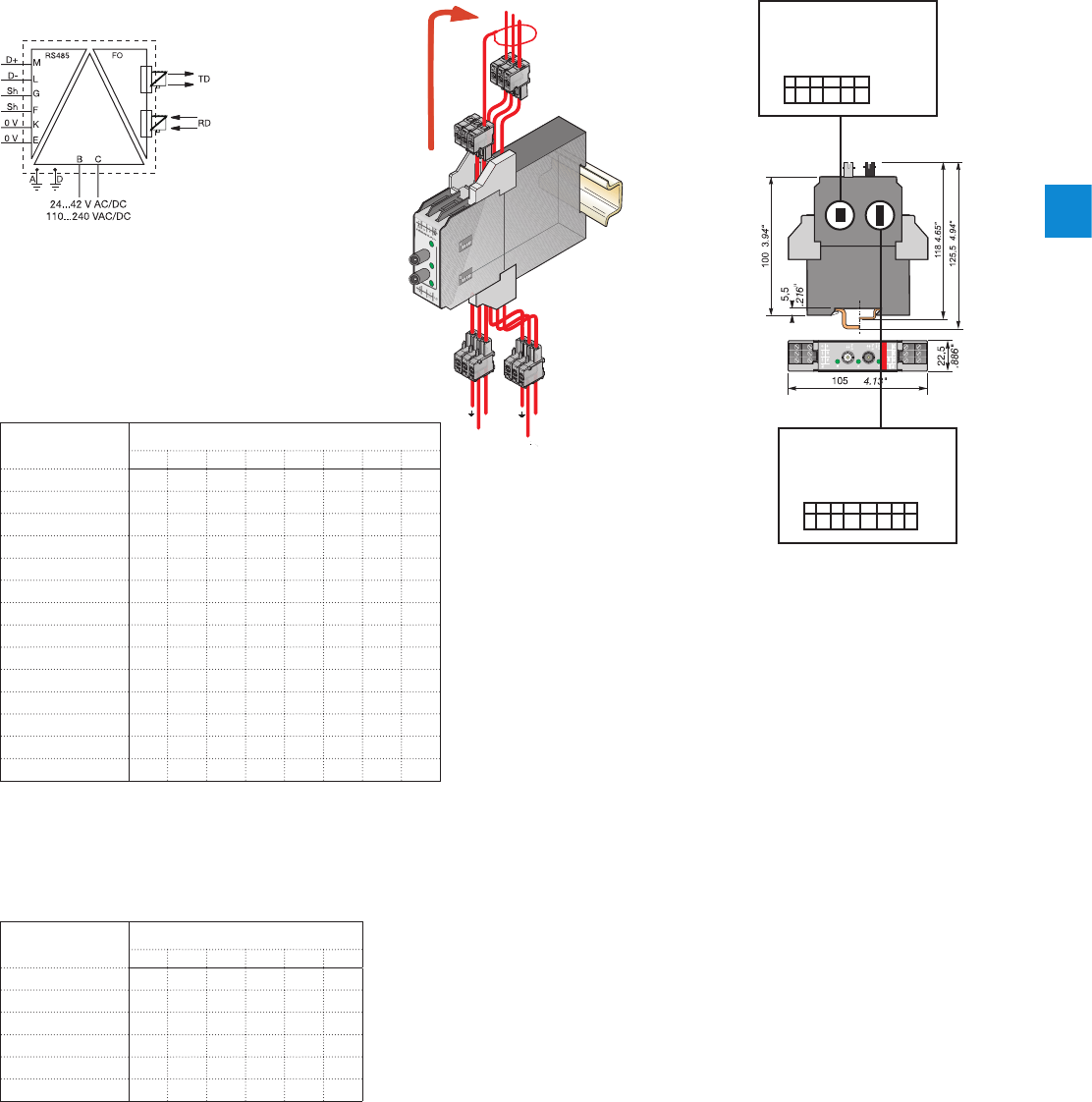
4
2CDC 110 004 C0210 | Catalog Electronic Products and Relays 2015 | ABB 4/42
Serial data converters
Technical information
ILPH RS 485 / FO
1SNA684246R0400
OV
D - D +
Shielding
~
-
~
+
Shielding
OV
←
→
FO Sending
FO Receiving
Baud rate configuration of
the micro-switch
Polarization configuration
of the micro-switch
1
1
2
2
SW 1
SW 2
OFF
OFF
6
6
3
3
7
4
4
85
5
Baudrate bit/s SW 1
12345678
1500000 M M M
500000 M M M
375000 M M M
187500 M M M M
136000 M M
115200 M M M M
93750 MMMM M
75000 M M M M M
57600 MMMMM
38400 M M M
19200 M M M M
9600 M M
4800 M M M M M M
300 M M
Baudrate bit/s SW 2
123456
Polarization M M
EOL 60 ohm MMM
EOL 120 ohm M M
EOL 180 ohm M M
EOL 240 ohm M
EOL indefinite
Baud rate:
SW1 DIP switch configuration
End-of-line resistor, polarization:
SW2 DIP switch configuration
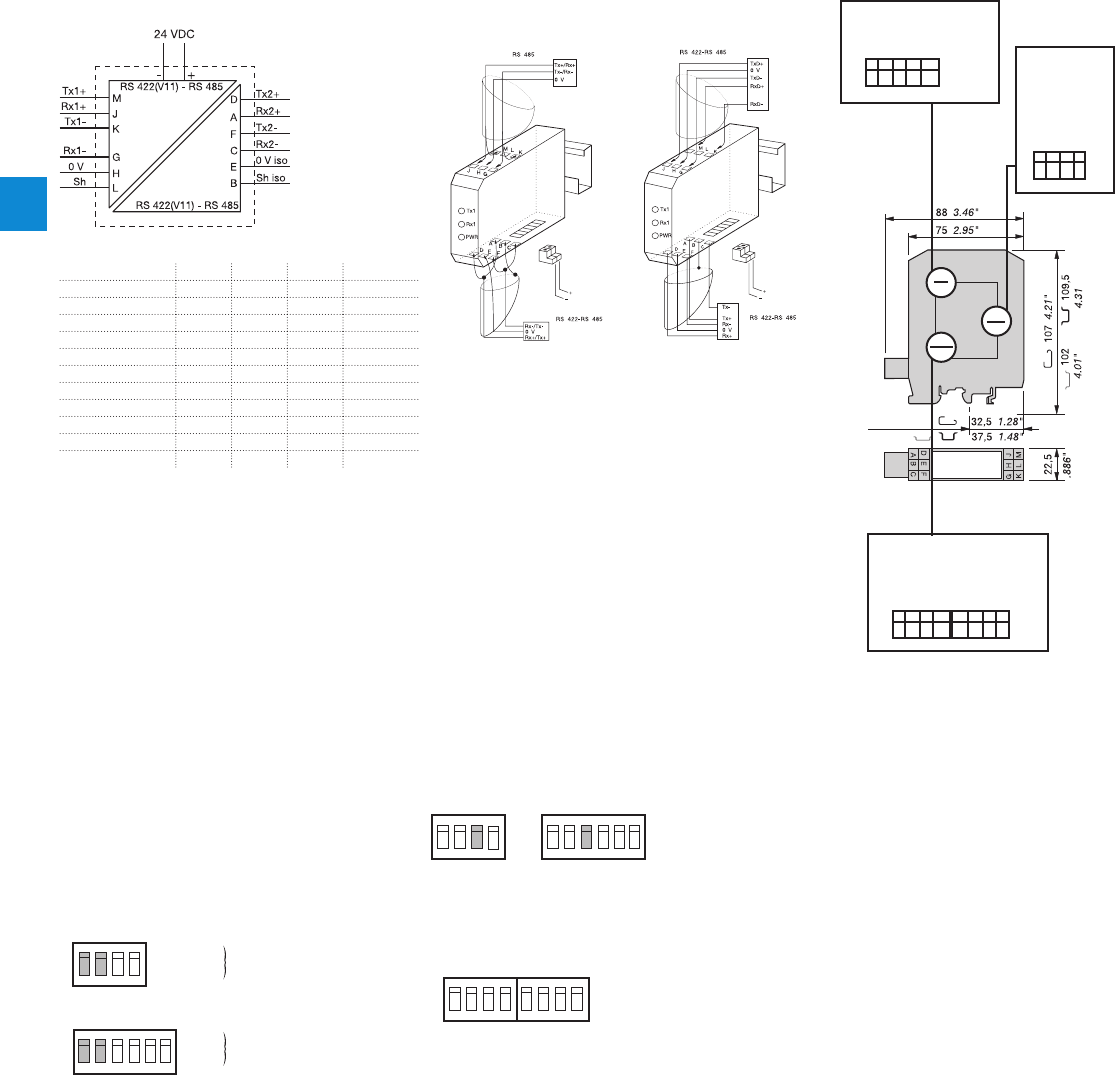
4
4/43 ABB | Catalog Electronic Products and Relays 2015 | 2CDC 110 004 C0210
Serial data converters
Technical information
center of rail
ILPH RS 422 - 485 / RS 422 / - 485
1SNA684212R2200
Nu = not used
X = zero
1 = contact closed
0 = contact open (aus)
(off)
OFF
1 2 3 4
1 2 3 4 5 6
OFF
INT 3
INT 4
INT 3.1
INT 3.2
INT 4.1
INT 4.2
OFF
OFF
INT 3
1 2 3 4 5 6
INT 4
1 2 3 4
OFF
1 2 3 4
OFF
INT 1 INT 2
"ON", polarizes the
reception channel Rx2
"ON", polarizes the
reception channel Rx1
RS 422 - RS 485 DRIVERS CONTROL
The RS 422 - RS 485 Drivers Control (transmitters
and receivers) makes the ILPH easy to use. The
control of the 2 channels is completely automatic ;
you only have to configure the baud rate needed.
The minimum turn off delay is about 1.5 character/
time from 27 µs to 10 ms depending on the baud
rate selected.
POLARIZATION OF THE RS 422 -
RS485 CONNECTIONS
The connections must always be polarized. The
ILPH is used to polarize the reception channels:
ADAPTING THE RS 422 -
RS485CONNECTIONS
The connections must always be adjusted to the
level of the reception channel of each subscriber
forming the end of the bus. The ILPH is used to
adjust the reception channel by setting the micro-
switch INT 3.3 and INT 4.3.
INT 3.3 and INT
4.3 "ON" 120 Ω
set adjustment
Caution :
The transmission
channels of both RS
422 - RS 485 serial link
interfaces always have
to be independently
polarized.
RS 422 - RS 485
4 wire serial link
RS 422 - RS 485
2 wire serial link
24 V DC
power supply
Connector J1
24 V DC
power supply
Connector J1
INT 1 INT 2 INT 3 INT 4
BAUD RATE 1234 1234 1234 123456
FULL DUPLEX 0000 0000 XXX1 XXX101
500 Kb/s 1111 1111 XXX0 XXX000
187.5 K b/s 1111 1110 XXX0 XXX000
93.75 Kb/s 1111 1100 XXX0 XXX000
38.4 Kb/s 1111 1000 XXX0 XXX000
19.2 Kb/s 1111 0000 XXX0 XXX000
9.6 Kb/s 1110 0000 XXX0 XXX000
4.8 Kb/s 1100 0000 XXX0 XXX000
2.4 Kb/s 1000 0000 XXX0 XXX000
1.2 Kb/s 0000 0000 XXX0 XXX000
1 2 3 4
BAUD RATE
By using the 8 micro-switches inside the box.
Permits to define up to 8 transmission speeds and
to select the Full Duplex operation mode (RS 422
/ RS 422) in addition with the INT 3.4 INT 4.4 and
INT 4.5 micro switches.
Baud rate configuration of
the micro-switch
Channel 1 configuration
of the micro-switch
Channel 1
configuration
of the micro-
switch
1
1
1
2
2
2
INT 1
INT 4
INT 4
OFF
OFF
OFF
OFF
INT 2
23
3
3
34
4
4
41
1
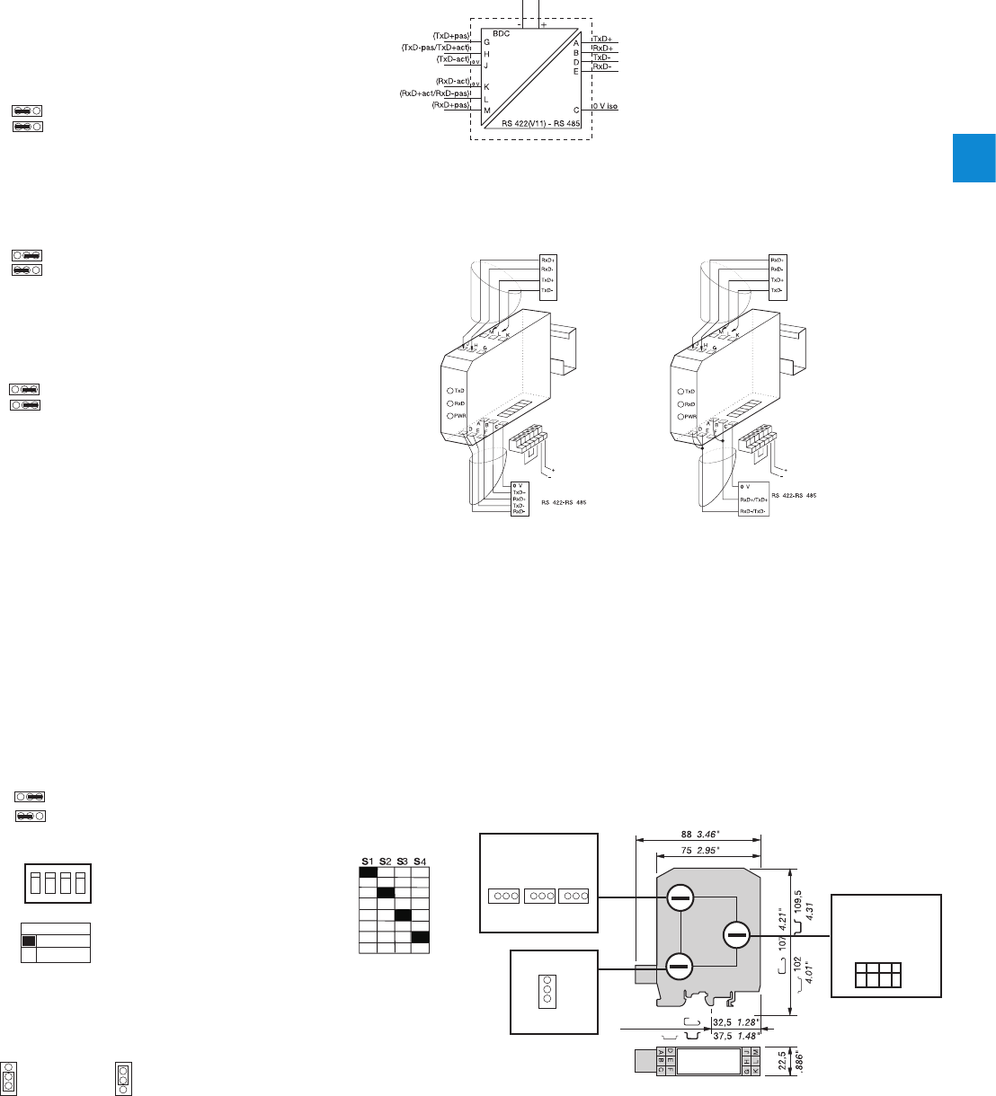
4
2CDC 110 004 C0210 | Catalog Electronic Products and Relays 2015 | ABB 4/44
Serial data converters
Technical information
Polarization
INT4
Rt
INT1 INT2 INT3
E R
Configuration
of the jumper
LINE AMPLIFIER CONFIGURATION
Configuration of amplifiers of the RS 422 - RS 485 (Receiver,
Transmitter) line provides greater flexibility of use.The various
configurations can be selected using the 2 jumpers (R INT2, E
INT1) located inside the box.
RS 485 LINK ON ONE PAIR
The Receiver and the Transmitter are activated alternately (never
at the same time) depending on the status of the Current Loop
Reception signal.
RS 485 LINK ON TWO PAIRS
Receiver permanently active. Transmitter controlled by the Current
Loop Reception signal.
RS 422 LINK ON TWO PAIRS
The Receiver and the Transmitter are both permanently active.
ILPH CL / RS 422 - 485
1SNA684232R2600
INT4
R
E
INT2
INT3
R
E
INT2 R ON
INT3 E
ON / OFF
R
E
INT2 R ON
INT3 E ON
Rt
Rt INT1
INT1
S1 S2 S3 S4
ON
OFF
INT4
on
off
Protection ON Protection OFF, used if power
supply at minimum value (21.6 V).
E ON/OFF Jumper E in position E ON/OFF
R ON/OFF Jumper R in position R ON/OFF
R ON Jumper R in position R ON
E ON/OFF Jumper E in position E ON/OFF
R ON Jumper R in position R ON
E ON Jumper E in position E ON
POLARIZATION OF THE RS 422 - RS 485 LINE
The line must always be polarized. The ILPH is used to polarize
the reception channel :
Connection by 1 wire P+ (J1.1) with 5 Viso (J1.4)
Connection by 1 wire P- (J1.2) with 0 Viso (J1.3)
ADAPTING THE RS 422 - RS 485 LINE
The line must always be adapted to the level of the reception
channel of each subscriber forming the end of the bus. The ILPH
is used to adapt the reception channel by setting the jumper Rt
correctly :
* Line adaptation, Rt = 120 Ω (Standard)
* No line adaptation, Rt = ∞
Transmission (TxD) active
Transmission(TxD) passive
Reception (RxD) active
Reception (RxD) passive
4...20 mA Signal
0...20 mA Signal
Signal logic 1 = 20 mA
Signal logic 0 = 20 mA
Legend
RS 422 - RS 485 2 wire serial link
CONNECTIONS
Example of connection with a CL
(current Loop) product, Transmission
(TxD) in active mode and Reception
(RxD) in passive mode.
Then, the ILPH must be configured
and connected Reception (RxD) in
passive mode and Transmission (TxD)
in active mode.
Note : For any other configuration, see
schematic diagram or front sticker of
the product.
Current Loop
Connector J1
24 V DC
power supply
Note :
The TxD channel of the RS 422
- RS 485 link must be polarized
independently too.
RS 422 - RS 485
4 wire serial link
Current Loop
Connector J1
24 V DC
power supply
POLARIZATION
The polarization can be configured using the INT4 jumper.
1 2 3 4
Configuration
of the micro-
switches
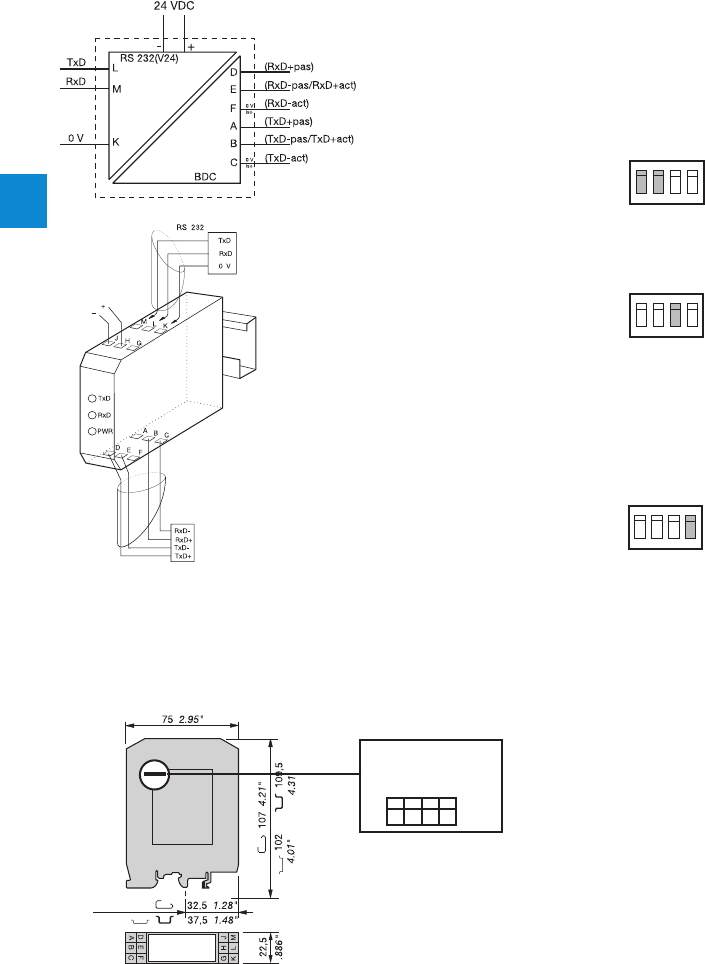
4
4/45 ABB | Catalog Electronic Products and Relays 2015 | 2CDC 110 004 C0210
Serial data converters
Technical information
ILPH RS 232 / CL
1SNA684202R0100
ON
OFF
CONFIGURATION
The various configurations can be selected using the 4 micro-switches located
inside the box.
OPERATING MODE ACTIVE OR PASSIVE
The Current Loop's Transmission and Reception can be independently in active
or passive mode.
Select operating mode using S1 and S2.
S1
Transmission(TxD) ON = Active / OFF = Passive
S2
Reception (RxD) ON = Active / OFF = Passive
S1 S2 S3 S4
ON
OFF
ON
OFF
SIGNAL LEVEL
Select signal level 4-20 mA or 0-20 mA. This selection is made using micro-
switch S3
S3 ON = 4-20 mA / OFF = 0-20 mA
Caution : It is not possible to select a 4-20 mA signal when the Reception is in
active mode.
LOGIC LEVEL
Configuration: Positive logic (0 Logic = 20 mA)
or negative logic (1 Logic = 20 mA)
using micro-switch S4
S4 ON = (1 = 20 mA) / OFF = (0 = 20 mA)
S1 S2 S3 S4
S1 S2 S3 S4
Current loop
24 V DC
power supply
CONNECTIONS
Example of connection with
a CL (Current Loop) product,
Transmission (TxD) in active
mode and Reception (RxD)
in passive mode. Then, the
ILPH must be configured and
connected Reception (RxD) in
passive mode and Transmission
(TxD) in active mode.
CAUTION: For any other
configuration, see schematic
diagram or front sticker of the
product.
ILPH RS 232 / CL
center of rail
S1 S2 S3 S4
Configuration of the
micro-switches

4
2CDC 110 004 C0210 | Catalog Electronic Products and Relays 2015 | ABB 4/46
Serial data converters
Technical data
Technical data
Data at Ta = 25 °C and rated values, unless otherwise indicated
ILPH RS 232 - 485 / Ethernet
Power supply 1
Voltage 10...34 V DC, 10...24 V AC
Voltage tolerance -10%, +10%
Consumption 2 W max
Connections coding screw removable connector 0 to 2.5 mm² (22-14 AWG)
Power supply 2
Voltage 10...34 V DC
Voltage tolerance -10%, +10%
Consumption 2 W max
Connections screw connector (AWG 20)
Serial link 1: RS 232 EIA RS 232
Overvoltage protection integrated
Baud rate / Transmission
distance max. 115.2 kbits/s / max. 15 m
Connections 2.5 mm² screw connector (AWG 20) or male SubD 9 points
Serial link 2: RS 485 EIA RS 485
Voltage integrated
Line polarization integrated
End line resistance integrated
Baud rate / Transmission distance max. 115.2 kbits/s / max. 1200 m
Connections coding screw removable connector 0 to 2.5 mm² (22-14 AWG)
Ethernet link
Overvoltage protection integrated
Baud rate / Transmission
distance 10-100 Mbits/s / max. 100 m without Hub or Switch with CAT5 cable
Connections RJ45 connector
Traffic indication
Voltage 1 yellow LED
Status of signal 3 green LED (RxD, TxD, LINK), 2 amber or green LED (Speed, Activity)
EMC behavior
Electrostatic discharge EN 61000-4-2
Radiated electromagnetic field EN 61000-4-3
Burst EN 61000-4-4
Surge EN 61000-4-5
Electromagnetic compatibility EN 55022
Other characteristics
Electrical isolation between serial link / power supply /
Ethernet link 750 VDC / 1500 VAC
Configuration of the operating mode using internal switches or/and software (TELNET or HYPERTERMINAL)
Operating temperature 0°C ... +60°C
Storage temperature -20°C ... +70°C
Mounting any required
DIN rail fixing (EN 50002) snap-on mounting
Wire size 2.5 mm² / stranded with ferrule, 4 mm² solid
Dimensions (WxDxH) 94 x 22.5 x 100 mm
Weight 120 g

4
4/47 ABB | Catalog Electronic Products and Relays 2015 | 2CDC 110 004 C0210
Serial data converters
Technical data
Technical data
Data at Ta = 25 °C and rated values, unless otherwise indicated
ILPH RS 232 / RS 422 - 485 (without isolation)
Power supply polarized
Voltage 24 V DC
Voltage tolerance 8.5...28 V DC
Supply current 100 mA max
Connections removable screw connectors (AWG 20)
Serial link 1: RS 232 EIA RS 232 C / CCITT V24 V28
Overvoltage protection integrated (transil 8 kV 1.2/50 µs)
Baud rate / Transmission
distance max. 38.4 kbits/s / max. 1200 m
Connections 2.5 mm² screw connectors (AWG 20)
Serial link 2: RS 422-485 EIA RS 485 and EIA RS 422 / CCITT V11
Overvoltage protection integrated (transil 8 kV 1.2/50 µs)
Baud rate / Transmission
distance max. 38.4 kbits / max. 1200 m
Connections 2.5 mm² screw connectors (AWG 20)
Traffic indication
Voltage 1 yellow LED
Connections 2 green LED (RxD, TxD)
EMC behavior
Electrostatic discharge EN 61000-4-2 level 3 6/8 kV
Radiated electromagnetic field EN 61000-4-3 level 310 V/m
Burst EN 61000-4-4 level 3 1 kV
Electromagnetic compatibility EN 55022 class B
Other characteristics
Electrical isolation between serial link / power supply /
Ethernet link no
Configuration of the operating
mode using internal jumper
Operating temperature 0°C ... +50°C
Storage temperature -25°C ... +80°C
Mounting any required
DIN rail fixing (EN 50002) snap-on mounting
Wire size 2.5 mm² / stranded with ferrule, 4 mm² solid
Dimensions (WxDxH) 88 x 22.5 x 100 mm
Weight 100 g

4
2CDC 110 004 C0210 | Catalog Electronic Products and Relays 2015 | ABB 4/48
Serial data converters
Technical data
Technical data
Data at Ta = 25 °C and rated values, unless otherwise indicated
ILPH RS 232 / RS 422 - 485 (isolated)
Power supply polarized
Voltage 24 V DC
Voltage tolerance 8.5...28 V DC
Supply current 100 mA max
Connections Removable screw connectors (Omniconnect)
Serial link 1: RS 232 EIA RS 232 C / CCITT V24 V28
Overvoltage protection integrated (transil 8 kV 1.2/50µs)
Baud rate / Transmission
distance max. 38.4 kbits/s / max. 15 m
Connections 2.5 mm² screw connectors (AWG 20)
Serial link 2: RS 422-485 EIA RS 485 and EIA RS 422 / CCITT V11
Overvoltage protection integrated (transil 8 kV 1.2/50 µs)
Baud rate / Transmission
distance max. 38.4 kbits / max. 1200 m
Connections 2.5 mm² screw connectors (AWG 20)
Traffic indication
Voltage 1 yellow LED
Connections 3 green LED (RxD, TxD and CTRL-IN)
EMC behavior
Electrostatic discharge EN 61000-4-2 level 3 6/8 kV
Radiated electromagnetic field EN 61000-4-3 level 310 V/m
Burst EN 61000-4-4 level 3 1 kV
Electromagnetic compatibility EN 55022 class B
Other characteristics
Electrical isolation between serial link / power supply /
Ethernet link 500 V DC
Configuration of the operating
mode using internal jumper
Operating temperature 0°C ... +50°C
Storage temperature -25°C ... +80°C
Mounting any required
DIN rail fixing (EN 50002) snap-on mounting
Wire size 2.5 mm² / stranded with ferrule, 4 mm² solid
Dimensions (WxDxH) 88 x 22.5 x 100 mm
Weight 100 g

4
4/49 ABB | Catalog Electronic Products and Relays 2015 | 2CDC 110 004 C0210
Serial data converters
Technical data
Technical data
Data at Ta = 25 °C and rated values, unless otherwise indicated
ILPH RS 232 / RS 422 - 485 (3 way electrical isolated)
Power supply Polarization for DC model
Voltage 24...48 V DC 115...230 V AC (50/60 Hz)
Voltage tolerance -15% ... +20% -15% ... +15%
Supply current 24 V DC<110 mA, 48 V DC<55 mA, 115 V AC<40 mA, 230 V DC<26 mA
Supply power ~ 3 W ~ 3 VA
Connections Removable screw connector (Omniconnect)
Serial link 1: RS 232 EA / TIA RS 232 new revision / CCITT V24 V28
Overvoltage protection integrated (transil 8 kV 1.2/50 μs)
Baud rate / Transmission
distance max. 19,2 kbits/s / max. 15 m / 2500 pF
Connections 2.5 mm² screw (AWG 20)
Serial link 2: RS 422-485 EIA / TIA RS 232 new revision / CCITT V24 V28
Overvoltage protection integrated (transil 8 kV 1.2/50μs)
Baud rate / Transmission
distance max. 19.2 kbits/s / max. 15 m
Connections 2.5 mm² screw (AWG 20)
Traffic indication
Voltage 1 yellow LED
Connections 4 green LED (RxD, RxC/D, TxD, TxC/D)
EMC behavior
Electrostatic discharge EN 61000-4-2 level 3 6/8 kV
Radiated electromagnetic field EN 61000-4-3 level 3 10 V/m
Burst EN 61000-4-4 level 3 1 kV
Electromagnetic compatibility EN 55022 class B
Other characteristics
Electrical isolation between RS 232 / Power supply /
RSS 422-RS 485 1,5 kV
Configuration of the operating
mode No
Operating temperature 0°C ... +50°C
Storage temperature -25°C ... +80°C
Mounting any required
DIN rail fixing (EN 50002) snap-on mounting
Wire size 2.5 mm² / stranded with ferrule, 4 mm² solid
Dimensions (WxDxH) 88 x 22,5 x 100 mm
Weight 100 g

4
2CDC 110 004 C0210 | Catalog Electronic Products and Relays 2015 | ABB 4/50
Serial data converters
Technical data
Technical data
Data at Ta = 25 °C and rated values, unless otherwise indicated
ILPH RS 232 / RS 232
Power supply DC model polarized
Voltage 24...48 V DC 115...230 V AC (50/60Hz)
Voltage tolerance -15%...+20% -15%...+15%
Supply current 24 V DC<155 mA;48 V DC<77 mA;110 V AC<40 mA;230 V DC<26 mA
Supply power ~ 3.15 W ~ 3.15 VA
Connections Removable screw connector (Omniconnect)
Interface 1: RS 232 EIA / TIA RS 232 new revision / CCITT V24 V28
Overvoltage protection integrated (transil 8 kV 1.2/50 µs)
Transmission capacity / Transmission distance max. 19.2 kbits/s / max. 15 m / 2500 pF
Connections 2.5 mm² screw (AWG 20)
Interface 2: RS 232 EIA / TIA RS 232 new revision / CCITT V24 V28
Overvoltage protection integrated (transil 8 kV 1.2/50 µs)
Transmission capacity / Transmission distance max. 19.2 kbits/s / max. 15 m
Connections 2.5 mm² screw (AWG 20)
Traffic indication
Voltage 1 yellow LED
Connections 4 green LED (RxD, RxC/D, TxD, TxC/D)
EMC behavior
Electrostatic discharge EN 61000-4-2 level 3 6/8 kV
Radiated electromagnetic field EN 61000-4-3 level 3 10 V/m
Burst EN 61000-4-4 level 3 1 kV
Electromagnetic compatibility EN 55022 class B
Other characteristics
Electrical isolation between serial link / power supply /
Ethernet link 1.5 kV
Configuration of the operating
mode No
Operating temperature 0°C ... +50°C
Storage temperature -25°C ... +80°C
Mounting any required
DIN rail fixing (EN 50002) snap-on mounting
Wire size 2.5 mm² / stranded with ferrule, 4 mm² solid
Dimensions (WxDxH) 88 x 22.5 x 100 mm
Weight 100 g

4
4/51 ABB | Catalog Electronic Products and Relays 2015 | 2CDC 110 004 C0210
Serial data converters
Technical data
Technical data
Data at Ta = 25 °C and rated values, unless otherwise indicated
ILPH RS 422 - 485 / RS 422 - 485
Power supply DC model polarized
Voltage 24 V DC
Voltage tolerance +/-15%
Supply current 120 mA max.
Connections Removable screw connector (Omniconnect)
Interface 1: RS 422-485 EIA / RS 485 and EIA RS 422 / CCITT V11
Overvoltage protection integrated (transil 8 kV 1.2/50 µs)
RS 485 data switching Time switching / Time delay transmission/reception 27 µs ...10 ms
Baud rate / Transmission
distance from 1.2 to 500 kbits/s / max. 1200 m up to 38.4 kbit/s
Connections 2.5 mm² screw (AWG 20)
Interface 2: RS 422-485 EIA / RS 485 and EIA RS 422 / CCITT V11
Overvoltage protection integrated (transil 8 kV 1.2/50 µs)
RS 485 data switching Time switching / Time delay transmission/reception 27 µs ...10 ms
Baud rate / Transmission
distance from 1.2 to 500 kbits/s / max. 1200 m up to 38.4 kbit/s
Connections 2.5 mm² screw (AWG 20)
Traffic indication
Voltage 1 yellow LED
Connections 2 green LED (RxD, TxD, )
EMC behavior
Electrostatic discharge EN 61000-4-2 level 3 6/8 kV
Radiated electromagnetic field EN 61000-4-3 level 3 10 V/m
Burst EN 61000-4-4 level 3 1 kV
Electromagnetic compatibility EN 55022 class B
Other characteristics
Electrical isolation between RS 232 / Power supply /
RSS 422-RS 485 500 V DC
Configuration of the operating
mode using internal DIP switches
Operating temperature 0°C ... +50°C
Storage temperature -25°C ... +80°C
Mounting any required
DIN rail fixing (EN 50002) snap-on mounting
Wire size 2.5 mm² / stranded with ferrule, 4 mm² solid
Dimensions (WxDxH) 88 x 22.5 x 100 mm
Weight 100 g

4
2CDC 110 004 C0210 | Catalog Electronic Products and Relays 2015 | ABB 4/52
Serial data converters
Technical data
Technical data
Data at Ta = 25 °C and rated values, unless otherwise indicated
ILPH RS 232 / FO
Power supplies
Supply voltage 24...42 V AC/DC (50/60 Hz) 110...240 V AC/DC (50/60 Hz)
Voltage tolerance -15% ... +10% -15% ... +10%
Connections Omniconnect pluggable connector
Interface 1: RS 232 CCITT V.24/DIN 66020- CCITT V.28 DIN 66259-EIA 232 E
Protection Integrated (transil 8 kV 1.2/50µs)
Max. speed / max. distance Max. 115.2 kbits/s / max. 15 m / 2500 pF
Connections Omniconnect pluggable connector
Fiber optic interface 2 DIN VDE 0888-1
Type of fiber / Connections Multimode fiber
Glass : ST connector; Plastic : FSMA screw connector
Wave length Glass : 820 nm; Plastic : 655 nm
Max. transmission power Glass : 50/125 µm : -14.4 db/m; Glass : 62.5/125 µm : -14 db/m; Plastic : 980/1000 µm : -8
db/m
Max. reception power Glass : -28 db/m; Plastic : -20 db/m
Max. speed Max. 115.2 kbits/s
Max. distance Glass : 50/125 µm : 3 km; Glass : 62.5/125 µm : 4 km; Plastic : 980/1000 µm : 40 m
Status indication
Power supply / Data exchange 1 green LED / 2 green LEDs (RxD, TxD)
EMC behavior
Electrostatic discharge EN 61000-4-2 Level 3 6/8 kV
Radiated electromagnetic field EN 61000-4-3 Level 3 10 V/m
Burst EN 61000-4-4 Level 3 1 kV
Electromagnetic compatibility EN 55022 Class B
Other characteristics
Electrical isolation input / power supply / output 2.5 kV
Operating temperature -20°C ... +60°C
Storage temperature -40°C ... +85°C
Mounting Onto DIN Rail (EN 50002)
Connections 14 AWG (2.5 mm²) fine stranded / 12 AWG (4 mm²) rigid
Dimensions (WxDxH) 105 x 22.5 x 112 mm / 4.13 x 0.89 x 4.41"
Weight 150 g / 0.33 lb

4
4/53 ABB | Catalog Electronic Products and Relays 2015 | 2CDC 110 004 C0210
Serial data converters
Technical data
Technical data
Data at Ta = 25 °C and rated values, unless otherwise indicated
ILPH RS 485 / FO
Power supplies
Supply voltage 24...42 V AC/DC (50/60 Hz) 110...240 V AC/DC (50/60 Hz)
Voltage tolerance -15% ... +10% -15% ... +10%
Connections Omniconnect pluggable connector
Interface 1: RS 232 ISO / IEC 8482 / DIN 66 259-4; EIA 485
Protection Integrated (transil 8 kV 1.2/50µs)
Max. speed / max. distance Max. 1.5 Mbits/s / max. 1200 m (38.4 kbit/s)
Connections Omniconnect pluggable connector
Fiber optic interface 2 DIN VDE 0888-1
Type of fiber / Connections Multimode fiber
Glass : ST connector; Plastic : FSMA screw connector
Wave length Glass : 820 nm; Plastic : 655 nm
Max. transmission power Glass : 50/125 µm : -14.4 db/m; Glass : 62.5/125 µm : -14 db/m; Plastic : 980/1000 µm : -8
db/m
Max. reception power Glass : -28 db/m; Plastic : -20 db/m
Max. speed Max. 1.5 Mbits/s
Max. distance Glass : 50/125 µm : 3 km; Glass : 62.5/125 µm : 4 km; Plastic : 980/1000 µm : 40 m
Status indication
Power supply / Data exchange 1 green LED / 2 green LEDs (RxD, TxD)
EMC behavior
Electrostatic discharge EN 61000-4-2 Level 3 6/8 kV
Radiated electromagnetic field EN 61000-4-3 Level 3 10 V/m
Burst EN 61000-4-4 Level 3 1 kV
Electromagnetic compatibility EN 55022 Class B
Other characteristics
Electrical isolation input / power supply / output 2.5 kV
Operating temperature -20°C ... +60°C
Storage temperature -40°C ... +85°C
Mounting Onto DIN Rail
Connections 14 AWG (2.5mm²) / fine stranded, 12 AWG (4 mm²) rigid
Dimensions (WxDxH) 105 x 22.5 x 112 mm / 4.13 x 0.89 x 4.41"
Weight 150 g / 0.33 lb

4
2CDC 110 004 C0210 | Catalog Electronic Products and Relays 2015 | ABB 4/54
Serial data converters
Technical data
Technical data
Data at Ta = 25 °C and rated values, unless otherwise indicated
ILPH RS 422 - 485 (for current loop)
Power supply DC model polarized
Voltage 24 V DC
Voltage tolerance +/-10%
Supply current 120 mA max.
Connections Removable screw connector (Omniconnect)
Interface 1: Current loop active/passive 0...20 mA / 4...20 mA, mode is settable
Logic level 0 = 20 mA or 1 = 20 mA, settable
Baud rate / Transmission
distance max. 38.4 kbit/s / max. 1200 m
Connections 2.5 mm² screw (AWG 20)
Serial link 2: RS 422/485 EIA RS 485 and EIA RS 422 / CCITT V 11
Overvoltage protection integrated (transil 8 kV 1.2/50 µs)
Baud rate / Transmission
distance max. 38.4 kbit/s / max. 1200 m
Connections 2.5 mm² screw (AWG 20)
Traffic indication
Voltage 1 yellow LED
Status of signal 2 green LED (RxD, TxD)
EMC behavior
Electrostatic discharge EN 61000-4-2 level 2 4/4 kV
Radiated electromagnetic field EN 61000-4-3 level 3 10 V/m
Burst EN 61000-4-4 level 1 0.5 kV
Electromagnetic compatibility EN 55022 class B
Other characteristics
Electrical isolation between input / output and power
supply / output depending on Current Loop (active/passive); 500 V DC (active) / 2000 V DC (passive)
RS 422-485 power supply 500 V DC
Configuration of the operating
mode using internal DIP switches
Operating temperature 0°C ... +50°C
Storage temperature -25°C ... +80°C
Mounting any required
DIN rail fixing (EN 50002) snap-on mounting
Wire size 2.5 mm² / stranded with ferrule, 4 mm² solid
Dimensions (WxDxH) 88 x 22.5 x 100 mm
Weight 100 g

4
4/55 ABB | Catalog Electronic Products and Relays 2015 | 2CDC 110 004 C0210
Serial data converters
Technical data
Technical data
Data at Ta = 25 °C and rated values, unless otherwise indicated
ILPH RS 232 / CL
Power supply DC model polarized
Voltage 24 V DC
Voltage tolerance +/-10%
Supply current 120 mA max.
Connections Removable screw connector (Omniconnect)
Serial link 2: RS 232 EIA RS 232 C / CCITT V 24 V 28
Logic level integrated (transil 8 kV 1.2/50 µs)
Baud rate / Transmission
distance max. 38.4 kbit/s / max. 15 m
Connections 2.5 mm² screw (AWG 20)
BdC serial link 2: RS 422/485 active/passive 0...20 mA / 4...20 mA mode settable
Overvoltage protection 0=20 mA or 1=20 mA settable
Baud rate / Transmission
distance max. 38.4 kbit/s / max. 1200 m
Connections 2.5 mm² screw (AWG 20)
Traffic indication
Voltage 1 yellow LED
Status signal 2 green LED (RxD, TxD)
EMC behavior
Electrostatic discharge EN 61000-4-2 level 3 6/8 kV
Radiated electromagnetic field EN 61000-4-3 level 3 10 V/m
Burst EN 61000-4-4 level 3 1 kV
Electromagnetic compatibility EN 55022 class B
Other characteristics
Electrical isolation between Current loop / RS 232 depending on current loop (active/passive) 500 V DC (active) / 2000 V DC (passive)
Electrical isolation between Current loop / power
supply 500 V DC (active) / 2000 V DC (passive)
Configuration of the operating
mode using internal DIP switches
Operating temperature 0°C ... +50°C
Storage temperature -25°C ... +80°C
Mounting any required
DIN rail fixing (EN 50002) snap-on mounting
Wire size 2.5 mm² / stranded with ferrule, 4 mm² solid
Dimensions (WxDxH) 88 x 22.5 x 100 mm
Weight 100 g

2CDC 110 004 C0210 | Catalog Electronic Products and Relays 2015 | ABB 4/56
4
Serial data converters
Notes
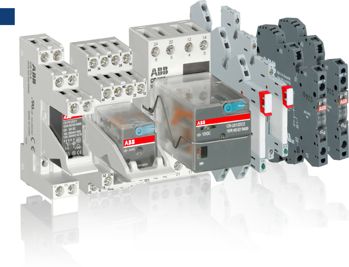
5
5/1 ABB | Catalog Electronic Products and Relays 2015 | 2CDC 110 004 C0210
Interface relays and optocouplers
Product group picture

5
2CDC 110 004 C0210 | Catalog Electronic Products and Relays 2015 | ABB 5/2
Interface relays and optocouplers
Table of contents
Interface Relays and Optocouplers
Pluggable interface relays ................................................................. 5/3
Table of contents 5/4
Benefits and advantages 5/5
Approvals and marks 5/7
Ordering details - CR-S range 5/8
Ordering details - CR-P range 5/9
Ordering details - CR-M range 5/10
Ordering details CR-P/M functional modules 5/13
Ordering details - CR-U range 5/14
Ordering details - CR-U accessories 5/15
Technical data - CR-P, CR-M, CR-U 5/16
Technical data, load limit curves - CR-P, CR-M, CR-U 5/18
Technical data - Sockets for CR-P and CR-M 5/19
Technical data - Sockets for CR-U 5/20
Technical data - CR-S range 5/21
Technical data - CR-S range sockets 5/22
Load limit curves 5/23
Connection diagrams 5/24
Dimensional drawings 5/25
Interface relays and optocouplers R600 range ................................. 5/27
Table of contents 5/28
Benefits and advantages 5/29
Type designators 5/30
Interface relays R600 range ............................................................. 5/31
Benefits and advantages 5/31
Selection 5/33
Ordering details 5/35
Connection diagrams 5/37
Technical data 5/38
General technical data 5/43
Dimensional drawings, Load limit curves 5/44
Optocouplers R600 range ............................................................... 5/45
Selection 5/45
Ordering details 5/47
Connection diagrams 5/48
Technical data 5/49
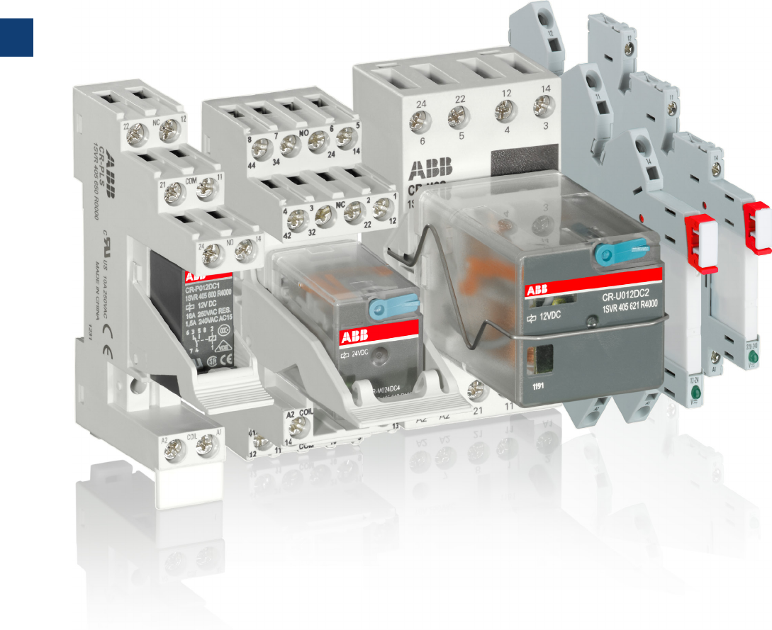
5
5/3 ABB | Catalog Electronic Products and Relays 2015 | 2CDC 110 004 C0210
Pluggable interface relays
Product group picture

5
2CDC 110 004 C0210 | Catalog Electronic Products and Relays 2015 | ABB 5/4
Pluggable interface relays
Table of contents
Pluggable interface relays
Benefits and advantages 5/5
Approvals and marks 5/7
Ordering details - CR-S range 5/8
Ordering details - CR-P range 5/9
Ordering details - CR-M range 5/10
Ordering details CR-P/M functional modules 5/13
Ordering details - CR-U range 5/14
Ordering details - CR-U accessories 5/15
Technical data - CR-P, CR-M, CR-U 5/16
Technical data, load limit curves - CR-P, CR-M, CR-U 5/18
Technical data - Sockets for CR-P and CR-M 5/19
Technical data - Sockets for CR-U 5/20
Technical data - CR-S range 5/21
Technical data - CR-S range sockets 5/22
Load limit curves 5/23
Connection diagrams 5/24
Dimensional drawings 5/25
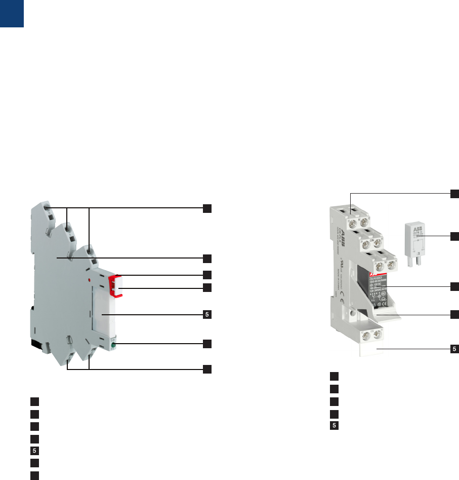
5
5/5 ABB | Catalog Electronic Products and Relays 2015 | 2CDC 110 004 C0210
Pluggable pcb relays CR-P
– 9 different coil voltages
– DC versions: 12 V, 24 V, 48 V, 110 V
– AC versions: 24 V, 48 V, 110 V, 120 V, 230 V
– Output contacts:
– 1 c/o contact (16 A) or
– 2 c/o contacts (8 A)
optionally equipped with gold contacts
– Logical or standard sockets
– Cadmium-free contact material
– Width of socket: 15,5 mm
– Pluggable function modules
– Reverse polarity protection/Freewheeling diode
– LED indication
– RC elements
– Overvoltage protection
Slim relays CR-S
– Standard slim relays (5 mm), sockets (6.2 mm) and acces-
sories
– Combination of 9 different rated control supply voltages
possible:
– DC versions: 5 V, 12 V, 24 V
– AC/DC versions: 12 V, 24 V, 48 V, 60 V, 110 V, 230 V
– Output: 1 c/o (SPDT) contacts (6 A), standard and goldpla-
ted contacts
– Cadmium-free contact material
– All sockets with LED
– Screw and spring connection terminals
– Jumper bar (red, black, blue), marker and separator availa-
ble as accessories
Pluggable interface relays
Benefits and advantages
1 Socket
2 Pluggable function module
3 Interface relay
4 Holder
4 Marker label
1 Output contacts
2 Socket
3 Relay holder
4 Marker
4 Interface relay
6 LED green: Control supply voltage applied
7 Control supply voltage
1
2
3
4
4
4
3
2
1
4
6
7
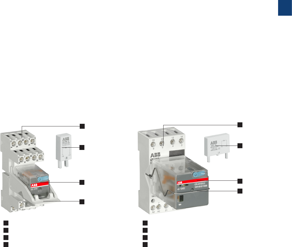
5
2CDC 110 004 C0210 | Catalog Electronic Products and Relays 2015 | ABB 5/6
Pluggable universal relays CR-U
– 12 different coil voltages
– DC versions: 12 V, 24 V, 48 V, 110 V, 125 V, 220 V
– AC versions: 24 V, 48 V, 60 V, 110 V, 120 V, 230 V
– Output contacts
– 2 c/o contacts (10 A) or
– 3 c/o contacts (10 A)
– Integrated test button for manual
actuation and locking of the output
contacts (blue = DC, orange = AC) that can be removed if
necessary
– With or without integrated LED
– Cadmium-free contact material
– Width on socket: 38 mm
– Pluggable function modules
– Reverse polarity protection/Freewheeling diode
– LED indication
– RC elements
– Overvoltage protection
– Multifunction time module
Pluggable miniature relays CR-M
– 2 different coil voltages
– DC versions: 12 V, 24 V, 48 V, 60 V, 110 V, 125V, 220 V
– AC versions: 24 V, 48 V, 110 V, 120 V, 230 V
– Output contacts
– 2 c/o contacts (12 A) or
– 3 c/o contacts (10 A) or
– 4 c/o contacts (6 A)
optionally equipped with gold contacts, LED and free
wheeling diode
– Integrated test button for manual actuation and locking of
the output contacts (blue = DC, orange = AC) that can be
removed if necessary
– With or without integrated LED
– Logical or standard sockets
– Cadmium-free contact material
– Width on socket: 27 mm
– Pluggable function modules
– Reverse polarity protection/Freewheeling diode
– LED indication
– RC elements
– Overvoltage protection
Pluggable interface relays
Benefits and advantages
1 Socket
2 Pluggable function module
3 Interface relay
4 Holder
1 Socket
2 Pluggable function module
3 Interface relay
4 Holder
11
22
33
4
4
5
5/7 ABB | Catalog Electronic Products and Relays 2015 | 2CDC 110 004 C0210
Approvals and marks
J existing
j pending Relays Sockets Modules
Approvals
CR-S
CR-P
CR-M
CR-U
CR-S
sockets
CR-PLS
CR-PSS
CR-PLC
CR-M..L..
CR-M..SS
CR-M..SF
CR-U..S
CR-U..E
CR-U..SM
CR-P/M
CR-U
GANSI/UL 508 J J J J J J J J J J J 6)
cGCAN/CSA C22.2 No.14 J J J J J1) J J2) J J3) J J J 6)
FCAN/CSA C22.2 No.14 J J J J J
JVDE J 8) J J 4) JJ 8)
REAC J J J J J J J J J J J J J
PLloyds Register J 5) J
ECCC J J J
CQC J
LRMRS JJ 7) J 7) J J J J J J J
Marks
aCE J J J J J J J J J J J J J
1) except CR-PLSx
2) except CR-M...LC
3) except CR-U3E
4) except 125 V DC devices
5) only devices with 4 c/o contacts
6) except CR-U61D, CR-U61DV
7) except 60 V and 125 V devices
8) only relays and sockets with screw terminals
Kinds of sockets
Standard sockets - Position of connecting terminals:
Coil connection (A1-A2) on lower socket side, contact
connections (n/o and n/c contacts) on the lower and upper
socket side.
Logical sockets - Position of connecting terminals:
Coil connection (A1-A2) on lower socket side, all contact
connections (common contacts, n/o and n/c contacts) on
upper socket side.
Details see connection diagrams
Kind of connecting terminals
Screw type Spring type Fork type
Pluggable interface relays
Approvals and marks
5
2CDC 110 004 C0210 | Catalog Electronic Products and Relays 2015 | ABB 5/8
Pluggable interface relays
Ordering details - CR-S range
Description
The pluggable interface relays of the CR-S Range are used for electrical isolation, amplification
and signal matching between the electronic controlling, e.g. PLC, iPC or field bus systems
and the sensor / actuator level. The CR-S Range combines the flexibility of a modular system
and the ability of switching high currents on a small footprint thus can be used in applications
where space saving is essential.
Ordering details - CR-S range pluggable interface relays
Rated control
supply voltage
Outputs Contact
ratings
Type Order code Price Pkg
qty
Weight
(1 pce)
kg (lb)
5 V DC 1 c/o
(SPDT)
standard
contacts
250 V, 6 A
CR-S005VDC1R 1SVR405501R1010
10 0.005
(0.011)
12 V DC CR-S012VDC1R 1SVR405501R2010
24 V DC CR-S024VDC1R 1SVR405501R3010
48 V DC CR-S048VDC1R 1SVR405501R4010
60 V DC CR-S060VDC1R 1SVR405501R5010
5 V DC 1 c/o
(SPDT)
gold plated
contacts
12 V,
250 mA
(3W)1)
CR-S005VDC1RG 1SVR405501R1020
10 0.005
(0.011)
12 V DC CR-S012VDC1RG 1SVR405501R2020
24 V DC CR-S024VDC1RG 1SVR405501R3020
48 V DC CR-S048VDC1RG 1SVR405501R4020
60 V DC CR-S060VDC1RG 1SVR405501R5020
Ordering details - CR-S range complete interface relays (relay + socket)
Rated control
supply voltage
Outputs Contact
ratings
Type Order code Price Pkg
qty
Weight
(1 pce)
kg (lb)
24 V AC/DC
1 c/o
(SPDT)
standard
contacts
250 V,
6 A
CR-S024VADC1CRS 1SVR4 0 5541R 3110
10 0.03
(0.066)
CR-S024VADC1CRZ 1SVR405541R3210
110 V AC/DC CR-S110VADC1CRS 1SV R 405541R 6110
CR-S110VADC1CRZ 1SVR405541R6210
230 V AC/DC CR-S230VADC1CRS 1SVR4 0 5541R7110
CR-S230VADC1CRZ 1SVR405541R7210
24 V AC/DC
1 c/o
(SPDT)
gold plated
contacts
12 V,
250 mA
(3W)1)
CR-S024VADC1CRGS 1SVR405541R3120
10 0.03
(0.066)
CR-S024VADC1CRGZ 1SVR405541R3220
110 V AC/DC CR-S110VADC1CRGS 1SVR405541R6120
CR-S110VADC1CRGZ 1SVR405541R6220
230 V AC/DC CR-S230VADC1CRGS 1SVR405541R7120
CR-S230VADC1CRGZ 1SVR405541R7220
1) If specified maximum values exceeded, the gold plating is destroyed. The maximum values of the standard contacts are then
valid.
Ordering details - CR-S range sockets
Rated control
supply voltage
Connection type Type Order code Price Pkg
qty
Weight
(1 pce)
kg (lb)
6-24 V DC Screw CR-S006/024VDC1SS 1SVR4 0 5521R110 0
10 0.025
(0.055)
Spring CR-S006/024VDC1SZ 1SVR405521R1200
12-24 V AC/DC Screw CR-S012/024VADC1SS 1SVR405521R3100
Spring CR-S012/024VADC1SZ 1SVR405521R3200
48-60
V AC/DC
Screw CR-S048/060VADC1SS 1SVR405521R5100
Spring CR-S048/060VADC1SZ 1SVR405521R5200
110 -125
V AC/DC
Screw C R-S110/125 VADC1SS 1SVR405521R6100
Spring CR- S110/125VA D C1S Z 1SVR405521R6200
220-240
V AC/DC
Screw CR-S220/240VADC1SS 1SVR405521R7100
Spring CR-S220/240VADC1SZ 1SVR405521R7200
Ordering details - CR-S range accessories
Version Type Order code Price Pkg
qty
Weight
(1 pce)
kg (lb)
Jumper bar 20 pole, blue color CR-SJB20-BLUE 1SVR405598R0700
10 0.008
(0.018)
Jumper bar 20 pole, red color CR-SJB20-RED 1SVR405598R0800
Jumper bar 20 pole, black color CR-SJB20-BLACK 1SVR405598R0900
Marker block CR-SM 1SNB041391R0610 10
0.0036
(0.0079)
Separator CR-SSEP 1SVR405599R0000 10 0.012
(0.026)
CR-S
2CDC 291 005 F0014
RS, SS = screw connection type
RZ, SZ = spring connection type
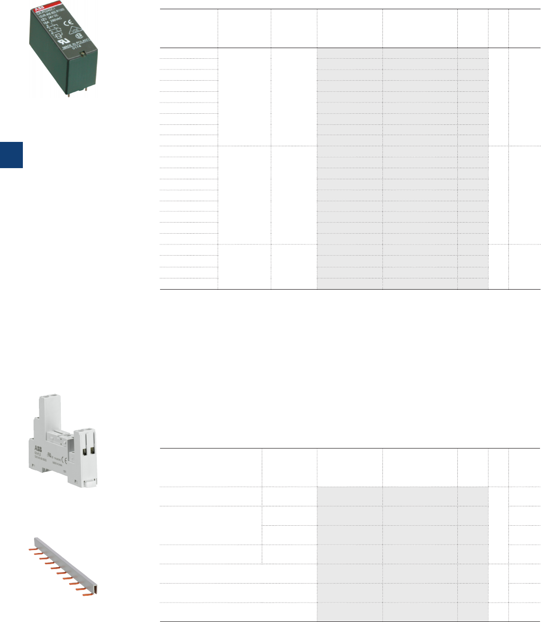
5
5/9 ABB | Catalog Electronic Products and Relays 2015 | 2CDC 110 004 C0210
Pluggable interface relays
Ordering details - CR-P range
Ordering details - CR-P range
Rated control
supply voltage
Outputs Contact
ratings
Type Order code Price Pkg
qty
Weight
(1 pce)
kg (lb)
12 V DC
1 c/o (SPDT) 250 V, 16 A
CR-P012DC1 1SVR405600R4000
10 0.014
(0.031)
24 V DC CR-P024DC1 1SVR405600R1000
48 V DC CR-P048DC1 1SVR405600R6000
110 V DC CR - P110DC1 1SVR405600R8000
24 V AC CR-P024AC1 1SVR405600R0000
48 V AC CR-P048AC1 1SVR405600R5000
110 V AC CR-P110AC1 1SVR405600R7000
120 V AC CR-P120AC1 1SVR405600R2000
230 V AC CR-P230AC1 1SVR405600R3000
12 V DC
2 c/o (SPDT) 250 V, 8 A
CR-P012DC2 1SVR405601R4000
10 0.014
(0.031)
24 V DC CR-P024DC2 1SVR405601R1000
48 V DC CR-P048DC2 1SVR405601R6000
110 V DC CR - P110DC2 1SVR405601R8000
24 V AC CR-P024AC2 1SVR405601R0000
48 V AC CR-P048AC2 1SVR405601R5000
110 V AC CR-P110AC2 1SVR405601R7000
120 V AC CR-P120AC2 1SVR405601R2000
230 V AC CR-P230AC2 1SVR405601R3000
24 V DC
2 c/o (SPDT)
gold contact 250 V, 8 A
CR-P024DC2 1SVR405606R1000
10 0.014
(0.031)
24 V AC CR-P024AC2G 1SVR405606R0000
110 V AC CR-P110AC2G 1SVR405606R7000
230 V AC CR-P230AC2G 1SVR405606R3000
Ordering details - Accessories
Version Connection
terminal
Type Order code Price Pkg
qty
Weight
(1 pce)
kg (lb)
Logical socket with protecti-
ve separation screw CR-PLS 1SVR405650R0000
10
0.045
(0.099)
Logical socket
screw CR-PLSx 1SVR405650R0100 0.043
(0.095)
spring CR-PLC 1SVR405650R0200 0.042
(0.093)
Standard socket screw CR-PSS 1SVR405650R1000 0.038
(0.084)
Plastic holder for socket CR-PH 1SVR405659R0000
10
0.002
(0.004)
Jumper bar for sockets with screw connec-
tion CR-PJ 1SVR405658R5000 0.018
(0.040)
Marker CR-PM 1SVR405658R0000 10 0.0002
(0.0004)
2CDC 291 004 F0007 2CDC 291 006 F0011
CR-PLS
CR-P
CR-PJ
2CDC 291 045 F0004
5
2CDC 110 004 C0210 | Catalog Electronic Products and Relays 2015 | ABB 5/10
Pluggable interface relays
Ordering details - CR-M range
Ordering details - CR-M range without LED
Rated control
supply voltage
Outputs Contact
ratings
Type Order code Price Pkg
qty
Weight
(1 pce)
kg (lb)
12 V DC
2 c/o (SPDT) 250 V, 12 A
CR-M012DC2 1SVR405611R4000
10 0.033
(0.073)
24 V DC CR-M024DC2 1SVR405611R1000
48 V DC CR-M048DC2 1SVR405611R6000
60 V DC CR-M060DC2 1SVR405611R4200
110 V DC CR-M110DC2 1SVR405611R8000
125 V DC CR-M125DC2 1SVR4 0 5611R82 0 0
220 V DC CR-M220DC2 1SVR405611R9000
24 V AC CR-M024AC2 1SVR405611R0000
48 V AC CR-M048AC2 1SVR405611R5000
110 V AC CR - M110AC2 1SVR405611R7000
120 V AC CR-M120AC2 1SVR405611R2000
230 V AC CR-M230AC2 1SVR405611R3000
12 V DC
3 c/o (SPDT) 250 V, 10 A
CR-M012DC3 1SVR405612R4000
10 0.033
(0.073)
24 V DC CR-M024DC3 1SVR405612R1000
48 V DC CR-M048DC3 1SVR405612R6000
60 V DC CR-M060DC3 1SVR405612R4200
110 V DC CR-M110DC3 1SVR405612R8000
125 V DC CR-M125DC3 1SVR405612R8200
220 V DC CR-M220DC3 1SVR405612R9000
24 V AC CR-M024AC3 1SVR405612R0000
48 V AC CR-M048AC3 1SVR405612R5000
60 V AC CR-M060AC3 1SVR405612R5200
110 V AC CR-M110AC3 1SVR405612R7000
120 V AC CR-M120AC3 1SVR405612R2000
230 V AC CR-M230AC3 1SVR405612R3000
12 V DC
4 c/o (SPDT) 250 V, 6 A
CR-M012DC4 1SVR405613R4000
10 0.033
(0.073)
24 V DC CR-M024DC4 1SVR405613R1000
48 V DC CR-M048DC4 1SVR405613R6000
60 V DC CR-M060DC4 1SVR405613R4200
110 V DC CR-M110DC4 1SVR405613R8000
125 V DC CR-M125DC4 1SVR405613R8200
220 V DC CR-M220DC4 1SVR405613R9000
24 V AC CR-M024AC4 1SVR405613R0000
48 V AC CR-M048AC4 1SVR405613R5000
110 V AC CR - M110AC 4 1SVR405613R7000
120 V AC CR-M120AC4 1SVR405613R2000
230 V AC CR-M230AC4 1SVR405613R3000
CR-M
2CDC 291 002 F0015
5
5/11 ABB | Catalog Electronic Products and Relays 2015 | 2CDC 110 004 C0210
Pluggable interface relays
Ordering details - CR-M range
Ordering details - CR-M range with LED
Rated control
supply voltage
Outputs Contact
ratings
Type Order code Price Pkg
qty
Weight
(1 pce)
kg (lb)
12 V DC
2 c/o (SPDT) 250 V,
12 A
CR-M012DC2L 1SVR405611R4100
10 0.033
(0.073)
24 V DC CR-M024DC2L 1SVR40 5 611R110 0
48 V DC CR-M048DC2L 1SVR405611R6100
60 V DC CR-M060DC2L 1SVR405611R4300
110 V DC CR-M110DC2L 1S VR40 5 611R 810 0
125 V DC CR-M125DC2L 1SV R405611R 8 3 0 0
220 V DC CR-M220DC2L 1SVR405611R9100
24 V AC CR-M024AC2L 1SVR405611R0100
48 V AC CR-M048AC2L 1S VR40 5 611R 510 0
110 V AC CR- M110AC2L 1SVR4 0 5611R710 0
120 V AC CR-M120AC2L 1SVR4 0 5611R210 0
230 V AC CR-M230AC2L 1SVR4 0 5611R310 0
12 V DC
3 c/o (SPDT) 250 V,
10 A
CR-M012DC3L 1SVR405612R4100
10 0.033
(0.073)
24 V DC CR-M024DC3L 1S VR40 5 612R110 0
48 V DC CR-M048DC3L 1SVR405612R6100
60 V DC CR-M060DC3L 1SVR405612R4300
110 V DC CR-M110DC3L 1SVR405612R8100
125 V DC CR-M125DC3L 1SVR405612R8300
220 V DC CR-M220DC3L 1SVR405612R9100
24 V AC CR-M024AC3L 1SVR405612R0100
48 V AC CR-M048AC3L 1SVR405612R5100
110 V AC CR-M110AC3L 1SVR405612R7100
120 V AC CR-M120AC3L 1SVR405612R2100
230 V AC CR-M230AC3L 1SVR405612R3100
12 V DC
4 c/o (SPDT) 250 V, 6 A
CR-M012DC4L 1SVR405613R4100
10 0.033
(0.073)
24 V DC CR-M024DC4L 1SVR4 05613R110 0
48 V DC CR-M048DC4L 1SVR405613R6100
60 V DC CR-M060DC4L 1SVR405613R4300
110 V DC CR-M110DC4L 1SVR405613R8100
125 V DC CR-M125DC4L 1SVR405613R8300
220 V DC CR-M220DC4L 1SVR405613R9100
24 V AC CR-M024AC4L 1SVR405613R0100
48 V AC CR-M048AC4L 1SVR405613R5100
110 V AC CR- M110AC 4L 1SVR405613R7100
120 V AC CR-M120AC4L 1SVR405613R2100
230 V AC CR-M230AC4L 1SVR405613R3100
Ordering details - CR-M range with LED and free-wheeling diode
Rated control
supply voltage
Outputs Contact
ratings
Type Order code Price Pkg
qty
Weight
(1 pce)
kg (lb)
24 V DC 4 c/o (SPDT) 250 V, 6 A CR-M024DC4LD 1SVR405614R1100 10 0.033
(0.073)
Ordering details - CR-M range with gold contacts
Rated control
supply voltage
Outputs Contact
ratings
Type Order code Price Pkg
qty
Weight
(1 pce)
kg (lb)
24 V DC
4 c/o (SPDT),
gold contacts 250 V, 6 A
CR-M024DC4G 1SVR405618R1000
10 0.033
(0.073)
24 V AC CR-M024AC4G 1SVR405618R0000
110 V AC CR- M110AC 4G 1SVR405618R7000
230 V AC CR-M230AC4G 1SVR405618R3000
CR-M
2CDC 291 002 F0015
5
2CDC 110 004 C0210 | Catalog Electronic Products and Relays 2015 | ABB 5/12
Pluggable interface relays
Ordering details - CR-M range
Rated control
supply voltage
Outputs Contact
ratings
Type Order code Price Pkg
qty
Weight
(1 pce)
kg (lb)
12 V DC
4 c/o (SPDT)
with gold
contacts and
LED
250 V /
6 A
CR-M012DC4LG 1SVR405618R4100
10 0.033
(0.073)
24 V DC CR-M024DC4LG 1SV R405618 R110 0
48 V DC CR-M048DC4LG 1SVR405618R6100
60 V DC CR-M060DC4LG 1SVR405618R4300
110 V DC CR-M110DC4LG 1SVR405618R8100
125 V DC CR-M125DC4LG 1SVR405618R8300
220 V DC CR-M220DC4LG 1SVR405618R9100
24 V AC CR-M024AC4LG 1SVR405618R0100
10 0.033
(0.073)
48 V AC CR-M048AC4LG 1SVR405618R5100
110 V AC CR- M110AC 4LG 1SVR405618R7100
120 V AC CR-M120AC4LG 1SVR405618R2100
230 V AC CR-M230AC4LG 1SVR405618R3100
Rated control
supply voltage
Outputs Contact
ratings
Type Order code Price Pkg
qty
Weight
(1 pce)
kg (lb)
12 V DC 4 c/o (SPDT)
with gold
contacts,
LED and
free-wheeling
diode
CR-M012DC4LDG 1SVR405618R4400
10 0.033
(0.073)
24 V DC CR-M024DC4LDG 1SVR405618R1400
Ordering details - Accessories
Version Connection
terminal
Type Order code Price Pkg
qty
Weight
(1 pce)
kg (lb)
Logical socket for 2 c/o
screw
CR-M2LS 1SV R4056 51R110 0
10
0.055
(0.121)
Logical socket for 3 c/o CR-M3LS 1SVR405651R2100 0.062
(0.137)
Logical socket for 2/4 c/o CR-M4LS 1SVR405651R3100 0.066
(0.14 6)
Logical socket for 2 c/o
spring
CR-M2LC 1SVR405651R1200
10
0.065
(0.14 3)
Logical socket for 2/4 c/o CR-M4LC 1SVR405651R3200 0.066
(0.14 6)
Standard socket for 2 c/o
screw
CR-M2SS 1SVR405651R1000
10
0.066
(0.14 6)
Standard socket for 3 c/o CR-M3SS 1SVR405651R2000 0.068
(0.150)
Standard socket for 2/4 c/o CR-M4SS 1SVR405651R3000 0.070
(0.154)
Standard socket for 2 c/o
fork type
CR-M2SF 1SVR405651R1300
10
0.040
(0.088)
Standard socket for 2/4 c/o CR-M4SF 1SVR405651R3300 0.048
(0.10 6)
Plastic holder CR-MH 1SVR405659R1000 10 0.003
(0.007)
Metal holder CR-MH1 1SVR405659R1100 10 0.0005
(0.001)
Jumper bar for sockets with
screw connection CR-MJ 1SVR405658R6000 10 0.029
(0.064)
Marker CR-MM 1SVR405658R1000 10 0.0005
(0.001)
2CDC 291 009 F00112CDC 291 005 F0007
CR-M4SS
CR-MJ
Ordering details – CR-M range with gold contacts and LED
Ordering details – CR-M range with gold contacts, LED and free-wheeling diode
CR-M
2CDC 291 002 F0015
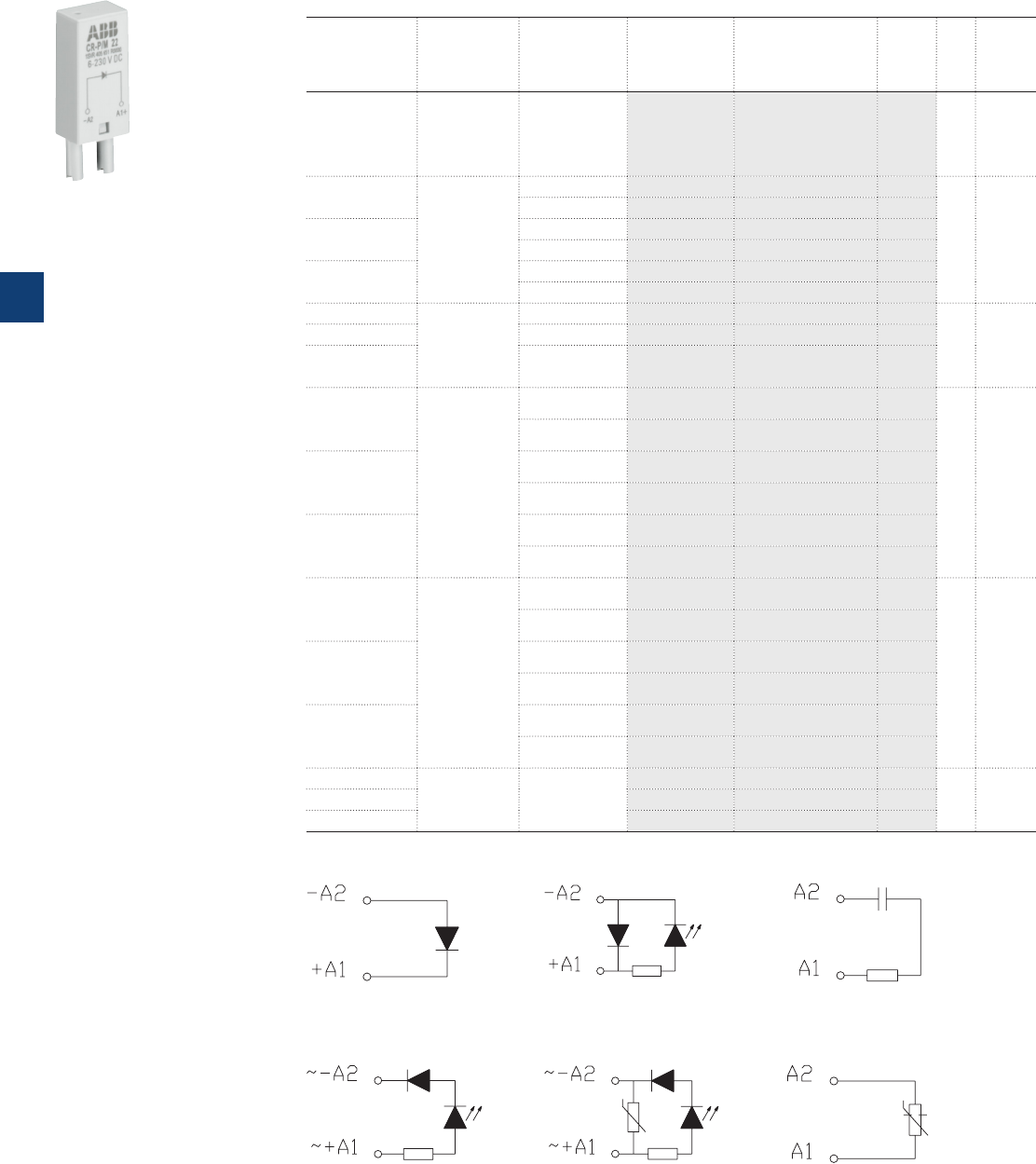
5
5/13 ABB | Catalog Electronic Products and Relays 2015 | 2CDC 110 004 C0210
Pluggable interface relays
Ordering details CR-P/M functional modules
Ordering details - CR-P/M range (all products stocked)
Rated control
supply voltage
Description Version Type Order code Price Pkg
qty
Weight
(1 pce)
kg (lb)
6-220 V DC
Diode -
Reverse
polarity
protection/free
wheeling diode
A1+, A 2- CR-P/M 22 1SVR405651R0000 10 0.003
(0.007)
6-24 V DC Diode and
LED - Reverse
polarity
protection/free
wheeling diode
red, A1+, A2- CR-P/M 42 1SVR405652R0000
10 0.003
(0.007)
green, A1+, A2-
CR-P/M 42V 1SVR405652R1000
24-60 V DC red, A1+, A2- CR-P/M 42B 1SVR405652R4000
green, A1+, A2- CR-P/M 42BV 1SVR405652R4100
110-230 V DC red, A1+, A2- CR-P/M 42C 1SVR405652R9000
green, A1+, A2- CR-P/M 42CV 1SVR405652R9100
6-24 V AC/DC
Spark
quenching
CR-P/M 52B 1SVR405653R0000
10 0.003
(0.007)
24-60 V AC/DC CR-P/M 52D 1SVR405653R4000
110 -230
V AC/DC CR-P/M 52C 1SVR405653R1000
6-24 V AC/DC
Diode, LED and
reverse polarity
protection
red, for DC A1+,
A2- CR-P/M 62 1SVR405654R0000
10 0.003
(0.007)
green, for DC
A1+, A 2- CR-P/M 62V 1SVR405654R1000
24-60 V AC/DC
red, for DC A1+,
A2- CR-P/M 62E 1SVR405654R4000
green, for DC
A1+, A 2- CR-P/M 62EV 1SVR405654R4100
110 V DC
110-230 V AC
red, for DC A1+,
A2- CR-P/M 92 1SVR405654R0100
green, for DC
A1+, A 2- CR-P/M 92V 1SVR405654R1100
6-24 V AC/DC
Varistor and
LED
Overvoltage
protection
red, for DC A1+,
A2- CR-P/M 62C 1SVR405655R0000
10 0.003
(0.007)
green, for DC
A1+, A 2- CR-P/M 62CV 1SVR405655R1000
24-60 V AC/DC
red, for DC A1+,
A2- CR-P/M 62D 1SVR405655R4000
green, for DC
A1+, A 2- CR-P/M 62DV 1SVR405655R4100
110 V DC
110-230 V AC
red, for DC A1+,
A2- CR-P/M 92C 1SVR405655R0100
green, for DC
A1+, A 2- CR-P/M 92CV 1SVR40 5655R110 0
24 V AC
Overvoltage
protection
CR-P/M 72 1SVR405656R0000
10 0.002
(0.004)
115 V AC CR-P/M 72A 1SVR405656R1000
230 V AC CR-P/M 82 1SVR405656R2000
Connection diagrams
2CDC 292 013 F0005
CR-P/M 22
2CDC 292 014 F0005
CR-P/M 42, CR-P/M 42B,
CR-P/M 42C, CR-P/M 42V,
CR-P/M 42BV, CR-P/M 42CV
2CDC 292 015 F0005
CR-P/M 52B, CR-P/M 52C
CR-P/M 52D,
2CDC 292 016 F0005
CR-P/M 62, CR-P/M 62E,
CR-P/M 92, CR-P/M 62V,
CR-P/M 62EV, CR-P/M 92V
2CDC 292 017 F0005
CR-P/M 62C, CR-P/M 62D,
CR-P/M 92C, CR-P/M 62CV,
CR-P/M 62DV CR-P/M 92CV
2CDC 292 018 F0005
CR-P/M 72, CR-P/M 82
CR-P/M 72A,
CR-P/M ...
2CDC 291 005 S0011
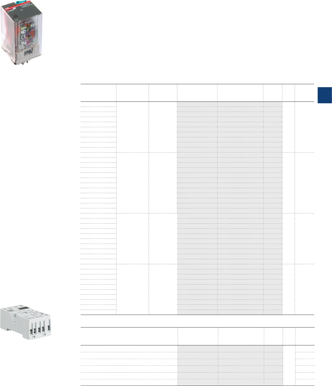
5
2CDC 110 004 C0210 | Catalog Electronic Products and Relays 2015 | ABB 5/14
Pluggable interface relays
Ordering details - CR-U range
Description
Interface relays are widely used in various industrial applications:
As an interface they link the electronic controlling, e.g. PLC (programmable logic controller),
PC or field bus systems, to the sensor / actuator level. Here, they take on various functions:
Switching of AC or DC loads with different resistive, inductive and capacitive parts, switching
voltages from a few mV up to 250 V, switching currents from a few mA up to 16 A, amplifica-
tion of weak control signals, electrical isolation of control and load circuits, and signal multi-
plying. In contrast to electronic switching devices, interface relays don’t use additional internal
protective circuits and thus are overload-proof against short-time variations like current or
voltage peaks.
Ordering details - CR-U range
Rated control
supply voltage
Outputs Contact
ratings
Type Order code Price Pkg
qty
Weight
(1 pce)
kg (lb)
12 V DC
2 c/o
without LED 250 V, 10 A
CR-U012DC2 1SVR405621R4000
10 0.083
(0.183)
24 V DC CR-U024DC2 1SVR405621R1000
48 V DC CR-U048DC2 1SVR405621R6000
110 V DC CR - U110 D C2 1SVR405621R8000
220 V DC CR-U220DC2 1SVR405621R9000
24 V AC CR-U024AC2 1SVR405621R0000
48 V AC CR-U048AC2 1SVR405621R5000
110 V AC CR-U110AC2 1SVR405621R7000
120 V AC CR-U120AC2 1SVR405621R2000
230 V AC CR-U230AC2 1SVR405621R3000
12 V DC
3 c/o
without LED 250 V, 10 A
CR-U012DC3 1SVR405622R4000
10 0.083
(0.183)
24 V DC CR-U024DC3 1SVR405622R1000
48 V DC CR-U048DC3 1SVR405622R6000
110 V DC CR-U110DC3 1SVR405622R8000
125 V DC CR-U125DC3 1SVR405622R8200
220 V DC CR-U220DC3 1SVR405622R9000
24 V AC CR-U024AC3 1SVR405622R0000
48 V AC CR-U048AC3 1SVR405622R5000
60 V AC CR-U060AC3 1SVR405622R5200
110 V AC CR-U110AC3 1SVR405622R7000
120 V AC CR-U120AC3 1SVR405622R2000
230 V AC CR-U230AC3 1SVR405622R3000
12 V DC
2 c/o
with LED 250 V, 10 A
CR-U012DC2L 1SVR405621R4100
10 0.083
(0.183)
24 V DC CR-U024DC2L 1SVR405621R1100
48 V DC CR-U048DC2L 1SVR405621R6100
110 V DC CR - U110 D C2L 1SVR405621R8100
220 V DC CR-U220DC2L 1SVR405621R9100
24 V AC CR-U024AC2L 1SVR405621R0100
48 V AC CR-U048AC2L 1SVR405621R5100
110 V AC CR-U110AC2L 1SVR405621R7100
120 V AC CR-U120AC2L 1SVR405621R2100
230 V AC CR-U230AC2L 1SVR405621R3100
12 V DC
3 c/o
with LED 250 V, 10 A
CR-U012DC3L 1SVR405622R4100
10 0.083
(0.183)
24 V DC CR-U024DC3L 1SVR405622R1100
48 V DC CR-U048DC3L 1SVR405622R6100
110 V DC CR-U110DC3L 1SVR405622R8100
220 V DC CR-U220DC3L 1SVR405622R9100
24 V AC CR-U024AC3L 1SVR405622R0100
48 V AC CR-U048AC3L 1SVR405622R5100
110 V AC CR-U110AC3L 1SVR405622R7100
120 V AC CR-U120AC3L 1SVR405622R2100
230 V AC CR-U230AC3L 1SVR405622R3100
CR-U
CR-U2S
2CDC 291 047 F0004
2CDC 291 007 S0011
Ordering details - Accessories
Version Type Order code Price Pkg
qty
Weight
(1 pce)
kg (lb)
Socket for 2 c/o and module CR-U2S 1SVR405670R0000
10
Socket for 3 c/o and module CR-U3S 1SVR405660R0000
Socket for 3 c/o CR-U3E 1SVR405660R0100
Socket small for 2 c/o CR-U2SM 1SV R405670 R110 0
Socket small for 3 c/o CR-U3SM 1SVR405660R1100
Holder for CR-U socket CR-UH 1SVR405669R0000
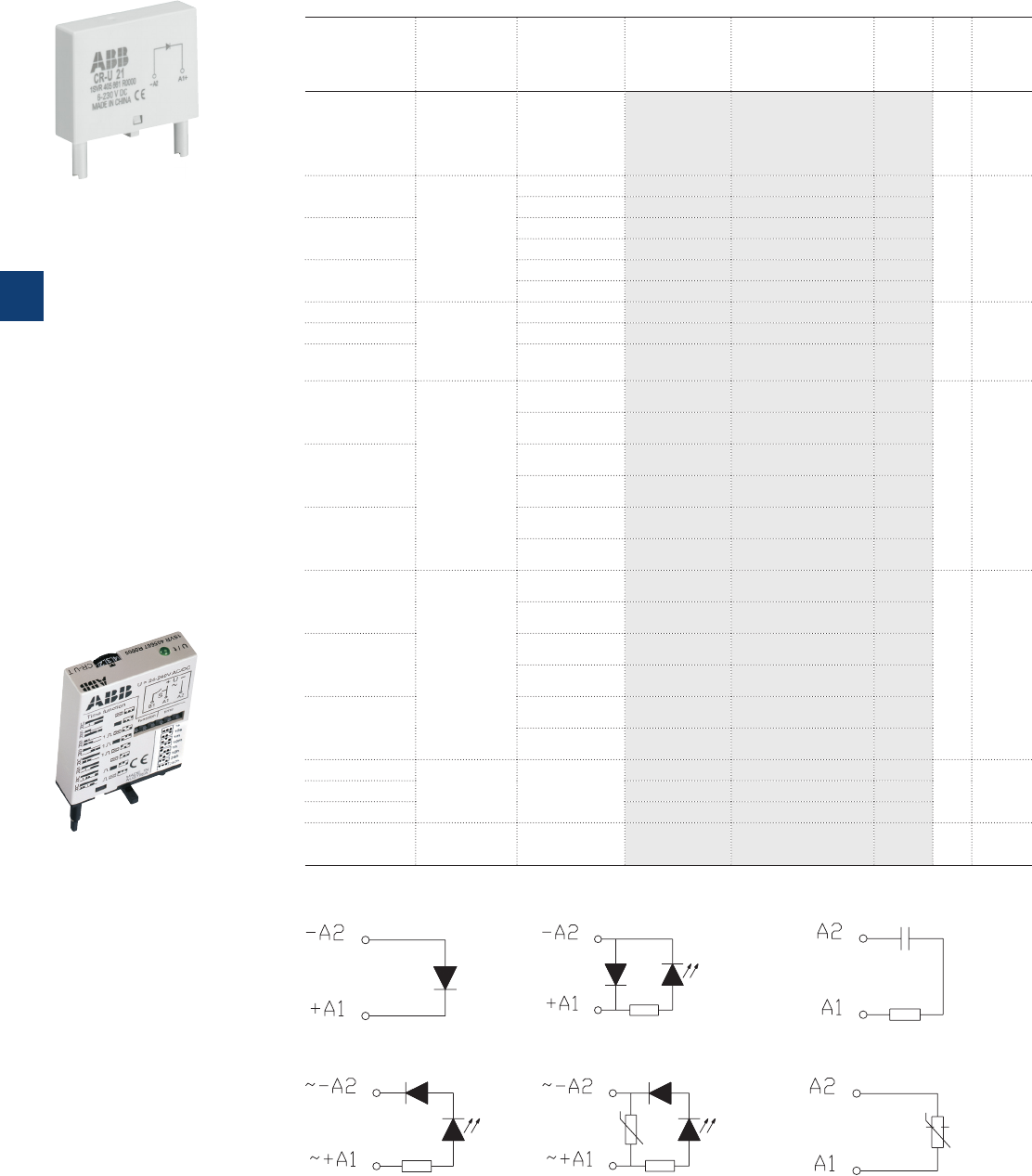
5
5/15 ABB | Catalog Electronic Products and Relays 2015 | 2CDC 110 004 C0210
Ordering details - CR-U range (all products stocked)
Rated control
supply voltage
Description Version Type Order code Price Pkg
qty
Weight
(1 pce)
kg (lb)
6-220 V DC
Diode -
Reverse
polarity
protection/
free wheeling
diode
A1+, A 2- CR-U 21 1SVR405661R0000 10 0.007
(0.015)
6-24 V DC Diode and
LED - Reverse
polarity
protection/
free wheeling
diode
red, A1+, A2- CR-U 41 1SVR405662R0000
10 0.007
(0.015)
green, A1+, A2- CR-U 41V 1SVR405662R1000
24-60 V DC red, A1+, A2- CR-U 41B 1SVR405662R4000
green, A1+, A2- CR-U 41BV 1SVR405662R4100
110 V DC red, A1+, A2- CR-U 41C 1SVR405662R9000
green, A1+, A2- CR-U 41CV 1SVR405662R9100
6-24 V AC/DC
Spark quen-
ching
CR-U 51B 1SVR405663R0000
10 0.007
(0.015)
24-60 V AC/DC CR-U 51D 1SVR405663R4000
110 -230
V AC/DC CR-U 51C 1SVR405663R1000
6-24 V AC/DC
Diode and
LED
red, for DC
A1+, A 2- CR-U 61 1SVR405664R0000
10 0.007
(0.015)
green, for DC
A1+, A 2- CR-U 61V 1SVR405664R1000
24-60 V AC/DC
red, for DC
A1+, A 2- CR-U 61E 1SVR405664R4000
green, for DC
A1+, A 2- CR-U 61EV 1SVR405664R4100
110 V DC 110-
230 V AC
red, for DC
A1+, A 2- CR-U 91 1SVR405664R0100
green, for DC
A1+, A 2- CR-U 91V 1SVR405664R1100
6-24 V AC/DC
Varistor and
LED
Overvoltage
protection
red, for DC
A1+, A 2- CR-U 61C 1SVR405665R0000
10 0.007
(0.015)
green, for DC
A1+, A 2- CR-U 61CV 1SVR405665R1000
24-60 V AC/DC
red, for DC
A1+, A 2- CR-U 61D 1SVR405665R4000
green, for DC
A1+, A 2- CR-U 61DV 1SVR405665R4100
110 V DC 110-
230 V AC
red, for DC
A1+, A 2- CR-U 91C 1SVR405665R0100
green, for DC
A1+, A 2- CR-U 91CV 1SVR405665R1100
24 V AC Overvoltage
protection,
varistor
CR-U 71 1SVR405666R0000
10 0.007
(0.015)
115 V AC CR-U 71A 1SVR405666R1000
230 V AC CR-U 81 1SVR405666R2000
24-240
V AC/DC Multifunction
time module
pluggable onto
CR-U2S and
CR-U3S
CR-U T 1SVR405667R0000 10 0.014
(0.031)
CR-U...
2CDC 291 004 S0011 2CDC 291 032 F0005
Pluggable interface relays
Ordering details - CR-U accessories
CR-U T
Connection diagrams
2CDC 292 013 F0005
CR-U 21
2CDC 292 014 F0005
CR-U 41, CR-U 41B, CR-U 41C,
CR-U 41V, CR-U 41BV, CR-U 41CV
2CDC 292 015 F0005
CR-U 51B, CR-U 51C CR-U 51D
2CDC 292 016 F0005
CR-U 61, CR-U 61E, CR-U 91,
CR-U 61V, CR-U 61EV, CR-U 91V
2CDC 292 017 F0005
CR-U 61C, CR-U 61CV, CR-U 61D,
CR-U 61DV, CR-U 91C, CR-U 91CV
2CDC 292 018 F0005
CR-U 71, CR-U 71A , CR-U 81
All CR-U modules can be plugged onto sockets CR-U2S and CR-U3S.
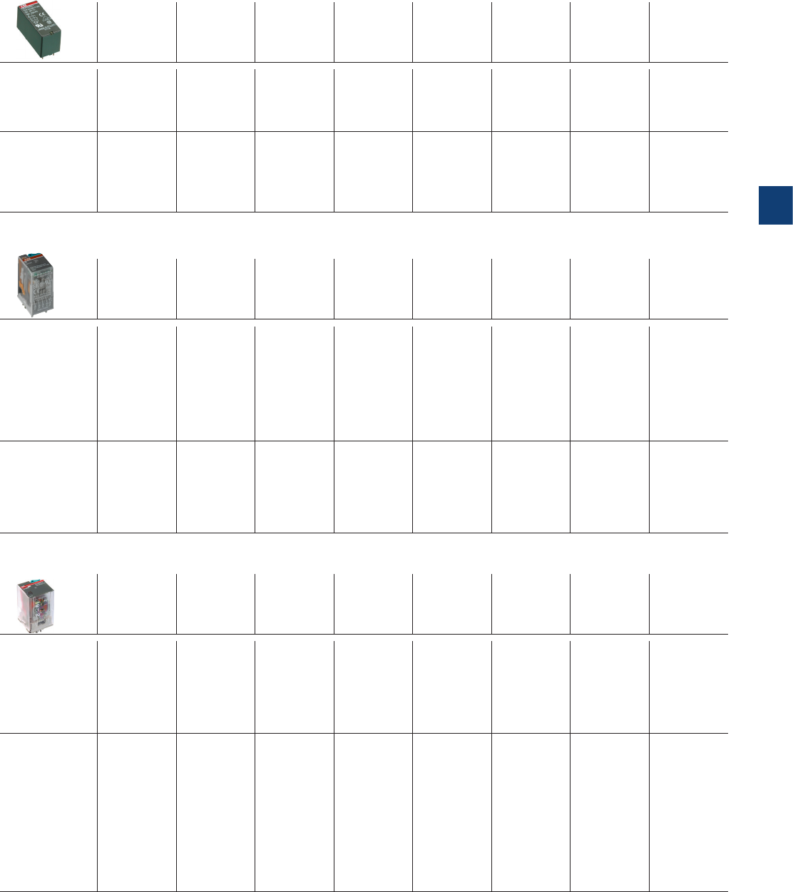
5
2CDC 110 004 C0210 | Catalog Electronic Products and Relays 2015 | ABB 5/16
Pluggable interface relays
Technical data - CR-P, CR-M, CR-U
Input circuit - coil data
Rated control
supply
voltage US
Rated
frequency
Make voltage
(at20 °C)
Maximum-
voltage (at55
°C)
Break
voltage
Rated power Coil re-
sistance
(at20°C)
Toleranceof
coil
resistance
DC coils 12 V DC - 8.4 V DC 30.6 V DC 0.1 US0.4-0.48 W 360 10%
24 V DC - 16.8 V DC 61.2 V DC 0.1 US0.4-0.48 W 1440 10%
48 V DC - 33.6 V DC 122.4 V DC 0.1 US0.4-0.48 W 5700 10%
110 V DC - 77 V DC 280 V DC 0.1 US0.4-0.48 W 25200 10%
AC coils 24 V AC 50 / 60 Hz 19.2 V AC 28.8 V AC 0.15 US0.75 VA 400 10%
48 V AC 50 / 60 Hz 38.4 V AC 57.6 V AC 0.15 US0.75 VA 1550 10%
110 V AC 50 / 60 Hz 88 V AC 132 V AC 0.15 US0.75 VA 8900 10%
120 V AC 50 / 60 Hz 96 V AC 144 V AC 0.15 US0.75 VA 10200 10%
230 V AC 50 / 60 Hz 184 V AC 276 V AC 0.15 US0.75 VA 38500 10%
CR-P range
CR-M range
Rated control
supply
voltage US
Rated
frequency
Make voltage
(at20 °C)
Maximum
voltage (at55
°C)
Break
voltage
Rated power Coil resis-
tance (at20
°C)
Toler ance of
coil
resistance
DC coils 12 V DC - 9.6 V DC 13.2 V DC 0.1 US0.9 W 160 10%
24 V DC - 19.2 DC 26.4 V DC 0.1 US0.9 W 640 10%
48 V DC - 38.4 V DC 52.8 V DC 0.1 US0.9 W 2600 10%
60 V DC - 48 V DC 66 V DC 0.1 US0.9 W 4000 10%
110 V DC - 88 V DC 121 V DC 0.1 US0.9 W 13600 10%
125 V DC -100 V DC 137.5 V DC 0.1 US0.9 W 16000 10%
220 V DC -176 V DC 242 V DC 0.1 US0.9 W 54000 10%
AC coils 24 V AC 50 / 60 Hz 19.2 V AC 26.4 V AC 0.2 US1.6 VA 158 10%
48 V AC 50 / 60 Hz 38.4 V AC 52.8 V AC 0.2 US1.6 VA 640 10%
60 V AC 50 / 60 Hz 48 V AC 66 V AC 0.2 US1.6 VA 930 10%
110 V AC 50 / 60 Hz 88 V AC 121 V AC 0.2 US1.6 VA 3450 10%
120 V AC 50 / 60 Hz 96 V AC 132 V AC 0.2 US1.6 VA 3770 10%
230 V AC 50 / 60 Hz 184 V AC 253 V AC 0.2 US1.6 VA 16100 10%
Rated control
supply
voltage US
Rated
frequency
Make voltage
(at20 °C)
Maximum
voltage (at55
°C)
Break
voltage
Rated power Coil re-
sistance
(at20°C)
Toler ance of
coil
resistance
DC coils 12 V DC -9.6 V DC 13.2 V DC 0.1 Us 1.5 W 110 10 %
24 V DC -19.2 V DC 26.4 V DC 0.1 Us 1.5 W 430 10 %
48 V DC -38.4 V DC 52.8 V DC 0.1 Us 1.5 W 1750 10 %
110 V DC -88.0 V DC 121.0 V DC 0.1 Us 1.5 W 9200 10 %
125 V DC -100 V DC 137.5 V DC 0.1 Us 1.5 W 11000 10 %
220 V DC -176.0 V DC 242.0 V DC 0.1 Us 1.5 W 37000 10 %
AC coils 24 V AC 50 / 60 Hz 19.2 V AC 26.4 V AC 0.15 US2.8 VA (50 Hz)
2.5 VA (60 Hz) 75 10 %
48 V AC 50 / 60 Hz 38.4 V AC 52.8 V AC 0.15 US2.8 VA (50 Hz)
2.5 VA (60 Hz) 305 10 %
60 V AC 50 / 60 Hz 48.0 V AC 66.0 V AC 0.15 US2.8 VA (50 Hz)
2.5 VA (60 Hz) 475 10 %
110 V AC 50 / 60 Hz 88.0 V AC 121.0 V AC 0.15 US2.8 VA (50 Hz)
2.5 VA (60 Hz) 1700 10 %
120 V AC 50 / 60 Hz 96.0 V AC 132.0 V AC 0.15 US2.8 VA (50 Hz)
2.5 VA (60 Hz) 1910 10 %
230 V AC 50 / 60 Hz 184.0 V AC 253.0 V AC 0.15 US2.8 VA (50 Hz)
2.5 VA (60 Hz) 7080 10 %
CR-U range

5
5/17 ABB | Catalog Electronic Products and Relays 2015 | 2CDC 110 004 C0210
Type CR-P...1 CR-P...2 CR-M...2 CR-M...3 CR-M...4 CR-U...2 CR-U...3
Output circuit(s) 11-12/14 11-12/14
21-22/24 11-12/14
21-22/24
11-12 /14
21-22/24
31-32/34
11-12 /14
21-22/24
31-32/34
41-42/44
11-12 /14
31-32/34
11-12 /14
21-22/24
31-32/34
Kind of output Relay, 1 c/o Relay, 2 c/o Relay, 2 c/o Relay, 3 c/o Relay, 4 c/o Relay, 2 c/o Relay, 3 c/o
Contact material AgNi
AgNi
AgNi/Au 5 µm
AgNi AgNi
AgNi
AgNi/Au 5 µm
AgNi
Rated operational voltage U
e
(VDE 0110, IEC 60947-1)
250 V
Minimum switching voltage 5 V 10 V (AgNi) 5 V (
AgNi/Au)
10 V
Maximum switching voltage DC 300 V DC 250 V DC
AC 440 V AC 250 V AC 440 V AC
Minimum switching current
5 mA (AgNi), 2 mA (AgNi/Au)
5 mA (AgNi) 5 mA (AgNi)
2 mA (AgNi/Au)
5 mA
Rated free air thermal current Ith 16 A 8 A 12 A 10 A 6 A 10 A
Rated
operational
current
(IEC 60947-
5-1)
AC-12 (resistive) 230 V 16 A 8 A 12 A 10 A 6 A 10 A
AC-15 (inductive) 230 V 1.5 A 1.5 A 1.5 A 1.5 A 1 A 1.5 A
AC-15 (inductive) 120 V 3 A 1.5 A 3 A
DC-12 (resistive) 24 V 16 A 8 A 12 A 10 A 6 A 10 A
DC-13 (inductive) 24 V 2.5 A 2 A 2.5 A 2.5 A 2 A 2 A
DC-13 (inductive) 120 V 0.22 A
DC-13 (inductive) 250 V 0.1 A
AC rating
(UL 508)
Utilization category (pilot duty)
(Contact rating code designation)
B300 B300 B300
max. rated operational voltage
300 V AC 300 V AC 300 V AC
Max. continuous thermal current
at utilization category
5 A 5 A 5 A 2.5 A 5 A
Max. making / breaking apparent
power at utilization category
3600 / 360 VA 3600 / 360 VA 1800 /
180VA 3600/360 VA
Utilization category (resistive)
(CSA22.2 No.14....) 16 A,
250VAC 8 A,
250VAC
10 A, 250VAC
12 A, 150VAC
6 A, 250VAC
10 A, 150VAC
5 A, 250VAC
10 A, 150VAC
10 A, 250 V AC (resistive +
single-phase)
DC rating *
(UL 508;
NEMA ICS-5)
Utilization category (pilot duty)
(Contact rating code designation)
R300
Max. rated operational voltage
300 V DC
Max. continuous thermal current
at utilization category
1 A
Max. making / breaking apparent
power at utilization category
28 VA
Utilization category (resistive)
(CSA22.2 No.14....) -
10 A, 24 V DC
-10 A, 28 V DC
Maximum making (inrush) current 30 A 15 A 24 A 20 A 12 A 20 A
Minimum switching power
0.3 W (AgNi), 0.05W(AgNi/Au)
0.3 W (AgNi), 0.1 W (AgNi/Au) 0.3 W
Maximum switching
(breaking) power AC1 (resistive) 4000 VA 2000 VA 3000 VA 2500 VA 1500 VA 2500 VA
Contact resistance 100 m
Maximum operating
frequency
rated load AC-1
600 switching cycles/h 1200 switching cycles/h
without load 72000 switching cycles/h 18000 switching cycles/h 12000 switching cycles/h
Mechanical lifetime > 3 x 10⁷ switching cycles > 2 x 10⁷ switching cycles
Electrical lifetime electrical AC1
(resistive)
> 0.7 x 10⁵
switching
cycles (16 A,
250 V)
> 105
switching
cycles (8 A,
250 V)
> 105 switching cycles
> 105 switching cycles
(12 A, 250 V)
(12 A, 250 V) (10 A, 250 V) (6 A, 250 V)
cos ϕsee reduction factor F
Response time typ. 7 ms typ. 13 ms (DC),10 ms (AC) typ. 18 ms (DC), 12 ms (AC)
Release time typ. 3 ms typ. 3 ms (DC), 8 ms (AC) typ. 7 ms (DC), 10 ms (AC)
Isolation data
Rated insulation voltage 400 V AC 250 V AC
Insulation class C250 / B400 C250 / B250 C250
Rated
impulse
withstand
voltage Uimp
between coil and contacts 5 kV AC 2.5 kV AC
between open contacts 1 kV AC 1.5 kV AC
between c/o (SPDT) contacts -2.5 kV AC 2.5 kV AC 2 kV AC 2 kV AC
Clearance between coil and contacts 10 mm 2.5 mm 1.6 mm 3 mm
Creepage distance between coil and contacts 10 mm 4 mm 3.2 mm 4.2 mm
Overvoltage category III III II III
Pollution degree 3 3 2 3
Pluggable interface relays
Technical data - CR-P, CR-M, CR-U
* Those ratings are based on different type tests but they are not covered by the cULus or CSA approvals.
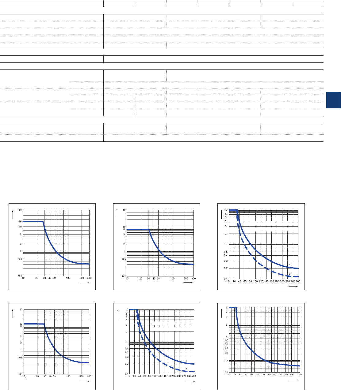
5
2CDC 110 004 C0210 | Catalog Electronic Products and Relays 2015 | ABB 5/18
Type CR-P...1 CR-P...2 CR-M...2 CR-M...3 CR-M...4 CR-U...2 CR-U...3
General data
Dimensions (W x H x D) when mounted 12.7 x 29 x 15.7 mm 21.2 x 27.5 x 35.6 mm 35 x 35 x 54.4 mm
Weight 14 g (0.031 lb) 35 g (0.077 lb) 83 g (0.18 lb)
Mounting on socket (see accessories)
Mounting position any
Degree of protection IP 67 IP 40
Electrical connection
Connection by socket
Environmental data
Ambient temperature range operation DC: -40...+85 °;
AC: -40...+70 °C DC: -40...+70 °; AC: -40...+55 °C
storage -40 ... +85 °C
Vibration resistance 10-150
Hz n/o contact 10 g 5 g 5 g
n/c contact 10 g 5 g 5 g 5 g
Shock resistance n/o contact 30 g 20 g 10 g 10 g
n/c contact 30 g 20 g 5 g 10 g
Standards
Product standard IEC/EN 60255-23, IEC/EN
60664-1, IEC/EN 61810-1 IEC/EN 60255-23, IEC/EN 60810-1,
IEC/EN 61810-7 IEC/EN 60255-1
Low Voltage Directive 2006/95/EC
Load limit curves - Maximum switching power at resistive DC load
CR-P with 1 c/o contact CR-P with 2 c/o contacts CR-U with 2 and 3 c/o contacts
CR-M with 2 c/o contacts CR-M with 3 c/o contacts CR-M with 4 c/o contacts
2CDC 292 005 F0204
DC current [A]
DC voltage [V]
2CDC 292 010 F0204
DC current [A]
DC voltage [V]
1 = resistive load, T = 0 ms
2 = inductive load, T = 40 ms
2CDC 292 028 F0204
DC voltage [V]
DC current [A]
2CDC 292 015 F0204
DC current [A]
DC voltage [V]
1 = resistive load, T = 0 ms
2 = inductive load, T = 40 ms
2CDC 292 019 F0204
DC voltage [V]
DC current [A]
2CDC 292 023 F0204
DC voltage [V]
DC current [A]
Pluggable interface relays
Technical data, load limit curves - CR-P, CR-M, CR-U
Approvals see page 5/6.

5
5/19 ABB | Catalog Electronic Products and Relays 2015 | 2CDC 110 004 C0210
Pluggable interface relays
Technical data - Sockets for CR-P and CR-M
Output circuits CR-PLS CR-PLS(x) CR-PSS CR-PLC CR-MxLS CR-MxSS CR-MxSF CR-MxLC
Output circuits 11-12/14, 21-22/24 11-12/14, 21-22/24, ...
Number of poles 22, 3 or 4 2 or 4
Rated voltage 250 V AC 300 V AC 250 V AC 250 V AC 300 V AC
Rated current 2 x 10 A1) 2 x 12 A1) 2 x 10 A1) 7 A 10 A
General data
Dimensions without holder and
module (L x W x H)
76 x 15.8 x
62 mm
(2.992 x 0.622
x 2.441 in)
78.5 x 15.5 x
61 mm
(3.011 x 0.610
x 2.402 in)
76 x 15.8 x
42.8 mm
(2.992 x 0.622
x 1.685 in)
97.5 x 16.3 x
45.2 mm
(3.839 x 0.642
x 1.780 in)
75 x 27.2 x
60.8 mm
(2.952 x 1.071
x 2.394 in)
75.2 x 27.2 x
42.6 mm
(2.961 x 1.071
x 1.677 in)
66.7 x 30.3 x
29 mm (2.626
x 1.193 x 1.142
in)
95 x 31 x
42.5 mm
(3.74 x 1.22 x
1.67 in)
Degree of protection terminals IP 20 B (EN 60529)
Temperature range operation -40...+70 °C -40...+85 °C -40...+70 °C -40...+70 °C -25...+85 °C
storage -40...+70 °C -40...+85 °C -40...+70 °C -40...+70 °C
Connection type screw connection spring
connection screw connection fork type
screw spring
connection
Maximum number of wires per
connecting terminal 22 (one per
connection
point)
2 - 2 (one per
connection
point)
Wire size rigid 2 x 2.5 mm2 (2 x 14 AWG) 2 x 1.5 mm2
(2 x 16 AWG)
0.2 - 1.5 mm
2
(24 x 16 AWG)
fine-strand 2 x 2.5 mm2 (2 x 14 AWG) 0.2-1.5 mm2
(24-16 AWG)
with wire end ferule 2 x 1.5 mm2 (2 x 16 AWG) 2 x 1.5 mm2 (2 x 16 AWG)
Stripping length -7 mm (0.28 in) - -
Tightening torque 0.6 Nm 0.8 Nm 0.6 Nm 0.6 Nm (5.31 lb.in)
Maximum
clamping
force
with 0.2 mm2---10 N ---10 N
with 1.5 mm2---40 N ---40 N
with wire end ferrule - - - - > 40 N
Mounting DIN rail (IEC/EN 60715)
Material socket PA 6+GF - V2 PA 6+GF - V2
contacts CuZn33 CuZn33
contact surface 5 μ Ni
5 μ tinned
5 μ Ni 5 μ Ni 6 μ Ni 5 μ tinned
terminals 8 μ Ni
8 μ galvanized
8 μ Ni XCrNi Steel 8 μ Ni CCSC
combi screw M3 8.8 Steel, 5μ Ni -8.8 Steel, 5μ Ni -
Isolation data
Insulation voltage > 5 kV > 3 kV > 5 kV > 3 kV > 4 kV
Isolation between coil and
contacts EN 61984 VDE 0106 /
101 EN 61984 -DIN EN
61140,
VDE 0140-1
Clearance and creepage distance EN 61984 DIN EN
60664-1 EN 61984 DIN EN 60664-1
Standards
Products standard EN 61984 EN 61984 - -
Low Voltage Directive 2006/95/EC 2006/95/EC
EMC Directive -2004/108/EC
1) Loads >10 A ( >12 A for CR-PLSx) require jumpering of terminal 11 with 21, 12 with 22, and 14 with 24

5
2CDC 110 004 C0210 | Catalog Electronic Products and Relays 2015 | ABB 5/20
Pluggable interface relays
Technical data - Sockets for CR-U
Output circuits CR-U2S CR-U3S CR-U3E CR-UxSM
Output circuits 11-12/14, 21-22/24,...
Number of poles 2 3 2 or 3
Rated voltage 250 V AC 300 V AC 250 V
Rated current 10 A
General data
Dimensions without holder and
module (L x W x H)
75.3 x 37.3 x 26 mm
(2.965 x 1.469 x 1.024 in)
75.3 x 38.1 x 26 mm
(2.965 x 1.500 x 1.024 in)
70 x 38 x 26 mm
(2.756 x 1.496 x 1.024 in)
61.8 x 38.1 x 26 mm
(2.756 x 1.500 x 1.024 in)
Degree of protection terminals IP 20 B (EN 60529)
Temperature range operation -40...+70 °C -40...+85 °C -40...+70 °C
storage -40...+70 °C -40...+85 °C -40...+70 °C
Wire size rigid 2 x 2.5 mm2 (2 x 14 AWG)
fine-strand 2 x 2.5 mm2 (2 x 14 AWG)
with wire end ferule 2 x 1.5 mm2 (2 x 16 AWG)
Tightening torque 0.6 Nm 0.8 Nm 0.6 Nm
Mounting DIN rail (IEC/EN 60715)
Material socket PA 6+GF - V2
contacts CuZn33
contact surface 6 μ Ni 3 μ Ni
terminals 8 μ Ni
8 μ galvanized
10 μ Ni
combi screw M3 8.8 Steel, 5μ Ni Steel, 8 μ Ni
Isolation data
Insulation voltage > 2 kV
Isolation between coil and
contacts EN 61984
Clearance and creepage distance EN 61984
Standards
Products standard EN 61984: 2001
Low Voltage Directive 2006/95/EC

5
5/21 ABB | Catalog Electronic Products and Relays 2015 | 2CDC 110 004 C0210
Pluggable interface relays
Technical data - CR-S range
Rated control
supply
voltage Us
Make voltage
(at 23 °C)
Maxium
voltage
(at 55 °C)
Break voltage Rated power Coil
resistance
(at 23 °C)
Toler ance of
coil
resistance
CR-S005VDC1R(G) 5 V DC 3.75 V DC 7.5 V DC 0.25 V DC 170 mW 147 Ω ± 10 %
CR-S012VDC1R(G) 12 V DC 9 V DC 18 V DC 0.6 V DC 170 mW 848 Ω ± 10 %
CR-S024VDC1R(G) 24 V DC 18 V DC 36 V DC 1.2 V DC 170 mW 3390 Ω ± 15 %
CR-S048VDC1R(G) 48 V DC 36 V DC 72 V DC 2.4 V DC 210 mW 10600 Ω ± 15 %
CR-S060VDC1R(G) 60 V DC 45 V DC 90 V DC 3 V DC 210 mW 16600 Ω ± 15 %
Output circuits
Output circuits 11-12 /14
Kind of output 1 c/o (SPDT)
Contact material AgSnO2 / AgSnO2/Au
Rated operational voltage Ue (IEC/EN 60947-1) 250 V AC
Minimum switching voltage 12 V DC
Maximum switching voltage 400 V AC / 125 V DC
Minimum switching current 100 mA (AgSnO2) / 10 mA (AgSnO2/Au)
Rated free air thermal current Ith 5 A
Rated operational current (IEC/EN 60947-5-1) AC12 (resistive) 230 V 6 A
AC15 (inductive) 230 V 1.5 A
AC15 (inductive) 120 V 3 A
DC12 (resistive) 24 V 6 A
DC13 (inductive) 24 V 1 A
DC13 (inductive) 120 V 0.22 A
DC13 (inductive) 250 V 0.11 A
AC rating (UL 508; NEMA ICS-5) Utilization category (pilot duty)
(Contact rating code designation) B300
DC rating (UL 508; NEMA ICS-5) Utilization category (pilot duty)
(Contact rating code designation) R300
Maximum making (inrush) current 15 A, 240 V AC
Minimum switching power 100 mA/12 V (AgSnO2) / 50 mW (AgSnO2/Au)
Maximum switching (breaking) power AC1 (resistive) 1500 VA, 250 V AC
Contact resistance 100 mW (at 1 A/ 6 V DC)
Maximum operating frequency rated load AC1 360 switching cycles/h
without load 18000 switching cycles/h
Mechanical lifetime 1 x 10⁷ switching cycles
Electrical lifetime AC1 (resistive) (n/c) 3 x 10⁴ switching cycles (at +85 °C)
(n/o) 1 x 10⁴ switching cycles (at +85 °C)
Response time 8 ms
Release time 4 ms
Isolation data
Rated insulation voltage 250 V AC
Rated impulse withstand voltage Uimp between coil and contacts 4000 V AC 1 min
between open contacts 1000 V AC 1 min
Clearance between coil and contacts 5.5 mm (0.217 in)
Creepage distance between coil and contacts 8 mm (0.315 in)
Overvoltage category III
Pollution degree 2
General data
Dimensions (W x H x D) 28 x 5 x 15 mm (1.102 x 0.196 x 0.590 in)
Weight 5 g (0.011 lb)
Mounting on socket
Mounting position any
Degree of protection RT II and RT III
Electrical connection
Connection by socket
Environmental data
Ambient temperature range operation -40...+85 °C
storage 0...+40 °C
Vibration resistance (10-150 Hz) n/o contact 10 Hz to 55 Hz 1mm DA
n/c contact 10 Hz to 55 Hz 1mm DA
Shock resistance n/o contact Functional 49 m/s² / Destructive 980 m/s²
n/c contact Functional 49 m/s² / Destructive 980 m/s²
Standards
Product standard IEC 61810-1
Low Voltage Directive 2006/95/EC
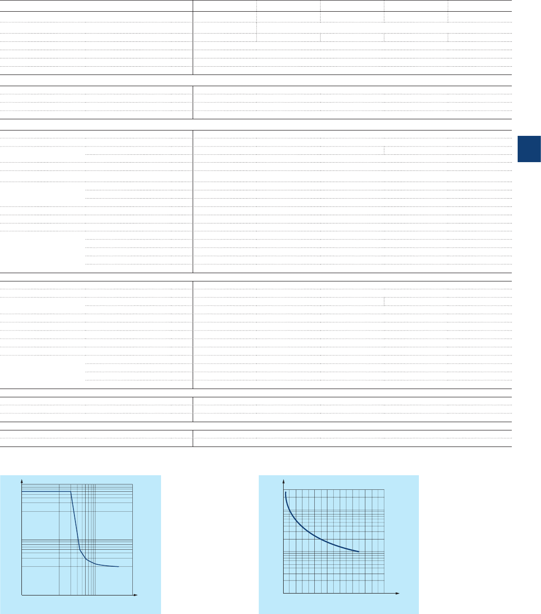
5
2CDC 110 004 C0210 | Catalog Electronic Products and Relays 2015 | ABB 5/22
Pluggable interface relays
Technical data - CR-S range sockets
Input circuits CR-S 6-24 V CR-S 12-24 V CR-S 48-60 V CR-S 110-125 V CR-S
220-240 V
Rated control supply voltage Us6-24 V DC 2-24 V AC/DC 48-60 V AC/DC 110-125 V AC/DC 220-240 V AC/DC
Rated control supply voltage Us tolerance (0.8-1.2) Un(0.8-1.1) U n
Typical current 11-29 mA 11-16 mA 3.6-4.5 mA 3.6 mA 3.6 mA
Response time 8 ms
Release time 4 ms
Status device green LED
Protective circuit yes
Output circuits
Output circuits 11-12/14
Number of poles 1
Rated voltage 250 V AC
Rated current 6 A
General data for CR-S with screw connection terminal
Dimensions without holder (L x W x H) 88.3 x 6.3 x 70.9 mm (3.476 x 0.248 x 2.789 in)
Degree of protection (EN 60529) Degree of protection (EN 60529) IP20 (terminals)
Temperature range operation -40...+70 °C -40...+55 °C
storage 0...+40 °C
Connection type Screw
Maximum nuber of wires per connection terminal 2
Wire size rigid 1 x 2.5 mm² (1 x 14 AWG) ; 2 x 1.5 mm² (2 x 16 AWG)
fine-strand 1 x 2.5 mm² (1 x 14 AWG); 2 x 1.5 mm² (2 x 16 AWG)
with wire end ferule 1 x 2.5 mm² (1 x 14 AWG); 2 x 1.0 mm² (2 x 18 AWG)
Tightening torque 0.5 Nm (4.426 lb.in)
Stripping length 7 mm (0.276 in)
Mounting (IEC/EN 60715) DIN rail
Material socket PA6 +GF-V2
contacts CuZn36
contact surface 3 μ Ni/Sn
terminals CuZn40, 3 μ Ni
combi screw M3 Fe
General data for CR-S with spring connection terminal
Dimensions without holder (L x W x H) 88.3 x 6.3 x 70.9 mm (3.476 x 0.248 x 2.789 in)
Degree of protection (EN 60529) Degree of protection (EN 60529) IP20 (terminals)
Temperature range operation -40...+70 °C -40...+55 °C
storage 0...+40 °C
Connection type Spring
Maximum nuber of wires per connection terminal 1
Wire size 2.5 mm² (14 AWG) rigid, fine-strand and with wire end ferule
Stripping length 7 mm (0.276 in)
Mounting (IEC/EN 60715) DIN rail
Material socket PA6 +GF-V2
contacts CuZn36
contact surface 3 μ Ni/Sn
spring terminals SUS301
Isolation data
Isolation between coil and contacts 5000 V AC
Resistance to shock coil to contact 1000 MW
Clearance and creepage distance IEC/EN 61984
Standards
Product stancard IEC/EN 61984: 2001
Low Voltage Directive 2006/95/EC
Load limit curves - Max. DC load breaking capacity Endurance curve
DC current (A)
DC voltage (V)
10
0.1
0.2
0.5
1
2
5
10
20 50 100 200
2CDC 292 012 F0214
Contact current (A)
Operations (*1000 ops)
0
5
10
50
100
1234 56
7
8
2CDC 292 013 F0214
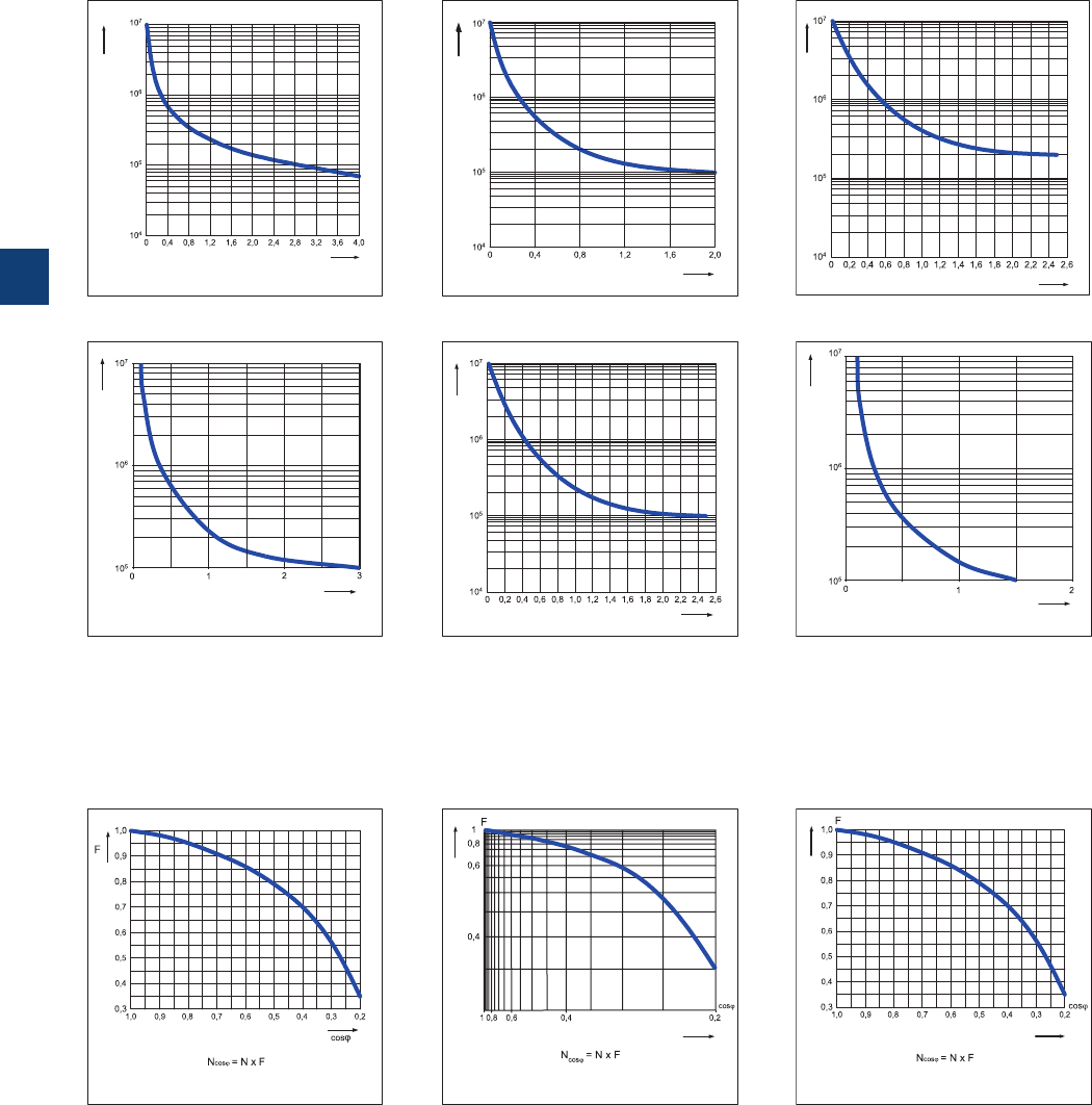
5
5/23 ABB | Catalog Electronic Products and Relays 2015 | 2CDC 110 004 C0210
Load limit curves - Electrical lifetime at resistive AC load
CR-P with 1 c/o contact CR-P with 2 c/o contacts CR-U with 2 and 3 c/o contacts
CR-M with 2 c/o contacts CR-M with 3 c/o contacts CR-M with 4 c/o contacts
2CDC 292 003 F0204
Switching cycles
Switching power [kVA]
2CDC 292 009 F0204
Switching cycles
Switching power [kVA]
2CDC 292 027 F0204
Switching cycles
Switching power [kVA]
2CDC 292 013 F0204
Switching cycles
Switching power [kVA]
2CDC 292 018 F0204
Switching cycles
Switching power [kVA]
2CDC 292 022 F0204
Switching cycles
Switching power [kVA]
Reduction factor F at inductive AC load
2CDC 292 004 F0204
Reduction factor
Power factor
2CDC 292 014 F0204
Reduction factor
Power factor Power factor
Reduction factor
2CDC 292 029 F0204
CR-P CR-M CR-U
Pluggable interface relays
Load limit curves
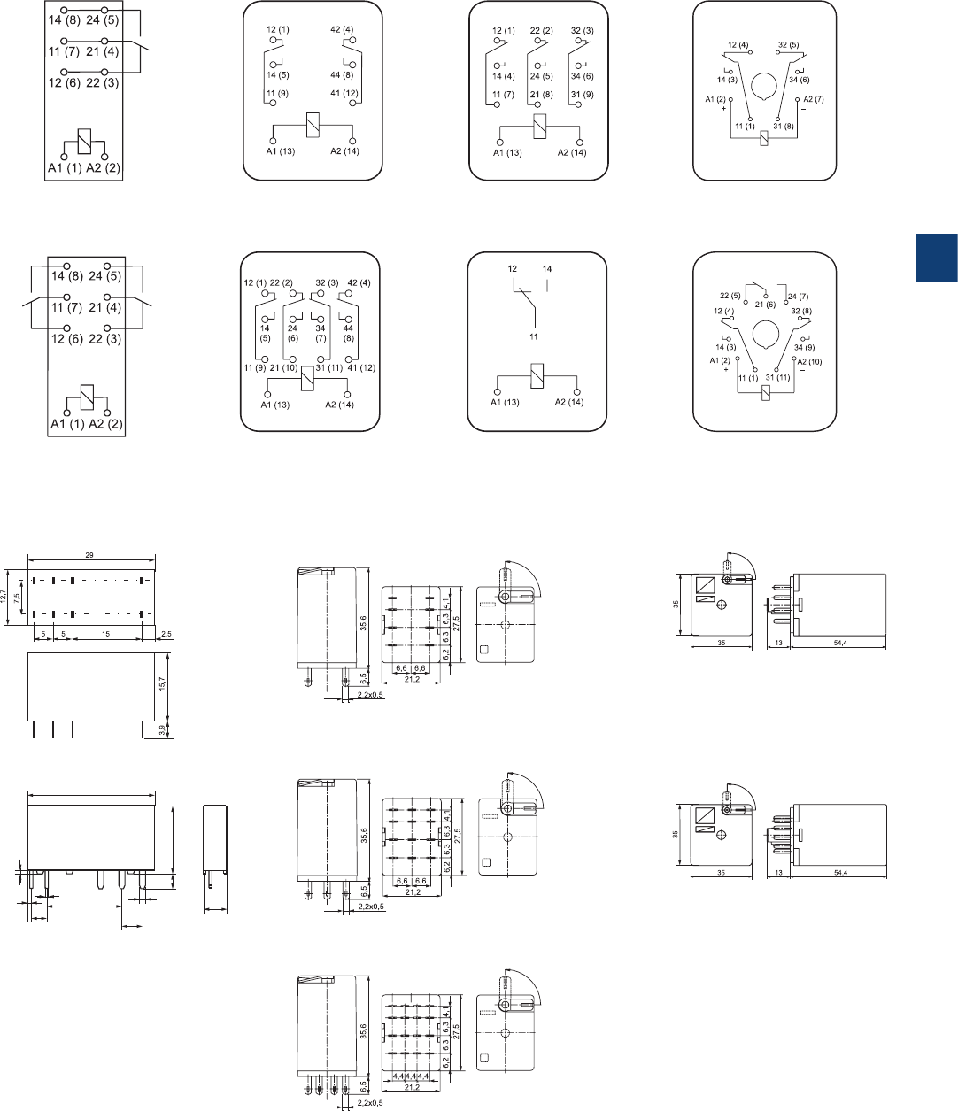
5
2CDC 110 004 C0210 | Catalog Electronic Products and Relays 2015 | ABB 5/24
Connection diagrams
Dimensional drawings Dimensions in mm and inches
CR-M with 2 c/o contacts
CR-P with 1 c/o contact CR-M with 2 c/o contacts CR-M with 3 c/o contacts CR-U with 2 c/o contacts
CR-P with 2 c/o contacts CR-M with 4 c/o contacts CR-S CR-U with 3 c/o contacts
CR-U with 2 c/o contacts
CR-P
CR-S
CR-M with 3 c/o contacts
CR-M with 4 c/o contacts
CR-U with 3 c/o contacts
2CDC 292 001 F0004
2CDC 292 008 F0004
2CDC 292 002 F00042CDC 292 052 F0013
1 0.039
0.5 0.020
0.9 0.035
0.5 0.020
3.78 0.149
5.04 0.198
5 0.197
16.38 0.645
28 1.102
15 0.591
3.5 0.138
2CDC 292 011 F0004
2CDC 292 016 F0004
2CDC 292 020 F0004
2CDC 292 001 F0014
2CDC 292 001 F0015
2CDC 292 002 F00152CDC 292 003 F0015
2CDC 292 024 F00042CDC 292 030 F0004
2CDC 292 025 F0004
2CDC 292 026 F0004
Pluggable interface relays
Connection diagrams
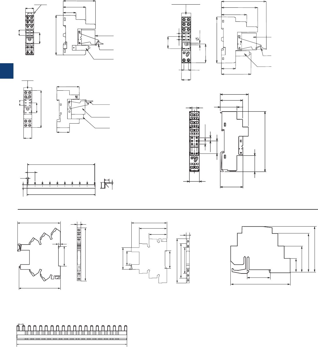
5
5/25 ABB | Catalog Electronic Products and Relays 2015 | 2CDC 110 004 C0210
20.32
5.085.08
15.5
7.62
29.4
3.2
78.5
24
50
62
61
42.5
Pluggable interface relays
Dimensional drawings
Dimensions in mm and inches
Relay
Jumper
CR-PLS - screw connection
CR-PLSx - screw connection
CR-PSS - screw connection
2CDC 292 033 F0004
2CDC 292 053 F0013
2CDC 292 054 F0013
2CDC 292 003 F0014
2CDC 292 002 F0014
CR-PLC - spring connection
CR-PJ
62
51,2
29
15,8
7,5
76
20
10
Marker
Relay
Holder
Pluggable
function module
42.8
15,8
24
76
10
20
Marker
Holder
Relay
Pluggable
function module
2CDC 292 006 F0211
2CDC 292 007 F0211
7,62
97,5
25,9
20,32
5,08
5,08
24,4
16,3
33,8
43,5
34,4
1,5
10
10
R1
2
±0,2
15,5
±0,2
9x15 (=139,5)
141,5
+1
6
±0,2
2CDC 292 010 F0011
2CDC 292 012 F0011
Pluggable function
module
Holder
76.6 3.016
73.2 2.882
3.5 0.138
35.4 1.394
94.7 3.728
6.2 0.244
6.3 0.248
123.2 4.850
2.8 0.110
0.8 0.031
16.7 0.657
6.7 0.264
70.9 2.791
6.3 0.272
44.2 1.74
52 2.047
69.4 2.732
88.3 3.476
28 1.102
35.4 1.394
55.4 2.181
35.8 1.409
92.7 3.650
35.7 1.406
20.6 0.811
40.2 1.583
59.8 2.354
71.1 2.799
Spring socket for CR-S range interface relays
Jumper bar CR-S
Screw socket for CR-S range interface relays Separator for CR-S
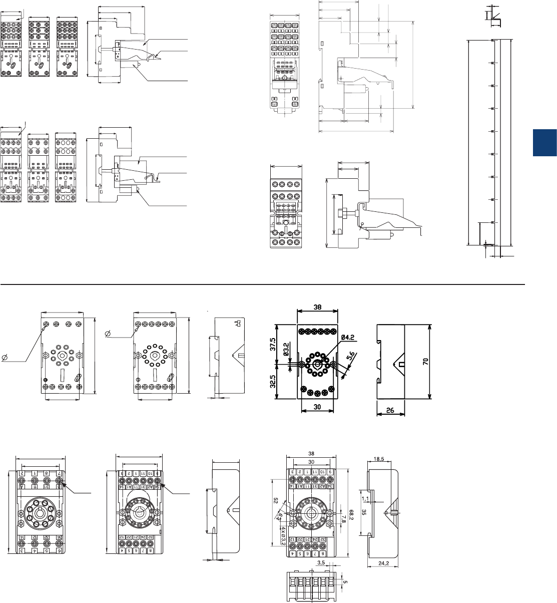
5
2CDC 110 004 C0210 | Catalog Electronic Products and Relays 2015 | ABB 5/26
Pluggable interface relays
Dimensional drawings
Dimensions in mm and inches
2CDC 292 081 F0004
CR-U2S - CR-U3S
CR-M2SS - CR-M3SS - CR-M4SS - screw connection
CR-M2LS - CR-M3LS - CR-M4LS - screw connection
CR-U3E
CR-U2SM
2CDC 292 002 F0005
CR-U3SM
31
27 26
79,5
42,5
33,2
24
12,4
12,4
15
95
5,5
2CDC 292 006 F0005
30,3
66,7
35,4
29 max
19
CR-M2LC , CR-M4LC - spring connection
CR-MxSF - screw connection
CR-MJ
9 - M3
12 - M3
37,3 38,1
29,8 29,8
4
75,3
75,3
35,4
CR-U2S CR-U3S
27,2
27,2 27,2
75,2
35,4
24
42,6
Marker
Relay
Holder
Pluggable
function module
2CDC 292 008 F0011
29,1
24
42,6
75
60,8
27,2
27,2 27,2
75
35,4
Marker
Relay
Holder
Pluggable
function module
CR-M2LS CR-M3LS CR-M4LS
2CDC 292 004 F0211
2CDC 292 005 F0011
2CDC 292 003 F0211
11 - M3
27,8
38,1
26
61,8
4
35,4
27,8
38,1
CR-U2SM CR-U3SM
8 - M3
61,8
2CDC 292 009 F0011
246.8
1
9,5
10
R1
9 x 27.2 (=244,8)
27.2 ±0.2
6±0,2
2±0,2
2CDC 292 011 F0011
5
5/27 ABB | Catalog Electronic Products and Relays 2015 | 2CDC 110 004 C0210
Interface relays and optocouplers R600 range
Product group picture

5
2CDC 110 004 C0210 | Catalog Electronic Products and Relays 2015 | ABB 5/28
Interface relays and optocouplers R600 range
Table of contents
Interface relays and optocouplers R600 range
Benefits and advantages 5/29
Type designators 5/30
Interface relays R600 range ............................................................. 5/31
Benefits and advantages 5/31
Selection 5/33
Ordering details 5/35
Connection diagrams 5/37
Technical data 5/38
General technical data 5/43
Dimensional drawings, Load limit curves 5/44
Optocouplers R600 range ............................................................... 5/45
Selection 5/45
Ordering details 5/47
Connection diagrams 5/48
Technical data 5/49
5
5/29 ABB | Catalog Electronic Products and Relays 2015 | 2CDC 110 004 C0210
Interface relays and optocouplers R600 range
Benefits and advantages
In today’s automation systems, PLCs are the core of industry. They link sensors and actuators to the process, which are con-
nected to the PLC via conventional wires.
However these PLCs are not completely isolated from the industrial environment, hence over voltage picks and transient cur-
rents can affect their operating functions. And additionally, their application field is often limited to 24 VDC / 100 mA.
So, with the aim to adapt application voltage and/or current and provide as well the right electrical isolation to the PLC, it is
recommended to install per I/O the right interface providing both voltage-current level adaptation and isolation protection.
This interfacing is possible thanks to ABB’s relays and optocouplers ranges, which offer wide adaptation in both voltage (from 5
to 400 V) and current (from 10-7 to 16 A) as well as high isolation between input and output from 2 to 4 KV.
R600 series
Standard range in screw clamp or spring clamp versions
– Spacing : 6 mm or 12 mm
– Wire size : 2.5 mm² (4 mm² solid wire)
– Contact type : 1 NO, 1 NC, 1 SPDT, 1 DPDT from
1 mA to 8 A / 250 V
2CDC 291 024 F0013
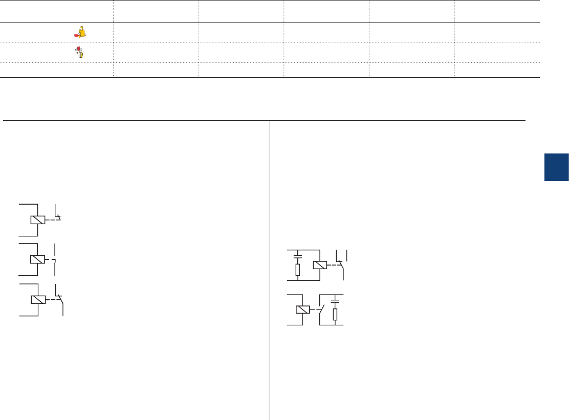
5
2CDC 110 004 C0210 | Catalog Electronic Products and Relays 2015 | ABB 5/30
Interface relays and optocouplers R600 range
Type designators
Description of contact types
0 1 Normally Closed 1 NC
1 1 Normally Open 1 NO
2 1 Change Over or Single Pole Double Through
Features
None Input voltage DC
A Input voltage AC/DC
R RC circuit protection :
-
Input protection against leakage current
- Increases relay contacts life
SERIES CODE NB OF RELAYS CONTACT TYPE NB OF CONTACTS
PER RELAY
PARTICULARITIES
R600 screw type R / B nnnn
R600 spring type R / B / R nnnn
1 0 1 2 1 2 None / A / R
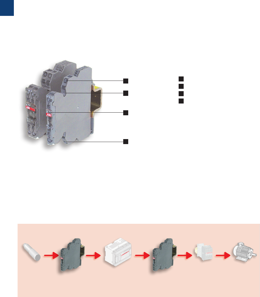
5
5/31 ABB | Catalog Electronic Products and Relays 2015 | 2CDC 110 004 C0210
Interface relays R600 range
Benefits and advantages
Characteristics
– Standard range available with screw or spring-type terminals
– 8 different rated control supply voltages:
DC versions: 5 V, 12 V, 24 V
AC/DC versions: 24 V, 48-60 V, 115 V, 230 V, 60-230 V
– Output: 1 n/c contact, 1 n/o contact, 1 c/o (SPDT) contact,
2 c/o (SPDT) contacts
– Devices with output contacts protected by built in RC cir-
cuit, which result in increased contact life
– Devices with leakage current protection on the input side
– Available with visible or covered switch on the front of the
unit, for the configuration of manual or automatic actuation
– With connection for jumper bar, except 2 c/o devices and
some discontinued devices
– Width: 6 mm (0.236 in) or 12 mm (0.472 in)
– LED for the indication of the operational state
– Accessories: Jumper bars, separator end section
– Approvals / Marks
H R P (pending) / a
Excellent adaption and conversion of digital signals
AC 110 V DC 24 V DC 24 V AC 110 V AC 380 V
AC 230V AC 230 V
Pushbutton R 600 Relay or R 600 Relay or Motor
Position Optocoupler PLC Optocoupler contactor Motor
switch
Sensor
1 Input - Control supply voltage
2 Jumper bar connection
3 Indication of operational states (green LED)
4 Output
1
2
3
4
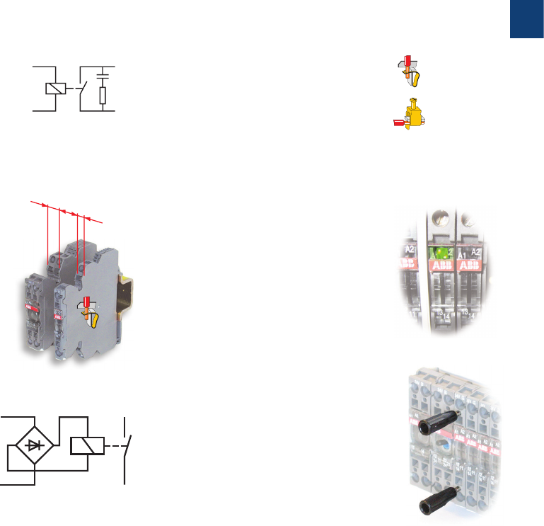
5
2CDC 110 004 C0210 | Catalog Electronic Products and Relays 2015 | ABB 5/32
Interface relays R600 range
Benefits and advantages
Increased contact life
The contacts of some devices are prote-
ced by built in RC-circuits which result
in increased contact life.
Space safing
With a width of only 6 mm or 12 mm the
compact design safes space in each
cabinet.
12 mm spacing
6 mm spacing
Variety of connections
R600 relays and optocouplers
are available with both screw
terminals or spring terminals.
Functioning status
Functioning display through a
green LED.
Only one part number AC/DC
Measurement & Test
Holes for holding DIA. 2 mm test
plugs to simplify any measure-
ment or test.
0.2 to 2.5 mm²
0.22 to 4 mm²
Interface relays are electromechanic and electronic input and output modules for electrical isolation, levelling, noise suppression or signal
amplification between control unit and process.
Boxed interface relays are used for electrical isolation, amplification and signal matching between the electronic controlling, e.g. PLC
(programmable logic controller), PC or field bus systems and the sensor / actuator level. The compact design and different connection
terminal possibilities optimize your panel installation.

5
5/33 ABB | Catalog Electronic Products and Relays 2015 | 2CDC 110 004 C0210
Interface relays R600 range
Selection
Order number
1SNA645034R2300
1SNA645036R2500
1SNA645534R2500
1SNA645536R2700
1SNA645073R0000
1SNA645035R2400
1SNA645075R0000
1SNA645575R0000
1SNA645535R2600
1SNA645573R0000
1SNA645019R0400
1SNA645519R0600
1SNA645014R2700
1SNA645018R0300
1SNA645514R2100
1SNA645001R0300
1SNA645005R0700
1SNA645501R0500
1SNA645505R0100
1SNA645012R2500
1SNA645512R2700
1SNA645071R0000
1SNA645571R0000
1SNA645072R0000
1SNA645572R0000
1SNA645002R0400
1SNA645006R0000
1SNA645502R0600
1SNA645506R0200
1SNA645040R1500
1SNA645540R1700
1SNA645003R0500
1SNA645007R0100
1SNA645046R0700
1SNA645503R0700
1SNA645507R0300
1SNA645546R0100
1SNA645041R0200
1SNA645541R0400
1SNA645016R2100
1SNA645017R2200
1SNA645004R0400
1SNA645008R1200
1SNA6 4 5011R24 0 0
1SNA645504R0000
1SNA645508R1400
1SNA6 4 5511R26 0 0
1SNA645013R2600
1SNA645513R2000
1SNA645020R0100
1SNA645520R0300
Type
RB 121-5VDC
RB 121-5VDC
RBR 121-5VDC
RBR 121-5VDC
RB121-12VDC
RB121-12VDC
RB121-AU-12VDC
RBR121-AU-12VDC
RBR121-12VDC
RBR121-12VDC
RB 101AR-24VAC/DC
RBR 101AR-24VAC/DC
RB 111A -24VAC/ DC
RB 111A R -24VAC/ D C
RBR 111A-24VAC/DC
RB 121A-24VAC/DC
RB 121A-24VAC/DC
RBR 121A-24VAC/DC
RBR 121A-24VAC/DC
RB 122A-24VAC/DC
RBR 122A-24VAC/DC
RB121-24VDC
RBR121-24VDC
RB121-AU-24VDC
1SNA645572R0000
RB 121A-48-60VAC/DC
RB 121A-48-60VAC/DC
RBR 121A-48-60VAC/DC
RBR 121A-48-60VAC/DC
RB 122A-48-60VAC/DC
RBR 122A-48-60VAC/DC
RB 121A-115VAC/DC
RB 121A-115VAC/DC
RB 121AR-115VAC/DC
RBR 121A-115VAC/DC
RBR 121A-115VAC/DC
RBR 121AR-115VAC/DC
RB 122A-115VAC/DC
RBR 122A-115VAC/DC
RB 111A -115VAC/DC
RB 111A-230VAC/DC
RB 121A-230VAC/DC
RB 121A-230VAC/DC
RB 121AR-230VAC/DC
RBR 121A-230VAC/DC
RBR 121A-230VAC/DC
RBR 121AR-230VAC/DC
RB 122A-230VAC/DC
RBR 122A-230VAC/DC
RB 121A 60-230VUC
RBR 121A 60-230VUC
Input voltage
5 V DC J J J J
12 V DC J J J J J J
24 V DC J JJJJJJJJJJJJJJ
48-60 V DC J J J J J J
115 V DC JJJJJJJJJ
230 V DC JJJJJJJJJ
60-230 V DC J J
24 V AC J JJJJJJJJJJ
48-60 V AC JJJJJJ
115 V AC JJJJJJJJJ
230 V AC J J J J J J J J J
60-230 V AC J J
Output rating
10 mA - 6 A J J J J J J J J J J J J J J J J J J J J J J J J J J J J
1 mA - 6 A J J J J J J J J J J J J J J J
1 mA - 8 A J J J J J J J J
Output contacts
c/o 1111111111 1111221111 111122 11111122 1111112211
n/o 1 1 1 1 1
n/c 1 1
Terminal type
Screw J J J J J J J J J J J J J J J J J J J J J J J J J J J
Spring J J J J J J J J J J J J J J J J J J J J J J J J

5
2CDC 110 004 C0210 | Catalog Electronic Products and Relays 2015 | ABB 5/34
Interface relays R600 range
Selection
Order number
1SNA645034R2300
1SNA645036R2500
1SNA645534R2500
1SNA645536R2700
1SNA645073R0000
1SNA645035R2400
1SNA645075R0000
1SNA645575R0000
1SNA645535R2600
1SNA645573R0000
1SNA645019R0400
1SNA645519R0600
1SNA645014R2700
1SNA645018R0300
1SNA645514R2100
1SNA645001R0300
1SNA645005R0700
1SNA645501R0500
1SNA645505R0100
1SNA645012R2500
1SNA645512R2700
1SNA645071R0000
1SNA645571R0000
1SNA645072R0000
1SNA645572R0000
1SNA645002R0400
1SNA645006R0000
1SNA645502R0600
1SNA645506R0200
1SNA645040R1500
1SNA645540R1700
1SNA645003R0500
1SNA645007R0100
1SNA645046R0700
1SNA645503R0700
1SNA645507R0300
1SNA645546R0100
1SNA645041R0200
1SNA645541R0400
1SNA645016R2100
1SNA645017R2200
1SNA645004R0400
1SNA645008R1200
1SNA6 4 5011R24 0 0
1SNA645504R0000
1SNA645508R1400
1SNA6 4 5511R26 0 0
1SNA645013R2600
1SNA645513R2000
1SNA645020R0100
1SNA645520R0300
Type
RB 121-5VDC
RB 121-5VDC
RBR 121-5VDC
RBR 121-5VDC
RB121-12VDC
RB121-12VDC
RB121-AU-12VDC
RBR121-AU-12VDC
RBR121-12VDC
RBR121-12VDC
RB 101AR-24VAC/DC
RBR 101AR-24VAC/DC
RB 111A -24VAC/ DC
RB 111A R -24VAC/ D C
RBR 111A-24VAC/DC
RB 121A-24VAC/DC
RB 121A-24VAC/DC
RBR 121A-24VAC/DC
RBR 121A-24VAC/DC
RB 122A-24VAC/DC
RBR 122A-24VAC/DC
RB121-24VDC
RBR121-24VDC
RB121-AU-24VDC
1SNA645572R0000
RB 121A-48-60VAC/DC
RB 121A-48-60VAC/DC
RBR 121A-48-60VAC/DC
RBR 121A-48-60VAC/DC
RB 122A-48-60VAC/DC
RBR 122A-48-60VAC/DC
RB 121A-115VAC/DC
RB 121A-115VAC/DC
RB 121AR-115VAC/DC
RBR 121A-115VAC/DC
RBR 121A-115VAC/DC
RBR 121AR-115VAC/DC
RB 122A-115VAC/DC
RBR 122A-115VAC/DC
RB 111A -115VAC/DC
RB 111A-230VAC/DC
RB 121A-230VAC/DC
RB 121A-230VAC/DC
RB 121AR-230VAC/DC
RBR 121A-230VAC/DC
RBR 121A-230VAC/DC
RBR 121AR-230VAC/DC
RB 122A-230VAC/DC
RBR 122A-230VAC/DC
RB 121A 60-230VUC
RBR 121A 60-230VUC
Input voltage
5 V DC J J J J
12 V DC J J J J J J
24 V DC J JJJJJJJJJJJJJJ
48-60 V DC J J J J J J
115 V DC JJJJJJJJJ
230 V DC JJJJJJJJJ
60-230 V DC J J
24 V AC J JJJJJJJJJJ
48-60 V AC J J J J J J
115 V AC JJJJJJJJJ
230 V AC JJJJJJJJJ
60-230 V AC J J
Output rating
10 mA - 6 A J J J J J J J J J J J J J J J J J J J J J J J J J J J J
1 mA - 6 A J J J J J J J J J J J J J J J
1 mA - 8 A J J J J J J J J
Output contacts
c/o 1111111111 1111221111 111122 11111122 1111112211
n/o 1 1 1 1 1
n/c 1 1
Terminal type
Screw J J J J J J J J J J J J J J J J J J J J J J J J J J J
Spring J J J J J J J J J J J J J J J J J J J J J J J J
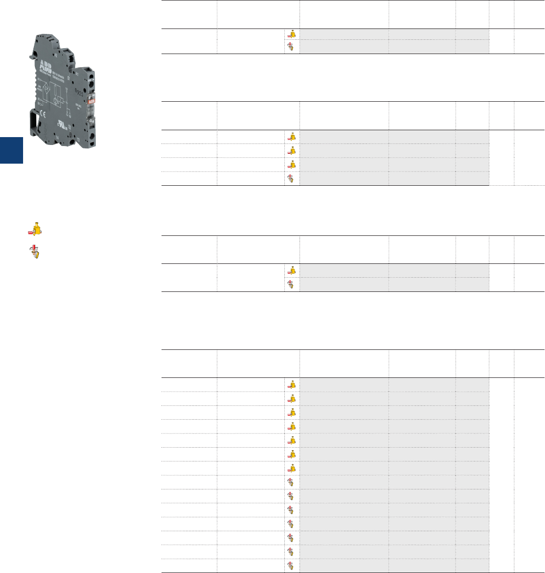
5
5/35 ABB | Catalog Electronic Products and Relays 2015 | 2CDC 110 004 C0210
Interface relays R600 range
Ordering details
Ordering details - 1 n/c contact: 250 V, 10 mA - 6 A (high level), width 12 mm
Rated control
supply voltage
Particularities and
connection type
Type Order code Price Pkg
qty
Weight
(1 pce)
kg (lb)
24 V AC/DC
RC circuit parallel to
contact on output
side
RB101AR-24VAC/DC 1SNA645019R0400
5
0.04
(0.088)
RBR101AR-24VAC/DC 1SNA645519R0600
Ordering details - 1 n/o contact: 250 V, 10 mA - 6 A (high level), width 12 mm
Rated control
supply voltage
Particularities and
connection type
Type Order code Price Pkg
qty
Weight
(1 pce)
kg (lb)
24 V AC/DC
RC circuit parallel to
contact on output
side
RB111AR-24VAC/D C 1SNA645018R0300
5
0.04
(0.088)
RBR111AR-24VAC/DC 1SNA645518R0500
Ordering details - 1 c/o (SPDT) contact: 250 V, 1 mA - 6 A (low level), width 6 mm
Rated control
supply voltage
Particularities and
connection type
Type Order code Price Pkg
qty
Weight
(1 pce)
kg (lb)
5 V DC A1-A2 polarized RB121-5VDC 1SNA645036R2500
10
0.02
(0.044)
12 V DC RB121-AU-12VDC 1SNA645075R0000
24 V DC RB121-AU-24VDC 1SNA645072R0000
24 V AC/DC RB121A-24VAC/DC 1SNA645005R0700
48-60 V AC/DC RB121A-48-60VAC/DC 1SNA645006R0000
115 V AC/DC RB121A-115VAC/DC 1SNA645007R0100
230 V AC/DC RB121A-230VAC/DC 1SNA645008R1200
5 V DC A1-A2 polarized RBR121-5VDC 1SNA645536R2700
12 V DC RBR121-AU-12VDC 1SNA645575R0000
24 V DC RBR121-AU-24VDC 1SNA645572R0000
24 V AC/DC RBR121A-24VAC/DC 1SNA645505R0100
48-60 V AC/DC RBR121A-48-60VUC 1SNA645506R0200
115 V AC/DC RBR121A-115VAC/DC 1SNA645507R0300
230 V AC/DC RBR121A-230VAC/DC 1SNA645508R1400
Ordering details - 1 n/o contact: 250 V, 10 mA - 6 A (high level) width 6 mm
Rated control
supply voltage
Particularities and
connection type
Type Order code Price Pkg
qty
Weight
(1 pce)
kg (lb)
24 V AC/DC RB111A -24VAC/ DC 1SNA645014R2700
10
0.02
(0.044)
115 V AC/DC R B111A -115VAC/DC 1SNA645016R2100
230 V AC/DC RB111A-230VAC/DC 1SNA645017R2200
24 V AC/DC RBR111A-24VAC/DC 1SNA645514R2100
R600 - 6 mm
screw terminals
spring terminals
2CDC 291 024 S0013
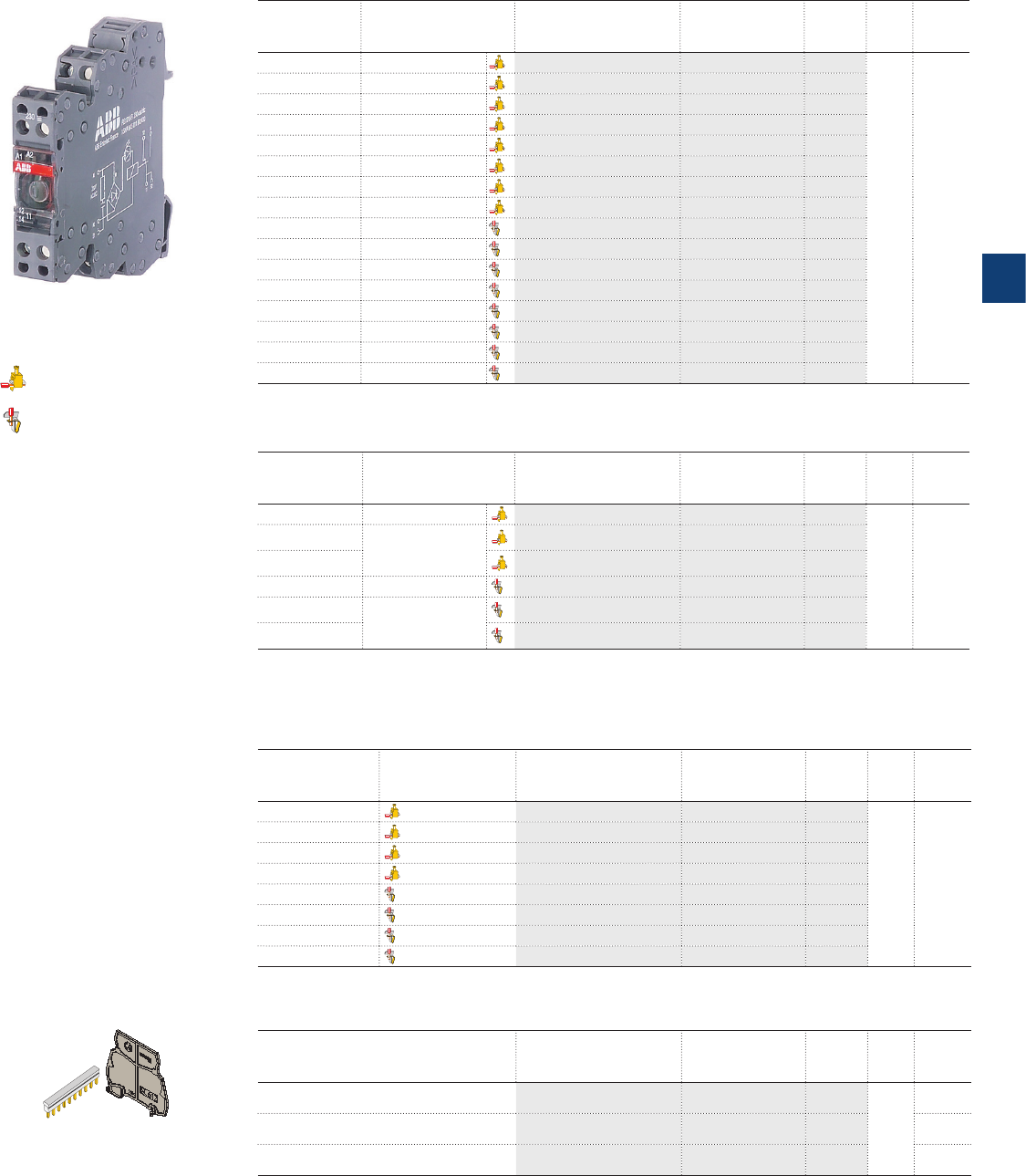
5
2CDC 110 004 C0210 | Catalog Electronic Products and Relays 2015 | ABB 5/36
Ordering details - 1 c/o (SPDT) contact: 250 V, 10 mA - 6 A (high level), width 6 mm
Rated control
supply
voltage
Particularities and
connection type
Type Order code Price Pkg
qty
Weight
(1 pce)
kg (lb)
5 V DC A1-A2 polarized RB121-5VDC 1SNA645034R2300
10
0.02
(0.044)
12 V DC A1-A2 polarized RB121-12VDC 1SNA645035R2400
12 V DC RB121-12VDC 1SNA645073R0000
24 V DC RB121-24VDC 1SNA645071R0000
24 V AC/DC RB121A-24VAC/DC 1SNA645001R0300
48-60 V AC/DC RB121A-48-60VAC/DC 1SNA645002R0400
115 V AC/DC RB121A-115VAC/DC 1SNA645003R0500
230 V AC/DC RB121A-230VAC/DC 1SNA645004R0400
5 V DC A1-A2 polarized RBR121-5VDC 1SNA645534R2500
12 V DC A1-A2 polarized RBR121-12VDC 1SNA645535R2600
12 V DC RBR121-12VDC 1SNA645573R0000
24 V DC RBR121-24VDC 1SNA645571R0000
24 V AC/DC RBR121A-24VAC/DC 1SNA645501R0500
48-60 V AC/DC RBR121A-48-60VUC 1SNA645502R0600
115 V AC/DC RBR121A-115VAC/DC 1SNA645503R0700
230 V AC/DC RBR121A-230VAC/DC 1SNA645504R0000
Ordering details - 1 c/o (SPDT) contact: 250 V, 10 mA - 6 A (high level), width 12 mm
Rated control
supply voltage
Particularities and
connection type
Type Order code Price Pkg
qty
Weight
(1 pce)
kg (lb)
60-230 V AC/DC RB121A-60-230VUC 1SNA645020R0100
0.04
(0.088)
115 V AC/DC Leakage current
protection, input side
RB121AR-115VAC/DC 1SNA645046R0700
230 V AC/DC RB121AR-230VAC/DC 1S N A64 5 011R 2400
60-230 V AC/DC RBR121A-60-230VUC 1SNA645520R0300
115 V AC/DC Leakage current
protection, input side
RBR121AR-115VAC/DC 1SNA645546R0100
230 V AC/DC RBR121AR-230VAC/DC 1S N A645 511R 2600
Ordering details - 2 c/o (SPDT) contacts: 250 V, 1 mA - 8 A (low level), width 12 mm
Rated control
supply voltage
Connection type Type Order code Price Pkg
qty
Weight
(1 pce)
kg (lb)
24 V AC/DC RB122A-24VAC/DC 1SNA645012R2500
5
0.04
(0.088)
48-60 V AC/DC RB122A-48-60VAC/DC 1SNA645040R1500
115 V AC/DC RB122A-115VAC/DC 1SNA645041R0200
230 V AC/DC RB122A-230VAC/DC 1SNA645013R2600
24 V AC/DC RBR122A-24VAC/DC 1SNA645512R2700
48-60 V AC/DC RBR122A-48-60VUC 1SNA645540R170 0
115 V AC/DC RBR122A-115VAC/DC 1SNA645541R040 0
230 V AC/DC RBR122A-230VAC/DC 1SNA645513R2000
Ordering details - Accessories
Description Type Order code Price Pkg
qty
Weight
(1 pce)
kg (lb)
24 V AC/DC BJ 612-10 1SNA290488R0100
10
0.05
(0.11)
48-60 V AC/DC BJ 612-20 1SNA206754R0000
0.01
(0.022)
230 V AC/DC SC 612 1S N A 29 0 474 R 02 00
0.05
(0.11)
screw terminals
spring terminals
Interface relays R600 range
Ordering details
R600 - 12 mm
SC612
BJ...
2CDC 291 013 S0013
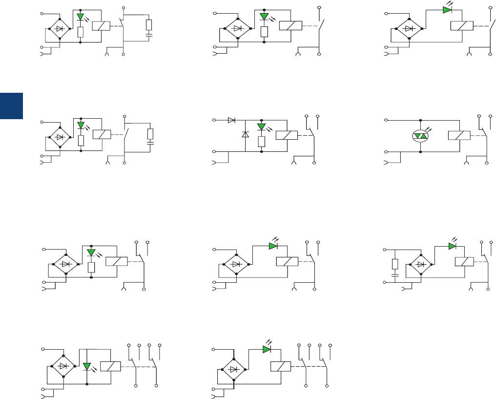
5
5/37 ABB | Catalog Electronic Products and Relays 2015 | 2CDC 110 004 C0210
Interface relays R600 range
Connection diagrams
11-12 n/c contact A1-A2 Control supply voltage
13-14 n/o contact S1 Connection for jumper bar (input side)
11-12/14 1st c/o contact S2 Connection for jumper bar (output side)
21-22/24 2nd c/o contact
A1
A
2
S1
11S2
12
2CDC 292 030 F0013
A1
A
2
S1
14S2
13
2CDC 292 031 F0013
A1
A2
S1
14
S2
13
2CDC 292 033 F0013
RB/RBR 101 AR RB/RBR 111 A - 24 V AC/DC RB/RBR 111 A - 48/60/115/230 V AC/DC
A1
A2
S1
14S2
13
2CDC 292 035 F0013
A1
A2
S1
11
S2
12 14
2CDC 292 036 F0013
A1
A
2
S1
11S2
12 14
2CDC 292 038 F0013
RB/RBR 111 AR RB/RBR 121
- 5 V DC, A1-A2 polarized
- 12 V DC, A1-A2 polarized, i.e. only:
1SNA645035R2400, 1SNA645535R2600
RB/RBR 121 (AU)
- 12/24 V DC, except:
1SNA645035R2400, 1SNA645535R2600
see connection diagram RB...121-5VDC
A1
A
2
S1
11
S2
12 14
2CDC 292 039 F0013
A1
A2
S1
11
S2
12 14
2CDC 292 040 F0013
A1
A2
S1
11
S2
12 14
2CDC 292 042 F0013
RB/RBR 121 A - 24 V AC/DC RB/RBR 121 A - 48/60/115/230 V AC/DC RB/RBR 121 AR
A1
A2
S1 11 21
12 14 22 24
2CDC 292 043 F0013
A1
A
2
S1 11 21
12 14 22 24
2CDC 292 044 F0013
RB/RB 122 A - 24/48/60 V AC/DC RB/RBR 122 A - 115/230 V AC/DC

5
2CDC 110 004 C0210 | Catalog Electronic Products and Relays 2015 | ABB 5/38
Interface relays R600 range
Technical data
Technical data
RB... 111A high level
Input circuit
Rated control supply voltage Us24 V AC/DC 48 V AC/DC 60 V AC/DC 115 V AC/DC 230 V AC/DC
Rated control supply voltage Us
tolerance DC -15 %, +20 % -15 %, +10 %
AC -/+ 10 %
Rated frequency 50/60 Hz
Typical power consumption 0.24 W 0.34 W 0.54 W 0.46 W 0.8 W
Typical current 10 mA 7 mA 9 mA 4 mA 3.5 mA
Drop-out voltage 4.5 V 8 V 8 V 17 V 27 V
Indication of operational states
green LED
V: control supply voltage applied
Output circuit
Kind of output 13-14 relay, 1 n/o contact
Rated operational voltage U
e
(IEC/EN 60947-1)
250 V AC
Minimum switching voltage 12 V
Maximum switching voltage 250 V AC
Minimum switching current 10 mA
Rated free air thermal current Ith 6 A
Rated operational
current
(IEC/EN 60947-5-1)
AC-12 (resistive) 230 V
6 A
AC-15 (inductive) 230 V
1.5 A
AC-15 (inductive) 120 V
3 A
DC-12 (resistive) 24 V
6 A
DC-13 (inductive) 24 V
1 A
DC-13 (inductive) 120 V
0.2 A
DC-13 (inductive) 230 V
0.1 A
AC rating
(UL508;
NEMAICS-5)
Utilization category (pilot duty)
B300
DC rating
(UL508;
NEMAICS-5)
Utilization category (pilot duty)
R300
Minimum switching power 0.6 W / 0.6 VA
Mechanical lifetime 1 x 10⁷ switching cycles
Electrical lifetime at AC-15 1 x 10⁵ switching cycles
Response time 5 ms 5 ms 5 ms 6 ms 7 ms
Release time 8 ms 8 ms 8 ms 15 ms 15 ms
Dimensions and weight RB 111 A RBR 111 A
Weight net weight 0.02 kg (0.044 lb)
Dimension product dimension 6 x 70 x 75 mm (0.236 x 2.76 x 2.95 in) 6 x 75 x 75 mm (0.236 x 2.95 x 2.95 in)

5
5/39 ABB | Catalog Electronic Products and Relays 2015 | 2CDC 110 004 C0210
Interface relays R600 range
Technical data
Technical data
RB... 111AR high level RB... 101AR high level
Input circuit
Rated control supply voltage Us24 V AC/DC
Rated control supply voltage Us
tolerance DC -15 %, +20 %
AC -/+ 10 %
Rated frequency 50/60 Hz
Typical power consumption 0.24 W
Typical current 10 mA
Drop-out voltage 4.5 V
Indication of operational states
green LED
V: control supply voltage applied
Output circuit
Kind of output 11-12 -relay, 1 n/c contact
13-14 relay, 1 n/o contact -
Rated operational voltage U
e
(IEC/EN 60947-1)
250 V AC
Minimum switching voltage 12 V
Maximum switching voltage 250 V AC
Minimum switching current 10 mA
Rated free air thermal current Ith
6 A
Rated operational
current
(IEC/EN 60947-5-1)
AC-12 (resistive) 230 V
6 A
AC-15 (inductive) 230 V
1.5 A
AC-15 (inductive) 120 V
3 A
DC-12 (resistive) 24 V
6 A
DC-13 (inductive) 24 V
1 A
DC-13 (inductive) 120 V
0.2 A
DC-13 (inductive) 230 V
0.1 A
AC rating
(UL508;
NEMAICS-5)
Utilization category (pilot duty)
B300
DC rating
(UL508;
NEMAICS-5)
Utilization category (pilot duty)
R300
Minimum switching power 0.6 W / 0.6 VA
Mechanical lifetime 1 x 10⁷ switching cycles
Electrical lifetime at AC-15 1 x 10⁵ switching cycles
Response time 5 ms
Release time 8 ms
Dimensions and weight RB 111AR / RB 101AR high level RBR 111A / RBR 111AR high level
Weight net weight 0.03 kg (0.066 lb)
Dimension product dimension 12 x 70 x 75 mm (0.472 x 2.76 x 2.95 in) 12 x 75 x 75 mm (0.472 x 2.95 x 2.95 in)

5
2CDC 110 004 C0210 | Catalog Electronic Products and Relays 2015 | ABB 5/40
Interface relays R600 range
Technical data
Technical data
RB... 121 / RB... 121A high level
Input circuit
Rated control supply voltage Us5 V DC 12 V DC 24 V AC/DC 48 V AC/DC 60 V AC/DC 115 V AC/DC
230 V AC/DC
Rated control supply voltage Us
tolerance DC -15 %, +20 %
-15 %, +10 %
AC --/+ 10 %
Rated frequency -50/60 Hz
Typical power consumption 0.2 W 0.2 W 0.24 W 0.33 W 0.54 W 0.46 W 0.8 W
Typical current 40 mA 16 mA 10 mA 7 mA 9 mA 4 mA 3.5 mA
Drop-out voltage 1.2 V 2.2 V 4.5 V 8 V 8 V 17 V 27 V
Indication of operational states
green LED
V: control supply voltage applied
Output circuit
Kind of output 11-12/14 relay, 1 c/o (SPDT) contact
Rated operational voltage U
e
(IEC/EN 60947-1)
250 V AC
Minimum switching voltage 12 V
Maximum switching voltage 250 V AC
Minimum switching current 10 mA
Rated free air thermal current Ith 6 A
Rated operational
current
(IEC/EN 60947-5-1)
AC-12 (resistive) 230 V
6 A
AC-15 (inductive) 230 V
1.5 A
AC-15 (inductive) 120 V
3 A
DC-12 (resistive) 24 V
6 A
DC-13 (inductive) 24 V
1 A
DC-13 (inductive) 120 V
0.2 A
DC-13 (inductive) 230 V
0.1 A
AC rating
(UL508;
NEMAICS-5)
Utilization category (pilot duty)
B300
DC rating
(UL508;
NEMAICS-5)
Utilization category (pilot duty)
R300
Minimum switching power 0.6 W / 0.6 VA
Mechanical lifetime 1 x 10⁷ switching cycles
Electrical lifetime at AC-15 1 x 10⁵ switching cycles
Response time 5 ms 5 ms 5 ms 5 ms 5 ms 6 ms 7 ms
Release time 8 ms 8 ms 8 ms 8 ms 8 ms 15 ms 16 ms
Dimensions and weight RB 121 / RB 121A high level RBR 121 / RBR 121 A high level
Weight net weight 0.02 kg (0.044 lb)
Dimension product dimension 6 x 70 x 75 mm (0.236 x 2.76 x 2.95 in) 6 x 75 x 75 mm (0.236 x 2.95 x 2.95 in)

5
5/41 ABB | Catalog Electronic Products and Relays 2015 | 2CDC 110 004 C0210
Interface relays R600 range
Technical data
Technical data
RB... 121 / RB... 121A low level
Input circuit
Rated control supply voltage Us5 V DC 12 V DC 24 V AC/DC 48 V AC/DC 60 V AC/DC 115 V AC/DC
230 V AC/DC
Rated control supply voltage Us
tolerance DC -15 %, +20 %
-15 %, +10 %
AC --/+ 10 %
Rated frequency -50/60 Hz
Typical power consumption 0.2 W 0.2 W 0.24 W 0.33 W 0.54 W 0.46 W 0.8 W
Typical current 40 mA 16 mA 10 mA 7 mA 9 mA 4 mA 3.5 mA
Drop-out voltage 1.2 V 2.2 V 4.5 V 8 V 8 V 17 V 27 V
Indication of operational states
green LED
V: control supply voltage applied
Output circuit
Kind of output 11-12/14 relay, 1 c/o (SPDT) contact
Rated operational voltage U
e
(IEC/EN 60947-1)
250 V AC
Minimum switching voltage 5 V
Maximum switching voltage 250 V AC
Minimum switching current 1 mA
Rated free air thermal current Ith 6 A
Rated operational
current
(IEC/EN 60947-5-1)
AC-12 (resistive) 230 V
6 A
AC-15 (inductive) 230 V
1.5 A
AC-15 (inductive) 120 V
3 A
DC-12 (resistive) 24 V
6 A
DC-13 (inductive) 24 V
1 A
DC-13 (inductive) 120 V
0.2 A
DC-13 (inductive) 230 V
0.1 A
AC rating
(UL508;
NEMAICS-5)
Utilization category (pilot duty)
B300
DC rating
(UL508;
NEMAICS-5)
Utilization category (pilot duty)
R300
Minimum switching power 0.05 W / 0.05 VA
Mechanical lifetime 1 x 10⁷ switching cycles
Electrical lifetime at AC-15 1 x 10⁵ switching cycles
Response time 5 ms 5 ms 5 ms 5 ms 5 ms 6 ms 7 ms
Release time 8 ms 8 ms 8 ms 8 ms 8 ms 15 ms 16 ms
Dimensions and weight RB 121 / RB 121A low level RBR 121 / RBR 121 A low level
Weight net weight 0.02 kg (0.044 lb)
Dimension product dimension 6 x 70 x 75 mm (0.236 x 2.76 x 2.95 in) 6 x 75 x 75 mm (0.236 x 2.95 x 2.95 in)

5
2CDC 110 004 C0210 | Catalog Electronic Products and Relays 2015 | ABB 5/42
Interface relays R600 range
Technical data
Technical data
RB... 121AR
Input circuit
Rated control supply voltage Us115 V AC/DC 230 V AC/DC
Rated control supply voltage Us
tolerance DC -20%, +15% -10%, +15%
AC -/+ 10 %
Rated frequency 50/60 Hz
Typical power consumption 2 W 2.8 W
Typical current 18 mA 12 mA
Drop-out voltage 17 V 27 V
Indication of operational states
green LED
V: control supply voltage applied
Output circuit
Kind of output 11-12/14 relay, 1 c/o (SPDT) contact
Rated operational voltage U
e
(IEC/EN 60947-1)
250 V AC
Minimum switching voltage 12 V
Maximum switching voltage 250 V AC
Minimum switching current 10 mA
Rated free air thermal current Ith 6 A
Rated operational
current
(IEC/EN 60947-5-1)
AC-12 (resistive) 230 V
6 A
AC-15 (inductive) 230 V
1.5 A
AC-15 (inductive) 120 V
3 A
DC-12 (resistive) 24 V
6 A
DC-13 (inductive) 24 V
1 A
DC-13 (inductive) 120 V
0.2 A
DC-13 (inductive) 230 V
0.1 A
AC rating
(UL508;
NEMAICS-5)
Utilization category (pilot duty)
B300
DC rating
(UL508;
NEMAICS-5)
Utilization category (pilot duty)
R300
Minimum switching power 0.6 W / 0.6 VA
Mechanical lifetime 1 x 10⁷ switching cycles
Electrical lifetime at AC-15 1 x 10⁵ switching cycles
Response time 6 ms 7 ms
Release time 15 ms 16 ms
Dimensions and weight RB 121AR RBR 121AR
Weight net weight 0.03 kg (0.066 lb)
Dimension product dimension 12 x 70 x 75 mm (0.472 x 2.76 x 2.95 in) 12 x 75 x 75 mm
(0.472 x 2.95 x 2.95 in)
Technical data
RB... 122A low level
Input circuit
Rated control supply voltage Us24 V AC/DC 48 V AC/DC 60 V AC/DC 115 V AC/DC 230 V AC/DC
Rated control supply voltage Us
tolerance DC -15 %, +20 % -15 %, +10 %
AC -/+ 10 %
Rated frequency 50/60 Hz
Typical power consumption 0.48 W 0.62 W 0.96 W 0.58 W 1.15 W
Typical current 20 mA 13 mA 16 mA 5 mA 5 mA
Drop-out 5.4 V 8.8 V 8.8 V V 20 V 10 V
Indication of operational states
green LED
V: control supply voltage applied
Output circuit
Kind of output 11-12/14 relay, 1st c/o (SPDT) contact
21-22/24 relay, 2nd c/o (SPDT) contact
Rated operational voltage U
e
(IEC/EN 60947-1)
250 V AC
Minimum switching voltage 5 V
Maximum switching voltage 250 V DC - 250 V AC
Minimum switching current 1 mA
Rated free air thermal current Ith 8 A 5 A
Rated operational
current
(IEC/EN 60947-5-1)
AC-12 (resistive) 230 V
8 A 5 A
DC-12 (resistive) 24 V 8 A 5 A
Minimum switching power 5 mW / 5 mVA
Mechanical lifetime 2 x 10⁷ switching cycles
Electrical lifetime at AC-15 1 x 10⁵ switching cycles
Response time 6 ms 10 ms 10 ms 6 ms 6 ms
Release time 10 ms 14 ms 14 ms 15 ms 15 ms
Dimensions and weight RB 122A low level RBR 122A low level
Weight net weight 0.03 kg (0.066 lb)
Dimension product dimension 12 x 70 x 75 mm (0.472 x 2.76 x 2.95 in) 12 x 75 x 75 mm (0.472 x 2.95 x 2.95 in)

5
5/43 ABB | Catalog Electronic Products and Relays 2015 | 2CDC 110 004 C0210
Technical data
RB RBR
General data
Material of housing UL 94 V0
Mounting DIN Rail
Degree of protection housing /
terminals IP20 NEMA1
Electrical connection Screw terminal Spring-type terminal
Wire size fine-stranded 0.22-2.5 mm² (24-14 AWG)
rigid 0.2-4 mm² (24-12 AWG) 0.2-2.5 mm² (24-14 AWG)
Stripping length 9 mm / 0.354 in
Tightening torque 0.4-0.6 Nm (3.5-5.3 lb.in)
Environmental data
Ambient temperature ranges storage -40...+80 °C
operation -20...+70 °C
Isolation data
Rated insulation voltage U
i
(IEC/EN 60950-1,
EN50178)
4000 V RMS
Rated impulse withstand
voltage U
imp
(EN 50178)
input / output 4000 V RMS (RB122A: 3800 V RMS, RB111AR: 3500 V RMS)
shock coil / output
4000 V RMS
output / output 1000 V RMS
Interface relays R600 range
General technical data
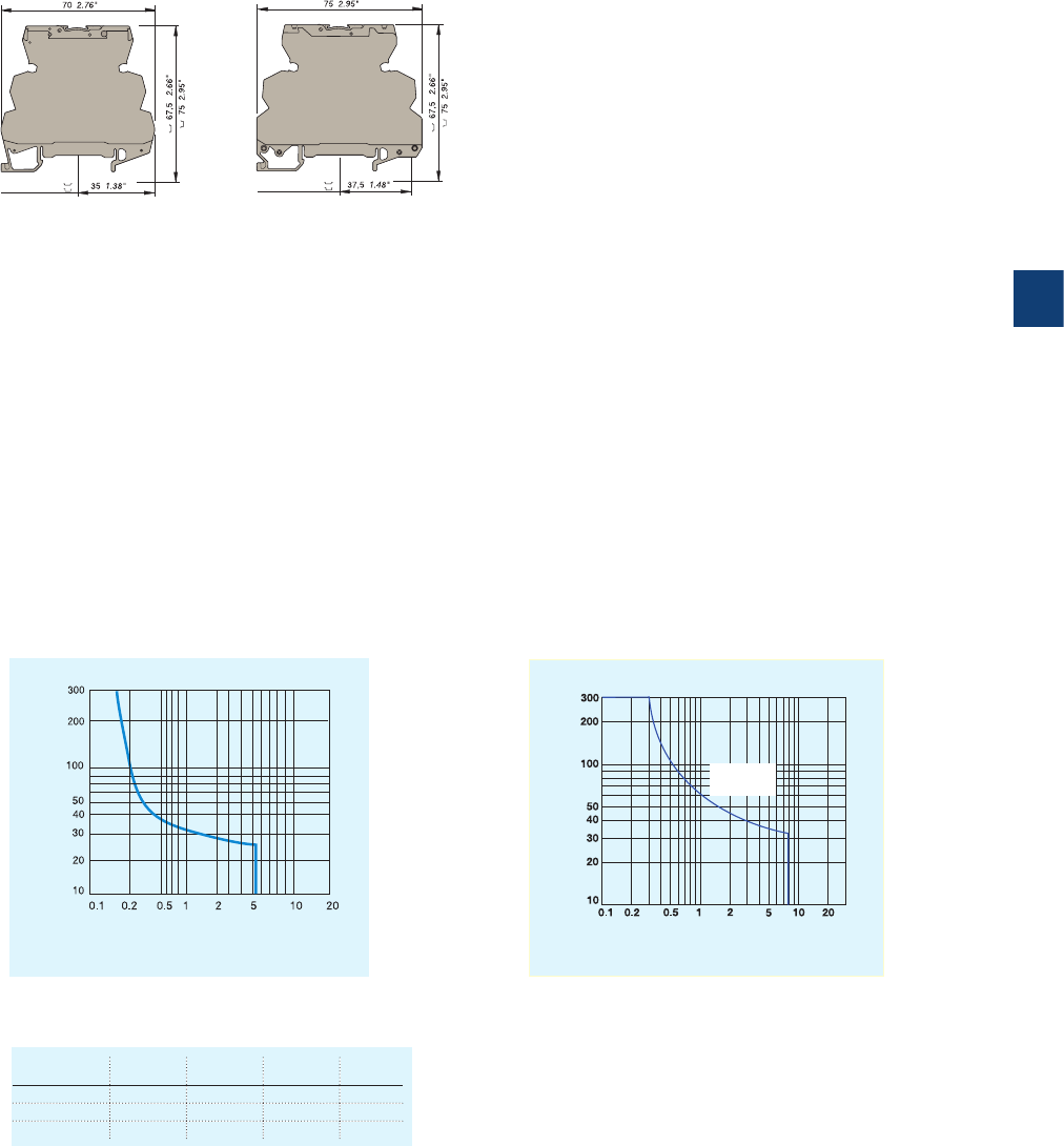
5
2CDC 110 004 C0210 | Catalog Electronic Products and Relays 2015 | ABB 5/44
Interface relays R600 range
Dimensional drawings, Load limit curves
center of rail
Screw clamp module
center of rail
Spring clamp module
All interface relays of R600 range
Load limit curves
Current (Acc)
Voltage (Vcc)
Limited load in CC
DC-12 AC-12 DC-13 AC-15
24 V 6 A 6 A 13 A
110/120 V 0,3 A 6 A 0.2 A 3 A
220/230 V 0.2 A 6 A 0.1 A 3 A
Current [A]
Voltage [V]
resistive
load
Max. DC load breaking capacity
Versions with 1 n/o, 1 n/c or 1 c/o contact Versions with 2 c/o contacts

5
5/45 ABB | Catalog Electronic Products and Relays 2015 | 2CDC 110 004 C0210
Optocouplers R600 range
Selection
Order number
1SNA645047R0000
1SNA645547R0200
1SNA645021R2600
1SNA645521R2000
1SNA645049R1200
1SNA645549R1400
1SNA645022R2700
1SNA645522R2100
1SNA645050R1700
1SNA645550R1100
1SNA645051R0400
1SNA645025R2200
1SNA645024R2100
1SNA645551R0600
1SNA645525R2400
1SNA645524R2300
1SNA645053R0600
1SNA645553R0000
1SNA645054R0700
1SNA645058R1300
1SNA645554R0100
1SNA645558R1500
1SNA645026R2300
1SNA645059R1400
1SNA645526R2500
1SNA645559R1600
1SNA645027R2400
1SNA645029R0600
1SNA645527R2600
1SNA645529R0000
1SNA645061R0600
1SNA645561R0000
1SNA645062R0700
1SNA645562R0100
1SNA645028R0500
1SNA645528R0700
Type
OBIC 0100 5-12VDC
OBRIC 0100 5-12VDC
OBIC 0100 24VDC
OBRIC 0100 24VDC
OBIC 0100 48-60VAC/DC
OBRIC 0100 48-60VAC/DC
OBIC 0100 115-230VAC/DC
OBRIC 0100 115-230VAC/DC
OBOC 1000-5-12VDC
OBROC 1000-5-12VDC
OBOC 1000-24VDC
OBOC 1500-24VAC/DC
OBOC 5000-24VDC
OBROC 1000-24VDC
OBROC 1500-24VAC/DC
OBROC 5000-24VDC
OBOC 1000-48-60VAC/DC
OBROC 1000-48-60VAC/DC
OBOC 1000-115VAC/DC
OBOC 5000-115VAC/DC
OBROC 1000-115VAC/DC
OBROC 5000-115VAC/DC
OBOC 1000-230VAC/DC
OBOC 5000-230VAC/DC
OBROC 1000-230VAC/DC
OBROC 5000-230VAC/DC
OBOA 1000-24VDC
OBOA 2000-24VDC
OBROA 1000-24VDC
OBROA 2000-24VDC
OBOA 1000-48-60VAC/DC
OBROA 1000-48-60VAC/DC
OBOA 1000-115VAC/DC
OBROA 1000-115VAC/DC
OBOA 1000-230VAC/DC
OBROA 1000-230VAC/DC
Input voltage
5-12 V DC J J J J
24 V DC JJ JJJJJJ JJJJ
48-60 V DC J J J J J J
115-230 V DC J J
115 V DC JJJJ JJ
230 V DC J J J J J J J J
24 V AC J J
48-60 V AC J J J J J J
115-230 V AC J J
115 V AC J J J J J J
230 V AC J J J J J J
Output rating
100 mA J J J J J J J J
2 A J J J J J J J J J J J J J J
5 A J J J J J J
1 A J J J J J J J J
Output voltage
58 V DC JJJJJ J J J JJJJJJJJJJJJJJJJJJ
230 V AC J J
400 V AC J J J J J J J J
Terminal type
Screw J J J J J J J J J J J J J J J J J J
Spring J J J J J J J J J J J J J J J J J J

5
2CDC 110 004 C0210 | Catalog Electronic Products and Relays 2015 | ABB 5/46
Optocouplers R600 range
Selection
Order number
1SNA645047R0000
1SNA645547R0200
1SNA645021R2600
1SNA645521R2000
1SNA645049R1200
1SNA645549R1400
1SNA645022R2700
1SNA645522R2100
1SNA645050R1700
1SNA645550R1100
1SNA645051R0400
1SNA645025R2200
1SNA645024R2100
1SNA645551R0600
1SNA645525R2400
1SNA645524R2300
1SNA645053R0600
1SNA645553R0000
1SNA645054R0700
1SNA645058R1300
1SNA645554R0100
1SNA645558R1500
1SNA645026R2300
1SNA645059R1400
1SNA645526R2500
1SNA645559R1600
1SNA645027R2400
1SNA645029R0600
1SNA645527R2600
1SNA645529R0000
1SNA645061R0600
1SNA645561R0000
1SNA645062R0700
1SNA645562R0100
1SNA645028R0500
1SNA645528R0700
Type
OBIC 0100 5-12VDC
OBRIC 0100 5-12VDC
OBIC 0100 24VDC
OBRIC 0100 24VDC
OBIC 0100 48-60VAC/DC
OBRIC 0100 48-60VAC/DC
OBIC 0100 115-230VAC/DC
OBRIC 0100 115-230VAC/DC
OBOC 1000-5-12VDC
OBROC 1000-5-12VDC
OBOC 1000-24VDC
OBOC 1500-24VAC/DC
OBOC 5000-24VDC
OBROC 1000-24VDC
OBROC 1500-24VAC/DC
OBROC 5000-24VDC
OBOC 1000-48-60VAC/DC
OBROC 1000-48-60VAC/DC
OBOC 1000-115VAC/DC
OBOC 5000-115VAC/DC
OBROC 1000-115VAC/DC
OBROC 5000-115VAC/DC
OBOC 1000-230VAC/DC
OBOC 5000-230VAC/DC
OBROC 1000-230VAC/DC
OBROC 5000-230VAC/DC
OBOA 1000-24VDC
OBOA 2000-24VDC
OBROA 1000-24VDC
OBROA 2000-24VDC
OBOA 1000-48-60VAC/DC
OBROA 1000-48-60VAC/DC
OBOA 1000-115VAC/DC
OBROA 1000-115VAC/DC
OBOA 1000-230VAC/DC
OBROA 1000-230VAC/DC
Input voltage
5-12 V DC J J J J
24 V DC J J J J J J J J J J J J
48-60 V DC J J J J J J
115-230 V DC J J
115 V DC J J J J J J
230 V DC J J J J J J J J
24 V AC J J
48-60 V AC J J J J J J
115-230 V AC J J
115 V AC J J J J J J
230 V AC J J J J J J
Output rating
100 mA J J J J J J J J
2 A J J J J J J J J J J J J J J
5 A J J J J J J
1 A J J J J J J J J
Output voltage
58 V DC JJJJJ J J J JJJJJJJJJJJJJJJJJJ
230 V AC J J
400 V AC J J J J J J J J
Terminal type
Screw J J J J J J J J J J J J J J J J J J
Spring J J J J J J J J J J J J J J J J J J
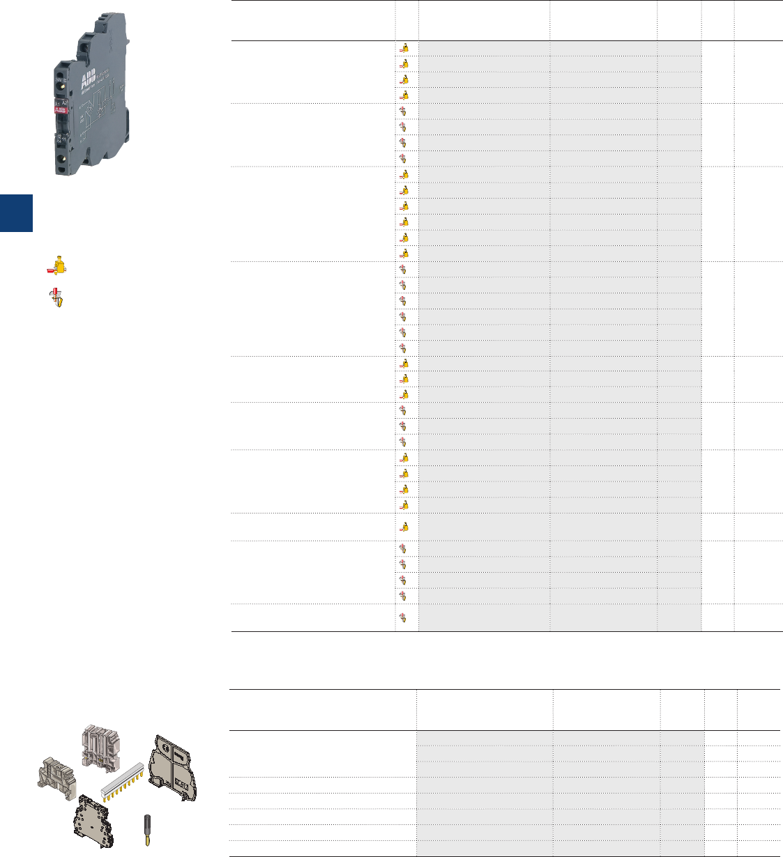
5
5/47 ABB | Catalog Electronic Products and Relays 2015 | 2CDC 110 004 C0210
Optocouplers R600 range
Ordering details
Ordering details - R600 range
R600 Optocoupler Type Order code Price Pkg
qty
Weight
(1 pce)
kg (lb)
Optocoupler module 100 mA/DC
OBIC 0100-5-12VDC
1SNA645047R0000
10 0.02
(0.44)
OBIC 0100-24VDC
1SNA645021R2600
OBIC 0100-48-60VAC/DC
1SNA645049R1200
OBIC 0100-115-230VAC/DC
1SNA645022R2700
Optocoupler module 100 mA/DC
OBRIC 0100-5-12VDC
1SNA645547R0200
10 0.02
(0.44)
OBRIC 0100-24VDC
1SNA645521R2000
OBRIC 0100-48-60VAC/DC
1SNA645549R1400
OBRIC 0100-115-230VAC/DC
1SNA645522R2100
Optocoupler module 2 A/DC
OBOC 1000-5-12VDC
1SNA645050R1700
10 0.02
(0.44)
OBOC 1000-24VDC
1SNA645051R0400
OBOC 1500-24VAC/DC
1SNA645025R2200
OBOC 1000-48-60VAC/DC
1SNA645053R0600
OBOC 1000-115VAC/DC
1SNA645054R0700
OBOC 1000-230VAC/DC
1SNA645026R2300
Optocoupler module 2 A/DC
OBROC 1000-5-12VDC
1SNA645550R1100
10 0.02
(0.44)
OBROC 1000-24VDC
1SNA645551R0600
OBROC 1500-24VAC/DC
1SNA645525R2400
OBROC 1000-48-60VAC/DC
1SNA645553R0000
OBROC 1000-115VAC/DC
1SNA645554R0100
OBROC 1000-230VAC/DC
1SNA645526R2500
Optocoupler module 5 A/DC
OBOC 5000-24VDC
1SNA645024R2100
10 0.02
(0.44)
OBOC 5000-115VAC/DC
1SNA645058R1300
OBOC 5000-230VAC/DC
1SNA645059R1400
Optocoupler module 5 A/DC
OBROC 5000-24VDC
1SNA645524R2300
10 0.02
(0.44)
OBROC 5000-115VAC/DC
1SNA645558R1500
OBROC 5000-230VAC/DC
1SNA645559R1600
Optocoupler module 1 A/AC
6mm spacing
OBOA 1000-24VDC
1SNA645027R2400
10 0.03
(0.066)
OBOA 1000-48-60VAC/DC
1SNA645061R0600
OBOA 1000-115VAC/DC
1SNA645062R0700
OBOA 1000-230VAC/DC
1SNA645028R0500
Optocoupler module 2 A/AC
12mm spacing
OBOA 2000-24VDC
1SNA645029R0600 50.03
(0.066)
Optocoupler module 1 A/AC
6mm spacing
OBROA 1000-24VDC
1SNA645527R2600
10 0.03
(0.066)
OBROA 1000-48-60VAC/DC
1SNA645561R0000
OBROA 1000-115VAC/DC
1SNA645562R0100
OBROA 1000-230VAC/DC
1SNA645528R0700
Optocoupler module 2 A/AC
12mm spacing
OBROA 2000-24VDC
1SNA645529R0000 50.03
(0.066)
Accessories Type Order code Price Pkg
qty
Weight
(1 pce)
kg (lb)
End section
BADH V0 1SNA116900R2700 50
BADL V0 1SNA399903R0200 50
BAM2 V0 1SNA399967R0100 50
Seperator end section SC 612 1S N A 29 0 474 R0 20 0 10
Divisible shunt 10 poles BJ 612-10 1SNA290488R0100 10
Divisible shunt 20 poles BJ 612-20 1SNA206754R0000 10
Test plug DIA. 2 mm FC2 1SNA645531R2200 10
Marking method RC65 / RC610 see marking
SC612
BADL BJ...
FC2
D 4/12-3...
BADH
2CDC 291 001 F0013
screw terminals
spring terminals
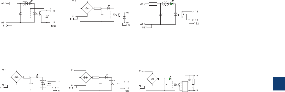
5
2CDC 110 004 C0210 | Catalog Electronic Products and Relays 2015 | ABB 5/48
Optocouplers R600 range
Connection diagrams
OB...IC 0100 - 5-12 V DC
115-230 V AC/DC
OB...IC 0100
24 V DC
24-48-60 V AC/DC
OB...OC 1000 - 5-12 V DC
OB...OC 1500 - 24 V AC/DC
OB...OC 1000
24 V DC
48-60-115-230 V AC/DC
OB...OC 5000
24 V DC
24-48-60-115-230 V AC/DC
OB...OA 1000
24 V DC
48-60-115-230 V AC/DC
OB...OA 2000 - 24 V DC
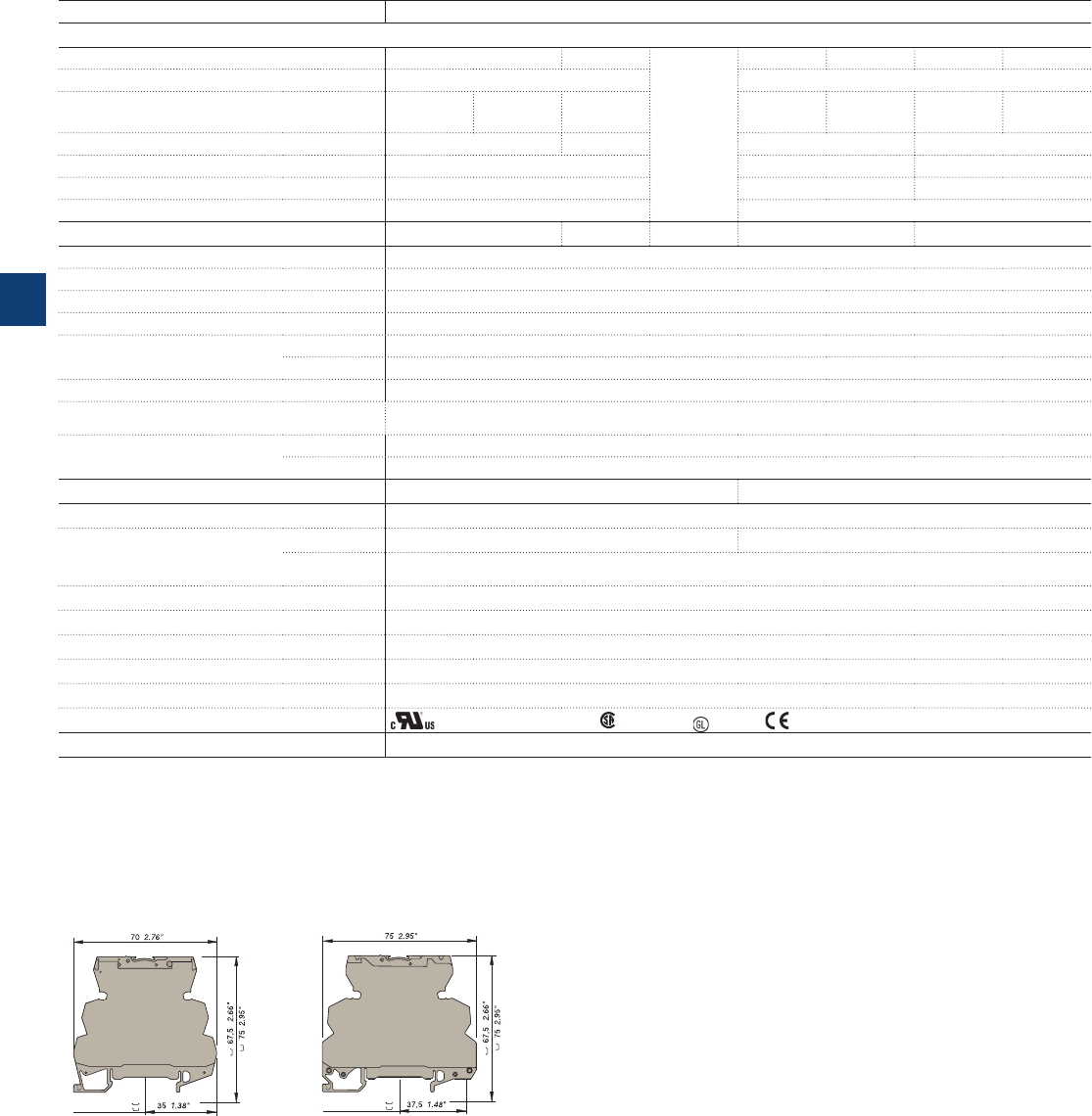
5
5/49 ABB | Catalog Electronic Products and Relays 2015 | 2CDC 110 004 C0210
Optocouplers R600 range
Technical data
Optocoupler : 5 to 58 V DC output / 100 mA - 6 mm 0.236“ spacing
OB...IC 0100
Relay characteristics coil
Input voltage: +20%, -15% on DC ; 10%, -10% on AC
5 V DC - 12 V DC 24 V DC
48 V AC/DC 60 V AC/DC
115 V AC/DC 230 V AC/DC
Frequency 50 / 60 Hz
Input current AC/DC 5 mA 9 mA 4 mA 4 mA 5 mA 7 mA /
16 mA 11.5 mA /
25 mA
Pull-in voltage at Is=100% 4 V 15 V 25 V 60 V AC / 70 V DC
Switching time C / O 10 µs / 500 µs
Operating frequency 1000 Hz 5 ms / 20 ms 5 ms / 15 ms
Permissible leakage current 20 Hz
Output 0.9 mA 1 mA 0.9 mA 1.6 mA
Output voltage 4.5 to 58 V DC
Output current min. 1 mA
Output current max. 100 mA
Output leakage current at Umax. < 50 µA
Residual voltage at I max and
U rated
typical 1 V
max 1.3 V
Frequency on inductive load
Isolation Input / Output input /
Output 2500 V RMS
Temperature storage -40...+80 °C
operating -20...+70 °C 1)
Other characteristics Screw clamp Spring clamp
Body material grey UL 94 V0
Wire size
Solid wire 0.2 - 4 mm² (24-12 AWG) 0.2-2.5 mm² (24-12 AWG)
Stranded
wire 0.22 - 2.5 mm² (24-12 AWG)
Rated wire size 2.5 mm² (12 AWG)
Wire stripping length 9 mm (0.354 in)
Recommended screwdriver 3.5 mm (0.137 in)
Protection IP20 NEMA1
Recommended torque 0.4-0.6 Nm (3.5-5.3 lb.in)
Approvals (pending for 12 V DC) , (pending), , LRS ,
Reference standards
CEI 947-7-1 / CEI 947-1 / CEI 1131-2 (in relevant parts) / CEI 60664-1 / CEM : IEC 1000-4-2, 3, 4, 5, 6.
1) Over 55°C, blocks have to be mounted on horizontal rail with 10 mm spacing between each block. For vertical rail mounting use temperature is 15°C less decreased.
center of rail
Screw clamp module
center of rail
Spring clamp module
Dimensional drawings
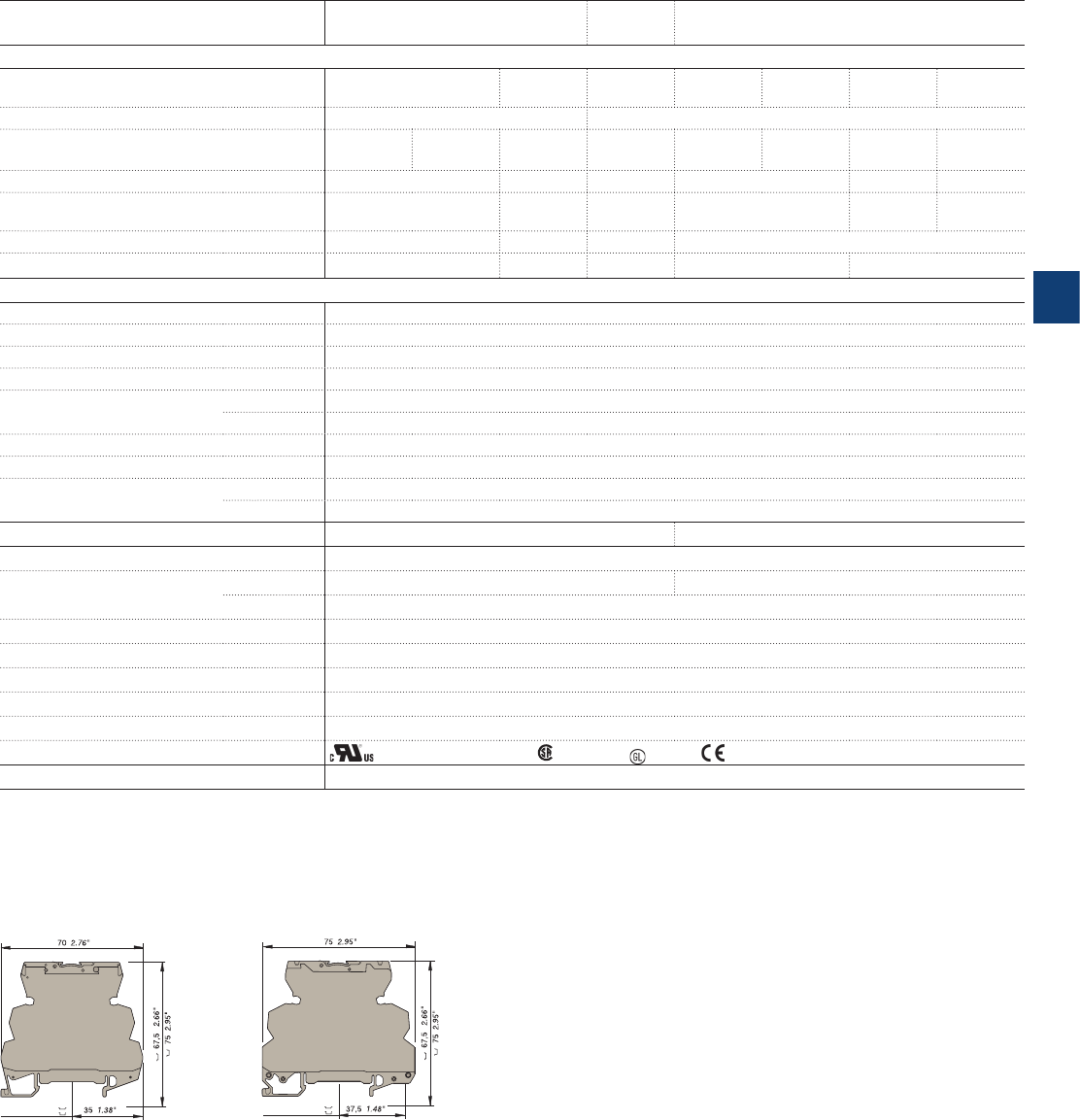
5
2CDC 110 004 C0210 | Catalog Electronic Products and Relays 2015 | ABB 5/50
Optocoupler : 5 to 58 V DC output / 2 A - 6 mm 0.236“ spacing
OB...OC 0100 OB..OC
1500 OB...OC 1000
Relay characteristics coil
Input voltage: +20%, -15% on DC ; 10%, -10%
on AC 5 V DC - 12 V DC 24 V DC 24 V AC/
DC 48 V AC/
DC 60 V AC/
DC 115 V AC/
DC 230 V AC/
DC
Frequency 50 / 60 Hz
Input current 5 mA 9 mA 4 mA 6.3 mA 4 mA 5.1 m A 4.2 mA 4 mA
Pull-in voltage at Is=100% 4 V 15 V 15 V 27 V 50 V 80 V
Switching time C / O 15 µs / 250 µs 30 µs /
400 µs 1 ms / 7
ms 5 ms / 20 ms 500 µs /
10 ms 1 ms /
15 ms
Operating frequency 2000 Hz 1000 Hz 60 Hz 20 Hz
Permissible leakage current 1 mA 0.8 mA 0.9 mA 1 mA 0.3 mA
Output
Output voltage 4.5 to 58 V DC
Output current min. 1 mA
Output current max. 2 A
Output leakage current at Umax. < 50 µA
Residual voltage at I max and
U rated
typical 0.1 V
max 0.5 V
Frequency on inductive load
Isolation Input / Output
input / Output
2500 V RMS
Temperature storage -40...+80 °C
operating -20...+70 °C 1)
Other characteristics Screw clamp Spring clamp
Body material grey UL 94 V0
Wire size Solid wire 0.2 - 4 mm² (24-12 AWG) 0.2-2.5 mm² (24-12 AWG)
Stranded wire
0.22 - 2.5 mm² (24-12 AWG)
Rated wire size 2.5 mm² (12 AWG)
Wire stripping length 9 mm (0.354 in)
Recommended screwdriver 3.5 mm (0.137 in)
Protection IP20 NEMA1
Recommended torque 0.4-0.6 Nm (3.5-5.3 lb.in)
Approvals (pending for 12 V DC) , (pending), , LRS ,
Reference standards
CEI 947-7-1 / CEI 947-1 / CEI 1131-2 (in relevant parts) / CEI 60664-1 / CEM : IEC 1000-4-2, 3, 4, 5, 6.
1) Over 55°C, blocks have to be mounted on horizontal rail with 10 mm spacing between each block. For vertical rail mounting use temperature is 15°C less decreased.
center of rail
Screw clamp module
center of rail
Spring clamp module
Dimensional drawings
Optocouplers R600 range
Technical data
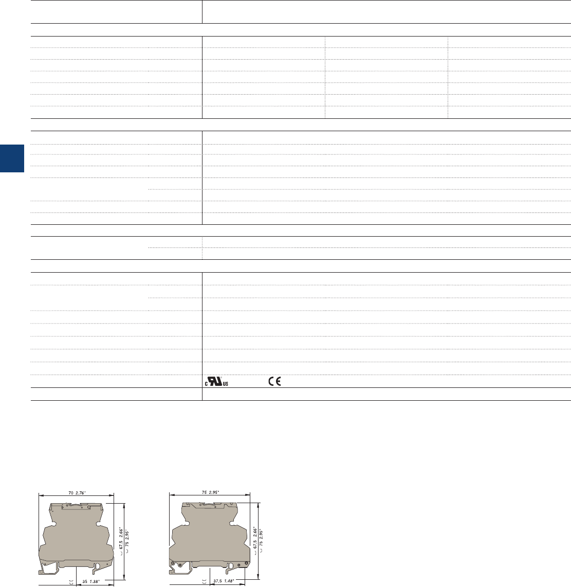
5
5/51 ABB | Catalog Electronic Products and Relays 2015 | 2CDC 110 004 C0210
Optocouplers R600 range
Technical data
Optocoupler : 5 to 58 V DC output / 5 A - 6 mm 0.236“ spacing
OB... OC 5000
Input
Input voltage 24 V DC 115 V AC/DC 230 V AC/DC
Frequency 50 / 60 Hz 50 / 60 Hz
Input current 5.4 mA 4.2 mA 4 mA
Pull-in voltage at Is=100% 12 V 50 V 80 V
Switching time C / O 30 µs / 400 µs 500 µs / 10 ms 1ms / 15 ms
Operating frequency 1000 Hz 50 Hz 35 Hz
Permissible leakage current 0.8 mA 0.3 mA 0.3 mA
Output
Output voltage 4.5- 58 V DC
Output current min. 1 mA
Output current max. 5 A
Output leakage current at Umax. < 50 µA
Residual voltage at I max and
U rated
typical 0.1 V
max 0.5 V
Frequency on inductive load See Note 1
Isolation Input / Output
input / Output
2500 V RMS
Temperature
Ambient temperature storage -40...+80 °C
operating See derating curve
Other characteristics
Body material grey UL 94 V0
Wire size Solid wire 0.2 - 4 mm² (24-12 AWG)
Stranded wire
0.22 - 2.5 mm² (24-12 AWG)
Rated wire size 2.5 mm² (12 AWG)
Wire stripping length 10 mm (0.394 in)
Recommended screwdriver 3.5 mm (0.137 in)
Protection IP20 NEMA1
Recommended torque 0.4-0.6 Nm (3.5-5.3 lb.in)
Approvals (pending),
Reference standards
CEI 947-7-1 / CEI 947-1 / CEI 1131-2 (in relevant parts) / CEI 60664-1 / CEM : IEC 1000-4-2, 3, 4, 5, 6.
Dimensional drawings
center of rail
Screw clamp module
center of rail
Spring clamp module
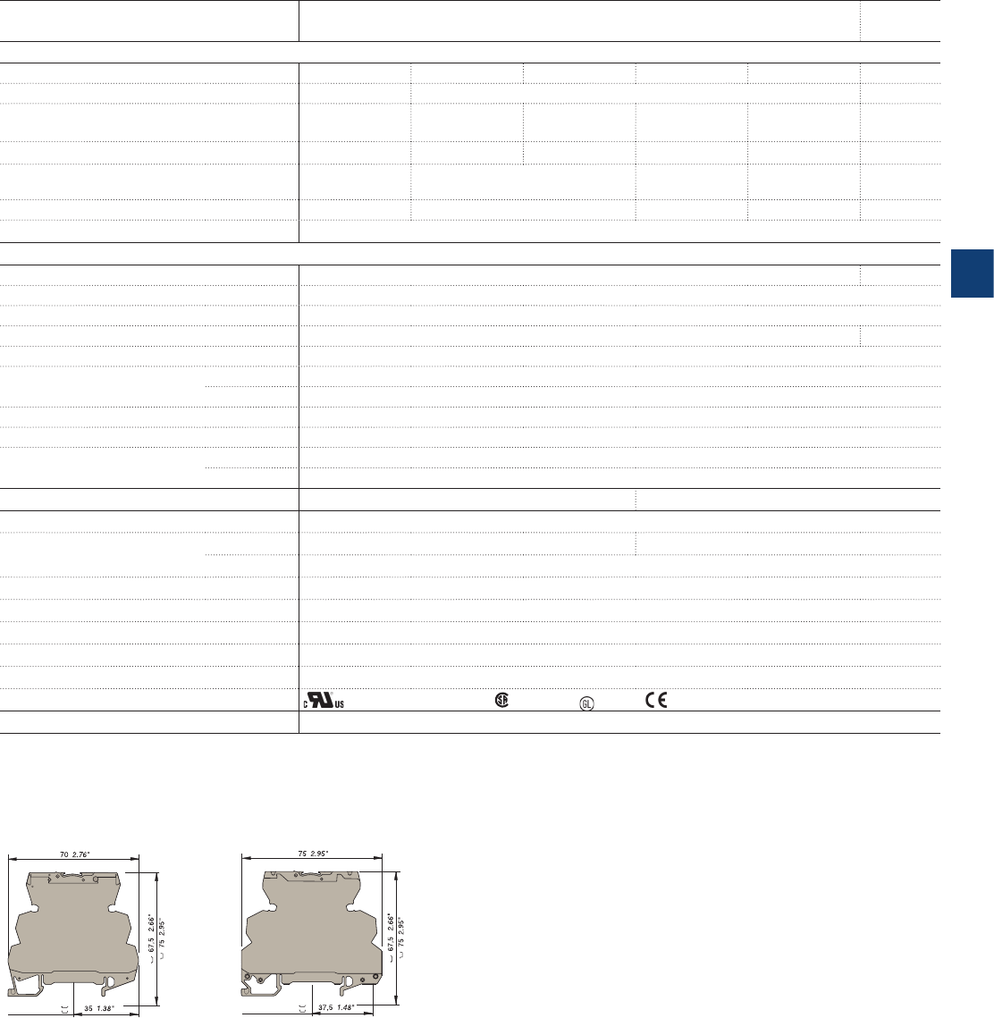
5
2CDC 110 004 C0210 | Catalog Electronic Products and Relays 2015 | ABB 5/52
Optocouplers R600 range
Technical data
Optocoupler : 24 to 400 V AC output / 1 A or 2 A max. - 6 mm or 12 mm spacing
OB...OA 1000 OB...OA
2000
Relay characteristics coil
Input voltage: +20%, -15% on DC ; 10%, -10% on AC
24 V DC 48 V AC/DC 60 V AC/DC 115 V AC/DC 230 V AC/DC 24 V DC
Frequency 50/60 Hz
Input current 3.6 mA 4.3 mA 5.5 mA 4.15 mA 4.6 mA 3.6 mA
Pull-in voltage at Is=100% 14 V 15 V 18 V 60 V 135 V 14 V
Switching time C / O 150 µs / 1 ms 3 ms / 30 ms 2.2 ms / 18 ms 2.5 ms / 25 ms 150 µs / 1
ms
Operating frequency 500 Hz 20 Hz 25 Hz 20 Hz 500 Hz
Permissible leakage current 1 mA
Output
Output voltage 24-400 V AC
10-230 V AC
Frequency 50/60 Hz
Output current min. 25 mA
Output current max. 1 A 2 A
Output leakage current at Umax. < 0.50 mA
Residual voltage at I max and
U rated
typical 1 V
max 1.6 V
Frequency on inductive load
Isolation Input / Output
input / Output
2500 V RMS
Temperature storage -40...+80 °C
operating -20...+70 °C 1)
Other characteristics Screw clamp Spring clamp
Body material grey UL 94 V0
Wire size Solid wire 0.2 - 4 mm² (24-12 AWG) 0.2-2.5 mm² (24-12 AWG)
Stranded wire
0.22 - 2.5 mm² (24-12 AWG)
Rated wire size 2.5 mm² (12 AWG)
Wire stripping length 9 mm (0.354 in)
Recommended screwdriver 3.5 mm (0.137 in)
Protection IP20 NEMA1
Recommended torque 0.4-0.6 Nm (3.5-5.3 lb.in)
Approvals (pending for 12 V DC) , (pending), , LRS ,
Reference standards
CEI 947-7-1 / CEI 947-1 / CEI 1131-2 (in relevant parts) / CEI 60664-1 / CEM : IEC 1000-4-2, 3, 4, 5, 6.
1) Over 55°C, blocks have to be mounted on horizontal rail with 10 mm spacing between each block. For vertical rail mounting use temperature is 15°C less decreased.
Dimensional drawings
center of rail
Screw clamp module
center of rail
Spring clamp module
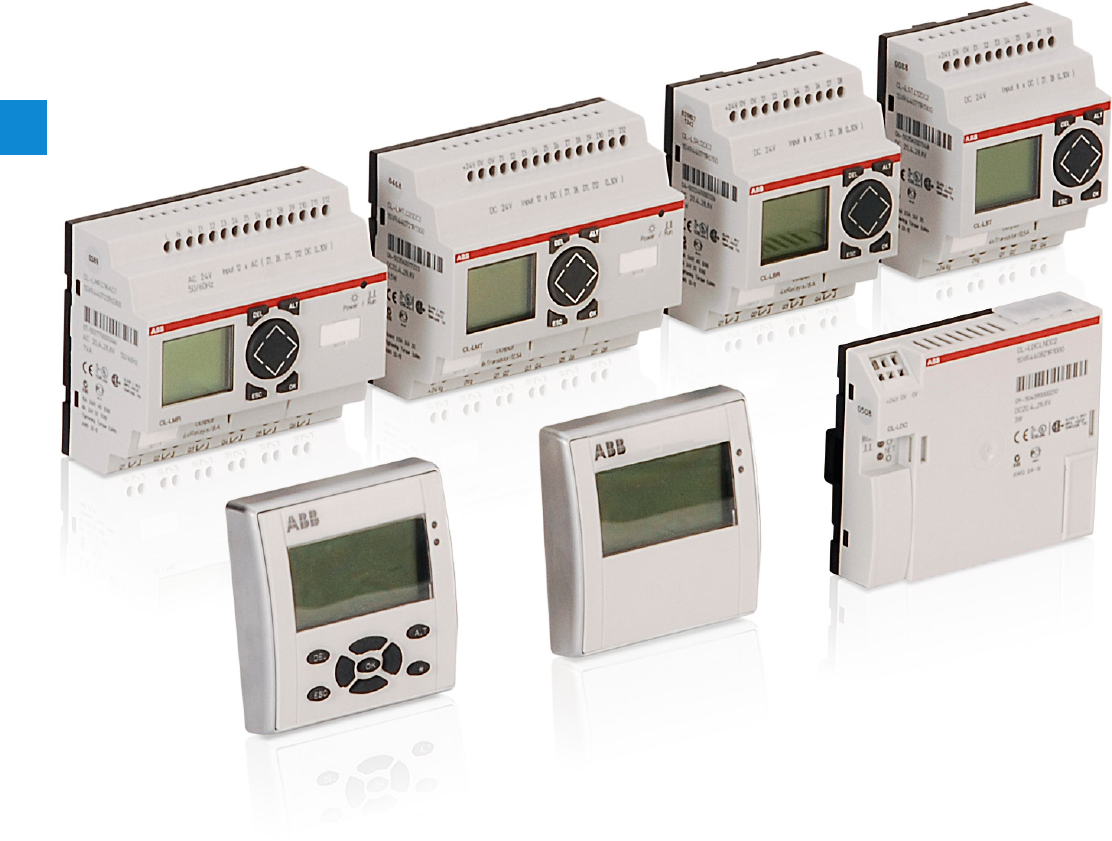
6/1 ABB | Catalog Electronic Products and Relays 2015 | 2CDC 110 004 C02010
6
Logic relays
Product group picture

2CDC 110 004 C0210 | Catalog Electronic Products and Relays 2015 | ABB 6/2
6
Logic relays
Table of contents
Logic relays
Logic relays 6/1
Product group picture 6/1
Table of contents 6/2
System overview 6/3
Approvals and marks 6/5
Ordering details - Stand alone logic relays 6/6
Ordering details - Expandable logic relays 6/7
Ordering details 6/8
Ordering details - Display systems 6/9
Technical data 6/10
Dimensional drawings 6/24

6/3 ABB | Catalog Electronic Products and Relays 2015 | 2CDC 110 004 C02010
6
Logic relays
System overview
1SVC 110 000 F 0554
S1 K1 S4
S5
K1 K2 T1
T1
T1
S6
Documentation (download from the internet)
Logic relay manual: 1SVC440795M0100
Remote display manual: 1SVC440795M2100
Display system manual: 1SVC440795M1100
Concept
CL range logic relays are suitable for small and medium-
sized control tasks and are able to substitute logic wiring in
a quick and simple manner.
They can be used for applications in control as well as for
timing functions, e.g.
– in buildings, lighting systems, air-conditioning systems,
general control functions,
– in small machines and systems or
– as stand-alone control module for small applications.
Steps to the application of CL range
– CL range can be used easily, rapidly and comfortably
without any time-consuming planning and programming.
– The user can discover the advantages and the benefit of
these logic relays in no time at all.
– CL range provides for the control statements according
to a simple circuit diagram.
– Setup, storage, simulation and documentation are per-
formed using the compact and user-friendly CL-SOFT
software (CL-LAS.PS002).
Software characteristics (CL-SOFT)
– Display on a PC monitor according to IEC, ANSI
– Different languages to choose from
– Easy installation on all Microsoft WindowsTM operating
systems
Logic links instead of wiring
Logic relays
– 8 or 12 digital inputs
– 4 or 6 digital relay outputs
– optionally with 4 or 8 transistor outputs
– 128 rungs
– 3 contacts as n/o or n/c contacts in series plus 1 coil
per rung
– optionally with 2 or 4 analog inputs (not 100-240 V AC
version)
– power flow display for checking the circuit diagram (de-
vices with display)
– expansions for local or remote level
– enclosure color RAL 7035
– DIN rail mounting
Display system
– useable as compact HMI logic relay
– fully graphic, backlit display module
– 12 digital inputs
– 4 digital relay outputs
– optionally with 4 transistor outputs
– 256 rungs
– 4 contacts as n/o or n/c contacts in series plus 1 coil
per rung
– optionally with 4 analog inputs (not 100-240 V AC ver-
sion)
– networking-compatible via CL-NET
– front panel mounting
– expansion for local
Remote display
– Remote display up to a distance of 5 m
– Illustration of text and status displays
– Remote adjustment via keypad
– Front panel mounting
Software
– 16 timing relays 0.01-99:59 h
– 16 counting relays for up-, down counting
– 8 weekly timer, 8 annual timers
– 16 analog value comparators
– 16 freely editable display texts
– 32 markers or auxiliary relays
Technical data overview
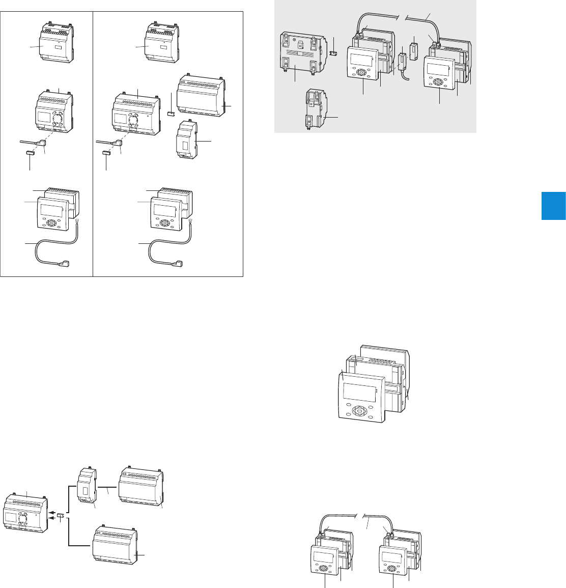
2CDC 110 004 C0210 | Catalog Electronic Products and Relays 2015 | ABB 6/4
6
Logic relays
System overview
Power
9
8a
8b
3
4
6, 8b
5
7
1b1a
2 2
6, 8b
5
9
8a
8b
Power
2CDC 312 001 F0b08
1a Logic relay CL-LS..
1b Expandable logic relay CL-LM..
2 Power supply CP-D...
3 I/O expansion CL-LER.., CL-LET.. for logic relays CL-LM..
4 Coupler unit CL-LEC.. for remote expansion of logic relays CL-LM..
5 Memory module CL-LAS.MD003 for logic relays CL-LS.., CL-LM..
6 Connecting cable CL-LAS.TK001, CL-LAS.TK002 to connect PC
7 CL-LINK plug CL-LAS.TK011
to connect expansion to logic relays CL-LM..
8a Remote display connection module CL-LDC.S..
8b Connecting cable CL-LAD.TK007
to connect a remote displays to a logic relay
9 Display module CL-LDD..
Logic relays
Stand alone Expandable
2b
1
3
2a
5
4
2CDC 312 037 F0b07
Expansion of logic relays*
1 Logic relay CL-LM..
2 I/O expansion CL-LER.., CL-LET..
2a local expansion
2b remote expansion
3 Coupler unit CL-LEC.. for remote expansion of logic relays CL-LM..
4 CL-LINK plug CL-LAS.TK011 for expansion of logic relays CL-LM..
5 up to 30 m
* max. 1 expansion per logic relay
7
9
8
6
5
3
2
1
3
2
1
...
44
CL-NET
10
2CDC 312 025 F0b06
1
2
3
2CDC 312 027 F0b06
3
2
1
3
2
1
4
...
5 5
CL-NET
2CDC 312 026 F0b06
Stand alone with I/O module
Communication via CL-NET
1 Display CL-LDD..
2 Remote display connection module CL-LDC.S..
incl. connecting cable
3 Display base module CL-LDC.L..
1 Display module CL-LDD..
2 Display base module CL-LDC.LN..
3 Display I/O module CL-LDR.., CL-LDT..
4 Termination resistor CL-LAD.TK009
5 I/O expansion CL-LER.., CL-LET..
6 Coupler unit CL-LEC.. for remote expansion
7 Memory module CL-LAD.MD004 for display base module
8 Connecting cable CL-LAD.TK002, CL-LAD.TK003,
CL-LAD.TK004
9 Connecting cable CL-LAD.TK001, CL-LAD.TK011
to connect PC
10 CL-LINK plug CL-LAS.TK011
for expansion of logic relays CL-LM..
K e.g. door of switchgear cabinet
Display system R Compact HMI logic relay
1 Display CL-LDD..
2 Display base module CL-LDC.LN.. for CL-NET
3 Display I/O module CL-LDR.., CL-LDT..
4 Connecting cable CL-LAD.TK002,
CL-LAD.TK003, CL-LAD.TK004
5 Termination resistor CL-LAD.TK009

6/5 ABB | Catalog Electronic Products and Relays 2015 | 2CDC 110 004 C02010
6
Logic relays
Approvals and marks
J existing
j pending Logic relays Expansions Display system
Accessories
Approvals
CL-LSR
C L- L S T
CL-LMR
C L- L M T
C L- L E R
C L- L E T
C L- L E C
CL-LDD
CL-LDC
CL-LDR
C L- L D T
C L- L A S
C L- L A D
BUL J J J J J J J J J J J J 1) J 2)
FCAN/CSA C22.2 No.14 J J J J J J J J J J J J 1) J 2)
FCAN/CSA C22.2 No.213
(hazardous locations) J J J J J J J J J J J J 1) J 2)
CGL JJJJ JJ 3) J 4) J
REAC k k k k k k k k k k k k k
PLloyds Register JJJJ JJ 3) J 4) J
Marks
aCE J J J J J J J J J J J J J
bC-Tick k k k k k k k k k k k k k
1) not for: CL-LAS-PS002, CL-LAS.TD001, CL-LAS.FD001, CL-LAS.TK002, CL-LAS.TK011
2) not for: CL-LAD.TK006, CL-LAD.TK011, CL-LAD.FD002
3) not for: CL-LDC.SDC2, CL-LDC.SAC2, CL-LDC.LAC2, CL-LDC.LNAC2
4) not for: CL-LDR.16AC2
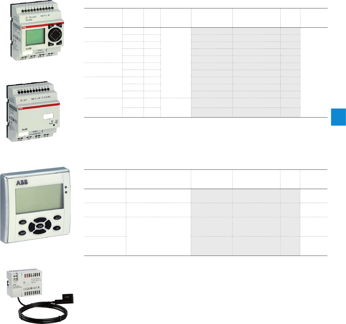
2CDC 110 004 C0210 | Catalog Electronic Products and Relays 2015 | ABB 6/6
6
Logic relays
Ordering details - Stand alone logic relays
Ordering details - Logic relays stand alone
Rated opera-
tional voltage
Display
+
Keypad
Timer Input /
Output
Type Order code Price
1 pce
Weight
(1 pce)
kg (lb)
24 V AC J J
8 inputs / 4
relay outputs
CL-LSR.C12AC1 1SVR440712R0300
0.20 (0.44)
JCL-LSR.CX12AC1 1SVR440712R0200
100-240 V AC
JCL-LSR.12AC2 1SVR440713R0100
J J CL-LSR.C12AC2 1SVR440713R0300
JCL-LSR.CX12AC2 1SVR440713R0200
12 V DC J J CL-LSR.C12DC1 1SVR440710R0300
JCL-LSR.CX12DC1 1SVR440710R0200
24 V DC
JCL-LSR.12DC2 1SVR440711R0100
J J CL-LSR.C12DC2 1S V R44 0711R030 0
JCL-LSR.CX12DC2 1SVR4 40711R 0 200
24 V DC J J 8 inputs /
4 transistor
outputs
C L- L S T. C12 D C 2 1SVR440711R1300
JC L- L S T. C X12 D C 2 1SVR4 4 0711R120 0
Ordering details - Display modules
Rated opera-
tional voltage
Description Type Order code Price
1 pce
Weight
(1 pce)
kg (lb)
-Graphic display 132 x 64
pixel CL-LDD.XK 1SVR440839R4500 0.14 (0.30)
-Graphic display 132 x 64
pixel, with keypad CL-LDD.K 1SVR440839R4400 0.13 (0.29)
24 V DC Module to displace the dis-
play from the logic relay, incl.
connecting cable CL-LAD.
TK007, 5m, lenght adaptable
CL-LDC.SDC2 1SVR440841R0000 0.16 (0.36)
100-240 V AC CL-LDC.SAC2 1SVR440843R0000 0.16 (0.36)
CL-LSR
CL-LST
CL-LDD.K
CL-LDC.S..
2CDC 281 034 F0006
2CDC 281 033 F0006
2CDC 281 028 F0006
2CDC 281 017 F0007
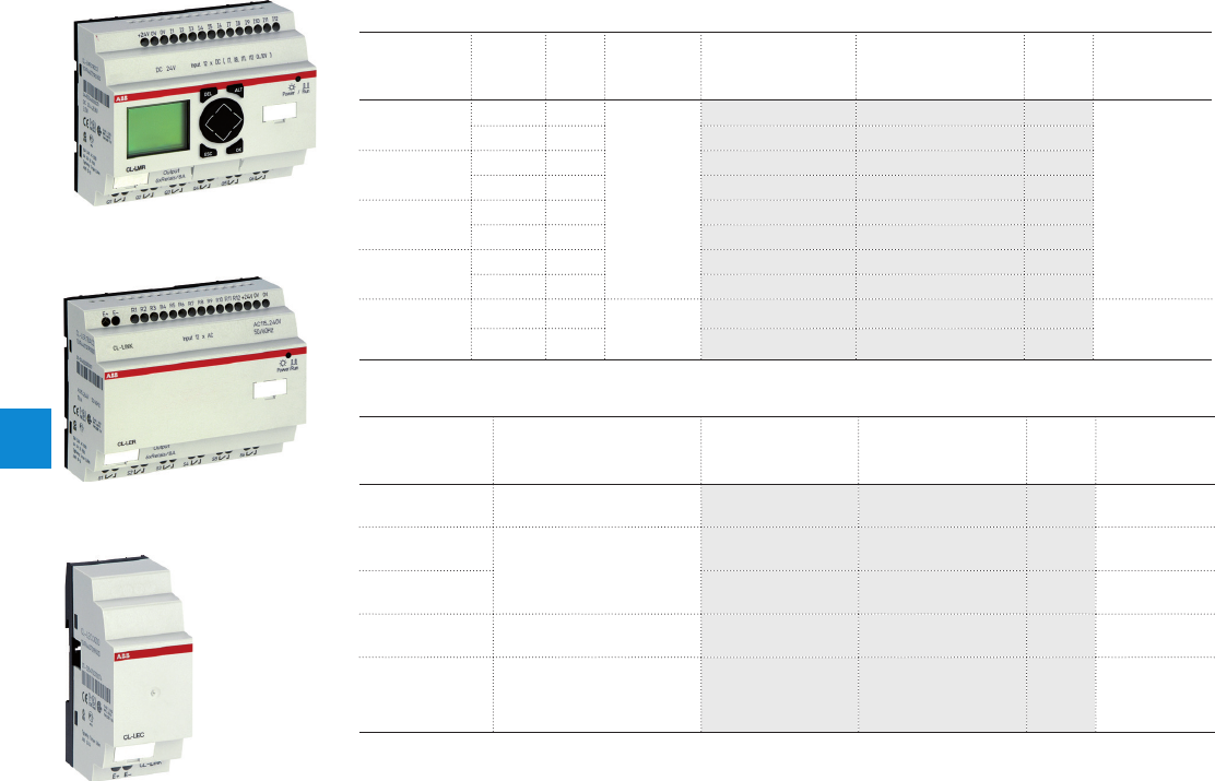
6/7 ABB | Catalog Electronic Products and Relays 2015 | 2CDC 110 004 C02010
6
Logic relays
Ordering details - Expandable logic relays
Ordering details - Logic relays expandable
Rated
operational
voltage
Display
+
Keypad
Timer Input /
Output
Type Order code Price
1 pce
Weight
(1 pce) kg (lb)
24 V AC J J
12 inputs
/ 6 relay
outputs
CL-LMR.C18AC1 1SVR440722R0300
0.36 (0.79)
JCL-LMR.CX18AC1 1SVR440722R0200
100-240 V AC J J CL-LMR.C18AC2 1SVR440723R0300
JCL-LMR.CX18AC2 1SVR440723R0200
12 V DC J J CL-LMR.C18DC1 1SVR440720R0300
JCL-LMR.CX18DC1 1SVR440720R0200
24 V DC J J CL-LMR.C18DC2 1SVR440721R0300
JCL-LMR.CX18DC2 1SVR440721R0200
24 V DC J J 12 inputs,
8 transistor
outputs
CL-LMT.C20DC2 1SVR440721R1300 0.36 (0.79)
JC L- L M T. CX 2 0 D C 2 1SVR440721R1200
Ordering details - Expansions
Rated opera-
tional voltage
Description Type Order code Price
1 pce
Weight
(1 pce) kg (lb)
-2 relay outputs C L- L E R . 2 O 1SVR440709R5000 0.07 (0.15)
100-240 V AC
12 inputs, 6 relay outputs
CL-LER.18AC2 1SVR440723R0000 0.26 (0.57)
24 V DC CL-LER.18DC2 1SVR440721R0000 0.22 (0.49)
24 V DC 12 inputs, 8 transistor
outputs CL-LET.20DC2 1SVR440721R1000 0.21 (0.46)
-
Coupler unit for remote
expansion with a distance
of up to 30 m
CL-LEC.CI000 1SVR440709R0000 0.07 (0.15)
CL-LER
CL-LEC
CL-LMR
2CDC 311 036 F0006
2CDC 311 037 F0007
2CDC 311 038 F0006
2CDC 110 004 C0210 | Catalog Electronic Products and Relays 2015 | ABB 6/8
6
Logic relays
Ordering details
Ordering details - CL-LA...
Description Type Order code Price
1 pce
Weight
(1 pce)
kg (lb)
Software for programming and control of CL
range devices. Installation CD-ROM for Micro-
soft WindowsTM.
CL-LAS.PS002 1SVR440799R8000 0.10
(0.21)
Memory module for logic relays
Memory size: 32 kB CL-LAS.MD003 1SVR440799R7000 0.02 (0.04
Cable with serial interface to connect PC and
logic relay. Length: 2 m C L- L A S .T K 0 0 1 1SVR440799R6000 0.10 (0.22)
Cable with USB interface to connect PC and
logic relay. Length: 2 m C L- L A S .T K 0 0 2 1SVR440799R6100 0.06 (0.13)
Cable for point-to-point connection of remote-
display connection module and logic relay,
length: 5m, adaptable
C L- L A D .T K 0 0 7 1SVR440899R6600 0.20 (0.44)
Fixing brackets for screw mounting of logic
relay, expansion, display base module C L- L A S .F D 0 0 1 1SVR440799R5000 0.01 (0.01)
Spare plug (CL-LINK) for connection of logic
relay to expansion C L- L A S .T K 011 1SVR440799R5100 0.10 (0.22)
Primary switch mode power supplies,
Rated input voltage: 100-240 V AC
Rated output voltage/current: 24 V DC / 0.42 A
CP-D 24/0.421) 1SVR427041R0000 0.06 (0.13)
Primary switch mode power supplies,
Rated input voltage: 100-240 V AC
Rated output voltage/current: 24 V DC / 1.3 A
CP-D 24/1.32) 1SVR427043R0100 0.19 (0.41)
1) replaces CL-LAS.SD001, technical data see chapter “Primary switch mode power supplies”
2) replaces CL-LAS.SD002, technical data see chapter “Primary switch mode power supplies”
CL-LAS.PS002
CL-LAS.MD003
CL-LAS.TK001
2CDC 311 012 F0007
2CDC 311 013 F0007 2CDC 311 014 F0007
6/9 ABB | Catalog Electronic Products and Relays 2015 | 2CDC 110 004 C02010
6
Ordering details - Display systems
Rated opera-
tional voltage
Description Type Order code Price
1 pce
Weight
(1 pce)
kg (lb)
-
Display module
Graphic display 132 x 64
pixel
CL-LDD.XK 1SVR440839R4500 0.14 (0.30)
-
Display module
Graphic display 132 x 64
pixel, with keypad
CL-LDD.K 1SVR440839R4400 0.13 (0.29)
24 V DC Display base module CPU /
power supply
CL-LDC.LDC2 1SVR440821R0000
0.16 (0.36)
100-240 V AC CL-LDC.LAC2 1SVR440823R0000
24 V DC Display base module
CPU / power supply,
networking-compatible
( C L- N E T )
CL-LDC.LNDC2 1SVR440821R1000
0.17 (0.38)
100-240 V AC CL-LDC.LNAC2 1SVR440823R1000
100-240 V AC Display I/O module
12 inputs, 4 relay outputs
CL-LDR.16AC2 1SVR440853R0000
0.17 (0.38)
24 V DC CL-LDR.16DC2 1SVR440851R0000
24 V DC
Display I/O module
12 inputs, 4 relay outputs,
1 analog output
CL-LDR.17DC2 1SVR440851R2000 0.17 (0.38)
24 V DC
Display I/O module
12 inputs, 4 transistor
outputs
CL-LDT.16DC2 1SVR440851R1000 0.14 (0.30)
24 V DC
Display I/O module
12 inputs, 4 transistor out-
puts, 1 analog output
CL-LDT.17DC2 1SVR440851R3000 0.14 (0.30)
Logic relays
Ordering details - Display systems
CL-LDD.K
CL-LDC.LN..
2CDC 311 028 F00062CDC 311 031 F0006
Ordering details - CL-LAD...
Description Type Order code Price
1 pce
Weight
(1 pce)
kg (lb)
Memory module for display base modules
Memory size: 256 kB C L- L A D .M D 0 0 4 1SVR440899R7000 0.02 (0.03)
Cable with serial interface to connect PC and
display base module C L- L A D .T K 0 0 1 1SVR440899R6000 0.11 (0.23)
Cable with USB interface to connect PC and
display base module C L- L A D .T K 011 1SVR440899R6700
Network cable (CL-NET) to connect 2 display
base modules Length: 0.3 m C L- L A D .T K 0 0 2 1SVR440899R6100 0.05 (0.12)
Network cable (CL-NET) to connect 2 display
base modules Length: 0.8 m CL-LAD.TK003 1SVR440899R6200 0.07 (0.14)
Network cable (CL-NET) to connect 2 display
base modules Length: 1.5 m C L- L A D .T K 0 0 4 1SVR440899R6300 0.08 (0.18)
Cable for point-to-point connection of remote
display connection modules and display base
module, length adaptable, Length: 5 m
CL-LAD.TK005 1SVR440899R6400 0.20 (0.44)
Cable for point-to-point connection of 2
display base modules, length adaptable.
Length: 5 m
C L- L A D .T K 0 0 6 1SVR440899R6500 0.12 (0.26)
Termination resistor, content: 2 pieces C L- L A D .T K 0 0 9 1SVR440899R6900 0.01 (0.02)
Protective cover, transparent, for harsh envi-
ronmental conditions and application in the
food industry
C L- L A D . F D 0 0 1 1SVR440899R1000 0.03 (0.07)
Protective cover, transparent and sealable C L- L A D . F D 011 1SVR440899R2000 0.03 (0.07)
Assembly tool for mounting of display mod-
ules C L- L A D. F D 0 0 2 1SVR440899R3000
CL-LAD.MD004
CL-LAD.TK001
CL-LAD.TK002
2CDC 311 018 F0007
2CDC 311 019 F00072CDC 311 020 F0006

2CDC 110 004 C0210 | Catalog Electronic Products and Relays 2015 | ABB 6/10
6
Logic relays
Technical data
Data at Ta = 25 °C and rated values, if nothing else indicated.
Type CL-LSR.C...12DC1 CL-LSR....12DC2
CL-LST.C...12DC2
CL-LSR.C...12AC1 CL-LSR...12AC2
Input circuit - supply circuit
Rated operational voltage Ue12 V DC 24 V DC 24 V AC 100-240 V AC
Rated operational voltage tolerance -15...+30 % -15...+20 % -15...+10 %
Operational voltage range 10.2-15.6 V DC 20.4-28.8 V DC 20.4-26.4 V AC 85-264 V AC
Rated frequency 0 Hz 50/60 Hz
Rated frequency tolerance -±5 %
Residual ripple m 5 % -
Input current at 12 V DC typ. 140 mA ---
at 24 V DC -typ. 80 mA - -
at 24 V AC --typ. 200 mA -
at 115/120 V AC (60 Hz)
---typ. 40 mA
at 230/240 V AC (50 Hz)
---typ. 20 mA
Power failure buffering (IEC/EN 61131-2) 10 ms 20 ms
Power dissipation at 12 V DC typ. 2 W ---
at 24 V DC -typ. 2 W - -
at 24 V AC --typ 5 VA -
at 115/120 V AC ---typ. 5 VA
at 230/240 V AC ---typ. 5 VA
Type CL-LMR.C...18DC1 CL-LMR.C...18DC2
CL-LMT.C...20DC2
CL-LMR.C...18AC1 CL-LMR.C...18AC2
Input circuit - supply circuit
Rated operational voltage Ue12 V DC 24 V DC 24 V AC 100-240 V AC
Rated operational voltage tolerance -15...+30 % -15...+20 % -15...+10 %
Operational voltage range 10.2-15.6 V DC 20.4-28.8 V DC 20.4-26.4 V AC 85-264 V AC
Rated frequency 0 Hz 50/60 Hz
Rated frequency tolerance -±5 %
Residual ripple m 5 % -
Input current at 12 V DC typ. 200 mA ---
at 24 V DC -typ. 140 mA - -
at 24 V AC --typ. 300 mA -
at 115/120 V AC (60 Hz)
---typ. 70 mA
at 230/240 V AC (50 Hz)
---typ. 35 mA
Power failure buffering (IEC/EN 61131-2) 10 ms 20 ms
Power dissipation at 12 V DC typ. 3.5 W ---
at 24 V DC -typ. 3.5 W - -
at 24 V AC --typ. 7 VA -
at 115/120 V AC ---typ. 10 VA
at 230/240 V AC ---typ. 10 VA
Type CL-LER.18DC2
CL-LET. 20DC2
CL-LER.18AC2
Input circuit - supply circuit
Rated operational voltage Ue24 V DC 100-240 V AC
Rated operational voltage tolerance -15...+20 % -15...+10 %
Operational voltage range 20.4-28.8 V DC 85-264 V AC
Rated frequency 0 Hz 50/60 Hz
Rated frequency tolerance -±5 %
Residual ripple m 5 % -
Input current at 24 V DC typ. 140 mA -
at 115/120 V AC (60 Hz)
-typ. 70 mA
at 230/240 V AC (50 Hz)
-typ. 35 mA
Power failure buffering (IEC/EN 61131-2) 10 ms 20 ms
Power dissipation at 24 V DC typ. 3.4 W -
at 115/120 V AC -typ. 10 VA
at 230/240 V AC -typ. 10 VA

6/11 ABB | Catalog Electronic Products and Relays 2015 | 2CDC 110 004 C02010
6
Logic relays
Technical data
Data at Ta = 25 °C and rated values, if nothing else indicated.
Type CL-LSR.C...12DC1 CL-LSR....12DC2
CL-LST.C...12DC2
CL-LSR.C...12AC1 CL-LSR.C...12AC2
Input circuit - Digital inputs 12 V DC 24 V DC 24 V AC 115 / 230 V AC
Number 8
Inputs can be used as analog inputs 2 (I7, I8) -
Indication of operational states LCD-Display (if existing)
Electrical isolation from voltage supply no
between digital inputs no
from the outputs yes
Rated operational
voltage Ue
12 V DC 24 V DC 24 V AC
Ue on „0“ signal 4 V DC (I1-I8) < 5 V DC (I1-I8) 0-6 V AC (sinusoidal) 0-40 V AC (sinusoidal)
Ue on „1“ signal 8 V DC (I1-I8) > 15 V DC (I1-I6),
> 8 V DC (I7, I8) > 9.5 V DC,
14-26.4 V AC
(sinusoidal) (I1-I6),
> 7 V AC (sinusoidal)
(I7,I8)
79-264 V AC
(sinusoidal)
Rated frequency -50-60 Hz
Input current
on „1“ signal 3.3 mA (at 12 V DC,
I1-I6),
1.1 mA (at 12 V DC,
I7, I8)
3.3 mA (at 24 V DC,
I6-I7),
2.2 mA (at 24 V DC,
I7, I8)
4 mA
(at 24 V AC, 50 Hz, I1-I6),
2 mA
(at 24 V AC, 50 Hz, I7,I8),
2 mA (at 24 V DC, I7, I8)
6x0.25 mA
(at 115 V AC, 60 Hz,
I1-I6),
6x0.5 mA
(at 230 V AC, 50 Hz,
I1-I6)
2x4 mA
(at 115 V AC, 60 Hz,
I7, I8),
2x6 mA
(at 230 V AC, 50 Hz,
I7, I8)
Time delay
from „0“ to „1“ debounce ON 20 ms 80 ms (at 50 Hz), 66 2/3 ms (at 60 Hz)
debounce OFF typ. 0.3 ms (I1-I6),
typ. 0.35 ms (I7, I8) typ. 0,25 ms (I1-I8) 20 ms (at 50 Hz), 16 2/3 ms (at 60 Hz)
Time delay
from „1“ to „0“ debounce ON 20 ms 80 ms (at 50 Hz),
66 2/3 ms (at 60 Hz) 80 ms (at 50 Hz, I1-I6),
66 2/3 ms (at 60 Hz,
I1-I6)
160 ms (at 50 Hz, I7, I8),
150 ms (at 60 Hz, I7, I8)
debounce OFF typ. 0.3 ms (I1-I6),
typ. 0.15 ms (I7, I8) -20 ms (at 50 Hz),
16 2/3 ms (at 60 Hz) 20 ms (at 50 Hz, I1-I6),
16 2/3 ms (at 60 Hz,
I1-I6)
100 ms (at 50 Hz, I7. I8),
100 ms (at 60 Hz, I7, I8)
Cable length (unshielded) 100 m - -
Maximum cable length per input -40 m 40 m (I1-I6),
100 m (I7, I8)
Frequency counter Number 2 (I3, I4) - -
counting frequency < 1 kHz - -
pulse shape square-wave - -
pulse / pause ratio 1:1 - -
Rapid counter inputs Number 2 (I1, I2) - -
counting frequency < 1 kHz - -
pulse shape square-wave - -
pulse / pause ratio 1:1 - -
Cable length (shielded) < 20 m - -
Input circuit - Analog inputs
Number 2 (I7, I8) -
Electrical isolation from voltage supply no -
from the digital inputs no -
from the outputs yes -
from PC interface,
memory
module, CL-NET,
C L- L I N K
no -
Input type DC voltage -
Signal range 0-10 V DC -
Resolution analog 0.01 V -
digital 0.01 V; 10 Bit (value 1-1023) -
Input impedance 11.2 k q-
Accuracy of the
actual value two CL devices ±3 % -
within one device ±2 %, ±0.12 V -
Conversion time
analog/digital Input delay ON 20 ms -
Input delay OFF each cycle -
Input current < 1 mA -
Cable length (shielded) < 30 m -

2CDC 110 004 C0210 | Catalog Electronic Products and Relays 2015 | ABB 6/12
6
Logic relays
Technical data
Data at Ta = 25 °C and rated values, if nothing else indicated.
Type CL-LMR.C...18DC1 CL-LMR.C...18DC2
CL-LMT.C...20DC2
CL-LMR.C...18AC1 CL-LMR.C...18AC2
Input circuit - Digital inputs 12 V DC 24 V DC 24 V AC 115 / 230 V AC
Number 12
Inputs can be used as analog inputs 4 (I7, I8, I11, I12) -
Indication of operational states LCD-Display (if existing)
Electrical isolation from voltage supply no
between digital inputs no
from the outputs yes
from PC interface,
memory module, CL-NET,
C L- L I N K
no yes
Rated operational
voltage Ue
12 V DC 24 V DC 24 V AC
Ue on „0“ signal 4 V DC (I1-I12) < 5 V DC
(I1-I12, R1-R12) 0-6 V AC (sinusoidal) 0-40 V AC (sinusoidal)
Ue on „1“ signal 8 V DC (I1-I12) > 15 V DC (I1-I6, I9, I10)
> 8 V DC (I7, I8, I11, I12) > 9.5 V DC,
14-26.4 V AC
(sinusoidal) (I1-I6, I9, I10)
> 7 V AC (sinusoidal)
(I7,I8; I11, I12)
79-264 V AC
(sinusoidal)
Rated frequency -50-60 Hz
Input current
on „1“ signal 3.3 mA
(at 12 V DC, I1-I6, I9-I12),
1.1 mA
(at 12 V DC, I7, I8)
3.3 mA
(at 24 V DC, I1-I6, I9, I10),
2.2 mA
(at 24 V DC, I7, I8, I11, I12)
4 mA
(at 24 V AC, 50 Hz,
I1-I6, I9, I10),
2 mA
(at 24 V AC, 50 Hz,
I7, I8, I11, I12),
2 mA
(
at 24 V DC, I7, I8, I11, I12)
6x0.25 mA
(at 115 V AC, 60 Hz,
I1-I6),
6x0.5 mA
(at 230 V AC, 50 Hz,
I1-I6)
2x4 mA
(at 115 V AC, 60 Hz,
I7, I8),
2x6 mA
(at 230 V AC, 50 Hz,
I7, I8),
4x0.25 mA
(at 115 V AC, 60 Hz,
I9-I12),
4x0.5 mA
(at 230 V AC, 50 Hz,
I9-I12)
Time delay
from „0“ to „1“ debounce ON 20 ms 80 ms (at 50 Hz), 66 2/3 ms (at 60 Hz)
debounce OFF
typ. 0.3 ms (I1-I6, I9, I10),
typ. 0.35 ms (I7, I8, I11, I12)
typ. 0.25 ms 20 ms (at 50 Hz), 16 2/3 ms (at 60 Hz)
Time delay
from „1“ to „0“ debounce ON 20 ms 80 ms (at 50 Hz), 66 2/3 ms (at 60 Hz)
debounce OFF
typ. 0.4 ms (I1-I6, I9, I10),
typ. 0.35 ms (I7, I8, I11, I12)
-20 ms (at 50 Hz), 16 2/3 ms (at 60 Hz)
Cable length (unshielded) 100 m
Maximum cable length per input max. 40 m,
typ. 40 m (I9, I10) typ. 40 m (I1-I6, I9-I12),
typ. 100 m (I7, I8)
Frequency counter number 2 (I3, I4) - -
counting frequency < 1 kHz - -
pulse shape square-wave - -
pulse / pause ratio 1:1 - -
Rapid counter inputs number 2 (I1, I2) - -
counting frequency < 1 kHz - -
pulse shape square-wave - -
pulse / pause ratio 1:1 - -
Cable length (shielded) < 20 m - -
Input circuit - Analog inputs
Number 4 (I7, I8, I11, I12) -
Electrical isolation from voltage supply no -
from the digital inputs no -
from the outputs yes -
from PC interface,
memory
module, CL-NET,
C L- L I N K
no -
Input type DC voltage -
Signal range 0-10 V DC -
Resolution analog 0.01 V -
digital 0.01 V; 10 Bit (value 1-1023) -
Input impedance 11.2 k q-
Accuracy of the
actual value two CL devices ±3 % -
within one device ±2 %, ±0.12 V -
Conversion time
analog/digital Input delay ON 20 ms -
Input delay OFF each cycle -
Input current < 1 mA -
Cable length (shielded) < 30 m -

6/13 ABB | Catalog Electronic Products and Relays 2015 | 2CDC 110 004 C02010
6
Logic relays
Technical data
Data at Ta = 25 °C and rated values, if nothing else indicated.
Type CL-LER.18DC2, CL-LET.20DC2 CL-LER.18AC2
Input circuit - Digital inputs 24 V DC 115 / 230 V AC
Number 12
Inputs can be used as analog inputs -
Indication of operational states -
Electrical isolation from voltage supply no
between digital inputs no
from the outputs yes
from PC interface,
memory
module, CL-NET,
C L- L I N K
no
Rated operational
voltage Ue
24 V DC
Ue on „0“ signal < 5 V DC (I1-I12, R1-R12) 0-40 V AC (sinusoidal)
Ue on „1“ signal -79-264 V AC (sinusoidal)
Rated frequency -50-60 Hz
Input current
on „1“ signal 3.3 mA (at 24 V DC, R1-R12) 12x0.25 mA (at 115 V AC, 60 Hz, R1-R12),
12x0.5 mA (at 230 V AC, 50 Hz, R1-R12)
Time delay
from „0“ to „1“ debounce ON 20 ms 80 ms (at 50 Hz, I1-I12, R1-R12),
66 2/3 ms (at 60 Hz, I1-I12, R1-R12)
debounce OFF typ. 0.25 ms (R1-R12) 20 ms (at 50 Hz, I1-I12, R1-R12),
16 2/3 ms (at 60 Hz, I1-I12, R1-R12)
Time delay
from „1“ to „0“ debounce ON 20 ms 80 ms (at 50 Hz, I1-I12, R1-R12),
66 2/3 ms (at 60 Hz, I1-I12, R1-R12)
debounce OFF -20 ms (at 50 Hz, I1-I12, R1-R12),
16 2/3 ms (at 60 Hz, I1-I12, R1-R12)
Cable length (unshielded) 100 m -
Maximum cable length per input -typ. 40 m (I1-I6, I9-I12, R1-R12),
typ. 100 m (I7, I8)

2CDC 110 004 C0210 | Catalog Electronic Products and Relays 2015 | ABB 6/14
6
Logic relays
Technical data
Data at Ta = 25 °C and rated values, if nothing else indicated.
Type CL-LSR... CL-LMR...
CL-LER...
CL-LER.2O
Output circuit - Relay outputs
Number 462
Outputs in groups of 1 2
Parallel switching of outputs to increase capacity not permissible
Fusing of the output relay circuit-breaker B16 or fuse 8 A (slow-acting)
Electrical isolation from voltage supply yes
from the inputs yes
from PC interface, memory module,
C L- N E T, CL- L I N K no
protective separation 300 V AC
basic isolation 600 V AC
Mechanical lifetime 10x106 switching cycles
Rung conventional thermal current (10 A UL) 8 A
recommended for load 12 V AC/DC > 500 mA
short-circuit proof cos j = 1;
characteristic B16 at 600 A 16 A
short-circuit proof cos j = 0,5 up to 0,7;
characteristic B16 at 900 A 16 A
Rated impulse withstand voltage Uimp
contact-coil
6 kV
Rated operational voltage Ue250 V AC
Rated insulation voltage Ui250 V AC
Protective separation (EN
50178) between coil and contact 300 V AC
between two contacts 300V AC
Making capacity AC-15, 250 V AC, 3 A (600 ops./h) 300.000 switching cycles
DC13, L/R m 150 ms, 24 V DC, 1 A
(500 ops./h) 200.000 switching cycles
Breaking capacity AC-15, 250 V AC, 3 A (600 ops./h) 300.000 switching cycles
DC13, L/R m 150 ms, 24 V DC, 1 A
(500 ops./h) 200.000 switching cycles
Incandesent lamp load 1000 W at 230/240 V AC 25.000 switching cycles
500 W at 115/120 V AC 25.000 switching cycles
Fluorescent lamp load 10 x 58 W at 230/240 V AC
with electrical control gear 25.000 switching cycles
10 x 58 W at 230/240 V AC
uncompensated 25.000 switching cycles
1 x 58 W at 230/240 V AC
conventional compensated 25.000 switching cycles
Switching frequency mechanical operations 10x106
switching frequency 10 Hz
resistive load / lamp load 2 Hz
inductive load 0.5 Hz
UL/CSA
Continuous current at 240 V 10 A AC
Continuous current at 24 V 8 A DC
AC Utilization catagory (Control Circuit Rating
Codes) B 300 Light Pilot Duty
max. rated operational voltage 300 V AC
max. continuous thermal current cos j =
1 at B 300 5 A
max. making / breaking apparent power
(Make/Break) cos j ≠ 1 at B 300 3600/360 VA
DC Utilization catagory (Control Circuit Rating
Codes) R 300 Light Pilot Duty
max. rated operational voltage 300 V DC
max. continuous thermal current at R 300 1 A
max. making / breaking apparent power
(Make/Break) at R 300 28/28 VA

6/15 ABB | Catalog Electronic Products and Relays 2015 | 2CDC 110 004 C02010
6
Logic relays
Technical data
Data at Ta = 25 °C and rated values, if nothing else indicated.
Type CL-LST... CL-LMT... CL-LET...
Output circuit - Transistor outputs
Number 4 8
Rated operational voltage Ue24 V DC
Operational voltage range 20.4-28.8 V DC
Residual ripple m 5 %
Supply current on „0“ signal typ. 9 mA / max. 16 mA typ. 18 mA / max. 32 mA
on „1“ signal
typ. 12 mA / max. 22 mA
typ. 24 mA / max. 44 mA
Reverse voltage protection yes (Attention: If supply voltage is reversed, applying voltage at the
outputs, causes a short circuit.)
Electrical isolation from voltage supply yes
from the inputs yes
from PC interface, memory module,
C L- N E T, CL- L I N K -
Rated operational current Ie on„1“ signal DC max. 0.5 A
Lamp load without Rv5 W
Residual current on „0“ signal per channel < 0.1 mA
Max. output voltage on „0“ signal at external load < 10 Mq2.5 V
on „1“ signal at Ie = 0.5 A U = Ue - 1 V
Short-circuit protection yes, thermal (analysis results from diagnosis input I16, I15; R15, R16)
Short-circuit tripping current for Ra m 10 mq0.7 A m Ie m 2 A per output
Total short-circuit current 8 A 16 A
Peak short-circuit current 16 A 32 A
Thermal tripping yes
Max. switching frequency with constant resistive load RL < 100 kq
(depending on active channels and their load) 40.000 switching cycles/h
Parallel connection of outputs with resistive load, inductive load with
external
suppressor, combination within one group
group 1: Q1-Q4 group 1: Q1-Q4,
group 2: Q5-Q8 group 1: S1-S4, group
2: S5-S8
number of outputs max. 4
max. total current 2 A (Attention! Outputs must be actuated simultaneously and for the
same length of time.)
Indication of operational states of the outputs LCD-Display (if existing)
Inductive load1) without external suppressor
T0.95 = 1 ms,
R = 48 q,
L = 16 mH
utilization factor 0.25 g
duty time 100 %
max. switching frequency f = 0,5 Hz
(max. duty time = 50 %) 1500 switching cycles
DC13,
T0.95 = 72 ms,
R = 48 q,
L = 1.15 H
utilization factor 0.25 g
duty time 100 %
max. switching frequency f = 0,5 Hz
(max. duty time = 50 %) 1500 switching cycles
T0.95 = 15 ms,
R = 48 q,
L = 0.24 H
utilization factor 0.25 g
duty time 100 %
max. switching frequency f = 0,5 Hz
(max. duty time = 50 %) 1500 switching cycles
Inductive load1) with external suppressor
demand factor 1 g
duty time 100 %
max. switching frequency
max. duty time depends on suppressor
1) For inductive loading, without external suppression of the transistor outputs, the following applies:
T0.95 = time in ms, until 95 % of the steady-state current is achieved. T0.95 3 × T0.65 = 3 × L/R.
Data transfer rate in the CL-NET network: bus lengths of 40 m and over only attainable with cables with additional cross-section and connection adapter.
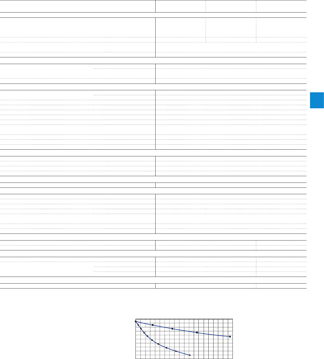
2CDC 110 004 C0210 | Catalog Electronic Products and Relays 2015 | ABB 6/16
6
Logic relays
Technical data
Data at Ta = 25 °C and rated values, if nothing else indicated.
Type CL-LSR..., CL-LST... CL-LMR... CL-LMT..
CL-LET.., CL-LER.18..
CL-LER.2O
CL-LEC.CI000
General data
Dimensions (W x H x D) 71.5 mm x 90 mm x
58 mm
(2.81 inch x 3.54 inch x
2.28 inch)
107.5 mm x 90 mm x
58 mm
(4.23 inch x 3.54 inch x
2.28 inch)
35.5 mm x 90 mm x
58 mm
(1.40 inch x 3.54 inch x
2.28 inch)
Weight 0.2 kg (0.44 lb) 0.3 kg (0.66 lb) 0.07 kg (0.15 lb)
Mounting DIN rail (IEC/EN 60715), 35 mm or screw mounting with fixing brackets
CL-LAS.FD001 (accessories)
Mounting position horizontal / vertical
Electrical connection
Wire size rigid 0.2-4 mm2 (22–12 AWG)
fine-strand with wire end
ferrule 0.2-2.5 mm2 (22–12 AWG)
Max. tightening torque 0.6 Nm
Environmental data
Ambient temperature range operation -25...+55 °C, cold acc. to IEC 60068-2-1, heat acc. to IEC 60068-2-2
storage -40...+70 °C
LCD-Display (clearly legible) 0...+55 °C
Condensation avoid condensation with suitable methods
Humidity, no condensation (IEC/EN 60068-2-30) 5-95 %
Air pressure (operation) 795-1080 hPa
Degree of protection (IEC/EN 60529) IP20
Vibration (IEC/EN 60068-2-6) 10-57 Hz (constant amplitude 0.15 mm), 57-150 Hz (constant
acceleration 2 g)
Shock resistance (half-sine 15 g / 11 ms) (IEC/EN 60068-2-27) 18 Shocks
Drop (IEC/EN 60068-2-31) height of fall 50 mm
Free fall, packaged (IEC/EN 60068-2-32) 1 m
Insulation data
Overvoltage category II
Pollution degree (DIN EN 60947) 2
Rating of air and creepage distances EN 50178, UL 508, CSA C22.2, No. 142
Insulation resistance EN 50178
Standards
Standards and directives EN 55011, EN 55022, IEC/EN 61000-4, IEC 60068-2-6, IEC 60068-2-27
Electromagnetic compatibility
Interference immunity
electrostatic discharge (ESD) IEC/EN 61000-4-2 Level 3 (air discharge 8 kV, contact discharge 6 kV)
electromag. field (HF radiation resistance) IEC/EN 61000-4-3 10 V/m
fast transients (Burst) IEC/EN 61000-4-4 Level 3 (supply cable 2 kV, signal lines 2 kV)
powerful impulses (Surge) IEC/EN 61000-4-5 supply cable symmetrical (AC) 2 kV,
Level 2 (supply cable symmetrical (DC) 0.5 kV)
HF line emission IEC/EN 61000-4-6 10 V
Interference suppression (EN 55011, EN 55022) class B
Real time clock
Back-up time see diagram -
Accuracy typ. ±5 (±0.5 h/year) -
Repeat accuracy of the time relay
Accuracy (from value) ±1 -
Resolution range „S“ 10 ms -
range „M:S“ 1 s -
range „H:M“ 1 min -
Retention behaviour
Write cycles of retention memory (minimum) 1.000.000 (106) -
180
200
160
140
120
100
80
60
40
20
0
55 ˚C
25 ˚C
01234567891011121314151617181920
Buffer time (hours)
2CDC 312 023 F0206
Operating time (years)
Technical diagram
Back-up time of the real time clock

6/17 ABB | Catalog Electronic Products and Relays 2015 | 2CDC 110 004 C02010
6
Logic relays
Technical data
Data at Ta = 25 °C and rated values, if nothing else indicated.
Type CL-LDD...
Input circuit - Supply circuit
Power failure buffering (IEC/EN 61131-2) 10 ms
General data
Dimensions (W x H x D) with keypad:
86.5 x 86.5 x 21.5 mm (3.41 x 3.41 x 0.85 inch)
without keypad:
86.5 x 86.5 x 20 mm (3.41 x 3.41 x 0.79 inch)
Weight 0.13 kg (0.29 lb)
Mounting 2 x 22.5 mm, with 2 retainers screwed
Mounting position horizontal / vertical
Environmental data
Ambient temperature range operation -25...+55 °C (cold acc. to IEC 60068-2-1, heat acc. to IEC
60068-2-2)
storage -40...+70 °C
LCD-Display (clearly legible) -5...+50 °C,
-10...0 °C (with backlit / continuous operation)
Condensation avoid condensation with suitable methods
Humidity, no condensation (IEC/EN 60068-2-30) 5-95 %
Air pressure (operation) 795-1080 hPa
Degree of protection (IEC/EN 60529) IP65
Vibration (IEC/EN 60068-2-6) 10-57 Hz (constant amplitude 0.15 mm), 57-150 Hz (constant
acceleration 2 g)
Shock resistance (half-sine 15 g / 11 ms) (IEC/EN 60068-2-27) 18 Shocks
Drop (IEC/EN 60068-2-31) height of fall 50 mm
Free fall, packaged (IEC/EN 60068-2-32) 1 m
Insulation data
Pollution degree (DIN EN 60947) 3
Rating of air and creepage distances EN 50178, UL 508, CSA 22.2, No 142
Insulation resistance EN 50178
Standards
Standards and directives EN 61000-6-1, EN 61000-6-2, EN 61000-6-3, EN 61000-6-4,
IEC 60068-2-6, IEC 60068-2-27
Electromagnetic compatibility
Interference immunity
electrostatic discharge (ESD) IEC/EN 61000-4-2 Level 3 (air discharge 8 kV, contact discharge 6 kV)
electromag. field (HF radiation resistance) IEC/EN 61000-4-3 10 V/m
fast transients (Burst) IEC/EN 61000-4-4 Level 3 (supply cable 2 kV, signal lines 2 kV)
powerful impulses (Surge) IEC/EN 61000-4-5 Level 3 (supply cable symmetrical 2 kV, CL-LDC.L...AC2)
Level 2 (0.5 kV supply cable symmetrical, CL-LDC.L...AC2)
HF line emission IEC/EN 61000-4-6 10 V
Interference suppression (EN 55011, EN 55022) class B

2CDC 110 004 C0210 | Catalog Electronic Products and Relays 2015 | ABB 6/18
6
Logic relays
Technical data
Data at Ta = 25 °C and rated values, if nothing else indicated.
Type
CL-LDC.SDC2 CL-LDC.SAC2 CL-LDC.LDC2 CL-LCD.LAC2
CL-LDC.LNDC2
CL-LDC.LNAC2
Input circuit - Supply circuit
Rated operational voltage Ue24 V DC 100-240 V AC 24 V DC 100-240 V AC 24 V DC 100-240 V AC
Rated operational voltage tolerance -15...+20 % -15...+10 % -15...+20 % -15...+10 % -15...+20 % -15...+10 %
Operational voltage range
20.4-28.8 V DC 85-264 V AC 20.4-28.8 V DC
85-264 V AC
20.4-28.8 V DC
85-264 V AC
Frequency 0 Hz 50/60 Hz 0 Hz 50/60 Hz 0 Hz 50/60 Hz
Frequency tolerance -± 5 % -± 5 % -± 5 %
Residual ripple m 5 % -m 5 % -m 5 % -
Input current at 24 V DC typ. 185 mA -typ. 200 mA -typ. 200 mA -
at 115/120 V AC (60 Hz)
-typ. 90 mA -typ. 90 mA -typ. 90 mA
at 230/240 V AC (50 Hz)
-typ. 60 mA -typ. 60 mA -typ. 60 mA
Power failure buffering (IEC/EN 61131-2) 10 ms
Power dissipation at 24 V DC 1.5 W -3.4 W -3.4 W -
at 115/120 V AC -typ. 11 VA -typ. 11 VA -typ. 11 VA
at 230/240 V AC -typ. 15 VA -typ. 15 VA -typ. 15 VA
Network - point-to-point connection
Number of stations 1 -
Data transfer rate CL-LS..., CL-LM... 9.6 kBaud -
CL-LDD 19.2 kBaud -
Distance max. 5 m -
Electrical isolation to voltage supply yes -
to connected device yes -
Termination system spring-type terminal -
Network - CL-NET
Number of stations max. 1 -max. 8
Data transfer rate 6 m -1000 kBit/s
25 m -500 kBit/s
40 m -250 kBit/s
125 m -125 kBit/s
300 m -50 kBit/s
700 m -20 kBit/s
1000 m -10 kBit/s
Electrical isolation to voltage supply -yes
to inputs -yes
to outputs -yes
to PC interface,
memory module,
C L- N E T, CL- L I N K
-yes
Bus terminator (first and last station) -yes
Termination system -RJ45, 8 pole
General data
Dimensions (W x H x D) 75 x 58 x 36.2 mm
(2.95 x 2.28 x 1.43 inch) 107.5 x 90 x 30 mm
(4.23 x 3.54 x 1.18 inch)
Weight 0.164 kg (0.36 lb) 0.145 kg (0.32 lb)
Mounting plugged onto CL-LDD plugged onto CL-LDD or on DIN rail (IEC/EN 60715)
Mounting position
Electrical connection - Supply circuit
Wire size fine-strand with wire
end ferrule 0.2 mm2 / 2.5 mm2 (24-12 AWG)
rigid 0.2 mm2 / 4 mm2 (24-12 AWG)
Electrical connection - Data cable
Wire size fine-strand with wire
end ferrule 0.08 mm2 / 1.5 mm2 (28-12
AWG) -0.2 mm2 / 2.5 mm2 (24-12
AWG)
rigid 0.08 mm2 / 2.5 mm2 (28-12
AWG) -0.2 mm2 / 4 mm2 (24-12 AWG)
Environmental data
Ambient temperature range operation -25...+55 °C (cold acc. to IEC 60068-2-1, heat acc. to IEC 60068-2-2)
storage -40...+70 °C
Condensation avoid condensation with suitable methods
Humidity, no condensation (IEC/EN 60068-2-30) 5-95 %
Air pressure (operation) 795-1080 hPa
Degree of protection (IEC/EN 60529) IP20
Vibration (IEC/EN 60068-2-6) 10-57 Hz (constant amplitude 0.15 mm), 57-150 Hz (constant acceleration 2 g)
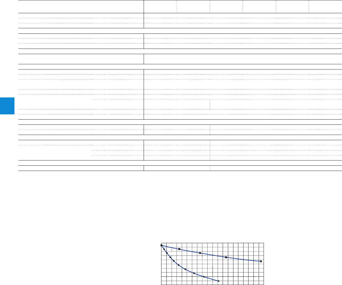
6/19 ABB | Catalog Electronic Products and Relays 2015 | 2CDC 110 004 C02010
6
Logic relays
Technical data
Data at Ta = 25 °C and rated values, if nothing else indicated.
Type CL-LDC.
SDC2
CL-LDC.
SAC2
CL-LDC.
LDC2
CL-LCD.
LAC2
CL-LDC.
LNDC2
CL-LDC.
LNAC2
Shock (half-sine 15 g / 11 ms) (IEC/EN 60068-2-27) 18 Shocks
Drop (IEC/EN 60068-2-31) height of fall 50 mm
Free fall, packaged (IEC/EN 60068-2-32) 1 m
Insulation data
Degree of protection (DIN EN 60947) 2
Rating of air and creepage distances EN 50178, UL 508, CSA 22.2, No 142
Isolation resistance EN 50178
Standards
Standards and directives EN 61000-6-1, EN 61000-6-2, EN 61000-6-3, EN 61000-6-4, IEC 60068-2-6, IEC 60068-
2-27
Electromagnetical compatibility
Interference immunity
electrostatic discharge (ESD) IEC/EN 61000-4-2 Level 3 (air discharge 8 kV, contact discharge 6 kV)
electromag. field (HF radiation
resistance) IEC/EN 61000-
4-3 10 V/m
fast transients (Burst) IEC/EN 61000-4-4 Level 3 (supply cable 2 kV, signal lines 2 kV)
powerful impulses (Surge) IEC/EN 61000-4-5 Level 3 (supply cable symmetrical 2 kV, CL-LDC.L...AC2)
Level 2 (1 kV supply cable
symmetrical) Level 2 (0.5 kV supply cable symmetrical, CL-LDC.L...AC2)
HF line emission IEC/EN 61000-4-6 10 V
Interference suppression (EN 55011, EN 55022) class B
Real time clock
Back-up time -see diagram
Accuracy -typ. ± 5 s/day (± 0,5 h/year)
Repeat accuracy of the time relay
Accuracy (from value) -± 0.02 %
Resolution range „S“ -5 ms
range „M:S“ -1 s
range „H:M“ -1 min
Retention behaviour
Write cycles of retention memory (minimum) -1010 (read/ write cycles)
180
200
160
140
120
100
80
60
40
20
0
55 ˚C
25 ˚C
01234567891011121314151617181920
Buffer time (hours)
2CDC 312 023 F0206
Operating time (years)
Technical diagram
Back-up time of the real time clock

2CDC 110 004 C0210 | Catalog Electronic Products and Relays 2015 | ABB 6/20
6
Logic relays
Technical data
Data at Ta = 25 °C and rated values, if nothing else indicated.
Type CL-LD...16DC2 CL-LD...17DC2 CL-LDR.16AC2
Input circuit - Digital inputs 24 V DC 115/230 V
Number 12
Inputs can be used as analog inputs 4 (I7, I8, I11, I12) -
Indication of operational states -LCD-Display (if existing)
Electrical isolation from supply voltage no
from digital inputs no
from the outputs yes
from PC interface, memory module,
C L- N E T, CL- L I N K yes
Rated operational voltage Ue24 V DC -
Ue on „0“ signal < 5 V DC (I1-I6, I9, I10), < 8 V DC (I7, I8, I11, I12) 0-40 V AC (sinusoidal)
Ue on „1“ signal
> 15 V DC (I1-I6, I9, I10), > 8 V DC (I7, I8, I11, I12)
79-264 V AC
(sinusoidal)
Rated frequency 0 Hz 50-60 Hz
Input current on „1“ signal 3.3 mA (at 24 V DC, I1-I6, I9, I10),
2.2 mA (at 24 V DC, I7, I8, I11, I12)
12x0.2 mA (at 115 V AC,
60 Hz, I1-I12),
12x0.5 mA (at 230 V
AC, 50 Hz, I1-I12)
Time delay from „0“ to „1“ debounce ON 20 ms 10 ms (at 50 Hz),
100 ms (at 60 Hz)
debounce OFF typ. 0.1 ms (I1-I4), typ. 0.25 ms (I5-I12) 10 ms (at 50 Hz),
100 ms (at 60 Hz)
Time delay
from „1“ to „0“ debounce ON 20 ms 10 ms (at 50 Hz),
100 ms (at 60 Hz)
debounce OFF typ. 0.1 ms (I1-I4), typ. 0.4 ms (I5, I6, I9, I10),
typ. 0.2 ms (I7, I8, I11, I12) 10 ms (at 50 Hz),
100 ms (at 60 Hz)
Cable length (unshielded) 100 m -
Maximum cable length per input -typ. 60 m
Frequency counter number 4 (I1, I2, I3, I4) -
counting frequency < 3 kHz -
pulse shape square-wave -
pulse / pause ratio 1:1 -
Incremental counter number 2 (I1 + I2, I3 + I4) -
counting frequency < 3 kHz -
pulse shape square-wave -
signal offset 90° -
pulse / pause ratio 1:1 -
Rapid counter inputs number 4 (I1, I2, I3, I4) -
counting frequency < 3 kHz -
pulse shape square-wave -
pulse / pause ratio 1:1 -
Cable length (shielded) < 20 m -
Input circuit - Analog inputs
Number 4 (I7, I8, I11, I12) -
Electrical isolation to voltage supply no -
to digital inputs no -
to outputs yes -
to PC interface, memory modul,
C L- N E T, CL- L I N K yes -
Input type DC voltage -
Signal range 0-10 V DC -
Resolution analog 0.01 V -
digital 0.01 V; 10 Bit (value 0-1023) -
Input impedance 11.2 k q-
Accuracy of the actual value two CL-LD...
devices ± 3 % -
within one device ± 2 % -
Conversion time analog/digital each cycle -
Input current < 1 mA -
Cable length (shielded) < 30 m -

6/21 ABB | Catalog Electronic Products and Relays 2015 | 2CDC 110 004 C02010
6
Logic relays
Technical data
Data at Ta = 25 °C and rated values, if nothing else indicated.
Type CL-LD...16DC2 CL-LD...17DC2 CL-LDR.16AC2
Output circuit - Analog outputs
Number - 1 -
Electrical separation from voltage supply -no -
from the digital inputs -no -
from the digital outputs -yes -
from PC interface, memory
module, CL-NET, CL-LINK -yes -
Output type -DC voltage -
Signal range -0-10 V DC -
Max. output current -0.01 A -
Burden resistance -1 kq-
Overload and short-circuit protection -yes -
Resolution analog -0.01 V DC -
digital -10 Bit, (value: 0-1023) -
Setting time -100 ms -
Accuracy -25...+55 °C -2 % -
25 °C -1 % -
Conversion time -each CPU cycle -
General data
Dimensions (W x H x D)
CL-LDR: 89 x 90 x 44 mm (3.5 x 3.54 x 1.73 inch)
CL-LDT (build-in): 89 x 90 x 25 mm (3.5 x 3.54 x 0.98
inch)
89 x 90 x 44 mm
(3.5 x 3.54 x 1.73 inch)
Weight
CL-LDR: 0.15 kg (0.33 lb) / CL-LDT: 014 kg (0.31 lb)
0.15 kg (0.33 lb)
Mounting snap-on power supply unit
Mounting position horizontal / vertical
Electrical connection
Wire size fine-strand with wire end ferrule 0.2 mm2 / 2.5 mm2 (24-12 AWG)
rigid 0.2 mm2 / 4 mm2 (24-12 AWG)
Electrical connection - Data cable
Wire size fine-strand with wire end ferrule 0.08 mm2 / 1.5 mm2 (28-12 AWG)
rigid 0.08 mm2 / 2.5 mm2 (28-12 AWG)
Environmental data
Ambient temperature range operation -25...+55 °C (cold acc. to IEC 60068-2-1, heat acc. to IEC 60068-2-2)
storage -40...+70 °C
Condensation avoid condensation with suitable methods
Humidity, no condensation (IEC/EN 60068-2-30) 5-95 %
Atmospheric pressure (operation) 795-1080 hPa
Degree of protection (IEC/EN 60529) IP20
Vibration (IEC/EN 60068-2-6) 10-57 Hz (constant amplitude 0.15 mm), 57-150 Hz (constant
acceleration 2 g)
Shock (half-sine 15 g / 11 ms) (IEC/EN 60068-2-27) 18 Shocks
Drop (IEC/EN 60068-2-31) height of fall 50 mm
Free fall, packaged (IEC/EN 60068-2-32) 1 m
Insulation data
Pollution degree 2
Rating of air and creepage distances EN 50178, UL 508, CSA C22.2, No. 142
Isolation resistance EN 50178
Standards
Standards and directives
EN 61000-6-1/-2/-3/-4, IEC/EN 61000-4, IEC 60068-2-6, IEC 60068-2-27
Electromagnetic compatibility
electrostatic discharge (ESD)
IEC/EN 61000-4-2
Level 3 (air discharge 8 kV, contact discharge 6 kV)
electromag. field (HF radiation res.)
IEC/EN 61000-4-3
10 V/m
fast transients (Burst)
IEC/EN 61000-4-4
Level 3 (supply cable 2 kV, signal cable 2 kV)
powerful impulses (Surge)
IEC/EN 61000-4-5
2 kV (supply cable symmetrical),
Level 2 (0.5 kV supply cable symmetrical)
HF line emission
IEC/EN 61000-4-6
10 V
Interference suppression (EN 55011, EN 55022) class B

2CDC 110 004 C0210 | Catalog Electronic Products and Relays 2015 | ABB 6/22
6
Logic relays
Technical data
Data at Ta = 25 °C and rated values, if nothing else indicated.
Type CL-LDR...
Output circuit - Relay outputs
Number 4
Outputs in groups of -
Parallel switching of outputs to increase capacity not permissible
Fusing of the output relay circuit-breaker B16 or fuse 8 A (slow-acting)
Electrical isolation from voltage supply yes
from the inputs yes
from PC interface, memory module, CL-NET,
C L- L I N K yes
protective separation 300 V AC
Basic isolation 600 V AC
Mechanical lifetime 10x106 switching cycles
Rung conventional thermal current (10 A UL) 8 A
recommended load 12 V AC/DC > 500 mA
short-circuit proof cos j = 1;
characteristic B16 at 600 A 16 A
short-circuit proof cos j = 0.5 up to 0.7;
characteristic B16 at 900 A 16 A
Rated impulse withstand voltage Uimp contact-coil 6 kV
Rated operational voltage Ue250 V AC
Rated insulation voltage Ui250 V AC
Protective separation (EN 50178) between coil and contact 300 V AC
between two contacts 300V AC
Making capacity AC-15, 250 V AC, 3 A (600 ops./h) 300.000 switching cycles
DC13, L/R m 150 ms, 24 V DC, 1 A (500 ops./h) 200.000 switching cycles
Breaking capacity AC-15, 250 V AC, 3 A (600 ops./h) 300.000 switching cycles
DC13, L/R m 150 ms, 24 V DC, 1 A (500 ops/h) 200.000 switching cycles
Incandesent lamp load 1000 W at 230/240 V AC 25.000 switching cycles
500 W at 115/120 V AC 25.000 switching cycles
Fluorescent lamp load 10 x 58 W at 230/240 V AC
with electrical control gear 25.000 switching cycles
10 x 58 W at 230/240 V AC
uncompensated 25.000 switching cycles
1 x 58 W at 230/240 V AC
conventional compensated 25.000 switching cycles
Switching frequency mechanical operations 10x106
switching frequency 10 Hz
resistive load / lamp load 2 Hz
inductive load 0.5 Hz
UL/CSA
Continuous current at 240 V 10 A AC
Continuous current at 24 V 8 A DC
AC Utilization category (Control Circuit Rating Codes) B 300 Light Pilot Duty
max. rated operational voltage 300 V AC
max. continuous thermal current cos j = 1 at B 300
5 A
max. making / breaking apparent power
(Make/Break) cos j ≠ 1 at B 300 3600/360 VA
DC Utilization category (Control Circuit Rating Codes) R 300 Light Pilot Duty
max. rated operational voltage 300 V DC
max. continuous thermal current at R 300 1 A
max. making / breaking apparent power
(Make/Break) at R 300 28/28 VA

6/23 ABB | Catalog Electronic Products and Relays 2015 | 2CDC 110 004 C02010
6
Logic relays
Technical data
Data at Ta = 25 °C and rated values, if nothing else indicated.
Type CL-LDT...
Output circuit - Transistor outputs
Number 4
Rated operational voltage Ue 24 V DC
Operational voltage range 20.4-28.8 V DC
Residual ripple -
Supply current on „0“ signal typ. 18 mA / max. 32 mA
on „1“ signal typ. 24 mA / max. 44 mA
Reverse voltage protection yes (Attention: If supply voltage is reversed,
applying voltage at the outputs, causes a short circuit.)
Electrical isolation from voltage supply yes
from the inputs yes
from PC interface, memory module,
C L- N E T, CL- L I N K yes
Rated operational current Ie on„1“ signal DC max. 0.5 A
Lamp load without Rv5 W (Q1-Q4)
Residual current on „0“ signal per channel < 0.1 mA
Max. output voltage on „0“ signal at external load < 10 Mq2.5 V
on „1“ signal at Ie = 0.5 A U = Ue - 1 V
Short-circuit protection thermal (Q1-Q4), (analysis results from diagnosis input I16)
Short-circuit tripping current for Ra m 10 mq0.7 A m Ie m 2 A per output
Total short-circuit current 8 A
Peak short-circuit current 16 A
Thermal tripping yes
Max. switching frequency with constant resistive load RL < 100 kq (depending on
active channels and their load) 40.000 switching cycles/h
Parallel connection of outputs with resistive load, inductive load with external
suppressor, combination within one group group 1: Q1-Q4
number of outputs max. 4
max. total current 2 A (Attention! Outputs must be actuated simultaneously
and for the same length of time.)
Indication of operational states of the outputs LCD-Display (if existing)
Inductive load1) without external suppressor
T0.95 = 1 ms,
R = 48 q,
L = 16 mH
utilization factor 0.25 g
duty time 100 %
max. switching frequency f = 0,5 Hz
(max. duty time = 50 %) 1500 switching cycles
DC13,
T0.95 = 72 ms,
R = 48 q,
L = 1.15 H
utilization factor 0.25 g
duty time 100 %
max. switching frequency f = 0,5 Hz
(max. duty time = 50 %) 1500 switching cycles
T0.95 = 15 ms,
R = 48 q,
L = 0.24 H
utilization factor 0.25 g
duty time 100 %
max. switching frequency f = 0,5 Hz
(max. duty time = 50 %) 1500 switching cycles
Inductive load1) with external suppressor
demand factor 1 g
duty time 100 %
max. switching frequency max. duty time depends on suppressor
1) For inductive loading, without external suppression of the transistor outputs, the following applies:
T0.95 = time in ms, until 95 % of the steady-state current is achieved. T0.95 3 × T0.65 = 3 × L/R.
Data transfer rate in the CL-NET network: bus lengths of 40 m and over only attainable with cables with additional cross-section and connection adapter.
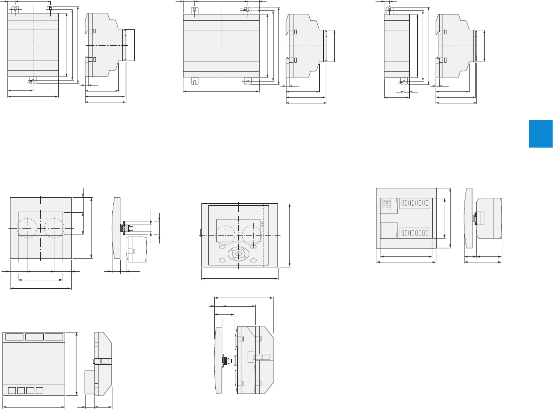
2CDC 110 004 C0210 | Catalog Electronic Products and Relays 2015 | ABB 6/24
6
Logic relays
Dimensional drawings
90
102
110
71.5
M4
10.75 50
35.75
45
58
56.5
47.5
4.5
2CDC 312 011 F0b06
90
102
110
M4
107.5
75 16.25
16.25
45
58
56.5
47.5
4.5
2CDC 312 012 F0b06
CL-LSR, CL-LST CL-LMR, CL-LMT
CL-LDD
32 17
20 13.7
86.5
30
62
86.5
28.25 28.25
22.3
30
2CDC 312 018 F0b06
90
102
110
45
58
56.5
47.5
4.5
7.5
35.5
7.5
M4
2CDC 312 013 F0b06
CL-LER.2O
90
88.2
107.5
20 43.2
33.7
2CDC 312 014 F0b06
65.5
29.3 36.2
86.5
75
86.5
58
2CDC 312 015 F0b06
90
88.1 19 25
2CDC 312 016 F0b06
CL-LDC.S..
CL-LDR, CL-LDT
CL-LDD.K + CL-LDC.L.. +
(CL-LDR or CL-LDT)
Dimensional drawings dimensions in mm

2/1 ABB | Catalog Electronic Products and Relays 2015 | 2CDC 110 004 C0210
7
Index
Alphanumerical
Type Page Type Page Type Page Type Page
Numbers
A
ADP.01 ...................................... 1/40
ADP.01 ...................................... 1/40
ADP.01 .................................... 2/130
ADP.01 ...................................... 4/22
ADP.02 .................................... 2/130
B
BADH V0................................... 5/47
BADL V0 ................................... 5/47
BAM2 V0................................... 5/47
BJ 612-10 ................................. 5/36
BJ 612-10 ................................. 5/47
BJ 612-20 ................................. 5/36
BJ 612-20 ................................. 5/47
C
C512-24 ................................. 2/104
C512-D ................................... 2/104
C512-E ................................... 2/104
C512-W .................................. 2/104
C513-D ................................... 2/104
C513-E ................................... 2/104
C513-W .................................. 2/104
CC-E I/I ....................................... 4/8
CC-E I/I ....................................... 4/8
CC-E I/I ....................................... 4/8
CC-E I/I ....................................... 4/8
CC-E I/I ....................................... 4/8
CC-E I/I ....................................... 4/8
CC-E I/I ....................................... 4/8
CC-E I/I ....................................... 4/8
CC-E I/I-1 ................................... 4/8
CC-E I/I-2 ................................... 4/8
CC-E I/V ..................................... 4/8
CC-E I/V ..................................... 4/8
CC-E IAC/I ................................ 4/11
CC-E IAC/I ................................ 4/11
CC-E IAC/I ................................ 4/11
CC-E IAC/I ................................ 4/11
CC-E IAC/ILPO .......................... 4/11
CC-E IAC/V ............................... 4/11
CC-E IAC/V ............................... 4/11
CC-E IDC/I ................................ 4/11
CC-E IDC/I ................................ 4/11
CC-E IDC/I ................................ 4/11
CC-E IDC/I ................................ 4/11
CC-E IDC/V ............................... 4/11
CC-E IDC/V ............................... 4/11
CC-E RTD/I ................................. 4/9
CC-E RTD/I ................................. 4/9
CC-E RTD/I ................................. 4/9
CC-E RTD/I ................................. 4/9
CC-E RTD/I ................................. 4/9
CC-E RTD/I ................................. 4/9
CC-E RTD/I ................................. 4/9
CC-E RTD/I ................................. 4/9
CC-E RTD/I ................................. 4/9
CC-E RTD/I ................................. 4/9
CC-E RTD/I ................................. 4/9
CC-E RTD/I ................................. 4/9
CC-E RTD/I ................................. 4/9
CC-E RTD/I ................................. 4/9
CC-E RTD/I ................................. 4/9
CC-E RTD/I ................................. 4/9
CC-E RTD/V ................................ 4/9
CC-E RTD/V ................................ 4/9
CC-E RTD/V ................................ 4/9
CC-E RTD/V ................................ 4/9
CC-E RTD/V ................................ 4/9
CC-E RTD/V ................................ 4/9
CC-E RTD/V ................................ 4/9
CC-E RTD/V ................................ 4/9
CC-E TC/I ................................. 4/10
CC-E TC/I ................................. 4/10
CC-E TC/I ................................. 4/10
CC-E TC/I ................................. 4/10
CC-E TC/I ................................. 4/10
CC-E TC/I ................................. 4/10
CC-E TC/I ................................. 4/10
CC-E TC/I ................................. 4/10
CC-E TC/V ................................ 4/10
CC-E TC/V ................................ 4/10
CC-E TC/V ................................ 4/10
CC-E TC/V ................................ 4/10
CC-E V/I ..................................... 4/8
CC-E V/I ..................................... 4/8
CC-E V/I ..................................... 4/8
CC-E V/I ..................................... 4/8
CC-E V/V .................................... 4/8
CC-E V/V .................................... 4/8
CC-E V/V .................................... 4/8
CC-E V/V .................................... 4/8
CC-E V/V .................................... 4/8
CC-E V/V .................................... 4/8
CC-E/I ...................................... 4/11
CC-E/I ...................................... 4/11
CC-E/RTD ................................... 4/9
CC-E/RTD ................................... 4/9
CC-E/STD ................................... 4/8
CC-E/STD ................................... 4/8
CC-E/TC ................................... 4/10
CC-E/TC ................................... 4/10
CC-U/I ...................................... 4/21
CC-U/I ...................................... 4/21
CC-U/RTD ................................ 4/21
CC-U/RTD ................................ 4/21
CC-U/RTDR .............................. 4/21
CC-U/RTDR .............................. 4/21
CC-U/STD ................................. 4/21
CC-U/STD ................................. 4/21
CC-U/STDR .............................. 4/21
CC-U/STDR .............................. 4/21
CC-U/TC ................................... 4/21
CC-U/TC ................................... 4/21
CC-U/TCR ................................ 4/21
CC-U/TCR ................................ 4/21
CC-U/V ..................................... 4/21
CC-U/V ..................................... 4/21
CL-LAD.FD001 ............................ 6/9
CL-LAD.FD002 ............................ 6/9
CL-LAD.FD011 ............................ 6/9
CL-LAD.MD004 ........................... 6/9
CL-LAD.TK001 ............................ 6/9
CL-LAD.TK002 ............................ 6/9
CL-LAD.TK003 ............................ 6/9
CL-LAD.TK004 ............................ 6/9
CL-LAD.TK005 ............................ 6/9
CL-LAD.TK006 ............................ 6/9
CL-LAD.TK007 ............................ 6/8
CL-LAD.TK009 ............................ 6/9
CL-LAD.TK011 ............................ 6/9
CL-LAS.FD001 ............................ 6/8
CL-LAS.MD003 ........................... 6/8
CL-LAS.PS002 ............................ 6/8
CL-LAS.TK001 ............................ 6/8
CL-LAS.TK002 ............................ 6/8
CL-LAS.TK011 ............................ 6/8
CL-LDC.LAC2 ............................. 6/9
CL-LDC.LDC2 ............................. 6/9
CL-LDC.LNAC2 ........................... 6/9
CL-LDC.LNDC2 ........................... 6/9
CL-LDC.SAC2 ............................. 6/6
CL-LDC.SDC2 ............................. 6/6
CL-LDD.K ................................... 6/6
CL-LDD.K ................................... 6/9
CL-LDD.XK ................................. 6/6
CL-LDD.XK ................................. 6/9
CL-LDR.16AC2 ........................... 6/9
CL-LDR.16DC2 ........................... 6/9
CL-LDR.17DC2 ........................... 6/9
CL-LDT.16DC2 ............................ 6/9
CL-LDT.17DC2 ............................ 6/9
CL-LEC.CI000 ............................. 6/7
CL-LER.18AC2 ............................ 6/7
CL-LER.18DC2 ........................... 6/7
CL-LER.2O ................................. 6/7
CL-LET.20DC2 ............................ 6/7
CL-LMR.C18AC1......................... 6/7
CL-LMR.C18AC2......................... 6/7
CL-LMR.C18DC1 ........................ 6/7
CL-LMR.C18DC2 ........................ 6/7
CL-LMR.CX18AC1....................... 6/7
CL-LMR.CX18AC2....................... 6/7
CL-LMR.CX18DC1 ...................... 6/7
CL-LMR.CX18DC2 ...................... 6/7
CL-LMT.C20DC2 ......................... 6/7
CL-LMT.CX20DC2 ....................... 6/7
CL-LSR.12AC2............................ 6/6
CL-LSR.12DC2 ........................... 6/6
CL-LSR.C12AC1 ......................... 6/6
CL-LSR.C12AC2 ......................... 6/6
CL-LSR.C12DC1 ......................... 6/6
CL-LSR.C12DC2 ......................... 6/6
CL-LSR.CX12AC1 ....................... 6/6
CL-LSR.CX12AC2 ....................... 6/6
CL-LSR.CX12DC1 ....................... 6/6
CL-LSR.CX12DC2 ....................... 6/6
CL-LST.C12DC2 .......................... 6/6
CL-LST.CX12DC2 ........................ 6/6
CM-AH-3 ................................ 2/116
CM-CT 100/1 .......................... 2/131
CM-CT 100/5 .......................... 2/131
CM-CT 150/1 .......................... 2/131
CM-CT 150/5 .......................... 2/131
CM-CT 200/1 .......................... 2/131
CM-CT 200/5 .......................... 2/131
CM-CT 300/1 .......................... 2/131
CM-CT 300/5 .......................... 2/131
CM-CT 400/1 .......................... 2/131
CM-CT 400/5 .......................... 2/131
CM-CT 50/1 ............................ 2/131
CM-CT 50/5 ............................ 2/131
CM-CT 500/1 .......................... 2/131
CM-CT 500/5 .......................... 2/131
CM-CT 600/1 .......................... 2/131
CM-CT 600/5 .......................... 2/131
CM-CT 75/1 ............................ 2/131
CM-CT 75/5 ............................ 2/131
CM-CT A ................................. 2/131
CM-EFS.2P ............................... 2/16
CM-EFS.2S ............................... 2/16
CM-ENE MAX .......................... 2/115
CM-ENE MAX .......................... 2/115

2CDC 110 004 C0210 | Catalog Electronic Products and Relays 2015 | ABB 2/2
7
Index
Alphanumerical
Type Page Type Page Type Page Type Page
CM-ENE MAX .......................... 2/115
CM-ENE MIN ........................... 2/115
CM-ENE MIN ........................... 2/115
CM-ENE MIN ........................... 2/115
CM-ENN ................................. 2/115
CM-ENN ................................. 2/115
CM-ENN ................................. 2/115
CM-ENN ................................. 2/115
CM-ENS.................................. 2/115
CM-ENS.................................. 2/115
CM-ENS.................................. 2/115
CM-ENS.................................. 2/115
CM-ENS UP/DOWN ................. 2/115
CM-ENS UP/DOWN ................. 2/115
CM-ENS UP/DOWN ................. 2/115
CM-ESS.1P ............................... 2/16
CM-ESS.1P ............................... 2/16
CM-ESS.1P ............................... 2/16
CM-ESS.1S ............................... 2/16
CM-ESS.1S ............................... 2/16
CM-ESS.1S ............................... 2/16
CM-ESS.2P ............................... 2/16
CM-ESS.2P ............................... 2/16
CM-ESS.2P ............................... 2/16
CM-ESS.2S ............................... 2/16
CM-ESS.2S ............................... 2/16
CM-ESS.2S ............................... 2/16
CM-ESS.MP .............................. 2/16
CM-ESS.MS .............................. 2/16
CM-GM-1 ................................ 2/116
CM-HE .................................... 2/116
CM-IVN.P .................................. 2/66
CM-IVN.S .................................. 2/66
CM-IWN.1P ............................... 2/66
CM-IWN.1S ............................... 2/66
CM-IWN.4P ............................... 2/66
CM-IWN.4S ............................... 2/66
CM-IWN.5P ............................... 2/66
CM-IWN.5S ............................... 2/66
CM-IWN.6P ............................... 2/66
CM-IWN.6S ............................... 2/66
CM-IWS.1P ............................... 2/66
CM-IWS.1S ............................... 2/66
CM-IWS.2P ............................... 2/66
CM-IWS.2S ............................... 2/66
CM-KH-3 ................................ 2/116
CM-LWN ................................... 2/76
CM-LWN ................................... 2/76
CM-LWN ................................... 2/76
CM-LWN ................................... 2/76
CM-LWN ................................... 2/76
CM-LWN ................................... 2/76
CM-LWN ................................... 2/76
CM-LWN ................................... 2/76
CM-LWN ................................... 2/76
CM-LWN ................................... 2/76
CM-MPN.52P ............................ 2/34
CM-MPN.52S ............................ 2/34
CM-MPN.62P ............................ 2/34
CM-MPN.62S ............................ 2/34
CM-MPN.72P ............................ 2/34
CM-MPN.72S ............................ 2/34
CM-MPS.11P ............................ 2/34
CM-MPS.11S ............................ 2/34
CM-MPS.21P ............................ 2/34
CM-MPS.21S ............................ 2/34
CM-MPS.23P ............................ 2/34
CM-MPS.23S ............................ 2/34
CM-MPS.31P ............................ 2/34
CM-MPS.31S ............................ 2/34
CM-MPS.41P ............................ 2/34
CM-MPS.41S ............................ 2/34
CM-MPS.43P ............................ 2/34
CM-MPS.43S ............................ 2/34
CM-MSE ................................... 2/90
CM-MSE ................................... 2/90
CM-MSE ................................... 2/90
CM-MSS.11P ............................ 2/90
CM-MSS.11S ............................ 2/90
CM-MSS.12P ............................ 2/90
CM-MSS.12S ............................ 2/90
CM-MSS.13P ............................ 2/90
CM-MSS.13S ............................ 2/90
CM-MSS.21P ............................ 2/90
CM-MSS.21S ............................ 2/90
CM-MSS.22P ............................ 2/90
CM-MSS.22S ............................ 2/90
CM-MSS.23P ............................ 2/90
CM-MSS.23S ............................ 2/90
CM-MSS.31P ............................ 2/90
CM-MSS.31S ............................ 2/90
CM-MSS.32P ............................ 2/90
CM-MSS.32S ............................ 2/90
CM-MSS.33P ............................ 2/90
CM-MSS.33S ............................ 2/90
CM-MSS.41P ............................ 2/90
CM-MSS.41S ............................ 2/90
CM-MSS.51P ............................ 2/90
CM-MSS.51S ............................ 2/90
CM-PAS.31P ............................. 2/33
CM-PAS.31S ............................. 2/33
CM-PAS.41P ............................. 2/33
CM-PAS.41S ............................. 2/33
CM-PBE .................................... 2/33
CM-PBE .................................... 2/33
CM-PFE .................................... 2/33
CM-PFS.P ................................. 2/33
CM-PFS.S ................................ 2/33
CM-PSS.31P ............................. 2/33
CM-PSS.31S ............................. 2/33
CM-PSS.41P ............................. 2/33
CM-PSS.41S ............................. 2/33
CM-PVE .................................... 2/33
CM-PVE .................................... 2/33
CM-PVS.31P ............................. 2/33
CM-PVS.31S ............................. 2/33
CM-PVS.41P ............................. 2/33
CM-PVS.41S ............................. 2/33
CM-PVS.81P ............................. 2/33
CM-PVS.81S ............................. 2/33
CM-SE-1000 ........................... 2/116
CM-SE-300 ............................. 2/116
CM-SE-600 ............................. 2/116
CM-SFS.21P ............................. 2/15
CM-SFS.21S ............................. 2/15
CM-SFS.22S ............................. 2/15
CM-SRS.11P ............................. 2/15
CM-SRS.11P ............................. 2/15
CM-SRS.11P ............................. 2/15
CM-SRS.11S ............................. 2/15
CM-SRS.11S ............................. 2/15
CM-SRS.11S ............................. 2/15
CM-SRS.12S ............................. 2/15
CM-SRS.12S ............................. 2/15
CM-SRS.12S ............................. 2/15
CM-SRS.21P ............................. 2/15
CM-SRS.21P ............................. 2/15
CM-SRS.21P ............................. 2/15
CM-SRS.21S ............................. 2/15
CM-SRS.21S ............................. 2/15
CM-SRS.21S ............................. 2/15
CM-SRS.22S ............................. 2/15
CM-SRS.22S ............................. 2/15
CM-SRS.22S ............................. 2/15
CM-SRS.M1P ............................ 2/15
CM-SRS.M1S ............................ 2/15
CM-SRS.M2S ............................ 2/15
CM-TCS.11P .......................... 2/104
CM-TCS.11S .......................... 2/104
CM-TCS.12P .......................... 2/104
CM-TCS.12S .......................... 2/104
CM-TCS.13P .......................... 2/104
CM-TCS.13S .......................... 2/104
CM-TCS.21P .......................... 2/104
CM-TCS.21S .......................... 2/104
CM-TCS.22P .......................... 2/104
CM-TCS.22S .......................... 2/104
CM-TCS.23P .......................... 2/104
CM-TCS.23S .......................... 2/104
CM-UFD.M22 ............................ 2/54
CM-UFD.M31 ............................ 2/54
CM-UFD.M33 ............................ 2/54
COV.01 ..................................... 1/40
COV.01 ................................... 2/130
COV.01 ..................................... 4/22
COV.02 ................................... 2/130
COV.11 ..................................... 1/40
COV.11 ................................... 2/130
COV.12 ................................... 2/130
CP-A CM .................................. 3/51
CP-A RU ................................... 3/51
CP-ASI/2.8 ................................ 3/60
CP-ASI/4.0 ................................ 3/60
CP-ASI/4.0 DC/DC .................... 3/60
CP-ASI/8.0 ................................ 3/60
CP-B 24/10.0 ............................ 3/68
CP-B 24/20.0 ............................ 3/68
CP-B 24/3.0 .............................. 3/68
CP-B EXT.2 ............................... 3/68
CP-C 24/10.0 ............................ 3/45
CP-C 24/20.0 ............................ 3/45
CP-C 24/5.0 .............................. 3/45
CP-C MM .................................. 3/45
CP-D 12/0.83 ............................ 3/10
CP-D 12/2.1 .............................. 3/10
CP-D 24/0.42 ............................ 3/10
CP-D 24/0.42 .............................. 6/8
CP-D 24/1.3 .............................. 3/10
CP-D 24/1.3 ................................ 6/8
CP-D 24/2.5 .............................. 3/10
CP-D 24/4.2 .............................. 3/10
CP-D RU ................................... 3/51
CP-E 12/10.0 ............................ 3/20
CP-E 12/2.5 .............................. 3/20
CP-E 24/0.75 ............................ 3/20
CP-E 24/1.25 ............................ 3/20
CP-E 24/10.0 ............................ 3/20
CP-E 24/2.5 .............................. 3/20
CP-E 24/20.0 ............................ 3/20
CP-E 24/5.0 .............................. 3/20
CP-E 48/0.62 ............................ 3/20
CP-E 48/1.25 ............................ 3/20
CP-E 48/10.0 ............................ 3/20
CP-E 48/5.0 .............................. 3/20

2/3 ABB | Catalog Electronic Products and Relays 2015 | 2CDC 110 004 C0210
7
Index
Alphanumerical
Type Page Type Page Type Page Type Page
CP-E 5/3.0 ................................ 3/20
CP-RUD .................................... 3/51
CP-S 24/10.0 ............................ 3/45
CP-S 24/20.0 ............................ 3/45
CP-S 24/5.0 .............................. 3/45
CP-T 24/10.0 ............................ 3/34
CP-T 24/20.0 ............................ 3/34
CP-T 24/40.0 ............................ 3/34
CP-T 24/5.0 .............................. 3/34
CP-T 48/10.0 ............................ 3/34
CP-T 48/20.0 ............................ 3/34
CP-T 48/5.0 .............................. 3/34
CR-M012DC2 ........................... 5/10
CR-M012DC2L .......................... 5/11
CR-M012DC3 ........................... 5/10
CR-M012DC3L .......................... 5/11
CR-M012DC4 ........................... 5/10
CR-M012DC4L .......................... 5/11
CR-M012DC4LDG ..................... 5/11
CR-M012DC4LG ....................... 5/11
CR-M024AC2 ............................ 5/10
CR-M024AC2L .......................... 5/11
CR-M024AC3 ............................ 5/10
CR-M024AC3L .......................... 5/11
CR-M024AC4 ............................ 5/10
CR-M024AC4G ......................... 5/11
CR-M024AC4L .......................... 5/11
CR-M024AC4LG ....................... 5/11
CR-M024DC2 ........................... 5/10
CR-M024DC2L .......................... 5/11
CR-M024DC3 ........................... 5/10
CR-M024DC3L .......................... 5/11
CR-M024DC4 ........................... 5/10
CR-M024DC4G ......................... 5/11
CR-M024DC4L .......................... 5/11
CR-M024DC4LD ....................... 5/11
CR-M024DC4LDG ..................... 5/11
CR-M024DC4LG ....................... 5/11
CR-M048AC2 ............................ 5/10
CR-M048AC2L .......................... 5/11
CR-M048AC3 ............................ 5/10
CR-M048AC3L .......................... 5/11
CR-M048AC4 ............................ 5/10
CR-M048AC4L .......................... 5/11
CR-M048AC4LG ....................... 5/11
CR-M048DC2 ........................... 5/10
CR-M048DC2L .......................... 5/11
CR-M048DC3 ........................... 5/10
CR-M048DC3L .......................... 5/11
CR-M048DC4 ........................... 5/10
CR-M048DC4L .......................... 5/11
CR-M048DC4LG ....................... 5/11
CR-M060AC3 ............................ 5/10
CR-M060DC2 ........................... 5/10
CR-M060DC2L .......................... 5/11
CR-M060DC3 ........................... 5/10
CR-M060DC3L .......................... 5/11
CR-M060DC4 ........................... 5/10
CR-M060DC4L .......................... 5/11
CR-M060DC4LG ....................... 5/11
CR-M110AC2 ............................ 5/10
CR-M110AC2L .......................... 5/11
CR-M110AC3 ............................ 5/10
CR-M110AC3L .......................... 5/11
CR-M110AC4 ............................ 5/10
CR-M110AC4G ......................... 5/11
CR-M110AC4L .......................... 5/11
CR-M110AC4LG ....................... 5/11
CR-M110DC2 ........................... 5/10
CR-M110DC2L .......................... 5/11
CR-M110DC3 ........................... 5/10
CR-M110DC3L .......................... 5/11
CR-M110DC4 ........................... 5/10
CR-M110DC4L .......................... 5/11
CR-M110DC4LG ....................... 5/11
CR-M120AC2 ............................ 5/10
CR-M120AC2L .......................... 5/11
CR-M120AC3 ............................ 5/10
CR-M120AC3L .......................... 5/11
CR-M120AC4 ............................ 5/10
CR-M120AC4L .......................... 5/11
CR-M120AC4LG ....................... 5/11
CR-M125DC2 ........................... 5/10
CR-M125DC2L .......................... 5/11
CR-M125DC3 ........................... 5/10
CR-M125DC3L .......................... 5/11
CR-M125DC4 ........................... 5/10
CR-M125DC4L .......................... 5/11
CR-M125DC4LG ....................... 5/11
CR-M220DC2 ........................... 5/10
CR-M220DC2L .......................... 5/11
CR-M220DC3 ........................... 5/10
CR-M220DC3L .......................... 5/11
CR-M220DC4 ........................... 5/10
CR-M220DC4L .......................... 5/11
CR-M220DC4LG ....................... 5/11
CR-M230AC2 ............................ 5/10
CR-M230AC2L .......................... 5/11
CR-M230AC3 ............................ 5/10
CR-M230AC3L .......................... 5/11
CR-M230AC4 ............................ 5/10
CR-M230AC4G ......................... 5/11
CR-M230AC4L .......................... 5/11
CR-M230AC4LG ....................... 5/11
CR-M2LC .................................. 5/11
CR-M2LS .................................. 5/11
CR-M2SF .................................. 5/11
CR-M2SS .................................. 5/11
CR-M3LS .................................. 5/11
CR-M3SS .................................. 5/11
CR-M4LC .................................. 5/11
CR-M4LS .................................. 5/11
CR-M4SF .................................. 5/11
CR-M4SS .................................. 5/11
CR-MH ..................................... 5/11
CR-MH1.................................... 5/11
CR-MJ ...................................... 5/11
CR-MM ..................................... 5/11
CR-P/M 22 ................................ 5/12
CR-P/M 42 ................................ 5/12
CR-P/M 42B ............................. 5/12
CR-P/M 42BV ........................... 5/12
CR-P/M 42C ............................. 5/12
CR-P/M 42CV ........................... 5/12
CR-P/M 42V .............................. 5/12
CR-P/M 52B ............................. 5/12
CR-P/M 52C ............................. 5/12
CR-P/M 52D ............................. 5/12
CR-P/M 62 ................................ 5/12
CR-P/M 62C ............................. 5/12
CR-P/M 62CV ........................... 5/12
CR-P/M 62D ............................. 5/12
CR-P/M 62DV ........................... 5/12
CR-P/M 62E .............................. 5/12
CR-P/M 62EV ............................ 5/12
CR-P/M 62V .............................. 5/12
CR-P/M 72 ................................ 5/12
CR-P/M 72A.............................. 5/12
CR-P/M 82 ................................ 5/12
CR-P/M 92 ................................ 5/12
CR-P/M 92C ............................. 5/12
CR-P/M 92CV ........................... 5/12
CR-P/M 92V .............................. 5/12
CR-P012DC1 .............................. 5/9
CR-P012DC2 .............................. 5/9
CR-P024AC1 .............................. 5/9
CR-P024AC2 .............................. 5/9
CR-P024AC2G ............................ 5/9
CR-P024DC1 .............................. 5/9
CR-P024DC2 .............................. 5/9
CR-P024DC2 .............................. 5/9
CR-P048AC1 .............................. 5/9
CR-P048AC2 .............................. 5/9
CR-P048DC1 .............................. 5/9
CR-P048DC2 .............................. 5/9
CR-P110AC1 .............................. 5/9
CR-P110AC2 .............................. 5/9
CR-P110AC2G ............................ 5/9
CR-P110DC1 .............................. 5/9
CR-P110DC2 .............................. 5/9
CR-P120AC1 .............................. 5/9
CR-P120AC2 .............................. 5/9
CR-P230AC1 .............................. 5/9
CR-P230AC2 .............................. 5/9
CR-P230AC2G ............................ 5/9
CR-PH ........................................ 5/9
CR-PJ ......................................... 5/9
CR-PLC ...................................... 5/9
CR-PLS ...................................... 5/9
CR-PLSx ..................................... 5/9
CR-PM ........................................ 5/9
CR-PSS ...................................... 5/9
CR-S005VDC1R .......................... 5/8
CR-S005VDC1RG ....................... 5/8
CR-S006/024VDC1SS ................. 5/8
CR-S006/024VDC1SZ ................. 5/8
CR-S012/024VADC1SS ............... 5/8
CR-S012/024VADC1SZ ............... 5/8
CR-S012VDC1R .......................... 5/8
CR-S012VDC1RG ....................... 5/8
CR-S024VADC1CRGS ................. 5/8
CR-S024VADC1CRGZ ................. 5/8
CR-S024VADC1CRS ................... 5/8
CR-S024VADC1CRZ .................... 5/8
CR-S024VDC1R .......................... 5/8
CR-S024VDC1RG ....................... 5/8
CR-S048/060VADC1SS ............... 5/8
CR-S048/060VADC1SZ ............... 5/8
CR-S048VDC1R .......................... 5/8
CR-S048VDC1RG ....................... 5/8
CR-S060VDC1R .......................... 5/8
CR-S060VDC1RG ....................... 5/8
CR-S110/125VADC1SS ............... 5/8
CR-S110/125VADC1SZ ............... 5/8
CR-S110VADC1CRGS ................. 5/8
CR-S110VADC1CRGZ ................. 5/8
CR-S110VADC1CRS ................... 5/8
CR-S110VADC1CRZ .................... 5/8
CR-S220/240VADC1SS ............... 5/8
CR-S220/240VADC1SZ ............... 5/8
CR-S230VADC1CRGS ................. 5/8
CR-S230VADC1CRGZ ................. 5/8
CR-S230VADC1CRS ................... 5/8
CR-S230VADC1CRZ .................... 5/8

2CDC 110 004 C0210 | Catalog Electronic Products and Relays 2015 | ABB 2/4
7
Index
Alphanumerical
Type Page Type Page Type Page Type Page
CR-SJB20-BLACK....................... 5/8
CR-SJB20-BLUE ......................... 5/8
CR-SJB20-RED ........................... 5/8
CR-SM ........................................ 5/8
CR-SSEP .................................... 5/8
CR-U 21 ................................... 5/14
CR-U 41 ................................... 5/14
CR-U 41B ................................. 5/14
CR-U 41BV ............................... 5/14
CR-U 41C ................................. 5/14
CR-U 41CV ............................... 5/14
CR-U 41V ................................. 5/14
CR-U 51B ................................. 5/14
CR-U 51C ................................. 5/14
CR-U 51D ................................. 5/14
CR-U 61 ................................... 5/14
CR-U 61C ................................. 5/14
CR-U 61CV ............................... 5/14
CR-U 61D ................................. 5/14
CR-U 61DV ............................... 5/14
CR-U 61E ................................. 5/14
CR-U 61EV ............................... 5/14
CR-U 61V ................................. 5/14
CR-U 71 ................................... 5/14
CR-U 71A ................................. 5/14
CR-U 81 ................................... 5/14
CR-U 91 ................................... 5/14
CR-U 91C ................................. 5/14
CR-U 91CV ............................... 5/14
CR-U 91V ................................. 5/14
CR-U T ..................................... 5/14
CR-U012DC2 ............................ 5/13
CR-U012DC2L .......................... 5/13
CR-U012DC3 ............................ 5/13
CR-U012DC3L .......................... 5/13
CR-U024AC2 ............................ 5/13
CR-U024AC2L .......................... 5/13
CR-U024AC3 ............................ 5/13
CR-U024AC3L .......................... 5/13
CR-U024DC2 ............................ 5/13
CR-U024DC2L .......................... 5/13
CR-U024DC3 ............................ 5/13
CR-U024DC3L .......................... 5/13
CR-U048AC2 ............................ 5/13
CR-U048AC2L .......................... 5/13
CR-U048AC3 ............................ 5/13
CR-U048AC3L .......................... 5/13
CR-U048DC2 ............................ 5/13
CR-U048DC2L .......................... 5/13
CR-U048DC3 ............................ 5/13
CR-U048DC3L .......................... 5/13
CR-U060AC3 ............................ 5/13
CR-U110AC2 ............................ 5/13
CR-U110AC2L .......................... 5/13
CR-U110AC3 ............................ 5/13
CR-U110AC3L .......................... 5/13
CR-U110DC2 ............................ 5/13
CR-U110DC2L .......................... 5/13
CR-U110DC3 ............................ 5/13
CR-U110DC3L .......................... 5/13
CR-U120AC2 ............................ 5/13
CR-U120AC2L .......................... 5/13
CR-U120AC3 ............................ 5/13
CR-U120AC3L .......................... 5/13
CR-U125DC3 ............................ 5/13
CR-U220DC2 ............................ 5/13
CR-U220DC2L .......................... 5/13
CR-U220DC3 ............................ 5/13
CR-U220DC3L .......................... 5/13
CR-U230AC2 ............................ 5/13
CR-U230AC2L .......................... 5/13
CR-U230AC3 ............................ 5/13
CR-U230AC3L .......................... 5/13
CR-U2S .................................... 5/13
CR-U2SM ................................. 5/13
CR-U3E .................................... 5/13
CR-U3S .................................... 5/13
CR-U3SM ................................. 5/13
CR-UH ...................................... 5/13
CT- MXS.22S............................. 1/37
CT-AHD.12 .................................. 1/8
CT-AHD.22 .................................. 1/8
CT-AHE ..................................... 1/20
CT-AHE ..................................... 1/20
CT-AHE ..................................... 1/20
CT-AHE ..................................... 1/20
CT-AHE ..................................... 1/20
CT-AHE ..................................... 1/20
CT-AHE ..................................... 1/20
CT-AHE ..................................... 1/20
CT-AHE ..................................... 1/20
CT-AHS.22P .............................. 1/38
CT-AHS.22S .............................. 1/38
CT-AKE ..................................... 1/21
CT-AKE ..................................... 1/21
CT-AKE ..................................... 1/21
CT-APS.12P .............................. 1/38
CT-APS.12S .............................. 1/38
CT-APS.21P .............................. 1/38
CT-APS.21S .............................. 1/38
CT-APS.22P .............................. 1/38
CT-APS.22S .............................. 1/38
CT-ARE ..................................... 1/20
CT-ARE ..................................... 1/20
CT-ARE ..................................... 1/20
CT-ARE ..................................... 1/20
CT-ARS.11P .............................. 1/38
CT-ARS.11S .............................. 1/38
CT-ARS.21P .............................. 1/38
CT-ARS.21S .............................. 1/38
CT-AWE .................................... 1/20
CT-AWE .................................... 1/20
CT-AWE .................................... 1/20
CT-AWE ................................... 1/21
CT-AWE ................................... 1/21
CT-AWE ................................... 1/21
CT-AWE ................................... 1/21
CT-AWE ................................... 1/21
CT-AWE ................................... 1/21
CT-AWE ................................... 1/21
CT-AWE ................................... 1/21
CT-AWE ................................... 1/21
CT-EBD.12 .................................. 1/8
CT-EBE ..................................... 1/21
CT-EBE ..................................... 1/21
CT-EKE ..................................... 1/21
CT-EKE ..................................... 1/21
CT-EKE ..................................... 1/21
CT-ERD.12 .................................. 1/8
CT-ERD.22 .................................. 1/8
CT-ERE ..................................... 1/20
CT-ERE ..................................... 1/20
CT-ERE ..................................... 1/20
CT-ERE ..................................... 1/20
CT-ERE ..................................... 1/20
CT-ERE ..................................... 1/20
CT-ERE ..................................... 1/20
CT-ERE ..................................... 1/20
CT-ERS.12P .............................. 1/38
CT-ERS.12S .............................. 1/38
CT-ERS.21P .............................. 1/38
CT-ERS.21S .............................. 1/38
CT-ERS.22P .............................. 1/38
CT-ERS.22S .............................. 1/38
CT-MBS.22P ............................. 1/37
CT-MBS.22S ............................. 1/37
CT-MFD.12 .................................. 1/8
CT-MFD.21 .................................. 1/8
CT-MFE ..................................... 1/20
CT-MFS.21 ................................ 1/37
CT-MFS.21P .............................. 1/37
CT-MKE .................................... 1/21
CT-MVS.12P ............................. 1/37
CT-MVS.12S ............................. 1/37
CT-MVS.21P ............................. 1/37
CT-MVS.21S ............................. 1/37
CT-MVS.22P ............................. 1/37
CT-MVS.22S ............................. 1/37
CT-MVS.23P ............................. 1/37
CT-MVS.23S ............................. 1/37
CT-MXS.22P.............................. 1/37
CT-SAD.22 .................................. 1/8
CT-SDD.22 .................................. 1/8
CT-SDE ..................................... 1/21
CT-SDE ..................................... 1/21
CT-SDE ..................................... 1/21
CT-SDS.22P .............................. 1/38
CT-SDS.22S .............................. 1/38
CT-SDS.23P .............................. 1/38
CT-SDS.23S .............................. 1/38
CT-TGD.12 .................................. 1/8
CT-TGD.22 .................................. 1/8
CT-VWD.12 ................................. 1/8
CT-VWE .................................... 1/20
CT-VWE .................................... 1/20
CT-VWE .................................... 1/20
CT-VWE .................................... 1/20
CT-VWE .................................... 1/20
CT-VWE .................................... 1/20
CT-WBS.22P ............................. 1/37
CT-WBS.22S ............................. 1/37
CT-YDE ..................................... 1/21
CT-YDE ..................................... 1/21
CT-YDE ..................................... 1/21
CT-YDE ..................................... 1/21
CT-YDE ..................................... 1/21
CT-YDE ..................................... 1/21
E
EPD24-TB-101-0.5A.................. 3/75
EPD24-TB-101-10A................... 3/75
EPD24-TB-101-12A................... 3/75
EPD24-TB-101-1A .................... 3/75
EPD24-TB-101-2A .................... 3/75
EPD24-TB-101-3A .................... 3/75
EPD24-TB-101-4A .................... 3/75
EPD24-TB-101-6A .................... 3/75
EPD24-TB-101-8A .................... 3/75
EPD-BB500............................... 3/75
EPD-SB21 ................................. 3/75
F
FC2 .......................................... 5/47

2/5 ABB | Catalog Electronic Products and Relays 2015 | 2CDC 110 004 C0210
7
Index
Alphanumerical
OBOC 1000-48-60VAC/DC ........ 5/47
OBOC 1000-5-12VDC ............... 5/47
OBOC 1500-24VAC/DC ............. 5/47
OBOC 5000-115VAC/DC ........... 5/47
OBOC 5000-230VAC/DC ........... 5/47
OBOC 5000-24VDC .................. 5/47
OBRIC 0100-115-230VAC/DC ... 5/47
OBRIC 0100-24VDC .................. 5/47
OBRIC 0100-48-60VAC/DC ....... 5/47
OBRIC 0100-5-12VDC ............... 5/47
OBROA 1000-115VAC/DC ......... 5/47
OBROA 1000-230VAC/DC ......... 5/47
OBROA 1000-24VDC ................ 5/47
OBROA 1000-48-60VAC/DC ...... 5/47
OBROA 2000-24VDC ................ 5/47
OBROC 1000-115VAC/DC ......... 5/47
OBROC 1000-230VAC/DC ......... 5/47
OBROC 1000-24VDC ................ 5/47
OBROC 1000-48-60VAC/DC ...... 5/47
OBROC 1000-5-12VDC ............. 5/47
OBROC 1500-24VAC/DC ........... 5/47
OBROC 5000-115VAC/DC ......... 5/47
OBROC 5000-230VAC/DC ......... 5/47
OBROC 5000-24VDC ................ 5/47
R
RB101AR-24VAC/DC ................. 5/35
RB111A-115VAC/DC ................. 5/35
RB111A-230VAC/DC ................. 5/35
RB111A-24VAC/DC ................... 5/35
RB111AR-24VAC/DC ................. 5/35
RB121-12VDC .......................... 5/36
RB121-12VDC .......................... 5/36
RB121-24VDC .......................... 5/36
RB121-5VDC ............................ 5/36
RB121-5VDC ............................ 5/35
RB121A-115VAC/DC ................. 5/36
RB121A-115VAC/DC ................. 5/35
RB121A-230VAC/DC ................. 5/36
RB121A-230VAC/DC ................. 5/35
RB121A-24VAC/DC ................... 5/36
RB121A-24VAC/DC ................... 5/35
RB121A-48-60VAC/DC .............. 5/36
RB121A-48-60VAC/DC .............. 5/35
RB121A-60-230VUC ................. 5/36
RB121AR-115VAC/DC ............... 5/36
RB121AR-230VAC/DC ............... 5/36
RB121-AU-12VDC ..................... 5/35
RB121-AU-24VDC ..................... 5/35
RB122A-115VAC/DC ................. 5/36
RB122A-230VAC/DC ................. 5/36
Type Page Type PageType Page
I
ILPH BdC /RS 422 - 485 (24 V DC
power supply) ............................ 4/37
ILPH RS 232 (24 V DC power supply)
4/37
ILPH RS 232 / FO-S (24...42 V AC/
DC power supply) ...................... 4/37
ILPH RS 232 / RS 232 (115-230 V AC
power supply) ............................ 4/37
ILPH RS 232 / RS 232 (24-48 V DC
power supply) ............................ 4/37
ILPH RS 232 / RS 422-485 ........ 4/37
ILPH RS 232 / RS 422-485 ........ 4/37
ILPH RS 232 / RS 422-485 (115-230
V AC power supply) ................... 4/37
ILPH RS 232 / RS 422-485 (24-48 V
DC power supply) ...................... 4/37
ILPH RS 232-RS 485 / Ethernet . 4/37
ILPH RS 422 - 485 / RS 422 - 485
(24 V DC power supply) ............. 4/37
ILPH RS 485 / FO-S (24...42 V AC/
DC power supply) ...................... 4/37
K
KA1-8029 ................................. 1/39
KA1-8030 ................................. 1/39
M
MA16-1060 ............................... 1/39
MAR.01..................................... 1/40
MAR.01..................................... 1/40
MAR.01................................... 2/130
MAR.01..................................... 4/22
MAR.02..................................... 1/40
MAR.02................................... 2/130
MAR.12..................................... 1/40
MAR.12................................... 2/130
MT-150B ................................... 1/39
MT-250B ................................... 1/39
MT-350B ................................... 1/39
O
OBIC 0100-115-230VAC/DC ...... 5/47
OBIC 0100-24VDC .................... 5/47
OBIC 0100-48-60VAC/DC.......... 5/47
OBIC 0100-5-12VDC ................. 5/47
OBOA 1000-115VAC/DC ........... 5/47
OBOA 1000-230VAC/DC ........... 5/47
OBOA 1000-24VDC ................... 5/47
OBOA 1000-48-60VAC/DC ........ 5/47
OBOA 2000-24VDC ................... 5/47
OBOC 1000-115VAC/DC ........... 5/47
OBOC 1000-230VAC/DC ........... 5/47
OBOC 1000-24VDC .................. 5/47
RB122A-24VAC/DC ................... 5/36
RB122A-48-60VAC/DC .............. 5/36
RBR101AR-24VAC/DC .............. 5/35
RBR111A-24VAC/DC ................. 5/35
RBR111AR-24VAC/DC .............. 5/35
RBR121-12VDC ........................ 5/36
RBR121-12VDC ........................ 5/36
RBR121-24VDC ........................ 5/36
RBR121-5VDC .......................... 5/36
RBR121-5VDC .......................... 5/35
RBR121A-115VAC/DC ............... 5/36
RBR121A-115VAC/DC ............... 5/35
RBR121A-230VAC/DC ............... 5/36
RBR121A-230VAC/DC ............... 5/35
RBR121A-24VAC/DC ................. 5/36
RBR121A-24VAC/DC ................. 5/35
RBR121A-48-60VUC ................. 5/36
RBR121A-48-60VUC ................. 5/35
RBR121A-60-230VUC ............... 5/36
RBR121AR-115VAC/DC ............ 5/36
RBR121AR-230VAC/DC ............ 5/36
RBR121-AU-12VDC .................. 5/35
RBR121-AU-24VDC .................. 5/35
RBR122A-115VAC/DC ............... 5/36
RBR122A-230VAC/DC ............... 5/36
RBR122A-24VAC/DC ................. 5/36
RBR122A-48-60VUC ................. 5/36
S
SC 612 ..................................... 5/36
SC 612 ..................................... 5/47
SK 615 562-87 .......................... 1/39
SK 615 562-88 .......................... 1/39

2CDC 110 004 C0210 | Catalog Electronic Products and Relays 2015 | ABB 2/6
7
Index
Numerical
1SAR
1SAR700100R0005 .. C512-24 ................................... 2/104
1SAR700100R0010 .. C512-W .................................... 2/104
1SAR700110R0010 .. C513-W .................................... 2/104
1SFA
1SFA611410R1506 .. MT-150B..................................... 1/39
1SFA611410R2506 .. MT-250B..................................... 1/39
1SFA611410R3506 .. MT-350B..................................... 1/39
1SFA611940R1060 .. MA16-1060 ................................ 1/39
1SFA616920R8029 .. KA1-8029 ................................... 1/39
1SFA616920R8030 .. KA1-8030 ................................... 1/39
1SNA
1SNA116900R2700 .. BADH V0 .................................... 5/47
1SNA206754R0000 .. BJ 612-20 .................................. 5/36
1SNA206754R0000 .. BJ 612-20 .................................. 5/47
1SNA290474R0200 .. SC 612 ....................................... 5/36
1SNA290474R0200 .. SC 612 ....................................... 5/47
1SNA290488R0100 .. BJ 612-10 .................................. 5/36
1SNA290488R0100 .. BJ 612-10 .................................. 5/47
1SNA399903R0200 .. BADL V0 ..................................... 5/47
1SNA399967R0100 .. BAM2 V0 .................................... 5/47
1SNA645001R0300 .. RB121A-24VAC/DC .................... 5/36
1SNA645002R0400 .. RB121A-48-60VAC/DC ............... 5/36
1SNA645003R0500 .. RB121A-115VAC/DC .................. 5/36
1SNA645004R0400 .. RB121A-230VAC/DC .................. 5/36
1SNA645005R0700 .. RB121A-24VAC/DC .................... 5/35
1SNA645006R0000 .. RB121A-48-60VAC/DC ............... 5/35
1SNA645007R0100 .. RB121A-115VAC/DC .................. 5/35
1SNA645008R1200 .. RB121A-230VAC/DC .................. 5/35
1SNA645011R2400 .. RB121AR-230VAC/DC ................ 5/36
1SNA645012R2500 .. RB122A-24VAC/DC .................... 5/36
1SNA645013R2600 .. RB122A-230VAC/DC .................. 5/36
1SNA645014R2700 .. RB111A-24VAC/DC .................... 5/35
1SNA645016R2100 .. RB111A-115VAC/DC .................. 5/35
1SNA645017R2200 .. RB111A-230VAC/DC .................. 5/35
1SNA645018R0300 .. RB111AR-24VAC/DC .................. 5/35
1SNA645019R0400 .. RB101AR-24VAC/DC .................. 5/35
1SNA645020R0100 .. RB121A-60-230VUC ................... 5/36
1SNA645021R2600 .. OBIC 0100-24VDC ...................... 5/47
1SNA645022R2700 .. OBIC 0100-115-230VAC/DC ....... 5/47
1SNA645024R2100 .. OBOC 5000-24VDC .................... 5/47
1SNA645025R2200 .. OBOC 1500-24VAC/DC .............. 5/47
1SNA645026R2300 .. OBOC 1000-230VAC/DC ............. 5/47
1SNA645027R2400 .. OBOA 1000-24VDC .................... 5/47
1SNA645028R0500 .. OBOA 1000-230VAC/DC ............. 5/47
1SNA645029R0600 .. OBOA 2000-24VDC .................... 5/47
1SNA645034R2300 .. RB121-5VDC .............................. 5/36
1SNA645035R2400 .. RB121-12VDC ............................ 5/36
1SNA645036R2500 .. RB121-5VDC .............................. 5/35
1SNA645040R1500 .. RB122A-48-60VAC/DC ............... 5/36
1SNA645041R0200 .. RB122A-115VAC/DC .................. 5/36
1SNA645046R0700 .. RB121AR-115VAC/DC ................ 5/36
1SNA645047R0000 .. OBIC 0100-5-12VDC .................. 5/47
1SNA645049R1200 .. OBIC 0100-48-60VAC/DC ........... 5/47
1SNA645050R1700 .. OBOC 1000-5-12VDC ................. 5/47
1SNA645051R0400 .. OBOC 1000-24VDC .................... 5/47
1SNA645053R0600 .. OBOC 1000-48-60VAC/DC ......... 5/47
1SNA645054R0700 .. OBOC 1000-115VAC/DC ............. 5/47
1SNA645058R1300 .. OBOC 5000-115VAC/DC ............. 5/47
1SNA645059R1400 .. OBOC 5000-230VAC/DC ............. 5/47
1SNA645061R0600 .. OBOA 1000-48-60VAC/DC .......... 5/47
1SNA645062R0700 .. OBOA 1000-115VAC/DC ............. 5/47
1SNA645071R0000 .. RB121-24VDC ............................ 5/36
1SNA645072R0000 .. RB121-AU-24VDC ...................... 5/35
1SNA645073R0000 .. RB121-12VDC ............................ 5/36
1SNA645075R0000 .. RB121-AU-12VDC ...................... 5/35
1SNA645501R0500 .. RBR121A-24VAC/DC .................. 5/36
1SNA645502R0600 .. RBR121A-48-60VUC................... 5/36
1SNA645503R0700 .. RBR121A-115VAC/DC ................ 5/36
1SNA645504R0000 .. RBR121A-230VAC/DC ................ 5/36
1SNA645505R0100 .. RBR121A-24VAC/DC .................. 5/35
1SNA645506R0200 .. RBR121A-48-60VUC................... 5/35
1SNA645507R0300 .. RBR121A-115VAC/DC ................ 5/35
1SNA645508R1400 .. RBR121A-230VAC/DC ................ 5/35
1SNA645511R2600 .. RBR121AR-230VAC/DC .............. 5/36
1SNA645512R2700 .. RBR122A-24VAC/DC .................. 5/36
1SNA645513R2000 .. RBR122A-230VAC/DC ................ 5/36
1SNA645514R2100 .. RBR111A-24VAC/DC .................. 5/35
1SNA645518R0500 .. RBR111AR-24VAC/DC ................ 5/35
1SNA645519R0600 .. RBR101AR-24VAC/DC ................ 5/35
1SNA645520R0300 .. RBR121A-60-230VUC ................. 5/36
1SNA645521R2000 .. OBRIC 0100-24VDC ................... 5/47
1SNA645522R2100 .. OBRIC 0100-115-230VAC/DC ..... 5/47
1SNA645524R2300 .. OBROC 5000-24VDC .................. 5/47
1SNA645525R2400 .. OBROC 1500-24VAC/DC ............ 5/47
1SNA645526R2500 .. OBROC 1000-230VAC/DC .......... 5/47
1SNA645527R2600 .. OBROA 1000-24VDC .................. 5/47
1SNA645528R0700 .. OBROA 1000-230VAC/DC........... 5/47
1SNA645529R0000 .. OBROA 2000-24VDC .................. 5/47
1SNA645531R2200 .. FC2 ............................................ 5/47
1SNA645534R2500 .. RBR121-5VDC ............................ 5/36
1SNA645535R2600 .. RBR121-12VDC .......................... 5/36
1SNA645536R2700 .. RBR121-5VDC ............................ 5/35
1SNA645540R1700 .. RBR122A-48-60VUC................... 5/36
1SNA645541R0400 .. RBR122A-115VAC/DC ................ 5/36
1SNA645546R0100 .. RBR121AR-115VAC/DC .............. 5/36
1SNA645547R0200 .. OBRIC 0100-5-12VDC ................ 5/47
1SNA645549R1400 .. OBRIC 0100-48-60VAC/DC ......... 5/47
1SNA645550R1100 .. OBROC 1000-5-12VDC............... 5/47
1SNA645551R0600 .. OBROC 1000-24VDC .................. 5/47
1SNA645553R0000 .. OBROC 1000-48-60VAC/DC ....... 5/47
1SNA645554R0100 .. OBROC 1000-115VAC/DC .......... 5/47
1SNA645558R1500 .. OBROC 5000-115VAC/DC .......... 5/47
1SNA645559R1600 .. OBROC 5000-230VAC/DC .......... 5/47
1SNA645561R0000 .. OBROA 1000-48-60VAC/DC ....... 5/47
1SNA645562R0100 .. OBROA 1000-115VAC/DC........... 5/47
1SNA645571R0000 .. RBR121-24VDC .......................... 5/36
1SNA645572R0000 .. RBR121-AU-24VDC .................... 5/35
1SNA645573R0000 .. RBR121-12VDC .......................... 5/36
1SNA645575R0000 .. RBR121-AU-12VDC .................... 5/35
1SNA684202R0100 .. ILPH RS 232 (24 V DC power supply)..
4/37
1SNA684212R2200 .. ILPH RS 422 - 485 / RS 422 - 485 (24
V DC power supply) .. 4/37
1SNA684231R2500 .. ILPH RS 232 / RS 422-485 ......... 4/37
1SNA684232R2600 .. ILPH BdC /RS 422 - 485 (24 V DC
power supply) ........... 4/37
1SNA684233R2700 .. ILPH RS 232 / RS 422-485 ......... 4/37
1SNA684234R0200 .. ILPH RS 232 / RS 232 (115-230 V AC
power supply) ........... 4/37
1SNA684234R2000 .. ILPH RS 232 / RS 232 (24-48 V DC
power supply) ........... 4/37
1SNA684236R2200 .. ILPH RS 232 / FO-S (24...42 V AC/DC
power supply) ........... 4/37
1SNA684246R0400 .. ILPH RS 485 / FO-S (24...42 V AC/DC
power supply) ........... 4/37
1SNA684252R0200 .. ILPH RS 232-RS 485 / Ethernet ... 4/37
1SNA684333R2300 .. ILPH RS 232 / RS 422-485 (24-48 V
DC power supply) ..... 4/37
1SNA684334R2400 .. ILPH RS 232 / RS 422-485 (115-230
V AC power supply) .. 4/37
1SNB041391R0610 .. CR-SM ......................................... 5/8
1SVR
1SVR010200R1600 .. CC-E I/I-1 ..................................... 4/8
1SVR010201R0300 .. CC-E I/I-2 ..................................... 4/8
1SVR010203R0500 .. CC-E IAC/ILPO ........................... 4/11
1SVR011700R0000 .. CC-E/STD .................................... 4/8
1SVR011701R2500 .. CC-E/RTD .................................... 4/9
1SVR011702R2600 .. CC-E/TC..................................... 4/10
1SVR011703R2700 .. CC-E/I ........................................ 4/11
1SVR011705R2100 .. CC-E/STD .................................... 4/8
1SVR011706R2200 .. CC-E/RTD .................................... 4/9
1SVR011707R2300 .. CC-E/TC..................................... 4/10
1SVR011708R0400 .. CC-E/I ........................................ 4/11
1SVR011710R2100 .. CC-E V/V ...................................... 4/8
1SVR011711R1600 .. CC-E V/I ....................................... 4/8
1SVR011712R1700 .. CC-E V/I ....................................... 4/8
1SVR011713R1000 .. CC-E I/V ....................................... 4/8
1SVR011714R1100 .. CC-E I/I ........................................ 4/8
1SVR011715R1200 .. CC-E I/I ........................................ 4/8
1SVR011716R1300 .. CC-E I/V ....................................... 4/8
1SVR011717R1400 .. CC-E I/I ........................................ 4/8
1SVR011718R2500 .. CC-E I/I ........................................ 4/8
Order code Type Page Order code Type Page Order code Type Page

2/7 ABB | Catalog Electronic Products and Relays 2015 | 2CDC 110 004 C0210
7
Index
Numerical
1SVR011719R2600 .. CC-E V/V ...................................... 4/8
1SVR011720R2300 .. CC-E V/V ...................................... 4/8
1SVR011721R1000 .. CC-E V/I ....................................... 4/8
1SVR011722R1100 .. CC-E V/I ....................................... 4/8
1SVR011723R1200 .. CC-E V/V ...................................... 4/8
1SVR011724R1300 .. CC-E I/I ........................................ 4/8
1SVR011725R1400 .. CC-E I/I ........................................ 4/8
1SVR011726R1500 .. CC-E V/V ...................................... 4/8
1SVR011727R1600 .. CC-E I/I ........................................ 4/8
1SVR011728R2700 .. CC-E I/I ........................................ 4/8
1SVR011729R2000 .. CC-E V/V ...................................... 4/8
1SVR011730R2500 .. CC-E RTD/V ................................. 4/9
1SVR011731R1200 .. CC-E RTD/I .................................. 4/9
1SVR011732R1300 .. CC-E RTD/I .................................. 4/9
1SVR011733R1400 .. CC-E RTD/V ................................. 4/9
1SVR011734R1500 .. CC-E RTD/I .................................. 4/9
1SVR011735R1600 .. CC-E RTD/I .................................. 4/9
1SVR011736R1700 .. CC-E RTD/V ................................. 4/9
1SVR011737R1000 .. CC-E RTD/I .................................. 4/9
1SVR011738R2100 .. CC-E RTD/I .................................. 4/9
1SVR011739R2200 .. CC-E RTD/V ................................. 4/9
1SVR011740R0700 .. CC-E RTD/I .................................. 4/9
1SVR011741R2400 .. CC-E RTD/I .................................. 4/9
1SVR011750R0100 .. CC-E TC/V.................................. 4/10
1SVR011751R2600 .. CC-E TC/I ................................... 4/10
1SVR011752R2700 .. CC-E TC/I ................................... 4/10
1SVR011753R2000 .. CC-E TC/V.................................. 4/10
1SVR011754R2100 .. CC-E TC/I ................................... 4/10
1SVR011755R2200 .. CC-E TC/I ................................... 4/10
1SVR011760R0300 .. CC-E TC/V.................................. 4/10
1SVR011761R2000 .. CC-E TC/I ................................... 4/10
1SVR011762R2100 .. CC-E TC/I ................................... 4/10
1SVR011763R2200 .. CC-E TC/V.................................. 4/10
1SVR011764R2300 .. CC-E TC/I ................................... 4/10
1SVR011765R2400 .. CC-E TC/I ................................... 4/10
1SVR011770R0500 .. CC-E IAC/V ................................ 4/11
1SVR011771R2200 .. CC-E IAC/I .................................. 4/11
1SVR011772R2300 .. CC-E IAC/I .................................. 4/11
1SVR011773R2400 .. CC-E IDC/V ................................ 4/11
1SVR011774R2500 .. CC-E IDC/I ................................. 4/11
1SVR011775R2600 .. CC-E IDC/I ................................. 4/11
1SVR011780R1100 .. CC-E IAC/V ................................ 4/11
1SVR011781R0600 .. CC-E IAC/I .................................. 4/11
1SVR011782R0700 .. CC-E IAC/I .................................. 4/11
1SVR011783R0000 .. CC-E IDC/V ................................ 4/11
1SVR011784R0100 .. CC-E IDC/I ................................. 4/11
1SVR011785R1100 .. CC-E IDC/I ................................. 4/11
1SVR011788R2400 .. CC-E RTD/V ................................. 4/9
1SVR011789R2500 .. CC-E RTD/I .................................. 4/9
1SVR011790R2200 .. CC-E RTD/I .................................. 4/9
1SVR011791R1700 .. CC-E RTD/V ................................. 4/9
1SVR011792R1000 .. CC-E RTD/I .................................. 4/9
1SVR011793R1100 .. CC-E RTD/I .................................. 4/9
1SVR011794R1200 .. CC-E RTD/V ................................. 4/9
1SVR011795R1300 .. CC-E RTD/I .................................. 4/9
1SVR011796R1400 .. CC-E RTD/I .................................. 4/9
1SVR011797R1500 .. CC-E RTD/V ................................. 4/9
1SVR011798R2600 .. CC-E RTD/I .................................. 4/9
1SVR011799R2700 .. CC-E RTD/I .................................. 4/9
1SVR040000R1700 .. CC-U/STD .................................. 4/21
1SVR040001R0400 .. CC-U/STD .................................. 4/21
1SVR040002R0500 .. CC-U/RTD .................................. 4/21
1SVR040003R0600 .. CC-U/RTD .................................. 4/21
1SVR040004R0700 .. CC-U/TC .................................... 4/21
1SVR040005R0000 .. CC-U/TC .................................... 4/21
1SVR040006R0100 .. CC-U/I ........................................ 4/21
1SVR040007R0200 .. CC-U/I ........................................ 4/21
1SVR040008R1300 .. CC-U/V ...................................... 4/21
1SVR040009R1400 .. CC-U/V ...................................... 4/21
1SVR040010R0000 .. CC-U/STDR ................................ 4/21
1SVR040011R2500 .. CC-U/STDR ................................ 4/21
1SVR040012R2600 .. CC-U/RTDR ................................ 4/21
1SVR040013R2700 .. CC-U/RTDR ................................ 4/21
1SVR040014R2000 .. CC-U/TCR .................................. 4/21
1SVR040015R2100 .. CC-U/TCR .................................. 4/21
1SVR366017R0100 .. MAR.01 ...................................... 1/40
1SVR366017R0100 .. MAR.01 ...................................... 1/40
1SVR366017R0100 .. MAR.01 .................................... 2/130
1SVR366017R0100 .. MAR.01 ...................................... 4/22
1SVR402902R0000 .. CM-HE ..................................... 2/116
1SVR405501R1010 .. CR-S005VDC1R ........................... 5/8
1SVR405501R1020 .. CR-S005VDC1RG ......................... 5/8
1SVR405501R2010 .. CR-S012VDC1R ........................... 5/8
1SVR405501R2020 .. CR-S012VDC1RG ......................... 5/8
1SVR405501R3010 .. CR-S024VDC1R ........................... 5/8
1SVR405501R3020 .. CR-S024VDC1RG ......................... 5/8
1SVR405501R4010 .. CR-S048VDC1R ........................... 5/8
1SVR405501R4020 .. CR-S048VDC1RG ......................... 5/8
1SVR405501R5010 .. CR-S060VDC1R ........................... 5/8
1SVR405501R5020 .. CR-S060VDC1RG ......................... 5/8
1SVR405521R1100 .. CR-S006/024VDC1SS .................. 5/8
1SVR405521R1200 .. CR-S006/024VDC1SZ ................... 5/8
1SVR405521R3100 .. CR-S012/024VADC1SS................. 5/8
1SVR405521R3200 .. CR-S012/024VADC1SZ ................. 5/8
1SVR405521R5100 .. CR-S048/060VADC1SS................. 5/8
1SVR405521R5200 .. CR-S048/060VADC1SZ ................. 5/8
1SVR405521R6100 .. CR-S110/125VADC1SS................. 5/8
1SVR405521R6200 .. CR-S110/125VADC1SZ ................. 5/8
1SVR405521R7100 .. CR-S220/240VADC1SS................. 5/8
1SVR405521R7200 .. CR-S220/240VADC1SZ ................. 5/8
1SVR405541R3110 .. CR-S024VADC1CRS ..................... 5/8
1SVR405541R3120 .. CR-S024VADC1CRGS .................. 5/8
1SVR405541R3210 .. CR-S024VADC1CRZ ..................... 5/8
1SVR405541R3220 .. CR-S024VADC1CRGZ ................... 5/8
1SVR405541R6110 .. CR-S110VADC1CRS ..................... 5/8
1SVR405541R6120 .. CR-S110VADC1CRGS .................. 5/8
1SVR405541R6210 .. CR-S110VADC1CRZ ..................... 5/8
1SVR405541R6220 .. CR-S110VADC1CRGZ ................... 5/8
1SVR405541R7110 .. CR-S230VADC1CRS ..................... 5/8
1SVR405541R7120 .. CR-S230VADC1CRGS .................. 5/8
1SVR405541R7210 .. CR-S230VADC1CRZ ..................... 5/8
1SVR405541R7220 .. CR-S230VADC1CRGZ ................... 5/8
1SVR405598R0700 .. CR-SJB20-BLUE .......................... 5/8
1SVR405598R0800 .. CR-SJB20-RED ............................ 5/8
1SVR405598R0900 .. CR-SJB20-BLACK ........................ 5/8
1SVR405599R0000 .. CR-SSEP ...................................... 5/8
1SVR405600R0000 .. CR-P024AC1 ................................ 5/9
1SVR405600R1000 .. CR-P024DC1 ................................ 5/9
1SVR405600R2000 .. CR-P120AC1 ................................ 5/9
1SVR405600R3000 .. CR-P230AC1 ................................ 5/9
1SVR405600R4000 .. CR-P012DC1 ................................ 5/9
1SVR405600R5000 .. CR-P048AC1 ................................ 5/9
1SVR405600R6000 .. CR-P048DC1 ................................ 5/9
1SVR405600R7000 .. CR-P110AC1 ................................ 5/9
1SVR405600R8000 .. CR-P110DC1 ................................ 5/9
1SVR405601R0000 .. CR-P024AC2 ................................ 5/9
1SVR405601R1000 .. CR-P024DC2 ................................ 5/9
1SVR405601R2000 .. CR-P120AC2 ................................ 5/9
1SVR405601R3000 .. CR-P230AC2 ................................ 5/9
1SVR405601R4000 .. CR-P012DC2 ................................ 5/9
1SVR405601R5000 .. CR-P048AC2 ................................ 5/9
1SVR405601R6000 .. CR-P048DC2 ................................ 5/9
1SVR405601R7000 .. CR-P110AC2 ................................ 5/9
1SVR405601R8000 .. CR-P110DC2 ................................ 5/9
1SVR405606R0000 .. CR-P024AC2G ............................. 5/9
1SVR405606R1000 .. CR-P024DC2 ................................ 5/9
1SVR405606R3000 .. CR-P230AC2G ............................. 5/9
1SVR405606R7000 .. CR-P110AC2G ............................. 5/9
1SVR405611R0000 .. CR-M024AC2 ............................. 5/10
1SVR405611R0100 .. CR-M024AC2L ........................... 5/11
1SVR405611R1000 .. CR-M024DC2 ............................. 5/10
1SVR405611R1100 .. CR-M024DC2L ........................... 5/11
1SVR405611R2000 .. CR-M120AC2 ............................. 5/10
1SVR405611R2100 .. CR-M120AC2L ........................... 5/11
1SVR405611R3000 .. CR-M230AC2 ............................. 5/10
1SVR405611R3100 .. CR-M230AC2L ........................... 5/11
1SVR405611R4000 .. CR-M012DC2 ............................. 5/10
1SVR405611R4100 .. CR-M012DC2L ........................... 5/11
1SVR405611R4200 .. CR-M060DC2 ............................. 5/10
1SVR405611R4300 .. CR-M060DC2L ........................... 5/11
1SVR405611R5000 .. CR-M048AC2 ............................. 5/10
1SVR405611R5100 .. CR-M048AC2L ........................... 5/11
1SVR405611R6000 .. CR-M048DC2 ............................. 5/10
Order code Type Page Order code Type Page Order code Type Page

2CDC 110 004 C0210 | Catalog Electronic Products and Relays 2015 | ABB 2/8
7
Index
Numerical
1SVR405611R6100 .. CR-M048DC2L ........................... 5/11
1SVR405611R7000 .. CR-M110AC2 ............................. 5/10
1SVR405611R7100 .. CR-M110AC2L ........................... 5/11
1SVR405611R8000 .. CR-M110DC2 ............................. 5/10
1SVR405611R8100 .. CR-M110DC2L ........................... 5/11
1SVR405611R8200 .. CR-M125DC2 ............................. 5/10
1SVR405611R8300 .. CR-M125DC2L ........................... 5/11
1SVR405611R9000 .. CR-M220DC2 ............................. 5/10
1SVR405611R9100 .. CR-M220DC2L ........................... 5/11
1SVR405612R0000 .. CR-M024AC3 ............................. 5/10
1SVR405612R0100 .. CR-M024AC3L ........................... 5/11
1SVR405612R1000 .. CR-M024DC3 ............................. 5/10
1SVR405612R1100 .. CR-M024DC3L ........................... 5/11
1SVR405612R2000 .. CR-M120AC3 ............................. 5/10
1SVR405612R2100 .. CR-M120AC3L ........................... 5/11
1SVR405612R3000 .. CR-M230AC3 ............................. 5/10
1SVR405612R3100 .. CR-M230AC3L ........................... 5/11
1SVR405612R4000 .. CR-M012DC3 ............................. 5/10
1SVR405612R4100 .. CR-M012DC3L ........................... 5/11
1SVR405612R4200 .. CR-M060DC3 ............................. 5/10
1SVR405612R4300 .. CR-M060DC3L ........................... 5/11
1SVR405612R5000 .. CR-M048AC3 ............................. 5/10
1SVR405612R5100 .. CR-M048AC3L ........................... 5/11
1SVR405612R5200 .. CR-M060AC3 ............................. 5/10
1SVR405612R6000 .. CR-M048DC3 ............................. 5/10
1SVR405612R6100 .. CR-M048DC3L ........................... 5/11
1SVR405612R7000 .. CR-M110AC3 ............................. 5/10
1SVR405612R7100 .. CR-M110AC3L ........................... 5/11
1SVR405612R8000 .. CR-M110DC3 ............................. 5/10
1SVR405612R8100 .. CR-M110DC3L ........................... 5/11
1SVR405612R8200 .. CR-M125DC3 ............................. 5/10
1SVR405612R8300 .. CR-M125DC3L ........................... 5/11
1SVR405612R9000 .. CR-M220DC3 ............................. 5/10
1SVR405612R9100 .. CR-M220DC3L ........................... 5/11
1SVR405613R0000 .. CR-M024AC4 ............................. 5/10
1SVR405613R0100 .. CR-M024AC4L ........................... 5/11
1SVR405613R1000 .. CR-M024DC4 ............................. 5/10
1SVR405613R1100 .. CR-M024DC4L ........................... 5/11
1SVR405613R2000 .. CR-M120AC4 ............................. 5/10
1SVR405613R2100 .. CR-M120AC4L ........................... 5/11
1SVR405613R3000 .. CR-M230AC4 ............................. 5/10
1SVR405613R3100 .. CR-M230AC4L ........................... 5/11
1SVR405613R4000 .. CR-M012DC4 ............................. 5/10
1SVR405613R4100 .. CR-M012DC4L ........................... 5/11
1SVR405613R4200 .. CR-M060DC4 ............................. 5/10
1SVR405613R4300 .. CR-M060DC4L ........................... 5/11
1SVR405613R5000 .. CR-M048AC4 ............................. 5/10
1SVR405613R5100 .. CR-M048AC4L ........................... 5/11
1SVR405613R6000 .. CR-M048DC4 ............................. 5/10
1SVR405613R6100 .. CR-M048DC4L ........................... 5/11
1SVR405613R7000 .. CR-M110AC4 ............................. 5/10
1SVR405613R7100 .. CR-M110AC4L ........................... 5/11
1SVR405613R8000 .. CR-M110DC4 ............................. 5/10
1SVR405613R8100 .. CR-M110DC4L ........................... 5/11
1SVR405613R8200 .. CR-M125DC4 ............................. 5/10
1SVR405613R8300 .. CR-M125DC4L ........................... 5/11
1SVR405613R9000 .. CR-M220DC4 ............................. 5/10
1SVR405613R9100 .. CR-M220DC4L ........................... 5/11
1SVR405614R1100 .. CR-M024DC4LD ......................... 5/11
1SVR405618R0000 .. CR-M024AC4G ........................... 5/11
1SVR405618R0100 .. CR-M024AC4LG ......................... 5/11
1SVR405618R1000 .. CR-M024DC4G........................... 5/11
1SVR405618R1100 .. CR-M024DC4LG ......................... 5/11
1SVR405618R1400 .. CR-M024DC4LDG ...................... 5/11
1SVR405618R2100 .. CR-M120AC4LG ......................... 5/11
1SVR405618R3000 .. CR-M230AC4G ........................... 5/11
1SVR405618R3100 .. CR-M230AC4LG ......................... 5/11
1SVR405618R4100 .. CR-M012DC4LG ......................... 5/11
1SVR405618R4300 .. CR-M060DC4LG ......................... 5/11
1SVR405618R4400 .. CR-M012DC4LDG ...................... 5/11
1SVR405618R5100 .. CR-M048AC4LG ......................... 5/11
1SVR405618R6100 .. CR-M048DC4LG ......................... 5/11
1SVR405618R7000 .. CR-M110AC4G ........................... 5/11
1SVR405618R7100 .. CR-M110AC4LG ......................... 5/11
1SVR405618R8100 .. CR-M110DC4LG ......................... 5/11
1SVR405618R8300 .. CR-M125DC4LG ......................... 5/11
1SVR405618R9100 .. CR-M220DC4LG ......................... 5/11
1SVR405621R0000 .. CR-U024AC2 .............................. 5/13
1SVR405621R0100 .. CR-U024AC2L ............................ 5/13
1SVR405621R1000 .. CR-U024DC2.............................. 5/13
1SVR405621R1100 .. CR-U024DC2L ............................ 5/13
1SVR405621R2000 .. CR-U120AC2 .............................. 5/13
1SVR405621R2100 .. CR-U120AC2L ............................ 5/13
1SVR405621R3000 .. CR-U230AC2 .............................. 5/13
1SVR405621R3100 .. CR-U230AC2L ............................ 5/13
1SVR405621R4000 CR-U012DC2.............................. 5/13
1SVR405621R4100 .. CR-U012DC2L ............................ 5/13
1SVR405621R5000 .. CR-U048AC2 .............................. 5/13
1SVR405621R5100 .. CR-U048AC2L ............................ 5/13
1SVR405621R6000 .. CR-U048DC2.............................. 5/13
1SVR405621R6100 .. CR-U048DC2L ............................ 5/13
1SVR405621R7000 .. CR-U110AC2 .............................. 5/13
1SVR405621R7100 .. CR-U110AC2L ............................ 5/13
1SVR405621R8000 .. CR-U110DC2.............................. 5/13
1SVR405621R8100 .. CR-U110DC2L ............................ 5/13
1SVR405621R9000 .. CR-U220DC2.............................. 5/13
1SVR405621R9100 .. CR-U220DC2L ............................ 5/13
1SVR405622R0000 .. CR-U024AC3 .............................. 5/13
1SVR405622R0100 .. CR-U024AC3L ............................ 5/13
1SVR405622R1000 .. CR-U024DC3.............................. 5/13
1SVR405622R1100 .. CR-U024DC3L ............................ 5/13
1SVR405622R2000 .. CR-U120AC3 .............................. 5/13
1SVR405622R2100 .. CR-U120AC3L ............................ 5/13
1SVR405622R3000 .. CR-U230AC3 .............................. 5/13
1SVR405622R3100 .. CR-U230AC3L ............................ 5/13
1SVR405622R4000 .. CR-U012DC3.............................. 5/13
1SVR405622R4100 .. CR-U012DC3L ............................ 5/13
1SVR405622R5000 .. CR-U048AC3 .............................. 5/13
1SVR405622R5100 .. CR-U048AC3L ............................ 5/13
1SVR405622R5200 .. CR-U060AC3 .............................. 5/13
1SVR405622R6000 .. CR-U048DC3.............................. 5/13
1SVR405622R6100 .. CR-U048DC3L ............................ 5/13
1SVR405622R7000 .. CR-U110AC3 .............................. 5/13
1SVR405622R7100 .. CR-U110AC3L ............................ 5/13
1SVR405622R8000 .. CR-U110DC3.............................. 5/13
1SVR405622R8100 .. CR-U110DC3L ............................ 5/13
1SVR405622R8200 .. CR-U125DC3.............................. 5/13
1SVR405622R9000 .. CR-U220DC3.............................. 5/13
1SVR405622R9100 .. CR-U220DC3L ............................ 5/13
1SVR405650R0000 .. CR-PLS ........................................ 5/9
1SVR405650R0100 .. CR-PLSx ...................................... 5/9
1SVR405650R0200 .. CR-PLC ........................................ 5/9
1SVR405650R1000 .. CR-PSS ........................................ 5/9
1SVR405651R0000 .. CR-P/M 22 ................................. 5/12
1SVR405651R1000 .. CR-M2SS ................................... 5/11
1SVR405651R1100 .. CR-M2LS ................................... 5/11
1SVR405651R1200 .. CR-M2LC ................................... 5/11
1SVR405651R1300 .. CR-M2SF ................................... 5/11
1SVR405651R2000 .. CR-M3SS ................................... 5/11
1SVR405651R2100 .. CR-M3LS ................................... 5/11
1SVR405651R3000 .. CR-M4SS ................................... 5/11
1SVR405651R3100 .. CR-M4LS ................................... 5/11
1SVR405651R3200 .. CR-M4LC ................................... 5/11
1SVR405651R3300 .. CR-M4SF ................................... 5/11
1SVR405652R0000 .. CR-P/M 42 ................................. 5/12
1SVR405652R1000 .. CR-P/M 42V ............................... 5/12
1SVR405652R4000 .. CR-P/M 42B ............................... 5/12
1SVR405652R4100 .. CR-P/M 42BV ............................. 5/12
1SVR405652R9000 .. CR-P/M 42C ............................... 5/12
1SVR405652R9100 .. CR-P/M 42CV ............................. 5/12
1SVR405653R0000 .. CR-P/M 52B ............................... 5/12
1SVR405653R1000 .. CR-P/M 52C ............................... 5/12
1SVR405653R4000 .. CR-P/M 52D ............................... 5/12
1SVR405654R0000 .. CR-P/M 62 ................................. 5/12
1SVR405654R0100 .. CR-P/M 92 ................................. 5/12
1SVR405654R1000 .. CR-P/M 62V ............................... 5/12
1SVR405654R1100 .. CR-P/M 92V ............................... 5/12
1SVR405654R4000 .. CR-P/M 62E ............................... 5/12
1SVR405654R4100 .. CR-P/M 62EV ............................. 5/12
1SVR405655R0000 .. CR-P/M 62C ............................... 5/12
1SVR405655R0100 .. CR-P/M 92C ............................... 5/12
1SVR405655R1000 .. CR-P/M 62CV ............................. 5/12
1SVR405655R1100 .. CR-P/M 92CV ............................. 5/12
Order code Type Page Order code Type Page Order code Type Page

2/9 ABB | Catalog Electronic Products and Relays 2015 | 2CDC 110 004 C0210
7
1SVR405655R4000 .. CR-P/M 62D ............................... 5/12
1SVR405655R4100 .. CR-P/M 62DV ............................. 5/12
1SVR405656R0000 .. CR-P/M 72 ................................. 5/12
1SVR405656R1000 .. CR-P/M 72A ............................... 5/12
1SVR405656R2000 .. CR-P/M 82 ................................. 5/12
1SVR405658R0000 .. CR-PM ......................................... 5/9
1SVR405658R1000 .. CR-MM....................................... 5/11
1SVR405658R5000 .. CR-PJ .......................................... 5/9
1SVR405658R6000 .. CR-MJ ........................................ 5/11
1SVR405659R0000 .. CR-PH .......................................... 5/9
1SVR405659R1000 .. CR-MH ....................................... 5/11
1SVR405659R1100 .. CR-MH1 ..................................... 5/11
1SVR405660R0000 .. CR-U3S ...................................... 5/13
1SVR405660R0100 .. CR-U3E ...................................... 5/13
1SVR405660R1100 .. CR-U3SM ................................... 5/13
1SVR405661R0000 .. CR-U 21 ..................................... 5/14
1SVR405662R0000 .. CR-U 41 ..................................... 5/14
1SVR405662R1000 .. CR-U 41V ................................... 5/14
1SVR405662R4000 .. CR-U 41B ................................... 5/14
1SVR405662R4100 .. CR-U 41BV ................................. 5/14
1SVR405662R9000 .. CR-U 41C ................................... 5/14
1SVR405662R9100 .. CR-U 41CV ................................. 5/14
1SVR405663R0000 .. CR-U 51B ................................... 5/14
1SVR405663R1000 .. CR-U 51C ................................... 5/14
1SVR405663R4000 .. CR-U 51D ................................... 5/14
1SVR405664R0000 .. CR-U 61 ..................................... 5/14
1SVR405664R0100 .. CR-U 91 ..................................... 5/14
1SVR405664R1000 .. CR-U 61V ................................... 5/14
1SVR405664R1100 .. CR-U 91V ................................... 5/14
1SVR405664R4000 .. CR-U 61E ................................... 5/14
1SVR405664R4100 .. CR-U 61EV ................................. 5/14
1SVR405665R0000 .. CR-U 61C ................................... 5/14
1SVR405665R0100 .. CR-U 91C ................................... 5/14
1SVR405665R1000 .. CR-U 61CV ................................. 5/14
1SVR405665R1100 .. CR-U 91CV ................................. 5/14
1SVR405665R4000 .. CR-U 61D ................................... 5/14
1SVR405665R4100 .. CR-U 61DV ................................. 5/14
1SVR405666R0000 .. CR-U 71 ..................................... 5/14
1SVR405666R1000 .. CR-U 71A ................................... 5/14
1SVR405666R2000 .. CR-U 81 ..................................... 5/14
1SVR405667R0000 .. CR-U T ....................................... 5/14
1SVR405669R0000 .. CR-UH ....................................... 5/13
1SVR405670R0000 .. CR-U2S ...................................... 5/13
1SVR405670R1100 .. CR-U2SM ................................... 5/13
1SVR423418R9000 .. CP-RUD ..................................... 3/51
1SVR427014R0000 .. CP-S 24/5.0 ............................... 3/45
1SVR427015R0100 .. CP-S 24/10.0 ............................. 3/45
1SVR427016R0100 .. CP-S 24/20.0 ............................. 3/45
1SVR427024R0000 .. CP-C 24/5.0 ............................... 3/45
1SVR427025R0000 .. CP-C 24/10.0 ............................. 3/45
1SVR427026R0000 .. CP-C 24/20.0 ............................. 3/45
1SVR427030R0000 .. CP-E 24/0.75.............................. 3/20
1SVR427030R2000 .. CP-E 48/0.62.............................. 3/20
1SVR427031R0000 .. CP-E 24/1.25.............................. 3/20
1SVR427031R2000 .. CP-E 48/1.25.............................. 3/20
1SVR427032R0000 .. CP-E 24/2.5 ............................... 3/20
1SVR427032R1000 .. CP-E 12/2.5 ............................... 3/20
1SVR427033R3000 .. CP-E 5/3.0 ................................. 3/20
1SVR427034R0000 .. CP-E 24/5.0 ............................... 3/20
1SVR427034R2000 .. CP-E 48/5.0 ............................... 3/20
1SVR427035R0000 .. CP-E 24/10.0.............................. 3/20
1SVR427035R1000 .. CP-E 12/10.0.............................. 3/20
1SVR427035R2000 .. CP-E 48/10.0.............................. 3/20
1SVR427036R0000 .. CP-E 24/20.0.............................. 3/20
1SVR427041R0000 .. CP-D 24/0.42 ............................. 3/10
1SVR427041R0000 .. CP-D 24/0.42 ............................... 6/8
1SVR427041R1000 .. CP-D 12/0.83 ............................. 3/10
1SVR427043R0100 .. CP-D 24/1.3 ............................... 3/10
1SVR427043R0100 .. CP-D 24/1.3 ................................. 6/8
1SVR427043R1200 .. CP-D 12/2.1 ............................... 3/10
1SVR427044R0200 .. CP-D 24/2.5 ............................... 3/10
1SVR427045R0400 .. CP-D 24/4.2 ............................... 3/10
1SVR427049R0000 .. CP-D RU .................................... 3/51
1SVR427054R0000 .. CP-T 24/5.0 ................................ 3/34
1SVR427054R2000 .. CP-T 48/5.0 ................................ 3/34
1SVR427055R0000 .. CP-T 24/10.0 .............................. 3/34
1SVR427055R2000 .. CP-T 48/10.0 .............................. 3/34
1SVR427056R0000 .. CP-T 24/20.0 .............................. 3/34
1SVR427056R2000 .. CP-T 48/20.0 .............................. 3/34
1SVR427057R0000 .. CP-T 24/40.0 .............................. 3/34
1SVR427060R0300 .. CP-B 24/3.0 ............................... 3/68
1SVR427060R1000 .. CP-B 24/10.0 ............................. 3/68
1SVR427060R2000 .. CP-B 24/20.0 ............................. 3/68
1SVR427065R0000 .. CP-B EXT.2 ................................. 3/68
1SVR427071R0000 .. CP-A RU..................................... 3/51
1SVR427075R0000 .. CP-A CM .................................... 3/51
1SVR427081R0000 .. CP-C MM ................................... 3/45
1SVR427090R0280 .. CP-ASI/2.8 ................................. 3/60
1SVR427090R0400 .. CP-ASI/4.0 ................................. 3/60
1SVR427090R0800 .. CP-ASI/8.0 ................................. 3/60
1SVR427095R0400 .. CP-ASI/4.0 DC/DC ...................... 3/60
1SVR430005R0100 .. COV.01 ....................................... 1/40
1SVR430005R0100 .. COV.01 ..................................... 2/130
1SVR430005R0100 .. COV.01 ....................................... 4/22
1SVR430029R0100 .. ADP.01 ....................................... 1/40
1SVR430029R0100 .. ADP.01 ....................................... 1/40
1SVR430029R0100 .. ADP.01 ..................................... 2/130
1SVR430029R0100 .. ADP.01 ....................................... 4/22
1SVR430043R0000 .. MAR.02 ...................................... 1/40
1SVR430043R0000 .. MAR.02 .................................... 2/130
1SVR430851R0100 .. CM-ENS ................................... 2/115
1SVR430851R0200 .. CM-ENS UP/DOWN .................. 2/115
1SVR430851R1100 .. CM-ENS ................................... 2/115
1SVR430851R1200 .. CM-ENS UP/DOWN .................. 2/115
1SVR430851R1300 .. CM-ENS ................................... 2/115
1SVR430851R9100 .. CM-ENS ................................... 2/115
1SVR430851R9200 .. CM-ENS UP/DOWN .................. 2/115
1SVR440005R0100 .. COV.02 ..................................... 2/130
1SVR440029R0100 .. ADP.02 ..................................... 2/130
1SVR440709R0000 .. CL-LEC.CI000 .............................. 6/7
1SVR440709R5000 .. CL-LER.2O ................................... 6/7
1SVR440710R0200 .. CL-LSR.CX12DC1 ......................... 6/6
1SVR440710R0300 .. CL-LSR.C12DC1........................... 6/6
1SVR440711R0100 .. CL-LSR.12DC2 ............................. 6/6
1SVR440711R0200 .. CL-LSR.CX12DC2 ......................... 6/6
1SVR440711R0300 .. CL-LSR.C12DC2........................... 6/6
1SVR440711R1200 .. CL-LST.CX12DC2 ......................... 6/6
1SVR440711R1300 .. CL-LST.C12DC2 ........................... 6/6
1SVR440712R0200 .. CL-LSR.CX12AC1 ......................... 6/6
1SVR440712R0300 .. CL-LSR.C12AC1 ........................... 6/6
1SVR440713R0100 .. CL-LSR.12AC2 ............................. 6/6
1SVR440713R0200 .. CL-LSR.CX12AC2 ......................... 6/6
1SVR440713R0300 .. CL-LSR.C12AC2 ........................... 6/6
1SVR440720R0200 .. CL-LMR.CX18DC1 ........................ 6/7
1SVR440720R0300 .. CL-LMR.C18DC1 .......................... 6/7
1SVR440721R0000 .. CL-LER.18DC2 ............................. 6/7
1SVR440721R0200 .. CL-LMR.CX18DC2 ........................ 6/7
1SVR440721R0300 .. CL-LMR.C18DC2 .......................... 6/7
1SVR440721R1000 .. CL-LET.20DC2 .............................. 6/7
1SVR440721R1200 .. CL-LMT.CX20DC2 ......................... 6/7
1SVR440721R1300 .. CL-LMT.C20DC2 ........................... 6/7
1SVR440722R0200 .. CL-LMR.CX18AC1 ........................ 6/7
1SVR440722R0300 .. CL-LMR.C18AC1 .......................... 6/7
1SVR440723R0000 .. CL-LER.18AC2 ............................. 6/7
1SVR440723R0200 .. CL-LMR.CX18AC2 ........................ 6/7
1SVR440723R0300 .. CL-LMR.C18AC2 .......................... 6/7
1SVR440799R5000 .. CL-LAS.FD001 .............................. 6/8
1SVR440799R5100 .. CL-LAS.TK011 .............................. 6/8
1SVR440799R6000 .. CL-LAS.TK001 .............................. 6/8
1SVR440799R6100 .. CL-LAS.TK002 .............................. 6/8
1SVR440799R7000 .. CL-LAS.MD003 ............................. 6/8
1SVR440799R8000 .. CL-LAS.PS002 ............................. 6/8
1SVR440821R0000 .. CL-LDC.LDC2 ............................... 6/9
1SVR440821R1000 .. CL-LDC.LNDC2 ............................ 6/9
1SVR440823R0000 .. CL-LDC.LAC2 ............................... 6/9
1SVR440823R1000 .. CL-LDC.LNAC2 ............................ 6/9
1SVR440839R4400 .. CL-LDD.K ..................................... 6/6
1SVR440839R4400 .. CL-LDD.K ..................................... 6/9
1SVR440839R4500 .. CL-LDD.XK ................................... 6/6
1SVR440839R4500 .. CL-LDD.XK ................................... 6/9
1SVR440841R0000 .. CL-LDC.SDC2 .............................. 6/6
1SVR440843R0000 .. CL-LDC.SAC2 .............................. 6/6
1SVR440851R0000 .. CL-LDR.16DC2 ............................. 6/9
Index
Numerical
Order code Type Page Order code Type Page Order code Type Page

2CDC 110 004 C0210 | Catalog Electronic Products and Relays 2015 | ABB 2/10
7
1SVR440851R1000 .. CL-LDT.16DC2 ............................. 6/9
1SVR440851R2000 .. CL-LDR.17DC2 ............................. 6/9
1SVR440851R3000 .. CL-LDT.17DC2 ............................. 6/9
1SVR440853R0000 .. CL-LDR.16AC2 ............................. 6/9
1SVR440899R1000 .. CL-LAD.FD001 ............................. 6/9
1SVR440899R2000 .. CL-LAD.FD011 ............................. 6/9
1SVR440899R3000 .. CL-LAD.FD002 ............................. 6/9
1SVR440899R6000 .. CL-LAD.TK001 ............................. 6/9
1SVR440899R6100 .. CL-LAD.TK002 ............................. 6/9
1SVR440899R6200 .. CL-LAD.TK003 ............................. 6/9
1SVR440899R6300 .. CL-LAD.TK004 ............................. 6/9
1SVR440899R6400 .. CL-LAD.TK005 ............................. 6/9
1SVR440899R6500 .. CL-LAD.TK006 ............................. 6/9
1SVR440899R6600 .. CL-LAD.TK007 ............................. 6/8
1SVR440899R6700 .. CL-LAD.TK011 ............................. 6/9
1SVR440899R6900 .. CL-LAD.TK009 ............................. 6/9
1SVR440899R7000 .. CL-LAD.MD004 ............................ 6/9
1SVR450050R0000 .. CM-ENN ................................... 2/115
1SVR450051R0000 .. CM-ENN ................................... 2/115
1SVR450055R0000 .. CM-ENN ................................... 2/115
1SVR450056R0000 .. CM-SE-300 .............................. 2/116
1SVR450056R0100 .. CM-SE-600 .............................. 2/116
1SVR450056R0200 .. CM-SE-1000............................. 2/116
1SVR450056R6000 .. CM-KH-3 .................................. 2/116
1SVR450056R7000 .. CM-AH-3 .................................. 2/116
1SVR450056R8000 .. CM-GM-1 ................................. 2/116
1SVR450059R0000 .. CM-ENN ................................... 2/115
1SVR450116R1000 .. CM-CT 50/1 ............................. 2/131
1SVR450116R1100 .. CM-CT 75/1 ............................. 2/131
1SVR450116R1200 .. CM-CT 100/1............................ 2/131
1SVR450116R1300 .. CM-CT 150/1............................ 2/131
1SVR450116R1400 .. CM-CT 200/1............................ 2/131
1SVR450116R5000 .. CM-CT 50/5 ............................. 2/131
1SVR450116R5100 .. CM-CT 75/5 ............................. 2/131
1SVR450116R5200 .. CM-CT 100/5............................ 2/131
1SVR450116R5300 .. CM-CT 150/5............................ 2/131
1SVR450116R5400 .. CM-CT 200/5............................ 2/131
1SVR450117R1100 .. CM-CT 300/1............................ 2/131
1SVR450117R1200 .. CM-CT 400/1............................ 2/131
1SVR450117R1300 .. CM-CT 500/1............................ 2/131
1SVR450117R1400 .. CM-CT 600/1............................ 2/131
1SVR450117R5100 .. CM-CT 300/5............................ 2/131
1SVR450117R5200 .. CM-CT 400/5............................ 2/131
1SVR450117R5300 .. CM-CT 500/5............................ 2/131
1SVR450117R5400 .. CM-CT 600/5............................ 2/131
1SVR450118R1000 .. CM-CT A .................................. 2/131
1SVR450330R0000 .. CM-LWN..................................... 2/76
1SVR450330R0100 .. CM-LWN..................................... 2/76
1SVR450331R0000 .. CM-LWN..................................... 2/76
1SVR450331R0100 .. CM-LWN..................................... 2/76
1SVR450332R0000 .. CM-LWN..................................... 2/76
1SVR450332R0100 .. CM-LWN..................................... 2/76
1SVR450334R0000 .. CM-LWN..................................... 2/76
1SVR450334R0100 .. CM-LWN..................................... 2/76
1SVR450335R0000 .. CM-LWN..................................... 2/76
1SVR450335R0100 .. CM-LWN..................................... 2/76
1SVR500020R0000 .. CT-MFD.12 ................................... 1/8
1SVR500020R1100 .. CT-MFD.21 ................................... 1/8
1SVR500100R0000 .. CT-ERD.12.................................... 1/8
1SVR500100R0100 .. CT-ERD.22.................................... 1/8
1SVR500110R0000 .. CT-AHD.12 ................................... 1/8
1SVR500110R0100 .. CT-AHD.22 ................................... 1/8
1SVR500130R0000 .. CT-VWD.12 ................................... 1/8
1SVR500150R0000 .. CT-EBD.12.................................... 1/8
1SVR500160R0000 .. CT-TGD.12 ................................... 1/8
1SVR500160R0100 .. CT-TGD.22 ................................... 1/8
1SVR500210R0100 .. CT-SAD.22.................................... 1/8
1SVR500211R0100 .. CT-SDD.22 ................................... 1/8
1SVR510730R0300 .. CM-UFD.M22.............................. 2/54
1SVR510730R0300 .. CM-UFD.M31.............................. 2/54
1SVR550019R0000 .. CT-MKE ...................................... 1/21
1SVR550029R8100 .. CT-MFE ...................................... 1/20
1SVR550100R1100 .. CT-ERE ....................................... 1/20
1SVR550100R2100 .. CT-ERE ....................................... 1/20
1SVR550100R4100 .. CT-ERE ....................................... 1/20
1SVR550100R5100 .. CT-ERE ....................................... 1/20
1SVR550107R1100 .. CT-ERE ....................................... 1/20
1SVR550107R2100 .. CT-ERE ....................................... 1/20
1SVR550107R4100 .. CT-ERE ....................................... 1/20
1SVR550107R5100 .. CT-ERE ....................................... 1/20
1SVR550110R1100 .. CT-AHE ...................................... 1/20
1SVR550110R2100 .. CT-AHE ...................................... 1/20
1SVR550110R4100 .. CT-AHE ...................................... 1/20
1SVR550111R1100 .. CT-AHE ...................................... 1/20
1SVR550111R2100 .. CT-AHE ...................................... 1/20
1SVR550111R4100 .. CT-AHE ...................................... 1/20
1SVR550118R1100 .. CT-AHE ...................................... 1/20
1SVR550118R2100 .. CT-AHE ...................................... 1/20
1SVR550118R4100 .. CT-AHE ...................................... 1/20
1SVR550120R1100 .. CT-ARE ...................................... 1/20
1SVR550120R4100 .. CT-ARE ...................................... 1/20
1SVR550127R1100 .. CT-ARE ...................................... 1/20
1SVR550127R4100 .. CT-ARE ...................................... 1/20
1SVR550130R1100 .. CT-VWE ...................................... 1/20
1SVR550130R2100 .. CT-VWE ...................................... 1/20
1SVR550130R4100 .. CT-VWE ...................................... 1/20
1SVR550137R1100 .. CT-VWE ...................................... 1/20
1SVR550137R2100 .. CT-VWE ...................................... 1/20
1SVR550137R4100 .. CT-VWE ...................................... 1/20
1SVR550140R1100 .. CT-AWE ..................................... 1/21
1SVR550140R2100 .. CT-AWE ..................................... 1/21
1SVR550140R4100 .. CT-AWE ..................................... 1/21
1SVR550141R1100 .. CT-AWE ..................................... 1/21
1SVR550141R2100 .. CT-AWE ..................................... 1/21
1SVR550141R4100 .. CT-AWE ..................................... 1/21
1SVR550148R1100 .. CT-AWE ..................................... 1/21
1SVR550148R2100 .. CT-AWE ..................................... 1/21
1SVR550148R4100 .. CT-AWE ..................................... 1/21
1SVR550150R3100 .. CT-AWE ...................................... 1/20
1SVR550151R3100 .. CT-AWE ...................................... 1/20
1SVR550158R3100 .. CT-AWE ...................................... 1/20
1SVR550160R1100 .. CT-EBE ....................................... 1/21
1SVR550167R1100 .. CT-EBE ....................................... 1/21
1SVR550200R1100 .. CT-YDE ...................................... 1/21
1SVR550200R2100 .. CT-YDE ...................................... 1/21
1SVR550200R4100 .. CT-YDE ...................................... 1/21
1SVR550207R1100 .. CT-YDE ...................................... 1/21
1SVR550207R2100 .. CT-YDE ...................................... 1/21
1SVR550207R4100 .. CT-YDE ...................................... 1/21
1SVR550210R4100 .. CT-SDE ...................................... 1/21
1SVR550212R4100 .. CT-SDE ...................................... 1/21
1SVR550217R4100 .. CT-SDE ...................................... 1/21
1SVR550509R1000 .. CT-EKE ....................................... 1/21
1SVR550509R2000 .. CT-EKE ....................................... 1/21
1SVR550509R4000 .. CT-EKE ....................................... 1/21
1SVR550519R1000 .. CT-AKE ....................................... 1/21
1SVR550519R2000 .. CT-AKE ....................................... 1/21
1SVR550519R4000 .. CT-AKE ....................................... 1/21
1SVR550800R9300 .. CM-MSE ..................................... 2/90
1SVR550801R9300 .. CM-MSE ..................................... 2/90
1SVR550805R9300 .. CM-MSE ..................................... 2/90
1SVR550824R9100 .. CM-PFE ...................................... 2/33
1SVR550850R9400 .. CM-ENE MAX ........................... 2/115
1SVR550850R9500 .. CM-ENE MIN ............................ 2/115
1SVR550851R9400 .. CM-ENE MAX ........................... 2/115
1SVR550851R9500 .. CM-ENE MIN ............................ 2/115
1SVR550855R9400 .. CM-ENE MAX ........................... 2/115
1SVR550855R9500 .. CM-ENE MIN ............................ 2/115
1SVR550870R9400 .. CM-PVE ..................................... 2/33
1SVR550871R9500 .. CM-PVE ..................................... 2/33
1SVR550881R9400 .. CM-PBE ..................................... 2/33
1SVR550882R9500 .. CM-PBE ..................................... 2/33
1SVR560730R3400 .. CM-UFD.M33.............................. 2/54
1SVR700101R0100 .. C512-D .................................... 2/104
1SVR700102R0100 .. C512-E ..................................... 2/104
1SVR700111R0100 .. C513-D .................................... 2/104
1SVR700112R0100 .. C513-E ..................................... 2/104
1SVR730005R0100 .. COV.11 ....................................... 1/40
1SVR730005R0100 .. COV.11 ..................................... 2/130
1SVR730006R0000 .. MAR.12 ...................................... 1/40
1SVR730006R0000 .. MAR.12 .................................... 2/130
1SVR730010R0200 .. CT-MFS.21 ................................. 1/37
1SVR730010R3200 .. CT-MBS.22S ............................... 1/37
Index
Numerical
Order code Type Page Order code Type Page Order code Type Page

2/11 ABB | Catalog Electronic Products and Relays 2015 | 2CDC 110 004 C0210
7
1SVR730020R0200 .. CT-MVS.21S ............................... 1/37
1SVR730020R3100 .. CT-MVS.12S ............................... 1/37
1SVR730020R3300 .. CT-MVS.22S ............................... 1/37
1SVR730021R2300 .. CT-MVS.23S ............................... 1/37
1SVR730030R3300 .. CT- MXS.22S .............................. 1/37
1SVR730040R3300 .. CT-WBS.22S............................... 1/37
1SVR730100R0300 .. CT-ERS.21S................................ 1/38
1SVR730100R3100 .. CT-ERS.12S................................ 1/38
1SVR730100R3300 .. CT-ERS.22S................................ 1/38
1SVR730110R3300 .. CT-AHS.22S ............................... 1/38
1SVR730120R3100 .. CT-ARS.11S ............................... 1/38
1SVR730120R3300 .. CT-ARS.21S ............................... 1/38
1SVR730180R0300 .. CT-APS.21S................................ 1/38
1SVR730180R3100 .. CT-APS.12S................................ 1/38
1SVR730180R3300 .. CT-APS.22S................................ 1/38
1SVR730210R3300 .. CT-SDS.22S ............................... 1/38
1SVR730211R2300 .. CT-SDS.23S ............................... 1/38
1SVR730660R0100 .. CM-IWS.1S ................................. 2/66
1SVR730670R0200 .. CM-IWS.2S ................................. 2/66
1SVR730700R0100 .. CM-MSS.12S .............................. 2/90
1SVR730700R0200 .. CM-MSS.22S .............................. 2/90
1SVR730700R2100 .. CM-MSS.13S .............................. 2/90
1SVR730700R2200 .. CM-MSS.23S .............................. 2/90
1SVR730712R0200 .. CM-MSS.32S .............................. 2/90
1SVR730712R1200 .. CM-MSS.41S .............................. 2/90
1SVR730712R1300 .. CM-MSS.51S .............................. 2/90
1SVR730712R1400 .. CM-MSS.31S .............................. 2/90
1SVR730712R2200 .. CM-MSS.33S .............................. 2/90
1SVR730720R1400 .. CM-MSS.11S .............................. 2/90
1SVR730722R1400 .. CM-MSS.21S .............................. 2/90
1SVR730740R0100 .. CM-TCS.11S ........................... 2/104
1SVR730740R0200 .. CM-TCS.12S ........................... 2/104
1SVR730740R0300 .. CM-TCS.13S ........................... 2/104
1SVR730740R9100 .. CM-TCS.21S ........................... 2/104
1SVR730740R9200 .. CM-TCS.22S ........................... 2/104
1SVR730740R9300 .. CM-TCS.23S ........................... 2/104
1SVR730750R0400 .. CM-EFS.2S................................. 2/16
1SVR730760R0400 .. CM-SFS.21S............................... 2/15
1SVR730760R0500 .. CM-SFS.22S............................... 2/15
1SVR730774R1300 .. CM-PAS.31S .............................. 2/33
1SVR730774R3300 .. CM-PAS.41S .............................. 2/33
1SVR730784R2300 .. CM-PSS.31S .............................. 2/33
1SVR730784R3300 .. CM-PSS.41S .............................. 2/33
1SVR730794R1300 .. CM-PVS.31S .............................. 2/33
1SVR730794R2300 .. CM-PVS.81S .............................. 2/33
1SVR730794R3300 .. CM-PVS.41S .............................. 2/33
1SVR730824R9300 .. CM-PFS.S ................................. 2/33
1SVR730830R0300 .. CM-ESS.1S ................................ 2/16
1SVR730830R0400 .. CM-ESS.2S ................................ 2/16
1SVR730830R0500 .. CM-ESS.MS ............................... 2/16
1SVR730831R0300 .. CM-ESS.1S ................................ 2/16
1SVR730831R0400 .. CM-ESS.2S ................................ 2/16
1SVR730831R1300 .. CM-ESS.1S ................................ 2/16
1SVR730831R1400 .. CM-ESS.2S ................................ 2/16
1SVR730840R0200 .. CM-SRS.11S .............................. 2/15
1SVR730840R0300 .. CM-SRS.12S .............................. 2/15
1SVR730840R0400 .. CM-SRS.21S .............................. 2/15
1SVR730840R0500 .. CM-SRS.22S .............................. 2/15
1SVR730840R0600 .. CM-SRS.M1S ............................. 2/15
1SVR730840R0700 .. CM-SRS.M2S ............................. 2/15
1SVR730841R0200 .. CM-SRS.11S .............................. 2/15
1SVR730841R0300 .. CM-SRS.12S .............................. 2/15
1SVR730841R0400 .. CM-SRS.21S .............................. 2/15
1SVR730841R0500 .. CM-SRS.22S .............................. 2/15
1SVR730841R1200 .. CM-SRS.11S .............................. 2/15
1SVR730841R1300 .. CM-SRS.12S .............................. 2/15
1SVR730841R1400 .. CM-SRS.21S .............................. 2/15
1SVR730841R1500 .. CM-SRS.22S .............................. 2/15
1SVR730884R1300 .. CM-MPS.31S .............................. 2/34
1SVR730884R3300 .. CM-MPS.41S .............................. 2/34
1SVR730884R4300 .. CM-MPS.43S .............................. 2/34
1SVR730885R1300 .. CM-MPS.11S .............................. 2/34
1SVR730885R3300 .. CM-MPS.21S .............................. 2/34
1SVR730885R4300 .. CM-MPS.23S .............................. 2/34
1SVR740010R0200 .. CT-MFS.21P ............................... 1/37
1SVR740010R3200 .. CT-MBS.22P ............................... 1/37
1SVR740020R0200 .. CT-MVS.21P ............................... 1/37
1SVR740020R3100 .. CT-MVS.12P ............................... 1/37
1SVR740020R3300 .. CT-MVS.22P ............................... 1/37
1SVR740021R2300 .. CT-MVS.23P ............................... 1/37
1SVR740030R3300 .. CT-MXS.22P ............................... 1/37
1SVR740040R3300 .. CT-WBS.22P............................... 1/37
1SVR740100R0300 .. CT-ERS.21P................................ 1/38
1SVR740100R3100 .. CT-ERS.12P................................ 1/38
1SVR740100R3300 .. CT-ERS.22P................................ 1/38
1SVR740110R3300 .. CT-AHS.22P ............................... 1/38
1SVR740120R3100 .. CT-ARS.11P ............................... 1/38
1SVR740120R3300 .. CT-ARS.21P ............................... 1/38
1SVR740180R0300 .. CT-APS.21P................................ 1/38
1SVR740180R3100 .. CT-APS.12P................................ 1/38
1SVR740180R3300 .. CT-APS.22P................................ 1/38
1SVR740210R3300 .. CT-SDS.22P ............................... 1/38
1SVR740211R2300 .. CT-SDS.23P ............................... 1/38
1SVR740660R0100 .. CM-IWS.1P ................................. 2/66
1SVR740670R0200 .. CM-IWS.2P ................................. 2/66
1SVR740700R0100 .. CM-MSS.12P .............................. 2/90
1SVR740700R0200 .. CM-MSS.22P .............................. 2/90
1SVR740700R2100 .. CM-MSS.13P .............................. 2/90
1SVR740700R2200 .. CM-MSS.23P .............................. 2/90
1SVR740712R0200 .. CM-MSS.32P .............................. 2/90
1SVR740712R1200 .. CM-MSS.41P .............................. 2/90
1SVR740712R1300 .. CM-MSS.51P .............................. 2/90
1SVR740712R1400 .. CM-MSS.31P .............................. 2/90
1SVR740712R2200 .. CM-MSS.33P .............................. 2/90
1SVR740720R1400 .. CM-MSS.11P .............................. 2/90
1SVR740722R1400 .. CM-MSS.21P .............................. 2/90
1SVR740740R0100 .. CM-TCS.11P ........................... 2/104
1SVR740740R0200 .. CM-TCS.12P ........................... 2/104
1SVR740740R0300 .. CM-TCS.13P ........................... 2/104
1SVR740740R9100 .. CM-TCS.21P ........................... 2/104
1SVR740740R9200 .. CM-TCS.22P ........................... 2/104
1SVR740740R9300 .. CM-TCS.23P ........................... 2/104
1SVR740750R0400 .. CM-EFS.2P................................. 2/16
1SVR740760R0400 .. CM-SFS.21P............................... 2/15
1SVR740774R1300 .. CM-PAS.31P .............................. 2/33
1SVR740774R3300 .. CM-PAS.41P .............................. 2/33
1SVR740784R2300 .. CM-PSS.31P .............................. 2/33
1SVR740784R3300 .. CM-PSS.41P .............................. 2/33
1SVR740794R1300 .. CM-PVS.31P .............................. 2/33
1SVR740794R2300 .. CM-PVS.81P .............................. 2/33
1SVR740794R3300 .. CM-PVS.41P .............................. 2/33
1SVR740824R9300 .. CM-PFS.P .................................. 2/33
1SVR740830R0300 .. CM-ESS.1P ................................ 2/16
1SVR740830R0400 .. CM-ESS.2P ................................ 2/16
1SVR740830R0500 .. CM-ESS.MP ............................... 2/16
1SVR740831R0300 .. CM-ESS.1P ................................ 2/16
1SVR740831R0400 .. CM-ESS.2P ................................ 2/16
1SVR740831R1300 .. CM-ESS.1P ................................ 2/16
1SVR740831R1400 .. CM-ESS.2P ................................ 2/16
1SVR740840R0200 .. CM-SRS.11P .............................. 2/15
1SVR740840R0400 .. CM-SRS.21P .............................. 2/15
1SVR740840R0600 .. CM-SRS.M1P ............................. 2/15
1SVR740841R0200 .. CM-SRS.11P .............................. 2/15
1SVR740841R0400 .. CM-SRS.21P .............................. 2/15
1SVR740841R1200 .. CM-SRS.11P .............................. 2/15
1SVR740841R1400 .. CM-SRS.21P .............................. 2/15
1SVR740884R1300 .. CM-MPS.31P .............................. 2/34
1SVR740884R3300 .. CM-MPS.41P .............................. 2/34
1SVR740884R4300 .. CM-MPS.43P .............................. 2/34
1SVR740885R1300 .. CM-MPS.11P .............................. 2/34
1SVR740885R3300 .. CM-MPS.21P .............................. 2/34
1SVR740885R4300 .. CM-MPS.23P .............................. 2/34
1SVR750005R0100 .. COV.12 ..................................... 2/130
1SVR750487R8300 .. CM-MPN.52S ............................. 2/34
1SVR750488R8300 .. CM-MPN.62S ............................. 2/34
1SVR750489R8300 .. CM-MPN.72S ............................. 2/34
1SVR750660R0200 .. CM-IWN.1S ................................ 2/66
1SVR750660R0300 .. CM-IWN.4S ................................ 2/66
1SVR750660R0400 .. CM-IWN.5S ................................ 2/66
1SVR750660R0500 .. CM-IWN.6S ................................ 2/66
1SVR750669R9400 .. CM-IVN.S ................................... 2/66
1SVR760487R8300 .. CM-MPN.52P ............................. 2/34
1SVR760488R8300 .. CM-MPN.62P ............................. 2/34
Index
Numerical
Order code Type Page Order code Type Page Order code Type Page

2CDC 110 004 C0210 | Catalog Electronic Products and Relays 2015 | ABB 2/12
7
1SVR760489R8300 .. CM-MPN.72P ............................. 2/34
1SVR760660R0200 .. CM-IWN.1P ................................ 2/66
1SVR760660R0300 .. CM-IWN.4P ................................ 2/66
1SVR760660R0400 .. CM-IWN.5P ................................ 2/66
1SVR760660R0500 .. CM-IWN.6P ................................ 2/66
1SVR760669R9400 .. CM-IVN.P ................................... 2/66
2CDE
2CDE601101R2001 .. EPD24-TB-101-1A ...................... 3/75
2CDE601101R2002 .. EPD24-TB-101-2A ...................... 3/75
2CDE601101R2003 .. EPD24-TB-101-3A ...................... 3/75
2CDE601101R2004 .. EPD24-TB-101-4A ...................... 3/75
2CDE601101R2006 .. EPD24-TB-101-6A ...................... 3/75
2CDE601101R2008 .. EPD24-TB-101-8A ...................... 3/75
2CDE601101R2010 .. EPD24-TB-101-10A .................... 3/75
2CDE601101R2012 .. EPD24-TB-101-12A .................... 3/75
2CDE601101R2905 .. EPD24-TB-101-0.5A ................... 3/75
2CDE605100R0500 .. EPD-BB500 ................................ 3/75
2CDE605200R0021 .. EPD-SB21 .................................. 3/75
GJD
GJD6155620R0087 .. SK 615 562-87 ........................... 1/39
GJD6155620R0088 .. SK 615 562-88 ........................... 1/39
Index
Numerical
Order code Type Page

Contact us
ABB STOTZ-KONTAKT GmbH
You can find the address of your local sales organisation
on the ABB homepage:
www.abb.com/contacts
> Low Voltage Products and Systems
Find out more about Electronic Products and Relays on:
http://new.abb.com/low-voltage/products/epr
DE ABB 2CDC 110 004 C0210 Rev A printed in Federal Republic of Germany (03/2015)
Note: We reserve the right to make technical changes or
modify the contents of this document without prior notice.
With regard to purchase orders, the agreed particulars shall
prevail. ABB AG does not accept any responsibility whatsoever
for potential errors or possible lack of information in this document.
We reserve all rights in this document and in the subject matter
and illustrations contained therein. Any reproduction, disclosure
to third parties or utilization of its contents – in whole or in parts –
is forbidden without prior written consent of ABB AG.
Copyright © 2015 ABB
All rights reserved
