STE120822139 161626 FCC Report
2016-04-05
: Pdf 161626 Fcc Report 161626_FCC__report CertsReports 161626 ProductFiles
Open the PDF directly: View PDF ![]() .
.
Page Count: 23

Shenzhen Certification Technology Service Co., Ltd.
Report No.: STE120822139 Page 1 of 23
FCC TEST REPORT
For
SHENZHEN UNIVERSAL ELECTRON TECHNOLOGY CO., LTD
USB HUB
Model No. : UE-U035
Prepared for : SHENZHEN UNIVERSAL ELECTRON TECHNOLOGY CO., LTD
Address : Floor 5, Building A, Wentao Industrial Park, Tangtou, Shiyan, Shenzhen,
China.
Prepared By : Shenzhen Certification Technology Service Co., Ltd.
Report Number : STE120822139
Date of Test : August 21-22, 2012
Date of Report : August 22, 2012

Shenzhen Certification Technology Service Co., Ltd.
Report No.: STE120822139 Page 2 of 23
TABLE OF CONTENTS
Description Page
Test Report Declaration ………………………………………...…….……...…3
1. SUMMARY OF STANDARDS AND RESULTS ..................................................................... 4
1.1. Description of Standards and Results.................................................................................. 4
2. GENERAL INFORMATION..................................................................................................... 5
2.1. Description of Device (EUT) .............................................................................................. 5
2.2. Tested Supporting System Details....................................................................................... 6
2.3. Block Diagram of connection between EUT and simulators.............................................. 6
2.4. Test Facility......................................................................................................................... 7
2.5. Measurement Uncertainty ................................................................................................... 7
3. POWER LINE CONDUCTED EMISSION TEST................................................................... 8
3.1. Test Equipment.................................................................................................................... 8
3.2. Block Diagram of Test Setup .............................................................................................. 8
3.3. Power Line Conducted Emission Test Limits..................................................................... 8
3.4. Configuration of EUT on Test............................................................................................. 9
3.5. Operating Condition of EUT............................................................................................... 9
3.6. Test Procedure..................................................................................................................... 9
3.7. Conducted Disturbance at Mains Terminals Test Results................................................... 9
4. RADIATED EMISSION TEST................................................................................................ 12
4.1. Test Equipment..................................................................................................................12
4.2. Block Diagram of Test Setup ............................................................................................ 12
4.3. Radiated Emission Limit................................................................................................... 13
4.4. EUT Configuration on Test............................................................................................... 13
4.5. Operating Condition of EUT............................................................................................. 14
4.6. Test Procedure................................................................................................................... 14
4.7. Radiated Disturbance Test Results.................................................................................... 15
5. PHOTOGRAPH......................................................................................................................... 18
5.1. Photos of Radiated Emission Test (In Anechoic Chamber).............................................. 18
5.2. Photos of Power Line Conducted Emission Test .............................................................. 19
6. PHOTOS OF THE EUT............................................................................................................ 20

Shenzhen Certification Technology Service Co., Ltd.
Report No.: STE120822139 Page 3 of 23
TEST REPORT VERIFICATION
Applicant :SHENZHEN UNIVERSAL ELECTRON TECHNOLOGY CO., LTD
Manufacturer :SHENZHEN UNIVERSAL ELECTRON TECHNOLOGY CO., LTD
EUT Description : USB HUB
(A) Model No. : UE-U035
(B)Trademark : N/A
(C) Serial No. : N/A
(D) Power Supply : DC 5V
(E) Test Voltage : DC 5V From PC AC 120V/60Hz
Measurement Standard Used:
FCC Rules and Regulations Part 15 Subpart B Class B 2011, ANSI C63.4-2003
The device described above is tested by Shenzhen Certification Technology Service Co., Ltd. to
determine the maximum emission levels emanating from the device. The maximum emission
levels are compared to the FCC Part 15 Subpart B Class B limits both conducted and radiated
emissions. The test results are contained in this test report and Shenzhen Certification Technology
Service Co., Ltd. is assumed of full responsibility for the accuracy and completeness of these
tests.
After the test, our opinion is that EUT compliance with the requirement of the above standards.
This report applies to above tested sample only. This report shall not be reproduced in parts
without written approval of Shenzhen Certification Technology Service Co., Ltd.
Date of Test : August 21-22, 2012 Report of date: August 22, 2012
Prepared by : Reviewer by :
Nina Wang/ Assistant Simple Guan / Assistant Manager
Shenzhen Certification Technology Service Co., Ltd.
Report No.: STE120822139 Page 4 of 23
1. SUMMARY OF STANDARDS AND RESULTS
1.1. Description of Standards and Results
The EUT have been tested according to the applicable standards as referenced below.
EMISSION
Description of Test Item Standard Limits Results
Power Line Conducted
Emission Test
FCC Part 15: 2011
ANSI C63.4: 2003 Class B PASS
Radiated Emission Test FCC Part 15: 2011
ANSI C63.4: 2003 Class B PASS

Shenzhen Certification Technology Service Co., Ltd.
Report No.: STE120822139 Page 5 of 23
2. GENERAL INFORMATION
2.1. Description of Device (EUT)
Description : USB HUB
Model Number : UE-U035
Trademark : N/A
Applicant : SHENZHEN UNIVERSAL ELECTRON TECHNOLOGY CO., LTD
Address : Floor 5, Building A, Wentao Industrial Park, Tangtou, Shiyan,
Shenzhen, China.
Manufacturer : SHENZHEN UNIVERSAL ELECTRON TECHNOLOGY CO., LTD
Address : Floor 5, Building A, Wentao Industrial Park, Tangtou, Shiyan,
Shenzhen, China.
Sample Type : Series production
Shenzhen Certification Technology Service Co., Ltd.
Report No.: STE120822139 Page 6 of 23
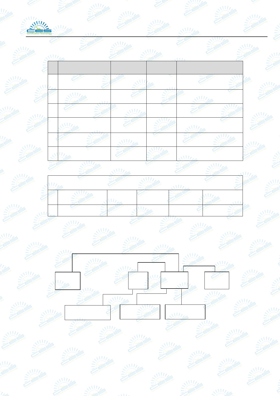
2.2. Tested Supporting System Details
No. Description Manufacturer Model Serial Number
1. Personal Computer ACER ASPIRE
M1830
PTSF90C00305005CAC300
0
2. Monitor ACER G205HV SNID:10306738385
3. USB Keyboard ACER SK-9625 KBUSB1580500037E0100
4. USB Mouse ACER
MS.11200.0
14 M-UAY-ACR2
5. Printer HP HP1020 CNCJ410726
6. USB Flash Disk N/A N/A N/A
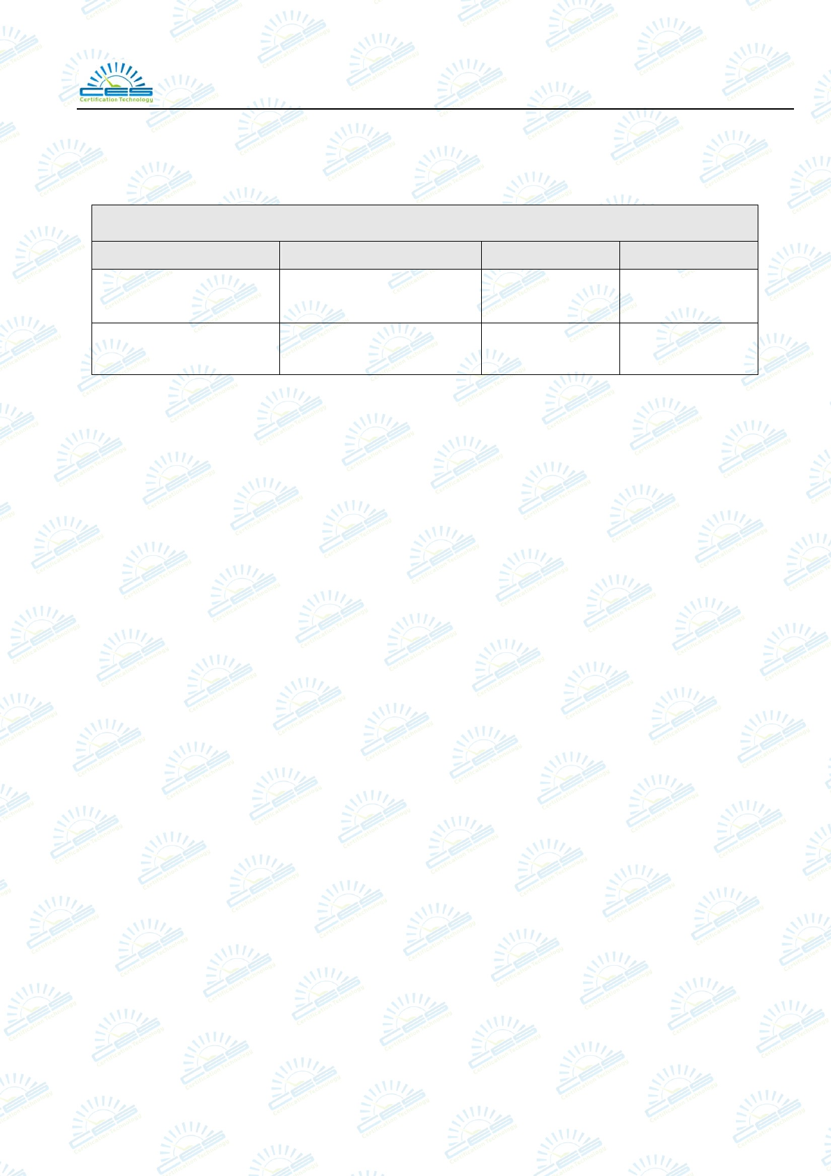
Signal Cable Description of the above Support Units
No. Port Name Cable Length Shielded
(Yes or No) Detachable
(Yes or No)
1 N/A N/A N/A N/A N/A
2.3. Block Diagram of connection between EUT and simulators
※ EUT: USB HUB
PC
EUT
Printer
Monitor
USB Keyboard USB Mouse
USB Flash Disk
Shenzhen Certification Technology Service Co., Ltd.
Report No.: STE120822139 Page 7 of 23
2.4. Test Facility
JAN 13, 2012 File on Federal Communication Commission
Registration Number:197647
October 11, 2011 Certificated by IC
Registration Number: 8528B
August 4, 2010 Certificated by CNAS
Registration Number: L4656
NOV. 17, 2008 Accredited by SGS
Registration Number: SWL-017
NOV. 18, 2008 Accredited by NEMKO
Registration Number: 17025
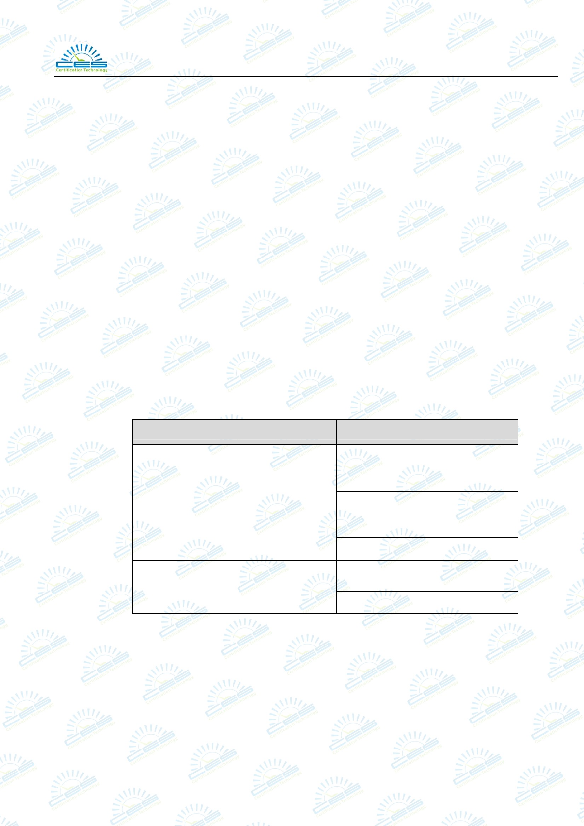
2.5. Measurement Uncertainty
(95% confidence levels, k=2)
Test Item Uncertainty
Uncertainty for Conduction emission test 2.50dB
3.04 dB (Distance: 3m Polarize: V)
Uncertainty for Radiation Emission test 3.02 dB (Distance: 3m Polarize: H)
3.56 dB (Distance: 3m Polarize: V)
Uncertainty for Radiation Emission test
(1GHz-18GHz) 3.84 dB (Distance: 3m Polarize: H)
0.6℃
Uncertainty for test site temperature and
humidity 3%
Shenzhen Certification Technology Service Co., Ltd.
Report No.: STE120822139 Page 8 of 23
3. POWER LINE CONDUCTED EMISSION TEST
3.1. Test Equipment
Item Equipment Manufacturer Model No. Serial No. Last Cal. Cal. Interval
1. Test Receiver Rohde &
Schwarz
ESCI 100843 Oct. 17, 11 1 Year
2. L.I.S.N.#1 Schwarzbeck NSLK8126 8126466 Oct. 17, 11 1 Year
3. L.I.S.N.#2 Kyoritsu KNW-242C 8-1920-1 Oct. 17, 11 1 Year
4. Terminator Hubersuhner 50Ω No. 1 Oct. 17, 11 1 Year
5. RF Cable Schwarzbeck 9111505/200 5995-12-161-
6890#
Apr 17, 12 1/2 Year
6. Coaxial
Switch
Schwarzbeck CX-210 N/A Apr 17, 12 1/2 Year
7. Pulse Limiter Schwarzbeck VTSD9516F 9618 Oct. 17, 11 1 Year
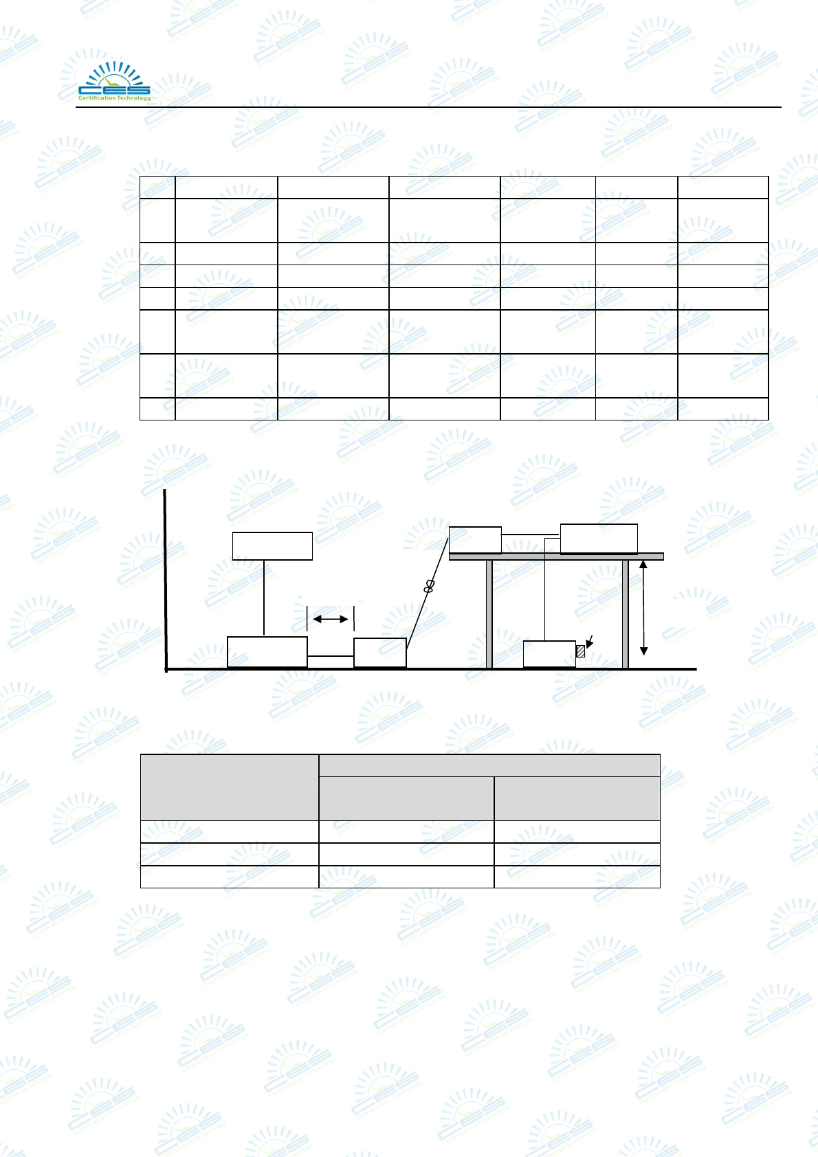
3.2. Block Diagram of Test Setup
3.3. Power Line Conducted Emission Test Limits
Maximum RF Line Voltage
Frequency Quasi-Peak Level
dB(μV)
Average Level
dB(μV)
150kHz ~ 500kHz 66 ~ 56* 56 ~ 46*
500kHz ~ 5MHz 56 46
5MHz ~ 30MHz 60 50
Notes: 1. Emission level=Read level+LISN factor-Preamp factor+Cable loss
2* Decreasing linearly with logarithm of frequency.
3. The lower limit shall apply at the transition frequencies.
EUT Peripheral
LISN LISN
Receiver
PC System
80cm
80cm
>80cm
50ΩImpedance
Shenzhen Certification Technology Service Co., Ltd.
Report No.: STE120822139 Page 9 of 23
3.4. Configuration of EUT on Test
The following equipment are installed on Power Line Conducted Emission Test to meet the
commission requirement and operating regulations in a manner which tends to maximize its
emission characteristics in a normal application.
Support Equipments : As Tested Supporting System Detail, in Section 2.2.
3.5. Operating Condition of EUT
3.5.1. Setup the EUT and simulator as shown as Section 3.2.
3.5.2. Turn on the power of all equipment.
3.5.3. Let the EUT work in test mode (Data Transmitting) and measure it.
3.6. Test Procedure
The EUT was placed on a non-metallic table, 80cm above the ground plane. The EUT Power
connected to the power mains through a line impedance stabilization network (L.I.S.N. 1#). The
other peripheral devices power cord connected to the power mains through a line impedance
stabilization network (L.I.S.N. #2), this provided a 50-ohm coupling impedance for the EUT
(Please refer to the block diagram of the test setup and photographs). Both sides of power line
were checked for maximum conducted interference. In order to find the maximum emission, the
relative positions of equipments and all of the interface cables were changed according to ANSI
C63.4-2003 on conducted Emission test.
The bandwidth of test receiver (R&S TEST RECEIVER ESCI) is set at 10kHz.
The frequency range from 150kHz to 30MHz is checked. The test result are reported on Section
3.7.
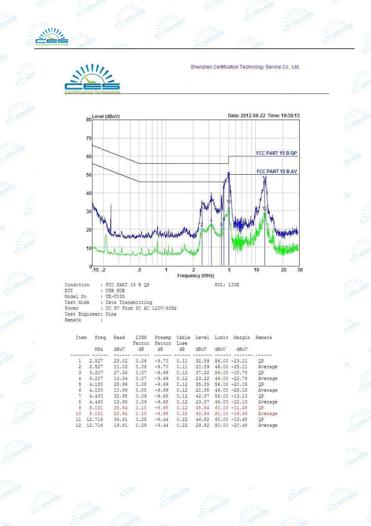
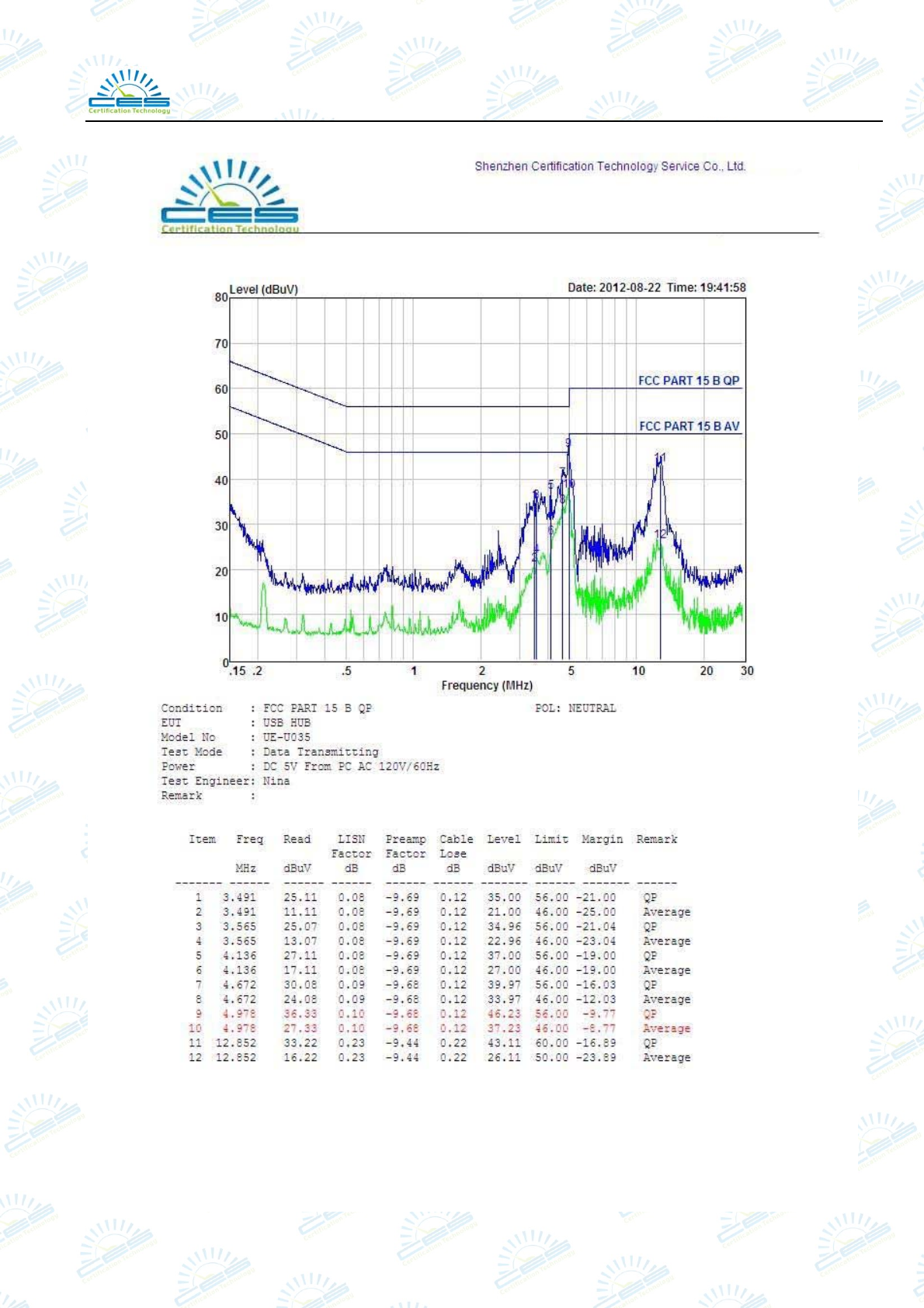
3.7. Conducted Disturbance at Mains Terminals Test Results
PASS. (All emissions not reported below are too low against the prescribed limits.)
The EUT with the following test mode was tested and read QP values and average values, the
test results are listed in next pages.
Temperature: 25℃ Humidity: 55%
The details of test mode is as follows:
No. Test Mode
1 Data Transmitting
Shenzhen Certification Technology Service Co., Ltd.
Report No.: STE120822139 Page 10 of 23
Shenzhen Certification Technology Service Co., Ltd.
Report No.: STE120822139 Page 11 of 23
Shenzhen Certification Technology Service Co., Ltd.
Report No.: STE120822139 Page 12 of 23
4. RADIATED EMISSION TEST
4.1. Test Equipment
Item Equipment Manufacturer Model No. Serial No. Last Cal. Cal. Interval
1 Test Receiver Rohde&Schwarz ESCI 101165 Oct. 17, 11 1 Year
2 Amplifier Schwarzbeck BBV9743 9743-019 Oct. 17, 11 1 Year
3 Bilog
Antenna
Schwarzbeck VULB 9168 VULB9168-43
8
Feb.12, 12 1 Year
4 RF Cable Schwarzbeck AK9515E 95891-2m Oct. 17, 11 1 Year
5 RF Cable Schwarzbeck AK9515E 95891-11m Oct. 17, 11 1 Year
6 RF Cable Schwarzbeck AK9515E 95891-0.5m Oct. 17, 11 1 Year
For frequency range 1GHz~5GHz (At Semi Anechoic Chamber)
Item Equipment Manufacturer Model No. Serial No. Last Cal. Cal.
Interval
1 Spectrum Analyzer Agilent E4446A US44300459 Oct. 17, 11 1 Year
2 Horn Antenna EMCO BBV9743 9743-019 Oct. 17, 11 1 Year
3 Amplifier Schwarzbeck SCHWARZBEC
K N/A Oct. 17, 11 1 Year
4 RF Cable Hubersuhner SUCOFLEX102 28620/2 Oct. 17, 11 1 Year
5 RF Cable Hubersuhner SUCOFLEX102 271471/4 Oct. 17, 11 1 Year
6 RF Cable Hubersuhner SUCOFLEX102 29086/2 Oct. 17, 11 1 Year
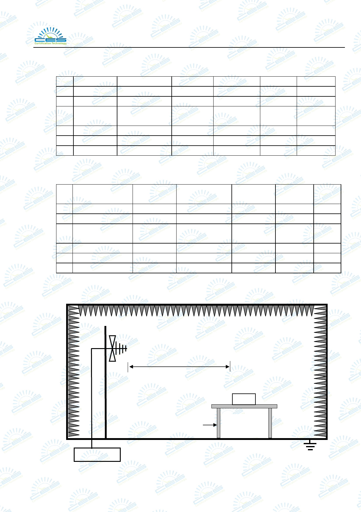
4.2. Block Diagram of Test Setup
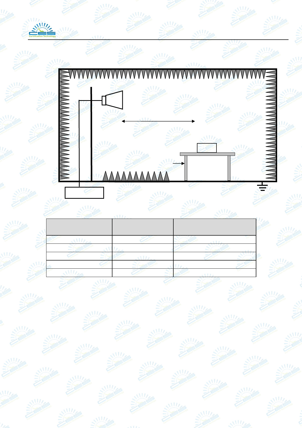
4.2.1. In Semi Anechoic Chamber (3m) Test Setup Diagram for 30MHz~1000MHz
ANTENNA ELEVATION VARIES FROM 1 TO 4 METERS
3m
EUT and
Su
pp
ort S
y
ste
m
TURN TABLE
(WOOD)
1.5m(L)*1.0m(W)*0.8m(H)
Receiver
Semi-anechoic Chamber
Shenzhen Certification Technology Service Co., Ltd.
Report No.: STE120822139 Page 13 of 23
4.2.2. In Semi Anechoic Chamber (3m) Test Setup Diagram for 1-5GHz
4.3. Radiated Emission Limit
Frequency
MHz
Distance
(Meters)
Field Strengths Limits
dB(μV)/m
30 ~ 88 3 40.0
88 ~ 216 3 43.5
216 ~ 960 3 46.0
960 ~ 1000 3 54.0
1000 ~ 5000 3 74(Peak) 54(Average)
Remark: (1) Emission level = Read level+Antenna Factor-Preamp Factor +Cable Loss
(2) The smaller limit shall apply at the cross point between two frequency bands.
(3) Distance is the distance in meters between the measuring instrument, antenna and the
closest point of any part of the device or system.
4.4. EUT Configuration on Test
The following equipment are installed on Radiated Emission Test to meet the commission
requirements and operating regulations in a manner that tends to maximize its emission
characteristics in normal application.
4.4.1. Support Equipments : As Tested Supporting System Detail, in Section 2.2.
ANTENNA ELEVATION VARIES FROM 1 TO 4 METERS
3m
EUT and
Su
pp
ort S
y
ste
m
TURN TABLE
(FIBRE GLASS)
1.5m(L)*1.0m(W)*0.8m(H)
Receiver
Semi-anechoic Chamber

Shenzhen Certification Technology Service Co., Ltd.
Report No.: STE120822139 Page 14 of 23
4.5. Operating Condition of EUT
4.5.1.Setup the EUT as shown in Section 4.2.
4.5.2.Turn on the power of all equipment.
4.5.3.Let the EUT work in test mode (Data Transmitting) and test it.
4.6. Test Procedure
The EUT was placed on a non-metallic table, 80 cm above the ground plane inside a
semi-anechoic chamber. An antenna was located 3m from the EUT on an adjustable mast. A
pre-scan was first performed in order to find prominent radiated emissions. For final emissions
measurements at each frequency of interest, the EUT were rotated and the antenna height was
varied between 1m and 4m in order to maximize the emission. Measurements in both horizontal
and vertical polarities were made and the data was recorded. In order to find the maximum
emission, the relative positions of equipments and all of the interface cables were changed
according to ANSI C63.4-2003 on Radiated Emission test.
The bandwidth setting on the test receiver (ROHDE&SCHWARZ TEST RECEIVER ESCI) is
120 kHz.
The resolution bandwidth of the Agilent Spectrum Analyzer E4446A was set at 1MHz. (For
above 1GHz)
The frequency range from 30MHz to 1000MHz was pre-scanned with a peak detector and all
final readings of measurement from Test Receiver are Quasi-Peak values.
The frequency range from 1GHz to 5GHz was checked with peak and average detector,
measurement distance is 3m in 3m chamber.
Finally, selected operating situations at Anechoic Chamber measurement, all the test results are
listed in section 4.7.
Shenzhen Certification Technology Service Co., Ltd.
Report No.: STE120822139 Page 15 of 23
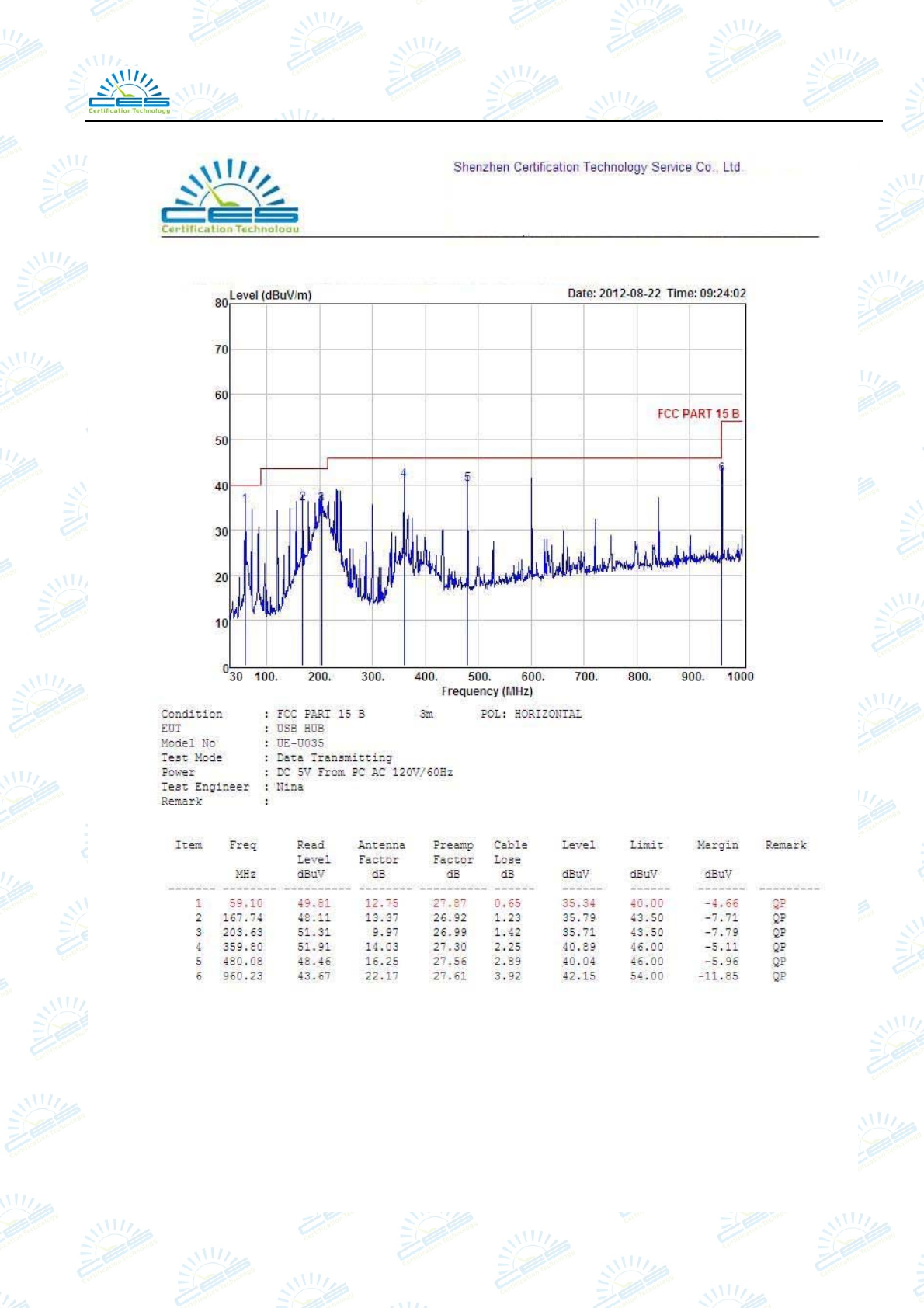
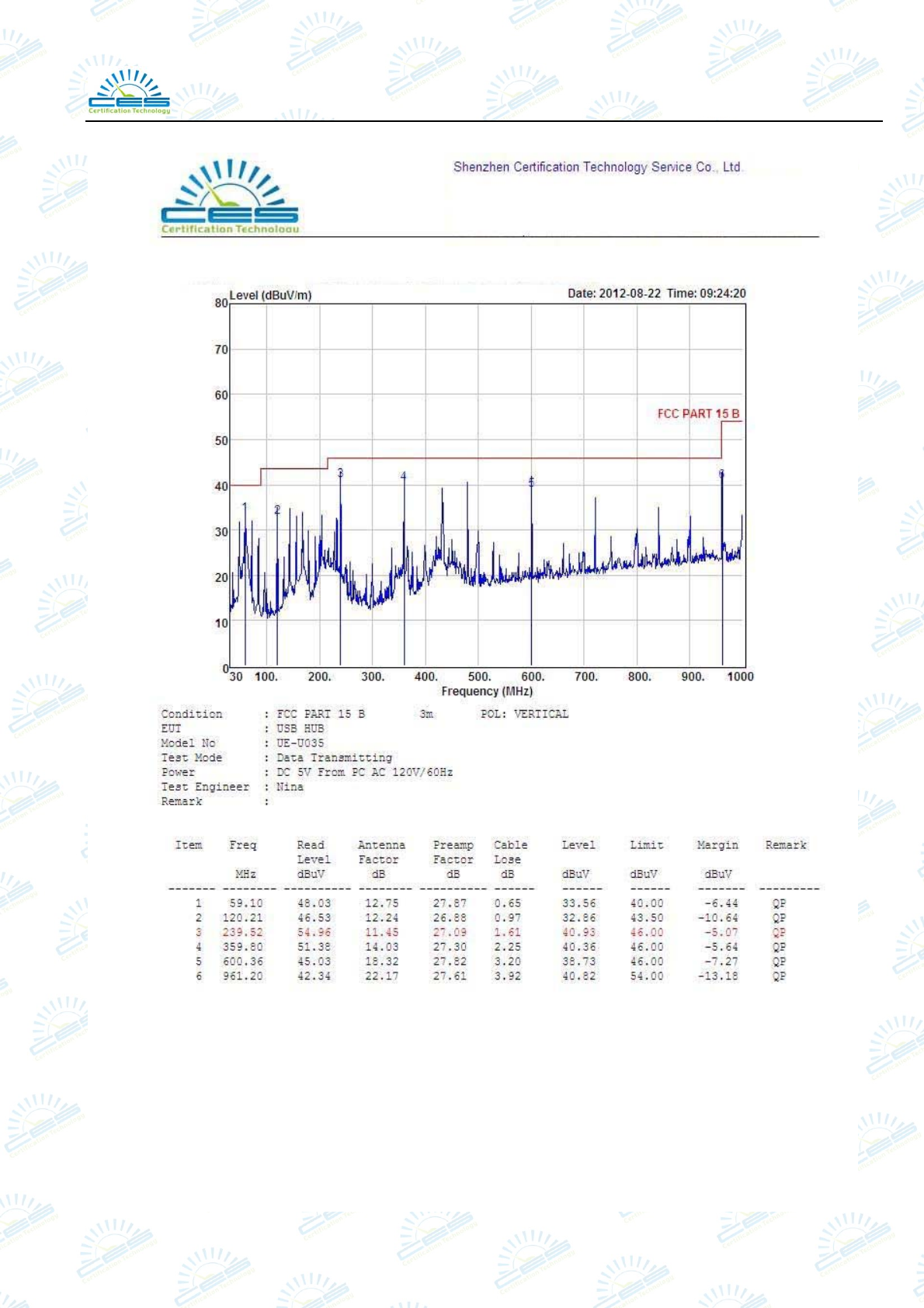
4.7. Radiated Disturbance Test Results
PASS. (All emissions not reported below are too low against the prescribed limits.)
For frequency range 30MHz~1000MHz
The EUT with the following test mode was tested and read QP values and average values, the
test results are listed in next pages.
Temperature: 25℃ Humidity: 55%
The details of test mode is as follows:
No. Test Mode
1 Data Transmitting
For frequency range 1GHz~5GHz
The highest frequency of the internal sources of the EUT is less than 108 MHz, the measurement
shall only be made up to 1 GHz. So the frequency rang 1GHz-5GHz radiation test not
applicable.
Shenzhen Certification Technology Service Co., Ltd.
Report No.: STE120822139 Page 16 of 23
Shenzhen Certification Technology Service Co., Ltd.
Report No.: STE120822139 Page 17 of 23
Shenzhen Certification Technology Service Co., Ltd.
Report No.: STE120822139 Page 18 of 23
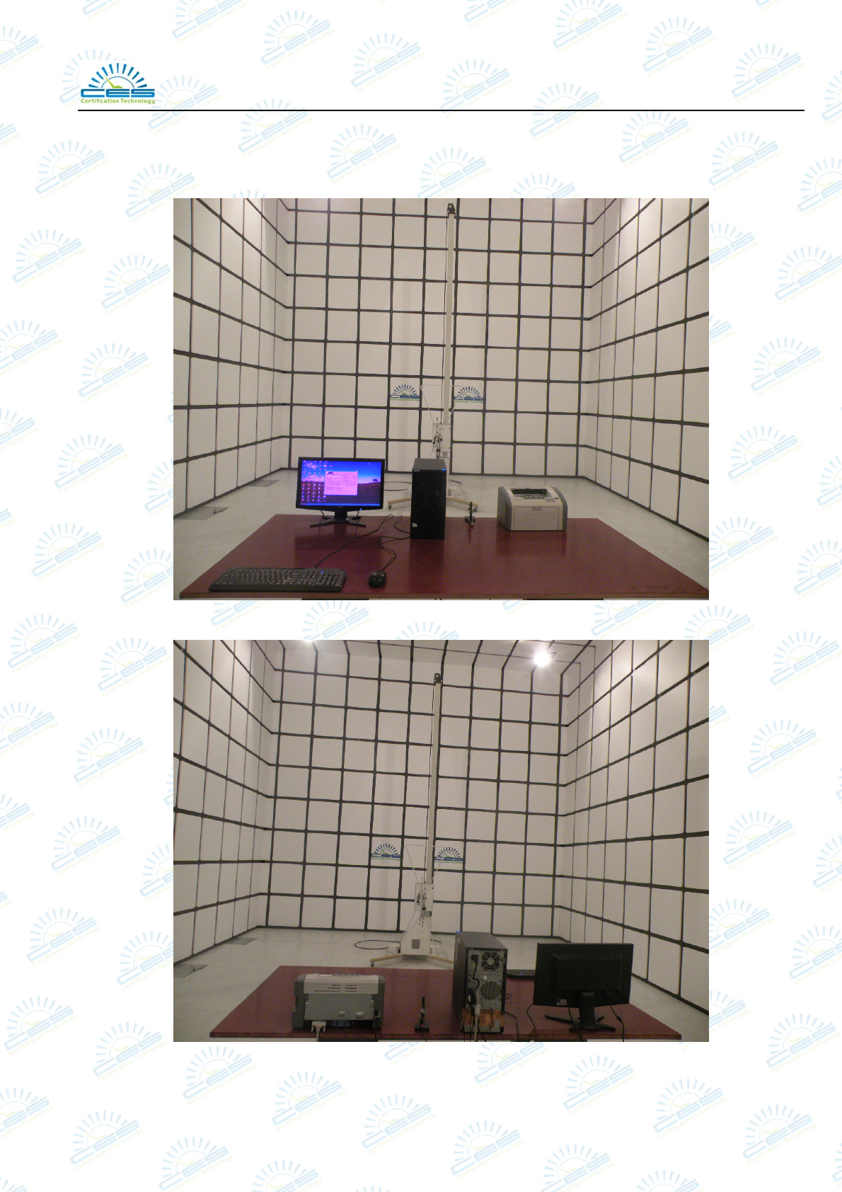
5. PHOTOGRAPH
5.1. Photos of Radiated Emission Test (In Anechoic Chamber)
Shenzhen Certification Technology Service Co., Ltd.
Report No.: STE120822139 Page 19 of 23
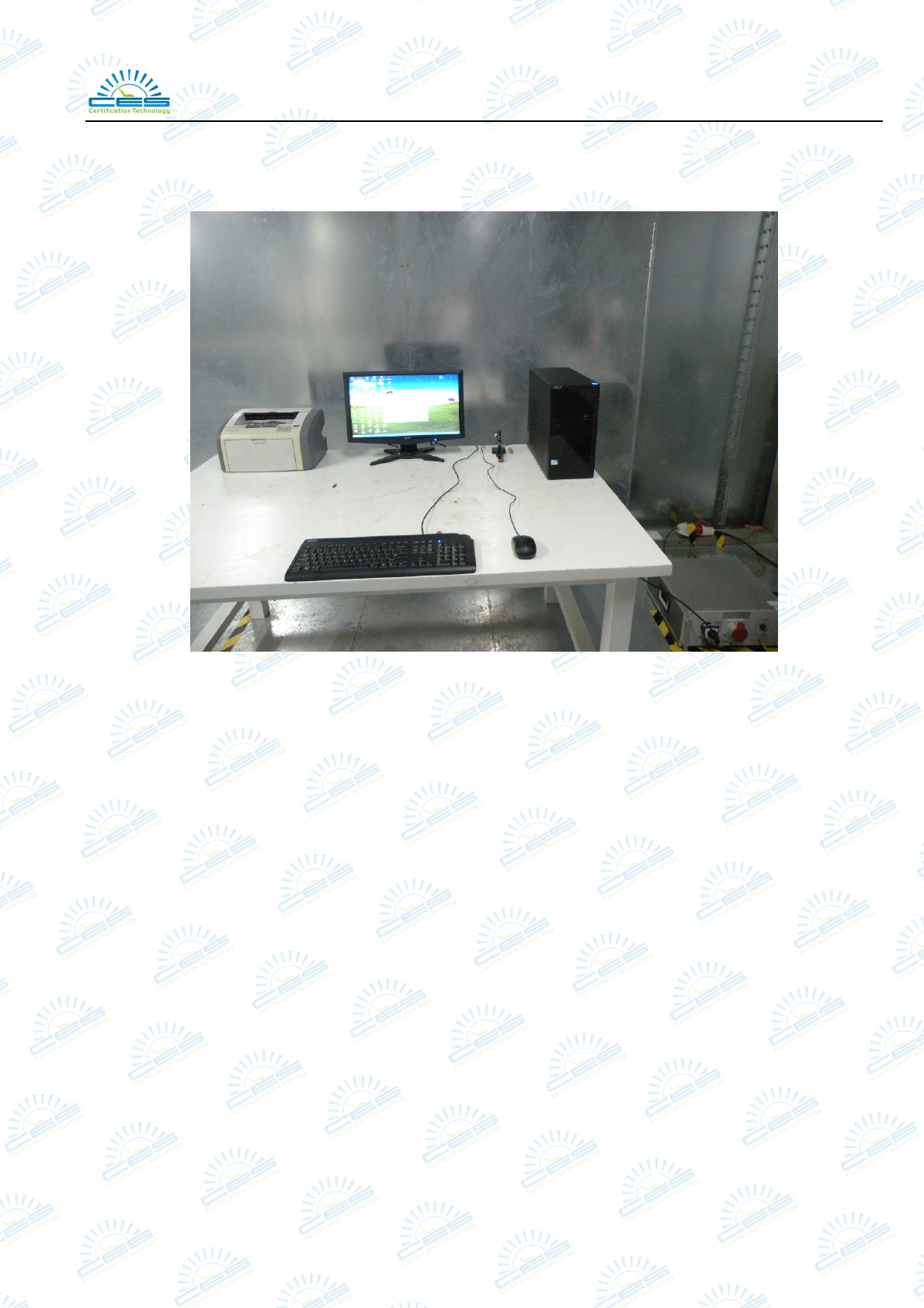
5.2. Photos of Power Line Conducted Emission Test
Shenzhen Certification Technology Service Co., Ltd.
Report No.: STE120822139 Page 20 of 23
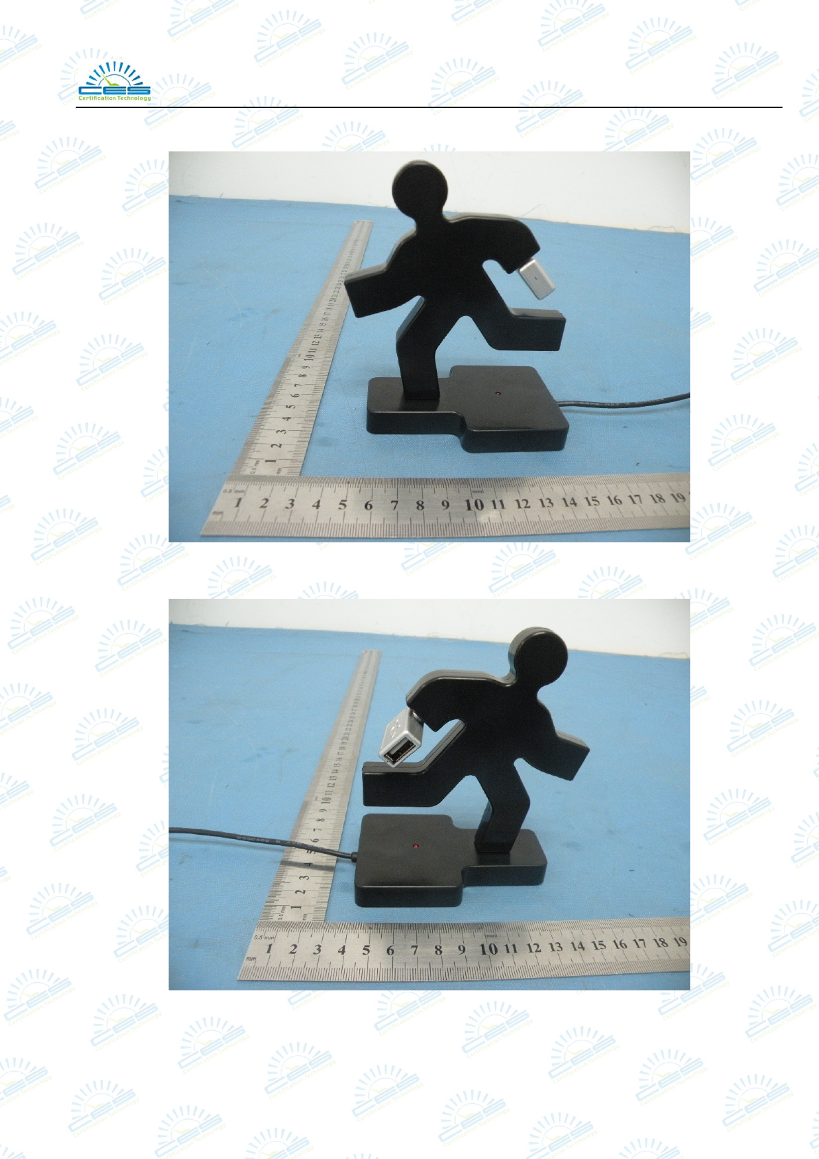
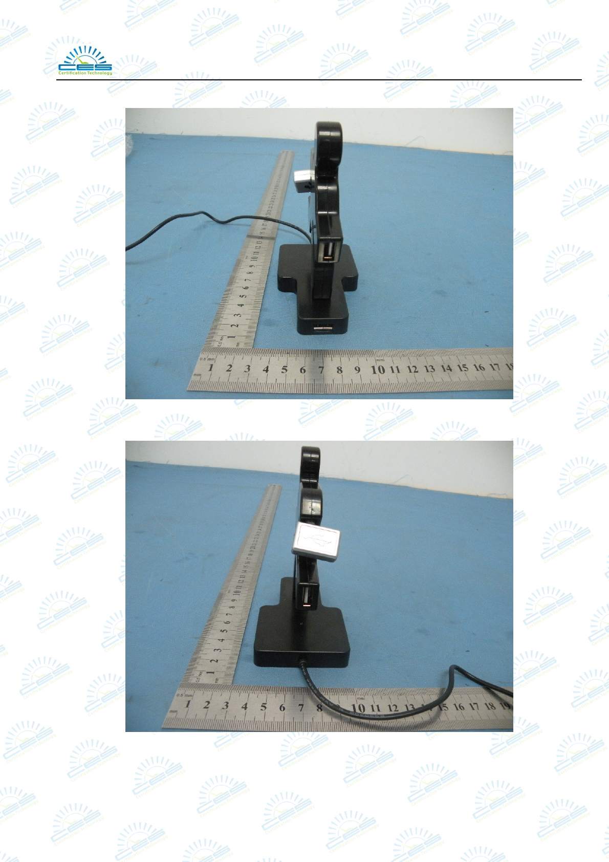
6. PHOTOS OF THE EUT
Front View
Rear View
Shenzhen Certification Technology Service Co., Ltd.
Report No.: STE120822139 Page 21 of 23
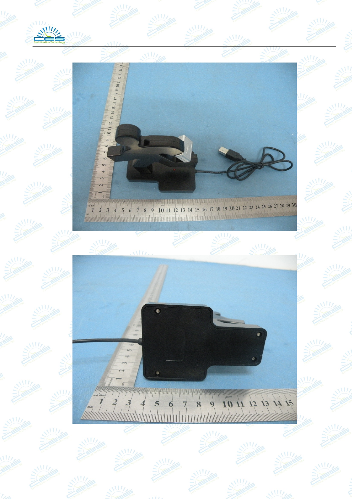
Top View
Bottom View
Shenzhen Certification Technology Service Co., Ltd.
Report No.: STE120822139 Page 22 of 23
Left View
Right View
Shenzhen Certification Technology Service Co., Ltd.
Report No.: STE120822139 Page 23 of 23
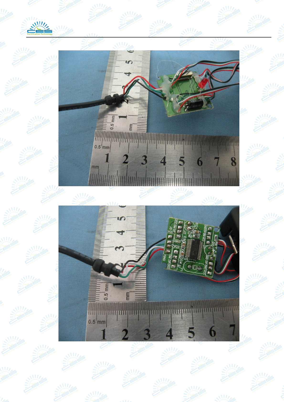
Inside view
Inside view
-------THE END OF REPORT-------
