171789 Catalog
2014-07-29
: Pdf 171789-Catalog 171789-Catalog 051712 Batch6 unilog
Open the PDF directly: View PDF ![]() .
.
Page Count: 33
- Contents
- Bussmann Circuit Components
- RAIL & BASE MOUNT TERMINAL BLOCKS
- General Specifications
- NDN Series .250” and .300” Centers
- NDN Series.375” and .635” Centers
- N & NFT Series .197”, .281” and .390” Centers
- NC, NSE & NSS Series 1.06” and .385” Centers
- PLU & PSU Series .390” and .625” Centers
- KT & PLK Series .250” and .390” Centers
- NTQ, BNQ & BQQ Series .390” and .437” Centers
- NDN Fuse Holders
- UB Series Circuit Breakers
- 15188 Series .375” Centers; 30A, 600V
- KU Series .625” Centers; 50A, 600V
- DOUBLE ROW TERMINAL BLOCKS
- POWER TERMINAL BLOCKS
- QC Power Distribution .562” and .687” Centers;
- Barrier Terminal .968” Centers; Rating 115A, 600V
- Dead Front Terminal .500” Centers; Rating 90A, 600V
- Splicer Terminal .812” thru 2.687” Centers; Ratings to 620A, 250V
- Power Distribution.812” thru 2.687” Centers; Ratings to 840A, 600V
- Connector/Stud .812” thru 2.687” Centers; Ratings to 760A, 600V
- Multiple-Input 1.78” Centers; Ratings 285A, 600V
- Miscellaneous

RAIL & BASE MOUNT TERMINAL BLOCKS PAGES
General Specifications & Accessories
for Rail Mount Terminal Blocks 3
NDN Series .250” and .300” Centers 4
NDN Series.375” and .635” Centers 5
N & NFT Series .197”, .281” and .390” Centers 6
NC, NSE & NSS Series 1.06” and .385” Centers 7
PLU & PSU Series .390” and .625” Centers 8
KT & PLK Series .250” and .390” Centers 9
NTQ, BNQ & BQQ Series .390” and .437” Centers 10
NDN Fuse Holders 11
UB Series Circuit Breakers 12
15188 Series .375” Centers; 30A, 600V 13
KU Series .625” Centers; 50A, 600V 14
DOUBLE ROW TERMINAL BLOCKS
Magnum®TB Series 100 .375” Centers; 20A, 300V 15 & 16
Magnum®TB Series 200 .437” Centers; 20A, 300-600V 17 & 18
Magnum®TB Series 300 .562” Centers; 20A-45A, 600V 19 & 20
Magnum®TB Series 400 .687” Centers; 75A, 600V 21
Magnum®TB Series Options Markings, Marker Strips, Covers 22 & 23
POWER TERMINAL BLOCKS
QC Power Distribution .562” and .687” Centers;
Ratings 40A, 250V and 70A, 600V 24
Barrier Terminal .968” Centers; Rating 115A, 600V 25
Dead Front Terminal .500” Centers; Rating 90A, 600V 25
Splicer Terminal .812” thru 2.687” Centers; Ratings to 620A, 250V 26
Power Distribution.812” thru 2.687” Centers; Ratings to 840A, 600V 27
Connector/Stud .812” thru 2.687” Centers; Ratings to 760A, 600V 28
Multiple-Input 1.78” Centers; Ratings 285A, 600V 29
MISCELLANEOUS
Photo Control Receptacle 13661 Series 30
Non-Fused Disconnect ND-1260 Series 31
Contents
Get the latest, most up-to-date specification data on products listed in this catalog
by calling Bussmann Information Fax.
BIF is a simple to use automated fax response system. No need to wait for normal
business hours, BIF is available around the clock for your convenience. All you
need is a touch-tone telephone and a fax machine to get specification data when
you want it.
ABIF document number is indicated with each product in this catalog. To get a
detailed specification sheet simply call 314-527-1450 and follow the prompts. In a
matter of minutes, a data sheet will be faxed to you. It’s that simple!
© 1995 Cooper Industries, Bussmann Division
Printed in U.S.A.
Bussmann
Information Fax ~
414.527.1450
This catalog is intended to present product data and provide technical information that will help the end
user with design application. Bussmann reserves the right, without notice, to change design or construc-
tion of any products and to discontinue or limit distribution of any products. Bussmann also reserves the
right to change or update, without notice, any technical information contained in this catalog. Once a
product has been selected, it should be tested by the user in all possible applications.
Courtesy of Steven Engineering, Inc. Ÿ 230 Ryan Way, South San Francisco, CA, 94080-6370 Ÿ Main Office: (650) 588-9200 Ÿ Outside Local Area: (800) 258-9200 Ÿ www.stevenengineering.com
GET CONNECTED WITH US
2
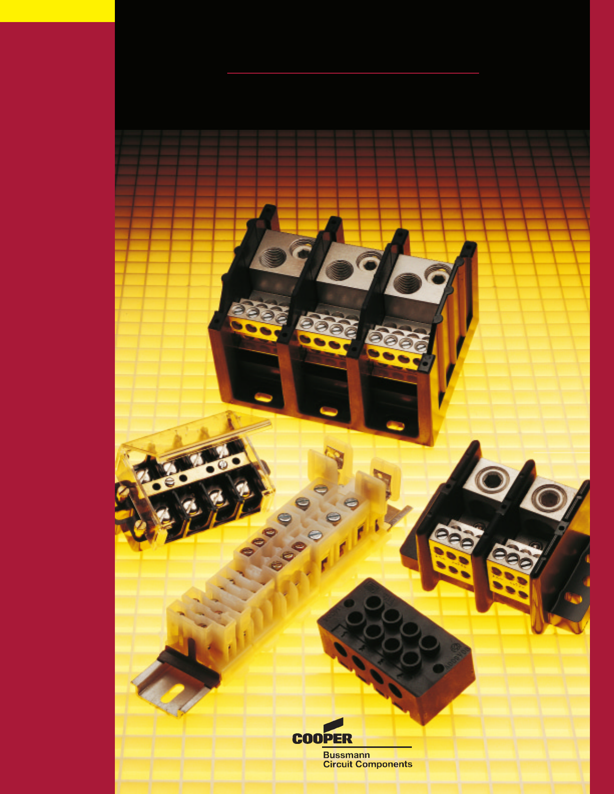
Bussmann Circuit Components
Bussmann Circuit Components has the most complete
selection of barrier style terminal blocks in North America.
The MAGNUM
®
brand pioneered the development of high
barrier, unbreakable single-row terminal strips for electrical/
electronic equipment. Accepted nationally, Magnum is a
leader in the field of terminal blocks, boards or strips.
Molded of flexible, resilient thermoplastic which elimi-
nates barrier and strip breakage and enables molding much
longer strips for convenience and utility, it is lighter than
thermoset phenolic. Rated at 94VO, it
also offers higher dimensional accuracy,
higher insulating quality and lower heat
absorption during wave soldering.
Complementing its full electronic
product line, BCC offers Double Row
Terminal Blocks, which are one of the
most widely used devices for terminat-
ing wires. Versatile and cost effective,
only a screwdriver is needed for installation, eliminating time
consuming splicing. High den-
sity circuitry conserves panel
space with a variety of termina-
tion styles. Increased insulation
is provided to stop leakage and
short circuits. In the field, the
high costs of changes are
reduced by simply rearranging
wire. Other BCC terminal block products include junction
blocks, power distribution blocks, sectional terminal blocks,
35mm DIN Rail terminal blocks, I/O connectors and MAG-
MASTER
®
interface systems.
The BCC design team is organized into three product
areas: Terminal Blocks, Circuit Breakers and Custom
Products. Thus, we concentrate our efforts on creative
designs and practical solutions for customer needs. Our
design engineers use state-of-the-art technology including
advanced computer aided design techniques. Employing
high-tech methods enables BCC to rapidly transform design
ideas into working models, expedited by our in-house model
shop. Prototypes are ready in weeks . . . not months.
BCC maintains a complete lab
facility for performing UL,
CSA & IEC qualification test-
ing. This saves time and money
by eliminating costly expenses
and procedures involved in
gaining approvals.
To keep in touch with ever-
changing industry advances,
BCC actively participates in respected industry organizations
including NEMA, SAE, and UL. Our design engineers hold
positions on several committees that influence the establish-
ment of industry standards.
Quality parts are produced by employees with an average
of 10 years' experience with BCC. Employees take great
pride in their workmanship and the success of Bussmann
Circuit Components. Their strong work ethic along with
quality assembly equipment assures highly reliable products.
The BCC commitment to quality parts and service is
apparent throughout the production process. Our comprehen-
sive quality systems are based on the Total Quality
Management philosophy. They start with conceptual design
and encompass every functional area of BCC. Employee
training, Continuous Quality Improvement Programs, Failure
Mode Effects Analysis (FMEA), CP and Cpk statistical meth-
ods and the use of process and quality control documents
such as SPC are all used. These systems measure both com-
pany and supplier activities providing the framework that
ensures quality products. ISO 9000 Quality Standards are
fully respected and current agency compliances include UL,
CSA, VDE, IEC and SAE. BCC has been the recipient of
several quality assurance certifications including the presti-
gious “Ford Q1” Award.
When searching for a
solution to your electronic
circuit protection or con-
nection needs, you can
rely on Bussmann Circuit
Components.
Get Connected With Us.
Courtesy of Steven Engineering, Inc. Ÿ 230 Ryan Way, South San Francisco, CA, 94080-6370 Ÿ Main Office: (650) 588-9200 Ÿ Outside Local Area: (800) 258-9200 Ÿ www.stevenengineering.com
Contents
Next
3
For complete specification data, call Bussmann Information Fax ~ 314.527.1450
NDNV4
High Density
48 circuits per foot
Series NDN Rail Mount Terminal Blocks
35mm DIN Rail Compatible
High density design: Up to 48 circuits per foot
Clamping collar: Secures wires
Large, captive, wire-ready screws: Speeds assembly
Snap-on installation to DIN rail: Fast, easy assembly
Fully shielded construction: 600V spacings
Unique one-piece construction: Increases reliability
Thermoplastic moldings: Strong and impact resistant
Material: UL Recognized 94V-2 thermoplastic
Collars: Heat treated stainless steel
Terminals: Tin plated copper alloy
Screws: Zinc plated steel
Approvals: UL E62622; CSA LR15364;
CE Pending
NDN63
Accepts wires larger
than standard
control circuits
NDNF1
Single pole
fuseholder accepts
13/32” x1-1/2”
fuses
NDN1/NDN111
Heavy-duty
90 Amp block
NDN3
Space saving
3-pole unit
NDNA200
Universal aluminum
35mm DIN mounting rail
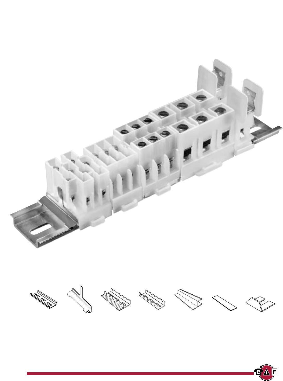
Series NDN Terminal Block Accessories
NDNA NDNAS NFTA NRA SOA72 MARKING JUMPERS
35mm DIN rail 35mm DIN rail C-rail C-rail 72” long TAPE See series
Aluminum End Stop Aluminum Low profile Stand-Off Channel See series specifications
NDNA 100 1 meter Lengths to 72” No flange for C-rail specifications
NDNA 200 2 meters Aluminum
Lengths to 37-1/2”
BIF document: 1400
Courtesy of Steven Engineering, Inc. Ÿ 230 Ryan Way, South San Francisco, CA, 94080-6370 Ÿ Main Office: (650) 588-9200 Ÿ Outside Local Area: (800) 258-9200 Ÿ www.stevenengineering.com
Contents
Next
Previous
4
For complete specification data, call Bussmann Information Fax ~ 314.527.1450
GET CONNECTED WITH US
NDNV4 Inches (Millimeters)
Rail Mount Terminal Blocks
SPECIFICATIONS
Rating: NDNV4 30A, 600V; UL/CSA
Center spacing: .250” (6.35)
Number of poles: 4
Circuits per foot: 48
Circuit jumper: JN4, 4 circuits
Wire size: AWG #10-22 CU
Screw size: #6-32
Mounting options: 35mm DIN rail, C-rail
Marking tape: MTC6
Torque rating: 18 in/lb max.
Operating temperature: 105°C
1.23
(31.24)
1.47
(37.33)
1.67
(42.41)
1.00
(25.40) Marking
Tape
1.34
(34.04)
NDN3 Inches (Millimeters)
SPECIFICATIONS
Rating: 30A - field wiring; 40A - factory wiring
600V; UL/CSA
Center spacing: .300” (7.62)
Number of poles: 3
Circuits per foot: 38
Circuit jumper: JNDN3, 2 circuits
Wire size: AWG #10-22 CU
Screw size: #6-32
Mounting options: 35mm DIN rail, C-rail
Marking tape: MT12-1/2
Torque rating: 18 in/lb max.
Operating temperature: 105°C
1.47
(37.33)
1.67
(42.41)
1.31
(33.27)
.94
(23.87)
BIF document: 1401
Courtesy of Steven Engineering, Inc. Ÿ 230 Ryan Way, South San Francisco, CA, 94080-6370 Ÿ Main Office: (650) 588-9200 Ÿ Outside Local Area: (800) 258-9200 Ÿ www.stevenengineering.com
Contents
Next
Previous
5
For complete specification data, call Bussmann Information Fax ~ 314.527.1450
Rail Mount Terminal Blocks
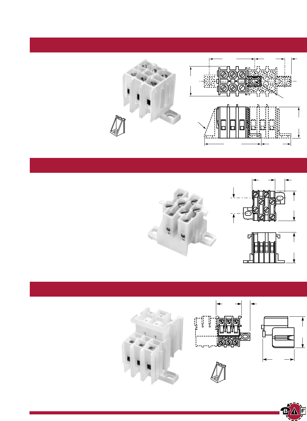
NDN63 Inches (Millimeters)
SPECIFICATIONS
Rating: 65A, 600V; UL/CSA
Center spacing: .375” (9.52)
Number of poles: 3
Circuits per foot: 30
Circuit jumper: JN3, 2 circuits
Wire size: AWG #6-18 CU
Screw size: #10-32
Mounting options: 35mm DIN rail, C-rail
Marking tape: MT12-1/2
Torque rating: 35 in/lb max.
Operating temperature: 105°C
NDN111 Inches (Millimeters)
SPECIFICATIONS
Rating: 90A, 600V; UL/CSA
Center spacing: .635” (16.13)
Number of poles: 3
Circuits per foot: 18
Circuit jumper: JN1, 2 circuits
Wire size: AWG #2-18 CU
Screw size: 1/4-28
Mounting options: 35mm DIN rail,
C-rail, Base Mount. * Dove tail option is
available for mounting side-by-side.
Order part no. NDN111-A.
Marking tape: MT12-1/2
Torque rating: 32 in/lb max.
Operating temperature: 105°C
1.50
(38.10)
1.67
(42.41)
1.45
(36.83)
1.17
(29.71)
1.87
(47.50)
.62
(15.75)
1.44
(36.57)
1.71
(43.48)
1.46
(37.13)
Mtg. holes
.18 (4.57) dia.
.28 (7.11) c'bores
Dovetail
Option
NDN1 Inches (Millimeters)
SPECIFICATIONS
Rating: 90A, 600V
Center spacing: .635” (16.13)
Number of poles: 1
Circuits per foot: 18
Wire size: AWG #2-18 CU
Screw size: 1/4-28
Mounting options: 35mm DIN rail, C-rail
* Dove-tail option is available for mounting
side-by-side. Order part no. NDN1-A.
Marking tape: MT12-1/2
Torque rating: 32 in/lb max.
Operating temperature: 105°C
.59
(14.99)
Dovetail
Option
1.43
(36.31)
1.71
(43.48)
1.32
(33.68)
BIF document: 1402
Courtesy of Steven Engineering, Inc. Ÿ 230 Ryan Way, South San Francisco, CA, 94080-6370 Ÿ Main Office: (650) 588-9200 Ÿ Outside Local Area: (800) 258-9200 Ÿ www.stevenengineering.com
Contents
Next
Previous
6
For complete specification data, call Bussmann Information Fax ~ 314.527.1450
GET CONNECTED WITH US
N512 Inches (Millimeters)
SPECIFICATIONS
Rating: 5A, 600V; UL/CSA
20A, 300V; UL/CSA
Center spacing: .197” (5.00)
Number of poles: 12
Circuits per foot: 60
Circuit jumper: JN512, 12 circuits
Wire size: AWG #12-22 CU
Screw size: #4-48
Mounting options: C-rail,
15mm DIN rail
Marking tape: AT512
Torque rating: 12 in/lb max.
Operating temperature: 105°C
2.40
(60.96)
1.09
(27.68)
.88
(22.35)
Rail Mount Terminal Blocks
NFT2 Inches (Millimeters)
SPECIFICATIONS
Rating: 40A, 600V; UL/CSA;
55A Factory Wired
Center spacing: .281” (7.13)
Number of poles: 2
Circuits per foot: 38
Circuit jumper: JN2, 2 circuits
Wire size: AWG #8-22 CU
Screw size: #8-32
Mounting options: C-rail
Marking tape: MT12-1/2
Torque rating: 18 in/lb max.
Operating temperature: 105°C
NFT3 Inches (Millimeters)
SPECIFICATIONS
Rating: 40A, 600V; UL/CSA;
55A Factory Wired
Center spacing: .390” (9.91)
Number of poles: 3
Circuits per foot: 28
Circuit jumper: JN3, 2 circuits
Wire size: AWG #8-22 CU
Screw size: #8-32
Mounting options: C-rail
Marking tape: MT12-1/2
Torque rating: 18 in/lb max.
Operating temperature: 105°C
.60
(15.44)
.65
(16.51)
.07
(1.78)
1.29
(32.94)
.93
(23.80)
1.68
(42.82)
1.23
(31.34)
.36
(9.14)
1.18
(29.97)
1.29
(32.94)
1.23
(31.37)
BIF document: 1403
BIF document: 1404
BIF document: 1405
Courtesy of Steven Engineering, Inc. Ÿ 230 Ryan Way, South San Francisco, CA, 94080-6370 Ÿ Main Office: (650) 588-9200 Ÿ Outside Local Area: (800) 258-9200 Ÿ www.stevenengineering.com
Contents
Next
Previous
7
For complete specification data, call Bussmann Information Fax ~ 314.527.1450
Rail & Base Mount Terminal Blocks
NC3 Inches (Millimeters)
SPECIFICATIONS
Rating: 175A, 600V; UL/CSA
Center spacing: 1.06” (26.92)
Number of poles: 3
Circuits per foot: 11
Wire size: 2/0-#14 CU/AL
Screw size: 5/16-24
Mounting options: C-rail,
Base Mount
Marking tape: MT12-1/2
Torque rating: 45 in/lb max.
Operating temperature: 105°C
NSE3 Inches (Millimeters)
SPECIFICATIONS
Rating: 115A, 600V; UL/CSA
Center spacing: 1.06” (26.92)
Number of poles: 3
Circuits per foot: 11
Circuit jumper: JNSE3, 2 circuits
Wire size: For use with wire crimped
to ring terminal.
Screw size: 1/4-28
Mounting options: C-rail, Base Mount
Marking tape: MT12-1/2
Operating temperature: 105°C
NSS3 Inches (Millimeters)
SPECIFICATIONS
Rating: 30A, 600V; UL/CSA
Center spacing: .385” (9.77)
Number of poles: 3
Circuits per foot: 28
Circuit jumper: JNSS3, 2 circuits
Wire size: For use with wire crimped
to ring terminal.
Screw size: #6-32
Mounting options: C-rail
Marking tape: MT12-1/2
Operating temperature: 105°C
Optional LS3 Terminal Cover
3.12
(79.38)
.250 x .190"
mtg. slots
1.25
(31.75)
1.75
(44.45)
1.75
(44.45)
1.75
(44.45)
.250 x .190
mtg. slots
1.53
(38.86)
3.12
(79.24)
1.25
(31.75)
1.24
(31.50)
1.25
(31.75)
1.32
(33.73)
Optional LS3 Terminal Cover
BIF document: 1406
BIF document: 1407
BIF document: 1408
Courtesy of Steven Engineering, Inc. Ÿ 230 Ryan Way, South San Francisco, CA, 94080-6370 Ÿ Main Office: (650) 588-9200 Ÿ Outside Local Area: (800) 258-9200 Ÿ www.stevenengineering.com
Contents
Next
Previous
8
For complete specification data, call Bussmann Information Fax ~ 314.527.1450
GET CONNECTED WITH US
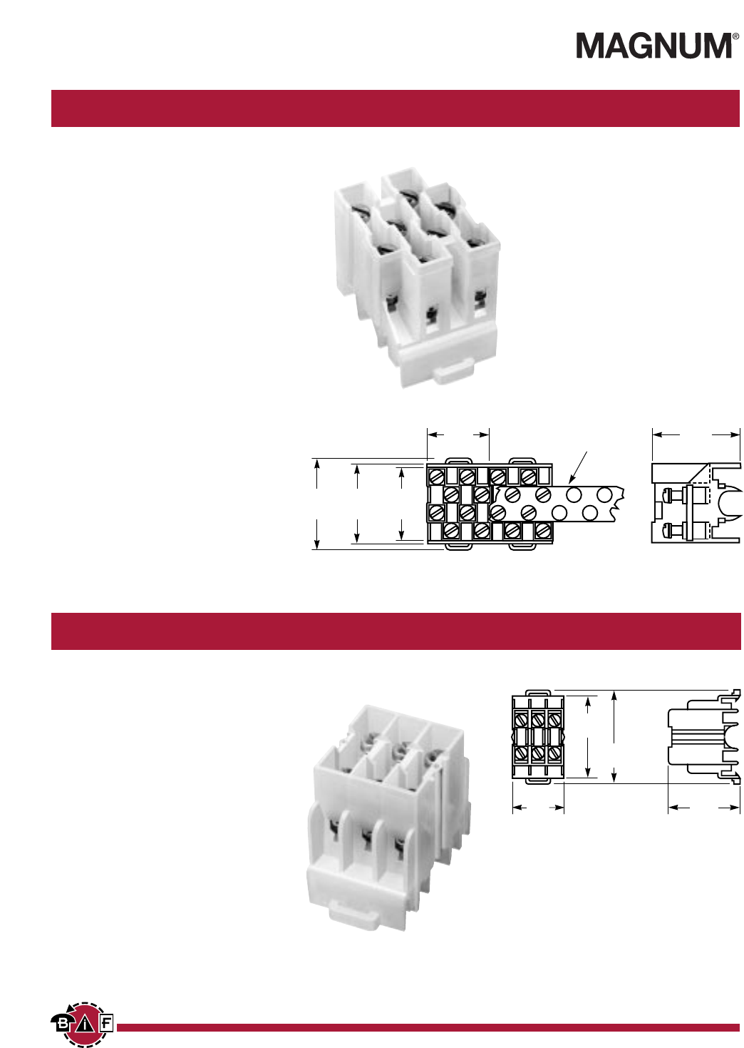
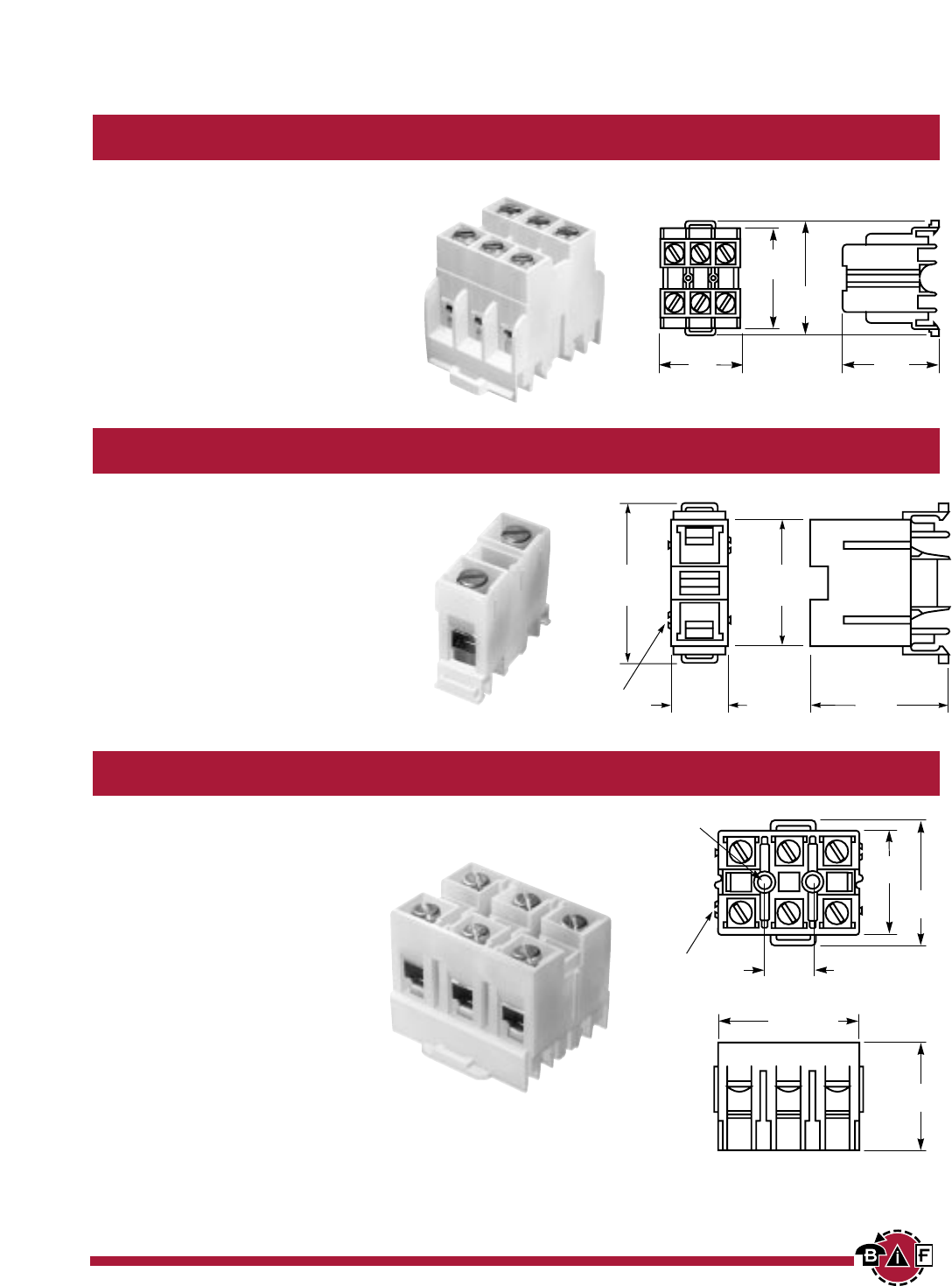
PLU3 Inches (Millimeters)
Depluggable Rail Mount Terminal Blocks
SPECIFICATIONS
Rating: 40A, 600V; UL/CSA
Center spacing: .390” (9.91)
Number of poles: 3
Circuits per foot: 28
Circuit jumper: JN3, 2 circuits
Wire size: AWG #8-22 CU
Screw size: #8-32
Mounting options: C-rail,
Stackable
Marking tape: MT12-1/2
Torque rating: 18 in/lb max.
Operating temperature: 105°C
PLU1 Series Inches (Millimeters)
SPECIFICATIONS
Rating: 70A, 600V; UL/CSA
Center spacing: .625” (15.88)
Number of poles: 1-3
PLU1 (1 pole)
PLU11 (2 pole)
PLU111 (3 pole)
Circuits per foot: 19
Circuit jumper: JN1, 2 circuits
Wire size: AWG #4-18 CU
Screw size: 1/4-28
Mounting options: C-rail, Stackable
Marking tape: MT12-1/2
Torque rating: 32 in/lb max.
Operating temperature: 105°C
PSU1 Series Inches (Millimeters)
SPECIFICATIONS
Rating: 45A*, 600V; UL/CSA
*45A rating achieved with ring terminal
crimped to wire.
Center spacing: .625” (15.88)
Number of poles: 1-3
PSU1 (1 pole)
PSU11 (2 pole)
PSU111 (3 pole)
Circuits per foot: 19
Wire size: For use with crimp on
connectors only.
Screw size: #10-32
Mounting options: C-rail, Stackable
Marking tape: MT12-1/2
Torque rating: 32 in/lb max.
Operating temperature: 105°C
1.25
(31.75)
.59
(14.98) 1.79
(45.64)
1.85
(46.99)
1.25
(31.75)
1.25
(31.75)
1.87
(47.49)
1.85
(46.99)
1.48
(37.59)
1.25
(31.75)
.625
(15.88)
1.93
(49.12)
2.44
(62.10)
1.48
(37.64)
1.30
(33.00)
.43
(11.10)
BIF document: 1409
BIF document: 1410
BIF document: 1411
Courtesy of Steven Engineering, Inc. Ÿ 230 Ryan Way, South San Francisco, CA, 94080-6370 Ÿ Main Office: (650) 588-9200 Ÿ Outside Local Area: (800) 258-9200 Ÿ www.stevenengineering.com
Contents
Next
Previous
9
For complete specification data, call Bussmann Information Fax ~ 314.527.1450
Base Mount Terminal Blocks
KT3 Inches (Millimeters)
SPECIFICATIONS
Rating: 40A, 600V; UL/CSA
Center spacing: .390” (9.91)
Number of poles: 3
Circuits per foot: 28
Circuit jumper: JN3, 2 circuits
Wire size: #8-22 CU
Screw size: #8-32
Mounting options: Base Mount,
Stackable
Marking tape: MT12-1/2
Torque rating: 18 in/lb max.
Operating temperature: 105°C
KT4 Inches (Millimeters)
SPECIFICATIONS
Rating: 30A, 600V; UL/CSA
Center spacing: .250” (6.35)
Number of poles: 4
Circuits per foot: 48
Circuit jumper: JN4, 4 circuits
Wire size: AWG #10-22 CU
Screw size: #6-32
Mounting options: Base Mount
Mounting screws recommended
every 12 circuits.
Marking tape: MTC6
Torque rating: 18 in/lb max.
Operating temperature: 105°C
PLK3 Inches (Millimeters)
SPECIFICATIONS
Rating: 40A, 600V; UL
Center spacing: .390” (9.91)
Number of poles: 3
Circuits per foot: 28
Circuit jumper: JN3, 2 circuits
Wire size: AWG #8-22 CU
Screw size: #8-32
Mounting options: Base Mount,
Stackable; End Piece (Part No. KAD)
is required for mounting. Mounting
screws recommended every 15
circuits.
Marking tape: MT12-1/2
Torque rating: 18 in/lb max.
Operating temperature: 105°C
#8 screw clearance
KAD
end mtg.
adapter
1.22
(31.04)
1.25
(31.75)
2.34
(59.51)
1.25
(31.75)
.25
(6.35)
1.25
(31.75)
1.87
(47.63)
1.34
(34.04)
1.26
(32.23)
.62
(15.88)
.98
(24.99)
.37
(9.40)
1.46
(37.22)
.56
(14.22)
1.79
(45.52)
1.84
(46.86)
KAD
End Mount Adapter Optional
KAD
End Mount Adapter Required
BIF document: 1412
BIF document: 1413
BIF document: 1414
Courtesy of Steven Engineering, Inc. Ÿ 230 Ryan Way, South San Francisco, CA, 94080-6370 Ÿ Main Office: (650) 588-9200 Ÿ Outside Local Area: (800) 258-9200 Ÿ www.stevenengineering.com
Contents
Next
Previous
10
For complete specification data, call Bussmann Information Fax ~ 314.527.1450
GET CONNECTED WITH US
AB
(N+2) x .437 (N+1) x .437
N = Number of circuits
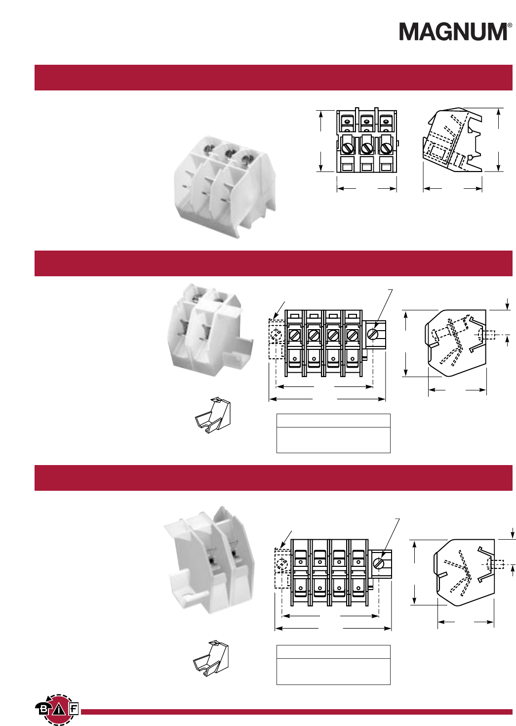
NTQ23 Inches (Millimeters)
Quick Connect Terminal Blocks
SPECIFICATIONS
Rating: 40A, 600V
Center spacing: .390” (9.91)
Number of poles: 3
Circuits per foot: 28
Wire size: AWG #8-22 CU
Screw size: #8-32
Mounting options: C-rail
Marking tape: MT12-1/2
Torque rating: 18 in/lb max.
Operating temperature: 105°C
BNQ21 Inches (Millimeters)
SPECIFICATIONS
Rating: 40A, 600V; UL/CSA
Center spacing: .437” (11.10)
Number of poles: 1
Circuits per foot: 24
Wire size: AWG #8-22 CU
Screw size: #8-32
Quick Connects: .250” x .031”
Mounting options: Base Mount.,
Stackable; End Piece (Part No. BQE)
is required for mounting. Mounting
screws recommended every 8 circuits.
Torque rating: 18 in/lb max.
Operating temperature: 105°C
BQQ41 Inches (Millimeters)
SPECIFICATIONS
Rating: 30A, 600V; UL/CSA
Center spacing: .437” (11.10)
Number of poles: 1
Circuits per foot: 24
Wire size: For use with quick
connect terminals only.
Quick Connects: .250” x .031”
Mounting options: Base Mount,
Stackable; End Piece (Part No. BQE)
is required for mounting. Mounting
screws recommended every 8 circuits.
Operating temperature: 105°C
BQE
End Mounting Adapter Required
1.41
(35.81)
.56
(14.28)
1.47
(37.33)
B
A
#8 mtg.
screw
#BQE
(end mtg. adaptor)
1.41
(35.81)
.56
(14.28)
#8 mtg.
screw
#BQE
(end mtg. adaptor)
B
A
1.47
(37.33)
1.25
(31.75)
1.25
(31.75)
1.25
(31.75)
1.31
(33.32)
BQE
End Mounting Adapter Required
BIF document: 1415
BIF document: 1416
BIF document: 1417
AB
(N+2) x .437 (N+1) x .437
N = Number of circuits
Courtesy of Steven Engineering, Inc. Ÿ 230 Ryan Way, South San Francisco, CA, 94080-6370 Ÿ Main Office: (650) 588-9200 Ÿ Outside Local Area: (800) 258-9200 Ÿ www.stevenengineering.com
Contents
Next
Previous
11
For complete specification data, call Bussmann Information Fax ~ 314.527.1450
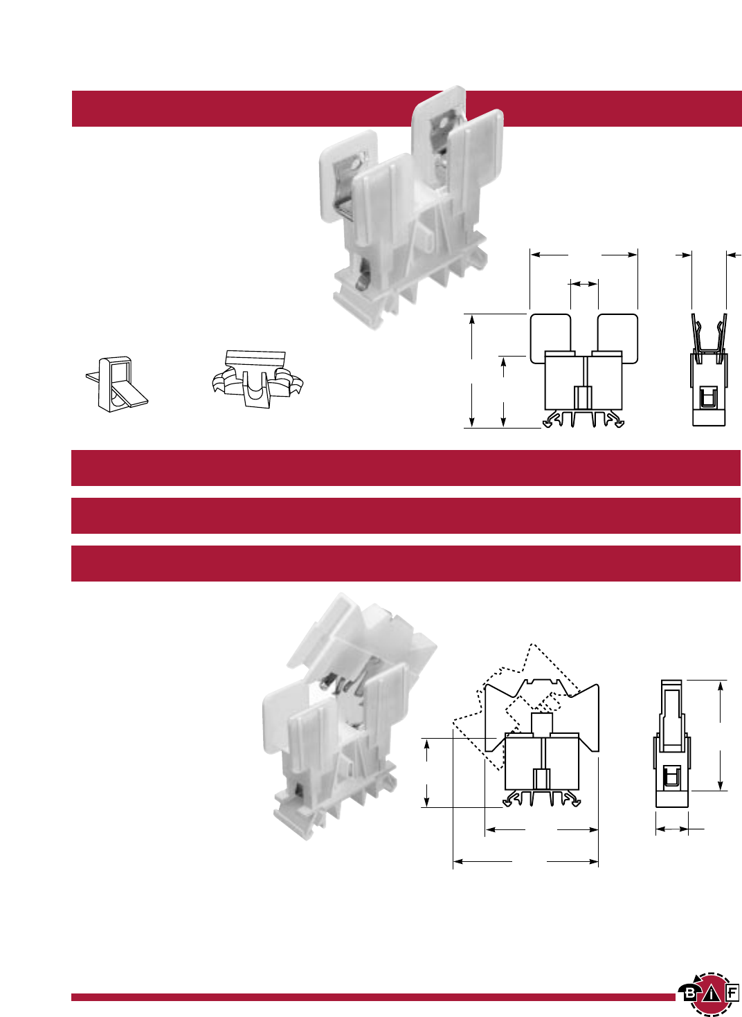
Rail Mount Fuse Holders
NDNF1 Inches (Millimeters)
SPECIFICATIONS
Rating: 30A, 600V; UL/CSA
Number of poles: 1
Fuse size: 13/32” x 1-1/2”
BCC recommends BUSS®KTK-R, FNQ-R
or equivalent.
Circuit jumper: JF1, 2 circuits
Wire size: AWG #8-22 CU
Mounting options: 35mm DIN rail, C-rail
Fuse Pullers: PF1 (standard);
*LPF1 (lighted neon or incandescent bulb).
Marking tape: MT12-1/2
Torque rating: 18 in/lb max.
Operating temperature: 105°C
NDND1 non-fused disconnect enables isolation of individual circuits for testing
SPECIFICATIONS
Ratings:
NDND1: 30A, 600V; UL/CSA
NDNFD1: 15A, 600V; CSA
NDNLFD1: 15A, 600V
Number of poles: 1
Fuse size: 1/4” x 1-1/4”
BCC recommends BUSS®AGC,
MDL or equivalent.
Circuit jumper: JF1, 2 circuits
Wire size: AWG #8-22 CU
Mounting options:
35mm DIN rail, C-rail
Marking tape: MT12-1/2
Torque rating: 18 in/lb max.
Operating temperature: 105°C
NDNFD1 fused disconnect block
NDNLFD1 fused disconnect with visual indicator* for blown fuse Inches (Millimeters)
.62
(15.74)
.46
(11.68)
1.93
(49.02)
1.25
(31.75)
2.00
(50.80)
1.25
(31.75)
2.31
(58.67)
2.06
(52.32)
.62
(15.74)
2.68
(68.07)
PF1
Fuse Puller
LPF1
Lighted Fuse Puller
*Visual indicator for blown fuse is neon or incandescent bulb, depending on voltage. Specify voltage required.
BIF document: 1418
Courtesy of Steven Engineering, Inc. Ÿ 230 Ryan Way, South San Francisco, CA, 94080-6370 Ÿ Main Office: (650) 588-9200 Ÿ Outside Local Area: (800) 258-9200 Ÿ www.stevenengineering.com
Contents
Next
Previous
12
For complete specification data, call Bussmann Information Fax ~ 314.527.1450
GET CONNECTED WITH US
Part Numbering System
■■■■■■■■■■–■■
Series Amperage
005 – 150
(.5A – 15A)
U B U
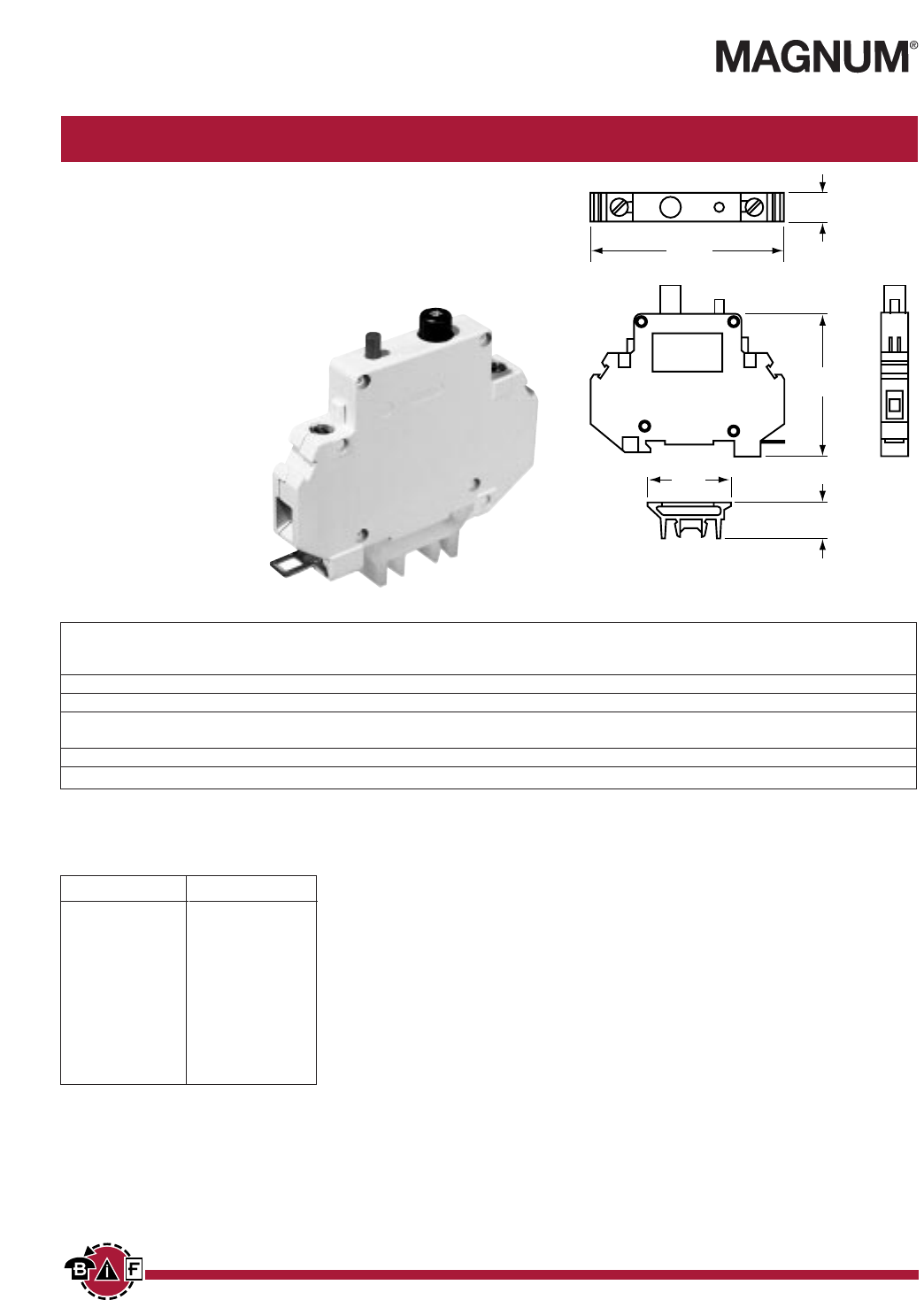
UB Series Inches (Millimeters)
Rail Mount Circuit Breakers
SPECIFICATIONS
Rating: .5 - 15A, 250VAC/65VDC; UL*/CSA/VDE
*For 9A - 15A units, UL voltage ratings: 125VAC/65VDC
Number of poles: 1
Max. interrupt cap.: 200A, but not over 100 times rated current.
Life: 4,000 cyc. 200% rated current; 6,000 cyc. rated current
Dielectric strength: 1,500VAC
Insulation resist: 100 Megohms
Mounting options: 35mm DIN rail,
C-rail (Adapter required for C-rail)
Weight: 3.2 oz.
Tripping Times in Seconds at 70°F
Percent rated current 100% 200% 300% 400% 500% 600% 1000% 2000%
Tripping time no trip 10 - 40 3 - 18 1.5 - 9 .8 - 6 .003 - 4 .003 - 2 max. .02
For elevated ambient temperatures, find proper current rating of circuit breaker by multiplying actual full load current with these factors.
Select closest (higher) amp rating.
Temperature 100°F (37.8°C) 120°F (48.9°C) 140°F (60°C) 160°F (71.1°C)
Factor 1.1 1.2 1.3 1.4
UBA-CR
(Req'd for C-rail mtg.)
.56
(14.43)
1.37
(35.04)
2.33
(59.18)
3.13
(79.60)
.45
(11.56)
Standard Current Ratings
Notes: Pressure connector is UL/CSA
Recognized for field wiring.
Contact factory for ratings below 1A.
Amps Ohms
0.5 8.000
1.0 1.900
1.5 0.900
2.0 0.480
2.5 0.320
3.0 0.260
3.5 0.160
4.0 0.130
4.5 0.085
5.0 0.076
5.5 0.064
Amps Ohms
6.0 0.056
6.5 0.035
7.0 0.036
8.0 0.032
9.0 0.022
10.0 0.018
11.0 0.016
12.0 0.016
13.0 0.016
14.0 0.012
15.0 0.012
BIF document: 1419
Courtesy of Steven Engineering, Inc. Ÿ 230 Ryan Way, South San Francisco, CA, 94080-6370 Ÿ Main Office: (650) 588-9200 Ÿ Outside Local Area: (800) 258-9200 Ÿ www.stevenengineering.com
Contents
Next
Previous
13
For complete specification data, call Bussmann Information Fax ~ 314.527.1450
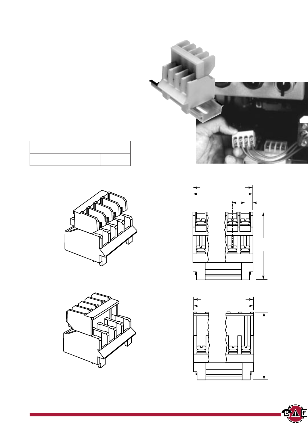
Series 15188
Disconnect Terminal Blocks for 35mm DIN Rail Mount
SPECIFICATIONS
Rating: 30A; 600V*
Center spacing: .375” (9.52 mm)
Wire Size: AWG #12–16 CU
Screw Size: #6-32 zinc plated philslot
Number of poles: 3 and 4 pole only
Mounting: 35mm DIN Rail
Optional End Stop NDNAS (shown on pg 4).
Jumpers: 2 through 4-pole available
Materials: Molded Base: Black, UL rated 94V-2
thermoplastic. Tin plated copper alloy contacts.
Torque rating: 12 in/lb max.
Operating temperature: 120°C
Approvals: UL E62622; CSA LR15364; CE Pending
Assembly* ORIENTATION
Reverse In-Line
3 Pole 15188-3R 15188-3
4 Pole 15188-4R 15188-4
* Includes male and female disconnect terminal block
assembly.
Photo courtesy of Square D Company.
IN-LINE WIRING DIRECTION
1.94
(49.27)
3 Pole = 1.19 (30.22)
4 Pole = 1.56 (39.62)
REVERSE WIRING DIRECTION
1.94
(49.27)
.375
(9.52)
.22
(5.58)
3 Pole = 1.19 (30.22)
4 Pole = 1.56 (39.62)
BIF document: 1420
*60A rating achieved with #10AWG wire crimped to ring terminal;
25A without.
Courtesy of Steven Engineering, Inc. Ÿ 230 Ryan Way, South San Francisco, CA, 94080-6370 Ÿ Main Office: (650) 588-9200 Ÿ Outside Local Area: (800) 258-9200 Ÿ www.stevenengineering.com
Contents
Next
Previous
No. of KU KUX only
Poles A B A
2 2.50 1.62 2.00
3 3.12 2.25 2.62
4 3.75 2.87 3.25
5 4.37 3.50 3.87
6 5.00 4.12 4.50
7 5.62 4.75 5.12
8 6.25 5.37 5.75
9 6.87 6.00 6.37
10 7.50 6.62 7.00
11 8.12 7.25 7.62
12 8.75 7.87 8.25
14
For complete specification data, call Bussmann Information Fax ~ 314.527.1450
GET CONNECTED WITH US
Series KU
Base Mount Double Row Terminal Blocks
SPECIFICATIONS
Rating: 60A, 600V*
Center Spacing: .625” (15.88 mm)
Number of poles: 2 - 12
Wire Size: AWG #6 CU max.
Screw Size: #10-32 brass nickel plated
Torque Rating: 20 in/lb max.
Distance Between Barriers: .437” (11.09 mm)
Mounting: Base mount. For 35mm DIN rail
mountable, consult factory.
Material: Molded base: Black, UL rated 94V-0
thermoplastic. Terminal plating: Nickel over brass.
Screws: Nickel plated brass.
Operating Temperature: 105°C max.
Approvals: UL E62622; CSA LR15364; CE Pending
KU12
1.25
(31.75)
A
B
#10 screw
clearance
.62
(15.88)
1.50
(38.10)
2.00
(50.80)
.43
(11.09)
.50
(12.70)
KUSC4
Dimensions in inches. To convert to millimeters,
multiply by 25.4.
*60A rating achieved with #6 copper wire crimped
to ring terminal
Accessories
MTMU##
Molded Marking Tape
Matte Finish
NUM##
Molded
Marking Tape
JU12
Jumper
12 Circuits
NUE
End Piece for NUC NUC##
Cover
Part Numbering System
Series Poles Screw Options Covers Marking Strip
■■
■■■■
■■■■
■■■■
■■■■
■■■■
■■■■
■■■■
■■■■
■■■■
■■■■
■■■■
■■■■
■■■■
■■
KU
- Standard block
2
to
12 00
- screws shipped bulk
WC
- Top cover &
MT
- Matte finish
KUX
- Short block
W
- brass washer head, 2 end plates
NU
- Numbered 1 to 12,
KUSC
- Standard w/shorting strap nickel plated horizontal
& 4 shorting screws
P
- Steel screw w/pressure plate
NUV
- Numbered 1 to 12,
KURL
- Standard w/removable link zinc plated vertical
KUXSC
- Short block w/shorting strap
B
- brass washer head, no plating
PT
- Marker strip for cover
& 4 shorting screws
KUXRL
- Short block w/removable link
KU
BIF document: 1421
Courtesy of Steven Engineering, Inc. Ÿ 230 Ryan Way, South San Francisco, CA, 94080-6370 Ÿ Main Office: (650) 588-9200 Ÿ Outside Local Area: (800) 258-9200 Ÿ www.stevenengineering.com
Contents
Next
Previous
15
For complete specification data, call Bussmann Information Fax ~ 314.527.1450
Poles A B Poles A B Poles A B
02 1.40 1.12 14 5.90 5.62 26 10.40 10.12
03 1.78 1.50 15 6.28 6.00 27 10.78 10.50
04 2.16 1.88 16 6.66 6.38 28 11.16 10.88
05 2.53 2.25 17 7.03 6.75 29 11.53 11.25
06 2.90 2.62 18 7.40 7.12 30 11.90 11.62
07 3.28 3.00 19 7.78 7.50 31 12.28 12.00
08 3.66 3.38 20 8.16 7.88 32 12.66 12.38
09 4.03 3.75 21 8.53 8.25 33 13.03 12.75
10 4.40 4.12 22 8.90 8.62 34 13.40 13.12
11 4.78 4.50 23 9.28 9.00 35 13.78 13.50
12 5.16 4.88 24 9.66 9.38 36 14.16 13.88
13 5.53 5.25 25 10.03 9.75
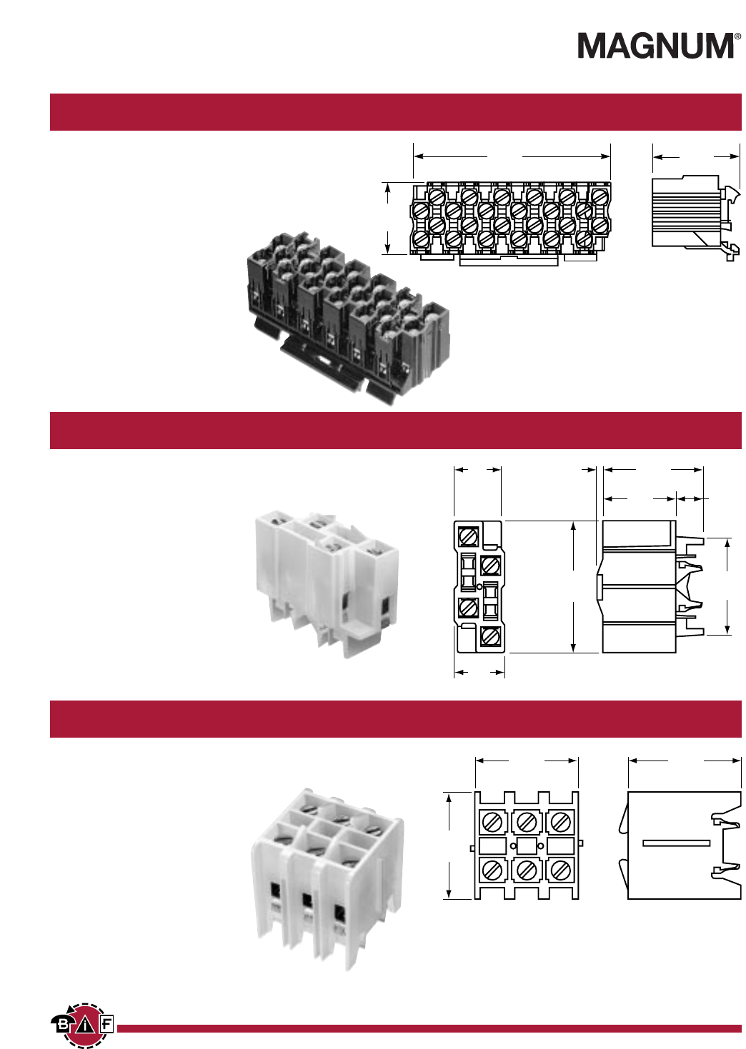
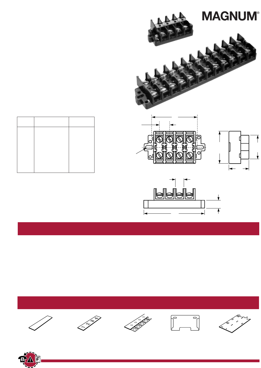
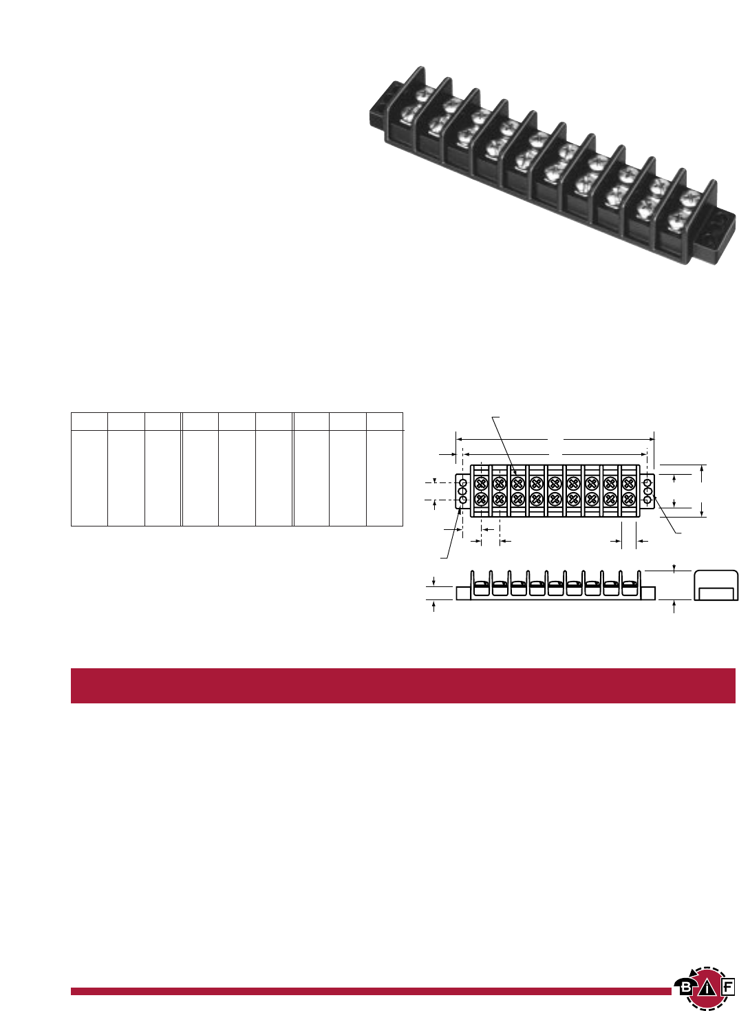
Series TB100
Double Row Terminal Blocks
SPECIFICATIONS
Rating: UL: 20A, 250V*
CSA: 20A; 150V*
Center Spacing: .375” (9.52 mm)
Wire Size: #14 - 22 AWG CU
Screw Size: #6-32 zinc plated philslot screws
Torque Rating: Max. torque for #6 screws - 9 in/lb.
Distance Between Barriers: .30” (7.62 mm)
Mounting: #6 screws
Materials: Molded base: Black, UL rated 94V-0 thermoplastic
Terminal plating: Tin over brass; Screws: Zinc plated steel
finished with a clear chromate and special coating to inhibit rust.
Hardware: Tin over brass
Operating Temperature: 260°F (130°C) max., -40°F (-40°C) min.
Creepage Paths: Terminal-to-terminal .275” (6.99 mm);
Terminal-to-mounting surface .300” (7.62 mm).
Breakdown Voltage: 3600V rms
Approvals: UL E62622; CSA LR15364; IEC Compliance; CE Pending
* Max. rating shown; some options may be rated lower - consult factory.
.14
(3.50)
.37
(9.50)
.30
(7.60)
.17 dia.
(4.30)
.14
(3.50)
.88
(22.30)
.41
(10.40)
.31 (7.90)
A
B
.25 (6.30)
* Dimensions in inches. To convert to millimeters, multiply by 25.4.
Part Numbering System
Inches (mm)
TB100
BIF document: 1422
Series Poles Screw Options Marking Hardware Options
■■
■■■■
■■■■
■■■■
■■■■
■■
-■■
■■■■
■■■■
■■■■
■■■■
■■■■
■■■■
■■■■
■■■■
■■■■
■■
02
to
36 Blank
- std. screws
L1
to
L6
- std. marking
QC1
to
QC20
- quick connects
00
- screws shipped bulk Marker strips (pg 23)
B
- brass philslot, nickel plated Covers (pg 22)
BS
- brass Sems philslot, nickel plated
SP
- steel Sems philslot, zinc plated
T B 1 0 0
Courtesy of Steven Engineering, Inc. Ÿ 230 Ryan Way, South San Francisco, CA, 94080-6370 Ÿ Main Office: (650) 588-9200 Ÿ Outside Local Area: (800) 258-9200 Ÿ www.stevenengineering.com
Contents
Next
Previous

16
For complete specification data, call Bussmann Information Fax ~ 314.527.1450
GET CONNECTED WITH US
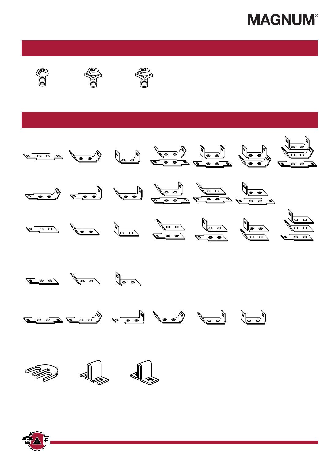
Screw Options
Hardware Options
B
Brass Philslot
Nickel Plated
BS
Brass SEMS
Philslot Nickel Plated
SP
Steel SEMS
Philslot Zinc Plated
QC8 QC9 QC11
QC10 QC12 QC13
QC7
QC20
QC108
QC 45° – QC 90°
QC105
Flat – QC 45°
QC109
QC 90° – QC 90°
J101
Flat slip-on
OJ4
Closed over barrier
OJ2
Slip-on over barrier
Quick Connects – Assembled Terminals .187” x .020”. Max. current rating 13 Amps. For other orientations,contact factory.
Quick Connects – Bulk Min. order per part no. – 100 pieces.
Jumpers – Bulk .020” thick tin plated brass. Min. order per part no. – 100 pieces. Contact factory for jumper assembly.
QC1 QC2 QC4
QC3 QC5 QC6
QC17 QC18 QC19
QC14 QC15 QC16
QC102
QC 45° – none
QC101
Flat – none
QC103
QC 90° – none
QC104
Flat – Flat
QC107
QC 45° – QC 45°
QC106
Flat – QC 90°
Courtesy of Steven Engineering, Inc. Ÿ 230 Ryan Way, South San Francisco, CA, 94080-6370 Ÿ Main Office: (650) 588-9200 Ÿ Outside Local Area: (800) 258-9200 Ÿ www.stevenengineering.com
Contents
Next
Previous
17
For complete specification data, call Bussmann Information Fax ~ 314.527.1450
Poles A B Poles A B Poles A B
02 1.63 1.31 12 6.00 5.68 22 10.37 10.06
03 2.07 1.75 13 6.44 6.12 23 10.81 10.50
04 2.51 2.18 14 6.87 6.56 24 11.25 10.93
05 2.94 2.62 15 7.31 7.00 25 11.68 11.37
06 3.38 3.06 16 7.75 7.43 26 12.12 11.81
07 3.82 3.50 17 8.19 7.87 27 12.56 12.25
08 4.25 3.93 18 8.62 8.31 28 13.00 12.68
09 4.69 4.37 19 9.06 8.75 29 13.44 13.12
10 5.13 4.81 20 9.50 9.18 30 13.87 13.56
11 5.57 5.25 21 9.94 9.62
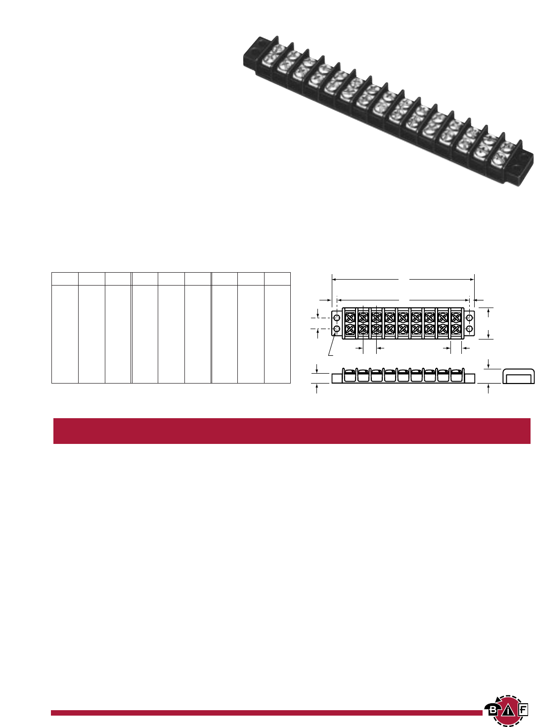
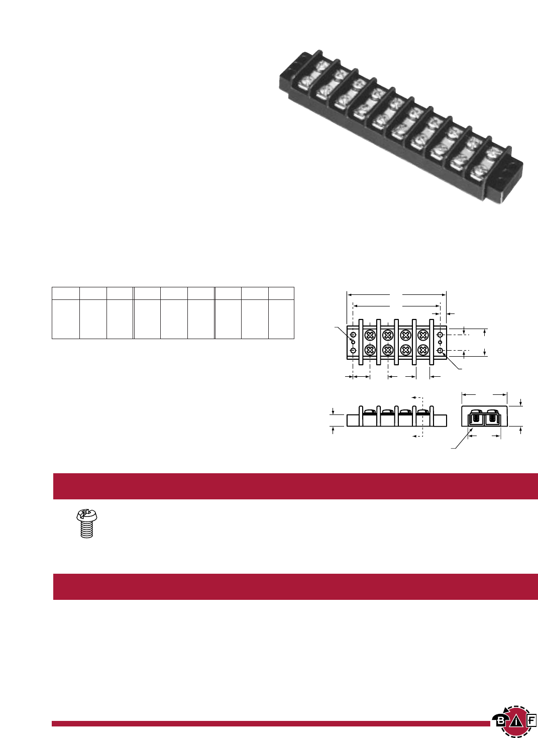
Series TB200 & TB200HB
Double Row Terminal Blocks
SPECIFICATIONS
Rating: TB200 – 20A, 300V*
TB200HB – 20A, 600V*
Center Spacing: .437” (11.10 mm)
Wire Size: #12 - 22 AWG CU
Screw Size: #6-32 zinc plated philslot screws
Torque Rating: Max. torque for #6 screws - 9 in/lb.
Distance Between Barriers: .353” (8.97 mm)
Mounting: #6 screws
Materials: Molded base: Black, UL rated 94V-0 thermoplastic
Terminal plating: Tin over brass; Screws: Zinc plated steel
finished with a clear chromate and special coating to inhibit rust
Hardware: Tin over brass
Operating Temperature: 260°F (130°C) max., -40°F (-40°C) min.
Creepage Paths: Terminal-to-terminal .400” (10.16 mm);
Terminal-to-mounting surface .375” (9.52 mm)
Breakdown Voltage: 4800V rms
Approvals: UL E62622; CSA LR15364; IEC Compliance; CE Pending
* Max. rating shown; some options may be rated lower - consult factory.
.16
(4.00)
.43
(11.10)
.35
(8.90)
.17 dia.
(4.30)
.16
(4.00)
1.12
(28.40)
.56
(14.20)
.44 (11.20)
A
B
.31 (7.80)
* Dimensions in inches. To convert to millimeters, multiply by 25.4.
Part Numbering System
Series Poles Screw Options Marking Hardware Options
■■
■■■■
■■■■
■■■■
■■■■
■■
-■■
■■■■
■■■■
■■■■
■■■■
■■■■
■■■■
■■■■
■■■■
■■■■
■■
200
02
to
30 Blank
- std. screws
L1
to
L6
- std. marking
QC1
to
QC20
- quick connects
200HB
00
- screws shipped bulk Marker strips (pg 23)
B
- brass philslot, nickel plated Covers (pg 22)
BS
- brass Sems philslot, zinc plated
SP
- steel Sems philslot, zinc plated
T B
.16
(4.00)
.43
(11.10)
.35
(8.90)
.17 dia.
(4.30)
.17 x .22 slots
(4.30 x 5.60)
.16
(4.00)
1.37
(34.80)
.90
(22.80)
.75
(19.00)
.44 (11.20)
A
B
.33 (8.40)
Inches (mm)
TB200
TB200HB
TB200
TB200HB
BIF document: 1423
Courtesy of Steven Engineering, Inc. Ÿ 230 Ryan Way, South San Francisco, CA, 94080-6370 Ÿ Main Office: (650) 588-9200 Ÿ Outside Local Area: (800) 258-9200 Ÿ www.stevenengineering.com
Contents
Next
Previous
18
For complete specification data, call Bussmann Information Fax ~ 314.527.1450
GET CONNECTED WITH US
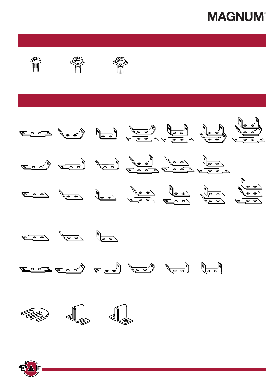
Screw Options
Hardware Options
B
Brass Philslot
Nickel Plated
BS
Brass SEMS
Philslot Zinc Plated
SP
Steel SEMS
Philslot Zinc Plated
J201
Flat slip-on
(Not available
on TB200HB)
OJ7
Closed over barrier
OJ3
Slip-on over barrier
Quick Connects – Assembled Terminals .250” x .031”. Max. current rating 24 Amps. For other orientations,contact factory.
Jumpers – Bulk .020” thick tin plated brass. Min. order per part no. – 100 pieces. Contact factory for jumper assembly.
QC8 QC9 QC11
QC10 QC12 QC13
QC7
QC20
QC208
QC 45° – QC 90°
QC205
Flat – QC 45°
QC209
QC 90° – QC 90°
Quick Connects – Bulk Min. order per part no. – 100 pieces.
QC1 QC2 QC4
QC3 QC5 QC6
QC17 QC18 QC19
QC14 QC15 QC16
QC202
QC 45° – none
QC201
Flat – none
QC203
QC 90° – none
QC204
Flat – Flat
QC207
QC 45° – QC 45°
QC206
Flat – QC 90°
Courtesy of Steven Engineering, Inc. Ÿ 230 Ryan Way, South San Francisco, CA, 94080-6370 Ÿ Main Office: (650) 588-9200 Ÿ Outside Local Area: (800) 258-9200 Ÿ www.stevenengineering.com
Contents
Next
Previous
19
For complete specification data, call Bussmann Information Fax ~ 314.527.1450
Poles A B Poles A B Poles A B
02 2.13 1.69 10 6.62 6.19 18 11.12 10.68
03 2.69 2.25 11 7.18 6.75 19 11.68 11.25
04 3.25 2.81 12 7.75 7.31 20 12.24 11.81
05 3.81 3.37 13 8.31 7.87 21 12.80 12.37
06 4.37 3.94 14 8.87 8.44 22 13.37 12.93
07 4.94 4.50 15 9.43 9.00 23 13.93 13.50
08 5.50 5.06 16 9.99 9.56 24 14.49 14.06
09 6.06 5.62 17 10.56 10.12
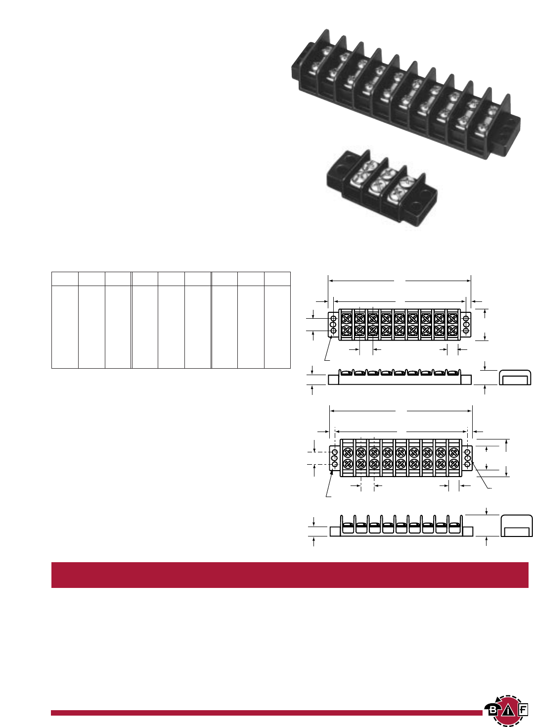
Series TB300 & TB345
Double Row Terminal Blocks
SPECIFICATIONS
Rating: TB300 – 30A, 600V*
TB345 – 45A, 600V*
Center Spacing: .562” (14.28 mm).
Wire Size: #10 - 22 AWG CU
Screw Size: TB300 – #8-32 zinc plated philslot screws
TB345 – #10-32 zinc plated philslot screws
Torque Rating: Max. torque for #8 screws - 16 in/lb;
#10 screws - 20 in/lb.
Distance Between Barriers: .412” (10.46 mm)
Mounting: #10 screws
Material: Molded base: Black, UL rated 94V-0 thermoplastic
Terminal plating: Tin over brass; Screws: Zinc plated steel
finished with a clear chromate and special coating to inhibit rust
Hardware: Tin over brass
Operating Temperature: 260°F (130°C) max., -40°F (-40°C) min.
Creepage Paths: Terminal-to-terminal .500” (12.70 mm);
Terminal-to-mounting surface .450” (11.43 mm)
Breakdown Voltage: 7500V rms
Approvals: UL E62622; CSA LR15364; IEC Compliance; CE Pending
* Max. rating shown; some options may be rated lower - consult factory.
.22
(5.60)
.56
(14.20) .56
(14.20)
.41
(10.40)
.21dia.
(5.30)
.21 x .25 slots
(5.30 x 6.30)
1.33
(33.80)
.90
(22.80)
.81
(20.50)
.50 (12.70)
A
B
8-32 binding head screw - TB 300
10-32 binding head screw - TB 345
.33 (8.40)
* Dimensions in inches. To convert to millimeters, multiply by 25.4.
Part Numbering System
Series Poles Screw Options Marking Hardware Options
■■
■■■■
■■■■
■■■■
■■■■
■■
-■■
■■■■
■■■■
■■■■
■■■■
■■■■
■■■■
■■■■
■■■■
■■■■
■■
300
02
to
24 Blank
- std. screws
L1
to
L6
- std. marking
QC1
to
QC20
- quick connects
345
00
- screws shipped bulk Marker strips (pg 23) (TB300 only)
B
- brass philslot, nickel plated Covers (pg 22)
BS
- brass Sems philslot, zinc plated
(TB300 only)
SP
- steel Sems philslot, zinc plated
T B
Inches (mm)
TB300 & TB345
BIF document: 1424
Courtesy of Steven Engineering, Inc. Ÿ 230 Ryan Way, South San Francisco, CA, 94080-6370 Ÿ Main Office: (650) 588-9200 Ÿ Outside Local Area: (800) 258-9200 Ÿ www.stevenengineering.com
Contents
Next
Previous
20
For complete specification data, call Bussmann Information Fax ~ 314.527.1450
GET CONNECTED WITH US
Screw Options
Hardware Options
B
Brass Philslot
Nickel Plated
BS
Brass SEMS
Philslot Zinc Plated
SP
Steel SEMS
Philslot Zinc Plated
J301
Flat slip-on
(TB300 only)
OJ6
Closed over barrier
OJ11
Slip-on over barrier
Quick Connects – Assembled *TB300 only. Terminals .250” x .031”. Max. current rating 24 Amps. For other orientations,contact factory.
Jumpers – Bulk .020” thick tin plated brass. Min. order per part no. – 100 pieces. Contact factory for jumper assembly.
QC8 QC9 QC11
QC10 QC12 QC13
QC7
QC20
QC208
QC 45° – QC 90°
QC205
Flat – QC 45°
QC209
QC 90° – QC 90°
Quick Connects – Bulk *TB300 only. Min. order per part no. – 100 pieces.
QC1 QC2 QC4
QC3 QC5 QC6
QC17 QC18 QC19
QC14 QC15 QC16
QC202
QC 45° – none
QC201
Flat – none
QC203
QC 90° – none
QC204
Flat – Flat
QC207
QC 45° – QC 45°
QC206
Flat – QC 90°
Courtesy of Steven Engineering, Inc. Ÿ 230 Ryan Way, South San Francisco, CA, 94080-6370 Ÿ Main Office: (650) 588-9200 Ÿ Outside Local Area: (800) 258-9200 Ÿ www.stevenengineering.com
Contents
Next
Previous
21
For complete specification data, call Bussmann Information Fax ~ 314.527.1450
Poles A B Poles A B Poles A B
02 2.51 2.06 06 5.26 4.81 10 8.01 7.56
03 3.20 2.75 07 5.95 5.50 11 8.70 8.25
04 3.89 3.44 08 6.64 6.19 12 9.39 8.94
05 4.58 4.13 09 7.33 6.88
Screw Options
B
Brass Philslot
Nickel Plated
Series TB400
Double Row Terminal Blocks
SPECIFICATIONS
Rating: 75A, 600V*
* 30A max. with #10 AWG; 75A max.
achieved with #4 AWG wire crimped to ring terminal.
Center Spacing: .687” (17.45 mm)
Wire Size: #10 - 14 AWG CU
Screw Size: #10-32 zinc plated philslot screws
Torque Rating: Max. torque for #10 screw - 20 in/lb.
Distance Between Barriers: .562” (14.27 mm)
Mounting: #10 screws
Material: Molded base: Black, UL rated 94V-0 thermoplastic
Terminal plating: Tin over brass; Screws: Zinc plated steel
finished with a clear chromate and special coating to inhibit rust
Operating Temperature: 260°F (130°C) max., -40°F (-40°C) min.
Creepage Paths: Terminal-to-terminal .598” (15.19 mm);
Terminal-to-mounting surface .542” (13.77 mm)
Breakdown Voltage: 7500V rms
Approvals: UL E62622; CSA LR15364; IEC Compliance; CE Pending
.15 dia.
(3.80)
.68
(17.40)
.22
(5.60)
A'
A'
A
B
A' - A'
.625
(15.90)
.1.12
(28.40)
.68
(17.40)
.56
(14.30)
1.81
(46.00)
.76
(19.30)
.46 (11.70)
1.34
(34.00)
.22 dia. (5.60)
Closed bottom
* Dimensions in inches. To convert to millimeters, multiply by 25.4.
Part Numbering System
Series Poles Screw Options Marking Hardware Options
■■
■■■■
■■■■
■■■■
■■■■
■■
-■■
■■■■
■■■■
■■■■
■■
02
to
12 Blank
- std. screws Not available Not available
00
- screws shipped bulk
B
- brass philslot, nickel plated
T B 4 0 0
Inches (mm)
TB400
BIF document: 1425
* 75A max acheived with #4 AWG wire crimped to ring terminal;
30A max. with #10 AWG.
Courtesy of Steven Engineering, Inc. Ÿ 230 Ryan Way, South San Francisco, CA, 94080-6370 Ÿ Main Office: (650) 588-9200 Ÿ Outside Local Area: (800) 258-9200 Ÿ www.stevenengineering.com
Contents
Next
Previous
All Series Marking Options & Accessories
Double Row Terminal Blocks
22
For complete specification data, call Bussmann Information Fax ~ 314.527.1450
GET CONNECTED WITH US
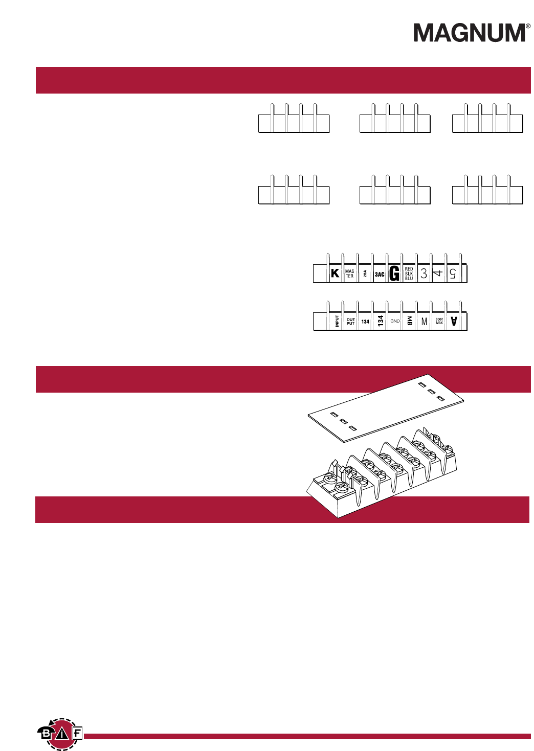
Marking Options
Special Marking
Special markings are available at an additional charge for
preparation. Production charges for setup, handling and
marking are the same as for standard marking. Drawing(s)
must be submitted to ensure accuracy of part required.
Consult factory for price and delivery.
Standard Marking
Standard markings are applied directly to the side(s) of a
block. Standard color is white. Standard height is .125”.
Note: Blocks marked on both sides require a different
code for each side. Example Style L1 on one side of the
block requires Style L2 on the other side to ensure com-
mon terminal marking. To order, add appropriate suffix
(L1, L2, L3, L4, L5 and/or L6) to block part number in the
proper sequence.
Note: Not available on TB400 Series
1 2 3 3 2 1
3 2 1 1 2 3
1
2
3
1
2
3
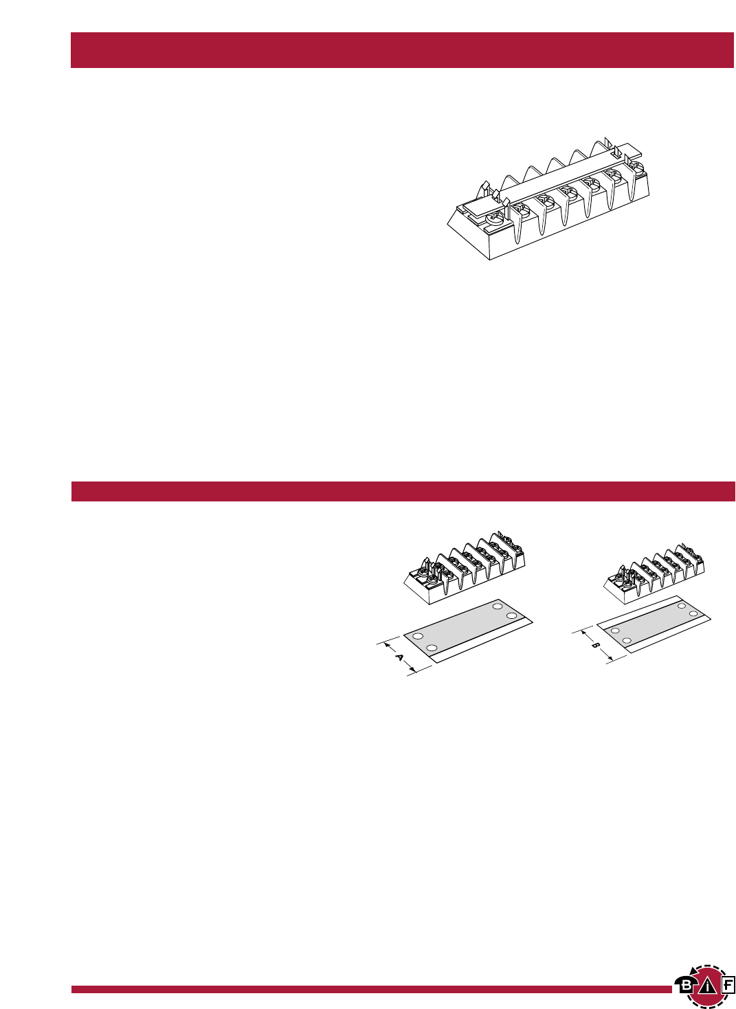
Covers
Covers prevent personnel, screws and foreign items from
contacting live terminals. Available in white or clear
plastic. Two cover clips supplied with each cover. Cover
width is 1.31 inches.
All covers must be ordered separately. Consult factory for
special legends.
Example: 10 position cover, white, TB100 Series, no
legends . . . Part # is X12010.
Part Numbering System
Series Cover Strip Poles
■■
■■■■
■■■■
■■■■
■■■■
■■■■
■■
120
- TB100/white
02
to
36
(TB100)
119
- TB100/clear
02
to
30
(TB200/TB200HB)
220
- TB200 & TB200HB* - white
02
to
24
(TB300/TB345)
219
- TB200 & TB200HB* - clear
320
- TB300 & TB345 - white
319
- TB300 & TB345 - clear
X
Cover Clips – Bulk
Part Number
DD1 – TB100 Series
DD2 – TB200 Series
DD2HB – TB200HB Series
DD3 – TB300 Series
L1 L2 L3
L4 L5 L6
Note: Not available on TB400 Series.
* For use on TB200HB, specify HB
after Part No. i.e., X21902HB
BIF document: 1426
Courtesy of Steven Engineering, Inc. Ÿ 230 Ryan Way, South San Francisco, CA, 94080-6370 Ÿ Main Office: (650) 588-9200 Ÿ Outside Local Area: (800) 258-9200 Ÿ www.stevenengineering.com
Contents
Next
Previous
23
For complete specification data, call Bussmann Information Fax ~ 314.527.1450
BIF document: 1427
Double Row Terminal Blocks
Top Marker Strips
Top mounting marker strips are available in white
(opaque) plastic. Two cover clips are supplied with each
marker strip.
All top marker strips must be ordered separately. Consult
factory for special legends.
Example: 12 position cover, TB200, .032” x .312”, with
no legends . . . Part # is X20312.
Example: 12 position cover, TB200HB, .060” x .500”,
with no legends . . . Part # is X23312HB.
Part Numbering System
Series Top Marker Strip Poles
■■
■■■■
■■■■
■■■■
■■■■
■■■■
■■
133
- TB100 (.060 thk x .500w)
02
to
36
(TB100) Note: Not available on TB400 Series.
103
- TB100 (.032 thk x .312w)
02
to
30
(TB200/TB200HB)* * For use on TB200HB, specify HB
233
- TB200 & TB200HB* (.060 thk x .500w)
02
to
24
(TB300/TB345) after Part No. i.e., X23302HB
203
- TB200 & TB200HB* (.032 thk x .312w)
333
- TB300 & TB345 (.060 thk x .500w)
303
- TB300 & TB345 (.032 thk x .380w)
X
Bottom Marker Strips
Bottom mounting marker strips are made of black PVC,
.030” thick. Space is available to handle most marking
situations. All marker strips must be ordered separately.
To order, specify part number, required legends and (BF)
bottom forward, (BR) bottom reverse, (TF) top forward, or
(TR) top reverse. Consult factory for specials.
Example: 13 position strip, TB100 with no legends, space
for marking one side . . . Part # is X10513.
Position for legends (one side, two sides) can be speci-
fied standard. Standard legend height is .125”. Standard
legends are 0-99. Special legends are available on spe-
cial order. Drawing(s) must be submitted to ensure accu-
racy of part required.
Part Numbering System
Series Bottom Marker Strip Poles Orientation
■■
■■■■
■■■■
■■■■
■■■■
■■■■
■■■■
■■■■
■■
105
- TB100 – marking one side
02
to
36
(TB100)
BF
– bottom forward
101
- TB100 – marking both sides
02
to
30
(TB200/TB200HB)
BR
– bottom reverse
205
- TB200 – marking one side
02
to
24
(TB300/TB345)
TF
– top forward
201
- TB200 – marking both sides
TR
– top reverse
295
- TB200HB – marking one side
291
- TB200HB – marking both sides
305
- TB300 & TB345 – marking one side
301
- TB300 & TB345 – marking both sides Note: Not available on TB400 Series.
X
Space for marking
one side
Space for marking
two sides
Top & Bottom Marking Strips
Courtesy of Steven Engineering, Inc. Ÿ 230 Ryan Way, South San Francisco, CA, 94080-6370 Ÿ Main Office: (650) 588-9200 Ÿ Outside Local Area: (800) 258-9200 Ÿ www.stevenengineering.com
Contents
Next
Previous
24
For complete specification data, call Bussmann Information Fax ~ 314.527.1450
GET CONNECTED WITH US
BIF document: 1428
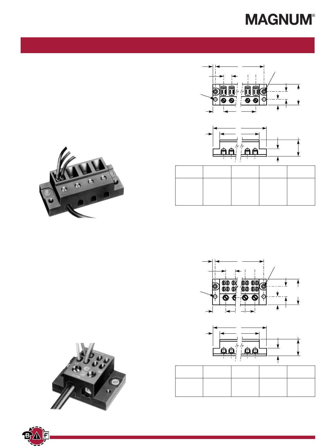
Series 11675
SPECIFICATIONS
Ratings: 40A, 250V; UL/CSA
Poles: 2 to 6 poles with (3) .250” quick-connect
terminals per pole.
Input wire sizes: #8 – #14 CU
Torque rating: 18 in/lb max.
Operating temperature: 150°C
Design: Screw connections for field wiring. Quick
connects reduce cost of internal wiring.
Agency approvals: UL E62622; CSA LR15364;
CE Pending
Quick-Connect Power Distribution Blocks Inches (Millimeters)
Power Blocks
Series 11675 & 11725
.43
(10.92)
1.03
(26.16)
.37
(9.39)
.20 (5.08) I.D.
eyelets
.20 (5.08)
dia. holes
.50
(12.70)
1.37
(34.79)
.20
(5.08)
.56
(14.22)
.76
(19.30)
.46
(11.68)
A
B
C
D
Part
Number A B C D
11675-2 2.09 1.68 .56 1.15
11675-3 2.66 2.25 1.12 1.71
11675-4 3.22 2.81 1.68 2.28
11675-5 3.78 3.37 2.25 2.84
11675-6 4.34 3.93 2.81 3.40
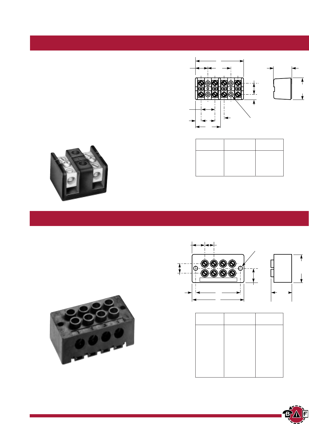
Series 11725
SPECIFICATIONS
Ratings: 70A, 600V; UL/CSA
Poles: 2, 3 or 4 poles with (4) .250” quick-connect
terminals per pole.
Input wire sizes: #2 – #14 CU/#8 AL
Torque rating: 45 in/lb max.
Operating temperature: 150°C
Design: Screw connections for field wiring. Quick
connects reduce cost of internal wiring.
Agency approvals: UL E62622; CSA LR15364;
CE Pending
.43
(10.92)
1.12
(28.44)
.59
(14.98)
.19 (4.98) I.D.
eyelets
.19 (4.98)
dia. holes
.62
(15.74)
1.84
(46.73)
.21
(5.33)
.68
(17.27)
.90
(22.86)
.56
(14.22)
A
B
C
D
Part
Number A B C D
11725-2 2.50 2.06 .68 1.37
11725-3 3.18 2.75 1.37 2.06
11725-4 3.87 3.43 2.06 2.75
11675-4
11725-2
Courtesy of Steven Engineering, Inc. Ÿ 230 Ryan Way, South San Francisco, CA, 94080-6370 Ÿ Main Office: (650) 588-9200 Ÿ Outside Local Area: (800) 258-9200 Ÿ www.stevenengineering.com
Contents
Next
Previous
25
For complete specification data, call Bussmann Information Fax ~ 314.527.1450
BIF document: 1429
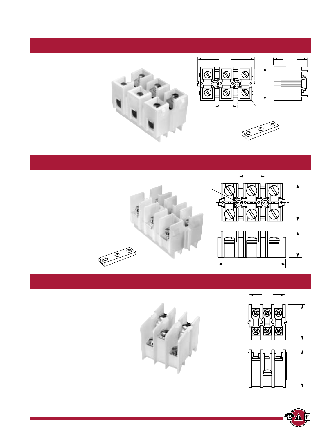
Series 14002
SPECIFICATIONS
Ratings: 115A, 600V; UL/CSA
Poles: 2 to 6 poles
Wire sizes: #2 – #14 CU/#8 AL
Operating temperature: 150°C
Marking: Marking strip optional, consult factory.
Options: CP = Pressure plate, rated 60A, 600V
Q = Quick-Connect, rated 50A, 600V
To order options, enter letter code
in front of Part No.: ie; CP14002-2
Agency approvals: UL E62622; CSA LR15364;
CE Pending
Barrier Terminal Blocks Inches (Millimeters)
Barrier & Dead Front Terminal Blocks
Series 14002 & 14004
.37
(9.39)
1.25
(31.75)
.17 (4.31) dia. holes
with .34 (8.63) dia. x
.75 (19.05) deep c'bore
.75
(19.05)
1.50
(38.10)
.87
(22.09)
.39
(9.90)
.96
(24.38)
.62
(15.74)
A
B
A*
Part
Number A B
14002-2 1.75 –
14002-3 2.37 –
14002-4 3.34 1.59
14002-5 3.96 2.21
14002-6 4.59 2.84
Note: “A” dimension for 14002-2 & 14002-3 only.
(14002-2 & 14002-3 have only two mounting holes.)
Series 14004
SPECIFICATIONS
Ratings: 90A, 600V; UL/CSA
Poles: 2 to 12 poles
Wire sizes: #4 – #14 CU/#8AL
Operating temperature: 75°C
Marking: Marking strip optional, consult factory.
Agency approvals: UL E62622; CSA LR15364
Dead Front Terminal Blocks Inches (Millimeters)
1.12
(28.44)
.21 (5.33)
dia. holes
.75
(19.05)
1.50
(38.10)
.65
(16.51)
.18
(4.57)
.50
(12.70)
.50
(12.70)
A
B
Part
Number A B
14004-2 1.81 1.43
14004-3 2.31 1.93
14004-4 2.81 2.43
14004-5 3.31 2.93
14004-6 3.81 3.43
14004-7 4.31 3.93
14004-8 4.81 4.93
14004-9 5.31 4.93
14004-10 5.81 5.43
14004-11 6.31 5.93
14004-12 6.81 6.43
14002-2
14004-4
Courtesy of Steven Engineering, Inc. Ÿ 230 Ryan Way, South San Francisco, CA, 94080-6370 Ÿ Main Office: (650) 588-9200 Ÿ Outside Local Area: (800) 258-9200 Ÿ www.stevenengineering.com
Contents
Next
Previous
26
For complete specification data, call Bussmann Information Fax ~ 314.527.1450
GET CONNECTED WITH US
No. of Poles A B
2 4.12 3.62
3 5.37 4.87
4 6.62 6.12
Connector
Part Line Load Material & Agency
Number Connection Connection Ampacity Approvals
*16000 2/0-#8CU-AL 2/0-#8 CU-AL AL-175A UL –
*16003 250MCM-#6CU 250MCM-#6CU CU-255A UL –
*16005 350MCM-#6CU-AL 350MCM-#6CU-AL AL-310A UL –
16200 #2-#14CU/#8AL #2-#14CU/#8AL AL-115A UL CSA
16201 1/0-#14CU 1/0-#14CU CU-150A UL CSA
16204 2/0-#8CU-AL 2/0-#8CU-AL AL-175A UL CSA
16301 250MCM-#6CU 250MCM-#6CU CU-255A UL CSA
16303 350MCM-#6CU-AL 350MCM-#6CU-AL AL-310A UL CSA
16306 500MCM-#6CU-AL 500MCM-#6CU-AL AL-380A UL CSA
16500 (2)350MCM-#4CU-AL (2)350MCM-#4CU-AL AL-620A UL CSA
16504 (2)500MCM-#6CU-AL (2)500MCM-#6CU-AL AL-760A UL CSA
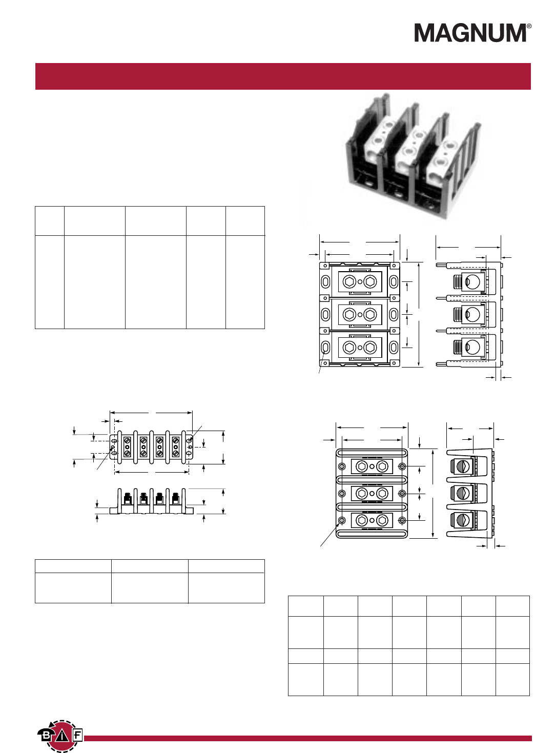
Series 160, 162, 163 & 165
SPECIFICATIONS
Ratings: To 620A, 600V; UL/CSA. See table.
Materials: Molded material: Black, UL rated 94V-0 thermoplastic
Operating Temperature: 150°C
Marking: Marker strip is optional, consult factory.
Agency approvals: UL E62622 General Industrial Class per UL
1059; CSA LR15364; CE Pending
Splicer Terminal Blocks Inches (Millimeters)
Power Blocks
* 160 Series Bases have mounting holes outside the barriers. Other bases
(162 through 165) have mounting holes within barriers. See dimensional
drawings.
2.00
(50.80)
.50
(12.70) .68
(17.27)
1.37
(33.02)
2.06
(52.32)
2.75
(69.85)
.21 x .37 slots
B
.26 dia.
holes
.37
(9.39)
1.00
(25.40)
A
A
B
C
E
F
E
GH
D
J
MTG. HOLES .21 x .41
C'BORE .42 x .62 x. 12 DEEP
Series 160 (2, 3, & 4-pole available)
Series 162 & 165 (1, 2, & 3-pole available)
Series A B C C C
1-pole 2-pole 3-pole
162 2.87 2.25 1.06 1.87 2.68
163 4.00 3.37 1.96 3.58 5.20
165 5.50 4.75 3.12 5.81 8.50
Series D E F G H J
162 1.75 .81 .53 .31 .84 .31
163 3.32 1.62 .97 .31 .87 .35
165 3.12 2.68 1.56 .37 1.37 .62
BIF document: 1430
A
B
C
E
F
E
G
D
H
J
.20 dia. hole w/ .40 dia. c'bore
Series 163 (1, 2, & 3-pole available)
Courtesy of Steven Engineering, Inc. Ÿ 230 Ryan Way, South San Francisco, CA, 94080-6370 Ÿ Main Office: (650) 588-9200 Ÿ Outside Local Area: (800) 258-9200 Ÿ www.stevenengineering.com
Contents
Next
Previous
27
For complete specification data, call Bussmann Information Fax ~ 314.527.1450
BIF document: 1431
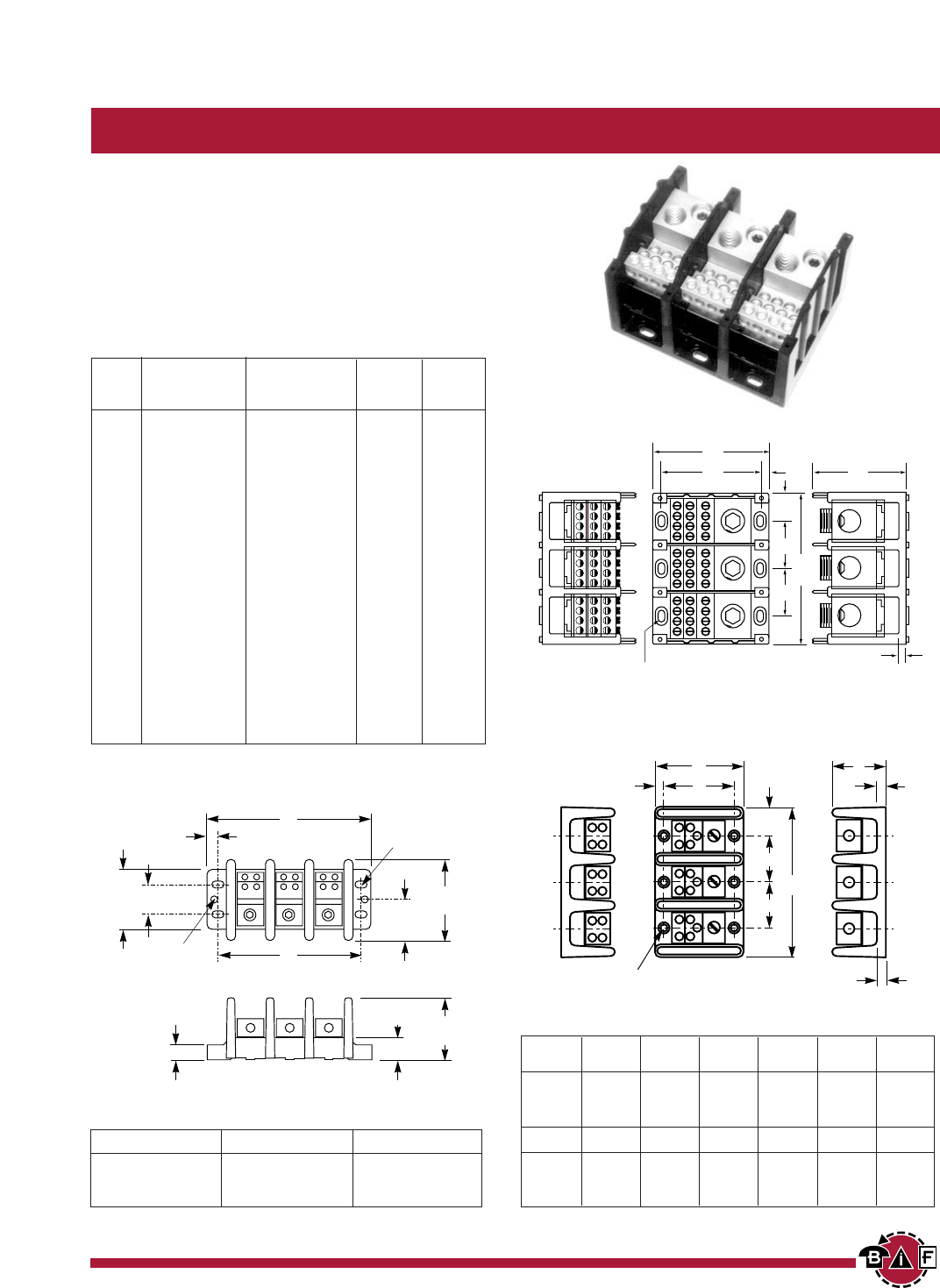
Series 160, 162, 163 & 165
SPECIFICATIONS
Ratings: To 840A, 600V; UL/CSA. See table.
Materials: Molded material: Black, UL rated 94V-0 thermoplastic
Operating Temperature: 150°C
Marking: Marker strip is optional; consult factory.
Agency approvals: UL E62622 General Industrial Class per
UL 1059; CSA LR15364; CE Pending
Power Distribution Blocks Inches (Millimeters)
Power Blocks
Connector
Part Line Load Material & Agency
Number Connection Connection Ampacity Approvals
*16021 2/0-#14CU/#8AL (6)#4-#14CU/#8AL AL-175A UL CSA
*16023 350MCM-#6CU-AL (6)#4-#14CU/#8AL AL-310A UL CSA
16220 2/0-#14CU/#8AL (4)#4-#14CU/#8AL AL-175A UL CSA
16321 2/0-#14CU-AL (6)#4-#14CU/#8AL AL-175A UL CSA
16323 350MCM-#6CU-AL (6)#4-#14CU/#8AL AL-310A UL CSA
16325 (2)2/0-#14CU/#8 AL (6)#4-#14CU/#8AL AL-350A UL CSA
16330 500MCM-#6CU-AL (6)#2-#14CU/#8AL AL-380A UL CSA
16332 350MCM-#6CU-AL (3)#2-#14CU/#8AL AL-310A UL CSA
& (2)1/0-#14CU/#8AL
16335 500MCM-#6CU-AL (3)#2-#14CU/#8AL AL-380A UL CSA
& (2)1/0-#14CU/#8AL UL –
16370 350MCM-#6CU-AL (12)#4-#14CU/#8AL AL-310A UL CSA
16371 350MCM-#6CU-AL (6)#2-#14CU/#8AL AL-310A UL CSA
(3)1/0-#14CU/#8AL
16372 350MCM-#6CU-AL (21)#10-#14CU/#10AL AL-310A UL CSA
16373 350MCM-#6CU-AL (3)1/0-#14CU/#8AL AL-310A UL CSA
(14)#10-#14CU/#8AL
16375 600MCM-#2CU-AL (12)#4-#14CU/#8AL AL-420A UL CSA
16376 600MCM-#2CU-AL (6)#2-#14CU/#8AL AL-420A UL CSA
(3)1/0-#14CU-8AL
16377 (2)300MCM-#2CU-AL (12)#4-#14CU/#8AL AL-570A UL –
16528 (2)600MCM-#2CU-AL (4)3/0-#8CU-AL AL-840A UL CSA
&
(4)#4-#14CU/#8AL
16530 (2)500MCM-#6CU-AL (12)#4-#14CU/#8AL AL-760A UL CSA
2.00
(50.80) .37
(9.39)
1.00
(25.40)
.50
(12.70) .68
(17.27)
1.37
(33.02)
2.06
(52.32)
2.75
(69.85)
.21 x .37 slots
B
A
.26 dia.
holes
20. dia. hole w/ .40 dia. c'bore
AD
HBG
J
F
C
E
E
Series 160 (2, 3, & 4-pole available)
Series 162 & 165 (1, 2, & 3-pole available)
No. of Poles A B
2 4.12 3.62
3 5.37 4.87
4 6.62 6.12
Series A B C C C
1-pole 2-pole 3-pole
162 2.87 2.25 1.06 1.87 2.68
163 4.00 3.37 1.96 3.58 5.20
165 5.50 4.75 3.12 5.81 8.50
Series D E F G H J
162 1.75 .81 .53 .31 .84 .31
163 3.32 1.62 .97 .31 .87 .35
165 3.12 2.68 1.56 .37 1.37 .62
* 160 Series Bases have mounting holes outside the barriers. Other bases
(162 through 165) have mounting holes within barriers. See dimensional
drawings.
C
D
E
F
E
A
BG
J
MTG. HOLES .21 x .41
C'BORE .42 x .62 x. 12 DEEP
Series 163 (1, 2, & 3-pole available)
Courtesy of Steven Engineering, Inc. Ÿ 230 Ryan Way, South San Francisco, CA, 94080-6370 Ÿ Main Office: (650) 588-9200 Ÿ Outside Local Area: (800) 258-9200 Ÿ www.stevenengineering.com
Contents
Next
Previous
28
For complete specification data, call Bussmann Information Fax ~ 314.527.1450
GET CONNECTED WITH US
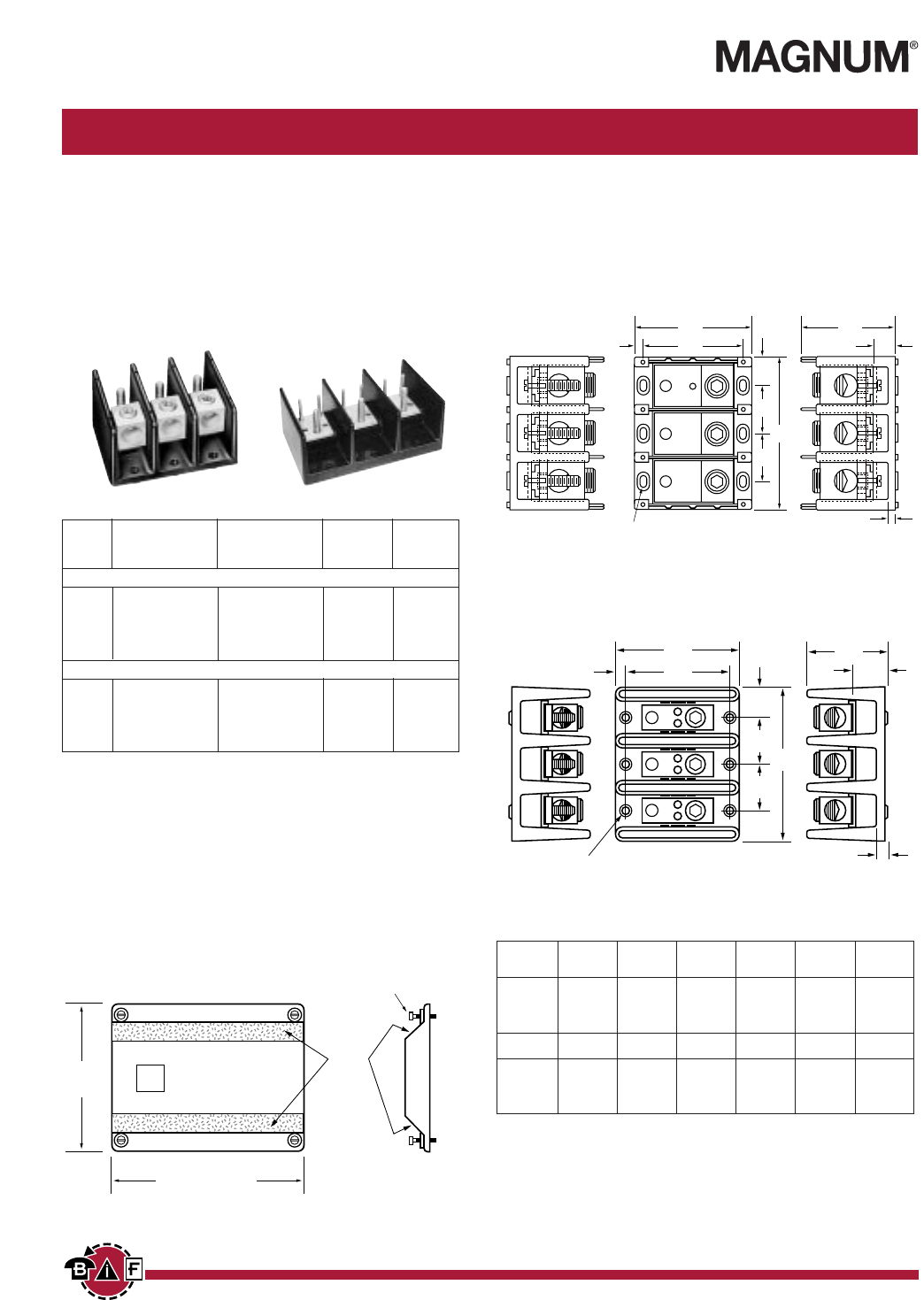
Series 162, 163 & 165
SPECIFICATIONS
Ratings: To 760A, 600V; UL/CSA. See table.
Materials: Molded material: Black, UL rated 94V-0 thermoplastic
Operating Temperature: 150°C
Agency approvals: UL E62622 General Industrial Class per
UL 1059. CSA LR15364; CE Pending.
Connector/Stud Power Distribution Blocks Inches (Millimeters)
Power Blocks
Connector
Part Line Load Material & Agency
Number Connection Connection Ampacity Approvals
Connector to Stud
16280 2/0-#14CU/#8AL 1/4-20x1/2 Stud AL-175A UL CSA
16281 2/0-#14CU/#8AL 1/4-20 Tapped hole AL-175A UL CSA
16378 500MCM-#6CU-AL (2)1/4-20x1 Stud AL-380A UL CSA
16383 500MCM-#6CU-AL (1)3/8-16x11/4Stud AL-380A UL CSA
16582 (2)500MCM-#6CU-AL (2)3/8-16x15/8Stud AL-760A UL CSA
Stud to Stud
16390 3/8-16x11/8Stud 3/8-16x11/8Stud CU-250A UL CSA
16394 1/2-13x11/16 Stud 1/2-13x11/16 Stud CU-400A UL CSA
16395 3/8-16x17/16 Stud (2)1/4-20x9/16 Stud CU-310A UL CSA
16591 3/8-16x17/16 Stud (2)3/8-16x17/16 Stud CU-400A UL –
16593 1/2-13x1 Stud 1/2-13x1 Stud CU-600A UL CSA
A
B
C
E
F
E
G
D
H
J
.20 dia. hole w/ .40 dia. c'bore
Series 163 (1, 2, & 3-pole available)
BIF document: 1432
Series A B C C C
1-pole 2-pole 3-pole
162 2.87 2.25 1.06 1.87 2.68
163 4.00 3.37 1.96 3.58 5.20
165 5.50 4.75 3.12 5.81 8.50
Series D E F G H J
162 1.75 .81 .53 .31 .84 .31
163 3.32 1.62 .97 .31 .87 .35
165 3.12 2.68 1.56 .37 1.37 .62
A
B
J
H
C
E
F
E
G
D
MTG. HOLES .21 x .41
C'BORE .42 x .62 x. 12 DEEP
Series 162 & 165 (1, 2, & 3-pole available)
BUSS
CPDB
®
TEXTURED
SURFACE
SUPPLIED WITH
(4) #4 THREAD-CUTTING SCREWS
ASSEMBLED AS SHOWN
CPDB-1=2.10"
CPDB-2=3.72"
CPDB-3=5.34"
4.14
New Option Available on
163 Series Power Blocks
PROTECTIVE COVER TO GUARD
AGAINST ACCIDENTAL CONTACT
• Clear with write on surface for field
termination identification.
• Available in 1, 2, & 3 poles.
Courtesy of Steven Engineering, Inc. Ÿ 230 Ryan Way, South San Francisco, CA, 94080-6370 Ÿ Main Office: (650) 588-9200 Ÿ Outside Local Area: (800) 258-9200 Ÿ www.stevenengineering.com
Contents
Next
Previous
29
For complete specification data, call Bussmann Information Fax ~ 314.527.1450
BIF document: 1433
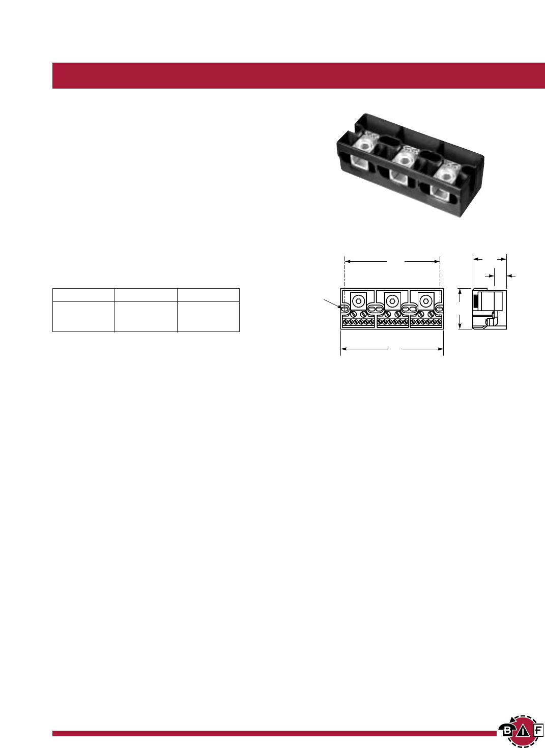
SPECIFICATIONS
Ratings: 285A, 600V; UL/CSA
Line connector: #300MCM-#6 CU/AL
Load connection: (6)#6-#14 CU/#8 AL
Material: Molded material; Black, UL rated 94V-
2 thermoplastic
Operating temperature: 125°C
Agency approvals: UL E62622; CSA LR15364;
CE Pending
Series EN 1.78” Centers Inches (Millimeters)
Power Blocks
Series EN
.20 x .37
mtg. slot
1.68
(42.67)
.50
(12.70)
2.12
(53.84)
A
B
Series A B
EN61 1.38 1.78
EN62 3.15 3.62
EN63 4.93 5.37
Courtesy of Steven Engineering, Inc. Ÿ 230 Ryan Way, South San Francisco, CA, 94080-6370 Ÿ Main Office: (650) 588-9200 Ÿ Outside Local Area: (800) 258-9200 Ÿ www.stevenengineering.com
Contents
Next
Previous
30
For complete specification data, call Bussmann Information Fax ~ 314.527.1450
GET CONNECTED WITH US
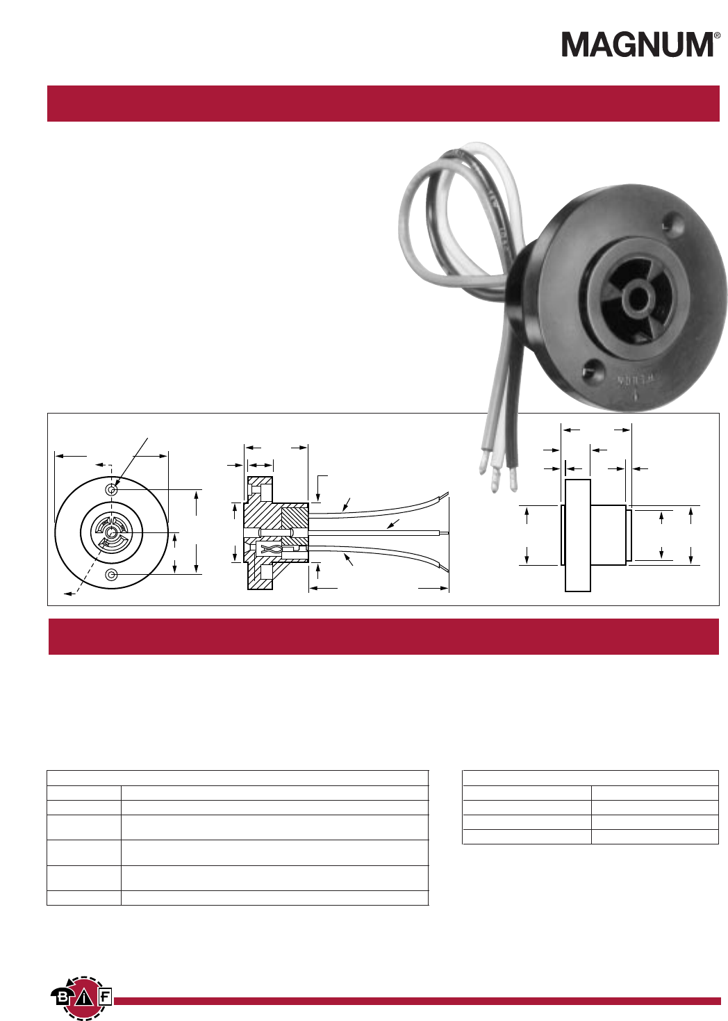
Photo Control Receptacle Series
Wire Management Products
■ 3-pole, 3-wire receptacles for plug-in, locking type photo
controls used in outdoor areas and roadway lighting.
■ Receptacle configuration, terminals and limiting dimensions
are in accordance with Figure 3 of EE Pub. No. TDJ-146,
NEMA Pub. No. SH 16-1962 and UL 773.
■ Wire types and sizes ranging from #12 AWG through 16 AWG
rated at 600V with temperature ratings from 105° to 200°C.
■ Hook-up wires are an integral part of the assembly with
lengths furnsihed to customer specification.
■ Available with .250 quick-connect terminals in lieu of wire
leads (13661-Q).
■ UL recognized under file E65288 for a rating of 1 KW or
1800VA for potentials up to 480V.
■ CSA certified under file LR21295 for 15 amps at 125V.
■ CE Pending.
BLACK (B)
WHITE (COM)
"Z" (WIRE LENGTH
IN INCHES)
RED (R)
A
A
.14 DIA. W/.28 DIA. x 80°
C'SINK (2 HOLES)
2.56
.96
1.93 1.37
1.45
1.37
1.56
.62
1.37 DIA.
1.37
Part Numbering System
Terminal Wire Wire Wire
Series Type Type Gauge Length
■■
■■■■
■■■■
■■■■
■■■■
■■-■■
■■■■
■■■■
■■■■
■■
W
= Wire See Table See Table Dimension
Q
= Quick Connect “Z”
13 661
TABLE I (WIRE TYPE)
ASS’Y NO. WIRE DESCRIPTION
13661-W1XX Min. of 26 Strands, Copper Conductor, 125ºC-600V Crosslinked Polyethylene.
13661-W2XX Min. of 26 Strands, Copper Conductor, Silicone Rubber Insulation And Fiber
Glass Braid Jacket, Nec. Type SFF-2(150ºC)
13661-W3XX Min. Of 26 Strands, Copper Conductor, Type TW, 105ºC-600V Insulation
(16 gauge only).
13661-W4XX Min. of 7 Strands, Copper Conductor Of .0192 Silicone Rubber Insulation And
Fiber Glass Braid Jacket, Nec. Type SF-2 (200ºC)
13661-W5XX Min. Of 19 Strands, Copper Conductor, Type AWM. 105ºC-600V Insulation.
TABLE II (WIRE GAUGE)
ASS’Y NO. GAUGE
13661-WX2X 12 Gauge
13661-WX4X 14 Gauge
13661-WX6X 16 Gauge
BIF document: 1434
MODEL 13661 MODEL 13661-Q
Courtesy of Steven Engineering, Inc. Ÿ 230 Ryan Way, South San Francisco, CA, 94080-6370 Ÿ Main Office: (650) 588-9200 Ÿ Outside Local Area: (800) 258-9200 Ÿ www.stevenengineering.com
Contents
Next
Previous
31
For complete specification data, call Bussmann Information Fax ~ 314.527.1450
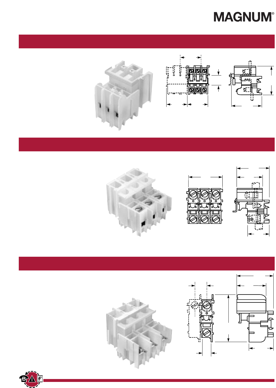
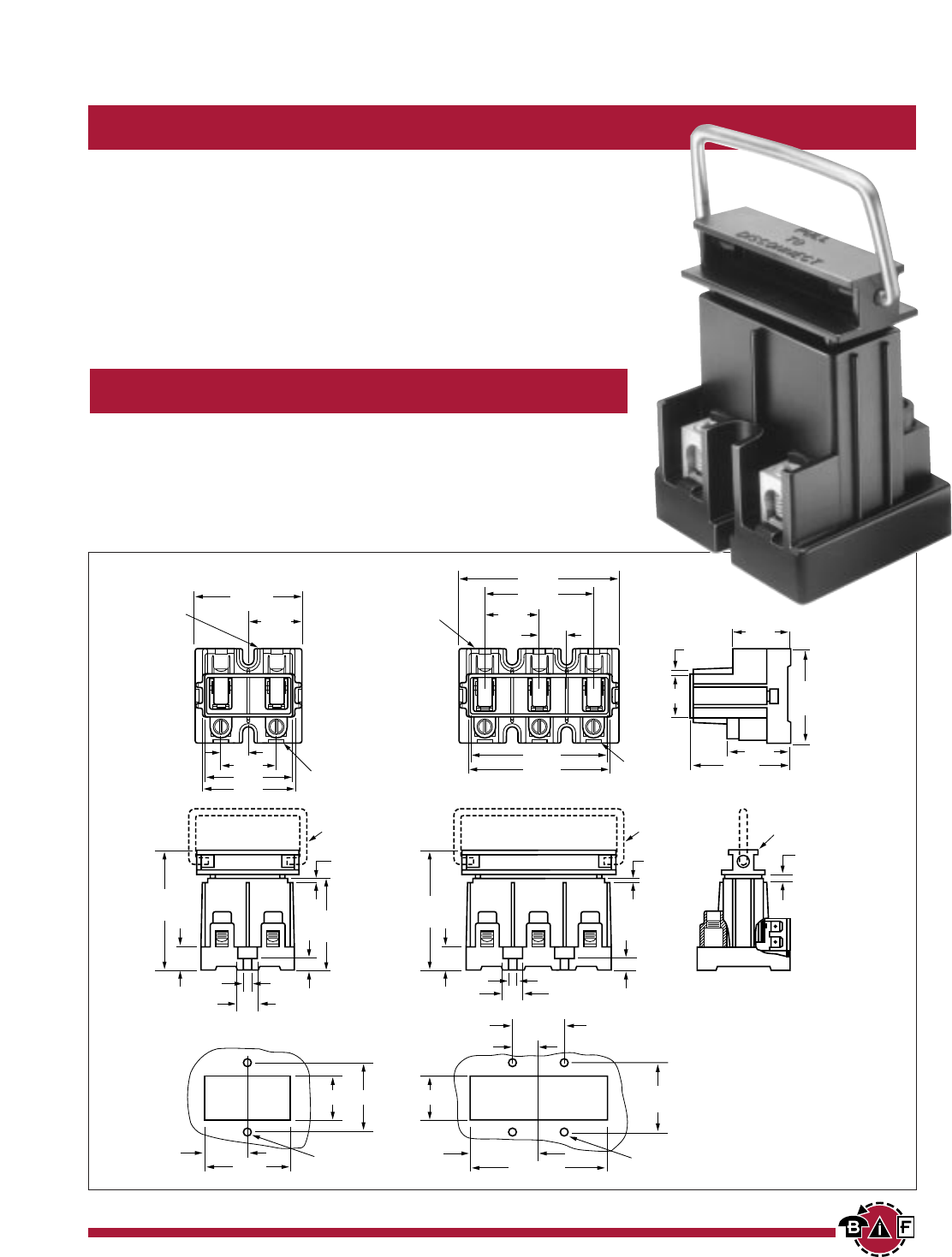
Nonfused, Disconnects
Disconnect Blocks
■ Ratings: 60A, 240V
■ Wire Range: #2-14 CU/#8 AL
■ Available in both 2 and 3 pole versions for both single and three phase systems.
■ Compact, one-piece thermoplastic housing is rated to 150°C.
■ Box connector or quick-connect terminations available on load side. Box
connector standard on line side.
■ Body of disconnect can be mounted enabling disconnect head (pull-out) to
interlock with door to insure power is off when door is open.
■ UL E120756; CSA LR 37129; CE Pending.
Part Numbering System
Line Side Load Side
Series Poles Connections Connections Options
■■
■■■■
■■■■
■■■■
■■■■
■■■■
■■■■
■■-■■
■■■■
■■■■
■■■■
■■
2C
= Box
C
= Box Connection
H
= Wire
3
Connection
Q
= (4) .250" Quick- Handle
Connects
ND-1 2 6 0
LINE SIDE
LOAD SIDE
WIRE HANDLE
OPTIONAL WIRE HANDLE
OPTIONAL
L0AD SIDE
2.50
1.25
.62
1.25
1.93
2.03
LINE SIDE
.06
2.25
2.96
.25
.54
.20
.40
1.06 1.061.70
1.031
2.06 .20 DIA. (2 HOLES) .20 DIA. (4 HOLES)
1.67 3.34
.62
1.25
.40
.20
1.70
.25
.54
2.96
.06 .18
MALE DISCONNECT
SHOWN INSTALLED
2.25
1.43
1.28
2.15
.12
1.00
3.28
3.18
1.25
2.50
3.62
.62
BIF document: 1435
Courtesy of Steven Engineering, Inc. Ÿ 230 Ryan Way, South San Francisco, CA, 94080-6370 Ÿ Main Office: (650) 588-9200 Ÿ Outside Local Area: (800) 258-9200 Ÿ www.stevenengineering.com
Contents
Next
Previous

BUSSMANN CIRCUIT COMPONENTS • 7300 W. Wilson Ave. • Chicago, IL 60656-4708 • Fax: 800-832-9873 • Phone: 888-YES MAGNUM
Website: http://www.busscc.com
An ISO 9001 Quality System Certified Facility
Look for other reliable products
in these comprehensive catalogs . . .
Circuit Protection
MAGNUM®Terminal Blocks
Products for the DC mobile and AC supplementary circuit protection
requirements including Shortstop®, Flat-Pak®and Hi-Amp™auto, manual
or modified reset and switchable circuit protectors, Maxi™ATC®, ATM®
blade type circuit protectors, Stud Type Junction Blocks, Small
Dimension Fuse Panels, Battery Disconnect Switches and Power
Distribution Modules.
A complete line of conventional terminal blocks in an easy-to-use
catalog. Includes Single Row, Double Row, Depluggable and Edge
Connectors, Interface Systems and accessories. Popular center
spacings include .250", .325", .375", .437", .562" and .687" with
the industry’s most comprehensive range of options.
MAGNUM®
GET CONNECTED WITH US
MAGNUM®Euro-Mag Terminal Blocks
MAGNUM®has just expanded it’s product line to include European style
PCB terminal blocks. These blocks are available in sizes ranging from
3.81mm to 10.16mm centers. Configurations include single, two-tier,
depluggable and screwless. All blocks have full agency approvals and
are available in horizontal, vertical, and 45º wire orientations.
FORM NO. MEP1/15M/1097
Courtesy of Steven Engineering, Inc. Ÿ 230 Ryan Way, South San Francisco, CA, 94080-6370 Ÿ Main Office: (650) 588-9200 Ÿ Outside Local Area: (800) 258-9200 Ÿ www.stevenengineering.com
Contents
Previous
