175555 EMC Report
175517 Emc Report 175517_EMC__Report 175517_EMC__Report CertsReports 175517 ProductFiles assets.mhint
175548 Emc Report 175548_EMC__Report 175548_EMC__Report CertsReports 175548 ProductFiles assets.mhint
2016-04-05
: Pdf 175555 Emc Report 175555_EMC__Report CertsReports 175555 ProductFiles
Open the PDF directly: View PDF ![]() .
.
Page Count: 24
Report Number: SZ0801001-E
May 12, 2008
SEC Engineering Service Co., Ltd. Page1 of 24
EMC COMPLIANCE TEST REPORT
for
HEADPHONE
Trade Name : QUEEN
Model Number : OV2009MV, OV510MV, OV740MV
Serial Number : N/A
Report Number : SZ0801001-E
Date :
May 12, 2008
Regulations :
See below
Standards Results (Pass/Fail)
EN55022:2006
EN55024:1998+A1:2001+A2:2003
-EN61000-4-2:1995+A1:1998+A2:2001
-EN61000-4-3:2006
PASS
PASS
PASS
PASS
Prepared for
:
LUNA INDUSTRIAL CO., LTD
TANGXIA INDUSTRIAL ZONE, HUIYANG DISTRICT,
HUIZHOU CITY, GUANGDONG PROVINCE, CHINA
Prepared by
:
SEC ENGINEERING SERVICES CO., LTD.
21A BLDG C, SHENNAN GARDEN, SCIENCE & TECHNOLOGY
PARK, NANSHAN, SHENZHEN, GUANGDONG, CHINA
TEL: 86-755-8611-0163
FAX: 86-755-8611-0248
Report Number: SZ0801001-E
May 12, 2008
SEC Engineering Service Co., Ltd. Page2 of 24
TABLE OF CONTENTS
1 VERIFICATION OF COMPLIANCE.......................................................................................................... 3
2 SYSTEM DESCRIPTION............................................................................................................................. 4
3 PRODUCT INFORMATION........................................................................................................................ 4
4 SUPPORT EQUIPMENT............................................................................................................................... 4
5 TEST FACILITY............................................................................................................................................ 5
6 TEST EQUIPMENT LIST............................................................................................................................. 6
7 TEST RESULTS............................................................................................................................................. 8
7.1 LINE CONDUCTED MEASUREMENT PROCEDURE .............................................................. 8
7.2 RADIATED MEASUREMENT PROCEDURE............................................................................ 10
7. 3 ELECTROSTATIC DISCHARGE................................................................................................... 15
7. 4 RADIATED ELECTROMAGNETIC FIELD.................................................................................18
8 PHOTOGRAPHS......................................................................................................................................... 21
8.1 PHOTOGRAPHS OF TEST SETUP...............................................................................................21
8.2 PHOTOGRAPHS OF EUT.............................................................................................................. 23

Report Number: SZ0801001-E
May 12, 2008
SEC Engineering Service Co., Ltd. Page3 of 24
1 VERIFICATION OF COMPLIANCE
Equipment Under Test: HEADPHONE
Trade Name: QUEEN
Model Number: OV2009MV, OV510MV, OV740MV
Serial Number: N/A
EUT Powered during test: 5V from PC
Applicant: LUNA INDUSTRIAL CO., LTD
TANGXIA INDUSTRIAL ZONE, HUIYANG DISTRICT, HUIZHOU CITY,
GUANGDONG PROVINCE, CHINA
Manufacturer: LUNA INDUSTRIAL CO., LTD
TANGXIA INDUSTRIAL ZONE, HUIYANG DISTRICT, HUIZHOU CITY,
GUANGDONG PROVINCE, CHINA
Type of Test: EMC Directive 2004/108/EC for CE Marking
Technical Standards: EN55022:1998+A1:2000+A2:2003
EN55024:1998+A1:2001+A2:2003
(EN61000-4-2:1995+A1:1998+A2:2001; EN61000-4-3:2002+A1:2002)
File Number: SZ0801001-E
Deviation: None
Condition of Test Sample: Normal
The above equipment was tested by SEC Engineering Services Co., Ltd. for compliance with the
requirements set forth in Directive 2004/108/EC and the Technical Standards mentioned above. This said
equipment in the configuration described in this report shows the maximum emission levels emanating from
equipment and the level of the immunity endurance of the equipment are within the compliance
requirements.
This report is an additional report from SZ0801001-E, just change the applicant to LUNA INDUSTRIAL CO.,
LTD and the model no., the model OV2009MV, OV510MV, OV740MV are identical to MSX8PRO in the report of
SZ0801001-E. just difference in the appearance.
The test results of this report relate only to the tested sample identified in this report.
Approved by Authorized Signatory:
Jack Wang/ Manager

Report Number: SZ0801001-E
May 12, 2008
SEC Engineering Service Co., Ltd. Page4 of 24
2 SYSTEM DESCRIPTION
EUT Test Program:
1. PC MIC was connected to NOTEBOOK PC via sound card port;
2. Other related support units worked as usual;
3. NOTEBOOK PC was loaded and executed in windows XP mode;
4. Keep the EUT working during test.
3 PRODUCT INFORMATION
Housing Type: Plastic
EUT Power Rating: 5v from PC
Power during test: 5v from PC
I/O Port of EUT:
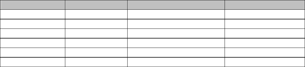
I/O Port Type Q’TY Tested with
1) Audio output port 2 2
4 SUPPORT EQUIPMENT
No. Equipment Model # Serial # Trade Name Data
Cable
Power
Cord
1) NOTEBOOK PC VECTRA
VL420MT CN15100363 HP N/A Unshielded
1.8m
**Note: All the above equipment/cables were placed in worse case positions to maximize emission signals during emission
test.
Grounding: Grounding was in accordance with the manufacturer’s requirements and conditions for the intended use.
Report Number: SZ0801001-E
May 12, 2008
SEC Engineering Service Co., Ltd. Page5 of 24
5 TEST FACILITY
Location: No.1 Workshop, M-10, Middle Section, Science& Technology Park,
Shenzhen, China
Site Accreditation: VCCI:
The 3m Semi-anechoic chamber and Shielded Room (7.5m×4.0m×3.0m)
have been registered in Accordance with the Regulations for Voluntary
Control Measure with Registration No.: R-2197 and C-2383 respectively.
Date of Registration: September 29, 2005. Valid until September 28, 2008.
FCC-Registration No.: 556682
Registered and fully described in a report filed with the (FCC) Federal
Communications Commission. The acceptance letter from the FCC is
maintained in our files. Registration 556682, Aug. 04, 2005.
Industry Canada (IC)
The 3m Semi-anechoic chamber has been registered by Certification and Engineering
Bureau of Industry Canada for radio equipment testing with Registration No.: 6002
Instrument Tolerance: All measuring equipment is in accord with ANSI C63.4 and CISPR 22
requirements that meet industry regulatory agency and accreditation agency
requirement.
Ground Plane: Two conductive reference ground planes were used during the Line Conducted Emission,
one in vertical and the other in horizontal. The dimensions of these ground planes are as below. The
vertical ground plane was placed distancing 40 cm to the rear of the wooden test table on where the EUT and
the support equipment were placed during test. The horizontal ground plane projected 50 cm beyond the
footprint of the EUT system and distanced 80 cm to the wooden test table. For Radiated Emission Test, one
horizontal conductive ground plane extended at least 1m beyond the periphery of the EUT and the largest
measuring antenna, and covered the entire area between the EUT and the antenna. It has no holes or gaps
having longitudinal dimensions larger than one-tenth of a wavelength at the highest frequency of
measurement up to 1GHz.
Report Number: SZ0801001-E
May 12, 2008
SEC Engineering Service Co., Ltd. Page6 of 24
6 TEST EQUIPMENT LIST
Instrumentation: The equipment conforms to the CISPR 16-1 / ANSI C63.2-1988 Specifications for
Electromagnetic Interference and Field Strength Instrumentation from 10 kHz to 1.0 GHz or above.
Equipment used during the tests:
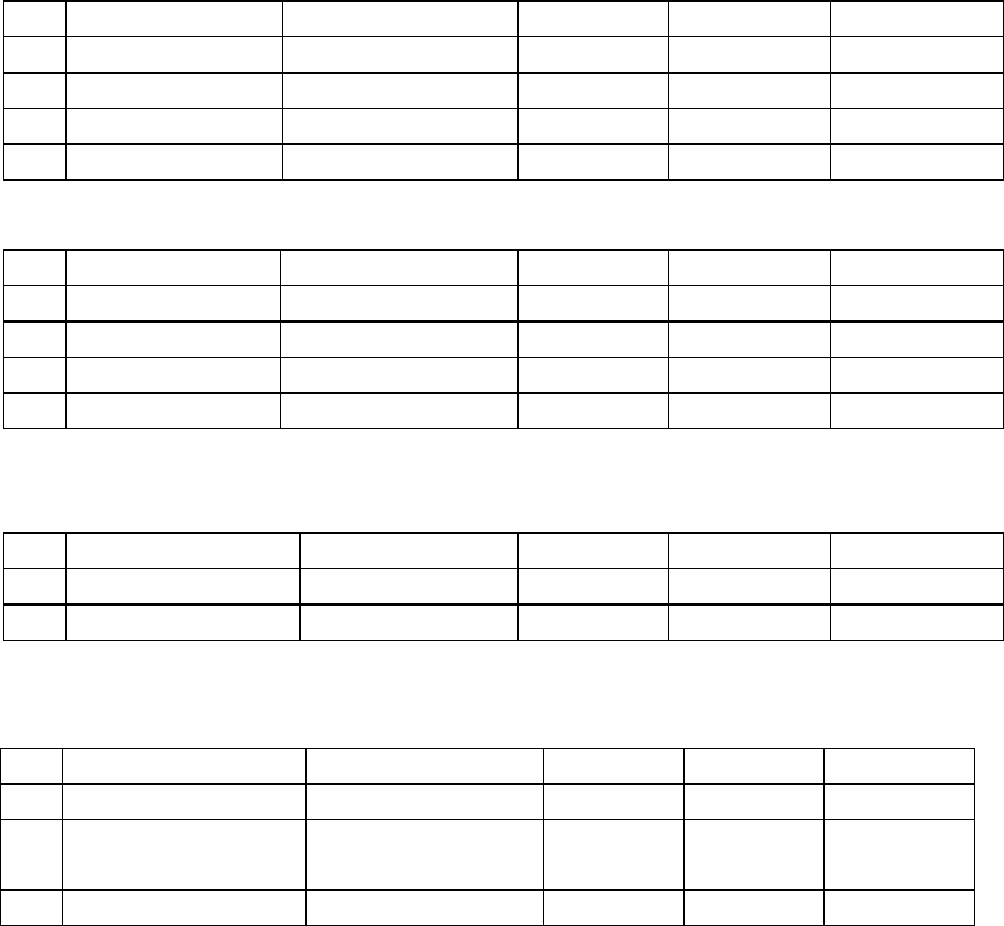
For Conducted Emission Test
Item Equipment Manufacturer Serial No. Last Cal. Cal. Interval
1 L.I.S.N. ETS-LINDGREN 00033512 27-06-2008 26-06-2009
2 EMI Test Receiver Rohde& Schwarz 10019 27-06-2008 26-06-2009
3 Shielding Room ZhongYu Electron SEL0042 N/A N/A
4 Coaxial Cable SGS SEL0024 01-06-2008 30-05-2009
For Radiated Emission Test
Item Equipment Manufacturer Serial No. Last Cal. Cal. Interval
1 EMI Test Receiver Rohde& Schwarz 100249 14-12-2008 13-12-2009
2 BiConiLog Antenna ETS-LINDGREN 00042673 03-08-2008 02-08-2009
3 Double-ridged horn ETS-LINDGREN 00035926 25-12-2008 24-12-2009
4 Amplifier Agilent Technologies 2944A10861 27-06-2008 26-06-2009
For Electrostatic Discharge Immunity Test
Item Equipment Manufacturer Serial No. Last Cal. Cal. Interval
1. ESD Simulator SCHAFFNER 414 14-06-2008 13-06-2009
ESD Ground Plane SGS(3m*3m) SEL0004 N/A N/A
For Conducted Immunity Test
Item Equipment Manufacturer Serial No. Last Cal. Cal. Interval
1. RF-Generator SCHAFFNER 1114 06-09-2008 15-09-2009
2. Coupling/Decoupling
Network SCHAFFNER 21243 03-09-2008 02-09-2009
3. EM CLAMP SCHAFFNER 21029 03-09-2008 02-09-2009
Report Number: SZ0801001-E
May 12, 2008
SEC Engineering Service Co., Ltd. Page7 of 24
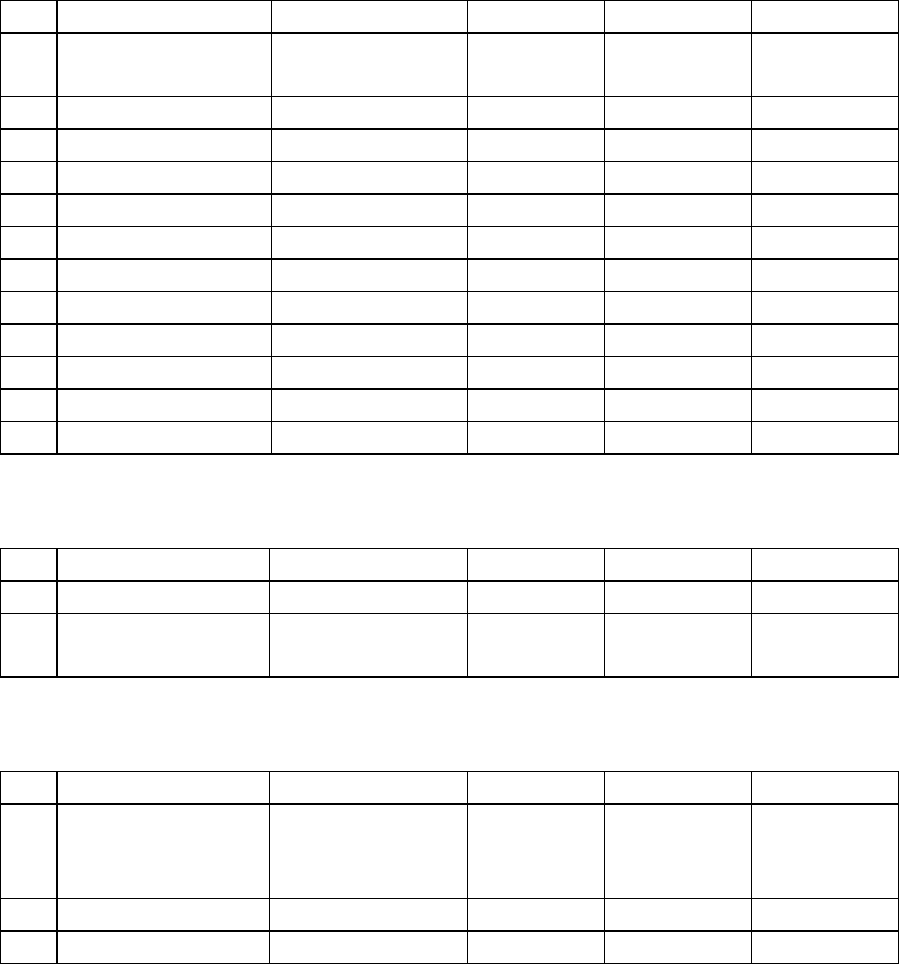
For RF Strength Susceptibility Test
Item Equipment Manufacturer Serial No. Last Cal. Cal. Interval
1. 3m Semi-Anechoic
Chamber ETS-LINDGREN N/A 16-06-2008 15-06-2009
2. Signal Generator Rohde& Schwarz 102319 27-06-2008 26-06-2009
3. Amplifier 30M-1GHz Amplifier Research 312698 03-05-2008 02-05-2009
4. Amplifier 0.8-3.0GHz Amplifier Research 312667 03-05-2008 02-05-2009
5 Power Meter Rohde& Schwarz 101287 27-06-2008 26-06-2009
6 Power Sensor Rohde& Schwarz 100247 27-06-2008 26-06-2009
7 Power Sensor Rohde& Schwarz 100248 27-06-2008 26-06-2009
8 Dual Directional Coupler Amplifier Research 80M-1GHz 05-08-2008 14-08-2009
9 Dual Directional Coupler Amplifier Research 0.8-4.2GHz 05-08-2008 14-08-2009
10 Software EMC32 Rohde& Schwarz SEL0082 N/A N/A
11 Log-periodic Antenna Amplifier Research 311820 N/A N/A
12 Antenna Tripod Amplifier Research 312383 N/A N/A
For Electrical Fast Transient/Burst Immunity, Surge, Voltage dips and Interruptions Test
Item Equipment Manufacturer Serial No. Last Cal. Cal. Interval
1. ProPLUS System Thermo ELECTRON 0412194 09-08-2008 08-08-2009
2 ProPLUS Capacitive
Clamp
Thermo ELECTRON
0501362 11-08-2008 10-08-2009
For General Used Equipment
Item Equipment Manufacturer Serial No. Last Cal. Cal. Interval
1. Temperature, Humidity
& Barometer
OREGON/VAISALA/
TESTO/
ANDTEK
EMC0001 TO
EMC0004
30-08-2008 29-08-2009
2. DMM Mastech SEL0044 20-09-2008 19-09-2009
3. Audio Rohde& Schwarz 100855 20-10-2008 19-10-2009
The calibrations of the measuring instruments, including any accessories that may effect such calibration,
are checked frequently to assure their accuracy. Adjustments are made and correction factors applied in
accordance with instructions contained in the manual for the measuring instrument.
Report Number: SZ0801001-E
May 12, 2008
SEC Engineering Service Co., Ltd. Page8 of 24
7 TEST RESULTS
7.1 LINE CONDUCTED MEASUREMENT PROCEDURE
7.1.1 PRELIMINARY LINE CONDUCTED EMISSION TEST
1) The equipment was set up as per the test configuration to simulate typical actual usage per the user’s manual. When the
EUT is a tabletop system, a wooden table with a height of 0.8 meters is used and is placed on the ground plane as per
EN55022 (see Test Facility for the dimensions of the ground plane used). When the EUT is a floor-standing equipment, it
is placed on the ground plane which has a 3-12 mm non-conductive covering to insulate the EUT from the ground plane.
2) Support equipment, if needed, was placed as per EN55022.
3) All I/O cables were positioned to simulate typical actual usage as per EN55022.
4) The EUT received power from PC, and PC received AC230V/50Hz power through a Line Impedance Stabilization
Network (LISN) which supplied power source and was grounded to the ground plane.
5) All support equipments received power from a second LISN supplying power of AC 230V/50Hz, if any.
6) The EUT test program was started. Emissions were measured on each current carrying line of the EUT using a spectrum
Analyzer / Receiver connected to the LISN powering the EUT. The LISN has two monitoring points: Line 1 (Hot
Side) and Line 2 (Neutral Side). Two scans were taken: one with Line 1 connected to Analyzer / Receiver and Line 2
connected to a 50 ohm load; the second scan had Line 1 connected to a 50 ohm load and Line 2 connected to the
Analyzer / Receiver.
7) Analyzer / Receiver scanned from 150kHz to 30MHz for emissions in each of the test modes.
8) During the above scans, the emissions were maximized by cable manipulation.
9) The following test mode(s) were scanned during the preliminary test:
Preliminary Conducted Emission Test
Frequency Range Investigated 150KHz TO 30 MHz
Mode of operation Date Data Report No. Worst Mode
Then, the EUT configuration and cable configuration of the above highest emission level were recorded for reference of final
testing.
Note: According to this case, this test item needs not to be carried out.
Report Number: SZ0801001-E
May 12, 2008
SEC Engineering Service Co., Ltd. Page9 of 24
7.1.2 FINAL LINE CONDUCTED EMISSION TEST
1) EUT and support equipment was set up on the test bench as per step 9 of the preliminary test.
2) A scan was taken on both power lines, Line 1 and Line 2, recording at least the six highest emissions. Emission frequency
and amplitude were recorded into a computer in which correction factors were used to calculate the emission level and
compare reading to the applicable limit. If EUT emission level was less –2dB to the A.V. limit in Peak mode, then the
emission signal was re-checked using an Average detector.
3) The test data of the worst case condition(s) was reported on the Summary Data page.
LINE CONDUCTED EMISSION LIMIT
Frequency Maximum RF Line Voltage
Q.P.
AVERAGE
150kHz-500kHz 66-56dBuV 56-46dBuV
500kHz-5MHz 56dBuV 46dBuV
5MHz-30MHz 60dBuV 50dBuV
**Note: The lower limit shall apply at the transition frequency.
Report Number: SZ0801001-E
May 12, 2008
SEC Engineering Service Co., Ltd. Page10 of 24
7.2 RADIATED MEASUREMENT PROCEDURE
7.2.1 PRELIMINARY RADIATED EMISSION TEST
1) The equipment was set up as per the test configuration to simulate typical actual usage per the user’s manual. When the
EUT is a tabletop system, a wooden turntable with a height of 0.8 meters is used which is placed on the ground plane as
per EN 55022 (see Test Facility for the dimensions of the ground plane used).When the EUT is a floor-standing
equipment, it is placed on the ground plane which has a 3-12 mm non-conductive covering to insulate the EUT from the
ground plane.
2) Support equipment, if needed, was placed as per EN55022.
3) All I/O cables were positioned to simulate typical actual usage as per EN55022.
4) The EUT received DC power from PC, and PC received AC 230V/50Hz through the outlet socket under the turntable. All
support equipments received AC 230V/50Hz power from socket under the turntable, if any.
5) The antenna was placed at 3 meter away from the EUT as stated in EN55022. The antenna connected to the Analyzer
via a cable and at times a pre-amplifier would be used.
6) The Analyzer / Receiver quickly scanned from 30MHz to 1000MHz. The EUT test program was started. Emissions
were scanned and measured rotating the EUT to 360 degrees and positioning the antenna 1 to 4 meters above the ground
plane, in both the vertical and the horizontal polarization, to maximize the emission reading level.
7) The following test mode(s) were scanned during the preliminary test:
Preliminary Radiated Emission Test
Frequency Range Investigated 30 MHz TO 1000 MHz
Mode of operation Date Data Report No. Worst Mode
Working 01/07/2008 MSX8PRO _0(V,H)
Then, the EUT and cable configuration, antenna position, polarization and turntable position of the above highest
emission level were recorded for final testing.
Report Number: SZ0801001-E
May 12, 2008
SEC Engineering Service Co., Ltd. Page11 of 24
7.2.2 FINAL RADIATED EMISSION TEST
1) EUT and support equipment were set up on the turntable as per step 7 of the preliminary test.
2) The Analyzer / Receiver scanned from 30MHz to 1000MHz. Emissions were scanned and measured rotating the EUT
to 360 degrees, varying cable placement and positioning the antenna 1 to 4 meters above the ground plane, in both the
vertical and the horizontal polarization, to maximize the emission reading level.
3) Recorded at least the six highest emissions. Emission frequency, amplitude, antenna position, polarization and turntable
position were recorded into a computer in which correction factors were used to calculate the emission level and compare
reading to the applicable limit and Q.P./Peak reading is presented.
4) The test data of the worst case condition(s) was reported on the Summary Data page.
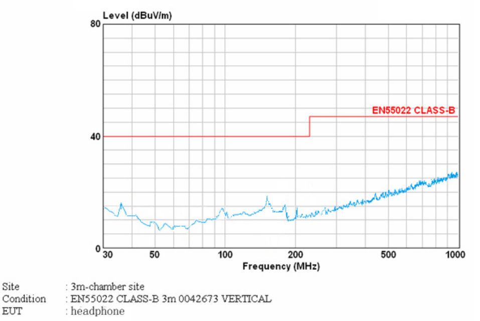
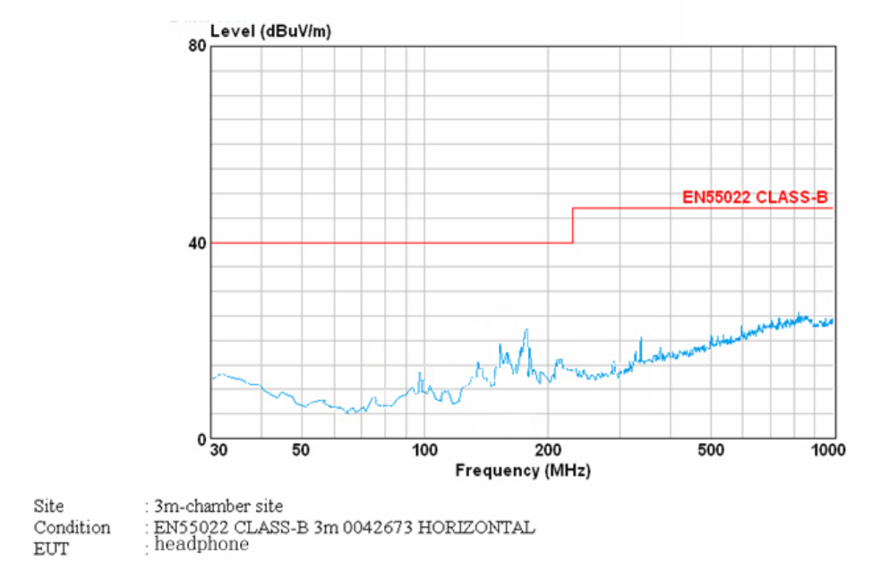
RADIATED EMISSION LIMIT
Frequency
(MHz)
Distance
(m)
Maximum Field Strength Limit
(dBuV/m/ Q.P.)
30-230 3 40
230-1000 3 47
**Note: The lower limit shall apply at the transition frequency.

Report Number: SZ0801001-E
May 12, 2008
SEC Engineering Service Co., Ltd. Page12 of 24
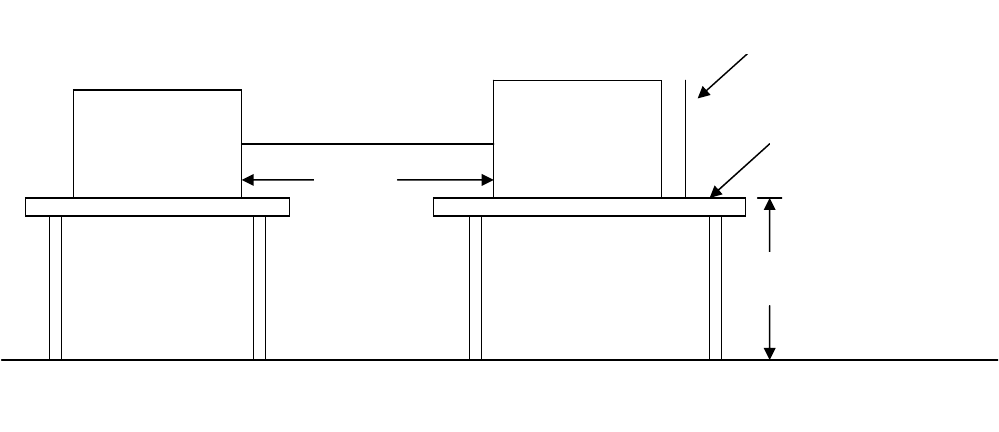
7.2.3 BLOCK DIAGRAM OF TEST SETUP
EUT :
HEADPHONE
Trade Name : NGS
Model Number : MSX8PRO
NOTEBOOK PC
HEADPHONE
(EUT)
Report Number: SZ0801001-E
May 12, 2008
SEC Engineering Service Co., Ltd. Page13 of 24
7.2.4 SUMMARY DATA (RADIATED EMISSION TEST)
Model Number: MSX8PRO Location: Chamber
Tes ted by: Rocky Polar: Vertical
Tes t Mode: Connect to PC Detector Function: Peak/QP
Report Number: SZ0801001-E
May 12, 2008
SEC Engineering Service Co., Ltd. Page14 of 24
Model Number: MSX8PRO Location: Chamber
Tes ted by: Rocky Polar: Horizontal
Tes t Mode: Connect to PC Detector Function: Peak/QP
Report Number: SZ0801001-E
May 12, 2008
SEC Engineering Service Co., Ltd. Page15 of 24
7. 3 ELECTROSTATIC DISCHARGE
7.3.1 ELECTROSTATIC DISCHARGE (ESD) IMMUNITY TEST
Port : Enclosure
Basic Standard : EN61000-4-2
Test Level : ± 8 kV (Air Discharge)
± 4 kV (Contact Discharge)
± 4 kV (Indirect Discharge)
Performance Criteria : A ( Standard require )
Tester :
Rocky
Temperature :
23oC
Humidity :
50%
7.3.2 Block Diagram of Test Setup
( The 470 k ohm resistors are installed per standard requirement )
Ground Reference Plane
Wooden Table
Support units
EUT
&
Support Units
VCP
HCP
>1m
0.8m
Report Number: SZ0801001-E
May 12, 2008
SEC Engineering Service Co., Ltd. Page16 of 24
7.3.3 Test Procedure:
1. The EUT was located 0.1 m minimum from all side of the HCP.
2. Set up the EUT with the support equipment.
3. EUT was loaded and executed in windows XP mode..
4. As per the requirement of EN55024; applying direct contact discharge at the sides other than front of EUT at minimum 50
discharges (25 positive and 25 negative) if applicable, can’t be applied direct contact discharge side of EUT then the indirect
discharge shall be applied. One of the test points shall be subjected to at least 50 indirect discharge (contact) to the front
edge of horizontal coupling plane.
5. Other parts of EUT where it is not possible to perform contact discharge then selecting appropriate points of EUT for air
discharge, a minimum of 10 single air discharges shall be applied.
6. The application of ESD to the contact of open connectors is not required.
7. Putting a mark on EUT to show tested points. The following test condition was followed during the tests.
Note: As per the A2 to EN61000-4-2, a bleed resistor cable is connected between the EUT and HCP
during the test.
The electrostatic discharges were applied as follows:
Amount of Discharges Voltage Coupling Result (Pass/Fail)
Mini 25 /Point ±4kV Contact Discharge Pass
Mini 25 /Point ±4kV Indirect Discharge HCP (Front) Pass
Mini 25 /Point ±4kV Indirect Discharge VCP (Left) Pass
Mini 25 /Point ±4kV Indirect Discharge VCP (Back) Pass
Mini 25 /Point ±4kV Indirect Discharge VCP (Right) Pass
Mini 10 /Point ±8kV Air Discharge Pass

Report Number: SZ0801001-E
May 12, 2008
SEC Engineering Service Co., Ltd. Page17 of 24
7.3.4 Performance & Result:
V Criteria A: The apparatus continues to operate as intended. No degradation of performance or loss of function is
allowed below a performance level specified by the manufacturer, when the apparatus is used as
intended. In some cases the performance level may be replaced by a permissible loss of performance.
Criteria B: The apparatus continues to operate as intended after the test. No degradation of performance or loss
of function is allowed below a performance level specified by the manufacturer, when the apparatus is
used as intended. In some cases the performance level may be replaced by a permissible loss of
performance. During the test, degradation of performance is however allowed.
Criteria C: Temporary loss of function is allowed, provided the functions self recoverable or can be restored by the
operation of controls.
V PASS FAILED
Report Number: SZ0801001-E
May 12, 2008
SEC Engineering Service Co., Ltd. Page18 of 24
7. 4 RADIATED ELECTROMAGNETIC FIELD
7.4.1 RADIATED ELECTROMAGNETIC FIELD IMMUNITY TEST
Port : Enclosure
Basic Standard : EN61000-4-3
Requirements :
3 V/m with 80% AM. 1kHz Modulation.
Performance Criteria : A ( Standard require )
Tester :
Rocky
Temperature :
23oC
Humidity :
50%
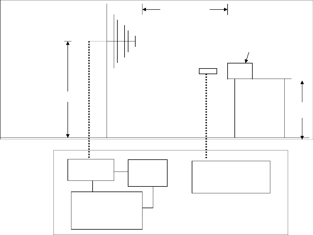
7.4.2 Block Diagram of Test Setup:
3 meter
1.5 meter
Power Amp Signal
Generator
EUT Monitoring by using a
camera
0.8m
Control Ro
om
9X6X6
Chamber
EUT &
Support Units
PC Controller to control
S.G. & PA as well as
forward power
Report Number: SZ0801001-E
May 12, 2008
SEC Engineering Service Co., Ltd. Page19 of 24
7.4.3 Test Procedure:
1. The EUT was located at the edge of supporting table keep 3 meter away from transmitting antenna, it just the calibrated
square area of field uniformity. The support units were located outside of the uniformity area, but the cable(s) connected
with EUT were exposed to the calibrated field as per EN61000-4-3.
2. EUT was loaded and executed in windows XP mode.
3. Setting the testing parameters of RS test software per EN61000-4-3.
4. Performing the pre-test at each side of with double specified level (6V/m) at 4% steps.
5. From the result of pre-test in step 4, choose the worst side of EUT for final test from 80 MHz to 1000 MHz at 1% steps.
6. Recording the test result in following table.
7. It is not necessary to perform test as per annex A of EN 55024 if the EUT doesn’t belong to TTE product.
Preliminary test conditions:
Test level : 6V/m
Steps : 4 % of fundamental
Dwell Time : 1 sec
Range (MHz) Field Modulation Polarity Position (°) Result (Pass/Fail)
80-1000 6V/m Yes H Front Pass
80-1000 6V/m Yes V Front Pass
80-1000 6V/m Yes H Right Pass
80-1000 6V/m Yes V Right Pass
80-1000 6V/m Yes H Back Pass
80-1000 6V/m Yes V Back Pass
80-1000 6V/m Yes H Left Pass
80-1000 6V/m Yes V Left Pass
Final test conditions:
Test level : 3V/m
Steps : 1 % of fundamental
Dwell Time : 1 sec
Range (MHz) Field Modulation Polarity Position (°) Result (Pass/Fail)
80-1000 3V/m Yes H Right Pass
80-1000 3V/m Yes V Right Pass
Report Number: SZ0801001-E
May 12, 2008
SEC Engineering Service Co., Ltd. Page20 of 24
7.4.4 Performance & Result
V Criteria A: The apparatus continues to operate as intended. No degradation of performance or loss of function is
allowed below a performance level specified by the manufacturer, when the apparatus is used as
intended. In some cases the performance level may be replaced by a permissible loss of performance.
Criteria B: The apparatus continues to operate as intended after the test. No degradation of performance or loss
of function is allowed below a performance level specified by the manufacturer, when the apparatus is
used as intended. In some cases the performance level may be replaced by a permissible loss of
performance. During the test, degradation of performance is however allowed.
Criteria C: Temporary loss of function is allowed, provided the functions self-recoverable or can be restored by the
operation of controls.
V PASS FAILED
Report Number: SZ0801001-E
May 12, 2008
SEC Engineering Service Co., Ltd. Page21 of 24
8 PHOTOGRAPHS
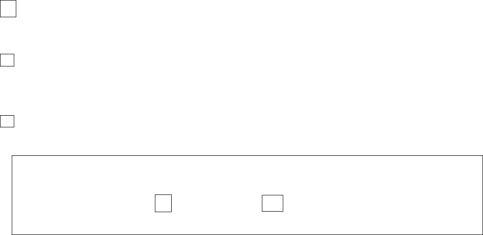
8.1 PHOTOGRAPHS OF TEST SETUP
RADIATED EMISSION TEST (EN 55022)
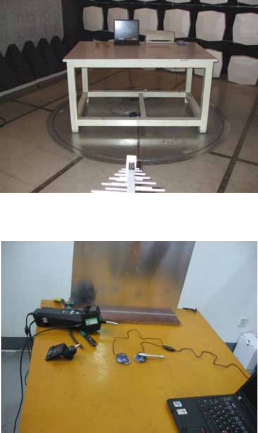
ELECTROSTATIC DISCHARGE TEST (EN 61000-4-2)
Report Number: SZ0801001-E
May 12, 2008
SEC Engineering Service Co., Ltd. Page22 of 24
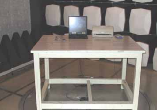
RADIATED ELECTROMAGNETIC FIELD (EN 61000-4-3)
Report Number: SZ0801001-E
May 12, 2008
SEC Engineering Service Co., Ltd. Page23 of 24
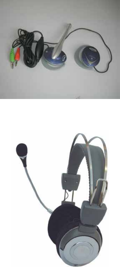
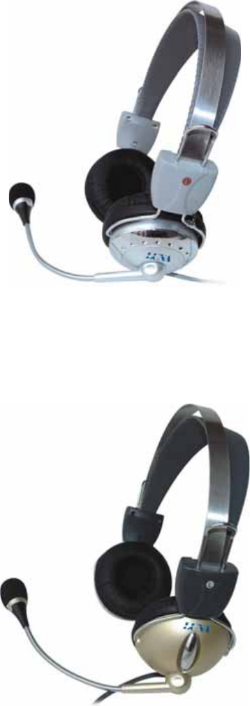
8.2 PHOTOGRAPHS OF EUT
Report Number: SZ0801001-E
May 12, 2008
SEC Engineering Service Co., Ltd. Page24 of 24
