EN 55022_v. 2006 179102 CE Certification Magic Control
2016-04-06
: Pdf 179102 Ce Certification Magic Control 179102_CE_certification--Magic_Control CertsReports 179102 ProductFiles
Open the PDF directly: View PDF ![]() .
.
Page Count: 57
of
Applicant: Magic Control Technology Corporation
Address: 6F, No.120-11,Sec.3, Jhongshan Rd., Jhonghe City, Taipei 235, Taiwan, R.O.C.
Tested and Prepared
by
ETS Product Service (Taiwan) Co., Ltd.
FCC Registration No.: 930600
Industry Canada filed test laboratory Reg. No. IC 5679
A2LA Accredited No.: 2300.01
PTCRB Accredited Type Certification Test House
Report No.: W6M20709-8534-E-11
6F, NO. 58, LANE 188, RUEY-KUANG RD., NEIHU TAIPEI 114, TAIWAN, R.O.C.
TEL: 886-2-66068877 FAX: 886-2-66068879 E-mail: ets@ets-bzt.com.tw
CE TEST REPORT
for
USB 2.0 Graphic Dock
Model No.: UVAD200
COPY

Registration number: W6M20709-8534-E-11
ETS Product Service (Taiwan) Co., Ltd.
6F, NO. 58, LANE 188, RUEY-KUANG RD., NEIHU, TAIPEI 114, TAIWAN, R.O.C. Page 1 of 36
Testing laboratory
Location
ETS Product Service (Taiwan) Co., Ltd.
OATS
No.5-1, Shuang Sing Village,
LiShuei Rd., Wanli Township,
Taipei County 207, Taiwan (R.O.C.)
Company
ETS Product Service (Taiwan) Co., Ltd.
6F, NO. 58, LANE 188, RUEY-KUANG RD.
NEIHU, TAIPEI 114, TAIWAN R.O.C.
Tel : 886-2-66068877
Fax : 886-2-66068879
Test location, where different from ETS Product Service (Taiwan) Co., Ltd.
Name : ./.
Street : ./.
Town : ./.
Country : ./.
Telephone : ./.
Fax : ./.
Details of applicant
Name : Magic Control Technology Corporation
Street : 6F, No. 120-11, Sec. 3, Jhongshan Rd., Jhonghe City,
Town : Taipei 235,
Country : Taiwan, R.O.C.
Telephone : +886-2-3234-6616
Fax : +886-2-3234-6606
Test item
Description of test item
Type of product : USB 2.0 Graphic Dock
Type identification : UVAD200
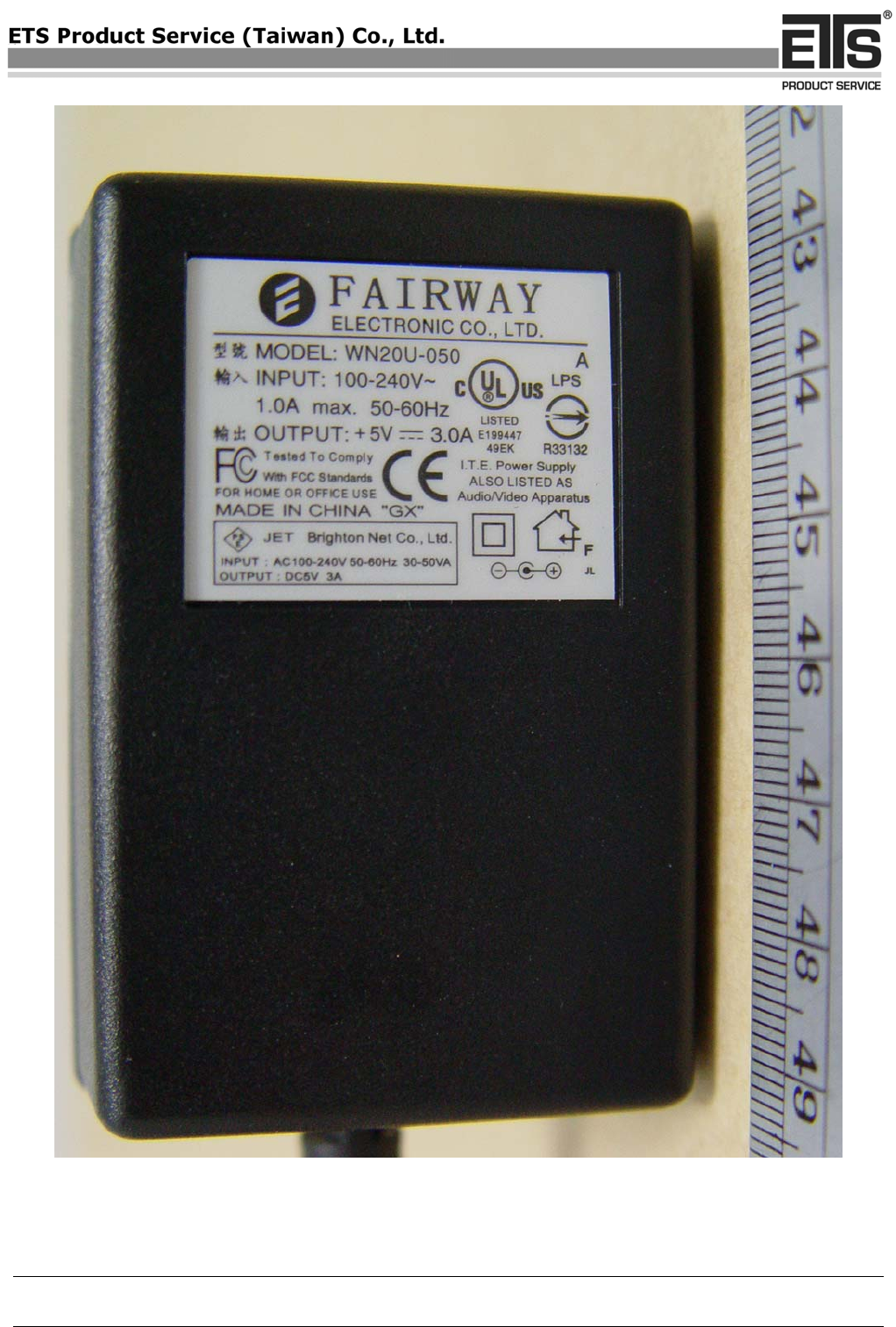
Input : 100-240VAC 1.0A 50-60Hz
Power supply
Output : 5VDC 3.0A
Test Standards
EN 55022 Class B (2006),
IEC/EN 61000-3-2 (2006), IEC/EN 61000-3-3 (1995+A1:2001+A2:2005)
EN 55024 (1998+A1 :2001+A2 :2003), (IEC/EN61000-4-2 (1995+A1:1998+A2: 2001)
/-3 (2006)/-4(2004)/-5(2006)/-6 (1996+A1: 2001)/-11 (2004))
Special statement: The standards applied to this test sample were under the demand of the
applicant. Any deviation from the applicable product standards is the responsibility of the
applicant. T-LISN does not need to test is according to customer’s request.
COPY
Registration number: W6M20709-8534-E-11
ETS Product Service (Taiwan) Co., Ltd.
6F, NO. 58, LANE 188, RUEY-KUANG RD., NEIHU, TAIPEI 114, TAIWAN, R.O.C. Page 2 of 36
Electro - Magnetic Compatibility
Test - Result
Device : USB 2.0 Graphic Dock
Model No : UVAD200
Manufacturer : Magic Control Technology Corporation
6F, No. 120-11, Sec. 3, Jhongshan Rd., Jhonghe City, Taipei 235, Taiwan, R.O.C.
: 1st test test after modification production test
Test
Emission / Immunity
Done
Test
passed
Test
failed
Emission
Conducted Emission
EN 55022 Class B (2006)
:
:
Emission
Radiated Emission
EN 55022 Class B (2006)
:
:
Harmonics
Current Harmonics
IEC/EN 61000 - 3 - 2 (2006)
:
:
Flicker
Voltage Fluctuations
IEC/EN 61000 - 3 - 3 (1995+A1:2001+A2:2005)
:
:
ESD
Electrostatic Discharge
IEC/EN 61000 - 4 - 2 (1995+A1:1998+A2: 2001)
:
:
RF - Field
Radiated Immunity
IEC/EN 61000 - 4 - 3 (2006)
:
:
Burst
Electrical Fast Transients
IEC/EN 61000 - 4 - 4 (2004)
:
:
Surge
Transients comm.& diff.mode
IEC/EN 61000 - 4 - 5 (2006)
:
:
RF-common
mode
RF continues conducted
IEC/EN 61000 - 4 - 6 (1996+A1: 2001)
:
:
V-dips
Voltage dips and Interruption IEC/EN 61000 - 4 - 11 (2004)
:
:
Technical responsibility for area of testing: Tester:
________________________ _________________
Issue Date: October 09, 2007 October 09, 2007
Note:
1. The result of this test report is valid only in connection to the sample has been tested at the laboratory of ETS Product
Service (Taiwan) Co., Ltd.
2. This test report shall always be duplicated in full pages unless the written approval of the testing laboratory is obtained.
COPY

Registration number: W6M20709-8534-E-11
ETS Product Service (Taiwan) Co., Ltd.
6F, NO. 58, LANE 188, RUEY-KUANG RD., NEIHU, TAIPEI 114, TAIWAN, R.O.C. Page 3 of 36
Test equipment utilized
No. Test equipment Type Serial No. Manufacturer Cal. Date Next Cal.
Date
ETSTW-CE 001 EMI TEST RECEIVER ESHS10 842121/013 R&S 2007/10/15 2008/10/14
ETSTW-CE 002 PREREULATOR MODE DC
POWER SUPPLY None None Function Test
ETSTW-CE 003 AC POWER SOURCE APS-9102 D161137 GW Function Test
ETSTW-CE 004 ZWEILEITER-V-
NETZNACHBILDUNG TWO-
LINE V-NETWORK ESH3-Z5 840731/011 R&S 2007/10/15 2008/10/14
ETSTW-CE 005 Line-Impedance Stabilisation
Network NNBM 8126D 137 Schwarzbeck 2007/10/15 2008/10/14
ETSTW-CE 006 IMPULSBEGRENZER PULSE
LIMITER ESH3-Z2 100226 R&S In House Certificate
ETSTW-CE 008 ABSORBING CLAMP MDS 21 3469 Schwarzbeck 2005/10/24 2007/10/23
ETSTW-CE 009 TEMP.&HUMIDITY CHAMBER GTH-225-40-1P-U MAA0305-009 GIANT FORCE 2007/8/2 2008/8/1
ETSTW-CE 013 CISPR 22 TWO BALANCED
TELECOM PAIRS IMPEDANCE
STABILIZATION NETWORK FCC-TLISN-T4-02 20242 FCC 2005/12/8 2007/12/7
ETSTW-CE 014 CISPR 22 TWO BALANCED
TELECOM PAIRS IMPEDANCE
STABILIZATION NETWORK FCC-TLISN-T2-02 20241 FCC 2005/12/7 2007/12/6
ETSTW-CE 015 CISPR 22 TWO BALANCED
TELECOM PAIRS IMPEDANCE
STABILIZATION NETWORK FCC-TLISN-T8-02 20307 FCC 2006/11/7 2008/11/6
ETSTW-CE 016 TWO-LINE V-NETWORK ENV216 100050 R&S 2006/11/21 2007/11/20
ETSTW-CS 003 COUPLING AND DECOUPLING
NETWORK CDN T400 19820 SCHAFFNER 2007/10/13 2008/10/12
ETSTW-CS 004 COUPLING AND DECOUPLING
NETWORK CDN M016 20053 SCHAFFNER 2007/10/9 2008/10/8
ETSTW-CS 005 RF Power Amplifier 100A250A 306547 AR 2007/10/9 2008/10/8
ETSTW-CS 008 6 dB Attenautor HFP-5100-3/06 N
M/F 2010876106 In House Certificate
ETSTW-RE 002 Function Generator 33220A MY43004982 Agilent 2007/10/13 2009/10/12
ETSTW-RE 003 EMI TEST RECEIVER ESI 26 831438/001 R&S 2006/10/20 2007/10/19
ETSTW-RE 004 EMI TEST RECEIVER ESI 40 832427/004 R&S 2006/10/30 2007/10/29
ETSTW-RE 005 EMI TEST RECEIVER ESVS10 843207/020 R&S 2007/10/11 2008/10/12
ETSTW-RE 010 PROGRAMMABLE LINEAR
POWER SUPPLY LPS-305 30503070181 MOTECH Function Test
ETSTW-RE 011 PROGRAMMABLE LINEAR
POWER SUPPLY LPS-305 30503070165 MOTECH Function Test
ETSTW-RE 017 Log-Periodic Antenna HL025 352886/001 R&S 2006/5/4 2008/5/3
ETSTW-RE 018 MICROWAVE HORN
ANTENNA AT4560 27212 AR 2004/11/8 2007/11/7
ETSTW-RE 020 MICROWAVE HORN
ANTENNA AT4002A 306915 AR Function Test
ETSTW-RE 021 SWEEP GENERATOR SWM05 835130/010 R&S 2007/10/9 2008/10/8
ETSTW-RE 027 Passive Loop Antenna 6512 00034563 EMCO In House Certificate
ETSTW-RE 028 Log-Periodic DipoleArray Antenna 3148 34429 EMCO 2006/5/26 2008/5/25
ETSTW-RE 029 Biconical Antenna 3109 33524 EMCO 2006/5/26 2008/5/25
ETSTW-RE 030 Double-Ridged Guide Horn
Antenna 3117 00035224 EMCO 2006/5/3 2008/5/2
ETSTW-RE 032 Millivoltmeter URV 55 849086/013 R&S 2007/10/9 2008/10/8
COPY
Registration number: W6M20709-8534-E-11
ETS Product Service (Taiwan) Co., Ltd.
6F, NO. 58, LANE 188, RUEY-KUANG RD., NEIHU, TAIPEI 114, TAIWAN, R.O.C. Page 4 of 36
ETSTW-RE 033 WaveRunner 6000A Serise
Oscilloscope WAVERUNNER
6100A LCRY0604P14508 LeCroy 2007/7/9 2008/7/8
ETSTW-RE 034 Power Sensor URV5-Z4 839313/006 R&S 2007/10/16 2008/10/15
ETSTW-RE 042 Biconical Antenna HK116 100172 R&S 2007/1/11 2009/1/10
ETSTW-RE 043 Log-Periodic Dipole Antenna HL223 100166 R&S 2006/5/8 2008/5/7
ETSTW-RE 044 Log-Periodic Antenna HL050 100094 R&S 2006/5/29 2008/5/28
ETSTW-RE 048 Triple Loop Antenna HXYZ 9170 HXYZ 9170-134 Schwarzbeck 2005/3/22 2008/3/21
ETSTW-RE 049 TRILOG Super Broadband test
Antenna VULB 9160 9160-3185 Schwarzbeck 2007/5/2 2009/5/1
ETSTW-RE 055 SPECTRUM ANALYZER FSU-26 200074 R&S 2007/7/16 2008/7/15
ETSTW-RE 064 Bluetooth Test Set MT8852B-042 6K00005709 Anritsu Function Test
ETSTW-RE 072 CELL SITE TEST SET 8921A 3339A00375 HP 2007/7/2 2009/7/1
ETSTW-EMI 001 HARMONICS 1000 HAR 1000-1P 093 EMC-PARTNER 2007/9/11 2008/9/10
ETSTW-EMS 001 BASELSTRASSE 160 CH-4242
LAUFEN CN-EFT1000 354 EMC-PARTNER 2004/11/2 2007/11/1
ETSTW-EMS 002 Frequency Converter YF-6020 308014 T-Power Function Test
ETSTW-EMS 003 EMC Immunity Test System TRA2000IN6 579 EMC-PARTNER 2006/11/8 2007/11/7
ETSTW-EMS 004 ESD Simulator ESD2000 16 EMC-PARTNER 2007/10/17 2008/10/16
ETSTW-EMS 008 Safety Test Solutions ELT-400 E-0039 Narda 2005/5/4 2008/5/3
ETSTW-EMS 009 Magnetic Field Antenna MF1000-1 104 EMC-PARTNER 2004/12/3 2007/12/2
ETSTW-EMS 010 Coupling De-coupling Network CDN-UTP8 14 EMC-PARTNER 2005/9/1 2008/8/31
ETSTW-EMS 011 Calibration Ficture F-203I-CF-23MM 451 FCC 2006/7/29 2008/7/28
ETSTW-EMS 012 EM Injection Clamp F-203I-23MM 476 FCC 2006/7/29 2008/7/28
ETSTW-EMS 014 Digital Thermo-Hygro Meter 0507 02 WISEWIND 2005/11/15 2007/11/14
ETSTW-RS 003 RF Power Amplifier 30S1G3 306933 AR 2007/10/9 2008/10/8
ETSTW-RS 004 RF Power Amplifier 150W1000 307009 AR 2007/10/9 2008/10/8
ETSTW-RS 005 Electric Field Probe Type 8.3 2244/90.21 AF-0016 Narda 2007/9/3 2009/9/2
ETSTW-RS 006 SIGNAL GENERATOR SML03 101551 R&S 2007/10/8 2008/10/7
ETSTW-RS 007 14" COLOR VIDEO MONITOR HS-CM145A 0512011548 Function Test
COPY

Registration number: W6M20709-8534-E-11
ETS Product Service (Taiwan) Co., Ltd.
6F, NO. 58, LANE 188, RUEY-KUANG RD., NEIHU, TAIPEI 114, TAIWAN, R.O.C. Page 5 of 36
Spurious Emission (EN 55022)
Test Equipment
a) Biconical Antenna (HK116)
For your reference please find it in our test equipment list at page 3 to 4 as number : ETSTW-RE 042
b) Log-Periodic Dipole Antenna (HL223)
For your reference please find it in our test equipment list at page 3 to 4 as number : ETSTW-RE 043
c) TRILOG Super Broadband test Antenna (VULB 9160)
For your reference please find it in our test equipment list at page 3 to 4 as number : ETSTW-RE 049
d) SIGNAL GENERATOR (SML03)
For your reference please find it in our test equipment list at page 3 to 4 as number : ETSTW-RS 006
e) EMI TEST RECEIVER (ESI 26)
For your reference please find it in our test equipment list at page 3 to 4 as number : ETSTW-RE 003
f) EMI TEST RECEIVER (ESI 40)
For your reference please find it in our test equipment list at page 3 to 4 as number : ETSTW-RE 004
Test Procedures
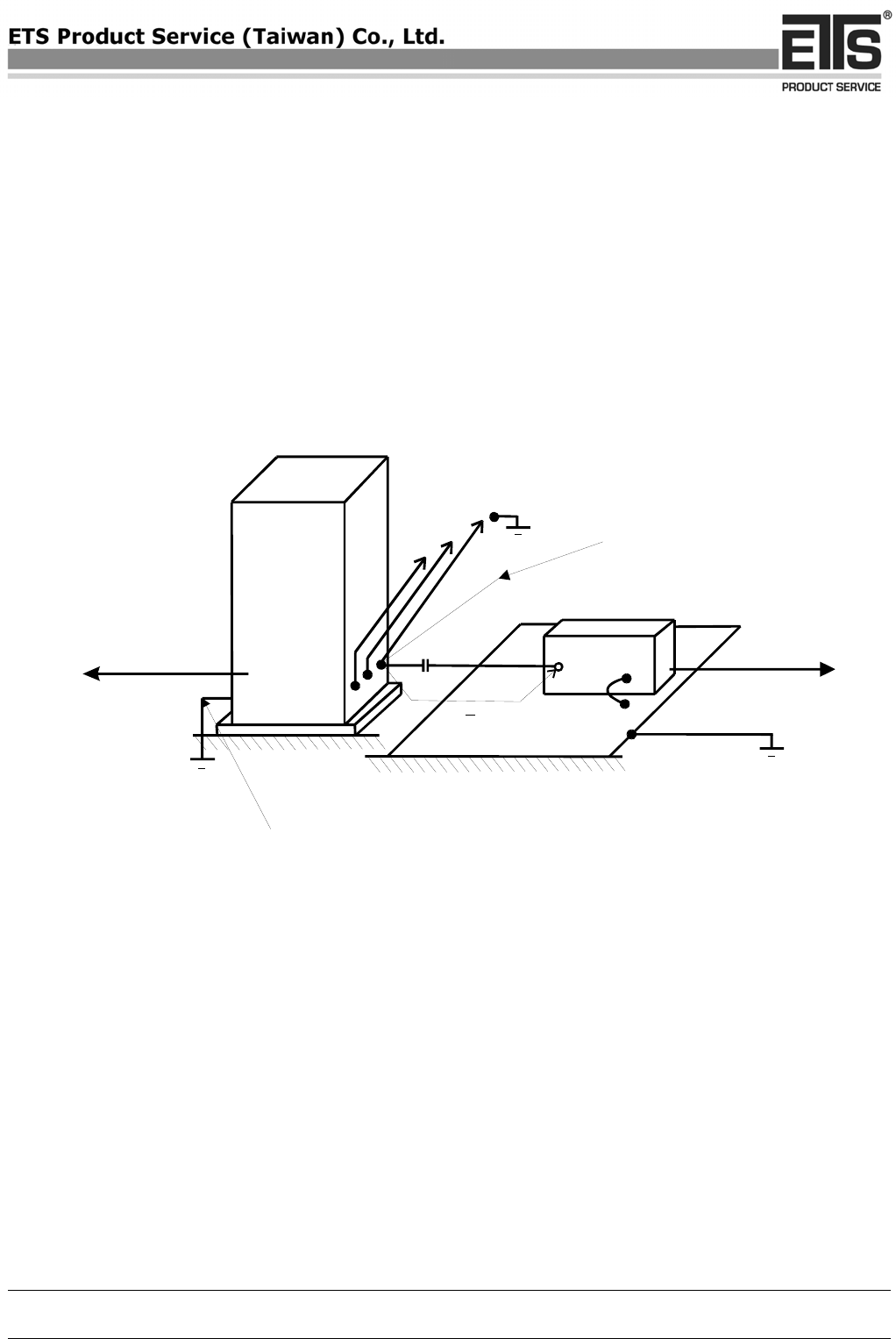
• Test configuration
The test configuration corresponds to the standard EN 55022. The equipment under test is placed on a
non metallic table with 0,8m height. The power supply and the RF connection points are close to the
equipment under test at the floor inside a connection box. The cables to this connection box are shielded
and below the double floor. The receiving antenna is placed in a height at 1,0m to 4,0m, in a distance of
10m. The measurement receiver is placed in a special room. (see picture 1) The observation of the
equipment under test is realized by 3 video cameras and by a microphone.
• Test parameters and marginal conditions
The test is carried out with horizontal and vertical polarisation of the antenna in a frequency range of 30
MHz to 1000 MHz. Further information please find in the test protocol.
COPY
Registration number: W6M20709-8534-E-11
ETS Product Service (Taiwan) Co., Ltd.
6F, NO. 58, LANE 188, RUEY-KUANG RD., NEIHU, TAIPEI 114, TAIWAN, R.O.C. Page 6 of 36
Radiated Emission accordin
g
to
EN 55022
10 cm
40 cm
min.
Non-conductive table
EUT
EUT = Equipment under test
80 cm
to the
ground
plane
3
Ferrite clamp
11
1
1 =
Picture 1
COPY

Registration number: W6M20709-8534-E-11
ETS Product Service (Taiwan) Co., Ltd.
6F, NO. 58, LANE 188, RUEY-KUANG RD., NEIHU, TAIPEI 114, TAIWAN, R.O.C. Page 7 of 36
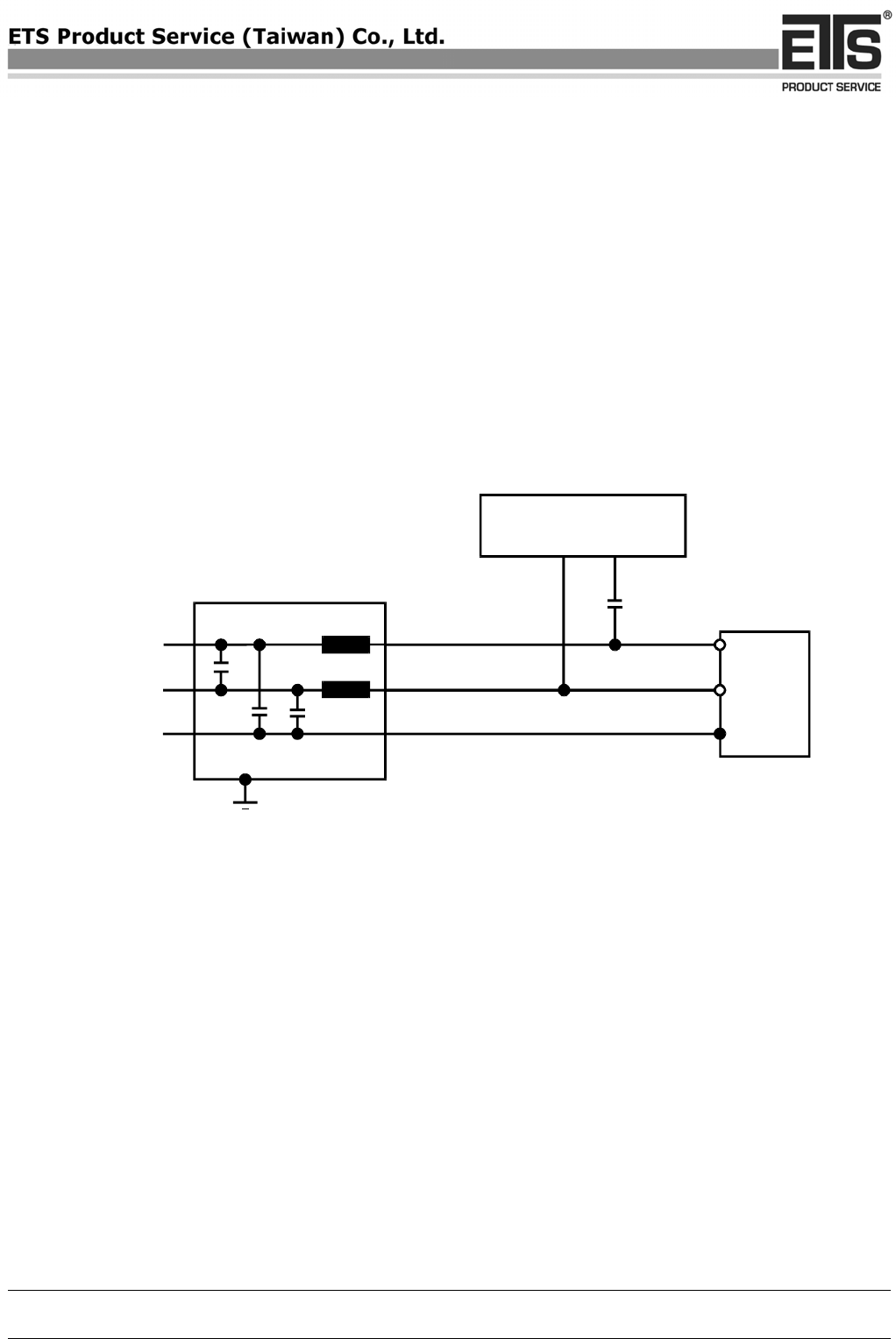
Conducted Emission (EN 55022)
Test Equipment
a) ZWEILEITER-V-NETZNACHBILDUNG TWO-LINE V-NETWORK (ESH3-Z5)
For your reference please find it in our test equipment list at page 3 to 4 as number : ETSTW-CE 004
b) IMPULS-BEGRENZER PULSE LIMITER (ESH3-Z2)
For your reference please find it in our test equipment list at page 3 to 4 as number : ETSTW-CE 006
c) EMI TEST RECEIVER (ESHS10)
For your reference please find it in our test equipment list at page 3 to 4 as number : ETSTW-CE 001
d) AC Power Source (APS-9102)
For your reference please find it in our test equipment list at page 3 to 4 as number : ETSTW-CE 003
e) CISPR 22 Two Balanced Telecom Pairs Impedance Stabilization Network (FCC-TLISN-T4-02)
For your reference please find it in our test equipment list at page 3 to 4 as number : ETSTW-CE 013
f) CISPR 22 Two Balanced Telecom Pairs Impedance Stabilization Network (FCC-TLISN-T2-02)
For your reference please find it in our test equipment list at page 3 to 4 as number : ETSTW-CE 014
g) CISPR 22 Two Balanced Telecom Pairs Impedance Stabilization Network (FCC-TLISN-T8-02)
For your reference please find it in our test equipment list at page 3 to 4 as number : ETSTW-CE 015
Test Procedures
• Test configuration
The test configuration is contained inside of a shielded chamber and corresponds to the standard
EN 55022. The equipment under test is placed in the facility on a wooden table 0.8m high. The
equipment under test is connected with the artificial mains network (AMN) in a distance of 0,8m and
also 0,8m from other subassembly and metallic area. (see picture 2) The observation of the equipment
under test is realized by 3 video cameras and by a microphone.
• Test parameters and marginal conditions
The test is carried out with nominal impedance by 50Ω / 50μH of the AMN in a frequency range 150
kHz to 30 MHz. Further information please find in test report.
COPY
Registration number: W6M20709-8534-E-11
ETS Product Service (Taiwan) Co., Ltd.
6F, NO. 58, LANE 188, RUEY-KUANG RD., NEIHU, TAIPEI 114, TAIWAN, R.O.C. Page 8 of 36
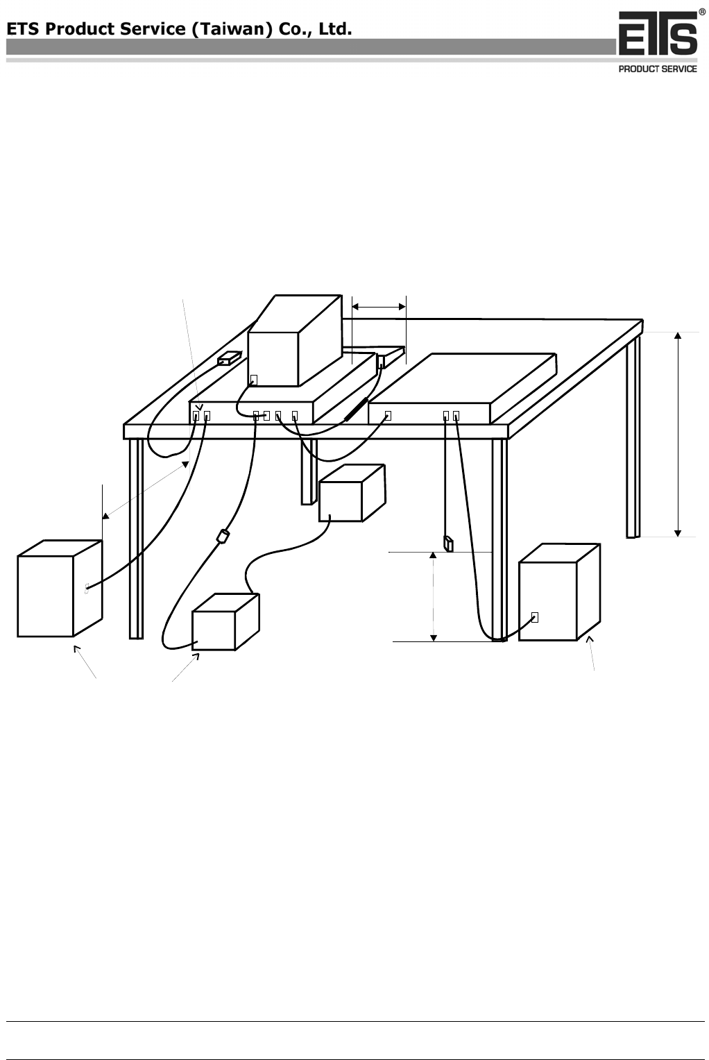
Picture 2
80 cm
to the
ground
table
80 cm
10 cm
40 cm
min
Conducted Emission according to
EN 55022
EUT
AMN
AMN
ISN
AE
Non-conductive table
Bonded to horizontal ground
planeBonded to horizontal ground
plane
Rear of EUT to flushed with
rear of taple top
AMN = Artificial mains network
AE = Associated equipment
EUT = Equipment under test
ISN = Impedance stabiliyation network
COPY

Registration number: W6M20709-8534-E-11
ETS Product Service (Taiwan) Co., Ltd.
6F, NO. 58, LANE 188, RUEY-KUANG RD., NEIHU, TAIPEI 114, TAIWAN, R.O.C. Page 9 of 36
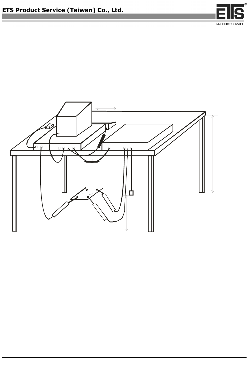
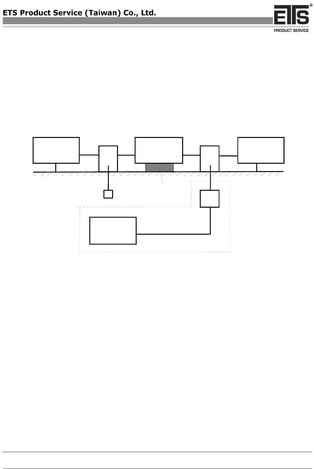
Harmonic Current Emission /Voltage Fluctuations and Flicker (IEC/EN 61000-3-2/-3)
Test Equipment
a) HARMONICS 1000 (HAR 1000-1P)
For your reference please find it in our test equipment list at page 3 to 4 as number : ETSTW-EMI 001
b) Frequency Converter (YF-6020)
For your reference please find it in our test equipment list at page 3 to 4 as number : ETSTW-EMS 002
Test Procedures
• Test configuration
The test configuration is correspondence to the standard IEC/EN 61000-3-2/-3. The equipment under
test is placed on a wooden table with a height of 0,8m in the EMC lab.
• Test parameters and marginal conditions
The harmonic test are carried out in according the classification A, B, C, D of the standard
IEC/EN 61000-3-2. The flicker test are carried out in according the time interval of the standard
IEC/EN 61000-3-3. Both tests are carried out with above mentioned equipment with 230V and 50 Hz.
(see picture 3) Further information please find in test protocol.
COPY
Registration number: W6M20709-8534-E-11
ETS Product Service (Taiwan) Co., Ltd.
6F, NO. 58, LANE 188, RUEY-KUANG RD., NEIHU, TAIPEI 114, TAIWAN, R.O.C. Page 10 of 36
Picture 3
S supply source
M measuring equipment
EUT equipment under test
U test voltage
Z input impedance of the measuring equipment
Z internal impedance of the supply source
I upper shrinkage portion of the conduction current order
G open-circuit voltage of the supply source
M
S
n
S
U
Z
s
M
Z
M
I
N
~
EUT
G
Current Harmonics and Flicker
according to
EN 61000 - 3 - 2,
EN 61000 - 3 - 3
COPY

Registration number: W6M20709-8534-E-11
ETS Product Service (Taiwan) Co., Ltd.
6F, NO. 58, LANE 188, RUEY-KUANG RD., NEIHU, TAIPEI 114, TAIWAN, R.O.C. Page 11 of 36
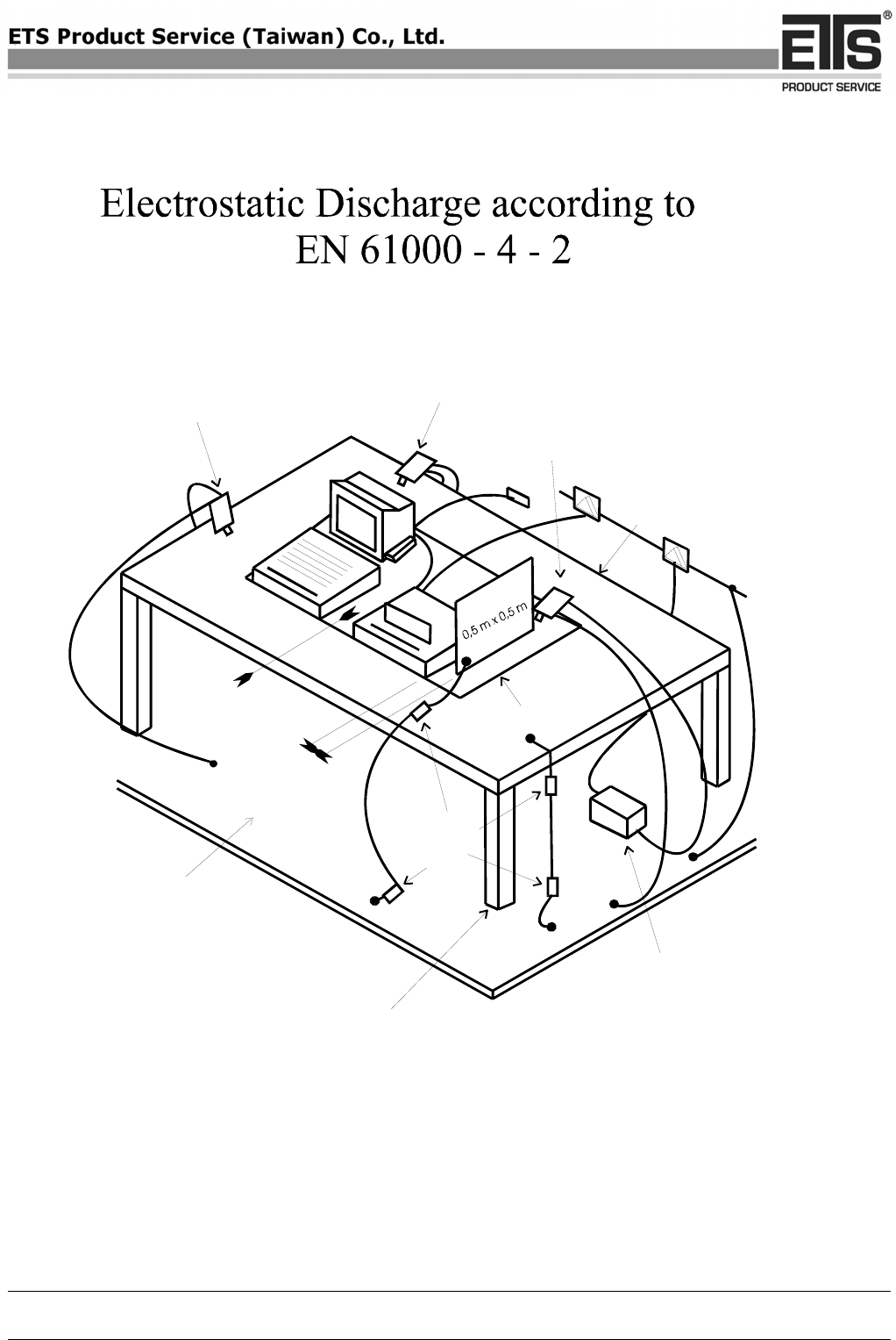
Electrostatic Discharge
Test Equipment
a) ESD Simulator (ESD2000)
For your reference please find it in our test equipment list at page 3 to 4 as number : ETSTW-EMS 004
b) EMC Immunity Test System (TRA2000IN6)
For your reference please find it in our test equipment list at page 3 to 4 as number : ETSTW-EMS 003
c) Frequency Converter (YF-6020)
For your reference please find it in our test equipment list at page 3 to 4 as number : ETSTW-EMS 002
Test Procedures
• Test configuration
The test configuration is in correspondence to the standard IEC/EN 61000-4-2. The equipment under
test is placed on a wooden table with one metal plate on its top and one metal plate under the table,
which is grounded. Both plates are connected with two 470 kΩ resistor in series. (see picture 4)
• Test parameters and marginal conditions
The test is carried out with ±2kV, ±4kV contact discharge and ±2kV, ±4kV and ±8kV air discharge.
Time between two discharges > 1 second
Ten discharges for every point every voltage and polarity
The tested points please find in the test protocol.
COPY
Registration number: W6M20709-8534-E-11
ETS Product Service (Taiwan) Co., Ltd.
6F, NO. 58, LANE 188, RUEY-KUANG RD., NEIHU, TAIPEI 114, TAIWAN, R.O.C. Page 12 of 36
0,1 m
0,1 m
Ω
Typical position for indirect
discharge to HCP
Typical position for
direct application
Typical position for
indirect discharge to
VCP Horizontal coupling plane
(HCP)
1,6 m x 0,8 m
Insulation
Resistor
470k
Power supply
Ground reference
plane
Wooden table
H = 0,8 m
Picture 4
COPY

Registration number: W6M20709-8534-E-11
ETS Product Service (Taiwan) Co., Ltd.
6F, NO. 58, LANE 188, RUEY-KUANG RD., NEIHU, TAIPEI 114, TAIWAN, R.O.C. Page 13 of 36
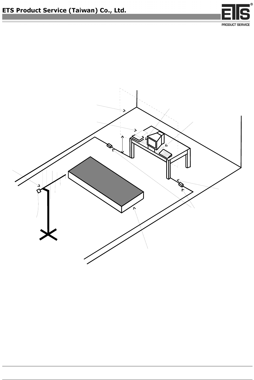
RF Electromagnetic Field (80-1000 MHz)
Test Equipment
a) Biconical Antenna (3109)
For your reference please find it in our test equipment list at page 3 to 4 as number: ETSTW-RE 029
b) Log-Periodic Dipole Antenna (HL223)
For your reference please find it in our test equipment list at page 3 to 4 as number: ETSTW-RE 043
c) MICROWAVE HORN ANTENNA (AT4560)
For your reference please find it in our test equipment list at page 3 to 4 as number: ETSTW-RE 018
d) Biconical Antenna (HK116)
For your reference please find it in our test equipment list at page 3 to 4 as number: ETSTW-RE 042
e) SIGNAL GENERATOR (SML03)
For your reference please find it in our test equipment list at page 3 to 4 as number: ETSTW-RS 006
f) RF Power Amplifier (150W1000)
For your reference please find it in our test equipment list at page 3 to 4 as number: ETSTW-RS 004
g) Electric Field Probe Type 8.3 (EMR-20)
For your reference please find it in our test equipment list at page 3 to 4 as number: ETSTW-RS 005
h) Millivoltmeter (URV 55)
For your reference please find it in our test equipment list at page 3 to 4 as number: ETSTW-RE 032
i) Power Sensor (URV5-Z4)
For your reference please find it in our test equipment list at page 3 to 4 as number: ETSTW-RE 034
Test Procedures
• Test configuration
The test configuration is contained inside of a shielded chamber and corresponds to the standard
IEC/EN 61000-4-3. The equipment under test is placed in the facility on a wooden table 0.8m high on
the centre axis of the chamber. The power supply and the RF connection points are close to the
equipment under test at the floor of the chamber inside a connection box. The cables to this connection
box are shielded and below the double floor. The transmitting antenna is placed in a height of 1.5m, in a
distance of 3.0m. The RF-generators are placed in a special room adjacent to the chamber. (see picture 5)
The observation of the equipment under test is realized by 3 video cameras and by a microphone. In
order to establish the severity of the test for EUTs an wires which must be tested close to the earth
reference plane or which have larger sides than 1,5m x 1,5 m, the intensity of the field is also recorded
at 0,4 m height, and for the full width and height of the EUT.
• Test parameters and marginal conditions
The tests are carried out with field strength by 3 V/m (measured in the un-modulated field) with
amplitude modulated signal by a depth of 80 % by a sinusoidal audio signal of 1 kHz. The logarithmic
step was 1% and the dwell time was 1s dependent of the EUT cycle time. Further information please
find in test protocol.
COPY
Registration number: W6M20709-8534-E-11
ETS Product Service (Taiwan) Co., Ltd.
6F, NO. 58, LANE 188, RUEY-KUANG RD., NEIHU, TAIPEI 114, TAIWAN, R.O.C. Page 14 of 36
Picture 5
RF - Field accordin
g
to
EN 61000 - 4 - 3
Field-generating
antenna
Lines > 3 m
or not defined
Irradiated length
has to be 1 m
0,8 m
Absorber elements placed as
required in partly covered
anechoice chambers to reduce
the ground reflexion
Absorber or
disturbance
filter
Uniform area
Non-conductive
table
Lines < 3 m
on 1 m total length,
low-induction
bunched
Real cabling
< 1 m
COPY

Registration number: W6M20709-8534-E-11
ETS Product Service (Taiwan) Co., Ltd.
6F, NO. 58, LANE 188, RUEY-KUANG RD., NEIHU, TAIPEI 114, TAIWAN, R.O.C. Page 15 of 36
Transients common mode
Test Equipment
a) EMC Immunity Test System (TRA2000IN6)
For your reference please find it in our test equipment list at page 3 to 4 as number : ETSTW-EMS 003
b) Frequency Converter (YF-6020)
For your reference please find it in our test equipment list at page 3 to 4 as number : ETSTW-EMS 002
c) BASELSTRASSE 160 CH-4242 LAUFEN (CN-EFT1000)
For your reference please find it in our test equipment list at page 3 to 4 as number : ETSTW-EMS 001
Test Procedures
• Test configuration
The test configuration is in correspondence to the standard IEC/EN 61000-4-4. The equipment under
test is placed on a wooden table with a height of 0,8m ±0,08m. The table stands on metal plate which is
grounded. (see picture 6)
• Test parameters and marginal conditions
The tests are carried out with 0,5 kV open circuit voltage on signal, control ports and DC power ports
and with 1 kV open circuit voltage on AC mains power input. The applied voltage please find in the test
protocol.
COPY
Registration number: W6M20709-8534-E-11
ETS Product Service (Taiwan) Co., Ltd.
6F, NO. 58, LANE 188, RUEY-KUANG RD., NEIHU, TAIPEI 114, TAIWAN, R.O.C. Page 16 of 36
Picture 6
PE = non-fused earthed conducor
N = neutral conductor
L1, L2, L3 = phase conductor
L, L, L
123
N
PE
**) 33 nF
I < 1m
~
~
~
Electrical Fast Transients accordin
g
to
EN 61000 - 4 - 4
EUT
EFT/B test generator
Connection to
the chassis
according to the
information of
the manufacturer.
The length must
be indicated on
the test plan.
floor floor
AC voltage *)
Sample of PE connection
on the housing
AC voltage
Safety earth
Ground reference plane
To the peripheral
equipment
*) DC voltage will be tested in a similar way
**) Isolating capacitor if required
COPY

Registration number: W6M20709-8534-E-11
ETS Product Service (Taiwan) Co., Ltd.
6F, NO. 58, LANE 188, RUEY-KUANG RD., NEIHU, TAIPEI 114, TAIWAN, R.O.C. Page 17 of 36
Transients surge common and differential mode
Test Equipment
a) EMC Immunity Test System (TRA2000IN6)
For your reference please find it in our test equipment list at page 3 to 4 as number : ETSTW-EMS 003
b) Frequency Converter (YF-6020)
For your reference please find it in our test equipment list at page 3 to 4 as number : ETSTW-EMS 002
Test Procedures
• Test configuration
The test configuration is in correspondence to the standard IEC/EN 61000-4-5. The equipment under
test is placed on a wooden table with a height of 0,8m. The table stands on metal plate which is
grounded.
• Test parameters and marginal conditions
The tests are carried out with 0.5, 1, 2 kV open circuit voltage for common mode and with 0.5, 1 kV
open circuit voltage for differential mode. (see picture 7) Further information please find in the test
protocol.
COPY
Registration number: W6M20709-8534-E-11
ETS Product Service (Taiwan) Co., Ltd.
6F, NO. 58, LANE 188, RUEY-KUANG RD., NEIHU, TAIPEI 114, TAIWAN, R.O.C. Page 18 of 36
Picture 7
L
L
N
PE
C = 18 F
μ
~
AC (DC)
Power
supply
Decoupling network
Hybrid generator
EUT
Reference ground
Transients common & differential mode
according to
EN 61000 - 4 - 5
COPY

Registration number: W6M20709-8534-E-11
ETS Product Service (Taiwan) Co., Ltd.
6F, NO. 58, LANE 188, RUEY-KUANG RD., NEIHU, TAIPEI 114, TAIWAN, R.O.C. Page 19 of 36
Radio frequency common mode
Test Equipment
a) SIGNAL GENERATOR (SML03)
For your reference please find it in our test equipment list at page 3 to 4 as number : ETSTW-RS 006
b) RF Power Amplifier (100A250A)
For your reference please find it in our test equipment list at page 3 to 4 as number : ETSTW-CS 005
c) COUPLING AND DECOUPLING NETWORK(CDN T400, CDN M016)
For your reference please find it in our test equipment list at page 3 to 4 as number : ETSTW-CS 003 ,
ETSTW-CS 004
d) Power Sensor (URV5-Z4)
For your reference please find it in our test equipment list at page 3 to 4 as number : ETSTW-RE 034
e) Millivoltmeter (URV 55)
For your reference please find it in our test equipment list at page 3 to 4 as number : ETSTW-RE 032
f) 6 dB Attenautor (HFP-5100-3/06 N M/F)
For your reference please find it in our test equipment list at page 3 to 4 as number : ETSTW-CS 008
g) Frequency Converter (YF-6020)
For your reference please find it in our test equipment list at page 3 to 4 as number : ETSTW-EMS 002
Test Procedures
• Test configuration
The test configuration is in correspondence to the standard IEC/EN 61000-4-6. The test is carried out on
a wooden table with a grounded metal plate on its top. The equipment under test is placed on an
insulating support of 0,1m height above this metal plate. (see picture 8)
• Test parameters and marginal conditions
The tests are carried out with a Voltage of 3V RMS (measured un-modulated) with amplitude
modulated signal by a depth of 80 % by a sinusoidal signal of 1 kHz. The frequency steps in the
frequency range 150 kHz - 80 MHz increments with 1 % of the actual frequency. The dwell time was 1s
dependent on the EUT cycle time. The tested ports please find in the test protocol.
COPY
Registration number: W6M20709-8534-E-11
ETS Product Service (Taiwan) Co., Ltd.
6F, NO. 58, LANE 188, RUEY-KUANG RD., NEIHU, TAIPEI 114, TAIWAN, R.O.C. Page 20 of 36
Picture 8
0,1 m
RF- continues conducted according to
EN 61000 - 4 - 6
Additional
appliance 1
Additional
appliance 2
CDN CDN
EUT
Reference ground
(pasted plate ) TT 2
Non-conductive
base
RF - generator
Test generator
T 50 - - termination
T 2 attenuator pad ( 6 dB )
CDN coupling network / decoupling network
Ω
COPY

Registration number: W6M20709-8534-E-11
ETS Product Service (Taiwan) Co., Ltd.
6F, NO. 58, LANE 188, RUEY-KUANG RD., NEIHU, TAIPEI 114, TAIWAN, R.O.C. Page 21 of 36
Voltage dips and interruptions
Test Equipment
a) EMC Immunity Test System (TRA2000IN6)
For your reference please find it in our test equipment list at page 3 to 4 as number : ETSTW-EMS 003
b) Frequency Converter (YF-6020)
For your reference please find it in our test equipment list at page 3 to 4 as number : ETSTW-EMS 002
Test Procedures
• Test configuration
The test configuration is in correspondence to the standard IEC/EN 61000-4-11. The equipment under
test is placed on a wooden table with a height of 0,8 metre. (see picture 9)
• Test parameters and marginal conditions
The test levels corresponding to a reduction of the supply voltage of 30 % (for 500ms) > 95 % (for
10ms) and interruption > 95 % (5s). The applied voltage please find in the test protocol.
COPY
Registration number: W6M20709-8534-E-11
ETS Product Service (Taiwan) Co., Ltd.
6F, NO. 58, LANE 188, RUEY-KUANG RD., NEIHU, TAIPEI 114, TAIWAN, R.O.C. Page 22 of 36
Picture 9
Volta
g
e dips and interruption
accordiing to
EN 61000 - 4 - 11
Control
Function
generator Power
amplifier EUT
Volt ag e me ter
Oscilloscope
Power
supply
Phase
Zero
COPY
Registration number: W6M20709-8534-E-11
ETS Product Service (Taiwan) Co., Ltd.
6F, NO. 58, LANE 188, RUEY-KUANG RD., NEIHU, TAIPEI 114, TAIWAN, R.O.C. Page 23 of 36
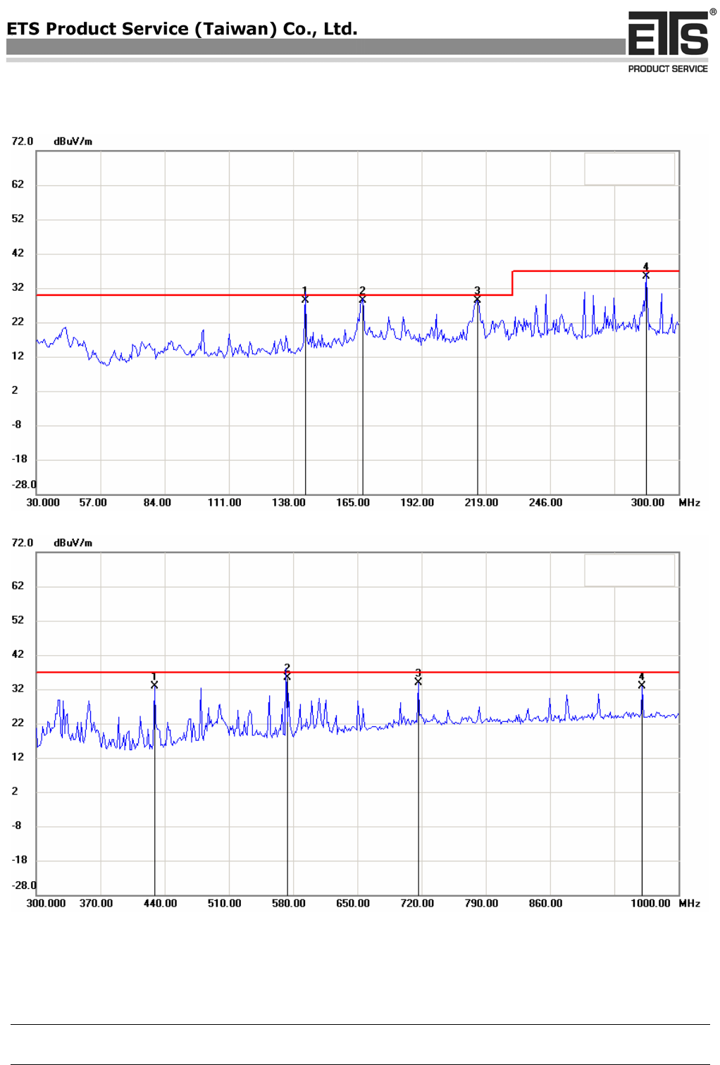
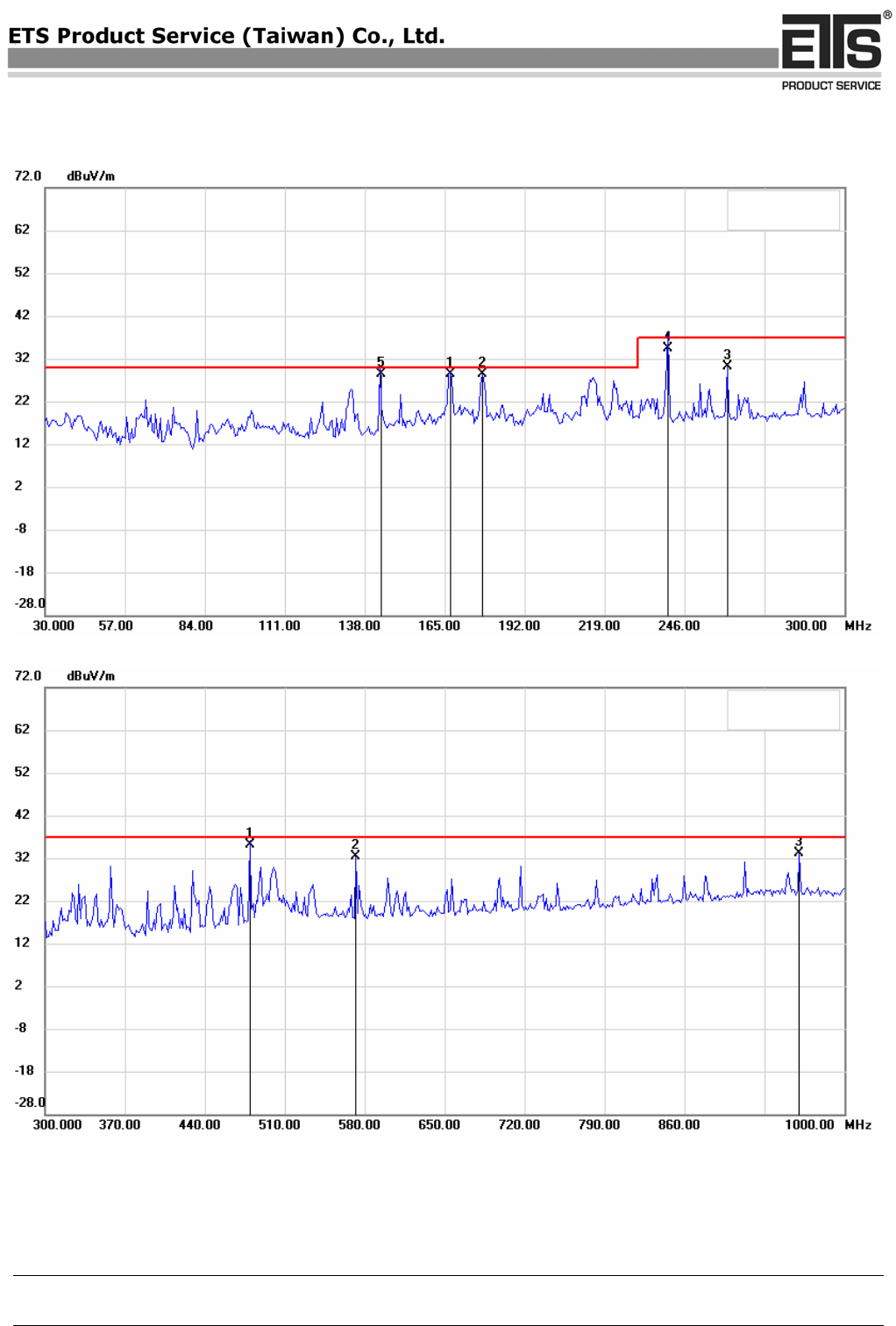
Radio Noise Field Strength
Emission
Summary table with radiated data of the test plots
Model: UVAD200 Date: 2007/10/1
Mode: Temperature: 26 °C Engineer: Jason
Polarization: Horizontal Humidity: 60 %
Frequency
(MHz) Reading
(dBuV) Detector Factor
(dB) Result
(dBuV/m) Limit
(dBuV/m) Margin
(dB)
Table
Degree
(Deg.)
Ant.
High
(cm) Note
143.09 13.35 QP 15.00 28.35 30.00 -1.65 100 320
167.43 13.28 QP 15.10 28.38 30.00 -1.62 150 350
215.59 15.95 QP 12.44 28.39 30.00 -1.61 188 250
286.47 20.53 QP 14.97 35.50 37.00 -1.50 30 220
429.06 14.54 peak 18.44 32.98 37.00 -4.02 120 120
572.73 14.06 QP 21.37 35.43 37.00 -1.57 30 150
716.63 9.93 peak 23.89 33.82 37.00 -3.18 150 122
960.72 5.66 peak 27.24 32.90 37.00 -4.10 180 210
Polarization: Vertical
Frequency
(MHz) Reading
(dBuV) Detector Factor
(dB) Result
(dBuV/m) Limit
(dBuV/m) Margin
(dB)
Table
Degree
(Deg.)
Ant.
High
(cm) Note
143.19 13.46 QP 15.00 28.46 30.00 -1.54 100 125
166.89 13.16 QP 15.12 28.28 30.00 -1.72 120 120
177.72 14.17 QP 14.23 28.40 30.00 -1.60 150 150
240.04 20.85 QP 13.57 34.42 37.00 -2.58 100 250
260.50 16.13 peak 14.10 30.23 37.00 -6.77 260 210
479.56 15.63 QP 19.58 35.21 37.00 -1.79 185 350
572.14 10.94 peak 21.36 32.30 37.00 -4.70 210 330
960.72 5.97 peak 27.24 33.21 37.00 -3.79 220 400
Note 1. Correction Factor = Antenna factor + Cable loss - Preamplifier
2. The formula of measured value as: Test Result = Reading + Correction Factor
3. Detector function in the form : PK = Peak, QP = Quasi Peak, AV = Average
4. All not in the table noted test results are more than 20 dB below the relevant limits.
5. See attached diagram as appendix.
COPY
Registration number: W6M20709-8534-E-11
ETS Product Service (Taiwan) Co., Ltd.
6F, NO. 58, LANE 188, RUEY-KUANG RD., NEIHU, TAIPEI 114, TAIWAN, R.O.C. Page 24 of 36
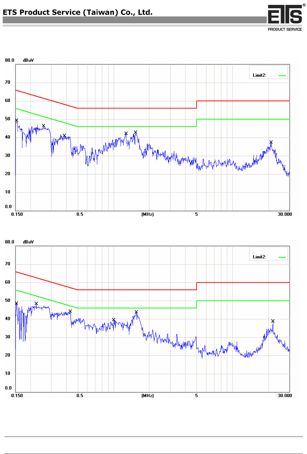
Conducted Emission
Emission
Model: UVAD200 Date: 2007/10/1
Mode: Temperature: 26 °C Engineer: Jason
Polarization: N Humidity: 60 %
Frequency
(MHz)
Reading
(dBuV)
QP Ave.
Factor
(dB)
Corr.
Result
(dBuV)
QP Ave.
Limit
(dBuV)
QP Ave.
Margin
(dB) Note
0.1535 29.89 6.51 10.10 39.99 16.61 65.81 55.81 -25.82
0.2584 33.84 22.46 10.10 43.94 32.56 61.48 51.48 -17.54
0.3871 26.47 13.35 10.10 36.57 23.45 58.13 48.13 -21.56
1.27 27.88 14.49 10.10 37.98 24.59 56 46 -18.02
1.535 26.57 15.32 10.10 36.67 25.42 56 46 -19.33
21.0556 21.28 14.30 10.10 31.38 24.40 60 50 -25.60
Polarization: L1
Frequency
(MHz)
Reading
(dBuV)
QP Ave.
Factor
(dB)
Corr.
Result
(dBuV)
QP Ave.
Limit
(dBuV)
QP Ave.
Margin
(dB) Note
0.1527 29.87 9.27 10.10 39.97 19.37 65.85 55.85 -25.88
0.2243 31.81 10.8 10.10 41.91 20.9 62.66 52.66 -20.75
0.4343 27.65 11.29 10.10 37.75 21.39 57.17 47.17 -19.42
1.005 23.45 9.36 10.10 33.55 19.46 56 46 -22.45
1.5549 29.31 17.58 10.10 39.41 27.68 56 46 -16.59
21.75 18.79 11.40 10.10 28.89 21.50 60 50 -28.50
Note 1. Correction Factor = Antenna factor + Cable loss - Preamplifier
2. The formula of measured value as: Test Result = Reading + Correction Factor
3. Detector function in the form : PK = Peak, QP = Quasi Peak, AV = Average
4. All not in the table noted test results are more than 20 dB below the relevant limits.
5. See attached diagram as appendix.
6. T-LISN does not need to test is according to customer’s request.
COPY
Registration number: W6M20709-8534-E-11
ETS Product Service (Taiwan) Co., Ltd.
6F, NO. 58, LANE 188, RUEY-KUANG RD., NEIHU, TAIPEI 114, TAIWAN, R.O.C. Page 25 of 36
Electrostatic Discharge
ESD
Standard : IEC/EN 61000 - 4 - 2
Device : UVAD200
Date : October 08, 2007
Test point
Table (T)
Floor (F)
Contact (C)
Air (A)
Voltage
(kV)
Polarity
( + / - )
Note
Housing T A 2, 4, 8 + / - B
Housing T C 2, 4 + / - B
Indirect T C 2, 4 + / - B
Temperature : 24.8 °C
Pressure : 990 hPa
Rel. humidity : 50 %
COPY
Registration number: W6M20709-8534-E-11
ETS Product Service (Taiwan) Co., Ltd.
6F, NO. 58, LANE 188, RUEY-KUANG RD., NEIHU, TAIPEI 114, TAIWAN, R.O.C. Page 26 of 36
ESD discharge points
The top of EUT
The bottom of EUT
COPY
Registration number: W6M20709-8534-E-11
ETS Product Service (Taiwan) Co., Ltd.
6F, NO. 58, LANE 188, RUEY-KUANG RD., NEIHU, TAIPEI 114, TAIWAN, R.O.C. Page 27 of 36
The front of EUT
The back of EUT
COPY
Registration number: W6M20709-8534-E-11
ETS Product Service (Taiwan) Co., Ltd.
6F, NO. 58, LANE 188, RUEY-KUANG RD., NEIHU, TAIPEI 114, TAIWAN, R.O.C. Page 28 of 36
The left of EUT
The right of EUT
COPY

Registration number: W6M20709-8534-E-11
ETS Product Service (Taiwan) Co., Ltd.
6F, NO. 58, LANE 188, RUEY-KUANG RD., NEIHU, TAIPEI 114, TAIWAN, R.O.C. Page 29 of 36
Note:
A: Normal performance within the specification.
B: Temporary degradation or less of function or performance which is self recoverable
C: Temporary degradation or loss of function or perform. which requires. operate intervention
or system reset
D: Degradation or loss of function which is not recoverable due to damage of equipment
(components) or software, or loss of data.
NA: Not Applicable
Explanation: ./.
COPY
Registration number: W6M20709-8534-E-11
ETS Product Service (Taiwan) Co., Ltd.
6F, NO. 58, LANE 188, RUEY-KUANG RD., NEIHU, TAIPEI 114, TAIWAN, R.O.C. Page 30 of 36
Interference Immunity Against Electromagnetic Irradiation
RF Field
Standard : IEC/EN 61000 – 4 – 3
Device : UVAD200
Date : October 08, 2007
Testequipment : Anechoic Chamber, Generator SMG (R&S), Monitoring System,
Amplifier 10W1000/150L (ar), Antenna SAS-200/521 (AHS)
Severity Level : 2 ( 3V/m ) Modulation Frequency : 1kHz (80%AM)
Pulsmodulation : 1 Hz (0,5s on;0,5s off)
V/m
3
2
1
0 100 200 300 400 500 600 700 800 900 1000
80 MHz
Note :
: A : No loss of performance or function
B : Temporary loss of function or performance which is self recoverable
C : Temporary loss of function or perform. which req. operator intervention or system reset
D : Loss of function which is not recoverable
Temperature : 23.9 °C
Pressure : 921 hPa
Rel. humidity : 52 %
COPY
Registration number: W6M20709-8534-E-11
ETS Product Service (Taiwan) Co., Ltd.
6F, NO. 58, LANE 188, RUEY-KUANG RD., NEIHU, TAIPEI 114, TAIWAN, R.O.C. Page 31 of 36
Electrical Fast Transients
Burst
Standard : IEC/EN 61000 – 4 – 4
Device : UVAD200
Date : October 08, 2007
Testport
Voltage
(kV)
Polarity
( + / - )
Waveform
Tr / Th
Repetiton
Frequency
(kHz)
Note
AC-Power line
1
+ / -
5/50 ns
5
A
Note : A : No loss of performance or function
B : Temporary loss of function or performance which is self recoverable
C : Temporary loss of function or perform. which req. operate. intervention or system reset
D : Loss of function which is not recoverable
Temperature : 23.9 °C
Pressure : 921 hPa
Rel. humidity : 52 %
COPY

Registration number: W6M20709-8534-E-11
ETS Product Service (Taiwan) Co., Ltd.
6F, NO. 58, LANE 188, RUEY-KUANG RD., NEIHU, TAIPEI 114, TAIWAN, R.O.C. Page 32 of 36
Transients common & diff. mode
Surge
Standard : IEC/EN 61000 - 4 - 5
Device : UVAD200
Date : October 08, 2007
Test mode
Voltage
( kV )
Waveform
Tr / Th
Note
AC-line to line
1
1.2/50 µs A
Note : A : No loss of performance or function
B : Temporary loss of function or performance which is self recoverable
C : Temporary loss of function or perform. which req. operate. intervention or system reset
D : Loss of function which is not recoverable
Temperature : 23.9 °C
Pressure : 921 hPa
Rel. humidity : 52 %
COPY
Registration number: W6M20709-8534-E-11
ETS Product Service (Taiwan) Co., Ltd.
6F, NO. 58, LANE 188, RUEY-KUANG RD., NEIHU, TAIPEI 114, TAIWAN, R.O.C. Page 33 of 36
continues conducted
RF - common mode
Standard : IEC/EN 61000 - 4 - 6
Device : UVAD200
Date : October 08, 2007
Test port
Voltage
(Vrms)
Modulation
Frequency
Frequency Range
Note
AC-Power line
3
1 kHz
150 kHz - 80 MHz A
Note : A : No loss of performance or function
B : Temporary loss of function or performance which is self recoverable
C : Temporary loss of function or perform. which req. operate. intervention or system reset
D : Loss of function which is not recoverable
Temperature : 23.9 °C
Pressure : 921 hPa
Rel. humidity : 52 %
COPY

Registration number: W6M20709-8534-E-11
ETS Product Service (Taiwan) Co., Ltd.
6F, NO. 58, LANE 188, RUEY-KUANG RD., NEIHU, TAIPEI 114, TAIWAN, R.O.C. Page 34 of 36
Voltage dips and interruption
V - Dips
Standard : IEC/EN 61000 - 4 - 11
Device : UVAD200
Date : October 08, 2007
Reduction of supply
voltage of
Voltage in % (in V)
Duration in ms
Note
Interruption (> 95 %)
0% (0 V)
250 (5 s) C
Dips (>95 %)
5% (12 V)
0,5 (10ms) A
Dips (30 %)
70% (161 V)
25 (500 ms) A
__________________________________________________________________________________________________
Note : A : No loss of performance or function
B : Temporary loss of function or performance which is self recoverable
C : Temporary loss of function or perform. which req. operate. intervention or system reset
D : Loss of function which is not recoverable
Temperature : 23.9 °C
Pressure : 921 hPa
Rel. humidity : 52 %
COPY
Registration number: W6M20709-8534-E-11
ETS Product Service (Taiwan) Co., Ltd.
6F, NO. 58, LANE 188, RUEY-KUANG RD., NEIHU, TAIPEI 114, TAIWAN, R.O.C. Page 35 of 36
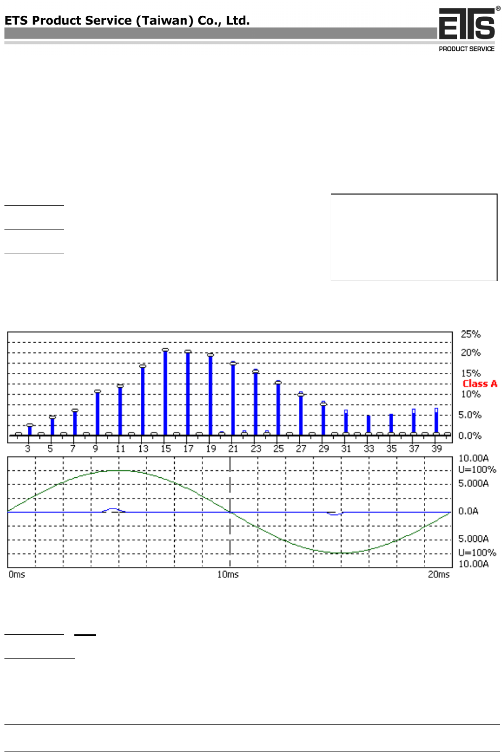
Current Harmonics
Harmonics
Standard : IEC/EN 61000 - 3 - 2
Device : UVAD200
Date : October 01, 2007
Class : A
Passed : yes / no
Explanation: See attached diagram as next page
Temperature : 23.9 °C
Pressure : 921 hPa
Rel. humidity : 52 %
COPY
Harmonic Emission - IEC 61000-3-2 , EN 61000-3-2 , (EN60555-2)
Comply: IEC 61000-3-2 Ed.2.1 :2001 (incl. Amd.14) - IEC 61000-4-7 Ed.1.0 :1991
W6M20709-8534
HARCS Setup File : unnamed
HARCS Report File : unnamed
Operator : Jason
Unit : USB 2.0 Graphic Dock
Serialnumber : UVAD200
Remarks
Full Bar : Actual Values
Empty Bar : Maximum Values
Blue : Current , Green : Voltage , Red : Failed
Measurement
Date : 2007/10/1 ¤W¤È 10:38 V4.15
Urms = 229.9V Freq = 50.000 Range: 10 A
Irms = 0.127A Ipk = 0.615A cf = 4.846
P = 12.03W S = 29.19VA pf = 0.412
COPY

THDi = 90.8 % THDu = 0.10 % Class A
Test - Time : 5min ( 100 %)
Test completed, Result: PASSED
Order Freq. Iavg Iavg%L Imax Imax%L Limit Status
[Hz] [A] [%] [A] [%] [A]
1 50 0.0538 0.0549
2 100 0.0000 0.0000 0.0000 0.0000 1.0800
3 150 0.0469 2.0391 0.0476 2.0699 2.3000
4 200 0.0000 0.0000 0.0000 0.0000 0.4300
5 250 0.0457 4.0124 0.0464 4.0690 1.1400
6 300 0.0000 0.0000 0.0000 0.0000 0.3000
7 350 0.0436 5.6627 0.0446 5.7864 0.7700
8 400 0.0000 0.0000 0.0000 0.0000 0.2300
9 450 0.0411 10.287 0.0415 10.376 0.4000
10 500 0.0000 0.0000 0.0000 0.0000 0.1840
11 550 0.0381 11.546 0.0385 11.652 0.3300
12 600 0.0000 0.0000 0.0000 0.0000 0.1533
13 650 0.0344 16.404 0.0348 16.567 0.2100
14 700 0.0000 0.0000 0.0000 0.0000 0.1314
15 750 0.0306 20.387 0.0311 20.752 0.1500
16 800 0.0000 0.0000 0.0000 0.0000 0.1150
17 850 0.0265 20.035 0.0269 20.291 0.1324
18 900 0.0000 0.0000 0.0000 0.0000 0.1022
19 950 0.0226 19.048 0.0226 19.070 0.1184
20 1000 0.0000 0.0000 0.0006 0.6634 0.0920
21 1050 0.0184 17.145 0.0189 17.660 0.1071
22 1100 0.0000 0.0000 0.0006 0.7298 0.0836
23 1150 0.0147 14.978 0.0153 15.598 0.0978
24 1200 0.0000 0.0000 0.0006 0.7961 0.0767
25 1250 0.0111 12.298 0.0116 12.885 0.0900
26 1300 0.0000 0.0000 0.0000 0.0000 0.0708
27 1350 0.0080 9.6453 0.0085 10.254 0.0833
28 1400 0.0000 0.0000 0.0000 0.0000 0.0657
29 1450 0.0055 7.1404 0.0061 7.8668 0.0776
30 1500 0.0000 0.0000 0.0000 0.0000 0.0613
31 1550 0.0000 0.0000 0.0043 5.8865 0.0726
32 1600 0.0000 0.0000 0.0000 0.0000 0.0575
33 1650 0.0000 0.0000 0.0031 4.4759 0.0682
34 1700 0.0000 0.0000 0.0000 0.0000 0.0541
35 1750 0.0000 0.0000 0.0031 4.7472 0.0643
36 1800 0.0000 0.0000 0.0000 0.0000 0.0511
37 1850 0.0000 0.0000 0.0037 6.0221 0.0608
38 1900 0.0000 0.0000 0.0000 0.0000 0.0484
39 1950 0.0000 0.0000 0.0037 6.3477 0.0577
40 2000 0.0000 0.0000 0.0000 0.0000 0.0460
Important:
- without "1000-4-7 Ed. 2" ( DFT-window is 16 periods )
COPY
Registration number: W6M20709-8534-E-11
ETS Product Service (Taiwan) Co., Ltd.
6F, NO. 58, LANE 188, RUEY-KUANG RD., NEIHU, TAIPEI 114, TAIWAN, R.O.C. Page 36 of 36
Voltage Fluctuation
Flicker
Standard : IEC/EN 61000 - 3 - 3
Device : UVAD200
Date : October 01, 2007
P st 0.07
P lt < 0,65 pass
dc < 3,3% pass
dt < 3% pass
d max (%) pass
Passed : yes / no
Explanation: See attached diagram as next page
Temperature : 23.9 °C
Pressure : 921 hPa
Rel. humidity : 52 %
COPY
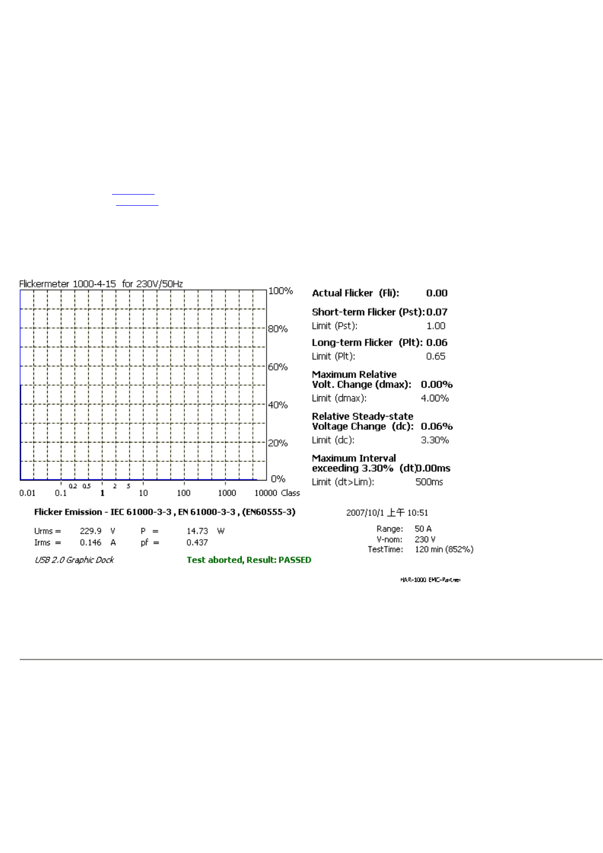
Flicker Emission - IEC 61000-3-3 , EN 61000-3-3 , (EN60555-3)
Comply: IEC 61000-3-3 Ed.1.1 :2002 (incl. Amd.1) - IEC 61000-4-15 Ed.1.0 :1997 (incl. Amd.1)
W6M20709-8534
HARCS Setup File : unnamed
HARCS Report File : unnamed
Operator : Jason
Unit : USB 2.0 Graphic Dock
Serialnumber : UVAD200
Remarks
Full Bar : Actual Values
Empty Bar : Maximum Values
Circles : Average Values
Blue : Current , Green : Voltage , Red : Failed
Measurement
Date : 2007/10/1 ¤W¤È 10:51 V4.15
Urms = 229.9V Freq = 50.000 Range: 50 A
Irms = 0.146A Ipk = 0.684A cf = 4.667
COPY

P = 14.73W S = 33.68VA pf = 0.437
Test - Time : 12 x 10min = 120min ( 852 %)
LIN (Line Impedance Network) : L: 0.24ohm +j0.15ohm N: 0.16ohm +j0.10ohm
Limits : Plt : 0.65 Pst : 1.00
dmax : 4.00 % dc : 3.30 %
dtLim: 3.30 % dt>Lim: 500ms
Test aborted, Result: PASSED
1
2
COPY

Registration number: W6M20709-8534-E-11
ETS Product Service (Taiwan) Co., Ltd..
6F, NO. 58, LANE 188, RUEY-KUANG RD., NEIHU, TAIPEI 114, TAIWAN, R.O.C. Appendix page 1 of 16
Appendix
A Measurement diagrams
1. Radiated Emission
( The measurement diagrams plots attached below are preliminary wideband scan with a peak
detector and for reference only. The final test results are listed on page 23.)
2 . Conducted Emission
( The measurement diagrams plots attached below are preliminary wideband scan with a
peak and average detector for reference only. The final test results are listed on page 24.)
B Photos
1. External Photos
2. Internal Photos
3. Set Up Photo of Radiated Emission
4. Set Up Photo of Conducted Emission
5. Set Up Photo of Current Harmonics& Voltage Fluctuations
6. Set Up Photo of ESD
7. Set Up Photo of RF-Field
8. Set Up Photo of EFT
9. Set Up Photo of Surge& DIP
10. Set Up Photo of CS
COPY
Registration number: W6M20709-8534-E-11
ETS Product Service (Taiwan) Co., Ltd..
6F, NO. 58, LANE 188, RUEY-KUANG RD., NEIHU, TAIPEI 114, TAIWAN, R.O.C. Appendix page 2 of 16
Radiated Emission
Antenna Polarization H
COPY
Registration number: W6M20709-8534-E-11
ETS Product Service (Taiwan) Co., Ltd..
6F, NO. 58, LANE 188, RUEY-KUANG RD., NEIHU, TAIPEI 114, TAIWAN, R.O.C. Appendix page 3 of 16
Antenna Polarization V
COPY
Registration number: W6M20709-8534-E-11
ETS Product Service (Taiwan) Co., Ltd..
6F, NO. 58, LANE 188, RUEY-KUANG RD., NEIHU, TAIPEI 114, TAIWAN, R.O.C. Appendix page 4 of 16
Conducted Emission
LISN N
LISN L1
COPY
Registration number: W6M20709-8534-E-11
ETS Product Service (Taiwan) Co., Ltd..
6F, NO. 58, LANE 188, RUEY-KUANG RD., NEIHU, TAIPEI 114, TAIWAN, R.O.C. Appendix page 5 of 16
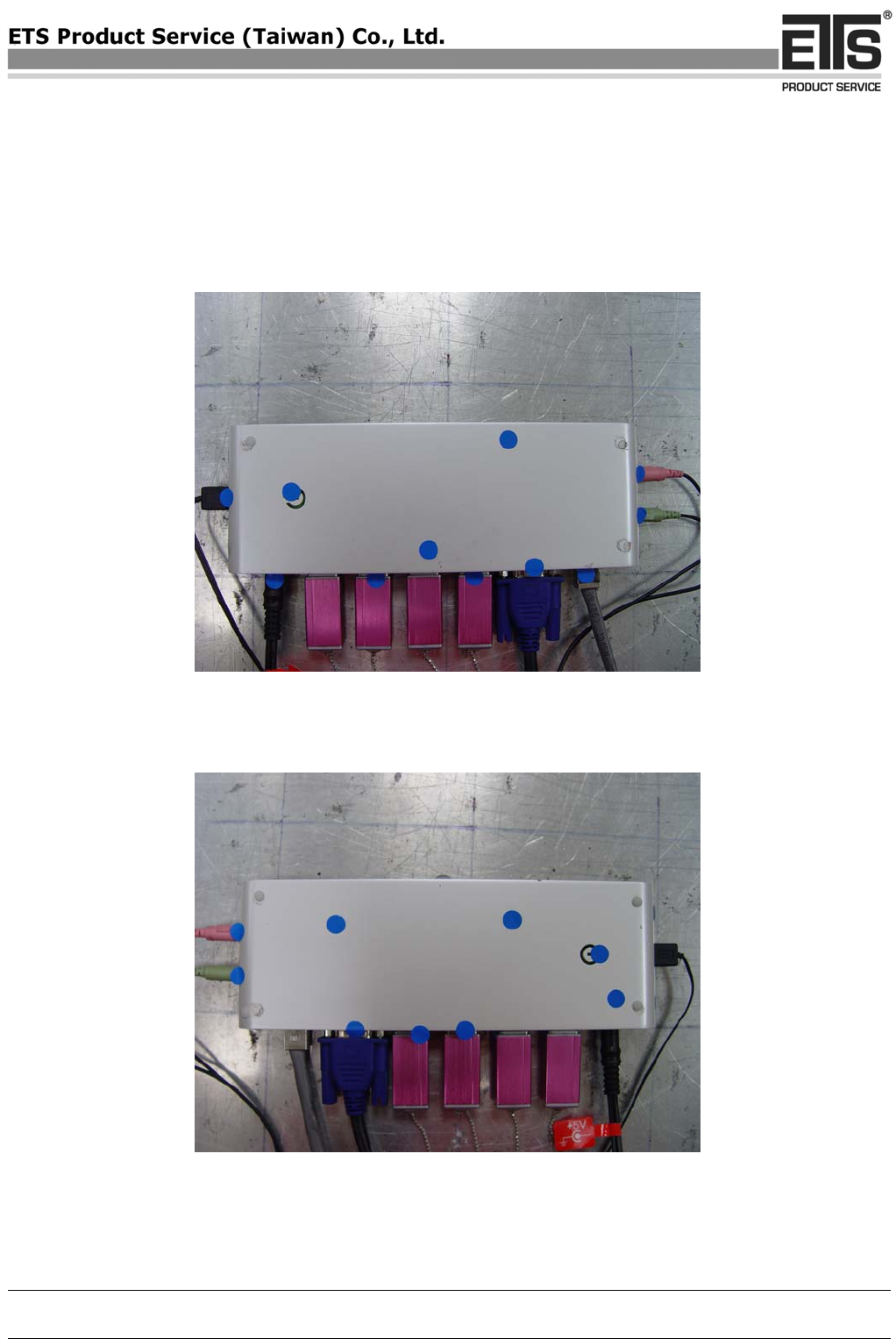
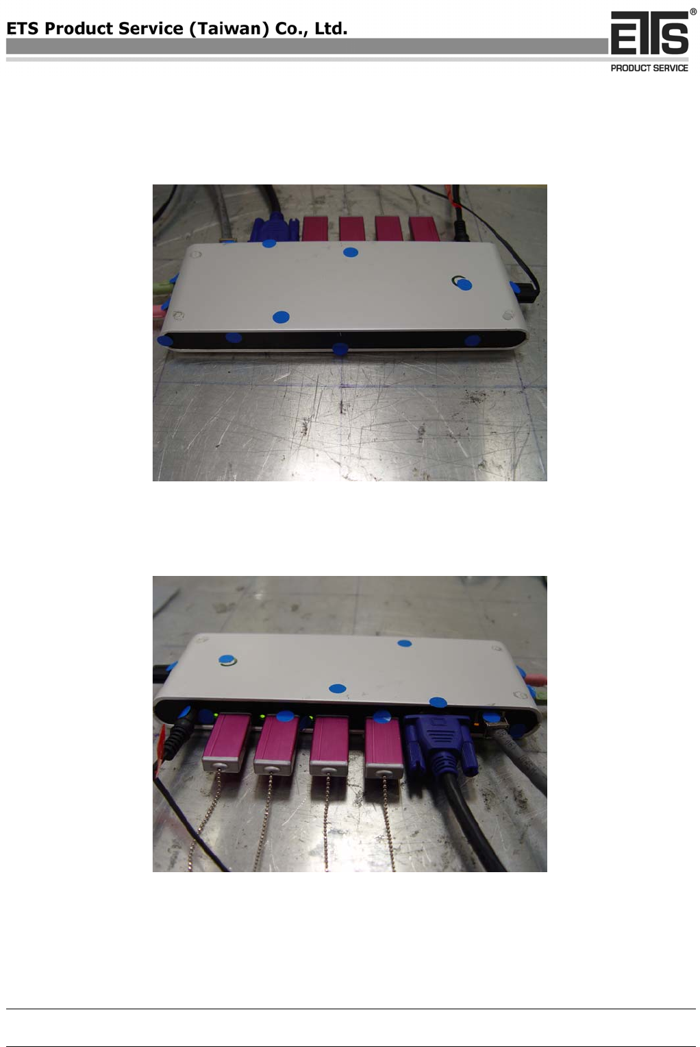
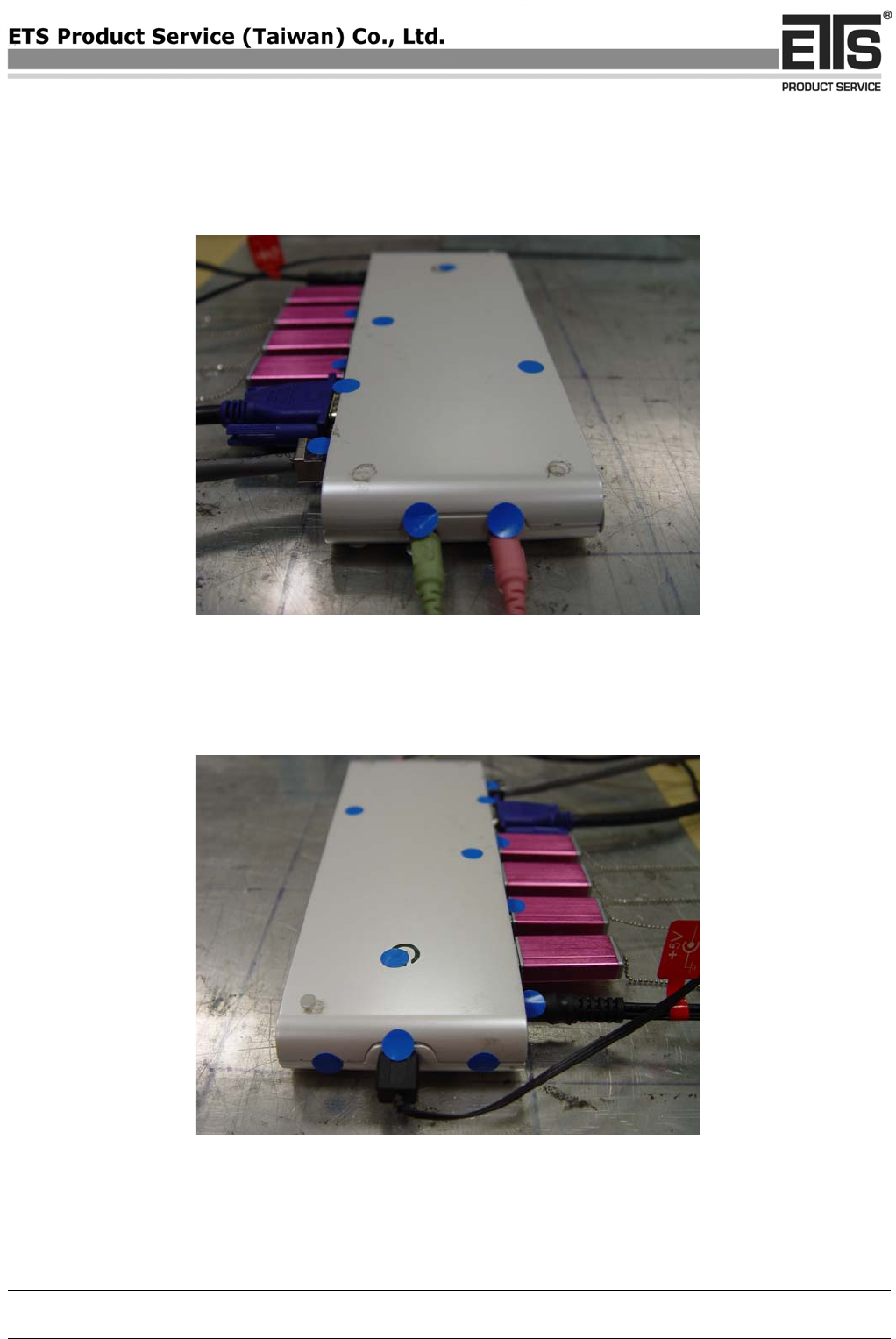
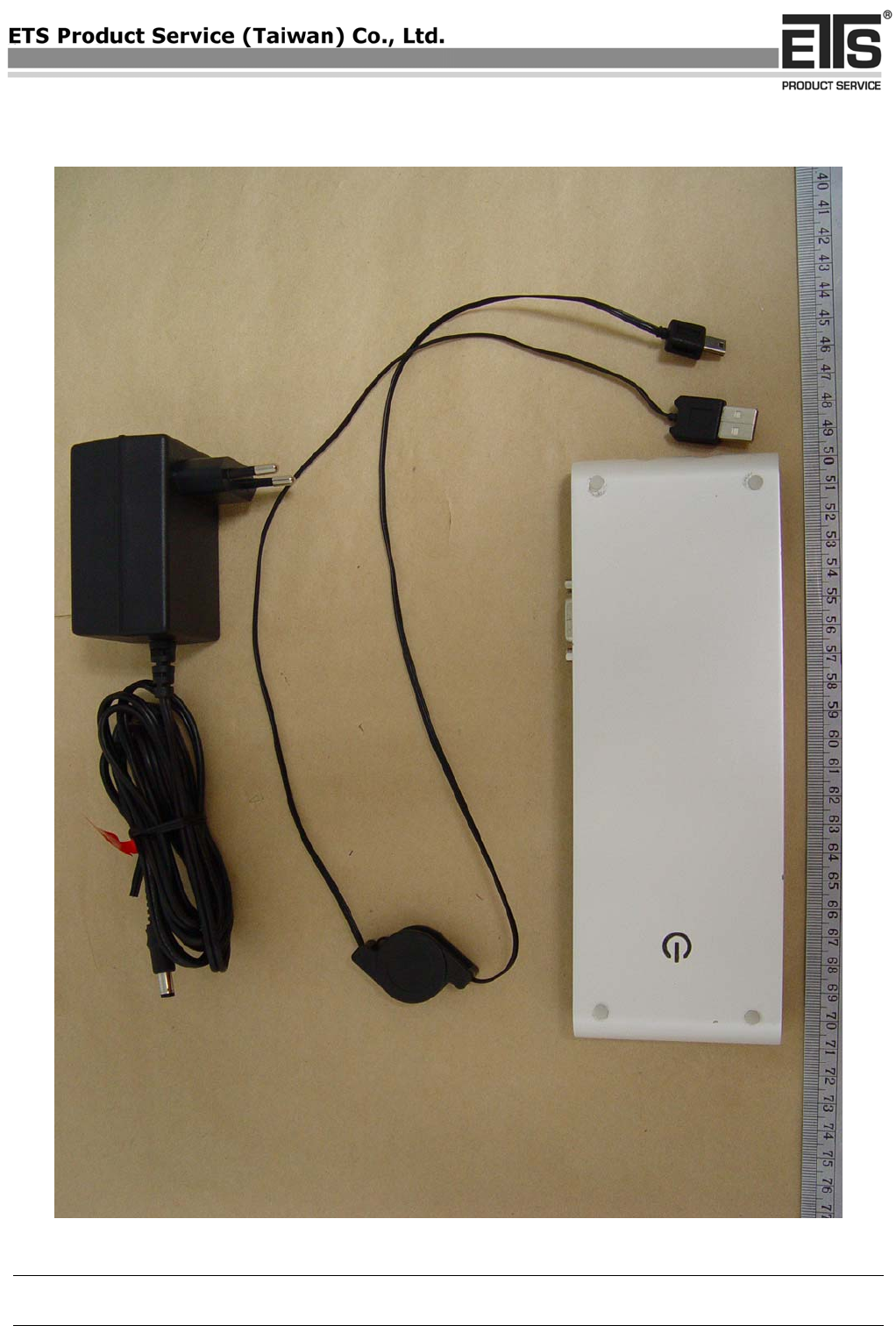
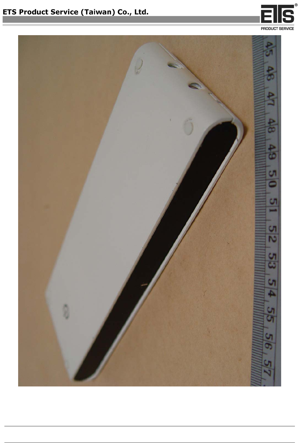
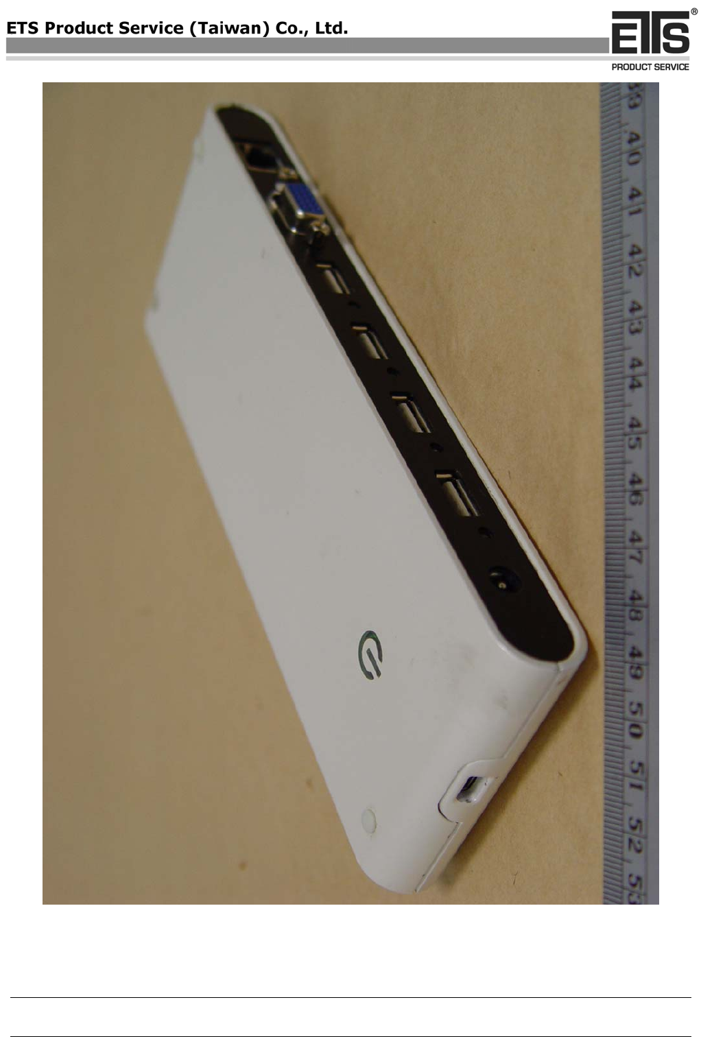
External Photos
COPY
Registration number: W6M20709-8534-E-11
ETS Product Service (Taiwan) Co., Ltd..
6F, NO. 58, LANE 188, RUEY-KUANG RD., NEIHU, TAIPEI 114, TAIWAN, R.O.C. Appendix page 6 of 16
COPY
Registration number: W6M20709-8534-E-11
ETS Product Service (Taiwan) Co., Ltd..
6F, NO. 58, LANE 188, RUEY-KUANG RD., NEIHU, TAIPEI 114, TAIWAN, R.O.C. Appendix page 7 of 16
COPY
Registration number: W6M20709-8534-E-11
ETS Product Service (Taiwan) Co., Ltd..
6F, NO. 58, LANE 188, RUEY-KUANG RD., NEIHU, TAIPEI 114, TAIWAN, R.O.C. Appendix page 8 of 16
COPY
Registration number: W6M20709-8534-E-11
ETS Product Service (Taiwan) Co., Ltd..
6F, NO. 58, LANE 188, RUEY-KUANG RD., NEIHU, TAIPEI 114, TAIWAN, R.O.C. Appendix page 9 of 16
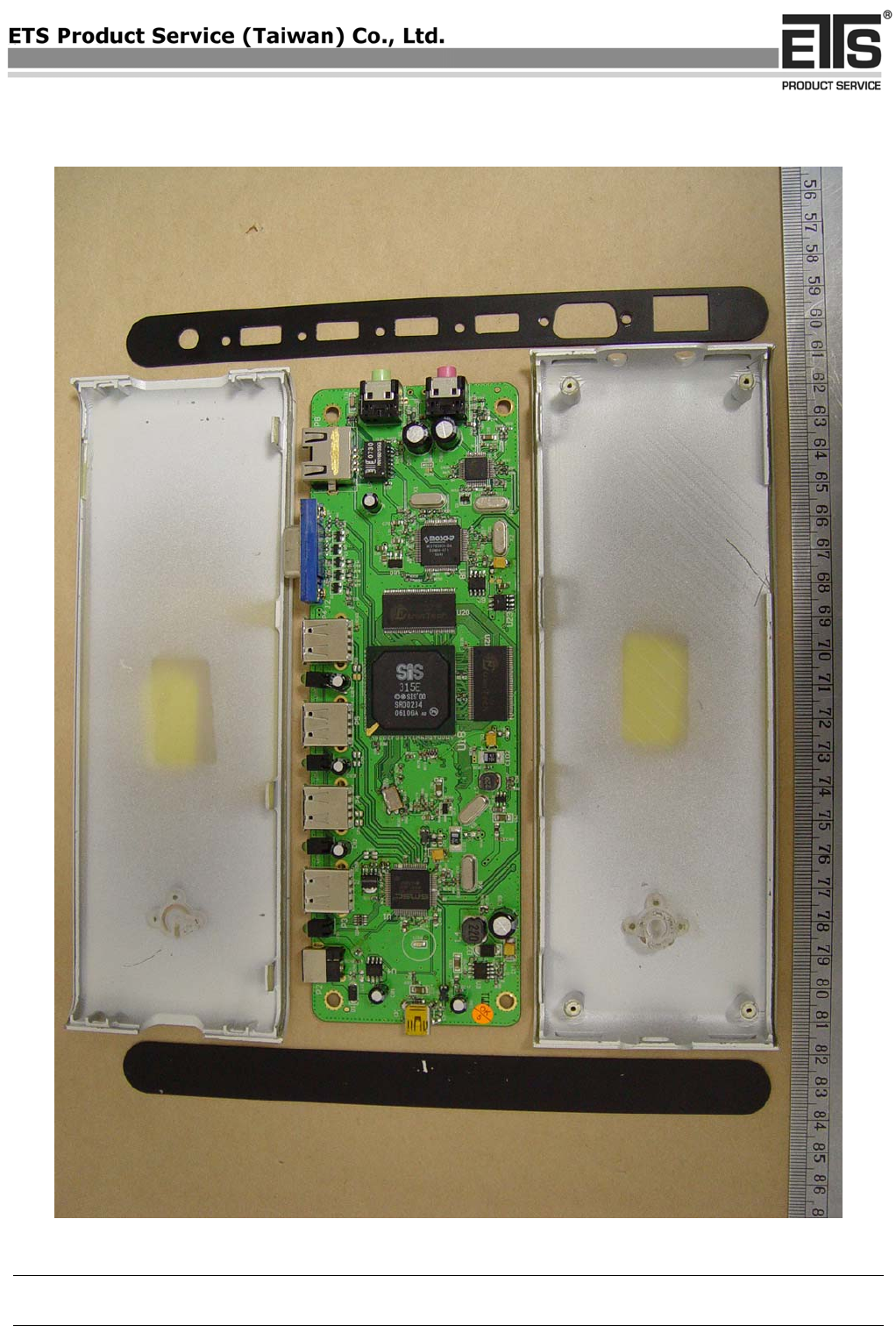
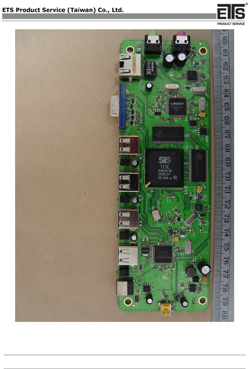
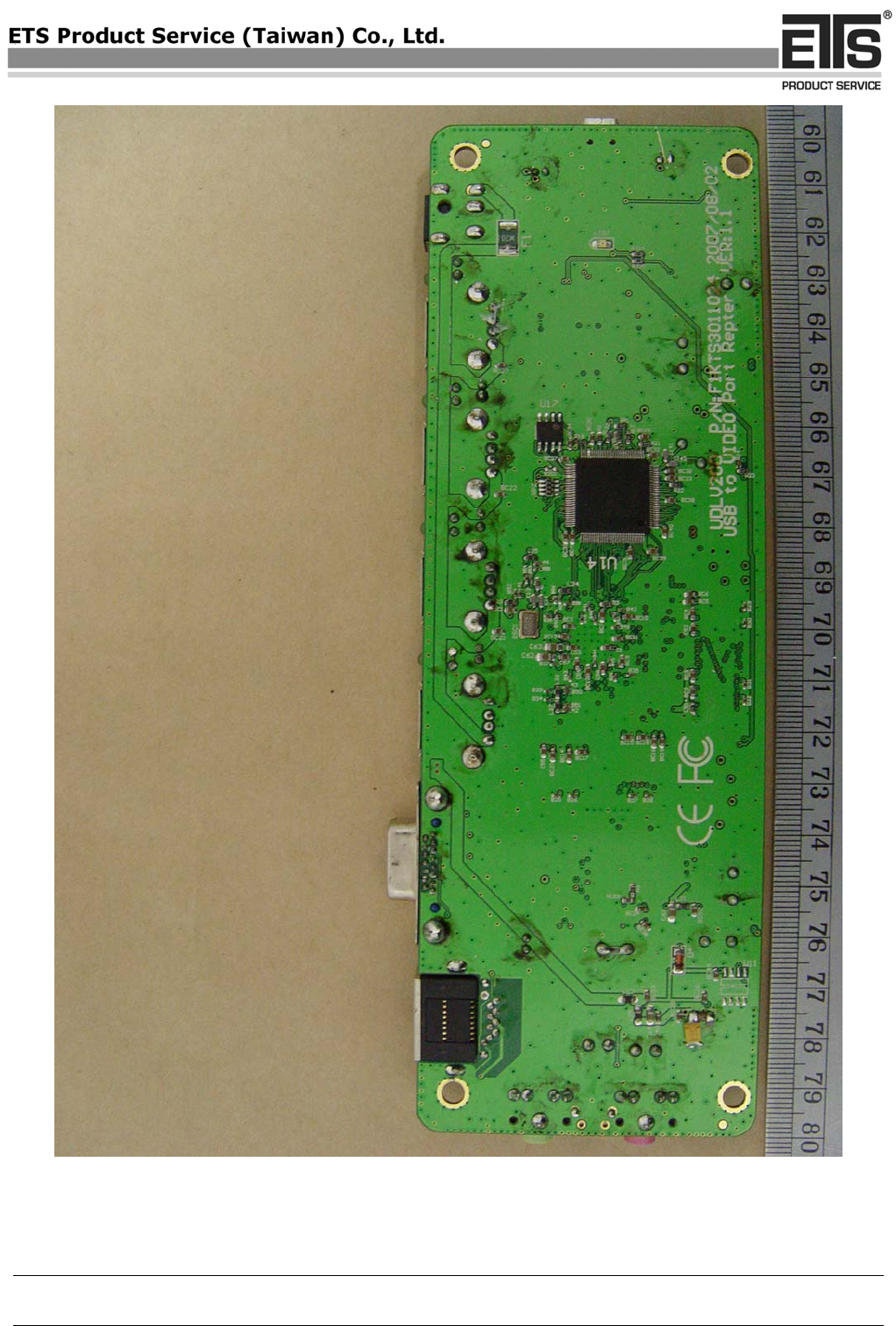
Internal Photos
COPY
Registration number: W6M20709-8534-E-11
ETS Product Service (Taiwan) Co., Ltd..
6F, NO. 58, LANE 188, RUEY-KUANG RD., NEIHU, TAIPEI 114, TAIWAN, R.O.C. Appendix page 10 of 16
COPY
Registration number: W6M20709-8534-E-11
ETS Product Service (Taiwan) Co., Ltd..
6F, NO. 58, LANE 188, RUEY-KUANG RD., NEIHU, TAIPEI 114, TAIWAN, R.O.C. Appendix page 11 of 16
COPY
Registration number: W6M20709-8534-E-11
ETS Product Service (Taiwan) Co., Ltd..
6F, NO. 58, LANE 188, RUEY-KUANG RD., NEIHU, TAIPEI 114, TAIWAN, R.O.C. Appendix page 12 of 16
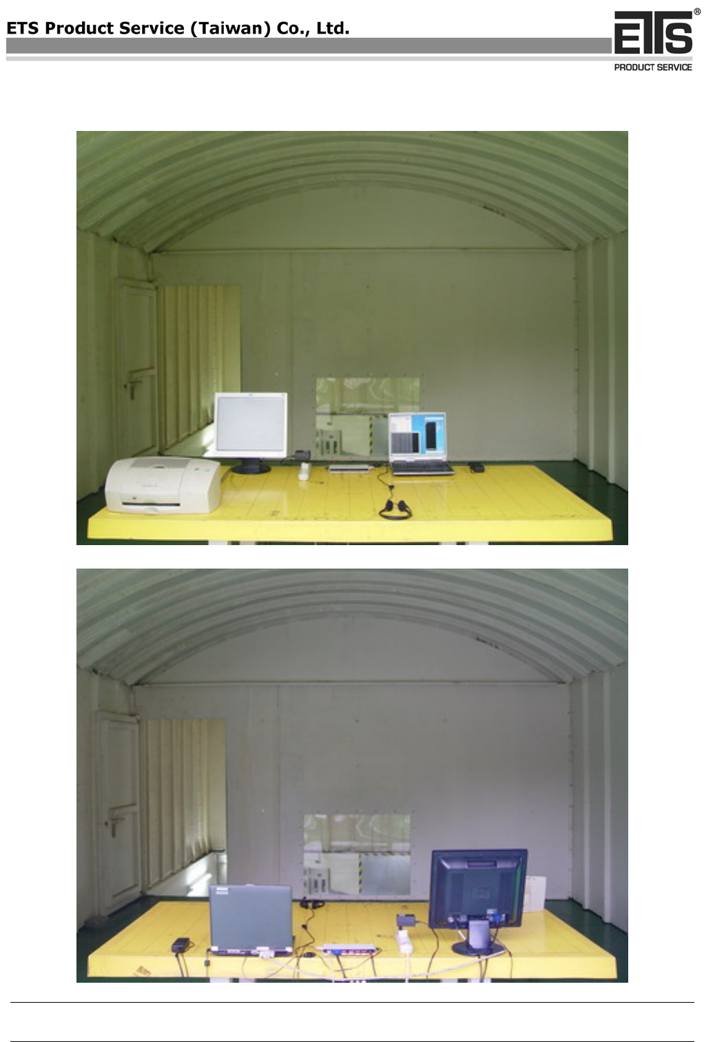
Set Up Photo of Radiated Emission
COPY
Registration number: W6M20709-8534-E-11
ETS Product Service (Taiwan) Co., Ltd..
6F, NO. 58, LANE 188, RUEY-KUANG RD., NEIHU, TAIPEI 114, TAIWAN, R.O.C. Appendix page 13 of 16
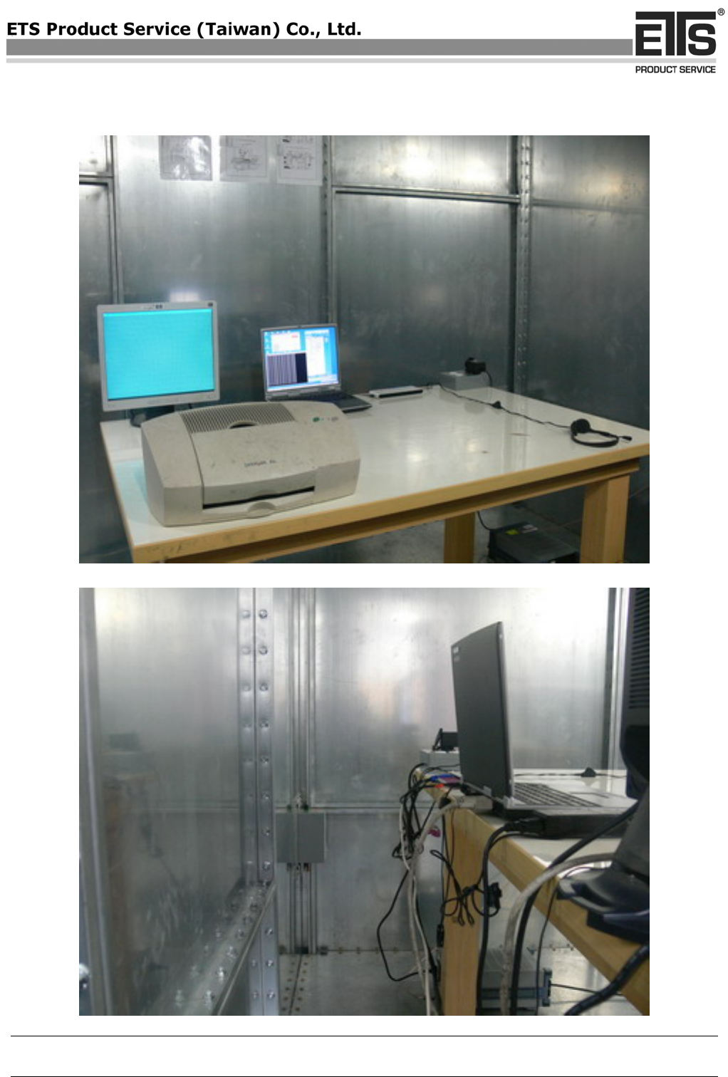
Set Up Photo of Conducted Emission
COPY
Registration number: W6M20709-8534-E-11
ETS Product Service (Taiwan) Co., Ltd..
6F, NO. 58, LANE 188, RUEY-KUANG RD., NEIHU, TAIPEI 114, TAIWAN, R.O.C. Appendix page 14 of 16
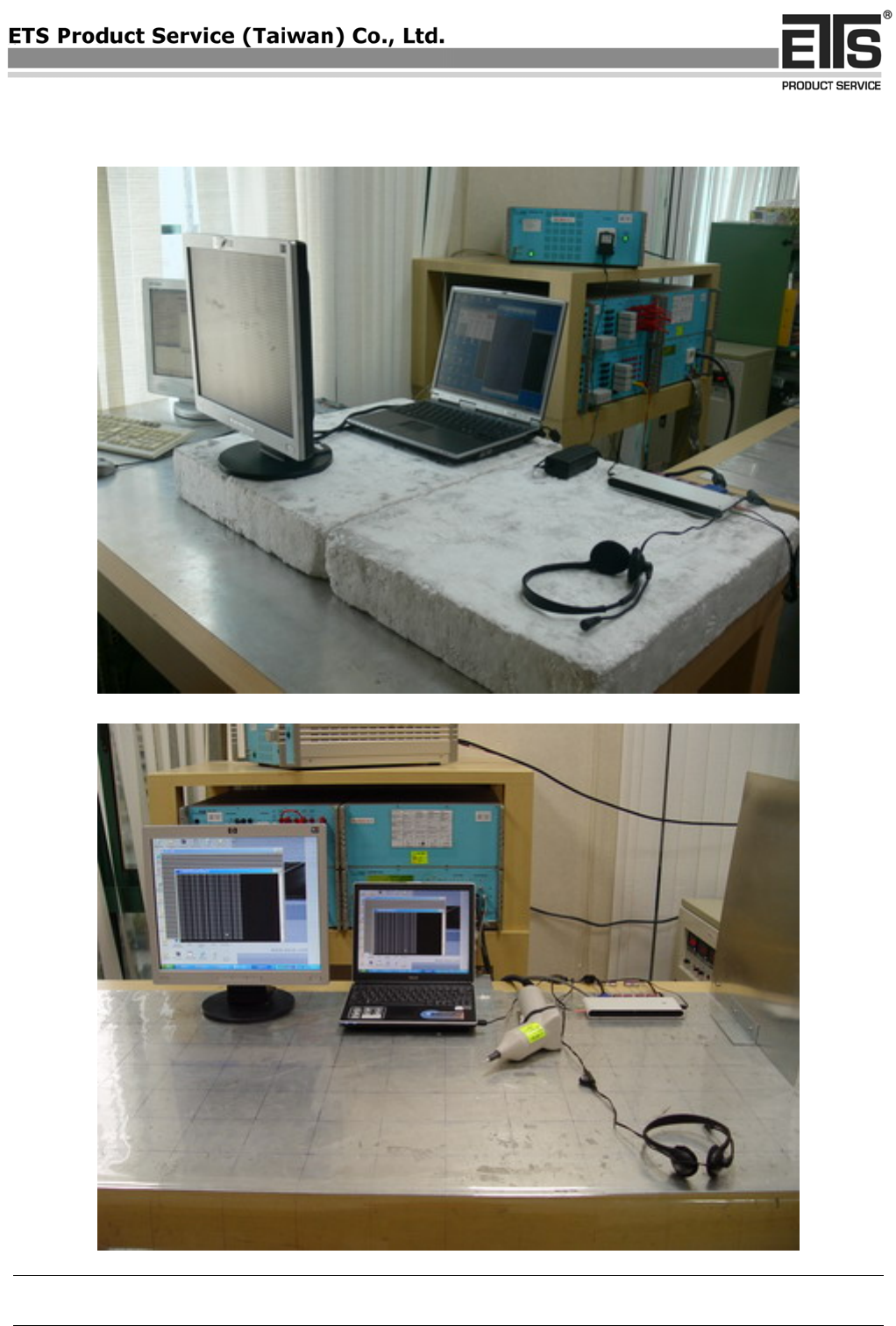
Set Up Photo of Current Harmonics& Voltage Fluctuations
Set Up Photo of ESD
COPY
Registration number: W6M20709-8534-E-11
ETS Product Service (Taiwan) Co., Ltd..
6F, NO. 58, LANE 188, RUEY-KUANG RD., NEIHU, TAIPEI 114, TAIWAN, R.O.C. Appendix page 15 of 16
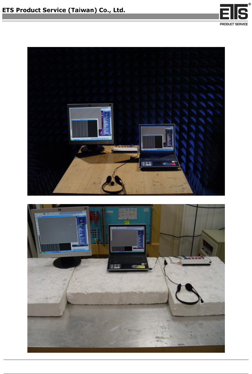
Set Up Photo of RF-Field
Set Up Photo of EFT
COPY
Registration number: W6M20709-8534-E-11
ETS Product Service (Taiwan) Co., Ltd..
6F, NO. 58, LANE 188, RUEY-KUANG RD., NEIHU, TAIPEI 114, TAIWAN, R.O.C. Appendix page 16 of 16
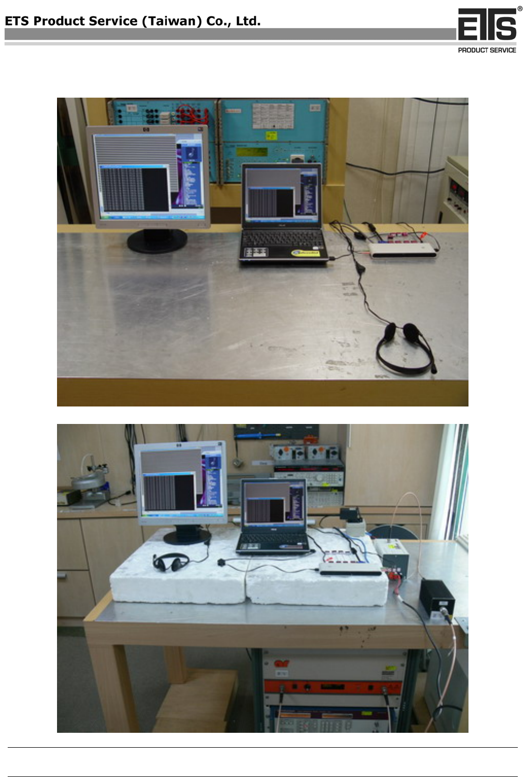
Set Up Photo of Surge& DIP
Set Up Photo of CS
COPY
