Leviton 51120 1 Surge Protector Installation Instructions Brochure
2014-05-16
: Pdf 184019-Brochure 1 184019-Brochure_1 078477 Batch3 unilog
Open the PDF directly: View PDF ![]() .
.
Page Count: 3

INSTALLATION
WARNINGS & CAUTIONS:
• TOBEINSTALLEDAND/ORUSEDINACCORDANCEWITHELECTRICALCODESANDREGULATIONS.
• INSTALLATIONOFC AT.NOS.51120-1AND51120-3SPDDEVICESINABRANCHCIRCUITMUSTBEDONEBYANELECTRICIAN.
• READALLINSTRUCTIONSBEFOREINSTALLING.
• CAT. NOS.51120-1AND51120-3SPDDEVICESMUSTBEINSTALLEDONALINETHATISSERVEDBYDISCONNECTMEANS,SUCHAS20-AMPCIRCUITBREAKERSOR20-AMP
FUSEDDISCONNECTSWITCHES.
• SPDMAYNOTSURVIVESUSTAINEDOVERVOLTAGES.
• USETHISDEVICEONLY WITH COPPER OR COPPER CLAD WIRE.
FEATURES:
• UL1449Listed-Type2SPD
• IEEEC62.41-1991categoryA&Bcombinationwavesuppression
• Solid-statesemiconductorSPDcircuitryforeachphase
• Eachphaseindependentlyfused
• GreenLEDdiagnosticindicatorforeachphase
• NEMA1metalenclosure
• Pre-punchedstandardknockouts
• Interiorplasticcircuitenclosureforaddedsafety
• Flushmountingenclosure
ForsuperiorlocalSPDprotection,useLevitonSurgeSuppressionOutletstoprotectagainstinternally-generatedtransientsbetweenthebranchpanelandthepointofuse.
DESCRIPTION:
Leviton’sCatalogNos.51120-1(120/240V,single-phaseversion)andthe51120-3(120/208V,3-phaseversion)BranchPanelMountedSPDdeviceshavebeendesignedtoprotect
residentialandsmallcommercialestablishmentsfromhighvoltagetransients.ThestandardJ-Boxmetalenclosurewithpre-punchedstandardsizeknockoutssimpliesush
mountingintypicalframeconstructionenvironments,andprovidesconvenientconnectionmeanstoexistingbranchpanels.
TO INSTALL:
System Voltage Requirements
1. Measurepanelvoltage,L-N,todeterminethesystemvoltage.SystemvoltagemustnotexceedthespeciedmaximumcontinuousRMSvoltageontheSPDdevicelabel.
Location and Mounting
1. LocatetheSPDdeviceascloseaspossibletothebranchcircuitbreakerpanel.ConnectionleadlengthbetweentheSPDdeviceandcircuitbreakerboxshouldbeminimalfor
bestprotection.ThelocationshouldalsopermitgoodvisibilityoftheSPDdevice’sdiagnosticlights.
2. Removethecircuitbreakerpanelcoveranddeterminethebreaker-panelwiringentrypointrelativetochosenlocationoftheSPDdevice.
NOTE:SincethecircuitbreakerpanelandtheSPDunithaveoverlappingcovers,installationshouldallowatleastoneinchofclearancefromtheedgeofthecircuitbreaker
panelcover.
3. Forsurface-mountcircuitbreakerpanels,theSPDdevicemaybeconnectedusingrigidconduittoanyconduitknockouthole.
4. Fornon-surfacemountinstallations,securetheSPDtothesupportstudinthewallbycuttinga6x6-inchmountinghole.
5. RemoveSPD’scoverandconnect3/4-inchexibleorrigidconduitbetweencircuitbreakerboxandtheSPD.
6. PlacetheSPDdeviceintothe6x6-inchmountingholeandsecureittotheexposedstuds.
Wiring Connections
TheSPDdeviceterminalblockaccepts4AWG–12AWGCOPPERWIREONLY.ForwirerangeSolidorStranded12AWGto10AWGuseTorque25in-lbs.For8AWGStranded
wireuse30in-lbs.ForStranded6AWG–4AWGuse35in-lbs.
1.
WARNING:TOAVOIDFIRE,SHOCKORDEATH,TURN OFF POWERATCIRCUITBREAKERORFUSEANDTESTTHATPOWERISOFFBEFOREWIRING!
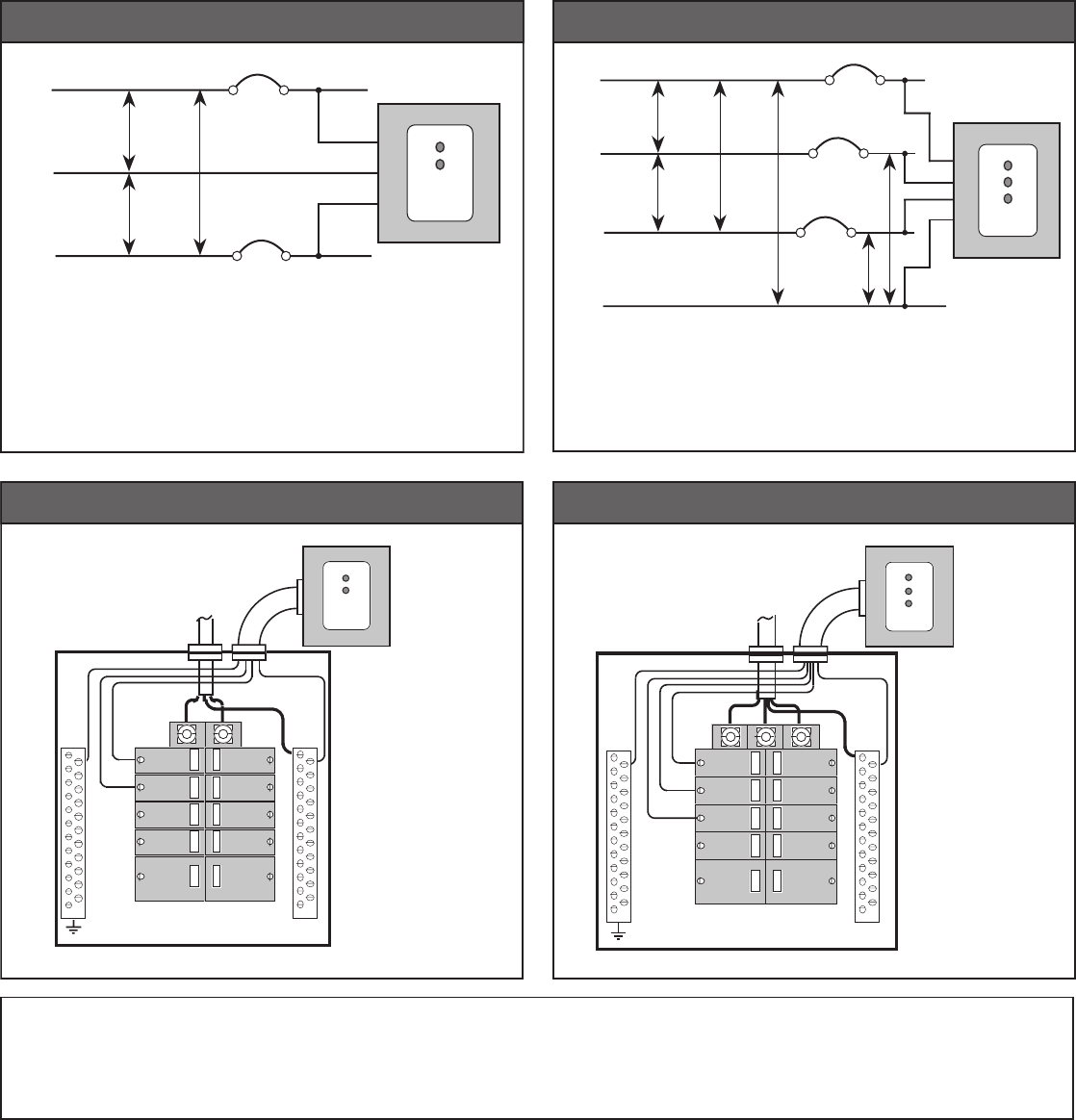
2. Connectwireleadstoterminalblock:BLACKtoPHASES,WHITEtoNEUTRALandGREENtoGROUND.SeeFigures 1through4onreverseside.
CAUTION:Ifplasticconduitisused,Greengroundwiremustbeconnectedtogroundlug,andGreenwireinsideenclosuremustalsobeconnectedtogroundlug.Failuretodo
somayresultinreorshock.SeeFig. 1,Fig. 2,Fig. 3andFig. 4onreversesideforinstallationdiagrams.
3. ThreadtheSPDdevice’swireleadsthroughtheconduittocircuitbreakerinterior.
4. SecuretheSPDcoverwiththescrewsremovedpreviously.
5. Selectcircuitbreakersascloseaspossibletoeachserviceentrancelug.Twenty-Amp(20A)circuitbreakersarerecommended,andmayshareSPDdeviceandbranchcircuit
leads.ThebreakersprovideadditionalfailureprotectionaswellasaSPDconnectionandservicingdisconnect.
NOTE:DonotconnectSPDleadsdirectlytoserviceentrancelugs.Thismayresultinre,shockordeath.
6. Leadlengthsshouldbeasshortaspossible.ConnecttheBLACKleadstoeachPHASEthroughtheselectedcircuitbreakers.ConnecttheWHITEleadtoNEUTRALascloseas
possibletoNEUTRALentranceservicelug.
NOTE: Avoidlongloopsanddonotcoilextraleadwire.
7. Replacethecircuitbreakerpanelcover.Installationiscomplete.
Power ON
1. Restorepowertocircuitbreakerpanel.ThegreendiagnosticlightsontheSPDdeviceshouldturnON.
2. Ifduringnormaloperationadiagnosticlightshutsoff,haveanelectriciandetermineifphasepowerisapplied.Ifpowerispresent,thenatransientsurgehasexceededtheSPD
device’srating.Theunitshouldbereplacedand/orupgradedassoonaspossible.
BRANCH PANEL MOUNTED SURGE PROTECTIVE DEVICE (SPD)
Cat. Nos. 51120-1&51120-3
DI-000-51120-00E
©2010LevitonMfg.Co.,Inc. DI-000-51120-00E
120 V
120 V
240 V
120/240 V
1
Ø
51120-1
L1
N
L2
Suitable for use on a circuit capable of delivering no more than 10,000
rms symmetrical amperes, 120 volts maximum when protected by a 20
ampere circuit breaker rated 120 volts minimum. The interrupting rating of
the fuse or circuit breaker shall not be less than the available fault current.
FIGURE 1 - SINGLE-PHASE INSTALLATION
Suitable for use on a circuit capable of delivering no more than 10,000
rms symmetrical amperes, 120 volts maximum when protected by a 20
ampere circuit breaker rated 120 volts minimum. The interrupting rating of
the fuse or circuit breaker shall not be less than the available fault current.
208 V
208 V
120 V
120 V
120 V
208 V
L3
L2
L1
N120/208 V
3
Ø
51120-3
FIGURE 2 - THREE-PHASE INSTALLATION
G
L1
L2
N
20
20
20
20
40
20
20
20
20
40
Flexible Conduit
to J-Box
Circuit Breaker Panel
(Cover Removed)
51120-1
FIGURE 3 - SINGLE-PHASE WIRING
Flexible Conduit
to J-Box
Circuit Breaker Panel
(Cover Removed)
51120-3
G
L1
L2
L3
N
20
20
20
20
40
20
20
20
20
40
FIGURE 4 - THREE-PHASE WIRING
LIMITED LIFETIME WARRANTY AND EXCLUSIONS
Leviton warrants to the original consumer purchaser and not for the benet of anyone else that this product at the time of its sale by Leviton is free of defects in materials and workmanship under
normal and proper use during the lifetime of the product. Leviton’s only obligation is to correct such defects by repair or replacement, at its option, if the product is returned prepaid, with proof of
purchasedate, anda descriptionof the problemtoLeviton Manufacturing Co., Inc., Att: Quality Assurance Department, 201 North Service Road, Melville, N.Y. 11747.This warrantyexcludesand
there is disclaimed liability for labor for removal of this product or reinstallation. This warranty is void if this product is installed improperly or in an improper environment, overloaded, misused, opened,
abused, or altered in any manner, or is not used under normal operating conditions or not in accordance with any labels or instructions. There are no other or implied warranties of any kind, including
merchantabilityandtnessforaparticularpurpose.Levitonisnotliableforincidental,indirect,special,orconsequentialdamages,includingwithoutlimitation,damageto,orlossofuseof,anyequipment,
lost sales or prots or delay or failure to perform this warranty obligation. The remedies provided herein are the exclusive remedies under this warranty, whether based on contract, tort or otherwise.
For Technical Assistance Call:
1-800-824-3005 (U.S.A. Only)
1 800 405-5320 (Canada Only)
www.leviton.com

ARTWORK PRINT SPECIFICATIONS
PART NUMBER REV DESCRIPTION
Line Screen:
Angle:
Resolution:
Offset Flexo
Other
Body Material:
Bindery
Thickness:
Trim
Perfect Bind
Die cut Saddle Stitch
Drill
Fold
The information in this document is the exclusive PROPRIETARY property of LEVITON MANUFACTURING COMPANY, INC. It is disclosed
with the understanding that acceptance or review by the recipient constitues an undertaking by the recipient. (1) to hold this information in strict
confidence, and (2) not to disclose, duplicate, copy, modify or use the information for any pupose other than that for which disclosed. © 2010 Leviton Mfg. Co., Inc.
Unpublished, All Rights Reserved
PlantApprovals:
PN-ARN: Pilot Rev:ECO Number:
Artwork Release Date:
Artwork Print Specification Sheet Rev A06.eps
PMCQA
Artist:
Notes:
Other
Cust Other
S & A
Mktg Eng
FOR LEVITON USE ONLY
SPECIFICATIONS :
PROCESS :
MANUAL INTERIORS / BINDERY / FOLD SCHEME :
COMMENTS :
For manuals - designates cover specifications
Dimensions:
Material:
Thickness:
Finish:
:
Spot
CMYK
1:
4:
3:
2:
Color(s): over
1:
4:
3:
2:
Fonts:
Spot
CMYK
1:
4:
3:
2:
Color(s): over
1:
4:
3:
2:
Fonts:
CI0054-3154
H Sanchez
Black Helvetica
1 1
FOLD SCHEME / BINDERY DIAGRAM
Fold Line
Die Cut Punch/Drill Hole
Part No.
DI-000-51120-00E
01 C. Clemente
C. Corona
J. Rhinestine T. Pulsonetti
10/13/10
11" x 8.5"
20 lb.
Offset
Instruction sheet
8.5"
11"
Part No. 8.5"
5.5"
FINAL
V. Lonigro
