Product Detail Manual
2014-09-27
: Pdf 189912-Attachment 189912-Attachment 000334 Batch8 unilog
Open the PDF directly: View PDF ![]() .
.
Page Count: 40
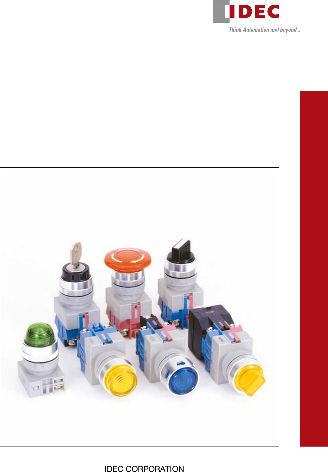
TW Series
Switches & Pilot Lights
(14/05/22)
2
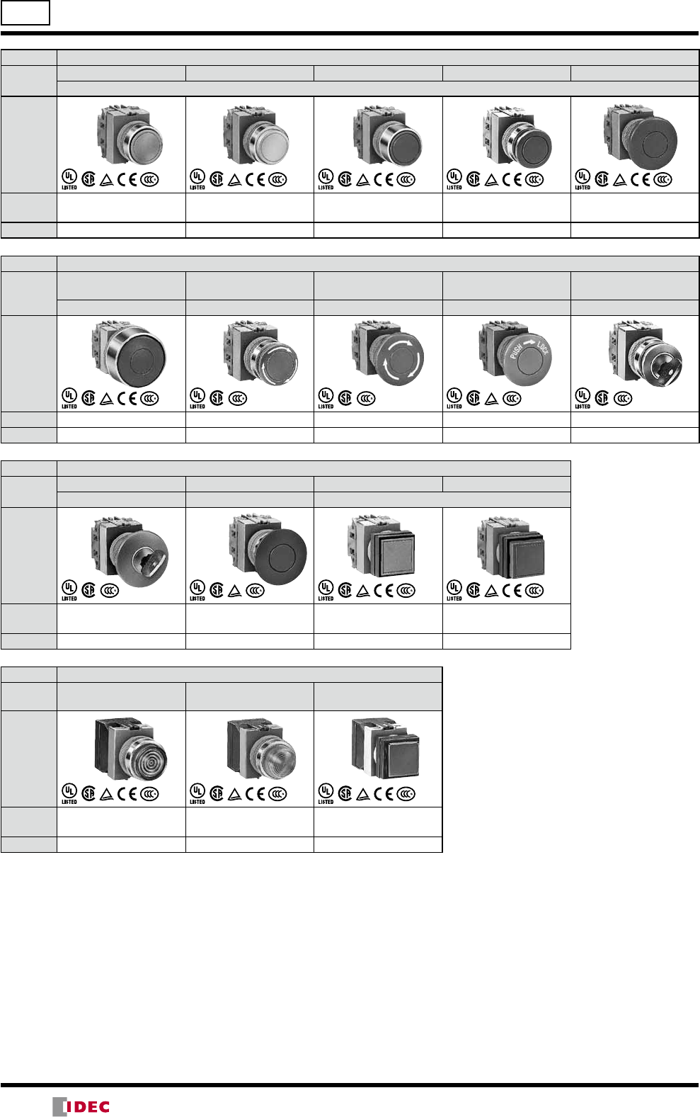
ø22 TW Series Selection Guide
Function Pushbutton
Category Flush Extended
Extended w/Full Shroud
ø29mm Mushroom ø40mm Mushroom
Momentary/Maintained
Shape
Model ABW1
AOW1
ABW2
AOW2
ABFW2
AOFW2
ABW3
AOW3
ABW4
AOW4
Page 7 7 7 7 8
Function Pushbutton
Category
ø40mm Mushroom
w/Full Shroud ø29mm Mushroom ø40mm Mushroom ø40mm Mushroom ø29mm Mushroom
Momentary Pushlock Turn Reset Pushlock Turn Reset Push Turn Lock Pushlock Key Reset
Shape
Model ABGW4 AVW3 AVW4 AJW4 AXW3
Page 8 8 8 8 8
Function Pushbutton
Category ø40mm Mushroom ø40mm Mushroom Square Flush Square Extended
Pushlock Key Reset Push Pull Momentary/Maintained
Shape
Model AXW4 AYW4 ABQW1
AOQW1
ABQW2
AOQW2
Page 9 9 9 9
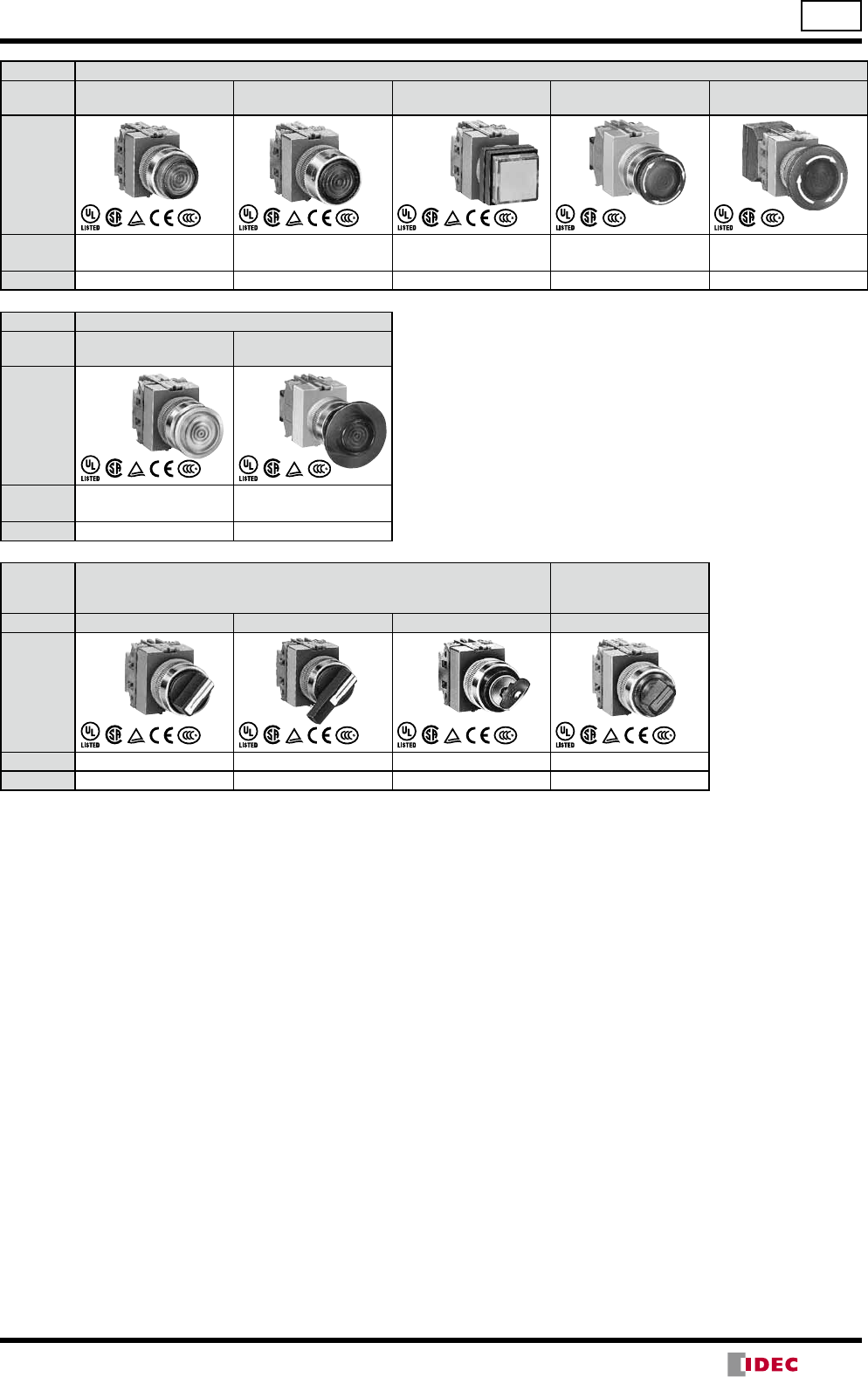
Function Pilot Light
Category Flush
(Non-marking/Marking) Dome Square Flush
(Marking)
Shape
Model APW1
APW1B APW2 APQW1B
Page 10 10 10
(14/05/22)
3
TW Series Selection Guide ø22
Function Illuminated Pushbutton (LED/Incandescent)
Category Extended
(Non-marking/Marking)
Extended w/Full Shroud
(Non-marking/Marking)
Square Extended
(Marking)
ø29mm Mushroom
Pushlock Turn Reset
ø40mm Mushroom
Pushlock Turn Reset
Shape
Part No. ALW2, ALW2B,
AOLW2, AOLW2B
ALFW2, AOLFW2
ALFW2B, AOLFW2B
ALQW2B
AOLQW2B
AVLW3
AVLW3B
AVLW4
AVLW4B
Page 12, 13 14, 15 16 17 18
Function Illuminated Pushbutton (Incandescent)
Category ø29mm Mushroom
(Non-marking/Marking) ø40mm Push-Pull
Shape
Part No. ALW3, ALW3B,
AOLW3, AOLW3B
AYLW4
AYLW4B
Page 17 18
Function Selector Switch
Illuminated Selector
Switch
(LED/Incandescent)
Category Knob Lever Key Knob
Shape
Part No. ASW ASW∗LASW∗KASLW
Page 21 22 23 24, 25
(14/05/22)
4
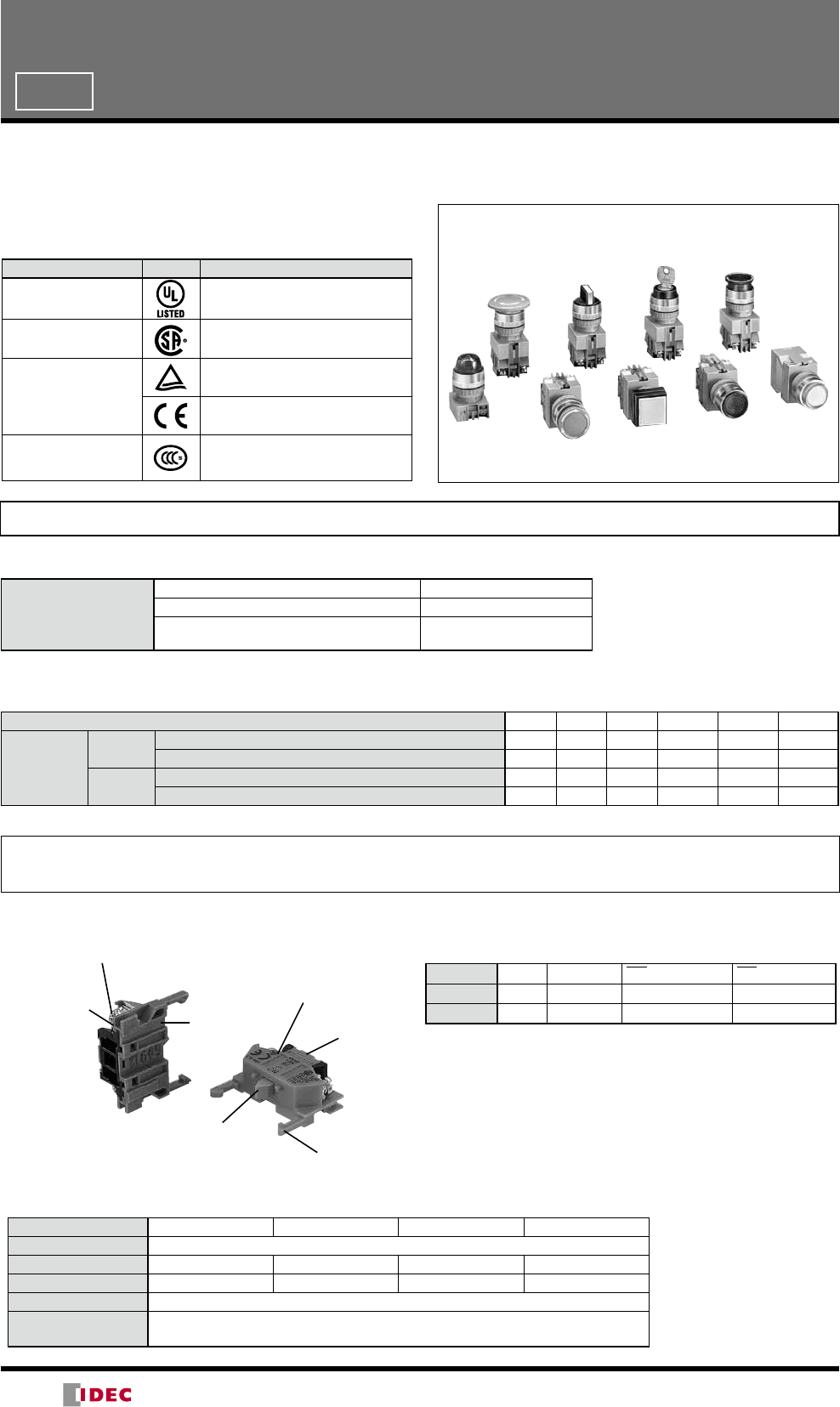
TW Series Switches & Pilot Lights
ø22
General-purpose switches & pilot lights for various applications
Heavy-duty type for high-level protection against
harsh environment
•Highly reliable HW contact blocks are used.
•Degree of protection: IP65 (IEC 60529)
•UL and CSA approved, EN compliant
Applicable Standards Mark File No. or Organization
UL508 UL Listing
File No. E68961
CSA C22.2 No.14 CSA File No. LR21451
EN60947-5-1
TÜV Rheinland
EU Low Voltage Directive
GB14048.5 CCC
No. 2003010305027380
(pilot light: No. 2007010304226713)
Specifications and Ratings
Contact Ratings
Contact Block
Rated Insulation Voltage 600V
Rated Continuous Current 10A
Contact Ratings by Utilization Category
IEC 60947-5-1
AC-15 (A600)
DC-13 (P600)
Characteristics
Contact Ratings by Utilization Category
Operational Voltage 24V 48V 50V 110 V 220V 440V
Operational
Current
AC
50/60 Hz
AC-12 Control of resistive loads and solid state loads 10A —10A 10A 6A 2A
AC-15 Control of electromagnetic loads (> 72 VA) 10A — 7A 5A 3A 1A
DC DC-12 Control of resistive loads and solid state loads 8A 4A — 2.2A 1.1A —
DC-13 Control of electromagnets 4A 2A — 1.1A 0.6A —
Minimum applicable load: 3V AC/DC, 5 mA (applicable range may vary with operating conditions and load types)
For the switches & pilot Lights listed below, the rated current (load switching current) is reduced to a half of the rated operational current of
the contact block. The rated insulation voltage (600V) and the rated thermal current (10A) remain unchanged.
•Selector switches and illuminated selector switches with contact code 2S, 3S, 4S, 2R, or 4R.
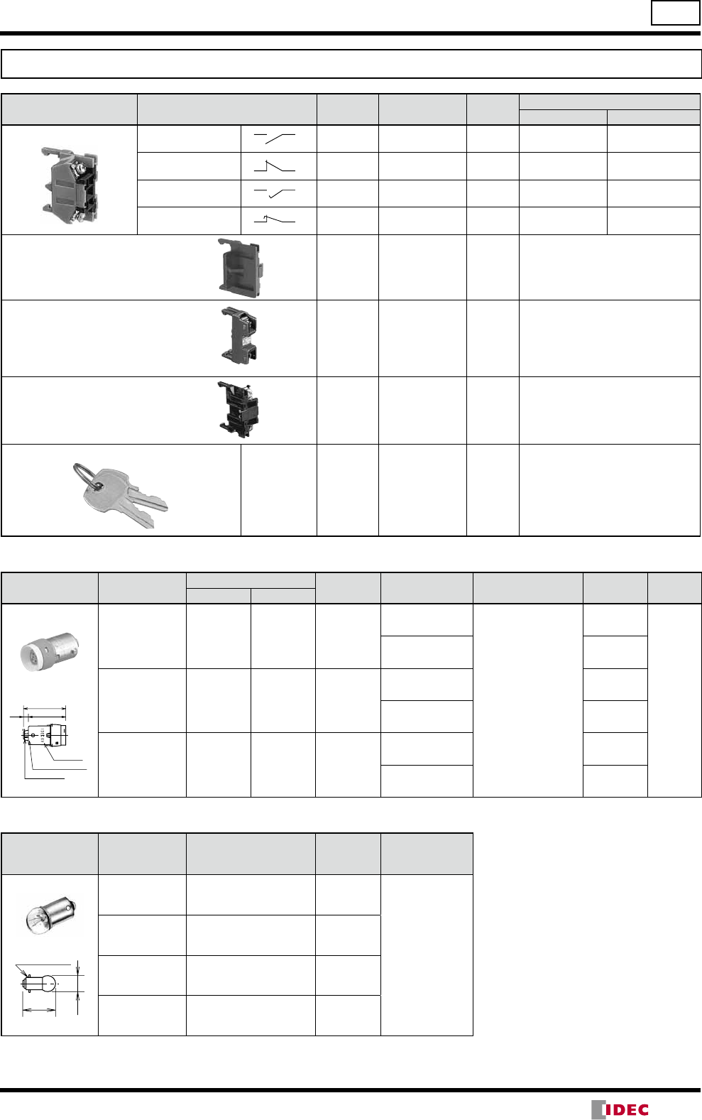
HW-C (Contact Block)
M3.5 terminal screw
2-way wiring possible Double-break rolling
action silver contacts
with raked surface
Contact Blocks
Contact NO NC NO (early make) NC (late break)
Housing Blue Purple red Blue Purple red
Push Rod Green Red Black White
Alkali-resistant
66 nylon housing
Push rod
Color-coded for
different contacts
Fitting groove
Snap-fit groove
Snap-fit latch
A maximum of four contact blocks in two
layers can mount on the operator.
Incandescent Lamp Ratings (LS)
Part No. LS-6 LS-8 LS-2 LS-3
Lamp Base BA9S/13
Rated Voltage 6V AC/DC 12V AC/DC 18V AC/DC 24V AC/DC
Wattage 1W (6.3V) 1W (18V) 1W (24V) 1W (30V)
Voltage Marking Die stamped on the base
Life (reference value) Approx. 1,000 hours minimum
(mean value when used on the rated voltage)
(14/05/22)
5
TW Series Switches & Pilot Lights ø22
LED Lamp Ratings (LSTD)
Part No. LSTD-6LSTD-1LSTD-2
Lamp Base BA9S/13
Rated Voltage 6V AC/DC 12V AC/DC 24V AC/DC
Voltage Range 6V AC/DC ±10% 12V AC/DC ±10% 24V AC/DC ±10%
Current Draw AC 8 mA 11 mA 11 mA
DC A, R, W:7 mA, G, PW, S:5.5 mA 10 mA 10 mA
Color Code A (amber), G (green), PW (pure white), R (red), S (blue), W (white)
Use a pure white LED lamp for yellow illumination
Lamp Base Color Same as illumination color
Voltage Marking Die stamped on the base
Life (reference value) Approx. 50,000 hours (until the brightness reduces to 50% of the initial value when lit at complete direct
current of the rated voltage under 25ºC environment.)
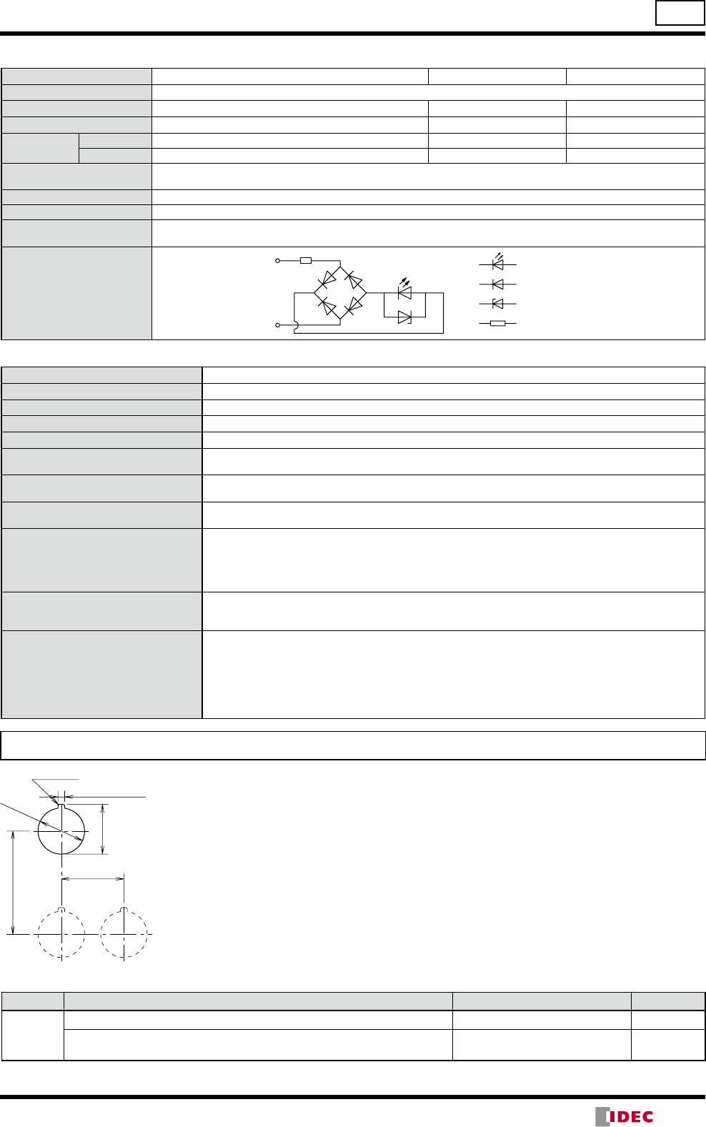
Internal Circuit
LED Chip
Resistor
Zener Diode
Protection Diode
X1
X2
Specifications
Operating Temperature –25 to +50°C (no freezing)
Storage Temperature –40 to +80°C
Operating Humidity 45 to 85% RH (no condensation)
Contact Resistance 50 mΩ maximum (initial value)
Insulation Resistance 100 MΩ minimum (500V DC megger)
Dielectric Strength Between live and dead metal parts: 2,500V AC, 1 minute
(Full voltage illuminated units: 2,000V AC, 1 minute)
Vibration Resistance Damage Limits: 30 Hz, amplitude 1.5 mm
Operating extremes: 5 to 55 Hz, amplitude 0.5 mm
Shock Resistance Damage limits: 1,000 m/s2
Operating extremes: 100 m/s2
Mechanical Life (minimum operations)
Pushbuttons, Illuminated pushbuttons
Momentary: 5,000,000
Others: 500,000
Selector switches: 500,000
Illuminated selector switches: 500,000
Electrical Life (minimum operations) Pushbuttons: 500,000 (switching frequency 1,800 operations/h, duty ratio 40%)
Illuminated pushbuttons: 500,000 (switching frequency 1,800 operations/h, duty ratio 40%)
Selector switches: 500,000 (switching frequency 1,200 operations/h, duty ratio 40%)
Weight (approx.)
68g (ABW122)
33g (APW122D)
89g (ALW22222D)
68g (ASW222)
107g (ASW2K22)
90g (ASLW22222D)
95g (APW126D)
Mounting Hole Layout
Degree of Protection
Part No. Unit NEMA ICS 6-110 IEC 60529
A∗∗∗∗
Pushbuttons, pilot lights, illuminated pushbuttons, and selector switches Type 1, 2, 3, 3R, (3S), 4, 5, 12,13 IP65
Illuminated selector switches, key pushbuttons, key reset pushbuttons, and
key selector switches Type 1, 2, 3R, 5, 12, 13 IP54
Note: (3S) of NEMA ICS 6-110 applies to the pilot lights with round lens.
(45 min.)
R0.8 max.
0
+0.4
+0.4
0
+0.2
0
30 (Note 2)
50
ø22.3
3.2
24.1
(Note 1)
Note 1: The 3.2 mm recess is for preventing rotation and is not necessary when the nameplate or anti-
rotation ring is not used.
Note 2: The minimum mounting centers are applicable to switches with one layer of contact blocks
(two contact blocks). When two layers of contact blocks are mounted, determine the minimum
mounting centers in consideration of convenience for wiring.
•ø40mm mushroom: 40 mm minimum
•2-position, 3-position lever selector switch: 39 mm minimum
•4-position, 5-position lever selector switch: 50 mm minimum
(14/05/22)
6
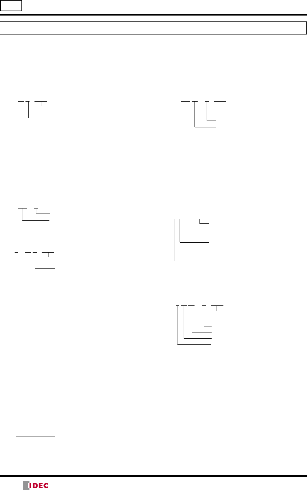
ø22 TW Series Ordering Information
ASW 2 K 20 B - MAU
Optional contact
MAU: Gold-plated silver contact
Key removable position code
2-position
•Maintained
(blank): Removable in all positions
B: Removable in left only
C: Removable in right only
•Spring return from right
(blank): Removable in left only
•Spring return from left
(blank): Removable in right only
3-position
•Maintained
(blank): Removable in all positions
B: Removable in left and center
C: Removable in right and center
D: Removable in center only
E: Removable in right and left
G: Removable in left only
H: Removable in right only
•Spring return from right
(blank): Removable in left and center
D: Removable in center only
G: Removable in left only
•Spring return from left
(blank): Removable in right and center
D: Removable in center only
H: Removable in right only
•Spring return two-way
(blank): Removable in center only
Contact arrangement code
Number of positions
Note:
•See pages 26 to 28 for contact arrangement codes.
•The key cannot be removed in the return position.
ASLW 2 16 22 D R - MAU
Optional contact
MAU: Gold-plated silver contact
Lens color code
Contact arrangement code
Operating voltage code
Number of positions
Note:
•See pages 26 to 28 for contact arrangement codes.
Selector Switch
ASW 2 L 11 - MAU
Optional contact
MAU: Gold-plated silver contact
Contact arrangement code
Operator type
(blank): Knob
L: Lever
Number of positions
Note:
•See pages 26 to 28 for contact arrangement codes.
Key Selector Switch
Illuminated Selector Switch
Ordering Information
•Specify an operator or lens color code in the Part No.
•All standard units are UL, CSA, EN, and TÜV approved.
•When a terminal cover is required, order an applicable
terminal cover referring to page 29.
Part No. development charts shown below can be used to specify switches/pilot lights other than those listed on the following
pages. Gold-plated silver contacts are also available.
Pushbuttons
Pilot Lights
ABW1 11 R - MAU
Optional contact
MAU: Gold-plated silver contact
Button color code
Contact arrangement code
10: 1NO 01: 1NC
11: 1NO-1NC 20: 2NO
02: 2NC 21: 2NO-1NC
12: 1NO-2NC 30: 3NO
03: 3NC 31: 3NO-1NC
22: 2NO-2NC 13: 1NO-3NC
40: 4NO 04: 4NC
Note:
•Push-pull type AYW4 can have a maximum of two contact blocks.
APW2 126 D R
Lens color code
Operating voltage code
Illuminated Pushbuttons
ALFW2 126 13 D R - MAU
Optional contact
MAU: Gold-plated silver contact
Lens color code
Contact arrangement code
10: 1NO 01: 1NC
11: 1NO-1NC 20: 2NO
02: 2NC 21: 2NO-1NC
12: 1NO-2NC 30: 3NO
03: 3NC 31: 3NO-1NC
22: 2NO-2NC 13: 1NO-3NC
40: 4NO 04: 4NC
Operating voltage code
Note:
•
Push-pull type AYLW4 can have a maximum of two contact blocks.
(14/05/22)
7
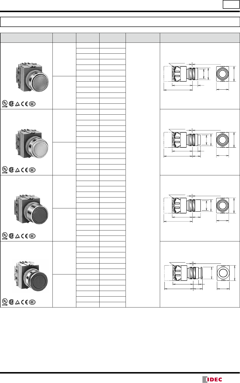
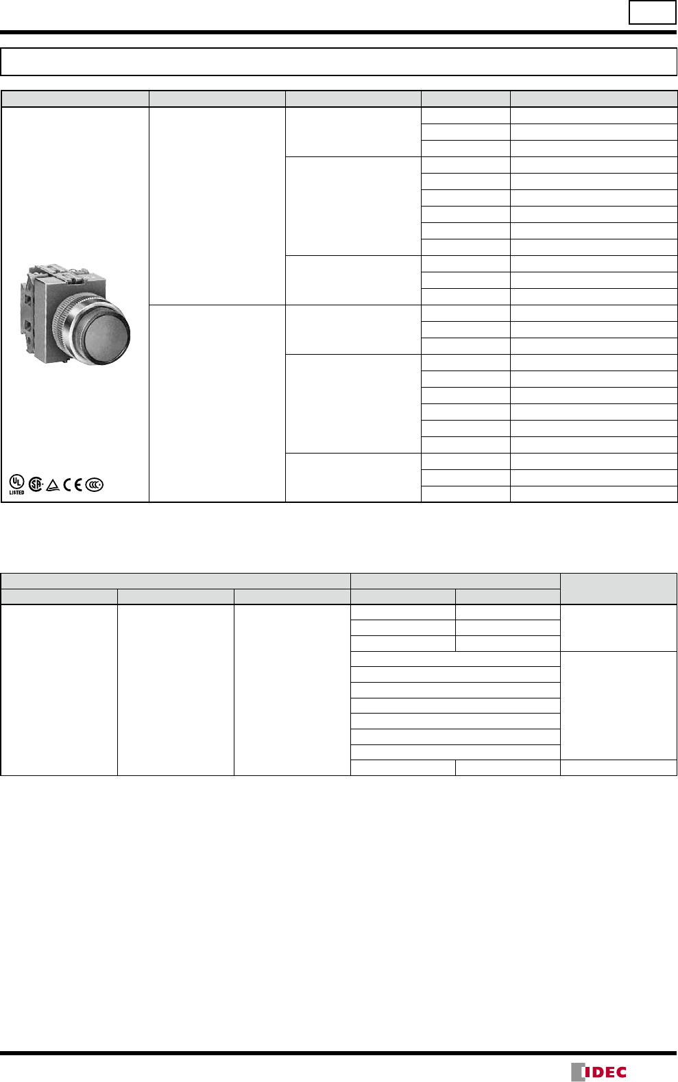
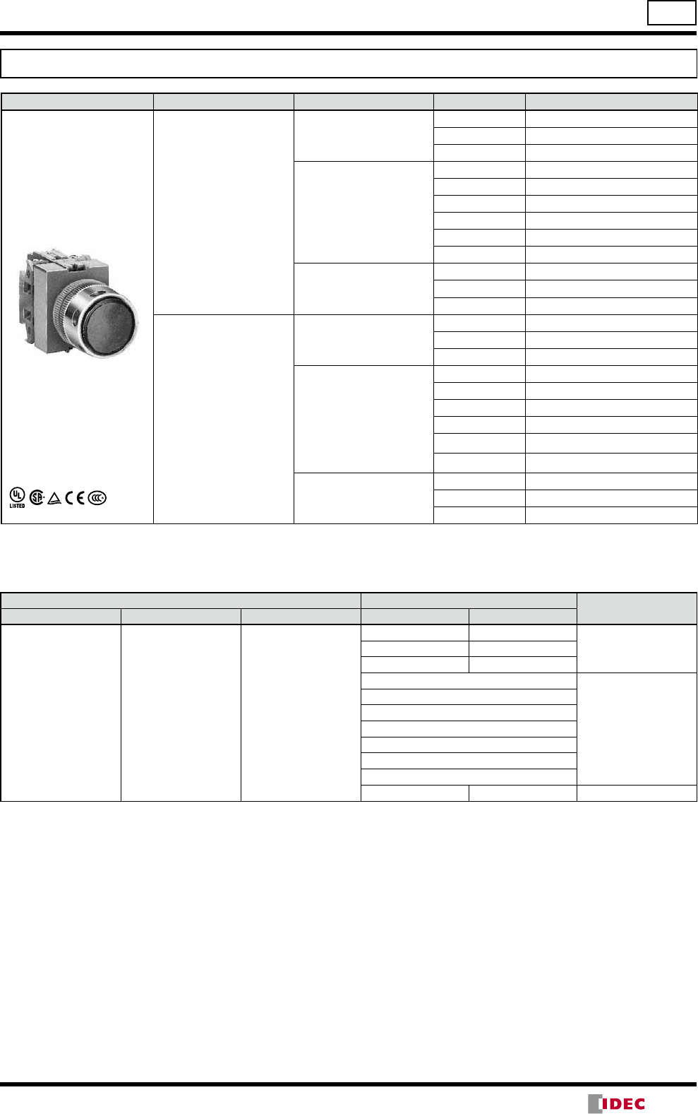
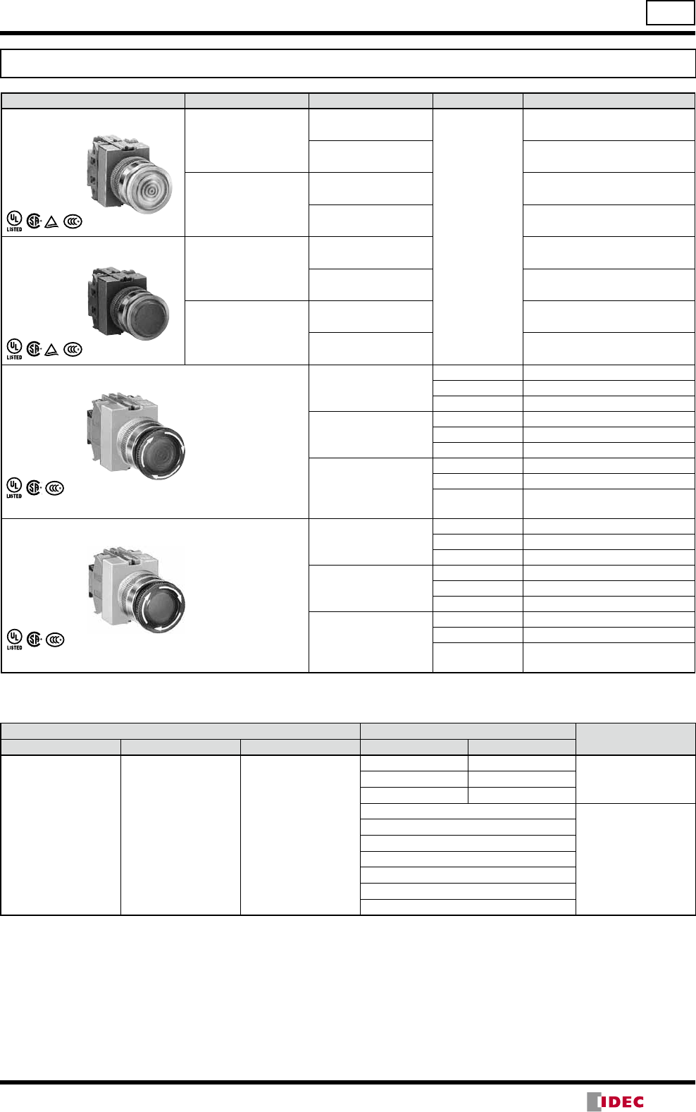
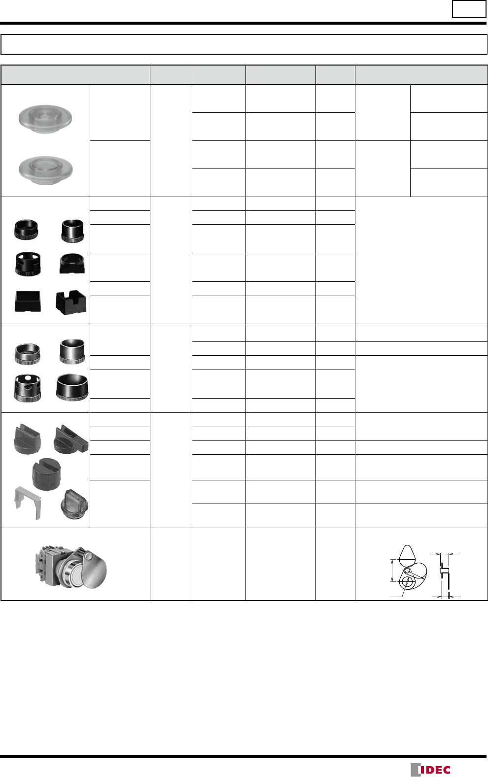
TW Series Pushbuttons ø22
Flush / Extended / Extended w/Full Shroud / Mushroom
Shape Operation Contact Part No. Button Color
Code Dimensions (mm)
Flush
ABW1
AOW1
Momentary
1NO ABW110
Specify a button
color code in
place of in the
Part No.
B: black
G: green
R: red
S: blue
W: white
Y: yellow
1NC ABW101
1NO-1NC ABW111
2NO ABW120
2NC ABW102
2NO-2NC ABW122
Maintained
1NO AOW110
1NC AOW101
1NO-1NC AOW111
2NO AOW120
2NC AOW102
2NO-2NC AOW122
Extended
ABW2
AOW2
Momentary
1NO ABW210
1NC ABW201
1NO-1NC ABW211
2NO ABW220
2NC ABW202
2NO-2NC ABW222
Maintained
1NO AOW210
1NC AOW201
1NO-1NC AOW211
2NO AOW220
2NC AOW202
2NO-2NC AOW222
Extended with Full Shroud
ABFW2
AOFW2
Momentary
1NO ABFW210
1NC ABFW201
1NO-1NC ABFW211
2NO ABFW220
2NC ABFW202
2NO-2NC ABFW222
Maintained
1NO AOFW210
1NC AOFW201
1NO-1NC AOFW211
2NO AOFW220
2NC AOFW202
2NO-2NC AOFW222
ø29mm Mushroom
ABW3
AOW3
Momentary
1NO ABW310
1NC ABW301
1NO-1NC ABW311
2NO ABW320
2NC ABW302
2NO-2NC ABW322
Maintained
1NO AOW310
1NC AOW301
1NO-1NC AOW311
2NO AOW320
2NC AOW302
2NO-2NC AOW322
•Round bezel and shroud (metal): Mat aluminum color
•Pushbuttons with one or three contact blocks contain a dummy block.
•Other contact arrangements and gold-plated silver contacts are also available. See page6.
30
37
ø29
ø24
13
M3.5 Terminal
Screws
68.5 (3-4 blocks)
48.5 (1-2 blocks)
Panel Thickness 1 to 6
13
19 30
37
ø29
ø24
M3.5 Terminal
Screws
68.5 (3-4 blocks)
48.5 (1-2 blocks)
Panel Thickness 1 to 6
ø29
30
37
ø24
19.5
M3.5 Terminal
Screws
68.5 (3-4 blocks)
48.5 (1-2 blocks)
Panel Thickness 1 to 6
M3.5 Terminal
Screws
13
22.5
68.5 (3-4 blocks)
48.5 (1-2 block)
Panel Thickness 1 to 6
30
37
ø29
(14/05/22)
8
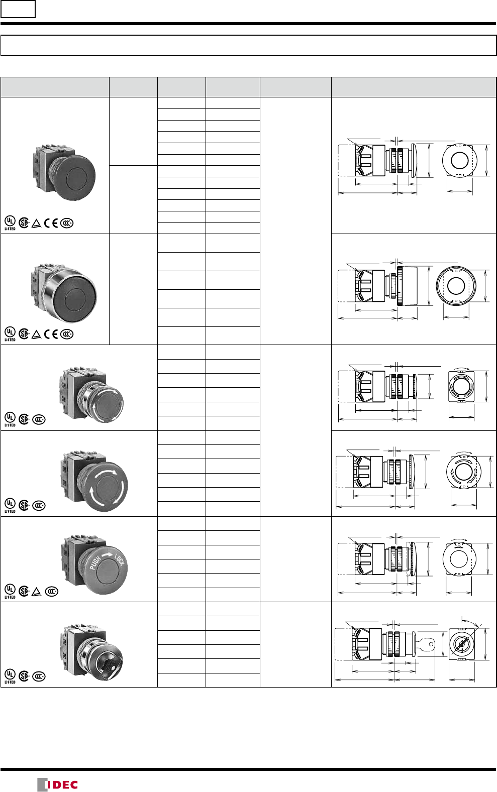
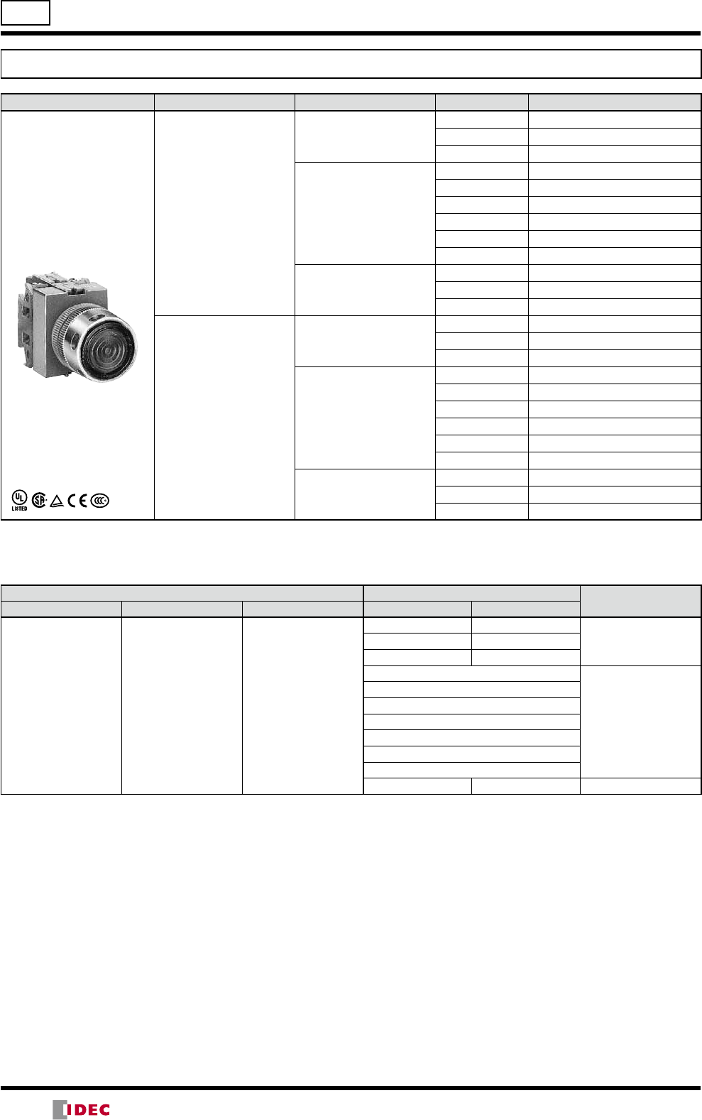
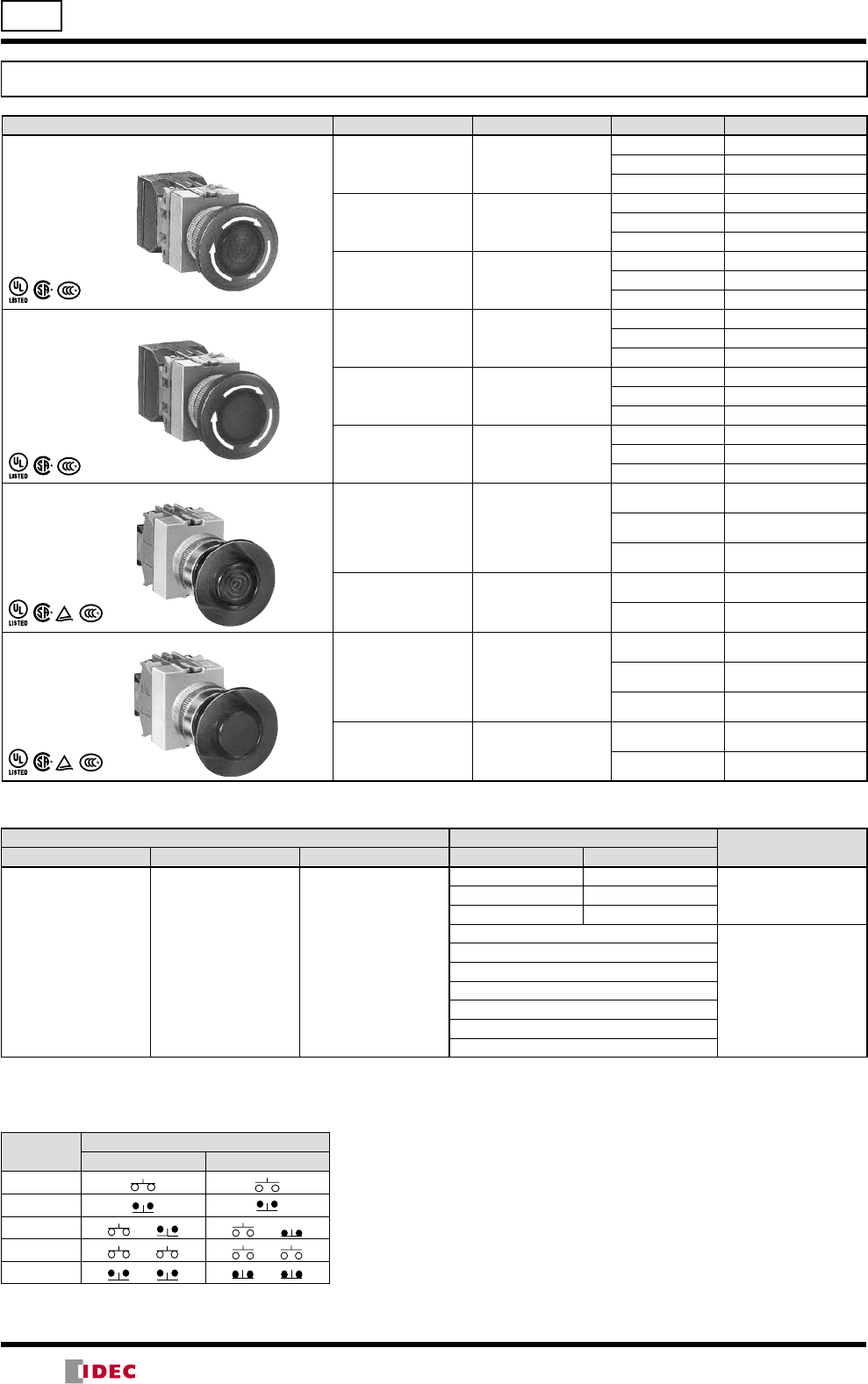
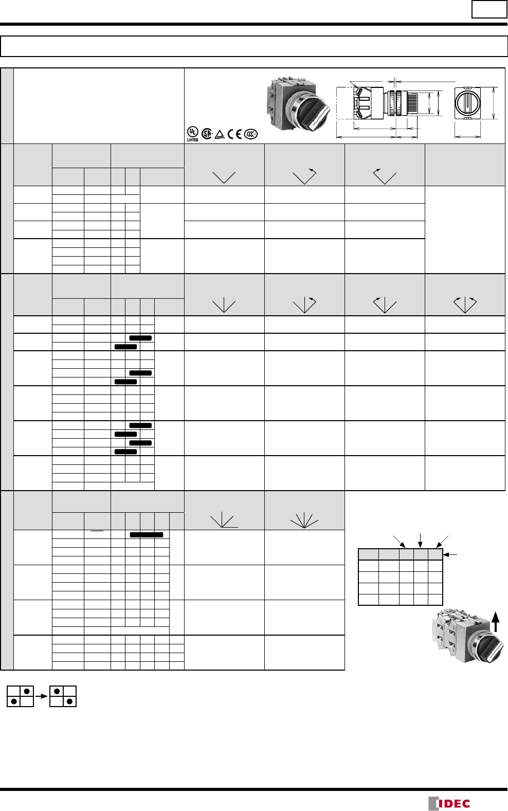
ø22 TW Series Pushbuttons
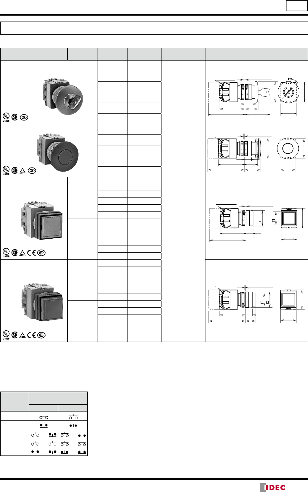
Mushroom / Pushlock Turn Reset / Push Turn Lock / Pushlock Key Reset
Shape Operation Contact Part No. Button Color
Code Dimensions (mm)
ø40mm Mushroom
ABW4
AOW4
Momentary
1NO ABW410
Specify a button
color code in
place of in the
Part No.
B: black
G: green
R: red
S: blue
W: white
Y: yellow
1NC ABW401
1NO-1NC ABW411
2NO ABW420
2NC ABW402
2NO-2NC ABW422
Maintained
1NO AOW410
1NC AOW401
1NO-1NC AOW411
2NO AOW420
2NC AOW402
2NO-2NC AOW422
ø40mm Mushroom
w/Full Shroud
ABGW4
Momentary
1NO ABGW410
1NC ABGW401
1NO-1NC ABGW411
2NO ABGW420
2NC ABGW402
2NO-2NC ABGW422
ø29mm Pushlock Turn Reset
AVW3 (Note) 1NO AVW310
R: red
Y: yellow
1NC AVW301
1NO-1NC AVW311
2NO AVW320
2NC AVW302
2NO-2NC AVW322
ø40mm Pushlock Turn Reset
AVW4 (Note) 1NO AVW410
1NC AVW401
1NO-1NC AVW411
2NO AVW420
2NC AVW402
2NO-2NC AVW422
ø40mm Push Turn Lock
AJW4 1NO AJW410
B: black
G: green
R: red
Y: yellow
1NC AJW401
1NO-1NC AJW411
2NO AJW420
2NC AJW402
2NO-2NC AJW422
ø29mm Pushlock Key Reset
AXW3 (Note) 1NO AXW310R
Red only
1NC AXW301R
1NO-1NC AXW311R
2NO AXW320R
2NC AXW302R
2NO-2NC AXW322R
•Round bezel (metal): Mat aluminum color
•Pushbuttons with one or three contact blocks contain a dummy block.
•Other contact arrangements and gold-plated silver contacts are also available. See page6.
Note: AVW3, AVW4, and AXW3 pushbuttons cannot be used as emergency stop switches. When emergency stop switches are required,
use XW or HW series pushbuttons (ISO 13850 and IEC 60947-5-5 compliant).
M3.5 Terminal
Screws
13
22.5
ø40
68.5 (3-4 blocks)
48.5 (1-2 blocks)
Panel Thickness 1 to 6
30
37
M3.5 Terminal
Screw
48.5 (1-2 blocks)
68.5 (3-4 blocks)
Panel Thickness 1 to 6
30
37
ø46
23
30
37
13
22.5
ø29
M3.5 Terminal
Screws
48.5 (1-2 blocks)
68.5 (3-4 blocks)
Panel Thickness
1 to 6 Reset Angle 75
M3.5 Terminal
Screws
48.5 (1-2 blocks)
68.5 (3-4 blocks)
Panel Thickness
1 to 6 Reset Angle 75
30
37
13
22.5
ø40
Reset Angle 75
30
37
13
22.5
ø40
P
U
S
H
L
O
C
K
M3.5 Terminal
Screws
48.5 (1-2 blocks)
68.5 (3-4 blocks)
Panel Thickness
1 to 6
Reset
(unlock)
37
25
47
13
ø29
45
30
M3.5 Terminal
Screws
48.5 (1-2 blocks)
68.5 (3-4 blocks)
Panel Thickness
1 to 6
(14/05/22)
9
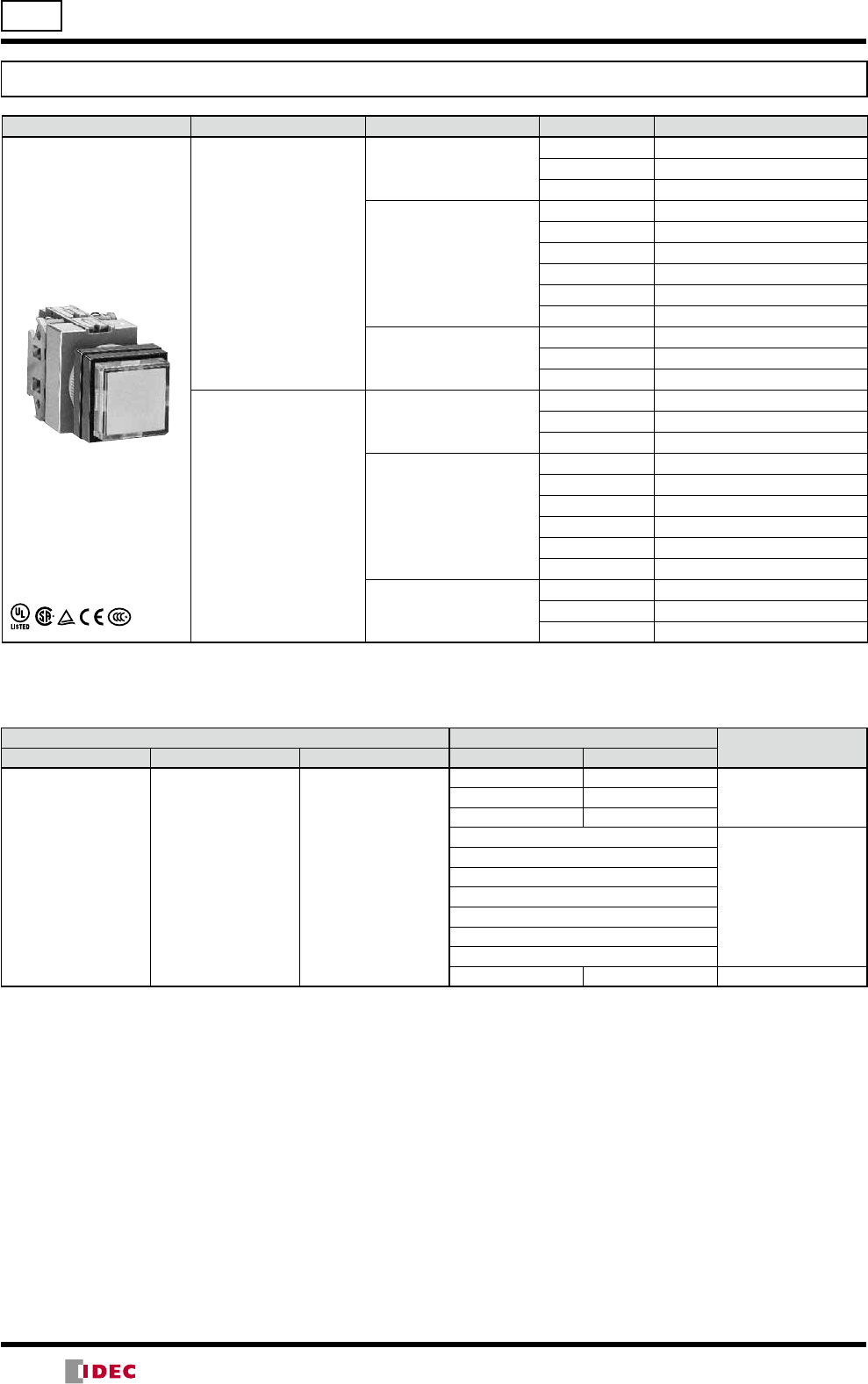
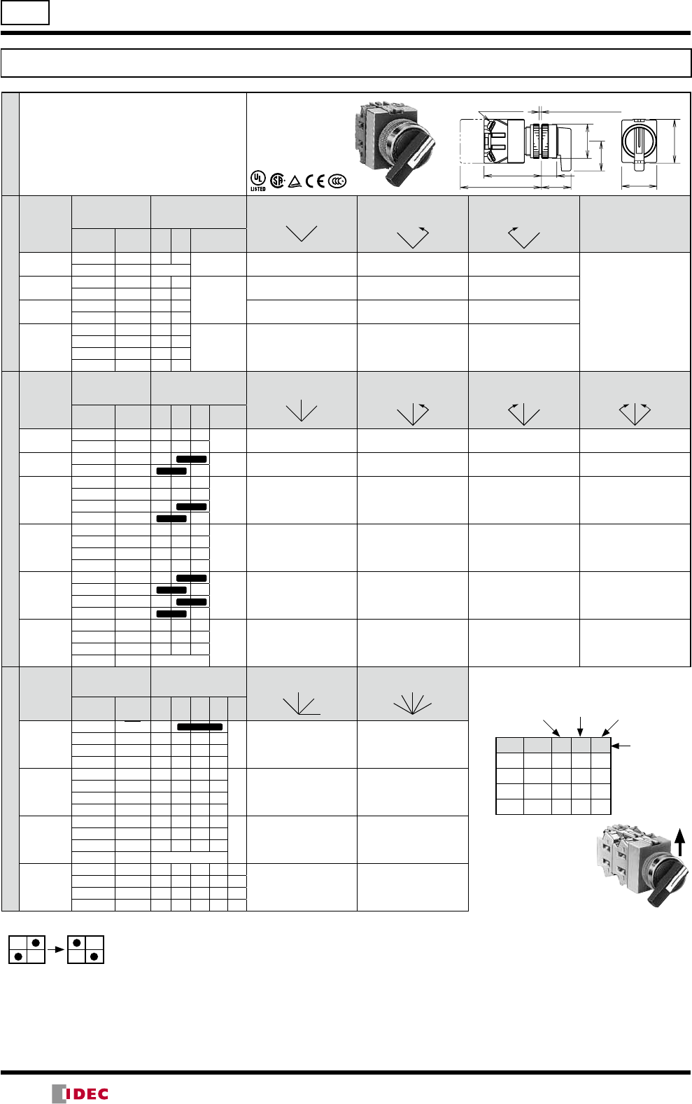
TW Series Pushbuttons ø22
Pushlock Key Reset / Push-Pull / Square Flush / Square Extended
Shape Operation Contact Part No. Button Color
Code Dimensions (mm)
ø40mm Mushroom Push Lock Key Reset
AXW4 (Note) 1NO AXW410R
Red only
1NC AXW401R
1NO-1NC AXW411R
2NO AXW420R
2NC AXW402R
2NO-2NC AXW422R
ø40mm Mushroom Push-Pull
AYW4 1NO AYW410
Specify a button
color code in
place of in the
Part No.
B: black
G: green
R: red
S: blue
W: white
Y: yellow
1NC AYW401
1NO-1NC AYW411
2NO AYW420
2NC AYW402
Square Flush
ABQW1
AOQW1
Momentary
1NO ABQW110
1NC ABQW101
1NO-1NC ABQW111
2NO ABQW120
2NC ABQW102
2NO-2NC ABQW122
Maintained
1NO AOQW110
1NC AOQW101
1NO-1NC AOQW111
2NO AOQW120
2NC AOQW102
2NO-2NC AOQW122
Square Extended
ABQW2
AOQW2
Momentary
1NO ABQW210
1NC ABQW201
1NO-1NC ABQW211
2NO ABQW220
2NC ABQW202
2NO-2NC ABQW222
Maintained
1NO AOQW210
1NC AOQW201
1NO-1NC AOQW211
2NO AOQW220
2NC AOQW202
2NO-2NC AOQW222
•Round bezel (metal): Mat aluminum color
•Square bezel (plastic): Black
•Pushbuttons with one or three contact blocks contain a dummy block.
•Other contact arrangements and gold-plated silver contacts are also available. See page6.
Note: AXW4 pushbuttons cannot be used as emergency stop switches. When emergency stop switches are required, use XW or HW
series pushbuttons (ISO 13850 and IEC 60947-5-5 compliant).
Contact Statuses of Push-Pull Switch
Contact
ø40mm Mushroom
Push-Pull Switch
Push Pull
1NO
1NC
1NO-1NC
2NO
2NC
Note: Push-pull switch can have a maximum of two contact blocks.
(unlock)
Reset
37
25
47
13
45
30
ø40
M3.5 Terminal
Screws
48.5 (1-2 blocks)
68.5 (3-4 blocks)
Panel Thickness
1 to 6
37
25
13
30
ø40
30.5
M3.5 Terminal
Screws
48.5 (1-2 blocks)
68.5 (3-4 blocks)
Panel Thickness
1 to 6
37
13
30
30
25
M3.5 Terminal
Screws
48.5 (1-2 blocks)
68.5 (3-4 blocks)
Panel Thickness
1 to 6
37
13
30
30
20
25
M3.5 Terminal
Screws
48.5 (1-2 blocks)
68.5 (3-4 blocks)
Panel Thickness
1 to 6
(14/05/22)
10
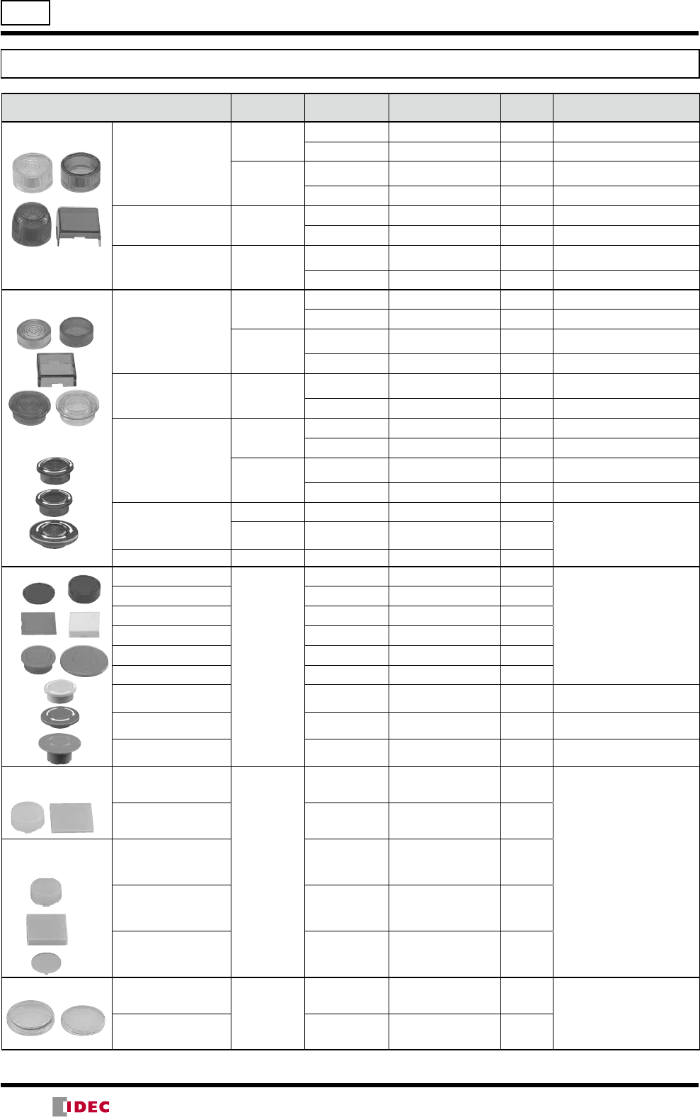
ø22 TW Series Pilot Lights
Round Flush / Dome / Square Flush Pilot Lights
Package Quantity: 1
Shape Lamp Part No. Lens/Illumination Color Code
Round Flush
APW1 Without Lamp APW199A: amber, G: green, R: red, S: blue, W: white,
Y: yellow
LED APW1-DA: amber, G: green, PW: pure white, R: red,
S: blue, W: white, Y: yellow
Incandescent APW1-A: amber, G: green, R: red, S: blue, W: white
Round Flush (Marking)
APW1B Without Lamp APW1B99A: amber, G: green, R: red, S: blue, W: white,
Y: yellow
LED APW1B-DA: amber, G: green, PW: pure white, R: red,
S: blue, W: white, Y: yellow
Incandescent APW1B-A: amber, G: green, R: red, S: blue, W: white
Dome
APW2 Without Lamp APW299A: amber, G: green, R: red, S: blue, W: white,
Y: yellow
LED APW2-DA: amber, G: green, PW: pure white, R: red,
S: blue, W: white, Y: yellow
Incandescent APW2-A: amber, G: green, R: red, S: blue, W: white
Square Flush (Marking)
APQW1B Without Lamp APQW1B99A: amber, G: green, R: red, S: blue, W: white,
Y: yellow
LED APQW1B-DA: amber, G: green, PW: pure white, R: red,
S: blue, W: white, Y: yellow
Incandescent APQW1B-A: amber, G: green, R: red, S: blue, W: white
Designation Code
Specify an designation code in place of - in the Part No.
- Operating Voltage Code Input Type
LED Incandescent
66: 6V AC/DC 66: 6V AC/DC
Full Voltage11: 12V AC/DC 88: 12V AC/DC
22: 24V AC/DC 33: 24V AC/DC
16: 100/110V AC
Transformer
126: 115/120V AC
26: 200/220V AC
246: 230/240V AC
386: 380V AC
46: 400/440V AC
486: 480V AC
16D: 110V DC — DC-DC Converter ∗
•Use a pure white LED lamp for yellow illumination.
•The white (W) lens of APW1B and APQW1B consists of a clear lens and a white marking plate.
•Round bezel (metal): Mat aluminum color Square bezel (plastic): Black
∗DC-DC converter types are not approved by UL, CSA, and TÜV, and not CE compliant (operating voltage 90 to 140V DC).
(14/05/22)
11
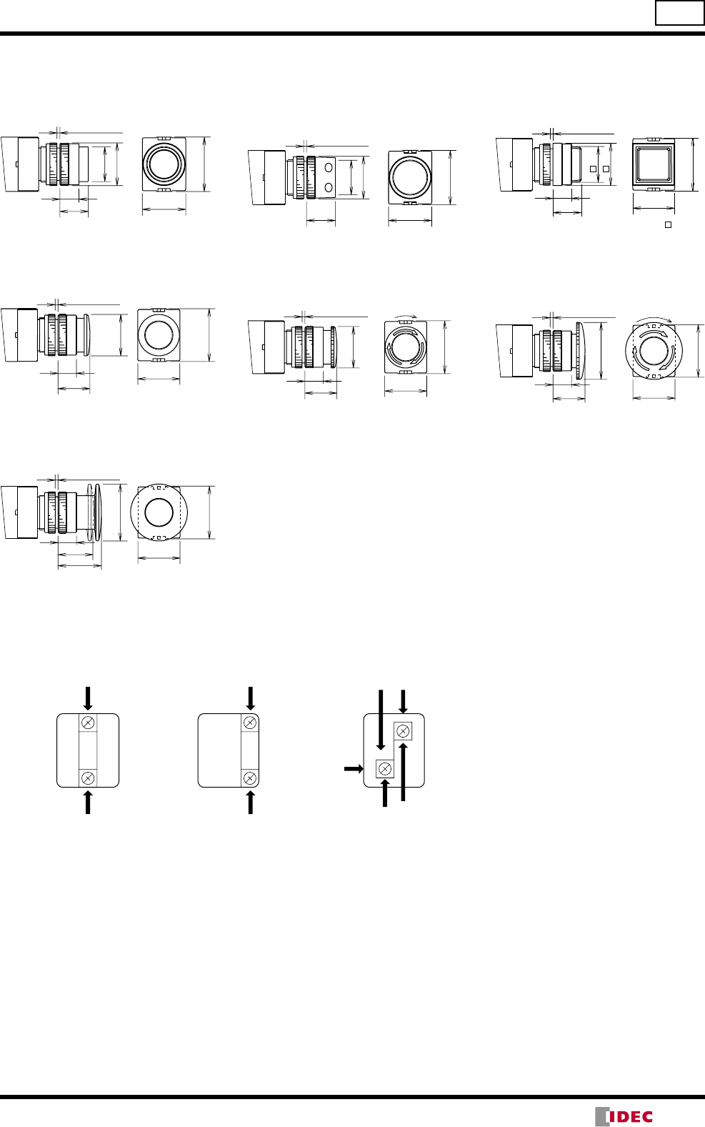
TW Series Pilot Lights ø22
Dimensions
Terminal Wiring (Bottom View)
•Arrows indicate access directions for wiring.
X1
X2
M3.5
X1
X2
M3.5
Full Voltage Transformer
DC-DC Converter
TOPTOP
28.5 13 30
ø29
37
ø24
17
Panel Thickness
1 to 6
28.5 13
66.5
30
ø29
37
ø24
17
M3.5 Terminal Screw
Panel Thickness
1 to 6
Round Flush APW1
Full Voltage
Dome APW2
Full Voltage
Dome APW2
Transformer, DC-DC Converter
Round Flush Marking APW1B
Full Voltage
Round Flush Marking APW1B
Transformer, DC-DC Converter
Round Flush APW1
Transformer, DC-DC Converter
Dome APW2
Transformer, DC-DC Converter
Dome APW2
Full Voltage
Marking plate: ø15.5 mm
28.5 13 30
ø29
37
ø24
17
Panel Thickness
1 to 6
Panel Thickness
1 to 6
28.5 13
25
30
ø23.6
ø29
37
M3.5 Terminal
Screw
Panel Thickness
1 to 6
28.5 13
66.5 25
30
ø23.6
ø29
37
Marking plate: 22 mm
Panel Thickness
1 to 6
28.5 13 30
37
16
25
30
Marking plate: 22 mm
M3.5 Terminal
Screw Panel Thickness 1 to 6
28.5 13
66.5
30
37
16
25
30
Marking plate: ø15.5 mm
28.5 13
66.5
30
ø29
37
ø24
17
M3.5 Terminal
Screw
Panel Thickness
1 to 6
(14/05/22)
12
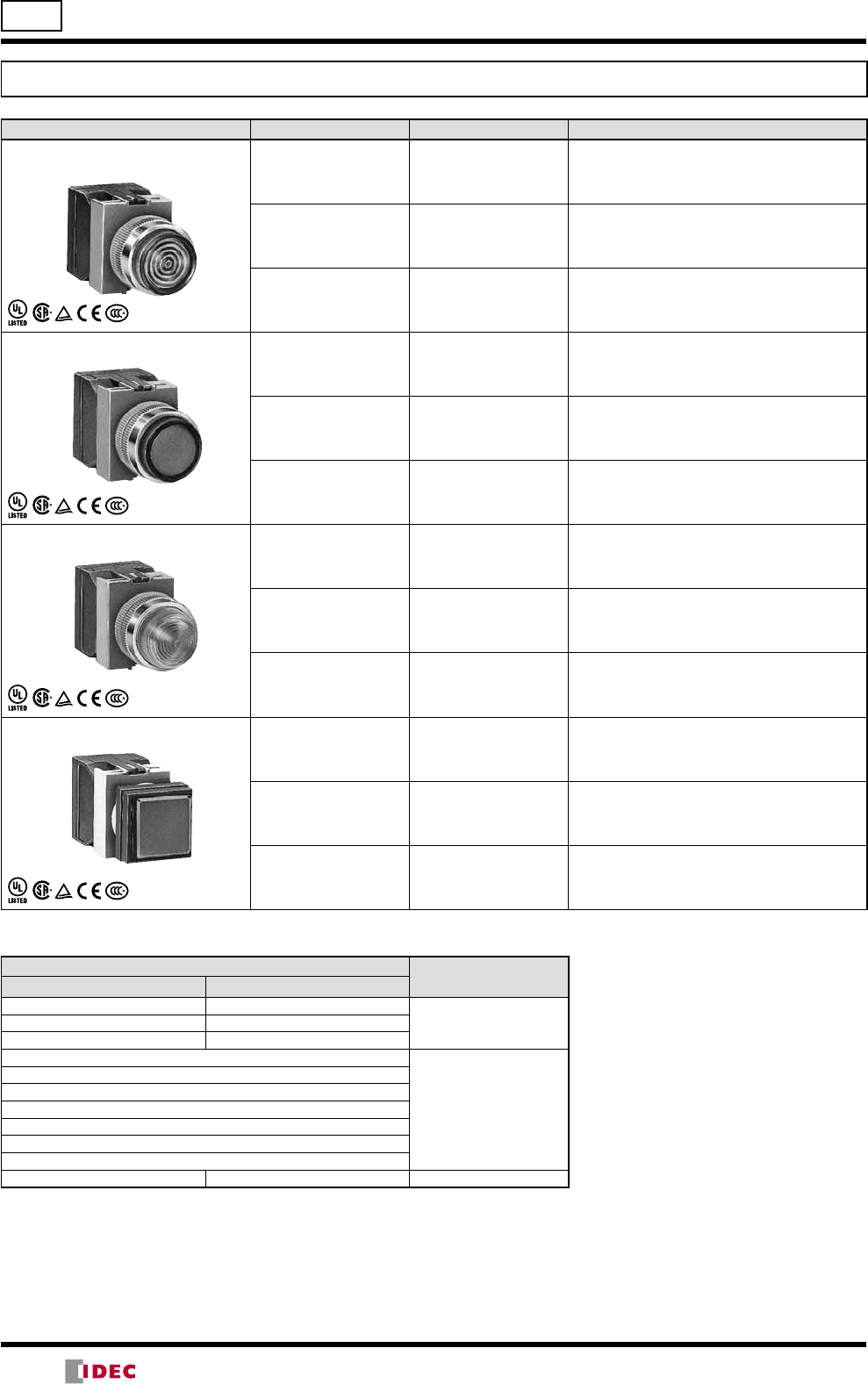
ø22 TW Series Illuminated Pushbuttons
Round Extended Illuminated Pushbuttons
Shape Operation Lamp Contact Part No.
Round Extended
ALW2
AOLW2
Momentary
Without Lamp
1NO-1NC ALW29911
2NO ALW29920
2NO-2NC ALW29922
LED
1NO-1NC ALW2-11D
2NO ALW2-20D
2NO-2NC ALW2-22D
1NO-1NC ALW21611DD(Note)
2NO ALW21620DD(Note)
2NO-2NC ALW21622DD(Note)
Incandescent
1NO-1NC ALW2-11
2NO ALW2-20
2NO-2NC ALW2-22
Maintained
Without Lamp
1NO-1NC AOLW29911
2NO AOLW29920
2NO-2NC AOLW29922
LED
1NO-1NC AOLW2-11 D
2NO AOLW2-20D
2NO-2NC AOLW2-22D
1NO-1NC AOLW21611DD(Note)
2NO AOLW21620DD(Note)
2NO-2NC AOLW21622DD(Note)
Incandescent
1NO-1NC AOLW2-11
2NO AOLW2-20
2NO-2NC AOLW2-22
Note: DC-DC converter types.
Designation Code
Specify a designation code in place of or - in the Part No.
Lens/Illumination Color Code - Operating Voltage Code Input Type
Without Lamp LED Incandescent LED Incandescent
A: amber
G: green
R: red
S: blue
W: white
Y: yellow
A: amber
G: green
PW: pure white
R: red
S: blue
W: white
Y: yellow
A: amber
G: green
R: red
S: blue
W: white
66: 6V AC/DC 66: 6V AC/DC
Full Voltage11: 12V AC/DC 88: 12V AC/DC
22: 24V AC/DC 33: 24V AC/DC
16: 100/110V AC
Transformer
126: 115/120V AC
26: 200/220V AC
246: 230/240V AC
386: 380V AC
46: 400/440V AC
486: 480V AC
16D: 110V DC — DC-DC Converter ∗
•Use a pure white LED lamp for yellow illumination.
∗DC-DC converter types are not approved by UL, CSA, and TÜV, and not CE compliant (operating voltage 90 to 140V DC).
(14/05/22)
13
TW Series Illuminated Pushbuttons ø22
Round Extended Illuminated Pushbuttons (Marking)
Shape Operation Lamp Contact Part No.
Round Extended (Marking)
ALW2B
AOLW2B
Momentary
Without Lamp
1NO-1NC ALW2B9911
2NO ALW2B9920
2NO-2NC ALW2B9922
LED
1NO-1NC ALW2B-11D
2NO ALW2B-20D
2NO-2NC ALW2B-22D
1NO-1NC ALW2B1611DD(Note)
2NO ALW2B1620DD(Note)
2NO-2NC ALW2B1622DD(Note)
Incandescent
1NO-1NC ALW2B-11
2NO ALW2B-20
2NO-2NC ALW2B-22
Maintained
Without Lamp
1NO-1NC AOLW2B9911
2NO AOLW2B9920
2NO-2NC AOLW2B9922
LED
1NO-1NC AOLW2B-11 D
2NO AOLW2B-20D
2NO-2NC AOLW2B-22D
1NO-1NC AOLW2B1611DD(Note)
2NO AOLW2B1620DD(Note)
2NO-2NC AOLW2B1622DD(Note)
Incandescent
1NO-1NC AOLW2B-11
2NO AOLW2B-20
2NO-2NC AOLW2B-22
Note: DC-DC converter types.
Designation Code
Specify a designation code in place of or - in the Part No.
Lens/Illumination Color Code - Operating Voltage Code Input Type
Without Lamp LED Incandescent LED Incandescent
A: amber
G: green
R: red
S: blue
W: white
Y: yellow
A: amber
G: green
PW: pure white
R: red
S: blue
W: white
Y: yellow
A: amber
G: green
R: red
S: blue
W: white
66: 6V AC/DC 66: 6V AC/DC
Full Voltage11: 12V AC/DC 88: 12V AC/DC
22: 24V AC/DC 33: 24V AC/DC
16: 100/110V AC
Transformer
126: 115/120V AC
26: 200/220V AC
246: 230/240V AC
386: 380V AC
46: 400/440V AC
486: 480V AC
16D: 110V DC — DC-DC Converter ∗
•Use a pure white LED lamp for yellow illumination.
∗DC-DC converter types are not approved by UL, CSA, and TÜV, and not CE compliant (operating voltage 90 to 140V DC).
(14/05/22)
14
ø22 TW Series Illuminated Pushbuttons
Round Extended with Full Shroud Illuminated Pushbuttons
Shape Operation Lamp Contact Part No.
Round Extended
With Full Shroud
ALFW2
AOLFW2
Momentary
Without Lamp
1NO-1NC ALFW29911
2NO ALFW29920
2NO-2NC ALFW29922
LED
1NO-1NC ALFW2-11D
2NO ALFW2-20D
2NO-2NC ALFW2-22D
1NO-1NC ALFW21611DD(Note)
2NO ALFW21620DD(Note)
2NO-2NC ALFW21622DD(Note)
Incandescent
1NO-1NC ALFW2-11
2NO ALFW2-20
2NO-2NC ALFW2-22
Maintained
Without Lamp
1NO-1NC AOLFW29911
2NO AOLFW29920
2NO-2NC AOLFW29922
LED
1NO-1NC AOLFW2-11D
2NO AOLFW2-20D
2NO-2NC AOLFW2-22D
1NO-1NC AOLFW21611DD(Note)
2NO AOLFW21620DD(Note)
2NO-2NC AOLFW21622DD(Note)
Incandescent
1NO-1NC AOLFW2-11
2NO AOLFW2-20
2NO-2NC AOLFW2-22
Note: DC-DC converter types.
Designation Code
Specify a designation code in place of or - in the Part No.
Lens/Illumination Color Code - Operating Voltage Code Input Type
Without Lamp LED Incandescent LED Incandescent
A: amber
G: green
R: red
S: blue
W: white
Y: yellow
A: amber
G: green
PW: pure white
R: red
S: blue
W: white
Y: yellow
A: amber
G: green
R: red
S: blue
W: white
66: 6V AC/DC 66: 6V AC/DC
Full Voltage11: 12V AC/DC 88: 12V AC/DC
22: 24V AC/DC 33: 24V AC/DC
16: 100/110V AC
Transformer
126: 115/120V AC
26: 200/220V AC
246: 230/240V AC
386: 380V AC
46: 400/440V AC
486: 480V AC
16D: 110V DC — DC-DC Converter ∗
•Use a pure white LED lamp for yellow illumination.
∗DC-DC converter types are not approved by UL, CSA, and TÜV, and not CE compliant (operating voltage 90 to 140V DC).
(14/05/22)
15
TW Series Illuminated Pushbuttons ø22
Round Extended with Full Shroud Illuminated Pushbuttons (Marking)
Shape Operation Lamp Contact Part No.
Round Extended (Marking)
With Full Shroud
ALFW2B
AOLFW2B
Momentary
Without Lamp
1NO-1NC ALFW2B9911
2NO ALFW2B9920
2NO-2NC ALFW2B9922
LED
1NO-1NC ALFW2B-11D
2NO ALFW2B-20D
2NO-2NC ALFW2B-22D
1NO-1NC ALFW2B1611DD(Note)
2NO ALFW2B1620DD(Note)
2NO-2NC ALFW2B1622DD(Note)
Incandescent
1NO-1NC ALFW2B-11
2NO ALFW2B-20
2NO-2NC ALFW2B-22
Maintained
Without Lamp
1NO-1NC AOLFW2B9911
2NO AOLFW2B9920
2NO-2NC AOLFW2B9922
LED
1NO-1NC AOLFW2B-11D
2NO AOLFW2B-20D
2NO-2NC AOLFW2B-22D
1NO-1NC AOLFW2B1611DD(Note)
2NO AOLFW2B1620DD(Note)
2NO-2NC AOLFW2B1622DD(Note)
Incandescent
1NO-1NC AOLFW2B-11
2NO AOLFW2B-20
2NO-2NC AOLFW2B-22
Note: DC-DC converter types.
Designation Code
Specify a designation code in place of - or in the Part No.
Lens/Illumination Color Code - Operating Voltage Code Input Type
Without Lamp LED Incandescent LED Incandescent
A: amber
G: green
R: red
S: blue
W: white
Y: yellow
A: amber
G: green
PW: pure white
R: red
S: blue
W: white
Y: yellow
A: amber
G: green
R: red
S: blue
W: white
66: 6V AC/DC 66: 6V AC/DC
Full Voltage11: 12V AC/DC 88: 12V AC/DC
22: 24V AC/DC 33: 24V AC/DC
16: 100/110V AC
Transformer
126: 115/120V AC
26: 200/220V AC
246: 230/240V AC
386: 380V AC
46: 400/440V AC
486: 480V AC
16D: 110V DC — DC-DC Converter ∗
•Use a pure white LED lamp for yellow illumination.
∗DC-DC converter types are not approved by UL, CSA, and TÜV, and not CE compliant (operating voltage 90 to 140V DC).
(14/05/22)
16
ø22 TW Series Illuminated Pushbuttons
Square Extended Illuminated Pushbuttons (Marking)
Shape Operation Lamp Contact Part No.
Square Extended (Marking)
ALQW2B
AOLQW2B
Momentary
Without Lamp
1NO-1NC ALQW2B9911
2NO ALQW2B9920
2NO-2NC ALQW2B9922
LED
1NO-1NC ALQW2B-11D
2NO ALQW2B-20D
2NO-2NC ALQW2B-22D
1NO-1NC ALQW2B1611DD(Note)
2NO ALQW2B1620DD(Note)
2NO-2NC ALQW2B1622DD(Note)
Incandescent
1NO-1NC ALQW2B-11
2NO ALQW2B-20
2NO-2NC ALQW2B-22
Maintained
Without Lamp
1NO-1NC AOLQW2B9911
2NO AOLQW2B9920
2NO-2NC AOLQW2B9922
LED
1NO-1NC AOLQW2B-11D
2NO AOLQW2B-20D
2NO-2NC AOLQW2B-22D
1NO-1NC
AOLQW2B1611DD
(Note)
2NO
AOLQW2B1620DD
(Note)
2NO-2NC
AOLQW2B1622DD
(Note)
Incandescent
1NO-1NC AOLQW2B-11
2NO AOLQW2B-20
2NO-2NC AOLQW2B-22
Note: DC-DC converter types.
Designation Code
Specify a designation code in place of or - in the Part No.
Lens/Illumination Color Code - Operating Voltage Code Input Type
Without Lamp LED Incandescent LED Incandescent
A: amber
G: green
R: red
S: blue
W: white
Y: yellow
A: amber
G: green
PW: pure white
R: red
S: blue
W: white
Y: yellow
A: amber
G: green
R: red
S: blue
W: white
66: 6V AC/DC 66: 6V AC/DC
Full Voltage11: 12V AC/DC 88: 12V AC/DC
22: 24V AC/DC 33: 24V AC/DC
16: 100/110V AC
Transformer
126: 115/120V AC
26: 200/220V AC
246: 230/240V AC
386: 380V AC
46: 400/440V AC
486: 480V AC
16D: 110V DC — DC-DC Converter *
•Use a pure white LED lamp for yellow illumination.
∗DC-DC converter types are not approved by UL, CSA, and TÜV, and not CE compliant (operating voltage 90 to 140V DC).
(14/05/22)
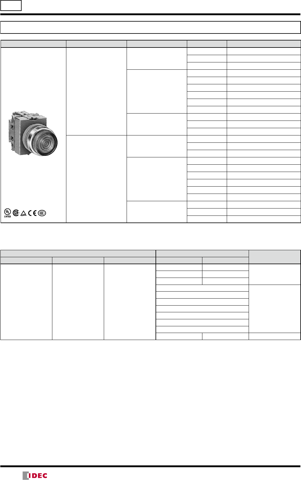
17
TW Series Illuminated Pushbuttons ø22
Mushroom (ø29) Illuminated Pushbuttons
Shape Operation Lamp Contact Part No.
ø29 Mushroom
ALW3
AOLW3 Momentary
Without Lamp
1NO-1NC
ALW39911
Incandescent ALW3-11
Maintained
Without Lamp AOLW39911
Incandescent AOLW3-11
ø29 Mushroom (Marking)
ALW3B
AOLW3B Momentary
Without Lamp ALW3B9911
Incandescent ALW3B-11
Maintained
Without Lamp AOLW3B9911
Incandescent AOLW3B-11
ø29 Mushroom Pushlock Turn Reset
AVLW3
(Note)
Without Lamp
1NO-1NC AVLW39911R
2NO AVLW39920R
2NO-2NC AVLW39922R
LED
1NO-1NC AVLW3-11DR
2NO AVLW3-20DR
2NO-2NC AVLW3-22DR
Incandescent
1NO-1NC AVLW3-11R
2NO AVLW3-20R
2NO-2NC AVLW3-22R
ø29 Mushroom Pushlock Turn Reset (Marking)
AVLW3B
(Note)
Without Lamp
1NO AVLW3B9911R
1NC AVLW3B9920R
1NO-1NC AVLW3B9922R
LED
1NO-1NC AVLW3B-11DR
2NO AVLW3B-20DR
2NO-2NC AVLW3B-22DR
Incandescent
1NO-1NC AVLW3B-11R
2NO AVLW3B-20R
2NO-2NC AVLW3B-22R
Designation Code
Specify a designation code in place of or - in the Part No.
Lens/Illumination Color Code - Operating Voltage Code Input Type
Without Lamp LED Incandescent LED Incandescent
A: amber
G: green
R: red
S: blue
W: white
Y: yellow
A: amber
G: green
PW: pure white
R: red
S: blue
W: white
Y: yellow
A: amber
G: green
R: red
S: blue
W: white
66: 6V AC/DC 66: 6V AC/DC
Full Voltage11: 12V AC/DC 88: 12V AC/DC
22: 24V AC/DC 33: 24V AC/DC
16: 100/110V AC
Transformer
126: 115/120V AC
26: 200/220V AC
246: 230/240V AC
386: 380V AC
46: 400/440V AC
486: 480V AC
•Use a pure white LED lamp for yellow illumination.
Note: TW series pushlock turn reset illuminated pushbuttons cannot be used as emergency stop switches under international safety
standards ISO13850 and IEC60947-5. For use as emergency stop switches, use XW or HW series.
(14/05/22)
18
Note: Push-pull switch can have a maximum of two contact blocks.
ø22 TW Series Illuminated Pushbuttons
Mushroom (ø40 mm) Illuminated Pushbuttons
Shape Lamp Input Type Contact Part No.
ø40 Mushroom Pushlock Turn Reset
AVLW4 Without Lamp Full Voltage
1NO-1NC AVLW49911R
2NO AVLW49920R
2NO-2NC AVLW49922R
LED Transformer
1NO-1NC AVLW4-11DR
2NO AVLW4-20DR
2NO-2NC AVLW4-22DR
Incandescent Transformer
1NO-1NC AVLW4-11R
2NO AVLW4-20R
2NO-2NC AVLW4-22R
ø40 Mushroom Pushlock Turn Reset (Marking)
AVLW4B Without Lamp Full Voltage
1NO AVLW4B9911R
1NC AVLW4B9920R
1NO-1NC AVLW4B9922R
LED Transformer
1NO-1NC AVLW4B-11DR
2NO AVLW4B-20DR
2NO-2NC AVLW4B-22DR
Incandescent Transformer
1NO-1NC AVLW4B-11R
2NO AVLW4B-20R
2NO-2NC AVLW4B-22R
ø40 Mushroom Push Pull
Without Lamp Full Voltage
1NO-1NC AYLW49911
2NO AYLW49920
2NO-2NC AYLW49922
Incandescent Transformer 1NO-1NC AYLW4-11
2NO AYLW4-20
ø40 Mushroom Push Pull (Marking)
Without Lamp Full Voltage
1NO AYLW4B9911
1NC AYLW4B9920
1NO-1NC AYLW4B9922
Incandescent Transformer 1NO-1NC AYLW4B-11
2NO AYLW4B-20
Designation Code
Specify a designation code in place of or - in the Part No.
Lens/Illumination Color Code - Operating Voltage Code Input Type
Without Lamp LED Incandescent LED Incandescent
A: amber
G: green
R: red
S: blue
W: white
Y: yellow
A: amber
G: green
PW: pure white
R: red
S: blue
W: white
Y: yellow
A: amber
G: green
R: red
S: blue
W: white
66: 6V AC/DC 66: 6V AC/DC
Full Voltage11: 12V AC/DC 88: 12V AC/DC
22: 24V AC/DC 33: 24V AC/DC
16: 100/110V AC
Transformer
126: 115/120V AC
26: 200/220V AC
246: 230/240V AC
386: 380V AC
46: 400/440V AC
486: 480V AC
•Use a pure white LED lamp for yellow illumination.
Note: TW series pushlock turn reset illuminated pushbuttons cannot be used as emergency stop switches under international safety
standards ISO13850 and IEC60947-5. For use as emergency stop switches, use XW or HW series.
Contact Statuses of Push-Pull Switch
Contact ø40mm Mushroom Push-Pull Switch
Push Pull
1NO
1NC
1NO-1NC
2NO
2NC
(2-position
maintained)
AYLW4
(2-position
maintained)
AYLW4B
(14/05/22)
19
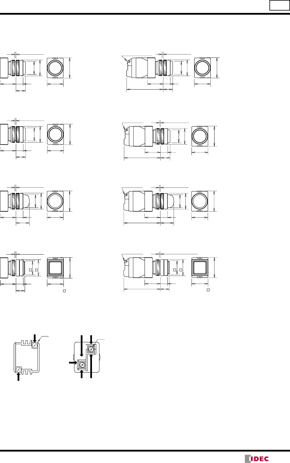
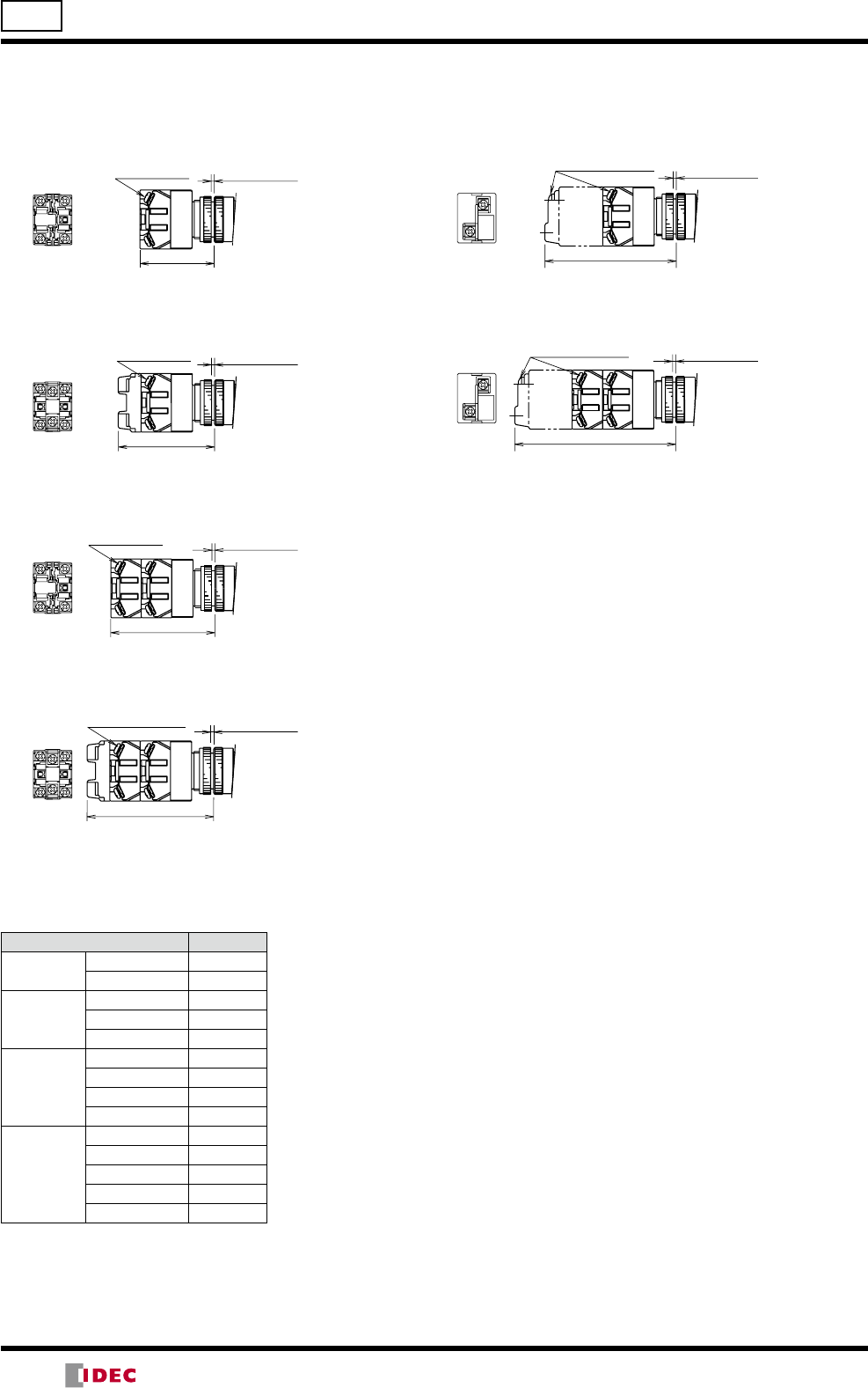
TW Series Illuminated Pushbuttons ø22
Dimensions (Operator)
Terminal Arrangement (Lamp Terminal) (Bottom View)
X1
X2
X1
X2
X1
X2
•Arrows indicate access directions for wiring.
Full Voltage Transformer
DC-DC Converter
TOP
TOP TOP
Full Voltage
When using TW-DA1B
Full Voltage Adapter for 2
or 4 contact blocks
When using HW-DA1B
Full Voltage Adapter for
1 or 3 contact blocks
Marking plate: ø15.5mm
Panel Thickness
1 to 6
13
19 30
ø24
ø29
37
Marking plate: ø13.9mm
Reset Angle: 75°
Panel Thickness
1 to 6
30
37
13
22.5
ø29
Marking plate: ø13.9mm
Panel Thickness
1 to 6
30
37
25
13
ø40
30.5
Marking plate: ø15.5mm
Panel Thickness
1 to 6
30
ø24
ø29
37
20
Marking plate: ø13.9mm
Reset Angle 75°
30
37
13
22.5
ø40
Panel Thickness
1 to 6
30
37
20
13
25
30
Marking plate: 21mm
Panel Thickness
1 to 6
Marking plate: ø13.9mm
30
37
13
ø29
22.5
Panel Thickness
1 to 6
Round Extended (non-marking/marking)
ALW2 / ALW2B / AOLW2 / AOLW2B
Round Extended with Full Shroud
ALFW2 / ALFW2B / AOLFW2 / AOLFW2B
Square Extended (marking)
ALQW2B / AOLQW2B
ø29 Mushroom (non-marking/marking)
ALW3 / ALW3B / AOLW3 / AOLW3B
ø29 Mushroom Pushlock Turn Reset
AVLW3 / AVLW3B
(non-marking/marking)
(non-marking/marking)
ø40 Mushroom Pushlock Turn Reset
AVLW4 / AVLW4B
(non-marking/marking)
ø40 Mushroom Push Pull
AYLW4 / AYLW4B
(non-marking/marking)
All dimensions in mm.
(14/05/22)
20
ø22 TW Series Illuminated Pushbuttons
X2
X1
X2
X1
M3.5 Terminal Screws Panel Thickness
1 to 6
86.5
106.5
M3.5 Terminal Screws Panel Thickness
1 to 6
X2 X1
X1
X2
X2 X1
X1
X2
M3.5
Terminal Screws Panel Thickness
1 to 6
48.5
63.5
M3.5
Terminal Screws Panel Thickness
1 to 6
68.5
M3.5
Terminal Screws Panel Thickness
1 to 6
83.5
M3.5 Terminal Screws Panel Thickness
1 to 6
1 contact
block
2 contact
blocks
3 contact
blocks
4 contact
blocks
4 contact
blocks
2 contact
blocks
Full Voltage Transformer
DC-DC Converter
When using HW-DA1B full-voltage adapter
When using TW-DA1B full-voltage adapter
When using TW-DA1B full-voltage adapter
When using HW-DA1B full-voltage adapter
Note: For push-pull units a maximum of two contact blocks can be used.
All dimensions in mm.
Dimensions
Contact Configuration and Codes
Contact Configuration Code
1 block 1NO 10
1NC 01
2 blocks
1NO-1NC 11
2NO 20
2NC 02
3 blocks
2NO-1NC 21
1NO-2NC 12
3NO 30
3NC 03
4 blocks
3NO-1NC 31
2NO-2NC 22
1NO-3NC 13
4NO 40
4NC 04
(14/05/22)
21
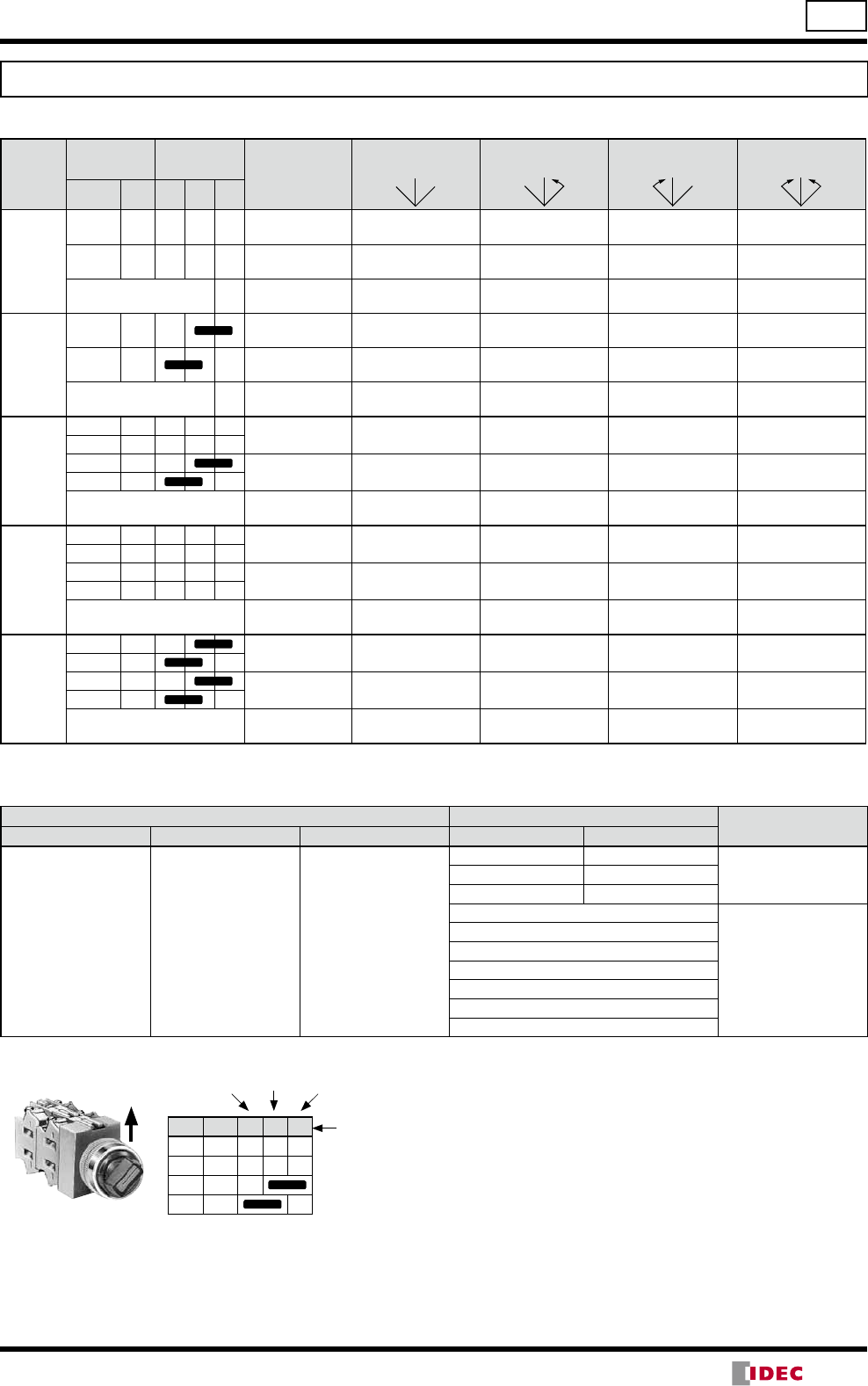
Selector Switches (Knob Operator)
No. of Positions
Shape
Contact Arrangement Chart
ASW
90° 2-position
Contact
Code
Contact Block Operator Position Maintained Spring Return
from Right
Spring Return
from Left —
Mounting
Position
Contact
L R
10
(1NO)
1NO ASW210 ASW2110 ASW2210 ∗
—
2Dummy
11
(1NO-1NC)
1NO ASW211 ASW2111 ASW2211 ∗
2NC
20
(2NO)
1NO ASW220 ASW2120 ASW2220 ∗
2NO
22
(2NO-2NC)
1NO
ASW222 ASW2122 ASW2222 ∗
2NC
3NO
4NC
45° 3-position
Contact
Code
Contact Block Operator Position Maintained Spring Return
from Right
Spring Return
from Left
Spring Return
Two-way
Mounting
Position
Contact
L C R
20
(2NO)
1NO ASW320 ASW3120 ASW3220 ASW3320
2NO
02
(2NC)
1NC ASW302 ASW3102 ASW3202 ASW3302
2NC
22
(2NO-2NC)
1NO
ASW322 ASW3122 ASW3222 ASW3322
2NO
3NC
4NC
40
(4NO)
1NO
ASW340 ASW3140 ASW3240 ASW3340
2NO
3NO
4NO
04
(4NC)
1NC
ASW304 ASW3104 ASW3204 ASW3304
2NC
3NC
4NC
3S
1NO
ASW33S-243 — — —
2NO
3NC
4Dummy
30° 5-position / 45° 4-position
Contact
Code
Contact Block Operator Position Maintained
2
1 3
4
Maintained
3
1
4
5
2
Contact Block Mounting Position
and Contact Arrangement Chart
Mounting
Position
Contact
12345
4S
1NC
ASW44S-407 —
2NC
3NC
4NO
4S
1NO
ASW44S-411 —
2NC
3NC
4NO
3S
1NO
ASW43S-461 —
2NC
3NC
4Dummy
4S
1NO
—ASW54S-501
2NC
3NC
4NO
•On the 2-position selector switches marked with ∗ above, the contact operation is reversed as follows.
•On the contact arrangement marked with in the table above, the rated current (load switching current) is reduced to a half of the rated
current of the contact block. The rated insulation voltage and the rated thermal current remain unchanged.
•Selector switches with one or three contact blocks contain a dummy block.
•Knob operator: White indicator on black knob
37
25
13
30
ø24
ø29
M3.5 Terminal
Screws
48.5 (2 blocks)
68.5 (4 blocks)
Panel Thickness 1 to 6
L R
C
L R
L C R
1NO
2NO
3NC
4NC
1
2
3
4
•For more contact
arrangement chart,
see pages 26 to 28.
Center RightLeft
Operator
Position
TOP
TW Series Selector Switches ø22
C
LR
C
LR
C
LR
LR
LR
(14/05/22)
22
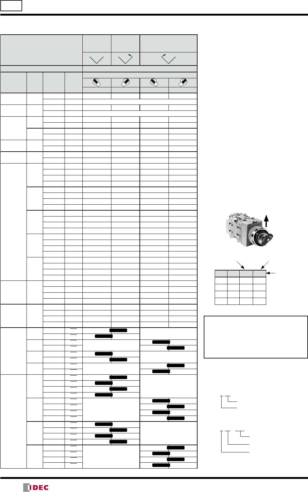
Selector Switches (Lever Operator)
No. of Positions
Shape
Contact Arrangement Chart
ASW∗L
90° 2-position
Contact
Code
Contact Block Operator Position Maintained
L R
Spring Return
from Right
Spring Return
from Left —
Mounting
Position
Contact
L R
10
(1NO)
1NO ASW2L10 ASW21L10 ASW22L10 ∗
—
2Dummy
11
(1NO-1NC)
1NO ASW2L11 ASW21L11 ASW22L11 ∗
2NC
20
(2NO)
1NO ASW2L20 ASW21L20 ASW22L20 ∗
2NO
22
(2NO-2NC)
1NO
ASW2L22 ASW21L22 ASW22L22 ∗
2NC
3NO
4NC
45° 3-position
Contact
Code
Contact Block Operator Position Maintained Spring Return
from Right
Spring Return
from Left
Spring Return
Two-way
Mounting
Position
Contact
L C R
20
(2NO)
1NO ASW3L20 ASW31L20 ASW32L20 ASW33L20
2NO
02
(2NC)
1NC ASW3L02 ASW31L02 ASW32L02 ASW33L02
2NC
22
(2NO-2NC)
1NO
ASW3L22 ASW31L22 ASW32L22 ASW33L22
2NO
3NC
4NC
40
(4NO)
1NO
ASW3L40 ASW31L40 ASW32L40 ASW33L40
2NO
3NO
4NO
04
(4NC)
1NC
ASW3L04 ASW31L04 ASW32L04 ASW33L04
2NC
3NC
4NC
3S
1NO
ASW3L3S-243 — — —
2NO
3NC
4Dummy
30° 5-position / 45° 4-position
Contact
Code
Contact Block Operator Position Maintained
2
13
4
Maintained
3
1
4
5
2
Contact Block Mounting Position
and Contact Arrangement Chart
Mounting
Position
Contact
1 2 3 4 5
4S
1NC
ASW4L4S-407 —
2NC
3NC
4NO
4S
1NO
ASW4L4S-411 —
2NC
3NC
4NO
3S
1NO
ASW4L3S-461 —
2NC
3NC
4Dummy
4S
1NO
—ASW5L4S-501
2NC
3NC
4NO
•On the 2-position selector switches marked with ∗ above, the contact operation is reversed as follows.
•On the contact arrangement marked with in the table above, the rated current (load switching current) is reduced to a half of the rated
current of the contact block. The rated insulation voltage and the rated thermal current remain unchanged.
•Selector switches with one or three contact blocks contain a dummy block.
•Lever operator: White indicator on black lever
M3.5 Terminal
Screws
48.5 (2 blocks)
68.5 (4 blocks)
Panel Thickness 1 to 6
37
13
30
ø29
ø25
25
C
LR
L C R
1NO
2NO
3NC
4NC
Center RightLeft
Operator
Position
1
2
3
4
•For more contact
arrangement chart,
see pages 26 to 28.
TOP
ø22 TW Series Selector Switches
C
LR
C
LR
C
LR
LR
LR
(14/05/22)
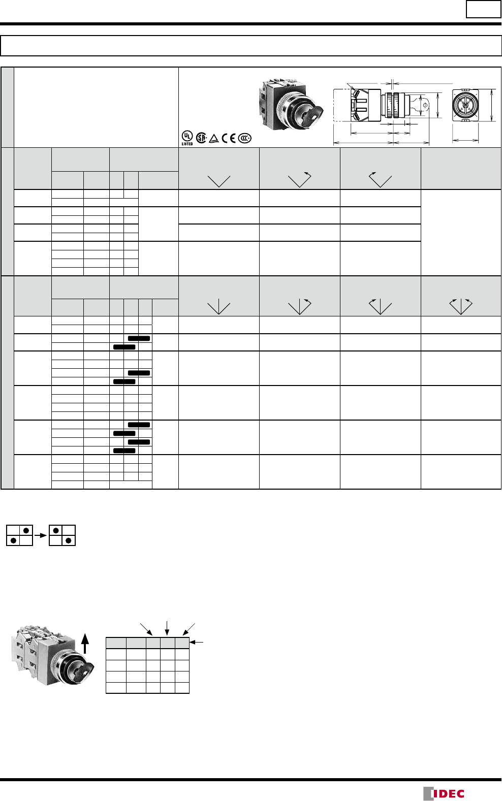
23
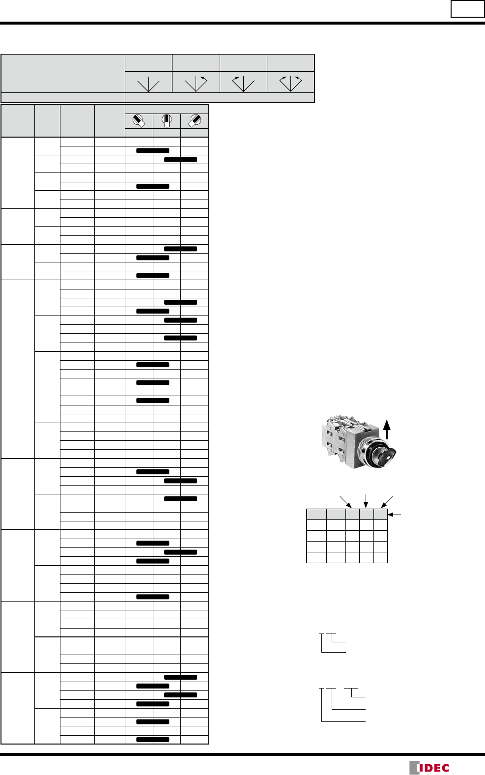
Key Selector Switches
No. of Positions
Shape
Contact Arrangement Chart
ASW∗K
90° 2-position
Contact
Code
Contact Block Operator Position Maintained Spring Return
from Right
Spring Return
from Left —
Mounting
Position
Contact
L R
10
(1NO)
1NO ASW2K10 ASW21K10 ASW22K10 ∗
—
2Dummy
11
(1NO-1NC)
1NO ASW2K11 ASW21K11 ASW22K11 ∗
2NC
20
(2NO)
1NO ASW2K20 ASW21K20 ASW22K20 ∗
2NO
22
(2NO-2NC)
1NO
ASW2K22 ASW21K22 ASW22K22 ∗
2NC
3NO
4NC
45° 3-position
Contact
Code
Contact Block Operator Position Maintained
C
LR
Spring Return
from Right
Spring Return
from Left
Spring Return
Two-way
Mounting
Position
Contact
L C R
20
(2NO)
1NO ASW3K20 ASW31K20 ASW32K20 ASW33K20
2NO
02
(2NC)
1NC ASW3K02 ASW31K02 ASW32K02 ASW33K02
2NC
22
(2NO-2NC)
1NO
ASW3K22 ASW31K22 ASW32K22 ASW33K22
2NO
3NC
4NC
40
(4NO)
1NO
ASW3K40 ASW31K40 ASW32K40 ASW33K40
2NO
3NO
4NO
04
(4NC)
1NC
ASW3K04 ASW31K04 ASW32K04 ASW33K04
2NC
3NC
4NC
3S
1NO
ASW3K3S-243 — — —
2NO
3NC
4Dummy
•On the spring-returned types, the key can be released only from the maintained position. On the maintained types, the key can be re-
leased from every position. Key retained positions are also available. See page6.
•On the 2-position selector switches marked with ∗ above, the contact operation is reversed as follows.
•On the contact arrangement marked with in the table above, the rated current (load switching current) is reduced to a half of the rated
current of the contact block. The rated insulation voltage and the rated thermal current remain unchanged.
•Key selector switches with one or three contact blocks contain a dummy block.
•Cylinder cover: Black, Cylinder: Metal
Contact Block Mounting Position and Contact Arrangement Chart
M3.5 Terminal
Screws
48.5 (2 blocks)
68.5 (4 blocks)
Panel Thickness 1 to 6
37
13
30
ø29
19
41
ø24
L R
1
2
3
4
•For more contact arrangement chart, see pages 26 to 28.
L C R
1NO
2NO
3NC
4NC
Center RightLeft
Operator
Position
TOP
TW Series Selector Switches ø22
C
LR
C
LR
C
LR
LR
LR
(14/05/22)
24
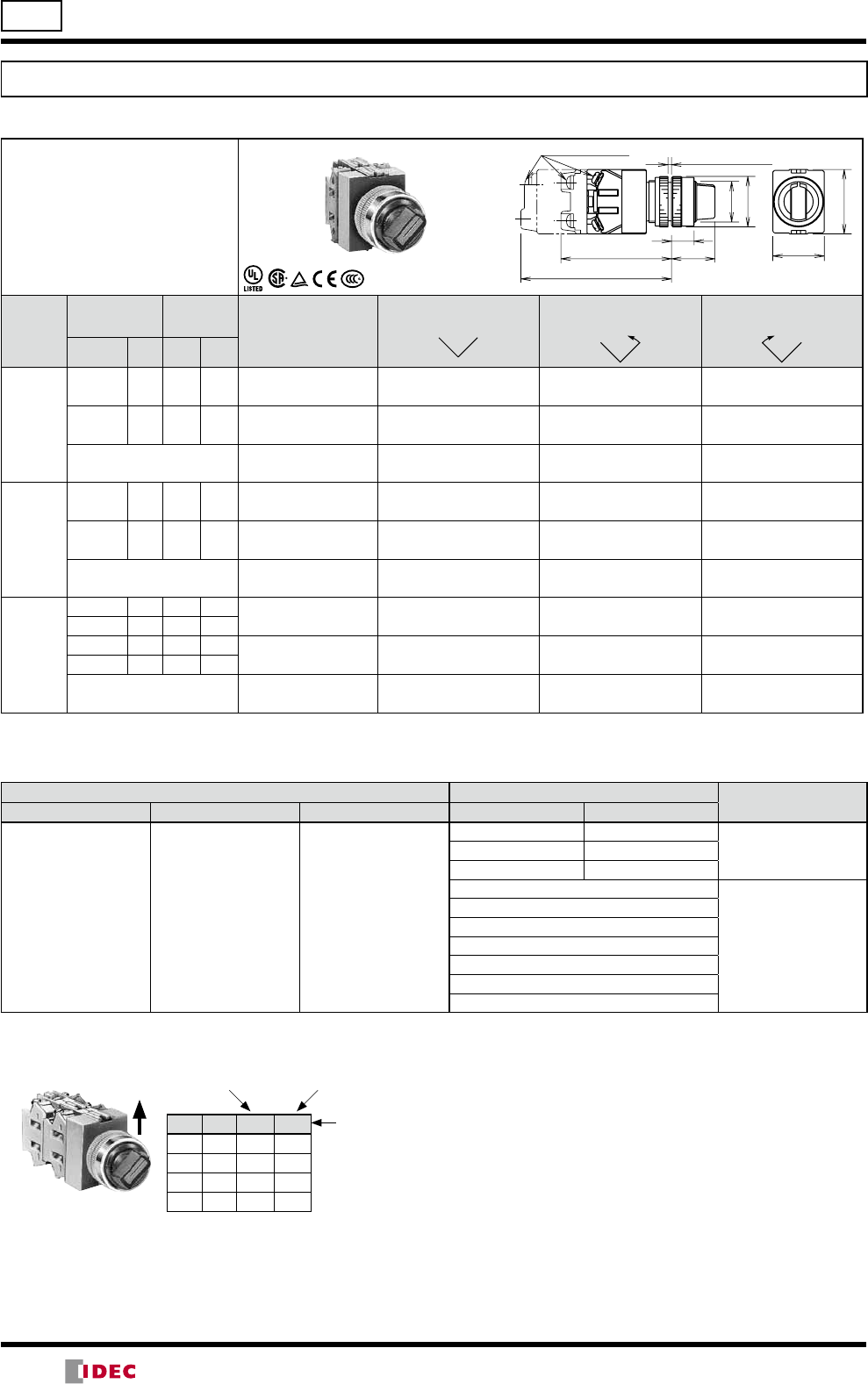
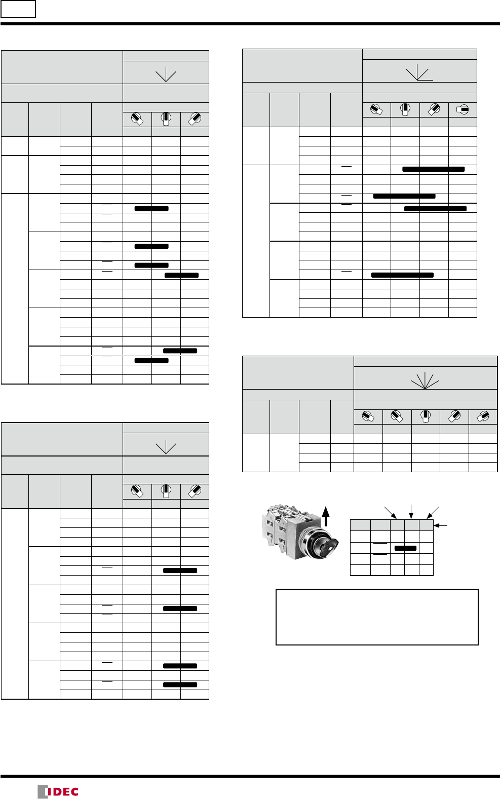
ø22 TW Series Illuminated Selector Switches
Illuminated Selector Switches
90° 2-position
Shape
Contact Arrangement Chart
ASLW
Contact
Code
Contact
Block
Operator
Position Lamp
Maintained
L R
Spring Return
from Right
Spring Return
from Left
Mounting
Position Contact L R
11
(1NO-1NC)
1 NO Without Lamp ASLW29911ASLW219911ASLW229911
2 NC LED ASLW2-11DASLW21-11DASLW22-11D
Incandescent ASLW2-11ASLW21-11ASLW22-11
20
(2NO)
1 NO Without Lamp ASLW29920ASLW219920ASLW229920
2 NO LED ASLW2-20DASLW21-20DASLW22-20D
Incandescent ASLW2-20ASLW21-20ASLW22-20
22
(2NO-2NC)
1 NO Without Lamp ASLW29922ASLW219922ASLW229922
2 NC
3 NO LED ASLW2-22DASLW21-22DASLW22-22D
4 NC
Incandescent ASLW2-22ASLW21-22ASLW22-22
Designation Code
Specify a designation code in place of or - in the Part No.
Lens/Illumination Color Code - Operating Voltage Code Input Type
Without Lamp LED Incandescent LED Incandescent
A: amber
G: green
R: red
S: blue
W: white
Y: yellow
A: amber
G: green
PW: pure white
R: red
S: blue
W: white
Y: yellow
A: amber
G: green
R: red
S: blue
W: white
66: 6V AC/DC 66: 6V AC/DC
Full Voltage11: 12V AC/DC 88: 12V AC/DC
22: 24V AC/DC 33: 24V AC/DC
16: 100/110V AC
Transformer
136: 115/120V AC
26: 200/220V AC
256: 230/240V AC
386: 380V AC
46: 400/440V AC
486: 480V AC
A: Rated voltage 24V AC/DC
B: Rated voltage 100/110V AC, 200/220V AC
M3.5 Terminal Screws
83.5 (4 blocks)
B: 86.5 (2 blocks), 106.5 (4 blocks)
A: 63.5 (2 blocks)
Panel Thickness 1 to 6
13
25
ø24
ø29
30
37
Contact Block Mounting Position and Contact Arrangement Chart
L R
1 NO
2 NC
3 NO
4 NC
RightLeft
Operator
Position
1
2
3
4
•For more contact arrangement chart, see pages 26 to 28.
TOP
LR
LR
(14/05/22)
25
Illuminated Selector Switches
45° 3-position
Contact
Code
Contact
Block
Operator
Position Lamp
Maintained
C
L R
Spring Return
from Right
Spring Return
from left
Spring Return
Two-way
Mounting
Position Contact L C R
20
(2NO)
1 NO Without Lamp ASLW39920 ASLW319920 ASLW329920 ASLW339920
2 NO LED ASLW3-20DASLW31-20DASLW32-20DASLW33-20D
Incandescent ASLW3-20ASLW31-20ASLW32-20ASLW33-20
02
(2NC)
1 NC Without Lamp ASLW39902 ASLW319902 ASLW329902 ASLW339902
2 NC LED ASLW3-02DASLW31-02DASLW32-02DASLW33-02D
Incandescent ASLW3-02ASLW31-02ASLW32-02ASLW33-02
22
(2NO-2NC)
1 NO Without Lamp ASLW39922 ASLW319922 ASLW329922 ASLW339922
2 NO
3 NC LED ASLW3-22DASLW31-22DASLW32-22DASLW33-22D
4 NC
Incandescent ASLW3-22ASLW31-22ASLW32-22ASLW33-22
40
(4NO)
1 NO Without Lamp ASLW39940 ASLW319940 ASLW329940 ASLW339940
2 NO
3 NO LED ASLW3-40DASLW31-40DASLW32-40DASLW33-40D
4 NO
Incandescent ASLW3-40ASLW31-40ASLW32-40ASLW33-40
04
(4NC)
1 NC Without Lamp ASLW39904 ASLW319904 ASLW329904 ASLW339904
2 NC
3 NC LED ASLW3-04DASLW31-04DASLW32-04DASLW33-04D
4 NC
Incandescent ASLW3-04ASLW31-04ASLW32-04ASLW33-04
Designation Code
Specify a designation code in place of or - in the Part No.
Lens/Illumination Color Code - Operating Voltage Code Input Type
Without Lamp LED Incandescent LED Incandescent
A: amber
G: green
R: red
S: blue
W: white
Y: yellow
A: amber
G: green
PW: pure white
R: red
S: blue
W: white
Y: yellow
A: amber
G: green
R: red
S: blue
W: white
66: 6V AC/DC 66: 6V AC/DC
Full Voltage11: 12V AC/DC 88: 12V AC/DC
22: 24V AC/DC 33: 24V AC/DC
16: 100/110V AC
Transformer
136: 115/120V AC
26: 200/220V AC
256: 230/240V AC
386: 380V AC
46: 400/440V AC
486: 480V AC
Contact Block Mounting Position and Contact Arrangement Chart
L C R
1 NO
2 NO
3 NC
4 NC
Center
RightLeft
Operator
Position
1
2
3
4
•For more contact arrangement chart, see pages 26 to 28.
TOP
TW Series Illuminated Selector Switches ø22
C
LR
C
LR
C
LR
(14/05/22)
26
90° 2-position (Maintained / Spring Return)
Positions
Maintained
Spring
Return
from Right
Spring Return from Left
L R
Operator Knob, Lever, Key, Illuminated
Contact
Code
Circuit
No.
Mounting
Position
Contact
Operator Positions
L R L R
10
(1NO) —1NO
2Dummy
01
(1NC) —1NC
2Dummy
11
(1NO-1NC)
—1NO
2NC
103 1NC
2NO
20
(2NO) —1NO
2NO
02
(2NC) —1NC
2NC
22
(2NO-2NC)
—
1NO
2NC
3NO
4NC
109
1NO
2NC
3NC
4NO
110
1NC
2NO
3NC
4NO
111
1NO
2NO
3NC
4NC
117
1NC
2NO
3NO
4NC
31
(3NO-1NC) 107
1NC
2NO
3NO
4NO
40
(4NO) —
1NO
2NO
3NO
4NO
2R
118 1NO
2NO
168 1NO
2NC
119 1NC
2NO
169 1NC
2NO
4R
120
1NO
2NC
3NO
4NC
170
1NO
2NC
3NO
4NC
121
1NC
2NO
3NC
4NO
171
1NC
2NO
3NC
4NO
ø22 TW Series Selector Switch Contact Arrangement Charts
LR
LR
1
2
3
4
Contact Block Mounting Position and
Contact Arrangement Chart
ASW 2 11
•When circuit number is not required:
Part No. Development
Contact Code (1NO-1NC)
2-position
ASW 2 11 - 103
•When circuit number is required:
Contact Code (1NO-1NC)
2-position
Circuit No.
L R
1NO
2NC
3NO
4NC
RightLeft
Operator
Position
TOP
•On the contact arrangement marked with
in the table, the rated current (load
switching current) is reduced to a half of
the rated current of the contact block.
The rated insulation voltage and the rated
thermal current remain unchanged.
(14/05/22)
27
TW Series Selector Switch Contact Arrangement Charts ø22
45° 3-position (Maintained / Spring Return)
Positions
Maintained
Spring Return
from Right
Spring Return
from Left
Spring Return
Two-way
C
L R
Operator Knob, Lever, Key, Illuminated
Contact
Code
Circuit
No.
Mounting
Position
Contact
Operator Positions
L C R
11
202 1NO
2NC
203 1NC
2NO
302 1NO
2NC
303 1NC
2NO
20
—1NO
2NO
301 1NO
2NO
02
—1NC
2NC
304 1NC
2NC
22
(2NO-
2NC)
—
1NO
2NO
3NC
4NC
210
1NC
2NO
3NC
4NO
308
1NO
2NC
3NO
4NC
309
1NO
2NC
3NC
4NO
310
1NC
2NO
3NC
4NO
31
(3NO-
1NC)
206
1NO
2NC
3NO
4NO
207
1NC
2NO
3NO
4NO
13
212
1NO
2NC
3NC
4NC
313
1NC
2NO
3NC
4NC
40
—
1NO
2NO
3NO
4NO
305
1NO
2NO
3NO
4NO
04
—
1NC
2NC
3NC
4NC
314
1NC
2NC
3NC
4NC
L C R
1NO
2NO
3NC
4NC
Center RightLeft
Operator
Position
1
2
3
4
Contact Block Mounting Position and
Contact Arrangement Chart
ASW 3 22
•When circuit number is not required:
Part No. Development
Contact Code (2NO-2NC)
3-position
ASW 3 22 - 210
•When circuit number is required:
Contact Code (2NO-2NC)
3-position
Circuit No.
TOP
C
LR
C
LR
C
LR
(14/05/22)
28
ø22 TW Series Selector Switch Contact Arrangement Charts
45° 3-position (Maintained)
Positions
Maintained
C
L R
Operator Knob, Lever, Key,
Illuminated
Contact
Code
Circuit
No.
Mounting
Position
Contact
Operator Positions
L C R
2S 1361 1NO
2NC
3S 243
1NO
2NO
3NC
4
Dummy
4S
233
1NO
2NC
3NC
4NO
234
1NO
2NC
3NC
4NC
235
1NC
2NO
3NC
4NO
237
1NO
2NO
3NC
4NO
240
1NC
2NC
3NC
4NO
45° 3-position (Maintained)
Positions
Maintained
C
LR
Operator Knob, Lever, Key,
Illuminated
Contact
Code
Circuit
No.
Mounting
Position
Contact
Operator Positions
L C R
4S
1336
1NO
2NO
3NC
4NC
1337
1NC
2NO
3NC
4NC
1352
1NO
2NC
3NC
4NO
1355
1NO
2NC
3NO
4NC
1359
1NC
2NC
3NC
4NC
45° 4-position (Maintained)
Positions
Maintained
2
1 3
4
Operator Knob, Lever
Contact
Code
Circuit
No.
Mounting
Position
Contact
Operator Positions
1 2 3 4
3S 461
1NO
2NC
3NC
4
Dummy
4S
405
1NC
2NC
3NC
4NC
407
1NC
2NC
3NC
4NO
409
1NO
2NC
3NC
4NC
411
1NO
2NC
3NC
4NO
30° 5-position (Maintained)
Positions
Maintained
3
1
4
5
2
Operator Knob, Lever
Contact
Code
Circuit
No.
Mounting
Position
Contact
Operator Positions
12345
4S 501
1NO
2NC
3NC
4NO
•On the contact arrangement marked with in the
table, the rated current (load switching current) is
reduced to a half of the rated current of the contact
block. The rated insulation voltage and the rated
thermal current remain unchanged.
L C R
1NO
2NO
3NC
4NC
Center RightLeft
Operator
Position
1
2
3
4TOP
(14/05/22)
29
TW Series Accessories and Replacement Parts ø22
Terminal Covers
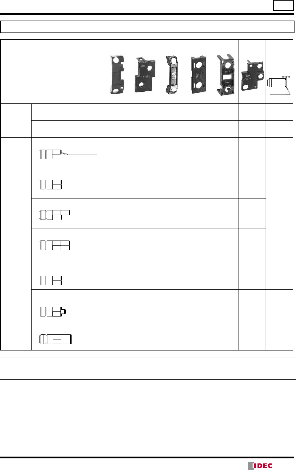
Terminal Cover
Switch/Pilot Light
HW-VL2 HW-VL3 HW-VL4 HW-VL5 HW-VL6 APS-PVL Use of
termi nal
covers
increases
the depth by
the dimen-
sions below.
•Pilot light
APW
APQW Full Voltage X +6mm
Transformer
DC-DC Converter X +3mm
•Pushbutton
ABW
AOW
AVW
ABQW
ABFW
AJW
AOQW
AOFW
AXW
ABGW
AYW
•Selector
switch
ASW
1 contact block
X
+3.5mm
2 contact blocks
X
2 pieces
3 contact blocks
X
2 pieces
4 contact blocks
X
2 pieces
•Illuminated
pushbutton
ALW
AOLW
ALFW
AOLFW
ALQW
AOLQW
AVLW
AYLW
•Illuminated
selector
switch
ASLW
Full Voltage, 1 or 3 contact
blocks X
2 pieces +3.5mm
Full Voltage, 2 or 4 contact
blocks X
For con-
tact blocks
2 pieces
X
For full
voltage
adapter
+3mm
Transformer
DC-DC Converter
X +3mm
Ordering Terminal Covers
Terminal covers are ordered separately.
When ordering terminal covers, specify the Part No. and required quantity.
39.8H × 14.1W 37.8H × 26W 39.8H × 8.7W 39.1H × 15.5W 40H × 14.8W 36H × 29.4W
Terminal
Cover
CB
Terminal Cover
CB
CB
CB CB
CB
CB CB
CB
CB
CB
FA
CB
CB
CB
CB Tr
(14/05/22)
30
ø22 TW Series Accessories and Replacement Parts
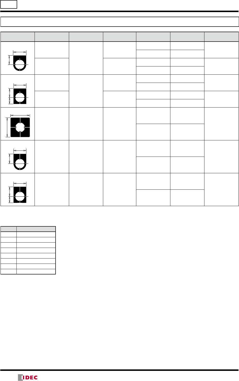
Nameplates
Dimensions (mm) Legend Material Part No. Ordering No. Package
Quantity Description
NWA
Blank
Aluminium
0.8 mm thick
NWA-0
NWA-0 1Black
NWA-0PN10 10
With Legend NWA-∗
NWA-∗1White letters on
black background
NWA-∗PN10 10
NWAQ
Blank
Aluminium
0.8 mm thick
NWAQ-0
NWAQ-0 1Black
NWAQ-0PN10 10
With Legend NWAQ-∗
NWAQ-∗1White letters on
black background
NWAQ-∗PN10 10
NWAS
Blank Aluminium
0.8 mm thick NWAS-0
NWAS-0 1
Black
NWAS-0PN10 10
NWAL
Blank Aluminium
0.8 mm thick NWAL-0
NWAL-0 1
Black
NWAL-0PN10 10
NWAQL
Blank Aluminium
0.8 mm thick NWAQL-0
NWAQL-0 1
Black
NWAQL-0PN10 10
•Specify a legend code in place of ∗ in the Ordering No.
OFF
29
20
OFF
29
2114.5
45
45
29
25
29
2514.5
Legends
Code Legend
0 (blank)
1 ON
2 OFF
3START
4STOP
31 OFF-ON
35 HAND-AUTO
53 HAND-OFF-AUTO
(14/05/22)
31
TW Series Accessories and Replacement Parts ø22
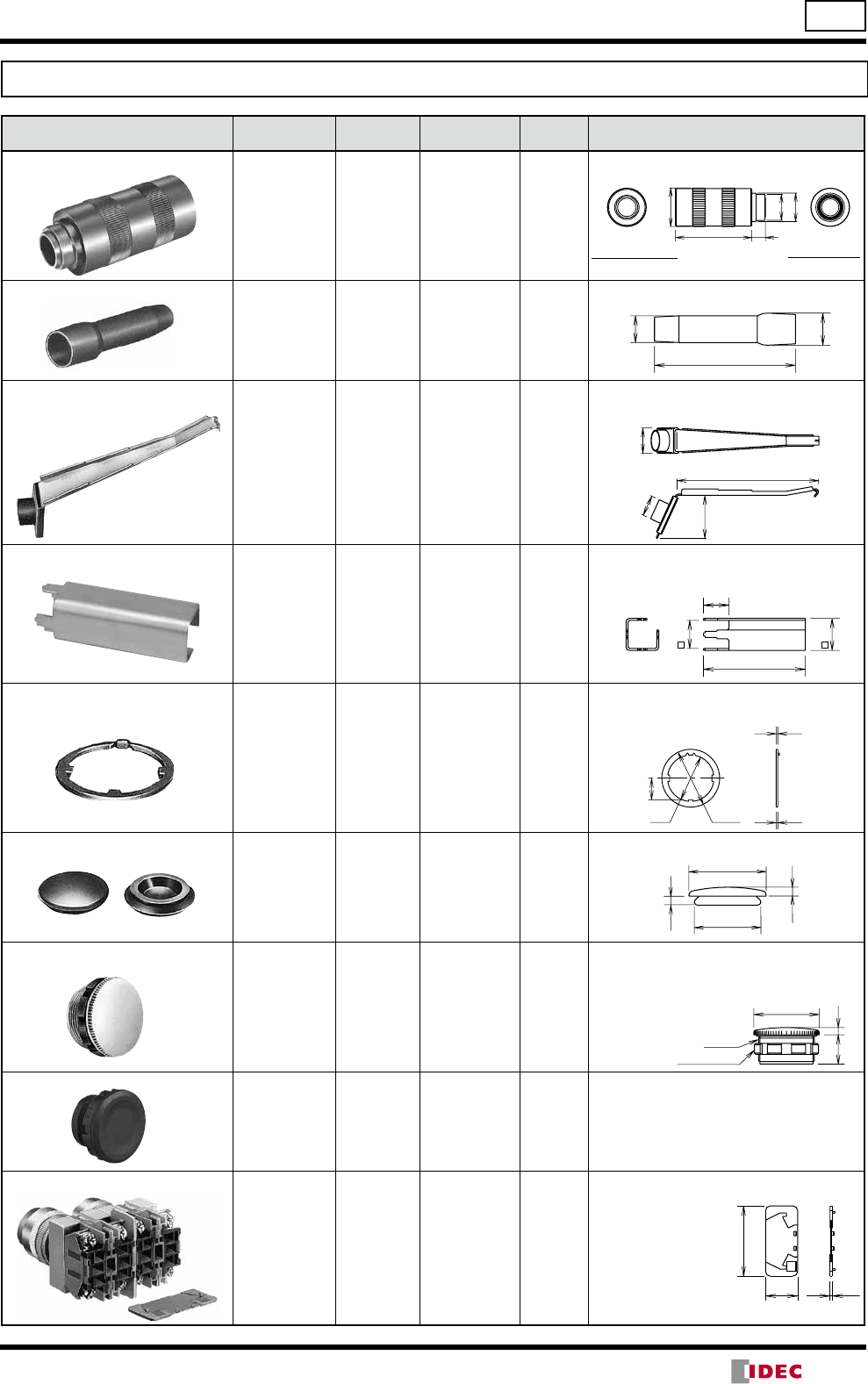
Accessories
Shape Material Part No. Ordering No. Package
Quantity Dimensions
Locking Ring Wrench
Rubber
(nitryl) OR-14 OR-14 1
• Used to tighten the round bezel when installing
the TW switch/pilot light onto a panel.
Lamp Holder Tool
Rubber
(nitryl) OR-55 OR-55 1
• Used to install and remove LED/incandescent
lamps.
Contact Block Removal Tool
Metal
(zinc-plated)
Rubber
(nitryl)
TW-KC1 TW-KC1 1
• Used to remove contact blocks, transformers,
lenses and adapters. Can also be used to
determine panel thickness adjustment.
Nut Locking Wrench
Metal
(nickel-plated) TW-KQ2 TW-KQ2 1
• Used to tighten the locking nuts inside of the
square bezel.This tool can be inserted into the
OR-14 locking ring wrench.
22.5
25.7
20
80
Anti-rotation Ring
Metal
(zinc-plated) OGL-31 OGL-31PN10 10
• Used to prevent the operator from rotating.
Generally used when using no nameplates on
selector switches.
ø22 ø27.4
10.2
0.8
Rubber Mounting Hole Plug
Rubber (black)
(nitryl) OB-31 OB-31PN05 5
• Used to plug unused ø22.2mm mounting
holes.
Metallic Mounting Hole Plug
Diecast Metal
(locking ring:
polyamide)
LW9Z-BM LW9Z-BM 1
• Used to plug unused ø22.2mm mounting holes.
• Tightening torque: 1.2 N·m
• Degree of protection: IP66 (without the 3.2mm
recess in the mounting hole)
Plastic Mounting Hole Plug
Plastic
(polyamide)
LW9Z-BP1
LW9Z-BP1 1
• Used to plug the unused ø22.2mm mounting
holes.
• Tighten the locking ring to a torque of 2.0 N·m.
IP65
• Mounting panel thickness: 0.8 to 6 mm
Barrier
Polyamide HW-VL1 HW-VL1PN10 10
• Used to prevent contact
between adjacent
lead wires when units
are mounted closely.
Barriers should be
always used in close
mounting.
ø46
1690
ø34
ø31
For ø22mm units
(close mounting)
For ø22/ø25mm units
59
ø11.6
ø14
39
130
23
ø19
ø29
ø25
3.5
3.5
Gasket
Locking Ring
ø25.8
12
3
45
20 1.5
(14/05/22)
32
ø22 TW Series Accessories and Replacement Parts
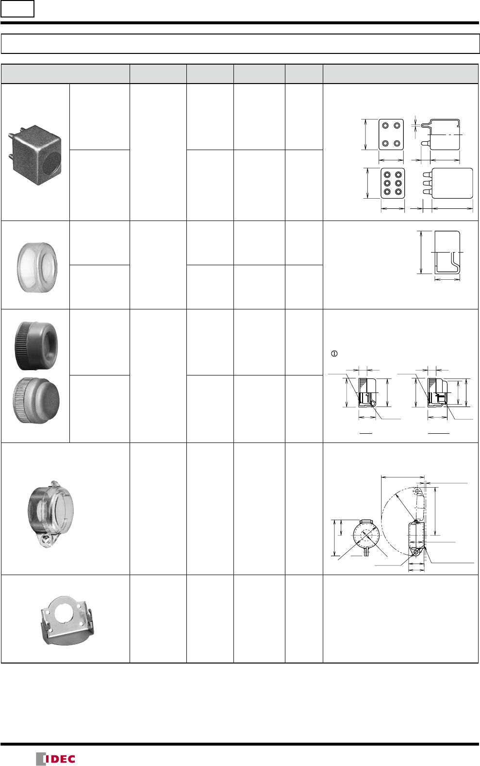
Accessories
Shape Material Part No. Ordering No. Package
Quantity Description
Contact Rubber
Boot For 1 layer of
contact blocks
(2 contact
blocks)
Rubber
(nitryl)
OCW-99 OCW-99 1
• Oiltight rubber boot used for pushbuttons and
selector switches.
• Temperature range: –5 to +60°C
• Black
For 2 layers of
contact blocks
(4 contact
blocks)
OCW-299 OCW-299 1
Button
Clear Boot For flush
pushbuttons
(ABW1/AOW1)
Rubber
(EPDM)
OC-31 OC-31 1
• Used to cover and pro tect
pushbuttons where units
are sub ject to water
splash. Not suitable for
out door use or where the
units are subject to oil
splash.
For extended
pushbuttons
(ABW2/AOW2) OC-32 OC-32 1
Button Cover
For flush
pushbuttons
(ABW1/AOW1)
Rubber
(nitryl)
OCW-10OCW-101
• Metallic bezels covered with rubber boot to
enhance waterproof and oiltight characteristics.
• Button is installed in the cover. Remove the
button from the pushbutton before using the
button cover.
• :
B (black), G (green), R (red), Y (yellow)
For extended
pushbuttons
(ABW2/AOW2) OCW-11OCW-111
Padlock Cover
Polyarylate
(gasket: nitryl
rubber)
HW9Z-KL1 HW9Z-KL1 1
• Used to protect momentary and maintained
pushbuttons, illuminated pushbuttons, knobs
selector switches, and key selector switches.
Padlock Cover
for Key Selector Switches
Metal
(copper) HS9Z-PC22 HS9Z-PC22 1
•For ASWK key selector switches.
Note: Specify a button color code or lens color code in place of or in the Ordering No.
2.2
14 45.5
38
48
14 65.5
38
50
OCW-99
OCW-299
22 (OC-32)
18 (OC-31)
ø32.6
Flush
M22
P1.0
ø31
18.5
ø32
9
Extended
M22
Button
installed
Button
installed
P1.0
ø32
9
ø26
ø31
21
Key hole ø8
Waterproof Rubbe
r
Gasket 0.5t
30
70
ø50
(ID: ø44.4)
93
29.5
30
R66.5
Panel Thickness
0.8 to 3.2
82.5
ø22.2
24 (inside)
(14/05/22)
33
TW Series Accessories and Replacement Parts ø22
Accessories
Shape Material Part No. Ordering No. Package
Quantity Remarks
ø40mm Lens
Non-marking
Plastic
ALW4L-ALW4L-1• Applicable
unit:
ALW3,
AOLW3
: G (green), R (red),
S (blue)
ALW4LD-ALW4LD-1: A (amber),
W (white)
Marking
ALW4BL-ALW4BL-1• Applicable
unit:
ALW3B,
AOLW3B
• Marking plate
is included
: G (green), R (red),
S (blue), W (white)
ALW4BLD-
ALW4BLD-1: A (amber)
Plastic Bezel ➊Flush
Plastic
AW-RP1B AW-RP1BPN05 5
Black
➋Extended AW-FP1B AW-FP1B 1
➌Extended
(for illuminated
pushbuttons)
AW-FP2B AW-FP2B 1
➍
Square round
(for round
pushbuttons)
AW-H1B AW-H1B 1
➎Square AW-Q1B AW-Q1B 1
➏Extended
with Full
Shroud
AW-QF1B AW-QF1B 1
Aluminium Bezel
➊Flush
Aluminium
AW-R1 AW-R1PN05 5Aluminium color (standard)
AW-R1B AW-R1B 1Black
➋Extended AW-F1 AW-F1 1
Aluminium color (standard)
➌Extended
(for illuminated
pushbuttons)
AW-F2 AW-F2 1
➍Mushroom AW-G4 AW-G4 1
Selector Operator ➊Knob
Plastic
ASWHHY-➁ASWHHY-➁PN02 2Specify a color code in place of ➁.
B (black), G (green), R (red)
➋Lever ASWHHL-➁ASWHHL-➁PN02 2
➌Round ASWHHM-B ASWHHM-BPN02 2Black only
➍Color Insert TW-HC1➁TW-HC1➁PN05 5Specify a color code in place of ➁.
B (black), G (green), R (red), S (blue),
W (white), Y (yellow)
➎Illuminated
selector
ASLWDDY-➁ASLWDDY-➁1Specify a color code in place of ➁.
A (amber), W (white), Y (yellow)
ASLWLDY-➁ASLWLDY-➁1Specify a color code in place of ➁.
G (green), R (red), S (blue)
Metal Protector
Metal OLW-C OLW-C 1
• Used to protect flush pushbuttons from
inadvertent operation.
➊
➍
➋
➎
➌
➎
➊ ➋
➌➍
➍
➌
➋
➊
➎
ø22.5
18.6
1.6t
R42.5
Mounting Centers
50 min.
15
(14/05/22)
34
Maintenance Parts
Shape Material Part No. Ordering No.
Package
Quantity
Color Code
Lens (for pilot lights)
Round flush
AS APW1L-APW1L-
PN05 5G (green), R (red), S (blue)
APW1LD-APW1LD-
PN05 5
A (amber), W (white), Y (yellow)
AS,
Marking
APW11L-APW11L-
PN05 5C (clear), G (green), R (red),
S (blue)
APW11LD-APW11LD-
PN05 5A (amber), Y (yellow)
Round extended AS APW2L-APW2L-
PN05 5G (green), R (red), S (blue)
APW2LD-APW2LD-
PN05 5
A (amber), W (white), Y (yellow)
Square flush AS,
Marking
APQW11L-APQW11L-
PN05 5C (clear), G (green), R (red),
S (blue)
APQW11LD-APQW11LD-PN05
5A (amber), Y (yellow)
Lens (for illuminated
pushbuttons)
Round extended
AS ALW2L-
ALW2L-
PN05 5G (green), R (red), S (blue)
ALW2LD-
ALW2LD-
PN05 5
A (amber), W (white), Y (yellow)
AS,
Marking
ALW21L-
ALW21L-
PN05 5C (clear), G (green), R (red),
S (blue)
ALW21LD-
ALW21LD-
PN05 5A (amber), Y (yellow)
Square extended AS ALQW21L-
ALQW21L-
PN05 5C (clear), G (green), R (red),
S (blue)
ALQW21LD-
ALQW21LD-
PN05 5A (amber), Y (yellow)
ø29mm mushroom
AS ALW3L-
ALW3L-
PN02 2G (green), R (red), S (blue)
ALW3LD-
ALW3LD-
PN02 2
A (amber), W (white), Y (yellow)
AS,
Marking
ALW31L-
ALW31L-
PN02 2C (clear), G (green), R (red),
S (blue)
ALW31LD-
ALW31LD-
PN02 2A (amber), Y (yellow)
ø29mm mushroom
AS AVLW3L-R AVLW3L-RPN02 2
AS,
Marking AVLW31L-R AVLW31L-RPN02 2
ø40mm mushroom AS AVLW4L-R AVLW4L-RPN02 2
Button
Round flush
Polyacetal
ABW1B-ABW1B-PN05 5
B (black)
G (green)
R (red)
S (blue)
W (white)
Y (yellow)
Round extended ABW2B-ABW2B-PN05 5
Square flush ABQW1B-ABQW1B-PN05 5
Square extended ABQW2B-ABQW2B-PN05 5
ø29mm mushroom ABW3B-ABW3B-PN02 2
ø40mm mushroom ABW4B-ABW4B-PN02 2
ø29mm pushlock turn
reset AVW3B-AVW3B-PN02 2R (red), Y (yellow)
ø40mm pushlock turn
reset AVW4B-AVW4B-PN02 2R (red), Y (yellow)
ø40mm push pull AYW4B-AYW4B-PN02 2B (black), G (green), R (red),
S (blue), W (white), Y (yellow)
Marking Plate
(for pilot lights) Round flush
Acrylic
APW2B APW2BPN05 5
• White
Square flush APQW1B APQW1BPN05 5
Marking Plate
(for illuminated
pushbuttons) Round extended ALW2B ALW2BPN05 5
Square extended ALQW2B ALQW2BPN05 5
ø29/40mm mushroom ALW3B ALW3BPN05 5
Waterproof Lens For APQW
Acrylic
APW00LN APW00LNPN05 5
For ALQW APW00L APW00LPN05 5
Note: Specify a button color code or lens color code in place of or in the Ordering No.
Use a clear lens for white or pure white illumination.
Lens (for pushlock
turn reset)
ø22 TW Series Accessories and Replacement Parts
(14/05/22)
35
TW Series Accessories and Replacement Parts ø22
Maintenance Parts
Shape Specification Part No. Ordering No.
Package
Quantity
Remarks
Housing Push Rod
Contact Block 1NO contact HW-C10 HW-C10 1Blue Green
1NC contact HW-C01 HW-C01 1Purple red Red
EM contact
(early make) HW-C10R HW-C10R 1Blue Black
LB contact
(late break) HW-C01R HW-C01R 1Purple red White
Dummy Block
TW-DB TW-DBPN10 10
• Used for non-illuminated units with
1NO or 1NC contact blocks.
• Black
Full Voltage Adapter
(for 2 or 4 contact blocks)
TW-DA1B TW-DA1BPN02 2
• Adapter with M3.5 screws used for
illuminated pushbutton or illuminated
selector switch. Snaps on to the back
of the contact block.
• Used with 2 or 4 contact blocks.
• Black
Full Voltage Adapter
(for 1 or 3 contact blocks)
HW-DA1B HW-
DA1BPN02 2
• Adapter with M3.5 screws used for il-
luminated pushbuttons or illumi nated
selector switch.
• Used with 1 or 3 contact blocks.
• Black
Spare Key
Metal TW-SK-0 TW-SK-0PN02 2 • For Key Selector Switch
• For Pushlock Key Reset
LED Lamps (LSTD)
Dimensions Operating
Voltage
Current Draw Part No. Ordering No. Illumination
Color Code
Package
Quantity Base
AC DC
6V AC/DC ±5% 8 mA
7 mA
(A, R, W)
5.5 mA
(G, PW, S)
LSTD-6
LSTD-6Specify a color
code in place of
in the Ordering No.
A: amber
G: green
PW: pure white
R: red
S: blue
W: white
Use a pure white
(PW) LED lamp
with yellow (Y) lens.
1
BA9S/13
LSTD-6PN10 10
12V AC/DC
±10% 11 mA 10 mA LSTD-1
LSTD-11
LSTD-1PN10 10
24V AC/DC
±10% 11 mA 10 mA LSTD-2
LSTD-21
LSTD-2PN10 10
Incandescent Lamps (LS)
Dimensions
Rated
Operating
Voltage
Lamp Ratings Part No. Package
Quantity
6V AC/DC 1W (6.3V) LS-6
1
12V AC/DC 1W (18V) LS-8
18V AC/DC 1W (24V) LS-2
24V AC/DC 1W (30V) LS-3
(
20.8
)
18.42.4
Grommet (x1)
Base (x2) BA9S/13
Voltage
Base BA9S/13
±1
±1.5
22.5
ø11
(14/05/22)
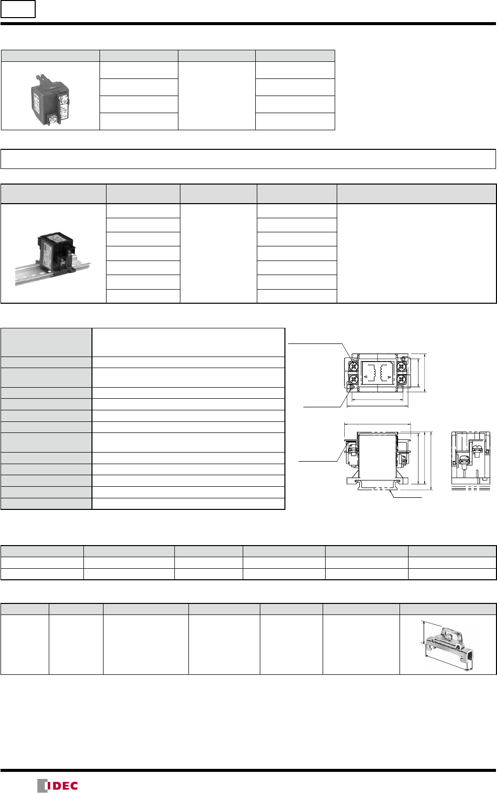
36
ø22 TW Series Accessories and Replacement Parts
Transformer Unit
Shape Primary Voltage Secondary Volt age Part No.
Transformer Unit 100/110V AC
5.5V
TW-T16B
120V AC TW-T126B
200/220V AC TW-T26B
240V AC TW-T246B
Transformer
Shape Primary Voltage Secondary
Voltage Part No. Applicable Load
Din Rail Mount Transformer
For 6V 100/110V AC
5.5V AC, 1W
TWR516
LSTD-6 LED lamp (6V AC/DC) or
LS-6 incandescent lamp (6V AC/DC, 1W)
115/120V AC TWR5126
200/220V AC TWR526
230/240V AC TWR5246
380V AC TWR5386
400/440V AC TWR546
480V AC TWR5486
Specifications
Operating Voltage
100/110V AC, 115/120V AC, 200/220V AC,
230/240V AC, 380V AC, 400/440V AC, 480V AC
(50/60Hz)
Current Draw 2.4 VA
Rated Insulation
Voltage 600V
Insulation Resistance 100 MΩ minimum (500V DC megger)
Operating Temperature –30 to +60°C (no freezing)
Storage Temperature –40 to +80°C (no freezing)
Operating Humidity 35 to 85% RH (no condensation)
Vibration Resistance Damage Limits: 30 Hz, amplitude 1.5 mm
Operating extremes: 5 to 55 Hz, amplitude 0.5 mm
Shock Resistance Damage limits, Operating Extremes: 1,000 m/s2
Dielectric Strength 2,500V AC, 1 minute
Terminal Screw M3.5
Applicable Wire 2 mm2 maximum, 2 wires maximum
Weight (approx.) 87g
Accessories
DIN Rail
Part No. Ordering No. Length Weight (approx.) Material Package Quantity
BAA1000 BAA1000PN10 1000 mm 200g Aluminum 10
BAP1000 BAP1000PN10 1000 mm 320g Steel 10
End Clip
Part No. Ordering No. Applicable DIN Rail Weight (approx.) Material Package Quantity Dimensions
BNL6 BNL6PN10 BAA1000
BAP1000 15g Steel
(Zinc-plated) 10
(24)
45 9
•Use plastic end clip BC9Z-E/NS35N when using 400/440V AC primary voltage transformers.
Dimensions
45.5
52
41
40
48
40
22
30
BAA1000
1
3 4
JAPAN
2
PRI.
SEC.
M3.5 Terminal Screw
Terminal Cover
Secondary Side Primary Side
2–ø3.3
Mounting Hole
(14/05/22)
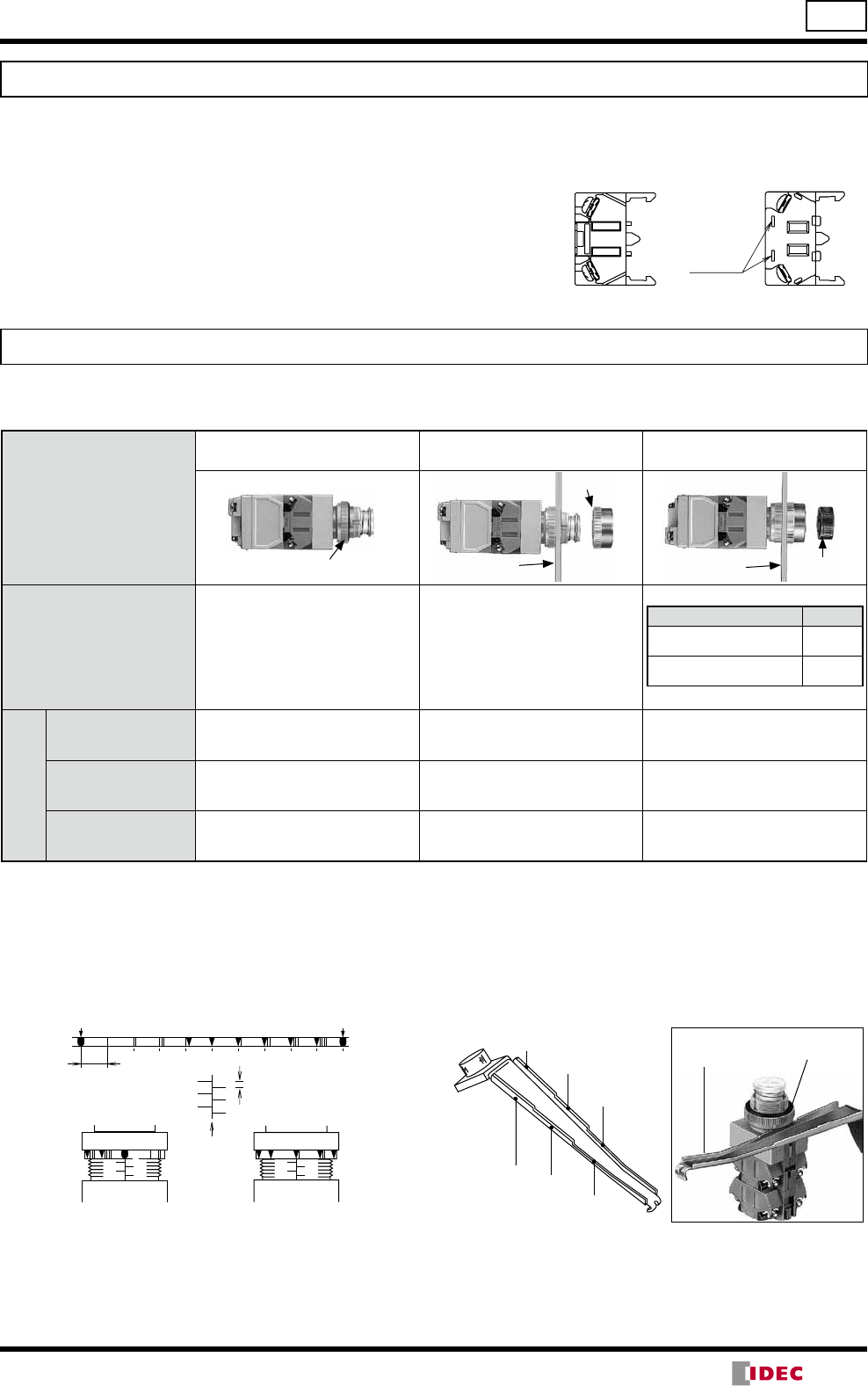
37
TW Series Instructions ø22
Adjusting Panel Thickness
The panel thickness ring provides adjustment from 1 to 6
mm in 1-mm increments. Set the panel thickness to line A.
Rotate the ring until the desired thickness indication around
the periphery is aligned with line A, as shown below.
0 0.1 0.2 0.3 0.4 0.5 0.6 0.7 0.8 0.9 0
Scale on Adjustment (in 0.1 mm)
0.1 mm
12
4
6
3
5
1 mm
Panel Thickness Scale
(in 1 mm on the operator)
A
3
543
54
66
2
Ex. Panel thickness 2 mm Ex. Panel thickness 2.6 mm
Note: When a nameplate or an anti-rotation ring is used, add
0.8mm to the panel thickness.
Total thickness
= Panel thickness + 0.8mm (nameplate or anti-rotation ring thickness)
Using the Contact Block Removal Tool to Adjust Panel
Thickness
Panel thickness can easily be adjusted to the values shown
below by inserting the contact block removal tool between
the adjustment ring and base.
Panel Thickness
Adjustment Ring
Contact Block
Removal Tool
1.6 mm
2.3 mm
3.5 mm
1 mm 2 mm
3.2 mm
Safety Precautions
Instructions
Panel Mounting
Panel thickness adjustment ring is used for the TW series. To attach the TW series to the panel, follow the procedures below.
Mounting order
Panel Thickness Adjustment Attaching the Unit to the Panel
with the Bezel
-Attaching the Button, Lens, and
Knob
Panel thickness adjustment ring Panel
Bezel
Lens
Panel
Remarks Attach the unit with the panel
thickness scale facing up.
Installation method
Tools
Locking ring wrench For tightening or removing round
bezels.
Nut locking wrench For tightening or removing square
bezels.
Contact block removal
tool Panel thickness adjustment
For installing or removing water-
proof lenses after the bezel is
attached.
For installing or removing round
lenses.
•Turn off the power to the TW series switches & pilot lights
before starting installation, removal, wiring, maintenance,
and inspection of the products. Failure to turn power off
may cause electrical shocks or fire hazard.
•To avoid a burn on your hand, use the lamp holder tool
when replacing lamps.
•For wiring, use wires of a proper size to meet the volt-
age and current requirements. Tighten the M3.5 terminal
screws to a tightening torque of 1.0 to 1.3 N·m. Failure to
tighten terminal screws may cause overheat and fire.
•Use HW-C contact blocks for the TW series. Do not re-
place with or add conventional TW series contact blocks.
Using a different type of contact block may lead to
malfunc tion.
Contact Block
HW-C
Rectangular
Holes
Contact Block
TW
Type Method
Flush/Extended pushbuttons,
Square lens, Selector operator Press in
29mm/40mm mushroom
button/lens, Dome lens Screw in
(14/05/22)
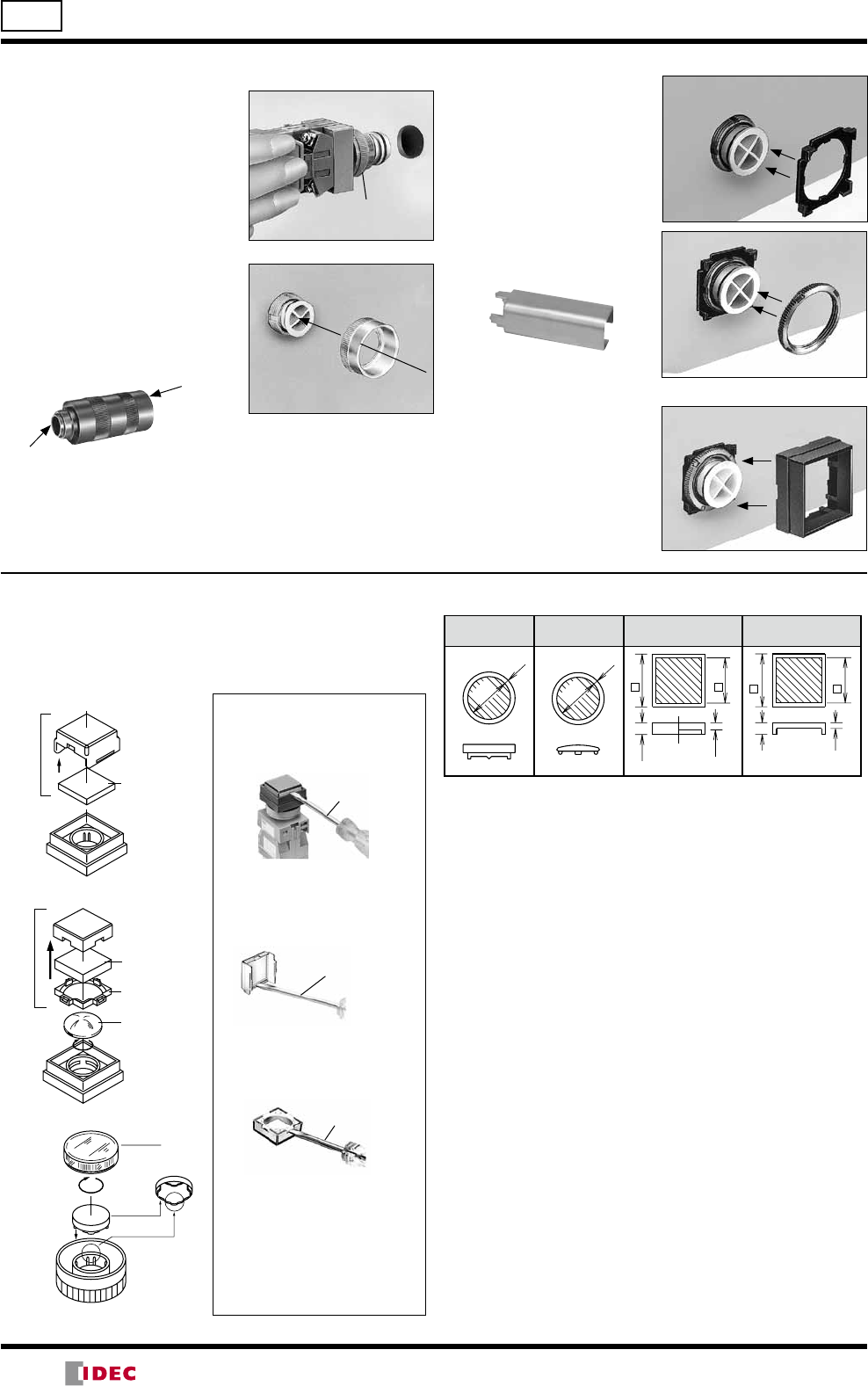
38
ø22 TW Series Instructions
Mounting into Panel Cut-out with Bezel
Insertion into Panel Cut-out
Insert the base into the panel
cut-out making sure that the
panel thickness scale is facing
up.
Panel thickness
adjustment ring
Round Bezel
All round bezels are screw-in
type. Be sure to use the locking
ring wrench to tighten the bezel.
•Recommended tightening torque is 2.0 N·m.
Side A
Use side B when mounting
units closely.
Use side B when
mounting the units
closely.
Locking Ring Wrench
OR-14 (optional)
Side B
Tighten
Remove
Square Bezel
1. Insert the base plate from
the front.
2. Insert the lock nut. For
easy installation, use the
nut locking wrench.
Nut Locking Wrench
TW-KQ2 (optional)
3. Mount the square bezel.
The bezel will snap onto the
base plate.
Square Bezel
Base Plate
Lock Nut
Installing Buttons, Lenses, and Operators
Lens Structure and Marking Plate
All square lens units are marking types. To engrave on the
marking plate, remove the marking plate from the lens.
•Illuminated Pushbuttons
Insert the screwdriver into the
hook and lightly push out the
lens.
1. Removing the Square Lens
Insert the screwdriver into the
recess of the lens and lightly
push out the lens.
Flat screwdriver
(5mm wide at
maximum)
Small flat screwdriver
3. Other Notes
The square lens of the illumi-
nated pushbutton cannot be
used without waterproof lens.
Always use the waterproof
lens.
Be sure to use the marking
plate even when it is not
engraved.
2. Removing the Marking Plate
•Pilot Light
Insert the screwdriver into the
recess of the lens.
Flat screwdriver
(5mm wide at
maximum)
[Square Pilot Lens]
[Square Illuminated Pushbutton]
Lens
Marking
Plate
Press in
[Round Marking]
Marking Plate Engraving Area
Round Mushroom Square (Pilot Light) Square (Illuminated
Pushbutton)
ø14 1.5
ø13 0.9
21
222.6
1.2
19
21
4.4
1.0
Note: The depth of the engraving must be within 0.5 mm.
Installing Round Lens and Waterproof Lens
When installing or removing round lens of pilot lights and
illu minated pushbuttons and waterproof lens of square pilot
lights and illuminated pushbuttons, press the rubber part of
the contact block removal tool onto the lens or waterproof
lens for secure tightening and easy removal.
Marking Plate
Insert
Square Lens
Marking Plate
Lens Retainer
Waterproof Lens
Press in
Square Lens
(14/05/22)
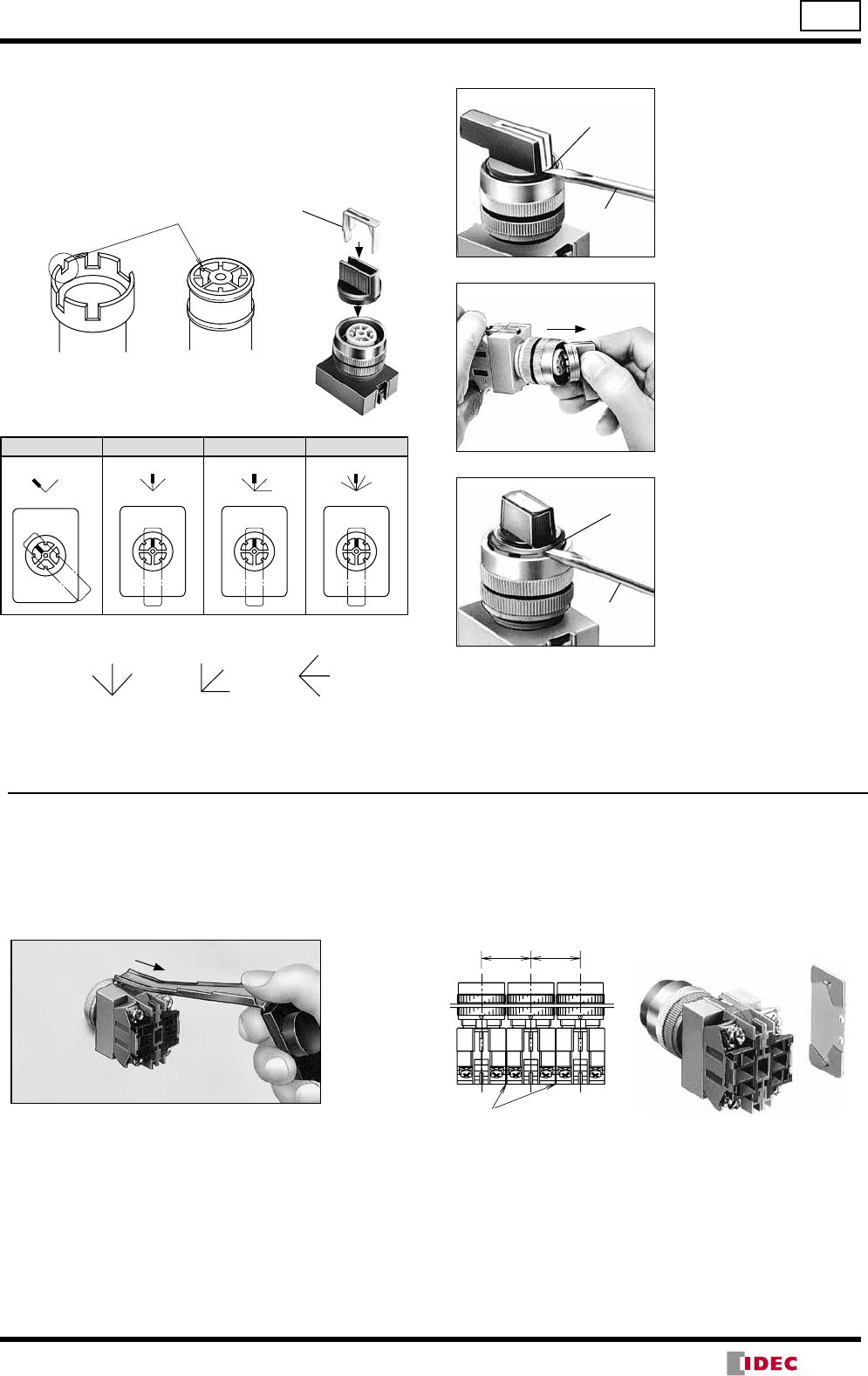
39
TW Series Instructions ø22
Installation of Selector Operators
1. The shaft of each selector or illuminated selector switch
has a recess to identify in which direction to install the
operator. Align the operator with the recess and press in
the operator.
2. Press color insert (non-illuminated) into the opera tor. The
color insert retains the operator
Selector Switch
(non-illuminated)
Illuminated
Selector Switch
Recess
Color insert
Press in
Press in
2-Position, 90°
3-Position, 45° 4-Position, 45° 5-Position, 30°
RL
R
C
L
3
4
2
1
45
3
2
1
[Example]
C
LR
LC
R
L
C
R
Standard Position
The non-illuminated operators can be installed in positions
other than the standard position as shown above.
Removing the Operator
Flat
screwdriver
Recess
Recess
Flat
screwdriver
1. Removing the Color
Insert
Insert a flat screwdriver
into the recess of the color
insert. Turn the screwdriver
to push out the insert from
the operator
2. Removing the Operator
(Non-illuminated)
Push the operator sideways
as shown in the left photo to
remove the operator.
3. Removing the Operator
(Illuminated)
Insert a flat screwdriver into
the recess of the operator
and turn the screwdriver to
remove the operator.
Removing Contact Blocks, Transformers
and Full Voltage Adapters
Insert the end of the contact block removal tool into the
snap-fit latch of the contact block (or transformer, full-
voltage adapter) and pull the tool as shown below.
Pull
Collective Mounting
When mounting the units closely in a horizontal row on
30-mm centers, use optional barriers to prevent
interconnection between adjoining terminals. The barriers
can be attached simply by pressing them onto the sides of
contact blocks.
Barrier (HW-VL1)
30 30
Tightening Torque for Terminal Screws
Tighten the M3.5 terminal screws to a torque of 1.0 to 1.3
N·m.
(14/05/22)
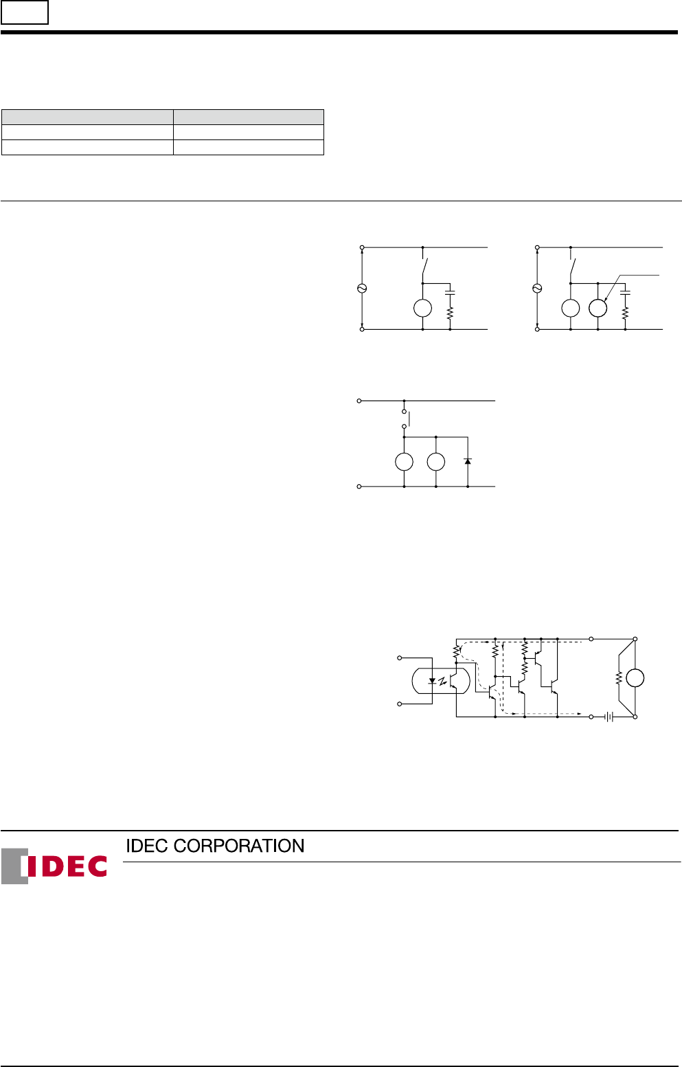
ø22 TW Series Instructions
IDEC CORPORATION (USA)
1175 Elko Drive, Sunnyvale, CA 94089-2209, USA
Tel: +1-408-747-0550 / (800) 262-IDEC (4332)
Fax: +1-408-744-9055 / (800) 635-6246
E-mail: opencontact@idec.com
IDEC CANADA LIMITED
3155 Pepper Mill Court, Unit 4
Mississauga, Ontario, L5L 4X7, Canada
Tel: +1-905-890-8561, Toll Free: (800) 262-IDEC (4332)
Fax: +1-905-890-8562
E-mail: sales@ca.idec.com
IDEC AUSTRALIA PTY. LTD.
Unit 17, 104 Ferntree Gully Road,
Oakleigh, Victoria 3166, Australia
Tel: +61-3-8523-5900, Toll Free: 1800-68-4332
Fax: +61-3-8523-5999
E-mail: sales@au.idec.com
IDEC ELECTRONICS LIMITED
Unit 2, Beechwood, Chineham Business Park,
Basingstoke, Hampshire RG24 8WA, UK
Tel: +44-1256-321000, Fax: +44-1256-327755
E-mail: sales@uk.idec.com
6-64, Nishi-Miyahara 2-Chome, Yodogawa-ku, Osaka 532-0004, Japan
Tel: +81-6-6398-2527, Fax: +81-6-6398-2547
E-mail: marketing@idec.co.jp
Specications and other descriptions in this brochure are subject to change without notice.
Cat. No. EP1432-3 MAY 2014 PDF
IDEC ELEKTROTECHNIK GmbH
Wendenstrasse 331, 20537 Hamburg, Germany
Tel: +49-40-25 30 54 - 0, Fax: +49-40-25 30 54 - 24
E-mail: service@idec.de
IDEC (SHANGHAI) CORPORATION
Room 701-702 Chong Hing Finance Center,
No. 288 Nanjing Road West, Shanghai 200003, PRC
Tel: +86-21-6135-1515
Fax: +86-21-6135-6225 / +86-21-6135-6226
E-mail: idec@cn.idec.com
IDEC (BEIJING) CORPORATION
Room 211B, Tower B, The Grand Pacic Building,
8A Guanghua Road, Chaoyang District,
Beijing 100026, PRC
Tel: +86-10-6581-6131, Fax: +86-10-6581-5119
IDEC (SHENZHEN) CORPORATION
Unit AB-3B2, Tian Xiang Building, Tian’an Cyber Park,
Fu Tian District, Shenzhen, Guang Dong 518040, PRC
Tel: +86-755-8356-2977, Fax: +86-755-8356-2944
IDEC IZUMI (H.K.) CO., LTD.
Unit G & H, 26/F., MG Tower,
No. 133 Hoi Bun Road, Kwun Tong, Kowloon,
Hong Kong
Tel: +852-2803-8989, Fax: +852-2565-0171
E-mail: info@hk.idec.com
IDEC TAIWAN CORPORATION
8F-1, No. 79, Hsin Tai Wu Road, Sec. 1,
Hsi-Chih District, 22101 New Taipei City, Taiwan
Tel: +886-2-2698-3929, Fax: +886-2-2698-3931
E-mail: service@tw.idec.com
IDEC IZUMI ASIA PTE. LTD.
No. 31, Tannery Lane #05-01,
HB Centre 2, Singapore 347788
Tel: +65-6746-1155, Fax: +65-6844-5995
E-mail: info@sg.idec.com
IDEC ASIA (THAILAND) CO.,LTD.
20th Fl., Sorachai Bldg., No.23/78,
Soi Sukhumvit 63, Sukhumvit Rd.,
Klongton-nua, Wattana, Bangkok 10110
Tel: +662-392-9765, Fax: +662-392-9768
E-mail: sales@th.idec.com
www.idec.com
Installation of LED Illuminated Units
1. Note the polarity for wiring when connecting to DC-DC
converter unit.
Terminal No. Polarity
X1 Positive
X2 Negative
2. Transformer type units are recommended for use in areas
subjected to noise.
3. Notes for Pure White LED Lamps
•Do not use the pure white LED outdoors, otherwise it will
lead to the degradation of brightness and color. Do not
remove or apply shock to the cap on the pure white LED
lamp, otherwise it may break or damage the cap.
•For the pure white LED, use a white lens. The illumination
color will be dull if a different color is used.
Notes on LED Illuminated Units
LED lamps consist of semiconductors. If the applied voltage
exceeds the rated voltage, LED elements may deteriorate
due to overheat, resulting in significant decrease in lumi-
nance, hue change, or failure of lighting. Also, if an extrane-
ous noise, transient voltage, or transient current is applied
to the circuit, similar effects may occur. When using LED
lamps, observe the following instructions.
Rated Voltage
The LED lamps are rated at 6V, 12V, or 24V AC/DC, and
can be used within ±10% the rated voltage of either AC or
DC.
DC Power
1. Switching power supply
Regulated voltage from switching power supply is best
suited. Make sure to use within the rated voltage of the
LED lamp.
2. Rechargeable battery
Note that the battery voltage may exceed the rated volt-
age of the LED lamp while the battery is being charged
and immediately after the charging is complete. Be sure to
use the LED lamp on a voltage of ±10% the rated volt age.
3. Full-wave rectification
Since the LED lamp is AC/DC compatible, a diode bridge
for rectification is not necessary. If the LED lamp is used
on a full-wave rectification current through a diode bridge,
the rectifier diodes will reduce the voltage, resulting in
lower luminance.
4. Single-phase half-wave rectification
This is not suitable for the power source of LED lamps.
Use constant-voltage DC power.
Noise
LED elements deteriorate due to extraneous noise, resulting
in significant decrease in luminance, hue change, or failure
of lighting. When such effects are anticipated, take a protec-
tion measure shown below, such as RC elements or a surge
absorber.
[Protection Example 1] For AC circuit
LED with
transformer LED R
C
LED
Ry
Relay
coil or
solenoid R
C
LED with
transformer
(Reference values) R: 120Ω
C: 0.1 μF
[Protection Example 2] For DC circuit
Ry LED Diode
Relay
coil or
solenoid
+
–
(Reference values of the diode)
Forward current: More than the Ry coil current
Reverse withstand voltage: Ry coil current ¥ 10
Countermeasures against Dim Lighting
1. Leakage currents through the transistors or a contact
protection circuit may cause the LED lamp to illuminate
dimly even when the output is off.
2. When the LED lamp is illuminated by a transistor output,
take the following measure.
[Circuit Example]
Connect shunt resistor R in parallel with the LED lamp.
R
Io
Io: Leakage current when the output is off
R: Shunt resistor
LED
(14/05/22)
