NIPSCO 11 06 W Rep
111370-Catalog 111370-Catalog 111370-Catalog 784572 Batch6 unilog cesco-content
145938-Attachment 145938-Attachment 145938-Attachment 784572 Batch6 unilog cesco-content
317435-Catalog 317435-Catalog 317435-Catalog 784572 Batch7 unilog cesco-content
145938-Attachment 145938-Attachment 145938-Attachment 784572 Batch7 unilog cesco-content
252625-Catalog 252625-Catalog 252625-Catalog 784572 Batch7 unilog cesco-content
2014-06-03
: Pdf 242787-Attachment 242787-Attachment 784572 Batch4 unilog
Open the PDF directly: View PDF ![]() .
.
Page Count: 32
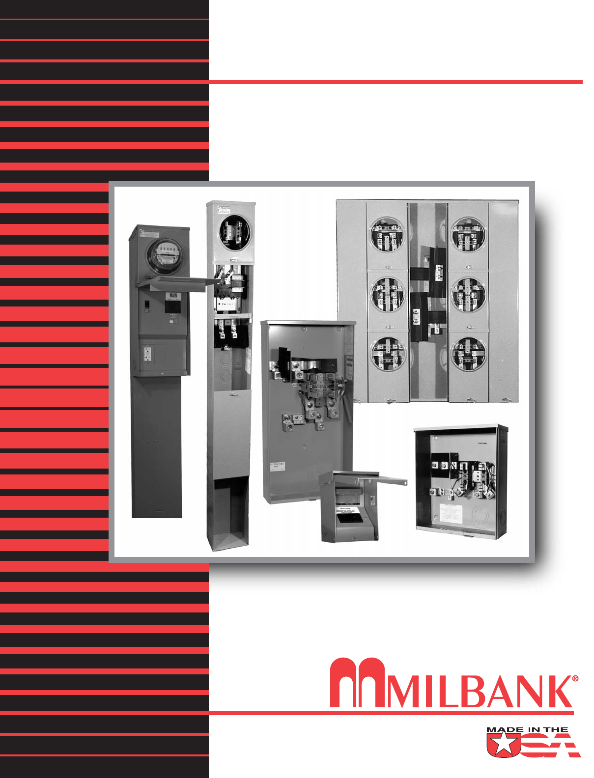
Meter Mounting Equipment
Northern Indiana Public Service Co.

MILBANK OVERVIEW
MILBANK OVERVIEW
2
2
ilbank Manufacturing
Company was estab-
lished in 1927 by
Charles A. Milbank.
Originally, the company manu-
factured high voltage switches;
however, by 1941 Milbank devot-
ed itself primarily to the manufac-
ture of sheet metal enclosures
and related equipment for the
electrical generation and distribu-
tion industry. Today we are an
industry leader in the manufac-
ture of electrical meter sockets.
Through a national network of
manufacturer’s representatives we
provide wholesale electrical dis-
tributors with quality electrical
products for the utility, contractor,
industrial and OEM markets.
As the meter standards have
changed, Milbank has been suc-
cessful in adapting its product
line to these changes. Our full
scale engineering department
designs products to meet cus-
tomer specifications and satisfy
all utility requirements.
Milbank’s employee base of over
1,000 with our five manufactur-
ing facilities comprising almost
550,000 square feet gives us the
flexibility to schedule, produce,
and ship orders quickly.
Currently, Milbank manufactures
over 10,000 different catalog
items, and this list continues to
grow. Our unique product offer-
ing includes: Residential &
Commercial Meter Sockets;
Residential & Commercial Meter
Pedestals; RV/MH Power Outlets,
Pedestals, and Transformers;
Commercial & Industrial
Electrical Enclosures; Circuit
Breakers; Disconnects & Safety
Switches; Safety Sockets; Utility &
Residential Secondary Pedestals;
Hubs and related accessories. If
you don’t find a unit in this cata-
log to service your needs, send us
your specifications and we will
be happy to work with you.
Our success has come from a
loyal customer base that can rely
on us to build quality products at
a fair price in a timely manner.
Our willingness and ability to
design and produce new products
to meet our customer demands is
an important factor to remain
competitive in today’s electrical
market.
Milbank has been serving the
electric utility & wholesale distri-
bution industries for over 75
years with innovative, quality
engineered products. So remem-
ber us for all of your meter
mounting and related require-
ments, and we will be happy to
serve you as we have in the
past—with dependable service
and quality products!
We take great pride in being
one of the few family-owned
businesses left in our industry.
We are a third generation run
business and truly believe that...
FAMILY MAKES A
DIFFERENCE!
Charles A. Milbank
1879-1966
Bill Martin Robert F. Waldrop,
1922-2002
Robert F. Waldrop, II
Chairman
Katrina Waldrop Henke
Vice Chairman
M
Milbank–Quality Metering Products for over 75 Years

3
TABLE OF CONTENTS
TABLE OF CONTENTS
CATALOG NUMBER LOGIC . . . . . . . . . . . . . . . . . . . . . . . . . . . . . . . . . . . . . . . . . . . . . . . . . . . . . . . . . . . . . . . . . . . . . . . . .4
DISCONNECTS
AIR CONDITIONER DISCONNECT . . . . . . . . . . . . . . . . . . . . . . . . . . . . . . . . . . . . . . . . . . . . . . . . . . . . . . . . . . . . . . . . . .5
AIR CONDITIONER DISCONNECT WITH GFCI RECEPTACLE . . . . . . . . . . . . . . . . . . . . . . . . . . . . . . . . . . . . . . . . . . .6
HOT TUB DISCONNECT . . . . . . . . . . . . . . . . . . . . . . . . . . . . . . . . . . . . . . . . . . . . . . . . . . . . . . . . . . . . . . . . . . . . . . . . . .6
SINGLE POSITION (HORN BYPASS)
125 AMP–4 TERMINAL–RINGLESS –600 VAC . . . . . . . . . . . . . . . . . . . . . . . . . . . . . . . . . . . . . . . . . . . . . . . . . . . . . . . . .7
200 AMP–4 TERMINAL–RINGLESS–600 VAC . . . . . . . . . . . . . . . . . . . . . . . . . . . . . . . . . . . . . . . . . . . . . . . . . . . . . . . . .8
200 AMP–4 TERMINAL–SIDE WIREWAY–RINGLESS–600 VAC . . . . . . . . . . . . . . . . . . . . . . . . . . . . . . . . . . . . . . . . . . .8
SINGLE POSITION (LEVER BYPASS)
200 AMP–5 & 7 TERMINAL–HEAVY DUTY–RINGLESS–600 VAC . . . . . . . . . . . . . . . . . . . . . . . . . . . . . . . . . . . . . . . . .9
320 AMP–4 TERMINAL–HEAVY DUTY–RINGLESS–600 VAC . . . . . . . . . . . . . . . . . . . . . . . . . . . . . . . . . . . . . . . . . . . .10
320 AMP CONTINUOUS–7 TERMINAL–HEAVY DUTY–RINGLESS–600 VAC . . . . . . . . . . . . . . . . . . . . . . . . . . . . . . .11
MULTIPLE POSITION
100, 150 & 200 AMP / POSITION–4 TERMINAL–HORIZONTAL GANGS–RINGLESS–300 VAC . . . . . . . . . . . . . . . . .12
200 AMP / POSITION–7 TERMINAL–HORIZONTAL GANGS–HEAVY DUTY–RINGLESS–600 VAC . . . . . . . . . . . . . .13
CONDOMINIUM METERING BANKS
125 & 200 AMP / POSITION–VERTICAL & RECTANGULAR–120 / 240 VAC . . . . . . . . . . . . . . . . . . . . . . . . . . . . . .14-15
PEDESTALS
100 & 200 AMP–4 TERMINAL–RESIDENTIAL–SINGLE OR DOUBLE POSITION–RINGLESS-600 VAC . . . . . . . . . . .16
100 / 200 AMP–5 & 7 TERMINAL–LEVER BYPASS–HEAVY DUTY–600 VAC . . . . . . . . . . . . . . . . . . . . . . . . . . . . . . .17
METER-MAIN / CIRCUIT BREAKERS
100 / 200 AMP–4 TERMINAL–CB MAIN DISCONNECT–RINGLESS–120 / 240 VAC . . . . . . . . . . . . . . . . . . . . . . . . . .18
100 / 200 AMP–4 TERMINAL–METER PEDESTAL–RINGLESS–PARALLEL MAIN–120 / 240 VAC . . . . . . . . . . . . . . .19
320 AMP–4 TERMINAL–WITH BREAKER–LEVER BYPASS–HEAVY DUTY–RINGLESS–120 / 240 VAC . . . . . . . . . .20
320 AMP–4 TERMINAL–NO BREAKER PROVISION–LEVER BYPASS–HEAVY DUTY–RINGLESS–600 VAC . . . . . .20
RV / MOBILE HOME PEDESTAL
200 AMP–4 TERMINAL–RINGLESS–120 / 240 VAC . . . . . . . . . . . . . . . . . . . . . . . . . . . . . . . . . . . . . . . . . . . . . . . . . . . .21
MISCELLANEOUS
ACCESSORIES . . . . . . . . . . . . . . . . . . . . . . . . . . . . . . . . . . . . . . . . . . . . . . . . . . . . . . . . . . . . . . . . . . . . . . . . . . . . . .22-23
CONDUIT AND AMPACITY INFORMATION . . . . . . . . . . . . . . . . . . . . . . . . . . . . . . . . . . . . . . . . . . . . . . . . . . . . . . . . . .24
ENERGIZATION OF ELECTRICAL EQUIPMENT . . . . . . . . . . . . . . . . . . . . . . . . . . . . . . . . . . . . . . . . . . . . . . . . . . . . . .25
MATERIALS AND FINISHES . . . . . . . . . . . . . . . . . . . . . . . . . . . . . . . . . . . . . . . . . . . . . . . . . . . . . . . . . . . . . . . . . . . . . .26
WATTHOUR METERS . . . . . . . . . . . . . . . . . . . . . . . . . . . . . . . . . . . . . . . . . . . . . . . . . . . . . . . . . . . . . . . . . . . . . . . . . . .27
OTHER MILBANK PRODUCTS . . . . . . . . . . . . . . . . . . . . . . . . . . . . . . . . . . . . . . . . . . . . . . . . . . . . . . . . . . . . . . . . . . . .28
INDEX . . . . . . . . . . . . . . . . . . . . . . . . . . . . . . . . . . . . . . . . . . . . . . . . . . . . . . . . . . . . . . . . . . . . . . . . . . . . . . . . . . . . . . . . . . . . .29
3
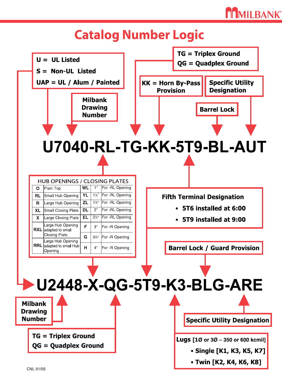
CATALOG NUMBER LOGIC
4
CATALOG NUMBER LOGIC
4
5
30 & 60 AMP–FUSIBLE / NON-FUSIBLE–AIR CONDITIONER DISCONNECTS
DISCONNECTS
30 & 60 AMP–FUSIBLE / NON-FUSIBLE–AIR CONDITIONER DISCONNECTS
5
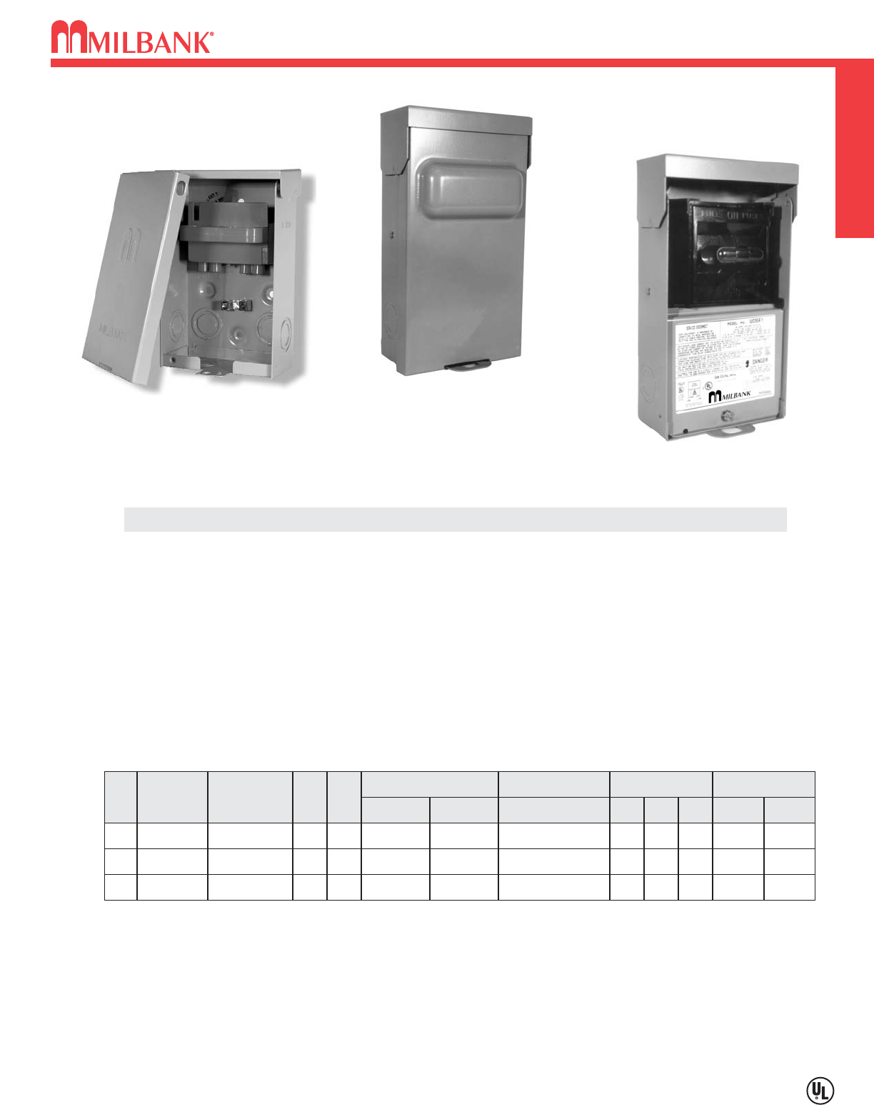
U3800
(No deadfront required)
Milbank’s air conditioner disconnect has a removable hinged cover which makes wiring a breeze. Our
compact design meets all wire bending space requirements in the NEC and also complies with article
440-14 in the NEC. To insure the safest conditions, we designed our disconnect pullers to be remov-
able or they may be reinstalled in the “off” position. Another safety feature is the padlock provision on
the front cover. As with all Milbank products, our enclosure is constructed of G90U galvanized steel
and finished with an attractive, light gray, baked powder coating. Our state of the art finish combines
epoxy and polyester hybrid resins into a hybrid powder coating which is then electrostatically applied.
This offers a durable, nonfading finish.
TECHNICAL INFORMATION
AMP TYPE CATALOG
NUMBER
MAX
H.P.
WT.
#
30 FUSIBLE U3803 33.7
60 FUSIBLE U3806 10 3.7
60
NONFUSIBLE
U3800 10 3.25
LINE & LOAD
WIRE RANGE
GROUND
WIRE RANGE DIMENSIONS WIRE RATING
CU AL CU/AL
#14-#2
AWG #12-#2
AWG #12-2 AWG
#14-#2
AWG #12-#2
AWG #12-2 AWG
#14-#2
AWG #12-#2
AWG #14-4 AWG
D″″W″″H″″CU °°CAL °°C
3 5 91
⁄
460°/75°60°
3 5 91
⁄
460°/75°60°
35860°/75°60°/75°
PROFILE
U3800 is UL Listed without deadfront. Line and
load terminations are fully insulated.
U3800 std. quantity is 20 per carton.
U3803 & U3806 std. quantity is 6 per
carton.
U3803
U3806
AC DISCONNECT / SPA BOX
6
AC DISCONNECT / SPA BOX DISCONNECTS
6
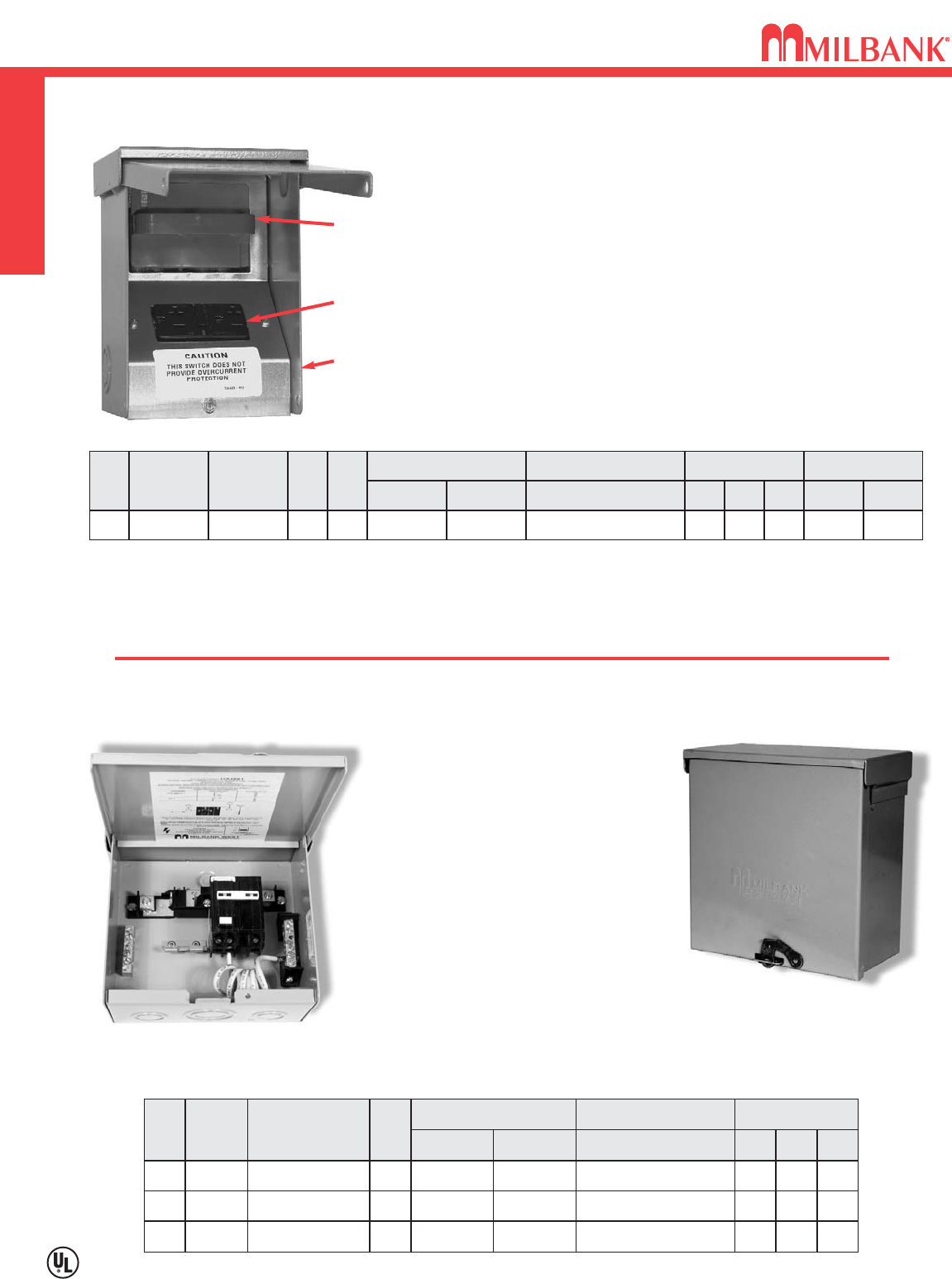
• Meets NEC # 210.63 Requirements *
• UL Listed as Power Outlet
• Type 3R Enclosure
• In-Use Cover**
• Duplex Ground Connector
• 1” Concentric Knockouts
AC DISCONNECT
•1
∅∅
, 240 Volt
• 60 amp, Non-Fused
GFCI RECEPTACLE
• 20 amp
• Reset/Test Button
• Padlock provision
Combination AC Disconnect / 20 Amp GFCI Receptacle–Together in 1 Box
To ensure the safest conditions, Milbank disconnect pullers are designed to be reversible so they may be reinstalled in the OFF position.
All units are designed with a padlock provision on the cover for security.
**Note: U3822-20GR cover rated as
IN-USE COVER
(Cover may be closed with cords plugged into receptacle).
*Reprinted with permission from NFPA 70-2002,
National Electrical Code
®, Copyright 2001, National Fire Protection Association, Quincy, MA 02269. This reprinted material is not the complete
and official position of the NFPA on the referenced subject, which is represented only by the standard in its entirety. National Electrical Code®and NEC®are registered trademarks of the
National Fire Protection Association, Quincy, MA.
* NEC®#210.63 Heating, Air-
Conditioning and Refrigeration
Equipment Outlet.
...The receptacle shall be locat-
ed on the same level and within
7.5 m (25 ft.) of the heating, air-
conditioning and refrigeration
equipment.
* NEC®#210.08 Ground-Fault
Circuit– Interruptor protection
for personnel.
U4881-O-50GB
AMP TYPE CATALOG
NUMBER
WT.
#
–
BREAKER
PROVISION
U4881-O 7
LINE & LOAD CONNECTOR
WIRE RANGE
GROUND CONNECTOR
WIRE RANGE DIMENSIONS
CU AL CU/AL
#14-1/0 #14-1/0 #14-1/0
D″″
W″″
H″″
3 3
⁄
471
⁄
281
⁄
2
50
60
BREAKER
BREAKER
U4881-O-50GB
U4881-O-60GB
8
8
#14-1/0
#14-1/0
#14-1/0
#14-1/0
#14-1/0
#14-1/0
3 3
⁄
4
3 3
⁄
4
71
⁄
2
71
⁄
2
81
⁄
2
81
⁄
2
••
240 volt ground fault protection
••
UL listed, Type 3R rainproof
••
Milbank reliability
••
Easy installation
••
2 pole, 50 amp GFCI breaker protection
••
Compact size:
8-1/2” H x 7-1/2” W x 3-3/4” D
••
3 or 4 wire installation
••
1
∅∅
, 120 / 240 VAC
••
Standard package of 12
••
2 extra one-pole breaker spaces
••
100 amp overall rating
Sub Panel Breaker Enclosure
••
Use as a 100 amp, 4 circuit sub panel
enclosure
• U4881-O has provision for (2) 2-pole or
(4) 1-pole small frame breakers
Hot Tub Disconnect or Sub Panel Breaker Enclosure–Type 3R
Spa Box with GFCI Protection
U3822-20GR
60 amp,
Non-Fused
AC Disconnect
Duplex 20 amp
GFCI Receptacle
Type 3R
Enclosure with
In-Use Cover
AMP TYPE CATALOG
NUMBER
MAX
H.P.
WT.
#
60
NONFUSIBLE
U3822-20GR
10 6
LINE & LOAD CONNECTOR
WIRE RANGE
GROUND CONNECTOR
WIRE RANGE DIMENSIONS WIRE RATING
CU AL CU/AL
#14-#2
AWG #12-#2
AWG #14-4 AWG
D″″W″″H″″CU °°CAL °°C
4.8 5.25 7.4 60°/75°60°/75°
7
Utility requirements for this equipment may vary. Always consult the serving utility for their requirements before ordering or
installing equipment in this catalog.
7
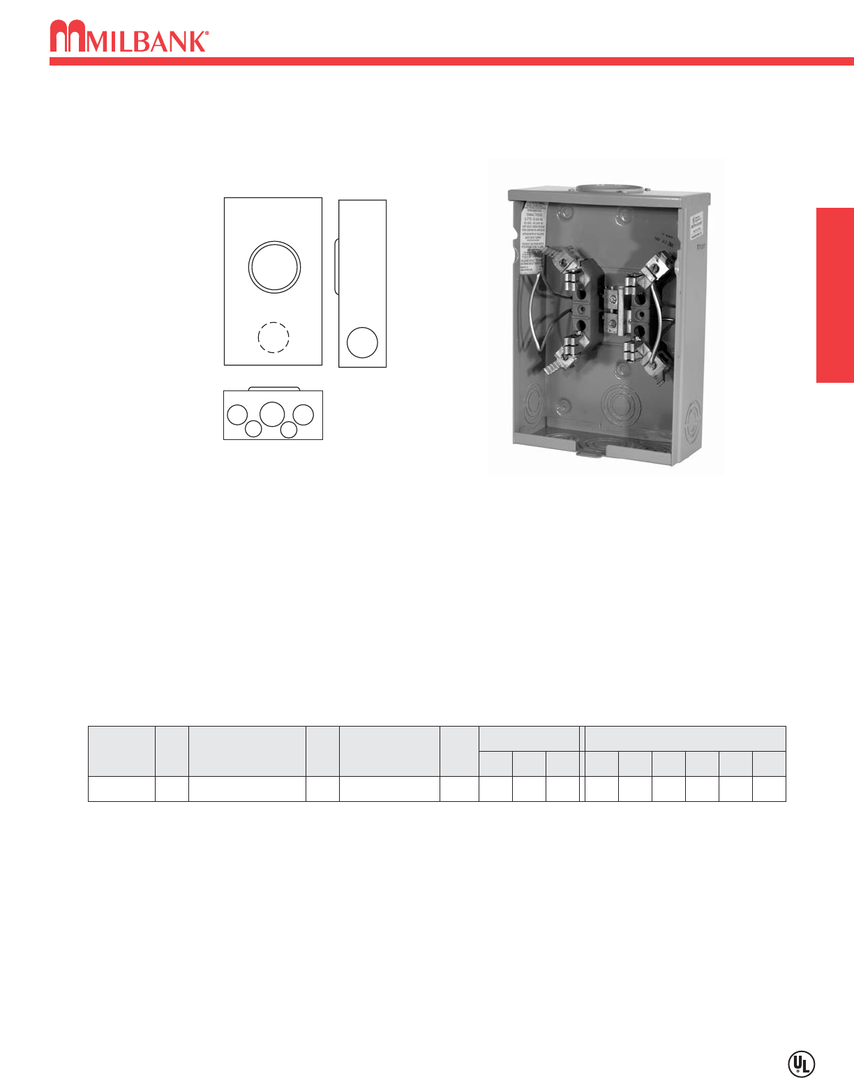
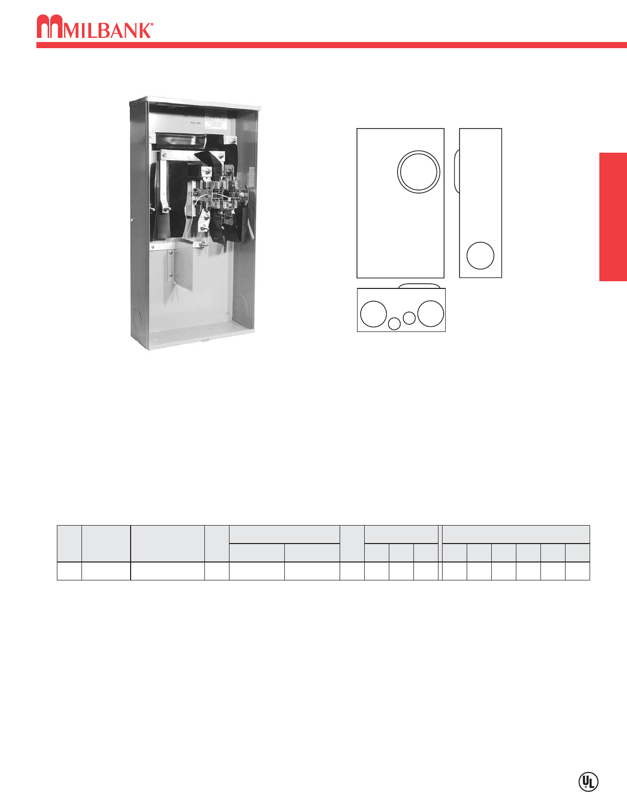
125 AMP–4 TERMINAL–RINGLESS–600 VAC
SINGLE POSITION
125 AMP–4 TERMINAL–RINGLESS–600 VAC
12
5
3
4
4
6
AMPSERVICE
OH 125
CATALOG
NUMBER
U7487-RL-TG-KK
HUB
H.O.
CONNECTORS
CU/AL
BY-
PASS
#6-2/0 HORN
DIMENSIONS CONCENTRIC K.O.’S
123456D″″W″″H″″
11
⁄
211
⁄
2211
⁄
4—1
⁄
435
⁄
16 8111
⁄
2
125 AMP–4 TERMINAL*–RINGLESS–1∅∅3W
HUBS: For proper hub selection see the hub suffix chart on the accessory page.
BYPASS: The -KK horn type bypass is factory installed and permits changing and testing of the meter without interrupting
customer service.
CONNECTORS: Extruded aluminum connectors are tin plated. Units are supplied with duplex neutral.
*FIFTH TERMINAL: For field mounted fifth terminal, order catalog number 5T24R.
7487
U7487-RL-TG-KK
8
Utility requirements for this equipment may vary. Always consult the serving utility for their requirements before ordering or
installing equipment in this catalog.
8
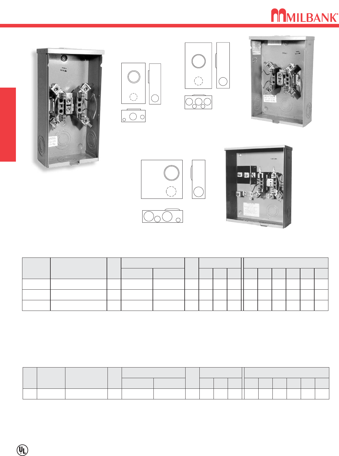
200 AMP–4 TERMINAL–RINGLESS–600 VAC
200 AMP–4 TERMINAL–RINGLESS–600 VAC SINGLE POSITION
SERVICE CATALOG
NUMBER HUB
OH U7021-RL-TG-KK H.O.
CONNECTORS
CU/AL
LINE LOAD
BY-
PASS
HORN
DIMENSIONS CONCENTRIC K.O.’S
123456
21
⁄
221
⁄
221
⁄
2—1
⁄
4
1
⁄
4,1
⁄
2
D″″W″″H″″
41
⁄
88151
⁄
2
#6-350 kcmil #6-350 kcmil
OH/UG U7040-RL-TG-KK H.O. HORN 21
⁄
221
⁄
221
⁄
221
⁄
21
⁄
4,1
⁄
21
⁄
441
⁄
811 151
⁄
2
#6-350 kcmil #6-350 kcmil
OH U8949-RL-TG-KK H.O. HORN 21
⁄
221
⁄
221
⁄
211
⁄
4—1
⁄
4
41
⁄
88151
⁄
2
#6-350 kcmil #6-350 kcmil
200 AMP–4 TERMINAL–RINGLESS
12
3
56
1
5
5
3
6
2
4 4
HUBS: For proper hub selection see the hub suffix chart on the accessory page.
FIFTH TERMINAL: For field mounted fifth terminal for U8949, U7021 & U7040, order catalog number K5T.
CONNECTORS: Extruded aluminum connectors are tin plated.
GROUND: For indoor service for U8949 order as extra catalog number BL1048-KK block assembly to be installed to provide
insulated neutral.
U7021-RL-TG-KK
U7040-RL-TG-KK
7021
7040
8949
U1980-O-KK
12
3456
1980
AMP SERVICE CATALOG
NUMBER HUB
CONNECTORS
CU/AL
LINE LOAD
BY-
PASS
DIMENSIONS CONCENTRIC K.O.’S
123456D″″W″″H″″
200 UG U1980-O-KK
BLANK
HORN 21
⁄
221
⁄
2311
⁄
221
⁄
21
⁄
4,1
⁄
2
41
⁄
213 151
⁄
4
#6-350 kcmil #6-350 kcmil
200 AMP–4 TERMINAL–SIDE WIREWAY–RINGLESS
FIFTH TERMINAL: For factory installed fifth terminal in the 9 o’clock position add the suffix -5T. For field mounted fifth terminal
order catalog number K5T.
CONNECTORS: Extruded aluminum connectors are tin plated. Units are supplied with triplex neutral.
9
Utility requirements for this equipment may vary. Always consult the serving utility for their requirements before ordering or
installing equipment in this catalog.
9
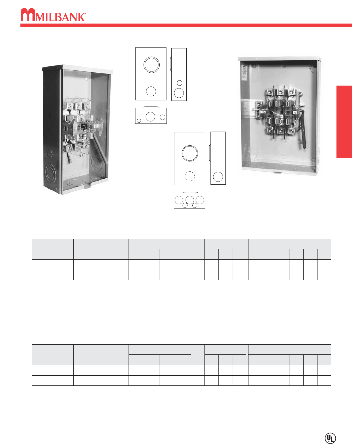
200 AMP–5 & 7 TERMINAL–LEVER BYPASS–HEAVY DUTY–RINGLESS–600 VAC
SINGLE POSITION
200 AMP–5 & 7 TERMINAL–LEVER BYPASS–HEAVY DUTY–RINGLESS–600 VAC
AMP
200
SERVICE CATALOG
NUMBER HUB
OH U9550-RL* H.O.
CONNECTORS
CU/AL
LINE LOAD
BY-
PASS
LEVER
DIMENSIONS CONCENTRIC K.O.’S
123456
321
⁄
23 — 1
⁄
4,1
⁄
23
⁄
4
D″″W″″H″″
47
⁄
810 181
⁄
2
#6-350 kcmil #6-350 kcmil
200 UG U9551-O*
BLANK LEVER
321
⁄
23 3 1
⁄
41
⁄
4,1
⁄
247
⁄
813 19#6-350 kcmil #6-350 kcmil
200 AMP–5 TERMINAL–RINGLESS–3∅∅3W
*Grounded B phase (may be field isolated).
HUBS: For proper hub selection see the hub suffix chart on the accessory page.
BYPASS: Lever supplies clamping action on meter spades and also operates bypass device.
CONNECTORS: Units supplied with extruded aluminum connectors and bonded triplex ground.
FIFTH TERMINAL: Fifth terminal is supplied in the 6 o’clock position. For factory installed fifth terminal in the 9 o’clock posi-
tion add the suffix -5T9 to the catalog number.
1
5
5
3
6
2
4 4
12
3
56
6
U9550-RL
9551
9701
9550
9700
AMP
200
SERVICE CATALOG
NUMBER HUB
OH U9700-RRL H.O.
CONNECTORS
CU/AL
LINE LOAD
BY-
PASS
LEVER
DIMENSIONS CONCENTRIC K.O.’S
123456
321
⁄
23 — 1
⁄
4,1
⁄
23
⁄
4
D″″W″″H″″
47
⁄
810 181
⁄
2
#6-350 kcmil #6-350 kcmil
200 UG U9701-O
BLANK
LEVER
321
⁄
23 3 1
⁄
41
⁄
4,1
⁄
2
47
⁄
813 19#6-350 kcmil #6-350 kcmil
200 AMP–7 TERMINAL–RINGLESS–3∅∅4W
HUBS: For proper hub selection see the hub suffix chart on the accessory page.
BYPASS: Lever supplies clamping action on meter spades and also operates bypass device.
CONNECTORS: Units supplied with extruded aluminum connectors and bonded triplex ground.
INSULATED NEUTRAL: For field installed insulated neutral for the U9701 order kit number K1047.
U9701-O
320 AMP–4 TERMINAL–LEVER BYPASS–HEAVY DUTY–RINGLESS–600 VAC
10
320 AMP–4 TERMINAL–LEVER BYPASS–HEAVY DUTY–RINGLESS–600 VAC SINGLE POSITION
Utility requirements for this equipment may vary. Always consult the serving utility for their requirements before ordering or
installing equipment in this catalog.
10
SERVICE
CATALOG
NUMBER HUB
OH U1779-RRL H.O.
CONNECTORS
CU/AL
LINE LOAD
BY-
PASS
LEVER
DIMENSIONS CONCENTRIC K.O.’S
123456
321
⁄
23 3 1
⁄
41
⁄
4,1
⁄
2
D″″W″″H″″
47
⁄
813 383
⁄
4
3/8″-16
STUD 3/8″-16
STUD
UG
U3000-O-K3L-K2L
BLANK
LEVER
33331
⁄
41
⁄
4,1
⁄
2
47
⁄
815 30
#4-600 kcmil
(2) 1/0-250 kcmil
TWIN #6-350
kcmil
5T
KIT
K3866
K3865
320 AMP–4 TERMINAL–RINGLESS–1∅∅3W–600 VAC
HUBS: For proper hub selection see the hub suffix chart on the accessory page.
BYPASS: Lever supplies clamping action and also operates bypass device.
CONNECTORS: Stud type units supplied with 3/8″-16 hex head nuts with Belleville washers. For connector kits, order as extra
K1540 (600 kcmil). For twin lug connectors order as extra K1350 (350 kcmil). U3000-O-K3L-K2L uses K1540L (single 600)
or K1350L (twin 350) non-rotating connectors for load side. Separate kits are required for both line and load.
FIFTH TERMINAL: For factory installed fifth terminal in the 6 o’clock position add the suffix -5T6 to the catalog number. For
factory installed fifth terminal in the 9 o’clock position at the suffix -5T9 to the catalog number. For field installed fifth termi-
nal, order as extra K3865.
1
6
5
4
3
4
2
1779
3000
3” KO–right
side only
U1779-RRL
(shown with optional
hub installed)
U3000-O-K3L-K2L
11
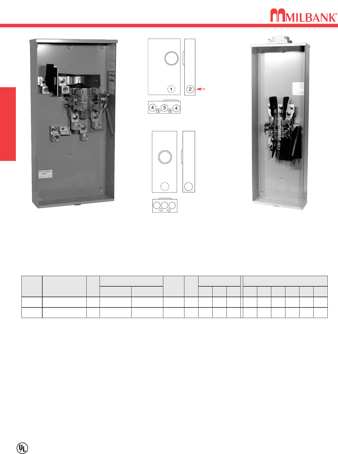
320 AMP CONTINUOUS–7 TERMINAL–LEVER BYPASS–HEAVY DUTY–RINGLESS–600 VAC
Utility requirements for this equipment may vary. Always consult the serving utility for their requirements before ordering or
installing equipment in this catalog.
11
320 AMP CONTINUOUS–7 TERMINAL–LEVER BYPASS–HEAVY DUTY–RINGLESS–600 VAC
SINGLE POSITION
AMP
320
SERVICE CATALOG
NUMBER HUB
OH/UG U2594-X-K7-INV C.P.
CONNECTORS
CU/AL
LINE LOAD
BY-
PASS
LEVER
DIMENSIONS CONCENTRIC K.O.’S
123456
– 3 4 4 1
⁄
41
⁄
2,3
⁄
4,1
D″″W″″H″″
61
⁄
219 341
⁄
8
#4-600
kcmil 3/8″-16
STUD
320 AMP–SIDE WIREWAY–7 TERMINAL–RINGLESS–3∅∅4W
HUBS: For proper hub selection see the hub suffix chart on the accessory page.
BYPASS: Lever supplies clamping action on meter spades and also operates bypass device.
CONNECTORS: Type K7 single barrel 600 kcmil (catalog number K3441) line side lugs included. For load side lugs, stud type
units are supplied with 3/8″-16 hex head nuts with Belleville washers. For single lug connector kits, order as extra K3441 (600
kcmil). For twin lug connectors order as extra K3442 (350 kcmil).
.
2
34
5
6
2594
U2594-X-K7-INV
(Shown without lugs)
320 AMP CONTINUOUS
400 AMP MAX.
100 & 200 AMP / POSITION–4 TERMINAL–HORIZONTAL GANG–RINGLESS–300 VAC
12
Utility requirements for this equipment may vary. Always consult the serving utility for their requirements before ordering or
installing equipment in this catalog.
12
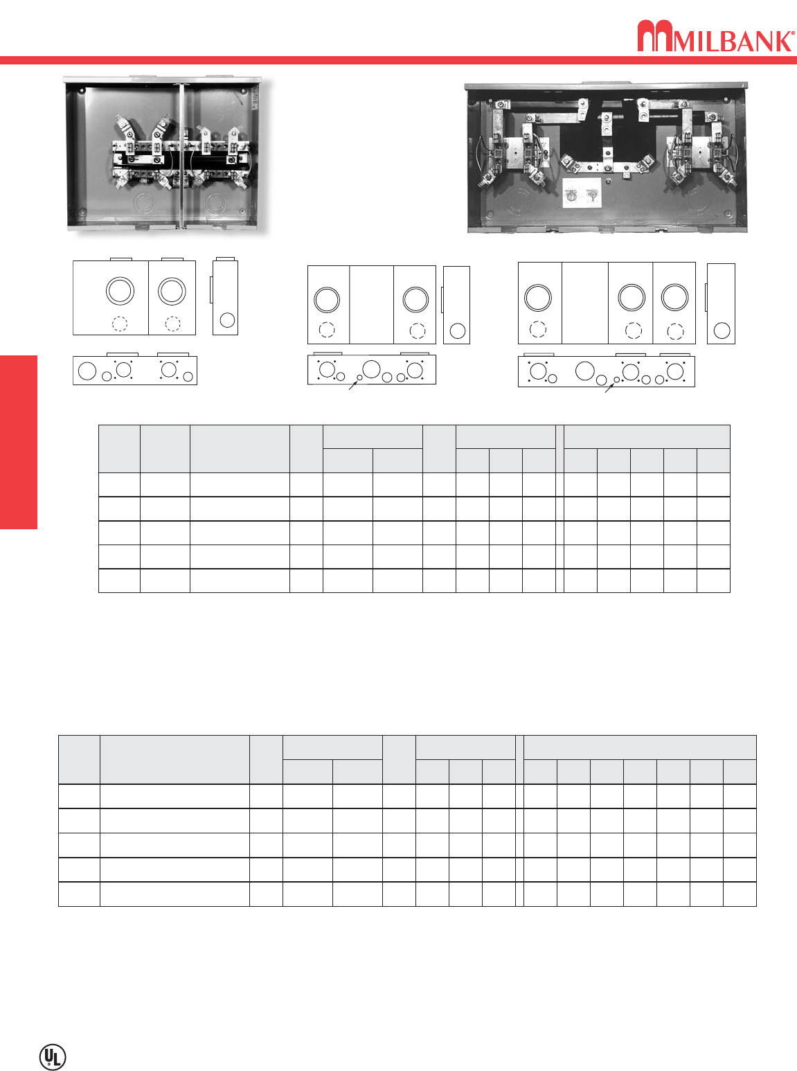
100 & 200 AMP / POSITION–4 TERMINAL–HORIZONTAL GANG–RINGLESS
300 VAC MULTIPLE POSITION
3
3
455
2
11
4″″SIDE WIREWAY
OH/UG SERVICE
L572-6
L572-XL-KK
112
3
4
564
5
7
112
3
4
56
7
1
44
5 5
150 & 200 AMP / POSITION–4 TERMINAL–RINGLESS–1∅∅3W–OH/UG–300 VAC
NO.
OF
POS.
CATALOG
NUMBER HUB
CONNECTOR
CU/AL
BY-
PASS
DIMENSIONS CONCENTRIC K.O.’S
1234567D″″W″″H″″
LINE LOAD
2U1252-X-KK* C.P. HORN 21
⁄
221
⁄
2321
⁄
21
⁄
211
⁄
4
51
⁄
8261
⁄
214
3/8″-16
STUD
#6-350
kcmil
3U1253-X-KK* C.P. HORN 21
⁄
221
⁄
2321
⁄
21
⁄
211
⁄
4
51
⁄
8
3411⁄16
14
3/8″-16
STUD
#6-350
kcmil
4U1254-X-KK* C.P. HORN 21
⁄
221
⁄
2321
⁄
21
⁄
211
⁄
4
51
⁄
8427
⁄
816
3/8″-16
STUD
#6-350
kcmil
5U1255-X-KK* C.P. HORN 21
⁄
221
⁄
2321
⁄
21
⁄
211
⁄
4
51
⁄
8547
⁄
816
3/8″-16
STUD
#6-350
kcmil
6U1256-X-KK* C.P. HORN 21
⁄
221
⁄
2321
⁄
21
⁄
211
⁄
4
51
⁄
8637
⁄
818
3/8″-16
STUD
#6-350
kcmil
HUB: For proper hub selection refer to the hub suffix chart on the accessory page. For the U1255 & U1256 units, two hub openings are supplied
and the extra opening is closed with a closing plate as standard.
FIFTH TERMINAL: For field mounted fifth terminal order catalog number K5T for 9 o’clock position.
*CONNECTORS: Extruded aluminum connectors are tin plated. Units supplied with 3/8″–16 hex head nuts with Belleville washers on line side.
Order connector kit K1541 (600 kcmil) as extra.
BUSSING: Refer to the Conduit & Ampacity Section on page 25 of this catalog for information on ampacity of bussing.
FOR OVERHEAD SERVICE: The U1254, U1255, and the U1256 units are factory assembled for underground service. If overhead service is
desired an extension kit is required; order catalog number K3923 for the U1254 and U1255 units, and K3955 for the U1256 unit. For factory
installed overhead service add suffix -EX to the catalog number.
1252 1253-6
U1252-X-KK (Shown with optional line side connectors)
NO.
OF
POS.
2
CATALOG
NUMBER
L572-XL-KK
HUB
C.P.
CONNECTOR
CU/AL
BY-
PASS
HORN
DIMENSIONS CONCENTRIC K.O.’S
1
22221
⁄
2
1
⁄
4,1
⁄
2
2345D″″
41
⁄
2
W″″
205
⁄
16
H″″
16
LINE
#2-350
kcmil
LOAD
#6-2/0
3L573-XL-KK C.P. HORN 22221
⁄
2
1
⁄
4,1
⁄
2
41
⁄
2281
⁄
216
#2-350
kcmil #6-2/0
4L574-XL-KK C.P. HORN 22221
⁄
2
1
⁄
4,1
⁄
2
41
⁄
2
4011⁄16
16
#2-350
kcmil #6-2/0
5L575-XL-KK C.P. HORN 22221
⁄
2
1
⁄
4,1
⁄
2
41
⁄
2487
⁄
816
#2-350
kcmil #6-2/0
6L576-XL-KK C.P. HORN 22221
⁄
2
1
⁄
4,1
⁄
2
41
⁄
2571
⁄
16 16
#2-350
kcmil #6-2/0
AMPS
100
100
100
100
100
100 AMP / POSITION– 4 TERMINAL–RINGLESS–1∅∅3W–OVERHEAD–300 VAC
CONNECTORS: Extruded aluminum connectors are tin plated.
BUSSING: Supplied with 5/16″ x 1″aluminum bussing.
FIFTH TERMINAL: For field installed fifth terminal, order as extra catalog number 5T8K2 for the 6 o’clock position, and Kit #K9959 for the
9 o’clock position.
EXTRA WIRE SPACE: Extra wire space of 4″provided on the left end of 2 and 3 position gangs. Furnished on both ends of 4, 5, and 6 position
gangs.
MAIN BUS RATING: For main bus rating, see the conduit and ampacity information page in this catalog.
BYPASS: The -KK horn type bypass is factory installed and permits changing and testing of the meter without interrupting customer service when
used with utility-supplied jumpers.
13
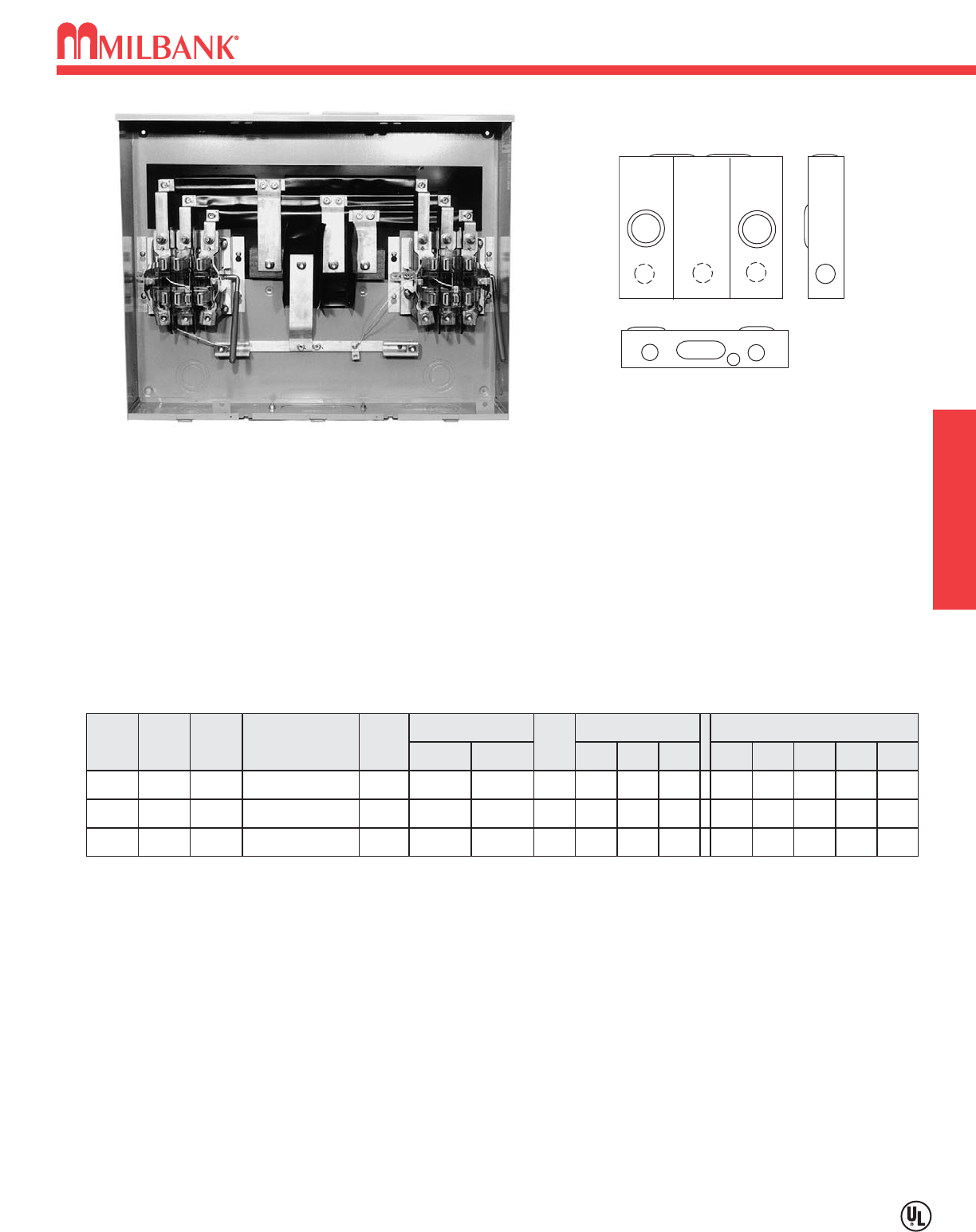
200 AMP / POSITION–7 TERMINAL–HORIZONTAL GANGS
LEVER BYPASS–HEAVY DUTY–RINGLESS–600 VAC
Utility requirements for this equipment may vary. Always consult the serving utility for their requirements before ordering or
installing equipment in this catalog.
13
200 AMP / POSITION–7 TERMINAL–HORIZONTAL GANGS
LEVER BYPASS–HEAVY DUTY–RINGLESS–600 VAC
MULTIPLE POSITION
NO.
OF
POS.
2
CATALOG
NUMBER
U2732-XT-PED
HUB
(2)C.P.
CONNECTOR
CU/AL
BY-
PASS
LEVER
DIMENSIONS CONCENTRIC K.O.’S
1
21
⁄
221
⁄
2PED 21
⁄
21⁄4,1⁄2
2345D″″
6
W″″
321⁄8
H″″
251⁄4
LINE
3/8″-16
STUD
LOAD
#6-350
kcmil
3U2733-XT-PED (2)C.P. LEVER 21
⁄
221
⁄
2PED 21
⁄
21⁄4,1⁄2
6423⁄16 251⁄4
3/8″-16
STUD
#6-350
kcmil
4U2734-XT-PED (2)C.P. LEVER 21
⁄
221
⁄
2PED 21
⁄
21⁄4,1⁄2
6521⁄4251⁄4
3/8″-16
STUD
#6-350
kcmil
SERV.
OH/UG
OH/UG
OH/UG
AMPS
200
200
200
200 AMP –7 TERMINAL–RINGLESS–3∅∅4W–OVERHEAD / UNDERGROUND*
HUBS: Units supplied with two closing plates. To order hubs as extra refer to the hub suffix chart on the accessory page.
BYPASS: Lever supplies clamping action on meter spades and also operates bypass device.
*CONNECTOR KITS: Line wire sections supplied with studs. For connector kits order K3082 (single-350 kcmil), K3441 (single-
600 kcmil), or twin K3442 (twin-350 kcmil) or K3083 (twin-600 kcmil.) Line connectors can be reversed to change from OH to
UG service.
*UNDERGROUND PEDESTALS: For underground service order S2291-TO pedestal raceway. A 12″pedestal extension kit is
also available. Order catalog number S2571.
BUSSING: Bussing is 3/8″x 1″aluminum. Refer to the conduit & ampacity page of this catalog for information on ampacity of
bussing.
1112
44
5
3
U2732-XT-PED
(shown without pedestal)
CENTER WIREWAY
CONDOMINIUM METERING BANKS–RINGLESS–OH/UG SERVICE–1
∅
3W–120 / 240 VAC
14
CONDOMINIUM METERING BANKS–RINGLESS–
OH/UG SERVICE–1
∅
3W–120 / 240 VAC CONDO MTR. BANKS
Utility requirements for this equipment may vary. Always consult the serving utility for their requirements before ordering or
installing equipment in this catalog.
14
CATALOG
NUMBER
NO.
OF
POS.
2
3
MAIN BUS
RATING
LINE
CONNECTOR
SIZE
U2852-X-KK-K1-PED 200 amp
U2853-X-KK-K1-PED 200 amp
#6-350 kcmil
#6-350 kcmil
CATALOG
NUMBER
NO.
OF
POS.
4
5
MAIN BUS
RATING
LINE
CONNECTOR
SIZE
U2854-X-KK-PED 400 amp
U2855-X-KK-PED 400 amp
*3/8″-16 STUD
*3/8″-16 STUD
6U2856-X-KK-PED 400 amp *3/8″-16 STUD
CATALOG
NUMBER
NO.
OF
POS.
4
5
MAIN BUS
RATING
LINE
CONNECTOR
SIZE
U2864-X-KK-PED 400 amp
U2865-X-KK-PED 600 amp
*3/8″-16 STUD
*3/8″-16 STUD
6U2866-X-KK-PED 600 amp *3/8″-16 STUD
CATALOG
NUMBER
NO.
OF
POS.
2
3
MAIN BUS
RATING
LINE
CONNECTOR
SIZE
U2862-X-KK-K1-PED 250 amp
U2863-X-KK-K1-PED 300 amp
#6-350 kcmil
#6-350 kcmil
SIZE SUFFIX
SINGLE
TWIN
K1539-K1
-K3
-K2
-K4
K1540
K1350
K1541
U2852-56
U2862-66
U2854-56
U2864-66
U2854-56
U2863-66
U2864-66
#6-350
kcmil
#4-600
kcmil
#6-350
kcmil
#2-600
kcmil
KIT
NUMBER
COMPATIBLE
WITH
WIRE
RANGE
*CONNECTORS: For line wire connector kits, order
separately.
FIFTH TERMINALS: For field mounted fifth terminal
order catalog number K2381. Order one per meter
position (9 o’clock position only).
BREAKERS: Units have provision for one double pole
main per meter position. Breakers not included, order
as extra Milbank type Qor QNR or comparable.
Refer to the accessories section in back of catalog.
UNDERGROUND SERVICE: For underground service
order S2291-TO pedestal raceway. Order separately.
PEDESTAL EXTENSION KIT: A 12” pedestal exten-
sion kit is also available. Order catalog number
S2571.
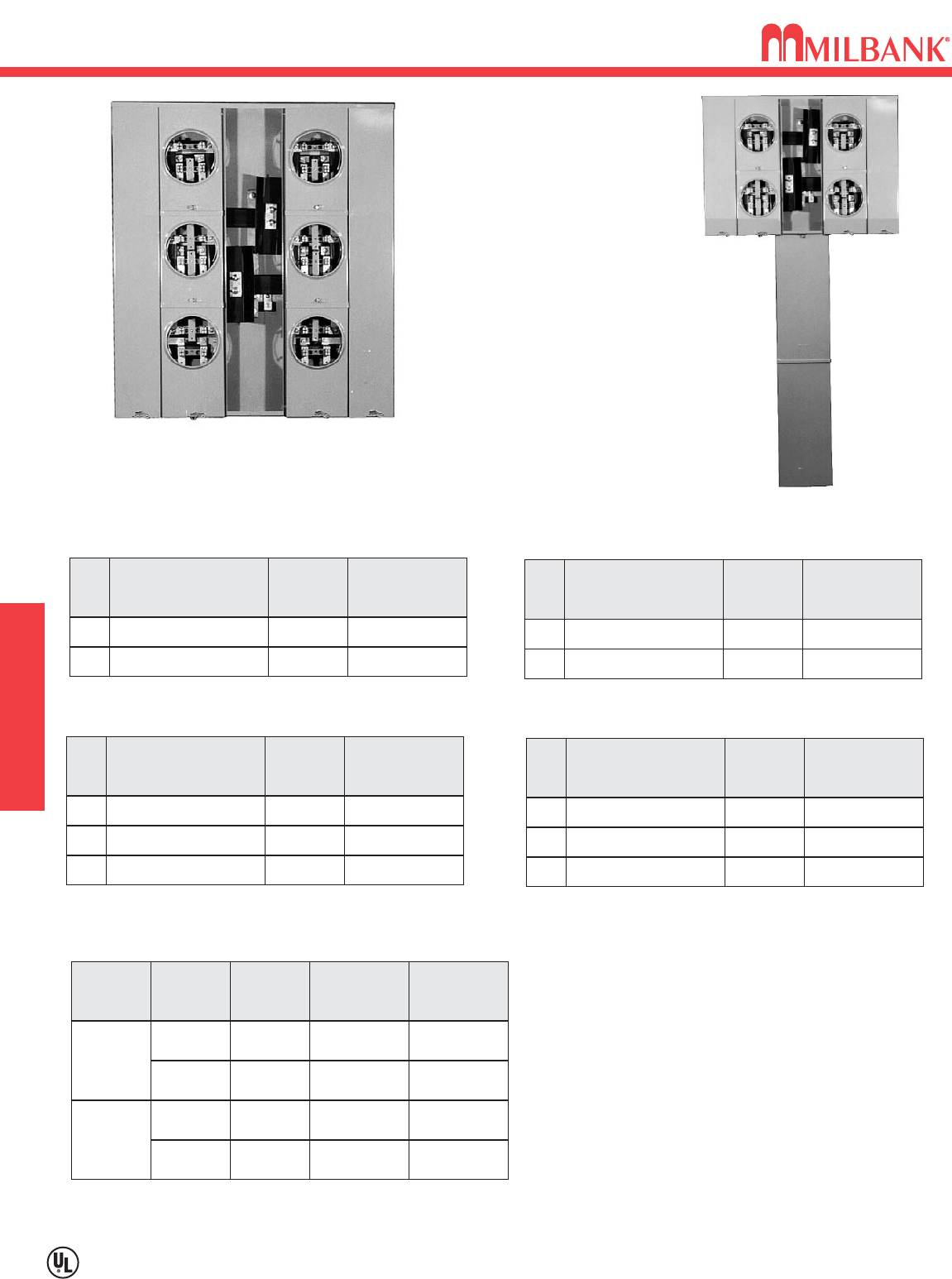
125 AMP/POSITION 200 AMP/POSITION
125 AMP/POSITION 200 AMP/POSITION
CONNECTOR KITS *
VERTICAL—1∅∅
RECTANGULAR—1∅∅
U2864-X-PED-KK
(Order breakers and pedestal
raceway as extra)
U2866-X
(Shown without pedestal)
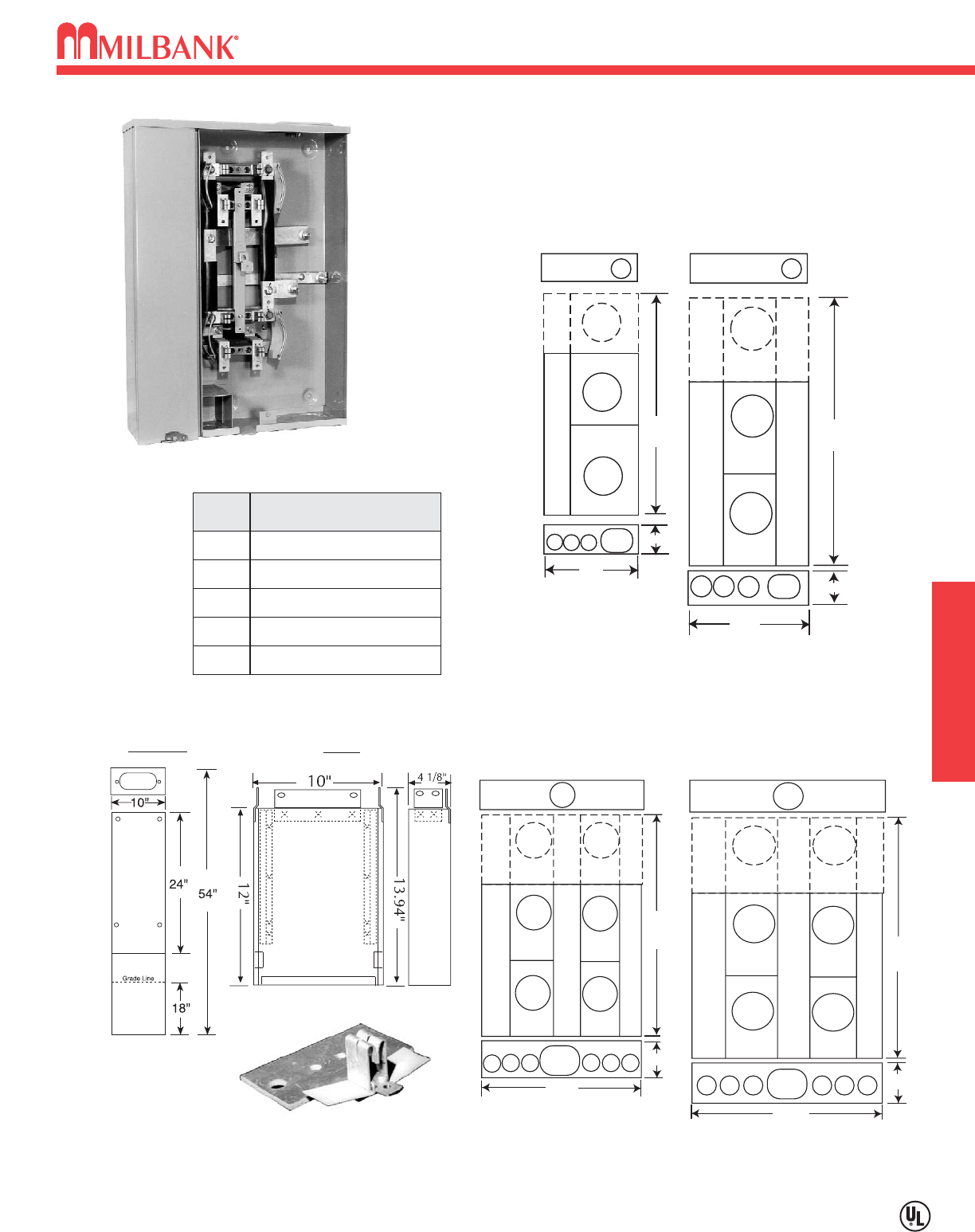
15
CONDOMINIUM METERING BANKS–RINGLESS–OH/UG SERVICE–1
∅
3W–120 / 240 VAC
Utility requirements for this equipment may vary. Always consult the serving utility for their requirements before ordering or
installing equipment in this catalog.
15
CONDOMINIUM METERING BANKS–RINGLESS–
OH/UG SERVICE–1
∅
3W–120 / 240 VAC
CONDO MTR. BANKS
29" or
41"
4-7/8"
25" or
37"
21"
E
A
18"
AA 4-7/8"
DD
EE
PED
PED
C
A
A
25" or
37"
4-7/8"
31"
PED AA
AA
C
29" or
41"
4-7/8"
36"
PED
EE EEEE
VERTICAL
with pedestal option in bottom
RECTANGULAR
with pedestal option in bottom
125 amp/pos.
(2-3 position)
200 amp/pos.
(2-3 position)
125 amp/pos.
(4,5 & 6 position)
200 amp/pos.
(4,5 & 6 position)
FIG.
A
B
C
D
E
DIMENSIONS
11
⁄
4″CONCENTRIC K.O.
1
⁄
4,1
⁄
2″CONCENTRIC K.O.
3″CONCENTRIC K.O.
4″HUB OPENING
2″CONCENTRIC K.O.
PED
PEDESTAL OPTION
Pedestal Raceway
S2291-TO
PEDESTAL OPTION
Pedestal Extension Unit
S2571
CONDOMINIUM METERING BANKS
FIFTH TERMINAL # K2381
(125-200 amp)
U2852-X
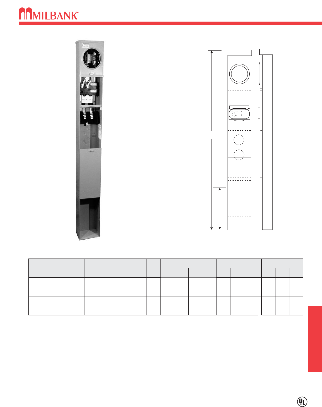
100 / 200 AMP–4 TERMINAL–RESIDENTIAL PEDESTAL
SINGLE OR DOUBLE POSITION–1
∅
3W–600 VAC
16
PEDESTALS
Utility requirements for this equipment may vary. Always consult the serving utility for their requirements before ordering or
installing equipment in this catalog.
16
100 / 200 AMP–4 TERMINAL–RESIDENTIAL PEDESTAL
SINGLE OR DOUBLE POSITION–1
∅
3W–600 VAC
Extension Unit
K5800
U8436-O
HANGING HOOK: Supplied with keyhole hanger for easy mounting.
EXTENSION UNIT: For 15” burial applications, order extension unit K5800; for 30” applications, order (2) K5800 units.
FIFTH TERMINAL: For field installed fifth terminal, order catalog number K5T (9 o’clock position).
BYPASS: Horn type bypass.
AMP
200
SERVICE CATALOG
NUMBER HUB
UG U8436-O
BLANK
CONNECTORS
CU/AL
LINE LOAD
BY-
PASS
HORN
DIMENSIONS CONCENTRIC K.O.’S
12345
2 2 5
⁄
16 1
⁄
22
D″″W″″H″″
41
⁄
8962
4/0
Crimp-On #6-350
kcmil
6
—
100 / 200 AMP—4 TERMINAL—CECHA APPROVED—RINGLESS—1∅∅3W—600 VAC
GRADE LINE
1
2
2
5
3
2
3
4
18.00
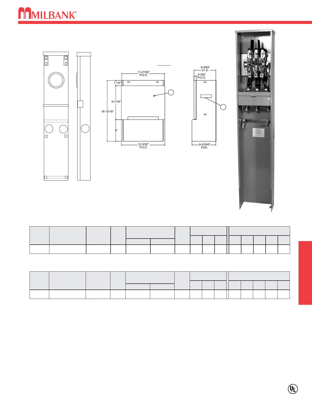
17
17
123
4
4
MILBANK
44
44
CATALOG
NUMBER
U9108-O
SERVICE
UG
HUB
BLANK
CONNECTORS
CU/AL
LINE LOAD
3/0-4/0 #6-350
kcmil
BY-
PASS
LEVER
DIMENSIONS CONCENTRIC K.O.’S
1D″″W″″H″″
21
⁄
2
611 58
2
21
⁄
2
3
21
⁄
2
4
5
⁄
16
5
—
#
OF
TERMS
5
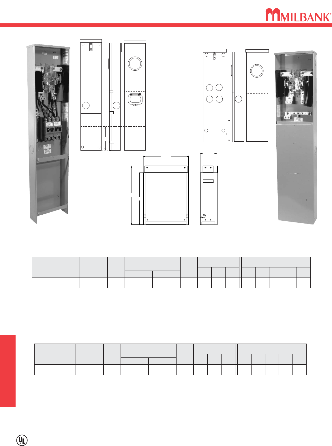
100 / 200 AMP—5 TERMINAL—HEAVY DUTY—1∅∅-3W OR 3∅∅-3W
CATALOG
NUMBER
U9107-O
SERVICE
UG
HUB
BLANK
CONNECTORS
CU/AL
LINE LOAD
3/0-4/0 #6-350
kcmil
BY-
PASS
LEVER
DIMENSIONS CONCENTRIC K.O.’S
1D″″W″″H″″
21
⁄
2
611 58
2
21
⁄
2
3
21
⁄
2
4
5
⁄
16
5
—
#
OF
TERMS
7
100 / 200 AMP—7 TERMINAL—HEAVY DUTY—3∅∅4W
BYPASS: Lever supplies clamping action on meter spades and also operates bypass device.
BOTTOM PLATE: Bottom plate is not furnished with this unit. However, if plate is required, order catalog number S9157 as
extra.
NEUTRAL: The U9108-O is supplied with a center disconnect neutral.
EXTENSION KIT: For direct burial applications, order kit S3488 as separate item.
U9107-O
9108
9107
PEDESTAL EXTENSION UNIT
S3488
100 / 200 AMP–5 & 7 TERMINAL–LEVER BYPASS
HEAVY DUTY PEDESTAL–600 VAC PEDESTALS
100 / 200 AMP–5 & 7 TERMINAL–LEVER BYPASS–HEAVY DUTY PEDESTAL–600 VAC
Utility requirements for this equipment may vary. Always consult the serving utility for their requirements before ordering or
installing equipment in this catalog.
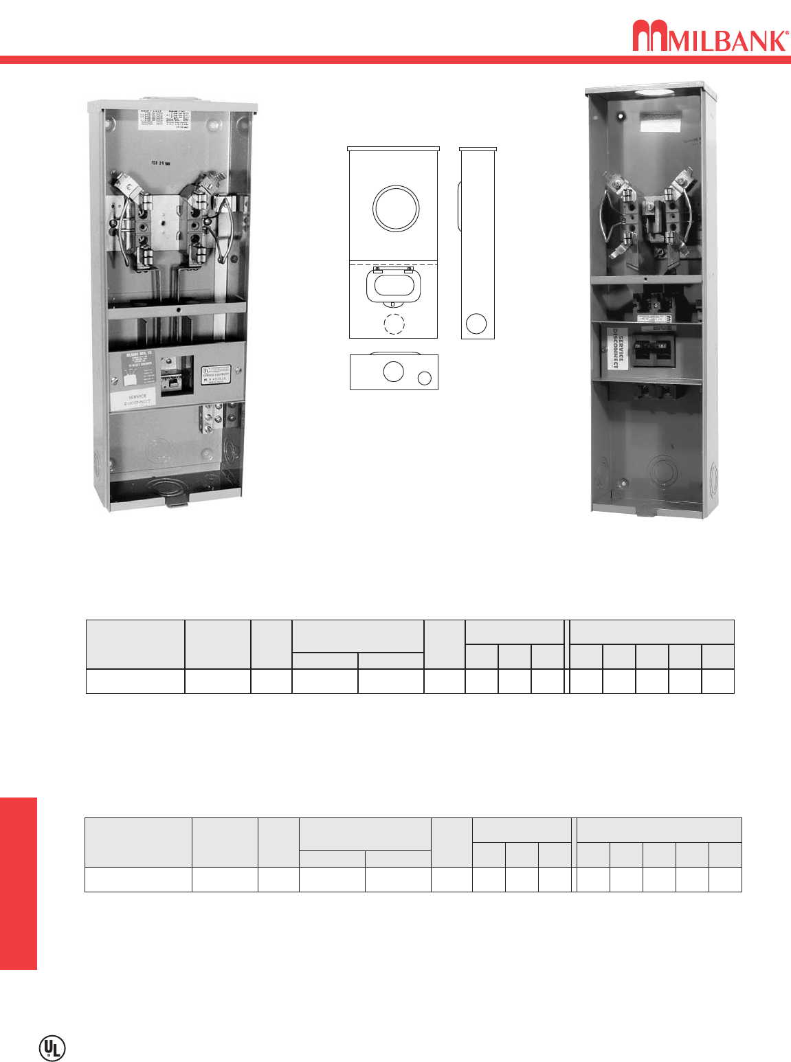
100 OR 200 AMP–CIRCUIT BREAKER MAIN DISCONNECT–SINGLE POSITION
METER MAIN–240 VAC
18
100 OR 200 AMP–CIRCUIT BREAKER MAIN DISCONNECT
SINGLE POSITION–METER MAIN–240 VAC
METER MAINS
Utility requirements for this equipment may vary. Always consult the serving utility for their requirements before ordering or
installing equipment in this catalog.
18
U7375-RL-KK U7607-RL-200-KK
(Supplied with 200 Amp circuit breaker)
CATALOG
NUMBER
U7375-RL-KK
SERVICE
OH
HUB
H.O.
CONNECTORS
CU/AL
LINE LOAD
#6-2/0 C.B.
BY-
PASS
HORN
DIMENSIONS CONCENTRIC K.O.’S
1D″″W″″H″″
11
⁄
4
33
⁄
481
⁄
822
2
11
⁄
4
3
11
⁄
4
4
1
⁄
4,1
⁄
2
5
—
100 AMP–4 TERMINAL—METER MAIN (PLUG-IN)—RINGLESS—1∅∅
CATALOG
NUMBER
U7607-RL-200-KK
SERVICE
OH
HUB
H.O.
CONNECTORS
CU/AL
LINE LOAD
#6-350
kcmil #1-300
kcmil
BY-
PASS
HORN
DIMENSIONS CONCENTRIC K.O.’S
1D″″W″″H″″
2
41
⁄
281
⁄
829
2
2
3
2
4
1
⁄
4,1
⁄
2
5
—
200 AMP–4 TERMINAL—METER MAIN—RINGLESS—1∅∅
CIRCUIT BREAKER: Main circuit breaker not supplied with unit. For 100 amp service order Milbank catalog number
Q2100 separately. See circuit breaker chart on accessory page for other compatible models.
CIRCUIT BREAKER: 200 amp main circuit breaker factory bussed. Order Milbank catalog number UQFB-200-X1 for
replacement. Other amperages available. See Milbank circuit breaker chart on accessory page.
HUBS: Order hubs separately–see accessory page for ordering information.
FIFTH TERMINAL: For field mounted fifth terminal for U7375 order catalog number 5T8K2. For field mounted fifth
terminal for U7607 order catalog number K5T. Mount in the 9 o’clock position only.
2
3
MILBANK
4
1
19
100 / 200 AMP–4 TERMINAL–METER PEDESTAL–PARALLEL MAIN–1
∅
–120 / 240 VAC
Utility requirements for this equipment may vary. Always consult the serving utility for their requirements before ordering or
installing equipment in this catalog.
19
METER MAINS
100 / 200 AMP–4 TERMINAL–METER PEDESTAL–PARALLEL MAIN–1
∅
–120 / 240 VAC
100 / 200 AMP–4 TERMINAL–C/B–RINGLESS–1∅∅3W–UG–10K / 22K AIC RATING
HUB
CONNECTOR
CU/AL
BY-
PASS
LINE LOAD
BLANK
HORN
#6-350
KCMIL
C/B
CATALOG NUMBER
W/ BREAKER
INSTALLED
NU8980-O-100-KK
NU8980-O-100-KK-LP
BLANK
HORN
#6-350
KCMIL
C/B
BLANK
HORN
#6-350
KCMIL
C/B
NU8980-O-200-KK
NU8980-O-200-KK-LP
MAIN BREAKER
22K10K
UQFPHUQFP
UQFPH
UQFP
UQFPH
UQFP
UQFPH
UQFP
BLANK
HORN
DIMENSIONS
CONCENTRIC K.O.’S
1 2 3D″″W″″H″″
2
1
⁄
2
2
1
⁄
2
—6 9 79
2
1
⁄
2
2
1
⁄
2
—6 9 70
2
1
⁄
2
2
1
⁄
2
—6 9 79
2
1
⁄
2
2
1
⁄
2
—
6 9 70
#6-350
KCMIL
C/B
MILBANK
1
2
Grade Line
STD = 79"
-LP = 70"
STD = 36"
-LP = 24"
NU8980-O-KK
MAIN CIRCUIT BREAKERS: For 10K AIC order with factory installed main. For 22K AIC order pedestal without main and order
circuit breaker separately. All main breakers are parallel connected. For series wired main order wire kit K4714 and UQFP-M
type circuit breaker. See Milbank circuit breaker chart on accessory page.
BRANCH CIRCUIT BREAKERS: Branch Interior accepts most manufacturers <100 amp. See plug-in breaker compatibility chart
on accessory page.
FIFTH TERMINAL: For field installed 5th terminal order 5T8K2. Mounts in 9 o'clock position only.
BYPASS: All pedestals have horn-type bypass installed for meter testing or replacement without interrupting customer service.
EXTENSION KIT: Available for low profile (-LP) units only. Order kit K4694. See accessory page.
20
320 AMP–4 TERMINAL–METER MAIN–LEVER BYPASS–HEAVY DUTY–2/200 AMP CB
METER MAINS
Utility requirements for this equipment may vary. Always consult the serving utility for their requirements before ordering or
installing equipment in this catalog.
20
320 AMP–4 TERMINAL–METER MAIN–LEVER BYPASS–HEAVY DUTY–2/200 AMP CB
CATALOG
NUMBER
U3849-O-2/200-INV
SERVICE
UG
HUB
BLANK
CONNECTORS
CU/AL
LINE LOAD
3/8″X 16
STUDS C.B. #1- 300
kcmil
BY-
PASS
LEVER
DIMENSIONS CONCENTRIC K.O.’S
1D″″W″″H″″
21
⁄
2
47
⁄
813 64
2
21
⁄
2
3
5
⁄
16
4
—
5
—
320 AMP–4 TERMINAL–METER MAIN WITH BREAKERS–RINGLESS–240 VAC–1∅∅3W
CATALOG
NUMBER
U1748-O-WI
SERVICE
UG
HUB
BLANK
CONNECTORS
CU/AL
LINE LOAD
3/8″X 16
STUDS TWIN #6-
350 kcmil
BY-
PASS
LEVER
DIMENSIONS CONCENTRIC K.O.’S
1D″″W″″H″″
21
⁄
2
47
⁄
813 64
2
21
⁄
2
3
21
⁄
2
4
5
⁄
16
5
—
320 AMP–4 TERMINAL–WITHOUT BREAKER PROVISION–RINGLESS–600 VAC–1∅∅3W
CONNECTORS: The line wire section is supplied with
3
⁄
8
″–16 studs with hex head nuts and captive Belleville washers. The line
side connectors are to be supplied by the Utility, load side is furnished.
BYPASS: The lever supplies clamping action on the meter spade and also operates the bypass device.
FIFTH TERMINAL: For field installed fifth terminal order kit number K3865.
PEDESTAL EXTENSION KIT: If extension kit is required, order as extra kit number S1848. See accessory page.
.
BREAKERS: Supplied from factory with 2 double-pole, 200 amp Milbank UQFB-200 or UQFBH-200 (22,000 AIC) bolt-on circuit breakers.
* Must order 22K AIC breakers separately. Order Milbank UQFBH-200 breakers.
CONNECTORS: The line wire section is supplied with 3/8”-16 studs with hex nuts and captive Bellville washers. For line side connectors, order as
extra catalog numbers K1539 (single-350 kcmil), or K1540 (single-600 kcmil), or for twin K1350 (twin-350 kcmil). Order one kit per unit.
EXTENSION KIT: For extension kit order as extra catalog number S1848.
.
U3849-O-2/200-INV U1748-O-WI
Grade Line
12
3
MILBANK
3
3 3
Grade Line
18"
Grade Line
1
23
1
2
44
4 4
Grade Line
18"
320 AMP CONTINUOUS
400 AMP MAX
4-27/32"
I.D.
13"
O.D.
16-15/16"
15"
S1848
Pedestal Extension Unit
21
21
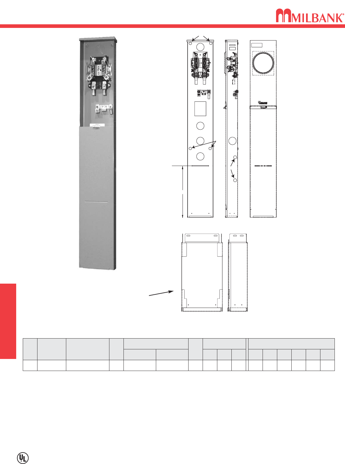
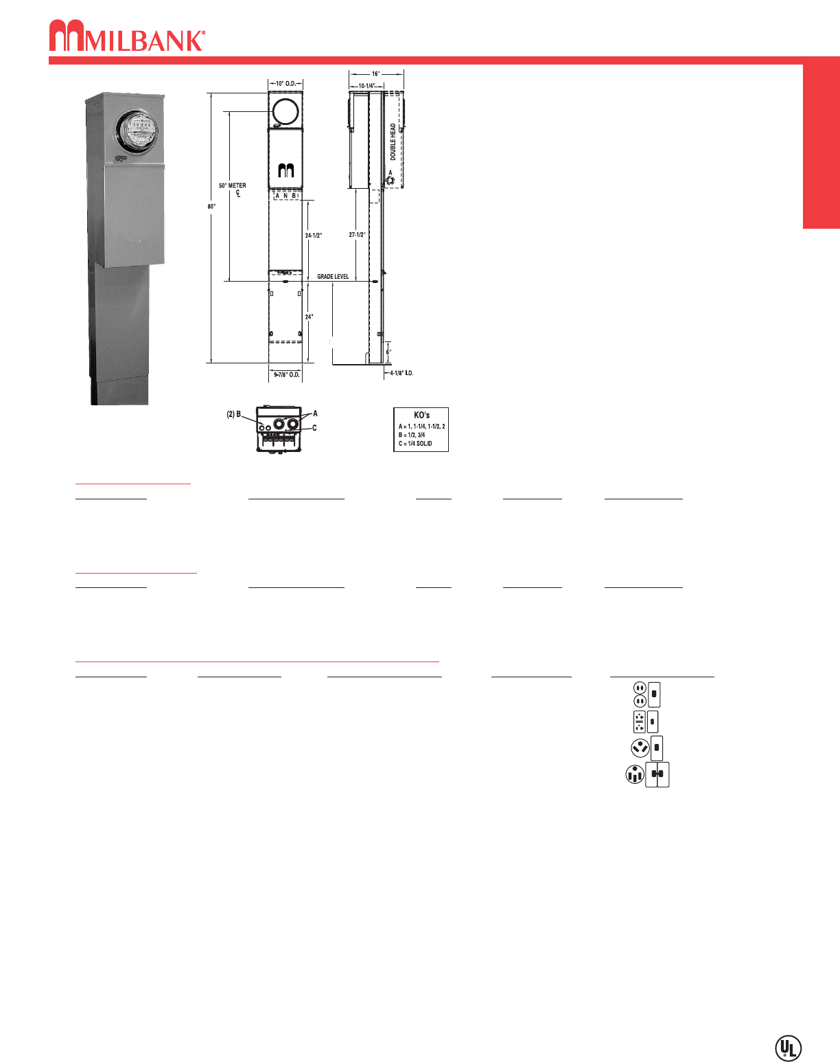
• UL Listed File E90945.
• 200 amp maximum, 120/240 V, 1∅3W.
• Ringless type meter socket with horn bypass and
stainless steel latch.
• Short circuit withstand rating 10K AIC, for 22K AIC, order
with “22” suffix.
• Type 3R construction for durable outdoor use.
• Milbank grey polyester powder coat finish.
• Wire terminations accept copper or aluminum conductors.
• Line & Neutral: (2) #6-350 kcmil per phase.
• Line Ground: (4) #14-1/0.
• Load (CB): 1/0 to 300 kcmil per pole.
• Load Neutral: (1) #6-350 kcmil.
• Load Ground: (2) #14-1/0, (4) #14/6.
• Commercial grade, plug-in main circuit breaker. Available
in 100, 125, 150 & 200 amp. Type UQFP-M.
• 4 circuit plated copper interior accepts (2) 2-pole or (4)
1-pole standard plug-in type circuit breakers. Branch
circuit rated to 125 amps max. Acceptable manufacturers:
Milbank, Cutler-Hammer, GE or Siemens.
• Factory or field installable receptacle bridge and recep-
tacle / circuit breaker kits available. See accessories.
U5136-O-200S
SINGLE PEDESTAL
CATALOG #MAIN BREAKER AMPS INTERIOR WEIGHT (lbs)
U5136-O-100S
UQFP-M-100 100 4 Circuit 82
U5136-O-200S
UQFP-M-200 200 4 Circuit 82
U5136-O-200S/22
UQFPH-M-200 200 4 Circuit 82
DOUBLE PEDESTAL
CATALOG #MAIN BREAKER AMPS INTERIOR WEIGHT (lbs)
U5137-O-100S
(2) UQFP-M-100 Series 100 4 Circuit 115
U5137-O-200S
(2) UQFP-M-200 Series 200 4 Circuit 115
U5137-O-200S/22
(2) UQFPH-M-200 Series 200 4 Circuit 115
RECEPTACLE / CIRCUIT BREAKER KITS AND ACCESSORIES (Sold separately)
CATALOG # RECEPTACLE CIRCUIT BREAKER CONDUCTOR CONFIGURATION
K5400-520
5-20R Duplex 20 amp, 1 Pole 12 Awg
K5400-520GR
5-20R Duplex GFI 20 amp, 1 Pole 12 Awg GFI Rec.
K5400-TT30
TT30R 30 amp, 1 Pole 10 Awg
K5400-1450
14-50R 50 amp, 2 Pole 8 Awg
K5400-BRIDGE-1POS
Self-grounded one position receptacle bridge with hardware
K5400-BRIDGE-2POS
Self-grounded two position receptacle bridge with hardware
K5415
Stabilizer foot with hardware
K5035
Pad mount kit with hardware (see note below)
K5T
5th terminal for 3 or 9 o’clock position
K5193
Wire kit to convert series wired main breaker to parallel
• A maximum of two receptacle / circuit breaker kits can be installed in each power head. Order from above. Other kits available.
Consult factory for factory-installed receptacle kits.
• Receptacle / circuit breaker kits include receptacle, circuit breaker, wire, cover plate and mounting screws.
• Receptacle bridge K5400-BRIDGE-1POS or K5400-BRIDGE-2POS not included with pedestal. Order separately.
• Pedestals are stocked with series wired main circuit breakers. Order K5193 kit to field convert to parallel main lug circuit
breaker. For parallel wired main circuit breakers, change “S” suffix to “P” (Ex.: U5136-O-100P).
•K5415 Stabilizer Foot sold separately. Recommended for double pedestals.
• Pad mount pedestals available. Order U5138 (single meter) or U5139 (double meter) prefix. K5035 pad mount kit required.
Order separately.
24”
RV/MH 200 AMP–SERIES U5136 & U5137–RINGLESS–METERED PEDESTAL
200 AMP–SERIES U5136 & U5137–RINGLESS–METERED PEDESTAL
MILBANK ACCESSORIES
22
MILBANK ACCESSORIES MISC.
22
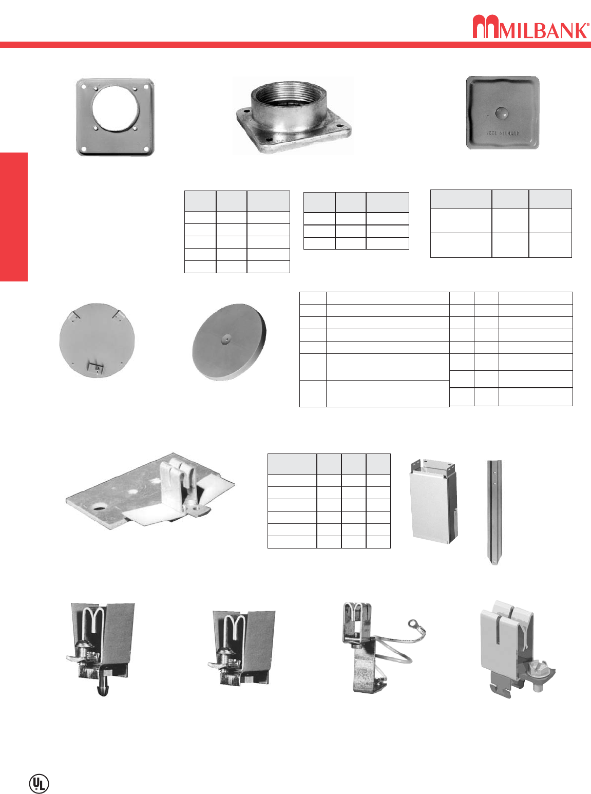
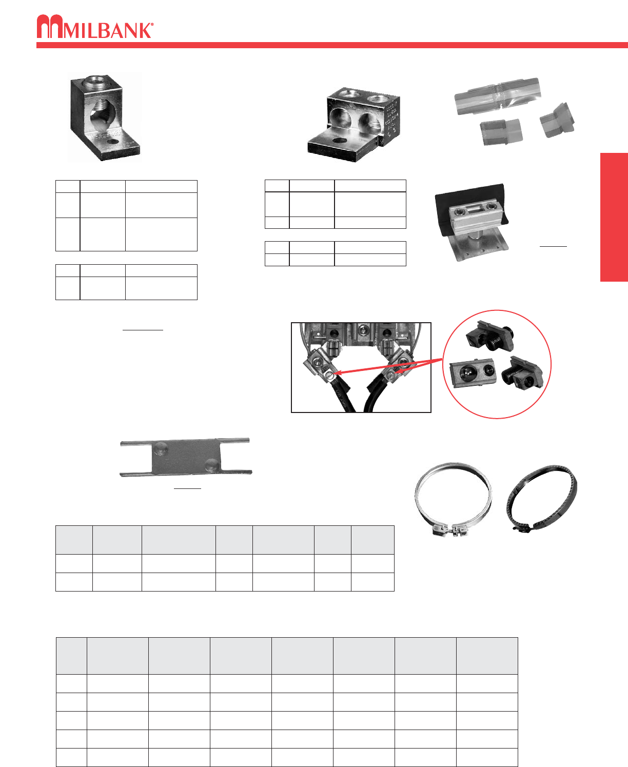
INTERCHANGEABLE UNIT HUBS
CLOSING COVERS
METAL CLOSING PLATE
(for ringless sockets)
CP-21
METER CLOSING PLATE
(Grey Plastic)
6003
HUB
ADAPTER PLATE
(Converts 4″opening to
21
⁄
2″opening)
S8324
FIFTH TERMINALS
PLUG-IN FIFTH TERMINAL
5T8K2
(Fits in round hole of old
style block)
BOLT-IN FIFTH TERMINAL
5T24R
(Fits in round hole of old
style block)
FIFTH TERMINAL
K5T
(Fits in square hole
of new style 200 amp block)
HEAVY DUTY JAW
CLAMPING
K3865
FOR CONDO METERING BANKS
(125-200 AMP) K2381
PEDESTAL EXTENSION UNITS
HUB SUFFIX CHART
OPlain Top WL 1″For -RL Opening
YL 11
⁄
4″For -RL Opening
ZL 11
⁄
2″For -RL Opening
DL 2″For -RL Opening
EL
F
G
H
21
⁄
2″For -RL Opening
3″For -R Opening
31
⁄
2″For -R Opening
4″For -R Opening
RL Small Hub Opening
RLarge Hub Opening
XL Small Closing Plate
X
RXL Large Hub Opening
adapted to small Closing Plate
RRL Large Hub Opening
adapted to small Hub Opening
Large Closing Plate
REMOVABLE HUB
CLOSING PLATE
DESCRIPTION SUFFIX CAT. #
STANDARD
(for -RL opening)
-XL A7551
LARGE
(for -R opening) -X A9064
1″
WL
SIZESUFFIX MILBANK
NO.
YL
ZL
DL
EL
A7514
11
⁄
4″A7515
11
⁄
2″A7516
2″A7517
21
⁄
2″A7518
3″
F
SIZESUFFIX MILBANK
NO.
G
H
A8110
31
⁄
2″A8111
4″A8112
SMALL “RL"OPENING
(STANDARD)
LARGE “R” OPENING
(HEAVY DUTY)
4 1
⁄
28 3
⁄
16 15
S8988
CATALOG
NUMBER D″″W″″H″″
S3488
S2571
S1848
611 15
4 1
⁄
8
4 7
⁄
8
10
13
12
15
K4694
K5800
6
4 1
⁄
8
9
9
24
15
#K3235
STAKE KIT
Suitable for
use with
pedestals for
extra support
MILBANK
2-POLE—200 AMP LARGE FRAME—10,000 AIC & 22,000 AIC
AMPS
100 UQFP-100
125 UQFP-125
150 UQFP-150
175 UQFP-175
200 UQFP-200
10,000 AIC
PLUG-IN
UQFPH-100
UQFPH-125
UQFPH-150
UQFPH-175
UQFPH-200
UQFB-100
UQFB-125
UQFP-150
UQFB-175
UQFB-200
10,000 AIC
BOLT-ON
22,000 AIC
PLUG-IN
UQFP-M-100
UQFP-M-125
UQFP-M-150
UQFP-M-175
UQFP-M-200
10,000 AIC
PLUG-IN
UQFPH-M-100
UQFPH-M-125
UQFPH-M-150
UQFPH-M-175
UQFPH-M-200
22,000 AIC
PLUG-IN
UQFB-100-X1
UQFB-125-X1
UQFP-150-X1
UQFB-175-X1
UQFB-200-X1
10,000 AIC
BOLT-ON
UQFBH-100
UQFBH-125
UQFBH-150
UQFBH-175
UQFBH-200
22,000 AIC
BOLT-ON
23
MILBANK ACCESSORIES
23
MILBANK ACCESSORIES
MISC.
ISOLATED
NEUTRAL
KIT
K1047
SEALING RINGS
SCREW TYPE
MR-4
BUCKLE HASP
MR-8
PLUG-IN BREAKER COMPATIBILITY CHART
AMPS MILBANK
CUTLER-HAMMER
(WESTINGHOUSE)
SIEMENS
(ITE)
SIEMENS
MURRAY /
CROUSE-HINDS
G.E. SQ-D
125-200 Q / QNR HQP / BR / WBJ Q / QN MD Q LINE —
≤≤ 100 Q QUICKLAG P /
BR / HQP QP MP Q LINE
HOMELINE
DISCONNECT SLEEVE
M5-144
CONNECTOR KITS
For use with 3/8”-16
stud type units only
SINGLE
TWIN
K1350K2 6-350 kcmil
K1350L
K1541
K2L
K4
6-350 kcmil
Non-rotating
4-600 kcmil
CATALOG #SUFFIX (3 per set) – 1 ∅∅
K3442K6 6-350 kcmil
K3083K8 4-600 kcmil
CATALOG #SUFFIX (4 per set) – 3 ∅∅
K3082K5 6-350 kcmil
K3441K7 4-600 kcmil or
(2) 1/0-250 kcmil
CATALOG #SUFFIX (4 per set) – 3 ∅∅
K1539K1 6-350 kcmil
K1540
K1540L
K3
K3L
4-600 kcmil or
(2) 1/0-250 kcmil
4-600 kcmil or
(2) 1/0-250 kcmil
Non-rotating
CATALOG #SUFFIX (3 per set) – 1 ∅∅
Replaces the load side slide-in nut assembly on
Milbank 200 amp sockets. Allows for a 100 amp tap
location in addition to the #6-350 kcmil load-side
connector. K5022 Includes Safety Barrier
Extensions–for applications over 300 VAC.
K4977-INT INTERNAL HEX
K5022-INT INTERNAL HEX
LOAD TAP CONNECTORS (3 per set)
ANTI-INVERSION CLIP
K4802
24
24
CONDUIT AND AMPACITY INFORMATION
CONDUIT AND AMPACITY INFORMATION MISC.
TYPE
RHW & RHH
(without outer covering)
THW
CONDUCTOR
SIZE
AWG,MCM
14
12
10
8
CONDUIT TRADE SIZES (INCHES)
1
⁄
23
⁄
4111
⁄
411
⁄
2221
⁄
2331
⁄
24
6
4
4
1
10
8
6
3
16
13
11
5
29
24
19
10
40
32
26
13
65
53
43
22
93
76
61
32
143
117
95
49
192
157
127
66
163
85
6 123710 16 23 36 48 62
3 1124610 15 23 31 40
1/0
2/0
3/0
4/0
250
300
350
400
500
600
700
750
1
1
1
1
1
1
1
2
1
1
1
3
3
2
1
5
5
4
3
8
7
6
5
12
10
9
7
16
14
12
10
21
18
15
13
1
1
1
1
1
1
1
1
1
1
1
1
2
2
1
1
1
4
3
3
2
1
6
5
4
4
3
8
7
6
5
4
10
9
8
7
6
1
1
1
1
1
1
1
1
1
3
2
2
4
3
3
5
4
4
TW
THW
FEPB (6 thru 2),
RHW and
RHH
(without outer covering)
RH, THHW
*This table is for concentric stranded conductors only. For cables with compact conductors refer to N.E.C.
*CU
A
18
16
14
12
10
8
6
4
3
2
1
1/0
2/0
3/0
4/0
250
300
350
400
500
600
700
750
255
285
310
335
380
420
460
475
—
—
20
25
35
50
65
85
100
115
130
150
175
200
230
B
250
300
350
400
500
600
700
750
—
—
—
12
10
8
6
4
3
2
1
1/0
2/0
3/0
4/0
A
AL or Cu-Clad AL
205
230
250
270
310
340
375
385
—
—
—
20
30
40
50
65
75
90
100
120
135
155
180
C
AMBIENT
TEMP.C°°
CORRECTION
FACTOR
AMBIENT
TEMP.F°°
21 - 25 1.05 70 - 77
26 - 30 1.00 79 - 86
31 - 35 .94 88 - 95
36 - 40 .88 97 - 104
41 - 45 .82 106 - 113
46 - 50 .75 115 - 122
51 - 55 .67 124 - 131
56 - 60 .58 133 - 140
61 - 65 .33 142 - 158
66 - 70 —160 - 176
*ALLOWABLE AMPACITIES OF INSULATED COPPER &
ALUMINUM CONDUCTORS (3W IN CONDUIT) 75°°C (167°°F)
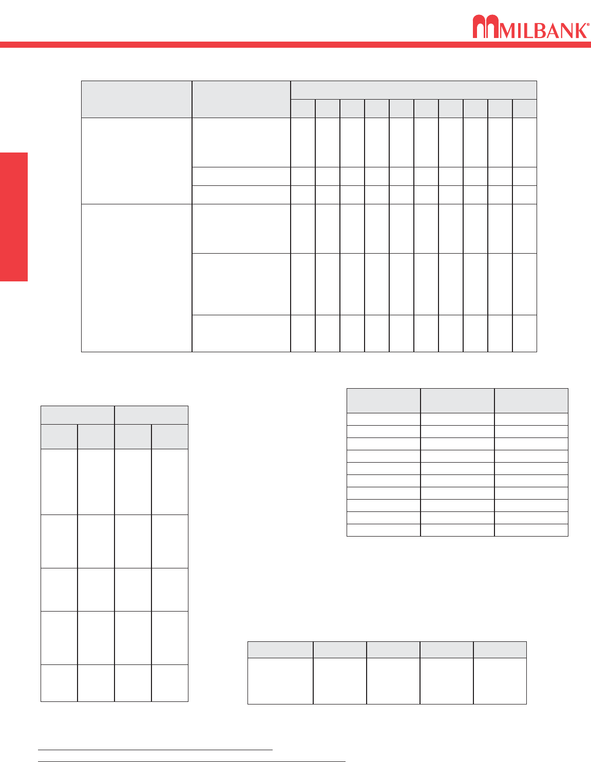
AMPACITY CORRECTION FACTORS
Overall ampere ratings of UL Listed Milbank multiple position meter sockets are based on 1993
N.E.C. Manual article 220-32 and ANSI / UL-414 (except where restricted by line connector size).
These requirements provide for a diversity factor / demand factor being utilized in determining the over-
all (main bus / lug) rating of a gang socket. All Milbank UL Listed gang sockets meet or exceed these
diversity factor/demand factor requirements. Standard overall ampacity ratings for UL Listed and non
UL Listed gang sockets are as shown in the chart below. Ampere ratings of meter sockets are based
on the meter socket being wired with 75°C insulated wire conductor, sized in accordance with Table
310-16 of the National Electric Code.
NO. OF METER
POSITIONS 100A / POS.
AMPACITY 125A / POS.
AMPACITY 150A / POS.
AMPACITY 200A / POS.
AMPACITY
2
3
4
5
6
200A
200A
200A
225A
270A
200A
225A
250A
285A
330A
200A
225A
270A
338A
396A
200A
270A
360A
450A
528A
MAXIMUM NUMBER OF CONDUCTORS IN CONDUIT*
A = Size: AWG/MCM
B = Ampere Rating for
Insulation Types:
FEPW, RH, RHW,
THW, THWN, XHHW,
USE, 2W.
C = Ampere Rating for
Insulation Types:
RH, RHW, THW,
THWN, XHHW, USE
(Per NEC table 310-16)
Unless otherwise permitted elsewhere in the Code, the overcurrent protection for conductor types marked with an obelisk () shall not exceed 15
amps for 14 AWG, 20 amps for 12 AWG, and 30 amps for 10 AWG copper: or 15 amps for 12 AWG and 25 amps for 10 AWG aluminum and
copper-clad aluminum after any correction factors for ambient temperature and number of conductors have been applied.
All meter sockets are 600 Volt rated unless otherwise noted.
All meter socket ampacity ratings are continuous duty unless otherwise noted.
GANG SOCKET OVERALL AMPACITIES
25
25
ENERGIZATION OF ELECTRICAL EQUIPMENT
BEFORE ENERGIZING
IMPORTANT NOTE
WHEN ENERGIZING
AFTER ENERGIZING
A. Give equipment a thorough visual examination to determine that:
1) No shipping or installation damage exists.
2) Proper clearances have been maintained.
3) All connections have been made.
4) Equipment is clean and dry.
B. Make a thorough examination to verify:
1) Tightness of all bolted connections (see table below).
2) Manually operate all circuit breakers, switches, relays, etc.
3) Check rigidity of all mountings, bus bars and components.
4) Use test equipment to check continuity of circuitry and integrity of insulation.
C. All switches and circuit breakers should be in the “off” position.
D. Verify that manual meter bypass (if applicable) is in non-bypass position.
E. Install cover and/or close doors.
F. If installation is not being energized at this time, follow “after-energizing” steps listed below. These
steps will secure the installation in case of accidental energization.
A. Use caution and follow established safety procedures:
1) Wear safety apparel.
2) Use safety equipment.
3) Take action to prevent injury to yourself and others in the event of failure of the installation.
4) Take action to prevent/decrease damage to property in the event of failure of the installation.
5) If you are unsure how to safely energize the installation, get someone who is knowledgeable to do it.
A. Secure the installation:
1) To prevent accidental contact with energized parts, cover all openings with approved filler devices.
2) To prevent unauthorized access, secure all covers and/or doors with approved security devices.
3) Attach/post information to advise others of potential hazards associated with the installation.
NOMINAL
SIZE
10
10
10
12
12
1/4
1/4
5/16
JOINT DESCRIPTION
SCREW NUT
BRASS
STEEL
STEEL
STEEL
STEEL
STEEL
STEEL
STEEL
Brass Nut or Extruded Hole
CU or AL Busbar <1/8″
Steel Nut or EH; CU or AL Busbar >1/8″
Aluminum Extruded Hole
Steel Nut or Extruded Hole
Aluminum Extruded Hole
Steel Nut or EH; CU or AL Busbar
Aluminum Extruded Hole
ALL
ALL
ALL
ALL
ALL
ALL
ALL
HEX
20-25 in. lbs.
25-30 in. lbs
30-35 in. lbs
30-35 in. lbs
40-50 in. lbs.
40-50 in. lbs.
50-60 in. lbs.
60-70 in. lbs.
5/16 STEEL Steel Nut or EH; CU or AL Busbar HEX 100-150 in. lbs.
3/8 STEEL Steel Nut HEX 150-200 in. lbs.
1/2 STEEL Steel Nut HEX 200-250 in. lbs.
HEAD TYPE TORQUE
( INCH LBS. )
*Interior labels typically indicate the required torque for wire connectors and studs, and should be referenced first.
EH: Extruded Hole
CU: Copper
AL: Aluminum
RECOMMENDED TORQUE FOR GENERAL APPLICATIONS*
In addition to national and local electrical codes, many utilities have specific requirements for metering equip-
ment. Always consult the serving utility for their specifications and requirements prior to ordering or installing
Milbank meter mounting equipment.
ENERGIZATION OF ELECTRICAL EQUIPMENT
MISC.

26
26
MATERIALS AND FINISHES
MATERIALS AND FINISHES MISC.
MATERIALS
STEEL SHEET
STEEL QUALITY
ALUMINUM EXTRUSION
ALUMINUM SHEET
COPPER SHEET & BUS
INSULATING MATERIALS
PROCESS
METAL FASTENERS
The meter equipment listed in this catalog is made of galvanized steel (AISI* G90) to afford the
best possible weather proofing. *American Iron and Steel Institute.
Light gray “state of the art” electrostatically applied powder paint offers a durable, non-fading
finish. For further information concerning the chemical analysis of the weather resistant finish,
please contact the factory.
Wire-Terminals: Alloy; 6061-T6, Tin-plated for CU/AL wire.
Bus Bar: Alloy; 6101-o & 6063-O
3000 series aluminum sheet, H14, or 5052 series aluminum sheet, H32. Where applicable thick-
nesses range from .064 — .125
Electrolytic copper with tin plating in most applications.
Zinc-coated with a chromate dip.
• In most units, support bases for current-carrying components are molded from fiberglass rein-
forced high-strength, track resistant, thermoset polyester molding compounds.
• Clear or black safety shields and polarity barriers are molded from high-strength, track resistant,
polycarbonate molding compounds.
• Various sheet insulating materials, as appropriate for the application are utilized in the fabrica-
tion of flat, formed and punched component parts and barriers.
16 gauge, galvanized, sheet: 1 1/4 oz./ sq.ft. class zinc-coated.
(AISI G90)
14 gauge, galvanized, sheet: 1 1/4 oz./ sq.ft. class zinc-coated.
FINISH
NEMA RATING
All Milbank meter sockets, CT cans and meter socket / breaker units have a Type 3R rating.
RATING
27
Utility requirements for this equipment may vary. Always consult the serving utility for their requirements before ordering or
installing equipment in this catalog.
27
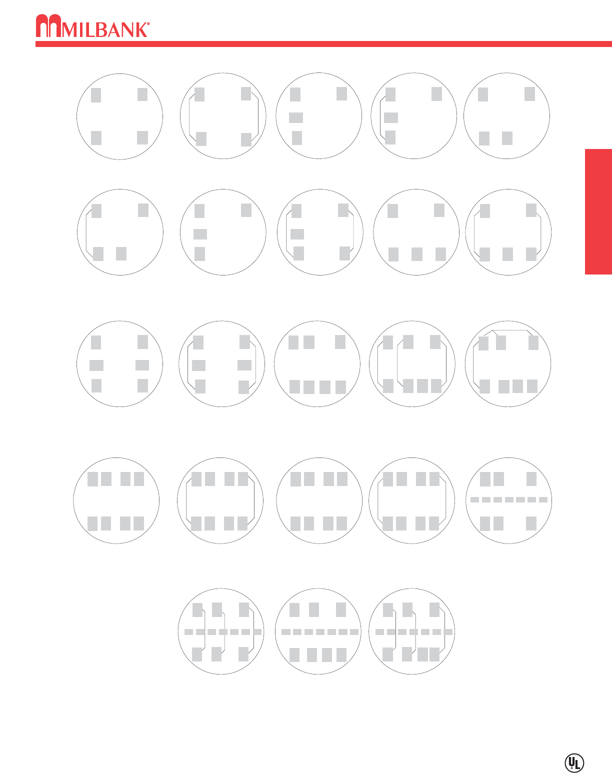
WATTHOUR METERS–STANDARD FORMS–TRANSFORMER RATED OR SELF-CONTAINED
SC SC TR TR TR
TR SC SC SC SC
TR TR SC SC TR
TR TR SC SC TR
TR TR TR
2 and 3-WIRE FORMS
1S & 2S
2 and 3-WIRE FORMS
1S & 2S with BYPASS
2-WIRE FORM 3S
5th Term. 9 o'clock
2-WIRE FORM 3S
with BYPASS
2-WIRE FORM 3S
5th Term.6 o'clock
2-WIRE FORM 3S
with BYPASS
2 ELEMENT
3-WIRE NETWORK
FORM 12S 5th
TERM. 9 o'clock
2 ELEMENT 3-WIRE
NETWORK FORM 12S
with BYPASS
5th Term. 9 o'clock
2 ELEMENT 3-WIRE
NETWORK FORM 12S
with BYPASS
5th Term. 6 o'clock
2 ELEMENT
3-WIRE NETWORK
FORM 12S 5th
TERM. 6 o'clock
3-WIRE FORM 4S 3-WIRE FORM 4S
WITH BYPASS
2 or 3 ELEMENT
3∅4W Y or Δ
Y FORM 14S
Δ FORM 15S
2 or 3 ELEMENT
3∅4W Y or Δ
FORMS 14S & 15S
with BYPASS
2 ELEMENT
3∅4W Y or Δ
Y FORM 7S
Δ FORM 24S
with BYPASS
2 ELEMENT
2∅3W, 2∅4W, 3∅3W
FORM 5S
2 ELEMENT 2∅3W,
2∅4W, 3∅3W
FORM 5S with
BYPASS
2 ELEMENT
2∅3W, 2∅4W, 3∅3W
FORM 13S
2 or 3 ELEMENT
2∅3W, 2∅4W, 3∅3W
FORM 13S with
BYPASS
2 or 3 ELEMENT
3∅4W Y or Δ
Y FORM 9S
Δ FORM 8S
2 or 3 ELEMENT
3∅4W Y or Δ
FORMS 8S & 9S
with BYPASS
2 ELEMENT
3∅4W Y
FORM 6S
2 ELEMENT
3∅4W Y
FORM 6S
with BYPASS
TR = TRANSFORMER RATED
SC = SELF CONTAINED
MISC. WATTHOUR METERS–STANDARD FORMS–TRANSFORMER RATED OR SELF-CONTAINED
28
ADDITIONAL MILBANK PRODUCTS MISC
28
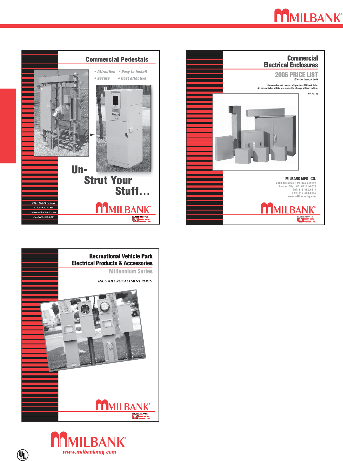
ADDITIONAL MILBANK PRODUCTS
In addition to your local utility’s meter mounting
equipment, Milbank also manufactures
supporting products, such as...
Air Conditioner Disconnects
Hot Tub Disconnects
RV/Mobile Home Power Outlets
Terminal Boxes
Temporary Power Outlets
Commercial Pedestals
Commercial Enclosures
CT Enclosures
Circuit Breakers
Distribution Unit Substations
Enclosed Circuit Breakers
Safety Switches
Test Switches
Contact your local distributor or go to
www.milbankmfg.com
to find additional product literature.
Other quality products available from Milbank

29
INDEX
INDEX
29
CAT. NO. PG
6003 . . . . . . . . . . . . . . . . . . . . . . . . .22
5T24R . . . . . . . . . . . . . . . . . . . . . . . .22
5T8K2 . . . . . . . . . . . . . . . . . . . . . . . .22
A7514 . . . . . . . . . . . . . . . . . . . . . . . .22
A7515 . . . . . . . . . . . . . . . . . . . . . . . .22
A7516 . . . . . . . . . . . . . . . . . . . . . . . .22
A7517 . . . . . . . . . . . . . . . . . . . . . . . .22
A7518 . . . . . . . . . . . . . . . . . . . . . . . .22
A7551 . . . . . . . . . . . . . . . . . . . . . . . .22
A8110 . . . . . . . . . . . . . . . . . . . . . . . .22
A8111 . . . . . . . . . . . . . . . . . . . . . . . .22
A8112 . . . . . . . . . . . . . . . . . . . . . . . .22
A9064 . . . . . . . . . . . . . . . . . . . . . . . .22
CP-21 . . . . . . . . . . . . . . . . . . . . . . . .22
K1047 . . . . . . . . . . . . . . . . . . . . . . . .23
K1350 . . . . . . . . . . . . . . . . . . . . .14,23
K1350L . . . . . . . . . . . . . . . . . . . . . . .23
K1539 . . . . . . . . . . . . . . . . . . . . .14, 23
K1540 . . . . . . . . . . . . . . . . . . . . .14, 23
K1540L . . . . . . . . . . . . . . . . . . . . . . .23
K1541 . . . . . . . . . . . . . . . . . . . . .14, 23
K2381 . . . . . . . . . . . . . . . . . . . . .15, 22
K3082 . . . . . . . . . . . . . . . . . . . . . . . .23
K3083 . . . . . . . . . . . . . . . . . . . . . . . .23
K3235 . . . . . . . . . . . . . . . . . . . . . . . .22
K3441 . . . . . . . . . . . . . . . . . . . . . . . .23
K3442 . . . . . . . . . . . . . . . . . . . . . . . .23
K3865 . . . . . . . . . . . . . . . . . . . . . . . .22
K4509 . . . . . . . . . . . . . . . . . . . . . . . .23
K4694 . . . . . . . . . . . . . . . . . . . . . . . .22
K4695 . . . . . . . . . . . . . . . . . . . . . . . .22
K5035 . . . . . . . . . . . . . . . . . . . . . . . .21
K5086 . . . . . . . . . . . . . . . . . . . . . . . .22
K5193 . . . . . . . . . . . . . . . . . . . . . . . .21
K5400-1450 . . . . . . . . . . . . . . . . . . .21
K5400-520 . . . . . . . . . . . . . . . . . . . .21
K5400-520GR . . . . . . . . . . . . . . . . . .21
K5400-BRIDGE-1POS . . . . . . . . . . .21
K5400-BRIDGE-2POS . . . . . . . . . . .21
K5400-TT30 . . . . . . . . . . . . . . . . . . .21
K5415 . . . . . . . . . . . . . . . . . . . . . . . .21
K5800 . . . . . . . . . . . . . . . . . . . . . . . .22
K5T . . . . . . . . . . . . . . . . . . . . . . .21, 22
L572-XL-KK . . . . . . . . . . . . . . . . . . .12
L573-XL-KK . . . . . . . . . . . . . . . . . . .12
L574-XL-KK . . . . . . . . . . . . . . . . . . .12
L575-XL-KK . . . . . . . . . . . . . . . . . . .12
L576-XL-KK . . . . . . . . . . . . . . . . . . .12
M5-144 . . . . . . . . . . . . . . . . . . . . . . .23
CAT. NO. PG
MR-4 . . . . . . . . . . . . . . . . . . . . . . . . .23
MR-8 . . . . . . . . . . . . . . . . . . . . . . . . .23
NU8980-O-100-KK . . . . . . . . . . . . . .19
NU8980-O-100-KK-LP . . . . . . . . . . .19
NU8980-O-200-KK . . . . . . . . . . . . . .19
NU8980-O-200-KK-LP . . . . . . . . . . .19
S1848 . . . . . . . . . . . . . . . . . . . . . . . .22
S2291-TO . . . . . . . . . . . . . . . . . . . . .15
S2571 . . . . . . . . . . . . . . . . . . . . .15, 22
S3488 . . . . . . . . . . . . . . . . . . . . . . . .22
S8324 . . . . . . . . . . . . . . . . . . . . . . . .22
S8988 . . . . . . . . . . . . . . . . . . . . . . . .22
U1252-X-KK . . . . . . . . . . . . . . . . . . .12
U1253-X-KK . . . . . . . . . . . . . . . . . . .12
U1254-X-KK . . . . . . . . . . . . . . . . . . .12
U1255-X-KK . . . . . . . . . . . . . . . . . . .12
U1256-X-KK . . . . . . . . . . . . . . . . . . .12
U1748-O-WI . . . . . . . . . . . . . . . . . . .20
U1779-RRL . . . . . . . . . . . . . . . . . . . .10
U1980-O-KK . . . . . . . . . . . . . . . . . . . .8
U2594-X-K7-INV . . . . . . . . . . . . . . . .11
U2732-XT-PED . . . . . . . . . . . . . . . . .13
U2733-XT-PED . . . . . . . . . . . . . . . . .13
U2734-XT-PED . . . . . . . . . . . . . . . . .13
U2852-X-KK-K1-PED . . . . . . . . . . . .14
U2853-X-KK-K1-PED . . . . . . . . . . . .14
U2854-X-KK-PED . . . . . . . . . . . . . . .14
U2855-X-KK-PED . . . . . . . . . . . . . . .14
U2856-X-KK-PED . . . . . . . . . . . . . . .14
U2862-X-KK-K1-PED . . . . . . . . . . . .14
U2863-X-KK-K1-PED . . . . . . . . . . . .14
U2864-X-KK-PED . . . . . . . . . . . . . . .14
U2865-X-KK-PED . . . . . . . . . . . . . . .14
U2866-X-KK-PED . . . . . . . . . . . . . . .14
U3000-O-K3L-K2L . . . . . . . . . . . . . .10
U3800 . . . . . . . . . . . . . . . . . . . . . . . . .5
U3803 . . . . . . . . . . . . . . . . . . . . . . . . .5
U3806 . . . . . . . . . . . . . . . . . . . . . . . . .5
U3822-20GR . . . . . . . . . . . . . . . . . . . .6
U3849-O-2/200-INV . . . . . . . . . . . . .20
U4881-O . . . . . . . . . . . . . . . . . . . . . . .6
U4881-O-50GB . . . . . . . . . . . . . . . . . .6
U4881-O-60GB . . . . . . . . . . . . . . . . . .6
U5136-O-100S . . . . . . . . . . . . . . . . .21
U5136-O-200S . . . . . . . . . . . . . . . . .21
U5136-O-200S/22 . . . . . . . . . . . . . . .21
U5137-O-100S . . . . . . . . . . . . . . . . .21
U5137-O-200S . . . . . . . . . . . . . . . . .21
U5137-O-200S/22 . . . . . . . . . . . . . . .21
CAT. NO. PG
U7021-RL-TG-KK . . . . . . . . . . . . . . . .8
U7040-RL-TG-KK . . . . . . . . . . . . . . . .8
U7375-RL-KK . . . . . . . . . . . . . . . . . .18
U7487-RL-TG-KK . . . . . . . . . . . . . . . .7
U7607-RL-200-KK . . . . . . . . . . . . . .18
U8436-O . . . . . . . . . . . . . . . . . . . . . .16
U8949-RL-TG-KK . . . . . . . . . . . . . . . .8
U9107-O . . . . . . . . . . . . . . . . . . . . . .17
U9108-O . . . . . . . . . . . . . . . . . . . . . .17
U9550-RL . . . . . . . . . . . . . . . . . . . . . .9
U9551-O . . . . . . . . . . . . . . . . . . . . . . .9
U9700-RRL . . . . . . . . . . . . . . . . . . . . .9
U9701-O . . . . . . . . . . . . . . . . . . . . . . .9
UQFB-100 . . . . . . . . . . . . . . . . . . . . .37
UQFB-100-X1 . . . . . . . . . . . . . . . . . .37
UQFB-125 . . . . . . . . . . . . . . . . . . . . .37
UQFB-125-X1 . . . . . . . . . . . . . . . . . .37
UQFB-150 . . . . . . . . . . . . . . . . . . . . .37
UQFB-150-X1 . . . . . . . . . . . . . . . . . .37
UQFB-175 . . . . . . . . . . . . . . . . . . . . .37
UQFB-175-X1 . . . . . . . . . . . . . . . . . .37
UQFB-200 . . . . . . . . . . . . . . . . . . . . .37
UQFB-200-X1 . . . . . . . . . . . . . . . . . .37
UQFBH-100 . . . . . . . . . . . . . . . . . . .37
UQFBH-125 . . . . . . . . . . . . . . . . . . .37
UQFBH-150 . . . . . . . . . . . . . . . . . . .37
UQFBH-175 . . . . . . . . . . . . . . . . . . .37
UQFBH-200 . . . . . . . . . . . . . . . . . . .37
UQFP-100 . . . . . . . . . . . . . . . . . . . . .37
UQFP-125 . . . . . . . . . . . . . . . . . . . . .37
UQFP-150 . . . . . . . . . . . . . . . . . . . . .37
UQFP-175 . . . . . . . . . . . . . . . . . . . . .37
UQFP-200 . . . . . . . . . . . . . . . . . . . . .37
UQFPH-100 . . . . . . . . . . . . . . . . . . .37
UQFPH-125 . . . . . . . . . . . . . . . . . . .37
UQFPH-150 . . . . . . . . . . . . . . . . . . .37
UQFPH-175 . . . . . . . . . . . . . . . . . . .37
UQFPH-200 . . . . . . . . . . . . . . . . . . .37
UQFPH-M-100 . . . . . . . . . . . . . . . . .37
UQFPH-M-125 . . . . . . . . . . . . . . . . .37
UQFPH-M-150 . . . . . . . . . . . . . . . . .37
UQFPH-M-175 . . . . . . . . . . . . . . . . .37
UQFPH-M-200 . . . . . . . . . . . . . . . . .37
UQFP-M-100 . . . . . . . . . . . . . . . . . .37
UQFP-M-125 . . . . . . . . . . . . . . . . . .37
UQFP-M-150 . . . . . . . . . . . . . . . . . .37
UQFP-M-175 . . . . . . . . . . . . . . . . . .37
UQFP-M-200 . . . . . . . . . . . . . . . . . .37

NOTES
30
NOTES
30

31
NOTES
NOTES
31
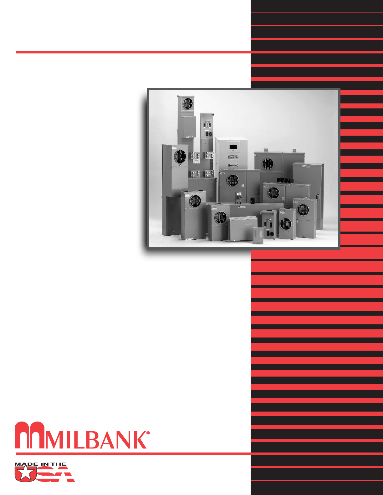
Meter Mounting Equipment & More!
Commercial Electrical Enclosures
Residential & Commercial Metering
Commercial Meter Pedestals
Disconnect Devices
Current Transformer Enclosures
RV/MH Pedestals
Temporary Power Outlets
Circuit Breakers
Distribution Unit Substations
Enclosed Circuit Breakers
Safety Switches
Test Switches
REPRESENTATIVE
Callas/Kingsley
845 Lively Boulevard
Wood Dale, IL 60191
Tel: 630-595-7887 Fax: 630-595-6922
www.ckelectricalsales.com
NIPSCO 11/06 (1K)
www.milbankmfg.com
MILBANK MFG. CO.
PO Box 419028
Kansas City, MO 64141-0028
Tel: 816-483-5314 Fax: 816-483-6357
Toll Free: 877-483-5314
www.milbankmfg.com
