Rittal RiLine60
239980-Attachment 239980-Attachment 239980-Attachment 639889 Batch8 unilog cesco-content
432027-Catalog 432027-Catalog 432027-Catalog 639889 Batch6 unilog cesco-content
250335-Catalog 1 250335-Catalog_1 250335-Catalog_1 639889 Batch7 unilog cesco-content
351225-Attachment 351225-Attachment 351225-Attachment 639889 Batch5 unilog cesco-content
2014-07-05
: Pdf 249613-Attachment 249613-Attachment 639889 Batch5 unilog
Open the PDF directly: View PDF ![]() .
.
Page Count: 12
60 mm system technology
for the global market
Rittal – RiLine60
2Rittal RiLine60 cULus listed
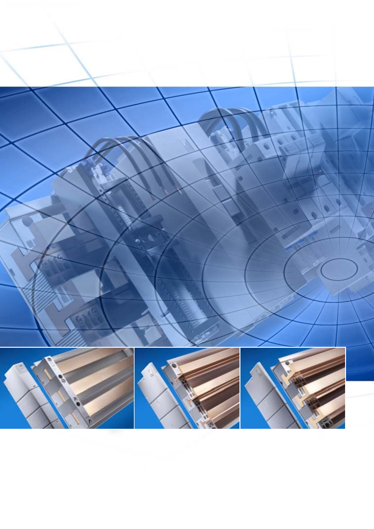
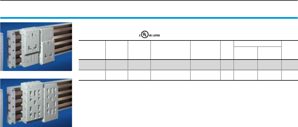
Rittal RiLine60 – three systems
Classic
for busbars with a square cross-
section up to 30 x 10 mm in feeder-
circuits up to 700 A
PLS 800
For feeder-circuits up to 700 A
PLS 1600
For feeder-circuits up to 1400 A
Unlike busbar sections with a square cross-section, PLS sections offer
unrestricted top-mounting of the busbar supports with top-mounting
components.
Innovative and compact
3Rittal RiLine60 cULus listed
Save time and money with easier
UL and CSA sign-offs.
The approval of power distribution
components is becoming ever
more important for international
switchgear producers.
approval of RiLine60
busbar systems offers significant
advantages for both the UL and
CSA market. Complex, time-
consuming engineering, inspection
and sign-off processes are reduced
to a minimum.
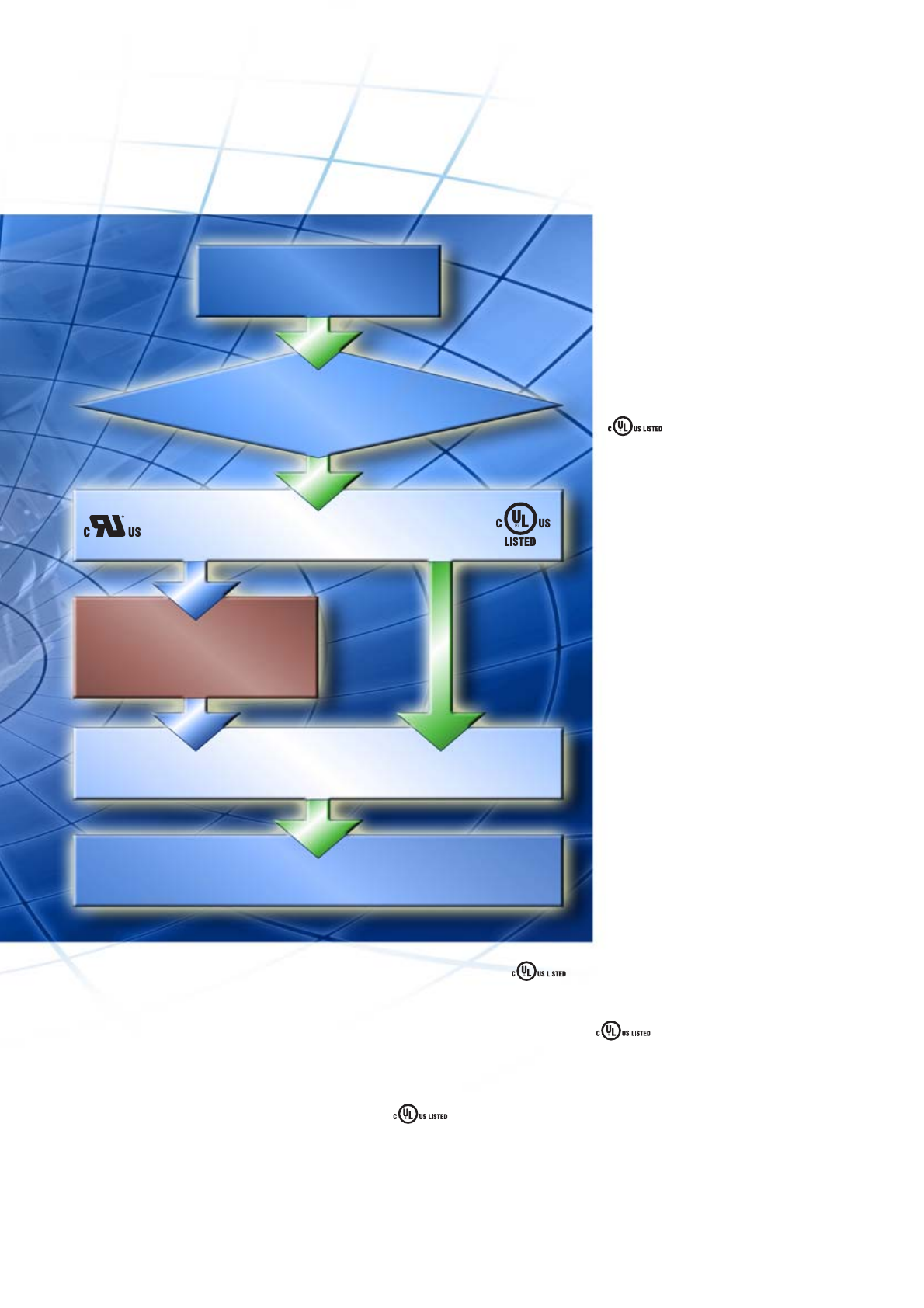
Important benefits and added value with RiLine60
Industrial
controllers
to UL 508A
Approval status RiLine60
Sign-off by inspector
Review of the COA(s)
of all UL-recognized
components used
Inspection of UL-compliant assembly
On-site sign-off by the
Authority Having Jurisdiction (AHJ)
1. Dramatic time savings
Straightforward UL and CSA sign-off
processes
2. Conditions of Acceptability (COA)
are eliminated, documentation work
is minimised
No additional tests required as with
UL-recognized components.
3. Cost savings for listed
switchgear producers
The usual UL costs for file entry of the
UL-recognized components are elimi-
nated.
4. A high level of acceptance among
end customers
RiLine60 meets the require-
ments of valid safety standards to per-
fection.
5. Barrierless access to the
CSA market
products are accepted on
the Canadian market with no further
test requirements.
6. Time- and cost-efficient project
planning
Reduced project planning work
when incorporating the engineering
considerations.
Simple, fast system sign-offs
4Rittal RiLine60 cULus listed
Background information on UL
UL or Underwriter Laboratory was founded
in 1894 as a non-profit-making organisa-
tion for testing and certification. UL oper-
ates five testing laboratories in the United
States and subsidiaries worldwide, with an
emphasis on product testing aimed at gen-
eral safety.
Why are UL approvals important?
●International regulations and standards
such as NEMA and IEC are used as
a basis by manufacturers for product
developments and subsequent testing.
●Nationally recognised test laboratories
confirm and certify that a product
complies with the specific standards;
in North America this is carried out
by organisations such as UL or CSA
(Canadian Standards Association).
●For many applications, the sole use of
UL and/or CSA-approved products is a
requirement; consequently, it is advisa-
ble to design electrical controllers for
North American applications with suita-
ble UL-approved components.
How does the US system for electrical
safety work?
Every piece of electrical equipment
(machine/plant) is tested by the compe-
tent local inspector (AHJ = Authority
Having Jurisdiction) prior to commission-
ing. The AHJ has the final say with regard
to commissioning. All AHJs use Standard
NFPA 70 (NFPA = National Fire Protection
Association) as a basis, which is generally
regarded as the NEC (National Electrical
Code). NFPA 70 is therefore an important
basis for UL 508A (Industrial Control
Panels).
The AHJ considers the use of UL-recog-
nized or UL-listed components an impor-
tant indication that a system complies with
the safety requirements to NFPA 70. This
saves time and money during construction
and commissioning of the equipment, as
the UL symbol indicates that testing of the
components and/or of the system did not
reveal any foreseeable risks with regard
to fire, electric shock and associated dan-
gers.
The UL symbols: “UL-listed” or
“UL-recognized”
When labelling UL-approved products,
a general distinction is made between
Recognized Components and Listed
Devices:
(Recognized Components)
This label is used on products which
are not complete in terms of their appli-
cation. These products are listed in the
UL’s “yellow component database”.
The correct use of such components
must make due allowance for the
“Conditions of Acceptability”, listing the
framework conditions and application
parameters approved by the UL.
(Listed Devices)
Here, it is only important to note that
the remarks and rating data specified
on the product are observed with the
application. Terminals for field-wiring
are authorised as Listed Devices
(cf. point 3).
Application areas for UL 508 and
UL 508A
UL 508 describes industrial control compo-
nents and is therefore the decisive stand-
ard for the assessment of Rittal SV compo-
nents. For example, this standard contains
information on:
●Starters
●Relays and contactors
●Circuit-breakers
●Controllers
UL 508A describes industrial control pan-
els and is therefore the decisive standard
for switchgear manufacturers.
For example, this standard contains infor-
mation on:
●Machine controllers
●Elevator controllers
●Crane controllers
●Equipment for heating, air-conditioning
and ventilation systems
Both standards describe control systems
for general industrial applications with a
rated voltage of up to 600 V. The maximum
permissible ambient temperature is 40°C.
Distinguishing between feeder- and
branch-circuits
Standard UL 508A makes a distinction
between feeder-circuits and branch &
control circuits. Generally speaking, the
term “feeder-circuits” refers to the part of
the circuit located at the supply end before
the last over-current protective device (a
device approved to UL 489). Increased
requirements with regard to creepage dis-
tances and clearances apply to this part
of the circuit.
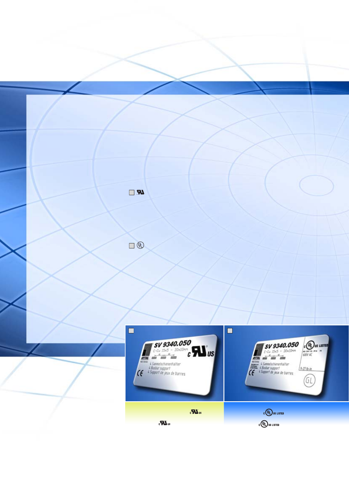
1
2
Rittal RiLine60 – Details for
mechanical and plant engineering
1
2
Recognized Component
Sample rating plate for a busbar
support with .
Listed Device
Sample rating plate for a busbar
support with .
5Rittal RiLine60 cULus listed
The term “branch & control circuits” refers
to the part of the circuit located after the
last over-current protective device. When
using busbar systems, it is important to
know whether the application is in the
feeder section or the branch section, as
the requirements governing the required
creepage distances and clearances are
significantly higher for feeder-circuits.
Important remarks
for the use of busbar systems
to UL 508A
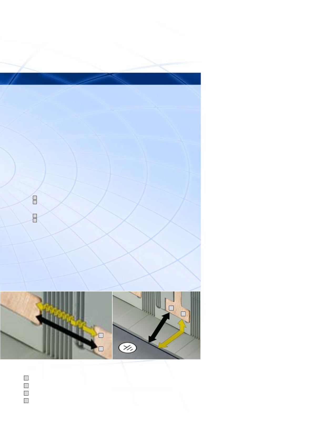
1. Creepage distances and clearances
One of the principal requirements in
UL 508A is the amendment to the required
creepage distances and clearances for
feeder-circuits.
For applications >250 V the following dis-
tances and clearances are required:
●Between phases:
Creepage distance 50.8 mm (2 inches)
Clearance 25.4 mm (1 inch)
●Between phase and earthed,
uninsulated metal parts:
Creepage distance 25.4 mm (1 inch)
Clearance 25.4 mm (1 inch)
Rittal RiLine60 complies with these require-
ments. All busbar connection adaptors and
component adaptors (OM adaptors with
standard AWG connection cables and
circuit-breaker adaptors) have been de-
signed in accordance with these require-
ments. However, users should bear in mind
a small number of differences from the IEC
version:
●Special UL busbar supports for flat bars
and Rittal PLS with increased creepage
distances and clearances.
●In order to guarantee the required dis-
tances between live parts and the
earthed mounting plate, the use of a
Rittal RiLine60 base tray is compulsory.
2. Rated currents
For untested busbar applications, UL 508A
specifies a current carrying capacity of
1000 A/inch2 (1.5 A/mm2) in the absence of
testing.
This value may be higher if the product or
application has undergone suitable test-
ing. Rittal has conducted extensive testing
in this respect in order to give users the
maximum benefits when using the RiLine60
busbar system. The benefit of such testing
is that SV busbar systems with higher rated
currents may be used than permitted by
the default value. For example, a busbar
with dimensions 30 x 10 mm can take 700 A
instead of 465 A.
3. Terminals for factory or field-wiring
In accordance with the UL standards,
connection terminals may be approved
for factory or field-wiring. If a terminal is
approved for factory-wiring, it may only be
used in switchgear assembly by suitably
trained professionals.
If connection terminals are to be used in
the field (e.g. on a construction site), the
component must be approved for field-wir-
ing. The terminals of the busbar connec-
tion adaptors and component adaptors
in the Rittal RiLine60 series have there-
fore been tested for field-wiring applica-
tions.
A
B
C
D
C
D
B
A
Compliance with standards is in-
dispensable for the safe design
and operation of electrical systems.
This is particularly true of the North
American market.
Here, products which conform to
the relevant regulations are a key
factor for problem-free acceptance
of electrical systems.
UL-approved components provide
a suitable basis, saving time and
money for the user by minimising
acceptance problems in advance.
Definition of creepage distances and clearances:
Creepage distance between active conductors/busbars
Clearance between active conductors/busbars
Creepage distance between active conductors/busbars and earthed metal parts
Clearance between active conductors/busbars and earthed metal parts
A
B
C
D
6Rittal RiLine60 cULus listed
Product overview
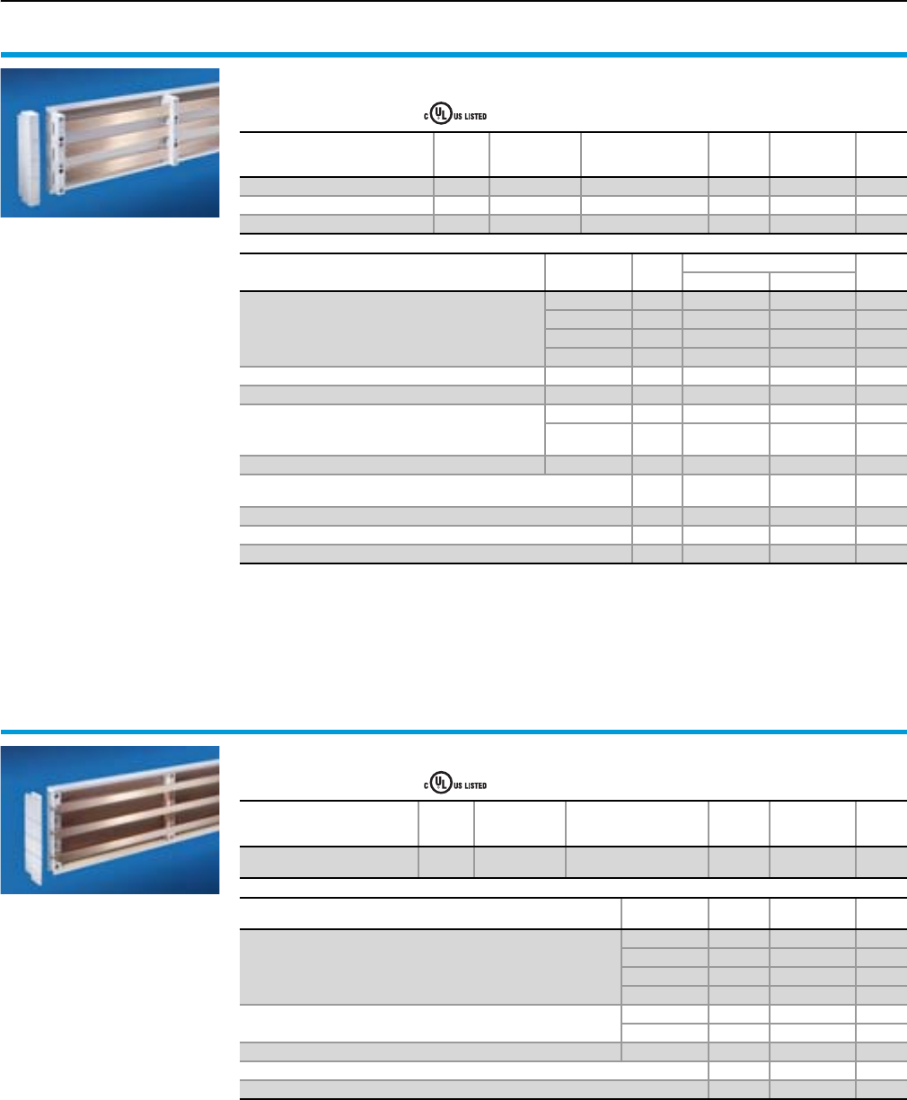
RiLine60 busbar system for flat copper bars (3-/4-pole)
For feeder-circuits UL 508A, , file E191125
Designation Version
Bar centre
distance
mm
For
busbars
mm
Packs
of
Model No.
SV
Cat. 32,
page
Busbar support 3-pole 60 15 x 5 – 30 x 10 4 9340.050 354
Busbar support 4-pole 60 15 x 5 – 30 x 10 4 9340.004 380
Busbar support 30 x 10 PLUS 4-pole 60 30 x 10 4 9342.014 382
System components
Designation Length
mm
Packs
of
Model No. SV Cat. 32,
page
3-pole 4-pole
Base tray for SV 9340.050
500 2 9340.100 –351
700 2 9340.110 –351
900 2 9340.120 –351
1100 2 9340.130 –351
Base tray for SV 9340.004 1100 2 – 9340.134 381
Base tray for SV 9342.014 1100 2 –9342.134 383
Cover section
700 2 9340.200 – 351
1100 2 9340.210 9340.214 351,
381/383
Base tray infill 100 2 9340.140 –351
Support panel for cover section 5 9340.220 9340.224 351,
381/383
End covers for SV 9340.050 2 9340.070 –354
End covers for SV 9340.004 2 – 9340.074 380
End covers for SV 9342.014 2 –9342.074 382
Note:
The use of a base tray is compulsory for UL applications.
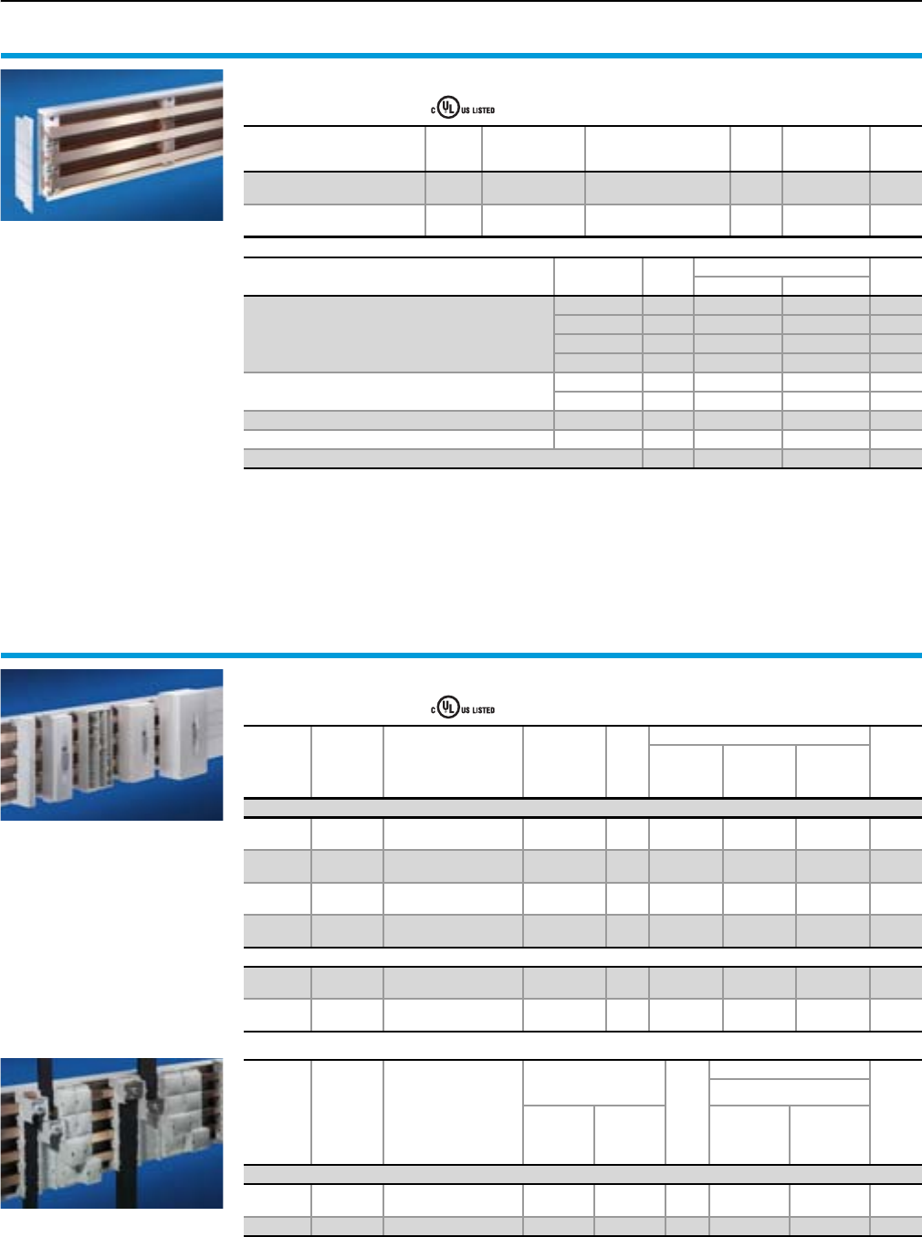
RiLine60 busbar system PLS 800 (3-pole)
For feeder-circuits UL 508A, , file E191125
Designation Version
Bar centre
distance
mm
For
PLS busbars1)
Cross-section mm2
Packs
of
Model No.
SV
Cat. 32,
page
Busbar support
PLS 800 3-pole 60 300 4 9341.050 355
System components
Designation Length
mm
Packs
of
Model No.
SV
Cat. 32,
page
Base tray
500 2 9341.100 353
700 2 9341.110 353
900 2 9341.120 353
1100 2 9341.130 353
Cover section 700 2 9340.200 353
1100 2 9340.210 353
Base tray infill 100 2 9341.140 353
Support panel for cover section 5 9340.220 353
End covers for SV 9341.050 2 9341.070 355
1) 5 mm bar thickness
Note:
The use of a base tray is compulsory for UL applications.
7Rittal RiLine60 cULus listed
Product overview
RiLine60 busbar system PLS 1600 (3-/4-pole)
For feeder-circuits UL 508A, , file E191125
Designation Version
Bar centre
distance
mm
For
PLS busbars1)
Cross-section mm2
Packs
of
Model No.
SV
Cat. 32,
page
Busbar support
PLS 1600 3-pole 60 900 4 9342.050 355
Busbar support
PLS 1600 PLUS 4-pole 60 900 4 9342.004 382
System components
Designation Length
mm
Packs
of
Model No. SV Cat. 32,
page
3-pole 4-pole
Base tray
500 2 9342.100 –353
700 2 9342.110 –353
900 2 9342.120 –353
1100 2 9342.130 9342.134 353/383
Cover section 700 2 9340.200 – 353
1100 2 9340.210 9340.214 353/383
Base tray infill 100 2 9342.140 –353
Support panel for cover section – 5 9340.220 9340.224 353/383
End covers for busbar supports 2 9342.070 9342.074 355/382
1) 10 mm bar thickness
Note:
The use of a base tray is compulsory for UL applications.
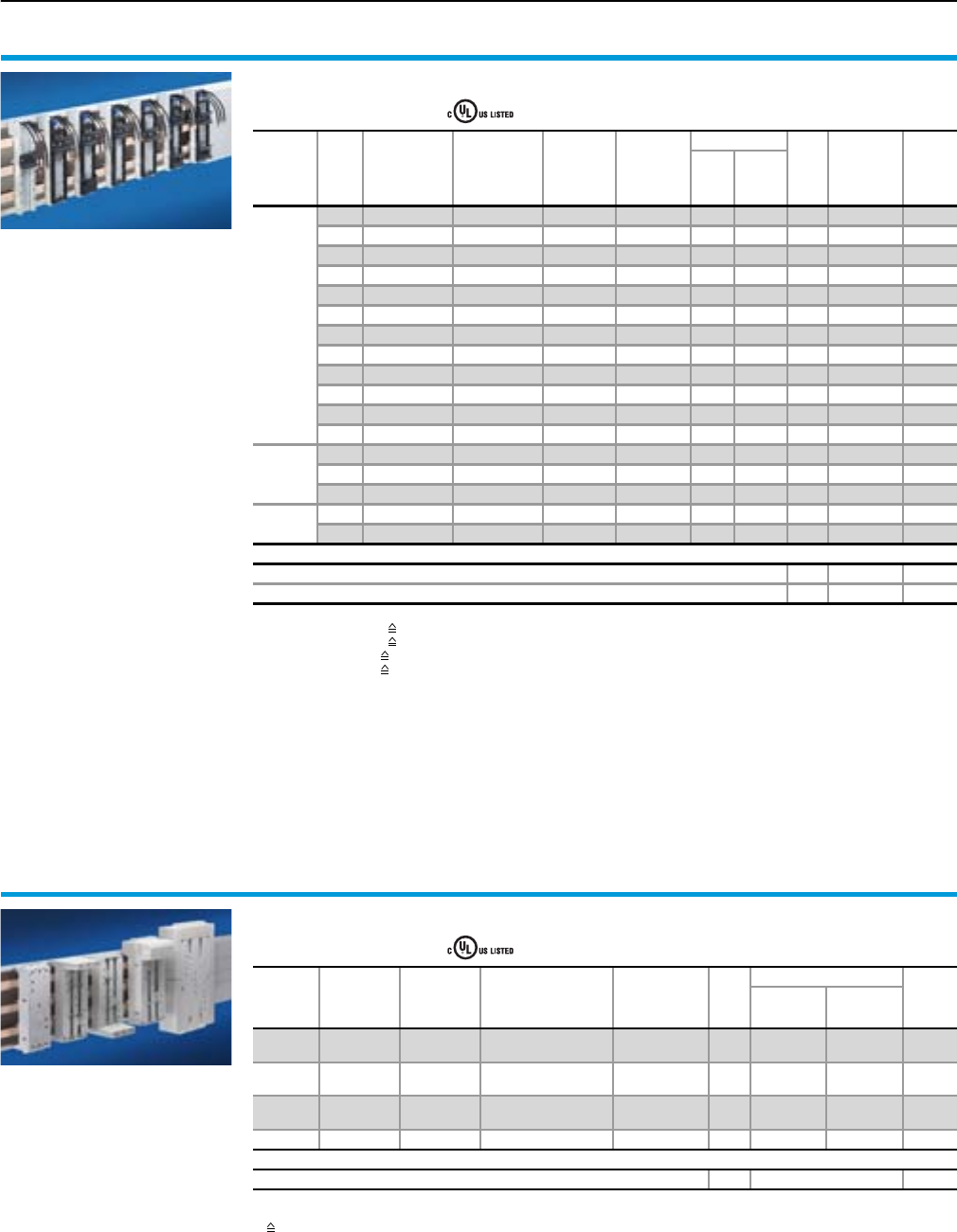
Busbar connection adaptor (3-/4-pole)
For feeder-circuits UL 508A, , file E191125
Rated
current
up to
Rated
operating
voltage
Connection
of round conductors
mm2 (AWG)
Clamping
area for
laminated
copper bars
mm
Packs
of
Model No. SV
Cat. 32,
page
Outlet at
top/bottom
Outlet at
top
Outlet at
bottom
3-pole
60 A 600 V~ 6 – 16
(AWG 10 – AWG 6) –1 – 9342.200 9342.210 356
125 A 600 V~ 16 – 35
(AWG 6 – AWG 2) 10 x 7.8 1 – 9342.230 9342.240 356
250 A 600 V~ 35 – 120
(AWG 2 – MCM 250) 18.5 x 15.5 1 9342.250 9342.260 9342.270 356
600 A 600 V~ 95 – 300
(AWG 3/0 – MCM 600) 33 x 20 1 – 9342.290 9342.300 356
4-pole
125 A 600 V~ 16 – 35
(AWG 6 – AWG 2) 10 x 7.8 1 9342.224 9342.234 9342.244 384
250 A 600 V~ 35 – 120
(AWG 2 – MCM 250) 18.5 x 15.5 1 9342.254 9342.264 9342.274 384
Rated
current
up to
Rated
operating
voltage
Connection
of round conductors
mm2 (AWG)
Clamping area for
laminated copper bars
mm Packs
of
Model No. SV
Cat. 32,
page
Outlet at top/bottom
for
5 mm
bar
thickness
for
10 mm
bar
thickness
Busbar
connection
adaptor
(3 x 1-pole)
Expansion
set
for 4-pole
configuration
3-/4-pole
800 A 600 V~ 95 – 300
(AWG 3/0 – MCM 600) 33 x 27 33 x 22 1 set 9342.310 9342.3141) 357/385
1400 A 600 V~ –65 x 27 65 x 22 1 set 9342.320 9342.3241) 357/385
1) Packs of = 1
8Rittal RiLine60 cULus listed
Product overview
OM adaptor/OM support (3-pole)
For feeder-circuits UL 508A, , file E191125
Version
Con-
struc-
tion
width
mm
Rated current
up to
Rated
operating
voltage
Connection
cables1)
Connection
of round
conductors
mm2
Support rails
Packs
of
Model No.
SV
Cat. 32,
page
Height
mm Qty.
OM
adaptor
45 25 A 600 V~ AWG 12 –10 11 9340.3102) 364
45 25 A 600 V~ AWG 12 – 10 1 1 9340.340 364
45 25 A 600 V~ AWG 12 –10 11 9340.3703) 364
45 32 A 600 V~ AWG 10 – 10 1 1 9340.350 364
45 32 A 600 V~ AWG 10 –10 21 9340.380 364
55 32 A 600 V~ AWG 10 – 10 1 1 9340.460 364
55 32 A 600 V~ AWG 10 –10 21 9340.470 364
75 40 A 600 V~ AWG 8 – 7.5 2 1 9340.7104) 365
55 65 A 600 V~ AWG 6 –10 11 9340.4102) 365
55 65 A 600 V~ AWG 6 – 10 1 1 9340.430 365
55 65 A 600 V~ AWG 6 –10 21 9340.450 365
75 65 A 600 V~ AWG 6 – 7.5 1 1 9340.7004) 365
OM
Premium
adaptor
45 25 A 600 V~ –1.5 – 4 10 11 9340.9005) 362
45 25 A 600 V~ – 1.5 – 4 10 2 1 9340.9106) 362
55 25 A 600 V~ –1.5 – 4 10 21 9340.9306) 362
OM
support
45 – – – – 10 – 1 9340.2603) 368
55 – – – – 10 11 9340.270 368
Accessories
Connection pin 20 9340.280 401
Insert strip 10 mm 2 9340.290 400
1) AWG = American Wire Gauges
AWG 12 = 3.31 mm24 mm2
AWG 10 = 5.26 mm26 mm2
AWG 8 = 8.37 mm210 mm2
AWG 6 = 13.3 mm216 mm2
2) Without support frame
3) With pin block
4) Witihout support frame, with insert strips
5) With sub-unit and pin block
6) With connector outlet
Circuit-breaker component adaptor (3-pole)
For feeder-circuits UL 508A, , file E191125
Con-
struction
width
mm
Rated
current
up to
Rated
operating
voltage
Connection
of round conductors
mm2 (AWG)
Clamping area
for laminated
copper bars
mm
Packs
of
Model No. SV
Cat. 32,
page
Cable outlet
top1)
Cable outlet
bottom1)
72 100 A 600 V~ 10 – 35
(AWG 6 – AWG 2) 10 x 7.8 1 9342.400 9342.410 370
90 125 A 600 V~ 35 – 120
(AWG 2 – MCM 250) 18.5 x 15.5 1 9342.540 9342.550 370
105 250 A 600 V~ 35 – 120
(AWG 2 – MCM 250) 18.5 x 15.5 1 9342.600 9342.610 371
140 600 A 600 V~ – 32 x 102) 1 9342.700 9342.710 371
Accessories
Insert strip 25 mm, for SV 9342.700/.710 43) 9342.720 400
1) Switch outlet or outgoing cable
2) Via M10 screw terminal
3) 1 set
9Rittal RiLine60 cULus listed
Product overview
Circuit-breaker component adaptor (4-pole)
For feeder-circuits UL 508A, , file E191125
Construction
width
mm
Rated
current
up to
Rated
operating
voltage
Connection
of round conductors
mm2 (AWG)
Clamping area
for laminated
copper bars
mm
Packs
of
Model No. SV
Cat. 32,
page
Cable outlet
top1)
Cable outlet
bottom1)
120 125 A 600 V~ 35 – 120
(AWG 2 – MCM 250) 18.5 x 15.5 1 9342.504 9342.514 386
140 250 A 600 V~ 35 – 120
(AWG 2 – MCM 250) 18.5 x 15.5 1 9342.604 9342.614 386
1) Switch outlet or outgoing cable
10 Rittal RiLine60 cULus listed
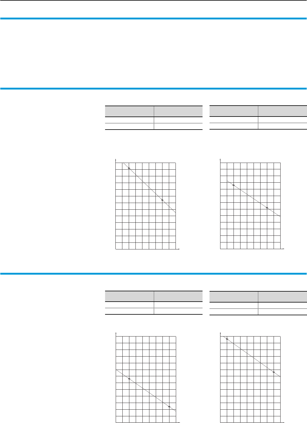
Short-circuit resistance diagrams
Rittal RiLine60 UL 508
During the course of testing, the test equip-
ment has been adjusted to the respective
root-mean-square values (IRMS). The result-
ant peak short-circuit currents Ip are shown
in the short-circuit protection diagrams
below.
The short-circuit resistance of Rittal
RiLine60 has been extensively tested.
Short-circuit resistance to UL criteria is
assessed via the root-mean-square value
of the short-circuit current (IRMS), which
must be applied for at least 3 periods.
200 250 450350 400300 600500 550
30
35
45
40
60
65
55
50
70
80
75
25
20
Busbar supports
for feeder-circuits 700 A,
3-pole
60 mm bar centre distance,
for busbars 15 x 5 – 30 x 10 mm.
Note:
SV 9340.050 with 30 x 5/10 mm
With a pre-fuse, the following short-circuit
value can be achieved:
Support spacing: 350 mm
Fuse: Class L 800 A
IRMS: 50 kA
Ip peak short-circuit current [kA]
Busbar support spacing [mm]
Support spacing
mm
IRMS
kA
250 30
500 22
20
25
35
30
450300200 250 350 400 550500 600
80
75
70
65
60
55
50
45
40
Ip peak short-circuit current [kA]
Busbar support spacing [mm]
Model No. SV 9340.050
with 30 x 5/10 mm
Model No. SV 9340.050
with 25 x 5 mm
20 x 5/10 mm
15 x 5/15 mm
Settings IRMS (Ieff.) of the test equipment with-
out prefuse:
Support spacing
mm
IRMS
kA
250 35
500 25
PLS busbar supports
for feeder-circuits
700 A (PLS 800)/1400 A (PLS 1600),
3-pole
60 mm bar centre distance,
for Mini-PLS special busbars.
Note:
SV 9342.050 (PLS 1600)
With a pre-fuse, the following short-circuit
value can be achieved:
Support spacing: 250 mm
Fuse: Class L 1400 A
IRMS: 65 kA
30
25
20
65
60
55
45
35
40
50
80
75
70
350200 250 300 450400 500 550150
450
20
25
30
200 250 300 350 400
50
40
35
45
55
60
65
500
70
75
80
550150
Ip peak short-circuit current [kA]
Busbar support spacing [mm]
Support spacing
mm
IRMS
kA
150 35
500 25
Ip peak short-circuit current [kA]
Busbar support spacing [mm]
Model No. SV 9341.050 (PLS 800) Model No. SV 9342.050 (PLS 1600)
Settings IRMS (Ieff.) of the test equipment with-
out prefuse:
Support spacing
mm
IRMS
kA
200 22
500 14
11Rittal RiLine60 cULus listed
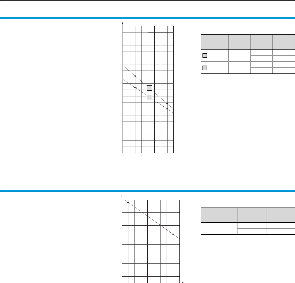
Short-circuit resistance diagrams
Busbar supports
up to 700 A, 4-pole
Model No. SV 9340.004/SV 9342.014
60 mm bar centre distance
Settings IRMS (Ieff.) of the test equipment with-
out prefuse:
Model No.
SV
Busbar
mm
Support
spacing
mm
IRMS
9340.004 15 x 5 –
30 x 10
250 30
500 22
9342.014 30 x 10 250 35
500 25
a
b
Ip peak short-circuit current [kA]
Busbar support spacing [mm]
60
55
50
45
40
35
30
25
20
200 250 400350300 450 500
65
70
75
80
85
90
95
100
105
110
115
b
a
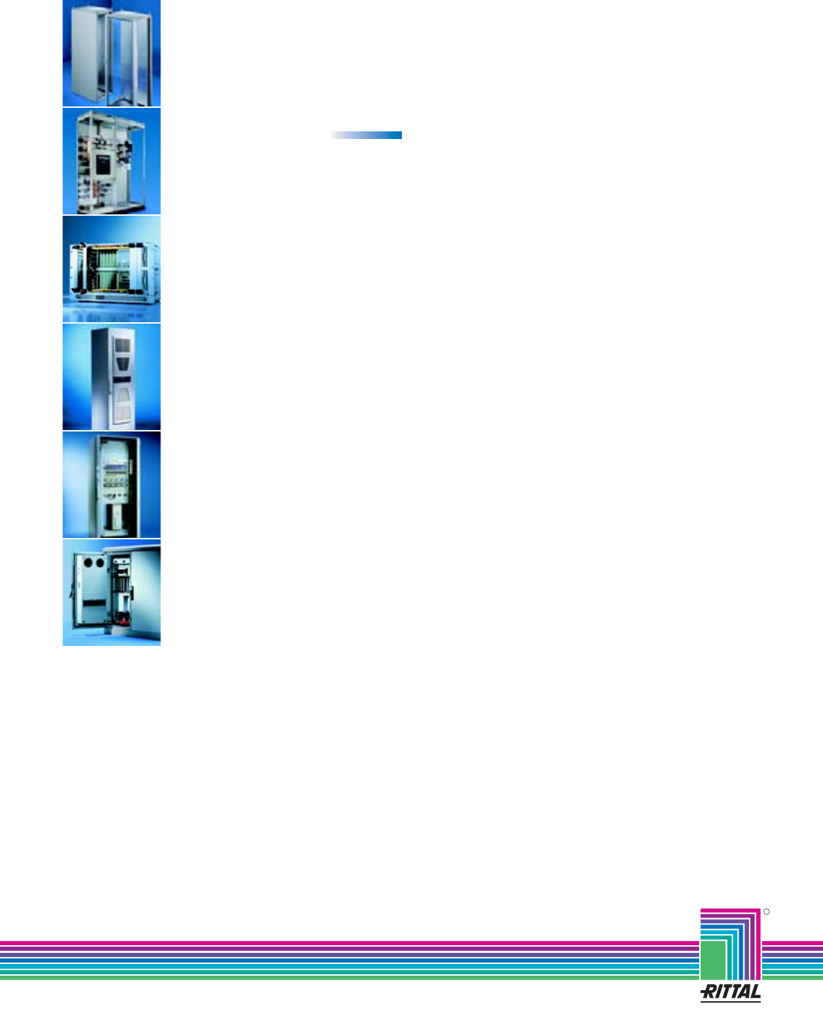
PLS busbar support
up to 1400 A, 4-pole
Model No. SV 9342.004
60 mm bar centre distance,
for PLS special busbar 1400 A.
Settings IRMS (Ieff.) of the test equipment with-
out prefuse:
Busbar
mm
Support
spacing
mm
RMS
kA
PLS 1600 150 35
500 25
30
25
20
65
60
55
45
35
40
50
80
75
70
350200 250 300 450400 500 550150
Ip peak short-circuit current [kA]
Busbar support spacing [mm]
R
Switch to perfection
All in all – solutions from Rittal
Rittal has one of the largest ranges of enclosures available
for immediate delivery. However, Rittal also supplies inte-
grated solutions – up to Level 4. This comprises mechanical
installation, power supply, electronic components, climate
control and central monitoring. For all of your requirements.
Fully assembled and functional. Wherever in the world you
develop and implement solutions for yourself and your
customers, we are close at hand. The global alliance
between production, distribution and service guarantees
closeness to the customer. Worldwide!
02/09 E480
Busbar systems RiLine60
Busbar systems 40/100/150/185 mm
Ri4Power low-voltage distribution systems
Electronic Packaging
IT Solutions
Communication Systems
System Climate Control
Power Distribution
Industrial Enclosures
Rittal GmbH & Co. KG Postfach 1662 D-35726 Herborn
Telephone: +49(0)2772 505-0 Telefax: +49(0)2772 505-2319 eMail: info@rittal.de www.rittal.com
