Intel(R) 64 And IA 32 Architectures Software Developer's Manual, Volume 2B 253667 Intel64 Archtectures Developers Manual Insruction Set Reference, N Z
253667-Intel64%20and%20IA-32%20Archtectures%20Software%20Developers%20Manual-Volume%202B-Insruction%20Set%20Reference%2C%20N-Z
User Manual: Pdf
Open the PDF directly: View PDF ![]() .
.
Page Count: 796 [warning: Documents this large are best viewed by clicking the View PDF Link!]
- Chapter 4 Instruction Set Reference, N-Z
- 4.1 Imm8 Control Byte Operation for PCMPESTRI / PCMPESTRM / PCMPISTRI / PCMPISTRM
- 4.2 Instructions (N-Z)
- NEG-Two's Complement Negation
- NOP-No Operation
- NOT-One's Complement Negation
- OR-Logical Inclusive OR
- ORPD-Bitwise Logical OR of Double-Precision Floating-Point Values
- ORPS-Bitwise Logical OR of Single-Precision Floating-Point Values
- OUT-Output to Port
- OUTS/OUTSB/OUTSW/OUTSD-Output String to Port
- PABSB/PABSW/PABSD - Packed Absolute Value
- PACKSSWB/PACKSSDW-Pack with Signed Saturation
- PACKUSDW - Pack with Unsigned Saturation
- PACKUSWB-Pack with Unsigned Saturation
- PADDB/PADDW/PADDD-Add Packed Integers
- PADDQ-Add Packed Quadword Integers
- PADDSB/PADDSW-Add Packed Signed Integers with Signed Saturation
- PADDUSB/PADDUSW-Add Packed Unsigned Integers with Unsigned Saturation
- PALIGNR - Packed Align Right
- PAND-Logical AND
- PANDN-Logical AND NOT
- PAUSE-Spin Loop Hint
- PAVGB/PAVGW-Average Packed Integers
- PBLENDVB - Variable Blend Packed Bytes
- PBLENDW - Blend Packed Words
- PCLMULQDQ - Carry-Less Multiplication Quadword
- PCMPEQB/PCMPEQW/PCMPEQD- Compare Packed Data for Equal
- PCMPEQQ - Compare Packed Qword Data for Equal
- PCMPESTRI - Packed Compare Explicit Length Strings, Return Index
- PCMPESTRM - Packed Compare Explicit Length Strings, Return Mask
- PCMPGTB/PCMPGTW/PCMPGTD-Compare Packed Signed Integers for Greater Than
- PCMPGTQ - Compare Packed Data for Greater Than
- PCMPISTRI - Packed Compare Implicit Length Strings, Return Index
- PCMPISTRM - Packed Compare Implicit Length Strings, Return Mask
- VPERMILPD - Permute Double-Precision Floating-Point Values
- VPERMILPS - Permute Single-Precision Floating-Point Values
- VPERM2F128 - Permute Floating-Point Values
- PEXTRB/PEXTRD/PEXTRQ - Extract Byte/Dword/Qword
- PEXTRW-Extract Word
- PHADDW/PHADDD - Packed Horizontal Add
- PHADDSW - Packed Horizontal Add and Saturate
- PHMINPOSUW - Packed Horizontal Word Minimum
- PHSUBW/PHSUBD - Packed Horizontal Subtract
- PHSUBSW - Packed Horizontal Subtract and Saturate
- PINSRB/PINSRD/PINSRQ - Insert Byte/Dword/Qword
- PINSRW-Insert Word
- PMADDUBSW - Multiply and Add Packed Signed and Unsigned Bytes
- PMADDWD-Multiply and Add Packed Integers
- PMAXSB - Maximum of Packed Signed Byte Integers
- PMAXSD - Maximum of Packed Signed Dword Integers
- PMAXSW-Maximum of Packed Signed Word Integers
- PMAXUB-Maximum of Packed Unsigned Byte Integers
- PMAXUD - Maximum of Packed Unsigned Dword Integers
- PMAXUW - Maximum of Packed Word Integers
- PMINSB - Minimum of Packed Signed Byte Integers
- PMINSD - Minimum of Packed Dword Integers
- PMINSW-Minimum of Packed Signed Word Integers
- PMINUB-Minimum of Packed Unsigned Byte Integers
- PMINUD - Minimum of Packed Dword Integers
- PMINUW - Minimum of Packed Word Integers
- PMOVMSKB-Move Byte Mask
- PMOVSX - Packed Move with Sign Extend
- PMOVZX - Packed Move with Zero Extend
- PMULDQ - Multiply Packed Signed Dword Integers
- PMULHRSW - Packed Multiply High with Round and Scale
- PMULHUW-Multiply Packed Unsigned Integers and Store High Result
- PMULHW-Multiply Packed Signed Integers and Store High Result
- PMULLD - Multiply Packed Signed Dword Integers and Store Low Result
- PMULLW-Multiply Packed Signed Integers and Store Low Result
- PMULUDQ-Multiply Packed Unsigned Doubleword Integers
- POP-Pop a Value from the Stack
- POPA/POPAD-Pop All General-Purpose Registers
- POPCNT - Return the Count of Number of Bits Set to 1
- POPF/POPFD/POPFQ-Pop Stack into EFLAGS Register
- POR-Bitwise Logical OR
- PREFETCHh-Prefetch Data Into Caches
- PSADBW-Compute Sum of Absolute Differences
- PSHUFB - Packed Shuffle Bytes
- PSHUFD-Shuffle Packed Doublewords
- PSHUFHW-Shuffle Packed High Words
- PSHUFLW-Shuffle Packed Low Words
- PSHUFW-Shuffle Packed Words
- PSIGNB/PSIGNW/PSIGND - Packed SIGN
- PSLLDQ-Shift Double Quadword Left Logical
- PSLLW/PSLLD/PSLLQ-Shift Packed Data Left Logical
- PSRAW/PSRAD-Shift Packed Data Right Arithmetic
- PSRLDQ-Shift Double Quadword Right Logical
- PSRLW/PSRLD/PSRLQ-Shift Packed Data Right Logical
- PSUBB/PSUBW/PSUBD-Subtract Packed Integers
- PSUBQ-Subtract Packed Quadword Integers
- PSUBSB/PSUBSW-Subtract Packed Signed Integers with Signed Saturation
- PSUBUSB/PSUBUSW-Subtract Packed Unsigned Integers with Unsigned Saturation
- PTEST- Logical Compare
- PUNPCKHBW/PUNPCKHWD/PUNPCKHDQ/PUNPCKHQDQ- Unpack High Data
- PUNPCKLBW/PUNPCKLWD/PUNPCKLDQ/PUNPCKLQDQ- Unpack Low Data
- PUSH-Push Word, Doubleword or Quadword Onto the Stack
- PUSHA/PUSHAD-Push All General-Purpose Registers
- PUSHF/PUSHFD-Push EFLAGS Register onto the Stack
- PXOR-Logical Exclusive OR
- RCL/RCR/ROL/ROR--Rotate
- RCPPS-Compute Reciprocals of Packed Single-Precision Floating- Point Values
- RCPSS-Compute Reciprocal of Scalar Single-Precision Floating-Point Values
- RDMSR-Read from Model Specific Register
- RDPMC-Read Performance-Monitoring Counters
- RDTSC-Read Time-Stamp Counter
- RDTSCP-Read Time-Stamp Counter and Processor ID
- REP/REPE/REPZ/REPNE/REPNZ-Repeat String Operation Prefix
- RET-Return from Procedure
- ROUNDPD - Round Packed Double Precision Floating-Point Values
- ROUNDPS - Round Packed Single Precision Floating-Point Values
- ROUNDSD - Round Scalar Double Precision Floating-Point Values
- ROUNDSS - Round Scalar Single Precision Floating-Point Values
- RSM-Resume from System Management Mode
- RSQRTPS-Compute Reciprocals of Square Roots of Packed Single- Precision Floating-Point Values
- RSQRTSS-Compute Reciprocal of Square Root of Scalar Single- Precision Floating-Point Value
- SAHF-Store AH into Flags
- SAL/SAR/SHL/SHR-Shift
- SBB-Integer Subtraction with Borrow
- SCAS/SCASB/SCASW/SCASD-Scan String
- SETcc-Set Byte on Condition
- SFENCE-Store Fence
- SGDT-Store Global Descriptor Table Register
- SHLD-Double Precision Shift Left
- SHRD-Double Precision Shift Right
- SHUFPD-Shuffle Packed Double-Precision Floating-Point Values
- SHUFPS-Shuffle Packed Single-Precision Floating-Point Values
- SIDT-Store Interrupt Descriptor Table Register
- SLDT-Store Local Descriptor Table Register
- SMSW-Store Machine Status Word
- SQRTPD-Compute Square Roots of Packed Double-Precision Floating- Point Values
- SQRTPS-Compute Square Roots of Packed Single-Precision Floating- Point Values
- SQRTSD-Compute Square Root of Scalar Double-Precision Floating- Point Value
- SQRTSS-Compute Square Root of Scalar Single-Precision Floating- Point Value
- VSTMXCSR-Store MXCSR Register State
- STC-Set Carry Flag
- STD-Set Direction Flag
- STI-Set Interrupt Flag
- STMXCSR-Store MXCSR Register State
- STOS/STOSB/STOSW/STOSD/STOSQ-Store String
- STR-Store Task Register
- SUB-Subtract
- SUBPD-Subtract Packed Double-Precision Floating-Point Values
- SUBPS-Subtract Packed Single-Precision Floating-Point Values
- SUBSD-Subtract Scalar Double-Precision Floating-Point Values
- SUBSS-Subtract Scalar Single-Precision Floating-Point Values
- SWAPGS-Swap GS Base Register
- SYSCALL-Fast System Call
- SYSENTER-Fast System Call
- SYSEXIT-Fast Return from Fast System Call
- SYSRET-Return From Fast System Call
- TEST-Logical Compare
- VTESTPD/VTESTPS-Packed Bit Test
- UCOMISD-Unordered Compare Scalar Double-Precision Floating-Point Values and Set EFLAGS
- UCOMISS-Unordered Compare Scalar Single-Precision Floating-Point Values and Set EFLAGS
- UD2-Undefined Instruction
- UNPCKHPD-Unpack and Interleave High Packed Double-Precision Floating-Point Values
- UNPCKHPS-Unpack and Interleave High Packed Single-Precision Floating-Point Values
- UNPCKLPD-Unpack and Interleave Low Packed Double-Precision Floating-Point Values
- UNPCKLPS-Unpack and Interleave Low Packed Single-Precision Floating-Point Values
- VERR/VERW-Verify a Segment for Reading or Writing
- WAIT/FWAIT-Wait
- WBINVD-Write Back and Invalidate Cache
- WRMSR-Write to Model Specific Register
- XADD-Exchange and Add
- XCHG-Exchange Register/Memory with Register
- XGETBV-Get Value of Extended Control Register
- XLAT/XLATB-Table Look-up Translation
- XOR-Logical Exclusive OR
- XORPD-Bitwise Logical XOR for Double-Precision Floating-Point Values
- XORPS-Bitwise Logical XOR for Single-Precision Floating-Point Values
- XRSTOR-Restore Processor Extended States
- XSAVE-Save Processor Extended States
- XSAVEOPT-Save Processor Extended States Optimized
- XSETBV-Set Extended Control Register
- VZEROALL-Zero All YMM Registers
- VZEROUPPER-Zero Upper Bits of YMM Registers
- Chapter 5 VMX Instruction Reference
- 5.1 Overview
- 5.2 Conventions
- 5.3 VMX Instructions
- INVEPT- Invalidate Translations Derived from EPT
- INVVPID- Invalidate Translations Based on VPID
- VMCALL-Call to VM Monitor
- VMCLEAR-Clear Virtual-Machine Control Structure
- VMLAUNCH/VMRESUME-Launch/Resume Virtual Machine
- VMPTRLD-Load Pointer to Virtual-Machine Control Structure
- VMPTRST-Store Pointer to Virtual-Machine Control Structure
- VMREAD-Read Field from Virtual-Machine Control Structure
- VMRESUME-Resume Virtual Machine
- VMWRITE-Write Field to Virtual-Machine Control Structure
- VMXOFF-Leave VMX Operation
- VMXON-Enter VMX Operation
- 5.4 VM Instruction Error Numbers
- Chapter 6 Safer Mode Extensions Reference
- 6.1 Overview
- 6.2 SMX Functionality
- 6.3 GETSEC Leaf Functions
- GETSEC[CAPABILITIES] - Report the SMX Capabilities
- GETSEC[ENTERACCS] - Execute Authenticated Chipset Code
- GETSEC[EXITAC]-Exit Authenticated Code Execution Mode
- GETSEC[SENTER]-Enter a Measured Environment
- GETSEC[SEXIT]-Exit Measured Environment
- GETSEC[PARAMETERS]-Report the SMX Parameters
- GETSEC[SMCTRL]-SMX Mode Control
- GETSEC[WAKEUP]-Wake up sleeping processors in measured environment
- Appendix A Opcode Map
- A.1 Using Opcode Tables
- A.2 Key to Abbreviations
- A.3 One, Two, and THREE-Byte Opcode Maps
- A.4 Opcode Extensions For One-Byte And Two- byte Opcodes
- A.5 Escape Opcode Instructions
- A.5.1 Opcode Look-up Examples for Escape Instruction Opcodes
- A.5.2 Escape Opcode Instruction Tables
- A.5.2.1 Escape Opcodes with D8 as First Byte
- A.5.2.2 Escape Opcodes with D9 as First Byte
- A.5.2.3 Escape Opcodes with DA as First Byte
- A.5.2.4 Escape Opcodes with DB as First Byte
- A.5.2.5 Escape Opcodes with DC as First Byte
- A.5.2.6 Escape Opcodes with DD as First Byte
- A.5.2.7 Escape Opcodes with DE as First Byte
- A.5.2.8 Escape Opcodes with DF As First Byte
- Appendix B Instruction Formats and Encodings
- B.1 Machine Instruction Format
- B.2 General-Purpose Instruction Formats and Encodings for Non-64-Bit Modes
- B.3 Pentium® Processor Family Instruction Formats and Encodings
- B.4 64-bit Mode Instruction Encodings for SIMD Instruction Extensions
- B.5 MMX Instruction Formats and Encodings
- B.6 Processor ExtendeD State INstruction Formats and EncodIngs
- B.7 P6 Family INstruction Formats and Encodings
- B.8 SSE Instruction Formats and Encodings
- B.9 SSE2 Instruction Formats and Encodings
- B.10 SSE3 Formats and Encodings Table
- B.11 SSsE3 Formats and Encoding Table
- B.12 AESNI and PCLMULQDQ INstruction Formats and Encodings
- B.13 Special Encodings for 64-Bit Mode
- B.14 SSE4.1 Formats and Encoding Table
- B.15 SSE4.2 Formats and Encoding Table
- B.16 Floating-Point Instruction Formats and Encodings
- B.17 VMX Instructions
- B.18 SMX Instructions
- Appendix C Intel® C/C++ Compiler Intrinsics and Functional Equivalents

Intel® 64 and IA-32
Architectures
Software Developer’s Manual
Volume 2B:
Instruction Set Reference, N-Z
NOTE: The Intel 64 and IA-32 Architectures Software
Developer's Manual consists of five volumes: Basic Architecture,
Order Number 253665; Instruction Set Reference A-M, Order
Number 253666; Instruction Set Reference N-Z, Order Number
253667; System Programming Guide, Part 1, Order Number
253668; System Programming Guide, Part 2, Order Number
253669. Refer to all five volumes when evaluating your design
needs.
Order Number: 253667-037US
January 2011

ii Vol. 3B
INFORMATION IN THIS DOCUMENT IS PROVIDED IN CONNECTION WITH INTEL PRODUCTS. NO LICENSE,
EXPRESS OR IMPLIED, BY ESTOPPEL OR OTHERWISE, TO ANY INTELLECTUAL PROPERTY RIGHTS IS GRANT-
ED BY THIS DOCUMENT. EXCEPT AS PROVIDED IN INTEL'S TERMS AND CONDITIONS OF SALE FOR SUCH
PRODUCTS, INTEL ASSUMES NO LIABILITY WHATSOEVER AND INTEL DISCLAIMS ANY EXPRESS OR IMPLIED
WARRANTY, RELATING TO SALE AND/OR USE OF INTEL PRODUCTS INCLUDING LIABILITY OR WARRANTIES
RELATING TO FITNESS FOR A PARTICULAR PURPOSE, MERCHANTABILITY, OR INFRINGEMENT OF ANY
PATENT, COPYRIGHT OR OTHER INTELLECTUAL PROPERTY RIGHT.
UNLESS OTHERWISE AGREED IN WRITING BY INTEL, THE INTEL PRODUCTS ARE NOT DESIGNED NOR IN-
TENDED FOR ANY APPLICATION IN WHICH THE FAILURE OF THE INTEL PRODUCT COULD CREATE A SITUA-
TION WHERE PERSONAL INJURY OR DEATH MAY OCCUR.
Intel may make changes to specifications and product descriptions at any time, without notice. Designers
must not rely on the absence or characteristics of any features or instructions marked "reserved" or "unde-
fined." Intel reserves these for future definition and shall have no responsibility whatsoever for conflicts or
incompatibilities arising from future changes to them. The information here is subject to change without no-
tice. Do not finalize a design with this information.
The Intel® 64 architecture processors may contain design defects or errors known as errata. Current char-
acterized errata are available on request.
Intel® Hyper-Threading Technology requires a computer system with an Intel® processor supporting Hyper-
Threading Technology and an Intel® HT Technology enabled chipset, BIOS and operating system.
Performance will vary depending on the specific hardware and software you use. For more information, see
http://www.intel.com/technology/hyperthread/index.htm; including details on which processors support Intel HT
Technology.
Intel® Virtualization Technology requires a computer system with an enabled Intel® processor, BIOS, virtual
machine monitor (VMM) and for some uses, certain platform software enabled for it. Functionality, perfor-
mance or other benefits will vary depending on hardware and software configurations. Intel® Virtualization
Technology-enabled BIOS and VMM applications are currently in development.
64-bit computing on Intel architecture requires a computer system with a processor, chipset, BIOS, oper-
ating system, device drivers and applications enabled for Intel® 64 architecture. Processors will not operate
(including 32-bit operation) without an Intel® 64 architecture-enabled BIOS. Performance will vary de-
pending on your hardware and software configurations. Consult with your system vendor for more infor-
mation.
Enabling Execute Disable Bit functionality requires a PC with a processor with Execute Disable Bit capability
and a supporting operating system. Check with your PC manufacturer on whether your system delivers Ex-
ecute Disable Bit functionality.
Intel, Pentium, Intel Xeon, Intel NetBurst, Intel Core, Intel Core Solo, Intel Core Duo, Intel Core 2 Duo,
Intel Core 2 Extreme, Intel Pentium D, Itanium, Intel SpeedStep, MMX, Intel Atom, and VTune are trade-
marks or registered trademarks of Intel Corporation or its subsidiaries in the United States and other coun-
tries.
*Other names and brands may be claimed as the property of others.
Contact your local Intel sales office or your distributor to obtain the latest specifications and before placing
your product order.
Copies of documents which have an ordering number and are referenced in this document, or other Intel
literature, may be obtained by calling 1-800-548-4725, or by visiting Intel’s website at http://www.intel.com
Copyright © 1997-2011 Intel Corporation

Vol. 2B 4-1
CHAPTER 4
INSTRUCTION SET REFERENCE, N-Z
4.1 IMM8 CONTROL BYTE OPERATION FOR PCMPESTRI /
PCMPESTRM / PCMPISTRI / PCMPISTRM
The notations introduced in this section are referenced in the reference pages of
PCMPESTRI, PCMPESTRM, PCMPISTRI, PCMPISTRM. The operation of the immediate
control byte is common to these four string text processing instructions of SSE4.2.
This section describes the common operations.
4.1.1 General Description
The operation of PCMPESTRI, PCMPESTRM, PCMPISTRI, PCMPISTRM is defined by
the combination of the respective opcode and the interpretation of an immediate
control byte that is part of the instruction encoding.
The opcode controls the relationship of input bytes/words to each other (determines
whether the inputs terminated strings or whether lengths are expressed explicitly) as
well as the desired output (index or mask).
The Imm8 Control Byte for PCMPESTRM/PCMPESTRI/PCMPISTRM/PCMPISTRI
encodes a significant amount of programmable control over the functionality of those
instructions. Some functionality is unique to each instruction while some is common
across some or all of the four instructions. This section describes functionality which
is common across the four instructions.
The arithmetic flags (ZF, CF, SF, OF, AF, PF) are set as a result of these instructions.
However, the meanings of the flags have been overloaded from their typical mean-
ings in order to provide additional information regarding the relationships of the two
inputs.
PCMPxSTRx instructions perform arithmetic comparisons between all possible pairs
of bytes or words, one from each packed input source operand. The boolean results
of those comparisons are then aggregated in order to produce meaningful results.
The Imm8 Control Byte is used to affect the interpretation of individual input
elements as well as control the arithmetic comparisons used and the specific aggre-
gation scheme.
Specifically, the Imm8 Control Byte consists of bit fields that control the following
attributes:
•Source data format — Byte/word data element granularity, signed or unsigned
elements

4-2 Vol. 2B
INSTRUCTION SET REFERENCE, N-Z
•Aggregation operation — Encodes the mode of per-element comparison
operation and the aggregation of per-element comparisons into an intermediate
result
•Polarity — Specifies intermediate processing to be performed on the interme-
diate result
•Output selection — Specifies final operation to produce the output (depending
on index or mask) from the intermediate result
4.1.2 Source Data Format
If the Imm8 Control Byte has bit[0] cleared, each source contains 16 packed bytes.
If the bit is set each source contains 8 packed words. If the Imm8 Control Byte has
bit[1] cleared, each input contains unsigned data. If the bit is set each source
contains signed data.
Table 4-1. Source Data Format
Imm8[1:0] Meaning Description
00b Unsigned bytes Both 128-bit sources are treated as packed, unsigned
bytes.
01b Unsigned words Both 128-bit sources are treated as packed, unsigned
words.
10b Signed bytes Both 128-bit sources are treated as packed, signed bytes.
11b Signed words Both 128-bit sources are treated as packed, signed words.

Vol. 2B 4-3
INSTRUCTION SET REFERENCE, N-Z
4.1.3 Aggregation Operation
All 256 (64) possible comparisons are always performed. The individual Boolean
results of those comparisons are referred by “BoolRes[Reg/Mem element index, Reg
element index].” Comparisons evaluating to “True” are represented with a 1, False
with a 0 (positive logic). The initial results are then aggregated into a 16-bit (8-bit)
intermediate result (IntRes1) using one of the modes described in the table below, as
determined by Imm8 Control Byte bit[3:2].
See Section 4.1.6 for a description of the overrideIfDataInvalid() function used in
Table 4-3.
Table 4-2. Aggregation Operation
Imm8[3:2] Mode Comparison
00b Equal any The arithmetic comparison is “equal.”
01b Ranges Arithmetic comparison is “greater than or equal” between
even indexed bytes/words of reg and each byte/word of
reg/mem.
Arithmetic comparison is “less than or equal” between odd
indexed bytes/words of reg and each byte/word of reg/mem.
(reg/mem[m] >= reg[n] for n = even, reg/mem[m] <= reg[n]
for n = odd)
10b Equal each The arithmetic comparison is “equal.”
11b Equal ordered The arithmetic comparison is “equal.”
Table 4-3. Aggregation Operation
Mode Pseudocode
Equal any
(find characters from a set)
UpperBound = imm8[0] ? 7 : 15;
IntRes1 = 0;
For j = 0 to UpperBound, j++
For i = 0 to UpperBound, i++
IntRes1[j] OR= overrideIfDataInvalid(BoolRes[j,i])

4-4 Vol. 2B
INSTRUCTION SET REFERENCE, N-Z
4.1.4 Polarity
IntRes1 may then be further modified by performing a 1’s compliment, according to
the value of the Imm8 Control Byte bit[4]. Optionally, a mask may be used such that
only those IntRes1 bits which correspond to “valid” reg/mem input elements are
complimented (note that the definition of a valid input element is dependant on the
specific opcode and is defined in each opcode’s description). The result of the
possible negation is referred to as IntRes2.
Ranges
(find characters from ranges)
UpperBound = imm8[0] ? 7 : 15;
IntRes1 = 0;
For j = 0 to UpperBound, j++
For i = 0 to UpperBound, i+=2
IntRes1[j] OR= (overrideIfDataInvalid(BoolRes[j,i]) AND
overrideIfDataInvalid(BoolRes[j,i+1]))
Equal each
(string compare)
UpperBound = imm8[0] ? 7 : 15;
IntRes1 = 0;
For i = 0 to UpperBound, i++
IntRes1[i] = overrideIfDataInvalid(BoolRes[i,i])
Equal ordered
(substring search)
UpperBound = imm8[0] ? 7 :15;
IntRes1 = imm8[0] ? 0xFF : 0xFFFF
For j = 0 to UpperBound, j++
For i = 0 to UpperBound-j, k=j to UpperBound, k++, i++
IntRes1[j] AND= overrideIfDataInvalid(BoolRes[k,i])
Table 4-4. Polarity
Imm8[5:4] Operation Description
00b Positive Polarity (+) IntRes2 = IntRes1
01b Negative Polarity (-) IntRes2 = -1 XOR IntRes1
10b Masked (+) IntRes2 = IntRes1
11b Masked (-) IntRes2[i] = IntRes1[i] if reg/mem[i] invalid, else =
~IntRes1[i]
Table 4-3. Aggregation Operation (Contd.)

Vol. 2B 4-5
INSTRUCTION SET REFERENCE, N-Z
4.1.5 Output Selection
For PCMPESTRI/PCMPISTRI, the Imm8 Control Byte bit[6] is used to determine if the
index is of the least significant or most significant bit of IntRes2.
Specifically for PCMPESTRM/PCMPISTRM, the Imm8 Control Byte bit[6] is used to
determine if the mask is a 16 (8) bit mask or a 128 bit byte/word mask.
4.1.6 Valid/Invalid Override of Comparisons
PCMPxSTRx instructions allow for the possibility that an end-of-string (EOS) situation
may occur within the 128-bit packed data value (see the instruction descriptions
below for details). Any data elements on either source that are determined to be past
the EOS are considered to be invalid, and the treatment of invalid data within a
comparison pair varies depending on the aggregation function being performed.
In general, the individual comparison result for each element pair BoolRes[i.j] can be
forced true or false if one or more elements in the pair are invalid. See Table 4-7.
Table 4-5. Ouput Selection
Imm8[6] Operation Description
0b Least significant index The index returned to ECX is of the least significant set bit in
IntRes2.
1b Most significant index The index returned to ECX is of the most significant set bit in
IntRes2.
Table 4-6. Output Selection
Imm8[6] Operation Description
0b Bit mask IntRes2 is returned as the mask to the least significant bits of
XMM0 with zero extension to 128 bits.
1b Byte/word mask IntRes2 is expanded into a byte/word mask (based on imm8[1])
and placed in XMM0. The expansion is performed by replicating
each bit into all of the bits of the byte/word of the same index.
Table 4-7. Comparison Result for Each Element Pair BoolRes[i.j]
xmm1
byte/ word
xmm2/
m128
byte/word
Imm8[3:2] =
00b
(equal any)
Imm8[3:2] =
01b
(ranges)
Imm8[3:2] =
10b
(equal each)
Imm8[3:2] = 11b
(equal ordered)
Invalid Invalid Force false Force false Force true Force true
Invalid Valid Force false Force false Force false Force true

4-6 Vol. 2B
INSTRUCTION SET REFERENCE, N-Z
4.1.7 Summary of Im8 Control byte
Valid Invalid Force false Force false Force false Force false
Valid Valid Do not force Do not force Do not force Do not force
Table 4-8. Summary of Imm8 Control Byte
Imm8 Description
-------0b 128-bit sources treated as 16 packed bytes.
-------1b 128-bit sources treated as 8 packed words.
------0-b Packed bytes/words are unsigned.
------1-b Packed bytes/words are signed.
----00--b Mode is equal any.
----01--b Mode is ranges.
----10--b Mode is equal each.
----11--b Mode is equal ordered.
---0----b IntRes1 is unmodified.
---1----b IntRes1 is negated (1’s compliment).
--0-----b Negation of IntRes1 is for all 16 (8) bits.
--1-----b Negation of IntRes1 is masked by reg/mem validity.
-0------b Index of the least significant, set, bit is used (regardless of corresponding
input element validity).
IntRes2 is returned in least significant bits of XMM0.
-1------b Index of the most significant, set, bit is used (regardless of corresponding
input element validity).
Each bit of IntRes2 is expanded to byte/word.
0-------b This bit currently has no defined effect, should be 0.
1-------b This bit currently has no defined effect, should be 0.
Table 4-7. Comparison Result for Each Element Pair BoolRes[i.j]
Vol. 2B 4-7
INSTRUCTION SET REFERENCE, N-Z
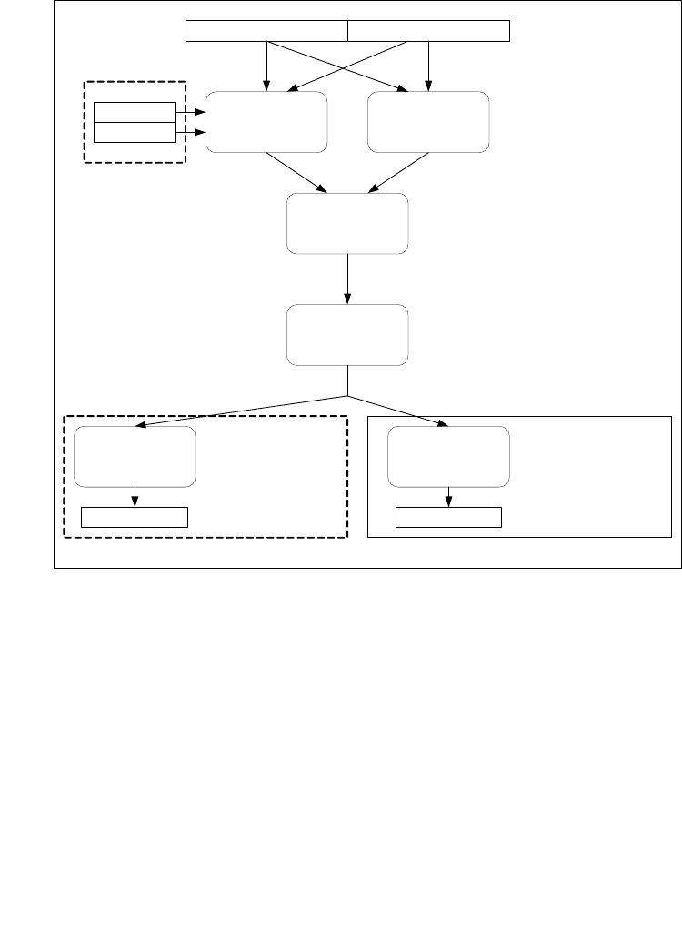
4.1.8 Diagram Comparison and Aggregation Process
4.2 INSTRUCTIONS (N-Z)
Chapter 4 continues an alphabetical discussion of Intel® 64 and IA-32 instructions
(N-Z). See also: Chapter 3, “Instruction Set Reference, A-M,” in the Intel® 64 and
IA-32 Architectures Software Developer’s Manual, Volume 2A.
Figure 4-1. Operation of PCMPSTRx and PCMPESTRx
PCMP*STRM onlyPCMP*STRI only
String A (xmm1) String B (xmm2/mem)
Compare all pairs of
(A
i
, B
j
)
Determine end -of-
string and mark
invalid elements
PCMPESTR* only
EAX/RAX
EDX/RDX
Aggregation function
BoolRes[i,j]
Optional boolean
negation
IntRes1
Generate index
IntRes2
Generate mask
imm8[1:0] =
00B: unsigned byte compares
01B: unsigned word compares
10B: signed byte compares
11B: signed word compares
imm8[3:2] =
00B: Equal any
01B: Ranges
10B: Equal each
11B: Equal ordered
imm8[6:5] =
x0B: don’t negate IntRes1
01B: negate all bits of IntRes1
11B: negate only bits of IntRes1
corresponding to valid
elements in String B
imm8[6] =
0: Return zero-extended IntRes2
1: expand IntRes2 to byte (word)
mask
imm8[6] =
0: index encodes least signifi-
cant true bit of IntRes 2
1: index encodes most signifi-
cant true bit of IntRes 2
ECX(RCX) XMM0

4-8 Vol. 2B NEG—Two's Complement Negation
INSTRUCTION SET REFERENCE, N-Z
NEG—Two's Complement Negation
Instruction Operand Encoding
Description
Replaces the value of operand (the destination operand) with its two's complement.
(This operation is equivalent to subtracting the operand from 0.) The destination
operand is located in a general-purpose register or a memory location.
This instruction can be used with a LOCK prefix to allow the instruction to be
executed atomically.
In 64-bit mode, the instruction’s default operation size is 32 bits. Using a REX prefix
in the form of REX.R permits access to additional registers (R8-R15). Using a REX
prefix in the form of REX.W promotes operation to 64 bits. See the summary chart at
the beginning of this section for encoding data and limits.
Operation
IF DEST = 0
THEN CF ← 0;
ELSE CF ← 1;
FI;
DEST ← [– (DEST)]
Opcode Instruction Op/
En
64-Bit
Mode
Compat/
Leg Mode
Description
F6 /3 NEG r/m8 A Valid Valid Two's complement negate
r/m8.
REX + F6 /3 NEG r/m8* A Valid N.E. Two's complement negate
r/m8.
F7 /3 NEG r/m16 A Valid Valid Two's complement negate
r/m16.
F7 /3 NEG r/m32 A Valid Valid Two's complement negate
r/m32.
REX.W + F7 /3 NEG r/m64 A Valid N.E. Two's complement negate
r/m64.
NOTES:
* In 64-bit mode, r/m8 can not be encoded to access the following byte registers if a REX prefix is
used: AH, BH, CH, DH.
Op/En Operand 1 Operand 2 Operand 3 Operand 4
A ModRM:r/m (r, w) NA NA NA

Vol. 2B 4-9
INSTRUCTION SET REFERENCE, N-Z
NEG—Two's Complement Negation
Flags Affected
The CF flag set to 0 if the source operand is 0; otherwise it is set to 1. The OF, SF, ZF,
AF, and PF flags are set according to the result.
Protected Mode Exceptions
#GP(0) If the destination is located in a non-writable segment.
If a memory operand effective address is outside the CS, DS,
ES, FS, or GS segment limit.
If the DS, ES, FS, or GS register contains a NULL segment
selector.
#SS(0) If a memory operand effective address is outside the SS
segment limit.
#PF(fault-code) If a page fault occurs.
#AC(0) If alignment checking is enabled and an unaligned memory
reference is made while the current privilege level is 3.
#UD If the LOCK prefix is used but the destination is not a memory
operand.
Real-Address Mode Exceptions
#GP If a memory operand effective address is outside the CS, DS,
ES, FS, or GS segment limit.
#SS If a memory operand effective address is outside the SS
segment limit.
#UD If the LOCK prefix is used but the destination is not a memory
operand.
Virtual-8086 Mode Exceptions
#GP(0) If a memory operand effective address is outside the CS, DS,
ES, FS, or GS segment limit.
#SS(0) If a memory operand effective address is outside the SS
segment limit.
#PF(fault-code) If a page fault occurs.
#AC(0) If alignment checking is enabled and an unaligned memory
reference is made.
#UD If the LOCK prefix is used but the destination is not a memory
operand.
Compatibility Mode Exceptions
Same as for protected mode exceptions.

4-10 Vol. 2B NEG—Two's Complement Negation
INSTRUCTION SET REFERENCE, N-Z
64-Bit Mode Exceptions
#SS(0) If a memory address referencing the SS segment is in a non-
canonical form.
#GP(0) If the memory address is in a non-canonical form.
#PF(fault-code) For a page fault.
#AC(0) If alignment checking is enabled and an unaligned memory
reference is made while the current privilege level is 3.
#UD If the LOCK prefix is used but the destination is not a memory
operand.

Vol. 2B 4-11
INSTRUCTION SET REFERENCE, N-Z
NOP—No Operation
NOP—No Operation
Instruction Operand Encoding
Description
This instruction performs no operation. It is a one-byte or multi-byte NOP that takes
up space in the instruction stream but does not impact machine context, except for
the EIP register.
The multi-byte form of NOP is available on processors with model encoding:
•CPUID.01H.EAX[Bytes 11:8] = 0110B or 1111B
The multi-byte NOP instruction does not alter the content of a register and will not
issue a memory operation. The instruction’s operation is the same in non-64-bit
modes and 64-bit mode.
Operation
The one-byte NOP instruction is an alias mnemonic for the XCHG (E)AX, (E)AX
instruction.
The multi-byte NOP instruction performs no operation on supported processors and
generates undefined opcode exception on processors that do not support the multi-
byte NOP instruction.
The memory operand form of the instruction allows software to create a byte
sequence of “no operation” as one instruction. For situations where multiple-byte
NOPs are needed, the recommended operations (32-bit mode and 64-bit mode) are:
Opcode Instruction Op/
En
64-Bit
Mode
Compat/
Leg Mode
Description
90 NOP A Valid Valid One byte no-operation
instruction.
0F 1F /0 NOP r/m16 B Valid Valid Multi-byte no-operation
instruction.
0F 1F /0 NOP r/m32 B Valid Valid Multi-byte no-operation
instruction.
Op/En Operand 1 Operand 2 Operand 3 Operand 4
ANA NA NA NA
B ModRM:r/m (r) NA NA NA

4-12 Vol. 2B NOP—No Operation
INSTRUCTION SET REFERENCE, N-Z
Flags Affected
None.
Exceptions (All Operating Modes)
#UD If the LOCK prefix is used.
Table 4-9. Recommended Multi-Byte Sequence of NOP Instruction
Length Assembly Byte Sequence
2 bytes 66 NOP 66 90H
3 bytes NOP DWORD ptr [EAX] 0F 1F 00H
4 bytes NOP DWORD ptr [EAX + 00H] 0F 1F 40 00H
5 bytes NOP DWORD ptr [EAX + EAX*1 + 00H] 0F 1F 44 00 00H
6 bytes 66 NOP DWORD ptr [EAX + EAX*1 + 00H] 66 0F 1F 44 00 00H
7 bytes NOP DWORD ptr [EAX + 00000000H] 0F 1F 80 00 00 00 00H
8 bytes NOP DWORD ptr [EAX + EAX*1 + 00000000H] 0F 1F 84 00 00 00 00 00H
9 bytes 66 NOP DWORD ptr [EAX + EAX*1 +
00000000H]
66 0F 1F 84 00 00 00 00
00H

Vol. 2B 4-13
INSTRUCTION SET REFERENCE, N-Z
NOT—One's Complement Negation
NOT—One's Complement Negation
Instruction Operand Encoding
Description
Performs a bitwise NOT operation (each 1 is set to 0, and each 0 is set to 1) on the
destination operand and stores the result in the destination operand location. The
destination operand can be a register or a memory location.
This instruction can be used with a LOCK prefix to allow the instruction to be
executed atomically.
In 64-bit mode, the instruction’s default operation size is 32 bits. Using a REX prefix
in the form of REX.R permits access to additional registers (R8-R15). Using a REX
prefix in the form of REX.W promotes operation to 64 bits. See the summary chart at
the beginning of this section for encoding data and limits.
Operation
DEST ← NOT DEST;
Flags Affected
None.
Protected Mode Exceptions
#GP(0) If the destination operand points to a non-writable segment.
If a memory operand effective address is outside the CS, DS,
ES, FS, or GS segment limit.
Opcode Instruction Op/
En
64-Bit
Mode
Compat/
Leg Mode
Description
F6 /2 NOT r/m8 A Valid Valid Reverse each bit of r/m8.
REX + F6 /2 NOT r/m8* AValid N.E. Reverse each bit of r/m8.
F7 /2 NOT r/m16 A Valid Valid Reverse each bit of r/m16.
F7 /2 NOT r/m32 A Valid Valid Reverse each bit of r/m32.
REX.W + F7 /2 NOT r/m64 AValid N.E. Reverse each bit of r/m64.
NOTES:
* In 64-bit mode, r/m8 can not be encoded to access the following byte registers if a REX prefix is
used: AH, BH, CH, DH.
Op/En Operand 1 Operand 2 Operand 3 Operand 4
A ModRM:r/m (r, w) NA NA NA

4-14 Vol. 2B NOT—One's Complement Negation
INSTRUCTION SET REFERENCE, N-Z
If the DS, ES, FS, or GS register contains a NULL segment
selector.
#SS(0) If a memory operand effective address is outside the SS
segment limit.
#PF(fault-code) If a page fault occurs.
#AC(0) If alignment checking is enabled and an unaligned memory
reference is made while the current privilege level is 3.
#UD If the LOCK prefix is used but the destination is not a memory
operand.
Real-Address Mode Exceptions
#GP If a memory operand effective address is outside the CS, DS,
ES, FS, or GS segment limit.
#SS If a memory operand effective address is outside the SS
segment limit.
#UD If the LOCK prefix is used but the destination is not a memory
operand.
Virtual-8086 Mode Exceptions
#GP(0) If a memory operand effective address is outside the CS, DS,
ES, FS, or GS segment limit.
#SS(0) If a memory operand effective address is outside the SS
segment limit.
#PF(fault-code) If a page fault occurs.
#AC(0) If alignment checking is enabled and an unaligned memory
reference is made.
#UD If the LOCK prefix is used but the destination is not a memory
operand.
Compatibility Mode Exceptions
Same as for protected mode exceptions.
64-Bit Mode Exceptions
#SS(0) If a memory address referencing the SS segment is in a non-
canonical form.
#GP(0) If the memory address is in a non-canonical form.
#PF(fault-code) If a page fault occurs.
#AC(0) If alignment checking is enabled and an unaligned memory
reference is made while the current privilege level is 3.
#UD If the LOCK prefix is used but the destination is not a memory
operand.

Vol. 2B 4-15
INSTRUCTION SET REFERENCE, N-Z
OR—Logical Inclusive OR
OR—Logical Inclusive OR
Opcode Instruction Op/
En
64-Bit
Mode
Compat/
Leg Mode
Description
0C ib OR AL, imm8 AValid Valid AL OR imm8.
0D iw OR AX, imm16 AValid Valid AX OR imm16.
0D id OR EAX, imm32 AValid Valid EAX OR imm32.
REX.W + 0D id OR RAX, imm32 AValid N.E. RAX OR imm32 (sign-
extended).
80 /1 ib OR r/m8, imm8 BValid Valid r/m8 OR imm8.
REX + 80 /1 ib OR r/m8*, imm8 BValid N.E. r/m8 OR imm8.
81 /1 iw OR r/m16, imm16 BValid Valid r/m16 OR imm16.
81 /1 id OR r/m32, imm32 BValid Valid r/m32 OR imm32.
REX.W + 81 /1
id
OR r/m64, imm32 BValid N.E. r/m64 OR imm32 (sign-
extended).
83 /1 ib OR r/m16, imm8 BValid Valid r/m16 OR imm8 (sign-
extended).
83 /1 ib OR r/m32, imm8 BValid Valid r/m32 OR imm8 (sign-
extended).
REX.W + 83 /1
ib
OR r/m64, imm8 BValid N.E. r/m64 OR imm8 (sign-
extended).
08 /rOR r/m8, r8 CV
alid Valid r/m8 OR r8.
REX + 08 /rOR r/m8*, r8* CValid N.E. r/m8 OR r8.
09 /rOR r/m16, r16 CValid Valid r/m16 OR r16.
09 /rOR r/m32, r32 CValid Valid r/m32 OR r32.
REX.W + 09 /rOR r/m64, r64 CValid N.E. r/m64 OR r64.
0A /rOR r8, r/m8 DValid Valid r8 OR r/m8.
REX + 0A /rOR r8*, r/m8* DValid N.E. r8 OR r/m8.
0B /rOR r16, r/m16 DValid Valid r16 OR r/m16.
0B /rOR r32, r/m32 DValid Valid r32 OR r/m32.
REX.W + 0B /rOR r64, r/m64 DValid N.E. r64 OR r/m64.
NOTES:
* In 64-bit mode, r/m8 can not be encoded to access the following byte registers if a REX prefix is
used: AH, BH, CH, DH.

4-16 Vol. 2B OR—Logical Inclusive OR
INSTRUCTION SET REFERENCE, N-Z
Instruction Operand Encoding
Description
Performs a bitwise inclusive OR operation between the destination (first) and source
(second) operands and stores the result in the destination operand location. The
source operand can be an immediate, a register, or a memory location; the destina-
tion operand can be a register or a memory location. (However, two memory oper-
ands cannot be used in one instruction.) Each bit of the result of the OR instruction is
set to 0 if both corresponding bits of the first and second operands are 0; otherwise,
each bit is set to 1.
This instruction can be used with a LOCK prefix to allow the instruction to be
executed atomically.
In 64-bit mode, the instruction’s default operation size is 32 bits. Using a REX prefix
in the form of REX.R permits access to additional registers (R8-R15). Using a REX
prefix in the form of REX.W promotes operation to 64 bits. See the summary chart at
the beginning of this section for encoding data and limits.
Operation
DEST ← DEST OR SRC;
Flags Affected
The OF and CF flags are cleared; the SF, ZF, and PF flags are set according to the
result. The state of the AF flag is undefined.
Protected Mode Exceptions
#GP(0) If the destination operand points to a non-writable segment.
If a memory operand effective address is outside the CS, DS,
ES, FS, or GS segment limit.
If the DS, ES, FS, or GS register contains a NULL segment
selector.
#SS(0) If a memory operand effective address is outside the SS
segment limit.
#PF(fault-code) If a page fault occurs.
Op/En Operand 1 Operand 2 Operand 3 Operand 4
A AL/AX/EAX/RAX imm8/16/32 NA NA
B ModRM:r/m (r, w) imm8/16/32 NA NA
C ModRM:r/m (r, w) ModRM:reg (r) NA NA
D ModRM:reg (r, w) ModRM:r/m (r) NA NA

Vol. 2B 4-17
INSTRUCTION SET REFERENCE, N-Z
OR—Logical Inclusive OR
#AC(0) If alignment checking is enabled and an unaligned memory
reference is made while the current privilege level is 3.
#UD If the LOCK prefix is used but the destination is not a memory
operand.
Real-Address Mode Exceptions
#GP If a memory operand effective address is outside the CS, DS,
ES, FS, or GS segment limit.
#SS If a memory operand effective address is outside the SS
segment limit.
#UD If the LOCK prefix is used but the destination is not a memory
operand.
Virtual-8086 Mode Exceptions
#GP(0) If a memory operand effective address is outside the CS, DS,
ES, FS, or GS segment limit.
#SS(0) If a memory operand effective address is outside the SS
segment limit.
#PF(fault-code) If a page fault occurs.
#AC(0) If alignment checking is enabled and an unaligned memory
reference is made.
#UD If the LOCK prefix is used but the destination is not a memory
operand.
Compatibility Mode Exceptions
Same as for protected mode exceptions.
64-Bit Mode Exceptions
#SS(0) If a memory address referencing the SS segment is in a non-
canonical form.
#GP(0) If the memory address is in a non-canonical form.
#PF(fault-code) If a page fault occurs.
#AC(0) If alignment checking is enabled and an unaligned memory
reference is made while the current privilege level is 3.
#UD If the LOCK prefix is used but the destination is not a memory
operand.

4-18 Vol. 2B ORPD—Bitwise Logical OR of Double-Precision Floating-Point Values
INSTRUCTION SET REFERENCE, N-Z
ORPD—Bitwise Logical OR of Double-Precision Floating-Point Values
Instruction Operand Encoding
Description
Performs a bitwise logical OR of the two or four packed double-precision floating-
point values from the first source operand and the second source operand, and stores
the result in the destination operand
In 64-bit mode, using a REX prefix in the form of REX.R permits this instruction to
access additional registers (XMM8-XMM15).
128-bit Legacy SSE version: The second source can be an XMM register or an 128-bit
memory location. The destination is not distinct from the first source XMM register
and the upper bits (VLMAX-1:128) of the corresponding YMM register destination are
unmodified.
VEX.128 encoded version: the first source operand is an XMM register or 128-bit
memory location. The destination operand is an XMM register. The upper bits
(VLMAX-1:128) of the destination YMM register destination are zeroed.
VEX.256 encoded version: The first source operand is a YMM register. The second
source operand can be a YMM register or a 256-bit memory location. The destination
operand is a YMM register.
If VORPD is encoded with VEX.L= 1, an attempt to execute the instruction encoded
with VEX.L= 1 will cause an #UD exception.
Opcode/
Instruction
Op/
En
64/32 bit
Mode
Support
CPUID
Feature
Flag
Description
66 0F 56 /r
ORPD xmm1, xmm2/m128
AV/V SSE2 Bitwise OR of xmm2/m128
and xmm1.
VEX.NDS.128.66.0F.WIG 56 /r
VORPD xmm1,xmm2, xmm3/m128
B V/V AVX Return the bitwise logical
OR of packed double-
precision floating-point
values in xmm2 and
xmm3/mem.
VEX.NDS.256.66.0F.WIG 56 /r
VORPD ymm1, ymm2, ymm3/m256
B V/V AVX Return the bitwise logical
OR of packed double-
precision floating-point
values in ymm2 and
ymm3/mem.
Op/En Operand 1 Operand 2 Operand 3 Operand 4
A ModRM:reg (r, w) ModRM:r/m (r) NA NA
B ModRM:reg (w) VEX.vvvv (r) ModRM:r/m (r) NA

Vol. 2B 4-19
INSTRUCTION SET REFERENCE, N-Z
ORPD—Bitwise Logical OR of Double-Precision Floating-Point Values
Operation
ORPD (128-bit Legacy SSE version)
DEST[63:0] DEST[63:0] BITWISE OR SRC[63:0]
DEST[127:64] DEST[127:64] BITWISE OR SRC[127:64]
DEST[VLMAX-1:128] (Unmodified)
VORPD (VEX.128 encoded version)
DEST[63:0] SRC1[63:0] BITWISE OR SRC2[63:0]
DEST[127:64] SRC1[127:64] BITWISE OR SRC2[127:64]
DEST[VLMAX-1:128] 0
VORPD (VEX.256 encoded version)
DEST[63:0] SRC1[63:0] BITWISE OR SRC2[63:0]
DEST[127:64] SRC1[127:64] BITWISE OR SRC2[127:64]
DEST[191:128] SRC1[191:128] BITWISE OR SRC2[191:128]
DEST[255:192] SRC1[255:192] BITWISE OR SRC2[255:192]
Intel® C/C++ Compiler Intrinsic Equivalent
ORPD __m128d _mm_or_pd(__m128d a, __m128d b);
VORPD __m256d _mm256_or_pd (__m256d a, __m256d b);
SIMD Floating-Point Exceptions
None.
Other Exceptions
See Exceptions Type 4; additionally
#UD If VEX.L = 1.

4-20 Vol. 2B ORPS—Bitwise Logical OR of Single-Precision Floating-Point Values
INSTRUCTION SET REFERENCE, N-Z
ORPS—Bitwise Logical OR of Single-Precision Floating-Point Values
Instruction Operand Encoding
Description
Performs a bitwise logical OR of the four or eight packed single-precision floating-
point values from the first source operand and the second source operand, and stores
the result in the destination operand.
In 64-bit mode, using a REX prefix in the form of REX.R permits this instruction to
access additional registers (XMM8-XMM15).
128-bit Legacy SSE version: The second source can be an XMM register or an 128-bit
memory location. The destination is not distinct from the first source XMM register
and the upper bits (VLMAX-1:128) of the corresponding YMM register destination are
unmodified.
VEX.128 encoded version: the first source operand is an XMM register or 128-bit
memory location. The destination operand is an XMM register. The upper bits
(VLMAX-1:128) of the destination YMM register destination are zeroed.
VEX.256 Encoded version: The first source operand is a YMM register. The second
source operand can be a YMM register or a 256-bit memory location. The destination
operand is a YMM register.
If VORPS is encoded with VEX.L= 1, an attempt to execute the instruction encoded
with VEX.L= 1 will cause an #UD exception.
Opcode/
Instruction
Op/
En
64/32 bit
Mode
Support
CPUID
Feature
Flag
Description
0F 56 /r
ORPS xmm1, xmm2/m128
AV/V SSE Bitwise OR of xmm1 and
xmm2/m128.
VEX.NDS.128.0F.WIG 56 /r
VORPS xmm1, xmm2, xmm3/m128
B V/V AVX Return the bitwise logical
OR of packed single-
precision floating-point
values in xmm2 and
xmm3/mem.
VEX.NDS.256.0F.WIG 56 /r
VORPS ymm1, ymm2, ymm3/m256
B V/V AVX Return the bitwise logical
OR of packed single-
precision floating-point
values in ymm2 and
ymm3/mem.
Op/En Operand 1 Operand 2 Operand 3 Operand 4
A ModRM:reg (r, w) ModRM:r/m (r) NA NA
B ModRM:reg (w) VEX.vvvv (r) ModRM:r/m (r) NA

Vol. 2B 4-21
INSTRUCTION SET REFERENCE, N-Z
ORPS—Bitwise Logical OR of Single-Precision Floating-Point Values
Operation
ORPS (128-bit Legacy SSE version)
DEST[31:0] SRC1[31:0] BITWISE OR SRC2[31:0]
DEST[63:32] SRC1[63:32] BITWISE OR SRC2[63:32]
DEST[95:64] SRC1[95:64] BITWISE OR SRC2[95:64]
DEST[127:96] SRC1[127:96] BITWISE OR SRC2[127:96]
DEST[VLMAX-1:128] (Unmodified)
VORPS (VEX.128 encoded version)
DEST[31:0] SRC1[31:0] BITWISE OR SRC2[31:0]
DEST[63:32] SRC1[63:32] BITWISE OR SRC2[63:32]
DEST[95:64] SRC1[95:64] BITWISE OR SRC2[95:64]
DEST[127:96] SRC1[127:96] BITWISE OR SRC2[127:96]
DEST[VLMAX-1:128] 0
VORPS (VEX.256 encoded version)
DEST[31:0] SRC1[31:0] BITWISE OR SRC2[31:0]
DEST[63:32] SRC1[63:32] BITWISE OR SRC2[63:32]
DEST[95:64] SRC1[95:64] BITWISE OR SRC2[95:64]
DEST[127:96] SRC1[127:96] BITWISE OR SRC2[127:96]
DEST[159:128] SRC1[159:128] BITWISE OR SRC2[159:128]
DEST[191:160] SRC1[191:160] BITWISE OR SRC2[191:160]
DEST[223:192] SRC1[223:192] BITWISE OR SRC2[223:192]
DEST[255:224] SRC1[255:224] BITWISE OR SRC2[255:224].
Intel C/C++ Compiler Intrinsic Equivalent
ORPS __m128 _mm_or_ps (__m128 a, __m128 b);
VORPS __m256 _mm256_or_ps (__m256 a, __m256 b);
SIMD Floating-Point Exceptions
None.
Other Exceptions
See Exceptions Type 4.

4-22 Vol. 2B OUT—Output to Port
INSTRUCTION SET REFERENCE, N-Z
OUT—Output to Port
Instruction Operand Encoding
Description
Copies the value from the second operand (source operand) to the I/O port specified
with the destination operand (first operand). The source operand can be register AL,
AX, or EAX, depending on the size of the port being accessed (8, 16, or 32 bits,
respectively); the destination operand can be a byte-immediate or the DX register.
Using a byte immediate allows I/O port addresses 0 to 255 to be accessed; using the
DX register as a source operand allows I/O ports from 0 to 65,535 to be accessed.
The size of the I/O port being accessed is determined by the opcode for an 8-bit I/O
port or by the operand-size attribute of the instruction for a 16- or 32-bit I/O port.
At the machine code level, I/O instructions are shorter when accessing 8-bit I/O
ports. Here, the upper eight bits of the port address will be 0.
This instruction is only useful for accessing I/O ports located in the processor’s I/O
address space. See Chapter 13, “Input/Output,” in the Intel® 64 and IA-32 Architec-
tures Software Developer’s Manual, Volume 1, for more information on accessing I/O
ports in the I/O address space.
Opcode* Instruction Op/
En
64-Bit
Mode
Compat/
Leg Mode
Description
E6 ib OUT imm8, AL A Valid Valid Output byte in AL to I/O port
address imm8.
E7 ib OUT imm8, AX A Valid Valid Output word in AX to I/O
port address imm8.
E7 ib OUT imm8, EAX A Valid Valid Output doubleword in EAX
to I/O port address imm8.
EE OUT DX, AL B Valid Valid Output byte in AL to I/O port
address in DX.
EF OUT DX, AX B Valid Valid Output word in AX to I/O
port address in DX.
EF OUT DX, EAX B Valid Valid Output doubleword in EAX
to I/O port address in DX.
NOTES:
* See IA-32 Architecture Compatibility section below.
Op/En Operand 1 Operand 2 Operand 3 Operand 4
Aimm8 NA NA NA
BNA NA NA NA

Vol. 2B 4-23
INSTRUCTION SET REFERENCE, N-Z
OUT—Output to Port
This instruction’s operation is the same in non-64-bit modes and 64-bit mode.
IA-32 Architecture Compatibility
After executing an OUT instruction, the Pentium® processor ensures that the EWBE#
pin has been sampled active before it begins to execute the next instruction. (Note
that the instruction can be prefetched if EWBE# is not active, but it will not be
executed until the EWBE# pin is sampled active.) Only the Pentium processor family
has the EWBE# pin.
Operation
IF ((PE = 1) and ((CPL > IOPL) or (VM = 1)))
THEN (* Protected mode with CPL > IOPL or virtual-8086 mode *)
IF (Any I/O Permission Bit for I/O port being accessed = 1)
THEN (* I/O operation is not allowed *)
#GP(0);
ELSE ( * I/O operation is allowed *)
DEST ← SRC; (* Writes to selected I/O port *)
FI;
ELSE (Real Mode or Protected Mode with CPL ≤ IOPL *)
DEST ← SRC; (* Writes to selected I/O port *)
FI;
Flags Affected
None.
Protected Mode Exceptions
#GP(0) If the CPL is greater than (has less privilege) the I/O privilege
level (IOPL) and any of the corresponding I/O permission bits in
TSS for the I/O port being accessed is 1.
#UD If the LOCK prefix is used.
Real-Address Mode Exceptions
#UD If the LOCK prefix is used.
Virtual-8086 Mode Exceptions
#GP(0) If any of the I/O permission bits in the TSS for the I/O port being
accessed is 1.
#PF(fault-code) If a page fault occurs.
#UD If the LOCK prefix is used.

4-24 Vol. 2B OUT—Output to Port
INSTRUCTION SET REFERENCE, N-Z
Compatibility Mode Exceptions
Same as protected mode exceptions.
64-Bit Mode Exceptions
Same as protected mode exceptions.

Vol. 2B 4-25
INSTRUCTION SET REFERENCE, N-Z
OUTS/OUTSB/OUTSW/OUTSD—Output String to Port
OUTS/OUTSB/OUTSW/OUTSD—Output String to Port
Instruction Operand Encoding
Description
Copies data from the source operand (second operand) to the I/O port specified with
the destination operand (first operand). The source operand is a memory location,
the address of which is read from either the DS:SI, DS:ESI or the RSI registers
(depending on the address-size attribute of the instruction, 16, 32 or 64, respec-
Opcode* Instruction Op/
En
64-Bit
Mode
Compat/
Leg Mode
Description
6E OUTS DX, m8 A Valid Valid Output byte from memory
location specified in DS:(E)SI
or RSI to I/O port specified in
DX**.
6F OUTS DX, m16 A Valid Valid Output word from memory
location specified in DS:(E)SI
or RSI to I/O port specified in
DX**.
6F OUTS DX, m32 A Valid Valid Output doubleword from
memory location specified in
DS:(E)SI or RSI to I/O port
specified in DX**.
6E OUTSB A Valid Valid Output byte from memory
location specified in DS:(E)SI
or RSI to I/O port specified in
DX**.
6F OUTSW A Valid Valid Output word from memory
location specified in DS:(E)SI
or RSI to I/O port specified in
DX**.
6F OUTSD A Valid Valid Output doubleword from
memory location specified in
DS:(E)SI or RSI to I/O port
specified in DX**.
NOTES:
* See IA-32 Architecture Compatibility section below.
** In 64-bit mode, only 64-bit (RSI) and 32-bit (ESI) address sizes are supported. In non-64-bit
mode, only 32-bit (ESI) and 16-bit (SI) address sizes are supported.
Op/En Operand 1 Operand 2 Operand 3 Operand 4
ANA NA NA NA

4-26 Vol. 2B OUTS/OUTSB/OUTSW/OUTSD—Output String to Port
INSTRUCTION SET REFERENCE, N-Z
tively). (The DS segment may be overridden with a segment override prefix.) The
destination operand is an I/O port address (from 0 to 65,535) that is read from the
DX register. The size of the I/O port being accessed (that is, the size of the source
and destination operands) is determined by the opcode for an 8-bit I/O port or by the
operand-size attribute of the instruction for a 16- or 32-bit I/O port.
At the assembly-code level, two forms of this instruction are allowed: the “explicit-
operands” form and the “no-operands” form. The explicit-operands form (specified
with the OUTS mnemonic) allows the source and destination operands to be specified
explicitly. Here, the source operand should be a symbol that indicates the size of the
I/O port and the source address, and the destination operand must be DX. This
explicit-operands form is provided to allow documentation; however, note that the
documentation provided by this form can be misleading. That is, the source operand
symbol must specify the correct type (size) of the operand (byte, word, or double-
word), but it does not have to specify the correct location. The location is always
specified by the DS:(E)SI or RSI registers, which must be loaded correctly before the
OUTS instruction is executed.
The no-operands form provides “short forms” of the byte, word, and doubleword
versions of the OUTS instructions. Here also DS:(E)SI is assumed to be the source
operand and DX is assumed to be the destination operand. The size of the I/O port is
specified with the choice of mnemonic: OUTSB (byte), OUTSW (word), or OUTSD
(doubleword).
After the byte, word, or doubleword is transferred from the memory location to the
I/O port, the SI/ESI/RSI register is incremented or decremented automatically
according to the setting of the DF flag in the EFLAGS register. (If the DF flag is 0, the
(E)SI register is incremented; if the DF flag is 1, the SI/ESI/RSI register is decre-
mented.) The SI/ESI/RSI register is incremented or decremented by 1 for byte oper-
ations, by 2 for word operations, and by 4 for doubleword operations.
The OUTS, OUTSB, OUTSW, and OUTSD instructions can be preceded by the REP
prefix for block input of ECX bytes, words, or doublewords. See “REP/REPE/REPZ
/REPNE/REPNZ—Repeat String Operation Prefix” in this chapter for a description of
the REP prefix. This instruction is only useful for accessing I/O ports located in the
processor’s I/O address space. See Chapter 13, “Input/Output,” in the Intel® 64 and
IA-32 Architectures Software Developer’s Manual, Volume 1, for more information on
accessing I/O ports in the I/O address space.
In 64-bit mode, the default operand size is 32 bits; operand size is not promoted by
the use of REX.W. In 64-bit mode, the default address size is 64 bits, and 64-bit
address is specified using RSI by default. 32-bit address using ESI is support using
the prefix 67H, but 16-bit address is not supported in 64-bit mode.
IA-32 Architecture Compatibility
After executing an OUTS, OUTSB, OUTSW, or OUTSD instruction, the Pentium
processor ensures that the EWBE# pin has been sampled active before it begins to
execute the next instruction. (Note that the instruction can be prefetched if EWBE#

Vol. 2B 4-27
INSTRUCTION SET REFERENCE, N-Z
OUTS/OUTSB/OUTSW/OUTSD—Output String to Port
is not active, but it will not be executed until the EWBE# pin is sampled active.) Only
the Pentium processor family has the EWBE# pin.
For the Pentium 4, Intel® Xeon®, and P6 processor family, upon execution of an
OUTS, OUTSB, OUTSW, or OUTSD instruction, the processor will not execute the next
instruction until the data phase of the transaction is complete.
Operation
IF ((PE = 1) and ((CPL > IOPL) or (VM = 1)))
THEN (* Protected mode with CPL > IOPL or virtual-8086 mode *)
IF (Any I/O Permission Bit for I/O port being accessed = 1)
THEN (* I/O operation is not allowed *)
#GP(0);
ELSE (* I/O operation is allowed *)
DEST ← SRC; (* Writes to I/O port *)
FI;
ELSE (Real Mode or Protected Mode or 64-Bit Mode with CPL ≤ IOPL *)
DEST ← SRC; (* Writes to I/O port *)
FI;
Byte transfer:
IF 64-bit mode
Then
IF 64-Bit Address Size
THEN
IF DF = 0
THEN RSI ← RSI RSI + 1;
ELSE RSI ← RSI or – 1;
FI;
ELSE (* 32-Bit Address Size *)
IF DF = 0
THEN ESI ← ESI + 1;
ELSE ESI ← ESI – 1;
FI;
FI;
ELSE
IF DF = 0
THEN (E)SI ← (E)SI + 1;
ELSE (E)SI ← (E)SI – 1;
FI;
FI;
Word transfer:
IF 64-bit mode
Then

4-28 Vol. 2B OUTS/OUTSB/OUTSW/OUTSD—Output String to Port
INSTRUCTION SET REFERENCE, N-Z
IF 64-Bit Address Size
THEN
IF DF = 0
THEN RSI ← RSI RSI + 2;
ELSE RSI ← RSI or – 2;
FI;
ELSE (* 32-Bit Address Size *)
IF DF = 0
THEN ESI ← ESI + 2;
ELSE ESI ← ESI – 2;
FI;
FI;
ELSE
IF DF = 0
THEN (E)SI ← (E)SI + 2;
ELSE (E)SI ← (E)SI – 2;
FI;
FI;
Doubleword transfer:
IF 64-bit mode
Then
IF 64-Bit Address Size
THEN
IF DF = 0
THEN RSI ← RSI RSI + 4;
ELSE RSI ← RSI or – 4;
FI;
ELSE (* 32-Bit Address Size *)
IF DF = 0
THEN ESI ← ESI + 4;
ELSE ESI ← ESI – 4;
FI;
FI;
ELSE
IF DF = 0
THEN (E)SI ← (E)SI + 4;
ELSE (E)SI ← (E)SI – 4;
FI;
FI;
Flags Affected
None.

Vol. 2B 4-29
INSTRUCTION SET REFERENCE, N-Z
OUTS/OUTSB/OUTSW/OUTSD—Output String to Port
Protected Mode Exceptions
#GP(0) If the CPL is greater than (has less privilege) the I/O privilege
level (IOPL) and any of the corresponding I/O permission bits in
TSS for the I/O port being accessed is 1.
If a memory operand effective address is outside the limit of the
CS, DS, ES, FS, or GS segment.
If the segment register contains a NULL segment selector.
#PF(fault-code) If a page fault occurs.
#AC(0) If alignment checking is enabled and an unaligned memory
reference is made while the current privilege level is 3.
#UD If the LOCK prefix is used.
Real-Address Mode Exceptions
#GP If a memory operand effective address is outside the CS, DS,
ES, FS, or GS segment limit.
#SS If a memory operand effective address is outside the SS
segment limit.
#UD If the LOCK prefix is used.
Virtual-8086 Mode Exceptions
#GP(0) If any of the I/O permission bits in the TSS for the I/O port being
accessed is 1.
#PF(fault-code) If a page fault occurs.
#AC(0) If alignment checking is enabled and an unaligned memory
reference is made.
#UD If the LOCK prefix is used.
Compatibility Mode Exceptions
Same as for protected mode exceptions.
64-Bit Mode Exceptions
#SS(0) If a memory address referencing the SS segment is in a non-
canonical form.
#GP(0) If the CPL is greater than (has less privilege) the I/O privilege
level (IOPL) and any of the corresponding I/O permission bits in
TSS for the I/O port being accessed is 1.
If the memory address is in a non-canonical form.
#PF(fault-code) If a page fault occurs.
#AC(0) If alignment checking is enabled and an unaligned memory
reference is made while the current privilege level is 3.

4-30 Vol. 2B OUTS/OUTSB/OUTSW/OUTSD—Output String to Port
INSTRUCTION SET REFERENCE, N-Z
#UD If the LOCK prefix is used.

Vol. 2B 4-31
INSTRUCTION SET REFERENCE, N-Z
PABSB/PABSW/PABSD — Packed Absolute Value
PABSB/PABSW/PABSD — Packed Absolute Value
Opcode/
Instruction
Op/
En
64/32 bit
Mode
Support
CPUID
Feature
Flag
Description
0F 38 1C /r1
PABSB mm1, mm2/m64
A V/V SSSE3 Compute the absolute value
of bytes in mm2/m64 and
store UNSIGNED result in
mm1.
66 0F 38 1C /r
PABSB xmm1, xmm2/m128
A V/V SSSE3 Compute the absolute value
of bytes in xmm2/m128 and
store UNSIGNED result in
xmm1.
0F 38 1D /r1
PABSW mm1, mm2/m64
A V/V SSSE3 Compute the absolute value
of 16-bit integers in
mm2/m64 and store
UNSIGNED result in mm1.
66 0F 38 1D /r
PABSW xmm1, xmm2/m128
A V/V SSSE3 Compute the absolute value
of 16-bit integers in
xmm2/m128 and store
UNSIGNED result in xmm1.
0F 38 1E /r1
PABSD mm1, mm2/m64
A V/V SSSE3 Compute the absolute value
of 32-bit integers in
mm2/m64 and store
UNSIGNED result in mm1.
66 0F 38 1E /r
PABSD xmm1, xmm2/m128
A V/V SSSE3 Compute the absolute value
of 32-bit integers in
xmm2/m128 and store
UNSIGNED result in xmm1.
VEX.128.66.0F38.WIG 1C /r
VPABSB xmm1, xmm2/m128
A V/V AVX Compute the absolute value
of bytes in xmm2/m128 and
store UNSIGNED result in
xmm1.
VEX.128.66.0F38.WIG 1D /r
VPABSW xmm1, xmm2/m128
A V/V AVX Compute the absolute value
of 16- bit integers in
xmm2/m128 and store
UNSIGNED result in xmm1.
VEX.128.66.0F38.WIG 1E /r
VPABSD xmm1, xmm2/m128
A V/V AVX Compute the absolute value
of 32- bit integers in
xmm2/m128 and store
UNSIGNED result in xmm1.
NOTES:
1. See note in Section 2.4, “Instruction Exception Specification”.

4-32 Vol. 2B PABSB/PABSW/PABSD — Packed Absolute Value
INSTRUCTION SET REFERENCE, N-Z
Instruction Operand Encoding
Description
PABSB/W/D computes the absolute value of each data element of the source operand
(the second operand) and stores the UNSIGNED results in the destination operand
(the first operand). PABSB operates on signed bytes, PABSW operates on 16-bit
words, and PABSD operates on signed 32-bit integers. The source operand can be an
MMX register or a 64-bit memory location, or it can be an XMM register or a 128-bit
memory location. The destination operand can be an MMX or an XMM register. Both
operands can be MMX register or XMM registers. When the source operand is a
128-bit memory operand, the operand must be aligned on a 16byte boundary or a
general-protection exception (#GP) will be generated.
In 64-bit mode, use the REX prefix to access additional registers.
128-bit Legacy SSE version: Bits (VLMAX-1:128) of the corresponding YMM destina-
tion register remain unchanged.
VEX.128 encoded version: Bits (VLMAX-1:128) of the destination YMM register are
zeroed. VEX.vvvv is reserved and must be 1111b, VEX.L must be 0; otherwise
instructions will #UD.
Operation
PABSB (with 64 bit operands)
Unsigned DEST[7:0] ← ABS(SRC[7:0])
Repeat operation for 2nd through 7th bytes
Unsigned DEST[63:56] ← ABS(SRC[63:56])
PABSB (with 128 bit operands)
Unsigned DEST[7:0] ← ABS(SRC[7:.0])
Repeat operation for 2nd through 15th bytes
Unsigned DEST[127:120] ← ABS(SRC[127:120])
PABSW (with 64 bit operands)
Unsigned DEST[15:0] ← ABS(SRC[15:0])
Repeat operation for 2nd through 3rd 16-bit words
Unsigned DEST[63:48] ← ABS(SRC[63:48])
PABSW (with 128 bit operands)
Unsigned DEST[15:0] ← ABS(SRC[15:0])
Repeat operation for 2nd through 7th 16-bit words
Unsigned DEST[127:112] ← ABS(SRC[127:112])
Op/En Operand 1 Operand 2 Operand 3 Operand 4
A ModRM:reg (w) ModRM:r/m (r) NA NA

Vol. 2B 4-33
INSTRUCTION SET REFERENCE, N-Z
PABSB/PABSW/PABSD — Packed Absolute Value
PABSD (with 64 bit operands)
Unsigned DEST[31:0] ← ABS(SRC[31:0])
Unsigned DEST[63:32] ← ABS(SRC[63:32])
PABSD (with 128 bit operands)
Unsigned DEST[31:0] ← ABS(SRC[31:0])
Repeat operation for 2nd through 3rd 32-bit double words
Unsigned DEST[127:96] ← ABS(SRC[127:96])
PABSB (128-bit Legacy SSE version)
DEST[127:0] BYTE_ABS(SRC)
DEST[VLMAX-1:128] (Unmodified)
VPABSB (VEX.128 encoded version)
DEST[127:0] BYTE_ABS(SRC)
DEST[VLMAX-1:128] 0
PABSW (128-bit Legacy SSE version)
DEST[127:0] WORD_ABS(SRC)
DEST[VLMAX-1:128] (Unmodified)
VPABSW (VEX.128 encoded version)
DEST[127:0] WORD_ABS(SRC)
DEST[VLMAX-1:128] 0
PABSD (128-bit Legacy SSE version)
DEST[127:0] DWORD_ABS(SRC)
DEST[VLMAX-1:128] (Unmodified)
VPABSD (VEX.128 encoded version)
DEST[127:0] DWORD_ABS(SRC)
DEST[VLMAX-1:128] 0
Intel C/C++ Compiler Intrinsic Equivalents
PABSB __m64 _mm_abs_pi8 (__m64 a)
PABSB __m128i _mm_abs_epi8 (__m128i a)
PABSW __m64 _mm_abs_pi16 (__m64 a)
PABSW __m128i _mm_abs_epi16 (__m128i a)
PABSD __m64 _mm_abs_pi32 (__m64 a)
PABSD __m128i _mm_abs_epi32 (__m128i a)

4-34 Vol. 2B PABSB/PABSW/PABSD — Packed Absolute Value
INSTRUCTION SET REFERENCE, N-Z
SIMD Floating-Point Exceptions
None.
Other Exceptions
See Exceptions Type 4; additionally
#UD If VEX.L = 1.
If VEX.vvvv != 1111B.

Vol. 2B 4-35
INSTRUCTION SET REFERENCE, N-Z
PACKSSWB/PACKSSDW—Pack with Signed Saturation
PACKSSWB/PACKSSDW—Pack with Signed Saturation
Opcode/
Instruction
Op/
En
64/32 bit
Mode
Support
CPUID
Feature
Flag
Description
0F 63 /r1
PACKSSWB mm1, mm2/m64
A V/V MMX Converts 4 packed signed
word integers from mm1
and from mm2/m64 into 8
packed signed byte integers
in mm1 using signed
saturation.
66 0F 63 /r
PACKSSWB xmm1, xmm2/m128
A V/V SSE2 Converts 8 packed signed
word integers from xmm1
and from xxm2/m128 into
16 packed signed byte
integers in xxm1 using
signed saturation.
0F 6B /r1
PACKSSDW mm1, mm2/m64
A V/V MMX Converts 2 packed signed
doubleword integers from
mm1 and from mm2/m64
into 4 packed signed word
integers in mm1 using
signed saturation.
66 0F 6B /r
PACKSSDW xmm1, xmm2/m128
A V/V SSE2 Converts 4 packed signed
doubleword integers from
xmm1 and from
xxm2/m128 into 8 packed
signed word integers in
xxm1 using signed
saturation.
VEX.NDS.128.66.0F.WIG 63 /r
VPACKSSWB xmm1,xmm2,
xmm3/m128
B V/V AVX Converts 8 packed signed
word integers from xmm2
and from xmm3/m128 into
16 packed signed byte
integers in xmm1 using
signed saturation.
VEX.NDS.128.66.0F.WIG 6B /r
VPACKSSDW xmm1,xmm2,
xmm3/m128
B V/V AVX Converts 4 packed signed
doubleword integers from
xmm2 and from
xmm3/m128 into 8 packed
signed word integers in
xmm1 using signed
saturation.
NOTES:
1. See note in Section 2.4, “Instruction Exception Specification”.
4-36 Vol. 2B PACKSSWB/PACKSSDW—Pack with Signed Saturation
INSTRUCTION SET REFERENCE, N-Z
Instruction Operand Encoding
Description
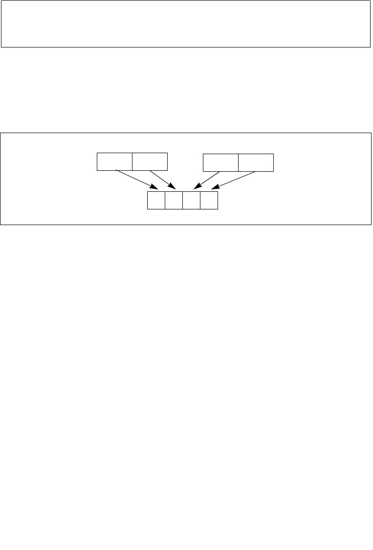
Converts packed signed word integers into packed signed byte integers (PACKSSWB)
or converts packed signed doubleword integers into packed signed word integers
(PACKSSDW), using saturation to handle overflow conditions. See Figure 4-2 for an
example of the packing operation.
The PACKSSWB instruction converts 4 or 8 signed word integers from the destination
operand (first operand) and 4 or 8 signed word integers from the source operand
(second operand) into 8 or 16 signed byte integers and stores the result in the desti-
nation operand. If a signed word integer value is beyond the range of a signed byte
integer (that is, greater than 7FH for a positive integer or greater than 80H for a
negative integer), the saturated signed byte integer value of 7FH or 80H, respec-
tively, is stored in the destination.
The PACKSSDW instruction packs 2 or 4 signed doublewords from the destination
operand (first operand) and 2 or 4 signed doublewords from the source operand
(second operand) into 4 or 8 signed words in the destination operand (see
Figure 4-2). If a signed doubleword integer value is beyond the range of a signed
word (that is, greater than 7FFFH for a positive integer or greater than 8000H for a
negative integer), the saturated signed word integer value of 7FFFH or 8000H,
respectively, is stored into the destination.
The PACKSSWB and PACKSSDW instructions operate on either 64-bit or 128-bit
operands. When operating on 64-bit operands, the destination operand must be an
MMX technology register and the source operand can be either an MMX technology
register or a 64-bit memory location. When operating on 128-bit operands, the desti-
nation operand must be an XMM register and the source operand can be either an
XMM register or a 128-bit memory location.
Op/En Operand 1 Operand 2 Operand 3 Operand 4
A ModRM:reg (r, w) ModRM:r/m (r) NA NA
B ModRM:reg (w) VEX.vvvv (r) ModRM:r/m (r) NA
Figure 4-2. Operation of the PACKSSDW Instruction Using 64-bit Operands
DC
64-Bit SRC
64-Bit DEST
D’ C’ B’ A’
64-Bit DEST
BA

Vol. 2B 4-37
INSTRUCTION SET REFERENCE, N-Z
PACKSSWB/PACKSSDW—Pack with Signed Saturation
In 64-bit mode, using a REX prefix in the form of REX.R permits this instruction to
access additional registers (XMM8-XMM15).
128-bit Legacy SSE version: Bits (VLMAX-1:128) of the corresponding YMM destina-
tion register remain unchanged.
VEX.128 encoded version: Bits (VLMAX-1:128) of the destination YMM register are
zeroed. VEX.L must be 0, otherwise the instruction will #UD.
Operation
PACKSSWB (with 64-bit operands)
DEST[7:0] ← SaturateSignedWordToSignedByte DEST[15:0];
DEST[15:8] ← SaturateSignedWordToSignedByte DEST[31:16];
DEST[23:16] ← SaturateSignedWordToSignedByte DEST[47:32];
DEST[31:24] ← SaturateSignedWordToSignedByte DEST[63:48];
DEST[39:32] ← SaturateSignedWordToSignedByte SRC[15:0];
DEST[47:40] ← SaturateSignedWordToSignedByte SRC[31:16];
DEST[55:48] ← SaturateSignedWordToSignedByte SRC[47:32];
DEST[63:56] ← SaturateSignedWordToSignedByte SRC[63:48];
PACKSSDW (with 64-bit operands)
DEST[15:0] ← SaturateSignedDoublewordToSignedWord DEST[31:0];
DEST[31:16] ← SaturateSignedDoublewordToSignedWord DEST[63:32];
DEST[47:32] ← SaturateSignedDoublewordToSignedWord SRC[31:0];
DEST[63:48] ← SaturateSignedDoublewordToSignedWord SRC[63:32];
PACKSSWB (with 128-bit operands)
DEST[7:0]← SaturateSignedWordToSignedByte (DEST[15:0]);
DEST[15:8] ← SaturateSignedWordToSignedByte (DEST[31:16]);
DEST[23:16] ← SaturateSignedWordToSignedByte (DEST[47:32]);
DEST[31:24] ← SaturateSignedWordToSignedByte (DEST[63:48]);
DEST[39:32] ← SaturateSignedWordToSignedByte (DEST[79:64]);
DEST[47:40] ← SaturateSignedWordToSignedByte (DEST[95:80]);
DEST[55:48] ← SaturateSignedWordToSignedByte (DEST[111:96]);
DEST[63:56] ← SaturateSignedWordToSignedByte (DEST[127:112]);
DEST[71:64] ← SaturateSignedWordToSignedByte (SRC[15:0]);
DEST[79:72] ← SaturateSignedWordToSignedByte (SRC[31:16]);
DEST[87:80] ← SaturateSignedWordToSignedByte (SRC[47:32]);
DEST[95:88] ← SaturateSignedWordToSignedByte (SRC[63:48]);
DEST[103:96] ← SaturateSignedWordToSignedByte (SRC[79:64]);
DEST[111:104] ← SaturateSignedWordToSignedByte (SRC[95:80]);
DEST[119:112] ← SaturateSignedWordToSignedByte (SRC[111:96]);
DEST[127:120] ← SaturateSignedWordToSignedByte (SRC[127:112]);
PACKSSDW (with 128-bit operands)

4-38 Vol. 2B PACKSSWB/PACKSSDW—Pack with Signed Saturation
INSTRUCTION SET REFERENCE, N-Z
DEST[15:0] ← SaturateSignedDwordToSignedWord (DEST[31:0]);
DEST[31:16] ← SaturateSignedDwordToSignedWord (DEST[63:32]);
DEST[47:32] ← SaturateSignedDwordToSignedWord (DEST[95:64]);
DEST[63:48] ← SaturateSignedDwordToSignedWord (DEST[127:96]);
DEST[79:64] ← SaturateSignedDwordToSignedWord (SRC[31:0]);
DEST[95:80] ← SaturateSignedDwordToSignedWord (SRC[63:32]);
DEST[111:96] ← SaturateSignedDwordToSignedWord (SRC[95:64]);
DEST[127:112] ← SaturateSignedDwordToSignedWord (SRC[127:96]);
PACKSSDW
DEST[127:0] SATURATING_PACK_DW(DEST, SRC)
DEST[VLMAX-1:128] (Unmodified)
VPACKSSDW
DEST[127:0] SATURATING_PACK_DW(DEST, SRC)
DEST[VLMAX-1:128] 0
PACKSSWB
DEST[127:0] SATURATING_PACK_WB(DEST, SRC)
DEST[VLMAX-1:128] (Unmodified)
VPACKSSWB
DEST[127:0] SATURATING_PACK_WB(DEST, SRC)
DEST[VLMAX-1:128] 0
Intel C/C++ Compiler Intrinsic Equivalents
PACKSSWB __m64 _mm_packs_pi16(__m64 m1, __m64 m2)
PACKSSWB __m128i _mm_packs_epi16(__m128i m1, __m128i m2)
PACKSSDW__m64 _mm_packs_pi32 (__m64 m1, __m64 m2)
PACKSSDW __m128i _mm_packs_epi32(__m128i m1, __m128i m2)
Flags Affected
None.
SIMD Floating-Point Exceptions
None.
Other Exceptions
See Exceptions Type 4; additionally
#UD If VEX.L = 1.

Vol. 2B 4-39
INSTRUCTION SET REFERENCE, N-Z
PACKUSDW — Pack with Unsigned Saturation
PACKUSDW — Pack with Unsigned Saturation
Instruction Operand Encoding
Description
Converts packed signed doubleword integers into packed unsigned word integers
using unsigned saturation to handle overflow conditions. If the signed doubleword
value is beyond the range of an unsigned word (that is, greater than FFFFH or less
than 0000H), the saturated unsigned word integer value of FFFFH or 0000H, respec-
tively, is stored in the destination.
128-bit Legacy SSE version: Bits (VLMAX-1:128) of the corresponding YMM destina-
tion register remain unchanged.
VEX.128 encoded version: Bits (VLMAX-1:128) of the destination YMM register are
zeroed. VEX.L must be 0, otherwise the instruction will #UD.
Operation
TMP[15:0] (DEST[31:0] < 0) ? 0 : DEST[15:0];
DEST[15:0] (DEST[31:0] > FFFFH) ? FFFFH : TMP[15:0] ;
Opcode/
Instruction
Op/
En
64/32 bit
Mode
Support
CPUID
Feature
Flag
Description
66 0F 38 2B /r
PACKUSDW xmm1, xmm2/m128
A V/V SSE4_1 Convert 4 packed signed
doubleword integers from
xmm1 and 4 packed signed
doubleword integers from
xmm2/m128 into 8 packed
unsigned word integers in
xmm1 using unsigned
saturation.
VEX.NDS.128.66.0F38.WIG 2B /r
VPACKUSDW xmm1, xmm2,
xmm3/m128
B V/V AVX Convert 4 packed signed
doubleword integers from
xmm2 and 4 packed signed
doubleword integers from
xmm3/m128 into 8 packed
unsigned word integers in
xmm1 using unsigned
saturation.
Op/En Operand 1 Operand 2 Operand 3 Operand 4
A ModRM:reg (r, w) ModRM:r/m (r) NA NA
B ModRM:reg (w) VEX.vvvv (r) ModRM:r/m (r) NA

4-40 Vol. 2B PACKUSDW — Pack with Unsigned Saturation
INSTRUCTION SET REFERENCE, N-Z
TMP[31:16] (DEST[63:32] < 0) ? 0 : DEST[47:32];
DEST[31:16] (DEST[63:32] > FFFFH) ? FFFFH : TMP[31:16] ;
TMP[47:32] (DEST[95:64] < 0) ? 0 : DEST[79:64];
DEST[47:32] (DEST[95:64] > FFFFH) ? FFFFH : TMP[47:32] ;
TMP[63:48] (DEST[127:96] < 0) ? 0 : DEST[111:96];
DEST[63:48] (DEST[127:96] > FFFFH) ? FFFFH : TMP[63:48] ;
TMP[63:48] (DEST[127:96] < 0) ? 0 : DEST[111:96];
DEST[63:48] (DEST[127:96] > FFFFH) ? FFFFH : TMP[63:48] ;
TMP[79:64] (SRC[31:0] < 0) ? 0 : SRC[15:0];
DEST[63:48] (SRC[31:0] > FFFFH) ? FFFFH : TMP[79:64] ;
TMP[95:80] (SRC[63:32] < 0) ? 0 : SRC[47:32];
DEST[95:80] (SRC[63:32] > FFFFH) ? FFFFH : TMP[95:80] ;
TMP[111:96] (SRC[95:64] < 0) ? 0 : SRC[79:64];
DEST[111:96] (SRC[95:64] > FFFFH) ? FFFFH : TMP[111:96] ;
TMP[127:112] (SRC[127:96] < 0) ? 0 : SRC[111:96];
DEST[128:112] (SRC[127:96] > FFFFH) ? FFFFH : TMP[127:112] ;
PACKUSDW (128-bit Legacy SSE version)
DEST[127:0] UNSIGNED_SATURATING_PACK_DW(DEST, SRC)
DEST[VLMAX-1:128] (Unmodified)
VPACKUSDW (VEX.128 encoded version)
DEST[127:0] UNSIGNED_SATURATING_PACK_DW(SRC1, SRC2)
DEST[VLMAX-1:128] 0
Intel C/C++ Compiler Intrinsic Equivalent
PACKUSDW __m128i _mm_packus_epi32(__m128i m1, __m128i m2);
Flags Affected
None.
SIMD Exceptions
None.
Other Exceptions
See Exceptions Type 4; additionally
#UD If VEX.L = 1.

Vol. 2B 4-41
INSTRUCTION SET REFERENCE, N-Z
PACKUSWB—Pack with Unsigned Saturation
PACKUSWB—Pack with Unsigned Saturation
Instruction Operand Encoding
Description
Converts 4 or 8 signed word integers from the destination operand (first operand)
and 4 or 8 signed word integers from the source operand (second operand) into 8 or
16 unsigned byte integers and stores the result in the destination operand. (See
Figure 4-2 for an example of the packing operation.) If a signed word integer value is
beyond the range of an unsigned byte integer (that is, greater than FFH or less than
00H), the saturated unsigned byte integer value of FFH or 00H, respectively, is stored
in the destination.
Opcode/
Instruction
Op/
En
64/32 bit
Mode
Support
CPUID
Feature
Flag
Description
0F 67 /r1
PACKUSWB mm, mm/m64
A V/V MMX Converts 4 signed word
integers from mm and 4
signed word integers from
mm/m64 into 8 unsigned
byte integers in mm using
unsigned saturation.
66 0F 67 /r
PACKUSWB xmm1, xmm2/m128
A V/V SSE2 Converts 8 signed word
integers from xmm1 and 8
signed word integers from
xmm2/m128 into 16
unsigned byte integers in
xmm1 using unsigned
saturation.
VEX.NDS.128.66.0F.WIG 67 /r
VPACKUSWB xmm1, xmm2,
xmm3/m128
B V/V AVX Converts 8 signed word
integers from xmm2 and 8
signed word integers from
xmm3/m128 into 16
unsigned byte integers in
xmm1 using unsigned
saturation.
NOTES:
1. See note in Section 2.4, “Instruction Exception Specification”.
Op/En Operand 1 Operand 2 Operand 3 Operand 4
A ModRM:reg (r, w) ModRM:r/m (r) NA NA
B ModRM:reg (w) VEX.vvvv (r) ModRM:r/m (r) NA

4-42 Vol. 2B PACKUSWB—Pack with Unsigned Saturation
INSTRUCTION SET REFERENCE, N-Z
The PACKUSWB instruction operates on either 64-bit or 128-bit operands. When
operating on 64-bit operands, the destination operand must be an MMX technology
register and the source operand can be either an MMX technology register or a 64-bit
memory location. When operating on 128-bit operands, the destination operand
must be an XMM register and the source operand can be either an XMM register or a
128-bit memory location.
In 64-bit mode, using a REX prefix in the form of REX.R permits this instruction to
access additional registers (XMM8-XMM15).
Operation
PACKUSWB (with 64-bit operands)
DEST[7:0] ← SaturateSignedWordToUnsignedByte DEST[15:0];
DEST[15:8] ← SaturateSignedWordToUnsignedByte DEST[31:16];
DEST[23:16] ← SaturateSignedWordToUnsignedByte DEST[47:32];
DEST[31:24] ← SaturateSignedWordToUnsignedByte DEST[63:48];
DEST[39:32] ← SaturateSignedWordToUnsignedByte SRC[15:0];
DEST[47:40] ← SaturateSignedWordToUnsignedByte SRC[31:16];
DEST[55:48] ← SaturateSignedWordToUnsignedByte SRC[47:32];
DEST[63:56] ← SaturateSignedWordToUnsignedByte SRC[63:48];
PACKUSWB (with 128-bit operands)
DEST[7:0]← SaturateSignedWordToUnsignedByte (DEST[15:0]);
DEST[15:8] ← SaturateSignedWordToUnsignedByte (DEST[31:16]);
DEST[23:16] ← SaturateSignedWordToUnsignedByte (DEST[47:32]);
DEST[31:24] ← SaturateSignedWordToUnsignedByte (DEST[63:48]);
DEST[39:32] ← SaturateSignedWordToUnsignedByte (DEST[79:64]);
DEST[47:40] ← SaturateSignedWordToUnsignedByte (DEST[95:80]);
DEST[55:48] ← SaturateSignedWordToUnsignedByte (DEST[111:96]);
DEST[63:56] ← SaturateSignedWordToUnsignedByte (DEST[127:112]);
DEST[71:64] ← SaturateSignedWordToUnsignedByte (SRC[15:0]);
DEST[79:72] ← SaturateSignedWordToUnsignedByte (SRC[31:16]);
DEST[87:80] ← SaturateSignedWordToUnsignedByte (SRC[47:32]);
DEST[95:88] ← SaturateSignedWordToUnsignedByte (SRC[63:48]);
DEST[103:96] ← SaturateSignedWordToUnsignedByte (SRC[79:64]);
DEST[111:104] ← SaturateSignedWordToUnsignedByte (SRC[95:80]);
DEST[119:112] ← SaturateSignedWordToUnsignedByte (SRC[111:96]);
DEST[127:120] ← SaturateSignedWordToUnsignedByte (SRC[127:112]);
PACKUSWB (128-bit Legacy SSE version)
DEST[127:0] UNSIGNED_SATURATING_PACK_WB(DEST, SRC)
DEST[VLMAX-1:128] (Unmodified)
VPACKUSWB (VEX.128 encoded version)

Vol. 2B 4-43
INSTRUCTION SET REFERENCE, N-Z
PACKUSWB—Pack with Unsigned Saturation
DEST[127:0] UNSIGNED_SATURATING_PACK_WB(SRC1, SRC2)
DEST[VLMAX-1:128] 0
Intel C/C++ Compiler Intrinsic Equivalent
PACKUSWB __m64 _mm_packs_pu16(__m64 m1, __m64 m2)
PACKUSWB __m128i _mm_packus_epi16(__m128i m1, __m128i m2)
Flags Affected
None.
SIMD Floating-Point Exceptions
None.
Other Exceptions
See Exceptions Type 4; additionally
#UD If VEX.L = 1.

4-44 Vol. 2B PADDB/PADDW/PADDD—Add Packed Integers
INSTRUCTION SET REFERENCE, N-Z
PADDB/PADDW/PADDD—Add Packed Integers
Instruction Operand Encoding
Opcode/
Instruction
Op/
En
64/32 bit
Mode
Support
CPUID
Feature
Flag
Description
0F FC /r1
PADDB mm, mm/m64
A V/V MMX Add packed byte integers
from mm/m64 and mm.
66 0F FC /r
PADDB xmm1, xmm2/m128
A V/V SSE2 Add packed byte integers
from xmm2/m128 and
xmm1.
0F FD /r1
PADDW mm, mm/m64
A V/V MMX Add packed word integers
from mm/m64 and mm.
66 0F FD /r
PADDW xmm1, xmm2/m128
A V/V SE2 Add packed word integers
from xmm2/m128 and
xmm1.
0F FE /r1
PADDD mm, mm/m64
A V/V MMX Add packed doubleword
integers from mm/m64 and
mm.
66 0F FE /r
PADDD xmm1, xmm2/m128
A V/V SSE2 Add packed doubleword
integers from xmm2/m128
and xmm1.
VEX.NDS.128.66.0F.WIG FC /r
VPADDB xmm1, xmm2,
xmm3/m128
B V/V AVX Add packed byte integers
from xmm3/m128 and
xmm2.
VEX.NDS.128.66.0F.WIG FD /r
VPADDW xmm1, xmm2,
xmm3/m128
B V/V AVX Add packed word integers
from xmm3/m128 and
xmm2.
VEX.NDS.128.66.0F.WIG FE /r
VPADDD xmm1, xmm2,
xmm3/m128
B V/V AVX Add packed doubleword
integers from xmm3/m128
and xmm2.
NOTES:
1. See note in Section 2.4, “Instruction Exception Specification”.
Op/En Operand 1 Operand 2 Operand 3 Operand 4
A ModRM:reg (r, w) ModRM:r/m (r) NA NA
B ModRM:reg (w) VEX.vvvv (r) ModRM:r/m (r) NA

Vol. 2B 4-45
INSTRUCTION SET REFERENCE, N-Z
PADDB/PADDW/PADDD—Add Packed Integers
Description
Performs a SIMD add of the packed integers from the source operand (second
operand) and the destination operand (first operand), and stores the packed integer
results in the destination operand. See Figure 9-4 in the Intel® 64 and IA-32 Archi-
tectures Software Developer’s Manual, Volume 1, for an illustration of a SIMD opera-
tion. Overflow is handled with wraparound, as described in the following paragraphs.
These instructions can operate on either 64-bit or 128-bit operands. When operating
on 64-bit operands, the destination operand must be an MMX technology register
and the source operand can be either an MMX technology register or a 64-bit
memory location. When operating on 128-bit operands, the destination operand
must be an XMM register and the source operand can be either an XMM register or a
128-bit memory location.
Adds the packed byte, word, doubleword, or quadword integers in the first source
operand to the second source operand and stores the result in the destination
operand. When a result is too large to be represented in the 8/16/32 integer (over-
flow), the result is wrapped around and the low bits are written to the destination
element (that is, the carry is ignored).
Note that these instructions can operate on either unsigned or signed (two’s comple-
ment notation) integers; however, it does not set bits in the EFLAGS register to indi-
cate overflow and/or a carry. To prevent undetected overflow conditions, software
must control the ranges of the values operated on.
In 64-bit mode, using a REX prefix in the form of REX.R permits this instruction to
access additional registers (XMM8-XMM15).
128-bit Legacy SSE version: Bits (VLMAX-1:128) of the corresponding YMM destina-
tion register remain unchanged.
VEX.128 encoded version: Bits (VLMAX-1:128) of the destination YMM register are
zeroed. VEX.L must be 0, otherwise the instruction will #UD.
Operation
PADDB (with 64-bit operands)
DEST[7:0] ← DEST[7:0] + SRC[7:0];
(* Repeat add operation for 2nd through 7th byte *)
DEST[63:56] ← DEST[63:56] + SRC[63:56];
PADDB (with 128-bit operands)
DEST[7:0] ← DEST[7:0] + SRC[7:0];
(* Repeat add operation for 2nd through 14th byte *)
DEST[127:120] ← DEST[111:120] + SRC[127:120];
PADDW (with 64-bit operands)
DEST[15:0] ← DEST[15:0] + SRC[15:0];
(* Repeat add operation for 2nd and 3th word *)
DEST[63:48] ← DEST[63:48] + SRC[63:48];

4-46 Vol. 2B PADDB/PADDW/PADDD—Add Packed Integers
INSTRUCTION SET REFERENCE, N-Z
PADDW (with 128-bit operands)
DEST[15:0] ← DEST[15:0] + SRC[15:0];
(* Repeat add operation for 2nd through 7th word *)
DEST[127:112] ← DEST[127:112] + SRC[127:112];
PADDD (with 64-bit operands)
DEST[31:0] ← DEST[31:0] + SRC[31:0];
DEST[63:32] ← DEST[63:32] + SRC[63:32];
PADDD (with 128-bit operands)
DEST[31:0] ← DEST[31:0] + SRC[31:0];
(* Repeat add operation for 2nd and 3th doubleword *)
DEST[127:96] ← DEST[127:96] + SRC[127:96];
VPADDB (VEX.128 encoded version)
DEST[7:0] SRC1[7:0]+SRC2[7:0]
DEST[15:8] SRC1[15:8]+SRC2[15:8]
DEST[23:16] SRC1[23:16]+SRC2[23:16]
DEST[31:24] SRC1[31:24]+SRC2[31:24]
DEST[39:32] SRC1[39:32]+SRC2[39:32]
DEST[47:40] SRC1[47:40]+SRC2[47:40]
DEST[55:48] SRC1[55:48]+SRC2[55:48]
DEST[63:56] SRC1[63:56]+SRC2[63:56]
DEST[71:64] SRC1[71:64]+SRC2[71:64]
DEST[79:72] SRC1[79:72]+SRC2[79:72]
DEST[87:80] SRC1[87:80]+SRC2[87:80]
DEST[95:88] SRC1[95:88]+SRC2[95:88]
DEST[103:96] SRC1[103:96]+SRC2[103:96]
DEST[111:104] SRC1[111:104]+SRC2[111:104]
DEST[119:112] SRC1[119:112]+SRC2[119:112]
DEST[127:120] SRC1[127:120]+SRC2[127:120]
DEST[VLMAX-1:128] 0
VPADDW (VEX.128 encoded version)
DEST[15:0] SRC1[15:0]+SRC2[15:0]
DEST[31:16] SRC1[31:16]+SRC2[31:16]
DEST[47:32] SRC1[47:32]+SRC2[47:32]
DEST[63:48] SRC1[63:48]+SRC2[63:48]
DEST[79:64] SRC1[79:64]+SRC2[79:64]
DEST[95:80] SRC1[95:80]+SRC2[95:80]
DEST[111:96] SRC1[111:96]+SRC2[111:96]
DEST[127:112] SRC1[127:112]+SRC2[127:112]
DEST[VLMAX-1:128] 0

Vol. 2B 4-47
INSTRUCTION SET REFERENCE, N-Z
PADDB/PADDW/PADDD—Add Packed Integers
VPADDD (VEX.128 encoded version)
DEST[31:0] SRC1[31:0]+SRC2[31:0]
DEST[63:32] SRC1[63:32]+SRC2[63:32]
DEST[95:64] SRC1[95:64]+SRC2[95:64]
DEST[127:96] SRC1[127:96]+SRC2[127:96]
DEST[VLMAX-1:128] 0
Intel C/C++ Compiler Intrinsic Equivalents
PADDB __m64 _mm_add_pi8(__m64 m1, __m64 m2)
PADDB __m128i _mm_add_epi8 (__m128ia,__m128ib )
PADDW __m64 _mm_add_pi16(__m64 m1, __m64 m2)
PADDW __m128i _mm_add_epi16 ( __m128i a, __m128i b)
PADDD __m64 _mm_add_pi32(__m64 m1, __m64 m2)
PADDD __m128i _mm_add_epi32 ( __m128i a, __m128i b)
Flags Affected
None.
SIMD Floating-Point Exceptions
None.
Other Exceptions
See Exceptions Type 4; additionally
#UD If VEX.L = 1.

4-48 Vol. 2B PADDQ—Add Packed Quadword Integers
INSTRUCTION SET REFERENCE, N-Z
PADDQ—Add Packed Quadword Integers
Instruction Operand Encoding
Description
Adds the first operand (destination operand) to the second operand (source operand)
and stores the result in the destination operand. The source operand can be a quad-
word integer stored in an MMX technology register or a 64-bit memory location, or it
can be two packed quadword integers stored in an XMM register or an 128-bit
memory location. The destination operand can be a quadword integer stored in an
MMX technology register or two packed quadword integers stored in an XMM register.
When packed quadword operands are used, a SIMD add is performed. When a quad-
word result is too large to be represented in 64 bits (overflow), the result is wrapped
around and the low 64 bits are written to the destination element (that is, the carry
is ignored).
Note that the PADDQ instruction can operate on either unsigned or signed (two’s
complement notation) integers; however, it does not set bits in the EFLAGS register
to indicate overflow and/or a carry. To prevent undetected overflow conditions, soft-
ware must control the ranges of the values operated on.
In 64-bit mode, using a REX prefix in the form of REX.R permits this instruction to
access additional registers (XMM8-XMM15).
128-bit Legacy SSE version: Bits (VLMAX-1:128) of the corresponding YMM destina-
tion register remain unchanged.
Opcode/
Instruction
Op/
En
64/32 bit
Mode
Support
CPUID
Feature
Flag
Description
0F D4 /r1
PADDQ mm1, mm2/m64
A V/V SSE2 Add quadword integer
mm2/m64 to mm1.
66 0F D4 /r
PADDQ xmm1, xmm2/m128
A V/V SSE2 Add packed quadword
integers xmm2/m128 to
xmm1.
VEX.NDS.128.66.0F.WIG D4 /r
VPADDQ xmm1, xmm2,
xmm3/m128
B V/V AVX Add packed quadword
integers xmm3/m128 and
xmm2.
NOTES:
1. See note in Section 2.4, “Instruction Exception Specification”.
Op/En Operand 1 Operand 2 Operand 3 Operand 4
A ModRM:reg (r, w) ModRM:r/m (r) NA NA
B ModRM:reg (w) VEX.vvvv (r) ModRM:r/m (r) NA

Vol. 2B 4-49
INSTRUCTION SET REFERENCE, N-Z
PADDQ—Add Packed Quadword Integers
VEX.128 encoded version: Bits (VLMAX-1:128) of the destination YMM register are
zeroed. VEX.L must be 0, otherwise the instruction will #UD.
Operation
PADDQ (with 64-Bit operands)
DEST[63:0] ← DEST[63:0] + SRC[63:0];
PADDQ (with 128-Bit operands)
DEST[63:0] ← DEST[63:0] + SRC[63:0];
DEST[127:64] ← DEST[127:64] + SRC[127:64];
VPADDQ (VEX.128 encoded version)
DEST[63:0] SRC1[63:0]+SRC2[63:0]
DEST[127:64] SRC1[127:64]+SRC2[127:64]
DEST[VLMAX-1:128] 0
Intel C/C++ Compiler Intrinsic Equivalents
PADDQ __m64 _mm_add_si64 (__m64 a, __m64 b)
PADDQ __m128i _mm_add_epi64 ( __m128i a, __m128i b)
Flags Affected
None.
Numeric Exceptions
None.
Other Exceptions
See Exceptions Type 4; additionally
#UD If VEX.L = 1.

4-50 Vol. 2B PADDSB/PADDSW—Add Packed Signed Integers with Signed Saturation
INSTRUCTION SET REFERENCE, N-Z
PADDSB/PADDSW—Add Packed Signed Integers with Signed
Saturation
Instruction Operand Encoding
Description
Performs a SIMD add of the packed signed integers from the source operand (second
operand) and the destination operand (first operand), and stores the packed integer
Opcode/
Instruction
Op/
En
64/32 bit
Mode
Support
CPUID
Feature
Flag
Description
0F EC /r1
PADDSB mm, mm/m64
A V/V MMX Add packed signed byte
integers from mm/m64 and
mm and saturate the
results.
66 0F EC /r
PADDSB xmm1, xmm2/m128
A V/V SSE2 Add packed signed byte
integers from xmm2/m128
and xmm1 saturate the
results.
0F ED /r1
PADDSW mm, mm/m64
A V/V MMX Add packed signed word
integers from mm/m64 and
mm and saturate the
results.
66 0F ED /r
PADDSW xmm1, xmm2/m128
A V/V SSE2 Add packed signed word
integers from xmm2/m128
and xmm1 and saturate the
results.
VEX.NDS.128.66.0F.WIG EC /r
VPADDSB xmm1, xmm2,
xmm3/m128
B V/V AVX Add packed signed byte
integers from xmm3/m128
and xmm2 saturate the
results.
VEX.NDS.128.66.0F.WIG ED /r
VPADDSW xmm1, xmm2,
xmm3/m128
B V/V AVX Add packed signed word
integers from xmm3/m128
and xmm2 and saturate the
results.
NOTES:
1. See note in Section 2.4, “Instruction Exception Specification”.
Op/En Operand 1 Operand 2 Operand 3 Operand 4
A ModRM:reg (r, w) ModRM:r/m (r) NA NA
B ModRM:reg (w) VEX.vvvv (r) ModRM:r/m (r) NA

Vol. 2B 4-51
INSTRUCTION SET REFERENCE, N-Z
PADDSB/PADDSW—Add Packed Signed Integers with Signed Saturation
results in the destination operand. See Figure 9-4 in the Intel® 64 and IA-32 Archi-
tectures Software Developer’s Manual, Volume 1, for an illustration of a SIMD opera-
tion. Overflow is handled with signed saturation, as described in the following
paragraphs.
These instructions can operate on either 64-bit or 128-bit operands. When operating
on 64-bit operands, the destination operand must be an MMX technology register
and the source operand can be either an MMX technology register or a 64-bit
memory location. When operating on 128-bit operands, the destination operand
must be an XMM register and the source operand can be either an XMM register or a
128-bit memory location.
The PADDSB instruction adds packed signed byte integers. When an individual byte
result is beyond the range of a signed byte integer (that is, greater than 7FH or less
than 80H), the saturated value of 7FH or 80H, respectively, is written to the destina-
tion operand.
The PADDSW instruction adds packed signed word integers. When an individual word
result is beyond the range of a signed word integer (that is, greater than 7FFFH or
less than 8000H), the saturated value of 7FFFH or 8000H, respectively, is written to
the destination operand.
In 64-bit mode, using a REX prefix in the form of REX.R permits this instruction to
access additional registers (XMM8-XMM15).
128-bit Legacy SSE version: Bits (VLMAX-1:128) of the corresponding YMM destina-
tion register remain unchanged.
VEX.128 encoded version: Bits (VLMAX-1:128) of the destination YMM register are
zeroed. VEX.L must be 0, otherwise the instruction will #UD.
Operation
PADDSB (with 64-bit operands)
DEST[7:0] ← SaturateToSignedByte(DEST[7:0] + SRC (7:0]);
(* Repeat add operation for 2nd through 7th bytes *)
DEST[63:56] ← SaturateToSignedByte(DEST[63:56] + SRC[63:56] );
PADDSB (with 128-bit operands)
DEST[7:0] ←SaturateToSignedByte (DEST[7:0] + SRC[7:0]);
(* Repeat add operation for 2nd through 14th bytes *)
DEST[127:120] ← SaturateToSignedByte (DEST[111:120] + SRC[127:120]);
VPADDSB
DEST[7:0] SaturateToSignedByte (SRC1[7:0] + SRC2[7:0]);
(* Repeat subtract operation for 2nd through 14th bytes *)
DEST[127:120] SaturateToSignedByte (SRC1[111:120] + SRC2[127:120]);
DEST[VLMAX-1:128] 0
PADDSW (with 64-bit operands)

4-52 Vol. 2B PADDSB/PADDSW—Add Packed Signed Integers with Signed Saturation
INSTRUCTION SET REFERENCE, N-Z
DEST[15:0] ← SaturateToSignedWord(DEST[15:0] + SRC[15:0] );
(* Repeat add operation for 2nd and 7th words *)
DEST[63:48] ← SaturateToSignedWord(DEST[63:48] + SRC[63:48] );
PADDSW (with 128-bit operands)
DEST[15:0] ← SaturateToSignedWord (DEST[15:0] + SRC[15:0]);
(* Repeat add operation for 2nd through 7th words *)
DEST[127:112] ← SaturateToSignedWord (DEST[127:112] + SRC[127:112]);
VPADDSW
DEST[15:0] SaturateToSignedWord (SRC1[15:0] + SRC2[15:0]);
(* Repeat subtract operation for 2nd through 7th words *)
DEST[127:112] SaturateToSignedWord (SRC1[127:112] + SRC2[127:112]);
DEST[VLMAX-1:128] 0
Intel C/C++ Compiler Intrinsic Equivalents
PADDSB __m64 _mm_adds_pi8(__m64 m1, __m64 m2)
PADDSB __m128i _mm_adds_epi8 ( __m128i a, __m128i b)
PADDSW __m64 _mm_adds_pi16(__m64 m1, __m64 m2)
PADDSW __m128i _mm_adds_epi16 ( __m128i a, __m128i b)
Flags Affected
None.
SIMD Floating-Point Exceptions
None.
Other Exceptions
See Exceptions Type 4; additionally
#UD If VEX.L = 1.

Vol. 2B 4-53
INSTRUCTION SET REFERENCE, N-Z
PADDUSB/PADDUSW—Add Packed Unsigned Integers with Unsigned Saturation
PADDUSB/PADDUSW—Add Packed Unsigned Integers with Unsigned
Saturation
Instruction Operand Encoding
Description
Performs a SIMD add of the packed unsigned integers from the source operand
(second operand) and the destination operand (first operand), and stores the packed
Opcode/
Instruction
Op/
En
64/32 bit
Mode
Support
CPUID
Feature
Flag
Description
0F DC /r1
PADDUSB mm, mm/m64
A V/V MMX Add packed unsigned byte
integers from mm/m64 and
mm and saturate the
results.
66 0F DC /r
PADDUSB xmm1, xmm2/m128
A V/V SSE2 Add packed unsigned byte
integers from xmm2/m128
and xmm1 saturate the
results.
0F DD /r1
PADDUSW mm, mm/m64
A V/V MMX Add packed unsigned word
integers from mm/m64 and
mm and saturate the
results.
66 0F DD /r
PADDUSW xmm1, xmm2/m128
A V/V SSE2 Add packed unsigned word
integers from xmm2/m128
to xmm1 and saturate the
results.
VEX.NDS.128.6
60F.WIG DC /r
VPADDUSB xmm1,
xmm2,
xmm3/m128
B V/V AVX Add packed unsigned byte
integers from xmm3/m128
to xmm2 and saturate the
results.
VEX.NDS.128.6
6.0F.WIG DD /r
VPADDUSW
xmm1, xmm2,
xmm3/m128
B V/V AVX Add packed unsigned word
integers from xmm3/m128
to xmm2 and saturate the
results.
NOTES:
1. See note in Section 2.4, “Instruction Exception Specification”.
Op/En Operand 1 Operand 2 Operand 3 Operand 4
A ModRM:reg (r, w) ModRM:r/m (r) NA NA
B ModRM:reg (w) VEX.vvvv (r) ModRM:r/m (r) NA

4-54 Vol. 2B PADDUSB/PADDUSW—Add Packed Unsigned Integers with Unsigned Saturation
INSTRUCTION SET REFERENCE, N-Z
integer results in the destination operand. See Figure 9-4 in the Intel® 64 and IA-32
Architectures Software Developer’s Manual, Volume 1, for an illustration of a SIMD
operation. Overflow is handled with unsigned saturation, as described in the
following paragraphs.
These instructions can operate on either 64-bit or 128-bit operands. When operating
on 64-bit operands, the destination operand must be an MMX technology register
and the source operand can be either an MMX technology register or a 64-bit
memory location. When operating on 128-bit operands, the destination operand
must be an XMM register and the source operand can be either an XMM register or a
128-bit memory location.
The PADDUSB instruction adds packed unsigned byte integers. When an individual
byte result is beyond the range of an unsigned byte integer (that is, greater than
FFH), the saturated value of FFH is written to the destination operand.
The PADDUSW instruction adds packed unsigned word integers. When an individual
word result is beyond the range of an unsigned word integer (that is, greater than
FFFFH), the saturated value of FFFFH is written to the destination operand.
In 64-bit mode, using a REX prefix in the form of REX.R permits this instruction to
access additional registers (XMM8-XMM15).
128-bit Legacy SSE version: Bits (VLMAX-1:128) of the corresponding YMM destina-
tion register remain unchanged.
VEX.128 encoded version: Bits (VLMAX-1:128) of the destination YMM register are
zeroed. VEX.L must be 0, otherwise the instruction will #UD.
Operation
PADDUSB (with 64-bit operands)
DEST[7:0] ← SaturateToUnsignedByte(DEST[7:0] + SRC (7:0] );
(* Repeat add operation for 2nd through 7th bytes *)
DEST[63:56] ← SaturateToUnsignedByte(DEST[63:56] + SRC[63:56]
PADDUSB (with 128-bit operands)
DEST[7:0] ← SaturateToUnsignedByte (DEST[7:0] + SRC[7:0]);
(* Repeat add operation for 2nd through 14th bytes *)
DEST[127:120] ← SaturateToUnSignedByte (DEST[127:120] + SRC[127:120]);
VPADDUSB
DEST[7:0] SaturateToUnsignedByte (SRC1[7:0] + SRC2[7:0]);
(* Repeat subtract operation for 2nd through 14th bytes *)
DEST[127:120] SaturateToUnsignedByte (SRC1[111:120] + SRC2[127:120]);
DEST[VLMAX-1:128] 0
PADDUSW (with 64-bit operands)
DEST[15:0] ← SaturateToUnsignedWord(DEST[15:0] + SRC[15:0] );

Vol. 2B 4-55
INSTRUCTION SET REFERENCE, N-Z
PADDUSB/PADDUSW—Add Packed Unsigned Integers with Unsigned Saturation
(* Repeat add operation for 2nd and 3rd words *)
DEST[63:48] ← SaturateToUnsignedWord(DEST[63:48] + SRC[63:48] );
PADDUSW (with 128-bit operands)
DEST[15:0] ← SaturateToUnsignedWord (DEST[15:0] + SRC[15:0]);
(* Repeat add operation for 2nd through 7th words *)
DEST[127:112] ← SaturateToUnSignedWord (DEST[127:112] + SRC[127:112]);
VPADDUSW
DEST[15:0] SaturateToUnsignedWord (SRC1[15:0] + SRC2[15:0]);
(* Repeat subtract operation for 2nd through 7th words *)
DEST[127:112] SaturateToUnsignedWord (SRC1[127:112] + SRC2[127:112]);
DEST[VLMAX-1:128] 0
Intel C/C++ Compiler Intrinsic Equivalents
PADDUSB __m64 _mm_adds_pu8(__m64 m1, __m64 m2)
PADDUSW __m64 _mm_adds_pu16(__m64 m1, __m64 m2)
PADDUSB __m128i _mm_adds_epu8 ( __m128i a, __m128i b)
PADDUSW __m128i _mm_adds_epu16 ( __m128i a, __m128i b)
Flags Affected
None.
Numeric Exceptions
None.
Other Exceptions
See Exceptions Type 4; additionally
#UD If VEX.L = 1.

4-56 Vol. 2B PALIGNR — Packed Align Right
INSTRUCTION SET REFERENCE, N-Z
PALIGNR — Packed Align Right
Instruction Operand Encoding
Description
PALIGNR concatenates the destination operand (the first operand) and the source
operand (the second operand) into an intermediate composite, shifts the composite
at byte granularity to the right by a constant immediate, and extracts the right-
aligned result into the destination. The first and the second operands can be an MMX
or an XMM register. The immediate value is considered unsigned. Immediate shift
counts larger than the 2L (i.e. 32 for 128-bit operands, or 16 for 64-bit operands)
produce a zero result. Both operands can be MMX register or XMM registers. When
the source operand is a 128-bit memory operand, the operand must be aligned on a
16-byte boundary or a general-protection exception (#GP) will be generated.
In 64-bit mode, use the REX prefix to access additional registers.
128-bit Legacy SSE version: Bits (VLMAX-1:128) of the corresponding YMM destina-
tion register remain unchanged.
Opcode/
Instruction
Op/
En
64/32 bit
Mode
Support
CPUID
Feature
Flag
Description
0F 3A 0F1
PALIGNR mm1, mm2/m64, imm8
A V/V SSSE3 Concatenate destination and
source operands, extract
byte-aligned result shifted
to the right by constant
value in imm8 into mm1.
66 0F 3A 0F
PALIGNR xmm1, xmm2/m128, imm8
A V/V SSSE3 Concatenate destination and
source operands, extract
byte-aligned result shifted
to the right by constant
value in imm8 into xmm1
VEX.NDS.128.66.0F3A.WIG 0F /r ib
VPALIGNR xmm1, xmm2,
xmm3/m128, imm8
B V/V AVX Concatenate xmm2 and
xmm3/m128, extract byte
aligned result shifted to the
right by constant value in
imm8 and result is stored in
xmm1.
NOTES:
1. See note in Section 2.4, “Instruction Exception Specification”.
Op/En Operand 1 Operand 2 Operand 3 Operand 4
A ModRM:reg (r, w) ModRM:r/m (r) imm8 NA
B ModRM:reg (w) VEX.vvvv (r) ModRM:r/m (r) NA

Vol. 2B 4-57
INSTRUCTION SET REFERENCE, N-Z
PALIGNR — Packed Align Right
VEX.128 encoded version: Bits (VLMAX-1:128) of the destination YMM register are
zeroed. VEX.L must be 0, otherwise the instruction will #UD.
Operation
PALIGNR (with 64-bit operands)
temp1[127:0] = CONCATENATE(DEST,SRC)>>(imm8*8)
DEST[63:0] = temp1[63:0]
PALIGNR (with 128-bit operands)
temp1[255:0] = CONCATENATE(DEST,SRC)>>(imm8*8)
DEST[127:0] = temp1[127:0]
VPALIGNR
temp1[255:0] CONCATENATE(SRC1,SRC2)>>(imm8*8)
DEST[127:0] temp1[127:0]
DEST[VLMAX-1:128] 0
Intel C/C++ Compiler Intrinsic Equivalents
PALIGNR __m64 _mm_alignr_pi8 (__m64 a, __m64 b, int n)
PALIGNR __m128i _mm_alignr_epi8 (__m128i a, __m128i b, int n)
SIMD Floating-Point Exceptions
None.
Other Exceptions
See Exceptions Type 4; additionally
#UD If VEX.L = 1.

4-58 Vol. 2B PAND—Logical AND
INSTRUCTION SET REFERENCE, N-Z
PAND—Logical AND
Instruction Operand Encoding
Description
Performs a bitwise logical AND operation on the source operand (second operand)
and the destination operand (first operand) and stores the result in the destination
operand. The source operand can be an MMX technology register or a 64-bit memory
location or it can be an XMM register or a 128-bit memory location. The destination
operand can be an MMX technology register or an XMM register. Each bit of the result
is set to 1 if the corresponding bits of the first and second operands are 1; otherwise,
it is set to 0.
In 64-bit mode, using a REX prefix in the form of REX.R permits this instruction to
access additional registers (XMM8-XMM15).
128-bit Legacy SSE version: Bits (VLMAX-1:128) of the corresponding YMM destina-
tion register remain unchanged.
VEX.128 encoded version: Bits (VLMAX-1:128) of the destination YMM register are
zeroed. VEX.L must be 0, otherwise the instruction will #UD.
Operation
PAND (128-bit Legacy SSE version)
DEST DEST AND SRC
DEST[VLMAX-1:1288] (Unmodified)
Opcode/
Instruction
Op/
En
64/32 bit
Mode
Support
CPUID
Feature
Flag
Description
0F DB /r1
PAND mm, mm/m64
AV/V MMX Bitwise AND mm/m64 and
mm.
66 0F DB /r
PAND xmm1, xmm2/m128
AV/V SSE2 Bitwise AND of
xmm2/m128 and xmm1.
VEX.NDS.128.66.0F.WIG DB /r
VPAND xmm1, xmm2, xmm3/m128
BV/V AVX Bitwise AND of
xmm3/m128 and xmm.
NOTES:
1. See note in Section 2.4, “Instruction Exception Specification”.
Op/En Operand 1 Operand 2 Operand 3 Operand 4
A ModRM:reg (r, w) ModRM:r/m (r) NA NA
B ModRM:reg (w) VEX.vvvv (r) ModRM:r/m (r) NA

Vol. 2B 4-59
INSTRUCTION SET REFERENCE, N-Z
PAND—Logical AND
VPAND (VEX.128 encoded version)
DEST SRC1 AND SRC2
DEST[VLMAX-1:128] 0
Intel C/C++ Compiler Intrinsic Equivalent
PAND __m64 _mm_and_si64 (__m64 m1, __m64 m2)
PAND __m128i _mm_and_si128 ( __m128i a, __m128i b)
Flags Affected
None.
Numeric Exceptions
None.
Other Exceptions
See Exceptions Type 4; additionally
#UD If VEX.L = 1.

4-60 Vol. 2B PANDN—Logical AND NOT
INSTRUCTION SET REFERENCE, N-Z
PANDN—Logical AND NOT
Instruction Operand Encoding
Description
Performs a bitwise logical NOT of the destination operand (first operand), then
performs a bitwise logical AND of the source operand (second operand) and the
inverted destination operand. The result is stored in the destination operand. The
source operand can be an MMX technology register or a 64-bit memory location or it
can be an XMM register or a 128-bit memory location. The destination operand can
be an MMX technology register or an XMM register. Each bit of the result is set to 1 if
the corresponding bit in the first operand is 0 and the corresponding bit in the second
operand is 1; otherwise, it is set to 0.
In 64-bit mode, using a REX prefix in the form of REX.R permits this instruction to
access additional registers (XMM8-XMM15).
128-bit Legacy SSE version: Bits (VLMAX-1:128) of the corresponding YMM destina-
tion register remain unchanged.
VEX.128 encoded version: Bits (VLMAX-1:1288) of the destination YMM register are
zeroed. VEX.L must be 0, otherwise the instruction will #UD.
Operation
PANDN(128-bit Legacy SSE version)
DEST NOT(DEST) AND SRC
Opcode/
Instruction
Op/
En
64/32 bit
Mode
Support
CPUID
Feature
Flag
Description
0F DF /r1
PANDN mm, mm/m64
AV/V MMX Bitwise AND NOT of
mm/m64 and mm.
66 0F DF /r
PANDN xmm1, xmm2/m128
AV/V SSE2 Bitwise AND NOT of
xmm2/m128 and xmm1.
VEX.NDS.128.66.0F.WIG DF /r
VPANDN xmm1, xmm2,
xmm3/m128
BV/V AVX Bitwise AND NOT of
xmm3/m128 and xmm2.
NOTES:
1. See note in Section 2.4, “Instruction Exception Specification”.
Op/En Operand 1 Operand 2 Operand 3 Operand 4
A ModRM:reg (r, w) ModRM:r/m (r) NA NA
B ModRM:reg (w) VEX.vvvv (r) ModRM:r/m (r) NA

Vol. 2B 4-61
INSTRUCTION SET REFERENCE, N-Z
PANDN—Logical AND NOT
DEST[VLMAX-1:128] (Unmodified)
VPANDN (VEX.128 encoded version)
DEST NOT(SRC1) AND SRC2
DEST[VLMAX-1:128] 0
Intel C/C++ Compiler Intrinsic Equivalent
PANDN __m64 _mm_andnot_si64 (__m64 m1, __m64 m2)
PANDN _m128i _mm_andnot_si128 ( __m128i a, __m128i b)
Flags Affected
None.
Numeric Exceptions
None.
Other Exceptions
See Exceptions Type 4; additionally
#UD If VEX.L = 1.

4-62 Vol. 2B PAUSE—Spin Loop Hint
INSTRUCTION SET REFERENCE, N-Z
PAUSE—Spin Loop Hint
Instruction Operand Encoding
Description
Improves the performance of spin-wait loops. When executing a “spin-wait loop,” a
Pentium 4 or Intel Xeon processor suffers a severe performance penalty when exiting
the loop because it detects a possible memory order violation. The PAUSE instruction
provides a hint to the processor that the code sequence is a spin-wait loop. The
processor uses this hint to avoid the memory order violation in most situations,
which greatly improves processor performance. For this reason, it is recommended
that a PAUSE instruction be placed in all spin-wait loops.
An additional function of the PAUSE instruction is to reduce the power consumed by
a Pentium 4 processor while executing a spin loop. The Pentium 4 processor can
execute a spin-wait loop extremely quickly, causing the processor to consume a lot of
power while it waits for the resource it is spinning on to become available. Inserting
a pause instruction in a spin-wait loop greatly reduces the processor’s power
consumption.
This instruction was introduced in the Pentium 4 processors, but is backward compat-
ible with all IA-32 processors. In earlier IA-32 processors, the PAUSE instruction
operates like a NOP instruction. The Pentium 4 and Intel Xeon processors implement
the PAUSE instruction as a pre-defined delay. The delay is finite and can be zero for
some processors. This instruction does not change the architectural state of the
processor (that is, it performs essentially a delaying no-op operation).
This instruction’s operation is the same in non-64-bit modes and 64-bit mode.
Operation
Execute_Next_Instruction(DELAY);
Numeric Exceptions
None.
Opcode Instruction Op/
En
64-Bit
Mode
Compat/
Leg Mode
Description
F3 90 PAUSE A Valid Valid Gives hint to processor that
improves performance of
spin-wait loops.
Op/En Operand 1 Operand 2 Operand 3 Operand 4
ANA NA NA NA

Vol. 2B 4-63
INSTRUCTION SET REFERENCE, N-Z
PAUSE—Spin Loop Hint
Exceptions (All Operating Modes)
#UD If the LOCK prefix is used.

4-64 Vol. 2B PAVGB/PAVGW—Average Packed Integers
INSTRUCTION SET REFERENCE, N-Z
PAVGB/PAVGW—Average Packed Integers
Instruction Operand Encoding
Description
Performs a SIMD average of the packed unsigned integers from the source operand
(second operand) and the destination operand (first operand), and stores the results
in the destination operand. For each corresponding pair of data elements in the first
and second operands, the elements are added together, a 1 is added to the tempo-
Opcode/
Instruction
Op/
En
64/32 bit
Mode
Support
CPUID
Feature
Flag
Description
0F E0 /r1
PAVGB mm1, mm2/m64
A V/V SSE Average packed unsigned
byte integers from
mm2/m64 and mm1 with
rounding.
66 0F E0, /r
PAVGB xmm1, xmm2/m128
A V/V SSE2 Average packed unsigned
byte integers from
xmm2/m128 and xmm1
with rounding.
0F E3 /r1
PAVGW mm1, mm2/m64
A V/V SSE Average packed unsigned
word integers from
mm2/m64 and mm1 with
rounding.
66 0F E3 /r
PAVGW xmm1, xmm2/m128
A V/V SSE2 Average packed unsigned
word integers from
xmm2/m128 and xmm1
with rounding.
VEX.NDS.128.66.0F.WIG E0 /r
VPAVGB xmm1, xmm2, xmm3/m128
B V/V AVX Average packed unsigned
byte integers from
xmm3/m128 and xmm2
with rounding.
VEX.NDS.128.66.0F.WIG E3 /r
VPAVGW xmm1, xmm2,
xmm3/m128
B V/V AVX Average packed unsigned
word integers from
xmm3/m128 and xmm2
with rounding.
NOTES:
1. See note in Section 2.4, “Instruction Exception Specification”.
Op/En Operand 1 Operand 2 Operand 3 Operand 4
A ModRM:reg (r, w) ModRM:r/m (r) NA NA
B ModRM:reg (w) VEX.vvvv (r) ModRM:r/m (r) NA

Vol. 2B 4-65
INSTRUCTION SET REFERENCE, N-Z
PAVGB/PAVGW—Average Packed Integers
rary sum, and that result is shifted right one bit position. The source operand can be
an MMX technology register or a 64-bit memory location or it can be an XMM register
or a 128-bit memory location. The destination operand can be an MMX technology
register or an XMM register.
The PAVGB instruction operates on packed unsigned bytes and the PAVGW instruc-
tion operates on packed unsigned words.
In 64-bit mode, using a REX prefix in the form of REX.R permits this instruction to
access additional registers (XMM8-XMM15).
128-bit Legacy SSE version: Bits (VLMAX-1:128) of the corresponding YMM destina-
tion register remain unchanged.
VEX.128 encoded version: Bits (VLMAX-1:128) of the destination YMM register are
zeroed. VEX.L must be 0, otherwise the instruction will #UD.
Operation
PAVGB (with 64-bit operands)
DEST[7:0] ← (SRC[7:0] + DEST[7:0] + 1) >> 1; (* Temp sum before shifting is 9 bits *)
(* Repeat operation performed for bytes 2 through 6 *)
DEST[63:56] ← (SRC[63:56] + DEST[63:56] + 1) >> 1;
PAVGW (with 64-bit operands)
DEST[15:0] ← (SRC[15:0] + DEST[15:0] + 1) >> 1; (* Temp sum before shifting is 17 bits *)
(* Repeat operation performed for words 2 and 3 *)
DEST[63:48] ← (SRC[63:48] + DEST[63:48] + 1) >> 1;
PAVGB (with 128-bit operands)
DEST[7:0] ← (SRC[7:0] + DEST[7:0] + 1) >> 1; (* Temp sum before shifting is 9 bits *)
(* Repeat operation performed for bytes 2 through 14 *)
DEST[127:120] ← (SRC[127:120] + DEST[127:120] + 1) >> 1;
PAVGW (with 128-bit operands)
DEST[15:0] ← (SRC[15:0] + DEST[15:0] + 1) >> 1; (* Temp sum before shifting is 17 bits *)
(* Repeat operation performed for words 2 through 6 *)
DEST[127:112] ← (SRC[127:112] + DEST[127:112] + 1) >> 1;
VPAVGB (VEX.128 encoded version)
DEST[7:0] (SRC1[7:0] + SRC2[7:0] + 1) >> 1;
(* Repeat operation performed for bytes 2 through 15 *)
DEST[127:120] (SRC1[127:120] + SRC2[127:120] + 1) >> 1
DEST[VLMAX-1:128] 0
VPAVGW (VEX.128 encoded version)
DEST[15:0] (SRC1[15:0] + SRC2[15:0] + 1) >> 1;
(* Repeat operation performed for 16-bit words 2 through 7 *)

4-66 Vol. 2B PAVGB/PAVGW—Average Packed Integers
INSTRUCTION SET REFERENCE, N-Z
DEST[127:112] (SRC1[127:112] + SRC2[127:112] + 1) >> 1
DEST[VLMAX-1:128] 0
Intel C/C++ Compiler Intrinsic Equivalent
PAVGB __m64 _mm_avg_pu8 (__m64 a, __m64 b)
PAVGW __m64 _mm_avg_pu16 (__m64 a, __m64 b)
PAVGB __m128i _mm_avg_epu8 ( __m128i a, __m128i b)
PAVGW __m128i _mm_avg_epu16 ( __m128i a, __m128i b)
Flags Affected
None.
Numeric Exceptions
None.
Other Exceptions
See Exceptions Type 4; additionally
#UD If VEX.L = 1.

Vol. 2B 4-67
INSTRUCTION SET REFERENCE, N-Z
PBLENDVB — Variable Blend Packed Bytes
PBLENDVB — Variable Blend Packed Bytes
Instruction Operand Encoding
Description
Conditionally copies byte elements from the source operand (second operand) to the
destination operand (first operand) depending on mask bits defined in the implicit
third register argument, XMM0. The mask bits are the most significant bit in each
byte element of the XMM0 register.
If a mask bit is “1", then the corresponding byte element in the source operand is
copied to the destination, else the byte element in the destination operand is left
unchanged.
The register assignment of the implicit third operand is defined to be the architectural
register XMM0.
128-bit Legacy SSE version: The first source operand and the destination operand is
the same. Bits (VLMAX-1:128) of the corresponding YMM destination register remain
unchanged. The mask register operand is implicitly defined to be the architectural
register XMM0. An attempt to execute PBLENDVB with a VEX prefix will cause #UD.
VEX.128 encoded version: The first source operand and the destination operand are
XMM registers. The second source operand is an XMM register or 128-bit memory
location. The mask operand is the third source register, and encoded in bits[7:4] of
the immediate byte(imm8). The bits[3:0] of imm8 are ignored. In 32-bit mode,
imm8[7] is ignored. The upper bits (VLMAX-1:128) of the corresponding YMM
Opcode/
Instruction
Op/
En
64/32 bit
Mode
Support
CPUID
Feature
Flag
Description
66 0F 38 10 /r
PBLENDVB xmm1, xmm2/m128,
<XMM0>
A V/V SSE4_1 Select byte values from
xmm1 and xmm2/m128
from mask specified in the
high bit of each byte in
XMM0 and store the values
into xmm1.
VEX.NDS.128.66.0F3A.W0 4C /r /is4
VPBLENDVB xmm1, xmm2,
xmm3/m128, xmm4
B V/V AVX Select byte values from
xmm2 and xmm3/m128
using mask bits in the
specified mask register,
xmm4, and store the values
into xmm1.
Op/En Operand 1 Operand 2 Operand 3 Operand 4
A ModRM:reg (r, w) ModRM:r/m (r) <XMM0> NA
B ModRM:reg (w) VEX.vvvv (r) ModRM:r/m (r) NA

4-68 Vol. 2B PBLENDVB — Variable Blend Packed Bytes
INSTRUCTION SET REFERENCE, N-Z
register (destination register) are zeroed. VEX.L must be 0, otherwise the instruction
will #UD. VEX.W must be 0, otherwise, the instruction will #UD.
VPBLENDVB permits the mask to be any XMM or YMM register. In contrast,
PBLENDVB treats XMM0 implicitly as the mask and do not support non-destructive
destination operation. An attempt to execute PBLENDVB encoded with a VEX prefix
will cause a #UD exception.
Operation
PBLENDVB (128-bit Legacy SSE version)
MASK XMM0
IF (MASK[7] == 1) THEN DEST[7:0] SRC[7:0];
ELSE DEST[7:0] DEST[7:0];
IF (MASK[15] == 1) THEN DEST[15:8] SRC[15:8];
ELSE DEST[15:8] DEST[15:8];
IF (MASK[23] == 1) THEN DEST[23:16] SRC[23:16]
ELSE DEST[23:16] DEST[23:16];
IF (MASK[31] == 1) THEN DEST[31:24] SRC[31:24]
ELSE DEST[31:24] DEST[31:24];
IF (MASK[39] == 1) THEN DEST[39:32] SRC[39:32]
ELSE DEST[39:32] DEST[39:32];
IF (MASK[47] == 1) THEN DEST[47:40] SRC[47:40]
ELSE DEST[47:40] DEST[47:40];
IF (MASK[55] == 1) THEN DEST[55:48] SRC[55:48]
ELSE DEST[55:48] DEST[55:48];
IF (MASK[63] == 1) THEN DEST[63:56] SRC[63:56]
ELSE DEST[63:56] DEST[63:56];
IF (MASK[71] == 1) THEN DEST[71:64] SRC[71:64]
ELSE DEST[71:64] DEST[71:64];
IF (MASK[79] == 1) THEN DEST[79:72] SRC[79:72]
ELSE DEST[79:72] DEST[79:72];
IF (MASK[87] == 1) THEN DEST[87:80] SRC[87:80]
ELSE DEST[87:80] DEST[87:80];
IF (MASK[95] == 1) THEN DEST[95:88] SRC[95:88]
ELSE DEST[95:88] DEST[95:88];
IF (MASK[103] == 1) THEN DEST[103:96] SRC[103:96]
ELSE DEST[103:96] DEST[103:96];
IF (MASK[111] == 1) THEN DEST[111:104] SRC[111:104]
ELSE DEST[111:104] DEST[111:104];
IF (MASK[119] == 1) THEN DEST[119:112] SRC[119:112]
ELSE DEST[119:112] DEST[119:112];
IF (MASK[127] == 1) THEN DEST[127:120] SRC[127:120]
ELSE DEST[127:120] DEST[127:120])

Vol. 2B 4-69
INSTRUCTION SET REFERENCE, N-Z
PBLENDVB — Variable Blend Packed Bytes
DEST[VLMAX-1:128] (Unmodified)
VPBLENDVB (VEX.128 encoded version)
MASK SRC3
IF (MASK[7] == 1) THEN DEST[7:0] SRC2[7:0];
ELSE DEST[7:0] SRC1[7:0];
IF (MASK[15] == 1) THEN DEST[15:8] SRC2[15:8];
ELSE DEST[15:8] SRC1[15:8];
IF (MASK[23] == 1) THEN DEST[23:16] SRC2[23:16]
ELSE DEST[23:16] SRC1[23:16];
IF (MASK[31] == 1) THEN DEST[31:24] SRC2[31:24]
ELSE DEST[31:24] SRC1[31:24];
IF (MASK[39] == 1) THEN DEST[39:32] SRC2[39:32]
ELSE DEST[39:32] SRC1[39:32];
IF (MASK[47] == 1) THEN DEST[47:40] SRC2[47:40]
ELSE DEST[47:40] SRC1[47:40];
IF (MASK[55] == 1) THEN DEST[55:48] SRC2[55:48]
ELSE DEST[55:48] SRC1[55:48];
IF (MASK[63] == 1) THEN DEST[63:56] SRC2[63:56]
ELSE DEST[63:56] SRC1[63:56];
IF (MASK[71] == 1) THEN DEST[71:64] SRC2[71:64]
ELSE DEST[71:64] SRC1[71:64];
IF (MASK[79] == 1) THEN DEST[79:72] SRC2[79:72]
ELSE DEST[79:72] SRC1[79:72];
IF (MASK[87] == 1) THEN DEST[87:80] SRC2[87:80]
ELSE DEST[87:80] SRC1[87:80];
IF (MASK[95] == 1) THEN DEST[95:88] SRC2[95:88]
ELSE DEST[95:88] SRC1[95:88];
IF (MASK[103] == 1) THEN DEST[103:96] SRC2[103:96]
ELSE DEST[103:96] SRC1[103:96];
IF (MASK[111] == 1) THEN DEST[111:104] SRC2[111:104]
ELSE DEST[111:104] SRC1[111:104];
IF (MASK[119] == 1) THEN DEST[119:112] SRC2[119:112]
ELSE DEST[119:112] SRC1[119:112];
IF (MASK[127] == 1) THEN DEST[127:120] SRC2[127:120]
ELSE DEST[127:120] SRC1[127:120])
DEST[VLMAX-1:128] 0
Intel C/C++ Compiler Intrinsic Equivalent
PBLENDVB __m128i _mm_blendv_epi8 (__m128i v1, __m128i v2, __m128i mask);

4-70 Vol. 2B PBLENDVB — Variable Blend Packed Bytes
INSTRUCTION SET REFERENCE, N-Z
Flags Affected
None.
SIMD Floating-Point Exceptions
None.
Other Exceptions
See Exceptions Type 4; additionally
#UD If VEX.L = 1.
If VEX.W = 1.

Vol. 2B 4-71
INSTRUCTION SET REFERENCE, N-Z
PBLENDW — Blend Packed Words
PBLENDW — Blend Packed Words
Instruction Operand Encoding
Description
Conditionally copies word elements from the source operand (second operand) to the
destination operand (first operand) depending on the immediate byte (third
operand). Each bit of Imm8 correspond to a word element.
If a bit is “1", then the corresponding word element in the source operand is copied
to the destination, else the word element in the destination operand is left
unchanged.
128-bit Legacy SSE version: Bits (VLMAX-1:1288) of the corresponding YMM desti-
nation register remain unchanged.
VEX.128 encoded version: Bits (VLMAX-1:128) of the destination YMM register are
zeroed. VEX.L must be 0, otherwise the instruction will #UD.
Operation
PBLENDW (128-bit Legacy SSE version)
IF (imm8[0] = 1) THEN DEST[15:0] SRC[15:0]
ELSE DEST[15:0] DEST[15:0]
IF (imm8[1] = 1) THEN DEST[31:16] SRC[31:16]
ELSE DEST[31:16] DEST[31:16]
IF (imm8[2] = 1) THEN DEST[47:32] SRC[47:32]
ELSE DEST[47:32] DEST[47:32]
IF (imm8[3] = 1) THEN DEST[63:48] SRC[63:48]
Opcode/
Instruction
Op/
En
64/32 bit
Mode
Support
CPUID
Feature
Flag
Description
66 0F 3A 0E /r ib
PBLENDW xmm1, xmm2/m128,
imm8
AV/V SSE4_1Select words from xmm1
and xmm2/m128 from mask
specified in imm8 and store
the values into xmm1.
VEX.NDS.128.6
6.0F3A.WIG 0E
/r ib
VPBLENDW
xmm1, xmm2,
xmm3/m128,
imm8
B V/V AVX Select words from xmm2
and xmm3/m128 from mask
specified in imm8 and store
the values into xmm1.
Op/En Operand 1 Operand 2 Operand 3 Operand 4
A ModRM:reg (r, w) ModRM:r/m (r) imm8 NA
B ModRM:reg (w) VEX.vvvv (r) ModRM:r/m (r) NA

4-72 Vol. 2B PBLENDW — Blend Packed Words
INSTRUCTION SET REFERENCE, N-Z
ELSE DEST[63:48] DEST[63:48]
IF (imm8[4] = 1) THEN DEST[79:64] SRC[79:64]
ELSE DEST[79:64] DEST[79:64]
IF (imm8[5] = 1) THEN DEST[95:80] SRC[95:80]
ELSE DEST[95:80] DEST[95:80]
IF (imm8[6] = 1) THEN DEST[111:96] SRC[111:96]
ELSE DEST[111:96] DEST[111:96]
IF (imm8[7] = 1) THEN DEST[127:112] SRC[127:112]
ELSE DEST[127:112] DEST[127:112]
VPBLENDW (VEX.128 encoded version)
IF (imm8[0] = 1) THEN DEST[15:0] SRC2[15:0]
ELSE DEST[15:0] SRC1[15:0]
IF (imm8[1] = 1) THEN DEST[31:16] SRC2[31:16]
ELSE DEST[31:16] SRC1[31:16]
IF (imm8[2] = 1) THEN DEST[47:32] SRC2[47:32]
ELSE DEST[47:32] SRC1[47:32]
IF (imm8[3] = 1) THEN DEST[63:48] SRC2[63:48]
ELSE DEST[63:48] SRC1[63:48]
IF (imm8[4] = 1) THEN DEST[79:64] SRC2[79:64]
ELSE DEST[79:64] SRC1[79:64]
IF (imm8[5] = 1) THEN DEST[95:80] SRC2[95:80]
ELSE DEST[95:80] SRC1[95:80]
IF (imm8[6] = 1) THEN DEST[111:96] SRC2[111:96]
ELSE DEST[111:96] SRC1[111:96]
IF (imm8[7] = 1) THEN DEST[127:112] SRC2[127:112]
ELSE DEST[127:112] SRC1[127:112]
DEST[VLMAX-1:128] 0
Intel C/C++ Compiler Intrinsic Equivalent
PBLENDW __m128i _mm_blend_epi16 (__m128i v1, __m128i v2, const int mask);
Flags Affected
None.
SIMD Floating-Point Exceptions
None.
Other Exceptions
See Exceptions Type 4; additionally
#UD If VEX.L = 1.

Vol. 2B 4-73
INSTRUCTION SET REFERENCE, N-Z
PCLMULQDQ - Carry-Less Multiplication Quadword
PCLMULQDQ - Carry-Less Multiplication Quadword
Instruction Operand Encoding
Description
Performs a carry-less multiplication of two quadwords, selected from the first source
and second source operand according to the value of the immediate byte. Bits 4 and
0 are used to select which 64-bit half of each operand to use according to Table 4-10,
other bits of the immediate byte are ignored.
Opcode/
Instruction
Op/
En
64/32 bit
Mode
Support
CPUID
Feature
Flag
Description
66 0F 3A 44 /r ib
PCLMULQDQ xmm1, xmm2/m128,
imm8
A V/V CLMUL Carry-less multiplication of
one quadword of xmm1 by
one quadword of
xmm2/m128, stores the
128-bit result in xmm1. The
immediate is used to deter-
mine which quadwords of
xmm1 and xmm2/m128
should be used.
VEX.NDS.128.66.0F3A.WIG 44 /r ib
VPCLMULQDQ xmm1, xmm2,
xmm3/m128, imm8
BV/V Both
CLMUL
and AVX
flags
Carry-less multiplication of
one quadword of xmm2 by
one quadword of
xmm3/m128, stores the
128-bit result in xmm1. The
immediate is used to deter-
mine which quadwords of
xmm2 and xmm3/m128
should be used.
Op/En Operand 1 Operand2 Operand3 Operand4
A ModRM:reg (r, w) ModRM:r/m (r) NA NA
B ModRM:reg (w) VEX.vvvv (r) ModRM:r/m (r) NA
Table 4-10. PCLMULQDQ Quadword Selection of Immediate Byte
Imm[4] Imm[0] PCLMULQDQ Operation
00CL_MUL( SRC2
1[63:0], SRC1[63:0] )
0 1 CL_MUL( SRC2[63:0], SRC1[127:64] )
1 0 CL_MUL( SRC2[127:64], SRC1[63:0] )
1 1 CL_MUL( SRC2[127:64], SRC1[127:64] )

4-74 Vol. 2B PCLMULQDQ - Carry-Less Multiplication Quadword
INSTRUCTION SET REFERENCE, N-Z
The first source operand and the destination operand are the same and must be an
XMM register. The second source operand can be an XMM register or a 128-bit
memory location. Bits (VLMAX-1:128) of the corresponding YMM destination register
remain unchanged.
Compilers and assemblers may implement the following pseudo-op syntax to simply
programming and emit the required encoding for Imm8.
Operation
PCLMULQDQ
IF (Imm8[0] = 0 )
THEN
TEMP1 SRC1 [63:0];
ELSE
TEMP1 SRC1 [127:64];
FI
IF (Imm8[4] = 0 )
THEN
TEMP2 SRC2 [63:0];
ELSE
TEMP2 SRC2 [127:64];
FI
For i = 0 to 63 {
TmpB [ i ] (TEMP1[ 0 ] and TEMP2[ i ]);
For j = 1 to i {
TmpB [ i ] TmpB [ i ] xor (TEMP1[ j ] and TEMP2[ i - j ])
}
DEST[ i ] TmpB[ i ];
}
For i = 64 to 126 {
NOTES:
1. SRC2 denotes the second source operand, which can be a register or memory; SRC1
denotes the first source and destination operand.
Table 4-11. Pseudo-Op and PCLMULQDQ Implementation
Pseudo-Op Imm8 Encoding
PCLMULLQLQDQ xmm1, xmm2 0000_0000B
PCLMULHQLQDQ xmm1, xmm2 0000_0001B
PCLMULLQHDQ xmm1, xmm2 0001_0000B
PCLMULHQHDQ xmm1, xmm2 0001_0001B

Vol. 2B 4-75
INSTRUCTION SET REFERENCE, N-Z
PCLMULQDQ - Carry-Less Multiplication Quadword
TmpB [ i ] 0;
For j = i - 63 to 63 {
TmpB [ i ] TmpB [ i ] xor (TEMP1[ j ] and TEMP2[ i - j ])
}
DEST[ i ] TmpB[ i ];
}
DEST[127] 0;
DEST[VLMAX-1:128] (Unmodified)
VPCLMULQDQ
IF (Imm8[0] = 0 )
THEN
TEMP1 SRC1 [63:0];
ELSE
TEMP1 SRC1 [127:64];
FI
IF (Imm8[4] = 0 )
THEN
TEMP2 SRC2 [63:0];
ELSE
TEMP2 SRC2 [127:64];
FI
For i = 0 to 63 {
TmpB [ i ] (TEMP1[ 0 ] and TEMP2[ i ]);
For j = 1 to i {
TmpB [i] TmpB [i] xor (TEMP1[ j ] and TEMP2[ i - j ])
}
DEST[i] TmpB[i];
}
For i = 64 to 126 {
TmpB [ i ] 0;
For j = i - 63 to 63 {
TmpB [i] TmpB [i] xor (TEMP1[ j ] and TEMP2[ i - j ])
}
DEST[i] TmpB[i];
}
DEST[VLMAX-1:127] 0;
Intel C/C++ Compiler Intrinsic Equivalent
(V)PCLMULQDQ __m128i _mm_clmulepi64_si128 (__m128i, __m128i, const int)

4-76 Vol. 2B PCLMULQDQ - Carry-Less Multiplication Quadword
INSTRUCTION SET REFERENCE, N-Z
SIMD Floating-Point Exceptions
None.
Other Exceptions
See Exceptions Type 4.

Vol. 2B 4-77
INSTRUCTION SET REFERENCE, N-Z
PCMPEQB/PCMPEQW/PCMPEQD— Compare Packed Data for Equal
PCMPEQB/PCMPEQW/PCMPEQD— Compare Packed Data for Equal
Instruction Operand Encoding
Opcode/
Instruction
Op/
En
64/32 bit
Mode
Support
CPUID
Feature
Flag
Description
0F 74 /r1
PCMPEQB mm, mm/m64
A V/V MMX Compare packed bytes in
mm/m64 and mm for
equality.
66 0F 74 /r
PCMPEQB xmm1, xmm2/m128
A V/V SSE2 Compare packed bytes in
xmm2/m128 and xmm1 for
equality.
0F 75 /r1
PCMPEQW mm, mm/m64
A V/V MMX Compare packed words in
mm/m64 and mm for
equality.
66 0F 75 /r
PCMPEQW xmm1, xmm2/m128
A V/V SSE2 Compare packed words in
xmm2/m128 and xmm1 for
equality.
0F 76 /r1
PCMPEQD mm, mm/m64
A V/V MMX Compare packed
doublewords in mm/m64
and mm for equality.
66 0F 76 /r
PCMPEQD xmm1, xmm2/m128
A V/V SSE2 Compare packed
doublewords in
xmm2/m128 and xmm1 for
equality.
VEX.NDS.128.66.0F.WIG 74 /r
VPCMPEQB xmm1, xmm2, xmm3
/m128
B V/V AVX Compare packed bytes in
xmm3/m128 and xmm2 for
equality.
VEX.NDS.128.66.0F.WIG 75 /r
VPCMPEQW xmm1, xmm2,
xmm3/m128
B V/V AVX Compare packed words in
xmm3/m128 and xmm2 for
equality.
VEX.NDS.128.66.0F.WIG 76 /r
VPCMPEQD xmm1, xmm2,
xmm3/m128
B V/V AVX Compare packed
doublewords in
xmm3/m128 and xmm2 for
equality.
NOTES:
1. See note in Section 2.4, “Instruction Exception Specification”.
Op/En Operand 1 Operand 2 Operand 3 Operand 4
A ModRM:reg (r, w) ModRM:r/m (r) NA NA
B ModRM:reg (w) VEX.vvvv (r) ModRM:r/m (r) NA

4-78 Vol. 2B PCMPEQB/PCMPEQW/PCMPEQD— Compare Packed Data for Equal
INSTRUCTION SET REFERENCE, N-Z
Description
Performs a SIMD compare for equality of the packed bytes, words, or doublewords in
the destination operand (first operand) and the source operand (second operand). If
a pair of data elements is equal, the corresponding data element in the destination
operand is set to all 1s; otherwise, it is set to all 0s. The source operand can be an
MMX technology register or a 64-bit memory location, or it can be an XMM register or
a 128-bit memory location. The destination operand can be an MMX technology
register or an XMM register.
The PCMPEQB instruction compares the corresponding bytes in the destination and
source operands; the PCMPEQW instruction compares the corresponding words in
the destination and source operands; and the PCMPEQD instruction compares the
corresponding doublewords in the destination and source operands.
In 64-bit mode, using a REX prefix in the form of REX.R permits this instruction to
access additional registers (XMM8-XMM15).
128-bit Legacy SSE version: Bits (VLMAX-1:128) of the corresponding YMM destina-
tion register remain unchanged.
VEX.128 encoded version: Bits (VLMAX-1:128) of the destination YMM register are
zeroed. VEX.L must be 0, otherwise the instruction will #UD.
Operation
PCMPEQB (with 64-bit operands)
IF DEST[7:0] = SRC[7:0]
THEN DEST[7:0) ← FFH;
ELSE DEST[7:0] ← 0; FI;
(* Continue comparison of 2nd through 7th bytes in DEST and SRC *)
IF DEST[63:56] = SRC[63:56]
THEN DEST[63:56] ← FFH;
ELSE DEST[63:56] ← 0; FI;
PCMPEQB (with 128-bit operands)
IF DEST[7:0] = SRC[7:0]
THEN DEST[7:0) ← FFH;
ELSE DEST[7:0] ← 0; FI;
(* Continue comparison of 2nd through 15th bytes in DEST and SRC *)
IF DEST[127:120] = SRC[127:120]
THEN DEST[127:120] ← FFH;
ELSE DEST[127:120] ← 0; FI;
PCMPEQW (with 64-bit operands)
IF DEST[15:0] = SRC[15:0]
THEN DEST[15:0] ← FFFFH;
ELSE DEST[15:0] ← 0; FI;
(* Continue comparison of 2nd and 3rd words in DEST and SRC *)

Vol. 2B 4-79
INSTRUCTION SET REFERENCE, N-Z
PCMPEQB/PCMPEQW/PCMPEQD— Compare Packed Data for Equal
IF DEST[63:48] = SRC[63:48]
THEN DEST[63:48] ← FFFFH;
ELSE DEST[63:48] ← 0; FI;
PCMPEQW (with 128-bit operands)
IF DEST[15:0] = SRC[15:0]
THEN DEST[15:0] ← FFFFH;
ELSE DEST[15:0] ← 0; FI;
(* Continue comparison of 2nd through 7th words in DEST and SRC *)
IF DEST[127:112] = SRC[127:112]
THEN DEST[127:112] ← FFFFH;
ELSE DEST[127:112] ← 0; FI;
PCMPEQD (with 64-bit operands)
IF DEST[31:0] = SRC[31:0]
THEN DEST[31:0] ← FFFFFFFFH;
ELSE DEST[31:0] ← 0; FI;
IF DEST[63:32] = SRC[63:32]
THEN DEST[63:32] ← FFFFFFFFH;
ELSE DEST[63:32] ← 0; FI;
PCMPEQD (with 128-bit operands)
IF DEST[31:0] = SRC[31:0]
THEN DEST[31:0] ← FFFFFFFFH;
ELSE DEST[31:0] ← 0; FI;
(* Continue comparison of 2nd and 3rd doublewords in DEST and SRC *)
IF DEST[127:96] = SRC[127:96]
THEN DEST[127:96] ← FFFFFFFFH;
ELSE DEST[127:96] ← 0; FI;
VPCMPEQB (VEX.128 encoded version)
DEST[127:0] COMPARE_BYTES_EQUAL(SRC1,SRC2)
DEST[VLMAX-1:128] 0
VPCMPEQW (VEX.128 encoded version)
DEST[127:0] COMPARE_WORDS_EQUAL(SRC1,SRC2)
DEST[VLMAX-1:128] 0
VPCMPEQD (VEX.128 encoded version)
DEST[127:0] COMPARE_DWORDS_EQUAL(SRC1,SRC2)
DEST[VLMAX-1:128] 0
Intel C/C++ Compiler Intrinsic Equivalents
PCMPEQB __m64 _mm_cmpeq_pi8 (__m64 m1, __m64 m2)

4-80 Vol. 2B PCMPEQB/PCMPEQW/PCMPEQD— Compare Packed Data for Equal
INSTRUCTION SET REFERENCE, N-Z
PCMPEQW __m64 _mm_cmpeq_pi16 (__m64 m1, __m64 m2)
PCMPEQD __m64 _mm_cmpeq_pi32 (__m64 m1, __m64 m2)
PCMPEQB __m128i _mm_cmpeq_epi8 ( __m128i a, __m128i b)
PCMPEQW __m128i _mm_cmpeq_epi16 ( __m128i a, __m128i b)
PCMPEQD __m128i _mm_cmpeq_epi32 ( __m128i a, __m128i b)
Flags Affected
None.
SIMD Floating-Point Exceptions
None.
Other Exceptions
See Exceptions Type 4; additionally
#UD If VEX.L = 1.

Vol. 2B 4-81
INSTRUCTION SET REFERENCE, N-Z
PCMPEQQ — Compare Packed Qword Data for Equal
PCMPEQQ — Compare Packed Qword Data for Equal
Instruction Operand Encoding
Description
Performs an SIMD compare for equality of the packed quadwords in the destination
operand (first operand) and the source operand (second operand). If a pair of data
elements is equal, the corresponding data element in the destination is set to all 1s;
otherwise, it is set to 0s.
128-bit Legacy SSE version: Bits (VLMAX-1:128) of the corresponding YMM destina-
tion register remain unchanged.
VEX.128 encoded version: Bits (VLMAX-1:128) of the destination YMM register are
zeroed. VEX.L must be 0, otherwise the instruction will #UD.
Operation
IF (DEST[63:0] = SRC[63:0])
THEN DEST[63:0] FFFFFFFFFFFFFFFFH;
ELSE DEST[63:0] 0; FI;
IF (DEST[127:64] = SRC[127:64])
THEN DEST[127:64] FFFFFFFFFFFFFFFFH;
ELSE DEST[127:64] 0; FI;
VPCMPEQQ (VEX.128 encoded version)
DEST[127:0] COMPARE_QWORDS_EQUAL(SRC1,SRC2)
DEST[VLMAX-1:128] 0
Opcode/
Instruction
Op/
En
64/32 bit
Mode
Support
CPUID
Feature
Flag
Description
66 0F 38 29 /r
PCMPEQQ xmm1, xmm2/m128
A V/V SSE4_1 Compare packed qwords in
xmm2/m128 and xmm1 for
equality.
VEX.NDS.128.66.0F38.WIG 29 /r
VPCMPEQQ xmm1, xmm2,
xmm3/m128
B V/V AVX Compare packed quadwords
in xmm3/m128 and xmm2
for equality.
Op/En Operand 1 Operand 2 Operand 3 Operand 4
A ModRM:reg (r, w) ModRM:r/m (r) NA NA
B ModRM:reg (w) VEX.vvvv (r) ModRM:r/m (r) NA

4-82 Vol. 2B PCMPEQQ — Compare Packed Qword Data for Equal
INSTRUCTION SET REFERENCE, N-Z
Intel C/C++ Compiler Intrinsic Equivalent
PCMPEQQ __m128i _mm_cmpeq_epi64(__m128i a, __m128i b);
Flags Affected
None.
SIMD Floating-Point Exceptions
None.
Other Exceptions
See Exceptions Type 4; additionally
#UD If VEX.L = 1.

Vol. 2B 4-83
INSTRUCTION SET REFERENCE, N-Z
PCMPESTRI — Packed Compare Explicit Length Strings, Return Index
PCMPESTRI — Packed Compare Explicit Length Strings, Return Index
Instruction Operand Encoding
Description
The instruction compares and processes data from two string fragments based on the
encoded value in the Imm8 Control Byte (see Section 4.1, “Imm8 Control Byte Oper-
ation for PCMPESTRI / PCMPESTRM / PCMPISTRI / PCMPISTRM”), and generates an
index stored to the count register (ECX/RCX).
Each string fragment is represented by two values. The first value is an xmm (or
possibly m128 for the second operand) which contains the data elements of the
string (byte or word data). The second value is stored in an input length register. The
input length register is EAX/RAX (for xmm1) or EDX/RDX (for xmm2/m128). The
length represents the number of bytes/words which are valid for the respective
xmm/m128 data.
The length of each input is interpreted as being the absolute-value of the value in the
length register. The absolute-value computation saturates to 16 (for bytes) and 8 (for
words), based on the value of imm8[bit3] when the value in the length register is
greater than 16 (8) or less than -16 (-8).
The comparison and aggregation operations are performed according to the encoded
value of Imm8 bit fields (see Section 4.1). The index of the first (or last, according to
imm8[6]) set bit of IntRes2 (see Section 4.1.4) is returned in ECX. If no bits are set
in IntRes2, ECX is set to 16 (8).
Note that the Arithmetic Flags are written in a non-standard manner in order to
supply the most relevant information:
CFlag – Reset if IntRes2 is equal to zero, set otherwise
Opcode/
Instruction
Op/
En
64/32 bit
Mode
Support
CPUID
Feature
Flag
Description
66 0F 3A 61 /r imm8
PCMPESTRI xmm1, xmm2/m128,
imm8
AV/V SSE4_2Perform a packed
comparison of string data
with explicit lengths,
generating an index, and
storing the result in ECX.
VEX.128.66.0F3A.WIG 61 /r ib
VPCMPESTRI xmm1, xmm2/m128,
imm8
A V/V AVX Perform a packed
comparison of string data
with explicit lengths,
generating an index, and
storing the result in ECX.
Op/En Operand 1 Operand 2 Operand 3 Operand 4
A ModRM:reg (r) ModRM:r/m (r) imm8 NA

4-84 Vol. 2B PCMPESTRI — Packed Compare Explicit Length Strings, Return Index
INSTRUCTION SET REFERENCE, N-Z
ZFlag – Set if absolute-value of EDX is < 16 (8), reset otherwise
SFlag – Set if absolute-value of EAX is < 16 (8), reset otherwise
OFlag – IntRes2[0]
AFlag – Reset
PFlag – Reset
Effective Operand Size
Intel C/C++ Compiler Intrinsic Equivalent For Returning Index
int _mm_cmpestri (__m128i a, int la, __m128i b, int lb, const int mode);
Intel C/C++ Compiler Intrinsics For Reading EFlag Results
int _mm_cmpestra (__m128i a, int la, __m128i b, int lb, const int mode);
int _mm_cmpestrc (__m128i a, int la, __m128i b, int lb, const int mode);
int _mm_cmpestro (__m128i a, int la, __m128i b, int lb, const int mode);
int _mm_cmpestrs (__m128i a, int la, __m128i b, int lb, const int mode);
int _mm_cmpestrz (__m128i a, int la, __m128i b, int lb, const int mode);
SIMD Floating-Point Exceptions
None.
Other Exceptions
See Exceptions Type 4; additionally
#UD If VEX.L = 1.
If VEX.vvvv != 1111B.
Operating
mode/size
Operand 1 Operand 2 Length 1 Length 2 Result
16 bit xmm xmm/m128 EAX EDX ECX
32 bit xmm xmm/m128 EAX EDX ECX
64 bit xmm xmm/m128 EAX EDX ECX
64 bit + REX.W xmm xmm/m128 RAX RDX RCX

Vol. 2B 4-85
INSTRUCTION SET REFERENCE, N-Z
PCMPESTRM — Packed Compare Explicit Length Strings, Return Mask
PCMPESTRM — Packed Compare Explicit Length Strings, Return Mask
Instruction Operand Encoding
Description
The instruction compares data from two string fragments based on the encoded
value in the imm8 contol byte (see Section 4.1, “Imm8 Control Byte Operation for
PCMPESTRI / PCMPESTRM / PCMPISTRI / PCMPISTRM”), and generates a mask
stored to XMM0.
Each string fragment is represented by two values. The first value is an xmm (or
possibly m128 for the second operand) which contains the data elements of the
string (byte or word data). The second value is stored in an input length register. The
input length register is EAX/RAX (for xmm1) or EDX/RDX (for xmm2/m128). The
length represents the number of bytes/words which are valid for the respective
xmm/m128 data.
The length of each input is interpreted as being the absolute-value of the value in the
length register. The absolute-value computation saturates to 16 (for bytes) and 8 (for
words), based on the value of imm8[bit3] when the value in the length register is
greater than 16 (8) or less than -16 (-8).
The comparison and aggregation operations are performed according to the encoded
value of Imm8 bit fields (see Section 4.1). As defined by imm8[6], IntRes2 is then
either stored to the least significant bits of XMM0 (zero extended to 128 bits) or
expanded into a byte/word-mask and then stored to XMM0.
Note that the Arithmetic Flags are written in a non-standard manner in order to
supply the most relevant information:
CFlag – Reset if IntRes2 is equal to zero, set otherwise
Opcode/
Instruction
Op/
En
64/32 bit
Mode
Support
CPUID
Feature
Flag
Description
66 0F 3A 60 /r imm8
PCMPESTRM xmm1, xmm2/m128,
imm8
AV/V SSE4_2Perform a packed
comparison of string data
with explicit lengths,
generating a mask, and
storing the result in XMM0
VEX.128.66.0F3A.WIG 60 /r ib
VPCMPESTRM xmm1, xmm2/m128,
imm8
A V/V AVX Perform a packed
comparison of string data
with explicit lengths,
generating a mask, and
storing the result in XMM0.
Op/En Operand 1 Operand 2 Operand 3 Operand 4
A ModRM:reg (r) ModRM:r/m (r) imm8 NA

4-86 Vol. 2B PCMPESTRM — Packed Compare Explicit Length Strings, Return Mask
INSTRUCTION SET REFERENCE, N-Z
ZFlag – Set if absolute-value of EDX is < 16 (8), reset otherwise
SFlag – Set if absolute-value of EAX is < 16 (8), reset otherwise
OFlag –IntRes2[0]
AFlag – Reset
PFlag – Reset
Note: In VEX.128 encoded versions, VEX.vvvv is reserved and must be 1111b, VEX.L
must be 1, otherwise the instruction will #UD.
Effective Operand Size
Intel C/C++ Compiler Intrinsic Equivalent For Returning Mask
__m128i _mm_cmpestrm (__m128i a, int la, __m128i b, int lb, const int mode);
Intel C/C++ Compiler Intrinsics For Reading EFlag Results
int _mm_cmpestra (__m128i a, int la, __m128i b, int lb, const int mode);
int _mm_cmpestrc (__m128i a, int la, __m128i b, int lb, const int mode);
int _mm_cmpestro (__m128i a, int la, __m128i b, int lb, const int mode);
int _mm_cmpestrs (__m128i a, int la, __m128i b, int lb, const int mode);
int _mm_cmpestrz (__m128i a, int la, __m128i b, int lb, const int mode);
SIMD Floating-Point Exceptions
None.
Other Exceptions
See Exceptions Type 4; additionally
#UD If VEX.L = 1.
If VEX.vvvv != 1111B.
Operating
mode/size
Operand1 Operand 2 Length1 Length2 Result
16 bit xmm xmm/m128 EAX EDX XMM0
32 bit xmm xmm/m128 EAX EDX XMM0
64 bit xmm xmm/m128 EAX EDX XMM0
64 bit + REX.W xmm xmm/m128 RAX RDX XMM0

Vol. 2B 4-87
INSTRUCTION SET REFERENCE, N-Z
PCMPGTB/PCMPGTW/PCMPGTD—Compare Packed Signed Integers for Greater Than
PCMPGTB/PCMPGTW/PCMPGTD—Compare Packed Signed Integers for
Greater Than
Opcode/
Instruction
Op/
En
64/32 bit
Mode
Support
CPUID
Feature
Flag
Description
0F 64 /r1
PCMPGTB mm, mm/m64
A V/V MMX Compare packed signed byte
integers in mm and
mm/m64 for greater than.
66 0F 64 /r
PCMPGTB xmm1, xmm2/m128
A V/V SSE2 Compare packed signed byte
integers in xmm1 and
xmm2/m128 for greater
than.
0F 65 /r1
PCMPGTW mm, mm/m64
A V/V MMX Compare packed signed
word integers in mm and
mm/m64 for greater than.
66 0F 65 /r
PCMPGTW xmm1, xmm2/m128
A V/V SSE2 Compare packed signed
word integers in xmm1 and
xmm2/m128 for greater
than.
0F 66 /r1
PCMPGTD mm, mm/m64
A V/V MMX Compare packed signed
doubleword integers in mm
and mm/m64 for greater
than.
66 0F 66 /r
PCMPGTD xmm1, xmm2/m128
A V/V SSE2 Compare packed signed
doubleword integers in
xmm1 and xmm2/m128 for
greater than.
VEX.NDS.128.6
6.0F.WIG 64 /r
VPCMPGTB xmm1,
xmm2,
xmm3/m128
B V/V AVX Compare packed signed byte
integers in xmm2 and
xmm3/m128 for greater
than.
VEX.NDS.128.6
6.0F.WIG 65 /r
VPCMPGTW
xmm1, xmm2,
xmm3/m128
B V/V AVX Compare packed signed
word integers in xmm2 and
xmm3/m128 for greater
than.
VEX.NDS.128.6
6.0F.WIG 66 /r
VPCMPGTD xmm1,
xmm2,
xmm3/m128
B V/V AVX Compare packed signed
doubleword integers in
xmm2 and xmm3/m128 for
greater than.
NOTES:
1. See note in Section 2.4, “Instruction Exception Specification”.

4-88 Vol. 2B PCMPGTB/PCMPGTW/PCMPGTD—Compare Packed Signed Integers for Greater Than
INSTRUCTION SET REFERENCE, N-Z
Instruction Operand Encoding
Description
Performs a SIMD signed compare for the greater value of the packed byte, word, or
doubleword integers in the destination operand (first operand) and the source
operand (second operand). If a data element in the destination operand is greater
than the corresponding date element in the source operand, the corresponding data
element in the destination operand is set to all 1s; otherwise, it is set to all 0s. The
source operand can be an MMX technology register or a 64-bit memory location, or it
can be an XMM register or a 128-bit memory location. The destination operand can
be an MMX technology register or an XMM register.
The PCMPGTB instruction compares the corresponding signed byte integers in the
destination and source operands; the PCMPGTW instruction compares the corre-
sponding signed word integers in the destination and source operands; and the
PCMPGTD instruction compares the corresponding signed doubleword integers in the
destination and source operands.
In 64-bit mode, using a REX prefix in the form of REX.R permits this instruction to
access additional registers (XMM8-XMM15).
128-bit Legacy SSE version: Bits (VLMAX-1:128) of the corresponding YMM destina-
tion register remain unchanged.
VEX.128 encoded version: Bits (VLMAX-1:128) of the destination YMM register are
zeroed. VEX.L must be 0, otherwise the instruction will #UD.
Operation
PCMPGTB (with 64-bit operands)
IF DEST[7:0] > SRC[7:0]
THEN DEST[7:0) ← FFH;
ELSE DEST[7:0] ← 0; FI;
(* Continue comparison of 2nd through 7th bytes in DEST and SRC *)
IF DEST[63:56] > SRC[63:56]
THEN DEST[63:56] ← FFH;
ELSE DEST[63:56] ← 0; FI;
PCMPGTB (with 128-bit operands)
IF DEST[7:0] > SRC[7:0]
THEN DEST[7:0) ← FFH;
ELSE DEST[7:0] ← 0; FI;
(* Continue comparison of 2nd through 15th bytes in DEST and SRC *)
Op/En Operand 1 Operand 2 Operand 3 Operand 4
A ModRM:reg (r, w) ModRM:r/m (r) NA NA
B ModRM:reg (w) VEX.vvvv (r) ModRM:r/m (r) NA

Vol. 2B 4-89
INSTRUCTION SET REFERENCE, N-Z
PCMPGTB/PCMPGTW/PCMPGTD—Compare Packed Signed Integers for Greater Than
IF DEST[127:120] > SRC[127:120]
THEN DEST[127:120] ← FFH;
ELSE DEST[127:120] ← 0; FI;
PCMPGTW (with 64-bit operands)
IF DEST[15:0] > SRC[15:0]
THEN DEST[15:0] ← FFFFH;
ELSE DEST[15:0] ← 0; FI;
(* Continue comparison of 2nd and 3rd words in DEST and SRC *)
IF DEST[63:48] > SRC[63:48]
THEN DEST[63:48] ← FFFFH;
ELSE DEST[63:48] ← 0; FI;
PCMPGTW (with 128-bit operands)
IF DEST[15:0] > SRC[15:0]
THEN DEST[15:0] ← FFFFH;
ELSE DEST[15:0] ← 0; FI;
(* Continue comparison of 2nd through 7th words in DEST and SRC *)
IF DEST[63:48] > SRC[127:112]
THEN DEST[127:112] ← FFFFH;
ELSE DEST[127:112] ← 0; FI;
PCMPGTD (with 64-bit operands)
IF DEST[31:0] > SRC[31:0]
THEN DEST[31:0] ← FFFFFFFFH;
ELSE DEST[31:0] ← 0; FI;
IF DEST[63:32] > SRC[63:32]
THEN DEST[63:32] ← FFFFFFFFH;
ELSE DEST[63:32] ← 0; FI;
PCMPGTD (with 128-bit operands)
IF DEST[31:0] > SRC[31:0]
THEN DEST[31:0] ← FFFFFFFFH;
ELSE DEST[31:0] ← 0; FI;
(* Continue comparison of 2nd and 3rd doublewords in DEST and SRC *)
IF DEST[127:96] > SRC[127:96]
THEN DEST[127:96] ← FFFFFFFFH;
ELSE DEST[127:96] ← 0; FI;
VPCMPGTB (VEX.128 encoded version)
DEST[127:0] COMPARE_BYTES_GREATER(SRC1,SRC2)
DEST[VLMAX-1:128] 0
VPCMPGTW (VEX.128 encoded version)
DEST[127:0] COMPARE_WORDS_GREATER(SRC1,SRC2)

4-90 Vol. 2B PCMPGTB/PCMPGTW/PCMPGTD—Compare Packed Signed Integers for Greater Than
INSTRUCTION SET REFERENCE, N-Z
DEST[VLMAX-1:128] 0
VPCMPGTD (VEX.128 encoded version)
DEST[127:0] COMPARE_DWORDS_GREATER(SRC1,SRC2)
DEST[VLMAX-1:128] 0
Intel C/C++ Compiler Intrinsic Equivalents
PCMPGTB __m64 _mm_cmpgt_pi8 (__m64 m1, __m64 m2)
PCMPGTW __m64 _mm_pcmpgt_pi16 (__m64 m1, __m64 m2)
DCMPGTD __m64 _mm_pcmpgt_pi32 (__m64 m1, __m64 m2)
PCMPGTB __m128i _mm_cmpgt_epi8 ( __m128i a, __m128i b)
PCMPGTW __m128i _mm_cmpgt_epi16 ( __m128i a, __m128i b)
DCMPGTD __m128i _mm_cmpgt_epi32 ( __m128i a, __m128i b)
Flags Affected
None.
Numeric Exceptions
None.
Other Exceptions
See Exceptions Type 4; additionally
#UD If VEX.L = 1.

Vol. 2B 4-91
INSTRUCTION SET REFERENCE, N-Z
PCMPGTQ — Compare Packed Data for Greater Than
PCMPGTQ — Compare Packed Data for Greater Than
Instruction Operand Encoding
Description
Performs an SIMD compare for the packed quadwords in the destination operand
(first operand) and the source operand (second operand). If the data element in the
first (destination) operand is greater than the corresponding element in the second
(source) operand, the corresponding data element in the destination is set to all 1s;
otherwise, it is set to 0s.
128-bit Legacy SSE version: Bits (VLMAX-1:128) of the corresponding YMM destina-
tion register remain unchanged.
VEX.128 encoded version: Bits (VLMAX-1:128) of the destination YMM register are
zeroed. VEX.L must be 0, otherwise the instruction will #UD.
Operation
IF (DEST[63-0] > SRC[63-0])
THEN DEST[63-0] FFFFFFFFFFFFFFFFH;
ELSE DEST[63-0] 0; FI
IF (DEST[127-64] > SRC[127-64])
THEN DEST[127-64] FFFFFFFFFFFFFFFFH;
ELSE DEST[127-64] 0; FI
VPCMPGTQ (VEX.128 encoded version)
DEST[127:0] COMPARE_QWORDS_GREATER(SRC1,SRC2)
DEST[VLMAX-1:128] 0
Opcode/
Instruction
Op/
En
64/32 bit
Mode
Support
CPUID
Feature
Flag
Description
66 0F 38 37 /r
PCMPGTQ xmm1,xmm2/m128
A V/V SSE4_2 Compare packed qwords in
xmm2/m128 and xmm1 for
greater than.
VEX.NDS.128.66.0F38.WIG 37 /r
VPCMPGTQ xmm1, xmm2,
xmm3/m128
B V/V AVX Compare packed signed
qwords in xmm2 and
xmm3/m128 for greater
than.
Op/En Operand 1 Operand 2 Operand 3 Operand 4
A ModRM:reg (r, w) ModRM:r/m (r) NA NA
B ModRM:reg (w) VEX.vvvv (r) ModRM:r/m (r) NA

4-92 Vol. 2B PCMPGTQ — Compare Packed Data for Greater Than
INSTRUCTION SET REFERENCE, N-Z
Intel C/C++ Compiler Intrinsic Equivalent
PCMPGTQ __m128i _mm_cmpgt_epi64(__m128i a, __m128i b)
Flags Affected
None.
SIMD Floating-Point Exceptions
None.
Other Exceptions
See Exceptions Type 4; additionally
#UD If VEX.L = 1.

Vol. 2B 4-93
INSTRUCTION SET REFERENCE, N-Z
PCMPISTRI — Packed Compare Implicit Length Strings, Return Index
PCMPISTRI — Packed Compare Implicit Length Strings, Return Index
Instruction Operand Encoding
Description
The instruction compares data from two strings based on the encoded value in the
Imm8 Control Byte (see Section 4.1, “Imm8 Control Byte Operation for PCMPESTRI /
PCMPESTRM / PCMPISTRI / PCMPISTRM”), and generates an index stored to ECX.
Each string is represented by a single value. The value is an xmm (or possibly m128
for the second operand) which contains the data elements of the string (byte or word
data). Each input byte/word is augmented with a valid/invalid tag. A byte/word is
considered valid only if it has a lower index than the least significant null byte/word.
(The least significant null byte/word is also considered invalid.)
The comparison and aggregation operations are performed according to the encoded
value of Imm8 bit fields (see Section 4.1). The index of the first (or last, according to
imm8[6] ) set bit of IntRes2 is returned in ECX. If no bits are set in IntRes2, ECX is
set to 16 (8).
Note that the Arithmetic Flags are written in a non-standard manner in order to
supply the most relevant information:
CFlag – Reset if IntRes2 is equal to zero, set otherwise
ZFlag – Set if any byte/word of xmm2/mem128 is null, reset otherwise
SFlag – Set if any byte/word of xmm1 is null, reset otherwise
OFlag –IntRes2[0]
AFlag – Reset
PFlag – Reset
Opcode/
Instruction
Op/
En
64/32 bit
Mode
Support
CPUID
Feature
Flag
Description
66 0F 3A 63 /r imm8
PCMPISTRI xmm1, xmm2/m128,
imm8
AV/V SSE4_2Perform a packed
comparison of string data
with implicit lengths,
generating an index, and
storing the result in ECX.
VEX.128.66.0F3A.WIG 63 /r ib
VPCMPISTRI xmm1, xmm2/m128,
imm8
A V/V AVX Perform a packed
comparison of string data
with implicit lengths,
generating an index, and
storing the result in ECX.
Op/En Operand 1 Operand 2 Operand 3 Operand 4
A ModRM:reg (r) ModRM:r/m (r) imm8 NA

4-94 Vol. 2B PCMPISTRI — Packed Compare Implicit Length Strings, Return Index
INSTRUCTION SET REFERENCE, N-Z
Note: In VEX.128 encoded version, VEX.vvvv is reserved and must be 1111b, VEX.L
must be 0, otherwise the instruction will #UD.
Effective Operand Size
Intel C/C++ Compiler Intrinsic Equivalent For Returning Index
int _mm_cmpistri (__m128i a, __m128i b, const int mode);
Intel C/C++ Compiler Intrinsics For Reading EFlag Results
int _mm_cmpistra (__m128i a, __m128i b, const int mode);
int _mm_cmpistrc (__m128i a, __m128i b, const int mode);
int _mm_cmpistro (__m128i a, __m128i b, const int mode);
int _mm_cmpistrs (__m128i a, __m128i b, const int mode);
int _mm_cmpistrz (__m128i a, __m128i b, const int mode);
SIMD Floating-Point Exceptions
None.
Other Exceptions
See Exceptions Type 4; additionally
#UD If VEX.L = 1.
If VEX.vvvv != 1111B.
Operating mode/size Operand1 Operand 2 Result
16 bit xmm xmm/m128 ECX
32 bit xmm xmm/m128 ECX
64 bit xmm xmm/m128 ECX
64 bit + REX.W xmm xmm/m128 RCX

Vol. 2B 4-95
INSTRUCTION SET REFERENCE, N-Z
PCMPISTRM — Packed Compare Implicit Length Strings, Return Mask
PCMPISTRM — Packed Compare Implicit Length Strings, Return Mask
Instruction Operand Encoding
Description
The instruction compares data from two strings based on the encoded value in the
imm8 byte (see Section 4.1, “Imm8 Control Byte Operation for PCMPESTRI /
PCMPESTRM / PCMPISTRI / PCMPISTRM”) generating a mask stored to XMM0.
Each string is represented by a single value. The value is an xmm (or possibly m128
for the second operand) which contains the data elements of the string (byte or word
data). Each input byte/word is augmented with a valid/invalid tag. A byte/word is
considered valid only if it has a lower index than the least significant null byte/word.
(The least significant null byte/word is also considered invalid.)
The comparison and aggregation operation are performed according to the encoded
value of Imm8 bit fields (see Section 4.1). As defined by imm8[6], IntRes2 is then
either stored to the least significant bits of XMM0 (zero extended to 128 bits) or
expanded into a byte/word-mask and then stored to XMM0.
Note that the Arithmetic Flags are written in a non-standard manner in order to
supply the most relevant information:
CFlag – Reset if IntRes2 is equal to zero, set otherwise
ZFlag – Set if any byte/word of xmm2/mem128 is null, reset otherwise
SFlag – Set if any byte/word of xmm1 is null, reset otherwise
OFlag – IntRes2[0]
AFlag – Reset
PFlag – Reset
Opcode/
Instruction
Op/
En
64/32 bit
Mode
Support
CPUID
Feature
Flag
Description
66 0F 3A 62 /r imm8
PCMPISTRM xmm1, xmm2/m128,
imm8
AV/V SSE4_2Perform a packed
comparison of string data
with implicit lengths,
generating a mask, and
storing the result in XMM0.
VEX.128.66.0F3A.WIG 62 /r ib
VPCMPISTRM xmm1, xmm2/m128,
imm8
A V/V AVX Perform a packed
comparison of string data
with implicit lengths,
generating a Mask, and
storing the result in XMM0.
Op/En Operand 1 Operand 2 Operand 3 Operand 4
A ModRM:reg (r) ModRM:r/m (r) imm8 NA

4-96 Vol. 2B PCMPISTRM — Packed Compare Implicit Length Strings, Return Mask
INSTRUCTION SET REFERENCE, N-Z
Note: In VEX.128 encoded versions, VEX.vvvv is reserved and must be 1111b, VEX.L
must be 1, otherwise the instruction will #UD.
Effective Operand Size
Intel C/C++ Compiler Intrinsic Equivalent For Returning Mask
__m128i _mm_cmpistrm (__m128i a, __m128i b, const int mode);
Intel C/C++ Compiler Intrinsics For Reading EFlag Results
int _mm_cmpistra (__m128i a, __m128i b, const int mode);
int _mm_cmpistrc (__m128i a, __m128i b, const int mode);
int _mm_cmpistro (__m128i a, __m128i b, const int mode);
int _mm_cmpistrs (__m128i a, __m128i b, const int mode);
int _mm_cmpistrz (__m128i a, __m128i b, const int mode);
SIMD Floating-Point Exceptions
None.
Other Exceptions
See Exceptions Type 4; additionally
#UD If VEX.L = 1.
If VEX.vvvv != 1111B.
Operating mode/size Operand1 Operand 2 Result
16 bit xmm xmm/m128 XMM0
32 bit xmm xmm/m128 XMM0
64 bit xmm xmm/m128 XMM0
64 bit + REX.W xmm xmm/m128 XMM0

Vol. 2B 4-97
INSTRUCTION SET REFERENCE, N-Z
VPERMILPD — Permute Double-Precision Floating-Point Values
VPERMILPD — Permute Double-Precision Floating-Point Values
Instruction Operand Encoding
Description
Permute double-precision floating-point values in the first source operand (second
operand) using 8-bit control fields in the low bytes of the second source operand
(third operand) and store results in the destination operand (first operand). The first
source operand is a YMM register, the second source operand is a YMM register or a
256-bit memory location, and the destination operand is a YMM register.
Opcode/
Instruction
Op/
En
64/32 bit
Mode
Support
CPUID
Feature
Flag
Description
VEX.NDS.128.66.0F38.W0 0D /r
VPERMILPD xmm1, xmm2,
xmm3/m128
AV/V AVX Permute double-precision
floating-point values in
xmm2 using controls from
xmm3/mem and store result
in xmm1.
VEX.NDS.256.66.0F38.W0 0D /r
VPERMILPD ymm1, ymm2,
ymm3/m256
AV/V AVX Permute double-precision
floating-point values in
ymm2 using controls from
ymm3/mem and store result
in ymm1.
VEX.128.66.0F3A.W0 05 /r ib
VPERMILPD xmm1, xmm2/m128,
imm8
BV/V AVX Permute double-precision
floating-point values in
xmm2/mem using controls
from imm8.
VEX.256.66.0F3A.W0 05 /r ib
VPERMILPD ymm1, ymm2/m256,
imm8
BV/V AVX Permute double-precision
floating-point values in
ymm2/mem using controls
from imm8.
Op/En Operand 1 Operand 2 Operand 3 Operand 4
A ModRM:reg (w) VEX.vvvv (r) ModRM:r/m (r) NA
B ModRM:reg (w) ModRM:r/m (r) NA NA
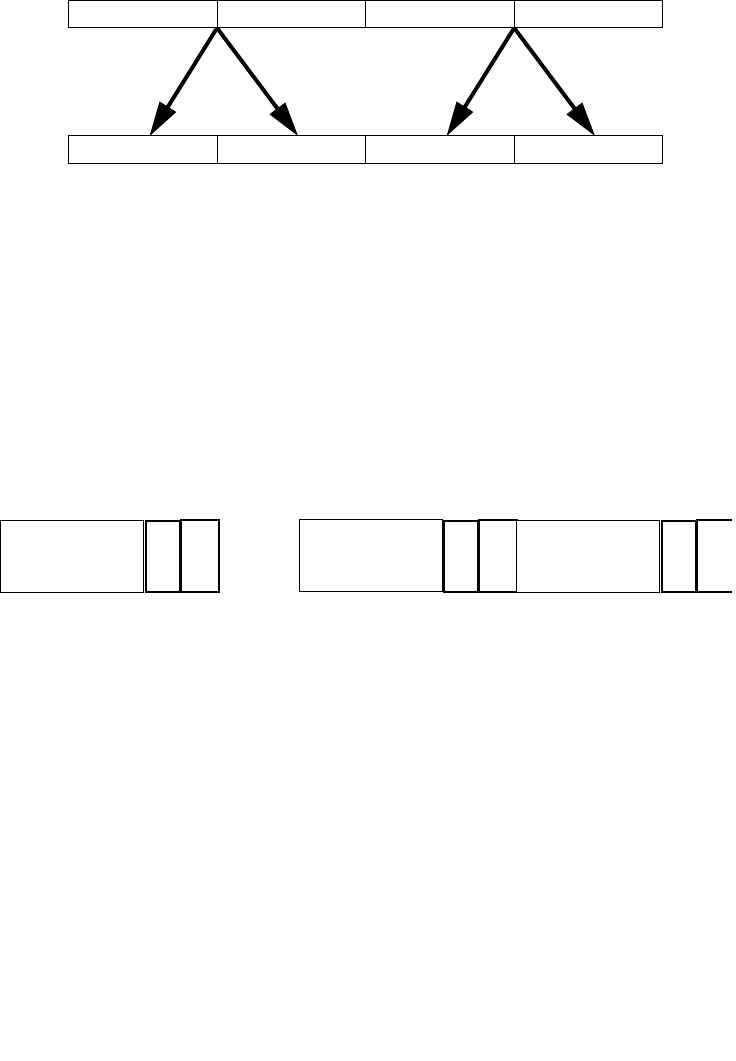
4-98 Vol. 2B VPERMILPD — Permute Double-Precision Floating-Point Values
INSTRUCTION SET REFERENCE, N-Z
Figure 4-3. VPERMILPD operation
There is one control byte per destination double-precision element. Each control byte
is aligned with the low 8 bits of the corresponding double-precision destination
element. Each control byte contains a 1-bit select field (see Figure 4-4) that deter-
mines which of the source elements are selected. Source elements are restricted to
lie in the same source 128-bit region as the destination.
Figure 4-4. VPERMILPD Shuffle Control
(immediate control version)
Permute double-precision floating-point values in the first source operand (second
operand) using two, 1-bit control fields in the low 2 bits of the 8-bit immediate and
store results in the destination operand (first operand). The source operand is a YMM
register or 256-bit memory location and the destination operand is a YMM register.
Note: For the VEX.128.66.0F3A 05 instruction version, VEX.vvvv is reserved and
must be 1111b otherwise instruction will #UD.
X2..X3 X2..X3 X0..X1 X0..X1
DEST
X3 X2
SRC1 X1 X0
1
sel
Bit
. . .
ignored
Control Field1Control Field 2Control Field 4
ignored
65
sel
ignored
194 193
sel
ignored
255
ignored
66
127
ignored
2
63

Vol. 2B 4-99
INSTRUCTION SET REFERENCE, N-Z
VPERMILPD — Permute Double-Precision Floating-Point Values
Note: For the VEX.256.66.0F3A 05 instruction version, VEX.vvvv is reserved and
must be 1111b otherwise instruction will #UD.
Operation
VPERMILPD (256-bit immediate version)
IF (imm8[0] = 0) THEN DEST[63:0]SRC1[63:0]
IF (imm8[0] = 1) THEN DEST[63:0]SRC1[127:64]
IF (imm8[1] = 0) THEN DEST[127:64]SRC1[63:0]
IF (imm8[1] = 1) THEN DEST[127:64]SRC1[127:64]
IF (imm8[2] = 0) THEN DEST[191:128]SRC1[191:128]
IF (imm8[2] = 1) THEN DEST[191:128]SRC1[255:192]
IF (imm8[3] = 0) THEN DEST[255:192]SRC1[191:128]
IF (imm8[3] = 1) THEN DEST[255:192]SRC1[255:192]
VPERMILPD (128-bit immediate version)
IF (imm8[0] = 0) THEN DEST[63:0]SRC1[63:0]
IF (imm8[0] = 1) THEN DEST[63:0]SRC1[127:64]
IF (imm8[1] = 0) THEN DEST[127:64]SRC1[63:0]
IF (imm8[1] = 1) THEN DEST[127:64]SRC1[127:64]
DEST[VLMAX-1:128] 0
VPERMILPD (256-bit variable version)
IF (SRC2[1] = 0) THEN DEST[63:0]SRC1[63:0]
IF (SRC2[1] = 1) THEN DEST[63:0]SRC1[127:64]
IF (SRC2[65] = 0) THEN DEST[127:64]SRC1[63:0]
IF (SRC2[65] = 1) THEN DEST[127:64]SRC1[127:64]
IF (SRC2[129] = 0) THEN DEST[191:128]SRC1[191:128]
IF (SRC2[129] = 1) THEN DEST[191:128]SRC1[255:192]
IF (SRC2[193] = 0) THEN DEST[255:192]SRC1[191:128]
IF (SRC2[193] = 1) THEN DEST[255:192]SRC1[255:192]
VPERMILPD (128-bit variable version)
IF (SRC2[1] = 0) THEN DEST[63:0]SRC1[63:0]
IF (SRC2[1] = 1) THEN DEST[63:0]SRC1[127:64]
IF (SRC2[65] = 0) THEN DEST[127:64]SRC1[63:0]
IF (SRC2[65] = 1) THEN DEST[127:64]SRC1[127:64]
DEST[VLMAX-1:128] 0
Intel C/C++ Compiler Intrinsic Equivalent
VPERMILPD __m128d _mm_permute_pd (__m128d a, int control)
VPERMILPD __m256d _mm256_permute_pd (__m256d a, int control)

4-100 Vol. 2B VPERMILPD — Permute Double-Precision Floating-Point Values
INSTRUCTION SET REFERENCE, N-Z
VPERMILPD __m128d _mm_permutevar_pd (__m128d a, __m128i control);
VPERMILPD __m256d _mm256_permutevar_pd (__m256d a, __m256i control);
SIMD Floating-Point Exceptions
None.
Other Exceptions
See Exceptions Type 6; additionally
#UD If VEX.W = 1

Vol. 2B 4-101
INSTRUCTION SET REFERENCE, N-Z
VPERMILPS — Permute Single-Precision Floating-Point Values
VPERMILPS — Permute Single-Precision Floating-Point Values
Instruction Operand Encoding
Description
(variable control version)
Permute single-precision floating-point values in the first source operand (second
operand) using 8-bit control fields in the low bytes of corresponding elements the
shuffle control (third operand) and store results in the destination operand (first
operand). The first source operand is a YMM register, the second source operand is a
YMM register or a 256-bit memory location, and the destination operand is a YMM
register.
Opcode/
Instruction
Op/
En
64/32 bit
Mode
Support
CPUID
Feature
Flag
Description
VEX.NDS.128.66.0F38.W0 0C /r
VPERMILPS xmm1, xmm2,
xmm3/m128
A V/V AVX Permute single-precision
floating-point values in
xmm2 using controls from
xmm3/mem and store result
in xmm1.
VEX.128.66.0F3A.W0 04 /r ib
VPERMILPS xmm1, xmm2/m128,
imm8
B V/V AVX Permute single-precision
floating-point values in
xmm2/mem using controls
from imm8 and store result
in xmm1.
VEX.NDS.256.66.0F38.W0 0C /r
VPERMILPS ymm1, ymm2,
ymm3/m256
A V/V AVX Permute single-precision
floating-point values in
ymm2 using controls from
ymm3/mem and store result
in ymm1.
VEX.256.66.0F3A.W0 04 /r ib
VPERMILPS ymm1, ymm2/m256,
imm8
B V/V AVX Permute single-precision
floating-point values in
ymm2/mem using controls
from imm8 and store result
in ymm1.
Op/En Operand 1 Operand 2 Operand 3 Operand 4
A ModRM:reg (w) VEX.vvvv (r) ModRM:r/m (r) NA
B ModRM:reg (w) ModRM:r/m (r) NA NA
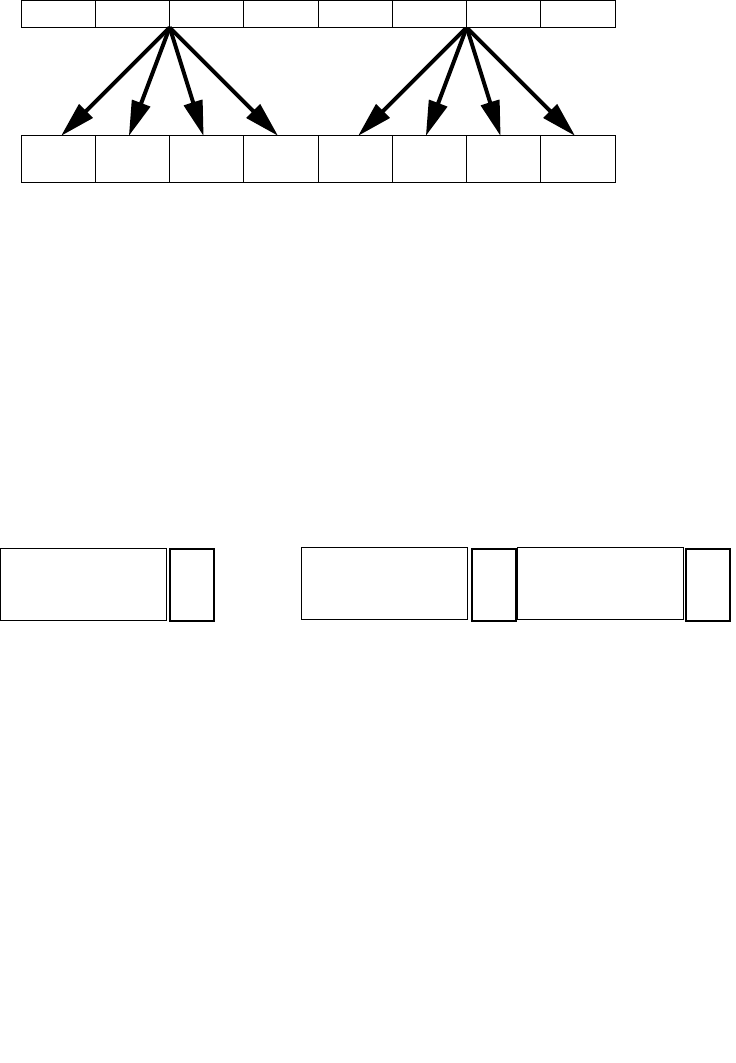
4-102 Vol. 2B VPERMILPS — Permute Single-Precision Floating-Point Values
INSTRUCTION SET REFERENCE, N-Z
Figure 4-5. VPERMILPS Operation
There is one control byte per destination single-precision element. Each control byte
is aligned with the low 8 bits of the corresponding single-precision destination
element. Each control byte contains a 2-bit select field (see Figure 4-6) that deter-
mines which of the source elements are selected. Source elements are restricted to
lie in the same source 128-bit region as the destination.
Figure 4-6. VPERMILPS Shuffle Control
(immediate control version)
Permute single-precision floating-point values in the first source operand (second
operand) using four 2-bit control fields in the 8-bit immediate and store results in the
destination operand (first operand). The source operand is a YMM register or 256-bit
memory location and the destination operand is a YMM register. This is similar to a
wider version of PSHUFD, just operating on single-precision floating-point values.
X7 .. X4 X7 .. X4
X3 ..X0
X3 .. X0
DEST
SRC1 X0X1X2X3X4X5X6X7
X3 .. X0
X7 .. X4 X7 .. X4
X3 ..X0
sel
Bit
34
33 32
sel
. . .
226 225 224
sel
ignored
Control Field 1Control Field 2Control Field 7
10
255
ignored ignored
63 31

Vol. 2B 4-103
INSTRUCTION SET REFERENCE, N-Z
VPERMILPS — Permute Single-Precision Floating-Point Values
Note: For the VEX.128.66.0F3A 04 instruction version, VEX.vvvv is reserved and
must be 1111b otherwise instruction will #UD.
Note: For the VEX.256.66.0F3A 04 instruction version, VEX.vvvv is reserved and
must be 1111b otherwise instruction will #UD.
Operation
Select4(SRC, control) {
CASE (control[1:0]) OF
0: TMP SRC[31:0];
1: TMP SRC[63:32];
2: TMP SRC[95:64];
3: TMP SRC[127:96];
ESAC;
RETURN TMP
}
VPERMILPS (256-bit immediate version)
DEST[31:0] Select4(SRC1[127:0], imm8[1:0]);
DEST[63:32] Select4(SRC1[127:0], imm8[3:2]);
DEST[95:64] Select4(SRC1[127:0], imm8[5:4]);
DEST[127:96] Select4(SRC1[127:0], imm8[7:6]);
DEST[159:128] Select4(SRC1[255:128], imm8[1:0]);
DEST[191:160] Select4(SRC1[255:128], imm8[3:2]);
DEST[223:192] Select4(SRC1[255:128], imm8[5:4]);
DEST[255:224] Select4(SRC1[255:128], imm8[7:6]);
VPERMILPS (128-bit immediate version)
DEST[31:0] Select4(SRC1[127:0], imm8[1:0]);
DEST[63:32] Select4(SRC1[127:0], imm8[3:2]);
DEST[95:64] Select4(SRC1[127:0], imm8[5:4]);
DEST[127:96] Select4(SRC1[127:0], imm8[7:6]);
DEST[VLMAX-1:128] 0
VPERMILPS (256-bit variable version)
DEST[31:0] Select4(SRC1[127:0], SRC2[1:0]);
DEST[63:32] Select4(SRC1[127:0], SRC2[33:32]);
DEST[95:64] Select4(SRC1[127:0], SRC2[65:64]);
DEST[127:96] Select4(SRC1[127:0], SRC2[97:96]);
DEST[159:128] Select4(SRC1[255:128], SRC2[129:128]);
DEST[191:160] Select4(SRC1[255:128], SRC2[161:160]);
DEST[223:192] Select4(SRC1[255:128], SRC2[193:192]);
DEST[255:224] Select4(SRC1[255:128], SRC2[225:224]);

4-104 Vol. 2B VPERMILPS — Permute Single-Precision Floating-Point Values
INSTRUCTION SET REFERENCE, N-Z
VPERMILPS (128-bit variable version)
DEST[31:0] Select4(SRC1[127:0], SRC2[1:0]);
DEST[63:32] Select4(SRC1[127:0], SRC2[33:32]);
DEST[95:64] Select4(SRC1[127:0], SRC2[65:64]);
DEST[127:96] Select4(SRC1[127:0], SRC2[97:96]);
DEST[VLMAX-1:128] 0
Intel C/C++ Compiler Intrinsic Equivalent
VPERM1LPS __m128 _mm_permute_ps (__m128 a, int control);
VPERM1LPS __m256 _mm256_permute_ps (__m256 a, int control);
VPERM1LPS __m128 _mm_permutevar_ps (__m128 a, __m128i control);
VPERM1LPS __m256 _mm256_permutevar_ps (__m256 a, __m256i control);
SIMD Floating-Point Exceptions
None.
Other Exceptions
See Exceptions Type 6; additionally
#UD If VEX.W = 1.
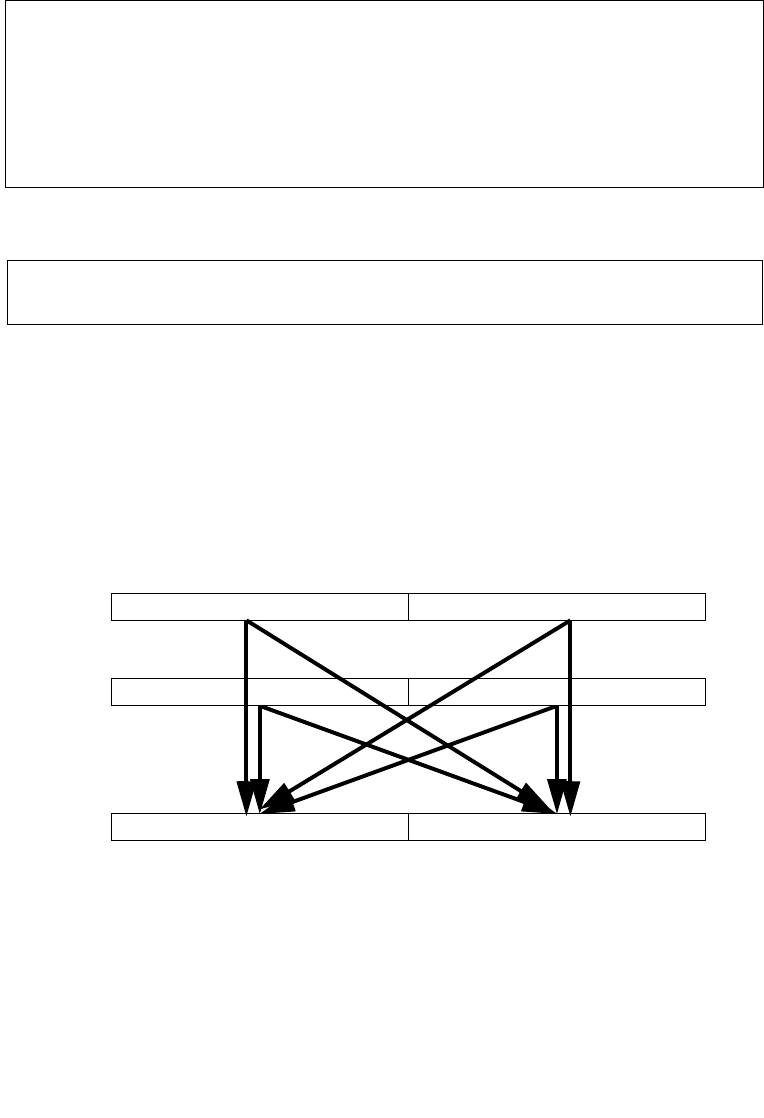
Vol. 2B 4-105
INSTRUCTION SET REFERENCE, N-Z
VPERM2F128 — Permute Floating-Point Values
VPERM2F128 — Permute Floating-Point Values
Instruction Operand Encoding
Description
Permute 128 bit floating-point-containing fields from the first source operand
(second operand) and second source operand (third operand) using bits in the 8-bit
immediate and store results in the destination operand (first operand). The first
source operand is a YMM register, the second source operand is a YMM register or a
256-bit memory location, and the destination operand is a YMM register.
Figure 4-7. VPERM2F128 Operation
Opcode/
Instruction
Op/
En
64/32 bit
Mode
Support
CPUID
Feature
Flag
Description
VEX.NDS.256.66.0F3A.W0 06 /r ib
VPERM2F128 ymm1, ymm2,
ymm3/m256, imm8
A V/V AVX Permute 128-bit floating-
point fields in ymm2 and
ymm3/mem using controls
from imm8 and store result
in ymm1.
Op/En Operand 1 Operand 2 Operand 3 Operand 4
A ModRM:reg (w) VEX.vvvv (r) ModRM:r/m (r) NA
DEST
SRC1 X0X1
X0, X1, Y0, or Y1
Y0Y1
X0, X1, Y0, or Y1
SRC2

4-106 Vol. 2B VPERM2F128 — Permute Floating-Point Values
INSTRUCTION SET REFERENCE, N-Z
Imm8[1:0] select the source for the first destination 128-bit field, imm8[5:4] select
the source for the second destination field. If imm8[3] is set, the low 128-bit field is
zeroed. If imm8[7] is set, the high 128-bit field is zeroed.
VEX.L must be 1, otherwise the instruction will #UD.
Operation
VPERM2F128
CASE IMM8[1:0] of
0: DEST[127:0] SRC1[127:0]
1: DEST[127:0] SRC1[255:128]
2: DEST[127:0] SRC2[127:0]
3: DEST[127:0] SRC2[255:128]
ESAC
CASE IMM8[5:4] of
0: DEST[255:128] SRC1[127:0]
1: DEST[255:128] SRC1[255:128]
2: DEST[255:128] SRC2[127:0]
3: DEST[255:128] SRC2[255:128]
ESAC
IF (imm8[3])
DEST[127:0] 0
FI
IF (imm8[7])
DEST[VLMAX-1:128] 0
FI
Intel C/C++ Compiler Intrinsic Equivalent
VPERM2F128 __m256 _mm256_permute2f128_ps (__m256 a, __m256 b, int control)
VPERM2F128 __m256d _mm256_permute2f128_pd (__m256d a, __m256d b, int control)
VPERM2F128 __m256i _mm256_permute2f128_si256 (__m256i a, __m256i b, int control)
SIMD Floating-Point Exceptions
None.
Other Exceptions
See Exceptions Type 6; additionally
#UD If VEX.L = 0

Vol. 2B 4-107
INSTRUCTION SET REFERENCE, N-Z
VPERM2F128 — Permute Floating-Point Values
If VEX.W = 1.

4-108 Vol. 2B PEXTRB/PEXTRD/PEXTRQ — Extract Byte/Dword/Qword
INSTRUCTION SET REFERENCE, N-Z
PEXTRB/PEXTRD/PEXTRQ — Extract Byte/Dword/Qword
Instruction Operand Encoding
Opcode/
Instruction
Op/
En
64/32 bit
Mode
Support
CPUID
Feature
Flag
Description
66 0F 3A 14
/r ib
PEXTRB reg/m8, xmm2, imm8
A V/V SSE4_1 Extract a byte integer value
from xmm2 at the source
byte offset specified by
imm8 into rreg or m8. The
upper bits of r32 or r64 are
zeroed.
66 0F 3A 16
/r ib
PEXTRD r/m32, xmm2, imm8
A V/V SSE4_1 Extract a dword integer
value from xmm2 at the
source dword offset
specified by imm8 into
r/m32.
66 REX.W 0F 3A 16
/r ib
PEXTRQ r/m64, xmm2, imm8
A V/N.E. SSE4_1 Extract a qword integer
value from xmm2 at the
source qword offset
specified by imm8 into
r/m64.
VEX.128.66.0F3A.W0 14 /r ib
VPEXTRB reg/m8, xmm2, imm8
AV
1/V AVX Extract a byte integer value
from xmm2 at the source
byte offset specified by
imm8 into reg or m8. The
upper bits of r64/r32 is
filled with zeros.
VEX.128.66.0F3A.W0 16 /r ib
VPEXTRD r32/m32, xmm2, imm8
A V/V AVX Extract a dword integer
value from xmm2 at the
source dword offset
specified by imm8 into
r32/m32.
VEX.128.66.0F3A.W1 16 /r ib
VPEXTRQ r64/m64, xmm2, imm8
A V/i AVX Extract a qword integer
value from xmm2 at the
source dword offset
specified by imm8 into
r64/m64.
NOTES:
1. In 64-bit mode, VEX.W1 is ignored for VPEXTRB (similar to legacy REX.W=1 prefix in PEXTRB).
Op/En Operand 1 Operand 2 Operand 3 Operand 4
A ModRM:r/m (w) ModRM:reg (r) imm8 NA

Vol. 2B 4-109
INSTRUCTION SET REFERENCE, N-Z
PEXTRB/PEXTRD/PEXTRQ — Extract Byte/Dword/Qword
Description
Extract a byte/dword/qword integer value from the source XMM register at a
byte/dword/qword offset determined from imm8[3:0]. The destination can be a
register or byte/dword/qword memory location. If the destination is a register, the
upper bits of the register are zero extended.
In legacy non-VEX encoded version and if the destination operand is a register, the
default operand size in 64-bit mode for PEXTRB/PEXTRD is 64 bits, the bits above the
least significant byte/dword data are filled with zeros. PEXTRQ is not encodable in
non-64-bit modes and requires REX.W in 64-bit mode.
Note: In VEX.128 encoded versions, VEX.vvvv is reserved and must be 1111b, VEX.L
must be 0, otherwise the instruction will #UD. If the destination operand is a register,
the default operand size in 64-bit mode for VPEXTRB/VPEXTRD is 64 bits, the bits
above the least significant byte/word/dword data are filled with zeros. Attempt to
execute VPEXTRQ in non-64-bit mode will cause #UD.
Operation
CASE of
PEXTRB: SEL COUNT[3:0];
TEMP (Src >> SEL*8) AND FFH;
IF (DEST = Mem8)
THEN
Mem8 TEMP[7:0];
ELSE IF (64-Bit Mode and 64-bit register selected)
THEN
R64[7:0] TEMP[7:0];
r64[63:8] ← ZERO_FILL; };
ELSE
R32[7:0] TEMP[7:0];
r32[31:8] ← ZERO_FILL; };
FI;
PEXTRD:SEL COUNT[1:0];
TEMP (Src >> SEL*32) AND FFFF_FFFFH;
DEST TEMP;
PEXTRQ: SEL COUNT[0];
TEMP (Src >> SEL*64);
DEST TEMP;
EASC:
(V)PEXTRTD/(V)PEXTRQ
IF (64-Bit Mode and 64-bit dest operand)
THEN
Src_Offset Imm8[0]

4-110 Vol. 2B PEXTRB/PEXTRD/PEXTRQ — Extract Byte/Dword/Qword
INSTRUCTION SET REFERENCE, N-Z
r64/m64 (Src >> Src_Offset * 64)
ELSE
Src_Offset Imm8[1:0]
r32/m32 ((Src >> Src_Offset *32) AND 0FFFFFFFFh);
FI
(V)PEXTRB ( dest=m8)
SRC_Offset Imm8[3:0]
Mem8 (Src >> Src_Offset*8)
(V)PEXTRB ( dest=reg)
IF (64-Bit Mode )
THEN
SRC_Offset Imm8[3:0]
DEST[7:0] ((Src >> Src_Offset*8) AND 0FFh)
DEST[63:8] ZERO_FILL;
ELSE
SRC_Offset . Imm8[3:0];
DEST[7:0] ((Src >> Src_Offset*8) AND 0FFh);
DEST[31:8] ZERO_FILL;
FI
Intel C/C++ Compiler Intrinsic Equivalent
PEXTRB int _mm_extract_epi8 (__m128i src, const int ndx);
PEXTRD int _mm_extract_epi32 (__m128i src, const int ndx);
PEXTRQ __int64 _mm_extract_epi64 (__m128i src, const int ndx);
Flags Affected
None.
SIMD Floating-Point Exceptions
None.
Other Exceptions
See Exceptions Type 5; additionally
#UD If VEX.L = 1.
If VEX.vvvv != 1111B.
If VPEXTRQ in non-64-bit mode, VEX.W=1.

Vol. 2B 4-111
INSTRUCTION SET REFERENCE, N-Z
PEXTRW—Extract Word
PEXTRW—Extract Word
Instruction Operand Encoding
Opcode/
Instruction
Op/
En
64/32 bit
Mode
Support
CPUID
Feature
Flag
Description
0F C5 /r ib1
PEXTRW reg, mm, imm8
A V/V SSE Extract the word specified
by imm8 from mm and move
it to reg, bits 15-0. The
upper bits of r32 or r64 is
zeroed.
66 0F C5 /r ib
PEXTRW reg, xmm, imm8
A V/V SSE4_1 Extract the word specified
by imm8 from xmm and
move it to reg, bits 15-0.
The upper bits of r32 or r64
is zeroed.
66 0F 3A 15
/r ib
PEXTRW reg/m16, xmm, imm8
B V/V SSE4_1 Extract the word specified
by imm8 from xmm and
copy it to lowest 16 bits of
reg or m16. Zero-extend
the result in the destination,
r32 or r64.
VEX.128.66.0F.W0 C5 /r ib
VPEXTRW reg, xmm1, imm8
AV
2/V AVX Extract the word specified
by imm8 from xmm1 and
move it to reg, bits 15:0.
Zero-extend the result. The
upper bits of r64/r32 is
filled with zeros.
VEX.128.66.0F3A.W0 15 /r ib
VPEXTRW reg/m16, xmm2, imm8
B V/V AVX Extract a word integer value
from xmm2 at the source
word offset specified by
imm8 into reg or m16. The
upper bits of r64/r32 is
filled with zeros.
NOTES:
1. See note in Section 2.4, “Instruction Exception Specification”.
2. In 64-bit mode, VEX.W1 is ignored for VPEXTRW (similar to legacy REX.W=1 prefix in PEXTRW).
Op/En Operand 1 Operand 2 Operand 3 Operand 4
A ModRM:reg (w) ModRM:r/m (r) imm8 NA
B ModRM:r/m (w) ModRM:reg (r) imm8 NA

4-112 Vol. 2B PEXTRW—Extract Word
INSTRUCTION SET REFERENCE, N-Z
Description
Copies the word in the source operand (second operand) specified by the count
operand (third operand) to the destination operand (first operand). The source
operand can be an MMX technology register or an XMM register. The destination
operand can be the low word of a general-purpose register or a 16-bit memory
address. The count operand is an 8-bit immediate. When specifying a word location
in an MMX technology register, the 2 least-significant bits of the count operand
specify the location; for an XMM register, the 3 least-significant bits specify the loca-
tion. The content of the destination register above bit 16 is cleared (set to all 0s).
In 64-bit mode, using a REX prefix in the form of REX.R permits this instruction to
access additional registers (XMM8-XMM15, R8-15). If the destination operand is a
general-purpose register, the default operand size is 64-bits in 64-bit mode.
Note: In VEX.128 encoded versions, VEX.vvvv is reserved and must be 1111b, VEX.L
must be 0, otherwise the instruction will #UD. If the destination operand is a register,
the default operand size in 64-bit mode for VPEXTRW is 64 bits, the bits above the
least significant byte/word/dword data are filled with zeros.
Operation
IF (DEST = Mem16)
THEN
SEL COUNT[2:0];
TEMP (Src >> SEL*16) AND FFFFH;
Mem16 TEMP[15:0];
ELSE IF (64-Bit Mode and destination is a general-purpose register)
THEN
FOR (PEXTRW instruction with 64-bit source operand)
{SEL ← COUNT[1:0];
TEMP ← (SRC >> (SEL ∗ 16)) AND FFFFH;
r64[15:0] ← TEMP[15:0];
r64[63:16] ← ZERO_FILL; };
FOR (PEXTRW instruction with 128-bit source operand)
{SEL ← COUNT[2:0];
TEMP ← (SRC >> (SEL ∗ 16)) AND FFFFH;
r64[15:0] ← TEMP[15:0];
r64[63:16] ← ZERO_FILL; }
ELSE
FOR (PEXTRW instruction with 64-bit source operand)
{SEL ← COUNT[1:0];
TEMP ← (SRC >> (SEL ∗ 16)) AND FFFFH;
r32[15:0] ← TEMP[15:0];
r32[31:16] ← ZERO_FILL; };
FOR (PEXTRW instruction with 128-bit source operand)
{SEL ← COUNT[2:0];

Vol. 2B 4-113
INSTRUCTION SET REFERENCE, N-Z
PEXTRW—Extract Word
TEMP ← (SRC >> (SEL ∗ 16)) AND FFFFH;
r32[15:0] ← TEMP[15:0];
r32[31:16] ← ZERO_FILL; };
FI;
FI;
(V)PEXTRW ( dest=m16)
SRC_Offset Imm8[2:0]
Mem16 (Src >> Src_Offset*16)
(V)PEXTRW ( dest=reg)
IF (64-Bit Mode )
THEN
SRC_Offset Imm8[2:0]
DEST[15:0] ((Src >> Src_Offset*16) AND 0FFFFh)
DEST[63:16] ZERO_FILL;
ELSE
SRC_Offset Imm8[2:0]
DEST[15:0] ((Src >> Src_Offset*16) AND 0FFFFh)
DEST[31:16] ZERO_FILL;
FI
Intel C/C++ Compiler Intrinsic Equivalent
PEXTRW int _mm_extract_pi16 (__m64 a, int n)
PEXTRW int _mm_extract_epi16 ( __m128i a, int imm)
Flags Affected
None.
Numeric Exceptions
None.
Other Exceptions
See Exceptions Type 5; additionally
#UD If VEX.L = 1.
If VEX.vvvv != 1111B.
If VPEXTRQ in non-64-bit mode, VEX.W=1.

4-114 Vol. 2B PHADDW/PHADDD — Packed Horizontal Add
INSTRUCTION SET REFERENCE, N-Z
PHADDW/PHADDD — Packed Horizontal Add
Instruction Operand Encoding
Description
PHADDW adds two adjacent 16-bit signed integers horizontally from the source and
destination operands and packs the 16-bit signed results to the destination operand
(first operand). PHADDD adds two adjacent 32-bit signed integers horizontally from
the source and destination operands and packs the 32-bit signed results to the desti-
nation operand (first operand). Both operands can be MMX or XMM registers. When
the source operand is a 128-bit memory operand, the operand must be aligned on a
16-byte boundary or a general-protection exception (#GP) will be generated.
In 64-bit mode, use the REX prefix to access additional registers.
128-bit Legacy SSE version: Bits (VLMAX-1:128) of the corresponding YMM destina-
tion register remain unchanged.
Opcode/
Instruction
Op/
En
64/32 bit
Mode
Support
CPUID
Feature
Flag
Description
0F 38 01 /r1
PHADDW mm1, mm2/m64
A V/V SSSE3 Add 16-bit signed integers
horizontally, pack to MM1.
66 0F 38 01 /r
PHADDW xmm1, xmm2/m128
A V/V SSSE3 Add 16-bit signed integers
horizontally, pack to XMM1.
0F 38 02 /r
PHADDD mm1, mm2/m64
A V/V SSSE3 Add 32-bit signed integers
horizontally, pack to MM1.
66 0F 38 02 /r
PHADDD xmm1, xmm2/m128
A V/V SSSE3 Add 32-bit signed integers
horizontally, pack to XMM1.
VEX.NDS.128.66.0F38.WIG 01 /r
VPHADDW xmm1, xmm2,
xmm3/m128
B V/V AVX Add 16-bit signed integers
horizontally, pack to xmm1.
VEX.NDS.128.66.0F38.WIG 02 /r
VPHADDD xmm1, xmm2,
xmm3/m128
B V/V AVX Add 32-bit signed integers
horizontally, pack to xmm1.
NOTES:
1. See note in Section 2.4, “Instruction Exception Specification”.
Op/En Operand 1 Operand 2 Operand 3 Operand 4
A ModRM:reg (r, w) ModRM:r/m (r) NA NA
B ModRM:reg (w) VEX.vvvv (r) ModRM:r/m (r) NA

Vol. 2B 4-115
INSTRUCTION SET REFERENCE, N-Z
PHADDW/PHADDD — Packed Horizontal Add
VEX.128 encoded version: Bits (VLMAX-1:128) of the destination YMM register are
zeroed. VEX.L must be 0, otherwise the instruction will #UD.
Operation
PHADDW (with 64-bit operands)
mm1[15-0] = mm1[31-16] + mm1[15-0];
mm1[31-16] = mm1[63-48] + mm1[47-32];
mm1[47-32] = mm2/m64[31-16] + mm2/m64[15-0];
mm1[63-48] = mm2/m64[63-48] + mm2/m64[47-32];
PHADDW (with 128-bit operands)
xmm1[15-0] = xmm1[31-16] + xmm1[15-0];
xmm1[31-16] = xmm1[63-48] + xmm1[47-32];
xmm1[47-32] = xmm1[95-80] + xmm1[79-64];
xmm1[63-48] = xmm1[127-112] + xmm1[111-96];
xmm1[79-64] = xmm2/m128[31-16] + xmm2/m128[15-0];
xmm1[95-80] = xmm2/m128[63-48] + xmm2/m128[47-32];
xmm1[111-96] = xmm2/m128[95-80] + xmm2/m128[79-64];
xmm1[127-112] = xmm2/m128[127-112] + xmm2/m128[111-96];
PHADDD (with 64-bit operands)
mm1[31-0] = mm1[63-32] + mm1[31-0];
mm1[63-32] = mm2/m64[63-32] + mm2/m64[31-0];
PHADDD (with 128-bit operands)
xmm1[31-0] = xmm1[63-32] + xmm1[31-0];
xmm1[63-32] = xmm1[127-96] + xmm1[95-64];
xmm1[95-64] = xmm2/m128[63-32] + xmm2/m128[31-0];
xmm1[127-96] = xmm2/m128[127-96] + xmm2/m128[95-64];
VPHADDW (VEX.128 encoded version)
DEST[15:0] SRC1[31:16] + SRC1[15:0]
DEST[31:16] SRC1[63:48] + SRC1[47:32]
DEST[47:32] SRC1[95:80] + SRC1[79:64]
DEST[63:48] SRC1[127:112] + SRC1[111:96]
DEST[79:64] SRC2[31:16] + SRC2[15:0]
DEST[95:80] SRC2[63:48] + SRC2[47:32]
DEST[111:96] SRC2[95:80] + SRC2[79:64]
DEST[127:112] SRC2[127:112] + SRC2[111:96]
DEST[VLMAX-1:128] 0
VPHADDD (VEX.128 encoded version)

4-116 Vol. 2B PHADDW/PHADDD — Packed Horizontal Add
INSTRUCTION SET REFERENCE, N-Z
DEST[31-0] SRC1[63-32] + SRC1[31-0]
DEST[63-32] SRC1[127-96] + SRC1[95-64]
DEST[95-64] SRC2[63-32] + SRC2[31-0]
DEST[127-96] SRC2[127-96] + SRC2[95-64]
DEST[VLMAX-1:128] 0
Intel C/C++ Compiler Intrinsic Equivalents
PHADDW __m64 _mm_hadd_pi16 (__m64 a, __m64 b)
PHADDW __m128i _mm_hadd_epi16 (__m128i a, __m128i b)
PHADDD __m64 _mm_hadd_pi32 (__m64 a, __m64 b)
PHADDD __m128i _mm_hadd_epi32 (__m128i a, __m128i b)
SIMD Floating-Point Exceptions
None.
Other Exceptions
See Exceptions Type 4; additionally
#UD If VEX.L = 1.

Vol. 2B 4-117
INSTRUCTION SET REFERENCE, N-Z
PHADDSW — Packed Horizontal Add and Saturate
PHADDSW — Packed Horizontal Add and Saturate
Instruction Operand Encoding
Description
PHADDSW adds two adjacent signed 16-bit integers horizontally from the source and
destination operands and saturates the signed results; packs the signed, saturated
16-bit results to the destination operand (first operand) Both operands can be MMX
or XMM registers. When the source operand is a 128-bit memory operand, the
operand must be aligned on a 16-byte boundary or a general-protection exception
(#GP) will be generated.
In 64-bit mode, use the REX prefix to access additional registers.
128-bit Legacy SSE version: Bits (VLMAX-1:128) of the corresponding YMM destina-
tion register remain unchanged.
VEX.128 encoded version: Bits (VLMAX-1:128) of the destination YMM register are
zeroed. VEX.L must be 0, otherwise the instruction will #UD.
Operation
PHADDSW (with 64-bit operands)
mm1[15-0] = SaturateToSignedWord((mm1[31-16] + mm1[15-0]);
mm1[31-16] = SaturateToSignedWord(mm1[63-48] + mm1[47-32]);
Opcode/
Instruction
Op/
En
64/32 bit
Mode
Support
CPUID
Feature
Flag
Description
0F 38 03 /r1
PHADDSW mm1, mm2/m64
A V/V SSSE3 Add 16-bit signed integers
horizontally, pack saturated
integers to MM1.
66 0F 38 03 /r
PHADDSW xmm1, xmm2/m128
A V/V SSSE3 Add 16-bit signed integers
horizontally, pack saturated
integers to XMM1.
VEX.NDS.128.66.0F38.WIG 03 /r
VPHADDSW xmm1, xmm2,
xmm3/m128
B V/V AVX Add 16-bit signed integers
horizontally, pack saturated
integers to xmm1.
NOTES:
1. See note in Section 2.4, “Instruction Exception Specification”.
Op/En Operand 1 Operand 2 Operand 3 Operand 4
A ModRM:reg (r, w) ModRM:r/m (r) NA NA
B ModRM:reg (w) VEX.vvvv (r) ModRM:r/m (r) NA

4-118 Vol. 2B PHADDSW — Packed Horizontal Add and Saturate
INSTRUCTION SET REFERENCE, N-Z
mm1[47-32] = SaturateToSignedWord(mm2/m64[31-16] + mm2/m64[15-0]);
mm1[63-48] = SaturateToSignedWord(mm2/m64[63-48] + mm2/m64[47-32]);
PHADDSW (with 128-bit operands)
xmm1[15-0]= SaturateToSignedWord(xmm1[31-16] + xmm1[15-0]);
xmm1[31-16] = SaturateToSignedWord(xmm1[63-48] + xmm1[47-32]);
xmm1[47-32] = SaturateToSignedWord(xmm1[95-80] + xmm1[79-64]);
xmm1[63-48] = SaturateToSignedWord(xmm1[127-112] + xmm1[111-96]);
xmm1[79-64] = SaturateToSignedWord(xmm2/m128[31-16] + xmm2/m128[15-0]);
xmm1[95-80] = SaturateToSignedWord(xmm2/m128[63-48] + xmm2/m128[47-32]);
xmm1[111-96] = SaturateToSignedWord(xmm2/m128[95-80] + xmm2/m128[79-64]);
xmm1[127-112] = SaturateToSignedWord(xmm2/m128[127-112] + xmm2/m128[111-96]);
VPHADDSW (VEX.128 encoded version)
DEST[15:0]= SaturateToSignedWord(SRC1[31:16] + SRC1[15:0])
DEST[31:16] = SaturateToSignedWord(SRC1[63:48] + SRC1[47:32])
DEST[47:32] = SaturateToSignedWord(SRC1[95:80] + SRC1[79:64])
DEST[63:48] = SaturateToSignedWord(SRC1[127:112] + SRC1[111:96])
DEST[79:64] = SaturateToSignedWord(SRC2[31:16] + SRC2[15:0])
DEST[95:80] = SaturateToSignedWord(SRC2[63:48] + SRC2[47:32])
DEST[111:96] = SaturateToSignedWord(SRC2[95:80] + SRC2[79:64])
DEST[127:112] = SaturateToSignedWord(SRC2[127:112] + SRC2[111:96])
DEST[VLMAX-1:128] 0
Intel C/C++ Compiler Intrinsic Equivalent
PHADDSW __m64 _mm_hadds_pi16 (__m64 a, __m64 b)
PHADDSW __m128i _mm_hadds_epi16 (__m128i a, __m128i b)
SIMD Floating-Point Exceptions
None.
Other Exceptions
See Exceptions Type 4; additionally
#UD If VEX.L = 1.

Vol. 2B 4-119
INSTRUCTION SET REFERENCE, N-Z
PHMINPOSUW — Packed Horizontal Word Minimum
PHMINPOSUW — Packed Horizontal Word Minimum
Instruction Operand Encoding
Description
Determine the minimum unsigned word value in the source operand (second
operand) and place the unsigned word in the low word (bits 0-15) of the destination
operand (first operand). The word index of the minimum value is stored in bits 16-
18 of the destination operand. The remaining upper bits of the destination are set to
zero.
128-bit Legacy SSE version: Bits (VLMAX-1:128) of the corresponding YMM destina-
tion register remain unchanged.
VEX.128 encoded version: Bits (VLMAX-1:128) of the destination YMM register are
zeroed. VEX.vvvv is reserved and must be 1111b, VEX.L must be 0, otherwise the
instruction will #UD.
Operation
PHMINPOSUW (128-bit Legacy SSE version)
INDEX 0;
MIN SRC[15:0]
IF (SRC[31:16] < MIN)
THEN INDEX 1; MIN SRC[31:16]; FI;
IF (SRC[47:32] < MIN)
Opcode/
Instruction
Op/
En
64/32 bit
Mode
Support
CPUID
Feature
Flag
Description
66 0F 38 41 /r
PHMINPOSUW xmm1, xmm2/m128
A V/V SSE4_1 Find the minimum unsigned
word in xmm2/m128 and
place its value in the low
word of xmm1 and its index
in the second-lowest word
of xmm1.
VEX.128.66.0F38.WIG 41 /r
VPHMINPOSUW xmm1, xmm2/m128
A V/V AVX Find the minimum unsigned
word in xmm2/m128 and
place its value in the low
word of xmm1 and its index
in the second-lowest word
of xmm1.
Op/En Operand 1 Operand 2 Operand 3 Operand 4
A ModRM:reg (w) ModRM:r/m (r) NA NA

4-120 Vol. 2B PHMINPOSUW — Packed Horizontal Word Minimum
INSTRUCTION SET REFERENCE, N-Z
THEN INDEX 2; MIN SRC[47:32]; FI;
* Repeat operation for words 3 through 6
IF (SRC[127:112] < MIN)
THEN INDEX 7; MIN SRC[127:112]; FI;
DEST[15:0] MIN;
DEST[18:16] INDEX;
DEST[127:19] 0000000000000000000000000000H;
VPHMINPOSUW (VEX.128 encoded version)
INDEX 0
MIN SRC[15:0]
IF (SRC[31:16] < MIN) THEN INDEX 1; MIN SRC[31:16]
IF (SRC[47:32] < MIN) THEN INDEX 2; MIN SRC[47:32]
* Repeat operation for words 3 through 6
IF (SRC[127:112] < MIN) THEN INDEX 7; MIN SRC[127:112]
DEST[15:0] MIN
DEST[18:16] INDEX
DEST[127:19] 0000000000000000000000000000H
DEST[VLMAX-1:128] 0
Intel C/C++ Compiler Intrinsic Equivalent
PHMINPOSUW __m128i _mm_minpos_epu16( __m128i packed_words);
Flags Affected
None.
SIMD Floating-Point Exceptions
None.
Other Exceptions
See Exceptions Type 4; additionally
#UD If VEX.L = 1.
If VEX.vvvv != 1111B.

Vol. 2B 4-121
INSTRUCTION SET REFERENCE, N-Z
PHSUBW/PHSUBD — Packed Horizontal Subtract
PHSUBW/PHSUBD — Packed Horizontal Subtract
Instruction Operand Encoding
Description
PHSUBW performs horizontal subtraction on each adjacent pair of 16-bit signed inte-
gers by subtracting the most significant word from the least significant word of each
pair in the source and destination operands, and packs the signed 16-bit results to
the destination operand (first operand). PHSUBD performs horizontal subtraction on
each adjacent pair of 32-bit signed integers by subtracting the most significant
doubleword from the least significant doubleword of each pair, and packs the signed
32-bit result to the destination operand. Both operands can be MMX or XMM regis-
ters. When the source operand is a 128-bit memory operand, the operand must be
Opcode/
Instruction
Op/
En
64/32 bit
Mode
Support
CPUID
Feature
Flag
Description
0F 38 05 /r1
PHSUBW mm1, mm2/m64
A V/V SSSE3 Subtract 16-bit signed
integers horizontally, pack
to MM1.
66 0F 38 05 /r
PHSUBW xmm1, xmm2/m128
A V/V SSSE3 Subtract 16-bit signed
integers horizontally, pack
to XMM1.
0F 38 06 /r
PHSUBD mm1, mm2/m64
A V/V SSSE3 Subtract 32-bit signed
integers horizontally, pack
to MM1.
66 0F 38 06 /r
PHSUBD xmm1, xmm2/m128
A V/V SSSE3 Subtract 32-bit signed
integers horizontally, pack
to XMM1.
VEX.NDS.128.66.0F38.WIG 05 /r
VPHSUBW xmm1, xmm2,
xmm3/m128
B V/V AVX Subtract 16-bit signed
integers horizontally, pack
to xmm1.
VEX.NDS.128.66.0F38.WIG 06 /r
VPHSUBD xmm1, xmm2,
xmm3/m128
B V/V AVX Subtract 32-bit signed
integers horizontally, pack
to xmm1.
NOTES:
1. See note in Section 2.4, “Instruction Exception Specification”.
Op/En Operand 1 Operand 2 Operand 3 Operand 4
A ModRM:reg (r, w) ModRM:r/m (r) NA NA
B ModRM:reg (r, w) VEX.vvvv (r) ModRM:r/m (r) NA

4-122 Vol. 2B PHSUBW/PHSUBD — Packed Horizontal Subtract
INSTRUCTION SET REFERENCE, N-Z
aligned on a 16-byte boundary or a general-protection exception (#GP) will be
generated.
In 64-bit mode, use the REX prefix to access additional registers.
128-bit Legacy SSE version: Bits (VLMAX-1:128) of the corresponding YMM destina-
tion register remain unchanged.
VEX.128 encoded version: Bits (VLMAX-1:128) of the destination YMM register are
zeroed. VEX.L must be 0, otherwise the instruction will #UD.
Operation
PHSUBW (with 64-bit operands)
mm1[15-0] = mm1[15-0] - mm1[31-16];
mm1[31-16] = mm1[47-32] - mm1[63-48];
mm1[47-32] = mm2/m64[15-0] - mm2/m64[31-16];
mm1[63-48] = mm2/m64[47-32] - mm2/m64[63-48];
PHSUBW (with 128-bit operands)
xmm1[15-0] = xmm1[15-0] - xmm1[31-16];
xmm1[31-16] = xmm1[47-32] - xmm1[63-48];
xmm1[47-32] = xmm1[79-64] - xmm1[95-80];
xmm1[63-48] = xmm1[111-96] - xmm1[127-112];
xmm1[79-64] = xmm2/m128[15-0] - xmm2/m128[31-16];
xmm1[95-80] = xmm2/m128[47-32] - xmm2/m128[63-48];
xmm1[111-96] = xmm2/m128[79-64] - xmm2/m128[95-80];
xmm1[127-112] = xmm2/m128[111-96] - xmm2/m128[127-112];
PHSUBD (with 64-bit operands)
mm1[31-0] = mm1[31-0] - mm1[63-32];
mm1[63-32] = mm2/m64[31-0] - mm2/m64[63-32];
PHSUBD (with 128-bit operands)
xmm1[31-0] = xmm1[31-0] - xmm1[63-32];
xmm1[63-32] = xmm1[95-64] - xmm1[127-96];
xmm1[95-64] = xmm2/m128[31-0] - xmm2/m128[63-32];
xmm1[127-96] = xmm2/m128[95-64] - xmm2/m128[127-96];
VPHSUBW (VEX.128 encoded version)
DEST[15:0] SRC1[15:0] - SRC1[31:16]
DEST[31:16] SRC1[47:32] - SRC1[63:48]
DEST[47:32] SRC1[79:64] - SRC1[95:80]
DEST[63:48] SRC1[111:96] - SRC1[127:112]
DEST[79:64] SRC2[15:0] - SRC2[31:16]
DEST[95:80] SRC2[47:32] - SRC2[63:48]

Vol. 2B 4-123
INSTRUCTION SET REFERENCE, N-Z
PHSUBW/PHSUBD — Packed Horizontal Subtract
DEST[111:96] SRC2[79:64] - SRC2[95:80]
DEST[127:112] SRC2[111:96] - SRC2[127:112]
DEST[VLMAX-1:128] 0
VPHSUBD (VEX.128 encoded version)
DEST[31-0] SRC1[31-0] - SRC1[63-32]
DEST[63-32] SRC1[95-64] - SRC1[127-96]
DEST[95-64] SRC2[31-0] - SRC2[63-32]
DEST[127-96] SRC2[95-64] - SRC2[127-96]
DEST[VLMAX-1:128] 0
Intel C/C++ Compiler Intrinsic Equivalents
PHSUBW __m64 _mm_hsub_pi16 (__m64 a, __m64 b)
PHSUBW __m128i _mm_hsub_epi16 (__m128i a, __m128i b)
PHSUBD __m64 _mm_hsub_pi32 (__m64 a, __m64 b)
PHSUBD __m128i _mm_hsub_epi32 (__m128i a, __m128i b)
SIMD Floating-Point Exceptions
None.
Other Exceptions
See Exceptions Type 4; additionally
#UD If VEX.L = 1.

4-124 Vol. 2B PHSUBSW — Packed Horizontal Subtract and Saturate
INSTRUCTION SET REFERENCE, N-Z
PHSUBSW — Packed Horizontal Subtract and Saturate
Instruction Operand Encoding
Description
PHSUBSW performs horizontal subtraction on each adjacent pair of 16-bit signed
integers by subtracting the most significant word from the least significant word of
each pair in the source and destination operands. The signed, saturated 16-bit
results are packed to the destination operand (first operand). Both operands can be
MMX or XMM register. When the source operand is a 128-bit memory operand, the
operand must be aligned on a 16-byte boundary or a general-protection exception
(#GP) will be generated.
In 64-bit mode, use the REX prefix to access additional registers.
128-bit Legacy SSE version: Bits (VLMAX-1:128) of the corresponding YMM destina-
tion register remain unchanged.
VEX.128 encoded version: Bits (VLMAX-1:128) of the destination YMM register are
zeroed. VEX.L must be 0, otherwise the instruction will #UD.
Operation
PHSUBSW (with 64-bit operands)
mm1[15-0] = SaturateToSignedWord(mm1[15-0] - mm1[31-16]);
mm1[31-16] = SaturateToSignedWord(mm1[47-32] - mm1[63-48]);
Opcode/
Instruction
Op/
En
64/32 bit
Mode
Support
CPUID
Feature
Flag
Description
0F 38 07 /r1
PHSUBSW mm1, mm2/m64
A V/V SSSE3 Subtract 16-bit signed
integer horizontally, pack
saturated integers to MM1.
66 0F 38 07 /r
PHSUBSW xmm1, xmm2/m128
A V/V SSSE3 Subtract 16-bit signed
integer horizontally, pack
saturated integers to XMM1
VEX.NDS.128.66.0F38.WIG 07 /r
VPHSUBSW xmm1, xmm2,
xmm3/m128
B V/V AVX Subtract 16-bit signed
integer horizontally, pack
saturated integers to xmm1.
NOTES:
1. See note in Section 2.4, “Instruction Exception Specification”.
Op/En Operand 1 Operand 2 Operand 3 Operand 4
A ModRM:reg (r, w) ModRM:r/m (r) NA NA
B ModRM:reg (r, w) VEX.vvvv (r) ModRM:r/m (r) NA

Vol. 2B 4-125
INSTRUCTION SET REFERENCE, N-Z
PHSUBSW — Packed Horizontal Subtract and Saturate
mm1[47-32] = SaturateToSignedWord(mm2/m64[15-0] - mm2/m64[31-16]);
mm1[63-48] = SaturateToSignedWord(mm2/m64[47-32] - mm2/m64[63-48]);
PHSUBSW (with 128-bit operands)
xmm1[15-0] = SaturateToSignedWord(xmm1[15-0] - xmm1[31-16]);
xmm1[31-16] = SaturateToSignedWord(xmm1[47-32] - xmm1[63-48]);
xmm1[47-32] = SaturateToSignedWord(xmm1[79-64] - xmm1[95-80]);
xmm1[63-48] = SaturateToSignedWord(xmm1[111-96] - xmm1[127-112]);
xmm1[79-64] = SaturateToSignedWord(xmm2/m128[15-0] - xmm2/m128[31-16]);
xmm1[95-80] =SaturateToSignedWord(xmm2/m128[47-32] - xmm2/m128[63-48]);
xmm1[111-96] =SaturateToSignedWord(xmm2/m128[79-64] - xmm2/m128[95-80]);
xmm1[127-112]= SaturateToSignedWord(xmm2/m128[111-96] - xmm2/m128[127-112]);
VPHSUBSW (VEX.128 encoded version)
DEST[15:0]= SaturateToSignedWord(SRC1[15:0] - SRC1[31:16])
DEST[31:16] = SaturateToSignedWord(SRC1[47:32] - SRC1[63:48])
DEST[47:32] = SaturateToSignedWord(SRC1[79:64] - SRC1[95:80])
DEST[63:48] = SaturateToSignedWord(SRC1[111:96] - SRC1[127:112])
DEST[79:64] = SaturateToSignedWord(SRC2[15:0] - SRC2[31:16])
DEST[95:80] = SaturateToSignedWord(SRC2[47:32] - SRC2[63:48])
DEST[111:96] = SaturateToSignedWord(SRC2[79:64] - SRC2[95:80])
DEST[127:112] = SaturateToSignedWord(SRC2[111:96] - SRC2[127:112])
DEST[VLMAX-1:128] 0
Intel C/C++ Compiler Intrinsic Equivalent
PHSUBSW __m64 _mm_hsubs_pi16 (__m64 a, __m64 b)
PHSUBSW __m128i _mm_hsubs_epi16 (__m128i a, __m128i b)
SIMD Floating-Point Exceptions
None.
Other Exceptions
See Exceptions Type 4; additionally
#UD If VEX.L = 1.

4-126 Vol. 2B PINSRB/PINSRD/PINSRQ — Insert Byte/Dword/Qword
INSTRUCTION SET REFERENCE, N-Z
PINSRB/PINSRD/PINSRQ — Insert Byte/Dword/Qword
Instruction Operand Encoding
Description
Copies a byte/dword/qword from the source operand (second operand) and inserts it
in the destination operand (first operand) at the location specified with the count
operand (third operand). (The other elements in the destination register are left
untouched.) The source operand can be a general-purpose register or a memory
Opcode/
Instruction
Op/
En
64/32 bit
Mode
Support
CPUID
Feature
Flag
Description
66 0F 3A 20 /r ib
PINSRB xmm1, r32/m8, imm8
AV/V SSE4_1Insert a byte integer value
from r32/m8 into xmm1 at
the destination element in
xmm1 specified by imm8.
66 0F 3A 22 /r ib
PINSRD xmm1, r/m32, imm8
A V/V SSE4_1 Insert a dword integer value
from r/m32 into the xmm1
at the destination element
specified by imm8.
66 REX.W 0F 3A 22 /r ib
PINSRQ xmm1, r/m64, imm8
A N. E./V SSE4_1 Insert a qword integer value
from r/m32 into the xmm1
at the destination element
specified by imm8.
VEX.NDS.128.66.0F3A.W0 20 /r ib
VPINSRB xmm1, xmm2, r32/m8,
imm8
BV
1/V AVX Merge a byte integer value
from r32/m8 and rest from
xmm2 into xmm1 at the
byte offset in imm8.
VEX.NDS.128.66.0F3A.W0 22 /r ib
VPINSRD xmm1, xmm2, r32/m32,
imm8
B V/V AVX Insert a dword integer value
from r32/m32 and rest from
xmm2 into xmm1 at the
dword offset in imm8.
VEX.NDS.128.66.0F3A.W1 22 /r ib
VPINSRQ xmm1, xmm2, r64/m64,
imm8
B V/I AVX Insert a qword integer value
from r64/m64 and rest from
xmm2 into xmm1 at the
qword offset in imm8.
NOTES:
1. In 64-bit mode, VEX.W1 is ignored for VPINSRB (similar to legacy REX.W=1 prefix with PINSRB).
Op/En Operand 1 Operand 2 Operand 3 Operand 4
A ModRM:reg (w) ModRM:r/m (r) imm8 NA
B ModRM:reg (w) VEX.vvvv (r) ModRM:r/m (r) NA

Vol. 2B 4-127
INSTRUCTION SET REFERENCE, N-Z
PINSRB/PINSRD/PINSRQ — Insert Byte/Dword/Qword
location. (When the source operand is a general-purpose register, PINSRB copies the
low byte of the register.) The destination operand is an XMM register. The count
operand is an 8-bit immediate. When specifying a qword[dword, byte] location in an
an XMM register, the [2, 4] least-significant bit(s) of the count operand specify the
location.
In 64-bit mode, using a REX prefix in the form of REX.R permits this instruction to
access additional registers (XMM8-XMM15, R8-15). Use of REX.W permits the use of
64 bit general purpose registers.
128-bit Legacy SSE version: Bits (VLMAX-1:128) of the corresponding YMM destina-
tion register remain unchanged.
VEX.128 encoded version: Bits (VLMAX-1:128) of the destination YMM register are
zeroed. VEX.L must be 0, otherwise the instruction will #UD. Attempt to execute
VPINSRQ in non-64-bit mode will cause #UD.
Operation
CASE OF
PINSRB: SEL COUNT[3:0];
MASK (0FFH << (SEL * 8));
TEMP (((SRC[7:0] << (SEL *8)) AND MASK);
PINSRD: SEL COUNT[1:0];
MASK (0FFFFFFFFH << (SEL * 32));
TEMP (((SRC << (SEL *32)) AND MASK) ;
PINSRQ: SEL COUNT[0]
MASK (0FFFFFFFFFFFFFFFFH << (SEL * 64));
TEMP (((SRC << (SEL *32)) AND MASK) ;
ESAC;
DEST ((DEST AND NOT MASK) OR TEMP);
VPINSRB (VEX.128 encoded version)
SEL imm8[3:0]
DEST[127:0] write_b_element(SEL, SRC2, SRC1)
DEST[VLMAX-1:128] 0
VPINSRD (VEX.128 encoded version)
SEL imm8[1:0]
DEST[127:0] write_d_element(SEL, SRC2, SRC1)
DEST[VLMAX-1:128] 0
VPINSRQ (VEX.128 encoded version)
SEL imm8[0]
DEST[127:0] write_q_element(SEL, SRC2, SRC1)
DEST[VLMAX-1:128] 0

4-128 Vol. 2B PINSRB/PINSRD/PINSRQ — Insert Byte/Dword/Qword
INSTRUCTION SET REFERENCE, N-Z
Intel C/C++ Compiler Intrinsic Equivalent
PINSRB __m128i _mm_insert_epi8 (__m128i s1, int s2, const int ndx);
PINSRD __m128i _mm_insert_epi32 (__m128i s2, int s, const int ndx);
PINSRQ __m128i _mm_insert_epi64(__m128i s2, __int64 s, const int ndx);
Flags Affected
None.
SIMD Floating-Point Exceptions
None.
Other Exceptions
See Exceptions Type 5; additionally
#UD If VEX.L = 1.
If VINSRQ in non-64-bit mode with VEX.W=1.

Vol. 2B 4-129
INSTRUCTION SET REFERENCE, N-Z
PINSRW—Insert Word
PINSRW—Insert Word
Instruction Operand Encoding
Description
Copies a word from the source operand (second operand) and inserts it in the desti-
nation operand (first operand) at the location specified with the count operand (third
operand). (The other words in the destination register are left untouched.) The
source operand can be a general-purpose register or a 16-bit memory location.
(When the source operand is a general-purpose register, the low word of the register
is copied.) The destination operand can be an MMX technology register or an XMM
register. The count operand is an 8-bit immediate. When specifying a word location in
an MMX technology register, the 2 least-significant bits of the count operand specify
the location; for an XMM register, the 3 least-significant bits specify the location.
In 64-bit mode, using a REX prefix in the form of REX.R permits this instruction to
access additional registers (XMM8-XMM15, R8-15).
128-bit Legacy SSE version: Bits (VLMAX-1:128) of the corresponding YMM destina-
tion register remain unchanged.
Opcode/
Instruction
Op/
En
64/32 bit
Mode
Support
CPUID
Feature
Flag
Description
0F C4 /r ib1
PINSRW mm, r32/m16, imm8
AV/V SSE Insert the low word from
r32 or from m16 into mm at
the word position specified
by imm8
66 0F C4 /r ib
PINSRW xmm, r32/m16, imm8
AV/V SSE2 Move the low word of r32 or
from m16 into xmm at the
word position specified by
imm8.
VEX.NDS.128.66.0F.W0 C4 /r ib
VPINSRW xmm1, xmm2, r32/m16,
imm8
BV
2/V AVX Insert a word integer value
from r32/m16 and rest from
xmm2 into xmm1 at the
word offset in imm8.
NOTES:
1. See note in Section 2.4, “Instruction Exception Specification”.
2. In 64-bit mode, VEX.W1 is ignored for VPINSRW (similar to legacy REX.W=1 prefix in PINSRW).
Op/En Operand 1 Operand 2 Operand 3 Operand 4
A ModRM:reg (w) ModRM:r/m (r) imm8 NA
B ModRM:reg (w) VEX.vvvv (r) ModRM:r/m (r) NA

4-130 Vol. 2B PINSRW—Insert Word
INSTRUCTION SET REFERENCE, N-Z
VEX.128 encoded version: Bits (VLMAX-1:128) of the destination YMM register are
zeroed. VEX.L must be 0, otherwise the instruction will #UD.
Operation
PINSRW (with 64-bit source operand)
SEL ← COUNT AND 3H;
CASE (Determine word position) OF
SEL ← 0: MASK ← 000000000000FFFFH;
SEL ← 1: MASK ← 00000000FFFF0000H;
SEL ← 2: MASK ← 0000FFFF00000000H;
SEL ← 3: MASK ← FFFF000000000000H;
DEST ← (DEST AND NOT MASK) OR (((SRC << (SEL ∗ 16)) AND MASK);
PINSRW (with 128-bit source operand)
SEL ← COUNT AND 7H;
CASE (Determine word position) OF
SEL ← 0: MASK ← 0000000000000000000000000000FFFFH;
SEL ← 1: MASK ← 000000000000000000000000FFFF0000H;
SEL ← 2: MASK ← 00000000000000000000FFFF00000000H;
SEL ← 3: MASK ← 0000000000000000FFFF000000000000H;
SEL ← 4: MASK ← 000000000000FFFF0000000000000000H;
SEL ← 5: MASK ← 00000000FFFF00000000000000000000H;
SEL ← 6: MASK ← 0000FFFF000000000000000000000000H;
SEL ← 7: MASK ← FFFF0000000000000000000000000000H;
DEST ← (DEST AND NOT MASK) OR (((SRC << (SEL ∗ 16)) AND MASK);
VPINSRW (VEX.128 encoded version)
SEL imm8[2:0]
DEST[127:0] write_w_element(SEL, SRC2, SRC1)
DEST[VLMAX-1:128] 0
Intel C/C++ Compiler Intrinsic Equivalent
PINSRW __m64 _mm_insert_pi16 (__m64 a, int d, int n)
PINSRW __m128i _mm_insert_epi16 ( __m128i a, int b, int imm)
Flags Affected
None.
Numeric Exceptions
None.

Vol. 2B 4-131
INSTRUCTION SET REFERENCE, N-Z
PINSRW—Insert Word
Other Exceptions
See Exceptions Type 5; additionally
#UD If VEX.L = 1.
If VINSRQ in non-64-bit mode with VEX.W=1.

4-132 Vol. 2B PMADDUBSW — Multiply and Add Packed Signed and Unsigned Bytes
INSTRUCTION SET REFERENCE, N-Z
PMADDUBSW — Multiply and Add Packed Signed and Unsigned Bytes
Instruction Operand Encoding
Description
PMADDUBSW multiplies vertically each unsigned byte of the destination operand
(first operand) with the corresponding signed byte of the source operand (second
operand), producing intermediate signed 16-bit integers. Each adjacent pair of
signed words is added and the saturated result is packed to the destination operand.
For example, the lowest-order bytes (bits 7-0) in the source and destination oper-
ands are multiplied and the intermediate signed word result is added with the corre-
sponding intermediate result from the 2nd lowest-order bytes (bits 15-8) of the
operands; the sign-saturated result is stored in the lowest word of the destination
register (15-0). The same operation is performed on the other pairs of adjacent
bytes. Both operands can be MMX register or XMM registers. When the source
operand is a 128-bit memory operand, the operand must be aligned on a 16-byte
boundary or a general-protection exception (#GP) will be generated.
In 64-bit mode, use the REX prefix to access additional registers.
Opcode/
Instruction
Op/
En
64/32 bit
Mode
Support
CPUID
Feature
Flag
Description
0F 38 04 /r1
PMADDUBSW mm1, mm2/m64
A V/V MMX Multiply signed and
unsigned bytes, add
horizontal pair of signed
words, pack saturated
signed-words to MM1.
66 0F 38 04 /r
PMADDUBSW xmm1, xmm2/m128
A V/V SSSE3 Multiply signed and
unsigned bytes, add
horizontal pair of signed
words, pack saturated
signed-words to XMM1.
VEX.NDS.128.66.0F38.WIG 04 /r
VPMADDUBSW xmm1, xmm2,
xmm3/m128
B V/V AVX Multiply signed and
unsigned bytes, add
horizontal pair of signed
words, pack saturated
signed-words to xmm1.
NOTES:
1. See note in Section 2.4, “Instruction Exception Specification”.
Op/En Operand 1 Operand 2 Operand 3 Operand 4
A ModRM:reg (r, w) ModRM:r/m (r) NA NA
B ModRM:reg (w) VEX.vvvv (r) ModRM:r/m (r) NA

Vol. 2B 4-133
INSTRUCTION SET REFERENCE, N-Z
PMADDUBSW — Multiply and Add Packed Signed and Unsigned Bytes
128-bit Legacy SSE version: Bits (VLMAX-1:128) of the corresponding YMM destina-
tion register remain unchanged.
VEX.128 encoded version: Bits (VLMAX-1:128) of the destination YMM register are
zeroed. VEX.L must be 0, otherwise the instruction will #UD.
Operation
PMADDUBSW (with 64 bit operands)
DEST[15-0] = SaturateToSignedWord(SRC[15-8]*DEST[15-8]+SRC[7-0]*DEST[7-0]);
DEST[31-16] = SaturateToSignedWord(SRC[31-24]*DEST[31-24]+SRC[23-16]*DEST[23-16]);
DEST[47-32] = SaturateToSignedWord(SRC[47-40]*DEST[47-40]+SRC[39-32]*DEST[39-32]);
DEST[63-48] = SaturateToSignedWord(SRC[63-56]*DEST[63-56]+SRC[55-48]*DEST[55-48]);
PMADDUBSW (with 128 bit operands)
DEST[15-0] = SaturateToSignedWord(SRC[15-8]* DEST[15-8]+SRC[7-0]*DEST[7-0]);
// Repeat operation for 2nd through 7th word
SRC1/DEST[127-112] = SaturateToSignedWord(SRC[127-120]*DEST[127-120]+ SRC[119-
112]* DEST[119-112]);
VPMADDUBSW (VEX.128 encoded version)
DEST[15:0] SaturateToSignedWord(SRC2[15:8]* SRC1[15:8]+SRC2[7:0]*SRC1[7:0])
// Repeat operation for 2nd through 7th word
DEST[127:112] SaturateToSignedWord(SRC2[127:120]*SRC1[127:120]+ SRC2[119:112]*
SRC1[119:112])
DEST[VLMAX-1:128] 0
Intel C/C++ Compiler Intrinsic Equivalents
PMADDUBSW __m64 _mm_maddubs_pi16 (__m64 a, __m64 b)
PMADDUBSW __m128i _mm_maddubs_epi16 (__m128i a, __m128i b)
SIMD Floating-Point Exceptions
None.
Other Exceptions
See Exceptions Type 4; additionally
#UD If VEX.L = 1.

4-134 Vol. 2B PMADDWD—Multiply and Add Packed Integers
INSTRUCTION SET REFERENCE, N-Z
PMADDWD—Multiply and Add Packed Integers
Instruction Operand Encoding
Description
Multiplies the individual signed words of the destination operand (first operand) by
the corresponding signed words of the source operand (second operand), producing
temporary signed, doubleword results. The adjacent doubleword results are then
summed and stored in the destination operand. For example, the corresponding low-
order words (15-0) and (31-16) in the source and destination operands are multi-
plied by one another and the doubleword results are added together and stored in
the low doubleword of the destination register (31-0). The same operation is
performed on the other pairs of adjacent words. (Figure 4-8 shows this operation
when using 64-bit operands.) The source operand can be an MMX technology register
or a 64-bit memory location, or it can be an XMM register or a 128-bit memory loca-
tion. The destination operand can be an MMX technology register or an XMM register.
Opcode/
Instruction
Op/
En
64/32 bit
Mode
Support
CPUID
Feature
Flag
Description
0F F5 /r1
PMADDWD mm, mm/m64
A V/V MMX Multiply the packed words in
mm by the packed words in
mm/m64, add adjacent
doubleword results, and
store in mm.
66 0F F5 /r
PMADDWD xmm1, xmm2/m128
A V/V SSE2 Multiply the packed word
integers in xmm1 by the
packed word integers in
xmm2/m128, add adjacent
doubleword results, and
store in xmm1.
VEX.NDS.128.66.0F.WIG F5 /r
VPMADDWD xmm1, xmm2,
xmm3/m128
B V/V AVX Multiply the packed word
integers in xmm2 by the
packed word integers in
xmm3/m128, add adjacent
doubleword results, and
store in xmm1.
NOTES:
1. See note in Section 2.4, “Instruction Exception Specification”.
Op/En Operand 1 Operand 2 Operand 3 Operand 4
A ModRM:reg (r, w) ModRM:r/m (r) NA NA
B ModRM:reg (w) VEX.vvvv (r) ModRM:r/m (r) NA
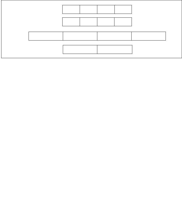
Vol. 2B 4-135
INSTRUCTION SET REFERENCE, N-Z
PMADDWD—Multiply and Add Packed Integers
The PMADDWD instruction wraps around only in one situation: when the 2 pairs of
words being operated on in a group are all 8000H. In this case, the result wraps
around to 80000000H.
In 64-bit mode, using a REX prefix in the form of REX.R permits this instruction to
access additional registers (XMM8-XMM15).
128-bit Legacy SSE version: Bits (VLMAX-1:128) of the corresponding YMM destina-
tion register remain unchanged.
VEX.128 encoded version: Bits (VLMAX-1:128) of the destination YMM register are
zeroed. VEX.L must be 0, otherwise the instruction will #UD.
Operation
PMADDWD (with 64-bit operands)
DEST[31:0] ← (DEST[15:0] ∗ SRC[15:0]) + (DEST[31:16] ∗ SRC[31:16]);
DEST[63:32] ← (DEST[47:32] ∗ SRC[47:32]) + (DEST[63:48] ∗ SRC[63:48]);
PMADDWD (with 128-bit operands)
DEST[31:0] ← (DEST[15:0] ∗ SRC[15:0]) + (DEST[31:16] ∗ SRC[31:16]);
DEST[63:32] ← (DEST[47:32] ∗ SRC[47:32]) + (DEST[63:48] ∗ SRC[63:48]);
DEST[95:64] ← (DEST[79:64] ∗ SRC[79:64]) + (DEST[95:80] ∗ SRC[95:80]);
DEST[127:96] ← (DEST[111:96] ∗ SRC[111:96]) + (DEST[127:112] ∗ SRC[127:112]);
VPMADDWD (VEX.128 encoded version)
DEST[31:0] (SRC1[15:0] * SRC2[15:0]) + (SRC1[31:16] * SRC2[31:16])
DEST[63:32] (SRC1[47:32] * SRC2[47:32]) + (SRC1[63:48] * SRC2[63:48])
DEST[95:64] (SRC1[79:64] * SRC2[79:64]) + (SRC1[95:80] * SRC2[95:80])
DEST[127:96] (SRC1[111:96] * SRC2[111:96]) + (SRC1[127:112] * SRC2[127:112])
DEST[VLMAX-1:128] 0
Figure 4-8. PMADDWD Execution Model Using 64-bit Operands
X3 X2 X1 X0
X3 ∗ Y3 X2 ∗ Y2 X1 ∗ Y1 X0 ∗ Y0
SRC
DEST
DEST
Y3 Y2 Y1 Y0
(X1∗Y1) + (X0∗Y0)
(X3∗Y3) + (X2∗Y2)
TEMP

4-136 Vol. 2B PMADDWD—Multiply and Add Packed Integers
INSTRUCTION SET REFERENCE, N-Z
Intel C/C++ Compiler Intrinsic Equivalent
PMADDWD __m64 _mm_madd_pi16(__m64 m1, __m64 m2)
PMADDWD __m128i _mm_madd_epi16 ( __m128i a, __m128i b)
Flags Affected
None.
Numeric Exceptions
None.
Other Exceptions
See Exceptions Type 4; additionally
#UD If VEX.L = 1.

Vol. 2B 4-137
INSTRUCTION SET REFERENCE, N-Z
PMAXSB — Maximum of Packed Signed Byte Integers
PMAXSB — Maximum of Packed Signed Byte Integers
Instruction Operand Encoding
Description
Compares packed signed byte integers in the destination operand (first operand) and
the source operand (second operand), and returns the maximum for each packed
value in the destination operand.
128-bit Legacy SSE version: Bits (VLMAX-1:128) of the corresponding YMM destina-
tion register remain unchanged.
VEX.128 encoded version: Bits (VLMAX-1:1288) of the destination YMM register are
zeroed. VEX.L must be 0, otherwise the instruction will #UD.
Operation
IF (DEST[7:0] > SRC[7:0])
THEN DEST[7:0] DEST[7:0];
ELSE DEST[7:0] SRC[7:0]; FI;
IF (DEST[15:8] > SRC[15:8])
THEN DEST[15:8] DEST[15:8];
ELSE DEST[15:8] SRC[15:8]; FI;
IF (DEST[23:16] > SRC[23:16])
THEN DEST[23:16] DEST[23:16];
ELSE DEST[23:16] SRC[23:16]; FI;
IF (DEST[31:24] > SRC[31:24])
Opcode/
Instruction
Op/
En
64/32 bit
Mode
Support
CPUID
Feature
Flag
Description
66 0F 38 3C /r
PMAXSB xmm1, xmm2/m128
A V/V SSE4_1 Compare packed signed byte
integers in xmm1 and
xmm2/m128 and store
packed maximum values in
xmm1.
VEX.NDS.128.66.0F38.WIG 3C /r
VPMAXSB xmm1, xmm2,
xmm3/m128
B V/V AVX Compare packed signed byte
integers in xmm2 and
xmm3/m128 and store
packed maximum values in
xmm1.
Op/En Operand 1 Operand 2 Operand 3 Operand 4
A ModRM:reg (r, w) ModRM:r/m (r) NA NA
B ModRM:reg (w) VEX.vvvv (r) ModRM:r/m (r) NA

4-138 Vol. 2B PMAXSB — Maximum of Packed Signed Byte Integers
INSTRUCTION SET REFERENCE, N-Z
THEN DEST[31:24] DEST[31:24];
ELSE DEST[31:24] SRC[31:24]; FI;
IF (DEST[39:32] > SRC[39:32])
THEN DEST[39:32] DEST[39:32];
ELSE DEST[39:32] SRC[39:32]; FI;
IF (DEST[47:40] > SRC[47:40])
THEN DEST[47:40] DEST[47:40];
ELSE DEST[47:40] SRC[47:40]; FI;
IF (DEST[55:48] > SRC[55:48])
THEN DEST[55:48] DEST[55:48];
ELSE DEST[55:48] SRC[55:48]; FI;
IF (DEST[63:56] > SRC[63:56])
THEN DEST[63:56] DEST[63:56];
ELSE DEST[63:56] SRC[63:56]; FI;
IF (DEST[71:64] > SRC[71:64])
THEN DEST[71:64] DEST[71:64];
ELSE DEST[71:64] SRC[71:64]; FI;
IF (DEST[79:72] > SRC[79:72])
THEN DEST[79:72] DEST[79:72];
ELSE DEST[79:72] SRC[79:72]; FI;
IF (DEST[87:80] > SRC[87:80])
THEN DEST[87:80] DEST[87:80];
ELSE DEST[87:80] SRC[87:80]; FI;
IF (DEST[95:88] > SRC[95:88])
THEN DEST[95:88] DEST[95:88];
ELSE DEST[95:88] SRC[95:88]; FI;
IF (DEST[103:96] > SRC[103:96])
THEN DEST[103:96] DEST[103:96];
ELSE DEST[103:96] SRC[103:96]; FI;
IF (DEST[111:104] > SRC[111:104])
THEN DEST[111:104] DEST[111:104];
ELSE DEST[111:104] SRC[111:104]; FI;
IF (DEST[119:112] > SRC[119:112])
THEN DEST[119:112] DEST[119:112];
ELSE DEST[119:112] SRC[119:112]; FI;
IF (DEST[127:120] > SRC[127:120])
THEN DEST[127:120] DEST[127:120];
ELSE DEST[127:120] SRC[127:120]; FI;
VPMAXSB (VEX.128 encoded version)
IF SRC1[7:0] >SRC2[7:0] THEN
DEST[7:0] SRC1[7:0];
ELSE

Vol. 2B 4-139
INSTRUCTION SET REFERENCE, N-Z
PMAXSB — Maximum of Packed Signed Byte Integers
DEST[7:0] SRC2[7:0]; FI;
(* Repeat operation for 2nd through 15th bytes in source and destination operands *)
IF SRC1[127:120] >SRC2[127:120] THEN
DEST[127:120] SRC1[127:120];
ELSE
DEST[127:120] SRC2[127:120]; FI;
DEST[VLMAX-1:128] 0
Intel C/C++ Compiler Intrinsic Equivalent
PMAXSB __m128i _mm_max_epi8 ( __m128i a, __m128i b);
Flags Affected
None.
SIMD Floating-Point Exceptions
None.
Other Exceptions
See Exceptions Type 4; additionally
#UD If VEX.L = 1.

4-140 Vol. 2B PMAXSD — Maximum of Packed Signed Dword Integers
INSTRUCTION SET REFERENCE, N-Z
PMAXSD — Maximum of Packed Signed Dword Integers
Instruction Operand Encoding
Description
Compares packed signed dword integers in the destination operand (first operand)
and the source operand (second operand), and returns the maximum for each
packed value in the destination operand.
128-bit Legacy SSE version: Bits (VLMAX-1:128) of the corresponding YMM destina-
tion register remain unchanged.
VEX.128 encoded version: Bits (VLMAX-1:1288) of the destination YMM register are
zeroed. VEX.L must be 0, otherwise the instruction will #UD.
Operation
IF (DEST[31:0] > SRC[31:0])
THEN DEST[31:0] DEST[31:0];
ELSE DEST[31:0] SRC[31:0]; FI;
IF (DEST[63:32] > SRC[63:32])
THEN DEST[63:32] DEST[63:32];
ELSE DEST[63:32] SRC[63:32]; FI;
IF (DEST[95:64] > SRC[95:64])
THEN DEST[95:64] DEST[95:64];
ELSE DEST[95:64] SRC[95:64]; FI;
IF (DEST[127:96] > SRC[127:96])
Opcode/
Instruction
Op/
En
64/32 bit
Mode
Support
CPUID
Feature
Flag
Description
66 0F 38 3D /r
PMAXSD xmm1, xmm2/m128
A V/V SSE4_1 Compare packed signed
dword integers in xmm1 and
xmm2/m128 and store
packed maximum values in
xmm1.
VEX.NDS.128.6
6.0F38.WIG 3D
/r
VPMAXSD xmm1,
xmm2,
xmm3/m128
B V/V AVX Compare packed signed
dword integers in xmm2 and
xmm3/m128 and store
packed maximum values in
xmm1.
Op/En Operand 1 Operand 2 Operand 3 Operand 4
A ModRM:reg (r, w) ModRM:r/m (r) NA NA
B ModRM:reg (w) VEX.vvvv (r) ModRM:r/m (r) NA

Vol. 2B 4-141
INSTRUCTION SET REFERENCE, N-Z
PMAXSD — Maximum of Packed Signed Dword Integers
THEN DEST[127:96] DEST[127:96];
ELSE DEST[127:96] SRC[127:96]; FI;
VPMAXSD (VEX.128 encoded version)
IF SRC1[31:0] > SRC2[31:0] THEN
DEST[31:0] SRC1[31:0];
ELSE
DEST[31:0] SRC2[31:0]; FI;
(* Repeat operation for 2nd through 3rd dwords in source and destination operands *)
IF SRC1[127:95] > SRC2[127:95] THEN
DEST[127:95] SRC1[127:95];
ELSE
DEST[127:95] SRC2[127:95]; FI;
DEST[VLMAX-1:128] 0
Intel C/C++ Compiler Intrinsic Equivalent
PMAXSD __m128i _mm_max_epi32 ( __m128i a, __m128i b);
Flags Affected
None.
SIMD Floating-Point Exceptions
None.
Other Exceptions
See Exceptions Type 4; additionally
#UD If VEX.L = 1.

4-142 Vol. 2B PMAXSW—Maximum of Packed Signed Word Integers
INSTRUCTION SET REFERENCE, N-Z
PMAXSW—Maximum of Packed Signed Word Integers
Instruction Operand Encoding
Description
Performs a SIMD compare of the packed signed word integers in the destination
operand (first operand) and the source operand (second operand), and returns the
maximum value for each pair of word integers to the destination operand. The source
operand can be an MMX technology register or a 64-bit memory location, or it can be
an XMM register or a 128-bit memory location. The destination operand can be an
MMX technology register or an XMM register.
In 64-bit mode, using a REX prefix in the form of REX.R permits this instruction to
access additional registers (XMM8-XMM15).
128-bit Legacy SSE version: Bits (VLMAX-1:128) of the corresponding YMM destina-
tion register remain unchanged.
VEX.128 encoded version: Bits (VLMAX-1:128) of the destination YMM register are
zeroed. VEX.L must be 0, otherwise the instruction will #UD.
Opcode/
Instruction
Op/
En
64/32 bit
Mode
Support
CPUID
Feature
Flag
Description
0F EE /r1
PMAXSW mm1, mm2/m64
A V/V SSE Compare signed word
integers in mm2/m64 and
mm1 and return maximum
values.
66 0F EE /r
PMAXSW xmm1, xmm2/m128
A V/V SSE2 Compare signed word
integers in xmm2/m128 and
xmm1 and return maximum
values.
VEX.NDS.128.66.0F.WIG EE /r
VPMAXSW xmm1, xmm2,
xmm3/m128
B V/V AVX Compare packed signed
word integers in
xmm3/m128 and xmm2 and
store packed maximum
values in xmm1.
NOTES:
1. See note in Section 2.4, “Instruction Exception Specification”.
Op/En Operand 1 Operand 2 Operand 3 Operand 4
A ModRM:reg (r, w) ModRM:r/m (r) NA NA
B ModRM:reg (w) VEX.vvvv (r) ModRM:r/m (r) NA

Vol. 2B 4-143
INSTRUCTION SET REFERENCE, N-Z
PMAXSW—Maximum of Packed Signed Word Integers
Operation
PMAXSW (64-bit operands)
IF DEST[15:0] > SRC[15:0]) THEN
DEST[15:0] ← DEST[15:0];
ELSE
DEST[15:0] ← SRC[15:0]; FI;
(* Repeat operation for 2nd and 3rd words in source and destination operands *)
IF DEST[63:48] > SRC[63:48]) THEN
DEST[63:48] ← DEST[63:48];
ELSE
DEST[63:48] ← SRC[63:48]; FI;
PMAXSW (128-bit operands)
IF DEST[15:0] > SRC[15:0]) THEN
DEST[15:0] ← DEST[15:0];
ELSE
DEST[15:0] ← SRC[15:0]; FI;
(* Repeat operation for 2nd through 7th words in source and destination operands *)
IF DEST[127:112] > SRC[127:112]) THEN
DEST[127:112] ← DEST[127:112];
ELSE
DEST[127:112] ← SRC[127:112]; FI;
VPMAXSW (VEX.128 encoded version)
IF SRC1[15:0] > SRC2[15:0] THEN
DEST[15:0] SRC1[15:0];
ELSE
DEST[15:0] SRC2[15:0]; FI;
(* Repeat operation for 2nd through 7th words in source and destination operands *)
IF SRC1[127:112] >SRC2[127:112] THEN
DEST[127:112] SRC1[127:112];
ELSE
DEST[127:112] SRC2[127:112]; FI;
DEST[VLMAX-1:128] 0
Intel C/C++ Compiler Intrinsic Equivalent
PMAXSW __m64 _mm_max_pi16(__m64 a, __m64 b)
PMAXSW __m128i _mm_max_epi16 ( __m128i a, __m128i b)
Flags Affected
None.

4-144 Vol. 2B PMAXSW—Maximum of Packed Signed Word Integers
INSTRUCTION SET REFERENCE, N-Z
Numeric Exceptions
None.
Other Exceptions
See Exceptions Type 4; additionally
#UD If VEX.L = 1.

Vol. 2B 4-145
INSTRUCTION SET REFERENCE, N-Z
PMAXUB—Maximum of Packed Unsigned Byte Integers
PMAXUB—Maximum of Packed Unsigned Byte Integers
Instruction Operand Encoding
Description
Performs a SIMD compare of the packed unsigned byte integers in the destination
operand (first operand) and the source operand (second operand), and returns the
maximum value for each pair of byte integers to the destination operand. The source
operand can be an MMX technology register or a 64-bit memory location, or it can be
an XMM register or a 128-bit memory location. The destination operand can be an
MMX technology register or an XMM register.
In 64-bit mode, using a REX prefix in the form of REX.R permits this instruction to
access additional registers (XMM8-XMM15).
128-bit Legacy SSE version: Bits (VLMAX-1:128) of the corresponding YMM destina-
tion register remain unchanged.
VEX.128 encoded version: Bits (VLMAX-1:128) of the destination YMM register are
zeroed. VEX.L must be 0, otherwise the instruction will #UD.
Opcode/
Instruction
Op/
En
64/32 bit
Mode
Support
CPUID
Feature
Flag
Description
0F DE /r1
PMAXUB mm1, mm2/m64
A V/V SSE Compare unsigned byte
integers in mm2/m64 and
mm1 and returns maximum
values.
66 0F DE /r
PMAXUB xmm1, xmm2/m128
A V/V SSE2 Compare unsigned byte
integers in xmm2/m128 and
xmm1 and returns
maximum values.
VEX.NDS.128.66.0F.WIG DE /r
VPMAXUB xmm1, xmm2,
xmm3/m128
B V/V AVX Compare packed unsigned
byte integers in xmm2 and
xmm3/m128 and store
packed maximum values in
xmm1.
NOTES:
1. See note in Section 2.4, “Instruction Exception Specification”.
Op/En Operand 1 Operand 2 Operand 3 Operand 4
A ModRM:reg (r, w) ModRM:r/m (r) NA NA
B ModRM:reg (w) VEX.vvvv (r) ModRM:r/m (r) NA

4-146 Vol. 2B PMAXUB—Maximum of Packed Unsigned Byte Integers
INSTRUCTION SET REFERENCE, N-Z
Operation
PMAXUB (64-bit operands)
IF DEST[7:0] > SRC[17:0]) THEN
DEST[7:0] ← DEST[7:0];
ELSE
DEST[7:0] ← SRC[7:0]; FI;
(* Repeat operation for 2nd through 7th bytes in source and destination operands *)
IF DEST[63:56] > SRC[63:56]) THEN
DEST[63:56] ← DEST[63:56];
ELSE
DEST[63:56] ← SRC[63:56]; FI;
PMAXUB (128-bit operands)
IF DEST[7:0] > SRC[17:0]) THEN
DEST[7:0] ← DEST[7:0];
ELSE
DEST[7:0] ← SRC[7:0]; FI;
(* Repeat operation for 2nd through 15th bytes in source and destination operands *)
IF DEST[127:120] > SRC[127:120]) THEN
DEST[127:120] ← DEST[127:120];
ELSE
DEST[127:120] ← SRC[127:120]; FI;
VPMAXUB (VEX.128 encoded version)
IF SRC1[7:0] >SRC2[7:0] THEN
DEST[7:0] SRC1[7:0];
ELSE
DEST[7:0] SRC2[7:0]; FI;
(* Repeat operation for 2nd through 15th bytes in source and destination operands *)
IF SRC1[127:120] >SRC2[127:120] THEN
DEST[127:120] SRC1[127:120];
ELSE
DEST[127:120] SRC2[127:120]; FI;
DEST[VLMAX-1:128] 0
Intel C/C++ Compiler Intrinsic Equivalent
PMAXUB __m64 _mm_max_pu8(__m64 a, __m64 b)
PMAXUB __m128i _mm_max_epu8 ( __m128i a, __m128i b)
Flags Affected
None.

Vol. 2B 4-147
INSTRUCTION SET REFERENCE, N-Z
PMAXUB—Maximum of Packed Unsigned Byte Integers
Numeric Exceptions
None.
Other Exceptions
See Exceptions Type 4; additionally
#UD If VEX.L = 1.

4-148 Vol. 2B PMAXUD — Maximum of Packed Unsigned Dword Integers
INSTRUCTION SET REFERENCE, N-Z
PMAXUD — Maximum of Packed Unsigned Dword Integers
Instruction Operand Encoding
Description
Compares packed unsigned dword integers in the destination operand (first operand)
and the source operand (second operand), and returns the maximum for each
packed value in the destination operand.
128-bit Legacy SSE version: Bits (VLMAX-1:128) of the corresponding YMM destina-
tion register remain unchanged.
VEX.128 encoded version: Bits (VLMAX-1:128) of the destination YMM register are
zeroed. VEX.L must be 0, otherwise the instruction will #UD.
Operation
IF (DEST[31:0] > SRC[31:0])
THEN DEST[31:0] DEST[31:0];
ELSE DEST[31:0] SRC[31:0]; FI;
IF (DEST[63:32] > SRC[63:32])
THEN DEST[63:32] DEST[63:32];
ELSE DEST[63:32] SRC[63:32]; FI;
IF (DEST[95:64] > SRC[95:64])
THEN DEST[95:64] DEST[95:64];
ELSE DEST[95:64] SRC[95:64]; FI;
IF (DEST[127:96] > SRC[127:96])
Opcode/
Instruction
Op/
En
64/32 bit
Mode
Support
CPUID
Feature
Flag
Description
66 0F 38 3F /r
PMAXUD xmm1, xmm2/m128
A V/V SSE4_1 Compare packed unsigned
dword integers in xmm1 and
xmm2/m128 and store
packed maximum values in
xmm1.
VEX.NDS.128.6
6.0F38.WIG 3F
/r
VPMAXUD xmm1,
xmm2,
xmm3/m128
B V/V AVX Compare packed unsigned
dword integers in xmm2 and
xmm3/m128 and store
packed maximum values in
xmm1.
Op/En Operand 1 Operand 2 Operand 3 Operand 4
A ModRM:reg (r, w) ModRM:r/m (r) NA NA
B ModRM:reg (w) VEX.vvvv (r) ModRM:r/m (r) NA

Vol. 2B 4-149
INSTRUCTION SET REFERENCE, N-Z
PMAXUD — Maximum of Packed Unsigned Dword Integers
THEN DEST[127:96] DEST[127:96];
ELSE DEST[127:96] SRC[127:96]; FI;
VPMAXUD (VEX.128 encoded version)
IF SRC1[31:0] > SRC2[31:0] THEN
DEST[31:0] SRC1[31:0];
ELSE
DEST[31:0] SRC2[31:0]; FI;
(* Repeat operation for 2nd through 3rd dwords in source and destination operands *)
IF SRC1[127:95] > SRC2[127:95] THEN
DEST[127:95] SRC1[127:95];
ELSE
DEST[127:95] SRC2[127:95]; FI;
DEST[VLMAX-1:128] 0
Intel C/C++ Compiler Intrinsic Equivalent
PMAXUD __m128i _mm_max_epu32 ( __m128i a, __m128i b);
Flags Affected
None.
SIMD Floating-Point Exceptions
None.
Other Exceptions
See Exceptions Type 4; additionally
#UD If VEX.L = 1.

4-150 Vol. 2B PMAXUW — Maximum of Packed Word Integers
INSTRUCTION SET REFERENCE, N-Z
PMAXUW — Maximum of Packed Word Integers
Instruction Operand Encoding
Description
Compares packed unsigned word integers in the destination operand (first operand)
and the source operand (second operand), and returns the maximum for each
packed value in the destination operand.
128-bit Legacy SSE version: Bits (VLMAX-1:128) of the corresponding YMM destina-
tion register remain unchanged.
VEX.128 encoded version: Bits (VLMAX-1:128) of the destination YMM register are
zeroed. VEX.L must be 0, otherwise the instruction will #UD.
Operation
IF (DEST[15:0] > SRC[15:0])
THEN DEST[15:0] DEST[15:0];
ELSE DEST[15:0] SRC[15:0]; FI;
IF (DEST[31:16] > SRC[31:16])
THEN DEST[31:16] DEST[31:16];
ELSE DEST[31:16] SRC[31:16]; FI;
IF (DEST[47:32] > SRC[47:32])
THEN DEST[47:32] DEST[47:32];
ELSE DEST[47:32] SRC[47:32]; FI;
IF (DEST[63:48] > SRC[63:48])
Opcode/
Instruction
Op/
En
64/32 bit
Mode
Support
CPUID
Feature
Flag
Description
66 0F 38 3E /r
PMAXUW xmm1, xmm2/m128
A V/V SSE4_1 Compare packed unsigned
word integers in xmm1 and
xmm2/m128 and store
packed maximum values in
xmm1.
VEX.NDS.128.66.0F38.WIG 3E/r
VPMAXUW xmm1, xmm2,
xmm3/m128
B V/V AVX Compare packed unsigned
word integers in
xmm3/m128 and xmm2 and
store maximum packed
values in xmm1.
Op/En Operand 1 Operand 2 Operand 3 Operand 4
A ModRM:reg (r, w) ModRM:r/m (r) NA NA
B ModRM:reg (w) VEX.vvvv (r) ModRM:r/m (r) NA

Vol. 2B 4-151
INSTRUCTION SET REFERENCE, N-Z
PMAXUW — Maximum of Packed Word Integers
THEN DEST[63:48] DEST[63:48];
ELSE DEST[63:48] SRC[63:48]; FI;
IF (DEST[79:64] > SRC[79:64])
THEN DEST[79:64] DEST[79:64];
ELSE DEST[79:64] SRC[79:64]; FI;
IF (DEST[95:80] > SRC[95:80])
THEN DEST[95:80] DEST[95:80];
ELSE DEST[95:80] SRC[95:80]; FI;
IF (DEST[111:96] > SRC[111:96])
THEN DEST[111:96] DEST[111:96];
ELSE DEST[111:96] SRC[111:96]; FI;
IF (DEST[127:112] > SRC[127:112])
THEN DEST[127:112] DEST[127:112];
ELSE DEST[127:112] SRC[127:112]; FI;
VPMAXUW (VEX.128 encoded version)
IF SRC1[15:0] > SRC2[15:0] THEN
DEST[15:0] SRC1[15:0];
ELSE
DEST[15:0] SRC2[15:0]; FI;
(* Repeat operation for 2nd through 7th words in source and destination operands *)
IF SRC1[127:112] >SRC2[127:112] THEN
DEST[127:112] SRC1[127:112];
ELSE
DEST[127:112] SRC2[127:112]; FI;
DEST[VLMAX-1:128] 0
Intel C/C++ Compiler Intrinsic Equivalent
PMAXUW__m128i _mm_max_epu16 ( __m128i a, __m128i b);
Flags Affected
None.
SIMD Floating-Point Exceptions
None.
Other Exceptions
See Exceptions Type 4; additionally
#UD If VEX.L = 1.

4-152 Vol. 2B PMINSB — Minimum of Packed Signed Byte Integers
INSTRUCTION SET REFERENCE, N-Z
PMINSB — Minimum of Packed Signed Byte Integers
Instruction Operand Encoding
Description
Compares packed signed byte integers in the destination operand (first operand) and
the source operand (second operand), and returns the minimum for each packed
value in the destination operand.
128-bit Legacy SSE version: Bits (VLMAX-1:1288) of the corresponding YMM desti-
nation register remain unchanged.
VEX.128 encoded version: Bits (VLMAX-1:128) of the destination YMM register are
zeroed. VEX.L must be 0, otherwise the instruction will #UD.
Operation
IF (DEST[7:0] < SRC[7:0])
THEN DEST[7:0] DEST[7:0];
ELSE DEST[7:0] SRC[7:0]; FI;
IF (DEST[15:8] < SRC[15:8])
THEN DEST[15:8] DEST[15:8];
ELSE DEST[15:8] SRC[15:8]; FI;
IF (DEST[23:16] < SRC[23:16])
THEN DEST[23:16] DEST[23:16];
ELSE DEST[23:16] SRC[23:16]; FI;
IF (DEST[31:24] < SRC[31:24])
Opcode/
Instruction
Op/
En
64/32 bit
Mode
Support
CPUID
Feature
Flag
Description
66 0F 38 38 /r
PMINSB xmm1, xmm2/m128
A V/V SSE4_1 Compare packed signed byte
integers in xmm1 and
xmm2/m128 and store
packed minimum values in
xmm1.
VEX.NDS.128.66.0F38.WIG 38 /r
VPMINSB xmm1, xmm2,
xmm3/m128
B V/V AVX Compare packed signed byte
integers in xmm2 and
xmm3/m128 and store
packed minimum values in
xmm1.
Op/En Operand 1 Operand 2 Operand 3 Operand 4
A ModRM:reg (r, w) ModRM:r/m (r) NA NA
B ModRM:reg (w) VEX.vvvv (r) ModRM:r/m (r) NA

Vol. 2B 4-153
INSTRUCTION SET REFERENCE, N-Z
PMINSB — Minimum of Packed Signed Byte Integers
THEN DEST[31:24] DEST[31:24];
ELSE DEST[31:24] SRC[31:24]; FI;
IF (DEST[39:32] < SRC[39:32])
THEN DEST[39:32] DEST[39:32];
ELSE DEST[39:32] SRC[39:32]; FI;
IF (DEST[47:40] < SRC[47:40])
THEN DEST[47:40] DEST[47:40];
ELSE DEST[47:40] SRC[47:40]; FI;
IF (DEST[55:48] < SRC[55:48])
THEN DEST[55:48] DEST[55:48];
ELSE DEST[55:48] SRC[55:48]; FI;
IF (DEST[63:56] < SRC[63:56])
THEN DEST[63:56] DEST[63:56];
ELSE DEST[63:56] SRC[63:56]; FI;
IF (DEST[71:64] < SRC[71:64])
THEN DEST[71:64] DEST[71:64];
ELSE DEST[71:64] SRC[71:64]; FI;
IF (DEST[79:72] < SRC[79:72])
THEN DEST[79:72] DEST[79:72];
ELSE DEST[79:72] SRC[79:72]; FI;
IF (DEST[87:80] < SRC[87:80])
THEN DEST[87:80] DEST[87:80];
ELSE DEST[87:80] SRC[87:80]; FI;
IF (DEST[95:88] < SRC[95:88])
THEN DEST[95:88] DEST[95:88];
ELSE DEST[95:88] SRC[95:88]; FI;
IF (DEST[103:96] < SRC[103:96])
THEN DEST[103:96] DEST[103:96];
ELSE DEST[103:96] SRC[103:96]; FI;
IF (DEST[111:104] < SRC[111:104])
THEN DEST[111:104] DEST[111:104];
ELSE DEST[111:104] SRC[111:104]; FI;
IF (DEST[119:112] < SRC[119:112])
THEN DEST[119:112] DEST[119:112];
ELSE DEST[119:112] SRC[119:112]; FI;
IF (DEST[127:120] < SRC[127:120])
THEN DEST[127:120] DEST[127:120];
ELSE DEST[127:120] SRC[127:120]; FI;
VPMINSB (VEX.128 encoded version)
IF SRC1[7:0] < SRC2[7:0] THEN
DEST[7:0] SRC1[7:0];
ELSE

4-154 Vol. 2B PMINSB — Minimum of Packed Signed Byte Integers
INSTRUCTION SET REFERENCE, N-Z
DEST[7:0] SRC2[7:0]; FI;
(* Repeat operation for 2nd through 15th bytes in source and destination operands *)
IF SRC1[127:120] < SRC2[127:120] THEN
DEST[127:120] SRC1[127:120];
ELSE
DEST[127:120] SRC2[127:120]; FI;
DEST[VLMAX-1:128] 0
Intel C/C++ Compiler Intrinsic Equivalent
PMINSB __m128i _mm_min_epi8 ( __m128i a, __m128i b);
Flags Affected
None.
SIMD Floating-Point Exceptions
None.
Other Exceptions
See Exceptions Type 4; additionally
#UD If VEX.L = 1.

Vol. 2B 4-155
INSTRUCTION SET REFERENCE, N-Z
PMINSD — Minimum of Packed Dword Integers
PMINSD — Minimum of Packed Dword Integers
Instruction Operand Encoding
Description
Compares packed signed dword integers in the destination operand (first operand)
and the source operand (second operand), and returns the minimum for each packed
value in the destination operand.
128-bit Legacy SSE version: Bits (VLMAX-1:1288) of the corresponding YMM desti-
nation register remain unchanged.
VEX.128 encoded version: Bits (VLMAX-1:128) of the destination YMM register are
zeroed. VEX.L must be 0, otherwise the instruction will #UD.
Operation
IF (DEST[31:0] < SRC[31:0])
THEN DEST[31:0] DEST[31:0];
ELSE DEST[31:0] SRC[31:0]; FI;
IF (DEST[63:32] < SRC[63:32])
THEN DEST[63:32] DEST[63:32];
ELSE DEST[63:32] SRC[63:32]; FI;
IF (DEST[95:64] < SRC[95:64])
THEN DEST[95:64] DEST[95:64];
ELSE DEST[95:64] SRC[95:64]; FI;
IF (DEST[127:96] < SRC[127:96])
Opcode/
Instruction
Op/
En
64/32 bit
Mode
Support
CPUID
Feature
Flag
Description
66 0F 38 39 /r
PMINSD xmm1, xmm2/m128
A V/V SSE4_1 Compare packed signed
dword integers in xmm1 and
xmm2/m128 and store
packed minimum values in
xmm1.
VEX.NDS.128.66.0F38.WIG 39 /r
VPMINSD xmm1, xmm2,
xmm3/m128
B V/V AVX Compare packed signed
dword integers in xmm2 and
xmm3/m128 and store
packed minimum values in
xmm1.
Op/En Operand 1 Operand 2 Operand 3 Operand 4
A ModRM:reg (r, w) ModRM:r/m (r) NA NA
B ModRM:reg (w) VEX.vvvv (r) ModRM:r/m (r) NA

4-156 Vol. 2B PMINSD — Minimum of Packed Dword Integers
INSTRUCTION SET REFERENCE, N-Z
THEN DEST[127:96] DEST[127:96];
ELSE DEST[127:96] SRC[127:96]; FI;
VPMINSD (VEX.128 encoded version)
IF SRC1[31:0] < SRC2[31:0] THEN
DEST[31:0] SRC1[31:0];
ELSE
DEST[31:0] SRC2[31:0]; FI;
(* Repeat operation for 2nd through 3rd dwords in source and destination operands *)
IF SRC1[127:95] < SRC2[127:95] THEN
DEST[127:95] SRC1[127:95];
ELSE
DEST[127:95] SRC2[127:95]; FI;
DEST[VLMAX-1:128] 0
Intel C/C++ Compiler Intrinsic Equivalent
PMINSD __m128i _mm_min_epi32 ( __m128i a, __m128i b);
Flags Affected
None.
SIMD Floating-Point Exceptions
None.
Other Exceptions
See Exceptions Type 4; additionally
#UD If VEX.L = 1.

Vol. 2B 4-157
INSTRUCTION SET REFERENCE, N-Z
PMINSW—Minimum of Packed Signed Word Integers
PMINSW—Minimum of Packed Signed Word Integers
Instruction Operand Encoding
Description
Performs a SIMD compare of the packed signed word integers in the destination
operand (first operand) and the source operand (second operand), and returns the
minimum value for each pair of word integers to the destination operand. The source
operand can be an MMX technology register or a 64-bit memory location, or it can be
an XMM register or a 128-bit memory location. The destination operand can be an
MMX technology register or an XMM register.
In 64-bit mode, using a REX prefix in the form of REX.R permits this instruction to
access additional registers (XMM8-XMM15).
128-bit Legacy SSE version: Bits (VLMAX-1:1288) of the corresponding YMM desti-
nation register remain unchanged.
VEX.128 encoded version: Bits (VLMAX-1:128) of the destination YMM register are
zeroed. VEX.L must be 0, otherwise the instruction will #UD.
Opcode/
Instruction
Op/
En
64/32 bit
Mode
Support
CPUID
Feature
Flag
Description
0F EA /r1
PMINSW mm1, mm2/m64
A V/V SSE Compare signed word
integers in mm2/m64 and
mm1 and return minimum
values.
66 0F EA /r
PMINSW xmm1, xmm2/m128
A V/V SSE2 Compare signed word
integers in xmm2/m128 and
xmm1 and return minimum
values.
VEX.NDS.128.66.0F.WIG EA /r
VPMINSW xmm1, xmm2,
xmm3/m128
B V/V AVX Compare packed signed
word integers in
xmm3/m128 and xmm2 and
return packed minimum
values in xmm1.
NOTES:
1. See note in Section 2.4, “Instruction Exception Specification”.
Op/En Operand 1 Operand 2 Operand 3 Operand 4
A ModRM:reg (r, w) ModRM:r/m (r) NA NA
B ModRM:reg (w) VEX.vvvv (r) ModRM:r/m (r) NA

4-158 Vol. 2B PMINSW—Minimum of Packed Signed Word Integers
INSTRUCTION SET REFERENCE, N-Z
Operation
PMINSW (64-bit operands)
IF DEST[15:0] < SRC[15:0] THEN
DEST[15:0] ← DEST[15:0];
ELSE
DEST[15:0] ← SRC[15:0]; FI;
(* Repeat operation for 2nd and 3rd words in source and destination operands *)
IF DEST[63:48] < SRC[63:48] THEN
DEST[63:48] ← DEST[63:48];
ELSE
DEST[63:48] ← SRC[63:48]; FI;
PMINSW (128-bit operands)
IF DEST[15:0] < SRC[15:0] THEN
DEST[15:0] ← DEST[15:0];
ELSE
DEST[15:0] ← SRC[15:0]; FI;
(* Repeat operation for 2nd through 7th words in source and destination operands *)
IF DEST[127:112] < SRC/m64[127:112] THEN
DEST[127:112] ← DEST[127:112];
ELSE
DEST[127:112] ← SRC[127:112]; FI;
VPMINSW (VEX.128 encoded version)
IF SRC1[15:0] < SRC2[15:0] THEN
DEST[15:0] SRC1[15:0];
ELSE
DEST[15:0] SRC2[15:0]; FI;
(* Repeat operation for 2nd through 7th words in source and destination operands *)
IF SRC1[127:112] < SRC2[127:112] THEN
DEST[127:112] SRC1[127:112];
ELSE
DEST[127:112] SRC2[127:112]; FI;
DEST[VLMAX-1:128] 0
Intel C/C++ Compiler Intrinsic Equivalent
PMINSW __m64 _mm_min_pi16 (__m64 a, __m64 b)
PMINSW __m128i _mm_min_epi16 ( __m128i a, __m128i b)
Flags Affected
None.

Vol. 2B 4-159
INSTRUCTION SET REFERENCE, N-Z
PMINSW—Minimum of Packed Signed Word Integers
Numeric Exceptions
None.
Other Exceptions
See Exceptions Type 4; additionally
#UD If VEX.L = 1.
#MF (64-bit operations only) If there is a pending x87 FPU exception.

4-160 Vol. 2B PMINUB—Minimum of Packed Unsigned Byte Integers
INSTRUCTION SET REFERENCE, N-Z
PMINUB—Minimum of Packed Unsigned Byte Integers
Instruction Operand Encoding
Description
Performs a SIMD compare of the packed unsigned byte integers in the destination
operand (first operand) and the source operand (second operand), and returns the
minimum value for each pair of byte integers to the destination operand. The source
operand can be an MMX technology register or a 64-bit memory location, or it can be
an XMM register or a 128-bit memory location. The destination operand can be an
MMX technology register or an XMM register.
In 64-bit mode, using a REX prefix in the form of REX.R permits this instruction to
access additional registers (XMM8-XMM15).
128-bit Legacy SSE version: Bits (VLMAX-1:128) of the corresponding YMM destina-
tion register remain unchanged.
VEX.128 encoded version: Bits (VLMAX-1:128) of the destination YMM register are
zeroed. VEX.L must be 0, otherwise the instruction will #UD.
Opcode/
Instruction
Op/
En
64/32 bit
Mode
Support
CPUID
Feature
Flag
Description
0F DA /r1
PMINUB mm1, mm2/m64
A V/V SSE Compare unsigned byte
integers in mm2/m64 and
mm1 and returns minimum
values.
66 0F DA /r
PMINUB xmm1, xmm2/m128
A V/V SSE2 Compare unsigned byte
integers in xmm2/m128 and
xmm1 and returns minimum
values.
VEX.NDS.128.66.0F.WIG DA /r
VPMINUB xmm1, xmm2,
xmm3/m128
B V/V AVX Compare packed unsigned
byte integers in xmm2 and
xmm3/m128 and store
packed minimum values in
xmm1.
NOTES:
1. See note in Section 2.4, “Instruction Exception Specification”.
Op/En Operand 1 Operand 2 Operand 3 Operand 4
A ModRM:reg (r, w) ModRM:r/m (r) NA NA
B ModRM:reg (w) VEX.vvvv (r) ModRM:r/m (r) NA

Vol. 2B 4-161
INSTRUCTION SET REFERENCE, N-Z
PMINUB—Minimum of Packed Unsigned Byte Integers
Operation
PMINUB (for 64-bit operands)
IF DEST[7:0] < SRC[17:0] THEN
DEST[7:0] ← DEST[7:0];
ELSE
DEST[7:0] ← SRC[7:0]; FI;
(* Repeat operation for 2nd through 7th bytes in source and destination operands *)
IF DEST[63:56] < SRC[63:56] THEN
DEST[63:56] ← DEST[63:56];
ELSE
DEST[63:56] ← SRC[63:56]; FI;
PMINUB (for 128-bit operands)
IF DEST[7:0] < SRC[17:0] THEN
DEST[7:0] ← DEST[7:0];
ELSE
DEST[7:0] ← SRC[7:0]; FI;
(* Repeat operation for 2nd through 15th bytes in source and destination operands *)
IF DEST[127:120] < SRC[127:120] THEN
DEST[127:120] ← DEST[127:120];
ELSE
DEST[127:120] ← SRC[127:120]; FI;
VPMINUB (VEX.128 encoded version)
VPMINUB instruction for 128-bit operands:
IF SRC1[7:0] < SRC2[7:0] THEN
DEST[7:0] SRC1[7:0];
ELSE
DEST[7:0] SRC2[7:0]; FI;
(* Repeat operation for 2nd through 15th bytes in source and destination operands *)
IF SRC1[127:120] < SRC2[127:120] THEN
DEST[127:120] SRC1[127:120];
ELSE
DEST[127:120] SRC2[127:120]; FI;
DEST[VLMAX-1:128] 0
Intel C/C++ Compiler Intrinsic Equivalent
PMINUB __m64 _m_min_pu8 (__m64 a, __m64 b)
PMINUB __m128i _mm_min_epu8 ( __m128i a, __m128i b)
Flags Affected
None.

4-162 Vol. 2B PMINUB—Minimum of Packed Unsigned Byte Integers
INSTRUCTION SET REFERENCE, N-Z
Numeric Exceptions
None.
Other Exceptions
See Exceptions Type 4; additionally
#UD If VEX.L = 1.

Vol. 2B 4-163
INSTRUCTION SET REFERENCE, N-Z
PMINUD — Minimum of Packed Dword Integers
PMINUD — Minimum of Packed Dword Integers
Instruction Operand Encoding
Description
Compares packed unsigned dword integers in the destination operand (first operand)
and the source operand (second operand), and returns the minimum for each packed
value in the destination operand.
128-bit Legacy SSE version: Bits (VLMAX-1:128) of the corresponding YMM destina-
tion register remain unchanged.
VEX.128 encoded version: Bits (VLMAX-1:128) of the destination YMM register are
zeroed. VEX.L must be 0, otherwise the instruction will #UD.
Operation
IF (DEST[31:0] < SRC[31:0])
THEN DEST[31:0] DEST[31:0];
ELSE DEST[31:0] SRC[31:0]; FI;
IF (DEST[63:32] < SRC[63:32])
THEN DEST[63:32] DEST[63:32];
ELSE DEST[63:32] SRC[63:32]; FI;
IF (DEST[95:64] < SRC[95:64])
THEN DEST[95:64] DEST[95:64];
ELSE DEST[95:64] SRC[95:64]; FI;
IF (DEST[127:96] < SRC[127:96])
Opcode/
Instruction
Op/
En
64/32 bit
Mode
Support
CPUID
Feature
Flag
Description
66 0F 38 3B /r
PMINUD xmm1, xmm2/m128
A V/V SSE4_1 Compare packed unsigned
dword integers in xmm1
and xmm2/m128 and store
packed minimum values in
xmm1.
VEX.NDS.128.66.0F38.WIG 3B /r
VPMINUD xmm1, xmm2,
xmm3/m128
B V/V AVX Compare packed unsigned
dword integers in xmm2 and
xmm3/m128 and store
packed minimum values in
xmm1.
Op/En Operand 1 Operand 2 Operand 3 Operand 4
A ModRM:reg (r, w) ModRM:r/m (r) NA NA
B ModRM:reg (w) VEX.vvvv (r) ModRM:r/m (r) NA

4-164 Vol. 2B PMINUD — Minimum of Packed Dword Integers
INSTRUCTION SET REFERENCE, N-Z
THEN DEST[127:96] DEST[127:96];
ELSE DEST[127:96] SRC[127:96]; FI;
VPMINUD (VEX.128 encoded version)
VPMINUD instruction for 128-bit operands:
IF SRC1[31:0] < SRC2[31:0] THEN
DEST[31:0] SRC1[31:0];
ELSE
DEST[31:0] SRC2[31:0]; FI;
(* Repeat operation for 2nd through 3rd dwords in source and destination operands *)
IF SRC1[127:95] < SRC2[127:95] THEN
DEST[127:95] SRC1[127:95];
ELSE
DEST[127:95] SRC2[127:95]; FI;
DEST[VLMAX-1:128] 0
Intel C/C++ Compiler Intrinsic Equivalent
PMINUD __m128i _mm_min_epu32 ( __m128i a, __m128i b);
Flags Affected
None.
SIMD Floating-Point Exceptions
None.
Other Exceptions
See Exceptions Type 4; additionally
#UD If VEX.L = 1.

Vol. 2B 4-165
INSTRUCTION SET REFERENCE, N-Z
PMINUW — Minimum of Packed Word Integers
PMINUW — Minimum of Packed Word Integers
Instruction Operand Encoding
Description
Compares packed unsigned word integers in the destination operand (first operand)
and the source operand (second operand), and returns the minimum for each packed
value in the destination operand.
128-bit Legacy SSE version: Bits (VLMAX-1:128) of the corresponding YMM destina-
tion register remain unchanged.
VEX.128 encoded version: Bits (VLMAX-1:128) of the destination YMM register are
zeroed. VEX.L must be 0, otherwise the instruction will #UD.
Operation
IF (DEST[15:0] < SRC[15:0])
THEN DEST[15:0] DEST[15:0];
ELSE DEST[15:0] SRC[15:0]; FI;
IF (DEST[31:16] < SRC[31:16])
THEN DEST[31:16] DEST[31:16];
ELSE DEST[31:16] SRC[31:16]; FI;
IF (DEST[47:32] < SRC[47:32])
THEN DEST[47:32] DEST[47:32];
ELSE DEST[47:32] SRC[47:32]; FI;
IF (DEST[63:48] < SRC[63:48])
Opcode/
Instruction
Op/
En
64/32 bit
Mode
Support
CPUID
Feature
Flag
Description
66 0F 38 3A /r
PMINUW xmm1, xmm2/m128
A V/V SSE4_1 Compare packed unsigned
word integers in xmm1 and
xmm2/m128 and store
packed minimum values in
xmm1.
VEX.NDS.128.66.0F38.WIG 3A/r
VPMINUW xmm1, xmm2,
xmm3/m128
B V/V AVX Compare packed unsigned
word integers in
xmm3/m128 and xmm2 and
return packed minimum
values in xmm1.
Op/En Operand 1 Operand 2 Operand 3 Operand 4
A ModRM:reg (r, w) ModRM:r/m (r) NA NA
B ModRM:reg (w) VEX.vvvv (r) ModRM:r/m (r) NA

4-166 Vol. 2B PMINUW — Minimum of Packed Word Integers
INSTRUCTION SET REFERENCE, N-Z
THEN DEST[63:48] DEST[63:48];
ELSE DEST[63:48] SRC[63:48]; FI;
IF (DEST[79:64] < SRC[79:64])
THEN DEST[79:64] DEST[79:64];
ELSE DEST[79:64] SRC[79:64]; FI;
IF (DEST[95:80] < SRC[95:80])
THEN DEST[95:80] DEST[95:80];
ELSE DEST[95:80] SRC[95:80]; FI;
IF (DEST[111:96] < SRC[111:96])
THEN DEST[111:96] DEST[111:96];
ELSE DEST[111:96] SRC[111:96]; FI;
IF (DEST[127:112] < SRC[127:112])
THEN DEST[127:112] DEST[127:112];
ELSE DEST[127:112] SRC[127:112]; FI;
VPMINUW (VEX.128 encoded version)
VPMINUW instruction for 128-bit operands:
IF SRC1[15:0] < SRC2[15:0] THEN
DEST[15:0] SRC1[15:0];
ELSE
DEST[15:0] SRC2[15:0]; FI;
(* Repeat operation for 2nd through 7th words in source and destination operands *)
IF SRC1[127:112] < SRC2[127:112] THEN
DEST[127:112] SRC1[127:112];
ELSE
DEST[127:112] SRC2[127:112]; FI;
DEST[VLMAX-1:128] 0
Intel C/C++ Compiler Intrinsic Equivalent
PMINUW __m128i _mm_min_epu16 ( __m128i a, __m128i b);
Flags Affected
None.
SIMD Floating-Point Exceptions
None.
Other Exceptions
See Exceptions Type 4; additionally
#UD If VEX.L = 1.

Vol. 2B 4-167
INSTRUCTION SET REFERENCE, N-Z
PMOVMSKB—Move Byte Mask
PMOVMSKB—Move Byte Mask
Instruction Operand Encoding
Description
Creates a mask made up of the most significant bit of each byte of the source
operand (second operand) and stores the result in the low byte or word of the desti-
nation operand (first operand). The source operand is an MMX technology register or
an XMM register; the destination operand is a general-purpose register. When oper-
ating on 64-bit operands, the byte mask is 8 bits; when operating on 128-bit oper-
ands, the byte mask is 16-bits.
In 64-bit mode, the instruction can access additional registers (XMM8-XMM15,
R8-R15) when used with a REX.R prefix. The default operand size is 64-bit in 64-bit
mode.
VEX.128 encodings are valid but identical in function. VEX.vvvv is reserved and must
be 1111b, VEX.L must be 0, otherwise the instruction will #UD.
Operation
PMOVMSKB (with 64-bit source operand and r32)
r32[0] ← SRC[7];
r32[1] ← SRC[15];
(* Repeat operation for bytes 2 through 6 *)
r32[7] ← SRC[63];
r32[31:8] ← ZERO_FILL;
Opcode Instruction Op/
En
64/32 bit
Mode
Support
CPUID
Feature
Flag
Description
0F D7 /r1
PMOVMSKB reg, mm
A V/V SSE Move a byte mask of mm to
reg. The upper bits of r32 or
r64 are zeroed
66 0F D7 /r
PMOVMSKB reg, xmm
A V/V SSE2 Move a byte mask of xmm
to reg. The upper bits of r32
or r64 are zeroed
VEX.128.66.0F.WIG D7 /r
VPMOVMSKB reg, xmm1
A V/V AVX Move a byte mask of xmm1
to reg. The upper bits of r32
or r64 are filled with zeros.
NOTES:
1. See note in Section 2.4, “Instruction Exception Specification”.
Op/En Operand 1 Operand 2 Operand 3 Operand 4
A ModRM:reg (w) ModRM:reg (r) NA NA

4-168 Vol. 2B PMOVMSKB—Move Byte Mask
INSTRUCTION SET REFERENCE, N-Z
(V)PMOVMSKB (with 128-bit source operand and r32)
r32[0] ← SRC[7];
r32[1] ← SRC[15];
(* Repeat operation for bytes 2 through 14 *)
r32[15] ← SRC[127];
r32[31:16] ← ZERO_FILL;
PMOVMSKB (with 64-bit source operand and r64)
r64[0] ← SRC[7];
r64[1] ← SRC[15];
(* Repeat operation for bytes 2 through 6 *)
r64[7] ← SRC[63];
r64[63:8] ← ZERO_FILL;
(V)PMOVMSKB (with 128-bit source operand and r64)
r64[0] ← SRC[7];
r64[1] ← SRC[15];
(* Repeat operation for bytes 2 through 14 *)
r64[15] ← SRC[127];
r64[63:16] ← ZERO_FILL;
Intel C/C++ Compiler Intrinsic Equivalent
PMOVMSKB int _mm_movemask_pi8(__m64 a)
PMOVMSKB int _mm_movemask_epi8 ( __m128i a)
Flags Affected
None.
Numeric Exceptions
None.
Other Exceptions
See Exceptions Type 7; additionally
#UD If VEX.L = 1.
If VEX.vvvv != 1111B.

Vol. 2B 4-169
INSTRUCTION SET REFERENCE, N-Z
PMOVSX — Packed Move with Sign Extend
PMOVSX — Packed Move with Sign Extend
Opcode/
Instruction
Op/
En
64/32 bit
Mode
Support
CPUID
Feature
Flag
Description
66 0f 38 20 /r
PMOVSXBW xmm1, xmm2/m64
A V/V SSE4_1 Sign extend 8 packed signed
8-bit integers in the low 8
bytes of xmm2/m64 to 8
packed signed 16-bit
integers in xmm1.
66 0f 38 21 /r
PMOVSXBD xmm1, xmm2/m32
A V/V SSE4_1 Sign extend 4 packed signed
8-bit integers in the low 4
bytes of xmm2/m32 to 4
packed signed 32-bit
integers in xmm1.
66 0f 38 22 /r
PMOVSXBQ xmm1, xmm2/m16
A V/V SSE4_1 Sign extend 2 packed signed
8-bit integers in the low 2
bytes of xmm2/m16 to 2
packed signed 64-bit
integers in xmm1.
66 0f 38 23 /r
PMOVSXWD xmm1, xmm2/m64
A V/V SSE4_1 Sign extend 4 packed signed
16-bit integers in the low 8
bytes of xmm2/m64 to 4
packed signed 32-bit
integers in xmm1.
66 0f 38 24 /r
PMOVSXWQ xmm1, xmm2/m32
A V/V SSE4_1 Sign extend 2 packed signed
16-bit integers in the low 4
bytes of xmm2/m32 to 2
packed signed 64-bit
integers in xmm1.
66 0f 38 25 /r
PMOVSXDQ xmm1, xmm2/m64
A V/V SSE4_1 Sign extend 2 packed signed
32-bit integers in the low 8
bytes of xmm2/m64 to 2
packed signed 64-bit
integers in xmm1.
VEX.128.66.0F38.WIG 20 /r
VPMOVSXBW xmm1, xmm2/m64
A V/V AVX Sign extend 8 packed 8-bit
integers in the low 8 bytes
of xmm2/m64 to 8 packed
16-bit integers in xmm1.
VEX.128.66.0F38.WIG 21 /r
VPMOVSXBD xmm1, xmm2/m32
A V/V AVX Sign extend 4 packed 8-bit
integers in the low 4 bytes
of xmm2/m32 to 4 packed
32-bit integers in xmm1.

4-170 Vol. 2B PMOVSX — Packed Move with Sign Extend
INSTRUCTION SET REFERENCE, N-Z
Instruction Operand Encoding
Description
Sign-extend the low byte/word/dword values in each word/dword/qword element of
the source operand (second operand) to word/dword/qword integers and stored as
packed data in the destination operand (first operand).
128-bit Legacy SSE version: Bits (VLMAX-1:128) of the corresponding YMM destina-
tion register remain unchanged.
VEX.128 encoded version: Bits (VLMAX-1:128) of the destination YMM register are
zeroed. VEX.vvvv is reserved and must be 1111b, VEX.L must be 0, otherwise the
instruction will #UD.
Operation
PMOVSXBW
DEST[15:0] SignExtend(SRC[7:0]);
DEST[31:16] SignExtend(SRC[15:8]);
DEST[47:32] SignExtend(SRC[23:16]);
DEST[63:48] SignExtend(SRC[31:24]);
VEX.128.66.0F38.WIG 22 /r
VPMOVSXBQ xmm1, xmm2/m16
A V/V AVX Sign extend 2 packed 8-bit
integers in the low 2 bytes
of xmm2/m16 to 2 packed
64-bit integers in xmm1.
VEX.128.66.0F38.WIG 23 /r
VPMOVSXWD xmm1, xmm2/m64
A V/V AVX Sign extend 4 packed 16-bit
integers in the low 8 bytes
of xmm2/m64 to 4 packed
32-bit integers in xmm1.
VEX.128.66.0F38.WIG 24 /r
VPMOVSXWQ xmm1, xmm2/m32
A V/V AVX Sign extend 2 packed 16-bit
integers in the low 4 bytes
of xmm2/m32 to 2 packed
64-bit integers in xmm1.
VEX.128.66.0F38.WIG 25 /r
VPMOVSXDQ xmm1, xmm2/m64
A V/V AVX Sign extend 2 packed 32-bit
integers in the low 8 bytes
of xmm2/m64 to 2 packed
64-bit integers in xmm1.
Op/En Operand 1 Operand 2 Operand 3 Operand 4
A ModRM:reg (w) ModRM:r/m (r) NA NA
Opcode/
Instruction
Op/
En
64/32 bit
Mode
Support
CPUID
Feature
Flag
Description

Vol. 2B 4-171
INSTRUCTION SET REFERENCE, N-Z
PMOVSX — Packed Move with Sign Extend
DEST[79:64] SignExtend(SRC[39:32]);
DEST[95:80] SignExtend(SRC[47:40]);
DEST[111:96] SignExtend(SRC[55:48]);
DEST[127:112] SignExtend(SRC[63:56]);
PMOVSXBD
DEST[31:0] SignExtend(SRC[7:0]);
DEST[63:32] SignExtend(SRC[15:8]);
DEST[95:64] SignExtend(SRC[23:16]);
DEST[127:96] SignExtend(SRC[31:24]);
PMOVSXBQ
DEST[63:0] SignExtend(SRC[7:0]);
DEST[127:64] SignExtend(SRC[15:8]);
PMOVSXWD
DEST[31:0] SignExtend(SRC[15:0]);
DEST[63:32] SignExtend(SRC[31:16]);
DEST[95:64] SignExtend(SRC[47:32]);
DEST[127:96] SignExtend(SRC[63:48]);
PMOVSXWQ
DEST[63:0] SignExtend(SRC[15:0]);
DEST[127:64] SignExtend(SRC[31:16]);
PMOVSXDQ
DEST[63:0] SignExtend(SRC[31:0]);
DEST[127:64] SignExtend(SRC[63:32]);
VPMOVSXBW
Packed_Sign_Extend_BYTE_to_WORD()
DEST[VLMAX-1:128] 0
VPMOVSXBD
Packed_Sign_Extend_BYTE_to_DWORD()
DEST[VLMAX-1:128] 0
VPMOVSXBQ
Packed_Sign_Extend_BYTE_to_QWORD()
DEST[VLMAX-1:128] 0
VPMOVSXWD
Packed_Sign_Extend_WORD_to_DWORD()
DEST[VLMAX-1:128] 0

4-172 Vol. 2B PMOVSX — Packed Move with Sign Extend
INSTRUCTION SET REFERENCE, N-Z
VPMOVSXWQ
Packed_Sign_Extend_WORD_to_QWORD()
DEST[VLMAX-1:128] 0
VPMOVSXDQ
Packed_Sign_Extend_DWORD_to_QWORD()
DEST[VLMAX-1:128] 0
Intel C/C++ Compiler Intrinsic Equivalent
PMOVSXBW __m128i _mm_ cvtepi8_epi16 ( __m128i a);
PMOVSXBD __m128i _mm_ cvtepi8_epi32 ( __m128i a);
PMOVSXBQ __m128i _mm_ cvtepi8_epi64 ( __m128i a);
PMOVSXWD __m128i _mm_ cvtepi16_epi32 ( __m128i a);
PMOVSXWQ __m128i _mm_ cvtepi16_epi64 ( __m128i a);
PMOVSXDQ __m128i _mm_ cvtepi32_epi64 ( __m128i a);
Flags Affected
None.
SIMD Floating-Point Exceptions
None.
Other Exceptions
See Exceptions Type 5; additionally
#UD If VEX.L = 1.
If VEX.vvvv != 1111B.

Vol. 2B 4-173
INSTRUCTION SET REFERENCE, N-Z
PMOVZX — Packed Move with Zero Extend
PMOVZX — Packed Move with Zero Extend
Opcode/
Instruction
Op/
En
64/32 bit
Mode
Support
CPUID
Feature
Flag
Description
66 0f 38 30 /r
PMOVZXBW xmm1, xmm2/m64
A V/V SSE4_1 Zero extend 8 packed 8-bit
integers in the low 8 bytes
of xmm2/m64 to 8 packed
16-bit integers in xmm1.
66 0f 38 31 /r
PMOVZXBD xmm1, xmm2/m32
A V/V SSE4_1 Zero extend 4 packed 8-bit
integers in the low 4 bytes
of xmm2/m32 to 4 packed
32-bit integers in xmm1.
66 0f 38 32 /r
PMOVZXBQ xmm1, xmm2/m16
A V/V SSE4_1 Zero extend 2 packed 8-bit
integers in the low 2 bytes
of xmm2/m16 to 2 packed
64-bit integers in xmm1.
66 0f 38 33 /r
PMOVZXWD xmm1, xmm2/m64
A V/V SSE4_1 Zero extend 4 packed 16-bit
integers in the low 8 bytes
of xmm2/m64 to 4 packed
32-bit integers in xmm1.
66 0f 38 34 /r
PMOVZXWQ xmm1, xmm2/m32
A V/V SSE4_1 Zero extend 2 packed 16-bit
integers in the low 4 bytes
of xmm2/m32 to 2 packed
64-bit integers in xmm1.
66 0f 38 35 /r
PMOVZXDQ xmm1, xmm2/m64
A V/V SSE4_1 Zero extend 2 packed 32-bit
integers in the low 8 bytes
of xmm2/m64 to 2 packed
64-bit integers in xmm1.
VEX.128.66.0F38.WIG 30 /r
VPMOVZXBW xmm1, xmm2/m64
A V/V AVX Zero extend 8 packed 8-bit
integers in the low 8 bytes
of xmm2/m64 to 8 packed
16-bit integers in xmm1.
VEX.128.66.0F38.WIG 31 /r
VPMOVZXBD xmm1, xmm2/m32
A V/V AVX Zero extend 4 packed 8-bit
integers in the low 4 bytes
of xmm2/m32 to 4 packed
32-bit integers in xmm1.
VEX.128.66.0F38.WIG 32 /r
VPMOVZXBQ xmm1, xmm2/m16
A V/V AVX Zero extend 2 packed 8-bit
integers in the low 2 bytes
of xmm2/m16 to 2 packed
64-bit integers in xmm1.

4-174 Vol. 2B PMOVZX — Packed Move with Zero Extend
INSTRUCTION SET REFERENCE, N-Z
Instruction Operand Encoding
Description
Zero-extend the low byte/word/dword values in each word/dword/qword element of
the source operand (second operand) to word/dword/qword integers and stored as
packed data in the destination operand (first operand).
128-bit Legacy SSE version: Bits (VLMAX-1:128) of the corresponding YMM destina-
tion register remain unchanged.
VEX.128 encoded version: Bits (VLMAX-1:128) of the destination YMM register are
zeroed. VEX.vvvv is reserved and must be 1111b, VEX.L must be 0, otherwise the
instruction will #UD.
Operation
PMOVZXBW
DEST[15:0] ZeroExtend(SRC[7:0]);
DEST[31:16] ZeroExtend(SRC[15:8]);
DEST[47:32] ZeroExtend(SRC[23:16]);
DEST[63:48] ZeroExtend(SRC[31:24]);
DEST[79:64] ZeroExtend(SRC[39:32]);
DEST[95:80] ZeroExtend(SRC[47:40]);
DEST[111:96] ZeroExtend(SRC[55:48]);
DEST[127:112] ZeroExtend(SRC[63:56]);
VEX.128.66.0F38.WIG 33 /r
VPMOVZXWD xmm1, xmm2/m64
AV/V AVX Zero extend 4 packed 16-bit
integers in the low 8 bytes
of xmm2/m64 to 4 packed
32-bit integers in xmm1.
VEX.128.66.0F38.WIG 34 /r
VPMOVZXWQ xmm1, xmm2/m32
AV/V AVX Zero extend 2 packed 16-bit
integers in the low 4 bytes
of xmm2/m32 to 2 packed
64-bit integers in xmm1.
VEX.128.66.0F38.WIG 35 /r
VPMOVZXDQ xmm1, xmm2/m64
AV/V AVX Zero extend 2 packed 32-bit
integers in the low 8 bytes
of xmm2/m64 to 2 packed
64-bit integers in xmm1.
Op/En Operand 1 Operand 2 Operand 3 Operand 4
A ModRM:reg (w) ModRM:r/m (r) NA NA
Opcode/
Instruction
Op/
En
64/32 bit
Mode
Support
CPUID
Feature
Flag
Description

Vol. 2B 4-175
INSTRUCTION SET REFERENCE, N-Z
PMOVZX — Packed Move with Zero Extend
PMOVZXBD
DEST[31:0] ZeroExtend(SRC[7:0]);
DEST[63:32] ZeroExtend(SRC[15:8]);
DEST[95:64] ZeroExtend(SRC[23:16]);
DEST[127:96] ZeroExtend(SRC[31:24]);
PMOVZXQB
DEST[63:0] ZeroExtend(SRC[7:0]);
DEST[127:64] ZeroExtend(SRC[15:8]);
PMOVZXWD
DEST[31:0] ZeroExtend(SRC[15:0]);
DEST[63:32] ZeroExtend(SRC[31:16]);
DEST[95:64] ZeroExtend(SRC[47:32]);
DEST[127:96] ZeroExtend(SRC[63:48]);
PMOVZXWQ
DEST[63:0] ZeroExtend(SRC[15:0]);
DEST[127:64] ZeroExtend(SRC[31:16]);
PMOVZXDQ
DEST[63:0] ZeroExtend(SRC[31:0]);
DEST[127:64] ZeroExtend(SRC[63:32]);
VPMOVZXBW
Packed_Zero_Extend_BYTE_to_WORD()
DEST[VLMAX-1:128] 0
VPMOVZXBD
Packed_Zero_Extend_BYTE_to_DWORD()
DEST[VLMAX-1:128] 0
VPMOVZXBQ
Packed_Zero_Extend_BYTE_to_QWORD()
DEST[VLMAX-1:128] 0
VPMOVZXWD
Packed_Zero_Extend_WORD_to_DWORD()
DEST[VLMAX-1:128] 0
VPMOVZXWQ
Packed_Zero_Extend_WORD_to_QWORD()
DEST[VLMAX-1:128] 0
VPMOVZXDQ

4-176 Vol. 2B PMOVZX — Packed Move with Zero Extend
INSTRUCTION SET REFERENCE, N-Z
Packed_Zero_Extend_DWORD_to_QWORD()
DEST[VLMAX-1:128] 0
Flags Affected
None
Intel C/C++ Compiler Intrinsic Equivalent
PMOVZXBW __m128i _mm_ cvtepu8_epi16 ( __m128i a);
PMOVZXBD __m128i _mm_ cvtepu8_epi32 ( __m128i a);
PMOVZXBQ __m128i _mm_ cvtepu8_epi64 ( __m128i a);
PMOVZXWD __m128i _mm_ cvtepu16_epi32 ( __m128i a);
PMOVZXWQ __m128i _mm_ cvtepu16_epi64 ( __m128i a);
PMOVZXDQ __m128i _mm_ cvtepu32_epi64 ( __m128i a);
Flags Affected
None.
SIMD Floating-Point Exceptions
None.
Other Exceptions
See Exceptions Type 5; additionally
#UD If VEX.L = 1.
If VEX.vvvv != 1111B.

Vol. 2B 4-177
INSTRUCTION SET REFERENCE, N-Z
PMULDQ — Multiply Packed Signed Dword Integers
PMULDQ — Multiply Packed Signed Dword Integers
Instruction Operand Encoding
Description
Performs two signed multiplications from two pairs of signed dword integers and
stores two 64-bit products in the destination operand (first operand). The 64-bit
product from the first/third dword element in the destination operand and the
first/third dword element of the source operand (second operand) is stored to the
low/high qword element of the destination.
If the source is a memory operand then all 128 bits will be fetched from memory but
the second and fourth dwords will not be used in the computation.
128-bit Legacy SSE version: Bits (VLMAX-1:128) of the corresponding YMM destina-
tion register remain unchanged.
VEX.128 encoded version: Bits (VLMAX-1:128) of the destination YMM register are
zeroed. VEX.L must be 0, otherwise the instruction will #UD.
Operation
PMULDQ (128-bit Legacy SSE version)
DEST[63:0] DEST[31:0] * SRC[31:0]
DEST[127:64] DEST[95:64] * SRC[95:64]
DEST[VLMAX-1:128] (Unmodified)
VPMULDQ (VEX.128 encoded version)
Opcode/
Instruction
Op/
En
64/32 bit
Mode
Support
CPUID
Feature
Flag
Description
66 0F 38 28 /r
PMULDQ xmm1, xmm2/m128
A V/V SSE4_1 Multiply the packed signed
dword integers in xmm1 and
xmm2/m128 and store the
quadword product in xmm1.
VEX.NDS.128.66.0F38.WIG 28 /r
VPMULDQ xmm1, xmm2,
xmm3/m128
B V/V AVX Multiply packed signed
doubleword integers in
xmm2 by packed signed
doubleword integers in
xmm3/m128, and store the
quadword results in xmm1.
Op/En Operand 1 Operand 2 Operand 3 Operand 4
A ModRM:reg (r, w) ModRM:r/m (r) NA NA
B ModRM:reg (w) VEX.vvvv (r) ModRM:r/m (r) NA

4-178 Vol. 2B PMULDQ — Multiply Packed Signed Dword Integers
INSTRUCTION SET REFERENCE, N-Z
DEST[63:0] SRC1[31:0] * SRC2[31:0]
DEST[127:64] SRC1[95:64] * SRC2[95:64]
DEST[VLMAX-1:128] 0
Intel C/C++ Compiler Intrinsic Equivalent
PMULDQ __m128i _mm_mul_epi32( __m128i a, __m128i b);
Flags Affected
None.
SIMD Floating-Point Exceptions
None.
Other Exceptions
See Exceptions Type 5; additionally
#UD If VEX.L = 1.
If VEX.vvvv != 1111B.

Vol. 2B 4-179
INSTRUCTION SET REFERENCE, N-Z
PMULHRSW — Packed Multiply High with Round and Scale
PMULHRSW — Packed Multiply High with Round and Scale
Instruction Operand Encoding
Description
PMULHRSW multiplies vertically each signed 16-bit integer from the destination
operand (first operand) with the corresponding signed 16-bit integer of the source
operand (second operand), producing intermediate, signed 32-bit integers. Each
intermediate 32-bit integer is truncated to the 18 most significant bits. Rounding is
always performed by adding 1 to the least significant bit of the 18-bit intermediate
result. The final result is obtained by selecting the 16 bits immediately to the right of
the most significant bit of each 18-bit intermediate result and packed to the destina-
tion operand. Both operands can be MMX register or XMM registers.
When the source operand is a 128-bit memory operand, the operand must be aligned
on a 16-byte boundary or a general-protection exception (#GP) will be generated.
In 64-bit mode, use the REX prefix to access additional registers.
128-bit Legacy SSE version: Bits (VLMAX-1:128) of the corresponding YMM destina-
tion register remain unchanged.
VEX.128 encoded version: Bits (VLMAX-1:128) of the destination YMM register are
zeroed. VEX.L must be 0, otherwise the instruction will #UD.
Opcode/
Instruction
Op/
En
64/32 bit
Mode
Support
CPUID
Feature
Flag
Description
0F 38 0B /r1
PMULHRSW mm1, mm2/m64
A V/V SSSE3 Multiply 16-bit signed
words, scale and round
signed doublewords, pack
high 16 bits to MM1.
66 0F 38 0B /r
PMULHRSW xmm1, xmm2/m128
A V/V SSSE3 Multiply 16-bit signed
words, scale and round
signed doublewords, pack
high 16 bits to XMM1.
VEX.NDS.128.66.0F38.WIG 0B /r
VPMULHRSW xmm1, xmm2,
xmm3/m128
B V/V AVX Multiply 16-bit signed
words, scale and round
signed doublewords, pack
high 16 bits to xmm1.
NOTES:
1. See note in Section 2.4, “Instruction Exception Specification”.
Op/En Operand 1 Operand 2 Operand 3 Operand 4
A ModRM:reg (r, w) ModRM:r/m (r) NA NA
B ModRM:reg (w) VEX.vvvv (r) ModRM:r/m (r) NA

4-180 Vol. 2B PMULHRSW — Packed Multiply High with Round and Scale
INSTRUCTION SET REFERENCE, N-Z
Operation
PMULHRSW (with 64-bit operands)
temp0[31:0] = INT32 ((DEST[15:0] * SRC[15:0]) >>14) + 1;
temp1[31:0] = INT32 ((DEST[31:16] * SRC[31:16]) >>14) + 1;
temp2[31:0] = INT32 ((DEST[47:32] * SRC[47:32]) >> 14) + 1;
temp3[31:0] = INT32 ((DEST[63:48] * SRc[63:48]) >> 14) + 1;
DEST[15:0] = temp0[16:1];
DEST[31:16] = temp1[16:1];
DEST[47:32] = temp2[16:1];
DEST[63:48] = temp3[16:1];
PMULHRSW (with 128-bit operand)
temp0[31:0] = INT32 ((DEST[15:0] * SRC[15:0]) >>14) + 1;
temp1[31:0] = INT32 ((DEST[31:16] * SRC[31:16]) >>14) + 1;
temp2[31:0] = INT32 ((DEST[47:32] * SRC[47:32]) >>14) + 1;
temp3[31:0] = INT32 ((DEST[63:48] * SRC[63:48]) >>14) + 1;
temp4[31:0] = INT32 ((DEST[79:64] * SRC[79:64]) >>14) + 1;
temp5[31:0] = INT32 ((DEST[95:80] * SRC[95:80]) >>14) + 1;
temp6[31:0] = INT32 ((DEST[111:96] * SRC[111:96]) >>14) + 1;
temp7[31:0] = INT32 ((DEST[127:112] * SRC[127:112) >>14) + 1;
DEST[15:0] = temp0[16:1];
DEST[31:16] = temp1[16:1];
DEST[47:32] = temp2[16:1];
DEST[63:48] = temp3[16:1];
DEST[79:64] = temp4[16:1];
DEST[95:80] = temp5[16:1];
DEST[111:96] = temp6[16:1];
DEST[127:112] = temp7[16:1];
VPMULHRSW (VEX.128 encoded version)
temp0[31:0] INT32 ((SRC1[15:0] * SRC2[15:0]) >>14) + 1
temp1[31:0] INT32 ((SRC1[31:16] * SRC2[31:16]) >>14) + 1
temp2[31:0] INT32 ((SRC1[47:32] * SRC2[47:32]) >>14) + 1
temp3[31:0] INT32 ((SRC1[63:48] * SRC2[63:48]) >>14) + 1
temp4[31:0] INT32 ((SRC1[79:64] * SRC2[79:64]) >>14) + 1
temp5[31:0] INT32 ((SRC1[95:80] * SRC2[95:80]) >>14) + 1
temp6[31:0] INT32 ((SRC1[111:96] * SRC2[111:96]) >>14) + 1
temp7[31:0] INT32 ((SRC1[127:112] * SRC2[127:112) >>14) + 1
DEST[15:0] temp0[16:1]
DEST[31:16] temp1[16:1]
DEST[47:32] temp2[16:1]
DEST[63:48] temp3[16:1]

Vol. 2B 4-181
INSTRUCTION SET REFERENCE, N-Z
PMULHRSW — Packed Multiply High with Round and Scale
DEST[79:64] temp4[16:1]
DEST[95:80] temp5[16:1]
DEST[111:96] temp6[16:1]
DEST[127:112] temp7[16:1]
DEST[VLMAX-1:128] 0
Intel C/C++ Compiler Intrinsic Equivalents
PMULHRSW __m64 _mm_mulhrs_pi16 (__m64 a, __m64 b)
PMULHRSW __m128i _mm_mulhrs_epi16 (__m128i a, __m128i b)
SIMD Floating-Point Exceptions
None.
Other Exceptions
See Exceptions Type 4; additionally
#UD If VEX.L = 1.

4-182 Vol. 2B PMULHUW—Multiply Packed Unsigned Integers and Store High Result
INSTRUCTION SET REFERENCE, N-Z
PMULHUW—Multiply Packed Unsigned Integers and Store High Result
Instruction Operand Encoding
Description
Performs a SIMD unsigned multiply of the packed unsigned word integers in the
destination operand (first operand) and the source operand (second operand), and
stores the high 16 bits of each 32-bit intermediate results in the destination operand.
(Figure 4-9 shows this operation when using 64-bit operands.) The source operand
can be an MMX technology register or a 64-bit memory location, or it can be an XMM
register or a 128-bit memory location. The destination operand can be an MMX tech-
nology register or an XMM register.
In 64-bit mode, using a REX prefix in the form of REX.R permits this instruction to
access additional registers (XMM8-XMM15).
128-bit Legacy SSE version: Bits (VLMAX-1:128) of the corresponding YMM destina-
tion register remain unchanged.
Opcode/
Instruction
Op/
En
64/32 bit
Mode
Support
CPUID
Feature
Flag
Description
0F E4 /r1
PMULHUW mm1, mm2/m64
A V/V SSE Multiply the packed
unsigned word integers in
mm1 register and
mm2/m64, and store the
high 16 bits of the results in
mm1.
66 0F E4 /r
PMULHUW xmm1, xmm2/m128
A V/V SSE2 Multiply the packed
unsigned word integers in
xmm1 and xmm2/m128,
and store the high 16 bits of
the results in xmm1.
VEX.NDS.128.66.0F.WIG E4 /r
VPMULHUW xmm1, xmm2,
xmm3/m128
B V/V AVX Multiply the packed
unsigned word integers in
xmm2 and xmm3/m128,
and store the high 16 bits of
the results in xmm1.
NOTES:
1. See note in Section 2.4, “Instruction Exception Specification”.
Op/En Operand 1 Operand 2 Operand 3 Operand 4
A ModRM:reg (r, w) ModRM:r/m (r) NA NA
B ModRM:reg (w) VEX.vvvv (r) ModRM:r/m (r) NA

Vol. 2B 4-183
INSTRUCTION SET REFERENCE, N-Z
PMULHUW—Multiply Packed Unsigned Integers and Store High Result
VEX.128 encoded version: Bits (VLMAX-1:128) of the destination YMM register are
zeroed. VEX.L must be 0, otherwise the instruction will #UD.
Operation
PMULHUW (with 64-bit operands)
TEMP0[31:0] ←DEST[15:0] ∗ SRC[15:0]; (* Unsigned multiplication *)
TEMP1[31:0] ←DEST[31:16] ∗ SRC[31:16];
TEMP2[31:0] ← DEST[47:32]
∗ SRC[47:32];
TEMP3[31:0] ←DEST[63:48] ∗ SRC[63:48];
DEST[15:0] ← TEMP0[31:16];
DEST[31:16] ← TEMP1[31:16];
DEST[47:32] ← TEMP2[31:16];
DEST[63:48] ← TEMP3[31:16];
PMULHUW (with 128-bit operands)
TEMP0[31:0] ← DEST[15:0]
∗ SRC[15:0]; (* Unsigned multiplication *)
TEMP1[31:0] ←DEST[31:16] ∗ SRC[31:16];
TEMP2[31:0] ← DEST[47:32]
∗ SRC[47:32];
TEMP3[31:0] ←DEST[63:48] ∗ SRC[63:48];
TEMP4[31:0] ←DEST[79:64] ∗ SRC[79:64];
TEMP5[31:0] ← DEST[95:80]
∗ SRC[95:80];
TEMP6[31:0] ← DEST[111:96]
∗ SRC[111:96];
TEMP7[31:0] ←DEST[127:112] ∗ SRC[127:112];
DEST[15:0] ← TEMP0[31:16];
DEST[31:16] ← TEMP1[31:16];
DEST[47:32] ← TEMP2[31:16];
DEST[63:48] ← TEMP3[31:16];
DEST[79:64] ← TEMP4[31:16];
DEST[95:80] ← TEMP5[31:16];
DEST[111:96] ← TEMP6[31:16];
Figure 4-9. PMULHUW and PMULHW Instruction Operation Using 64-bit Operands
X3 X2 X1 X0
Z3 = X3 ∗ Y3 Z2 = X2 ∗ Y2 Z1 = X1 ∗ Y1 Z0 = X0 ∗ Y0
SRC
DEST
DEST
Y3 Y2 Y1 Y0
TEMP
Z3[31:16] Z2[31:16] Z1[31:16] Z0[31:16]

4-184 Vol. 2B PMULHUW—Multiply Packed Unsigned Integers and Store High Result
INSTRUCTION SET REFERENCE, N-Z
DEST[127:112] ← TEMP7[31:16];
VPMULHUW (VEX.128 encoded version)
TEMP0[31:0] SRC1[15:0] * SRC2[15:0]
TEMP1[31:0] SRC1[31:16] * SRC2[31:16]
TEMP2[31:0] SRC1[47:32] * SRC2[47:32]
TEMP3[31:0] SRC1[63:48] * SRC2[63:48]
TEMP4[31:0] SRC1[79:64] * SRC2[79:64]
TEMP5[31:0] SRC1[95:80] * SRC2[95:80]
TEMP6[31:0] SRC1[111:96] * SRC2[111:96]
TEMP7[31:0] SRC1[127:112] * SRC2[127:112]
DEST[15:0] TEMP0[31:16]
DEST[31:16] TEMP1[31:16]
DEST[47:32] TEMP2[31:16]
DEST[63:48] TEMP3[31:16]
DEST[79:64] TEMP4[31:16]
DEST[95:80] TEMP5[31:16]
DEST[111:96] TEMP6[31:16]
DEST[127:112] TEMP7[31:16]
DEST[VLMAX-1:128] 0
Intel C/C++ Compiler Intrinsic Equivalent
PMULHUW __m64 _mm_mulhi_pu16(__m64 a, __m64 b)
PMULHUW __m128i _mm_mulhi_epu16 ( __m128i a, __m128i b)
Flags Affected
None.
Numeric Exceptions
None.
Other Exceptions
See Exceptions Type 4; additionally
#UD If VEX.L = 1.

Vol. 2B 4-185
INSTRUCTION SET REFERENCE, N-Z
PMULHW—Multiply Packed Signed Integers and Store High Result
PMULHW—Multiply Packed Signed Integers and Store High Result
Instruction Operand Encoding
Description
Performs a SIMD signed multiply of the packed signed word integers in the destina-
tion operand (first operand) and the source operand (second operand), and stores
the high 16 bits of each intermediate 32-bit result in the destination operand.
(Figure 4-9 shows this operation when using 64-bit operands.) The source operand
can be an MMX technology register or a 64-bit memory location, or it can be an XMM
register or a 128-bit memory location. The destination operand can be an MMX tech-
nology register or an XMM register.
n 64-bit mode, using a REX prefix in the form of REX.R permits this instruction to
access additional registers (XMM8-XMM15).
128-bit Legacy SSE version: Bits (VLMAX-1:128) of the corresponding YMM destina-
tion register remain unchanged.
VEX.128 encoded version: Bits (VLMAX-1:128) of the destination YMM register are
zeroed. VEX.L must be 0, otherwise the instruction will #UD.
Opcode/
Instruction
Op/
En
64/32 bit
Mode
Support
CPUID
Feature
Flag
Description
0F E5 /r1
PMULHW mm, mm/m64
A V/V MMX Multiply the packed signed
word integers in mm1
register and mm2/m64, and
store the high 16 bits of the
results in mm1.
66 0F E5 /r
PMULHW xmm1, xmm2/m128
A V/V SSE2 Multiply the packed signed
word integers in xmm1 and
xmm2/m128, and store the
high 16 bits of the results in
xmm1.
VEX.NDS.128.66.0F.WIG E5 /r
VPMULHW xmm1, xmm2,
xmm3/m128
B V/V AVX Multiply the packed signed
word integers in xmm2 and
xmm3/m128, and store the
high 16 bits of the results in
xmm1.
NOTES:
1. See note in Section 2.4, “Instruction Exception Specification”.
Op/En Operand 1 Operand 2 Operand 3 Operand 4
A ModRM:reg (r, w) ModRM:r/m (r) NA NA
B ModRM:reg (w) VEX.vvvv (r) ModRM:r/m (r) NA

4-186 Vol. 2B PMULHW—Multiply Packed Signed Integers and Store High Result
INSTRUCTION SET REFERENCE, N-Z
Operation
PMULHW (with 64-bit operands)
TEMP0[31:0] ← DEST[15:0]
∗ SRC[15:0]; (* Signed multiplication *)
TEMP1[31:0] ← DEST[31:16]
∗ SRC[31:16];
TEMP2[31:0] ← DEST[47:32]
∗ SRC[47:32];
TEMP3[31:0] ←DEST[63:48] ∗ SRC[63:48];
DEST[15:0] ← TEMP0[31:16];
DEST[31:16] ← TEMP1[31:16];
DEST[47:32] ← TEMP2[31:16];
DEST[63:48] ← TEMP3[31:16];
PMULHW (with 128-bit operands)
TEMP0[31:0] ← DEST[15:0]
∗ SRC[15:0]; (* Signed multiplication *)
TEMP1[31:0] ←DEST[31:16] ∗ SRC[31:16];
TEMP2[31:0] ← DEST[47:32]
∗ SRC[47:32];
TEMP3[31:0] ←DEST[63:48] ∗ SRC[63:48];
TEMP4[31:0] ←DEST[79:64] ∗ SRC[79:64];
TEMP5[31:0] ← DEST[95:80]
∗ SRC[95:80];
TEMP6[31:0] ← DEST[111:96]
∗ SRC[111:96];
TEMP7[31:0] ←DEST[127:112] ∗ SRC[127:112];
DEST[15:0] ← TEMP0[31:16];
DEST[31:16] ← TEMP1[31:16];
DEST[47:32] ← TEMP2[31:16];
DEST[63:48] ← TEMP3[31:16];
DEST[79:64] ← TEMP4[31:16];
DEST[95:80] ← TEMP5[31:16];
DEST[111:96] ← TEMP6[31:16];
DEST[127:112] ← TEMP7[31:16];
VPMULHW (VEX.128 encoded version)
TEMP0[31:0] SRC1[15:0] * SRC2[15:0] (*Signed Multiplication*)
TEMP1[31:0] SRC1[31:16] * SRC2[31:16]
TEMP2[31:0] SRC1[47:32] * SRC2[47:32]
TEMP3[31:0] SRC1[63:48] * SRC2[63:48]
TEMP4[31:0] SRC1[79:64] * SRC2[79:64]
TEMP5[31:0] SRC1[95:80] * SRC2[95:80]
TEMP6[31:0] SRC1[111:96] * SRC2[111:96]
TEMP7[31:0] SRC1[127:112] * SRC2[127:112]
DEST[15:0] TEMP0[31:16]
DEST[31:16] TEMP1[31:16]
DEST[47:32] TEMP2[31:16]
DEST[63:48] TEMP3[31:16]
DEST[79:64] TEMP4[31:16]

Vol. 2B 4-187
INSTRUCTION SET REFERENCE, N-Z
PMULHW—Multiply Packed Signed Integers and Store High Result
DEST[95:80] TEMP5[31:16]
DEST[111:96] TEMP6[31:16]
DEST[127:112] TEMP7[31:16]
DEST[VLMAX-1:128] 0
Intel C/C++ Compiler Intrinsic Equivalent
PMULHW __m64 _mm_mulhi_pi16 (__m64 m1, __m64 m2)
PMULHW __m128i _mm_mulhi_epi16 ( __m128i a, __m128i b)
Flags Affected
None.
SIMD Floating-Point Exceptions
None.
Other Exceptions
See Exceptions Type 4; additionally
#UD If VEX.L = 1.

4-188 Vol. 2B PMULLD — Multiply Packed Signed Dword Integers and Store Low Result
INSTRUCTION SET REFERENCE, N-Z
PMULLD — Multiply Packed Signed Dword Integers and Store Low
Result
Instruction Operand Encoding
Description
Performs four signed multiplications from four pairs of signed dword integers and
stores the lower 32 bits of the four 64-bit products in the destination operand (first
operand). Each dword element in the destination operand is multiplied with the
corresponding dword element of the source operand (second operand) to obtain a
64-bit intermediate product.
128-bit Legacy SSE version: Bits (VLMAX-1:128) of the corresponding YMM destina-
tion register remain unchanged.
VEX.128 encoded version: Bits (VLMAX-1:128) of the destination YMM register are
zeroed. VEX.L must be 0, otherwise the instruction will #UD.
Operation
Temp0[63:0] DEST[31:0] * SRC[31:0];
Temp1[63:0] DEST[63:32] * SRC[63:32];
Temp2[63:0] DEST[95:64] * SRC[95:64];
Temp3[63:0] DEST[127:96] * SRC[127:96];
DEST[31:0] Temp0[31:0];
DEST[63:32] Temp1[31:0];
DEST[95:64] Temp2[31:0];
Opcode/
Instruction
Op/
En
64/32 bit
Mode
Support
CPUID
Feature
Flag
Description
66 0F 38 40 /r
PMULLD xmm1, xmm2/m128
A V/V SSE4_1 Multiply the packed dword
signed integers in xmm1
and xmm2/m128 and store
the low 32 bits of each
product in xmm1.
VEX.NDS.128.66.0F38.WIG 40 /r
VPMULLD xmm1, xmm2,
xmm3/m128
B V/V AVX Multiply the packed dword
signed integers in xmm2
and xmm3/m128 and store
the low 32 bits of each
product in xmm1.
Op/En Operand 1 Operand 2 Operand 3 Operand 4
A ModRM:reg (r, w) ModRM:r/m (r) NA NA
B ModRM:reg (w) VEX.vvvv (r) ModRM:r/m (r) NA

Vol. 2B 4-189
INSTRUCTION SET REFERENCE, N-Z
PMULLD — Multiply Packed Signed Dword Integers and Store Low Result
DEST[127:96] Temp3[31:0];
VPMULLD (VEX.128 encoded version)
Temp0[63:0] SRC1[31:0] * SRC2[31:0]
Temp1[63:0] SRC1[63:32] * SRC2[63:32]
Temp2[63:0] SRC1[95:64] * SRC2[95:64]
Temp3[63:0] SRC1[127:96] * SRC2[127:96]
DEST[31:0] Temp0[31:0]
DEST[63:32] Temp1[31:0]
DEST[95:64] Temp2[31:0]
DEST[127:96] Temp3[31:0]
DEST[VLMAX-1:128] 0
Intel C/C++ Compiler Intrinsic Equivalent
PMULLUD __m128i _mm_mullo_epi32(__m128i a, __m128i b);
Flags Affected
None.
SIMD Floating-Point Exceptions
None.
Other Exceptions
See Exceptions Type 4; additionally
#UD If VEX.L = 1.

4-190 Vol. 2B PMULLW—Multiply Packed Signed Integers and Store Low Result
INSTRUCTION SET REFERENCE, N-Z
PMULLW—Multiply Packed Signed Integers and Store Low Result
Instruction Operand Encoding
Description
Performs a SIMD signed multiply of the packed signed word integers in the destina-
tion operand (first operand) and the source operand (second operand), and stores
the low 16 bits of each intermediate 32-bit result in the destination operand.
(Figure 4-9 shows this operation when using 64-bit operands.) The source operand
can be an MMX technology register or a 64-bit memory location, or it can be an XMM
register or a 128-bit memory location. The destination operand can be an MMX tech-
nology register or an XMM register.
In 64-bit mode, using a REX prefix in the form of REX.R permits this instruction to
access additional registers (XMM8-XMM15).
128-bit Legacy SSE version: Bits (VLMAX-1:128) of the corresponding YMM destina-
tion register remain unchanged.
VEX.128 encoded version: Bits (VLMAX-1:128) of the destination YMM register are
zeroed. VEX.L must be 0, otherwise the instruction will #UD.
Opcode/
Instruction
Op/
En
64/32 bit
Mode
Support
CPUID
Feature
Flag
Description
0F D5 /r1
PMULLW mm, mm/m64
A V/V MMX Multiply the packed signed
word integers in mm1
register and mm2/m64, and
store the low 16 bits of the
results in mm1.
66 0F D5 /r
PMULLW xmm1, xmm2/m128
A V/V SSE2 Multiply the packed signed
word integers in xmm1 and
xmm2/m128, and store the
low 16 bits of the results in
xmm1.
VEX.NDS.128.66.0F.WIG D5 /r
VPMULLW xmm1, xmm2,
xmm3/m128
B V/V AVX Multiply the packed dword
signed integers in xmm2
and xmm3/m128 and store
the low 32 bits of each
product in xmm1.
NOTES:
1. See note in Section 2.4, “Instruction Exception Specification”.
Op/En Operand 1 Operand 2 Operand 3 Operand 4
A ModRM:reg (r, w) ModRM:r/m (r) NA NA
B ModRM:reg (w) VEX.vvvv (r) ModRM:r/m (r) NA

Vol. 2B 4-191
INSTRUCTION SET REFERENCE, N-Z
PMULLW—Multiply Packed Signed Integers and Store Low Result
Operation
PMULLW (with 64-bit operands)
TEMP0[31:0] ← DEST[15:0]
∗ SRC[15:0]; (* Signed multiplication *)
TEMP1[31:0] ← DEST[31:16]
∗ SRC[31:16];
TEMP2[31:0] ← DEST[47:32]
∗ SRC[47:32];
TEMP3[31:0] ←DEST[63:48] ∗ SRC[63:48];
DEST[15:0] ← TEMP0[15:0];
DEST[31:16] ← TEMP1[15:0];
DEST[47:32] ← TEMP2[15:0];
DEST[63:48] ← TEMP3[15:0];
PMULLW (with 128-bit operands)
TEMP0[31:0] ← DEST[15:0]
∗ SRC[15:0]; (* Signed multiplication *)
TEMP1[31:0] ←DEST[31:16] ∗ SRC[31:16];
TEMP2[31:0] ← DEST[47:32]
∗ SRC[47:32];
TEMP3[31:0] ←DEST[63:48] ∗ SRC[63:48];
TEMP4[31:0] ←DEST[79:64] ∗ SRC[79:64];
TEMP5[31:0] ← DEST[95:80]
∗ SRC[95:80];
TEMP6[31:0] ← DEST[111:96]
∗ SRC[111:96];
TEMP7[31:0] ←DEST[127:112] ∗ SRC[127:112];
DEST[15:0] ← TEMP0[15:0];
DEST[31:16] ← TEMP1[15:0];
DEST[47:32] ← TEMP2[15:0];
DEST[63:48] ← TEMP3[15:0];
DEST[79:64] ← TEMP4[15:0];
DEST[95:80] ← TEMP5[15:0];
DEST[111:96] ← TEMP6[15:0];
DEST[127:112] ← TEMP7[15:0];
VPMULLW (VEX.128 encoded version)
Figure 4-10. PMULLU Instruction Operation Using 64-bit Operands
X3 X2 X1 X0
Z3 = X3 ∗ Y3 Z2 = X2 ∗ Y2 Z1 = X1 ∗ Y1 Z0 = X0 ∗ Y0
SRC
DEST
DEST
Y3 Y2 Y1 Y0
TEMP
Z3[15:0] Z2[15:0] Z1[15:0] Z0[15:0]

4-192 Vol. 2B PMULLW—Multiply Packed Signed Integers and Store Low Result
INSTRUCTION SET REFERENCE, N-Z
Temp0[31:0] SRC1[15:0] * SRC2[15:0]
Temp1[31:0] SRC1[31:16] * SRC2[31:16]
Temp2[31:0] SRC1[47:32] * SRC2[47:32]
Temp3[31:0] SRC1[63:48] * SRC2[63:48]
Temp4[31:0] SRC1[79:64] * SRC2[79:64]
Temp5[31:0] SRC1[95:80] * SRC2[95:80]
Temp6[31:0] SRC1[111:96] * SRC2[111:96]
Temp7[31:0] SRC1[127:112] * SRC2[127:112]
DEST[15:0] Temp0[15:0]
DEST[31:16] Temp1[15:0]
DEST[47:32] Temp2[15:0]
DEST[63:48] Temp3[15:0]
DEST[79:64] Temp4[15:0]
DEST[95:80] Temp5[15:0]
DEST[111:96] Temp6[15:0]
DEST[127:112] Temp7[15:0]
DEST[VLMAX-1:128] 0
Intel C/C++ Compiler Intrinsic Equivalent
PMULLW __m64 _mm_mullo_pi16(__m64 m1, __m64 m2)
PMULLW __m128i _mm_mullo_epi16 ( __m128i a, __m128i b)
Flags Affected
None.
SIMD Floating-Point Exceptions
None.
Other Exceptions
See Exceptions Type 4; additionally
#UD If VEX.L = 1.

Vol. 2B 4-193
INSTRUCTION SET REFERENCE, N-Z
PMULUDQ—Multiply Packed Unsigned Doubleword Integers
PMULUDQ—Multiply Packed Unsigned Doubleword Integers
Instruction Operand Encoding
Description
Multiplies the first operand (destination operand) by the second operand (source
operand) and stores the result in the destination operand. The source operand can be
an unsigned doubleword integer stored in the low doubleword of an MMX technology
register or a 64-bit memory location, or it can be two packed unsigned doubleword
integers stored in the first (low) and third doublewords of an XMM register or an
128-bit memory location. The destination operand can be an unsigned doubleword
integer stored in the low doubleword an MMX technology register or two packed
doubleword integers stored in the first and third doublewords of an XMM register. The
result is an unsigned quadword integer stored in the destination an MMX technology
register or two packed unsigned quadword integers stored in an XMM register. When
a quadword result is too large to be represented in 64 bits (overflow), the result is
Opcode/
Instruction
Op/
En
64/32 bit
Mode
Support
CPUID
Feature
Flag
Description
0F F4 /r1
PMULUDQ mm1, mm2/m64
A V/V SSE2 Multiply unsigned
doubleword integer in mm1
by unsigned doubleword
integer in mm2/m64, and
store the quadword result in
mm1.
66 0F F4 /r
PMULUDQ xmm1, xmm2/m128
A V/V SSE2 Multiply packed unsigned
doubleword integers in
xmm1 by packed unsigned
doubleword integers in
xmm2/m128, and store the
quadword results in xmm1.
VEX.NDS.128.66.0F.WIG F4 /r
VPMULUDQ xmm1, xmm2,
xmm3/m128
B V/V AVX Multiply packed unsigned
doubleword integers in
xmm2 by packed unsigned
doubleword integers in
xmm3/m128, and store the
quadword results in xmm1.
NOTES:
1. See note in Section 2.4, “Instruction Exception Specification”.
Op/En Operand 1 Operand 2 Operand 3 Operand 4
A ModRM:reg (r, w) ModRM:r/m (r) NA NA
B ModRM:reg (w) VEX.vvvv (r) ModRM:r/m (r) NA

4-194 Vol. 2B PMULUDQ—Multiply Packed Unsigned Doubleword Integers
INSTRUCTION SET REFERENCE, N-Z
wrapped around and the low 64 bits are written to the destination element (that is,
the carry is ignored).
For 64-bit memory operands, 64 bits are fetched from memory, but only the low
doubleword is used in the computation; for 128-bit memory operands, 128 bits are
fetched from memory, but only the first and third doublewords are used in the
computation.
In 64-bit mode, using a REX prefix in the form of REX.R permits this instruction to
access additional registers (XMM8-XMM15).
128-bit Legacy SSE version: Bits (VLMAX-1:128) of the corresponding YMM destina-
tion register remain unchanged.
VEX.128 encoded version: Bits (VLMAX-1:128) of the destination YMM register are
zeroed. VEX.L must be 0, otherwise the instruction will #UD.
Operation
PMULUDQ (with 64-Bit operands)
DEST[63:0] ← DEST[31:0] ∗ SRC[31:0];
PMULUDQ (with 128-Bit operands)
DEST[63:0] ← DEST[31:0] ∗ SRC[31:0];
DEST[127:64] ← DEST[95:64] ∗ SRC[95:64];
VPMULUDQ (VEX.128 encoded version)
DEST[63:0] SRC1[31:0] * SRC2[31:0]
DEST[127:64] SRC1[95:64] * SRC2[95:64]
DEST[VLMAX-1:128] 0
Intel C/C++ Compiler Intrinsic Equivalent
PMULUDQ __m64 _mm_mul_su32 (__m64 a, __m64 b)
PMULUDQ __m128i _mm_mul_epu32 ( __m128i a, __m128i b)
Flags Affected
None.
SIMD Floating-Point Exceptions
None.
Other Exceptions
See Exceptions Type 4; additionally
#UD If VEX.L = 1.

Vol. 2B 4-195
INSTRUCTION SET REFERENCE, N-Z
POP—Pop a Value from the Stack
POP—Pop a Value from the Stack
Opcode Instruction Op/
En
64-Bit
Mode
Compat/
Leg Mode
Description
8F /0 POP r/m16 A Valid Valid Pop top of stack into m16;
increment stack pointer.
8F /0 POP r/m32 A N.E. Valid Pop top of stack into m32;
increment stack pointer.
8F /0 POP r/m64 A Valid N.E. Pop top of stack into m64;
increment stack pointer.
Cannot encode 32-bit
operand size.
58+ rw POP r16 B Valid Valid Pop top of stack into r16;
increment stack pointer.
58+ rd POP r32 B N.E. Valid Pop top of stack into r32;
increment stack pointer.
58+ rd POP r64 B Valid N.E. Pop top of stack into r64;
increment stack pointer.
Cannot encode 32-bit
operand size.
1F POP DS C Invalid Valid Pop top of stack into DS;
increment stack pointer.
07 POP ES C Invalid Valid Pop top of stack into ES;
increment stack pointer.
17 POP SS C Invalid Valid Pop top of stack into SS;
increment stack pointer.
0F A1 POP FS C Valid Valid Pop top of stack into FS;
increment stack pointer by
16 bits.
0F A1 POP FS C N.E. Valid Pop top of stack into FS;
increment stack pointer by
32 bits.
0F A1 POP FS C Valid N.E. Pop top of stack into FS;
increment stack pointer by
64 bits.
0F A9 POP GS C Valid Valid Pop top of stack into GS;
increment stack pointer by
16 bits.
0F A9 POP GS C N.E. Valid Pop top of stack into GS;
increment stack pointer by
32 bits.

4-196 Vol. 2B POP—Pop a Value from the Stack
INSTRUCTION SET REFERENCE, N-Z
Instruction Operand Encoding
Description
Loads the value from the top of the stack to the location specified with the destina-
tion operand (or explicit opcode) and then increments the stack pointer. The destina-
tion operand can be a general-purpose register, memory location, or segment
register.
The address-size attribute of the stack segment determines the stack pointer size
(16, 32, 64 bits) and the operand-size attribute of the current code segment deter-
mines the amount the stack pointer is incremented (2, 4, 8 bytes).
For example, if the address- and operand-size attributes are 32, the 32-bit ESP
register (stack pointer) is incremented by 4; if they are 16, the 16-bit SP register is
incremented by 2. (The B flag in the stack segment’s segment descriptor determines
the stack’s address-size attribute, and the D flag in the current code segment’s
segment descriptor, along with prefixes, determines the operand-size attribute and
also the address-size attribute of the destination operand.)
If the destination operand is one of the segment registers DS, ES, FS, GS, or SS, the
value loaded into the register must be a valid segment selector. In protected mode,
popping a segment selector into a segment register automatically causes the
descriptor information associated with that segment selector to be loaded into the
hidden (shadow) part of the segment register and causes the selector and the
descriptor information to be validated (see the “Operation” section below).
A NULL value (0000-0003) may be popped into the DS, ES, FS, or GS register without
causing a general protection fault. However, any subsequent attempt to reference a
segment whose corresponding segment register is loaded with a NULL value causes
a general protection exception (#GP). In this situation, no memory reference occurs
and the saved value of the segment register is NULL.
The POP instruction cannot pop a value into the CS register. To load the CS register
from the stack, use the RET instruction.
Opcode Instruction Op/
En
64-Bit
Mode
Compat/
Leg Mode
Description
0F A9 POP GS C Valid N.E. Pop top of stack into GS;
increment stack pointer by
64 bits.
Op/En Operand 1 Operand 2 Operand 3 Operand 4
A ModRM:r/m (w) NA NA NA
Breg (w) NA NA NA
CNA NA NA NA

Vol. 2B 4-197
INSTRUCTION SET REFERENCE, N-Z
POP—Pop a Value from the Stack
If the ESP register is used as a base register for addressing a destination operand in
memory, the POP instruction computes the effective address of the operand after it
increments the ESP register. For the case of a 16-bit stack where ESP wraps to 0H as
a result of the POP instruction, the resulting location of the memory write is
processor-family-specific.
The POP ESP instruction increments the stack pointer (ESP) before data at the old top
of stack is written into the destination.
A POP SS instruction inhibits all interrupts, including the NMI interrupt, until after
execution of the next instruction. This action allows sequential execution of POP SS
and MOV ESP, EBP instructions without the danger of having an invalid stack during
an interrupt1. However, use of the LSS instruction is the preferred method of loading
the SS and ESP registers.
In 64-bit mode, using a REX prefix in the form of REX.R permits access to additional
registers (R8-R15). When in 64-bit mode, POPs using 32-bit operands are not encod-
able and POPs to DS, ES, SS are not valid. See the summary chart at the beginning
of this section for encoding data and limits.
Operation
IF StackAddrSize = 32
THEN
IF OperandSize = 32
THEN
DEST ← SS:ESP; (* Copy a doubleword *)
ESP ← ESP + 4;
ELSE (* OperandSize = 16*)
DEST ← SS:ESP; (* Copy a word *)
ESP ← ESP + 2;
FI;
ELSE IF StackAddrSize = 64
THEN
IF OperandSize = 64
THEN
DEST ← SS:RSP; (* Copy quadword *)
RSP ← RSP + 8;
1. If a code instruction breakpoint (for debug) is placed on an instruction located immediately after
a POP SS instruction, the breakpoint may not be triggered. However, in a sequence of instruc-
tions that POP the SS register, only the first instruction in the sequence is guaranteed to delay
an interrupt.
In the following sequence, interrupts may be recognized before POP ESP executes:
POP SS
POP SS
POP ESP

4-198 Vol. 2B POP—Pop a Value from the Stack
INSTRUCTION SET REFERENCE, N-Z
ELSE (* OperandSize = 16*)
DEST ← SS:RSP; (* Copy a word *)
RSP ← RSP + 2;
FI;
FI;
ELSE StackAddrSize = 16
THEN
IF OperandSize = 16
THEN
DEST ← SS:SP; (* Copy a word *)
SP ← SP + 2;
ELSE (* OperandSize = 32 *)
DEST ← SS:SP; (* Copy a doubleword *)
SP ← SP + 4;
FI;
FI;
Loading a segment register while in protected mode results in special actions, as
described in the following listing. These checks are performed on the segment
selector and the segment descriptor it points to.
64-BIT_MODE
IF FS, or GS is loaded with non-NULL selector;
THEN
IF segment selector index is outside descriptor table limits
OR segment is not a data or readable code segment
OR ((segment is a data or nonconforming code segment)
AND (both RPL and CPL > DPL))
THEN #GP(selector);
IF segment not marked present
THEN #NP(selector);
ELSE
SegmentRegister ← segment selector;
SegmentRegister ← segment descriptor;
FI;
FI;
IF FS, or GS is loaded with a NULL selector;
THEN
SegmentRegister ← segment selector;
SegmentRegister ← segment descriptor;
FI;

Vol. 2B 4-199
INSTRUCTION SET REFERENCE, N-Z
POP—Pop a Value from the Stack
PREOTECTED MODE OR COMPATIBILITY MODE;
IF SS is loaded;
THEN
IF segment selector is NULL
THEN #GP(0);
FI;
IF segment selector index is outside descriptor table limits
or segment selector's RPL ≠ CPL
or segment is not a writable data segment
or DPL ≠ CPL
THEN #GP(selector);
FI;
IF segment not marked present
THEN #SS(selector);
ELSE
SS ← segment selector;
SS ← segment descriptor;
FI;
FI;
IF DS, ES, FS, or GS is loaded with non-NULL selector;
THEN
IF segment selector index is outside descriptor table limits
or segment is not a data or readable code segment
or ((segment is a data or nonconforming code segment)
and (both RPL and CPL > DPL))
THEN #GP(selector);
FI;
IF segment not marked present
THEN #NP(selector);
ELSE
SegmentRegister ← segment selector;
SegmentRegister ← segment descriptor;
FI;
FI;
IF DS, ES, FS, or GS is loaded with a NULL selector
THEN
SegmentRegister ← segment selector;
SegmentRegister ← segment descriptor;
FI;

4-200 Vol. 2B POP—Pop a Value from the Stack
INSTRUCTION SET REFERENCE, N-Z
Flags Affected
None.
Protected Mode Exceptions
#GP(0) If attempt is made to load SS register with NULL segment
selector.
If the destination operand is in a non-writable segment.
If a memory operand effective address is outside the CS, DS,
ES, FS, or GS segment limit.
If the DS, ES, FS, or GS register is used to access memory and it
contains a NULL segment selector.
#GP(selector) If segment selector index is outside descriptor table limits.
If the SS register is being loaded and the segment selector's RPL
and the segment descriptor’s DPL are not equal to the CPL.
If the SS register is being loaded and the segment pointed to is a
non-writable data segment.
If the DS, ES, FS, or GS register is being loaded and the
segment pointed to is not a data or readable code segment.
If the DS, ES, FS, or GS register is being loaded and the
segment pointed to is a data or nonconforming code segment,
but both the RPL and the CPL are greater than the DPL.
#SS(0) If the current top of stack is not within the stack segment.
If a memory operand effective address is outside the SS
segment limit.
#SS(selector) If the SS register is being loaded and the segment pointed to is
marked not present.
#NP If the DS, ES, FS, or GS register is being loaded and the
segment pointed to is marked not present.
#PF(fault-code) If a page fault occurs.
#AC(0) If an unaligned memory reference is made while the current
privilege level is 3 and alignment checking is enabled.
#UD If the LOCK prefix is used.
Real-Address Mode Exceptions
#GP If a memory operand effective address is outside the CS, DS,
ES, FS, or GS segment limit.
#UD If the LOCK prefix is used.
Virtual-8086 Mode Exceptions
#GP(0) If a memory operand effective address is outside the CS, DS,
ES, FS, or GS segment limit.

Vol. 2B 4-201
INSTRUCTION SET REFERENCE, N-Z
POP—Pop a Value from the Stack
#PF(fault-code) If a page fault occurs.
#AC(0) If an unaligned memory reference is made while alignment
checking is enabled.
#UD If the LOCK prefix is used.
Compatibility Mode Exceptions
Same as for protected mode exceptions.
64-Bit Mode Exceptions
#GP(0) If the memory address is in a non-canonical form.
#SS(U) If the stack address is in a non-canonical form.
#GP(selector) If the descriptor is outside the descriptor table limit.
If the FS or GS register is being loaded and the segment pointed
to is not a data or readable code segment.
If the FS or GS register is being loaded and the segment pointed
to is a data or nonconforming code segment, but both the RPL
and the CPL are greater than the DPL.
#AC(0) If an unaligned memory reference is made while alignment
checking is enabled.
#PF(fault-code) If a page fault occurs.
#NP If the FS or GS register is being loaded and the segment pointed
to is marked not present.
#UD If the LOCK prefix is used.

4-202 Vol. 2B POPA/POPAD—Pop All General-Purpose Registers
INSTRUCTION SET REFERENCE, N-Z
POPA/POPAD—Pop All General-Purpose Registers
Instruction Operand Encoding
Description
Pops doublewords (POPAD) or words (POPA) from the stack into the general-purpose
registers. The registers are loaded in the following order: EDI, ESI, EBP, EBX, EDX,
ECX, and EAX (if the operand-size attribute is 32) and DI, SI, BP, BX, DX, CX, and AX
(if the operand-size attribute is 16). (These instructions reverse the operation of the
PUSHA/PUSHAD instructions.) The value on the stack for the ESP or SP register is
ignored. Instead, the ESP or SP register is incremented after each register is loaded.
The POPA (pop all) and POPAD (pop all double) mnemonics reference the same
opcode. The POPA instruction is intended for use when the operand-size attribute is
16 and the POPAD instruction for when the operand-size attribute is 32. Some
assemblers may force the operand size to 16 when POPA is used and to 32 when
POPAD is used (using the operand-size override prefix [66H] if necessary). Others
may treat these mnemonics as synonyms (POPA/POPAD) and use the current setting
of the operand-size attribute to determine the size of values to be popped from the
stack, regardless of the mnemonic used. (The D flag in the current code segment’s
segment descriptor determines the operand-size attribute.)
This instruction executes as described in non-64-bit modes. It is not valid in 64-bit
mode.
Operation
IF 64-Bit Mode
THEN
#UD;
ELSE
IF OperandSize = 32 (* Instruction = POPAD *)
THEN
EDI ← Pop();
ESI ← Pop();
EBP ← Pop();
Opcode Instruction Op/
En
64-Bit
Mode
Compat/
Leg Mode
Description
61 POPA A Invalid Valid Pop DI, SI, BP, BX, DX, CX,
and AX.
61 POPAD A Invalid Valid Pop EDI, ESI, EBP, EBX, EDX,
ECX, and EAX.
Op/En Operand 1 Operand 2 Operand 3 Operand 4
ANA NA NA NA

Vol. 2B 4-203
INSTRUCTION SET REFERENCE, N-Z
POPA/POPAD—Pop All General-Purpose Registers
Increment ESP by 4; (* Skip next 4 bytes of stack *)
EBX ← Pop();
EDX ← Pop();
ECX ← Pop();
EAX ← Pop();
ELSE (* OperandSize = 16, instruction = POPA *)
DI ← Pop();
SI ← Pop();
BP ← Pop();
Increment ESP by 2; (* Skip next 2 bytes of stack *)
BX ← Pop();
DX ← Pop();
CX ← Pop();
AX ← Pop();
FI;
FI;
Flags Affected
None.
Protected Mode Exceptions
#SS(0) If the starting or ending stack address is not within the stack
segment.
#PF(fault-code) If a page fault occurs.
#AC(0) If an unaligned memory reference is made while the current
privilege level is 3 and alignment checking is enabled.
#UD If the LOCK prefix is used.
Real-Address Mode Exceptions
#SS If the starting or ending stack address is not within the stack
segment.
#UD If the LOCK prefix is used.
Virtual-8086 Mode Exceptions
#SS(0) If the starting or ending stack address is not within the stack
segment.
#PF(fault-code) If a page fault occurs.
#AC(0) If an unaligned memory reference is made while alignment
checking is enabled.
#UD If the LOCK prefix is used.

4-204 Vol. 2B POPA/POPAD—Pop All General-Purpose Registers
INSTRUCTION SET REFERENCE, N-Z
Compatibility Mode Exceptions
Same as for protected mode exceptions.
64-Bit Mode Exceptions
#UD If in 64-bit mode.

Vol. 2B 4-205
INSTRUCTION SET REFERENCE, N-Z
POPCNT — Return the Count of Number of Bits Set to 1
POPCNT — Return the Count of Number of Bits Set to 1
Instruction Operand Encoding
Description
This instruction calculates of number of bits set to 1 in the second operand (source)
and returns the count in the first operand (a destination register).
Operation
Count = 0;
For (i=0; i < OperandSize; i++)
{ IF (SRC[ i] = 1) // i’th bit
THEN Count++; FI;
}
DEST Count;
Flags Affected
OF, SF, ZF, AF, CF, PF are all cleared. ZF is set if SRC = 0, otherwise ZF is cleared
Intel C/C++ Compiler Intrinsic Equivalent
POPCNT int _mm_popcnt_u32(unsigned int a);
POPCNT int64_t _mm_popcnt_u64(unsigned __int64 a);
Protected Mode Exceptions
#GP(0) If a memory operand effective address is outside the CS, DS,
ES, FS or GS segments.
Opcode Instruction Op/
En
64-Bit
Mode
Compat/
Leg Mode
Description
F3 0F B8 /r POPCNT r16,
r/m16
A Valid Valid POPCNT on r/m16
F3 0F B8 /r POPCNT r32,
r/m32
A Valid Valid POPCNT on r/m32
F3 REX.W 0F B8
/r
POPCNT r64,
r/m64
A Valid N.E. POPCNT on r/m64
Op/En Operand 1 Operand 2 Operand 3 Operand 4
A ModRM:reg (w) ModRM:r/m (r) NA NA

4-206 Vol. 2B POPCNT — Return the Count of Number of Bits Set to 1
INSTRUCTION SET REFERENCE, N-Z
#SS(0) If a memory operand effective address is outside the SS
segment limit.
#PF (fault-code) For a page fault.
#UD If CPUID.01H:ECX.POPCNT [Bit 23] = 0.
If LOCK prefix is used.
Either the prefix REP (F3h) or REPN (F2H) is used.
Real Mode Exceptions
#GP(0) If any part of the operand lies outside of the effective address
space from 0 to 0FFFFH.
#SS(0) If a memory operand effective address is outside the SS
segment limit.
#UD If CPUID.01H:ECX.POPCNT [Bit 23] = 0.
If LOCK prefix is used.
Either the prefix REP (F3h) or REPN (F2H) is used.
Virtual 8086 Mode Exceptions
#GP(0) If any part of the operand lies outside of the effective address
space from 0 to 0FFFFH.
#SS(0) If a memory operand effective address is outside the SS
segment limit.
#PF (fault-code) For a page fault.
#UD If CPUID.01H:ECX.POPCNT [Bit 23] = 0.
If LOCK prefix is used.
Either the prefix REP (F3h) or REPN (F2H) is used.
Compatibility Mode Exceptions
Same exceptions as in Protected Mode.
64-Bit Mode Exceptions
#GP(0) If the memory address is in a non-canonical form.
#SS(0) If a memory address referencing the SS segment is in a non-
canonical form.
#PF (fault-code) For a page fault.
#UD If CPUID.01H:ECX.POPCNT [Bit 23] = 0.
If LOCK prefix is used.
Either the prefix REP (F3h) or REPN (F2H) is used.

Vol. 2B 4-207
INSTRUCTION SET REFERENCE, N-Z
POPF/POPFD/POPFQ—Pop Stack into EFLAGS Register
POPF/POPFD/POPFQ—Pop Stack into EFLAGS Register
Instruction Operand Encoding
Description
Pops a doubleword (POPFD) from the top of the stack (if the current operand-size
attribute is 32) and stores the value in the EFLAGS register, or pops a word from the
top of the stack (if the operand-size attribute is 16) and stores it in the lower 16 bits
of the EFLAGS register (that is, the FLAGS register). These instructions reverse the
operation of the PUSHF/PUSHFD instructions.
The POPF (pop flags) and POPFD (pop flags double) mnemonics reference the same
opcode. The POPF instruction is intended for use when the operand-size attribute is
16; the POPFD instruction is intended for use when the operand-size attribute is 32.
Some assemblers may force the operand size to 16 for POPF and to 32 for POPFD.
Others may treat the mnemonics as synonyms (POPF/POPFD) and use the setting of
the operand-size attribute to determine the size of values to pop from the stack.
The effect of POPF/POPFD on the EFLAGS register changes, depending on the mode
of operation. When the processor is operating in protected mode at privilege level 0
(or in real-address mode, the equivalent to privilege level 0), all non-reserved flags
in the EFLAGS register except RF1, VIP, VIF, and VM may be modified. VIP, VIF and
VM remain unaffected.
When operating in protected mode with a privilege level greater than 0, but less than
or equal to IOPL, all flags can be modified except the IOPL field and VIP, VIF, and VM.
Here, the IOPL flags are unaffected, the VIP and VIF flags are cleared, and the VM
flag is unaffected. The interrupt flag (IF) is altered only when executing at a level at
least as privileged as the IOPL. If a POPF/POPFD instruction is executed with insuffi-
cient privilege, an exception does not occur but privileged bits do not change.
Opcode Instruction Op/
En
64-Bit
Mode
Compat/
Leg Mode
Description
9D POPF A Valid Valid Pop top of stack into lower
16 bits of EFLAGS.
9D POPFD A N.E. Valid Pop top of stack into
EFLAGS.
REX.W + 9D POPFQ A Valid N.E. Pop top of stack and zero-
extend into RFLAGS.
Op/En Operand 1 Operand 2 Operand 3 Operand 4
ANA NA NA NA
1. RF is always zero after the execution of POPF. This is because POPF, like all instructions, clears
RF as it begins to execute.

4-208 Vol. 2B POPF/POPFD/POPFQ—Pop Stack into EFLAGS Register
INSTRUCTION SET REFERENCE, N-Z
When operating in virtual-8086 mode, the IOPL must be equal to 3 to use
POPF/POPFD instructions; VM, RF, IOPL, VIP, and VIF are unaffected. If the IOPL is
less than 3, POPF/POPFD causes a general-protection exception (#GP).
In 64-bit mode, use REX.W to pop the top of stack to RFLAGS. The mnemonic
assigned is POPFQ (note that the 32-bit operand is not encodable). POPFQ pops 64
bits from the stack, loads the lower 32 bits into RFLAGS, and zero extends the upper
bits of RFLAGS.
See Chapter 3 of the Intel® 64 and IA-32 Architectures Software Developer’s
Manual, Volume 1, for more information about the EFLAGS registers.
Operation
IF VM = 0 (* Not in Virtual-8086 Mode *)
THEN IF CPL = 0
THEN
IF OperandSize = 32;
THEN
EFLAGS ← Pop(); (* 32-bit pop *)
(* All non-reserved flags except RF, VIP, VIF, and VM can be modified;
VIP and VIF are cleared; RF, VM, and all reserved bits are unaffected. *)
ELSE IF (Operandsize = 64)
RFLAGS = Pop(); (* 64-bit pop *)
(* All non-reserved flags except RF, VIP, VIF, and VM can be modified; VIP
and VIF are cleared; RF, VM, and all reserved bits are unaffected.*)
ELSE (* OperandSize = 16 *)
EFLAGS[15:0] ← Pop(); (* 16-bit pop *)
(* All non-reserved flags can be modified. *)
FI;
ELSE (* CPL > 0 *)
IF OperandSize = 32
THEN
IF CPL > IOPL
THEN
EFLAGS ← Pop(); (* 32-bit pop *)
(* All non-reserved bits except IF, IOPL, RF, VIP, and
VIF can be modified; IF, IOPL, RF, VM, and all reserved
bits are unaffected; VIP and VIF are cleared. *)
ELSE
EFLAGS ← Pop(); (* 32-bit pop *)
(* All non-reserved bits except IOPL, RF, VIP, and VIF can be
modified; IOPL, RF, VM, and all reserved bits are
unaffected; VIP and VIF are cleared. *)
FI;

Vol. 2B 4-209
INSTRUCTION SET REFERENCE, N-Z
POPF/POPFD/POPFQ—Pop Stack into EFLAGS Register
ELSE IF (Operandsize = 64)
IF CPL > IOPL
THEN
RFLAGS ← Pop(); (* 64-bit pop *)
(* All non-reserved bits except IF, IOPL, RF, VIP, and
VIF can be modified; IF, IOPL, RF, VM, and all reserved
bits are unaffected; VIP and VIF are cleared. *)
ELSE
RFLAGS ← Pop(); (* 64-bit pop *)
(* All non-reserved bits except IOPL, RF, VIP, and VIF can be
modified; IOPL, RF, VM, and all reserved bits are
unaffected; VIP and VIF are cleared. *)
FI;
ELSE (* OperandSize = 16 *)
EFLAGS[15:0] ← Pop(); (* 16-bit pop *)
(* All non-reserved bits except IOPL can be modified; IOPL and all
reserved bits are unaffected. *)
FI;
FI;
ELSE (* In Virtual-8086 Mode *)
IF IOPL = 3
THEN IF OperandSize = 32
THEN
EFLAGS ← Pop();
(* All non-reserved bits except VM, RF, IOPL, VIP, and VIF can be
modified; VM, RF, IOPL, VIP, VIF, and all reserved bits are unaffected. *)
ELSE
EFLAGS[15:0] ← Pop(); FI;
(* All non-reserved bits except IOPL can be modified;
IOPL and all reserved bits are unaffected. *)
ELSE (* IOPL < 3 *)
#GP(0); (* Trap to virtual-8086 monitor. *)
FI;
FI;
FI;
Flags Affected
All flags may be affected; see the Operation section for details.
Protected Mode Exceptions
#SS(0) If the top of stack is not within the stack segment.
#PF(fault-code) If a page fault occurs.

4-210 Vol. 2B POPF/POPFD/POPFQ—Pop Stack into EFLAGS Register
INSTRUCTION SET REFERENCE, N-Z
#AC(0) If an unaligned memory reference is made while the current
privilege level is 3 and alignment checking is enabled.
#UD If the LOCK prefix is used.
Real-Address Mode Exceptions
#SS If the top of stack is not within the stack segment.
#UD If the LOCK prefix is used.
Virtual-8086 Mode Exceptions
#GP(0) If the I/O privilege level is less than 3.
If an attempt is made to execute the POPF/POPFD instruction
with an operand-size override prefix.
#SS(0) If the top of stack is not within the stack segment.
#PF(fault-code) If a page fault occurs.
#AC(0) If an unaligned memory reference is made while alignment
checking is enabled.
#UD If the LOCK prefix is used.
Compatibility Mode Exceptions
Same as for protected mode exceptions.
64-Bit Mode Exceptions
#GP(0) If the memory address is in a non-canonical form.
#SS(0) If the stack address is in a non-canonical form.
#PF(fault-code) If a page fault occurs.
#AC(0) If alignment checking is enabled and an unaligned memory
reference is made while the current privilege level is 3.
#UD If the LOCK prefix is used.

Vol. 2B 4-211
INSTRUCTION SET REFERENCE, N-Z
POR—Bitwise Logical OR
POR—Bitwise Logical OR
Instruction Operand Encoding
Description
Performs a bitwise logical OR operation on the source operand (second operand) and
the destination operand (first operand) and stores the result in the destination
operand. The source operand can be an MMX technology register or a 64-bit memory
location or it can be an XMM register or a 128-bit memory location. The destination
operand can be an MMX technology register or an XMM register. Each bit of the result
is set to 1 if either or both of the corresponding bits of the first and second operands
are 1; otherwise, it is set to 0.
In 64-bit mode, using a REX prefix in the form of REX.R permits this instruction to
access additional registers (XMM8-XMM15).
128-bit Legacy SSE version: Bits (VLMAX-1:128) of the corresponding YMM destina-
tion register remain unchanged.
VEX.128 encoded version: Bits (VLMAX-1:128) of the destination YMM register are
zeroed. VEX.L must be 0, otherwise the instruction will #UD.
Operation
POR (128-bit Legacy SSE version)
DEST DEST OR SRC
DEST[VLMAX-1:128] (Unmodified)
Opcode Instruction Op/
En
64/32 bit
Mode
Support
CPUID
Feature
Flag
Description
0F EB /r1
POR mm, mm/m64
AV/V MMX Bitwise OR of mm/m64 and
mm.
66 0F EB /r
POR xmm1, xmm2/m128
A V/V SSE2 Bitwise OR of xmm2/m128
and xmm1.
VEX.NDS.128.66.0F.WIG EB /r
VPOR xmm1, xmm2, xmm3/m128
B V/V AVX Bitwise OR of xmm2/m128
and xmm3.
NOTES:
1. See note in Section 2.4, “Instruction Exception Specification”.
Op/En Operand 1 Operand 2 Operand 3 Operand 4
A ModRM:reg (r, w) ModRM:r/m (r) NA NA
B ModRM:reg (w) VEX.vvvv (r) ModRM:r/m (r) NA

4-212 Vol. 2B POR—Bitwise Logical OR
INSTRUCTION SET REFERENCE, N-Z
VPOR (VEX.128 encoded version)
DEST SRC1 OR SRC2
DEST[VLMAX-1:128] 0
Intel C/C++ Compiler Intrinsic Equivalent
POR __m64 _mm_or_si64(__m64 m1, __m64 m2)
POR __m128i _mm_or_si128(__m128i m1, __m128i m2)
Flags Affected
None.
SIMD Floating-Point Exceptions
None.
Other Exceptions
See Exceptions Type 4; additionally
#UD If VEX.L = 1.

Vol. 2B 4-213
INSTRUCTION SET REFERENCE, N-Z
PREFETCHh—Prefetch Data Into Caches
PREFETCHh—Prefetch Data Into Caches
Instruction Operand Encoding
Description
Fetches the line of data from memory that contains the byte specified with the source
operand to a location in the cache hierarchy specified by a locality hint:
•T0 (temporal data)—prefetch data into all levels of the cache hierarchy.
—Pentium III processor—1st- or 2nd-level cache.
— Pentium 4 and Intel Xeon processors—2nd-level cache.
•T1 (temporal data with respect to first level cache)—prefetch data into level 2
cache and higher.
—Pentium III processor—2nd-level cache.
— Pentium 4 and Intel Xeon processors—2nd-level cache.
•T2 (temporal data with respect to second level cache)—prefetch data into level 2
cache and higher.
—Pentium III processor—2nd-level cache.
— Pentium 4 and Intel Xeon processors—2nd-level cache.
•NTA (non-temporal data with respect to all cache levels)—prefetch data into non-
temporal cache structure and into a location close to the processor, minimizing
cache pollution.
—Pentium III processor—1st-level cache
Opcode Instruction Op/
En
64-Bit
Mode
Compat/
Leg Mode
Description
0F 18 /1 PREFETCHT0 m8 AValid Valid Move data from m8 closer
to the processor using T0
hint.
0F 18 /2 PREFETCHT1 m8 AValid Valid Move data from m8 closer
to the processor using T1
hint.
0F 18 /3 PREFETCHT2 m8 AValid Valid Move data from m8 closer
to the processor using T2
hint.
0F 18 /0 PREFETCHNTA m8 AValid Valid Move data from m8 closer
to the processor using NTA
hint.
Op/En Operand 1 Operand 2 Operand 3 Operand 4
A ModRM:r/m (r) NA NA NA

4-214 Vol. 2B PREFETCHh—Prefetch Data Into Caches
INSTRUCTION SET REFERENCE, N-Z
— Pentium 4 and Intel Xeon processors—2nd-level cache
The source operand is a byte memory location. (The locality hints are encoded into
the machine level instruction using bits 3 through 5 of the ModR/M byte. Use of any
ModR/M value other than the specified ones will lead to unpredictable behavior.)
If the line selected is already present in the cache hierarchy at a level closer to the
processor, no data movement occurs. Prefetches from uncacheable or WC memory
are ignored.
The PREFETCHh instruction is merely a hint and does not affect program behavior. If
executed, this instruction moves data closer to the processor in anticipation of future
use.
The implementation of prefetch locality hints is implementation-dependent, and can
be overloaded or ignored by a processor implementation. The amount of data
prefetched is also processor implementation-dependent. It will, however, be a
minimum of 32 bytes.
It should be noted that processors are free to speculatively fetch and cache data from
system memory regions that are assigned a memory-type that permits speculative
reads (that is, the WB, WC, and WT memory types). A PREFETCHh instruction is
considered a hint to this speculative behavior. Because this speculative fetching can
occur at any time and is not tied to instruction execution, a PREFETCHh instruction is
not ordered with respect to the fence instructions (MFENCE, SFENCE, and LFENCE) or
locked memory references. A PREFETCHh instruction is also unordered with respect
to CLFLUSH instructions, other PREFETCHh instructions, or any other general instruc-
tion. It is ordered with respect to serializing instructions such as CPUID, WRMSR,
OUT, and MOV CR.
This instruction’s operation is the same in non-64-bit modes and 64-bit mode.
Operation
FETCH (m8);
Intel C/C++ Compiler Intrinsic Equivalent
void _mm_prefetch(char *p, int i)
The argument “*p” gives the address of the byte (and corresponding cache line) to
be prefetched. The value “i” gives a constant (_MM_HINT_T0, _MM_HINT_T1,
_MM_HINT_T2, or _MM_HINT_NTA) that specifies the type of prefetch operation to
be performed.
Numeric Exceptions
None.

Vol. 2B 4-215
INSTRUCTION SET REFERENCE, N-Z
PREFETCHh—Prefetch Data Into Caches
Exceptions (All Operating Modes)
#UD If the LOCK prefix is used.

4-216 Vol. 2B PSADBW—Compute Sum of Absolute Differences
INSTRUCTION SET REFERENCE, N-Z
PSADBW—Compute Sum of Absolute Differences
Instruction Operand Encoding
Description
Computes the absolute value of the difference of 8 unsigned byte integers from the
source operand (second operand) and from the destination operand (first operand).
These 8 differences are then summed to produce an unsigned word integer result
Opcode/
Instruction
Op/
En
64/32 bit
Mode
Support
CPUID
Feature
Flag
Description
0F F6 /r1
PSADBW mm1, mm2/m64
A V/V SSE Computes the absolute
differences of the packed
unsigned byte integers from
mm2 /m64 and mm1;
differences are then
summed to produce an
unsigned word integer
result.
66 0F F6 /r
PSADBW xmm1, xmm2/m128
A V/V SSE2 Computes the absolute
differences of the packed
unsigned byte integers from
xmm2 /m128 and xmm1;
the 8 low differences and 8
high differences are then
summed separately to
produce two unsigned word
integer results.
VEX.NDS.128.66.0F.WIG F6 /r
VPSADBW xmm1, xmm2,
xmm3/m128
B V/V AVX Computes the absolute
differences of the packed
unsigned byte integers from
xmm3 /m128 and xmm2;
the 8 low differences and 8
high differences are then
summed separately to
produce two unsigned word
integer results.
NOTES:
1. See note in Section 2.4, “Instruction Exception Specification”.
Op/En Operand 1 Operand 2 Operand 3 Operand 4
A ModRM:reg (r, w) ModRM:r/m (r) NA NA
B ModRM:reg (w) VEX.vvvv (r) ModRM:r/m (r) NA

Vol. 2B 4-217
INSTRUCTION SET REFERENCE, N-Z
PSADBW—Compute Sum of Absolute Differences
that is stored in the destination operand. The source operand can be an MMX tech-
nology register or a 64-bit memory location or it can be an XMM register or a 128-bit
memory location. The destination operand can be an MMX technology register or an
XMM register. Figure 4-11 shows the operation of the PSADBW instruction when
using 64-bit operands.
When operating on 64-bit operands, the word integer result is stored in the low word
of the destination operand, and the remaining bytes in the destination operand are
cleared to all 0s.
When operating on 128-bit operands, two packed results are computed. Here, the 8
low-order bytes of the source and destination operands are operated on to produce a
word result that is stored in the low word of the destination operand, and the 8 high-
order bytes are operated on to produce a word result that is stored in bits 64 through
79 of the destination operand. The remaining bytes of the destination operand are
cleared.
In 64-bit mode, using a REX prefix in the form of REX.R permits this instruction to
access additional registers (XMM8-XMM15).
128-bit Legacy SSE version: Bits (VLMAX-1:128) of the corresponding YMM destina-
tion register remain unchanged.
VEX.128 encoded version: Bits (VLMAX-1:128) of the destination YMM register are
zeroed. VEX.L must be 0, otherwise the instruction will #UD.
Operation
PSADBW (when using 64-bit operands)
TEMP0 ← ABS(DEST[7:0] − SRC[7:0]);
(* Repeat operation for bytes 2 through 6 *)
TEMP7 ← ABS(DEST[63:56] − SRC[63:56]);
DEST[15:0] ← SUM(TEMP0:TEMP7);
DEST[63:16] ← 000000000000H;
Figure 4-11. PSADBW Instruction Operation Using 64-bit Operands
X3 X2 X1 X0
SRC
DEST
TEMP
X4X5X6X7
Y3 Y2 Y1 Y0Y4Y5Y6Y7
ABS(X0:Y0)ABS(X7:Y7) ABS(X6:Y6) ABS(X5:Y5) ABS(X4:Y4) ABS(X3:Y3) ABS(X2:Y2) ABS(X1:Y1)
DEST 00H 00H00H00H00H00H SUM(TEMP7...TEMP0)

4-218 Vol. 2B PSADBW—Compute Sum of Absolute Differences
INSTRUCTION SET REFERENCE, N-Z
PSADBW (when using 128-bit operands)
TEMP0 ← ABS(DEST[7:0] − SRC[7:0]);
(* Repeat operation for bytes 2 through 14 *)
TEMP15 ← ABS(DEST[127:120] − SRC[127:120]);
DEST[15:0] ← SUM(TEMP0:TEMP7);
DEST[63:16] ← 000000000000H;
DEST[79:64] ← SUM(TEMP8:TEMP15);
DEST[127:80] ← 000000000000H;
DEST[VLMAX-1:128] (Unmodified)
VPSADBW (VEX.128 encoded version)
TEMP0 ABS(SRC1[7:0] - SRC2[7:0])
(* Repeat operation for bytes 2 through 14 *)
TEMP15 ABS(SRC1[127:120] - SRC2[127:120])
DEST[15:0] SUM(TEMP0:TEMP7)
DEST[63:16] 000000000000H
DEST[79:64] SUM(TEMP8:TEMP15)
DEST[127:80] 00000000000
DEST[VLMAX-1:128] 0
Intel C/C++ Compiler Intrinsic Equivalent
PSADBW __m64 _mm_sad_pu8(__m64 a,__m64 b)
PSADBW __m128i _mm_sad_epu8(__m128i a, __m128i b)
Flags Affected
None.
SIMD Floating-Point Exceptions
None.
Other Exceptions
See Exceptions Type 4; additionally
#UD If VEX.L = 1.

Vol. 2B 4-219
INSTRUCTION SET REFERENCE, N-Z
PSHUFB — Packed Shuffle Bytes
PSHUFB — Packed Shuffle Bytes
Instruction Operand Encoding
Description
PSHUFB performs in-place shuffles of bytes in the destination operand (the first
operand) according to the shuffle control mask in the source operand (the second
operand). The instruction permutes the data in the destination operand, leaving the
shuffle mask unaffected. If the most significant bit (bit[7]) of each byte of the shuffle
control mask is set, then constant zero is written in the result byte. Each byte in the
shuffle control mask forms an index to permute the corresponding byte in the desti-
nation operand. The value of each index is the least significant 4 bits (128-bit opera-
tion) or 3 bits (64-bit operation) of the shuffle control byte. Both operands can be
MMX register or XMM registers. When the source operand is a 128-bit memory
operand, the operand must be aligned on a 16-byte boundary or a general-protection
exception (#GP) will be generated.
In 64-bit mode, use the REX prefix to access additional registers.
128-bit Legacy SSE version: The first source operand and the destination operand
are the same. Bits (VLMAX-1:128) of the corresponding YMM destination register
remain unchanged.
VEX.128 encoded version: The destination operand is the first operand, the first
source operand is the second operand, the second source operand is the third
Opcode/
Instruction
Op/
En
64/32 bit
Mode
Support
CPUID
Feature
Flag
Description
0F 38 00 /r1
PSHUFB mm1, mm2/m64
A V/V SSSE3 Shuffle bytes in mm1
according to contents of
mm2/m64.
66 0F 38 00 /r
PSHUFB xmm1, xmm2/m128
A V/V SSSE3 Shuffle bytes in xmm1
according to contents of
xmm2/m128.
VEX.NDS.128.66.0F38.WIG 00 /r
VPSHUFB xmm1, xmm2,
xmm3/m128
B V/V AVX Shuffle bytes in xmm2
according to contents of
xmm3/m128.
NOTES:
1. See note in Section 2.4, “Instruction Exception Specification”.
Op/En Operand 1 Operand 2 Operand 3 Operand 4
A ModRM:reg (r, w) ModRM:r/m (r) NA NA
B ModRM:reg (w) VEX.vvvv (r) ModRM:r/m (r) NA

4-220 Vol. 2B PSHUFB — Packed Shuffle Bytes
INSTRUCTION SET REFERENCE, N-Z
operand. Bits (VLMAX-1:128) of the destination YMM register are zeroed. VEX.L must
be 0, otherwise the instruction will #UD.
Operation
PSHUFB (with 64 bit operands)
for i = 0 to 7 {
if (SRC[(i * 8)+7] = 1 ) then
DEST[(i*8)+7...(i*8)+0] ← 0;
else
index[2..0] ← SRC[(i*8)+2 .. (i*8)+0];
DEST[(i*8)+7...(i*8)+0] ← DEST[(index*8+7)..(index*8+0)];
endif;
}
PSHUFB (with 128 bit operands)
for i = 0 to 15 {
if (SRC[(i * 8)+7] = 1 ) then
DEST[(i*8)+7..(i*8)+0] ← 0;
else
index[3..0] ← SRC[(i*8)+3 .. (i*8)+0];
DEST[(i*8)+7..(i*8)+0] ← DEST[(index*8+7)..(index*8+0)];
endif
}
DEST[VLMAX-1:128] 0
VPSHUFB (VEX.128 encoded version)
for i = 0 to 15 {
if (SRC2[(i * 8)+7] == 1 ) then
DEST[(i*8)+7..(i*8)+0] 0;
else
index[3..0] SRC2[(i*8)+3 .. (i*8)+0];
DEST[(i*8)+7..(i*8)+0] SRC1[(index*8+7)..(index*8+0)];
endif
}
DEST[VLMAX-1:128] 0

Vol. 2B 4-221
INSTRUCTION SET REFERENCE, N-Z
PSHUFB — Packed Shuffle Bytes
Intel C/C++ Compiler Intrinsic Equivalent
PSHUFB __m64 _mm_shuffle_pi8 (__m64 a, __m64 b)
PSHUFB __m128i _mm_shuffle_epi8 (__m128i a, __m128i b)
SIMD Floating-Point Exceptions
None.
Other Exceptions
See Exceptions Type 4; additionally
#UD If VEX.L = 1.
Figure 4-12. PSHUB with 64-Bit Operands
++))++++++
++++++))++
++++))++++
00
00
00
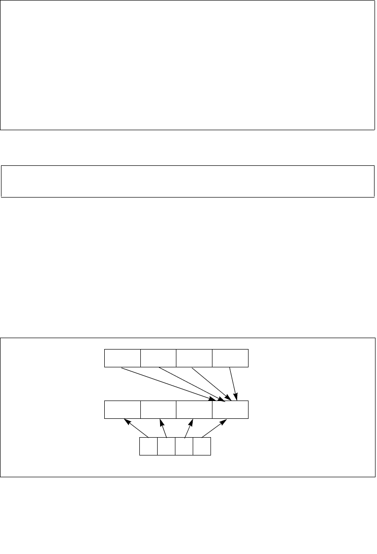
4-222 Vol. 2B PSHUFD—Shuffle Packed Doublewords
INSTRUCTION SET REFERENCE, N-Z
PSHUFD—Shuffle Packed Doublewords
Instruction Operand Encoding
Description
Copies doublewords from source operand (second operand) and inserts them in the
destination operand (first operand) at the locations selected with the order operand
(third operand). Figure 4-13 shows the operation of the PSHUFD instruction and the
encoding of the order operand. Each 2-bit field in the order operand selects the
contents of one doubleword location in the destination operand. For example, bits 0
and 1 of the order operand select the contents of doubleword 0 of the destination
operand. The encoding of bits 0 and 1 of the order operand (see the field encoding in
Figure 4-13) determines which doubleword from the source operand will be copied to
doubleword 0 of the destination operand.
Opcode/
Instruction
Op/
En
64/32 bit
Mode
Support
CPUID
Feature
Flag
Description
66 0F 70 /r ib
PSHUFD xmm1, xmm2/m128, imm8
A V/V SSE2 Shuffle the doublewords in
xmm2/m128 based on the
encoding in imm8 and store
the result in xmm1.
VEX.128.66.0F.WIG 70 /r ib
VPSHUFD xmm1, xmm2/m128,
imm8
A V/V AVX Shuffle the doublewords in
xmm2/m128 based on the
encoding in imm8 and store
the result in xmm1.
Op/En Operand 1 Operand 2 Operand 3 Operand 4
A ModRM:reg (w) ModRM:r/m (r) imm8 NA
Figure 4-13. PSHUFD Instruction Operation
X3 X2 X1 X0
SRC
DEST Y3 Y2 Y1 Y0
ORDER
00B - X0
01B - X1
10B - X2
11B - X3
Encoding
of Fields in
ORDER
01234567 Operand

Vol. 2B 4-223
INSTRUCTION SET REFERENCE, N-Z
PSHUFD—Shuffle Packed Doublewords
The source operand can be an XMM register or a 128-bit memory location. The desti-
nation operand is an XMM register. The order operand is an 8-bit immediate. Note
that this instruction permits a doubleword in the source operand to be copied to more
than one doubleword location in the destination operand.
In 64-bit mode, using a REX prefix in the form of REX.R permits this instruction to
access additional registers (XMM8-XMM15).
128-bit Legacy SSE version: Bits (VLMAX-1:128) of the corresponding YMM destina-
tion register remain unchanged.
VEX.128 encoded version: Bits (VLMAX-1:1288) of the destination YMM register are
zeroed. VEX.vvvv is reserved and must be 1111b, VEX.L must be 0, otherwise the
instruction will #UD.
Operation
PSHUFD (128-bit Legacy SSE version)
DEST[31:0] (SRC >> (ORDER[1:0] * 32))[31:0];
DEST[63:32] (SRC >> (ORDER[3:2] * 32))[31:0];
DEST[95:64] (SRC >> (ORDER[5:4] * 32))[31:0];
DEST[127:96] (SRC >> (ORDER[7:6] * 32))[31:0];
DEST[VLMAX-1:128] (Unmodified)
VPSHUFD (VEX.128 encoded version)
DEST[31:0] (SRC >> (ORDER[1:0] * 32))[31:0];
DEST[63:32] (SRC >> (ORDER[3:2] * 32))[31:0];
DEST[95:64] (SRC >> (ORDER[5:4] * 32))[31:0];
DEST[127:96] (SRC >> (ORDER[7:6] * 32))[31:0];
DEST[VLMAX-1:128] 0
Intel C/C++ Compiler Intrinsic Equivalent
PSHUFD __m128i _mm_shuffle_epi32(__m128i a, int n)
Flags Affected
None.
SIMD Floating-Point Exceptions
None.
Other Exceptions
See Exceptions Type 4; additionally
#UD If VEX.L = 1.
If VEX.vvvv != 1111B.

4-224 Vol. 2B PSHUFHW—Shuffle Packed High Words
INSTRUCTION SET REFERENCE, N-Z
PSHUFHW—Shuffle Packed High Words
Instruction Operand Encoding
Description
Copies words from the high quadword of the source operand (second operand) and
inserts them in the high quadword of the destination operand (first operand) at word
locations selected with the order operand (third operand). This operation is similar to
the operation used by the PSHUFD instruction, which is illustrated in Figure 4-13. For
the PSHUFHW instruction, each 2-bit field in the order operand selects the contents
of one word location in the high quadword of the destination operand. The binary
encodings of the order operand fields select words (0, 1, 2 or 3, 4) from the high
quadword of the source operand to be copied to the destination operand. The low
quadword of the source operand is copied to the low quadword of the destination
operand.
The source operand can be an XMM register or a 128-bit memory location. The desti-
nation operand is an XMM register. The order operand is an 8-bit immediate. Note
that this instruction permits a word in the high quadword of the source operand to be
copied to more than one word location in the high quadword of the destination
operand.
In 64-bit mode, using a REX prefix in the form of REX.R permits this instruction to
access additional registers (XMM8-XMM15).
128-bit Legacy SSE version: Bits (VLMAX-1:128) of the corresponding YMM destina-
tion register remain unchanged.
VEX.128 encoded version: Bits (VLMAX-1:128) of the destination YMM register are
zeroed. VEX.vvvv is reserved and must be 1111b, VEX.L must be 0, otherwise the
instruction will #UD.
Opcode/
Instruction
Op/
En
64/32 bit
Mode
Support
CPUID
Feature
Flag
Description
F3 0F 70 /r ib
PSHUFHW xmm1, xmm2/ m128,
imm8
A V/V SSE2 Shuffle the high words in
xmm2/m128 based on the
encoding in imm8 and store
the result in xmm1.
VEX.128.F3.0F.WIG 70 /r ib
VPSHUFHW xmm1, xmm2/m128,
imm8
A V/V AVX Shuffle the high words in
xmm2/m128 based on the
encoding in imm8 and store
the result in xmm1.
Op/En Operand 1 Operand 2 Operand 3 Operand 4
A ModRM:reg (w) ModRM:r/m (r) imm8 NA

Vol. 2B 4-225
INSTRUCTION SET REFERENCE, N-Z
PSHUFHW—Shuffle Packed High Words
Operation
PSHUFHW (128-bit Legacy SSE version)
DEST[63:0] SRC[63:0]
DEST[79:64] (SRC >> (imm[1:0] *16))[79:64]
DEST[95:80] (SRC >> (imm[3:2] * 16))[79:64]
DEST[111:96] (SRC >> (imm[5:4] * 16))[79:64]
DEST[127:112] (SRC >> (imm[7:6] * 16))[79:64]
DEST[VLMAX-1:128] (Unmodified)
VPSHUFHW (VEX.128 encoded version)
DEST[63:0] SRC1[63:0]
DEST[79:64] (SRC1 >> (imm[1:0] *16))[79:64]
DEST[95:80] (SRC1 >> (imm[3:2] * 16))[79:64]
DEST[111:96] (SRC1 >> (imm[5:4] * 16))[79:64]
DEST[127:112] (SRC1 >> (imm[7:6] * 16))[79:64]
DEST[VLMAX-1:128] 0
Intel C/C++ Compiler Intrinsic Equivalent
PSHUFHW __m128i _mm_shufflehi_epi16(__m128i a, int n)
Flags Affected
None.
SIMD Floating-Point Exceptions
None.
Other Exceptions
See Exceptions Type 4; additionally
#UD If VEX.L = 1.
If VEX.vvvv != 1111B.

4-226 Vol. 2B PSHUFLW—Shuffle Packed Low Words
INSTRUCTION SET REFERENCE, N-Z
PSHUFLW—Shuffle Packed Low Words
Instruction Operand Encoding
Description
Copies words from the low quadword of the source operand (second operand) and
inserts them in the low quadword of the destination operand (first operand) at word
locations selected with the order operand (third operand). This operation is similar to
the operation used by the PSHUFD instruction, which is illustrated in Figure 4-13. For
the PSHUFLW instruction, each 2-bit field in the order operand selects the contents of
one word location in the low quadword of the destination operand. The binary encod-
ings of the order operand fields select words (0, 1, 2, or 3) from the low quadword of
the source operand to be copied to the destination operand. The high quadword of
the source operand is copied to the high quadword of the destination operand.
The source operand can be an XMM register or a 128-bit memory location. The desti-
nation operand is an XMM register. The order operand is an 8-bit immediate. Note
that this instruction permits a word in the low quadword of the source operand to be
copied to more than one word location in the low quadword of the destination
operand.
In 64-bit mode, using a REX prefix in the form of REX.R permits this instruction to
access additional registers (XMM8-XMM15).
128-bit Legacy SSE version: Bits (VLMAX-1:128) of the corresponding YMM destina-
tion register remain unchanged.
VEX.128 encoded version: Bits (VLMAX-1:128) of the destination YMM register are
zeroed. VEX.vvvv is reserved and must be 1111b, VEX.L must be 0, otherwise
instructions will #UD.
Opcode/
Instruction
Op/
En
64/32 bit
Mode
Support
CPUID
Feature
Flag
Description
F2 0F 70 /r ib
PSHUFLW xmm1, xmm2/m128,
imm8
A V/V SSE2 Shuffle the low words in
xmm2/m128 based on the
encoding in imm8 and store
the result in xmm1.
VEX.128.F2.0F.WIG 70 /r ib
VPSHUFLW xmm1, xmm2/m128,
imm8
A V/V AVX Shuffle the low words in
xmm2/m128 based on the
encoding in imm8 and store
the result in xmm1.
Op/En Operand 1 Operand 2 Operand 3 Operand 4
A ModRM:reg (w) ModRM:r/m (r) imm8 NA

Vol. 2B 4-227
INSTRUCTION SET REFERENCE, N-Z
PSHUFLW—Shuffle Packed Low Words
Operation
PSHUFLW (128-bit Legacy SSE version)
DEST[15:0] (SRC >> (imm[1:0] *16))[15:0]
DEST[31:16] (SRC >> (imm[3:2] * 16))[15:0]
DEST[47:32] (SRC >> (imm[5:4] * 16))[15:0]
DEST[63:48] (SRC >> (imm[7:6] * 16))[15:0]
DEST[127:64] SRC[127:64]
DEST[VLMAX-1:128] (Unmodified)
VPSHUFLW (VEX.128 encoded version)
DEST[15:0] (SRC1 >> (imm[1:0] *16))[15:0]
DEST[31:16] (SRC1 >> (imm[3:2] * 16))[15:0]
DEST[47:32] (SRC1 >> (imm[5:4] * 16))[15:0]
DEST[63:48] (SRC1 >> (imm[7:6] * 16))[15:0]
DEST[127:64] SRC[127:64]
DEST[VLMAX-1:128] 0
Intel C/C++ Compiler Intrinsic Equivalent
PSHUFLW __m128i _mm_shufflelo_epi16(__m128i a, int n)
Flags Affected
None.
SIMD Floating-Point Exceptions
None.
Other Exceptions
See Exceptions Type 4; additionally
#UD If VEX.L = 1.
If VEX.vvvv != 1111B.

4-228 Vol. 2B PSHUFW—Shuffle Packed Words
INSTRUCTION SET REFERENCE, N-Z
PSHUFW—Shuffle Packed Words
Instruction Operand Encoding
Description
Copies words from the source operand (second operand) and inserts them in the
destination operand (first operand) at word locations selected with the order operand
(third operand). This operation is similar to the operation used by the PSHUFD
instruction, which is illustrated in Figure 4-13. For the PSHUFW instruction, each 2-
bit field in the order operand selects the contents of one word location in the destina-
tion operand. The encodings of the order operand fields select words from the source
operand to be copied to the destination operand.
The source operand can be an MMX technology register or a 64-bit memory location.
The destination operand is an MMX technology register. The order operand is an 8-bit
immediate. Note that this instruction permits a word in the source operand to be
copied to more than one word location in the destination operand.
In 64-bit mode, using a REX prefix in the form of REX.R permits this instruction to
access additional registers (XMM8-XMM15).
Operation
DEST[15:0] ← (SRC >> (ORDER[1:0] * 16))[15:0];
DEST[31:16] ← (SRC >> (ORDER[3:2] * 16))[15:0];
DEST[47:32] ← (SRC >> (ORDER[5:4] * 16))[15:0];
DEST[63:48] ← (SRC >> (ORDER[7:6] * 16))[15:0];
Intel C/C++ Compiler Intrinsic Equivalent
PSHUFW __m64 _mm_shuffle_pi16(__m64 a, int n)
Flags Affected
None.
Opcode Instruction Op/
En
64-Bit
Mode
Compat/
Leg Mode
Description
0F 70 /r ib PSHUFW mm1,
mm2/m64, imm8
A Valid Valid Shuffle the words in
mm2/m64 based on the
encoding in imm8 and store
the result in mm1.
Op/En Operand 1 Operand 2 Operand 3 Operand 4
A ModRM:reg (w) ModRM:r/m (r) imm8 NA

Vol. 2B 4-229
INSTRUCTION SET REFERENCE, N-Z
PSHUFW—Shuffle Packed Words
Numeric Exceptions
None.
Protected Mode Exceptions
#GP(0) If a memory operand effective address is outside the CS, DS,
ES, FS, or GS segment limit.
#SS(0) If a memory operand effective address is outside the SS
segment limit.
#UD If CR0.EM[bit 2] = 1.
If the LOCK prefix is used.
#NM If CR0.TS[bit 3] = 1.
#MF If there is a pending x87 FPU exception.
#PF(fault-code) If a page fault occurs.
#AC(0) If alignment checking is enabled and an unaligned memory
reference is made while the current privilege level is 3.
Real-Address Mode Exceptions
#GP If any part of the operand lies outside of the effective address
space from 0 to FFFFH.
#UD If CR0.EM[bit 2] = 1.
If the LOCK prefix is used.
#NM If CR0.TS[bit 3] = 1.
#MF If there is a pending x87 FPU exception.
Virtual-8086 Mode Exceptions
Same exceptions as in real address mode.
#PF(fault-code) For a page fault.
#AC(0) If alignment checking is enabled and an unaligned memory
reference is made.
Compatibility Mode Exceptions
Same as for protected mode exceptions.
64-Bit Mode Exceptions
#SS(0) If a memory address referencing the SS segment is in a non-
canonical form.
#GP(0) If the memory address is in a non-canonical form.
#UD If CR0.EM[bit 2] = 1.
If the LOCK prefix is used.
#NM If CR0.TS[bit 3] = 1.
#MF If there is a pending x87 FPU exception.

4-230 Vol. 2B PSHUFW—Shuffle Packed Words
INSTRUCTION SET REFERENCE, N-Z
#PF(fault-code) If a page fault occurs.
#AC(0) If alignment checking is enabled and an unaligned memory
reference is made while the current privilege level is 3.

Vol. 2B 4-231
INSTRUCTION SET REFERENCE, N-Z
PSIGNB/PSIGNW/PSIGND — Packed SIGN
PSIGNB/PSIGNW/PSIGND — Packed SIGN
Opcode Instruction Op/
En
64/32 bit
Mode
Support
CPUID
Feature
Flag
Description
0F 38 08 /r1
PSIGNB mm1, mm2/m64
A V/V SSSE3 Negate/zero/preserve
packed byte integers in
mm1 depending on the
corresponding sign in
mm2/m64
66 0F 38 08 /r
PSIGNB xmm1, xmm2/m128
A V/V SSSE3 Negate/zero/preserve
packed byte integers in
xmm1 depending on the
corresponding sign in
xmm2/m128.
0F 38 09 /r1
PSIGNW mm1, mm2/m64
A V/V SSSE3 Negate/zero/preserve
packed word integers in
mm1 depending on the
corresponding sign in
mm2/m128.
66 0F 38 09 /r
PSIGNW xmm1, xmm2/m128
A V/V SSSE3 Negate/zero/preserve
packed word integers in
xmm1 depending on the
corresponding sign in
xmm2/m128.
0F 38 0A /r1
PSIGND mm1, mm2/m64
A V/V SSSE3 Negate/zero/preserve
packed doubleword integers
in mm1 depending on the
corresponding sign in
mm2/m128.
66 0F 38 0A /r
PSIGND xmm1, xmm2/m128
A V/V SSSE3 Negate/zero/preserve
packed doubleword integers
in xmm1 depending on the
corresponding sign in
xmm2/m128.
VEX.NDS.128.66.0F38.WIG 08 /r
VPSIGNB xmm1, xmm2,
xmm3/m128
B V/V AVX Negate/zero/preserve
packed byte integers in
xmm2 depending on the
corresponding sign in
xmm3/m128.

4-232 Vol. 2B PSIGNB/PSIGNW/PSIGND — Packed SIGN
INSTRUCTION SET REFERENCE, N-Z
Instruction Operand Encoding
Description
PSIGNB/PSIGNW/PSIGND negates each data element of the destination operand
(the first operand) if the signed integer value of the corresponding data element in
the source operand (the second operand) is less than zero. If the signed integer
value of a data element in the source operand is positive, the corresponding data
element in the destination operand is unchanged. If a data element in the source
operand is zero, the corresponding data element in the destination operand is set to
zero.
PSIGNB operates on signed bytes. PSIGNW operates on 16-bit signed words.
PSIGND operates on signed 32-bit integers. Both operands can be MMX register or
XMM registers. When the source operand is a 128bit memory operand, the operand
must be aligned on a 16-byte boundary or a general-protection exception (#GP) will
be generated.
In 64-bit mode, use the REX prefix to access additional registers.
128-bit Legacy SSE version: Bits (VLMAX-1:128) of the corresponding YMM destina-
tion register remain unchanged.
VEX.128 encoded version: Bits (VLMAX-1:128) of the destination YMM register are
zeroed. VEX.L must be 0, otherwise instructions will #UD.
VEX.NDS.128.66.0F38.WIG 09 /r
VPSIGNW xmm1, xmm2,
xmm3/m128
B V/V AVX Negate/zero/preserve
packed word integers in
xmm2 depending on the
corresponding sign in
xmm3/m128.
VEX.NDS.128.66.0F38.WIG 0A /r
VPSIGND xmm1, xmm2,
xmm3/m128
B V/V AVX Negate/zero/preserve
packed doubleword integers
in xmm2 depending on the
corresponding sign in
xmm3/m128.
NOTES:
1. See note in Section 2.4, “Instruction Exception Specification”.
Op/En Operand 1 Operand 2 Operand 3 Operand 4
A ModRM:reg (r, w) ModRM:r/m (r) NA NA
B ModRM:reg (w) VEX.vvvv (r) ModRM:r/m (r) NA
Opcode Instruction Op/
En
64/32 bit
Mode
Support
CPUID
Feature
Flag
Description

Vol. 2B 4-233
INSTRUCTION SET REFERENCE, N-Z
PSIGNB/PSIGNW/PSIGND — Packed SIGN
Operation
PSIGNB (with 64 bit operands)
IF (SRC[7:0] < 0 )
DEST[7:0] ← Neg(DEST[7:0])
ELSEIF (SRC[7:0] = 0 )
DEST[7:0] ← 0
ELSEIF (SRC[7:0] > 0 )
DEST[7:0] ← DEST[7:0]
Repeat operation for 2nd through 7th bytes
IF (SRC[63:56] < 0 )
DEST[63:56] ← Neg(DEST[63:56])
ELSEIF (SRC[63:56] = 0 )
DEST[63:56] ← 0
ELSEIF (SRC[63:56] > 0 )
DEST[63:56] ← DEST[63:56]
PSIGNB (with 128 bit operands)
IF (SRC[7:0] < 0 )
DEST[7:0] ← Neg(DEST[7:0])
ELSEIF (SRC[7:0] = 0 )
DEST[7:0] ← 0
ELSEIF (SRC[7:0] > 0 )
DEST[7:0] ← DEST[7:0]
Repeat operation for 2nd through 15th bytes
IF (SRC[127:120] < 0 )
DEST[127:120] ← Neg(DEST[127:120])
ELSEIF (SRC[127:120] = 0 )
DEST[127:120] ← 0
ELSEIF (SRC[127:120] > 0 )
DEST[127:120] ← DEST[127:120]
PSIGNW (with 64 bit operands)
IF (SRC[15:0] < 0 )
DEST[15:0] ← Neg(DEST[15:0])
ELSEIF (SRC[15:0] = 0 )
DEST[15:0] ← 0
ELSEIF (SRC[15:0] > 0 )
DEST[15:0] ← DEST[15:0]
Repeat operation for 2nd through 3rd words
IF (SRC[63:48] < 0 )

4-234 Vol. 2B PSIGNB/PSIGNW/PSIGND — Packed SIGN
INSTRUCTION SET REFERENCE, N-Z
DEST[63:48] ← Neg(DEST[63:48])
ELSEIF (SRC[63:48] = 0 )
DEST[63:48] ← 0
ELSEIF (SRC[63:48] > 0 )
DEST[63:48] ← DEST[63:48]
PSIGNW (with 128 bit operands)
IF (SRC[15:0] < 0 )
DEST[15:0] ← Neg(DEST[15:0])
ELSEIF (SRC[15:0] = 0 )
DEST[15:0] ← 0
ELSEIF (SRC[15:0] > 0 )
DEST[15:0] ← DEST[15:0]
Repeat operation for 2nd through 7th words
IF (SRC[127:112] < 0 )
DEST[127:112] ← Neg(DEST[127:112])
ELSEIF (SRC[127:112] = 0 )
DEST[127:112] ← 0
ELSEIF (SRC[127:112] > 0 )
DEST[127:112] ← DEST[127:112]
PSIGND (with 64 bit operands)
IF (SRC[31:0] < 0 )
DEST[31:0] ← Neg(DEST[31:0])
ELSEIF (SRC[31:0] = 0 )
DEST[31:0] ← 0
ELSEIF (SRC[31:0] > 0 )
DEST[31:0] ← DEST[31:0]
IF (SRC[63:32] < 0 )
DEST[63:32] ← Neg(DEST[63:32])
ELSEIF (SRC[63:32] = 0 )
DEST[63:32] ← 0
ELSEIF (SRC[63:32] > 0 )
DEST[63:32] ← DEST[63:32]
PSIGND (with 128 bit operands)
IF (SRC[31:0] < 0 )
DEST[31:0] ← Neg(DEST[31:0])
ELSEIF (SRC[31:0] = 0 )
DEST[31:0] ← 0
ELSEIF (SRC[31:0] > 0 )
DEST[31:0] ← DEST[31:0]

Vol. 2B 4-235
INSTRUCTION SET REFERENCE, N-Z
PSIGNB/PSIGNW/PSIGND — Packed SIGN
Repeat operation for 2nd through 3rd double words
IF (SRC[127:96] < 0 )
DEST[127:96] ← Neg(DEST[127:96])
ELSEIF (SRC[127:96] = 0 )
DEST[127:96] ← 0
ELSEIF (SRC[127:96] > 0 )
DEST[127:96] ← DEST[127:96]
VPSIGNB (VEX.128 encoded version)
DEST[127:0] BYTE_SIGN(SRC1, SRC2)
DEST[VLMAX-1:128] 0
VPSIGNW (VEX.128 encoded version)
DEST[127:0] WORD_SIGN(SRC1, SRC2)
DEST[VLMAX-1:128] 0
VPSIGND (VEX.128 encoded version)
DEST[127:0] DWORD_SIGN(SRC1, SRC2)
DEST[VLMAX-1:128] 0
Intel C/C++ Compiler Intrinsic Equivalent
PSIGNB __m64 _mm_sign_pi8 (__m64 a, __m64 b)
PSIGNB __m128i _mm_sign_epi8 (__m128i a, __m128i b)
PSIGNW __m64 _mm_sign_pi16 (__m64 a, __m64 b)
PSIGNW __m128i _mm_sign_epi16 (__m128i a, __m128i b)
PSIGND __m64 _mm_sign_pi32 (__m64 a, __m64 b)
PSIGND __m128i _mm_sign_epi32 (__m128i a, __m128i b)
SIMD Floating-Point Exceptions
None.
Other Exceptions
See Exceptions Type 4; additionally
#UD If VEX.L = 1.

4-236 Vol. 2B PSLLDQ—Shift Double Quadword Left Logical
INSTRUCTION SET REFERENCE, N-Z
PSLLDQ—Shift Double Quadword Left Logical
Instruction Operand Encoding
Description
Shifts the destination operand (first operand) to the left by the number of bytes spec-
ified in the count operand (second operand). The empty low-order bytes are cleared
(set to all 0s). If the value specified by the count operand is greater than 15, the
destination operand is set to all 0s. The destination operand is an XMM register. The
count operand is an 8-bit immediate.
128-bit Legacy SSE version: The source and destination operands are the same. Bits
(VLMAX-1:128) of the corresponding YMM destination register remain unchanged.
VEX.128 encoded version: Bits (VLMAX-1:128) of the destination YMM register are
zeroed. VEX.vvvv encodes the destination register, and VEX.B + ModRM.r/m encodes
the source register. VEX.L must be 0, otherwise instructions will #UD.
Operation
PSLLDQ(128-bit Legacy SSE version)
TEMP COUNT
IF (TEMP > 15) THEN TEMP 16; FI
DEST DEST << (TEMP * 8)
DEST[VLMAX-1:128] (Unmodified)
VPSLLDQ (VEX.128 encoded version)
TEMP COUNT
IF (TEMP > 15) THEN TEMP 16; FI
DEST SRC << (TEMP * 8)
DEST[VLMAX-1:128] 0
Opcode/
Instruction
Op/
En
64/32 bit
Mode
Support
CPUID
Feature
Flag
Description
66 0F 73 /7 ib
PSLLDQ xmm1, imm8
AV/V SSE2 Shift xmm1 left by imm8
bytes while shifting in 0s.
VEX.NDD.128.66.0F.WIG 73 /7 ib
VPSLLDQ xmm1, xmm2, imm8
B V/V AVX Shift xmm2 left by imm8
bytes while shifting in 0s
and store result in xmm1.
Op/En Operand 1 Operand 2 Operand 3 Operand 4
A ModRM:r/m (r, w) imm8 NA NA
B VEX.vvvv (w) ModRM:r/m (r) NA NA

Vol. 2B 4-237
INSTRUCTION SET REFERENCE, N-Z
PSLLDQ—Shift Double Quadword Left Logical
Intel C/C++ Compiler Intrinsic Equivalent
PSLLDQ __m128i _mm_slli_si128 ( __m128i a, int imm)
Flags Affected
None.
Numeric Exceptions
None.
Other Exceptions
See Exceptions Type 7; additionally
#UD If VEX.L = 1.

4-238 Vol. 2B PSLLW/PSLLD/PSLLQ—Shift Packed Data Left Logical
INSTRUCTION SET REFERENCE, N-Z
PSLLW/PSLLD/PSLLQ—Shift Packed Data Left Logical
Opcode/
Instruction
Op/
En
64/32 bit
Mode
Support
CPUID
Feature
Flag
Description
0F F1 /r1
PSLLW mm, mm/m64
AV/V MMX Shift words in mm left
mm/m64 while shifting in
0s.
66 0F F1 /r
PSLLW xmm1, xmm2/m128
AV/V SSE2 Shift words in xmm1 left by
xmm2/m128 while shifting
in 0s.
0F 71 /6 ib
PSLLW xmm1, imm8
BV/V MMX Shift words in mm left by
imm8 while shifting in 0s.
66 0F 71 /6 ib
PSLLW xmm1, imm8
BV/V SSE2 Shift words in xmm1 left by
imm8 while shifting in 0s.
0F F2 /r1
PSLLD mm, mm/m64
AV/V MMX Shift doublewords in mm
left by mm/m64 while
shifting in 0s.
66 0F F2 /r
PSLLD xmm1, xmm2/m128
A V/V SSE2 Shift doublewords in xmm1
left by xmm2/m128 while
shifting in 0s.
0F 72 /6 ib1
PSLLD mm, imm8
BV/V MMX Shift doublewords in mm
left by imm8 while shifting
in 0s.
66 0F 72 /6 ib
PSLLD xmm1, imm8
B V/V SSE2 Shift doublewords in xmm1
left by imm8 while shifting
in 0s.
0F F3 /r1
PSLLQ mm, mm/m64
AV/V MMX Shift quadword in mm left
by mm/m64 while shifting
in 0s.
66 0F F3 /r
PSLLQ xmm1, xmm2/m128
AV/V SSE2 Shift quadwords in xmm1
left by xmm2/m128 while
shifting in 0s.
0F 73 /6 ib1
PSLLQ mm, imm8
BV/V MMX Shift quadword in mm left
by imm8 while shifting in 0s.
66 0F 73 /6 ib
PSLLQ xmm1, imm8
BV/V SSE2 Shift quadwords in xmm1
left by imm8 while shifting
in 0s.

Vol. 2B 4-239
INSTRUCTION SET REFERENCE, N-Z
PSLLW/PSLLD/PSLLQ—Shift Packed Data Left Logical
Instruction Operand Encoding
Description
Shifts the bits in the individual data elements (words, doublewords, or quadword) in
the destination operand (first operand) to the left by the number of bits specified in
the count operand (second operand). As the bits in the data elements are shifted left,
the empty low-order bits are cleared (set to 0). If the value specified by the count
operand is greater than 15 (for words), 31 (for doublewords), or 63 (for a quad-
Opcode/
Instruction
Op/
En
64/32 bit
Mode
Support
CPUID
Feature
Flag
Description
VEX.NDS.128.66.0F.WIG F1 /r
VPSLLW xmm1, xmm2, xmm3/m128
C V/V AVX Shift words in xmm2 left by
amount specified in
xmm3/m128 while shifting
in 0s.
VEX.NDD.128.66.0F.WIG 71 /6 ib
VPSLLW xmm1, xmm2, imm8
D V/V AVX Shift words in xmm2 left by
imm8 while shifting in 0s.
VEX.NDS.128.66.0F.WIG F2 /r
VPSLLD xmm1, xmm2, xmm3/m128
C V/V AVX Shift doublewords in xmm2
left by amount specified in
xmm3/m128 while shifting
in 0s.
VEX.NDD.128.66.0F.WIG 72 /6 ib
VPSLLD xmm1, xmm2, imm8
D V/V AVX Shift doublewords in xmm2
left by imm8 while shifting
in 0s.
VEX.NDS.128.66.0F.WIG F3 /r
VPSLLQ xmm1, xmm2, xmm3/m128
CV/V AVX Shift quadwords in xmm2
left by amount specified in
xmm3/m128 while shifting
in 0s.
VEX.NDD.128.66.0F.WIG 73 /6 ib
VPSLLQ xmm1, xmm2, imm8
DV/V AVX Shift quadwords in xmm2
left by imm8 while shifting
in 0s.
NOTES:
1. See note in Section 2.4, “Instruction Exception Specification”.
Op/En Operand 1 Operand 2 Operand 3 Operand 4
A ModRM:reg (r, w) ModRM:r/m (r) NA NA
B ModRM:r/m (r, w) imm8 NA NA
C ModRM:reg (w) VEX.vvvv (r) ModRM:r/m (r) NA
D VEX.vvvv (w) ModRM:r/m (r) NA NA
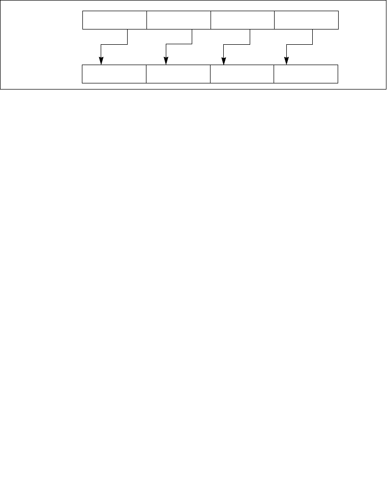
4-240 Vol. 2B PSLLW/PSLLD/PSLLQ—Shift Packed Data Left Logical
INSTRUCTION SET REFERENCE, N-Z
word), then the destination operand is set to all 0s. Figure 4-14 gives an example of
shifting words in a 64-bit operand.
The destination operand may be an MMX technology register or an XMM register; the
count operand can be either an MMX technology register or an 64-bit memory loca-
tion, an XMM register or a 128-bit memory location, or an 8-bit immediate. Note that
only the first 64-bits of a 128-bit count operand are checked to compute the count.
The PSLLW instruction shifts each of the words in the destination operand to the left
by the number of bits specified in the count operand; the PSLLD instruction shifts
each of the doublewords in the destination operand; and the PSLLQ instruction shifts
the quadword (or quadwords) in the destination operand.
In 64-bit mode, using a REX prefix in the form of REX.R permits this instruction to
access additional registers (XMM8-XMM15).
128-bit Legacy SSE version: Bits (VLMAX-1:128) of the corresponding YMM destina-
tion register remain unchanged. If the count operand is a memory address, 128 bits
are loaded but the upper 64 bits are ignored.
VEX.128 encoded version: Bits (VLMAX-1:128) of the destination YMM register are
zeroed. For shifts with an immediate count (VEX.128.66.0F 71-73 /6), VEX.vvvv
encodes the destination register, and VEX.B + ModRM.r/m encodes the source
register. VEX.L must be 0, otherwise instructions will #UD. If the count operand is a
memory address, 128 bits are loaded but the upper 64 bits are ignored.
Operation
PSLLW (with 64-bit operand)
IF (COUNT > 15)
THEN
DEST[64:0] ← 0000000000000000H;
ELSE
DEST[15:0] ← ZeroExtend(DEST[15:0] << COUNT);
(* Repeat shift operation for 2nd and 3rd words *)
DEST[63:48] ← ZeroExtend(DEST[63:48] << COUNT);
FI;
Figure 4-14. PSLLW, PSLLD, and PSLLQ Instruction Operation Using 64-bit Operand
DEST
DEST
Pre-Shift
Post-Shift
Shift Left
X0
X0 << COUNT
X3 X2 X1
X1 << COUNTX2 << COUNTX3 << COUNT
with Zero
Extension

Vol. 2B 4-241
INSTRUCTION SET REFERENCE, N-Z
PSLLW/PSLLD/PSLLQ—Shift Packed Data Left Logical
PSLLD (with 64-bit operand)
IF (COUNT > 31)
THEN
DEST[64:0] ← 0000000000000000H;
ELSE
DEST[31:0] ← ZeroExtend(DEST[31:0] << COUNT);
DEST[63:32] ← ZeroExtend(DEST[63:32] << COUNT);
FI;
PSLLQ (with 64-bit operand)
IF (COUNT > 63)
THEN
DEST[64:0] ← 0000000000000000H;
ELSE
DEST ← ZeroExtend(DEST << COUNT);
FI;
PSLLW (with 128-bit operand)
COUNT ← COUNT_SOURCE[63:0];
IF (COUNT > 15)
THEN
DEST[128:0] ← 00000000000000000000000000000000H;
ELSE
DEST[15:0] ← ZeroExtend(DEST[15:0] << COUNT);
(* Repeat shift operation for 2nd through 7th words *)
DEST[127:112] ← ZeroExtend(DEST[127:112] << COUNT);
FI;
PSLLD (with 128-bit operand)
COUNT ← COUNT_SOURCE[63:0];
IF (COUNT > 31)
THEN
DEST[128:0] ← 00000000000000000000000000000000H;
ELSE
DEST[31:0] ← ZeroExtend(DEST[31:0] << COUNT);
(* Repeat shift operation for 2nd and 3rd doublewords *)
DEST[127:96] ← ZeroExtend(DEST[127:96] << COUNT);
FI;
PSLLQ (with 128-bit operand)
COUNT ← COUNT_SOURCE[63:0];
IF (COUNT > 63)
THEN
DEST[128:0] ← 00000000000000000000000000000000H;
ELSE

4-242 Vol. 2B PSLLW/PSLLD/PSLLQ—Shift Packed Data Left Logical
INSTRUCTION SET REFERENCE, N-Z
DEST[63:0] ← ZeroExtend(DEST[63:0] << COUNT);
DEST[127:64] ← ZeroExtend(DEST[127:64] << COUNT);
FI;
PSLLW (xmm, xmm, xmm/m128)
DEST[127:0] LOGICAL_LEFT_SHIFT_WORDS(DEST, SRC)
DEST[VLMAX-1:128] (Unmodified)
PSLLW (xmm, imm8)
DEST[127:0] LOGICAL_LEFT_SHIFT_WORDS(DEST, imm8)
DEST[VLMAX-1:128] (Unmodified)
VPSLLD (xmm, xmm, xmm/m128)
DEST[127:0] LOGICAL_LEFT_SHIFT_DWORDS(SRC1, SRC2)
DEST[VLMAX-1:128] 0
VPSLLD (xmm, imm8)
DEST[127:0] LOGICAL_LEFT_SHIFT_DWORDS(SRC1, imm8)
DEST[VLMAX-1:128] 0
PSLLD (xmm, xmm, xmm/m128)
DEST[127:0] LOGICAL_LEFT_SHIFT_DWORDS(DEST, SRC)
DEST[VLMAX-1:128] (Unmodified)
PSLLD (xmm, imm8)
DEST[127:0] LOGICAL_LEFT_SHIFT_DWORDS(DEST, imm8)
DEST[VLMAX-1:128] (Unmodified)
VPSLLQ (xmm, xmm, xmm/m128)
DEST[127:0] LOGICAL_LEFT_SHIFT_QWORDS(SRC1, SRC2)
DEST[VLMAX-1:128] 0
VPSLLQ (xmm, imm8)
DEST[127:0] LOGICAL_LEFT_SHIFT_QWORDS(SRC1, imm8)
DEST[VLMAX-1:128] 0
PSLLQ (xmm, xmm, xmm/m128)
DEST[127:0] LOGICAL_LEFT_SHIFT_QWORDS(DEST, SRC)
DEST[VLMAX-1:128] (Unmodified)
PSLLQ (xmm, imm8)
DEST[127:0] LOGICAL_LEFT_SHIFT_QWORDS(DEST, imm8)
DEST[VLMAX-1:128] (Unmodified)

Vol. 2B 4-243
INSTRUCTION SET REFERENCE, N-Z
PSLLW/PSLLD/PSLLQ—Shift Packed Data Left Logical
VPSLLW (xmm, xmm, xmm/m128)
DEST[127:0] LOGICAL_LEFT_SHIFT_WORDS(SRC1, SRC2)
DEST[VLMAX-1:128] 0
VPSLLW (xmm, imm8)
DEST[127:0] LOGICAL_LEFT_SHIFT_WORDS(SRC1, imm8)
DEST[VLMAX-1:128] 0
PSLLW (xmm, xmm, xmm/m128)
DEST[127:0] LOGICAL_LEFT_SHIFT_WORDS(DEST, SRC)
DEST[VLMAX-1:128] (Unmodified)
PSLLW (xmm, imm8)
DEST[127:0] LOGICAL_LEFT_SHIFT_WORDS(DEST, imm8)
DEST[VLMAX-1:128] (Unmodified)
VPSLLD (xmm, xmm, xmm/m128)
DEST[127:0] LOGICAL_LEFT_SHIFT_DWORDS(SRC1, SRC2)
DEST[VLMAX-1:128] 0
VPSLLD (xmm, imm8)
DEST[127:0] LOGICAL_LEFT_SHIFT_DWORDS(SRC1, imm8)
DEST[VLMAX-1:128] 0
Intel C/C++ Compiler Intrinsic Equivalents
PSLLW __m64 _mm_slli_pi16 (__m64 m, int count)
PSLLW __m64 _mm_sll_pi16(__m64 m, __m64 count)
PSLLW __m128i _mm_slli_pi16(__m64 m, int count)
PSLLW __m128i _mm_slli_pi16(__m128i m, __m128i count)
PSLLD __m64 _mm_slli_pi32(__m64 m, int count)
PSLLD __m64 _mm_sll_pi32(__m64 m, __m64 count)
PSLLD __m128i _mm_slli_epi32(__m128i m, int count)
PSLLD __m128i _mm_sll_epi32(__m128i m, __m128i count)
PSLLQ __m64 _mm_slli_si64(__m64 m, int count)
PSLLQ __m64 _mm_sll_si64(__m64 m, __m64 count)
PSLLQ __m128i _mm_slli_epi64(__m128i m, int count)
PSLLQ __m128i _mm_sll_epi64(__m128i m, __m128i count)

4-244 Vol. 2B PSLLW/PSLLD/PSLLQ—Shift Packed Data Left Logical
INSTRUCTION SET REFERENCE, N-Z
Flags Affected
None.
Numeric Exceptions
None.
Other Exceptions
See Exceptions Type 4 and 7 for non-VEX-encoded instructions.
#UD If VEX.L = 1.

Vol. 2B 4-245
INSTRUCTION SET REFERENCE, N-Z
PSRAW/PSRAD—Shift Packed Data Right Arithmetic
PSRAW/PSRAD—Shift Packed Data Right Arithmetic
Opcode/
Instruction
Op/
En
64/32 bit
Mode
Support
CPUID
Feature
Flag
Description
0F E1 /r1
PSRAW mm, mm/m64
AV/V MMX Shift words in mm right by
mm/m64 while shifting in
sign bits.
66 0F E1 /r
PSRAW xmm1, xmm2/m128
A V/V SSE2 Shift words in xmm1 right
by xmm2/m128 while
shifting in sign bits.
0F 71 /4 ib1
PSRAW mm, imm8
BV/V MMX Shift words in mm right by
imm8 while shifting in sign
bits
66 0F 71 /4 ib
PSRAW xmm1, imm8
B V/V SSE2 Shift words in xmm1 right
by imm8 while shifting in
sign bits
0F E2 /r1
PSRAD mm, mm/m64
A V/V MMX Shift doublewords in mm
right by mm/m64 while
shifting in sign bits.
66 0F E2 /r
PSRAD xmm1, xmm2/m128
A V/V SSE2 Shift doubleword in xmm1
right by xmm2 /m128 while
shifting in sign bits.
0F 72 /4 ib1
PSRAD mm, imm8
B V/V MMX Shift doublewords in mm
right by imm8 while shifting
in sign bits.
66 0F 72 /4 ib
PSRAD xmm1, imm8
B V/V SSE2 Shift doublewords in xmm1
right by imm8 while shifting
in sign bits.
VEX.NDS.128.66.0F.WIG E1 /r
VPSRAW xmm1, xmm2,
xmm3/m128
C V/V AVX Shift words in xmm2 right
by amount specified in
xmm3/m128 while shifting
in sign bits.
VEX.NDD.128.66.0F.WIG 71 /4 ib
VPSRAW xmm1, xmm2, imm8
D V/V AVX Shift words in xmm2 right
by imm8 while shifting in
sign bits.
VEX.NDS.128.66.0F.WIG E2 /r
VPSRAD xmm1, xmm2,
xmm3/m128
C V/V AVX Shift doublewords in xmm2
right by amount specified in
xmm3/m128 while shifting
in sign bits.
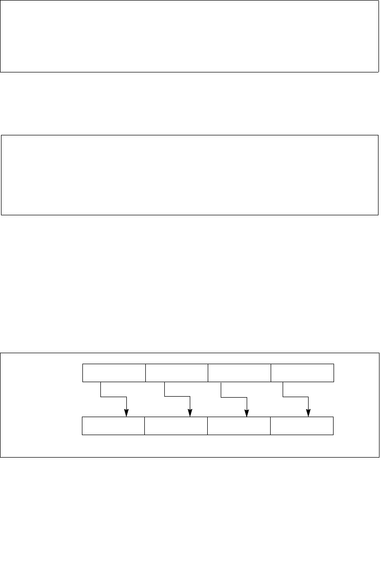
4-246 Vol. 2B PSRAW/PSRAD—Shift Packed Data Right Arithmetic
INSTRUCTION SET REFERENCE, N-Z
Instruction Operand Encoding
Description
Shifts the bits in the individual data elements (words or doublewords) in the destina-
tion operand (first operand) to the right by the number of bits specified in the count
operand (second operand). As the bits in the data elements are shifted right, the
empty high-order bits are filled with the initial value of the sign bit of the data
element. If the value specified by the count operand is greater than 15 (for words) or
31 (for doublewords), each destination data element is filled with the initial value of
the sign bit of the element. (Figure 4-15 gives an example of shifting words in a 64-
bit operand.)
The destination operand may be an MMX technology register or an XMM register; the
count operand can be either an MMX technology register or an 64-bit memory loca-
Opcode/
Instruction
Op/
En
64/32 bit
Mode
Support
CPUID
Feature
Flag
Description
VEX.NDD.128.66.0F.WIG 72 /4 ib
VPSRAD xmm1, xmm2, imm8
DV/V AVX Shift doublewords in xmm2
right by imm8 while shifting
in sign bits.
NOTES:
1. See note in Section 2.4, “Instruction Exception Specification”.
Op/En Operand 1 Operand 2 Operand 3 Operand 4
A ModRM:reg (r, w) ModRM:r/m (r) NA NA
B ModRM:r/m (r, w) imm8 NA NA
C ModRM:reg (w) VEX.vvvv (r) ModRM:r/m (r) NA
D VEX.vvvv (w) ModRM:r/m (r) NA NA
Figure 4-15. PSRAW and PSRAD Instruction Operation Using a 64-bit Operand
DEST
DEST
Pre-Shift
Post-Shift
Shift Right
X0
X0 >> COUNT
X3 X2 X1
X1 >> COUNTX2 >> COUNTX3 >> COUNT
with Sign
Extension

Vol. 2B 4-247
INSTRUCTION SET REFERENCE, N-Z
PSRAW/PSRAD—Shift Packed Data Right Arithmetic
tion, an XMM register or a 128-bit memory location, or an 8-bit immediate. Note that
only the first 64-bits of a 128-bit count operand are checked to compute the count.
The PSRAW instruction shifts each of the words in the destination operand to the
right by the number of bits specified in the count operand, and the PSRAD instruction
shifts each of the doublewords in the destination operand.
In 64-bit mode, using a REX prefix in the form of REX.R permits this instruction to
access additional registers (XMM8-XMM15).
128-bit Legacy SSE version: Bits (VLMAX-1:128) of the corresponding YMM destina-
tion register remain unchanged. If the count operand is a memory address, 128 bits
are loaded but the upper 64 bits are ignored.
VEX.128 encoded version: Bits (VLMAX-1:128) of the destination YMM register are
zeroed. For shifts with an immediate count (VEX.128.66.0F 71-73 /4), VEX.vvvv
encodes the destination register, and VEX.B + ModRM.r/m encodes the source
register. VEX.L must be 0, otherwise instructions will #UD. : Bits (255:128) of the
corresponding YMM destination register remain unchanged. If the count operand is a
memory address, 128 bits are loaded but the upper 64 bits are ignored.
Operation
PSRAW (with 64-bit operand)
IF (COUNT > 15)
THEN COUNT ← 16;
FI;
DEST[15:0] ← SignExtend(DEST[15:0] >> COUNT);
(* Repeat shift operation for 2nd and 3rd words *)
DEST[63:48] ← SignExtend(DEST[63:48] >> COUNT);
PSRAD (with 64-bit operand)
IF (COUNT > 31)
THEN COUNT ← 32;
FI;
DEST[31:0] ← SignExtend(DEST[31:0] >> COUNT);
DEST[63:32] ← SignExtend(DEST[63:32] >> COUNT);
PSRAW (with 128-bit operand)
COUNT ← COUNT_SOURCE[63:0];
IF (COUNT > 15)
THEN COUNT ← 16;
FI;
DEST[15:0] ← SignExtend(DEST[15:0] >> COUNT);
(* Repeat shift operation for 2nd through 7th words *)
DEST[127:112] ← SignExtend(DEST[127:112] >> COUNT);

4-248 Vol. 2B PSRAW/PSRAD—Shift Packed Data Right Arithmetic
INSTRUCTION SET REFERENCE, N-Z
PSRAD (with 128-bit operand)
COUNT ← COUNT_SOURCE[63:0];
IF (COUNT > 31)
THEN COUNT ← 32;
FI;
DEST[31:0] ← SignExtend(DEST[31:0] >> COUNT);
(* Repeat shift operation for 2nd and 3rd doublewords *)
DEST[127:96] ← SignExtend(DEST[127:96] >>COUNT);
PSRAW (xmm, xmm, xmm/m128)
DEST[127:0] ARITHMETIC_RIGHT_SHIFT_WORDS(DEST, SRC)
DEST[VLMAX-1:128] (Unmodified)
PSRAW (xmm, imm8)
DEST[127:0] ARITHMETIC_RIGHT_SHIFT_WORDS(DEST, imm8)
DEST[VLMAX-1:128] (Unmodified)
VPSRAW (xmm, xmm, xmm/m128)
DEST[127:0] ARITHMETIC_RIGHT_SHIFT_WORDS(SRC1, SRC2)
DEST[VLMAX-1:128] 0
VPSRAW (xmm, imm8)
DEST[127:0] ARITHMETIC_RIGHT_SHIFT_WORDS(SRC1, imm8)
DEST[VLMAX-1:128] 0
PSRAD (xmm, xmm, xmm/m128)
DEST[127:0] ARITHMETIC_RIGHT_SHIFT_DWORDS(DEST, SRC)
DEST[VLMAX-1:128] (Unmodified)
PSRAD (xmm, imm8)
DEST[127:0] ARITHMETIC_RIGHT_SHIFT_DWORDS(DEST, imm8)
DEST[VLMAX-1:128] (Unmodified)
VPSRAD (xmm, xmm, xmm/m128)
DEST[127:0] ARITHMETIC_RIGHT_SHIFT_DWORDS(SRC1, SRC2)
DEST[VLMAX-1:128] 0
VPSRAD (xmm, imm8)
DEST[127:0] ARITHMETIC_RIGHT_SHIFT_DWORDS(SRC1, imm8)
DEST[VLMAX-1:128] 0

Vol. 2B 4-249
INSTRUCTION SET REFERENCE, N-Z
PSRAW/PSRAD—Shift Packed Data Right Arithmetic
Intel C/C++ Compiler Intrinsic Equivalents
PSRAW __m64 _mm_srai_pi16 (__m64 m, int count)
PSRAW __m64 _mm_sra_pi16 (__m64 m, __m64 count)
PSRAD __m64 _mm_srai_pi32 (__m64 m, int count)
PSRAD __m64 _mm_sra_pi32 (__m64 m, __m64 count)
PSRAW __m128i _mm_srai_epi16(__m128i m, int count)
PSRAW __m128i _mm_sra_epi16(__m128i m, __m128i count))
PSRAD __m128i _mm_srai_epi32 (__m128i m, int count)
PSRAD __m128i _mm_sra_epi32 (__m128i m, __m128i count)
Flags Affected
None.
Numeric Exceptions
None.
Other Exceptions
See Exceptions Type 4 and 7 for non-VEX-encoded instructions.
#UD If VEX.L = 1.

4-250 Vol. 2B PSRLDQ—Shift Double Quadword Right Logical
INSTRUCTION SET REFERENCE, N-Z
PSRLDQ—Shift Double Quadword Right Logical
Instruction Operand Encoding
Description
Shifts the destination operand (first operand) to the right by the number of bytes
specified in the count operand (second operand). The empty high-order bytes are
cleared (set to all 0s). If the value specified by the count operand is greater than 15,
the destination operand is set to all 0s. The destination operand is an XMM register.
The count operand is an 8-bit immediate.
In 64-bit mode, using a REX prefix in the form of REX.R permits this instruction to
access additional registers (XMM8-XMM15).
128-bit Legacy SSE version: The source and destination operands are the same. Bits
(VLMAX-1:128) of the corresponding YMM destination register remain unchanged.
VEX.128 encoded version: Bits (VLMAX-1:128) of the destination YMM register are
zeroed. VEX.vvvv encodes the destination register, and VEX.B + ModRM.r/m encodes
the source register. VEX.L must be 0, otherwise instructions will #UD.
Operation
PSRLDQ(128-bit Legacy SSE version)
TEMP COUNT
IF (TEMP > 15) THEN TEMP 16; FI
DEST DEST >> (TEMP * 8)
DEST[VLMAX-1:128] (Unmodified)
VPSRLDQ (VEX.128 encoded version)
TEMP COUNT
IF (TEMP > 15) THEN TEMP 16; FI
DEST SRC >> (TEMP * 8)
Opcode/
Instruction
Op/
En
64/32 bit
Mode
Support
CPUID
Feature
Flag
Description
66 0F 73 /3 ib
PSRLDQ xmm1, imm8
AV/V SSE2 Shift xmm1 right by imm8
while shifting in 0s.
VEX.NDD.128.66.0F.WIG 73 /3 ib
VPSRLDQ xmm1, xmm2, imm8
B V/V AVX Shift xmm2 right by imm8
bytes while shifting in 0s.
Op/En Operand 1 Operand 2 Operand 3 Operand 4
A ModRM:r/m (r, w) imm8 NA NA
B VEX.vvvv (w) ModRM:r/m (r) NA NA

Vol. 2B 4-251
INSTRUCTION SET REFERENCE, N-Z
PSRLDQ—Shift Double Quadword Right Logical
DEST[VLMAX-1:128] 0
Intel C/C++ Compiler Intrinsic Equivalents
PSRLDQ __m128i _mm_srli_si128 ( __m128i a, int imm)
Flags Affected
None.
Numeric Exceptions
None.
Other Exceptions
See Exceptions Type 7; additionally
#UD If VEX.L = 1.

4-252 Vol. 2B PSRLW/PSRLD/PSRLQ—Shift Packed Data Right Logical
INSTRUCTION SET REFERENCE, N-Z
PSRLW/PSRLD/PSRLQ—Shift Packed Data Right Logical
Opcode/
Instruction
Op/
En
64/32 bit
Mode
Support
CPUID
Feature
Flag
Description
0F D1 /r1
PSRLW mm, mm/m64
AV/V MMX Shift words in mm right by
amount specified in
mm/m64 while shifting in
0s.
66 0F D1 /r
PSRLW xmm1, xmm2/m128
AV/V SSE2 Shift words in xmm1 right
by amount specified in
xmm2/m128 while shifting
in 0s.
0F 71 /2 ib1
PSRLW mm, imm8
BV/V MMX Shift words in mm right by
imm8 while shifting in 0s.
66 0F 71 /2 ib
PSRLW xmm1, imm8
BV/V SSE2 Shift words in xmm1 right
by imm8 while shifting in 0s.
0F D2 /r1
PSRLD mm, mm/m64
AV/V MMX Shift doublewords in mm
right by amount specified in
mm/m64 while shifting in
0s.
66 0F D2 /r
PSRLD xmm1, xmm2/m128
A V/V SSE2 Shift doublewords in xmm1
right by amount specified in
xmm2 /m128 while shifting
in 0s.
0F 72 /2 ib1
PSRLD mm, imm8
BV/V MMX Shift doublewords in mm
right by imm8 while shifting
in 0s.
66 0F 72 /2 ib
PSRLD xmm1, imm8
B V/V SSE2 Shift doublewords in xmm1
right by imm8 while shifting
in 0s.
0F D3 /r1
PSRLQ mm, mm/m64
AV/V MMX Shift mm right by amount
specified in mm/m64 while
shifting in 0s.
66 0F D3 /r
PSRLQ xmm1, xmm2/m128
AV/V SSE2 Shift quadwords in xmm1
right by amount specified in
xmm2/m128 while shifting
in 0s.
0F 73 /2 ib1
PSRLQ mm, imm8
BV/V MMX Shift mm right by imm8
while shifting in 0s.

Vol. 2B 4-253
INSTRUCTION SET REFERENCE, N-Z
PSRLW/PSRLD/PSRLQ—Shift Packed Data Right Logical
Instruction Operand Encoding
Description
Shifts the bits in the individual data elements (words, doublewords, or quadword) in
the destination operand (first operand) to the right by the number of bits specified in
Opcode/
Instruction
Op/
En
64/32 bit
Mode
Support
CPUID
Feature
Flag
Description
66 0F 73 /2 ib
PSRLQ xmm1, imm8
B V/V SSE2 Shift quadwords in xmm1
right by imm8 while shifting
in 0s.
VEX.NDS.128.66.0F.WIG D1 /r
VPSRLW xmm1, xmm2,
xmm3/m128
C V/V AVX Shift words in xmm2 right
by amount specified in
xmm3/m128 while shifting
in 0s.
VEX.NDD.128.66.0F.WIG 71 /2 ib
VPSRLW xmm1, xmm2, imm8
D V/V AVX Shift words in xmm2 right
by imm8 while shifting in 0s.
VEX.NDS.128.66.0F.WIG D2 /r
VPSRLD xmm1, xmm2, xmm3/m128
C V/V AVX Shift doublewords in xmm2
right by amount specified in
xmm3/m128 while shifting
in 0s.
VEX.NDD.128.66.0F.WIG 72 /2 ib
VPSRLD xmm1, xmm2, imm8
D V/V AVX Shift doublewords in xmm2
right by imm8 while shifting
in 0s.
VEX.NDS.128.66.0F.WIG D3 /r
VPSRLQ xmm1, xmm2, xmm3/m128
CV/V AVX Shift quadwords in xmm2
right by amount specified in
xmm3/m128 while shifting
in 0s.
VEX.NDD.128.66.0F.WIG 73 /2 ib
VPSRLQ xmm1, xmm2, imm8
DV/V AVX Shift quadwords in xmm2
right by imm8 while shifting
in 0s.
NOTES:
1. See note in Section 2.4, “Instruction Exception Specification”.
Op/En Operand 1 Operand 2 Operand 3 Operand 4
A ModRM:reg (r, w) ModRM:r/m (r) NA NA
B ModRM:r/m (r, w) imm8 NA NA
C ModRM:reg (w) VEX.vvvv (r) ModRM:r/m (r) NA
D VEX.vvvv (w) ModRM:r/m (r) NA NA
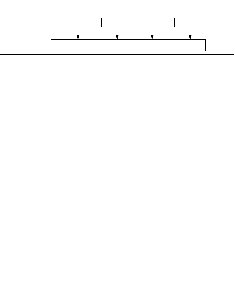
4-254 Vol. 2B PSRLW/PSRLD/PSRLQ—Shift Packed Data Right Logical
INSTRUCTION SET REFERENCE, N-Z
the count operand (second operand). As the bits in the data elements are shifted
right, the empty high-order bits are cleared (set to 0). If the value specified by the
count operand is greater than 15 (for words), 31 (for doublewords), or 63 (for a
quadword), then the destination operand is set to all 0s. Figure 4-16 gives an
example of shifting words in a 64-bit operand.
The destination operand may be an MMX technology register or an XMM register; the
count operand can be either an MMX technology register or an 64-bit memory loca-
tion, an XMM register or a 128-bit memory location, or an 8-bit immediate. Note that
only the first 64-bits of a 128-bit count operand are checked to compute the count.
The PSRLW instruction shifts each of the words in the destination operand to the right
by the number of bits specified in the count operand; the PSRLD instruction shifts
each of the doublewords in the destination operand; and the PSRLQ instruction shifts
the quadword (or quadwords) in the destination operand.
In 64-bit mode, using a REX prefix in the form of REX.R permits this instruction to
access additional registers (XMM8-XMM15).
128-bit Legacy SSE version: Bits (VLMAX-1:128) of the corresponding YMM destina-
tion register remain unchanged. If the count operand is a memory address, 128 bits
are loaded but the upper 64 bits are ignored.
VEX.128 encoded version: Bits (VLMAX-1:128) of the destination YMM register are
zeroed. For shifts with an immediate count (VEX.128.66.0F 71-73 /2), VEX.vvvv
encodes the destination register, and VEX.B + ModRM.r/m encodes the source
register. VEX.L must be 0, otherwise instructions will #UD. If the count operand is a
memory address, 128 bits are loaded but the upper 64 bits are ignored.
Operation
PSRLW (with 64-bit operand)
IF (COUNT > 15)
THEN
DEST[64:0] ← 0000000000000000H
ELSE
DEST[15:0] ← ZeroExtend(DEST[15:0] >> COUNT);
(* Repeat shift operation for 2nd and 3rd words *)
Figure 4-16. PSRLW, PSRLD, and PSRLQ Instruction Operation Using 64-bit Operand
DEST
DEST
Pre-Shift
Post-Shift
Shift Right
X0
X0 >> COUNT
X3 X2 X1
X1 >> COUNTX2 >> COUNTX3 >> COUNT
with Zero
Extension

Vol. 2B 4-255
INSTRUCTION SET REFERENCE, N-Z
PSRLW/PSRLD/PSRLQ—Shift Packed Data Right Logical
DEST[63:48] ← ZeroExtend(DEST[63:48] >> COUNT);
FI;
PSRLD (with 64-bit operand)
IF (COUNT > 31)
THEN
DEST[64:0] ← 0000000000000000H
ELSE
DEST[31:0] ← ZeroExtend(DEST[31:0] >> COUNT);
DEST[63:32] ← ZeroExtend(DEST[63:32] >> COUNT);
FI;
PSRLQ (with 64-bit operand)
IF (COUNT > 63)
THEN
DEST[64:0] ← 0000000000000000H
ELSE
DEST ← ZeroExtend(DEST >> COUNT);
FI;
PSRLW (with 128-bit operand)
COUNT ← COUNT_SOURCE[63:0];
IF (COUNT > 15)
THEN
DEST[128:0] ← 00000000000000000000000000000000H
ELSE
DEST[15:0] ← ZeroExtend(DEST[15:0] >> COUNT);
(* Repeat shift operation for 2nd through 7th words *)
DEST[127:112] ← ZeroExtend(DEST[127:112] >> COUNT);
FI;
PSRLD (with 128-bit operand)
COUNT ← COUNT_SOURCE[63:0];
IF (COUNT > 31)
THEN
DEST[128:0] ← 00000000000000000000000000000000H
ELSE
DEST[31:0] ← ZeroExtend(DEST[31:0] >> COUNT);
(* Repeat shift operation for 2nd and 3rd doublewords *)
DEST[127:96] ← ZeroExtend(DEST[127:96] >> COUNT);
FI;
PSRLQ (with 128-bit operand)
COUNT ← COUNT_SOURCE[63:0];
IF (COUNT > 15)

4-256 Vol. 2B PSRLW/PSRLD/PSRLQ—Shift Packed Data Right Logical
INSTRUCTION SET REFERENCE, N-Z
THEN
DEST[128:0] ← 00000000000000000000000000000000H
ELSE
DEST[63:0] ← ZeroExtend(DEST[63:0] >> COUNT);
DEST[127:64] ← ZeroExtend(DEST[127:64] >> COUNT);
FI;
PSRLW (xmm, xmm, xmm/m128)
DEST[127:0] LOGICAL_RIGHT_SHIFT_WORDS(DEST, SRC)
DEST[VLMAX-1:128] (Unmodified)
PSRLW (xmm, imm8)
DEST[127:0] LOGICAL_RIGHT_SHIFT_WORDS(DEST, imm8)
DEST[VLMAX-1:128] (Unmodified)
VPSRLW (xmm, xmm, xmm/m128)
DEST[127:0] LOGICAL_RIGHT_SHIFT_WORDS(SRC1, SRC2)
DEST[VLMAX-1:128] 0
VPSRLW (xmm, imm8)
DEST[127:0] LOGICAL_RIGHT_SHIFT_WORDS(SRC1, imm8)
DEST[VLMAX-1:128] 0
PSRLD (xmm, xmm, xmm/m128)
DEST[127:0] LOGICAL_RIGHT_SHIFT_DWORDS(DEST, SRC)
DEST[VLMAX-1:128] (Unmodified)
PSRLD (xmm, imm8)
DEST[127:0] LOGICAL_RIGHT_SHIFT_DWORDS(DEST, imm8)
DEST[VLMAX-1:128] (Unmodified)
VPSRLD (xmm, xmm, xmm/m128)
DEST[127:0] LOGICAL_RIGHT_SHIFT_DWORDS(SRC1, SRC2)
DEST[VLMAX-1:128] 0
VPSRLD (xmm, imm8)
DEST[127:0] LOGICAL_RIGHT_SHIFT_DWORDS(SRC1, imm8)
DEST[VLMAX-1:128] 0
PSRLQ (xmm, xmm, xmm/m128)
DEST[127:0] LOGICAL_RIGHT_SHIFT_QWORDS(DEST, SRC)
DEST[VLMAX-1:128] (Unmodified)

Vol. 2B 4-257
INSTRUCTION SET REFERENCE, N-Z
PSRLW/PSRLD/PSRLQ—Shift Packed Data Right Logical
PSRLQ (xmm, imm8)
DEST[127:0] LOGICAL_RIGHT_SHIFT_QWORDS(DEST, imm8)
DEST[VLMAX-1:128] (Unmodified)
VPSRLQ (xmm, xmm, xmm/m128)
DEST[127:0] LOGICAL_RIGHT_SHIFT_QWORDS(SRC1, SRC2)
DEST[VLMAX-1:128] 0
VPSRLQ (xmm, imm8)
DEST[127:0] LOGICAL_RIGHT_SHIFT_QWORDS(SRC1, imm8)
DEST[VLMAX-1:128] 0
Intel C/C++ Compiler Intrinsic Equivalents
PSRLW __m64 _mm_srli_pi16(__m64 m, int count)
PSRLW __m64 _mm_srl_pi16 (__m64 m, __m64 count)
PSRLW __m128i _mm_srli_epi16 (__m128i m, int count)
PSRLW __m128i _mm_srl_epi16 (__m128i m, __m128i count)
PSRLD __m64 _mm_srli_pi32 (__m64 m, int count)
PSRLD __m64 _mm_srl_pi32 (__m64 m, __m64 count)
PSRLD __m128i _mm_srli_epi32 (__m128i m, int count)
PSRLD __m128i _mm_srl_epi32 (__m128i m, __m128i count)
PSRLQ __m64 _mm_srli_si64 (__m64 m, int count)
PSRLQ __m64 _mm_srl_si64 (__m64 m, __m64 count)
PSRLQ __m128i _mm_srli_epi64 (__m128i m, int count)
PSRLQ __m128i _mm_srl_epi64 (__m128i m, __m128i count)
Flags Affected
None.
Numeric Exceptions
None.
Other Exceptions
See Exceptions Type 4 and 7 for non-VEX-encoded instructions.
#UD If VEX.L = 1.

4-258 Vol. 2B PSUBB/PSUBW/PSUBD—Subtract Packed Integers
INSTRUCTION SET REFERENCE, N-Z
PSUBB/PSUBW/PSUBD—Subtract Packed Integers
Opcode/
Instruction
Op/
En
64/32 bit
Mode
Support
CPUID
Feature
Flag
Description
0F F8 /r1
PSUBB mm, mm/m64
A V/V MMX Subtract packed byte
integers in mm/m64 from
packed byte integers in mm.
66 0F F8 /r
PSUBB xmm1, xmm2/m128
AV/V SSE2 Subtract packed byte
integers in xmm2/m128
from packed byte integers
in xmm1.
0F F9 /r1
PSUBW mm, mm/m64
A V/V MMX Subtract packed word
integers in mm/m64 from
packed word integers in mm.
66 0F F9 /r
PSUBW xmm1, xmm2/m128
A V/V SSE2 Subtract packed word
integers in xmm2/m128
from packed word integers
in xmm1.
0F FA /r1
PSUBD mm, mm/m64
A V/V MMX Subtract packed doubleword
integers in mm/m64 from
packed doubleword integers
in mm.
66 0F FA /r
PSUBD xmm1, xmm2/m128
A V/V SSE2 Subtract packed doubleword
integers in xmm2/mem128
from packed doubleword
integers in xmm1.
VEX.NDS.128.66.0F.WIG F8 /r
VPSUBB xmm1, xmm2, xmm3/m128
B V/V AVX Subtract packed byte
integers in xmm3/m128
from xmm2.
VEX.NDS.128.66.0F.WIG F9 /r
VPSUBW xmm1, xmm2,
xmm3/m128
B V/V AVX Subtract packed word
integers in xmm3/m128
from xmm2.
VEX.NDS.128.66.0F.WIG FA /r
VPSUBD xmm1, xmm2,
xmm3/m128
B V/V AVX Subtract packed doubleword
integers in xmm3/m128
from xmm2.
NOTES:
1. See note in Section 2.4, “Instruction Exception Specification”.

Vol. 2B 4-259
INSTRUCTION SET REFERENCE, N-Z
PSUBB/PSUBW/PSUBD—Subtract Packed Integers
Instruction Operand Encoding
Description
Performs a SIMD subtract of the packed integers of the source operand (second
operand) from the packed integers of the destination operand (first operand), and
stores the packed integer results in the destination operand. See Figure 9-4 in the
Intel® 64 and IA-32 Architectures Software Developer’s Manual, Volume 1, for an
illustration of a SIMD operation. Overflow is handled with wraparound, as described
in the following paragraphs.
These instructions can operate on either 64-bit or 128-bit operands. When operating
on 64-bit operands, the destination operand must be an MMX technology register
and the source operand can be either an MMX technology register or a 64-bit
memory location. When operating on 128-bit operands, the destination operand
must be an XMM register and the source operand can be either an XMM register or a
128-bit memory location.
The PSUBB instruction subtracts packed byte integers. When an individual result is
too large or too small to be represented in a byte, the result is wrapped around and
the low 8 bits are written to the destination element.
The PSUBW instruction subtracts packed word integers. When an individual result is
too large or too small to be represented in a word, the result is wrapped around and
the low 16 bits are written to the destination element.
The PSUBD instruction subtracts packed doubleword integers. When an individual
result is too large or too small to be represented in a doubleword, the result is
wrapped around and the low 32 bits are written to the destination element.
Note that the PSUBB, PSUBW, and PSUBD instructions can operate on either
unsigned or signed (two's complement notation) packed integers; however, it does
not set bits in the EFLAGS register to indicate overflow and/or a carry. To prevent
undetected overflow conditions, software must control the ranges of values upon
which it operates.
In 64-bit mode, using a REX prefix in the form of REX.R permits this instruction to
access additional registers (XMM8-XMM15).
128-bit Legacy SSE version: Bits (VLMAX-1:128) of the corresponding YMM destina-
tion register remain unchanged.
VEX.128 encoded version: Bits (VLMAX-1:128) of the destination YMM register are
zeroed. VEX.L must be 0, otherwise instructions will #UD.
Op/En Operand 1 Operand 2 Operand 3 Operand 4
A ModRM:reg (r, w) ModRM:r/m (r) NA NA
B ModRM:reg (w) VEX.vvvv (r) ModRM:r/m (r) NA

4-260 Vol. 2B PSUBB/PSUBW/PSUBD—Subtract Packed Integers
INSTRUCTION SET REFERENCE, N-Z
Operation
PSUBB (with 64-bit operands)
DEST[7:0] ← DEST[7:0] − SRC[7:0];
(* Repeat subtract operation for 2nd through 7th byte *)
DEST[63:56] ← DEST[63:56] − SRC[63:56];
PSUBB (with 128-bit operands)
DEST[7:0] ← DEST[7:0] − SRC[7:0];
(* Repeat subtract operation for 2nd through 14th byte *)
DEST[127:120] ← DEST[111:120] − SRC[127:120];
PSUBW (with 64-bit operands)
DEST[15:0] ← DEST[15:0] − SRC[15:0];
(* Repeat subtract operation for 2nd and 3rd word *)
DEST[63:48] ← DEST[63:48] − SRC[63:48];
PSUBW (with 128-bit operands)
DEST[15:0] ← DEST[15:0] − SRC[15:0];
(* Repeat subtract operation for 2nd through 7th word *)
DEST[127:112] ← DEST[127:112] − SRC[127:112];
PSUBD (with 64-bit operands)
DEST[31:0] ← DEST[31:0] − SRC[31:0];
DEST[63:32] ← DEST[63:32] − SRC[63:32];
PSUBD (with 128-bit operands)
DEST[31:0] ← DEST[31:0] − SRC[31:0];
(* Repeat subtract operation for 2nd and 3rd doubleword *)
DEST[127:96] ← DEST[127:96] − SRC[127:96];
VPSUBB (VEX.128 encoded version)
DEST[7:0] SRC1[7:0]-SRC2[7:0]
DEST[15:8] SRC1[15:8]-SRC2[15:8]
DEST[23:16] SRC1[23:16]-SRC2[23:16]
DEST[31:24] SRC1[31:24]-SRC2[31:24]
DEST[39:32] SRC1[39:32]-SRC2[39:32]
DEST[47:40] SRC1[47:40]-SRC2[47:40]
DEST[55:48] SRC1[55:48]-SRC2[55:48]
DEST[63:56] SRC1[63:56]-SRC2[63:56]
DEST[71:64] SRC1[71:64]-SRC2[71:64]
DEST[79:72] SRC1[79:72]-SRC2[79:72]
DEST[87:80] SRC1[87:80]-SRC2[87:80]
DEST[95:88] SRC1[95:88]-SRC2[95:88]
DEST[103:96] SRC1[103:96]-SRC2[103:96]

Vol. 2B 4-261
INSTRUCTION SET REFERENCE, N-Z
PSUBB/PSUBW/PSUBD—Subtract Packed Integers
DEST[111:104] SRC1[111:104]-SRC2[111:104]
DEST[119:112] SRC1[119:112]-SRC2[119:112]
DEST[127:120] SRC1[127:120]-SRC2[127:120]
DEST[VLMAX-1:128] 00
VPSUBW (VEX.128 encoded version)
DEST[15:0] SRC1[15:0]-SRC2[15:0]
DEST[31:16] SRC1[31:16]-SRC2[31:16]
DEST[47:32] SRC1[47:32]-SRC2[47:32]
DEST[63:48] SRC1[63:48]-SRC2[63:48]
DEST[79:64] SRC1[79:64]-SRC2[79:64]
DEST[95:80] SRC1[95:80]-SRC2[95:80]
DEST[111:96] SRC1[111:96]-SRC2[111:96]
DEST[127:112] SRC1[127:112]-SRC2[127:112]
DEST[VLMAX-1:128] 0
VPSUBD (VEX.128 encoded version)
DEST[31:0] SRC1[31:0]-SRC2[31:0]
DEST[63:32] SRC1[63:32]-SRC2[63:32]
DEST[95:64] SRC1[95:64]-SRC2[95:64]
DEST[127:96] SRC1[127:96]-SRC2[127:96]
DEST[VLMAX-1:128] 0
Intel C/C++ Compiler Intrinsic Equivalents
PSUBB __m64 _mm_sub_pi8(__m64 m1, __m64 m2)
PSUBW __m64 _mm_sub_pi16(__m64 m1, __m64 m2)
PSUBD __m64 _mm_sub_pi32(__m64 m1, __m64 m2)
PSUBB __m128i _mm_sub_epi8 ( __m128i a, __m128i b)
PSUBW __m128i _mm_sub_epi16 ( __m128i a, __m128i b)
PSUBD __m128i _mm_sub_epi32 ( __m128i a, __m128i b)
Flags Affected
None.
Numeric Exceptions
None.
Other Exceptions
See Exceptions Type 4; additionally
#UD If VEX.L = 1.

4-262 Vol. 2B PSUBQ—Subtract Packed Quadword Integers
INSTRUCTION SET REFERENCE, N-Z
PSUBQ—Subtract Packed Quadword Integers
Instruction Operand Encoding
Description
Subtracts the second operand (source operand) from the first operand (destination
operand) and stores the result in the destination operand. The source operand can be
a quadword integer stored in an MMX technology register or a 64-bit memory loca-
tion, or it can be two packed quadword integers stored in an XMM register or an
128-bit memory location. The destination operand can be a quadword integer stored
in an MMX technology register or two packed quadword integers stored in an XMM
register. When packed quadword operands are used, a SIMD subtract is performed.
When a quadword result is too large to be represented in 64 bits (overflow), the
result is wrapped around and the low 64 bits are written to the destination element
(that is, the carry is ignored).
Note that the PSUBQ instruction can operate on either unsigned or signed (two’s
complement notation) integers; however, it does not set bits in the EFLAGS register
to indicate overflow and/or a carry. To prevent undetected overflow conditions, soft-
ware must control the ranges of the values upon which it operates.
In 64-bit mode, using a REX prefix in the form of REX.R permits this instruction to
access additional registers (XMM8-XMM15).
128-bit Legacy SSE version: Bits (VLMAX-1:128) of the corresponding YMM destina-
tion register remain unchanged.
Opcode/
Instruction
Op/
En
64/32 bit
Mode
Support
CPUID
Feature
Flag
Description
0F FB /r1
PSUBQ mm1, mm2/m64
A V/V SSE2 Subtract quadword integer
in mm1 from mm2 /m64.
66 0F FB /r
PSUBQ xmm1, xmm2/m128
AV/V SSE2 Subtract packed quadword
integers in xmm1 from
xmm2 /m128.
VEX.NDS.128.66.0F.WIG FB/r
VPSUBQ xmm1, xmm2,
xmm3/m128
B V/V AVX Subtract packed quadword
integers in xmm3/m128
from xmm2.
NOTES:
1. See note in Section 2.4, “Instruction Exception Specification”.
Op/En Operand 1 Operand 2 Operand 3 Operand 4
A ModRM:reg (r, w) ModRM:r/m (r) NA NA
B ModRM:reg (w) VEX.vvvv (r) ModRM:r/m (r) NA

Vol. 2B 4-263
INSTRUCTION SET REFERENCE, N-Z
PSUBQ—Subtract Packed Quadword Integers
VEX.128 encoded version: Bits (VLMAX-1:128) of the destination YMM register are
zeroed. VEX.L must be 0, otherwise instructions will #UD.
Operation
PSUBQ (with 64-Bit operands)
DEST[63:0] ← DEST[63:0] − SRC[63:0];
PSUBQ (with 128-Bit operands)
DEST[63:0] ← DEST[63:0] − SRC[63:0];
DEST[127:64] ← DEST[127:64] − SRC[127:64];
VPSUBQ (VEX.128 encoded version)
DEST[63:0] SRC1[63:0]-SRC2[63:0]
DEST[127:64] SRC1[127:64]-SRC2[127:64]
DEST[VLMAX-1:128] 0
Intel C/C++ Compiler Intrinsic Equivalents
PSUBQ __m64 _mm_sub_si64(__m64 m1, __m64 m2)
PSUBQ __m128i _mm_sub_epi64(__m128i m1, __m128i m2)
Flags Affected
None.
Numeric Exceptions
None.
Other Exceptions
See Exceptions Type 4; additionally
#UD If VEX.L = 1.

4-264 Vol. 2B PSUBSB/PSUBSW—Subtract Packed Signed Integers with Signed Saturation
INSTRUCTION SET REFERENCE, N-Z
PSUBSB/PSUBSW—Subtract Packed Signed Integers with Signed
Saturation
Instruction Operand Encoding
Opcode/
Instruction
Op/
En
64/32 bit
Mode
Support
CPUID
Feature
Flag
Description
0F E8 /r1
PSUBSB mm, mm/m64
A V/V MMX Subtract signed packed
bytes in mm/m64 from
signed packed bytes in mm
and saturate results.
66 0F E8 /r
PSUBSB xmm1, xmm2/m128
A V/V SSE2 Subtract packed signed byte
integers in xmm2/m128
from packed signed byte
integers in xmm1 and
saturate results.
0F E9 /r1
PSUBSW mm, mm/m64
A V/V MMX Subtract signed packed
words in mm/m64 from
signed packed words in mm
and saturate results.
66 0F E9 /r
PSUBSW xmm1, xmm2/m128
AV/V SSE2 Subtract packed signed
word integers in
xmm2/m128 from packed
signed word integers in
xmm1 and saturate results.
VEX.NDS.128.66.0F.WIG E8 /r
VPSUBSB xmm1, xmm2,
xmm3/m128
B V/V AVX Subtract packed signed byte
integers in xmm3/m128
from packed signed byte
integers in xmm2 and
saturate results.
VEX.NDS.128.66.0F.WIG E9 /r
VPSUBSW xmm1, xmm2,
xmm3/m128
B V/V AVX Subtract packed signed
word integers in
xmm3/m128 from packed
signed word integers in
xmm2 and saturate results.
NOTES:
1. See note in Section 2.4, “Instruction Exception Specification”.
Op/En Operand 1 Operand 2 Operand 3 Operand 4
A ModRM:reg (r, w) ModRM:r/m (r) NA NA
B ModRM:reg (w) VEX.vvvv (r) ModRM:r/m (r) NA

Vol. 2B 4-265
INSTRUCTION SET REFERENCE, N-Z
PSUBSB/PSUBSW—Subtract Packed Signed Integers with Signed Saturation
Description
Performs a SIMD subtract of the packed signed integers of the source operand
(second operand) from the packed signed integers of the destination operand (first
operand), and stores the packed integer results in the destination operand. See
Figure 9-4 in the Intel® 64 and IA-32 Architectures Software Developer’s Manual,
Volume 1, for an illustration of a SIMD operation. Overflow is handled with signed
saturation, as described in the following paragraphs.
These instructions can operate on either 64-bit or 128-bit operands. When operating
on 64-bit operands, the destination operand must be an MMX technology register
and the source operand can be either an MMX technology register or a 64-bit
memory location. When operating on 128-bit operands, the destination operand
must be an XMM register and the source operand can be either an XMM register or a
128-bit memory location.
The PSUBSB instruction subtracts packed signed byte integers. When an individual
byte result is beyond the range of a signed byte integer (that is, greater than 7FH or
less than 80H), the saturated value of 7FH or 80H, respectively, is written to the
destination operand.
The PSUBSW instruction subtracts packed signed word integers. When an individual
word result is beyond the range of a signed word integer (that is, greater than 7FFFH
or less than 8000H), the saturated value of 7FFFH or 8000H, respectively, is written
to the destination operand.
In 64-bit mode, using a REX prefix in the form of REX.R permits this instruction to
access additional registers (XMM8-XMM15).
128-bit Legacy SSE version: Bits (VLMAX-1:128) of the corresponding YMM destina-
tion register remain unchanged.
VEX.128 encoded version: Bits (VLMAX-1:128) of the destination YMM register are
zeroed. VEX.L must be 0, otherwise instructions will #UD.
Operation
PSUBSB (with 64-bit operands)
DEST[7:0] ← SaturateToSignedByte (DEST[7:0] − SRC (7:0]);
(* Repeat subtract operation for 2nd through 7th bytes *)
DEST[63:56] ← SaturateToSignedByte (DEST[63:56] − SRC[63:56] );
PSUBSB (with 128-bit operands)
DEST[7:0] ← SaturateToSignedByte (DEST[7:0] − SRC[7:0]);
(* Repeat subtract operation for 2nd through 14th bytes *)
DEST[127:120] ← SaturateToSignedByte (DEST[127:120] − SRC[127:120]);
PSUBSW (with 64-bit operands)
DEST[15:0] ← SaturateToSignedWord (DEST[15:0] − SRC[15:0] );
(* Repeat subtract operation for 2nd and 7th words *)
DEST[63:48] ← SaturateToSignedWord (DEST[63:48] − SRC[63:48] );

4-266 Vol. 2B PSUBSB/PSUBSW—Subtract Packed Signed Integers with Signed Saturation
INSTRUCTION SET REFERENCE, N-Z
PSUBSW (with 128-bit operands)
DEST[15:0] ← SaturateToSignedWord (DEST[15:0] − SRC[15:0]);
(* Repeat subtract operation for 2nd through 7th words *)
DEST[127:112] ← SaturateToSignedWord (DEST[127:112] − SRC[127:112]);
VPSUBSB
DEST[7:0] SaturateToSignedByte (SRC1[7:0] - SRC2[7:0]);
(* Repeat subtract operation for 2nd through 14th bytes *)
DEST[127:120] SaturateToSignedByte (SRC1[127:120] - SRC2[127:120]);
DEST[VLMAX-1:128] 0
VPSUBSW
DEST[15:0] SaturateToSignedWord (SRC1[15:0] - SRC2[15:0]);
(* Repeat subtract operation for 2nd through 7th words *)
DEST[127:112] SaturateToSignedWord (SRC1[127:112] - SRC2[127:112]);
DEST[VLMAX-1:128] 0
Intel C/C++ Compiler Intrinsic Equivalents
PSUBSB __m64 _mm_subs_pi8(__m64 m1, __m64 m2)
PSUBSB __m128i _mm_subs_epi8(__m128i m1, __m128i m2)
PSUBSW __m64 _mm_subs_pi16(__m64 m1, __m64 m2)
PSUBSW __m128i _mm_subs_epi16(__m128i m1, __m128i m2)
Flags Affected
None.
Numeric Exceptions
None.
Other Exceptions
See Exceptions Type 4; additionally
#UD If VEX.L = 1.

Vol. 2B 4-267
INSTRUCTION SET REFERENCE, N-Z
PSUBUSB/PSUBUSW—Subtract Packed Unsigned Integers with Unsigned Saturation
PSUBUSB/PSUBUSW—Subtract Packed Unsigned Integers with
Unsigned Saturation
Instruction Operand Encoding
Opcode/
Instruction
Op/
En
64/32 bit
Mode
Support
CPUID
Feature
Flag
Description
0F D8 /r1
PSUBUSB mm, mm/m64
AV/V MMX Subtract unsigned packed
bytes in mm/m64 from
unsigned packed bytes in
mm and saturate result.
66 0F D8 /r
PSUBUSB xmm1, xmm2/m128
A V/V SSE2 Subtract packed unsigned
byte integers in
xmm2/m128 from packed
unsigned byte integers in
xmm1 and saturate result.
0F D9 /r1
PSUBUSW mm, mm/m64
AV/V MMX Subtract unsigned packed
words in mm/m64 from
unsigned packed words in
mm and saturate result.
66 0F D9 /r
PSUBUSW xmm1, xmm2/m128
A V/V SSE2 Subtract packed unsigned
word integers in
xmm2/m128 from packed
unsigned word integers in
xmm1 and saturate result.
VEX.NDS.128.66.0F.WIG D8 /r
VPSUBUSB xmm1, xmm2,
xmm3/m128
B V/V AVX Subtract packed unsigned
byte integers in
xmm3/m128 from packed
unsigned byte integers in
xmm2 and saturate result.
VEX.NDS.128.66.0F.WIG D9 /r
VPSUBUSW xmm1, xmm2,
xmm3/m128
B V/V AVX Subtract packed unsigned
word integers in
xmm3/m128 from packed
unsigned word integers in
xmm2 and saturate result.
NOTES:
1. See note in Section 2.4, “Instruction Exception Specification”.
Op/En Operand 1 Operand 2 Operand 3 Operand 4
A ModRM:reg (r, w) ModRM:r/m (r) NA NA
B ModRM:reg (w) VEX.vvvv (r) ModRM:r/m (r) NA

4-268 Vol. 2B PSUBUSB/PSUBUSW—Subtract Packed Unsigned Integers with Unsigned Saturation
INSTRUCTION SET REFERENCE, N-Z
Description
Performs a SIMD subtract of the packed unsigned integers of the source operand
(second operand) from the packed unsigned integers of the destination operand (first
operand), and stores the packed unsigned integer results in the destination operand.
See Figure 9-4 in the Intel® 64 and IA-32 Architectures Software Developer’s
Manual, Volume 1, for an illustration of a SIMD operation. Overflow is handled with
unsigned saturation, as described in the following paragraphs.
These instructions can operate on either 64-bit or 128-bit operands. When operating
on 64-bit operands, the destination operand must be an MMX technology register
and the source operand can be either an MMX technology register or a 64-bit
memory location. When operating on 128-bit operands, the destination operand
must be an XMM register and the source operand can be either an XMM register or a
128-bit memory location.
The PSUBUSB instruction subtracts packed unsigned byte integers. When an indi-
vidual byte result is less than zero, the saturated value of 00H is written to the desti-
nation operand.
The PSUBUSW instruction subtracts packed unsigned word integers. When an indi-
vidual word result is less than zero, the saturated value of 0000H is written to the
destination operand.
In 64-bit mode, using a REX prefix in the form of REX.R permits this instruction to
access additional registers (XMM8-XMM15).
128-bit Legacy SSE version: Bits (VLMAX-1:128) of the corresponding YMM destina-
tion register remain unchanged.
VEX.128 encoded version: Bits (VLMAX-1:128) of the destination YMM register are
zeroed. VEX.L must be 0, otherwise instructions will #UD.
Operation
PSUBUSB (with 64-bit operands)
DEST[7:0] ← SaturateToUnsignedByte (DEST[7:0] − SRC (7:0] );
(* Repeat add operation for 2nd through 7th bytes *)
DEST[63:56] ← SaturateToUnsignedByte (DEST[63:56] − SRC[63:56];
PSUBUSB (with 128-bit operands)
DEST[7:0] ← SaturateToUnsignedByte (DEST[7:0] − SRC[7:0]);
(* Repeat add operation for 2nd through 14th bytes *)
DEST[127:120] ← SaturateToUnSignedByte (DEST[127:120] − SRC[127:120]);
PSUBUSW (with 64-bit operands)
DEST[15:0] ← SaturateToUnsignedWord (DEST[15:0] − SRC[15:0] );
(* Repeat add operation for 2nd and 3rd words *)
DEST[63:48] ← SaturateToUnsignedWord (DEST[63:48] − SRC[63:48] );
PSUBUSW (with 128-bit operands)

Vol. 2B 4-269
INSTRUCTION SET REFERENCE, N-Z
PSUBUSB/PSUBUSW—Subtract Packed Unsigned Integers with Unsigned Saturation
DEST[15:0] ← SaturateToUnsignedWord (DEST[15:0] − SRC[15:0]);
(* Repeat add operation for 2nd through 7th words *)
DEST[127:112] ← SaturateToUnSignedWord (DEST[127:112] − SRC[127:112]);
VPSUBUSB
DEST[7:0] SaturateToUnsignedByte (SRC1[7:0] - SRC2[7:0]);
(* Repeat subtract operation for 2nd through 14th bytes *)
DEST[127:120] SaturateToUnsignedByte (SRC1[127:120] - SRC2[127:120]);
DEST[VLMAX-1:128] 0
VPSUBUSW
DEST[15:0] SaturateToUnsignedWord (SRC1[15:0] - SRC2[15:0]);
(* Repeat subtract operation for 2nd through 7th words *)
DEST[127:112] SaturateToUnsignedWord (SRC1[127:112] - SRC2[127:112]);
DEST[VLMAX-1:128] 0
Intel C/C++ Compiler Intrinsic Equivalents
PSUBUSB __m64 _mm_subs_pu8(__m64 m1, __m64 m2)
PSUBUSB __m128i _mm_subs_epu8(__m128i m1, __m128i m2)
PSUBUSW __m64 _mm_subs_pu16(__m64 m1, __m64 m2)
PSUBUSW __m128i _mm_subs_epu16(__m128i m1, __m128i m2)
Flags Affected
None.
Numeric Exceptions
None.
Other Exceptions
See Exceptions Type 4; additionally
#UD If VEX.L = 1.

4-270 Vol. 2B PTEST- Logical Compare
INSTRUCTION SET REFERENCE, N-Z
PTEST- Logical Compare
Instruction Operand Encoding
Description
PTEST and VPTEST set the ZF flag if all bits in the result are 0 of the bitwise AND of
the first source operand (first operand) and the second source operand (second
operand). VPTEST sets the CF flag if all bits in the result are 0 of the bitwise AND of
the second source operand (second operand) and the logical NOT of the destination
operand.
Opcode/
Instruction
Op/
En
64/32 bit
Mode
Support
CPUID
Feature
Flag
Description
66 0F 38 17 /r
PTEST xmm1, xmm2/m128
AV/V SSE4_1Set ZF if xmm2/m128 AND
xmm1 result is all 0s. Set CF
if xmm2/m128 AND NOT
xmm1 result is all 0s.
VEX.128.66.0F38.WIG 17 /r
VPTEST xmm1, xmm2/m128
A V/V AVX Set ZF and CF depending on
bitwise AND and ANDN of
sources.
VEX.256.66.0F38.WIG 17 /r
VPTEST ymm1, ymm2/m256
A V/V AVX Set ZF and CF depending on
bitwise AND and ANDN of
sources.
VEX.128.66.0F38.W0 0E /r
VTESTPS xmm1, xmm2/m128
A V/V AVX Set ZF and CF depending on
sign bit AND and ANDN of
packed single-precision
floating-point sources.
VEX.256.66.0F38.W0 0E /r
VTESTPS ymm1, ymm2/m256
A V/V AVX Set ZF and CF depending on
sign bit AND and ANDN of
packed single-precision
floating-point sources.
VEX.128.66.0F38.W0 0F /r
VTESTPD xmm1, xmm2/m128
A V/V AVX Set ZF and CF depending on
sign bit AND and ANDN of
packed double-precision
floating-point sources.
VEX.256.66.0F38.W0 0F /r
VTESTPD ymm1, ymm2/m256
A V/V AVX Set ZF and CF depending on
sign bit AND and ANDN of
packed double-precision
floating-point sources.
Op/En Operand 1 Operand 2 Operand 3 Operand 4
A ModRM:reg (r) ModRM:r/m (r) NA NA

Vol. 2B 4-271
INSTRUCTION SET REFERENCE, N-Z
PTEST- Logical Compare
VTESTPS performs a bitwise comparison of all the sign bits of the packed single-
precision elements in the first source operation and corresponding sign bits in the
second source operand. If the AND of the source sign bits with the dest sign bits
produces all zeros, the ZF is set else the ZF is clear. If the AND of the source sign bits
with the inverted dest sign bits produces all zeros the CF is set else the CF is clear. An
attempt to execute VTESTPS with VEX.W=1 will cause #UD.
VTESTPD performs a bitwise comparison of all the sign bits of the double-precision
elements in the first source operation and corresponding sign bits in the second
source operand. If the AND of the source sign bits with the dest sign bits produces all
zeros, the ZF is set else the ZF is clear. If the AND the source sign bits with the
inverted dest sign bits produces all zeros the CF is set else the CF is clear. An attempt
to execute VTESTPS with VEX.W=1 will cause #UD.
The first source register is specified by the ModR/M reg field.
128-bit version: The first source register is an XMM register. The second source
register can be an XMM register or a 256-bit memory location. The destination
register is not modified.
VEX.256 encoded version: The first source register is a YMM register. The second
source register can be a YMM register or a 256-bit memory location. The destination
register is not modified.
Note: In VEX-encoded versions, VEX.vvvv is reserved and must be 1111b, otherwise
instructions will #UD.
Operation
PTEST (128-bit versions)
IF (SRC[127:0] BITWISE AND DEST[127:0] == 0)
THEN ZF 1;
ELSE ZF 0;
IF (SRC[127:0] BITWISE AND NOT DEST[127:0] == 0)
THEN CF 1;
ELSE CF 0;
DEST (unmodified)
AF OF PF SF 0;
VPTEST (VEX.256 encoded version)
IF (SRC[255:0] BITWISE AND DEST[255:0] == 0) THEN ZF 1;
ELSE ZF 0;
IF (SRC[255:0] BITWISE AND NOT DEST[255:0] == 0) THEN CF 1;
ELSE CF 0;
DEST (unmodified)
AF OF PF SF 0;
VTESTPS (VEX.256 encoded version)

4-272 Vol. 2B PTEST- Logical Compare
INSTRUCTION SET REFERENCE, N-Z
TEMP[255:0] SRC[255:0] AND DEST[255:0]
IF (TEMP[31] = TEMP[63] = TEMP[95] = TEMP[127]= TEMP[160] =TEMP[191] = TEMP[224] =
TEMP[255] = 0)
THEN ZF 1;
ELSE ZF 0;
TEMP[255:0] SRC[255:0] AND NOT DEST[255:0]
IF (TEMP[31] = TEMP[63] = TEMP[95] = TEMP[127]= TEMP[160] =TEMP[191] = TEMP[224] =
TEMP[255] = 0)
THEN CF 1;
ELSE CF 0;
DEST (unmodified)
AF OF PF SF 0;
VTESTPD (VEX.256 encoded version)
TEMP[255:0] SRC[255:0] AND DEST[255:0]
IF (TEMP[63] = TEMP[127] = TEMP[191] = TEMP[255] = 0)
THEN ZF 1;
ELSE ZF 0;
TEMP[255:0] SRC[255:0] AND NOT DEST[255:0]
IF (TEMP[63] = TEMP[127] = TEMP[191] = TEMP[255] = 0)
THEN CF 1;
ELSE CF 0;
DEST (unmodified)
AF OF PF SF 0;
Intel C/C++ Compiler Intrinsic Equivalent
PTEST int _mm_testz_si128 (__m128i s1, __m128i s2);
int _mm_testc_si128 (__m128i s1, __m128i s2);
int _mm_testnzc_si128 (__m128i s1, __m128i s2);
VPTEST
int _mm256_testz_si256 (__m256i s1, __m256i s2);
int _mm256_testc_si256 (__m256i s1, __m256i s2);
int _mm256_testnzc_si256 (__m256i s1, __m256i s2);
int _mm_testz_si128 (__m128i s1, __m128i s2);
int _mm_testc_si128 (__m128i s1, __m128i s2);

Vol. 2B 4-273
INSTRUCTION SET REFERENCE, N-Z
PTEST- Logical Compare
int _mm_testnzc_si128 (__m128i s1, __m128i s2);
VTESTPS
int _mm256_testz_ps (__m256 s1, __m256 s2);
int _mm256_testc_ps (__m256 s1, __m256 s2);
int _mm256_testnzc_ps (__m256 s1, __m128 s2);
int _mm_testz_ps (__m128 s1, __m128 s2);
int _mm_testc_ps (__m128 s1, __m128 s2);
int _mm_testnzc_ps (__m128 s1, __m128 s2);
VTESTPD
int _mm256_testz_pd (__m256d s1, __m256d s2);
int _mm256_testc_pd (__m256d s1, __m256d s2);
int _mm256_testnzc_pd (__m256d s1, __m256d s2);
int _mm_testz_pd (__m128d s1, __m128d s2);
int _mm_testc_pd (__m128d s1, __m128d s2);
int _mm_testnzc_pd (__m128d s1, __m128d s2);
Flags Affected
The 0F, AF, PF, SF flags are cleared and the ZF, CF flags are set according to the oper-
ation.
SIMD Floating-Point Exceptions
None.
Other Exceptions
See Exceptions Type 4; additionally
#UD If VEX.vvvv != 1111B.
If VEX.W = 1 for VTESTPS or VTESTPD.

4-274 Vol. 2B PUNPCKHBW/PUNPCKHWD/PUNPCKHDQ/PUNPCKHQDQ— Unpack High Data
INSTRUCTION SET REFERENCE, N-Z
PUNPCKHBW/PUNPCKHWD/PUNPCKHDQ/PUNPCKHQDQ— Unpack
High Data
Opcode/
Instruction
Op/
En
64/32 bit
Mode
Support
CPUID
Feature
Flag
Description
0F 68 /r1
PUNPCKHBW mm, mm/m64
A V/V MMX Unpack and interleave high-
order bytes from mm and
mm/m64 into mm.
66 0F 68 /r
PUNPCKHBW xmm1, xmm2/m128
A V/V SSE2 Unpack and interleave high-
order bytes from xmm1 and
xmm2/m128 into xmm1.
0F 69 /r1
PUNPCKHWD mm, mm/m64
A V/V MMX Unpack and interleave high-
order words from mm and
mm/m64 into mm.
66 0F 69 /r
PUNPCKHWD xmm1, xmm2/m128
A V/V SSE2 Unpack and interleave high-
order words from xmm1 and
xmm2/m128 into xmm1.
0F 6A /r1
PUNPCKHDQ mm, mm/m64
A V/V MMX Unpack and interleave high-
order doublewords from mm
and mm/m64 into mm.
66 0F 6A /r
PUNPCKHDQ xmm1, xmm2/m128
A V/V SSE2 Unpack and interleave high-
order doublewords from
xmm1 and xmm2/m128
into xmm1.
66 0F 6D /r
PUNPCKHQDQ xmm1, xmm2/m128
A V/V SSE2 Unpack and interleave high-
order quadwords from
xmm1 and xmm2/m128
into xmm1.
VEX.NDS.128.66.0F.WIG 68/r
VPUNPCKHBW xmm1,xmm2,
xmm3/m128
B V/V AVX Interleave high-order bytes
from xmm2 and
xmm3/m128 into xmm1.
VEX.NDS.128.66.0F.WIG 69/r
VPUNPCKHWD xmm1,xmm2,
xmm3/m128
B V/V AVX Interleave high-order words
from xmm2 and
xmm3/m128 into xmm1.
VEX.NDS.128.66.0F.WIG 6A/r
VPUNPCKHDQ xmm1, xmm2,
xmm3/m128
B V/V AVX Interleave high-order
doublewords from xmm2
and xmm3/m128 into
xmm1.
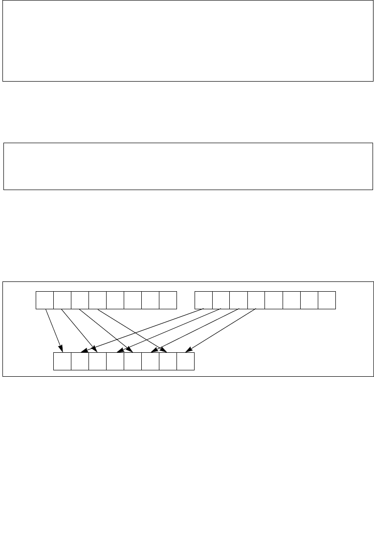
Vol. 2B 4-275
INSTRUCTION SET REFERENCE, N-Z
PUNPCKHBW/PUNPCKHWD/PUNPCKHDQ/PUNPCKHQDQ— Unpack High Data
Instruction Operand Encoding
Description
Unpacks and interleaves the high-order data elements (bytes, words, doublewords,
or quadwords) of the destination operand (first operand) and source operand
(second operand) into the destination operand. Figure 4-17 shows the unpack oper-
ation for bytes in 64-bit operands. The low-order data elements are ignored.
The source operand can be an MMX technology register or a 64-bit memory location,
or it can be an XMM register or a 128-bit memory location. The destination operand
can be an MMX technology register or an XMM register. When the source data comes
from a 64-bit memory operand, the full 64-bit operand is accessed from memory, but
the instruction uses only the high-order 32 bits. When the source data comes from a
128-bit memory operand, an implementation may fetch only the appropriate 64 bits;
however, alignment to a 16-byte boundary and normal segment checking will still be
enforced.
Opcode/
Instruction
Op/
En
64/32 bit
Mode
Support
CPUID
Feature
Flag
Description
VEX.NDS.128.66.0F.WIG 6D/r
VPUNPCKHQDQ xmm1, xmm2,
xmm3/m128
B V/V AVX Interleave high-order
quadword from xmm2 and
xmm3/m128 into xmm1
register.
NOTES:
1. See note in Section 2.4, “Instruction Exception Specification”.
Op/En Operand 1 Operand 2 Operand 3 Operand 4
A ModRM:reg (r, w) ModRM:r/m (r) NA NA
B ModRM:reg (w) VEX.vvvv (r) ModRM:r/m (r) NA
Figure 4-17. PUNPCKHBW Instruction Operation Using 64-bit Operands
X4X7 X6 X5 Y4Y7 Y6 Y5
X0X3 X2 X1
Y0Y3 Y2 Y1 X4X7 X6 X5
Y4Y7 Y6 Y5
SRC DEST
DEST

4-276 Vol. 2B PUNPCKHBW/PUNPCKHWD/PUNPCKHDQ/PUNPCKHQDQ— Unpack High Data
INSTRUCTION SET REFERENCE, N-Z
The PUNPCKHBW instruction interleaves the high-order bytes of the source and
destination operands, the PUNPCKHWD instruction interleaves the high-order words
of the source and destination operands, the PUNPCKHDQ instruction interleaves the
high-order doubleword (or doublewords) of the source and destination operands,
and the PUNPCKHQDQ instruction interleaves the high-order quadwords of the
source and destination operands.
These instructions can be used to convert bytes to words, words to doublewords,
doublewords to quadwords, and quadwords to double quadwords, respectively, by
placing all 0s in the source operand. Here, if the source operand contains all 0s, the
result (stored in the destination operand) contains zero extensions of the high-order
data elements from the original value in the destination operand. For example, with
the PUNPCKHBW instruction the high-order bytes are zero extended (that is,
unpacked into unsigned word integers), and with the PUNPCKHWD instruction, the
high-order words are zero extended (unpacked into unsigned doubleword integers).
In 64-bit mode, using a REX prefix in the form of REX.R permits this instruction to
access additional registers (XMM8-XMM15).
128-bit Legacy SSE versions: Bits (VLMAX-1:128) of the corresponding YMM destina-
tion register remain unchanged.
VEX.128 encoded versions: Bits (VLMAX-1:128) of the destination YMM register are
zeroed. VEX.L must be 0, otherwise instructions will #UD.
Operation
PUNPCKHBW instruction with 64-bit operands:
DEST[7:0] ← DEST[39:32];
DEST[15:8] ← SRC[39:32];
DEST[23:16] ← DEST[47:40];
DEST[31:24] ← SRC[47:40];
DEST[39:32] ← DEST[55:48];
DEST[47:40] ← SRC[55:48];
DEST[55:48] ← DEST[63:56];
DEST[63:56] ← SRC[63:56];
PUNPCKHW instruction with 64-bit operands:
DEST[15:0] ← DEST[47:32];
DEST[31:16] ← SRC[47:32];
DEST[47:32] ← DEST[63:48];
DEST[63:48] ← SRC[63:48];
PUNPCKHDQ instruction with 64-bit operands:
DEST[31:0] ← DEST[63:32];
DEST[63:32] ← SRC[63:32];
PUNPCKHBW instruction with 128-bit operands:
DEST[7:0]← DEST[71:64];

Vol. 2B 4-277
INSTRUCTION SET REFERENCE, N-Z
PUNPCKHBW/PUNPCKHWD/PUNPCKHDQ/PUNPCKHQDQ— Unpack High Data
DEST[15:8] ← SRC[71:64];
DEST[23:16] ← DEST[79:72];
DEST[31:24] ← SRC[79:72];
DEST[39:32] ← DEST[87:80];
DEST[47:40] ← SRC[87:80];
DEST[55:48] ← DEST[95:88];
DEST[63:56] ← SRC[95:88];
DEST[71:64] ← DEST[103:96];
DEST[79:72] ← SRC[103:96];
DEST[87:80] ← DEST[111:104];
DEST[95:88] ← SRC[111:104];
DEST[103:96] ← DEST[119:112];
DEST[111:104] ← SRC[119:112];
DEST[119:112] ← DEST[127:120];
DEST[127:120] ← SRC[127:120];
PUNPCKHWD instruction with 128-bit operands:
DEST[15:0] ← DEST[79:64];
DEST[31:16] ← SRC[79:64];
DEST[47:32] ← DEST[95:80];
DEST[63:48] ← SRC[95:80];
DEST[79:64] ← DEST[111:96];
DEST[95:80] ← SRC[111:96];
DEST[111:96] ← DEST[127:112];
DEST[127:112] ← SRC[127:112];
PUNPCKHDQ instruction with 128-bit operands:
DEST[31:0] ← DEST[95:64];
DEST[63:32] ← SRC[95:64];
DEST[95:64] ← DEST[127:96];
DEST[127:96] ← SRC[127:96];
PUNPCKHQDQ instruction:
DEST[63:0] ← DEST[127:64];
DEST[127:64] ← SRC[127:64];
PUNPCKHBW
DEST[127:0] INTERLEAVE_HIGH_BYTES(DEST, SRC)
DEST[VLMAX-1:128] (Unmodified)
VPUNPCKHBW
DEST[127:0] INTERLEAVE_HIGH_BYTES(SRC1, SRC2)
DEST[VLMAX-1:128] 0

4-278 Vol. 2B PUNPCKHBW/PUNPCKHWD/PUNPCKHDQ/PUNPCKHQDQ— Unpack High Data
INSTRUCTION SET REFERENCE, N-Z
PUNPCKHWD
DEST[127:0] INTERLEAVE_HIGH_WORDS(DEST, SRC)
DEST[VLMAX-1:128] (Unmodified)
VPUNPCKHWD
DEST[127:0] INTERLEAVE_HIGH_WORDS(SRC1, SRC2)
DEST[VLMAX-1:128] 0
PUNPCKHDQ
DEST[127:0] INTERLEAVE_HIGH_DWORDS(DEST, SRC)
DEST[VLMAX-1:128] (Unmodified)
VPUNPCKHDQ
DEST[127:0] INTERLEAVE_HIGH_DWORDS(SRC1, SRC2)
DEST[VLMAX-1:128] 0
PUNPCKHQDQ
DEST[127:0] INTERLEAVE_HIGH_QWORDS(DEST, SRC)
DEST[VLMAX-1:128] (Unmodified)
VPUNPCKHQDQ
DEST[127:0] INTERLEAVE_HIGH_QWORDS(SRC1, SRC2)
DEST[VLMAX-1:128] 0
Intel C/C++ Compiler Intrinsic Equivalents
PUNPCKHBW __m64 _mm_unpackhi_pi8(__m64 m1, __m64 m2)
PUNPCKHBW __m128i _mm_unpackhi_epi8(__m128i m1, __m128i m2)
PUNPCKHWD __m64 _mm_unpackhi_pi16(__m64 m1,__m64 m2)
PUNPCKHWD __m128i _mm_unpackhi_epi16(__m128i m1,__m128i m2)
PUNPCKHDQ __m64 _mm_unpackhi_pi32(__m64 m1, __m64 m2)
PUNPCKHDQ __m128i _mm_unpackhi_epi32(__m128i m1, __m128i m2)
PUNPCKHQDQ __m128i _mm_unpackhi_epi64 ( __m128i a, __m128i b)
Flags Affected
None.
Numeric Exceptions
None.

Vol. 2B 4-279
INSTRUCTION SET REFERENCE, N-Z
PUNPCKHBW/PUNPCKHWD/PUNPCKHDQ/PUNPCKHQDQ— Unpack High Data
Other Exceptions
See Exceptions Type 4; additionally
#UD If VEX.L = 1.

4-280 Vol. 2B PUNPCKLBW/PUNPCKLWD/PUNPCKLDQ/PUNPCKLQDQ— Unpack Low Data
INSTRUCTION SET REFERENCE, N-Z
PUNPCKLBW/PUNPCKLWD/PUNPCKLDQ/PUNPCKLQDQ—
Unpack Low Data
Opcode/
Instruction
Op/
En
64/32 bit
Mode
Support
CPUID
Feature
Flag
Description
0F 60 /r1
PUNPCKLBW mm, mm/m32
A V/V MMX Interleave low-order bytes
from mm and mm/m32 into
mm.
66 0F 60 /r
PUNPCKLBW xmm1, xmm2/m128
A V/V SSE2 Interleave low-order bytes
from xmm1 and
xmm2/m128 into xmm1.
0F 61 /r1
PUNPCKLWD mm, mm/m32
A V/V MMX Interleave low-order words
from mm and mm/m32 into
mm.
66 0F 61 /r
PUNPCKLWD xmm1, xmm2/m128
A V/V SSE2 Interleave low-order words
from xmm1 and
xmm2/m128 into xmm1.
0F 62 /r1
PUNPCKLDQ mm, mm/m32
A V/V MMX Interleave low-order
doublewords from mm and
mm/m32 into mm.
66 0F 62 /r
PUNPCKLDQ xmm1, xmm2/m128
A V/V SSE2 Interleave low-order
doublewords from xmm1
and xmm2/m128 into
xmm1.
66 0F 6C /r
PUNPCKLQDQ xmm1, xmm2/m128
A V/V SSE2 Interleave low-order
quadword from xmm1 and
xmm2/m128 into xmm1
register.
VEX.NDS.128.66.0F.WIG 60/r
VPUNPCKLBW xmm1,xmm2,
xmm3/m128
B V/V AVX Interleave low-order bytes
from xmm2 and
xmm3/m128 into xmm1.
VEX.NDS.128.66.0F.WIG 61/r
VPUNPCKLWD xmm1,xmm2,
xmm3/m128
B V/V AVX Interleave low-order words
from xmm2 and
xmm3/m128 into xmm1.
VEX.NDS.128.66.0F.WIG 62/r
VPUNPCKLDQ xmm1, xmm2,
xmm3/m128
B V/V AVX Interleave low-order
doublewords from xmm2
and xmm3/m128 into
xmm1.
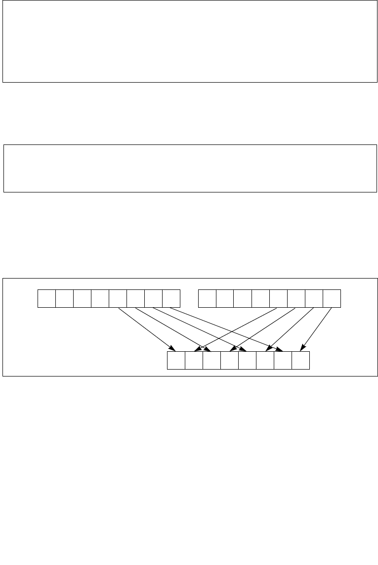
Vol. 2B 4-281
INSTRUCTION SET REFERENCE, N-Z
PUNPCKLBW/PUNPCKLWD/PUNPCKLDQ/PUNPCKLQDQ— Unpack Low Data
Instruction Operand Encoding
Description
Unpacks and interleaves the low-order data elements (bytes, words, doublewords,
and quadwords) of the destination operand (first operand) and source operand
(second operand) into the destination operand. (Figure 4-18 shows the unpack oper-
ation for bytes in 64-bit operands.). The high-order data elements are ignored.
The source operand can be an MMX technology register or a 32-bit memory location,
or it can be an XMM register or a 128-bit memory location. The destination operand
can be an MMX technology register or an XMM register. When the source data comes
from a 128-bit memory operand, an implementation may fetch only the appropriate
64 bits; however, alignment to a 16-byte boundary and normal segment checking
will still be enforced.
The PUNPCKLBW instruction interleaves the low-order bytes of the source and desti-
nation operands, the PUNPCKLWD instruction interleaves the low-order words of the
source and destination operands, the PUNPCKLDQ instruction interleaves the low-
Opcode/
Instruction
Op/
En
64/32 bit
Mode
Support
CPUID
Feature
Flag
Description
VEX.NDS.128.66.0F.WIG 6C/r
VPUNPCKLQDQ xmm1, xmm2,
xmm3/m128
B V/V AVX Interleave low-order
quadword from xmm2 and
xmm3/m128 into xmm1
register.
NOTES:
1. See note in Section 2.4, “Instruction Exception Specification”.
Op/En Operand 1 Operand 2 Operand 3 Operand 4
A ModRM:reg (r, w) ModRM:r/m (r) NA NA
B ModRM:reg (w) VEX.vvvv (r) ModRM:r/m (r) NA
Figure 4-18. PUNPCKLBW Instruction Operation Using 64-bit Operands
X0X3 X2 X1 Y0Y3 Y2 Y1
X0X3 X2 X1
Y0Y3 Y2 Y1 X4X7 X6 X5
Y4Y7 Y6 Y5
SRC DEST
DEST

4-282 Vol. 2B PUNPCKLBW/PUNPCKLWD/PUNPCKLDQ/PUNPCKLQDQ— Unpack Low Data
INSTRUCTION SET REFERENCE, N-Z
order doubleword (or doublewords) of the source and destination operands, and the
PUNPCKLQDQ instruction interleaves the low-order quadwords of the source and
destination operands.
These instructions can be used to convert bytes to words, words to doublewords,
doublewords to quadwords, and quadwords to double quadwords, respectively, by
placing all 0s in the source operand. Here, if the source operand contains all 0s, the
result (stored in the destination operand) contains zero extensions of the high-order
data elements from the original value in the destination operand. For example, with
the PUNPCKLBW instruction the high-order bytes are zero extended (that is,
unpacked into unsigned word integers), and with the PUNPCKLWD instruction, the
high-order words are zero extended (unpacked into unsigned doubleword integers).
In 64-bit mode, using a REX prefix in the form of REX.R permits this instruction to
access additional registers (XMM8-XMM15).
128-bit Legacy SSE versions: Bits (VLMAX-1:128) of the corresponding YMM destina-
tion register remain unchanged.
VEX.128 encoded versions: Bits (VLMAX-1:128) of the destination YMM register are
zeroed. VEX.L must be 0, otherwise instructions will #UD.
Operation
PUNPCKLBW instruction with 64-bit operands:
DEST[63:56] ← SRC[31:24];
DEST[55:48] ← DEST[31:24];
DEST[47:40] ← SRC[23:16];
DEST[39:32] ← DEST[23:16];
DEST[31:24] ← SRC[15:8];
DEST[23:16] ← DEST[15:8];
DEST[15:8] ← SRC[7:0];
DEST[7:0] ← DEST[7:0];
PUNPCKLWD instruction with 64-bit operands:
DEST[63:48] ← SRC[31:16];
DEST[47:32] ← DEST[31:16];
DEST[31:16] ← SRC[15:0];
DEST[15:0] ← DEST[15:0];
PUNPCKLDQ instruction with 64-bit operands:
DEST[63:32] ← SRC[31:0];
DEST[31:0] ← DEST[31:0];
PUNPCKLBW instruction with 128-bit operands:
DEST[7:0]← DEST[7:0];
DEST[15:8] ← SRC[7:0];
DEST[23:16] ← DEST[15:8];

Vol. 2B 4-283
INSTRUCTION SET REFERENCE, N-Z
PUNPCKLBW/PUNPCKLWD/PUNPCKLDQ/PUNPCKLQDQ— Unpack Low Data
DEST[31:24] ← SRC[15:8];
DEST[39:32] ← DEST[23:16];
DEST[47:40] ← SRC[23:16];
DEST[55:48] ← DEST[31:24];
DEST[63:56] ← SRC[31:24];
DEST[71:64] ← DEST[39:32];
DEST[79:72] ← SRC[39:32];
DEST[87:80] ← DEST[47:40];
DEST[95:88] ← SRC[47:40];
DEST[103:96] ← DEST[55:48];
DEST[111:104] ← SRC[55:48];
DEST[119:112] ← DEST[63:56];
DEST[127:120] ← SRC[63:56];
PUNPCKLWD instruction with 128-bit operands:
DEST[15:0] ← DEST[15:0];
DEST[31:16] ← SRC[15:0];
DEST[47:32] ← DEST[31:16];
DEST[63:48] ← SRC[31:16];
DEST[79:64] ← DEST[47:32];
DEST[95:80] ← SRC[47:32];
DEST[111:96] ← DEST[63:48];
DEST[127:112] ← SRC[63:48];
PUNPCKLDQ instruction with 128-bit operands:
DEST[31:0] ← DEST[31:0];
DEST[63:32] ← SRC[31:0];
DEST[95:64] ← DEST[63:32];
DEST[127:96] ← SRC[63:32];
PUNPCKLQDQ
DEST[63:0] ← DEST[63:0];
DEST[127:64] ← SRC[63:0];
VPUNPCKLBW
DEST[127:0] INTERLEAVE_BYTES(SRC1, SRC2)
DEST[VLMAX-1:128] 0
VPUNPCKLWD
DEST[127:0] INTERLEAVE_WORDS(SRC1, SRC2)
DEST[VLMAX-1:128] 0
VPUNPCKLDQ
DEST[127:0] INTERLEAVE_DWORDS(SRC1, SRC2)

4-284 Vol. 2B PUNPCKLBW/PUNPCKLWD/PUNPCKLDQ/PUNPCKLQDQ— Unpack Low Data
INSTRUCTION SET REFERENCE, N-Z
DEST[VLMAX-1:128] 0
VPUNPCKLQDQ
DEST[127:0] INTERLEAVE_QWORDS(SRC1, SRC2)
DEST[VLMAX-1:128] 0
Intel C/C++ Compiler Intrinsic Equivalents
PUNPCKLBW __m64 _mm_unpacklo_pi8 (__m64 m1, __m64 m2)
PUNPCKLBW __m128i _mm_unpacklo_epi8 (__m128i m1, __m128i m2)
PUNPCKLWD __m64 _mm_unpacklo_pi16 (__m64 m1, __m64 m2)
PUNPCKLWD __m128i _mm_unpacklo_epi16 (__m128i m1, __m128i m2)
PUNPCKLDQ __m64 _mm_unpacklo_pi32 (__m64 m1, __m64 m2)
PUNPCKLDQ __m128i _mm_unpacklo_epi32 (__m128i m1, __m128i m2)
PUNPCKLQDQ __m128i _mm_unpacklo_epi64 (__m128i m1, __m128i m2)
Flags Affected
None.
Numeric Exceptions
None.
Other Exceptions
See Exceptions Type 4; additionally
#UD If VEX.L = 1.

Vol. 2B 4-285
INSTRUCTION SET REFERENCE, N-Z
PUSH—Push Word, Doubleword or Quadword Onto the Stack
PUSH—Push Word, Doubleword or Quadword Onto the Stack
Opcode* Instruction Op/
En
64-Bit
Mode
Compat/
Leg Mode
Description
FF /6 PUSH r/m16 A Valid Valid Push r/m16.
FF /6 PUSH r/m32 AN.E. Valid Push r/m32.
FF /6 PUSH r/m64 AValid N.E. Push r/m64. Default
operand size 64-bits.
50+rw PUSH r16 B Valid Valid Push r16.
50+rd PUSH r32 BN.E. Valid Push r32.
50+rd PUSH r64 BValid N.E. Push r64. Default operand
size 64-bits.
6A PUSH imm8 C Valid Valid Push sign-extended imm8.
Stack pointer is
decremented by the size of
stack pointer.
68 PUSH imm16 C Valid Valid Push imm16. Stack pointer
is decremented by the size
of stack pointer.
68 PUSH imm32 C Valid Valid Push sign-extended imm32.
Stack pointer is
decremented by the size of
stack pointer.
0E PUSH CS D Invalid Valid Push CS.
16 PUSH SS D Invalid Valid Push SS.
1E PUSH DS D Invalid Valid Push DS.
06 PUSH ES D Invalid Valid Push ES.
0F A0 PUSH FS D Valid Valid Push FS and decrement
stack pointer by 16 bits.
0F A0 PUSH FS D N.E. Valid Push FS and decrement
stack pointer by 32 bits.
0F A0 PUSH FS D Valid N.E. Push FS. Default operand
size 64-bits. (66H override
causes 16-bit operation).
0F A8 PUSH GS D Valid Valid Push GS and decrement
stack pointer by 16 bits.
0F A8 PUSH GS D N.E. Valid Push GS and decrement
stack pointer by 32 bits.

4-286 Vol. 2B PUSH—Push Word, Doubleword or Quadword Onto the Stack
INSTRUCTION SET REFERENCE, N-Z
Instruction Operand Encoding
Description
Decrements the stack pointer and then stores the source operand on the top of the
stack. The address-size attribute of the stack segment determines the stack pointer
size (16, 32 or 64 bits). The operand-size attribute of the current code segment
determines the amount the stack pointer is decremented (2, 4 or 8 bytes).
In non-64-bit modes: if the address-size and operand-size attributes are 32, the
32-bit ESP register (stack pointer) is decremented by 4. If both attributes are 16, the
16-bit SP register (stack pointer) is decremented by 2.
If the source operand is an immediate and its size is less than the address size of the
stack, a sign-extended value is pushed on the stack. If the source operand is the FS
or GS and its size is less than the address size of the stack, the zero-extended value
is pushed on the stack.
The B flag in the stack segment’s segment descriptor determines the stack’s address-
size attribute. The D flag in the current code segment’s segment descriptor (with
prefixes), determines the operand-size attribute and the address-size attribute of the
source operand. Pushing a 16-bit operand when the stack address-size attribute is 32
can result in a misaligned stack pointer (a stack pointer that is not be aligned on a
doubleword boundary).
The PUSH ESP instruction pushes the value of the ESP register as it existed before
the instruction was executed. Thus if a PUSH instruction uses a memory operand in
which the ESP register is used for computing the operand address, the address of the
operand is computed before the ESP register is decremented.
In the real-address mode, if the ESP or SP register is 1 when the PUSH instruction is
executed, an #SS exception is generated but not delivered (the stack error reported
prevents #SS delivery). Next, the processor generates a #DF exception and enters a
Opcode* Instruction Op/
En
64-Bit
Mode
Compat/
Leg Mode
Description
0F A8 PUSH GS D Valid N.E. Push GS, default operand
size 64-bits. (66H override
causes 16-bit operation).
NOTES:
* See IA-32 Architecture Compatibility section below.
Op/En Operand 1 Operand 2 Operand 3 Operand 4
A ModRM:r/m (r) NA NA NA
Breg (r) NA NA NA
C imm8/16/32 NA NA NA
DNA NA NA NA

Vol. 2B 4-287
INSTRUCTION SET REFERENCE, N-Z
PUSH—Push Word, Doubleword or Quadword Onto the Stack
shutdown state as described in the #DF discussion in Chapter 6 of the Intel® 64 and
IA-32 Architectures Software Developer’s Manual, Volume 3A.
In 64-bit mode, the instruction’s default operation size is 64 bits. In a push, the
64-bit RSP register (stack pointer) is decremented by 8. A 66H override causes
16-bit operation. Note that pushing a 16-bit operand can result in the stack pointer
misaligned to 8-byte boundary.
IA-32 Architecture Compatibility
For IA-32 processors from the Intel 286 on, the PUSH ESP instruction pushes the
value of the ESP register as it existed before the instruction was executed. (This is
also true for Intel 64 architecture, real-address and virtual-8086 modes of IA-32
architecture.) For the Intel® 8086 processor, the PUSH SP instruction pushes the new
value of the SP register (that is the value after it has been decremented by 2).
Operation
IF StackAddrSize = 64
THEN
IF OperandSize = 64
THEN
RSP ← (RSP − 8);
IF (SRC is FS or GS)
THEN
TEMP = ZeroExtend64(SRC);
ELSE IF (SRC is IMMEDIATE)
TEMP = SignExtend64(SRC); FI;
ELSE
TEMP = SRC;
FI
RSP ← TEMP; (* Push quadword *)
ELSE (* OperandSize = 16; 66H used *)
RSP ← (RSP − 2);
RSP ← SRC; (* Push word *)
FI;
ELSE IF StackAddrSize = 32
THEN
IF OperandSize = 32
THEN
ESP ← (ESP − 4);
IF (SRC is FS or GS)
THEN
TEMP = ZeroExtend32(SRC);
ELSE IF (SRC is IMMEDIATE)

4-288 Vol. 2B PUSH—Push Word, Doubleword or Quadword Onto the Stack
INSTRUCTION SET REFERENCE, N-Z
TEMP = SignExtend32(SRC); FI;
ELSE
TEMP = SRC;
FI;
SS:ESP ← TEMP; (* Push doubleword *)
ELSE (* OperandSize = 16*)
ESP ← (ESP − 2);
SS:ESP ← SRC; (* Push word *)
FI;
ELSE StackAddrSize = 16
IF OperandSize = 16
THEN
SP ← (SP − 2);
SS:SP ← SRC; (* Push word *)
ELSE (* OperandSize = 32 *)
SP ← (SP − 4);
SS:SP ← SRC; (* Push doubleword *)
FI;
FI;
FI;
Flags Affected
None.
Protected Mode Exceptions
#GP(0) If a memory operand effective address is outside the CS, DS,
ES, FS, or GS segment limit.
If the DS, ES, FS, or GS register is used to access memory and it
contains a NULL segment selector.
#SS(0) If a memory operand effective address is outside the SS
segment limit.
#PF(fault-code) If a page fault occurs.
#AC(0) If alignment checking is enabled and an unaligned memory
reference is made while the current privilege level is 3.
#UD If the LOCK prefix is used.
Real-Address Mode Exceptions
#GP If a memory operand effective address is outside the CS, DS,
ES, FS, or GS segment limit.
#SS If a memory operand effective address is outside the SS
segment limit.

Vol. 2B 4-289
INSTRUCTION SET REFERENCE, N-Z
PUSH—Push Word, Doubleword or Quadword Onto the Stack
If the new value of the SP or ESP register is outside the stack
segment limit.
#UD If the LOCK prefix is used.
Virtual-8086 Mode Exceptions
#GP(0) If a memory operand effective address is outside the CS, DS,
ES, FS, or GS segment limit.
#SS(0) If a memory operand effective address is outside the SS
segment limit.
#PF(fault-code) If a page fault occurs.
#AC(0) If alignment checking is enabled and an unaligned memory
reference is made.
#UD If the LOCK prefix is used.
Compatibility Mode Exceptions
Same exceptions as in protected mode.
64-Bit Mode Exceptions
#GP(0) If the memory address is in a non-canonical form.
#SS(U) If the stack address is in a non-canonical form.
#PF(fault-code) If a page fault occurs.
#AC(0) If alignment checking is enabled and an unaligned memory
reference is made while the current privilege level is 3.
#UD If the LOCK prefix is used.

4-290 Vol. 2B PUSHA/PUSHAD—Push All General-Purpose Registers
INSTRUCTION SET REFERENCE, N-Z
PUSHA/PUSHAD—Push All General-Purpose Registers
Instruction Operand Encoding
Description
Pushes the contents of the general-purpose registers onto the stack. The registers
are stored on the stack in the following order: EAX, ECX, EDX, EBX, ESP (original
value), EBP, ESI, and EDI (if the current operand-size attribute is 32) and AX, CX, DX,
BX, SP (original value), BP, SI, and DI (if the operand-size attribute is 16). These
instructions perform the reverse operation of the POPA/POPAD instructions. The
value pushed for the ESP or SP register is its value before prior to pushing the first
register (see the “Operation” section below).
The PUSHA (push all) and PUSHAD (push all double) mnemonics reference the same
opcode. The PUSHA instruction is intended for use when the operand-size attribute is
16 and the PUSHAD instruction for when the operand-size attribute is 32. Some
assemblers may force the operand size to 16 when PUSHA is used and to 32 when
PUSHAD is used. Others may treat these mnemonics as synonyms (PUSHA/PUSHAD)
and use the current setting of the operand-size attribute to determine the size of
values to be pushed from the stack, regardless of the mnemonic used.
In the real-address mode, if the ESP or SP register is 1, 3, or 5 when PUSHA/PUSHAD
executes: an #SS exception is generated but not delivered (the stack error reported
prevents #SS delivery). Next, the processor generates a #DF exception and enters a
shutdown state as described in the #DF discussion in Chapter 6 of the Intel® 64 and
IA-32 Architectures Software Developer’s Manual, Volume 3A.
This instruction executes as described in compatibility mode and legacy mode. It is
not valid in 64-bit mode.
Operation
IF 64-bit Mode
THEN #UD
Opcode Instruction Op/
En
64-Bit
Mode
Compat/
Leg Mode
Description
60 PUSHA A Invalid Valid Push AX, CX, DX, BX, original
SP, BP, SI, and DI.
60 PUSHAD A Invalid Valid Push EAX, ECX, EDX, EBX,
original ESP, EBP, ESI, and
EDI.
Op/En Operand 1 Operand 2 Operand 3 Operand 4
ANA NA NA NA

Vol. 2B 4-291
INSTRUCTION SET REFERENCE, N-Z
PUSHA/PUSHAD—Push All General-Purpose Registers
FI;
IF OperandSize = 32 (* PUSHAD instruction *)
THEN
Temp ← (ESP);
Push(EAX);
Push(ECX);
Push(EDX);
Push(EBX);
Push(Temp);
Push(EBP);
Push(ESI);
Push(EDI);
ELSE (* OperandSize = 16, PUSHA instruction *)
Temp ← (SP);
Push(AX);
Push(CX);
Push(DX);
Push(BX);
Push(Temp);
Push(BP);
Push(SI);
Push(DI);
FI;
Flags Affected
None.
Protected Mode Exceptions
#SS(0) If the starting or ending stack address is outside the stack
segment limit.
#PF(fault-code) If a page fault occurs.
#AC(0) If an unaligned memory reference is made while the current
privilege level is 3 and alignment checking is enabled.
#UD If the LOCK prefix is used.
Real-Address Mode Exceptions
#GP If the ESP or SP register contains 7, 9, 11, 13, or 15.
#UD If the LOCK prefix is used.
Virtual-8086 Mode Exceptions
#GP(0) If the ESP or SP register contains 7, 9, 11, 13, or 15.

4-292 Vol. 2B PUSHA/PUSHAD—Push All General-Purpose Registers
INSTRUCTION SET REFERENCE, N-Z
#PF(fault-code) If a page fault occurs.
#AC(0) If an unaligned memory reference is made while alignment
checking is enabled.
#UD If the LOCK prefix is used.
Compatibility Mode Exceptions
Same exceptions as in protected mode.
64-Bit Mode Exceptions
#UD If in 64-bit mode.

Vol. 2B 4-293
INSTRUCTION SET REFERENCE, N-Z
PUSHF/PUSHFD—Push EFLAGS Register onto the Stack
PUSHF/PUSHFD—Push EFLAGS Register onto the Stack
Instruction Operand Encoding
Description
Decrements the stack pointer by 4 (if the current operand-size attribute is 32) and
pushes the entire contents of the EFLAGS register onto the stack, or decrements the
stack pointer by 2 (if the operand-size attribute is 16) and pushes the lower 16 bits
of the EFLAGS register (that is, the FLAGS register) onto the stack. These instruc-
tions reverse the operation of the POPF/POPFD instructions.
When copying the entire EFLAGS register to the stack, the VM and RF flags (bits 16
and 17) are not copied; instead, the values for these flags are cleared in the EFLAGS
image stored on the stack. See Chapter 3 of the Intel® 64 and IA-32 Architectures
Software Developer’s Manual, Volume 1, for more information about the EFLAGS
register.
The PUSHF (push flags) and PUSHFD (push flags double) mnemonics reference the
same opcode. The PUSHF instruction is intended for use when the operand-size
attribute is 16 and the PUSHFD instruction for when the operand-size attribute is 32.
Some assemblers may force the operand size to 16 when PUSHF is used and to 32
when PUSHFD is used. Others may treat these mnemonics as synonyms
(PUSHF/PUSHFD) and use the current setting of the operand-size attribute to deter-
mine the size of values to be pushed from the stack, regardless of the mnemonic
used.
In 64-bit mode, the instruction’s default operation is to decrement the stack pointer
(RSP) by 8 and pushes RFLAGS on the stack. 16-bit operation is supported using the
operand size override prefix 66H. 32-bit operand size cannot be encoded in this
mode. When copying RFLAGS to the stack, the VM and RF flags (bits 16 and 17) are
not copied; instead, values for these flags are cleared in the RFLAGS image stored on
the stack.
When in virtual-8086 mode and the I/O privilege level (IOPL) is less than 3, the
PUSHF/PUSHFD instruction causes a general protection exception (#GP).
Opcode* Instruction Op/
En
64-Bit
Mode
Compat/
Leg Mode
Description
9C PUSHF A Valid Valid Push lower 16 bits of
EFLAGS.
9C PUSHFD A N.E. Valid Push EFLAGS.
9C PUSHFQ A Valid N.E. Push RFLAGS.
Op/En Operand 1 Operand 2 Operand 3 Operand 4
ANA NA NA NA

4-294 Vol. 2B PUSHF/PUSHFD—Push EFLAGS Register onto the Stack
INSTRUCTION SET REFERENCE, N-Z
In the real-address mode, if the ESP or SP register is 1 when PUSHF/PUSHFD instruc-
tion executes: an #SS exception is generated but not delivered (the stack error
reported prevents #SS delivery). Next, the processor generates a #DF exception and
enters a shutdown state as described in the #DF discussion in Chapter 6 of the
Intel® 64 and IA-32 Architectures Software Developer’s Manual, Volume 3A.
Operation
IF (PE = 0) or (PE = 1 and ((VM = 0) or (VM = 1 and IOPL = 3)))
(* Real-Address Mode, Protected mode, or Virtual-8086 mode with IOPL equal to 3 *)
THEN
IF OperandSize = 32
THEN
push (EFLAGS AND 00FCFFFFH);
(* VM and RF EFLAG bits are cleared in image stored on the stack *)
ELSE
push (EFLAGS); (* Lower 16 bits only *)
FI;
ELSE IF 64-bit MODE (* In 64-bit Mode *)
IF OperandSize = 64
THEN
push (RFLAGS AND 00000000_00FCFFFFH);
(* VM and RF RFLAG bits are cleared in image stored on the stack; *)
ELSE
push (EFLAGS); (* Lower 16 bits only *)
FI;
ELSE (* In Virtual-8086 Mode with IOPL less than 3 *)
#GP(0); (* Trap to virtual-8086 monitor *)
FI;
Flags Affected
None.
Protected Mode Exceptions
#SS(0) If the new value of the ESP register is outside the stack segment
boundary.
#PF(fault-code) If a page fault occurs.
#AC(0) If an unaligned memory reference is made while the current
privilege level is 3 and alignment checking is enabled.
#UD If the LOCK prefix is used.

Vol. 2B 4-295
INSTRUCTION SET REFERENCE, N-Z
PUSHF/PUSHFD—Push EFLAGS Register onto the Stack
Real-Address Mode Exceptions
#UD If the LOCK prefix is used.
Virtual-8086 Mode Exceptions
#GP(0) If the I/O privilege level is less than 3.
#PF(fault-code) If a page fault occurs.
#AC(0) If an unaligned memory reference is made while alignment
checking is enabled.
#UD If the LOCK prefix is used.
Compatibility Mode Exceptions
Same exceptions as in protected mode.
64-Bit Mode Exceptions
#GP(0) If the memory address is in a non-canonical form.
#SS(0) If the stack address is in a non-canonical form.
#PF(fault-code) If a page fault occurs.
#AC(0) If an unaligned memory reference is made while the current
privilege level is 3 and alignment checking is enabled.
#UD If the LOCK prefix is used.

4-296 Vol. 2B PXOR—Logical Exclusive OR
INSTRUCTION SET REFERENCE, N-Z
PXOR—Logical Exclusive OR
Instruction Operand Encoding
Description
Performs a bitwise logical exclusive-OR (XOR) operation on the source operand
(second operand) and the destination operand (first operand) and stores the result in
the destination operand. The source operand can be an MMX technology register or a
64-bit memory location or it can be an XMM register or a 128-bit memory location.
The destination operand can be an MMX technology register or an XMM register. Each
bit of the result is 1 if the corresponding bits of the two operands are different; each
bit is 0 if the corresponding bits of the operands are the same.
In 64-bit mode, using a REX prefix in the form of REX.R permits this instruction to
access additional registers (XMM8-XMM15).
128-bit Legacy SSE version: Bits (VLMAX-1:128) of the corresponding YMM destina-
tion register remain unchanged.
VEX.128 encoded version: Bits (VLMAX-1:128) of the destination YMM register are
zeroed. VEX.L must be 0, otherwise instructions will #UD.
Operation
PXOR (128-bit Legacy SSE version)
DEST DEST XOR SRC
DEST[VLMAX-1:128] (Unmodified)
Opcode*/
Instruction
Op/
En
64/32 bit
Mode
Support
CPUID
Feature
Flag
Description
0F EF /r1
PXOR mm, mm/m64
AV/V MMX Bitwise XOR of mm/m64
and mm.
66 0F EF /r
PXOR xmm1, xmm2/m128
AV/V SSE2 Bitwise XOR of
xmm2/m128 and xmm1.
VEX.NDS.128.66.0F.WIG EF /r
VPXOR xmm1, xmm2, xmm3/m128
BV/V AVX Bitwise XOR of
xmm3/m128 and xmm2.
NOTES:
1. See note in Section 2.4, “Instruction Exception Specification”.
Op/En Operand 1 Operand 2 Operand 3 Operand 4
A ModRM:reg (r, w) ModRM:r/m (r) NA NA
B ModRM:reg (w) VEX.vvvv (r) ModRM:r/m (r) NA

Vol. 2B 4-297
INSTRUCTION SET REFERENCE, N-Z
PXOR—Logical Exclusive OR
VPXOR (VEX.128 encoded version)
DEST SRC1 XOR SRC2
DEST[VLMAX-1:128] 0
Intel C/C++ Compiler Intrinsic Equivalent
PXOR __m64 _mm_xor_si64 (__m64 m1, __m64 m2)
PXOR __m128i _mm_xor_si128 ( __m128i a, __m128i b)
Flags Affected
None.
Numeric Exceptions
None.
Other Exceptions
See Exceptions Type 4; additionally
#UD If VEX.L = 1.

4-298 Vol. 2B RCL/RCR/ROL/ROR-—Rotate
INSTRUCTION SET REFERENCE, N-Z
RCL/RCR/ROL/ROR-—Rotate
Opcode** Instruction Op/
En
64-Bit
Mode
Compat/
Leg Mode
Description
D0 /2 RCL r/m8, 1 A Valid Valid Rotate 9 bits (CF, r/m8) left
once.
REX + D0 /2 RCL r/m8*, 1 A Valid N.E. Rotate 9 bits (CF, r/m8) left
once.
D2 /2 RCL r/m8, CL B Valid Valid Rotate 9 bits (CF, r/m8) left
CL times.
REX + D2 /2 RCL r/m8*, CL B Valid N.E. Rotate 9 bits (CF, r/m8) left
CL times.
C0 /2 ib RCL r/m8, imm8 CValid Valid Rotate 9 bits (CF, r/m8) left
imm8 times.
REX + C0 /2 ib RCL r/m8*, imm8 C Valid N.E. Rotate 9 bits (CF, r/m8) left
imm8 times.
D1 /2 RCL r/m16, 1 A Valid Valid Rotate 17 bits (CF, r/m16)
left once.
D3 /2 RCL r/m16, CL B Valid Valid Rotate 17 bits (CF, r/m16)
left CL times.
C1 /2 ib RCL r/m16, imm8 CValid Valid Rotate 17 bits (CF, r/m16)
left imm8 times.
D1 /2 RCL r/m32, 1 A Valid Valid Rotate 33 bits (CF, r/m32)
left once.
REX.W + D1 /2 RCL r/m64, 1 A Valid N.E. Rotate 65 bits (CF, r/m64)
left once. Uses a 6 bit count.
D3 /2 RCL r/m32, CL B Valid Valid Rotate 33 bits (CF, r/m32)
left CL times.
REX.W + D3 /2 RCL r/m64, CL B Valid N.E. Rotate 65 bits (CF, r/m64)
left CL times. Uses a 6 bit
count.
C1 /2 ib RCL r/m32, imm8 CValid Valid Rotate 33 bits (CF, r/m32)
left imm8 times.
REX.W + C1 /2
ib
RCL r/m64, imm8 C Valid N.E. Rotate 65 bits (CF, r/m64)
left imm8 times. Uses a 6 bit
count.
D0 /3 RCR r/m8, 1 A Valid Valid Rotate 9 bits (CF, r/m8) right
once.
REX + D0 /3 RCR r/m8*, 1 A Valid N.E. Rotate 9 bits (CF, r/m8) right
once.

Vol. 2B 4-299
INSTRUCTION SET REFERENCE, N-Z
RCL/RCR/ROL/ROR-—Rotate
Opcode** Instruction Op/
En
64-Bit
Mode
Compat/
Leg Mode
Description
D2 /3 RCR r/m8, CL B Valid Valid Rotate 9 bits (CF, r/m8) right
CL times.
REX + D2 /3 RCR r/m8*, CL B Valid N.E. Rotate 9 bits (CF, r/m8) right
CL times.
C0 /3 ib RCR r/m8, imm8 CValid Valid Rotate 9 bits (CF, r/m8) right
imm8 times.
REX + C0 /3 ib RCR r/m8*, imm8 C Valid N.E. Rotate 9 bits (CF, r/m8) right
imm8 times.
D1 /3 RCR r/m16, 1 A Valid Valid Rotate 17 bits (CF, r/m16)
right once.
D3 /3 RCR r/m16, CL B Valid Valid Rotate 17 bits (CF, r/m16)
right CL times.
C1 /3 ib RCR r/m16, imm8 CValid Valid Rotate 17 bits (CF, r/m16)
right imm8 times.
D1 /3 RCR r/m32, 1 A Valid Valid Rotate 33 bits (CF, r/m32)
right once. Uses a 6 bit
count.
REX.W + D1 /3 RCR r/m64, 1 A Valid N.E. Rotate 65 bits (CF, r/m64)
right once. Uses a 6 bit
count.
D3 /3 RCR r/m32, CL B Valid Valid Rotate 33 bits (CF, r/m32)
right CL times.
REX.W + D3 /3 RCR r/m64, CL B Valid N.E. Rotate 65 bits (CF, r/m64)
right CL times. Uses a 6 bit
count.
C1 /3 ib RCR r/m32, imm8 CValid Valid Rotate 33 bits (CF, r/m32)
right imm8 times.
REX.W + C1 /3
ib
RCR r/m64, imm8 C Valid N.E. Rotate 65 bits (CF, r/m64)
right imm8 times. Uses a 6
bit count.
D0 /0 ROL r/m8, 1 A Valid Valid Rotate 8 bits r/m8 left once.
REX + D0 /0 ROL r/m8*, 1 A Valid N.E. Rotate 8 bits r/m8 left once
D2 /0 ROL r/m8, CL B Valid Valid Rotate 8 bits r/m8 left CL
times.
REX + D2 /0 ROL r/m8*, CL B Valid N.E. Rotate 8 bits r/m8 left CL
times.
C0 /0 ib ROL r/m8, imm8 CValid Valid Rotate 8 bits r/m8 left imm8
times.

4-300 Vol. 2B RCL/RCR/ROL/ROR-—Rotate
INSTRUCTION SET REFERENCE, N-Z
Opcode** Instruction Op/
En
64-Bit
Mode
Compat/
Leg Mode
Description
REX + C0 /0 ib ROL r/m8*, imm8 C Valid N.E. Rotate 8 bits r/m8 left imm8
times.
D1 /0 ROL r/m16, 1 A Valid Valid Rotate 16 bits r/m16 left
once.
D3 /0 ROL r/m16, CL B Valid Valid Rotate 16 bits r/m16 left CL
times.
C1 /0 ib ROL r/m16, imm8 CValid Valid Rotate 16 bits r/m16 left
imm8 times.
D1 /0 ROL r/m32, 1 A Valid Valid Rotate 32 bits r/m32 left
once.
REX.W + D1 /0 ROL r/m64, 1 A Valid N.E. Rotate 64 bits r/m64 left
once. Uses a 6 bit count.
D3 /0 ROL r/m32, CL B Valid Valid Rotate 32 bits r/m32 left CL
times.
REX.W + D3 /0 ROL r/m64, CL B Valid N.E. Rotate 64 bits r/m64 left CL
times. Uses a 6 bit count.
C1 /0 ib ROL r/m32, imm8 CValid Valid Rotate 32 bits r/m32 left
imm8 times.
C1 /0 ib ROL r/m64, imm8 C Valid N.E. Rotate 64 bits r/m64 left
imm8 times. Uses a 6 bit
count.
D0 /1 ROR r/m8, 1 A Valid Valid Rotate 8 bits r/m8 right
once.
REX + D0 /1 ROR r/m8*, 1 A Valid N.E. Rotate 8 bits r/m8 right
once.
D2 /1 ROR r/m8, CL B Valid Valid Rotate 8 bits r/m8 right CL
times.
REX + D2 /1 ROR r/m8*, CL BValid N.E. Rotate 8 bits r/m8 right CL
times.
C0 /1 ib ROR r/m8, imm8 CValid Valid Rotate 8 bits r/m16 right
imm8 times.
REX + C0 /1 ib ROR r/m8*, imm8 C Valid N.E. Rotate 8 bits r/m16 right
imm8 times.
D1 /1 ROR r/m16, 1 A Valid Valid Rotate 16 bits r/m16 right
once.
D3 /1 ROR r/m16, CL B Valid Valid Rotate 16 bits r/m16 right
CL times.

Vol. 2B 4-301
INSTRUCTION SET REFERENCE, N-Z
RCL/RCR/ROL/ROR-—Rotate
Instruction Operand Encoding
Description
Shifts (rotates) the bits of the first operand (destination operand) the number of bit
positions specified in the second operand (count operand) and stores the result in the
destination operand. The destination operand can be a register or a memory loca-
tion; the count operand is an unsigned integer that can be an immediate or a value in
the CL register. In legacy and compatibility mode, the processor restricts the count to
a number between 0 and 31 by masking all the bits in the count operand except the
5 least-significant bits.
The rotate left (ROL) and rotate through carry left (RCL) instructions shift all the bits
toward more-significant bit positions, except for the most-significant bit, which is
rotated to the least-significant bit location. The rotate right (ROR) and rotate through
Opcode** Instruction Op/
En
64-Bit
Mode
Compat/
Leg Mode
Description
C1 /1 ib ROR r/m16, imm8 CValid Valid Rotate 16 bits r/m16 right
imm8 times.
D1 /1 ROR r/m32, 1 A Valid Valid Rotate 32 bits r/m32 right
once.
REX.W + D1 /1 ROR r/m64, 1 A Valid N.E. Rotate 64 bits r/m64 right
once. Uses a 6 bit count.
D3 /1 ROR r/m32, CL B Valid Valid Rotate 32 bits r/m32 right
CL times.
REX.W + D3 /1 ROR r/m64, CL B Valid N.E. Rotate 64 bits r/m64 right
CL times. Uses a 6 bit count.
C1 /1 ib ROR r/m32, imm8 CValid Valid Rotate 32 bits r/m32 right
imm8 times.
REX.W + C1 /1
ib
ROR r/m64, imm8 C Valid N.E. Rotate 64 bits r/m64 right
imm8 times. Uses a 6 bit
count.
NOTES:
* In 64-bit mode, r/m8 can not be encoded to access the following byte registers if a REX prefix is
used: AH, BH, CH, DH.
** See IA-32 Architecture Compatibility section below.
Op/En Operand 1 Operand 2 Operand 3 Operand 4
A ModRM:r/m (w) 1 NA NA
B ModRM:r/m (w) CL (r) NA NA
C ModRM:r/m (w) imm8 NA NA

4-302 Vol. 2B RCL/RCR/ROL/ROR-—Rotate
INSTRUCTION SET REFERENCE, N-Z
carry right (RCR) instructions shift all the bits toward less significant bit positions,
except for the least-significant bit, which is rotated to the most-significant bit loca-
tion.
The RCL and RCR instructions include the CF flag in the rotation. The RCL instruction
shifts the CF flag into the least-significant bit and shifts the most-significant bit into
the CF flag. The RCR instruction shifts the CF flag into the most-significant bit and
shifts the least-significant bit into the CF flag. For the ROL and ROR instructions, the
original value of the CF flag is not a part of the result, but the CF flag receives a copy
of the bit that was shifted from one end to the other.
The OF flag is defined only for the 1-bit rotates; it is undefined in all other cases
(except that a zero-bit rotate does nothing, that is affects no flags). For left rotates,
the OF flag is set to the exclusive OR of the CF bit (after the rotate) and the most-
significant bit of the result. For right rotates, the OF flag is set to the exclusive OR of
the two most-significant bits of the result.
In 64-bit mode, using a REX prefix in the form of REX.R permits access to additional
registers (R8-R15). Use of REX.W promotes the first operand to 64 bits and causes
the count operand to become a 6-bit counter.
IA-32 Architecture Compatibility
The 8086 does not mask the rotation count. However, all other IA-32 processors
(starting with the Intel 286 processor) do mask the rotation count to 5 bits, resulting
in a maximum count of 31. This masking is done in all operating modes (including the
virtual-8086 mode) to reduce the maximum execution time of the instructions.
Operation
(* RCL and RCR instructions *)
SIZE ← OperandSize;
CASE (determine count) OF
SIZE ← 8: tempCOUNT ← (COUNT AND 1FH) MOD 9;
SIZE ← 16: tempCOUNT ← (COUNT AND 1FH) MOD 17;
SIZE ← 32: tempCOUNT ← COUNT AND 1FH;
SIZE ← 64: tempCOUNT ← COUNT AND 3FH;
ESAC;
(* RCL instruction operation *)
WHILE (tempCOUNT ≠ 0)
DO
tempCF ← MSB(DEST);
DEST ← (DEST ∗ 2) + CF;
CF ← tempCF;
tempCOUNT ← tempCOUNT – 1;
OD;

Vol. 2B 4-303
INSTRUCTION SET REFERENCE, N-Z
RCL/RCR/ROL/ROR-—Rotate
ELIHW;
IF COUNT = 1
THEN OF ← MSB(DEST) XOR CF;
ELSE OF is undefined;
FI;
(* RCR instruction operation *)
IF COUNT = 1
THEN OF ← MSB(DEST) XOR CF;
ELSE OF is undefined;
FI;
WHILE (tempCOUNT ≠ 0)
DO
tempCF ← LSB(SRC);
DEST ← (DEST / 2) + (CF * 2SIZE);
CF ← tempCF;
tempCOUNT ← tempCOUNT – 1;
OD;
(* ROL and ROR instructions *)
SIZE ← OperandSize;
CASE (determine count) OF
SIZE ← 8: tempCOUNT ← (COUNT AND 1FH) MOD 8; (* Mask count before MOD *)
SIZE ← 16: tempCOUNT ← (COUNT AND 1FH) MOD 16;
SIZE ← 32: tempCOUNT ← (COUNT AND 1FH) MOD 32;
SIZE ← 64: tempCOUNT ← (COUNT AND 3FH) MOD 64;
ESAC;
(* ROL instruction operation *)
IF (tempCOUNT > 0) (* Prevents updates to CF *)
WHILE (tempCOUNT ≠ 0)
DO
tempCF ← MSB(DEST);
DEST ← (DEST ∗ 2) + tempCF;
tempCOUNT ← tempCOUNT – 1;
OD;
ELIHW;
CF ← LSB(DEST);
IF COUNT = 1
THEN OF ← MSB(DEST) XOR CF;
ELSE OF is undefined;
FI;
FI;

4-304 Vol. 2B RCL/RCR/ROL/ROR-—Rotate
INSTRUCTION SET REFERENCE, N-Z
(* ROR instruction operation *)
IF tempCOUNT > 0) (* Prevent updates to CF *)
WHILE (tempCOUNT ≠ 0)
DO
tempCF ← LSB(SRC);
DEST ← (DEST / 2) + (tempCF ∗ 2SIZE);
tempCOUNT ← tempCOUNT – 1;
OD;
ELIHW;
CF ← MSB(DEST);
IF COUNT = 1
THEN OF ← MSB(DEST) XOR MSB − 1(DEST);
ELSE OF is undefined;
FI;
FI;
Flags Affected
The CF flag contains the value of the bit shifted into it. The OF flag is affected only for
single-bit rotates (see “Description” above); it is undefined for multi-bit rotates. The
SF, ZF, AF, and PF flags are not affected.
Protected Mode Exceptions
#GP(0) If the source operand is located in a non-writable segment.
If a memory operand effective address is outside the CS, DS,
ES, FS, or GS segment limit.
If the DS, ES, FS, or GS register contains a NULL segment
selector.
#SS(0) If a memory operand effective address is outside the SS
segment limit.
#PF(fault-code) If a page fault occurs.
#AC(0) If alignment checking is enabled and an unaligned memory
reference is made while the current privilege level is 3.
#UD If the LOCK prefix is used.
Real-Address Mode Exceptions
#GP If a memory operand effective address is outside the CS, DS,
ES, FS, or GS segment limit.
#SS If a memory operand effective address is outside the SS
segment limit.
#UD If the LOCK prefix is used.

Vol. 2B 4-305
INSTRUCTION SET REFERENCE, N-Z
RCL/RCR/ROL/ROR-—Rotate
Virtual-8086 Mode Exceptions
#GP(0) If a memory operand effective address is outside the CS, DS,
ES, FS, or GS segment limit.
#SS(0) If a memory operand effective address is outside the SS
segment limit.
#PF(fault-code) If a page fault occurs.
#AC(0) If alignment checking is enabled and an unaligned memory
reference is made.
#UD If the LOCK prefix is used.
Compatibility Mode Exceptions
Same exceptions as in protected mode.
64-Bit Mode Exceptions
#SS(0) If a memory address referencing the SS segment is in a non-
canonical form.
#GP(0) If the source operand is located in a nonwritable segment.
If the memory address is in a non-canonical form.
#PF(fault-code) If a page fault occurs.
#AC(0) If alignment checking is enabled and an unaligned memory
reference is made while the current privilege level is 3.
#UD If the LOCK prefix is used.

4-306 Vol. 2B RCPPS—Compute Reciprocals of Packed Single-Precision Floating-Point Values
INSTRUCTION SET REFERENCE, N-Z
RCPPS—Compute Reciprocals of Packed Single-Precision Floating-
Point Values
Instruction Operand Encoding
Description
Performs a SIMD computation of the approximate reciprocals of the four packed
single-precision floating-point values in the source operand (second operand) stores
the packed single-precision floating-point results in the destination operand. The
source operand can be an XMM register or a 128-bit memory location. The destina-
tion operand is an XMM register. See Figure 10-5 in the Intel® 64 and IA-32 Architec-
tures Software Developer’s Manual, Volume 1, for an illustration of a SIMD single-
precision floating-point operation.
The relative error for this approximation is:
|Relative Error| ≤ 1.5 ∗ 2−12
The RCPPS instruction is not affected by the rounding control bits in the MXCSR
register. When a source value is a 0.0, an ∞ of the sign of the source value is
returned. A denormal source value is treated as a 0.0 (of the same sign). Tiny results
are always flushed to 0.0, with the sign of the operand. (Input values greater than or
equal to |1.11111111110100000000000B∗2125| are guaranteed to not produce tiny
Opcode*/
Instruction
Op/
En
64/32 bit
Mode
Support
CPUID
Feature
Flag
Description
0F 53 /r
RCPPS xmm1, xmm2/m128
A V/V SSE Computes the approximate
reciprocals of the packed
single-precision floating-
point values in xmm2/m128
and stores the results in
xmm1.
VEX.128.0F.WIG 53 /r
VRCPPS xmm1, xmm2/m128
A V/V AVX Computes the approximate
reciprocals of packed single-
precision values in
xmm2/mem and stores the
results in xmm1.
VEX.256.0F.WIG 53 /r
VRCPPS ymm1, ymm2/m256
A V/V AVX Computes the approximate
reciprocals of packed single-
precision values in
ymm2/mem and stores the
results in ymm1.
Op/En Operand 1 Operand 2 Operand 3 Operand 4
A ModRM:reg (w) ModRM:r/m (r) NA NA

Vol. 2B 4-307
INSTRUCTION SET REFERENCE, N-Z
RCPPS—Compute Reciprocals of Packed Single-Precision Floating-Point Values
results; input values less than or equal to |1.00000000000110000000001B*2126|
are guaranteed to produce tiny results, which are in turn flushed to 0.0; and input
values in between this range may or may not produce tiny results, depending on the
implementation.) When a source value is an SNaN or QNaN, the SNaN is converted to
a QNaN or the source QNaN is returned.
In 64-bit mode, using a REX prefix in the form of REX.R permits this instruction to
access additional registers (XMM8-XMM15).
VEX.256 encoded version: The first source operand is a YMM register. The second
source operand can be a YMM register or a 256-bit memory location. The destination
operand is a YMM register.
VEX.128 encoded version: the first source operand is an XMM register or 128-bit
memory location. The destination operand is an XMM register. The upper bits
(VLMAX-1:128) of the corresponding YMM register destination are zeroed.
128-bit Legacy SSE version: The second source can be an XMM register or an 128-bit
memory location. The destination is not distinct from the first source XMM register
and the upper bits (VLMAX-1:128) of the corresponding YMM register destination are
unmodified.
Note: In VEX-encoded versions, VEX.vvvv is reserved and must be 1111b, otherwise
instructions will #UD.
Operation
RCPPS (128-bit Legacy SSE version)
DEST[31:0] APPROXIMATE(1/SRC[31:0])
DEST[63:32] APPROXIMATE(1/SRC[63:32])
DEST[95:64] APPROXIMATE(1/SRC[95:64])
DEST[127:96] APPROXIMATE(1/SRC[127:96])
DEST[VLMAX-1:128] (Unmodified)
VRCPPS (VEX.128 encoded version)
DEST[31:0] APPROXIMATE(1/SRC[31:0])
DEST[63:32] APPROXIMATE(1/SRC[63:32])
DEST[95:64] APPROXIMATE(1/SRC[95:64])
DEST[127:96] APPROXIMATE(1/SRC[127:96])
DEST[VLMAX-1:128] 0
VRCPPS (VEX.256 encoded version)
DEST[31:0] APPROXIMATE(1/SRC[31:0])
DEST[63:32] APPROXIMATE(1/SRC[63:32])
DEST[95:64] APPROXIMATE(1/SRC[95:64])
DEST[127:96] APPROXIMATE(1/SRC[127:96])
DEST[159:128] APPROXIMATE(1/SRC[159:128])
DEST[191:160] APPROXIMATE(1/SRC[191:160])

4-308 Vol. 2B RCPPS—Compute Reciprocals of Packed Single-Precision Floating-Point Values
INSTRUCTION SET REFERENCE, N-Z
DEST[223:192] APPROXIMATE(1/SRC[223:192])
DEST[255:224] APPROXIMATE(1/SRC[255:224])
Intel C/C++ Compiler Intrinsic Equivalent
RCCPS __m128 _mm_rcp_ps(__m128 a)
RCPPS __m256 _mm256_rcp_ps (__m256 a);
SIMD Floating-Point Exceptions
None.
Other Exceptions
See Exceptions Type 4; additionally
#UD If VEX.vvvv != 1111B.

Vol. 2B 4-309
INSTRUCTION SET REFERENCE, N-Z
RCPSS—Compute Reciprocal of Scalar Single-Precision Floating-Point Values
RCPSS—Compute Reciprocal of Scalar Single-Precision Floating-Point
Values
Instruction Operand Encoding
Description
Computes of an approximate reciprocal of the low single-precision floating-point
value in the source operand (second operand) and stores the single-precision
floating-point result in the destination operand. The source operand can be an XMM
register or a 32-bit memory location. The destination operand is an XMM register.
The three high-order doublewords of the destination operand remain unchanged.
See Figure 10-6 in the Intel® 64 and IA-32 Architectures Software Developer’s
Manual, Volume 1, for an illustration of a scalar single-precision floating-point oper-
ation.
The relative error for this approximation is:
|Relative Error| ≤ 1.5 ∗ 2−12
The RCPSS instruction is not affected by the rounding control bits in the MXCSR
register. When a source value is a 0.0, an ∞ of the sign of the source value is
returned. A denormal source value is treated as a 0.0 (of the same sign). Tiny results
Opcode*/
Instruction
Op/
En
64/32 bit
Mode
Support
CPUID
Feature
Flag
Description
F3 0F 53 /r
RCPSS xmm1, xmm2/m32
A V/V SSE Computes the approximate
reciprocal of the scalar
single-precision floating-
point value in xmm2/m32
and stores the result in
xmm1.
VEX.NDS.LIG.F3.0F.WIG 53 /r
VRCPSS xmm1, xmm2, xmm3/m32
B V/V AVX Computes the approximate
reciprocal of the scalar
single-precision floating-
point value in xmm3/m32
and stores the result in
xmm1. Also, upper single
precision floating-point
values (bits[127:32]) from
xmm2 are copied to
xmm1[127:32].
Op/En Operand 1 Operand 2 Operand 3 Operand 4
A ModRM:reg (w) ModRM:r/m (r) NA NA
B ModRM:reg (w) VEX.vvvv (r) ModRM:r/m (r) NA

4-310 Vol. 2B RCPSS—Compute Reciprocal of Scalar Single-Precision Floating-Point Values
INSTRUCTION SET REFERENCE, N-Z
are always flushed to 0.0, with the sign of the operand. (Input values greater than or
equal to |1.11111111110100000000000B∗2125| are guaranteed to not produce tiny
results; input values less than or equal to |1.00000000000110000000001B*2126|
are guaranteed to produce tiny results, which are in turn flushed to 0.0; and input
values in between this range may or may not produce tiny results, depending on the
implementation.) When a source value is an SNaN or QNaN, the SNaN is converted to
a QNaN or the source QNaN is returned.
In 64-bit mode, using a REX prefix in the form of REX.R permits this instruction to
access additional registers (XMM8-XMM15).
128-bit Legacy SSE version: The first source operand and the destination operand
are the same. Bits (VLMAX-1:32) of the corresponding YMM destination register
remain unchanged.
VEX.128 encoded version: Bits (VLMAX-1:128) of the destination YMM register are
zeroed.
Operation
RCPSS (128-bit Legacy SSE version)
DEST[31:0] APPROXIMATE(1/SRC[31:0])
DEST[VLMAX-1:32] (Unmodified)
VRCPSS (VEX.128 encoded version)
DEST[31:0] APPROXIMATE(1/SRC2[31:0])
DEST[127:32] SRC1[127:32]
DEST[VLMAX-1:128] 0
Intel C/C++ Compiler Intrinsic Equivalent
RCPSS __m128 _mm_rcp_ss(__m128 a)
SIMD Floating-Point Exceptions
None.
Other Exceptions
See Exceptions Type 5.

Vol. 2B 4-311
INSTRUCTION SET REFERENCE, N-Z
RDMSR—Read from Model Specific Register
RDMSR—Read from Model Specific Register
Instruction Operand Encoding
Description
Reads the contents of a 64-bit model specific register (MSR) specified in the ECX
register into registers EDX:EAX. (On processors that support the Intel 64 architec-
ture, the high-order 32 bits of RCX are ignored.) The EDX register is loaded with the
high-order 32 bits of the MSR and the EAX register is loaded with the low-order 32
bits. (On processors that support the Intel 64 architecture, the high-order 32 bits of
each of RAX and RDX are cleared.) If fewer than 64 bits are implemented in the MSR
being read, the values returned to EDX:EAX in unimplemented bit locations are
undefined.
This instruction must be executed at privilege level 0 or in real-address mode; other-
wise, a general protection exception #GP(0) will be generated. Specifying a reserved
or unimplemented MSR address in ECX will also cause a general protection excep-
tion.
The MSRs control functions for testability, execution tracing, performance-moni-
toring, and machine check errors. Appendix B, “Model-Specific Registers (MSRs),” in
the Intel® 64 and IA-32 Architectures Software Developer’s Manual, Volume 3B, lists
all the MSRs that can be read with this instruction and their addresses. Note that
each processor family has its own set of MSRs.
The CPUID instruction should be used to determine whether MSRs are supported
(CPUID.01H:EDX[5] = 1) before using this instruction.
IA-32 Architecture Compatibility
The MSRs and the ability to read them with the RDMSR instruction were introduced
into the IA-32 Architecture with the Pentium processor. Execution of this instruction
by an IA-32 processor earlier than the Pentium processor results in an invalid opcode
exception #UD.
Opcode* Instruction Op/
En
64-Bit
Mode
Compat/
Leg Mode
Description
0F 32 RDMSR A Valid Valid Read MSR specified by ECX
into EDX:EAX.
NOTES:
* See IA-32 Architecture Compatibility section below.
Op/En Operand 1 Operand 2 Operand 3 Operand 4
ANA NA NA NA

4-312 Vol. 2B RDMSR—Read from Model Specific Register
INSTRUCTION SET REFERENCE, N-Z
See “Changes to Instruction Behavior in VMX Non-Root Operation” in Chapter 22 of
the Intel® 64 and IA-32 Architectures Software Developer’s Manual, Volume 3B, for
more information about the behavior of this instruction in VMX non-root operation.
Operation
EDX:EAX ← MSR[ECX];
Flags Affected
None.
Protected Mode Exceptions
#GP(0) If the current privilege level is not 0.
If the value in ECX specifies a reserved or unimplemented MSR
address.
#UD If the LOCK prefix is used.
Real-Address Mode Exceptions
#GP If the value in ECX specifies a reserved or unimplemented MSR
address.
#UD If the LOCK prefix is used.
Virtual-8086 Mode Exceptions
#GP(0) The RDMSR instruction is not recognized in virtual-8086 mode.
Compatibility Mode Exceptions
Same exceptions as in protected mode.
64-Bit Mode Exceptions
#GP(0) If the current privilege level is not 0.
If the value in ECX or RCX specifies a reserved or unimple-
mented MSR address.
#UD If the LOCK prefix is used.

Vol. 2B 4-313
INSTRUCTION SET REFERENCE, N-Z
RDPMC—Read Performance-Monitoring Counters
RDPMC—Read Performance-Monitoring Counters
Instruction Operand Encoding
Description
The EAX register is loaded with the low-order 32 bits. The EDX register is loaded with
the supported high-order bits of the counter. The number of high-order bits loaded
into EDX is implementation specific on processors that do no support architectural
performance monitoring. The width of fixed-function and general-purpose perfor-
mance counters on processors supporting architectural performance monitoring are
reported by CPUID 0AH leaf. See below for the treatment of the EDX register for
“fast” reads.
The ECX register selects one of two type of performance counters, specifies the index
relative to the base of each counter type, and selects “fast” read mode if supported.
The two counter types are :
•General-purpose or special-purpose performance counters: The number of
general-purpose counters is model specific if the processor does not support
architectural performance monitoring, see Chapter 30 of Intel® 64 and IA-32
Architectures Software Developer’s Manual, Volume 3B. Special-purpose
counters are available only in selected processor members, see Section 30.13,
30.14 of Intel® 64 and IA-32 Architectures Software Developer’s Manual,
Volume 3B. This counter type is selected if ECX[30] is clear.
•Fixed-function performance counter. The number fixed-function performance
counters is enumerated by CPUID 0AH leaf. See Chapter 30 of Intel® 64 and
IA-32 Architectures Software Developer’s Manual, Volume 3B. This counter type
is selected if ECX[30] is set.
ECX[29:0] specifies the index. The width of general-purpose performance counters
are 40-bits for processors that do not support architectural performance monitoring
counters.The width of special-purpose performance counters are implementation
specific. The width of fixed-function performance counters and general-purpose
performance counters on processor supporting architectural performance monitoring
are reported by CPUID 0AH leaf.
Opcode* Instruction Op/
En
64-Bit
Mode
Compat/
Leg Mode
Description
0F 33 RDPMC A Valid Valid Read performance-
monitoring counter
specified by ECX into
EDX:EAX.
Op/En Operand 1 Operand 2 Operand 3 Operand 4
ANA NA NA NA

4-314 Vol. 2B RDPMC—Read Performance-Monitoring Counters
INSTRUCTION SET REFERENCE, N-Z
Table 4-12 lists valid indices of the general-purpose and special-purpose perfor-
mance counters according to the derived DisplayFamily_DisplayModel values of
CPUID encoding for each processor family (see CPUID instruction in Chapter 3,
“Instruction Set Reference, A-M” in the Intel® 64 and IA-32 Architectures Software
Developer’s Manual, Volume 2A).
The Pentium 4 and Intel Xeon processors also support “fast” (32-bit) and “slow”
(40-bit) reads on the first 18 performance counters. Selected this option using
Table 4-12. Valid General and Special Purpose Performance Counter Index Range for
RDPMC
Processor Family DisplayFamily_Display
Model/ Other
Signatures
Valid PMC
Index Range
General-
purpose
Counters
P6 06H_01H, 06H_03H,
06H_05H, 06H_06H,
06H_07H, 06H_08H,
06H_0AH, 06H_0BH
0, 1 0, 1
Pentium® 4, Intel® Xeon
processors
0FH_00H, 0FH_01H,
0FH_02H
≥ 0 and ≤ 17 ≥ 0 and ≤ 17
Pentium 4, Intel Xeon processors (0FH_03H, 0FH_04H,
0FH_06H) and (L3 is
absent)
≥ 0 and ≤ 17 ≥ 0 and ≤ 17
Pentium M processors 06H_09H, 06H_0DH 0, 1 0, 1
64-bit Intel Xeon processors
with L3
0FH_03H, 0FH_04H)
and (L3 is present)
≥ 0 and ≤ 25 ≥ 0 and ≤ 17
Intel® Core™ Solo and Intel®
Core™ Duo processors, Dual-core
Intel® Xeon® processor LV
06H_0EH 0, 1 0, 1
Intel® Core™2 Duo processor,
Intel Xeon processor 3000,
5100, 5300, 7300 Series -
general-purpose PMC
06H_0FH 0, 1 0, 1
Intel Xeon processors 7100
series with L3
(0FH_06H) and (L3 is
present)
≥ 0 and ≤ 25 ≥ 0 and ≤ 17
Intel® Core™2 Duo processor
family, Intel Xeon processor
family - general-purpose PMC
06H_17H 0, 1 0, 1
Intel Xeon processors 7400
series
(06H_1DH) ≥ 0 and ≤ 9 0, 1
Intel® Atom™ processor family 06H_1CH 0, 1 0, 1
Intel® Core™i7 processor, Intel
Xeon processors 5500 series
06H_1AH, 06H_1EH,
06H_1FH, 06H_2EH
0-3 0, 1, 2, 3

Vol. 2B 4-315
INSTRUCTION SET REFERENCE, N-Z
RDPMC—Read Performance-Monitoring Counters
ECX[31]. If bit 31 is set, RDPMC reads only the low 32 bits of the selected perfor-
mance counter. If bit 31 is clear, all 40 bits are read. A 32-bit result is returned in EAX
and EDX is set to 0. A 32-bit read executes faster on Pentium 4 processors and Intel
Xeon processors than a full 40-bit read.
On 64-bit Intel Xeon processors with L3, performance counters with indices 18-25
are 32-bit counters. EDX is cleared after executing RDPMC for these counters. On
Intel Xeon processor 7100 series with L3, performance counters with indices 18-25
are also 32-bit counters.
In Intel Core 2 processor family, Intel Xeon processor 3000, 5100, 5300 and 7400
series, the fixed-function performance counters are 40-bits wide; they can be
accessed by RDMPC with ECX between from 4000_0000H and 4000_0002H.
On Intel Xeon processor 7400 series, there are eight 32-bit special-purpose counters
addressable with indices 2-9, ECX[30]=0.
When in protected or virtual 8086 mode, the performance-monitoring counters
enabled (PCE) flag in register CR4 restricts the use of the RDPMC instruction as
follows. When the PCE flag is set, the RDPMC instruction can be executed at any priv-
ilege level; when the flag is clear, the instruction can only be executed at privilege
level 0. (When in real-address mode, the RDPMC instruction is always enabled.)
The performance-monitoring counters can also be read with the RDMSR instruction,
when executing at privilege level 0.
The performance-monitoring counters are event counters that can be programmed
to count events such as the number of instructions decoded, number of interrupts
received, or number of cache loads. Appendix A, “Performance Monitoring Events,” in
the Intel® 64 and IA-32 Architectures Software Developer’s Manual, Volume 3B, lists
the events that can be counted for various processors in the Intel 64 and IA-32
architecture families.
The RDPMC instruction is not a serializing instruction; that is, it does not imply that
all the events caused by the preceding instructions have been completed or that
events caused by subsequent instructions have not begun. If an exact event count is
desired, software must insert a serializing instruction (such as the CPUID instruction)
before and/or after the RDPMC instruction.
In the Pentium 4 and Intel Xeon processors, performing back-to-back fast reads are
not guaranteed to be monotonic. To guarantee monotonicity on back-to-back reads,
a serializing instruction must be placed between the two RDPMC instructions.
The RDPMC instruction can execute in 16-bit addressing mode or virtual-8086 mode;
however, the full contents of the ECX register are used to select the counter, and the
event count is stored in the full EAX and EDX registers. The RDPMC instruction was
introduced into the IA-32 Architecture in the Pentium Pro processor and the Pentium
processor with MMX technology. The earlier Pentium processors have performance-
monitoring counters, but they must be read with the RDMSR instruction.

4-316 Vol. 2B RDPMC—Read Performance-Monitoring Counters
INSTRUCTION SET REFERENCE, N-Z
Operation
(* Intel Core i7 processor family and Intel Xeon processor 3400, 5500 series*)
Most significant counter bit (MSCB) = 47
IF ((CR4.PCE = 1) or (CPL = 0) or (CR0.PE = 0))
THEN IF (ECX[30] = 1 and ECX[29:0] in valid fixed-counter range)
EAX ← IA32_FIXED_CTR(ECX)[30:0];
EDX ← IA32_FIXED_CTR(ECX)[MSCB:32];
ELSE IF (ECX[30] = 0 and ECX[29:0] in valid general-purpose counter range)
EAX ← PMC(ECX[30:0])[31:0];
EDX ← PMC(ECX[30:0])[MSCB:32];
ELSE (* ECX is not valid or CR4.PCE is 0 and CPL is 1, 2, or 3 and CR0.PE is 1 *)
#GP(0);
FI;
(* Intel Core 2 Duo processor family and Intel Xeon processor 3000, 5100, 5300, 7400 series*)
Most significant counter bit (MSCB) = 39
IF ((CR4.PCE = 1) or (CPL = 0) or (CR0.PE = 0))
THEN IF (ECX[30] = 1 and ECX[29:0] in valid fixed-counter range)
EAX ← IA32_FIXED_CTR(ECX)[30:0];
EDX ← IA32_FIXED_CTR(ECX)[MSCB:32];
ELSE IF (ECX[30] = 0 and ECX[29:0] in valid general-purpose counter range)
EAX ← PMC(ECX[30:0])[31:0];
EDX ← PMC(ECX[30:0])[MSCB:32];
ELSE IF (ECX[30] = 0 and ECX[29:0] in valid special-purpose counter range)
EAX ← PMC(ECX[30:0])[31:0]; (* 32-bit read *)
ELSE (* ECX is not valid or CR4.PCE is 0 and CPL is 1, 2, or 3 and CR0.PE is 1 *)
#GP(0);
FI;
(* P6 family processors and Pentium processor with MMX technology *)
IF (ECX = 0 or 1) and ((CR4.PCE = 1) or (CPL = 0) or (CR0.PE = 0))
THEN
EAX ← PMC(ECX)[31:0];
EDX ← PMC(ECX)[39:32];
ELSE (* ECX is not 0 or 1 or CR4.PCE is 0 and CPL is 1, 2, or 3 and CR0.PE is 1 *)
#GP(0);
FI;
(* Processors with CPUID family 15 *)

Vol. 2B 4-317
INSTRUCTION SET REFERENCE, N-Z
RDPMC—Read Performance-Monitoring Counters
IF ((CR4.PCE = 1) or (CPL = 0) or (CR0.PE = 0))
THEN IF (ECX[30:0] = 0:17)
THEN IF ECX[31] = 0
THEN
EAX ← PMC(ECX[30:0])[31:0]; (* 40-bit read *)
EDX ← PMC(ECX[30:0])[39:32];
ELSE (* ECX[31] = 1*)
THEN
EAX ← PMC(ECX[30:0])[31:0]; (* 32-bit read *)
EDX ← 0;
FI;
ELSE IF (*64-bit Intel Xeon processor with L3 *)
THEN IF (ECX[30:0] = 18:25 )
EAX ← PMC(ECX[30:0])[31:0]; (* 32-bit read *)
EDX ← 0;
FI;
ELSE IF (*Intel Xeon processor 7100 series with L3 *)
THEN IF (ECX[30:0] = 18:25 )
EAX ← PMC(ECX[30:0])[31:0]; (* 32-bit read *)
EDX ← 0;
FI;
ELSE (* Invalid PMC index in ECX[30:0], see Table 4-15. *)
GP(0);
FI;
ELSE (* CR4.PCE = 0 and (CPL = 1, 2, or 3) and CR0.PE = 1 *)
#GP(0);
FI;
Flags Affected
None.
Protected Mode Exceptions
#GP(0) If the current privilege level is not 0 and the PCE flag in the CR4
register is clear.
If an invalid performance counter index is specified (see
Table 4-12).
(Pentium 4 and Intel Xeon processors) If the value in ECX[30:0]
is not within the valid range.
#UD If the LOCK prefix is used.

4-318 Vol. 2B RDPMC—Read Performance-Monitoring Counters
INSTRUCTION SET REFERENCE, N-Z
Real-Address Mode Exceptions
#GP If an invalid performance counter index is specified (see
Table 4-12).
(Pentium 4 and Intel Xeon processors) If the value in ECX[30:0]
is not within the valid range.
#UD If the LOCK prefix is used.
Virtual-8086 Mode Exceptions
#GP(0) If the PCE flag in the CR4 register is clear.
If an invalid performance counter index is specified (see
Table 4-12).
(Pentium 4 and Intel Xeon processors) If the value in ECX[30:0]
is not within the valid range.
#UD If the LOCK prefix is used.
Compatibility Mode Exceptions
Same exceptions as in protected mode.
64-Bit Mode Exceptions
#GP(0) If the current privilege level is not 0 and the PCE flag in the CR4
register is clear.
If an invalid performance counter index is specified in ECX[30:0]
(see Table 4-12).
#UD If the LOCK prefix is used.

Vol. 2B 4-319
INSTRUCTION SET REFERENCE, N-Z
RDTSC—Read Time-Stamp Counter
RDTSC—Read Time-Stamp Counter
Instruction Operand Encoding
Description
Loads the current value of the processor’s time-stamp counter (a 64-bit MSR) into
the EDX:EAX registers. The EDX register is loaded with the high-order 32 bits of the
MSR and the EAX register is loaded with the low-order 32 bits. (On processors that
support the Intel 64 architecture, the high-order 32 bits of each of RAX and RDX are
cleared.)
The processor monotonically increments the time-stamp counter MSR every clock
cycle and resets it to 0 whenever the processor is reset. See “Time Stamp Counter”
in Chapter 16 of the Intel® 64 and IA-32 Architectures Software Developer’s Manual,
Volume 3B, for specific details of the time stamp counter behavior.
When in protected or virtual 8086 mode, the time stamp disable (TSD) flag in
register CR4 restricts the use of the RDTSC instruction as follows. When the TSD flag
is clear, the RDTSC instruction can be executed at any privilege level; when the flag
is set, the instruction can only be executed at privilege level 0. (When in real-address
mode, the RDTSC instruction is always enabled.)
The time-stamp counter can also be read with the RDMSR instruction, when
executing at privilege level 0.
The RDTSC instruction is not a serializing instruction. It does not necessarily wait
until all previous instructions have been executed before reading the counter. Simi-
larly, subsequent instructions may begin execution before the read operation is
performed. If software requires RDTSC to be executed only after all previous instruc-
tions have completed locally, it can either use RDTSCP (if the processor supports that
instruction) or execute the sequence LFENCE;RDTSC.
This instruction was introduced by the Pentium processor.
See “Changes to Instruction Behavior in VMX Non-Root Operation” in Chapter 22 of
the Intel® 64 and IA-32 Architectures Software Developer’s Manual, Volume 3B, for
more information about the behavior of this instruction in VMX non-root operation.
Operation
IF (CR4.TSD = 0) or (CPL = 0) or (CR0.PE = 0)
Opcode* Instruction Op/
En
64-Bit
Mode
Compat/
Leg Mode
Description
0F 31 RDTSC A Valid Valid Read time-stamp counter
into EDX:EAX.
Op/En Operand 1 Operand 2 Operand 3 Operand 4
ANA NA NA NA

4-320 Vol. 2B RDTSC—Read Time-Stamp Counter
INSTRUCTION SET REFERENCE, N-Z
THEN EDX:EAX ← TimeStampCounter;
ELSE (* CR4.TSD = 1 and (CPL = 1, 2, or 3) and CR0.PE = 1 *)
#GP(0);
FI;
Flags Affected
None.
Protected Mode Exceptions
#GP(0) If the TSD flag in register CR4 is set and the CPL is greater than
0.
#UD If the LOCK prefix is used.
Real-Address Mode Exceptions
#UD If the LOCK prefix is used.
Virtual-8086 Mode Exceptions
#GP(0) If the TSD flag in register CR4 is set.
#UD If the LOCK prefix is used.
Compatibility Mode Exceptions
Same exceptions as in protected mode.
64-Bit Mode Exceptions
Same exceptions as in protected mode.

Vol. 2B 4-321
INSTRUCTION SET REFERENCE, N-Z
RDTSCP—Read Time-Stamp Counter and Processor ID
RDTSCP—Read Time-Stamp Counter and Processor ID
Instruction Operand Encoding
Description
Loads the current value of the processor’s time-stamp counter (a 64-bit MSR) into
the EDX:EAX registers and also loads the IA32_TSC_AUX MSR (address
C000_0103H) into the ECX register. The EDX register is loaded with the high-order
32 bits of the IA32_TSC MSR; the EAX register is loaded with the low-order 32 bits of
the IA32_TSC MSR; and the ECX register is loaded with the low-order 32-bits of
IA32_TSC_AUX MSR. On processors that support the Intel 64 architecture, the high-
order 32 bits of each of RAX, RDX, and RCX are cleared.
The processor monotonically increments the time-stamp counter MSR every clock
cycle and resets it to 0 whenever the processor is reset. See “Time Stamp Counter”
in Chapter 16 of the Intel® 64 and IA-32 Architectures Software Developer’s Manual,
Volume 3B, for specific details of the time stamp counter behavior.
When in protected or virtual 8086 mode, the time stamp disable (TSD) flag in
register CR4 restricts the use of the RDTSCP instruction as follows. When the TSD
flag is clear, the RDTSCP instruction can be executed at any privilege level; when the
flag is set, the instruction can only be executed at privilege level 0. (When in real-
address mode, the RDTSCP instruction is always enabled.)
The RDTSCP instruction waits until all previous instructions have been executed
before reading the counter. However, subsequent instructions may begin execution
before the read operation is performed.
The presence of the RDTSCP instruction is indicated by CPUID leaf 80000001H, EDX
bit 27. If the bit is set to 1 then RDTSCP is present on the processor.
See “Changes to Instruction Behavior in VMX Non-Root Operation” in Chapter 22 of
the Intel® 64 and IA-32 Architectures Software Developer’s Manual, Volume 3B, for
more information about the behavior of this instruction in VMX non-root operation.
Operation
IF (CR4.TSD = 0) or (CPL = 0) or (CR0.PE = 0)
Opcode* Instruction Op/
En
64-Bit
Mode
Compat/
Leg Mode
Description
0F 01 F9 RDTSCP A Valid Valid Read 64-bit time-stamp
counter and 32-bit
IA32_TSC_AUX value into
EDX:EAX and ECX.
Op/En Operand 1 Operand 2 Operand 3 Operand 4
ANA NA NA NA

4-322 Vol. 2B RDTSCP—Read Time-Stamp Counter and Processor ID
INSTRUCTION SET REFERENCE, N-Z
THEN
EDX:EAX ← TimeStampCounter;
ECX ← IA32_TSC_AUX[31:0];
ELSE (* CR4.TSD = 1 and (CPL = 1, 2, or 3) and CR0.PE = 1 *)
#GP(0);
FI;
Flags Affected
None.
Protected Mode Exceptions
#GP(0) If the TSD flag in register CR4 is set and the CPL is greater than
0.
#UD If the LOCK prefix is used.
If CPUID.80000001H:EDX.RDTSCP[bit 27] = 0.
Real-Address Mode Exceptions
#UD If the LOCK prefix is used.
If CPUID.80000001H:EDX.RDTSCP[bit 27] = 0.
Virtual-8086 Mode Exceptions
#GP(0) If the TSD flag in register CR4 is set.
#UD If the LOCK prefix is used.
If CPUID.80000001H:EDX.RDTSCP[bit 27] = 0.
Compatibility Mode Exceptions
Same exceptions as in protected mode.
64-Bit Mode Exceptions
Same exceptions as in protected mode.

Vol. 2B 4-323
INSTRUCTION SET REFERENCE, N-Z
REP/REPE/REPZ/REPNE/REPNZ—Repeat String Operation Prefix
REP/REPE/REPZ/REPNE/REPNZ—Repeat String Operation Prefix
Opcode Instruction Op/
En
64-Bit
Mode
Compat/
Leg Mode
Description
F3 6C REP INS m8, DX A Valid Valid Input (E)CX bytes from port
DX into ES:[(E)DI].
F3 6C REP INS m8, DX A Valid N.E. Input RCX bytes from port
DX into [RDI].
F3 6D REP INS m16, DX A Valid Valid Input (E)CX words from port
DX into ES:[(E)DI.]
F3 6D REP INS m32, DX A Valid Valid Input (E)CX doublewords
from port DX into ES:[(E)DI].
F3 6D REP INS r/m32, DX A Valid N.E. Input RCX default size from
port DX into [RDI].
F3 A4 REP MOVS m8, m8 A Valid Valid Move (E)CX bytes from
DS:[(E)SI] to ES:[(E)DI].
F3 REX.W A4 REP MOVS m8, m8 A Valid N.E. Move RCX bytes from [RSI]
to [RDI].
F3 A5 REP MOVS m16,
m16
A Valid Valid Move (E)CX words from
DS:[(E)SI] to ES:[(E)DI].
F3 A5 REP MOVS m32,
m32
A Valid Valid Move (E)CX doublewords
from DS:[(E)SI] to ES:[(E)DI].
F3 REX.W A5 REP MOVS m64,
m64
A Valid N.E. Move RCX quadwords from
[RSI] to [RDI].
F3 6E REP OUTS DX,
r/m8
AValid Valid Output (E)CX bytes from
DS:[(E)SI] to port DX.
F3 REX.W 6E REP OUTS DX,
r/m8*
A Valid N.E. Output RCX bytes from [RSI]
to port DX.
F3 6F REP OUTS DX,
r/m16
A Valid Valid Output (E)CX words from
DS:[(E)SI] to port DX.
F3 6F REP OUTS DX,
r/m32
A Valid Valid Output (E)CX doublewords
from DS:[(E)SI] to port DX.
F3 REX.W 6F REP OUTS DX,
r/m32
A Valid N.E. Output RCX default size
from [RSI] to port DX.
F3 AC REP LODS AL A Valid Valid Load (E)CX bytes from
DS:[(E)SI] to AL.
F3 REX.W AC REP LODS AL A Valid N.E. Load RCX bytes from [RSI]
to AL.
F3 AD REP LODS AX A Valid Valid Load (E)CX words from
DS:[(E)SI] to AX.

4-324 Vol. 2B REP/REPE/REPZ/REPNE/REPNZ—Repeat String Operation Prefix
INSTRUCTION SET REFERENCE, N-Z
F3 AD REP LODS EAX A Valid Valid Load (E)CX doublewords
from DS:[(E)SI] to EAX.
F3 REX.W AD REP LODS RAX A Valid N.E. Load RCX quadwords from
[RSI] to RAX.
F3 AA REP STOS m8 A Valid Valid Fill (E)CX bytes at ES:[(E)DI]
with AL.
F3 REX.W AA REP STOS m8 A Valid N.E. Fill RCX bytes at [RDI] with
AL.
F3 AB REP STOS m16 A Valid Valid Fill (E)CX words at ES:[(E)DI]
with AX.
F3 AB REP STOS m32 A Valid Valid Fill (E)CX doublewords at
ES:[(E)DI] with EAX.
F3 REX.W AB REP STOS m64 A Valid N.E. Fill RCX quadwords at [RDI]
with RAX.
F3 A6 REPE CMPS m8,
m8
A Valid Valid Find nonmatching bytes in
ES:[(E)DI] and DS:[(E)SI].
F3 REX.W A6 REPE CMPS m8,
m8
A Valid N.E. Find non-matching bytes in
[RDI] and [RSI].
F3 A7 REPE CMPS m16,
m16
A Valid Valid Find nonmatching words in
ES:[(E)DI] and DS:[(E)SI].
F3 A7 REPE CMPS m32,
m32
A Valid Valid Find nonmatching
doublewords in ES:[(E)DI]
and DS:[(E)SI].
F3 REX.W A7 REPE CMPS m64,
m64
A Valid N.E. Find non-matching
quadwords in [RDI] and
[RSI].
F3 AE REPE SCAS m8 A Valid Valid Find non-AL byte starting at
ES:[(E)DI].
F3 REX.W AE REPE SCAS m8 A Valid N.E. Find non-AL byte starting at
[RDI].
F3 AF REPE SCAS m16 A Valid Valid Find non-AX word starting
at ES:[(E)DI].
F3 AF REPE SCAS m32 A Valid Valid Find non-EAX doubleword
starting at ES:[(E)DI].
F3 REX.W AF REPE SCAS m64 A Valid N.E. Find non-RAX quadword
starting at [RDI].
F2 A6 REPNE CMPS m8,
m8
A Valid Valid Find matching bytes in
ES:[(E)DI] and DS:[(E)SI].
Opcode Instruction Op/
En
64-Bit
Mode
Compat/
Leg Mode
Description

Vol. 2B 4-325
INSTRUCTION SET REFERENCE, N-Z
REP/REPE/REPZ/REPNE/REPNZ—Repeat String Operation Prefix
Instruction Operand Encoding
Description
Repeats a string instruction the number of times specified in the count register or
until the indicated condition of the ZF flag is no longer met. The REP (repeat), REPE
(repeat while equal), REPNE (repeat while not equal), REPZ (repeat while zero), and
REPNZ (repeat while not zero) mnemonics are prefixes that can be added to one of
the string instructions. The REP prefix can be added to the INS, OUTS, MOVS, LODS,
and STOS instructions, and the REPE, REPNE, REPZ, and REPNZ prefixes can be
added to the CMPS and SCAS instructions. (The REPZ and REPNZ prefixes are synon-
ymous forms of the REPE and REPNE prefixes, respectively.) The behavior of the REP
prefix is undefined when used with non-string instructions.
The REP prefixes apply only to one string instruction at a time. To repeat a block of
instructions, use the LOOP instruction or another looping construct. All of these
repeat prefixes cause the associated instruction to be repeated until the count in
register is decremented to 0. See Table 4-13.
F2 REX.W A6 REPNE CMPS m8,
m8
A Valid N.E. Find matching bytes in [RDI]
and [RSI].
F2 A7 REPNE CMPS m16,
m16
A Valid Valid Find matching words in
ES:[(E)DI] and DS:[(E)SI].
F2 A7 REPNE CMPS m32,
m32
A Valid Valid Find matching doublewords
in ES:[(E)DI] and DS:[(E)SI].
F2 REX.W A7 REPNE CMPS m64,
m64
A Valid N.E. Find matching doublewords
in [RDI] and [RSI].
F2 AE REPNE SCAS m8 AValid Valid Find AL, starting at
ES:[(E)DI].
F2 REX.W AE REPNE SCAS m8 A Valid N.E. Find AL, starting at [RDI].
F2 AF REPNE SCAS m16 AValid Valid Find AX, starting at
ES:[(E)DI].
F2 AF REPNE SCAS m32 AValid Valid Find EAX, starting at
ES:[(E)DI].
F2 REX.W AF REPNE SCAS m64 A Valid N.E. Find RAX, starting at [RDI].
NOTES:
* In 64-bit mode, r/m8 can not be encoded to access the following byte registers if a REX prefix is
used: AH, BH, CH, DH.
Op/En Operand 1 Operand 2 Operand 3 Operand 4
ANA NA NA NA
Opcode Instruction Op/
En
64-Bit
Mode
Compat/
Leg Mode
Description

4-326 Vol. 2B REP/REPE/REPZ/REPNE/REPNZ—Repeat String Operation Prefix
INSTRUCTION SET REFERENCE, N-Z
The REPE, REPNE, REPZ, and REPNZ prefixes also check the state of the ZF flag after
each iteration and terminate the repeat loop if the ZF flag is not in the specified state.
When both termination conditions are tested, the cause of a repeat termination can
be determined either by testing the count register with a JECXZ instruction or by
testing the ZF flag (with a JZ, JNZ, or JNE instruction).
When the REPE/REPZ and REPNE/REPNZ prefixes are used, the ZF flag does not
require initialization because both the CMPS and SCAS instructions affect the ZF flag
according to the results of the comparisons they make.
A repeating string operation can be suspended by an exception or interrupt. When
this happens, the state of the registers is preserved to allow the string operation to
be resumed upon a return from the exception or interrupt handler. The source and
destination registers point to the next string elements to be operated on, the EIP
register points to the string instruction, and the ECX register has the value it held
following the last successful iteration of the instruction. This mechanism allows long
string operations to proceed without affecting the interrupt response time of the
system.
When a fault occurs during the execution of a CMPS or SCAS instruction that is
prefixed with REPE or REPNE, the EFLAGS value is restored to the state prior to the
execution of the instruction. Since the SCAS and CMPS instructions do not use
EFLAGS as an input, the processor can resume the instruction after the page fault
handler.
Use the REP INS and REP OUTS instructions with caution. Not all I/O ports can handle
the rate at which these instructions execute. Note that a REP STOS instruction is the
fastest way to initialize a large block of memory.
In 64-bit mode, default operation size is 32 bits. The default count register is RCX for
REP INS and REP OUTS; it is ECX for other instructions. REX.W does not promote
operation to 64-bit for REP INS and REP OUTS. However, using a REX prefix in the
form of REX.W does promote operation to 64-bit operands for other
REP/REPNE/REPZ/REPNZ instructions. See the summary chart at the beginning of
this section for encoding data and limits.
Table 4-13. Repeat Prefixes
Repeat Prefix Termination Condition 1* Termination Condition 2
REP RCX or (E)CX = 0 None
REPE/REPZ RCX or (E)CX = 0ZF = 0
REPNE/REPNZ RCX or (E)CX = 0 ZF = 1
NOTES:
* Count register is CX, ECX or RCX by default, depending on attributes of the operating modes. In
64-bit mode, if default operation size is 32 bits, the count register becomes RCX when a REX.W
prefix is used.

Vol. 2B 4-327
INSTRUCTION SET REFERENCE, N-Z
REP/REPE/REPZ/REPNE/REPNZ—Repeat String Operation Prefix
Operation
IF AddressSize = 16
THEN
Use CX for CountReg;
ELSE IF AddressSize = 64 and REX.W used
THEN Use RCX for CountReg; FI;
ELSE
Use ECX for CountReg;
FI;
WHILE CountReg ≠ 0
DO
Service pending interrupts (if any);
Execute associated string instruction;
CountReg ← (CountReg – 1);
IF CountReg = 0
THEN exit WHILE loop; FI;
IF (Repeat prefix is REPZ or REPE) and (ZF = 0)
or (Repeat prefix is REPNZ or REPNE) and (ZF = 1)
THEN exit WHILE loop; FI;
OD;
Flags Affected
None; however, the CMPS and SCAS instructions do set the status flags in the
EFLAGS register.
Exceptions (All Operating Modes)
Exceptions may be generated by an instruction associated with the prefix.
64-Bit Mode Exceptions
#GP(0) If the memory address is in a non-canonical form.

4-328 Vol. 2B RET—Return from Procedure
INSTRUCTION SET REFERENCE, N-Z
RET—Return from Procedure
Instruction Operand Encoding
Description
Transfers program control to a return address located on the top of the stack. The
address is usually placed on the stack by a CALL instruction, and the return is made
to the instruction that follows the CALL instruction.
The optional source operand specifies the number of stack bytes to be released after
the return address is popped; the default is none. This operand can be used to
release parameters from the stack that were passed to the called procedure and are
no longer needed. It must be used when the CALL instruction used to switch to a new
procedure uses a call gate with a non-zero word count to access the new procedure.
Here, the source operand for the RET instruction must specify the same number of
bytes as is specified in the word count field of the call gate.
The RET instruction can be used to execute three different types of returns:
•Near return — A return to a calling procedure within the current code segment
(the segment currently pointed to by the CS register), sometimes referred to as
an intrasegment return.
•Far return — A return to a calling procedure located in a different segment than
the current code segment, sometimes referred to as an intersegment return.
•Inter-privilege-level far return — A far return to a different privilege level
than that of the currently executing program or procedure.
Opcode* Instruction Op/
En
64-Bit
Mode
Compat/
Leg Mode
Description
C3 RET A Valid Valid Near return to calling
procedure.
CB RET A Valid Valid Far return to calling
procedure.
C2 iw RET imm16 B Valid Valid Near return to calling
procedure and pop imm16
bytes from stack.
CA iw RET imm16 B Valid Valid Far return to calling
procedure and pop imm16
bytes from stack.
Op/En Operand 1 Operand 2 Operand 3 Operand 4
ANA NA NA NA
B imm16 NA NA NA

Vol. 2B 4-329
INSTRUCTION SET REFERENCE, N-Z
RET—Return from Procedure
The inter-privilege-level return type can only be executed in protected mode. See the
section titled “Calling Procedures Using Call and RET” in Chapter 6 of the Intel® 64
and IA-32 Architectures Software Developer’s Manual, Volume 1, for detailed infor-
mation on near, far, and inter-privilege-level returns.
When executing a near return, the processor pops the return instruction pointer
(offset) from the top of the stack into the EIP register and begins program execution
at the new instruction pointer. The CS register is unchanged.
When executing a far return, the processor pops the return instruction pointer from
the top of the stack into the EIP register, then pops the segment selector from the top
of the stack into the CS register. The processor then begins program execution in the
new code segment at the new instruction pointer.
The mechanics of an inter-privilege-level far return are similar to an intersegment
return, except that the processor examines the privilege levels and access rights of
the code and stack segments being returned to determine if the control transfer is
allowed to be made. The DS, ES, FS, and GS segment registers are cleared by the
RET instruction during an inter-privilege-level return if they refer to segments that
are not allowed to be accessed at the new privilege level. Since a stack switch also
occurs on an inter-privilege level return, the ESP and SS registers are loaded from
the stack.
If parameters are passed to the called procedure during an inter-privilege level call,
the optional source operand must be used with the RET instruction to release the
parameters on the return. Here, the parameters are released both from the called
procedure’s stack and the calling procedure’s stack (that is, the stack being returned
to).
In 64-bit mode, the default operation size of this instruction is the stack size, i.e. 64
bits.
Operation
(* Near return *)
IF instruction = Near return
THEN;
IF OperandSize = 32
THEN
IF top 4 bytes of stack not within stack limits
THEN #SS(0); FI;
EIP ← Pop();
ELSE
IF OperandSize = 64
THEN
IF top 8 bytes of stack not within stack limits
THEN #SS(0); FI;
RIP ← Pop();

4-330 Vol. 2B RET—Return from Procedure
INSTRUCTION SET REFERENCE, N-Z
ELSE (* OperandSize = 16 *)
IF top 2 bytes of stack not within stack limits
THEN #SS(0); FI;
tempEIP ← Pop();
tempEIP ← tempEIP AND 0000FFFFH;
IF tempEIP not within code segment limits
THEN #GP(0); FI;
EIP ← tempEIP;
FI;
FI;
IF instruction has immediate operand
THEN IF StackAddressSize = 32
THEN
ESP ← ESP + SRC; (* Release parameters from stack *)
ELSE
IF StackAddressSize = 64
THEN
RSP ← RSP + SRC; (* Release parameters from stack *)
ELSE (* StackAddressSize = 16 *)
SP ← SP + SRC; (* Release parameters from stack *)
FI;
FI;
FI;
FI;
(* Real-address mode or virtual-8086 mode *)
IF ((PE = 0) or (PE = 1 AND VM = 1)) and instruction = far return
THEN
IF OperandSize = 32
THEN
IF top 8 bytes of stack not within stack limits
THEN #SS(0); FI;
EIP ← Pop();
CS ← Pop(); (* 32-bit pop, high-order 16 bits discarded *)
ELSE (* OperandSize = 16 *)
IF top 4 bytes of stack not within stack limits
THEN #SS(0); FI;
tempEIP ← Pop();
tempEIP ← tempEIP AND 0000FFFFH;
IF tempEIP not within code segment limits
THEN #GP(0); FI;
EIP ← tempEIP;
CS ← Pop(); (* 16-bit pop *)

Vol. 2B 4-331
INSTRUCTION SET REFERENCE, N-Z
RET—Return from Procedure
FI;
IF instruction has immediate operand
THEN
SP ← SP + (SRC AND FFFFH); (* Release parameters from stack *)
FI;
FI;
(* Protected mode, not virtual-8086 mode *)
IF (PE = 1 and VM = 0 and IA32_EFER.LMA = 0) and instruction = far RET
THEN
IF OperandSize = 32
THEN
IF second doubleword on stack is not within stack limits
THEN #SS(0); FI;
ELSE (* OperandSize = 16 *)
IF second word on stack is not within stack limits
THEN #SS(0); FI;
FI;
IF return code segment selector is NULL
THEN #GP(0); FI;
IF return code segment selector addresses descriptor beyond descriptor table limit
THEN #GP(selector); FI;
Obtain descriptor to which return code segment selector points from descriptor table;
IF return code segment descriptor is not a code segment
THEN #GP(selector); FI;
IF return code segment selector RPL < CPL
THEN #GP(selector); FI;
IF return code segment descriptor is conforming
and return code segment DPL > return code segment selector RPL
THEN #GP(selector); FI;
IF return code segment descriptor is non-conforming and return code
segment DPL ≠ return code segment selector RPL
THEN #GP(selector); FI;
IF return code segment descriptor is not present
THEN #NP(selector); FI:
IF return code segment selector RPL > CPL
THEN GOTO RETURN-OUTER-PRIVILEGE-LEVEL;
ELSE GOTO RETURN-TO-SAME-PRIVILEGE-LEVEL;
FI;
FI;
RETURN-SAME-PRIVILEGE-LEVEL:
IF the return instruction pointer is not within the return code segment limit
THEN #GP(0); FI;

4-332 Vol. 2B RET—Return from Procedure
INSTRUCTION SET REFERENCE, N-Z
IF OperandSize = 32
THEN
EIP ← Pop();
CS ← Pop(); (* 32-bit pop, high-order 16 bits discarded *)
ESP ← ESP + SRC; (* Release parameters from stack *)
ELSE (* OperandSize = 16 *)
EIP ← Pop();
EIP ← EIP AND 0000FFFFH;
CS ← Pop(); (* 16-bit pop *)
ESP ← ESP + SRC; (* Release parameters from stack *)
FI;
RETURN-OUTER-PRIVILEGE-LEVEL:
IF top (16 + SRC) bytes of stack are not within stack limits (OperandSize = 32)
or top (8 + SRC) bytes of stack are not within stack limits (OperandSize = 16)
THEN #SS(0); FI;
Read return segment selector;
IF stack segment selector is NULL
THEN #GP(0); FI;
IF return stack segment selector index is not within its descriptor table limits
THEN #GP(selector); FI;
Read segment descriptor pointed to by return segment selector;
IF stack segment selector RPL ≠ RPL of the return code segment selector
or stack segment is not a writable data segment
or stack segment descriptor DPL ≠ RPL of the return code segment selector
THEN #GP(selector); FI;
IF stack segment not present
THEN #SS(StackSegmentSelector); FI;
IF the return instruction pointer is not within the return code segment limit
THEN #GP(0); FI;
CPL ← ReturnCodeSegmentSelector(RPL);
IF OperandSize = 32
THEN
EIP ← Pop();
CS ← Pop(); (* 32-bit pop, high-order 16 bits discarded; segment descriptor
information also loaded *)
CS(RPL) ← CPL;
ESP ← ESP + SRC; (* Release parameters from called procedure’s stack *)
tempESP ← Pop();
tempSS ← Pop(); (* 32-bit pop, high-order 16 bits discarded; segment
descriptor information also loaded *)
ESP ← tempESP;
SS ← tempSS;

Vol. 2B 4-333
INSTRUCTION SET REFERENCE, N-Z
RET—Return from Procedure
ELSE (* OperandSize = 16 *)
EIP ← Pop();
EIP ← EIP AND 0000FFFFH;
CS ← Pop(); (* 16-bit pop; segment descriptor information also loaded *)
CS(RPL) ← CPL;
ESP ← ESP + SRC; (* Release parameters from called procedure’s stack *)
tempESP ← Pop();
tempSS ← Pop(); (* 16-bit pop; segment descriptor information also loaded *)
ESP ← tempESP;
SS ← tempSS;
FI;
FOR each of segment register (ES, FS, GS, and DS)
DO
IF segment register points to data or non-conforming code segment
and CPL > segment descriptor DPL (* DPL in hidden part of segment register *)
THEN SegmentSelector ← 0; (* Segment selector invalid *)
FI;
OD;
ESP ESP + SRC; (* Release parameters from calling procedure’s stack *)
(* IA-32e Mode *)
IF (PE = 1 and VM = 0 and IA32_EFER.LMA = 1) and instruction = far RET
THEN
IF OperandSize = 32
THEN
IF second doubleword on stack is not within stack limits
THEN #SS(0); FI;
IF first or second doubleword on stack is not in canonical space
THEN #SS(0); FI;
ELSE
IF OperandSize = 16
THEN
IF second word on stack is not within stack limits
THEN #SS(0); FI;
IF first or second word on stack is not in canonical space
THEN #SS(0); FI;
ELSE (* OperandSize = 64 *)
IF first or second quadword on stack is not in canonical space
THEN #SS(0); FI;
FI
FI;

4-334 Vol. 2B RET—Return from Procedure
INSTRUCTION SET REFERENCE, N-Z
IF return code segment selector is NULL
THEN GP(0); FI;
IF return code segment selector addresses descriptor beyond descriptor table limit
THEN GP(selector); FI;
IF return code segment selector addresses descriptor in non-canonical space
THEN GP(selector); FI;
Obtain descriptor to which return code segment selector points from descriptor table;
IF return code segment descriptor is not a code segment
THEN #GP(selector); FI;
IF return code segment descriptor has L-bit = 1 and D-bit = 1
THEN #GP(selector); FI;
IF return code segment selector RPL < CPL
THEN #GP(selector); FI;
IF return code segment descriptor is conforming
and return code segment DPL > return code segment selector RPL
THEN #GP(selector); FI;
IF return code segment descriptor is non-conforming
and return code segment DPL ≠ return code segment selector RPL
THEN #GP(selector); FI;
IF return code segment descriptor is not present
THEN #NP(selector); FI:
IF return code segment selector RPL > CPL
THEN GOTO IA-32E-MODE-RETURN-OUTER-PRIVILEGE-LEVEL;
ELSE GOTO IA-32E-MODE-RETURN-SAME-PRIVILEGE-LEVEL;
FI;
FI;
IA-32E-MODE-RETURN-SAME-PRIVILEGE-LEVEL:
IF the return instruction pointer is not within the return code segment limit
THEN #GP(0); FI;
IF the return instruction pointer is not within canonical address space
THEN #GP(0); FI;
IF OperandSize = 32
THEN
EIP ← Pop();
CS ← Pop(); (* 32-bit pop, high-order 16 bits discarded *)
ESP ← ESP + SRC; (* Release parameters from stack *)
ELSE
IF OperandSize = 16
THEN
EIP ← Pop();
EIP ← EIP AND 0000FFFFH;
CS ← Pop(); (* 16-bit pop *)

Vol. 2B 4-335
INSTRUCTION SET REFERENCE, N-Z
RET—Return from Procedure
ESP ← ESP + SRC; (* Release parameters from stack *)
ELSE (* OperandSize = 64 *)
RIP ← Pop();
CS ← Pop(); (* 64-bit pop, high-order 48 bits discarded *)
ESP ← ESP + SRC; (* Release parameters from stack *)
FI;
FI;
IA-32E-MODE-RETURN-OUTER-PRIVILEGE-LEVEL:
IF top (16 + SRC) bytes of stack are not within stack limits (OperandSize = 32)
or top (8 + SRC) bytes of stack are not within stack limits (OperandSize = 16)
THEN #SS(0); FI;
IF top (16 + SRC) bytes of stack are not in canonical address space (OperandSize = 32)
or top (8 + SRC) bytes of stack are not in canonical address space (OperandSize = 16)
or top (32 + SRC) bytes of stack are not in canonical address space (OperandSize = 64)
THEN #SS(0); FI;
Read return stack segment selector;
IF stack segment selector is NULL
THEN
IF new CS descriptor L-bit = 0
THEN #GP(selector);
IF stack segment selector RPL = 3
THEN #GP(selector);
FI;
IF return stack segment descriptor is not within descriptor table limits
THEN #GP(selector); FI;
IF return stack segment descriptor is in non-canonical address space
THEN #GP(selector); FI;
Read segment descriptor pointed to by return segment selector;
IF stack segment selector RPL ≠ RPL of the return code segment selector
or stack segment is not a writable data segment
or stack segment descriptor DPL ≠ RPL of the return code segment selector
THEN #GP(selector); FI;
IF stack segment not present
THEN #SS(StackSegmentSelector); FI;
IF the return instruction pointer is not within the return code segment limit
THEN #GP(0); FI:
IF the return instruction pointer is not within canonical address space
THEN #GP(0); FI;
CPL ← ReturnCodeSegmentSelector(RPL);
IF OperandSize = 32
THEN
EIP ← Pop();

4-336 Vol. 2B RET—Return from Procedure
INSTRUCTION SET REFERENCE, N-Z
CS ← Pop(); (* 32-bit pop, high-order 16 bits discarded, segment descriptor
information also loaded *)
CS(RPL) ← CPL;
ESP ← ESP + SRC; (* Release parameters from called procedure’s stack *)
tempESP ← Pop();
tempSS ← Pop(); (* 32-bit pop, high-order 16 bits discarded, segment descriptor
information also loaded *)
ESP ← tempESP;
SS ← tempSS;
ELSE
IF OperandSize = 16
THEN
EIP ← Pop();
EIP ← EIP AND 0000FFFFH;
CS ← Pop(); (* 16-bit pop; segment descriptor information also loaded *)
CS(RPL) ← CPL;
ESP ← ESP + SRC; (* release parameters from called
procedure’s stack *)
tempESP ← Pop();
tempSS ← Pop(); (* 16-bit pop; segment descriptor information loaded *)
ESP ← tempESP;
SS ← tempSS;
ELSE (* OperandSize = 64 *)
RIP ← Pop();
CS ← Pop(); (* 64-bit pop; high-order 48 bits discarded; segment
descriptor information loaded *)
CS(RPL) ← CPL;
ESP ← ESP + SRC; (* Release parameters from called procedure’s
stack *)
tempESP ← Pop();
tempSS ← Pop(); (* 64-bit pop; high-order 48 bits discarded; segment
descriptor information also loaded *)
ESP ← tempESP;
SS ← tempSS;
FI;
FI;
FOR each of segment register (ES, FS, GS, and DS)
DO
IF segment register points to data or non-conforming code segment
and CPL > segment descriptor DPL; (* DPL in hidden part of segment register *)
THEN SegmentSelector ← 0; (* SegmentSelector invalid *)
FI;
OD;

Vol. 2B 4-337
INSTRUCTION SET REFERENCE, N-Z
RET—Return from Procedure
ESP ESP + SRC; (* Release parameters from calling procedure’s stack *)
Flags Affected
None.
Protected Mode Exceptions
#GP(0) If the return code or stack segment selector NULL.
If the return instruction pointer is not within the return code
segment limit
#GP(selector) If the RPL of the return code segment selector is less then the
CPL.
If the return code or stack segment selector index is not within
its descriptor table limits.
If the return code segment descriptor does not indicate a code
segment.
If the return code segment is non-conforming and the segment
selector’s DPL is not equal to the RPL of the code segment’s
segment selector
If the return code segment is conforming and the segment
selector’s DPL greater than the RPL of the code segment’s
segment selector
If the stack segment is not a writable data segment.
If the stack segment selector RPL is not equal to the RPL of the
return code segment selector.
If the stack segment descriptor DPL is not equal to the RPL of
the return code segment selector.
#SS(0) If the top bytes of stack are not within stack limits.
If the return stack segment is not present.
#NP(selector) If the return code segment is not present.
#PF(fault-code) If a page fault occurs.
#AC(0) If an unaligned memory access occurs when the CPL is 3 and
alignment checking is enabled.
Real-Address Mode Exceptions
#GP If the return instruction pointer is not within the return code
segment limit
#SS If the top bytes of stack are not within stack limits.

4-338 Vol. 2B RET—Return from Procedure
INSTRUCTION SET REFERENCE, N-Z
Virtual-8086 Mode Exceptions
#GP(0) If the return instruction pointer is not within the return code
segment limit
#SS(0) If the top bytes of stack are not within stack limits.
#PF(fault-code) If a page fault occurs.
#AC(0) If an unaligned memory access occurs when alignment checking
is enabled.
Compatibility Mode Exceptions
Same as 64-bit mode exceptions.
64-Bit Mode Exceptions
#GP(0) If the return instruction pointer is non-canonical.
If the return instruction pointer is not within the return code
segment limit.
If the stack segment selector is NULL going back to compatibility
mode.
If the stack segment selector is NULL going back to CPL3 64-bit
mode.
If a NULL stack segment selector RPL is not equal to CPL going
back to non-CPL3 64-bit mode.
If the return code segment selector is NULL.
#GP(selector) If the proposed segment descriptor for a code segment does not
indicate it is a code segment.
If the proposed new code segment descriptor has both the D-bit
and L-bit set.
If the DPL for a nonconforming-code segment is not equal to the
RPL of the code segment selector.
If CPL is greater than the RPL of the code segment selector.
If the DPL of a conforming-code segment is greater than the
return code segment selector RPL.
If a segment selector index is outside its descriptor table limits.
If a segment descriptor memory address is non-canonical.
If the stack segment is not a writable data segment.
If the stack segment descriptor DPL is not equal to the RPL of
the return code segment selector.
If the stack segment selector RPL is not equal to the RPL of the
return code segment selector.
#SS(0) If an attempt to pop a value off the stack violates the SS limit.

Vol. 2B 4-339
INSTRUCTION SET REFERENCE, N-Z
RET—Return from Procedure
If an attempt to pop a value off the stack causes a non-canonical
address to be referenced.
#NP(selector) If the return code or stack segment is not present.
#PF(fault-code) If a page fault occurs.
#AC(0) If alignment checking is enabled and an unaligned memory
reference is made while the current privilege level is 3.

4-340 Vol. 2B ROUNDPD — Round Packed Double Precision Floating-Point Values
INSTRUCTION SET REFERENCE, N-Z
ROUNDPD — Round Packed Double Precision Floating-Point Values
Instruction Operand Encoding
Description
Round the 2 double-precision floating-point values in the source operand (second
operand) using the rounding mode specified in the immediate operand (third
operand) and place the results in the destination operand (first operand). The
rounding process rounds each input floating-point value to an integer value and
returns the integer result as a single-precision floating-point value.
The immediate operand specifies control fields for the rounding operation, three bit
fields are defined and shown in Figure 4-19. Bit 3 of the immediate byte controls
processor behavior for a precision exception, bit 2 selects the source of rounding
mode control. Bits 1:0 specify a non-sticky rounding-mode value (Table 4-14 lists the
encoded values for rounding-mode field).
The Precision Floating-Point Exception is signaled according to the immediate
operand. If any source operand is an SNaN then it will be converted to a QNaN. If
DAZ is set to ‘1 then denormals will be converted to zero before rounding.
Opcode*/
Instruction
Op/
En
64/32 bit
Mode
Support
CPUID
Feature
Flag
Description
66 0F 3A 09 /r ib
ROUNDPD xmm1, xmm2/m128,
imm8
A V/V SSE4_1 Round packed double
precision floating-point
values in xmm2/m128 and
place the result in xmm1.
The rounding mode is
determined by imm8.
VEX.128.66.0F3A.WIG 09 /r ib
VROUNDPD xmm1, xmm2/m128,
imm8
A V/V AVX Round packed double-
precision floating-point
values in xmm2/m128 and
place the result in xmm1.
The rounding mode is
determined by imm8.
VEX.256.66.0F3A.WIG 09 /r ib
VROUNDPD ymm1, ymm2/m256,
imm8
A V/V AVX Round packed double-
precision floating-point
values in ymm2/m256 and
place the result in ymm1.
The rounding mode is
determined by imm8.
Op/En Operand 1 Operand 2 Operand 3 Operand 4
A ModRM:reg (w) ModRM:r/m (r) imm8 NA
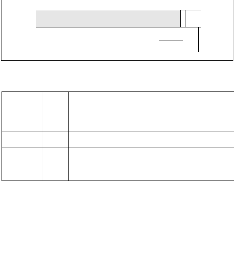
Vol. 2B 4-341
INSTRUCTION SET REFERENCE, N-Z
ROUNDPD — Round Packed Double Precision Floating-Point Values
128-bit Legacy SSE version: The second source can be an XMM register or 128-bit
memory location. The destination is not distinct from the first source XMM register
and the upper bits (VLMAX-1:128) of the corresponding YMM register destination are
unmodified.
VEX.128 encoded version: the source operand second source operand or a 128-bit
memory location. The destination operand is an XMM register. The upper bits
(VLMAX-1:128) of the corresponding YMM register destination are zeroed.
VEX.256 encoded version: The source operand is a YMM register or a 256-bit
memory location. The destination operand is a YMM register.
Note: In VEX-encoded versions, VEX.vvvv is reserved and must be 1111b, otherwise
instructions will #UD.
Operation
IF (imm[2] = ‘1)
THEN // rounding mode is determined by MXCSR.RC
DEST[63:0] ConvertDPFPToInteger_M(SRC[63:0]);
DEST[127:64] ConvertDPFPToInteger_M(SRC[127:64]);
Figure 4-19. Bit Control Fields of Immediate Byte for ROUNDxx Instruction
Table 4-14. Rounding Modes and Encoding of Rounding Control (RC) Field
Rounding
Mode
RC Field
Setting
Description
Round to
nearest (even)
00B Rounded result is the closest to the infinitely precise result. If two
values are equally close, the result is the even value (i.e., the integer
value with the least-significant bit of zero).
Round down
(toward −∞)
01B Rounded result is closest to but no greater than the infinitely precise
result.
Round up
(toward +∞)
10B Rounded result is closest to but no less than the infinitely precise
result.
Round toward
zero (Truncate)
11B Rounded result is closest to but no greater in absolute value than the
infinitely precise result.
8
RS — Rounding select; 1: MXCSR.RC, 0: Imm8.RC
RC — Rounding mode
3210
P — Precision Mask; 0: normal, 1: inexact
Reserved

4-342 Vol. 2B ROUNDPD — Round Packed Double Precision Floating-Point Values
INSTRUCTION SET REFERENCE, N-Z
ELSE // rounding mode is determined by IMM8.RC
DEST[63:0] ConvertDPFPToInteger_Imm(SRC[63:0]);
DEST[127:64] ConvertDPFPToInteger_Imm(SRC[127:64]);
FI
ROUNDPD (128-bit Legacy SSE version)
DEST[63:0] RoundToInteger(SRC[63:0]], ROUND_CONTROL)
DEST[127:64] RoundToInteger(SRC[127:64]], ROUND_CONTROL)
DEST[VLMAX-1:128] (Unmodified)
VROUNDPD (VEX.128 encoded version)
DEST[63:0] RoundToInteger(SRC[63:0]], ROUND_CONTROL)
DEST[127:64] RoundToInteger(SRC[127:64]], ROUND_CONTROL)
DEST[VLMAX-1:128] 0
VROUNDPD (VEX.256 encoded version)
DEST[63:0] RoundToInteger(SRC[63:0], ROUND_CONTROL)
DEST[127:64] RoundToInteger(SRC[127:64]], ROUND_CONTROL)
DEST[191:128] RoundToInteger(SRC[191:128]], ROUND_CONTROL)
DEST[255:192] RoundToInteger(SRC[255:192] ], ROUND_CONTROL)
Intel C/C++ Compiler Intrinsic Equivalent
__m128 _mm_round_pd(__m128d s1, int iRoundMode);
__m128 _mm_floor_pd(__m128d s1);
__m128 _mm_ceil_pd(__m128d s1)
__m256 _mm256_round_pd(__m256d s1, int iRoundMode);
__m256 _mm256_floor_pd(__m256d s1);
__m256 _mm256_ceil_pd(__m256d s1)
SIMD Floating-Point Exceptions
Invalid (signaled only if SRC = SNaN)
Precision (signaled only if imm[3] = ‘0; if imm[3] = ‘1, then the Precision Mask in the
MXSCSR is ignored and precision exception is not signaled.)
Note that Denormal is not signaled by ROUNDPD.
Other Exceptions
See Exceptions Type 2; additionally
#UD If VEX.vvvv != 1111B.

Vol. 2B 4-343
INSTRUCTION SET REFERENCE, N-Z
ROUNDPS — Round Packed Single Precision Floating-Point Values
ROUNDPS — Round Packed Single Precision Floating-Point Values
Instruction Operand Encoding
Description
Round the 4 single-precision floating-point values in the source operand (second
operand) using the rounding mode specified in the immediate operand (third
operand) and place the results in the destination operand (first operand). The
rounding process rounds each input floating-point value to an integer value and
returns the integer result as a single-precision floating-point value.
The immediate operand specifies control fields for the rounding operation, three bit
fields are defined and shown in Figure 4-19. Bit 3 of the immediate byte controls
processor behavior for a precision exception, bit 2 selects the source of rounding
mode control. Bits 1:0 specify a non-sticky rounding-mode value (Table 4-14 lists the
encoded values for rounding-mode field).
The Precision Floating-Point Exception is signaled according to the immediate
operand. If any source operand is an SNaN then it will be converted to a QNaN. If
DAZ is set to ‘1 then denormals will be converted to zero before rounding.
Opcode*/
Instruction
Op/
En
64/32 bit
Mode
Support
CPUID
Feature
Flag
Description
66 0F 3A 08
/r ib
ROUNDPS xmm1, xmm2/m128,
imm8
A V/V SSE4_1 Round packed single
precision floating-point
values in xmm2/m128 and
place the result in xmm1.
The rounding mode is
determined by imm8.
VEX.128.66.0F3A.WIG 08 /r ib
VROUNDPS xmm1, xmm2/m128,
imm8
A V/V AVX Round packed single-
precision floating-point
values in xmm2/m128 and
place the result in xmm1.
The rounding mode is
determined by imm8.
VEX.256.66.0F3A.WIG 08 /r ib
VROUNDPS ymm1, ymm2/m256,
imm8
A V/V AVX Round packed single-
precision floating-point
values in ymm2/m256 and
place the result in ymm1.
The rounding mode is
determined by imm8.
Op/En Operand 1 Operand 2 Operand 3 Operand 4
A ModRM:reg (w) ModRM:r/m (r) imm8 NA

4-344 Vol. 2B ROUNDPS — Round Packed Single Precision Floating-Point Values
INSTRUCTION SET REFERENCE, N-Z
128-bit Legacy SSE version: The second source can be an XMM register or 128-bit
memory location. The destination is not distinct from the first source XMM register
and the upper bits (VLMAX-1:128) of the corresponding YMM register destination are
unmodified.
VEX.128 encoded version: the source operand second source operand or a 128-bit
memory location. The destination operand is an XMM register. The upper bits
(VLMAX-1:128) of the corresponding YMM register destination are zeroed.
VEX.256 encoded version: The source operand is a YMM register or a 256-bit
memory location. The destination operand is a YMM register.
Note: In VEX-encoded versions, VEX.vvvv is reserved and must be 1111b otherwise
instructions will #UD.
Operation
IF (imm[2] = ‘1)
THEN // rounding mode is determined by MXCSR.RC
DEST[31:0] ConvertSPFPToInteger_M(SRC[31:0]);
DEST[63:32] ConvertSPFPToInteger_M(SRC[63:32]);
DEST[95:64] ConvertSPFPToInteger_M(SRC[95:64]);
DEST[127:96] ConvertSPFPToInteger_M(SRC[127:96]);
ELSE // rounding mode is determined by IMM8.RC
DEST[31:0] ConvertSPFPToInteger_Imm(SRC[31:0]);
DEST[63:32] ConvertSPFPToInteger_Imm(SRC[63:32]);
DEST[95:64] ConvertSPFPToInteger_Imm(SRC[95:64]);
DEST[127:96] ConvertSPFPToInteger_Imm(SRC[127:96]);
FI;
ROUNDPS(128-bit Legacy SSE version)
DEST[31:0] RoundToInteger(SRC[31:0], ROUND_CONTROL)
DEST[63:32] RoundToInteger(SRC[63:32], ROUND_CONTROL)
DEST[95:64] RoundToInteger(SRC[95:64]], ROUND_CONTROL)
DEST[127:96] RoundToInteger(SRC[127:96]], ROUND_CONTROL)
DEST[VLMAX-1:128] (Unmodified)
VROUNDPS (VEX.128 encoded version)
DEST[31:0] RoundToInteger(SRC[31:0], ROUND_CONTROL)
DEST[63:32] RoundToInteger(SRC[63:32], ROUND_CONTROL)
DEST[95:64] RoundToInteger(SRC[95:64]], ROUND_CONTROL)
DEST[127:96] RoundToInteger(SRC[127:96]], ROUND_CONTROL)
DEST[VLMAX-1:128] 0
VROUNDPS (VEX.256 encoded version)
DEST[31:0] RoundToInteger(SRC[31:0], ROUND_CONTROL)

Vol. 2B 4-345
INSTRUCTION SET REFERENCE, N-Z
ROUNDPS — Round Packed Single Precision Floating-Point Values
DEST[63:32] RoundToInteger(SRC[63:32], ROUND_CONTROL)
DEST[95:64] RoundToInteger(SRC[95:64]], ROUND_CONTROL)
DEST[127:96] RoundToInteger(SRC[127:96]], ROUND_CONTROL)
DEST[159:128] RoundToInteger(SRC[159:128]], ROUND_CONTROL)
DEST[191:160] RoundToInteger(SRC[191:160]], ROUND_CONTROL)
DEST[223:192] RoundToInteger(SRC[223:192] ], ROUND_CONTROL)
DEST[255:224] RoundToInteger(SRC[255:224] ], ROUND_CONTROL)
Intel C/C++ Compiler Intrinsic Equivalent
__m128 _mm_round_ps(__m128 s1, int iRoundMode);
__m128 _mm_floor_ps(__m128 s1);
__m128 _mm_ceil_ps(__m128 s1)
__m256 _mm256_round_ps(__m256 s1, int iRoundMode);
__m256 _mm256_floor_ps(__m256 s1);
__m256 _mm256_ceil_ps(__m256 s1)
SIMD Floating-Point Exceptions
Invalid (signaled only if SRC = SNaN)
Precision (signaled only if imm[3] = ‘0; if imm[3] = ‘1, then the Precision Mask in the
MXSCSR is ignored and precision exception is not signaled.)
Note that Denormal is not signaled by ROUNDPS.
Other Exceptions
See Exceptions Type 2; additionally
#UD If VEX.vvvv != 1111B.

4-346 Vol. 2B ROUNDSD — Round Scalar Double Precision Floating-Point Values
INSTRUCTION SET REFERENCE, N-Z
ROUNDSD — Round Scalar Double Precision Floating-Point Values
Instruction Operand Encoding
Description
Round the DP FP value in the lower qword of the source operand (second operand)
using the rounding mode specified in the immediate operand (third operand) and
place the result in the destination operand (first operand). The rounding process
rounds a double-precision floating-point input to an integer value and returns the
integer result as a double precision floating-point value in the lowest position. The
upper double precision floating-point value in the destination is retained.
The immediate operand specifies control fields for the rounding operation, three bit
fields are defined and shown in Figure 4-19. Bit 3 of the immediate byte controls
processor behavior for a precision exception, bit 2 selects the source of rounding
mode control. Bits 1:0 specify a non-sticky rounding-mode value (Table 4-14 lists the
encoded values for rounding-mode field).
The Precision Floating-Point Exception is signaled according to the immediate
operand. If any source operand is an SNaN then it will be converted to a QNaN. If
DAZ is set to ‘1 then denormals will be converted to zero before rounding.
Opcode*/
Instruction
Op/
En
64/32 bit
Mode
Support
CPUID
Feature
Flag
Description
66 0F 3A 0B /r ib
ROUNDSD xmm1, xmm2/m64, imm8
A V/V SSE4_1 Round the low packed
double precision floating-
point value in xmm2/m64
and place the result in
xmm1. The rounding mode
is determined by imm8.
VEX.NDS.LIG.66.0F3A.WIG 0B /r ib
VROUNDSD xmm1, xmm2,
xmm3/m64, imm8
B V/V AVX Round the low packed
double precision floating-
point value in xmm3/m64
and place the result in
xmm1. The rounding mode
is determined by imm8.
Upper packed double
precision floating-point
value (bits[127:64]) from
xmm2 is copied to
xmm1[127:64].
Op/En Operand 1 Operand 2 Operand 3 Operand 4
A ModRM:reg (w) ModRM:r/m (r) imm8 NA
B ModRM:reg (w) VEX.vvvv (r) ModRM:r/m (r) NA

Vol. 2B 4-347
INSTRUCTION SET REFERENCE, N-Z
ROUNDSD — Round Scalar Double Precision Floating-Point Values
128-bit Legacy SSE version: The first source operand and the destination operand
are the same. Bits (VLMAX-1:64) of the corresponding YMM destination register
remain unchanged.
VEX.128 encoded version: Bits (VLMAX-1:128) of the destination YMM register are
zeroed.
Operation
IF (imm[2] = ‘1)
THEN // rounding mode is determined by MXCSR.RC
DEST[63:0] ConvertDPFPToInteger_M(SRC[63:0]);
ELSE // rounding mode is determined by IMM8.RC
DEST[63:0] ConvertDPFPToInteger_Imm(SRC[63:0]);
FI;
DEST[127:63] remains unchanged ;
ROUNDSD (128-bit Legacy SSE version)
DEST[63:0] RoundToInteger(SRC[63:0], ROUND_CONTROL)
DEST[VLMAX-1:64] (Unmodified)
VROUNDSD (VEX.128 encoded version)
DEST[63:0] RoundToInteger(SRC2[63:0], ROUND_CONTROL)
DEST[127:64] SRC1[127:64]
DEST[VLMAX-1:128] 0
Intel C/C++ Compiler Intrinsic Equivalent
ROUNDSD __m128d mm_round_sd(__m128d dst, __m128d s1, int iRoundMode);
__m128d mm_floor_sd(__m128d dst, __m128d s1);
__m128d mm_ceil_sd(__m128d dst, __m128d s1);
SIMD Floating-Point Exceptions
Invalid (signaled only if SRC = SNaN)
Precision (signaled only if imm[3] = ‘0; if imm[3] = ‘1, then the Precision Mask in the
MXSCSR is ignored and precision exception is not signaled.)
Note that Denormal is not signaled by ROUNDSD.
Other Exceptions
See Exceptions Type 3.

4-348 Vol. 2B ROUNDSS — Round Scalar Single Precision Floating-Point Values
INSTRUCTION SET REFERENCE, N-Z
ROUNDSS — Round Scalar Single Precision Floating-Point Values
Instruction Operand Encoding
Description
Round the single-precision floating-point value in the lowest dword of the source
operand (second operand) using the rounding mode specified in the immediate
operand (third operand) and place the result in the destination operand (first
operand). The rounding process rounds a single-precision floating-point input to an
integer value and returns the result as a single-precision floating-point value in the
lowest position. The upper three single-precision floating-point values in the destina-
tion are retained.
The immediate operand specifies control fields for the rounding operation, three bit
fields are defined and shown in Figure 4-19. Bit 3 of the immediate byte controls
processor behavior for a precision exception, bit 2 selects the source of rounding
mode control. Bits 1:0 specify a non-sticky rounding-mode value (Table 4-14 lists the
encoded values for rounding-mode field).
Opcode*/
Instruction
Op/
En
64/32 bit
Mode
Support
CPUID
Feature
Flag
Description
66 0F 3A 0A /r ib
ROUNDSS xmm1, xmm2/m32, imm8
A V/V SSE4_1 Round the low packed single
precision floating-point
value in xmm2/m32 and
place the result in xmm1.
The rounding mode is
determined by imm8.
VEX.NDS.LIG.66.0F3A.WIG 0A ib
VROUNDSS xmm1, xmm2,
xmm3/m32, imm8
B V/V AVX Round the low packed single
precision floating-point
value in xmm3/m32 and
place the result in xmm1.
The rounding mode is
determined by imm8. Also,
upper packed single
precision floating-point
values (bits[127:32]) from
xmm2 are copied to
xmm1[127:32].
Op/En Operand 1 Operand 2 Operand 3 Operand 4
A ModRM:reg (w) ModRM:r/m (r) imm8 NA
B ModRM:reg (w) VEX.vvvv (r) ModRM:r/m (r) NA

Vol. 2B 4-349
INSTRUCTION SET REFERENCE, N-Z
ROUNDSS — Round Scalar Single Precision Floating-Point Values
The Precision Floating-Point Exception is signaled according to the immediate
operand. If any source operand is an SNaN then it will be converted to a QNaN. If
DAZ is set to ‘1 then denormals will be converted to zero before rounding.
128-bit Legacy SSE version: The first source operand and the destination operand
are the same. Bits (VLMAX-1:32) of the corresponding YMM destination register
remain unchanged.
VEX.128 encoded version: Bits (VLMAX-1:128) of the destination YMM register are
zeroed.
Operation
IF (imm[2] = ‘1)
THEN // rounding mode is determined by MXCSR.RC
DEST[31:0] ConvertSPFPToInteger_M(SRC[31:0]);
ELSE // rounding mode is determined by IMM8.RC
DEST[31:0] ConvertSPFPToInteger_Imm(SRC[31:0]);
FI;
DEST[127:32] remains unchanged ;
ROUNDSS (128-bit Legacy SSE version)
DEST[31:0] RoundToInteger(SRC[31:0], ROUND_CONTROL)
DEST[VLMAX-1:32] (Unmodified)
VROUNDSS (VEX.128 encoded version)
DEST[31:0] RoundToInteger(SRC2[31:0], ROUND_CONTROL)
DEST[127:32] SRC1[127:32]
DEST[VLMAX-1:128] 0
Intel C/C++ Compiler Intrinsic Equivalent
ROUNDSS __m128 mm_round_ss(__m128 dst, __m128 s1, int iRoundMode);
__m128 mm_floor_ss(__m128 dst, __m128 s1);
__m128 mm_ceil_ss(__m128 dst, __m128 s1);
SIMD Floating-Point Exceptions
Invalid (signaled only if SRC = SNaN)
Precision (signaled only if imm[3] = ‘0; if imm[3] = ‘1, then the Precision Mask in the
MXSCSR is ignored and precision exception is not signaled.)
Note that Denormal is not signaled by ROUNDSS.
Other Exceptions
See Exceptions Type 3.

4-350 Vol. 2B RSM—Resume from System Management Mode
INSTRUCTION SET REFERENCE, N-Z
RSM—Resume from System Management Mode
Instruction Operand Encoding
Description
Returns program control from system management mode (SMM) to the application
program or operating-system procedure that was interrupted when the processor
received an SMM interrupt. The processor’s state is restored from the dump created
upon entering SMM. If the processor detects invalid state information during state
restoration, it enters the shutdown state. The following invalid information can cause
a shutdown:
•Any reserved bit of CR4 is set to 1.
•Any illegal combination of bits in CR0, such as (PG=1 and PE=0) or (NW=1 and
CD=0).
•(Intel Pentium and Intel486™ processors only.) The value stored in the state
dump base field is not a 32-KByte aligned address.
The contents of the model-specific registers are not affected by a return from SMM.
The SMM state map used by RSM supports resuming processor context for non-
64-bit modes and 64-bit mode.
See Chapter 26, “System Management,” in the Intel® 64 and IA-32 Architectures
Software Developer’s Manual, Volume 3B, for more information about SMM and the
behavior of the RSM instruction.
Operation
ReturnFromSMM;
IF (IA-32e mode supported) or (CPUID DisplayFamily_DisplayModel = 06H_0CH )
THEN
ProcessorState ← Restore(SMMDump(IA-32e SMM STATE MAP));
Else
ProcessorState ← Restore(SMMDump(Non-32-Bit-Mode SMM STATE MAP));
FI
Opcode* Instruction Op/
En
64-Bit
Mode
Compat/
Leg Mode
Description
0F AA RSM A Invalid Valid Resume operation of
interrupted program.
Op/En Operand 1 Operand 2 Operand 3 Operand 4
ANA NA NA NA

Vol. 2B 4-351
INSTRUCTION SET REFERENCE, N-Z
RSM—Resume from System Management Mode
Flags Affected
All.
Protected Mode Exceptions
#UD If an attempt is made to execute this instruction when the
processor is not in SMM.
If the LOCK prefix is used.
Real-Address Mode Exceptions
Same exceptions as in protected mode.
Virtual-8086 Mode Exceptions
Same exceptions as in protected mode.
Compatibility Mode Exceptions
Same exceptions as in protected mode.
64-Bit Mode Exceptions
Same exceptions as in protected mode.

4-352 Vol. 2B RSQRTPS—Compute Reciprocals of Square Roots of Packed Single-Precision Floating-
Point Values
INSTRUCTION SET REFERENCE, N-Z
RSQRTPS—Compute Reciprocals of Square Roots of Packed Single-
Precision Floating-Point Values
Instruction Operand Encoding
Description
Performs a SIMD computation of the approximate reciprocals of the square roots of
the four packed single-precision floating-point values in the source operand (second
operand) and stores the packed single-precision floating-point results in the destina-
tion operand. The source operand can be an XMM register or a 128-bit memory loca-
tion. The destination operand is an XMM register. See Figure 10-5 in the Intel® 64
and IA-32 Architectures Software Developer’s Manual, Volume 1, for an illustration of
a SIMD single-precision floating-point operation.
The relative error for this approximation is:
|Relative Error| ≤ 1.5 ∗ 2−12
The RSQRTPS instruction is not affected by the rounding control bits in the MXCSR
register. When a source value is a 0.0, an ∞ of the sign of the source value is
returned. A denormal source value is treated as a 0.0 (of the same sign). When a
Opcode*/
Instruction
Op/
En
64/32 bit
Mode
Support
CPUID
Feature
Flag
Description
0F 52 /r
RSQRTPS xmm1, xmm2/m128
A V/V SSE Computes the approximate
reciprocals of the square
roots of the packed single-
precision floating-point
values in xmm2/m128 and
stores the results in xmm1.
VEX.128.0F.WIG 52 /r
VRSQRTPS xmm1, xmm2/m128
A V/V AVX Computes the approximate
reciprocals of the square
roots of packed single-
precision values in
xmm2/mem and stores the
results in xmm1.
VEX.256.0F.WIG 52 /r
VRSQRTPS ymm1, ymm2/m256
A V/V AVX Computes the approximate
reciprocals of the square
roots of packed single-
precision values in
ymm2/mem and stores the
results in ymm1.
Op/En Operand 1 Operand 2 Operand 3 Operand 4
A ModRM:reg (w) ModRM:r/m (r) NA NA

Vol. 2B 4-353
INSTRUCTION SET REFERENCE, N-Z
RSQRTPS—Compute Reciprocals of Square Roots of Packed Single-Precision Floating-
Point Values
source value is a negative value (other than −0.0), a floating-point indefinite is
returned. When a source value is an SNaN or QNaN, the SNaN is converted to a QNaN
or the source QNaN is returned.
In 64-bit mode, using a REX prefix in the form of REX.R permits this instruction to
access additional registers (XMM8-XMM15).
VEX.256 encoded version: The first source operand is a YMM register. The second
source operand can be a YMM register or a 256-bit memory location. The destination
operand is a YMM register.
VEX.128 encoded version: the first source operand is an XMM register or 128-bit
memory location. The destination operand is an XMM register. The upper bits
(VLMAX-1:128) of the corresponding YMM register destination are zeroed.
128-bit Legacy SSE version: The second source can be an XMM register or an 128-bit
memory location. The destination is not distinct from the first source XMM register
and the upper bits (VLMAX-1:128) of the corresponding YMM register destination are
unmodified.
Note: In VEX-encoded versions, VEX.vvvv is reserved and must be 1111b, otherwise
instructions will #UD.
Operation
RSQRTPS (128-bit Legacy SSE version)
DEST[31:0] APPROXIMATE(1/SQRT(SRC[31:0]))
DEST[63:32] APPROXIMATE(1/SQRT(SRC1[63:32]))
DEST[95:64] APPROXIMATE(1/SQRT(SRC1[95:64]))
DEST[127:96] APPROXIMATE(1/SQRT(SRC2[127:96]))
DEST[VLMAX-1:128] (Unmodified)
VRSQRTPS (VEX.128 encoded version)
DEST[31:0] APPROXIMATE(1/SQRT(SRC[31:0]))
DEST[63:32] APPROXIMATE(1/SQRT(SRC1[63:32]))
DEST[95:64] APPROXIMATE(1/SQRT(SRC1[95:64]))
DEST[127:96] APPROXIMATE(1/SQRT(SRC2[127:96]))
DEST[VLMAX-1:128] 0
VRSQRTPS (VEX.256 encoded version)
DEST[31:0] APPROXIMATE(1/SQRT(SRC[31:0]))
DEST[63:32] APPROXIMATE(1/SQRT(SRC1[63:32]))
DEST[95:64] APPROXIMATE(1/SQRT(SRC1[95:64]))
DEST[127:96] APPROXIMATE(1/SQRT(SRC2[127:96]))
DEST[159:128] APPROXIMATE(1/SQRT(SRC2[159:128]))
DEST[191:160] APPROXIMATE(1/SQRT(SRC2[191:160]))
DEST[223:192] APPROXIMATE(1/SQRT(SRC2[223:192]))
DEST[255:224] APPROXIMATE(1/SQRT(SRC2[255:224]))

4-354 Vol. 2B RSQRTPS—Compute Reciprocals of Square Roots of Packed Single-Precision Floating-
Point Values
INSTRUCTION SET REFERENCE, N-Z
Intel C/C++ Compiler Intrinsic Equivalent
RSQRTPS __m128 _mm_rsqrt_ps(__m128 a)
RSQRTPS __m256 _mm256_rsqrt_ps (__m256 a);
SIMD Floating-Point Exceptions
None.
Other Exceptions
See Exceptions Type 4; additionally
#UD If VEX.vvvv != 1111B.

Vol. 2B 4-355
INSTRUCTION SET REFERENCE, N-Z
RSQRTSS—Compute Reciprocal of Square Root of Scalar Single-Precision Floating-Point
Value
RSQRTSS—Compute Reciprocal of Square Root of Scalar Single-
Precision Floating-Point Value
Instruction Operand Encoding
Description
Computes an approximate reciprocal of the square root of the low single-precision
floating-point value in the source operand (second operand) stores the single-preci-
sion floating-point result in the destination operand. The source operand can be an
XMM register or a 32-bit memory location. The destination operand is an XMM
register. The three high-order doublewords of the destination operand remain
unchanged. See Figure 10-6 in the Intel® 64 and IA-32 Architectures Software
Developer’s Manual, Volume 1, for an illustration of a scalar single-precision floating-
point operation.
The relative error for this approximation is:
|Relative Error| ≤ 1.5 ∗ 2−12
The RSQRTSS instruction is not affected by the rounding control bits in the MXCSR
register. When a source value is a 0.0, an ∞ of the sign of the source value is
returned. A denormal source value is treated as a 0.0 (of the same sign). When a
Opcode*/
Instruction
Op/
En
64/32 bit
Mode
Support
CPUID
Feature
Flag
Description
F3 0F 52 /r
RSQRTSS xmm1, xmm2/m32
A V/V SSE Computes the approximate
reciprocal of the square root
of the low single-precision
floating-point value in
xmm2/m32 and stores the
results in xmm1.
VEX.NDS.LIG.F3.0F.WIG 52 /r
VRSQRTSS xmm1, xmm2,
xmm3/m32
B V/V AVX Computes the approximate
reciprocal of the square root
of the low single precision
floating-point value in
xmm3/m32 and stores the
results in xmm1. Also, upper
single precision floating-
point values (bits[127:32])
from xmm2 are copied to
xmm1[127:32].
Op/En Operand 1 Operand 2 Operand 3 Operand 4
A ModRM:reg (w) ModRM:r/m (r) NA NA
B ModRM:reg (w) VEX.vvvv (r) ModRM:r/m (r) NA

4-356 Vol. 2B RSQRTSS—Compute Reciprocal of Square Root of Scalar Single-Precision Floating-Point
Value
INSTRUCTION SET REFERENCE, N-Z
source value is a negative value (other than −0.0), a floating-point indefinite is
re turned . W he n a source value is an SNaN or QNaN, the SNaN is converted to a QNaN
or the source QNaN is returned.
In 64-bit mode, using a REX prefix in the form of REX.R permits this instruction to
access additional registers (XMM8-XMM15).
128-bit Legacy SSE version: The first source operand and the destination operand
are the same. Bits (VLMAX-1:32) of the corresponding YMM destination register
remain unchanged.
VEX.128 encoded version: Bits (VLMAX-1:128) of the destination YMM register are
zeroed.
Operation
RSQRTSS (128-bit Legacy SSE version)
DEST[31:0] APPROXIMATE(1/SQRT(SRC2[31:0]))
DEST[VLMAX-1:32] (Unmodified)
VRSQRTSS (VEX.128 encoded version)
DEST[31:0] APPROXIMATE(1/SQRT(SRC2[31:0]))
DEST[127:32] SRC1[31:0]
DEST[VLMAX-1:128] 0
Intel C/C++ Compiler Intrinsic Equivalent
RSQRTSS __m128 _mm_rsqrt_ss(__m128 a)
SIMD Floating-Point Exceptions
None.
Other Exceptions
See Exceptions Type 5.

Vol. 2B 4-357
INSTRUCTION SET REFERENCE, N-Z
SAHF—Store AH into Flags
SAHF—Store AH into Flags
Instruction Operand Encoding
Description
Loads the SF, ZF, AF, PF, and CF flags of the EFLAGS register with values from the
corresponding bits in the AH register (bits 7, 6, 4, 2, and 0, respectively). Bits 1, 3,
and 5 of register AH are ignored; the corresponding reserved bits (1, 3, and 5) in the
EFLAGS register remain as shown in the “Operation” section below.
This instruction executes as described above in compatibility mode and legacy mode.
It is valid in 64-bit mode only if CPUID.80000001H:ECX.LAHF-SAHF[bit 0] = 1.
Operation
IF IA-64 Mode
THEN
IF CPUID.80000001H.ECX[0] = 1;
THEN
RFLAGS(SF:ZF:0:AF:0:PF:1:CF) ← AH;
ELSE
#UD;
FI
ELSE
EFLAGS(SF:ZF:0:AF:0:PF:1:CF) ← AH;
FI;
Flags Affected
The SF, ZF, AF, PF, and CF flags are loaded with values from the AH register. Bits 1, 3,
and 5 of the EFLAGS register are unaffected, with the values remaining 1, 0, and 0,
respectively.
Opcode* Instruction Op/
En
64-Bit
Mode
Compat/
Leg Mode
Description
9E SAHF A Invalid* Valid Loads SF, ZF, AF, PF, and CF
from AH into EFLAGS
register.
NOTES:
* Valid in specific steppings. See Description section.
Op/En Operand 1 Operand 2 Operand 3 Operand 4
ANA NA NA NA

4-358 Vol. 2B SAHF—Store AH into Flags
INSTRUCTION SET REFERENCE, N-Z
Protected Mode Exceptions
None.
Real-Address Mode Exceptions
None.
Virtual-8086 Mode Exceptions
None.
Compatibility Mode Exceptions
None.
64-Bit Mode Exceptions
#UD If CPUID.80000001H.ECX[0] = 0.
If the LOCK prefix is used.

Vol. 2B 4-359
INSTRUCTION SET REFERENCE, N-Z
SAL/SAR/SHL/SHR—Shift
SAL/SAR/SHL/SHR—Shift
Opcode*** Instruction Op/
En
64-Bit
Mode
Compat/
Leg Mode
Description
D0 /4 SAL r/m8, 1 A Valid Valid Multiply r/m8 by 2, once.
REX + D0 /4 SAL r/m8**, 1 A Valid N.E. Multiply r/m8 by 2, once.
D2 /4 SAL r/m8, CL B Valid Valid Multiply r/m8 by 2, CL times.
REX + D2 /4 SAL r/m8**, CL B Valid N.E. Multiply r/m8 by 2, CL times.
C0 /4 ib SAL r/m8, imm8 CValid Valid Multiply r/m8 by 2, imm8
times.
REX + C0 /4 ib SAL r/m8**, imm8 C Valid N.E. Multiply r/m8 by 2, imm8
times.
D1 /4 SAL r/m16, 1 A Valid Valid Multiply r/m16 by 2, once.
D3 /4 SAL r/m16, CL B Valid Valid Multiply r/m16 by 2, CL
times.
C1 /4 ib SAL r/m16, imm8 CValid Valid Multiply r/m16 by 2, imm8
times.
D1 /4 SAL r/m32, 1 A Valid Valid Multiply r/m32 by 2, once.
REX.W + D1 /4 SAL r/m64, 1 A Valid N.E. Multiply r/m64 by 2, once.
D3 /4 SAL r/m32, CL B Valid Valid Multiply r/m32 by 2, CL
times.
REX.W + D3 /4 SAL r/m64, CL B Valid N.E. Multiply r/m64 by 2, CL
times.
C1 /4 ib SAL r/m32, imm8 CValid Valid Multiply r/m32 by 2, imm8
times.
REX.W + C1 /4
ib
SAL r/m64, imm8 CValid N.E. Multiply r/m64 by 2, imm8
times.
D0 /7 SAR r/m8, 1 A Valid Valid Signed divide* r/m8 by 2,
once.
REX + D0 /7 SAR r/m8**, 1 A Valid N.E. Signed divide* r/m8 by 2,
once.
D2 /7 SAR r/m8, CL B Valid Valid Signed divide* r/m8 by 2, CL
times.
REX + D2 /7 SAR r/m8**, CL B Valid N.E. Signed divide* r/m8 by 2, CL
times.
C0 /7 ib SAR r/m8, imm8 C Valid Valid Signed divide* r/m8 by 2,
imm8 time.
REX + C0 /7 ib SAR r/m8**, imm8 C Valid N.E. Signed divide* r/m8 by 2,
imm8 times.

4-360 Vol. 2B SAL/SAR/SHL/SHR—Shift
INSTRUCTION SET REFERENCE, N-Z
Opcode Instruction Op/
En
64-Bit
Mode
Compat/
Leg Mode
Description
D1 /7 SAR r/m16,1 A Valid Valid Signed divide* r/m16 by 2,
once.
D3 /7 SAR r/m16, CL B Valid Valid Signed divide* r/m16 by 2,
CL times.
C1 /7 ib SAR r/m16, imm8 C Valid Valid Signed divide* r/m16 by 2,
imm8 times.
D1 /7 SAR r/m32, 1 A Valid Valid Signed divide* r/m32 by 2,
once.
REX.W + D1 /7 SAR r/m64, 1 A Valid N.E. Signed divide* r/m64 by 2,
once.
D3 /7 SAR r/m32, CL B Valid Valid Signed divide* r/m32 by 2,
CL times.
REX.W + D3 /7 SAR r/m64, CL B Valid N.E. Signed divide* r/m64 by 2,
CL times.
C1 /7 ib SAR r/m32, imm8 C Valid Valid Signed divide* r/m32 by 2,
imm8 times.
REX.W + C1 /7
ib
SAR r/m64, imm8 C Valid N.E. Signed divide* r/m64 by 2,
imm8 times
D0 /4 SHL r/m8, 1 A Valid Valid Multiply r/m8 by 2, once.
REX + D0 /4 SHL r/m8**, 1 A Valid N.E. Multiply r/m8 by 2, once.
D2 /4 SHL r/m8, CL B Valid Valid Multiply r/m8 by 2, CL times.
REX + D2 /4 SHL r/m8**, CL B Valid N.E. Multiply r/m8 by 2, CL times.
C0 /4 ib SHL r/m8, imm8 CValid Valid Multiply r/m8 by 2, imm8
times.
REX + C0 /4 ib SHL r/m8**, imm8 C Valid N.E. Multiply r/m8 by 2, imm8
times.
D1 /4 SHL r/m16,1 A Valid Valid Multiply r/m16 by 2, once.
D3 /4 SHL r/m16, CL B Valid Valid Multiply r/m16 by 2, CL
times.
C1 /4 ib SHL r/m16, imm8 CValid Valid Multiply r/m16 by 2, imm8
times.
D1 /4 SHL r/m32,1 A Valid Valid Multiply r/m32 by 2, once.
REX.W + D1 /4 SHL r/m64,1 A Valid N.E. Multiply r/m64 by 2, once.
D3 /4 SHL r/m32, CL B Valid Valid Multiply r/m32 by 2, CL
times.
REX.W + D3 /4 SHL r/m64, CL B Valid N.E. Multiply r/m64 by 2, CL
times.

Vol. 2B 4-361
INSTRUCTION SET REFERENCE, N-Z
SAL/SAR/SHL/SHR—Shift
Opcode Instruction Op/
En
64-Bit
Mode
Compat/
Leg Mode
Description
C1 /4 ib SHL r/m32, imm8 CValid Valid Multiply r/m32 by 2, imm8
times.
REX.W + C1 /4
ib
SHL r/m64, imm8 C Valid N.E. Multiply r/m64 by 2, imm8
times.
D0 /5 SHR r/m8,1 A Valid Valid Unsigned divide r/m8 by 2,
once.
REX + D0 /5 SHR r/m8**, 1 A Valid N.E. Unsigned divide r/m8 by 2,
once.
D2 /5 SHR r/m8, CL B Valid Valid Unsigned divide r/m8 by 2,
CL times.
REX + D2 /5 SHR r/m8**, CL B Valid N.E. Unsigned divide r/m8 by 2,
CL times.
C0 /5 ib SHR r/m8, imm8 C Valid Valid Unsigned divide r/m8 by 2,
imm8 times.
REX + C0 /5 ib SHR r/m8**, imm8 C Valid N.E. Unsigned divide r/m8 by 2,
imm8 times.
D1 /5 SHR r/m16, 1 A Valid Valid Unsigned divide r/m16 by 2,
once.
D3 /5 SHR r/m16, CL B Valid Valid Unsigned divide r/m16 by 2,
CL times
C1 /5 ib SHR r/m16, imm8 C Valid Valid Unsigned divide r/m16 by 2,
imm8 times.
D1 /5 SHR r/m32, 1 A Valid Valid Unsigned divide r/m32 by 2,
once.
REX.W + D1 /5 SHR r/m64, 1 A Valid N.E. Unsigned divide r/m64 by 2,
once.
D3 /5 SHR r/m32, CL B Valid Valid Unsigned divide r/m32 by 2,
CL times.
REX.W + D3 /5 SHR r/m64, CL B Valid N.E. Unsigned divide r/m64 by 2,
CL times.
C1 /5 ib SHR r/m32, imm8 C Valid Valid Unsigned divide r/m32 by 2,
imm8 times.
REX.W + C1 /5
ib
SHR r/m64, imm8 C Valid N.E. Unsigned divide r/m64 by 2,
imm8 times.

4-362 Vol. 2B SAL/SAR/SHL/SHR—Shift
INSTRUCTION SET REFERENCE, N-Z
Instruction Operand Encoding
Description
Shifts the bits in the first operand (destination operand) to the left or right by the
number of bits specified in the second operand (count operand). Bits shifted beyond
the destination operand boundary are first shifted into the CF flag, then discarded. At
the end of the shift operation, the CF flag contains the last bit shifted out of the desti-
nation operand.
The destination operand can be a register or a memory location. The count operand
can be an immediate value or the CL register. The count is masked to 5 bits (or 6 bits
if in 64-bit mode and REX.W is used). The count range is limited to 0 to 31 (or 63 if
64-bit mode and REX.W is used). A special opcode encoding is provided for a count
of 1.
The shift arithmetic left (SAL) and shift logical left (SHL) instructions perform the
same operation; they shift the bits in the destination operand to the left (toward
more significant bit locations). For each shift count, the most significant bit of the
destination operand is shifted into the CF flag, and the least significant bit is cleared
(see Figure 7-7 in the Intel® 64 and IA-32 Architectures Software Developer’s
Manual, Volume 1).
The shift arithmetic right (SAR) and shift logical right (SHR) instructions shift the bits
of the destination operand to the right (toward less significant bit locations). For each
shift count, the least significant bit of the destination operand is shifted into the CF
flag, and the most significant bit is either set or cleared depending on the instruction
type. The SHR instruction clears the most significant bit (see Figure 7-8 in the Intel®
64 and IA-32 Architectures Software Developer’s Manual, Volume 1); the SAR
instruction sets or clears the most significant bit to correspond to the sign (most
significant bit) of the original value in the destination operand. In effect, the SAR
instruction fills the empty bit position’s shifted value with the sign of the unshifted
value (see Figure 7-9 in the Intel® 64 and IA-32 Architectures Software Developer’s
Manual, Volume 1).
NOTES:
* Not the same form of division as IDIV; rounding is toward negative infinity.
** In 64-bit mode, r/m8 can not be encoded to access the following byte registers if a REX prefix is
used: AH, BH, CH, DH.
***See IA-32 Architecture Compatibility section below.
Op/En Operand 1 Operand 2 Operand 3 Operand 4
A ModRM:r/m (r, w) 1 NA NA
B ModRM:r/m (r, w) CL (r) NA NA
C ModRM:r/m (r, w) imm8 NA NA

Vol. 2B 4-363
INSTRUCTION SET REFERENCE, N-Z
SAL/SAR/SHL/SHR—Shift
The SAR and SHR instructions can be used to perform signed or unsigned division,
respectively, of the destination operand by powers of 2. For example, using the SAR
instruction to shift a signed integer 1 bit to the right divides the value by 2.
Using the SAR instruction to perform a division operation does not produce the same
result as the IDIV instruction. The quotient from the IDIV instruction is rounded
toward zero, whereas the “quotient” of the SAR instruction is rounded toward nega-
tive infinity. This difference is apparent only for negative numbers. For example,
when the IDIV instruction is used to divide -9 by 4, the result is -2 with a remainder
of -1. If the SAR instruction is used to shift -9 right by two bits, the result is -3 and
the “remainder” is +3; however, the SAR instruction stores only the most significant
bit of the remainder (in the CF flag).
The OF flag is affected only on 1-bit shifts. For left shifts, the OF flag is set to 0 if the
most-significant bit of the result is the same as the CF flag (that is, the top two bits
of the original operand were the same); otherwise, it is set to 1. For the SAR instruc-
tion, the OF flag is cleared for all 1-bit shifts. For the SHR instruction, the OF flag is
set to the most-significant bit of the original operand.
In 64-bit mode, the instruction’s default operation size is 32 bits and the mask width
for CL is 5 bits. Using a REX prefix in the form of REX.R permits access to additional
registers (R8-R15). Using a REX prefix in the form of REX.W promotes operation to
64-bits and sets the mask width for CL to 6 bits. See the summary chart at the begin-
ning of this section for encoding data and limits.
IA-32 Architecture Compatibility
The 8086 does not mask the shift count. However, all other IA-32 processors
(starting with the Intel 286 processor) do mask the shift count to 5 bits, resulting in
a maximum count of 31. This masking is done in all operating modes (including the
virtual-8086 mode) to reduce the maximum execution time of the instructions.
Operation
IF 64-Bit Mode and using REX.W
THEN
countMASK ← 3FH;
ELSE
countMASK ← 1FH;
FI
tempCOUNT ← (COUNT AND countMASK);
tempDEST ← DEST;
WHILE (tempCOUNT ≠ 0)
DO
IF instruction is SAL or SHL
THEN
CF ← MSB(DEST);

4-364 Vol. 2B SAL/SAR/SHL/SHR—Shift
INSTRUCTION SET REFERENCE, N-Z
ELSE (* Instruction is SAR or SHR *)
CF ← LSB(DEST);
FI;
IF instruction is SAL or SHL
THEN
DEST ← DEST ∗ 2;
ELSE
IF instruction is SAR
THEN
DEST ← DEST / 2; (* Signed divide, rounding toward negative infinity *)
ELSE (* Instruction is SHR *)
DEST ← DEST / 2 ; (* Unsigned divide *)
FI;
FI;
tempCOUNT ← tempCOUNT – 1;
OD;
(* Determine overflow for the various instructions *)
IF (COUNT and countMASK) = 1
THEN
IF instruction is SAL or SHL
THEN
OF ← MSB(DEST) XOR CF;
ELSE
IF instruction is SAR
THEN
OF ← 0;
ELSE (* Instruction is SHR *)
OF ← MSB(tempDEST);
FI;
FI;
ELSE IF (COUNT AND countMASK) = 0
THEN
All flags unchanged;
ELSE (* COUNT not 1 or 0 *)
OF ← undefined;
FI;
FI;
Flags Affected
The CF flag contains the value of the last bit shifted out of the destination operand; it
is undefined for SHL and SHR instructions where the count is greater than or equal to
the size (in bits) of the destination operand. The OF flag is affected only for 1-bit

Vol. 2B 4-365
INSTRUCTION SET REFERENCE, N-Z
SAL/SAR/SHL/SHR—Shift
shifts (see “Description” above); otherwise, it is undefined. The SF, ZF, and PF flags
are set according to the result. If the count is 0, the flags are not affected. For a non-
zero count, the AF flag is undefined.
Protected Mode Exceptions
#GP(0) If the destination is located in a non-writable segment.
If a memory operand effective address is outside the CS, DS,
ES, FS, or GS segment limit.
If the DS, ES, FS, or GS register contains a NULL segment
selector.
#SS(0) If a memory operand effective address is outside the SS
segment limit.
#PF(fault-code) If a page fault occurs.
#AC(0) If alignment checking is enabled and an unaligned memory
reference is made while the current privilege level is 3.
#UD If the LOCK prefix is used.
Real-Address Mode Exceptions
#GP If a memory operand effective address is outside the CS, DS,
ES, FS, or GS segment limit.
#SS If a memory operand effective address is outside the SS
segment limit.
#UD If the LOCK prefix is used.
Virtual-8086 Mode Exceptions
#GP(0) If a memory operand effective address is outside the CS, DS,
ES, FS, or GS segment limit.
#SS(0) If a memory operand effective address is outside the SS
segment limit.
#PF(fault-code) If a page fault occurs.
#AC(0) If alignment checking is enabled and an unaligned memory
reference is made.
#UD If the LOCK prefix is used.
Compatibility Mode Exceptions
Same exceptions as in protected mode.
64-Bit Mode Exceptions
#SS(0) If a memory address referencing the SS segment is in a non-
canonical form.
#GP(0) If the memory address is in a non-canonical form.

4-366 Vol. 2B SAL/SAR/SHL/SHR—Shift
INSTRUCTION SET REFERENCE, N-Z
#PF(fault-code) If a page fault occurs.
#AC(0) If alignment checking is enabled and an unaligned memory
reference is made while the current privilege level is 3.
#UD If the LOCK prefix is used.

Vol. 2B 4-367
INSTRUCTION SET REFERENCE, N-Z
SBB—Integer Subtraction with Borrow
SBB—Integer Subtraction with Borrow
Opcode Instruction Op/
En
64-Bit
Mode
Compat/
Leg Mode
Description
1C ib SBB AL, imm8 A Valid Valid Subtract with borrow imm8
from AL.
1D iw SBB AX, imm16 A Valid Valid Subtract with borrow
imm16 from AX.
1D id SBB EAX, imm32 A Valid Valid Subtract with borrow
imm32 from EAX.
REX.W + 1D id SBB RAX, imm32 A Valid N.E. Subtract with borrow sign-
extended imm.32 to 64-bits
from RAX.
80 /3 ib SBB r/m8, imm8 B Valid Valid Subtract with borrow imm8
from r/m8.
REX + 80 /3 ib SBB r/m8*, imm8 BValid N.E. Subtract with borrow imm8
from r/m8.
81 /3 iw SBB r/m16,
imm16
B Valid Valid Subtract with borrow
imm16 from r/m16.
81 /3 id SBB r/m32,
imm32
B Valid Valid Subtract with borrow
imm32 from r/m32.
REX.W + 81 /3
id
SBB r/m64,
imm32
B Valid N.E. Subtract with borrow sign-
extended imm32 to 64-bits
from r/m64.
83 /3 ib SBB r/m16, imm8 B Valid Valid Subtract with borrow sign-
extended imm8 from r/m16.
83 /3 ib SBB r/m32, imm8 B Valid Valid Subtract with borrow sign-
extended imm8 from r/m32.
REX.W + 83 /3
ib
SBB r/m64, imm8 B Valid N.E. Subtract with borrow sign-
extended imm8 from r/m64.
18 /rSBB r/m8, r8 C Valid Valid Subtract with borrow r8
from r/m8.
REX + 18 /rSBB r/m8*, r8 CValid N.E. Subtract with borrow r8
from r/m8.
19 /rSBB r/m16, r16 C Valid Valid Subtract with borrow r16
from r/m16.
19 /rSBB r/m32, r32 C Valid Valid Subtract with borrow r32
from r/m32.
REX.W + 19 /rSBB r/m64, r64 CValid N.E. Subtract with borrow r64
from r/m64.

4-368 Vol. 2B SBB—Integer Subtraction with Borrow
INSTRUCTION SET REFERENCE, N-Z
Instruction Operand Encoding
Description
Adds the source operand (second operand) and the carry (CF) flag, and subtracts the
result from the destination operand (first operand). The result of the subtraction is
stored in the destination operand. The destination operand can be a register or a
memory location; the source operand can be an immediate, a register, or a memory
location. (However, two memory operands cannot be used in one instruction.) The
state of the CF flag represents a borrow from a previous subtraction.
When an immediate value is used as an operand, it is sign-extended to the length of
the destination operand format.
The SBB instruction does not distinguish between signed or unsigned operands.
Instead, the processor evaluates the result for both data types and sets the OF and
CF flags to indicate a borrow in the signed or unsigned result, respectively. The SF
flag indicates the sign of the signed result.
The SBB instruction is usually executed as part of a multibyte or multiword subtrac-
tion in which a SUB instruction is followed by a SBB instruction.
Opcode Instruction Op/
En
64-Bit
Mode
Compat/
Leg Mode
Description
1A /rSBB r8, r/m8 D Valid Valid Subtract with borrow r/m8
from r8.
REX + 1A /rSBB r8*, r/m8* DValid N.E. Subtract with borrow r/m8
from r8.
1B /rSBB r16, r/m16 D Valid Valid Subtract with borrow r/m16
from r16.
1B /rSBB r32, r/m32 D Valid Valid Subtract with borrow r/m32
from r32.
REX.W + 1B /rSBB r64, r/m64 DValid N.E. Subtract with borrow r/m64
from r64.
NOTES:
* In 64-bit mode, r/m8 can not be encoded to access the following byte registers if a REX prefix is
used: AH, BH, CH, DH.
Op/En Operand 1 Operand 2 Operand 3 Operand 4
A AL/AX/EAX/RAX imm8/16/32 NA NA
B ModRM:r/m (w) imm8/16/32 NA NA
C ModRM:r/m (w) ModRM:reg (r) NA NA
D ModRM:reg (w) ModRM:r/m (r) NA NA

Vol. 2B 4-369
INSTRUCTION SET REFERENCE, N-Z
SBB—Integer Subtraction with Borrow
This instruction can be used with a LOCK prefix to allow the instruction to be
executed atomically.
In 64-bit mode, the instruction’s default operation size is 32 bits. Using a REX prefix
in the form of REX.R permits access to additional registers (R8-R15). Using a REX
prefix in the form of REX.W promotes operation to 64 bits. See the summary chart at
the beginning of this section for encoding data and limits.
Operation
DEST ← (DEST – (SRC + CF));
Flags Affected
The OF, SF, ZF, AF, PF, and CF flags are set according to the result.
Protected Mode Exceptions
#GP(0) If the destination is located in a non-writable segment.
If a memory operand effective address is outside the CS, DS,
ES, FS, or GS segment limit.
If the DS, ES, FS, or GS register contains a NULL segment
selector.
#SS(0) If a memory operand effective address is outside the SS
segment limit.
#PF(fault-code) If a page fault occurs.
#AC(0) If alignment checking is enabled and an unaligned memory
reference is made while the current privilege level is 3.
#UD If the LOCK prefix is used but the destination is not a memory
operand.
Real-Address Mode Exceptions
#GP If a memory operand effective address is outside the CS, DS,
ES, FS, or GS segment limit.
#SS If a memory operand effective address is outside the SS
segment limit.
#UD If the LOCK prefix is used but the destination is not a memory
operand.
Virtual-8086 Mode Exceptions
#GP(0) If a memory operand effective address is outside the CS, DS,
ES, FS, or GS segment limit.
#SS(0) If a memory operand effective address is outside the SS
segment limit.

4-370 Vol. 2B SBB—Integer Subtraction with Borrow
INSTRUCTION SET REFERENCE, N-Z
#PF(fault-code) If a page fault occurs.
#AC(0) If alignment checking is enabled and an unaligned memory
reference is made.
#UD If the LOCK prefix is used but the destination is not a memory
operand.
Compatibility Mode Exceptions
Same exceptions as in protected mode.
64-Bit Mode Exceptions
#SS(0) If a memory address referencing the SS segment is in a non-
canonical form.
#GP(0) If the memory address is in a non-canonical form.
#PF(fault-code) If a page fault occurs.
#AC(0) If alignment checking is enabled and an unaligned memory
reference is made while the current privilege level is 3.
#UD If the LOCK prefix is used but the destination is not a memory
operand.

Vol. 2B 4-371
INSTRUCTION SET REFERENCE, N-Z
SCAS/SCASB/SCASW/SCASD—Scan String
SCAS/SCASB/SCASW/SCASD—Scan String
Instruction Operand Encoding
Description
In non-64-bit modes and in default 64-bit mode: this instruction compares a byte,
word, doubleword or quadword specified using a memory operand with the value in
AL, AX, or EAX. It then sets status flags in EFLAGS recording the results. The memory
operand address is read from ES:(E)DI register (depending on the address-size
Opcode Instruction Op/
En
64-Bit
Mode
Compat/
Leg Mode
Description
AE SCAS m8 A Valid Valid Compare AL with byte at
ES:(E)DI or RDI, then set
status flags.*
AF SCAS m16 A Valid Valid Compare AX with word at
ES:(E)DI or RDI, then set
status flags.*
AF SCAS m32 A Valid Valid Compare EAX with
doubleword at ES(E)DI or
RDI then set status flags.*
REX.W + AF SCAS m64 A Valid N.E. Compare RAX with
quadword at RDI or EDI then
set status flags.
AE SCASB A Valid Valid Compare AL with byte at
ES:(E)DI or RDI then set
status flags.*
AF SCASW A Valid Valid Compare AX with word at
ES:(E)DI or RDI then set
status flags.*
AF SCASD A Valid Valid Compare EAX with
doubleword at ES:(E)DI or
RDI then set status flags.*
REX.W + AF SCASQ A Valid N.E. Compare RAX with
quadword at RDI or EDI then
set status flags.
NOTES:
* In 64-bit mode, only 64-bit (RDI) and 32-bit (EDI) address sizes are supported. In non-64-bit
mode, only 32-bit (EDI) and 16-bit (DI) address sizes are supported.
Op/En Operand 1 Operand 2 Operand 3 Operand 4
ANA NA NA NA

4-372 Vol. 2B SCAS/SCASB/SCASW/SCASD—Scan String
INSTRUCTION SET REFERENCE, N-Z
attribute of the instruction and the current operational mode). Note that ES cannot
be overridden with a segment override prefix.
At the assembly-code level, two forms of this instruction are allowed. The explicit-
operand form and the no-operands form. The explicit-operand form (specified using
the SCAS mnemonic) allows a memory operand to be specified explicitly. The
memory operand must be a symbol that indicates the size and location of the
operand value. The register operand is then automatically selected to match the size
of the memory operand (AL register for byte comparisons, AX for word comparisons,
EAX for doubleword comparisons). The explicit-operand form is provided to allow
documentation. Note that the documentation provided by this form can be
misleading. That is, the memory operand symbol must specify the correct type (size)
of the operand (byte, word, or doubleword) but it does not have to specify the correct
location. The location is always specified by ES:(E)DI.
The no-operands form of the instruction uses a short form of SCAS. Again, ES:(E)DI
is assumed to be the memory operand and AL, AX, or EAX is assumed to be the
register operand. The size of operands is selected by the mnemonic: SCASB (byte
comparison), SCASW (word comparison), or SCASD (doubleword comparison).
After the comparison, the (E)DI register is incremented or decremented automati-
cally according to the setting of the DF flag in the EFLAGS register. If the DF flag is 0,
the (E)DI register is incremented; if the DF flag is 1, the (E)DI register is decre-
mented. The register is incremented or decremented by 1 for byte operations, by 2
for word operations, and by 4 for doubleword operations.
SCAS, SCASB, SCASW, SCASD, and SCASQ can be preceded by the REP prefix for
block comparisons of ECX bytes, words, doublewords, or quadwords. Often, however,
these instructions will be used in a LOOP construct that takes some action based on
the setting of status flags. See “REP/REPE/REPZ /REPNE/REPNZ—Repeat String
Operation Prefix” in this chapter for a description of the REP prefix.
In 64-bit mode, the instruction’s default address size is 64-bits, 32-bit address size is
supported using the prefix 67H. Using a REX prefix in the form of REX.W promotes
operation on doubleword operand to 64 bits. The 64-bit no-operand mnemonic is
SCASQ. Address of the memory operand is specified in either RDI or EDI, and
AL/AX/EAX/RAX may be used as the register operand. After a comparison, the desti-
nation register is incremented or decremented by the current operand size
(depending on the value of the DF flag). See the summary chart at the beginning of
this section for encoding data and limits.
Operation
Non-64-bit Mode:
IF (Byte cmparison)
THEN
temp ← AL − SRC;
SetStatusFlags(temp);
THEN IF DF = 0

Vol. 2B 4-373
INSTRUCTION SET REFERENCE, N-Z
SCAS/SCASB/SCASW/SCASD—Scan String
THEN (E)DI ← (E)DI + 1;
ELSE (E)DI ← (E)DI – 1; FI;
ELSE IF (Word comparison)
THEN
temp ← AX − SRC;
SetStatusFlags(temp);
IF DF = 0
THEN (E)DI ← (E)DI + 2;
ELSE (E)DI ← (E)DI – 2; FI;
FI;
ELSE IF (Doubleword comparison)
THEN
temp ← EAX – SRC;
SetStatusFlags(temp);
IF DF = 0
THEN (E)DI ← (E)DI + 4;
ELSE (E)DI ← (E)DI – 4; FI;
FI;
FI;
64-bit Mode:
IF (Byte cmparison)
THEN
temp ← AL − SRC;
SetStatusFlags(temp);
THEN IF DF = 0
THEN (R|E)DI ← (R|E)DI + 1;
ELSE (R|E)DI ← (R|E)DI – 1; FI;
ELSE IF (Word comparison)
THEN
temp ← AX − SRC;
SetStatusFlags(temp);
IF DF = 0
THEN (R|E)DI ← (R|E)DI + 2;
ELSE (R|E)DI ← (R|E)DI – 2; FI;
FI;
ELSE IF (Doubleword comparison)
THEN
temp ← EAX – SRC;
SetStatusFlags(temp);
IF DF = 0
THEN (R|E)DI ← (R|E)DI + 4;
ELSE (R|E)DI ← (R|E)DI – 4; FI;

4-374 Vol. 2B SCAS/SCASB/SCASW/SCASD—Scan String
INSTRUCTION SET REFERENCE, N-Z
FI;
ELSE IF (Quadword comparison using REX.W )
THEN
temp ← RAX − SRC;
SetStatusFlags(temp);
IF DF = 0
THEN (R|E)DI ← (R|E)DI + 8;
ELSE (R|E)DI ← (R|E)DI – 8;
FI;
FI;
F
Flags Affected
The OF, SF, ZF, AF, PF, and CF flags are set according to the temporary result of the
comparison.
Protected Mode Exceptions
#GP(0) If a memory operand effective address is outside the limit of the
ES segment.
If the ES register contains a NULL segment selector.
If an illegal memory operand effective address in the ES
segment is given.
#PF(fault-code) If a page fault occurs.
#AC(0) If alignment checking is enabled and an unaligned memory
reference is made while the current privilege level is 3.
#UD If the LOCK prefix is used.
Real-Address Mode Exceptions
#GP If a memory operand effective address is outside the CS, DS,
ES, FS, or GS segment limit.
#SS If a memory operand effective address is outside the SS
segment limit.
#UD If the LOCK prefix is used.
Virtual-8086 Mode Exceptions
#GP(0) If a memory operand effective address is outside the CS, DS,
ES, FS, or GS segment limit.
#SS(0) If a memory operand effective address is outside the SS
segment limit.
#PF(fault-code) If a page fault occurs.

Vol. 2B 4-375
INSTRUCTION SET REFERENCE, N-Z
SCAS/SCASB/SCASW/SCASD—Scan String
#AC(0) If alignment checking is enabled and an unaligned memory
reference is made.
#UD If the LOCK prefix is used.
Compatibility Mode Exceptions
Same exceptions as in protected mode.
64-Bit Mode Exceptions
#GP(0) If the memory address is in a non-canonical form.
#PF(fault-code) If a page fault occurs.
#AC(0) If alignment checking is enabled and an unaligned memory
reference is made while the current privilege level is 3.
#UD If the LOCK prefix is used.

4-376 Vol. 2B SETcc—Set Byte on Condition
INSTRUCTION SET REFERENCE, N-Z
SETcc—Set Byte on Condition
Opcode Instruction Op/
En
64-Bit
Mode
Compat/
Leg Mode
Description
0F 97 SETA r/m8 A Valid Valid Set byte if above (CF=0 and
ZF=0).
REX + 0F 97 SETA r/m8* A Valid N.E. Set byte if above (CF=0 and
ZF=0).
0F 93 SETAE r/m8 A Valid Valid Set byte if above or equal
(CF=0).
REX + 0F 93 SETAE r/m8* A Valid N.E. Set byte if above or equal
(CF=0).
0F 92 SETB r/m8 A Valid Valid Set byte if below (CF=1).
REX + 0F 92 SETB r/m8* A Valid N.E. Set byte if below (CF=1).
0F 96 SETBE r/m8 A Valid Valid Set byte if below or equal
(CF=1 or ZF=1).
REX + 0F 96 SETBE r/m8* A Valid N.E. Set byte if below or equal
(CF=1 or ZF=1).
0F 92 SETC r/m8 A Valid Valid Set byte if carry (CF=1).
REX + 0F 92 SETC r/m8* A Valid N.E. Set byte if carry (CF=1).
0F 94 SETE r/m8 A Valid Valid Set byte if equal (ZF=1).
REX + 0F 94 SETE r/m8* A Valid N.E. Set byte if equal (ZF=1).
0F 9F SETG r/m8 A Valid Valid Set byte if greater (ZF=0
and SF=OF).
REX + 0F 9F SETG r/m8* A Valid N.E. Set byte if greater (ZF=0
and SF=OF).
0F 9D SETGE r/m8 A Valid Valid Set byte if greater or equal
(SF=OF).
REX + 0F 9D SETGE r/m8* A Valid N.E. Set byte if greater or equal
(SF=OF).
0F 9C SETL r/m8 A Valid Valid Set byte if less (SF≠ OF).
REX + 0F 9C SETL r/m8* A Valid N.E. Set byte if less (SF≠ OF).
0F 9E SETLE r/m8 A Valid Valid Set byte if less or equal
(ZF=1 or SF≠ OF).
REX + 0F 9E SETLE r/m8* A Valid N.E. Set byte if less or equal
(ZF=1 or SF≠ OF).
0F 96 SETNA r/m8 A Valid Valid Set byte if not above (CF=1
or ZF=1).

Vol. 2B 4-377
INSTRUCTION SET REFERENCE, N-Z
SETcc—Set Byte on Condition
REX + 0F 96 SETNA r/m8* A Valid N.E. Set byte if not above (CF=1
or ZF=1).
0F 92 SETNAE r/m8 A Valid Valid Set byte if not above or
equal (CF=1).
REX + 0F 92 SETNAE r/m8* A Valid N.E. Set byte if not above or
equal (CF=1).
0F 93 SETNB r/m8 A Valid Valid Set byte if not below (CF=0).
REX + 0F 93 SETNB r/m8* A Valid N.E. Set byte if not below (CF=0).
0F 97 SETNBE r/m8 A Valid Valid Set byte if not below or
equal (CF=0 and ZF=0).
REX + 0F 97 SETNBE r/m8* A Valid N.E. Set byte if not below or
equal (CF=0 and ZF=0).
0F 93 SETNC r/m8 A Valid Valid Set byte if not carry (CF=0).
REX + 0F 93 SETNC r/m8* A Valid N.E. Set byte if not carry (CF=0).
0F 95 SETNE r/m8 A Valid Valid Set byte if not equal (ZF=0).
REX + 0F 95 SETNE r/m8* A Valid N.E. Set byte if not equal (ZF=0).
0F 9E SETNG r/m8 A Valid Valid Set byte if not greater
(ZF=1 or SF≠ OF)
REX + 0F 9E SETNG r/m8* A Valid N.E. Set byte if not greater
(ZF=1 or SF≠ OF).
0F 9C SETNGE r/m8 A Valid Valid Set byte if not greater or
equal (SF≠ OF).
REX + 0F 9C SETNGE r/m8* A Valid N.E. Set byte if not greater or
equal (SF≠ OF).
0F 9D SETNL r/m8 A Valid Valid Set byte if not less (SF=OF).
REX + 0F 9D SETNL r/m8* A Valid N.E. Set byte if not less (SF=OF).
0F 9F SETNLE r/m8 A Valid Valid Set byte if not less or equal
(ZF=0 and SF=OF).
REX + 0F 9F SETNLE r/m8* A Valid N.E. Set byte if not less or equal
(ZF=0 and SF=OF).
0F 91 SETNO r/m8 A Valid Valid Set byte if not overflow
(OF=0).
REX + 0F 91 SETNO r/m8* A Valid N.E. Set byte if not overflow
(OF=0).
0F 9B SETNP r/m8 A Valid Valid Set byte if not parity (PF=0).
Opcode Instruction Op/
En
64-Bit
Mode
Compat/
Leg Mode
Description

4-378 Vol. 2B SETcc—Set Byte on Condition
INSTRUCTION SET REFERENCE, N-Z
Instruction Operand Encoding
Description
Sets the destination operand to 0 or 1 depending on the settings of the status flags
(CF, SF, OF, ZF, and PF) in the EFLAGS register. The destination operand points to a
byte register or a byte in memory. The condition code suffix (cc) indicates the condi-
tion being tested for.
REX + 0F 9B SETNP r/m8* A Valid N.E. Set byte if not parity (PF=0).
0F 99 SETNS r/m8 A Valid Valid Set byte if not sign (SF=0).
REX + 0F 99 SETNS r/m8* A Valid N.E. Set byte if not sign (SF=0).
0F 95 SETNZ r/m8 A Valid Valid Set byte if not zero (ZF=0).
REX + 0F 95 SETNZ r/m8* A Valid N.E. Set byte if not zero (ZF=0).
0F 90 SETO r/m8 A Valid Valid Set byte if overflow (OF=1)
REX + 0F 90 SETO r/m8* A Valid N.E. Set byte if overflow (OF=1).
0F 9A SETP r/m8 A Valid Valid Set byte if parity (PF=1).
REX + 0F 9A SETP r/m8* A Valid N.E. Set byte if parity (PF=1).
0F 9A SETPE r/m8 A Valid Valid Set byte if parity even
(PF=1).
REX + 0F 9A SETPE r/m8* A Valid N.E. Set byte if parity even
(PF=1).
0F 9B SETPO r/m8 A Valid Valid Set byte if parity odd
(PF=0).
REX + 0F 9B SETPO r/m8* A Valid N.E. Set byte if parity odd
(PF=0).
0F 98 SETS r/m8 A Valid Valid Set byte if sign (SF=1).
REX + 0F 98 SETS r/m8* A Valid N.E. Set byte if sign (SF=1).
0F 94 SETZ r/m8 A Valid Valid Set byte if zero (ZF=1).
REX + 0F 94 SETZ r/m8* AValid N.E. Set byte if zero (ZF=1).
NOTES:
* In 64-bit mode, r/m8 can not be encoded to access the following byte registers if a REX prefix is
used: AH, BH, CH, DH.
Op/En Operand 1 Operand 2 Operand 3 Operand 4
A ModRM:r/m (r) NA NA NA
Opcode Instruction Op/
En
64-Bit
Mode
Compat/
Leg Mode
Description

Vol. 2B 4-379
INSTRUCTION SET REFERENCE, N-Z
SETcc—Set Byte on Condition
The terms “above” and “below” are associated with the CF flag and refer to the rela-
tionship between two unsigned integer values. The terms “greater” and “less” are
associated with the SF and OF flags and refer to the relationship between two signed
integer values.
Many of the SETcc instruction opcodes have alternate mnemonics. For example,
SETG (set byte if greater) and SETNLE (set if not less or equal) have the same
opcode and test for the same condition: ZF equals 0 and SF equals OF. These alter-
nate mnemonics are provided to make code more intelligible. Appendix B, “EFLAGS
Condition Codes,” in the Intel® 64 and IA-32 Architectures Software Developer’s
Manual, Volume 1, shows the alternate mnemonics for various test conditions.
Some languages represent a logical one as an integer with all bits set. This represen-
tation can be obtained by choosing the logically opposite condition for the SETcc
instruction, then decrementing the result. For example, to test for overflow, use the
SETNO instruction, then decrement the result.
In IA-64 mode, the operand size is fixed at 8 bits. Use of REX prefix enable uniform
addressing to additional byte registers. Otherwise, this instruction’s operation is the
same as in legacy mode and compatibility mode.
Operation
IF condition
THEN DEST ← 1;
ELSE DEST ← 0;
FI;
Flags Affected
None.
Protected Mode Exceptions
#GP(0) If the destination is located in a non-writable segment.
If a memory operand effective address is outside the CS, DS,
ES, FS, or GS segment limit.
If the DS, ES, FS, or GS register contains a NULL segment
selector.
#SS(0) If a memory operand effective address is outside the SS
segment limit.
#PF(fault-code) If a page fault occurs.
#UD If the LOCK prefix is used.
Real-Address Mode Exceptions
#GP If a memory operand effective address is outside the CS, DS,
ES, FS, or GS segment limit.

4-380 Vol. 2B SETcc—Set Byte on Condition
INSTRUCTION SET REFERENCE, N-Z
#SS If a memory operand effective address is outside the SS
segment limit.
#UD If the LOCK prefix is used.
Virtual-8086 Mode Exceptions
#GP(0) If a memory operand effective address is outside the CS, DS,
ES, FS, or GS segment limit.
#SS(0) If a memory operand effective address is outside the SS
segment limit.
#PF(fault-code) If a page fault occurs.
#UD If the LOCK prefix is used.
Compatibility Mode Exceptions
Same exceptions as in protected mode.
64-Bit Mode Exceptions
#SS(0) If a memory address referencing the SS segment is in a non-
canonical form.
#GP(0) If the memory address is in a non-canonical form.
#PF(fault-code) If a page fault occurs.
#UD If the LOCK prefix is used.

Vol. 2B 4-381
INSTRUCTION SET REFERENCE, N-Z
SFENCE—Store Fence
SFENCE—Store Fence
Instruction Operand Encoding
Description
Performs a serializing operation on all store-to-memory instructions that were issued
prior the SFENCE instruction. This serializing operation guarantees that every store
instruction that precedes the SFENCE instruction in program order becomes globally
visible before any store instruction that follows the SFENCE instruction. The SFENCE
instruction is ordered with respect to store instructions, other SFENCE instructions,
any LFENCE and MFENCE instructions, and any serializing instructions (such as the
CPUID instruction). It is not ordered with respect to load instructions.
Weakly ordered memory types can be used to achieve higher processor performance
through such techniques as out-of-order issue, write-combining, and write-
collapsing. The degree to which a consumer of data recognizes or knows that the
data is weakly ordered varies among applications and may be unknown to the
producer of this data. The SFENCE instruction provides a performance-efficient way
of ensuring store ordering between routines that produce weakly-ordered results and
routines that consume this data.
This instruction’s operation is the same in non-64-bit modes and 64-bit mode.
Operation
Wait_On_Following_Stores_Until(preceding_stores_globally_visible);
Intel C/C++ Compiler Intrinsic Equivalent
void _mm_sfence(void)
Exceptions (All Operating Modes)
#UD If CPUID.01H:EDX.SSE2[bit 26] = 0.
If the LOCK prefix is used.
Opcode* Instruction Op/
En
64-Bit
Mode
Compat/
Leg Mode
Description
0F AE /7 SFENCE A Valid Valid Serializes store operations.
Op/En Operand 1 Operand 2 Operand 3 Operand 4
ANA NA NA NA

4-382 Vol. 2B SGDT—Store Global Descriptor Table Register
INSTRUCTION SET REFERENCE, N-Z
SGDT—Store Global Descriptor Table Register
Instruction Operand Encoding
Description
Stores the content of the global descriptor table register (GDTR) in the destination
operand. The destination operand specifies a memory location.
In legacy or compatibility mode, the destination operand is a 6-byte memory loca-
tion. If the operand-size attribute is 16 bits, the limit is stored in the low 2 bytes and
the 24-bit base address is stored in bytes 3-5, and byte 6 is zero-filled. If the
operand-size attribute is 32 bits, the 16-bit limit field of the register is stored in the
low 2 bytes of the memory location and the 32-bit base address is stored in the high
4 bytes.
In IA-32e mode, the operand size is fixed at 8+2 bytes. The instruction stores an 8-
byte base and a 2-byte limit.
SGDT is useful only by operating-system software. However, it can be used in appli-
cation programs without causing an exception to be generated. See
“LGDT/LIDT—Load Global/Interrupt Descriptor Table Register” in Chapter 3, Intel®
64 and IA-32 Architectures Software Developer’s Manual, Volume 2A, for information
on loading the GDTR and IDTR.
IA-32 Architecture Compatibility
The 16-bit form of the SGDT is compatible with the Intel 286 processor if the upper 8
bits are not referenced. The Intel 286 processor fills these bits with 1s; the Pentium
4, Intel Xeon, P6 processor family, Pentium, Intel486, and Intel386™ processors fill
these bits with 0s.
Operation
IF instruction is SGDT
IF OperandSize = 16
THEN
DEST[0:15] ← GDTR(Limit);
Opcode* Instruction Op/
En
64-Bit
Mode
Compat/
Leg Mode
Description
0F 01 /0 SGDT mA Valid Valid Store GDTR to m.
NOTES:
* See IA-32 Architecture Compatibility section below.
Op/En Operand 1 Operand 2 Operand 3 Operand 4
A ModRM:r/m (w) NA NA NA

Vol. 2B 4-383
INSTRUCTION SET REFERENCE, N-Z
SGDT—Store Global Descriptor Table Register
DEST[16:39] ← GDTR(Base); (* 24 bits of base address stored *)
DEST[40:47] ← 0;
ELSE IF (32-bit Operand Size)
DEST[0:15] ← GDTR(Limit);
DEST[16:47] ← GDTR(Base); (* Full 32-bit base address stored *)
FI;
ELSE (* 64-bit Operand Size *)
DEST[0:15] ← GDTR(Limit);
DEST[16:79] ← GDTR(Base); (* Full 64-bit base address stored *)
FI;
FI;
Flags Affected
None.
Protected Mode Exceptions
#UD If the destination operand is a register.
If the LOCK prefix is used.
#GP(0) If the destination is located in a non-writable segment.
If a memory operand effective address is outside the CS, DS,
ES, FS, or GS segment limit.
If the DS, ES, FS, or GS register is used to access memory and it
contains a NULL segment selector.
#SS(0) If a memory operand effective address is outside the SS
segment limit.
#PF(fault-code) If a page fault occurs.
#AC(0) If alignment checking is enabled and an unaligned memory
reference is made while the current privilege level is 3.
Real-Address Mode Exceptions
#UD If the destination operand is a register.
If the LOCK prefix is used.
#GP If a memory operand effective address is outside the CS, DS,
ES, FS, or GS segment limit.
#SS If a memory operand effective address is outside the SS
segment limit.
Virtual-8086 Mode Exceptions
#UD If the destination operand is a register.
If the LOCK prefix is used.

4-384 Vol. 2B SGDT—Store Global Descriptor Table Register
INSTRUCTION SET REFERENCE, N-Z
#GP(0) If a memory operand effective address is outside the CS, DS,
ES, FS, or GS segment limit.
#SS(0) If a memory operand effective address is outside the SS
segment limit.
#PF(fault-code) If a page fault occurs.
#AC(0) If alignment checking is enabled and an unaligned memory
reference is made.
Compatibility Mode Exceptions
Same exceptions as in protected mode.
64-Bit Mode Exceptions
#SS(0) If a memory address referencing the SS segment is in a non-
canonical form.
#UD If the destination operand is a register.
If the LOCK prefix is used.
#GP(0) If the memory address is in a non-canonical form.
#PF(fault-code) If a page fault occurs.
#AC(0) If alignment checking is enabled and an unaligned memory
reference is made while the current privilege level is 3.

Vol. 2B 4-385
INSTRUCTION SET REFERENCE, N-Z
SHLD—Double Precision Shift Left
SHLD—Double Precision Shift Left
Instruction Operand Encoding
Description
The SHLD instruction is used for multi-precision shifts of 64 bits or more.
The instruction shifts the first operand (destination operand) to the left the number
of bits specified by the third operand (count operand). The second operand (source
operand) provides bits to shift in from the right (starting with bit 0 of the destination
operand).
The destination operand can be a register or a memory location; the source operand
is a register. The count operand is an unsigned integer that can be stored in an imme-
diate byte or in the CL register. If the count operand is CL, the shift count is the
logical AND of CL and a count mask. In non-64-bit modes and default 64-bit mode;
only bits 0 through 4 of the count are used. This masks the count to a value between
0 and 31. If a count is greater than the operand size, the result is undefined.
Opcode* Instruction Op/
En
64-Bit
Mode
Compat/
Leg Mode
Description
0F A4 SHLD r/m16, r16,
imm8
AValid Valid Shift r/m16 to left imm8
places while shifting bits
from r16 in from the right.
0F A5 SHLD r/m16, r16,
CL
BValid Valid Shift r/m16 to left CL places
while shifting bits from r16
in from the right.
0F A4 SHLD r/m32, r32,
imm8
AValid Valid Shift r/m32 to left imm8
places while shifting bits
from r32 in from the right.
REX.W + 0F A4 SHLD r/m64, r64,
imm8
AValid N.E. Shift r/m64 to left imm8
places while shifting bits
from r64 in from the right.
0F A5 SHLD r/m32, r32,
CL
BValid Valid Shift r/m32 to left CL places
while shifting bits from r32
in from the right.
REX.W + 0F A5 SHLD r/m64, r64,
CL
BValid N.E. Shift r/m64 to left CL places
while shifting bits from r64
in from the right.
Op/En Operand 1 Operand 2 Operand 3 Operand 4
A ModRM:r/m (w) ModRM:reg (r) imm8 NA
B ModRM:r/m (w) ModRM:reg (r) CL NA

4-386 Vol. 2B SHLD—Double Precision Shift Left
INSTRUCTION SET REFERENCE, N-Z
If the count is 1 or greater, the CF flag is filled with the last bit shifted out of the desti-
nation operand. For a 1-bit shift, the OF flag is set if a sign change occurred; other-
wise, it is cleared. If the count operand is 0, flags are not affected.
In 64-bit mode, the instruction’s default operation size is 32 bits. Using a REX prefix
in the form of REX.R permits access to additional registers (R8-R15). Using a REX
prefix in the form of REX.W promotes operation to 64 bits (upgrading the count mask
to 6 bits). See the summary chart at the beginning of this section for encoding data
and limits.
Operation
IF (In 64-Bit Mode and REX.W = 1)
THEN COUNT ← COUNT MOD 64;
ELSE COUNT ← COUNT MOD 32;
FI
SIZE ← OperandSize;
IF COUNT = 0
THEN
No operation;
ELSE
IF COUNT > SIZE
THEN (* Bad parameters *)
DEST is undefined;
CF, OF, SF, ZF, AF, PF are undefined;
ELSE (* Perform the shift *)
CF ← BIT[DEST, SIZE – COUNT];
(* Last bit shifted out on exit *)
FOR i ← SIZE – 1 DOWN TO COUNT
DO
Bit(DEST, i) ← Bit(DEST, i – COUNT);
OD;
FOR i ← COUNT – 1 DOWN TO 0
DO
BIT[DEST, i] ← BIT[SRC, i – COUNT + SIZE];
OD;
FI;
FI;
Flags Affected
If the count is 1 or greater, the CF flag is filled with the last bit shifted out of the desti-
nation operand and the SF, ZF, and PF flags are set according to the value of the
result. For a 1-bit shift, the OF flag is set if a sign change occurred; otherwise, it is
cleared. For shifts greater than 1 bit, the OF flag is undefined. If a shift occurs, the AF

Vol. 2B 4-387
INSTRUCTION SET REFERENCE, N-Z
SHLD—Double Precision Shift Left
flag is undefined. If the count operand is 0, the flags are not affected. If the count is
greater than the operand size, the flags are undefined.
Protected Mode Exceptions
#GP(0) If the destination is located in a non-writable segment.
If a memory operand effective address is outside the CS, DS,
ES, FS, or GS segment limit.
If the DS, ES, FS, or GS register contains a NULL segment
selector.
#SS(0) If a memory operand effective address is outside the SS
segment limit.
#PF(fault-code) If a page fault occurs.
#AC(0) If alignment checking is enabled and an unaligned memory
reference is made while the current privilege level is 3.
#UD If the LOCK prefix is used.
Real-Address Mode Exceptions
#GP If a memory operand effective address is outside the CS, DS,
ES, FS, or GS segment limit.
#SS If a memory operand effective address is outside the SS
segment limit.
#UD If the LOCK prefix is used.
Virtual-8086 Mode Exceptions
#GP(0) If a memory operand effective address is outside the CS, DS,
ES, FS, or GS segment limit.
#SS(0) If a memory operand effective address is outside the SS
segment limit.
#PF(fault-code) If a page fault occurs.
#AC(0) If alignment checking is enabled and an unaligned memory
reference is made.
#UD If the LOCK prefix is used.
Compatibility Mode Exceptions
Same exceptions as in protected mode.
64-Bit Mode Exceptions
#SS(0) If a memory address referencing the SS segment is in a non-
canonical form.
#GP(0) If the memory address is in a non-canonical form.

4-388 Vol. 2B SHLD—Double Precision Shift Left
INSTRUCTION SET REFERENCE, N-Z
#PF(fault-code) If a page fault occurs.
#AC(0) If alignment checking is enabled and an unaligned memory
reference is made while the current privilege level is 3.
#UD If the LOCK prefix is used.

Vol. 2B 4-389
INSTRUCTION SET REFERENCE, N-Z
SHRD—Double Precision Shift Right
SHRD—Double Precision Shift Right
Instruction Operand Encoding
Description
The SHRD instruction is useful for multi-precision shifts of 64 bits or more.
The instruction shifts the first operand (destination operand) to the right the number
of bits specified by the third operand (count operand). The second operand (source
operand) provides bits to shift in from the left (starting with the most significant bit
of the destination operand).
The destination operand can be a register or a memory location; the source operand
is a register. The count operand is an unsigned integer that can be stored in an imme-
diate byte or the CL register. If the count operand is CL, the shift count is the logical
AND of CL and a count mask. In non-64-bit modes and default 64-bit mode, the
width of the count mask is 5 bits. Only bits 0 through 4 of the count register are used
(masking the count to a value between 0 and 31). If the count is greater than the
operand size, the result is undefined.
Opcode* Instruction Op/
En
64-Bit
Mode
Compat/
Leg Mode
Description
0F AC SHRD r/m16, r16,
imm8
AValid Valid Shift r/m16 to right imm8
places while shifting bits
from r16 in from the left.
0F AD SHRD r/m16, r16,
CL
BValid Valid Shift r/m16 to right CL
places while shifting bits
from r16 in from the left.
0F AC SHRD r/m32, r32,
imm8
AValid Valid Shift r/m32 to right imm8
places while shifting bits
from r32 in from the left.
REX.W + 0F AC SHRD r/m64, r64,
imm8
AValid N.E. Shift r/m64 to right imm8
places while shifting bits
from r64 in from the left.
0F AD SHRD r/m32, r32,
CL
BValid Valid Shift r/m32 to right CL
places while shifting bits
from r32 in from the left.
REX.W + 0F AD SHRD r/m64, r64,
CL
BValid N.E. Shift r/m64 to right CL
places while shifting bits
from r64 in from the left.
Op/En Operand 1 Operand 2 Operand 3 Operand 4
A ModRM:r/m (w) ModRM:reg (r) imm8 NA
B ModRM:r/m (w) ModRM:reg (r) CL NA

4-390 Vol. 2B SHRD—Double Precision Shift Right
INSTRUCTION SET REFERENCE, N-Z
If the count is 1 or greater, the CF flag is filled with the last bit shifted out of the desti-
nation operand. For a 1-bit shift, the OF flag is set if a sign change occurred; other-
wise, it is cleared. If the count operand is 0, flags are not affected.
In 64-bit mode, the instruction’s default operation size is 32 bits. Using a REX prefix
in the form of REX.R permits access to additional registers (R8-R15). Using a REX
prefix in the form of REX.W promotes operation to 64 bits (upgrading the count mask
to 6 bits). See the summary chart at the beginning of this section for encoding data
and limits.
Operation
IF (In 64-Bit Mode and REX.W = 1)
THEN COUNT ← COUNT MOD 64;
ELSE COUNT ← COUNT MOD 32;
FI
SIZE ← OperandSize;
IF COUNT = 0
THEN
No operation;
ELSE
IF COUNT > SIZE
THEN (* Bad parameters *)
DEST is undefined;
CF, OF, SF, ZF, AF, PF are undefined;
ELSE (* Perform the shift *)
CF ← BIT[DEST, COUNT – 1]; (* Last bit shifted out on exit *)
FOR i ← 0 TO SIZE – 1 – COUNT
DO
BIT[DEST, i] ← BIT[DEST, i + COUNT];
OD;
FOR i ← SIZE – COUNT TO SIZE – 1
DO
BIT[DEST,i] ← BIT[SRC, i + COUNT – SIZE];
OD;
FI;
FI;
Flags Affected
If the count is 1 or greater, the CF flag is filled with the last bit shifted out of the desti-
nation operand and the SF, ZF, and PF flags are set according to the value of the
result. For a 1-bit shift, the OF flag is set if a sign change occurred; otherwise, it is
cleared. For shifts greater than 1 bit, the OF flag is undefined. If a shift occurs, the AF
flag is undefined. If the count operand is 0, the flags are not affected. If the count is
greater than the operand size, the flags are undefined.

Vol. 2B 4-391
INSTRUCTION SET REFERENCE, N-Z
SHRD—Double Precision Shift Right
Protected Mode Exceptions
#GP(0) If the destination is located in a non-writable segment.
If a memory operand effective address is outside the CS, DS,
ES, FS, or GS segment limit.
If the DS, ES, FS, or GS register contains a NULL segment
selector.
#SS(0) If a memory operand effective address is outside the SS
segment limit.
#PF(fault-code) If a page fault occurs.
#AC(0) If alignment checking is enabled and an unaligned memory
reference is made while the current privilege level is 3.
#UD If the LOCK prefix is used.
Real-Address Mode Exceptions
#GP If a memory operand effective address is outside the CS, DS,
ES, FS, or GS segment limit.
#SS If a memory operand effective address is outside the SS
segment limit.
#UD If the LOCK prefix is used.
Virtual-8086 Mode Exceptions
#GP(0) If a memory operand effective address is outside the CS, DS,
ES, FS, or GS segment limit.
#SS(0) If a memory operand effective address is outside the SS
segment limit.
#PF(fault-code) If a page fault occurs.
#AC(0) If alignment checking is enabled and an unaligned memory
reference is made.
#UD If the LOCK prefix is used.
Compatibility Mode Exceptions
Same exceptions as in protected mode.
64-Bit Mode Exceptions
#SS(0) If a memory address referencing the SS segment is in a non-
canonical form.
#GP(0) If the memory address is in a non-canonical form.
#PF(fault-code) If a page fault occurs.
#AC(0) If alignment checking is enabled and an unaligned memory
reference is made while the current privilege level is 3.

4-392 Vol. 2B SHRD—Double Precision Shift Right
INSTRUCTION SET REFERENCE, N-Z
#UD If the LOCK prefix is used.

Vol. 2B 4-393
INSTRUCTION SET REFERENCE, N-Z
SHUFPD—Shuffle Packed Double-Precision Floating-Point Values
SHUFPD—Shuffle Packed Double-Precision Floating-Point Values
Instruction Operand Encoding
Description
Moves either of the two packed double-precision floating-point values from destina-
tion operand (first operand) into the low quadword of the destination operand;
moves either of the two packed double-precision floating-point values from the
source operand into to the high quadword of the destination operand (see
Figure 4-20). The select operand (third operand) determines which values are
moved to the destination operand.
128-bit Legacy SSE version: The source can be an XMM register or an 128-bit
memory location. The destination is not distinct from the first source XMM register
and the upper bits (VLMAX-1:128) of the corresponding YMM register destination are
unmodified.
VEX.128 encoded version: the first source operand is an XMM register or 128-bit
memory location. The destination operand is an XMM register. The upper bits
(VLMAX-1:128) of the corresponding YMM register destination are zeroed.
Opcode*/
Instruction
Op/
En
64/32 bit
Mode
Support
CPUID
Feature
Flag
Description
66 0F C6 /r ib
SHUFPD xmm1, xmm2/m128, imm8
A V/V SSE2 Shuffle packed double-
precision floating-point
values selected by imm8
from xmm1 and
xmm2/m128 to xmm1.
VEX.NDS.128.66.0F.WIG C6 /r ib
VSHUFPD xmm1, xmm2,
xmm3/m128, imm8
B V/V AVX Shuffle Packed double-
precision floating-point
values selected by imm8
from xmm2 and
xmm3/mem.
VEX.NDS.256.66.0F.WIG C6 /r ib
VSHUFPD ymm1, ymm2,
ymm3/m256, imm8
B V/V AVX Shuffle Packed double-
precision floating-point
values selected by imm8
from ymm2 and
ymm3/mem.
Op/En Operand 1 Operand 2 Operand 3 Operand 4
A ModRM:reg (r, w) ModRM:r/m (r) imm8 NA
B ModRM:reg (w) VEX.vvvv (r) ModRM:r/m (r) NA
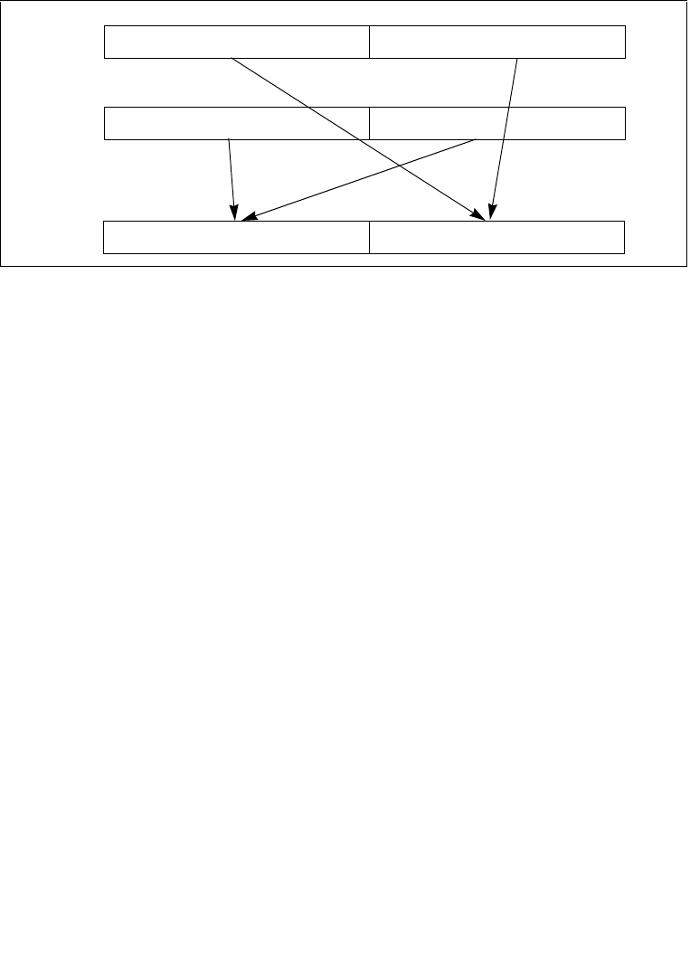
4-394 Vol. 2B SHUFPD—Shuffle Packed Double-Precision Floating-Point Values
INSTRUCTION SET REFERENCE, N-Z
VEX.256 encoded version: The first source operand is a YMM register. The second
source operand can be a YMM register or a 256-bit memory location. The destination
operand is a YMM register.
The source operand can be an XMM register or a 128-bit memory location. The desti-
nation operand is an XMM register. The select operand is an 8-bit immediate: bit 0
selects which value is moved from the destination operand to the result (where 0
selects the low quadword and 1 selects the high quadword) and bit 1 selects which
value is moved from the source operand to the result. Bits 2 through 7 of the select
operand are reserved and must be set to 0.
In 64-bit mode, using a REX prefix in the form of REX.R permits this instruction to
access additional registers (XMM8-XMM15).
Operation
IF SELECT[0] = 0
THEN DEST[63:0] ← DEST[63:0];
ELSE DEST[63:0] ← DEST[127:64]; FI;
IF SELECT[1] = 0
THEN DEST[127:64] ← SRC[63:0];
ELSE DEST[127:64] ← SRC[127:64]; FI;
SHUFPD (128-bit Legacy SSE version)
IF IMM0[0] = 0
THEN DEST[63:0] SRC1[63:0]
ELSE DEST[63:0] SRC1[127:64] FI;
IF IMM0[1] = 0
THEN DEST[127:64] SRC2[63:0]
Figure 4-20. SHUFPD Shuffle Operation
X1 X0
Y1 Y0
Y1 or Y0 X1 or X0
SRC
DEST
DEST

Vol. 2B 4-395
INSTRUCTION SET REFERENCE, N-Z
SHUFPD—Shuffle Packed Double-Precision Floating-Point Values
ELSE DEST[127:64] SRC2[127:64] FI;
DEST[VLMAX-1:128] (Unmodified)
VSHUFPD (VEX.128 encoded version)
IF IMM0[0] = 0
THEN DEST[63:0] SRC1[63:0]
ELSE DEST[63:0] SRC1[127:64] FI;
IF IMM0[1] = 0
THEN DEST[127:64] SRC2[63:0]
ELSE DEST[127:64] SRC2[127:64] FI;
DEST[VLMAX-1:128] 0
VSHUFPD (VEX.256 encoded version)
IF IMM0[0] = 0
THEN DEST[63:0] SRC1[63:0]
ELSE DEST[63:0] SRC1[127:64] FI;
IF IMM0[1] = 0
THEN DEST[127:64] SRC2[63:0]
ELSE DEST[127:64] SRC2[127:64] FI;
IF IMM0[2] = 0
THEN DEST[191:128] SRC1[191:128]
ELSE DEST[191:128] SRC1[255:192] FI;
IF IMM0[3] = 0
THEN DEST[255:192] SRC2[191:128]
ELSE DEST[255:192] SRC2[255:192] FI;
Intel C/C++ Compiler Intrinsic Equivalent
SHUFPD __m128d _mm_shuffle_pd(__m128d a, __m128d b, unsigned int imm8)
VSHUFPD __m256d _mm256_shuffle_pd (__m256d a, __m256d b, const int select);
SIMD Floating-Point Exceptions
None.
Other Exceptions
See Exceptions Type 4.

4-396 Vol. 2B SHUFPS—Shuffle Packed Single-Precision Floating-Point Values
INSTRUCTION SET REFERENCE, N-Z
SHUFPS—Shuffle Packed Single-Precision Floating-Point Values
Instruction Operand Encoding
Description
Moves two of the four packed single-precision floating-point values from the destina-
tion operand (first operand) into the low quadword of the destination operand;
moves two of the four packed single-precision floating-point values from the source
operand (second operand) into to the high quadword of the destination operand (see
Figure 4-21). The select operand (third operand) determines which values are
moved to the destination operand.
128-bit Legacy SSE version: The source can be an XMM register or an 128-bit
memory location. The destination is not distinct from the first source XMM register
and the upper bits (VLMAX-1:128) of the corresponding YMM register destination are
unmodified.
VEX.128 encoded version: the first source operand is an XMM register or 128-bit
memory location. The destination operand is an XMM register. The upper bits
(VLMAX-1:128) of the corresponding YMM register destination are zeroed.
determines which values are moved to the destination operand.
Opcode*/
Instruction
Op/
En
64/32 bit
Mode
Support
CPUID
Feature
Flag
Description
0F C6 /r ib
SHUFPS xmm1, xmm2/m128, imm8
A V/V SSE Shuffle packed single-
precision floating-point
values selected by imm8
from xmm1 and
xmm1/m128 to xmm1.
VEX.NDS.128.0F.WIG C6 /r ib
VSHUFPS xmm1, xmm2,
xmm3/m128, imm8
B V/V AVX Shuffle Packed single-
precision floating-point
values selected by imm8
from xmm2 and
xmm3/mem.
VEX.NDS.256.0F.WIG C6 /r ib
VSHUFPS ymm1, ymm2,
ymm3/m256, imm8
B V/V AVX Shuffle Packed single-
precision floating-point
values selected by imm8
from ymm2 and
ymm3/mem.
Op/En Operand 1 Operand 2 Operand 3 Operand 4
A ModRM:reg (r, w) ModRM:r/m (r) imm8 NA
B ModRM:reg (w) VEX.vvvv (r) ModRM:r/m (r) NA
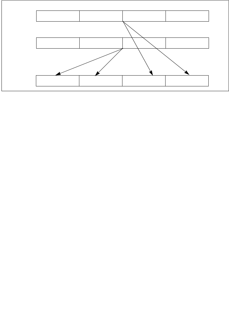
Vol. 2B 4-397
INSTRUCTION SET REFERENCE, N-Z
SHUFPS—Shuffle Packed Single-Precision Floating-Point Values
VEX.256 encoded version: The first source operand is a YMM register. The second
source operand can be a YMM register or a 256-bit memory location. The destination
operand is a YMM register.
The source operand can be an XMM register or a 128-bit memory location. The desti-
nation operand is an XMM register. The select operand is an 8-bit immediate: bits 0
and 1 select the value to be moved from the destination operand to the low double-
word of the result, bits 2 and 3 select the value to be moved from the destination
operand to the second doubleword of the result, bits 4 and 5 select the value to be
moved from the source operand to the third doubleword of the result, and bits 6 and
7 select the value to be moved from the source operand to the high doubleword of
the result.
In 64-bit mode, using a REX prefix in the form of REX.R permits this instruction to
access additional registers (XMM8-XMM15).
Operation
CASE (SELECT[1:0]) OF
0: DEST[31:0] ← DEST[31:0];
1: DEST[31:0] ← DEST[63:32];
2: DEST[31:0] ← DEST[95:64];
3: DEST[31:0] ← DEST[127:96];
ESAC;
CASE (SELECT[3:2]) OF
0: DEST[63:32] ← DEST[31:0];
1: DEST[63:32] ← DEST[63:32];
2: DEST[63:32] ← DEST[95:64];
3: DEST[63:32] ← DEST[127:96];
Figure 4-21. SHUFPS Shuffle Operation
X3 X2 X1 X0
Y3 Y2 Y1 Y0
Y3 ... Y0 Y3 ... Y0 X3 ... X0 X3 ... X0
DEST
SRC
DEST

4-398 Vol. 2B SHUFPS—Shuffle Packed Single-Precision Floating-Point Values
INSTRUCTION SET REFERENCE, N-Z
ESAC;
CASE (SELECT[5:4]) OF
0: DEST[95:64] ← SRC[31:0];
1: DEST[95:64] ← SRC[63:32];
2: DEST[95:64] ← SRC[95:64];
3: DEST[95:64] ← SRC[127:96];
ESAC;
CASE (SELECT[7:6]) OF
0: DEST[127:96] ← SRC[31:0];
1: DEST[127:96] ← SRC[63:32];
2: DEST[127:96] ← SRC[95:64];
3: DEST[127:96] ← SRC[127:96];
ESAC;
SHUFPS (128-bit Legacy SSE version)
DEST[31:0] Select4(SRC1[127:0], imm8[1:0]);
DEST[63:32] Select4(SRC1[127:0], imm8[3:2]);
DEST[95:64] Select4(SRC2[127:0], imm8[5:4]);
DEST[127:96] Select4(SRC2[127:0], imm8[7:6]);
DEST[VLMAX-1:128] (Unmodified)
VSHUFPS (VEX.128 encoded version)
DEST[31:0] Select4(SRC1[127:0], imm8[1:0]);
DEST[63:32] Select4(SRC1[127:0], imm8[3:2]);
DEST[95:64] Select4(SRC2[127:0], imm8[5:4]);
DEST[127:96] Select4(SRC2[127:0], imm8[7:6]);
DEST[VLMAX-1:128] 0
VSHUFPS (VEX.256 encoded version)
DEST[31:0] Select4(SRC1[127:0], imm8[1:0]);
DEST[63:32] Select4(SRC1[127:0], imm8[3:2]);
DEST[95:64] Select4(SRC2[127:0], imm8[5:4]);
DEST[127:96] Select4(SRC2[127:0], imm8[7:6]);
DEST[159:128] Select4(SRC1[255:128], imm8[1:0]);
DEST[191:160] Select4(SRC1[255:128], imm8[3:2]);
DEST[223:192] Select4(SRC2[255:128], imm8[5:4]);
DEST[255:224] Select4(SRC2[255:128], imm8[7:6]);
Intel C/C++ Compiler Intrinsic Equivalent
SHUFPS __m128 _mm_shuffle_ps(__m128 a, __m128 b, unsigned int imm8)
VSHUFPS __m256 _mm256_shuffle_ps (__m256 a, __m256 b, const int select);

Vol. 2B 4-399
INSTRUCTION SET REFERENCE, N-Z
SHUFPS—Shuffle Packed Single-Precision Floating-Point Values
SIMD Floating-Point Exceptions
None.
Other Exceptions
See Exceptions Type 4.

4-400 Vol. 2B SIDT—Store Interrupt Descriptor Table Register
INSTRUCTION SET REFERENCE, N-Z
SIDT—Store Interrupt Descriptor Table Register
Instruction Operand Encoding
Description
Stores the content the interrupt descriptor table register (IDTR) in the destination
operand. The destination operand specifies a 6-byte memory location.
In non-64-bit modes, if the operand-size attribute is 32 bits, the 16-bit limit field of
the register is stored in the low 2 bytes of the memory location and the 32-bit base
address is stored in the high 4 bytes. If the operand-size attribute is 16 bits, the limit
is stored in the low 2 bytes and the 24-bit base address is stored in the third, fourth,
and fifth byte, with the sixth byte filled with 0s.
In 64-bit mode, the operand size fixed at 8+2 bytes. The instruction stores 8-byte
base and 2-byte limit values.
SIDT is only useful in operating-system software; however, it can be used in applica-
tion programs without causing an exception to be generated. See “LGDT/LIDT—Load
Global/Interrupt Descriptor Table Register” in Chapter 3, Intel® 64 and IA-32 Archi-
tectures Software Developer’s Manual, Volume 2A, for information on loading the
GDTR and IDTR.
IA-32 Architecture Compatibility
The 16-bit form of SIDT is compatible with the Intel 286 processor if the upper 8 bits
are not referenced. The Intel 286 processor fills these bits with 1s; the Pentium 4,
Intel Xeon, P6 processor family, Pentium, Intel486, and Intel386 processors fill these
bits with 0s.
Operation
IF instruction is SIDT
THEN
IF OperandSize = 16
THEN
DEST[0:15] ← IDTR(Limit);
DEST[16:39] ← IDTR(Base); (* 24 bits of base address stored; *)
DEST[40:47] ← 0;
Opcode* Instruction Op/
En
64-Bit
Mode
Compat/
Leg Mode
Description
0F 01 /1 SIDT mA Valid Valid Store IDTR to m.
Op/En Operand 1 Operand 2 Operand 3 Operand 4
A ModRM:r/m (w) NA NA NA

Vol. 2B 4-401
INSTRUCTION SET REFERENCE, N-Z
SIDT—Store Interrupt Descriptor Table Register
ELSE IF (32-bit Operand Size)
DEST[0:15] ← IDTR(Limit);
DEST[16:47] ← IDTR(Base); FI; (* Full 32-bit base address stored *)
ELSE (* 64-bit Operand Size *)
DEST[0:15] ← IDTR(Limit);
DEST[16:79] ← IDTR(Base); (* Full 64-bit base address stored *)
FI;
FI;
Flags Affected
None.
Protected Mode Exceptions
#GP(0) If the destination is located in a non-writable segment.
If a memory operand effective address is outside the CS, DS,
ES, FS, or GS segment limit.
If the DS, ES, FS, or GS register is used to access memory and it
contains a NULL segment selector.
#SS(0) If a memory operand effective address is outside the SS
segment limit.
#PF(fault-code) If a page fault occurs.
#AC(0) If alignment checking is enabled and an unaligned memory
reference is made while the current privilege level is 3.
#UD If the LOCK prefix is used.
Real-Address Mode Exceptions
#GP If a memory operand effective address is outside the CS, DS,
ES, FS, or GS segment limit.
#SS If a memory operand effective address is outside the SS
segment limit.
#UD If the LOCK prefix is used.
Virtual-8086 Mode Exceptions
#GP(0) If a memory operand effective address is outside the CS, DS,
ES, FS, or GS segment limit.
#SS(0) If a memory operand effective address is outside the SS
segment limit.
#PF(fault-code) If a page fault occurs.
#AC(0) If alignment checking is enabled and an unaligned memory
reference is made.
#UD If the LOCK prefix is used.

4-402 Vol. 2B SIDT—Store Interrupt Descriptor Table Register
INSTRUCTION SET REFERENCE, N-Z
Compatibility Mode Exceptions
Same exceptions as in protected mode.
64-Bit Mode Exceptions
#SS(0) If a memory address referencing the SS segment is in a non-
canonical form.
#UD If the destination operand is a register.
If the LOCK prefix is used.
#GP(0) If the memory address is in a non-canonical form.
#PF(fault-code) If a page fault occurs.
#AC(0) If alignment checking is enabled and an unaligned memory
reference is made while the current privilege level is 3.

Vol. 2B 4-403
INSTRUCTION SET REFERENCE, N-Z
SLDT—Store Local Descriptor Table Register
SLDT—Store Local Descriptor Table Register
Instruction Operand Encoding
Description
Stores the segment selector from the local descriptor table register (LDTR) in the
destination operand. The destination operand can be a general-purpose register or a
memory location. The segment selector stored with this instruction points to the
segment descriptor (located in the GDT) for the current LDT. This instruction can only
be executed in protected mode.
Outside IA-32e mode, when the destination operand is a 32-bit register, the 16-bit
segment selector is copied into the low-order 16 bits of the register. The high-order
16 bits of the register are cleared for the Pentium 4, Intel Xeon, and P6 family proces-
sors. They are undefined for Pentium, Intel486, and Intel386 processors. When the
destination operand is a memory location, the segment selector is written to memory
as a 16-bit quantity, regardless of the operand size.
In compatibility mode, when the destination operand is a 32-bit register, the 16-bit
segment selector is copied into the low-order 16 bits of the register. The high-order
16 bits of the register are cleared. When the destination operand is a memory loca-
tion, the segment selector is written to memory as a 16-bit quantity, regardless of
the operand size.
In 64-bit mode, using a REX prefix in the form of REX.R permits access to additional
registers (R8-R15). The behavior of SLDT with a 64-bit register is to zero-extend the
16-bit selector and store it in the register. If the destination is memory and operand
size is 64, SLDT will write the 16-bit selector to memory as a 16-bit quantity, regard-
less of the operand size
Operation
DEST ← LDTR(SegmentSelector);
Flags Affected
None.
Opcode* Instruction Op/
En
64-Bit
Mode
Compat/
Leg Mode
Description
0F 00 /0 SLDT r/m16 A Valid Valid Stores segment selector
from LDTR in r/m16.
REX.W + 0F 00
/0
SLDT r64/m16 A Valid Valid Stores segment selector
from LDTR in r64/m16.
Op/En Operand 1 Operand 2 Operand 3 Operand 4
A ModRM:r/m (w) NA NA NA

4-404 Vol. 2B SLDT—Store Local Descriptor Table Register
INSTRUCTION SET REFERENCE, N-Z
Protected Mode Exceptions
#GP(0) If the destination is located in a non-writable segment.
If a memory operand effective address is outside the CS, DS,
ES, FS, or GS segment limit.
If the DS, ES, FS, or GS register is used to access memory and it
contains a NULL segment selector.
#SS(0) If a memory operand effective address is outside the SS
segment limit.
#PF(fault-code) If a page fault occurs.
#AC(0) If alignment checking is enabled and an unaligned memory
reference is made while the current privilege level is 3.
#UD If the LOCK prefix is used.
Real-Address Mode Exceptions
#UD The SLDT instruction is not recognized in real-address mode.
If the LOCK prefix is used.
Virtual-8086 Mode Exceptions
#UD The SLDT instruction is not recognized in virtual-8086 mode.
If the LOCK prefix is used.
Compatibility Mode Exceptions
Same exceptions as in protected mode.
64-Bit Mode Exceptions
#SS(0) If a memory address referencing the SS segment is in a non-
canonical form.
#GP(0) If the memory address is in a non-canonical form.
#PF(fault-code) If a page fault occurs.
#AC(0) If alignment checking is enabled and an unaligned memory
reference is made while the current privilege level is 3.
#UD If the LOCK prefix is used.

Vol. 2B 4-405
INSTRUCTION SET REFERENCE, N-Z
SMSW—Store Machine Status Word
SMSW—Store Machine Status Word
Instruction Operand Encoding
Description
Stores the machine status word (bits 0 through 15 of control register CR0) into the
destination operand. The destination operand can be a general-purpose register or a
memory location.
In non-64-bit modes, when the destination operand is a 32-bit register, the low-order
16 bits of register CR0 are copied into the low-order 16 bits of the register and the
high-order 16 bits are undefined. When the destination operand is a memory loca-
tion, the low-order 16 bits of register CR0 are written to memory as a 16-bit quantity,
regardless of the operand size.
In 64-bit mode, the behavior of the SMSW instruction is defined by the following
examples:
•SMSW r16 operand size 16, store CR0[15:0] in r16
•SMSW r32 operand size 32, zero-extend CR0[31:0], and store in r32
•SMSW r64 operand size 64, zero-extend CR0[63:0], and store in r64
•SMSW m16 operand size 16, store CR0[15:0] in m16
•SMSW m16 operand size 32, store CR0[15:0] in m16 (not m32)
•SMSW m16 operands size 64, store CR0[15:0] in m16 (not m64)
SMSW is only useful in operating-system software. However, it is not a privileged
instruction and can be used in application programs. The is provided for compatibility
with the Intel 286 processor. Programs and procedures intended to run on the
Opcode* Instruction Op/
En
64-Bit
Mode
Compat/
Leg Mode
Description
0F 01 /4 SMSW r/m16 A Valid Valid Store machine status word
to r/m16.
0F 01 /4 SMSW r32/m16 A Valid Valid Store machine status word
in low-order 16 bits of
r32/m16; high-order 16 bits
of r32 are undefined.
REX.W + 0F 01
/4
SMSW r64/m16 A Valid Valid Store machine status word
in low-order 16 bits of
r64/m16; high-order 16 bits
of r32 are undefined.
Op/En Operand 1 Operand 2 Operand 3 Operand 4
A ModRM:r/m (w) NA NA NA

4-406 Vol. 2B SMSW—Store Machine Status Word
INSTRUCTION SET REFERENCE, N-Z
Pentium 4, Intel Xeon, P6 family, Pentium, Intel486, and Intel386 processors should
use the MOV (control registers) instruction to load the machine status word.
See “Changes to Instruction Behavior in VMX Non-Root Operation” in Chapter 22 of
the Intel® 64 and IA-32 Architectures Software Developer’s Manual, Volume 3B, for
more information about the behavior of this instruction in VMX non-root operation.
Operation
DEST ← CR0[15:0];
(* Machine status word *)
Flags Affected
None.
Protected Mode Exceptions
#GP(0) If the destination is located in a non-writable segment.
If a memory operand effective address is outside the CS, DS,
ES, FS, or GS segment limit.
If the DS, ES, FS, or GS register is used to access memory and it
contains a NULL segment selector.
#SS(0) If a memory operand effective address is outside the SS
segment limit.
#PF(fault-code) If a page fault occurs.
#AC(0) If alignment checking is enabled and an unaligned memory
reference is made while the current privilege level is 3.
#UD If the LOCK prefix is used.
Real-Address Mode Exceptions
#GP If a memory operand effective address is outside the CS, DS,
ES, FS, or GS segment limit.
#SS(0) If a memory operand effective address is outside the SS
segment limit.
#UD If the LOCK prefix is used.
Virtual-8086 Mode Exceptions
#GP(0) If a memory operand effective address is outside the CS, DS,
ES, FS, or GS segment limit.
#SS(0) If a memory operand effective address is outside the SS
segment limit.
#PF(fault-code) If a page fault occurs.

Vol. 2B 4-407
INSTRUCTION SET REFERENCE, N-Z
SMSW—Store Machine Status Word
#AC(0) If alignment checking is enabled and an unaligned memory
reference is made.
#UD If the LOCK prefix is used.
Compatibility Mode Exceptions
Same exceptions as in protected mode.
64-Bit Mode Exceptions
#SS(0) If a memory address referencing the SS segment is in a non-
canonical form.
#GP(0) If the memory address is in a non-canonical form.
#PF(fault-code) If a page fault occurs.
#AC(0) If alignment checking is enabled and an unaligned memory
reference is made while the current privilege level is 3.
#UD If the LOCK prefix is used.

4-408 Vol. 2B SQRTPD—Compute Square Roots of Packed Double-Precision Floating-Point Values
INSTRUCTION SET REFERENCE, N-Z
SQRTPD—Compute Square Roots of Packed Double-Precision Floating-
Point Values
Instruction Operand Encoding
Description
Performs a SIMD computation of the square roots of the two packed double-precision
floating-point values in the source operand (second operand) stores the packed
double-precision floating-point results in the destination operand. The source
operand can be an XMM register or a 128-bit memory location. The destination
operand is an XMM register. See Figure 11-3 in the Intel® 64 and IA-32 Architectures
Software Developer’s Manual, Volume 1, for an illustration of a SIMD double-preci-
sion floating-point operation.
In 64-bit mode, using a REX prefix in the form of REX.R permits this instruction to
access additional registers (XMM8-XMM15).
128-bit Legacy SSE version: The second source can be an XMM register or 128-bit
memory location. The destination is not distinct from the first source XMM register
and the upper bits (VLMAX-1:128) of the corresponding YMM register destination are
unmodified.
Opcode*/
Instruction
Op/
En
64/32 bit
Mode
Support
CPUID
Feature
Flag
Description
66 0F 51 /r
SQRTPD xmm1, xmm2/m128
A V/V SSE2 Computes square roots of
the packed double-precision
floating-point values in
xmm2/m128 and stores the
results in xmm1.
VEX.128.66.0F.WIG 51 /r
VSQRTPD xmm1, xmm2/m128
A V/V AVX Computes Square Roots of
the packed double-precision
floating-point values in
xmm2/m128 and stores the
result in xmm1.
VEX.256.66.0F.WIG 51/r
VSQRTPD ymm1, ymm2/m256
A V/V AVX Computes Square Roots of
the packed double-precision
floating-point values in
ymm2/m256 and stores the
result in ymm1.
Op/En Operand 1 Operand 2 Operand 3 Operand 4
A ModRM:reg (w) ModRM:r/m (r) NA NA

Vol. 2B 4-409
INSTRUCTION SET REFERENCE, N-Z
SQRTPD—Compute Square Roots of Packed Double-Precision Floating-Point Values
VEX.128 encoded version: the source operand second source operand or a 128-bit
memory location. The destination operand is an XMM register. The upper bits
(VLMAX-1:128) of the corresponding YMM register destination are zeroed.
VEX.256 encoded version: The source operand is a YMM register or a 256-bit
memory location. The destination operand is a YMM register.
Note: In VEX-encoded versions, VEX.vvvv is reserved and must be 1111b otherwise
instructions will #UD.
Operation
SQRTPD (128-bit Legacy SSE version)
DEST[63:0] SQRT(SRC[63:0])
DEST[127:64] SQRT(SRC[127:64])
DEST[VLMAX-1:128] (Unmodified)
VSQRTPD (VEX.128 encoded version)
DEST[63:0] SQRT(SRC[63:0])
DEST[127:64] SQRT(SRC[127:64])
DEST[VLMAX-1:128] 0
VSQRTPD (VEX.256 encoded version)
DEST[63:0] SQRT(SRC[63:0])
DEST[127:64] SQRT(SRC[127:64])
DEST[191:128] SQRT(SRC[191:128])
DEST[255:192] SQRT(SRC[255:192])
Intel C/C++ Compiler Intrinsic Equivalent
SQRTPD __m128d _mm_sqrt_pd (m128d a)
SQRTPD __m256d _mm256_sqrt_pd (__m256d a);
SIMD Floating-Point Exceptions
Invalid, Precision, Denormal.
Other Exceptions
See Exceptions Type 2; additionally
#UD If VEX.vvvv != 1111B.

4-410 Vol. 2B SQRTPS—Compute Square Roots of Packed Single-Precision Floating-Point Values
INSTRUCTION SET REFERENCE, N-Z
SQRTPS—Compute Square Roots of Packed Single-Precision Floating-
Point Values
Instruction Operand Encoding
Description
Performs a SIMD computation of the square roots of the four packed single-precision
floating-point values in the source operand (second operand) stores the packed
single-precision floating-point results in the destination operand. The source operand
can be an XMM register or a 128-bit memory location. The destination operand is an
XMM register. See Figure 10-5 in the Intel® 64 and IA-32 Architectures Software
Developer’s Manual, Volume 1, for an illustration of a SIMD single-precision floating-
point operation.
In 64-bit mode, using a REX prefix in the form of REX.R permits this instruction to
access additional registers (XMM8-XMM15).
128-bit Legacy SSE version: The second source can be an XMM register or 128-bit
memory location. The destination is not distinct from the first source XMM register
and the upper bits (VLMAX-1:128) of the corresponding YMM register destination are
unmodified.
Opcode*/
Instruction
Op/
En
64/32 bit
Mode
Support
CPUID
Feature
Flag
Description
0F 51 /r
SQRTPS xmm1, xmm2/m128
A V/V SSE Computes square roots of
the packed single-precision
floating-point values in
xmm2/m128 and stores the
results in xmm1.
VEX.128.0F.WIG 51 /r
VSQRTPS xmm1, xmm2/m128
A V/V AVX Computes Square Roots of
the packed single-precision
floating-point values in
xmm2/m128 and stores the
result in xmm1.
VEX.256.0F.WIG 51/r
VSQRTPS ymm1, ymm2/m256
A V/V AVX Computes Square Roots of
the packed single-precision
floating-point values in
ymm2/m256 and stores the
result in ymm1.
Op/En Operand 1 Operand 2 Operand 3 Operand 4
A ModRM:reg (w) ModRM:r/m (r) NA NA

Vol. 2B 4-411
INSTRUCTION SET REFERENCE, N-Z
SQRTPS—Compute Square Roots of Packed Single-Precision Floating-Point Values
VEX.128 encoded version: the source operand second source operand or a 128-bit
memory location. The destination operand is an XMM register. The upper bits
(VLMAX-1:128) of the corresponding YMM register destination are zeroed.
VEX.256 encoded version: The source operand is a YMM register or a 256-bit
memory location. The destination operand is a YMM register.
Note: In VEX-encoded versions, VEX.vvvv is reserved and must be 1111b otherwise
instructions will #UD.
Operation
SQRTPS (128-bit Legacy SSE version)
DEST[31:0] SQRT(SRC[31:0])
DEST[63:32] SQRT(SRC[63:32])
DEST[95:64] SQRT(SRC[95:64])
DEST[127:96] SQRT(SRC[127:96])
DEST[VLMAX-1:128] (Unmodified)
VSQRTPS (VEX.128 encoded version)
DEST[31:0] SQRT(SRC[31:0])
DEST[63:32] SQRT(SRC[63:32])
DEST[95:64] SQRT(SRC[95:64])
DEST[127:96] SQRT(SRC[127:96])
DEST[VLMAX-1:128] 0
VSQRTPS (VEX.256 encoded version)
DEST[31:0] SQRT(SRC[31:0])
DEST[63:32] SQRT(SRC[63:32])
DEST[95:64] SQRT(SRC[95:64])
DEST[127:96] SQRT(SRC[127:96])
DEST[159:128] SQRT(SRC[159:128])
DEST[191:160] SQRT(SRC[191:160])
DEST[223:192] SQRT(SRC[223:192])
DEST[255:224] SQRT(SRC[255:224])
Intel C/C++ Compiler Intrinsic Equivalent
SQRTPS __m128 _mm_sqrt_ps(__m128 a)
SQRTPS __m256 _mm256_sqrt_ps (__m256 a);
SIMD Floating-Point Exceptions
Invalid, Precision, Denormal.

4-412 Vol. 2B SQRTPS—Compute Square Roots of Packed Single-Precision Floating-Point Values
INSTRUCTION SET REFERENCE, N-Z
Other Exceptions
See Exceptions Type 2; additionally
#UD If VEX.vvvv != 1111B.

Vol. 2B 4-413
INSTRUCTION SET REFERENCE, N-Z
SQRTSD—Compute Square Root of Scalar Double-Precision Floating-Point Value
SQRTSD—Compute Square Root of Scalar Double-Precision Floating-
Point Value
Instruction Operand Encoding
Description
Computes the square root of the low double-precision floating-point value in the
source operand (second operand) and stores the double-precision floating-point
result in the destination operand. The source operand can be an XMM register or a
64-bit memory location. The destination operand is an XMM register. The high quad-
word of the destination operand remains unchanged. See Figure 11-4 in the Intel®
64 and IA-32 Architectures Software Developer’s Manual, Volume 1, for an illustra-
tion of a scalar double-precision floating-point operation.
In 64-bit mode, using a REX prefix in the form of REX.R permits this instruction to
access additional registers (XMM8-XMM15).
128-bit Legacy SSE version: The first source operand and the destination operand
are the same. Bits (VLMAX-1:64) of the corresponding YMM destination register
remain unchanged.
VEX.128 encoded version: Bits (VLMAX-1:128) of the destination YMM register are
zeroed.
Opcode*/
Instruction
Op/
En
64/32 bit
Mode
Support
CPUID
Feature
Flag
Description
F2 0F 51 /r
SQRTSD xmm1, xmm2/m64
A V/V SSE2 Computes square root of
the low double-precision
floating-point value in
xmm2/m64 and stores the
results in xmm1.
VEX.NDS.LIG.F2.0F.WIG 51/
VSQRTSD xmm1,xmm2, xmm3/m64
B V/V AVX Computes square root of
the low double-precision
floating point value in
xmm3/m64 and stores the
results in xmm2. Also, upper
double precision floating-
point value (bits[127:64])
from xmm2 is copied to
xmm1[127:64].
Op/En Operand 1 Operand 2 Operand 3 Operand 4
A ModRM:reg (w) ModRM:r/m (r) NA NA
B ModRM:reg (w) VEX.vvvv (r) ModRM:r/m (r) NA

4-414 Vol. 2B SQRTSD—Compute Square Root of Scalar Double-Precision Floating-Point Value
INSTRUCTION SET REFERENCE, N-Z
Operation
SQRTSD (128-bit Legacy SSE version)
DEST[63:0] SQRT(SRC[63:0])
DEST[VLMAX-1:64] (Unmodified)
VSQRTSD (VEX.128 encoded version)
DEST[63:0] SQRT(SRC2[63:0])
DEST[127:64] SRC1[127:64]
DEST[VLMAX-1:128] 0
Intel C/C++ Compiler Intrinsic Equivalent
SQRTSD __m128d _mm_sqrt_sd (m128d a, m128d b)
SIMD Floating-Point Exceptions
Invalid, Precision, Denormal.
Other Exceptions
See Exceptions Type 3.

Vol. 2B 4-415
INSTRUCTION SET REFERENCE, N-Z
SQRTSS—Compute Square Root of Scalar Single-Precision Floating-Point Value
SQRTSS—Compute Square Root of Scalar Single-Precision Floating-
Point Value
Instruction Operand Encoding
Description
Computes the square root of the low single-precision floating-point value in the
source operand (second operand) and stores the single-precision floating-point
result in the destination operand. The source operand can be an XMM register or a
32-bit memory location. The destination operand is an XMM register. The three high-
order doublewords of the destination operand remain unchanged. See Figure 10-6 in
the Intel® 64 and IA-32 Architectures Software Developer’s Manual, Volume 1, for
an illustration of a scalar single-precision floating-point operation.
In 64-bit mode, using a REX prefix in the form of REX.R permits this instruction to
access additional registers (XMM8-XMM15).
128-bit Legacy SSE version: The first source operand and the destination operand
are the same. Bits (VLMAX-1:32) of the corresponding YMM destination register
remain unchanged.
VEX.128 encoded version: Bits (VLMAX-1:128) of the destination YMM register are
zeroed.
Opcode*/
Instruction
Op/
En
64/32 bit
Mode
Support
CPUID
Feature
Flag
Description
F3 0F 51 /r
SQRTSS xmm1, xmm2/m32
A V/V SSE Computes square root of
the low single-precision
floating-point value in
xmm2/m32 and stores the
results in xmm1.
VEX.NDS.LIG.F3.0F.WIG 51
VSQRTSS xmm1, xmm2, xmm3/m32
B V/V AVX Computes square root of
the low single-precision
floating-point value in
xmm3/m32 and stores the
results in xmm1. Also, upper
single precision floating-
point values (bits[127:32])
from xmm2 are copied to
xmm1[127:32].
Op/En Operand 1 Operand 2 Operand 3 Operand 4
A ModRM:reg (w) ModRM:r/m (r) NA NA
B ModRM:reg (w) VEX.vvvv (r) ModRM:r/m (r) NA

4-416 Vol. 2B SQRTSS—Compute Square Root of Scalar Single-Precision Floating-Point Value
INSTRUCTION SET REFERENCE, N-Z
Operation
SQRTSS (128-bit Legacy SSE version)
DEST[31:0] SQRT(SRC2[31:0])
DEST[VLMAX-1:32] (Unmodified)
VSQRTSS (VEX.128 encoded version)
DEST[31:0] SQRT(SRC2[31:0])
DEST[127:32] SRC1[127:32]
DEST[VLMAX-1:128] 0
Intel C/C++ Compiler Intrinsic Equivalent
SQRTSS __m128 _mm_sqrt_ss(__m128 a)
SIMD Floating-Point Exceptions
Invalid, Precision, Denormal.
Other Exceptions
See Exceptions Type 3.

Vol. 2B 4-417
INSTRUCTION SET REFERENCE, N-Z
VSTMXCSR—Store MXCSR Register State
VSTMXCSR—Store MXCSR Register State
Instruction Operand Encoding
Description
Stores the contents of the MXCSR control and status register to the destination
operand. The destination operand is a 32-bit memory location. The reserved bits in
the MXCSR register are stored as 0s.
This instruction’s operation is the same in non-64-bit modes and 64-bit mode.
VEX.L must be 0, otherwise instructions will #UD.
Operation
m32 ← MXCSR;
Intel C/C++ Compiler Intrinsic Equivalent
_mm_getcsr(void)
SIMD Floating-Point Exceptions
None.
Other Exceptions
See Exceptions Type 9
Opcode*/
Instruction
Op/
En
64/32 bit
Mode
Support
CPUID
Feature
Flag
Description
VEX.LZ.0F.WIG AE /3
VSTMXCSR m32
A V/V AVX Store contents of MXCSR
register to m32.
Op/En Operand 1 Operand 2 Operand 3 Operand 4
A ModRM:r/m (w) NA NA NA

4-418 Vol. 2B STC—Set Carry Flag
INSTRUCTION SET REFERENCE, N-Z
STC—Set Carry Flag
Instruction Operand Encoding
Description
Sets the CF flag in the EFLAGS register.
This instruction’s operation is the same in non-64-bit modes and 64-bit mode.
Operation
CF ← 1;
Flags Affected
The CF flag is set. The OF, ZF, SF, AF, and PF flags are unaffected.
Exceptions (All Operating Modes)
#UD If the LOCK prefix is used.
Opcode* Instruction Op/
En
64-Bit
Mode
Compat/
Leg Mode
Description
F9 STC A Valid Valid Set CF flag.
Op/En Operand 1 Operand 2 Operand 3 Operand 4
ANA NA NA NA

Vol. 2B 4-419
INSTRUCTION SET REFERENCE, N-Z
STD—Set Direction Flag
STD—Set Direction Flag
Instruction Operand Encoding
Description
Sets the DF flag in the EFLAGS register. When the DF flag is set to 1, string operations
decrement the index registers (ESI and/or EDI).
This instruction’s operation is the same in non-64-bit modes and 64-bit mode.
Operation
DF ← 1;
Flags Affected
The DF flag is set. The CF, OF, ZF, SF, AF, and PF flags are unaffected.
Exceptions (All Operating Modes)
#UD If the LOCK prefix is used.
Opcode* Instruction Op/
En
64-Bit
Mode
Compat/
Leg Mode
Description
FD STD A Valid Valid Set DF flag.
Op/En Operand 1 Operand 2 Operand 3 Operand 4
ANA NA NA NA

4-420 Vol. 2B STI—Set Interrupt Flag
INSTRUCTION SET REFERENCE, N-Z
STI—Set Interrupt Flag
Instruction Operand Encoding
Description
If protected-mode virtual interrupts are not enabled, STI sets the interrupt flag (IF)
in the EFLAGS register. After the IF flag is set, the processor begins responding to
external, maskable interrupts after the next instruction is executed. The delayed
effect of this instruction is provided to allow interrupts to be enabled just before
returning from a procedure (or subroutine). For instance, if an STI instruction is
followed by an RET instruction, the RET instruction is allowed to execute before
external interrupts are recognized1. If the STI instruction is followed by a CLI instruc-
tion (which clears the IF flag), the effect of the STI instruction is negated.
The IF flag and the STI and CLI instructions do not prohibit the generation of excep-
tions and NMI interrupts. NMI interrupts (and SMIs) may be blocked for one macro-
instruction following an STI.
When protected-mode virtual interrupts are enabled, CPL is 3, and IOPL is less than
3; STI sets the VIF flag in the EFLAGS register, leaving IF unaffected.
Table 4-15 indicates the action of the STI instruction depending on the processor’s
mode of operation and the CPL/IOPL settings of the running program or procedure.
This instruction’s operation is the same in non-64-bit modes and 64-bit mode.
Opcode* Instruction Op/
En
64-Bit
Mode
Compat/
Leg Mode
Description
FB STI A Valid Valid Set interrupt flag; external,
maskable interrupts enabled
at the end of the next
instruction.
Op/En Operand 1 Operand 2 Operand 3 Operand 4
ANA NA NA NA
1. The STI instruction delays recognition of interrupts only if it is executed with EFLAGS.IF = 0. In a
sequence of STI instructions, only the first instruction in the sequence is guaranteed to delay
interrupts.
In the following instruction sequence, interrupts may be recognized before RET executes:
STI
STI
RET

Vol. 2B 4-421
INSTRUCTION SET REFERENCE, N-Z
STI—Set Interrupt Flag
Operation
IF PE = 0 (* Executing in real-address mode *)
THEN
IF ← 1; (* Set Interrupt Flag *)
ELSE (* Executing in protected mode or virtual-8086 mode *)
IF VM = 0 (* Executing in protected mode*)
THEN
IF IOPL ≥ CPL
THEN
IF ← 1; (* Set Interrupt Flag *)
ELSE
IF (IOPL < CPL) and (CPL = 3) and (VIP = 0)
THEN
VIF ← 1; (* Set Virtual Interrupt Flag *)
ELSE
#GP(0);
FI;
FI;
ELSE (* Executing in Virtual-8086 mode *)
IF IOPL = 3
THEN
IF ← 1; (* Set Interrupt Flag *)
ELSE
IF ((IOPL < 3) and (VIP = 0) and (VME = 1))
THEN
Table 4-15. Decision Table for STI Results
PE VM IOPL CPL PVI VIP VME STI Result
0XXXXXX IF = 1
10
≥ CPLXXXX IF = 1
10
< CPL310X VIF = 1
10
< CPL < 3XXX GP Fault
10
< CPL X 0 X X GP Fault
10
< CPL X X 1 X GP Fault
113XXXX IF = 1
11
< 3X X 0 1 VIF = 1
11
< 3X X 1 X GP Fault
11
< 3XXX0 GP Fault
NOTES:
X = This setting has no impact.

4-422 Vol. 2B STI—Set Interrupt Flag
INSTRUCTION SET REFERENCE, N-Z
VIF ← 1; (* Set Virtual Interrupt Flag *)
ELSE
#GP(0); (* Trap to virtual-8086 monitor *)
FI;)
FI;
FI;
FI;
Flags Affected
The IF flag is set to 1; or the VIF flag is set to 1.
Protected Mode Exceptions
#GP(0) If the CPL is greater (has less privilege) than the IOPL of the
current program or procedure.
#UD If the LOCK prefix is used.
Real-Address Mode Exceptions
#UD If the LOCK prefix is used.
Virtual-8086 Mode Exceptions
Same exceptions as in protected mode.
Compatibility Mode Exceptions
Same exceptions as in protected mode.
64-Bit Mode Exceptions
Same exceptions as in protected mode.

Vol. 2B 4-423
INSTRUCTION SET REFERENCE, N-Z
STMXCSR—Store MXCSR Register State
STMXCSR—Store MXCSR Register State
Instruction Operand Encoding
Description
Stores the contents of the MXCSR control and status register to the destination
operand. The destination operand is a 32-bit memory location. The reserved bits in
the MXCSR register are stored as 0s.
This instruction’s operation is the same in non-64-bit modes and 64-bit mode.
Operation
m32 ← MXCSR;
Intel C/C++ Compiler Intrinsic Equivalent
_mm_getcsr(void)
Exceptions
None.
Numeric Exceptions
None.
Protected Mode Exceptions
#GP(0) For an illegal memory operand effective address in the CS, DS,
ES, FS, or GS segments.
#SS(0) For an illegal address in the SS segment.
#PF(fault-code) For a page fault.
#UD If CR0.EM[bit 2] = 1.
#NM If CR0.TS[bit 3] = 1.
Opcode* Instruction Op/
En
64-Bit
Mode
Compat/
Leg Mode
Description
0F AE /3 STMXCSR m32 A Valid Valid Store contents of MXCSR
register to m32.
Op/En Operand 1 Operand 2 Operand 3 Operand 4
A ModRM:r/m (w) NA NA NA

4-424 Vol. 2B STMXCSR—Store MXCSR Register State
INSTRUCTION SET REFERENCE, N-Z
#AC For unaligned memory reference. To enable #AC exceptions,
three conditions must be true: CR0.AM[bit 18] = 1,
EFLAGS.AC[bit 18] = 1, current CPL = 3.
#UD If CR4.OSFXSR[bit 9] = 0.
If CPUID.01H:EDX.SSE[bit 25] = 0.
If the LOCK prefix is used.
Real Address Mode Exceptions
GP(0) If any part of the operand would lie outside of the effective
address space from 0 to 0FFFFH.
#UD If CR0.EM[bit 2] = 1.
#NM If CR0.TS[bit 3] = 1.
#UD If CR4.OSFXSR[bit 9] = 0.
If CPUID.01H:EDX.SSE[bit 25] = 0.
If the LOCK prefix is used.
Virtual 8086 Mode Exceptions
Same exceptions as in real address mode.
#PF(fault-code) For a page fault.
#AC For unaligned memory reference.
Compatibility Mode Exceptions
Same exceptions as in protected mode.
64-Bit Mode Exceptions
#SS(0) If a memory address referencing the SS segment is in a non-
canonical form.
#GP(0) If the memory address is in a non-canonical form.
#PF(fault-code) For a page fault.
#NM If CR0.TS[bit 3] = 1.
#AC For unaligned memory reference. To enable #AC exceptions,
three conditions must be true: CR0.AM[bit 18] = 1,
EFLAGS.AC[bit 18] = 1, current CPL = 3
#UD If CR0.EM[bit 2] = 1.
If CR4.OSFXSR[bit 9] = 0.
If CPUID.01H:EDX.SSE[bit 25] = 0.
If the LOCK prefix is used.

Vol. 2B 4-425
INSTRUCTION SET REFERENCE, N-Z
STOS/STOSB/STOSW/STOSD/STOSQ—Store String
STOS/STOSB/STOSW/STOSD/STOSQ—Store String
Instruction Operand Encoding
Description
In non-64-bit and default 64-bit mode; stores a byte, word, or doubleword from the
AL, AX, or EAX register (respectively) into the destination operand. The destination
operand is a memory location, the address of which is read from either the ES:EDI or
ES:DI register (depending on the address-size attribute of the instruction and the
Opcode Instruction Op/
En
64-Bit
Mode
Compat/
Leg Mode
Description
AA STOS m8 A Valid Valid For legacy mode, store AL at
address ES:(E)DI; For 64-bit
mode store AL at address
RDI or EDI.
AB STOS m16 A Valid Valid For legacy mode, store AX
at address ES:(E)DI; For 64-
bit mode store AX at
address RDI or EDI.
AB STOS m32 A Valid Valid For legacy mode, store EAX
at address ES:(E)DI; For 64-
bit mode store EAX at
address RDI or EDI.
REX.W + AB STOS m64 A Valid N.E. Store RAX at address RDI or
EDI.
AA STOSB A Valid Valid For legacy mode, store AL at
address ES:(E)DI; For 64-bit
mode store AL at address
RDI or EDI.
AB STOSW A Valid Valid For legacy mode, store AX
at address ES:(E)DI; For 64-
bit mode store AX at
address RDI or EDI.
AB STOSD A Valid Valid For legacy mode, store EAX
at address ES:(E)DI; For 64-
bit mode store EAX at
address RDI or EDI.
REX.W + AB STOSQ A Valid N.E. Store RAX at address RDI or
EDI.
Op/En Operand 1 Operand 2 Operand 3 Operand 4
ANA NA NA NA

4-426 Vol. 2B STOS/STOSB/STOSW/STOSD/STOSQ—Store String
INSTRUCTION SET REFERENCE, N-Z
mode of operation). The ES segment cannot be overridden with a segment override
prefix.
At the assembly-code level, two forms of the instruction are allowed: the “explicit-
operands” form and the “no-operands” form. The explicit-operands form (specified
with the STOS mnemonic) allows the destination operand to be specified explicitly.
Here, the destination operand should be a symbol that indicates the size and location
of the destination value. The source operand is then automatically selected to match
the size of the destination operand (the AL register for byte operands, AX for word
operands, EAX for doubleword operands). The explicit-operands form is provided to
allow documentation; however, note that the documentation provided by this form
can be misleading. That is, the destination operand symbol must specify the correct
type (size) of the operand (byte, word, or doubleword), but it does not have to
specify the correct location. The location is always specified by the ES:(E)DI
register. These must be loaded correctly before the store string instruction is
executed.
The no-operands form provides “short forms” of the byte, word, doubleword, and
quadword versions of the STOS instructions. Here also ES:(E)DI is assumed to be the
destination operand and AL, AX, or EAX is assumed to be the source operand. The
size of the destination and source operands is selected by the mnemonic: STOSB
(byte read from register AL), STOSW (word from AX), STOSD (doubleword from
EAX).
After the byte, word, or doubleword is transferred from the register to the memory
location, the (E)DI register is incremented or decremented according to the setting of
the DF flag in the EFLAGS register. If the DF flag is 0, the register is incremented; if
the DF flag is 1, the register is decremented (the register is incremented or decre-
mented by 1 for byte operations, by 2 for word operations, by 4 for doubleword oper-
ations).
In 64-bit mode, the default address size is 64 bits, 32-bit address size is supported
using the prefix 67H. Using a REX prefix in the form of REX.W promotes operation on
doubleword operand to 64 bits. The promoted no-operand mnemonic is STOSQ.
STOSQ (and its explicit operands variant) store a quadword from the RAX register
into the destination addressed by RDI or EDI. See the summary chart at the begin-
ning of this section for encoding data and limits.
The STOS, STOSB, STOSW, STOSD, STOSQ instructions can be preceded by the REP
prefix for block loads of ECX bytes, words, or doublewords. More often, however,
these instructions are used within a LOOP construct because data needs to be moved
into the AL, AX, or EAX register before it can be stored. See “REP/REPE/REPZ
/REPNE/REPNZ—Repeat String Operation Prefix” in this chapter for a description of
the REP prefix.
Operation
Non-64-bit Mode:
IF (Byte store)

Vol. 2B 4-427
INSTRUCTION SET REFERENCE, N-Z
STOS/STOSB/STOSW/STOSD/STOSQ—Store String
THEN
DEST ← AL;
THEN IF DF = 0
THEN (E)DI ← (E)DI + 1;
ELSE (E)DI ← (E)DI – 1;
FI;
ELSE IF (Word store)
THEN
DEST ← AX;
THEN IF DF = 0
THEN (E)DI ← (E)DI + 2;
ELSE (E)DI ← (E)DI – 2;
FI;
FI;
ELSE IF (Doubleword store)
THEN
DEST ← EAX;
THEN IF DF = 0
THEN (E)DI ← (E)DI + 4;
ELSE (E)DI ← (E)DI – 4;
FI;
FI;
FI;
64-bit Mode:
IF (Byte store)
THEN
DEST ← AL;
THEN IF DF = 0
THEN (R|E)DI ← (R|E)DI + 1;
ELSE (R|E)DI ← (R|E)DI – 1;
FI;
ELSE IF (Word store)
THEN
DEST ← AX;
THEN IF DF = 0
THEN (R|E)DI ← (R|E)DI + 2;
ELSE (R|E)DI ← (R|E)DI – 2;
FI;
FI;
ELSE IF (Doubleword store)
THEN
DEST ← EAX;

4-428 Vol. 2B STOS/STOSB/STOSW/STOSD/STOSQ—Store String
INSTRUCTION SET REFERENCE, N-Z
THEN IF DF = 0
THEN (R|E)DI ← (R|E)DI + 4;
ELSE (R|E)DI ← (R|E)DI – 4;
FI;
FI;
ELSE IF (Quadword store using REX.W )
THEN
DEST ← RAX;
THEN IF DF = 0
THEN (R|E)DI ← (R|E)DI + 8;
ELSE (R|E)DI ← (R|E)DI – 8;
FI;
FI;
FI;
Flags Affected
None.
Protected Mode Exceptions
#GP(0) If the destination is located in a non-writable segment.
If a memory operand effective address is outside the limit of the
ES segment.
If the ES register contains a NULL segment selector.
#PF(fault-code) If a page fault occurs.
#AC(0) If alignment checking is enabled and an unaligned memory
reference is made while the current privilege level is 3.
#UD If the LOCK prefix is used.
Real-Address Mode Exceptions
#GP If a memory operand effective address is outside the ES
segment limit.
#UD If the LOCK prefix is used.
Virtual-8086 Mode Exceptions
#GP(0) If a memory operand effective address is outside the ES
segment limit.
#PF(fault-code) If a page fault occurs.
#AC(0) If alignment checking is enabled and an unaligned memory
reference is made.
#UD If the LOCK prefix is used.

Vol. 2B 4-429
INSTRUCTION SET REFERENCE, N-Z
STOS/STOSB/STOSW/STOSD/STOSQ—Store String
Compatibility Mode Exceptions
Same exceptions as in protected mode.
64-Bit Mode Exceptions
#GP(0) If the memory address is in a non-canonical form.
#PF(fault-code) If a page fault occurs.
#AC(0) If alignment checking is enabled and an unaligned memory
reference is made while the current privilege level is 3.
#UD If the LOCK prefix is used.

4-430 Vol. 2B STR—Store Task Register
INSTRUCTION SET REFERENCE, N-Z
STR—Store Task Register
Instruction Operand Encoding
Description
Stores the segment selector from the task register (TR) in the destination operand.
The destination operand can be a general-purpose register or a memory location.
The segment selector stored with this instruction points to the task state segment
(TSS) for the currently running task.
When the destination operand is a 32-bit register, the 16-bit segment selector is
copied into the lower 16 bits of the register and the upper 16 bits of the register are
cleared. When the destination operand is a memory location, the segment selector is
written to memory as a 16-bit quantity, regardless of operand size.
In 64-bit mode, operation is the same. The size of the memory operand is fixed at 16
bits. In register stores, the 2-byte TR is zero extended if stored to a 64-bit register.
The STR instruction is useful only in operating-system software. It can only be
executed in protected mode.
Operation
DEST ← TR(SegmentSelector);
Flags Affected
None.
Protected Mode Exceptions
#GP(0) If the destination is a memory operand that is located in a non-
writable segment or if the effective address is outside the CS,
DS, ES, FS, or GS segment limit.
If the DS, ES, FS, or GS register is used to access memory and it
contains a NULL segment selector.
#SS(0) If a memory operand effective address is outside the SS
segment limit.
#PF(fault-code) If a page fault occurs.
Opcode Instruction Op/
En
64-Bit
Mode
Compat/
Leg Mode
Description
0F 00 /1 STR r/m16 A Valid Valid Stores segment selector
from TR in r/m16.
Op/En Operand 1 Operand 2 Operand 3 Operand 4
A ModRM:r/m (w) NA NA NA

Vol. 2B 4-431
INSTRUCTION SET REFERENCE, N-Z
STR—Store Task Register
#AC(0) If alignment checking is enabled and an unaligned memory
reference is made while the current privilege level is 3.
#UD If the LOCK prefix is used.
Real-Address Mode Exceptions
#UD The STR instruction is not recognized in real-address mode.
Virtual-8086 Mode Exceptions
#UD The STR instruction is not recognized in virtual-8086 mode.
Compatibility Mode Exceptions
Same exceptions as in protected mode.
64-Bit Mode Exceptions
#GP(0) If the memory address is in a non-canonical form.
#SS(U) If the stack address is in a non-canonical form.
#PF(fault-code) If a page fault occurs.
#AC(0) If alignment checking is enabled and an unaligned memory
reference is made while the current privilege level is 3.
#UD If the LOCK prefix is used.

4-432 Vol. 2B SUB—Subtract
INSTRUCTION SET REFERENCE, N-Z
SUB—Subtract
Opcode Instruction Op/
En
64-Bit
Mode
Compat/
Leg Mode
Description
2C ib SUB AL, imm8 A Valid Valid Subtract imm8 from AL.
2D iw SUB AX, imm16 A Valid Valid Subtract imm16 from AX.
2D id SUB EAX, imm32 A Valid Valid Subtract imm32 from EAX.
REX.W + 2D id SUB RAX, imm32 AValid N.E. Subtract imm32 sign-
extended to 64-bits from
RAX.
80 /5 ib SUB r/m8, imm8 B Valid Valid Subtract imm8 from r/m8.
REX + 80 /5 ib SUB r/m8*, imm8 BValid N.E. Subtract imm8 from r/m8.
81 /5 iw SUB r/m16,
imm16
B Valid Valid Subtract imm16 from
r/m16.
81 /5 id SUB r/m32,
imm32
B Valid Valid Subtract imm32 from
r/m32.
REX.W + 81 /5
id
SUB r/m64,
imm32
BValid N.E. Subtract imm32 sign-
extended to 64-bits from
r/m64.
83 /5 ib SUB r/m16, imm8 B Valid Valid Subtract sign-extended
imm8 from r/m16.
83 /5 ib SUB r/m32, imm8 B Valid Valid Subtract sign-extended
imm8 from r/m32.
REX.W + 83 /5
ib
SUB r/m64, imm8 B Valid N.E. Subtract sign-extended
imm8 from r/m64.
28 /rSUB r/m8, r8 C Valid Valid Subtract r8 from r/m8.
REX + 28 /rSUB r/m8*, r8* CValid N.E. Subtract r8 from r/m8.
29 /rSUB r/m16, r16 C Valid Valid Subtract r16 from r/m16.
29 /rSUB r/m32, r32 C Valid Valid Subtract r32 from r/m32.
REX.W + 29 /rSUB r/m64, r32 CValid N.E. Subtract r64 from r/m64.
2A /rSUB r8, r/m8 D Valid Valid Subtract r/m8 from r8.
REX + 2A /rSUB r8*, r/m8* DValid N.E. Subtract r/m8 from r8.
2B /rSUB r16, r/m16 D Valid Valid Subtract r/m16 from r16.
2B /rSUB r32, r/m32 D Valid Valid Subtract r/m32 from r32.
REX.W + 2B /rSUB r64, r/m64 DValid N.E. Subtract r/m64 from r64.
NOTES:
* In 64-bit mode, r/m8 can not be encoded to access the following byte registers if a REX prefix is
used: AH, BH, CH, DH.

Vol. 2B 4-433
INSTRUCTION SET REFERENCE, N-Z
SUB—Subtract
Instruction Operand Encoding
Description
Subtracts the second operand (source operand) from the first operand (destination
operand) and stores the result in the destination operand. The destination operand
can be a register or a memory location; the source operand can be an immediate,
register, or memory location. (However, two memory operands cannot be used in one
instruction.) When an immediate value is used as an operand, it is sign-extended to
the length of the destination operand format.
The SUB instruction performs integer subtraction. It evaluates the result for both
signed and unsigned integer operands and sets the OF and CF flags to indicate an
overflow in the signed or unsigned result, respectively. The SF flag indicates the sign
of the signed result.
In 64-bit mode, the instruction’s default operation size is 32 bits. Using a REX prefix
in the form of REX.R permits access to additional registers (R8-R15). Using a REX
prefix in the form of REX.W promotes operation to 64 bits. See the summary chart at
the beginning of this section for encoding data and limits.
This instruction can be used with a LOCK prefix to allow the instruction to be
executed atomically.
Operation
DEST ← (DEST – SRC);
Flags Affected
The OF, SF, ZF, AF, PF, and CF flags are set according to the result.
Protected Mode Exceptions
#GP(0) If the destination is located in a non-writable segment.
If a memory operand effective address is outside the CS, DS,
ES, FS, or GS segment limit.
If the DS, ES, FS, or GS register contains a NULL segment
selector.
#SS(0) If a memory operand effective address is outside the SS
segment limit.
Op/En Operand 1 Operand 2 Operand 3 Operand 4
A AL/AX/EAX/RAX imm8/26/32 NA NA
B ModRM:r/m (r, w) imm8/26/32 NA NA
C ModRM:r/m (r, w) ModRM:reg (r) NA NA
D ModRM:reg (r, w) ModRM:r/m (r) NA NA

4-434 Vol. 2B SUB—Subtract
INSTRUCTION SET REFERENCE, N-Z
#PF(fault-code) If a page fault occurs.
#AC(0) If alignment checking is enabled and an unaligned memory
reference is made while the current privilege level is 3.
#UD If the LOCK prefix is used but the destination is not a memory
operand.
Real-Address Mode Exceptions
#GP If a memory operand effective address is outside the CS, DS,
ES, FS, or GS segment limit.
#SS If a memory operand effective address is outside the SS
segment limit.
#UD If the LOCK prefix is used but the destination is not a memory
operand.
Virtual-8086 Mode Exceptions
#GP(0) If a memory operand effective address is outside the CS, DS,
ES, FS, or GS segment limit.
#SS(0) If a memory operand effective address is outside the SS
segment limit.
#PF(fault-code) If a page fault occurs.
#AC(0) If alignment checking is enabled and an unaligned memory
reference is made.
#UD If the LOCK prefix is used but the destination is not a memory
operand.
Compatibility Mode Exceptions
Same exceptions as in protected mode.
64-Bit Mode Exceptions
#SS(0) If a memory address referencing the SS segment is in a non-
canonical form.
#GP(0) If the memory address is in a non-canonical form.
#PF(fault-code) If a page fault occurs.
#AC(0) If alignment checking is enabled and an unaligned memory
reference is made while the current privilege level is 3.
#UD If the LOCK prefix is used but the destination is not a memory
operand.

Vol. 2B 4-435
INSTRUCTION SET REFERENCE, N-Z
SUBPD—Subtract Packed Double-Precision Floating-Point Values
SUBPD—Subtract Packed Double-Precision Floating-Point Values
Instruction Operand Encoding
Description
Performs a SIMD subtract of the two packed double-precision floating-point values in
the source operand (second operand) from the two packed double-precision floating-
point values in the destination operand (first operand), and stores the packed
double-precision floating-point results in the destination operand. The source
operand can be an XMM register or a 128-bit memory location. The destination
operand is an XMM register. See Figure 11-3 in the Intel® 64 and IA-32 Architectures
Software Developer’s Manual, Volume 1, for an illustration of a SIMD double-preci-
sion floating-point operation.
In 64-bit mode, using a REX prefix in the form of REX.R permits this instruction to
access additional registers (XMM8-XMM15).
128-bit Legacy SSE version: T second source can be an XMM register or an 128-bit
memory location. The destination is not distinct from the first source XMM register
and the upper bits (VLMAX-1:128) of the corresponding YMM register destination are
unmodified.
Opcode/
Instruction
Op/
En
64/32 bit
Mode
Support
CPUID
Feature
Flag
Description
66 0F 5C /r
SUBPD xmm1, xmm2/m128
A V/V SSE2 Subtract packed double-
precision floating-point
values in xmm2/m128 from
xmm1.
VEX.NDS.128.66.0F.WIG 5C /r
VSUBPD xmm1,xmm2, xmm3/m128
B V/V AVX Subtract packed double-
precision floating-point
values in xmm3/mem from
xmm2 and stores result in
xmm1.
VEX.NDS.256.66.0F.WIG 5C /r
VSUBPD ymm1, ymm2, ymm3/m256
B V/V AVX Subtract packed double-
precision floating-point
values in ymm3/mem from
ymm2 and stores result in
ymm1.
Op/En Operand 1 Operand 2 Operand 3 Operand 4
A ModRM:reg (r, w) ModRM:r/m (r) NA NA
B ModRM:reg (w) VEX.vvvv (r) ModRM:r/m (r) NA

4-436 Vol. 2B SUBPD—Subtract Packed Double-Precision Floating-Point Values
INSTRUCTION SET REFERENCE, N-Z
VEX.128 encoded version: the first source operand is an XMM register or 128-bit
memory location. The destination operand is an XMM register. The upper bits
(VLMAX-1:128) of the corresponding YMM register destination are zeroed.
VEX.256 encoded version: The first source operand is a YMM register. The second
source operand can be a YMM register or a 256-bit memory location. The destination
operand is a YMM register.
Operation
SUBPD (128-bit Legacy SSE version)
DEST[63:0] DEST[63:0] - SRC[63:0]
DEST[127:64] DEST[127:64] - SRC[127:64]
DEST[VLMAX-1:128] (Unmodified)
VSUBPD (VEX.128 encoded version)
DEST[63:0] SRC1[63:0] - SRC2[63:0]
DEST[127:64] SRC1[127:64] - SRC2[127:64]
DEST[VLMAX-1:128] 0
VSUBPD (VEX.256 encoded version)
DEST[63:0] SRC1[63:0] - SRC2[63:0]
DEST[127:64] SRC1[127:64] - SRC2[127:64]
DEST[191:128] SRC1[191:128] - SRC2[191:128]
DEST[255:192] SRC1[255:192] - SRC2[255:192]
Intel C/C++ Compiler Intrinsic Equivalent
SUBPD __m128d _mm_sub_pd (m128d a, m128d b)
VSUBPD __m256d _mm256_sub_pd (__m256d a, __m256d b);
SIMD Floating-Point Exceptions
Overflow, Underflow, Invalid, Precision, Denormal.
Other Exceptions
See Exceptions Type 2.

Vol. 2B 4-437
INSTRUCTION SET REFERENCE, N-Z
SUBPS—Subtract Packed Single-Precision Floating-Point Values
SUBPS—Subtract Packed Single-Precision Floating-Point Values
Instruction Operand Encoding
Description
Performs a SIMD subtract of the four packed single-precision floating-point values in
the source operand (second operand) from the four packed single-precision floating-
point values in the destination operand (first operand), and stores the packed single-
precision floating-point results in the destination operand. The source operand can
be an XMM register or a 128-bit memory location. The destination operand is an XMM
register. See Figure 10-5 in the Intel® 64 and IA-32 Architectures Software Devel-
oper’s Manual, Volume 1, for an illustration of a SIMD double-precision floating-point
operation.
In 64-bit mode, using a REX prefix in the form of REX.R permits this instruction to
access additional registers (XMM8-XMM15).
128-bit Legacy SSE version: The second source can be an XMM register or an 128-bit
memory location. The destination is not distinct from the first source XMM register
and the upper bits (VLMAX-1:128) of the corresponding YMM register destination are
unmodified.
Opcode/
Instruction
Op/
En
64/32 bit
Mode
Support
CPUID
Feature
Flag
Description
0F 5C /r
SUBPS xmm1 xmm2/m128
A V/V SSE Subtract packed single-
precision floating-point
values in xmm2/mem from
xmm1.
VEX.NDS.128.0F.WIG 5C /r
VSUBPS xmm1,xmm2, xmm3/m128
B V/V AVX Subtract packed single-
precision floating-point
values in xmm3/mem from
xmm2 and stores result in
xmm1.
VEX.NDS.256.0F.WIG 5C /r
VSUBPS ymm1, ymm2, ymm3/m256
B V/V AVX Subtract packed single-
precision floating-point
values in ymm3/mem from
ymm2 and stores result in
ymm1.
Op/En Operand 1 Operand 2 Operand 3 Operand 4
A ModRM:reg (r, w) ModRM:r/m (r) NA NA
B ModRM:reg (w) VEX.vvvv (r) ModRM:r/m (r) NA

4-438 Vol. 2B SUBPS—Subtract Packed Single-Precision Floating-Point Values
INSTRUCTION SET REFERENCE, N-Z
VEX.128 encoded version: the first source operand is an XMM register or 128-bit
memory location. The destination operand is an XMM register. The upper bits
(VLMAX-1:128) of the corresponding YMM register destination are zeroed.
VEX.256 encoded version: The first source operand is a YMM register. The second
source operand can be a YMM register or a 256-bit memory location. The destination
operand is a YMM register.
Operation
SUBPS (128-bit Legacy SSE version)
DEST[31:0] SRC1[31:0] - SRC2[31:0]
DEST[63:32] SRC1[63:32] - SRC2[63:32]
DEST[95:64] SRC1[95:64] - SRC2[95:64]
DEST[127:96] SRC1[127:96] - SRC2[127:96]
DEST[VLMAX-1:128] (Unmodified)
VSUBPS (VEX.128 encoded version)
DEST[31:0] SRC1[31:0] - SRC2[31:0]
DEST[63:32] SRC1[63:32] - SRC2[63:32]
DEST[95:64] SRC1[95:64] - SRC2[95:64]
DEST[127:96] SRC1[127:96] - SRC2[127:96]
DEST[VLMAX-1:128] 0
VSUBPS (VEX.256 encoded version)
DEST[31:0] SRC1[31:0] - SRC2[31:0]
DEST[63:32] SRC1[63:32] - SRC2[63:32]
DEST[95:64] SRC1[95:64] - SRC2[95:64]
DEST[127:96] SRC1[127:96] - SRC2[127:96]
DEST[159:128] SRC1[159:128] - SRC2[159:128]
DEST[191:160] SRC1[191:160] - SRC2[191:160]
DEST[223:192] SRC1[223:192] - SRC2[223:192]
DEST[255:224] SRC1[255:224] - SRC2[255:224].
Intel C/C++ Compiler Intrinsic Equivalent
SUBPS __m128 _mm_sub_ps(__m128 a, __m128 b)
VSUBPS __m256 _mm256_sub_ps (__m256 a, __m256 b);
SIMD Floating-Point Exceptions
Overflow, Underflow, Invalid, Precision, Denormal.

Vol. 2B 4-439
INSTRUCTION SET REFERENCE, N-Z
SUBPS—Subtract Packed Single-Precision Floating-Point Values
Other Exceptions
See Exceptions Type 2.

4-440 Vol. 2B SUBSD—Subtract Scalar Double-Precision Floating-Point Values
INSTRUCTION SET REFERENCE, N-Z
SUBSD—Subtract Scalar Double-Precision Floating-Point Values
Instruction Operand Encoding
Description
Subtracts the low double-precision floating-point value in the source operand
(second operand) from the low double-precision floating-point value in the destina-
tion operand (first operand), and stores the double-precision floating-point result in
the destination operand. The source operand can be an XMM register or a 64-bit
memory location. The destination operand is an XMM register. The high quadword of
the destination operand remains unchanged. See Figure 11-4 in the Intel® 64 and
IA-32 Architectures Software Developer’s Manual, Volume 1, for an illustration of a
scalar double-precision floating-point operation.
In 64-bit mode, using a REX prefix in the form of REX.R permits this instruction to
access additional registers (XMM8-XMM15).
128-bit Legacy SSE version: The destination and first source operand are the same.
Bits (VLMAX-1:64) of the corresponding YMM destination register remain unchanged.
VEX.128 encoded version: Bits (127:64) of the XMM register destination are copied
from corresponding bits in the first source operand. Bits (VLMAX-1:128) of the desti-
nation YMM register are zeroed.
Operation
SUBSD (128-bit Legacy SSE version)
DEST[63:0] DEST[63:0] - SRC[63:0]
DEST[VLMAX-1:64] (Unmodified)
Opcode/
Instruction
Op/
En
64/32 bit
Mode
Support
CPUID
Feature
Flag
Description
F2 0F 5C /r
SUBSD xmm1, xmm2/m64
A V/V SSE2 Subtracts the low double-
precision floating-point
values in xmm2/mem64
from xmm1.
VEX.NDS.LIG.F2.0F.WIG 5C /r
VSUBSD xmm1,xmm2, xmm3/m64
B V/V AVX Subtract the low double-
precision floating-point
value in xmm3/mem from
xmm2 and store the result
in xmm1.
Op/En Operand 1 Operand 2 Operand 3 Operand 4
A ModRM:reg (r, w) ModRM:r/m (r) NA NA
B ModRM:reg (w) VEX.vvvv (r) ModRM:r/m (r) NA

Vol. 2B 4-441
INSTRUCTION SET REFERENCE, N-Z
SUBSD—Subtract Scalar Double-Precision Floating-Point Values
VSUBSD (VEX.128 encoded version)
DEST[63:0] SRC1[63:0] - SRC2[63:0]
DEST[127:64] SRC1[127:64]
DEST[VLMAX-1:128] 0
Intel C/C++ Compiler Intrinsic Equivalent
SUBSD __m128d _mm_sub_sd (m128d a, m128d b)
SIMD Floating-Point Exceptions
Overflow, Underflow, Invalid, Precision, Denormal.
Other Exceptions
See Exceptions Type 3.

4-442 Vol. 2B SUBSS—Subtract Scalar Single-Precision Floating-Point Values
INSTRUCTION SET REFERENCE, N-Z
SUBSS—Subtract Scalar Single-Precision Floating-Point Values
Instruction Operand Encoding
Description
Subtracts the low single-precision floating-point value in the source operand (second
operand) from the low single-precision floating-point value in the destination
operand (first operand), and stores the single-precision floating-point result in the
destination operand. The source operand can be an XMM register or a 32-bit memory
location. The destination operand is an XMM register. The three high-order double-
words of the destination operand remain unchanged. See Figure 10-6 in the Intel®
64 and IA-32 Architectures Software Developer’s Manual, Volume 1, for an illustra-
tion of a scalar single-precision floating-point operation.
In 64-bit mode, using a REX prefix in the form of REX.R permits this instruction to
access additional registers (XMM8-XMM15).
128-bit Legacy SSE version: The destination and first source operand are the same.
Bits (VLMAX-1:32) of the corresponding YMM destination register remain unchanged.
VEX.128 encoded version: Bits (127:32) of the XMM register destination are copied
from corresponding bits in the first source operand. Bits (VLMAX-1:128) of the desti-
nation YMM register are zeroed.
Operation
SUBSS (128-bit Legacy SSE version)
DEST[31:0] DEST[31:0] - SRC[31:0]
DEST[VLMAX-1:32] (Unmodified)
Opcode/
Instruction
Op/
En
64/32 bit
Mode
Support
CPUID
Feature
Flag
Description
F3 0F 5C /r
SUBSS xmm1, xmm2/m32
A V/V SSE Subtract the lower single-
precision floating-point
values in xmm2/m32 from
xmm1.
VEX.NDS.LIG.F3.0F.WIG 5C /r
VSUBSS xmm1,xmm2, xmm3/m32
B V/V AVX Subtract the low single-
precision floating-point
value in xmm3/mem from
xmm2 and store the result
in xmm1.
Op/En Operand 1 Operand 2 Operand 3 Operand 4
A ModRM:reg (r, w) ModRM:r/m (r) NA NA
B ModRM:reg (w) VEX.vvvv (r) ModRM:r/m (r) NA

Vol. 2B 4-443
INSTRUCTION SET REFERENCE, N-Z
SUBSS—Subtract Scalar Single-Precision Floating-Point Values
VSUBSS (VEX.128 encoded version)
DEST[31:0] SRC1[31:0] - SRC2[31:0]
DEST[127:32] SRC1[127:32]
DEST[VLMAX-1:128] 0
Intel C/C++ Compiler Intrinsic Equivalent
SUBSS __m128 _mm_sub_ss(__m128 a, __m128 b)
SIMD Floating-Point Exceptions
Overflow, Underflow, Invalid, Precision, Denormal.
Other Exceptions
See Exceptions Type 3.

4-444 Vol. 2B SWAPGS—Swap GS Base Register
INSTRUCTION SET REFERENCE, N-Z
SWAPGS—Swap GS Base Register
Instruction Operand Encoding
Description
SWAPGS exchanges the current GS base register value with the value contained in
MSR address C0000102H (MSR_KERNELGSbase). KernelGSbase is guaranteed to be
canonical; so SWAPGS does not perform a canonical check. The SWAPGS instruction
is a privileged instruction intended for use by system software.
When using SYSCALL to implement system calls, there is no kernel stack at the OS
entry point. Neither is there a straightforward method to obtain a pointer to kernel
structures from which the kernel stack pointer could be read. Thus, the kernel can't
save general purpose registers or reference memory.
By design, SWAPGS does not require any general purpose registers or memory oper-
ands. No registers need to be saved before using the instruction. SWAPGS exchanges
the CPL 0 data pointer from the KernelGSbase MSR with the GS base register. The
kernel can then use the GS prefix on normal memory references to access kernel
data structures. Similarly, when the OS kernel is entered using an interrupt or excep-
tion (where the kernel stack is already set up), SWAPGS can be used to quickly get a
pointer to the kernel data structures.
The KernelGSbase MSR itself is only accessible using RDMSR/WRMSR instructions.
Those instructions are only accessible at privilege level 0. WRMSR will cause a
#GP(0) if the value to be written to KernelGSbase MSR is non-canonical.
See Table 4-16.
Opcode Instruction Op/
En
64-Bit
Mode
Compat/
Leg Mode
Description
0F 01 /7 SWAPGS A Valid Invalid Exchanges the current GS
base register value with the
value contained in MSR
address C0000102H.
Op/En Operand 1 Operand 2 Operand 3 Operand 4
ANA NA NA NA
Table 4-16. SWAPGS Operation Parameters
Opcode ModR/M Byte Instruction
MOD REG R/M Not 64-bit
Mode
64-bit Mode
OF 01 MOD ≠ 11 111 xxx INVLPG INVLPG
11 111 000 #UD SWAPGS
11 111 ≠ 000 #UD #UD

Vol. 2B 4-445
INSTRUCTION SET REFERENCE, N-Z
SWAPGS—Swap GS Base Register
Operation
IF CS.L ≠ 1 (* Not in 64-Bit Mode *)
THEN
#UD; FI;
IF CPL ≠ 0
THEN #GP(0); FI;
tmp ← GS(BASE);
GS(BASE) ← KERNELGSbase;
KERNELGSbase ← tmp;
Flags Affected
None
Protected Mode Exceptions
#UD If Mode ≠ 64-Bit.
Real-Address Mode Exceptions
#UD If Mode ≠ 64-Bit.
Virtual-8086 Mode Exceptions
#UD If Mode ≠ 64-Bit.
Compatibility Mode Exceptions
#UD If Mode ≠ 64-Bit.
64-Bit Mode Exceptions
#GP(0) If CPL ≠ 0.
If the LOCK prefix is used.

4-446 Vol. 2B SYSCALL—Fast System Call
INSTRUCTION SET REFERENCE, N-Z
SYSCALL—Fast System Call
Instruction Operand Encoding
Description
SYSCALL saves the RIP of the instruction following SYSCALL to RCX and loads a new
RIP from the IA32_LSTAR (64-bit mode). Upon return, SYSRET copies the value
saved in RCX to the RIP.
SYSCALL saves RFLAGS (lower 32 bit only) in R11. It then masks RFLAGS with an
OS-defined value using the IA32_FMASK (MSR C000_0084). The actual mask value
used by the OS is the complement of the value written to the IA32_FMASK MSR.
None of the bits in RFLAGS are automatically cleared (except for RF). SYSRET
restores RFLAGS from R11 (the lower 32 bits only).
Software should not alter the CS or SS descriptors in a manner that violates the
following assumptions made by SYSCALL/SYSRET:
•The CS and SS base and limit remain the same for all processes, including the
operating system (the base is 0H and the limit is 0FFFFFFFFH).
•The CS of the SYSCALL target has a privilege level of 0.
•The CS of the SYSRET target has a privilege level of 3.
SYSCALL/SYSRET do not check for violations of these assumptions.
Operation
IF (CS.L ≠ 1 ) or (IA32_EFER.LMA ≠ 1) or (IA32_EFER.SCE ≠ 1)
(* Not in 64-Bit Mode or SYSCALL/SYSRET not enabled in IA32_EFER *)
THEN #UD; FI;
RCX ← RIP;
RIP ← LSTAR_MSR;
R11 ← EFLAGS;
EFLAGS ← (EFLAGS MASKED BY IA32_FMASK);
CPL ← 0;
CS(SEL) ← IA32_STAR_MSR[47:32];
CS(DPL) ← 0;
CS(BASE) ← 0;
Opcode Instruction Op/
En
64-Bit
Mode
Compat/
Leg Mode
Description
0F 05 SYSCALL A Valid Invalid Fast call to privilege level 0
system procedures.
Op/En Operand 1 Operand 2 Operand 3 Operand 4
ANA NA NA NA

Vol. 2B 4-447
INSTRUCTION SET REFERENCE, N-Z
SYSCALL—Fast System Call
CS(LIMIT) ← 0xFFFFF;
CS(GRANULAR) ← 1;
SS(SEL) ← IA32_STAR_MSR[47:32] + 8;
SS(DPL) ← 0;
SS(BASE) ← 0;
SS(LIMIT) ← 0xFFFFF;
SS(GRANULAR) ← 1;
Flags Affected
All.
Protected Mode Exceptions
#UD If Mode ≠ 64-bit.
Real-Address Mode Exceptions
#UD If Mode ≠ 64-bit.
Virtual-8086 Mode Exceptions
#UD If Mode ≠ 64-bit.
Compatibility Mode Exceptions
#UD If Mode ≠ 64-bit.
64-Bit Mode Exceptions
#UD If IA32_EFER.SCE = 0.
If the LOCK prefix is used.

4-448 Vol. 2B SYSENTER—Fast System Call
INSTRUCTION SET REFERENCE, N-Z
SYSENTER—Fast System Call
Instruction Operand Encoding
Description
Executes a fast call to a level 0 system procedure or routine. SYSENTER is a
companion instruction to SYSEXIT. The instruction is optimized to provide the
maximum performance for system calls from user code running at privilege level 3 to
operating system or executive procedures running at privilege level 0.
Prior to executing the SYSENTER instruction, software must specify the privilege
level 0 code segment and code entry point, and the privilege level 0 stack segment
and stack pointer by writing values to the following MSRs:
•IA32_SYSENTER_CS — Contains a 32-bit value, of which the lower 16 bits are
the segment selector for the privilege level 0 code segment. This value is also
used to compute the segment selector of the privilege level 0 stack segment.
•IA32_SYSENTER_EIP — Contains the 32-bit offset into the privilege level 0 code
segment to the first instruction of the selected operating procedure or routine.
•IA32_SYSENTER_ESP — Contains the 32-bit stack pointer for the privilege level
0 stack.
These MSRs can be read from and written to using RDMSR/WRMSR. Register
addresses are listed in Table 4-17. The addresses are defined to remain fixed for
future Intel 64 and IA-32 processors.
When SYSENTER is executed, the processor:
1. Loads the segment selector from the IA32_SYSENTER_CS into the CS register.
2. Loads the instruction pointer from the IA32_SYSENTER_EIP into the EIP register.
3. Adds 8 to the value in IA32_SYSENTER_CS and loads it into the SS register.
Opcode Instruction Op/
En
64-Bit
Mode
Compat/
Leg Mode
Description
0F 34 SYSENTER A Valid Valid Fast call to privilege level 0
system procedures.
Op/En Operand 1 Operand 2 Operand 3 Operand 4
ANA NA NA NA
Table 4-17. MSRs Used By the SYSENTER and SYSEXIT Instructions
MSR Address
IA32_SYSENTER_CS 174H
IA32_SYSENTER_ESP 175H
IA32_SYSENTER_EIP 176H

Vol. 2B 4-449
INSTRUCTION SET REFERENCE, N-Z
SYSENTER—Fast System Call
4. Loads the stack pointer from the IA32_SYSENTER_ESP into the ESP register.
5. Switches to privilege level 0.
6. Clears the VM flag in the EFLAGS register, if the flag is set.
7. Begins executing the selected system procedure.
The processor does not save a return IP or other state information for the calling
procedure.
The SYSENTER instruction always transfers program control to a protected-mode
code segment with a DPL of 0. The instruction requires that the following conditions
are met by the operating system:
•The segment descriptor for the selected system code segment selects a flat,
32-bit code segment of up to 4 GBytes, with execute, read, accessed, and non-
conforming permissions.
•The segment descriptor for selected system stack segment selects a flat 32-bit
stack segment of up to 4 GBytes, with read, write, accessed, and expand-up
permissions.
The SYSENTER instruction can be invoked from all operating modes except real-
address mode.
The SYSENTER and SYSEXIT instructions are companion instructions, but they do not
constitute a call/return pair. When executing a SYSENTER instruction, the processor
does not save state information for the user code, and neither the SYSENTER nor the
SYSEXIT instruction supports passing parameters on the stack.
To use the SYSENTER and SYSEXIT instructions as companion instructions for transi-
tions between privilege level 3 code and privilege level 0 operating system proce-
dures, the following conventions must be followed:
•The segment descriptors for the privilege level 0 code and stack segments and
for the privilege level 3 code and stack segments must be contiguous in the
global descriptor table. This convention allows the processor to compute the
segment selectors from the value entered in the SYSENTER_CS_MSR MSR.
•The fast system call “stub” routines executed by user code (typically in shared
libraries or DLLs) must save the required return IP and processor state
information if a return to the calling procedure is required. Likewise, the
operating system or executive procedures called with SYSENTER instructions
must have access to and use this saved return and state information when
returning to the user code.
The SYSENTER and SYSEXIT instructions were introduced into the IA-32 architecture
in the Pentium II processor. The availability of these instructions on a processor is
indicated with the SYSENTER/SYSEXIT present (SEP) feature flag returned to the
EDX register by the CPUID instruction. An operating system that qualifies the SEP
flag must also qualify the processor family and model to ensure that the
SYSENTER/SYSEXIT instructions are actually present. For example:
IF CPUID SEP bit is set

4-450 Vol. 2B SYSENTER—Fast System Call
INSTRUCTION SET REFERENCE, N-Z
THEN IF (Family = 6) and (Model < 3) and (Stepping < 3)
THEN
SYSENTER/SYSEXIT_Not_Supported; FI;
ELSE
SYSENTER/SYSEXIT_Supported; FI;
FI;
When the CPUID instruction is executed on the Pentium Pro processor (model 1), the
processor returns a the SEP flag as set, but does not support the SYSENTER/SYSEXIT
instructions.
Operation
IF CR0.PE = 0 THEN #GP(0); FI;
IF SYSENTER_CS_MSR[15:2] = 0 THEN #GP(0); FI;
EFLAGS.VM ← 0; (* ensures protected mode execution *)
EFLAGS.IF ← 0; (* Mask interrupts *)
EFLAGS.RF ← 0;
CS.SEL ← SYSENTER_CS_MSR (* Operating system provides CS *)
(* Set rest of CS to a fixed value *)
CS.SEL.RPL ← 0;
CS.BASE ← 0; (* Flat segment *)
CS.ARbyte.G ← 1; (* 4-KByte granularity *)
CS.ARbyte.S ← 1;
CS.ARbyte.TYPE ← 1011B; (* Execute + Read, Accessed *)
CS.ARbyte.D ← 1; (* 32-bit code segment*)
CS.ARbyte.DPL ← 0;
CS.ARbyte.P ← 1;
CS.LIMIT ← FFFFFH; (* with 4-KByte granularity, implies a 4-GByte limit *)
CPL ← 0;
SS.SEL ← CS.SEL + 8;
(* Set rest of SS to a fixed value *)
SS.SEL.RPL ← 0;
SS.BASE ← 0; (* Flat segment *)
SS.ARbyte.G ← 1; (* 4-KByte granularity *)
SS.ARbyte.S ← 1;
SS.ARbyte.TYPE ← 0011B; (* Read/Write, Accessed *)
SS.ARbyte.D ← 1; (* 32-bit stack segment*)
SS.ARbyte.DPL ← 0;
SS.ARbyte.P ← 1;
SS.LIMIT ← FFFFFH; (* with 4-KByte granularity, implies a 4-GByte limit *)
ESP ← SYSENTER_ESP_MSR;

Vol. 2B 4-451
INSTRUCTION SET REFERENCE, N-Z
SYSENTER—Fast System Call
EIP ← SYSENTER_EIP_MSR;
IA-32e Mode Operation
In IA-32e mode, SYSENTER executes a fast system calls from user code running at
privilege level 3 (in compatibility mode or 64-bit mode) to 64-bit executive proce-
dures running at privilege level 0. This instruction is a companion instruction to the
SYSEXIT instruction.
In IA-32e mode, the IA32_SYSENTER_EIP and IA32_SYSENTER_ESP MSRs hold
64-bit addresses and must be in canonical form; IA32_SYSENTER_CS must not
contain a NULL selector.
When SYSENTER transfers control, the following fields are generated and bits set:
•Target code segment — Reads non-NULL selector from IA32_SYSENTER_CS.
•New CS attributes — L-bit = 1 (go to 64-bit mode); CS base = 0, CS limit =
FFFFFFFFH.
•Target instruction — Reads 64-bit canonical address from
IA32_SYSENTER_EIP.
•Stack segment — Computed by adding 8 to the value from
IA32_SYSENTER_CS.
•Stack pointer — Reads 64-bit canonical address from IA32_SYSENTER_ESP.
•New SS attributes — SS base = 0, SS limit = FFFFFFFFH.
Flags Affected
VM, IF, RF (see Operation above)
Protected Mode Exceptions
#GP(0) If IA32_SYSENTER_CS[15:2] = 0.
#UD If the LOCK prefix is used.
Real-Address Mode Exceptions
#GP If protected mode is not enabled.
#UD If the LOCK prefix is used.
Virtual-8086 Mode Exceptions
Same exceptions as in protected mode.
Compatibility Mode Exceptions
Same exceptions as in protected mode.

4-452 Vol. 2B SYSENTER—Fast System Call
INSTRUCTION SET REFERENCE, N-Z
64-Bit Mode Exceptions
Same exceptions as in protected mode.

Vol. 2B 4-453
INSTRUCTION SET REFERENCE, N-Z
SYSEXIT—Fast Return from Fast System Call
SYSEXIT—Fast Return from Fast System Call
Instruction Operand Encoding
Description
Executes a fast return to privilege level 3 user code. SYSEXIT is a companion instruc-
tion to the SYSENTER instruction. The instruction is optimized to provide the
maximum performance for returns from system procedures executing at protections
levels 0 to user procedures executing at protection level 3. It must be executed from
code executing at privilege level 0.
Prior to executing SYSEXIT, software must specify the privilege level 3 code segment
and code entry point, and the privilege level 3 stack segment and stack pointer by
writing values into the following MSR and general-purpose registers:
•IA32_SYSENTER_CS — Contains a 32-bit value, of which the lower 16 bits are
the segment selector for the privilege level 0 code segment in which the
processor is currently executing. This value is used to compute the segment
selectors for the privilege level 3 code and stack segments.
•EDX — Contains the 32-bit offset into the privilege level 3 code segment to the
first instruction to be executed in the user code.
•ECX — Contains the 32-bit stack pointer for the privilege level 3 stack.
The IA32_SYSENTER_CS MSR can be read from and written to using
RDMSR/WRMSR. The register address is listed in Table 4-17. This address is defined
to remain fixed for future Intel 64 and IA-32 processors.
When SYSEXIT is executed, the processor:
1. Adds 16 to the value in IA32_SYSENTER_CS and loads the sum into the CS
selector register.
2. Loads the instruction pointer from the EDX register into the EIP register.
3. Adds 24 to the value in IA32_SYSENTER_CS and loads the sum into the SS
selector register.
4. Loads the stack pointer from the ECX register into the ESP register.
Opcode Instruction Op/
En
64-Bit
Mode
Compat/
Leg Mode
Description
0F 35 SYSEXIT A Valid Valid Fast return to privilege level
3 user code.
REX.W + 0F 35 SYSEXIT A Valid Valid Fast return to 64-bit mode
privilege level 3 user code.
Op/En Operand 1 Operand 2 Operand 3 Operand 4
ANA NA NA NA

4-454 Vol. 2B SYSEXIT—Fast Return from Fast System Call
INSTRUCTION SET REFERENCE, N-Z
5. Switches to privilege level 3.
6. Begins executing the user code at the EIP address.
See “SWAPGS—Swap GS Base Register” in this chapter for information about using
the SYSENTER and SYSEXIT instructions as companion call and return instructions.
The SYSEXIT instruction always transfers program control to a protected-mode code
segment with a DPL of 3. The instruction requires that the following conditions are
met by the operating system:
•The segment descriptor for the selected user code segment selects a flat, 32-bit
code segment of up to 4 GBytes, with execute, read, accessed, and non-
conforming permissions.
•The segment descriptor for selected user stack segment selects a flat, 32-bit
stack segment of up to 4 GBytes, with expand-up, read, write, and accessed
permissions.
The SYSEXIT instruction can be invoked from all operating modes except real-
address mode and virtual 8086 mode.
The SYSENTER and SYSEXIT instructions were introduced into the IA-32 architecture
in the Pentium II processor. The availability of these instructions on a processor is
indicated with the SYSENTER/SYSEXIT present (SEP) feature flag returned to the
EDX register by the CPUID instruction. An operating system that qualifies the SEP
flag must also qualify the processor family and model to ensure that the
SYSENTER/SYSEXIT instructions are actually present. For example:
IF CPUID SEP bit is set
THEN IF (Family = 6) and (Model < 3) and (Stepping < 3)
THEN
SYSENTER/SYSEXIT_Not_Supported; FI;
ELSE
SYSENTER/SYSEXIT_Supported; FI;
FI;
When the CPUID instruction is executed on the Pentium Pro processor (model 1), the
processor returns a the SEP flag as set, but does not support the SYSENTER/SYSEXIT
instructions.
Operation
IF SYSENTER_CS_MSR[15:2] = 0 THEN #GP(0); FI;
IF CR0.PE = 0 THEN #GP(0); FI;
IF CPL ≠ 0 THEN #GP(0); FI;
CS.SEL ← (SYSENTER_CS_MSR + 16); (* Segment selector for return CS *)
(* Set rest of CS to a fixed value *)
CS.SEL.RPL ← 3;
CS.BASE ← 0; (* Flat segment *)

Vol. 2B 4-455
INSTRUCTION SET REFERENCE, N-Z
SYSEXIT—Fast Return from Fast System Call
CS.ARbyte.G ← 1; (* 4-KByte granularity *)
CS.ARbyte.S ← 1;
CS.ARbyte.TYPE ← 1011B; (* Execute, Read, Non-Conforming Code *)
CS.ARbyte.D ← 1; (* 32-bit code segment*)
CS.ARbyte.DPL ← 3;
CS.ARbyte.P ← 1;
CS.LIMIT ← FFFFFH; (* with 4-KByte granularity, implies a 4-GByte limit *)
CPL ← 3;
SS.SEL ← (SYSENTER_CS_MSR + 24); (* Segment selector for return SS *)
(* Set rest of SS to a fixed value *);
SS.SEL.RPL ← 3;
SS.BASE ← 0; (* Flat segment *)
SS.ARbyte.G ←1; (* 4-KByte granularity *)
SS.ARbyte.S ← 1;
SS.ARbyte.TYPE ← 0011B; (* Expand Up, Read/Write, Data *)
SS.ARbyte.D ← 1; (* 32-bit stack segment*)
SS.ARbyte.DPL ← 3;
SS.ARbyte.P ← 1;
SS.LIMIT ← FFFFFH; (* with 4-KByte granularity, implies a 4-GByte limit *)
ESP ← ECX;
EIP ← EDX;
IA-32e Mode Operation
In IA-32e mode, SYSEXIT executes a fast system calls from a 64-bit executive proce-
dures running at privilege level 0 to user code running at privilege level 3 (in compat-
ibility mode or 64-bit mode). This instruction is a companion instruction to the
SYSENTER instruction.
In IA-32e mode, the IA32_SYSENTER_EIP and IA32_SYSENTER_ESP MSRs hold
64-bit addresses and must be in canonical form; IA32_SYSENTER_CS must not
contain a NULL selector.
When the SYSEXIT instruction transfers control to 64-bit mode user code using
REX.W, the following fields are generated and bits set:
•Target code segment — Computed by adding 32 to the value in the
IA32_SYSENTER_CS.
•New CS attributes — L-bit = 1 (go to 64-bit mode).
•Target instruction — Reads 64-bit canonical address in RDX.
•Stack segment — Computed by adding 8 to the value of CS selector.
•Stack pointer — Update RSP using 64-bit canonical address in RCX.
When SYSEXIT transfers control to compatibility mode user code when the operand
size attribute is 32 bits, the following fields are generated and bits set:

4-456 Vol. 2B SYSEXIT—Fast Return from Fast System Call
INSTRUCTION SET REFERENCE, N-Z
•Target code segment — Computed by adding 16 to the value in
IA32_SYSENTER_CS.
•New CS attributes — L-bit = 0 (go to compatibility mode).
•Target instruction — Fetch the target instruction from 32-bit address in EDX.
•Stack segment — Computed by adding 24 to the value in IA32_SYSENTER_CS.
•Stack pointer — Update ESP from 32-bit address in ECX.
Flags Affected
None.
Protected Mode Exceptions
#GP(0) If IA32_SYSENTER_CS[15:2] = 0.
If CPL ≠ 0.
#UD If the LOCK prefix is used.
Real-Address Mode Exceptions
#GP If protected mode is not enabled.
#UD If the LOCK prefix is used.
Virtual-8086 Mode Exceptions
#GP(0) Always.
Compatibility Mode Exceptions
Same exceptions as in protected mode.
64-Bit Mode Exceptions
#GP(0) If IA32_SYSENTER_CS = 0.
If CPL ≠ 0.
If ECX or EDX contains a non-canonical address.
#UD If the LOCK prefix is used.

Vol. 2B 4-457
INSTRUCTION SET REFERENCE, N-Z
SYSRET—Return From Fast System Call
SYSRET—Return From Fast System Call
Instruction Operand Encoding
Description
SYSCALL saves the RIP of the instruction following the SYSCALL into RCX and loads
the new RIP from the LSTAR (64-bit mode only). Upon return, SYSRET copies the
value saved in RCX to the RIP.
In a return to 64-bit mode using Osize 64, SYSRET sets the CS selector value to MSR
IA32_STAR[63:48] +16. The SS is set to IA32_STAR[63:48] + 8.
SYSRET transfer control to compatibility mode using Osize 32. The CS selector value
is set to MSR IA32_STAR[63:48]. The SS is set to IA32_STAR[63:48] + 8.
It is the responsibility of the OS to keep descriptors in the GDT/LDT that correspond
to selectors loaded by SYSCALL/SYSRET consistent with the base, limit and attribute
values forced by the these instructions.
Software should not alter the CS or SS descriptors in a manner that violates the
following assumptions made by SYSCALL/SYSRET:
•CS and SS base and limit remain the same for all processes, including the
operating system.
•CS of the SYSCALL target has a privilege level of 0.
•CS of the SYSRET target has a privilege level of 3.
SYSCALL/SYSRET do not check for violations of these assumptions.
Operation
IF (CS.L ≠ 1 ) or (IA32_EFER.LMA ≠ 1) or (IA32_EFER.SCE ≠ 1)
(* Not in 64-Bit Mode or SYSCALL/SYSRET not enabled in IA32_EFER *)
THEN #UD; FI;
IF (CPL ≠ 0)
THEN #GP(0); FI;
IF (RCX ≠ CANONICAL_ADDRESS)
Opcode Instruction Op/
En
64-Bit
Mode
Compat/
Leg Mode
Description
0F 07 SYSRET A Valid Invalid Return to compatibility
mode from fast system call
REX.W + 0F 07 SYSRET A Valid Invalid Return to 64-bit mode from
fast system call
Op/En Operand 1 Operand 2 Operand 3 Operand 4
ANA NA NA NA

4-458 Vol. 2B SYSRET—Return From Fast System Call
INSTRUCTION SET REFERENCE, N-Z
THEN #GP(0); FI;
IF (OPERAND_SIZE = 64)
THEN (* Return to 64-Bit Mode *)
EFLAGS ← R11;
CPL ← 0x3;
CS(SEL) ← IA32_STAR[63:48] + 16;
CS(PL) ← 0x3;
SS(SEL) ← IA32_STAR[63:48] + 8;
SS(PL) ← 0x3;
RIP ← RCX;
ELSE (* Return to Compatibility Mode *)
EFLAGS ← R11;
CPL ← 0x3;
CS(SEL) ← IA32_STAR[63:48] ;
CS(PL) ← 0x3;
SS(SEL) ← IA32_STAR[63:48] + 8;
SS(PL) ← 0x3;
EIP ← ECX;
FI;
Flags Affected
VM, IF, RF.
Protected Mode Exceptions
#UD If Mode ≠ 64-Bit.
Real-Address Mode Exceptions
#UD If Mode ≠ 64-Bit.
Virtual-8086 Mode Exceptions
#UD If Mode ≠ 64-Bit.
Compatibility Mode Exceptions
#UD If Mode ≠ 64-Bit.
64-Bit Mode Exceptions
#UD If IA32_EFER.SCE bit = 0.
If the LOCK prefix is used.
#GP(0) If CPL ≠ 0.
If ECX contains a non-canonical address.

Vol. 2B 4-459
INSTRUCTION SET REFERENCE, N-Z
TEST—Logical Compare
TEST—Logical Compare
Opcode Instruction Op/
En
64-Bit
Mode
Compat/
Leg Mode
Description
A8 ib TEST AL, imm8 AValid Valid AND imm8 with AL; set SF,
ZF, PF according to result.
A9 iw TEST AX, imm16 AValid Valid AND imm16 with AX; set SF,
ZF, PF according to result.
A9 id TEST EAX, imm32 AValid Valid AND imm32 with EAX; set
SF, ZF, PF according to
result.
REX.W + A9 id TEST RAX, imm32 AValid N.E. AND imm32 sign-extended
to 64-bits with RAX; set SF,
ZF, PF according to result.
F6 /0 ib TEST r/m8, imm8 BValid Valid AND imm8 with r/m8; set
SF, ZF, PF according to
result.
REX + F6 /0 ib TEST r/m8*, imm8 BValid N.E. AND imm8 with r/m8; set
SF, ZF, PF according to
result.
F7 /0 iw TEST r/m16,
imm16
BValid Valid AND imm16 with r/m16; set
SF, ZF, PF according to
result.
F7 /0 id TEST r/m32,
imm32
BValid Valid AND imm32 with r/m32; set
SF, ZF, PF according to
result.
REX.W + F7 /0
id
TEST r/m64,
imm32
BValid N.E. AND imm32 sign-extended
to 64-bits with r/m64; set
SF, ZF, PF according to
result.
84 /rTEST r/m8, r8 CV
alid Valid AND r8 with r/m8; set SF,
ZF, PF according to result.
REX + 84 /rTEST r/m8*, r8* CValid N.E. AND r8 with r/m8; set SF,
ZF, PF according to result.
85 /rTEST r/m16, r16 CValid Valid AND r16 with r/m16; set SF,
ZF, PF according to result.
85 /rTEST r/m32, r32 CValid Valid AND r32 with r/m32; set SF,
ZF, PF according to result.
REX.W + 85 /rTEST r/m64, r64 CValid N.E. AND r64 with r/m64; set SF,
ZF, PF according to result.

4-460 Vol. 2B TEST—Logical Compare
INSTRUCTION SET REFERENCE, N-Z
Instruction Operand Encoding
Description
Computes the bit-wise logical AND of first operand (source 1 operand) and the
second operand (source 2 operand) and sets the SF, ZF, and PF status flags according
to the result. The result is then discarded.
In 64-bit mode, using a REX prefix in the form of REX.R permits access to additional
registers (R8-R15). Using a REX prefix in the form of REX.W promotes operation to
64 bits. See the summary chart at the beginning of this section for encoding data and
limits.
Operation
TEMP ← SRC1 AND SRC2;
SF ← MSB(TEMP);
IF TEMP = 0
THEN ZF ← 1;
ELSE ZF ← 0;
FI:
PF ← BitwiseXNOR(TEMP[0:7]);
CF ← 0;
OF ← 0;
(* AF is undefined *)
Flags Affected
The OF and CF flags are set to 0. The SF, ZF, and PF flags are set according to the
result (see the “Operation” section above). The state of the AF flag is undefined.
Protected Mode Exceptions
#GP(0) If a memory operand effective address is outside the CS, DS,
ES, FS, or GS segment limit.
NOTES:
* In 64-bit mode, r/m8 can not be encoded to access the following byte registers if a REX prefix is
used: AH, BH, CH, DH.
Op/En Operand 1 Operand 2 Operand 3 Operand 4
A AL/AX/EAX/RAX imm8/16/32 NA NA
B ModRM:r/m (r) imm8/16/32 NA NA
C ModRM:r/m (r) ModRM:reg (r) NA NA

Vol. 2B 4-461
INSTRUCTION SET REFERENCE, N-Z
TEST—Logical Compare
If the DS, ES, FS, or GS register contains a NULL segment
selector.
#SS(0) If a memory operand effective address is outside the SS
segment limit.
#PF(fault-code) If a page fault occurs.
#AC(0) If alignment checking is enabled and an unaligned memory
reference is made while the current privilege level is 3.
#UD If the LOCK prefix is used.
Real-Address Mode Exceptions
#GP If a memory operand effective address is outside the CS, DS,
ES, FS, or GS segment limit.
#SS If a memory operand effective address is outside the SS
segment limit.
#UD If the LOCK prefix is used.
Virtual-8086 Mode Exceptions
#GP(0) If a memory operand effective address is outside the CS, DS,
ES, FS, or GS segment limit.
#SS(0) If a memory operand effective address is outside the SS
segment limit.
#PF(fault-code) If a page fault occurs.
#AC(0) If alignment checking is enabled and an unaligned memory
reference is made.
#UD If the LOCK prefix is used.
Compatibility Mode Exceptions
Same exceptions as in protected mode.
64-Bit Mode Exceptions
#SS(0) If a memory address referencing the SS segment is in a non-
canonical form.
#GP(0) If the memory address is in a non-canonical form.
#PF(fault-code) If a page fault occurs.
#AC(0) If alignment checking is enabled and an unaligned memory
reference is made while the current privilege level is 3.
#UD If the LOCK prefix is used.


Vol. 2B 4-463
INSTRUCTION SET REFERENCE, N-Z
UCOMISD—Unordered Compare Scalar Double-Precision Floating-Point Values and Set
EFLAGS
UCOMISD—Unordered Compare Scalar Double-Precision Floating-Point
Values and Set EFLAGS
Instruction Operand Encoding
Description
Performs and unordered compare of the double-precision floating-point values in the
low quadwords of source operand 1 (first operand) and source operand 2 (second
operand), and sets the ZF, PF, and CF flags in the EFLAGS register according to the
result (unordered, greater than, less than, or equal). The OF, SF and AF flags in the
EFLAGS register are set to 0. The unordered result is returned if either source
operand is a NaN (QNaN or SNaN).
Source operand 1 is an XMM register; source operand 2 can be an XMM register or a
64 bit memory location.
The UCOMISD instruction differs from the COMISD instruction in that it signals a
SIMD floating-point invalid operation exception (#I) only when a source operand is
an SNaN. The COMISD instruction signals an invalid operation exception if a source
operand is either a QNaN or an SNaN.
The EFLAGS register is not updated if an unmasked SIMD floating-point exception is
generated.
In 64-bit mode, using a REX prefix in the form of REX.R permits this instruction to
access additional registers (XMM8-XMM15).
Note: In VEX-encoded versions, VEX.vvvv is reserved and must be 1111b, otherwise
instructions will #UD.
Opcode/
Instruction
Op/
En
64/32 bit
Mode
Support
CPUID
Feature
Flag
Description
66 0F 2E /r
UCOMISD xmm1, xmm2/m64
A V/V SSE2 Compares (unordered) the
low double-precision
floating-point values in
xmm1 and xmm2/m64 and
set the EFLAGS accordingly.
VEX.LIG.66.0F.WIG 2E /r
VUCOMISD xmm1, xmm2/m64
A V/V AVX Compare low double
precision floating-point
values in xmm1 and
xmm2/mem64 and set the
EFLAGS flags accordingly.
Op/En Operand 1 Operand 2 Operand 3 Operand 4
A ModRM:reg (r) ModRM:r/m (r) NA NA

4-464 Vol. 2B UCOMISD—Unordered Compare Scalar Double-Precision Floating-Point Values and Set
EFLAGS
INSTRUCTION SET REFERENCE, N-Z
Operation
RESULT ← UnorderedCompare(SRC1[63:0] < > SRC2[63:0]) {
(* Set EFLAGS *)
CASE (RESULT) OF
UNORDERED: ZF, PF, CF ← 111;
GREATER_THAN: ZF, PF, CF ← 000;
LESS_THAN: ZF, PF, CF ← 001;
EQUAL: ZF, PF, CF ← 100;
ESAC;
OF, AF, SF ← 0;
Intel C/C++ Compiler Intrinsic Equivalent
int _mm_ucomieq_sd(__m128d a, __m128d b)
int _mm_ucomilt_sd(__m128d a, __m128d b)
int _mm_ucomile_sd(__m128d a, __m128d b)
int _mm_ucomigt_sd(__m128d a, __m128d b)
int _mm_ucomige_sd(__m128d a, __m128d b)
int _mm_ucomineq_sd(__m128d a, __m128d b)
SIMD Floating-Point Exceptions
Invalid (if SNaN operands), Denormal.
Other Exceptions
See Exceptions Type 3; additionally
#UD If VEX.vvvv != 1111B.

Vol. 2B 4-465
INSTRUCTION SET REFERENCE, N-Z
UCOMISS—Unordered Compare Scalar Single-Precision Floating-Point Values and Set
EFLAGS
UCOMISS—Unordered Compare Scalar Single-Precision Floating-Point
Values and Set EFLAGS
Instruction Operand Encoding
Description
Performs and unordered compare of the single-precision floating-point values in the
low doublewords of the source operand 1 (first operand) and the source operand 2
(second operand), and sets the ZF, PF, and CF flags in the EFLAGS register according
to the result (unordered, greater than, less than, or equal). In The OF, SF and AF
flags in the EFLAGS register are set to 0. The unordered result is returned if either
source operand is a NaN (QNaN or SNaN).
Source operand 1 is an XMM register; source operand 2 can be an XMM register or a
32 bit memory location.
The UCOMISS instruction differs from the COMISS instruction in that it signals a
SIMD floating-point invalid operation exception (#I) only when a source operand is
an SNaN. The COMISS instruction signals an invalid operation exception if a source
operand is either a QNaN or an SNaN.
The EFLAGS register is not updated if an unmasked SIMD floating-point exception is
generated.
In 64-bit mode, using a REX prefix in the form of REX.R permits this instruction to
access additional registers (XMM8-XMM15).
Note: In VEX-encoded versions, VEX.vvvv is reserved and must be 1111b, otherwise
instructions will #UD.
Opcode/
Instruction
Op/
En
64/32 bit
Mode
Support
CPUID
Feature
Flag
Description
0F 2E /r
UCOMISS xmm1, xmm2/m32
A V/V SSE Compare lower single-
precision floating-point
value in xmm1 register with
lower single-precision
floating-point value in
xmm2/mem and set the
status flags accordingly.
VEX.LIG.0F.WIG 2E /r
VUCOMISS xmm1, xmm2/m32
A V/V AVX Compare low single
precision floating-point
values in xmm1 and
xmm2/mem32 and set the
EFLAGS flags accordingly.
Op/En Operand 1 Operand 2 Operand 3 Operand 4
A ModRM:reg (r) ModRM:r/m (r) NA NA

4-466 Vol. 2B UCOMISS—Unordered Compare Scalar Single-Precision Floating-Point Values and Set
EFLAGS
INSTRUCTION SET REFERENCE, N-Z
Operation
RESULT ← UnorderedCompare(SRC1[31:0] <> SRC2[31:0]) {
(* Set EFLAGS *)
CASE (RESULT) OF
UNORDERED: ZF,PF,CF ← 111;
GREATER_THAN: ZF,PF,CF ← 000;
LESS_THAN: ZF,PF,CF ← 001;
EQUAL: ZF,PF,CF ← 100;
ESAC;
OF,AF,SF ← 0;
Intel C/C++ Compiler Intrinsic Equivalent
int _mm_ucomieq_ss(__m128 a, __m128 b)
int _mm_ucomilt_ss(__m128 a, __m128 b)
int _mm_ucomile_ss(__m128 a, __m128 b)
int _mm_ucomigt_ss(__m128 a, __m128 b)
int _mm_ucomige_ss(__m128 a, __m128 b)
int _mm_ucomineq_ss(__m128 a, __m128 b)
SIMD Floating-Point Exceptions
Invalid (if SNaN operands), Denormal.
Other Exceptions
See Exceptions Type 3; additionally
#UD If VEX.vvvv != 1111B.

Vol. 2B 4-467
INSTRUCTION SET REFERENCE, N-Z
UD2—Undefined Instruction
UD2—Undefined Instruction
Instruction Operand Encoding
Description
Generates an invalid opcode exception. This instruction is provided for software
testing to explicitly generate an invalid opcode exception. The opcode for this
instruction is reserved for this purpose.
Other than raising the invalid opcode exception, this instruction has no effect on
processor state or memory.
Even though it is the execution of the UD2 instruction that causes the invalid opcode
exception, the instruction pointer saved by delivery of the exception references the
UD2 instruction (and not the following instruction).
This instruction’s operation is the same in non-64-bit modes and 64-bit mode.
Operation
#UD (* Generates invalid opcode exception *);
Flags Affected
None.
Exceptions (All Operating Modes)
#UD Raises an invalid opcode exception in all operating modes.
Opcode Instruction Op/
En
64-Bit
Mode
Compat/
Leg Mode
Description
0F 0B UD2 A Valid Valid Raise invalid opcode
exception.
Op/En Operand 1 Operand 2 Operand 3 Operand 4
ANA NA NA NA

4-468 Vol. 2B UNPCKHPD—Unpack and Interleave High Packed Double-Precision Floating-Point Values
INSTRUCTION SET REFERENCE, N-Z
UNPCKHPD—Unpack and Interleave High Packed Double-Precision
Floating-Point Values
Instruction Operand Encoding
Description
Performs an interleaved unpack of the high double-precision floating-point values
from the source operand (second operand) and the destination operand (first
operand). See Figure 4-22.
Opcode/
Instruction
Op/
En
64/32 bit
Mode
Support
CPUID
Feature
Flag
Description
66 0F 15 /r
UNPCKHPD xmm1, xmm2/m128
A V/V SSE2 Unpacks and Interleaves
double-precision floating-
point values from high
quadwords of xmm1 and
xmm2/m128.
VEX.NDS.128.66.0F.WIG 15 /r
VUNPCKHPD xmm1,xmm2,
xmm3/m128
BV/V AVX Unpacks and Interleaves
double precision floating-
point values from high
quadwords of xmm2 and
xmm3/m128.
VEX.NDS.256.66.0F.WIG 15 /r
VUNPCKHPD ymm1,ymm2,
ymm3/m256
BV/V AVX Unpacks and Interleaves
double precision floating-
point values from high
quadwords of ymm2 and
ymm3/m256.
Op/En Operand 1 Operand 2 Operand 3 Operand 4
A ModRM:reg (r, w) ModRM:r/m (r) NA NA
B ModRM:reg (w) VEX.vvvv (r) ModRM:r/m (r) NA

Vol. 2B 4-469
INSTRUCTION SET REFERENCE, N-Z
UNPCKHPD—Unpack and Interleave High Packed Double-Precision Floating-Point Values
When unpacking from a memory operand, an implementation may fetch only the
appropriate 64 bits; however, alignment to 16-byte boundary and normal segment
checking will still be enforced.
In 64-bit mode, using a REX prefix in the form of REX.R permits this instruction to
access additional registers (XMM8-XMM15).
128-bit Legacy SSE version: The second source can be an XMM register or an 128-bit
memory location. The destination is not distinct from the first source XMM register
and the upper bits (VLMAX-1:128) of the corresponding YMM register destination are
unmodified.
VEX.128 encoded version: the first source operand is an XMM register or 128-bit
memory location. The destination operand is an XMM register. The upper bits
(VLMAX-1:128) of the corresponding YMM register destination are zeroed.
Operation
UNPCKHPD (128-bit Legacy SSE version)
DEST[63:0] SRC1[127:64]
DEST[127:64] SRC2[127:64]
DEST[VLMAX-1:128] (Unmodified)
VUNPCKHPD (VEX.128 encoded version)
DEST[63:0] SRC1[127:64]
DEST[127:64] SRC2[127:64]
DEST[VLMAX-1:128] 0
VUNPCKHPD (VEX.256 encoded version)
DEST[63:0] SRC1[127:64]
Figure 4-22. UNPCKHPD Instruction High Unpack and Interleave Operation
X1 X0
Y1 Y0
Y1 X1
DEST
SRC
DEST

4-470 Vol. 2B UNPCKHPD—Unpack and Interleave High Packed Double-Precision Floating-Point Values
INSTRUCTION SET REFERENCE, N-Z
DEST[127:64] SRC2[127:64]
DEST[191:128]SRC1[255:192]
DEST[255:192]SRC2[255:192]
Intel C/C++ Compiler Intrinsic Equivalent
UNPCKHPD__m128d _mm_unpackhi_pd(__m128d a, __m128d b)
UNPCKHPD __m256d _mm256_unpackhi_pd(__m256d a, __m256d b)
SIMD Floating-Point Exceptions
None.
Other Exceptions
See Exceptions Type 4.

Vol. 2B 4-471
INSTRUCTION SET REFERENCE, N-Z
UNPCKHPS—Unpack and Interleave High Packed Single-Precision Floating-Point Values
UNPCKHPS—Unpack and Interleave High Packed Single-Precision
Floating-Point Values
Instruction Operand Encoding
Description
Performs an interleaved unpack of the high-order single-precision floating-point
values from the source operand (second operand) and the destination operand (first
operand). See Figure 4-23. The source operand can be an XMM register or a 128-bit
memory location; the destination operand is an XMM register.
Opcode/
Instruction
Op/
En
64/32 bit
Mode
Support
CPUID
Feature
Flag
Description
0F 15 /r
UNPCKHPS xmm1, xmm2/m128
AV/V SSE Unpacks and Interleaves
single-precision floating-
point values from high
quadwords of xmm1 and
xmm2/mem into xmm1.
VEX.NDS.128.0F.WIG 15 /r
VUNPCKHPS xmm1,xmm2,
xmm3/m128
BV/V AVX Unpacks and Interleaves
single-precision floating-
point values from high
quadwords of xmm2 and
xmm3/m128.
VEX.NDS.256.0F.WIG 15 /r
VUNPCKHPS
ymm1,ymm2,ymm3/m256
BV/V AVX Unpacks and Interleaves
single-precision floating-
point values from high
quadwords of ymm2 and
ymm3/m256.
Op/En Operand 1 Operand 2 Operand 3 Operand 4
A ModRM:reg (r, w) ModRM:r/m (r) NA NA
B ModRM:reg (w) VEX.vvvv (r) ModRM:r/m (r) NA
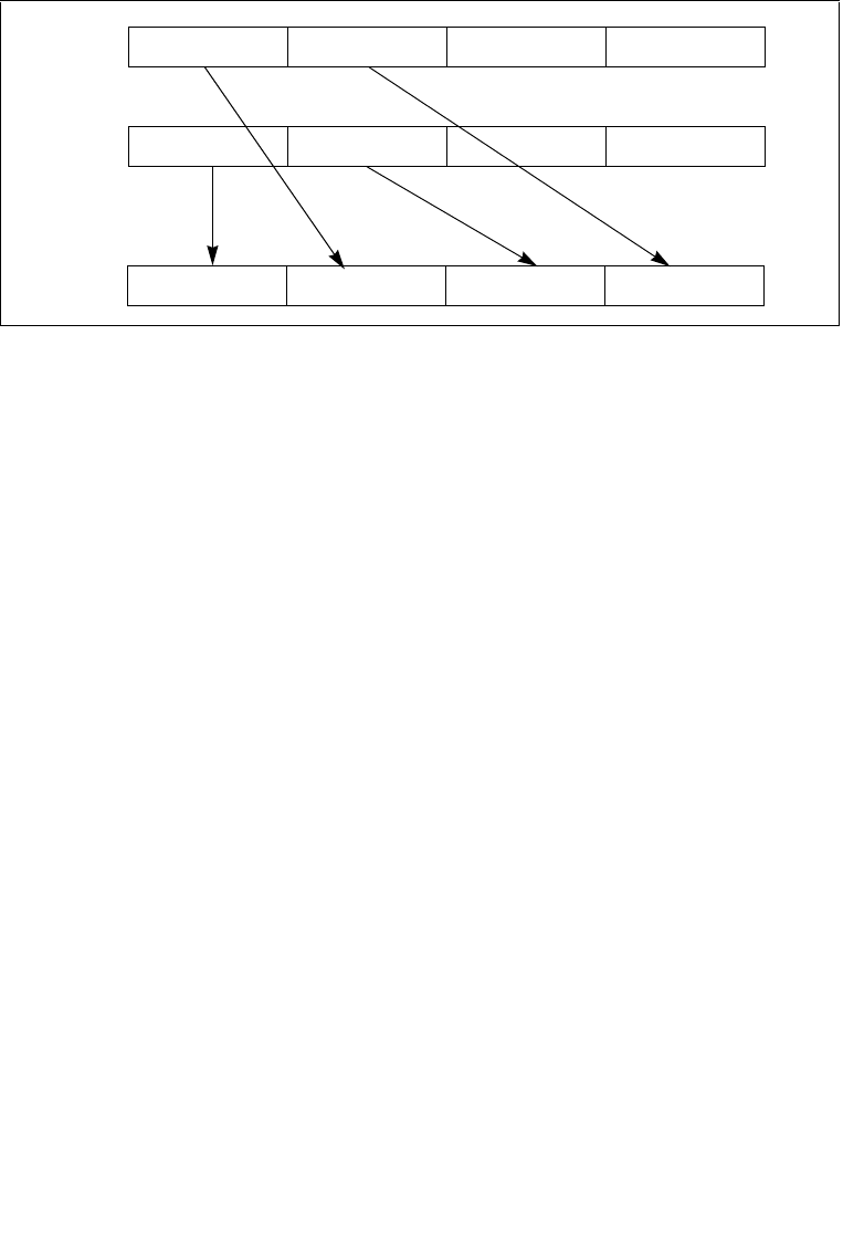
4-472 Vol. 2B UNPCKHPS—Unpack and Interleave High Packed Single-Precision Floating-Point Values
INSTRUCTION SET REFERENCE, N-Z
When unpacking from a memory operand, an implementation may fetch only the
appropriate 64 bits; however, alignment to 16-byte boundary and normal segment
checking will still be enforced.
In 64-bit mode, using a REX prefix in the form of REX.R permits this instruction to
access additional registers (XMM8-XMM15).
128-bit Legacy SSE version: T second source can be an XMM register or an 128-bit
memory location. The destination is not distinct from the first source XMM register
and the upper bits (VLMAX-1:128) of the corresponding YMM register destination are
unmodified.
VEX.128 encoded version: the first source operand is an XMM register or 128-bit
memory location. The destination operand is an XMM register. The upper bits
(VLMAX-1:128) of the corresponding YMM register destination are zeroed.
Operation
UNPCKHPS (128-bit Legacy SSE version)
DEST[31:0] SRC1[95:64]
DEST[63:32] SRC2[95:64]
DEST[95:64] SRC1[127:96]
DEST[127:96] SRC2[127:96]
DEST[VLMAX-1:128] (Unmodified)
VUNPCKHPS (VEX.128 encoded version)
DEST[31:0] SRC1[95:64]
DEST[63:32] SRC2[95:64]
DEST[95:64] SRC1[127:96]
DEST[127:96] SRC2[127:96]
DEST[VLMAX-1:128] 0
Figure 4-23. UNPCKHPS Instruction High Unpack and Interleave Operation
X3 X2 X1 X0
Y3 Y2 Y1 Y0
Y3 X3 Y2 X2
DEST
SRC
DEST

Vol. 2B 4-473
INSTRUCTION SET REFERENCE, N-Z
UNPCKHPS—Unpack and Interleave High Packed Single-Precision Floating-Point Values
VUNPCKHPS (VEX.256 encoded version)
DEST[31:0] SRC1[95:64]
DEST[63:32] SRC2[95:64]
DEST[95:64] SRC1[127:96]
DEST[127:96] SRC2[127:96]
DEST[159:128] SRC1[223:192]
DEST[191:160] SRC2[223:192]
DEST[223:192] SRC1[255:224]
DEST[255:224] SRC2[255:224]
Intel C/C++ Compiler Intrinsic Equivalent
UNPCKHPS __m128 _mm_unpackhi_ps(__m128 a, __m128 b)
UNPCKHPS __m256 _mm256_unpackhi_ps (__m256 a, __m256 b);
SIMD Floating-Point Exceptions
None.
Other Exceptions
See Exceptions Type 4.

4-474 Vol. 2B UNPCKLPD—Unpack and Interleave Low Packed Double-Precision Floating-Point Values
INSTRUCTION SET REFERENCE, N-Z
UNPCKLPD—Unpack and Interleave Low Packed Double-Precision
Floating-Point Values
Instruction Operand Encoding
Description
Performs an interleaved unpack of the low double-precision floating-point values
from the source operand (second operand) and the destination operand (first
operand). See Figure 4-24. The source operand can be an XMM register or a 128-bit
memory location; the destination operand is an XMM register.
Opcode/
Instruction
Op/
En
64/32 bit
Mode
Support
CPUID
Feature
Flag
Description
66 0F 14 /r
UNPCKLPD xmm1, xmm2/m128
A V/V SSE2 Unpacks and Interleaves
double-precision floating-
point values from low
quadwords of xmm1 and
xmm2/m128.
VEX.NDS.128.66.0F.WIG 14 /r
VUNPCKLPD xmm1,xmm2,
xmm3/m128
BV/V AVX Unpacks and Interleaves
double precision floating-
point values low high
quadwords of xmm2 and
xmm3/m128.
VEX.NDS.256.66.0F.WIG 14 /r
VUNPCKLPD ymm1,ymm2,
ymm3/m256
BV/V AVX Unpacks and Interleaves
double precision floating-
point values low high
quadwords of ymm2 and
ymm3/m256.
Op/En Operand 1 Operand 2 Operand 3 Operand 4
A ModRM:reg (r, w) ModRM:r/m (r) NA NA
B ModRM:reg (w) VEX.vvvv (r) ModRM:r/m (r) NA

Vol. 2B 4-475
INSTRUCTION SET REFERENCE, N-Z
UNPCKLPD—Unpack and Interleave Low Packed Double-Precision Floating-Point Values
When unpacking from a memory operand, an implementation may fetch only the
appropriate 64 bits; however, alignment to 16-byte boundary and normal segment
checking will still be enforced.
In 64-bit mode, using a REX prefix in the form of REX.R permits this instruction to
access additional registers (XMM8-XMM15).
128-bit Legacy SSE version: T second source can be an XMM register or an 128-bit
memory location. The destination is not distinct from the first source XMM register
and the upper bits (VLMAX-1:128) of the corresponding YMM register destination are
unmodified.
VEX.128 encoded version: the first source operand is an XMM register or 128-bit
memory location. The destination operand is an XMM register. The upper bits
(VLMAX-1:128) of the corresponding YMM register destination are zeroed.
Operation
UNPCKLPD (128-bit Legacy SSE version)
DEST[63:0] SRC1[63:0]
DEST[127:64] SRC2[63:0]
DEST[VLMAX-1:128] (Unmodified)
VUNPCKLPD (VEX.128 encoded version)
DEST[63:0] SRC1[63:0]
DEST[127:64] SRC2[63:0]
DEST[VLMAX-1:128] 0
VUNPCKLPD (VEX.256 encoded version)
DEST[63:0] SRC1[63:0]
Figure 4-24. UNPCKLPD Instruction Low Unpack and Interleave Operation
X1 X0
Y1 Y0
Y0 X0
DEST
SRC
DEST

4-476 Vol. 2B UNPCKLPD—Unpack and Interleave Low Packed Double-Precision Floating-Point Values
INSTRUCTION SET REFERENCE, N-Z
DEST[127:64] SRC2[63:0]
DEST[191:128] SRC1[191:128]
DEST[255:192] SRC2[191:128]
Intel C/C++ Compiler Intrinsic Equivalent
UNPCKHPD__m128d _mm_unpacklo_pd(__m128d a, __m128d b)
UNPCKLPD __m256d _mm256_unpacklo_pd(__m256d a, __m256d b)
SIMD Floating-Point Exceptions
None.
Other Exceptions
See Exceptions Type 4.

Vol. 2B 4-477
INSTRUCTION SET REFERENCE, N-Z
UNPCKLPS—Unpack and Interleave Low Packed Single-Precision Floating-Point Values
UNPCKLPS—Unpack and Interleave Low Packed Single-Precision
Floating-Point Values
Instruction Operand Encoding
Description
Performs an interleaved unpack of the low-order single-precision floating-point
values from the source operand (second operand) and the destination operand (first
operand). See Figure 4-25. The source operand can be an XMM register or a 128-bit
memory location; the destination operand is an XMM register.
Opcode/
Instruction
Op/
En
64/32 bit
Mode
Support
CPUID
Feature
Flag
Description
0F 14 /r
UNPCKLPS xmm1, xmm2/m128
AV/V SSE Unpacks and Interleaves
single-precision floating-
point values from low
quadwords of xmm1 and
xmm2/mem into xmm1.
VEX.NDS.128.0F.WIG 14 /r
VUNPCKLPS xmm1,xmm2,
xmm3/m128
BV/V AVX Unpacks and Interleaves
single-precision floating-
point values from low
quadwords of xmm2 and
xmm3/m128.
VEX.NDS.256.0F.WIG 14 /r
VUNPCKLPS
ymm1,ymm2,ymm3/m256
BV/V AVX Unpacks and Interleaves
single-precision floating-
point values from low
quadwords of ymm2 and
ymm3/m256.
Op/En Operand 1 Operand 2 Operand 3 Operand 4
A ModRM:reg (r, w) ModRM:r/m (r) NA NA
B ModRM:reg (w) VEX.vvvv (r) ModRM:r/m (r) NA

4-478 Vol. 2B UNPCKLPS—Unpack and Interleave Low Packed Single-Precision Floating-Point Values
INSTRUCTION SET REFERENCE, N-Z
When unpacking from a memory operand, an implementation may fetch only the
appropriate 64 bits; however, alignment to 16-byte boundary and normal segment
checking will still be enforced.
In 64-bit mode, using a REX prefix in the form of REX.R permits this instruction to
access additional registers (XMM8-XMM15).
128-bit Legacy SSE version: T second source can be an XMM register or an 128-bit
memory location. The destination is not distinct from the first source XMM register
and the upper bits (255:128) of the corresponding YMM register destination are
unmodified.
VEX.128 encoded version: the first source operand is an XMM register or 128-bit
memory location. The destination operand is an XMM register. The upper bits
(255:128) of the corresponding YMM register destination are zeroed.
Operation
UNPCKLPS (128-bit Legacy SSE version)
DEST[31:0] SRC1[31:0]
DEST[63:32] SRC2[31:0]
DEST[95:64] SRC1[63:32]
DEST[127:96] SRC2[63:32]
DEST[VLMAX-1:128] (Unmodified)
VUNPCKLPS (VEX.128 encoded version)
DEST[31:0] SRC1[31:0]
DEST[63:32] SRC2[31:0]
DEST[95:64] SRC1[63:32]
DEST[127:96] SRC2[63:32]
Figure 4-25. UNPCKLPS Instruction Low Unpack and Interleave Operation
X3 X2 X1 X0
Y3 Y2 Y1 Y0
Y1 X1 Y0 X0
DEST
SRC
DEST

Vol. 2B 4-479
INSTRUCTION SET REFERENCE, N-Z
UNPCKLPS—Unpack and Interleave Low Packed Single-Precision Floating-Point Values
DEST[VLMAX-1:128] 0
UNPCKLPS (VEX.256 encoded version)
DEST[31:0] SRC1[31:0]
DEST[63:32] SRC2[31:0]
DEST[95:64] SRC1[63:32]
DEST[127:96] SRC2[63:32]
DEST[159:128] SRC1[159:128]
DEST[191:160] SRC2[159:128]
DEST[223:192] SRC1[191:160]
DEST[255:224] SRC2[191:160]
Intel C/C++ Compiler Intrinsic Equivalent
UNPCKLPS __m128 _mm_unpacklo_ps(__m128 a, __m128 b)
UNPCKLPS __m256 _mm256_unpacklo_ps (__m256 a, __m256 b);
SIMD Floating-Point Exceptions
None.
Other Exceptions
See Exceptions Type 4.

4-480 Vol. 2B VERR/VERW—Verify a Segment for Reading or Writing
INSTRUCTION SET REFERENCE, N-Z
VERR/VERW—Verify a Segment for Reading or Writing
Instruction Operand Encoding
Description
Verifies whether the code or data segment specified with the source operand is read-
able (VERR) or writable (VERW) from the current privilege level (CPL). The source
operand is a 16-bit register or a memory location that contains the segment selector
for the segment to be verified. If the segment is accessible and readable (VERR) or
writable (VERW), the ZF flag is set; otherwise, the ZF flag is cleared. Code segments
are never verified as writable. This check cannot be performed on system segments.
To set the ZF flag, the following conditions must be met:
•The segment selector is not NULL.
•The selector must denote a descriptor within the bounds of the descriptor table
(GDT or LDT).
•The selector must denote the descriptor of a code or data segment (not that of a
system segment or gate).
•For the VERR instruction, the segment must be readable.
•For the VERW instruction, the segment must be a writable data segment.
•If the segment is not a conforming code segment, the segment’s DPL must be
greater than or equal to (have less or the same privilege as) both the CPL and the
segment selector's RPL.
The validation performed is the same as is performed when a segment selector is
loaded into the DS, ES, FS, or GS register, and the indicated access (read or write) is
performed. The segment selector's value cannot result in a protection exception,
enabling the software to anticipate possible segment access problems.
This instruction’s operation is the same in non-64-bit modes and 64-bit mode. The
operand size is fixed at 16 bits.
Opcode Instruction Op/
En
64-Bit
Mode
Compat/
Leg Mode
Description
0F 00 /4 VERR r/m16 A Valid Valid Set ZF=1 if segment
specified with r/m16 can be
read.
0F 00 /5 VERW r/m16 B Valid Valid Set ZF=1 if segment
specified with r/m16 can be
written.
Op/En Operand 1 Operand 2 Operand 3 Operand 4
A ModRM:r/m (r) NA NA NA
BNA NA NA NA

Vol. 2B 4-481
INSTRUCTION SET REFERENCE, N-Z
VERR/VERW—Verify a Segment for Reading or Writing
Operation
IF SRC(Offset) > (GDTR(Limit) or (LDTR(Limit))
THEN ZF ← 0; FI;
Read segment descriptor;
IF SegmentDescriptor(DescriptorType) = 0 (* System segment *)
or (SegmentDescriptor(Type) ≠ conforming code segment)
and (CPL > DPL) or (RPL > DPL)
THEN
ZF ← 0;
ELSE
IF ((Instruction = VERR) and (Segment readable))
or ((Instruction = VERW) and (Segment writable))
THEN
ZF ← 1;
FI;
FI;
Flags Affected
The ZF flag is set to 1 if the segment is accessible and readable (VERR) or writable
(VERW); otherwise, it is set to 0.
Protected Mode Exceptions
The only exceptions generated for these instructions are those related to illegal
addressing of the source operand.
#GP(0) If a memory operand effective address is outside the CS, DS,
ES, FS, or GS segment limit.
If the DS, ES, FS, or GS register is used to access memory and it
contains a NULL segment selector.
#SS(0) If a memory operand effective address is outside the SS
segment limit.
#PF(fault-code) If a page fault occurs.
#AC(0) If alignment checking is enabled and an unaligned memory
reference is made while the current privilege level is 3.
#UD If the LOCK prefix is used.
Real-Address Mode Exceptions
#UD The VERR and VERW instructions are not recognized in real-
address mode.
If the LOCK prefix is used.

4-482 Vol. 2B VERR/VERW—Verify a Segment for Reading or Writing
INSTRUCTION SET REFERENCE, N-Z
Virtual-8086 Mode Exceptions
#UD The VERR and VERW instructions are not recognized in virtual-
8086 mode.
If the LOCK prefix is used.
Compatibility Mode Exceptions
Same exceptions as in protected mode.
64-Bit Mode Exceptions
#SS(0) If a memory address referencing the SS segment is in a non-
canonical form.
#GP(0) If the memory address is in a non-canonical form.
#PF(fault-code) If a page fault occurs.
#AC(0) If alignment checking is enabled and an unaligned memory
reference is made while the current privilege level is 3.
#UD If the LOCK prefix is used.

Vol. 2B 4-483
INSTRUCTION SET REFERENCE, N-Z
WAIT/FWAIT—Wait
WAIT/FWAIT—Wait
Instruction Operand Encoding
Description
Causes the processor to check for and handle pending, unmasked, floating-point
exceptions before proceeding. (FWAIT is an alternate mnemonic for WAIT.)
This instruction is useful for synchronizing exceptions in critical sections of code.
Coding a WAIT instruction after a floating-point instruction ensures that any
unmasked floating-point exceptions the instruction may raise are handled before the
processor can modify the instruction’s results. See the section titled “Floating-Point
Exception Synchronization” in Chapter 8 of the Intel® 64 and IA-32 Architectures
Software Developer’s Manual, Volume 1, for more information on using the
WAIT/FWAIT instruction.
This instruction’s operation is the same in non-64-bit modes and 64-bit mode.
Operation
CheckForPendingUnmaskedFloatingPointExceptions;
FPU Flags Affected
The C0, C1, C2, and C3 flags are undefined.
Floating-Point Exceptions
None.
Protected Mode Exceptions
#NM If CR0.MP[bit 1] = 1 and CR0.TS[bit 3] = 1.
#UD If the LOCK prefix is used.
Opcode Instruction Op/
En
64-Bit
Mode
Compat/
Leg Mode
Description
9B WAIT A Valid Valid Check pending unmasked
floating-point exceptions.
9B FWAIT A Valid Valid Check pending unmasked
floating-point exceptions.
Op/En Operand 1 Operand 2 Operand 3 Operand 4
ANA NA NA NA

4-484 Vol. 2B WAIT/FWAIT—Wait
INSTRUCTION SET REFERENCE, N-Z
Real-Address Mode Exceptions
Same exceptions as in protected mode.
Virtual-8086 Mode Exceptions
Same exceptions as in protected mode.
Compatibility Mode Exceptions
Same exceptions as in protected mode.
64-Bit Mode Exceptions
Same exceptions as in protected mode.

Vol. 2B 4-485
INSTRUCTION SET REFERENCE, N-Z
WBINVD—Write Back and Invalidate Cache
WBINVD—Write Back and Invalidate Cache
Instruction Operand Encoding
Description
Writes back all modified cache lines in the processor’s internal cache to main memory
and invalidates (flushes) the internal caches. The instruction then issues a special-
function bus cycle that directs external caches to also write back modified data and
another bus cycle to indicate that the external caches should be invalidated.
After executing this instruction, the processor does not wait for the external caches
to complete their write-back and flushing operations before proceeding with instruc-
tion execution. It is the responsibility of hardware to respond to the cache write-back
and flush signals. The amount of time or cycles for WBINVD to complete will vary due
to size and other factors of different cache hierarchies. As a consequence, the use of
the WBINVD instruction can have an impact on logical processor interrupt/event
response time.
The WBINVD instruction is a privileged instruction. When the processor is running in
protected mode, the CPL of a program or procedure must be 0 to execute this
instruction. This instruction is also a serializing instruction (see “Serializing Instruc-
tions” in Chapter 10 of the Intel® 64 and IA-32 Architectures Software Developer’s
Manual, Volume 3A).
In situations where cache coherency with main memory is not a concern, software
can use the INVD instruction.
This instruction’s operation is the same in non-64-bit modes and 64-bit mode.
IA-32 Architecture Compatibility
The WBINVD instruction is implementation dependent, and its function may be
implemented differently on future Intel 64 and IA-32 processors. The instruction is
not supported on IA-32 processors earlier than the Intel486 processor.
Operation
WriteBack(InternalCaches);
Opcode Instruction Op/
En
64-Bit
Mode
Compat/
Leg Mode
Description
0F 09 WBINVD A Valid Valid Write back and flush Internal
caches; initiate writing-back
and flushing of external
caches.
Op/En Operand 1 Operand 2 Operand 3 Operand 4
ANA NA NA NA

4-486 Vol. 2B WBINVD—Write Back and Invalidate Cache
INSTRUCTION SET REFERENCE, N-Z
Flush(InternalCaches);
SignalWriteBack(ExternalCaches);
SignalFlush(ExternalCaches);
Continue; (* Continue execution *)
Flags Affected
None.
Protected Mode Exceptions
#GP(0) If the current privilege level is not 0.
#UD If the LOCK prefix is used.
Real-Address Mode Exceptions
#UD If the LOCK prefix is used.
Virtual-8086 Mode Exceptions
#GP(0) WBINVD cannot be executed at the virtual-8086 mode.
Compatibility Mode Exceptions
Same exceptions as in protected mode.
64-Bit Mode Exceptions
Same exceptions as in protected mode.

Vol. 2B 4-487
INSTRUCTION SET REFERENCE, N-Z
WRMSR—Write to Model Specific Register
WRMSR—Write to Model Specific Register
Instruction Operand Encoding
Description
Writes the contents of registers EDX:EAX into the 64-bit model specific register
(MSR) specified in the ECX register. (On processors that support the Intel 64 archi-
tecture, the high-order 32 bits of RCX are ignored.) The contents of the EDX register
are copied to high-order 32 bits of the selected MSR and the contents of the EAX
register are copied to low-order 32 bits of the MSR. (On processors that support the
Intel 64 architecture, the high-order 32 bits of each of RAX and RDX are ignored.)
Undefined or reserved bits in an MSR should be set to values previously read.
This instruction must be executed at privilege level 0 or in real-address mode; other-
wise, a general protection exception #GP(0) is generated. Specifying a reserved or
unimplemented MSR address in ECX will also cause a general protection exception.
The processor will also generate a general protection exception if software attempts
to write to bits in a reserved MSR.
When the WRMSR instruction is used to write to an MTRR, the TLBs are invalidated.
This includes global entries (see “Translation Lookaside Buffers (TLBs)” in Chapter 3
of the Intel® 64 and IA-32 Architectures Software Developer’s Manual, Volume 3A).
MSRs control functions for testability, execution tracing, performance-monitoring
and machine check errors. Appendix B, “Model-Specific Registers (MSRs)”, in the
Intel® 64 and IA-32 Architectures Software Developer’s Manual, Volume 3B, lists all
MSRs that can be read with this instruction and their addresses. Note that each
processor family has its own set of MSRs.
The WRMSR instruction is a serializing instruction (see “Serializing Instructions” in
Chapter 8 of the Intel® 64 and IA-32 Architectures Software Developer’s Manual,
Volume 3A).
The CPUID instruction should be used to determine whether MSRs are supported
(CPUID.01H:EDX[5] = 1) before using this instruction.
IA-32 Architecture Compatibility
The MSRs and the ability to read them with the WRMSR instruction were introduced
into the IA-32 architecture with the Pentium processor. Execution of this instruction
Opcode Instruction Op/
En
64-Bit
Mode
Compat/
Leg Mode
Description
0F 30 WRMSR A Valid Valid Write the value in EDX:EAX
to MSR specified by ECX.
Op/En Operand 1 Operand 2 Operand 3 Operand 4
ANA NA NA NA

4-488 Vol. 2B WRMSR—Write to Model Specific Register
INSTRUCTION SET REFERENCE, N-Z
by an IA-32 processor earlier than the Pentium processor results in an invalid opcode
exception #UD.
Operation
MSR[ECX] ← EDX:EAX;
Flags Affected
None.
Protected Mode Exceptions
#GP(0) If the current privilege level is not 0.
If the value in ECX specifies a reserved or unimplemented MSR
address.
If the value in EDX:EAX sets bits that are reserved in the MSR
specified by ECX.
#UD If the LOCK prefix is used.
Real-Address Mode Exceptions
#GP If the value in ECX specifies a reserved or unimplemented MSR
address.
If the value in EDX:EAX sets bits that are reserved in the MSR
specified by ECX.
#UD If the LOCK prefix is used.
Virtual-8086 Mode Exceptions
#GP(0) The WRMSR instruction is not recognized in virtual-8086 mode.
Compatibility Mode Exceptions
Same exceptions as in protected mode.
64-Bit Mode Exceptions
Same exceptions as in protected mode.

Vol. 2B 4-489
INSTRUCTION SET REFERENCE, N-Z
XADD—Exchange and Add
XADD—Exchange and Add
Instruction Operand Encoding
Description
Exchanges the first operand (destination operand) with the second operand (source
operand), then loads the sum of the two values into the destination operand. The
destination operand can be a register or a memory location; the source operand is a
register.
In 64-bit mode, the instruction’s default operation size is 32 bits. Using a REX prefix
in the form of REX.R permits access to additional registers (R8-R15). Using a REX
prefix in the form of REX.W promotes operation to 64 bits. See the summary chart at
the beginning of this section for encoding data and limits.
This instruction can be used with a LOCK prefix to allow the instruction to be
executed atomically.
IA-32 Architecture Compatibility
IA-32 processors earlier than the Intel486 processor do not recognize this instruc-
tion. If this instruction is used, you should provide an equivalent code sequence that
runs on earlier processors.
Opcode Instruction Op/
En
64-Bit
Mode
Compat/
Leg Mode
Description
0F C0 /rXADD r/m8, r8 A Valid Valid Exchange r8 and r/m8; load
sum into r/m8.
REX + 0F C0 /rXADD r/m8*, r8* A Valid N.E. Exchange r8 and r/m8; load
sum into r/m8.
0F C1 /rXADD r/m16, r16 A Valid Valid Exchange r16 and r/m16;
load sum into r/m16.
0F C1 /rXADD r/m32, r32 A Valid Valid Exchange r32 and r/m32;
load sum into r/m32.
REX.W + 0F C1
/r
XADD r/m64, r64 A Valid N.E. Exchange r64 and r/m64;
load sum into r/m64.
NOTES:
* In 64-bit mode, r/m8 can not be encoded to access the following byte registers if a REX prefix is
used: AH, BH, CH, DH.
Op/En Operand 1 Operand 2 Operand 3 Operand 4
A ModRM:r/m (r, w) ModRM:reg (r) NA NA

4-490 Vol. 2B XADD—Exchange and Add
INSTRUCTION SET REFERENCE, N-Z
Operation
TEMP ← SRC + DEST;
SRC ← DEST;
DEST ← TEMP;
Flags Affected
The CF, PF, AF, SF, ZF, and OF flags are set according to the result of the addition,
which is stored in the destination operand.
Protected Mode Exceptions
#GP(0) If the destination is located in a non-writable segment.
If a memory operand effective address is outside the CS, DS,
ES, FS, or GS segment limit.
If the DS, ES, FS, or GS register contains a NULL segment
selector.
#SS(0) If a memory operand effective address is outside the SS
segment limit.
#PF(fault-code) If a page fault occurs.
#AC(0) If alignment checking is enabled and an unaligned memory
reference is made while the current privilege level is 3.
#UD If the LOCK prefix is used but the destination is not a memory
operand.
Real-Address Mode Exceptions
#GP If a memory operand effective address is outside the CS, DS,
ES, FS, or GS segment limit.
#SS If a memory operand effective address is outside the SS
segment limit.
#UD If the LOCK prefix is used but the destination is not a memory
operand.
Virtual-8086 Mode Exceptions
#GP(0) If a memory operand effective address is outside the CS, DS,
ES, FS, or GS segment limit.
#SS(0) If a memory operand effective address is outside the SS
segment limit.
#PF(fault-code) If a page fault occurs.
#AC(0) If alignment checking is enabled and an unaligned memory
reference is made.

Vol. 2B 4-491
INSTRUCTION SET REFERENCE, N-Z
XADD—Exchange and Add
#UD If the LOCK prefix is used but the destination is not a memory
operand.
Compatibility Mode Exceptions
Same exceptions as in protected mode.
64-Bit Mode Exceptions
#SS(0) If a memory address referencing the SS segment is in a non-
canonical form.
#GP(0) If the memory address is in a non-canonical form.
#PF(fault-code) If a page fault occurs.
#AC(0) If alignment checking is enabled and an unaligned memory
reference is made while the current privilege level is 3.
#UD If the LOCK prefix is used but the destination is not a memory
operand.

4-492 Vol. 2B XCHG—Exchange Register/Memory with Register
INSTRUCTION SET REFERENCE, N-Z
XCHG—Exchange Register/Memory with Register
Opcode Instruction Op/
En
64-Bit
Mode
Compat/
Leg Mode
Description
90+rw XCHG AX, r16 A Valid Valid Exchange r16 with AX.
90+rw XCHG r16, AX B Valid Valid Exchange AX with r16.
90+rd XCHG EAX, r32 A Valid Valid Exchange r32 with EAX.
REX.W + 90+rd XCHG RAX, r64 A Valid N.E. Exchange r64 with RAX.
90+rd XCHG r32, EAX B Valid Valid Exchange EAX with r32.
REX.W + 90+rd XCHG r64, RAX B Valid N.E. Exchange RAX with r64.
86 /rXCHG r/m8, r8 C Valid Valid Exchange r8 (byte register)
with byte from r/m8.
REX + 86 /rXCHG r/m8*, r8* C Valid N.E. Exchange r8 (byte register)
with byte from r/m8.
86 /rXCHG r8, r/m8 D Valid Valid Exchange byte from r/m8
with r8 (byte register).
REX + 86 /rXCHG r8*, r/m8* D Valid N.E. Exchange byte from r/m8
with r8 (byte register).
87 /rXCHG r/m16, r16 C Valid Valid Exchange r16 with word
from r/m16.
87 /rXCHG r16, r/m16 D Valid Valid Exchange word from r/m16
with r16.
87 /rXCHG r/m32, r32 C Valid Valid Exchange r32 with
doubleword from r/m32.
REX.W + 87 /rXCHG r/m64, r64 C Valid N.E. Exchange r64 with
quadword from r/m64.
87 /rXCHG r32, r/m32 D Valid Valid Exchange doubleword from
r/m32 with r32.
REX.W + 87 /rXCHG r64, r/m64 D Valid N.E. Exchange quadword from
r/m64 with r64.
NOTES:
* In 64-bit mode, r/m8 can not be encoded to access the following byte registers if a REX prefix is
used: AH, BH, CH, DH.

Vol. 2B 4-493
INSTRUCTION SET REFERENCE, N-Z
XCHG—Exchange Register/Memory with Register
Instruction Operand Encoding
Description
Exchanges the contents of the destination (first) and source (second) operands. The
operands can be two general-purpose registers or a register and a memory location.
If a memory operand is referenced, the processor’s locking protocol is automatically
implemented for the duration of the exchange operation, regardless of the presence
or absence of the LOCK prefix or of the value of the IOPL. (See the LOCK prefix
description in this chapter for more information on the locking protocol.)
This instruction is useful for implementing semaphores or similar data structures for
process synchronization. (See “Bus Locking” in Chapter 8 of the Intel® 64 and IA-32
Architectures Software Developer’s Manual, Volume 3A, for more information on bus
locking.)
The XCHG instruction can also be used instead of the BSWAP instruction for 16-bit
operands.
In 64-bit mode, the instruction’s default operation size is 32 bits. Using a REX prefix
in the form of REX.R permits access to additional registers (R8-R15). Using a REX
prefix in the form of REX.W promotes operation to 64 bits. See the summary chart at
the beginning of this section for encoding data and limits.
Operation
TEMP ← DEST;
DEST ← SRC;
SRC ← TEMP;
Flags Affected
None.
Protected Mode Exceptions
#GP(0) If either operand is in a non-writable segment.
If a memory operand effective address is outside the CS, DS,
ES, FS, or GS segment limit.
If the DS, ES, FS, or GS register contains a NULL segment
selector.
Op/En Operand 1 Operand 2 Operand 3 Operand 4
A AX/EAX/RAX (r, w) reg (r, w) NA NA
B reg (r, w) AX/EAX/RAX (r, w) NA NA
C ModRM:r/m (r, w) ModRM:reg (r, w) NA NA
D ModRM:reg (r, w) ModRM:r/m (r, w) NA NA

4-494 Vol. 2B XCHG—Exchange Register/Memory with Register
INSTRUCTION SET REFERENCE, N-Z
#SS(0) If a memory operand effective address is outside the SS
segment limit.
#PF(fault-code) If a page fault occurs.
#AC(0) If alignment checking is enabled and an unaligned memory
reference is made while the current privilege level is 3.
#UD If the LOCK prefix is used but the destination is not a memory
operand.
Real-Address Mode Exceptions
#GP If a memory operand effective address is outside the CS, DS,
ES, FS, or GS segment limit.
#SS If a memory operand effective address is outside the SS
segment limit.
#UD If the LOCK prefix is used but the destination is not a memory
operand.
Virtual-8086 Mode Exceptions
#GP(0) If a memory operand effective address is outside the CS, DS,
ES, FS, or GS segment limit.
#SS(0) If a memory operand effective address is outside the SS
segment limit.
#PF(fault-code) If a page fault occurs.
#AC(0) If alignment checking is enabled and an unaligned memory
reference is made.
#UD If the LOCK prefix is used but the destination is not a memory
operand.
Compatibility Mode Exceptions
Same exceptions as in protected mode.
64-Bit Mode Exceptions
#SS(0) If a memory address referencing the SS segment is in a non-
canonical form.
#GP(0) If the memory address is in a non-canonical form.
#PF(fault-code) If a page fault occurs.
#AC(0) If alignment checking is enabled and an unaligned memory
reference is made while the current privilege level is 3.
#UD If the LOCK prefix is used but the destination is not a memory
operand.

Vol. 2B 4-495
INSTRUCTION SET REFERENCE, N-Z
XGETBV—Get Value of Extended Control Register
XGETBV—Get Value of Extended Control Register
Instruction Operand Encoding
Description
Reads the contents of the extended control register (XCR) specified in the ECX
register into registers EDX:EAX. (On processors that support the Intel 64 architec-
ture, the high-order 32 bits of RCX are ignored.) The EDX register is loaded with the
high-order 32 bits of the XCR and the EAX register is loaded with the low-order 32
bits. (On processors that support the Intel 64 architecture, the high-order 32 bits of
each of RAX and RDX are cleared.) If fewer than 64 bits are implemented in the XCR
being read, the values returned to EDX:EAX in unimplemented bit locations are
undefined.
Specifying a reserved or unimplemented XCR in ECX causes a general protection
exception.
Currently, only XCR0 (the XFEATURE_ENABLED_MASK register) is supported. Thus,
all other values of ECX are reserved and will cause a #GP(0).
Operation
EDX:EAX ← XCR[ECX];
Flags Affected
None.
Protected Mode Exceptions
#GP(0) If an invalid XCR is specified in ECX.
#UD If CPUID.01H:ECX.XSAVE[bit 26] = 0.
If CR4.OSXSAVE[bit 18] = 0.
If the LOCK prefix is used.
If 66H, F3H or F2H prefix is used.
Opcode Instruction Op/
En
64-Bit
Mode
Compat/
Leg Mode
Description
0F 01 D0 XGETBV A Valid Valid Reads an XCR specified by
ECX into EDX:EAX.
Op/En Operand 1 Operand 2 Operand 3 Operand 4
ANA NA NA NA

4-496 Vol. 2B XGETBV—Get Value of Extended Control Register
INSTRUCTION SET REFERENCE, N-Z
Real-Address Mode Exceptions
#GP If an invalid XCR is specified in ECX.
#UD If CPUID.01H:ECX.XSAVE[bit 26] = 0.
If CR4.OSXSAVE[bit 18] = 0.
If the LOCK prefix is used.
If 66H, F3H or F2H prefix is used.
Virtual-8086 Mode Exceptions
Same exceptions as in protected mode.
Compatibility Mode Exceptions
Same exceptions as in protected mode.
64-Bit Mode Exceptions
Same exceptions as in protected mode.

Vol. 2B 4-497
INSTRUCTION SET REFERENCE, N-Z
XLAT/XLATB—Table Look-up Translation
XLAT/XLATB—Table Look-up Translation
Instruction Operand Encoding
Description
Locates a byte entry in a table in memory, using the contents of the AL register as a
table index, then copies the contents of the table entry back into the AL register. The
index in the AL register is treated as an unsigned integer. The XLAT and XLATB
instructions get the base address of the table in memory from either the DS:EBX or
the DS:BX registers (depending on the address-size attribute of the instruction, 32 or
16, respectively). (The DS segment may be overridden with a segment override
prefix.)
At the assembly-code level, two forms of this instruction are allowed: the “explicit-
operand” form and the “no-operand” form. The explicit-operand form (specified with
the XLAT mnemonic) allows the base address of the table to be specified explicitly
with a symbol. This explicit-operands form is provided to allow documentation;
however, note that the documentation provided by this form can be misleading. That
is, the symbol does not have to specify the correct base address. The base address is
always specified by the DS:(E)BX registers, which must be loaded correctly before
the XLAT instruction is executed.
The no-operands form (XLATB) provides a “short form” of the XLAT instructions. Here
also the processor assumes that the DS:(E)BX registers contain the base address of
the table.
In 64-bit mode, operation is similar to that in legacy or compatibility mode. AL is
used to specify the table index (the operand size is fixed at 8 bits). RBX, however, is
used to specify the table’s base address. See the summary chart at the beginning of
this section for encoding data and limits.
Operation
IF AddressSize = 16
Opcode Instruction Op/
En
64-Bit
Mode
Compat/
Leg Mode
Description
D7 XLAT m8 A Valid Valid Set AL to memory byte
DS:[(E)BX + unsigned AL].
D7 XLATB A Valid Valid Set AL to memory byte
DS:[(E)BX + unsigned AL].
REX.W + D7 XLATB A Valid N.E. Set AL to memory byte
[RBX + unsigned AL].
Op/En Operand 1 Operand 2 Operand 3 Operand 4
ANA NA NA NA

4-498 Vol. 2B XLAT/XLATB—Table Look-up Translation
INSTRUCTION SET REFERENCE, N-Z
THEN
AL ← (DS:BX + ZeroExtend(AL));
ELSE IF (AddressSize = 32)
AL ← (DS:EBX + ZeroExtend(AL)); FI;
ELSE (AddressSize = 64)
AL ← (RBX + ZeroExtend(AL));
FI;
Flags Affected
None.
Protected Mode Exceptions
#GP(0) If a memory operand effective address is outside the CS, DS,
ES, FS, or GS segment limit.
If the DS, ES, FS, or GS register contains a NULL segment
selector.
#SS(0) If a memory operand effective address is outside the SS
segment limit.
#PF(fault-code) If a page fault occurs.
#UD If the LOCK prefix is used.
Real-Address Mode Exceptions
#GP If a memory operand effective address is outside the CS, DS,
ES, FS, or GS segment limit.
#SS If a memory operand effective address is outside the SS
segment limit.
#UD If the LOCK prefix is used.
Virtual-8086 Mode Exceptions
#GP(0) If a memory operand effective address is outside the CS, DS,
ES, FS, or GS segment limit.
#SS(0) If a memory operand effective address is outside the SS
segment limit.
#PF(fault-code) If a page fault occurs.
#UD If the LOCK prefix is used.
Compatibility Mode Exceptions
Same exceptions as in protected mode.

Vol. 2B 4-499
INSTRUCTION SET REFERENCE, N-Z
XLAT/XLATB—Table Look-up Translation
64-Bit Mode Exceptions
#SS(0) If a memory address referencing the SS segment is in a non-
canonical form.
#GP(0) If the memory address is in a non-canonical form.
#PF(fault-code) If a page fault occurs.
#UD If the LOCK prefix is used.

4-500 Vol. 2B XOR—Logical Exclusive OR
INSTRUCTION SET REFERENCE, N-Z
XOR—Logical Exclusive OR
Opcode Instruction Op/
En
64-Bit
Mode
Compat/
Leg Mode
Description
34 ib XOR AL, imm8 AValid Valid AL XOR imm8.
35 iw XOR AX, imm16 AValid Valid AX XOR imm16.
35 id XOR EAX, imm32 AValid Valid EAX XOR imm32.
REX.W + 35 id XOR RAX, imm32 A Valid N.E. RAX XOR imm32 (sign-
extended).
80 /6 ib XOR r/m8, imm8 BValid Valid r/m8 XOR imm8.
REX + 80 /6 ib XOR r/m8*, imm8 BValid N.E. r/m8 XOR imm8.
81 /6 iw XOR r/m16,
imm16
BValid Valid r/m16 XOR imm16.
81 /6 id XOR r/m32,
imm32
BValid Valid r/m32 XOR imm32.
REX.W + 81 /6
id
XOR r/m64,
imm32
BValid N.E. r/m64 XOR imm32 (sign-
extended).
83 /6 ib XOR r/m16, imm8 BValid Valid r/m16 XOR imm8 (sign-
extended).
83 /6 ib XOR r/m32, imm8 BValid Valid r/m32 XOR imm8 (sign-
extended).
REX.W + 83 /6
ib
XOR r/m64, imm8 BValid N.E. r/m64 XOR imm8 (sign-
extended).
30 /rXOR r/m8, r8 CValid Valid r/m8 XOR r8.
REX + 30 /rXOR r/m8*, r8* CValid N.E. r/m8 XOR r8.
31 /rXOR r/m16, r16 CValid Valid r/m16 XOR r16.
31 /rXOR r/m32, r32 CValid Valid r/m32 XOR r32.
REX.W + 31 /rXOR r/m64, r64 CValid N.E. r/m64 XOR r64.
32 /rXOR r8, r/m8 DValid Valid r8 XOR r/m8.
REX + 32 /rXOR r8*, r/m8* DValid N.E. r8 XOR r/m8.
33 /rXOR r16, r/m16 DValid Valid r16 XOR r/m16.
33 /rXOR r32, r/m32 DValid Valid r32 XOR r/m32.
REX.W + 33 /rXOR r64, r/m64 DValid N.E. r64 XOR r/m64.
NOTES:
* In 64-bit mode, r/m8 can not be encoded to access the following byte registers if a REX prefix is
used: AH, BH, CH, DH.

Vol. 2B 4-501
INSTRUCTION SET REFERENCE, N-Z
XOR—Logical Exclusive OR
Instruction Operand Encoding
Description
Performs a bitwise exclusive OR (XOR) operation on the destination (first) and source
(second) operands and stores the result in the destination operand location. The
source operand can be an immediate, a register, or a memory location; the destina-
tion operand can be a register or a memory location. (However, two memory oper-
ands cannot be used in one instruction.) Each bit of the result is 1 if the
corresponding bits of the operands are different; each bit is 0 if the corresponding
bits are the same.
This instruction can be used with a LOCK prefix to allow the instruction to be
executed atomically.
In 64-bit mode, using a REX prefix in the form of REX.R permits access to additional
registers (R8-R15). Using a REX prefix in the form of REX.W promotes operation to
64 bits. See the summary chart at the beginning of this section for encoding data and
limits.
Operation
DEST ← DEST XOR SRC;
Flags Affected
The OF and CF flags are cleared; the SF, ZF, and PF flags are set according to the
result. The state of the AF flag is undefined.
Protected Mode Exceptions
#GP(0) If the destination operand points to a non-writable segment.
If a memory operand effective address is outside the CS, DS,
ES, FS, or GS segment limit.
If the DS, ES, FS, or GS register contains a NULL segment
selector.
#SS(0) If a memory operand effective address is outside the SS
segment limit.
#PF(fault-code) If a page fault occurs.
Op/En Operand 1 Operand 2 Operand 3 Operand 4
A AL/AX/EAX/RAX imm8/16/32 NA NA
B ModRM:r/m (r, w) imm8/16/32 NA NA
C ModRM:r/m (r, w) ModRM:reg (r) NA NA
D ModRM:reg (r, w) ModRM:r/m (r) NA NA

4-502 Vol. 2B XOR—Logical Exclusive OR
INSTRUCTION SET REFERENCE, N-Z
#AC(0) If alignment checking is enabled and an unaligned memory
reference is made while the current privilege level is 3.
#UD If the LOCK prefix is used but the destination is not a memory
operand.
Real-Address Mode Exceptions
#GP If a memory operand effective address is outside the CS, DS,
ES, FS, or GS segment limit.
#SS If a memory operand effective address is outside the SS
segment limit.
#UD If the LOCK prefix is used but the destination is not a memory
operand.
Virtual-8086 Mode Exceptions
#GP(0) If a memory operand effective address is outside the CS, DS,
ES, FS, or GS segment limit.
#SS(0) If a memory operand effective address is outside the SS
segment limit.
#PF(fault-code) If a page fault occurs.
#AC(0) If alignment checking is enabled and an unaligned memory
reference is made.
#UD If the LOCK prefix is used but the destination is not a memory
operand.
Compatibility Mode Exceptions
Same exceptions as in protected mode.
64-Bit Mode Exceptions
#SS(0) If a memory address referencing the SS segment is in a non-
canonical form.
#GP(0) If the memory address is in a non-canonical form.
#PF(fault-code) If a page fault occurs.
#AC(0) If alignment checking is enabled and an unaligned memory
reference is made while the current privilege level is 3.
#UD If the LOCK prefix is used but the destination is not a memory
operand.

Vol. 2B 4-503
INSTRUCTION SET REFERENCE, N-Z
XORPD—Bitwise Logical XOR for Double-Precision Floating-Point Values
XORPD—Bitwise Logical XOR for Double-Precision Floating-Point
Values
Instruction Operand Encoding
Description
Performs a bitwise logical exclusive-OR of the two packed double-precision floating-
point values from the source operand (second operand) and the destination operand
(first operand), and stores the result in the destination operand. The source operand
can be an XMM register or a 128-bit memory location. The destination operand is an
XMM register.
In 64-bit mode, using a REX prefix in the form of REX.R permits this instruction to
access additional registers (XMM8-XMM15).
128-bit Legacy SSE version: The second source can be an XMM register or an 128-bit
memory location. The destination is not distinct from the first source XMM register
and the upper bits (VLMAX-1:128) of the corresponding YMM register destination are
unmodified.
VEX.128 encoded version: the first source operand is an XMM register or 128-bit
memory location. The destination operand is an XMM register. The upper bits
(VLMAX-1:128) of the corresponding YMM register destination are zeroed.
Opcode/
Instruction
Op/
En
64/32 bit
Mode
Support
CPUID
Feature
Flag
Description
66 0F 57 /r
XORPD xmm1, xmm2/m128
A V/V SSE2 Bitwise exclusive-OR of
xmm2/m128 and xmm1.
VEX.NDS.128.66.0F.WIG 57 /r
VXORPD xmm1,xmm2, xmm3/m128
B V/V AVX Return the bitwise logical
XOR of packed double-
precision floating-point
values in xmm2 and
xmm3/mem.
VEX.NDS.256.66.0F.WIG 57 /r
VXORPD ymm1, ymm2,
ymm3/m256
B V/V AVX Return the bitwise logical
XOR of packed double-
precision floating-point
values in ymm2 and
ymm3/mem.
Op/En Operand 1 Operand 2 Operand 3 Operand 4
A ModRM:reg (r, w) ModRM:r/m (r) NA NA
B ModRM:reg (w) VEX.vvvv (r) ModRM:r/m (r) NA

4-504 Vol. 2B XORPD—Bitwise Logical XOR for Double-Precision Floating-Point Values
INSTRUCTION SET REFERENCE, N-Z
VEX.256 encoded version: The first source operand is a YMM register. The second
source operand can be a YMM register or a 256-bit memory location. The destination
operand is a YMM register.
Operation
XORPD (128-bit Legacy SSE version)
DEST[63:0] DEST[63:0] BITWISE XOR SRC[63:0]
DEST[127:64] DEST[127:64] BITWISE XOR SRC[127:64]
DEST[VLMAX-1:128] (Unmodified)
VXORPD (VEX.128 encoded version)
DEST[63:0] SRC1[63:0] BITWISE XOR SRC2[63:0]
DEST[127:64] SRC1[127:64] BITWISE XOR SRC2[127:64]
DEST[VLMAX-1:128] 0
VXORPD (VEX.256 encoded version)
DEST[63:0] SRC1[63:0] BITWISE XOR SRC2[63:0]
DEST[127:64] SRC1[127:64] BITWISE XOR SRC2[127:64]
DEST[191:128] SRC1[191:128] BITWISE XOR SRC2[191:128]
DEST[255:192] SRC1[255:192] BITWISE XOR SRC2[255:192]
Intel C/C++ Compiler Intrinsic Equivalent
XORPD __m128d _mm_xor_pd(__m128d a, __m128d b)
VXORPD __m256d _mm256_xor_pd (__m256d a, __m256d b);
SIMD Floating-Point Exceptions
None.
Other Exceptions
See Exceptions Type 4.

Vol. 2B 4-505
INSTRUCTION SET REFERENCE, N-Z
XORPS—Bitwise Logical XOR for Single-Precision Floating-Point Values
XORPS—Bitwise Logical XOR for Single-Precision Floating-Point Values
Instruction Operand Encoding
Description
Performs a bitwise logical exclusive-OR of the four packed single-precision floating-
point values from the source operand (second operand) and the destination operand
(first operand), and stores the result in the destination operand. The source operand
can be an XMM register or a 128-bit memory location. The destination operand is an
XMM register.
In 64-bit mode, using a REX prefix in the form of REX.R permits this instruction to
access additional registers (XMM8-XMM15).
128-bit Legacy SSE version: The second source can be an XMM register or an 128-bit
memory location. The destination is not distinct from the first source XMM register
and the upper bits (VLMAX-1:128) of the corresponding YMM register destination are
unmodified.
VEX.128 encoded version: the first source operand is an XMM register or 128-bit
memory location. The destination operand is an XMM register. The upper bits
(VLMAX-1:128) of the corresponding YMM register destination are zeroed.
VEX.256 encoded version: The first source operand is a YMM register. The second
source operand can be a YMM register or a 256-bit memory location. The destination
operand is a YMM register.
Opcode/
Instruction
Op/
En
64/32 bit
Mode
Support
CPUID
Feature
Flag
Description
0F 57 /r
XORPS xmm1, xmm2/m128
A V/V SSE Bitwise exclusive-OR of
xmm2/m128 and xmm1.
VEX.NDS.128.0F.WIG 57 /r
VXORPS xmm1,xmm2, xmm3/m128
B V/V AVX Return the bitwise logical
XOR of packed single-
precision floating-point
values in xmm2 and
xmm3/mem.
VEX.NDS.256.0F.WIG 57 /r
VXORPS ymm1, ymm2, ymm3/m256
B V/V AVX Return the bitwise logical
XOR of packed single-
precision floating-point
values in ymm2 and
ymm3/mem.
Op/En Operand 1 Operand 2 Operand 3 Operand 4
A ModRM:reg (r, w) ModRM:r/m (r) NA NA
B ModRM:reg (w) VEX.vvvv (r) ModRM:r/m (r) NA

4-506 Vol. 2B XORPS—Bitwise Logical XOR for Single-Precision Floating-Point Values
INSTRUCTION SET REFERENCE, N-Z
Operation
XORPS (128-bit Legacy SSE version)
DEST[31:0] SRC1[31:0] BITWISE XOR SRC2[31:0]
DEST[63:32] SRC1[63:32] BITWISE XOR SRC2[63:32]
DEST[95:64] SRC1[95:64] BITWISE XOR SRC2[95:64]
DEST[127:96] SRC1[127:96] BITWISE XOR SRC2[127:96]
DEST[VLMAX-1:128] (Unmodified)
VXORPS (VEX.128 encoded version)
DEST[31:0] SRC1[31:0] BITWISE XOR SRC2[31:0]
DEST[63:32] SRC1[63:32] BITWISE XOR SRC2[63:32]
DEST[95:64] SRC1[95:64] BITWISE XOR SRC2[95:64]
DEST[127:96] SRC1[127:96] BITWISE XOR SRC2[127:96]
DEST[VLMAX-1:128] 0
VXORPS (VEX.256 encoded version)
DEST[31:0] SRC1[31:0] BITWISE XOR SRC2[31:0]
DEST[63:32] SRC1[63:32] BITWISE XOR SRC2[63:32]
DEST[95:64] SRC1[95:64] BITWISE XOR SRC2[95:64]
DEST[127:96] SRC1[127:96] BITWISE XOR SRC2[127:96]
DEST[159:128] SRC1[159:128] BITWISE XOR SRC2[159:128]
DEST[191:160] SRC1[191:160] BITWISE XOR SRC2[191:160]
DEST[223:192] SRC1[223:192] BITWISE XOR SRC2[223:192]
DEST[255:224] SRC1[255:224] BITWISE XOR SRC2[255:224].
Intel C/C++ Compiler Intrinsic Equivalent
XORPS __m128 _mm_xor_ps(__m128 a, __m128 b)
VXORPS __m256 _mm256_xor_ps (__m256 a, __m256 b);
SIMD Floating-Point Exceptions
None.
Other Exceptions
See Exceptions Type 4.

Vol. 2B 4-507
INSTRUCTION SET REFERENCE, N-Z
XRSTOR—Restore Processor Extended States
XRSTOR—Restore Processor Extended States
Instruction Operand Encoding
Description
Performs a full or partial restore of the enabled processor states using the state infor-
mation stored in the memory address specified by the source operand. The implicit
EDX:EAX register pair specifies a 64-bit restore mask.
The format of the XSAVE/XRSTOR area is shown in Table 4-18. The memory layout of
the XSAVE/XRSTOR area may have holes between save areas written by the
processor as a result of the processor not supporting certain processor extended
states or system software not supporting certain processor extended states.
Opcode Instruction Op/
En
64-Bit
Mode
Compat/
Leg Mode
Description
0F AE /5 XRSTOR mem A Valid Valid Restore processor extended
states from memory. The
states are specified by
EDX:EAX
REX.W+ 0F AE
/5
XRSTOR64 mem A Valid N.E. Restore processor extended
states from memory. The
states are specified by
EDX:EAX
Op/En Operand 1 Operand 2 Operand 3 Operand 4
A ModRM:r/m (r) NA NA NA

4-508 Vol. 2B XRSTOR—Restore Processor Extended States
INSTRUCTION SET REFERENCE, N-Z
XRSTOR operates on each subset of the processor state or a processor extended
state in one of three ways (depending on the corresponding bit in XCR0
(XFEATURE_ENABLED_MASK register), the restore mask EDX:EAX, and the save
mask XSAVE.HEADER.XSTATE_BV in memory):
•Updates the processor state component using the state information stored in the
respective save area (see Table 4-18) of the source operand, if the corresponding
bit in XCR0, EDX:EAX, and XSAVE.HEADER.XSTATE_BV are all 1.
•Writes certain registers in the processor state component using processor-
supplied values (see Table 4-20) without using state information stored in
respective save area of the memory region, if the corresponding bit in XCR0 and
EDX:EAX are both 1, but the corresponding bit in XSAVE.HEADER.XSTATE_BV is
0.
•The processor state component is unchanged, if the corresponding bit in XCR0 or
EDX:EAX is 0.
The format of the header section (XSAVE.HEADER) of the XSAVE/XRSTOR area is
shown in Table 4-19.
Table 4-18. General Layout of XSAVE/XRSTOR Save Area
Save Areas Offset (Byte) Size (Bytes)
FPU/SSE SaveArea1
NOTES:
1. Bytes 464:511 are available for software use. XRSTOR ignores the value contained in bytes
464:511 of an XSAVE SAVE image.
0512
Header 512 64
Reserved
(Ext_Save_Area_2)
CPUID.(EAX=0DH, ECX=2):EBX CPUID.(EAX=0DH, ECX=2):EAX
Reserved(Ext_Save_A
rea_3)
CPUID.(EAX=0DH, ECX=3):EBX CPUID.(EAX=0DH, ECX=3):EAX
Reserved(Ext_Save_A
rea_4)
CPUID.(EAX=0DH, ECX=4):EBX CPUID.(EAX=0DH, ECX=4):EAX
Reserved(...) ... ...
Table 4-19. XSAVE.HEADER Layout
15 8 7 0 Byte Offset
from Header
Byte Offset from
XSAVE/XRSTOR Area
Rsrvd (Must be 0) XSTATE_BV 0 512
Reserved Rsrvd (Must be 0) 16 528

Vol. 2B 4-509
INSTRUCTION SET REFERENCE, N-Z
XRSTOR—Restore Processor Extended States
If a processor state component is not enabled in XCR0 but the corresponding save
mask bit in XSAVE.HEADER.XSTATE_BV is 1, an attempt to execute XRSTOR will
cause a #GP(0) exception. Software may specify all 1’s in the implicit restore mask
EDX:EAX, so that all the enabled processors states in XCR0 are restored from state
information stored in memory or from processor supplied values. When using all 1's
as the restore mask, software is required to determine the total size of the
XSAVE/XRSTOR save area (specified as source operand) to fit all enabled processor
states by using the value enumerated in CPUID.(EAX=0D, ECX=0):EBX.
An attempt to restore processor states with writing 1s to reserved bits in certain
registers (see Table 4-21) will cause a #GP(0) exception.
Because bit 63 of XCR0 is reserved for future bit vector expansion, it will not be used
for any future processor state feature, and XRSTOR will ignore bit 63 of EDX:EAX
(EDX[31].
A source operand not aligned to 64-byte boundary (for 64-bit and 32-bit modes) will
Reserved Reserved 32 544
Reserved Reserved 48 560
Table 4-20. Processor Supplied Init Values XRSTOR May Use
Processor State Component Processor Supplied Register Values
x87 FPU State FCW ← 037FH; FTW ← 0FFFFH; FSW ← 0H; FPU CS ← 0H;
FPU DS ← 0H; FPU IP ← 0H; FPU DP ← 0; ST0-ST7 ← 0;
SSE State1
NOTES:
1. MXCSR state is not updated by processor supplied values. MXCSR state can only be updated by
XRSTOR from state information stored in XSAVE/XRSTOR area.
If 64-bit Mode: XMM0-XMM15 ← 0H;
Else XMM0-XMM7 ← 0H
Table 4-21. Reserved Bit Checking and XRSTOR
Processor State Component Reserved Bit Checking
X87 FPU State None
SSE State Reserved bits of MXCSR
Table 4-19. XSAVE.HEADER Layout (Contd.)
15 8 7 0 Byte Offset
from Header
Byte Offset from
XSAVE/XRSTOR Area

4-510 Vol. 2B XRSTOR—Restore Processor Extended States
INSTRUCTION SET REFERENCE, N-Z
result in a general-protection (#GP) exception. In 64-bit mode, the upper 32 bits of
RDX and RAX are ignored.
Operation
/* The alignment of the x87 and SSE fields in the XSAVE area is the same as in FXSAVE area*/
RS_TMP_MASK[62:0] ← (EDX[30:0] << 32 ) OR EAX[31:0];
ST_TMP_MASK[62:0] ← SRCMEM.HEADER.XSTATE_BV[62:0];
IF ( ( (XCR0[62:0] XOR 7FFFFFFF_FFFFFFFFH ) AND ST_TMP_MASK[62:0] ) )
THEN
#GP(0)
ELSE
FOR i = 0, 62 STEP 1
IF ( RS_TMP_MASK[i] and XCR0[i] )
THEN
IF ( ST_TMP_MASK[i] )
CASE ( i ) OF
0: Processor state[x87 FPU] ← SRCMEM. FPUSSESave_Area[FPU];
1: Processor state[SSE] ← SRCMEM. FPUSSESave_Area[SSE];
// MXCSR is loaded as part of the SSE state
DEFAULT: // i corresponds to a valid sub-leaf index of CPUID leaf 0DH
Processor state[i] ← SRCMEM. Ext_Save_Area[ i ];
ESAC;
ELSE
Processor extended state[i] ← Processor supplied values; (see Table 4-20)
CASE ( i ) OF
1: MXCSR ← SRCMEM. FPUSSESave_Area[SSE];
ESAC;
FI;
FI;
NEXT;
FI;
Flags Affected
None.
Protected Mode Exceptions
#GP(0) If a memory operand effective address is outside the CS, DS,
ES, FS, or GS segment limit.
If a memory operand is not aligned on a 64-byte boundary,
regardless of segment.

Vol. 2B 4-511
INSTRUCTION SET REFERENCE, N-Z
XRSTOR—Restore Processor Extended States
If a bit in XCR0 is 0 and the corresponding bit in
HEADER.XSTATE_BV field of the source operand is 1.
If bytes 23:8 of HEADER is not zero.
If attempting to write any reserved bits of the MXCSR register
with 1.
#SS(0) If a memory operand effective address is outside the SS
segment limit.
#PF(fault-code) If a page fault occurs.
#NM If CR0.TS[bit 3] = 1.
#UD If CPUID.01H:ECX.XSAVE[bit 26] = 0.
If CR4.OSXSAVE[bit 18] = 0.
If the LOCK prefix is used.
If 66H, F3H or F2H prefix is used.
#AC If this exception is disabled a general protection exception
(#GP) is signaled if the memory operand is not aligned on a 16-
byte boundary, as described above. If the alignment check
exception (#AC) is enabled (and the CPL is 3), signaling of #AC
is not guaranteed and may vary with implementation, as
follows. In all implementations where #AC is not signaled, a
general protection exception is signaled in its place. In addition,
the width of the alignment check may also vary with implemen-
tation. For instance, for a given implementation, an alignment
check exception might be signaled for a 2-byte misalignment,
whereas a general protection exception might be signaled for all
other misalignments (4-, 8-, or 16-byte misalignments).
Real-Address Mode Exceptions
#GP If a memory operand is not aligned on a 64-byte boundary,
regardless of segment.
If any part of the operand lies outside the effective address
space from 0 to FFFFH.
If a bit in XCR0 is 0 and the corresponding bit in
HEADER.XSTATE_BV field of the source operand is 1.
If bytes 23:8 of HEADER is not zero.
If attempting to write any reserved bits of the MXCSR register
with 1.
#NM If CR0.TS[bit 3] = 1.
#UD If CPUID.01H:ECX.XSAVE[bit 26] = 0.
If CR4.OSXSAVE[bit 18] = 0.
If the LOCK prefix is used.
If 66H, F3H or F2H prefix is used.

4-512 Vol. 2B XRSTOR—Restore Processor Extended States
INSTRUCTION SET REFERENCE, N-Z
Virtual-8086 Mode Exceptions
Same exceptions as in Protected Mode
Compatibility Mode Exceptions
Same exceptions as in protected mode.
64-Bit Mode Exceptions
#GP(0) If the memory address is in a non-canonical form.
If a memory operand is not aligned on a 64-byte boundary,
regardless of segment.
If a bit in XCR0 is 0 and the corresponding bit in
XSAVE.HEADER.XSTATE_BV is 1.
If bytes 23:8 of HEADER is not zero.
If attempting to write any reserved bits of the MXCSR register
with 1.
#SS(0) If a memory address referencing the SS segment is in a non-
canonical form.
#PF(fault-code) If a page fault occurs.
#NM If CR0.TS[bit 3] = 1.
#UD If CPUID.01H:ECX.XSAVE[bit 26] = 0.
If CR4.OSXSAVE[bit 18] = 0.
If the LOCK prefix is used.
If 66H, F3H or F2H prefix is used.
#AC If this exception is disabled a general protection exception
(#GP) is signaled if the memory operand is not aligned on a
16-byte boundary, as described above. If the alignment check
exception (#AC) is enabled (and the CPL is 3), signaling of #AC
is not guaranteed and may vary with implementation, as
follows. In all implementations where #AC is not signaled, a
general protection exception is signaled in its place. In addition,
the width of the alignment check may also vary with implemen-
tation. For instance, for a given implementation, an alignment
check exception might be signaled for a 2-byte misalignment,
whereas a general protection exception might be signaled for all
other misalignments (4-, 8-, or 16-byte misalignments).

Vol. 2B 4-513
INSTRUCTION SET REFERENCE, N-Z
XSAVE—Save Processor Extended States
XSAVE—Save Processor Extended States
Instruction Operand Encoding
Description
Performs a full or partial save of the enabled processor state components to a
memory address specified in the destination operand. A full or partial save of the
processor states is specified by an implicit mask operand via the register pair,
EDX:EAX. The destination operand is a memory location that must be 64-byte
aligned.
The implicit 64-bit mask operand in EDX:EAX specifies the subset of enabled
processor state components to save into the XSAVE/XRSTOR save area. The
XSAVE/XRSTOR save area comprises of individual save area for each processor state
components and a header section, see Table 4-18. Each component save area is
written if both the corresponding bits in the save mask operand and in XCR0 (the
XFEATURE_ENABLED_MASK register) are 1. A processor state component save area
is not updated if either one of the corresponding bits in the mask operand or in XCR0
is 0. If the mask operand (EDX:EAX) contains all 1's, all enabled processor state
components in XCR0 are written to the respective component save area.
The bit assignment used for the EDX:EAX register pair matches XCR0 (see chapter 2
of Vol. 3B). For the XSAVE instruction, software can specify "1" in any bit position of
EDX:EAX, irrespective of whether the corresponding bit position in XCR0 is valid for
the processor. The bit vector in EDX:EAX is "anded" with XCR0 to determine which
save area will be written. When specifying 1 in any bit position of EDX:EAX mask,
software is required to determine the total size of the XSAVE/XRSTOR save area
(specified as destination operand) to fit all enabled processor states by using the
value enumerated in CPUID.(EAX=0D, ECX=0):EBX.
The content layout of the XSAVE/XRSTOR save area is architecturally defined to be
extendable and enumerated via the sub-leaves of CPUID.0DH leaf. The extendable
framework of the XSAVE/XRSTOR layout is depicted by Table 4-18. The layout of the
Opcode Instruction Op/
En
64-Bit
Mode
Compat/
Leg Mode
Description
0F AE /4 XSAVE mem A Valid Valid Save processor extended
states to memory. The
states are specified by
EDX:EAX
REX.W+ 0F AE
/4
XSAVE64 mem A Valid N.E. Save processor extended
states to memory. The
states are specified by
EDX:EAX
Op/En Operand 1 Operand 2 Operand 3 Operand 4
A ModRM:r/m (w) NA NA NA

4-514 Vol. 2B XSAVE—Save Processor Extended States
INSTRUCTION SET REFERENCE, N-Z
XSAVE/XRSTOR save area is fixed and may contain non-contiguous individual save
areas. The XSAVE/XRSTOR save area is not compacted if some features are not
saved or are not supported by the processor and/or by system software.
The layout of the register fields of first 512 bytes of the XSAVE/XRSTOR is the same
as the FXSAVE/FXRSTOR area (refer to “FXSAVE—Save x87 FPU, MMX Technology,
and SSE State” on page 468). But XSAVE/XRSTOR organizes the 512 byte area as
x87 FPU states (including FPU operation states, x87/MMX data registers), MXCSR
(including MXCSR_MASK), and XMM registers.
Bytes 464:511 are available for software use. The processor does not write to bytes
464:511 when executing XSAVE.
The processor writes 1 or 0 to each HEADER.XSTATE_BV[i] bit field of an enabled
processor state component in a manner that is consistent to XRSTOR's interaction
with HEADER.XSTATE_BV (see the operation section of XRSTOR instruction). If a
processor implementation discern that a processor state component is in its initial-
ized state (according to Table 4-20) it may modify the corresponding bit in the
HEADER.XSTATE_BV as ‘0’.
A destination operand not aligned to 64-byte boundary (in either 64-bit or 32-bit
modes) will result in a general-protection (#GP) exception being generated. In 64-bit
mode, the upper 32 bits of RDX and RAX are ignored.
Operation
TMP_MASK[62:0] ← ( (EDX[30:0] << 32 ) OR EAX[31:0] ) AND XCR0[62:0];
FOR i = 0, 62 STEP 1
IF ( TMP_MASK[i] = 1) THEN
THEN
CASE ( i ) of
0: DEST.FPUSSESAVE_Area[x87 FPU] ← processor state[x87 FPU];
1: DEST.FPUSSESAVE_Area[SSE] ← processor state[SSE];
// SSE state include MXCSR
DEFAULT: // i corresponds to a valid sub-leaf index of CPUID leaf 0DH
DEST.Ext_Save_Area[ i ] ← processor state[i] ;
ESAC:
DEST.HEADER.XSTATE_BV[i] ← INIT_FUNCTION[i];
FI;
NEXT;
Flags Affected
None.
Protected Mode Exceptions
#GP(0) If a memory operand effective address is outside the CS, DS,
ES, FS, or GS segment limit.

Vol. 2B 4-515
INSTRUCTION SET REFERENCE, N-Z
XSAVE—Save Processor Extended States
If a memory operand is not aligned on a 64-byte boundary,
regardless of segment.
#SS(0) If a memory operand effective address is outside the SS
segment limit.
#PF(fault-code) If a page fault occurs.
#NM If CR0.TS[bit 3] = 1.
#UD If CPUID.01H:ECX.XSAVE[bit 26] = 0.
If CR4.OSXSAVE[bit 18] = 0.
If the LOCK prefix is used.
If 66H, F3H or F2H prefix is used.
#AC If this exception is disabled a general protection exception
(#GP) is signaled if the memory operand is not aligned on a
16-byte boundary, as described above. If the alignment check
exception (#AC) is enabled (and the CPL is 3), signaling of #AC
is not guaranteed and may vary with implementation, as
follows. In all implementations where #AC is not signaled, a
general protection exception is signaled in its place. In addition,
the width of the alignment check may also vary with implemen-
tation. For instance, for a given implementation, an alignment
check exception might be signaled for a 2-byte misalignment,
whereas a general protection exception might be signaled for all
other misalignments (4-, 8-, or 16-byte misalignments).
Real-Address Mode Exceptions
#GP If a memory operand is not aligned on a 64-byte boundary,
regardless of segment.
If any part of the operand lies outside the effective address
space from 0 to FFFFH.
#NM If CR0.TS[bit 3] = 1.
#UD If CPUID.01H:ECX.XSAVE[bit 26] = 0.
If CR4.OSXSAVE[bit 18] = 0.
If the LOCK prefix is used.
If 66H, F3H or F2H prefix is used.
Virtual-8086 Mode Exceptions
Same exceptions as in protected mode.
Compatibility Mode Exceptions
Same exceptions as in protected mode.

4-516 Vol. 2B XSAVE—Save Processor Extended States
INSTRUCTION SET REFERENCE, N-Z
64-Bit Mode Exceptions
#SS(0) If a memory address referencing the SS segment is in a non-
canonical form.
#GP(0) If the memory address is in a non-canonical form.
If a memory operand is not aligned on a 64-byte boundary,
regardless of segment.
#PF(fault-code) If a page fault occurs.
#NM If CR0.TS[bit 3] = 1.
#UD If CPUID.01H:ECX.XSAVE[bit 26] = 0.
If CR4.OSXSAVE[bit 18] = 0.
If the LOCK prefix is used.
If 66H, F3H or F2H prefix is used.
#AC If this exception is disabled a general protection exception
(#GP) is signaled if the memory operand is not aligned on a
16-byte boundary, as described above. If the alignment check
exception (#AC) is enabled (and the CPL is 3), signaling of #AC
is not guaranteed and may vary with implementation, as
follows. In all implementations where #AC is not signaled, a
general protection exception is signaled in its place. In addition,
the width of the alignment check may also vary with implemen-
tation. For instance, for a given implementation, an alignment
check exception might be signaled for a 2-byte misalignment,
whereas a general protection exception might be signaled for all
other misalignments (4-, 8-, or 16-byte misalignments).

Vol. 2B 4-517
INSTRUCTION SET REFERENCE, N-Z
XSAVEOPT—Save Processor Extended States Optimized
XSAVEOPT—Save Processor Extended States Optimized
Instruction Operand Encoding
Description
Performs a full or partial save of the enabled processor state components to a
memory address specified in the destination operand. A full or partial save of the
processor states is specified by an implicit mask operand via the register pair,
EDX:EAX. The destination operand is a memory location that must be 64-byte
aligned. The hardware may optimize the manner in which data is saved. The perfor-
mance of this instruction will be equal or better than using the XSAVE instruction.
The implicit 64-bit mask operand in EDX:EAX specifies the subset of enabled
processor state components to save into the XSAVE/XRSTOR save area. The
XSAVE/XRSTOR save area comprises of individual save area for each processor state
components and a header section, see Table 3-3.
The bit assignment used for the EDX:EAX register pair matches XCR0 (the
XFEATURE_ENABLED_MASK register). For the XSAVEOPT instruction, software can
specify "1" in any bit position of EDX:EAX, irrespective of whether the corresponding
bit position in XCR0 is valid for the processor. The bit vector in EDX:EAX is "anded"
with XCR0 to determine which save area will be written. When specifying 1 in any bit
position of EDX:EAX mask, software is required to determine the total size of the
XSAVE/XRSTOR save area (specified as destination operand) to fit all enabled
processor states by using the value enumerated in CPUID.(EAX=0D, ECX=0):EBX.
The content layout of the XSAVE/XRSTOR save area is architecturally defined to be
extendable and enumerated via the sub-leaves of CPUID.0DH leaf. The extendable
framework of the XSAVE/XRSTOR layout is depicted by Table 3-3. The layout of the
XSAVE/XRSTOR save area is fixed and may contain non-contiguous individual save
Opcode/
Instruction
Op/
En
64/32 bit
Mode
Support
CPUID
Feature
Flag
Description
0F AE /6
XSAVEOPT mem
A V/V XSAVEOPT Save processor extended
states specified in EDX:EAX
to memory, optimizing the
state save operation if
possible.
REX.W + 0F AE /6
XSAVEOPT64 mem
A V/V XSAVEOPT Save processor extended
states specified in EDX:EAX
to memory, optimizing the
state save operation if
possible.
Op/En Operand 1 Operand 2 Operand 3 Operand 4
A ModRM:r/m (w) NA NA NA

4-518 Vol. 2B XSAVEOPT—Save Processor Extended States Optimized
INSTRUCTION SET REFERENCE, N-Z
areas. The XSAVE/XRSTOR save area is not compacted if some features are not
saved or are not supported by the processor and/or by system software.
The layout of the register fields of first 512 bytes of the XSAVE/XRSTOR is the same
as the FXSAVE/FXRSTOR area. But XSAVE/XRSTOR organizes the 512 byte area as
x87 FPU states (including FPU operation states, x87/MMX data registers), MXCSR
(including MXCSR_MASK), and XMM registers.
The processor writes 1 or 0 to each.HEADER.XSTATE_BV[i] bit field of an enabled
processor state component in a manner that is consistent to XRSTOR's interaction
with HEADER.XSTATE_BV.
The state updated to the XSAVE/XRSTOR area may be optimized as follows:
•If the state is in its initialized form, the corresponding XSTATE_BV bit may be set
to 0, and the corresponding processor state component that is indicated as
initialized will not be saved to memory.
A processor state component save area is not updated if either one of the corre-
sponding bits in the mask operand or in XCR0 is 0. The processor state component
that is updated to the save area is computed by bit-wise AND of the mask operand
(EDX:EAX) with XCR0.
HEADER.XSTATE_BV is updated to reflect the data that is actually written to the save
area. A "1" bit in the header indicates the contents of the save area corresponding to
that bit are valid. A "0" bit in the header indicates that the state corresponding to
that bit is in its initialized form. The memory image corresponding to a "0" bit may
or may not contain the correct (initialized) value since only the header bit (and not
the save area contents) is updated when the header bit value is 0. XRSTOR will
ensure the correct value is placed in the register state regardless of the value of the
save area when the header bit is zero.
Operation
TMP_MASK[62:0] (EDX[30:0] << 32 ) OR EAX[31:0] ) AND XCR0[62:0];
FOR i = 0, 62 STEP 1
IF (TMP_MASK[i] = 1)
THEN
If not HW_CAN_OPTIMIZE_SAVE
THEN
CASE ( i ) of
0: DEST.FPUSSESAVE_Area[x87 FPU] processor state[x87 FPU];
1: DEST.FPUSSESAVE_Area[SSE] processor state[SSE];
// SSE state include MXCSR
2: DEST.EXT_SAVE_Area2[YMM] processor state[YMM];
DEFAULT: // i corresponds to a valid sub-leaf index of CPUID leaf 0DH
DEST.Ext_Save_Area[ i ] processor state[i] ;
ESAC:
FI;
DEST.HEADER.XSTATE_BV[i] INIT_FUNCTION[i];

Vol. 2B 4-519
INSTRUCTION SET REFERENCE, N-Z
XSAVEOPT—Save Processor Extended States Optimized
FI;
NEXT;
Flags Affected
None.
Protected Mode Exceptions
#GP(0) If a memory operand effective address is outside the CS, DS,
ES, FS, or GS segment limit.
If a memory operand is not aligned on a 64-byte boundary,
regardless of segment.
#SS(0) If a memory operand effective address is outside the SS
segment limit.
#PF(fault-code) If a page fault occurs.
#NM If CR0.TS[bit 3] = 1.
#UD If CPUID.01H:ECX.XSAVE[bit 26] = 0.
If CPUID.(EAX=0DH, ECX=01H):EAX.XSAVEOPT[bit 0] = 0.
If CR4.OSXSAVE[bit 18] = 0.
If the LOCK prefix is used.
If 66H, F3H or F2H prefix is used.
Real-Address Mode Exceptions
#GP If a memory operand is not aligned on a 64-byte boundary,
regardless of segment.
If any part of the operand lies outside the effective address
space from 0 to FFFFH.
#NM If CR0.TS[bit 3] = 1.
#UD If CPUID.01H:ECX.XSAVE[bit 26] = 0.
If CPUID.(EAX=0DH, ECX=01H):EAX.XSAVEOPT[bit 0] = 0.
If CR4.OSXSAVE[bit 18] = 0.
If the LOCK prefix is used.
If 66H, F3H or F2H prefix is used.
Virtual-8086 Mode Exceptions
Same exceptions as in protected mode.
Compatibility Mode Exceptions
Same exceptions as in protected mode.

4-520 Vol. 2B XSAVEOPT—Save Processor Extended States Optimized
INSTRUCTION SET REFERENCE, N-Z
64-Bit Mode Exceptions
#SS(0) If a memory address referencing the SS segment is in a non-
canonical form.
#GP(0) If the memory address is in a non-canonical form.
If a memory operand is not aligned on a 64-byte boundary,
regardless of segment.
#PF(fault-code) If a page fault occurs.
#NM If CR0.TS[bit 3] = 1.
#UD If CPUID.01H:ECX.XSAVE[bit 26] = 0.
If CPUID.(EAX=0DH, ECX=01H):EAX.XSAVEOPT[bit 0] = 0.
If CR4.OSXSAVE[bit 18] = 0.
If the LOCK prefix is used.
If 66H, F3H or F2H prefix is used.

Vol. 2B 4-521
INSTRUCTION SET REFERENCE, N-Z
XSETBV—Set Extended Control Register
XSETBV—Set Extended Control Register
Instruction Operand Encoding
Description
Writes the contents of registers EDX:EAX into the 64-bit extended control register
(XCR) specified in the ECX register. (On processors that support the Intel 64 archi-
tecture, the high-order 32 bits of RCX are ignored.) The contents of the EDX register
are copied to high-order 32 bits of the selected XCR and the contents of the EAX
register are copied to low-order 32 bits of the XCR. (On processors that support the
Intel 64 architecture, the high-order 32 bits of each of RAX and RDX are ignored.)
Undefined or reserved bits in an XCR should be set to values previously read.
This instruction must be executed at privilege level 0 or in real-address mode; other-
wise, a general protection exception #GP(0) is generated. Specifying a reserved or
unimplemented XCR in ECX will also cause a general protection exception. The
processor will also generate a general protection exception if software attempts to
write to reserved bits in an XCR.
Currently, only XCR0 (the XFEATURE_ENABLED_MASK register) is supported. Thus,
all other values of ECX are reserved and will cause a #GP(0). Note that bit 0 of XCR0
(corresponding to x87 state) must be set to 1; the instruction will cause a #GP(0) if
an attempt is made to clear this bit.
Operation
XCR[ECX] ← EDX:EAX;
Flags Affected
None.
Protected Mode Exceptions
#GP(0) If the current privilege level is not 0.
If an invalid XCR is specified in ECX.
If the value in EDX:EAX sets bits that are reserved in the XCR
specified by ECX.
Opcode Instruction Op/
En
64-Bit
Mode
Compat/
Leg Mode
Description
0F 01 D1 XSETBV A Valid Valid Write the value in EDX:EAX
to the XCR specified by ECX.
Op/En Operand 1 Operand 2 Operand 3 Operand 4
ANA NA NA NA

4-522 Vol. 2B XSETBV—Set Extended Control Register
INSTRUCTION SET REFERENCE, N-Z
If an attempt is made to clear bit 0 of XCR0.
#UD If CPUID.01H:ECX.XSAVE[bit 26] = 0.
If CR4.OSXSAVE[bit 18] = 0.
If the LOCK prefix is used.
If 66H, F3H or F2H prefix is used.
Real-Address Mode Exceptions
#GP If an invalid XCR is specified in ECX.
If the value in EDX:EAX sets bits that are reserved in the XCR
specified by ECX.
If an attempt is made to clear bit 0 of XCR0.
#UD If CPUID.01H:ECX.XSAVE[bit 26] = 0.
If CR4.OSXSAVE[bit 18] = 0.
If the LOCK prefix is used.
If 66H, F3H or F2H prefix is used.
Virtual-8086 Mode Exceptions
#GP(0) The XSETBV instruction is not recognized in virtual-8086 mode.
Compatibility Mode Exceptions
Same exceptions as in protected mode.
64-Bit Mode Exceptions
Same exceptions as in protected mode.

Vol. 2B 4-523
INSTRUCTION SET REFERENCE, N-Z
VZEROALL—Zero All YMM Registers
VZEROALL—Zero All YMM Registers
Instruction Operand Encoding
Description
The instruction zeros contents of all XMM or YMM registers.
Note: VEX.vvvv is reserved and must be 1111b, otherwise instructions will #UD. In
Compatibility and legacy 32-bit mode only the lower 8 registers are modified.
Operation
VZEROALL (VEX.256 encoded version)
IF (64-bit mode)
YMM0[VLMAX-1:0] 0
YMM1[VLMAX-1:0] 0
YMM2[VLMAX-1:0] 0
YMM3[VLMAX-1:0] 0
YMM4[VLMAX-1:0] 0
YMM5[VLMAX-1:0] 0
YMM6[VLMAX-1:0] 0
YMM7[VLMAX-1:0] 0
YMM8[VLMAX-1:0] 0
YMM9[VLMAX-1:0] 0
YMM10[VLMAX-1:0] 0
YMM11[VLMAX-1:0] 0
YMM12[VLMAX-1:0] 0
YMM13[VLMAX-1:0] 0
YMM14[VLMAX-1:0] 0
YMM15[VLMAX-1:0] 0
ELSE
YMM0[VLMAX-1:0] 0
YMM1[VLMAX-1:0] 0
YMM2[VLMAX-1:0] 0
Opcode/
Instruction
Op/
En
64/32 bit
Mode
Support
CPUID
Feature
Flag
Description
VEX.256.0F.WIG 77
VZEROALL
A V/V AVX Zero all YMM registers.
Op/En Operand 1 Operand 2 Operand 3 Operand 4
ANA NA NA NA

4-524 Vol. 2B VZEROALL—Zero All YMM Registers
INSTRUCTION SET REFERENCE, N-Z
YMM3[VLMAX-1:0] 0
YMM4[VLMAX-1:0] 0
YMM5[VLMAX-1:0] 0
YMM6[VLMAX-1:0] 0
YMM7[VLMAX-1:0] 0
YMM8-15: Unmodified
FI
Intel C/C++ Compiler Intrinsic Equivalent
VZEROALL _mm256_zeroall()
SIMD Floating-Point Exceptions
None.
Other Exceptions
See Exceptions Type 8.

Vol. 2B 4-525
INSTRUCTION SET REFERENCE, N-Z
VZEROUPPER—Zero Upper Bits of YMM Registers
VZEROUPPER—Zero Upper Bits of YMM Registers
Instruction Operand Encoding
Description
The instruction zeros the upper 128 bits of all YMM registers. The lower 128-bits of
the registers (the corresponding XMM registers) are unmodified.
This instruction is recommended when transitioning between AVX and legacy SSE
code - it will eliminate performance penalties caused by false dependencies.
Note: VEX.vvvv is reserved and must be 1111b otherwise instructions will #UD. In
Compatibility and legacy 32-bit mode only the lower 8 registers are modified.
Operation
VZEROUPPER
IF (64-bit mode)
YMM0[VLMAX-1:128] 0
YMM1[VLMAX-1:128] 0
YMM2[VLMAX-1:128] 0
YMM3[VLMAX-1:128] 0
YMM4[VLMAX-1:128] 0
YMM5[VLMAX-1:128] 0
YMM6[VLMAX-1:128] 0
YMM7[VLMAX-1:128] 0
YMM8[VLMAX-1:128] 0
YMM9[VLMAX-1:128] 0
YMM10[VLMAX-1:128] 0
YMM11[VLMAX-1:128] 0
YMM12[VLMAX-1:128] 0
YMM13[VLMAX-1:128] 0
YMM14[VLMAX-1:128] 0
YMM15[VLMAX-1:128] 0
ELSE
Opcode/
Instruction
Op/
En
64/32 bit
Mode
Support
CPUID
Feature
Flag
Description
VEX.128.0F.WIG 77
VZEROUPPER
A V/V AVX Zero upper 128 bits of all
YMM registers.
Op/En Operand 1 Operand 2 Operand 3 Operand 4
ANA NA NA NA

4-526 Vol. 2B VZEROUPPER—Zero Upper Bits of YMM Registers
INSTRUCTION SET REFERENCE, N-Z
YMM0[VLMAX-1:128] 0
YMM1[VLMAX-1:128] 0
YMM2[VLMAX-1:128] 0
YMM3[VLMAX-1:128] 0
YMM4[VLMAX-1:128] 0
YMM5[VLMAX-1:128] 0
YMM6[VLMAX-1:128] 0
YMM7[VLMAX-1:128] 0
YMM8-15: unmodified
FI
Intel C/C++ Compiler Intrinsic Equivalent
VZEROUPPER _mm256_zeroupper()
SIMD Floating-Point Exceptions
None.
Other Exceptions
See Exceptions Type 8.

Vol. 2B 5-1
CHAPTER 5
VMX INSTRUCTION REFERENCE
5.1 OVERVIEW
This chapter describes the virtual-machine extensions (VMX) for the Intel 64 and
IA-32 architectures. VMX is intended to support virtualization of processor hardware
and a system software layer acting as a host to multiple guest software environ-
ments. The virtual-machine extensions (VMX) includes five instructions that manage
the virtual-machine control structure (VMCS) and five instruction that manage VMX
operation. Additional details of VMX are described in IA-32 Intel Architecture Soft-
ware Developer’s Manual, Volume 3B.
The behavior of the VMCS-maintenance instructions is summarized below:
•VMPTRLD — This instruction takes a single 64-bit source operand that is in
memory. It makes the referenced VMCS active and current, loading the current-
VMCS pointer with this operand and establishes the current VMCS based on the
contents of VMCS-data area in the referenced VMCS region. Because this makes
the referenced VMCS active, a logical processor may start maintaining on the
processor some of the VMCS data for the VMCS.
•VMPTRST — This instruction takes a single 64-bit destination operand that is in
memory. The current-VMCS pointer is stored into the destination operand.
•VMCLEAR — This instruction takes a single 64-bit operand that is in memory.
The instruction sets the launch state of the VMCS referenced by the operand to
“clear”, renders that VMCS inactive, and ensures that data for the VMCS have
been written to the VMCS-data area in the referenced VMCS region. If the
operand is the same as the current-VMCS pointer, that pointer is made invalid.
•VMREAD — This instruction reads a component from the VMCS (the encoding of
that field is given in a register operand) and stores it into a destination operand
that may be a register or in memory.
•VMWRITE — This instruction writes a component to the VMCS (the encoding of
that field is given in a register operand) from a source operand that may be a
register or in memory.
The behavior of the VMX management instructions is summarized below:
•VMCALL — This instruction allows a guest in VMX non-root operation to call the
VMM for service. A VM exit occurs, transferring control to the VMM.
•VMLAUNCH — This instruction launches a virtual machine managed by the
VMCS. A VM entry occurs, transferring control to the VM.
•VMRESUME — This instruction resumes a virtual machine managed by the
VMCS. A VM entry occurs, transferring control to the VM.
•VMXOFF — This instruction causes the processor to leave VMX operation.

5-2 Vol. 2B
VMX INSTRUCTION REFERENCE
•VMXON — This instruction takes a single 64-bit source operand that is in
memory. It causes a logical processor to enter VMX root operation and to use the
memory referenced by the operand to support VMX operation.
Only VMCALL can be executed in compatibility mode (causing a VM exit). The other
VMX instructions generate invalid-opcode exceptions if executed in compatibility
mode.
The behavior of the VMX-specific TLB-management instructions is summarized
below:
•INVEPT — This instruction invalidates entries in the TLBs and paging-structure
caches that were derived from Extended Page Tables (EPT).
•INVVPID — This instruction invalidates entries in the TLBs and paging-structure
caches based on a Virtual-Processor Identifier (VPID).
5.2 CONVENTIONS
The operation sections for the VMX instructions in Section 5.3 use the pseudo-func-
tion VMexit, which indicates that the logical processor performs a VM exit.
The operation sections also use the pseudo-functions VMsucceed, VMfail,
VMfailInvalid, and VMfailValid. These pseudo-functions signal instruction success or
failure by setting or clearing bits in RFLAGS and, in some cases, by writing the
VM-instruction error field. The following pseudocode fragments detail these func-
tions:
VMsucceed:
CF ← 0;
PF ← 0;
AF ← 0;
ZF ← 0;
SF ← 0;
OF ← 0;
VMfail(ErrorNumber):
IF VMCS pointer is valid
THEN VMfailValid(ErrorNumber);
ELSE VMfailInvalid;
FI;
VMfailInvalid:
CF ← 1;
PF ← 0;
AF ← 0;
ZF ← 0;
SF ← 0;

Vol. 2B 5-3
VMX INSTRUCTION REFERENCE
OF ← 0;
VMfailValid(ErrorNumber):// executed only if there is a current VMCS
CF ← 0;
PF ← 0;
AF ← 0;
ZF ← 1;
SF ← 0;
OF ← 0;
Set the VM-instruction error field to ErrorNumber;
The different VM-instruction error numbers are enumerated in Section 5.4, “VM
Instruction Error Numbers”.
5.3 VMX INSTRUCTIONS
This section provides detailed descriptions of the VMX instructions.

5-4 Vol. 2B INVEPT— Invalidate Translations Derived from EPT
VMX INSTRUCTION REFERENCE
INVEPT— Invalidate Translations Derived from EPT
Description
Invalidates mappings in the translation lookaside buffers (TLBs) and paging-struc-
ture caches that were derived from extended page tables (EPT). (See Chapter 25,
“Support for Address Translation” in IA-32 Intel Architecture Software Developer’s
Manual, Volume 3B.) Invalidation is based on the INVEPT type specified in the
register operand and the INVEPT descriptor specified in the memory operand.
Outside IA-32e mode, the register operand is always 32 bits, regardless of the value
of CS.D. In 64-bit mode, the register operand has 64 bits; however, if bits 63:32 of
the register operand are not zero, INVEPT fails due to an attempt to use an unsup-
ported INVEPT type (see below).
The INVEPT types supported by a logical processors are reported in the
IA32_VMX_EPT_VPID_CAP MSR (see Appendix “VMX Capability Reporting Facility” in
IA-32 Intel Architecture Software Developer’s Manual, Volume 3B). There are two
INVEPT types currently defined:
•Single-context invalidation. If the INVEPT type is 1, the logical processor
invalidates all mappings associated with bits 51:12 of the EPT pointer (EPTP)
specified in the INVEPT descriptor. It may invalidate other mappings as well.
•Global invalidation: If the INVEPT type is 2, the logical processor invalidates
mappings associated with all EPTPs.
If an unsupported INVEPT type is specified, the instruction fails.
INVEPT invalidates all the specified mappings for the indicated EPTP(s) regardless of
the VPID and PCID values with which those mappings may be associated.
The INVEPT descriptor comprises 128 bits and contains a 64-bit EPTP value in
bits 63:0 (see Figure 5-1).
Opcode Instruction Description
66 0F 38 80 INVEPT r64, m128 Invalidates EPT-derived entries in the TLBs and
paging-structure caches (in 64-bit mode)
66 0F 38 80 INVEPT r32, m128 Invalidates EPT-derived entries in the TLBs and
paging-structure caches (outside 64-bit mode)
Figure 5-1. INVEPT Descriptor
0127 64 63
Reserved EPT pointer (EPTP)

Vol. 2B 5-5
VMX INSTRUCTION REFERENCE
INVEPT— Invalidate Translations Derived from EPT
Operation
IF (not in VMX operation) or (CR0.PE = 0) or (RFLAGS.VM = 1) or (IA32_EFER.LMA = 1 and CS.L = 0)
THEN #UD;
ELSIF in VMX non-root operation
THEN VM exit;
ELSIF CPL > 0
THEN #GP(0);
ELSE
INVEPT_TYPE ← value of register operand;
IF IA32_VMX_EPT_VPID_CAP MSR indicates that processor does not support INVEPT_TYPE
THEN VMfail(Invalid operand to INVEPT/INVVPID);
ELSE // INVEPT_TYPE must be 1 or 2
INVEPT_DESC ← value of memory operand;
EPTP ← INVEPT_DESC[63:0];
CASE INVEPT_TYPE OF
1: // single-context invalidation
IF VM entry with the “enable EPT“ VM execution control set to 1
would fail due to the EPTP value
THEN VMfail(Invalid operand to INVEPT/INVVPID);
ELSE
Invalidate mappings associated with EPTP[51:12];
VMsucceed;
FI;
BREAK;
2: // global invalidation
Invalidate mappings associated with all EPTPs;
VMsucceed;
BREAK;
ESAC;
FI;
FI;
Flags Affected
See the operation section and Section 5.2.
Protected Mode Exceptions
#GP(0) If the current privilege level is not 0.
If the memory operand effective address is outside the CS, DS,
ES, FS, or GS segment limit.
If the DS, ES, FS, or GS register contains an unusable segment.
If the source operand is located in an execute-only code
segment.

5-6 Vol. 2B INVEPT— Invalidate Translations Derived from EPT
VMX INSTRUCTION REFERENCE
#PF(fault-code) If a page fault occurs in accessing the memory operand.
#SS(0) If the memory operand effective address is outside the SS
segment limit.
If the SS register contains an unusable segment.
#UD If not in VMX operation.
If the logical processor does not support EPT
(IA32_VMX_PROCBASED_CTLS2[33]=0).
If the logical processor supports EPT
(IA32_VMX_PROCBASED_CTLS2[33]=1) but does not support
the INVEPT instruction (IA32_VMX_EPT_VPID_CAP[20]=0).
Real-Address Mode Exceptions
#UD A logical processor cannot be in real-address mode while in VMX
operation and the INVEPT instruction is not recognized outside
VMX operation.
Virtual-8086 Mode Exceptions
#UD The INVEPT instruction is not recognized in virtual-8086 mode.
Compatibility Mode Exceptions
#UD The INVEPT instruction is not recognized in compatibility mode.
64-Bit Mode Exceptions
#GP(0) If the current privilege level is not 0.
If the memory operand is in the CS, DS, ES, FS, or GS segments
and the memory address is in a non-canonical form.
#PF(fault-code) If a page fault occurs in accessing the memory operand.
#SS(0) If the memory operand is in the SS segment and the memory
address is in a non-canonical form.
#UD If not in VMX operation.
If the logical processor does not support EPT
(IA32_VMX_PROCBASED_CTLS2[33]=0).
If the logical processor supports EPT
(IA32_VMX_PROCBASED_CTLS2[33]=1) but does not support
the INVEPT instruction (IA32_VMX_EPT_VPID_CAP[20]=0).

Vol. 2B 5-7
VMX INSTRUCTION REFERENCE
INVVPID— Invalidate Translations Based on VPID
INVVPID— Invalidate Translations Based on VPID
Description
Invalidates mappings in the translation lookaside buffers (TLBs) and paging-struc-
ture caches based on virtual-processor identifier (VPID). (See Chapter 25,
“Support for Address Translation” in IA-32 Intel Architecture Software Developer’s
Manual, Volume 3B.) Invalidation is based on the INVVPID type specified in the
register operand and the INVVPID descriptor specified in the memory operand.
Outside IA-32e mode, the register operand is always 32 bits, regardless of the value
of CS.D. In 64-bit mode, the register operand has 64 bits; however, if bits 63:32 of
the register operand are not zero, INVVPID fails due to an attempt to use an unsup-
ported INVVPID type (see below).
The INVVPID types supported by a logical processors are reported in the
IA32_VMX_EPT_VPID_CAP MSR (see Appendix “VMX Capability Reporting Facility” in
IA-32 Intel Architecture Software Developer’s Manual, Volume 3B). There are four
INVVPID types currently defined:
•Individual-address invalidation: If the INVVPID type is 0, the logical processor
invalidates mappings for a single linear address and tagged with the VPID
specified in the INVVPID descriptor. In some cases, it may invalidate mappings
for other linear addresses (or with other VPIDs) as well.
•Single-context invalidation: If the INVVPID type is 1, the logical processor
invalidates all mappings tagged with the VPID specified in the INVVPID
descriptor. In some cases, it may invalidate mappings for other VPIDs as well.
•All-contexts invalidation: If the INVVPID type is 2, the logical processor
invalidates all mappings tagged with all VPIDs except VPID 0000H. In some
cases, it may invalidate translations with VPID 0000H as well.
•Single-context invalidation, retaining global translations: If the INVVPID type is
3, the logical processor invalidates all mappings tagged with the VPID specified in
the INVVPID descriptor except global translations. In some cases, it may
invalidate global translations (and mappings with other VPIDs) as well. See the
“Caching Translation Information” section in Chapter 4 of the IA-32 Intel Archi-
tecture Software Developer’s Manual, Volumes 3A for information about global
translations.
If an unsupported INVVPID type is specified, the instruction fails.
Opcode Instruction Description
66 0F 38 81 INVVPID r64, m128 Invalidates entries in the TLBs and paging-structure
caches based on VPID (in 64-bit mode)
66 0F 38 81 INVVPID r32, m128 Invalidates entries in the TLBs and paging-structure
caches based on VPID (outside 64-bit mode)

5-8 Vol. 2B INVVPID— Invalidate Translations Based on VPID
VMX INSTRUCTION REFERENCE
INVVPID invalidates all the specified mappings for the indicated VPID(s) regardless
of the EPTP and PCID values with which those mappings may be associated.
The INVVPID descriptor comprises 128 bits and consists of a VPID and a linear
address as shown in Figure 5-2.
Operation
IF (not in VMX operation) or (CR0.PE = 0) or (RFLAGS.VM = 1) or (IA32_EFER.LMA = 1 and CS.L = 0)
THEN #UD;
ELSIF in VMX non-root operation
THEN VM exit;
ELSIF CPL > 0
THEN #GP(0);
ELSE
INVVPID_TYPE ← value of register operand;
IF IA32_VMX_EPT_VPID_CAP MSR indicates that processor does not support
INVVPID_TYPE
THEN VMfail(Invalid operand to INVEPT/INVVPID);
ELSE // INVVPID_TYPE must be in the range 0–3
INVVPID_DESC ← value of memory operand;
IF INVVPID_DESC[63:16] ≠ 0
THEN VMfail(Invalid operand to INVEPT/INVVPID);
ELSE
CASE INVVPID_TYPE OF
0: // individual-address invalidation
VPID ← INVVPID_DESC[15:0];
IF VPID = 0
THEN VMfail(Invalid operand to INVEPT/INVVPID);
ELSE
GL_ADDR ← INVVPID_DESC[127:64];
IF (GL_ADDR is not in a canonical form)
THEN
VMfail(Invalid operand to INVEPT/INVVPID);
ELSE
Figure 5-2. INVVPID Descriptor
0127 64 63
Linear address Reserved VPID
1615

Vol. 2B 5-9
VMX INSTRUCTION REFERENCE
INVVPID— Invalidate Translations Based on VPID
Invalidate mappings for GL_ADDR tagged
with VPID;
VMsucceed;
FI;
FI;
BREAK;
1: // single-context invalidation
VPID_CTX ← INVVPID_DESC[15:0];
IF VPID = 0
THEN VMfail(Invalid operand to INVEPT/INVVPID);
ELSE
Invalidate all mappings tagged with VPID;
VMsucceed;
FI;
BREAK;
2: // all-context invalidation
Invalidate all mappings tagged with all non-zero VPIDs;
VMsucceed;
BREAK;
3: // single-context invalidation retaining globals
VPID ← INVVPID_DESC[15:0];
IF VPID = 0
THEN VMfail(Invalid operand to INVEPT/INVVPID);
ELSE
Invalidate all mappings tagged with VPID except
global translations;
VMsucceed;
FI;
BREAK;
ESAC;
FI;
FI;
FI;
Flags Affected
See the operation section and Section 5.2.
Protected Mode Exceptions
#GP(0) If the current privilege level is not 0.
If the memory operand effective address is outside the CS, DS,
ES, FS, or GS segment limit.
If the DS, ES, FS, or GS register contains an unusable segment.

5-10 Vol. 2B INVVPID— Invalidate Translations Based on VPID
VMX INSTRUCTION REFERENCE
If the source operand is located in an execute-only code
segment.
#PF(fault-code) If a page fault occurs in accessing the memory operand.
#SS(0) If the memory operand effective address is outside the SS
segment limit.
If the SS register contains an unusable segment.
#UD If not in VMX operation.
If the logical processor does not support VPIDs
(IA32_VMX_PROCBASED_CTLS2[37]=0).
If the logical processor supports VPIDs
(IA32_VMX_PROCBASED_CTLS2[37]=1) but does not support
the INVVPID instruction (IA32_VMX_EPT_VPID_CAP[32]=0).
Real-Address Mode Exceptions
#UD A logical processor cannot be in real-address mode while in VMX
operation and the INVVPID instruction is not recognized outside
VMX operation.
Virtual-8086 Mode Exceptions
#UD The INVVPID instruction is not recognized in virtual-8086 mode.
Compatibility Mode Exceptions
#UD The INVVPID instruction is not recognized in compatibility mode.
64-Bit Mode Exceptions
#GP(0) If the current privilege level is not 0.
If the memory operand is in the CS, DS, ES, FS, or GS segments
and the memory address is in a non-canonical form.
#PF(fault-code) If a page fault occurs in accessing the memory operand.
#SS(0) If the memory destination operand is in the SS segment and the
memory address is in a non-canonical form.
#UD If not in VMX operation.
If the logical processor does not support VPIDs
(IA32_VMX_PROCBASED_CTLS2[37]=0).
If the logical processor supports VPIDs
(IA32_VMX_PROCBASED_CTLS2[37]=1) but does not support
the INVVPID instruction (IA32_VMX_EPT_VPID_CAP[32]=0).

Vol. 2B 5-11
VMX INSTRUCTION REFERENCE
VMCALL—Call to VM Monitor
VMCALL—Call to VM Monitor
Description
This instruction allows guest software can make a call for service into an underlying
VM monitor. The details of the programming interface for such calls are VMM-specific;
this instruction does nothing more than cause a VM exit, registering the appropriate
exit reason.
Use of this instruction in VMX root operation invokes an SMM monitor (see Section
26.15.2 in IA-32 Intel Architecture Software Developer’s Manual, Volume 3B). This
invocation will activate the dual-monitor treatment of system-management interrupts
(SMIs) and system-management mode (SMM) if it is not already active (see Section
26.15.6 in IA-32 Intel Architecture Software Developer’s Manual, Volume 3B).
Operation
IF not in VMX operation
THEN #UD;
ELSIF in VMX non-root operation
THEN VM exit;
ELSIF (RFLAGS.VM = 1) or (IA32_EFER.LMA = 1 and CS.L = 0)
THEN #UD;
ELSIF CPL > 0
THEN #GP(0);
ELSIF in SMM or the logical processor does not support the dual-monitor treatment of SMIs and
SMM or the valid bit in the IA32_SMM_MONITOR_CTL MSR is clear
THEN VMfail (VMCALL executed in VMX root operation);
ELSIF dual-monitor treatment of SMIs and SMM is active
THEN perform an SMM VM exit (see Section 26.15.2
of the Intel® 64 and IA-32 Architectures Software Developer’s Manual, Volume 3B);
ELSIF current-VMCS pointer is not valid
THEN VMfailInvalid;
ELSIF launch state of current VMCS is not clear
THEN VMfailValid(VMCALL with non-clear VMCS);
ELSIF VM-exit control fields are not valid (see Section 26.15.6.1 of the Intel® 64 and IA-32 Archi-
tectures Software Developer’s Manual, Volume 3B)
THEN VMfailValid (VMCALL with invalid VM-exit control fields);
ELSE
enter SMM;
read revision identifier in MSEG;
Opcode Instruction Description
0F 01 C1 VMCALL Call to VM monitor by causing VM exit.

5-12 Vol. 2B VMCALL—Call to VM Monitor
VMX INSTRUCTION REFERENCE
IF revision identifier does not match that supported by processor
THEN
leave SMM;
VMfailValid(VMCALL with incorrect MSEG revision identifier);
ELSE
read SMM-monitor features field in MSEG (see Section 26.15.6.2,
in the Intel® 64 and IA-32 Architectures Software Developer’s Manual, Volume 3B);
IF features field is invalid
THEN
leave SMM;
VMfailValid(VMCALL with invalid SMM-monitor features);
ELSE activate dual-monitor treatment of SMIs and SMM (see Section 26.15.6
in the Intel® 64 and IA-32 Architectures Software Developer’s Manual, Volume
3B);
FI;
FI;
FI;
Flags Affected
See the operation section and Section 5.2.
Protected Mode Exceptions
#GP(0) If the current privilege level is not 0 and the logical processor is
in VMX root operation.
#UD If executed outside VMX operation.
Real-Address Mode Exceptions
#UD A logical processor cannot be in real-address mode while in VMX
operation and the VMCALL instruction is not recognized outside
VMX operation.
Virtual-8086 Mode Exceptions
#UD If executed outside VMX non-root operation.
Compatibility Mode Exceptions
#UD If executed outside VMX non-root operation.
64-Bit Mode Exceptions
#UD If executed outside VMX non-root operation.

Vol. 2B 5-13
VMX INSTRUCTION REFERENCE
VMCLEAR—Clear Virtual-Machine Control Structure
VMCLEAR—Clear Virtual-Machine Control Structure
Description
This instruction applies to the VMCS whose VMCS region resides at the physical
address contained in the instruction operand. The instruction ensures that VMCS
data for that VMCS (some of these data may be currently maintained on the
processor) are copied to the VMCS region in memory. It also initializes parts of the
VMCS region (for example, it sets the launch state of that VMCS to clear). See
Chapter 21, “Virtual-Machine Control Structures,” in the Intel® 64 and IA-32 Archi-
tectures Software Developer’s Manual, Volume 3B.
The operand of this instruction is always 64 bits and is always in memory. If the
operand is the current-VMCS pointer, then that pointer is made invalid (set to
FFFFFFFF_FFFFFFFFH).
Note that the VMCLEAR instruction might not explicitly write any VMCS data to
memory; the data may be already resident in memory before the VMCLEAR is
executed.
Operation
IF (register operand) or (not in VMX operation) or (CR0.PE = 0) or (RFLAGS.VM = 1) or
(IA32_EFER.LMA = 1 and CS.L = 0)
THEN #UD;
ELSIF in VMX non-root operation
THEN VM exit;
ELSIF CPL > 0
THEN #GP(0);
ELSE
addr ← contents of 64-bit in-memory operand;
IF addr is not 4KB-aligned OR
addr sets any bits beyond the physical-address width1
THEN VMfail(VMCLEAR with invalid physical address);
ELSIF addr = VMXON pointer
THEN VMfail(VMCLEAR with VMXON pointer);
ELSE
ensure that data for VMCS referenced by the operand is in memory;
initialize implementation-specific data in VMCS region;
Opcode Instruction Description
66 0F C7 /6 VMCLEAR m64 Copy VMCS data to VMCS region in memory.
1. If IA32_VMX_BASIC[48] is read as 1, VMfail occurs if addr sets any bits in the range 63:32; see
Appendix G.1.

5-14 Vol. 2B VMCLEAR—Clear Virtual-Machine Control Structure
VMX INSTRUCTION REFERENCE
launch state of VMCS referenced by the operand ← “clear”
IF operand addr = current-VMCS pointer
THEN current-VMCS pointer ← FFFFFFFF_FFFFFFFFH;
FI;
VMsucceed;
FI;
FI;
Flags Affected
See the operation section and Section 5.2.
Protected Mode Exceptions
#GP(0) If the current privilege level is not 0.
If the memory operand effective address is outside the CS, DS,
ES, FS, or GS segment limit.
If the DS, ES, FS, or GS register contains an unusable segment.
If the operand is located in an execute-only code segment.
#PF(fault-code) If a page fault occurs in accessing the memory operand.
#SS(0) If the memory operand effective address is outside the SS
segment limit.
If the SS register contains an unusable segment.
#UD If operand is a register.
If not in VMX operation.
Real-Address Mode Exceptions
#UD A logical processor cannot be in real-address mode while in VMX
operation and the VMCLEAR instruction is not recognized outside
VMX operation.
Virtual-8086 Mode Exceptions
#UD The VMCLEAR instruction is not recognized in virtual-8086
mode.
Compatibility Mode Exceptions
#UD The VMCLEAR instruction is not recognized in compatibility
mode.
64-Bit Mode Exceptions
#GP(0) If the current privilege level is not 0.
If the source operand is in the CS, DS, ES, FS, or GS segments
and the memory address is in a non-canonical form.

Vol. 2B 5-15
VMX INSTRUCTION REFERENCE
VMCLEAR—Clear Virtual-Machine Control Structure
#PF(fault-code) If a page fault occurs in accessing the memory operand.
#SS(0) If the source operand is in the SS segment and the memory
address is in a non-canonical form.
#UD If operand is a register.
If not in VMX operation.

5-16 Vol. 2B VMLAUNCH/VMRESUME—Launch/Resume Virtual Machine
VMX INSTRUCTION REFERENCE
VMLAUNCH/VMRESUME—Launch/Resume Virtual Machine
Description
Effects a VM entry managed by the current VMCS.
•VMLAUNCH fails if the launch state of current VMCS is not “clear”. If the
instruction is successful, it sets the launch state to “launched.”
•VMRESUME fails if the launch state of the current VMCS is not “launched.”
If VM entry is attempted, the logical processor performs a series of consistency
checks as detailed in Chapter 23, “VM Entries,” in the Intel® 64 and IA-32 Architec-
tures Software Developer’s Manual, Volume 3B. Failure to pass checks on the VMX
controls or on the host-state area passes control to the instruction following the
VMLAUNCH or VMRESUME instruction. If these pass but checks on the guest-state
area fail, the logical processor loads state from the host-state area of the VMCS,
passing control to the instruction referenced by the RIP field in the host-state area.
VM entry is not allowed when events are blocked by MOV SS or POP SS. Neither
VMLAUNCH nor VMRESUME should be used immediately after either MOV to SS or
POP to SS.
Operation
IF (not in VMX operation) or (CR0.PE = 0) or (RFLAGS.VM = 1) or (IA32_EFER.LMA = 1 and CS.L = 0)
THEN #UD;
ELSIF in VMX non-root operation
THEN VMexit;
ELSIF CPL > 0
THEN #GP(0);
ELSIF current-VMCS pointer is not valid
THEN VMfailInvalid;
ELSIF events are being blocked by MOV SS
THEN VMfailValid(VM entry with events blocked by MOV SS);
ELSIF (VMLAUNCH and launch state of current VMCS is not “clear”)
THEN VMfailValid(VMLAUNCH with non-clear VMCS);
ELSIF (VMRESUME and launch state of current VMCS is not “launched”)
THEN VMfailValid(VMRESUME with non-launched VMCS);
ELSE
Check settings of VMX controls and host-state area;
IF invalid settings
Opcode Instruction Description
0F 01 C2 VMLAUNCH Launch virtual machine managed by current VMCS.
0F 01 C3 VMRESUME Resume virtual machine managed by current VMCS.

Vol. 2B 5-17
VMX INSTRUCTION REFERENCE
VMLAUNCH/VMRESUME—Launch/Resume Virtual Machine
THEN VMfailValid(VM entry with invalid VMX-control field(s)) or
VMfailValid(VM entry with invalid host-state field(s)) or
VMfailValid(VM entry with invalid executive-VMCS pointer)) or
VMfailValid(VM entry with non-launched executive VMCS) or
VMfailValid(VM entry with executive-VMCS pointer not VMXON pointer) or
VMfailValid(VM entry with invalid VM-execution control fields in executive
VMCS)
as appropriate;
ELSE
Attempt to load guest state and PDPTRs as appropriate;
clear address-range monitoring;
IF failure in checking guest state or PDPTRs
THEN VM entry fails (see Section 22.7, in the
Intel® 64 and IA-32 Architectures Software Developer’s Manual, Volume 3B);
ELSE
Attempt to load MSRs from VM-entry MSR-load area;
IF failure
THEN VM entry fails (see Section 22.7, in the Intel® 64 and IA-32
Architectures Software Developer’s Manual, Volume 3B);
ELSE
IF VMLAUNCH
THEN launch state of VMCS ← “launched”;
FI;
IF in SMM and “entry to SMM” VM-entry control is 0
THEN
IF “deactivate dual-monitor treatment” VM-entry
control is 0
THEN SMM-transfer VMCS pointer ←
current-VMCS pointer;
FI;
IF executive-VMCS pointer is VMX pointer
THEN current-VMCS pointer ←
VMCS-link pointer;
ELSE current-VMCS pointer ←
executive-VMCS pointer;
FI;
leave SMM;
FI;
VM entry succeeds;
FI;
FI;
FI;
FI;

5-18 Vol. 2B VMLAUNCH/VMRESUME—Launch/Resume Virtual Machine
VMX INSTRUCTION REFERENCE
Further details of the operation of the VM-entry appear in Chapter 22 of IA-32 Intel
Architecture Software Developer’s Manual, Volume 3B.
Flags Affected
See the operation section and Section 5.2.
Protected Mode Exceptions
#GP(0) If the current privilege level is not 0.
#UD If executed outside VMX operation.
Real-Address Mode Exceptions
#UD A logical processor cannot be in real-address mode while in VMX
operation and the VMLAUNCH and VMRESUME instructions are
not recognized outside VMX operation.
Virtual-8086 Mode Exceptions
#UD The VMLAUNCH and VMRESUME instructions are not recognized
in virtual-8086 mode.
Compatibility Mode Exceptions
#UD The VMLAUNCH and VMRESUME instructions are not recognized
in compatibility mode.
64-Bit Mode Exceptions
#GP(0) If the current privilege level is not 0.
#UD If executed outside VMX operation.

Vol. 2B 5-19
VMX INSTRUCTION REFERENCE
VMPTRLD—Load Pointer to Virtual-Machine Control Structure
VMPTRLD—Load Pointer to Virtual-Machine Control Structure
Description
Marks the current-VMCS pointer valid and loads it with the physical address in the
instruction operand. The instruction fails if its operand is not properly aligned, sets
unsupported physical-address bits, or is equal to the VMXON pointer. In addition, the
instruction fails if the 32 bits in memory referenced by the operand do not match the
VMCS revision identifier supported by this processor.1
The operand of this instruction is always 64 bits and is always in memory.
Operation
IF (register operand) or (not in VMX operation) or (CR0.PE = 0) or (RFLAGS.VM = 1) or
(IA32_EFER.LMA = 1 and CS.L = 0)
THEN #UD;
ELSIF in VMX non-root operation
THEN VMexit;
ELSIF CPL > 0
THEN #GP(0);
ELSE
addr ← contents of 64-bit in-memory source operand;
IF addr is not 4KB-aligned OR
addr sets any bits beyond the physical-address width2
THEN VMfail(VMPTRLD with invalid physical address);
ELSIF addr = VMXON pointer
THEN VMfail(VMPTRLD with VMXON pointer);
ELSE
rev ← 32 bits located at physical address addr;
IF rev ≠ VMCS revision identifier supported by processor
THEN VMfail(VMPTRLD with incorrect VMCS revision identifier);
ELSE
current-VMCS pointer ← addr;
VMsucceed;
Opcode Instruction Description
0F C7 /6 VMPTRLD m64 Loads the current VMCS pointer from memory.
1. Software should consult the VMX capability MSR VMX_BASIC to discover the VMCS revision iden-
tifier supported by this processor (see Appendix G, “VMX Capability Reporting Facility,” in the
Intel® 64 and IA-32 Architectures Software Developer’s Manual, Volume 3B).
2. If IA32_VMX_BASIC[48] is read as 1, VMfail occurs if addr sets any bits in the range 63:32; see
Appendix G.1.

5-20 Vol. 2B VMPTRLD—Load Pointer to Virtual-Machine Control Structure
VMX INSTRUCTION REFERENCE
FI;
FI;
FI;
Flags Affected
See the operation section and Section 5.2.
Protected Mode Exceptions
#GP(0) If the current privilege level is not 0.
If the memory source operand effective address is outside the
CS, DS, ES, FS, or GS segment limit.
If the DS, ES, FS, or GS register contains an unusable segment.
If the source operand is located in an execute-only code
segment.
#PF(fault-code) If a page fault occurs in accessing the memory source operand.
#SS(0) If the memory source operand effective address is outside the
SS segment limit.
If the SS register contains an unusable segment.
#UD If operand is a register.
If not in VMX operation.
Real-Address Mode Exceptions
#UD A logical processor cannot be in real-address mode while in VMX
operation and the VMPTRLD instruction is not recognized
outside VMX operation.
Virtual-8086 Mode Exceptions
#UD The VMPTRLD instruction is not recognized in virtual-8086
mode.
Compatibility Mode Exceptions
#UD The VMPTRLD instruction is not recognized in compatibility
mode.
64-Bit Mode Exceptions
#GP(0) If the current privilege level is not 0.
If the source operand is in the CS, DS, ES, FS, or GS segments
and the memory address is in a non-canonical form.
#PF(fault-code) If a page fault occurs in accessing the memory source operand.

Vol. 2B 5-21
VMX INSTRUCTION REFERENCE
VMPTRLD—Load Pointer to Virtual-Machine Control Structure
#SS(0) If the source operand is in the SS segment and the memory
address is in a non-canonical form.
#UD If operand is a register.
If not in VMX operation.

5-22 Vol. 2B VMPTRST—Store Pointer to Virtual-Machine Control Structure
VMX INSTRUCTION REFERENCE
VMPTRST—Store Pointer to Virtual-Machine Control Structure
Description
Stores the current-VMCS pointer into a specified memory address. The operand of
this instruction is always 64 bits and is always in memory.
Operation
IF (register operand) or (not in VMX operation) or (CR0.PE = 0) or (RFLAGS.VM = 1) or
(IA32_EFER.LMA = 1 and CS.L = 0)
THEN #UD;
ELSIF in VMX non-root operation
THEN VMexit;
ELSIF CPL > 0
THEN #GP(0);
ELSE
64-bit in-memory destination operand ← current-VMCS pointer;
VMsucceed;
FI;
Flags Affected
See the operation section and Section 5.2.
Protected Mode Exceptions
#GP(0) If the current privilege level is not 0.
If the memory destination operand effective address is outside
the CS, DS, ES, FS, or GS segment limit.
If the DS, ES, FS, or GS register contains an unusable segment.
If the destination operand is located in a read-only data
segment or any code segment.
#PF(fault-code) If a page fault occurs in accessing the memory destination
operand.
#SS(0) If the memory destination operand effective address is outside
the SS segment limit.
If the SS register contains an unusable segment.
#UD If operand is a register.
If not in VMX operation.
Opcode Instruction Description
0F C7 /7 VMPTRST m64 Stores the current VMCS pointer into memory.

Vol. 2B 5-23
VMX INSTRUCTION REFERENCE
VMPTRST—Store Pointer to Virtual-Machine Control Structure
Real-Address Mode Exceptions
#UD A logical processor cannot be in real-address mode while in VMX
operation and the VMPTRST instruction is not recognized outside
VMX operation.
Virtual-8086 Mode Exceptions
#UD The VMPTRST instruction is not recognized in virtual-8086
mode.
Compatibility Mode Exceptions
#UD The VMPTRST instruction is not recognized in compatibility
mode.
64-Bit Mode Exceptions
#GP(0) If the current privilege level is not 0.
If the destination operand is in the CS, DS, ES, FS, or GS
segments and the memory address is in a non-canonical form.
#PF(fault-code) If a page fault occurs in accessing the memory destination
operand.
#SS(0) If the destination operand is in the SS segment and the memory
address is in a non-canonical form.
#UD If operand is a register.
If not in VMX operation.

5-24 Vol. 2B VMREAD—Read Field from Virtual-Machine Control Structure
VMX INSTRUCTION REFERENCE
VMREAD—Read Field from Virtual-Machine Control Structure
Description
Reads a specified field from the VMCS and stores it into a specified destination
operand (register or memory).
The specific VMCS field is identified by the VMCS-field encoding contained in the
register source operand. Outside IA-32e mode, the source operand has 32 bits,
regardless of the value of CS.D. In 64-bit mode, the source operand has 64 bits;
however, if bits 63:32 of the source operand are not zero, VMREAD will fail due to an
attempt to access an unsupported VMCS component (see operation section).
The effective size of the destination operand, which may be a register or in memory,
is always 32 bits outside IA-32e mode (the setting of CS.D is ignored with respect to
operand size) and 64 bits in 64-bit mode. If the VMCS field specified by the source
operand is shorter than this effective operand size, the high bits of the destination
operand are cleared to 0. If the VMCS field is longer, then the high bits of the field are
not read.
Note that any faults resulting from accessing a memory destination operand can
occur only after determining, in the operation section below, that the VMCS pointer is
valid and that the specified VMCS field is supported.
Operation
IF (not in VMX operation) or (RFLAGS.VM = 1) or (IA32_EFER.LMA = 1 and CS.L = 0)
THEN #UD;
ELSIF in VMX non-root operation
THEN VMexit;
ELSIF CPL > 0
THEN #GP(0);
ELSIF current-VMCS pointer is not valid
THEN VMfailInvalid;
ELSIF register source operand does not correspond to any VMCS field
THEN VMfailValid(VMREAD/VMWRITE from/to unsupported VMCS component);
ELSE
DEST ← contents of VMCS field indexed by register source operand;
VMsucceed;
FI;
Opcode Instruction Description
0F 78 VMREAD r/m64, r64 Reads a specified VMCS field (in 64-bit mode).
0F 78 VMREAD r/m32, r32 Reads a specified VMCS field (outside 64-bit mode).

Vol. 2B 5-25
VMX INSTRUCTION REFERENCE
VMREAD—Read Field from Virtual-Machine Control Structure
Flags Affected
See the operation section and Section 5.2.
Protected Mode Exceptions
#GP(0) If the current privilege level is not 0.
If a memory destination operand effective address is outside the
CS, DS, ES, FS, or GS segment limit.
If the DS, ES, FS, or GS register contains an unusable segment.
If the destination operand is located in a read-only data
segment or any code segment.
#PF(fault-code) If a page fault occurs in accessing a memory destination
operand.
#SS(0) If a memory destination operand effective address is outside the
SS segment limit.
If the SS register contains an unusable segment.
#UD If not in VMX operation.
Real-Address Mode Exceptions
#UD A logical processor cannot be in real-address mode while in VMX
operation and the VMREAD instruction is not recognized outside
VMX operation.
Virtual-8086 Mode Exceptions
#UD The VMREAD instruction is not recognized in virtual-8086 mode.
Compatibility Mode Exceptions
#UD The VMREAD instruction is not recognized in compatibility mode.
64-Bit Mode Exceptions
#GP(0) If the current privilege level is not 0.
If the memory destination operand is in the CS, DS, ES, FS, or
GS segments and the memory address is in a non-canonical
form.
#PF(fault-code) If a page fault occurs in accessing a memory destination
operand.
#SS(0) If the memory destination operand is in the SS segment and the
memory address is in a non-canonical form.
#UD If not in VMX operation.

5-26 Vol. 2B VMRESUME—Resume Virtual Machine
VMX INSTRUCTION REFERENCE
VMRESUME—Resume Virtual Machine
See VMLAUNCH/VMRESUME—Launch/Resume Virtual Machine.

Vol. 2B 5-27
VMX INSTRUCTION REFERENCE
VMWRITE—Write Field to Virtual-Machine Control Structure
VMWRITE—Write Field to Virtual-Machine Control Structure
Description
Writes to a specified field in the VMCS specified by a secondary source operand
(register only) using the contents of a primary source operand (register or memory).
The VMCS field is identified by the VMCS-field encoding contained in the register
secondary source operand. Outside IA-32e mode, the secondary source operand is
always 32 bits, regardless of the value of CS.D. In 64-bit mode, the secondary source
operand has 64 bits; however, if bits 63:32 of the secondary source operand are not
zero, VMWRITE will fail due to an attempt to access an unsupported VMCS compo-
nent (see operation section).
The effective size of the primary source operand, which may be a register or in
memory, is always 32 bits outside IA-32e mode (the setting of CS.D is ignored with
respect to operand size) and 64 bits in 64-bit mode. If the VMCS field specified by the
secondary source operand is shorter than this effective operand size, the high bits of
the primary source operand are ignored. If the VMCS field is longer, then the high bits
of the field are cleared to 0.
Note that any faults resulting from accessing a memory source operand occur after
determining, in the operation section below, that the VMCS pointer is valid but before
determining if the destination VMCS field is supported.
Operation
IF (not in VMX operation) or (CR0.PE = 0) or (RFLAGS.VM = 1) or (IA32_EFER.LMA = 1 and CS.L = 0)
THEN #UD;
ELSIF in VMX non-root operation
THEN VMexit;
ELSIF CPL > 0
THEN #GP(0);
ELSIF current-VMCS pointer is not valid
THEN VMfailInvalid;
ELSIF register destination operand does not correspond to any VMCS field
THEN VMfailValid(VMREAD/VMWRITE from/to unsupported VMCS component);
ELSIF VMCS field indexed by register destination operand is read-only)
THEN VMfailValid(VMWRITE to read-only VMCS component);
ELSE
VMCS field indexed by register destination operand ← SRC;
VMsucceed;
Opcode Instruction Description
0F 79 VMWRITE r64, r/m64 Writes a specified VMCS field (in 64-bit mode)
0F 79 VMWRITE r32, r/m32 Writes a specified VMCS field (outside 64-bit mode)

5-28 Vol. 2B VMWRITE—Write Field to Virtual-Machine Control Structure
VMX INSTRUCTION REFERENCE
FI;
Flags Affected
See the operation section and Section 5.2.
Protected Mode Exceptions
#GP(0) If the current privilege level is not 0.
If a memory source operand effective address is outside the CS,
DS, ES, FS, or GS segment limit.
If the DS, ES, FS, or GS register contains an unusable segment.
If the source operand is located in an execute-only code
segment.
#PF(fault-code) If a page fault occurs in accessing a memory source operand.
#SS(0) If a memory source operand effective address is outside the SS
segment limit.
If the SS register contains an unusable segment.
#UD If not in VMX operation.
Real-Address Mode Exceptions
#UD A logical processor cannot be in real-address mode while in VMX
operation and the VMWRITE instruction is not recognized
outside VMX operation.
Virtual-8086 Mode Exceptions
#UD The VMWRITE instruction is not recognized in virtual-8086
mode.
Compatibility Mode Exceptions
#UD The VMWRITE instruction is not recognized in compatibility
mode.
64-Bit Mode Exceptions
#GP(0) If the current privilege level is not 0.
If the memory source operand is in the CS, DS, ES, FS, or GS
segments and the memory address is in a non-canonical form.
#PF(fault-code) If a page fault occurs in accessing a memory source operand.
#SS(0) If the memory source operand is in the SS segment and the
memory address is in a non-canonical form.
#UD If not in VMX operation.

Vol. 2B 5-29
VMX INSTRUCTION REFERENCE
VMXOFF—Leave VMX Operation
VMXOFF—Leave VMX Operation
Description
Takes the logical processor out of VMX operation, unblocks INIT signals, conditionally
re-enables A20M, and clears any address-range monitoring.1
Operation
IF (not in VMX operation) or (CR0.PE = 0) or (RFLAGS.VM = 1) or (IA32_EFER.LMA = 1 and CS.L = 0)
THEN #UD;
ELSIF in VMX non-root operation
THEN VMexit;
ELSIF CPL > 0
THEN #GP(0);
ELSIF dual-monitor treatment of SMIs and SMM is active
THEN VMfail(VMXOFF under dual-monitor treatment of SMIs and SMM);
ELSE
leave VMX operation;
unblock INIT;
IF IA32_SMM_MONITOR_CTL[2] = 02
THEN unblock SMIs;
IF outside SMX operation3
THEN unblock and enable A20M;
FI;
clear address-range monitoring;
VMsucceed;
FI;
Opcode Instruction Description
0F 01 C4 VMXOFF Leaves VMX operation.
1. See the information on MONITOR/MWAIT in Chapter 8, “Multiple-Processor Management,” of the
Intel® 64 and IA-32 Architectures Software Developer’s Manual, Volume 3A.
2. Setting IA32_SMM_MONITOR_CTL[bit 2] to 1 prevents VMXOFF from unblocking SMIs regardless
of the value of the register’s value bit (bit 0). Not all processors allow this bit to be set to 1. Soft-
ware should consult the VMX capability MSR IA32_VMX_MISC (see Appendix G.6) to determine
whether this is allowed.
3. A logical processor is outside SMX operation if GETSEC[SENTER] has not been executed or if
GETSEC[SEXIT] was executed after the last execution of GETSEC[SENTER]. See Chapter 6, “Safer
Mode Extensions Reference.”

5-30 Vol. 2B VMXOFF—Leave VMX Operation
VMX INSTRUCTION REFERENCE
Flags Affected
See the operation section and Section 5.2.
Protected Mode Exceptions
#GP(0) If executed in VMX root operation with CPL > 0.
#UD If executed outside VMX operation.
Real-Address Mode Exceptions
#UD A logical processor cannot be in real-address mode while in VMX
operation and the VMXOFF instruction is not recognized outside
VMX operation.
Virtual-8086 Mode Exceptions
#UD The VMXOFF instruction is not recognized in virtual-8086 mode.
Compatibility Mode Exceptions
#UD The VMXOFF instruction is not recognized in compatibility mode.
64-Bit Mode Exceptions
#GP(0) If executed in VMX root operation with CPL > 0.
#UD If executed outside VMX operation.

Vol. 2B 5-31
VMX INSTRUCTION REFERENCE
VMXON—Enter VMX Operation
VMXON—Enter VMX Operation
Description
Puts the logical processor in VMX operation with no current VMCS, blocks INIT
signals, disables A20M, and clears any address-range monitoring established by the
MONITOR instruction.1
The operand of this instruction is a 4KB-aligned physical address (the VMXON
pointer) that references the VMXON region, which the logical processor may use to
support VMX operation. This operand is always 64 bits and is always in memory.
Operation
IF (register operand) or (CR0.PE = 0) or (RFLAGS.VM = 1) or (IA32_EFER.LMA = 1 and CS.L = 0)
THEN #UD;
ELSIF not in VMX operation
THEN
IF (CPL > 0) or (in A20M mode) or
(the values of CR0 and CR4 are not supported in VMX operation2) or
(bit 0 (lock bit) of IA32_FEATURE_CONTROL MSR is clear) or
(in SMX operation3 and bit 1 of IA32_FEATURE_CONTROL MSR is clear) or
(outside SMX operation and bit 2 of IA32_FEATURE_CONTROL MSR is clear)
THEN #GP(0);
ELSE
addr ← contents of 64-bit in-memory source operand;
IF addr is not 4KB-aligned or
addr sets any bits beyond the physical-address width4
THEN VMfailInvalid;
ELSE
Opcode Instruction Description
F3 0F C7 /6 VMXON m64 Enter VMX root operation.
1. See the information on MONITOR/MWAIT in Chapter 8, “Multiple-Processor Management,” of the
Intel® 64 and IA-32 Architectures Software Developer’s Manual, Volume 3A.
2. See Section 19.8 of the Intel® 64 and IA-32 Architectures Software Developer’s Manual, Volume
3B.
3. A logical processor is in SMX operation if GETSEC[SEXIT] has not been executed since the last
execution of GETSEC[SENTER]. A logical processor is outside SMX operation if GETSEC[SENTER]
has not been executed or if GETSEC[SEXIT] was executed after the last execution of GET-
SEC[SENTER]. See Chapter 6, “Safer Mode Extensions Reference.”
4. If IA32_VMX_BASIC[48] is read as 1, VMfailInvalid occurs if addr sets any bits in the range 63:32;
see Appendix G.1.

5-32 Vol. 2B VMXON—Enter VMX Operation
VMX INSTRUCTION REFERENCE
rev ← 32 bits located at physical address addr;
IF rev ≠ VMCS revision identifier supported by processor
THEN VMfailInvalid;
ELSE
current-VMCS pointer ← FFFFFFFF_FFFFFFFFH;
enter VMX operation;
block INIT signals;
block and disable A20M;
clear address-range monitoring;
VMsucceed;
FI;
FI;
FI;
ELSIF in VMX non-root operation
THEN VMexit;
ELSIF CPL > 0
THEN #GP(0);
ELSE VMfail(“VMXON executed in VMX root operation”);
FI;
Flags Affected
See the operation section and Section 5.2.
Protected Mode Exceptions
#GP(0) If executed outside VMX operation with CPL>0 or with invalid
CR0 or CR4 fixed bits.
If executed in A20M mode.
If the memory source operand effective address is outside the
CS, DS, ES, FS, or GS segment limit.
If the DS, ES, FS, or GS register contains an unusable segment.
If the source operand is located in an execute-only code
segment.
#PF(fault-code) If a page fault occurs in accessing the memory source operand.
#SS(0) If the memory source operand effective address is outside the
SS segment limit.
If the SS register contains an unusable segment.
#UD If operand is a register.
If executed with CR4.VMXE = 0.
Real-Address Mode Exceptions
#UD The VMXON instruction is not recognized in real-address mode.

Vol. 2B 5-33
VMX INSTRUCTION REFERENCE
VMXON—Enter VMX Operation
Virtual-8086 Mode Exceptions
#UD The VMXON instruction is not recognized in virtual-8086 mode.
Compatibility Mode Exceptions
#UD The VMXON instruction is not recognized in compatibility mode.
64-Bit Mode Exceptions
#GP(0) If executed outside VMX operation with CPL > 0 or with invalid
CR0 or CR4 fixed bits.
If executed in A20M mode.
If the source operand is in the CS, DS, ES, FS, or GS segments
and the memory address is in a non-canonical form.
#PF(fault-code) If a page fault occurs in accessing the memory source operand.
#SS(0) If the source operand is in the SS segment and the memory
address is in a non-canonical form.
#UD If operand is a register.
If executed with CR4.VMXE = 0.

5-34 Vol. 2B
VMX INSTRUCTION REFERENCE
5.4 VM INSTRUCTION ERROR NUMBERS
For certain error conditions, the VM-instruction error field is loaded with an error
number to indicate the source of the error. Table 5-1 lists VM-instruction error
numbers.
Table 5-1. VM-Instruction Error Numbers
Error
Number Description
1 VMCALL executed in VMX root operation
2 VMCLEAR with invalid physical address
3 VMCLEAR with VMXON pointer
4 VMLAUNCH with non-clear VMCS
5 VMRESUME with non-launched VMCS
6 VMRESUME after VMXOFF (VMXOFF and VMXON between VMLAUNCH and VMRESUME)1
7 VM entry with invalid control field(s)2,3
8 VM entry with invalid host-state field(s)2
9 VMPTRLD with invalid physical address
10 VMPTRLD with VMXON pointer
11 VMPTRLD with incorrect VMCS revision identifier
12 VMREAD/VMWRITE from/to unsupported VMCS component
13 VMWRITE to read-only VMCS component
15 VMXON executed in VMX root operation
16 VM entry with invalid executive-VMCS pointer2
17 VM entry with non-launched executive VMCS2
18 VM entry with executive-VMCS pointer not VMXON pointer (when attempting to
deactivate the dual-monitor treatment of SMIs and SMM)2
19 VMCALL with non-clear VMCS (when attempting to activate the dual-monitor treatment
of SMIs and SMM)
20 VMCALL with invalid VM-exit control fields
22 VMCALL with incorrect MSEG revision identifier (when attempting to activate the dual-
monitor treatment of SMIs and SMM)
23 VMXOFF under dual-monitor treatment of SMIs and SMM
24 VMCALL with invalid SMM-monitor features (when attempting to activate the dual-
monitor treatment of SMIs and SMM)

Vol. 2B 5-35
VMX INSTRUCTION REFERENCE
25 VM entry with invalid VM-execution control fields in executive VMCS (when attempting to
return from SMM)2,3
26 VM entry with events blocked by MOV SS.
28 Invalid operand to INVEPT/INVVPID.
NOTES:
1. Earlier versions of this manual described this error as “VMRESUME with a corrupted VMCS”.
2. VM-entry checks on control fields and host-state fields may be performed in any order. Thus, an
indication by error number of one cause does not imply that there are not also other errors. Differ-
ent processors may give different error numbers for the same VMCS.
3. Error number 7 is not used for VM entries that return from SMM that fail due to invalid
VM-execution control fields in the executive VMCS. Error number 25 is used for these cases.
Table 5-1. VM-Instruction Error Numbers (Contd.)
Error
Number Description

5-36 Vol. 2B
VMX INSTRUCTION REFERENCE

Vol. 2B 6-1
CHAPTER 6
SAFER MODE EXTENSIONS REFERENCE
6.1 OVERVIEW
This chapter describes the Safer Mode Extensions (SMX) for the Intel 64 and IA-32
architectures. Safer Mode Extensions (SMX) provide a programming interface for
system software to establish a measured environment within the platform to support
trust decisions by end users. The measured environment includes:
•Measured launch of a system executive, referred to as a Measured Launched
Environment (MLE)1. The system executive may be based on a Virtual Machine
Monitor (VMM), a measured VMM is referred to as MVMM2.
•Mechanisms to ensure the above measurement is protected and stored in a
secure location in the platform.
•Protection mechanisms that allow the VMM to control attempts to modify the
VMM
The measurement and protection mechanisms used by a measured environment are
supported by the capabilities of an Intel® Trusted Execution Technology (Intel®
TXT) platform:
•The SMX are the processor’s programming interface in an Intel TXT platform;
•The chipset in an Intel TXT platform provides enforcement of the protection
mechanisms;
•Trusted Platform Module (TPM) 1.2 in the platform provides platform configu-
ration registers (PCRs) to store software measurement values.
6.2 SMX FUNCTIONALITY
SMX functionality is provided in an Intel 64 processor through the GETSEC instruc-
tion via leaf functions. The GETSEC instruction supports multiple leaf functions. Leaf
functions are selected by the value in EAX at the time GETSEC is executed. Each
GETSEC leaf function is documented separately in the reference pages with a unique
mnemonic (even though these mnemonics share the same opcode, 0F 37).
1. See Intel® Trusted Execution Technology Measured Launched Environment Programming Guide.
2. An MVMM is sometimes referred to as a measured launched environment (MLE). See Intel®
Trusted Execution Technology Measured Launched Environment Programming Guide

6-2 Vol. 2B
SAFER MODE EXTENSIONS REFERENCE
6.2.1 Detecting and Enabling SMX
Software can detect support for SMX operation using the CPUID instruction. If soft-
ware executes CPUID with 1 in EAX, a value of 1 in bit 6 of ECX indicates support for
SMX operation (GETSEC is available), see CPUID instruction for the layout of feature
flags of reported by CPUID.01H:ECX.
System software enables SMX operation by setting CR4.SMXE[Bit 14] = 1 before
attempting to execute GETSEC. Otherwise, execution of GETSEC results in the
processor signaling an invalid opcode exception (#UD).
If the CPUID SMX feature flag is clear (CPUID.01H.ECX[Bit 6] = 0), attempting to set
CR4.SMXE[Bit 14] results in a general protection exception.
The IA32_FEATURE_CONTROL MSR (at address 03AH) provides feature control bits
that configure operation of VMX and SMX. These bits are documented in Table 6-1.
•Bit 0 is a lock bit. If the lock bit is clear, an attempt to execute VMXON will cause
a general-protection exception. Attempting to execute GETSEC[SENTER] when
the lock bit is clear will also cause a general-protection exception. If the lock bit
is set, WRMSR to the IA32_FEATURE_CONTROL MSR will cause a general-
protection exception. Once the lock bit is set, the MSR cannot be modified until a
power-on reset. System BIOS can use this bit to provide a setup option for BIOS
to disable support for VMX, SMX or both VMX and SMX.
•Bit 1 enables VMX in SMX operation (between executing the SENTER and SEXIT
leaves of GETSEC). If this bit is clear, an attempt to execute VMXON in SMX will
cause a general-protection exception if executed in SMX operation. Attempts to
set this bit on logical processors that do not support both VMX operation (Chapter
5, “VMX Instruction Reference”) and SMX operation cause general-protection
exceptions.
Table 6-1. Layout of IA32_FEATURE_CONTROL
Bit Position Description
0 Lock bit (0 = unlocked, 1 = locked). When set to '1' further writes to this MSR
are blocked.
1Enable VMX in SMX operation
2 Enable VMX outside SMX operation
7:3 Reserved
14:8 SENTER Local Function Enables: When set, each bit in the field represents an
enable control for a corresponding SENTER function.
15 SENTER Global Enable: Must be set to ‘1’ to enable operation of
GETSEC[SENTER]
63:16 Reserved

Vol. 2B 6-3
SAFER MODE EXTENSIONS REFERENCE
•Bit 2 enables VMX outside SMX operation. If this bit is clear, an attempt to
execute VMXON will cause a general-protection exception if executed outside
SMX operation. Attempts to set this bit on logical processors that do not support
VMX operation cause general-protection exceptions.
•Bits 8 through 14 specify enabled functionality of the SENTER leaf function. Each
bit in the field represents an enable control for a corresponding SENTER function.
Only enabled SENTER leaf functionality can be used when executing SENTER.
•Bits 15 specify global enable of all SENTER functionalities.
6.2.2 SMX Instruction Summary
System software must first query for available GETSEC leaf functions by executing
GETSEC[CAPABILITIES]. The CAPABILITIES leaf function returns a bit map of avail-
able GETSEC leaves. An attempt to execute an unsupported leaf index results in an
undefined opcode (#UD) exception.
6.2.2.1 GETSEC[CAPABILITIES]
The SMX functionality provides an architectural interface for newer processor gener-
ations to extend SMX capabilities. Specifically, the GETSEC instruction provides a
capability leaf function for system software to discover the available GETSEC leaf
functions that are supported in a processor. Table 6-2 lists the currently available
GETSEC leaf functions.
.Table 6-2. GETSEC Leaf Functions
Index (EAX) Leaf function Description
0 CAPABILITIES Returns the available leaf functions of the GETSEC
instruction
1Undefined Reserved
2 ENTERACCS Enter
3EXITAC Exit
4 SENTER Launch an MLE
5SEXIT Exit the MLE
6 PARAMETERS Return SMX related parameter information
7 SMCTRL SMX mode control
8 WAKEUP Wake up sleeping processors in safer mode
9 - (4G-1) Undefined Reserved

6-4 Vol. 2B
SAFER MODE EXTENSIONS REFERENCE
6.2.2.2 GETSEC[ENTERACCS]
The GETSEC[ENTERACCS] leaf enables authenticated code execution mode. The
ENTERACCS leaf function performs an authenticated code module load using the
chipset public key as the signature verification. ENTERACCS requires the existence of
an Intel® Trusted Execution Technology capable chipset since it unlocks the chipset
private configuration register space after successful authentication of the loaded
module. The physical base address and size of the authenticated code module are
specified as input register values in EBX and ECX, respectively.
While in the authenticated code execution mode, certain processor state properties
change. For this reason, the time in which the processor operates in authenticated
code execution mode should be limited to minimize impact on external system
events.
Upon entry into , the previous paging context is disabled (since the authenticated
code module image is specified with physical addresses and can no longer rely upon
external memory-based page-table structures).
Prior to executing the GETSEC[ENTERACCS] leaf, system software must ensure the
logical processor issuing GETSEC[ENTERACCS] is the boot-strap processor (BSP), as
indicated by IA32_APIC_BASE.BSP = 1. System software must ensure other logical
processors are in a suitable idle state and not marked as BSP.
The GETSEC[ENTERACCS] leaf may be used by different agents to load different
authenticated code modules to perform functions related to different aspects of a
measured environment, for example system software and Intel® TXT enabled BIOS
may use more than one authenticated code modules.
6.2.2.3 GETSEC[EXITAC]
GETSEC[EXITAC] takes the processor out of . When this instruction leaf is executed,
the contents of the authenticated code execution area are scrubbed and control is
transferred to the non-authenticated context defined by a near pointer passed with
the GETSEC[EXITAC] instruction.
The authenticated code execution area is no longer accessible after completion of
GETSEC[EXITAC]. RBX (or EBX) holds the address of the near absolute indirect
target to be taken.
6.2.2.4 GETSEC[SENTER]
The GETSEC[SENTER] leaf function is used by the initiating logical processor (ILP) to
launch an MLE. GETSEC[SENTER] can be considered a superset of the ENTERACCS
leaf, because it enters as part of the measured environment launch.
Measured environment startup consists of the following steps:
•the ILP rendezvous the responding logical processors (RLPs) in the platform into
a controlled state (At the completion of this handshake, all the RLPs except for

Vol. 2B 6-5
SAFER MODE EXTENSIONS REFERENCE
the ILP initiating the measured environment launch are placed in a newly defined
SENTER sleep state).
•Load and authenticate the authenticated code module required by the measured
environment, and enter authenticated code execution mode.
•Verify and lock certain system configuration parameters.
•Measure the dynamic root of trust and store into the PCRs in TPM.
•Transfer control to the MLE with interrupts disabled.
Prior to executing the GETSEC[SENTER] leaf, system software must ensure the plat-
form’s TPM is ready for access and the ILP is the boot-strap processor (BSP), as indi-
cated by IA32_APIC_BASE.BSP. System software must ensure other logical
processors (RLPs) are in a suitable idle state and not marked as BSP.
System software launching a measurement environment is responsible for providing
a proper authenticate code module address when executing GETSEC[SENTER]. The
AC module responsible for the launch of a measured environment and loaded by
GETSEC[SENTER] is referred to as SINIT. See Intel® Trusted Execution Technology
Measured Launched Environment Programming Guide for additional information on
system software requirements prior to executing GETSEC[SENTER].
6.2.2.5 GETSEC[SEXIT]
System software exits the measured environment by executing the instruction
GETSEC[SEXIT] on the ILP. This instruction rendezvous the responding logical
processors in the platform for exiting from the measured environment. External
events (if left masked) are unmasked and Intel® TXT-capable chipset’s private
configuration space is re-locked.
6.2.2.6 GETSEC[PARAMETERS]
The GETSEC[PARAMETERS] leaf function is used to report attributes, options and
limitations of SMX operation. Software uses this leaf to identify operating limits or
additional options.
The information reported by GETSEC[PARAMETERS] may require executing the leaf
multiple times using EBX as an index. If the GETSEC[PARAMETERS] instruction leaf
or if a specific parameter field is not available, then SMX operation should be inter-
preted to use the default limits of respective GETSEC leaves or parameter fields
defined in the GETSEC[PARAMETERS] leaf.
6.2.2.7 GETSEC[SMCTRL]
The GETSEC[SMCTRL] leaf function is used for providing additional control over
specific conditions associated with the SMX architecture. An input register is
supported for selecting the control operation to be performed. See the specific leaf
description for details on the type of control provided.

6-6 Vol. 2B
SAFER MODE EXTENSIONS REFERENCE
6.2.2.8 GETSEC[WAKEUP]
Responding logical processors (RLPs) are placed in the SENTER sleep state after the
initiating logical processor executes GETSEC[SENTER]. The ILP can wake up RLPs to
join the measured environment by using GETSEC[WAKEUP].When the RLPs in
SENTER sleep state wake up, these logical processors begin execution at the entry
point defined in a data structure held in system memory (pointed to by an chipset
register LT.MLE.JOIN) in TXT configuration space.
6.2.3 Measured Environment and SMX
This section gives a simplified view of a representative life cycle of a measured envi-
ronment that is launched by a system executive using SMX leaf functions. Intel®
Trusted Execution Technology Measured Launched Environment Programming Guide
provides more detailed examples of using SMX and chipset resources (including
chipset registers, Trusted Platform Module) to launch an MVMM.
The life cycle starts with the system executive (an OS, an OS loader, and so forth)
loading the MLE and SINIT AC module into available system memory. The system
executive must validate and parpare the platform for the measured launch. When the
platform is properly configured, the system executive executes GETSEC[SENTER] on
the initiating logical processor (ILP) to rendezvous the responding logical processors
into an SENTER sleep state, the ILP then enters into using the SINIT AC module. In
a multi-threaded or multi-processing environment, the system executive must
ensure that other logical processors are already in an idle loop, or asleep (such as
after executing HLT) before executing GETSEC[SENTER].
After the GETSEC[SENTER] rendezvous handshake is performed between all logical
processors in the platform, the ILP loads the chipset authenticated code module
(SINIT) and performs an authentication check. If the check passes, the processor
hashes the SINIT AC module and stores the result into TPM PCR 17. It then switches
execution context to the SINIT AC module. The SINIT AC module will perform a
number of platfom operations, including: verifying the system configuration,
protecting the system memory used by the MLE from I/O devices capable of DMA,
producing a hash of the MLE, storing the hash value in TPM PCR 18, and various other
operations. When SINIT completes execution, it executes the GETSEC[EXITAC]
instruction and transfers control the MLE at the designated entry point.
Upon receiving control from the SINIT AC module, the MLE must establish its protec-
tion and isolation controls before enabling DMA and interrupts and transferring
control to other software modules. It must also wakeup the RLPs from their SENTER
sleep state using the GETSEC[WAKEUP] instruction and bring them into its protection
and isolation environment.
While executing in a measured environment, the MVMM can access the Trusted Plat-
form Module (TPM) in locality 2. The MVMM has complete access to all TPM
commands and may use the TPM to report current measurement values or use the
measurement values to protect information such that only when the platform config-

Vol. 2B 6-7
SAFER MODE EXTENSIONS REFERENCE
uration registers (PCRs) contain the same value is the information released from the
TPM. This protection mechanism is known as sealing.
A measured environment shutdown is ultimately completed by executing
GETSEC[SEXIT]. Prior to this step system software is responsible for scrubbing
sensitive information left in the processor caches, system memory.
6.3 GETSEC LEAF FUNCTIONS
This section provides detailed descriptions of each leaf function of the GETSEC
instruction. GETSEC is available only if CPUID.01H:ECX[Bit 6] = 1. This indicates the
availability of SMX and the GETSEC instruction. Before GETSEC can be executed,
SMX must be enabled by setting CR4.SMXE[Bit 14] = 1.
A GETSEC leaf can only be used if it is shown to be available as reported by the
GETSEC[CAPABILITIES] function. Attempts to access a GETSEC leaf index not
supported by the processor, or if CR4.SMXE is 0, results in the signaling of an unde-
fined opcode exception.
All GETSEC leaf functions are available in protected mode, including the compatibility
sub-mode of IA-32e mode and the 64-bit sub-mode of IA-32e mode. Unless other-
wise noted, the behavior of all GETSEC functions and interactions related to the
measured environment are independent of IA-32e mode. This also applies to the
interpretation of register widths1 passed as input parameters to GETSEC functions
and to register results returned as output parameters.
The GETSEC functions ENTERACCS, SENTER, SEXIT, and WAKEUP require a Intel®
TXT capable-chipset to be present in the platform. The GETSEC[CAPABILITIES]
returned bit vector in position 0 indicates an Intel® TXT-capable chipset has been
sampled present2 by the processor.
The processor's operating mode also affects the execution of the following GETSEC
leaf functions: SMCTRL, ENTERACCS, EXITAC, SENTER, SEXIT, and WAKEUP. These
functions are only allowed in protected mode at CPL = 0. They are not allowed while
in SMM in order to prevent potential intra-mode conflicts. Further execution qualifica-
tions exist to prevent potential architectural conflicts (for example: nesting of the
measured environment or authenticated code execution mode). See the definitions
of the GETSEC leaf functions for specific requirements.
1. This chapter uses the 64-bit notation RAX, RIP, RSP, RFLAGS, etc. for processor registers
because processors that support SMX also support Intel 64 Architecture. The MVMM can be
launched in IA-32e mode or outside IA-32e mode. The 64-bit notation of processor registers also
refer to its 32-bit forms if SMX is used in 32-bit environment. In some places, notation such as
EAX is used to refer specifically to lower 32 bits of the indicated register
2. Sampled present means that the processor sent a message to the chipset and the chipset
responded that it (a) knows about the message and (b) is capable of executing SENTER. This
means that the chipset CAN support Intel® TXT, and is configured and WILLING to support it.

6-8 Vol. 2B
SAFER MODE EXTENSIONS REFERENCE
For the purpose of performance monitor counting, the execution of GETSEC functions
is counted as a single instruction with respect to retired instructions. The response by
a responding logical processor (RLP) to messages associated with GETSEC[SENTER]
or GTSEC[SEXIT] is transparent to the retired instruction count on the ILP.

Vol. 2B 6-9
SAFER MODE EXTENSIONS REFERENCE
GETSEC[CAPABILITIES] - Report the SMX Capabilities
GETSEC[CAPABILITIES] - Report the SMX Capabilities
Description
The GETSEC[CAPABILITIES] function returns a bit vector of supported GETSEC leaf
functions. The CAPABILITIES leaf of GETSEC is selected with EAX set to 0 at entry.
EBX is used as the selector for returning the bit vector field in EAX. GETSEC[CAPABIL-
ITIES] may be executed at all privilege levels, but the CR4.SMXE bit must be set or an
undefined opcode exception (#UD) is returned.
With EBX = 0 upon execution of GETSEC[CAPABILITIES], EAX returns the a bit vector
representing status on the presence of a Intel® TXT-capable chipset and the first 30
available GETSEC leaf functions. The format of the returned bit vector is provided in
Table 6- 3 .
If bit 0 is set to 1, then an Intel® TXT-capable chipset has been sampled present by
the processor. If bits in the range of 1-30 are set, then the corresponding GETSEC leaf
function is available. If the bit value at a given bit index is 0, then the GETSEC leaf
function corresponding to that index is unsupported and attempted execution results
in a #UD.
Bit 31 of EAX indicates if further leaf indexes are supported. If the Extended Leafs bit
31 is set, then additional leaf functions are accessed by repeating GETSEC[CAPABILI-
TIES] with EBX incremented by one. When the most significant bit of EAX is not set,
then additional GETSEC leaf functions are not supported; indexing EBX to a higher
value results in EAX returning zero.
Opcode Instruction Description
0F 37
(EAX = 0)
GETSEC[CAPA
BILITIES]
Report the SMX capabilities.
The capabilities index is input in EBX with the result returned in
EAX.
Table 6-3. Getsec Capability Result Encoding (EBX = 0)
Field Bit position Description
Chipset Present 0 Intel® TXT-capable chipset is present
Undefined 1 Reserved
ENTERACCS 2 GETSEC[ENTERACCS] is available
EXITAC 3 GETSEC[EXITAC] is available
SENTER 4 GETSEC[SENTER] is available
SEXIT 5 GETSEC[SEXIT] is available

6-10 Vol. 2B GETSEC[CAPABILITIES] - Report the SMX Capabilities
SAFER MODE EXTENSIONS REFERENCE
Operation
IF (CR4.SMXE=0)
THEN #UD;
ELSIF (in VMX non-root operation)
THEN VM Exit (reason=”GETSEC instruction”);
IF (EBX=0) THEN
BitVector← 0;
IF (TXT chipset present)
BitVector[Chipset present]← 1;
IF (ENTERACCS Available)
THEN BitVector[ENTERACCS]← 1;
IF (EXITAC Available)
THEN BitVector[EXITAC]← 1;
IF (SENTER Available)
THEN BitVector[SENTER]← 1;
IF (SEXIT Available)
THEN BitVector[SEXIT]← 1;
IF (PARAMETERS Available)
THEN BitVector[PARAMETERS]← 1;
IF (SMCTRL Available)
THEN BitVector[SMCTRL]← 1;
IF (WAKEUP Available)
THEN BitVector[WAKEUP]← 1;
EAX← BitVector;
ELSE
EAX← 0;
END;;
Flags Affected
None
PARAMETERS 6 GETSEC[PARAMETERS] is available
SMCTRL 7 GETSEC[SMCTRL] is available
WAKEUP 8 GETSEC[WAKEUP] is available
Undefined 30:9 Reserved
Extended Leafs 31 Reserved for extended information reporting of
GETSEC capabilities
Table 6-3. Getsec Capability Result Encoding (EBX = 0) (Contd.)
Field Bit position Description

Vol. 2B 6-11
SAFER MODE EXTENSIONS REFERENCE
GETSEC[CAPABILITIES] - Report the SMX Capabilities
Use of Prefixes
LOCK Causes #UD
REP* Cause #UD (includes REPNE/REPNZ and REP/REPE/REPZ)
Operand size Causes #UD
Segment overrides Ignored
Address size Ignored
REX Ignored
Protected Mode Exceptions
#UD IF CR4.SMXE = 0.
Real-Address Mode Exceptions
#UD IF CR4.SMXE = 0.
Virtual-8086 Mode Exceptions
#UD IF CR4.SMXE = 0.
Compatibility Mode Exceptions
#UD IF CR4.SMXE = 0.
64-Bit Mode Exceptions
#UD IF CR4.SMXE = 0.
VM-exit Condition
Reason (GETSEC) IF in VMX non-root operation.

6-12 Vol. 2B GETSEC[ENTERACCS] - Execute Authenticated Chipset Code
SAFER MODE EXTENSIONS REFERENCE
GETSEC[ENTERACCS] - Execute Authenticated Chipset Code
Description
The GETSEC[ENTERACCS] function loads, authenticates and executes an authenti-
cated code module using an Intel® TXT platform chipset's public key. The ENTER-
ACCS leaf of GETSEC is selected with EAX set to 2 at entry.
There are certain restrictions enforced by the processor for the execution of the
GETSEC[ENTERACCS] instruction:
•Execution is not allowed unless the processor is in protected mode or IA-32e
mode with CPL = 0 and EFLAGS.VM = 0.
•Processor cache must be available and not disabled, that is, CR0.CD and CR0.NW
bits must be 0.
•For processor packages containing more than one logical processor, CR0.CD is
checked to ensure consistency between enabled logical processors.
•For enforcing consistency of operation with numeric exception reporting using
Interrupt 16, CR0.NE must be set.
•An Intel TXT-capable chipset must be present as communicated to the processor
by sampling of the power-on configuration capability field after reset.
•The processor can not already be in authenticated code execution mode as
launched by a previous GETSEC[ENTERACCS] or GETSEC[SENTER] instruction
without a subsequent exiting using GETSEC[EXITAC]).
•To avoid potential operability conflicts between modes, the processor is not
allowed to execute this instruction if it currently is in SMM or VMX operation.
•To insure consistent handling of SIPI messages, the processor executing the
GETSEC[ENTERACCS] instruction must also be designated the BSP (boot-strap
processor) as defined by A32_APIC_BASE.BSP (Bit 8).
Failure to conform to the above conditions results in the processor signaling a general
protection exception.
Prior to execution of the ENTERACCS leaf, other logical processors, i.e. RLPs, in the
platform must be:
•idle in a wait-for-SIPI state (as initiated by an INIT assertion or through reset for
non-BSP designated processors), or
•in the SENTER sleep state as initiated by a GETSEC[SENTER] from the initiating
logical processor (ILP).
Opcode Instruction Description
0F 37
(EAX = 2)
GETSEC[ENTERACCS] Enter authenticated code execution mode.
EBX holds the authenticated code module physical base
address. ECX holds the authenticated code module size
(bytes).

Vol. 2B 6-13
SAFER MODE EXTENSIONS REFERENCE
GETSEC[ENTERACCS] - Execute Authenticated Chipset Code
If other logical processor(s) in the same package are not idle in one of these states,
execution of ENTERACCS signals a general protection exception. The same require-
ment and action applies if the other logical processor(s) of the same package do not
have CR0.CD = 0.
A successful execution of ENTERACCS results in the ILP entering an authenticated
code execution mode. Prior to reaching this point, the processor performs several
checks. These include:
•Establish and check the location and size of the specified authenticated code
module to be executed by the processor.
•Inhibit the ILP’s response to the external events: INIT, A20M, NMI and SMI.
•Broadcast a message to enable protection of memory and I/O from other
processor agents.
•Load the designated code module into an authenticated code execution area.
•Isolate the contents of the authenticated code execution area from further state
modification by external agents.
•Authenticate the authenticated code module.
•Initialize the initiating logical processor state based on information contained in
the authenticated code module header.
•Unlock the Intel® TXT-capable chipset private configuration space and TPM
locality 3 space.
•Begin execution in the authenticated code module at the defined entry point.
The GETSEC[ENTERACCS] function requires two additional input parameters in the
general purpose registers EBX and ECX. EBX holds the authenticated code (AC)
module physical base address (the AC module must reside below 4 GBytes in phys-
ical address space) and ECX holds the AC module size (in bytes). The physical base
address and size are used to retrieve the code module from system memory and load
it into the internal authenticated code execution area. The base physical address is
checked to verify it is on a modulo-4096 byte boundary. The size is verified to be a
multiple of 64, that it does not exceed the internal authenticated code execution area
capacity (as reported by GETSEC[CAPABILITIES]), and that the top address of the AC
module does not exceed 32 bits. An error condition results in an abort of the authen-
ticated code execution launch and the signaling of a general protection exception.
As an integrity check for proper processor hardware operation, execution of
GETSEC[ENTERACCS] will also check the contents of all the machine check status
registers (as reported by the MSRs IA32_MCi_STATUS) for any valid uncorrectable
error condition. In addition, the global machine check status register
IA32_MCG_STATUS MCIP bit must be cleared and the IERR processor package pin
(or its equivalent) must not be asserted, indicating that no machine check exception
processing is currently in progress. These checks are performed prior to initiating the
load of the authenticated code module. Any outstanding valid uncorrectable machine
check error condition present in these status registers at this point will result in the
processor signaling a general protection violation.

6-14 Vol. 2B GETSEC[ENTERACCS] - Execute Authenticated Chipset Code
SAFER MODE EXTENSIONS REFERENCE
The ILP masks the response to the assertion of the external signals INIT#, A20M,
NMI#,and SMI#. This masking remains active until optionally unmasked by
GETSEC[EXITAC] (this defined unmasking behavior assumes GETSEC[ENTERACCS]
was not executed by a prior GETSEC[SENTER]). The purpose of this masking control
is to prevent exposure to existing external event handlers that may not be under the
control of the authenticated code module..
The ILP sets an internal flag to indicate it has entered authenticated code execution
mode. The state of the A20M pin is likewise masked and forced internally to a de-
asserted state so that any external assertion is not recognized during authenticated
code execution mode.
To prevent other (logical) processors from interfering with the ILP operating in
authenticated code execution mode, memory (excluding implicit write-back transac-
tions) access and I/O originating from other processor agents are blocked. This
protection starts when the ILP enters into authenticated code execution mode. Only
memory and I/O transactions initiated from the ILP are allowed to proceed. Exiting
authenticated code execution mode is done by executing GETSEC[EXITAC]. The
protection of memory and I/O activities remains in effect until the ILP executes
GETSEC[EXITAC].
Prior to launching the authenticated execution module using GETSEC[ENTERACCS]
or GETSEC[SENTER], the processor’s MTRRs (Memory Type Range Registers) must
first be initialized to map out the authenticated RAM addresses as WB (writeback).
Failure to do so may affect the ability for the processor to maintain isolation of the
loaded authenticated code module. If the processor detected this requirement is not
met, it will signal an Intel® TXT reset condition with an error code during the loading
of the authenticated code module.
While physical addresses within the load module must be mapped as WB, the
memory type for locations outside of the module boundaries must be mapped to one
of the supported memory types as returned by GETSEC[PARAMETERS] (or UC as
default).
To conform to the minimum granularity of MTRR MSRs for specifying the memory
type, authenticated code RAM (ACRAM) is allocated to the processor in 4096 byte
granular blocks. If an AC module size as specified in ECX is not a multiple of 4096
then the processor will allocate up to the next 4096 byte boundary for mapping as
ACRAM with indeterminate data. This pad area will not be visible to the authenticated
code module as external memory nor can it depend on the value of the data used to
fill the pad area.
At the successful completion of GETSEC[ENTERACCS], the architectural state of the
processor is partially initialized from contents held in the header of the authenticated
code module. The processor GDTR, CS, and DS selectors are initialized from fields
within the authenticated code module. Since the authenticated code module must be
relocatable, all address references must be relative to the authenticated code module
base address in EBX. The processor GDTR base value is initialized to the AC module
header field GDTBasePtr + module base address held in EBX and the GDTR limit is set
to the value in the GDTLimit field. The CS selector is initialized to the AC module
header SegSel field, while the DS selector is initialized to CS + 8. The segment

Vol. 2B 6-15
SAFER MODE EXTENSIONS REFERENCE
GETSEC[ENTERACCS] - Execute Authenticated Chipset Code
descriptor fields are implicitly initialized to BASE=0, LIMIT=FFFFFh, G=1, D=1, P=1,
S=1, read/write access for DS, and execute/read access for CS. The processor
begins the authenticated code module execution with the EIP set to the AC module
header EntryPoint field + module base address (EBX). The AC module based fields
used for initializing the processor state are checked for consistency and any failure
results in a shutdown condition.
A summary of the register state initialization after successful completion of
GETSEC[ENTERACCS] is given for the processor in Table 6-4. The paging is disabled
upon entry into authenticated code execution mode. The authenticated code module
is loaded and initially executed using physical addresses. It is up to the system soft-
ware after execution of GETSEC[ENTERACCS] to establish a new (or restore its
previous) paging environment with an appropriate mapping to meet new protection
requirements. EBP is initialized to the authenticated code module base physical
address for initial execution in the authenticated environment. As a result, the
authenticated code can reference EBP for relative address based references, given
that the authenticated code module must be position independent.
Table 6-4. Register State Initialization after GETSEC[ENTERACCS]
Register State Initialization Status Comment
CR0 PG←0, AM←0, WP←0: Others
unchanged
Paging, Alignment Check, Write-
protection are disabled
CR4 MCE←0: Others unchanged Machine Check Exceptions Disabled
EFLAGS 00000002H
IA32_EFER 0H IA-32e mode disabled
EIP AC.base + EntryPoint AC.base is in EBX as input to
GETSEC[ENTERACCS]
[E|R]BX Pre-ENTERACCS state: Next [E|R]IP
prior to GETSEC[ENTERACCS]
Carry forward 64-bit processor
state across GETSEC[ENTERACCS]
ECX Pre-ENTERACCS state:
[31:16]=GDTR.limit; [15:0]=CS.sel
Carry forward processor state
across GETSEC[ENTERACCS]
[E|R]DX Pre-ENTERACCS state:
GDTR base
Carry forward 64-bit processor
state across GETSEC[ENTERACCS]
EBP AC.base
CS Sel=[SegSel], base=0, limit=FFFFFh,
G=1, D=1, AR=9BH
DS Sel=[SegSel] +8, base=0,
limit=FFFFFh, G=1, D=1, AR=93H

6-16 Vol. 2B GETSEC[ENTERACCS] - Execute Authenticated Chipset Code
SAFER MODE EXTENSIONS REFERENCE
The segmentation related processor state that has not been initialized by
GETSEC[ENTERACCS] requires appropriate initialization before use. Since a new GDT
context has been established, the previous state of the segment selector values held
in ES, SS, FS, GS, TR, and LDTR might not be valid.
The MSR IA32_EFER is also unconditionally cleared as part of the processor state
initialized by ENTERACCS. Since paging is disabled upon entering authenticated code
execution mode, a new paging environment will have to be reestablished in order to
establish IA-32e mode while operating in authenticated code execution mode.
Debug exception and trap related signaling is also disabled as part of
GETSEC[ENTERACCS]. This is achieved by resetting DR7, TF in EFLAGs, and the MSR
IA32_DEBUGCTL. These debug functions are free to be re-enabled once supporting
exception handler(s), descriptor tables, and debug registers have been properly
initialized following entry into authenticated code execution mode. Also, any pending
single-step trap condition will have been cleared upon entry into this mode.
The IA32_MISC_ENABLE MSR is initialized upon entry into authenticated execution
mode. Certain bits of this MSR are preserved because preserving these bits may be
important to maintain previously established platform settings (See the footnote for
Table 6-5.). The remaining bits are cleared for the purpose of establishing a more
consistent environment for the execution of authenticated code modules. One of the
impacts of initializing this MSR is any previous condition established by the MONITOR
instruction will be cleared.
To support the possible return to the processor architectural state prior to execution
of GETSEC[ENTERACCS], certain critical processor state is captured and stored in the
general- purpose registers at instruction completion. [E|R]BX holds effective address
([E|R]IP) of the instruction that would execute next after GETSEC[ENTERACCS],
ECX[15:0] holds the CS selector value, ECX[31:16] holds the GDTR limit field, and
[E|R]DX holds the GDTR base field. The subsequent authenticated code can preserve
the contents of these registers so that this state can be manually restored if needed,
prior to exiting authenticated code execution mode with GETSEC[EXITAC]. For the
processor state after exiting authenticated code execution mode, see the description
of GETSEC[SEXIT].
GDTR Base= AC.base (EBX) + [GDTBasePtr],
Limit=[GDTLimit]
DR7 00000400H
IA32_DEBUGCTL 0H
IA32_MISC_ENA
BLE
see Table 6-5 for example The number of initialized fields may
change due.to processor
implementation
Table 6-4. Register State Initialization after GETSEC[ENTERACCS] (Contd.)
Register State Initialization Status Comment

Vol. 2B 6-17
SAFER MODE EXTENSIONS REFERENCE
GETSEC[ENTERACCS] - Execute Authenticated Chipset Code
The IDTR will also require reloading with a new IDT context after entering authenti-
cated code execution mode, before any exceptions or the external interrupts INTR
and NMI can be handled. Since external interrupts are re-enabled at the completion
of authenticated code execution mode (as terminated with EXITAC), it is recom-
mended that a new IDT context be established before this point. Until such a new IDT
context is established, the programmer must take care in not executing an INT n
instruction or any other operation that would result in an exception or trap signaling.
Prior to completion of the GETSEC[ENTERACCS] instruction and after successful
authentication of the AC module, the private configuration space of the Intel TXT
chipset is unlocked. The authenticated code module alone can gain access to this
normally restricted chipset state for the purpose of securing the platform.
Table 6-5. IA32_MISC_ENALBES MSR Initialization1 by ENTERACCS and SENTER
NOTES:
1. The number of IA32_MISC_ENABLE fields that are initialized may vary due to processor imple-
mentations.
Field Bit position Description
Fast strings enable 0 Clear to 0
FOPCODE compatibility
mode enable
2Clear to 0
Thermal monitor
enable
3 Set to 1 if other thermal monitor capability is not
enabled.2
2. ENTERACCS (and SENTER) initialize the state of processor thermal throttling such that at least a
minimum level is enabled. If thermal throttling is already enabled when executing one of these
GETSEC leaves, then no change in the thermal throttling control settings will occur. If thermal
throttling is disabled, then it will be enabled via setting of the thermal throttle control bit 3 as a
result of executing these GETSEC leaves.
Split-lock disable 4 Clear to 0
Bus lock on cache line
splits disable
8Clear to 0
Hardware prefetch
disable
9Clear to 0
GV1/2 legacy enable 15 Clear to 0
MONITOR/MWAIT s/m
enable
18 Clear to 0
Adjacent sector
prefetch disable
19 Clear to 0

6-18 Vol. 2B GETSEC[ENTERACCS] - Execute Authenticated Chipset Code
SAFER MODE EXTENSIONS REFERENCE
Once the authenticated code module is launched at the completion of
GETSEC[ENTERACCS], it is free to enable interrupts by setting EFLAGS.IF and enable
NMI by execution of IRET. This presumes that it has re-established interrupt handling
support through initialization of the IDT, GDT, and corresponding interrupt handling
code.
Operation in a Uni-Processor Platform
(* The state of the internal flag ACMODEFLAG persists across instruction boundary *)
IF (CR4.SMXE=0)
THEN #UD;
ELSIF (in VMX non-root operation)
THEN VM Exit (reason=”GETSEC instruction”);
ELSIF (GETSEC leaf unsupported)
THEN #UD;
ELSIF ((in VMX operation) or
(CR0.PE=0) or (CR0.CD=1) or (CR0.NW=1) or (CR0.NE=0) or
(CPL>0) or (EFLAGS.VM=1) or
(IA32_APIC_BASE.BSP=0) or
(TXT chipset not present) or
(ACMODEFLAG=1) or (IN_SMM=1))
THEN #GP(0);
IF (GETSEC[PARAMETERS].Parameter_Type = 5, MCA_Handling (bit 6) = 0)
FOR I = 0 to IA32_MCG_CAP.COUNT-1 DO
IF (IA32_MC[I]_STATUS = uncorrectable error)
THEN #GP(0);
OD;
FI;
IF (IA32_MCG_STATUS.MCIP=1) or (IERR pin is asserted)
THEN #GP(0);
ACBASE← EBX;
ACSIZE← ECX;
IF (((ACBASE MOD 4096) != 0) or ((ACSIZE MOD 64 )!= 0 ) or (ACSIZE < minimum module size) OR
(ACSIZE > authenticated RAM capacity)) or ((ACBASE+ACSIZE) > (2^32 -1)))
THEN #GP(0);
IF (secondary thread(s) CR0.CD = 1) or ((secondary thread(s) NOT(wait-for-SIPI)) and
(secondary thread(s) not in SENTER sleep state)
THEN #GP(0);
Mask SMI, INIT, A20M, and NMI external pin events;
IA32_MISC_ENABLE← (IA32_MISC_ENABLE & MASK_CONST*)
(* The hexadecimal value of MASK_CONST may vary due to processor implementations *)
A20M← 0;
IA32_DEBUGCTL← 0;
Invalidate processor TLB(s);
Drain Outgoing Transactions;

Vol. 2B 6-19
SAFER MODE EXTENSIONS REFERENCE
GETSEC[ENTERACCS] - Execute Authenticated Chipset Code
ACMODEFLAG← 1;
SignalTXTMessage(ProcessorHold);
Load the internal ACRAM based on the AC module size;
(* Ensure that all ACRAM loads hit Write Back memory space *)
IF (ACRAM memory type != WB)
THEN TXT-SHUTDOWN(#BadACMMType);
IF (AC module header version isnot supported) OR (ACRAM[ModuleType] <> 2)
THEN TXT-SHUTDOWN(#UnsupportedACM);
(* Authenticate the AC Module and shutdown with an error if it fails *)
KEY← GETKEY(ACRAM, ACBASE);
KEYHASH← HASH(KEY);
CSKEYHASH← READ(TXT.PUBLIC.KEY);
IF (KEYHASH <> CSKEYHASH)
THEN TXT-SHUTDOWN(#AuthenticateFail);
SIGNATURE← DECRYPT(ACRAM, ACBASE, KEY);
(* The value of SIGNATURE_LEN_CONST is implementation-specific*)
FOR I=0 to SIGNATURE_LEN_CONST - 1 DO
ACRAM[SCRATCH.I]← SIGNATURE[I];
COMPUTEDSIGNATURE← HASH(ACRAM, ACBASE, ACSIZE);
FOR I=0 to SIGNATURE_LEN_CONST - 1 DO
ACRAM[SCRATCH.SIGNATURE_LEN_CONST+I]← COMPUTEDSIGNATURE[I];
IF (SIGNATURE<>COMPUTEDSIGNATURE)
THEN TXT-SHUTDOWN(#AuthenticateFail);
ACMCONTROL← ACRAM[CodeControl];
IF ((ACMCONTROL.0 = 0) and (ACMCONTROL.1 = 1) and (snoop hit to modified line detected on
ACRAM load))
THEN TXT-SHUTDOWN(#UnexpectedHITM);
IF (ACMCONTROL reserved bits are set)
THEN TXT-SHUTDOWN(#BadACMFormat);
IF ((ACRAM[GDTBasePtr] < (ACRAM[HeaderLen] * 4 + Scratch_size)) OR
((ACRAM[GDTBasePtr] + ACRAM[GDTLimit]) >= ACSIZE))
THEN TXT-SHUTDOWN(#BadACMFormat);
IF ((ACMCONTROL.0 = 1) and (ACMCONTROL.1 = 1) and (snoop hit to modified line detected on
ACRAM load))
THEN ACEntryPoint← ACBASE+ACRAM[ErrorEntryPoint];
ELSE
ACEntryPoint← ACBASE+ACRAM[EntryPoint];
IF ((ACEntryPoint >= ACSIZE) OR (ACEntryPoint < (ACRAM[HeaderLen] * 4 + Scratch_size)))THEN
TXT-SHUTDOWN(#BadACMFormat);
IF (ACRAM[GDTLimit] & FFFF0000h)
THEN TXT-SHUTDOWN(#BadACMFormat);
IF ((ACRAM[SegSel] > (ACRAM[GDTLimit] - 15)) OR (ACRAM[SegSel] < 8))
THEN TXT-SHUTDOWN(#BadACMFormat);
IF ((ACRAM[SegSel].TI=1) OR (ACRAM[SegSel].RPL!=0))

6-20 Vol. 2B GETSEC[ENTERACCS] - Execute Authenticated Chipset Code
SAFER MODE EXTENSIONS REFERENCE
THEN TXT-SHUTDOWN(#BadACMFormat);
CR0.[PG.AM.WP]← 0;
CR4.MCE← 0;
EFLAGS← 00000002h;
IA32_EFER← 0h;
[E|R]BX← [E|R]IP of the instruction after GETSEC[ENTERACCS];
ECX← Pre-GETSEC[ENTERACCS] GDT.limit:CS.sel;
[E|R]DX← Pre-GETSEC[ENTERACCS] GDT.base;
EBP← ACBASE;
GDTR.BASE← ACBASE+ACRAM[GDTBasePtr];
GDTR.LIMIT← ACRAM[GDTLimit];
CS.SEL← ACRAM[SegSel];
CS.BASE← 0;
CS.LIMIT← FFFFFh;
CS.G← 1;
CS.D← 1;
CS.AR← 9Bh;
DS.SEL← ACRAM[SegSel]+8;
DS.BASE← 0;
DS.LIMIT← FFFFFh;
DS.G← 1;
DS.D← 1;
DS.AR← 93h;
DR7← 00000400h;
IA32_DEBUGCTL← 0;
SignalTXTMsg(OpenPrivate);
SignalTXTMsg(OpenLocality3);
EIP← ACEntryPoint;
END;
Flags Affected
All flags are cleared.
Use of Prefixes
LOCK Causes #UD
REP* Cause #UD (includes REPNE/REPNZ and REP/REPE/REPZ)
Operand size Causes #UD
Segment overrides Ignored
Address size Ignored
REX Ignored

Vol. 2B 6-21
SAFER MODE EXTENSIONS REFERENCE
GETSEC[ENTERACCS] - Execute Authenticated Chipset Code
Protected Mode Exceptions
#UD If CR4.SMXE = 0.
If GETSEC[ENTERACCS] is not reported as supported by
GETSEC[CAPABILITIES].
#GP(0) If CR0.CD = 1 or CR0.NW = 1 or CR0.NE = 0 or CR0.PE = 0 or
CPL > 0 or EFLAGS.VM = 1.
If a Intel® TXT-capable chipset is not present.
If in VMX root operation.
If the initiating processor is not designated as the bootstrap
processor via the MSR bit IA32_APIC_BASE.BSP.
If the processor is already in authenticated code execution
mode.
If the processor is in SMM.
If a valid uncorrectable machine check error is logged in
IA32_MC[I]_STATUS.
If the authenticated code base is not on a 4096 byte boundary.
If the authenticated code size > processor internal authenti-
cated code area capacity.
If the authenticated code size is not modulo 64.
If other enabled logical processor(s) of the same package
CR0.CD = 1.
If other enabled logical processor(s) of the same package are
not in the wait-for-SIPI or SENTER sleep state.
Real-Address Mode Exceptions
#UD If CR4.SMXE = 0.
If GETSEC[ENTERACCS] is not reported as supported by
GETSEC[CAPABILITIES].
#GP(0) GETSEC[ENTERACCS] is not recognized in real-address mode.
Virtual-8086 Mode Exceptions
#UD If CR4.SMXE = 0.
If GETSEC[ENTERACCS] is not reported as supported by
GETSEC[CAPABILITIES].
#GP(0) GETSEC[ENTERACCS] is not recognized in virtual-8086 mode.
Compatibility Mode Exceptions
All protected mode exceptions apply.
#GP IF AC code module does not reside in physical address below
2^32 -1.

6-22 Vol. 2B GETSEC[ENTERACCS] - Execute Authenticated Chipset Code
SAFER MODE EXTENSIONS REFERENCE
64-Bit Mode Exceptions
All protected mode exceptions apply.
#GP IF AC code module does not reside in physical address below
2^32 -1.
VM-exit Condition
Reason (GETSEC) IF in VMX non-root operation.

Vol. 2B 6-23
SAFER MODE EXTENSIONS REFERENCE
GETSEC[EXITAC]—Exit Authenticated Code Execution Mode
GETSEC[EXITAC]—Exit Authenticated Code Execution Mode
Description
The GETSEC[EXITAC] leaf function exits the ILP out of authenticated code execution
mode established by GETSEC[ENTERACCS] or GETSEC[SENTER]. The EXITAC leaf of
GETSEC is selected with EAX set to 3 at entry. EBX (or RBX, if in 64-bit mode) holds
the near jump target offset for where the processor execution resumes upon exiting
authenticated code execution mode. EDX contains additional parameter control
information. Currently only an input value of 0 in EDX is supported. All other EDX
settings are considered reserved and result in a general protection violation.
GETSEC[EXITAC] can only be executed if the processor is in protected mode with CPL
= 0 and EFLAGS.VM = 0. The processor must also be in authenticated code execution
mode. To avoid potential operability conflicts between modes, the processor is not
allowed to execute this instruction if it is in SMM or in VMX operation. A violation of
these conditions results in a general protection violation.
Upon completion of the GETSEC[EXITAC] operation, the processor unmasks
responses to external event signals INIT#, NMI#, and SMI#. This unmasking is
performed conditionally, based on whether the authenticated code execution mode
was entered via execution of GETSEC[SENTER] or GETSEC[ENTERACCS]. If the
processor is in authenticated code execution mode due to the execution of
GETSEC[SENTER], then these external event signals will remain masked. In this
case, A20M is kept disabled in the measured environment until the measured envi-
ronment executes GETSEC[SEXIT]. INIT# is unconditionally unmasked by EXITAC.
Note that any events that are pending, but have been blocked while in authenticated
code execution mode, will be recognized at the completion of the GETSEC[EXITAC]
instruction if the pin event is unmasked.
The intent of providing the ability to optionally leave the pin events SMI#, and NMI#
masked is to support the completion of a measured environment bring-up that
makes use of VMX. In this envisioned security usage scenario, these events will
remain masked until an appropriate virtual machine has been established in order to
field servicing of these events in a safer manner. Details on when and how events are
masked and unmasked in VMX operation are described in Intel® 64 and IA-32 Archi-
tectures Software Developer’s Manual, Volume 3B. It should be cautioned that if no
VMX environment is to be activated following GETSEC[EXITAC], that these events
will remain masked until the measured environment is exited with GETSEC[SEXIT].
If this is not desired then the GETSEC function SMCTRL(0) can be used for
unmasking SMI# in this context. NMI# can be correspondingly unmasked by execu-
tion of IRET.
Opcode Instruction Description
0F 37
(EAX=3)
GETSEC[EXITA
C]
Exit authenticated code execution mode.
RBX holds the Near Absolute Indirect jump target and EDX hold
the exit parameter flags

6-24 Vol. 2B GETSEC[EXITAC]—Exit Authenticated Code Execution Mode
SAFER MODE EXTENSIONS REFERENCE
A successful exit of the authenticated code execution mode requires the ILP to
perform additional steps as outlined below:
•Invalidate the contents of the internal authenticated code execution area.
•Invalidate processor TLBs.
•Clear the internal processor AC Mode indicator flag.
•Re-lock the TPM locality 3 space.
•Unlock the Intel® TXT-capable chipset memory and I/O protections to allow
memory and I/O activity by other processor agents.
•Perform a near absolute indirect jump to the designated instruction location.
The content of the authenticated code execution area is invalidated by hardware in
order to protect it from further use or visibility. This internal processor storage area
can no longer be used or relied upon after GETSEC[EXITAC]. Data structures need to
be re-established outside of the authenticated code execution area if they are to be
referenced after EXITAC. Since addressed memory content formerly mapped to the
authenticated code execution area may no longer be coherent with external system
memory after EXITAC, processor TLBs in support of linear to physical address trans-
lation are also invalidated.
Upon completion of GETSEC[EXITAC] a near absolute indirect transfer is performed
with EIP loaded with the contents of EBX (based on the current operating mode size).
In 64-bit mode, all 64 bits of RBX are loaded into RIP if REX.W precedes
GETSEC[EXITAC]. Otherwise RBX is treated as 32 bits even while in 64-bit mode.
Conventional CS limit checking is performed as part of this control transfer. Any
exception conditions generated as part of this control transfer will be directed to the
existing IDT; thus it is recommended that an IDTR should also be established prior to
execution of the EXITAC function if there is a need for fault handling. In addition, any
segmentation related (and paging) data structures to be used after EXITAC should be
re-established or validated by the authenticated code prior to EXITAC.
In addition, any segmentation related (and paging) data structures to be used after
EXITAC need to be re-established and mapped outside of the authenticated RAM
designated area by the authenticated code prior to EXITAC. Any data structure held
within the authenticated RAM allocated area will no longer be accessible after
completion by EXITAC.
Operation
(* The state of the internal flag ACMODEFLAG and SENTERFLAG persist across instruction
boundary *)
IF (CR4.SMXE=0)
THEN #UD;
ELSIF ( in VMX non-root operation)
THEN VM Exit (reason=”GETSEC instruction”);
ELSIF (GETSEC leaf unsupported)
THEN #UD;
ELSIF ((in VMX operation) or ( (in 64-bit mode) and ( RBX is non-canonical) )

Vol. 2B 6-25
SAFER MODE EXTENSIONS REFERENCE
GETSEC[EXITAC]—Exit Authenticated Code Execution Mode
(CR0.PE=0) or (CPL>0) or (EFLAGS.VM=1) or
(ACMODEFLAG=0) or (IN_SMM=1)) or (EDX != 0))
THEN #GP(0);
IF (OperandSize = 32)
THEN tempEIP← EBX;
ELSIF (OperandSize = 64)
THEN tempEIP← RBX;
ELSE
tempEIP← EBX AND 0000FFFFH;
IF (tempEIP > code segment limit)
THEN #GP(0);
Invalidate ACRAM contents;
Invalidate processor TLB(s);
Drain outgoing messages;
SignalTXTMsg(CloseLocality3);
SignalTXTMsg(LockSMRAM);
SignalTXTMsg(ProcessorRelease);
Unmask INIT;
IF (SENTERFLAG=0)
THEN Unmask SMI, INIT, NMI, and A20M pin event;
ELSEIF (IA32_SMM_MONITOR_CTL[0] = 0)
THEN Unmask SMI pin event;
ACMODEFLAG← 0;
EIP← tempEIP;
END;
Flags Affected
None.
Use of Prefixes
LOCK Causes #UD
REP* Cause #UD (includes REPNE/REPNZ and REP/REPE/REPZ)
Operand size Causes #UD
Segment overrides Ignored
Address size Ignored
REX.W Sets 64-bit mode Operand size attribute
Protected Mode Exceptions
#UD If CR4.SMXE = 0.
If GETSEC[EXITAC] is not reported as supported by
GETSEC[CAPABILITIES].

6-26 Vol. 2B GETSEC[EXITAC]—Exit Authenticated Code Execution Mode
SAFER MODE EXTENSIONS REFERENCE
#GP(0) If CR0.PE = 0 or CPL>0 or EFLAGS.VM =1.
If in VMX root operation.
If the processor is not currently in authenticated code execution
mode.
If the processor is in SMM.
If any reserved bit position is set in the EDX parameter register.
Real-Address Mode Exceptions
#UD If CR4.SMXE = 0.
If GETSEC[EXITAC] is not reported as supported by
GETSEC[CAPABILITIES].
#GP(0) GETSEC[EXITAC] is not recognized in real-address mode.
Virtual-8086 Mode Exceptions
#UD If CR4.SMXE = 0.
If GETSEC[EXITAC] is not reported as supported by
GETSEC[CAPABILITIES].
#GP(0) GETSEC[EXITAC] is not recognized in virtual-8086 mode.
Compatibility Mode Exceptions
All protected mode exceptions apply.
64-Bit Mode Exceptions
All protected mode exceptions apply.
#GP(0) If the target address in RBX is not in a canonical form.
VM-Exit Condition
Reason (GETSEC) IF in VMX non-root operation.

Vol. 2B 6-27
SAFER MODE EXTENSIONS REFERENCE
GETSEC[SENTER]—Enter a Measured Environment
GETSEC[SENTER]—Enter a Measured Environment
Description
The GETSEC[SENTER] instruction initiates the launch of a measured environment
and places the initiating logical processor (ILP) into the authenticated code execution
mode. The SENTER leaf of GETSEC is selected with EAX set to 4 at execution. The
physical base address of the AC module to be loaded and authenticated is specified in
EBX. The size of the module in bytes is specified in ECX. EDX controls the level of
functionality supported by the measured environment launch. To enable the full func-
tionality of the protected environment launch, EDX must be initialized to zero.
The authenticated code base address and size parameters (in bytes) are passed to
the GETSEC[SENTER] instruction using EBX and ECX respectively. The ILP evaluates
the contents of these registers according to the rules for the AC module address in
GETSEC[ENTERACCS]. AC module execution follows the same rules, as set by
GETSEC[ENTERACCS].
The launching software must ensure that the TPM.ACCESS_0.activeLocality bit is
clear before executing the GETSEC[SENTER] instruction.
There are restrictions enforced by the processor for execution of the
GETSEC[SENTER] instruction:
•Execution is not allowed unless the processor is in protected mode or IA-32e
mode with CPL = 0 and EFLAGS.VM = 0.
•Processor cache must be available and not disabled using the CR0.CD and NW
bits.
•For enforcing consistency of operation with numeric exception reporting using
Interrupt 16, CR0.NE must be set.
•An Intel TXT-capable chipset must be present as communicated to the processor
by sampling of the power-on configuration capability field after reset.
•The processor can not be in authenticated code execution mode or already in a
measured environment (as launched by a previous GETSEC[ENTERACCS] or
GETSEC[SENTER] instruction).
•To avoid potential operability conflicts between modes, the processor is not
allowed to execute this instruction if it currently is in SMM or VMX operation.
Opcode Instruction Description
0F 37
(EAX=4)
GETSEC[SENTER] Launch a measured environment
EBX holds the SINIT authenticated code module physical
base address.
ECX holds the SINIT authenticated code module size
(bytes).
EDX controls the level of functionality supported by the
measured environment launch.

6-28 Vol. 2B GETSEC[SENTER]—Enter a Measured Environment
SAFER MODE EXTENSIONS REFERENCE
•To insure consistent handling of SIPI messages, the processor executing the
GETSEC[SENTER] instruction must also be designated the BSP (boot-strap
processor) as defined by A32_APIC_BASE.BSP (Bit 8).
•EDX must be initialized to a setting supportable by the processor. Unless
enumeration by the GETSEC[PARAMETERS] leaf reports otherwise, only a value
of zero is supported.
Failure to abide by the above conditions results in the processor signaling a general
protection violation.
This instruction leaf starts the launch of a measured environment by initiating a
rendezvous sequence for all logical processors in the platform. The rendezvous
sequence involves the initiating logical processor sending a message (by executing
GETSEC[SENTER]) and other responding logical processors (RLPs) acknowledging
the message, thus synchronizing the RLP(s) with the ILP.
In response to a message signaling the completion of rendezvous, RLPs clear the
bootstrap processor indicator flag (IA32_APIC_BASE.BSP) and enter an SENTER
sleep state. In this sleep state, RLPs enter an idle processor condition while waiting
to be activated after a measured environment has been established by the system
executive. RLPs in the SENTER sleep state can only be activated by the GETSEC leaf
function WAKEUP in a measured environment.
A successful launch of the measured environment results in the initiating logical
processor entering the authenticated code execution mode. Prior to reaching this
point, the ILP performs the following steps internally:
•Inhibit processor response to the external events: INIT, A20M, NMI, and SMI.
•Establish and check the location and size of the authenticated code module to be
executed by the ILP.
•Check for the existence of an Intel® TXT-capable chipset.
•Verify the current power management configuration is acceptable.
•Broadcast a message to enable protection of memory and I/O from activities
from other processor agents.
•Load the designated AC module into authenticated code execution area.
•Isolate the content of authenticated code execution area from further state
modification by external agents.
•Authenticate the AC module.
•Updated the Trusted Platform Module (TPM) with the authenticated code
module's hash.
•Initialize processor state based on the authenticated code module header infor-
mation.
•Unlock the Intel® TXT-capable chipset private configuration register space and
TPM locality 3 space.
•Begin execution in the authenticated code module at the defined entry point.

Vol. 2B 6-29
SAFER MODE EXTENSIONS REFERENCE
GETSEC[SENTER]—Enter a Measured Environment
As an integrity check for proper processor hardware operation, execution of
GETSEC[SENTER] will also check the contents of all the machine check status regis-
ters (as reported by the MSRs IA32_MCi_STATUS) for any valid uncorrectable error
condition. In addition, the global machine check status register IA32_MCG_STATUS
MCIP bit must be cleared and the IERR processor package pin (or its equivalent)
must be not asserted, indicating that no machine check exception processing is
currently in-progress. These checks are performed twice: once by the ILP prior to the
broadcast of the rendezvous message to RLPs, and later in response to RLPs
acknowledging the rendezvous message. Any outstanding valid uncorrectable
machine check error condition present in the machine check status registers at the
first check point will result in the ILP signaling a general protection violation. If an
outstanding valid uncorrectable machine check error condition is present at the
second check point, then this will result in the corresponding logical processor
signaling the more severe TXT-shutdown condition with an error code of 12.
Before loading and authentication of the target code module is performed, the
processor also checks that the current voltage and bus ratio encodings correspond to
known good values supportable by the processor. The MSR IA32_PERF_STATUS
values are compared against either the processor supported maximum operating
target setting, system reset setting, or the thermal monitor operating target. If the
current settings do not meet any of these criteria then the SENTER function will
attempt to change the voltage and bus ratio select controls in a processor-specific
manner. This adjustment may be to the thermal monitor, minimum (if different), or
maximum operating target depending on the processor.
This implies that some thermal operating target parameters configured by BIOS may
be overridden by SENTER. The measured environment software may need to take
responsibility for restoring such settings that are deemed to be safe, but not neces-
sarily recognized by SENTER. If an adjustment is not possible when an out of range
setting is discovered, then the processor will abort the measured launch. This may be
the case for chipset controlled settings of these values or if the controllability is not
enabled on the processor. In this case it is the responsibility of the external software
to program the chipset voltage ID and/or bus ratio select settings to known good
values recognized by the processor, prior to executing SENTER.
NOTE
For a mobile processor, an adjustment can be made according to the
thermal monitor operating target. For a quad-core processor the
SENTER adjustment mechanism may result in a more conservative
but non-uniform voltage setting, depending on the pre-SENTER
settings per core.
The ILP and RLPs mask the response to the assertion of the external signals INIT#,
A20M, NMI#, and SMI#. The purpose of this masking control is to prevent exposure
to existing external event handlers until a protected handler has been put in place to
directly handle these events. Masked external pin events may be unmasked condi-
tionally or unconditionally via the GETSEC[EXITAC], GETSEC[SEXIT],
GETSEC[SMCTRL] or for specific VMX related operations such as a VM entry or the

6-30 Vol. 2B GETSEC[SENTER]—Enter a Measured Environment
SAFER MODE EXTENSIONS REFERENCE
VMXOFF instruction (see respective GETSEC leaves and Intel® 64 and IA-32 Archi-
tectures Software Developer’s Manual, Volume 3B for more details).The state of the
A20M pin is masked and forced internally to a de-asserted state so that external
assertion is not recognized. A20M masking as set by GETSEC[SENTER] is undone
only after taking down the measured environment with the GETSEC[SEXIT] instruc-
tion or processor reset. INTR is masked by simply clearing the EFLAGS.IF bit. It is the
responsibility of system software to control the processor response to INTR through
appropriate management of EFLAGS.
To prevent other (logical) processors from interfering with the ILP operating in
authenticated code execution mode, memory (excluding implicit write-back transac-
tions) and I/O activities originating from other processor agents are blocked. This
protection starts when the ILP enters into authenticated code execution mode. Only
memory and I/O transactions initiated from the ILP are allowed to proceed. Exiting
authenticated code execution mode is done by executing GETSEC[EXITAC]. The
protection of memory and I/O activities remains in effect until the ILP executes
GETSEC[EXITAC].
Once the authenticated code module has been loaded into the authenticated code
execution area, it is protected against further modification from external bus snoops.
There is also a requirement that the memory type for the authenticated code module
address range be WB (via initialization of the MTRRs prior to execution of this instruc-
tion). If this condition is not satisfied, it is a violation of security and the processor
will force a TXT system reset (after writing an error code to the chipset LT.ERROR-
CODE register). This action is referred to as a Intel® TXT reset condition. It is
performed when it is considered unreliable to signal an error through the conven-
tional exception reporting mechanism.
To conform to the minimum granularity of MTRR MSRs for specifying the memory
type, authenticated code RAM (ACRAM) is allocated to the processor in 4096 byte
granular blocks. If an AC module size as specified in ECX is not a multiple of 4096
then the processor will allocate up to the next 4096 byte boundary for mapping as
ACRAM with indeterminate data. This pad area will not be visible to the authenticated
code module as external memory nor can it depend on the value of the data used to
fill the pad area.
Once successful authentication has been completed by the ILP, the computed hash is
stored in the TPM at PCR17 after this register is implicitly reset. PCR17 is a dedicated
register for holding the computed hash of the authenticated code module loaded and
subsequently executed by the GETSEC[SENTER]. As part of this process, the
dynamic PCRs 18-22 are reset so they can be utilized by subsequently software for
registration of code and data modules. After successful execution of SENTER, PCR17
contains the measurement of AC code and the SENTER launching parameters.
After authentication is completed successfully, the private configuration space of the
Intel® TXT-capable chipset is unlocked so that the authenticated code module and
measured environment software can gain access to this normally restricted chipset
state. The Intel® TXT-capable chipset private configuration space can be locked later
by software writing to the chipset LT.CMD.CLOSE-PRIVATE register or unconditionally
using the GETSEC[SEXIT] instruction.

Vol. 2B 6-31
SAFER MODE EXTENSIONS REFERENCE
GETSEC[SENTER]—Enter a Measured Environment
The SENTER leaf function also initializes some processor architecture state for the ILP
from contents held in the header of the authenticated code module. Since the
authenticated code module is relocatable, all address references are relative to the
base address passed in via EBX. The ILP GDTR base value is initialized to EBX +
[GDTBasePtr] and GDTR limit set to [GDTLimit]. The CS selector is initialized to the
value held in the AC module header field SegSel, while the DS, SS, and ES selectors
are initialized to CS+8. The segment descriptor fields are initialized implicitly with
BASE=0, LIMIT=FFFFFh, G=1, D=1, P=1, S=1, read/write/accessed for DS, SS, and
ES, while execute/read/accessed for CS. Execution in the authenticated code module
for the ILP begins with the EIP set to EBX + [EntryPoint]. AC module defined fields
used for initializing processor state are consistency checked with a failure resulting in
an TXT-shutdown condition.
Table 6-6 provides a summary of processor state initialization for the ILP and RLP(s)
after successful completion of GETSEC[SENTER]. For both ILP and RLP(s), paging is
disabled upon entry to the measured environment. It is up to the ILP to establish a
trusted paging environment, with appropriate mappings, to meet protection require-
ments established during the launch of the measured environment. RLP state initial-
ization is not completed until a subsequent wake-up has been signaled by execution
of the GETSEC[WAKEUP] function by the ILP.
Table 6-6. Register State Initialization after GETSEC[SENTER] and GETSEC[WAKEUP]
Register State ILP after GETSEC[SENTER] RLP after GETSEC[WAKEUP]
CR0 PG←0, AM←0, WP←0; Others
unchanged
PG←0, CD←0, NW←0, AM←0, WP←0;
PE←1, NE←1
CR4 00004000H 00004000H
EFLAGS 00000002H 00000002H
IA32_EFER 0H 0
EIP [EntryPoint from MLE header1] [LT.MLE.JOIN + 12]
EBX Unchanged [SINIT.BASE] Unchanged
EDX SENTER control flags Unchanged
EBP SINIT.BASE Unchanged
CS Sel=[SINIT SegSel], base=0,
limit=FFFFFh, G=1, D=1, AR=9BH
Sel = [LT.MLE.JOIN + 8], base = 0, limit
= FFFFFH, G = 1, D = 1, AR = 9BH
DS, ES, SS Sel=[SINIT SegSel] +8, base=0,
limit=FFFFFh, G=1, D=1, AR=93H
Sel = [LT.MLE.JOIN + 8] +8, base = 0,
limit = FFFFFH, G = 1, D = 1, AR = 93H

6-32 Vol. 2B GETSEC[SENTER]—Enter a Measured Environment
SAFER MODE EXTENSIONS REFERENCE
Segmentation related processor state that has not been initialized by
GETSEC[SENTER] requires appropriate initialization before use. Since a new GDT
context has been established, the previous state of the segment selector values held
in FS, GS, TR, and LDTR may no longer be valid. The IDTR will also require reloading
with a new IDT context after launching the measured environment before exceptions
or the external interrupts INTR and NMI can be handled. In the meantime, the
programmer must take care in not executing an INT n instruction or any other condi-
tion that would result in an exception or trap signaling.
Debug exception and trap related signaling is also disabled as part of execution of
GETSEC[SENTER]. This is achieved by clearing DR7, TF in EFLAGs, and the MSR
IA32_DEBUGCTL as defined in Table 6-6. These can be re-enabled once supporting
exception handler(s), descriptor tables, and debug registers have been properly re-
initialized following SENTER. Also, any pending single-step trap condition will be
cleared at the completion of SENTER for both the ILP and RLP(s).
Performance related counters and counter control registers are cleared as part of
execution of SENTER on both the ILP and RLP. This implies any active performance
counters at the time of SENTER execution will be disabled. To reactive the processor
performance counters, this state must be re-initialized and re-enabled.
Since MCE along with all other state bits (with the exception of SMXE) are cleared in
CR4 upon execution of SENTER processing, any enabled machine check error condi-
tion that occurs will result in the processor performing the TXT-shutdown action. This
also applies to an RLP while in the SENTER sleep state. For each logical processor
GDTR Base= SINIT.base (EBX) +
[SINIT.GDTBasePtr],
Limit=[SINIT.GDTLimit]
Base = [LT.MLE.JOIN + 4], Limit =
[LT.MLE.JOIN]
DR7 00000400H 00000400H
IA32_DEBUGC
TL
0H 0H
Performance
counters and
counter control
registers
0H 0H
IA32_MISC_EN
ABLE
See Table 6-5 See Table 6-5
IA32_SMM_MO
NITOR_CTL
Bit 2←0 Bit 2←0
NOTES:
1. See Intel® Trusted Execution Technology Measured Launched Environment Pro-
gramming Guide for MLE header format.
Table 6-6. Register State Initialization after GETSEC[SENTER] and GETSEC[WAKEUP]

Vol. 2B 6-33
SAFER MODE EXTENSIONS REFERENCE
GETSEC[SENTER]—Enter a Measured Environment
CR4.MCE must be reestablished with a valid machine check exception handler to
otherwise avoid an TXT-shutdown under such conditions.
The MSR IA32_EFER is also unconditionally cleared as part of the processor state
initialized by SENTER for both the ILP and RLP. Since paging is disabled upon entering
authenticated code execution mode, a new paging environment will have to be re-
established if it is desired to enable IA-32e mode while operating in authenticated
code execution mode.
The miscellaneous feature control MSR, IA32_MISC_ENABLE, is initialized as part of
the measured environment launch. Certain bits of this MSR are preserved because
preserving these bits may be important to maintain previously established platform
settings. See the footnote for Table 6-5 The remaining bits are cleared for the
purpose of establishing a more consistent environment for the execution of authenti-
cated code modules. Among the impact of initializing this MSR, any previous condi-
tion established by the MONITOR instruction will be cleared.
Effect of MSR IA32_FEATURE_CONTROL MSR
Bits 15:8 of the IA32_FEATURE_CONTROL MSR affect the execution of
GETSEC[SENTER]. These bits consist of two fields:
•Bit 15: a global enable control for execution of SENTER.
•Bits 14:8: a parameter control field providing the ability to qualify SENTER
execution based on the level of functionality specified with corresponding EDX
parameter bits 6:0.
The layout of these fields in the IA32_FEATURE_CONTROL MSR is shown in Table 6-1.
Prior to the execution of GETSEC[SENTER], the lock bit of IA32_FEATURE_CONTROL
MSR must be bit set to affirm the settings to be used. Once the lock bit is set, only a
power-up reset condition will clear this MSR. The IA32_FEATURE_CONTROL MSR
must be configured in accordance to the intended usage at platform initialization.
Note that this MSR is only available on SMX or VMX enabled processors. Otherwise,
IA32_FEATURE_CONTROL is treated as reserved.
The Intel® Trusted Execution Technology Measured Launched Environment Programming Guide
provides additional details and requirements for programming measured environ-
ment software to launch in an Intel TXT platform.
Operation in a Uni-Processor Platform
(* The state of the internal flag ACMODEFLAG and SENTERFLAG persist across instruction
boundary *)
GETSEC[SENTER] (ILP only):
IF (CR4.SMXE=0)
THEN #UD;
ELSE IF (in VMX non-root operation)
THEN VM Exit (reason=”GETSEC instruction”);
ELSE IF (GETSEC leaf unsupported)
THEN #UD;

6-34 Vol. 2B GETSEC[SENTER]—Enter a Measured Environment
SAFER MODE EXTENSIONS REFERENCE
ELSE IF ((in VMX root operation) or
(CR0.PE=0) or (CR0.CD=1) or (CR0.NW=1) or (CR0.NE=0) or
(CPL>0) or (EFLAGS.VM=1) or
(IA32_APIC_BASE.BSP=0) or (TXT chipset not present) or
(SENTERFLAG=1) or (ACMODEFLAG=1) or (IN_SMM=1) or
(TPM interface is not present) or
(EDX != (SENTER_EDX_support_mask & EDX)) or
(IA32_CR_FEATURE_CONTROL[0]=0) or (IA32_CR_FEATURE_CONTROL[15]=0) or
((IA32_CR_FEATURE_CONTROL[14:8] & EDX[6:0]) != EDX[6:0]))
THEN #GP(0);
IF (GETSEC[PARAMETERS].Parameter_Type = 5, MCA_Handling (bit 6) = 0)
FOR I = 0 to IA32_MCG_CAP.COUNT-1 DO
IF IA32_MC[I]_STATUS = uncorrectable error
THEN #GP(0);
FI;
OD;
FI;
IF (IA32_MCG_STATUS.MCIP=1) or (IERR pin is asserted)
THEN #GP(0);
ACBASE← EBX;
ACSIZE← ECX;
IF (((ACBASE MOD 4096) != 0) or ((ACSIZE MOD 64) != 0 ) or (ACSIZE < minimum
module size) or (ACSIZE > AC RAM capacity) or ((ACBASE+ACSIZE) > (2^32 -1)))
THEN #GP(0);
Mask SMI, INIT, A20M, and NMI external pin events;
SignalTXTMsg(SENTER);
DO
WHILE (no SignalSENTER message);
TXT_SENTER__MSG_EVENT (ILP & RLP):
Mask and clear SignalSENTER event;
Unmask SignalSEXIT event;
IF (in VMX operation)
THEN TXT-SHUTDOWN(#IllegalEvent);
FOR I = 0 to IA32_MCG_CAP.COUNT-1 DO
IF IA32_MC[I]_STATUS = uncorrectable error
THEN TXT-SHUTDOWN(#UnrecovMCError);
FI;
OD;
IF (IA32_MCG_STATUS.MCIP=1) or (IERR pin is asserted)
THEN TXT-SHUTDOWN(#UnrecovMCError);
IF (Voltage or bus ratio status are NOT at a known good state)
THEN IF (Voltage select and bus ratio are internally adjustable)

Vol. 2B 6-35
SAFER MODE EXTENSIONS REFERENCE
GETSEC[SENTER]—Enter a Measured Environment
THEN
Make product-specific adjustment on operating parameters;
ELSE
TXT-SHUTDOWN(#IIlegalVIDBRatio);
FI;
IA32_MISC_ENABLE← (IA32_MISC_ENABLE & MASK_CONST*)
(* The hexadecimal value of MASK_CONST may vary due to processor implementations *)
A20M← 0;
IA32_DEBUGCTL← 0;
Invalidate processor TLB(s);
Drain outgoing transactions;
Clear performance monitor counters and control;
SENTERFLAG← 1;
SignalTXTMsg(SENTERAck);
IF (logical processor is not ILP)
THEN GOTO RLP_SENTER_ROUTINE;
(* ILP waits for all logical processors to ACK *)
DO
DONE← TXT.READ(LT.STS);
WHILE (not DONE);
SignalTXTMsg(SENTERContinue);
SignalTXTMsg(ProcessorHold);
FOR I=ACBASE to ACBASE+ACSIZE-1 DO
ACRAM[I-ACBASE].ADDR← I;
ACRAM[I-ACBASE].DATA← LOAD(I);
OD;
IF (ACRAM memory type != WB)
THEN TXT-SHUTDOWN(#BadACMMType);
IF (AC module header version is not supported) OR (ACRAM[ModuleType] <> 2)
THEN TXT-SHUTDOWN(#UnsupportedACM);
KEY← GETKEY(ACRAM, ACBASE);
KEYHASH← HASH(KEY);
CSKEYHASH← LT.READ(LT.PUBLIC.KEY);
IF (KEYHASH <> CSKEYHASH)
THEN TXT-SHUTDOWN(#AuthenticateFail);
SIGNATURE← DECRYPT(ACRAM, ACBASE, KEY);
(* The value of SIGNATURE_LEN_CONST is implementation-specific*)
FOR I=0 to SIGNATURE_LEN_CONST - 1 DO
ACRAM[SCRATCH.I]← SIGNATURE[I];
COMPUTEDSIGNATURE← HASH(ACRAM, ACBASE, ACSIZE);
FOR I=0 to SIGNATURE_LEN_CONST - 1 DO
ACRAM[SCRATCH.SIGNATURE_LEN_CONST+I]← COMPUTEDSIGNATURE[I];

6-36 Vol. 2B GETSEC[SENTER]—Enter a Measured Environment
SAFER MODE EXTENSIONS REFERENCE
IF (SIGNATURE != COMPUTEDSIGNATURE)
THEN TXT-SHUTDOWN(#AuthenticateFail);
ACMCONTROL← ACRAM[CodeControl];
IF ((ACMCONTROL.0 = 0) and (ACMCONTROL.1 = 1) and (snoop hit to modified line detected on
ACRAM load))
THEN TXT-SHUTDOWN(#UnexpectedHITM);
IF (ACMCONTROL reserved bits are set)
THEN TXT-SHUTDOWN(#BadACMFormat);
IF ((ACRAM[GDTBasePtr] < (ACRAM[HeaderLen] * 4 + Scratch_size)) OR
((ACRAM[GDTBasePtr] + ACRAM[GDTLimit]) >= ACSIZE))
THEN TXT-SHUTDOWN(#BadACMFormat);
IF ((ACMCONTROL.0 = 1) and (ACMCONTROL.1 = 1) and (snoop hit to modified
line detected on ACRAM load))
THEN ACEntryPoint← ACBASE+ACRAM[ErrorEntryPoint];
ELSE
ACEntryPoint← ACBASE+ACRAM[EntryPoint];
IF ((ACEntryPoint >= ACSIZE) or (ACEntryPoint < (ACRAM[HeaderLen] * 4 + Scratch_size)))
THEN TXT-SHUTDOWN(#BadACMFormat);
IF ((ACRAM[SegSel] > (ACRAM[GDTLimit] - 15)) or (ACRAM[SegSel] < 8))
THEN TXT-SHUTDOWN(#BadACMFormat);
IF ((ACRAM[SegSel].TI=1) or (ACRAM[SegSel].RPL!=0))
THEN TXT-SHUTDOWN(#BadACMFormat);
ACRAM[SCRATCH.SIGNATURE_LEN_CONST]← EDX;
WRITE(TPM.HASH.START)← 0;
FOR I=0 to SIGNATURE_LEN_CONST + 3 DO
WRITE(TPM.HASH.DATA)← ACRAM[SCRATCH.I];
WRITE(TPM.HASH.END)← 0;
ACMODEFLAG← 1;
CR0.[PG.AM.WP]← 0;
CR4← 00004000h;
EFLAGS← 00000002h;
IA32_EFER← 0;
EBP← ACBASE;
GDTR.BASE← ACBASE+ACRAM[GDTBasePtr];
GDTR.LIMIT← ACRAM[GDTLimit];
CS.SEL← ACRAM[SegSel];
CS.BASE← 0;
CS.LIMIT← FFFFFh;
CS.G← 1;
CS.D← 1;
CS.AR← 9Bh;
DS.SEL← ACRAM[SegSel]+8;
DS.BASE← 0;
DS.LIMIT← FFFFFh;

Vol. 2B 6-37
SAFER MODE EXTENSIONS REFERENCE
GETSEC[SENTER]—Enter a Measured Environment
DS.G← 1;
DS.D← 1;
DS.AR← 93h;
SS← DS;
ES← DS;
DR7← 00000400h;
IA32_DEBUGCTL← 0;
SignalTXTMsg(UnlockSMRAM);
SignalTXTMsg(OpenPrivate);
SignalTXTMsg(OpenLocality3);
EIP← ACEntryPoint;
END;
RLP_SENTER_ROUTINE: (RLP only)
Mask SMI, INIT, A20M, and NMI external pin events
Unmask SignalWAKEUP event;
Wait for SignalSENTERContinue message;
IA32_APIC_BASE.BSP← 0;
GOTO SENTER sleep state;
END;
Flags Affected
All flags are cleared.
Use of Prefixes
LOCK Causes #UD
REP* Cause #UD (includes REPNE/REPNZ and REP/REPE/REPZ)
Operand size Causes #UD
Segment overrides Ignored
Address size Ignored
REX Ignored
Protected Mode Exceptions
#UD If CR4.SMXE = 0.
If GETSEC[SENTER] is not reported as supported by
GETSEC[CAPABILITIES].
#GP(0) If CR0.CD = 1 or CR0.NW = 1 or CR0.NE = 0 or CR0.PE = 0 or
CPL > 0 or EFLAGS.VM = 1.
If in VMX root operation.
If the initiating processor is not designated as the bootstrap
processor via the MSR bit IA32_APIC_BASE.BSP.

6-38 Vol. 2B GETSEC[SENTER]—Enter a Measured Environment
SAFER MODE EXTENSIONS REFERENCE
If an Intel® TXT-capable chipset is not present.
If an Intel® TXT-capable chipset interface to TPM is not detected
as present.
If a protected partition is already active or the processor is
already in authenticated code mode.
If the processor is in SMM.
If a valid uncorrectable machine check error is logged in
IA32_MC[I]_STATUS.
If the authenticated code base is not on a 4096 byte boundary.
If the authenticated code size > processor's authenticated code
execution area storage capacity.
If the authenticated code size is not modulo 64.
Real-Address Mode Exceptions
#UD If CR4.SMXE = 0.
If GETSEC[SENTER] is not reported as supported by
GETSEC[CAPABILITIES].
#GP(0) GETSEC[SENTER] is not recognized in real-address mode.
Virtual-8086 Mode Exceptions
#UD If CR4.SMXE = 0.
If GETSEC[SENTER] is not reported as supported by
GETSEC[CAPABILITIES].
#GP(0) GETSEC[SENTER] is not recognized in virtual-8086 mode.
Compatibility Mode Exceptions
All protected mode exceptions apply.
#GP IF AC code module does not reside in physical address below
2^32 -1.
64-Bit Mode Exceptions
All protected mode exceptions apply.
#GP IF AC code module does not reside in physical address below
2^32 -1.
VM-Exit Condition
Reason (GETSEC) IF in VMX non-root operation.

Vol. 2B 6-39
SAFER MODE EXTENSIONS REFERENCE
GETSEC[SEXIT]—Exit Measured Environment
GETSEC[SEXIT]—Exit Measured Environment
Description
The GETSEC[SEXIT] instruction initiates an exit of a measured environment estab-
lished by GETSEC[SENTER]. The SEXIT leaf of GETSEC is selected with EAX set to 5
at execution. This instruction leaf sends a message to all logical processors in the
platform to signal the measured environment exit.
There are restrictions enforced by the processor for the execution of the
GETSEC[SEXIT] instruction:
•Execution is not allowed unless the processor is in protected mode (CR0.PE = 1)
with CPL = 0 and EFLAGS.VM = 0.
•The processor must be in a measured environment as launched by a previous
GETSEC[SENTER] instruction, but not still in authenticated code execution mode.
•To avoid potential inter-operability conflicts between modes, the processor is not
allowed to execute this instruction if it currently is in SMM or in VMX operation.
•To insure consistent handling of SIPI messages, the processor executing the
GETSEC[SEXIT] instruction must also be designated the BSP (bootstrap
processor) as defined by the register bit IA32_APIC_BASE.BSP (bit 8).
Failure to abide by the above conditions results in the processor signaling a general
protection violation.
This instruction initiates a sequence to rendezvous the RLPs with the ILP. It then
clears the internal processor flag indicating the processor is operating in a measured
environment.
In response to a message signaling the completion of rendezvous, all RLPs restart
execution with the instruction that was to be executed at the time GETSEC[SEXIT]
was recognized. This applies to all processor conditions, with the following excep-
tions:
•If an RLP executed HLT and was in this halt state at the time of the message
initiated by GETSEC[SEXIT], then execution resumes in the halt state.
•If an RLP was executing MWAIT, then a message initiated by GETSEC[SEXIT]
causes an exit of the MWAIT state, falling through to the next instruction.
•If an RLP was executing an intermediate iteration of a string instruction, then the
processor resumes execution of the string instruction at the point which the
message initiated by GETSEC[SEXIT] was recognized.
•If an RLP is still in the SENTER sleep state (never awakened with
GETSEC[WAKEUP]), it will be sent to the wait-for-SIPI state after first clearing
Opcode Instruction Description
0F 37
(EAX=5)
GETSEC[SEXIT] Exit measured environment

6-40 Vol. 2B GETSEC[SEXIT]—Exit Measured Environment
SAFER MODE EXTENSIONS REFERENCE
the bootstrap processor indicator flag (IA32_APIC_BASE.BSP) and any pending
SIPI state. In this case, such RLPs are initialized to an architectural state
consistent with having taken a soft reset using the INIT# pin.
Prior to completion of the GETSEC[SEXIT] operation, both the ILP and any active
RLPs unmask the response of the external event signals INIT#, A20M, NMI#, and
SMI#. This unmasking is performed unconditionally to recognize pin events which
are masked after a GETSEC[SENTER]. The state of A20M is unmasked, as the A20M
pin is not recognized while the measured environment is active.
On a successful exit of the measured environment, the ILP re-locks the Intel® TXT-
capable chipset private configuration space. GETSEC[SEXIT] does not affect the
content of any PCR.
At completion of GETSEC[SEXIT] by the ILP, execution proceeds to the next instruc-
tion. Since EFLAGS and the debug register state are not modified by this instruction,
a pending trap condition is free to be signaled if previously enabled.
Operation in a Uni-Processor Platform
(* The state of the internal flag ACMODEFLAG and SENTERFLAG persist across instruction
boundary *)
GETSEC[SEXIT] (ILP only):
IF (CR4.SMXE=0)
THEN #UD;
ELSE IF (in VMX non-root operation)
THEN VM Exit (reason=”GETSEC instruction”);
ELSE IF (GETSEC leaf unsupported)
THEN #UD;
ELSE IF ((in VMX root operation) or
(CR0.PE=0) or (CPL>0) or (EFLAGS.VM=1) or
(IA32_APIC_BASE.BSP=0) or
(TXT chipset not present) or
(SENTERFLAG=0) or (ACMODEFLAG=1) or (IN_SMM=1))
THEN #GP(0);
SignalTXTMsg(SEXIT);
DO
WHILE (no SignalSEXIT message);
TXT_SEXIT_MSG_EVENT (ILP & RLP):
Mask and clear SignalSEXIT event;
Clear MONITOR FSM;
Unmask SignalSENTER event;
IF (in VMX operation)
THEN TXT-SHUTDOWN(#IllegalEvent);
SignalTXTMsg(SEXITAck);
IF (logical processor is not ILP)

Vol. 2B 6-41
SAFER MODE EXTENSIONS REFERENCE
GETSEC[SEXIT]—Exit Measured Environment
THEN GOTO RLP_SEXIT_ROUTINE;
(* ILP waits for all logical processors to ACK *)
DO
DONE← READ(LT.STS);
WHILE (NOT DONE);
SignalTXTMsg(SEXITContinue);
SignalTXTMsg(ClosePrivate);
SENTERFLAG← 0;
Unmask SMI, INIT, A20M, and NMI external pin events;
END;
RLP_SEXIT_ROUTINE (RLPs only):
Wait for SignalSEXITContinue message;
Unmask SMI, INIT, A20M, and NMI external pin events;
IF (prior execution state = HLT)
THEN reenter HLT state;
IF (prior execution state = SENTER sleep)
THEN
IA32_APIC_BASE.BSP← 0;
Clear pending SIPI state;
Call INIT_PROCESSOR_STATE;
Unmask SIPI event;
GOTO WAIT-FOR-SIPI;
FI;
END;
Flags Affected
ILP: None.
RLPs: all flags are modified for an RLP. returning to wait-for-SIPI state, none other-
wise
Use of Prefixes
LOCK Causes #UD
REP* Cause #UD (includes REPNE/REPNZ and REP/REPE/REPZ)
Operand size Causes #UD
Segment overrides Ignored
Address size Ignored
REX Ignored
Protected Mode Exceptions
#UD If CR4.SMXE = 0.

6-42 Vol. 2B GETSEC[SEXIT]—Exit Measured Environment
SAFER MODE EXTENSIONS REFERENCE
If GETSEC[SEXIT] is not reported as supported by
GETSEC[CAPABILITIES].
#GP(0) If CR0.PE = 0 or CPL > 0 or EFLAGS.VM = 1.
If in VMX root operation.
If the initiating processor is not designated as the via the MSR
bit IA32_APIC_BASE.BSP.
If an Intel® TXT-capable chipset is not present.
If a protected partition is not already active or the processor is
already in authenticated code mode.
If the processor is in SMM.
Real-Address Mode Exceptions
#UD If CR4.SMXE = 0.
If GETSEC[SEXIT] is not reported as supported by
GETSEC[CAPABILITIES].
#GP(0) GETSEC[SEXIT] is not recognized in real-address mode.
Virtual-8086 Mode Exceptions
#UD If CR4.SMXE = 0.
If GETSEC[SEXIT] is not reported as supported by
GETSEC[CAPABILITIES].
#GP(0) GETSEC[SEXIT] is not recognized in virtual-8086 mode.
Compatibility Mode Exceptions
All protected mode exceptions apply.
64-Bit Mode Exceptions
All protected mode exceptions apply.
VM-Exit Condition
Reason (GETSEC) IF in VMX non-root operation.

Vol. 2B 6-43
SAFER MODE EXTENSIONS REFERENCE
GETSEC[PARAMETERS]—Report the SMX Parameters
GETSEC[PARAMETERS]—Report the SMX Parameters
Description
The GETSEC[PARAMETERS] instruction returns specific parameter information for
SMX features supported by the processor. Parameter information is returned in EAX,
EBX, and ECX, with the input parameter selected using EBX.
Software retrieves parameter information by searching with an input index for EBX
starting at 0, and then reading the returned results in EAX, EBX, and ECX. EAX[4:0]
is designated to return a parameter type field indicating if a parameter is available
and what type it is. If EAX[4:0] is returned with 0, this designates a null parameter
and indicates no more parameters are available.
Table 6-7 defines the parameter types supported in current and future implementa-
tions.
Opcode Instruction Description
0F 37
(EAX=6)
GETSEC[PARAMETERS] Report the SMX Parameters
The parameters index is input in EBX with the result
returned in EAX, EBX, and ECX.
Table 6-7. SMX Reporting Parameters Format
Parameter
Type EAX[4:0]
Parameter
Description EAX[31:5] EBX[31:0] ECX[31:0]
0NULLReserved (0
returned)
Reserved
(unmodified)
Reserved
(unmodified)
1Supported AC
module versions
Reserved (0
returned)
version
comparison
mask
version
numbers
supported
2Max size of
authenticated
code execution
area
Multiply by 32 for
size in bytes
Reserved
(unmodified)
Reserved
(unmodified)
3 External memory
types supported
during AC mode
Memory type bit
mask
Reserved
(unmodified)
Reserved
(unmodified)

6-44 Vol. 2B GETSEC[PARAMETERS]—Report the SMX Parameters
SAFER MODE EXTENSIONS REFERENCE
Table 6-8. TXT Feature Extensions Flags
Supported AC module versions (as defined by the AC module HeaderVersion field)
can be determined for a particular SMX capable processor by the type 1 parameter.
Using EBX to index through the available parameters reported by GETSEC[PARAME-
TERS] for each unique parameter set returned for type 1, software can determine the
complete list of AC module version(s) supported.
4Selective SENTER
functionality
control
EAX[14:8]
correspond to
available SENTER
function disable
controls
Reserved
(unmodified)
Reserved
(unmodified)
5TXT extensions
support
TXT Feature
Extensions Flags
(see Table 6-8)
Reserved Reserved
6-31 Undefined Reserved
(unmodified)
Reserved
(unmodified)
Reserved
(unmodified)
Bit Definition Description
5 Processor based
S-CRTM support
Returns 1 if this processor implements a processor-
rooted S-CRTM capability and 0 if not (S-CRTM is rooted in
BIOS).
This flag cannot be used to infer whether the chipset
supports TXT or whether the processor support SMX.
6 Machine Check
Handling
Returns 1 if it machine check status registers can be
preserved through ENTERACCS and SENTER. If this bit is
1, the caller of ENTERACCS and SENTER is not required to
clear machine check error status bits before invoking
these GETSEC leaves.
If this bit returns 0, the caller of ENTERACCS and SENTER
must clear all machine check error status bits before
invoking these GETSEC leaves.
31:7 Reserved Reserved for future use. Will return 0.
Table 6-7. SMX Reporting Parameters Format (Contd.)
Parameter
Type EAX[4:0]
Parameter
Description EAX[31:5] EBX[31:0] ECX[31:0]

Vol. 2B 6-45
SAFER MODE EXTENSIONS REFERENCE
GETSEC[PARAMETERS]—Report the SMX Parameters
For each parameter set, EBX returns the comparison mask and ECX returns the avail-
able HeaderVersion field values supported, after AND'ing the target HeaderVersion
with the comparison mask. Software can then determine if a particular AC module
version is supported by following the pseudo-code search routine given below:
parameter_search_index= 0
do {
EBX= parameter_search_index++
EAX= 6
GETSEC
if (EAX[4:0] = 1) {
if ((version_query & EBX) = ECX) {
version_is_supported= 1
break
}
}
} while (EAX[4:0]!= 0)
If only AC modules with a HeaderVersion of 0 are supported by the processor, then
only one parameter set of type 1 will be returned, as follows: EAX = 00000001H,
EBX = FFFFFFFFH and ECX = 00000000H.
The maximum capacity for an authenticated code execution area supported by the
processor is reported with the parameter type of 2. The maximum supported size in
bytes is determined by multiplying the returned size in EAX[31:5] by 32. Thus, for a
maximum supported authenticated RAM size of 32KBytes, EAX returns with
00008002H.
Supportable memory types for memory mapped outside of the authenticated code
execution area are reported with the parameter type of 3. While is active, as initiated
by the GETSEC functions SENTER and ENTERACCS and terminated by EXITAC, there
are restrictions on what memory types are allowed for the rest of system memory. It
is the responsibility of the system software to initialize the memory type range
register (MTRR) MSRs and/or the page attribute table (PAT) to only map memory
types consistent with the reporting of this parameter. The reporting of supportable
memory types of external memory is indicated using a bit map returned in
EAX[31:8]. These bit positions correspond to the memory type encodings defined for
the MTRR MSR and PAT programming. See Table 6-9.
The parameter type of 4 is used for enumerating the availability of selective
GETSEC[SENTER] function disable controls. If a 1 is reported in bits 14:8 of the
returned parameter EAX, then this indicates a disable control capability exists with
SENTER for a particular function. The enumerated field in bits 14:8 corresponds to
use of the EDX input parameter bits 6:0 for SENTER. If an enumerated field bit is set
to 1, then the corresponding EDX input parameter bit of EDX may be set to 1 to
disable that designated function. If the enumerated field bit is 0 or this parameter is
not reported, then no disable capability exists with the corresponding EDX input
parameter for SENTER, and EDX bit(s) must be cleared to 0 to enable execution of

6-46 Vol. 2B GETSEC[PARAMETERS]—Report the SMX Parameters
SAFER MODE EXTENSIONS REFERENCE
SENTER. If no selective disable capability for SENTER exists as enumerated, then the
corresponding bits in the IA32_FEATURE_CONTROL MSR bits 14:8 must also be
programmed to 1 if the SENTER global enable bit 15 of the MSR is set. This is
required to enable future extensibility of SENTER selective disable capability with
respect to potentially separate software initialization of the MSR.
If the GETSEC[PARAMETERS] leaf or specific parameter is not present for a given
SMX capable processor, then default parameter values should be assumed. These are
defined in Table 6-10.
Operation
(* example of a processor supporting only a 0.0 HeaderVersion, 32K ACRAM size, memory types UC
and WC *)
IF (CR4.SMXE=0)
THEN #UD;
ELSE IF (in VMX non-root operation)
Table 6-9. External Memory Types Using Parameter 3
EAX Bit Position Parameter Description
8 Uncacheable (UC)
9 Write Combining (WC)
11:10 Reserved
12 Write-through (WT)
13 Write-protected (WP)
14 Write-back (WB)
31:15 Reserved
Table 6-10. Default Parameter Values
Parameter Type
EAX[4:0]
Default
Setting Parameter Description
1 0.0 only Supported AC module versions
2 32 KBytes Authenticated code execution area size
3 UC only External memory types supported during AC
execution mode
4 None Available SENTER selective disable controls

Vol. 2B 6-47
SAFER MODE EXTENSIONS REFERENCE
GETSEC[PARAMETERS]—Report the SMX Parameters
THEN VM Exit (reason=”GETSEC instruction”);
ELSE IF (GETSEC leaf unsupported)
THEN #UD;
(* example of a processor supporting a 0.0 HeaderVersion *)
IF (EBX=0) THEN
EAX← 00000001h;
EBX← FFFFFFFFh;
ECX← 00000000h;
ELSE IF (EBX=1)
(* example of a processor supporting a 32K ACRAM size *)
THEN EAX← 00008002h;
ESE IF (EBX= 2)
(* example of a processor supporting external memory types of UC and WC *)
THEN EAX← 00000303h;
ESE IF (EBX= other value(s) less than unsupported index value)
(* EAX value varies. Consult Table 6-7 and Table 6-8*)
ELSE (* unsupported index*)
EAX¨ 00000000h;
END;
Flags Affected
None.
Use of Prefixes
LOCK Causes #UD
REP* Cause #UD (includes REPNE/REPNZ and REP/REPE/REPZ)
Operand size Causes #UD
Segment overrides Ignored
Address size Ignored
REX Ignored
Protected Mode Exceptions
#UD If CR4.SMXE = 0.
If GETSEC[PARAMETERS] is not reported as supported by
GETSEC[CAPABILITIES].
Real-Address Mode Exceptions
#UD If CR4.SMXE = 0.
If GETSEC[PARAMETERS] is not reported as supported by
GETSEC[CAPABILITIES].

6-48 Vol. 2B GETSEC[PARAMETERS]—Report the SMX Parameters
SAFER MODE EXTENSIONS REFERENCE
Virtual-8086 Mode Exceptions
#UD If CR4.SMXE = 0.
If GETSEC[PARAMETERS] is not reported as supported by
GETSEC[CAPABILITIES].
Compatibility Mode Exceptions
All protected mode exceptions apply.
64-Bit Mode Exceptions
All protected mode exceptions apply.
VM-Exit Condition
Reason (GETSEC) IF in VMX non-root operation.

Vol. 2B 6-49
SAFER MODE EXTENSIONS REFERENCE
GETSEC[SMCTRL]—SMX Mode Control
GETSEC[SMCTRL]—SMX Mode Control
Description
The GETSEC[SMCTRL] instruction is available for performing certain SMX specific
mode control operations. The operation to be performed is selected through the input
register EBX. Currently only an input value in EBX of 0 is supported. All other EBX
settings will result in the signaling of a general protection violation.
If EBX is set to 0, then the SMCTRL leaf is used to re-enable SMI events. SMI is
masked by the ILP executing the GETSEC[SENTER] instruction (SMI is also masked
in the responding logical processors in response to SENTER rendezvous messages.).
The determination of when this instruction is allowed and the events that are
unmasked is dependent on the processor context (See Table 6-11). For brevity, the
usage of SMCTRL where EBX=0 will be referred to as GETSEC[SMCTRL(0)].
As part of support for launching a measured environment, the SMI, NMI and INIT
events are masked after GETSEC[SENTER], and remain masked after exiting authen-
ticated execution mode. Unmasking these events should be accompanied by securely
enabling these event handlers. These security concerns can be addressed in VMX
operation by a MVMM.
The VM monitor can choose two approaches:
•In a dual monitor approach, the executive software will set up an SMM monitor in
parallel to the executive VMM (i.e. the MVMM), see Chapter 26, “System
Management” of Intel® 64 and IA-32 Architectures Software Developer’s
Manual, Volume 3B. The SMM monitor is dedicated to handling SMI events
without compromising the security of the MVMM. This usage model of handling
SMI while a measured environment is active does not require the use of
GETSEC[SMCTRL(0)] as event re-enabling after the VMX environment launch is
handled implicitly and through separate VMX based controls.
•If a dedicated SMM monitor will not be established and SMIs are to be handled
within the measured environment, then GETSEC[SMCTRL(0)] can be used by the
executive software to re-enable SMI that has been masked as a result of SENTER.
Table 6-11 defines the processor context in which GETSEC[SMCTRL(0)] can be used
and which events will be unmasked. Note that the events that are unmasked are
dependent upon the currently operating processor context.
Opcode Instruction Description
0F 37 (EAX = 7) GETSEC[SMCTRL] Perform specified SMX mode control as selected
with the input EBX.

6-50 Vol. 2B GETSEC[SMCTRL]—SMX Mode Control
SAFER MODE EXTENSIONS REFERENCE
Operation
(* The state of the internal flag ACMODEFLAG and SENTERFLAG persist across instruction
boundary *)
IF (CR4.SMXE=0)
THEN #UD;
ELSE IF (in VMX non-root operation)
THEN VM Exit (reason=”GETSEC instruction”);
ELSE IF (GETSEC leaf unsupported)
THEN #UD;
ELSE IF ((CR0.PE=0) or (CPL>0) OR (EFLAGS.VM=1))
THEN #GP(0);
ELSE IF((EBX=0) and (SENTERFLAG=1) and (ACMODEFLAG=0) and (IN_SMM=0) and
(((in VMX root operation) and (SMM monitor not configured)) or (not in VMX operation)) )
THEN unmask SMI;
ELSE
#GP(0);
END
Flags Affected
None.
Use of Prefixes
LOCK Causes #UD
Table 6-11. Supported Actions for GETSEC[SMCTRL(0)]
ILP Mode of Operation SMCTRL execution action
In VMX non-root operation VM exit
SENTERFLAG = 0 #GP(0), illegal context
In authenticated code execution
mode (ACMODEFLAG = 1)
#GP(0), illegal context
SENTERFLAG = 1, not in VMX
operation, not in SMM
Unmask SMI
SENTERFLAG = 1, in VMX root
operation, not in SMM
Unmask SMI if SMM monitor is not configured,
otherwise #GP(0)
SENTERFLAG = 1, In VMX root
operation, in SMM
#GP(0), illegal context

Vol. 2B 6-51
SAFER MODE EXTENSIONS REFERENCE
GETSEC[SMCTRL]—SMX Mode Control
REP* Cause #UD (includes REPNE/REPNZ and REP/REPE/REPZ)
Operand size Causes #UD
Segment overrides Ignored
Address size Ignored
REX Ignored
Protected Mode Exceptions
#UD If CR4.SMXE = 0.
If GETSEC[SMCTRL] is not reported as supported by
GETSEC[CAPABILITIES].
#GP(0) If CR0.PE = 0 or CPL > 0 or EFLAGS.VM = 1.
If in VMX root operation.
If a protected partition is not already active or the processor is
currently in authenticated code mode.
If the processor is in SMM.
If the SMM monitor is not configured
Real-Address Mode Exceptions
#UD If CR4.SMXE = 0.
If GETSEC[SMCTRL] is not reported as supported by
GETSEC[CAPABILITIES].
#GP(0) GETSEC[SMCTRL] is not recognized in real-address mode.
Virtual-8086 Mode Exceptions
#UD If CR4.SMXE = 0.
If GETSEC[SMCTRL] is not reported as supported by
GETSEC[CAPABILITIES].
#GP(0) GETSEC[SMCTRL] is not recognized in virtual-8086 mode.
Compatibility Mode Exceptions
All protected mode exceptions apply.
64-Bit Mode Exceptions
All protected mode exceptions apply.
VM-exit Condition
Reason (GETSEC) IF in VMX non-root operation.

6-52 Vol. 2B GETSEC[WAKEUP]—Wake up sleeping processors in measured environment
SAFER MODE EXTENSIONS REFERENCE
GETSEC[WAKEUP]—Wake up sleeping processors in measured
environment
Description
The GETSEC[WAKEUP] leaf function broadcasts a wake-up message to all logical
processors currently in the SENTER sleep state. This GETSEC leaf must be executed
only by the ILP, in order to wake-up the RLPs. Responding logical processors (RLPs)
enter the SENTER sleep state after completion of the SENTER rendezvous sequence.
The GETSEC[WAKEUP] instruction may only be executed:
•In a measured environment as initiated by execution of GETSEC[SENTER].
•Outside of authenticated code execution mode.
•Execution is not allowed unless the processor is in protected mode with CPL = 0
and EFLAGS.VM = 0.
•In addition, the logical processor must be designated as the boot-strap processor
as configured by setting IA32_APIC_BASE.BSP = 1.
If these conditions are not met, attempts to execute GETSEC[WAKEUP] result in a
general protection violation.
An RLP exits the SENTER sleep state and start execution in response to a WAKEUP
signal initiated by ILP’s execution of GETSEC[WAKEUP]. The RLP retrieves a pointer
to a data structure that contains information to enable execution from a defined
entry point. This data structure is located using a physical address held in the Intel®
TXT-capable chipset configuration register LT.MLE.JOIN. The register is publicly writ-
able in the chipset by all processors and is not restricted by the Intel® TXT-capable
chipset configuration register lock status. The format of this data structure is defined
in Table 6-12.
Opcode Instruction Description
0F 37
(EAX=8)
GETSEC[WAKE
UP]
Wake up the responding logical processors from the SENTER
sleep state.
Table 6-12. RLP MVMM JOIN Data Structure
Offset Field
0GDT limit
4 GDT base pointer
8 Segment selector initializer
12 EIP

Vol. 2B 6-53
SAFER MODE EXTENSIONS REFERENCE
GETSEC[WAKEUP]—Wake up sleeping processors in measured environment
The MLE JOIN data structure contains the information necessary to initialize RLP
processor state and permit the processor to join the measured environment. The
GDTR, LIP, and CS, DS, SS, and ES selector values are initialized using this data
structure. The CS selector index is derived directly from the segment selector initial-
izer field; DS, SS, and ES selectors are initialized to CS+8. The segment descriptor
fields are initialized implicitly with BASE = 0, LIMIT = FFFFFH, G = 1, D = 1, P = 1, S
= 1; read/write/access for DS, SS, and ES; and execute/read/access for CS. It is the
responsibility of external software to establish a GDT pointed to by the MLE JOIN data
structure that contains descriptor entries consistent with the implicit settings initial-
ized by the processor (see Table 6-6). Certain states from the content of Table 6-12
are checked for consistency by the processor prior to execution. A failure of any
consistency check results in the RLP aborting entry into the protected environment
and signaling an Intel® TXT shutdown condition. The specific checks performed are
documented later in this section. After successful completion of processor consis-
tency checks and subsequent initialization, RLP execution in the measured environ-
ment begins from the entry point at offset 12 (as indicated in Table 6-12).
Operation
(* The state of the internal flag ACMODEFLAG and SENTERFLAG persist across instruction
boundary *)
IF (CR4.SMXE=0)
THEN #UD;
ELSE IF (in VMX non-root operation)
THEN VM Exit (reason=”GETSEC instruction”);
ELSE IF (GETSEC leaf unsupported)
THEN #UD;
ELSE IF ((CR0.PE=0) or (CPL>0) or (EFLAGS.VM=1) or (SENTERFLAG=0) or (ACMODEFLAG=1) or
(IN_SMM=0) or (in VMX operation) or (IA32_APIC_BASE.BSP=0) or (TXT chipset not present))
THEN #GP(0);
ELSE
SignalTXTMsg(WAKEUP);
END;
RLP_SIPI_WAKEUP_FROM_SENTER_ROUTINE: (RLP only)
WHILE (no SignalWAKEUP event);
IF (IA32_SMM_MONITOR_CTL[0] != ILP.IA32_SMM_MONITOR_CTL[0])
THEN TXT-SHUTDOWN(#IllegalEvent)
IF (IA32_SMM_MONITOR_CTL[0] = 0)
THEN Unmask SMI pin event;
ELSE
Mask SMI pin event;
Mask A20M, and NMI external pin events (unmask INIT);
Mask SignalWAKEUP event;

6-54 Vol. 2B GETSEC[WAKEUP]—Wake up sleeping processors in measured environment
SAFER MODE EXTENSIONS REFERENCE
Invalidate processor TLB(s);
Drain outgoing transactions;
TempGDTRLIMIT← LOAD(LT.MLE.JOIN);
TempGDTRBASE← LOAD(LT.MLE.JOIN+4);
TempSegSel← LOAD(LT.MLE.JOIN+8);
TempEIP← LOAD(LT.MLE.JOIN+12);
IF (TempGDTLimit & FFFF0000h)
THEN TXT-SHUTDOWN(#BadJOINFormat);
IF ((TempSegSel > TempGDTRLIMIT-15) or (TempSegSel < 8))
THEN TXT-SHUTDOWN(#BadJOINFormat);
IF ((TempSegSel.TI=1) or (TempSegSel.RPL!=0))
THEN TXT-SHUTDOWN(#BadJOINFormat);
CR0.[PG,CD,NW,AM,WP]← 0;
CR0.[NE,PE]← 1;
CR4← 00004000h;
EFLAGS← 00000002h;
IA32_EFER← 0;
GDTR.BASE← TempGDTRBASE;
GDTR.LIMIT← TempGDTRLIMIT;
CS.SEL← TempSegSel;
CS.BASE← 0;
CS.LIMIT← FFFFFh;
CS.G← 1;
CS.D← 1;
CS.AR← 9Bh;
DS.SEL← TempSegSel+8;
DS.BASE← 0;
DS.LIMIT← FFFFFh;
DS.G← 1;
DS.D← 1;
DS.AR← 93h;
SS← DS;
ES← DS;
DR7← 00000400h;
IA32_DEBUGCTL← 0;
EIP← TempEIP;
END;
Flags Affected
None.
Use of Prefixes
LOCK Causes #UD

Vol. 2B 6-55
SAFER MODE EXTENSIONS REFERENCE
GETSEC[WAKEUP]—Wake up sleeping processors in measured environment
REP* Cause #UD (includes REPNE/REPNZ and REP/REPE/REPZ)
Operand size Causes #UD
Segment overrides Ignored
Address size Ignored
REX Ignored
Protected Mode Exceptions
#UD If CR4.SMXE = 0.
If GETSEC[WAKEUP] is not reported as supported by
GETSEC[CAPABILITIES].
#GP(0) If CR0.PE = 0 or CPL > 0 or EFLAGS.VM = 1.
If in VMX operation.
If a protected partition is not already active or the processor is
currently in authenticated code mode.
If the processor is in SMM.
#UD If CR4.SMXE = 0.
If GETSEC[WAKEUP] is not reported as supported by
GETSEC[CAPABILITIES].
#GP(0) GETSEC[WAKEUP] is not recognized in real-address mode.
Virtual-8086 Mode Exceptions
#UD If CR4.SMXE = 0.
If GETSEC[WAKEUP] is not reported as supported by
GETSEC[CAPABILITIES].
#GP(0) GETSEC[WAKEUP] is not recognized in virtual-8086 mode.
Compatibility Mode Exceptions
All protected mode exceptions apply.
64-Bit Mode Exceptions
All protected mode exceptions apply.
VM-exit Condition
Reason (GETSEC) IF in VMX non-root operation.

6-56 Vol. 2B
SAFER MODE EXTENSIONS REFERENCE

Vol. 2B A-1
APPENDIX A
OPCODE MAP
Use the opcode tables in this chapter to interpret IA-32 and Intel 64 architecture
object code. Instructions are divided into encoding groups:
•1-byte, 2-byte and 3-byte opcode encodings are used to encode integer, system,
MMX technology, SSE/SSE2/SSE3/SSSE3/SSE4, and VMX instructions. Maps for
these instructions are given in Table A-2 through Table A-6.
•Escape opcodes (in the format: ESC character, opcode, ModR/M byte) are used
for floating-point instructions. The maps for these instructions are provided in
Table A-7 through Table A-22.
NOTE
All blanks in opcode maps are reserved and must not be used. Do not
depend on the operation of undefined or blank opcodes.
A.1 USING OPCODE TABLES
Tables in this appendix list opcodes of instructions (including required instruction
prefixes, opcode extensions in associated ModR/M byte). Blank cells in the tables
indicate opcodes that are reserved or undefined.
The opcode map tables are organized by hex values of the upper and lower 4 bits of
an opcode byte. For 1-byte encodings (Table A-2), use the four high-order bits of an
opcode to index a row of the opcode table; use the four low-order bits to index a
column of the table. For 2-byte opcodes beginning with 0FH (Table A-3), skip any
instruction prefixes, the 0FH byte (0FH may be preceded by 66H, F2H, or F3H) and
use the upper and lower 4-bit values of the next opcode byte to index table rows and
columns. Similarly, for 3-byte opcodes beginning with 0F38H or 0F3AH (Table A-4),
skip any instruction prefixes, 0F38H or 0F3AH and use the upper and lower 4-bit
values of the third opcode byte to index table rows and columns. See Section A.2.4,
“Opcode Look-up Examples for One, Two, and Three-Byte Opcodes.”
When a ModR/M byte provides opcode extensions, this information qualifies opcode
execution. For information on how an opcode extension in the ModR/M byte modifies
the opcode map in Table A-2 and Table A-3, see Section A.4.
The escape (ESC) opcode tables for floating point instructions identify the eight high
order bits of opcodes at the top of each page. See Section A.5. If the accompanying
ModR/M byte is in the range of 00H-BFH, bits 3-5 (the top row of the third table on
each page) along with the reg bits of ModR/M determine the opcode. ModR/M bytes

A-2 Vol. 2B
OPCODE MAP
outside the range of 00H-BFH are mapped by the bottom two tables on each page of
the section.
A.2 KEY TO ABBREVIATIONS
Operands are identified by a two-character code of the form Zz. The first character,
an uppercase letter, specifies the addressing method; the second character, a lower-
case letter, specifies the type of operand.
A.2.1 Codes for Addressing Method
The following abbreviations are used to document addressing methods:
A Direct address: the instruction has no ModR/M byte; the address of the
operand is encoded in the instruction. No base register, index register, or
scaling factor can be applied (for example, far JMP (EA)).
C The reg field of the ModR/M byte selects a control register (for example, MOV
(0F20, 0F22)).
D The reg field of the ModR/M byte selects a debug register (for example,
MOV (0F21,0F23)).
E A ModR/M byte follows the opcode and specifies the operand. The operand is
either a general-purpose register or a memory address. If it is a memory
address, the address is computed from a segment register and any of the
following values: a base register, an index register, a scaling factor, a
displacement.
FEFLAGS/RFLAGS Register.
G The reg field of the ModR/M byte selects a general register (for example, AX
(000)).
H The VEX.vvvv field of the VEX prefix selects a 128-bit XMM register or a 256-
bit YMM register, determined by operand type. For legacy SSE encodings this
operand does not exist, changing the instruction to destructive form.
I Immediate data: the operand value is encoded in subsequent bytes of the
instruction.
J The instruction contains a relative offset to be added to the instruction
pointer register (for example, JMP (0E9), LOOP).
K Mask registers: rK is reg field, mK is r/m field, vK is vvvv field.
L The upper 4 bits of the 8-bit immediate selects a 128-bit XMM register or a
256-bit YMM register, determined by operand type.

Vol. 2B A-3
OPCODE MAP
M The ModR/M byte may refer only to memory (for example, BOUND, LES,
LDS, LSS, LFS, LGS, CMPXCHG8B).
N The R/M field of the ModR/M byte selects a packed-quadword, MMX tech-
nology register.
O The instruction has no ModR/M byte. The offset of the operand is coded as a
word or double word (depending on address size attribute) in the instruction.
No base register, index register, or scaling factor can be applied (for example,
MOV (A0–A3)).
P The reg field of the ModR/M byte selects a packed quadword MMX technology
register.
Q A ModR/M byte follows the opcode and specifies the operand. The operand is
either an MMX technology register or a memory address. If it is a memory
address, the address is computed from a segment register and any of the
following values: a base register, an index register, a scaling factor, and a
displacement.
R The R/M field of the ModR/M byte may refer only to a general register (for
example, MOV (0F20-0F23)).
S The reg field of the ModR/M byte selects a segment register (for example,
MOV (8C,8E)).
U The R/M field of the ModR/M byte selects a 128-bit XMM register or a 256-bit
YMM register, determined by operand type.
V The reg field of the ModR/M byte selects a 128-bit XMM register or a 256-bit
YMM register, determined by operand type.
W A ModR/M byte follows the opcode and specifies the operand. The operand is
either a 128-bit XMM register, a 256-bit YMM register (determined by
operand type), or a memory address. If it is a memory address, the address
is computed from a segment register and any of the following values: a base
register, an index register, a scaling factor, and a displacement.
X Memory addressed by the DS:rSI register pair (for example, MOVS, CMPS,
OUTS, or LODS).
Y Memory addressed by the ES:rDI register pair (for example, MOVS, CMPS,
INS, STOS, or SCAS).
A.2.2 Codes for Operand Type
The following abbreviations are used to document operand types:
a Two one-word operands in memory or two double-word operands in memory,
depending on operand-size attribute (used only by the BOUND instruction).
b Byte, regardless of operand-size attribute.
c Byte or word, depending on operand-size attribute.
d Doubleword, regardless of operand-size attribute.

A-4 Vol. 2B
OPCODE MAP
dq Double-quadword, regardless of operand-size attribute.
p 32-bit, 48-bit, or 80-bit pointer, depending on operand-size attribute.
pd 128-bit or 256-bit packed double-precision floating-point data.
pi Quadword MMX technology register (for example: mm0).
ps 128-bit or 256-bit packed single-precision floating-point data.
q Quadword, regardless of operand-size attribute.
qq Quad-Quadword (256-bits), regardless of operand-size attribute.
s 6-byte or 10-byte pseudo-descriptor.
sd Scalar element of a 128-bit double-precision floating data.
ss Scalar element of a 128-bit single-precision floating data.
si Doubleword integer register (for example: eax).
v Word, doubleword or quadword (in 64-bit mode), depending on operand-size
attribute.
w Word, regardless of operand-size attribute.
x dq or qq based on the operand-size attribute.
y Doubleword or quadword (in 64-bit mode), depending on operand-size
attribute.
z Word for 16-bit operand-size or doubleword for 32 or 64-bit operand-size.
A.2.3 Register Codes
When an opcode requires a specific register as an operand, the register is identified
by name (for example, AX, CL, or ESI). The name indicates whether the register is
64, 32, 16, or 8 bits wide.
A register identifier of the form eXX or rXX is used when register width depends on
the operand-size attribute. eXX is used when 16 or 32-bit sizes are possible; rXX is
used when 16, 32, or 64-bit sizes are possible. For example: eAX indicates that the
AX register is used when the operand-size attribute is 16 and the EAX register is used
when the operand-size attribute is 32. rAX can indicate AX, EAX or RAX.
When the REX.B bit is used to modify the register specified in the reg field of the
opcode, this fact is indicated by adding “/x” to the register name to indicate the addi-
tional possibility. For example, rCX/r9 is used to indicate that the register could either
be rCX or r9. Note that the size of r9 in this case is determined by the operand size
attribute (just as for rCX).

Vol. 2B A-5
OPCODE MAP
A.2.4 Opcode Look-up Examples for One, Two,
and Three-Byte Opcodes
This section provides examples that demonstrate how opcode maps are used.
A.2.4.1 One-Byte Opcode Instructions
The opcode map for 1-byte opcodes is shown in Table A-2. The opcode map for 1-
byte opcodes is arranged by row (the least-significant 4 bits of the hexadecimal
value) and column (the most-significant 4 bits of the hexadecimal value). Each entry
in the table lists one of the following types of opcodes:
•Instruction mnemonics and operand types using the notations listed in Section
A.2
•Opcodes used as an instruction prefix
For each entry in the opcode map that corresponds to an instruction, the rules for
interpreting the byte following the primary opcode fall into one of the following
cases:
•A ModR/M byte is required and is interpreted according to the abbreviations listed
in Section A.1 and Chapter 2, “Instruction Format,” of the Intel® 64 and IA-32
Architectures Software Developer’s Manual, Volume 2A. Operand types are listed
according to notations listed in Section A.2.
•A ModR/M byte is required and includes an opcode extension in the reg field in
the ModR/M byte. Use Table A-6 when interpreting the ModR/M byte.
•Use of the ModR/M byte is reserved or undefined. This applies to entries that
represent an instruction prefix or entries for instructions without operands that
use ModR/M (for example: 60H, PUSHA; 06H, PUSH ES).
Example A-1. Look-up Example for 1-Byte Opcodes
Opcode 030500000000H for an ADD instruction is interpreted using the 1-byte
opcode map (Table A-2) as follows:
•The first digit (0) of the opcode indicates the table row and the second digit (3)
indicates the table column. This locates an opcode for ADD with two operands.
•The first operand (type Gv) indicates a general register that is a word or
doubleword depending on the operand-size attribute. The second operand (type
Ev) indicates a ModR/M byte follows that specifies whether the operand is a word
or doubleword general-purpose register or a memory address.
•The ModR/M byte for this instruction is 05H, indicating that a 32-bit displacement
follows (00000000H). The reg/opcode portion of the ModR/M byte (bits 3-5) is
000, indicating the EAX register.
The instruction for this opcode is ADD EAX, mem_op, and the offset of mem_op is
00000000H.

A-6 Vol. 2B
OPCODE MAP
Some 1- and 2-byte opcodes point to group numbers (shaded entries in the opcode
map table). Group numbers indicate that the instruction uses the reg/opcode bits in
the ModR/M byte as an opcode extension (refer to Section A.4).
A.2.4.2 Two-Byte Opcode Instructions
The two-byte opcode map shown in Table A-3 includes primary opcodes that are
either two bytes or three bytes in length. Primary opcodes that are 2 bytes in length
begin with an escape opcode 0FH. The upper and lower four bits of the second
opcode byte are used to index a particular row and column in Table A-3.
Two-byte opcodes that are 3 bytes in length begin with a mandatory prefix (66H,
F2H, or F3H) and the escape opcode (0FH). The upper and lower four bits of the third
byte are used to index a particular row and column in Table A-3 (except when the
second opcode byte is the 3-byte escape opcodes 38H or 3AH; in this situation refer
to Section A.2.4.3).
For each entry in the opcode map, the rules for interpreting the byte following the
primary opcode fall into one of the following cases:
•A ModR/M byte is required and is interpreted according to the abbreviations listed
in Section A.1 and Chapter 2, “Instruction Format,” of the Intel® 64 and IA-32
Architectures Software Developer’s Manual, Volume 2A. The operand types are
listed according to notations listed in Section A.2.
•A ModR/M byte is required and includes an opcode extension in the reg field in
the ModR/M byte. Use Table A-6 when interpreting the ModR/M byte.
•Use of the ModR/M byte is reserved or undefined. This applies to entries that
represent an instruction without operands that are encoded using ModR/M (for
example: 0F77H, EMMS).
Example A-2. Look-up Example for 2-Byte Opcodes
Look-up opcode 0FA4050000000003H for a SHLD instruction using Table A-3.
•The opcode is located in row A, column 4. The location indicates a SHLD
instruction with operands Ev, Gv, and Ib. Interpret the operands as follows:
— Ev: The ModR/M byte follows the opcode to specify a word or doubleword
operand.
— Gv: The reg field of the ModR/M byte selects a general-purpose register.
— Ib: Immediate data is encoded in the subsequent byte of the instruction.
•The third byte is the ModR/M byte (05H). The mod and opcode/reg fields of
ModR/M indicate that a 32-bit displacement is used to locate the first operand in
memory and eAX as the second operand.
•The next part of the opcode is the 32-bit displacement for the destination
memory operand (00000000H). The last byte stores immediate byte that
provides the count of the shift (03H).

Vol. 2B A-7
OPCODE MAP
•By this breakdown, it has been shown that this opcode represents the
instruction: SHLD DS:00000000H, EAX, 3.
A.2.4.3 Three-Byte Opcode Instructions
The three-byte opcode maps shown in Table A-4 and Table A-5 includes primary
opcodes that are either 3 or 4 bytes in length. Primary opcodes that are 3 bytes in
length begin with two escape bytes 0F38H or 0F3A. The upper and lower four bits of
the third opcode byte are used to index a particular row and column in Table A-4 or
Table A-5.
Three-byte opcodes that are 4 bytes in length begin with a mandatory prefix (66H,
F2H, or F3H) and two escape bytes (0F38H or 0F3AH). The upper and lower four bits
of the fourth byte are used to index a particular row and column in Table A-4 or Table
A-5.
For each entry in the opcode map, the rules for interpreting the byte following the
primary opcode fall into the following case:
•A ModR/M byte is required and is interpreted according to the abbreviations listed
in A.1 and Chapter 2, “Instruction Format,” of the Intel® 64 and IA-32 Architec-
tures Software Developer’s Manual, Volume 2A. The operand types are listed
according to notations listed in Section A.2.
Example A-3. Look-up Example for 3-Byte Opcodes
Look-up opcode 660F3A0FC108H for a PALIGNR instruction using Table A-5.
•66H is a prefix and 0F3AH indicate to use Table A-5. The opcode is located in row
0, column F indicating a PALIGNR instruction with operands Vdq, Wdq, and Ib.
Interpret the operands as follows:
— Vdq: The reg field of the ModR/M byte selects a 128-bit XMM register.
— Wdq: The R/M field of the ModR/M byte selects either a 128-bit XMM register
or memory location.
— Ib: Immediate data is encoded in the subsequent byte of the instruction.
•The next byte is the ModR/M byte (C1H). The reg field indicates that the first
operand is XMM0. The mod shows that the R/M field specifies a register and the
R/M indicates that the second operand is XMM1.
•The last byte is the immediate byte (08H).
•By this breakdown, it has been shown that this opcode represents the
instruction: PALIGNR XMM0, XMM1, 8.
A.2.4.4 VEX Prefix Instructions
Instructions that include a VEX prefix are organized relative to the 2-byte and 3-byte
opcode maps, based on the VEX.mmmmm field encoding of implied 0F, 0F38H,
0F3AH, respectively. Each entry in the opcode map of a VEX-encoded instruction is
based on the value of the opcode byte, similar to non-VEX-encoded instructions.

A-8 Vol. 2B
OPCODE MAP
A VEX prefix includes several bit fields that encode implied 66H, F2H, F3H prefix
functionality (VEX.pp), operand order (VEX.W), and operand size/opcode informa-
tion (VEX.L). See section ### for details.
Opcode tables A2-A5 include instructions which do not include a VEX prefix. Opcode
tables A6-A8 contain instructions which must include a VEX prefix. In the VEX opcode
tables, where the VEX.pp, VEX.W, and VEX.L information differentiates instructions it
is indicated by the general notation (vPPwL). Non-VEX-encoded instructions that
require mandatory 66H, F2H, F3H prefix functionality before the opcode have used
the form (PP), PP = 66, F2, F3, or white space. The parts of the VEX vPPwL notation
should be interpreted as follows:
v - Indicates a VEX prefix encoding is required (vpsrlw in table A9). “v” is not shown
but a VEX prefix is required for instructions in separate VEX tables (A6, A7
and A8).
PP - The value of none, 66, F2, or F3, indicates the VEX.pp field must be encoded
accordingly. For non-VEX instructions this is with the legacy prefix. For VEX
instructions this encoding is with the embedded “PP” field.
w - If the instruction uses VEX.W to determine operand order, the presence of the
lower case 'w' indicates that the VEX.W=1 and the absence indicates
VEX.W=0.
L - When VEX.L is used as an opcode extension rather than indicating operand size
(VZEROALL, VZEROUPPER), presence of 'L' indicates VEX.L=1 and absence
indicates VEX.L=0.
Operand size of VEX prefix instructions can be determined by the operand type code.
128-bit vectors are indicated by 'dq', 256-bit vectors are indicated by 'qq', and
instructions with operands supporting either 128 or 256-bit, determined by VEX.L,
are indicated by 'x'.
The entry "VMOVUPD Vx,Wx" indicates both VEX.L=0 and VEX.L=1 are supported,
because VEX.L=0 and the operand notation Vx, indicate the destination operand can
be 256-bit YMM register or 128-bit XMM register.
A.2.5 Superscripts Utilized in Opcode Tables
Table A-1 contains notes on particular encodings. These notes are indicated in the
following opcode maps by superscripts. Gray cells indicate instruction groupings.
Table A-1. Superscripts Utilized in Opcode Tables
Superscript
Symbol
Meaning of Symbol
1A Bits 5, 4, and 3 of ModR/M byte used as an opcode extension (refer to Section
A.4, “Opcode Extensions For One-Byte And Two-byte Opcodes”).
1B Use the 0F0B opcode (UD2 instruction) or the 0FB9H opcode when deliberately
trying to generate an invalid opcode exception (#UD).

Vol. 2B A-9
OPCODE MAP
A.3 ONE, TWO, AND THREE-BYTE OPCODE MAPS
See Table A-2 through Table A-5 below. The tables are multiple page presentations.
Rows and columns with sequential relationships are placed on facing pages to make
look-up tasks easier. Note that table footnotes are not presented on each page. Table
footnotes for each table are presented on the last page of the table.
1C Some instructions added in the Pentium III processor may use the same two-
byte opcode. If the instruction has variations, or the opcode represents
different instructions, the ModR/M byte will be used to differentiate the
instruction. For the value of the ModR/M byte needed to decode the instruction,
see Table A-6.
These instructions include SFENCE, STMXCSR, LDMXCSR, FXRSTOR, and
FXSAVE, as well as PREFETCH and its variations.
i64 The instruction is invalid or not encodable in 64-bit mode. 40 through 4F (single-
byte INC and DEC) are REX prefix combinations when in 64-bit mode (use FE/FF
Grp 4 and 5 for INC and DEC).
o64 Instruction is only available when in 64-bit mode.
d64 When in 64-bit mode, instruction defaults to 64-bit operand size and cannot
encode 32-bit operand size.
f64 The operand size is forced to a 64-bit operand size when in 64-bit mode
(prefixes that change operand size are ignored for this instruction in 64-bit
mode).
v VEX form only exists. There is no legacy SSE form of the instruction.
v1 VEX128 & SSE forms only exist (no VEX256), when can’t be inferred from the
data size.
Table A-1. Superscripts Utilized in Opcode Tables
Superscript
Symbol
Meaning of Symbol

A-10 Vol. 2B
OPCODE MAP
This page intentionally left blank

Vol. 2B A-11
OPCODE MAP
Table A-2. One-byte Opcode Map: (00H — F7H) *
01 2 3456 7
0ADD PUSH
ESi64 POP
ESi64
Eb, Gb Ev, Gv Gb, Eb Gv, Ev AL, Ib rAX, Iz
1ADC PUSH
SSi64 POP
SSi64
Eb, Gb Ev, Gv Gb, Eb Gv, Ev AL, Ib rAX, Iz
2AND SEG=ES
(Prefix)
DAAi64
Eb, Gb Ev, Gv Gb, Eb Gv, Ev AL, Ib rAX, Iz
3XOR SEG=SS
(Prefix)
AAAi64
Eb, Gb Ev, Gv Gb, Eb Gv, Ev AL, Ib rAX, Iz
4 INCi64 general register / REXo64 Prefixes
eAX
REX
eCX
REX.B
eDX
REX.X
eBX
REX.XB
eSP
REX.R
eBP
REX.RB
eSI
REX.RX
eDI
REX.RXB
5PUSHd64 general register
rAX/r8 rCX/r9 rDX/r10 rBX/r11 rSP/r12 rBP/r13 rSI/r14 rDI/r15
6 PUSHAi64/
PUSHADi64 POPAi64/
POPADi64 BOUNDi64
Gv, Ma
ARPLi64
Ew, Gw
MOVSXDo64
Gv, Ev
SEG=FS
(Prefix)
SEG=GS
(Prefix)
Operand
Size
(Prefix)
Address
Size
(Prefix)
7 Jccf64, Jb - Short-displacement jump on condition
O NO B/NAE/C NB/AE/NC Z/E NZ/NE BE/NA NBE/A
8Immediate Grp 11A TEST XCHG
Eb, Ib Ev, Iz Eb, Ibi64 Ev, Ib Eb, Gb Ev, Gv Eb, Gb Ev, Gv
9NOP
PAUSE(F3)
XCHG r8, rAX
XCHG word, double-word or quad-word register with rAX
rCX/r9 rDX/r10 rBX/r11 rSP/r12 rBP/r13 rSI/r14 rDI/r15
AMOV MOVS/B
Xb, Yb
MOVS/W/D/Q
Xv, Yv
CMPS/B
Xb, Yb
CMPS/W/D
Xv, Yv
AL, Ob rAX, Ov Ob, AL Ov, rAX
BMOV immediate byte into byte register
AL/R8L, Ib CL/R9L, Ib DL/R10L, Ib BL/R11L, Ib AH/R12L, Ib CH/R13L, Ib DH/R14L, Ib BH/R15L, Ib
CShift Grp 21A RETNf64
Iw
RETNf64 LESi64
Gz,
MpVEX+2byte
LDSi64
Gz, Mp
VEX+1byte
Grp 111A - MOV
Eb, Ib Ev, Ib Eb, Ib Ev, Iz
DShift Grp 21A AAMi64
Ib
AADi64
Ib
XLAT/
XLATB
Eb, 1 Ev, 1 Eb, CL Ev, CL
E LOOPNEf64/
LOOPNZf64
Jb
LOOPEf64/
LOOPZf64
Jb
LOOPf64
Jb
JrCXZf64/
Jb
IN OUT
AL, Ib eAX, Ib Ib, AL Ib, eAX
FLOCK
(Prefix)
REPNE
(Prefix)
REP/REPE
(Prefix)
HLT CMC Unary Grp 31A
Eb Ev

A-12 Vol. 2B
OPCODE MAP
Table A-2. One-byte Opcode Map: (08H — FFH) *
89ABCDEF
0ORPUSH
CSi64 2-byte
escape
(Table A-3)
Eb, Gb Ev, Gv Gb, Eb Gv, Ev AL, Ib rAX, Iz
1 SBB PUSH
DSi64 POP
DSi64
Eb, Gb Ev, Gv Gb, Eb Gv, Ev AL, Ib rAX, Iz
2 SUB SEG=CS
(Prefix)
DASi64
Eb, Gb Ev, Gv Gb, Eb Gv, Ev AL, Ib rAX, Iz
3CMPSEG=DS
(Prefix)
AASi64
Eb, Gb Ev, Gv Gb, Eb Gv, Ev AL, Ib rAX, Iz
4DEC
i64 general register / REXo64 Prefixes
eAX
REX.W
eCX
REX.WB
eDX
REX.WX
eBX
REX.WXB
eSP
REX.WR
eBP
REX.WRB
eSI
REX.WRX
eDI
REX.WRXB
5POP
d64 into general register
rAX/r8 rCX/r9 rDX/r10 rBX/r11 rSP/r12 rBP/r13 rSI/r14 rDI/r15
6PUSH
d64
Iz
IMUL
Gv, Ev, Iz
PUSHd64
Ib
IMUL
Gv, Ev, Ib
INS/
INSB
Yb, DX
INS/
INSW/
INSD
Yz, DX
OUTS/
OUTSB
DX, Xb
OUTS/
OUTSW/
OUTSD
DX, Xz
7 Jccf64, Jb- Short displacement jump on condition
S NS P/PE NP/PO L/NGE NL/GE LE/NG NLE/G
8MOVMOV
Ev, Sw
LEA
Gv, M
MOV
Sw, Ew
Grp 1A1A
POPd64 Ev
Eb, Gb Ev, Gv Gb, Eb Gv, Ev
9CBW/
CWDE/
CDQE
CWD/
CDQ/
CQO
CALLFi64
Ap
FWAIT/
WAIT
PUSHF/D/Q
d64/
Fv
POPF/D/Q
d64/
Fv
SAHF LAHF
A TEST STOS/B
Yb, AL
STOS/W/D/Q
Yv, rAX
LODS/B
AL, Xb
LODS/W/D/Q
rAX, Xv
SCAS/B
AL, Yb
SCAS/W/D/Q
rAX, Xv
AL, Ib rAX, Iz
B MOV immediate word or double into word, double, or quad register
rAX/r8, Iv rCX/r9, Iv rDX/r10, Iv rBX/r11, Iv rSP/r12, Iv rBP/r13, Iv rSI/r14, Iv rDI/r15 , Iv
CENTERLEAVE
d64 RETF RETF INT 3 INT INTOi64 IRET/D/Q
Iw, Ib Iw Ib
D ESC (Escape to coprocessor instruction set)
ECALL
f64 JMP IN OUT
Jz nearf64
Jz
fari64
Ap
shortf64
Jb
AL, DX eAX, DX DX, AL DX, eAX
F CLC STC CLI STI CLD STD INC/DEC INC/DEC
Grp 41A Grp 51A
NOTES:
*All blanks in all opcode maps are reserved and must not be used. Do not depend on the operation of
undefined or reserved locations.

Vol. 2B A-13
OPCODE MAP
Table A-3. Two-byte Opcode Map: 00H — 77H (First Byte is 0FH) *
pfx01234 5 67
0
Grp 61A Grp 71A LAR
Gv, Ew
LSL
Gv, Ew
SYSCALLo64 CLTS SYSRETo64
1
vmovups
Vps, Wps
vmovups
Wps, Vps
vmovlps
Vq, Hq, Mq
vmovhlps
Vq, Hq, Uq
vmovlps
Mq, Vq
vunpcklps
Vps, Wq
Vx, Hx, Wx
vunpckhps
Vps, Wq
Vx, Hx, Wx
vmovhpsv1
Vdq, Hq, Mq
vmovlhps
Vdq, Hq, Uq
vmovhpsv1
Mq, Vq
66 vmovupd
Vpd, Wpd
vmovupd
Wpd,Vpd
vmovlpd
Vq, Hq, Mq
vmovlpd
Mq, Vq
vunpcklpd
Vpd,WqVx,Hx,Wx
vunpckhpd
Vpd,WqVx,Hx,Wx
vmovhpdv1
Vdq, Hq, Mq
vmovhpdv1
Mq, Vq
F3
vmovss
Vss, Wss
Mss, Hss, Vss
vmovss
Wss, Vss
Mss, Hss, Vss
vmovsldup
Vq, Wq
Vx, Wx
vmovshdup
Vq, Wq
Vx, Wx
F2
vmovsd
Vsd, Wsd
Vsd, Hsd, Msd
vmovsd
Vsd, Wsd
Vsd, Hsd, Msd
vmovddup
Vq, Wq
Vx, Wx
22
MOV
Rd, Cd
MOV
Rd, Dd
MOV
Cd, Rd
MOV
Dd, Rd
33
WRMSR RDTSC RDMSR RDPMC SYSENTER SYSEXIT GETSEC
44 CMOVcc, (Gv, Ev) - Conditional Move
O NO B/C/NAE AE/NB/NC E/Z NE/NZ BE/NA A/NBE
5
vmovmskps
Gy, Ups
vsqrtps
Wps, Vps
vrsqrtps
Wps, Vps
vrcpps
Wps, Vps
vandps
Vps, Hps, Wps
vandnps
Vps, Hps, Wps
vorps
Vps, Hps, Wps
vxorps
Vps, Hps, Wps
66 vmovmskpd
Gy,Upd
vsqrtpd
Wpd,Vpd
vandpd
Wpd, Hpd, Vpd
vandnpd
Wpd, Hpd, Vpd
vorpd
Wpd, Hpd, Vpd
vxorpd
Wpd, Hpd, Vpd
F3 vsqrtss
Vss, Hss, Wss
vrsqrtss
Vss, Hss, Wss
vrcpss
Vss, Hss, Wss
F2 vsqrtsd
Vsd, Hsd, Wsd
6
punpcklbw
Pq, Qd
punpcklwd
Pq, Qd
punpckldq
Pq, Qd
packsswb
Pq, Qq
pcmpgtb
Pq, Qq
pcmpgtw
Pq, Qq
pcmpgtd
Pq, Qq
packuswb
Pq, Qq
66 vpunpcklbw
Vdq, Hdq, Wdq
vpunpcklwd
Vdq, Hdq, Wdq
vpunpckldq
Vdq, Hdq, Wdq
vpacksswb
Vdq, Hdq,Wdq
vpcmpgtb
Vdq, Hdq, Wdq
vpcmpgtw
Vdq, Hdq, Wdq
vpcmpgtd
Vdq, Hdq, Wdq
vpackuswb
Vdq, Hdq, Wdq
F3
7
pshufw
Pq, Qq, Ib
(Grp 121A)(Grp 131A)(Grp 141A) pcmpeqb
Pq, Qq
pcmpeqw
Pq, Qq
pcmpeqd
Pq, Qq
emmsvzeroupp
erv
vzeroall(L)v
66 vpshufd
Vdq,Hdq,Wdq,Ib
vpcmpeqb
Vdq, Hdq, Wdq
vpcmpeqw
Vdq, Hdq, Wdq
vpcmpeqd
Vdq, Hdq, Wdq
F3 vpshufhw
Vdq,Hdq,Wdq,Ib
F2 vpshuflw
Vdq,Hdq,Wdq,Ib

A-14 Vol. 2B
OPCODE MAP
Table A-3. Two-byte Opcode Map: 08H — 7FH (First Byte is 0FH) *
pfx 8 9 A B C D E F
0
INVD WBINVD 2-byte Illegal
Opcodes
UD21B
NOP Ev
1
Prefetch1C
(Grp 161A)
NOP Ev
2
vmovaps
Vps, Wps
vmovaps
Wps, Vps
cvtpi2ps
Vps, Qpi
vmovntps
Mps, Vps
cvttps2pi
Ppi, Wps
cvtps2pi
Ppi, Wps
vucomiss
Vss, Wss
vcomiss
Vss, Wss
66 vmovapd
Vpd, Wpd
vmovapd
Wpd,Vpd
cvtpi2pd
Vpd, Qpi
vmovntpd
Mpd, Vpd
cvttpd2pi
Ppi, Wpd
cvtpd2pi
Qpi, Wpd
vucomisd
Vsd, Wsd
vcomisd
Vsd, Wsd
F3 vcvtsi2ss
Vss, Hss, Ey
vcvttss2si
Gy, Wss
vcvtss2si
Gy, Wss
F2 vcvtsi2sd
Vsd, Hsd, Ey
vcvttsd2si
Gy, Wsd
vcvtsd2si
Gy, Wsd
3 3
3-byte escape
(Table A-4)
3-byte escape
(Table A-5)
4 4 CMOVcc(Gv, Ev) - Conditional Move
S NS P/PE NP/PO L/NGE NL/GE LE/NG NLE/G
5
vaddps
Vps, Hps, Wps
vmulps
Vps, Hps, Wps
vcvtps2pd
Vpd, Wps
vcvtdq2ps
Vps, Wdq
vsubps
Vps, Hps, Wps
vminps
Vps, Hps, Wps
vdivps
Vps, Hps, Wps
vmaxps
Vps, Hps, Wps
66 vaddpd
Vpd, Hpd, Wpd
vmulpd
Vpd, Hpd, Wpd
vcvtpd2ps
Vps, Wpd
vcvtps2dq
Vdq, Wps
vsubpd
Vpd, Hpd, Wpd
vminpd
Vpd, Hpd, Wpd
vdivpd
Vpd, Hpd, Wpd
vmaxpd
Vpd, Hpd, Wpd
F3 vaddss
Vss, Hss, Wss
vmulss
Vss, Hss, Wss
vcvtss2sd
Vsd, Hx, Wss
vcvttps2dq
Vdq, Wps
vsubss
Vss, Hss, Wss
vminss
Vss, Hss, Wss
vdivss
Vss, Hss, Wss
vmaxss
Vss, Hss, Wss
F2 vaddsd
Vsd, Hsd, Wsd
vmulsd
Vsd, Hsd, Wsd
vcvtsd2ss
Vss, Hx, Wsd
vsubsd
Vsd, Hsd, Wsd
vminsd
Vsd, Hsd, Wsd
vdivsd
Vsd, Hsd, Wsd
vmaxsd
Vsd, Hsd, Wsd
6
punpckhbw
Pq, Qd
punpckhwd
Pq, Qd
punpckhdq
Pq, Qd
packssdw
Pq, Qd
movd/q
Pd, Ey
movq
Pq, Qq
66
vpunpckhbw
Vdq, Hdq, Wdq
vpunpckhwd
Vdq, Hdq, Wdq
vpunpckhdq
Vdq, Hdq, Wdq
vpackssdw
Vdq, Hdq, Wdq
vpunpcklqdq
Vdq, Hdq, Wdq
vpunpckhqdq
Vdq, Hdq, Wdq
vmovd/q
Vy, Ey
vmovdqa
Vdq, Wdq
Vx, Wx
F3
vmovdqu
Vdq, Wdq
Vx, Wx
7
VMREAD
Ey, Gy
VMWRITE
Gy, Ey
movd/q
Ey, Pd
movq
Qq, Pq
66 vhaddpd
Vpd, Hpd, Wpd
vhsubpd
Vpd, Hpd, Wpd
vmovd/qv
Ey, Vy
vmovdqav
Wdq,Vdq Wx,Vx
F3 vmovqv
Vq, Wq
vmovdquv
Wdq,Vdq Wx,Vx
F2 vhaddps
Vps, Hps, Wps
vhsubps
Vps, Hps, Wps

Vol. 2B A-15
OPCODE MAP
Table A-3. Two-byte Opcode Map: 80H — F7H (First Byte is 0FH) *
pfx0 123 4 567
8Jccf64, Jz - Long-displacement jump on condition
O NO B/CNAE AE/NB/NC E/Z NE/NZ BE/NA A/NBE
9SETcc, Eb - Byte Set on condition
O NO B/C/NAE AE/NB/NC E/Z NE/NZ BE/NA A/NBE
APUSHd64
FS
POPd64
FS
CPUID BT
Ev, Gv
SHLD
Ev, Gv, Ib
SHLD
Ev, Gv, CL
B
CMPXCHG LSS
Gv, Mp
BTR
Ev, Gv
LFS
Gv, Mp
LGS
Gv, Mp
MOVZX
Eb, Gb Ev, Gv Gv, Eb Gv, Ew
C
XADD
Eb, Gb
XADD
Ev, Gv
vcmpps
Vps,Hps,Wps,Ib
movnti
My, Gy
pinsrw
Pq,Ry/Mw,Ib
pextrw
Gd, Nq, Ib
vshufps
Vps,Hps,Wps,Ib
Grp 91A
66 vcmppd
Vpd,Hpd,Wpd,Ib
vpinsrw
Vdq,Hdq,Ry/Mw,Ib
vpextrw
Gd, Udq, Ib
vshufpd
Vpd,Hpd,Wpd,Ib
F3 vcmpss
Vss,Hss,Wss,Ib
F2 vcmpsd
Vsd,Hsd,Wsd,Ib
D
psrlw
Pq, Qq
psrld
Pq, Qq
psrlq
Pq, Qq
paddq
Pq, Qq
pmullw
Pq, Qq
pmovmskb
Gd, Nq
66 vaddsubpd
Vpd, Hpd, Wpd
vpsrlw
Vdq, Hdq, Wdq
vpsrld
Vdq, Hdq, Wdq
vpsrlq
Vdq, Hdq, Wdq
vpaddq
Vdq, Hdq, Wdq
vpmullw
Vdq, Hdq, Wdq
vmovq
Wq, Vq
vpmovmskb Gd,
Udq
F3 movq2dq
Vdq, Nq
F2 vaddsubps
Vps, Hps, Wps
movdq2q
Pq, Uq
E
pavgb
Pq, Qq
psraw
Pq, Qq
psrad
Pq, Qq
pavgw
Pq, Qq
pmulhuw
Pq, Qq
pmulhw
Pq, Qq
movntq
Mq, Pq
66
vpavgb
Vdq, Hdq, Wdq
vpsraw
Vdq, Hdq, Wdq
vpsrad
Vdq, Hdq, Wdq
vpavgw
Vdq, Hdq, Wdq
vpmulhuw
Vdq, Hdq, Wdq
vpmulhw
Vdq, Hdq, Wdq
vcvttpd2dq
Vdq, Wpd
Vx, Wpd
vmovntdq
Mdq, Vdq
Mx, Vx
F3
vcvtdq2pd
Vdq, Wpd
Vx, Wpd
F2
vcvtpd2dq
Vdq, Wpd
Vx, Wpd
F
psllw
Pq, Qq
pslld
Pq, Qq
psllq
Pq, Qq
pmuludq
Pq, Qq
pmaddwd
Pq, Qq
psadbw
Pq, Qq
maskmovq
Pq, Nq
66 vpsllw
Vdq, Hdq, Wdq
vpslld
Vdq, Hdq, Wdq
vpsllq
Vdq, Hdq, Wdq
vpmuludq
Vdq, Hdq, Wdq
vpmaddwd Vdq,
Hdq, Wdq
vpsadbw
Vdq, Hdq, Wdq
vmaskmovdqu
Vdq, Udq
F2
vlddqu
Vdq, Mdq
Vx, Mx

A-16 Vol. 2B
OPCODE MAP
Table A-3. Two-byte Opcode Map: 88H — FFH (First Byte is 0FH) *
pfx 8 9 A B C D E F
8 Jccf64, Jz - Long-displacement jump on condition
S NS P/PE NP/PO L/NGE NL/GE LE/NG NLE/G
9 SETcc, Eb - Byte Set on condition
S NS P/PE NP/PO L/NGE NL/GE LE/NG NLE/G
A PUSHd64
GS
POPd64
GS
RSM BTS
Ev, Gv
SHRD
Ev, Gv, Ib
SHRD
Ev, Gv, CL
(Grp 151A)1C IMUL
Gv, Ev
B
JMPE
(reserved for
emulator on IPF)
Grp 101A
Invalid
Opcode1B
Grp 81A
Ev, Ib
BTC
Ev, Gv
BSF
Gv, Ev
BSR
Gv, Ev
MOVSX
Gv, Eb Gv, Ew
F3 POPCNT Gv,
Ev
C
BSWAP
RAX/EAX/
R8/R8D
RCX/ECX/
R9/R9D
RDX/EDX/
R10/R10D
RBX/EBX/
R11/R11D
RSP/ESP/
R12/R12D
RBP/EBP/
R13/R13D
RSI/ESI/
R14/R14D
RDI/EDI/
R15/R15D
D
psubusb
Pq, Qq
psubusw
Pq, Qq
pminub
Pq, Qq
pand
Pq, Qq
paddusb
Pq, Qq
paddusw
Pq, Qq
pmaxub
Pq, Qq
pandn
Pq, Qq
66 vpsubusb
Vdq, Hdq, Wdq
vpsubusw
Vdq, Hdq, Wdq
vpminub
Vdq, Hdq, Wdq
vpand
Vdq, Hdq, Wdq
vpaddusb
Vdq, Hdq, Wdq
vpaddusw
Vdq, Hdq, Wdq
vpmaxub
Vdq, Hdq, Wdq
vpandn
Vdq, Hdq, Wdq
F3
F2
E
psubsb
Pq, Qq
psubsw
Pq, Qq
pminsw
Pq, Qq
por
Pq, Qq
paddsb
Pq, Qq
paddsw
Pq, Qq
pmaxsw
Pq, Qq
pxor
Pq, Qq
66 vpsubsbv
Vdq, Hdq, Wdq
vpsubswv
Vdq, Hdq, Wdq
vpminswv
Vdq, Hdq, Wdq
vporv
Vdq, Hdq, Wdq
vpaddsbv
Vdq, Hdq, Wdq
vpaddswv
Vdq, Hdq, Wdq
vpmaxswv
Vdq, Hdq, Wdq
vpxorv
Vdq, Hdq, Wdq
F3
F2
F
psubb
Pq, Qq
psubw
Pq, Qq
psubd
Pq, Qq
psubq
Pq, Qq
paddb
Pq, Qq
paddw
Pq, Qq
paddd
Pq, Qq
66 vpsubb
Vdq, Hdq, Wdq
vpsubw
Vdq, Hdq, Wdq
vpsubd
Vdq, Hdq, Wdq
vpsubq
Vdq, Hdq, Wdq
vpaddb
Vdq, Hdq, Wdq
vpaddw
Vdq, Hdq, Wdq
vpaddd
Vdq, Hdq, Wdq
F2
NOTES:
*All blanks in all opcode maps are reserved and must not be used. Do not depend on the operation of unde-
fined or reserved locations.

Vol. 2B A-17
OPCODE MAP
Table A-4. Three-byte Opcode Map: 00H — F7H (First Two Bytes are 0F 38H) *
pfx012345 6 7
0
pshufb
Pq, Qq
phaddw
Pq, Qq
phaddd
Pq, Qq
phaddsw
Pq, Qq
pmaddubsw
Pq, Qq
phsubw
Pq, Qq
phsubd
Pq, Qq
phsubsw
Pq, Qq
66 vpshufb
Vdq, Hdq, Wdq
vphaddw
Vdq, Hdq, Wdq
vphaddd
Vdq, Hdq, Wdq
vphaddsw
Vdq, Hdq, Wdq
vpmaddubsw
Vdq, Hdq, Wdq
vphsubw
Vdq, Hdq, Wdq
vphsubd
Vdq, Hdq, Wdq
vphsubsw
Vdq, Hdq, Wdq
166
vpblendvb
Vdq, Hdq, Wdq
blendvps
Vdq, Wdq
Vx, Wx
blendvpd
Vdq, Wdq
Vx, Wx
vptest
Vdq, Wdq
Vx, Wx
266vpmovsxbw
Vdq, Udq/Mq
vpmovsxbd
Vdq, Udq/Md
vpmovsxbq
Vdq, Udq/Mw
vpmovsxwd
Vdq, Udq/Mq
vpmovsxwq
Vdq, Udq/Md
vpmovsxdq
Vdq, Udq/Mq
366vpmovzxbw
Vdq, Udq/Mq
vpmovzxbd
Vdq, Udq/Md
vpmovzxbq
Vdq, Udq/Mw
vpmovzxwd
Vdq, Udq/Mq
vpmovzxwq
Vdq, Udq/Md
vpmovzxdq
Vdq, Udq/Mq
vpcmpgtq Vdq,
Hdq, Wdq
466 vpmulld
Vdq, Hdq, Wdq
vphminposuw
Vdq, Wdq
5
6
7
866 INVEPT
Gy, Mdq
INVVPID
Gy, Mdq
9
A
B
C
D
E
F
MOVBE
Gy, My
MOVBE
My, Gy
66 MOVBE
Gw, Mw
MOVBE
Mw, Gw
F3
F2 CRC32
Gd, Eb
CRC32
Gd, Ey
66 &
F2
CRC32
Gd, Eb
CRC32
Gd, Ew

A-18 Vol. 2B
OPCODE MAP
Table A-4. Three-byte Opcode Map: 08H — FFH (First Two Bytes are 0F 38H) *
pfx 8 9 A B C D E F
0
psignb
Pq, Qq
psignw
Pq, Qq
psignd
Pq, Qq
pmulhrsw
Pq, Qq
66
vpsignb
Vdq, Hdq, Wdq
vpsignw
Vdq, Hdq, Wdq
vpsignd
Vdq, Hdq, Wdq
vpmulhrsw Vdq,
Hdq, Wdq
vpermilpsv
Vx,Hx,Wx
vpermilpdv
Vx,Hx,Wx
vtestpsv
Vx, Wx
vtestpdv
Vx, Wx
1
pabsb
Pq, Qq
pabsw
Pq, Qq
pabsd
Pq, Qq
66
vbroadcastssv
Vx, Md
vbroadcastsdv
Vqq, Mq
vbroadcastf128
v Vqq, Mdq
vpabsb
Vdq, Hdq, Wdq
vpabsw
Vdq, Hdq, Wdq
vpabsd
Vdq, Hdq, Wdq
266 vpmuldq
Vdq, Hdq, Wdq
vpcmpeqq Vdq,
Hdq, Wdq
vmovntdqa
Vdq, Hdq, Mdq
vpackusdw
Vdq, Hdq, Wdq
vmaskmovpsv
Vx,Hx,Mx
vmaskmovpdv
Vx,Hx,Mx
vmaskmovpsv
Mx,Vx,Hx
vmaskmovpdv
Mx,Vx,Hx
366 vpminsb
Vdq, Hdq, Wdq
vpminsd
Vdq, Hdq, Wdq
vpminuw
Vdq, Hdq, Wdq
vpminud
Vdq, Hdq, Wdq
vpmaxsb
Vdq, Hdq, Wdq
vpmaxsd
Vdq, Hdq, Wdq
vpmaxuw
Vdq, Hdq, Wdq
vpmaxud
Vdq, Hdq, Wdq
4
5
6
7
8
9
A
B
C
D66 VAESIMC
Vdq, Wdq
VAESENC
Vdq,Hdq,Wdq
VAESENCLAST
Vdq,Hdq,Wdq
VAESDEC
Vdq,Hdq,Wdq
VAESDECLAST
Vdq,Hdq,Wdq
E
F66
F3
F2
NOTES:
*All blanks in all opcode maps are reserved and must not be used. Do not depend on the operation of unde-
fined or reserved locations.

Vol. 2B A-19
OPCODE MAP
Table A-5. Three-byte Opcode Map: 00H — F7H (First two bytes are 0F 3AH) *
pfx01234567
066
vpermilpsv
Vx, Wx, Ib
vpermilpdv
Vx, Wx, Ib
vperm2f128v
Vqq,Hqq,Wqq,Ib
166 vpextrb
Rd/Mb, Vdq, Ib
vpextrw
Rd/Mw, Vdq, Ib
vpextrd/q Ey,
Vdq, Ib
vextractps
Ed, Vdq, Ib
266
vpinsrb
Vdq,Hdq,Ry/Mb
,Ib
vinsertps
Vdq,Hdq,Udq/M
d,Ib
vpinsrd/q
Vdq,Hdq,Ey,Ib
3
466
vdpps
Vdq,Wdq,Ib
Vx,Hx,Wx,Ib
vdppd
Vdq,Wdq,Ib
Vx,Hx,Wx,Ib
vmpsadbw
Vdq,Hdq,Wdq,Ib
vpclmulqdq
Vdq,Hdq,Wdq,Ib
5
666vpcmpestrm
dq, Wdq, Ib
vpcmpestri Vdq,
Wdq, Ib
vpcmpistrm Vdq,
Wdq, Ib
vpcmpistri
Vdq, Wdq, Ib
7
8
9
A
B
C
D
E
F

A-20 Vol. 2B
OPCODE MAP
Table A-5. Three-byte Opcode Map: 08H — FFH (First Two Bytes are 0F 3AH) *
pfx 8 9 A B C D E F
0
palignr
Pq, Qq, Ib
66
vroundps
Vdq,Wdq,Ib
Vx,Hx,Wx,Ib
vroundpd
Vdq,Wdq,Ib
Vx,Hx,Wx,Ib
vroundss
Vss,Hss,Wss,Ib
vroundsd
Vss,Hss,Wss,Ib
vblendps
Vdq,Wdq,Ib
Vx,Hx,Wx,Ib
vblendpd
Vdq,Wdq,Ib
Vx,Hx,Wx,Ib
vpblendw
Vdq,Hdq,Wdq,Ib
vpalignr
Vdq,Hdq,Wdq,Ib
166 vinsertf128v
Vqq,Hqq,Wqq,Ib
vextractf128v
Wdq,Vqq,Ib
2
3
466
vblendvpsvVx,Hx
,Wx,Lx,Ib
vblendvpdvVx,Hx
,Wx,Lx,Ib
vpblendvbvVdq,
Hdq,Wdq,
Ldq,Ib
5
6
7
8
9
A
B
C
D66 VAESKEYGEN
Vdq, Wdq, Ib
E
F
NOTES:
*All blanks in all opcode maps are reserved and must not be used. Do not depend on the operation of
undefined or reserved locations.

Vol. 2B A-21
OPCODE MAP
A.4 OPCODE EXTENSIONS FOR ONE-BYTE AND TWO-
BYTE OPCODES
Some 1-byte and 2-byte opcodes use bits 3-5 of the ModR/M byte (the nnn field in
Figure A-1) as an extension of the opcode.
Opcodes that have opcode extensions are indicated in Table A-6 and organized by
group number. Group numbers (from 1 to 16, second column) provide a table entry
point. The encoding for the r/m field for each instruction can be established using the
third column of the table.
A.4.1 Opcode Look-up Examples Using Opcode Extensions
An Example is provided below.
Example A-3. Interpreting an ADD Instruction
An ADD instruction with a 1-byte opcode of 80H is a Group 1 instruction:
•Table A-6 indicates that the opcode extension field encoded in the ModR/M byte
for this instruction is 000B.
•The r/m field can be encoded to access a register (11B) or a memory address
using a specified addressing mode (for example: mem = 00B, 01B, 10B).
Example A-2. Looking Up 0F01C3H
Look up opcode 0F01C3 for a VMRESUME instruction by using Table A-2, Table A-3
and Table A-6:
•0F tells us that this instruction is in the 2-byte opcode map.
•01 (row 0, column 1 in Table A-3) reveals that this opcode is in Group 7 of Table
A-6.
•C3 is the ModR/M byte. The first two bits of C3 are 11B. This tells us to look at the
second of the Group 7 rows in Table A-6.
•The Op/Reg bits [5,4,3] are 000B. This tells us to look in the 000 column for
Group 7.
•Finally, the R/M bits [2,1,0] are 011B. This identifies the opcode as the
VMRESUME instruction.
mod nnn R/M
Figure A-1. ModR/M Byte nnn Field (Bits 5, 4, and 3)

A-22 Vol. 2B
OPCODE MAP
A.4.2 Opcode Extension Tables
See Table A-6 below.
Table A-6. Opcode Extensions for One- and Two-byte Opcodes by Group Number *
Opcode Group Mod 7,6 pfx
Encoding of Bits 5,4,3 of the ModR/M Byte (bits 2,1,0 in parenthesis)
000 001 010 011 100 101 110 111
80-83 1mem,
11B
ADD OR ADC SBB AND SUB XOR CMP
8F 1A mem,
11B
POP
C0,C1 reg, imm
D0, D1 reg, 1
D2, D3 reg, CL
2
mem,
11B
ROL ROR RCL RCR SHL/SAL SHR SAR
F6, F7 3mem,
11B
TEST
Ib/Iz
NOT NEG MUL
AL/rAX
IMUL
AL/rAX
DIV
AL/rAX
IDIV
AL/rAX
FE 4mem,
11B
INC
Eb
DEC
Eb
FF 5mem,
11B
INC
Ev
DEC
Ev
CALLNf64
Ev
CALLF
Ep
JMPNf64
Ev
JMPF
Ep
PUSHd64
Ev
0F 00 6mem,
11B
SLDT
Rv/Mw
STR
Rv/Mw
LLDT
Ew
LTR
Ew
VERR
Ew
VERW
Ew
0F 01 7
mem SGDT
Ms
SIDT
Ms
LGDT
Ms
LIDT
Ms
SMSW
Mw/Rv
LMSW
Ew
INVLPG
Mb
11B VMCALL (001)
VMLAUNCH
(010)
VMRESUME
(011)
VMXOFF
(100)
MONITOR
(000)
MWAIT (001)
XGETBV
(000)
XSETBV
(001)
SWAPGS
o64(000)
RDTSCP (001)
0F BA 8mem,
11B
BT BTS BTR BTC
0F C7 9mem
CMPXCH8B
Mq
CMPXCHG16B
Mdq
VMPTRLD Mq VMPTRST Mq
66 VMCLEAR
Mq
F3 VMXON
Mq
VMPTRST Mq
11B
0F B9 10 mem
11B
C6
11
mem,
11B
MOV
Eb, Ib
C7 mem MOV
Ev, Iz
11B

Vol. 2B A-23
OPCODE MAP
Opcode Group Mod 7,6 pfx
Encoding of Bits 5,4,3 of the ModR/M Byte (bits 2,1,0 in parenthesis)
000 001 010 011 100 101 110 111
0F 71 12
mem
11B
psrlw
Nq, Ib
psraw
Nq, Ib
psllw
Nq, Ib
66 vpsrlw
Hdq,Udq,Ib
vpsraw
Hdq,Udq,Ib
vpsllw
Hdq,Udq,Ib
0F 72 13
mem
11B
psrld
Nq, Ib
psrad
Nq, Ib
pslld
Nq, Ib
66 vpsrld
Hdq,Udq,Ib
vpsrad
Hdq,Udq,Ib
vpslld
Hdq,Udq,Ib
0F 73 14
mem
11B
psrlq
Nq, Ib
psllq
Nq, Ib
66 vpsrlq
Hdq,Udq,Ib
vpsrldq
Hdq,Udq,Ib
vpsllq
Hdq,Udq,Ib
vpslldq
Hdq,Udq,Ib
0F AE 15 mem fxsave fxrstor ldmxcsr stmxcsr XSAVE XRSTOR XSAVEOPT clflush
11B lfence mfence sfence
0F 18 16 mem prefetch
NTA
prefetch
T0
prefetch
T1
prefetch
T2
11B
NOTES:
*All blanks in all opcode maps are reserved and must not be used. Do not depend on the operation of undefined
or reserved locations.
Table A-6. Opcode Extensions for One- and Two-byte Opcodes by Group Number *

A-24 Vol. 2B
OPCODE MAP
A.5 ESCAPE OPCODE INSTRUCTIONS
Opcode maps for coprocessor escape instruction opcodes (x87 floating-point
instruction opcodes) are in Table A-7 through Table A-22. These maps are grouped
by the first byte of the opcode, from D8-DF. Each of these opcodes has a ModR/M
byte. If the ModR/M byte is within the range of 00H-BFH, bits 3-5 of the ModR/M byte
are used as an opcode extension, similar to the technique used for 1-and 2-byte
opcodes (see A.4). If the ModR/M byte is outside the range of 00H through BFH, the
entire ModR/M byte is used as an opcode extension.
A.5.1 Opcode Look-up Examples for Escape Instruction Opcodes
Examples are provided below.
Example A-5. Opcode with ModR/M Byte in the 00H through BFH Range
DD0504000000H can be interpreted as follows:
•The instruction encoded with this opcode can be located in Section . Since the
ModR/M byte (05H) is within the 00H through BFH range, bits 3 through 5 (000)
of this byte indicate the opcode for an FLD double-real instruction (see Table
A-9).
•The double-real value to be loaded is at 00000004H (the 32-bit displacement
that follows and belongs to this opcode).
Example A-3. Opcode with ModR/M Byte outside the 00H through BFH Range
D8C1H can be interpreted as follows:
•This example illustrates an opcode with a ModR/M byte outside the range of 00H
through BFH. The instruction can be located in Section A.4.
•In Table A-8, the ModR/M byte C1H indicates row C, column 1 (the FADD
instruction using ST(0), ST(1) as operands).
A.5.2 Escape Opcode Instruction Tables
Tables are listed below.
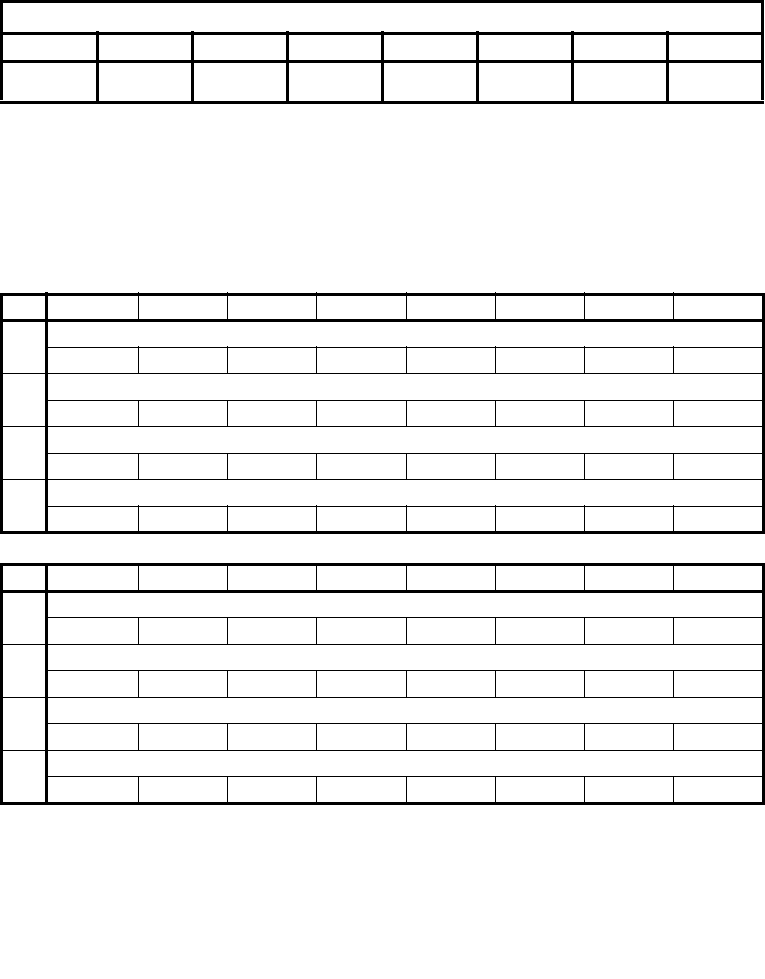
Vol. 2B A-25
OPCODE MAP
A.5.2.1 Escape Opcodes with D8 as First Byte
Table A-7 and A-8 contain maps for the escape instruction opcodes that begin with D8H. Table
A-7 shows the map if the ModR/M byte is in the range of 00H-BFH. Here, the value of bits 3-5
(the nnn field in Figure A-1) selects the instruction.
Table A-8 shows the map if the ModR/M byte is outside the range of 00H-BFH. Here, the first
digit of the ModR/M byte selects the table row and the second digit selects the column.
Table A-7. D8 Opcode Map When ModR/M Byte is Within 00H to BFH *
nnn Field of ModR/M Byte (refer to Figure A.4)
000B 001B 010B 011B 100B 101B 110B 111B
FADD single-
real
FMUL single-
real
FCOM single-
real
FCOMP single-
real
FSUB single-
real
FSUBR single-
real
FDIV single-real FDIVR single-
real
NOTES:
*All blanks in all opcode maps are reserved and must not be used. Do not depend on the operation of
undefined or reserved locations.
Table A-8. D8 Opcode Map When ModR/M Byte is Outside 00H to BFH *
01234567
CFADD
ST(0),ST(0) ST(0),ST(1) ST(0),ST(2) ST(0),ST(3) ST(0),ST(4) ST(0),ST(5) ST(0),ST(6) ST(0),ST(7)
DFCOM
ST(0),ST(0) ST(0),ST(1) ST(0),T(2) ST(0),ST(3) ST(0),ST(4) ST(0),ST(5) ST(0),ST(6) ST(0),ST(7)
EFSUB
ST(0),ST(0) ST(0),ST(1) ST(0),ST(2) ST(0),ST(3) ST(0),ST(4) ST(0),ST(5) ST(0),ST(6) ST(0),ST(7)
FFDIV
ST(0),ST(0) ST(0),ST(1) ST(0),ST(2) ST(0),ST(3) ST(0),ST(4) ST(0),ST(5) ST(0),ST(6) ST(0),ST(7)
89ABCDEF
CFMUL
ST(0),ST(0) ST(0),ST(1) ST(0),ST(2) ST(0),ST(3) ST(0),ST(4) ST(0),ST(5) ST(0),ST(6) ST(0),ST(7)
DFCOMP
ST(0),ST(0) ST(0),ST(1) ST(0),T(2) ST(0),ST(3) ST(0),ST(4) ST(0),ST(5) ST(0),ST(6) ST(0),ST(7)
EFSUBR
ST(0),ST(0) ST(0),ST(1) ST(0),ST(2) ST(0),ST(3) ST(0),ST(4) ST(0),ST(5) ST(0),ST(6) ST(0),ST(7)
FFDIVR
ST(0),ST(0) ST(0),ST(1) ST(0),ST(2) ST(0),ST(3) ST(0),ST(4) ST(0),ST(5) ST(0),ST(6) ST(0),ST(7)
NOTES:
*All blanks in all opcode maps are reserved and must not be used. Do not depend on the operation of
undefined or reserved locations.

A-26 Vol. 2B
OPCODE MAP
A.5.2.2 Escape Opcodes with D9 as First Byte
Table A-9 and A-10 contain maps for escape instruction opcodes that begin with D9H. Table A-9
shows the map if the ModR/M byte is in the range of 00H-BFH. Here, the value of bits 3-5 (the
nnn field in Figure A-1) selects the instruction.
.
Table A-10 shows the map if the ModR/M byte is outside the range of 00H-BFH. Here, the first
digit of the ModR/M byte selects the table row and the second digit selects the column.
Table A-9. D9 Opcode Map When ModR/M Byte is Within 00H to BFH *
nnn Field of ModR/M Byte
000B 001B 010B 011B 100B 101B 110B 111B
FLD
single-real
FST
single-real
FSTP
single-real
FLDENV
14/28 bytes
FLDCW
2 bytes
FSTENV
14/28 bytes
FSTCW
2 bytes
NOTES:
*All blanks in all opcode maps are reserved and must not be used. Do not depend on the operation of
undefined or reserved locations.
Table A-10. D9 Opcode Map When ModR/M Byte is Outside 00H to BFH *
0 12345 6 7
CFLD
ST(0),ST(0) ST(0),ST(1) ST(0),ST(2) ST(0),ST(3) ST(0),ST(4) ST(0),ST(5) ST(0),ST(6) ST(0),ST(7)
DFNOP
E FCHS FABS FTST FXAM
F F2XM1 FYL2X FPTAN FPATAN FXTRACT FPREM1 FDECSTP FINCSTP
89ABCDEF
CFXCH
ST(0),ST(0) ST(0),ST(1) ST(0),ST(2) ST(0),ST(3) ST(0),ST(4) ST(0),ST(5) ST(0),ST(6) ST(0),ST(7)
D
E FLD1 FLDL2T FLDL2E FLDPI FLDLG2 FLDLN2 FLDZ
F FPREM FYL2XP1 FSQRT FSINCOS FRNDINT FSCALE FSIN FCOS
NOTES:
*All blanks in all opcode maps are reserved and must not be used. Do not depend on the operation of
undefined or reserved locations.

Vol. 2B A-27
OPCODE MAP
A.5.2.3 Escape Opcodes with DA as First Byte
Table A-11 and A-12 contain maps for escape instruction opcodes that begin with DAH. Table
A-11 shows the map if the ModR/M byte is in the range of 00H-BFH. Here, the value of bits 3-5
(the nnn field in Figure A-1) selects the instruction.
Table A-11 shows the map if the ModR/M byte is outside the range of 00H-BFH. Here, the first
digit of the ModR/M byte selects the table row and the second digit selects the column.
Table A-11. DA Opcode Map When ModR/M Byte is Within 00H to BFH *
nnn Field of ModR/M Byte
000B 001B 010B 011B 100B 101B 110B 111B
FIADD
dword-integer
FIMUL
dword-integer
FICOM
dword-integer
FICOMP
dword-integer
FISUB
dword-integer
FISUBR
dword-integer
FIDIV
dword-integer
FIDIVR
dword-integer
NOTES:
*All blanks in all opcode maps are reserved and must not be used. Do not depend on the operation of
undefined or reserved locations.
Table A-12. DA Opcode Map When ModR/M Byte is Outside 00H to BFH *
0 12345 6 7
CFCMOVB
ST(0),ST(0) ST(0),ST(1) ST(0),ST(2) ST(0),ST(3) ST(0),ST(4) ST(0),ST(5) ST(0),ST(6) ST(0),ST(7)
DFCMOVBE
ST(0),ST(0) ST(0),ST(1) ST(0),ST(2) ST(0),ST(3) ST(0),ST(4) ST(0),ST(5) ST(0),ST(6) ST(0),ST(7)
E
F
89ABCDEF
CFCMOVE
ST(0),ST(0) ST(0),ST(1) ST(0),ST(2) ST(0),ST(3) ST(0),ST(4) ST(0),ST(5) ST(0),ST(6) ST(0),ST(7)
DFCMOVU
ST(0),ST(0) ST(0),ST(1) ST(0),ST(2) ST(0),ST(3) ST(0),ST(4) ST(0),ST(5) ST(0),ST(6) ST(0),ST(7)
E FUCOMPP
F
NOTES:
*All blanks in all opcode maps are reserved and must not be used. Do not depend on the operation of
undefined or reserved locations.

A-28 Vol. 2B
OPCODE MAP
A.5.2.4 Escape Opcodes with DB as First Byte
Table A-13 and A-14 contain maps for escape instruction opcodes that begin with DBH. Table
A-13 shows the map if the ModR/M byte is in the range of 00H-BFH. Here, the value of bits 3-5
(the nnn field in Figure A-1) selects the instruction.
Table A-14 shows the map if the ModR/M byte is outside the range of 00H-BFH. Here, the first
digit of the ModR/M byte selects the table row and the second digit selects the column.
Table A-13. DB Opcode Map When ModR/M Byte is Within 00H to BFH *
nnn Field of ModR/M Byte
000B 001B 010B 011B 100B 101B 110B 111B
FILD
dword-integer
FISTTP dword-
integer
FIST
dword-integer
FISTP
dword-integer
FLD
extended-real
FSTP
extended-real
NOTES:
*All blanks in all opcode maps are reserved and must not be used. Do not depend on the operation of
undefined or reserved locations.
Table A-14. DB Opcode Map When ModR/M Byte is Outside 00H to BFH *
0 12345 6 7
C FCMOVNB
ST(0),ST(0) ST(0),ST(1) ST(0),ST(2) ST(0),ST(3) ST(0),ST(4) ST(0),ST(5) ST(0),ST(6) ST(0),ST(7)
D FCMOVNBE
ST(0),ST(0) ST(0),ST(1) ST(0),ST(2) ST(0),ST(3) ST(0),ST(4) ST(0),ST(5) ST(0),ST(6) ST(0),ST(7)
EFCLEXFINIT
FFCOMI
ST(0),ST(0) ST(0),ST(1) ST(0),ST(2) ST(0),ST(3) ST(0),ST(4) ST(0),ST(5) ST(0),ST(6) ST(0),ST(7)
89ABCDEF
C FCMOVNE
ST(0),ST(0) ST(0),ST(1) ST(0),ST(2) ST(0),ST(3) ST(0),ST(4) ST(0),ST(5) ST(0),ST(6) ST(0),ST(7)
D FCMOVNU
ST(0),ST(0) ST(0),ST(1) ST(0),ST(2) ST(0),ST(3) ST(0),ST(4) ST(0),ST(5) ST(0),ST(6) ST(0),ST(7)
E FUCOMI
ST(0),ST(0) ST(0),ST(1) ST(0),ST(2) ST(0),ST(3) ST(0),ST(4) ST(0),ST(5) ST(0),ST(6) ST(0),ST(7)
F
NOTES:
*All blanks in all opcode maps are reserved and must not be used. Do not depend on the operation of
undefined or reserved locations.
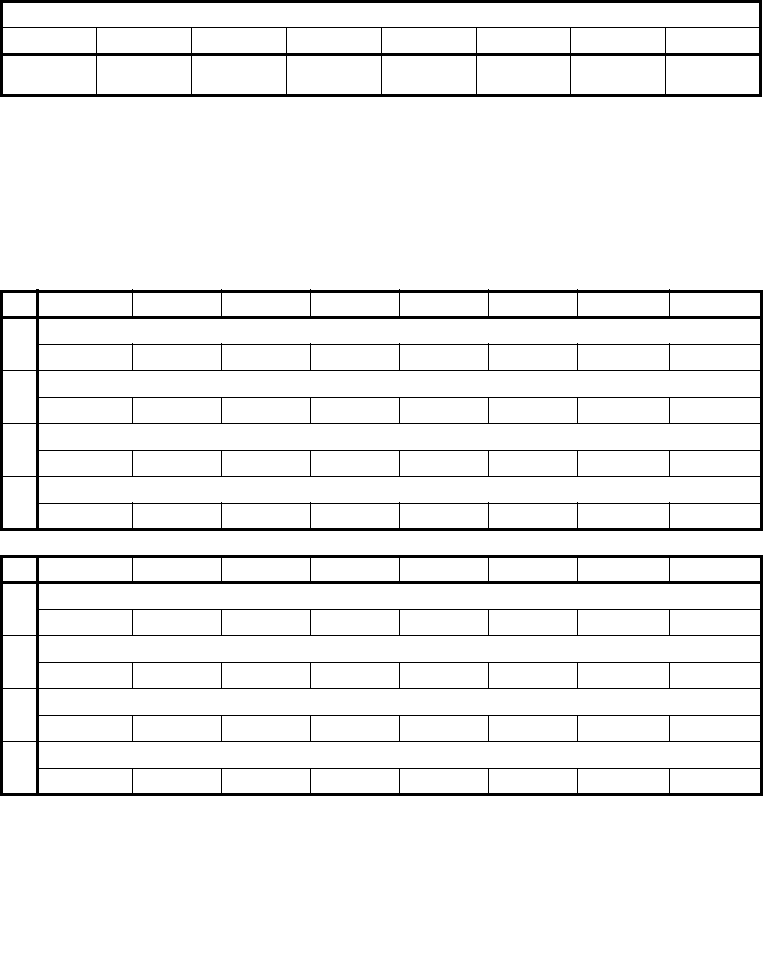
Vol. 2B A-29
OPCODE MAP
A.5.2.5 Escape Opcodes with DC as First Byte
Table A-15 and A-16 contain maps for escape instruction opcodes that begin with DCH. Table
A-15 shows the map if the ModR/M byte is in the range of 00H-BFH. Here, the value of bits 3-5
(the nnn field in Figure A-1) selects the instruction.
Table A-16 shows the map if the ModR/M byte is outside the range of 00H-BFH. In this case the
first digit of the ModR/M byte selects the table row and the second digit selects the column.
Table A-15. DC Opcode Map When ModR/M Byte is Within 00H to BFH *
nnn Field of ModR/M Byte (refer to Figure A-1)
000B 001B 010B 011B 100B 101B 110B 111B
FADD double-
real
FMUL double-
real
FCOM
double-real
FCOMP
double-real
FSUB double-
real
FSUBR
double-real
FDIV double-
real
FDIVR
double-real
NOTES:
*All blanks in all opcode maps are reserved and must not be used. Do not depend on the operation of
undefined or reserved locations.
Table A-16. DC Opcode Map When ModR/M Byte is Outside 00H to BFH *
0 12345 6 7
CFADD
ST(0),ST(0) ST(1),ST(0) ST(2),ST(0) ST(3),ST(0) ST(4),ST(0) ST(5),ST(0) ST(6),ST(0) ST(7),ST(0)
D
E FSUBR
ST(0),ST(0) ST(1),ST(0) ST(2),ST(0) ST(3),ST(0) ST(4),ST(0) ST(5),ST(0) ST(6),ST(0) ST(7),ST(0)
FFDIVR
ST(0),ST(0) ST(1),ST(0) ST(2),ST(0) ST(3),ST(0) ST(4),ST(0) ST(5),ST(0) ST(6),ST(0) ST(7),ST(0)
89ABCDEF
CFMUL
ST(0),ST(0) ST(1),ST(0) ST(2),ST(0) ST(3),ST(0) ST(4),ST(0) ST(5),ST(0) ST(6),ST(0) ST(7),ST(0)
D
EFSUB
ST(0),ST(0) ST(1),ST(0) ST(2),ST(0) ST(3),ST(0) ST(4),ST(0) ST(5),ST(0) ST(6),ST(0) ST(7),ST(0)
FFDIV
ST(0),ST(0) ST(1),ST(0) ST(2),ST(0) ST(3),ST(0) ST(4),ST(0) ST(5),ST(0) ST(6),ST(0) ST(7),ST(0)
NOTES:
*All blanks in all opcode maps are reserved and must not be used. Do not depend on the operation of
undefined or reserved locations.

A-30 Vol. 2B
OPCODE MAP
A.5.2.6 Escape Opcodes with DD as First Byte
Table A-17 and A-18 contain maps for escape instruction opcodes that begin with DDH. Table
A-17 shows the map if the ModR/M byte is in the range of 00H-BFH. Here, the value of bits 3-5
(the nnn field in Figure A-1) selects the instruction.
Table A-18 shows the map if the ModR/M byte is outside the range of 00H-BFH. The first digit of
the ModR/M byte selects the table row and the second digit selects the column.
Table A-17. DD Opcode Map When ModR/M Byte is Within 00H to BFH *
nnn Field of ModR/M Byte
000B 001B 010B 011B 100B 101B 110B 111B
FLD double-
real
FISTTP
integer64
FST double-
real
FSTP double-
real
FRSTOR
98/108bytes
FSAVE
98/108bytes
FSTSW 2
bytes
NOTES:
*All blanks in all opcode maps are reserved and must not be used. Do not depend on the operation of
undefined or reserved locations.
Table A-18. DD Opcode Map When ModR/M Byte is Outside 00H to BFH *
0 12345 6 7
CFFREE
ST(0) ST(1) ST(2) ST(3) ST(4) ST(5) ST(6) ST(7)
DFST
ST(0) ST(1) ST(2) ST(3) ST(4) ST(5) ST(6) ST(7)
E FUCOM
ST(0),ST(0) ST(1),ST(0) ST(2),ST(0) ST(3),ST(0) ST(4),ST(0) ST(5),ST(0) ST(6),ST(0) ST(7),ST(0)
F
89ABCDEF
C
DFSTP
ST(0) ST(1) ST(2) ST(3) ST(4) ST(5) ST(6) ST(7)
E FUCOMP
ST(0) ST(1) ST(2) ST(3) ST(4) ST(5) ST(6) ST(7)
F
NOTES:
*All blanks in all opcode maps are reserved and must not be used. Do not depend on the operation of
undefined or reserved locations.
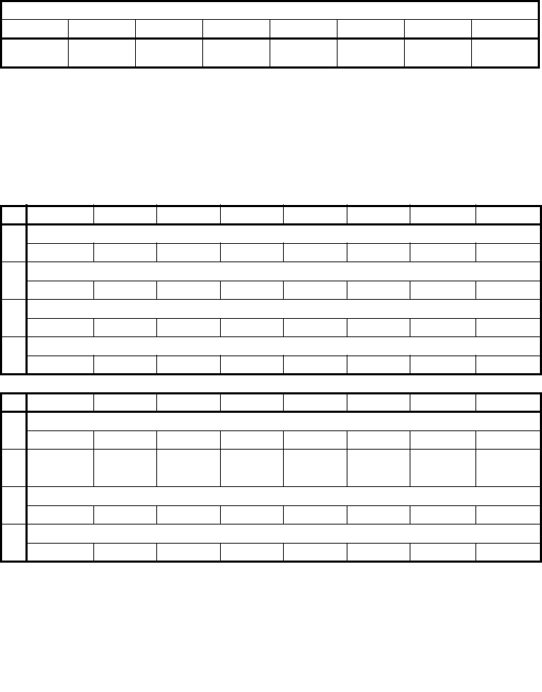
Vol. 2B A-31
OPCODE MAP
A.5.2.7 Escape Opcodes with DE as First Byte
Table A-19 and A-20 contain opcode maps for escape instruction opcodes that begin with DEH.
Table A-19 shows the opcode map if the ModR/M byte is in the range of 00H-BFH. In this case,
the value of bits 3-5 (the nnn field in Figure A-1) selects the instruction.
Table A-20 shows the opcode map if the ModR/M byte is outside the range of 00H-BFH. The first
digit of the ModR/M byte selects the table row and the second digit selects the column.
Table A-19. DE Opcode Map When ModR/M Byte is Within 00H to BFH *
nnn Field of ModR/M Byte
000B 001B 010B 011B 100B 101B 110B 111B
FIADD
word-integer
FIMUL
word-integer
FICOM
word-integer
FICOMP word-
integer
FISUB
word-integer
FISUBR word-
integer
FIDIV
word-integer
FIDIVR
word-integer
NOTES:
*All blanks in all opcode maps are reserved and must not be used. Do not depend on the operation of
undefined or reserved locations.
Table A-20. DE Opcode Map When ModR/M Byte is Outside 00H to BFH *
0 12345 6 7
C FADDP
ST(0),ST(0) ST(1),ST(0) ST(2),ST(0) ST(3),ST(0) ST(4),ST(0) ST(5),ST(0) ST(6),ST(0) ST(7),ST(0)
D
EFSUBRP
ST(0),ST(0) ST(1),ST(0) ST(2),ST(0) ST(3),ST(0) ST(4),ST(0) ST(5),ST(0) ST(6),ST(0) ST(7),ST(0)
FFDIVRP
ST(0),ST(0) ST(1),ST(0) ST(2),ST(0) ST(3),ST(0) ST(4),ST(0) ST(5),ST(0) ST(6),ST(0) ST(7),ST(0)
89ABCDEF
CFMULP
ST(0),ST(0) ST(1),ST(0) ST(2),ST(0) ST(3),ST(0) ST(4),ST(0) ST(5),ST(0) ST(6),ST(0) ST(7),ST(0)
DFCOMPP
EFSUBP
ST(0),ST(0) ST(1),ST(0) ST(2),ST(0) ST(3),ST(0) ST(4),ST(0) ST(5),ST(0) ST(6),ST(0) ST(7),ST(0)
FFDIVP
ST(0),ST(0) ST(1),ST(0) ST(2),ST(0). ST(3),ST(0) ST(4),ST(0) ST(5),ST(0) ST(6),ST(0) ST(7),ST(0)
NOTES:
*All blanks in all opcode maps are reserved and must not be used. Do not depend on the operation of
undefined or reserved locations.

A-32 Vol. 2B
OPCODE MAP
A.5.2.8 Escape Opcodes with DF As First Byte
Table A-21 and A-22 contain the opcode maps for escape instruction opcodes that begin with
DFH. Table A-21 shows the opcode map if the ModR/M byte is in the range of 00H-BFH. Here,
the value of bits 3-5 (the nnn field in Figure A-1) selects the instruction.
Table A-22 shows the opcode map if the ModR/M byte is outside the range of 00H-BFH. The first
digit of the ModR/M byte selects the table row and the second digit selects the column.
Table A-21. DF Opcode Map When ModR/M Byte is Within 00H to BFH *
nnn Field of ModR/M Byte
000B 001B 010B 011B 100B 101B 110B 111B
FILD
word-integer
FISTTP
word-integer
FIST
word-integer
FISTP
word-integer
FBLD packed-
BCD
FILD
qword-integer
FBSTP packed-
BCD
FISTP
qword-integer
NOTES:
*All blanks in all opcode maps are reserved and must not be used. Do not depend on the operation of
undefined or reserved locations.
Table A-22. DF Opcode Map When ModR/M Byte is Outside 00H to BFH *
0 12345 6 7
C
D
E FSTSW
AX
FFCOMIP
ST(0),ST(0) ST(0),ST(1) ST(0),ST(2) ST(0),ST(3) ST(0),ST(4) ST(0),ST(5) ST(0),ST(6) ST(0),ST(7)
89ABCDEF
C
D
E FUCOMIP
ST(0),ST(0) ST(0),ST(1) ST(0),ST(2) ST(0),ST(3) ST(0),ST(4) ST(0),ST(5) ST(0),ST(6) ST(0),ST(7)
F
NOTES:
*All blanks in all opcode maps are reserved and must not be used. Do not depend on the operation of
undefined or reserved locations.
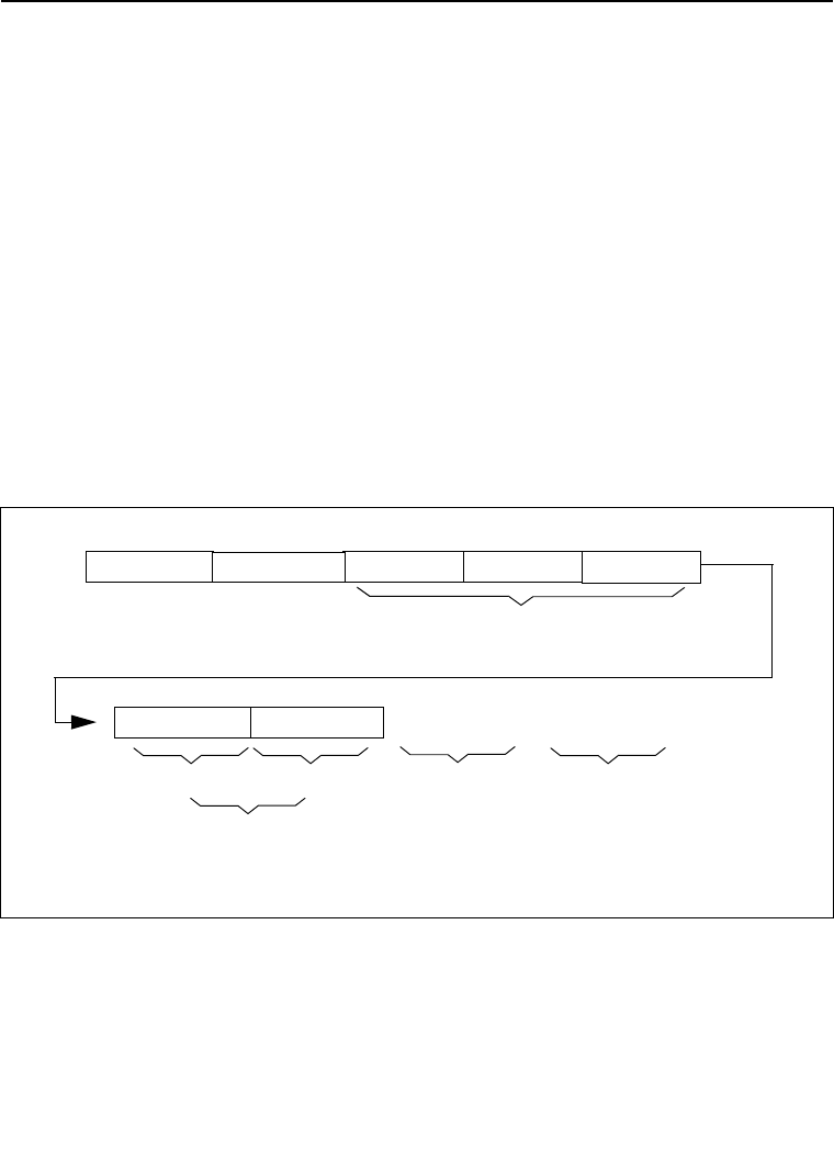
Vol. 2B B-1
APPENDIX B
INSTRUCTION FORMATS AND ENCODINGS
This appendix provides machine instruction formats and encodings of IA-32 instruc-
tions. The first section describes the IA-32 architecture’s machine instruction format.
The remaining sections show the formats and encoding of general-purpose, MMX, P6
family, SSE/SSE2/SSE3, x87 FPU instructions, and VMX instructions. Those instruc-
tion formats also apply to Intel 64 architecture. Instruction formats used in 64-bit
mode are provided as supersets of the above.
B.1 MACHINE INSTRUCTION FORMAT
All Intel Architecture instructions are encoded using subsets of the general machine
instruction format shown in Figure B-1. Each instruction consists of:
•an opcode
•a register and/or address mode specifier consisting of the ModR/M byte and
sometimes the scale-index-base (SIB) byte (if required)
•a displacement and an immediate data field (if required)
The following sections discuss this format.
Figure B-1. General Machine Instruction Format
ModR/M Byte
7 6 5 4 3 2 1 0 7 6 5 4 3 2 1 0
7-6 5-3 2-07-6 5-3 2-0
T T T T T T T T T T T T T T T T
Mod Reg* R/M Scale Index Base d32 | 16 | 8 | Noned32 | 16 | 8 | None
SIB Byte Address Displacement
(4, 2, 1 Bytes or None)
Immediate Data
(4,2,1 Bytes or None)
Register and/or Address
Mode Specifier
Legacy Prefixes REX Prefixes
7 6 5 4 3 2 1 0
T T T T T T T T
(optional)
Grp 1, Grp 2,
Grp 3, Grp 4
NOTE:
* The Reg Field may be used as an
1, 2, or 3 Byte Opcodes (T = Opcode

B-2 Vol. 2B
INSTRUCTION FORMATS AND ENCODINGS
B.1.1 Legacy Prefixes
The legacy prefixes noted in Figure B-1 include 66H, 67H, F2H and F3H. They are
optional, except when F2H, F3H and 66H are used in new instruction extensions.
Legacy prefixes must be placed before REX prefixes.
Refer to Chapter 2, “Instruction Format,” in the Intel® 64 and IA-32 Architectures
Software Developer’s Manual, Volume 2A, for more information on legacy prefixes.
B.1.2 REX Prefixes
REX prefixes are a set of 16 opcodes that span one row of the opcode map and
occupy entries 40H to 4FH. These opcodes represent valid instructions (INC or DEC)
in IA-32 operating modes and in compatibility mode. In 64-bit mode, the same
opcodes represent the instruction prefix REX and are not treated as individual
instructions.
Refer to Chapter 2, “Instruction Format,” in the Intel® 64 and IA-32 Architectures
Software Developer’s Manual, Volume 2A, for more information on REX prefixes.
B.1.3 Opcode Fields
The primary opcode for an instruction is encoded in one to three bytes of the instruc-
tion. Within the primary opcode, smaller encoding fields may be defined. These fields
vary according to the class of operation being performed.
Almost all instructions that refer to a register and/or memory operand have a
register and/or address mode byte following the opcode. This byte, the ModR/M byte,
consists of the mod field (2 bits), the reg field (3 bits; this field is sometimes an
opcode extension), and the R/M field (3 bits). Certain encodings of the ModR/M byte
indicate that a second address mode byte, the SIB byte, must be used.
If the addressing mode specifies a displacement, the displacement value is placed
immediately following the ModR/M byte or SIB byte. Possible sizes are 8, 16, or 32
bits. If the instruction specifies an immediate value, the immediate value follows any
displacement bytes. The immediate, if specified, is always the last field of the
instruction.
Refer to Chapter 2, “Instruction Format,” in the Intel® 64 and IA-32 Architectures
Software Developer’s Manual, Volume 2A, for more information on opcodes.
B.1.4 Special Fields
Table B-1 lists bit fields that appear in certain instructions, sometimes within the
opcode bytes. All of these fields (except the d bit) occur in the general-purpose
instruction formats in Table B-13.

Vol. 2B B-3
INSTRUCTION FORMATS AND ENCODINGS
B.1.4.1 Reg Field (reg) for Non-64-Bit Modes
The reg field in the ModR/M byte specifies a general-purpose register operand. The
group of registers specified is modified by the presence and state of the w bit in an
encoding (refer to Section B.1.4.3). Table B-2 shows the encoding of the reg field
when the w bit is not present in an encoding; Table B-3 shows the encoding of the reg
field when the w bit is present.
Table B-1. Special Fields Within Instruction Encodings
Field Name Description
Number of
Bits
reg General-register specifier (see Table B-4 or B-5) 3
w Specifies if data is byte or full-sized, where full-sized is 16 or 32
bits (see Table B-6)
1
s Specifies sign extension of an immediate field (see Table B-7) 1
sreg2 Segment register specifier for CS, SS, DS, ES (see Table B-8) 2
sreg3 Segment register specifier for CS, SS, DS, ES, FS, GS (see Table B-8) 3
eee Specifies a special-purpose (control or debug) register (see
Table B-9)
3
tttn For conditional instructions, specifies a condition asserted or
negated (see Table B-12)
4
d Specifies direction of data operation (see Table B-11) 1
Table B-2. Encoding of reg Field When w Field is Not Present in Instruction
reg Field
Register Selected during
16-Bit Data Operations
Register Selected during
32-Bit Data Operations
000 AX EAX
001 CX ECX
010 DX EDX
011 BX EBX
100 SP ESP
101 BP EBP
110 SI ESI
111 DI EDI

B-4 Vol. 2B
INSTRUCTION FORMATS AND ENCODINGS
B.1.4.2 Reg Field (reg) for 64-Bit Mode
Just like in non-64-bit modes, the reg field in the ModR/M byte specifies a general-
purpose register operand. The group of registers specified is modified by the pres-
ence of and state of the w bit in an encoding (refer to Section B.1.4.3). Table B-4
shows the encoding of the reg field when the w bit is not present in an encoding;
Table B-5 shows the encoding of the reg field when the w bit is present.
Table B-3. Encoding of reg Field When w Field is Present in Instruction
Register Specified by reg Field
During 16-Bit Data Operations
Register Specified by reg Field
During 32-Bit Data Operations
Function of w Field Function of w Field
reg When w = 0 When w = 1 reg When w = 0 When w = 1
000 AL AX 000 AL EAX
001 CL CX 001 CL ECX
010 DL DX 010 DL EDX
011 BL BX 011 BL EBX
100 AH SP 100 AH ESP
101 CH BP 101 CH EBP
110 DH SI 110 DH ESI
111 BH DI 111 BH EDI
Table B-4. Encoding of reg Field When w Field is Not Present in Instruction
reg Field
Register Selected
during
16-Bit Data Operations
Register Selected
during
32-Bit Data Operations
Register Selected
during
64-Bit Data Operations
000 AX EAX RAX
001 CX ECX RCX
010 DX EDX RDX
011 BX EBX RBX
100 SP ESP RSP
101 BP EBP RBP
110 SI ESI RSI
111 DI EDI RDI

Vol. 2B B-5
INSTRUCTION FORMATS AND ENCODINGS
B.1.4.3 Encoding of Operand Size (w) Bit
The current operand-size attribute determines whether the processor is performing
16-bit, 32-bit or 64-bit operations. Within the constraints of the current operand-size
attribute, the operand-size bit (w) can be used to indicate operations on 8-bit oper-
ands or the full operand size specified with the operand-size attribute. Table B-6
shows the encoding of the w bit depending on the current operand-size attribute.
B.1.4.4 Sign-Extend (s) Bit
The sign-extend (s) bit occurs in instructions with immediate data fields that are
being extended from 8 bits to 16 or 32 bits. See Table B-7.
Table B-5. Encoding of reg Field When w Field is Present in Instruction
Register Specified by reg Field
During 16-Bit Data Operations
Register Specified by reg Field
During 32-Bit Data Operations
Function of w Field Function of w Field
reg When w = 0 When w = 1 reg When w = 0When w = 1
000 AL AX 000 AL EAX
001 CL CX 001 CL ECX
010 DL DX 010 DL EDX
011 BL BX 011 BL EBX
100 AH1SP 100 AH* ESP
101 CH1BP 101 CH* EBP
110 DH1SI 110 DH* ESI
111 BH1DI 111 BH* EDI
NOTES:
1. AH, CH, DH, BH can not be encoded when REX prefix is used. Such an expression defaults to the
low byte.
Table B-6. Encoding of Operand Size (w) Bit
w Bit
Operand Size When
Operand-Size Attribute is 16 Bits
Operand Size When
Operand-Size Attribute is 32 Bits
0 8 Bits 8 Bits
1 16 Bits 32 Bits

B-6 Vol. 2B
INSTRUCTION FORMATS AND ENCODINGS
B.1.4.5 Segment Register (sreg) Field
When an instruction operates on a segment register, the reg field in the ModR/M byte
is called the sreg field and is used to specify the segment register. Table B-8 shows
the encoding of the sreg field. This field is sometimes a 2-bit field (sreg2) and other
times a 3-bit field (sreg3).
B.1.4.6 Special-Purpose Register (eee) Field
When control or debug registers are referenced in an instruction they are encoded in
the eee field, located in bits 5 though 3 of the ModR/M byte (an alternate encoding of
the sreg field). See Table B-9.
Table B-7. Encoding of Sign-Extend (s) Bit
s
Effect on 8-Bit
Immediate Data
Effect on 16- or 32-Bit
Immediate Data
0None None
1 Sign-extend to fill 16-bit or 32-bit destination None
Table B-8. Encoding of the Segment Register (sreg) Field
2-Bit sreg2 Field
Segment Register
Selected 3-Bit sreg3 Field
Segment Register
Selected
00 ES 000 ES
01 CS 001 CS
10 SS 010 SS
11 DS 011 DS
100 FS
101 GS
110 Reserved1
111 Reserved
NOTES:
1. Do not use reserved encodings.

Vol. 2B B-7
INSTRUCTION FORMATS AND ENCODINGS
B.1.4.7 Condition Test (tttn) Field
For conditional instructions (such as conditional jumps and set on condition), the
condition test field (tttn) is encoded for the condition being tested. The ttt part of the
field gives the condition to test and the n part indicates whether to use the condition
(n =0) or its negation (n =1).
•For 1-byte primary opcodes, the tttn field is located in bits 3, 2, 1, and 0 of the
opcode byte.
•For 2-byte primary opcodes, the tttn field is located in bits 3, 2, 1, and 0 of the
second opcode byte.
Table B-10 shows the encoding of the tttn field.
Table B-9. Encoding of Special-Purpose Register (eee) Field
eee Control Register Debug Register
000 CR0 DR0
001 Reserved1DR1
010 CR2 DR2
011 CR3 DR3
100 CR4 Reserved
101 Reserved Reserved
110 Reserved DR6
111 Reserved DR7
NOTES:
1. Do not use reserved encodings.

B-8 Vol. 2B
INSTRUCTION FORMATS AND ENCODINGS
B.1.4.8 Direction (d) Bit
In many two-operand instructions, a direction bit (d) indicates which operand is
considered the source and which is the destination. See Table B-11.
•When used for integer instructions, the d bit is located at bit 1 of a 1-byte primary
opcode. Note that this bit does not appear as the symbol “d” in Table B-13; the
actual encoding of the bit as 1 or 0 is given.
•When used for floating-point instructions (in Table B-16), the d bit is shown as bit
2 of the first byte of the primary opcode.
Table B-10. Encoding of Conditional Test (tttn) Field
t t t n Mnemonic Condition
0000 O Overflow
0001 NO No overflow
0010 B, NAE Below, Not above or equal
0011 NB, AE Not below, Above or equal
0100 E, Z Equal, Zero
0101 NE, NZ Not equal, Not zero
0110 BE, NA Below or equal, Not above
0111 NBE, A Not below or equal, Above
1000 S Sign
1001 NS Not sign
1010 P, PE Parity, Parity Even
1011 NP, PO Not parity, Parity Odd
1100 L, NGE Less than, Not greater than or equal to
1101 NL, GE Not less than, Greater than or equal to
1110 LE, NG Less than or equal to, Not greater than
1111 NLE, G Not less than or equal to, Greater than
Table B-11. Encoding of Operation Direction (d) Bit
d Source Destination
0 reg Field ModR/M or SIB Byte
1 ModR/M or SIB Byte reg Field

Vol. 2B B-9
INSTRUCTION FORMATS AND ENCODINGS
B.1.5 Other Notes
Table B-12 contains notes on particular encodings. These notes are indicated in the
tables shown in the following sections by superscripts.
B.2 GENERAL-PURPOSE INSTRUCTION FORMATS AND
ENCODINGS FOR NON-64-BIT MODES
Table B-13 shows machine instruction formats and encodings for general purpose
instructions in non-64-bit modes.
Table B-12. Notes on Instruction Encoding
Symbol Note
A A value of 11B in bits 7 and 6 of the ModR/M byte is reserved.
B A value of 01B (or 10B) in bits 7 and 6 of the ModR/M byte is reserved.
Table B-13. General Purpose Instruction Formats and Encodings
for Non-64-Bit Modes
Instruction and Format Encoding
AAA – ASCII Adjust after Addition 0011 0111
AAD – ASCII Adjust AX before Division 1101 0101 : 0000 1010
AAM – ASCII Adjust AX after Multiply 1101 0100 : 0000 1010
AAS – ASCII Adjust AL after Subtraction 0011 1111
ADC – ADD with Carry
register1 to register2 0001 000w : 11 reg1 reg2
register2 to register1 0001 001w : 11 reg1 reg2
memory to register 0001 001w : mod reg r/m
register to memory 0001 000w : mod reg r/m
immediate to register 1000 00sw : 11 010 reg : immediate data
immediate to AL, AX, or EAX 0001 010w : immediate data
immediate to memory 1000 00sw : mod 010 r/m : immediate data
ADD – Add
register1 to register2 0000 000w : 11 reg1 reg2
register2 to register1 0000 001w : 11 reg1 reg2
memory to register 0000 001w : mod reg r/m
register to memory 0000 000w : mod reg r/m

B-10 Vol. 2B
INSTRUCTION FORMATS AND ENCODINGS
immediate to register 1000 00sw : 11 000 reg : immediate data
immediate to AL, AX, or EAX 0000 010w : immediate data
immediate to memory 1000 00sw : mod 000 r/m : immediate data
AND – Logical AND
register1 to register2 0010 000w : 11 reg1 reg2
register2 to register1 0010 001w : 11 reg1 reg2
memory to register 0010 001w : mod reg r/m
register to memory 0010 000w : mod reg r/m
immediate to register 1000 00sw : 11 100 reg : immediate data
immediate to AL, AX, or EAX 0010 010w : immediate data
immediate to memory 1000 00sw : mod 100 r/m : immediate data
ARPL – Adjust RPL Field of Selector
from register 0110 0011 : 11 reg1 reg2
from memory 0110 0011 : mod reg r/m
BOUND – Check Array Against Bounds 0110 0010 : modA reg r/m
BSF – Bit Scan Forward
register1, register2 0000 1111 : 1011 1100 : 11 reg1 reg2
memory, register 0000 1111 : 1011 1100 : mod reg r/m
BSR – Bit Scan Reverse
register1, register2 0000 1111 : 1011 1101 : 11 reg1 reg2
memory, register 0000 1111 : 1011 1101 : mod reg r/m
BSWAP – Byte Swap 0000 1111 : 1100 1 reg
BT – Bit Test
register, immediate 0000 1111 : 1011 1010 : 11 100 reg: imm8
data
memory, immediate 0000 1111 : 1011 1010 : mod 100 r/m : imm8
data
register1, register2 0000 1111 : 1010 0011 : 11 reg2 reg1
memory, reg 0000 1111 : 1010 0011 : mod reg r/m
BTC – Bit Test and Complement
Table B-13. General Purpose Instruction Formats and Encodings
for Non-64-Bit Modes (Contd.)
Instruction and Format Encoding

Vol. 2B B-11
INSTRUCTION FORMATS AND ENCODINGS
register, immediate 0000 1111 : 1011 1010 : 11 111 reg: imm8
data
memory, immediate 0000 1111 : 1011 1010 : mod 111 r/m : imm8
data
register1, register2 0000 1111 : 1011 1011 : 11 reg2 reg1
memory, reg 0000 1111 : 1011 1011 : mod reg r/m
BTR – Bit Test and Reset
register, immediate 0000 1111 : 1011 1010 : 11 110 reg: imm8
data
memory, immediate 0000 1111 : 1011 1010 : mod 110 r/m : imm8
data
register1, register2 0000 1111 : 1011 0011 : 11 reg2 reg1
memory, reg 0000 1111 : 1011 0011 : mod reg r/m
BTS – Bit Test and Set
register, immediate 0000 1111 : 1011 1010 : 11 101 reg: imm8
data
memory, immediate 0000 1111 : 1011 1010 : mod 101 r/m : imm8
data
register1, register2 0000 1111 : 1010 1011 : 11 reg2 reg1
memory, reg 0000 1111 : 1010 1011 : mod reg r/m
CALL – Call Procedure (in same segment)
direct 1110 1000 : full displacement
register indirect 1111 1111 : 11 010 reg
memory indirect 1111 1111 : mod 010 r/m
CALL – Call Procedure (in other segment)
direct 1001 1010 : unsigned full offset, selector
indirect 1111 1111 : mod 011 r/m
CBW – Convert Byte to Word 1001 1000
CDQ – Convert Doubleword to Qword 1001 1001
CLC – Clear Carry Flag 1111 1000
CLD – Clear Direction Flag 1111 1100
Table B-13. General Purpose Instruction Formats and Encodings
for Non-64-Bit Modes (Contd.)
Instruction and Format Encoding

B-12 Vol. 2B
INSTRUCTION FORMATS AND ENCODINGS
CLI – Clear Interrupt Flag 1111 1010
CLTS – Clear Task-Switched Flag in CR0 0000 1111 : 0000 0110
CMC – Complement Carry Flag 1111 0101
CMP – Compare Two Operands
register1 with register2 0011 100w : 11 reg1 reg2
register2 with register1 0011 101w : 11 reg1 reg2
memory with register 0011 100w : mod reg r/m
register with memory 0011 101w : mod reg r/m
immediate with register 1000 00sw : 11 111 reg : immediate data
immediate with AL, AX, or EAX 0011 110w : immediate data
immediate with memory 1000 00sw : mod 111 r/m : immediate data
CMPS/CMPSB/CMPSW/CMPSD – Compare
String Operands
1010 011w
CMPXCHG – Compare and Exchange
register1, register2 0000 1111 : 1011 000w : 11 reg2 reg1
memory, register 0000 1111 : 1011 000w : mod reg r/m
CPUID – CPU Identification 0000 1111 : 1010 0010
CWD – Convert Word to Doubleword 1001 1001
CWDE – Convert Word to Doubleword 1001 1000
DAA – Decimal Adjust AL after Addition 0010 0111
DAS – Decimal Adjust AL after Subtraction 0010 1111
DEC – Decrement by 1
register 1111 111w : 11 001 reg
register (alternate encoding) 0100 1 reg
memory 1111 111w : mod 001 r/m
DIV – Unsigned Divide
AL, AX, or EAX by register 1111 011w : 11 110 reg
AL, AX, or EAX by memory 1111 011w : mod 110 r/m
HLT – Halt 1111 0100
Table B-13. General Purpose Instruction Formats and Encodings
for Non-64-Bit Modes (Contd.)
Instruction and Format Encoding

Vol. 2B B-13
INSTRUCTION FORMATS AND ENCODINGS
IDIV – Signed Divide
AL, AX, or EAX by register 1111 011w : 11 111 reg
AL, AX, or EAX by memory 1111 011w : mod 111 r/m
IMUL – Signed Multiply
AL, AX, or EAX with register 1111 011w : 11 101 reg
AL, AX, or EAX with memory 1111 011w : mod 101 reg
register1 with register2 0000 1111 : 1010 1111 : 11 : reg1 reg2
register with memory 0000 1111 : 1010 1111 : mod reg r/m
register1 with immediate to register2 0110 10s1 : 11 reg1 reg2 : immediate data
memory with immediate to register 0110 10s1 : mod reg r/m : immediate data
IN – Input From Port
fixed port 1110 010w : port number
variable port 1110 110w
INC – Increment by 1
reg 1111 111w : 11 000 reg
reg (alternate encoding) 0100 0 reg
memory 1111 111w : mod 000 r/m
INS – Input from DX Port 0110 110w
INT n – Interrupt Type n 1100 1101 : type
INT – Single-Step Interrupt 3 1100 1100
INTO – Interrupt 4 on Overflow 1100 1110
INVD – Invalidate Cache 0000 1111 : 0000 1000
INVLPG – Invalidate TLB Entry 0000 1111 : 0000 0001 : mod 111 r/m
IRET/IRETD – Interrupt Return 1100 1111
Jcc – Jump if Condition is Met
8-bit displacement 0111 tttn : 8-bit displacement
full displacement 0000 1111 : 1000 tttn : full displacement
JCXZ/JECXZ – Jump on CX/ECX Zero
Address-size prefix differentiates JCXZ
and JECXZ
1110 0011 : 8-bit displacement
Table B-13. General Purpose Instruction Formats and Encodings
for Non-64-Bit Modes (Contd.)
Instruction and Format Encoding

B-14 Vol. 2B
INSTRUCTION FORMATS AND ENCODINGS
JMP – Unconditional Jump (to same segment)
short 1110 1011 : 8-bit displacement
direct 1110 1001 : full displacement
register indirect 1111 1111 : 11 100 reg
memory indirect 1111 1111 : mod 100 r/m
JMP – Unconditional Jump (to other segment)
direct intersegment 1110 1010 : unsigned full offset, selector
indirect intersegment 1111 1111 : mod 101 r/m
LAHF – Load Flags into AHRegister 1001 1111
LAR – Load Access Rights Byte
from register 0000 1111 : 0000 0010 : 11 reg1 reg2
from memory 0000 1111 : 0000 0010 : mod reg r/m
LDS – Load Pointer to DS 1100 0101 : modA,B reg r/m
LEA – Load Effective Address 1000 1101 : modA reg r/m
LEAVE – High Level Procedure Exit 1100 1001
LES – Load Pointer to ES 1100 0100 : modA,B reg r/m
LFS – Load Pointer to FS 0000 1111 : 1011 0100 : modA reg r/m
LGDT – Load Global Descriptor Table Register 0000 1111 : 0000 0001 : modA 010 r/m
LGS – Load Pointer to GS 0000 1111 : 1011 0101 : modA reg r/m
LIDT – Load Interrupt Descriptor Table
Register
0000 1111 : 0000 0001 : modA 011 r/m
LLDT – Load Local Descriptor Table Register
LDTR from register 0000 1111 : 0000 0000 : 11 010 reg
LDTR from memory 0000 1111 : 0000 0000 : mod 010 r/m
LMSW – Load Machine Status Word
from register 0000 1111 : 0000 0001 : 11 110 reg
from memory 0000 1111 : 0000 0001 : mod 110 r/m
LOCK – Assert LOCK# Signal Prefix 1111 0000
LODS/LODSB/LODSW/LODSD – Load String
Operand
1010 110w
Table B-13. General Purpose Instruction Formats and Encodings
for Non-64-Bit Modes (Contd.)
Instruction and Format Encoding

Vol. 2B B-15
INSTRUCTION FORMATS AND ENCODINGS
LOOP – Loop Count 1110 0010 : 8-bit displacement
LOOPZ/LOOPE – Loop Count while Zero/Equal 1110 0001 : 8-bit displacement
LOOPNZ/LOOPNE – Loop Count while not
Zero/Equal
1110 0000 : 8-bit displacement
LSL – Load Segment Limit
from register 0000 1111 : 0000 0011 : 11 reg1 reg2
from memory 0000 1111 : 0000 0011 : mod reg r/m
LSS – Load Pointer to SS 0000 1111 : 1011 0010 : modA reg r/m
LTR – Load Task Register
from register 0000 1111 : 0000 0000 : 11 011 reg
from memory 0000 1111 : 0000 0000 : mod 011 r/m
MOV – Move Data
register1 to register2 1000 100w : 11 reg1 reg2
register2 to register1 1000 101w : 11 reg1 reg2
memory to reg 1000 101w : mod reg r/m
reg to memory 1000 100w : mod reg r/m
immediate to register 1100 011w : 11 000 reg : immediate data
immediate to register (alternate encoding) 1011 w reg : immediate data
immediate to memory 1100 011w : mod 000 r/m : immediate data
memory to AL, AX, or EAX 1010 000w : full displacement
AL, AX, or EAX to memory 1010 001w : full displacement
MOV – Move to/from Control Registers
CR0 from register 0000 1111 : 0010 0010 : 11 000 reg
CR2 from register 0000 1111 : 0010 0010 : 11 010reg
CR3 from register 0000 1111 : 0010 0010 : 11 011 reg
CR4 from register 0000 1111 : 0010 0010 : 11 100 reg
register from CR0-CR4 0000 1111 : 0010 0000 : 11 eee reg
MOV – Move to/from Debug Registers
DR0-DR3 from register 0000 1111 : 0010 0011 : 11 eee reg
DR4-DR5 from register 0000 1111 : 0010 0011 : 11 eee reg
Table B-13. General Purpose Instruction Formats and Encodings
for Non-64-Bit Modes (Contd.)
Instruction and Format Encoding

B-16 Vol. 2B
INSTRUCTION FORMATS AND ENCODINGS
DR6-DR7 from register 0000 1111 : 0010 0011 : 11 eee reg
register from DR6-DR7 0000 1111 : 0010 0001 : 11 eee reg
register from DR4-DR5 0000 1111 : 0010 0001 : 11 eee reg
register from DR0-DR3 0000 1111 : 0010 0001 : 11 eee reg
MOV – Move to/from Segment Registers
register to segment register 1000 1110 : 11 sreg3 reg
register to SS 1000 1110 : 11 sreg3 reg
memory to segment reg 1000 1110 : mod sreg3 r/m
memory to SS 1000 1110 : mod sreg3 r/m
segment register to register 1000 1100 : 11 sreg3 reg
segment register to memory 1000 1100 : mod sreg3 r/m
MOVBE – Move data after swapping bytes
memory to register 0000 1111 : 0011 1000:1111 0000 : mod reg
r/m
register to memory 0000 1111 : 0011 1000:1111 0001 : mod reg
r/m
MOVS/MOVSB/MOVSW/MOVSD – Move Data
from String to String
1010 010w
MOVSX – Move with Sign-Extend
memory to reg 0000 1111 : 1011 111w : mod reg r/m
MOVZX – Move with Zero-Extend
register2 to register1 0000 1111 : 1011 011w : 11 reg1 reg2
memory to register 0000 1111 : 1011 011w : mod reg r/m
MUL – Unsigned Multiply
AL, AX, or EAX with register 1111 011w : 11 100 reg
AL, AX, or EAX with memory 1111 011w : mod 100 r/m
NEG – Two's Complement Negation
register 1111 011w : 11 011 reg
memory 1111 011w : mod 011 r/m
NOP – No Operation 1001 0000
NOP – Multi-byte No Operation1
Table B-13. General Purpose Instruction Formats and Encodings
for Non-64-Bit Modes (Contd.)
Instruction and Format Encoding

Vol. 2B B-17
INSTRUCTION FORMATS AND ENCODINGS
register 0000 1111 0001 1111 : 11 000 reg
memory 0000 1111 0001 1111 : mod 000 r/m
NOT – One's Complement Negation
register 1111 011w : 11 010 reg
memory 1111 011w : mod 010 r/m
OR – Logical Inclusive OR
register1 to register2 0000 100w : 11 reg1 reg2
register2 to register1 0000 101w : 11 reg1 reg2
memory to register 0000 101w : mod reg r/m
register to memory 0000 100w : mod reg r/m
immediate to register 1000 00sw : 11 001 reg : immediate data
immediate to AL, AX, or EAX 0000 110w : immediate data
immediate to memory 1000 00sw : mod 001 r/m : immediate data
OUT – Output to Port
fixed port 1110 011w : port number
variable port 1110 111w
OUTS – Output to DX Port 0110 111w
POP – Pop a Word from the Stack
register 1000 1111 : 11 000 reg
register (alternate encoding) 0101 1 reg
memory 1000 1111 : mod 000 r/m
POP – Pop a Segment Register from the Stack
(Note: CS cannot be sreg2 in this usage.)
segment register DS, ES 000 sreg2 111
segment register SS 000 sreg2 111
segment register FS, GS 0000 1111: 10 sreg3 001
POPA/POPAD – Pop All General Registers 0110 0001
POPF/POPFD – Pop Stack into FLAGS or
EFLAGS Register
1001 1101
PUSH – Push Operand onto the Stack
Table B-13. General Purpose Instruction Formats and Encodings
for Non-64-Bit Modes (Contd.)
Instruction and Format Encoding

B-18 Vol. 2B
INSTRUCTION FORMATS AND ENCODINGS
register 1111 1111 : 11 110 reg
register (alternate encoding) 0101 0 reg
memory 1111 1111 : mod 110 r/m
immediate 0110 10s0 : immediate data
PUSH – Push Segment Register onto the
Stack
segment register CS,DS,ES,SS 000 sreg2 110
segment register FS,GS 0000 1111: 10 sreg3 000
PUSHA/PUSHAD – Push All General Registers 0110 0000
PUSHF/PUSHFD – Push Flags Register onto
the Stack
1001 1100
RCL – Rotate thru Carry Left
register by 1 1101 000w : 11 010 reg
memory by 1 1101 000w : mod 010 r/m
register by CL 1101 001w : 11 010 reg
memory by CL 1101 001w : mod 010 r/m
register by immediate count 1100 000w : 11 010 reg : imm8 data
memory by immediate count 1100 000w : mod 010 r/m : imm8 data
RCR – Rotate thru Carry Right
register by 1 1101 000w : 11 011 reg
memory by 1 1101 000w : mod 011 r/m
register by CL 1101 001w : 11 011 reg
memory by CL 1101 001w : mod 011 r/m
register by immediate count 1100 000w : 11 011 reg : imm8 data
memory by immediate count 1100 000w : mod 011 r/m : imm8 data
RDMSR – Read from Model-Specific Register 0000 1111 : 0011 0010
RDPMC – Read Performance Monitoring
Counters
0000 1111 : 0011 0011
RDTSC – Read Time-Stamp Counter 0000 1111 : 0011 0001
Table B-13. General Purpose Instruction Formats and Encodings
for Non-64-Bit Modes (Contd.)
Instruction and Format Encoding

Vol. 2B B-19
INSTRUCTION FORMATS AND ENCODINGS
RDTSCP – Read Time-Stamp Counter and
Processor ID
0000 1111 : 0000 0001: 1111 1001
REP INS – Input String 1111 0011 : 0110 110w
REP LODS – Load String 1111 0011 : 1010 110w
REP MOVS – Move String 1111 0011 : 1010 010w
REP OUTS – Output String 1111 0011 : 0110 111w
REP STOS – Store String 1111 0011 : 1010 101w
REPE CMPS – Compare String 1111 0011 : 1010 011w
REPE SCAS – Scan String 1111 0011 : 1010 111w
REPNE CMPS – Compare String 1111 0010 : 1010 011w
REPNE SCAS – Scan String 1111 0010 : 1010 111w
RET – Return from Procedure (to same
segment)
no argument 1100 0011
adding immediate to SP 1100 0010 : 16-bit displacement
RET – Return from Procedure (to other
segment)
intersegment 1100 1011
adding immediate to SP 1100 1010 : 16-bit displacement
ROL – Rotate Left
register by 1 1101 000w : 11 000 reg
memory by 1 1101 000w : mod 000 r/m
register by CL 1101 001w : 11 000 reg
memory by CL 1101 001w : mod 000 r/m
register by immediate count 1100 000w : 11 000 reg : imm8 data
memory by immediate count 1100 000w : mod 000 r/m : imm8 data
ROR – Rotate Right
register by 1 1101 000w : 11 001 reg
memory by 1 1101 000w : mod 001 r/m
register by CL 1101 001w : 11 001 reg
memory by CL 1101 001w : mod 001 r/m
Table B-13. General Purpose Instruction Formats and Encodings
for Non-64-Bit Modes (Contd.)
Instruction and Format Encoding

B-20 Vol. 2B
INSTRUCTION FORMATS AND ENCODINGS
register by immediate count 1100 000w : 11 001 reg : imm8 data
memory by immediate count 1100 000w : mod 001 r/m : imm8 data
RSM – Resume from System Management
Mode
0000 1111 : 1010 1010
SAHF – Store AH into Flags 1001 1110
SAL – Shift Arithmetic Left same instruction as SHL
SAR – Shift Arithmetic Right
register by 1 1101 000w : 11 111 reg
memory by 1 1101 000w : mod 111 r/m
register by CL 1101 001w : 11 111 reg
memory by CL 1101 001w : mod 111 r/m
register by immediate count 1100 000w : 11 111 reg : imm8 data
memory by immediate count 1100 000w : mod 111 r/m : imm8 data
SBB – Integer Subtraction with Borrow
register1 to register2 0001 100w : 11 reg1 reg2
register2 to register1 0001 101w : 11 reg1 reg2
memory to register 0001 101w : mod reg r/m
register to memory 0001 100w : mod reg r/m
immediate to register 1000 00sw : 11 011 reg : immediate data
immediate to AL, AX, or EAX 0001 110w : immediate data
immediate to memory 1000 00sw : mod 011 r/m : immediate data
SCAS/SCASB/SCASW/SCASD – Scan String 1010 111w
SETcc – Byte Set on Condition
register 0000 1111 : 1001 tttn : 11 000 reg
memory 0000 1111 : 1001 tttn : mod 000 r/m
SGDT – Store Global Descriptor Table Register 0000 1111 : 0000 0001 : modA 000 r/m
SHL – Shift Left
register by 1 1101 000w : 11 100 reg
memory by 1 1101 000w : mod 100 r/m
Table B-13. General Purpose Instruction Formats and Encodings
for Non-64-Bit Modes (Contd.)
Instruction and Format Encoding

Vol. 2B B-21
INSTRUCTION FORMATS AND ENCODINGS
register by CL 1101 001w : 11 100 reg
memory by CL 1101 001w : mod 100 r/m
register by immediate count 1100 000w : 11 100 reg : imm8 data
memory by immediate count 1100 000w : mod 100 r/m : imm8 data
SHLD – Double Precision Shift Left
register by immediate count 0000 1111 : 1010 0100 : 11 reg2 reg1 : imm8
memory by immediate count 0000 1111 : 1010 0100 : mod reg r/m : imm8
register by CL 0000 1111 : 1010 0101 : 11 reg2 reg1
memory by CL 0000 1111 : 1010 0101 : mod reg r/m
SHR – Shift Right
register by 1 1101 000w : 11 101 reg
memory by 1 1101 000w : mod 101 r/m
register by CL 1101 001w : 11 101 reg
memory by CL 1101 001w : mod 101 r/m
register by immediate count 1100 000w : 11 101 reg : imm8 data
memory by immediate count 1100 000w : mod 101 r/m : imm8 data
SHRD – Double Precision Shift Right
register by immediate count 0000 1111 : 1010 1100 : 11 reg2 reg1 : imm8
memory by immediate count 0000 1111 : 1010 1100 : mod reg r/m : imm8
register by CL 0000 1111 : 1010 1101 : 11 reg2 reg1
memory by CL 0000 1111 : 1010 1101 : mod reg r/m
SIDT – Store Interrupt Descriptor Table
Register
0000 1111 : 0000 0001 : modA 001 r/m
SLDT – Store Local Descriptor Table Register
to register 0000 1111 : 0000 0000 : 11 000 reg
to memory 0000 1111 : 0000 0000 : mod 000 r/m
SMSW – Store Machine Status Word
to register 0000 1111 : 0000 0001 : 11 100 reg
to memory 0000 1111 : 0000 0001 : mod 100 r/m
STC – Set Carry Flag 1111 1001
Table B-13. General Purpose Instruction Formats and Encodings
for Non-64-Bit Modes (Contd.)
Instruction and Format Encoding

B-22 Vol. 2B
INSTRUCTION FORMATS AND ENCODINGS
STD – Set Direction Flag 1111 1101
STI – Set Interrupt Flag 1111 1011
STOS/STOSB/STOSW/STOSD – Store String
Data
1010 101w
STR – Store Task Register
to register 0000 1111 : 0000 0000 : 11 001 reg
to memory 0000 1111 : 0000 0000 : mod 001 r/m
SUB – Integer Subtraction
register1 to register2 0010 100w : 11 reg1 reg2
register2 to register1 0010 101w : 11 reg1 reg2
memory to register 0010 101w : mod reg r/m
register to memory 0010 100w : mod reg r/m
immediate to register 1000 00sw : 11 101 reg : immediate data
immediate to AL, AX, or EAX 0010 110w : immediate data
immediate to memory 1000 00sw : mod 101 r/m : immediate data
TEST – Logical Compare
register1 and register2 1000 010w : 11 reg1 reg2
memory and register 1000 010w : mod reg r/m
immediate and register 1111 011w : 11 000 reg : immediate data
immediate and AL, AX, or EAX 1010 100w : immediate data
immediate and memory 1111 011w : mod 000 r/m : immediate data
UD2 – Undefined instruction 0000 FFFF : 0000 1011
VERR – Verify a Segment for Reading
register 0000 1111 : 0000 0000 : 11 100 reg
memory 0000 1111 : 0000 0000 : mod 100 r/m
VERW – Verify a Segment for Writing
register 0000 1111 : 0000 0000 : 11 101 reg
memory 0000 1111 : 0000 0000 : mod 101 r/m
WAIT – Wait 1001 1011
Table B-13. General Purpose Instruction Formats and Encodings
for Non-64-Bit Modes (Contd.)
Instruction and Format Encoding

Vol. 2B B-23
INSTRUCTION FORMATS AND ENCODINGS
WBINVD – Writeback and Invalidate Data
Cache
0000 1111 : 0000 1001
WRMSR – Write to Model-Specific Register 0000 1111 : 0011 0000
XADD – Exchange and Add
register1, register2 0000 1111 : 1100 000w : 11 reg2 reg1
memory, reg 0000 1111 : 1100 000w : mod reg r/m
XCHG – Exchange Register/Memory with
Register
register1 with register2 1000 011w : 11 reg1 reg2
AX or EAX with reg 1001 0 reg
memory with reg 1000 011w : mod reg r/m
XLAT/XLATB – Table Look-up Translation 1101 0111
XOR – Logical Exclusive OR
register1 to register2 0011 000w : 11 reg1 reg2
register2 to register1 0011 001w : 11 reg1 reg2
memory to register 0011 001w : mod reg r/m
register to memory 0011 000w : mod reg r/m
immediate to register 1000 00sw : 11 110 reg : immediate data
immediate to AL, AX, or EAX 0011 010w : immediate data
immediate to memory 1000 00sw : mod 110 r/m : immediate data
Prefix Bytes
address size 0110 0111
LOCK 1111 0000
operand size 0110 0110
CS segment override 0010 1110
DS segment override 0011 1110
ES segment override 0010 0110
FS segment override 0110 0100
GS segment override 0110 0101
SS segment override 0011 0110
Table B-13. General Purpose Instruction Formats and Encodings
for Non-64-Bit Modes (Contd.)
Instruction and Format Encoding

B-24 Vol. 2B
INSTRUCTION FORMATS AND ENCODINGS
B.2.1 General Purpose Instruction Formats and Encodings for
64-Bit Mode
Table B-15 shows machine instruction formats and encodings for general purpose
instructions in 64-bit mode.
NOTES:
1. The multi-byte NOP instruction does not alter the content of the register and will not issue a
memory
operation.
Table B-14. Special Symbols
Symbol Application
S If the value of REX.W. is 1, it overrides the presence of 66H.
w The value of bit W. in REX is has no effect.
Table B-15. General Purpose Instruction Formats and Encodings
for 64-Bit Mode
Instruction and Format Encoding
ADC – ADD with Carry
register1 to register2 0100 0R0B : 0001 000w : 11 reg1 reg2
qwordregister1 to qwordregister2 0100 1R0B : 0001 0001 : 11 qwordreg1
qwordreg2
register2 to register1 0100 0R0B : 0001 001w : 11 reg1 reg2
qwordregister1 to qwordregister2 0100 1R0B : 0001 0011 : 11 qwordreg1
qwordreg2
memory to register 0100 0RXB : 0001 001w : mod reg r/m
memory to qwordregister 0100 1RXB : 0001 0011 : mod qwordreg r/m
register to memory 0100 0RXB : 0001 000w : mod reg r/m
qwordregister to memory 0100 1RXB : 0001 0001 : mod qwordreg r/m
immediate to register 0100 000B : 1000 00sw : 11 010 reg :
immediate
immediate to qwordregister 0100 100B : 1000 0001 : 11 010 qwordreg :
imm32
immediate to qwordregister 0100 1R0B : 1000 0011 : 11 010 qwordreg :
imm8
immediate to AL, AX, or EAX 0001 010w : immediate data

Vol. 2B B-25
INSTRUCTION FORMATS AND ENCODINGS
immediate to RAX 0100 1000 : 0000 0101 : imm32
immediate to memory 0100 00XB : 1000 00sw : mod 010 r/m :
immediate
immediate32 to memory64 0100 10XB : 1000 0001 : mod 010 r/m :
imm32
immediate8 to memory64 0100 10XB : 1000 0031 : mod 010 r/m : imm8
ADD – Add
register1 to register2 0100 0R0B : 0000 000w : 11 reg1 reg2
qwordregister1 to qwordregister2 0100 1R0B 0000 0000 : 11 qwordreg1
qwordreg2
register2 to register1 0100 0R0B : 0000 001w : 11 reg1 reg2
qwordregister1 to qwordregister2 0100 1R0B 0000 0010 : 11 qwordreg1
qwordreg2
memory to register 0100 0RXB : 0000 001w : mod reg r/m
memory64 to qwordregister 0100 1RXB : 0000 0000 : mod qwordreg r/m
register to memory 0100 0RXB : 0000 000w : mod reg r/m
qwordregister to memory64 0100 1RXB : 0000 0011 : mod qwordreg r/m
immediate to register 0100 0000B : 1000 00sw : 11 000 reg :
immediate data
immediate32 to qwordregister 0100 100B : 1000 0001 : 11 010 qwordreg :
imm
immediate to AL, AX, or EAX 0000 010w : immediate8
immediate to RAX 0100 1000 : 0000 0101 : imm32
immediate to memory 0100 00XB : 1000 00sw : mod 000 r/m :
immediate
immediate32 to memory64 0100 10XB : 1000 0001 : mod 010 r/m :
imm32
immediate8 to memory64 0100 10XB : 1000 0011 : mod 010 r/m : imm8
AND – Logical AND
register1 to register2 0100 0R0B 0010 000w : 11 reg1 reg2
qwordregister1 to qwordregister2 0100 1R0B 0010 0001 : 11 qwordreg1
qwordreg2
register2 to register1 0100 0R0B 0010 001w : 11 reg1 reg2
Table B-15. General Purpose Instruction Formats and Encodings
for 64-Bit Mode (Contd.)
Instruction and Format Encoding

B-26 Vol. 2B
INSTRUCTION FORMATS AND ENCODINGS
register1 to register2 0100 1R0B 0010 0011 : 11 qwordreg1
qwordreg2
memory to register 0100 0RXB 0010 001w : mod reg r/m
memory64 to qwordregister 0100 1RXB : 0010 0011 : mod qwordreg r/m
register to memory 0100 0RXB : 0010 000w : mod reg r/m
qwordregister to memory64 0100 1RXB : 0010 0001 : mod qwordreg r/m
immediate to register 0100 000B : 1000 00sw : 11 100 reg :
immediate
immediate32 to qwordregister 0100 100B 1000 0001 : 11 100 qwordreg :
imm32
immediate to AL, AX, or EAX 0010 010w : immediate
immediate32 to RAX 0100 1000 0010 1001 : imm32
immediate to memory 0100 00XB : 1000 00sw : mod 100 r/m :
immediate
immediate32 to memory64 0100 10XB : 1000 0001 : mod 100 r/m :
immediate32
immediate8 to memory64 0100 10XB : 1000 0011 : mod 100 r/m :
imm8
BSF – Bit Scan Forward
register1, register2 0100 0R0B 0000 1111 : 1011 1100 : 11 reg1
reg2
qwordregister1, qwordregister2 0100 1R0B 0000 1111 : 1011 1100 : 11
qwordreg1 qwordreg2
memory, register 0100 0RXB 0000 1111 : 1011 1100 : mod reg
r/m
memory64, qwordregister 0100 1RXB 0000 1111 : 1011 1100 : mod
qwordreg r/m
BSR – Bit Scan Reverse
register1, register2 0100 0R0B 0000 1111 : 1011 1101 : 11 reg1
reg2
qwordregister1, qwordregister2 0100 1R0B 0000 1111 : 1011 1101 : 11
qwordreg1 qwordreg2
memory, register 0100 0RXB 0000 1111 : 1011 1101 : mod reg
r/m
Table B-15. General Purpose Instruction Formats and Encodings
for 64-Bit Mode (Contd.)
Instruction and Format Encoding

Vol. 2B B-27
INSTRUCTION FORMATS AND ENCODINGS
memory64, qwordregister 0100 1RXB 0000 1111 : 1011 1101 : mod
qwordreg r/m
BSWAP – Byte Swap 0000 1111 : 1100 1 reg
BSWAP – Byte Swap 0100 100B 0000 1111 : 1100 1 qwordreg
BT – Bit Test
register, immediate 0100 000B 0000 1111 : 1011 1010 : 11 100
reg: imm8
qwordregister, immediate8 0100 100B 1111 : 1011 1010 : 11 100
qwordreg: imm8 data
memory, immediate 0100 00XB 0000 1111 : 1011 1010 : mod
100 r/m : imm8
memory64, immediate8 0100 10XB 0000 1111 : 1011 1010 : mod
100 r/m : imm8 data
register1, register2 0100 0R0B 0000 1111 : 1010 0011 : 11 reg2
reg1
qwordregister1, qwordregister2 0100 1R0B 0000 1111 : 1010 0011 : 11
qwordreg2 qwordreg1
memory, reg 0100 0RXB 0000 1111 : 1010 0011 : mod reg
r/m
memory, qwordreg 0100 1RXB 0000 1111 : 1010 0011 : mod
qwordreg r/m
BTC – Bit Test and Complement
register, immediate 0100 000B 0000 1111 : 1011 1010 : 11 111
reg: imm8
qwordregister, immediate8 0100 100B 0000 1111 : 1011 1010 : 11 111
qwordreg: imm8
memory, immediate 0100 00XB 0000 1111 : 1011 1010 : mod
111 r/m : imm8
memory64, immediate8 0100 10XB 0000 1111 : 1011 1010 : mod
111 r/m : imm8
register1, register2 0100 0R0B 0000 1111 : 1011 1011 : 11 reg2
reg1
Table B-15. General Purpose Instruction Formats and Encodings
for 64-Bit Mode (Contd.)
Instruction and Format Encoding

B-28 Vol. 2B
INSTRUCTION FORMATS AND ENCODINGS
qwordregister1, qwordregister2 0100 1R0B 0000 1111 : 1011 1011 : 11
qwordreg2 qwordreg1
memory, register 0100 0RXB 0000 1111 : 1011 1011 : mod reg
r/m
memory, qwordreg 0100 1RXB 0000 1111 : 1011 1011 : mod
qwordreg r/m
BTR – Bit Test and Reset
register, immediate 0100 000B 0000 1111 : 1011 1010 : 11 110
reg: imm8
qwordregister, immediate8 0100 100B 0000 1111 : 1011 1010 : 11 110
qwordreg: imm8
memory, immediate 0100 00XB 0000 1111 : 1011 1010 : mod
110 r/m : imm8
memory64, immediate8 0100 10XB 0000 1111 : 1011 1010 : mod
110 r/m : imm8
register1, register2 0100 0R0B 0000 1111 : 1011 0011 : 11 reg2
reg1
qwordregister1, qwordregister2 0100 1R0B 0000 1111 : 1011 0011 : 11
qwordreg2 qwordreg1
memory, register 0100 0RXB 0000 1111 : 1011 0011 : mod reg
r/m
memory64, qwordreg 0100 1RXB 0000 1111 : 1011 0011 : mod
qwordreg r/m
BTS – Bit Test and Set
register, immediate 0100 000B 0000 1111 : 1011 1010 : 11 101
reg: imm8
qwordregister, immediate8 0100 100B 0000 1111 : 1011 1010 : 11 101
qwordreg: imm8
memory, immediate 0100 00XB 0000 1111 : 1011 1010 : mod
101 r/m : imm8
memory64, immediate8 0100 10XB 0000 1111 : 1011 1010 : mod
101 r/m : imm8
Table B-15. General Purpose Instruction Formats and Encodings
for 64-Bit Mode (Contd.)
Instruction and Format Encoding

Vol. 2B B-29
INSTRUCTION FORMATS AND ENCODINGS
register1, register2 0100 0R0B 0000 1111 : 1010 1011 : 11 reg2
reg1
qwordregister1, qwordregister2 0100 1R0B 0000 1111 : 1010 1011 : 11
qwordreg2 qwordreg1
memory, register 0100 0RXB 0000 1111 : 1010 1011 : mod reg
r/m
memory64, qwordreg 0100 1RXB 0000 1111 : 1010 1011 : mod
qwordreg r/m
CALL – Call Procedure (in same segment)
direct 1110 1000 : displacement32
register indirect 0100 WR00w 1111 1111 : 11 010 reg
memory indirect 0100 W0XBw 1111 1111 : mod 010 r/m
CALL – Call Procedure (in other segment)
indirect 1111 1111 : mod 011 r/m
indirect 0100 10XB 0100 1000 1111 1111 : mod 011
r/m
CBW – Convert Byte to Word 1001 1000
CDQ – Convert Doubleword to Qword+ 1001 1001
CDQE – RAX, Sign-Extend of EAX 0100 1000 1001 1001
CLC – Clear Carry Flag 1111 1000
CLD – Clear Direction Flag 1111 1100
CLI – Clear Interrupt Flag 1111 1010
CLTS – Clear Task-Switched Flag in CR0 0000 1111 : 0000 0110
CMC – Complement Carry Flag 1111 0101
CMP – Compare Two Operands
register1 with register2 0100 0R0B 0011 100w : 11 reg1 reg2
qwordregister1 with qwordregister2 0100 1R0B 0011 1001 : 11 qwordreg1
qwordreg2
register2 with register1 0100 0R0B 0011 101w : 11 reg1 reg2
qwordregister2 with qwordregister1 0100 1R0B 0011 101w : 11 qwordreg1
qwordreg2
memory with register 0100 0RXB 0011 100w : mod reg r/m
Table B-15. General Purpose Instruction Formats and Encodings
for 64-Bit Mode (Contd.)
Instruction and Format Encoding

B-30 Vol. 2B
INSTRUCTION FORMATS AND ENCODINGS
memory64 with qwordregister 0100 1RXB 0011 1001 : mod qwordreg r/m
register with memory 0100 0RXB 0011 101w : mod reg r/m
qwordregister with memory64 0100 1RXB 0011 101w1 : mod qwordreg r/m
immediate with register 0100 000B 1000 00sw : 11 111 reg : imm
immediate32 with qwordregister 0100 100B 1000 0001 : 11 111 qwordreg :
imm64
immediate with AL, AX, or EAX 0011 110w : imm
immediate32 with RAX 0100 1000 0011 1101 : imm32
immediate with memory 0100 00XB 1000 00sw : mod 111 r/m : imm
immediate32 with memory64 0100 1RXB 1000 0001 : mod 111 r/m : imm64
immediate8 with memory64 0100 1RXB 1000 0011 : mod 111 r/m : imm8
CMPS/CMPSB/CMPSW/CMPSD/CMPSQ –
Compare String Operands
compare string operands [ X at DS:(E)SI with Y
at ES:(E)DI ]
1010 011w
qword at address RSI with qword at address
RDI
0100 1000 1010 0111
CMPXCHG – Compare and Exchange
register1, register2 0000 1111 : 1011 000w : 11 reg2 reg1
byteregister1, byteregister2 0100 000B 0000 1111 : 1011 0000 : 11
bytereg2 reg1
qwordregister1, qwordregister2 0100 100B 0000 1111 : 1011 0001 : 11
qwordreg2 reg1
memory, register 0000 1111 : 1011 000w : mod reg r/m
memory8, byteregister 0100 00XB 0000 1111 : 1011 0000 : mod
bytereg r/m
memory64, qwordregister 0100 10XB 0000 1111 : 1011 0001 : mod
qwordreg r/m
CPUID – CPU Identification 0000 1111 : 1010 0010
CQO – Sign-Extend RAX 0100 1000 1001 1001
CWD – Convert Word to Doubleword 1001 1001
CWDE – Convert Word to Doubleword 1001 1000
Table B-15. General Purpose Instruction Formats and Encodings
for 64-Bit Mode (Contd.)
Instruction and Format Encoding

Vol. 2B B-31
INSTRUCTION FORMATS AND ENCODINGS
DEC – Decrement by 1
register 0100 000B 1111 111w : 11 001 reg
qwordregister 0100 100B 1111 1111 : 11 001 qwordreg
memory 0100 00XB 1111 111w : mod 001 r/m
memory64 0100 10XB 1111 1111 : mod 001 r/m
DIV – Unsigned Divide
AL, AX, or EAX by register 0100 000B 1111 011w : 11 110 reg
Divide RDX:RAX by qwordregister 0100 100B 1111 0111 : 11 110 qwordreg
AL, AX, or EAX by memory 0100 00XB 1111 011w : mod 110 r/m
Divide RDX:RAX by memory64 0100 10XB 1111 0111 : mod 110 r/m
ENTER – Make Stack Frame for High Level
Procedure
1100 1000 : 16-bit displacement : 8-bit level
(L)
HLT – Halt 1111 0100
IDIV – Signed Divide
AL, AX, or EAX by register 0100 000B 1111 011w : 11 111 reg
RDX:RAX by qwordregister 0100 100B 1111 0111 : 11 111 qwordreg
AL, AX, or EAX by memory 0100 00XB 1111 011w : mod 111 r/m
RDX:RAX by memory64 0100 10XB 1111 0111 : mod 111 r/m
IMUL – Signed Multiply
AL, AX, or EAX with register 0100 000B 1111 011w : 11 101 reg
RDX:RAX <- RAX with qwordregister 0100 100B 1111 0111 : 11 101 qwordreg
AL, AX, or EAX with memory 0100 00XB 1111 011w : mod 101 r/m
RDX:RAX <- RAX with memory64 0100 10XB 1111 0111 : mod 101 r/m
register1 with register2 0000 1111 : 1010 1111 : 11 : reg1 reg2
qwordregister1 <- qwordregister1 with
qwordregister2
0100 1R0B 0000 1111 : 1010 1111 : 11 :
qwordreg1 qwordreg2
register with memory 0100 0RXB 0000 1111 : 1010 1111 : mod reg
r/m
qwordregister <- qwordregister
withmemory64
0100 1RXB 0000 1111 : 1010 1111 : mod
qwordreg r/m
register1 with immediate to register2 0100 0R0B 0110 10s1 : 11 reg1 reg2 : imm
Table B-15. General Purpose Instruction Formats and Encodings
for 64-Bit Mode (Contd.)
Instruction and Format Encoding

B-32 Vol. 2B
INSTRUCTION FORMATS AND ENCODINGS
qwordregister1 <- qwordregister2 with sign-
extended immediate8
0100 1R0B 0110 1011 : 11 qwordreg1
qwordreg2 : imm8
qwordregister1 <- qwordregister2 with
immediate32
0100 1R0B 0110 1001 : 11 qwordreg1
qwordreg2 : imm32
memory with immediate to register 0100 0RXB 0110 10s1 : mod reg r/m : imm
qwordregister <- memory64 with sign-
extended immediate8
0100 1RXB 0110 1011 : mod qwordreg r/m :
imm8
qwordregister <- memory64 with
immediate32
0100 1RXB 0110 1001 : mod qwordreg r/m :
imm32
IN – Input From Port
fixed port 1110 010w : port number
variable port 1110 110w
INC – Increment by 1
reg 0100 000B 1111 111w : 11 000 reg
qwordreg 0100 100B 1111 1111 : 11 000 qwordreg
memory 0100 00XB 1111 111w : mod 000 r/m
memory64 0100 10XB 1111 1111 : mod 000 r/m
INS – Input from DX Port 0110 110w
INT n – Interrupt Type n 1100 1101 : type
INT – Single-Step Interrupt 3 1100 1100
INTO – Interrupt 4 on Overflow 1100 1110
INVD – Invalidate Cache 0000 1111 : 0000 1000
INVLPG – Invalidate TLB Entry 0000 1111 : 0000 0001 : mod 111 r/m
IRETO – Interrupt Return 1100 1111
Jcc – Jump if Condition is Met
8-bit displacement 0111 tttn : 8-bit displacement
displacements (excluding 16-bit relative
offsets)
0000 1111 : 1000 tttn : displacement32
JCXZ/JECXZ – Jump on CX/ECX Zero
Address-size prefix differentiates JCXZ and
JECXZ
1110 0011 : 8-bit displacement
JMP – Unconditional Jump (to same segment)
Table B-15. General Purpose Instruction Formats and Encodings
for 64-Bit Mode (Contd.)
Instruction and Format Encoding

Vol. 2B B-33
INSTRUCTION FORMATS AND ENCODINGS
short 1110 1011 : 8-bit displacement
direct 1110 1001 : displacement32
register indirect 0100 W00Bw : 1111 1111 : 11 100 reg
memory indirect 0100 W0XBw : 1111 1111 : mod 100 r/m
JMP – Unconditional Jump (to other segment)
indirect intersegment 0100 00XB : 1111 1111 : mod 101 r/m
64-bit indirect intersegment 0100 10XB : 1111 1111 : mod 101 r/m
LAR – Load Access Rights Byte
from register 0100 0R0B : 0000 1111 : 0000 0010 : 11
reg1 reg2
from dwordregister to qwordregister, masked
by 00FxFF00H
0100 WR0B : 0000 1111 : 0000 0010 : 11
qwordreg1 dwordreg2
from memory 0100 0RXB : 0000 1111 : 0000 0010 : mod
reg r/m
from memory32 to qwordregister, masked by
00FxFF00H
0100 WRXB 0000 1111 : 0000 0010 : mod
r/m
LEA – Load Effective Address
in wordregister/dwordregister 0100 0RXB : 1000 1101 : modA reg r/m
in qwordregister 0100 1RXB : 1000 1101 : modA qwordreg r/m
LEAVE – High Level Procedure Exit 1100 1001
LFS – Load Pointer to FS
FS:r16/r32 with far pointer from memory 0100 0RXB : 0000 1111 : 1011 0100 : modA
reg r/m
FS:r64 with far pointer from memory 0100 1RXB : 0000 1111 : 1011 0100 : modA
qwordreg r/m
LGDT – Load Global Descriptor Table Register 0100 10XB : 0000 1111 : 0000 0001 : modA
010 r/m
LGS – Load Pointer to GS
GS:r16/r32 with far pointer from memory 0100 0RXB : 0000 1111 : 1011 0101 : modA
reg r/m
GS:r64 with far pointer from memory 0100 1RXB : 0000 1111 : 1011 0101 : modA
qwordreg r/m
Table B-15. General Purpose Instruction Formats and Encodings
for 64-Bit Mode (Contd.)
Instruction and Format Encoding

B-34 Vol. 2B
INSTRUCTION FORMATS AND ENCODINGS
LIDT – Load Interrupt Descriptor Table
Register
0100 10XB : 0000 1111 : 0000 0001 : modA
011 r/m
LLDT – Load Local Descriptor Table Register
LDTR from register 0100 000B : 0000 1111 : 0000 0000 : 11 010
reg
LDTR from memory 0100 00XB :0000 1111 : 0000 0000 : mod
010 r/m
LMSW – Load Machine Status Word
from register 0100 000B : 0000 1111 : 0000 0001 : 11 110
reg
from memory 0100 00XB :0000 1111 : 0000 0001 : mod
110 r/m
LOCK – Assert LOCK# Signal Prefix 1111 0000
LODS/LODSB/LODSW/LODSD/LODSQ – Load
String Operand
at DS:(E)SI to AL/EAX/EAX 1010 110w
at (R)SI to RAX 0100 1000 1010 1101
LOOP – Loop Count
if count != 0, 8-bit displacement 1110 0010
if count !=0, RIP + 8-bit displacement sign-
extended to 64-bits
0100 1000 1110 0010
LOOPE – Loop Count while Zero/Equal
if count != 0 & ZF =1, 8-bit displacement 1110 0001
if count !=0 & ZF = 1, RIP + 8-bit displacement
sign-extended to 64-bits
0100 1000 1110 0001
LOOPNE/LOOPNZ – Loop Count while not
Zero/Equal
if count != 0 & ZF = 0, 8-bit displacement 1110 0000
if count !=0 & ZF = 0, RIP + 8-bit displacement
sign-extended to 64-bits
0100 1000 1110 0000
LSL – Load Segment Limit
from register 0000 1111 : 0000 0011 : 11 reg1 reg2
Table B-15. General Purpose Instruction Formats and Encodings
for 64-Bit Mode (Contd.)
Instruction and Format Encoding

Vol. 2B B-35
INSTRUCTION FORMATS AND ENCODINGS
from qwordregister 0100 1R00 0000 1111 : 0000 0011 : 11
qwordreg1 reg2
from memory16 0000 1111 : 0000 0011 : mod reg r/m
from memory64 0100 1RXB 0000 1111 : 0000 0011 : mod
qwordreg r/m
LSS – Load Pointer to SS
SS:r16/r32 with far pointer from memory 0100 0RXB : 0000 1111 : 1011 0010 : modA
reg r/m
SS:r64 with far pointer from memory 0100 1WXB : 0000 1111 : 1011 0010 : modA
qwordreg r/m
LTR – Load Task Register
from register 0100 0R00 : 0000 1111 : 0000 0000 : 11 011
reg
from memory 0100 00XB : 0000 1111 : 0000 0000 : mod
011 r/m
MOV – Move Data
register1 to register2 0100 0R0B : 1000 100w : 11 reg1 reg2
qwordregister1 to qwordregister2 0100 1R0B 1000 1001 : 11 qwordeg1
qwordreg2
register2 to register1 0100 0R0B : 1000 101w : 11 reg1 reg2
qwordregister2 to qwordregister1 0100 1R0B 1000 1011 : 11 qwordreg1
qwordreg2
memory to reg 0100 0RXB : 1000 101w : mod reg r/m
memory64 to qwordregister 0100 1RXB 1000 1011 : mod qwordreg r/m
reg to memory 0100 0RXB : 1000 100w : mod reg r/m
qwordregister to memory64 0100 1RXB 1000 1001 : mod qwordreg r/m
immediate to register 0100 000B : 1100 011w : 11 000 reg : imm
immediate32 to qwordregister (zero extend) 0100 100B 1100 0111 : 11 000 qwordreg :
imm32
immediate to register (alternate encoding) 0100 000B : 1011 w reg : imm
immediate64 to qwordregister (alternate
encoding)
0100 100B 1011 1000 reg : imm64
immediate to memory 0100 00XB : 1100 011w : mod 000 r/m : imm
Table B-15. General Purpose Instruction Formats and Encodings
for 64-Bit Mode (Contd.)
Instruction and Format Encoding

B-36 Vol. 2B
INSTRUCTION FORMATS AND ENCODINGS
immediate32 to memory64 (zero extend) 0100 10XB 1100 0111 : mod 000 r/m : imm32
memory to AL, AX, or EAX 0100 0000 : 1010 000w : displacement
memory64 to RAX 0100 1000 1010 0001 : displacement64
AL, AX, or EAX to memory 0100 0000 : 1010 001w : displacement
RAX to memory64 0100 1000 1010 0011 : displacement64
MOV – Move to/from Control Registers
CR0-CR4 from register 0100 0R0B : 0000 1111 : 0010 0010 : 11 eee
reg (eee = CR#)
CRx from qwordregister 0100 1R0B : 0000 1111 : 0010 0010 : 11 eee
qwordreg (Reee = CR#)
register from CR0-CR4 0100 0R0B : 0000 1111 : 0010 0000 : 11 eee
reg (eee = CR#)
qwordregister from CRx 0100 1R0B 0000 1111 : 0010 0000 : 11 eee
qwordreg (Reee = CR#)
MOV – Move to/from Debug Registers
DR0-DR7 from register 0000 1111 : 0010 0011 : 11 eee reg (eee =
DR#)
DR0-DR7 from quadregister 0100 10OB 0000 1111 : 0010 0011 : 11 eee
reg (eee = DR#)
register from DR0-DR7 0000 1111 : 0010 0001 : 11 eee reg (eee =
DR#)
quadregister from DR0-DR7 0100 10OB 0000 1111 : 0010 0001 : 11 eee
quadreg (eee = DR#)
MOV – Move to/from Segment Registers
register to segment register 0100 W00Bw : 1000 1110 : 11 sreg reg
register to SS 0100 000B : 1000 1110 : 11 sreg reg
memory to segment register 0100 00XB : 1000 1110 : mod sreg r/m
memory64 to segment register (lower 16 bits) 0100 10XB 1000 1110 : mod sreg r/m
memory to SS 0100 00XB : 1000 1110 : mod sreg r/m
segment register to register 0100 000B : 1000 1100 : 11 sreg reg
segment register to qwordregister (zero
extended)
0100 100B 1000 1100 : 11 sreg qwordreg
segment register to memory 0100 00XB : 1000 1100 : mod sreg r/m
Table B-15. General Purpose Instruction Formats and Encodings
for 64-Bit Mode (Contd.)
Instruction and Format Encoding

Vol. 2B B-37
INSTRUCTION FORMATS AND ENCODINGS
segment register to memory64 (zero
extended)
0100 10XB 1000 1100 : mod sreg3 r/m
MOVBE – Move data after swapping bytes
memory to register 0100 0RXB : 0000 1111 : 0011 1000:1111
0000 : mod reg r/m
memory64 to qwordregister 0100 1RXB : 0000 1111 : 0011 1000:1111
0000 : mod reg r/m
register to memory 0100 0RXB :0000 1111 : 0011 1000:1111
0001 : mod reg r/m
qwordregister to memory64 0100 1RXB :0000 1111 : 0011 1000:1111
0001 : mod reg r/m
MOVS/MOVSB/MOVSW/MOVSD/MOVSQ –
Move Data from String to String
Move data from string to string 1010 010w
Move data from string to string (qword) 0100 1000 1010 0101
MOVSX/MOVSXD – Move with Sign-Extend
register2 to register1 0100 0R0B : 0000 1111 : 1011 111w : 11
reg1 reg2
byteregister2 to qwordregister1 (sign-
extend)
0100 1R0B 0000 1111 : 1011 1110 : 11
quadreg1 bytereg2
wordregister2 to qwordregister1 0100 1R0B 0000 1111 : 1011 1111 : 11
quadreg1 wordreg2
dwordregister2 to qwordregister1 0100 1R0B 0110 0011 : 11 quadreg1
dwordreg2
memory to register 0100 0RXB : 0000 1111 : 1011 111w : mod
reg r/m
memory8 to qwordregister (sign-extend) 0100 1RXB 0000 1111 : 1011 1110 : mod
qwordreg r/m
memory16 to qwordregister 0100 1RXB 0000 1111 : 1011 1111 : mod
qwordreg r/m
memory32 to qwordregister 0100 1RXB 0110 0011 : mod qwordreg r/m
MOVZX – Move with Zero-Extend
register2 to register1 0100 0R0B : 0000 1111 : 1011 011w : 11
reg1 reg2
Table B-15. General Purpose Instruction Formats and Encodings
for 64-Bit Mode (Contd.)
Instruction and Format Encoding

B-38 Vol. 2B
INSTRUCTION FORMATS AND ENCODINGS
dwordregister2 to qwordregister1 0100 1R0B 0000 1111 : 1011 0111 : 11
qwordreg1 dwordreg2
memory to register 0100 0RXB : 0000 1111 : 1011 011w : mod
reg r/m
memory32 to qwordregister 0100 1RXB 0000 1111 : 1011 0111 : mod
qwordreg r/m
MUL – Unsigned Multiply
AL, AX, or EAX with register 0100 000B : 1111 011w : 11 100 reg
RAX with qwordregister (to RDX:RAX) 0100 100B 1111 0111 : 11 100 qwordreg
AL, AX, or EAX with memory 0100 00XB 1111 011w : mod 100 r/m
RAX with memory64 (to RDX:RAX) 0100 10XB 1111 0111 : mod 100 r/m
NEG – Two's Complement Negation
register 0100 000B : 1111 011w : 11 011 reg
qwordregister 0100 100B 1111 0111 : 11 011 qwordreg
memory 0100 00XB : 1111 011w : mod 011 r/m
memory64 0100 10XB 1111 0111 : mod 011 r/m
NOP – No Operation 1001 0000
NOT – One's Complement Negation
register 0100 000B : 1111 011w : 11 010 reg
qwordregister 0100 000B 1111 0111 : 11 010 qwordreg
memory 0100 00XB : 1111 011w : mod 010 r/m
memory64 0100 1RXB 1111 0111 : mod 010 r/m
OR – Logical Inclusive OR
register1 to register2 0000 100w : 11 reg1 reg2
byteregister1 to byteregister2 0100 0R0B 0000 1000 : 11 bytereg1
bytereg2
qwordregister1 to qwordregister2 0100 1R0B 0000 1001 : 11 qwordreg1
qwordreg2
register2 to register1 0000 101w : 11 reg1 reg2
byteregister2 to byteregister1 0100 0R0B 0000 1010 : 11 bytereg1
bytereg2
Table B-15. General Purpose Instruction Formats and Encodings
for 64-Bit Mode (Contd.)
Instruction and Format Encoding

Vol. 2B B-39
INSTRUCTION FORMATS AND ENCODINGS
qwordregister2 to qwordregister1 0100 0R0B 0000 1011 : 11 qwordreg1
qwordreg2
memory to register 0000 101w : mod reg r/m
memory8 to byteregister 0100 0RXB 0000 1010 : mod bytereg r/m
memory8 to qwordregister 0100 0RXB 0000 1011 : mod qwordreg r/m
register to memory 0000 100w : mod reg r/m
byteregister to memory8 0100 0RXB 0000 1000 : mod bytereg r/m
qwordregister to memory64 0100 1RXB 0000 1001 : mod qwordreg r/m
immediate to register 1000 00sw : 11 001 reg : imm
immediate8 to byteregister 0100 000B 1000 0000 : 11 001 bytereg :
imm8
immediate32 to qwordregister 0100 000B 1000 0001 : 11 001 qwordreg :
imm32
immediate8 to qwordregister 0100 000B 1000 0011 : 11 001 qwordreg :
imm8
immediate to AL, AX, or EAX 0000 110w : imm
immediate64 to RAX 0100 1000 0000 1101 : imm64
immediate to memory 1000 00sw : mod 001 r/m : imm
immediate8 to memory8 0100 00XB 1000 0000 : mod 001 r/m : imm8
immediate32 to memory64 0100 00XB 1000 0001 : mod 001 r/m : imm32
immediate8 to memory64 0100 00XB 1000 0011 : mod 001 r/m : imm8
OUT – Output to Port
fixed port 1110 011w : port number
variable port 1110 111w
OUTS – Output to DX Port
output to DX Port 0110 111w
POP – Pop a Value from the Stack
wordregister 0101 0101 : 0100 000B : 1000 1111 : 11 000
reg16
qwordregister 0100 W00BS : 1000 1111 : 11 000 reg64
wordregister (alternate encoding) 0101 0101 : 0100 000B : 0101 1 reg16
Table B-15. General Purpose Instruction Formats and Encodings
for 64-Bit Mode (Contd.)
Instruction and Format Encoding

B-40 Vol. 2B
INSTRUCTION FORMATS AND ENCODINGS
qwordregister (alternate encoding) 0100 W00B : 0101 1 reg64
memory64 0100 W0XBS : 1000 1111 : mod 000 r/m
memory16 0101 0101 : 0100 00XB 1000 1111 : mod
000 r/m
POP – Pop a Segment Register from the Stack
(Note: CS cannot be sreg2 in this usage.)
segment register FS, GS 0000 1111: 10 sreg3 001
POPF/POPFQ – Pop Stack into FLAGS/RFLAGS
Register
pop stack to FLAGS register 0101 0101 : 1001 1101
pop Stack to RFLAGS register 0100 1000 1001 1101
PUSH – Push Operand onto the Stack
wordregister 0101 0101 : 0100 000B : 1111 1111 : 11 110
reg16
qwordregister 0100 W00BS : 1111 1111 : 11 110 reg64
wordregister (alternate encoding) 0101 0101 : 0100 000B : 0101 0 reg16
qwordregister (alternate encoding) 0100 W00BS : 0101 0 reg64
memory16 0101 0101 : 0100 000B : 1111 1111 : mod
110 r/m
memory64 0100 W00BS : 1111 1111 : mod 110 r/m
immediate8 0110 1010 : imm8
immediate16 0101 0101 : 0110 1000 : imm16
immediate64 0110 1000 : imm64
PUSH – Push Segment Register onto the
Stack
segment register FS,GS 0000 1111: 10 sreg3 000
PUSHF/PUSHFD – Push Flags Register onto
the Stack
1001 1100
RCL – Rotate thru Carry Left
register by 1 0100 000B : 1101 000w : 11 010 reg
qwordregister by 1 0100 100B 1101 0001 : 11 010 qwordreg
memory by 1 0100 00XB : 1101 000w : mod 010 r/m
Table B-15. General Purpose Instruction Formats and Encodings
for 64-Bit Mode (Contd.)
Instruction and Format Encoding

Vol. 2B B-41
INSTRUCTION FORMATS AND ENCODINGS
memory64 by 1 0100 10XB 1101 0001 : mod 010 r/m
register by CL 0100 000B : 1101 001w : 11 010 reg
qwordregister by CL 0100 100B 1101 0011 : 11 010 qwordreg
memory by CL 0100 00XB : 1101 001w : mod 010 r/m
memory64 by CL 0100 10XB 1101 0011 : mod 010 r/m
register by immediate count 0100 000B : 1100 000w : 11 010 reg : imm
qwordregister by immediate count 0100 100B 1100 0001 : 11 010 qwordreg :
imm8
memory by immediate count 0100 00XB : 1100 000w : mod 010 r/m : imm
memory64 by immediate count 0100 10XB 1100 0001 : mod 010 r/m : imm8
RCR – Rotate thru Carry Right
register by 1 0100 000B : 1101 000w : 11 011 reg
qwordregister by 1 0100 100B 1101 0001 : 11 011 qwordreg
memory by 1 0100 00XB : 1101 000w : mod 011 r/m
memory64 by 1 0100 10XB 1101 0001 : mod 011 r/m
register by CL 0100 000B : 1101 001w : 11 011 reg
qwordregister by CL 0100 000B 1101 0010 : 11 011 qwordreg
memory by CL 0100 00XB : 1101 001w : mod 011 r/m
memory64 by CL 0100 10XB 1101 0011 : mod 011 r/m
register by immediate count 0100 000B : 1100 000w : 11 011 reg : imm8
qwordregister by immediate count 0100 100B 1100 0001 : 11 011 qwordreg :
imm8
memory by immediate count 0100 00XB : 1100 000w : mod 011 r/m : imm8
memory64 by immediate count 0100 10XB 1100 0001 : mod 011 r/m : imm8
RDMSR – Read from Model-Specific Register
load ECX-specified register into EDX:EAX 0000 1111 : 0011 0010
RDPMC – Read Performance Monitoring
Counters
load ECX-specified performance counter into
EDX:EAX
0000 1111 : 0011 0011
RDTSC – Read Time-Stamp Counter
Table B-15. General Purpose Instruction Formats and Encodings
for 64-Bit Mode (Contd.)
Instruction and Format Encoding

B-42 Vol. 2B
INSTRUCTION FORMATS AND ENCODINGS
read time-stamp counter into EDX:EAX 0000 1111 : 0011 0001
RDTSCP – Read Time-Stamp Counter and
Processor ID
0000 1111 : 0000 0001: 1111 1001
REP INS – Input String
REP LODS – Load String
REP MOVS – Move String
REP OUTS – Output String
REP STOS – Store String
REPE CMPS – Compare String
REPE SCAS – Scan String
REPNE CMPS – Compare String
REPNE SCAS – Scan String
RET – Return from Procedure (to same
segment)
no argument 1100 0011
adding immediate to SP 1100 0010 : 16-bit displacement
RET – Return from Procedure (to other
segment)
intersegment 1100 1011
adding immediate to SP 1100 1010 : 16-bit displacement
ROL – Rotate Left
register by 1 0100 000B 1101 000w : 11 000 reg
byteregister by 1 0100 000B 1101 0000 : 11 000 bytereg
qwordregister by 1 0100 100B 1101 0001 : 11 000 qwordreg
memory by 1 0100 00XB 1101 000w : mod 000 r/m
memory8 by 1 0100 00XB 1101 0000 : mod 000 r/m
memory64 by 1 0100 10XB 1101 0001 : mod 000 r/m
register by CL 0100 000B 1101 001w : 11 000 reg
byteregister by CL 0100 000B 1101 0010 : 11 000 bytereg
qwordregister by CL 0100 100B 1101 0011 : 11 000 qwordreg
Table B-15. General Purpose Instruction Formats and Encodings
for 64-Bit Mode (Contd.)
Instruction and Format Encoding

Vol. 2B B-43
INSTRUCTION FORMATS AND ENCODINGS
memory by CL 0100 00XB 1101 001w : mod 000 r/m
memory8 by CL 0100 00XB 1101 0010 : mod 000 r/m
memory64 by CL 0100 10XB 1101 0011 : mod 000 r/m
register by immediate count 1100 000w : 11 000 reg : imm8
byteregister by immediate count 0100 000B 1100 0000 : 11 000 bytereg :
imm8
qwordregister by immediate count 0100 100B 1100 0001 : 11 000 bytereg :
imm8
memory by immediate count 1100 000w : mod 000 r/m : imm8
memory8 by immediate count 0100 00XB 1100 0000 : mod 000 r/m : imm8
memory64 by immediate count 0100 10XB 1100 0001 : mod 000 r/m : imm8
ROR – Rotate Right
register by 1 0100 000B 1101 000w : 11 001 reg
byteregister by 1 0100 000B 1101 0000 : 11 001 bytereg
qwordregister by 1 0100 100B 1101 0001 : 11 001 qwordreg
memory by 1 0100 00XB 1101 000w : mod 001 r/m
memory8 by 1 0100 00XB 1101 0000 : mod 001 r/m
memory64 by 1 0100 10XB 1101 0001 : mod 001 r/m
register by CL 0100 000B 1101 001w : 11 001 reg
byteregister by CL 0100 000B 1101 0010 : 11 001 bytereg
qwordregister by CL 0100 100B 1101 0011 : 11 001 qwordreg
memory by CL 0100 00XB 1101 001w : mod 001 r/m
memory8 by CL 0100 00XB 1101 0010 : mod 001 r/m
memory64 by CL 0100 10XB 1101 0011 : mod 001 r/m
register by immediate count 0100 000B 1100 000w : 11 001 reg : imm8
byteregister by immediate count 0100 000B 1100 0000 : 11 001 reg : imm8
qwordregister by immediate count 0100 100B 1100 0001 : 11 001 qwordreg :
imm8
memory by immediate count 0100 00XB 1100 000w : mod 001 r/m : imm8
memory8 by immediate count 0100 00XB 1100 0000 : mod 001 r/m : imm8
Table B-15. General Purpose Instruction Formats and Encodings
for 64-Bit Mode (Contd.)
Instruction and Format Encoding

B-44 Vol. 2B
INSTRUCTION FORMATS AND ENCODINGS
memory64 by immediate count 0100 10XB 1100 0001 : mod 001 r/m : imm8
RSM – Resume from System Management
Mode
0000 1111 : 1010 1010
SAL – Shift Arithmetic Left same instruction as SHL
SAR – Shift Arithmetic Right
register by 1 0100 000B 1101 000w : 11 111 reg
byteregister by 1 0100 000B 1101 0000 : 11 111 bytereg
qwordregister by 1 0100 100B 1101 0001 : 11 111 qwordreg
memory by 1 0100 00XB 1101 000w : mod 111 r/m
memory8 by 1 0100 00XB 1101 0000 : mod 111 r/m
memory64 by 1 0100 10XB 1101 0001 : mod 111 r/m
register by CL 0100 000B 1101 001w : 11 111 reg
byteregister by CL 0100 000B 1101 0010 : 11 111 bytereg
qwordregister by CL 0100 100B 1101 0011 : 11 111 qwordreg
memory by CL 0100 00XB 1101 001w : mod 111 r/m
memory8 by CL 0100 00XB 1101 0010 : mod 111 r/m
memory64 by CL 0100 10XB 1101 0011 : mod 111 r/m
register by immediate count 0100 000B 1100 000w : 11 111 reg : imm8
byteregister by immediate count 0100 000B 1100 0000 : 11 111 bytereg :
imm8
qwordregister by immediate count 0100 100B 1100 0001 : 11 111 qwordreg :
imm8
memory by immediate count 0100 00XB 1100 000w : mod 111 r/m : imm8
memory8 by immediate count 0100 00XB 1100 0000 : mod 111 r/m : imm8
memory64 by immediate count 0100 10XB 1100 0001 : mod 111 r/m : imm8
SBB – Integer Subtraction with Borrow
register1 to register2 0100 0R0B 0001 100w : 11 reg1 reg2
byteregister1 to byteregister2 0100 0R0B 0001 1000 : 11 bytereg1
bytereg2
quadregister1 to quadregister2 0100 1R0B 0001 1001 : 11 quadreg1
quadreg2
Table B-15. General Purpose Instruction Formats and Encodings
for 64-Bit Mode (Contd.)
Instruction and Format Encoding

Vol. 2B B-45
INSTRUCTION FORMATS AND ENCODINGS
register2 to register1 0100 0R0B 0001 101w : 11 reg1 reg2
byteregister2 to byteregister1 0100 0R0B 0001 1010 : 11 reg1 bytereg2
byteregister2 to byteregister1 0100 1R0B 0001 1011 : 11 reg1 bytereg2
memory to register 0100 0RXB 0001 101w : mod reg r/m
memory8 to byteregister 0100 0RXB 0001 1010 : mod bytereg r/m
memory64 to byteregister 0100 1RXB 0001 1011 : mod quadreg r/m
register to memory 0100 0RXB 0001 100w : mod reg r/m
byteregister to memory8 0100 0RXB 0001 1000 : mod reg r/m
quadregister to memory64 0100 1RXB 0001 1001 : mod reg r/m
immediate to register 0100 000B 1000 00sw : 11 011 reg : imm
immediate8 to byteregister 0100 000B 1000 0000 : 11 011 bytereg :
imm8
immediate32 to qwordregister 0100 100B 1000 0001 : 11 011 qwordreg :
imm32
immediate8 to qwordregister 0100 100B 1000 0011 : 11 011 qwordreg :
imm8
immediate to AL, AX, or EAX 0100 000B 0001 110w : imm
immediate32 to RAL 0100 1000 0001 1101 : imm32
immediate to memory 0100 00XB 1000 00sw : mod 011 r/m : imm
immediate8 to memory8 0100 00XB 1000 0000 : mod 011 r/m : imm8
immediate32 to memory64 0100 10XB 1000 0001 : mod 011 r/m : imm32
immediate8 to memory64 0100 10XB 1000 0011 : mod 011 r/m : imm8
SCAS/SCASB/SCASW/SCASD – Scan String
scan string 1010 111w
scan string (compare AL with byte at RDI) 0100 1000 1010 1110
scan string (compare RAX with qword at RDI) 0100 1000 1010 1111
SETcc – Byte Set on Condition
register 0100 000B 0000 1111 : 1001 tttn : 11 000
reg
register 0100 0000 0000 1111 : 1001 tttn : 11 000
reg
Table B-15. General Purpose Instruction Formats and Encodings
for 64-Bit Mode (Contd.)
Instruction and Format Encoding

B-46 Vol. 2B
INSTRUCTION FORMATS AND ENCODINGS
memory 0100 00XB 0000 1111 : 1001 tttn : mod 000
r/m
memory 0100 0000 0000 1111 : 1001 tttn : mod 000
r/m
SGDT – Store Global Descriptor Table Register 0000 1111 : 0000 0001 : modA 000 r/m
SHL – Shift Left
register by 1 0100 000B 1101 000w : 11 100 reg
byteregister by 1 0100 000B 1101 0000 : 11 100 bytereg
qwordregister by 1 0100 100B 1101 0001 : 11 100 qwordreg
memory by 1 0100 00XB 1101 000w : mod 100 r/m
memory8 by 1 0100 00XB 1101 0000 : mod 100 r/m
memory64 by 1 0100 10XB 1101 0001 : mod 100 r/m
register by CL 0100 000B 1101 001w : 11 100 reg
byteregister by CL 0100 000B 1101 0010 : 11 100 bytereg
qwordregister by CL 0100 100B 1101 0011 : 11 100 qwordreg
memory by CL 0100 00XB 1101 001w : mod 100 r/m
memory8 by CL 0100 00XB 1101 0010 : mod 100 r/m
memory64 by CL 0100 10XB 1101 0011 : mod 100 r/m
register by immediate count 0100 000B 1100 000w : 11 100 reg : imm8
byteregister by immediate count 0100 000B 1100 0000 : 11 100 bytereg :
imm8
quadregister by immediate count 0100 100B 1100 0001 : 11 100 quadreg :
imm8
memory by immediate count 0100 00XB 1100 000w : mod 100 r/m : imm8
memory8 by immediate count 0100 00XB 1100 0000 : mod 100 r/m : imm8
memory64 by immediate count 0100 10XB 1100 0001 : mod 100 r/m : imm8
SHLD – Double Precision Shift Left
register by immediate count 0100 0R0B 0000 1111 : 1010 0100 : 11 reg2
reg1 : imm8
qwordregister by immediate8 0100 1R0B 0000 1111 : 1010 0100 : 11
qworddreg2 qwordreg1 : imm8
Table B-15. General Purpose Instruction Formats and Encodings
for 64-Bit Mode (Contd.)
Instruction and Format Encoding

Vol. 2B B-47
INSTRUCTION FORMATS AND ENCODINGS
memory by immediate count 0100 0RXB 0000 1111 : 1010 0100 : mod reg
r/m : imm8
memory64 by immediate8 0100 1RXB 0000 1111 : 1010 0100 : mod
qwordreg r/m : imm8
register by CL 0100 0R0B 0000 1111 : 1010 0101 : 11 reg2
reg1
quadregister by CL 0100 1R0B 0000 1111 : 1010 0101 : 11
quadreg2 quadreg1
memory by CL 0100 00XB 0000 1111 : 1010 0101 : mod reg
r/m
memory64 by CL 0100 1RXB 0000 1111 : 1010 0101 : mod
quadreg r/m
SHR – Shift Right
register by 1 0100 000B 1101 000w : 11 101 reg
byteregister by 1 0100 000B 1101 0000 : 11 101 bytereg
qwordregister by 1 0100 100B 1101 0001 : 11 101 qwordreg
memory by 1 0100 00XB 1101 000w : mod 101 r/m
memory8 by 1 0100 00XB 1101 0000 : mod 101 r/m
memory64 by 1 0100 10XB 1101 0001 : mod 101 r/m
register by CL 0100 000B 1101 001w : 11 101 reg
byteregister by CL 0100 000B 1101 0010 : 11 101 bytereg
qwordregister by CL 0100 100B 1101 0011 : 11 101 qwordreg
memory by CL 0100 00XB 1101 001w : mod 101 r/m
memory8 by CL 0100 00XB 1101 0010 : mod 101 r/m
memory64 by CL 0100 10XB 1101 0011 : mod 101 r/m
register by immediate count 0100 000B 1100 000w : 11 101 reg : imm8
byteregister by immediate count 0100 000B 1100 0000 : 11 101 reg : imm8
qwordregister by immediate count 0100 100B 1100 0001 : 11 101 reg : imm8
memory by immediate count 0100 00XB 1100 000w : mod 101 r/m : imm8
memory8 by immediate count 0100 00XB 1100 0000 : mod 101 r/m : imm8
Table B-15. General Purpose Instruction Formats and Encodings
for 64-Bit Mode (Contd.)
Instruction and Format Encoding

B-48 Vol. 2B
INSTRUCTION FORMATS AND ENCODINGS
memory64 by immediate count 0100 10XB 1100 0001 : mod 101 r/m : imm8
SHRD – Double Precision Shift Right
register by immediate count 0100 0R0B 0000 1111 : 1010 1100 : 11 reg2
reg1 : imm8
qwordregister by immediate8 0100 1R0B 0000 1111 : 1010 1100 : 11
qwordreg2 qwordreg1 : imm8
memory by immediate count 0100 00XB 0000 1111 : 1010 1100 : mod reg
r/m : imm8
memory64 by immediate8 0100 1RXB 0000 1111 : 1010 1100 : mod
qwordreg r/m : imm8
register by CL 0100 000B 0000 1111 : 1010 1101 : 11 reg2
reg1
qwordregister by CL 0100 1R0B 0000 1111 : 1010 1101 : 11
qwordreg2 qwordreg1
memory by CL 0000 1111 : 1010 1101 : mod reg r/m
memory64 by CL 0100 1RXB 0000 1111 : 1010 1101 : mod
qwordreg r/m
SIDT – Store Interrupt Descriptor Table
Register
0000 1111 : 0000 0001 : modA 001 r/m
SLDT – Store Local Descriptor Table Register
to register 0100 000B 0000 1111 : 0000 0000 : 11 000
reg
to memory 0100 00XB 0000 1111 : 0000 0000 : mod
000 r/m
SMSW – Store Machine Status Word
to register 0100 000B 0000 1111 : 0000 0001 : 11 100
reg
to memory 0100 00XB 0000 1111 : 0000 0001 : mod
100 r/m
STC – Set Carry Flag 1111 1001
STD – Set Direction Flag 1111 1101
STI – Set Interrupt Flag 1111 1011
Table B-15. General Purpose Instruction Formats and Encodings
for 64-Bit Mode (Contd.)
Instruction and Format Encoding

Vol. 2B B-49
INSTRUCTION FORMATS AND ENCODINGS
STOS/STOSB/STOSW/STOSD/STOSQ – Store
String Data
store string data 1010 101w
store string data (RAX at address RDI) 0100 1000 1010 1011
STR – Store Task Register
to register 0100 000B 0000 1111 : 0000 0000 : 11 001
reg
to memory 0100 00XB 0000 1111 : 0000 0000 : mod
001 r/m
SUB – Integer Subtraction
register1 from register2 0100 0R0B 0010 100w : 11 reg1 reg2
byteregister1 from byteregister2 0100 0R0B 0010 1000 : 11 bytereg1
bytereg2
qwordregister1 from qwordregister2 0100 1R0B 0010 1000 : 11 qwordreg1
qwordreg2
register2 from register1 0100 0R0B 0010 101w : 11 reg1 reg2
byteregister2 from byteregister1 0100 0R0B 0010 1010 : 11 bytereg1
bytereg2
qwordregister2 from qwordregister1 0100 1R0B 0010 1011 : 11 qwordreg1
qwordreg2
memory from register 0100 00XB 0010 101w : mod reg r/m
memory8 from byteregister 0100 0RXB 0010 1010 : mod bytereg r/m
memory64 from qwordregister 0100 1RXB 0010 1011 : mod qwordreg r/m
register from memory 0100 0RXB 0010 100w : mod reg r/m
byteregister from memory8 0100 0RXB 0010 1000 : mod bytereg r/m
qwordregister from memory8 0100 1RXB 0010 1000 : mod qwordreg r/m
immediate from register 0100 000B 1000 00sw : 11 101 reg : imm
immediate8 from byteregister 0100 000B 1000 0000 : 11 101 bytereg :
imm8
immediate32 from qwordregister 0100 100B 1000 0001 : 11 101 qwordreg :
imm32
Table B-15. General Purpose Instruction Formats and Encodings
for 64-Bit Mode (Contd.)
Instruction and Format Encoding

B-50 Vol. 2B
INSTRUCTION FORMATS AND ENCODINGS
immediate8 from qwordregister 0100 100B 1000 0011 : 11 101 qwordreg :
imm8
immediate from AL, AX, or EAX 0100 000B 0010 110w : imm
immediate32 from RAX 0100 1000 0010 1101 : imm32
immediate from memory 0100 00XB 1000 00sw : mod 101 r/m : imm
immediate8 from memory8 0100 00XB 1000 0000 : mod 101 r/m : imm8
immediate32 from memory64 0100 10XB 1000 0001 : mod 101 r/m : imm32
immediate8 from memory64 0100 10XB 1000 0011 : mod 101 r/m : imm8
SWAPGS – Swap GS Base Register
GS base register value for value in MSR
C0000102H
0000 1111 0000 0001 [this one
incomplete]
SYSCALL – Fast System Call
fast call to privilege level 0 system
procedures
0000 1111 0000 0101
SYSRET – Return From Fast System Call
return from fast system call 0000 1111 0000 0111
TEST – Logical Compare
register1 and register2 0100 0R0B 1000 010w : 11 reg1 reg2
byteregister1 and byteregister2 0100 0R0B 1000 0100 : 11 bytereg1
bytereg2
qwordregister1 and qwordregister2 0100 1R0B 1000 0101 : 11 qwordreg1
qwordreg2
memory and register 0100 0R0B 1000 010w : mod reg r/m
memory8 and byteregister 0100 0RXB 1000 0100 : mod bytereg r/m
memory64 and qwordregister 0100 1RXB 1000 0101 : mod qwordreg r/m
immediate and register 0100 000B 1111 011w : 11 000 reg : imm
immediate8 and byteregister 0100 000B 1111 0110 : 11 000 bytereg :
imm8
immediate32 and qwordregister 0100 100B 1111 0111 : 11 000 bytereg :
imm8
immediate and AL, AX, or EAX 0100 000B 1010 100w : imm
Table B-15. General Purpose Instruction Formats and Encodings
for 64-Bit Mode (Contd.)
Instruction and Format Encoding

Vol. 2B B-51
INSTRUCTION FORMATS AND ENCODINGS
immediate32 and RAX 0100 1000 1010 1001 : imm32
immediate and memory 0100 00XB 1111 011w : mod 000 r/m : imm
immediate8 and memory8 0100 1000 1111 0110 : mod 000 r/m : imm8
immediate32 and memory64 0100 1000 1111 0111 : mod 000 r/m : imm32
UD2 – Undefined instruction 0000 FFFF : 0000 1011
VERR – Verify a Segment for Reading
register 0100 000B 0000 1111 : 0000 0000 : 11 100
reg
memory 0100 00XB 0000 1111 : 0000 0000 : mod
100 r/m
VERW – Verify a Segment for Writing
register 0100 000B 0000 1111 : 0000 0000 : 11 101
reg
memory 0100 00XB 0000 1111 : 0000 0000 : mod
101 r/m
WAIT – Wait 1001 1011
WBINVD – Writeback and Invalidate Data
Cache
0000 1111 : 0000 1001
WRMSR – Write to Model-Specific Register
write EDX:EAX to ECX specified MSR 0000 1111 : 0011 0000
write RDX[31:0]:RAX[31:0] to RCX specified
MSR
0100 1000 0000 1111 : 0011 0000
XADD – Exchange and Add
register1, register2 0100 0R0B 0000 1111 : 1100 000w : 11 reg2
reg1
byteregister1, byteregister2 0100 0R0B 0000 1111 : 1100 0000 : 11
bytereg2 bytereg1
qwordregister1, qwordregister2 0100 0R0B 0000 1111 : 1100 0001 : 11
qwordreg2 qwordreg1
memory, register 0100 0RXB 0000 1111 : 1100 000w : mod
reg r/m
Table B-15. General Purpose Instruction Formats and Encodings
for 64-Bit Mode (Contd.)
Instruction and Format Encoding

B-52 Vol. 2B
INSTRUCTION FORMATS AND ENCODINGS
memory8, bytereg 0100 1RXB 0000 1111 : 1100 0000 : mod
bytereg r/m
memory64, qwordreg 0100 1RXB 0000 1111 : 1100 0001 : mod
qwordreg r/m
XCHG – Exchange Register/Memory with
Register
register1 with register2 1000 011w : 11 reg1 reg2
AX or EAX with register 1001 0 reg
memory with register 1000 011w : mod reg r/m
XLAT/XLATB – Table Look-up Translation
AL to byte DS:[(E)BX + unsigned AL] 1101 0111
AL to byte DS:[RBX + unsigned AL] 0100 1000 1101 0111
XOR – Logical Exclusive OR
register1 to register2 0100 0RXB 0011 000w : 11 reg1 reg2
byteregister1 to byteregister2 0100 0R0B 0011 0000 : 11 bytereg1
bytereg2
qwordregister1 to qwordregister2 0100 1R0B 0011 0001 : 11 qwordreg1
qwordreg2
register2 to register1 0100 0R0B 0011 001w : 11 reg1 reg2
byteregister2 to byteregister1 0100 0R0B 0011 0010 : 11 bytereg1
bytereg2
qwordregister2 to qwordregister1 0100 1R0B 0011 0011 : 11 qwordreg1
qwordreg2
memory to register 0100 0RXB 0011 001w : mod reg r/m
memory8 to byteregister 0100 0RXB 0011 0010 : mod bytereg r/m
memory64 to qwordregister 0100 1RXB 0011 0011 : mod qwordreg r/m
register to memory 0100 0RXB 0011 000w : mod reg r/m
byteregister to memory8 0100 0RXB 0011 0000 : mod bytereg r/m
qwordregister to memory8 0100 1RXB 0011 0001 : mod qwordreg r/m
immediate to register 0100 000B 1000 00sw : 11 110 reg : imm
immediate8 to byteregister 0100 000B 1000 0000 : 11 110 bytereg :
imm8
Table B-15. General Purpose Instruction Formats and Encodings
for 64-Bit Mode (Contd.)
Instruction and Format Encoding

Vol. 2B B-53
INSTRUCTION FORMATS AND ENCODINGS
B.3 PENTIUM® PROCESSOR FAMILY INSTRUCTION
FORMATS AND ENCODINGS
The following table shows formats and encodings introduced by the Pentium
processor family.
immediate32 to qwordregister 0100 100B 1000 0001 : 11 110 qwordreg :
imm32
immediate8 to qwordregister 0100 100B 1000 0011 : 11 110 qwordreg :
imm8
immediate to AL, AX, or EAX 0100 000B 0011 010w : imm
immediate to RAX 0100 1000 0011 0101 : immediate data
immediate to memory 0100 00XB 1000 00sw : mod 110 r/m : imm
immediate8 to memory8 0100 00XB 1000 0000 : mod 110 r/m : imm8
immediate32 to memory64 0100 10XB 1000 0001 : mod 110 r/m : imm32
immediate8 to memory64 0100 10XB 1000 0011 : mod 110 r/m : imm8
Prefix Bytes
address size 0110 0111
LOCK 1111 0000
operand size 0110 0110
CS segment override 0010 1110
DS segment override 0011 1110
ES segment override 0010 0110
FS segment override 0110 0100
GS segment override 0110 0101
SS segment override 0011 0110
Table B-16. Pentium Processor Family Instruction Formats and Encodings,
Non-64-Bit Modes
Instruction and Format Encoding
CMPXCHG8B – Compare and Exchange 8
Bytes
Table B-15. General Purpose Instruction Formats and Encodings
for 64-Bit Mode (Contd.)
Instruction and Format Encoding

B-54 Vol. 2B
INSTRUCTION FORMATS AND ENCODINGS
B.4 64-BIT MODE INSTRUCTION ENCODINGS FOR SIMD
INSTRUCTION EXTENSIONS
Non-64-bit mode instruction encodings for MMX Technology, SSE, SSE2, and SSE3
are covered by applying these rules to Table B-19 through Table B-31. Table B-34
lists special encodings (instructions that do not follow the rules below).
1. The REX instruction has no effect:
•On immediates
•If both operands are MMX registers
•On MMX registers and XMM registers
•If an MMX register is encoded in the reg field of the ModR/M byte
2. If a memory operand is encoded in the r/m field of the ModR/M byte, REX.X and
REX.B may be used for encoding the memory operand.
3. If a general-purpose register is encoded in the r/m field of the ModR/M byte,
REX.B may be used for register encoding and REX.W may be used to encode the
64-bit operand size.
4. If an XMM register operand is encoded in the reg field of the ModR/M byte, REX.R
may be used for register encoding. If an XMM register operand is encoded in the
r/m field of the ModR/M byte, REX.B may be used for register encoding.
EDX:EAX with memory64 0000 1111 : 1100 0111 : mod 001 r/m
Table B-17. Pentium Processor Family Instruction Formats and Encodings, 64-Bit
Mode
Instruction and Format Encoding
CMPXCHG8B/CMPXCHG16B – Compare and
Exchange Bytes
EDX:EAX with memory64 0000 1111 : 1100 0111 : mod 001 r/m
RDX:RAX with memory128 0100 10XB 0000 1111 : 1100 0111 : mod
001 r/m
Table B-16. Pentium Processor Family Instruction Formats and Encodings,
Non-64-Bit Modes

Vol. 2B B-55
INSTRUCTION FORMATS AND ENCODINGS
B.5 MMX INSTRUCTION FORMATS AND ENCODINGS
MMX instructions, except the EMMS instruction, use a format similar to the 2-byte
Intel Architecture integer format. Details of subfield encodings within these formats
are presented below.
B.5.1 Granularity Field (gg)
The granularity field (gg) indicates the size of the packed operands that the instruc-
tion is operating on. When this field is used, it is located in bits 1 and 0 of the second
opcode byte. Table B-18 shows the encoding of the gg field.
B.5.2 MMX Technology and General-Purpose Register Fields
(mmxreg and reg)
When MMX technology registers (mmxreg) are used as operands, they are encoded
in the ModR/M byte in the reg field (bits 5, 4, and 3) and/or the R/M field (bits 2, 1,
and 0).
If an MMX instruction operates on a general-purpose register (reg), the register is
encoded in the R/M field of the ModR/M byte.
B.5.3 MMX Instruction Formats and Encodings Table
Table B-19 shows the formats and encodings of the integer instructions.
Table B-18. Encoding of Granularity of Data Field (gg)
gg Granularity of Data
00 Packed Bytes
01 Packed Words
10 Packed Doublewords
11 Quadword
Table B-19. MMX Instruction Formats and Encodings
Instruction and Format Encoding
EMMS – Empty MMX technology state 0000 1111:01110111
MOVD – Move doubleword
reg to mmreg 0000 1111:0110 1110: 11 mmxreg reg
reg from mmxreg 0000 1111:0111 1110: 11 mmxreg reg
mem to mmxreg 0000 1111:0110 1110: mod mmxreg r/m

B-56 Vol. 2B
INSTRUCTION FORMATS AND ENCODINGS
mem from mmxreg 0000 1111:0111 1110: mod mmxreg r/m
MOVQ – Move quadword
mmxreg2 to mmxreg1 0000 1111:0110 1111: 11 mmxreg1 mmxreg2
mmxreg2 from mmxreg1 0000 1111:0111 1111: 11 mmxreg1 mmxreg2
mem to mmxreg 0000 1111:0110 1111: mod mmxreg r/m
mem from mmxreg 0000 1111:0111 1111: mod mmxreg r/m
PACKSSDW1 – Pack dword to word data
(signed with saturation)
mmxreg2 to mmxreg1 0000 1111:0110 1011: 11 mmxreg1 mmxreg2
memory to mmxreg 0000 1111:0110 1011: mod mmxreg r/m
PACKSSWB1 – Pack word to byte data
(signed with saturation)
mmxreg2 to mmxreg1 0000 1111:0110 0011: 11 mmxreg1 mmxreg2
memory to mmxreg 0000 1111:0110 0011: mod mmxreg r/m
PACKUSWB1 – Pack word to byte data
(unsigned with saturation)
mmxreg2 to mmxreg1 0000 1111:0110 0111: 11 mmxreg1 mmxreg2
memory to mmxreg 0000 1111:0110 0111: mod mmxreg r/m
PADD – Add with wrap-around
mmxreg2 to mmxreg1 0000 1111: 1111 11gg: 11 mmxreg1 mmxreg2
memory to mmxreg 0000 1111: 1111 11gg: mod mmxreg r/m
PADDS – Add signed with saturation
mmxreg2 to mmxreg1 0000 1111: 1110 11gg: 11 mmxreg1 mmxreg2
memory to mmxreg 0000 1111: 1110 11gg: mod mmxreg r/m
PADDUS – Add unsigned with saturation
mmxreg2 to mmxreg1 0000 1111: 1101 11gg: 11 mmxreg1 mmxreg2
memory to mmxreg 0000 1111: 1101 11gg: mod mmxreg r/m
PAND – Bitwise And
mmxreg2 to mmxreg1 0000 1111:1101 1011: 11 mmxreg1 mmxreg2
memory to mmxreg 0000 1111:1101 1011: mod mmxreg r/m
PANDN – Bitwise AndNot
mmxreg2 to mmxreg1 0000 1111:1101 1111: 11 mmxreg1 mmxreg2
Table B-19. MMX Instruction Formats and Encodings (Contd.)
Instruction and Format Encoding

Vol. 2B B-57
INSTRUCTION FORMATS AND ENCODINGS
memory to mmxreg 0000 1111:1101 1111: mod mmxreg r/m
PCMPEQ – Packed compare for equality
mmxreg1 with mmxreg2 0000 1111:0111 01gg: 11 mmxreg1 mmxreg2
mmxreg with memory 0000 1111:0111 01gg: mod mmxreg r/m
PCMPGT – Packed compare greater
(signed)
mmxreg1 with mmxreg2 0000 1111:0110 01gg: 11 mmxreg1 mmxreg2
mmxreg with memory 0000 1111:0110 01gg: mod mmxreg r/m
PMADDWD – Packed multiply add
mmxreg2 to mmxreg1 0000 1111:1111 0101: 11 mmxreg1 mmxreg2
memory to mmxreg 0000 1111:1111 0101: mod mmxreg r/m
PMULHUW – Packed multiplication, store
high word (unsigned)
mmxreg2 to mmxreg1 0000 1111: 1110 0100: 11 mmxreg1 mmxreg2
memory to mmxreg 0000 1111: 1110 0100: mod mmxreg r/m
PMULHW – Packed multiplication, store
high word
mmxreg2 to mmxreg1 0000 1111:1110 0101: 11 mmxreg1 mmxreg2
memory to mmxreg 0000 1111:1110 0101: mod mmxreg r/m
PMULLW – Packed multiplication, store low
word
mmxreg2 to mmxreg1 0000 1111:1101 0101: 11 mmxreg1 mmxreg2
memory to mmxreg 0000 1111:1101 0101: mod mmxreg r/m
POR – Bitwise Or
mmxreg2 to mmxreg1 0000 1111:1110 1011: 11 mmxreg1 mmxreg2
memory to mmxreg 0000 1111:1110 1011: mod mmxreg r/m
PSLL2 – Packed shift left logical
mmxreg1 by mmxreg2 0000 1111:1111 00gg: 11 mmxreg1 mmxreg2
mmxreg by memory 0000 1111:1111 00gg: mod mmxreg r/m
mmxreg by immediate 0000 1111:0111 00gg: 11 110 mmxreg: imm8
data
PSRA2 – Packed shift right arithmetic
Table B-19. MMX Instruction Formats and Encodings (Contd.)
Instruction and Format Encoding

B-58 Vol. 2B
INSTRUCTION FORMATS AND ENCODINGS
mmxreg1 by mmxreg2 0000 1111:1110 00gg: 11 mmxreg1 mmxreg2
mmxreg by memory 0000 1111:1110 00gg: mod mmxreg r/m
mmxreg by immediate 0000 1111:0111 00gg: 11 100 mmxreg: imm8
data
PSRL2 – Packed shift right logical
mmxreg1 by mmxreg2 0000 1111:1101 00gg: 11 mmxreg1 mmxreg2
mmxreg by memory 0000 1111:1101 00gg: mod mmxreg r/m
mmxreg by immediate 0000 1111:0111 00gg: 11 010 mmxreg: imm8
data
PSUB – Subtract with wrap-around
mmxreg2 from mmxreg1 0000 1111:1111 10gg: 11 mmxreg1 mmxreg2
memory from mmxreg 0000 1111:1111 10gg: mod mmxreg r/m
PSUBS – Subtract signed with saturation
mmxreg2 from mmxreg1 0000 1111:1110 10gg: 11 mmxreg1 mmxreg2
memory from mmxreg 0000 1111:1110 10gg: mod mmxreg r/m
PSUBUS – Subtract unsigned with
saturation
mmxreg2 from mmxreg1 0000 1111:1101 10gg: 11 mmxreg1 mmxreg2
memory from mmxreg 0000 1111:1101 10gg: mod mmxreg r/m
PUNPCKH – Unpack high data to next larger
type
mmxreg2 to mmxreg1 0000 1111:0110 10gg: 11 mmxreg1 mmxreg2
memory to mmxreg 0000 1111:0110 10gg: mod mmxreg r/m
PUNPCKL – Unpack low data to next larger
type
mmxreg2 to mmxreg1 0000 1111:0110 00gg: 11 mmxreg1 mmxreg2
memory to mmxreg 0000 1111:0110 00gg: mod mmxreg r/m
PXOR – Bitwise Xor
mmxreg2 to mmxreg1 0000 1111:1110 1111: 11 mmxreg1 mmxreg2
memory to mmxreg 0000 1111:1110 1111: mod mmxreg r/m
Table B-19. MMX Instruction Formats and Encodings (Contd.)
Instruction and Format Encoding

Vol. 2B B-59
INSTRUCTION FORMATS AND ENCODINGS
B.6 PROCESSOR EXTENDED STATE INSTRUCTION
FORMATS AND ENCODINGS
Table B-20 shows the formats and encodings for several instructions that relate to
processor extended state management.
B.7 P6 FAMILY INSTRUCTION FORMATS AND
ENCODINGS
Table B-20 shows the formats and encodings for several instructions that were intro-
duced into the IA-32 architecture in the P6 family processors.
NOTES:
1. The pack instructions perform saturation from signed packed data of one type to signed or
unsigned data of the next smaller type.
2. The format of the shift instructions has one additional format to support shifting by immediate
shift-counts. The shift operations are not supported equally for all data types.
Table B-20. Formats and Encodings of XSAVE/XRSTOR/XGETBV/XSETBV Instructions
Instruction and Format Encoding
XGETBV – Get Value of Extended Control
Register
0000 1111:0000 0001: 1101 0000
XRSTOR – Restore Processor Extended
States10000 1111:1010 1110: modA 101 r/m
XSAVE – Save Processor Extended States10000 1111:1010 1110: modA 100 r/m
XSETBV – Set Extended Control Register 0000 1111:0000 0001: 1101 0001
NOTES:
1. For XSAVE and XRSTOR, “mod = 11” is reserved.
Table B-21. Formats and Encodings of P6 Family Instructions
Instruction and Format Encoding
CMOVcc – Conditional Move
register2 to register1 0000 1111: 0100 tttn : 11 reg1 reg2
Table B-19. MMX Instruction Formats and Encodings (Contd.)
Instruction and Format Encoding

B-60 Vol. 2B
INSTRUCTION FORMATS AND ENCODINGS
B.8 SSE INSTRUCTION FORMATS AND ENCODINGS
The SSE instructions use the ModR/M format and are preceded by the 0FH prefix
byte. In general, operations are not duplicated to provide two directions (that is,
separate load and store variants).
The following three tables (Tables B-22, B-23, and B-24) show the formats and
encodings for the SSE SIMD floating-point, SIMD integer, and cacheability and
memory ordering instructions, respectively. Some SSE instructions require a manda-
tory prefix (66H, F2H, F3H) as part of the two-byte opcode. Mandatory prefixes are
included in the tables.
memory to register 0000 1111 : 0100 tttn : mod reg r/m
FCMOVcc – Conditional Move on EFLAG
Register Condition Codes
move if below (B) 11011 010 : 11 000 ST(i)
move if equal (E) 11011 010 : 11 001 ST(i)
move if below or equal (BE) 11011 010 : 11 010 ST(i)
move if unordered (U) 11011 010 : 11 011 ST(i)
move if not below (NB) 11011 011 : 11 000 ST(i)
move if not equal (NE) 11011 011 : 11 001 ST(i)
move if not below or equal (NBE) 11011 011 : 11 010 ST(i)
move if not unordered (NU) 11011 011 : 11 011 ST(i)
FCOMI – Compare Real and Set EFLAGS 11011 011 : 11 110 ST(i)
FXRSTOR – Restore x87 FPU, MMX, SSE,
and SSE2 State10000 1111:1010 1110: modA 001 r/m
FXSAVE – Save x87 FPU, MMX, SSE, and
SSE2 State10000 1111:1010 1110: modA 000 r/m
SYSENTER – Fast System Call 0000 1111:0011 0100
SYSEXIT – Fast Return from Fast System
Call
0000 1111:0011 0101
NOTES:
1. For FXSAVE and FXRSTOR, “mod = 11” is reserved.
Table B-21. Formats and Encodings of P6 Family Instructions (Contd.)
Instruction and Format Encoding

Vol. 2B B-61
INSTRUCTION FORMATS AND ENCODINGS
Table B-22. Formats and Encodings of SSE Floating-Point Instructions
Instruction and Format Encoding
ADDPS—Add Packed Single-Precision
Floating-Point Values
xmmreg to xmmreg 0000 1111:0101 1000:11 xmmreg1 xmmreg2
mem to xmmreg 0000 1111:0101 1000: mod xmmreg r/m
ADDSS—Add Scalar Single-Precision
Floating-Point Values
xmmreg to xmmreg 1111 0011:0000 1111:01011000:11 xmmreg1
xmmreg2
mem to xmmreg 1111 0011:0000 1111:01011000: mod xmmreg r/m
ANDNPS—Bitwise Logical AND NOT of
Packed Single-Precision Floating-Point
Values
xmmreg to xmmreg 0000 1111:0101 0101:11 xmmreg1 xmmreg2
mem to xmmreg 0000 1111:0101 0101: mod xmmreg r/m
ANDPS—Bitwise Logical AND of Packed
Single-Precision Floating-Point Values
xmmreg to xmmreg 0000 1111:0101 0100:11 xmmreg1 xmmreg2
mem to xmmreg 0000 1111:0101 0100: mod xmmreg r/m
CMPPS—Compare Packed Single-
Precision Floating-Point Values
xmmreg to xmmreg, imm8 0000 1111:1100 0010:11 xmmreg1 xmmreg2:
imm8
mem to xmmreg, imm8 0000 1111:1100 0010: mod xmmreg r/m: imm8
CMPSS—Compare Scalar Single-
Precision Floating-Point Values
xmmreg to xmmreg, imm8 1111 0011:0000 1111:1100 0010:11 xmmreg1
xmmreg2: imm8
mem to xmmreg, imm8 1111 0011:0000 1111:1100 0010: mod xmmreg
r/m: imm8
COMISS—Compare Scalar Ordered
Single-Precision Floating-Point Values
and Set EFLAGS
xmmreg to xmmreg 0000 1111:0010 1111:11 xmmreg1 xmmreg2
mem to xmmreg 0000 1111:0010 1111: mod xmmreg r/m

B-62 Vol. 2B
INSTRUCTION FORMATS AND ENCODINGS
CVTPI2PS—Convert Packed
Doubleword Integers to Packed Single-
Precision Floating-Point Values
mmreg to xmmreg 0000 1111:0010 1010:11 xmmreg1 mmreg1
mem to xmmreg 0000 1111:0010 1010: mod xmmreg r/m
CVTPS2PI—Convert Packed Single-
Precision Floating-Point Values to
Packed Doubleword Integers
xmmreg to mmreg 0000 1111:0010 1101:11 mmreg1 xmmreg1
mem to mmreg 0000 1111:0010 1101: mod mmreg r/m
CVTSI2SS—Convert Doubleword
Integer to Scalar Single-Precision
Floating-Point Value
r32 to xmmreg1 1111 0011:0000 1111:00101010:11 xmmreg r32
mem to xmmreg 1111 0011:0000 1111:00101010: mod xmmreg r/m
CVTSS2SI—Convert Scalar Single-
Precision Floating-Point Value to
Doubleword Integer
xmmreg to r32 1111 0011:0000 1111:0010 1101:11 r32 xmmreg
mem to r32 1111 0011:0000 1111:0010 1101: mod r32 r/m
CVTTPS2PI—Convert with Truncation
Packed Single-Precision Floating-Point
Values to Packed Doubleword Integers
xmmreg to mmreg 0000 1111:0010 1100:11 mmreg1 xmmreg1
mem to mmreg 0000 1111:0010 1100: mod mmreg r/m
CVTTSS2SI—Convert with Truncation
Scalar Single-Precision Floating-Point
Value to Doubleword Integer
xmmreg to r32 1111 0011:0000 1111:0010 1100:11 r32 xmmreg1
mem to r32 1111 0011:0000 1111:0010 1100: mod r32 r/m
DIVPS—Divide Packed Single-Precision
Floating-Point Values
xmmreg to xmmreg 0000 1111:0101 1110:11 xmmreg1 xmmreg2
mem to xmmreg 0000 1111:0101 1110: mod xmmreg r/m
DIVSS—Divide Scalar Single-Precision
Floating-Point Values
Table B-22. Formats and Encodings of SSE Floating-Point Instructions (Contd.)
Instruction and Format Encoding

Vol. 2B B-63
INSTRUCTION FORMATS AND ENCODINGS
xmmreg to xmmreg 1111 0011:0000 1111:0101 1110:11 xmmreg1
xmmreg2
mem to xmmreg 1111 0011:0000 1111:0101 1110: mod xmmreg
r/m
LDMXCSR—Load MXCSR Register State
m32 to MXCSR 0000 1111:1010 1110:modA 010 mem
MAXPS—Return Maximum Packed
Single-Precision Floating-Point Values
xmmreg to xmmreg 0000 1111:0101 1111:11 xmmreg1 xmmreg2
mem to xmmreg 0000 1111:0101 1111: mod xmmreg r/m
MAXSS—Return Maximum Scalar
Double-Precision Floating-Point Value
xmmreg to xmmreg 1111 0011:0000 1111:0101 1111:11 xmmreg1
xmmreg2
mem to xmmreg 1111 0011:0000 1111:0101 1111: mod xmmreg
r/m
MINPS—Return Minimum Packed
Double-Precision Floating-Point
Values
xmmreg to xmmreg 0000 1111:0101 1101:11 xmmreg1 xmmreg2
mem to xmmreg 0000 1111:0101 1101: mod xmmreg r/m
MINSS—Return Minimum Scalar Double-
Precision Floating-Point Value
xmmreg to xmmreg 1111 0011:0000 1111:0101 1101:11 xmmreg1
xmmreg2
mem to xmmreg 1111 0011:0000 1111:0101 1101: mod xmmreg
r/m
MOVAPS—Move Aligned Packed
Single-Precision Floating-Point Values
xmmreg2 to xmmreg1 0000 1111:0010 1000:11 xmmreg2 xmmreg1
mem to xmmreg1 0000 1111:0010 1000: mod xmmreg r/m
xmmreg1 to xmmreg2 0000 1111:0010 1001:11 xmmreg1 xmmreg2
xmmreg1 to mem 0000 1111:0010 1001: mod xmmreg r/m
Table B-22. Formats and Encodings of SSE Floating-Point Instructions (Contd.)
Instruction and Format Encoding

B-64 Vol. 2B
INSTRUCTION FORMATS AND ENCODINGS
MOVHLPS—Move Packed Single-
Precision Floating-Point Values High to
Low
xmmreg to xmmreg 0000 1111:0001 0010:11 xmmreg1 xmmreg2
MOVHPS—Move High Packed Single-
Precision Floating-Point Values
mem to xmmreg 0000 1111:0001 0110: mod xmmreg r/m
xmmreg to mem 0000 1111:0001 0111: mod xmmreg r/m
MOVLHPS—Move Packed Single-
Precision Floating-Point Values Low to
High
xmmreg to xmmreg 0000 1111:00010110:11 xmmreg1 xmmreg2
MOVLPS—Move Low Packed Single-
Precision Floating-Point Values
mem to xmmreg 0000 1111:0001 0010: mod xmmreg r/m
xmmreg to mem 0000 1111:0001 0011: mod xmmreg r/m
MOVMSKPS—Extract Packed Single-
Precision Floating-Point Sign Mask
xmmreg to r32 0000 1111:0101 0000:11 r32 xmmreg
MOVSS—Move Scalar Single-Precision
Floating-Point Values
xmmreg2 to xmmreg1 1111 0011:0000 1111:0001 0000:11 xmmreg2
xmmreg1
mem to xmmreg1 1111 0011:0000 1111:0001 0000: mod xmmreg
r/m
xmmreg1 to xmmreg2 1111 0011:0000 1111:0001 0001:11 xmmreg1
xmmreg2
xmmreg1 to mem 1111 0011:0000 1111:0001 0001: mod xmmreg
r/m
MOVUPS—Move Unaligned Packed
Single-Precision Floating-Point Values
xmmreg2 to xmmreg1 0000 1111:0001 0000:11 xmmreg2 xmmreg1
mem to xmmreg1 0000 1111:0001 0000: mod xmmreg r/m
xmmreg1 to xmmreg2 0000 1111:0001 0001:11 xmmreg1 xmmreg2
xmmreg1 to mem 0000 1111:0001 0001: mod xmmreg r/m
Table B-22. Formats and Encodings of SSE Floating-Point Instructions (Contd.)
Instruction and Format Encoding

Vol. 2B B-65
INSTRUCTION FORMATS AND ENCODINGS
MULPS—Multiply Packed Single-
Precision Floating-Point Values
xmmreg to xmmreg 0000 1111:0101 1001:11 xmmreg1 xmmreg2
mem to xmmreg 0000 1111:0101 1001: mod xmmreg r/m
MULSS—Multiply Scalar Single-Precision
Floating-Point Values
xmmreg to xmmreg 1111 0011:0000 1111:0101 1001:11 xmmreg1
xmmreg2
mem to xmmreg 1111 0011:0000 1111:0101 1001: mod xmmreg
r/m
ORPS—Bitwise Logical OR of Single-
Precision Floating-Point Values
xmmreg to xmmreg 0000 1111:0101 0110:11 xmmreg1 xmmreg2
mem to xmmreg 0000 1111:0101 0110: mod xmmreg r/m
RCPPS—Compute Reciprocals of Packed
Single-Precision Floating-Point Values
xmmreg to xmmreg 0000 1111:0101 0011:11 xmmreg1 xmmreg2
mem to xmmreg 0000 1111:0101 0011: mod xmmreg r/m
RCPSS—Compute Reciprocals of Scalar
Single-Precision Floating-Point Value
xmmreg to xmmreg 1111 0011:0000 1111:01010011:11 xmmreg1
xmmreg2
mem to xmmreg 1111 0011:0000 1111:01010011: mod xmmreg r/m
RSQRTPS—Compute Reciprocals of
Square Roots of Packed Single-
Precision Floating-Point Values
xmmreg to xmmreg 0000 1111:0101 0010:11 xmmreg1 xmmreg2
mem to xmmreg 0000 1111:0101 0010: mode xmmreg r/m
RSQRTSS—Compute Reciprocals of
Square Roots of Scalar Single-Precision
Floating-Point Value
xmmreg to xmmreg 1111 0011:0000 1111:0101 0010:11 xmmreg1
xmmreg2
mem to xmmreg 1111 0011:0000 1111:0101 0010: mod xmmreg
r/m
Table B-22. Formats and Encodings of SSE Floating-Point Instructions (Contd.)
Instruction and Format Encoding

B-66 Vol. 2B
INSTRUCTION FORMATS AND ENCODINGS
SHUFPS—Shuffle Packed Single-
Precision Floating-Point Values
xmmreg to xmmreg, imm8 0000 1111:1100 0110:11 xmmreg1 xmmreg2:
imm8
mem to xmmreg, imm8 0000 1111:1100 0110: mod xmmreg r/m: imm8
SQRTPS—Compute Square Roots of
Packed Single-Precision Floating-Point
Values
xmmreg to xmmreg 0000 1111:0101 0001:11 xmmreg1 xmmreg2
mem to xmmreg 0000 1111:0101 0001: mod xmmreg r/m
SQRTSS—Compute Square Root of
Scalar Single-Precision Floating-Point
Value
xmmreg to xmmreg 1111 0011:0000 1111:0101 0001:11 xmmreg1
xmmreg2
mem to xmmreg 1111 0011:0000 1111:0101 0001:mod xmmreg r/m
STMXCSR—Store MXCSR Register State
MXCSR to mem 0000 1111:1010 1110:modA 011 mem
SUBPS—Subtract Packed Single-
Precision Floating-Point Values
xmmreg to xmmreg 0000 1111:0101 1100:11 xmmreg1 xmmreg2
mem to xmmreg 0000 1111:0101 1100:mod xmmreg r/m
SUBSS—Subtract Scalar Single-
Precision Floating-Point Values
xmmreg to xmmreg 1111 0011:0000 1111:0101 1100:11 xmmreg1
xmmreg2
mem to xmmreg 1111 0011:0000 1111:0101 1100:mod xmmreg r/m
UCOMISS—Unordered Compare Scalar
Ordered Single-Precision Floating-Point
Values and Set EFLAGS
xmmreg to xmmreg 0000 1111:0010 1110:11 xmmreg1 xmmreg2
mem to xmmreg 0000 1111:0010 1110: mod xmmreg r/m
UNPCKHPS—Unpack and Interleave
High Packed Single-Precision Floating-
Point Values
Table B-22. Formats and Encodings of SSE Floating-Point Instructions (Contd.)
Instruction and Format Encoding

Vol. 2B B-67
INSTRUCTION FORMATS AND ENCODINGS
xmmreg to xmmreg 0000 1111:0001 0101:11 xmmreg1 xmmreg2
mem to xmmreg 0000 1111:0001 0101: mod xmmreg r/m
UNPCKLPS—Unpack and Interleave Low
Packed Single-Precision Floating-Point
Values
xmmreg to xmmreg 0000 1111:0001 0100:11 xmmreg1 xmmreg2
mem to xmmreg 0000 1111:0001 0100: mod xmmreg r/m
XORPS—Bitwise Logical XOR of Single-
Precision Floating-Point Values
xmmreg to xmmreg 0000 1111:0101 0111:11 xmmreg1 xmmreg2
mem to xmmreg 0000 1111:0101 0111: mod xmmreg r/m
Table B-23. Formats and Encodings of SSE Integer Instructions
Instruction and Format Encoding
PAVGB/PAVGW—Average Packed Integers
mmreg to mmreg 0000 1111:1110 0000:11 mmreg1 mmreg2
0000 1111:1110 0011:11 mmreg1 mmreg2
mem to mmreg 0000 1111:1110 0000: mod mmreg r/m
0000 1111:1110 0011: mod mmreg r/m
PEXTRW—Extract Word
mmreg to reg32, imm8 0000 1111:1100 0101:11 r32 mmreg: imm8
PINSRW—Insert Word
reg32 to mmreg, imm8 0000 1111:1100 0100:11 mmreg r32: imm8
m16 to mmreg, imm8 0000 1111:1100 0100: mod mmreg r/m:
imm8
PMAXSW—Maximum of Packed Signed Word
Integers
mmreg to mmreg 0000 1111:1110 1110:11 mmreg1 mmreg2
mem to mmreg 0000 1111:1110 1110: mod mmreg r/m
PMAXUB—Maximum of Packed Unsigned Byte
Integers
mmreg to mmreg 0000 1111:1101 1110:11 mmreg1 mmreg2
mem to mmreg 0000 1111:1101 1110: mod mmreg r/m
Table B-22. Formats and Encodings of SSE Floating-Point Instructions (Contd.)
Instruction and Format Encoding

B-68 Vol. 2B
INSTRUCTION FORMATS AND ENCODINGS
PMINSW—Minimum of Packed Signed Word
Integers
mmreg to mmreg 0000 1111:1110 1010:11 mmreg1 mmreg2
mem to mmreg 0000 1111:1110 1010: mod mmreg r/m
PMINUB—Minimum of Packed Unsigned Byte
Integers
mmreg to mmreg 0000 1111:1101 1010:11 mmreg1 mmreg2
mem to mmreg 0000 1111:1101 1010: mod mmreg r/m
PMOVMSKB—Move Byte Mask To Integer
mmreg to reg32 0000 1111:1101 0111:11 r32 mmreg
PMULHUW—Multiply Packed Unsigned Integers
and Store High Result
mmreg to mmreg 0000 1111:1110 0100:11 mmreg1 mmreg2
mem to mmreg 0000 1111:1110 0100: mod mmreg r/m
PSADBW—Compute Sum of Absolute
Differences
mmreg to mmreg 0000 1111:1111 0110:11 mmreg1 mmreg2
mem to mmreg 0000 1111:1111 0110: mod mmreg r/m
PSHUFW—Shuffle Packed Words
mmreg to mmreg, imm8 0000 1111:0111 0000:11 mmreg1 mmreg2:
imm8
mem to mmreg, imm8 0000 1111:0111 0000: mod mmreg r/m:
imm8
Table B-24. Format and Encoding of SSE Cacheability & Memory Ordering
Instructions
Instruction and Format Encoding
MASKMOVQ—Store Selected Bytes of Quadword
mmreg to mmreg 0000 1111:1111 0111:11 mmreg1
mmreg2
MOVNTPS—Store Packed Single-Precision Floating-
Point Values Using Non-Temporal Hint
xmmreg to mem 0000 1111:0010 1011: mod xmmreg
r/m
Table B-23. Formats and Encodings of SSE Integer Instructions (Contd.)
Instruction and Format Encoding

Vol. 2B B-69
INSTRUCTION FORMATS AND ENCODINGS
B.9 SSE2 INSTRUCTION FORMATS AND ENCODINGS
The SSE2 instructions use the ModR/M format and are preceded by the 0FH prefix
byte. In general, operations are not duplicated to provide two directions (that is,
separate load and store variants).
The following three tables show the formats and encodings for the SSE2 SIMD
floating-point, SIMD integer, and cacheability instructions, respectively. Some SSE2
instructions require a mandatory prefix (66H, F2H, F3H) as part of the two-byte
opcode. These prefixes are included in the tables.
B.9.1 Granularity Field (gg)
The granularity field (gg) indicates the size of the packed operands that the instruc-
tion is operating on. When this field is used, it is located in bits 1 and 0 of the second
opcode byte. Table B-25 shows the encoding of this gg field.
MOVNTQ—Store Quadword Using Non-Temporal
Hint
mmreg to mem 0000 1111:1110 0111: mod mmreg r/m
PREFETCHT0—Prefetch Temporal to All Cache
Levels
0000 1111:0001 1000:modA 001 mem
PREFETCHT1—Prefetch Temporal to First Level
Cache
0000 1111:0001 1000:modA 010 mem
PREFETCHT2—Prefetch Temporal to Second Level
Cache
0000 1111:0001 1000:modA 011 mem
PREFETCHNTA—Prefetch Non-Temporal to All
Cache Levels
0000 1111:0001 1000:modA 000 mem
SFENCE—Store Fence 0000 1111:1010 1110:11 111 000
Table B-25. Encoding of Granularity of Data Field (gg)
gg Granularity of Data
00 Packed Bytes
01 Packed Words
10 Packed Doublewords
11 Quadword
Table B-24. Format and Encoding of SSE Cacheability & Memory Ordering
Instructions (Contd.)
Instruction and Format Encoding

B-70 Vol. 2B
INSTRUCTION FORMATS AND ENCODINGS
Table B-26. Formats and Encodings of SSE2 Floating-Point Instructions
Instruction and Format Encoding
ADDPD—Add Packed Double-
Precision Floating-Point Values
xmmreg to xmmreg 0110 0110:0000 1111:0101 1000:11 xmmreg1
xmmreg2
mem to xmmreg 0110 0110:0000 1111:0101 1000: mod xmmreg r/m
ADDSD—Add Scalar Double-Precision
Floating-Point Values
xmmreg to xmmreg 1111 0010:0000 1111:0101 1000:11 xmmreg1
xmmreg2
mem to xmmreg 1111 0010:0000 1111:0101 1000: mod xmmreg r/m
ANDNPD—Bitwise Logical AND NOT
of Packed Double-Precision Floating-
Point Values
xmmreg to xmmreg 0110 0110:0000 1111:0101 0101:11 xmmreg1
xmmreg2
mem to xmmreg 0110 0110:0000 1111:0101 0101: mod xmmreg r/m
ANDPD—Bitwise Logical AND of Packed
Double-Precision Floating-Point Values
xmmreg to xmmreg 0110 0110:0000 1111:0101 0100:11 xmmreg1
xmmreg2
mem to xmmreg 0110 0110:0000 1111:0101 0100: mod xmmreg r/m
CMPPD—Compare Packed Double-
Precision Floating-Point Values
xmmreg to xmmreg, imm8 0110 0110:0000 1111:1100 0010:11 xmmreg1
xmmreg2: imm8
mem to xmmreg, imm8 0110 0110:0000 1111:1100 0010: mod xmmreg r/m:
imm8
CMPSD—Compare Scalar Double-
Precision Floating-Point Values
xmmreg to xmmreg, imm8 1111 0010:0000 1111:1100 0010:11 xmmreg1
xmmreg2: imm8
mem to xmmreg, imm8 11110 010:0000 1111:1100 0010: mod xmmreg r/m:
imm8
COMISD—Compare Scalar Ordered
Double-Precision Floating-Point
Values and Set EFLAGS

Vol. 2B B-71
INSTRUCTION FORMATS AND ENCODINGS
xmmreg to xmmreg 0110 0110:0000 1111:0010 1111:11 xmmreg1
xmmreg2
mem to xmmreg 0110 0110:0000 1111:0010 1111: mod xmmreg r/m
CVTPI2PD—Convert Packed
Doubleword Integers to Packed
Double-Precision Floating-Point
Values
mmreg to xmmreg 0110 0110:0000 1111:0010 1010:11 xmmreg1
mmreg1
mem to xmmreg 0110 0110:0000 1111:0010 1010: mod xmmreg r/m
CVTPD2PI—Convert Packed Double-
Precision Floating-Point Values to
Packed Doubleword Integers
xmmreg to mmreg 0110 0110:0000 1111:0010 1101:11 mmreg1
xmmreg1
mem to mmreg 0110 0110:0000 1111:0010 1101: mod mmreg r/m
CVTSI2SD—Convert Doubleword
Integer to Scalar Double-Precision
Floating-Point Value
r32 to xmmreg1 1111 0010:0000 1111:0010 1010:11 xmmreg r32
mem to xmmreg 1111 0010:0000 1111:0010 1010: mod xmmreg r/m
CVTSD2SI—Convert Scalar Double-
Precision Floating-Point Value to
Doubleword Integer
xmmreg to r32 1111 0010:0000 1111:0010 1101:11 r32 xmmreg
mem to r32 1111 0010:0000 1111:0010 1101: mod r32 r/m
CVTTPD2PI—Convert with Truncation
Packed Double-Precision Floating-
Point Values to Packed Doubleword
Integers
xmmreg to mmreg 0110 0110:0000 1111:0010 1100:11 mmreg xmmreg
mem to mmreg 0110 0110:0000 1111:0010 1100: mod mmreg r/m
CVTTSD2SI—Convert with
Truncation Scalar Double-Precision
Floating-Point Value to Doubleword
Integer
xmmreg to r32 1111 0010:0000 1111:0010 1100:11 r32 xmmreg
Table B-26. Formats and Encodings of SSE2 Floating-Point Instructions (Contd.)
Instruction and Format Encoding

B-72 Vol. 2B
INSTRUCTION FORMATS AND ENCODINGS
mem to r32 1111 0010:0000 1111:0010 1100: mod r32 r/m
CVTPD2PS—Covert Packed Double-
Precision Floating-Point Values to
Packed Single-Precision Floating-
Point Values
xmmreg to xmmreg 0110 0110:0000 1111:0101 1010:11 xmmreg1
xmmreg2
mem to xmmreg 0110 0110:0000 1111:0101 1010: mod xmmreg r/m
CVTPS2PD—Covert Packed Single-
Precision Floating-Point Values to
Packed Double-Precision Floating-
Point Values
xmmreg to xmmreg 0000 1111:0101 1010:11 xmmreg1 xmmreg2
mem to xmmreg 0000 1111:0101 1010: mod xmmreg r/m
CVTSD2SS—Covert Scalar Double-
Precision Floating-Point Value to
Scalar Single-Precision Floating-Point
Value
xmmreg to xmmreg 1111 0010:0000 1111:0101 1010:11 xmmreg1
xmmreg2
mem to xmmreg 1111 0010:0000 1111:0101 1010: mod xmmreg r/m
CVTSS2SD—Covert Scalar Single-
Precision Floating-Point Value to
Scalar Double-Precision Floating-
Point Value
xmmreg to xmmreg 1111 0011:0000 1111:0101 1010:11 xmmreg1
xmmreg2
mem to xmmreg 1111 0011:00001 111:0101 1010: mod xmmreg r/m
CVTPD2DQ—Convert Packed Double-
Precision Floating-Point Values to
Packed Doubleword Integers
xmmreg to xmmreg 1111 0010:0000 1111:1110 0110:11 xmmreg1
xmmreg2
mem to xmmreg 1111 0010:0000 1111:1110 0110: mod xmmreg r/m
Table B-26. Formats and Encodings of SSE2 Floating-Point Instructions (Contd.)
Instruction and Format Encoding

Vol. 2B B-73
INSTRUCTION FORMATS AND ENCODINGS
CVTTPD2DQ—Convert With
Truncation Packed Double-Precision
Floating-Point Values to Packed
Doubleword Integers
xmmreg to xmmreg 0110 0110:0000 1111:1110 0110:11 xmmreg1
xmmreg2
mem to xmmreg 0110 0110:0000 1111:1110 0110: mod xmmreg r/m
CVTDQ2PD—Convert Packed
Doubleword Integers to Packed
Single-Precision Floating-Point
Values
xmmreg to xmmreg 1111 0011:0000 1111:1110 0110:11 xmmreg1
xmmreg2
mem to xmmreg 1111 0011:0000 1111:1110 0110: mod xmmreg r/m
CVTPS2DQ—Convert Packed Single-
Precision Floating-Point Values to
Packed Doubleword Integers
xmmreg to xmmreg 0110 0110:0000 1111:0101 1011:11 xmmreg1
xmmreg2
mem to xmmreg 0110 0110:0000 1111:0101 1011: mod xmmreg r/m
CVTTPS2DQ—Convert With
Truncation Packed Single-Precision
Floating-Point Values to Packed
Doubleword Integers
xmmreg to xmmreg 1111 0011:0000 1111:0101 1011:11 xmmreg1
xmmreg2
mem to xmmreg 1111 0011:0000 1111:0101 1011: mod xmmreg r/m
CVTDQ2PS—Convert Packed
Doubleword Integers to Packed
Double-Precision Floating-Point
Values
xmmreg to xmmreg 0000 1111:0101 1011:11 xmmreg1 xmmreg2
mem to xmmreg 0000 1111:0101 1011: mod xmmreg r/m
DIVPD—Divide Packed Double-
Precision Floating-Point Values
xmmreg to xmmreg 0110 0110:0000 1111:0101 1110:11 xmmreg1
xmmreg2
mem to xmmreg 0110 0110:0000 1111:0101 1110: mod xmmreg r/m
Table B-26. Formats and Encodings of SSE2 Floating-Point Instructions (Contd.)
Instruction and Format Encoding

B-74 Vol. 2B
INSTRUCTION FORMATS AND ENCODINGS
DIVSD—Divide Scalar Double-
Precision Floating-Point Values
xmmreg to xmmreg 1111 0010:0000 1111:0101 1110:11 xmmreg1
xmmreg2
mem to xmmreg 1111 0010:0000 1111:0101 1110: mod xmmreg r/m
MAXPD—Return Maximum Packed
Double-Precision Floating-Point
Values
xmmreg to xmmreg 0110 0110:0000 1111:0101 1111:11 xmmreg1
xmmreg2
mem to xmmreg 0110 0110:0000 1111:0101 1111: mod xmmreg r/m
MAXSD—Return Maximum Scalar
Double-Precision Floating-Point
Value
xmmreg to xmmreg 1111 0010:0000 1111:0101 1111:11 xmmreg1
xmmreg2
mem to xmmreg 1111 0010:0000 1111:0101 1111: mod xmmreg r/m
MINPD—Return Minimum Packed
Double-Precision Floating-Point
Values
xmmreg to xmmreg 0110 0110:0000 1111:0101 1101:11 xmmreg1
xmmreg2
mem to xmmreg 0110 0110:0000 1111:0101 1101: mod xmmreg r/m
MINSD—Return Minimum Scalar
Double-Precision Floating-Point
Value
xmmreg to xmmreg 1111 0010:0000 1111:0101 1101:11 xmmreg1
xmmreg2
mem to xmmreg 1111 0010:0000 1111:0101 1101: mod xmmreg r/m
MOVAPD—Move Aligned Packed
Double-Precision Floating-Point
Values
xmmreg1 to xmmreg2 0110 0110:0000 1111:0010 1001:11 xmmreg2
xmmreg1
xmmreg1 to mem 0110 0110:0000 1111:0010 1001: mod xmmreg r/m
xmmreg2 to xmmreg1 0110 0110:0000 1111:0010 1000:11 xmmreg1
xmmreg2
Table B-26. Formats and Encodings of SSE2 Floating-Point Instructions (Contd.)
Instruction and Format Encoding

Vol. 2B B-75
INSTRUCTION FORMATS AND ENCODINGS
mem to xmmreg1 0110 0110:0000 1111:0010 1000: mod xmmreg r/m
MOVHPD—Move High Packed Double-
Precision Floating-Point Values
xmmreg to mem 0110 0110:0000 1111:0001 0111: mod xmmreg r/m
mem to xmmreg 0110 0110:0000 1111:0001 0110: mod xmmreg r/m
MOVLPD—Move Low Packed Double-
Precision Floating-Point Values
xmmreg to mem 0110 0110:0000 1111:0001 0011: mod xmmreg r/m
mem to xmmreg 0110 0110:0000 1111:0001 0010: mod xmmreg r/m
MOVMSKPD—Extract Packed Double-
Precision Floating-Point Sign Mask
xmmreg to r32 0110 0110:0000 1111:0101 0000:11 r32 xmmreg
MOVSD—Move Scalar Double-
Precision Floating-Point Values
xmmreg1 to xmmreg2 1111 0010:0000 1111:0001 0001:11 xmmreg2
xmmreg1
xmmreg1 to mem 1111 0010:0000 1111:0001 0001: mod xmmreg r/m
xmmreg2 to xmmreg1 1111 0010:0000 1111:0001 0000:11 xmmreg1
xmmreg2
mem to xmmreg1 1111 0010:0000 1111:0001 0000: mod xmmreg r/m
MOVUPD—Move Unaligned Packed
Double-Precision Floating-Point
Values
xmmreg2 to xmmreg1 0110 0110:0000 1111:0001 0001:11 xmmreg2
xmmreg1
mem to xmmreg1 0110 0110:0000 1111:0001 0001: mod xmmreg r/m
xmmreg1 to xmmreg2 0110 0110:0000 1111:0001 0000:11 xmmreg1
xmmreg2
xmmreg1 to mem 0110 0110:0000 1111:0001 0000: mod xmmreg r/m
MULPD—Multiply Packed Double-
Precision Floating-Point Values
xmmreg to xmmreg 0110 0110:0000 1111:0101 1001:11 xmmreg1
xmmreg2
mem to xmmreg 0110 0110:0000 1111:0101 1001: mod xmmreg r/m
Table B-26. Formats and Encodings of SSE2 Floating-Point Instructions (Contd.)
Instruction and Format Encoding

B-76 Vol. 2B
INSTRUCTION FORMATS AND ENCODINGS
MULSD—Multiply Scalar Double-
Precision Floating-Point Values
xmmreg to xmmreg 1111 0010:00001111:01011001:11 xmmreg1
xmmreg2
mem to xmmreg 1111 0010:00001111:01011001: mod xmmreg r/m
ORPD—Bitwise Logical OR of
Double-Precision Floating-Point
Values
xmmreg to xmmreg 0110 0110:0000 1111:0101 0110:11 xmmreg1
xmmreg2
mem to xmmreg 0110 0110:0000 1111:0101 0110: mod xmmreg r/m
SHUFPD—Shuffle Packed Double-
Precision Floating-Point Values
xmmreg to xmmreg, imm8 0110 0110:0000 1111:1100 0110:11 xmmreg1
xmmreg2: imm8
mem to xmmreg, imm8 0110 0110:0000 1111:1100 0110: mod xmmreg r/m:
imm8
SQRTPD—Compute Square Roots of
Packed Double-Precision Floating-
Point Values
xmmreg to xmmreg 0110 0110:0000 1111:0101 0001:11 xmmreg1
xmmreg2
mem to xmmreg 0110 0110:0000 1111:0101 0001: mod xmmreg r/m
SQRTSD—Compute Square Root of
Scalar Double-Precision Floating-
Point Value
xmmreg to xmmreg 1111 0010:0000 1111:0101 0001:11 xmmreg1
xmmreg2
mem to xmmreg 1111 0010:0000 1111:0101 0001: mod xmmreg r/m
SUBPD—Subtract Packed Double-
Precision Floating-Point Values
xmmreg to xmmreg 0110 0110:0000 1111:0101 1100:11 xmmreg1
xmmreg2
mem to xmmreg 0110 0110:0000 1111:0101 1100: mod xmmreg r/m
Table B-26. Formats and Encodings of SSE2 Floating-Point Instructions (Contd.)
Instruction and Format Encoding

Vol. 2B B-77
INSTRUCTION FORMATS AND ENCODINGS
SUBSD—Subtract Scalar Double-
Precision Floating-Point Values
xmmreg to xmmreg 1111 0010:0000 1111:0101 1100:11 xmmreg1
xmmreg2
mem to xmmreg 1111 0010:0000 1111:0101 1100: mod xmmreg r/m
UCOMISD—Unordered Compare
Scalar Ordered Double-Precision
Floating-Point Values and Set
EFLAGS
xmmreg to xmmreg 0110 0110:0000 1111:0010 1110:11 xmmreg1
xmmreg2
mem to xmmreg 0110 0110:0000 1111:0010 1110: mod xmmreg r/m
UNPCKHPD—Unpack and Interleave
High Packed Double-Precision
Floating-Point Values
xmmreg to xmmreg 0110 0110:0000 1111:0001 0101:11 xmmreg1
xmmreg2
mem to xmmreg 0110 0110:0000 1111:0001 0101: mod xmmreg r/m
UNPCKLPD—Unpack and Interleave
Low Packed Double-Precision
Floating-Point Values
xmmreg to xmmreg 0110 0110:0000 1111:0001 0100:11 xmmreg1
xmmreg2
mem to xmmreg 0110 0110:0000 1111:0001 0100: mod xmmreg r/m
XORPD—Bitwise Logical OR of
Double-Precision Floating-Point
Values
xmmreg to xmmreg 0110 0110:0000 1111:0101 0111:11 xmmreg1
xmmreg2
mem to xmmreg 0110 0110:0000 1111:0101 0111: mod xmmreg r/m
Table B-26. Formats and Encodings of SSE2 Floating-Point Instructions (Contd.)
Instruction and Format Encoding

B-78 Vol. 2B
INSTRUCTION FORMATS AND ENCODINGS
Table B-27. Formats and Encodings of SSE2 Integer Instructions
Instruction and Format Encoding
MOVD—Move Doubleword
reg to xmmreg 0110 0110:0000 1111:0110 1110: 11 xmmreg reg
reg from xmmreg 0110 0110:0000 1111:0111 1110: 11 xmmreg reg
mem to xmmreg 0110 0110:0000 1111:0110 1110: mod xmmreg r/m
mem from xmmreg 0110 0110:0000 1111:0111 1110: mod xmmreg r/m
MOVDQA—Move Aligned Double
Quadword
xmmreg to xmmreg 0110 0110:0000 1111:0110 1111:11 xmmreg1
xmmreg2
xmmreg from xmmreg 0110 0110:0000 1111:0111 1111:11 xmmreg1
xmmreg2
mem to xmmreg 0110 0110:0000 1111:0110 1111: mod xmmreg r/m
mem from xmmreg 0110 0110:0000 1111:0111 1111: mod xmmreg r/m
MOVDQU—Move Unaligned Double
Quadword
xmmreg to xmmreg 1111 0011:0000 1111:0110 1111:11 xmmreg1
xmmreg2
xmmreg from xmmreg 1111 0011:0000 1111:0111 1111:11 xmmreg1
xmmreg2
mem to xmmreg 1111 0011:0000 1111:0110 1111: mod xmmreg r/m
mem from xmmreg 1111 0011:0000 1111:0111 1111: mod xmmreg r/m
MOVQ2DQ—Move Quadword from
MMX to XMM Register
mmreg to xmmreg 1111 0011:0000 1111:1101 0110:11 mmreg1
mmreg2
MOVDQ2Q—Move Quadword from
XMM to MMX Register
xmmreg to mmreg 1111 0010:0000 1111:1101 0110:11 mmreg1
mmreg2
MOVQ—Move Quadword
xmmreg2 to xmmreg1 1111 0011:0000 1111:0111 1110: 11 xmmreg1
xmmreg2
xmmreg2 from xmmreg1 0110 0110:0000 1111:1101 0110: 11 xmmreg1
xmmreg2
mem to xmmreg 1111 0011:0000 1111:0111 1110: mod xmmreg r/m

Vol. 2B B-79
INSTRUCTION FORMATS AND ENCODINGS
mem from xmmreg 0110 0110:0000 1111:1101 0110: mod xmmreg r/m
PACKSSDW1—Pack Dword To Word
Data (signed with saturation)
xmmreg2 to xmmreg1 0110 0110:0000 1111:0110 1011: 11 xmmreg1
xmmreg2
memory to xmmreg 0110 0110:0000 1111:0110 1011: mod xmmreg r/m
PACKSSWB—Pack Word To Byte Data
(signed with saturation)
xmmreg2 to xmmreg1 0110 0110:0000 1111:0110 0011: 11 xmmreg1
xmmreg2
memory to xmmreg 0110 0110:0000 1111:0110 0011: mod xmmreg r/m
PACKUSWB—Pack Word To Byte Data
(unsigned with saturation)
xmmreg2 to xmmreg1 0110 0110:0000 1111:0110 0111: 11 xmmreg1
xmmreg2
memory to xmmreg 0110 0110:0000 1111:0110 0111: mod xmmreg r/m
PADDQ—Add Packed Quadword
Integers
mmreg to mmreg 0000 1111:1101 0100:11 mmreg1 mmreg2
mem to mmreg 0000 1111:1101 0100: mod mmreg r/m
xmmreg to xmmreg 0110 0110:0000 1111:1101 0100:11 xmmreg1
xmmreg2
mem to xmmreg 0110 0110:0000 1111:1101 0100: mod xmmreg r/m
PADD—Add With Wrap-around
xmmreg2 to xmmreg1 0110 0110:0000 1111: 1111 11gg: 11 xmmreg1
xmmreg2
memory to xmmreg 0110 0110:0000 1111: 1111 11gg: mod xmmreg r/m
PADDS—Add Signed With Saturation
xmmreg2 to xmmreg1 0110 0110:0000 1111: 1110 11gg: 11 xmmreg1
xmmreg2
memory to xmmreg 0110 0110:0000 1111: 1110 11gg: mod xmmreg r/m
PADDUS—Add Unsigned With
Saturation
xmmreg2 to xmmreg1 0110 0110:0000 1111: 1101 11gg: 11 xmmreg1
xmmreg2
Table B-27. Formats and Encodings of SSE2 Integer Instructions (Contd.)
Instruction and Format Encoding

B-80 Vol. 2B
INSTRUCTION FORMATS AND ENCODINGS
memory to xmmreg 0110 0110:0000 1111: 1101 11gg: mod xmmreg r/m
PAND—Bitwise And
xmmreg2 to xmmreg1 0110 0110:0000 1111:1101 1011: 11 xmmreg1
xmmreg2
memory to xmmreg 0110 0110:0000 1111:1101 1011: mod xmmreg r/m
PANDN—Bitwise AndNot
xmmreg2 to xmmreg1 0110 0110:0000 1111:1101 1111: 11 xmmreg1
xmmreg2
memory to xmmreg 0110 0110:0000 1111:1101 1111: mod xmmreg r/m
PAVGB—Average Packed Integers
xmmreg to xmmreg 0110 0110:0000 1111:11100 000:11 xmmreg1
xmmreg2
mem to xmmreg 01100110:00001111:11100000 mod xmmreg r/m
PAVGW—Average Packed Integers
xmmreg to xmmreg 0110 0110:0000 1111:1110 0011:11 xmmreg1
xmmreg2
mem to xmmreg 0110 0110:0000 1111:1110 0011 mod xmmreg r/m
PCMPEQ—Packed Compare For
Equality
xmmreg1 with xmmreg2 0110 0110:0000 1111:0111 01gg: 11 xmmreg1
xmmreg2
xmmreg with memory 0110 0110:0000 1111:0111 01gg: mod xmmreg r/m
PCMPGT—Packed Compare Greater
(signed)
xmmreg1 with xmmreg2 0110 0110:0000 1111:0110 01gg: 11 xmmreg1
xmmreg2
xmmreg with memory 0110 0110:0000 1111:0110 01gg: mod xmmreg r/m
PEXTRW—Extract Word
xmmreg to reg32, imm8 0110 0110:0000 1111:1100 0101:11 r32 xmmreg:
imm8
PINSRW—Insert Word
reg32 to xmmreg, imm8 0110 0110:0000 1111:1100 0100:11 xmmreg r32:
imm8
Table B-27. Formats and Encodings of SSE2 Integer Instructions (Contd.)
Instruction and Format Encoding

Vol. 2B B-81
INSTRUCTION FORMATS AND ENCODINGS
m16 to xmmreg, imm8 0110 0110:0000 1111:1100 0100: mod xmmreg r/m:
imm8
PMADDWD—Packed Multiply Add
xmmreg2 to xmmreg1 0110 0110:0000 1111:1111 0101: 11 xmmreg1
xmmreg2
memory to xmmreg 0110 0110:0000 1111:1111 0101: mod xmmreg r/m
PMAXSW—Maximum of Packed
Signed Word Integers
xmmreg to xmmreg 0110 0110:0000 1111:1110 1110:11 xmmreg1
xmmreg2
mem to xmmreg 01100110:00001111:11101110: mod xmmreg r/m
PMAXUB—Maximum of Packed
Unsigned Byte Integers
xmmreg to xmmreg 0110 0110:0000 1111:1101 1110:11 xmmreg1
xmmreg2
mem to xmmreg 0110 0110:0000 1111:1101 1110: mod xmmreg r/m
PMINSW—Minimum of Packed Signed
Word Integers
xmmreg to xmmreg 0110 0110:0000 1111:1110 1010:11 xmmreg1
xmmreg2
mem to xmmreg 0110 0110:0000 1111:1110 1010: mod xmmreg r/m
PMINUB—Minimum of Packed
Unsigned Byte Integers
xmmreg to xmmreg 0110 0110:0000 1111:1101 1010:11 xmmreg1
xmmreg2
mem to xmmreg 0110 0110:0000 1111:1101 1010 mod xmmreg r/m
PMOVMSKB—Move Byte Mask To
Integer
xmmreg to reg32 0110 0110:0000 1111:1101 0111:11 r32 xmmreg
PMULHUW—Packed multiplication,
store high word (unsigned)
xmmreg2 to xmmreg1 0110 0110:0000 1111:1110 0100: 11 xmmreg1
xmmreg2
memory to xmmreg 0110 0110:0000 1111:1110 0100: mod xmmreg r/m
Table B-27. Formats and Encodings of SSE2 Integer Instructions (Contd.)
Instruction and Format Encoding

B-82 Vol. 2B
INSTRUCTION FORMATS AND ENCODINGS
PMULHW—Packed Multiplication,
store high word
xmmreg2 to xmmreg1 0110 0110:0000 1111:1110 0101: 11 xmmreg1
xmmreg2
memory to xmmreg 0110 0110:0000 1111:1110 0101: mod xmmreg r/m
PMULLW—Packed Multiplication,
store low word
xmmreg2 to xmmreg1 0110 0110:0000 1111:1101 0101: 11 xmmreg1
xmmreg2
memory to xmmreg 0110 0110:0000 1111:1101 0101: mod xmmreg r/m
PMULUDQ—Multiply Packed
Unsigned Doubleword Integers
mmreg to mmreg 0000 1111:1111 0100:11 mmreg1 mmreg2
mem to mmreg 0000 1111:1111 0100: mod mmreg r/m
xmmreg to xmmreg 0110 0110:00001111:1111 0100:11 xmmreg1
xmmreg2
mem to xmmreg 0110 0110:00001111:1111 0100: mod xmmreg r/m
POR—Bitwise Or
xmmreg2 to xmmreg1 0110 0110:0000 1111:1110 1011: 11 xmmreg1
xmmreg2
xmemory to xmmreg 0110 0110:0000 1111:1110 1011: mod xmmreg r/m
PSADBW—Compute Sum of Absolute
Differences
xmmreg to xmmreg 0110 0110:0000 1111:1111 0110:11 xmmreg1
xmmreg2
mem to xmmreg 0110 0110:0000 1111:1111 0110: mod xmmreg r/m
PSHUFLW—Shuffle Packed Low
Words
xmmreg to xmmreg, imm8 1111 0010:0000 1111:0111 0000:11 xmmreg1
xmmreg2: imm8
mem to xmmreg, imm8 1111 0010:0000 1111:0111 0000:11 mod xmmreg
r/m: imm8
Table B-27. Formats and Encodings of SSE2 Integer Instructions (Contd.)
Instruction and Format Encoding

Vol. 2B B-83
INSTRUCTION FORMATS AND ENCODINGS
PSHUFHW—Shuffle Packed High
Words
xmmreg to xmmreg, imm8 1111 0011:0000 1111:0111 0000:11 xmmreg1
xmmreg2: imm8
mem to xmmreg, imm8 1111 0011:0000 1111:0111 0000: mod xmmreg r/m:
imm8
PSHUFD—Shuffle Packed
Doublewords
xmmreg to xmmreg, imm8 0110 0110:0000 1111:0111 0000:11 xmmreg1
xmmreg2: imm8
mem to xmmreg, imm8 0110 0110:0000 1111:0111 0000: mod xmmreg r/m:
imm8
PSLLDQ—Shift Double Quadword Left
Logical
xmmreg, imm8 0110 0110:0000 1111:0111 0011:11 111 xmmreg:
imm8
PSLL—Packed Shift Left Logical
xmmreg1 by xmmreg2 0110 0110:0000 1111:1111 00gg: 11 xmmreg1
xmmreg2
xmmreg by memory 0110 0110:0000 1111:1111 00gg: mod xmmreg r/m
xmmreg by immediate 0110 0110:0000 1111:0111 00gg: 11 110 xmmreg:
imm8
PSRA—Packed Shift Right Arithmetic
xmmreg1 by xmmreg2 0110 0110:0000 1111:1110 00gg: 11 xmmreg1
xmmreg2
xmmreg by memory 0110 0110:0000 1111:1110 00gg: mod xmmreg r/m
xmmreg by immediate 0110 0110:0000 1111:0111 00gg: 11 100 xmmreg:
imm8
PSRLDQ—Shift Double Quadword
Right Logical
xmmreg, imm8 0110 0110:00001111:01110011:11 011 xmmreg:
imm8
PSRL—Packed Shift Right Logical
xmmreg1 by xmmreg2 0110 0110:0000 1111:1101 00gg: 11 xmmreg1
xmmreg2
xmmreg by memory 0110 0110:0000 1111:1101 00gg: mod xmmreg r/m
Table B-27. Formats and Encodings of SSE2 Integer Instructions (Contd.)
Instruction and Format Encoding

B-84 Vol. 2B
INSTRUCTION FORMATS AND ENCODINGS
xmmreg by immediate 0110 0110:0000 1111:0111 00gg: 11 010 xmmreg:
imm8
PSUBQ—Subtract Packed Quadword
Integers
mmreg to mmreg 0000 1111:11111 011:11 mmreg1 mmreg2
mem to mmreg 0000 1111:1111 1011: mod mmreg r/m
xmmreg to xmmreg 0110 0110:0000 1111:1111 1011:11 xmmreg1
xmmreg2
mem to xmmreg 0110 0110:0000 1111:1111 1011: mod xmmreg r/m
PSUB—Subtract With Wrap-around
xmmreg2 from xmmreg1 0110 0110:0000 1111:1111 10gg: 11 xmmreg1
xmmreg2
memory from xmmreg 0110 0110:0000 1111:1111 10gg: mod xmmreg r/m
PSUBS—Subtract Signed With
Saturation
xmmreg2 from xmmreg1 0110 0110:0000 1111:1110 10gg: 11 xmmreg1
xmmreg2
memory from xmmreg 0110 0110:0000 1111:1110 10gg: mod xmmreg r/m
PSUBUS—Subtract Unsigned With
Saturation
xmmreg2 from xmmreg1 0000 1111:1101 10gg: 11 xmmreg1 xmmreg2
memory from xmmreg 0000 1111:1101 10gg: mod xmmreg r/m
PUNPCKH—Unpack High Data To
Next Larger Type
xmmreg to xmmreg 0110 0110:0000 1111:0110 10gg:11 xmmreg1
xmmreg2
mem to xmmreg 0110 0110:0000 1111:0110 10gg: mod xmmreg r/m
PUNPCKHQDQ—Unpack High Data
xmmreg to xmmreg 0110 0110:0000 1111:0110 1101:11 xmmreg1
xmmreg2
mem to xmmreg 0110 0110:0000 1111:0110 1101: mod xmmreg r/m
PUNPCKL—Unpack Low Data To Next
Larger Type
xmmreg to xmmreg 0110 0110:0000 1111:0110 00gg:11 xmmreg1
xmmreg2
Table B-27. Formats and Encodings of SSE2 Integer Instructions (Contd.)
Instruction and Format Encoding

Vol. 2B B-85
INSTRUCTION FORMATS AND ENCODINGS
mem to xmmreg 0110 0110:0000 1111:0110 00gg: mod xmmreg r/m
PUNPCKLQDQ—Unpack Low Data
xmmreg to xmmreg 0110 0110:0000 1111:0110 1100:11 xmmreg1
xmmreg2
mem to xmmreg 0110 0110:0000 1111:0110 1100: mod xmmreg r/m
PXOR—Bitwise Xor
xmmreg2 to xmmreg1 0110 0110:0000 1111:1110 1111: 11 xmmreg1
xmmreg2
memory to xmmreg 0110 0110:0000 1111:1110 1111: mod xmmreg r/m
Table B-28. Format and Encoding of SSE2 Cacheability Instructions
Instruction and Format Encoding
MASKMOVDQU—Store Selected
Bytes of Double Quadword
xmmreg to xmmreg 0110 0110:0000 1111:1111 0111:11 xmmreg1
xmmreg2
CLFLUSH—Flush Cache Line
mem 0000 1111:1010 1110: mod 111 r/m
MOVNTPD—Store Packed Double-
Precision Floating-Point Values Using
Non-Temporal Hint
xmmreg to mem 0110 0110:0000 1111:0010 1011: mod xmmreg r/m
MOVNTDQ—Store Double Quadword
Using Non-Temporal Hint
xmmreg to mem 0110 0110:0000 1111:1110 0111: mod xmmreg r/m
MOVNTI—Store Doubleword Using
Non-Temporal Hint
reg to mem 0000 1111:1100 0011: mod reg r/m
PAUSE—Spin Loop Hint 1111 0011:1001 0000
LFENCE—Load Fence 0000 1111:1010 1110: 11 101 000
MFENCE—Memory Fence 0000 1111:1010 1110: 11 110 000
Table B-27. Formats and Encodings of SSE2 Integer Instructions (Contd.)
Instruction and Format Encoding

B-86 Vol. 2B
INSTRUCTION FORMATS AND ENCODINGS
B.10 SSE3 FORMATS AND ENCODINGS TABLE
The tables in this section provide SSE3 formats and encodings. Some SSE3 instruc-
tions require a mandatory prefix (66H, F2H, F3H) as part of the two-byte opcode.
These prefixes are included in the tables.
When in IA-32e mode, use of the REX.R prefix permits instructions that use general
purpose and XMM registers to access additional registers. Some instructions require
the REX.W prefix to promote the instruction to 64-bit operation. Instructions that
require the REX.W prefix are listed (with their opcodes) in Section B.13.
Table B-29. Formats and Encodings of SSE3 Floating-Point Instructions
Instruction and Format Encoding
ADDSUBPD—Add /Sub packed DP FP
numbers from XMM2/Mem to XMM1
xmmreg2 to xmmreg1 01100110:00001111:11010000:11 xmmreg1
xmmreg2
mem to xmmreg 01100110:00001111:11010000: mod xmmreg
r/m
ADDSUBPS—Add /Sub packed SP FP
numbers from XMM2/Mem to XMM1
xmmreg2 to xmmreg1 11110010:00001111:11010000:11 xmmreg1
xmmreg2
mem to xmmreg 11110010:00001111:11010000: mod xmmreg
r/m
HADDPD—Add horizontally packed DP FP
numbers XMM2/Mem to XMM1
xmmreg2 to xmmreg1 01100110:00001111:01111100:11 xmmreg1
xmmreg2
mem to xmmreg 01100110:00001111:01111100: mod xmmreg
r/m
HADDPS—Add horizontally packed SP FP
numbers XMM2/Mem to XMM1
xmmreg2 to xmmreg1 11110010:00001111:01111100:11 xmmreg1
xmmreg2
mem to xmmreg 11110010:00001111:01111100: mod xmmreg
r/m
HSUBPD—Sub horizontally packed DP FP
numbers XMM2/Mem to XMM1
xmmreg2 to xmmreg1 01100110:00001111:01111101:11 xmmreg1
xmmreg2

Vol. 2B B-87
INSTRUCTION FORMATS AND ENCODINGS
mem to xmmreg 01100110:00001111:01111101: mod xmmreg
r/m
HSUBPS—Sub horizontally packed SP FP
numbers XMM2/Mem to XMM1
xmmreg2 to xmmreg1 11110010:00001111:01111101:11 xmmreg1
xmmreg2
mem to xmmreg 11110010:00001111:01111101: mod xmmreg
r/m
Table B-30. Formats and Encodings for SSE3 Event Management Instructions
Instruction and Format Encoding
MONITOR—Set up a linear address range to
be monitored by hardware
eax, ecx, edx 0000 1111 : 0000 0001:11 001 000
MWAIT—Wait until write-back store
performed within the range specified by
the instruction MONITOR
eax, ecx 0000 1111 : 0000 0001:11 001 001
Table B-31. Formats and Encodings for SSE3 Integer and Move Instructions
Instruction and Format Encoding
FISTTP—Store ST in int16 (chop) and pop
m16int 11011 111 : modA 001 r/m
FISTTP—Store ST in int32 (chop) and pop
m32int 11011 011 : modA 001 r/m
FISTTP—Store ST in int64 (chop) and pop
m64int 11011 101 : modA 001 r/m
LDDQU—Load unaligned integer 128-bit
xmm, m128 11110010:00001111:11110000: modA xmmreg
r/m
MOVDDUP—Move 64 bits representing one
DP data from XMM2/Mem to XMM1 and
duplicate
xmmreg2 to xmmreg1 11110010:00001111:00010010:11 xmmreg1
xmmreg2
Table B-29. Formats and Encodings of SSE3 Floating-Point Instructions (Contd.)
Instruction and Format Encoding

B-88 Vol. 2B
INSTRUCTION FORMATS AND ENCODINGS
B.11 SSSE3 FORMATS AND ENCODING TABLE
The tables in this section provide SSSE3 formats and encodings. Some SSSE3
instructions require a mandatory prefix (66H) as part of the three-byte opcode.
These prefixes are included in the table below.
mem to xmmreg 11110010:00001111:00010010: mod xmmreg
r/m
MOVSHDUP—Move 128 bits representing 4
SP data from XMM2/Mem to XMM1 and
duplicate high
xmmreg2 to xmmreg1 11110011:00001111:00010110:11 xmmreg1
xmmreg2
mem to xmmreg 11110011:00001111:00010110: mod xmmreg
r/m
MOVSLDUP—Move 128 bits representing 4
SP data from XMM2/Mem to XMM1 and
duplicate low
xmmreg2 to xmmreg1 11110011:00001111:00010010:11 xmmreg1
xmmreg2
mem to xmmreg 11110011:00001111:00010010: mod xmmreg
r/m
Table B-32. Formats and Encodings for SSSE3 Instructions
Instruction and Format Encoding
PABSB—Packed Absolute
Value Bytes
mmreg to mmreg 0000 1111:0011 1000: 0001 1100:11 mmreg1 mmreg2
mem to mmreg 0000 1111:0011 1000: 0001 1100: mod mmreg r/m
xmmreg to xmmreg 0110 0110:0000 1111:0011 1000: 0001 1100:11 xmmreg1
xmmreg2
mem to xmmreg 0110 0110:0000 1111:0011 1000: 0001 1100: mod xmmreg r/m
PABSD—Packed
Absolute Value Double
Words
mmreg to mmreg 0000 1111:0011 1000: 0001 1110:11 mmreg1 mmreg2
Table B-31. Formats and Encodings for SSE3 Integer and Move Instructions (Contd.)
Instruction and Format Encoding

Vol. 2B B-89
INSTRUCTION FORMATS AND ENCODINGS
mem to mmreg 0000 1111:0011 1000: 0001 1110: mod mmreg r/m
xmmreg to xmmreg 0110 0110:0000 1111:0011 1000: 0001 1110:11 xmmreg1
xmmreg2
mem to xmmreg 0110 0110:0000 1111:0011 1000: 0001 1110: mod xmmreg r/m
PABSW—Packed
Absolute Value Words
mmreg to mmreg 0000 1111:0011 1000: 0001 1101:11 mmreg1 mmreg2
mem to mmreg 0000 1111:0011 1000: 0001 1101: mod mmreg r/m
xmmreg to xmmreg 0110 0110:0000 1111:0011 1000: 0001 1101:11 xmmreg1
xmmreg2
mem to xmmreg 0110 0110:0000 1111:0011 1000: 0001 1101: mod xmmreg r/m
PALIGNR—Packed Align
Right
mmreg to mmreg, imm8 0000 1111:0011 1010: 0000 1111:11 mmreg1 mmreg2: imm8
mem to mmreg, imm8 0000 1111:0011 1010: 0000 1111: mod mmreg r/m: imm8
xmmreg to xmmreg,
imm8
0110 0110:0000 1111:0011 1010: 0000 1111:11 xmmreg1
xmmreg2: imm8
mem to xmmreg, imm8 0110 0110:0000 1111:0011 1010: 0000 1111: mod xmmreg r/m:
imm8
PHADDD—Packed
Horizontal Add Double
Words
mmreg to mmreg 0000 1111:0011 1000: 0000 0010:11 mmreg1 mmreg2
mem to mmreg 0000 1111:0011 1000: 0000 0010: mod mmreg r/m
xmmreg to xmmreg 0110 0110:0000 1111:0011 1000: 0000 0010:11 xmmreg1
xmmreg2
mem to xmmreg 0110 0110:0000 1111:0011 1000: 0000 0010: mod xmmreg r/m
PHADDSW—Packed
Horizontal Add and
Saturate
mmreg to mmreg 0000 1111:0011 1000: 0000 0011:11 mmreg1 mmreg2
mem to mmreg 0000 1111:0011 1000: 0000 0011: mod mmreg r/m
xmmreg to xmmreg 0110 0110:0000 1111:0011 1000: 0000 0011:11 xmmreg1
xmmreg2
Table B-32. Formats and Encodings for SSSE3 Instructions (Contd.)
Instruction and Format Encoding

B-90 Vol. 2B
INSTRUCTION FORMATS AND ENCODINGS
mem to xmmreg 0110 0110:0000 1111:0011 1000: 0000 0011: mod xmmreg r/m
PHADDW—Packed
Horizontal Add Words
mmreg to mmreg 0000 1111:0011 1000: 0000 0001:11 mmreg1 mmreg2
mem to mmreg 0000 1111:0011 1000: 0000 0001: mod mmreg r/m
xmmreg to xmmreg 0110 0110:0000 1111:0011 1000: 0000 0001:11 xmmreg1
xmmreg2
mem to xmmreg 0110 0110:0000 1111:0011 1000: 0000 0001: mod xmmreg r/m
PHSUBD—Packed
Horizontal Subtract
Double Words
mmreg to mmreg 0000 1111:0011 1000: 0000 0110:11 mmreg1 mmreg2
mem to mmreg 0000 1111:0011 1000: 0000 0110: mod mmreg r/m
xmmreg to xmmreg 0110 0110:0000 1111:0011 1000: 0000 0110:11 xmmreg1
xmmreg2
mem to xmmreg 0110 0110:0000 1111:0011 1000: 0000 0110: mod xmmreg r/m
PHSUBSW—Packed
Horizontal Subtract and
Saturate
mmreg to mmreg 0000 1111:0011 1000: 0000 0111:11 mmreg1 mmreg2
mem to mmreg 0000 1111:0011 1000: 0000 0111: mod mmreg r/m
xmmreg to xmmreg 0110 0110:0000 1111:0011 1000: 0000 0111:11 xmmreg1
xmmreg2
mem to xmmreg 0110 0110:0000 1111:0011 1000: 0000 0111: mod xmmreg r/m
PHSUBW—Packed
Horizontal Subtract
Words
mmreg to mmreg 0000 1111:0011 1000: 0000 0101:11 mmreg1 mmreg2
mem to mmreg 0000 1111:0011 1000: 0000 0101: mod mmreg r/m
xmmreg to xmmreg 0110 0110:0000 1111:0011 1000: 0000 0101:11 xmmreg1
xmmreg2
mem to xmmreg 0110 0110:0000 1111:0011 1000: 0000 0101: mod xmmreg r/m
Table B-32. Formats and Encodings for SSSE3 Instructions (Contd.)
Instruction and Format Encoding

Vol. 2B B-91
INSTRUCTION FORMATS AND ENCODINGS
PMADDUBSW—Multiply
and Add Packed Signed
and Unsigned Bytes
mmreg to mmreg 0000 1111:0011 1000: 0000 0100:11 mmreg1 mmreg2
mem to mmreg 0000 1111:0011 1000: 0000 0100: mod mmreg r/m
xmmreg to xmmreg 0110 0110:0000 1111:0011 1000: 0000 0100:11 xmmreg1
xmmreg2
mem to xmmreg 0110 0110:0000 1111:0011 1000: 0000 0100: mod xmmreg r/m
PMULHRSW—Packed
Multiply HIgn with Round
and Scale
mmreg to mmreg 0000 1111:0011 1000: 0000 1011:11 mmreg1 mmreg2
mem to mmreg 0000 1111:0011 1000: 0000 1011: mod mmreg r/m
xmmreg to xmmreg 0110 0110:0000 1111:0011 1000: 0000 1011:11 xmmreg1
xmmreg2
mem to xmmreg 0110 0110:0000 1111:0011 1000: 0000 1011: mod xmmreg r/m
PSHUFB—Packed Shuffle
Bytes
mmreg to mmreg 0000 1111:0011 1000: 0000 0000:11 mmreg1 mmreg2
mem to mmreg 0000 1111:0011 1000: 0000 0000: mod mmreg r/m
xmmreg to xmmreg 0110 0110:0000 1111:0011 1000: 0000 0000:11 xmmreg1
xmmreg2
mem to xmmreg 0110 0110:0000 1111:0011 1000: 0000 0000: mod xmmreg r/m
PSIGNB—Packed Sign
Bytes
mmreg to mmreg 0000 1111:0011 1000: 0000 1000:11 mmreg1 mmreg2
mem to mmreg 0000 1111:0011 1000: 0000 1000: mod mmreg r/m
xmmreg to xmmreg 0110 0110:0000 1111:0011 1000: 0000 1000:11 xmmreg1
xmmreg2
mem to xmmreg 0110 0110:0000 1111:0011 1000: 0000 1000: mod xmmreg r/m
PSIGND—Packed Sign
Double Words
mmreg to mmreg 0000 1111:0011 1000: 0000 1010:11 mmreg1 mmreg2
mem to mmreg 0000 1111:0011 1000: 0000 1010: mod mmreg r/m
Table B-32. Formats and Encodings for SSSE3 Instructions (Contd.)
Instruction and Format Encoding

B-92 Vol. 2B
INSTRUCTION FORMATS AND ENCODINGS
B.12 AESNI AND PCLMULQDQ INSTRUCTION FORMATS
AND ENCODINGS
Table B-33 shows the formats and encodings for AESNI and PCLMULQDQ instruc-
tions.
xmmreg to xmmreg 0110 0110:0000 1111:0011 1000: 0000 1010:11 xmmreg1
xmmreg2
mem to xmmreg 0110 0110:0000 1111:0011 1000: 0000 1010: mod xmmreg r/m
PSIGNW—Packed Sign
Words
mmreg to mmreg 0000 1111:0011 1000: 0000 1001:11 mmreg1 mmreg2
mem to mmreg 0000 1111:0011 1000: 0000 1001: mod mmreg r/m
xmmreg to xmmreg 0110 0110:0000 1111:0011 1000: 0000 1001:11 xmmreg1
xmmreg2
mem to xmmreg 0110 0110:0000 1111:0011 1000: 0000 1001: mod xmmreg r/m
Table B-33. Formats and Encodings of AESNI and PCLMULQDQ Instructions
Instruction and Format Encoding
AESDEC—Perform One Round of an AES
Decryption Flow
xmmreg2 to xmmreg1 0110 0110:0000 1111:0011 1000:1101
1110:11 xmmreg1 xmmreg2
mem to xmmreg 0110 0110:0000 1111:0011 1000:1101 1110:
mod xmmreg r/m
AESDECLAST—Perform Last Round of an
AES Decryption Flow
xmmreg2 to xmmreg1 0110 0110:0000 1111:0011 1000:1101
1111:11 xmmreg1 xmmreg2
mem to xmmreg 0110 0110:0000 1111:0011 1000:1101 1111:
mod xmmreg r/m
AESENC—Perform One Round of an AES
Encryption Flow
xmmreg2 to xmmreg1 0110 0110:0000 1111:0011 1000:1101
1100:11 xmmreg1 xmmreg2
Table B-32. Formats and Encodings for SSSE3 Instructions (Contd.)
Instruction and Format Encoding

Vol. 2B B-93
INSTRUCTION FORMATS AND ENCODINGS
B.13 SPECIAL ENCODINGS FOR 64-BIT MODE
The following Pentium, P6, MMX, SSE, SSE2, SSE3 instructions are promoted to
64-bit operation in IA-32e mode by using REX.W. However, these entries are special
cases that do not follow the general rules (specified in Section B.4).
mem to xmmreg 0110 0110:0000 1111:0011 1000:1101 1100:
mod xmmreg r/m
AESENCLAST—Perform Last Round of an
AES Encryption Flow
xmmreg2 to xmmreg1 0110 0110:0000 1111:0011 1000:1101
1101:11 xmmreg1 xmmreg2
mem to xmmreg 0110 0110:0000 1111:0011 1000:1101 1101:
mod xmmreg r/m
AESIMC—Perform the AES InvMixColumn
Transformation
xmmreg2 to xmmreg1 0110 0110:0000 1111:0011 1000:1101
1011:11 xmmreg1 xmmreg2
mem to xmmreg 0110 0110:0000 1111:0011 1000:1101 1011:
mod xmmreg r/m
AESKEYGENASSIST—AES Round Key
Generation Assist
xmmreg2 to xmmreg1, imm8 0110 0110:0000 1111:0011 1010:1101
1111:11 xmmreg1 xmmreg2: imm8
mem to xmmreg, imm8 0110 0110:0000 1111:0011 1010:1101 1111:
mod xmmreg r/m: imm8
PCLMULQDQ—Carry-Less Multiplication
Quadword
xmmreg2 to xmmreg1, imm8 0110 0110:0000 1111:0011 1010:0100
0100:11 xmmreg1 xmmreg2: imm8
mem to xmmreg, imm8 0110 0110:0000 1111:0011 1010:0100 0100:
mod xmmreg r/m: imm8
Table B-33. Formats and Encodings of AESNI and PCLMULQDQ Instructions
Instruction and Format Encoding

B-94 Vol. 2B
INSTRUCTION FORMATS AND ENCODINGS
Table B-34. Special Case Instructions Promoted Using REX.W
Instruction and Format Encoding
CMOVcc—Conditional Move
register2 to register1 0100 0R0B 0000 1111: 0100 tttn : 11 reg1
reg2
qwordregister2 to qwordregister1 0100 1R0B 0000 1111: 0100 tttn : 11
qwordreg1 qwordreg2
memory to register 0100 0RXB 0000 1111 : 0100 tttn : mod reg
r/m
memory64 to qwordregister 0100 1RXB 0000 1111 : 0100 tttn : mod
qwordreg r/m
CVTSD2SI—Convert Scalar Double-Precision
Floating-Point Value to Doubleword Integer
xmmreg to r32 0100 0R0B 1111 0010:0000 1111:0010
1101:11 r32 xmmreg
xmmreg to r64 0100 1R0B 1111 0010:0000 1111:0010
1101:11 r64 xmmreg
mem64 to r32 0100 0R0XB 1111 0010:0000 1111:0010
1101: mod r32 r/m
mem64 to r64 0100 1RXB 1111 0010:0000 1111:0010
1101: mod r64 r/m
CVTSI2SS—Convert Doubleword Integer to
Scalar Single-Precision Floating-Point Value
r32 to xmmreg1 0100 0R0B 1111 0011:0000 1111:0010
1010:11 xmmreg r32
r64 to xmmreg1 0100 1R0B 1111 0011:0000 1111:0010
1010:11 xmmreg r64
mem to xmmreg 0100 0RXB 1111 0011:0000 1111:0010
1010: mod xmmreg r/m
mem64 to xmmreg 0100 1RXB 1111 0011:0000 1111:0010
1010: mod xmmreg r/m
CVTSI2SD—Convert Doubleword Integer to
Scalar Double-Precision Floating-Point Value
r32 to xmmreg1 0100 0R0B 1111 0010:0000 1111:0010
1010:11 xmmreg r32
r64 to xmmreg1 0100 1R0B 1111 0010:0000 1111:0010
1010:11 xmmreg r64

Vol. 2B B-95
INSTRUCTION FORMATS AND ENCODINGS
mem to xmmreg 0100 0RXB 1111 0010:0000 1111:00101
010: mod xmmreg r/m
mem64 to xmmreg 0100 1RXB 1111 0010:0000 1111:0010
1010: mod xmmreg r/m
CVTSS2SI—Convert Scalar Single-Precision
Floating-Point Value to Doubleword Integer
xmmreg to r32 0100 0R0B 1111 0011:0000 1111:0010
1101:11 r32 xmmreg
xmmreg to r64 0100 1R0B 1111 0011:0000 1111:0010
1101:11 r64 xmmreg
mem to r32 0100 0RXB 11110011:00001111:00101101:
mod r32 r/m
mem32 to r64 0100 1RXB 1111 0011:0000 1111:0010
1101: mod r64 r/m
CVTTSD2SI—Convert with Truncation Scalar
Double-Precision Floating-Point Value to
Doubleword Integer
xmmreg to r32 0100 0R0B
11110010:00001111:00101100:11 r32
xmmreg
xmmreg to r64 0100 1R0B 1111 0010:0000 1111:0010
1100:11 r64 xmmreg
mem64 to r32 0100 0RXB 1111 0010:0000 1111:0010
1100: mod r32 r/m
mem64 to r64 0100 1RXB 1111 0010:0000 1111:0010
1100: mod r64 r/m
CVTTSS2SI—Convert with Truncation Scalar
Single-Precision Floating-Point Value to
Doubleword Integer
xmmreg to r32 0100 0R0B 1111 0011:0000 1111:0010
1100:11 r32 xmmreg1
xmmreg to r64 0100 1R0B 1111 0011:0000 1111:0010
1100:11 r64 xmmreg1
mem to r32 0100 0RXB 1111 0011:0000 1111:0010
1100: mod r32 r/m
Table B-34. Special Case Instructions Promoted Using REX.W (Contd.)
Instruction and Format Encoding

B-96 Vol. 2B
INSTRUCTION FORMATS AND ENCODINGS
mem32 to r64 0100 1RXB 1111 0011:0000 1111:0010
1100: mod r64 r/m
MOVD/MOVQ—Move doubleword
reg to mmxreg 0100 0R0B 0000 1111:0110 1110: 11
mmxreg reg
qwordreg to mmxreg 0100 1R0B 0000 1111:0110 1110: 11
mmxreg qwordreg
reg from mmxreg 0100 0R0B 0000 1111:0111 1110: 11
mmxreg reg
qwordreg from mmxreg 0100 1R0B 0000 1111:0111 1110: 11
mmxreg qwordreg
mem to mmxreg 0100 0RXB 0000 1111:0110 1110: mod
mmxreg r/m
mem64 to mmxreg 0100 1RXB 0000 1111:0110 1110: mod
mmxreg r/m
mem from mmxreg 0100 0RXB 0000 1111:0111 1110: mod
mmxreg r/m
mem64 from mmxreg 0100 1RXB 0000 1111:0111 1110: mod
mmxreg r/m
mmxreg with memory 0100 0RXB 0000 1111:0110 01gg: mod
mmxreg r/m
MOVMSKPS—Extract Packed Single-Precision
Floating-Point Sign Mask
xmmreg to r32 0100 0R0B 0000 1111:0101 0000:11 r32
xmmreg
xmmreg to r64 0100 1R0B 00001111:01010000:11 r64
xmmreg
PEXTRW—Extract Word
mmreg to reg32, imm8 0100 0R0B 0000 1111:1100 0101:11 r32
mmreg: imm8
mmreg to reg64, imm8 0100 1R0B 0000 1111:1100 0101:11 r64
mmreg: imm8
xmmreg to reg32, imm8 0100 0R0B 0110 0110 0000 1111:1100
0101:11 r32 xmmreg: imm8
xmmreg to reg64, imm8 0100 1R0B 0110 0110 0000 1111:1100
0101:11 r64 xmmreg: imm8
Table B-34. Special Case Instructions Promoted Using REX.W (Contd.)
Instruction and Format Encoding

Vol. 2B B-97
INSTRUCTION FORMATS AND ENCODINGS
B.14 SSE4.1 FORMATS AND ENCODING TABLE
The tables in this section provide SSE4.1 formats and encodings. Some SSE4.1
instructions require a mandatory prefix (66H, F2H, F3H) as part of the three-byte
opcode. These prefixes are included in the tables.
In 64-bit mode, some instructions requires REX.W, the byte sequence of REX.W
prefix in the opcode sequence is shown.
PINSRW—Insert Word
reg32 to mmreg, imm8 0100 0R0B 0000 1111:1100 0100:11 mmreg
r32: imm8
reg64 to mmreg, imm8 0100 1R0B 0000 1111:1100 0100:11 mmreg
r64: imm8
m16 to mmreg, imm8 0100 0R0B 0000 1111:1100 0100 mod
mmreg r/m: imm8
m16 to mmreg, imm8 0100 1RXB 0000 1111:11000100 mod
mmreg r/m: imm8
reg32 to xmmreg, imm8 0100 0RXB 0110 0110 0000 1111:1100
0100:11 xmmreg r32: imm8
reg64 to xmmreg, imm8 0100 0RXB 0110 0110 0000 1111:1100
0100:11 xmmreg r64: imm8
m16 to xmmreg, imm8 0100 0RXB 0110 0110 0000 1111:1100
0100 mod xmmreg r/m: imm8
m16 to xmmreg, imm8 0100 1RXB 0110 0110 0000 1111:1100
0100 mod xmmreg r/m: imm8
PMOVMSKB—Move Byte Mask To Integer
mmreg to reg32 0100 0RXB 0000 1111:1101 0111:11 r32
mmreg
mmreg to reg64 0100 1R0B 0000 1111:1101 0111:11 r64
mmreg
xmmreg to reg32 0100 0RXB 0110 0110 0000 1111:1101
0111:11 r32 mmreg
xmmreg to reg64 0110 0110 0000 1111:1101 0111:11 r64
xmmreg
Table B-34. Special Case Instructions Promoted Using REX.W (Contd.)
Instruction and Format Encoding

B-98 Vol. 2B
INSTRUCTION FORMATS AND ENCODINGS
Table B-35. Encodings of SSE4.1 instructions
Instruction and Format Encoding
BLENDPD — Blend Packed Double-
Precision Floats
xmmreg to xmmreg 0110 0110:0000 1111:0011 1010: 0000 1101:11
xmmreg1 xmmreg2
mem to xmmreg 0110 0110:0000 1111:0011 1010: 0000 1101: mod
xmmreg r/m
BLENDPS — Blend Packed Single-
Precision Floats
xmmreg to xmmreg 0110 0110:0000 1111:0011 1010: 0000 1100:11
xmmreg1 xmmreg2
mem to xmmreg 0110 0110:0000 1111:0011 1010: 0000 1100: mod
xmmreg r/m
BLENDVPD — Variable Blend Packed
Double-Precision Floats
xmmreg to xmmreg <xmm0> 0110 0110:0000 1111:0011 1000: 0001 0101:11
xmmreg1 xmmreg2
mem to xmmreg <xmm0> 0110 0110:0000 1111:0011 1000: 0001 0101: mod
xmmreg r/m
BLENDVPS — Variable Blend Packed
Single-Precision Floats
xmmreg to xmmreg <xmm0> 0110 0110:0000 1111:0011 1000: 0001 0100:11
xmmreg1 xmmreg2
mem to xmmreg <xmm0> 0110 0110:0000 1111:0011 1000: 0001 0100: mod
xmmreg r/m
DPPD — Packed Double-Precision Dot
Products
xmmreg to xmmreg, imm8 0110 0110:0000 1111:0011 1010: 0100 0001:11
xmmreg1 xmmreg2: imm8
mem to xmmreg, imm8 0110 0110:0000 1111:0011 1010: 0100 0001: mod
xmmreg r/m: imm8
DPPS — Packed Single-Precision Dot
Products
xmmreg to xmmreg, imm8 0110 0110:0000 1111:0011 1010: 0100 0000:11
xmmreg1 xmmreg2: imm8
mem to xmmreg, imm8 0110 0110:0000 1111:0011 1010: 0100 0000: mod
xmmreg r/m: imm8

Vol. 2B B-99
INSTRUCTION FORMATS AND ENCODINGS
EXTRACTPS — Extract From Packed
Single-Precision Floats
reg from xmmreg , imm8 0110 0110:0000 1111:0011 1010: 0001 0111:11
xmmreg reg: imm8
mem from xmmreg , imm8 0110 0110:0000 1111:0011 1010: 0001 0111: mod
xmmreg r/m: imm8
INSERTPS — Insert Into Packed
Single-
Precision Floats
xmmreg to xmmreg, imm8 0110 0110:0000 1111:0011 1010: 0010 0001:11
xmmreg1 xmmreg2: imm8
mem to xmmreg, imm8 0110 0110:0000 1111:0011 1010: 0010 0001: mod
xmmreg r/m: imm8
MOVNTDQA — Load Double
Quadword Non-temporal Aligned
m128 to xmmreg 0110 0110:0000 1111:0011 1000: 0010 1010:11 r/m
xmmreg2
MPSADBW — Multiple Packed Sums
of
Absolute Difference
xmmreg to xmmreg, imm8 0110 0110:0000 1111:0011 1010: 0100 0010:11
xmmreg1 xmmreg2: imm8
mem to xmmreg, imm8 0110 0110:0000 1111:0011 1010: 0100 0010: mod
xmmreg r/m: imm8
PACKUSDW — Pack with Unsigned
Saturation
xmmreg to xmmreg 0110 0110:0000 1111:0011 1000: 0010 1011:11
xmmreg1 xmmreg2
mem to xmmreg 0110 0110:0000 1111:0011 1000: 0010 1011: mod
xmmreg r/m
PBLENDVB — Variable Blend Packed
Bytes
xmmreg to xmmreg <xmm0> 0110 0110:0000 1111:0011 1000: 0001 0000:11
xmmreg1 xmmreg2
mem to xmmreg <xmm0> 0110 0110:0000 1111:0011 1000: 0001 0000: mod
xmmreg r/m
PBLENDW — Blend Packed Words
Table B-35. Encodings of SSE4.1 instructions
Instruction and Format Encoding

B-100 Vol. 2B
INSTRUCTION FORMATS AND ENCODINGS
xmmreg to xmmreg, imm8 0110 0110:0000 1111:0011 1010: 0001 1110:11
xmmreg1 xmmreg2: imm8
mem to xmmreg, imm8 0110 0110:0000 1111:0011 1010: 0000 1110: mod
xmmreg r/m: imm8
PCMPEQQ — Compare Packed Qword
Data of Equal
xmmreg to xmmreg 0110 0110:0000 1111:0011 1000: 0010 1001:11
xmmreg1 xmmreg2
mem to xmmreg 0110 0110:0000 1111:0011 1000: 0010 1001: mod
xmmreg r/m
PEXTRB — Extract Byte
reg from xmmreg , imm8 0110 0110:0000 1111:0011 1010: 0001 0100:11 reg
xmmreg: imm8
xmmreg to mem, imm8 0110 0110:0000 1111:0011 1010: 0001 0100: mod
xmmreg r/m: imm8
PEXTRD — Extract DWord
reg from xmmreg, imm8 0110 0110:0000 1111:0011 1010: 0001 0110:11 reg
xmmreg: imm8
xmmreg to mem, imm8 0110 0110:0000 1111:0011 1010: 0001 0110: mod
xmmreg r/m: imm8
PEXTRQ — Extract QWord
r64 from xmmreg, imm8 0110 0110:REX.W:0000 1111:0011 1010: 0001
0110:11 reg xmmreg: imm8
m64 from xmmreg, imm8 0110 0110:REX.W:0000 1111:0011 1010: 0001
0110: mod xmmreg r/m: imm8
PEXTRW — Extract Word
reg from xmmreg, imm8 0110 0110:0000 1111:0011 1010: 0001 0101:11 reg
xmmreg: imm8
mem from xmmreg, imm8 0110 0110:0000 1111:0011 1010: 0001 0101: mod
xmmreg r/m: imm8
PHMINPOSUW — Packed Horizontal
Word Minimum
xmmreg to xmmreg 0110 0110:0000 1111:0011 1000: 0100 0001:11
xmmreg1 xmmreg2
Table B-35. Encodings of SSE4.1 instructions
Instruction and Format Encoding

Vol. 2B B-101
INSTRUCTION FORMATS AND ENCODINGS
mem to xmmreg 0110 0110:0000 1111:0011 1000: 0100 0001: mod
xmmreg r/m
PINSRB — Extract Byte
reg to xmmreg, imm8 0110 0110:0000 1111:0011 1010: 0010 0000:11
xmmreg reg: imm8
mem to xmmreg, imm8 0110 0110:0000 1111:0011 1010: 0010 0000: mod
xmmreg r/m: imm8
PINSRD — Extract DWord
reg to xmmreg, imm8 0110 0110:0000 1111:0011 1010: 0010 0010:11
xmmreg reg: imm8
mem to xmmreg, imm8 0110 0110:0000 1111:0011 1010: 0010 0010: mod
xmmreg r/m: imm8
PINSRQ — Extract QWord
r64 to xmmreg, imm8 0110 0110:REX.W:0000 1111:0011 1010: 0010
0010:11 xmmreg reg: imm8
m64 to xmmreg, imm8 0110 0110:REX.W:0000 1111:0011 1010: 0010
0010: mod xmmreg r/m: imm8
PMAXSB — Maximum of Packed
Signed Byte Integers
xmmreg to xmmreg 0110 0110:0000 1111:0011 1000: 0011 1100:11
xmmreg1 xmmreg2
mem to xmmreg 0110 0110:0000 1111:0011 1000: 0011 1100: mod
xmmreg r/m
PMAXSD — Maximum of Packed
Signed Dword Integers
xmmreg to xmmreg 0110 0110:0000 1111:0011 1000: 0011 1101:11
xmmreg1 xmmreg2
mem to xmmreg 0110 0110:0000 1111:0011 1000: 0011 1101: mod
xmmreg r/m
PMAXUD — Maximum of Packed
Unsigned Dword Integers
xmmreg to xmmreg 0110 0110:0000 1111:0011 1000: 0011 1111:11
xmmreg1 xmmreg2
mem to xmmreg 0110 0110:0000 1111:0011 1000: 0011 1111: mod
xmmreg r/m
Table B-35. Encodings of SSE4.1 instructions
Instruction and Format Encoding

B-102 Vol. 2B
INSTRUCTION FORMATS AND ENCODINGS
PMAXUW — Maximum of Packed
Unsigned Word Integers
xmmreg to xmmreg 0110 0110:0000 1111:0011 1000: 0011 1110:11
xmmreg1 xmmreg2
mem to xmmreg 0110 0110:0000 1111:0011 1000: 0011 1110: mod
xmmreg r/m
PMINSB — Minimum of Packed Signed
Byte Integers
xmmreg to xmmreg 0110 0110:0000 1111:0011 1000: 0011 1000:11
xmmreg1 xmmreg2
mem to xmmreg 0110 0110:0000 1111:0011 1000: 0011 1000: mod
xmmreg r/m
PMINSD — Minimum of Packed Signed
Dword Integers
xmmreg to xmmreg 0110 0110:0000 1111:0011 1000: 0011 1001:11
xmmreg1 xmmreg2
mem to xmmreg 0110 0110:0000 1111:0011 1000: 0011 1001: mod
xmmreg r/m
PMINUD — Minimum of Packed
Unsigned Dword Integers
xmmreg to xmmreg 0110 0110:0000 1111:0011 1000: 0011 1011:11
xmmreg1 xmmreg2
mem to xmmreg 0110 0110:0000 1111:0011 1000: 0011 1011: mod
xmmreg r/m
PMINUW — Minimum of Packed
Unsigned Word Integers
xmmreg to xmmreg 0110 0110:0000 1111:0011 1000: 0011 1010:11
xmmreg1 xmmreg2
mem to xmmreg 0110 0110:0000 1111:0011 1000: 0011 1010: mod
xmmreg r/m
PMOVSXBD — Packed Move Sign
Extend - Byte to Dword
xmmreg to xmmreg 0110 0110:0000 1111:0011 1000: 0010 0001:11
xmmreg1 xmmreg2
mem to xmmreg 0110 0110:0000 1111:0011 1000: 0010 0001: mod
xmmreg r/m
Table B-35. Encodings of SSE4.1 instructions
Instruction and Format Encoding

Vol. 2B B-103
INSTRUCTION FORMATS AND ENCODINGS
PMOVSXBQ — Packed Move Sign
Extend - Byte to Qword
xmmreg to xmmreg 0110 0110:0000 1111:0011 1000: 0010 0010:11
xmmreg1 xmmreg2
mem to xmmreg 0110 0110:0000 1111:0011 1000: 0010 0010: mod
xmmreg r/m
PMOVSXBW — Packed Move Sign
Extend - Byte to Word
xmmreg to xmmreg 0110 0110:0000 1111:0011 1000: 0010 0000:11
xmmreg1 xmmreg2
mem to xmmreg 0110 0110:0000 1111:0011 1000: 0010 0000: mod
xmmreg r/m
PMOVSXWD — Packed Move Sign
Extend - Word to Dword
xmmreg to xmmreg 0110 0110:0000 1111:0011 1000: 0010 0011:11
xmmreg1 xmmreg2
mem to xmmreg 0110 0110:0000 1111:0011 1000: 0010 0011: mod
xmmreg r/m
PMOVSXWQ — Packed Move Sign
Extend - Word to Qword
xmmreg to xmmreg 0110 0110:0000 1111:0011 1000: 0010 0100:11
xmmreg1 xmmreg2
mem to xmmreg 0110 0110:0000 1111:0011 1000: 0010 0100: mod
xmmreg r/m
PMOVSXDQ — Packed Move Sign
Extend - Dword to Qword
xmmreg to xmmreg 0110 0110:0000 1111:0011 1000: 0010 0101:11
xmmreg1 xmmreg2
mem to xmmreg 0110 0110:0000 1111:0011 1000: 0010 0101: mod
xmmreg r/m
PMOVZXBD — Packed Move Zero
Extend - Byte to Dword
xmmreg to xmmreg 0110 0110:0000 1111:0011 1000: 0011 0001:11
xmmreg1 xmmreg2
mem to xmmreg 0110 0110:0000 1111:0011 1000: 0011 0001: mod
xmmreg r/m
Table B-35. Encodings of SSE4.1 instructions
Instruction and Format Encoding

B-104 Vol. 2B
INSTRUCTION FORMATS AND ENCODINGS
PMOVZXBQ — Packed Move Zero
Extend - Byte to Qword
xmmreg to xmmreg 0110 0110:0000 1111:0011 1000: 0011 0010:11
xmmreg1 xmmreg2
mem to xmmreg 0110 0110:0000 1111:0011 1000: 0011 0010: mod
xmmreg r/m
PMOVZXBW — Packed Move Zero
Extend - Byte to Word
xmmreg to xmmreg 0110 0110:0000 1111:0011 1000: 0011 0000:11
xmmreg1 xmmreg2
mem to xmmreg 0110 0110:0000 1111:0011 1000: 0011 0000: mod
xmmreg r/m
PMOVZXWD — Packed Move Zero
Extend - Word to Dword
xmmreg to xmmreg 0110 0110:0000 1111:0011 1000: 0011 0011:11
xmmreg1 xmmreg2
mem to xmmreg 0110 0110:0000 1111:0011 1000: 0011 0011: mod
xmmreg r/m
PMOVZXWQ — Packed Move Zero
Extend - Word to Qword
xmmreg to xmmreg 0110 0110:0000 1111:0011 1000: 0011 0100:11
xmmreg1 xmmreg2
mem to xmmreg 0110 0110:0000 1111:0011 1000: 0011 0100: mod
xmmreg r/m
PMOVZXDQ — Packed Move Zero
Extend - Dword to Qword
xmmreg to xmmreg 0110 0110:0000 1111:0011 1000: 0011 0101:11
xmmreg1 xmmreg2
mem to xmmreg 0110 0110:0000 1111:0011 1000: 0011 0101: mod
xmmreg r/m
PMULDQ — Multiply Packed Signed
Dword Integers
xmmreg to xmmreg 0110 0110:0000 1111:0011 1000: 0010 1000:11
xmmreg1 xmmreg2
mem to xmmreg 0110 0110:0000 1111:0011 1000: 0010 1000: mod
xmmreg r/m
Table B-35. Encodings of SSE4.1 instructions
Instruction and Format Encoding

Vol. 2B B-105
INSTRUCTION FORMATS AND ENCODINGS
PMULLD — Multiply Packed Signed
Dword Integers, Store low Result
xmmreg to xmmreg 0110 0110:0000 1111:0011 1000: 0100 0000:11
xmmreg1 xmmreg2
mem to xmmreg 0110 0110:0000 1111:0011 1000: 0100 0000: mod
xmmreg r/m
PTEST — Logical Compare
xmmreg to xmmreg 0110 0110:0000 1111:0011 1000: 0001 0111:11
xmmreg1 xmmreg2
mem to xmmreg 0110 0110:0000 1111:0011 1000: 0001 0111: mod
xmmreg r/m
ROUNDPD — Round Packed Double-
Precision Values
xmmreg to xmmreg, imm8 0110 0110:0000 1111:0011 1010: 0000 1001:11
xmmreg1 xmmreg2: imm8
mem to xmmreg, imm8 0110 0110:0000 1111:0011 1010: 0000 1001: mod
xmmreg r/m: imm8
ROUNDPS — Round Packed Single-
Precision Values
xmmreg to xmmreg, imm8 0110 0110:0000 1111:0011 1010: 0000 1000:11
xmmreg1 xmmreg2: imm8
mem to xmmreg, imm8 0110 0110:0000 1111:0011 1010: 0000 1000: mod
xmmreg r/m: imm8
ROUNDSD — Round Scalar Double-
Precision Value
xmmreg to xmmreg, imm8 0110 0110:0000 1111:0011 1010: 0000 1011:11
xmmreg1 xmmreg2: imm8
mem to xmmreg, imm8 0110 0110:0000 1111:0011 1010: 0000 1011: mod
xmmreg r/m: imm8
ROUNDSS — Round Scalar Single-
Precision Value
xmmreg to xmmreg, imm8 0110 0110:0000 1111:0011 1010: 0000 1010:11
xmmreg1 xmmreg2: imm8
mem to xmmreg, imm8 0110 0110:0000 1111:0011 1010: 0000 1010: mod
xmmreg r/m: imm8
Table B-35. Encodings of SSE4.1 instructions
Instruction and Format Encoding

B-106 Vol. 2B
INSTRUCTION FORMATS AND ENCODINGS
B.15 SSE4.2 FORMATS AND ENCODING TABLE
The tables in this section provide SSE4.2 formats and encodings. Some SSE4.2
instructions require a mandatory prefix (66H, F2H, F3H) as part of the three-byte
opcode. These prefixes are included in the tables. In 64-bit mode, some instructions
requires REX.W, the byte sequence of REX.W prefix in the opcode sequence is
shown.
Table B-36. Encodings of SSE4.2 instructions
Instruction and Format Encoding
CRC32 — Accumulate CRC32
reg2 to reg1 1111 0010:0000 1111:0011 1000: 1111 000w :11
reg1 reg2
mem to reg 1111 0010:0000 1111:0011 1000: 1111 000w : mod
reg r/m
bytereg2 to reg1 1111 0010:0100 WR0B:0000 1111:0011 1000: 1111
0000 :11 reg1 bytereg2
m8 to reg 1111 0010:0100 WR0B:0000 1111:0011 1000: 1111
0000 : mod reg r/m
qwreg2 to qwreg1 1111 0010:0100 1R0B:0000 1111:0011 1000: 1111
0000 :11 qwreg1 qwreg2
mem64 to qwreg 1111 0010:0100 1R0B:0000 1111:0011 1000: 1111
0000 : mod qwreg r/m
PCMPESTRI— Packed Compare
Explicit-Length Strings To Index
xmmreg2 to xmmreg1, imm8 0110 0110:0000 1111:0011 1010: 0110 0001:11
xmmreg1 xmmreg2: imm8
mem to xmmreg 0110 0110:0000 1111:0011 1010: 0110 0001: mod
xmmreg r/m
PCMPESTRM— Packed Compare
Explicit-Length Strings To Mask
xmmreg2 to xmmreg1, imm8 0110 0110:0000 1111:0011 1010: 0110 0000:11
xmmreg1 xmmreg2: imm8
mem to xmmreg 0110 0110:0000 1111:0011 1010: 0110 0000: mod
xmmreg r/m
PCMPISTRI— Packed Compare
Implicit-Length String To Index

Vol. 2B B-107
INSTRUCTION FORMATS AND ENCODINGS
B.16 FLOATING-POINT INSTRUCTION FORMATS AND
ENCODINGS
Table B-35 shows the five different formats used for floating-point instructions. In all
cases, instructions are at least two bytes long and begin with the bit pattern 11011.
xmmreg2 to xmmreg1, imm8 0110 0110:0000 1111:0011 1010: 0110 0011:11
xmmreg1 xmmreg2: imm8
mem to xmmreg 0110 0110:0000 1111:0011 1010: 0110 0011: mod
xmmreg r/m
PCMPISTRM— Packed Compare
Implicit-Length Strings To Mask
xmmreg2 to xmmreg1, imm8 0110 0110:0000 1111:0011 1010: 0110 0010:11
xmmreg1 xmmreg2: imm8
mem to xmmreg 0110 0110:0000 1111:0011 1010: 0110 0010: mod
xmmreg r/m
PCMPGTQ— Packed Compare Greater
Than
xmmreg to xmmreg 0110 0110:0000 1111:0011 1000: 0011 0111:11
xmmreg1 xmmreg2
mem to xmmreg 0110 0110:0000 1111:0011 1000: 0011 0111: mod
xmmreg r/m
POPCNT— Return Number of Bits Set to
1
reg2 to reg1 1111 0011:0000 1111:1011 1000:11 reg1 reg2
mem to reg1 1111 0011:0000 1111:1011 1000:mod reg1 r/m
qwreg2 to qwreg1 1111 0011:0100 1R0B:0000 1111:1011 1000:11
reg1 reg2
mem64 to qwreg1 1111 0011:0100 1R0B:0000 1111:1011 1000:mod
reg1 r/m
Table B-37. General Floating-Point Instruction Formats
Instruction
First Byte Second Byte Optional Fields
1 11011 OPA 1 mod 1 OPB r/m s-i-b disp
Table B-36. Encodings of SSE4.2 instructions
Instruction and Format Encoding

B-108 Vol. 2B
INSTRUCTION FORMATS AND ENCODINGS
The Mod and R/M fields of the ModR/M byte have the same interpretation as the
corresponding fields of the integer instructions. The SIB byte and disp (displace-
ment) are optionally present in instructions that have Mod and R/M fields. Their pres-
ence depends on the values of Mod and R/M, as for integer instructions.
Table B-36 shows the formats and encodings of the floating-point instructions.
2 11011 MF OPA mod OPB r/m s-i-b disp
3 11011 d P OPA 1 1 OPB R ST(i)
4 11011 0 0 1 1 1 1 OP
5 11011 0 1 1 1 1 1 OP
15–11 10 9 8 7 6 5 4 3 2 1 0
MF = Memory Format
00 — 32-bit real
01 — 32-bit integer
10 — 64-bit real
11 — 16-bit integer
P = Pop
0 — Do not pop stack
1 — Pop stack after operation
d = Destination
0 — Destination is ST(0)
1 — Destination is ST(i)
R XOR d = 0 — Destination OP Source
R XOR d = 1 — Source OP Destination
ST(i) = Register stack element i
000 = Stack Top
001 = Second stack element
⋅
⋅
⋅
111 = Eighth stack element
Table B-38. Floating-Point Instruction Formats and Encodings
Instruction and Format Encoding
F2XM1 – Compute 2ST(0) – 1 11011 001 : 1111 0000
FABS – Absolute Value 11011 001 : 1110 0001
FADD – Add
ST(0) ← ST(0) + 32-bit memory 11011 000 : mod 000 r/m
ST(0) ← ST(0) + 64-bit memory 11011 100 : mod 000 r/m
ST(d) ← ST(0) + ST(i) 11011 d00 : 11 000 ST(i)
FADDP – Add and Pop
ST(0) ← ST(0) + ST(i) 11011 110 : 11 000 ST(i)
FBLD – Load Binary Coded Decimal 11011 111 : mod 100 r/m
FBSTP – Store Binary Coded Decimal and Pop 11011 111 : mod 110 r/m
FCHS – Change Sign 11011 001 : 1110 0000
Table B-37. General Floating-Point Instruction Formats

Vol. 2B B-109
INSTRUCTION FORMATS AND ENCODINGS
FCLEX – Clear Exceptions 11011 011 : 1110 0010
FCOM – Compare Real
32-bit memory 11011 000 : mod 010 r/m
64-bit memory 11011 100 : mod 010 r/m
ST(i) 11011 000 : 11 010 ST(i)
FCOMP – Compare Real and Pop
32-bit memory 11011 000 : mod 011 r/m
64-bit memory 11011 100 : mod 011 r/m
ST(i) 11011 000 : 11 011 ST(i)
FCOMPP – Compare Real and Pop Twice 11011 110 : 11 011 001
FCOMIP – Compare Real, Set EFLAGS, and Pop 11011 111 : 11 110 ST(i)
FCOS – Cosine of ST(0) 11011 001 : 1111 1111
FDECSTP – Decrement Stack-Top Pointer 11011 001 : 1111 0110
FDIV – Divide
ST(0) ← ST(0) ÷ 32-bit memory 11011 000 : mod 110 r/m
ST(0) ← ST(0) ÷ 64-bit memory 11011 100 : mod 110 r/m
ST(d) ← ST(0) ÷ ST(i) 11011 d00 : 1111 R ST(i)
FDIVP – Divide and Pop
ST(0) ← ST(0) ÷ ST(i) 11011 110 : 1111 1 ST(i)
FDIVR – Reverse Divide
ST(0) ← 32-bit memory ÷ ST(0) 11011 000 : mod 111 r/m
ST(0) ← 64-bit memory ÷ ST(0) 11011 100 : mod 111 r/m
ST(d) ← ST(i) ÷ ST(0) 11011 d00 : 1111 R ST(i)
FDIVRP – Reverse Divide and Pop
ST(0) ¨ ST(i) ÷ ST(0) 11011 110 : 1111 0 ST(i)
FFREE – Free ST(i) Register 11011 101 : 1100 0 ST(i)
FIADD – Add Integer
ST(0) ← ST(0) + 16-bit memory 11011 110 : mod 000 r/m
ST(0) ← ST(0) + 32-bit memory 11011 010 : mod 000 r/m
FICOM – Compare Integer
Table B-38. Floating-Point Instruction Formats and Encodings (Contd.)
Instruction and Format Encoding

B-110 Vol. 2B
INSTRUCTION FORMATS AND ENCODINGS
16-bit memory 11011 110 : mod 010 r/m
32-bit memory 11011 010 : mod 010 r/m
FICOMP – Compare Integer and Pop
16-bit memory 11011 110 : mod 011 r/m
32-bit memory 11011 010 : mod 011 r/m
FIDIV
ST(0) ← ST(0) ÷ 16-bit memory 11011 110 : mod 110 r/m
ST(0) ← ST(0) ÷ 32-bit memory 11011 010 : mod 110 r/m
FIDIVR
ST(0) ← 16-bit memory ÷ ST(0) 11011 110 : mod 111 r/m
ST(0) ← 32-bit memory ÷ ST(0) 11011 010 : mod 111 r/m
FILD – Load Integer
16-bit memory 11011 111 : mod 000 r/m
32-bit memory 11011 011 : mod 000 r/m
64-bit memory 11011 111 : mod 101 r/m
FIMUL
ST(0) ← ST(0) × 16-bit memory 11011 110 : mod 001 r/m
ST(0) ← ST(0) × 32-bit memory 11011 010 : mod 001 r/m
FINCSTP – Increment Stack Pointer 11011 001 : 1111 0111
FINIT – Initialize Floating-Point Unit
FIST – Store Integer
16-bit memory 11011 111 : mod 010 r/m
32-bit memory 11011 011 : mod 010 r/m
FISTP – Store Integer and Pop
16-bit memory 11011 111 : mod 011 r/m
32-bit memory 11011 011 : mod 011 r/m
64-bit memory 11011 111 : mod 111 r/m
FISUB
ST(0) ← ST(0) - 16-bit memory 11011 110 : mod 100 r/m
ST(0) ← ST(0) - 32-bit memory 11011 010 : mod 100 r/m
Table B-38. Floating-Point Instruction Formats and Encodings (Contd.)
Instruction and Format Encoding

Vol. 2B B-111
INSTRUCTION FORMATS AND ENCODINGS
FISUBR
ST(0) ← 16-bit memory − ST(0) 11011 110 : mod 101 r/m
ST(0) ← 32-bit memory − ST(0) 11011 010 : mod 101 r/m
FLD – Load Real
32-bit memory 11011 001 : mod 000 r/m
64-bit memory 11011 101 : mod 000 r/m
80-bit memory 11011 011 : mod 101 r/m
ST(i) 11011 001 : 11 000 ST(i)
FLD1 – Load +1.0 into ST(0) 11011 001 : 1110 1000
FLDCW – Load Control Word 11011 001 : mod 101 r/m
FLDENV – Load FPU Environment 11011 001 : mod 100 r/m
FLDL2E – Load log2(ε) into ST(0) 11011 001 : 1110 1010
FLDL2T – Load log2(10) into ST(0) 11011 001 : 1110 1001
FLDLG2 – Load log10(2) into ST(0) 11011 001 : 1110 1100
FLDLN2 – Load logε(2) into ST(0) 11011 001 : 1110 1101
FLDPI – Load π into ST(0) 11011 001 : 1110 1011
FLDZ – Load +0.0 into ST(0) 11011 001 : 1110 1110
FMUL – Multiply
ST(0) ← ST(0) × 32-bit memory 11011 000 : mod 001 r/m
ST(0) ← ST(0) × 64-bit memory 11011 100 : mod 001 r/m
ST(d) ← ST(0) × ST(i) 11011 d00 : 1100 1 ST(i)
FMULP – Multiply
ST(i) ← ST(0) × ST(i) 11011 110 : 1100 1 ST(i)
FNOP – No Operation 11011 001 : 1101 0000
FPATAN – Partial Arctangent 11011 001 : 1111 0011
FPREM – Partial Remainder 11011 001 : 1111 1000
FPREM1 – Partial Remainder (IEEE) 11011 001 : 1111 0101
FPTAN – Partial Tangent 11011 001 : 1111 0010
FRNDINT – Round to Integer 11011 001 : 1111 1100
FRSTOR – Restore FPU State 11011 101 : mod 100 r/m
FSAVE – Store FPU State 11011 101 : mod 110 r/m
Table B-38. Floating-Point Instruction Formats and Encodings (Contd.)
Instruction and Format Encoding

B-112 Vol. 2B
INSTRUCTION FORMATS AND ENCODINGS
FSCALE – Scale 11011 001 : 1111 1101
FSIN – Sine 11011 001 : 1111 1110
FSINCOS – Sine and Cosine 11011 001 : 1111 1011
FSQRT – Square Root 11011 001 : 1111 1010
FST – Store Real
32-bit memory 11011 001 : mod 010 r/m
64-bit memory 11011 101 : mod 010 r/m
ST(i) 11011 101 : 11 010 ST(i)
FSTCW – Store Control Word 11011 001 : mod 111 r/m
FSTENV – Store FPU Environment 11011 001 : mod 110 r/m
FSTP – Store Real and Pop
32-bit memory 11011 001 : mod 011 r/m
64-bit memory 11011 101 : mod 011 r/m
80-bit memory 11011 011 : mod 111 r/m
ST(i) 11011 101 : 11 011 ST(i)
FSTSW – Store Status Word into AX 11011 111 : 1110 0000
FSTSW – Store Status Word into Memory 11011 101 : mod 111 r/m
FSUB – Subtract
ST(0) ← ST(0) – 32-bit memory 11011 000 : mod 100 r/m
ST(0) ← ST(0) – 64-bit memory 11011 100 : mod 100 r/m
ST(d) ← ST(0) – ST(i) 11011 d00 : 1110 R ST(i)
FSUBP – Subtract and Pop
ST(0) ← ST(0) – ST(i) 11011 110 : 1110 1 ST(i)
FSUBR – Reverse Subtract
ST(0) ← 32-bit memory – ST(0) 11011 000 : mod 101 r/m
ST(0) ← 64-bit memory – ST(0) 11011 100 : mod 101 r/m
ST(d) ← ST(i) – ST(0) 11011 d00 : 1110 R ST(i)
FSUBRP – Reverse Subtract and Pop
ST(i) ← ST(i) – ST(0) 11011 110 : 1110 0 ST(i)
FTST – Test 11011 001 : 1110 0100
FUCOM – Unordered Compare Real 11011 101 : 1110 0 ST(i)
Table B-38. Floating-Point Instruction Formats and Encodings (Contd.)
Instruction and Format Encoding

Vol. 2B B-113
INSTRUCTION FORMATS AND ENCODINGS
FUCOMP – Unordered Compare Real and Pop 11011 101 : 1110 1 ST(i)
FUCOMPP – Unordered Compare Real and Pop
Twice
11011 010 : 1110 1001
FUCOMI – Unorderd Compare Real and Set
EFLAGS
11011 011 : 11 101 ST(i)
FUCOMIP – Unorderd Compare Real, Set
EFLAGS, and Pop
11011 111 : 11 101 ST(i)
FXAM – Examine 11011 001 : 1110 0101
FXCH – Exchange ST(0) and ST(i) 11011 001 : 1100 1 ST(i)
FXTRACT – Extract Exponent and Significand 11011 001 : 1111 0100
FYL2X – ST(1) × log2(ST(0)) 11011 001 : 1111 0001
FYL2XP1 – ST(1) × log2(ST(0) + 1.0) 11011 001 : 1111 1001
FWAIT – Wait until FPU Ready 1001 1011
Table B-38. Floating-Point Instruction Formats and Encodings (Contd.)
Instruction and Format Encoding

B-114 Vol. 2B
INSTRUCTION FORMATS AND ENCODINGS
B.17 VMX INSTRUCTIONS
Table B-37 describes virtual-machine extensions (VMX).
Table B-39. Encodings for VMX Instructions
Instruction and Format Encoding
INVEPT—Invalidate Cached EPT Mappings
Descriptor m128 according to reg 01100110 00001111 00111000 10000000: mod
reg r/m
INVVPID—Invalidate Cached VPID
Mappings
Descriptor m128 according to reg 01100110 00001111 00111000 10000001: mod
reg r/m
VMCALL—Call to VM Monitor
Call VMM: causes VM exit.00001111 00000001 11000001
VMCLEAR—Clear Virtual-Machine Control
Structure
mem32:VMCS_data_ptr 01100110 00001111 11000111: mod 110 r/m
mem64:VMCS_data_ptr 01100110 00001111 11000111: mod 110 r/m
VMLAUNCH—Launch Virtual Machine
Launch VM managed by Current_VMCS 00001111 00000001 11000010
VMRESUME—Resume Virtual Machine
Resume VM managed by Current_VMCS 00001111 00000001 11000011
VMPTRLD—Load Pointer to Virtual-
Machine Control Structure
mem32 to Current_VMCS_ptr 00001111 11000111: mod 110 r/m
mem64 to Current_VMCS_ptr 00001111 11000111: mod 110 r/m
VMPTRST—Store Pointer to Virtual-
Machine Control Structure
Current_VMCS_ptr to mem32 00001111 11000111: mod 111 r/m
Current_VMCS_ptr to mem64 00001111 11000111: mod 111 r/m
VMREAD—Read Field from Virtual-
Machine Control Structure
r32 (VMCS_fieldn) to r32
r32 (VMCS_fieldn) to mem32
r64 (VMCS_fieldn) to r64
r64 (VMCS_fieldn) to mem64
00001111 01111000: 11 reg2 reg1
00001111 01111000: mod r32 r/m
00001111 01111000: 11 reg2 reg1
00001111 01111000: mod r64 r/m

Vol. 2B B-115
INSTRUCTION FORMATS AND ENCODINGS
VMWRITE—Write Field to Virtual-Machine
Control Structure
r32 to r32 (VMCS_fieldn)
mem32 to r32 (VMCS_fieldn)
r64 to r64 (VMCS_fieldn)
mem64 to r64 (VMCS_fieldn)
00001111 01111001: 11 reg1 reg2
00001111 01111001: mod r32 r/m
00001111 01111001: 11 reg1 reg2
00001111 01111001: mod r64 r/m
VMXOFF—Leave VMX Operation
Leave VMX. 00001111 00000001 11000100
VMXON—Enter VMX Operation
Enter VMX. 11110011 000011111 11000111: mod 110 r/m
Table B-39. Encodings for VMX Instructions
Instruction and Format Encoding

B-116 Vol. 2B
INSTRUCTION FORMATS AND ENCODINGS
B.18 SMX INSTRUCTIONS
Table B-38 describes Safer Mode extensions (VMX). GETSEC leaf functions are selected
by a valid value in EAX on input.
Table B-40. Encodings for SMX Instructions
Instruction and Format Encoding
GETSEC—GETSEC leaf functions are
selected by the value in EAX on input
GETSEC[CAPABILITIES]. 00001111 00110111 (EAX= 0)
GETSEC[ENTERACCS]. 00001111 00110111 (EAX= 2)
GETSEC[EXITAC]. 00001111 00110111 (EAX= 3)
GETSEC[SENTER]. 00001111 00110111 (EAX= 4)
GETSEC[SEXIT]. 00001111 00110111 (EAX= 5)
GETSEC[PARAMETERS]. 00001111 00110111 (EAX= 6)
GETSEC[SMCTRL]. 00001111 00110111 (EAX= 7)
GETSEC[WAKEUP]. 00001111 00110111 (EAX= 8)

Vol. 2B C-1
APPENDIX C
INTEL® C/C++ COMPILER INTRINSICS AND
FUNCTIONAL EQUIVALENTS
The two tables in this appendix itemize the Intel C/C++ compiler intrinsics and
functional equivalents for the Intel MMX technology, SSE, SSE2, SSE3, and SSSE3
instructions.
There may be additional intrinsics that do not have an instruction equivalent. It is
strongly recommended that the reader reference the compiler documentation for the
complete list of supported intrinsics. Please refer to
http://www.intel.com/support/performancetools/.
Table C-1 presents simple intrinsics and Table C-2 presents composite intrinsics.
Some intrinsics are “composites” because they require more than one instruction to
implement them.
Intel C/C++ Compiler intrinsic names reflect the following naming conventions:
_mm_<intrin_op>_<suffix>
where:
<intrin_op>Indicates the intrinsics basic operation; for example, add for
addition and sub for subtraction
<suffix>Denotes the type of data operated on by the instruction. The
first one or two letters of each suffix denotes whether the
data is packed (p), extended packed (ep), or scalar (s).
The remaining letters denote the type:
s single-precision floating point
d double-precision floating point
i128 signed 128-bit integer
i64 signed 64-bit integer
u64 unsigned 64-bit integer
i32 signed 32-bit integer
u32 unsigned 32-bit integer
i16 signed 16-bit integer
u16 unsigned 16-bit integer
i8 signed 8-bit integer
u8 unsigned 8-bit integer
The variable r is generally used for the intrinsic's return value. A number appended to
a variable name indicates the element of a packed object. For example, r0 is the
lowest word of r.

C-2 Vol. 2B
INTEL® C/C++ COMPILER INTRINSICS AND FUNCTIONAL EQUIVALENTS
The packed values are represented in right-to-left order, with the lowest value being
used for scalar operations. Consider the following example operation:
double a[2] = {1.0, 2.0};
__m128d t = _mm_load_pd(a);
The result is the same as either of the following:
__m128d t = _mm_set_pd(2.0, 1.0);
__m128d t = _mm_setr_pd(1.0, 2.0);
In other words, the XMM register that holds the value t will look as follows:
The “scalar” element is 1.0. Due to the nature of the instruction, some intrinsics
require their arguments to be immediates (constant integer literals).
To use an intrinsic in your code, insert a line with the following syntax:
data_type intrinsic_name (parameters)
Where:
data_type Is the return data type, which can be either void, int,
__m64, __m128, __m128d, or __m128i. Only the
_mm_empty intrinsic returns void.
intrinsic_name Is the name of the intrinsic, which behaves like a function
that you can use in your C/C++ code instead of in-lining the
actual instruction.
parameters Represents the parameters required by each intrinsic.
C.1 SIMPLE INTRINSICS
NOTE
For detailed descriptions of the intrinsics in Table C-1, see the corre-
sponding mnemonic in Chapter 3 in the “Intel® 64 and IA-32 Archi-
tectures Software Developer’s Manual, Volume 2A”, or Chapter 4,
“Instruction Set Reference, N-Z” in the “Intel® 64 and IA-32 Archi-
tectures Software Developer’s Manual, Volume 2B”.
0127 64 63
2.0 1.0

Vol. 2B C-3
INTEL® C/C++ COMPILER INTRINSICS AND FUNCTIONAL EQUIVALENTS
Table C-1. Simple Intrinsics
Mnemonic Intrinsic
ADDPD __m128d _mm_add_pd(__m128d a, __m128d b)
ADDPS __m128 _mm_add_ps(__m128 a, __m128 b)
ADDSD __m128d _mm_add_sd(__m128d a, __m128d b)
ADDSS __m128 _mm_add_ss(__m128 a, __m128 b)
ADDSUBPD __m128d _mm_addsub_pd(__m128d a, __m128d b)
ADDSUBPS __m128 _mm_addsub_ps(__m128 a, __m128 b)
AESDEC __m128i _mm_aesdec (__m128i, __m128i)
AESDECLAST __m128i _mm_aesdeclast (__m128i, __m128i)
AESENC __m128i _mm_aesenc (__m128i, __m128i)
AESENCLAST __m128i _mm_aesenclast (__m128i, __m128i)
AESIMC __m128i _mm_aesimc (__m128i)
AESKEYGENASSIST __m128i _mm_aesimc (__m128i, const int)
ANDNPD __m128d _mm_andnot_pd(__m128d a, __m128d b)
ANDNPS __m128 _mm_andnot_ps(__m128 a, __m128 b)
ANDPD __m128d _mm_and_pd(__m128d a, __m128d b)
ANDPS __m128 _mm_and_ps(__m128 a, __m128 b)
BLENDPD __m128d _mm_blend_pd(__m128d v1, __m128d v2, const int mask)
BLENDPS __m128 _mm_blend_ps(__m128 v1, __m128 v2, const int mask)
BLENDVPD __m128d _mm_blendv_pd(__m128d v1, __m128d v2, __m128d v3)
BLENDVPS __m128 _mm_blendv_ps(__m128 v1, __m128 v2, __m128 v3)
CLFLUSH void _mm_clflush(void const *p)
CMPPD __m128d _mm_cmpeq_pd(__m128d a, __m128d b)
__m128d _mm_cmplt_pd(__m128d a, __m128d b)
__m128d _mm_cmple_pd(__m128d a, __m128d b)
__m128d _mm_cmpgt_pd(__m128d a, __m128d b)
__m128d _mm_cmpge_pd(__m128d a, __m128d b)
__m128d _mm_cmpneq_pd(__m128d a, __m128d b)
__m128d _mm_cmpnlt_pd(__m128d a, __m128d b)
__m128d _mm_cmpngt_pd(__m128d a, __m128d b)
__m128d _mm_cmpnge_pd(__m128d a, __m128d b)
__m128d _mm_cmpord_pd(__m128d a, __m128d b)
__m128d _mm_cmpunord_pd(__m128d a, __m128d b)
__m128d _mm_cmpnle_pd(__m128d a, __m128d b)
CMPPS __m128 _mm_cmpeq_ps(__m128 a, __m128 b)
__m128 _mm_cmplt_ps(__m128 a, __m128 b)

C-4 Vol. 2B
INTEL® C/C++ COMPILER INTRINSICS AND FUNCTIONAL EQUIVALENTS
__m128 _mm_cmple_ps(__m128 a, __m128 b)
__m128 _mm_cmpgt_ps(__m128 a, __m128 b)
__m128 _mm_cmpge_ps(__m128 a, __m128 b)
__m128 _mm_cmpneq_ps(__m128 a, __m128 b)
__m128 _mm_cmpnlt_ps(__m128 a, __m128 b)
__m128 _mm_cmpngt_ps(__m128 a, __m128 b)
__m128 _mm_cmpnge_ps(__m128 a, __m128 b)
__m128 _mm_cmpord_ps(__m128 a, __m128 b)
__m128 _mm_cmpunord_ps(__m128 a, __m128 b)
__m128 _mm_cmpnle_ps(__m128 a, __m128 b)
CMPSD __m128d _mm_cmpeq_sd(__m128d a, __m128d b)
__m128d _mm_cmplt_sd(__m128d a, __m128d b)
__m128d _mm_cmple_sd(__m128d a, __m128d b)
__m128d _mm_cmpgt_sd(__m128d a, __m128d b)
__m128d _mm_cmpge_sd(__m128d a, __m128d b)
__m128 _mm_cmpneq_sd(__m128d a, __m128d b)
__m128 _mm_cmpnlt_sd(__m128d a, __m128d b)
__m128d _mm_cmpnle_sd(__m128d a, __m128d b)
__m128d _mm_cmpngt_sd(__m128d a, __m128d b)
__m128d _mm_cmpnge_sd(__m128d a, __m128d b)
__m128d _mm_cmpord_sd(__m128d a, __m128d b)
__m128d _mm_cmpunord_sd(__m128d a, __m128d b)
CMPSS __m128 _mm_cmpeq_ss(__m128 a, __m128 b)
__m128 _mm_cmplt_ss(__m128 a, __m128 b)
__m128 _mm_cmple_ss(__m128 a, __m128 b)
__m128 _mm_cmpgt_ss(__m128 a, __m128 b)
__m128 _mm_cmpge_ss(__m128 a, __m128 b)
__m128 _mm_cmpneq_ss(__m128 a, __m128 b)
__m128 _mm_cmpnlt_ss(__m128 a, __m128 b)
__m128 _mm_cmpnle_ss(__m128 a, __m128 b)
__m128 _mm_cmpngt_ss(__m128 a, __m128 b)
__m128 _mm_cmpnge_ss(__m128 a, __m128 b)
__m128 _mm_cmpord_ss(__m128 a, __m128 b)
__m128 _mm_cmpunord_ss(__m128 a, __m128 b)
COMISD int _mm_comieq_sd(__m128d a, __m128d b)
Table C-1. Simple Intrinsics (Contd.)
Mnemonic Intrinsic

Vol. 2B C-5
INTEL® C/C++ COMPILER INTRINSICS AND FUNCTIONAL EQUIVALENTS
int _mm_comilt_sd(__m128d a, __m128d b)
int _mm_comile_sd(__m128d a, __m128d b)
int _mm_comigt_sd(__m128d a, __m128d b)
int _mm_comige_sd(__m128d a, __m128d b)
int _mm_comineq_sd(__m128d a, __m128d b)
COMISS int _mm_comieq_ss(__m128 a, __m128 b)
int _mm_comilt_ss(__m128 a, __m128 b)
int _mm_comile_ss(__m128 a, __m128 b)
int _mm_comigt_ss(__m128 a, __m128 b)
int _mm_comige_ss(__m128 a, __m128 b)
int _mm_comineq_ss(__m128 a, __m128 b)
CRC32 unsigned int _mm_crc32_u8(unsigned int crc, unsigned char data)
unsigned int _mm_crc32_u16(unsigned int crc, unsigned short data)
unsigned int _mm_crc32_u32(unsigned int crc, unsigned int data)
unsigned __int64 _mm_crc32_u64(unsinged __int64 crc, unsigned __int64 data)
CVTDQ2PD __m128d _mm_cvtepi32_pd(__m128i a)
CVTDQ2PS __m128 _mm_cvtepi32_ps(__m128i a)
CVTPD2DQ __m128i _mm_cvtpd_epi32(__m128d a)
CVTPD2PI __m64 _mm_cvtpd_pi32(__m128d a)
CVTPD2PS __m128 _mm_cvtpd_ps(__m128d a)
CVTPI2PD __m128d _mm_cvtpi32_pd(__m64 a)
CVTPI2PS __m128 _mm_cvt_pi2ps(__m128 a, __m64 b)
__m128 _mm_cvtpi32_ps(__m128 a, __m64 b)
CVTPS2DQ __m128i _mm_cvtps_epi32(__m128 a)
CVTPS2PD __m128d _mm_cvtps_pd(__m128 a)
CVTPS2PI __m64 _mm_cvt_ps2pi(__m128 a)
__m64 _mm_cvtps_pi32(__m128 a)
CVTSD2SI int _mm_cvtsd_si32(__m128d a)
CVTSD2SS __m128 _mm_cvtsd_ss(__m128 a, __m128d b)
CVTSI2SD __m128d _mm_cvtsi32_sd(__m128d a, int b)
CVTSI2SS __m128 _mm_cvt_si2ss(__m128 a, int b)
__m128 _mm_cvtsi32_ss(__m128 a, int b)
CVTSS2SD __m128d _mm_cvtss_sd(__m128d a, __m128 b)
CVTSS2SI int _mm_cvt_ss2si(__m128 a)
int _mm_cvtss_si32(__m128 a)
CVTTPD2DQ __m128i _mm_cvttpd_epi32(__m128d a)
CVTTPD2PI __m64 _mm_cvttpd_pi32(__m128d a)
Table C-1. Simple Intrinsics (Contd.)
Mnemonic Intrinsic

C-6 Vol. 2B
INTEL® C/C++ COMPILER INTRINSICS AND FUNCTIONAL EQUIVALENTS
CVTTPS2DQ __m128i _mm_cvttps_epi32(__m128 a)
CVTTPS2PI __m64 _mm_cvtt_ps2pi(__m128 a)
__m64 _mm_cvttps_pi32(__m128 a)
CVTTSD2SI int _mm_cvttsd_si32(__m128d a)
CVTTSS2SI int _mm_cvtt_ss2si(__m128 a)
int _mm_cvttss_si32(__m128 a)
__m64 _mm_cvtsi32_si64(int i)
int _mm_cvtsi64_si32(__m64 m)
DIVPD __m128d _mm_div_pd(__m128d a, __m128d b)
DIVPS __m128 _mm_div_ps(__m128 a, __m128 b)
DIVSD __m128d _mm_div_sd(__m128d a, __m128d b)
DIVSS __m128 _mm_div_ss(__m128 a, __m128 b)
DPPD __m128d _mm_dp_pd(__m128d a, __m128d b, const int mask)
DPPS __m128 _mm_dp_ps(__m128 a, __m128 b, const int mask)
EMMS void _mm_empty()
EXTRACTPS int _mm_extract_ps(__m128 src, const int ndx)
HADDPD __m128d _mm_hadd_pd(__m128d a, __m128d b)
HADDPS __m128 _mm_hadd_ps(__m128 a, __m128 b)
HSUBPD __m128d _mm_hsub_pd(__m128d a, __m128d b)
HSUBPS __m128 _mm_hsub_ps(__m128 a, __m128 b)
INSERTPS __m128 _mm_insert_ps(__m128 dst, __m128 src, const int ndx)
LDDQU __m128i _mm_lddqu_si128(__m128i const *p)
LDMXCSR __mm_setcsr(unsigned int i)
LFENCE void _mm_lfence(void)
MASKMOVDQU void _mm_maskmoveu_si128(__m128i d, __m128i n, char *p)
MASKMOVQ void _mm_maskmove_si64(__m64 d, __m64 n, char *p)
MAXPD __m128d _mm_max_pd(__m128d a, __m128d b)
MAXPS __m128 _mm_max_ps(__m128 a, __m128 b)
MAXSD __m128d _mm_max_sd(__m128d a, __m128d b)
MAXSS __m128 _mm_max_ss(__m128 a, __m128 b)
MFENCE void _mm_mfence(void)
MINPD __m128d _mm_min_pd(__m128d a, __m128d b)
MINPS __m128 _mm_min_ps(__m128 a, __m128 b)
MINSD __m128d _mm_min_sd(__m128d a, __m128d b)
MINSS __m128 _mm_min_ss(__m128 a, __m128 b)
MONITOR void _mm_monitor(void const *p, unsigned extensions, unsigned hints)
Table C-1. Simple Intrinsics (Contd.)
Mnemonic Intrinsic

Vol. 2B C-7
INTEL® C/C++ COMPILER INTRINSICS AND FUNCTIONAL EQUIVALENTS
MOVAPD __m128d _mm_load_pd(double * p)
void_mm_store_pd(double *p, __m128d a)
MOVAPS __m128 _mm_load_ps(float * p)
void_mm_store_ps(float *p, __m128 a)
MOVD __m128i _mm_cvtsi32_si128(int a)
int _mm_cvtsi128_si32(__m128i a)
__m64 _mm_cvtsi32_si64(int a)
int _mm_cvtsi64_si32(__m64 a)
MOVDDUP __m128d _mm_movedup_pd(__m128d a)
__m128d _mm_loaddup_pd(double const * dp)
MOVDQA __m128i _mm_load_si128(__m128i * p)
void_mm_store_si128(__m128i *p, __m128i a)
MOVDQU __m128i _mm_loadu_si128(__m128i * p)
void_mm_storeu_si128(__m128i *p, __m128i a)
MOVDQ2Q __m64 _mm_movepi64_pi64(__m128i a)
MOVHLPS __m128 _mm_movehl_ps(__m128 a, __m128 b)
MOVHPD __m128d _mm_loadh_pd(__m128d a, double * p)
void _mm_storeh_pd(double * p, __m128d a)
MOVHPS __m128 _mm_loadh_pi(__m128 a, __m64 * p)
void _mm_storeh_pi(__m64 * p, __m128 a)
MOVLPD __m128d _mm_loadl_pd(__m128d a, double * p)
void _mm_storel_pd(double * p, __m128d a)
MOVLPS __m128 _mm_loadl_pi(__m128 a, __m64 *p)
void_mm_storel_pi(__m64 * p, __m128 a)
MOVLHPS __m128 _mm_movelh_ps(__m128 a, __m128 b)
MOVMSKPD int _mm_movemask_pd(__m128d a)
MOVMSKPS int _mm_movemask_ps(__m128 a)
MOVNTDQA __m128i _mm_stream_load_si128(__m128i *p)
MOVNTDQ void_mm_stream_si128(__m128i * p, __m128i a)
MOVNTPD void_mm_stream_pd(double * p, __m128d a)
MOVNTPS void_mm_stream_ps(float * p, __m128 a)
MOVNTI void_mm_stream_si32(int * p, int a)
MOVNTQ void_mm_stream_pi(__m64 * p, __m64 a)
MOVQ __m128i _mm_loadl_epi64(__m128i * p)
void_mm_storel_epi64(_m128i * p, __m128i a)
Table C-1. Simple Intrinsics (Contd.)
Mnemonic Intrinsic

C-8 Vol. 2B
INTEL® C/C++ COMPILER INTRINSICS AND FUNCTIONAL EQUIVALENTS
__m128i _mm_move_epi64(__m128i a)
MOVQ2DQ __m128i _mm_movpi64_epi64(__m64 a)
MOVSD __m128d _mm_load_sd(double * p)
void_mm_store_sd(double * p, __m128d a)
__m128d _mm_move_sd(__m128d a, __m128d b)
MOVSHDUP __m128 _mm_movehdup_ps(__m128 a)
MOVSLDUP __m128 _mm_moveldup_ps(__m128 a)
MOVSS __m128 _mm_load_ss(float * p)
void_mm_store_ss(float * p, __m128 a)
__m128 _mm_move_ss(__m128 a, __m128 b)
MOVUPD __m128d _mm_loadu_pd(double * p)
void_mm_storeu_pd(double *p, __m128d a)
MOVUPS __m128 _mm_loadu_ps(float * p)
void_mm_storeu_ps(float *p, __m128 a)
MPSADBW __m128i _mm_mpsadbw_epu8(__m128i s1, __m128i s2, const int mask)
MULPD __m128d _mm_mul_pd(__m128d a, __m128d b)
MULPS __m128 _mm_mul_ss(__m128 a, __m128 b)
MULSD __m128d _mm_mul_sd(__m128d a, __m128d b)
MULSS __m128 _mm_mul_ss(__m128 a, __m128 b)
MWAIT void _mm_mwait(unsigned extensions, unsigned hints)
ORPD __m128d _mm_or_pd(__m128d a, __m128d b)
ORPS __m128 _mm_or_ps(__m128 a, __m128 b)
PABSB __m64 _mm_abs_pi8 (__m64 a)
__m128i _mm_abs_epi8 (__m128i a)
PABSD __m64 _mm_abs_pi32 (__m64 a)
__m128i _mm_abs_epi32 (__m128i a)
PABSW __m64 _mm_abs_pi16 (__m64 a)
__m128i _mm_abs_epi16 (__m128i a)
PACKSSWB __m128i _mm_packs_epi16(__m128i m1, __m128i m2)
PACKSSWB __m64 _mm_packs_pi16(__m64 m1, __m64 m2)
PACKSSDW __m128i _mm_packs_epi32 (__m128i m1, __m128i m2)
PACKSSDW __m64 _mm_packs_pi32 (__m64 m1, __m64 m2)
PACKUSDW __m128i _mm_packus_epi32(__m128i m1, __m128i m2)
PACKUSWB __m128i _mm_packus_epi16(__m128i m1, __m128i m2)
PACKUSWB __m64 _mm_packs_pu16(__m64 m1, __m64 m2)
Table C-1. Simple Intrinsics (Contd.)
Mnemonic Intrinsic

Vol. 2B C-9
INTEL® C/C++ COMPILER INTRINSICS AND FUNCTIONAL EQUIVALENTS
PADDB __m128i _mm_add_epi8(__m128i m1, __m128i m2)
PADDB __m64 _mm_add_pi8(__m64 m1, __m64 m2)
PADDW __m128i _mm_add_epi16(__m128i m1, __m128i m2)
PADDW __m64 _mm_add_pi16(__m64 m1, __m64 m2)
PADDD __m128i _mm_add_epi32(__m128i m1, __m128i m2)
PADDD __m64 _mm_add_pi32(__m64 m1, __m64 m2)
PADDQ __m128i _mm_add_epi64(__m128i m1, __m128i m2)
PADDQ __m64 _mm_add_si64(__m64 m1, __m64 m2)
PADDSB __m128i _mm_adds_epi8(__m128i m1, __m128i m2)
PADDSB __m64 _mm_adds_pi8(__m64 m1, __m64 m2)
PADDSW __m128i _mm_adds_epi16(__m128i m1, __m128i m2)
PADDSW __m64 _mm_adds_pi16(__m64 m1, __m64 m2)
PADDUSB __m128i _mm_adds_epu8(__m128i m1, __m128i m2)
PADDUSB __m64 _mm_adds_pu8(__m64 m1, __m64 m2)
PADDUSW __m128i _mm_adds_epu16(__m128i m1, __m128i m2)
PADDUSW __m64 _mm_adds_pu16(__m64 m1, __m64 m2)
PALIGNR __m64 _mm_alignr_pi8 (__m64 a, __m64 b, int n)
__m128i _mm_alignr_epi8 (__m128i a, __m128i b, int n)
PAND __m128i _mm_and_si128(__m128i m1, __m128i m2)
PAND __m64 _mm_and_si64(__m64 m1, __m64 m2)
PANDN __m128i _mm_andnot_si128(__m128i m1, __m128i m2)
PANDN __m64 _mm_andnot_si64(__m64 m1, __m64 m2)
PAUSE void _mm_pause(void)
PAVGB __m128i _mm_avg_epu8(__m128i a, __m128i b)
PAVGB __m64 _mm_avg_pu8(__m64 a, __m64 b)
PAVGW __m128i _mm_avg_epu16(__m128i a, __m128i b)
PAVGW __m64 _mm_avg_pu16(__m64 a, __m64 b)
PBLENDVB __m128i _mm_blendv_epi (__m128i v1, __m128i v2, __m128i mask)
PBLENDW __m128i _mm_blend_epi16(__m128i v1, __m128i v2, const int mask)
PCLMULQDQ __m128i _mm_clmulepi64_si128 (__m128i, __m128i, const int)
PCMPEQB __m128i _mm_cmpeq_epi8(__m128i m1, __m128i m2)
PCMPEQB __m64 _mm_cmpeq_pi8(__m64 m1, __m64 m2)
PCMPEQQ __m128i _mm_cmpeq_epi64(__m128i a, __m128i b)
PCMPEQW __m128i _mm_cmpeq_epi16 (__m128i m1, __m128i m2)
PCMPEQW __m64 _mm_cmpeq_pi16 (__m64 m1, __m64 m2)
Table C-1. Simple Intrinsics (Contd.)
Mnemonic Intrinsic

C-10 Vol. 2B
INTEL® C/C++ COMPILER INTRINSICS AND FUNCTIONAL EQUIVALENTS
PCMPEQD __m128i _mm_cmpeq_epi32(__m128i m1, __m128i m2)
PCMPEQD __m64 _mm_cmpeq_pi32(__m64 m1, __m64 m2)
PCMPESTRI int _mm_cmpestri (__m128i a, int la, __m128i b, int lb, const int mode)
int _mm_cmpestra (__m128i a, int la, __m128i b, int lb, const int mode)
int _mm_cmpestrc (__m128i a, int la, __m128i b, int lb, const int mode)
int _mm_cmpestro (__m128i a, int la, __m128i b, int lb, const int mode)
int _mm_cmpestrs (__m128i a, int la, __m128i b, int lb, const int mode)
int _mm_cmpestrz (__m128i a, int la, __m128i b, int lb, const int mode)
PCMPESTRM __m128i _mm_cmpestrm (__m128i a, int la, __m128i b, int lb, const int mode)
int _mm_cmpestra (__m128i a, int la, __m128i b, int lb, const int mode)
int _mm_cmpestrc (__m128i a, int la, __m128i b, int lb, const int mode)
int _mm_cmpestro (__m128i a, int la, __m128i b, int lb, const int mode)
int _mm_cmpestrs (__m128i a, int la, __m128i b, int lb, const int mode)
int _mm_cmpestrz (__m128i a, int la, __m128i b, int lb, const int mode)
PCMPGTB __m128i _mm_cmpgt_epi8 (__m128i m1, __m128i m2)
PCMPGTB __m64 _mm_cmpgt_pi8 (__m64 m1, __m64 m2)
PCMPGTW __m128i _mm_cmpgt_epi16(__m128i m1, __m128i m2)
PCMPGTW __m64 _mm_cmpgt_pi16 (__m64 m1, __m64 m2)
PCMPGTD __m128i _mm_cmpgt_epi32(__m128i m1, __m128i m2)
PCMPGTD __m64 _mm_cmpgt_pi32(__m64 m1, __m64 m2)
PCMPISTRI __m128i _mm_cmpestrm (__m128i a, int la, __m128i b, int lb, const int mode)
int _mm_cmpestra (__m128i a, int la, __m128i b, int lb, const int mode)
int _mm_cmpestrc (__m128i a, int la, __m128i b, int lb, const int mode)
int _mm_cmpestro (__m128i a, int la, __m128i b, int lb, const int mode)
int _mm_cmpestrs (__m128i a, int la, __m128i b, int lb, const int mode)
int _mm_cmpistrz (__m128i a, __m128i b, const int mode)
PCMPISTRM __m128i _mm_cmpistrm (__m128i a, __m128i b, const int mode)
int _mm_cmpistra (__m128i a, __m128i b, const int mode)
int _mm_cmpistrc (__m128i a, __m128i b, const int mode)
int _mm_cmpistro (__m128i a, __m128i b, const int mode)
int _mm_cmpistrs (__m128i a, __m128i b, const int mode)
int _mm_cmpistrz (__m128i a, __m128i b, const int mode)
PCMPGTQ __m128i _mm_cmpgt_epi64(__m128i a, __m128i b)
PEXTRB int _mm_extract_epi8 (__m128i src, const int ndx)
PEXTRD int _mm_extract_epi32 (__m128i src, const int ndx)
Table C-1. Simple Intrinsics (Contd.)
Mnemonic Intrinsic

Vol. 2B C-11
INTEL® C/C++ COMPILER INTRINSICS AND FUNCTIONAL EQUIVALENTS
PEXTRQ __int64 _mm_extract_epi64 (__m128i src, const int ndx)
PEXTRW int _mm_extract_epi16(__m128i a, int n)
PEXTRW int _mm_extract_pi16(__m64 a, int n)
int _mm_extract_epi16 (__m128i src, int ndx)
PHADDD __m64 _mm_hadd_pi32 (__m64 a, __m64 b)
__m128i _mm_hadd_epi32 (__m128i a, __m128i b)
PHADDSW __m64 _mm_hadds_pi16 (__m64 a, __m64 b)
__m128i _mm_hadds_epi16 (__m128i a, __m128i b)
PHADDW __m64 _mm_hadd_pi16 (__m64 a, __m64 b)
__m128i _mm_hadd_epi16 (__m128i a, __m128i b)
PHMINPOSUW __m128i _mm_minpos_epu16( __m128i packed_words)
PHSUBD __m64 _mm_hsub_pi32 (__m64 a, __m64 b)
__m128i _mm_hsub_epi32 (__m128i a, __m128i b)
PHSUBSW __m64 _mm_hsubs_pi16 (__m64 a, __m64 b)
__m128i _mm_hsubs_epi16 (__m128i a, __m128i b)
PHSUBW __m64 _mm_hsub_pi16 (__m64 a, __m64 b)
__m128i _mm_hsub_epi16 (__m128i a, __m128i b)
PINSRB __m128i _mm_insert_epi8(__m128i s1, int s2, const int ndx)
PINSRD __m128i _mm_insert_epi32(__m128i s2, int s, const int ndx)
PINSRQ __m128i _mm_insert_epi64(__m128i s2, __int64 s, const int ndx)
PINSRW __m128i _mm_insert_epi16(__m128i a, int d, int n)
PINSRW __m64 _mm_insert_pi16(__m64 a, int d, int n)
PMADDUBSW __m64 _mm_maddubs_pi16 (__m64 a, __m64 b)
__m128i _mm_maddubs_epi16 (__m128i a, __m128i b)
PMADDWD __m128i _mm_madd_epi16(__m128i m1 __m128i m2)
PMADDWD __m64 _mm_madd_pi16(__m64 m1, __m64 m2)
PMAXSB __m128i _mm_max_epi8( __m128i a, __m128i b)
PMAXSD __m128i _mm_max_epi32( __m128i a, __m128i b)
PMAXSW __m128i _mm_max_epi16(__m128i a, __m128i b)
PMAXSW __m64 _mm_max_pi16(__m64 a, __m64 b)
PMAXUB __m128i _mm_max_epu8(__m128i a, __m128i b)
PMAXUB __m64 _mm_max_pu8(__m64 a, __m64 b)
PMAXUD __m128i _mm_max_epu32( __m128i a, __m128i b)
PMAXUW __m128i _mm_max_epu16( __m128i a, __m128i b)
PMINSB _m128i _mm_min_epi8( __m128i a, __m128i b)
Table C-1. Simple Intrinsics (Contd.)
Mnemonic Intrinsic

C-12 Vol. 2B
INTEL® C/C++ COMPILER INTRINSICS AND FUNCTIONAL EQUIVALENTS
PMINSD __m128i _mm_min_epi32( __m128i a, __m128i b)
PMINSW __m128i _mm_min_epi16(__m128i a, __m128i b)
PMINSW __m64 _mm_min_pi16(__m64 a, __m64 b)
PMINUB __m128i _mm_min_epu8(__m128i a, __m128i b)
PMINUB __m64 _mm_min_pu8(__m64 a, __m64 b)
PMINUD __m128i _mm_min_epu32 ( __m128i a, __m128i b)
PMINUW __m128i _mm_min_epu16 ( __m128i a, __m128i b)
PMOVMSKB int _mm_movemask_epi8(__m128i a)
PMOVMSKB int _mm_movemask_pi8(__m64 a)
PMOVSXBW __m128i _mm_ cvtepi8_epi16( __m128i a)
PMOVSXBD __m128i _mm_ cvtepi8_epi32( __m128i a)
PMOVSXBQ __m128i _mm_ cvtepi8_epi64( __m128i a)
PMOVSXWD __m128i _mm_ cvtepi16_epi32( __m128i a)
PMOVSXWQ __m128i _mm_ cvtepi16_epi64( __m128i a)
PMOVSXDQ __m128i _mm_ cvtepi32_epi64( __m128i a)
PMOVZXBW __m128i _mm_ cvtepu8_epi16( __m128i a)
PMOVZXBD __m128i _mm_ cvtepu8_epi32( __m128i a)
PMOVZXBQ __m128i _mm_ cvtepu8_epi64( __m128i a)
PMOVZXWD __m128i _mm_ cvtepu16_epi32( __m128i a)
PMOVZXWQ __m128i _mm_ cvtepu16_epi64( __m128i a)
PMOVZXDQ __m128i _mm_ cvtepu32_epi64( __m128i a)
PMULDQ __m128i _mm_mul_epi32( __m128i a, __m128i b)
PMULHRSW __m64 _mm_mulhrs_pi16 (__m64 a, __m64 b)
__m128i _mm_mulhrs_epi16 (__m128i a, __m128i b)
PMULHUW __m128i _mm_mulhi_epu16(__m128i a, __m128i b)
PMULHUW __m64 _mm_mulhi_pu16(__m64 a, __m64 b)
PMULHW __m128i _mm_mulhi_epi16(__m128i m1, __m128i m2)
PMULHW __m64 _mm_mulhi_pi16(__m64 m1, __m64 m2)
PMULLUD __m128i _mm_mullo_epi32(__m128i a, __m128i b)
PMULLW __m128i _mm_mullo_epi16(__m128i m1, __m128i m2)
PMULLW __m64 _mm_mullo_pi16(__m64 m1, __m64 m2)
PMULUDQ __m64 _mm_mul_su32(__m64 m1, __m64 m2)
__m128i _mm_mul_epu32(__m128i m1, __m128i m2)
POPCNT int _mm_popcnt_u32(unsigned int a)
int64_t _mm_popcnt_u64(unsigned __int64 a)
Table C-1. Simple Intrinsics (Contd.)
Mnemonic Intrinsic

Vol. 2B C-13
INTEL® C/C++ COMPILER INTRINSICS AND FUNCTIONAL EQUIVALENTS
POR __m64 _mm_or_si64(__m64 m1, __m64 m2)
POR __m128i _mm_or_si128(__m128i m1, __m128i m2)
PREFETCHh void _mm_prefetch(char *a, int sel)
PSADBW __m128i _mm_sad_epu8(__m128i a, __m128i b)
PSADBW __m64 _mm_sad_pu8(__m64 a, __m64 b)
PSHUFB __m64 _mm_shuffle_pi8 (__m64 a, __m64 b)
__m128i _mm_shuffle_epi8 (__m128i a, __m128i b)
PSHUFD __m128i _mm_shuffle_epi32(__m128i a, int n)
PSHUFHW __m128i _mm_shufflehi_epi16(__m128i a, int n)
PSHUFLW __m128i _mm_shufflelo_epi16(__m128i a, int n)
PSHUFW __m64 _mm_shuffle_pi16(__m64 a, int n)
PSIGNB __m64 _mm_sign_pi8 (__m64 a, __m64 b)
__m128i _mm_sign_epi8 (__m128i a, __m128i b)
PSIGND __m64 _mm_sign_pi32 (__m64 a, __m64 b)
__m128i _mm_sign_epi32 (__m128i a, __m128i b)
PSIGNW __m64 _mm_sign_pi16 (__m64 a, __m64 b)
__m128i _mm_sign_epi16 (__m128i a, __m128i b)
PSLLW __m128i _mm_sll_epi16(__m128i m, __m128i count)
PSLLW __m128i _mm_slli_epi16(__m128i m, int count)
PSLLW __m64 _mm_sll_pi16(__m64 m, __m64 count)
__m64 _mm_slli_pi16(__m64 m, int count)
PSLLD __m128i _mm_slli_epi32(__m128i m, int count)
__m128i _mm_sll_epi32(__m128i m, __m128i count)
PSLLD __m64 _mm_slli_pi32(__m64 m, int count)
__m64 _mm_sll_pi32(__m64 m, __m64 count)
PSLLQ __m64 _mm_sll_si64(__m64 m, __m64 count)
__m64 _mm_slli_si64(__m64 m, int count)
PSLLQ __m128i _mm_sll_epi64(__m128i m, __m128i count)
__m128i _mm_slli_epi64(__m128i m, int count)
PSLLDQ __m128i _mm_slli_si128(__m128i m, int imm)
PSRAW __m128i _mm_sra_epi16(__m128i m, __m128i count)
__m128i _mm_srai_epi16(__m128i m, int count)
PSRAW __m64 _mm_sra_pi16(__m64 m, __m64 count)
__m64 _mm_srai_pi16(__m64 m, int count)
PSRAD __m128i _mm_sra_epi32 (__m128i m, __m128i count)
Table C-1. Simple Intrinsics (Contd.)
Mnemonic Intrinsic

C-14 Vol. 2B
INTEL® C/C++ COMPILER INTRINSICS AND FUNCTIONAL EQUIVALENTS
__m128i _mm_srai_epi32 (__m128i m, int count)
PSRAD __m64 _mm_sra_pi32 (__m64 m, __m64 count)
__m64 _mm_srai_pi32 (__m64 m, int count)
PSRLW _m128i _mm_srl_epi16 (__m128i m, __m128i count)
__m128i _mm_srli_epi16 (__m128i m, int count)
__m64 _mm_srl_pi16 (__m64 m, __m64 count)
__m64 _mm_srli_pi16(__m64 m, int count)
PSRLD __m128i _mm_srl_epi32 (__m128i m, __m128i count)
__m128i _mm_srli_epi32 (__m128i m, int count)
PSRLD __m64 _mm_srl_pi32 (__m64 m, __m64 count)
__m64 _mm_srli_pi32 (__m64 m, int count)
PSRLQ __m128i _mm_srl_epi64 (__m128i m, __m128i count)
__m128i _mm_srli_epi64 (__m128i m, int count)
PSRLQ __m64 _mm_srl_si64 (__m64 m, __m64 count)
__m64 _mm_srli_si64 (__m64 m, int count)
PSRLDQ __m128i _mm_srli_si128(__m128i m, int imm)
PSUBB __m128i _mm_sub_epi8(__m128i m1, __m128i m2)
PSUBB __m64 _mm_sub_pi8(__m64 m1, __m64 m2)
PSUBW __m128i _mm_sub_epi16(__m128i m1, __m128i m2)
PSUBW __m64 _mm_sub_pi16(__m64 m1, __m64 m2)
PSUBD __m128i _mm_sub_epi32(__m128i m1, __m128i m2)
PSUBD __m64 _mm_sub_pi32(__m64 m1, __m64 m2)
PSUBQ __m128i _mm_sub_epi64(__m128i m1, __m128i m2)
PSUBQ __m64 _mm_sub_si64(__m64 m1, __m64 m2)
PSUBSB __m128i _mm_subs_epi8(__m128i m1, __m128i m2)
PSUBSB __m64 _mm_subs_pi8(__m64 m1, __m64 m2)
PSUBSW __m128i _mm_subs_epi16(__m128i m1, __m128i m2)
PSUBSW __m64 _mm_subs_pi16(__m64 m1, __m64 m2)
PSUBUSB __m128i _mm_subs_epu8(__m128i m1, __m128i m2)
PSUBUSB __m64 _mm_subs_pu8(__m64 m1, __m64 m2)
PSUBUSW __m128i _mm_subs_epu16(__m128i m1, __m128i m2)
PSUBUSW __m64 _mm_subs_pu16(__m64 m1, __m64 m2)
PTEST int _mm_testz_si128(__m128i s1, __m128i s2)
int _mm_testc_si128(__m128i s1, __m128i s2)
int _mm_testnzc_si128(__m128i s1, __m128i s2)
Table C-1. Simple Intrinsics (Contd.)
Mnemonic Intrinsic

Vol. 2B C-15
INTEL® C/C++ COMPILER INTRINSICS AND FUNCTIONAL EQUIVALENTS
PUNPCKHBW __m64 _mm_unpackhi_pi8(__m64 m1, __m64 m2)
PUNPCKHBW __m128i _mm_unpackhi_epi8(__m128i m1, __m128i m2)
PUNPCKHWD __m64 _mm_unpackhi_pi16(__m64 m1,__m64 m2)
PUNPCKHWD __m128i _mm_unpackhi_epi16(__m128i m1, __m128i m2)
PUNPCKHDQ ___m64 _mm_unpackhi_pi32(__m64 m1, __m64 m2)
PUNPCKHDQ __m128i _mm_unpackhi_epi32(__m128i m1, __m128i m2)
PUNPCKHQDQ __m128i _mm_unpackhi_epi64(__m128i m1, __m128i m2)
PUNPCKLBW __m64 _mm_unpacklo_pi8 (__m64 m1, __m64 m2)
PUNPCKLBW __m128i _mm_unpacklo_epi8 (__m128i m1, __m128i m2)
PUNPCKLWD __m64 _mm_unpacklo_pi16(__m64 m1, __m64 m2)
PUNPCKLWD __m128i _mm_unpacklo_epi16(__m128i m1, __m128i m2)
PUNPCKLDQ __m64 _mm_unpacklo_pi32(__m64 m1, __m64 m2)
PUNPCKLDQ __m128i _mm_unpacklo_epi32(__m128i m1, __m128i m2)
PUNPCKLQDQ __m128i _mm_unpacklo_epi64(__m128i m1, __m128i m2)
PXOR __m64 _mm_xor_si64(__m64 m1, __m64 m2)
PXOR __m128i _mm_xor_si128(__m128i m1, __m128i m2)
RCPPS __m128 _mm_rcp_ps(__m128 a)
RCPSS __m128 _mm_rcp_ss(__m128 a)
ROUNDPD __m128 mm_round_pd(__m128d s1, int iRoundMode)
__m128 mm_floor_pd(__m128d s1)
__m128 mm_ceil_pd(__m128d s1)
ROUNDPS __m128 mm_round_ps(__m128 s1, int iRoundMode)
__m128 mm_floor_ps(__m128 s1)
__m128 mm_ceil_ps(__m128 s1)
ROUNDSD __m128d mm_round_sd(__m128d dst, __m128d s1, int iRoundMode)
__m128d mm_floor_sd(__m128d dst, __m128d s1)
__m128d mm_ceil_sd(__m128d dst, __m128d s1)
ROUNDSS __m128 mm_round_ss(__m128 dst, __m128 s1, int iRoundMode)
__m128 mm_floor_ss(__m128 dst, __m128 s1)
__m128 mm_ceil_ss(__m128 dst, __m128 s1)
RSQRTPS __m128 _mm_rsqrt_ps(__m128 a)
RSQRTSS __m128 _mm_rsqrt_ss(__m128 a)
SFENCE void_mm_sfence(void)
SHUFPD __m128d _mm_shuffle_pd(__m128d a, __m128d b, unsigned int imm8)
SHUFPS __m128 _mm_shuffle_ps(__m128 a, __m128 b, unsigned int imm8)
Table C-1. Simple Intrinsics (Contd.)
Mnemonic Intrinsic

C-16 Vol. 2B
INTEL® C/C++ COMPILER INTRINSICS AND FUNCTIONAL EQUIVALENTS
SQRTPD __m128d _mm_sqrt_pd(__m128d a)
SQRTPS __m128 _mm_sqrt_ps(__m128 a)
SQRTSD __m128d _mm_sqrt_sd(__m128d a)
SQRTSS __m128 _mm_sqrt_ss(__m128 a)
STMXCSR _mm_getcsr(void)
SUBPD __m128d _mm_sub_pd(__m128d a, __m128d b)
SUBPS __m128 _mm_sub_ps(__m128 a, __m128 b)
SUBSD __m128d _mm_sub_sd(__m128d a, __m128d b)
SUBSS __m128 _mm_sub_ss(__m128 a, __m128 b)
UCOMISD int _mm_ucomieq_sd(__m128d a, __m128d b)
int _mm_ucomilt_sd(__m128d a, __m128d b)
int _mm_ucomile_sd(__m128d a, __m128d b)
int _mm_ucomigt_sd(__m128d a, __m128d b)
int _mm_ucomige_sd(__m128d a, __m128d b)
int _mm_ucomineq_sd(__m128d a, __m128d b)
UCOMISS int _mm_ucomieq_ss(__m128 a, __m128 b)
int _mm_ucomilt_ss(__m128 a, __m128 b)
int _mm_ucomile_ss(__m128 a, __m128 b)
int _mm_ucomigt_ss(__m128 a, __m128 b)
int _mm_ucomige_ss(__m128 a, __m128 b)
int _mm_ucomineq_ss(__m128 a, __m128 b)
UNPCKHPD __m128d _mm_unpackhi_pd(__m128d a, __m128d b)
UNPCKHPS __m128 _mm_unpackhi_ps(__m128 a, __m128 b)
UNPCKLPD __m128d _mm_unpacklo_pd(__m128d a, __m128d b)
UNPCKLPS __m128 _mm_unpacklo_ps(__m128 a, __m128 b)
XORPD __m128d _mm_xor_pd(__m128d a, __m128d b)
XORPS __m128 _mm_xor_ps(__m128 a, __m128 b)
Table C-1. Simple Intrinsics (Contd.)
Mnemonic Intrinsic

Vol. 2B C-17
INTEL® C/C++ COMPILER INTRINSICS AND FUNCTIONAL EQUIVALENTS
C.2 COMPOSITE INTRINSICS
Table C-2. Composite Intrinsics
Mnemonic Intrinsic
(composite) __m128i _mm_set_epi64(__m64 q1, __m64 q0)
(composite) __m128i _mm_set_epi32(int i3, int i2, int i1, int i0)
(composite) __m128i _mm_set_epi16(short w7,short w6, short w5, short w4, short w3, short w2,
short w1,short w0)
(composite) __m128i _mm_set_epi8(char w15,char w14, char w13, char w12, char w11, char w10,
char w9, char w8, char w7,char w6, char w5, char w4, char w3, char w2,char w1, char w0)
(composite) __m128i _mm_set1_epi64(__m64 q)
(composite) __m128i _mm_set1_epi32(int a)
(composite) __m128i _mm_set1_epi16(short a)
(composite) __m128i _mm_set1_epi8(char a)
(composite) __m128i _mm_setr_epi64(__m64 q1, __m64 q0)
(composite) __m128i _mm_setr_epi32(int i3, int i2, int i1, int i0)
(composite) __m128i _mm_setr_epi16(short w7,short w6, short w5, short w4, short w3, short w2, short w,
short w0)
(composite) __m128i _mm_setr_epi8(char w15,char w14, char w13, char w12, char w11, char w10,
char w9, char w8,char w7, char w6,char w5, char w4, char w3, char w2,char w1,char w0)
(composite) __m128i _mm_setzero_si128()
(composite) __m128 _mm_set_ps1(float w)
__m128 _mm_set1_ps(float w)
(composite) __m128cmm_set1_pd(double w)
(composite) __m128d _mm_set_sd(double w)
(composite) __m128d _mm_set_pd(double z, double y)
(composite) __m128 _mm_set_ps(float z, float y, float x, float w)
(composite) __m128d _mm_setr_pd(double z, double y)
(composite) __m128 _mm_setr_ps(float z, float y, float x, float w)
(composite) __m128d _mm_setzero_pd(void)
(composite) __m128 _mm_setzero_ps(void)
MOVSD +
shuffle
__m128d _mm_load_pd(double * p)
__m128d _mm_load1_pd(double *p)
MOVSS +
shuffle
__m128 _mm_load_ps1(float * p)
__m128 _mm_load1_ps(float *p)
MOVAPD +
shuffle
__m128d _mm_loadr_pd(double * p)
MOVAPS +
shuffle
__m128 _mm_loadr_ps(float * p)
MOVSD +
shuffle
void _mm_store1_pd(double *p, __m128d a)

C-18 Vol. 2B
INTEL® C/C++ COMPILER INTRINSICS AND FUNCTIONAL EQUIVALENTS
MOVSS +
shuffle
void _mm_store_ps1(float * p, __m128 a)
void _mm_store1_ps(float *p, __m128 a)
MOVAPD +
shuffle
_mm_storer_pd(double * p, __m128d a)
MOVAPS +
shuffle
_mm_storer_ps(float * p, __m128 a)
Table C-2. Composite Intrinsics (Contd.)
Mnemonic Intrinsic
Vol. 2B INDEX-1
INDEX
Numerics
0000, B-59
64-bit mode
control and debug registers, 2-15
default operand size, 2-15
direct memory-offset MOVs, 2-13
general purpose encodings, B-24
immediates, 2-14
introduction, 2-9
machine instructions, B-1
reg (reg) field, B-4
REX prefixes, 2-9, B-2
RIP-relative addressing, 2-14
SIMD encodings, B-54
special instruction encodings, B-93
summary table notation, 3-10
A
AAA instruction, 3-23, 3-25
AAD instruction, 3-25
AAM instruction, 3-27
AAS instruction, 3-29
Access rights, segment descriptor, 3-577
ADC instruction, 3-31, 3-606
ADD instruction, 3-23, 3-35, 3-300, 3-606
ADDPD instruction, 3-38
ADDPS instruction, 3-40
Addressing methods
RIP-relative, 2-14
Addressing, segments, 1-6
ADDSD instruction, 3-42
ADDSS instruction, 3-44
ADDSUBPD instruction, 3-46
ADDSUBPS instruction, 3-49
AESDEC/AESDECLAST- Perform One Round of an AES
Decryption Flow, 3-58
AESIMC- Perform the AES InvMixColumn
Transformation, 3-54
AESKEYGENASSIST - AES Round Key Generation
Assist, 3-62
AND instruction, 3-64, 3-606
ANDNPD instruction, 3-71
ANDNPS instruction, 3-73
ANDPD instruction, 3-67
ANDPS instruction, 3-69
Arctangent, x87 FPU operation, 3-405
ARPL instruction, 3-75
authenticated code execution mode, 6-4
B
B (default stack size) flag, segment descriptor, 4-286
Base (operand addressing), 2-4
BCD integers
packed, 3-300, 3-302, 3-343, 3-345
unpacked, 3-23, 3-25, 3-27, 3-29
Binary numbers, 1-6
Bit order, 1-4
bootstrap processor, 6-21, 6-28, 6-37, 6-39, 6-40
BOUND instruction, 3-89, 3-92
BOUND range exceeded exception (#BR), 3-89, 3-92
Branch hints, 2-2
Brand information, 3-228
processor brand index, 3-232
processor brand string, 3-229
BSF instruction, 3-96
BSR instruction, 3-99
BSWAP instruction, 3-102
BT instruction, 3-104
BTC instruction, 3-107, 3-606
BTR instruction, 3-110, 3-606
BTS instruction, 3-113, 3-606
Byte order, 1-4
C
Cache and TLB information, 3-222
Cache Inclusiveness, 3-205
Caches, invalidating (flushing), 3-541, 4-485
CALL instruction, 3-116
GETSEC, 6-3
CBW instruction, 3-135
CDQ instruction, 3-298
CDQE instruction, 3-135
CF (carry) flag, EFLAGS register, 3-35, 3-104, 3-107,
3-110, 3-113, 3-137, 3-146, 3-304,
3-505, 3-511, 3-761, 4-302, 4-368,
4-386, 4-390, 4-418, 4-433
CLC instruction, 3-137
CLD instruction, 3-138
CLFLUSH instruction, 3-139
CPUID flag, 3-221
CLI instruction, 3-141
CLTS instruction, 3-144
CMC instruction, 3-146
CMOVcc flag, 3-221
CMOVcc instructions, 3-147
CPUID flag, 3-221
CMP instruction, 3-154
CMPPD instruction, 3-157
CMPPS instruction, 3-167
CMPS instruction, 3-174, 4-325
CMPSB instruction, 3-174
CMPSD instruction, 3-174, 3-180
CMPSQ instruction, 3-174
CMPSS instruction, 3-186
CMPSW instruction, 3-174
CMPXCHG instruction, 3-192, 3-606
CMPXCHG16B instruction, 3-195
CPUID bit, 3-217
CMPXCHG8B instruction, 3-195
CPUID flag, 3-220
COMISD instruction, 3-198
COMISS instruction, 3-200
Compatibility mode
INDEX
INDEX-2 Vol. 2B
introduction, 2-9
see 64-bit mode
summary table notation, 3-11
Compatibility, software, 1-5
compilers
documentation, 1-9
Condition code flags, EFLAGS register, 3-147
Condition code flags, x87 FPU status word
flags affected by instructions, 3-18
setting, 3-455, 3-457, 3-460
Conditional jump, 3-556
Conforming code segment, 3-578
Constants (floating point), loading, 3-393
Control registers, moving values to and from, 3-663
Cosine, x87 FPU operation, 3-361, 3-430
CPL, 3-141, 4-480
CPUID instruction, 3-202, 3-221
36-bit page size extension, 3-221
AP-485, 1-9
APIC on-chip, 3-220
basic CPUID information, 3-203
cache and TLB characteristics, 3-204
CLFLUSH flag, 3-221
CLFLUSH instruction cache line size, 3-214
CMPXCHG16B flag, 3-217
CMPXCHG8B flag, 3-220
CPL qualified debug store, 3-217
debug extensions, CR4.DE, 3-220
debug store supported, 3-221
deterministic cache parameters leaf, 3-204,
3-207, 3-208, 3-209
extended function information, 3-209
feature information, 3-219
FPU on-chip, 3-220
FSAVE flag, 3-221
FXRSTOR flag, 3-221
HT technology flag, 3-222
IA-32e mode available, 3-210
input limits for EAX, 3-211
L1 Context ID, 3-217
local APIC physical ID, 3-215
machine check architecture, 3-221
machine check exception, 3-220
memory type range registers, 3-220
MONITOR feature information, 3-227
MONITOR/MWAIT flag, 3-216
MONITOR/MWAIT leaf, 3-205, 3-206, 3-207,
3-208
MWAIT feature information, 3-227
page attribute table, 3-221
page size extension, 3-220
performance monitoring features, 3-228
physical address bits, 3-211
physical address extension, 3-220
power management, 3-227, 3-228
processor brand index, 3-214, 3-228
processor brand string, 3-210, 3-228
processor serial number, 3-204, 3-221
processor type field, 3-214
RDMSR flag, 3-220
returned in EBX, 3-214
returned in ECX & EDX, 3-215
self snoop, 3-222
SpeedStep technology, 3-217
SS2 extensions flag, 3-222
SSE extensions flag, 3-222
SSE3 extensions flag, 3-216
SSSE3 extensions flag, 3-217
SYSENTER flag, 3-220
SYSEXIT flag, 3-220
thermal management, 3-227, 3-228
thermal monitor, 3-217, 3-221, 3-222
time stamp counter, 3-220
using CPUID, 3-202
vendor ID string, 3-211
version information, 3-203, 3-227
virtual 8086 Mode flag, 3-220
virtual address bits, 3-211
WRMSR flag, 3-220
CQO instruction, 3-298
CR0 control register, 4-405
CS register, 3-118, 3-526, 3-545, 3-565, 3-658,
4-196
CVTDQ2PD instruction, 3-238
CVTDQ2PS instruction, 3-245
CVTPD2DQ instruction, 3-247
CVTPD2PI instruction, 3-250
CVTPD2PS instruction, 3-253
CVTPI2PD instruction, 3-256
CVTPI2PS instruction, 3-259
CVTPS2DQ instruction, 3-262, 3-263
CVTPS2PD instruction, 3-264
CVTPS2PI instruction, 3-267
CVTSD2SI instruction, 3-270
CVTSD2SS instruction, 3-272
CVTSI2SD instruction, 3-274
CVTSI2SS instruction, 3-276
CVTSS2SD instruction, 3-278
CVTSS2SI instruction, 3-280
CVTTPD2DQ instruction, 3-282
CVTTPD2PI instruction, 3-282, 3-285
CVTTPS2DQ instruction, 3-288
CVTTPS2PI instruction, 3-291
CVTTSD2SI instruction, 3-294
CVTTSS2SI instruction, 3-296
CWD instruction, 3-298
CWDE instruction, 3-135
C/C++ compiler intrinsics
compiler functional equivalents, C-1
composite, C-17
description of, 3-15
lists of, C-1
simple, C-2
Vol. 2B INDEX-3
INDEX
D
D (default operation size) flag, segment descriptor,
4-196, 4-202, 4-286
DAA instruction, 3-300
DAS instruction, 3-302
Debug registers, moving value to and from, 3-667
DEC instruction, 3-304, 3-606
Denormalized finite number, 3-460
Detecting and Enabling SMX
level 2, 6-2
DF (direction) flag, EFLAGS register, 3-138, 3-176,
3-515, 3-609, 3-729, 4-26, 4-372, 4-419
Displacement (operand addressing), 2-4
DIV instruction, 3-307
Divide error exception (#DE), 3-307
DIVPD instruction, 3-311
DIVPS instruction, 3-313
DIVSD instruction, 3-315
DIVSS instruction, 3-317
DS register, 3-175, 3-586, 3-609, 3-729, 4-25, 4-26
E
EDI register, 4-371, 4-419, 4-425
Effective address, 3-591
EFLAGS register
condition codes, 3-151, 3-352, 3-358
flags affected by instructions, 3-18
popping, 4-207
popping on return from interrupt, 3-545
pushing, 4-293
pushing on interrupts, 3-526
saving, 4-357
status flags, 3-154, 3-561, 4-378, 4-460
EIP register, 3-117, 3-526, 3-545, 3-565
EMMS instruction, 3-325
Encodings
See machine instructions, opcodes
ENTER instruction, 3-327
GETSEC, 6-4, 6-12
Error numbers
VM-instruction error field, 5-34
ES register, 3-586, 4-26, 4-371, 4-372, 4-425, 4-426
ESI register, 3-175, 3-609, 3-729, 4-25, 4-419
ESP register, 3-118, 4-197
Exceptions
BOUND range exceeded (#BR), 3-89, 3-92
notation, 1-7
overflow exception (#OF), 3-525
returning from, 3-545
GETSEC, 6-4, 6-6
Exponent, extracting from floating-point number,
3-478
Extract exponent and significand, x87 FPU operation
, 3-478
F
F2XM1 instruction, 3-335, 3-478
FABS instruction, 3-337
FADD instruction, 3-339
FADDP instruction, 3-339
Far pointer, loading, 3-585
Far return, RET instruction, 4-328
FBLD instruction, 3-343
FBSTP instruction, 3-345
FCHS instruction, 3-348
FCLEX instruction, 3-350
FCMOVcc instructions, 3-352
FCOM instruction, 3-354
FCOMI instruction, 3-358
FCOMIP instruction, 3-358
FCOMP instruction, 3-354
FCOMPP instruction, 3-354
FCOS instruction, 3-361
FDECSTP instruction, 3-363
FDIV instruction, 3-365
FDIVP instruction, 3-365
FDIVR instruction, 3-369
FDIVRP instruction, 3-369
Feature information, processor, 3-202
FFREE instruction, 3-373
FIADD instruction, 3-339
FICOM instruction, 3-374
FICOMP instruction, 3-374
FIDIV instruction, 3-365
FIDIVR instruction, 3-369
FILD instruction, 3-377
FIMUL instruction, 3-400
FINCSTP instruction, 3-379
FINIT instruction, 3-381
FINIT/FNINIT instructions, 3-422
FIST instruction, 3-383
FISTP instruction, 3-383
FISTTP instruction, 3-387
FISUB instruction, 3-447
FISUBR instruction, 3-451
FLD instruction, 3-390
FLD1 instruction, 3-393
FLDCW instruction, 3-395
FLDENV instruction, 3-397
FLDL2E instruction, 3-393
FLDL2T instruction, 3-393
FLDLG2 instruction, 3-393
FLDLN2 instruction, 3-393
FLDPI instruction, 3-393
FLDZ instruction, 3-393
Floating point instructions
machine encodings, B-94
Floating-point exceptions
SSE and SSE2 SIMD, 3-21
x87 FPU, 3-20
Flushing
caches, 3-541, 4-485
TLB entry, 3-543
INDEX
INDEX-4 Vol. 2B
FMUL instruction, 3-400
FMULP instruction, 3-400
FNCLEX instruction, 3-350
FNINIT instruction, 3-381
FNOP instruction, 3-404
FNSAVE instruction, 3-422
FNSTCW instruction, 3-438
FNSTENV instruction, 3-397, 3-441
FNSTSW instruction, 3-444
FPATAN instruction, 3-405
FPREM instruction, 3-408
FPREM1 instruction, 3-411
FPTAN instruction, 3-414
FRNDINT instruction, 3-417
FRSTOR instruction, 3-419
FS register, 3-586
FSAVE instruction, 3-422
FSAVE/FNSAVE instructions, 3-419
FSCALE instruction, 3-426
FSIN instruction, 3-428
FSINCOS instruction, 3-430
FSQRT instruction, 3-433
FST instruction, 3-435
FSTCW instruction, 3-438
FSTENV instruction, 3-441
FSTP instruction, 3-435
FSTSW instruction, 3-444
FSUB instruction, 3-447
FSUBP instruction, 3-447
FSUBR instruction, 3-451
FSUBRP instruction, 3-451
FTST instruction, 3-455
FUCOM instruction, 3-457
FUCOMI instruction, 3-358
FUCOMIP instruction, 3-358
FUCOMP instruction, 3-457
FUCOMPP instruction, 3-457
FXAM instruction, 3-460
FXCH instruction, 3-462
FXRSTOR instruction, 3-464
CPUID flag, 3-221
FXSAVE instruction, 3-468, 4-495, 4-507, 4-513,
4-517, 4-521, 4-523, 4-525
CPUID flag, 3-221
FXTRACT instruction, 3-426, 3-478
FYL2X instruction, 3-480
FYL2XP1 instruction, 3-482
G
GDT (global descriptor table), 3-598, 3-601
GDTR (global descriptor table register), 3-598, 4-382
General-purpose instructions
64-bit encodings, B-24
non-64-bit encodings, B-9
General-purpose registers
moving value to and from, 3-658
popping all, 4-202
pushing all, 4-290
GETSEC, 6-1, 6-3, 6-7
GS register, 3-586
H
HADDPD instruction, 3-484, 3-486
HADDPS instruction, 3-487
Hexadecimal numbers, 1-6
HLT instruction, 3-491
HSUBPD instruction, 3-493
HSUBPS instruction, 3-496
Hyper-Threading Technology
CPUID flag, 3-222
I
IA-32e mode
CPUID flag, 3-210
introduction, 2-9, 2-16
see 64-bit mode
see compatibility mode
IA32_SYSENTER_CS MSR, 4-451, 4-456
IA32_SYSENTER_EIP MSR, 4-451
IA32_SYSENTER_ESP MSR, 4-451
IDIV instruction, 3-500
IDT (interrupt descriptor table), 3-526, 3-598
IDTR (interrupt descriptor table register), 3-598,
4-400
IF (interrupt enable) flag, EFLAGS register, 3-141,
4-420
Immediate operands, 2-4
IMUL instruction, 3-504
IN instruction, 3-509
INC instruction, 3-511, 3-606
Index (operand addressing), 2-4
Initialization x87 FPU, 3-381
initiating logical processor, 6-4, 6-6, 6-12, 6-13, 6-27,
6-28
INS instruction, 3-514, 4-325
INSB instruction, 3-514
INSD instruction, 3-514
instruction encodings, B-88, B-97
Instruction format
base field, 2-4
description of reference information, 3-1
displacement, 2-4
immediate, 2-4
index field, 2-4
Mod field, 2-4
ModR/M byte, 2-4
opcode, 2-3
operands, 1-6
prefixes, 2-1
reg/opcode field, 2-4
r/m field, 2-4
scale field, 2-4
SIB byte, 2-4
Vol. 2B INDEX-5
INDEX
See also: machine instructions, opcodes
Instruction reference, nomenclature, 3-1
Instruction set, reference, 3-1
INSW instruction, 3-514
INT 3 instruction, 3-525
Integer, storing, x87 FPU data type, 3-383
Intel 64 architecture
definition of, 1-3
instruction format, 2-1
relation to IA-32, 1-3
Intel developer link, 1-9
Intel NetBurst microarchitecture, 1-2
Intel software network link, 1-9
Intel VTune Performance Analyzer
related information, 1-9
Intel Xeon processor, 1-1
Intel® Trusted Execution Technology, 6-4
Inter-privilege level
call, CALL instruction, 3-117
return, RET instruction, 4-328
Interrupts
interrupt vector 4, 3-525
returning from, 3-545
software, 3-525
INTn instruction, 3-525
INTO instruction, 3-525
Intrinsics
compiler functional equivalents, C-1
composite, C-17
description of, 3-15
list of, C-1
simple, C-2
INVD instruction, 3-541
INVLPG instruction, 3-543
IOPL (I/O privilege level) field, EFLAGS register, 3-141,
4-293, 4-420
IRET instruction, 3-545
IRETD instruction, 3-545
J
Jcc instructions, 3-556
JMP instruction, 3-564
Jump operation, 3-564
L
L1 Context ID, 3-217
LAHF instruction, 3-575
LAR instruction, 3-577
Last branch
interrupt & exception recording
description of, 4-341
LDDQU instruction, 3-581
LDMXCSR instruction, 3-583
LDS instruction, 3-585
LDT (local descriptor table), 3-601
LDTR (local descriptor table register), 3-601, 4-403
LEA instruction, 3-591
LEAVE instruction, 3-594
LES instruction, 3-585
LFENCE instruction, 3-596
LFS instruction, 3-585
LGDT instruction, 3-598
LGS instruction, 3-585
LIDT instruction, 3-598
LLDT instruction, 3-601
LMSW instruction, 3-604
Load effective address operation, 3-591
LOCK prefix, 3-32, 3-36, 3-65, 3-108, 3-111, 3-114,
3-193, 3-304, 3-511, 3-606, 4-8, 4-13,
4-16, 4-369, 4-433, 4-489, 4-493, 4-501
Locking operation, 3-606
LODS instruction, 3-608, 4-325
LODSB instruction, 3-608
LODSD instruction, 3-608
LODSQ instruction, 3-608
LODSW instruction, 3-608
Log epsilon, x87 FPU operation, 3-480
Log (base 2), x87 FPU operation, 3-482
LOOP instructions, 3-612
LOOPcc instructions, 3-612
LSL instruction, 3-615
LSS instruction, 3-585
LTR instruction, 3-619
M
Machine check architecture
CPUID flag, 3-221
description, 3-221
Machine instructions
64-bit mode, B-1
condition test (tttn) field, B-7
direction bit (d) field, B-8
floating-point instruction encodings, B-94
general description, B-1
general-purpose encodings, B-9–B-53
legacy prefixes, B-2
MMX encodings, B-55–B-58
opcode fields, B-2
operand size (w) bit, B-5
P6 family encodings, B-59
Pentium processor family encodings, B-53
reg (reg) field, B-3, B-4
REX prefixes, B-2
segment register (sreg) field, B-6
sign-extend (s) bit, B-5
SIMD 64-bit encodings, B-54
special 64-bit encodings, B-93
special fields, B-2
special-purpose register (eee) field, B-6
SSE encodings, B-60–B-69
SSE2 encodings, B-69–B-85
SSE3 encodings, B-86–B-88
SSSE3 encodings, B-88–B-92
INDEX
NDEX-6 Vol. 2B
VMX encodings, B-114–B-115, B-116
See also: opcodes
Machine status word, CR0 register, 3-604, 4-405
MASKMOVDQU instruction, 3-622
MASKMOVQ instruction, 3-624
MAXPD instruction, 3-631
MAXPS instruction, 3-634
MAXSD instruction, 3-637
MAXSS instruction, 3-639
measured environment, 6-1
Measured Launched Environment, 6-1, 6-33
MFENCE instruction, 3-641
MINPD instruction, 3-643
MINPS instruction, 3-646
MINSD instruction, 3-649
MINSS instruction, 3-651
MLE, 6-1
MMX instructions
CPUID flag for technology, 3-221
encodings, B-55
Mod field, instruction format, 2-4
Model & family information, 3-227
ModR/M byte, 2-4
16-bit addressing forms, 2-6
32-bit addressing forms of, 2-7
description of, 2-4
MONITOR instruction, 3-653
CPUID flag, 3-216
feature data, 3-227
MOV instruction, 3-656
MOV instruction (control registers), 3-663
MOV instruction (debug registers), 3-667, 3-675
MOVAPD instruction, 3-669
MOVAPS instruction, 3-672
MOVD instruction, 3-675
MOVDDUP instruction, 3-681
MOVDQ2Q instruction, 3-690
MOVDQA instruction, 3-684
MOVDQU instruction, 3-687
MOVHLPS instruction, 3-692
MOVHPD instruction, 3-694
MOVHPS instruction, 3-696
MOVLHP instruction, 3-698
MOVLHPS instruction, 3-698
MOVLPD instruction, 3-700
MOVLPS instruction, 3-702
MOVMSKPD instruction, 3-704
MOVMSKPS instruction, 3-706
MOVNTDQ instruction, 3-712
MOVNTI instruction, 3-714
MOVNTPD instruction, 3-716
MOVNTPS instruction, 3-718
MOVNTQ instruction, 3-720
MOVQ instruction, 3-675, 3-723
MOVQ2DQ instruction, 3-726
MOVS instruction, 3-728, 4-325
MOVSB instruction, 3-728
MOVSD instruction, 3-728, 3-733
MOVSHDUP instruction, 3-736
MOVSLDUP instruction, 3-739
MOVSQ instruction, 3-728
MOVSS instruction, 3-742
MOVSW instruction, 3-728
MOVSX instruction, 3-745
MOVSXD instruction, 3-745
MOVUPD instruction, 3-748
MOVUPS instruction, 3-751
MOVZX instruction, 3-754
MSRs (model specific registers)
reading, 4-311
MUL instruction, 3-27, 3-761
MULPD instruction, 3-764
MULPS instruction, 3-766
MULSD instruction, 3-768
MULSS instruction, 3-770
Multi-byte no operation, 4-8, 4-11, B-16
MVMM, 6-1, 6-6, 6-7, 6-49
MWAIT instruction, 3-772
CPUID flag, 3-216
feature data, 3-227
N
NaN. testing for, 3-455
Near
return, RET instruction, 4-328
NEG instruction, 3-606, 4-8
NetBurst microarchitecture (see Intel NetBurst
microarchitecture)
No operation, 4-8, 4-11, B-16
Nomenclature, used in instruction reference pages,
3-1
NOP instruction, 4-11
NOT instruction, 3-606, 4-13
Notation
bit and byte order, 1-4
exceptions, 1-7
hexadecimal and binary numbers, 1-6
instruction operands, 1-6
reserved bits, 1-5
segmented addressing, 1-6
Notational conventions, 1-4
NT (nested task) flag, EFLAGS register, 3-545
O
OF (carry) flag, EFLAGS register, 3-505
OF (overflow) flag, EFLAGS register, 3-35, 3-525,
3-761, 4-368, 4-386, 4-390, 4-433
Opcode format, 2-3
Opcodes
addressing method codes for, A-2
extensions, A-21
extensions tables, A-22
group numbers, A-21
integers
Vol. 2B INDEX-7
INDEX
one-byte opcodes, A-11
two-byte opcodes, A-13
key to abbreviations, A-2
look-up examples, A-5, A-21, A-24
ModR/M byte, A-21
one-byte opcodes, A-5, A-11
opcode maps, A-1
operand type codes for, A-3
register codes for, A-4
superscripts in tables, A-8
two-byte opcodes, A-6, A-7, A-13
VMX instructions, B-114, B-116
x87 ESC instruction opcodes, A-24
Operands, 1-6
OR instruction, 3-606, 4-15
ORPD instruction, 4-18
ORPS instruction, 4-20
OUT instruction, 4-22
OUTS instruction, 4-25, 4-325
OUTSB instruction, 4-25
OUTSD instruction, 4-25
OUTSW instruction, 4-25
Overflow exception (#OF), 3-525
P
P6 family processors
description of, 1-1
machine encodings, B-59
PABSB instruction, 4-31
PABSD instruction, 4-31
PABSW instruction, 4-31
PACKSSDW instruction, 4-35
PACKSSWB instruction, 4-35
PACKUSWB instruction, 4-41
PADDB instruction, 4-44
PADDD instruction, 4-44
PADDQ instruction, 4-48
PADDSB instruction, 4-50
PADDSW instruction, 4-50
PADDUSB instruction, 4-53
PADDUSW instruction, 4-53
PADDW instruction, 4-44
PALIGNR instruction, 4-56
PAND instruction, 4-58
PANDN instruction, 4-60
GETSEC, 6-5
PAUSE instruction, 4-62
PAVGB instruction, 4-64
PAVGW instruction, 4-64
PCE flag, CR4 register, 4-315
PCMPEQB instruction, 4-77
PCMPEQD instruction, 4-77
PCMPEQW instruction, 4-77
PCMPGTB instruction, 4-87
PCMPGTD instruction, 4-87
PCMPGTW instruction, 4-87
PE (protection enable) flag, CR0 register, 3-604
Pending break enable, 3-222
Pentium 4 processor, 1-1
Pentium II processor, 1-2
Pentium III processor, 1-2
Pentium Pro processor, 1-2
Pentium processor, 1-1
Pentium processor family processors
machine encodings, B-53
Performance-monitoring counters
CPUID inquiry for, 3-228
PEXTRW instruction, 4-111
PHADDD instruction, 4-114
PHADDSW instruction, 4-117
PHADDW instruction, 4-114
PHSUBD instruction, 4-121
PHSUBSW instruction, 4-124
PHSUBW instruction, 4-121
Pi, 3-393
PINSRW instruction, 4-129, 4-231
PMADDUBSW instruction, 4-132
PMADDUDSW instruction, 4-132
PMADDWD instruction, 4-134
PMAXSW instruction, 4-142
PMAXUB instruction, 4-145
PMINSW instruction, 4-157
PMINUB instruction, 4-160
PMOVMSKB instruction, 4-163
PMULHRSW instruction, 4-179
PMULHUW instruction, 4-182
PMULHW instruction, 4-185
PMULLW instruction, 4-190
PMULUDQ instruction, 4-193
POP instruction, 4-195
POPA instruction, 4-202
POPAD instruction, 4-202
POPF instruction, 4-207
POPFD instruction, 4-207
POPFQ instruction, 4-207
POR instruction, 4-211
PREFETCHh instruction, 4-213
Prefixes
Address-size override prefix, 2-2
Branch hints, 2-2
branch hints, 2-2
instruction, description of, 2-1
legacy prefix encodings, B-2
LOCK, 2-2, 3-606
Operand-size override prefix, 2-2
REP or REPE/REPZ, 2-2
REPNE/REPNZ, 2-2
REP/REPE/REPZ/REPNE/REPNZ, 4-323
REX prefix encodings, B-2
Segment override prefixes, 2-2
PSADBW instruction, 4-216
Pseudo-functions
VMfail, 5-2
VMfailInvalid, 5-2
VMfailValid, 5-2
INDEX
INDEX-8 Vol. 2B
VMsucceed, 5-2
PSHUFB instruction, 4-219
PSHUFD instruction, 4-222
PSHUFHW instruction, 4-224
PSHUFLW instruction, 4-226
PSHUFW instruction, 4-228
PSIGNB instruction, 4-231
PSIGND instruction, 4-231
PSIGNW instruction, 4-231
PSLLD instruction, 4-238
PSLLDQ instruction, 4-236
PSLLQ instruction, 4-238
PSLLW instruction, 4-238
PSRAD instruction, 4-245
PSRAW instruction, 4-245
PSRLD instruction, 4-252
PSRLDQ instruction, 4-250
PSRLQ instruction, 4-252
PSRLW instruction, 4-252
PSUBB instruction, 4-258
PSUBD instruction, 4-258
PSUBQ instruction, 4-262
PSUBSB instruction, 4-264
PSUBSW instruction, 4-264
PSUBUSB instruction, 4-267
PSUBUSW instruction, 4-267
PSUBW instruction, 4-258
PUNPCKHBW instruction, 4-274
PUNPCKHDQ instruction, 4-274
PUNPCKHQDQ instruction, 4-274
PUNPCKHWD instruction, 4-274
PUNPCKLBW instruction, 4-280
PUNPCKLDQ instruction, 4-280
PUNPCKLQDQ instruction, 4-280
PUNPCKLWD instruction, 4-280
PUSH instruction, 4-285
PUSHA instruction, 4-290
PUSHAD instruction, 4-290
PUSHF instruction, 4-293
PUSHFD instruction, 4-293
PXOR instruction, 4-296
R
RC (rounding control) field, x87 FPU control word,
3-384, 3-393, 3-435
RCL instruction, 4-298
RCPPS instruction, 4-306
RCPSS instruction, 4-309
RCR instruction, 4-298
RDMSR instruction, 4-311, 4-315, 4-319
CPUID flag, 3-220
RDPMC instruction, 4-313
RDTSC instruction, 4-319, 4-321
Reg/opcode field, instruction format, 2-4
Related literature, 1-8
Remainder, x87 FPU operation, 3-411
REP/REPE/REPZ/REPNE/REPNZ prefixes, 3-176,
3-515, 4-26, 4-323
Reserved
use of reserved bits, 1-5
Responding logical processor, 6-6
responding logical processor, 6-4, 6-5, 6-6
RET instruction, 4-328
REX prefixes
addressing modes, 2-11
and INC/DEC, 2-10
encodings, 2-10, B-2
field names, 2-11
ModR/M byte, 2-10
overview, 2-9
REX.B, 2-10
REX.R, 2-10
REX.W, 2-10
special encodings, 2-13
RIP-relative addressing, 2-14
ROL instruction, 4-298
ROR instruction, 4-298
Rounding
modes, floating-point operations, 4-341
Rounding control (RC) field
MXCSR register, 4-341
x87 FPU control word, 4-341
Rounding, round to integer, x87 FPU operation, 3-417
RPL field, 3-75
RSM instruction, 4-350
RSQRTPS instruction, 4-352
RSQRTSS instruction, 4-355
R/m field, instruction format, 2-4
S
Safer Mode Extensions, 6-1
SAHF instruction, 4-357
SAL instruction, 4-359
SAR instruction, 4-359
SBB instruction, 3-606, 4-367
Scale (operand addressing), 2-4
Scale, x87 FPU operation, 3-426
Scan string instructions, 4-371
SCAS instruction, 4-325, 4-371
SCASB instruction, 4-371
SCASD instruction, 4-371
SCASW instruction, 4-371
Segment
descriptor, segment limit, 3-615
limit, 3-615
registers, moving values to and from, 3-658
selector, RPL field, 3-75
Segmented addressing, 1-6
Self Snoop, 3-222
GETSEC, 6-2, 6-4, 6-6
SENTER sleep state, 6-12
SETcc instructions, 4-376
GETSEC, 6-5
Vol. 2B INDEX-9
INDEX
SF (sign) flag, EFLAGS register, 3-35
SFENCE instruction, 4-381
SGDT instruction, 4-382
SHAF instruction, 4-357
Shift instructions, 4-359
SHL instruction, 4-359
SHLD instruction, 4-385
SHR instruction, 4-359
SHRD instruction, 4-389
SHUFPD instruction, 4-393
SHUFPS instruction, 4-396
SIB byte, 2-4
32-bit addressing forms of, 2-8
description of, 2-4
SIDT instruction, 4-382, 4-400
Significand, extracting from floating-point number,
3-478
SIMD floating-point exceptions, unmasking, effects of
, 3-583
Sine, x87 FPU operation, 3-428, 3-430
SINIT, 6-5
SLDT instruction, 4-403
GETSEC, 6-5
SMSW instruction, 4-405
SpeedStep technology, 3-217
SQRTPD instruction, 4-408
SQRTPS instruction, 4-410
SQRTSD instruction, 4-413
SQRTSS instruction, 4-415
Square root, Fx87 PU operation, 3-433
SS register, 3-586, 3-658, 4-197
SSE extensions
cacheability instruction encodings, B-68
CPUID flag, 3-222
floating-point encodings, B-60
instruction encodings, B-60
integer instruction encodings, B-67
memory ordering encodings, B-68
SSE2 extensions
cacheability instruction encodings, B-85
CPUID flag, 3-222
floating-point encodings, B-70
integer instruction encodings, B-78
SSE3
CPUID flag, 3-216
SSE3 extensions
CPUID flag, 3-216
event mgmt instruction encodings, B-87
floating-point instruction encodings, B-86
integer instruction encodings, B-87, B-88
SSSE3 extensions, B-88, B-97
CPUID flag, 3-217
Stack, pushing values on, 4-286
Status flags, EFLAGS register, 3-151, 3-154, 3-352,
3-358, 3-561, 4-378, 4-460
STC instruction, 4-417, 4-418
STD instruction, 4-419
Stepping information, 3-227
STI instruction, 4-420
STMXCSR instruction, 4-423
STOS instruction, 4-325, 4-425
STOSB instruction, 4-425
STOSD instruction, 4-425
STOSQ instruction, 4-425
STOSW instruction, 4-425
STR instruction, 4-430
String instructions, 3-174, 3-514, 3-608, 3-728,
4-25, 4-371, 4-425
SUB instruction, 3-29, 3-302, 3-606, 4-432
SUBPD instruction, 4-435
SUBSS instruction, 4-442
SWAPGS instruction, 4-444
SYSCALL instruction, 4-446
SYSENTER instruction, 4-448
CPUID flag, 3-220
SYSEXIT instruction, 4-453
CPUID flag, 3-220
SYSRET instruction, 4-457
T
Tangent, x87 FPU operation, 3-414
Task register
loading, 3-619
storing, 4-430
Task switch
CALL instruction, 3-117
return from nested task, IRET instruction, 3-545
TEST instruction, 4-459, 4-462
Thermal Monitor
CPUID flag, 3-222
Thermal Monitor 2, 3-217
CPUID flag, 3-217
Time Stamp Counter, 3-220
Time-stamp counter, reading, 4-319, 4-321
TLB entry, invalidating (flushing), 3-543
Trusted Platform Module, 6-6
TS (task switched) flag, CR0 register, 3-144
TSD flag, CR4 register, 4-319, 4-321
TSS, relationship to task register, 4-430
U
UCOMISD instruction, 4-462
UCOMISS instruction, 4-465
UD2 instruction, 4-467
Undefined, format opcodes, 3-455
Unordered values, 3-354, 3-455, 3-457
UNPCKHPD instruction, 4-468
UNPCKHPS instruction, 4-471
UNPCKLPD instruction, 4-474
UNPCKLPS instruction, 4-477
V
VERR instruction, 4-480
Version information, processor, 3-202
INDEX
INDEX-10 Vol. 2B
VERW instruction, 4-480
VEX, 3-4
VEX.B, 3-4
VEX.L, 3-4
VEX.mmmmm, 3-4
VEX.pp, 3-5
VEX.R, 3-6
VEX.vvvv, 3-4
VEX.W, 3-4
VEX.X, 3-4
Virtual Machine Monitor, 6-1
VM (virtual 8086 mode) flag, EFLAGS register, 3-545
VMCALL instruction, 5-1
VMCLEAR instruction, 5-1
VMCS
error numbers, 5-34
VM-instruction error field, 5-34
VMLAUNCH instruction, 5-1
VMM, 6-1
VMPTRLD instruction, 5-1
VMPTRST instruction, 5-1
VMREAD instruction, 5-1
VMRESUME instruction, 5-1, 5-2
VMWRITE instruction, 5-1
VMXOFF instruction, 5-1
VMXON instruction, 5-2
W
WAIT/FWAIT instructions, 4-483
GETSEC, 6-6
WBINVD instruction, 4-485
WBINVD/INVD bit, 3-205
Write-back and invalidate caches, 4-485
WRMSR instruction, 4-487
CPUID flag, 3-220
X
x87 FPU
checking for pending x87 FPU exceptions, 4-483
constants, 3-393
initialization, 3-381
instruction opcodes, A-24
x87 FPU control word
loading, 3-395, 3-397
RC field, 3-384, 3-393, 3-435
restoring, 3-419
saving, 3-422, 3-441
storing, 3-438
x87 FPU data pointer, 3-397, 3-419, 3-422, 3-441
x87 FPU instruction pointer, 3-397, 3-419, 3-422,
3-441
x87 FPU last opcode, 3-397, 3-419, 3-422, 3-441
x87 FPU status word
condition code flags, 3-354, 3-374, 3-455, 3-457,
3-460
loading, 3-397
restoring, 3-419
saving, 3-422, 3-441, 3-444
TOP field, 3-379
x87 FPU flags affected by instructions, 3-18
x87 FPU tag word, 3-397, 3-419, 3-422, 3-441
XADD instruction, 3-606, 4-489
XCHG instruction, 3-606, 4-492
XFEATURE_ENABLED_MASK, 4-495, 4-508, 4-513,
4-517, 4-518, 4-521, 4-522
XGETBV, 4-495, 4-507, B-59
XLAB instruction, 4-497
XLAT instruction, 4-497
XOR instruction, 3-606, 4-500
XORPD instruction, 4-503
XORPS instruction, 4-505
XRSTOR, 4-514, 4-518, B-59
XSAVE, 4-495, 4-496, 4-507, 4-508, 4-509, 4-510,
4-511, 4-512, 4-513, 4-514, 4-515,
4-516, 4-517, 4-518, 4-519, 4-520,
4-522, B-59
XSETBV, 4-517, 4-521, B-59
Z
ZF (zero) flag, EFLAGS register, 3-192, 3-577, 3-612,
3-615, 4-325, 4-480
