Brochure
44561-Brochure 44561-Brochure 44561-Brochure 783669 batch2_2 unilog cesco-content
2014-09-08
: Pdf 2779-Brochure 2779-Brochure 783669 Batch2 unilog
Open the PDF directly: View PDF ![]() .
.
Page Count: 365 [warning: Documents this large are best viewed by clicking the View PDF Link!]
1
GGC
45
Compression
CSWS
2 – 4
CSWD
5 – 10
CLWS
11 – 13
CLWD
17 – 22
CLND
23 – 28
CLNF
29 – 30
CLNU
31
CCL
32 – 37
CRAM
38
SOLDER LUGS
39
CT
40
GGA
44
CCS
42 – 43
CTL
41
ULT
46
ELT
47
ACL, ACN
48 – 51
2ACL, 2ACN
52 – 53
ASL
54
ACO
61 – 62
ACO-90
63
IACL
64
2IACL
65
AS
66 – 68
ILSCONS
Non-Insulated Forks
82
ILSCONS
Non-Insulated
Splices
84
ILSCONS
Disconnects and
Flag Terminals
86
CRIMP ‘N SEAL
Forks, Splices,
Disconnects, Bullets
88
ILSCON TOOLS
89
COMPRESSION DIE
INDEX
90 – 97
CLNS
14 – 16
ILSCONS
Vinyl Splices
85
CRIMP ‘N SEAL
Rings
87
CPM
55 – 57
UCS
69
ACM
58 – 60
ILSCONS
Vinyl Rings
79 – 80
HT
73 – 74
RLT
75
AH
72
P840
71
ILSCONS
Non-Insulated Rings
76 – 78
PICS
70
ILSCONS
Vinyl Forks
83
ILSCONS
High Temperature
Rings
81
A
4730 Madison Road, Cincinnati, Ohio 45227-1426 Phone 513 533-6200 Fax 513 871-4084 Web site www.ilsco.com
Canada 1050 Lakeshore Road East, Mississauga, Ontario, Canada L5E1E4 Phone 905 274-2341 Fax 905 274-8763
2
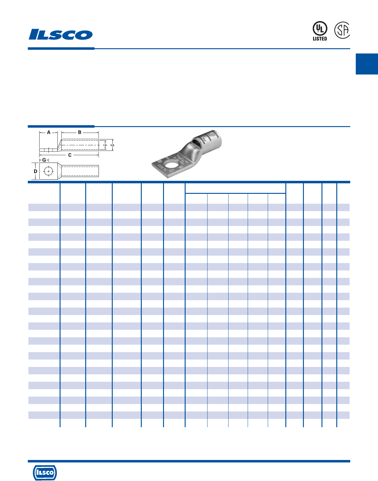
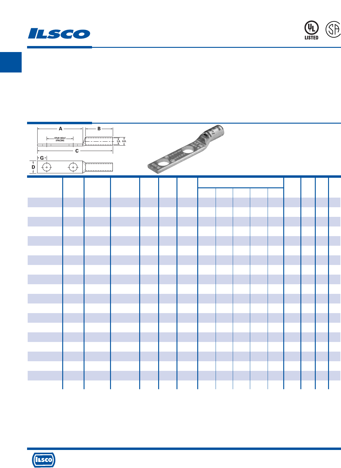
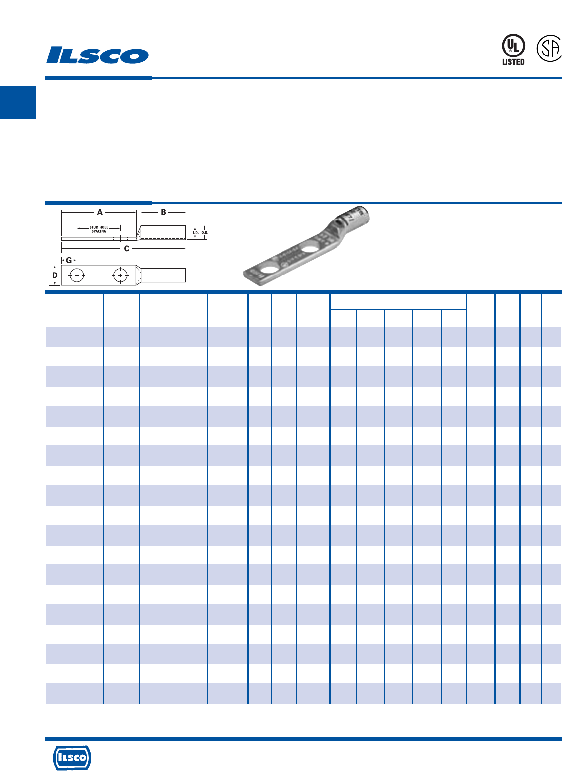
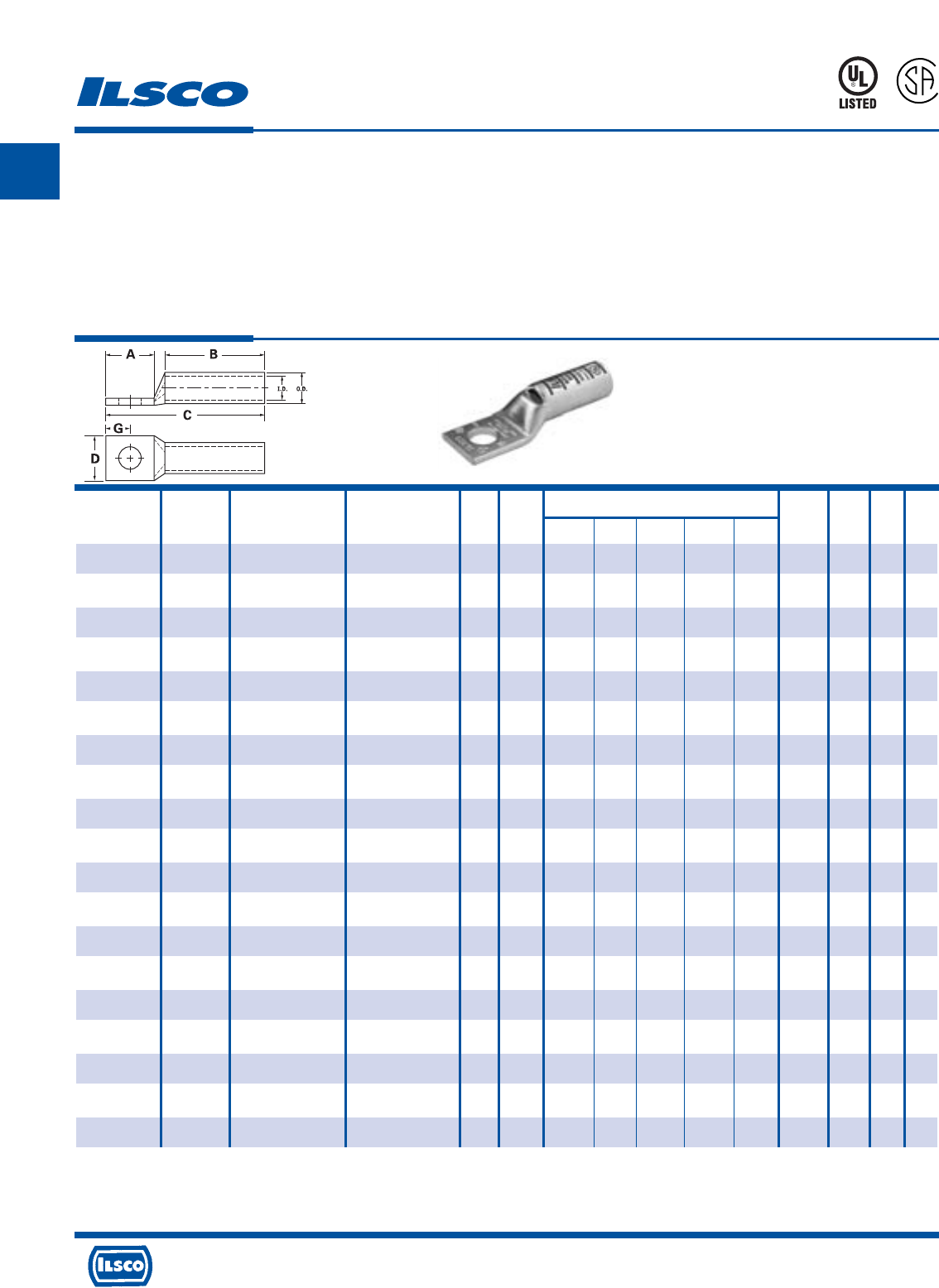
SureCrimp®
Copper Compression Lugs - Standard Barrel
1 Hole, w/Sight Hole - Conductor Range: #1 - #8
TYPE
CSWS
L
R
-
2
9
6
0
1
453G
Features
•
Manufactured from high strength seamless copper tubing.
•
Electro-Tin plated.
•
Maximum conductivity and excellent crimping characteristics.
•
Chamfered entry.
•
Color coded.
•
UL 486A 90°C Listed and CSA Certified for 600 Volts.
•
If proper high voltage spacing and insulation techniques are used, may be used for high voltage applications up to 35KV.
•
For Copper conductor only.
•
Ilsco connectors are UL Listed and CSA Certified with ILSCO and other Manufacturers' tools.+
•
UL File E6207
Stud Dimensions Die
Catalog Wire Alt Expanded* Bolt Hole Color Die
Number Size Wire Size Wire Range Size Dia. A B C D G Code Index O.D. I.D.
CSWS-8-10 #8 AWG #8 FLEX - 10 0.219 0.562 0.500 1.257 0.374 0.258 Red I-21 0.272 0.179
CSWS-8-14 #8 AWG #8 FLEX - 1/4 0.281 0.680 0.500 1.375 0.486 0.320 Red I-21 0.272 0.179
CSWS-8-516 #8 AWG #8 FLEX - 5/16 0.343 0.875 0.500 1.570 0.532 0.352 Red I-21 0.272 0.179
CSWS-8-38 #8 AWG #8 FLEX - 3/8 0.406 0.875 0.500 1.570 0.593 0.414 Red I-21 0.272 0.179
CSWS-6-10 #6 AWG - - 10 0.219 0.562 0.500 1.257 0.411 0.258 Blue I-24 0.295 0.203
CSWS-6-14 #6 AWG - - 1/4 0.281 0.680 0.500 1.375 0.411 0.320 Blue I-24 0.295 0.203
CSWS-6-516 #6 AWG - - 5/16 0.343 0.875 0.500 1.570 0.532 0.352 Blue I-24 0.295 0.203
CSWS-6-38 #6 AWG - - 3/8 0.406 0.875 0.500 1.570 0.593 0.414 Blue I-24 0.295 0.203
CSWS-6-12 #6 AWG - - 1/2 0.562 1.250 0.500 1.945 0.750 0.546 Blue I-24 0.295 0.203
CSWS-6-34 #6 AWG - - 3/4 0.781 1.687 0.500 2.382 0.411 0.750 Blue I-24 0.295 0.203
CSWS-4-10 #4 AWG #6 FLEX 4-6 AWG 10 0.219 0.562 0.500 1.296 0.486 0.258 Gray I-29 0.343 0.250
CSWS-4-14 #4 AWG #6 FLEX 4-6 AWG 1/4 0.281 0.680 0.500 1.414 0.486 0.320 Gray I-29 0.343 0.250
CSWS-4-516 #4 AWG #6 FLEX 4-6 AWG 5/16 0.343 0.875 0.500 1.609 0.486 0.352 Gray I-29 0.343 0.250
CSWS-4-38 #4 AWG #6 FLEX 4-6 AWG 3/8 0.406 0.875 0.500 1.609 0.593 0.414 Gray I-29 0.343 0.250
CSWS-4-12 #4 AWG #6 FLEX 4-6 AWG 1/2 0.562 1.250 0.500 1.984 0.750 0.546 Gray I-29 0.343 0.250
CSWS-3-10 #3 AWG #4 FLEX 3-6 AWG 10 0.219 0.562 0.625 1.442 0.532 0.258 White I-29 0.375 0.275
CSWS-3-14 #3 AWG #4 FLEX 3-6 AWG 1/4 0.281 0.680 0.625 1.560 0.532 0.320 White I-29 0.375 0.275
CSWS-3-516 #3 AWG #4 FLEX 3-6 AWG 5/16 0.343 0.875 0.625 1.755 0.532 0.352 White I-29 0.375 0.275
CSWS-3-38 #3 AWG #4 FLEX 3-6 AWG 3/8 0.406 0.875 0.625 1.755 0.593 0.414 White I-29 0.375 0.275
CSWS-3-12 #3 AWG #4 FLEX 3-6 AWG 1/2 0.562 1.250 0.625 2.130 0.750 0.546 White I-29 0.375 0.275
CSWS-2-10 #2 AWG - 2-6 AWG 10 0.219 0.562 0.625 1.473 0.599 0.258 Brown I-33 0.421 0.312
CSWS-2-14 #2 AWG - 2-6 AWG 1/4 0.281 0.680 0.625 1.591 0.599 0.320 Brown I-33 0.421 0.312
CSWS-2-516 #2 AWG - 2-6 AWG 5/16 0.343 0.875 0.625 1.786 0.599 0.352 Brown I-33 0.421 0.312
CSWS-2-38 #2 AWG - 2-6 AWG 3/8 0.406 0.875 0.625 1.786 0.599 0.414 Brown I-33 0.421 0.312
CSWS-2-12 #2 AWG - 2-6 AWG 1/2 0.562 1.250 0.625 2.161 0.750 0.546 Brown I-33 0.421 0.312
CSWS-1-10 #1 AWG #2 FLEX 1-6 AWG 10 0.219 0.562 0.625 1.517 0.673 0.258 Green I-37 0.468 0.359
CSWS-1-14 #1 AWG #2 FLEX 1-6 AWG 1/4 0.281 0.875 0.625 1.830 0.673 0.320 Green I-37 0.468 0.359
CSWS-1-516 #1 AWG #2 FLEX 1-6 AWG 5/16 0.343 0.875 0.625 1.830 0.673 0.352 Green I-37 0.468 0.359
CSWS-1-38 #1 AWG #2 FLEX 1-6 AWG 3/8 0.406 0.875 0.625 1.830 0.673 0.414 Green I-37 0.468 0.359
CSWS-1-12 #1 AWG #2 FLEX 1-6 AWG 1/2 0.562 1.250 0.625 2.205 0.750 0.546 Green I-37 0.468 0.359
* When installed with specified dieless tools
+ See pages 90 to 97 for complete tooling information.
For Bent Tangs change the 4th letter to a B and add “-4” for 45 deg. or “-9” for 90 deg.
A
4730 Madison Road, Cincinnati, Ohio 45227-1426 Phone 513 533-6200 Fax 513 871-4084 Web site www.ilsco.com
Canada 1050 Lakeshore Road East, Mississauga, Ontario, Canada L5E1E4 Phone 905 274-2341 Fax 905 274-8763
3
Stud Dimensions Die
Catalog Wire Alt Expanded* Bolt Hole Color Die
Number Size Wire Size Wire Range Size Dia. A B C D G Code Index O.D. I.D.
CSWS-1/0-10 1/0 AWG #1 FLEX 1/0-6 AWG 10 0.219 0.562 0.750 1.668 0.738 0.258 Pink I-42 0.515 0.390
CSWS-1/0-14 1/0 AWG #1 FLEX 1/0-6 AWG 1/4 0.281 0.875 0.750 1.981 0.738 0.320 Pink I-42 0.515 0.390
CSWS-1/0-516 1/0 AWG #1 FLEX 1/0-6 AWG 5/16 0.343 0.875 0.750 1.981 0.738 0.352 Pink I-42 0.515 0.390
CSWS-1/0-38 1/0 AWG #1 FLEX 1/0-6 AWG 3/8 0.406 0.875 0.750 1.981 0.738 0.414 Pink I-42 0.515 0.390
CSWS-1/0-12 1/0 AWG #1 FLEX 1/0-6 AWG 1/2 0.562 1.250 0.750 2.356 0.738 0.546 Pink I-42 0.515 0.390
CSWS-2/0-10 2/0 AWG 1/0 FLEX 2/0-4 AWG 10 0.219 0.562 0.750 1.708 0.811 0.258 Black I-45 0.562 0.437
CSWS-2/0-14 2/0 AWG 1/0 FLEX 2/0-4 AWG 1/4 0.281 0.875 0.750 2.021 0.811 0.320 Black I-45 0.562 0.437
CSWS-2/0-516 2/0 AWG 1/0 FLEX 2/0-4 AWG 5/16 0.343 0.875 0.750 2.021 0.811 0.352 Black I-45 0.562 0.437
CSWS-2/0-38 2/0 AWG 1/0 FLEX 2/0-4 AWG 3/8 0.406 0.875 0.750 2.021 0.811 0.414 Black I-45 0.562 0.437
CSWS-2/0-12 2/0 AWG 1/0 FLEX 2/0-4 AWG 1/2 0.562 1.250 0.750 2.396 0.811 0.546 Black I-45 0.562 0.437
CSWS-3/0-10 3/0 AWG 2/0 FLEX 3/0-2 AWG 10 0.219 0.562 0.750 1.751 0.885 0.258 Orange I-50 0.609 0.484
CSWS-3/0-14 3/0 AWG 2/0 FLEX 3/0-2 AWG 1/4 0.281 0.875 0.750 2.064 0.885 0.320 Orange I-50 0.609 0.484
CSWS-3/0-516 3/0 AWG 2/0 FLEX 3/0-2 AWG 5/16 0.343 0.875 0.750 2.064 0.885 0.352 Orange I-50 0.609 0.484
CSWS-3/0-38 3/0 AWG 2/0 FLEX 3/0-2 AWG 3/8 0.406 0.875 0.750 2.064 0.885 0.414 Orange I-50 0.609 0.484
CSWS-3/0-12 3/0 AWG 2/0 FLEX 3/0-2 AWG 1/2 0.562 1.250 0.750 2.439 0.885 0.546 Orange I-50 0.609 0.484
CSWS-4/0-14 4/0 AWG 3/0 FLEX 4/0-1 AWG 1/4 0.281 0.875 0.875 2.241 0.999 0.320 Purple I-54 0.687 0.546
CSWS-4/0-516 4/0 AWG 3/0 FLEX 4/0-1 AWG 5/16 0.343 0.875 0.875 2.241 0.999 0.352 Purple I-54 0.687 0.546
CSWS-4/0-38 4/0 AWG 3/0 FLEX 4/0-1 AWG 3/8 0.406 0.875 0.875 2.241 0.999 0.414 Purple I-54 0.687 0.546
CSWS-4/0-12 4/0 AWG 3/0 FLEX 4/0-1 AWG 1/2 0.562 1.250 0.875 2.616 0.999 0.546 Purple I-54 0.687 0.546
CSWS-250-516 250kcmil 4/0 FLEX 250kcmil - 1/0 AWG 5/16 0.343 0.875 1.063 2.469 1.088 0.352 Yellow I-62 0.750 0.593
CSWS-250-38 250kcmil 4/0 FLEX 250kcmil - 1/0 AWG 3/8 0.406 0.875 1.063 2.469 1.088 0.414 Yellow I-62 0.750 0.593
CSWS-250-12 250kcmil 4/0 FLEX 250kcmil - 1/0 AWG 1/2 0.562 1.250 1.063 2.844 1.088 0.546 Yellow I-62 0.750 0.593
CSWS-300-516 300kcmil 250 G,H FLEX 300kcmil - 2/0 AWG 5/16 0.343 0.875 1.063 2.525 1.189 0.352 White I-66 0.812 0.660
CSWS-300-38 300kcmil 250 G,H FLEX 300kcmil - 2/0 AWG 3/8 0.406 0.875 1.063 2.525 1.189 0.414 White I-66 0.812 0.660
CSWS-300-12 300kcmil 250 G,H FLEX 300kcmil - 2/0 AWG 1/2 0.562 1.250 1.063 2.900 1.189 0.546 White I-66 0.812 0.660
CSWS-300-58 300kcmil 250 G,H FLEX 300kcmil - 2/0 AWG 5/8 0.656 1.437 1.063 3.087 1.189 0.671 White I-66 0.812 0.660
CSWS-350-38 350kcmil 250 I,K,M FLEX 350kcmil - 3/0 AWG 3/8 0.406 0.875 1.063 2.561 1.291 0.414 Red I-71 0.890 0.703
262.2 DLO
CSWS-350-12 350kcmil 250 I,K,M FLEX 350kcmil - 3/0 AWG 1/2 0.562 1.250 1.063 2.936 1.291 0.546 Red I-71 0.890 0.703
262.2 DLO
CSWS-350-58 350kcmil 250 I,K,M FLEX 350kcmil - 3/0 AWG 5/8 0.656 1.437 1.063 3.123 1.291 0.671 Red I-71 0.890 0.703
262.2 DLO
CSWS-400-38 400kcmil 300 G,H,I,K,M FLEX 400kcmil - 4/0 AWG 3/8 0.406 0.875 1.188 2.730 1.365 0.414 Blue I-76 0.937 0.750
313.1 DLO
CSWS-400-12 400kcmil 300 G,H,I,K,M FLEX 400kcmil - 4/0 AWG 1/2 0.562 1.250 1.188 3.105 1.365 0.546 Blue I-76 0.937 0.750
313.1 DLO
CSWS-400-58 400kcmil 300 G,H,I,K,M FLEX 400kcmil - 4/0 AWG 5/8 0.656 1.437 1.188 3.292 1.365 0.671 Blue I-76 0.937 0.750
313.1 DLO
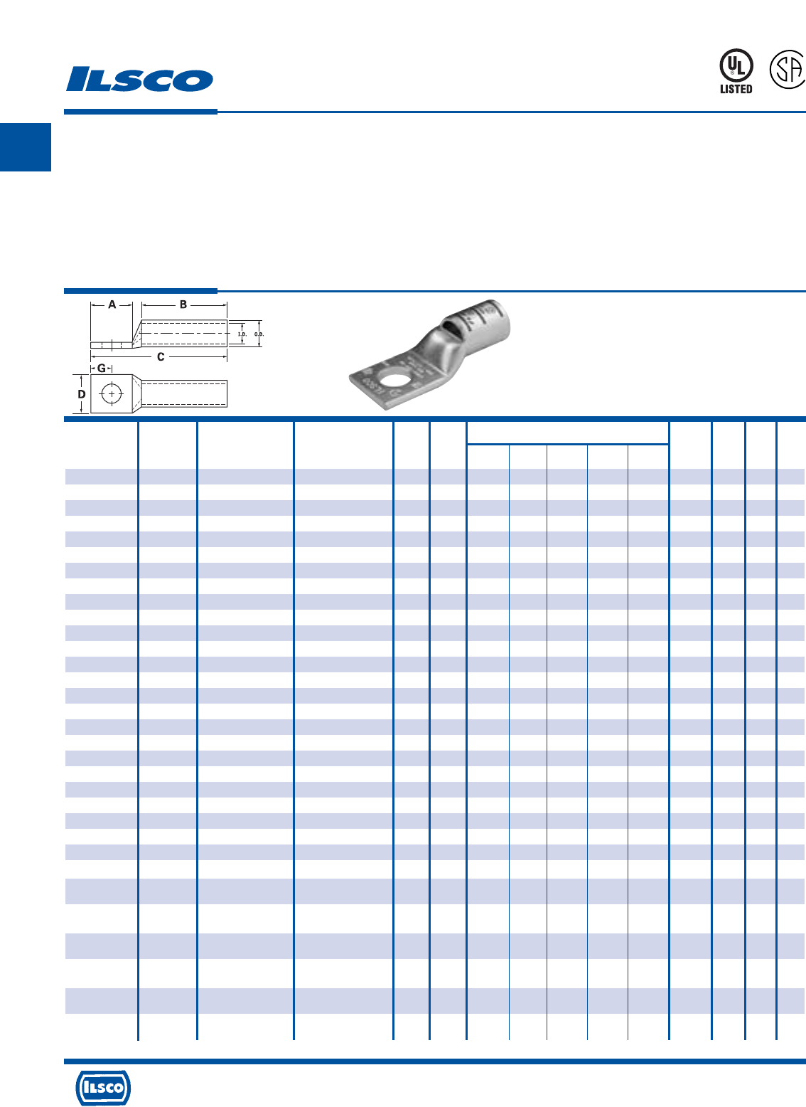
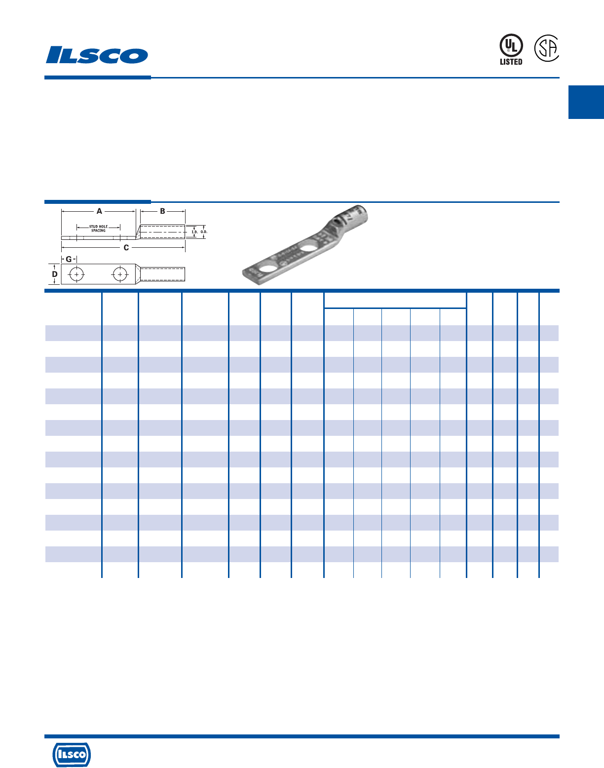
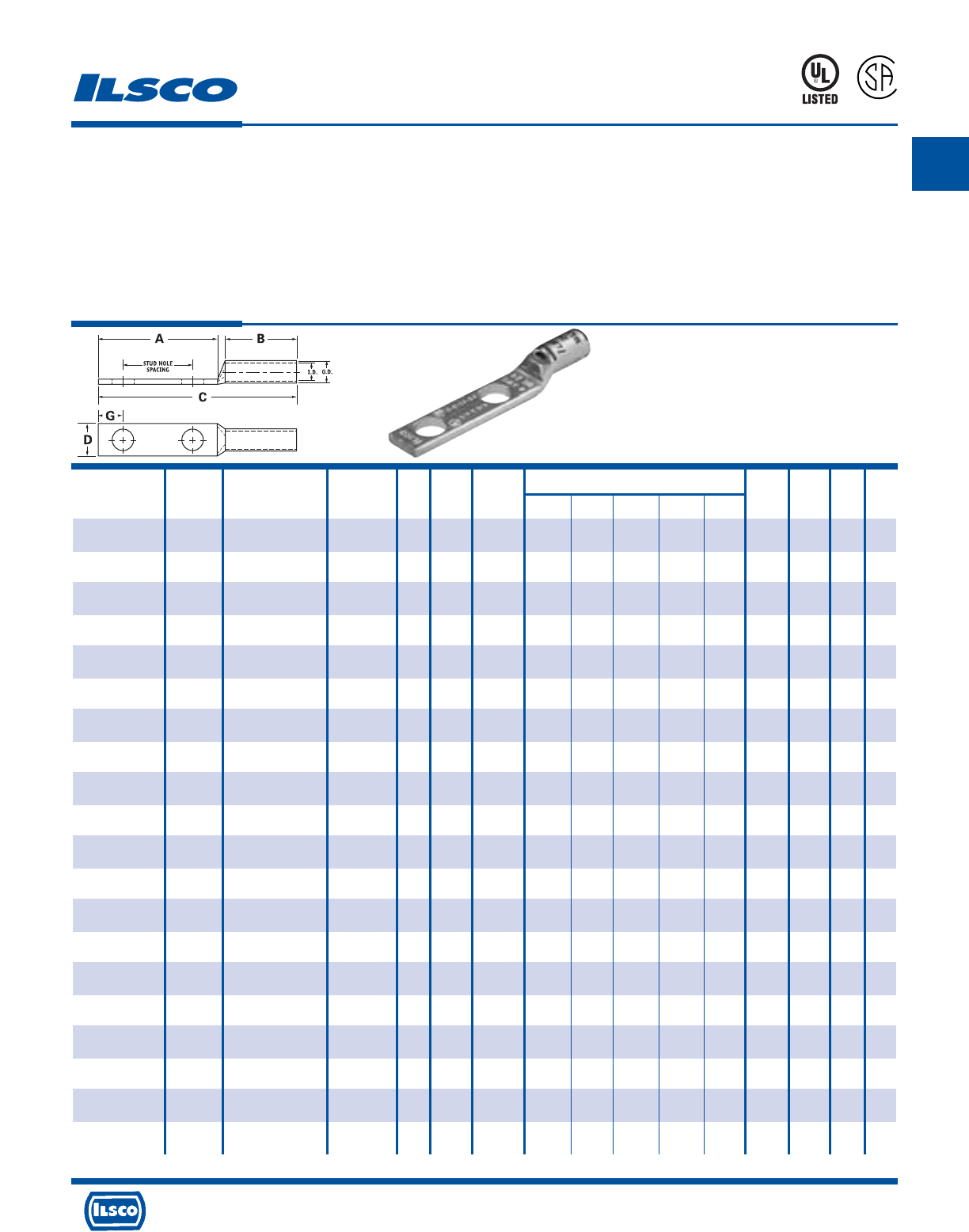
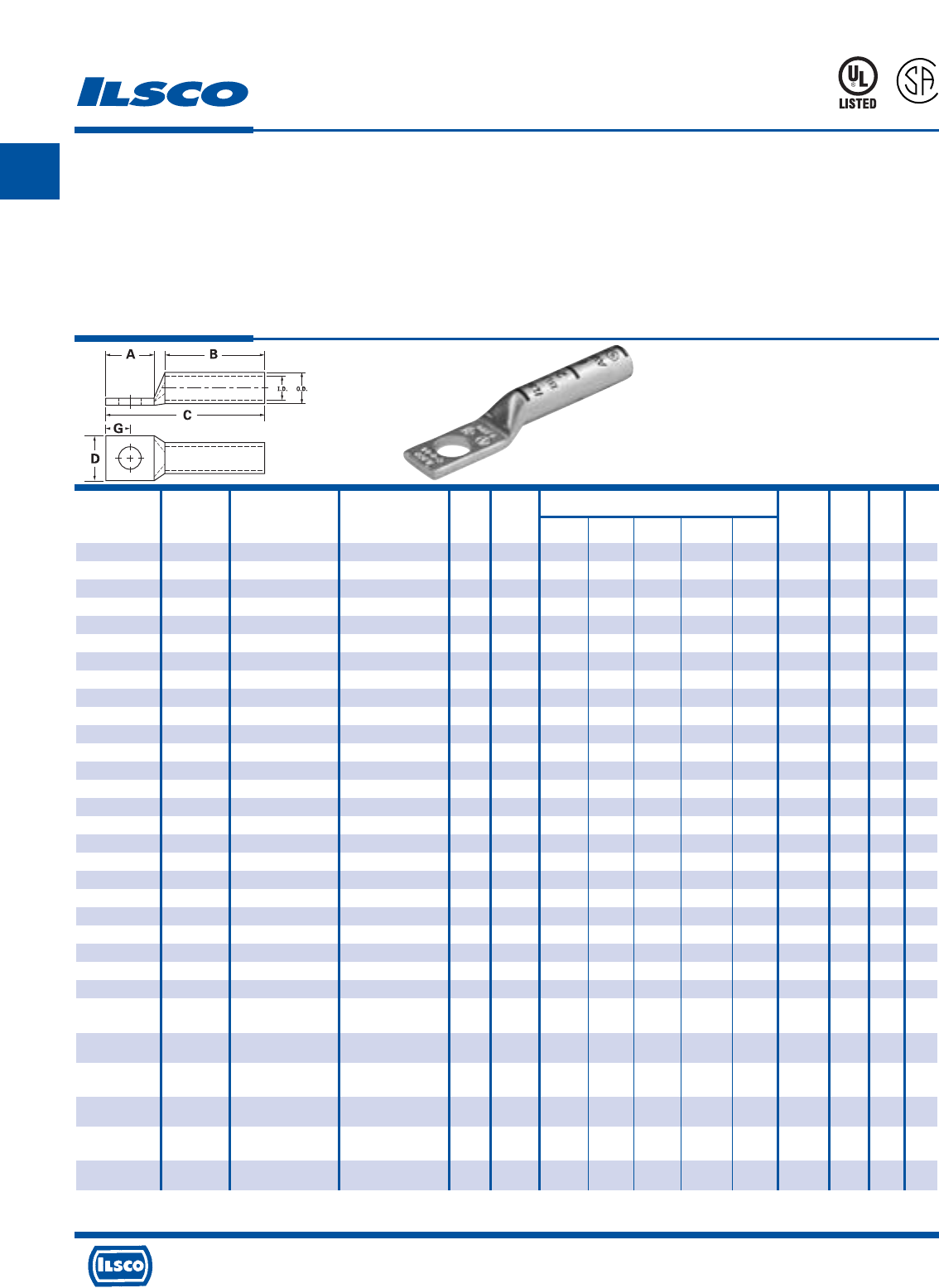
SureCrimp®
Copper Compression Lugs - Standard Barrel
1 Hole, w/Sight Hole - Conductor Range: 400kcmil - 1/0
TYPE
CSWS
L
R
-
2
9
6
0
1
453G
Features
•
Manufactured from high strength seamless copper tubing.
•
Electro-Tin plated.
•
Maximum conductivity and excellent crimping characteristics.
•
Chamfered entry.
•
Color coded.
•
UL 486A 90°C Listed and CSA Certified for 600 Volts.
•
If proper high voltage spacing and insulation techniques are used, may be used for high voltage applications up to 35KV.
•
For Copper conductor only.
•
Ilsco connectors are UL Listed and CSA Certified with ILSCO and other Manufacturers' tools.+
•
UL File E6207
* When installed with specified dieless tools
+
See pages 90 to 97 for complete tooling information. For Bent Tangs change the 4th letter to a B and add “-4” for 45 deg. or “-9” for 90 deg.
A
4730 Madison Road, Cincinnati, Ohio 45227-1426 Phone 513 533-6200 Fax 513 871-4084 Web site www.ilsco.com
Canada 1050 Lakeshore Road East, Mississauga, Ontario, Canada L5E1E4 Phone 905 274-2341 Fax 905 274-8763
4
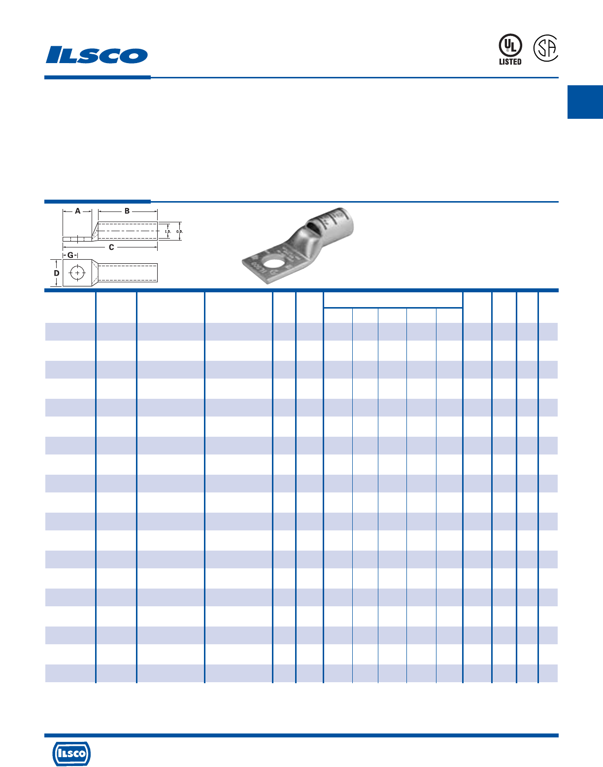
SureCrimp®
Copper Compression Lugs - Standard Barrel
1 Hole, w/Sight Hole - Conductor Range: 1000kcmil - 500kcmil
TYPE
CSWS
L
R
-
2
9
6
0
1
453G
Features
•
Manufactured from high strength seamless copper tubing.
•
Electro-Tin plated.
•
Maximum conductivity and excellent crimping characteristics.
•
Chamfered entry.
•
Color coded.
•
UL 486A 90°C Listed and CSA Certified for 600 Volts.
•
If proper high voltage spacing and insulation techniques are used, may be used for high voltage applications up to 35KV.
•
For Copper conductor only.
•
Ilsco connectors are UL Listed and CSA Certified with ILSCO and other Manufacturers' tools.+
•
UL File E6207
Stud Dimensions Die
Catalog Wire Alt Expanded* Bolt Hole Color Die
Number Size Wire Size Wire Range Size Dia. A B C D G Code Index O.D. I.D.
CSWS-500-12 500kcmil 350 G,H,I,K,M FLEX 500kcmil - 250kcmil 1/2 0.562 1.250 1.300 3.282 1.535 0.414 Brown I-87 1.062 0.828
373.7 DLO
CSWS-500-38 500kcmil 350 G,H,I,K,M FLEX 500kcmil - 250kcmil 3/8 0.406 0.875 1.300 2.907 1.535 0.546 Brown I-87 1.062 0.828
373.7 DLO
CSWS-500-58 500kcmil 350 G,H,I,K,M FLEX 500kcmil - 250kcmil 5/8 0.656 1.437 1.300 3.469 1.535 0.671 Brown I-87 1.062 0.828
373.7 DLO
CSWS-600-38 600kcmil 400 G,H,I,K,M FLEX 600kcmil - 250kcmil 3/8 0.406 0.875 1.375 3.059 1.712 0.414 Green I-94 1.187 0.920
444.4 DLO
CSWS-600-12 600kcmil 400 G,H,I,K,M FLEX 600kcmil - 250kcmil 1/2 0.562 1.250 1.375 3.434 1.712 0.546 Green I-94 1.187 0.920
444.4 DLO
CSWS-600-58 600kcmil 400 G,H,I,K,M FLEX 600kcmil - 250kcmil 5/8 0.656 1.437 1.375 3.621 1.712 0.671 Green I-94 1.187 0.920
444.4 DLO
CSWS-650-516 650kcmil 500 G,H,I,K,M FLEX 650kcmil - 350kcmil 1/32 0.343 0.875 1.375 3.119 1.764 0.352 Pink I-99 1.217 0.958
535.3 DLO
CSWS-650-38 650kcmil 500 G,H,I,K,M FLEX 650kcmil - 350kcmil 3/8 0.406 0.875 1.375 3.119 1.764 0.414 Pink I-99 1.217 0.958
535.3 DLO
CSWS-650-12 650kcmil 500 G,H,I,K,M FLEX 650kcmil - 350kcmil 1/2 0.562 1.25 1.375 3.494 1.764 0.546 Pink I-99 1.217 0.958
535.3 DLO
CSWS-650-58 650kcmil 500 G,H,I,K,M FLEX 650kcmil - 350kcmil 5/8 0.656 1.437 1.375 3.681 1.764 0.671 Pink I-99 1.217 0.958
535.3 DLO
CSWS-700-38 700kcmil 500 G,H,I,K,M FLEX 700kcmil - 350kcmil 3/8 0.406 0.875 1.375 3.119 1.816 0.414 Pink I-99 1.250 0.991
535.3 DLO
CSWS-700-12 700kcmil 500 G,H,I,K,M FLEX 700kcmil - 350kcmil 1/2 0.562 1.250 1.375 3.494 1.816 0.546 Pink I-99 1.250 0.991
535.3 DLO
CSWS-700-58 700kcmil 500 G,H,I,K,M FLEX 700kcmil - 350kcmil 5/8 0.656 1.437 1.375 3.681 1.816 0.671 Pink I-99 1.250 0.991
535.3 DLO
CSWS-750-38 750kcmil 600 G,H,I,M FLEX 750 kcmil - 500kcmil 3/8 0.406 0.875 1.500 3.277 1.901 0.414 Black I-106 1.313 1.031
646.4 DLO
CSWS-750-12 750kcmil 600 G,H,I,M FLEX 750kcmil - 500kcmil 1/2 0.562 1.250 1.500 3.652 1.901 0.546 Black I-106 1.313 1.031
646.4 DLO
CSWS-750-58 750kcmil 600 G,H,I,M FLEX 750kcmil - 500kcmil 5/8 0.656 1.437 1.500 3.839 1.901 0.671 Black I-106 1.313 1.031
646.4 DLO
CSWS-1000-38 1000kcmil 750 G,H,I FLEX 1000kcmil - 750kcmil 3/8 0.406 0.875 1.625 3.525 2.169 0.414 White I-125 1.500 1.172
777.7 DLO
CSWS-1000-12 1000kcmil 750 G,H,I FLEX 1000kcmil - 750kcmil 1/2 0.562 1.250 1.625 3.900 2.169 0.546 White I-125 1.500 1.172
777.7 DLO
CSWS-1000-58 1000kcmil 750 G,H,I FLEX 1000kcmil - 750kcmil 5/8 0.656 1.437 1.625 4.087 2.169 0.671 White I-125 1.500 1.172
777.7 DLO
* When installed with specified dieless tools
+ See pages 90 to 97 for complete tooling information.
For Bent Tangs change the 4th letter to a B and add “-4” for 45 deg. or “-9” for 90 deg.
A
4730 Madison Road, Cincinnati, Ohio 45227-1426 Phone 513 533-6200 Fax 513 871-4084 Web site www.ilsco.com
Canada 1050 Lakeshore Road East, Mississauga, Ontario, Canada L5E1E4 Phone 905 274-2341 Fax 905 274-8763
5
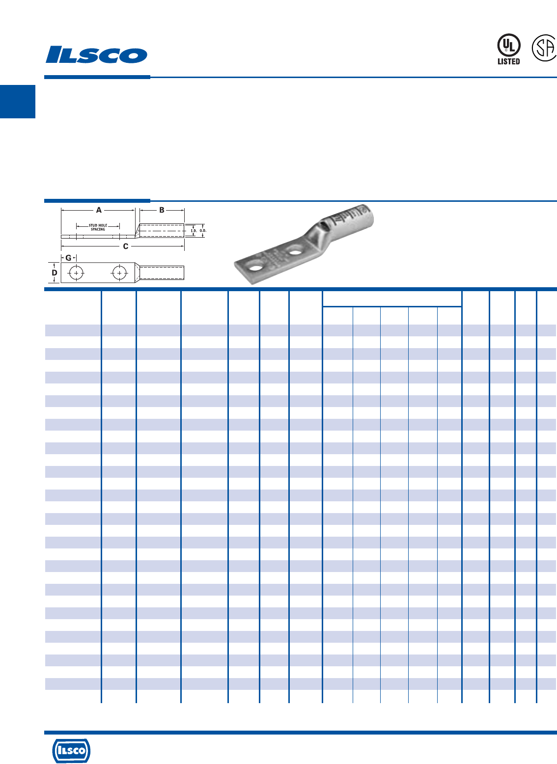
TYPE
CSWD
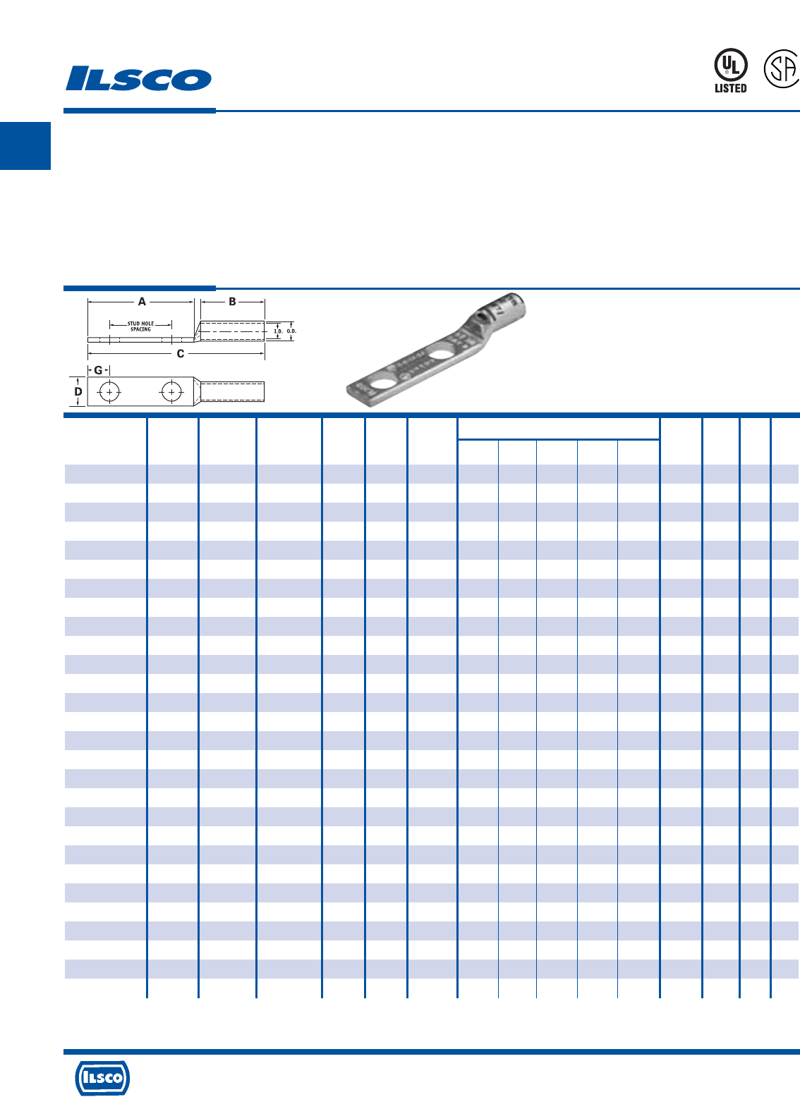
SureCrimp®
Copper Compression Lugs - Standard Barrel
2 Hole, w/Sight Hole - Conductor Range: #6 - #8
L
R
-
2
9
6
0
1
453G
Features
•
Manufactured from high strength seamless copper tubing.
•
Electro-Tin plated.
•
Maximum conductivity and excellent crimping characteristics.
•
Chamfered entry.
•
Color coded.
•
UL 486A 90°C Listed and CSA Certified for 600 Volts.
•
If proper high voltage spacing and insulation techniques are used, may be used for high voltage applications up to 35KV.
•
For Copper conductor only.
•
Ilsco connectors are UL Listed and CSA Certified with ILSCO and other Manufacturers' tools.+
•
UL File E6207
Stud Stud Dimensions Die
Catalog Wire Alt Expanded* Bolt Hole Hole Color Die
Number Size Wire Size Wire Range Size Dia. Spacing A B C D G Code Index O.D. I.D.
CSWD-8-10-58 #8 AWG #8 FLEX - 10 0.219 0.625 1.250 0.500 1.945 0.374 0.258 Red I-21 0.272 0.179
CSWD-8-10-34 #8 AWG #8 FLEX - 10 0.219 0.750 1.437 0.500 2.132 0.374 0.258 Red I-21 0.272 0.179
CSWD-8-14-58 #8 AWG #8 FLEX - 1/4 0.281 0.625 1.437 0.500 2.132 0.486 0.320 Red I-21 0.272 0.179
CSWD-8-14-34 #8 AWG #8 FLEX - 1/4 0.281 0.750 1.437 0.500 2.132 0.486 0.320 Red I-21 0.272 0.179
CSWD-8-14-1 #8 AWG #8 FLEX - 1/4 0.281 1.000 1.687 0.500 2.382 0.486 0.320 Red I-21 0.272 0.179
CSWD-8-38-1 #8 AWG #8 FLEX - 3/8 0.406 1.000 1.937 0.500 2.632 0.593 0.414 Red I-21 0.272 0.179
CSWD-6-10-12 #6 AWG - - 10 0.219 0.500 1.250 0.500 1.945 0.411 0.258 Blue I-24 0.295 0.203
CSWD-6-10-58 #6 AWG - - 10 0.219 0.625 1.250 0.500 1.945 0.411 0.258 Blue I-24 0.295 0.203
CSWD-6-10-1116 #6 AWG - - 10 0.219 0.687 1.250 0.500 1.945 0.411 0.258 Blue I-24 0.295 0.203
CSWD-6-10-34 #6 AWG - - 10 0.219 0.750 1.437 0.500 2.132 0.411 0.258 Blue I-24 0.295 0.203
CSWD-6-14-12 #6 AWG - - 1/4 0.281 0.500 1.250 0.500 1.945 0.411 0.320 Blue I-24 0.295 0.203
CSWD-6-14-58 #6 AWG - - 1/4 0.281 0.625 1.437 0.500 2.132 0.411 0.320 Blue I-24 0.295 0.203
CSWD-6-14-34 #6 AWG - - 1/4 0.281 0.750 1.437 0.500 2.132 0.411 0.320 Blue I-24 0.295 0.203
CSWD-6-14-1 #6 AWG - - 1/4 0.281 1.000 1.687 0.500 2.382 0.411 0.320 Blue I-24 0.295 0.203
CSWD-6-516-34 #6 AWG - - 5/16 0.343 0.750 1.687 0.500 2.382 0.532 0.352 Blue I-24 0.295 0.203
CSWD-6-516-1 #6 AWG - - 5/16 0.343 1.000 1.937 0.500 2.632 0.532 0.352 Blue I-24 0.295 0.203
CSWD-6-38-34 #6 AWG - - 3/8 0.406 0.750 1.687 0.500 2.382 0.593 0.414 Blue I-24 0.295 0.203
CSWD-6-38-78 #6 AWG - - 3/8 0.406 0.875 1.937 0.500 2.632 0.593 0.414 Blue I-24 0.295 0.203
CSWD-6-38-1 #6 AWG - - 3/8 0.406 1.000 1.937 0.500 2.632 0.593 0.414 Blue I-24 0.295 0.203
CSWD-6-12-134 #6 AWG - - 1/2 0.562 1.750 3.000 0.500 3.695 0.750 0.546 Blue I-24 0.295 0.203
* When installed with specified dieless tools
+ See pages 90 to 97 for complete tooling information.
For Bent Tangs change the 4th letter to a B and add “-4” for 45 deg. or “-9” for 90 deg.
A
4730 Madison Road, Cincinnati, Ohio 45227-1426 Phone 513 533-6200 Fax 513 871-4084 Web site www.ilsco.com
Canada 1050 Lakeshore Road East, Mississauga, Ontario, Canada L5E1E4 Phone 905 274-2341 Fax 905 274-8763
6
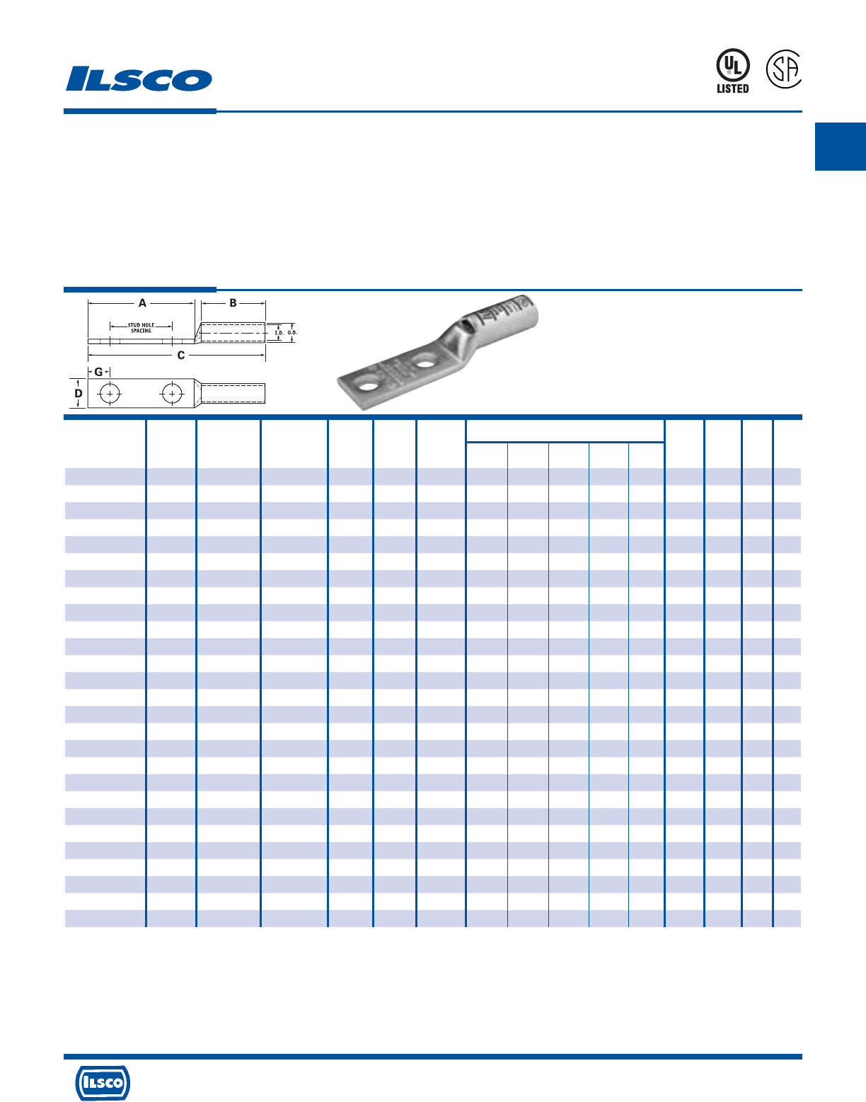
TYPE
CSWD
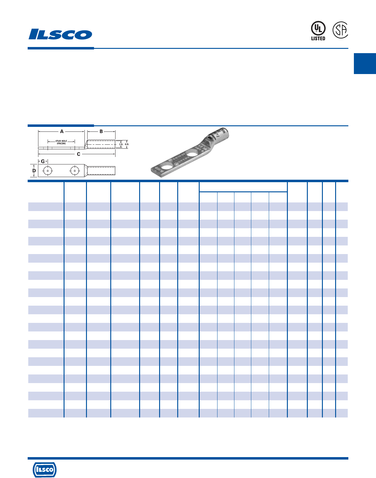
SureCrimp®
Copper Compression Lugs - Standard Barrel
2 Hole, w/Sight Hole - Conductor Range: #3 - #4
L
R
-
2
9
6
0
1
453G
Features
•
Manufactured from high strength seamless copper tubing.
•
Electro-Tin plated.
•
Maximum conductivity and excellent crimping characteristics.
•
Chamfered entry.
•
Color coded.
•
UL 486A 90°C Listed and CSA Certified for 600 Volts.
•
If proper high voltage spacing and insulation techniques are used, may be used for high voltage applications up to 35KV.
•
For Copper conductor only.
•
Ilsco connectors are UL Listed and CSA Certified with ILSCO and other Manufacturers' tools.+
•
UL File E6207
Stud Stud Dimensions Die
Catalog Wire Alt Expanded* Bolt Hole Hole Color Die
Number Size Wire Size Wire Range Size Dia. Spacing A B C D G Code Index O.D. I.D.
CSWD-4-10-58 #4 AWG #6 FLEX 4-6 AWG 10 0.219 0.625 1.250 0.500 1.984 0.486 0.258 Gray I-29 0.343 0.250
CSWD-4-10-34 #4 AWG #6 FLEX 4-6 AWG 10 0.219 0.750 1.437 0.500 2.171 0.486 0.258 Gray I-29 0.343 0.250
CSWD-4-10-1 #4 AWG #6 FLEX 4-6 AWG 10 0.219 1.000 1.687 0.500 2.421 0.486 0.258 Gray I-29 0.343 0.250
CSWD-4-14-58 #4 AWG #6 FLEX 4-6 AWG 1/4 0.281 0.625 1.437 0.500 2.171 0.486 0.320 Gray I-29 0.343 0.250
CSWD-4-14-34 #4 AWG #6 FLEX 4-6 AWG 1/4 0.281 0.750 1.437 0.500 2.171 0.486 0.320 Gray I-29 0.343 0.250
CSWD-4-14-1 #4 AWG #6 FLEX 4-6 AWG 1/4 0.281 1.000 1.687 0.500 2.421 0.486 0.320 Gray I-29 0.343 0.250
CSWD-4-516-1 #4 AWG #6 FLEX 4-6 AWG 1/4 0.343 1.000 1.937 0.500 2.671 0.486 0.320 Gray I-29 0.343 0.250
CSWD-4-38-34 #4 AWG #6 FLEX 4-6 AWG 3/8 0.406 0.750 1.687 0.500 2.421 0.593 0.414 Gray I-29 0.343 0.250
CSWD-4-38-1 #4 AWG #6 FLEX 4-6 AWG 3/8 0.406 1.000 1.937 0.500 2.671 0.593 0.414 Gray I-29 0.343 0.250
CSWD-4-12-134 #4 AWG #6 FLEX 4-6 AWG 1/2 0.562 1.750 3.000 0.500 3.734 0.750 0.546 Gray I-29 0.343 0.250
CSWD-3-14-58 #3 AWG #4 FLEX 3-6 AWG 1/4 0.281 0.625 1.437 0.625 2.317 0.532 0.320 White I-29 0.375 0.275
CSWD-3-14-34 #3 AWG #4 FLEX 3-6 AWG 1/4 0.281 0.750 1.437 0.625 2.317 0.532 0.320 White I-29 0.375 0.275
CSWD-3-516-1 #3 AWG #4 FLEX 3-6 AWG 5/16 0.343 1.000 1.937 0.625 2.817 0.532 0.352 White I-29 0.375 0.275
CSWD-3-38-34 #3 AWG #4 FLEX 3-6 AWG 3/8 0.406 0.750 1.687 0.625 2.567 0.593 0.414 White I-29 0.375 0.275
CSWD-3-38-1 #3 AWG #4 FLEX 3-6 AWG 3/8 0.406 1.000 1.937 0.625 2.817 0.593 0.414 White I-29 0.375 0.275
CSWD-3-12-134 #3 AWG #4 FLEX 3-6 AWG 1/2 0.562 1.750 3.000 0.625 3.880 0.750 0.546 White I-29 0.375 0.275
* When installed with specified dieless tools
+ See pages 90 to 97 for complete tooling information.
For Bent Tangs change the 4th letter to a B and add “-4” for 45 deg. or “-9” for 90 deg.
A
4730 Madison Road, Cincinnati, Ohio 45227-1426 Phone 513 533-6200 Fax 513 871-4084 Web site www.ilsco.com
Canada 1050 Lakeshore Road East, Mississauga, Ontario, Canada L5E1E4 Phone 905 274-2341 Fax 905 274-8763
7
TYPE
CSWD
SureCrimp®
Copper Compression Lugs - Standard Barrel
2 Hole, w/Sight Hole - Conductor Range: 1/0 - #2
L
R
-
2
9
6
0
1
453G
Features
•
Manufactured from high strength seamless copper tubing.
•
Electro-Tin plated.
•
Maximum conductivity and excellent crimping characteristics.
•
Chamfered entry.
•
Color coded.
•
UL 486A 90°C Listed and CSA Certified for 600 Volts.
•
If proper high voltage spacing and insulation techniques are used, may be used for high voltage applications up to 35KV.
•
For Copper conductor only.
•
Ilsco connectors are UL Listed and CSA Certified with ILSCO and other Manufacturers' tools.+
•
UL File E6207
Stud Stud Dimensions Die
Catalog Wire Alt Expanded* Bolt Hole Hole Color Die
Number Size Wire Size Wire Range Size Dia. Spacing A B C D G Code Index O.D. I.D.
CSWD-2-10-34 #2 AWG - 2-6 AWG 10 0.219 0.750 1.437 0.625 2.348 0.599 0.258 Brown I-33 0.421 0.312
CSWD-2-14-58 #2 AWG - 2-6 AWG 1/4 0.281 0.625 1.437 0.625 2.348 0.599 0.320 Brown I-33 0.421 0.312
CSWD-2-14-34 #2 AWG - 2-6 AWG 1/4 0.281 0.750 1.437 0.625 2.348 0.599 0.320 Brown I-33 0.421 0.312
CSWD-2-14-1 #2 AWG - 2-6 AWG 1/4 0.281 1.000 1.687 0.625 2.598 0.599 0.320 Brown I-33 0.421 0.312
CSWD-2-516-34 #2 AWG - 2-6 AWG 5/16 0.343 0.750 1.687 0.625 2.598 0.599 0.352 Brown I-33 0.421 0.312
CSWD-2-516-1 #2 AWG - 2-6 AWG 5/16 0.343 1.000 1.937 0.625 2.848 0.599 0.352 Brown I-33 0.421 0.312
CSWD-2-38-34 #2 AWG - 2-6 AWG 3/8 0.406 0.750 1.687 0.625 2.598 0.599 0.414 Brown I-33 0.421 0.312
CSWD-2-38-78 #2 AWG - 2-6 AWG 3/8 0.406 0.875 1.937 0.625 2.848 0.599 0.414 Brown I-33 0.421 0.312
CSWD-2-38-1 #2 AWG - 2-6 AWG 3/8 0.406 1.000 1.937 0.625 2.848 0.599 0.414 Brown I-33 0.421 0.312
CSWD-2-38-134 #2 AWG - 2-6 AWG 3/8 0.406 1.750 2.625 0.625 3.536 0.599 0.414 Brown I-33 0.421 0.312
CSWD-2-12-134 #2 AWG - 2-6 AWG 1/2 0.562 1.750 3.000 0.625 3.911 0.750 0.546 Brown I-33 0.421 0.312
CSWD-1-14-58 #1 AWG #2 FLEX 1-6 AWG 1/4 0.281 0.625 1.437 0.625 2.392 0.673 0.320 Green I-37 0.468 0.359
CSWD-1-14-34 #1 AWG #2 FLEX 1-6 AWG 1/4 0.281 0.750 1.437 0.625 2.392 0.673 0.320 Green I-37 0.468 0.359
CSWD-1-14-1 #1 AWG #2 FLEX 1-6 AWG 1/4 0.281 1.000 1.687 0.625 2.642 0.673 0.320 Green I-37 0.468 0.359
CSWD-1-516-78 #1 AWG #2 FLEX 1-6 AWG 5/16 0.343 0.875 1.687 0.625 2.642 0.673 0.352 Green I-37 0.468 0.359
CSWD-1-516-1 #1 AWG #2 FLEX 1-6 AWG 5/16 0.343 1.000 1.937 0.625 2.892 0.673 0.352 Green I-37 0.468 0.359
CSWD-1-38-1 #1 AWG #2 FLEX 1-6 AWG 3/8 0.406 1.000 1.937 0.625 2.892 0.673 0.414 Green I-37 0.468 0.359
CSWD-1-12-134 #1 AWG #2 FLEX 1-6 AWG 1/2 0.562 1.750 3.000 0.625 3.955 0.750 0.546 Green I-37 0.468 0.359
CSWD-1/0-14-58 1/0 AWG #1 FLEX 1/0-6 AWG 1/4 0.281 0.625 1.437 0.750 2.543 0.738 0.320 Pink I-42 0.515 0.390
CSWD-1/0-14-34 1/0 AWG #1 FLEX 1/0-6 AWG 1/4 0.281 0.750 1.437 0.750 2.543 0.738 0.320 Pink I-42 0.515 0.390
CSWD-1/0-14-1 1/0 AWG #1 FLEX 1/0-6 AWG 1/4 0.281 1.000 1.687 0.750 2.793 0.738 0.320 Pink I-42 0.515 0.390
CSWD-1/0-516-34 1/0 AWG #1 FLEX 1/0-6 AWG 5/16 0.343 0.750 1.687 0.750 2.793 0.738 0.352 Pink I-42 0.515 0.390
CSWD-1/0-516-78 1/0 AWG #1 FLEX 1/0-6 AWG 5/16 0.343 0.875 1.687 0.750 2.793 0.738 0.352 Pink I-42 0.515 0.390
CSWD-1/0-516-1 1/0 AWG #1 FLEX 1/0-6 AWG 5/16 0.343 1.000 1.937 0.750 3.043 0.738 0.352 Pink I-42 0.515 0.390
CSWD-1/0-38-1 1/0 AWG #1 FLEX 1/0-6 AWG 3/8 0.406 1.000 1.937 0.750 3.043 0.738 0.414 Pink I-42 0.515 0.390
CSWD-1/0-38-134 1/0 AWG #1 FLEX 1/0-6 AWG 3/8 0.406 1.750 2.625 0.750 3.731 0.738 0.414 Pink I-42 0.515 0.390
CSWD-1/0-12-1 1/0 AWG #1 FLEX 1/0-6 AWG 1/2 0.562 1.000 2.125 0.750 3.231 0.738 0.546 Pink I-42 0.515 0.390
CSWD-1/0-12-134 1/0 AWG #1 FLEX 1/0-6 AWG 1/2 0.562 1.750 3.000 0.750 4.106 0.738 0.546 Pink I-42 0.515 0.390
* When installed with specified dieless tools + See pages 90 to 97 for complete tooling information.
For Bent Tangs change the 4th letter to a B and add “-4” for 45 deg. or “-9” for 90 deg.
A
4730 Madison Road, Cincinnati, Ohio 45227-1426 Phone 513 533-6200 Fax 513 871-4084 Web site www.ilsco.com
Canada 1050 Lakeshore Road East, Mississauga, Ontario, Canada L5E1E4 Phone 905 274-2341 Fax 905 274-8763
8
TYPE
CSWD
SureCrimp®
Copper Compression Lugs - Standard Barrel
2 Hole, w/Sight Hole - Conductor Range: 4/0 - 2/0
L
R
-
2
9
6
0
1
453G
Features
•
Manufactured from high strength seamless copper tubing.
•
Electro-Tin plated.
•
Maximum conductivity and excellent crimping characteristics.
•
Chamfered entry.
•
Color coded.
•
UL 486A 90°C Listed and CSA Certified for 600 Volts.
•
If proper high voltage spacing and insulation techniques are used, may be used for high voltage applications up to 35KV.
•
For Copper conductor only.
•
Ilsco connectors are UL Listed and CSA Certified with ILSCO and other Manufacturers' tools.+
•
UL File E6207
Stud Stud Dimensions Die
Catalog Wire Alt Expanded* Bolt Hole Hole Color Die
Number Size Wire Size Wire Range Size Dia. Spacing A B C D G Code Index O.D. I.D.
CSWD-2/0-14-58 2/0 AWG 1/0 FLEX 2/0-4 AWG 1/4 0.281 0.625 1.437 0.750 2.583 0.811 0.320 Black I-45 0.562 0.437
CSWD-2/0-14-34 2/0 AWG 1/0 FLEX 2/0-4 AWG 1/4 0.281 0.750 1.437 0.750 2.583 0.811 0.320 Black I-45 0.562 0.437
CSWD-2/0-14-1 2/0 AWG 1/0 FLEX 2/0-4 AWG 1/4 0.281 1.000 1.687 0.750 2.833 0.811 0.320 Black I-45 0.562 0.437
CSWD-2/0-516-78 2/0 AWG 1/0 FLEX 2/0-4 AWG 5/16 0.343 0.875 1.687 0.750 2.833 0.811 0.352 Black I-45 0.562 0.437
CSWD-2/0-516-1 2/0 AWG 1/0 FLEX 2/0-4 AWG 5/16 0.343 1.000 1.937 0.750 3.083 0.811 0.352 Black I-45 0.562 0.437
CSWD-2/0-38-1 2/0 AWG 1/0 FLEX 2/0-4 AWG 3/8 0.406 1.000 1.937 0.750 3.083 0.811 0.414 Black I-45 0.562 0.437
CSWD-2/0-38-134 2/0 AWG 1/0 FLEX 2/0-4 AWG 3/8 0.406 1.750 2.625 0.750 3.771 0.811 0.414 Black I-45 0.562 0.437
CSWD-2/0-12-1 2/0 AWG 1/0 FLEX 2/0-4 AWG 1/2 0.562 1.000 2.125 0.750 3.271 0.811 0.546 Black I-45 0.562 0.437
CSWD-2/0-12-134 2/0 AWG 1/0 FLEX 2/0-4 AWG 1/2 0.562 1.750 3.000 0.750 4.146 0.811 0.546 Black I-45 0.562 0.437
CSWD-3/0-14-58 3/0 AWG 2/0 FLEX 3/0-2 AWG 1/4 0.281 0.625 1.437 0.750 2.626 0.885 0.320 Orange I-50 0.609 0.484
CSWD-3/0-14-34 3/0 AWG 2/0 FLEX 3/0-2 AWG 1/4 0.281 0.750 1.437 0.750 2.626 0.885 0.320 Orange I-50 0.609 0.484
CSWD-3/0-516-1 3/0 AWG 2/0 FLEX 3/0-2 AWG 5/16 0.343 1.000 1.937 0.750 3.126 0.885 0.352 Orange I-50 0.609 0.484
CSWD-3/0-38-1 3/0 AWG 2/0 FLEX 3/0-2 AWG 3/8 0.406 1.000 1.937 0.750 3.126 0.885 0.414 Orange I-50 0.609 0.484
CSWD-3/0-12-134 3/0 AWG 2/0 FLEX 3/0-2 AWG 1/2 0.562 1.750 3.000 0.750 4.189 0.885 0.546 Orange I-50 0.609 0.484
CSWD-4/0-14-58 4/0 AWG 3/0 FLEX 4/0-1 AWG 1/4 0.281 0.625 1.437 0.875 2.803 0.999 0.320 Purple I-54 0.687 0.546
CSWD-4/0-14-34 4/0 AWG 3/0 FLEX 4/0-1 AWG 1/4 0.281 0.750 1.437 0.875 2.803 0.999 0.320 Purple I-54 0.687 0.546
CSWD-4/0-14-1 4/0 AWG 3/0 FLEX 4/0-1 AWG 1/4 0.281 1.000 1.687 0.875 3.053 0.999 0.320 Purple I-54 0.687 0.546
CSWD-4/0-516-34 4/0 AWG 3/0 FLEX 4/0-1 AWG 5/16 0.343 0.750 1.687 0.875 3.053 0.999 0.352 Purple I-54 0.687 0.546
CSWD-4/0-516-1 4/0 AWG 3/0 FLEX 4/0-1 AWG 5/16 0.343 1.000 1.937 0.875 3.303 0.999 0.352 Purple I-54 0.687 0.546
CSWD-4/0-516-134 4/0 AWG 3/0 FLEX 4/0-1 AWG 5/16 0.343 1.750 2.500 0.875 3.866 0.999 0.352 Purple I-54 0.687 0.546
CSWD-4/0-38-1 4/0 AWG 3/0 FLEX 4/0-1 AWG 3/8 0.406 1.000 1.937 0.875 3.303 0.999 0.414 Purple I-54 0.687 0.546
CSWD-4/0-38-134 4/0 AWG 3/0 FLEX 4/0-1 AWG 3/8 0.406 1.750 2.625 0.875 3.991 0.999 0.414 Purple I-54 0.687 0.546
CSWD-4/0-12-1 4/0 AWG 3/0 FLEX 4/0-1 AWG 1/2 0.562 1.000 2.125 0.875 3.491 0.999 0.546 Purple I-54 0.687 0.546
CSWD-4/0-12-114 4/0 AWG 3/0 FLEX 4/0-1 AWG 1/2 0.562 1.250 2.500 0.875 3.866 0.999 0.546 Purple I-54 0.687 0.546
CSWD-4/0-12-134 4/0 AWG 3/0 FLEX 4/0-1 AWG 1/2 0.562 1.750 3.000 0.875 4.366 0.999 0.546 Purple I-54 0.687 0.546
* When installed with specified dieless tools
+ See pages 90 to 97 for complete tooling information.
For Bent Tangs change the 4th letter to a B and add “-4” for 45 deg. or “-9” for 90 deg.
A
4730 Madison Road, Cincinnati, Ohio 45227-1426 Phone 513 533-6200 Fax 513 871-4084 Web site www.ilsco.com
Canada 1050 Lakeshore Road East, Mississauga, Ontario, Canada L5E1E4 Phone 905 274-2341 Fax 905 274-8763
9
TYPE
CSWD
SureCrimp®
Copper Compression Lugs - Standard Barrel
2 Hole, w/Sight Hole - Conductor Range: 500kcmil - 250kcmil
L
R
-
2
9
6
0
1
453G
Features
•
Manufactured from high strength seamless copper tubing.
•
Electro-Tin plated.
•
Maximum conductivity and excellent crimping characteristics.
•
Chamfered entry.
•
Color coded.
•
UL 486A 90°C Listed and CSA Certified for 600 Volts.
•
If proper high voltage spacing and insulation techniques are used, may be used for high voltage applications up to 35KV.
•
For Copper conductor only.
•
Ilsco connectors are UL Listed and CSA Certified with ILSCO and other Manufacturers' tools.+
•
UL File E6207
Stud Stud Dimensions Die
Catalog Wire Alt Expanded* Bolt Hole Hole Color Die
Number Size Wire Size Wire Range Size Dia. Spacing A B C D G Code Index O.D. I.D.
CSWD-250-14-34 250kcmil 4/0 FLEX 250kcmil - 1/4 0.281 0.750 1.437 1.063 3.031 1.088 0.320 Yellow I-62 0.750 0.593
1/0 AWG
CSWD-250-38-1 250kcmil 4/0 FLEX 250kcmil - 3/8 0.406 1.00 1.937 1.063 3.531 1.088 0.414 Yellow I-62 0.750 0.593
1/0 AWG
CSWD-250-38-134 250kcmil 4/0 FLEX 250kcmil - 3/8 0.406 1.750 2.625 1.063 4.219 1.088 0.414 Yellow I-62 0.750 0.593
1/0 AWG
CSWD-250-12-114 250kcmil 4/0 FLEX 250kcmil - 1/2 0.562 1.250 2.500 1.063 4.094 1.088 0.546 Yellow I-62 0.750 0.593
1/0 AWG
CSWD-250-12-134 250kcmil 4/0 FLEX 250kcmil - 1/2 0.562 1.750 3.000 1.063 4.594 1.088 0.546 Yellow I-62 0.750 0.593
1/0 AWG
CSWD-300-38-1 300kcmil 250 G,H FLEX 300kcmil - 3/8 0.406 1.000 1.937 1.063 3.587 1.189 0.414 White I-66 0.812 0.660
2/0 AWG
CSWD-300-12-134 300kcmil 250 G,H FLEX 300kcmil - 1/2 0.562 1.750 3.000 1.063 4.650 1.189 0.546 White I-66 0.812 0.660
2/0 AWG
CSWD-350-14-34 350kcmil 250 I,K,M FLEX 350kcmil - 1/4 0.281 0.750 1.437 1.063 3.123 1.291 0.320 Red I-71 0.890 0.703
262.2 DLO 3/0 AWG
CSWD-350-516-134 350kcmil 250 I,K,M FLEX 350kcmil - 5/16 0.343 1.750 2.500 1.063 4.186 1.291 0.352 Red I-71 0.890 0.703
262.2 DLO 3/0 AWG
CSWD-350-38-1 350kcmil 250 I,K,M FLEX 350kcmil - 3/8 0.406 1.000 1.937 1.063 3.623 1.291 0.414 Red I-71 0.890 0.703
262.2 DLO 3/0 AWG
CSWD-350-12-114 350kcmil 250 I,K,M FLEX 350kcmil - 1/2 0.562 1.250 2.500 1.063 4.186 1.291 0.546 Red I-71 0.890 0.703
262.2 DLO 3/0 AWG
CSWD-350-12-134 350kcmil 250 I,K,M FLEX 350kcmil - 1/2 0.562 1.750 3.000 1.063 4.686 1.291 0.546 Red I-71 0.890 0.703
262.2 DLO 3/0 AWG
CSWD-400-38-1 400kcmil 300 G,H,I,K,M FLEX 400kcmil - 3/8 0.406 1.000 1.937 1.188 3.792 1.365 0.414 Blue I-76 0.937 0.750
313.1 DLO 4/0 AWG
CSWD-400-38-116 400kcmil 300 G,H,I,K,M FLEX 400kcmil - 3/8 0.406 1.062 1.937 1.188 3.792 1.365 0.414 Blue I-76 0.937 0.750
313.1 DLO 4/0 AWG
CSWD-400-12-134 400kcmil 300 G,H,I,K,M FLEX 400kcmil - 1/2 0.562 1.750 3.000 1.188 4.855 1.365 0.546 Blue I-76 0.937 0.750
313.1 DLO 4/0 AWG
CSWD-500-14-34 500kcmil 350 G,H,I,K,M FLEX 500kcmil - 1/4 0.281 0.750 1.437 1.300 3.469 1.535 0.320 Brown I-87 1.062 0.828
373.7 DLO 250kcmil
CSWD-500-38-1 500kcmil 350 G,H,I,K,M FLEX 500kcmil - 3/8 0.406 1.000 1.937 1.300 3.969 1.535 0.414 Brown I-87 1.062 0.828
373.7 DLO 250kcmil
CSWD-500-12-114 500kcmil 350 G,H,I,K,M FLEX 500kcmil - 1/2 0.562 1.250 2.500 1.300 4.532 1.535 0.546 Brown I-87 1.062 0.828
373.7 DLO 250kcmil
CSWD-500-12-134 500kcmil 350 G,H,I,K,M FLEX 500kcmil - 1/2 0.562 1.750 3.000 1.300 5.032 1.535 0.546 Brown I-87 1.062 0.828
373.7 DLO 250kcmil
* When installed with specified dieless tools + See pages 90 to 97 for complete tooling information.
For Bent Tangs change the 4th letter to a B and add “-4” for 45 deg. or “-9” for 90 deg.
A
4730 Madison Road, Cincinnati, Ohio 45227-1426 Phone 513 533-6200 Fax 513 871-4084 Web site www.ilsco.com
Canada 1050 Lakeshore Road East, Mississauga, Ontario, Canada L5E1E4 Phone 905 274-2341 Fax 905 274-8763
10
TYPE
CSWD
SureCrimp®
Copper Compression Lugs - Standard Barrel
2 Hole w/Sight Hole - Conductor Range: 1000kcmil - 600kcmil
L
R
-
2
9
6
0
1
453G
Features
•
Manufactured from high strength seamless copper tubing.
•
Electro-Tin plated.
•
Maximum conductivity and excellent crimping characteristics.
•
Chamfered entry.
•
Color coded.
•
UL 486A 90°C Listed and CSA Certified for 600 Volts.
•
If proper high voltage spacing and insulation techniques are used, may be used for high voltage applications up to 35KV.
•
For Copper conductor only.
•
Ilsco connectors are UL Listed and CSA Certified with ILSCO and other Manufacturers' tools.+
•
UL File E6207
Stud Stud Dimensions Die
Catalog Wire Alt Expanded* Bolt Hole Hole Color Die
Number Size Wire Size Wire Range Size Dia. Spacing A B C D G Code Index O.D. I.D.
CSWD-600-38-1 600kcmil 400 G,H,I,K,M FLEX 600kcmil - 3/8 0.406 1.000 1.937 1.375 4.121 1.712 0.414 Green I-94 1.187 0.920
444.4 DLO 250kcmil
CSWD-600-12-134 600kcmil 400 G,H,I,K,M FLEX 600kcmil - 1/2 0.562 1.750 3.000 1.375 5.184 1.712 0.546 Green I-94 1.187 0.920
444.4 DLO 250kcmil
CSWD-650-12-134 650kcmil 500 G,H,I,K,M FLEX 650kcmil - 1/2 0.562 1.75 3 1.375 5.244 1.764 0.546 Pink I-99 1.217 0.958
535.3 DLO 350kcmil
CSWD-650-12-114 650kcmil 500 G,H,I,K,M FLEX 650kcmil - 1/2 0.562 1.25 2.5 1.375 4.744 1.764 0.546 Pink I-99 1.217 0.958
535.3 DLO 350kcmil
CSWD-650-38-1 650kcmil 500 G,H,I,K,M FLEX 650kcmil - 3/8 0.406 1 1.937 1.375 4.181 1.764 0.414 Pink I-99 1.217 0.958
535.3 DLO 350kcmil
CSWD-650-38-118 650kcmil 500 G,H,I,K,M FLEX 650kcmil - 3/8 0.406 1.125 2.125 1.375 4.369 1.764 0.414 Pink I-99 1.217 0.958
535.3 DLO 350kcmil
CSWD-650-516-1 650kcmil 500 G,H,I,K,M FLEX 650kcmil - 1/32 0.343 1 1.937 1.375 4.181 1.764 0.352 Pink I-99 1.217 0.958
535.3 DLO 350kcmil
CSWD-700-38-1 700kcmil 500 G,H,I,K,M FLEX 700kcmil - 3/8 0.406 1.000 1.937 1.375 4.181 1.816 0.414 Pink I-99 1.250 0.991
535.3 DLO 350kcmil
CSWD-700-12-114 700kcmil 500 G,H,I,K,M FLEX 700kcmil - 1/2 0.562 1.250 2.500 1.375 4.744 1.816 0.546 Pink I-99 1.250 0.991
535.3 DLO 350kcmil
CSWD-700-12-134 700kcmil 500 G,H,I,K,M FLEX 700kcmil - 1/2 0.562 1.750 3.000 1.375 5.244 1.816 0.546 Pink I-99 1.250 0.991
535.3 DLO 350kcmil
CSWD-700-12-178 700kcmil 500 G,H,I,K,M FLEX 700kcmil - 1/2 0.562 1.875 3.000 1.375 5.244 1.816 0.546 Pink I-99 1.250 0.991
535.3 DLO 350kcmil
CSWD-750-38-1 750kcmil 600 G,H,I,M FLEX 750kcmil - 3/8 0.406 1.000 1.937 1.500 4.339 1.901 0.414 Black I-106 1.313 1.031
646.4 DLO 500kcmil
CSWD-750-38-118 750kcmil 600 G,H,I,M FLEX 750kcmil - 3/8 0.406 1.125 2.125 1.500 4.527 1.901 0.414 Black I-106 1.313 1.031
646.4 DLO 500kcmil
CSWD-750-12-112 750kcmil 600 G,H,I,M FLEX 750kcmil - 1/2 0.562 1.500 2.625 1.500 5.027 1.901 0.546 Black I-106 1.313 1.031
646.4 DLO 500kcmil
CSWD-750-12-134 750kcmil 600 G,H,I,M FLEX 750kcmil - 1/2 0.562 1.750 3.000 1.500 5.402 1.901 0.546 Black I-106 1.313 1.031
646.4 DLO 500kcmil
CSWD-750-58-112 750kcmil 600 G,H,I,M FLEX 750kcmil - 5/8 0.562 1.500 3.000 1.500 5.402 1.901 0.671 Black I-106 1.313 1.031
646.4 DLO 500kcmil
CSWD-1000-38-1 1000kcmil 750 G,H,I FLEX 1000kcmil - 3/8 0.406 1.000 1.937 1.625 4.587 2.169 0.414 White I-125 1.500 1.172
777.7 DLO 750kcmil
CSWD-1000-12-114 1000kcmil 750 G,H,I FLEX 1000kcmil - 1/2 0.562 1.250 2.500 1.625 5.150 2.169 0.546 White I-125 1.500 1.172
777.7 DLO 750kcmil
CSWD-1000-12-134 1000kcmil 750 G,H,I FLEX 1000kcmil - 1/2 0.562 1.750 3.000 1.625 5.650 2.169 0.546 White I-125 1.500 1.172
777.7 DLO 750kcmil
CSWD-1000-58-112 1000kcmil 750 G,H,I FLEX 1000kcmil - 5/8 0.562 1.500 3.000 1.625 5.650 2.169 0.671 White I-125 1.500 1.172
777.7 DLO 750kcmil
* When installed with specified dieless tools
+
See pages 90 to 97 for complete tooling information. For Bent Tangs change the 4th letter to a B and add “-4” for 45 deg. or “-9” for 90 deg.
A
4730 Madison Road, Cincinnati, Ohio 45227-1426 Phone 513 533-6200 Fax 513 871-4084 Web site www.ilsco.com
Canada 1050 Lakeshore Road East, Mississauga, Ontario, Canada L5E1E4 Phone 905 274-2341 Fax 905 274-8763
11
SureCrimp®
Copper Compression Lugs - Long Barrel
1 Hole, w/Sight Hole - Conductor Range: #1 - #8
TYPE
CLWS
L
R
-
2
9
6
0
1
453G
Features
•
Manufactured from high strength seamless copper tubing.
•
Electro-Tin plated.
•
Maximum conductivity and excellent crimping characteristics.
•
Long barrel length with chamfered entry.
•
Color coded.
•
UL 486A 90°C Listed and CSA Certified for 600 Volts.
•
If proper high voltage spacing and insulation techniques are used, may be used for high voltage applications up to 35KV.
•
For Copper conductor only.
•
Ilsco connectors are UL Listed and CSA Certified with ILSCO and other Manufacturers' tools.+
•
UL File E6207
Stud Dimensions Die
Catalog Wire Alt Expanded* Bolt Hole Color Die
Number Size Wire Size Wire Range Size Dia. A B C D G Code Index O.D. I.D.
CLWS-8-10 #8 AWG #8 FLEX - 10 0.219 0.562 0.812 1.569 0.374 0.258 Red I-21 0.272 0.179
CLWS-8-14 #8 AWG #8 FLEX - 1/4 0.281 0.680 0.812 1.687 0.486 0.320 Red I-21 0.272 0.179
CLWS-8-516 #8 AWG #8 FLEX - 5/16 0.343 0.875 0.812 1.882 0.532 0.352 Red I-21 0.272 0.179
CLWS-8-38 #8 AWG #8 FLEX - 3/8 0.406 0.875 0.812 1.882 0.593 0.414 Red I-21 0.272 0.179
CLWS-6-10 #6 AWG - - 10 0.219 0.562 1.125 1.882 0.411 0.258 Blue I-24 0.295 0.203
CLWS-6-14 #6 AWG - - 1/4 0.281 0.680 1.125 2.000 0.411 0.320 Blue I-24 0.295 0.203
CLWS-6-516 #6 AWG - - 5/16 0.343 0.875 1.125 2.195 0.532 0.352 Blue I-24 0.295 0.203
CLWS-6-38 #6 AWG - - 3/8 0.406 0.875 1.125 2.195 0.593 0.414 Blue I-24 0.295 0.203
CLWS-6-12 #6 AWG - - 1/2 0.562 1.250 1.125 2.570 0.750 0.546 Blue I-24 0.295 0.203
CLWS-6-34 #6 AWG - - 3/4 0.781 1.687 1.125 3.007 0.411 0.750 Blue I-24 0.295 0.203
CLWS-4-10 #4 AWG #6 FLEX 4-6 AWG 10 0.219 0.562 1.125 1.921 0.486 0.258 Gray I-29 0.343 0.250
CLWS-4-14 #4 AWG #6 FLEX 4-6 AWG 1/4 0.281 0.680 1.125 2.039 0.486 0.320 Gray I-29 0.343 0.250
CLWS-4-516 #4 AWG #6 FLEX 4-6 AWG 5/16 0.343 0.875 1.125 2.234 0.486 0.352 Gray I-29 0.343 0.250
CLWS-4-38 #4 AWG #6 FLEX 4-6 AWG 3/8 0.406 0.875 1.125 2.234 0.593 0.414 Gray I-29 0.343 0.250
CLWS-4-12 #4 AWG #6 FLEX 4-6 AWG 1/2 0.562 1.250 1.125 2.609 0.750 0.546 Gray I-29 0.343 0.250
CLWS-3-10 #3 AWG #4 FLEX 3-6 AWG 10 0.219 0.562 1.125 1.942 0.532 0.258 White I-29 0.375 0.275
CLWS-3-14 #3 AWG #4 FLEX 3-6 AWG 1/4 0.281 0.680 1.125 2.060 0.532 0.320 White I-29 0.375 0.275
CLWS-3-516 #3 AWG #4 FLEX 3-6 AWG 5/16 0.343 0.875 1.125 2.255 0.532 0.352 White I-29 0.375 0.275
CLWS-3-38 #3 AWG #4 FLEX 3-6 AWG 3/8 0.406 0.875 1.125 2.255 0.593 0.414 White I-29 0.375 0.275
CLWS-3-12 #3 AWG #4 FLEX 3-6 AWG 1/2 0.562 1.250 1.125 2.630 0.750 0.546 White I-29 0.375 0.275
CLWS-2-10 #2 AWG - 2-6 AWG 10 0.219 0.562 1.125 1.973 0.599 0.258 Brown I-33 0.421 0.312
CLWS-2-14 #2 AWG - 2-6 AWG 1/4 0.281 0.680 1.125 2.091 0.599 0.320 Brown I-33 0.421 0.312
CLWS-2-516 #2 AWG - 2-6 AWG 5/16 0.343 0.875 1.125 2.286 0.599 0.352 Brown I-33 0.421 0.312
CLWS-2-38 #2 AWG - 2-6 AWG 3/8 0.406 0.875 1.125 2.286 0.599 0.414 Brown I-33 0.421 0.312
CLWS-2-12 #2 AWG - 2-6 AWG 1/2 0.562 1.250 1.125 2.661 0.750 0.546 Brown I-33 0.421 0.312
CLWS-1-10 #1 AWG #2 FLEX 1-6 AWG 10 0.219 0.562 1.375 2.267 0.673 0.258 Green I-37 0.468 0.359
CLWS-1-14 #1 AWG #2 FLEX 1-6 AWG 1/4 0.281 0.875 1.375 2.580 0.673 0.320 Green I-37 0.468 0.359
CLWS-1-516 #1 AWG #2 FLEX 1-6 AWG 5/16 0.343 0.875 1.375 2.580 0.673 0.352 Green I-37 0.468 0.359
CLWS-1-38 #1 AWG #2 FLEX 1-6 AWG 3/8 0.406 0.875 1.375 2.580 0.673 0.414 Green I-37 0.468 0.359
CLWS-1-12 #1 AWG #2 FLEX 1-6 AWG 1/2 0.562 1.250 1.375 2.955 0.750 0.546 Green I-37 0.468 0.359
* When installed with specified dieless tools
+ See pages 90 to 97 for complete tooling information.
For Bent Tangs change the 4th letter to a B and add “-4” for 45 deg. or “-9” for 90 deg.
A
4730 Madison Road, Cincinnati, Ohio 45227-1426 Phone 513 533-6200 Fax 513 871-4084 Web site www.ilsco.com
Canada 1050 Lakeshore Road East, Mississauga, Ontario, Canada L5E1E4 Phone 905 274-2341 Fax 905 274-8763
12
SureCrimp®
Copper Compression Lugs - Long Barrel
1 Hole, w/Sight Hole - Conductor Range: 400kcmil - 1/0
TYPE
CLWS
L
R
-
2
9
6
0
1
453G
Features
•
Manufactured from high strength seamless copper tubing.
•
Electro-Tin plated.
•
Maximum conductivity and excellent crimping characteristics.
•
Long barrel length with chamfered entry.
•
Color coded.
•
UL 486A 90°C Listed and CSA Certified for 600 Volts.
•
If proper high voltage spacing and insulation techniques are used, may be used for high voltage applications up to 35KV.
•
For Copper conductor only.
•
Ilsco connectors are UL Listed and CSA Certified with ILSCO and other Manufacturers' tools.+
•
UL File E6207
Stud Dimensions Die
Catalog Wire Alt Expanded* Bolt Hole Color Die
Number Size Wire Size Wire Range Size Dia. A B C D G Code Index O.D. I.D.
CLWS-1/0-10 1/0 AWG #1 FLEX 1/0-6 AWG 10 0.219 0.562 1.500 2.418 0.738 0.258 Pink I-42 0.515 0.390
CLWS-1/0-14 1/0 AWG #1 FLEX 1/0-6 AWG 1/4 0.281 0.875 1.500 2.731 0.738 0.320 Pink I-42 0.515 0.390
CLWS-1/0-516 1/0 AWG #1 FLEX 1/0-6 AWG 5/16 0.343 0.875 1.500 2.731 0.738 0.352 Pink I-42 0.515 0.390
CLWS-1/0-38 1/0 AWG #1 FLEX 1/0-6 AWG 3/8 0.406 0.875 1.500 2.731 0.738 0.414 Pink I-42 0.515 0.390
CLWS-1/0-12 1/0 AWG #1 FLEX 1/0-6 AWG 1/2 0.562 1.250 1.500 3.106 0.738 0.546 Pink I-42 0.515 0.390
CLWS-2/0-10 2/0 AWG 1/0 FLEX 2/0-4 AWG 10 0.219 0.562 1.500 2.458 0.811 0.258 Black I-45 0.562 0.437
CLWS-2/0-14 2/0 AWG 1/0 FLEX 2/0-4 AWG 1/4 0.281 0.875 1.500 2.771 0.811 0.320 Black I-45 0.562 0.437
CLWS-2/0-516 2/0 AWG 1/0 FLEX 2/0-4 AWG 5/16 0.343 0.875 1.500 2.771 0.811 0.352 Black I-45 0.562 0.437
CLWS-2/0-38 2/0 AWG 1/0 FLEX 2/0-4 AWG 3/8 0.406 0.875 1.500 2.771 0.811 0.414 Black I-45 0.562 0.437
CLWS-2/0-12 2/0 AWG 1/0 FLEX 2/0-4 AWG 1/2 0.562 1.250 1.500 3.146 0.811 0.546 Black I-45 0.562 0.437
CLWS-3/0-10 3/0 AWG 2/0 FLEX 3/0-2 AWG 10 0.219 0.562 1.500 2.501 0.885 0.258 Orange I-50 0.609 0.484
CLWS-3/0-14 3/0 AWG 2/0 FLEX 3/0-2 AWG 1/4 0.281 0.875 1.500 2.814 0.885 0.320 Orange I-50 0.609 0.484
CLWS-3/0-516 3/0 AWG 2/0 FLEX 3/0-2 AWG 5/16 0.343 0.875 1.500 2.814 0.885 0.352 Orange I-50 0.609 0.484
CLWS-3/0-38 3/0 AWG 2/0 FLEX 3/0-2 AWG 3/8 0.406 0.875 1.500 2.814 0.885 0.414 Orange I-50 0.609 0.484
CLWS-3/0-12 3/0 AWG 2/0 FLEX 3/0-2 AWG 1/2 0.562 1.250 1.500 3.189 0.885 0.546 Orange I-50 0.609 0.484
CLWS-4/0-14 4/0 AWG 3/0 FLEX 4/0-1 AWG 1/4 0.281 0.875 1.500 2.866 0.999 0.320 Purple I-54 0.687 0.546
CLWS-4/0-516 4/0 AWG 3/0 FLEX 4/0-1 AWG 5/16 0.343 0.875 1.500 2.866 0.999 0.352 Purple I-54 0.687 0.546
CLWS-4/0-38 4/0 AWG 3/0 FLEX 4/0-1 AWG 3/8 0.406 0.875 1.500 2.866 0.999 0.414 Purple I-54 0.687 0.546
CLWS-4/0-12 4/0 AWG 3/0 FLEX 4/0-1 AWG 1/2 0.562 1.250 1.500 3.241 0.999 0.546 Purple I-54 0.687 0.546
CLWS-250-516 250kcmil 4/0 FLEX 250kcmil - 1/0 AWG 5/16 0.343 0.875 1.688 3.094 1.088 0.352 Yellow I-62 0.750 0.593
CLWS-250-38 250kcmil 4/0 FLEX 250kcmil - 1/0 AWG 3/8 0.406 0.875 1.688 3.094 1.088 0.414 Yellow I-62 0.750 0.593
CLWS-250-12 250kcmil 4/0 FLEX 250kcmil - 1/0 AWG 1/2 0.562 1.250 1.688 3.469 1.088 0.546 Yellow I-62 0.750 0.593
CLWS-300-516 300kcmil 250 G,H FLEX 300kcmil - 2/0 AWG 5/16 0.343 0.875 2.000 3.462 1.189 0.352 White I-66 0.812 0.660
CLWS-300-38 300kcmil 250 G,H FLEX 300kcmil - 2/0 AWG 3/8 0.406 0.875 2.000 3.462 1.189 0.414 White I-66 0.812 0.660
CLWS-300-12 300kcmil 250 G,H FLEX 300kcmil - 2/0 AWG 1/2 0.562 1.250 2.000 3.837 1.189 0.546 White I-66 0.812 0.660
CLWS-350-38 350kcmil 250 I,K,M FLEX 350kcmil - 3/0 AWG 3/8 0.406 0.875 2.000 3.498 1.291 0.414 Red I-71 0.890 0.703
262.2 DLO
CLWS-350-12 350kcmil 250 I,K,M FLEX 350kcmil - 3/0 AWG 1/2 0.562 1.250 2.000 3.873 1.291 0.546 Red I-71 0.890 0.703
262.2 DLO
CLWS-350-58 350kcmil 250 I,K,M FLEX 350kcmil - 3/0 AWG 5/8 0.656 1.437 2.000 4.060 1.291 0.671 Red I-71 0.890 0.703
262.2 DLO
CLWS-400-38 400kcmil 300 G,H,I,K,M FLEX 400kcmil - 4/0 AWG 3/8 0.406 0.875 2.125 3.667 1.365 0.414 Blue I-76 0.937 0.750
313.1 DLO
CLWS-400-12 400kcmil 300 G,H,I,K,M FLEX 400kcmil - 4/0 AWG 1/2 0.562 1.250 2.125 4.042 1.365 0.546 Blue I-76 0.937 0.750
313.1 DLO
CLWS-400-58 400kcmil 300 G,H,I,K,M FLEX 400kcmil - 4/0 AWG 5/8 0.656 1.437 2.125 4.229 1.365 0.671 Blue I-76 0.937 0.750
313.1 DLO
* When installed with specified dieless tools + See pages 90 to 97 for complete tooling information.
For Bent Tangs change the 4th letter to a B and add “-4” for 45 deg. or “-9” for 90 deg.
A
4730 Madison Road, Cincinnati, Ohio 45227-1426 Phone 513 533-6200 Fax 513 871-4084 Web site www.ilsco.com
Canada 1050 Lakeshore Road East, Mississauga, Ontario, Canada L5E1E4 Phone 905 274-2341 Fax 905 274-8763
13
SureCrimp®
Copper Compression Lugs - Long Barrel
1 Hole, w/Sight Hole - Conductor Range: 1000kcmil - 500kcmil
TYPE
CLWS
L
R
-
2
9
6
0
1
453G
Features
•
Manufactured from high strength seamless copper tubing.
•
Electro-Tin plated.
•
Maximum conductivity and excellent crimping characteristics.
•
Long barrel length with chamfered entry.
•
Color coded.
•
UL 486A 90°C Listed and CSA Certified for 600 Volts.
•
If proper high voltage spacing and insulation techniques are used, may be used for high voltage applications up to 35KV.
•
For Copper conductor only.
•
Ilsco connectors are UL Listed and CSA Certified with ILSCO and other Manufacturers' tools.+
•
UL File E6207
Stud Dimensions Die
Catalog Wire Alt Expanded* Bolt Hole Color Die
Number Size Wire Size Wire Range Size Dia. A B C D G Code Index O.D. I.D.
CLWS-500-38 500kcmil 350 G,H,I,K,M FLEX 500kcmil - 250kcmil 3/8 0.406 0.875 2.250 3.857 1.535 0.414 Brown I-87 1.062 0.828
373.7 DLO
CLWS-500-12 500kcmil 350 G,H,I,K,M FLEX 500kcmil - 250kcmil 1/2 0.562 1.250 2.250 4.232 1.535 0.546 Brown I-87 1.062 0.828
373.7 DLO
CLWS-500-58 500kcmil 350 G,H,I,K,M FLEX 500kcmil - 250kcmil 5/8 0.656 1.437 2.250 4.419 1.535 0.671 Brown I-87 1.062 0.828
373.7 DLO
CLWS-600-38 600kcmil 400 G,H,I,K,M FLEX 600kcmil - 250kcmil 3/8 0.406 0.875 2.687 4.371 1.712 0.414 Green I-94 1.187 0.920
444.4 DLO
CLWS-600-12 600kcmil 400 G,H,I,K,M FLEX 600kcmil - 250kcmil 1/2 0.562 1.250 2.687 4.746 1.712 0.546 Green I-94 1.187 0.920
444.4 DLO
CLWS-600-58 600kcmil 400 G,H,I,K,M FLEX 600kcmil - 250kcmil 5/8 0.656 1.437 2.687 4.933 1.712 0.671 Green I-94 1.187 0.920
444.4 DLO
CLWS-650-516 650kcmil 500 G,H,I,K,M FLEX 650kcmil - 350kcmil 1/32 0.343 0.875 2.687 4.431 1.764 0.352 Pink I-99 1.217 0.958
535.3 DLO
CLWS-650-38 650kcmil 500 G,H,I,K,M FLEX 650kcmil - 350kcmil 3/8 0.406 0.875 2.687 4.431 1.764 0.414 Pink I-99 1.217 0.958
535.3 DLO
CLWS-650-12 650kcmil 500 G,H,I,K,M FLEX 650kcmil - 350kcmil 1/2 0.562 1.25 2.687 4.806 1.764 0.546 Pink I-99 1.217 0.958
535.3 DLO
CLWS-650-58 650kcmil 500 G,H,I,K,M FLEX 650kcmil - 350kcmil 5/8 0.656 1.437 2.687 4.993 1.764 0.671 Pink I-99 1.217 0.958
535.3 DLO
CLWS-700-38 700kcmil 500 G,H,I,K,M FLEX 700kcmil - 350kcmil 3/8 0.406 0.875 2.687 4.431 1.816 0.414 Pink I-99 1.250 0.991
535.3 DLO
CLWS-700-12 700kcmil 500 G,H,I,K,M FLEX 700kcmil - 350kcmil 1/2 0.562 1.250 2.687 4.806 1.816 0.546 Pink I-99 1.250 0.991
535.3 DLO
CLWS-700-58 700kcmil 500 G,H,I,K,M FLEX 700kcmil - 350kcmil 5/8 0.656 1.437 2.687 4.993 1.816 0.671 Pink I-99 1.250 0.991
535.3 DLO
CLWS-750-38 750kcmil 600 G,H,I,M FLEX 750kcmil - 500kcmil 3/8 0.406 0.875 2.875 4.652 1.901 0.414 Black I-106 1.313 1.031
646.4 DLO
CLWS-750-12 750kcmil 600 G,H,I,M FLEX 750kcmil - 500kcmil 1/2 0.562 1.250 2.875 5.027 1.901 0.546 Black I-106 1.313 1.031
646.4 DLO
CLWS-750-58 750kcmil 600 G,H,I,M FLEX 750kcmil - 500kcmil 5/8 0.656 1.437 2.875 5.214 1.901 0.671 Black I-106 1.313 1.031
646.4 DLO
CLWS-1000-38 1000kcmil 750 G,H,I FLEX 1000kcmil - 750kcmil 3/8 0.406 0.875 3.000 4.900 2.169 0.414 White I-125 1.500 1.172
777.7 DLO
CLWS-1000-12 1000kcmil 750 G,H,I FLEX 1000kcmil - 750kcmil 1/2 0.562 1.250 3.000 5.275 2.169 0.546 White I-125 1.500 1.172
777.7 DLO
CLWS-1000-58 1000kcmil 750 G,H,I FLEX 1000kcmil - 750kcmil 5/8 0.656 1.437 3.000 5.462 2.169 0.671 White I-125 1.500 1.172
777.7 DLO
* When installed with specified dieless tools
+ See pages 90 to 97 for complete tooling information.
For Bent Tangs change the 4th letter to a B and add “-4” for 45 deg. or “-9” for 90 deg.

A
4730 Madison Road, Cincinnati, Ohio 45227-1426 Phone 513 533-6200 Fax 513 871-4084 Web site www.ilsco.com
Canada 1050 Lakeshore Road East, Mississauga, Ontario, Canada L5E1E4 Phone 905 274-2341 Fax 905 274-8763
14
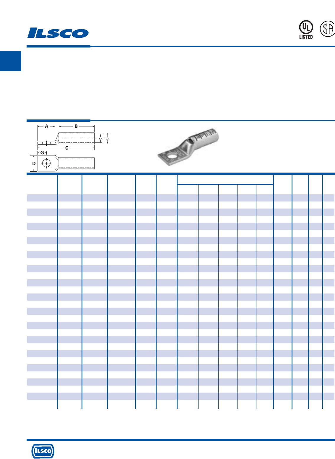
SureCrimp®
Copper Compression Lugs - Long Barrel
1 Hole, w/o Sight Hole - Conductor Range: #1 - #8
TYPE
CLNS
L
R
-
2
9
6
0
1
453G
Features
•
Manufactured from high strength seamless copper tubing.
•
Electro-Tin plated.
•
Maximum conductivity and excellent crimping characteristics.
•
Long barrel length with chamfered entry.
•
Color coded.
•
UL 486A 90°C Listed and CSA Certified for 600 Volts.
•
If proper high voltage spacing and insulation techniques are used, may be used for high voltage applications up to 35KV.
•
For Copper conductor only.
•
Ilsco connectors are UL Listed and CSA Certified with ILSCO and other Manufacturers' tools.+
•
UL File E6207
Stud Dimensions Die
Catalog Wire Alt Expanded* Bolt Hole Color Die
Number Size Wire Size Wire Range Size Dia. A B C D G Code Index O.D. I.D.
CLNS-8-10 #8 AWG #8 FLEX - 10 0.219 0.562 0.812 1.569 0.374 0.258 Red I-21 0.272 0.179
CLNS-8-14 #8 AWG #8 FLEX - 1/4 0.281 0.680 0.812 1.687 0.486 0.320 Red I-21 0.272 0.179
CLNS-8-516 #8 AWG #8 FLEX - 5/16 0.343 0.875 0.812 1.882 0.532 0.352 Red I-21 0.272 0.179
CLNS-8-38 #8 AWG #8 FLEX - 3/8 0.406 0.875 0.812 1.882 0.593 0.414 Red I-21 0.272 0.179
CLNS-6-10 #6 AWG - - 10 0.219 0.562 1.125 1.882 0.411 0.258 Blue I-24 0.295 0.203
CLNS-6-14 #6 AWG - - 1/4 0.281 0.680 1.125 2.000 0.411 0.320 Blue I-24 0.295 0.203
CLNS-6-516 #6 AWG - - 5/16 0.343 0.875 1.125 2.195 0.532 0.352 Blue I-24 0.295 0.203
CLNS-6-38 #6 AWG - - 3/8 0.406 0.875 1.125 2.195 0.593 0.414 Blue I-24 0.295 0.203
CLNS-6-12 #6 AWG - - 1/2 0.562 1.250 1.125 2.570 0.750 0.546 Blue I-24 0.295 0.203
CLNS-4-10 #4 AWG #6 FLEX 4-6 AWG 10 0.219 0.562 1.125 1.921 0.486 0.258 Gray I-29 0.343 0.250
CLNS-4-14 #4 AWG #6 FLEX 4-6 AWG 1/4 0.281 0.680 1.125 2.039 0.486 0.320 Gray I-29 0.343 0.250
CLNS-4-516 #4 AWG #6 FLEX 4-6 AWG 5/16 0.343 0.875 1.125 2.234 0.486 0.352 Gray I-29 0.343 0.250
CLNS-4-38 #4 AWG #6 FLEX 4-6 AWG 3/8 0.406 0.875 1.125 2.234 0.593 0.414 Gray I-29 0.343 0.250
CLNS-4-12 #4 AWG #6 FLEX 4-6 AWG 1/2 0.562 1.250 1.125 2.609 0.750 0.546 Gray I-29 0.343 0.250
CLNS-3-10 #3 AWG #4 FLEX 3-6 AWG 10 0.219 0.562 1.125 1.942 0.532 0.258 White I-29 0.375 0.275
CLNS-3-14 #3 AWG #4 FLEX 3-6 AWG 1/4 0.281 0.680 1.125 2.060 0.532 0.320 White I-29 0.375 0.275
CLNS-3-516 #3 AWG #4 FLEX 3-6 AWG 5/16 0.343 0.875 1.125 2.255 0.532 0.352 White I-29 0.375 0.275
CLNS-3-38 #3 AWG #4 FLEX 3-6 AWG 3/8 0.406 0.875 1.125 2.255 0.593 0.414 White I-29 0.375 0.275
CLNS-3-12 #3 AWG #4 FLEX 3-6 AWG 1/2 0.562 1.250 1.125 2.630 0.750 0.546 White I-29 0.375 0.275
CLNS-2-10 #2 AWG - 2-6 AWG 10 0.219 0.562 1.125 1.973 0.599 0.258 Brown I-33 0.421 0.312
CLNS-2-14 #2 AWG - 2-6 AWG 1/4 0.281 0.680 1.125 2.091 0.599 0.320 Brown I-33 0.421 0.312
CLNS-2-516 #2 AWG - 2-6 AWG 5/16 0.343 0.875 1.125 2.286 0.599 0.352 Brown I-33 0.421 0.312
CLNS-2-38 #2 AWG - 2-6 AWG 3/8 0.406 0.875 1.125 2.286 0.599 0.414 Brown I-33 0.421 0.312
CLNS-2-12 #2 AWG - 2-6 AWG 1/2 0.562 1.250 1.125 2.661 0.750 0.546 Brown I-33 0.421 0.312
CLNS-1-10 #1 AWG #2 FLEX 1-6 AWG 10 0.219 0.562 1.375 2.267 0.673 0.258 Green I-37 0.468 0.359
CLNS-1-14 #1 AWG #2 FLEX 1-6 AWG 1/4 0.281 0.875 1.375 2.580 0.673 0.320 Green I-37 0.468 0.359
CLNS-1-516 #1 AWG #2 FLEX 1-6 AWG 5/16 0.343 0.875 1.375 2.580 0.673 0.352 Green I-37 0.468 0.359
CLNS-1-38 #1 AWG #2 FLEX 1-6 AWG 3/8 0.406 0.875 1.375 2.580 0.673 0.414 Green I-37 0.468 0.359
CLNS-1-12 #1 AWG #2 FLEX 1-6 AWG 1/2 0.562 1.250 1.375 2.955 0.750 0.546 Green I-37 0.468 0.359
* When installed with specified dieless tools
+ See pages 90 to 97 for complete tooling information.
For Bent Tangs change the 4th letter to a B and add “-4” for 45 deg. or “-9” for 90 deg.
A
4730 Madison Road, Cincinnati, Ohio 45227-1426 Phone 513 533-6200 Fax 513 871-4084 Web site www.ilsco.com
Canada 1050 Lakeshore Road East, Mississauga, Ontario, Canada L5E1E4 Phone 905 274-2341 Fax 905 274-8763
15
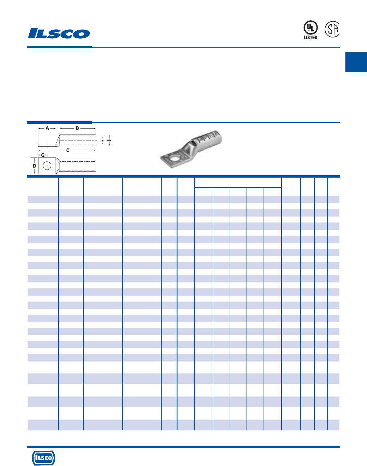
SureCrimp®
Copper Compression Lugs - Long Barrel
1 Hole, w/o Sight Hole - Conductor Range: 400kcmil - 1/0
TYPE
CLNS
L
R
-
2
9
6
0
1
453G
Features
•
Manufactured from high strength seamless copper tubing.
•
Electro-Tin plated.
•
Maximum conductivity and excellent crimping characteristics.
•
Long barrel length with chamfered entry.
•
Color coded.
•
UL 486A 90°C Listed and CSA Certified for 600 Volts.
•
If proper high voltage spacing and insulation techniques are used, may be used for high voltage applications up to 35KV.
•
For Copper conductor only.
•
Ilsco connectors are UL Listed and CSA Certified with ILSCO and other Manufacturers' tools.+
•
UL File E6207
Stud Dimensions Die
Catalog Wire Alt Expanded* Bolt Hole Color Die
Number Size Wire Size Wire Range Size Dia. A B C D G Code Index O.D. I.D.
CLNS-1/0-10 1/0 AWG #1 FLEX 1/0-6 AWG 10 0.219 0.562 1.500 2.418 0.738 0.258 Pink I-42 0.515 0.390
CLNS-1/0-14 1/0 AWG #1 FLEX 1/0-6 AWG 1/4 0.281 0.875 1.500 2.731 0.738 0.320 Pink I-42 0.515 0.390
CLNS-1/0-516 1/0 AWG #1 FLEX 1/0-6 AWG 5/16 0.343 0.875 1.500 2.731 0.738 0.352 Pink I-42 0.515 0.390
CLNS-1/0-38 1/0 AWG #1 FLEX 1/0-6 AWG 3/8 0.406 0.875 1.500 2.731 0.738 0.414 Pink I-42 0.515 0.390
CLNS-1/0-12 1/0 AWG #1 FLEX 1/0-6 AWG 1/2 0.562 1.250 1.500 3.106 0.738 0.546 Pink I-42 0.515 0.390
CLNS-2/0-10 2/0 AWG 1/0 FLEX 2/0-4 AWG 10 0.219 0.562 1.500 2.458 0.811 0.258 Black I-45 0.562 0.437
CLNS-2/0-14 2/0 AWG 1/0 FLEX 2/0-4 AWG 1/4 0.281 0.875 1.500 2.771 0.811 0.320 Black I-45 0.562 0.437
CLNS-2/0-516 2/0 AWG 1/0 FLEX 2/0-4 AWG 5/16 0.343 0.875 1.500 2.771 0.811 0.352 Black I-45 0.562 0.437
CLNS-2/0-38 2/0 AWG 1/0 FLEX 2/0-4 AWG 3/8 0.406 0.875 1.500 2.771 0.811 0.414 Black I-45 0.562 0.437
CLNS-2/0-12 2/0 AWG 1/0 FLEX 2/0-4 AWG 1/2 0.562 1.250 1.500 3.146 0.811 0.546 Black I-45 0.562 0.437
CLNS-3/0-10 3/0 AWG 2/0 FLEX 3/0-2 AWG 10 0.219 0.562 1.500 2.501 0.885 0.258 Orange I-50 0.609 0.484
CLNS-3/0-14 3/0 AWG 2/0 FLEX 3/0-2 AWG 1/4 0.281 0.875 1.500 2.814 0.885 0.320 Orange I-50 0.609 0.484
CLNS-3/0-516 3/0 AWG 2/0 FLEX 3/0-2 AWG 5/16 0.343 0.875 1.500 2.814 0.885 0.352 Orange I-50 0.609 0.484
CLNS-3/0-38 3/0 AWG 2/0 FLEX 3/0-2 AWG 3/8 0.406 0.875 1.500 2.814 0.885 0.414 Orange I-50 0.609 0.484
CLNS-3/0-12 3/0 AWG 2/0 FLEX 3/0-2 AWG 1/2 0.562 1.250 1.500 3.189 0.885 0.546 Orange I-50 0.609 0.484
CLNS-4/0-14 4/0 AWG 3/0 FLEX 4/0-1 AWG 1/4 0.281 0.875 1.500 2.866 0.999 0.320 Purple I-54 0.687 0.546
CLNS-4/0-516 4/0 AWG 3/0 FLEX 4/0-1 AWG 5/16 0.343 0.875 1.500 2.866 0.999 0.352 Purple I-54 0.687 0.546
CLNS-4/0-38 4/0 AWG 3/0 FLEX 4/0-1 AWG 3/8 0.406 0.875 1.500 2.866 0.999 0.414 Purple I-54 0.687 0.546
CLNS-4/0-12 4/0 AWG 3/0 FLEX 4/0-1 AWG 1/2 0.562 1.250 1.500 3.241 0.999 0.546 Purple I-54 0.687 0.546
CLNS-250-516 250kcmil 4/0 FLEX 250kcmil - 1/0 AWG 5/16 0.343 0.875 1.688 3.094 1.088 0.352 Yellow I-62 0.750 0.593
CLNS-250-38 250kcmil 4/0 FLEX 250kcmil - 1/0 AWG 3/8 0.406 0.875 1.688 3.094 1.088 0.414 Yellow I-62 0.750 0.593
CLNS-250-12 250kcmil 4/0 FLEX 250kcmil - 1/0 AWG 1/2 0.562 1.250 1.688 3.469 1.088 0.546 Yellow I-62 0.750 0.593
CLNS-300-516 300kcmil 250 G,H FLEX 300kcmil - 2/0 AWG 5/16 0.343 0.875 2.000 3.462 1.189 0.352 White I-66 0.812 0.660
CLNS-300-38 300kcmil 250 G,H FLEX 300kcmil - 2/0 AWG 3/8 0.406 0.875 2.000 3.462 1.189 0.414 White I-66 0.812 0.660
CLNS-300-12 300kcmil 250 G,H FLEX 300kcmil - 2/0 AWG 1/2 0.562 1.250 2.000 3.837 1.189 0.546 White I-66 0.812 0.660
CLNS-350-38 350kcmil 250 I,K,M FLEX 350kcmil - 3/0 AWG 3/8 0.406 0.875 2.000 3.498 1.291 0.414 Red I-71 0.890 0.703
262.2 DLO
CLNS-350-12 350kcmil 250 I,K,M FLEX 350kcmil - 3/0 AWG 1/2 0.562 1.250 2.000 3.873 1.291 0.546 Red I-71 0.890 0.703
262.2 DLO
CLNS-350-58 350kcmil 250 I,K,M FLEX 350kcmil - 3/0 AWG 5/8 0.656 1.437 2.000 4.060 1.291 0.671 Red I-71 0.890 0.703
262.2 DLO
CLNS-400-38 400kcmil 300 G,H,I,K,M FLEX 400kcmil - 4/0 AWG 3/8 0.406 0.875 2.125 3.667 1.365 0.414 Blue I-76 0.937 0.750
313.1 DLO
CLNS-400-12 400kcmil 300 G,H,I,K,M FLEX 400kcmil - 4/0 AWG 1/2 0.562 1.250 2.125 4.042 1.365 0.546 Blue I-76 0.937 0.750
313.1 DLO
CLNS-400-58 400kcmil 300 G,H,I,K,M FLEX 400kcmil - 4/0 AWG 5/8 0.656 1.437 2.125 4.229 1.365 0.671 Blue I-76 0.937 0.750
313.1 DLO
* When installed with specified dieless tools + See pages 90 to 97 for complete tooling information.
For Bent Tangs change the 4th letter to a B and add “-4” for 45 deg. or “-9” for 90 deg.

A
4730 Madison Road, Cincinnati, Ohio 45227-1426 Phone 513 533-6200 Fax 513 871-4084 Web site www.ilsco.com
Canada 1050 Lakeshore Road East, Mississauga, Ontario, Canada L5E1E4 Phone 905 274-2341 Fax 905 274-8763
16
TYPE
CLNS
SureCrimp®
Copper Compression Lugs - Long Barrel
1 Hole, w/o Sight Hole - Conductor Range: 1000kcmil - 500kcmil
L
R
-
2
9
6
0
1
453G
Features
•
Manufactured from high strength seamless copper tubing.
•
Electro-Tin plated.
•
Maximum conductivity and excellent crimping characteristics.
•
Long barrel length with chamfered entry.
•
Color coded.
•
UL 486A 90°C Listed and CSA Certified for 600 Volts.
•
If proper high voltage spacing and insulation techniques are used, may be used for high voltage applications up to 35KV.
•
For Copper conductor only.
•
Ilsco connectors are UL Listed and CSA Certified with ILSCO and other Manufacturers' tools.+
•
UL File E6207
Stud Dimensions Die
Catalog Wire Alt Expanded* Bolt Hole Color Die
Number Size Wire Size Wire Range Size Dia. A B C D G Code Index O.D. I.D.
CLNS-500-38 500kcmil 350 G,H,I,K,M FLEX 500kcmil - 250kcmil 3/8 0.406 0.875 2.250 3.857 1.535 0.414 Brown I-87 1.062 0.828
373.7 DLO
CLNS-500-12 500kcmil 350 G,H,I,K,M FLEX 500kcmil - 250kcmil 1/2 0.562 1.250 2.250 4.232 1.535 0.546 Brown I-87 1.062 0.828
373.7 DLO
CLNS-500-58 500kcmil 350 G,H,I,K,M FLEX 500kcmil - 250kcmil 5/8 0.656 1.437 2.250 4.419 1.535 0.671 Brown I-87 1.062 0.828
373.7 DLO
CLNS-600-38 600kcmil 400 G,H,I,K,M FLEX 600kcmil - 250kcmil 3/8 0.406 0.875 2.687 4.371 1.712 0.414 Green I-94 1.187 0.920
444.4 DLO
CLNS-600-12 600kcmil 400 G,H,I,K,M FLEX 600kcmil - 250kcmil 1/2 0.562 1.250 2.687 4.746 1.712 0.546 Green I-94 1.187 0.920
444.4 DLO
CLNS-600-58 600kcmil 400 G,H,I,K,M FLEX 600kcmil - 250kcmil 5/8 0.656 1.437 2.687 4.933 1.712 0.671 Green I-94 1.187 0.920
444.4 DLO
CLNS-650-516 650kcmil 500 G,H,I,K,M FLEX 650kcmil - 350kcmil 1/32 0.343 0.875 2.687 4.431 1.764 0.352 Pink I-99 1.217 0.958
535.3 DLO
CLNS-650-38 650kcmil 500 G,H,I,K,M FLEX 650kcmil - 350kcmil 3/8 0.406 0.875 2.687 4.431 1.764 0.414 Pink I-99 1.217 0.958
535.3 DLO
CLNS-650-12 650kcmil 500 G,H,I,K,M FLEX 650kcmil - 350kcmil 1/2 0.562 1.25 2.687 4.806 1.764 0.546 Pink I-99 1.217 0.958
535.3 DLO
CLNS-650-58 650kcmil 500 G,H,I,K,M FLEX 650kcmil - 350kcmil 5/8 0.656 1.437 2.687 4.993 1.764 0.671 Pink I-99 1.217 0.958
535.3 DLO
CLNS-700-38 700kcmil 500 G,H,I,K,M FLEX 700kcmil - 350kcmil 3/8 0.406 0.875 2.687 4.431 1.816 0.414 Pink I-99 1.250 0.991
535.3 DLO
CLNS-700-12 700kcmil 500 G,H,I,K,M FLEX 700kcmil - 350kcmil 1/2 0.562 1.250 2.687 4.806 1.816 0.546 Pink I-99 1.250 0.991
535.3 DLO
CLNS-700-58 700kcmil 500 G,H,I,K,M FLEX 700kcmil - 350kcmil 5/8 0.656 1.437 2.687 4.993 1.816 0.671 Pink I-99 1.250 0.991
535.3 DLO
CLNS-750-38 750kcmil 600 G,H,I,M FLEX 750kcmil - 500kcmil 3/8 0.406 0.875 2.875 4.652 1.901 0.414 Black I-106 1.313 1.031
646.4 DLO
CLNS-750-12 750kcmil 600 G,H,I,M FLEX 750kcmil - 500kcmil 1/2 0.562 1.250 2.875 5.027 1.901 0.546 Black I-106 1.313 1.031
646.4 DLO
CLNS-750-58 750kcmil 600 G,H,I,M FLEX 750kcmil - 500kcmil 5/8 0.656 1.437 2.875 5.214 1.901 0.671 Black I-106 1.313 1.031
646.4 DLO
CLNS-1000-38 1000kcmil 750 G,H,I FLEX 1000kcmil - 750kcmil 3/8 0.406 0.875 3.000 4.900 2.169 0.414 White I-125 1.500 1.172
777.7 DLO
CLNS-1000-12 1000kcmil 750 G,H,I FLEX 1000kcmil - 750kcmil 1/2 0.562 1.250 3.000 5.275 2.169 0.546 White I-125 1.500 1.172
777.7 DLO
CLNS-1000-58 1000kcmil 750 G,H,I FLEX 1000kcmil - 750kcmil 5/8 0.656 1.437 3.000 5.462 2.169 0.671 White I-125 1.500 1.172
777.7 DLO
* When installed with specified dieless tools
+ See pages 90 to 97 for complete tooling information.
For Bent Tangs change the 4th letter to a B and add “-4” for 45 deg. or “-9” for 90 deg.
A
4730 Madison Road, Cincinnati, Ohio 45227-1426 Phone 513 533-6200 Fax 513 871-4084 Web site www.ilsco.com
Canada 1050 Lakeshore Road East, Mississauga, Ontario, Canada L5E1E4 Phone 905 274-2341 Fax 905 274-8763
17
TYPE
CLWD
SureCrimp®
Copper Compression Lugs - Long Barrel
2 Hole, w/Sight Hole - Conductor Range: #4 - #8
L
R
-
2
9
6
0
1
453G
Features
•
Manufactured from high strength seamless copper tubing.
•
Electro-Tin plated.
•
Maximum conductivity and excellent crimping characteristics.
•
Long barrel length with chamfered entry.
•
Color coded.
•
UL 486A 90°C Listed and CSA Certified for 600 Volts.
•
If proper high voltage spacing and insulation techniques are used, may be used for high voltage applications up to 35KV.
•
For Copper conductor only.
•
Ilsco connectors are UL Listed and CSA Certified with ILSCO and other Manufacturers' tools.+
•
UL File E6207
Stud Stud Dimensions Die
Catalog Wire Alt Expanded* Bolt Hole Hole Color Die
Number Size Wire Size Wire Range Size Dia. Spacing A B C D G Code Index O.D. I.D.
CLWD-8-10-58 #8 AWG #8 FLEX - 10 0.219 0.625 1.250 0.812 2.257 0.374 0.258 Red I-21 0.272 0.179
CLWD-8-10-34 #8 AWG #8 FLEX - 10 0.219 0.750 1.437 0.812 2.444 0.374 0.258 Red I-21 0.272 0.179
CLWD-8-14-58 #8 AWG #8 FLEX - 1/4 0.281 0.625 1.437 0.812 2.444 0.486 0.320 Red I-21 0.272 0.179
CLWD-8-14-34 #8 AWG #8 FLEX - 1/4 0.281 0.750 1.437 0.812 2.444 0.486 0.320 Red I-21 0.272 0.179
CLWD-8-14-1 #8 AWG #8 FLEX - 1/4 0.281 1.000 1.687 0.812 2.694 0.486 0.320 Red I-21 0.272 0.179
CLWD-8-38-1 #8 AWG #8 FLEX - 3/8 0.406 1.000 1.937 0.812 2.944 0.593 0.414 Red I-21 0.272 0.179
CLWD-6-10-12 #6 AWG - - 10 0.219 0.500 1.250 1.125 2.570 0.411 0.258 Blue I-24 0.295 0.203
CLWD-6-10-58 #6 AWG - - 10 0.219 0.625 1.250 1.125 2.570 0.411 0.258 Blue I-24 0.295 0.203
CLWD-6-10-1116 #6 AWG - - 10 0.219 0.687 1.250 1.125 2.570 0.411 0.258 Blue I-24 0.295 0.203
CLWD-6-10-34 #6 AWG - - 10 0.219 0.750 1.437 1.125 2.757 0.411 0.258 Blue I-24 0.295 0.203
CLWD-6-14-12 #6 AWG - - 1/4 0.281 0.500 1.250 1.125 2.570 0.411 0.320 Blue I-24 0.295 0.203
CLWD-6-14-58 #6 AWG - - 1/4 0.281 0.625 1.437 1.125 2.757 0.411 0.320 Blue I-24 0.295 0.203
CLWD-6-14-34 #6 AWG - - 1/4 0.281 0.750 1.437 1.125 2.757 0.411 0.320 Blue I-24 0.295 0.203
CLWD-6-14-1 #6 AWG - - 1/4 0.281 1.000 1.687 1.125 3.007 0.411 0.320 Blue I-24 0.295 0.203
CLWD-6-516-34 #6 AWG - - 5/16 0.343 0.750 1.687 1.125 3.007 0.532 0.352 Blue I-24 0.295 0.203
CLWD-6-516-1 #6 AWG - - 5/16 0.343 1.000 1.937 1.125 3.257 0.532 0.352 Blue I-24 0.295 0.203
CLWD-6-38-34 #6 AWG - - 3/8 0.406 0.750 1.687 1.125 3.007 0.593 0.414 Blue I-24 0.295 0.203
CLWD-6-38-78 #6 AWG - - 3/8 0.406 0.875 1.937 1.125 3.257 0.593 0.414 Blue I-24 0.295 0.203
CLWD-6-38-1 #6 AWG - - 3/8 0.406 1.000 1.937 1.125 3.257 0.593 0.414 Blue I-24 0.295 0.203
CLWD-6-12-134 #6 AWG - - 1/2 0.562 1.750 3.000 1.125 4.320 0.750 0.546 Blue I-24 0.295 0.203
CLWD-4-10-58 #4 AWG #6 FLEX 4-6 AWG 10 0.219 0.625 1.250 1.125 2.609 0.486 0.258 Gray I-29 0.343 0.250
CLWD-4-10-34 #4 AWG #6 FLEX 4-6 AWG 10 0.219 0.750 1.437 1.125 2.796 0.486 0.258 Gray I-29 0.343 0.250
CLWD-4-10-1 #4 AWG #6 FLEX 4-6 AWG 10 0.219 1.000 1.687 1.125 3.046 0.486 0.258 Gray I-29 0.343 0.250
CLWD-4-14-58 #4 AWG #6 FLEX 4-6 AWG 1/4 0.281 0.625 1.437 1.125 2.796 0.486 0.320 Gray I-29 0.343 0.250
CLWD-4-14-34 #4 AWG #6 FLEX 4-6 AWG 1/4 0.281 0.750 1.437 1.125 2.796 0.486 0.320 Gray I-29 0.343 0.250
CLWD-4-14-1 #4 AWG #6 FLEX 4-6 AWG 1/4 0.281 1.000 1.687 1.125 3.046 0.486 0.320 Gray I-29 0.343 0.250
CLWD-4-516-58 #4 AWG #6 FLEX 4-6 AWG 5/16 0.343 0.625 1.437 1.125 2.796 0.486 0.352 Gray I-29 0.343 0.250
CLWD-4-516-34 #4 AWG #6 FLEX 4-6 AWG 5/16 0.343 0.750 1.687 1.125 3.046 0.486 0.352 Gray I-29 0.343 0.250
CLWD-4-516-1 #4 AWG #6 FLEX 4-6 AWG 5/16 0.343 1.000 1.937 1.125 3.296 0.486 0.352 Gray I-29 0.343 0.250
CLWD-4-38-34 #4 AWG #6 FLEX 4-6 AWG 3/8 0.406 0.750 1.687 1.125 3.046 0.593 0.414 Gray I-29 0.343 0.250
CLWD-4-38-1 #4 AWG #6 FLEX 4-6 AWG 3/8 0.406 1.000 1.937 1.125 3.296 0.593 0.414 Gray I-29 0.343 0.250
CLWD-4-12-134 #4 AWG #6 FLEX 4-6 AWG 1/2 0.562 1.750 3.000 1.125 4.359 0.750 0.546 Gray I-29 0.343 0.250
* When installed with specified dieless tools + See pages 90 to 97 for complete tooling information.
For Bent Tangs change the 4th letter to a B and add “-4” for 45 deg. or “-9” for 90 deg.
A
4730 Madison Road, Cincinnati, Ohio 45227-1426 Phone 513 533-6200 Fax 513 871-4084 Web site www.ilsco.com
Canada 1050 Lakeshore Road East, Mississauga, Ontario, Canada L5E1E4 Phone 905 274-2341 Fax 905 274-8763
18
TYPE
CLWD
SureCrimp®
Copper Compression Lugs - Long Barrel
2 Hole, w/Sight Hole - Conductor Range: #1 - #3
L
R
-
2
9
6
0
1
453G
Features
•
Manufactured from high strength seamless copper tubing.
•
Electro-Tin plated.
•
Maximum conductivity and excellent crimping characteristics.
•
Long barrel length with chamfered entry.
•
Color coded.
•
UL 486A 90°C Listed and CSA Certified for 600 Volts.
•
If proper high voltage spacing and insulation techniques are used, may be used for high voltage applications up to 35KV.
•
For Copper conductor only.
•
Ilsco connectors are UL Listed and CSA Certified with ILSCO and other Manufacturers' tools.+
•
UL File E6207
Stud Stud Dimensions Die
Catalog Wire Alt Expanded* Bolt Hole Hole Color Die
Number Size Wire Size Wire Range Size Dia. Spacing A B C D G Code Index O.D. I.D.
CLWD-3-14-58 #3 AWG #4 FLEX 3-6 AWG 1/4 0.281 0.625 1.437 1.125 2.817 0.532 0.320 White I-29 0.375 0.275
CLWD-3-14-34 #3 AWG #4 FLEX 3-6 AWG 1/4 0.281 0.750 1.437 1.125 2.817 0.532 0.320 White I-29 0.375 0.275
CLWD-3-516-58 #3 AWG #4 FLEX 3-6 AWG 5/16 0.343 0.625 1.437 1.125 2.817 0.532 0.352 White I-29 0.375 0.275
CLWD-3-516-1 #3 AWG #4 FLEX 3-6 AWG 5/16 0.343 1.000 1.937 1.125 3.317 0.532 0.352 White I-29 0.375 0.275
CLWD-3-38-34 #3 AWG #4 FLEX 3-6 AWG 3/8 0.406 0.750 1.687 1.125 3.067 0.593 0.414 White I-29 0.375 0.275
CLWD-3-38-1 #3 AWG #4 FLEX 3-6 AWG 3/8 0.406 1.000 1.937 1.125 3.317 0.593 0.414 White I-29 0.375 0.275
CLWD-3-12-134 #3 AWG #4 FLEX 3-6 AWG 1/2 0.562 1.750 3.000 1.125 4.380 0.750 0.546 White I-29 0.375 0.275
CLWD-2-10-34 #2 AWG - 2-6 AWG 10 0.219 0.750 1.437 1.125 2.848 0.599 0.258 Brown I-33 0.421 0.312
CLWD-2-14-58 #2 AWG - 2-6 AWG 1/4 0.281 0.625 1.437 1.125 2.848 0.599 0.320 Brown I-33 0.421 0.312
CLWD-2-14-34 #2 AWG - 2-6 AWG 1/4 0.281 0.750 1.437 1.125 2.848 0.599 0.320 Brown I-33 0.421 0.312
CLWD-2-14-1 #2 AWG - 2-6 AWG 1/4 0.281 1.000 1.687 1.125 3.098 0.599 0.320 Brown I-33 0.421 0.312
CLWD-2-516-58 #2 AWG - 2-6 AWG 5/16 0.343 0.625 1.687 1.125 3.098 0.599 0.352 Brown I-33 0.421 0.312
CLWD-2-516-34 #2 AWG - 2-6 AWG 5/16 0.343 0.750 1.687 1.125 3.098 0.599 0.352 Brown I-33 0.421 0.312
CLWD-2-516-1 #2 AWG - 2-6 AWG 5/16 0.343 1.000 1.937 1.125 3.348 0.599 0.352 Brown I-33 0.421 0.312
CLWD-2-38-58 #2 AWG - 2-6 AWG 3/8 0.406 0.625 1.687 1.125 3.098 0.599 0.414 Brown I-33 0.421 0.312
CLWD-2-38-34 #2 AWG - 2-6 AWG 3/8 0.406 0.750 1.687 1.125 3.098 0.599 0.414 Brown I-33 0.421 0.312
CLWD-2-38-78 #2 AWG - 2-6 AWG 3/8 0.406 0.875 1.937 1.125 3.348 0.599 0.414 Brown I-33 0.421 0.312
CLWD-2-38-1 #2 AWG - 2-6 AWG 3/8 0.406 1.000 1.937 1.125 3.348 0.599 0.414 Brown I-33 0.421 0.312
CLWD-2-38-134 #2 AWG - 2-6 AWG 3/8 0.406 1.750 2.625 1.125 4.036 0.599 0.414 Brown I-33 0.421 0.312
CLWD-2-12-134 #2 AWG - 2-6 AWG 1/2 0.562 1.750 3.000 1.125 4.411 0.750 0.546 Brown I-33 0.421 0.312
CLWD-1-14-58 #1 AWG #2 FLEX 1-6 AWG 1/4 0.281 0.625 1.437 1.375 3.142 0.673 0.320 Green I-37 0.468 0.359
CLWD-1-14-34 #1 AWG #2 FLEX 1-6 AWG 1/4 0.281 0.750 1.437 1.375 3.142 0.673 0.320 Green I-37 0.468 0.359
CLWD-1-14-1 #1 AWG #2 FLEX 1-6 AWG 1/4 0.281 1.000 1.687 1.375 3.392 0.673 0.320 Green I-37 0.468 0.359
CLWD-1-516-78 #1 AWG #2 FLEX 1-6 AWG 5/16 0.343 0.875 1.687 1.375 3.392 0.673 0.352 Green I-37 0.468 0.359
CLWD-1-516-1 #1 AWG #2 FLEX 1-6 AWG 5/16 0.343 1.000 1.937 1.375 3.642 0.673 0.352 Green I-37 0.468 0.359
CLWD-1-38-1 #1 AWG #2 FLEX 1-6 AWG 3/8 0.406 1.000 1.937 1.375 3.642 0.673 0.414 Green I-37 0.468 0.359
CLWD-1-12-134 #1 AWG #2 FLEX 1-6 AWG 1/2 0.562 1.750 3.000 1.375 4.705 0.750 0.546 Green I-37 0.468 0.359
* When installed with specified dieless tools
+ See pages 90 to 97 for complete tooling information.
For Bent Tangs change the 4th letter to a B and add “-4” for 45 deg. or “-9” for 90 deg.

A
4730 Madison Road, Cincinnati, Ohio 45227-1426 Phone 513 533-6200 Fax 513 871-4084 Web site www.ilsco.com
Canada 1050 Lakeshore Road East, Mississauga, Ontario, Canada L5E1E4 Phone 905 274-2341 Fax 905 274-8763
19
SureCrimp®
Copper Compression Lugs - Long Barrel
2 Hole, w/Sight Hole - Conductor Range: 3/0 - 1/0
TYPE
CLWD
L
R
-
2
9
6
0
1
453G
Features
•
Manufactured from high strength seamless copper tubing.
•
Electro-Tin plated.
•
Maximum conductivity and excellent crimping characteristics.
•
Long barrel length with chamfered entry.
•
Color coded.
•
UL 486A 90°C Listed and CSA Certified for 600 Volts.
•
If proper high voltage spacing and insulation techniques are used, may be used for high voltage applications up to 35KV.
•
For Copper conductor only.
•
Ilsco connectors are UL Listed and CSA Certified with ILSCO and other Manufacturers' tools.+
•
UL File E6207
Stud Stud Dimensions Die
Catalog Wire Alt Expanded* Bolt Hole Hole Color Die
Number Size Wire Size Wire Range Size Dia. Spacing A B C D G Code Index O.D. I.D.
CLWD-1/0-14-58 1/0 AWG #1 FLEX 1/0-6 AWG 1/4 0.281 0.625 1.437 1.500 3.293 0.738 0.320 Pink I-42 0.515 0.390
CLWD-1/0-14-34 1/0 AWG #1 FLEX 1/0-6 AWG 1/4 0.281 0.750 1.437 1.500 3.293 0.738 0.320 Pink I-42 0.515 0.390
CLWD-1/0-14-1 1/0 AWG #1 FLEX 1/0-6 AWG 1/4 0.281 1.000 1.687 1.500 3.543 0.738 0.320 Pink I-42 0.515 0.390
CLWD-1/0-516-34 1/0 AWG #1 FLEX 1/0-6 AWG 5/16 0.343 0.750 1.687 1.500 3.543 0.738 0.352 Pink I-42 0.515 0.390
CLWD-1/0-516-78 1/0 AWG #1 FLEX 1/0-6 AWG 5/16 0.343 0.875 1.687 1.500 3.543 0.738 0.352 Pink I-42 0.515 0.390
CLWD-1/0-516-1 1/0 AWG #1 FLEX 1/0-6 AWG 5/16 0.343 1.000 1.937 1.500 3.793 0.738 0.352 Pink I-42 0.515 0.390
CLWD-1/0-38-1 1/0 AWG #1 FLEX 1/0-6 AWG 3/8 0.406 1.000 1.937 1.500 3.793 0.738 0.414 Pink I-42 0.515 0.390
CLWD-1/0-38-134 1/0 AWG #1 FLEX 1/0-6 AWG 3/8 0.406 1.750 2.625 1.500 4.481 0.738 0.414 Pink I-42 0.515 0.390
CLWD-1/0-12-1 1/0 AWG #1 FLEX 1/0-6 AWG 1/2 0.562 1.000 2.125 1.500 3.981 0.738 0.546 Pink I-42 0.515 0.390
CLWD-1/0-12-134 1/0 AWG #1 FLEX 1/0-6 AWG 1/2 0.562 1.750 3.000 1.500 4.856 0.738 0.546 Pink I-42 0.515 0.390
CLWD-2/0-14-58 2/0 AWG 1/0 FLEX 2/0-4 AWG 1/4 0.281 0.625 1.437 1.500 3.333 0.811 0.320 Black I-45 0.562 0.437
CLWD-2/0-14-34 2/0 AWG 1/0 FLEX 2/0-4 AWG 1/4 0.281 0.750 1.437 1.500 3.333 0.811 0.320 Black I-45 0.562 0.437
CLWD-2/0-14-1 2/0 AWG 1/0 FLEX 2/0-4 AWG 1/4 0.281 1.000 1.687 1.500 3.583 0.811 0.320 Black I-45 0.562 0.437
CLWD-2/0-516-1 2/0 AWG 1/0 FLEX 2/0-4 AWG 5/16 0.343 1.000 1.937 1.500 3.833 0.811 0.352 Black I-45 0.562 0.437
CLWD-2/0-38-1 2/0 AWG 1/0 FLEX 2/0-4 AWG 3/8 0.406 1.000 1.937 1.500 3.833 0.811 0.414 Black I-45 0.562 0.437
CLWD-2/0-38-134 2/0 AWG 1/0 FLEX 2/0-4 AWG 3/8 0.406 1.750 2.625 1.500 4.521 0.811 0.414 Black I-45 0.562 0.437
CLWD-2/0-12-1 2/0 AWG 1/0 FLEX 2/0-4 AWG 1/2 0.562 1.000 2.125 1.500 4.021 0.811 0.546 Black I-45 0.562 0.437
CLWD-2/0-12-134 2/0 AWG 1/0 FLEX 2/0-4 AWG 1/2 0.562 1.750 3.000 1.500 4.896 0.811 0.546 Black I-45 0.562 0.437
CLWD-3/0-14-58 3/0 AWG 2/0 FLEX 3/0-2 AWG 1/4 0.281 0.625 1.437 1.500 3.376 0.885 0.320 Orange I-50 0.609 0.484
CLWD-3/0-14-34 3/0 AWG 2/0 FLEX 3/0-2 AWG 1/4 0.281 0.750 1.437 1.500 3.376 0.885 0.320 Orange I-50 0.609 0.484
CLWD-3/0-516-1 3/0 AWG 2/0 FLEX 3/0-2 AWG 5/16 0.343 1.000 1.937 1.500 3.876 0.885 0.352 Orange I-50 0.609 0.484
CLWD-3/0-38-1 3/0 AWG 2/0 FLEX 3/0-2 AWG 3/8 0.406 1.000 1.937 1.500 3.876 0.885 0.414 Orange I-50 0.609 0.484
CLWD-3/0-12-134 3/0 AWG 2/0 FLEX 3/0-2 AWG 1/2 0.562 1.750 3.000 1.500 4.939 0.885 0.546 Orange I-50 0.609 0.484
* When installed with specified dieless tools
+ See pages 90 to 97 for complete tooling information.
For Bent Tangs change the 4th letter to a B and add “-4” for 45 deg. or “-9” for 90 deg.
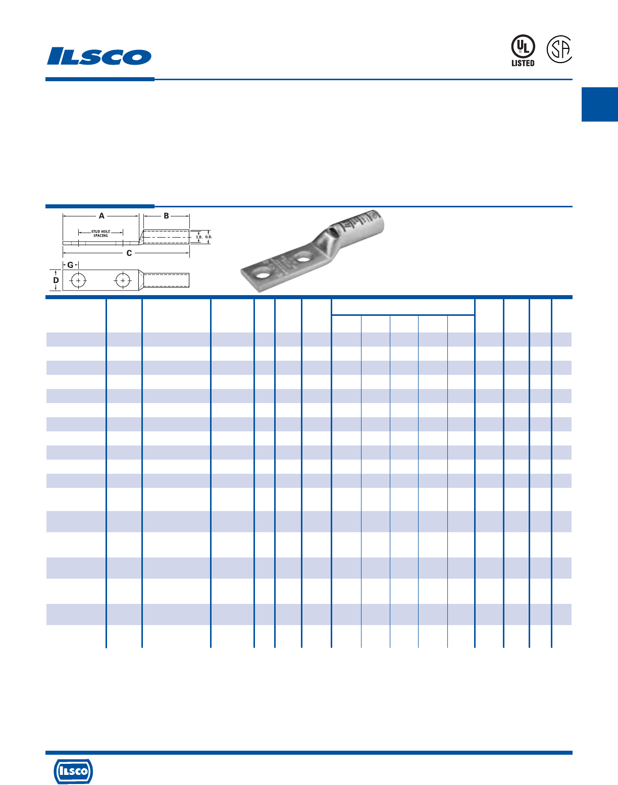
A
4730 Madison Road, Cincinnati, Ohio 45227-1426 Phone 513 533-6200 Fax 513 871-4084 Web site www.ilsco.com
Canada 1050 Lakeshore Road East, Mississauga, Ontario, Canada L5E1E4 Phone 905 274-2341 Fax 905 274-8763
20
TYPE
CLWD
SureCrimp®
Copper Compression Lugs - Long Barrel
2 Hole, w/Sight Hole - Conductor Range: 300kcmil - 4/0
L
R
-
2
9
6
0
1
453G
Features
•
Manufactured from high strength seamless copper tubing.
•
Electro-Tin plated.
•
Maximum conductivity and excellent crimping characteristics.
•
Long barrel length with chamfered entry.
•
Color coded.
•
UL 486A 90°C Listed and CSA Certified for 600 Volts.
•
If proper high voltage spacing and insulation techniques are used, may be used for high voltage applications up to 35KV.
•
For Copper conductor only.
•
Ilsco connectors are UL Listed and CSA Certified with ILSCO and other Manufacturers' tools.+
•
UL File E6207
Stud Stud Dimensions Die
Catalog Wire Alt Expanded* Bolt Hole Hole Color Die
Number Size Wire Size Wire Range Size Dia. Spacing A B C D G Code Index O.D. I.D.
CLWD-4/0-14-58 4/0 AWG 3/0 FLEX 4/0-1 AWG 1/4 0.281 0.625 1.437 1.500 3.428 0.999 0.320 Purple I-54 0.687 0.546
CLWD-4/0-14-34 4/0 AWG 3/0 FLEX 4/0-1 AWG 1/4 0.281 0.750 1.437 1.500 3.428 0.999 0.320 Purple I-54 0.687 0.546
CLWD-4/0-14-1 4/0 AWG 3/0 FLEX 4/0-1 AWG 1/4 0.281 1.000 1.687 1.500 3.678 0.999 0.320 Purple I-54 0.687 0.546
CLWD-4/0-516-34 4/0 AWG 3/0 FLEX 4/0-1 AWG 5/16 0.343 0.750 1.687 1.500 3.678 0.999 0.352 Purple I-54 0.687 0.546
CLWD-4/0-516-1 4/0 AWG 3/0 FLEX 4/0-1 AWG 5/16 0.343 1.000 1.937 1.500 3.928 0.999 0.352 Purple I-54 0.687 0.546
CLWD-4/0-516-134 4/0 AWG 3/0 FLEX 4/0-1 AWG 5/16 0.343 1.750 2.500 1.500 4.491 0.999 0.352 Purple I-54 0.687 0.546
CLWD-4/0-38-1 4/0 AWG 3/0 FLEX 4/0-1 AWG 3/8 0.406 1.000 1.937 1.500 3.928 0.999 0.414 Purple I-54 0.687 0.546
CLWD-4/0-38-134 4/0 AWG 3/0 FLEX 4/0-1 AWG 3/8 0.406 1.750 2.625 1.500 4.616 0.999 0.414 Purple I-54 0.687 0.546
CLWD-4/0-12-1 4/0 AWG 3/0 FLEX 4/0-1 AWG 1/2 0.562 1.000 2.125 1.500 4.116 0.999 0.546 Purple I-54 0.687 0.546
CLWD-4/0-12-114 4/0 AWG 3/0 FLEX 4/0-1 AWG 1/2 0.562 1.250 2.500 1.500 4.491 0.999 0.546 Purple I-54 0.687 0.546
CLWD-4/0-12-134 4/0 AWG 3/0 FLEX 4/0-1 AWG 1/2 0.562 1.750 3.000 1.500 4.991 0.999 0.546 Purple I-54 0.687 0.546
CLWD-250-14-34 250kcmil 4/0 FLEX 250kcmil - 1/4 0.281 0.750 1.437 1.688 3.656 1.088 0.320 Yellow I-62 0.750 0.593
1/0 AWG
CLWD-250-38-1 250kcmil 4/0 FLEX 250kcmil - 3/8 0.406 1.000 1.937 1.688 4.156 1.088 0.414 Yellow I-62 0.750 0.593
1/0 AWG
CLWD-250-38-134 250kcmil 4/0 FLEX 250kcmil - 3/8 0.406 1.750 2.625 1.688 4.844 1.088 0.414 Yellow I-62 0.750 0.593
1/0 AWG
CLWD-250-12-114 250kcmil 4/0 FLEX 250kcmil - 1/2 0.562 1.250 2.500 1.688 4.719 1.088 0.546 Yellow I-62 0.750 0.593
1/0 AWG
CLWD-250-12-134 250kcmil 4/0 FLEX 250kcmil - 1/2 0.562 1.750 3.000 1.688 5.219 1.088 0.546 Yellow I-62 0.750 0.593
1/0 AWG
CLWD-300-38-1 300kcmil 250 G,H FLEX 300kcmil - 3/8 0.406 1.000 1.937 2.000 4.524 1.189 0.414 White I-66 0.812 0.660
2/0 AWG
CLWD-300-12-134 300kcmil 250 G,H FLEX 300kcmil - 1/2 0.562 1.750 3.000 2.000 5.587 1.189 0.546 White I-66 0.812 0.660
2/0 AWG
* When installed with specified dieless tools
+ See pages 90 to 97 for complete tooling information.
For Bent Tangs change the 4th letter to a B and add “-4” for 45 deg. or “-9” for 90 deg.
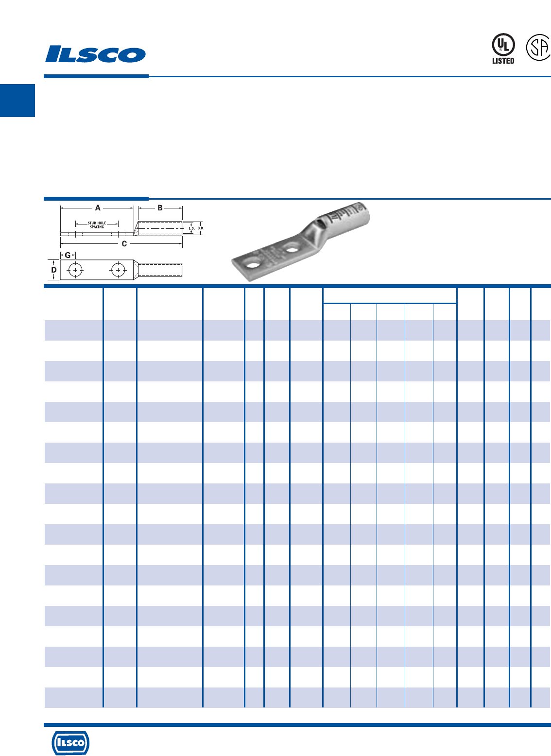
A
4730 Madison Road, Cincinnati, Ohio 45227-1426 Phone 513 533-6200 Fax 513 871-4084 Web site www.ilsco.com
Canada 1050 Lakeshore Road East, Mississauga, Ontario, Canada L5E1E4 Phone 905 274-2341 Fax 905 274-8763
21
TYPE
CLWD
SureCrimp®
Copper Compression Lugs - Long Barrel
2 Hole, w/Sight Hole - Conductor Range: 650kcmil - 350kcmil
L
R
-
2
9
6
0
1
453G
Features
•
Manufactured from high strength seamless copper tubing.
•
Electro-Tin plated.
•
Maximum conductivity and excellent crimping characteristics.
•
Long barrel length with chamfered entry.
•
Color coded.
•
UL 486A 90°C Listed and CSA Certified for 600 Volts.
•
If proper high voltage spacing and insulation techniques are used, may be used for high voltage applications up to 35KV.
•
For Copper conductor only.
•
Ilsco connectors are UL Listed and CSA Certified with ILSCO and other Manufacturers' tools.+
•
UL File E6207
Stud Stud Dimensions Die
Catalog Wire Alt Expanded* Bolt Hole Hole Color Die
Number Size Wire Size Wire Range Size Dia. Spacing A B C D G Code Index O.D. I.D.
CLWD-350-14-34 350kcmil 250 I,K,M FLEX 350kcmil - 1/4 0.281 0.750 1.437 2.000 4.060 1.291 0.320 Red I-71 0.890 0.703
262.2 DLO 3/0 AWG
CLWD-350-516-134 350kcmil 250 I,K,M FLEX 350kcmil - 5/16 0.343 1.750 2.500 2.000 5.123 1.291 0.352 Red I-71 0.890 0.703
262.2 DLO 3/0 AWG
CLWD-350-38-1 350kcmil 250 I,K,M FLEX 350kcmil - 3/8 0.406 1.000 1.937 2.000 4.560 1.291 0.414 Red I-71 0.890 0.703
262.2 DLO 3/0 AWG
CLWD-350-12-114 350kcmil 250 I,K,M FLEX 350kcmil - 1/2 0.562 1.250 2.500 2.000 5.123 1.291 0.546 Red I-71 0.890 0.703
262.2 DLO 3/0 AWG
CLWD-350-12-134 350kcmil 250 I,K,M FLEX 350kcmil - 1/2 0.562 1.750 3.000 2.000 5.623 1.291 0.546 Red I-71 0.890 0.703
262.2 DLO 3/0 AWG
CLWD-400-38-1 400kcmil 300 G,H,I,K,M FLEX 400kcmil - 3/8 0.406 1.000 1.937 2.125 4.729 1.365 0.414 Blue I-76 0.937 0.750
313.1 DLO 4/0 AWG
CLWD-400-38-116 400kcmil 300 G,H,I,K,M FLEX 400kcmil - 3/8 0.406 1.062 1.937 2.125 4.729 1.365 0.414 Blue I-76 0.937 0.750
313.1 DLO 4/0 AWG
CLWD-400-12-134 400kcmil 300 G,H,I,K,M FLEX 400kcmil - 1/2 0.562 1.750 3.000 2.125 5.792 1.365 0.546 Blue I-76 0.937 0.750
313.1 DLO 4/0 AWG
CLWD-500-14-34 500kcmil 350 G,H,I,K,M FLEX 500kcmil - 1/4 0.281 0.750 1.437 2.250 4.419 1.535 0.320 Brown I-87 1.062 0.828
373.7 DLO 250kcmil
CLWD-500-38-1 500kcmil 350 G,H,I,K,M FLEX 500kcmil - 3/8 0.406 1.000 1.937 2.250 4.919 1.535 0.414 Brown I-87 1.062 0.828
373.7 DLO 250kcmil
CLWD-500-12-114 500kcmil 350 G,H,I,K,M FLEX 500kcmil - 1/2 0.562 1.250 2.500 2.250 5.482 1.535 0.546 Brown I-87 1.062 0.828
373.7 DLO 250kcmil
CLWD-500-12-134 500kcmil 350 G,H,I,K,M FLEX 500kcmil - 1/2 0.562 1.750 3.000 2.250 5.982 1.535 0.546 Brown I-87 1.062 0.828
373.7 DLO 250kcmil
CLWD-600-38-1 600kcmil 400 G,H,I,K,M FLEX 600kcmil - 3/8 0.406 1.000 1.937 2.687 5.433 1.712 0.414 Green I-94 1.187 0.920
444.4 DLO 250kcmil
CLWD-600-12-134 600kcmil 400 G,H,I,K,M FLEX 600kcmil - 1/2 0.562 1.750 3.000 2.687 6.496 1.712 0.546 Green I-94 1.187 0.920
444.4 DLO 250kcmil
CLWD-650-12-114 650kcmil 500 G,H,I,K,M FLEX 650kcmil - 1/2 0.562 1.25 2.5 2.687 6.056 1.764 0.546 Pink I-99 1.217 0.958
535.3 DLO 350kcmil
CLWD-650-12-134 650kcmil 500 G,H,I,K,M FLEX 650kcmil - 1/2 0.562 1.75 3 2.687 6.556 1.764 0.546 Pink I-99 1.217 0.958
535.3 DLO 350kcmil
CLWD-650-38-1 650kcmil 500 G,H,I,K,M FLEX 650kcmil - 3/8 0.406 1 1.937 2.687 5.493 1.764 0.414 Pink I-99 1.217 0.958
535.3 DLO 350kcmil
CLWD-650-38-118 650kcmil 500 G,H,I,K,M FLEX 650kcmil - 3/8 0.406 1.125 2.125 2.687 5.681 1.764 0.414 Pink I-99 1.217 0.958
535.3 DLO 350kcmil
CLWD-650-516-1 650kcmil 500 G,H,I,K,M FLEX 650kcmil - 1/32 0.343 1 1.937 2.687 5.493 1.764 0.3515 Pink I-99 1.217 0.958
535.3 DLO 350kcmil
* When installed with specified dieless tools
+
See pages 90 to 97 for complete tooling information. For Bent Tangs change the 4th letter to a B and add “-4” for 45 deg. or “-9” for 90 deg.
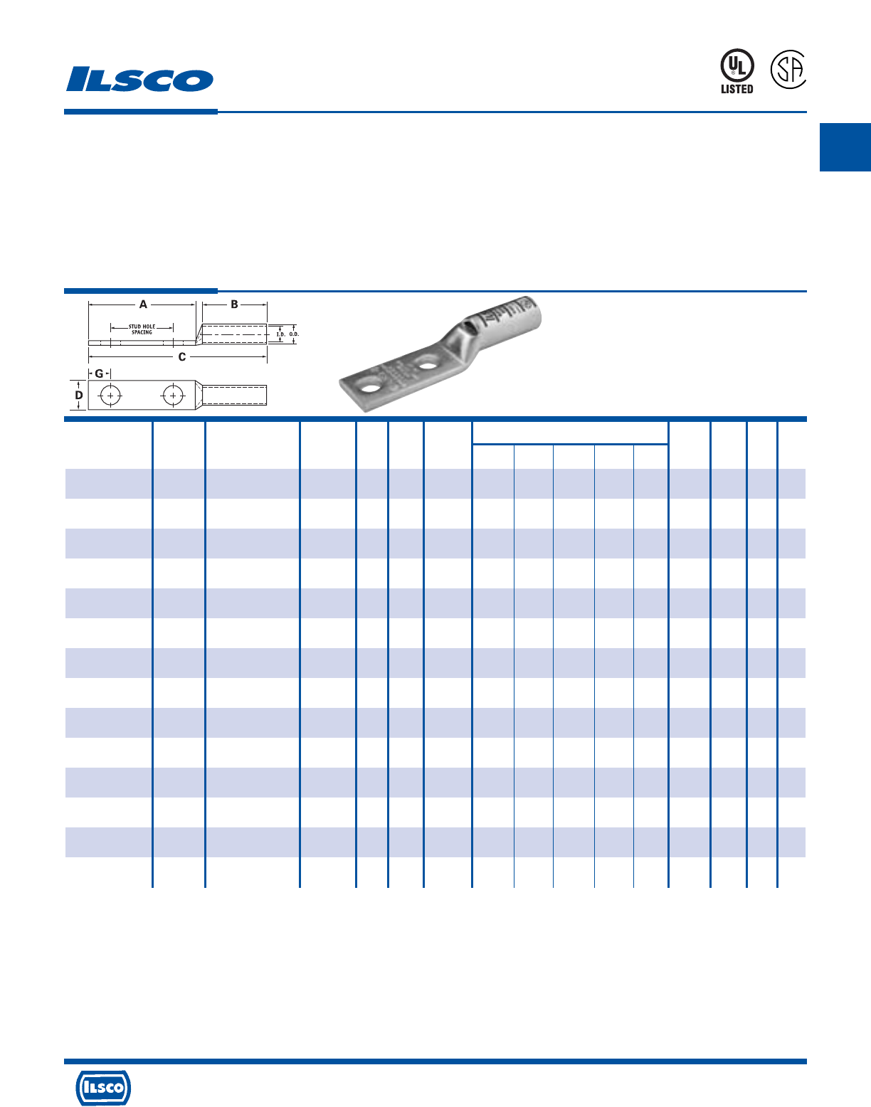
A
4730 Madison Road, Cincinnati, Ohio 45227-1426 Phone 513 533-6200 Fax 513 871-4084 Web site www.ilsco.com
Canada 1050 Lakeshore Road East, Mississauga, Ontario, Canada L5E1E4 Phone 905 274-2341 Fax 905 274-8763
22
TYPE
CLWD
SureCrimp®
Copper Compression Lugs - Long Barrel
2 Hole, w/Sight Hole - Conductor Range: 1000kcmil - 700kcmil
L
R
-
2
9
6
0
1
453G
Features
•
Manufactured from high strength seamless copper tubing.
•
Electro-Tin plated.
•
Maximum conductivity and excellent crimping characteristics.
•
Long barrel length with chamfered entry.
•
Color coded.
•
UL 486A 90°C Listed and CSA Certified for 600 Volts.
•
If proper high voltage spacing and insulation techniques are used, may be used for high voltage applications up to 35KV.
•
For Copper conductor only.
•
Ilsco connectors are UL Listed and CSA Certified with ILSCO and other Manufacturers' tools.+
•
UL File E6207
Stud Stud Dimensions Die
Catalog Wire Alt Expanded* Bolt Hole Hole Color Die
Number Size Wire Size Wire Range Size Dia. Spacing A B C D G Code Index O.D. I.D.
CLWD-700-38-1 700kcmil 500 G,H,I,K,M FLEX 700kcmil - 3/8 0.406 1.000 1.937 2.687 5.493 1.816 0.414 Pink I-99 1.250 0.991
535.3 DLO 350kcmil
CLWD-700-38-118 700kcmil 500 G,H,I,K,M FLEX 700kcmil - 3/8 0.406 1.125 2.125 2.687 5.681 1.816 0.414 Pink I-99 1.250 0.991
535.3 DLO 350kcmil
CLWD-700-12-112 700kcmil 500 G,H,I,K,M FLEX 700kcmil - 1/2 0.562 1.500 2.625 2.687 6.181 1.816 0.546 Pink I-99 1.250 0.991
535.3 DLO 350kcmil
CLWD-700-12-134 700kcmil 500 G,H,I,K,M FLEX 700kcmil - 1/2 0.562 1.750 3.000 2.687 6.556 1.816 0.546 Pink I-99 1.250 0.991
535.3 DLO 350kcmil
CLWD-700-12-178 700kcmil 500 G,H,I,K,M FLEX 700kcmil - 1/2 0.562 1.875 3.000 2.687 6.556 1.816 0.546 Pink I-99 1.250 0.991
535.3 DLO 350kcmil
CLWD-750-38-1 750kcmil 600 G,H,I,M FLEX 750kcmil - 3/8 0.406 1.000 1.937 2.875 5.714 1.901 0.414 Black I-106 1.313 1.031
646.4 DLO 500kcmil
CLWD-750-38-118 750kcmil 600 G,H,I,M FLEX 750kcmil - 3/8 0.406 1.125 2.125 2.875 5.902 1.901 0.414 Black I-106 1.313 1.031
646.4 DLO 500kcmil
CLWD-750-12-112 750kcmil 600 G,H,I,M FLEX 750kcmil - 1/2 0.562 1.500 2.625 2.875 6.402 1.901 0.546 Black I-106 1.313 1.031
646.4 DLO 500kcmil
CLWD-750-12-134 750kcmil 600 G,H,I,M FLEX 750kcmil - 1/2 0.562 1.750 3.000 2.875 6.777 1.901 0.546 Black I-106 1.313 1.031
646.4 DLO 500kcmil
CLWD-750-58-112 750kcmil 600 G,H,I,M FLEX 750kcmil - 5/8 0.562 1.500 3.000 2.875 6.777 1.901 0.671 Black I-106 1.313 1.031
646.4 DLO 500kcmil
CLWD-1000-38-1 1000kcmil 750 G,H,I FLEX 1000kcmil - 3/8 0.406 1.000 1.937 3.000 5.962 2.169 0.414 White I-125 1.500 1.172
777.7 DLO 750kcmil
CLWD-1000-12-114 1000kcmil 750 G,H,I FLEX 1000kcmil - 1/2 0.562 1.250 2.500 3.000 6.525 2.169 0.546 White I-125 1.500 1.172
777.7 DLO 750kcmil
CLWD-1000-12-134 1000kcmil 750 G,H,I FLEX 1000kcmil - 1/2 0.562 1.750 3.000 3.000 7.025 2.169 0.546 White I-125 1.500 1.172
777.7 DLO 750kcmil
CLWD-1000-58-112 1000kcmil 750 G,H,I FLEX 1000kcmil - 5/8 0.562 1.500 3.000 3.000 7.025 2.169 0.671 White I-125 1.500 1.172
777.7 DLO 750kcmil
* When installed with specified dieless tools
+ See pages 90 to 97 for complete tooling information.
For Bent Tangs change the 4th letter to a B and add “-4” for 45 deg. or “-9” for 90 deg.
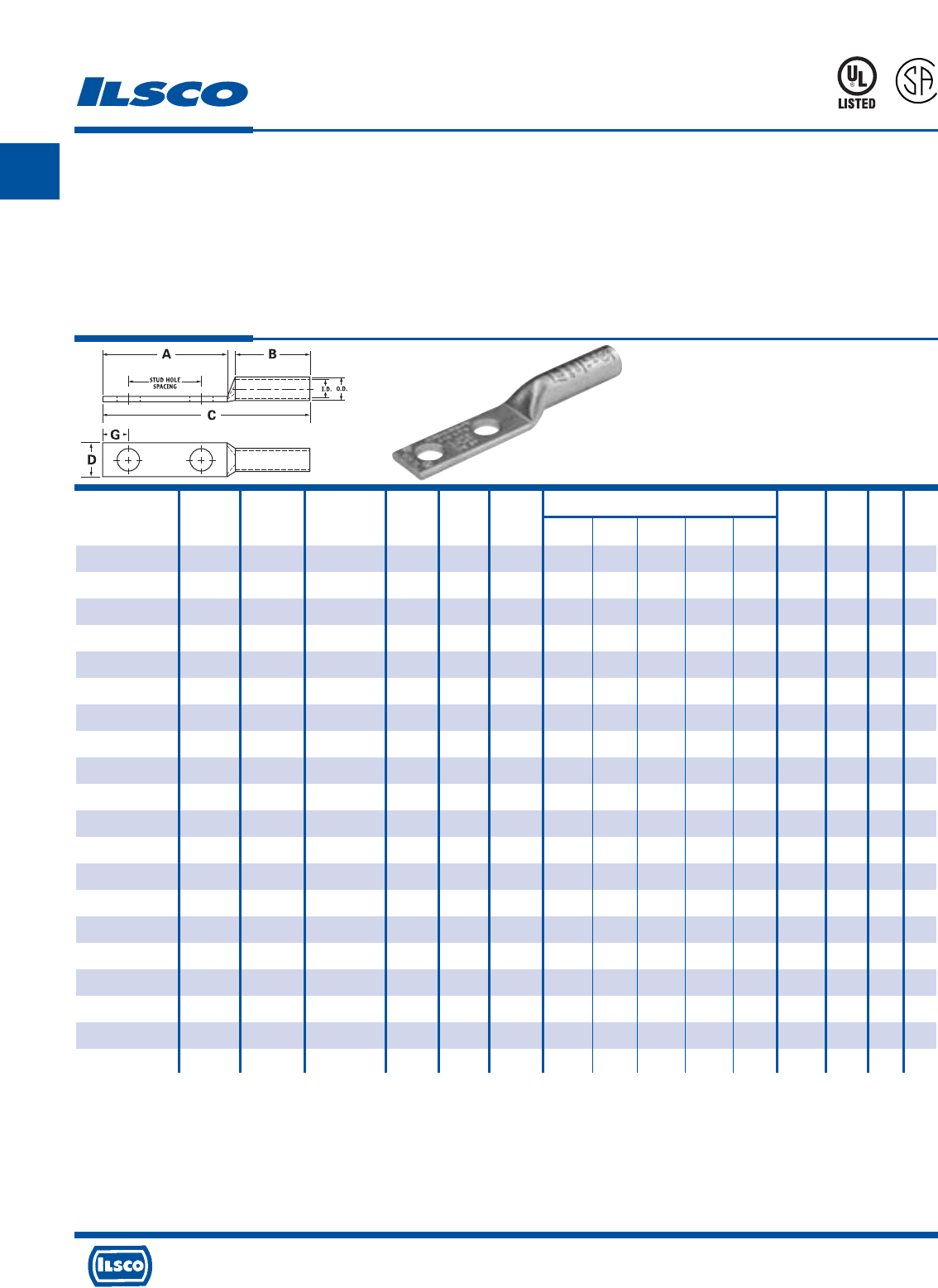
A
4730 Madison Road, Cincinnati, Ohio 45227-1426 Phone 513 533-6200 Fax 513 871-4084 Web site www.ilsco.com
Canada 1050 Lakeshore Road East, Mississauga, Ontario, Canada L5E1E4 Phone 905 274-2341 Fax 905 274-8763
23
TYPE
CLND
SureCrimp®
Copper Compression Lugs - Long Barrel
2 Hole, w/o Sight Hole - Conductor Range: #6 - #8
L
R
-
2
9
6
0
1
453G
Features
•
Manufactured from high strength seamless copper tubing.
•
Electro-Tin plated.
•
Maximum conductivity and excellent crimping characteristics.
•
Long barrel length with chamfered entry.
•
Color coded.
•
UL 486A 90°C Listed and CSA Certified for 600 Volts.
•
If proper high voltage spacing and insulation techniques are used, may be used for high voltage applications up to 35KV.
•
For Copper conductor only.
•
Ilsco connectors are UL Listed and CSA Certified with ILSCO and other Manufacturers' tools.+
•
UL File E6207
Stud Stud Dimensions Die
Catalog Wire Alt Expanded* Bolt Hole Hole Color Die
Number Size Wire Size Wire Range Size Dia. Spacing A B C D G Code Index O.D. I.D.
CLND-8-10-58 #8 AWG #8 FLEX - 10 0.219 0.625 1.250 0.812 2.257 0.374 0.258 Red I-21 0.272 0.179
CLND-8-10-34 #8 AWG #8 FLEX - 10 0.219 0.750 1.437 0.812 2.444 0.374 0.258 Red I-21 0.272 0.179
CLND-8-14-58 #8 AWG #8 FLEX - 1/4 0.281 0.625 1.437 0.812 2.444 0.486 0.320 Red I-21 0.272 0.179
CLND-8-14-34 #8 AWG #8 FLEX - 1/4 0.281 0.750 1.437 0.812 2.444 0.486 0.320 Red I-21 0.272 0.179
CLND-8-14-1 #8 AWG #8 FLEX - 1/4 0.281 1.000 1.687 0.812 2.694 0.486 0.320 Red I-21 0.272 0.179
CLND-8-38-1 #8 AWG #8 FLEX - 3/8 0.406 1.000 1.937 0.812 2.944 0.593 0.414 Red I-21 0.272 0.179
CLND-6-10-12 #6 AWG - - 10 0.219 0.500 1.250 1.125 2.570 0.411 0.258 Blue I-24 0.295 0.203
CLND-6-10-58 #6 AWG - - 10 0.219 0.625 1.250 1.125 2.570 0.411 0.258 Blue I-24 0.295 0.203
CLND-6-10-1116 #6 AWG - - 10 0.219 0.687 1.250 1.125 2.570 0.411 0.258 Blue I-24 0.295 0.203
CLND-6-10-34 #6 AWG - - 10 0.219 0.750 1.437 1.125 2.757 0.411 0.258 Blue I-24 0.295 0.203
CLND-6-14-12 #6 AWG - - 1/4 0.281 0.500 1.250 1.125 2.570 0.411 0.320 Blue I-24 0.295 0.203
CLND-6-14-58 #6 AWG - - 1/4 0.281 0.625 1.437 1.125 2.757 0.411 0.320 Blue I-24 0.295 0.203
CLND-6-14-34 #6 AWG - - 1/4 0.281 0.750 1.437 1.125 2.757 0.411 0.320 Blue I-24 0.295 0.203
CLND-6-14-1 #6 AWG - - 1/4 0.281 1.000 1.687 1.125 3.007 0.411 0.320 Blue I-24 0.295 0.203
CLND-6-516-34 #6 AWG - - 5/16 0.343 0.750 1.687 1.125 3.007 0.532 0.352 Blue I-24 0.295 0.203
CLND-6-516-1 #6 AWG - - 5/16 0.343 1.000 1.937 1.125 3.257 0.532 0.352 Blue I-24 0.295 0.203
CLND-6-38-34 #6 AWG - - 3/8 0.406 0.750 1.687 1.125 3.007 0.593 0.414 Blue I-24 0.295 0.203
CLND-6-38-78 #6 AWG - - 3/8 0.406 0.875 1.937 1.125 3.257 0.593 0.414 Blue I-24 0.295 0.203
CLND-6-38-1 #6 AWG - - 3/8 0.406 1.000 1.937 1.125 3.257 0.593 0.414 Blue I-24 0.295 0.203
CLND-6-12-134 #6 AWG - - 1/2 0.562 1.750 3.000 1.125 4.320 0.750 0.546 Blue I-24 0.295 0.203
* When installed with specified dieless tools
+ See pages 90 to 97 for complete tooling information.
For Bent Tangs change the 4th letter to a B and add “-4” for 45 deg. or “-9” for 90 deg.

A
4730 Madison Road, Cincinnati, Ohio 45227-1426 Phone 513 533-6200 Fax 513 871-4084 Web site www.ilsco.com
Canada 1050 Lakeshore Road East, Mississauga, Ontario, Canada L5E1E4 Phone 905 274-2341 Fax 905 274-8763
24
TYPE
CLND
SureCrimp®
Copper Compression Lugs - Long Barrel
2 Hole, w/o Sight Hole - Conductor Range: #3 - #4
L
R
-
2
9
6
0
1
453G
Features
•
Manufactured from high strength seamless copper tubing.
•
Electro-Tin plated.
•
Maximum conductivity and excellent crimping characteristics.
•
Long barrel length with chamfered entry.
•
Color coded.
•
UL 486A 90°C Listed and CSA Certified for 600 Volts.
•
If proper high voltage spacing and insulation techniques are used, may be used for high voltage applications up to 35KV.
•
For Copper conductor only.
•
Ilsco connectors are UL Listed and CSA Certified with ILSCO and other Manufacturers' tools.+
•
UL File E6207
Stud Stud Dimensions Die
Catalog Wire Alt Expanded* Bolt Hole Hole Color Die
Number Size Wire Size Wire Range Size Dia. Spacing A B C D G Code Index O.D. I.D.
CLND-4-10-58 #4 AWG #6 FLEX 4-6 AWG 10 0.219 0.625 1.250 1.125 2.609 0.486 0.258 Gray I-29 0.343 0.250
CLND-4-10-34 #4 AWG #6 FLEX 4-6 AWG 10 0.219 0.750 1.437 1.125 2.796 0.486 0.258 Gray I-29 0.343 0.250
CLND-4-10-1 #4 AWG #6 FLEX 4-6 AWG 10 0.219 1.000 1.687 1.125 3.046 0.486 0.258 Gray I-29 0.343 0.250
CLND-4-14-58 #4 AWG #6 FLEX 4-6 AWG 1/4 0.281 0.625 1.437 1.125 2.796 0.486 0.320 Gray I-29 0.343 0.250
CLND-4-14-34 #4 AWG #6 FLEX 4-6 AWG 1/4 0.281 0.750 1.437 1.125 2.796 0.486 0.320 Gray I-29 0.343 0.250
CLND-4-516-34 #4 AWG #6 FLEX 4-6 AWG 5/16 0.343 0.750 1.687 1.125 3.046 0.486 0.352 Gray I-29 0.343 0.250
CLND-4-516-1 #4 AWG #6 FLEX 4-6 AWG 5/16 0.343 1.000 1.937 1.125 3.296 0.486 0.352 Gray I-29 0.343 0.250
CLND-4-38-34 #4 AWG #6 FLEX 4-6 AWG 3/8 0.406 0.750 1.687 1.125 3.046 0.593 0.414 Gray I-29 0.343 0.250
CLND-4-38-1 #4 AWG #6 FLEX 4-6 AWG 3/8 0.406 1.000 1.937 1.125 3.296 0.593 0.414 Gray I-29 0.343 0.250
CLND-4-12-134 #4 AWG #6 FLEX 4-6 AWG 1/2 0.562 1.750 3.000 1.125 4.359 0.750 0.546 Gray I-29 0.343 0.250
CLND-3-14-58 #3 AWG #4 FLEX 3-6 AWG 1/4 0.281 0.625 1.437 1.125 2.817 0.532 0.320 White I-29 0.375 0.275
CLND-3-14-34 #3 AWG #4 FLEX 3-6 AWG 1/4 0.281 0.750 1.437 1.125 2.817 0.532 0.320 White I-29 0.375 0.275
CLND-3-516-58 #3 AWG #4 FLEX 3-6 AWG 5/16 0.343 0.625 1.437 1.125 2.817 0.532 0.352 White I-29 0.375 0.275
CLND-3-516-1 #3 AWG #4 FLEX 3-6 AWG 5/16 0.343 1.000 1.937 1.125 3.317 0.532 0.352 White I-29 0.375 0.275
CLND-3-38-34 #3 AWG #4 FLEX 3-6 AWG 3/8 0.406 0.750 1.687 1.125 3.067 0.593 0.414 White I-29 0.375 0.275
CLND-3-38-1 #3 AWG #4 FLEX 3-6 AWG 3/8 0.406 1.000 1.937 1.125 3.317 0.593 0.414 White I-29 0.375 0.275
CLND-3-12-134 #3 AWG #4 FLEX 3-6 AWG 1/2 0.562 1.750 3.000 1.125 4.380 0.750 0.546 White I-29 0.375 0.275
* When installed with specified dieless tools
+ See pages 90 to 97 for complete tooling information.
For Bent Tangs change the 4th letter to a B and add “-4” for 45 deg. or “-9” for 90 deg.
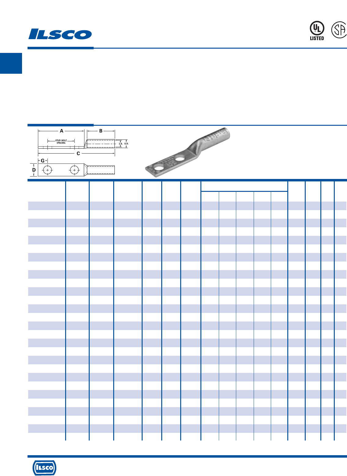
A
4730 Madison Road, Cincinnati, Ohio 45227-1426 Phone 513 533-6200 Fax 513 871-4084 Web site www.ilsco.com
Canada 1050 Lakeshore Road East, Mississauga, Ontario, Canada L5E1E4 Phone 905 274-2341 Fax 905 274-8763
25
TYPE
CLND
SureCrimp®
Copper Compression Lugs - Long Barrel
2 Hole, w/o Sight Hole - Conductor Range: 1/0 - #2
L
R
-
2
9
6
0
1
453G
Features
•
Manufactured from high strength seamless copper tubing.
•
Electro-Tin plated.
•
Maximum conductivity and excellent crimping characteristics.
•
Long barrel length with chamfered entry.
•
Color coded.
•
UL 486A 90°C Listed and CSA Certified for 600 Volts.
•
If proper high voltage spacing and insulation techniques are used, may be used for high voltage applications up to 35KV.
•
For Copper conductor only.
•
Ilsco connectors are UL Listed and CSA Certified with ILSCO and other Manufacturers' tools.+
•
UL File E6207
Stud Stud Dimensions Die
Catalog Wire Alt Expanded* Bolt Hole Hole Color Die
Number Size Wire Size Wire Range Size Dia. Spacing A B C D G Code Index O.D. I.D.
CLND-2-10-34 #2 AWG - 2-6 AWG 10 0.219 0.750 1.437 1.125 2.848 0.599 0.258 Brown I-33 0.421 0.312
CLND-2-14-58 #2 AWG - 2-6 AWG 1/4 0.281 0.625 1.437 1.125 2.848 0.599 0.320 Brown I-33 0.421 0.312
CLND-2-14-34 #2 AWG - 2-6 AWG 1/4 0.281 0.750 1.437 1.125 2.848 0.599 0.320 Brown I-33 0.421 0.312
CLND-2-14-1 #2 AWG - 2-6 AWG 1/4 0.281 1.000 1.687 1.125 3.098 0.599 0.320 Brown I-33 0.421 0.312
CLND-2-516-34 #2 AWG - 2-6 AWG 5/16 0.343 0.750 1.687 1.125 3.098 0.599 0.352 Brown I-33 0.421 0.312
CLND-2-516-1 #2 AWG - 2-6 AWG 5/16 0.343 1.000 1.937 1.125 3.348 0.599 0.352 Brown I-33 0.421 0.312
CLND-2-38-34 #2 AWG - 2-6 AWG 3/8 0.406 0.750 1.687 1.125 3.098 0.599 0.414 Brown I-33 0.421 0.312
CLND-2-38-78 #2 AWG - 2-6 AWG 3/8 0.406 0.875 1.937 1.125 3.348 0.599 0.414 Brown I-33 0.421 0.312
CLND-2-38-1 #2 AWG - 2-6 AWG 3/8 0.406 1.000 1.937 1.125 3.348 0.599 0.414 Brown I-33 0.421 0.312
CLND-2-38-134 #2 AWG - 2-6 AWG 3/8 0.406 1.750 2.625 1.125 4.036 0.599 0.414 Brown I-33 0.421 0.312
CLND-2-12-134 #2 AWG - 2-6 AWG 1/2 0.562 1.750 3.000 1.125 4.411 0.750 0.546 Brown I-33 0.421 0.312
CLND-1-14-58 #1 AWG #2 FLEX 1-6 AWG 1/4 0.281 0.625 1.437 1.375 3.142 0.673 0.320 Green I-37 0.468 0.359
CLND-1-14-34 #1 AWG #2 FLEX 1-6 AWG 1/4 0.281 0.750 1.437 1.375 3.142 0.673 0.320 Green I-37 0.468 0.359
CLND-1-14-1 #1 AWG #2 FLEX 1-6 AWG 1/4 0.281 1.000 1.687 1.375 3.392 0.673 0.320 Green I-37 0.468 0.359
CLND-1-516-78 #1 AWG #2 FLEX 1-6 AWG 5/16 0.343 0.875 1.687 1.375 3.392 0.673 0.352 Green I-37 0.468 0.359
CLND-1-516-1 #1 AWG #2 FLEX 1-6 AWG 5/16 0.343 1.000 1.937 1.375 3.642 0.673 0.352 Green I-37 0.468 0.359
CLND-1-38-1 #1 AWG #2 FLEX 1-6 AWG 3/8 0.406 1.000 1.937 1.375 3.642 0.673 0.414 Green I-37 0.468 0.359
CLND-1-12-134 #1 AWG #2 FLEX 1-6 AWG 1/2 0.562 1.750 3.000 1.375 4.705 0.750 0.546 Green I-37 0.468 0.359
CLND-1/0-14-58 1/0 AWG #1 FLEX 1/0-6 AWG 1/4 0.281 0.625 1.437 1.500 3.293 0.738 0.320 Pink I-42 0.515 0.390
CLND-1/0-14-34 1/0 AWG #1 FLEX 1/0-6 AWG 1/4 0.281 0.750 1.437 1.500 3.293 0.738 0.320 Pink I-42 0.515 0.390
CLND-1/0-14-1 1/0 AWG #1 FLEX 1/0-6 AWG 1/4 0.281 1.000 1.687 1.500 3.543 0.738 0.320 Pink I-42 0.515 0.390
CLND-1/0-516-34 1/0 AWG #1 FLEX 1/0-6 AWG 5/16 0.343 0.750 1.687 1.500 3.543 0.738 0.352 Pink I-42 0.515 0.390
CLND-1/0-516-78 1/0 AWG #1 FLEX 1/0-6 AWG 5/16 0.343 0.875 1.687 1.500 3.543 0.738 0.352 Pink I-42 0.515 0.390
CLND-1/0-516-1 1/0 AWG #1 FLEX 1/0-6 AWG 5/16 0.343 1.000 1.937 1.500 3.793 0.738 0.352 Pink I-42 0.515 0.390
CLND-1/0-38-1 1/0 AWG #1 FLEX 1/0-6 AWG 3/8 0.406 1.000 1.937 1.500 3.793 0.738 0.414 Pink I-42 0.515 0.390
CLND-1/0-38-134 1/0 AWG #1 FLEX 1/0-6 AWG 3/8 0.406 1.750 2.625 1.500 4.481 0.738 0.414 Pink I-42 0.515 0.390
CLND-1/0-12-1 1/0 AWG #1 FLEX 1/0-6 AWG 1/2 0.562 1.000 2.125 1.500 3.981 0.738 0.546 Pink I-42 0.515 0.390
CLND-1/0-12-134 1/0 AWG #1 FLEX 1/0-6 AWG 1/2 0.562 1.750 3.000 1.500 4.856 0.738 0.546 Pink I-42 0.515 0.390
* When installed with specified dieless tools + See pages 90 to 97 for complete tooling information.
For Bent Tangs change the 4th letter to a B and add “-4” for 45 deg. or “-9” for 90 deg.
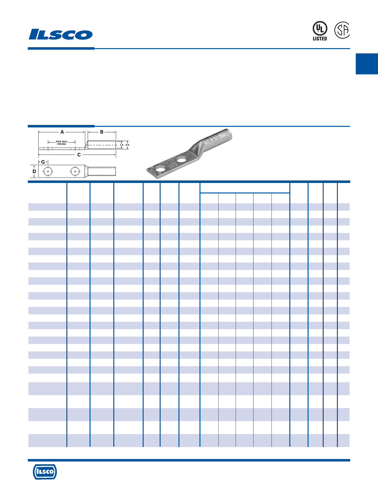
A
4730 Madison Road, Cincinnati, Ohio 45227-1426 Phone 513 533-6200 Fax 513 871-4084 Web site www.ilsco.com
Canada 1050 Lakeshore Road East, Mississauga, Ontario, Canada L5E1E4 Phone 905 274-2341 Fax 905 274-8763
26
TYPE
CLND
SureCrimp®
Copper Compression Lugs - Long Barrel
2 Hole, w/o Sight Hole - Conductor Range: 250kcmil - 2/0
L
R
-
2
9
6
0
1
453G
Features
•
Manufactured from high strength seamless copper tubing.
•
Electro-Tin plated.
•
Maximum conductivity and excellent crimping characteristics.
•
Long barrel length with chamfered entry.
•
Color coded.
•
UL 486A 90°C Listed and CSA Certified for 600 Volts.
•
If proper high voltage spacing and insulation techniques are used, may be used for high voltage applications up to 35KV.
•
For Copper conductor only.
•
Ilsco connectors are UL Listed and CSA Certified with ILSCO and other Manufacturers' tools.+
•
UL File E6207
Stud Stud Dimensions Die
Catalog Wire Alt Expanded* Bolt Hole Hole Color Die
Number Size Wire Size Wire Range Size Dia. Spacing A B C D G Code Index O.D. I.D.
CLND-2/0-14-58 2/0 AWG 1/0 FLEX 2/0-4 AWG 1/4 0.281 0.625 1.437 1.500 3.333 0.811 0.320 Black I-45 0.562 0.437
CLND-2/0-14-34 2/0 AWG 1/0 FLEX 2/0-4 AWG 1/4 0.281 0.750 1.437 1.500 3.333 0.811 0.320 Black I-45 0.562 0.437
CLND-2/0-14-1 2/0 AWG 1/0 FLEX 2/0-4 AWG 1/4 0.281 1.000 1.687 1.500 3.583 0.811 0.320 Black I-45 0.562 0.437
CLND-2/0-516-1 2/0 AWG 1/0 FLEX 2/0-4 AWG 5/16 0.343 1.000 1.937 1.500 3.833 0.811 0.352 Black I-45 0.562 0.437
CLND-2/0-38-1 2/0 AWG 1/0 FLEX 2/0-4 AWG 3/8 0.406 1.000 1.937 1.500 3.833 0.811 0.414 Black I-45 0.562 0.437
CLND-2/0-38-134 2/0 AWG 1/0 FLEX 2/0-4 AWG 3/8 0.406 1.750 2.625 1.500 4.521 0.811 0.414 Black I-45 0.562 0.437
CLND-2/0-12-1 2/0 AWG 1/0 FLEX 2/0-4 AWG 1/2 0.562 1.000 2.125 1.500 4.021 0.811 0.546 Black I-45 0.562 0.437
CLND-2/0-12-134 2/0 AWG 1/0 FLEX 2/0-4 AWG 1/2 0.562 1.750 3.000 1.500 4.896 0.811 0.546 Black I-45 0.562 0.437
CLND-3/0-14-58 3/0 AWG 2/0 FLEX 3/0-2 AWG 1/4 0.281 0.625 1.437 1.500 3.376 0.885 0.320 Orange I-50 0.609 0.484
CLND-3/0-14-34 3/0 AWG 2/0 FLEX 3/0-2 AWG 1/4 0.281 0.750 1.437 1.500 3.376 0.885 0.320 Orange I-50 0.609 0.484
CLND-3/0-516-1 3/0 AWG 2/0 FLEX 3/0-2 AWG 5/16 0.343 1.000 1.937 1.500 3.876 0.885 0.352 Orange I-50 0.609 0.484
CLND-3/0-38-1 3/0 AWG 2/0 FLEX 3/0-2 AWG 3/8 0.406 1.000 1.937 1.500 3.876 0.885 0.414 Orange I-50 0.609 0.484
CLND-3/0-12-134 3/0 AWG 2/0 FLEX 3/0-2 AWG 1/2 0.562 1.750 3.000 1.500 4.939 0.885 0.546 Orange I-50 0.609 0.484
CLND-4/0-14-58 4/0 AWG 3/0 FLEX 4/0-1 AWG 1/4 0.281 0.625 1.437 1.500 3.428 0.999 0.320 Purple I-54 0.687 0.546
CLND-4/0-14-34 4/0 AWG 3/0 FLEX 4/0-1 AWG 1/4 0.281 0.750 1.437 1.500 3.428 0.999 0.320 Purple I-54 0.687 0.546
CLND-4/0-14-1 4/0 AWG 3/0 FLEX 4/0-1 AWG 1/4 0.281 1.000 1.687 1.500 3.678 0.999 0.320 Purple I-54 0.687 0.546
CLND-4/0-516-34 4/0 AWG 3/0 FLEX 4/0-1 AWG 5/16 0.343 0.750 1.687 1.500 3.678 0.999 0.352 Purple I-54 0.687 0.546
CLND-4/0-516-1 4/0 AWG 3/0 FLEX 4/0-1 AWG 5/16 0.343 1.000 1.937 1.500 3.928 0.999 0.352 Purple I-54 0.687 0.546
CLND-4/0-516-134 4/0 AWG 3/0 FLEX 4/0-1 AWG 5/16 0.343 1.750 2.500 1.500 4.491 0.999 0.352 Purple I-54 0.687 0.546
CLND-4/0-38-1 4/0 AWG 3/0 FLEX 4/0-1 AWG 3/8 0.406 1.000 1.937 1.500 3.928 0.999 0.414 Purple I-54 0.687 0.546
CLND-4/0-38-134 4/0 AWG 3/0 FLEX 4/0-1 AWG 3/8 0.406 1.750 2.625 1.500 4.616 0.999 0.414 Purple I-54 0.687 0.546
CLND-4/0-12-1 4/0 AWG 3/0 FLEX 4/0-1 AWG 1/2 0.562 1.000 2.125 1.500 4.116 0.999 0.546 Purple I-54 0.687 0.546
CLND-4/0-12-114 4/0 AWG 3/0 FLEX 4/0-1 AWG 1/2 0.562 1.250 2.500 1.500 4.491 0.999 0.546 Purple I-54 0.687 0.546
CLND-4/0-12-134 4/0 AWG 3/0 FLEX 4/0-1 AWG 1/2 0.562 1.750 3.000 1.500 4.991 0.999 0.546 Purple I-54 0.687 0.546
CLND-250-14-34 250kcmil 4/0 FLEX 250kcmil - 1/4 0.281 0.750 1.437 1.688 3.656 1.088 0.320 Yellow I-62 0.750 0.593
1/0 AWG
CLND-250-38-1 250kcmil 4/0 FLEX 250kcmil - 3/8 0.406 1.000 1.937 1.688 4.156 1.088 0.414 Yellow I-62 0.750 0.593
1/0 AWG
CLND-250-38-134 250kcmil 4/0 FLEX 250kcmil - 3/8 0.406 1.750 2.625 1.688 4.844 1.088 0.414 Yellow I-62 0.750 0.593
1/0 AWG
CLND-250-12-114 250kcmil 4/0 FLEX 250kcmil - 1/2 0.562 1.250 2.500 1.688 4.719 1.088 0.546 Yellow I-62 0.750 0.593
1/0 AWG
CLND-250-12-134 250kcmil 4/0 FLEX 250kcmil - 1/2 0.562 1.750 3.000 1.688 5.219 1.088 0.546 Yellow I-62 0.750 0.593
1/0 AWG
* When installed with specified dieless tools
+
See pages 90 to 97 for complete tooling information. For Bent Tangs change the 4th letter to a B and add “-4” for 45 deg. or “-9” for 90 deg.
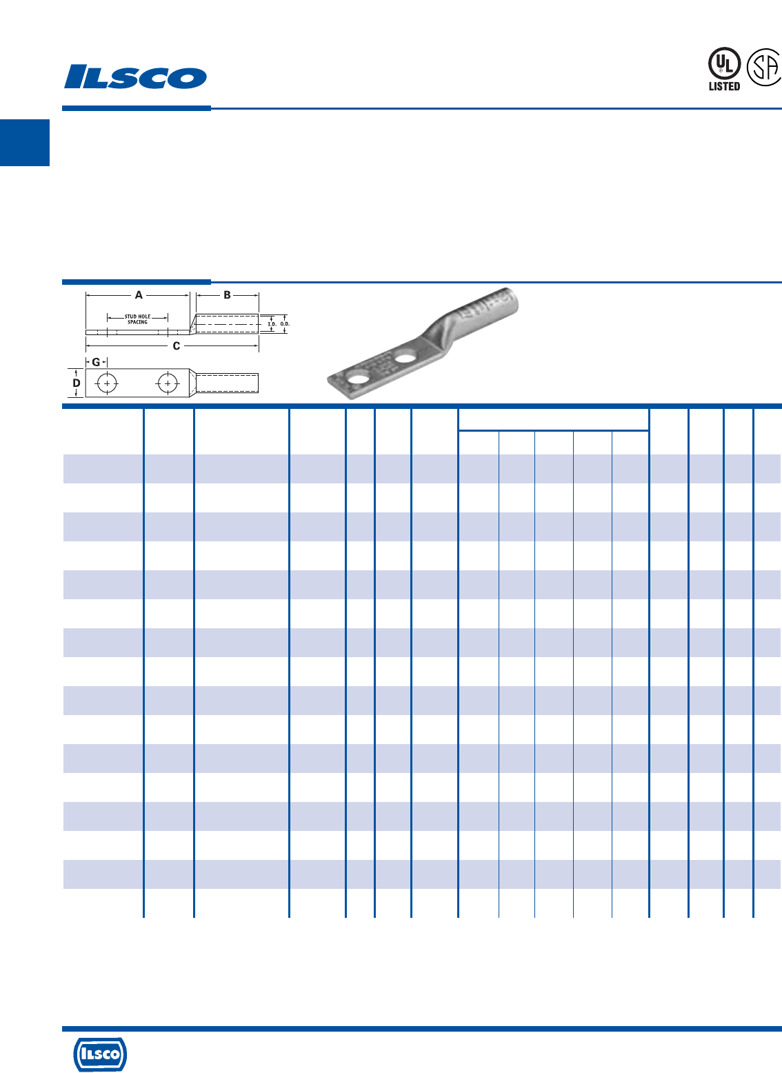
A
4730 Madison Road, Cincinnati, Ohio 45227-1426 Phone 513 533-6200 Fax 513 871-4084 Web site www.ilsco.com
Canada 1050 Lakeshore Road East, Mississauga, Ontario, Canada L5E1E4 Phone 905 274-2341 Fax 905 274-8763
27
TYPE
CLND
SureCrimp®
Copper Compression Lugs - Long Barrel
2 Hole, w/o Sight Hole - Conductor Range: 600kcmil - 300kcmil
L
R
-
2
9
6
0
1
453G
Features
•
Manufactured from high strength seamless copper tubing.
•
Electro-Tin plated.
•
Maximum conductivity and excellent crimping characteristics.
•
Long barrel length with chamfered entry.
•
Color coded.
•
UL 486A 90°C Listed and CSA Certified for 600 Volts.
•
If proper high voltage spacing and insulation techniques are used, may be used for high voltage applications up to 35KV.
•
For Copper conductor only.
•
Ilsco connectors are UL Listed and CSA Certified with ILSCO and other Manufacturers' tools.+
•
UL File E6207
Stud Stud Dimensions Die
Catalog Wire Alt Expanded* Bolt Hole Hole Color Die
Number Size Wire Size Wire Range Size Dia. Spacing A B C D G Code Index O.D. I.D.
CLND-300-38-1 300kcmil 250 G,H FLEX 300kcmil - 3/8 0.406 1.000 1.937 2.000 4.524 1.189 0.414 White I-66 0.812 0.660
2/0 AWG
CLND-300-12-134 300kcmil 250 G,H FLEX 300kcmil - 1/2 0.562 1.750 3.000 2.000 5.587 1.189 0.546 White I-66 0.812 0.660
2/0 AWG
CLND-350-14-34 350kcmil 250 I,K,M FLEX 350kcmil - 1/4 0.281 0.750 1.437 2.000 4.060 1.291 0.320 Red I-71 0.890 0.703
262.2 DLO 3/0 AWG
CLND-350-516-134 350kcmil 250 I,K,M FLEX 350kcmil - 5/16 0.343 1.750 2.500 2.000 5.123 1.291 0.352 Red I-71 0.890 0.703
262.2 DLO 3/0 AWG
CLND-350-38-1 350kcmil 250 I,K,M FLEX 350kcmil - 3/8 0.406 1.000 1.937 2.000 4.560 1.291 0.414 Red I-71 0.890 0.703
262.2 DLO 3/0 AWG
CLND-350-12-114 350kcmil 250 I,K,M FLEX 350kcmil - 1/2 0.562 1.250 2.500 2.000 5.123 1.291 0.546 Red I-71 0.890 0.703
262.2 DLO 3/0 AWG
CLND-350-12-134 350kcmil 250 I,K,M FLEX 350kcmil - 1/2 0.562 1.750 3.000 2.000 5.623 1.291 0.546 Red I-71 0.890 0.703
262.2 DLO 3/0 AWG
CLND-400-38-1 400kcmil 300 G,H,I,K,M FLEX 400kcmil - 3/8 0.406 1.000 1.937 2.125 4.729 1.365 0.414 Blue I-76 0.937 0.750
313.1 DLO 4/0 AWG
CLND-400-38-116 400kcmil 300 G,H,I,K,M FLEX 400kcmil - 3/8 0.406 1.062 1.937 2.125 4.729 1.365 0.414 Blue I-76 0.937 0.750
313.1 DLO 4/0 AWG
CLND-400-12-134 400kcmil 300 G,H,I,K,M FLEX 400kcmil - 1/2 0.562 1.750 3.000 2.125 5.792 1.365 0.546 Blue I-76 0.937 0.750
313.1 DLO 4/0 AWG
CLND-500-14-34 500kcmil 350 G,H,I,K,M FLEX 500kcmil - 1/4 0.281 0.750 1.437 2.250 4.419 1.535 0.320 Brown I-87 1.062 0.828
373.7 DLO 250kcmil
CLND-500-38-1 500kcmil 350 G,H,I,K,M FLEX 500kcmil - 3/8 0.406 1.000 1.937 2.250 4.919 1.535 0.414 Brown I-87 1.062 0.828
373.7 DLO 250kcmil
CLND-500-12-114 500kcmil 350 G,H,I,K,M FLEX 500kcmil - 1/2 0.562 1.250 2.500 2.250 5.482 1.535 0.546 Brown I-87 1.062 0.828
373.7 DLO 250kcmil
CLND-500-12-134 500kcmil 350 G,H,I,K,M FLEX 500kcmil - 1/2 0.562 1.750 3.000 2.250 5.982 1.535 0.546 Brown I-87 1.062 0.828
373.7 DLO 250kcmil
CLND-600-38-1 600kcmil 400 G,H,I,K,M FLEX 600kcmil - 3/8 0.406 1.000 1.937 2.687 5.433 1.712 0.414 Green I-94 1.187 0.920
444.4 DLO 250kcmil
CLND-600-12-134 600kcmil 400 G,H,I,K,M FLEX 600kcmil - 1/2 0.562 1.750 3.000 2.687 6.496 1.712 0.546 Green I-94 1.187 0.920
444.4 DLO 250kcmil
* When installed with specified dieless tools
+ See pages 90 to 97 for complete tooling information.
For Bent Tangs change the 4th letter to a B and add “-4” for 45 deg. or “-9” for 90 deg.

A
4730 Madison Road, Cincinnati, Ohio 45227-1426 Phone 513 533-6200 Fax 513 871-4084 Web site www.ilsco.com
Canada 1050 Lakeshore Road East, Mississauga, Ontario, Canada L5E1E4 Phone 905 274-2341 Fax 905 274-8763
28
TYPE
CLND
SureCrimp®
Copper Compression Lugs - Long Barrel
2 Hole, w/o Sight Hole - Conductor Range: 1000kcmil - 650kcmil
L
R
-
2
9
6
0
1
453G
Features
•
Manufactured from high strength seamless copper tubing.
•
Electro-Tin plated.
•
Maximum conductivity and excellent crimping characteristics.
•
Long barrel length with chamfered entry.
•
Color coded.
•
UL 486A 90°C Listed and CSA Certified for 600 Volts.
•
If proper high voltage spacing and insulation techniques are used, may be used for high voltage applications up to 35KV.
•
For Copper conductor only.
•
Ilsco connectors are UL Listed and CSA Certified with ILSCO and other Manufacturers' tools.+
•
UL File E6207
Stud Stud Dimensions Die
Catalog Wire Alt Expanded* Bolt Hole Hole Color Die
Number Size Wire Size Wire Range Size Dia. Spacing A B C D G Code Index O.D. I.D.
CLND-650-12-114 650kcmil 500 G,H,I,K,M FLEX 650kcmil - 1/2 0.562 1.25 2.5 2.687 6.056 1.764 0.546 Pink I-99 1.217 0.958
535.3 DLO 350kcmil
CLND-650-12-134 650kcmil 500 G,H,I,K,M FLEX 650kcmil - 1/2 0.562 1.75 3 2.687 6.556 1.764 0.546 Pink I-99 1.217 0.958
535.3 DLO 350kcmil
CLND-650-38-1 650kcmil 500 G,H,I,K,M FLEX 650kcmil - 3/8 0.406 1 2.125 2.687 5.493 1.764 0.414 Pink I-99 1.217 0.958
535.3 DLO 350kcmil
CLND-650-38-118 650kcmil 500 G,H,I,K,M FLEX 650kcmil - 3/8 0.406 1.125 2.125 2.687 5.681 1.764 0.414 Pink I-99 1.217 0.958
535.3 DLO 350kcmil
CLND-650-516-1 650kcmil 500 G,H,I,K,M FLEX 650kcmil - 1/32 0.343 1 1.937 2.687 5.493 1.764 0.3515 Pink I-99 1.217 0.958
535.3 DLO 350kcmil
CLND-700-38-1 700kcmil 500 G,H,I,K,M FLEX 700kcmil - 3/8 0.406 1.000 1.937 2.687 5.493 1.816 0.414 Pink I-99 1.250 0.991
535.3 DLO 350kcmil
CLND-700-38-118 700kcmil 500 G,H,I,K,M FLEX 700kcmil - 3/8 0.406 1.125 2.125 2.687 5.681 1.816 0.414 Pink I-99 1.250 0.991
535.3 DLO 350kcmil
CLND-700-12-112 700kcmil 500 G,H,I,K,M FLEX 700kcmil - 1/2 0.562 1.500 2.625 2.687 6.181 1.816 0.546 Pink I-99 1.250 0.991
535.3 DLO 350kcmil
CLND-700-12-134 700kcmil 500 G,H,I,K,M FLEX 700kcmil - 1/2 0.562 1.750 3.000 2.687 6.556 1.816 0.546 Pink I-99 1.250 0.991
535.3 DLO 350kcmil
CLND-700-12-178 700kcmil 500 G,H,I,K,M FLEX 700kcmil - 1/2 0.562 1.875 3.000 2.687 6.556 1.816 0.546 Pink I-99 1.250 0.991
535.3 DLO 350kcmil
CLND-750-38-1 750kcmil 600 G,H,I,M FLEX 750kcmil - 3/8 0.406 1.000 1.937 2.875 5.714 1.901 0.414 Black I-106 1.313 1.031
646.4 DLO 500kcmil
CLND-750-38-118 750kcmil 600 G,H,I,M FLEX 750kcmil - 3/8 0.406 1.125 2.125 2.875 5.902 1.901 0.414 Black I-106 1.313 1.031
646.4 DLO 500kcmil
CLND-750-12-112 750kcmil 600 G,H,I,M FLEX 750kcmil - 1/2 0.562 1.500 2.625 2.875 6.402 1.901 0.546 Black I-106 1.313 1.031
646.4 DLO 500kcmil
CLND-750-12-134 750kcmil 600 G,H,I,M FLEX 750kcmil - 1/2 0.562 1.750 3.000 2.875 6.777 1.901 0.546 Black I-106 1.313 1.031
646.4 DLO 500kcmil
CLND-750-58-112 750kcmil 600 G,H,I,M FLEX 750kcmil - 5/8 0.562 1.500 3.000 2.875 6.777 1.901 0.671 Black I-106 1.313 1.031
646.4 DLO 500kcmil
CLND-1000-38-1 1000kcmil 750 G,H,I FLEX 1000kcmil - 3/8 0.406 1.000 1.937 3.000 5.962 2.169 0.414 White I-125 1.500 1.172
777.7 DLO 750kcmil
CLND-1000-12-114 1000kcmil 750 G,H,I FLEX 1000kcmil - 1/2 0.562 1.250 2.500 3.000 6.525 2.169 0.546 White I-125 1.500 1.172
777.7 DLO 750kcmil
CLND-1000-12-134 1000kcmil 750 G,H,I FLEX 1000kcmil - 1/2 0.562 1.750 3.000 3.000 7.025 2.169 0.546 White I-125 1.500 1.172
777.7 DLO 750kcmil
CLND-1000-58-112 1000kcmil 750 G,H,I FLEX 1000kcmil - 5/8 0.562 1.500 3.000 3.000 7.025 2.169 0.671 White I-125 1.500 1.172
777.7 DLO 750kcmil
* When installed with specified dieless tools + See pages 90 to 97 for complete tooling information.
For Bent Tangs change the 4th letter to a B and add “-4” for 45 deg. or “-9” for 90 deg.
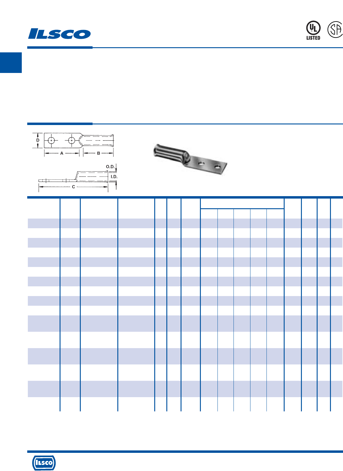
A
4730 Madison Road, Cincinnati, Ohio 45227-1426 Phone 513 533-6200 Fax 513 871-4084 Web site www.ilsco.com
Canada 1050 Lakeshore Road East, Mississauga, Ontario, Canada L5E1E4 Phone 905 274-2341 Fax 905 274-8763
29
TYPE
CLNF
SureCrimp®
Copper Compression Lugs - Long Barrel
Flared End, w/o Sight Hole - Conductor Range: 500kcmil - 2/0
L
R
-
2
9
6
0
1
453G
Features
•
Manufactured from high strength seamless copper tubing.
•
Electro-Tin plated.
•
Maximum conductivity and excellent crimping characteristics.
•
Long barrel length with chamfered entry.
•
Color coded.
•
UL 486A 90°C Listed and CSA Certified for 600 Volts.
•
If proper high voltage spacing and insulation techniques are used, may be used for high voltage applications up to 35KV.
•
For Copper conductor only.
•
Ilsco connectors are UL Listed and CSA Certified with ILSCO and other Manufacturers' tools.+
•
UL File E6207
Stud Stud Dimensions Die
Catalog Wire Alt Expanded* Bolt Hole Hole Color Die
Number Size Wire Size Wire Range Size Dia. Spacing A B C D G Code Index O.D. I.D.
CLNF-2/0-12-134 2/0 AWG 1/0 FLEX 2/0-4 AWG 1/2 0.531 1.750 3.000 1.938 5.219 0.813 0.546 Black I-45 0.562 0.437
CLNF-2/0-38 2/0 AWG 1/0 FLEX 2/0-4 AWG 3/8 0.406 - 0.875 1.938 3.094 0.813 0.414 Black I-45 0.562 0.437
CLNF-3/0-12-134 3/0 AWG 2/0 FLEX 3/0-2 AWG 1/2 0.531 1.750 3.000 1.938 5.250 0.906 0.546 Orange I-50 0.609 0.484
CLNF-3/0-12 3/0 AWG 2/0 FLEX 3/0-2 AWG 1/2 0.531 - 1.000 1.938 3.250 0.906 0.546 Orange I-50 0.609 0.484
CLNF-4/0-12-134 4/0 AWG 3/0 FLEX 4/0-1 AWG 1/2 0.531 1.750 3.000 2.125 5.469 1.000 0.546 Purple I-54 0.687 0.546
CLNF-4/0-12 4/0 AWG 3/0 FLEX 4/0-1 AWG 1/2 0.531 - 1.000 2.125 3.469 1.000 0.546 Purple I-54 0.687 0.546
CLNF-250-12-134 250kcmil 4/0 FLEX 250kcmil-1/0 AWG 1/2 0.531 1.750 3.000 2.125 5.563 1.090 0.546 Yellow I-62 0.750 0.593
CLNF-250-12 250kcmil 4/0 FLEX 250kcmil-1/0 AWG 1/2 0.531 - 1.125 2.125 3.688 1.090 0.546 Yellow I-62 0.750 0.593
CLNF-300-12-134 300kcmil 250 G, H FLEX 300kcmil-2/0 AWG 1/2 0.531 1.750 3.000 2.250 5.937 1.188 0.546 White I-66 0.812 0.660
CLNF-300-58 300kcmil 250 G, H FLEX 300kcmil-2/0 AWG 5/8 0.688 - 1.125 2.250 3.875 1.188 0.671 White I-66 0.812 0.660
CLNF-350-12-134 350kcmil 250 I,K,M FLEX 350kcmil-3/0 AWG 1/2 0.531 1.750 3.000 2.563 6.000 1.280 0.546 Red I-71 0.890 0.703
262.2 DLO
CLNF-350-58 350kcmil 250 I,K,M FLEX 350kcmil-3/0 AWG 5/8 0.688 - 1.125 2.563 4.125 1.280 0.671 Red I-71 0.890 0.703
262.2 DLO
CLNF-400-12-134 400kcmil 300 G,H,I,K,M FLEX 400kcmil-4/0 AWG 1/2 0.531 1.750 3.000 2.688 6.313 1.375 0.546 Blue I-76 0.937 0.750
313.1 DLO
CLNF-400-58 400kcmil 300 G,H,I,K,M FLEX 400kcmil-4/0 AWG 5/8 0.688 - 1.500 2.688 4.813 1.375 0.671 Blue I-76 0.937 0.750
313.1 DLO
CLNF-500-12-134 500kcmil 350 G,H,I,K,M FLEX 500kcmil-250kcmil 1/2 0.531 1.750 3.000 2.813 6.313 1.531 0.546 Brown I-87 1.062 0.828
373.7 DLO
CLNF-500-58 500kcmil 350 G,H,I,K,M FLEX 500kcmil-250kcmil 5/8 0.688 - 1.500 2.813 4.813 1.531 0.671 Brown I-87 1.062 0.828
373.7 DLO
* When installed with specified dieless tools
+ See pages 90 to 97 for complete tooling information.
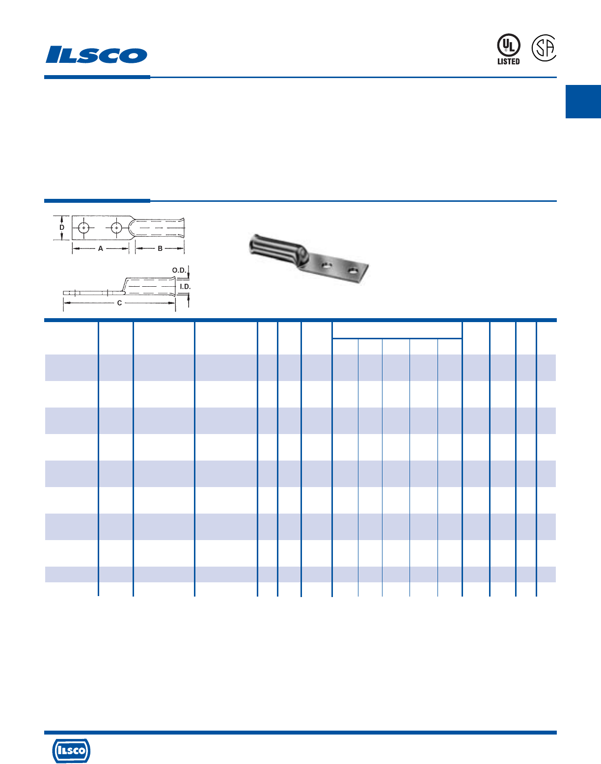
A
4730 Madison Road, Cincinnati, Ohio 45227-1426 Phone 513 533-6200 Fax 513 871-4084 Web site www.ilsco.com
Canada 1050 Lakeshore Road East, Mississauga, Ontario, Canada L5E1E4 Phone 905 274-2341 Fax 905 274-8763
30
TYPE
CLNF
SureCrimp®
Copper Compression Lugs - Long Barrel
Flared End, w/o Sight Hole - Conductor Range: 1111 kcmil - 600kcmil
L
R
-
2
9
6
0
1
453G
Features
•
Manufactured from high strength seamless copper tubing.
•
Electro-Tin plated.
•
Maximum conductivity and excellent crimping characteristics.
•
Long barrel length with chamfered entry.
•
Color coded.
•
UL 486A 90°C Listed and CSA Certified for 600 Volts.
•
If proper high voltage spacing and insulation techniques are used, may be used for high voltage applications up to 35KV.
•
For Copper conductor only.
•
Ilsco connectors are UL Listed and CSA Certified with ILSCO and other Manufacturers' tools.+
•
UL File E6207
Stud Stud Dimensions Die
Catalog Wire Alt Expanded* Bolt Hole Hole Color Die
Number Size Wire Size Wire Range Size Dia. Spacing A B C D G Code Index O.D. I.D.
CLNF-600-12-134 600kcmil 400 G,H,I,K,M FLEX 600kcmil-250kcmil 1/2 0.531 1.750 3.000 2.875 6.813 1.680 0.546 Green I-94 1.187 0.920
444.4 DLO
CLNF-600-58 600kcmil 400 G,H,I,K,M FLEX 600kcmil-250kcmil 5/8 0.688 - 1.500 2.875 5.375 1.680 0.671 Green I-94 1.187 0.920
444.4 DLO
CLNF-700-12-134 700kcmil 500 G,H,I,K,M FLEX 700kcmil-350kcmil 1/2 0.531 1.750 3.000 2.813 6.625 1.844 0.546 Pink I-99 1.250 0.991
535.3 DLO
CLNF-700-58 700kcmil 500 G,H,I,K,M FLEX 700kcmil-350kcmil 5/8 0.688 - 1.750 2.563 5.375 1.844 0.671 Pink I-99 1.250 0.991
535.3 DLO
CLNF-750-12-134 750kcmil 600 G,H,I,M FLEX 750kcmil-500kcmil 1/2 0.531 1.750 3.000 2.813 6.625 1.906 0.546 Black I-106 1.313 1.031
646.4 DLO
CLNF-750-58 750kcmil 600 G,H,I,M FLEX 750kcmil-500kcmil 5/8 0.688 - 1.938 2.813 5.563 1.906 0.671 Black I-106 1.313 1.031
646.4 DLO
CLNF-1000-12-134 1000kcmil 750 G,H, I FLEX 1000kcmil-750kcmil 1/2 0.531 1.750 3.000 3.563 7.438 2.188 0.546 White I-125 1.500 1.172
777.7 DLO
CLNF-1000-58 1000kcmil 750 G,H, I FLEX 1000kcmil-750kcmil 5/8 0.688 - 2.125 3.563 6.563 2.188 0.671 White I-125 1.500 1.172
777.7 DLO
CLNF-1111-12-134 1111kcmil - - 1/2 0.562 1.750 3.000 3.313 7.438 2.600 0.546 White IDT-12 1.750 1.458
CLNF-1111-58 1111kcmil - - 5/8 0.656 - 2.250 3.563 6.688 2.600 0.671 White IDT-12 1.750 1.458
* When installed with specified dieless tools
+ See pages 90 to 97 for complete tooling information.
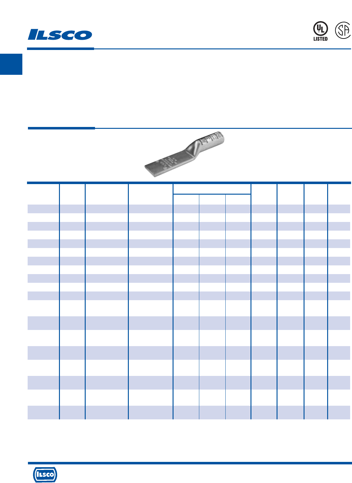
A
4730 Madison Road, Cincinnati, Ohio 45227-1426 Phone 513 533-6200 Fax 513 871-4084 Web site www.ilsco.com
Canada 1050 Lakeshore Road East, Mississauga, Ontario, Canada L5E1E4 Phone 905 274-2341 Fax 905 274-8763
31
Dimensions Die
Catalog Wire Alt Expanded* Color Die
Number Size Wire Size Wire Range A B D Code Index O.D. I.D.
CLNU-6 6 AWG - - 3.000 1.130 0.760 Blue I-24 0.295 0.203
CLNU-4 4 AWG #6 Flex 4-6 AWG 3.000 1.130 0.760 White I-29 0.343 0.250
CLNU-3 3 AWG #4 Flex 3-6 AWG 3.000 1.130 0.750 White I-29 0.375 0.275
CLNU-2 2 AWG - 2-6 AWG 3.000 1.130 0.740 Brown I-33 0.421 0.312
CLNU-1 1 AWG #2 Flex 1-6 AWG 3.000 1.380 0.740 Green I-37 0.468 0.359
CLNU-1/0 1/0 AWG #1 Flex 1/0-6 AWG 3.000 1.500 0.740 Pink I-42 0.515 0.390
CLNU-2/0 2/0 AWG 1/0 Flex 2/0-4 AWG 3.000 1.500 0.810 Black I-45 0.562 0.437
CLNU-3/0 3/0 AWG 2/0 Flex 3/0-2 AWG 3.000 1.500 0.890 Orange I-50 0.609 0.484
CLNU-4/0 4/0 AWG 3/0 Flex 4/0-1 AWG 3.000 1.500 1.000 Purple I-54 0.687 0.546
CLNU-250 250kcmil 4/0 Flex 250kcmil-1/0 AWG 3.000 1.690 1.090 Yellow I-62 0.750 0.593
CLNU-300 300kcmil 250 G,H Flex 300kcmil-2/0 AWG 3.000 2.000 1.190 White I-66 0.812 0.660
CLNU-350 350kcmil 250 I,K,M Flex 350kcmil-3/0 AWG 3.000 2.000 1.290 Red I-71 0.890 0.703
262.2 DLO
CLNU-400 400kcmil 300 G,H,I,K,M Flex 400kcmil-4/0 AWG 3.000 2.130 1.370 Blue I-76 0.937 0.750
313.1 DLO
CLNU-500 500kcmil 350 G,H,I,K,M Flex 500kcmil-250kcmil 3.000 2.250 1.530 Brown I-87 1.062 0.828
373.7 DLO
CLNU-600 600kcmil 400 G,H,I,K,M Flex 600kcmil-250kcmil 3.000 2.690 1.710 Green I-94 1.187 0.920
444.4 DLO
CLNU-650 650kcmil 500 G,H,I,K,M Flex 650kcmil-350kcmil 3.000 2.690 1.760 Pink I-99 1.217 0.958
535.3 DLO
CLNU-700 700kcmil 500 G,H,I,K,M Flex 700kcmil-350kcmil 3.000 2.690 1.820 Pink I-99 1.250 0.991
535.3 DLO
CLNU-750 750kcmil 600 G,H,I,M Flex 750kcmil-500kcmil 3.000 2.880 1.900 Black I-106 1.313 1.031
646.4 DLO
CLNU-1000 1000kcmil 750 G,H,I Flex 1000kcmil-750kcmil 3.000 3.000 2.170 White I-125 1.500 1.172
777.7 DLO
SureCrimp®
Copper Compression Lugs
500kcmil
TYPE
CLNU
L
R
-
2
9
6
0
1
453G
Features
•
Manufactured from high strength seamless copper tubing.
•
Electro-Tin plated.
•
Maximum conductivity and excellent crimping characteristics.
•
Long barrel length with chamfered entry.
•
Color coded.
•
UL 486A 90°C Listed and CSA Certified for 600 Volts.
•
If proper high voltage spacing and insulation techniques are used, may be used for high voltage applications up to 35KV.
•
For Copper conductor only.
•
Ilsco connectors are UL Listed and CSA Certified with ILSCO and other Manufacturers' tools.+
•
UL File E6207
* When installed with specified dieless tools
+ See pages 90 to 97 for complete tooling information.
For Bent Tangs change the 4th letter to a B and add “-4” for 45 deg. or “-9” for 90 deg.
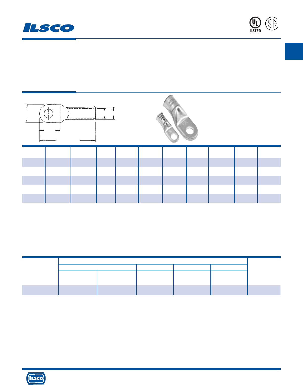
A
4730 Madison Road, Cincinnati, Ohio 45227-1426 Phone 513 533-6200 Fax 513 871-4084 Web site www.ilsco.com
Canada 1050 Lakeshore Road East, Mississauga, Ontario, Canada L5E1E4 Phone 905 274-2341 Fax 905 274-8763
32
Catalog Wire Alt Bolt Tang Tang Tang Overall Die
Number Size Wire Size Size Length Width Thickness Length Color Code I.D. O.D.
CCL-8-10 8 AWG 8 FLEX #8-#10 0.579 0.445 0.071 1.201 RED 0.185 0.256
CCL-8-14 8 AWG 8 FLEX 1/4 0.579 0.445 0.071 1.201 RED 0.185 0.256
CCL-8-516 8 AWG 8 FLEX 5/16 0.724 0.598 0.059 1.276 RED 0.185 0.256
CCL-8-38 8 AWG 8 FLEX 3/8 0.724 0.598 0.059 1.276 RED 0.185 0.256
CCL-8-12 8 AWG 8 FLEX 1/2 0.858 0.752 0.059 1.480 RED 0.185 0.256
Standard Stranded Conductor
ILSCO Burndy Thomas & Betts AET
MT-25 ILC-10-N MY29-3 M 5 406
Catalog Hand Dieless Die No. Hand Dieless Color
Number No. of Crimps No. of Crimps No. of Crimps Code
CCL-8 - Red - -
(2) (1) Red
Copper Compression Lugs
Conductor Size #8
TYPE
CCL
Features
•
Electro-tin plated
•
Sight hole for visual inspection of proper cable insertion
•
Solid seamless tang for performance and strength
•
Electrolytic copper for high conductivity
•
UL 486A 90˚ C Listed and CSA Certified
•
For copper conductor only
•
Installing Tool: MT-25
453G
L
R
-
2
9
6
0
1
CONTINUED ON NEXT PAGE.
UL Listed and CSA Certified 600 volts maximum when installed with tools and dies shown above. If proper high voltage spacings and insulation techniques are used, these
compression connectors can be used for high voltage applications up to 35KV.
UL File E6207
Tooling Information
Overall Length
Tang
Length
Tang
Width O.D.
I.D.
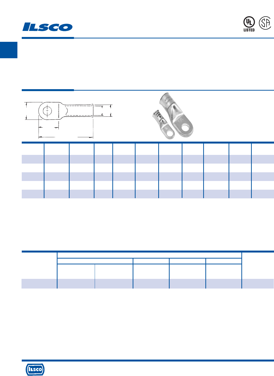
A
4730 Madison Road, Cincinnati, Ohio 45227-1426 Phone 513 533-6200 Fax 513 871-4084 Web site www.ilsco.com
Canada 1050 Lakeshore Road East, Mississauga, Ontario, Canada L5E1E4 Phone 905 274-2341 Fax 905 274-8763
33
Copper Compression Lugs
Conductor Size #6
TYPE
CCL
Features
•
Electro-tin plated
•
Sight hole for visual inspection of proper cable insertion
•
Solid seamless tang for performance and strength
•
Electrolytic copper for high conductivity
•
UL 486A 90˚ C Listed and CSA Certified
•
For copper conductor only
•
Installing Tool: MT-25
Catalog Wire Alt Bolt Tang Tang Tang Overall Die
Number Size Wire Size Size Length Width Thickness Length Color Code I.D. O.D.
CCL-6-10 6 AWG 6 FLEX #10 0.579 0.445 0.075 1.268 BLUE 0.232 0.299
CCL-6-14 6 AWG 6 FLEX 1/4 0.579 0.445 0.075 1.268 BLUE 0.232 0.299
CCL-6-516 6 AWG 6 FLEX 5/16 0.724 0.598 0.067 1.409 BLUE 0.232 0.299
CCL-6-38 6 AWG 6 FLEX 3/8 0.724 0.598 0.067 1.409 BLUE 0.232 0.299
CCL-6-12 6 AWG 6 FLEX 1/2 0.858 0.752 0.059 1.551 BLUE 0.232 0.299
Standard Stranded Conductor
ILSCO Burndy Thomas & Betts AET
MT-25 ILC-10-N MY29-3 M 5 406
Catalog Hand Dieless Die No. Hand Dieless Color
Number No. of Crimps No. of Crimps No. of Crimps Code
CCL-6 - Blue Blue A/1
(2) (1) (1) Blue
CONTINUED ON NEXT PAGE.
Tooling Information
UL Listed and CSA Certified 600 volts maximum when installed with tools and dies shown above. If proper high voltage spacings and insulation techniques are used, these
compression connectors can be used for high voltage applications up to 35KV.
UL File E6207
Overall Length
Tang
Length
Tang
Width O.D.
I.D.
453G
L
R
-
2
9
6
0
1

A
4730 Madison Road, Cincinnati, Ohio 45227-1426 Phone 513 533-6200 Fax 513 871-4084 Web site www.ilsco.com
Canada 1050 Lakeshore Road East, Mississauga, Ontario, Canada L5E1E4 Phone 905 274-2341 Fax 905 274-8763
34
Copper Compression Lugs
Conductor Size #4
TYPE
CCL
Features
•
Electro-tin plated
•
Sight hole for visual inspection of proper cable insertion
•
Solid seamless tang for performance and strength
•
Electrolytic copper for high conductivity
•
UL 486A 90˚ C Listed and CSA Certified
•
For copper conductor only
•
Installing Tool: MT-25
Standard Stranded Conductor
ILSCO Burndy Thomas & Betts AET
MT-25 ILC-10-N MY29-3 M 5 406
Catalog Hand Dieless Die No. Hand Dieless Color
Number No. of Crimps No. of Crimps No. of Crimps Code
CCL-4 Grey Grey A/1
(1) (2) (1) (1) Grey
CONTINUED ON NEXT PAGE.
Dimensions in inches – approximate.
Tooling Information
Catalog Wire Alt Bolt Tang Tang Tang Overall Die
Number Size Wire Size Size Length Width Thickness Length Color Code I.D. O.D.
CCL-4-10 4 AWG 4 FLEX #10 0.681 0.516 0.075 1.496 GRAY 0.283 0.362
CCL-4-14 4 AWG 4 FLEX 1/4 0.681 0.516 0.075 1.496 GRAY 0.283 0.362
CCL-4-516 4 AWG 4 FLEX 5/16 0.728 0.626 0.075 1.496 GRAY 0.283 0.362
CCL-4-38 4 AWG 4 FLEX 3/8 0.728 0.626 0.075 1.496 GRAY 0.283 0.362
CCL-4-12 4 AWG 4 FLEX 1/2 0.858 0.752 0.091 1.681 GRAY 0.283 0.362
UL Listed and CSA Certified 600 volts maximum when installed with tools and dies shown above. If proper high voltage spacings and insulation techniques are used, these
compression connectors can be used for high voltage applications up to 35KV.
UL File E6207
Overall Length
Tang
Length
Tang
Width O.D.
I.D.
453G
L
R
-
2
9
6
0
1

A
4730 Madison Road, Cincinnati, Ohio 45227-1426 Phone 513 533-6200 Fax 513 871-4084 Web site www.ilsco.com
Canada 1050 Lakeshore Road East, Mississauga, Ontario, Canada L5E1E4 Phone 905 274-2341 Fax 905 274-8763
35
Copper Compression Lugs
Conductor Range #1-#2
TYPE
CCL
Features
•
Electro-tin plated
•
Sight hole for visual inspection of proper cable insertion
•
Solid seamless tang for performance and strength
•
Electrolytic copper for high conductivity
•
UL 486A 90˚ C Listed and CSA Certified
•
For copper conductor only
•
Installing Tool: MT-25
Standard Stranded Conductor
ILSCO Burndy Thomas & Betts AET
MT-25 ILC-10-N MY29-3 M 5 406
Catalog Hand Dieless Die No. Hand Dieless Color
Number No. of Crimps No. of Crimps No. of Crimps Code
CCL-2 Brown Brown C/1
(1) (2) (1) (1) Brown
CCL-1 Green Green C/1
(1) (2) (1) (1) Green
CONTINUED ON NEXT PAGE.
Tooling Information
Catalog Wire Alt Bolt Tang Tang Tang Overall Die
Number Size Wire Size Size Length Width Thickness Length Color Code I.D. O.D.
CCL-2-14 2 AWG 3 FLEX 1/4 0.728 0.598 0.094 1.606 BROWN 0.335 0.429
CCL-2-516 2 AWG 3 FLEX 5/16 0.728 0.598 0.094 1.606 BROWN 0.335 0.429
CCL-2-38 2 AWG 3 FLEX 3/8 0.728 0.598 0.094 1.606 BROWN 0.335 0.429
CCL-2-12 2 AWG 3 FLEX 1/2 0.858 0.752 0.102 1.752 BROWN 0.335 0.429
CCL-1-14 1 AWG 2 FLEX 1/4 0.858 0.650 0.098 1.720 GREEN 0.362 0.461
CCL-1-516 1 AWG 2 FLEX 5/16 0.858 0.650 0.098 1.720 GREEN 0.362 0.461
CCL-1-38 1 AWG 2 FLEX 3/8 0.858 0.650 0.098 1.720 GREEN 0.362 0.461
CCL-1-12 1 AWG 2 FLEX 1/2 0.858 0.752 0.102 1.831 GREEN 0.362 0.461
UL Listed and CSA Certified 600 volts maximum when installed with tools and dies shown above. If proper high voltage spacings and insulation techniques are used, these
compression connectors can be used for high voltage applications up to 35KV.
UL File E6207
Overall Length
Tang
Length
Tang
Width O.D.
I.D.
453G
L
R
-
2
9
6
0
1
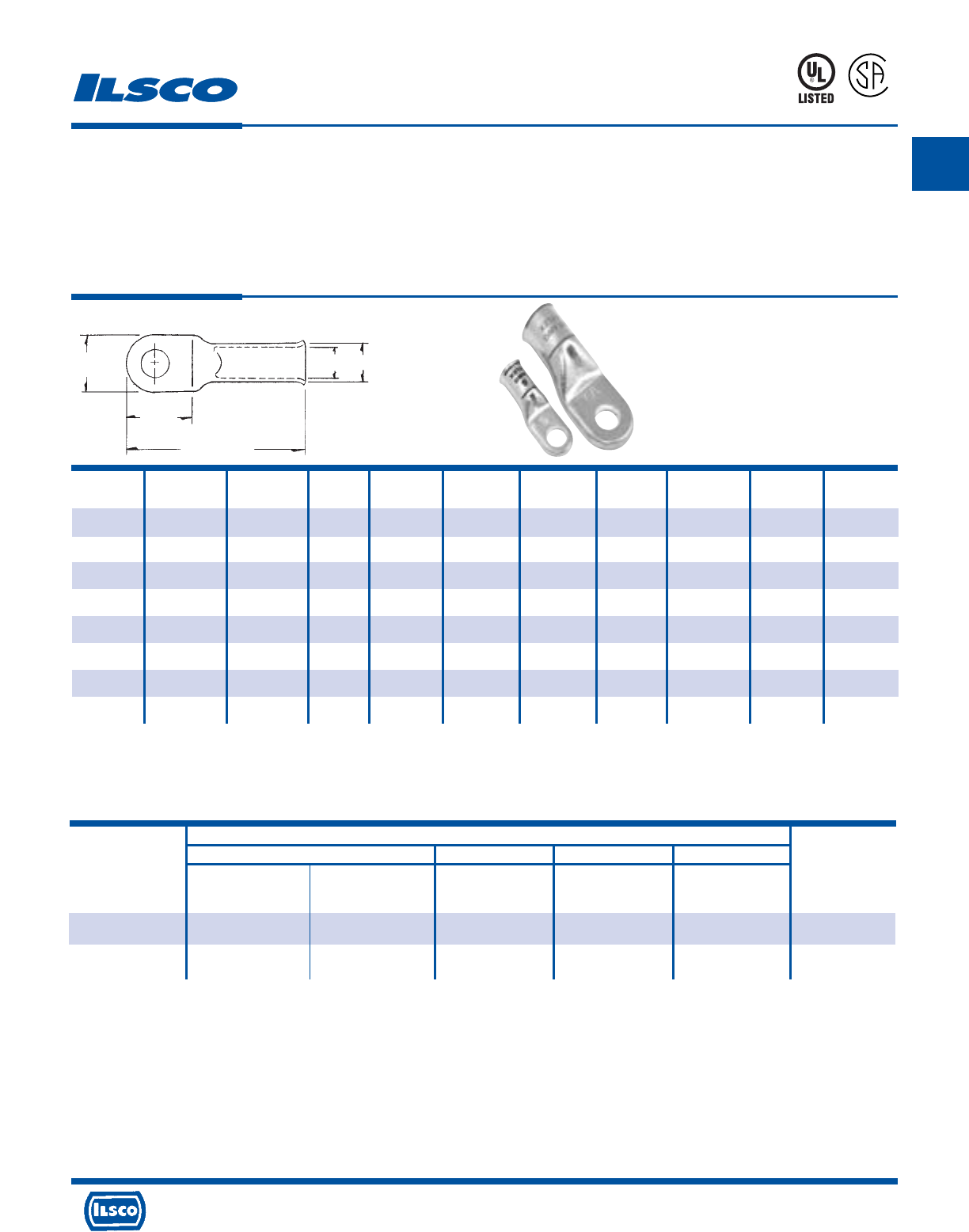
A
4730 Madison Road, Cincinnati, Ohio 45227-1426 Phone 513 533-6200 Fax 513 871-4084 Web site www.ilsco.com
Canada 1050 Lakeshore Road East, Mississauga, Ontario, Canada L5E1E4 Phone 905 274-2341 Fax 905 274-8763
36
Copper Compression Lugs
Conductor Range 2/0-1/0
TYPE
CCL
Features
•
Electro-tin plated
•
Sight hole for visual inspection of proper cable insertion
•
Solid seamless tang for performance and strength
•
Electrolytic copper for high conductivity
•
UL 486A 90˚ C Listed and CSA Certified
•
For copper conductor only
•
Installing Tool: MT-25
Standard Stranded Conductor
ILSCO Burndy Thomas & Betts AET
MT-25 ILC-10-N MY29-3 M 5 406
Catalog Hand Dieless Die No. Hand Dieless Color
Number No. of Crimps No. of Crimps No. of Crimps Code
CCL-1/0 Pink Pink B/1
(1) (2) (1) (1) Pink
CCL-2/0 Black B/1
(1) - (1) (1) Black
Tooling Information
CONTINUED ON NEXT PAGE.
Catalog Wire Alt Bolt Tang Tang Tang Overall Die
Number Size Wire Size Size Length Width Thickness Length Color Code I.D. O.D.
CCL-1/0-14 1/0 AWG 1 FLEX 1/4 0.791 0.713 0.110 1.831 PINK 0.406 0.516
CCL-1/0-516 1/0 AWG 1 FLEX 5/16 0.791 0.713 0.110 1.831 PINK 0.406 0.516
CCL-1/0-38 1/0 AWG 1 FLEX 3/8 0.791 0.713 0.110 1.831 PINK 0.406 0.516
CCL-1/0-12 1/0 AWG 1 FLEX 1/2 0.890 0.815 0.110 1.902 PINK 0.406 0.516
CCL-2/0-14 2/0 AWG 1/0 FLEX 1/4 0.929 0.815 0.110 2.055 BLACK 0.461 0.571
CCL-2/0-516 2/0 AWG 1/0 FLEX 5/16 0.929 0.815 0.110 2.055 BLACK 0.461 0.571
CCL-2/0-38 2/0 AWG 1/0 FLEX 3/8 0.929 0.815 0.110 2.055 BLACK 0.461 0.571
CCL-2/0-12 2/0 AWG 1/0 FLEX 1/2 0.929 0.815 0.110 2.055 BLACK 0.461 0.571
UL Listed and CSA Certified 600 volts maximum when installed with tools and dies shown above. If proper high voltage spacings and insulation techniques are used, these
compression connectors can be used for high voltage applications up to 35KV.
UL File E6207
Overall Length
Tang
Length
Tang
Width O.D.
I.D.
453G
L
R
-
2
9
6
0
1
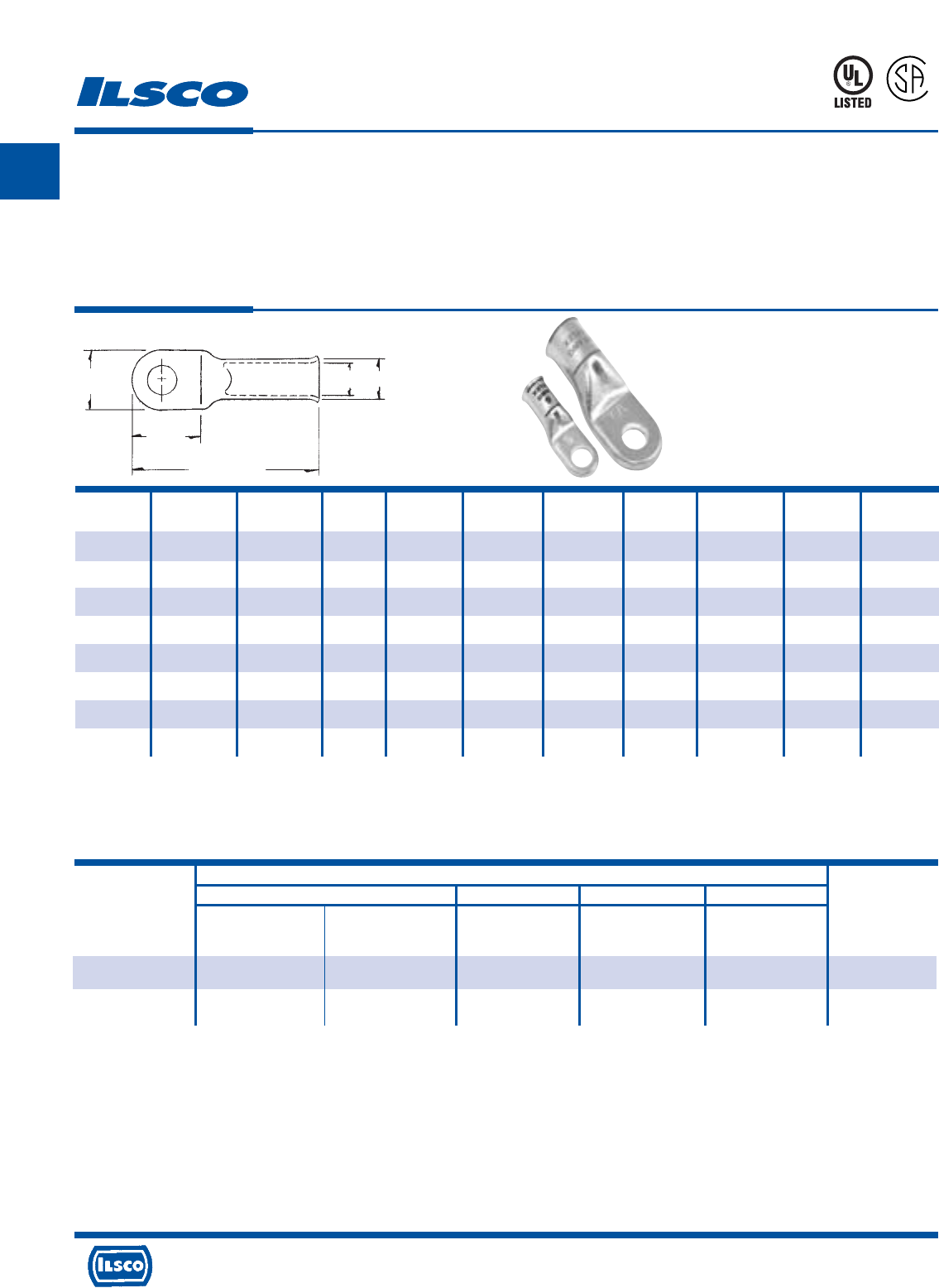
A
4730 Madison Road, Cincinnati, Ohio 45227-1426 Phone 513 533-6200 Fax 513 871-4084 Web site www.ilsco.com
Canada 1050 Lakeshore Road East, Mississauga, Ontario, Canada L5E1E4 Phone 905 274-2341 Fax 905 274-8763
37
Copper Compression Lugs
Conductor Range 4/0-3/0
TYPE
CCL
Features
•
Electro-tin plated
•
Sight hole for visual inspection of proper cable insertion
•
Solid seamless tang for performance and strength
•
Electrolytic copper for high conductivity
•
UL 486A 90˚ C Listed and CSA Certified
•
For copper conductor only
•
Installing Tool: MT-25
Standard Stranded Conductor
ILSCO Burndy Thomas & Betts AET
MT-25 ILC-10-N MY29-3 M 5 406
Catalog Hand Dieless Die No. Hand Dieless Color
Number No. of Crimps No. of Crimps No. of Crimps Code
CCL-3/0 Orange -/1
(1) - (1) (1) Orange
CCL-4/0 Purple -/1
(2) - (1) (1) Purple
Tooling Information
Catalog Wire Alt Bolt Tang Tang Tang Overall Die
Number Size Wire Size Size Length Width Thickness Length Color Code I.D. O.D.
CCL-3/0-14 3/0 AWG 2/0 FLEX 1/4 0.969 0.894 0.118 2.161 ORANGE 0.512 0.630
CCL-3/0-516 3/0 AWG 2/0 FLEX 5/16 0.969 0.894 0.118 2.161 ORANGE 0.512 0.630
CCL-3/0-38 3/0 AWG 2/0 FLEX 3/8 0.969 0.894 0.118 2.161 ORANGE 0.512 0.630
CCL-3/0-12 3/0 AWG 2/0 FLEX 1/2 0.969 0.894 0.118 2.161 ORANGE 0.512 0.630
CCL-4/0-14 4/0 AWG 3/0 FLEX 1/4 1.071 1.035 0.130 2.382 PURPLE 0.591 0.720
CCL-4/0-516 4/0 AWG 3/0 FLEX 5/16 1.071 1.035 0.130 2.382 PURPLE 0.591 0.720
CCL-4/0-38 4/0 AWG 3/0 FLEX 3/8 1.071 1.035 0.130 2.382 PURPLE 0.591 0.720
CCL-4/0-12 4/0 AWG 3/0 FLEX 1/2 1.071 1.035 0.130 2.382 PURPLE 0.591 0.720
UL Listed and CSA Certified 600 volts maximum when installed with tools and dies shown above. If proper high voltage spacings and insulation techniques are used, these
compression connectors can be used for high voltage applications up to 35KV.
UL File E6207
Overall Length
Tang
Length
Tang
Width O.D.
I.D.
453G
L
R
-
2
9
6
0
1
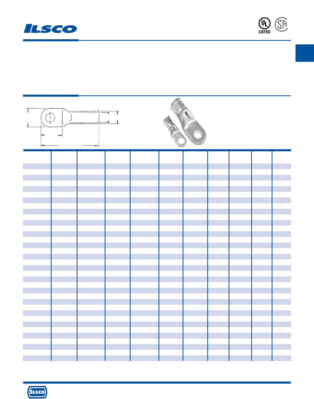
A
4730 Madison Road, Cincinnati, Ohio 45227-1426 Phone 513 533-6200 Fax 513 871-4084 Web site www.ilsco.com
Canada 1050 Lakeshore Road East, Mississauga, Ontario, Canada L5E1E4 Phone 905 274-2341 Fax 905 274-8763
38
Catalog Alt Wire Bolt Tang Tang Tang Overall Die
Number Wire Size Size Size Length Width Thickness Length Color Code I.D. O.D.
CRA-8-8/10M 8 FLEX 8 AWG #8-#10 0.579 0.445 0.071 1.201 RED 0.185 0.256
CRA-8-14M 8 FLEX 8 AWG 1/4 0.579 0.445 0.071 1.201 RED 0.185 0.256
CRA-8-516M 8 FLEX 8 AWG 5/16 0.724 0.598 0.059 1.276 RED 0.185 0.256
CRA-8-38M 8 FLEX 8 AWG 3/8 0.724 0.598 0.059 1.276 RED 0.185 0.256
CRA-8-12M 8 FLEX 8 AWG 1/2 0.858 0.752 0.059 1.480 RED 0.185 0.256
CRA-6-10M 6 FLEX 6 AWG #10 0.579 0.445 0.075 1.268 BLUE 0.232 0.299
CRA-6-14M 6 FLEX 6 AWG 1/4 0.579 0.445 0.075 1.268 BLUE 0.232 0.299
CRA-6-516-M 6 FLEX 6 AWG 5/16 0.724 0.598 0.067 1.409 BLUE 0.232 0.299
CRA-6-38M 6 FLEX 6 AWG 3/8 0.724 0.598 0.067 1.409 BLUE 0.232 0.299
CRA-6-12M 6 FLEX 6 AWG 1/2 0.858 0.752 0.059 1.551 BLUE 0.232 0.299
CRA-4-10M 4 FLEX 4 AWG #10 0.681 0.516 0.075 1.496 GRAY 0.283 0.362
CRA-4-14M 4 FLEX 4 AWG 1/4 0.681 0.516 0.075 1.496 GRAY 0.283 0.362
CRA-4-516M 4 FLEX 4 AWG 5/16 0.728 0.626 0.075 1.496 GRAY 0.283 0.362
CRA-4-38M 4 FLEX 4 AWG 3/8 0.728 0.626 0.075 1.496 GRAY 0.283 0.362
CRA-4-12M 4 FLEX 4 AWG 1/2 0.858 0.752 0.091 1.681 GRAY 0.283 0.362
CRA-2-14M 2 FLEX 1 AWG 1/4 0.858 0.650 0.098 1.720 GREEN 0.362 0.461
CRA-2-516M 2 FLEX 1 AWG 5/16 0.858 0.650 0.098 1.720 GREEN 0.362 0.461
CRA-2-38M 2 FLEX 1 AWG 3/8 0.858 0.650 0.098 1.720 GREEN 0.362 0.461
CRA-2-12M 2 FLEX 1 AWG 1/2 0.858 0.752 0.102 1.831 GREEN 0.362 0.461
CRA-1-14M 1 FLEX 1/0 AWG 1/4 0.791 0.713 0.110 1.831 PINK 0.406 0.516
CRA-1-516M 1 FLEX 1/0 AWG 5/16 0.791 0.713 0.110 1.831 PINK 0.406 0.516
CRA-1-38M 1 FLEX 1/0 AWG 3/8 0.791 0.713 0.110 1.831 PINK 0.406 0.516
CRA-1-12M 1 FLEX 1/0 AWG 1/2 0.890 0.815 0.110 1.902 PINK 0.406 0.516
CRA-1/0-14M 1/0 FLEX 2/0 AWG 1/4 0.929 0.815 0.110 2.055 BLACK 0.461 0.571
CRA-1/0-516M 1/0 FLEX 2/0 AWG 5/16 0.929 0.815 0.110 2.055 BLACK 0.461 0.571
CRA-1/0-38M 1/0 FLEX 2/0 AWG 3/8 0.929 0.815 0.110 2.055 BLACK 0.461 0.571
CRA-1/0-12M 1/0 FLEX 2/0 AWG 1/2 0.929 0.815 0.110 2.055 BLACK 0.461 0.571
CRA-2/0-14M 2/0 FLEX 3/0 AWG 1/4 0.969 0.894 0.118 2.161 ORANGE 0.512 0.630
CRA-2/0-516M 2/0 FLEX 3/0 AWG 5/16 0.969 0.894 0.118 2.161 ORANGE 0.512 0.630
CRA-2/0-38-M 2/0 FLEX 3/0 AWG 3/8 0.969 0.894 0.118 2.161 ORANGE 0.512 0.630
CRA-2/0-12M 2/0 FLEX 3/0 AWG 1/2 0.969 0.894 0.118 2.161 ORANGE 0.512 0.630
CRA-3/0-38M 3/0 FLEX 4/0 AWG 3/8 1.071 1.035 0.130 2.382 PURPLE 0.591 0.720
CRA-3/0-12M 3/0 FLEX 4/0 AWG 1/2 1.071 1.035 0.130 2.382 PURPLE 0.591 0.720
CRA-4/0-38M 4/0 FLEX 250 kcmil 3/8 1.228 1.201 0.130 2.614 YELLOW 0.685 0.815
CRA-4/0-12M 4/0 FLEX 250 kcmil 1/2 1.228 1.201 0.130 2.614 YELLOW 0.685 0.815
Copper Mining Lugs
For copper conductor only
TYPE
CRAM
Features
•
Electro-tin plated
•
Sight hole for visual inspection
•
Solid seamless tang for performance and strength
•
Electrolytic copper for high conductivity
•
UL 486A 90˚C Listed and CSA Certified
•
For copper conductor only
•
Installing Tool: MT-25
Overall Length
Tang
Length
Tang
Width O.D.
I.D.
453G
L
R
-
2
9
6
0
1
UL File E6207
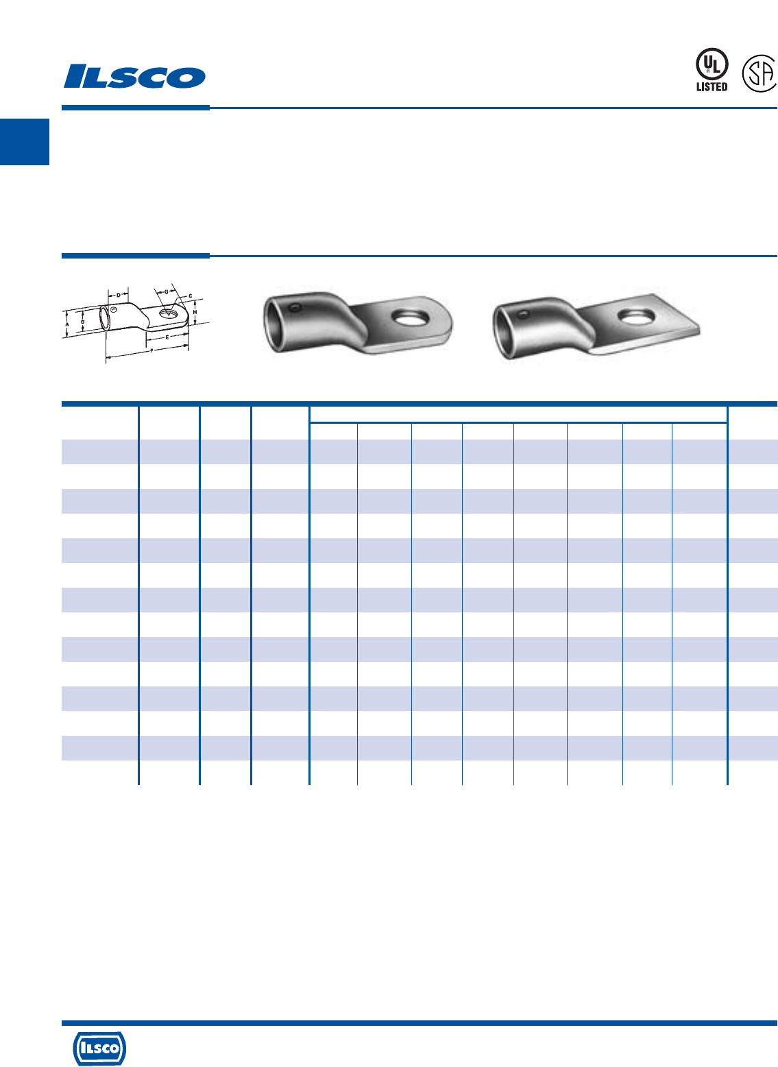
A
4730 Madison Road, Cincinnati, Ohio 45227-1426 Phone 513 533-6200 Fax 513 871-4084 Web site www.ilsco.com
Canada 1050 Lakeshore Road East, Mississauga, Ontario, Canada L5E1E4 Phone 905 274-2341 Fax 905 274-8763
39
Catalog Number Old Figure Wire Dimensions Amp
A Description Number Size B Bolt Size C D E F G H Rating
3/16 25A 1 10 9/64 #8 11/64 11/32 15/32 15/16 3/16 1/4 25 Amp
1/4 35A 1 8 3/16 #10 13/64 11/32 1/2 1-1/32 7/32 3/8 35 Amp
5/16 50A 1 6 15/64 #10 13/64 13/32 19/32 1-7/32 1/4 7/16 50 Amp
3/8 70A 1 4 9/32 1/4 9/32 7/16 11/16 1-3/8 9/32 17/32 70 Amp
7/16 90A 1 2 11/32 1/4 9/32 1/2 3/4 1-1/2 11/32 5/8 90 Amp
1/2 125A 1 1/0 25/64 5/16 11/32 9/16 13/16 1-3/4 13/32 3/4 125 Amp
9/16 150A 1 2/0 15/32 3/8 13/32 11/16 15/16 2 7/16 13/16 150 Amp
5/8 175A 1 3/0 33/64 3/8 13/32 25/32 1 2-1/8 1/2 29/32 175 Amp
11/16 225A 1 4/0 9/16 3/8 13/32 27/32 1-5/32 2-3/8 17/32 31/32 225 Amp
13/16 250A 1 250kcmil 43/64 3/8 13/32 31/32 1-1/4 2-21/32 5/8 1-3/16 250 Amp
1-1/8 450A 2 600kcmil 61/64 3/8 13/32 1-1/2 2-1/4 4-7/16 1 1-5/8 450 Amp
1-5/16 550A 2 800kcmil 1-3/32 1/2 17/32 1-13/16 2-1/2 5-1/16 1-1/8 1-15/16 550 Amp
1-7/16 650A 2 1000kcmil 1-7/32 7/8 29/32 2 2-1/2 5-3/8 1-3/16 2-1/8 650 Amp
1-3/4 850A 2 1500kcmil 1-15/32 1 1-1/32 2-3/8 3-1/8 6-5/8 1-7/16 2-5/8 850 Amp
Copper Soldering Lugs
One Hole
TYPE
Solder
Lugs
Features
•
Manufactured from high strength copper tubing
•
Seamless construction
•
Clearly marked with wire size
•
UL Listed and CSA Certified for 600 volts, 90˚ C
Benefits
•
Provides maximum conductivity
•
Won’t leak solder
•
Provides easy identification
•
Ensures reliability
453G
L
R
-
2
9
6
0
1
Fig. 1 Fig. 2
Tested to UL 486A-486B, UL File E6207
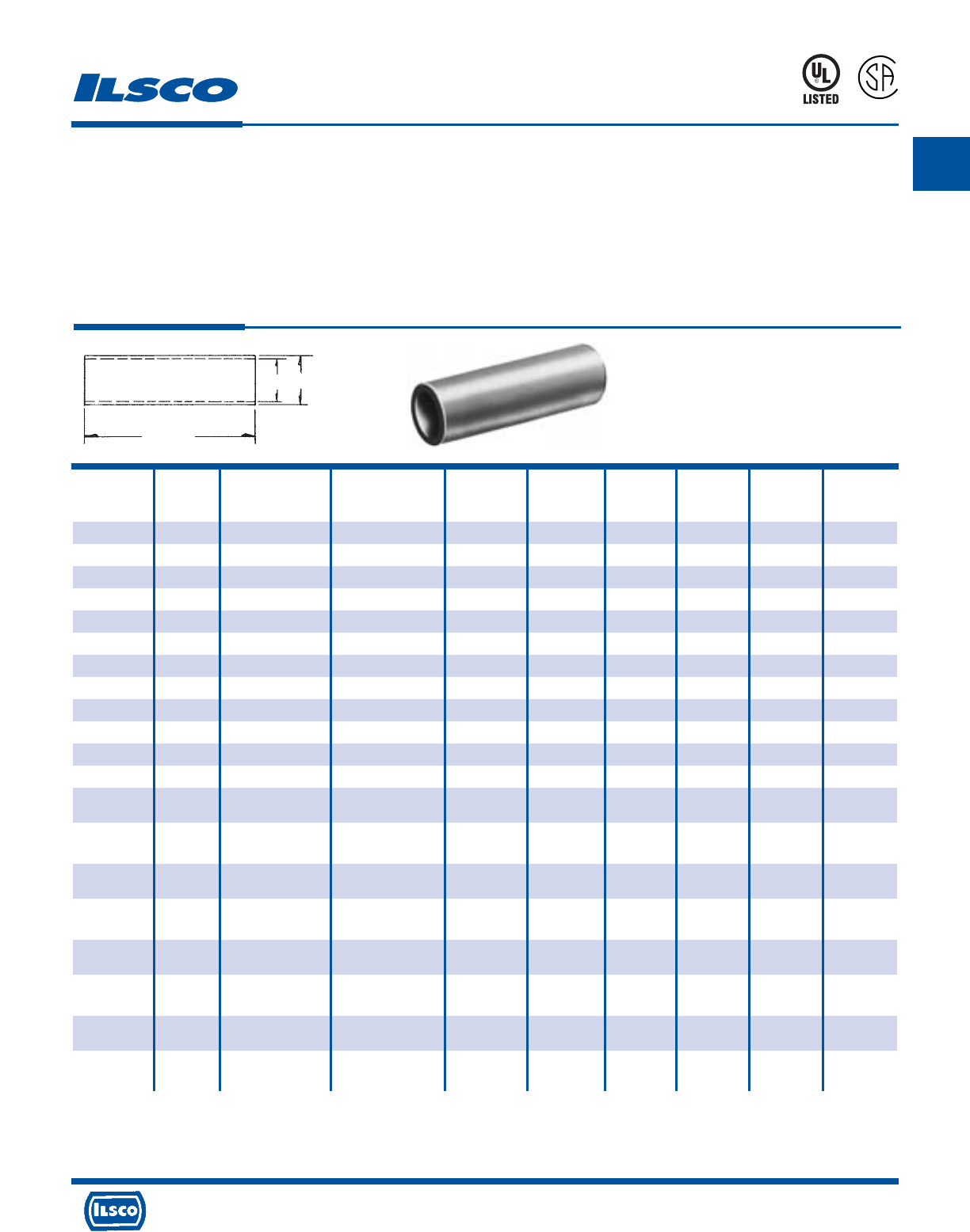
A
4730 Madison Road, Cincinnati, Ohio 45227-1426 Phone 513 533-6200 Fax 513 871-4084 Web site www.ilsco.com
Canada 1050 Lakeshore Road East, Mississauga, Ontario, Canada L5E1E4 Phone 905 274-2341 Fax 905 274-8763
40
Die Die
Catalog Wire Alt Expanded* Barrel Color Die Catalog
Number Size Wire Size Wire Range Length Code Index Number O.D. I.D.
CT-8 8 AWG #8 Flex - 1.125 Red I-21 ILD-21 0.272 0.179
CT-6 6 AWG - - 1.750 Blue I-24 ILD-24 0.295 0.203
CT-4 4 AWG #6 Flex 4-6 AWG 1.875 Gray I-29 ILD-29 0.343 0.250
CT-3 3 AWG #4 Flex 3-6 AWG 1.750 White I-29 ILD-29 0.375 0.275
CT-2 2 AWG - 2-6 AWG 1.875 Brown I-33 ILD-33 0.421 0.312
CT-1 1 AWG #2 Flex 1-6 AWG 1.875 Green I-37 ILD-37 0.468 0.359
CT-1/0 1/0 AWG #1 Flex 1/0-6 AWG 1.875 Pink I-42 ILD-42 0.515 0.390
CT-2/0 2/0 AWG 1/0 Flex 2/0-4 AWG 2.000 Black I-45 ILD-45 0.562 0.437
CT-3/0 3/0 AWG 2/0 Flex 3/0-2 AWG 2.125 Orange I-50 ILD-50 0.609 0.484
CT-4/0 4/0 AWG 3/0 Flex 4/0-1 AWG 2.125 Purple I-54 ILD-54 0.687 0.546
CT-250 250kcmil 4/0 Flex 250kcmil-1/0 AWG 2.250 Yellow I-62 ILD-62 0.750 0.593
CT-300 300kcmil 250 G,H Flex 300kcmil-2/0 AWG 2.250 White I-66 ILD-66 0.812 0.660
CT-350 350kcmil 250 I,K,M Flex 350kcmil-3/0 AWG 2.375 Red I-71 ILD-71 0.890 0.703
262.2 DLO
CT-400 400kcmil 300 G,H,I,K,M Flex 400kcmil-4/0 AWG 2.500 Blue I-76 ILD-76 0.937 0.750
313.1 DLO
CT-500 500kcmil 350 G,H,I,K,M Flex 500kcmil-250kcmil 2.875 Brown I-87 ILD-87 1.062 0.828
373.7 DLO
CT-600 600kcmil 400 G,H,I,K,M Flex 600kcmil-250kcmil 2.875 Green I-94 ILD-94 1.187 0.920
444.4 DLO
CT-650 650kcmil 500 G,H,I,K,M Flex 650kcmil-350kcmil 2.875 Pink I-99 ILD-99 1.222 0.962
535.3 DLO
CT-700 700kcmil 500 G,H,I,K,M Flex 700kcmil-350kcmil 3.375 Pink I-99 ILD-99 1.250 0.991
535.3 DLO
CT-750 750kcmil 600 G,H,I,M Flex 750kcmil-500kcmil 3.375 Black I-106 ILD-106 1.313 1.031
646.4 DLO
CT-1000 1000kcmil 750 G,H,I Flex 1000kcmil-750kcmil 3.875 White I-125 ILD-125 1.500 1.172
777.7 DLO
Copper Compression Sleeves - Short Barrel
Conductor Range: 1000kcmil-#8
TYPE
CT
L
R
-
2
9
6
0
1
453G
Features
•
Manufactured from high strength seamless copper tubing.
•
Electro-Tin plated.
•
Maximum conductivity and excellent crimping characteristics.
•
Chamfered entry.
•
Color coded.
•
UL 486A 90°C Listed and CSA Certified for 600 Volts.
•
If proper high voltage spacing and insulation techniques are used, may be used for high voltage applications up to 35KV.
•
For Copper conductor only.
•
Ilsco connectors are UL Listed and CSA Certified with ILSCO or other Manufacturers' tools.
•
UL File E6207
* When installed with specified dieless tools
See pages 90 to 97 for complete tooling information.
Length
I.D. O.D.
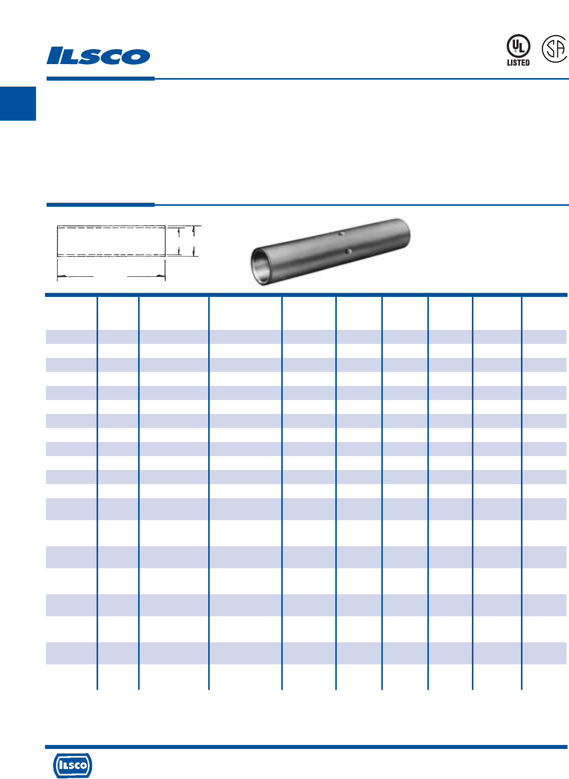
A
4730 Madison Road, Cincinnati, Ohio 45227-1426 Phone 513 533-6200 Fax 513 871-4084 Web site www.ilsco.com
Canada 1050 Lakeshore Road East, Mississauga, Ontario, Canada L5E1E4 Phone 905 274-2341 Fax 905 274-8763
41
Die Die
Catalog Wire Alt Expanded* Barrel Color Die Catalog
Number Size Wire Size Wire Range Length Code Index Number O.D. I.D.
CTL-8 8 AWG - - 1.75 Red I-21 ILD-21 0.272 0.179
CTL-6 6 AWG - - 2.375 Blue I-24 ILD-24 0.295 0.203
CTL-4 4 AWG #6 Flex 4-6 AWG 2.375 Gray I-29 ILD-29 0.343 0.250
CTL-3 3 AWG #4 Flex 3-6 AWG 2.375 White I-29 ILD-29 0.375 0.275
CTL-2 2 AWG - 2-6 AWG 2.625 Brown I-33 ILD-33 0.421 0.312
CTL-1 1 AWG #2 Flex 1-6 AWG 2.875 Green I-37 ILD-37 0.468 0.359
CTL-1/0 1/0 AWG #1 Flex 1/0-6 AWG 2.875 Pink I-42 ILD-42 0.515 0.390
CTL-2/0 2/0 AWG 1/0 Flex 2/0-4 AWG 3.125 Black I-45 ILD-45 0.562 0.437
CTL-3/0 3/0 AWG 2/0 Flex 3/0-2 AWG 3.125 Orange I-50 ILD-50 0.609 0.484
CTL-4/0 4/0 AWG 3/0 Flex 4/0-1 AWG 3.375 Purple I-54 ILD-54 0.687 0.546
CTL-250 250kcmil 4/0 Flex 250kcmil-1/0 AWG 3.375 Yellow I-62 ILD-62 0.750 0.593
CTL-300 300kcmil 250 G,H Flex 300kcmil-2/0 AWG 4.125 White I-66 ILD-66 0.812 0.660
CTL-350 350kcmil 250 I,K,M Flex 350kcmil-3/0 AWG 4.125 Red I-71 ILD-71 0.890 0.703
262.2 DLO
CTL-400 400kcmil 300 G,H,I,K,M Flex 400kcmil-4/0 AWG 4.375 Blue I-76 ILD-76 0.937 0.750
313.1 DLO
CTL-500 500kcmil 350 G,H,I,K,M Flex 500kcmil-250kcmil 4.625 Brown I-87 ILD-87 1.062 0.828
373.7 DLO
CTL-600 600kcmil 400 G,H,I,K,M Flex 600kcmil-250kcmil 4.625 Green I-94 ILD-94 1.187 0.920
444.4 DLO
CTL-650 650kcmil 500 G,H,I,K,M Flex 650kcmil-350kcmil 4.625 Pink I-99 ILD-99 1.222 0.962
535.3 DLO
CTL-700 700kcmil 500 G,H,I,K,M Flex 700kcmil-350kcmil 5.875 Pink I-99 ILD-99 1.250 0.991
535.3 DLO
CTL-750 750kcmil 600 G,H,I,M Flex 750kcmil-500kcmil 5.875 Black I-106 ILD-106 1.313 1.031
646.4 DLO
CTL-1000 1000kcmil 750 G,H,I Flex 1000kcmil-750kcmil 6.125 White I-125 ILD-125 1.500 1.172
777.7 DLO
Copper Compression Sleeves - Long Barrel
Conductor Range: 1000kcmil-#6
TYPE
CTL
L
R
-
2
9
6
0
1
453G
Features
•
Manufactured from high strength seamless copper tubing.
•
Electro-Tin plated.
•
Maximum conductivity and excellent crimping characteristics.
•
Chamfered entry.
•
Color coded.
•
UL 486A 90°C Listed and CSA Certified for 600 Volts.
•
If proper high voltage spacing and insulation techniques are used, may be used for high voltage applications up to 35KV.
•
For Copper conductor only.
•
Ilsco connectors are UL Listed and CSA Certified with ILSCO or other Manufacturers' tools.
•
UL File E6207
* When installed with specified dieless tools
See pages 90 to 97 for complete tooling information.
Length
I.D. O.D.
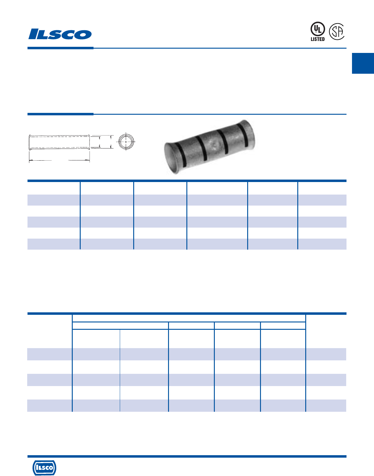
A
4730 Madison Road, Cincinnati, Ohio 45227-1426 Phone 513 533-6200 Fax 513 871-4084 Web site www.ilsco.com
Canada 1050 Lakeshore Road East, Mississauga, Ontario, Canada L5E1E4 Phone 905 274-2341 Fax 905 274-8763
42
Catalog Wire Color
Number Size Code L O.D. I.D.
CCS-8 8 Red 49/64 1/4 11/64
CCS-6 6 Blue 1-1/16 5/16 15/64
CCS-4 4 Grey 1-13/64 23/64 9/32
CCS-2 2 Brown 1-23/64 7/16 21/64
CCS-1 1 Green 1-23/64 15/32 23/64
Copper Compression Sleeves - Light Duty
Conductor Range #1-#8
TYPE
CCS
Features
•
Manufactured from high strength copper
•
Electro-tin plated
•
UL Listed and CSA Certified for 600 volts, 90˚ C
•
Color coded
•
Sight hole
•
Flared end
Benefits
•
Provides maximum conductivity and excellent
crimping characteristics
•
Provides low contact resistance
•
Ensures reliability for copper conductors
•
Provides visual tooling recommendation for Ilsco or
standard industry tools
•
Allows visual cable inspection
•
Easy wire insertion
8M24
A
P
-
1
0
0
9
7
3
-
1
CONTINUED ON NEXT PAGE.
UL Listed and CSA Certified 600 volts maximum when installed with tools and dies shown above. If proper high voltage spacings and insulation techniques are used, these
compression connectors can be used for high voltage applications up to 35KV. See stuffer sheet for complete information on tooling.
UL File E158587
Standard Stranded Conductor
ILSCO Burndy Thomas & Betts AET
MT-25 ILC-10-N MY29-3 M 5 406
Catalog Hand Dieless Die No. Hand Dieless Color
Number No. of Crimps No. of Crimps No. of Crimps Code
CCS-8 - Red - -
(2) (1) Red
CCS-6 - Blue Blue A/1
(2) (1) (1) Blue
CCS-4 Grey Grey A/1
(1) (2) (1) (1) Grey
CCS-2 Brown Brown C/1
(1) (2) (1) (1) Brown
CCS-1 Green Green C/1
(1) (2) (1) (1) Green
Tooling Information
L
I.D. O.D.
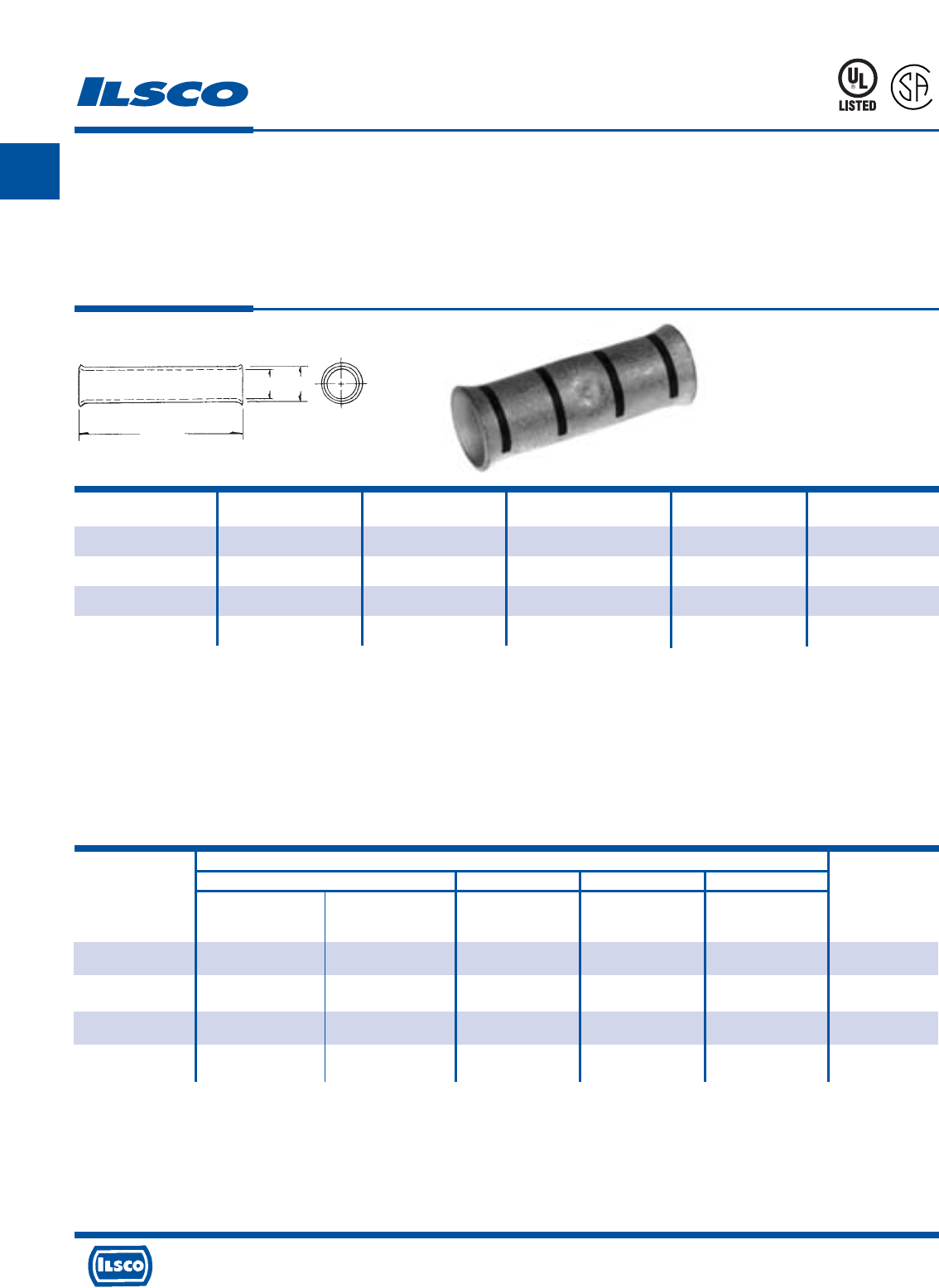
A
4730 Madison Road, Cincinnati, Ohio 45227-1426 Phone 513 533-6200 Fax 513 871-4084 Web site www.ilsco.com
Canada 1050 Lakeshore Road East, Mississauga, Ontario, Canada L5E1E4 Phone 905 274-2341 Fax 905 274-8763
43
Catalog Wire Color
Number Size Code L O.D. I.D.
CCS-1/0 1/0 Pink 1-35/64 33/64 13/32
CCS-2/0 2/0 Black 1-51/64 37/64 15/32
CCS-3/0 3/0 Orange 1-29/32 5/8 33/64
CCS-4/0 4/0 Purple 2 11/16 9/16
Copper Compression Sleeves - Light Duty
Conductor Range 4/0-1/0
TYPE
CCS
Features
•
Manufactured from high strength copper
•
Electro-tin plated
•
UL Listed and CSA Certified for 600 volts, 90˚ C
•
Color coded
•
Sight hole
•
Flared end
Benefits
•
Provides maximum conductivity and excellent
crimping characteristics
•
Provides low contact resistance
•
Ensures reliability for copper conductors
•
Provides visual tooling recommendation for Ilsco or
standard industry tools
•
Allows visual inspection
•
Easy wire insertion
8M24
A
P
-
1
0
0
9
7
3
-
1
UL Listed and CSA Certified 600 volts maximum when installed with tools and dies shown above. If proper high voltage spacings and insulation techniques are used, these
compression connectors can be used for high voltage applications up to 35KV. See stuffer sheet for complete information on tooling.
UL File E158587
Standard Stranded Conductor
ILSCO Burndy Thomas & Betts AET
MT-25 ILC-10-N MY29-3 M 5 406
Catalog Hand Dieless Die No. Hand Dieless Color
Number No. of Crimps No. of Crimps No. of Crimps Code
CCS-1/0 Pink Pink B/1
(1) (2) (1) (1) Pink
CCS-2/0 Black B/1
(1) - (1) (1) Black
CCS-3/0 Orange -/1
(1) - (1) (1) Orange
CCS-4/0 Purple -/1
(2) - (2) (1) Purple
Tooling Information
L
I.D. O.D.
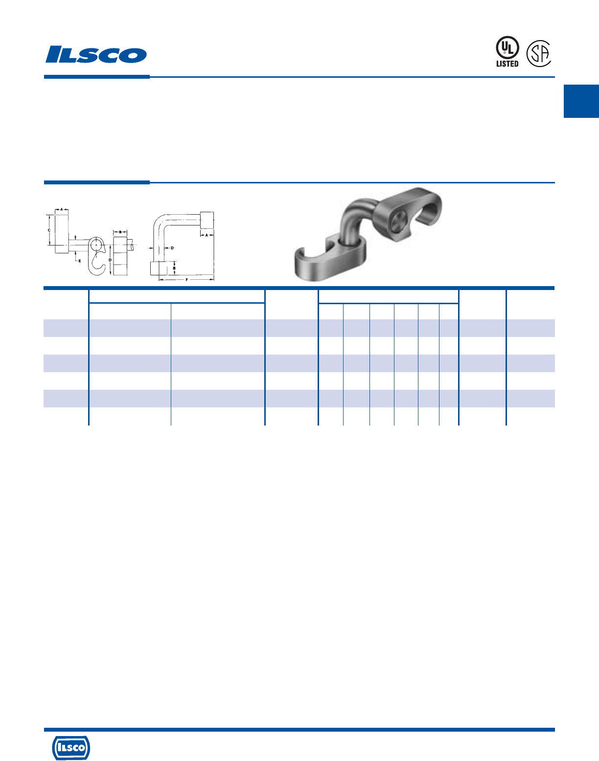
A
4730 Madison Road, Cincinnati, Ohio 45227-1426 Phone 513 533-6200 Fax 513 871-4084 Web site www.ilsco.com
Canada 1050 Lakeshore Road East, Mississauga, Ontario, Canada L5E1E4 Phone 905 274-2341 Fax 905 274-8763
44
Wire Range Dimensions A B
Catalog Rod Die Die
Number Main Tap Size A B C D E F Index Index
GGA-1 2str-6sol 2str-6sol - .75 .75 1.09 1.09 .313 2.50 O O
GGA-2 250kcmil-1str 2str-6sol 1/2, 5/8 .75 .75 1.66 1.09 .313 2.50 997 O
GGA-3 250kcmil-2str 250kcmil-2str 1/2, 5/8 .75 .75 1.66 1.66 .500 2.50 997 997
GGA-4 500kcmil-250kcmil 2str-6sol 5/8, 3/4 .75 .75 2.09 1.09 .313 2.50 998 O
GGA-5 500kcmil-250kcmil 250kcmil-2str 5/8, 3/4 .75 .75 2.09 1.66 .500 2.50 998 997
GGA-6 500kcmil-250kcmil 500kcmil-250kcmil 5/8, 3/4 .75 .75 2.28 2.28 .750 2.50 999/1011 999/1011
Grounding Grid Connectors
TYPE
GGA
Features
•
Manufactured from high strength copper alloy
•
Clearly marked with wire size and die index
•
Range taking
•
Connector can be adjusted prior to installation
•
Non-hazardous installation
•
Prefilled with inhibiting compound
•
Temperature Rating 90˚ C
Benefits
•
Provides maximum conductivity and eliminates the possibility of
corrosion. Suitable for direct burial.
•
Provides easy identification and tooling recommendation
•
Reduces inventory. Six sizes cover a wire range from 500kcmil to #6,
and 1/2" to 3/4" ground rods.
•
Permits adjustments to be made for misaligned cross grids
•
Can be installed in all types of weather with no need for protective
equipment or clothing. Does not produce heat or dangerous particles.
•
Prevents oxides from forming
•
Ensures reliability
NOTE: Hydraulic tools required on all sizes except GGA-1
Dieless tools can not be used
L
R
-
5
4
6
5
667P
Tested to UL 467, UL File E34440
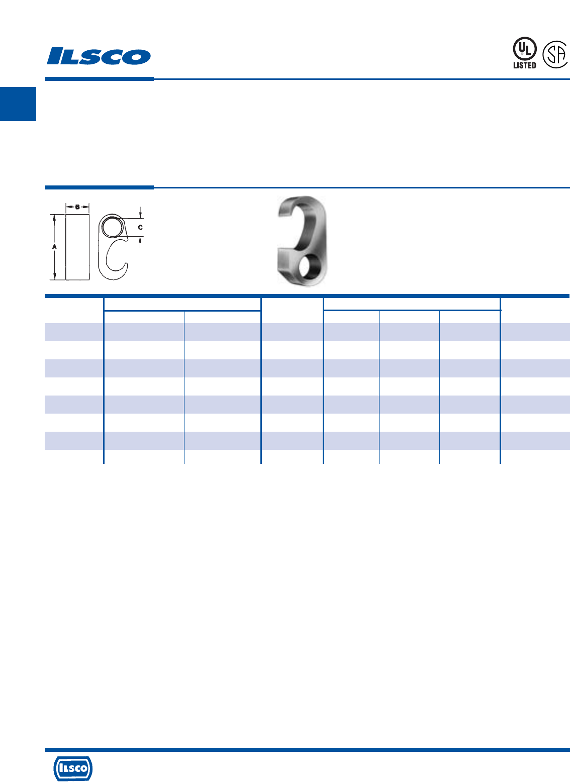
A
4730 Madison Road, Cincinnati, Ohio 45227-1426 Phone 513 533-6200 Fax 513 871-4084 Web site www.ilsco.com
Canada 1050 Lakeshore Road East, Mississauga, Ontario, Canada L5E1E4 Phone 905 274-2341 Fax 905 274-8763
45
Catalog Wire Range Rod Dimensions
Number Main Tap Size A B C Index
GGC-1 2str-6sol 2str-6sol - 1.4 .75 .33 0
GGC-2 250kcmil-1/0str 2str-4sol 1/2, 5/8 2.1 .75 .33 997
GGC-3 250kcmil-1/0str 2/0str-1/0str 1/2, 5/8 2.1 .75 .44 997
GGC-4 250kcmil-1/0str 250kcmil-3/0str 1/2, 5/8 2.1 .75 .61 997
GGC-5 500kcmil-250kcmil 2str-4sol 5/8, 3/4 2.6 .75 .33 998
GGC-6 500kcmil-250kcmil 2/0str-1/0str 5/8, 3/4 2.6 .75 .44 998
GGC-7 500kcmil-250kcmil 250kcmil-3/0str 5/8, 3/4 2.6 .75 .61 998
GGC-8 500kcmil-250kcmil 500kcmil-350kcmil 5/8, 3/4 2.9 .75 .84 999/1011
Grounding Grid Connectors
TYPE
GGC
Features
•
Manufactured from high strength copper alloy
•
Clearly marked with wire size and die index
•
Range taking
•
Versatile
•
Non-hazardous installation
•
Prefilled with inhibiting compound
•
Temperature Rating 90˚ C
Benefits
•
Provides maximum conductivity and eliminates the possibility of
corrosion. Suitable for direct burial.
•
Provides easy identification and tooling recommendation
•
Reduces inventory. Eight sizes cover a wire range from 500kcmil to #6,
and 1/2" to 3/4" ground rods.
•
Can be used as a tap connector or as a lap splice connector
•
Can be installed in all types of weather with no need for protective
equipment or clothing. Does not produce heat or dangerous particles.
•
Prevents oxides from forming
•
Ensures reliability
667P
NOTE: Hydraulic tools required on all sizes except GGC-1
Dieless tools can not be used
L
R
-
5
4
6
5
Tested to UL 467, UL File E34440
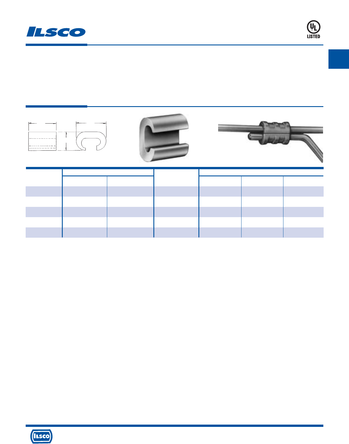
A
4730 Madison Road, Cincinnati, Ohio 45227-1426 Phone 513 533-6200 Fax 513 871-4084 Web site www.ilsco.com
Canada 1050 Lakeshore Road East, Mississauga, Ontario, Canada L5E1E4 Phone 905 274-2341 Fax 905 274-8763
46
Copper Wire Range Dimensions
Catalog Die
Number Main Tap Index L W H
ULT-4-Z 4str-6sol 6str-6sol BG or 5/8 3/4 15/32 49/64
ULT-5-Z 4str-6sol 4str-4sol BG or 5/8 3/4 15/32 27/32
ULT-6-Z 2str-2sol 6str-8sol C 7/8 5/8 1
ULT-7-Z 2str-2sol 2str-2sol C 7/8 39/64 1-1/16
ULT-12-Z 4/0str-3/0str 4/0str-3/0str F or D3 1-1/8 1 1-5/8
Copper C Crimps
TYPE
ULT
Features
•
Manufactured from high strength copper alloy
•
Clearly marked with wire size and die index
•
Range taking
•
UL Listed for 600 volts, 90˚ C
Benefits
•
Provides maximum conductivity and eliminates the
possibility of corrosion
•
Provides easy identification and tooling
recommendation
•
Reduces inventory
•
Ensures reliability
453G
L
H
W
Tested to UL 486A-486B, UL File E6207
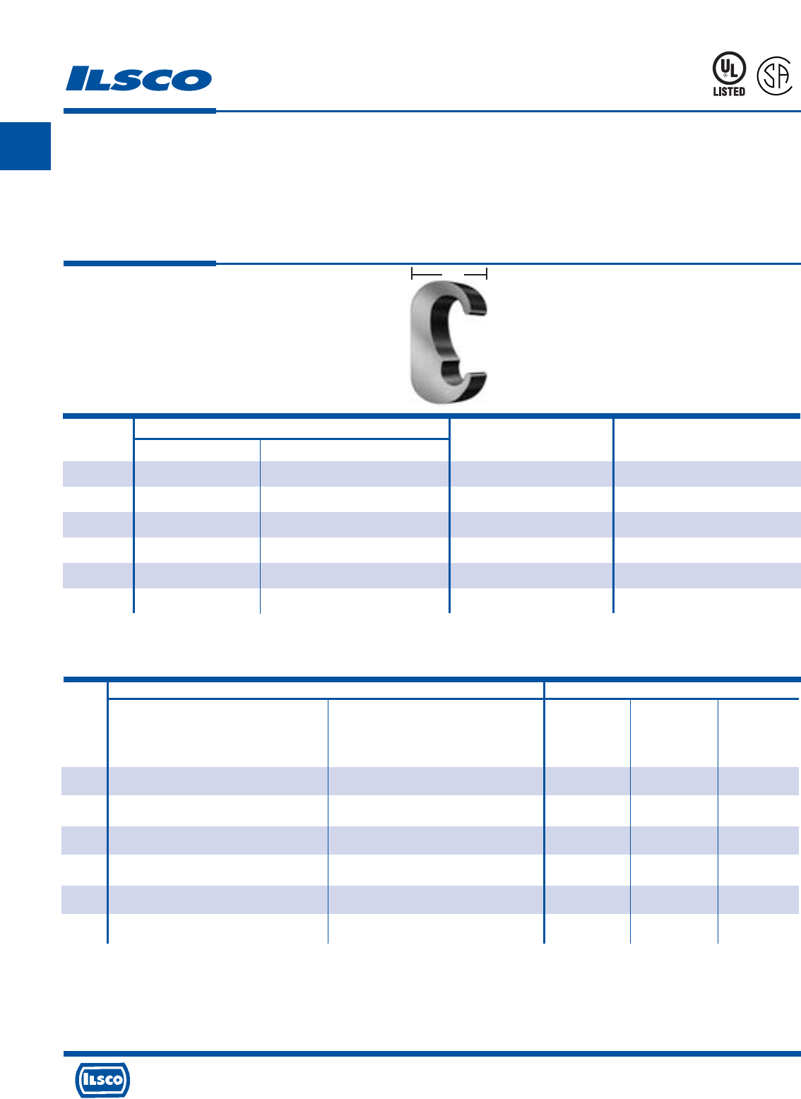
A
4730 Madison Road, Cincinnati, Ohio 45227-1426 Phone 513 533-6200 Fax 513 871-4084 Web site www.ilsco.com
Canada 1050 Lakeshore Road East, Mississauga, Ontario, Canada L5E1E4 Phone 905 274-2341 Fax 905 274-8763
47
W
ILSCO Burndy
ILC-12H-N, ILCB-12-N ILC-15H Y-35 Y-45 Y-46
ILC-12-N
Die No. Die No.
Die Index Die Index Die Index
Catalog No. of No. of No. of No. of No. of
Number Crimps Crimps Crimps Crimps Crimps
ELT-1 ILD-C - C (U Type) C (U Type) C (U Type)
(1) - (1) (1) (1)
ELT-4 ILD-O - O (U Type) O (U Type) O (U Type)
(1) - (1) (1) (1)
ELT-2 ILD-O - O (U Type) O (U Type) O (U Type)
(1) - (1) (1) (1)
ELT-5 ILD-U997 - 997 (U Type) 997 (U Type) 997 (U Type)
(1) - (1) (1) (1)
ELT-3 ILD-U997 - 997 (U Type) 997 (U Type) 997 (U Type)
(1) - (1) (1) (1)
ELT-6 ILD-U1011 ILD-P1011 - 1011 (U Type) 1011 (U Type)
(1) (2) - (2) (1)
Copper E Crimps
Grounding Connectors
TYPE
ELT
Features
•
Manufactured from copper alloy
•
Clearly marked with wire size and die index
•
Range taking
•
UL Listed and CSA Certified for grounding and bonding,
rated for 600 volts
•
May be used in ground grid applications
Benefits
•
Provides maximum conductivity and eliminates the
possibility of corrosion. Suitable for direct burial
•
Provides easy identification and tooling
recommendation
•
Reduces inventory
•
Ensures reliability
•
Flexibility in application
A
P
-
5
4
6
5
Copper Wire Range
Catalog Die
Number Main Tap W Index
ELT-1 2str-6sol 2str-6sol .75 C (U Type)
ELT-4 2/0str-1str 2str-6str .75 0 (U Type)
ELT-2 2/0str-1str 2/0str-1str .75 0 (U Type)
ELT-5 250kcmil-3/0str 2/0str-6sol .75 997 (U Type)
ELT-3 250kcmil-3/0str 250kcmil-3/0str .900 997 (U Type)
ELT-6 500kcmil-300kcmil 250kcmil-3/0str .875 1011 (U Type)
Tooling Information
667P
See stuffer sheet for complete information on tooling.
Tested to UL 467, UL File E34440
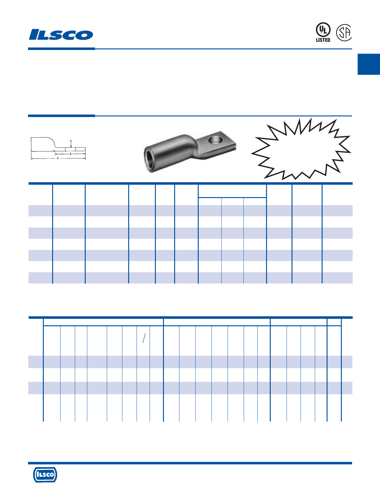
A
4730 Madison Road, Cincinnati, Ohio 45227-1426 Phone 513 533-6200 Fax 513 871-4084 Web site www.ilsco.com
Canada 1050 Lakeshore Road East, Mississauga, Ontario, Canada L5E1E4 Phone 905 274-2341 Fax 905 274-8763
48
Aluminum Compression Lugs
Conductor Range: #2-#8
TYPE
ACL
Features
•
Electro-tin plated
•
Manufactured from high strength aluminum alloy
•
Chamfered barrel
•
UL 486B 90˚ C Listed and CSA Certified
for 600 volts
•
Color coded
•
Clearly marked with wire size and die index for Ilsco
tools, proper number and location of crimps
•
Prefilled with DE-OX
•
Color coded end caps inserted in barrel
Benefits
•
Provides low contact resistance
•
Provides maximum conductivity and excellent crimping characteristics
•
Provides easy conductor insertion
•
Ensures reliability for copper or aluminum conductors
•
Provides visual tooling recommendation for Ilsco or standard industry tools
•
Provides easy identification and tooling recommendation
•
Prevents oxides from forming
•
Prevents foreign materials from entering the connector prior to usage and
color code identifies the proper compression die
453G
L
R
-
2
9
6
0
1
UL Listed and CSA Certified 600 volts maximum when installed with tools and dies shown above. If proper high voltage spacings and insulation techniques are used, the aluminum
compression connectors can be used for high voltage applications up to 35KV.
See stuffer sheet for complete information on tooling.
Tested to UL 486A-486B, UL File E6207
UL Listed and CSA
Certified Range-Taking
When Installed with
IDT-12-N Tool
ILSCO Burndy Thomas & Betts
ILC-12-N ILCB-12-N IDTB-6 IDT-6, IDT-6H ILC-15H MT-25 94285 IDT-12-N Y-48B Y-35 Y-39 Y-45 Y-46 MY29-3 Y644M
13642
TBM 15 21940
ILC-12H-N 6.2 Ton Hand Left Rt. Hand 12 Ton 15 Ton 40 Ton
Die No. Die No. Dieless Dieless Die No. Dieless Die Die Dieless Die Index Die Index Die Index Die Index Die Index Dieless Dieless
Die Index Die Index Die Index
Catalog No. of No. of No. of No. of No. of No. of No. of No. of No. of No. of No. of No. of No. of No. of No. of No. of No. of No. of
Number Crimps Crimps Crimps Crimps Crimps Crimps Crimps Crimps Crimps Crimps Crimps Crimps Crimps Crimps Crimps Crimps Crimps Crimps
ACL-8/ ILD-2 ILD-2 - - ILD-2 - M/K - - - - - - - - 24 24 -
ACN-8 (1) (1) (1) (1) (2) (1) (1) (2)
ACL-6 ILD-3 ILD-3 - - ILD-3 - K/K - 346 346 346 346 - - 29 29 29
(1) (1) (1) (1) (1) (1) (2) (1) (1) (1) (1) (1) (1) (1) (2) (2) (2)
ACL-4/ ILD-4 ILD-4 - - ILD-4 - H/H - 375 375 375 375 - - 37 37 37
ACN-4 (2) (2) (1) (1) (2) (1) (3) (1) (1) (1) (1) (1) (1) (1) (2) (2) (2)
ACL-2/ ILD-7 ILD-7 - - ILD-7 - - 348 348 348 348 - - 42 42H 42
ACN-2 (1) or (1) or (2) (2) (1) or E/A (1)
ILD-6 ILD-6 - - ILD-6 (2) (3) (1) (2)
(3) (3) (3) (1) (1) (1) (1) (2) (4) (2)
Wire Range
Catalog Wire When Installed Die Color Bolt Tang Dimensions Die
Number Size With IDT-12-N Tool Code Size Width C E F Index O.D. I.D.
ACL-8 8 8 Blue 1/4 1/2 9/32 11/16 1-7/16 2 5/16 11/64
ACN-8 8 8 Blue #10 1/2 13/64 11/16 1-7/16 2 5/16 11/64
ACL-6 6 6 Gray 1/4 1/2 9/32 11/16 1-43/64 3 11/32 3/16
ACL-4 4 4-6 Green 1/4 9/16 9/32 23/32 1-13/16 4 7/16 1/4
ACN-4 4 4-6 Green 5/16 9/16 11/32 23/32 1-13/16 4 7/16 1/4
ACL-2 2 2-6 Pink 1/4 11/16 9/32 23/32 1-7/8 7 17/32 5/16
ACN-2 2 2-6 Pink 5/16 11/16 11/32 23/32 1-7/8 7 17/32 5/16
CONTINUED ON NEXT PAGE.
Tooling Information
Anderson
TBM-8 Versa
Hand Crimp
Tool Dieless
No. of No. of Color
Crimps Crimps Code
--
(1) Blue
--
(2) Gray
--
(2) (1) Green
--
--
(2) (1) Pink
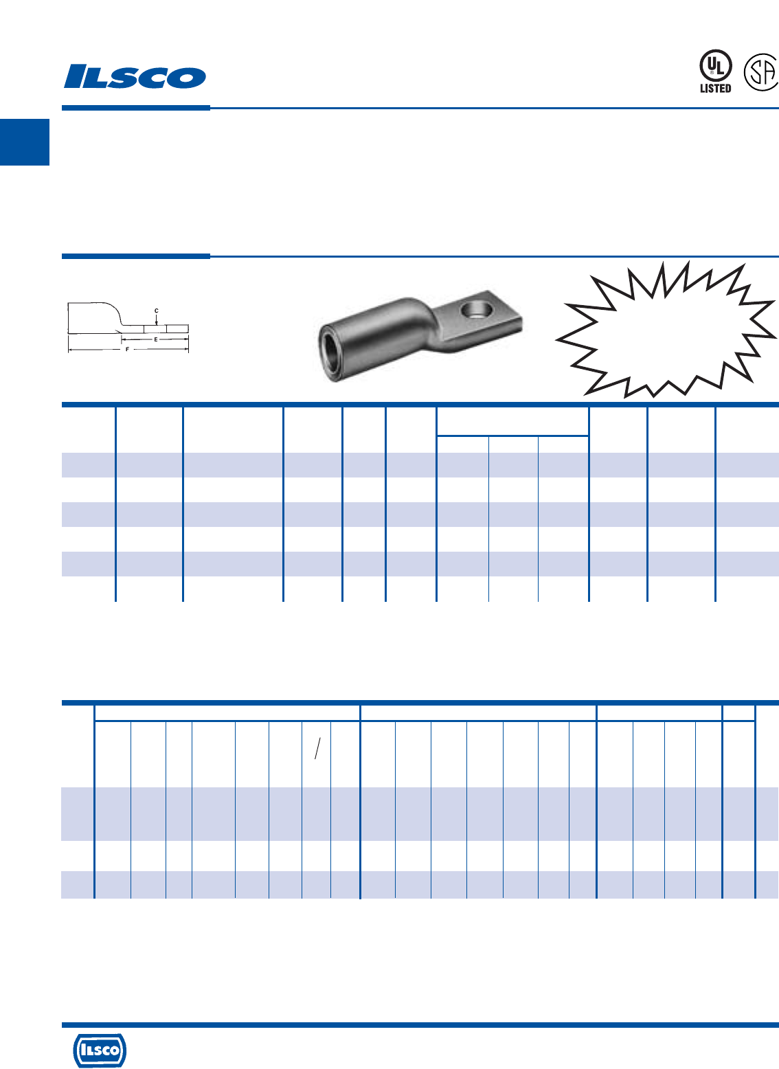
A
4730 Madison Road, Cincinnati, Ohio 45227-1426 Phone 513 533-6200 Fax 513 871-4084 Web site www.ilsco.com
Canada 1050 Lakeshore Road East, Mississauga, Ontario, Canada L5E1E4 Phone 905 274-2341 Fax 905 274-8763
49
Aluminum Compression Lugs
Conductor Range: 2/0-#1
TYPE
ACL
Features
•
Electro-tin plated
•
Manufactured from high strength aluminum alloy
•
Chamfered barrel
•
UL 486B 90˚ C Listed and CSA Certified
for 600 volts
•
Color coded
•
Clearly marked with wire size and die index for Ilsco
tools, proper number and location of crimps
•
Prefilled with DE-OX
•
Color coded end caps inserted in barrel
Benefits
•
Provides low contact resistance
•
Provides maximum conductivity and excellent crimping characteristics
•
Provides easy conductor insertion
•
Ensures reliability for copper or aluminum conductors
•
Provides visual tooling recommendation for Ilsco or standard industry tools
•
Provides easy identification and tooling recommendation
•
Prevents oxides from forming
•
Prevents foreign materials from entering the connector prior to usage and
color code identifies the proper compression die
453G
L
R
-
2
9
6
0
1
UL Listed and CSA Certified 600 volts maximum when installed with tools and dies shown above. If proper high voltage spacings and insulation techniques are used, the aluminum
compression connectors can be used for high voltage applications up to 35KV.
See stuffer sheet for complete information on tooling.
Tested to UL 486A-486B, UL File E6207
ILSCO Burndy Thomas & Betts
ILC-12-N ILCB-12-N IDTB-6 IDT-6, IDT-6H ILC-15H MT-25 94285 IDT-12-N Y-48B Y-35 Y-39 Y-45 Y-46 MY29-3 Y644M
13642
TBM 15 21940
ILC-12H-N 6.2 Ton Hand Left Rt. Hand 12 Ton 15 Ton 40 Ton
Die No. Die No. Dieless Dieless Die No. Dieless Die Die Dieless Die Index Die Index Die Index Die Index Die Index Dieless Dieless
Die Index Die Index Die Index
Catalog No. of No. of No. of No. of No. of No. of No. of No. of No. of No. of No. of No. of No. of No. of No. of No. of No. of No. of
Number Crimps Crimps Crimps Crimps Crimps Crimps Crimps Crimps Crimps Crimps Crimps Crimps Crimps Crimps Crimps Crimps Crimps Crimps
ACL-1/ ILD-7 ILD-7 - - ILD-7 - - - 471 471 471 471 - - 45 45 45
ACN-1 (1) or (1) or (1) or
ILD-6 ILD-6 - - ILD-6 - E/A - - - - - - - - - - -
(4) (4) (2) (2) (4) (2) (4) (1) (1) (1) (1) (1) (2) (1) (3) (3) (3)
ACL-1/0/ ILD-8 ILD-8 - - ILD-8 - A/C - 296 296 296 296 296 - - 50 50 50
ACN-1/0 (1) (1) (2) (2) (1) (2) (5) (1) (1) (1) (1) (1) (1) (2) (1) (3) (3) (3)
ACL-2/0/ ILD-10 ILD-10 - - ILD-10 - A/B - 297 297 297 297 297 - - 54 54H 54
ACN-2/0 (1) (1) (2) (2) (1) (2) (4) (1) (1) (2) (2) (2) (2) (2) (1) (3) (6) (3)
Wire Range
Catalog Wire When Installed Die Color Bolt Tang Dimensions Die
Number Size With IDT-12-N Tool Code Size Width C E F Index O.D. I.D.
ACL-1 1 1-2 Gold 1/4 3/4 9/32 29/32 2-25/64 7 35/64 23/64
ACN-1 1 1-2 Gold 5/16 3/4 11/32 29/32 2-25/64 7 35/64 23/64
ACL-1/0 1/0 1/0-1 Tan 3/8 7/8 13/32 15/16 2-9/16 8 39/64 25/64
ACN-1/0 1/0 1/0-1 Tan 5/16 7/8 11/32 15/16 2-9/16 8 39/64 25/64
ACL-2/0 2/0 2/0-1 Olive 3/8 31/32 13/32 1 2-5/8 10 43/64 7/16
ACN-2/0 2/0 2/0-1 Olive 1/2 31/32 9/16 1 2-5/8 10 43/64 7/16
CONTINUED ON NEXT PAGE.
Tooling Information
Anderson
TBM-8 Versa
Hand Crimp
Tool Dieless
No. of No. of Color
Crimps Crimps Code
--
--
(3) (2) Gold
(3) (2) Tan
(3) (2) Olive
UL Listed and CSA
Certified Range-Taking
When Installed with
IDT-12-N Tool
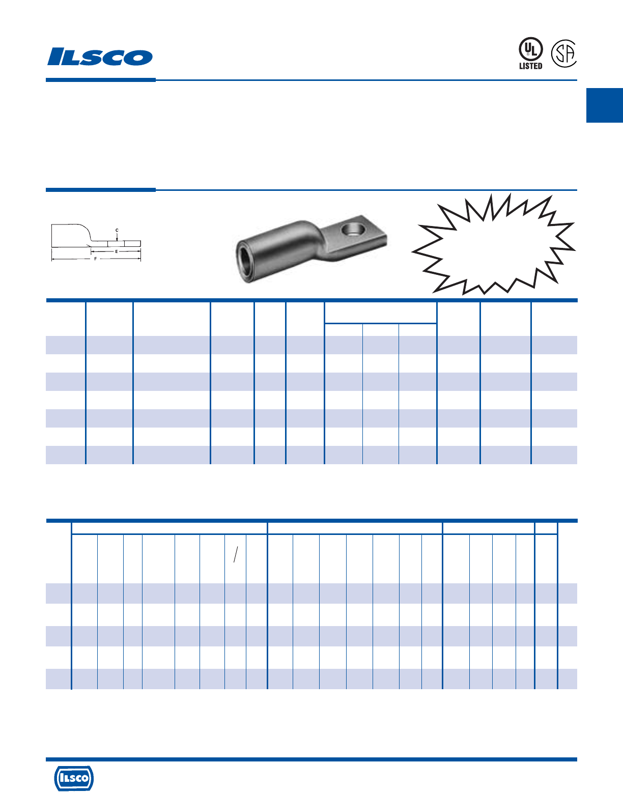
A
4730 Madison Road, Cincinnati, Ohio 45227-1426 Phone 513 533-6200 Fax 513 871-4084 Web site www.ilsco.com
Canada 1050 Lakeshore Road East, Mississauga, Ontario, Canada L5E1E4 Phone 905 274-2341 Fax 905 274-8763
50
Aluminum Compression Lugs
Conductor Range: 350kcmil-3/0
TYPE
ACL
Features
•
Electro-tin plated
•
Manufactured from high strength aluminum alloy
•
Chamfered barrel
•
UL 486B 90˚ C Listed and CSA Certified
for 600 volts
•
Color coded
•
Clearly marked with wire size and die index for Ilsco
tools, proper number and location of crimps
•
Prefilled with DE-OX
•
Color coded end caps inserted in barrel
Benefits
•
Provides low contact resistance
•
Provides maximum conductivity and excellent crimping characteristics
•
Provides easy conductor insertion
•
Ensures reliability for copper or aluminum conductors
•
Provides visual tooling recommendation for Ilsco or standard industry tools
•
Provides easy identification and tooling recommendation
•
Prevents oxides from forming
•
Prevents foreign materials from entering the connector prior to usage and
color code identifies the proper compression die
453G
L
R
-
2
9
6
0
1
UL Listed and CSA Certified 600 volts maximum when installed with tools and dies shown above. If proper high voltage spacings and insulation techniques are used, the aluminum
compression connectors can be used for high voltage applications up to 35KV.
See stuffer sheet for complete information on tooling.
Tested to UL 486A-486B, UL File E6207
Wire Range
Catalog Wire When Installed Die Color Bolt Tang Dimensions Die
Number Size With IDT-12-N Tool Code Size Width C E F Index O.D. I.D.
ACL-3/0 3/0 3/0-1 Ruby 3/8 1-1/16 13/32 1-1/16 2-13/16 10 49/64 1/2
ACN-3/0 3/0 3/0-1 Ruby 1/2 1-1/16 9/16 1-1/16 2-13/16 10 49/64 1/2
ACL-4/0 4/0 4/0-1 White 3/8 1-1/8 13/32 1-1/16 3-3/8 12 55/64 9/16
ACN-4/0 4/0 4/0-1 White 1/2 1-1/8 9/16 1-1/16 3-3/8 12 55/64 9/16
ACL-250 250kcmil 250kcmil-1/0 Red 1/2 1-21/64 17/32 1-1/2 3-7/8 13 59/64 39/64
ACL-300 300kcmil 300kcmil-2/0 Blue 1/2 1-7/16 17/32 1-1/2 4-1/16 14 1-1/64 21/32
ACL-350 350kcmil 350kcmil-3/0 Brown 1/2 1-9/16 17/32 1-1/2 4-3/32 14 1-1/8 23/32
CONTINUED ON NEXT PAGE.
Tooling Information
ILSCO Burndy Thomas & Betts
ILC-12-N ILCB-12-N IDTB-6 IDT-6, IDT-6H ILC-15H MT-25 94285 IDT-12-N Y-48B Y-35 Y-39 Y-45 Y-46 MY29-3 Y644M
13642
TBM 15 21940
ILC-12H-N 6.2 Ton Hand Left Rt. Hand 12 Ton 15 Ton 40 Ton
Die No. Die No. Dieless Dieless Die No. Dieless Die Die Dieless Die Index Die Index Die Index Die Index Die Index Dieless Dieless
Die Index Die Index Die Index
Catalog No. of No. of No. of No. of No. of No. of No. of No. of No. of No. of No. of No. of No. of No. of No. of No. of No. of No. of
Number Crimps Crimps Crimps Crimps Crimps Crimps Crimps Crimps Crimps Crimps Crimps Crimps Crimps Crimps Crimps Crimps Crimps Crimps
ACL-3/0/ ILD-10 ILD-10 - - ILD-10 - A/A - 467 467 467 467 467 - - 60 60 60
ACN-3/0 (2) (2) (3) (3) (2) (2) (4) (1) (1) (2) (2) (2) (2) (2) (1) (3) (3) (3)
ACL-4/0/ ILD-12 ILD-12 - - ILD-12 - - - 298 298 298 298 298 - - 66H 66 66
ACN-4/0 (1) (1) (3) (3) (1) (2) (2) (1) (2) (2) (2) (2) (2) (1) (4) (2) (2)
ACL-250 ILD-13 ILD-13 - - ILD-13 - - - 324 324 324 324 324 - - 71H 71H 71
(2) (2) (3) (3) (2) (2) (1) (2) (2) (2) (2) (1) (4) (4) (2)
ACL-300 ILD-14 ILD-14 - - ILD-14 - - - 470 470 470 470 470 - - 76H 76 76
(2) (2) (4) (4) (2) (2) (1) (2) (2) (2) (2) (1) (4) (2) (2)
ACL-350 ILD-14 ILD-14 - - ILD-14 - - - 299 299 299 299 299 - - 87H 87H 87
(2) (2) (4) (4) (2) (2) (1) (2) (2) (2) (2) (1) (4) (4) (2)
Anderson
TBM-8
Versa
Hand Crimp
Tool
Dieless
No. of No. of Color
Crimps Crimps Code
--
(3) (2) Ruby
--
(5) (3) White
--
(5) (3) Red
--
(5) (3) Blue
--
(6) (3)
Brown
UL Listed and CSA
Certified Range-Taking
When Installed with
IDT-12-N Tool
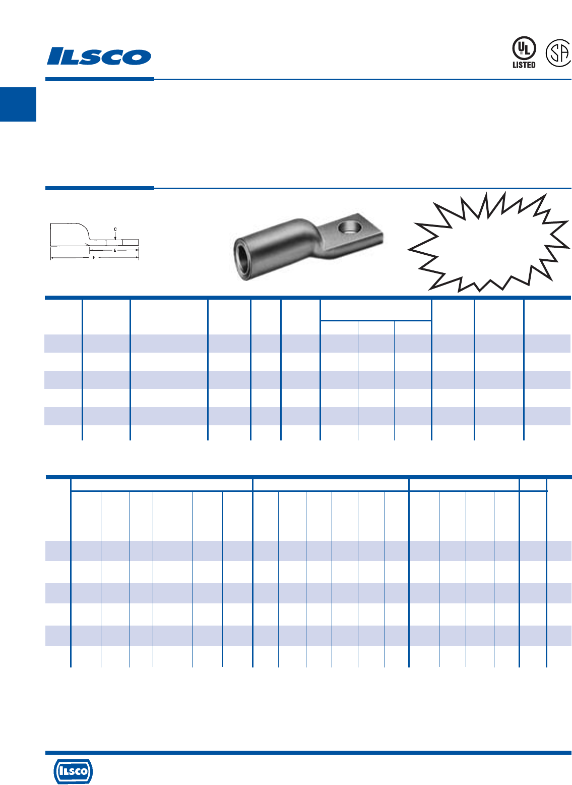
A
4730 Madison Road, Cincinnati, Ohio 45227-1426 Phone 513 533-6200 Fax 513 871-4084 Web site www.ilsco.com
Canada 1050 Lakeshore Road East, Mississauga, Ontario, Canada L5E1E4 Phone 905 274-2341 Fax 905 274-8763
51
Aluminum Compression Lugs
Conductor Range: 1000MCM-400MCM
TYPE
ACL
Features
•
Electro-tin plated
•
Manufactured from high strength aluminum alloy
•
Chamfered barrel
•
UL 486B 90˚ C Listed and CSA Certified
for 600 volts
•
Color coded
•
Clearly marked with wire size and die index for Ilsco
tools, proper number and location of crimps
•
Prefilled with DE-OX
•
Color coded end caps inserted in barrel
Benefits
•
Provides low contact resistance
•
Provides maximum conductivity and excellent crimping characteristics
•
Provides easy conductor insertion
•
Ensures reliability for copper or aluminum conductors
•
Provides visual tooling recommendation for Ilsco or standard industry tools
•
Provides easy identification and tooling recommendation
•
Prevents oxides from forming
•
Prevents foreign materials from entering the connector prior to usage and
color code identifies the proper compression die
453G
L
R
-
2
9
6
0
1
UL Listed and CSA Certified 600 volts maximum when installed with tools and dies shown above. If proper high voltage spacings and insulation techniques are used, the aluminum
compression connectors can be used for high voltage applications up to 35KV.
See stuffer sheet for complete information on tooling.
Tested to UL 486A-486B, UL File E6207
Wire Range
Catalog Wire When Installed Die Color Bolt Tang Dimensions Die
Number Size With IDT-12-N Tool Code Size Width C E F Index O.D. I.D.
ACL-400 400kcmil 400kcmil-4/0 Green 1/2 1-5/8 17/32 1-9/16 4-7/8 16 1-3/16 49/64
ACL-500 500kcmil 500kcmil-4/0 Pink 1/2 1-13/16 17/32 1-9/16 4-7/8 16A 1-21/64 55/64
ACL-600 600kcmil 600kcmil-250kcmil Black 5/8 1-15/16 21/32 2 5-3/8 17 1-21/64 59/64
ACL-700 700kcmil 700kcmil-350kcmil Purple 5/8 2-1/16 21/32 2-3/32 5-21/32 17 1-13/32 1
ACL-750 750kcmil 750kcmil-500kcmil Yellow 5/8 2-3/16 21/32 2-3/32 5-21/32 18 1-29/64 1-1/32
ACL-1000 1000kcmil 1000kcmil-750kcmil Brown 5/8 2-1/2 21/32 2-1/4 6-5/8 20 1-53/64 1-3/16
Tooling Information
ILSCO Burndy Thomas & Betts
Anderson
ILC-12-N ILCB-12-N IDTB-6 IDT-6, IDT-6H ILC-15H IDT-12-N Y-48B Y-35 Y-39 Y-45 Y-46
Y644M
13642 TBM 15 21940 TBM-8 Versa
ILC-12H-N 6.2 Ton 12 Ton 40 Ton Hand Crimp
Die No. Die No. Dieless Dieless Die No. Dieless
Die Index Die Index Die Index Die Index Die Index
Dieless
Die Index Die Index Die Index
Tool
Dieless
Catalog No. of No. of No. of No. of No. of No. of No. of No. of No. of No. of No. of No. of No. of No. of No. of No. of No. of Color
Number Crimps Crimps Crimps Crimps Crimps Crimps Crimps Crimps Crimps Crimps Crimps Crimps Crimps Crimps Crimps Crimps Crimps Code
ACL-400 ILD-16 ILD-16 - - ILD-16 - 472 472 472 472 472 - 94H 94H 94 - -
(3) (3) (4) (4) (3) (2) (2) (4) (4) (4) (4) (1) (4) (4) (2) (4) Green
ACL-500 ILD-16A ILD-16A - - ILD-16A - 300 300 300 300 300 - 99H 99H 99 - -
(3) (3) (4) (4) (3) (2) (2) (4) (4) (4) (4) (1) (4) (4) (2) (4) Pink
ACL-600 ILD-17 ILD-17 - - ILD-17 - 473 473 473 473 473 - 106H 106 106 - -
(4) (4) (4) (4) (4) (2) (2) (4) (4) (4) (4) (1) (4) (2) (2) (4) Black
ACL-700 ILD-17 ILD-17 - - ILD-17 - 936 - 936 936 936 - 112H 112H 112 - -
(4) (4) (4) (4) (4) (2) (2) (4) (4) (4) (1) (4) (4) (2) Purple
ACL-750 ILD-18 ILD-18 - - ILD-18 - 936 - 936 936 936 - 115H 115H 115 - -
(5) (5) (4) (4) (5) (2) (2) (4) (4) (4) (1) (4) (4) (2) Yellow
ACL-1000
- - - - - - 302 - - - - - - 140H 140 - -
(3) (2) (2) (1) (4) (2) Brown
UL Listed and CSA
Certified Range-Taking
When Installed with
IDT-12-N Tool
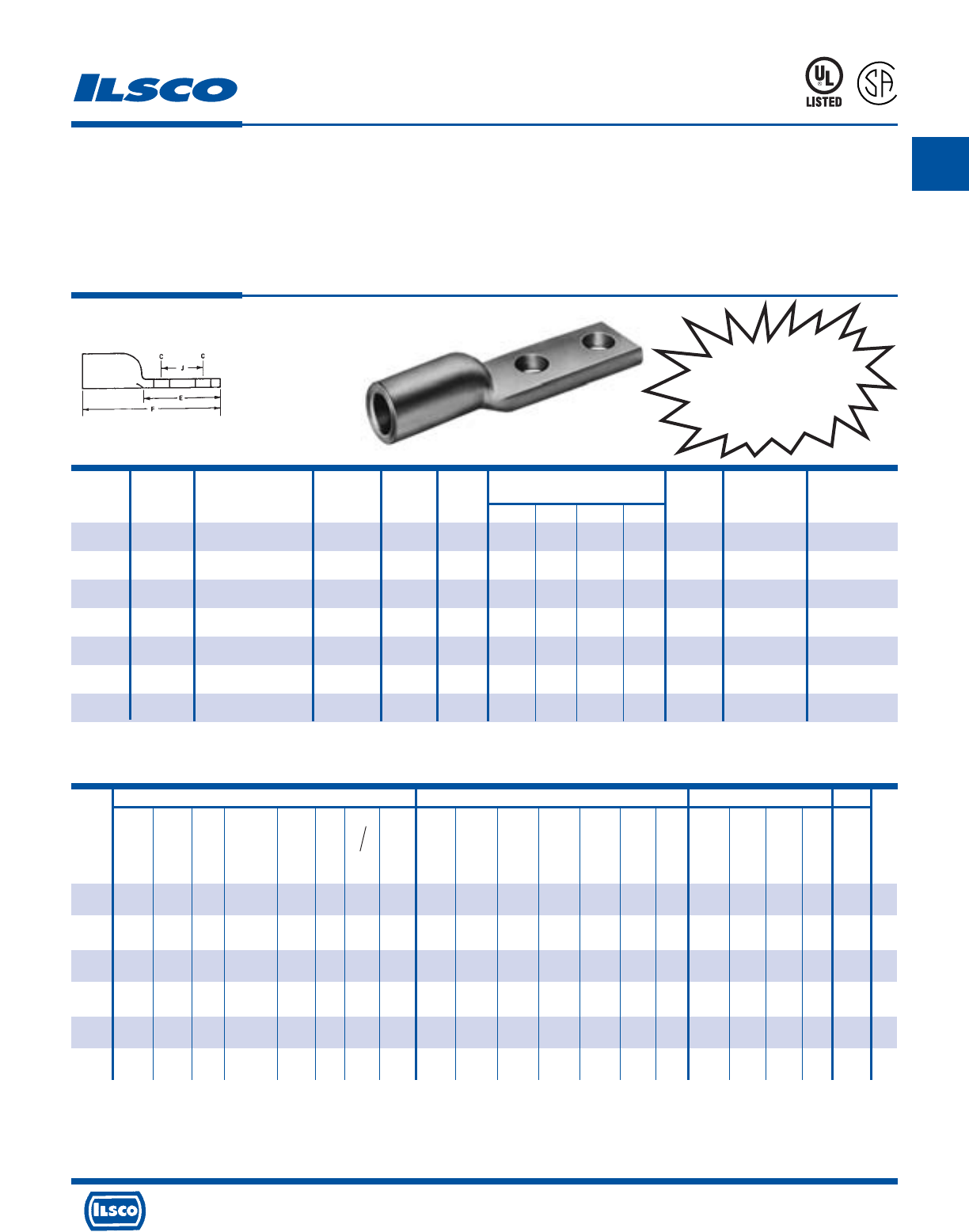
A
4730 Madison Road, Cincinnati, Ohio 45227-1426 Phone 513 533-6200 Fax 513 871-4084 Web site www.ilsco.com
Canada 1050 Lakeshore Road East, Mississauga, Ontario, Canada L5E1E4 Phone 905 274-2341 Fax 905 274-8763
52
Wire Range
Catalog Wire When Installed Die Color Bolt Tang Dimensions Die
No. Size With IDT-12-N Tool Code Size Width C E F J Index O.D. I.D.
2ACL-1/0 1/0 1/0-1 Tan 3/8 (2) 7/8 13/32(2) 1-7/8 3-15/32 1 8 39/64 25/64
2ACN-1/0 1/0 1/0-1 Tan 1/2 (2) 7/8 17/32(2) 3 4-5/8 1-3/4 8 39/64 25/64
2ACL-2/0 2/0 2/0-1 Olive 1/2 (2) 31/32 9/16(2) 3-3/8 5 1-3/4 10 43/64 7/16
2ACL-3/0 3/0 3/0-1 Ruby 1/2 (2) 1-1/16 9/16(2) 3-3/8 5-5/32 1-3/4 10 49/64 1/2
2ACL-4/0 4/0 4/0-1 White 1/2 (2) 1-1/8 9/16(2) 3-3/8 5-5/8 1-3/4 12 55/64 9/16
2ACL-250 250kcmil 250kcmil-1/0 Red 1/2 (2) 1-21/64 9/16(2) 3-3/8 5-3/4 1-3/4 13 59/64 39/64
2ACL-300 300kcmil 300kcmil-2/0 Blue 1/2 (2) 1-7/16 9/16(2) 3-3/8 5-15/16 1-3/4 14 1-1/64 21/32
Aluminum Compression Lugs
Conductor Range: 300kcmil-1/0
TYPE
2ACL
Features
•
Electro-tin plated
•
Manufactured from high strength aluminum alloy
•
Chamfered barrel
•
UL 486B 90˚ C Listed and CSA Certified
for 600 volts
•
Color coded
•
Clearly marked with wire size and die index for Ilsco
tools, proper number and location of crimps
•
Prefilled with DE-OX
•
Color coded end caps inserted in barrel
Benefits
•
Provides low contact resistance
•
Provides maximum conductivity and excellent crimping characteristics
•
Provides easy conductor insertion
•
Ensures reliability for copper or aluminum conductors
•
Provides visual tooling recommendation for Ilsco or standard industry tools
•
Provides easy identification and tooling recommendation
•
Prevents oxides from forming
•
Prevents foreign materials from entering the connector prior to usage and
color code identifies the proper compression die
453G
L
R
-
2
9
6
0
1
Tooling Information
UL Listed and CSA Certified 600 volts maximum when installed with tools and dies shown above. If proper high voltage spacings and insulation techniques are used, the aluminum
compression connectors can be used for high voltage applications up to 35KV.
See stuffer sheet for complete information on tooling.
Tested to UL 486A-486B, UL File E6207
CONTINUED ON NEXT PAGE.
ILSCO Burndy Thomas & Betts
ILC-12-N ILCB-12-N IDTB-6 IDT-6, IDT-6H ILC-15H MT-25 94285 IDT-12-N Y-48B Y-35 Y-39 Y-45 Y-46 MY29-3 Y644M
13642
TBM 15 21940
ILC-12H-N 6.2 Ton Hand Left Rt. Hand 12 Ton 15 Ton 40 Ton
Die No. Die No. Die No. Dieless Die No. Dieless Die Die Dieless Die Index Die Index Die Index Die Index Die Index Dieless Dieless
Die Index Die Index Die Index
Catalog No. of No. of No. of No. of No. of No. of No. of No. of No. of No. of No. of No. of No. of No. of No. of No. of No. of No. of
Number Crimps Crimps Crimps Crimps Crimps Crimps Crimps Crimps Crimps Crimps Crimps Crimps Crimps Crimps Crimps Crimps Crimps Crimps
2ACL-1/0
ILD-8 ILD-8 - - ILD-8 - A/C - 296 296 296 296 296 - - 50 50 50
2ACN-1/0
(1) (1) (2) (2) (1) (2) (5) (1) (1) (1) (1) (1) (1) (2) (1) (3) (3) (3)
2ACL-2/0
ILD-10 ILD-10 - - ILD-10 - A/B - 297 297 297 297 297 - - 54 54H 54
(1) (1) (2) (2) (1) (2) (4) (1) (1) (2) (2) (2) (2) (2) (1) (3) (6) (3)
2ACL-3/0
ILD-10 ILD-10 - - ILD-10 - A/A - 467 467 467 467 467 - - 60 60 60
(2) (2) (3) (3) (2) (2) (4) (1) (1) (2) (2) (2) (2) (2) (1) (3) (3) (3)
2ACL-4/0
ILD-12 ILD-12 - - ILD-12 - - - 298 298 298 298 298 - - 66H 66 66
(1) (1) (3) (3) (1) (2) (2) (1) (2) (2) (2) (2) (2) (1) (4) (2) (2)
2ACL-250
ILD-13 ILD-13 - - ILD-13 - - - 324 324 324 324 324 - - 71H 71H 71
(2) (2) (3) (3) (2) (2) (1) (2) (2) (2) (2) (1) (4) (4) (2)
2ACL-300
ILD-14 ILD-14 - - ILD-14 - - - 470 470 470 470 470 - - 76H 76 76
(2) (2) (4) (4) (2) (2) (1) (2) (2) (2) (2) (1) (4) (2) (2)
Anderson
TBM-8 Versa
Hand Crimp
Tool Dieless
No. of No. of Color
Crimps Crimps Code
--
(3) (2) Tan
--
(3) (2) Olive
--
(3) (2) Ruby
--
(5) (3) White
--
(5) (3) Red
--
(5) (3) Blue
UL Listed and CSA
Certified Range-Taking
When Installed with
IDT-12-N Tool
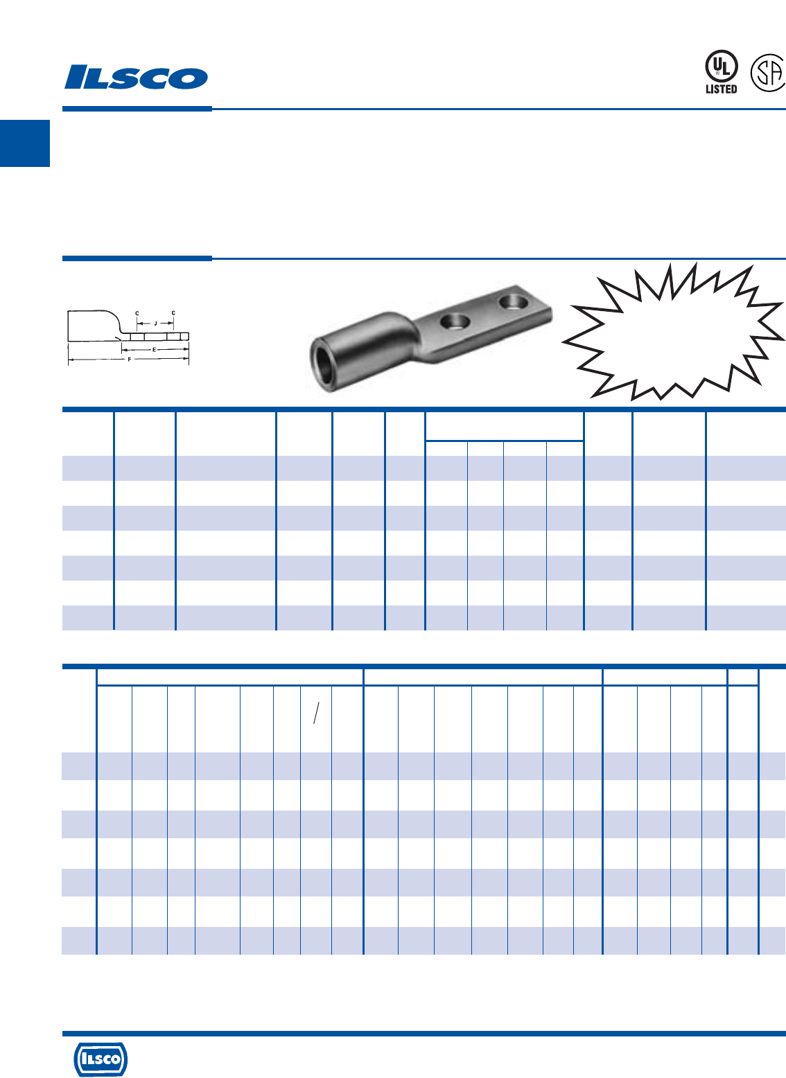
A
4730 Madison Road, Cincinnati, Ohio 45227-1426 Phone 513 533-6200 Fax 513 871-4084 Web site www.ilsco.com
Canada 1050 Lakeshore Road East, Mississauga, Ontario, Canada L5E1E4 Phone 905 274-2341 Fax 905 274-8763
53
Wire Range
Catalog Wire When Installed Die Color Bolt Tang Dimensions Die
No. Size With IDT-12-N Tool Code Size Width C E F J Index O.D. I.D.
2ACL-350 350kcmil 350kcmil-3/0 Brown 1/2 (2) 1-9/16 9/16(2) 3-3/8 5-31/32 1-3/4 14 1-1/8 23/32
2ACL-400 400kcmil 400kcmil-4/0 Green 1/2 (2) 1-5/8 9/16(2) 3-3/8 6-11/16 1-3/4 16 1-3/16 49/64
2ACL-500 500kcmil 500kcmil-4/0 Pink 1/2 (2) 1-13/16 9/16(2) 3-3/8 6-11/16 1-3/4 16A 1-21/64 55/64
2ACL-600 600kcmil 600kcmil-250kcmil Black 1/2 (2) 1-15/16 9/16(2) 3-3/8 6-3/4 1-3/4 17 1-21/64 59/64
2ACL-700 700kcmil 700kcmil-350kcmil Purple 1/2 (2) 2-1/16 9/16(2) 3-3/8 6-15/16 1-3/4 17 1-13/32 1
2ACL-750 750kcmil 750kcmil-500kcmil Yellow 1/2 (2) 2-1/16 9/16(2) 3-3/8 6-15/16 1-3/4 18 1-29/64 1-1/32
2ACL-1000 1000kcmil 1000kcmil-750kcmil Brown 1/2 (2) 2-1/2 9/16(2) 3-3/8 7-3/4 1-3/4 20 1-53/64 1-3/16
Aluminum Compression Lugs
Conductor Range: 1000kcmil-350kcmil
TYPE
2ACL
Features
•
Electro-tin plated
•
Manufactured from high strength aluminum alloy
•
Chamfered barrel
•
UL 486B 90˚ C Listed and CSA Certified
for 600 volts
•
Color coded
•
Clearly marked with wire size and die index for Ilsco
tools, proper number and location of crimps
•
Prefilled with DE-OX
•
Color coded end caps inserted in barrel
Benefits
•
Provides low contact resistance
•
Provides maximum conductivity and excellent crimping characteristics
•
Provides easy conductor insertion
•
Ensures reliability for copper or aluminum conductors
•
Provides visual tooling recommendation for Ilsco or standard industry tools
•
Provides easy identification and tooling recommendation
•
Prevents oxides from forming
•
Prevents foreign materials from entering the connector prior to usage and
color code identifies the proper compression die
453G
L
R
-
2
9
6
0
1
UL Listed and CSA Certified 600 volts maximum when installed with tools and dies shown above. If proper high voltage spacings and insulation techniques are used, the aluminum
compression connectors can be used for high voltage applications up to 35KV.
See stuffer sheet for complete information on tooling.
Tested to UL 486A-486B, UL File E6207
Tooling Information
ILSCO Burndy Thomas & Betts
ILC-12-N ILCB-12-N IDTB-6 IDT-6, IDT-6H ILC-15H MT-25 94285 IDT-12-N Y-48B Y-35 Y-39 Y-45 Y-46 MY29-3 Y644M
13642
TBM 15 21940
ILC-12H-N 6.2 Ton Hand Left Rt. Hand 12 Ton 15 Ton 40 Ton
Die No. Die No. Die No. Dieless Die No. Dieless Die Die Dieless Die Index Die Index Die Index Die Index Die Index Dieless Dieless
Die Index Die Index Die Index
Catalog No. of No. of No. of No. of No. of No. of No. of No. of No. of No. of No. of No. of No. of No. of No. of No. of No. of No. of
Number Crimps Crimps Crimps Crimps Crimps Crimps Crimps Crimps Crimps Crimps Crimps Crimps Crimps Crimps Crimps Crimps Crimps Crimps
2ACL-350
ILD-14 ILD-14 - - ILD-14 - - - 299 299 299 299 299 - - 87H 87H 87
(2) (2) (4) (4) (2) (2) (1) (2) (2) (2) (2) (1) (4) (4) (2)
2ACL-400
ILD-16 ILD-16 - - ILD-16 - - - 472 472 472 472 472 - - 94H 94H 94
(3) (3) (4) (4) (3) (2) (2) (4) (4) (4) (4) (1) (4) (4) (2)
2ACL-500
ILD-16A
ILD-16A
--
ILD-16A
- 300 300 300 300 300 - - 99H 99H 99
(3) (3) (4) (4) (3) - - (2) (2) (4) (4) (4) (4) (1) (4) (4) (2)
2ACL-600
ILD-17 ILD-17 - - ILD-17 - - - 473 473 473 473 473 - - 106H 106 106
(4) (4) (4) (4) (4) (2) (2) (4) (4) (4) (4) (1) (4) (2) (2)
2ACL-700
ILD-17 ILD-17 - - ILD-17 - - - 936 - 936 936 936 - - 112H 112H 112
(4) (4) (4) (4) (4) (2) (2) (4) (4) (4) (1) (4) (4) (2)
2ACL-750
ILD-18 ILD-18 - - ILD-18 - - - 936 - 936 936 936 - - 115H 115H 115
(5) (5) (4) (4) (5) (2) (2) (4) (4) (4) (1) (4) (4) (2)
2ACL-1000
- - - - - - - - 302 - - - - - - - 140H 140
(3) (2) (2) (1) (4) (2)
Anderson
TBM-8
Versa
Hand Crimp
Tool
Dieless
No. of No. of Color
Crimps Crimps Code
87H -
(6) (3) Brown
--
(4) Green
--
(4) Pink
--
(4) Black
--
Purple
--
Yellow
--
Brown
UL Listed and CSA
Certified Range-Taking
When Installed with
IDT-12-N Tool
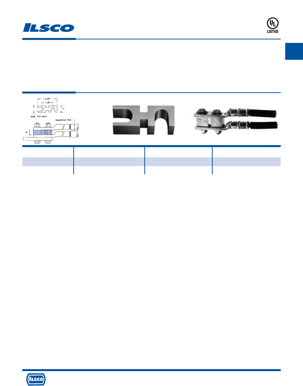
A
4730 Madison Road, Cincinnati, Ohio 45227-1426 Phone 513 533-6200 Fax 513 871-4084 Web site www.ilsco.com
Canada 1050 Lakeshore Road East, Mississauga, Ontario, Canada L5E1E4 Phone 905 274-2341 Fax 905 274-8763
54
Catalog Wire Insulation H
Number Range O.D.
ASL-250 250kcmil-1/0 55/64 3/4
ASL-750 750 kcmil-1/0 1-3/8 1-1/4
Stacking Adaptor For Compression Lugs
TYPE
ASL
Features
•
Electro-tin plated
•
Manufactured from high strength aluminum alloy
•
Two sizes cover a wire range from 750 kcmil-1/0
•
Unique design
•
Versatile
•
UL Listed for 600 volts, 90˚ C
Benefits
•
Provides low contact resistance
•
Can be used with both aluminum and copper terminals
•
Permits inventories to be kept to a minimum
•
Allows vertical stacking to minimize space requirements
•
Can be used with copper and/or aluminum connectors
•
Ensures reliability
453G
ASL
Tested to UL 486A-486B, UL File E6207
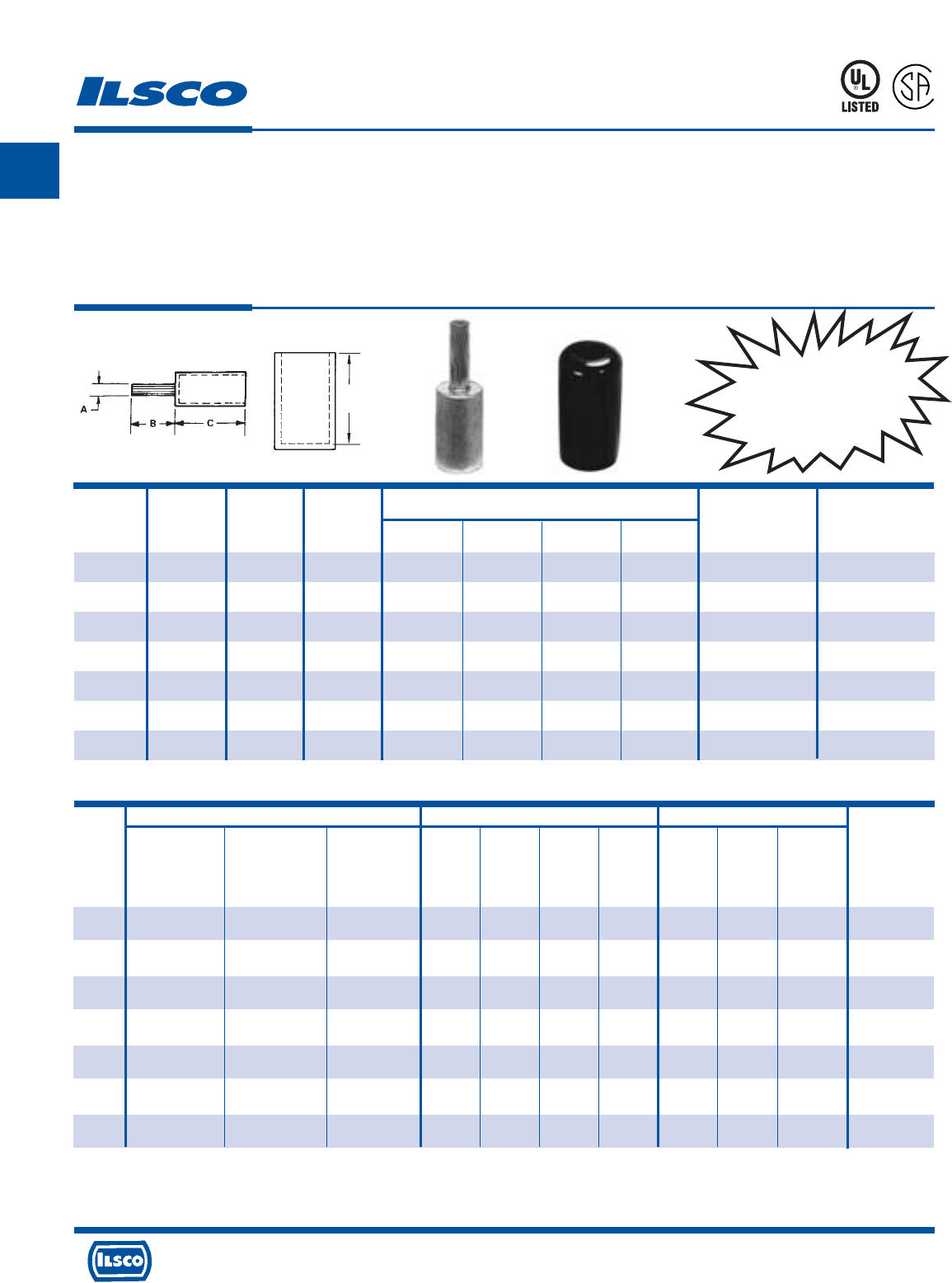
A
4730 Madison Road, Cincinnati, Ohio 45227-1426 Phone 513 533-6200 Fax 513 871-4084 Web site www.ilsco.com
Canada 1050 Lakeshore Road East, Mississauga, Ontario, Canada L5E1E4 Phone 905 274-2341 Fax 905 274-8763
55
ILSCO Burndy Thomas & Betts
ILC-12-N ILCB-12-N ILC-15H Y-46 Y-35 Y-39 Y-45 13642 TBM 15 21940
ILC-12H-N 12 Ton 15 Ton 40 Ton
Die No. Die No. Die No. Die Index Die Index Die Index Die Index Die Index Die Index Die Index
Catalog No. of No. of No. of No. of No. of No. of No. of No. of No. of No. of Color
Number Crimps Crimps Crimps Crimps Crimps Crimps Crimps Crimps Crimps Crimps Code
CPM-6 ILD-9 ILD-9 ILD-9 297 297 297 297 50 50 50
(3) (3) (3) (2) (2) (2) (2) (2) (2) (2) Orange
CPM-4 ILD-9 ILD-9 ILD-9 297 297 297 297 50 50 87
(3) (3) (3) (2) (2) (2) (2) (2) (2) (2) Orange
CPM-2 ILD-9 ILD-9 ILD-9 297 297 297 297 50 50 87
(3) (3) (3) (2) (2) (2) (2) (2) (2) (2) Orange
CPM-1 ILD-9 ILD-9 ILD-9 297 297 297 297 50 50 87
(3) (3) (3) (2) (2) (2) (2) (2) (2) (2) Orange
CPM-1/0 ILD-12 ILD-12 ILD-12 324 324 324 324 76H 76 76
(1) (1) (1) (2) (2) (2) (2) (4) (2) (2) White
CPM-2/0 ILD-12 ILD-12 ILD-12 324 324 324 324 76H 76 76
(1) (1) (1) (2) (2) (2) (2) (4) (2) (2) White
CPM-3/0 ILD-12 ILD-12 ILD-12 324 324 324 324 76H 76 76
(1) (1) (1) (2) (2) (2) (2) (4) (2) (2) White
Copper Pigtail Adaptor
Conductor Range: 3/0-#6 Copper or Aluminum
TYPE
CPM
Features
•
Barrel manufactured from high strength aluminum alloy
•
Pigtail manufactured from high conductivity copper
•
Chamfered barrel
•
UL Listed and CSA Certified for 600 volts, 90˚ C
•
Clearly marked with wire size and die index for Ilsco
tools, proper number and location of crimps
•
Prefilled with DE-OX
•
Color coded end caps inserted in barrel
•
Supplied with insulating cover
•
Rated for full ampacity of incoming conductor
Benefits
•
Allows insertion into equipment supplied with either copper or aluminum
connectors
•
Provides maximum conductivity and excellent crimping characteristics
•
Provides easy conductor insertion
•
Ensures reliability for copper and aluminum conductors
•
Provides easy identification and tooling recommendation
•
Prevents oxides from forming
•
Prevents foreign materials from entering the connector prior to usage and
color code identifies the proper compression die
•
Eliminates taping
941R
L
R
-
2
9
6
0
1
UL Listed and CSA Certified 600 volts maximum when installed with tools and dies shown above. If proper high voltage spacings and insulation techniques are used, the
aluminum compression connectors can be used for high voltage applications up to 35KV.
Dieless crimp tools must not be used to crimp CPM/CPML adapters. See stuffer sheet for complete information on tooling.
Tested to UL 486A-486B, UL File E62525
CONTINUED ON NEXT PAGE.
Tooling Information
Dimensions
Catalog Wire Die Copper Cover
Number Size Color Pin Size A B C D O.D. I.D.
CPM-6 6 Orange 8 1/8 7/8 1-11/32 1-11/16 21/32 3/16
CPM-4 4 Orange 6 3/16 7/8 1-11/32 1-11/16 21/32 1/4
CPM-2 2 Orange 4 15/64 7/8 1-11/32 1-11/16 21/32 5/16
CPM-1 1 Orange 3 17/64 1 1-11/32 1-11/16 21/32 23/64
CPM-l/0 1/0 White 2 19/64 1-1/4 1-19/32 2-3/32 29/32 25/64
CPM-2/0 2/0 White 1 11/32 1-1/4 1-19/32 2-3/32 29/32 7/16
CPM-3/0 3/0 White 1/0 3/8 1-3/8 1-7/8 2-3/32 29/32 1/2
D
UL Listed and CSA
Certified for Copper
or Aluminum
Conductors
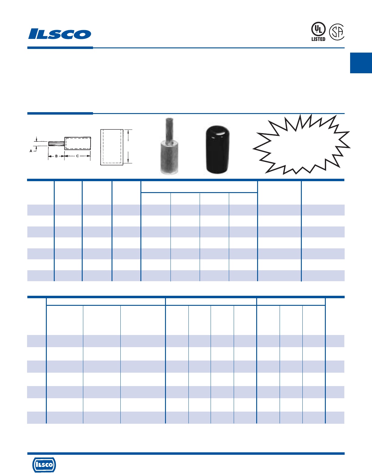
A
4730 Madison Road, Cincinnati, Ohio 45227-1426 Phone 513 533-6200 Fax 513 871-4084 Web site www.ilsco.com
Canada 1050 Lakeshore Road East, Mississauga, Ontario, Canada L5E1E4 Phone 905 274-2341 Fax 905 274-8763
56
CONTINUED ON NEXT PAGE.
Dimensions
Catalog Wire Die Copper Cover
Number Size Color Pin Size A B C D O.D. I.D.
CPM-4/0 4/0 White 2/0 13/32 1-3/8 1-7/8 2-3/32 29/32 9/16
CPM-250 250kcmil Brown 3/0 15/32 1-1/2 2-1/16 2-27/32 1-5/32 39/64
CPM-300 300kcmil Brown 4/0 17/32 1-5/8 2-1/16 2-27/32 1-5/32 21/32
CPM-350 350kcmil Brown 4/0 17/32 1-5/8 2-1/16 2-27/32 1-5/32 23/32
CPM-400 400kcmil Pink 250kcmil 37/64 1-7/8 2-3/32 2-13/32 1-3/8 49/64
CPM-500 500kcmil Pink 350kcmil 11/16 1-7/8 2-3/32 2-13/32 1-3/8 55/64
CPM-600 600kcmil Yellow 350kcmil 11/16 1-7/8 2-3/4 3-3/32 1-1/2 59/64
UL Listed and CSA
Certified for Copper
or Aluminum
Conductors
ILSCO Burndy Thomas & Betts
ILC-12-N ILCB-12-N ILC-15H Y-46 Y-35 Y-39 Y-45 13642 TBM 15 21940
ILC-12H-N 12 Ton 15 Ton 40 Ton
Die No. Die No. Die No. Die Index Die Index Die Index Die Index Die Index Die Index Die Index
Catalog No. of No. of No. of No. of No. of No. of No. of No. of No. of No. of Color
Number Crimps Crimps Crimps Crimps Crimps Crimps Crimps Crimps Crimps Crimps Code
CPM-4/0 ILD-12 ILD-12 ILD-12 324 324 324 324 76H 76 76
(1) (1) (1) (2) (2) (2) (2) (4) (2) (2) White
CPM-250 ILD-14 ILD-14 ILD-14 299 299 299 299 87H 87H 87
(2*) (2*) (2*) (2*) (2*) (2*) (2*) (2) (2) (1) Brown
CPM-300 ILD-14 ILD-14 ILD-14 299 299 299 299 87H 87H 87
(2*) (2*) (2*) (2*) (2*) (2*) (2*) (2) (2) (1) Brown
CPM-350 ILD-14 ILD-14 ILD-14 299 299 299 299 87H 87H 87
(2*) (2*) (2*) (2*) (2*) (2*) (2*) (2) (2) (1) Brown
CPM-400
ILD-16A ILD-16A ILD-16A
300 300 300 300 106H 106 106
(2*) (2*) (2*) (3) (3) (3) (3) (2) (1) (1) Pink
CPM-500
ILD-16A ILD-16A ILD-16A
300 300 300 300 106H 106 106
(2*) (2*) (2*) (3) (3) (3) (3) (2) (1) (1) Pink
CPM-600 ILD-18 ILD-18 ILD-18 936 936 936 936 115H 115H 115
(3) (3) (3) (3) (3) (3) (3) (3) (3) (2) Yellow
Copper Pigtail Adaptor
Conductor Range: 600kcmil-4/0 Copper or Aluminum
TYPE
CPM
Features
•
Barrel manufactured from high strength aluminum alloy
•
Pigtail manufactured from high conductivity copper
•
Chamfered barrel
•
UL Listed and CSA Certified for 600 volts, 90˚ C
•
Clearly marked with wire size and die index for Ilsco
tools, proper number and location of crimps
•
Prefilled with DE-OX
•
Color coded end caps inserted in barrel
•
Supplied with insulating cover
•
Rated for full ampacity of incoming conductor
Benefits
•
Allows insertion into equipment supplied with either copper or aluminum
connectors
•
Provides maximum conductivity and excellent crimping characteristics
•
Provides easy conductor insertion
•
Ensures reliability for copper and aluminum conductors
•
Provides easy identification and tooling recommendation
•
Prevents oxides from forming
•
Prevents foreign materials from entering the connector prior to usage and
color code identifies the proper compression die
•
Eliminates taping
941R
L
R
-
2
9
6
0
1
UL Listed and CSA Certified 600 volts maximum when installed with tools and dies shown above. If proper high voltage spacings and insulation techniques are used, the
aluminum compression connectors can be used for high voltage applications up to 35KV.
*Overlap Crimps Dieless crimp tools must not be used to crimp CPM/CPML adapters. See stuffer sheet for complete information on tooling.
Tested to UL 486A-486B, UL File E62525
Tooling Information
D
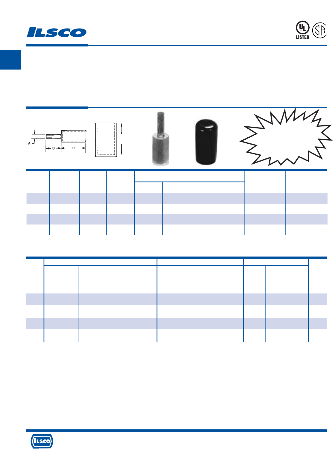
A
4730 Madison Road, Cincinnati, Ohio 45227-1426 Phone 513 533-6200 Fax 513 871-4084 Web site www.ilsco.com
Canada 1050 Lakeshore Road East, Mississauga, Ontario, Canada L5E1E4 Phone 905 274-2341 Fax 905 274-8763
57
ILSCO Burndy Thomas & Betts
ILC-12-N ILCB-12-N ILC-15H Y-46 Y-35 Y-39 Y-45 13642 TBM 15 21940
ILC-12H-N 12 Ton 15 Ton 40 Ton
Die No. Die No. Die No. Die Index Die Index Die Index Die Index Die Index Die Index Die Index
Catalog No. of No. of No. of No. of No. of No. of No. of No. of No. of No. of Color
Number Crimps Crimps Crimps Crimps Crimps Crimps Crimps Crimps Crimps Crimps Code
CPM-750 ILD-18 ILD-18 ILD-18 936 936 936 936 115H 115H 115
(3) (3) (3) (3) (3) (3) (3) (3) (3) (2) Yellow
CPML-500 ILD-16A ILD-16A ILD-16A 300 300 300 300 106H 106 106
(2*) (2*) (2*) (3) (3) (3) (3) (2) (1) (1) Pink
CPML-600 ILD-18 ILD-18 ILD-18 936 936 936 936 115H 115H 115
(3*) (3*) (3*) (3) (3) (3) (3) (3) (3) (2) Yellow
CPML-750 ILD-18 ILD-18 ILD-18 936 936 936 936 115H 115H 115
(3*) (3*) (3*) (3) (3) (3) (3) (3) (3) (2) Yellow
Copper Pigtail Adaptor
Conductor Range:
750kcmil-500kcmil Copper or Aluminum
TYPE
CPM
CPML
Features
•
Barrel manufactured from high strength aluminum alloy
•
Pigtail manufactured from high conductivity copper
•
Chamfered barrel
•
UL Listed and CSA Certified for 600 volts, 90˚ C
•
Clearly marked with wire size and die index for Ilsco
tools, proper number and location of crimps
•
Prefilled with DE-OX
•
Color coded end caps inserted in barrel
•
Supplied with insulating cover
•
Rated for full ampacity of incoming conductor
Benefits
•
Allows insertion into equipment supplied with either copper or aluminum
connectors
•
Provides maximum conductivity and excellent crimping characteristics
•
Provides easy conductor insertion
•
Ensures reliability for copper and aluminum conductors
•
Provides easy identification and tooling recommendation
•
Prevents oxides from forming
•
Prevents foreign materials from entering the connector prior to usage and
color code identifies the proper compression die
•
Eliminates taping
941R
L
R
-
2
9
6
0
1
UL Listed and CSA Certified 600 volts maximum when installed with tools and dies shown above. If proper high voltage spacings and insulation techniques are used, the
aluminum compression connectors can be used for high voltage applications up to 35KV.
*Overlap Crimps
Dieless crimp tools must not be used to crimp CPM/CPML adaptors.
See stuffer sheet for complete information on tooling.
Tested to UL 486A-486B, UL File E62525
Tooling Information
D
Dimensions
Catalog Wire Die Copper Cover
Number Range Color Pin Size A B C D O.D. I.D.
CPM-750
750kcmil-700kcmil
Yellow 500kcmil 13/16 2 2-3/4 3-3/32 1-1/2 1-1/32
CPML-500 500kcmil Pink 350kcmil 11/16 3 2-3/32 2-13/32 1-3/8 55/64
CPML-600 600kcmil Yellow 350kcmil 11/16 3 2-3/4 3-3/32 1-1/2 59/64
CPML-750
750kcmil-700kcmil
Yellow 500kcmil 13/16 3 2-3/4 3-3/32 1-1/2 1-1/32
UL Listed and CSA
Certified for Copper
or Aluminum
Conductors
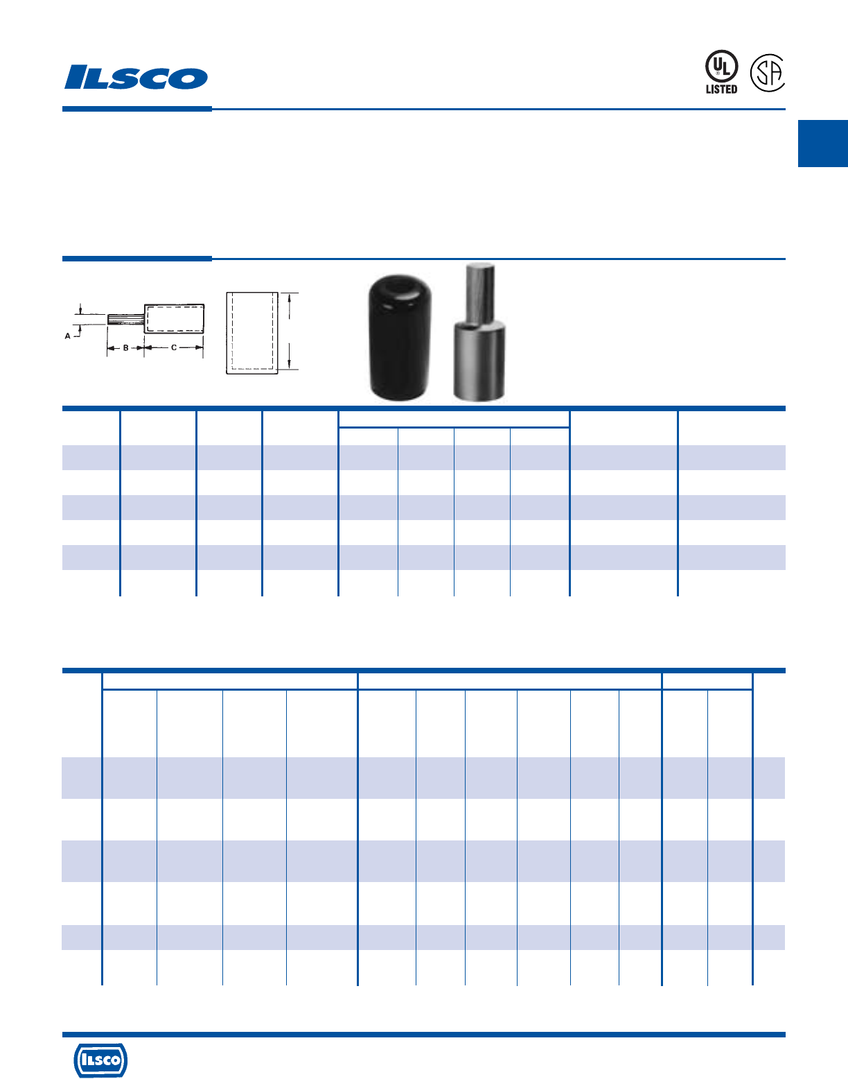
A
4730 Madison Road, Cincinnati, Ohio 45227-1426 Phone 513 533-6200 Fax 513 871-4084 Web site www.ilsco.com
Canada 1050 Lakeshore Road East, Mississauga, Ontario, Canada L5E1E4 Phone 905 274-2341 Fax 905 274-8763
58
ILSCO Burndy Thomas & Betts
ILC-12-N ILCB-12-N ILC-15H IDT-12-N Y750 Family Y-35 Y-39 Y-45 Y-46 Y644M 13642 13100A
ILC-12H-N 12 Ton 15 Ton
Die No. Die No. Die No. Die No. Die Index Die Index Die Index Die Index Die Index Dieless Die Index Die Index
Catalog No. of No. of No. of No. of No. of No. of No. of No. of No. of No. of No. of No. of Color
Number Crimps Crimps Crimps Crimps Crimps Crimps Crimps Crimps Crimps Crimps Crimps Crimps Code
ACM-6 ILD-8 ILD-8 ILD-8 296 296 296 296 296 45H 45H
Gold Gold Tan
(1) (1) (1) (1) (1) (1) (1) (1) (1) (1) (2) (2)
ACM-4 ILD-8 ILD-8 ILD-8 296 296 296 296 296 45H 45H
Gold Gold Tan
(1) (1) (1) (1) (1) (1) (1) (1) (1) (1) (2) (2)
ACM-2 ILD-8 ILD-8 ILD-8 296 296 296 296 296 45H 45H
Gold Gold Tan
(1) (1) (1) (1) (1) (1) (1) (1) (1) (1) (2) (2)
ACM-1 ILD-8 ILD-8 ILD-8 296 296 296 296 296 45H 45H
Gold Gold Tan
(1) (1) (1) (1) (1) (1) (1) (1) (1) (1) (2) (2)
ACM-1/0 ILD-12 ILD-12 ILD-12 298 298 298 298 298 66H 66H
(1) (1) (1) (1) (2*) (2*) (2*) (2*) (2*) (1) (2) (2) White
ACM-2/0 ILD-12 ILD-12 ILD-12 298 298 298 298 298 66H 66H
(1) (1) (1) (1) (2*) (2*) (2*) (2*) (2*) (1) (2) (2) White
Aluminum Pigtail Adaptor - Dual Rated
Conductor Range: 2/0-#6
TYPE
ACM
Features
•
Manufactured from high strength aluminum alloy
•
Pin is knurled
•
Chamfered barrel
•
UL Listed and CSA Certified for 600 volts, 90˚ C
•
Clearly marked with wire size and die index for Ilsco
tools, proper number and location of crimps
•
Prefilled with DE-OX
•
Color coded end caps inserted in barrel
•
Supplied with insulating cover
Benefits
•
Provides maximum conductivity and excellent crimping characteristics
•
Permits greater surface contact
•
Provides easy conductor insertion
•
Ensures reliability for aluminum or copper conductors
•
Provides easy identification and tooling recommendation
•
Prevents oxides from forming
•
Prevents foreign materials from entering the connector prior to usage and
color code identifies the proper compression die
•
Eliminates taping
941R
L
R
-
2
9
6
0
1
*Overlap Crimps
See stuffer sheet for complete information on tooling.
Tested to UL 486A-486B, UL File E62525
CONTINUED ON NEXT PAGE.
Tooling Information
D
Catalog Wire Die Dimensions
Number Size Color Pin Size A B C D
(cover)
O.D. I.D.
ACM-6 6 Tan #4 7/32 11/16 1-13/64 1-3/4 39/64 3/16
ACM-4 4 Tan #4 1/4 11/16 1-13/64 1-3/4 39/64 1/4
ACM-2 2 Tan #4 1/4 11/16 1-13/64 1-3/4 39/64 5/16
ACM-1 1 Tan #3 17/64 27/32 1-13/64 1-3/4 39/64 23/64
ACM-1/0 1/0 White #2 19/64 27/32 1-3/8 2 55/64 25/64
ACM-2/0 2/0 White #1 11/32 27/32 1-3/8 2 55/64 7/16
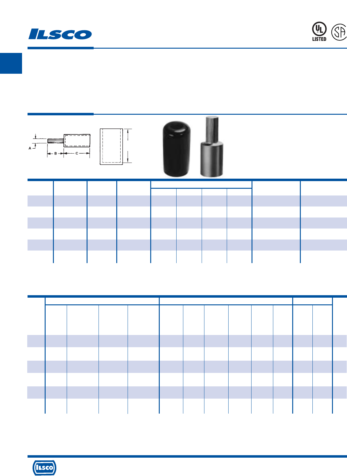
A
4730 Madison Road, Cincinnati, Ohio 45227-1426 Phone 513 533-6200 Fax 513 871-4084 Web site www.ilsco.com
Canada 1050 Lakeshore Road East, Mississauga, Ontario, Canada L5E1E4 Phone 905 274-2341 Fax 905 274-8763
59
ILSCO Burndy Thomas & Betts
ILC-12-N ILCB-12-N ILC-15H IDT-12-N Y750 Family Y-35 Y-39 Y-45 Y-46 Y644M 13642 13100A
ILC-12H-N 12 Ton 15 Ton
Die No. Die No. Die No. Die No. Die Index Die Index Die Index Die Index Die Index Dieless Die Index Die Index
Catalog No. of No. of No. of No. of No. of No. of No. of No. of No. of No. of No. of No. of Color
Number Crimps Crimps Crimps Crimps Crimps Crimps Crimps Crimps Crimps Crimps Crimps Crimps Code
ACM-3/0 ILD-12 ILD-12 ILD-12 298 298 298 298 298 66H 66H
(1) (1) (1) (1) (2*) (2*) (2*) (2*) (2*) (1) (2) (2) White
ACM-4/0 ILD-12 ILD-12 ILD-12 298 298 298 298 298 66H 66H
(1) (1) (1) (1) (2*) (2*) (2*) (2*) (2*) (1) (2) (2) White
ACM-250 ILD-14 ILD-14 ILD-14 299 299 299 299 299 87H 87H
(1) (1) (1) (1) (2*) (2*) (2*) (2*) (2*) (1) (2) (2) Brown
ACM-300 ILD-14 ILD-14 ILD-14 299 299 299 299 299 87H 87H
(1) (1) (1) (1) (2*) (2*) (2*) (2*) (2*) (1) (2) (2) Brown
ACM-350 ILD-14 ILD-14 ILD-14 299 299 299 299 299 87H 87H
(1) (1) (1) (1) (2*) (2*) (2*) (2*) (2*) (1) (2) (2) Brown
ACM-400 ILD-16A ILD-16A ILD-16A 300 300 300 300 300 99H 99H
(2) (2) (2) (1) (3) (3) (3) (3) (3) (1) (3) (3) Pink
Aluminum Pigtail Adaptor - Dual Rated
Conductor Range: 400kcmil-3/0
TYPE
ACM
Features
•
Manufactured from high strength aluminum alloy
•
Pin is knurled
•
Chamfered barrel
•
UL Listed and CSA Certified for 600 volts, 90˚ C
•
Clearly marked with wire size and die index for Ilsco
tools, proper number and location of crimps
•
Prefilled with DE-OX
•
Color coded end caps inserted in barrel
•
Supplied with insulating cover
Benefits
•
Provides maximum conductivity and excellent crimping characteristics
•
Permits greater surface contact
•
Provides easy conductor insertion
•
Ensures reliability for aluminum or copper conductors
•
Provides easy identification and tooling recommendation
•
Prevents oxides from forming
•
Prevents foreign materials from entering the connector prior to usage and
color code identifies the proper compression die
•
Eliminates taping
941R
L
R
-
2
9
6
0
1
*Overlap Crimps
See stuffer sheet for complete information on tooling.
Tested to UL 486A-486B, UL File E62525
Tooling Information
D
CONTINUED ON NEXT PAGE.
Catalog Wire Die Dimensions
Number Size Color Pin Size A B C D
(cover)
O.D. I.D.
ACM-3/0 3/0 White 1/0 3/8 1-7/32 1-3/8 2 55/64 1/2
ACM-4/0 4/0 White 2/0 27/64 1-7/32 1-3/8 2 55/64 35/64
ACM-250 250kcmil Brown 3/0 15/32 1-7/32 1-13/32 2-1/4 1-7/64 39/64
ACM-300 300kcmil Brown 4/0 17/32 1-11/32 1-13/32 2-1/4 1-7/64 21/32
ACM-350 350kcmil Brown 250kcmil 37/64 1-11/32 1-13/32 2-1/4 1-7/64 23/32
ACM-400 400kcmil Pink 300kcmil 5/8 1-39/64 2-1/32 3-1/4 1-21/64 49/64
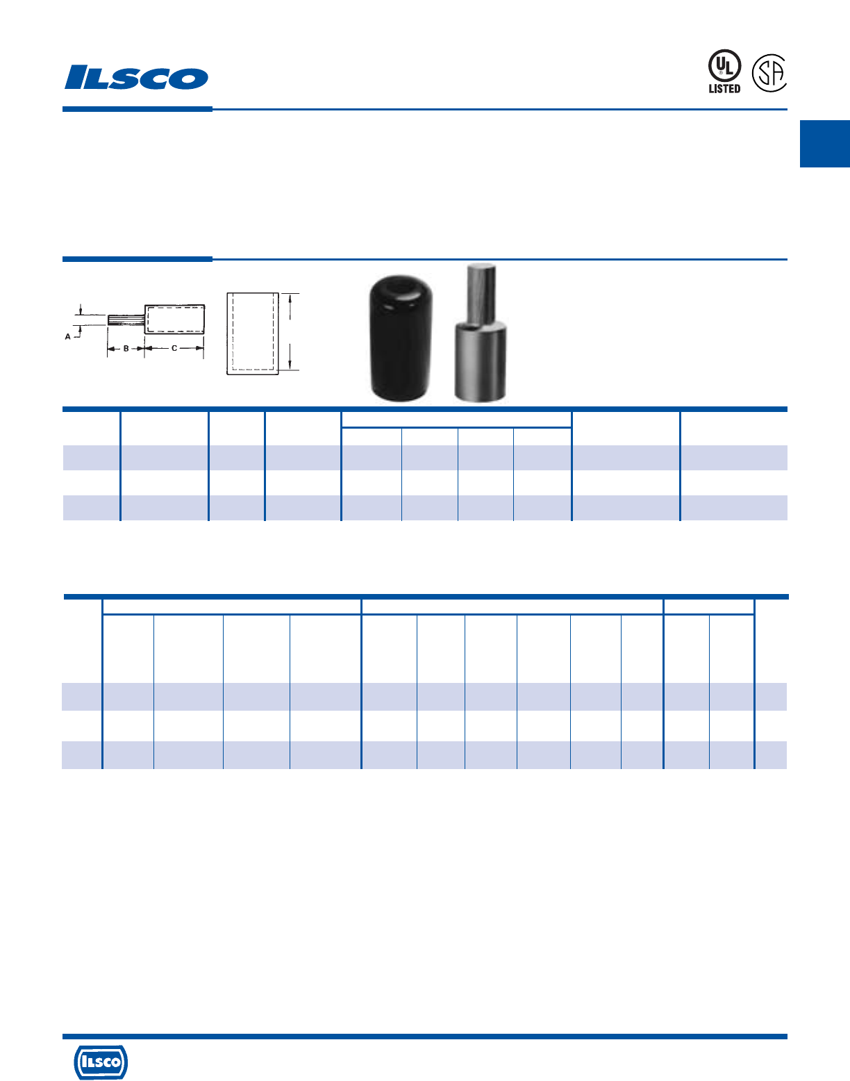
A
4730 Madison Road, Cincinnati, Ohio 45227-1426 Phone 513 533-6200 Fax 513 871-4084 Web site www.ilsco.com
Canada 1050 Lakeshore Road East, Mississauga, Ontario, Canada L5E1E4 Phone 905 274-2341 Fax 905 274-8763
60
ILSCO Burndy Thomas & Betts
ILC-12-N ILCB-12-N ILC-15H IDT-12-N Y750 Family Y-35 Y-39 Y-45 Y-46 Y644M 13642 13100A
ILC-12H-N 12 Ton 15 Ton
Die No. Die No. Die No. Die No. Die Index Die Index Die Index Die Index Die Index Dieless Die Index Die Index
Catalog No. of No. of No. of No. of No. of No. of No. of No. of No. of No. of No. of No. of Color
Number Crimps Crimps Crimps Crimps Crimps Crimps Crimps Crimps Crimps Crimps Crimps Crimps Code
ACM-500
ILD-16A ILD-16A ILD-16A 300 300 300 300 300 99H 99H
(2) (2) (2) (1) (3) (3) (3) (3) (3) (1) (3) (3) Pink
ACM-600
ILD-18 ILD-18 ILD-18 936 936 936 936 936 115H 115H
(3) (3) (3) (1) (3) (3) (3) (3) (3) (1) (3) (3) Yellow
ACM-750
ILD-18 ILD-18 ILD-18 936 936 936 936 936 115H 115H
(3) (3) (3) (1) (3) (3) (3) (3) (3) (1) (3) (3) Yellow
Aluminum Pigtail Adaptor - Dual Rated
Conductor Range: 750kcmil-500kcmil
TYPE
ACM
Features
•
Manufactured from high strength aluminum alloy
•
Pin is knurled
•
Chamfered barrel
•
UL Listed and CSA Certified for 600 volts, 90˚ C
•
Clearly marked with wire size and die index for Ilsco
tools, proper number and location of crimps
•
Prefilled with DE-OX
•
Color coded end caps inserted in barrel
•
Supplied with insulating cover
Benefits
•
Provides maximum conductivity and excellent crimping characteristics
•
Permits greater surface contact
•
Provides easy conductor insertion
•
Ensures reliability for aluminum or copper conductors
•
Provides easy identification and tooling recommendation
•
Prevents oxides from forming
•
Prevents foreign materials from entering the connector prior to usage and
color code identifies the proper compression die
•
Eliminates taping
941R
L
R
-
2
9
6
0
1
*Overlap Crimps
See stuffer sheet for complete information on tooling.
Tested to UL 486A-486B, UL File E62525
Tooling Information
Catalog Wire Die Dimensions
Number Size Color Pin Size A B C D
(cover)
O.D. I.D.
ACM-500 500kcmil Pink 350kcmil 11/16 1-39/64 2-1/32 3-1/4 1-21/64 55/64
ACM-600 600kcmil Yellow 400kcmil 47/64 1-41/64 2-1/32 3-1/4 1-15/32 59/64
ACM-750 750kcmil-700kcmil Yellow 500kcmil 13/16 1-49/64 2-1/32 3-1/4 1-15/32 1-1/32
D
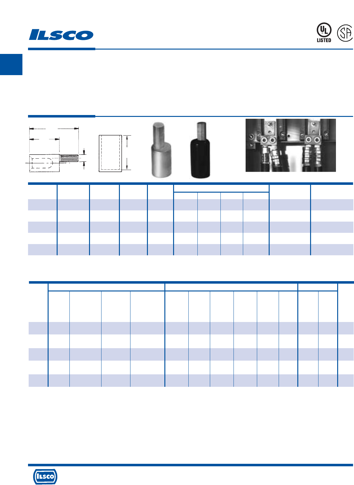
A
4730 Madison Road, Cincinnati, Ohio 45227-1426 Phone 513 533-6200 Fax 513 871-4084 Web site www.ilsco.com
Canada 1050 Lakeshore Road East, Mississauga, Ontario, Canada L5E1E4 Phone 905 274-2341 Fax 905 274-8763
61
Catalog Die Color Die Dimensions
Number Wire Size Code Index Pin Size F C A D (cover) O.D. I.D.
AC0-2/0 2/0 White 12 #1 2-7/32 1-3/8 11/32 2 55/64 7/16
AC0-3/0 3/0 White 12 1/0 2-19/32 1-3/8 3/8 2 55/64 1/2
AC0-4/0 4/0 White 12 2/0 2-19/32 1-3/8 27/64 2 55/64 35/64
AC0-250 250kcmil Brown 14 3/0 2-5/8 1-13/32 15/32 2-1/4 1-7/64 19/32
AC0-300 300kcmil Brown 14 4/0 2-3/4 1-13/32 17/32 2-1/4 1-7/64 21/32
ILSCO Burndy Thomas & Betts
ILC-12-N ILCB-12-N ILC-15H IDT-12-N Y750 Family Y-35 Y-39 Y-45 Y-46 Y644M 13642 13100A
ILC-12H-N 12 Ton 15 Ton
Die No. Die No. Die No. Die No. Die Index Die Index Die Index Die Index Die Index Dieless Die Index Die Index
Catalog No. of No. of No. of No. of No. of No. of No. of No. of No. of No. of No. of No. of Color
Number Crimps Crimps Crimps Crimps Crimps Crimps Crimps Crimps Crimps Crimps Crimps Crimps Code
ACO-2/0 ILD-12 ILD-12 ILD-12 298 298 298 298 298 66H 66
(1) (1) (1) (1) (2*) (2*) (2*) (2*) (2*) (1) (2) (2) White
ACO-3/0 ILD-12 ILD-12 ILD-12 298 298 298 298 298 66H 66
(1) (1) (1) (1) (2*) (2*) (2*) (2*) (2*) (1) (2) (2) White
ACO-4/0 ILD-12 ILD-12 ILD-12 298 298 298 298 298 66H 66
(1) (1) (1) (1) (2*) (2*) (2*) (2*) (2*) (1) (2) (2) White
ACO-250 ILD-14 ILD-14 ILD-14 299 299 299 299 299 87H 87
(1) (1) (1) (1) (2*) (2*) (2*) (2*) (2*) (1) (2) (2) Brown
ACO-300 ILD-14 ILD-14 ILD-14 299 299 299 299 299 87H 87
(1) (1) (1) (1) (2*) (2*) (2*) (2*) (2*) (1) (2) (2) Brown
Aluminum Offset Pigtail Adaptor
Dual Rated - Conductor Range: 300kcmil-2/0
Tooling Information
TYPE
ACO
Features
•
Manufactured from high strength aluminum alloy
•
Pin is knurled
•
Pin is off center
•
Chamfered barrel
•
UL Listed and CSA Certified for 600 volts, 90˚ C
•
Clearly marked with wire size and die index for Ilsco
tools, proper number and location of crimps
•
Prefilled with DE-OX
•
Color coded end caps inserted in barrel
•
Supplied with insulating cover
Benefits
•
Provides maximum conductivity and excellent crimping characteristics
•
Permits greater surface contact
•
Allows connectors to be rotated for parallel applications. Multiple conductor
lugs hole spacing does NOT permit insertion of straight pin connectors
•
Provides easy conductor insertion
•
Ensures reliability for aluminum or copper conductors
•
Provides easy identification and tooling recommendation
•
Prevents oxides from forming
•
Prevents foreign materials from entering the connector prior to usage and
color code identifies the proper compression die
•
Eliminates taping
L
R
-
2
9
6
0
1
941R
CONTINUED ON NEXT PAGE.
Cover and connector are packaged together (ONLY).
* Overlap Crimps
See stuffer sheet for complete information on tooling.
Tested to UL 486A-486B, UL File E62525
Lug Will Not Accept Straight Pin Offset Pin Design - Application
F
A
D
C
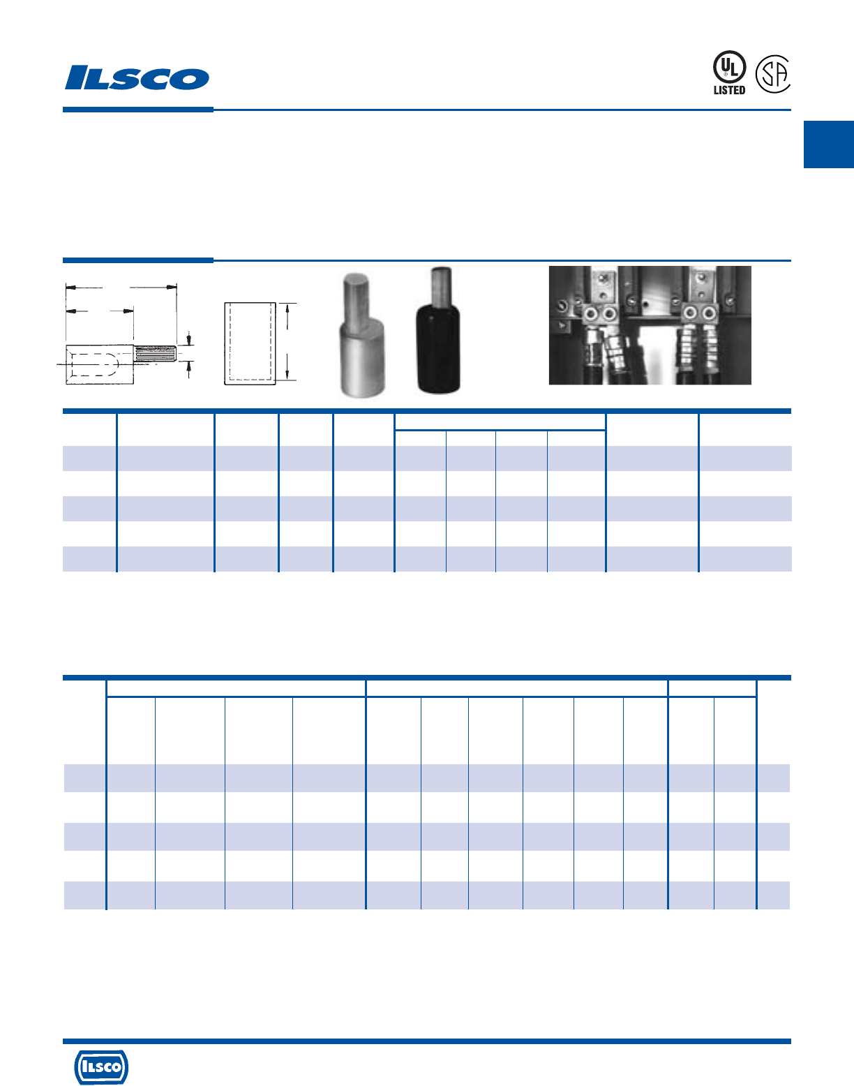
A
4730 Madison Road, Cincinnati, Ohio 45227-1426 Phone 513 533-6200 Fax 513 871-4084 Web site www.ilsco.com
Canada 1050 Lakeshore Road East, Mississauga, Ontario, Canada L5E1E4 Phone 905 274-2341 Fax 905 274-8763
62
Aluminum Offset Pigtail Adaptor
Dual Rated - Conductor Range: 1000kcmil-350kcmil
TYPE
ACO
Features
•
Manufactured from high strength aluminum alloy
•
Pin is knurled
•
Pin is off center
•
Chamfered barrel
•
UL Listed and CSA Certified for 600 volts, 90˚ C
•
Clearly marked with wire size and die index for Ilsco
tools, proper number and location of crimps
•
Prefilled with DE-OX
•
Color coded end caps inserted in barrel
•
Supplied with insulating cover
Benefits
•
Provides maximum conductivity and excellent crimping characteristics
•
Permits greater surface contact
•
Allows connectors to be rotated for parallel applications. Multiple conductor
lugs hole spacing does NOT permit insertion of straight pin connectors
•
Provides easy conductor insertion
•
Ensures reliability for aluminum or copper conductors
•
Provides easy identification and tooling recommendation
•
Prevents oxides from forming
•
Prevents foreign materials from entering the connector prior to usage and
color code identifies the proper compression die
•
Eliminates taping
L
R
-
2
9
6
0
1
941R
Lug Will Not Accept Straight Pin Offset Pin Design - Application
ILSCO Burndy Thomas & Betts
ILC-12-N ILCB-12-N ILC-15H IDT-12-N Y750 Family Y-35 Y-39 Y-45 Y-46 Y644M 13642 13100A
ILC-12H-N 12 Ton 15 Ton
Die No. Die No. Die No. Die No. Die Index Die Index Die Index Die Index Die Index Dieless Die Index Die Index
Catalog No. of No. of No. of No. of No. of No. of No. of No. of No. of No. of No. of No. of Color
Number Crimps Crimps Crimps Crimps Crimps Crimps Crimps Crimps Crimps Crimps Crimps Crimps Code
ACO-350 ILD-14 ILD-14 ILD-14 299 299 299 299 299 87H 87
(1) (1) (1) (1) (2*) (2*) (2*) (2*) (2*) (1) (2) (2) Brown
ACO-500 ILD-16A ILD-16A ILD-16A 300 300 300 300 300 99H 99H
(2) (2) (2) (1) (3) (3) (3) (3) (3) (1) (3) (3) Pink
ACO-600 ILD-18 ILD-18 ILD-18 936 936 936 936 936 115H 115H
(3) (3) (3) (1) (3) (3) (3) (3) (3) (1) (3) (3) Yellow
ACO-750 ILD-18 ILD-18 ILD-18 936 936 936 936 936 115H 115H
(3) (3) (3) (1) (3) (3) (3) (3) (3) (1) (3) (3) Yellow
ACO-1000 - - - - - - - - - - -
(1) (1)
Tooling Information
* Overlap Crimps
See stuffer sheet for complete information on tooling.
Tested to UL 486A-486B, UL File E62525
Catalog Die Color Die Dimensions
Number Wire Range Code Index Pin Size F C A D (cover) O.D. I.D.
ACO-350 350kcmil Brown 14 250kcmil 2-3/4 1-13/32 37/64 2-1/4 1-7/64 23/32
ACO-500 500kcmil Pink 16A 350kcmil 3-5/8 2-1/32 11/16 3-1/4 1-21/64 55/64
ACO-600 600kcmil Yellow 18 400kcmil 3-43/64 2-1/32 47/64 3-1/4 1-15/32 59/64
ACO-750 750kcmil-700kcmil Yellow 18 500kcmil 3-51/64 2-1/32 13/16 3-1/4 1-15/32 1-1/32
ACO-1000* 1000kcmil-750kcmil - - 600kcmil 4-1/32 2-1/32 29/32 - 1-45/64 1-3/16
A
C
F
D
Cover and connector are packaged together (ONLY).
* Not supplied with cover
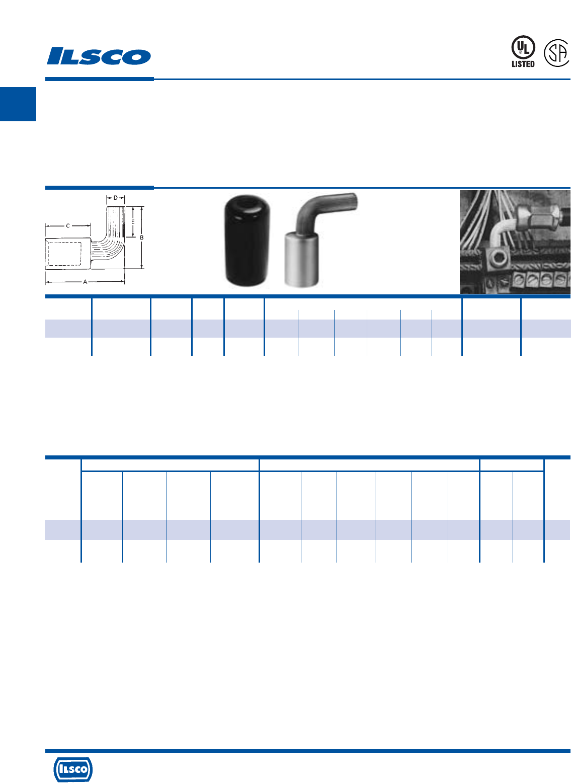
A
4730 Madison Road, Cincinnati, Ohio 45227-1426 Phone 513 533-6200 Fax 513 871-4084 Web site www.ilsco.com
Canada 1050 Lakeshore Road East, Mississauga, Ontario, Canada L5E1E4 Phone 905 274-2341 Fax 905 274-8763
63
Catalog Die Color Die
Number Wire Range Code Index Pin Size A B C D E Cover O.D. I.D.
ACO-90-350 350kcmil Brown 14 250kcmil 2.49 2.68 1.41 .57 1.34 2-1/4 1-7/64 23/32
ACO-90-500 500kcmil Pink 16A 350kcmil 3.30 3.16 2.03 .68 1.60 3-1/4 1-21/64 55/64
Aluminum 90˚ Pigtail Adaptor
Dual Rated - Conductor Range: 500kcmil-350kcmil
TYPE
ACO-90
Features
•
Manufactured from high strength aluminum alloy
•
Pin is bent
•
Pin is knurled
•
Chamfered barrel
•
UL Listed and CSA Certified for 600 volts, 90˚ C
•
Clearly marked with wire size and die index for Ilsco
tools, proper number and location of crimps
•
Prefilled with DE-OX
•
Color coded end caps inserted in barrel
•
Supplied with insulating cover
Benefits
•
Provides maximum conductivity and excellent crimping characteristics
•
Eliminates the need to bend the conductor. Designed for use in tight applications
where room for the required bending radius of the wire is not available
•
Permits greater surface contact
•
Provides easy conductor insertion
•
Ensures reliability for aluminum or copper conductors
•
Provides easy identification and tooling recommendation
•
Prevents oxides from forming
•
Prevents foreign materials from entering the connector prior to usage and color
code identifies the proper compression die
•
Eliminates taping
941R
L
R
-
2
9
6
0
1
Cover & Connector are packaged together (ONLY).
* Overlap Crimps
See stuffer sheet for complete information on tooling.
Tested to UL 486A-486B, UL File E62525
Tooling Information
ILSCO Burndy Thomas & Betts
ILC-12-N ILCB-12-N ILC-15H IDT-12-N Y750 Family Y-35 Y-39 Y-45 Y-46 Y644M 13642 13100A
ILC-12H-N 12 Ton 15 Ton
Die No. Die No. Die No. Die No. Die Index Die Index Die Index Die Index Die Index Dieless Die Index Die Index
Catalog No. of No. of No. of No. of No. of No. of No. of No. of No. of No. of No. of No. of Color
Number Crimps Crimps Crimps Crimps Crimps Crimps Crimps Crimps Crimps Crimps Crimps Crimps Code
ACO-90-350 ILD-14 ILD-14 ILD-14 299 299 299 299 299 87H 87
(1) (1) (2) (1) (2*) (2*) (2*) (2*) (2*) (1) (2) (2) Brown
ACO-90-500 ILD-16A ILD-16A ILD-16A 300 300 300 300 300 99H 99H
(2) (2) (2) (1) (3) (3) (3) (3) (3) (1) (3) (3) Pink
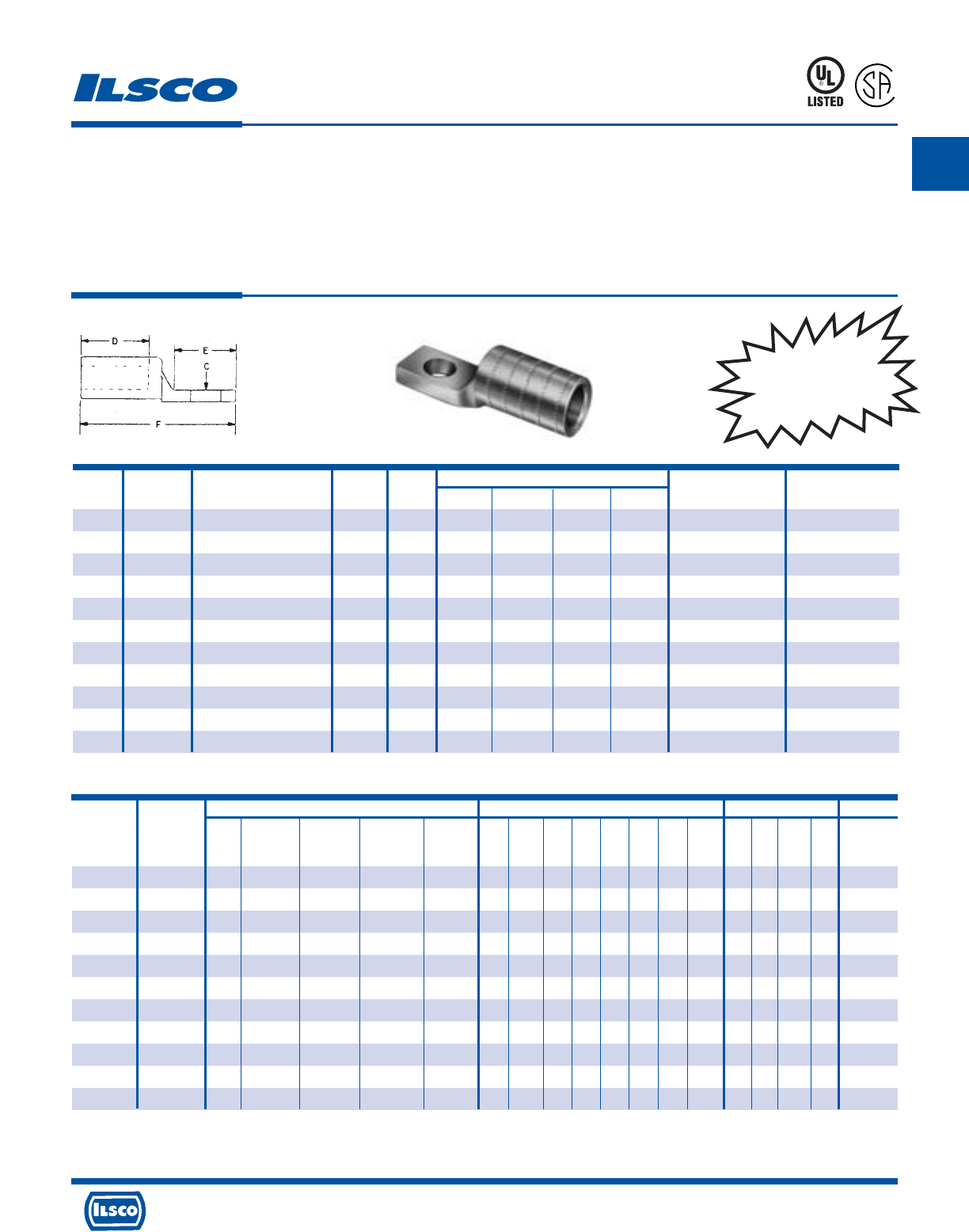
A
4730 Madison Road, Cincinnati, Ohio 45227-1426 Phone 513 533-6200 Fax 513 871-4084 Web site www.ilsco.com
Canada 1050 Lakeshore Road East, Mississauga, Ontario, Canada L5E1E4 Phone 905 274-2341 Fax 905 274-8763
64
Aluminum Compression Lugs
Narrow Tang
TYPE
IACL
Features
•
Manufactured from high strength aluminum alloy
•
Four OD sizes accommodate a wire range from #4 to
600 kcmil
•
Chamfered barrel
•
Prefilled with DE-OX
•
Color coded end caps inserted in barrel and ink
marked with die number and number of crimps
•
Electro tin plated
•
UL Listed for 600 volts, 90˚ C
•
Dual Rated
Benefits
•
Provides maximum conductivity and excellent crimping
characteristics
•
Requires only four installation dies to crimp eleven conductor
sizes. Tang width remains constant within an OD size and is
designed to fit transformer pads.
•
Provides easy conductor insertion
•
Prevents oxides from forming
•
Prevents foreign materials from entering the connector prior to
usage and color code identifies the proper compression die
•
Provides low contact resistance
•
Ensures reliability
453G
L
R
-
2
9
6
0
1
Catalog Wire
Wire Range When
Tang Bolt Dimensions Ilsco Die Color
Number Size
Installed With IDT-12-N Tool
Width Size D E F C Die Index Code
IACL-4 4 4-6 29/32 1/2 1-7/16 1-3/32 3 9/16 9 Orange
IACL-2 2 2-6 29/32 1/2 1-7/16 1-3/32 3 9/16 9 Orange
IACL-1/0 1/0 1/0-1 29/32 1/2 1-7/16 1-3/32 3 9/16 9 Orange
IACL-2/0 2/0 2/0-1 29/32 1/2 1-7/16 1-9/32 3-3/16 9/16 12 White
IACL-3/0 3/0 3/0-1 29/32 1/2 1-7/16 1-9/32 3-3/16 9/16 12 White
IACL-4/0 4/0 4/0-1 29/32 1/2 1-7/16 1-9/32 3-3/16 9/16 12 White
IACL-250 250kcmil 250kcmil-1/0 29/32 1/2 1-7/16 1-9/32 3-3/16 9/16 12 White
IACL-300 300kcmil 300kcmil-2/0 1-1/4 1/2 1-3/4 1-5/16 3-11/16 9/16 14 Blue
IACL-350 350kcmil 350kcmil-3/0 1-1/4 1/2 1-3/4 1-5/16 3-11/16 9/16 14 Blue
IACL-500 500kcmil 500kcmil-4/0 1-1/4 1/2 1-3/4 1-5/16 3-11/16 9/16 14 Blue
IACL-600 600kcmil 600kcmil-250kcmil 1-19/32 1/2 3-3/16 1-5/8 5-3/4 9/16 18 Yellow
ILSCO Burndy
ILC-12-N
Catalog Die ILC-12H-N ILCB-12-N ILC-15H IDT-12-N Die Y34A Y35 Y39 Y45 Y46 Y48B Y644M Die
Number Color Index 12 Ton Dieless Index Dieless Index
IACL-4 Orange 9 (3) (3) (2) (1) 297 (2) (2) (2) (2) (2) (2) (1) 50
IACL-2 Orange 9 (3) (3) (2) (1) 297 (2) (2) (2) (2) (2) (2) (1) 50
IACL-1/0 Orange 9 (3) (3) (2) (1) 297 (2) (2) (2) (2) (2) (2) (1) 50
IACL-2/0 White 12 (1) (1) (2) (1) 324 (2) (2) (2) (2) (2) (2) (1) 71
IACL-2/0 White 12 (1) (1) (2) (1) 324 (2) (2) (2) (2) (2) (2) (1) 71
IACL-2/0 White 12 (1) (1) (2) (1) 324 (2) (2) (2) (2) (2) (2) (1) 71
IACL-250 White 12 (1) (1) (2) (1) 324 (2) (2) (2) (2) (2) (2) (1) 71
IACL-300 Blue 14 (2) (2) (2) (1) 299 - (2) (2) (2) (2) (2) (1) 87
IACL-350 Blue 14 (2) (2) (2) (1) 299 - (2) (2) (2) (2) (2) (1) 87
IACL-500 Blue 14 (2) (2) (2) (1) 299 - (2) (2) (2) (2) (2) (1) 87
IACL-600 Yellow 18 (3) (3) (3) (1) 936 - - (3) (3) (3) (3) (1) 115
Thomas & Betts
Anderson
13642 TBM 15 21940 VC-6 - Ft.
12 15 40 Dieless No.
Ton Ton Ton of Crimps
(2) (2) (2) (2)
(2) (2) (2) (2)
(2) (2) (2) (2)
(2) (2) (2) (2)
(2) (2) (2) (2)
(2) (2) (2) (2)
(2) (2) (2) (2)
(2) (2) (2) (2)
(2) (2) (2) (2)
(2) (2) (2) (2)
(3) (3) (3) -
Tooling Information
Formerly
UCL
Series
* UL Listed for 600 volts maximum when installed with tools and dies shown above. If proper high voltage spacings and insulation techniques are used, these compression
connectors can be used for high voltage applications up to 35KV.
See stuffer sheet for complete information on tooling. Tested to UL 486A-486B, UL File E6207
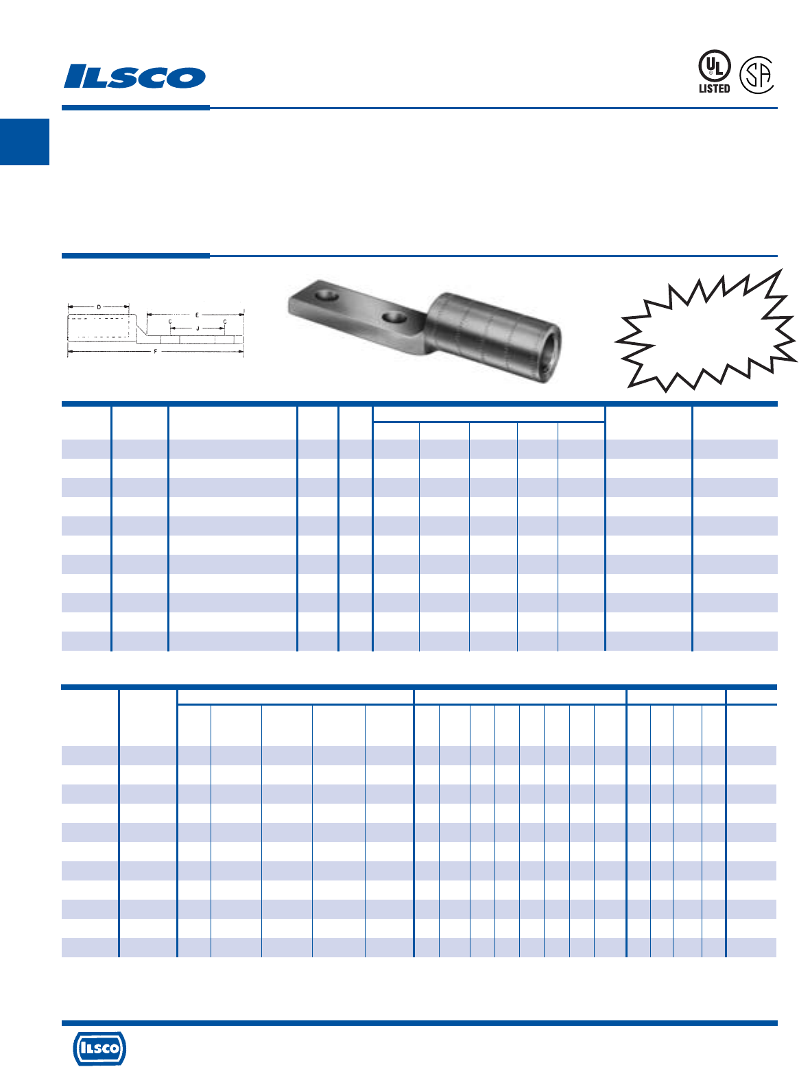
A
4730 Madison Road, Cincinnati, Ohio 45227-1426 Phone 513 533-6200 Fax 513 871-4084 Web site www.ilsco.com
Canada 1050 Lakeshore Road East, Mississauga, Ontario, Canada L5E1E4 Phone 905 274-2341 Fax 905 274-8763
65
Aluminum Compression Lugs
Narrow Tang
TYPE
2IACL
Features
•
Manufactured from high strength aluminum alloy
•
Four OD sizes accommodate a wire range from 1/0 to
1000 kcmil
•
Chamfered barrel
•
Prefilled with DE-OX
•
Color coded end caps inserted in barrel and ink
marked with die number and number of crimps
•
Electro tin plated
•
UL Listed for 600 volts, 90˚ C
•
Dual Rated
Benefits
•
Provides maximum conductivity and excellent crimping
characteristics
•
Requires only four installation dies to crimp eleven conductor
sizes. Tang width remains constant within an OD size and is
designed to fit transformer pads.
•
Provides easy conductor insertion
•
Prevents oxides from forming
•
Prevents foreign materials from entering the connector prior to
usage and color code identifies the proper compression die
•
Provides low contact resistance
•
Ensures reliability
Catalog Wire
Wire Range When
Tang Bolt Dimensions Ilsco Die Color
Number Size
Installed With IDT-12-N Tool
Width Size D E F C J Die Index Code
2IACL-1/0 1/0 1/0-1 1 1/2 1-1/2 3-1/4 5-3/16 9/16(2) 1-3/4 9 Orange
2IACL-2/0 2/0 2/0-1 1-1/4 1/2 1-7/8 3-1/4 5-3/4 9/16(2) 1-3/4 12 White
2IACL-3/0 3/0 3/0-1 1-1/4 1/2 1-7/8 3-1/4 5-3/4 9/16(2) 1-3/4 12 White
2IACL-4/0 4/0 4/0-1 1-1/4 1/2 1-7/8 3-1/4 5-3/4 9/16(2) 1-3/4 12 White
2IACL-250 250kcmil 250kcmil-1/0 1-1/4 1/2 1-7/8 3-1/4 5-3/4 9/16(2) 1-3/4 12 White
2IACL-300 300kcmil 300kcmil-2/0 1-1/4 1/2 2-3/8 3-1/4 6 9/16(2) 1-3/4 14 Blue
2IACL-350 350kcmil 350kcmil-3/0 1-1/4 1/2 2-3/8 3-1/4 6 9/16(2) 1-3/4 14 Blue
2IACL-500 500kcmil 500kcmil-4/0 1-1/4 1/2 2-3/8 3-1/4 6 9/16(2) 1-3/4 14 Blue
2IACL-600 600kcmil 600kcmil-250kcmil 1-39/64 1/2 3-3/16 3-1/4 7 9/16(2) 1-3/4 18 Yellow
2IACL-750 750kcmil 750kcmil-500kcmil 1-39/64 1/2 3-3/16 3-1/4 7-1/4 9/16(2) 1-3/4 18 Yellow
2IACL-1000
1000kcmil 1000kcmil-750kcmil 1-39/64 1/2 3-3/16 3-1/4 7-1/4 9/16(2) 1-3/4 18 Yellow
453G
L
R
-
2
9
6
0
1
ILSCO Burndy
ILC-12-N
Catalog Die ILC-12H-N ILCB-12-N ILC-15H IDT-12-N Die Y34A Y35 Y39 Y45 Y46 Y48B Y644M Die
Number Color Index 12 Ton Dieless Index Dieless Index
2IACL-1/0 Orange 9 (3) (3) (2) (1) 297 (2) (2) (2) (2) (2) (2) (1) 50
2IACL-2/0 White 12 (1) (1) (2) (1) 324 (2) (2) (2) (2) (2) (2) (1) 71
2IACL-2/0 White 12 (1) (1) (2) (1) 324 (2) (2) (2) (2) (2) (2) (1) 71
2IACL-250 White 12 (1) (1) (2) (1) 324 (2) (2) (2) (2) (2) (2) (1) 71
2IACL-2/0 White 12 (1) (1) (2) (1) 324 (2) (2) (2) (2) (2) (2) (1) 71
2IACL-300 Blue 14 (2) (2) (2) (1) 299 - (2) (2) (2) (2) (2) (1) 87
2IACL-350 Blue 14 (2) (2) (2) (1) 299 - (2) (2) (2) (2) (2) (1) 87
2IACL-500 Blue 14 (2) (2) (2) (1) 299 - (2) (2) (2) (2) (2) (1) 87
2IACL-600 Yellow 18 (3) (3) (3) (1) 936 - - (3) (3) (3) (3) (1) 115
2IACL-750 Yellow 18 (3) (3) (3) (1) 936 - - (3) (3) (3) (3) (1) 115
2IACL-1000 Yellow 18 - - (3) (1) 936 - - (3) (3) (3) (3) (1) 115
Thomas & Betts
Anderson
13642 TBM 15 21940 VC-6 - Ft.
12 15 40 Dieless No.
Ton Ton Ton of Crimps
(2) (2) (2) (2)
(2) (2) (2) (2)
(2) (2) (2) (2)
(2) (2) (2) (2)
(2) (2) (2) (2)
(2) (2) (2) (2)
(2) (2) (2) (2)
(2) (2) (2) (2)
(3) (3) (3) -
(3) (3) (3) -
(3) (3) (3)
Tooling Information
Formerly
2UCL
Series
* UL Listed for 600 volts maximum when installed with tools and dies shown above. If proper high voltage spacings and insulation techniques are used, these compression
connectors can be used for high voltage applications up to 35KV.
See stuffer sheet for complete information on tooling. Tested to UL 486A-486B, UL File E6207

A
4730 Madison Road, Cincinnati, Ohio 45227-1426 Phone 513 533-6200 Fax 513 871-4084 Web site www.ilsco.com
Canada 1050 Lakeshore Road East, Mississauga, Ontario, Canada L5E1E4 Phone 905 274-2341 Fax 905 274-8763
66
UL Listed and CSA
Certified Range-Taking
When Installed with
IDT-12-N Tool
Wire Range
Catalog Wire When Installed Die Color Die
Number Size With IDT-12-N Tool Code L Index O.D. I.D.
AS-8 8 8 Blue 1-3/16 2 5/16 5/32
AS-6 6 6 Gray 1-5/8 3 11/32 3/16
AS-4 4 4-6 Green 1-7/8 4 7/16 1/4
AS-2 2 2-6 Pink 2-3/8 7 17/32 5/16
AS-1 1 1-2 Gold 2-3/8 7 35/64 23/64
AS-1/0 1/0 1/0 - 1 Tan 2-3/8 8 39/64 25/64
AS-2/0 2/0 2/0 - 1 Olive 2-1/2 10 43/64 7/16
Aluminum Compression Sleeves
Conductor Range: 2/0-#8
TYPE
AS
Features
•
Electro-tin plated
•
Manufactured from high strength aluminum alloy
•
Chamfered barrel
•
UL Listed and CSA Certified for 600 volts, 90˚ C
•
Color coded
•
Center wire stop
•
Clearly marked with wire size and die index for Ilsco
tools, proper number and location of crimps
•
Prefilled with DE-OX
•
Color coded end caps inserted in each end
Benefits
•
Provides low contact resistance
•
Provides maximum conductivity and excellent crimping characteristics
•
Provides easy conductor insertion
•
Ensures reliability for copper or aluminum conductors
•
Provides visual tooling recommendation for Ilsco or standard industry tools
•
Prevents dissimilar metals from coming into contact and insures that
conductors are fully inserted
•
Provides easy identification and tooling recommendation
•
Prevents oxides from forming
•
Prevents foreign materials from entering the connector prior to usage and
color code identifies the proper compression die
453G
L
R
-
2
9
6
0
1
UL Listed and CSA Certified 600 volts maximum when installed with tools and dies shown above. If proper high voltage spacings and insulation techniques are used, the
aluminum compression connectors can be used for high voltage applications up to 35KV.
See stuffer sheet for complete information on tooling. Tested to UL 486A-486B, UL File E6207
CONTINUED ON NEXT PAGE.
Tooling Information
L
I.D. O.D.
Anderson
TBM-8 Versa
Hand Crimp
Tool Dieless
No. of No. of Color
Crimps Crimps Code
--
(1) Blue
--
(2) Gray
--
(2) (1) Green
--
(2) (1) Pink
--
(3) (2) Gold
--
(3) (2) Tan
--
(3) (2) Olive
ILSCO Burndy Thomas & Betts
ILC-12-N ILCB-12-N IDTB-6 IDT-6, IDT-6H ILC-15H MT-25 94285 IDT-12-N Y-35 Y-39 Y-45 Y-46 MY29-3 Y644M
13642
TBM 15 21940
ILC-12H-N 6.2 Ton Hand Left Rt. Hand 12 Ton 15 Ton 40 Ton
Die No. Die No. Dieless Dieless Die No. Dieless Die Die Dieless Die Index Die Index Die Index Die Index Dieless Dieless
Die Index Die Index Die Index
Catalog No. of No. of No. of No. of No. of No. of No. of No. of No. of No. of No. of No. of No. of No. of No. of No. of No. of
Number Crimps Crimps Crimps Crimps Crimps Crimps Crimps Crimps Crimps Crimps Crimps Crimps Crimps Crimps Crimps Crimps Crimps
AS-8 ILD-2 ILD-2 - - ILD-2 - M/K - - - - - - - 24 24 24
(1) (1) (1) (1) (2) (1) (1) (2)
AS-6 ILD-3 ILD-3 - - ILD-3 - K/K - 346 346 346 346 - - 29 29 29
(1) (1) (1) (1) (1) (1) (2) (1) (1) (1) (1) (1) (1) (1) (2) (2) (2)
AS-4 ILD-4 ILD-4 - - ILD-4 - H/H - 375 375 375 375 - - 37 37 37
(2) (2) (1) (1) (2) (1) (3) (1) (1) (1) (1) (1) (1) (1) (2) (2) (2)
AS-2 ILD-7 (1) ILD-7 (1) - - ILD-7 (1) - E/A - 348 348 348 348 - - 42 42H 42
ILD-6 (3) ILD-6 (3) (2) (2) ILD-6 (3) (2) (3) (1) (1) (1) (1) (1) (2) (1) (2) (4) (2)
AS-1 ILD-7 (1) ILD-7 (1) - - ILD-7 (1) - E/A - 471 471 471 471 - - 45 45 45
ILD-6 (4) ILD-6 (4) (2) (2) ILD-6 (4) (2) (4) (1) (1) (1) (1) (1) (2) (1) (3) (3) (3)
AS-1/0 ILD-8 ILD-8 - - ILD-8 - A/C - 296 296 296 296 - - 50 50 50
(1) (1) (2) (2) (1) (2) (5) (1) (1) (1) (1) (1) (2) (1) (3) (3) (3)
AS-2/0 ILD-10 ILD-10 - - ILD-10 - A/B - 297 297 297 297 - - 54 54H 54
(1) (1) (2) (2) (1) (2) (4) (1) (2) (2) (2) (2) (2) (1) (3) (6) (3)
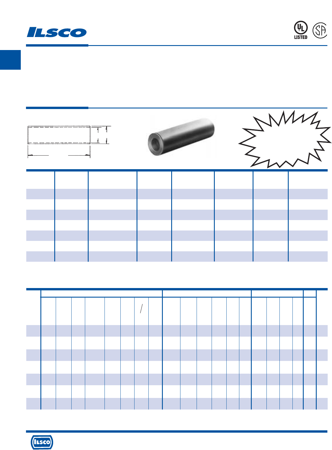
A
4730 Madison Road, Cincinnati, Ohio 45227-1426 Phone 513 533-6200 Fax 513 871-4084 Web site www.ilsco.com
Canada 1050 Lakeshore Road East, Mississauga, Ontario, Canada L5E1E4 Phone 905 274-2341 Fax 905 274-8763
67
Aluminum Compression Sleeves
Conductor Range: 500kcmil-3/0
TYPE
AS
Features
•
Electro-tin plated
•
Manufactured from high strength aluminum alloy
•
Chamfered barrel
•
UL Listed and CSA Certified for 600 volts, 90˚ C
•
Color coded
•
Center wire stop
•
Clearly marked with wire size and die index for Ilsco
tools, proper number and location of crimps
•
Prefilled with DE-OX
•
Color coded end caps inserted in each end
Benefits
•
Provides low contact resistance
•
Provides maximum conductivity and excellent crimping characteristics
•
Provides easy conductor insertion
•
Ensures reliability for copper or aluminum conductors
•
Provides visual tooling recommendation for Ilsco or standard industry tools
•
Prevents dissimilar metals from coming into contact and insures that
conductors are fully inserted
•
Provides easy identification and tooling recommendation
•
Prevents oxides from forming
•
Prevents foreign materials from entering the connector prior to usage and
color code identifies the proper compression die
453G
L
R
-
2
9
6
0
1
Wire Range
Catalog Wire When Installed Die Color Die
Number Size With IDT-12-N Tool Code L Index O.D. I.D.
AS-3/0 3/0 3/0-1 Ruby 2-5/8 10 49/64 1/2
AS-4/0 4/0 4/0-1 White 3-11/16 12 55/64 9/16
AS-250 250kcmil 250kcmil-1/0 Red 3-15/16 13 59/64 39/64
AS-300 300kcmil 300kcmil-2/0 Blue 4-1/16 14 1-1/64 21/32
AS-350 350kcmil 350kcmil-3/0 Brown 5-1/16 14 1-7/64 23/32
AS-400 400kcmil 400kcmil-4/0 Green 5-1/16 16 1-3/16 49/64
AS-500 500kcmil 500kcmil-4/0 Pink 5-1/16 16A 1-5/16 55/64
UL Listed and CSA Certified 600 volts maximum when installed with tools and dies shown above. If proper high voltage spacings and insulation techniques are used, the
aluminum compression connectors can be used for high voltage applications up to 35KV.
See stuffer sheet for complete information on tooling. Tested to UL 486A-486B, UL File E6207
Tooling Information
L
I.D. O.D.
CONTINUED ON NEXT PAGE.
ILSCO Burndy Thomas & Betts
ILC-12-N ILCB-12-N IDTB-6 IDT-6, IDT-6H ILC-15H MT-25 94285 IDT-12-N Y-35 Y-39 Y-45 Y-46 MY29-3 Y644M
13642
TBM 15 21940
ILC-12H-N 6.2 Ton Hand Left Rt. Hand 12 Ton 15 Ton 40 Ton
Die No. Die No. Dieless Dieless Die No. Dieless Die Die Dieless Die Index Die Index Die Index Die Index Dieless Dieless
Die Index Die Index Die Index
Catalog No. of No. of No. of No. of No. of No. of No. of No. of No. of No. of No. of No. of No. of No. of No. of No. of No. of
Number Crimps Crimps Crimps Crimps Crimps Crimps Crimps Crimps Crimps Crimps Crimps Crimps Crimps Crimps Crimps Crimps Crimps
AS-3/0 ILD-10 ILD-10 - - ILD-10 - A/A - 467 467 467 467 - - 60 60 60
(2) (2) (3) (3) (2) (2) (4) (1) (2) (2) (2) (2) (2) (1) (3) (3) (3)
AS-4/0 ILD-12 ILD-12 - - ILD-12 - - - 298 298 298 298 - - 66H 66 66
(1) (1) (3) (3) (1) (2) (2) (2) (2) (2) (2) (2) (1) (4) (2) (2)
AS-250 ILD-13 ILD-13 - - ILD-13 - - - 324 324 324 324 - - 71H 71H 71
(2) (2) (3) (3) (2) (2) (2) (2) (2) (2) (1) (4) (4) (2)
AS-300 ILD-14 ILD-14 - - ILD-14 - - - 470 470 470 470 - - 76H 76 76
(2) (2) (4) (4) (2) (2) (2) (2) (2) (2) (1) (4) (2) (2)
AS-350 ILD-14 ILD-14 - - ILD-14 - - - 299 299 299 299 - - 87H 87H 87
(2) (2) (4) (4) (2) (2) (2) (2) (2) (2) (1) (4) (4) (2)
AS-400 ILD-16 ILD-16 - - ILD-16 - - - 472 472 472 472 - - 94H 94H 94
(3) (3) (4) (4) (3) (2) (4) (4) (4) (4) (1) (4) (4) (2)
AS-500
ILD-16A ILD-16A
--
ILD-16A
- - - 300 300 300 300 - - 99H 99H 99
(3) (3) (4) (4) (3) (2) (4) (4) (4) (4) (1) (4) (4) (2)
Anderson
TBM-8
Versa
Hand Crimp
Tool
Dieless
No. of No. of Color
Crimps Crimps Code
--
(3) (2) Ruby
--
(5) (3) White
--
(5) (3) Red
--
(5) (3) Blue
--
(6) (3)
Brown
--
(4) Green
--
(4) Pink
UL Listed and CSA
Certified Range-Taking
When Installed with
IDT-12-N Tool
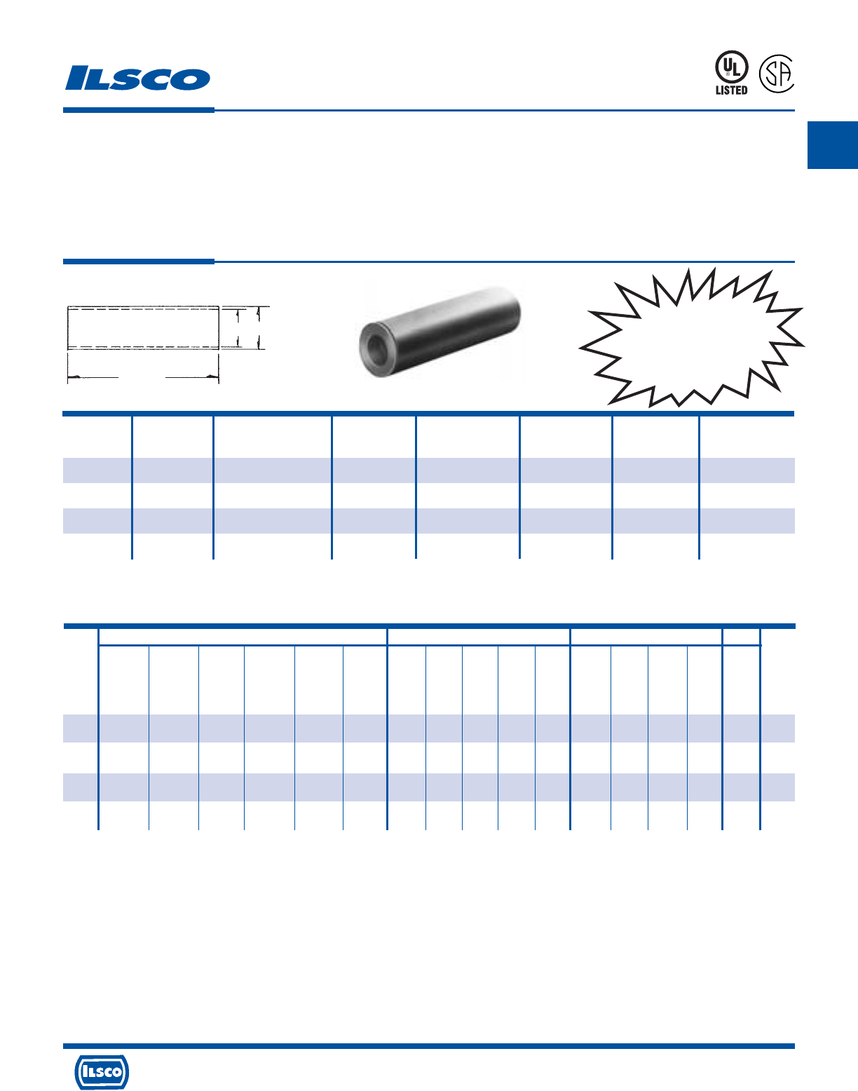
A
4730 Madison Road, Cincinnati, Ohio 45227-1426 Phone 513 533-6200 Fax 513 871-4084 Web site www.ilsco.com
Canada 1050 Lakeshore Road East, Mississauga, Ontario, Canada L5E1E4 Phone 905 274-2341 Fax 905 274-8763
68
Aluminum Compression Sleeves
Conductor Range: 1000kcmil-600kcmil
TYPE
AS
Features
•
Electro-tin plated
•
Manufactured from high strength aluminum alloy
•
Chamfered barrel
•
UL Listed and CSA Certified for 600 volts, 90˚ C
•
Color coded
•
Center wire stop
•
Clearly marked with wire size and die index for Ilsco
tools, proper number and location of crimps
•
Prefilled with DE-OX
•
Color coded end caps inserted in each end
Benefits
•
Provides low contact resistance
•
Provides maximum conductivity and excellent crimping characteristics
•
Provides easy conductor insertion
•
Ensures reliability for copper or aluminum conductors
•
Provides visual tooling recommendation for Ilsco or standard industry tools
•
Prevents dissimilar metals from coming into contact and insures that
conductors are fully inserted
•
Provides easy identification and tooling recommendation
•
Prevents oxides from forming
•
Prevents foreign materials from entering the connector prior to usage and
color code identifies the proper compression die
453G
L
R
-
2
9
6
0
1
Wire Range
Catalog Wire When Installed Die Color Die
Number Size With IDT-12-N Tool Code L Index O.D. I.D.
AS-600 600kcmil 600kcmil-250kcmil Black 5-5/16 17 1-5/16 59/64
AS-700 700kcmil 700kcmil-350kcmil Purple 5-13/16 17 1-13/32 1
AS-750 750kcmil 750kcmil-500kcmil Yellow 5-13/16 18 1-29/64 1-1/32
AS-1000 1000kcmil 1000kcmil-750kcmil Brown 7-1/8 20 1-53/64 1-3/16
UL Listed and CSA Certified 600 volts maximum when installed with tools and dies shown above. If proper high voltage spacings and insulation techniques are used, the
aluminum compression connectors can be used for high voltage applications up to 35KV.
See stuffer sheet for complete information on tooling.
Tested to UL 486A-486B, UL File E6207
Tooling Information
L
I.D. O.D.
ILSCO Burndy Thomas & Betts
Anderson
ILC-12-N ILCB-12-N IDTB-6 IDT-6, IDT-6H ILC-15H IDT-12-N Y-35 Y-39 Y-45 Y-46
Y644M
13642 TBM 15 21940 TBM Versa
ILC-12H-N 6.2 Ton 12 Ton 15 Ton 40 Ton Hand Crimp
Die No. Die No. Dieless Dieless Die No. Dieless
Die Index Die Index Die Index Die Index
Dieless
Die Index Die Index Die Index
Tool
Dieless
Catalog No. of No. of No. of No. of No. of No. of No. of No. of No. of No. of No. of No. of No. of No. of No. of No. of Color
Number Crimps Crimps Crimps Crimps Crimps Crimps Crimps Crimps Crimps Crimps Crimps Crimps Crimps Crimps Crimps Crimps Code
AS-600 ILD-17 ILD-17 - - ILD-17 - 473 473 473 473 - 106H 106 106 - -
(4) (4) (4) (4) (4) (2) (4) (4) (4) (4) (1) (4) (2) (2) (4) Black
AS-700 ILD-17 ILD-17 - - ILD-17 - - 936 936 936 - 112H 112H 112 - -
(4) (4) (4) (4) (4) (2) (4) (4) (4) (1) (4) (4) (2) Purple
AS-750 ILD-18 ILD-18 - - ILD-18 - - 936 936 936 - 115H 115H 115 - -
(5) (5) (4) (4) (5) (2) (4) (4) (4) (1) (4) (4) (2) Yellow
AS-1000
- - - - - - - - - - - - 140H 140 - -
(3) (2) (1) (4) (2) Brown
UL Listed and CSA
Certified Range-Taking
When Installed with
IDT-12-N Tool
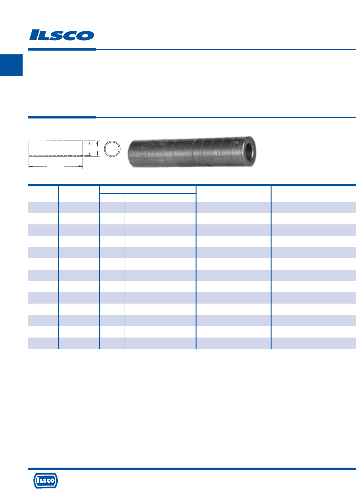
A
4730 Madison Road, Cincinnati, Ohio 45227-1426 Phone 513 533-6200 Fax 513 871-4084 Web site www.ilsco.com
Canada 1050 Lakeshore Road East, Mississauga, Ontario, Canada L5E1E4 Phone 905 274-2341 Fax 905 274-8763
69
Catalog Wire Dimensions
Number Range L O.D. I.D. Installing Dies Die Index
UCS-4-Z 4 3" 41/64 9/32 BG, 5/8, 8A 9
UCS-2-Z 2 3" 41/64 11/32 BG, 5/8, 8A 9
UCS-1/0-Z 1/0 3" 41/64 27/64 BG, 5/8, 8A 9
UCS-2/0-Z 2/0 4" 29/32 7/16 249, 840, TX, 76, 11A 13
UCS-3/0-Z 3/0 4" 29/32 1/2 249, 840, TX, 76, 11A 13
UCS-4/0-Z 4/0 4" 29/32 9/16 249, 840, TX, 76, 11A 13
UCS-250-Z 250kcmil 4" 29/32 19/32 249, 840, TX, 76, 11A 13
UCS-300-Z 300kcmil 5" 1-5/32 21/32 299, 655, 705, 1-1/8, 13A 14
UCS-350-Z 350kcmil 5" 1-5/32 45/64 299, 655, 705, 96, 1-1/8, 13A 14
UCS-500-Z 500kcmil 5" 1-5/32 27/32 299, 655, 705, 96, 1-1/8, 13A 14
UCS-600-Z 600kcmil 6" 1-39/64 59/64 301, 1-1/2, 140 18
UCS-700/750-Z 750kcmil - 700kcmil 6" 1-39/64 1-1/32 301, 1-1/2, 140, 72H 18
UCS-1000-Z 1000kcmil 7" 1-39/64 1-3/16 301, 1-1/2, 140, 72H 18
Aluminum Compression Sleeves - Utility Type
TYPE
UCS
Features
•
Manufactured from high strength aluminum alloy,
rated for 600 volts, 90˚ C
•
Four OD sizes accommodate a wire range from
1000kcmil to #4
•
Chamfered barrel
•
Prefilled with DE-OX
•
Solid barrier in center
•
Color coded end caps inserted in barrel
Benefits
•
Provides maximum conductivity and excellent crimping
characteristics
•
Requires only four installation dies to crimp fourteen
conductor sizes.
•
Provides easy conductor insertion
•
Prevents oxides from forming
•
Prevents dissimilar metals from coming into contact
•
Prevents foreign materials from entering the connector prior to
usage and color code identifies the proper compression die
L
I.D. O.D.
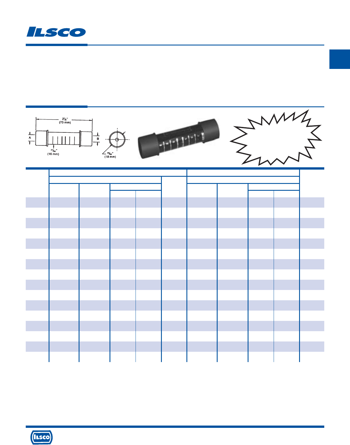
A
4730 Madison Road, Cincinnati, Ohio 45227-1426 Phone 513 533-6200 Fax 513 871-4084 Web site www.ilsco.com
Canada 1050 Lakeshore Road East, Mississauga, Ontario, Canada L5E1E4 Phone 905 274-2341 Fax 905 274-8763
70
End “A” End “B”
Conductor Range Conductor Range
Catalog Diameter Color Diameter Color
Number ACSR AWG max. min. Code ACSR AWG max. min. Code
PICS-61 - 6 sol - 8 str 0.162 0.144 Green - 6 sol - 8 str 0.162 0.144 Green
PICS-62 6 4 sol - 6 str 0.204 0.184 Blue - 8 sol - 10 str 0.128 0.114 Brown
PICS-63 6 4 sol - 6 str 0.204 0.184 Blue - 6 sol - 8 str 0.162 0.144 Green
PICS-64 6 4 sol - 6 str 0.204 0.184 Blue 6 4 sol - 6 str 0.204 0.184 Blue
PICS-65 4 2 sol - 3-4 str 0.258 0.213 Orange - 8 sol - 10 str 0.128 0.114 Brown
PICS-66 4 2 sol - 3-4 str 0.258 0.213 Orange - 6 sol - 8 str 0.162 0.144 Green
PICS-67 4 2 sol - 3-4 str 0.258 0.213 Orange 6 4 sol - 6 str 0.204 0.184 Blue
PICS-68 4 2 sol - 3-4 str 0.258 0.213 Orange 4 2 sol - 3-4 str 0.258 0.213 Orange
PICS-70 2 1-2 str 0.328 0.268 Red - 6 sol - 8 str 0.162 0.144 Green
PICS-71 2 1-2 str 0.328 0.268 Red 6 4 sol - 6 str 0.204 0.184 Blue
PICS-72 2 1-2 str 0.328 0.268 Red 4 2 sol - 3-4 str 0.258 0.213 Orange
PICS-73 2 1-2 str 0.328 0.268 Red 2 1-2 str 0.328 0.268 Red
PICS-75 1/0 1/0 0.398 0.368 Yellow 6 4 sol - 6 str 0.204 0.184 Blue
PICS-76 1/0 1/0 0.398 0.368 Yellow 4 2 sol - 3-4 str 0.258 0.213 Orange
PICS-77 1/0 1/0 0.398 0.368 Yellow 2 2-1 str 0.328 0.268 Red
PICS-78 1/0 1/0 0.398 0.368 Yellow - 1/0 0.398 0.368 Yellow
Insulated Aluminum Service Entrance Sleeves
TYPE
PICS
Features
•
Pre-insulated
•
Concave polyethylene end caps
•
Dual rated
•
Meets ANSI C119.4 requirements
•
RUS Listed
•
Die Index 5/8 or BG
Benefits
•
Fast, easy installation
•
Seal out dirt but are easily pierced when inserting conductor
•
For use with aluminum-aluminum and aluminum-copper conductors
•
Ensures reliability
Replaces
PIK Series
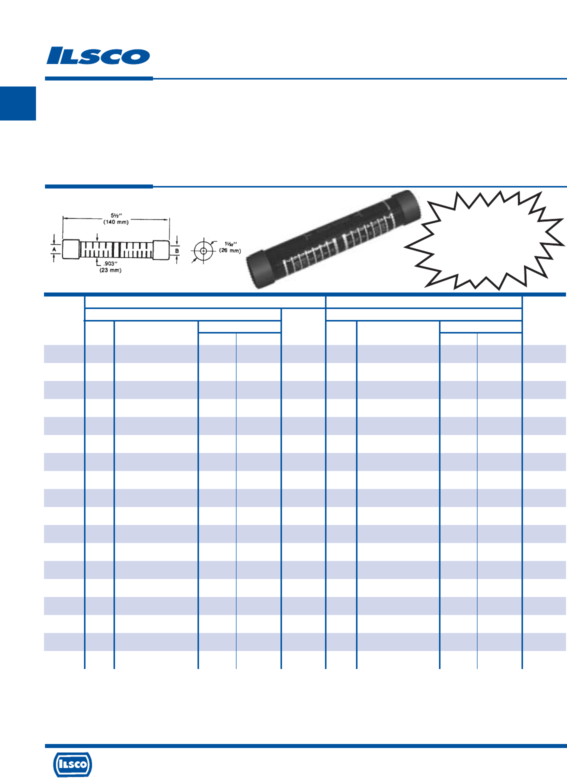
A
4730 Madison Road, Cincinnati, Ohio 45227-1426 Phone 513 533-6200 Fax 513 871-4084 Web site www.ilsco.com
Canada 1050 Lakeshore Road East, Mississauga, Ontario, Canada L5E1E4 Phone 905 274-2341 Fax 905 274-8763
71
Insulated Aluminum Service Entrance Sleeves
TYPE
P840
Features
•
Pre-insulated
•
Concave polyethylene end caps
•
Dual rated
•
Meets ANSI C119.4 requirements
•
RUS Listed
•
Die Index 840
Benefits
•
Fast, easy installation
•
Seal out dirt but are easily pierced when inserting conductor
•
For use with aluminum-aluminum and aluminum-copper conductors
•
Ensures reliability
End “A” End “B”
Conductor Range Conductor Range
Catalog Diameter Color Diameter Color
Number ACSR AWG max. min. Code ACSR AWG max. min. Code
PICS-834 1/0 2/0 (compact) or 1/0 0.398 0.365 Yellow 4 2 sol - 3-4 str 0.258 0.213 Orange
PICS-835 1/0 2/0 (compact) or 1/0 0.398 0.365 Yellow 2 1-2 str 0.328 0.268 Red
PICS-836 1/0 2/0 (compact) or 1/0 0.398 0.365 Yellow 1/0 2/0 (compact) or 1/0 0.398 0.365 Yellow
PICS-844 2/0 3/0 (compact) or 2/0 0.448 0.414 Gray 4 2 sol - 3-4 str 0.258 0.213 Orange
PICS-845 2/0 3/0 (compact) or 2/0 0.448 0.414 Gray 2 1-2 str 0.328 0.268 Red
PICS-846 2/0 3/0 (compact) or 2/0 0.448 0.414 Gray 1/0 2/0 (compact) or 1/0 0.398 0.365 Yellow
PICS-847 2/0 3/0 (compact) or 2/0 0.448 0.414 Gray 2/0 3/0 (compact) or 2/0 0.448 0.414 Gray
PICS-854 3/0 4/0 (compact) or 3/0 0.502 0.464 Black 4 2 sol - 3-4 str 0.258 0.213 Orange
PICS-855 3/0 4/0 (compact) or 3/0 0.502 0.464 Black 2 1-2 str 0.328 0.268 Red
PICS-856 3/0 4/0 (compact) or 3/0 0.502 0.464 Black 1/0 2/0 (compact) or 1/0 0.398 0.365 Yellow
PICS-857 3/0 4/0 (compact) or 3/0 0.502 0.464 Black 2/0 3/0 (compact) or 2/0 0.448 0.414 Gray
PICS-858 3/0 4/0 (compact) or 3/0 0.502 0.464 Black 3/0 4/0 (compact) or 3/0 0.502 0.464 Black
PICS-864 4/0 4/0 0.564 0.522 Pink 4 2 sol - 3-4 str 0.258 0.213 Orange
PICS-865 4/0 4/0 0.564 0.522 Pink 2 1-2 str 0.328 0.268 Red
PICS-866 4/0 4/0 0.564 0.522 Pink 1/0 1/0 0.398 0.365 Yellow
PICS-867 4/0 4/0 0.564 0.522 Pink 2/0 3/0 (compact) or 2/0 0.448 0.414 Gray
PICS-868 4/0 4/0 0.564 0.522 Pink 3/0 4/0 (compact) or 3/0 0.502 0.464 Black
PICS-869 4/0 4/0 0.564 0.522 Pink 4/0 4/0 0.564 0.522 Pink
Replaces
PIK840
Series
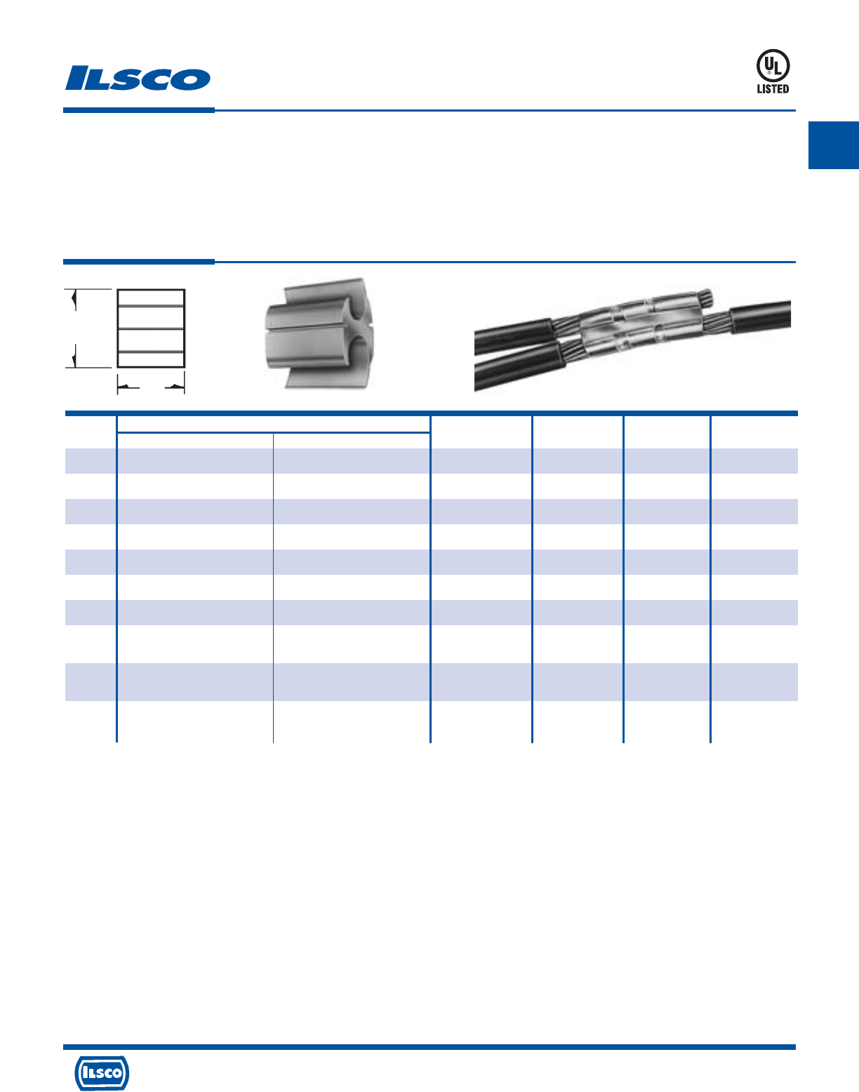
A
4730 Madison Road, Cincinnati, Ohio 45227-1426 Phone 513 533-6200 Fax 513 871-4084 Web site www.ilsco.com
Canada 1050 Lakeshore Road East, Mississauga, Ontario, Canada L5E1E4 Phone 905 274-2341 Fax 905 274-8763
72
Catalog Wire Range Ilsco Die
Number Main Tap Compression Tool Index L W
AH-1 1/0 str - 6 str 1 str - 6 str ND-58/ND-60 0 1.62 1.78
AH-2 4/0 str - 1 str 1 str - 6 str ND-58/ND-60 D3 1.88 2.31
AH-3 4/0 str - 3/0 str 4/0 str - 3/0 str ND-58/ND-60 D3 2.50 2.50
AH-4 4/0 str - 1 str 2/0 str - 1 str ND-58/ND-60 D3 2.50 2.38
AH-5 400kcmil - 4/0 str 400kcmil - 4/0 str ILC-15H* N 3.50 3.09
AH-6 500kcmil - 4/0 str 2/0 str - 6 str ILC-15H* N 2.00 2.84
AH-8 600kcmil - 350kcmil 350kcmil - 2/0 str ILC-15H* KR 3.50 4.50
AH-10 1000kcmil Compact - 600kcmil AL 350kcmil - 2/0 str ILC-15H* KR 3.50 4.62
750kcmil - 600kcmil CU
AH-11 1000kcmil Compact - 600kcmil AL 600kcmil - 350kcmil ILC-15H* KR 4.62 4.75
750kcmil - 600kcmil CU
AH-12 1000 Compact - 600kcmil AL 1000kcmil Compact - 600kcmil AL ILC-15H* KR 4.62 4.78
750kcmil - 600kcmil CU 750kcmil - 600kcmil CU
Aluminum Compression Tap Connectors
Dual Rated
TYPE
AH
Features
•
Prefilled with oxide inhibitor
•
Color coded
•
Rated for 600 Volts, 90˚ C
•
Manufactured from high strength aluminum alloy
•
UL Listed
Benefits
•
Provides corrosion resistance
•
Provides visual tooling recommendation for ILSCO or standard industry tools
•
Can be used on any secondary splice or tap application
•
Provides maximum conductivity and excellent crimping characteristics
•
Ensures reliability for copper or aluminum conductors
453G
W
L
*Other hydraulic tools can be used. See stuffer sheet for complete information on tooling.
Tested to UL 486A-486B, UL File E6207
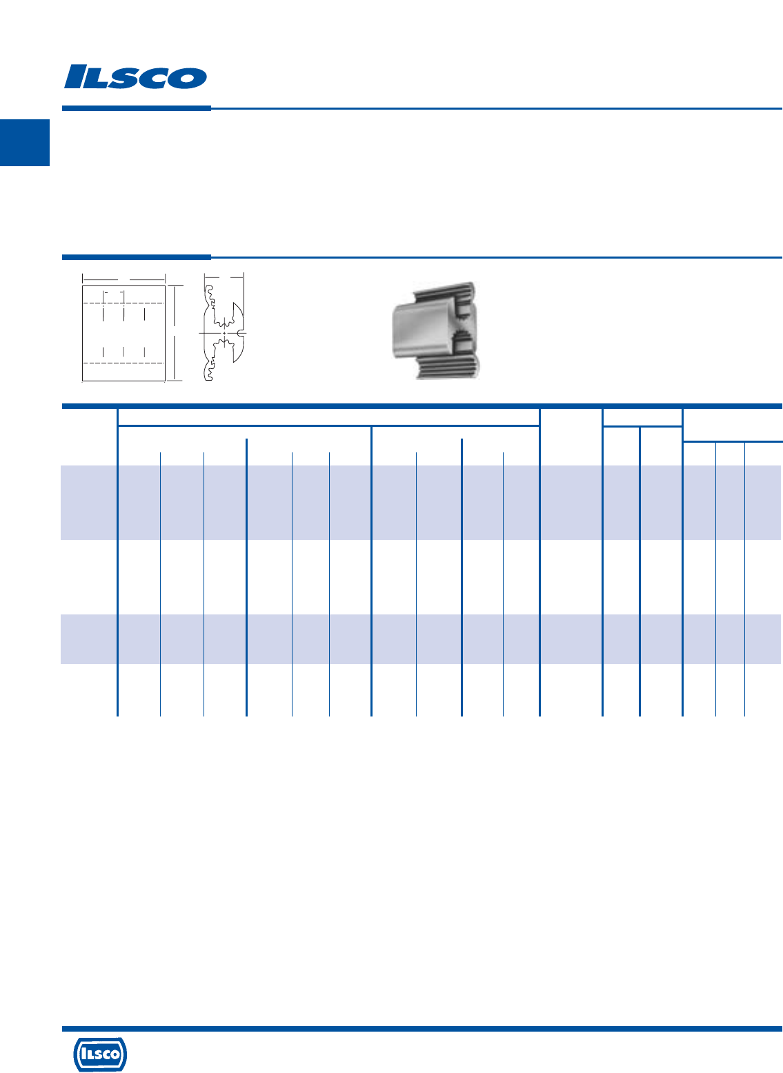
A
4730 Madison Road, Cincinnati, Ohio 45227-1426 Phone 513 533-6200 Fax 513 871-4084 Web site www.ilsco.com
Canada 1050 Lakeshore Road East, Mississauga, Ontario, Canada L5E1E4 Phone 905 274-2341 Fax 905 274-8763
73
DISCONTINUED
TO BE
Wire Range No. of Crimps
Standard Wire Compact Wire
ILSCO ILSCO
Dimensions
Catalog A Groove B Groove A Groove B Groove Connector
ND-58 ILC-15
Number ACSR str sol ACSR str sol ACSR str ACSR str Die Tool Tool L W H
HT-3-Z 2/0 3/0 - 2 1 1/0 3/0 3/0 1 1 D3 5 2
1/0 2/0 - 3 2 1 2/0 - 2 2 D3 5 2
---432--44D3 521-7/813/16 2-3/16
---644--66D3 52
----66----D3 52
HT-5-Z 4/0 4/0 - 2 1 1/0 266-18/1 266 1 1 D3 5 2
3/0 - - 3 2 1 4/0 250 2 2 D3 5 2
---432-4/044D3 521-7/853/64 2-1/4
---644--66D3 52
----66----D3 52
HT-6-Z 4/0 4/0 - 2/0 2/0 - 266-18/1 266 2/0 3/0 D3 7 3
3/0 3/0 - 1/0 1/0 - 4/0 250 1/0 2/0 D3 7 3 2-1/4 53/64 2-3/8
---1--3/04/0-1/0D3 73
HT-7-Z 4/0 4/0 - 4/0 4/0 - 266-18/1 266 266-18/1 266 D3 7 3
3/0 3/0 - 3/0 3/0 - 4/0 250 4/0 250 D3 7 3 2-1/2 7/8 2-1/2
------3/04/03/04/0D3 73
Aluminum Compression Tap Connectors
TYPE
HT
Features
•
Serrated interior
•
Prefilled with oxide inhibitor
•
Installed with industry standard “O” and “D” dies
•
Rated for 600 Volts
•
Manufactured from high strength aluminum alloy
Benefits
•
Assures positive mating with cable strands when compressed
•
Provides corrosion resistance
•
Provides convenient die selection
•
Can be used on any secondary splice or tap application
•
Provides maximum conductivity and excellent crimping characteristics
Consult factory for tool and die information.
L
H
W
A
B
1 str-6 sol AL-CU
UTILCO HT-1 DIE 0
1 str-6 sol AL-CU
.375
TYP.
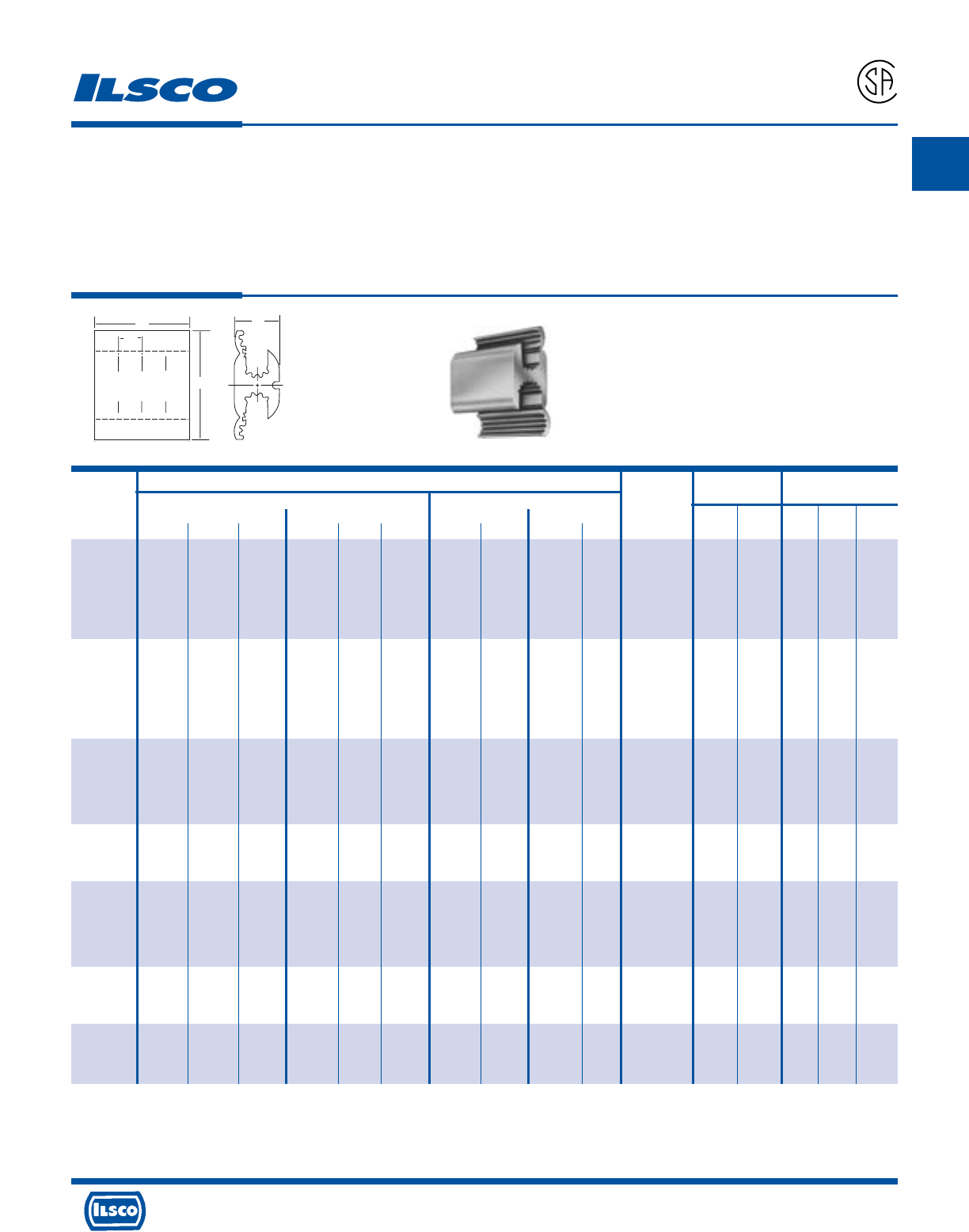
A
4730 Madison Road, Cincinnati, Ohio 45227-1426 Phone 513 533-6200 Fax 513 871-4084 Web site www.ilsco.com
Canada 1050 Lakeshore Road East, Mississauga, Ontario, Canada L5E1E4 Phone 905 274-2341 Fax 905 274-8763
74
Aluminum Compression Tap Connectors
TYPE
HT
Features
•
Serrated interior
•
Prefilled with oxide inhibitor
•
Installed with industry standard “O” and “D” dies
•
Rated for 600 Volts, CSA Certified
•
Manufactured from high strength aluminum alloy
Benefits
•
Assures positive mating with cable strands when compressed
•
Provides corrosion resistance
•
Provides convenient die selection
•
Can be used on any secondary splice or tap application
•
Provides maximum conductivity and excellent crimping characteristics
A
P
-
5
4
6
5
L
H
W
A
B
1 str-6 sol AL-CU
1 str-6 sol AL-CU
.375
TYP.
Wire Range
Standard Wire Compact Wire No. of Crimps Dimensions
Catalog A Groove B Groove A Groove B Groove Connector
Mech. Hyd.
Number ACSR str sol ACSR str sol ACSR str ACSR str Die Tool Tool L W H
HT-6 2, 1, 1, 2, 1, 1, 1, 1, 1, 1, O 4 2
3, 2, 2, 3, 2, 2, 2, 2, 2, 2, O 4 2
4, 3, 3, 4, 3, 3, 3, 3, 3, 3, O 4 2 1-1/2 23/32 1-23/32
6, 4, 4, 6, 4, 4, 4, 4, 4, 4, O 4 2
- 66- 666666O 42
----------O 42
HT-8 1/0, 2/0, 3/0, 2, 1, 1/0, 2/0, 2/0, 1, 1, O 5 2
1, 1/0, 2/0, 3, 2, 1, 1/0, 1/0, 2, 2, O 5 2
2, 1, 1/0, 4, 3, 2, 1, 1, 3, 3, O 5 2 1-1/2 45/64 1-25/32
32164,3,224,4O 52
----6,4,--66,O 52
-----6----O 52
HT-2 2/0, 3/0, - 2, 1, 1/0, 3/0, 3/0 1, 1, D3 5 2
1/02/0- 3,2,1,2/0- 2,2,D3 52
---4,3,2,--4,4,D3 521-7/813/16 2-3/16
---64,4,--66D3 52
----66----D3 52
HT-4 2/0, 3/0, - 2/0, 3/0, - 3/0, 3/0, 3/0, 3/0, D3 6 2
1/0, 2/0 - 1/0, 2/0, - 2/0, 2/0, 2/0, 2/0, D3 6 2 1-7/8 57/64 2-17/64
1 1/0 - 1 1/0 - 1/0 1/0 1/0 1/0 D3 6 2
HT-3 4/0, 4/0 - 2, 1, 1/0, 266, 266, 1, 1, D3 5 2
3/0 - - 3, 2, 1, 4/0 250, 2, 2, D3 5 2
---4,3,2,-4/04,4,D3 521-7/853/64 2-1/4
---64,4,--66D3 52
----66----D3 52
HT-5 4/0, 4/0, - 2/0, 2/0, - 266, 266, 2/0, 3/0, D3 7 3
3/0 3/0 - 1/0 1/0 - 4/0, 250, 1/0, 2/0, D3 7 3 2-1/4 53/64 2-3/8
------3/04/0-1/0D3 73
HT-7 4/0, 4/0, - 4/0, 4/0, - 266, 266, 266, 266, D3 7 3
3/0 3/0 - 3/0 3/0 - 4/0, 250, 4/0, 250, D3 7 3 2-1/2 7/8 2-1/2
------3/04/03/04/0D3 73
Consult factory for tool and die information.
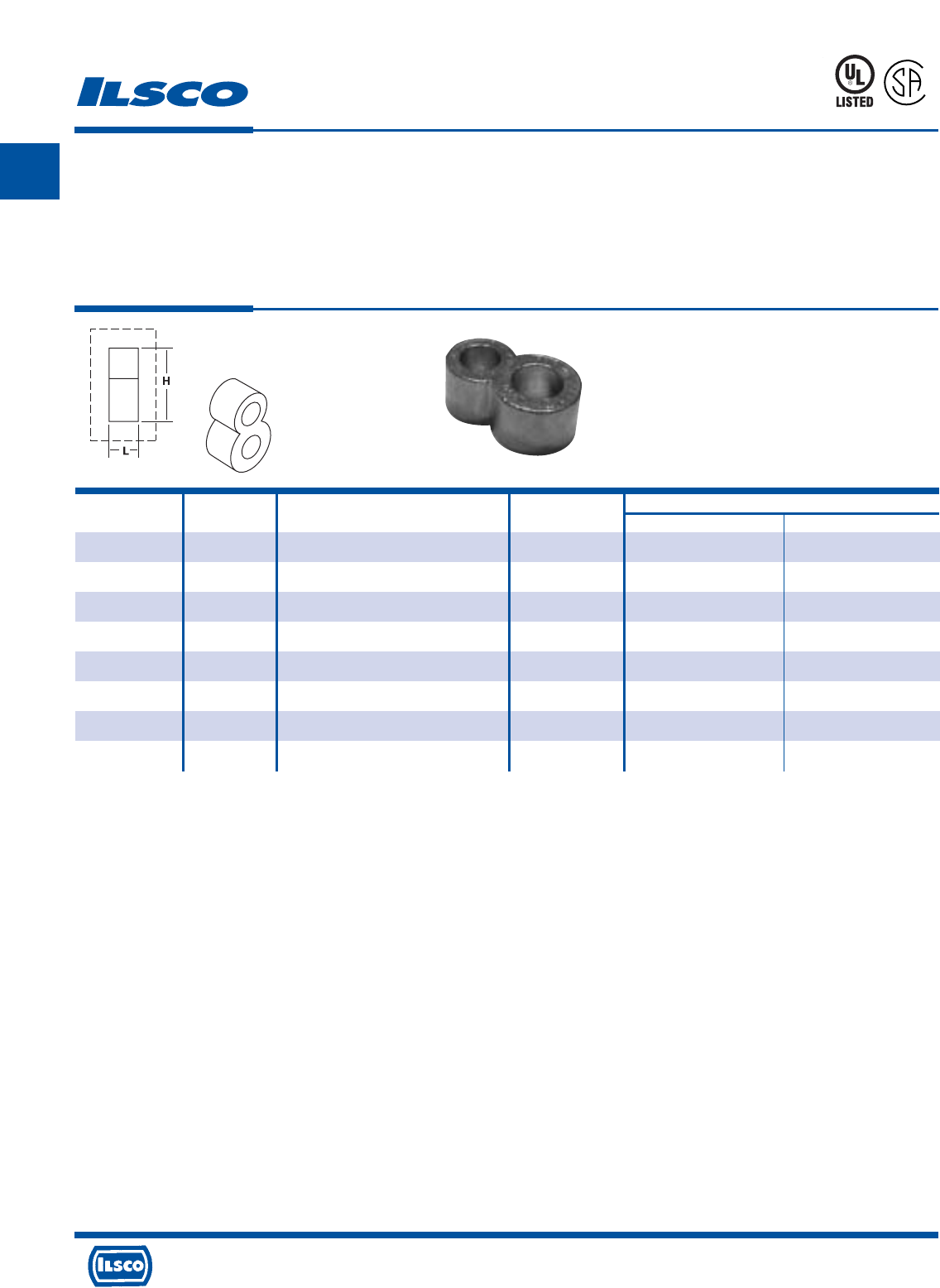
A
4730 Madison Road, Cincinnati, Ohio 45227-1426 Phone 513 533-6200 Fax 513 871-4084 Web site www.ilsco.com
Canada 1050 Lakeshore Road East, Mississauga, Ontario, Canada L5E1E4 Phone 905 274-2341 Fax 905 274-8763
75
L
Grounding Connectors
For Copper Conductor Only
TYPE
RLT
Features
•
Prefilled with oxide inhibitor and bagged
•
Clearly marked with wire size and die index
•
UL Listed for 600 Volts and CSA Certified for
direct burial in earth or concrete
•
Range taking
•
Manufactured from high strength copper alloy
Benefits
•
Prevents oxides from forming
•
Provides easy identification and tooling recommendation
•
Ensures reliability
•
Reduces inventory. Eight sizes cover a wire range
of #2-500kcmil
•
Provides maximum conductivity and eliminates the possibility
of corrosion
667P
Catalog Ground Wire Die Dimensions
Number Rod Size Range Index H L
RLT-2 1/2 2 (.292 Dia.) - 2/0 (.419 Dia.) 998/1011 1.94 .88
RLT-3 5/8 2 (.292 Dia.) - 2/0 (.419 Dia.) 998/1011 1.97 .88
RLT-4 3/4 2 (.292 Dia.) - 2/0 (.419 Dia.) 998/1011 2.19 .88
RLT-5 1/2 4/0 (.528 Dia.) - 250kcmil (.575 Dia.) 998/1011 1.94 .88
RLT-6 5/8 4/0 (.528 Dia.) - 250kcmil (.575 Dia.) 998/1011 2.14 .88
RLT-7 3/4 4/0 (.528 Dia.) - 250kcmil (.575 Dia.) 998/1011 2.19 .88
RLT-8 5/8 300kcmil (.630 Dia.) - 500kcmil (.813 Dia.) 998/1011 2.14 .88
RLT-9 3/4 300kcmil (.630 Dia.) - 500kcmil (.813 Dia.) 998/1011 2.44 .88
UL File E158587
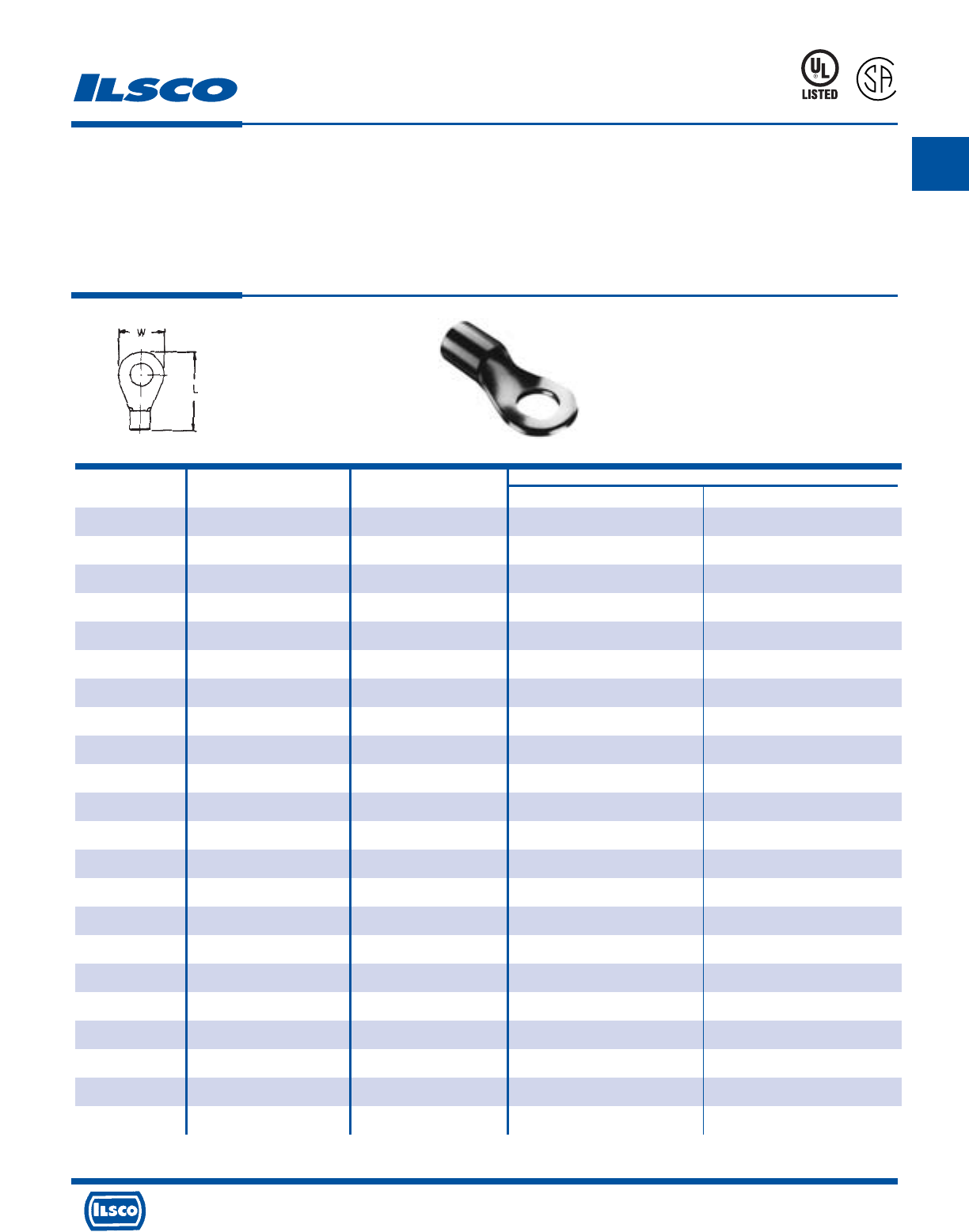
A
4730 Madison Road, Cincinnati, Ohio 45227-1426 Phone 513 533-6200 Fax 513 871-4084 Web site www.ilsco.com
Canada 1050 Lakeshore Road East, Mississauga, Ontario, Canada L5E1E4 Phone 905 274-2341 Fax 905 274-8763
76
Non-Insulated Ring Terminals
TYPE
ILSCONS
Features
•
Manufactured from high strength copper alloy
•
Electro-tin plated
•
Silver solder brazed seam
•
Packaged in convenient small quantities
•
UL Listed and CSA Certified, 90˚ C
Benefits
•
Provides maximum conductivity
•
Provides low contact resistance
•
May be crimped anywhere and will not split open, even under extreme
operating stresses
•
Can be displayed on merchandise racks
•
Ensures reliability for copper conductor
Can be supplied in bulk. Consult factory for part number.
UL File E158587
Catalog Wire Stud Dimensions
Number Range Size L W
44100-B20 18-22 4 .45 .20
44101-B20 18-22 6 .62 .25
44102-B20 18-22 8 .75 .31
44103-B20 18-22 10 .75 .31
44104-B20 18-22 1/4 .94 .47
44105-B20 18-22 5/16 .94 .47
44106-B20 18-22 3/8 .97 .53
44110-B20 14-16 4 .95 .25
44111-B20 14-16 6 .71 .31
44112-B20 14-16 8 .71 .31
44113-B20 14-16 10 .71 .31
44114-B20 14-16 1/4 .94 .46
44115-B20 14-16 5/16 .94 .46
44116-B20 14-16 3/8 .97 .53
44120-B20 10-12 6 .90 .37
44121-B20 10-12 8 .90 .37
44122-B20 10-12 10 .90 .37
44123-B20 10-12 1/4 1.01 .52
44124-B20 10-12 5/16 1.01 .52
44125-B20 10-12 3/8 1.01 .59
44126-B20 10-12 7/16 1.13 .71
44127-B20 10-12 1/2 1.13 .71
8M24
L
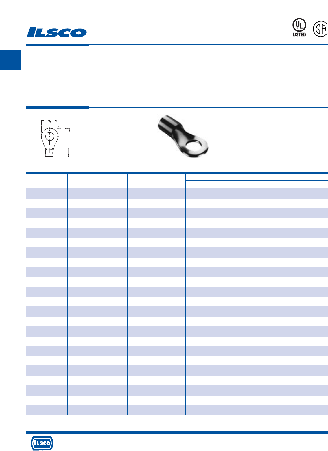
A
4730 Madison Road, Cincinnati, Ohio 45227-1426 Phone 513 533-6200 Fax 513 871-4084 Web site www.ilsco.com
Canada 1050 Lakeshore Road East, Mississauga, Ontario, Canada L5E1E4 Phone 905 274-2341 Fax 905 274-8763
77
Non-Insulated Ring Terminals
TYPE
ILSCONS
Features
•
Manufactured from high strength copper alloy
•
Electro-tin plated
•
Silver solder brazed seam
•
Packaged in convenient small quantities
•
UL Listed and CSA Certified, 90˚ C
Benefits
•
Provides maximum conductivity
•
Provides low contact resistance
•
May be crimped anywhere and will not split open, even under extreme
operating stresses
•
Can be displayed on merchandise racks
•
Ensures reliability for copper conductor
Catalog Wire Stud Dimensions
Number Range Size L W
44130-B10 8 10 1.20 .59
44131-B10 8 1/4 1.20 .59
44140-B10 6 10 1.18 .47
44141-B10 6 1/4 1.18 .47
44142-B10 6 5/16 1.26 .63
44143-B10 6 3/8 1.26 .63
44150-B10 4 10 1.30 .66
44151-B10 4 1/4 1.30 .66
44152-B10 4 5/16 1.30 .66
44153-B10 4 3/8 1.30 .66
44154-B10 4 7/16 1.30 .66
44155-B10 4 1/2 1.90 .88
44160-B10 2 10 1.55 .60
44161-B10 2 1/4 1.55 .60
44162-B10 2 5/16 1.55 .70
44163-B10 2 3/8 1.55 .70
44164-B10 2 7/16 1.55 .81
44165-B10 2 1/2 1.93 .81
44170-B2 1/0 1/4 1.93 .88
44171-B2 1/0 5/16 1.93 .88
44172-B2 1/0 3/8 1.93 .88
44173-B2 1/0 7/16 1.93 .88
44174-B2 1/0 1/2 1.93 .88
8M24
L
Can be supplied in bulk. Consult factory for part number.
UL File E158587
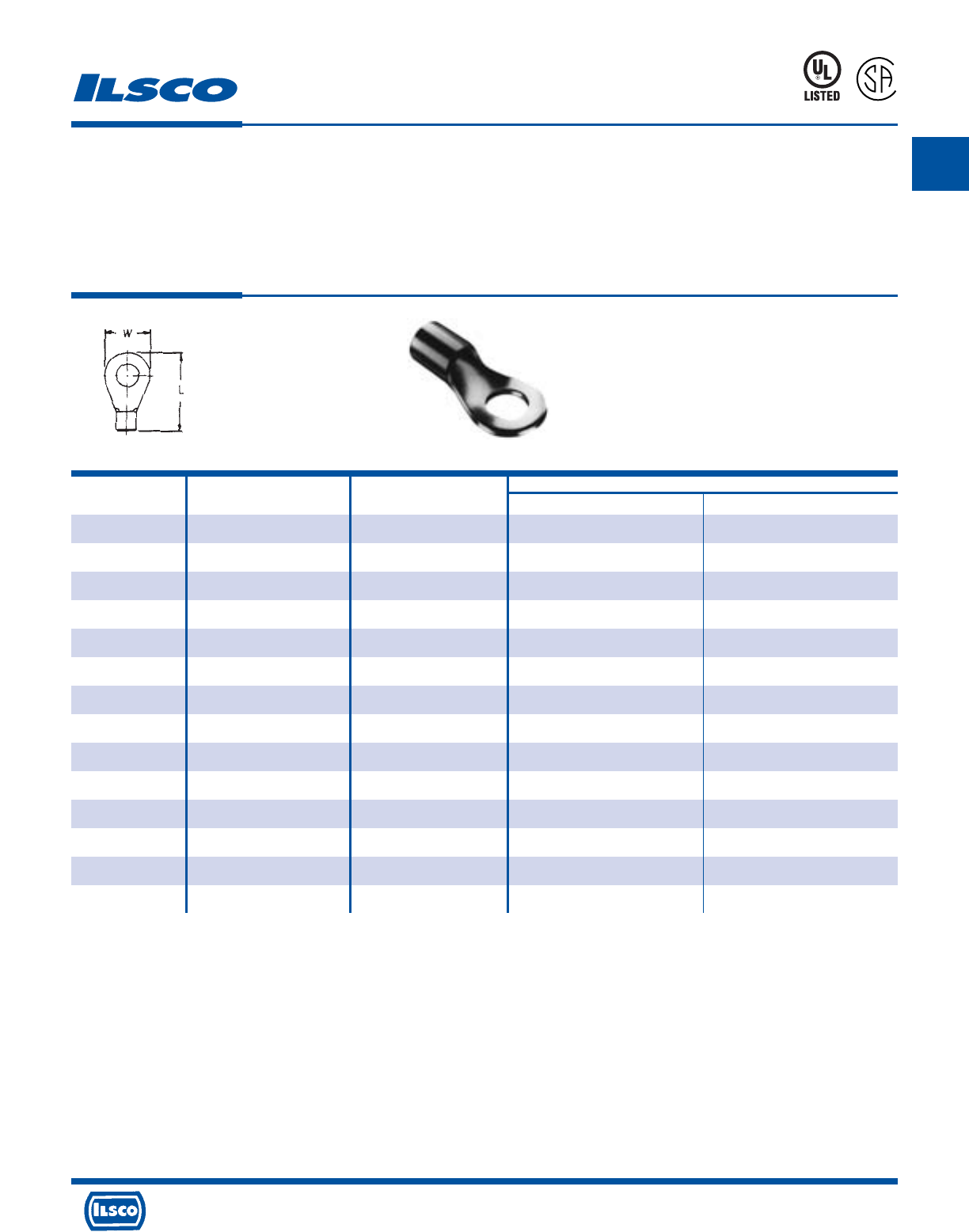
A
4730 Madison Road, Cincinnati, Ohio 45227-1426 Phone 513 533-6200 Fax 513 871-4084 Web site www.ilsco.com
Canada 1050 Lakeshore Road East, Mississauga, Ontario, Canada L5E1E4 Phone 905 274-2341 Fax 905 274-8763
78
Non-Insulated Ring Terminals
TYPE
ILSCONS
Features
•
Manufactured from high strength copper alloy
•
Electro-tin plated
•
Silver solder brazed seam
•
Packaged in convenient small quantities
•
UL Listed and CSA Certified, 90˚ C
Benefits
•
Provides maximum conductivity
•
Provides low contact resistance
•
May be crimped anywhere and will not split open, even under extreme
operating stresses
•
Can be displayed on merchandise racks
•
Ensures reliability for copper conductor
Can be supplied in bulk. Consult factory for part number.
UL File E158587
Catalog Wire Stud Dimensions
Number Range Size L W
44180-B2 2/0 1/4 1.93 .88
44181-B2 2/0 5/16 1.93 .88
44182-B2 2/0 3/8 1.93 .88
44183-B2 2/0 7/16 1.93 .88
44184-B2 2/0 1/2 1.93 .88
44190-B2 3/0 1/4 1.97 .93
44191-B2 3/0 5/16 1.97 .93
44192-B2 3/0 3/8 1.97 .93
44193-B2 3/0 7/16 1.97 .93
44194-B2 3/0 1/2 1.97 .93
44195-B2 4/0 5/16 2.17 1.08
44196-B2 4/0 3/8 2.17 1.08
44197-B2 4/0 7/16 2.17 1.08
44198-B2 4/0 1/2 2.17 1.08
8M24
L
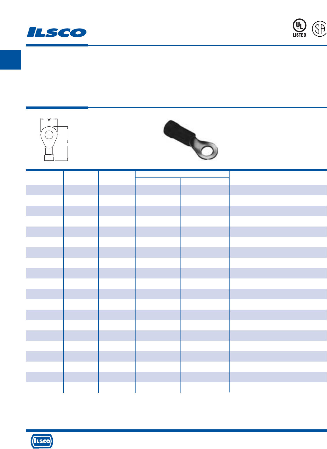
A
4730 Madison Road, Cincinnati, Ohio 45227-1426 Phone 513 533-6200 Fax 513 871-4084 Web site www.ilsco.com
Canada 1050 Lakeshore Road East, Mississauga, Ontario, Canada L5E1E4 Phone 905 274-2341 Fax 905 274-8763
79
Vinyl Insulated Ring Terminals
TYPE
ILSCONS
Features
•
Color coded
•
Manufactured from high strength copper alloy
•
Electro-tin plated
•
Vinyl insulation
•
Packaged in convenient small quantities
•
UL Listed and CSA Certified for 600 volts, 90˚ C
Benefits
•
Provides easy wire range identification
#22-18 AWG Red
#16-14 AWG Blue
#12-10 AWG Yellow
•
Provides maximum conductivity
•
Provides low contact resistance
•
Provides tough pliable insulative qualities to protect connectors and wire
from corrosion as well as providing some strain relief
•
Can be displayed on merchandise racks
•
Ensures reliability for copper conductor
Can be supplied in bulk. Consult factory for part number.
UL File E158587
Catalog Wire Stud Dimensions Maximum Wire
Number Range Size L W Insulated Diameter
44200-B10 18-22 4 .74 .22 .145
44201-B10 18-22 6 .91 .31 .145
44202-B10 18-22 8 .91 .31 .145
44203-B10 18-22 10 .91 .31 .145
44204-B10 18-22 1/4 1.10 .46 .145
44205-B10 18-22 5/16 1.14 .53 .145
44206-B10 18-22 3/8 1.14 .53 .145
44210-B10 14-16 4 .80 .25 .175
44211-B10 14-16 6 .88 .25 .175
44212-B10 14-16 8 .94 .31 .175
44213-B10 14-16 10 .94 .31 .175
44214-B10 14-16 1/4 1.06 .53 .175
44215-B10 14-16 5/16 1.06 .53 .175
44216-B10 14-16 3/8 1.06 .53 .175
44220-B10 10-12 6 .95 .28 .255
44221-B10 10-12 8 .95 .28 .255
44222-B10 10-12 10 1.00 .38 .255
44223-B10 10-12 1/4 1.22 .53 .255
44224-B10 10-12 3/8 1.33 .53 .255
44225-B10 10-12 7/16 1.46 .71 .255
8M24
L
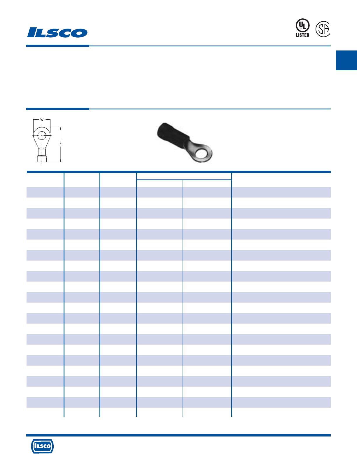
A
4730 Madison Road, Cincinnati, Ohio 45227-1426 Phone 513 533-6200 Fax 513 871-4084 Web site www.ilsco.com
Canada 1050 Lakeshore Road East, Mississauga, Ontario, Canada L5E1E4 Phone 905 274-2341 Fax 905 274-8763
80
Vinyl Insulated Ring Terminals
TYPE
ILSCONS
Features
•
Color coded
•
Manufactured from high strength copper alloy
•
Electro-tin plated
•
Vinyl insulation
•
Packaged in convenient small quantities
•
UL Listed and CSA Certified for 600 volts,90˚ C
Benefits
•
Provides easy wire range identification
#22-18 AWG Red
#16-14 AWG Blue
#12-10 AWG Yellow
•
Provides maximum conductivity
•
Provides low contact resistance
•
Provides tough pliable insulative qualities to protect connectors and wire
from corrosion as well as providing some strain relief
•
Can be displayed on merchandise racks
•
Ensures reliability for copper conductor
* Nylon Insulated Ring
Can be supplied in bulk. Consult factory for part number. UL File E158587
Catalog Wire Stud Dimensions Maximum Wire
Number Range Size L W Insulated Diameter
44226-B10 10-12 1/2 1.52 .75 .255
44230-B5 8 10 1.28 .47 .385
44231-B5 8 1/4 1.28 .47 .385
44240-B5 6 10 1.62 .47 .440
44241-B5 6 1/4 1.62 .47 .440
44242-B5 6 5/16 1.70 .63 .440
44243-B5 6 3/8 1.70 .63 .440
44250-B5 4 10 1.81 .66 .515
44251-B5 4 1/4 1.81 .66 .515
44252-B5 4 5/16 1.81 .66 .515
44253-B5 4 3/8 1.81 .66 .515
44254-B5 4 7/16 1.81 .66 .515
44255-B5 4 1/2 2.41 .88 .515
45314-P100 14-16 10 .94 .31 .175
45315-P100 14-16 1/4 1.06 .53 .175
45316-P100 14-16 5/16 1.06 .53 .175
45316N-P100* 14-16 5/16 1.06 .53 .175
45317-P100 14-16 3/8 1.06 .53 .175
45414-P50 10-12 10 1.00 .38 .255
45415-P50 10-12 1/4 1.22 .53 .255
45416-P50 10-12 5/16 1.46 .71 .255
45417-P50 10-12 3/8 1.33 .53 .255
8M24
L
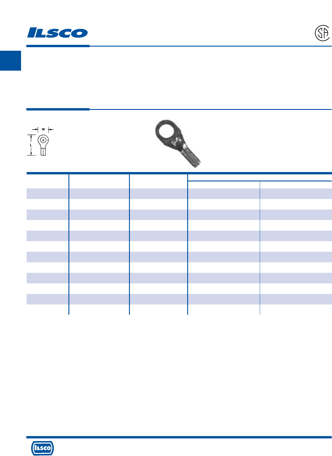
A
4730 Madison Road, Cincinnati, Ohio 45227-1426 Phone 513 533-6200 Fax 513 871-4084 Web site www.ilsco.com
Canada 1050 Lakeshore Road East, Mississauga, Ontario, Canada L5E1E4 Phone 905 274-2341 Fax 905 274-8763
81
High Temperature, Non-Insulated Ring Terminals
TYPE
ILSCONS
Features
•
Manufactured from high strength steel alloy
•
Electro-tin plated
•
Silver solder brazed seam
•
Packaged in convenient small quantities
•
900˚ F 482˚ C Continuous, 1200˚ F 649˚ C Intermittent
Benefits
•
Provides maximum conductivity
•
Provides low contact resistance
•
May be crimped anywhere and will not split open, even under extreme
operating stresses
•
Can be displayed on merchandise racks
Catalog Wire Stud Dimensions
Number Range Size L W
44300-B20 18-22 4-6 .65 .25
44301-B20 18-22 8-10 .69 .31
44302-B20 18-22 12-1/4 .93 .56
44310-B20 14-16 4-6 .65 .25
44311-B20 14-16 8-10 .69 .31
44312-B20 14-16 12-1/4 .90 .46
44320-B20 10-12 4-6 .67 .28
44321-B20 10-12 8-10 .72 .37
44322-B20 10-12 12-1/4 .93 .53
44323-B20 10-12 5/16-3/8 .99 .60
44330-B10 8 12-1/4 .95 .47
44340-B10 6 5/16-3/8 1.22 .63
Can be supplied in bulk. Consult factory for part number.
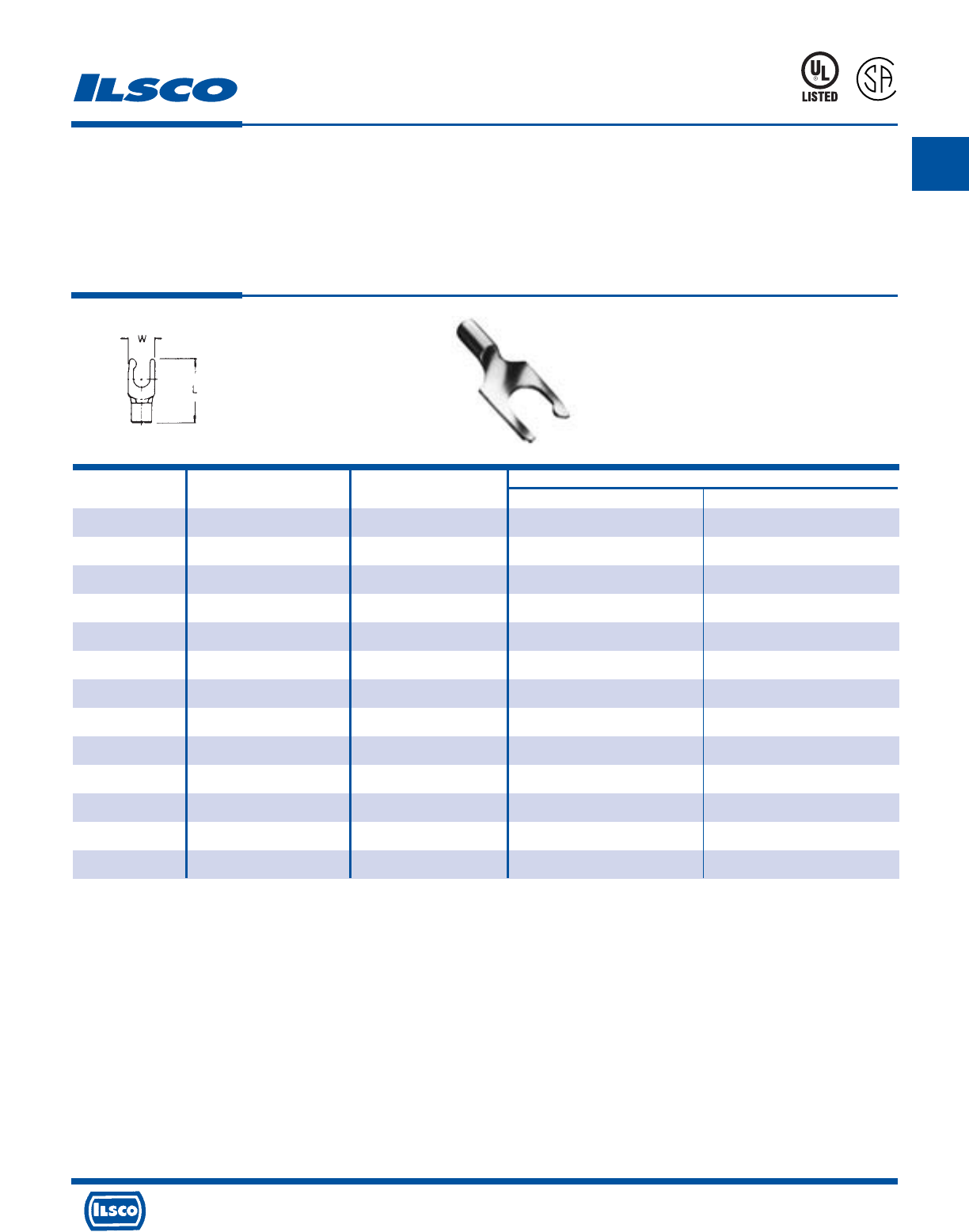
A
4730 Madison Road, Cincinnati, Ohio 45227-1426 Phone 513 533-6200 Fax 513 871-4084 Web site www.ilsco.com
Canada 1050 Lakeshore Road East, Mississauga, Ontario, Canada L5E1E4 Phone 905 274-2341 Fax 905 274-8763
82
Non-Insulated Fork Terminals
TYPE
ILSCONS
Features
•
Manufactured from high strength copper alloy
•
Electro-tin plated
•
Silver solder brazed seam
•
Packaged in convenient small quantities
•
UL Listed and CSA Certified, 90˚ C
Benefits
•
Provides maximum conductivity
•
Provides low contact resistance
•
May be crimped anywhere and will not split open, even under extreme
operating stresses
•
Can be displayed on merchandise racks
•
Ensures reliability for copper conductor
Can be supplied in bulk. Consult factory for part number.
UL File E158587
Catalog Wire Stud Dimensions
Number Range Size L W
44400-B20 18-22 4 .68 .25
44401-B20 18-22 6 .68 .25
44402-B20 18-22 8 .68 .30
44403-B20 18-22 10 .68 .32
44410-B20 14-16 4 .68 .25
44411-B20 14-16 6 .68 .25
44412-B20 14-16 8 .68 .25
44413-B20 14-16 10 .68 .30
44414-B20 14-16 1/4 .90 .32
44420-B20 14-16 6 .73 .28
44421-B20 10-12 8 .73 .32
44422-B20 10-12 10 .73 .32
44423-B20 10-12 1/4 .94 .43
8M24
L
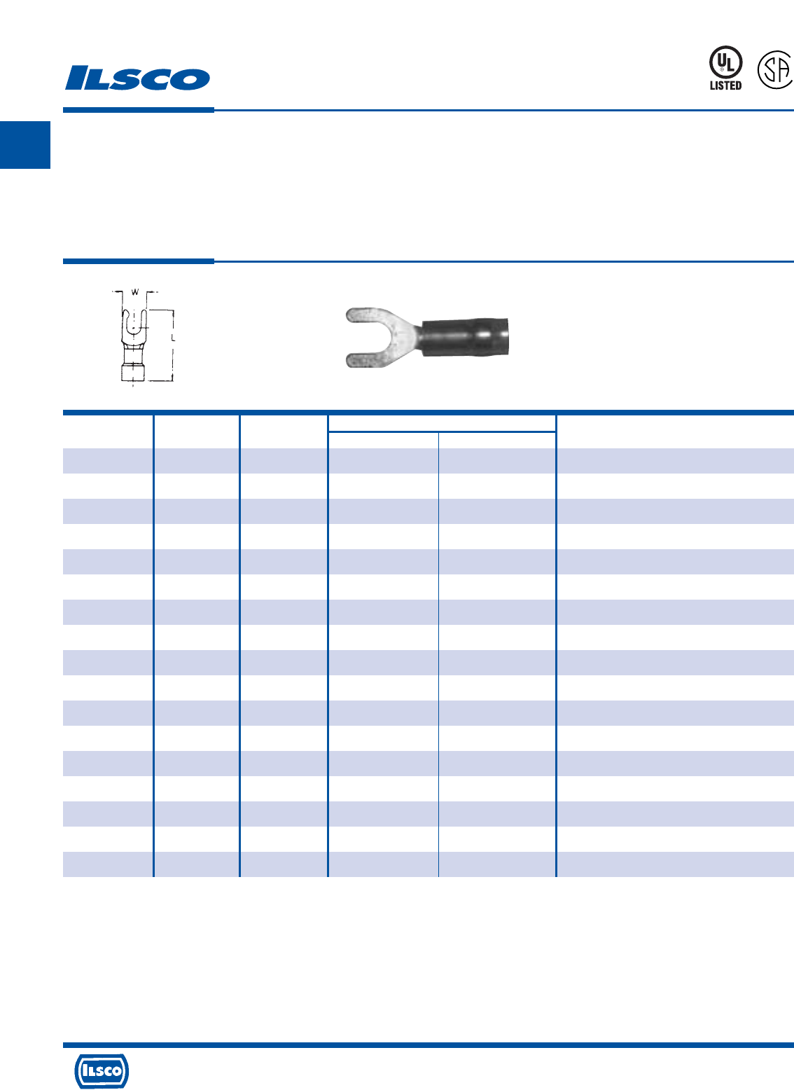
A
4730 Madison Road, Cincinnati, Ohio 45227-1426 Phone 513 533-6200 Fax 513 871-4084 Web site www.ilsco.com
Canada 1050 Lakeshore Road East, Mississauga, Ontario, Canada L5E1E4 Phone 905 274-2341 Fax 905 274-8763
83
Catalog Wire Stud Dimensions Maximum Wire
Number Range Size L W Insulated Diameter
44500-B10 18-22 4 .88 .25 .145
44501-B10 18-22 6 .88 .29 .145
44502-B10 18-22 8 .88 .31 .145
44503-B10 18-22 10 .88 .31 .145
44511-B10 14-16 6 .88 .29 .175
44512-B10 14-16 8 .88 .31 .175
44513-B10 14-16 10 .88 .31 .175
44514-B10 14-16 1/4 1.10 .43 .175
44520-B10 10-12 6 1.06 .28 .255
44521-B10 10-12 8 1.06 .28 .255
44522-B10 10-12 10 1.06 .28 .255
44523-B10 10-12 1/4 1.24 .43 .255
45322FL-P100* 14-16 6 .88 .29 .175
45323FL-P100* 14-16 8 .88 .31 .175
45324FL-P100* 14-16 10 .88 .31 .175
45423FL-P50* 10-12 8 1.06 .28 .255
45424FL-P50* 10-12 10 1.06 .28 .255
Vinyl Insulated Fork Terminals
TYPE
ILSCONS
Features
•
Color coded
•
Manufactured from high strength copper alloy
•
Electro-tin plated
•
Vinyl insulation
•
Packaged in convenient small quantities
•
UL Listed and CSA Certified for 600 volts, 90˚ C
Benefits
•
Provides easy wire range identification
#22-18 AWG Red
#16-14 AWG Blue
#12-10 AWG Yellow
•
Provides maximum conductivity
•
Provides low contact resistance
•
Provides tough pliable insulative qualities to protect connectors and wire
from corrosion as well as providing some strain relief
•
Can be displayed on merchandise racks
•
Ensures reliability for copper conductor
* Flanged Fork
Can be supplied in bulk. Consult factory for part number.
UL File E158587
8M24
L
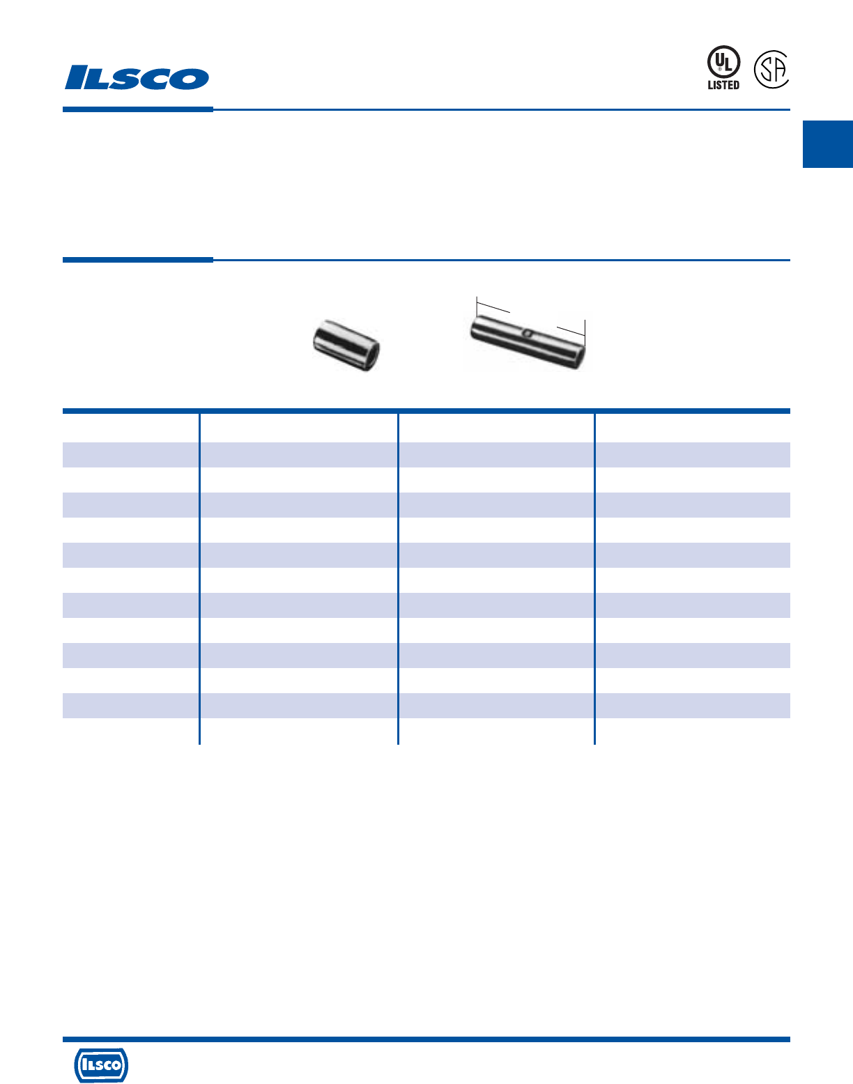
A
4730 Madison Road, Cincinnati, Ohio 45227-1426 Phone 513 533-6200 Fax 513 871-4084 Web site www.ilsco.com
Canada 1050 Lakeshore Road East, Mississauga, Ontario, Canada L5E1E4 Phone 905 274-2341 Fax 905 274-8763
84
Catalog Figure Wire
Number Number Range L
44600-B20 1 18-22 .33
44610-B20 1 14-16 .33
44620-B20 1 10-12 .33
44630-B10 1 8 .38
44640-B10 1 6 .46
44650-B10 1 4 .54
44800-B20 2 18-22 .63
44810-B20 2 14-16 .63
44820-B20 2 10-12 .82
44830-B10 2 8 .77
44840-B10 2 6 1.02
44850-B10 2 4 1.20
Non-Insulated Splices
TYPE
ILSCONS
Features
•
Manufactured from high strength copper alloy
•
Electro-tin plated
•
Packaged in convenient small quantities
•
UL Listed and CSA Certified, 90˚ C
Benefits
•
Provides maximum conductivity
•
Provides low contact resistance
•
Can be displayed on merchandise racks
•
Ensures reliability for copper conductor
Fig. 1 Fig. 2
Can be supplied in bulk. Consult factory for part number.
UL File E158587
8M24
L
L
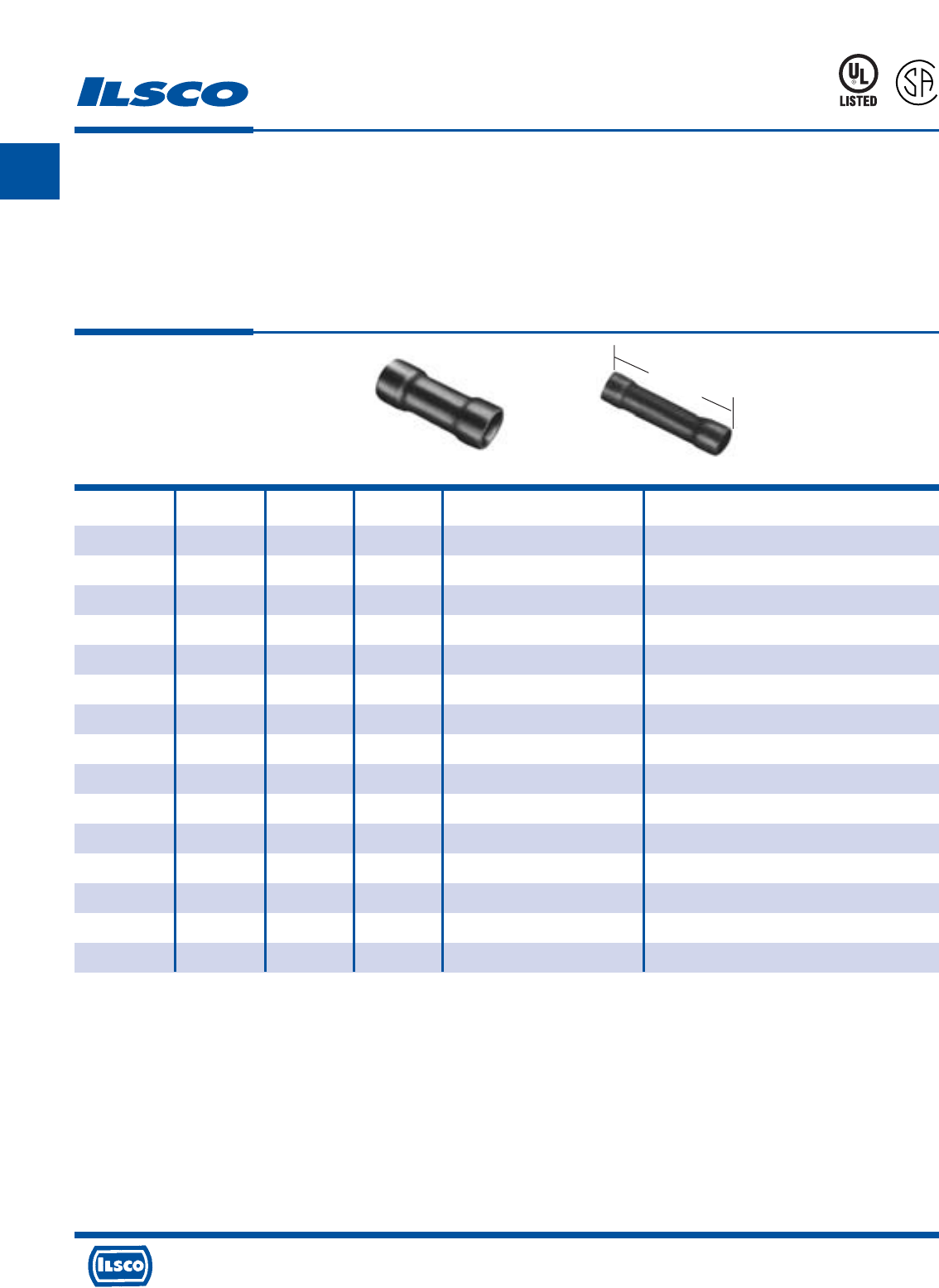
A
4730 Madison Road, Cincinnati, Ohio 45227-1426 Phone 513 533-6200 Fax 513 871-4084 Web site www.ilsco.com
Canada 1050 Lakeshore Road East, Mississauga, Ontario, Canada L5E1E4 Phone 905 274-2341 Fax 905 274-8763
85
Catalog Figure Wire Maximum Wire Connector
Number Number Range L Insulated Diameter Type
44700-B10 1 18-22 .76 .145 Parallel Splice
44710-B10 1 14-16 .76 .175 Parallel Splice
44720-B10 1 10-12 .83 .255 Parallel Splice
44730-B5 1 8 1.05 .385 Parallel Splice
44740-B5 1 6 1.19 .440 Parallel Splice
44750-B5 1 4 1.41 .515 Parallel Splice
44900-B10 2 18-22 .95 .145 Butt Splice
44910-B10 2 14-16 1.02 .175 Butt Splice
44920-B10 2 10-12 1.01 .255 Butt Splice
44930-B5 2 8 1.46 .385 Butt Splice
44940-B5 2 6 1.80 .440 Butt Splice
44950-B5 2 4 1.95 .515 Butt Splice
45130-P100 1 18-22 .76 .145 Vinyl Insulated Splice
45330-P100 1 14-16 .76 .175 Vinyl Insulated Splice
45430-P50 1 10-12 .83 .255 Vinyl Insulated Splice
Vinyl Insulated Splices
TYPE
ILSCONS
Features
•
Color coded
•
Manufactured from high strength copper alloy
•
Electro-tin plated
•
Silver solder brazed seam
•
Vinyl insulation
•
Packaged in convenient small quantities
•
UL Listed and CSA Certified for 600 volts, 90˚ C
Benefits
•
Provides easy wire range identification
#22-18 AWG Red
#16-14 AWG Blue
#12-10 AWG Yellow
•
Provides maximum conductivity
•
Provides low contact resistance
•
May be crimped anywhere and will not split open, even under extreme
operating stresses
•
Provides tough pliable insulative qualities to protect connectors and wire
from corrosion as well as providing some strain relief
•
Can be displayed on merchandise racks
•
Ensures reliability for copper conductor
Fig. 1 Fig. 2
Can be supplied in bulk. Consult factory for part number.
UL File E158587
8M24
L
L
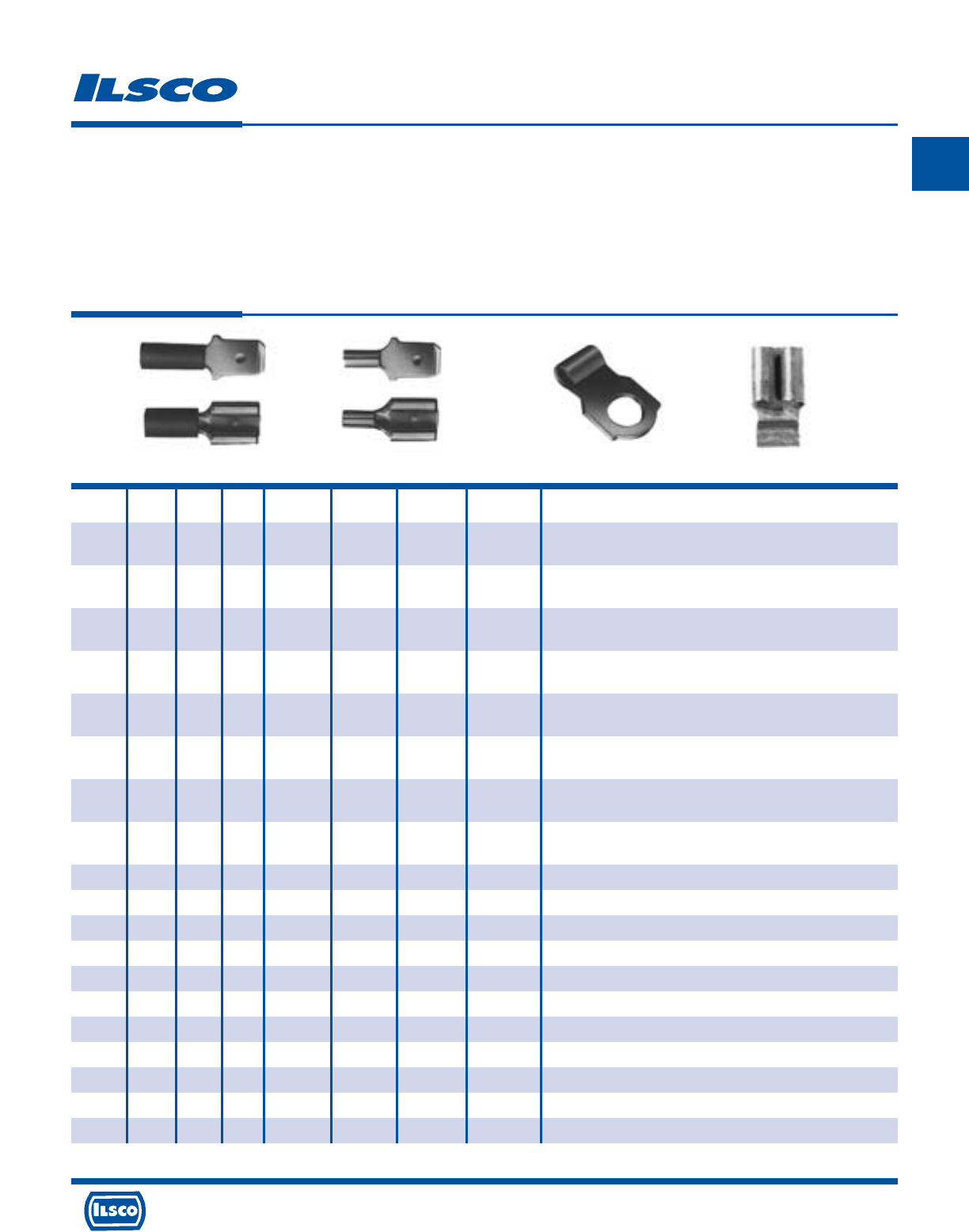
A
4730 Madison Road, Cincinnati, Ohio 45227-1426 Phone 513 533-6200 Fax 513 871-4084 Web site www.ilsco.com
Canada 1050 Lakeshore Road East, Mississauga, Ontario, Canada L5E1E4 Phone 905 274-2341 Fax 905 274-8763
86
Catalog Figure Wire Stud Connector
Number Number Range Size Type Width Thickness Length Type
45100-B10 1 18-22 - Female 1/4 - -
Disconnects - Insulated - Male - Female - Brass Sleeve - Vinyl Insulation
45101-B10 1 18-22 - Male 1/4 - -
45110-B10 1 14-16 - Female 1/4 - -
Disconnects - Insulated - Male - Female - Brass Sleeve - Vinyl Insulation
45111-B10 1 14-16 - Male 1/4 - -
45120-B10 1 10-12 - Female 1/4 - -
Disconnects - Insulated - Male - Female - Brass Sleeve - Vinyl Insulation
45121-B10 1 10-12 - Male 1/4 - -
45112-B10 1 14-16 - Female 3/16 - -
Disconnects - Insulated - Male - Female - Brass Sleeve - Vinyl Insulation
45113-B10 1 14-16 - Male 3/16 - -
45200-B10 2 18-22 - Female 1/4 - - Disconnects - Uninsulated - Male - Female
45201-B10 2 18-22 - Male 1/4 - -
45210-B10 2 14-16 - Female 1/4 - - Disconnects - Uninsulated - Male - Female
45211-B10 2 14-16 - Male 1/4 - -
45220-B10 2 10-12 - Female 1/4 - - Disconnects - Uninsulated - Male - Female
45221-B10 2 10-12 - Male 1/4 - -
45212-B10 2 14-16 - Female 3/16 - - Disconnects - Uninsulated - Male - Female
45213-B10 2 14-16 - Male 3/16 - -
45300-B10 3 18-22 10 - 21/32 - 3/8 Ring Flag Terminals - Uninsulated
45310-B10 3 14-16 10 - 11/16 - 3/8 Ring Flag Terminals - Uninsulated
45320-B10 3 10-12 10 - 11/16 - 3/8 Ring Flag Terminals - Uninsulated
45400-B10 4 18-22 - - .187 .016 .46 Female Quick-Slide Flag Terminals - Uninsulated
45401-B10 4 18-22 - - .250 .030 .50 Female Quick-Slide Flag Terminals - Uninsulated
45410-B10 4 14-16 - - .187 .016 .49 Female Quick-Slide Flag Terminals - Uninsulated
45411-B10 4 14-16 - - .250 .030 .51 Female Quick-Slide Flag Terminals - Uninsulated
45420-B10 4 10-12 - - .250 .030 .61 Female Quick-Slide Flag Terminals - Uninsulated
45393-P100 1 14-16 - Female 1/4 - - Vinyl Insulated Disconnect
45483-P50 1 10-12 - Male 1/4 - - Vinyl Insulated Disconnect
45493-P50 1 10-12 - Female 1/4 - - Vinyl Insulated Disconnect
Disconnects and Flag Terminals
TYPE
ILSCONS
Features
•
Color coded
•
Manufactured from high strength copper alloy
•
Electro-tin plated
•
Silver solder brazed seam
•
Vinyl insulation
•
Packaged in convenient small quantities
•
Insulated connectors are rated for 600 volts, 90˚ C
Benefits
•
Provides easy wire range identification
#22-18 AWG Red
#16-14 AWG Blue
#12-10 AWG Yellow
•
Provides maximum conductivity
•
Provides low contact resistance
•
May be crimped anywhere and will not split open, even under extreme
operating stresses
•
Provides tough pliable insulative qualities to protect connectors and wire
from corrosion as well as providing some strain relief
•
Can be displayed on merchandise racks
•
Ensures reliability for copper conductor
Fig. 1 Fig. 2 Fig. 3 Fig. 4
Can be supplied in bulk. Consult factory for part number.
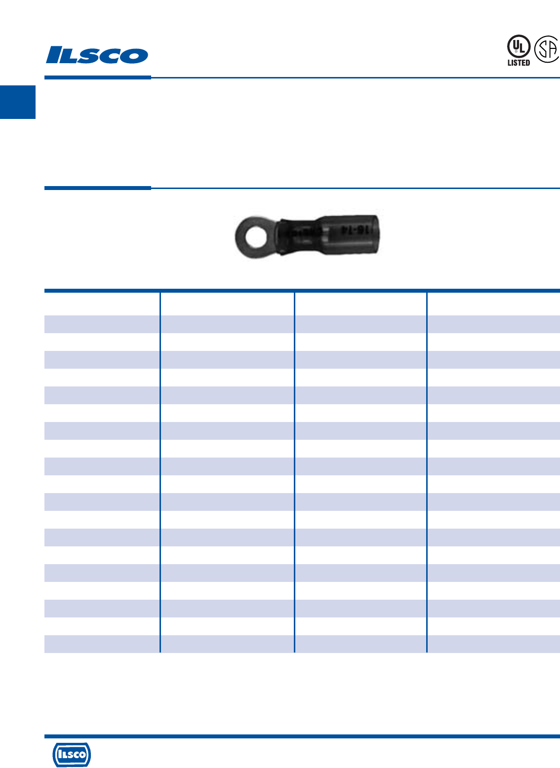
A
4730 Madison Road, Cincinnati, Ohio 45227-1426 Phone 513 533-6200 Fax 513 871-4084 Web site www.ilsco.com
Canada 1050 Lakeshore Road East, Mississauga, Ontario, Canada L5E1E4 Phone 905 274-2341 Fax 905 274-8763
87
Catalog Wire Stud Maximum Wire
Number Range Size Insulation
31112-B10 18-22 6 .170
31113-B10 18-22 8 .170
31114-B10 18-22 10 .170
31115-B10 18-22 1/4" .170
31312-B10 14-16 6 .190
31313-B10 14-16 8 .190
31314-B10 14-16 10 .190
31315-B10 14-16 1/4" .190
31316-B10 14-16 5/16" .190
31317-B10 14-16 3/8" .190
31413-B10 10-12 8 .240
31414-B10 10-12 10 .240
31415-B10 10-12 1/4" .240
31417-B10 10-12 3/8" .240
31419-B10 10-12 1/2" .240
31514-B5 8 10 .310
31515-B5 8 1/4" .310
31517-B5 8 3/8" .310
31519-B5 8 1/2" .310
Crimp 'N Seal®Watertight Ring Connectors
Heat Shrinkable
TYPE
CNS
Features
•
Dual wall tubing
•
Color coded
•
Manufactured from high strength copper alloy
•
Electro-tin plated
•
Silver solder brazed seam
•
UL Listed and CSA Certified for 600 volts, 90˚ C
•
Serrated barrel
•
Packaged in convenient small quantities
Benefits
•
Irradiated, thermally stabilized, high density polyolefin has inner wall of hot
melt adhesive to insure watertight seal
•
Provides easy wire range identification. #22-18 AWG Red, #16-14 AWG Blue,
#12-10 AWG Yellow
•
Provides maximum conductivity
•
Provides low contact resistance
•
May be crimped anywhere and will not split open, even under extreme
operating stresses
•
Ensures reliability for copper conductor
•
“V” grooves inside barrel securely grip wire and prevent pullout
•
Can be displayed on merchandise racks
Can be supplied in bulk. Consult factory for part number.
UL File E158587
8M24
L
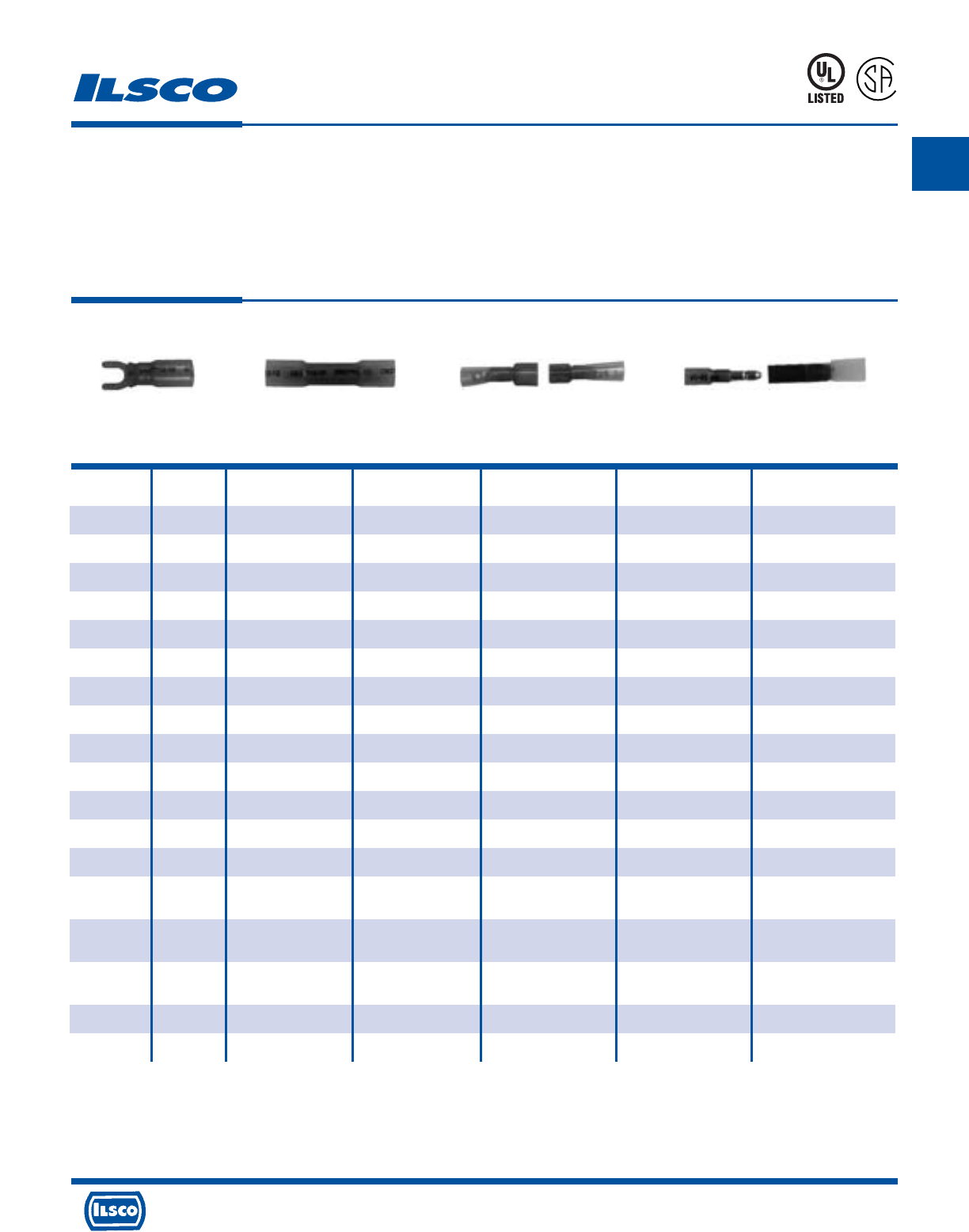
A
4730 Madison Road, Cincinnati, Ohio 45227-1426 Phone 513 533-6200 Fax 513 871-4084 Web site www.ilsco.com
Canada 1050 Lakeshore Road East, Mississauga, Ontario, Canada L5E1E4 Phone 905 274-2341 Fax 905 274-8763
88
Catalog Fig. Wire Stud Maximum Wire Connector
Number Number Range Size Style Insulation Type
31122-B10 1 18-22 6 - .170 Forks
31123-B10 1 18-22 8 - .170 Forks
31124-B10 1 18-22 10 - .170 Forks
31322-B10 1 14-16 6 - .190 Forks
31323-B10 1 14-16 8 - .190 Forks
31324-B10 1 14-16 10 - .190 Forks
31423-B10 1 10-12 8 - .240 Forks
31424-B10 1 10-12 10 - .240 Forks
31425-B10 1 10-12 1/4" - .240 Forks
31130-B10 2 18-22 BS - .170 Butt Splices
31330-B10 2 14-16 BS - .190 Butt Splices
31430-B10 2 10-12 BS - .240 Butt Splices
31530-B5 2 8 BS - .310 Butt Splices
30187-B10 3 18-22 - Male .170 Quick Disconnects
30197-B10 3 18-22 - Female .170 Fully Insulated
30387-B10 3 14-16 - Male .190 Quick Disconnects
30397-B10 3 14-16 - Female .190 Fully Insulated
30487-B10 3 10-12 - Male .240 Quick Disconnects
30497-B10 3 10-12 - Female .240 Fully Insulated
30369-B10 4 14-16 - Male .190 Bullets
30379-B10 4 14-16 - Female .190 Bullets
Crimp 'N Seal®Watertight Connectors
Heat Shrinkable Forks, Splices, Disconnects, Bullets
TYPE
CNS
Features
•
Dual wall tubing
•
Color coded
•
Manufactured from high strength copper alloy
•
Electro-tin plated
•
Silver solder brazed seam
•
UL Listed and CSA Certified for 600 volts, 90˚C
•
Serrated barrel
•
Packaged in convenient small quantities
Benefits
•
Irradiated, thermally stabilized, high density polyolefin has inner wall of hot
melt adhesive to insure watertight seal
•
Provides easy wire range identification. #22-18 AWG Red, #16-14 AWG Blue,
#12-10 AWG Yellow
•
Provides maximum conductivity
•
Provides low contact resistance
•
May be crimped anywhere and will not split open, even under extreme
operating stresses
•
Ensures reliability for copper conductor
•
“V” grooves inside barrel securely grip wire and prevent pullout
•
Can be displayed on merchandise racks
Fig. 1 Fig. 2 Fig. 3 Fig. 4
Can be supplied in bulk. Consult factory for part number.
UL File E158587
8M24
L
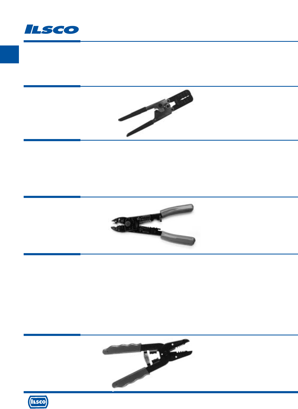
A
4730 Madison Road, Cincinnati, Ohio 45227-1426 Phone 513 533-6200 Fax 513 871-4084 Web site www.ilsco.com
Canada 1050 Lakeshore Road East, Mississauga, Ontario, Canada L5E1E4 Phone 905 274-2341 Fax 905 274-8763
89
Crimping Tools
TYPE
94130
Controlled-Cycle
Crimper
Features
•
Dieless tool
•
Ratchet mechanism
•
Compound action
•
Cushion grip handles
•
Crimps insulated wire terminals
•
Wire Range: 10-22 AWG, Weight .8 lb
Benefits
•
No need to purchase and maintain dies
•
Assures proper crimp force every time
•
Delivers maximum crimp force with minimum effort
•
Provides user comfort
•
Provides flexibility in use
TYPE
94140
Multi Purpose
Crimp Tool
Features
•
Heavy duty carbon steel construction
•
Comfort grip handles
•
Spring loaded action
•
Safety lock mechanism
•
Color coded crimp nest
•
Crimp nest
•
Wire cutter
•
Machine screw cutters
•
Wire stripper/wire gauge
Benefits
•
Provides durable rugged reliability
•
Provides user comfort
•
Enables multiple crimps
•
Provides for compact storage
•
For insulated terminals
•
For uninsulated terminals
•
Easily cuts solid and stranded wire
•
Cuts and rethreads 4-40, 6-32, 8-32, 10-24, and 10-32 machine screws
•
26-8 AWG
TYPE
WS-1
Wire Stripper
Features
•
Cushion grip handles
•
Crimp die
•
Wire strip gauge
•
Plier nose
•
Wire loop holes
•
Wire cutter
•
“Open” spring
•
Metric markings
•
Precision stripping
•
Wire crimp range: 14-20 AWG
Benefits
•
Eases pressure on hands when working for long periods or with larger
conductor
•
Built in crimp die allows you to crimp insulated terminals from 20AWG to
14AWG
•
Convenient stamped wire strip gauge makes it easy to strip conductors to
specific length consistently
•
Flat plier nose allows you to conveniently punch and twist knock outs
•
Built in looping holes allow you to conveniently bend eye loop into end of
conductor
•
Built in cutter is precision ground to cut small conductor copper intended to be
stripped (Strips #10 - 18 AWG)
•
Conveniently holds tool in open position to facilitate wire insertion
•
Metric markings provide for use of tool on products that have been sized
metrically
•
Precision ground wire stripping holes provide a clean cutting and stripping
action of insulation
A
4730 Madison Road, Cincinnati, Ohio 45227-1426 Phone 513 533-6200 Fax 513 871-4084 Web site www.ilsco.com
Canada 1050 Lakeshore Road East, Mississauga, Ontario, Canada L5E1E4 Phone 905 274-2341 Fax 905 274-8763
90
ILC-12-N,
IDT-6, ILC-12H-N,
IDT-6H ILC-12,
6.2 Ton ILC-12H,
Dieless, ILC-14, IDT-12,
IDTB-6 ILC-14H 12 Ton, IDT-12H, ILC-15H
6.2 Ton ILCB-12-N, IDT-12-N IDTB-12 15 Ton,
Dieless ILCB-12 15 Ton 11 Ton ILC-30H
Lug Class B/C Color Die 94285 MT-25 ILC-10-N Battery 12 Ton Battery Dieless Dieless 30 Ton ILC-750
Size Wire Size Code Index Left Die Right Die Crimps Crimps Index Crimps Crimps Crimps Crimps Crimps Crimps Crimps
8 8 AWG Red 21 M K 2 1 Red 1 1 1 1
6 6 AWG Blue 24 K K 2 1 Blue 2 1 1 1 1
4 4 AWG Gray 29 K K 2 1 Gray 2 1 1 1 1 1 1
3 3 AWG White 29 K K 2 1 Gray 2 1 1 1 1 1 1
2 2 AWG Brown 33 H H 2 2 Brown 2 1 1 1 1 1 1
1 1 AWG Green 37 H H 2 2 Green 2 1 1 1 1 1 1
1/0 1/0 AWG Pink 42 E A 2 2 Pink 4 1 1 1 1 1 1
2/0 2/0 AWG Black 45 E A 3 2 1 1 1 1 1 1
3/0 3/0 AWG Orange 50 A C 3 2 2 1 1 1 1 1
4/0 4/0 AWG Purple 54 A B 3 2 2 1 1 1 1 1
250 250kcmil Yellow 62 A A 3 2 2 1 1 1 1 1
300 300kcmil White 66 221122
350 350kcmil Red 71 221122
400 400kcmil Blue 76 221122
500 500kcmil Brown 87 221122
600 600kcmil Green 94 221122
700 700kcmil Pink 99 321122
750 750kcmil Black 106 321122
1000 1000kcmil White 125 2112
Series CS, CL Compression Connectors
for Class B/C Copper Wire Only
L
R
-
2
9
6
0
1
453G
ILSCO TOOLS -
Tooling Information
UL Listed and CSA Certified when installed with tools and dies shown above
a) Connectors are marked with color, die numbers and required number of crimps for ILSCO hydraulic tools. When using other listed tools, consult chart for crimps
required. Crimps should be evenly spaced on connector.
b) The ILSCO 94285, MT-25 and all dieless tools are not color coded or do not contain the die index.
c) Strip Length = Barrel Length + 1/16 Inch
d) For long barrel connectors double the amount of crimps indicated on chart except for 1000kcmil add only one additional crimp.
WARNING! Do Not Use with Aluminum Wire
Manual Hand Tools
Hydraulic Tools
RANGE TAKING
Lug Standard Expanded No. Crimps for ILSCO IDT-12,IDT-12-N No. Crimps for ILSCO IDTB-6,
Size Wire Size Wire Size and Burndy Y644M, PAT644 IDT-6 and IDT-6H
44 AWG 4 - 6 AWG 1
33 AWG 3 - 6 AWG 1 1
22 AWG 2 - 6 AWG 1 1
11 AWG 1 - 6 AWG 1 1
1/0 1/0 AWG 1/0 - 6 AWG 1 1
2/0 2/0 AWG 2/0 - 4 AWG 1 1
3/0 3/0 AWG 3/0 - 2 AWG 1 2
4/0 4/0 AWG 4/0 - 1 AWG 1 2
250 250kcmil 250kcmil - 1/0 AWG 1 2
300 300kcmil 300kcmil - 2/0 AWG 1 2
350 350kcmil 350kcmil - 3/0 AWG 1 2
400 400kcmil 400kcmil - 4/0 AWG 1 2
500 500kcmil 500kcmil - 250kcmil 1 2
600 600kcmil 600kcmil - 250kcmil 1 2
700 700kcmil 700kcmil - 350kcmil 1 3
750 750kcmil 750kcmil - 500kcmil 1 3
1000 1000kcmil 1000kcmil - 750kcmil 1
A
4730 Madison Road, Cincinnati, Ohio 45227-1426 Phone 513 533-6200 Fax 513 871-4084 Web site www.ilsco.com
Canada 1050 Lakeshore Road East, Mississauga, Ontario, Canada L5E1E4 Phone 905 274-2341 Fax 905 274-8763
91
ILC-12-N,
IDT-6, ILC-12H-N,
IDT-6H ILC-12,
6.2 Ton ILC-12H,
Dieless, ILC-14, IDT-12,
IDTB-6 ILC-14H 12 Ton, IDT-12H, ILC-15H
6.2 Ton ILCB-12-N, IDT-12-N IDTB-12 15 Ton,
Dieless ILCB-12 15 Ton 11 Ton ILC-30H
Lug Class B/C Color Die 94285 MT-25 ILC-10-N Battery 12 Ton Battery Dieless Dieless 30 Ton
Size Wire Size Code Index Left Die Right Die Crimps Crimps Index Crimps Crimps Crimps Crimps Crimps Crimps
8 8 AWG Red 21 M K 2 1 Red 1 1 1
6 6 AWG Blue 24 K K 2 1 Blue 2 1 1 1 1
4 4 AWG Gray 29 K K 2 1 Gray 2 1 1 1 1 1
3 3 AWG White 29 K K 2 1 Gray 2 1 1 1 1 1
2 2 AWG Brown 33 H H 2 2 Brown 2 1 1 1 1 1
1 1 AWG Green 37 H H 2 2 Green 2 1 1 1 1 1
1/0 1/0 AWG Pink 42 E A 2 2 Pink 4 1 1 1 1 1
2/0 2/0 AWG Black 45 E A 3 2 1 1 1 1 1
3/0 3/0 AWG Orange 50 A C 3 2 2 1 1 1 1
4/0 4/0 AWG Purple 54 A B 3 2 2 1 1 1 1
250 250kcmil Yellow 62 A A 3 2 2 1 1 1 1
300 300kcmil White 66 22112
350 350kcmil Red 71 22112
400 400kcmil Blue 76 22112
500 500kcmil Brown 87 22112
600 600kcmil Green 94 22112
700 700kcmil Pink 99 32112
750 750kcmil Black 106 32112
1000 1000kcmil White 125 2112
Series CT, CTL Compression Connectors
for Class B/C Copper Wire Only
L
R
-
2
9
6
0
1
453G
ILSCO TOOLS -
Tooling Information
UL Listed and CSA Certified when installed with tools and dies shown above
a) Number of crimps shown on chart must be on each end of the CT splicer connectors.
b) The CT connectors are marked with color, the die numbers and required number of crimps for ILSCO hydraulic tools. When using other listed tools, consult chart for crimps
required. Crimps should be evenly spaced on connector.
c) The ILSCO 94285, MT-25 and all dieless tools are not color coded or do not contain the die index.
d) For long barrel (CTL) connectors add one additional crimp to each side of barrel.
WARNING! Do Not Use with Aluminum Wire
Manual Hand Tools
Hydraulic Tools
A
4730 Madison Road, Cincinnati, Ohio 45227-1426 Phone 513 533-6200 Fax 513 871-4084 Web site www.ilsco.com
Canada 1050 Lakeshore Road East, Mississauga, Ontario, Canada L5E1E4 Phone 905 274-2341 Fax 905 274-8763
92
ILC-12-N,
IDT-6, ILC-12H-N,
IDT-6H ILC-12,
6.2 Ton ILC-12H,
Dieless, ILC-14, IDT-12,
IDTB-6 ILC-14H 12 Ton, IDT-12H, ILC-15H
6.2 Ton ILCB-12-N, IDT-12-N IDTB-12 15 Ton,
Fine Dieless ILCB-12 15 Ton 11 Ton ILC-30H
Lug Strand Approved Color Die 94285 ILC-10-N Battery 12 Ton Battery Dieless Dieless 30 Ton ILC-750
Size Wire Size Wire Classes Code Index Left Die Right Die Crimps Index Crimps Crimps Crimps Crimps Crimps Crimps Crimps
8 8 G,H,I,K,M,DLO Red 21 Red 1 1 1 1
4 6 G,H,I,K,M,DLO Gray 29 Blue 2 1 1 1
3 4 G,H,I,K,M,DLO White 29 K K 2 Gray 2 1 1 1 1 1 1
1 2 G,H,I,K,M,DLO Green 37 H H 2 Green 2 1 1 1 1 1 1
1/0 1 G,H,I,K,M,DLO Pink 42 H H 2 Pink 4 1 1 1 1 1 1
2/0 1/0 G,H,I,K,M,DLO Black 45 E A 3 1 1 1 1 1 1
3/0 2/0 G,H,I,K,M,DLO Orange 50 E A 3 1 1 1 1 1 1
4/0 3/0 G,H,I,K,M,DLO Purple 54 A B 3 1 1 1 1 1 1
250 4/0 G,H,I,K,M,DLO Yellow 62 A B 3 1 1 1 1 1 1
300 250 G,H White 66 1 2 1 1 2 2
350 250 I,K,M Red 71 1 2 1 1 2 2
350 262 DLO Red 71 1 2 1 1 2 2
400 300 G,H,I,K,M Blue 76 2 2 1 1 2 2
400 313 DLO Blue 76 2 2 1 1 2 2
500 350 G,H,I,K,M Brown 87 2 2 1 1 2 2
500 373 DLO Brown 87 2 2 1 1 2 2
600 400 G,H,I,K,M Green 94 2 2 1 1 2 2
600 444 DLO Green 94 2 2 1 1 2 2
700 500 G,H,I,K,M Pink 99 3 2 1 1 2 2
700 535 DLO Pink 99 3 2 1 1 2 2
750 600 G,H,I,M Black 106 3 2 1 1 2 2
750 646 DLO Black 106 3 2 1 1 2 2
1000 750 G,H,I White 125 3113
1000 777 DLO White 125 3113
Series CS, CL Compression Connectors
for Fine Strand Copper Wire Only
L
R
-
2
9
6
0
1
453G
ILSCO TOOLS -
Tooling Information
UL Listed and CSA Certified when installed with tools and dies shown above
a) Connectors are marked with color, die numbers and required number of crimps for ILSCO hydraulic tools. When using other listed tools, consult chart for crimps
required. Crimps should be evenly spaced on connector.
b) The ILSCO 94285, MT-25 and all dieless tools are not color coded or do not contain the die index.
c) Strip Length = Barrel Length + 1/16 Inch
d) For long barrel connectors double the amount of crimps indicated on chart except for 1000kcmil add only one additional crimp.
WARNING! Do Not Use with Aluminum Wire
Manual Hand Tools
Hydraulic Tools
A
4730 Madison Road, Cincinnati, Ohio 45227-1426 Phone 513 533-6200 Fax 513 871-4084 Web site www.ilsco.com
Canada 1050 Lakeshore Road East, Mississauga, Ontario, Canada L5E1E4 Phone 905 274-2341 Fax 905 274-8763
93
Series CT, CTL - Compression Connectors
for Fine Strand Copper Wire Only
L
R
-
2
9
6
0
1
453G
ILC-12-N,
IDT-6, ILC-12H-N,
IDT-6H ILC-12,
6.2 Ton ILC-12H,
Dieless, ILC-14, IDT-12,
IDTB-6 ILC-14H 12 Ton, IDT-12H, ILC-15H
6.2 Ton ILCB-12-N, IDT-12-N IDTB-12 15 Ton,
Fine Dieless ILCB-12 15 Ton 11 Ton ILC-30H
Lug Strand Approved Color Die 94285 ILC-10-N Battery 12 Ton Battery Dieless Dieless 30 Ton
Size Wire Size Wire Classes Code Index Left Die Right Die Crimps Index Crimps Crimps Crimps Crimps Crimps Crimps
8 8 G,H,I,K,M,DLO Red 21 M K 2 Red 1 1 1
4 6 G,H,I,K,M,DLO Gray 29 K K 2 Blue 2 1 1
3 4 G,H,I,K,M,DLO White 29 K K 2 Gray 2 1 1 1 1 1
1 2 G,H,I,K,M,DLO Green 37 H H 2 Green 2 1 1 1 1 1
1/0 1 G,H,I,K,M,DLO Pink 42 H H 2 Pink 4 1 1 1 1 1
2/0 1/0 G,H,I,K,M,DLO Black 45 E A 3 1 1 1 1 1
3/0 2/0 G,H,I,K,M,DLO Orange 50 E A 3 2 1 1 1 1
4/0 3/0 G,H,I,K,M,DLO Purple 54 A B 3 2 1 1 1 1
250 4/0 G,H,I,K,M,DLO Yellow 62 A B 3 2 1 1 1 1
300 250 G,H White 66 2 2 1 1 2
350 250 I,K,M Red 71 2 2 1 1 2
350 262 DLO Red 71 2 2 1 1 2
400 300 G,H,I,K,M Blue 76 2 2 1 1 2
400 313 DLO Blue 76 2 2 1 1 2
500 350 G,H,I,K,M Brown 87 2 2 1 1 2
500 373 DLO Brown 87 2 2 1 1 2
600 400 G,H,I,K,M Green 94 2 2 1 1 2
600 444 DLO Green 94 2 2 1 1 2
700 500 G,H,I,K,M Pink 99 3 3 1 1 3
700 535 DLO Pink 99 3 3 1 1 3
750 600 G,H,I,M Black 106 3 3 1 1 3
750 646 DLO Black 106 3 3 1 1 3
1000 750 G,H,I White 125 3113
1000 777 DLO White 125 3113
ILSCO TOOLS -
Tooling Information
WARNING! Do Not Use with Aluminum Wire
Manual Hand Tools
Hydraulic Tools
UL Listed and CSA Certified when installed with tools and dies shown above
a) Number of crimps shown on chart must be on each end of the CT splicer connectors.
b) The CT connectors are marked with color, the die numbers and required number of crimps for ILSCO hydraulic tools. When using other listed tools, consult chart for crimps
required. Crimps should be evenly spaced on connector.
c) The ILSCO 94285, MT-25 and all dieless tools are not color coded or do not contain the die index.
d) For long barrel (CTL) connectors add one additional crimp to each side of barrel.
A
4730 Madison Road, Cincinnati, Ohio 45227-1426 Phone 513 533-6200 Fax 513 871-4084 Web site www.ilsco.com
Canada 1050 Lakeshore Road East, Mississauga, Ontario, Canada L5E1E4 Phone 905 274-2341 Fax 905 274-8763
94
Anderson Burndy T&B Greenlee
VC6-FT,
VC6-FTR,
VC6-FT-BP PAT81KFT, ‡ HK06FT,
VC7-FT, Y81KFT, Y644M, Y35, Y35BH, Y46, Y46C 13100A, RK06FT,
VC7-FTR Y81KFTMBH PAT644 Y39, Y750, Requires TBM14M, EK06FT 1990
Lug Class B/C Dieless Y1MR, Y1MRTC Dieless Dieless Y750BH, PAT750 Die Adaptor TBM25S TBM14BSCR K111 Dieless Dieless
Size Wire Size Crimps Index Crimps Crimps Crimps Die Part Crimps Die Part Crimps Index Crimps Die Part Crimps Index Crimps Crimps Crimps
8 8 AWG 1 Red 1 1 U8CRT 1 U8CRT 1 Red 1 15520 1 Red 1
6 6 AWG 1 Blue 1 1 U5CRT 1 U5CRT 1 Blue 1 15522 1 Blue 2 1
4 4 AWG 1 Gray 2 1 1 U4CRT 1 U4CRT 1 Gray 2 15527-CK 1 Gray 2 1 1
3 3 AWG 1 White 2 1 1 U3CRT 1 U3CRT 1 Gray 2 1 1
2 2 AWG 1 Brown 2 1 1 U2CRT 1 U2CRT 1 Brown 2 15528 1 Brown 2 1 1
1 1 AWG 1 1 1 U1CRT-1 1 U1CRT-1 1 15513-CK 1 Green 2 1 1
1/0 1/0 AWG 1 1 1 U25RT 1 U25RT 1 15508 1 Pink 4 1 1
2/0 2/0 AWG 1 1 1 U26RT 1 U26RT 1 15526 1 1 1
3/0 3/0 AWG 1 1 1 U27RT 1 U27RT 1 15530 1 2 1
4/0 4/0 AWG 1 1 1 U28RT 1 U28RT 1 15511 1 2 1
250 250kcmil 2 2 1 U29RT 1 U29RT 1 15510-CK 1 2 1
300 300kcmil 2 2 1 U30RT 2 U30RT 2 15534 2 2 1
350 350kcmil 3* 2 1 U31RT 2 U31RT 2 15514-CK 2 2 1
400 400kcmil 3* 2 1 U32RT 2 U32RT 2 15512 2 2 1
500 500kcmil 3* 2 1 U34RT 2 U34RT 2 15506 2 2 1
600 600kcmil 4* 2 1 U36RT 2 U36RT 2 15536-CK 2 2 1
700 700kcmil 4* 3 1 U38RT 2 U38RT 2 15505 2 3 1
750 750kcmil 4* 3 1 U39RT 2 U39RT 2 15515-CK 2 3 1
1000 1000kcmil 3 1 P44RT 3 15504 2 1
Series CS, CL - Compression Connectors
for Class B/C Copper Wire Only
L
R
-
2
9
6
0
1
453G
COMPETITOR’S TOOLS -
Tooling Information
Dieless* - Crimps will overlap
WARNING! Do Not Use with Aluminum Wire
UL Listed and CSA Certified when installed with tools and dies shown above
a) Connectors are marked with color, die numbers and required number of crimps for ILSCO hydraulic tools. When using other listed tools, consult chart for crimps
required. Crimps should be evenly spaced on connector.
b) The ILSCO 94285, MT-25 and all dieless tools are not color coded or do not contain the die index.
c) Consult manufacturers data for catalog numbers of dies for each tool.
d) Strip Length = Barrel Length + 1/16 Inch
e) For long barrel connectors double the amount of crimps indicated on chart except for 1000kcmil add only one additional crimp.
‡ Allows expanded wire range to be used.
A
4730 Madison Road, Cincinnati, Ohio 45227-1426 Phone 513 533-6200 Fax 513 871-4084 Web site www.ilsco.com
Canada 1050 Lakeshore Road East, Mississauga, Ontario, Canada L5E1E4 Phone 905 274-2341 Fax 905 274-8763
95
Anderson Burndy T&B Greenlee
VC6-FT,
VC6-FTR,
VC6-FT-BP, PAT81KFT,
‡
HK06FT,
Fine VC7-FT, Y81KFT, Y644M, Y35, Y35BH, Y46, Y46C 13100A, RK06FT,
Strand VC7-FTR Y81KFTMBH PAT644 Y39, Y750, Requires TBM14M, EK06FT 1990
Lug Wire Approved Dieless Y1MR, Y1MRTC Dieless Dieless Y750BH, PAT750 Die Adaptor TBM25S TBM14BSCR K111 Dieless Dieless
Size Size Wire Classes Crimps Index Crimps Crimps Crimps Die Part Crimps Die Part Crimps Index Crimps Die Part Crimps Index Crimps Crimps Crimps
8 8 G,H,I,K,M,DLO 1 Red 1 1 U8CRT 1 U8CRT 1 Red 1 15520 1 Red 1
4 6 G,H,I,K,M,DLO 1 Blue 2 1 U5CRT 1 U5CRT 1 Blue 2 15522 1 Blue 2
3 4 G,H,I,K,M,DLO 1 Gray 2 1 1 U4CRT 1 U4CRT 1 Gray 2 15528 1 Gray 2 1 1
1 2 G,H,I,K,M,DLO 1 Brown 2 1 1 U2CRT 1 U2CRT 1 Brown 3 15513-CK 1 Green 2 1 1
1/0 1 G,H,I,K,M,DLO 1 1 1 U1CRT-1 1 U1CRT-1 1 15508 1 Pink 4 1 1
2/0 1/0 G,H,I,K,M,DLO 1 1 1 U25RT 1 U25RT 1 15526 1 1 1
3/0 2/0 G,H,I,K,M,DLO 2 2 1 U26RT 1 U26RT 1 15530 1 1 1
4/0 3/0 G,H,I,K,M,DLO 2 2 1 U27RT 1 U27RT 1 15511 1 1 1
250 4/0 G,H,I,K,M,DLO 2 2 1 U28RT 1 U28RT 1 15510-CK 2 1 1
300 250 G,H 2 2 1 U29RT 2 U29RT 2 15534 2 1 1
350 250 I,K,M 3* 2 1 U30RT 2 U30RT 2 2 1 1
350 262 DLO 3* 2 1 2 2 2 1 1
400 300 G,H,I,K,M 3* 2 1 U31RT 2 U31RT 2 15514-CK 2 2 1
400 313 DLO 3* 2 1 2 2 2 2 1
500 350 G,H,I,K,M 3* 2 1 U32RT 2 U32RT 2 15512 2 2 1
500 373 DLO 3* 2 1 2 2 15517 2 2 1
600 400 G,H,I,K,M 4* 2 1 U34RT 2 U34RT 2 15536-CK 2 2 1
600 444 DLO 4* 2 1 2 2 2 2 1
700 500 G,H,I,K,M 4* 3 1 U38XRT 2 U38XRT 2 15505 2 3 1
700 535 DLO 4* 3 1 2 2 2 3 1
750 600 G,H,I,M 4* 3 1 U39RT 2 U39RT 2 15515-CK 2 3 1
750 646 DLO 4* 3 1 2 2 2 3 1
1000 750 G,H,I 3 1 U44XRT 3 15504 3 1
1000 777 DLO 3 1 3 3 1
Series CS, CL - Compression Connectors
for Fine Strand Copper Wire Only
L
R
-
2
9
6
0
1
453G
COMPETITOR’S TOOLS -
Tooling Information
Dieless* - Crimps will overlap
WARNING! Do Not Use with Aluminum Wire
UL Listed and CSA Certified when installed with tools and dies shown above
a) Connectors are marked with color, die numbers and required number of crimps for ILSCO hydraulic tools. When using other listed tools, consult chart for crimps
required. Crimps should be evenly spaced on connector.
b) The ILSCO 94285, MT-25 and all dieless tools are not color coded or do not contain the die index.
c) Strip Length = Barrel Length + 1/16 Inch
d) For long barrel connectors double the amount of crimps indicated on chart except for 1000kcmil add only one additional crimp.
‡ Allows expanded wire range to be used.
A
4730 Madison Road, Cincinnati, Ohio 45227-1426 Phone 513 533-6200 Fax 513 871-4084 Web site www.ilsco.com
Canada 1050 Lakeshore Road East, Mississauga, Ontario, Canada L5E1E4 Phone 905 274-2341 Fax 905 274-8763
96
Catalog For Use With
Number Aluminum Compression Connectors Copper Compression Connectors
+ ILD-OH HT-1, HT-2, AH-1 GGC-1, GGA-1, GGA-2, GGA-4
+ ILD-D3H HT-3, HT-4, HT-5, HT-6, HT-7, AH-2, AH-3, AH-4 ULT-12
Catalog
Number Description
ILD-UADP Permits ILD-1 – ILD-18 and standard U dies to be inserted in ILC-15H Tool
ILD-PADP Permits P style dies to be inserted in ILC-15H Tool
Catalog For Use With
Number Aluminum Compression Connectors Copper Compression Connectors
ILD-K-840* UCS-2/0, UCS-3/0, UCS-4/0, UCS-250, PICS-834 thru PICS-869
ILD-C* ULT-6, ULT-7, ELT-1
ILD-D3* HT-2, HT-3, HT-4, HT-5, HT-7, AH-2, AH-3, AH-4 ULT-12
ILD-0* HT-1, HT-6, HT-8, AH-1 GGC-1, GGA-1, GGA-2, GGA-4, ELT-2, ELT-4
ILD-N* AH-5, AH-6, AH-7
ILD-KR* AH-8, AH-9, AH-10, AH-11, AH-12
ILD-U997* GGA-2, GGA-3, GGA-5, GGC-2, GGC-3, GGC-4, ELT-3, ELT-5
ILD-U998* GGA-4, GGA-5, GGC-5, GGC-6, GGC-7, RLT
ILD-P998 GGA-4, GGA-5, GGC-5, GGC-6, GGC-7, RLT
+
ILD-P999 GGA-6, GGC-8
ILD-U1011* GGA-6, GGC-8, ELT-6, RLT
ILD-P1011 GGA-6, GGC-8, RLT
ILD-UBG PICS-61 thru PICS-78 ULT-4, ULT-5
Catalog For Use With
Number Aluminum Compression Connectors Copper Compression Connectors
ND-0 HT-1, HT-2, AH-1 GGC-1, GGA-1, GGA-2, GGA-4
ND-BG PICS-61 thru PICS-78 ULT-4, ULT-5
ND-C ULT-6, ULT-7
ND-K-840 UCS-2/0, UCS-3/0 UCS-4/0, UCS-250, PICS-834 thru PICS-869
Compression Die Index
+Consult factory for availability.
COMPRESSOR DIES FOR ILC-15, ILC-15H AND ILC-750
+Consult factory for availability. * Must be used with ILD-ADP when using ILC-15 tool.
DIE ADAPTOR FOR ILC-15H
Catalog
Number Description
ILD-ADP Permits ILD-1 – ILD-18 and standard U dies to be inserted in ILC-15 Tool
DIE ADAPTOR FOR ILC-15
COMPRESSOR DIES FOR IDT-12 AND IDT-12H
COMPRESSOR DIES FOR ND-58 AND ND-60
A
4730 Madison Road, Cincinnati, Ohio 45227-1426 Phone 513 533-6200 Fax 513 871-4084 Web site www.ilsco.com
Canada 1050 Lakeshore Road East, Mississauga, Ontario, Canada L5E1E4 Phone 905 274-2341 Fax 905 274-8763
97
Catalog Wire Size
Number Aluminum Terminals and Splices ACM and ACO Pin Connectors CPM Pin Connectors
ILD-1
ILD-2 8
ILD-3 6
ILD-4 4
ILD-5
ILD-6
ILD-7 2, 1
ILD-8 1/0 6, 4, 2, 1
ILD-9 6, 4, 2, 1
ILD-10 2/0, 3/0
ILD-11
ILD-12 4/0 1/0, 2/0, 3/0, 4/0 1/0, 2/0, 3/0, 4/0
ILD-13 250kcmil
ILD-14 300kcmil, 350kcmil 250kcmil, 300kcmil, 350kcmil 250kcmil, 300kcmil, 350kcmil
ILD-15
ILD-16 400kcmil
ILD-16A *500kcmil 400kcmil, 500kcmil 400kcmil,500 kcmil
ILD-17 *600kcmil, *700 kcmil
ILD-18 *700kcmil 600kcmil, 750kcmil 600 kcmil,750 kcmil
Compression Die Index
Compressor Dies For ILC-12-N, ILC-12H-N, ILCB-12-N, ILC-15H,
ILC-12, ILC-12H, ILC-14, ILC-14H, ILCB-12, ILC-15, ILC-750
* Cannot be used on Sleeves with ILC-12-N, ILC-12H-N, ILC-12 and ILC-12H tools
Catalog Class B/C Copper Wire Only Fine Strand Copper Wire Only
Number Series CS, CL, CT, CTL Series CS, CL, CT, CTL
ILD-21 8 AWG 8 FLEX CLASS G,H,I,K,M,DLO
ILD-24 6 AWG -
ILD-29 4-3 AWG 6-4 FLEX CLASS G,H,I,K,M,DLO
ILD-33 2 AWG -
ILD-37 1 AWG 2 FLEX CLASS G,H,I,K,M,DLO
ILD-42 1/0 AWG 1 FLEX CLASS G,H,I,K,M,DLO
ILD-45 2/0 AWG 1/0 FLEX CLASS G,H,I,K,M,DLO
ILD-50 3/0 AWG 2/0 FLEX CLASS G,H,I,K,M,DLO
ILD-54 4/0 AWG 3/0 FLEX CLASS G,H,I,K,M,DLO
ILD-62 250kcmil 4/0 FLEX CLASS G,H,I,K,M,DLO
ILD-66 300kcmil 250 G,H
ILD-71 350kcmil 250 I,K,M, 262 DLO
ILD-76 400kcmil 300 G,H,I,K,M, 313 DLO
ILD-87 500kcmil 350 G,H,I,K,M, 373 DLO
ILD-94 600kcmil 400 G,H,I,K,M, 444 DLO
ILD-99 700kcmil 500 G,H,I,K,M, 535 DLO
ILD-106 750kcmil 600 G,H,I,M, 646 DLO
ILD-125 1000kcmil 750 G,H,I, 777 DLO
Compressor Dies For ILC-12, ILC-12-N, ILC-12H, ILC-12H-N,
ILCB-12, ILCB-12-N, ILC-14, ILC-14H, ILC-15, ILC-15H, ILC-750
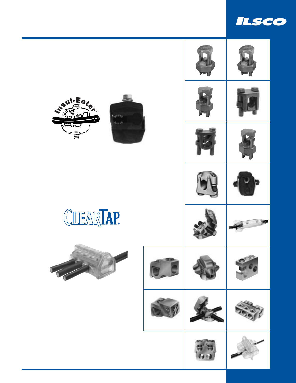
98
Split Bolts
IK
99
IK3
100
SK
101
GTT
109
IPC
106
GTA
107
GT4T
112
GT2
111
GTC
110
GTA/GTT KIT
113
PCT
116
MGTT
114
115
AK
104
SPAR
108
PTA
DBA, DBA-S
105
IKB
102
IKS
103
Put More Money in Your Pocket
with these Labor Savers!
KUP-L-Tap®
Insulation Piercing Connectors
Insulated Multi-Tap Connectors
•Fully insulated – Work it Hot
•Versatile – Dual Rated
•Dependable – UL Listed, CSA Certified
•Time Saver – No stripping, no wire
brushing, no oxide inhibitor, no taping
•Convenient – Wire Range 750kcmil-14
•Fully insulated – No taping
•Versatile – Dual Rated, Two-sided
entry splice or tap
•Dependable – UL Listed
•Time Saver – Captive pressure
screws in “Quick Start” position,
no taping, Self-closing openings
eliminate lost plugs and caps
•Convenient – Wire Range 800kcmil-14
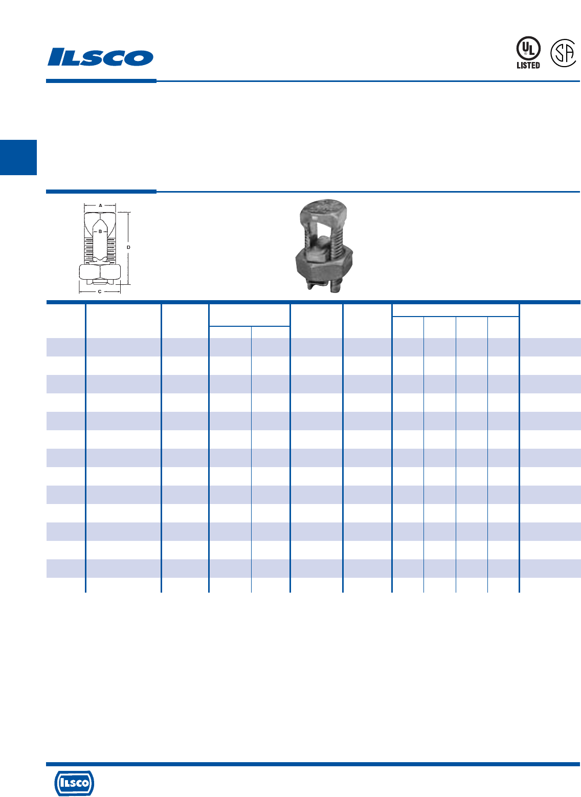
4730 Madison Road, Cincinnati, Ohio 45227-1426 Phone 513 533-6200 Fax 513 871-4084 Web site www.ilsco.com
Canada 1050 Lakeshore Road East, Mississauga, Ontario, Canada L5E1E4 Phone 905 274-2341 Fax 905 274-8763
99
B
Min. Tap Max. Cond Dimensions
Catalog Range For Equal With One Copperweld Rebar With Wire Recommended
Number Main & Tap Max. Main Str Type A 6 or 8 AWG Diameter A B C D Torque (IN-LB)
IK-10 10str - 16str 16str - - N/A .057 - .125 .125 0.344 0.500 0.719 80
IK-8 8str - 16str 16str - - N/A .057 - .145 .145 0.375 0.500 0.844 80
IK-6 6sol - 10sol 16sol - - N/A .102 - .162 .165 0.500 0.625 1.047 165
IK-4 4sol - 8sol 16sol 3 No. 12 8A N/A .128 - .204 .215 0.562 0.688 1.047 165
IK-3 2sol - 6sol 12sol 3 No. 9 5A N/A .162 - .258 .328 0.688 0.812 1.312 275
IK-2 2str - 6sol 14str 3 No. 7 3A N/A .162 - .292 .328 0.688 0.812 1.312 275
IK-1/0 1/0str - 4sol 14sol 3 No. 6 2A N/A .204 - .375 .377 0.750 0.875 1.641 385
IK-2/0 2/0str - 2sol 14str 3 No. 5 - #3 (3/8) .258 - .418 .420 0.812 1.000 1.812 385
IK-3/0 3/0str - 2sol 12sol 7 No. 7 - N/A .258 - .470 0.466 0.875 1.125 2.000 500
IK-250 250kcmil - 1/0sol 10sol 7 No. 5 - #4 (1/2) .325 - .575 0.579 1.000 1.312 2.078 650
IK-350 350kcmil - 4/0str 8sol 19 No. 7 - #5 (5/8 .528 - .682 0.746 1.500 1.625 2.625 650
IK-500 500kcmil - 250kcmil 8sol 19 No. 6 - #6 (3/4) .575 - .815 0.834 1.625 1.812 3.000 825
IK-750 750kcmil - 350kcmil 8sol 19 No. 5 - N/A .682 - .999 1.030 1.938 2.125 3.750 1000
IK-1000 1000kcmil - 500kcmil 8sol - - N/A .815 - 1.153 1.222 2.250 2.500 4.000 1100
Copper Split Bolts
TYPE
IK
Features
•
Manufactured from high strength copper alloy.
•
Precision tooled threads.
•
UL 467 Listed for Grounding and Bonding 8 thru 500kcmil
•
CSA certified for Grounding and Bonding 8 thru 250kcmil
•
UL listed and CSA Certified for 600 volts, 90° C
•
RUS Accepted 8 thru 1/0 AWG
•
For use with copper conductor types: Solid, Compact,
Compressed, Concentric.
•
ROHS compliant.
Benefits
•
Provides maximum conductivity and high breakage
resistance.
•
Allows maximum torque to be applied.
•
Suitable for direct burial and earth and concrete.
460C
7
0
1
5
7
0
UL File E6207
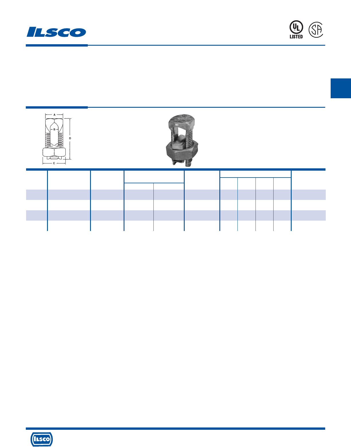
TYPE
IK3
Three Wire Copper Split Bolts
Features
•
Manufactured from high strength copper alloy.
•
Precision tooled threads.
•
UL 467 Listed for Grounding and Bonding thru 500kcmil
•
CSA certified for Grounding and Bonding thru 250kcmil
•
UL listed and CSA Certified for 600 volts, 90° C
•
RUS Accepted
•
For use with copper conductor types: Solid, Compact,
Compressed, Concentric.
•
ROHS compliant.
Benefits
•
Provides maximum conductivity and high breakage
resistance.
•
Allows maximum torque to be applied.
•
Suitable for direct burial and earth and concrete.
4730 Madison Road, Cincinnati, Ohio 45227-1426 Phone 513 533-6200 Fax 513 871-4084 Web site www.ilsco.com
Canada 1050 Lakeshore Road East, Mississauga, Ontario, Canada L5E1E4 Phone 905 274-2341 Fax 905 274-8763
100
B
460C
7
0
1
5
7
0
Min. Tap Max Cond Dimensions
Catalog Range For Equal With One Copperweld Wire Diameter Recommended
Number Main & Tap Max. Main Str Type A Range A B C D Torque (IN-LB)
IK3-8 8str - 16str 16str - - .057 - .145 0.144 0.375 0.500 0.844 80
IK3-6 6sol - 10sol 16sol - - .102 - .162 0.166 0.500 0.625 1.109 165
IK3-4 4sol - 8sol 16sol 3 No. 12 8A .128 - .204 0.217 0.562 0.688 1.266 165
IK3-2 2str - 6sol 14str 3 No. 7 3A .162 - .258 0.326 0.688 0.812 1.547 275
UL File E6207
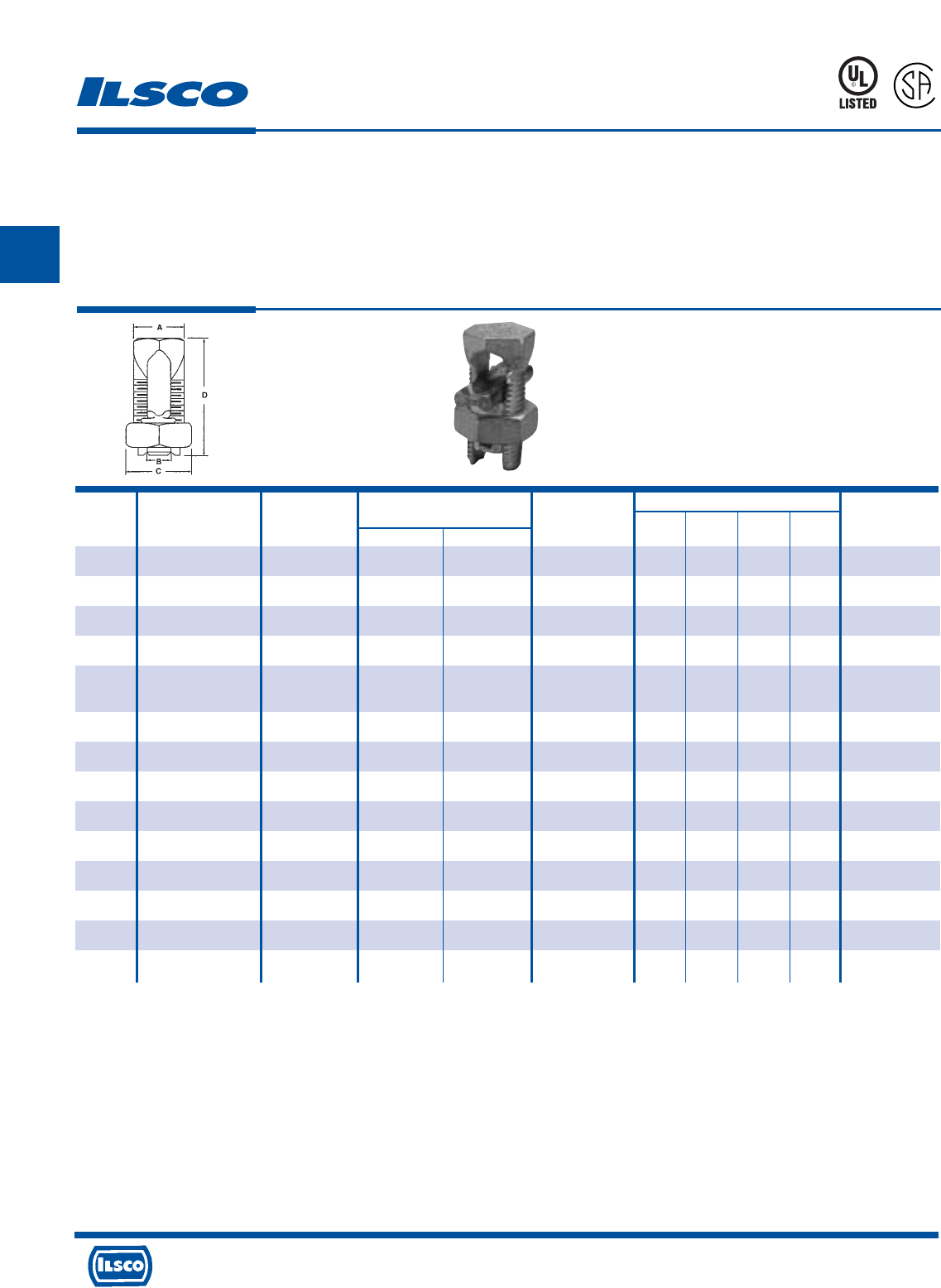
4730 Madison Road, Cincinnati, Ohio 45227-1426 Phone 513 533-6200 Fax 513 871-4084 Web site www.ilsco.com
Canada 1050 Lakeshore Road East, Mississauga, Ontario, Canada L5E1E4 Phone 905 274-2341 Fax 905 274-8763
101
B
Tin Plated Copper Split Bolts
TYPE
SK
Features
•
Manufactured from high strength copper alloy.
•
Electro-tin plated bolt, nut, spacer and pressure bar
•
Precision tooled threads.
•
UL listed and CSA Certified for 600 volts, 90° C
•
SK-10, SK-8, SK3, SK-2 SK-1/0, SK-2/0 are RUS Accepted.
•
For use with copper conductor types: Solid, Compact,
Compressed, Concentric.
•
ROHS compliant.
Benefits
•
Provides maximum conductivity and high breakage
resistance.
•
Provides low contact resistance.
•
Suitable for direct burial and earth and concrete.
460C
7
0
1
5
7
0
Min. Tap Max Cond Dimensions
Catalog Range For Equal With One Copperweld Wire Diameter Recommended
Number Main & Tap Max. Main Str Type A Range A B C D Torque (IN-LB)
SK-10 10str - 16str 16str - - .057 - .116 .144 0.375 0.500 0.844 80
SK-8 8str - 16str 16str - - .057 - .145 0.144 0.375 0.500 0.844 80
SK-6 8str - 14str 14str - - .073 - .146 .166 0.500 0.625 1.109 165
SK-4 6str - 10str 10sol 3 No. 12 8A .116 - .184 0.217 0.562 0.688 1.266 165
SK-3 4str - 8sol AL 8sol AL 3 No. 9 5A .128 - .258 0.326 0.688 0.812 1.547 275
2sol - 8sol CU 8sol CU
SK-2 2str - 8sol 8sol 3 No. 7 3A .128 - .316 0.326 0.688 0.812 1.547 275
SK-1/0 1/0str - 6sol 10sol 3 No. 6 - .162 - .375 0.376 0.750 0.875 1.641 385
SK-2/0 2/0str - 6str 10sol 3 No. 5 - .184 - .419 .420 0.812 1.000 1.812 385
SK-3/0 3/0str - 4str 6sol 7 No. 7 - .198 - .470 0.466 0.875 1.125 2.000 500
SK-250 250kcmil - 4str 4str 7 No. 5 - .232 - .575 0.577 1.000 1.312 2.328 650
SK-350 350kcmil - 3/0str 1sol 19 No. 7 - .447 - .682 0.746 1.500 1.625 2.625 650
SK-500 500kcmil - 3/0str 1/0str 19 No. 6 - .447 - .815 0.834 1.625 1.812 3.000 825
SK-750 750kcmil - 250kcmil 2/0str 19 No. 5 - .563 - .999 1.030 1.938 2.125 3.750 1000
SK-1000 1000kcmil - 350kcmil 4/0str - - .682 - .1.162 1.222 2.250 2.500 4.000 1100
UL File E12822
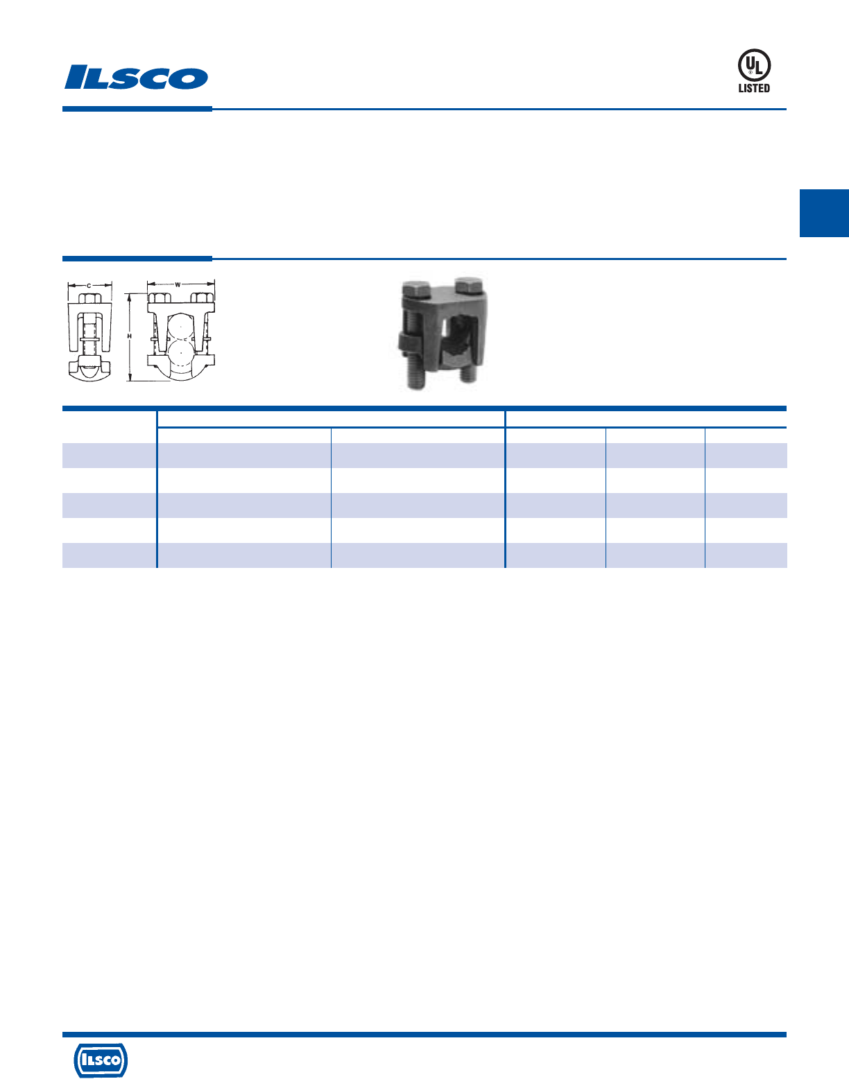
Catalog Copper Wire Range Dimensions
Number Main Tap C H W
IKB-4/0 + 1/0-4/0 4/0-10 1.10 1.97 1.72
IKB-350 + 350kcmil-250kcmil 350kcmil-10 1.38 2.48 1.12
IKB-500 500kcmil-400kcmil 500kcmil-10 1.50 2.80 2.25
IKB-800 800kcmil-400kcmil 800kcmil-3/0 1.62 3.32 2.50
IKB-1000 1000kcmil-500kcmil 1000kcmil-3/0 2.00 3.78 3.03
Copper Two Bolt Connectors
TYPE
IKB
Features
•
Manufactured from high strength copper alloy
•
Two bolt design
•
Longer peened bolt
•
UL Listed, rated for 600 volts
•
For copper conductor only
Benefits
•
Allows maximum conductivity and high breakage
resistance
•
Allows maximum pressure to be applied directly to the
conductor strands
•
Permits a swivel action for easier installation
•
Ensures reliability
+ REA Listed
Tested to UL 486A-486B, UL File E6207
453G
4730 Madison Road, Cincinnati, Ohio 45227-1426 Phone 513 533-6200 Fax 513 871-4084 Web site www.ilsco.com
Canada 1050 Lakeshore Road East, Mississauga, Ontario, Canada L5E1E4 Phone 905 274-2341 Fax 905 274-8763
102
B
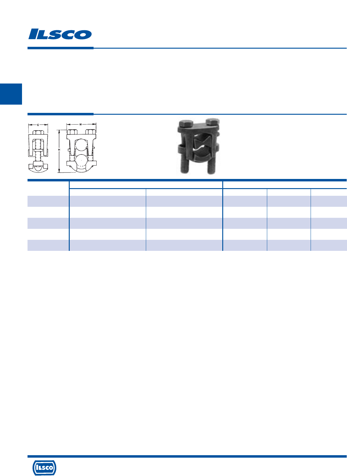
4730 Madison Road, Cincinnati, Ohio 45227-1426 Phone 513 533-6200 Fax 513 871-4084 Web site www.ilsco.com
Canada 1050 Lakeshore Road East, Mississauga, Ontario, Canada L5E1E4 Phone 905 274-2341 Fax 905 274-8763
103
B
Catalog Wire Range Dimensions
Number Main Tap C H W
IKS-4/0 4/0-1/0 4/0-6 1.12 2.31 1.72
IKS-350 350kcmil-250kcmil 350kcmil-6 1.38 2.62 2.12
IKS-500 500kcmil-400kcmil 500kcmil-4 1.50 3.00 2.26
IKS-800 800kcmil-400kcmil 800kcmil-4/0 1.62 3.50 2.50
IKS-1000 1000kcmil-500kcmil 1000kcmil-4/0 2.00 4.03 3.03
Two Bolt Connectors
TYPE
IKS
Features
•
Manufactured from high strength copper alloy
•
Electro-tin plated
•
Two bolt design
•
Longer peened bolt
•
Serrated spacer bar
•
For copper conductor only
•
Rated for 600 volts
Benefits
•
Allows maximum conductivity and high breakage
resistance
•
Provides low contact resistance
•
Allows maximum pressure to be applied directly to the
conductor strands
•
Permits a swivel action for easier installation
•
Makes a secure connection
•
Ensures reliability
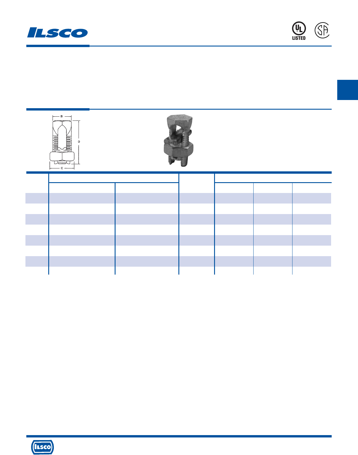
Wire Range Recommended Dimensions
Catalog Tightening
Number Main Tap Torque B C D
AK-6 6 str-10 sol 6 str-10 sol 165 .56 .75 1.88
AK-4 4 str-8 sol 4 str-10 sol 165 .62 .81 1.38
AK-2 2 str-6 str Compact 2 str-8 str 275 .69 .94 1.58
AK-1/0 1/0 str-2 str Compact 1/0 str-8 str 385 .75 1.00 1.92
AK-2/0 2/0 str-2 str Compact 2/0 str-8 str 385 .88 1.12 1.92
AK-4/0 4/0 str-2 str Compact 4/0 str-6 str 500 1.13 1.49 2.54
AK-350 350kcmil-1/0 str Compact 350kcmil-4 str 650 1.50 1.69 3.24
AK-500 500kcmil-400kcmil Compact 500kcmil-2 str Compact 825 1.73 2.00 3.62
Aluminum Split Bolt - Dual Rated
TYPE
AK
Features
•
Manufactured from heat treated aluminum alloy
•
Triangular edges
•
UL Listed and CSA Certified for 600 volts, 90˚ C
•
Electro-tin plated
•
Spacer bar
•
Hex Head
Benefits
•
Provides maximum conductivity and strength for
copper and aluminum conductors
•
Bite into the conductor to break through surface oxides
which eliminates wire brushing
•
Ensures reliability for copper or aluminum conductors
•
Provides low contact resistance
•
Separates dissimilar metals which prevents galvanic
corrosion
•
Provides ease of installation with standard wrenches
670B
7
2
6
3
2
DE-OX Inhibitor is recommended for all aluminum terminations.
UL File E9998
4730 Madison Road, Cincinnati, Ohio 45227-1426 Phone 513 533-6200 Fax 513 871-4084 Web site www.ilsco.com
Canada 1050 Lakeshore Road East, Mississauga, Ontario, Canada L5E1E4 Phone 905 274-2341 Fax 905 274-8763
104
B
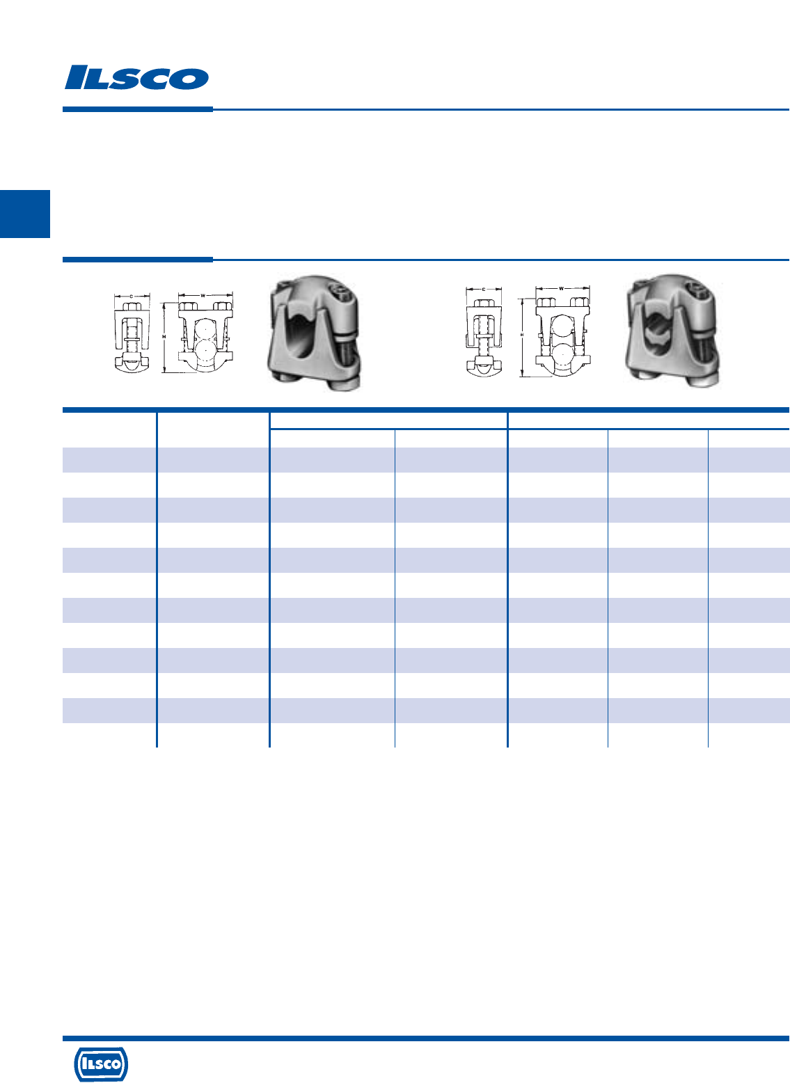
4730 Madison Road, Cincinnati, Ohio 45227-1426 Phone 513 533-6200 Fax 513 871-4084 Web site www.ilsco.com
Canada 1050 Lakeshore Road East, Mississauga, Ontario, Canada L5E1E4 Phone 905 274-2341 Fax 905 274-8763
105
B
Fig. 1 Fig. 2
Catalog Figure Wire Range Dimensions
Number Number Main Tap C W H
DBA-2/0 1 2/0-2 2/0-10 1-1/8 1-5/8 1-5/8
DBA-250 1 250kcmil-1/0 250kcmil-10 1-5/16 2 2
DBA-350 1 350kcmil-4/0 350kcmil-10 1-9/16 2-11/32 2-1/4
DBA-500 1 500kcmil-350kcmil 500kcmil-10 1-3/4 2-1/2 2-3/4
DBA-800 1 800kcmil-400kcmil 800kcmil-3/0 1-7/8 2-7/8 3
DBA-1000 1 1000kcmil-500kcmil 1000kcmil-3/0 2-1/4 3-3/16 3-1/2
DBA-2/0S 2 2/0-2 2/0-10 1-1/8 1-5/8 1-5/8
DBA-250S 2 250kcmil-1/0 250kcmil-10 1-5/16 2 2
DBA-350S 2 350kcmil-4/0 350kcmil-10 1-9/16 2-11/32 2-1/4
DBA-500S 2 500kcmil-350kcmil 500kcmil-10 1-3/4 2-1/2 2-3/4
DBA-800S 2 800kcmil-400kcmil 800kcmil-3/0 1-7/8 2-7/8 3
DBA-1000S 2 1000kcmil-500kcmil 1000kcmil-3/0 2-1/4 3-3/16 3-1/2
Aluminum Two Bolt Connectors - Dual Rated
TYPE
DBA
DBA-S
Features
•
Manufactured from high strength aluminum alloy
•
Heat treated
•
Wax plated
•
Neoprene washers
•
Range taking
•
Re-usable
•
Type DBA-S - Spacer bar
•
Rated for 600 volts
Benefits
•
Type DBA - Suitable for copper to copper or aluminum to aluminum
conductors
Type DBA-S - Suitable for copper and/or aluminum conductors in any
combination
•
Provides maximum strength
•
Provides low contact resistance
•
Hold the bolts captive and eliminates the possibility of loose hardware
•
Permits inventories to be kept to a minimum
•
Provides efficient use and flexibility in the field
•
Separates dissimilar metals
•
Ensures reliability
DE-OX Inhibitor is recommended for all aluminum terminations.
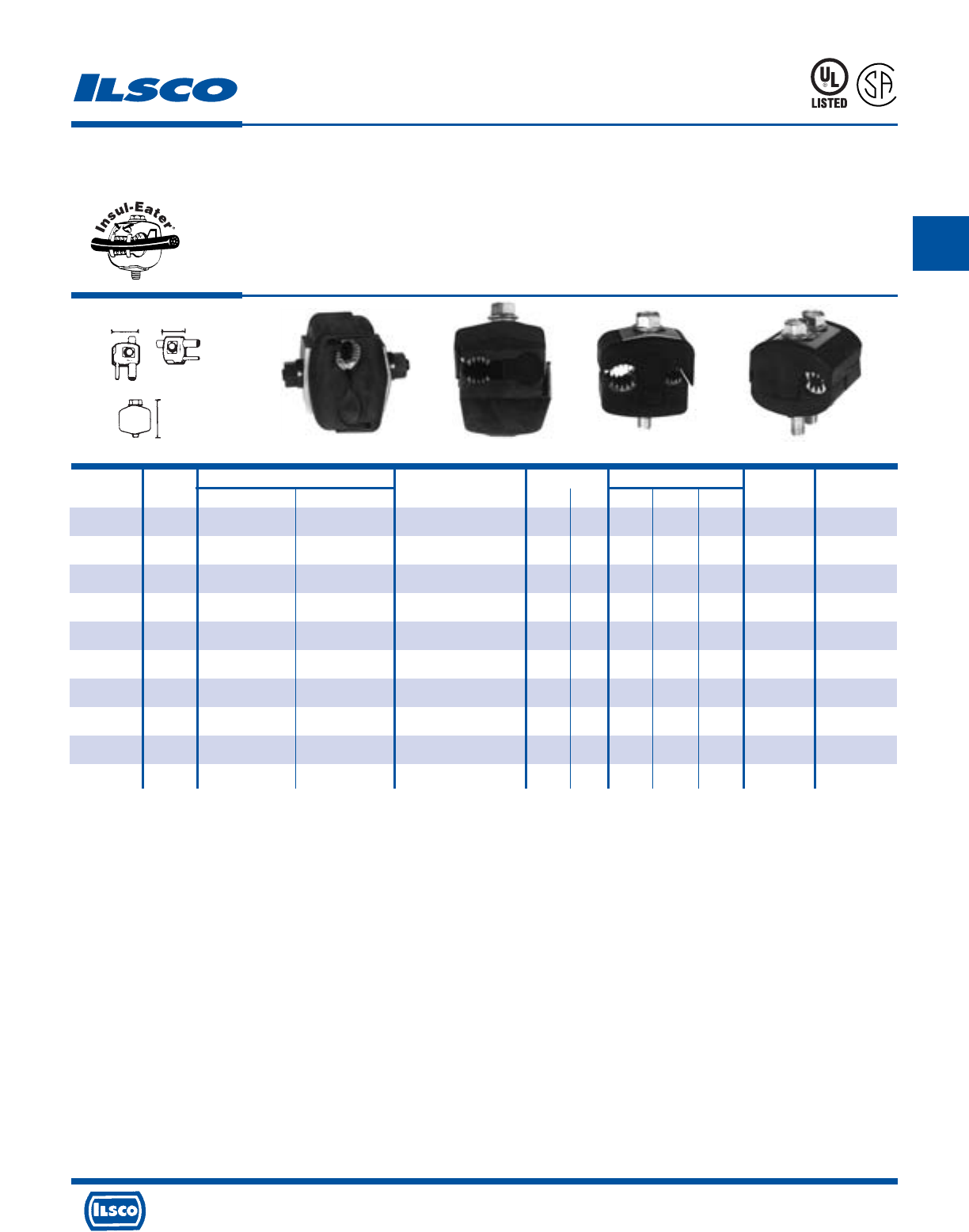
Catalog Figure Wire Range Current Rating Dimensions Torque Bolt Head
Number Number Main Tap Volts CU AL L W H Ft. Lbs. Size
IPC-1/0-2 3 1/0-8 2-8 300
(480 Grounded Y System)
130 100 1-7/32 1-15/32 2-5/16 16 1/2
IPC-4/0-6 2 4/0-4 6-14 600 75 60 1-27/64 1 1-7/8 13 1/2
IPC-4/0-2/0 3 4/0-2 2/0-6 600 195 150 1-21/32 1-7/8 2-7/8 25 1/2
IPC-250-4/0 2 250kcmil-1 4/0-6 600 260 205 1-7/8 2-11/32 3-11/32 30 5/8
IPC-350-4/0 3 350kcmil-4/0 4/0-10 300
(480 Grounded Y System)
260 205 1-43/64 2-7/16 3-1/8 25 5/8
IPC-350-350 4 350kcmil-4/0 350kcmil-4/0 300
(480 Grounded Y System)
350 280 2-43/64 2-23/32 3-1/4 25 5/8
IPC-500-12 1 500kcmil-250kcmil 10-12 300
(480 Grounded Y System)
40 35 1-43/64 2-7/16 3-1/4 25 5/8
IPC-500-250 1 500kcmil-250kcmil 250kcmil-4 600 290 230 2-27/64 2-29/32 3-3/4 55 5/8-11/16
IPC-500-500 1 500kcmil-300kcmil 500kcmil-250kcmil 600 430 350 3-3/16 3-5/8 5 75 7/8-7/8
IPC-750-500 1 750kcmil-500kcmil 500kcmil-350kcmil 600 430 350 3-3/16 3-5/8 5 75 7/8-7/8
KUP-L-Tap®Insulation Piercing Connectors
Dual Rated
TYPE
IPC
Features
•
Body is molded from tough, resilient glass-filled nylon
•
Compact design
•
Tin plated copper contact teeth
•
Insulation piercing
•
Perforated end tabs
•
Pre-filled with silicone lubricant
•
Versatile
•
Increased safety
•
Horizontal line grid
•
Temperature rating 90˚ C
Fig. 1 Fig. 2 Fig. 3 Fig. 4
Benefits
•
Provides high degree of breakage resistance and long dependable use
•
Saves space
•
Easily penetrates most types of insulation
•
No need to strip the conductor which saves installation time
•
Break out easily by hand
•
Prevents oxidation and moisture from entering the contact area
•
Can be used as a splice or tap connector
•
Contains no external energized parts. Can be installed “hot” on energized
conductors providing tap conductor is not under load.
•
Provides a visual guide for proper installation of conductors
923F
L
R
-
2
4
3
5
9
Tested to UL 486A-486B, UL File E6207
WL
H
4730 Madison Road, Cincinnati, Ohio 45227-1426 Phone 513 533-6200 Fax 513 871-4084 Web site www.ilsco.com
Canada 1050 Lakeshore Road East, Mississauga, Ontario, Canada L5E1E4 Phone 905 274-2341 Fax 905 274-8763
106
B
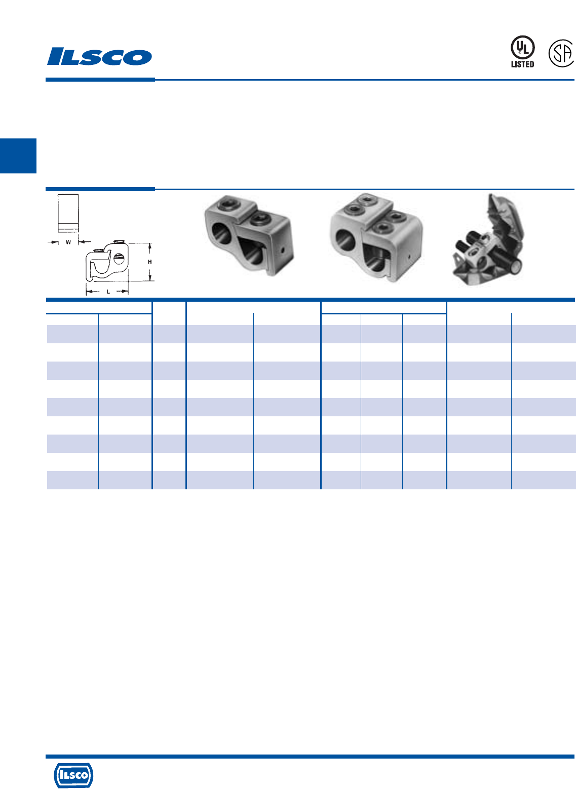
4730 Madison Road, Cincinnati, Ohio 45227-1426 Phone 513 533-6200 Fax 513 871-4084 Web site www.ilsco.com
Canada 1050 Lakeshore Road East, Mississauga, Ontario, Canada L5E1E4 Phone 905 274-2341 Fax 905 274-8763
107
B
Catalog Number Figure Wire Range Dimensions Hex Size
Connector Cover Number Main Tap L W H Main Tap
GTA-2-2 GTC-2 1 2-12 str 2-12 AL 2-14 CU 1-1/4 9/16 1 Slot Slot
GTA-0-0 GTC-0 1 1/0-2 1/0-12 AL 1/0-14 CU 1-9/16 3/4 1-1/8 Slot Slot
GTA-250-0 GTC-250-350 1 250kcmil-1/0 1/0-12 AL 1/0-14 CU 2 15/16 1-7/16 5/16 Slot
GTA-250-250 GTC-250-350 1 250kcmil-1/0 250kcmil-6 2-1/8 15/16 1-7/16 5/16 5/16
GTA-350-350 GTC-250-350 1 350kcmil-4/0 350kcmil-6 2-7/16 1 1-11/16 3/8 3/8
GTA-500-500 GTC-500 1 500kcmil-350kcmil 500kcmil-2 2-15/16 1-1/4 2 3/8 3/8
GTA-750-500 GTC-750-500 1 750kcmil-500kcmil 500kcmil-2 3-3/8 1-5/16 2-7/16 3/8 3/8
GTA-750-750 GTPC-750-750 2 750kcmil-500kcmil 750kcmil-1/0 3-3/8 2-5/8 2-7/16 1/2 1/2
GTA-1000-500 Not Available 1 1000kcmil-750kcmil 500kcmil-2 3-3/8 1-15/16 2-7/16 1/2 3/8
Parallel Tap Connectors - Dual Rated
Lay-In
TYPE
GTA
Features
•
Manufactured from high strength 6061-T6 aluminum
alloy
•
Electro-tin plated
•
UL Listed and CSA Certified for 600 volts,
Temp. rating 90˚ C
•
Compact design
•
Range taking
•
Re-usable
•
Lay-in main conductor
•
Insulating cover available
Fig. 1 Fig. 2
Benefits
•
Suitable for use with either copper or aluminum
conductors
•
Provides low contact resistance
•
Ensures reliability for copper or aluminum conductors
•
Saves space and reduces installation time
•
Permits inventories to be kept to a minimum
•
Provides efficient use and flexibility in the field
•
No need to break the feeder cable
•
Eliminates taping
Insulating covers are available for most connector sizes.
See page 110 for additional information on covers
Note: If ordering with cover, add suffix w/c to catalog number.
DE-OX Inhibitor is recommended for all aluminum terminations.
Tested to UL 486A-486B, UL File E6207
453G
L
R
-
2
9
6
0
1
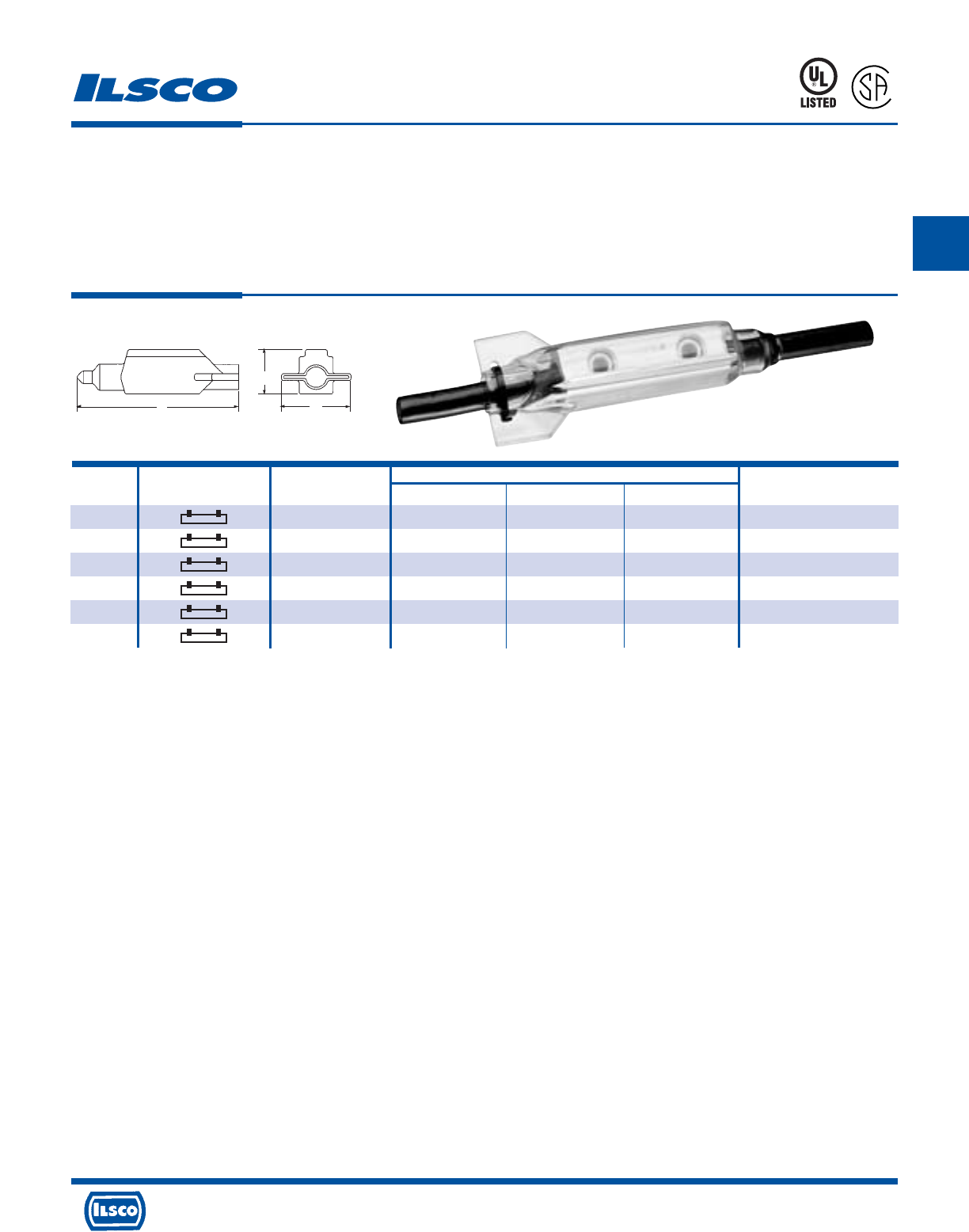
Catalog Wire Dimensions Screw
Number Connector Shape Range L W H Size & Shape
SPAR-4 4-14 3.30 1.55 .76 slotted
SPAR-2 2-14 3.83 1.75 .95 slotted
SPAR-1/0 1/0-14 4.80 1.94 1.14 3/16” socket head
SPAR-250 250kcmil-6 5.67 2.41 1.29 5/16” socket head
SPAR-350 350kcmil-6 6.17 3.29 1.79 5/16” socket head
SPAR-500 500kcmil-4 7.94 3.66 2.28 3/8” socket head
RocketSplice®
Insulated Splicer-Reducer Connector
TYPE
SPAR
L
R
-
2
9
6
0
1
453G
Features
•
Transparent flexible insulating cover
•
Range adjustable trim-to-fit tip
•
Unique shape and compact design
•
Connector, cover and cable tie packaged together
•
UL Listed and CSA Certified for 600 volts
•
Dual Rated
Benefits
•
No taping and allows visual inspection of splice
•
Ensures proper fit of cover to cable
•
Provides ease of installation, versatility and
serviceability of connections made in tight spaces
•
Provides ease of ordering
•
Ensures reliability
•
Use with copper or aluminum conductor
L
H
W
Not suitable for direct burial.
DE-OX Oxide Inhibitor is recommended for all aluminum terminations.
Tested to UL 486A-486B, UL File E6207
4730 Madison Road, Cincinnati, Ohio 45227-1426 Phone 513 533-6200 Fax 513 871-4084 Web site www.ilsco.com
Canada 1050 Lakeshore Road East, Mississauga, Ontario, Canada L5E1E4 Phone 905 274-2341 Fax 905 274-8763
108
B
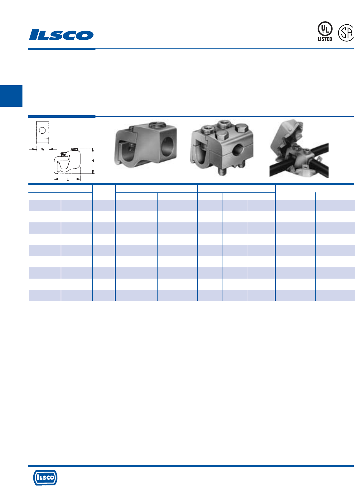
4730 Madison Road, Cincinnati, Ohio 45227-1426 Phone 513 533-6200 Fax 513 871-4084 Web site www.ilsco.com
Canada 1050 Lakeshore Road East, Mississauga, Ontario, Canada L5E1E4 Phone 905 274-2341 Fax 905 274-8763
109
B
Catalog Number Figure Wire Range Dimensions Hex Size
Connector Cover Number Main Tap L W H Main Tap
GTT-2-2 GTC-2 1 2-12 str 2-12 AL 2-14 CU 1-1/4 9/16 1 Slot Slot
GTT-0-0 GTC-0 1 1/0-2 1/0-12 AL 1/0-14 CU 1-9/16 3/4 1-1/8 Slot Slot
GTT-250-0 GTC-250-350 1 250kcmil-1/0 1/0-12 AL 1/0-14 CU 2 7/8 1-7/16 5/16 Slot
GTT-250-250 GTC-250-350 1 250kcmil-1/0 250kcmil-6 2-1/8 7/8 1-7/16 5/16 5/16
GTT-350-350 GTC-500 1 350kcmil-4/0 350kcmil-6 2-7/16 1 1-11/16 3/8 3/8
GTT-500-500 GTC-500 1 500kcmil-350kcmil 500kcmil-2 2-15/16 1-1/4 2 3/8 3/8
GTT-750-500 GTC-750-500 1 750kcmil-500kcmil 500kcmil-2 3-3/8 1-1/4 2-7/16 3/8 3/8
GTT-750-750 GTTC-750-750 2 750kcmil-500kcmil 750kcmil-600kcmil 3-3/8 2-3/8 2-7/16 1/2 EH 3/4
GTT-1000-500 Not Available 1 1000kcmil-750kcmil 500kcmil-2 3-3/8 1-1/4 2-7/16 1/2 3/8
“T” Tap Connectors - Dual Rated
Lay-In
TYPE
GTT
Features
•
Manufactured from high strength 6061-T6 aluminum
alloy
•
Electro-tin plated
•
UL Listed and CSA Certified for 600 volts, 90˚ C
•
Compact design
•
Range taking
•
Re-usable
•
Lay-in main conductor
•
Insulating cover available
Fig. 1 Fig. 2
Benefits
•
Suitable for use with either copper or aluminum
conductors
•
Provides low contact resistance
•
Ensures reliability for copper or aluminum conductors
•
Saves space and reduces installation time
•
Permits inventories to be kept to a minimum
•
Provides efficient use and flexibility in the field
•
No need to break the feeder cable
•
Eliminates taping
EH-External Hex
Insulating covers are available for most connector sizes.
See page 110 for additional information on covers
Note: If ordering with cover, add suffix w/c to catalog number.
DE-OX Inhibitor is recommended for all aluminum terminations.
Tested to UL 486A-486B, UL File E6207
453G
L
R
-
2
9
6
0
1
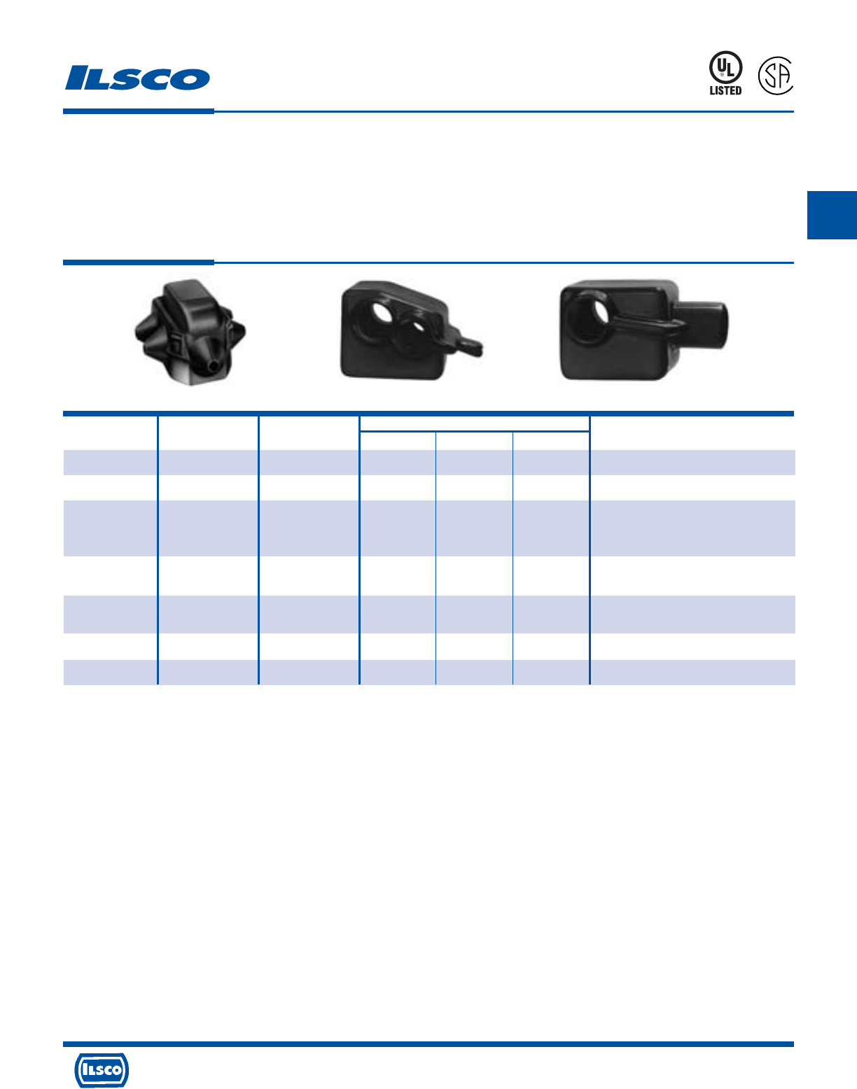
Catalog Figure Dimensions
Number Number Color L W H Used with Connector
GTC-2 1 Black 2-1/4 1-13/16 1-1/4 GTA-2-2: GTT-2-2
GTC-0 1 Black 2-1/2 2-3/32 1-3/8 GTA-0-0: GTT-0-0
GTA-250-0: GTA-250-250
GTC-250-350 1 Black 3-61/64 3-1/32 2 GTA-350-350
GTT-250-0: GTT-250-250
GTT-350-350
GTC-500 1 Black 4-1/8 3-1/16 2-31/32 GTA-500-500
GTT-500-500
GTC-750-500 1 Black 4-7/8 3-1/8 2-23/32 GTA-750-500
GTT-750-500
GTPC-750-750* 2 Black 4-7/8 4 2-7/8 GTA-750-750
GTTC-750-750* 3 Black 5-3/4 4-1/4 3-1/16 GTT-750-750
Insulating Covers For GTA-GTT
TYPE
GTC
Features
•
Snap closure
•
Color coded
•
UL Listed and CSA Certified for 600 volts, 90˚ C except
for GTPC-750-750 and GTTC-750-750
Fig. 1 Fig. 2 Fig. 3
Benefits
•
Installs quickly and saves labor time by eliminating
taping
•
Provides ease of identification in the field
•
Ensures reliability
453G
L
R
-
2
9
6
0
1
* Not UL Listed or CSA Certified
Tested to UL 486A-486B, UL File E6207
4730 Madison Road, Cincinnati, Ohio 45227-1426 Phone 513 533-6200 Fax 513 871-4084 Web site www.ilsco.com
Canada 1050 Lakeshore Road East, Mississauga, Ontario, Canada L5E1E4 Phone 905 274-2341 Fax 905 274-8763
110
B
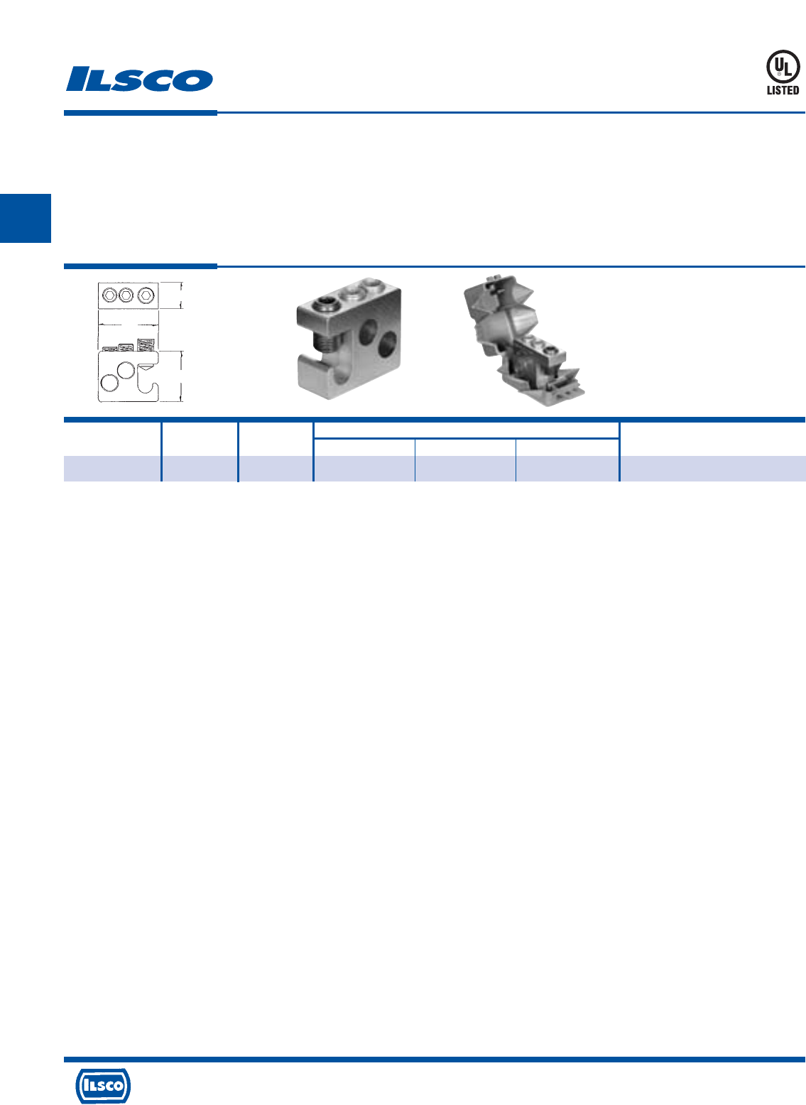
4730 Madison Road, Cincinnati, Ohio 45227-1426 Phone 513 533-6200 Fax 513 871-4084 Web site www.ilsco.com
Canada 1050 Lakeshore Road East, Mississauga, Ontario, Canada L5E1E4 Phone 905 274-2341 Fax 905 274-8763
111
B
Catalog Wire Range No. of Dimensions Hex
Number Main & Tap Taps L W H Size
GT2-250-W/C 250kcmil-2 2 31/32 2-9/32 1-15/16 5/16
Multiple Tap Connector - Dual Rated
Lay-In
TYPE
GT2
Features
•
Manufactured from high strength 6061-T6 aluminum
alloy
•
Electro-tin plated
•
UL Listed for 600 volts, 90˚ C
•
Compact design
•
Range taking
•
Re-usable
•
Lay-in main conductor
•
Supplied with cover
Benefits
•
Suitable for use with either copper or aluminum
conductors
•
Provides low contact resistance
•
Ensures reliability for copper or aluminum conductors
•
Saves space and reduces installation time
•
Permits inventories to be kept to a minimum
•
Provides efficient use and flexibility in the field
•
No need to break the feeder cable
•
Eliminates taping
453G
DE-OX Inhibitor is recommended for all aluminum terminations.
Tested to UL 486A-486B, UL File E6207
L
H
W
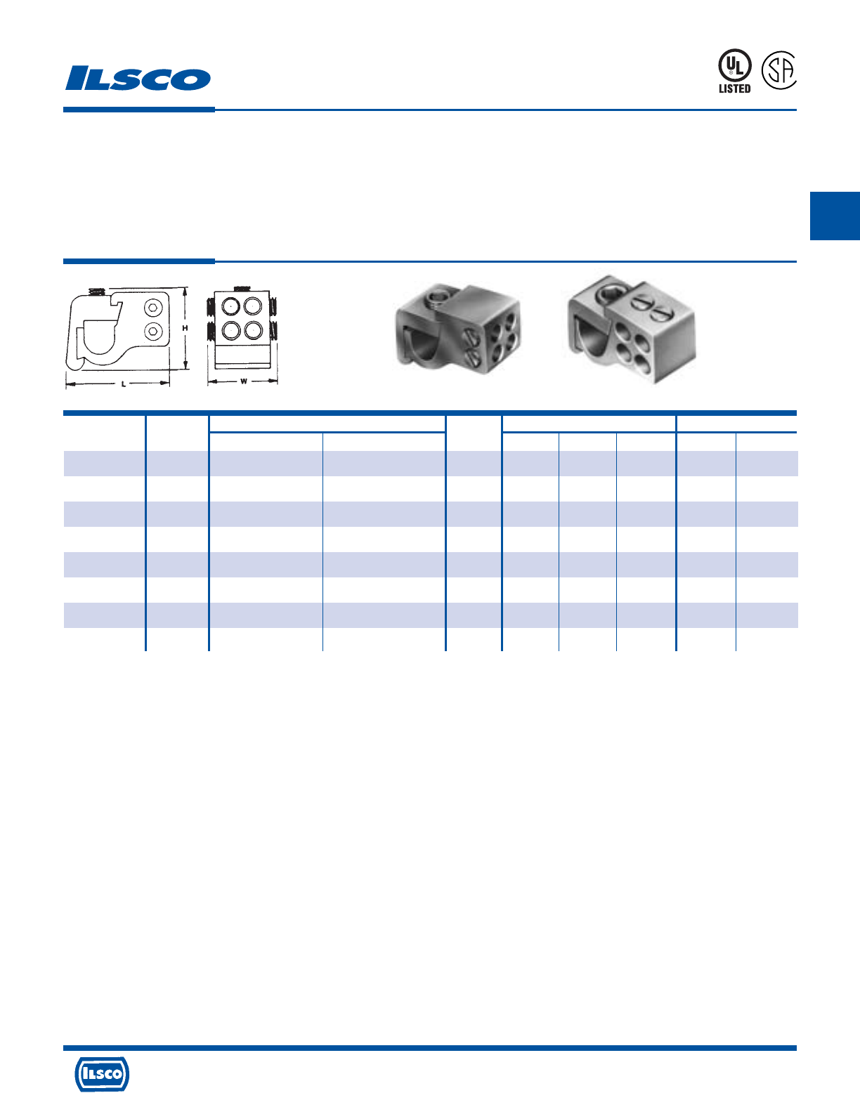
Catalog Figure Wire Range No. of Dimensions Hex Size
Number Number Main Tap Taps L W H Main Tap
*GT4T-250-2-1 1 250kcmil-1/0 2-12 AL, 2-14 CU 4 2-3/16 1-1/8 1-35/64 5/16 Slot
*GT4T-250-2-2 2 250kcmil-1/0 2-12 AL, 2-14 CU 4 2-3/16 1-1/8 1-35/64 5/16 Slot
†GT4T-350-2-1 1 350kcmil-4/0 2-12 AL, 2-14 CU 4 2-17/32 1-1/8 1-17/32 3/8 Slot
*GT4T-350-2-2 2 350kcmil-4/0 2-12 AL, 2-14 CU 4 2-17/32 1-1/8 1-17/32 3/8 Slot
†GT4T-500-2-1 1 500kcmil-350kcmil 2-12 AL, 2-14 CU 4 2-31/32 1-1/4 1-11/16 3/8 Slot
†GT4T-500-2-2 2 500kcmil-350kcmil 2-12 AL, 2-14 CU 4 2-31/32 1-1/4 1-11/16 3/8 Slot
†GT4T-500-0-1 1 500kcmil-350kcmil 1/0-12 AL, 1/0-14 CU 4 2-31/32 1-1/4 1-11/16 3/8 Slot
†GT4T-500-0-2 2 500kcmil-350kcmil 1/0-12 AL, 1/0-14 CU 4 2-31/32 1-1/4 1-11/16 3/8 Slot
Multiple Tap Connector - Dual Rated
Lay-In
TYPE
GT4T
Features
•
Manufactured from high strength 6061-T6 aluminum
alloy
•
Electro-tin plated
•
UL Listed and CSA Certified for 600 volts, 90˚ C
•
Compact design
•
Range taking
•
Re-usable
•
Lay-in main conductor
•
Insulating cover available
Benefits
•
Suitable for use with either copper or aluminum conductors
•
Provides low contact resistance
•
Ensures reliability for copper or aluminum conductors
•
Can make up to four taps off a single main which saves space and
reduces installation time
•
Permits inventories to be kept to a minimum
•
Provides efficient use and flexibility in the field
•
No need to break the feeder cable
•
Eliminates taping
* GTC-250-350 Cover can be used. See page 113.
† GTC-500 can be used. See page 113.
DE-OX Inhibitor is recommended for all aluminum terminations.
Tested to UL 486A-486B, UL File E6207
453G
L
R
-
2
9
6
0
1
Fig. 1 Fig. 2
4730 Madison Road, Cincinnati, Ohio 45227-1426 Phone 513 533-6200 Fax 513 871-4084 Web site www.ilsco.com
Canada 1050 Lakeshore Road East, Mississauga, Ontario, Canada L5E1E4 Phone 905 274-2341 Fax 905 274-8763
112
B
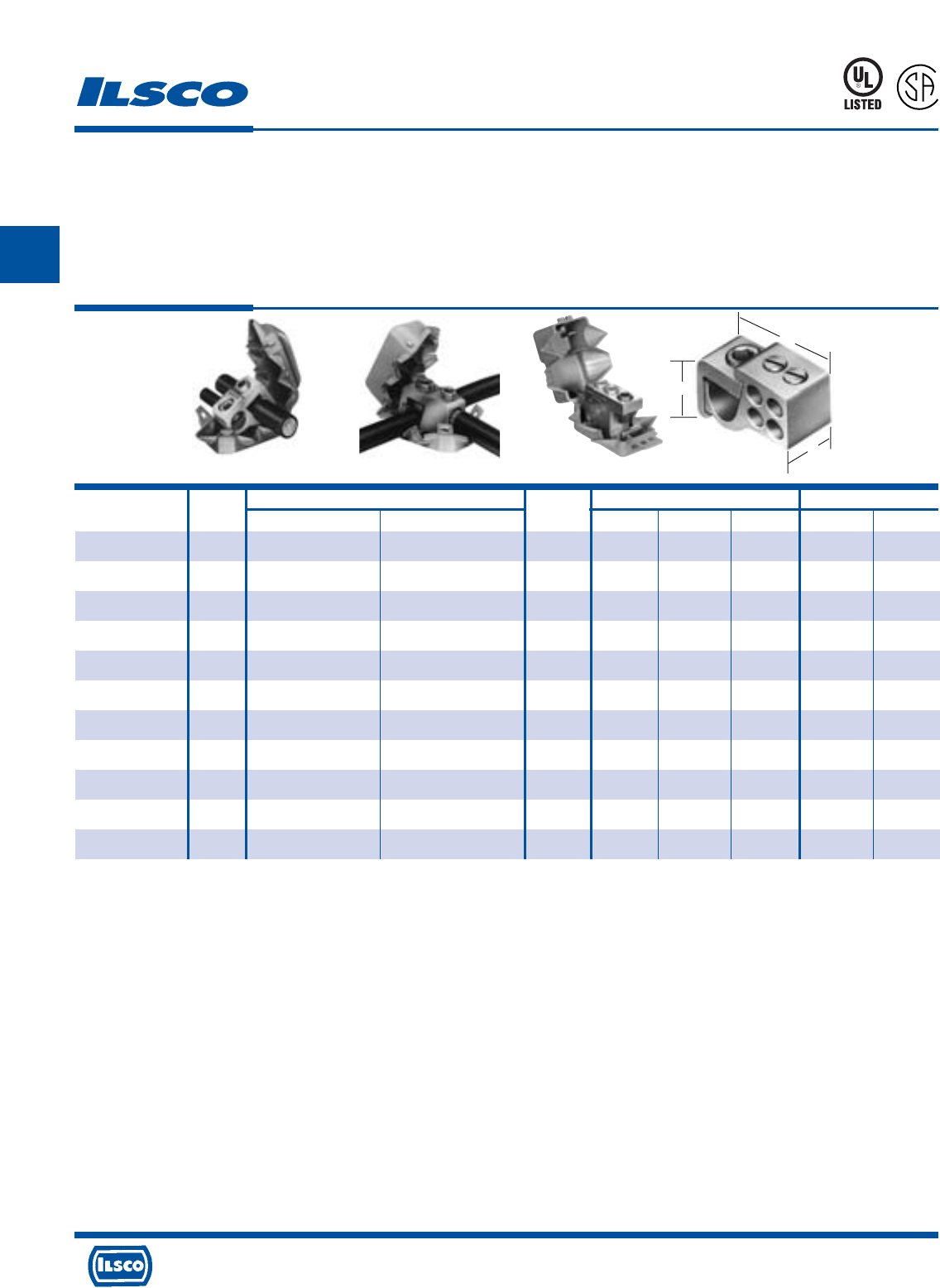
4730 Madison Road, Cincinnati, Ohio 45227-1426 Phone 513 533-6200 Fax 513 871-4084 Web site www.ilsco.com
Canada 1050 Lakeshore Road East, Mississauga, Ontario, Canada L5E1E4 Phone 905 274-2341 Fax 905 274-8763
113
B
Catalog Figure Wire Range No. of Dimensions Hex Size
Number Number Main Tap Taps L W H Main Tap
GTA-0-0-KIT 1 1/0-2 1/0-12 AL, 1/0-14 CU 1 3/4 1-7/16 1-1/8 Slot Slot
GTA-2-2-KIT 1 2-12 2-12 AL, 2-14 CU 1 9/16 1-1/8 1 Slot Slot
GTA-250-0-KIT 1 250kcmil-1/0 1/0-12 AL, 1/0-14 CU 1 7/8 2 1-7/16 5/16 Slot
GTA-250-250-KIT 1 250kcmil-1/0 250kcmil-6 1 7/8 2 1-7/16 5/16 5/16
GTT-0-0-KIT 2 1/0-2 1/0-12 AL, 1/0-14 CU 1 3/4 1-9/16 1-1/8 Slot Slot
GTT-2-2-KIT 2 2-12 2-12 AL, 2-14 CU 1 9/16 1-1/4 1 Slot Slot
GTT-250-0-KIT 2 250kcmil-1/0 1/0-12 AL, 1/0-14 CU 1 7/8 2 1-7/16 5/16 Slot
GTT-250-250-KIT 2 250kcmil-1/0 250kcmil-6 1 7/8 2-1/8 1-7/16 5/16 5/16
GT2-250-KIT 3 250kcmil-2 250kcmil-2 2 1-3/4 3-1/4 2-1/2 5/16 5/16
GT4T-250-2-2-KIT 4 250kcmil-1/0 2-12 AL, 2-14 CU 4 2-1/4 1 1-11/16 5/16 Slot
GT4T-350-2-2-KIT 4 350kcmil-4/0 2-12 AL, 2-14 CU 4 2-7/16 1 1-3/4 3/8 Slot
Tap Connector Kits - Dual Rated
TYPE
GTA/GTT
KITS
Features
•
Kit includes connector, cover and 5cc DE-OX tube
•
Manufactured from high strength aluminum alloy
•
Cover has snap closure
•
UL Listed and CSA Certified for 600 volts, 90˚ C
Benefits
•
Saves time, convenient
•
Suitable for use with copper or aluminum conductors
•
Installs quickly, eliminates taping
•
Ensures reliability
Covers rated at 600V 90˚C.
Note: Covers are for indoor use only.
Tested to UL 486A-486B, UL File E6207
453G
L
R
-
2
9
6
0
1
Fig. 1 Fig. 2 Fig. 3 Fig. 4
W
H
L
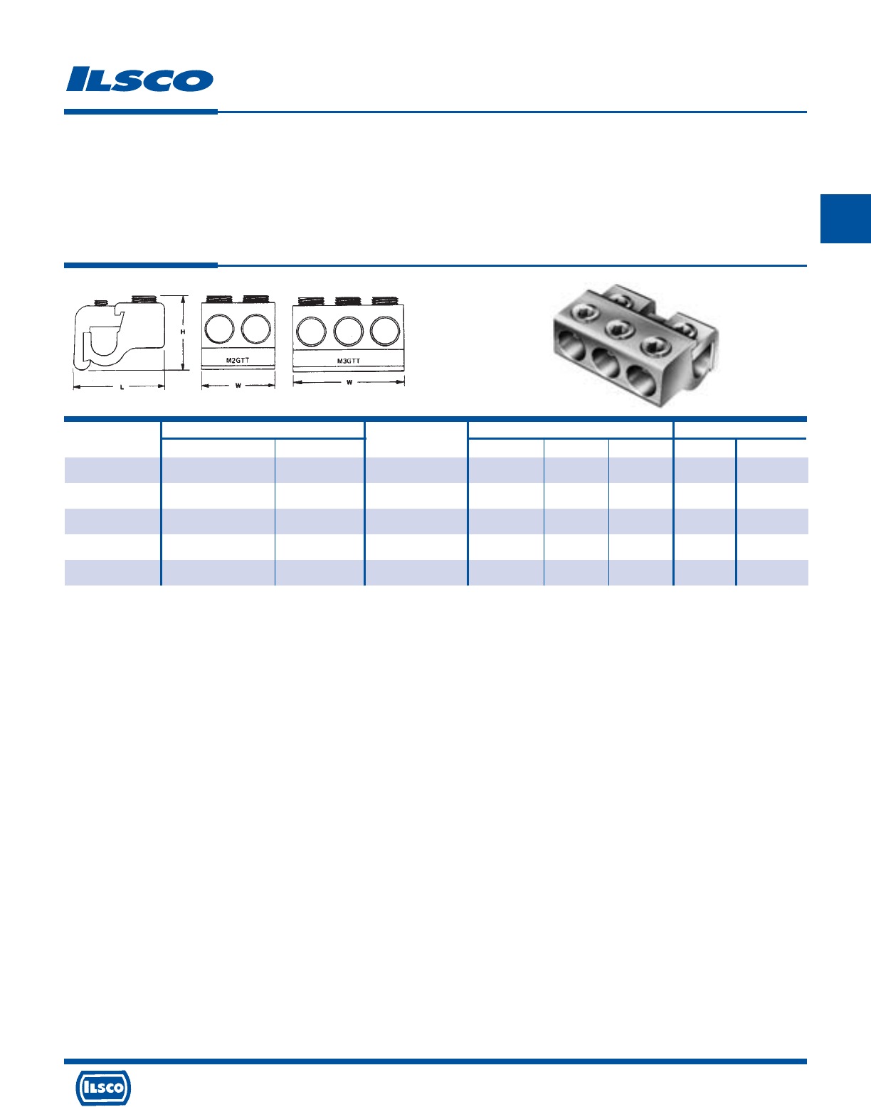
Catalog Wire Range No. of Tap Dimensions Hex Size
Number Main Tap Openings L W H Main Tap
M2GTT-250-250 250kcmil-1/0 250kcmil-6 2 2 1-3/4 1-5/8 5/16 5/16
M2GTT-350-350 350kcmil-4/0 350kcmil-6 2 2-1/4 2 1-11/16 5/16 5/16
M3GTT-350-350 350kcmil-4/0 350kcmil-6 3 2-1/4 3 1-11/16 5/16 5/16
M2GTT-500-500 500kcmil-350kcmil 500kcmil-2 2 2-3/4 2-3/8 1-13/16 3/8 3/8
M3GTT-500-500 500kcmil-350kcmil 500kcmil-2 3 2-3/4 3-1/2 1-13/16 3/8 3/8
Multiple Tap Connector - Dual Rated
Lay-In
TYPE
MGTT
Features
•
Manufactured from high strength 6061-T6 aluminum
alloy
•
Electro-tin plated
•
Dual-Rated
•
Compact design
•
Range taking
•
Re-usable
•
Lay-in main conductor
•
Rated for 600 volts
Benefits
•
Suitable for use with either copper or aluminum
conductors
•
Provides low contact resistance
•
Can be used with copper and/or aluminum conductors
•
Saves space and reduces installation time
•
Permits inventories to be kept to a minimum
•
Provides efficient use and flexibility in the field
•
No need to break the feeder cable
•
Ensures reliability
DE-OX Inhibitor is recommended for all aluminum terminations.
4730 Madison Road, Cincinnati, Ohio 45227-1426 Phone 513 533-6200 Fax 513 871-4084 Web site www.ilsco.com
Canada 1050 Lakeshore Road East, Mississauga, Ontario, Canada L5E1E4 Phone 905 274-2341 Fax 905 274-8763
114
B
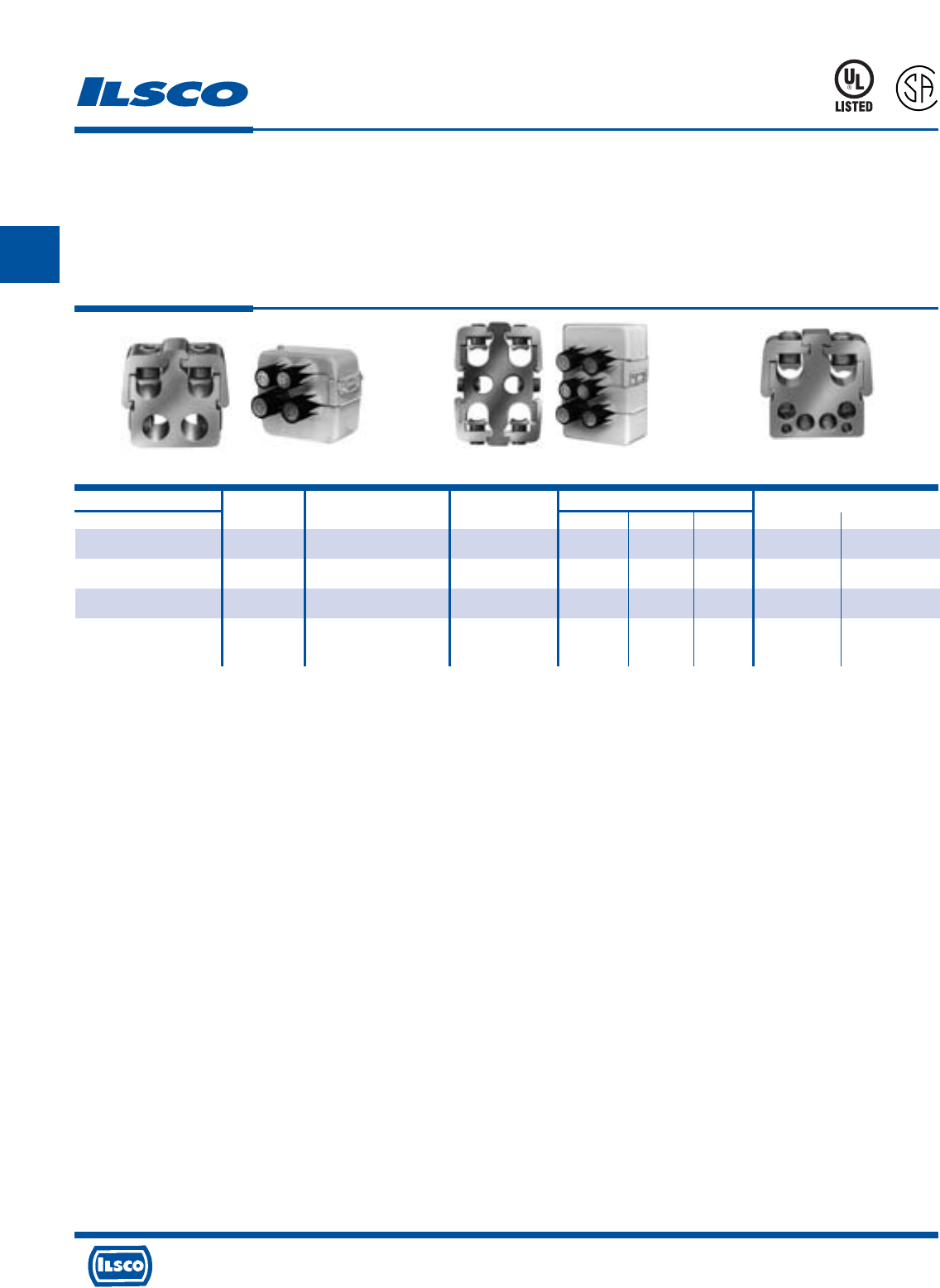
4730 Madison Road, Cincinnati, Ohio 45227-1426 Phone 513 533-6200 Fax 513 871-4084 Web site www.ilsco.com
Canada 1050 Lakeshore Road East, Mississauga, Ontario, Canada L5E1E4 Phone 905 274-2341 Fax 905 274-8763
115
B
Catalog Number Figure Main Wire Bottom Tap Dimensions Hex Size
Connector Number Range Range H W D Main Tap
PTA2-500-500-W/C 1 Two: 500kcmil-250kcmil Two: 500kcmil-4 3-15/16 3-1/2 1-1/4 3/8 3/8
PTA2-750-500-W/C 1 Two: 750kcmil-350kcmil Two: 500kcmil-4 3-5/8 4-3/32 1-5/16 3/8 3/8
PTA4-750-500-W/C 2 Four: 750kcmil-350kcmil Two: 500kcmil-4 5-7/8 4-3/32 1-5/16 3/8 3/8
PTA26-500-4/0*+ 3 Two: 500kcmil-4/0 Four: 4/0-6 3-15/16 3-1/2 1-1/4 3/8 5/16
Two: 2-14 Slotted
Multiple Tap Connector - Dual Rated
TYPE
PTA
Features
•
Manufactured from high strength 6061-T6 aluminum
alloy
•
Electro-tin plated
•
UL Listed and CSA Certified for 600 volts, 90˚ C
•
Compact design
•
Range taking
•
Re-usable
•
Lay-in main conductors
•
Supplied with insulating cover
Fig. 1 Fig. 2 Fig. 3
Benefits
•
Suitable for use with either copper or aluminum
conductors
•
Provides low contact resistance
•
Ensures reliability for copper or aluminum conductors
•
Saves space and reduces installation time
•
Permits inventories to be kept to a minimum
•
Provides efficient use and flexibility in the field
•
No need to break the feeder cables
•
Eliminates taping
Note: W/C indicates product is supplied with insulating cover.
* Not CSA Certified.
+ Cover must be ordered separately. For non UL cover, order 1 each RO614WOOA and RO615WOOA.
DE-OX Inhibitor is recommended for all aluminum terminations.
Tested to UL 486A-486B, UL File E6207
453G
L
R
-
2
9
6
0
1
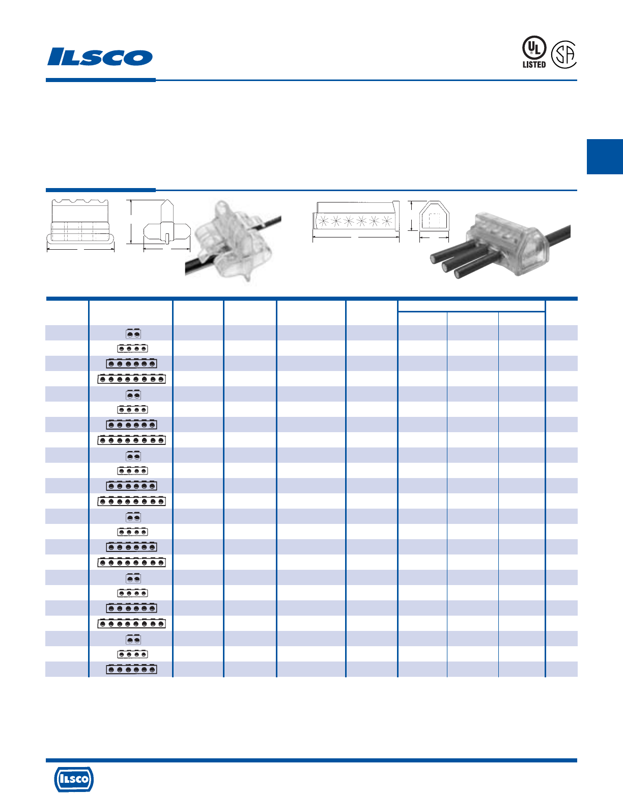
Catalog Figure No. Wire Ampere Dimensions Hex
Number Connector Shape No. Of Ports Range Rating L W H Size
PCT-2-4 1 2 4-14 95 1.46 1.57 1.43 slot
PCT-4-4 1 4 4-14 95 2.46 1.57 1.43 slot
PCT-6-4 1 6 4-14 95 3.46 1.57 1.43 slot
PCT-8-4 1 8 4-14 95 4.46 1.57 1.43 slot
PCT-2-2/0 2 2 2/0-14 195 2.61 2.30 1.97 3/16
PCT-4-2/0 2 4 2/0-14 195 4.30 2.30 1.97 3/16
PCT-6-2/0 2 6 2/0-14 195 5.98 2.30 1.97 3/16
PCT-8-2/0 2 8 2/0-14 195 7.67 2.30 1.97 3/16
PCT-2-4/0 2 2 4/0-6 260 2.33 2.49 2.25 5/16
PCT-4-4/0 2 4 4/0-6 260 4.19 2.49 2.25 5/16
PCT-6-4/0 2 6 4/0-6 260 6.05 2.49 2.25 5/16
PCT-8-4/0 2 8 4/0-6 260 7.91 2.49 2.25 5/16
PCT-2-350 2 2 350 kcmil-6 350 2.75 2.69 2.65 5/16
PCT-4-350 2 4 350 kcmil-6 350 5.06 2.69 2.65 5/16
PCT-6-350 2 6 350 kcmil-6 350 7.37 2.69 2.65 5/16
PCT-8-350 2 8 350 kcmil-6 350 9.68 2.69 2.65 5/16
PCT-2-600 2 2 600 kcmil-4 475 3.17 3.20 3.27 3/8
PCT-4-600 2 4 600 kcmil-4 475 5.73 3.20 3.27 3/8
PCT-6-600 2 6 600 kcmil-4 475 8.29 3.20 3.27 3/8
PCT-8-600 2 8 600 kcmil-4 475 10.86 3.20 3.27 3/8
PCT-2-800 2 2 800kcmil-250kcmil 555 3.91 3.34 3.30 1/2
PCT-4-800 2 4 800kcmil-250kcmil 555 7.03 3.34 3.30 1/2
PCT-6-800 2 6 800kcmil-250kcmil 555 10.15 3.34 3.30 1/2
ClearTap®Insulated Multi-Tap Connectors
TYPE
PCT
453G
Features
•
Transparent flexible insulating cover
•
Captive pressure screws
•
Self-closing openings
•
Access from both sides of connector
•
Broad wire range: 800kcmil-14
•
UL Listed for 600 volts, 90˚ C
•
Dual Rated
Benefits
•
No taping and allows visual inspection of connection
•
No wasted time finding screws
•
No lost or loose caps and plugs
•
Provides greater versatility
•
Reduces inventory
•
Ensures reliability
•
For copper or aluminum conductor
L
Fig. 1 (Patented) Fig. 2
H
W
L
H
W
Not suitable for direct burial.
Tested to UL 486A-486B, UL File E6207
L
R
-
2
9
6
0
1
4730 Madison Road, Cincinnati, Ohio 45227-1426 Phone 513 533-6200 Fax 513 871-4084 Web site www.ilsco.com
Canada 1050 Lakeshore Road East, Mississauga, Ontario, Canada L5E1E4 Phone 905 274-2341 Fax 905 274-8763
116
B
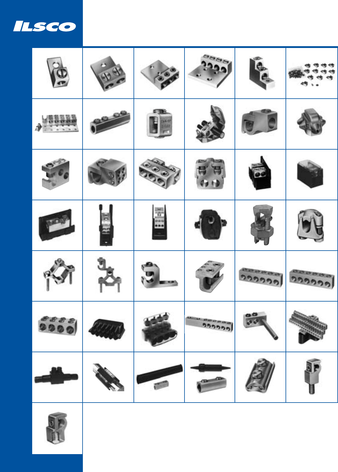
117
Mechanical
Aluminum - Dual Rated
TA
119
AU
120
T3A
121
PB
123
TLK
124
SPA
126
GTT
129
GTC
130
GT2
131
PTA
134
MGTT
133
GT4T
132
LDA
135
LDB
135
PDA
136
PDC
136
PDB
137 – 142
IPC
143
DBA/DBA-S
145
AGC
146
SGC
146
GBL
147
PED-Z
149
PSA-Z
150
PED-CP
151
PEC
150
PET
152
PTT
153
NB
154
USPA-SS
155
DBK
156
ASK
156
PG
158
GRF
159
SS, SSK, SSKC
157
GRM
159
USGL
125
CA
127
GBT
148
PED-X
150
T4A4
122
AK
144
GTA
128
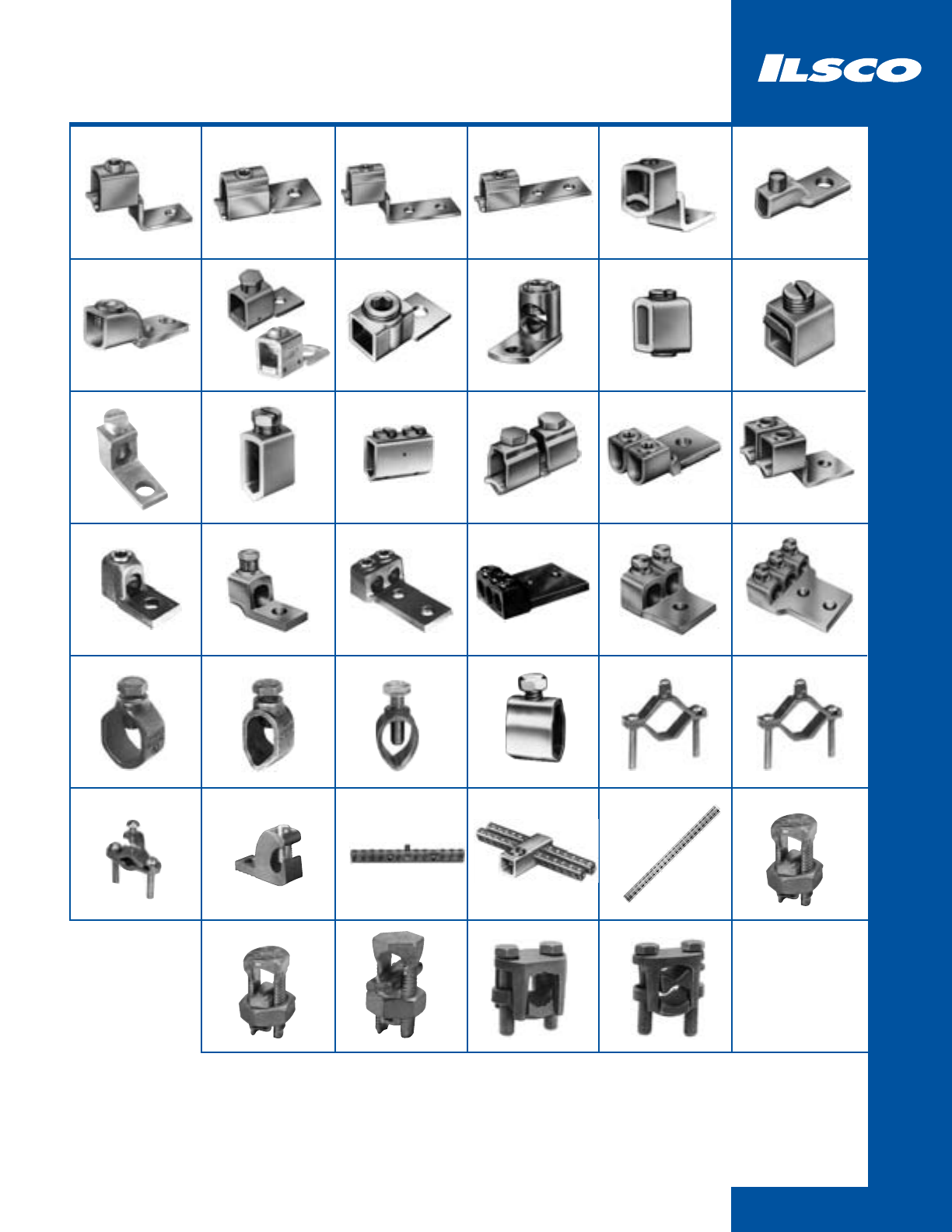
118
Mechanical
Copper
SLU/SAU
160
SLS/SAS
160
E
161
SLUH
162
LO
163
VT/LO-S
164
LY
165
CP
166
CO
167 – 168
COPP
169
N
173
2SC
172
SX
171
TC
170
MU
174
LU
174
CL
175 - 176
HL
177
CL
178
CL
178
H2L
179
CGRC
181
GRC
184
DCGC
185
D167
190
CAN
191
N-174
191
IK
192
SK
194
IKB
195
H
161
197
BGC
186 - 187
BGDB
188
GBL-DB
189
IK3
193
TORQUE
INDEX
BGRC
182
XT
165
H3L
180
SRC
183
IKS
196
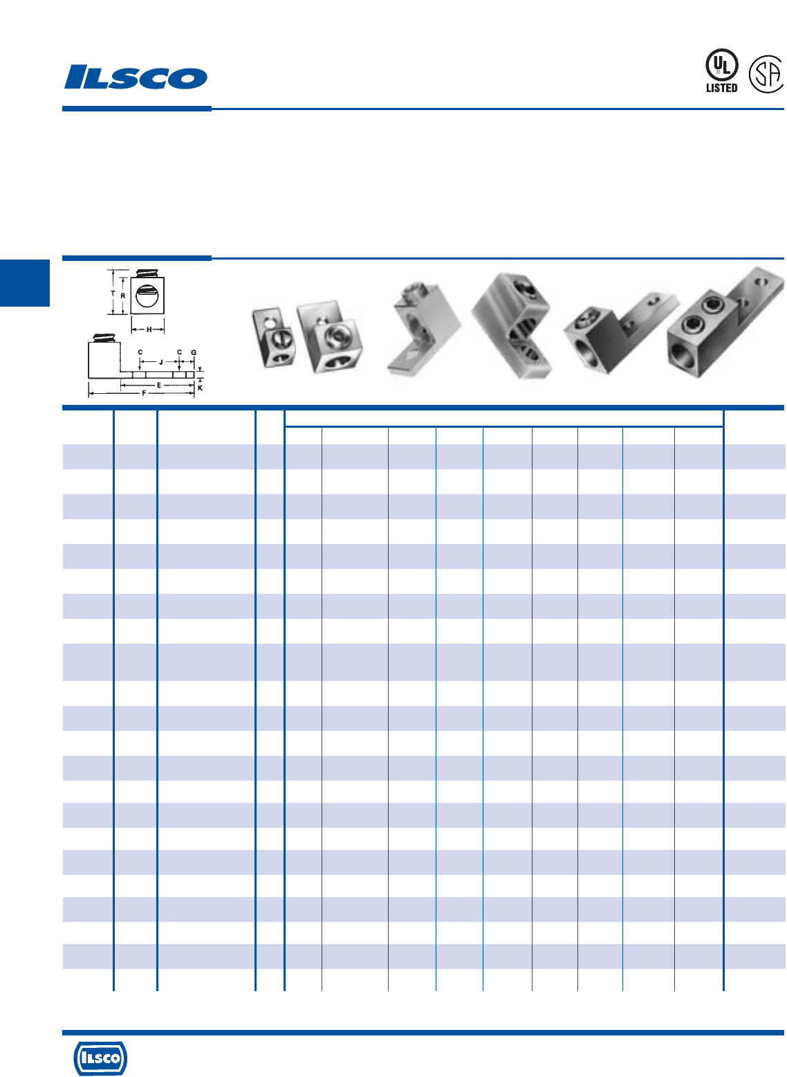
4730 Madison Road, Cincinnati, Ohio 45227-1426 Phone 513 533-6200 Fax 513 871-4084 Web site www.ilsco.com
Canada 1050 Lakeshore Road East, Mississauga, Ontario, Canada L5E1E4 Phone 905 274-2341 Fax 905 274-8763
119
C
Catalog Figure Wire Bolt Dimensions Hex
Number Number Range Size C E F G H J K R T Size
TA-6-S 1 4-14 1/4 17/64 11/16 1-1/16 1/4 1/2 – 3/32 1/2 41/64 S
TA-2 1 2-14 1/4 17/64 11/16 1-5/32 5/16 1/2 – 7/64 9/16 3/4 S
TA-0 1 1/0-14 1/4 17/64 27/32 1-15/32 7/16 5/8 – 3/16 25/32 29/32 S
TA-2/0 2 2/0-14 1/4 17/64 27/32 1-15/32 7/16 5/8 – 3/16 25/32 1-1/32 3/16
TA-250 2 250kcmil-6 5/16 21/64 1 2 15/32 1 – 1/4 1-1/8 1-21/64 5/16
TA-300 2 300kcmil-6 1/4 9/32 1 2 1/2 55/64 – 1/4 1-1/8 1-11/32 5/16
TA-350 2 350kcmil-6 3/8 13/32 1-1/8 2-1/4 1/2 1-1/8 – 1/4 1-1/4 1-29/64 3/8
TA-500 2 500kcmil-4 3/8 13/32 1-19/32 2-13/16 7/8 1-1/2 – 5/16 1-13/16 1-13/16 3/8
TA-500-S 3 One: 600kcmil-4 3/8 13/32 1-1/2 2-13/16 5/8 1-5/16 – 5/16 1-13/16 2-3/16 1/2
Two: 250kcmil-1/0
TA-600 2 600kcmil-2 3/8 13/32 1-13/16 3-3/16 7/8 1-1/2 – 7/16 1-9/16 1-31/32 1/2
TA-800 2 800kcmil-300kcmil 5/8 21/32 1-3/4 3-3/8 7/8 1-3/4 – 1/2 1-15/16 2-15/64 1/2
TA-800-S 4 800kcmil-3/0 5/8 21/32 1-3/4 3-1/4 11/16 1-5/16 – 1/2 1-13/16 2-3/16 1/2
TA-1000 2 1000kcmil-350kcmil 5/8 21/32 1-3/4 3-3/8 7/8 1-3/4 – 1/2 1-15/16 2-25/64 9/16
TA-1000-S 4 1000kcmil-500kcmil 5/8 21/32 1-3/4 3-1/4 11/16 1-7/16 – 1/2 1-13/16 2-3/16 9/16
TA-350-2NS
5 350kcmil-6 1/2 9/16 3 4-5/16 5/8 1-1/8 1-3/4 5/16 1-3/8 1-29/64 3/8
TA-600-2NS
5 600kcmil-2 1/2 9/16 3-5/16 4-11/16 5/8 1-1/2 1-3/4 7/16 1-3/8 1-59/64 1/2
TA-800-2NS
5 800kcmil-300kcmil 1/2 9/16 3-1/8 4-3/4 5/8 1-3/4 1-3/4 1/2 1-15/16 2-3/16 1/2
TA-1000-2NS
5 1000kcmil-500kcmil 1/2 9/16 3-1/8 4-3/4 5/8 1-3/4 1-3/4 1/2 1-15/16 2-27/64 9/16
TA-350-2N 6 350kcmil-6 1/2 9/16 3-1/4 5-1/2 5/8 1-1/4 1-3/4 3/8 1-1/2 1-21/32 (2)3/8
TA-600-2N 6 600kcmil-2 1/2 9/16 3-1/4 5-1/2 5/8 1-3/8 1-3/4 3/8 1-1/2 1-31/32 (2)3/8
TA-800-2N 6 800kcmil-300kcmil 1/2 9/16 3-5/8 5.97 5/8 1-1/2 1-3/4 1/2 1.813 2-15/64 (2)1/2
TA-1000-2N 6 1000kcmil-500kcmil 1/2 9/16 3-5/8 5.97 5/8 1-5/8 1-3/4 1/2 1.813 2-25/64 (2)1/2
Aluminum Mechanical Lugs - Dual Rated
One Conductor
TYPE
TA
Features
•
Manufactured from high strength 6061-T6 aluminum
alloy
•
Electro-tin plated
•
Chamfered wire entry
•
UL Listed and CSA Certified for 600 volts, 90˚ C
Fig. 1 Fig. 2 Fig. 3 Fig. 4 Fig. 5 Fig. 6
Benefits
•
Suitable for use with either copper or aluminum
conductors
•
Provides low contact resistance
•
Provides ease of installation
•
Ensures reliability for copper or aluminum
conductors
453G
L
R
-
2
9
6
0
1
DE-OX Inhibitor is recommended for all aluminum terminations. Tested to UL 486A-486B, UL File E6207
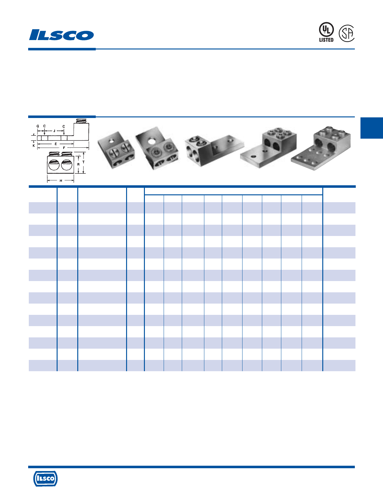
4730 Madison Road, Cincinnati, Ohio 45227-1426 Phone 513 533-6200 Fax 513 871-4084 Web site www.ilsco.com
Canada 1050 Lakeshore Road East, Mississauga, Ontario, Canada L5E1E4 Phone 905 274-2341 Fax 905 274-8763
120
C
Catalog Figure Wire Bolt Dimensions Hex
Number Number Range Size C E F G H J K R T Size
AU-0 1 Two: 1/0-14 1/4 17/64 27/32 1-15/32 7/16 1-1/8 – 3/16 51/64 29/32 S
AU-2/0 2 Two: 2/0-14 1/4 17/64 27/32 1-15/32 27/64 1-1/4 – 3/16 51/64 1-1/32 3/16
AU-250 2 Two: 250kcmil-6 3/8 25/64 1-9/16 2-9/16 7/8 1-21/32 – 1/4 1-3/16 1-9/32 5/16
AU-350 2 Two: 350kcmil-4 1/2 9/16 1-3/4 2-7/8 7/8 1-57/64 – 1/4 1-1/4 1-3/8 5/16
AU-600 2 Two: 600kcmil-2 1/2 17/32 1-13/16 3-3/16 5/8 2-13/32 – 7/16 1-9/16 1-31/32 1/2
AU-800 2
Two: 800kcmil-300kcmil
5/8 21/32 1-3/4 3-3/8 7/8 3-3/16 – 1/2 1-15/16 2-15/64 1/2
AU-1000 2
Two: 1000kcmil-500kcmil
5/8 21/32 1-3/4 3-3/8 7/8 3-3/16 – 1/2 1-15/16 2-25/64 9/16
AU-600-2NS 3 Two: 600kcmil-2 1/2 9/16 3-5/16 4-11/16 5/8 2-13/32 1-3/4 7/16 1-3/8 2-3/64 1/2
AU-800-2NS 3
Two: 800kcmil-300kcmil
1/2 9/16 3-1/8 4-3/4 5/8 3-3/16 1-3/4 1/2 1-15/16 2-3/16 1/2
AU-1000-2NS
3
Two: 1000kcmil-500kcmil
1/2 9/16 3-1/8 4-3/4 5/8 3-3/16 1-3/4 1/2 1-5/8 2-33/64 9/16
AU-350-2N 4 Two: 350kcmil-6 1/2 9/16 3 4-5/16 5/8 2 1-3/4 5/16 1-3/8 1-29/64 5/16
AU-350-N* 5 Two: 350kcmil-6 1/2 9/16 3-1/4 5-1/2 5/8 2-3/4 1-3/4 3/8 1-1/2 1-31/32 5/16
AU-600-2N* 5 Two: 600kcmil-2 1/2 9/16 3-1/4 5-1/2 5/8 2-3/4 1-3/4 3/8 1-1/2 1-31/32 1/2
AU-800-2N* 5 Two: 800kcmil-300kcmil 1/2 9/16 3-5/8 5-31/32 5/8 3 1-3/4 1/2 1-13/16 2-15/64 1/2
AU-1000-2N* 5
Two: 1000kcmil-500kcmil
1/2 9/16 3-5/8 5-31/32 5/8 3-1/4 1-3/4 1/2 1-13/16 2-25/64 9/16
TYPE
AU
Aluminum Mechanical Lugs - Dual Rated
Two Conductor
Features
•
Manufactured from high strength 6061-T6 aluminum
alloy
•
Electro-tin plated
•
Chamfered wire entry
•
UL Listed and CSA Certified for 600 volts, 90˚ C
Benefits
•
Suitable for use with either copper or aluminum
conductors
•
Provides low contact resistance
•
Provides ease of installation
•
Ensures reliability for copper or aluminum
conductors
453G
L
R
-
2
9
6
0
1
Fig. 1 Fig. 2 Fig. 3 Fig. 4 Fig. 5
DE-OX Inhibitor is recommended for all aluminum terminations.
Tested to UL 486A-486B, UL File E6207
* Mounting hole spacing from side to side, hole to hole is .875
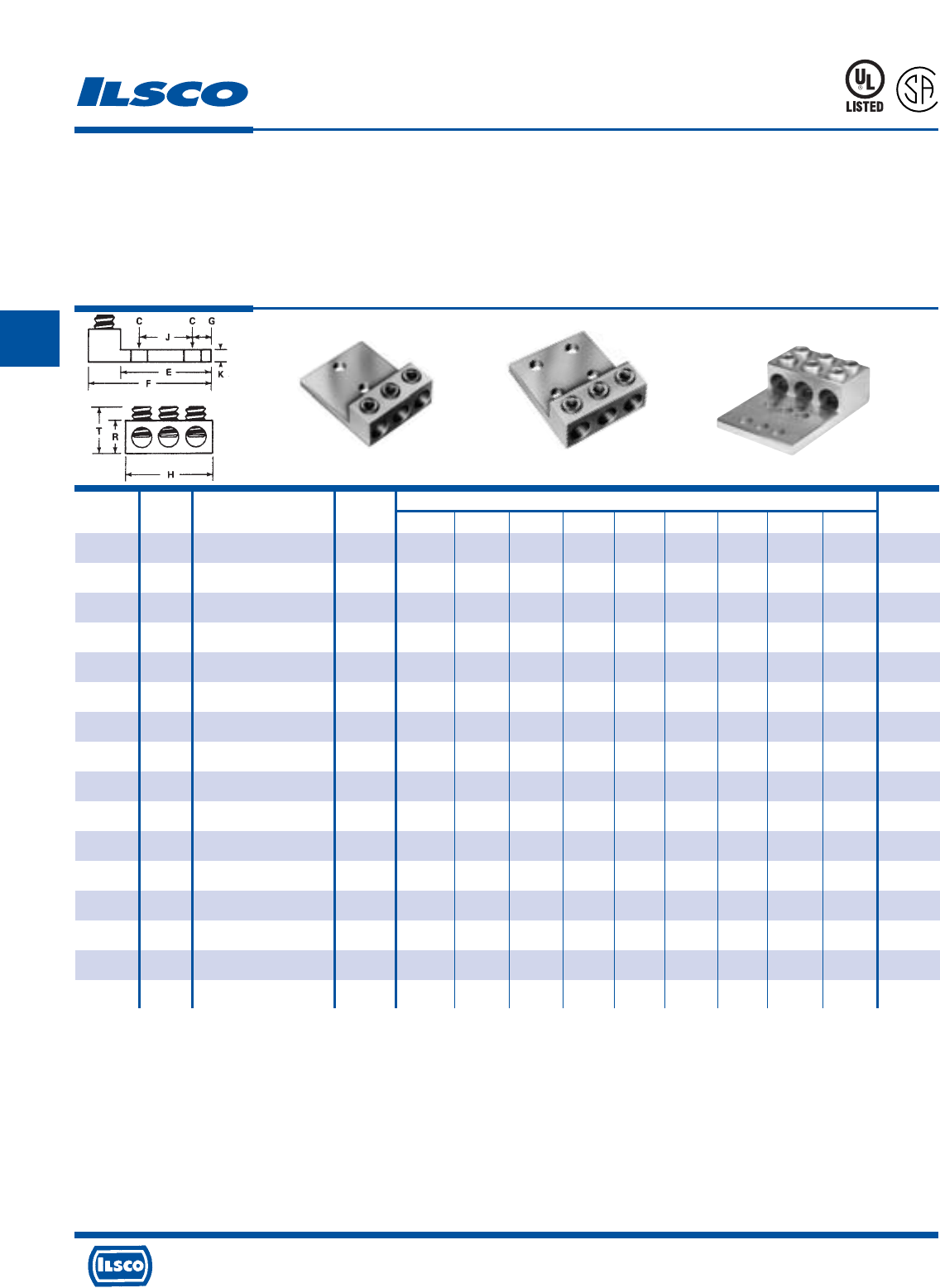
4730 Madison Road, Cincinnati, Ohio 45227-1426 Phone 513 533-6200 Fax 513 871-4084 Web site www.ilsco.com
Canada 1050 Lakeshore Road East, Mississauga, Ontario, Canada L5E1E4 Phone 905 274-2341 Fax 905 274-8763
121
C
Fig. 1 Fig. 2 Fig. 3
Catalog Figure Wire Bolt Dimensions Hex
Number Number Range Size C E F G H J K R T Size
T3A2-2 1 Three: 2-14 5/16 11/32 1-11/16 2-3/16 11/32 1-19/32 7/8 3/16 5/8 13/16 Slot
T3A2-0 1 Three: 1/0-14 3/8 7/16 2-5/32 2-29/32 11/32 1-15/16 1 1/4 7/8 15/16 Slot
T3A2-3/0N 1 Three: 3/0-6 1/2 9/16 3 3-7/8 5/8 2-13/16 1-3/4 5/16 1-1/8 1-1/2 5/16
T3A2-250N 1 Three: 250kcmil-6 1/2 9/16 3 4 5/8 2-13/16 1-3/4 5/16 1-3/16 1-17/32 5/16
T3A2-350N 1 Three: 350kcmil-6 1/2 9/16 3 4-5/16 5/8 3 1-3/4 5/16 1-3/8 1-17/32 5/16
T3A2-600N* 3 Three: 600kcmil-2 1/2 9/16 3-1/4 5-1/2 5/8 3-1/2 1-3/4 3/8 1-1/2 1-49/64 3/8
T3A2-800N* 3
Three: 800kcmil-350kcmil 1/2
9/16 3-5/8 5-31/32 5/8 4-1/8 1-3/4 1/2 1-13/16 2-21/64 5/16
T3A2-1000N*
3
Three: 1000kcmil-500kcmil
1/2 9/16 3-5/8 5-31/32 5/8 4-7/8 1-3/4 1/2 1-13/16 2-21/64 3/8
T3A4-2 2 Three: 2-14 5/16 11/32 1-11/16 2-3/16 11/32 1-19/32 7/8 3/16 5/8 13/16 Slot
T3A4-0 2 Three: 1/0-14 3/8 7/16 2-5/32 2-29/32 11/32 1-15/16 1 1/4 7/8 15/16 Slot
T3A4-3/0N 2 Three: 3/0-6 1/2 9/16 3 3-7/8 5/8 2-13/16 1-3/4 5/16 1-1/8 1-1/2 5/16
T3A4-250N 2 Three: 250kcmil-6 1/2 9/16 3 4 5/8 2-13/16 1-3/4 5/16 1-3/16 1-17/32 5/16
T3A4-350N 2 Three: 350kcmil-6 1/2 9/16 3 4-5/16 5/8 3 1-3/4 5/16 1-3/8 1-17/32 5/16
T3A4-600N* 3 Three: 600kcmil-2 1/2 9/16 3-1/4 5-1/2 5/8 3-1/2 1-3/4 3/8 1-1/2 1-49/64 1/2
T3A4-800N* 3
Three: 800kcmil-350kcmil
1/2 9/16 3-5/8 5-31/32 5/8 4-1/8 1-3/4 1/2 1-13/16 2-21/64 1/2
T3A4-1000N*
3
Three: 1000kcmil-500kcmil
1/2 9/16 3-5/8 5-31/32 5/8 4-7/8 1-3/4 1/2 1-13/16 2-21/64 1/2
Aluminum Mechanical Lugs - Dual Rated
Three Conductor
TYPE
T3A
Features
•
Manufactured from high strength 6061-T6 aluminum
alloy
•
Electro tin plated
•
Chamfered wire entry
•
UL Listed and CSA Certified for 600 volts, 90˚ C
Benefits
•
Suitable for use with either copper or aluminum
conductors
•
Provides low contact resistance
•
Provides ease of installation
•
Ensures reliability for copper or aluminum
conductors
DE-OX Inhibitor is recommended for all aluminum terminations.
Tested to UL 486A-486B, UL File E6207
* Mounting hole spacing from side to side, hole to hole is .875
453G
L
R
-
2
9
6
0
1
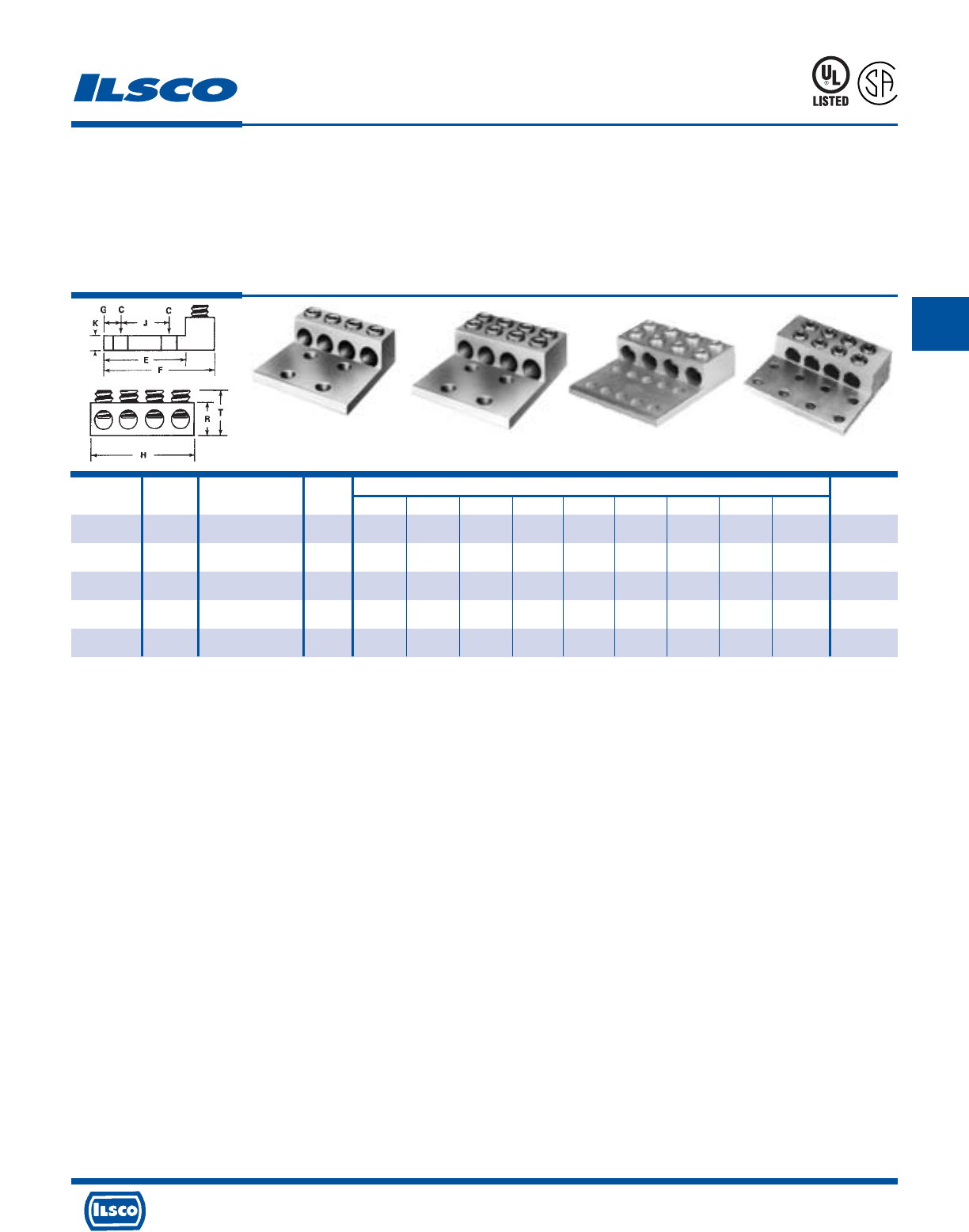
4730 Madison Road, Cincinnati, Ohio 45227-1426 Phone 513 533-6200 Fax 513 871-4084 Web site www.ilsco.com
Canada 1050 Lakeshore Road East, Mississauga, Ontario, Canada L5E1E4 Phone 905 274-2341 Fax 905 274-8763
122
C
Catalog Figure Wire Bolt Dimensions Hex
Number Number Range Size C E F G H J K R T Size
T4A4-250N* 1 250kcmil-6 1/2 9/16 3 4 5/8 3-49/64 1-3/4 5/16 1-3/16 1-17/32 5/16
T4A4-350N* 1 350kcmil-6 1/2 9/16 3 4-5/16 5/8 4-1/64 1-3/4 5/16 1-3/8 1-17/32 5/16
T4A4-600N* 3 600kcmil-2 1/2 9/16 3-1/4 5-1/2 5/8 5 1-3/4 3/8 1-1/2 1-7/8 1/2
T4A4-800N* 2 800kcmil-350kcmil 1/2 9/16 3-5/8 5-31/32 5/8 6 1-3/4 1/2 1-13/16 2-13/64 1/2
T4A4-1000N* 4 1000kcmil-350kcmil 1/2 9/16 3-5/8 5-31/32 5/8 6-1/2 1-3/4 1/2 1-13/16 2-13/64 1/2
TYPE
T4A4
Aluminum Mechanical Lugs - Dual Rated
Four Conductor
Features
•
Manufactured from high strength 6061-T6 aluminum
alloy
•
Electro-tin plated
•
Chamfered wire entry
•
UL Listed and CSA Certified for 600 volts, 90˚ C
Benefits
•
Suitable for use with either copper or aluminum
conductors
•
Provides low contact resistance
•
Provides ease of installation
•
Ensures reliability for copper or aluminum
conductors
453G
L
R
-
2
9
6
0
1
DE-OX Inhibitor is recommended for all aluminum terminations.
Tested to UL 486A-486B, UL File E6207
* Mounting hole spacing from side to side, hole to hole is .875
Fig. 1 Fig. 2 Fig. 3 Fig. 4
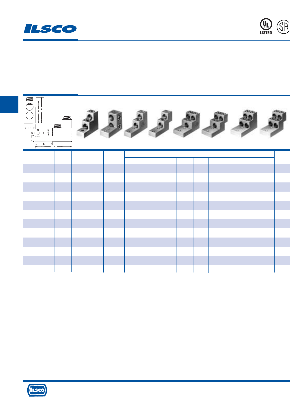
4730 Madison Road, Cincinnati, Ohio 45227-1426 Phone 513 533-6200 Fax 513 871-4084 Web site www.ilsco.com
Canada 1050 Lakeshore Road East, Mississauga, Ontario, Canada L5E1E4 Phone 905 274-2341 Fax 905 274-8763
123
C
Catalog Figure Wire Bolt Dimensions Hex
Number Number Range Size C E F G H J K R T Size
PB2-300 1 300kcmil-6 5/16 21/64 1 3 15/32 1 - 5/16 2 2-5/16 5/16
PB2-500 2 500kcmil-4/0 1/4 9/32 1-11/16 2-29/32 1/4 1-7/16 11/16 5/8 2-3/8 1-27/64 3/8
PB2-600 4 600kcmil-2 3/8 13/32 2-11/32 4-29/32 3/8 1-1/2 1-3/8 3/4 3 3-29/64 1/2
PB3-600 6 600kcmil-2 3/8 13/32 2-11/32 4-29/32 3/8 2-15/32 1-3/8 3/4 3 3-29/64 1/2
PB4-600 8 600kcmil-2 3/8 13/32 2-11/32 4-29/32 3/8 2-15/32 1-3/8 3/4 3 3-29/64 1/2
PB2-750 4 750kcmil-1/0 3/8 13/32 2-11/32 4-29/32 3/8 1-11/16 1-3/8 3/4 3 3-29/64 1/2
PB4-750 8 750kcmil-1/0 3/8 13/32 2-11/32 4-29/32 3/8 2-5/8 1-3/8 3/4 3 3-29/64 1/2
PB3-600-2N 5 600kcmil-2 1/2 9/16 3-1/8 5-11/16 3/8 2-15/32 1-3/4 3/4 3 3-29/64 1/2
PB2-600-2N 3 600kcmil-2 1/2 9/16 3-1/8 5-11/16 3/8 1-1/2 1-3/4 3/4 3 3-29/64 1/2
PB2-750-2N 3 750kcmil-1/0 1/2 9/16 3-1/8 5-11/16 3/8 1-11/16 1-3/4 3/4 3 3-29/64 1/2
PB4-600-2N 7 600kcmil-2 1/2 9/16 3-1/8 5-11/16 3/8 2-15/32 1-3/4 3/4 3 3-29/64 1/2
PB4-750-2N 7 750kcmil-1/0 1/2 9/16 3-1/8 5-11/16 3/8 3-1/16 1-3/4 3/4 3 3-29/64 1/2
TYPE
PB
Aluminum Panelboard Lugs - Dual Rated
Features
•
Manufactured from high strength 6061-T6 aluminum
alloy
•
Electro-tin plated
•
Chamfered wire entry
•
UL Listed and CSA Certified for 600 volts, 90˚ C
•
Stacked design
Fig. 1 Fig. 2 Fig. 3 Fig. 4 Fig. 5 Fig. 6 Fig. 7 Fig. 8
Benefits
•
Suitable for use with either copper or aluminum
conductors
•
Provides low contact resistance
•
Provides ease of installation
•
Ensures reliability for copper or aluminum
conductors
•
Saves space and reduces installation time
DE-OX Inhibitor is recommended for all aluminum terminations.
Tested to UL 486A-486B, UL File E6207
453G
L
R
-
2
9
6
0
1
K
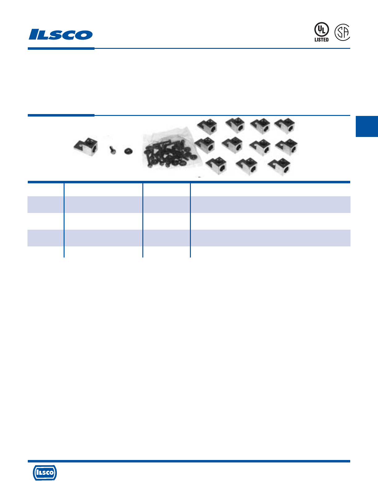
4730 Madison Road, Cincinnati, Ohio 45227-1426 Phone 513 533-6200 Fax 513 871-4084 Web site www.ilsco.com
Canada 1050 Lakeshore Road East, Mississauga, Ontario, Canada L5E1E4 Phone 905 274-2341 Fax 905 274-8763
124
C
Catalog
Number XFMR KVA Size Lugs in Kit Bolts in Kit
TLK-1 15-371/2 1-Phase, Eight TA-2, Eight 1/4-20 x 3/4 Bolts,
15-45 3-Phase Four TA-250 Eight 1/2-20 Flange Nuts
TLK-2 50-75 1-Phase, Twelve TA-250 Eight 1/4-20 x 3/4 Bolts, Eight 1/4-20 x 1-3/4 Bolts
75-112-1/2 3-Phase and Sixteen 1/4-20 Flange Nuts
TLK-3 100-167 1-Phase, Three TA-250 and Three 1/4-20 x 3/4 Bolts, Three 1/4-20 nuts, Sixteen 3/8-16-2 Bolts,
150-300 3-Phase Twenty-two TA-600 Sixteen 3/8-16 Flange Nuts, Sixteen 3/8 flat washer
TLK-4 500 3-Phase Twenty-nine TA-600 Eighteen 3/8-16 x 2 Bolts and Eighteen 3/8-16 Flange Nuts
Transformer Lug Kits - Dual Rated
TYPE
TLK
Features
•
Connectors manufactured from high strength 6061-T6
aluminum alloy
•
Electro-tin plated
•
Chamfered wire entry
•
UL Listed and CSA Certified for 600 volts
•
Kit includes all required hardware
Benefits
•
Suitable for use with either copper or aluminum
conductors
•
Provides low contact resistance
•
Provides ease of installation
•
Ensures reliability for copper or aluminum
conductors
Dimensional data for connectors see Type TA.
DE-OX Inhibitor is recommended for all aluminum terminations.
453G
L
R
-
2
9
6
0
1
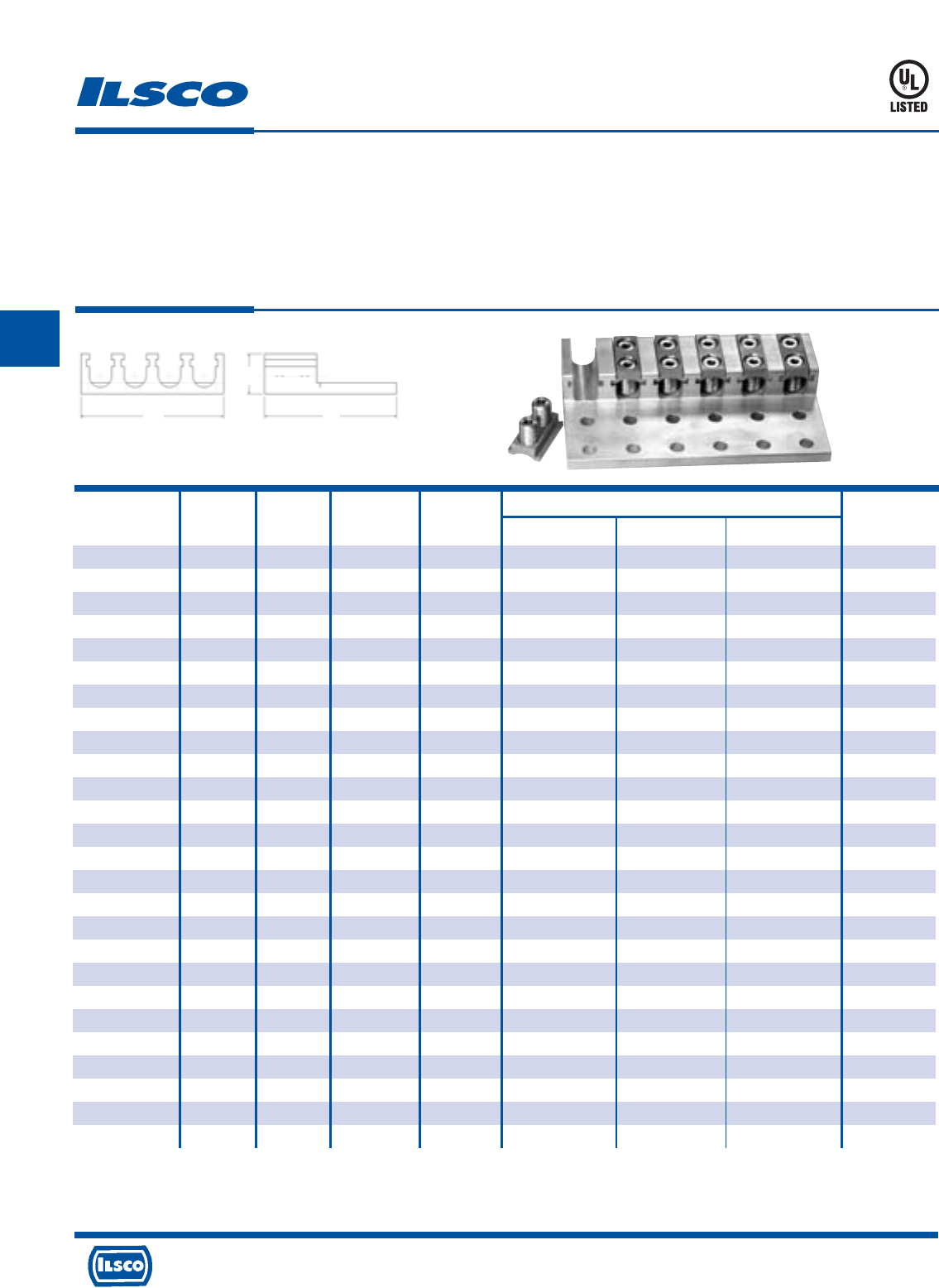
4730 Madison Road, Cincinnati, Ohio 45227-1426 Phone 513 533-6200 Fax 513 871-4084 Web site www.ilsco.com
Canada 1050 Lakeshore Road East, Mississauga, Ontario, Canada L5E1E4 Phone 905 274-2341 Fax 905 274-8763
125
C
Catalog Number of Number Wire Mounting Dimensions Hex
Number Mtg. Holes of Ports Range Bolt Size Width Length Height Size
USGL-350R21 2 1 350 kcmil-6 1/2 1.50 4.69 1.56 5/16
USGL-350R42 4 2 350 kcmil-6 1/2 2.75 4.69 1.56 5/16
USGL-350R43 4 3 350 kcmil-6 1/2 4.00 4.69 1.56 5/16
USGL-350R64 6 4 350 kcmil-6 1/2 5.25 4.69 1.56 5/16
USGL-350R86 8 6 350 kcmil-6 1/2 7.75 4.69 1.56 5/16
USGL-350R128 12 8 350 kcmil-6 1/2 10.25 4.69 1.56 5/16
USGL-600R21 2 1 600 kcmil-2 1/2 1.68 5.35 1.69 5/16
USGL-600R42 4 2 600 kcmil-2 1/2 3.08 5.35 1.69 5/16
USGL-600R63 6 3 600 kcmil-2 1/2 4.81 5.35 1.69 5/16
USGL-600R84 8 4 600 kcmil-2 1/2 6.45 5.35 1.69 5/16
USGL-600R106 10 6 600 kcmil-2 1/2 8.69 5.35 1.69 5/16
USGL-600R148 14 8 600 kcmil-2 1/2 11.70 5.35 1.69 5/16
USGL-750R21 2 1 750 kcmil-1/0 1/2 1.76 5.97 1.81 5/16
USGL-750R42 4 2 750 kcmil-1/0 1/2 3.31 5.97 1.81 5/16
USGL-750R63 6 3 750 kcmil-1/0 1/2 4.88 5.97 1.81 5/16
USGL-750R84 8 4 750 kcmil-1/0 1/2 6.45 5.97 1.81 5/16
USGL-750R126 12 6 750 kcmil-1/0 1/2 9.95 5.97 1.81 5/16
USGL-750R148 14 8 750 kcmil-1/0 1/2 12.30 5.97 1.81 5/16
USGL-1000R21 2 1 1000 kcmil-1/0 1/2 2.00 6.19 1.88 5/16
USGL-1000R22 2 2 1000 kcmil-1/0 1/2 3.68 6.19 1.88 5/16
USGL-1000R42 4 2 1000 kcmil-1/0 1/2 3.68 6.19 1.88 5/16
USGL-1000R43 4 3 1000 kcmil-1/0 1/2 5.37 6.19 1.88 5/16
USGL-1000R63 6 3 1000 kcmil-1/0 1/2 5.37 6.19 1.88 5/16
USGL-1000R84 8 4 1000 kcmil-1/0 1/2 7.06 6.19 1.88 5/16
USGL-1000R126 12 6 1000 kcmil-1/0 1/2 10.44 6.19 1.88 5/16
USGL-1000R168 16 8 1000 kcmil-1/0 1/2 13.81 6.19 1.88 5/16
TYPE
USGL
Lay-In ClearTrax®Connectors
Features
•
Compact, lay-in design
•
Manufactured from high strength 6061-T6 aluminum for
strength and conductivity
•
High strength aluminum 5/16" drive torque screw
•
Clear plated coating
•
Designed for installation on standard NEMA mounting
holes
•
UL Listed
•
1-3/4" NEMA spacing on mounting holes
Benefits
•
Solves the problem of trying to bend larger size cables into place
•
Dual rated for aluminum or copper conductors
•
Enables range taking
•
Provides low contact resistance
•
Conforms to industry standards
•
Ensures reliability
•
Industry standard
453G
W
H
L
Add T for tin plated, P for Pre-filled with De-Ox
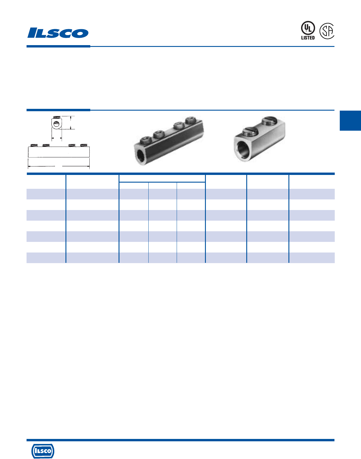
4730 Madison Road, Cincinnati, Ohio 45227-1426 Phone 513 533-6200 Fax 513 871-4084 Web site www.ilsco.com
Canada 1050 Lakeshore Road East, Mississauga, Ontario, Canada L5E1E4 Phone 905 274-2341 Fax 905 274-8763
126
C
Catalog Wire Dimensions Number of Screw Hex
Number Range L W H Screws Diameter Size
SPA-2 2-14 1-3/16 29/64 9/16 2 3/8 Slot
SPA-0 1/0-14 1-29/32 5/8 11/16 2 7/16 3/16
SPA-250 250kcmil-6 2-5/16 7/8 1 2 5/8 5/16
SPA-350 350kcmil-6 2-15/32 1 1-1/4 2 11/16 5/16
SPA-500 500kcmil-3/0 3-7/8 1-1/8 1-5/8 2 13/16 3/8
SPA-750 750kcmil-250kcmil 5-7/16 1-3/8 1-3/4 4 15/16 1/2
SPA-1000 1000kcmil-500kcmil 8-11/16 1-3/4 1-3/4 6 1-1/8 9/16
Aluminum Splicer/Reducer - Dual Rated
TYPE
SPA
Features
•
Manufactured from high strength 6061-T6 aluminum
alloy
•
Electro-tin plated
•
Chamfered wire entry
•
UL Listed and CSA Certified for 600 volts, 90˚ C
•
Rounded bottoms
•
Large screw diameters
•
Wire stop in center
Benefits
•
Suitable for use with either copper or aluminum
conductors
•
Provides low contact resistance
•
Provides ease of installation
•
Ensures reliability for copper or aluminum
conductors
•
Facilitates taping
•
Ensures all wire strands are held securely
•
Prevents dissimilar metals coming into contact
DE-OX Inhibitor is recommended for all aluminum terminations.
Tested to UL 486A-486B, UL File E6207
453G
L
R
-
2
9
6
0
1
H
L
W
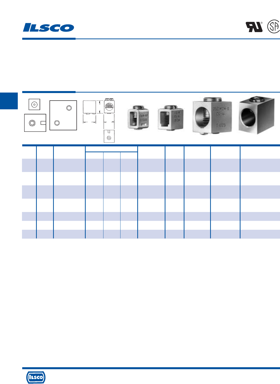
4730 Madison Road, Cincinnati, Ohio 45227-1426 Phone 513 533-6200 Fax 513 871-4084 Web site www.ilsco.com
Canada 1050 Lakeshore Road East, Mississauga, Ontario, Canada L5E1E4 Phone 905 274-2341 Fax 905 274-8763
127
C
Catalog Figure Wire Dimensions Style and Flat Bossed Two Mounting Hex
Number Number Range L W H Size of Boss Bottom Hole Tapped Holes Tapped Size
CA4SP 1 2-14 CU 15/32 1/2 23/32 Sq. .229 - 10-32 - Slot
2-12 AL
CA4RP 1 2-14 CU 15/32 1/2 23/32 Rd. .229 - 10-32 - Slot
2-12 AL
CA5SP 2 1/0-14 CU 5/8 9/16 11/16 Sq. .229 - 10-32 - Slot
1/0-12 AL
CA5RP 2 1/0-14 CU 5/8 9/16 11/16 Rd. .229 - 10-32 - Slot
1/0-12 AL
CA6RP 3 250kcmil-6 1 13/16 1 Rd. .285 - 1/4-20 - 5/16
CA7 4 500kcmil-1/0 1-3/8 1-15/64 1-13/32 - YES - 1/4-20 3/8
CA8 4 750kcmil-500kcmil 1-15/16 1-3/8 1-3/4 - YES - 5/16-18 1/2
Aluminum Box-Type Mechanical Lugs
Dual Rated
TYPE
CA
Features
•
Manufactured from high strength 6061-T6 aluminum
alloy
•
Electro-tin plated
•
UL Recognized for 75˚ C and is CSA certified, rated for
600 volts
•
Design includes bossed mounting holes
Fig. 1 Fig. 2 Fig. 3 Fig. 4
Benefits
•
Suitable for use with either copper or aluminum
conductors
•
Provides low contact resistance
•
Ensures reliability
•
Acts as an anti-rotation device and prevents
connector from turning
Bottom view (mounting configuration)
L
R
-
2
9
6
0
1
DE-OX Oxide Inhibitor is recommended for all aluminum terminations.
Tested to UL 486A-486B, UL File E6207
Fig. 1 & 2 Bottom View
Fig. 3 Fig. 4
H
W
L
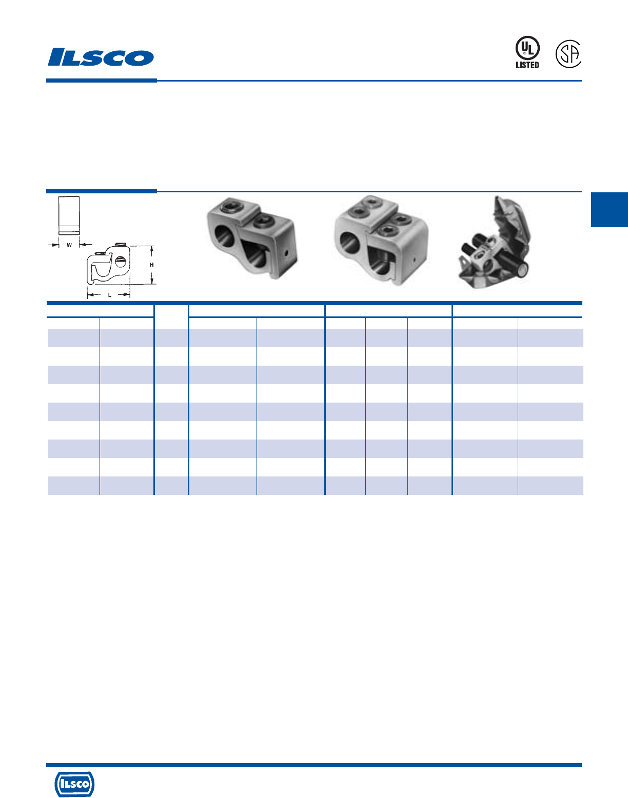
4730 Madison Road, Cincinnati, Ohio 45227-1426 Phone 513 533-6200 Fax 513 871-4084 Web site www.ilsco.com
Canada 1050 Lakeshore Road East, Mississauga, Ontario, Canada L5E1E4 Phone 905 274-2341 Fax 905 274-8763
128
C
Catalog Number Figure Wire Range Dimensions Hex Size
Connector Cover Number Main Tap L W H Main Tap
GTA-2-2 GTC-2 1 2-12 str 2-12 AL 2-14 CU 1-1/4 9/16 1 Slot Slot
GTA-0-0 GTC-0 1 1/0-2 1/0-12 AL 1/0-14 CU 1-9/16 3/4 1-1/8 Slot Slot
GTA-250-0 GTC-250-350 1 250kcmil-1/0 1/0-12 AL 1/0-14 CU 2 15/16 1-7/16 5/16 Slot
GTA-250-250 GTC-250-350 1 250kcmil-1/0 250kcmil-6 2-1/8 15/16 1-7/16 5/16 5/16
GTA-350-350 GTC-250-350 1 350kcmil-4/0 350kcmil-6 2-7/16 1 1-11/16 3/8 3/8
GTA-500-500 GTC-500 1 500kcmil-350kcmil 500kcmil-2 2-15/16 1-1/4 2 3/8 3/8
GTA-750-500 GTC-750-500 1 750kcmil-500kcmil 500kcmil-2 3-3/8 1-5/16 2-7/16 3/8 3/8
GTA-750-750 GTPC-750-750 2 750kcmil-500kcmil 750kcmil-1/0 3-3/8 2-5/8 2-7/16 1/2 1/2
GTA-1000-500 Not Available 1 1000kcmil-750kcmil 500kcmil-2 3-3/8 1-15/16 2-7/16 1/2 3/8
Parallel Tap Connectors - Dual Rated
Lay-In
TYPE
GTA
Features
•
Manufactured from high strength 6061-T6 aluminum
alloy
•
Electro-tin plated
•
UL Listed and CSA Certified for 600 volts,
Temp. rating 90˚ C
•
Compact design
•
Range taking
•
Re-usable
•
Lay-in main conductor
•
Insulating cover available
Fig. 1 Fig. 2
Benefits
•
Suitable for use with either copper or aluminum
conductors
•
Provides low contact resistance
•
Ensures reliability for copper or aluminum conductors
•
Saves space and reduces installation time
•
Permits inventories to be kept to a minimum
•
Provides efficient use and flexibility in the field
•
No need to break the feeder cable
•
Eliminates taping
Insulating covers are available for most connector sizes.
See page 130 for additional information on covers
Note: If ordering with cover, add suffix w/c to catalog number.
DE-OX Inhibitor is recommended for all aluminum terminations.
Tested to UL 486A-486B, UL File E6207
453G
L
R
-
2
9
6
0
1

4730 Madison Road, Cincinnati, Ohio 45227-1426 Phone 513 533-6200 Fax 513 871-4084 Web site www.ilsco.com
Canada 1050 Lakeshore Road East, Mississauga, Ontario, Canada L5E1E4 Phone 905 274-2341 Fax 905 274-8763
129
C
Catalog Number Figure Wire Range Dimensions Hex Size
Connector Cover Number Main Tap L W H Main Tap
GTT-2-2 GTC-2 1 2-12 str 2-12 AL 2-14 CU 1-1/4 9/16 1 Slot Slot
GTT-0-0 GTC-0 1 1/0-2 1/0-12 AL 1/0-14 CU 1-9/16 3/4 1-1/8 Slot Slot
GTT-250-0 GTC-250-350 1 250kcmil-1/0 1/0-12 AL 1/0-14 CU 2 7/8 1-7/16 5/16 Slot
GTT-250-250 GTC-250-350 1 250kcmil-1/0 250kcmil-6 2-1/8 7/8 1-7/16 5/16 5/16
GTT-350-350 GTC-500 1 350kcmil-4/0 350kcmil-6 2-7/16 1 1-11/16 3/8 3/8
GTT-500-500 GTC-500 1 500kcmil-350kcmil 500kcmil-2 2-15/16 1-1/4 2 3/8 3/8
GTT-750-500 GTC-750-500 1 750kcmil-500kcmil 500kcmil-2 3-3/8 1-1/4 2-7/16 3/8 3/8
GTT-750-750 GTC-750-750 2 750kcmil-500kcmil 750kcmil-600kcmil 3-3/8 2-3/8 2-7/16 1/2 EH 3/4
GTT-1000-500 Not Available 1 1000kcmil-750kcmil 500kcmil-2 3-3/8 1-1/4 2-7/16 1/2 3/8
“T” Tap Connectors - Dual Rated
Lay-In
TYPE
GTT
Features
•
Manufactured from high strength 6061-T6 aluminum
alloy
•
Electro-tin plated
•
UL Listed and CSA Certified for 600 volts,
Temp. rating 90˚ C
•
Compact design
•
Range taking
•
Re-usable
•
Lay-in main conductor
•
Insulating cover available
Fig. 1 Fig. 2
Benefits
•
Suitable for use with either copper or aluminum
conductors
•
Provides low contact resistance
•
Ensures reliability for copper or aluminum conductors
•
Saves space and reduces installation time
•
Permits inventories to be kept to a minimum
•
Provides efficient use and flexibility in the field
•
No need to break the feeder cable
•
Eliminates taping
EH-External Hex
Insulating covers are available for most connector sizes.
See page 130 for additional information on covers
Note: If ordering with cover, add suffix w/c to catalog number.
DE-OX Inhibitor is recommended for all aluminum terminations.
Tested to UL 486A-486B, UL File E6207
453G
L
R
-
2
9
6
0
1
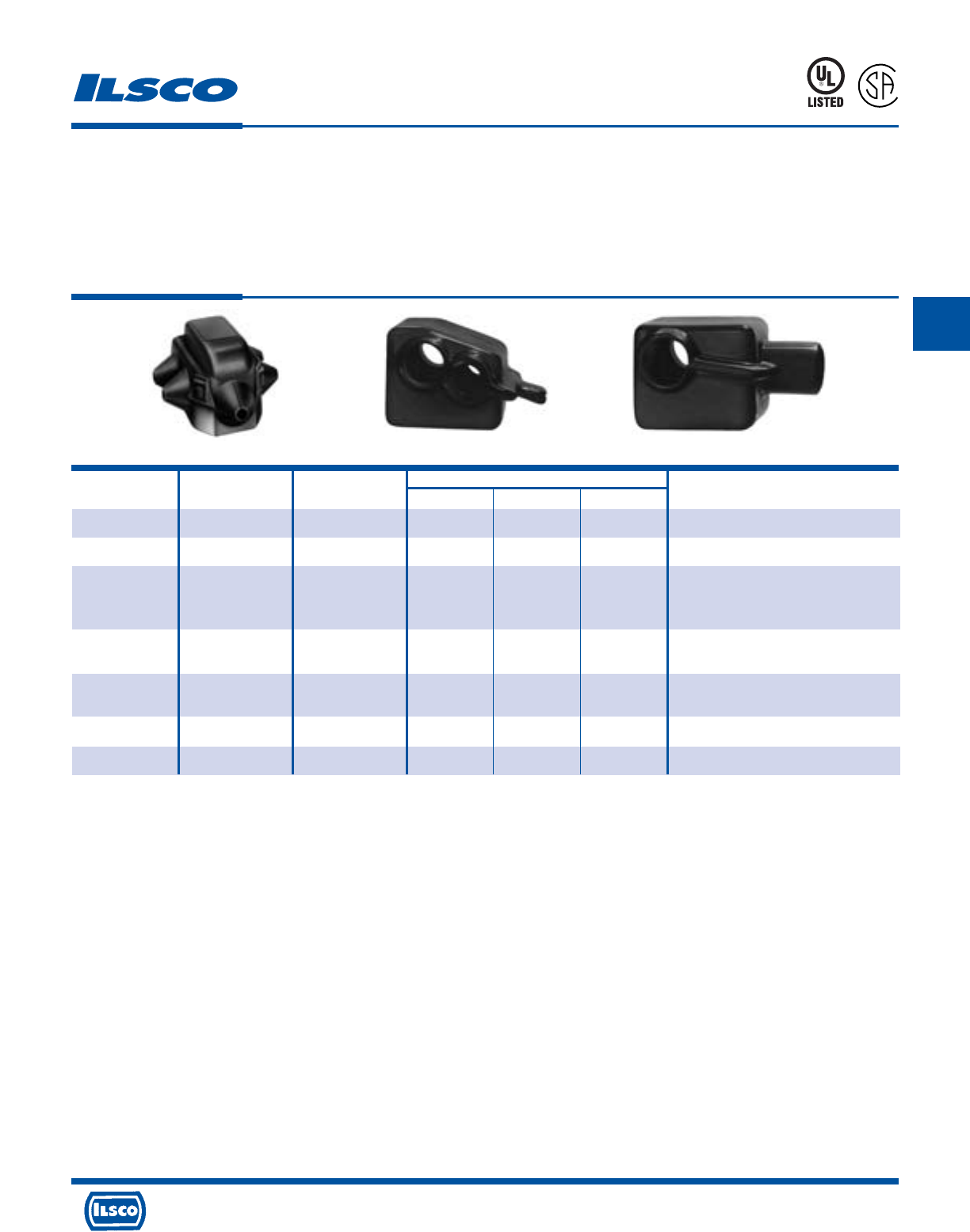
4730 Madison Road, Cincinnati, Ohio 45227-1426 Phone 513 533-6200 Fax 513 871-4084 Web site www.ilsco.com
Canada 1050 Lakeshore Road East, Mississauga, Ontario, Canada L5E1E4 Phone 905 274-2341 Fax 905 274-8763
130
C
Catalog Figure Dimensions
Number Number Color L W H Used with Connector
GTC-2 1 Black 2-1/4 1-13/16 1-1/4 GTA-2-2: GTT-2-2
GTC-0 1 Black 2-1/2 2-3/32 1-3/8 GTA-0-0: GTT-0-0
GTA-250-0: GTA-250-250
GTC-250-350 1 Black 3-61/64 3-1/32 2 GTA-350-350
GTT-250-0: GTT-250-250
GTT-350-350
GTC-500 1 Black 4-1/8 3-1/16 2-31/32 GTA-500-500
GTT-500-500
GTC-750-500 1 Black 4-7/8 3-1/8 2-23/32 GTA-750-500
GTT-750-500
GTPC-750-750* 2 Black 4-7/8 4 2-7/8 GTA-750-750
GTTC-750-750* 3 Black 5-3/4 4-1/4 3-1/16 GTT-750-750
Insulating Covers For GTA-GTT
TYPE
GTC
Features
•
Snap closure
•
Color coded
•
UL Listed and CSA Certified for 600 volts, 90˚ C except
for GTPC-750-750 and GTTC-750-750
Fig. 1 Fig. 2 Fig. 3
Benefits
•
Installs quickly and saves labor time by eliminating
taping
•
Provides ease of identification in the field
•
Ensures reliability
453G
L
R
-
2
9
6
0
1
* Not UL Listed or CSA Certified
Tested to UL 486A-486B, UL File E6207
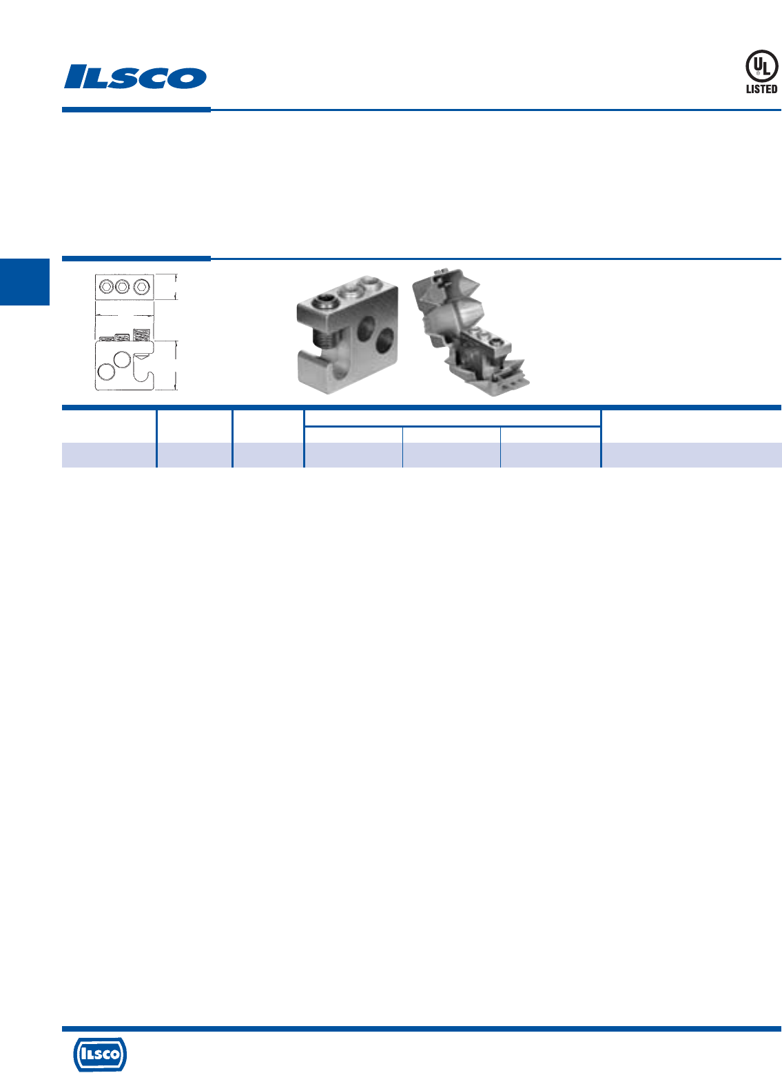
4730 Madison Road, Cincinnati, Ohio 45227-1426 Phone 513 533-6200 Fax 513 871-4084 Web site www.ilsco.com
Canada 1050 Lakeshore Road East, Mississauga, Ontario, Canada L5E1E4 Phone 905 274-2341 Fax 905 274-8763
131
C
Catalog Wire Range No. of Dimensions Hex
Number Main & Tap Taps L W H Size
GT2-250-W/C 250kcmil-2 2 31/32 2-9/32 1-15/16 5/16
Multiple Tap Connector - Dual Rated
Lay-In
TYPE
GT2
Features
•
Manufactured from high strength 6061-T6 aluminum
alloy
•
Electro-tin plated
•
UL Listed for 600 volts, 90˚ C
•
Compact design
•
Range taking
•
Re-usable
•
Lay-in main conductor
•
Supplied with cover
Benefits
•
Suitable for use with either copper or aluminum
conductors
•
Provides low contact resistance
•
Ensures reliability for copper or aluminum conductors
•
Saves space and reduces installation time
•
Permits inventories to be kept to a minimum
•
Provides efficient use and flexibility in the field
•
No need to break the feeder cable
•
Eliminates taping
453G
DE-OX Inhibitor is recommended for all aluminum terminations.
Tested to UL 486A-486B, UL File E6207
L
H
W
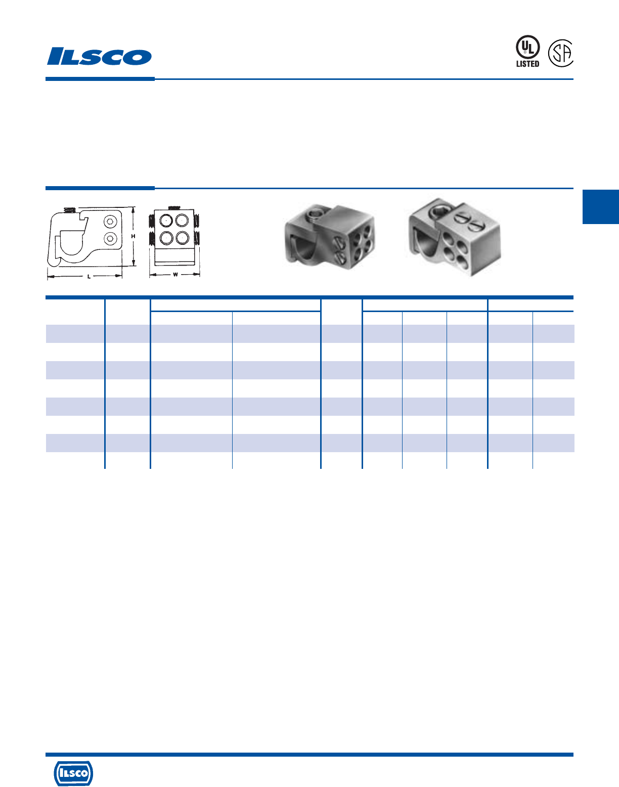
4730 Madison Road, Cincinnati, Ohio 45227-1426 Phone 513 533-6200 Fax 513 871-4084 Web site www.ilsco.com
Canada 1050 Lakeshore Road East, Mississauga, Ontario, Canada L5E1E4 Phone 905 274-2341 Fax 905 274-8763
132
C
Catalog Figure Wire Range No. of Dimensions Hex Size
Number Number Main Tap Taps L W H Main Tap
*GT4T-250-2-1 1 250kcmil-1/0 2-12 AL, 2-14 CU 4 2-3/16 1-1/8 1-35/64 5/16 Slot
*GT4T-250-2-2 2 250kcmil-1/0 2-12 AL, 2-14 CU 4 2-3/16 1-1/8 1-35/64 5/16 Slot
†GT4T-350-2-1 1 350kcmil-4/0 2-12 AL, 2-14 CU 4 2-17/32 1-1/8 1-17/32 3/8 Slot
*GT4T-350-2-2 2 350kcmil-4/0 2-12 AL, 2-14 CU 4 2-17/32 1-1/8 1-17/32 3/8 Slot
†GT4T-500-2-1 1 500kcmil-350kcmil 2-12 AL, 2-14 CU 4 2-31/32 1-1/4 1-11/16 3/8 Slot
†GT4T-500-2-2 2 500kcmil-350kcmil 2-12 AL, 2-14 CU 4 2-31/32 1-1/4 1-11/16 3/8 Slot
†GT4T-500-0-1 1 500kcmil-350kcmil 1/0-12 AL, 1/0-14 CU 4 2-31/32 1-1/4 1-11/16 3/8 Slot
†GT4T-500-0-2 2 500kcmil-350kcmil 1/0-12 AL, 1/0-14 CU 4 2-31/32 1-1/4 1-11/16 3/8 Slot
Multiple Tap Connector - Dual Rated
Lay-In
TYPE
GT4T
Features
•
Manufactured from high strength 6061-T6 aluminum
alloy
•
Electro-tin plated
•
UL Listed and CSA Certified for 600 volts, 90˚ C
•
Compact design
•
Range taking
•
Re-usable
•
Lay-in main conductor
•
Insulating cover available
Benefits
•
Suitable for use with either copper or aluminum conductors
•
Provides low contact resistance
•
Ensures reliability for copper or aluminum conductors
•
Can make up to four taps off a single main which saves space and
reduces installation time
•
Permits inventories to be kept to a minimum
•
Provides efficient use and flexibility in the field
•
No need to break the feeder cable
•
Eliminates taping
* GTC-250-350 Cover can be used. See page 133.
† GTC-500 Cover can be used. See page 133.
DE-OX Inhibitor is recommended for all aluminum terminations.
Tested to UL 486A-486B, UL File E6207
453G
L
R
-
2
9
6
0
1
Fig. 1 Fig. 2
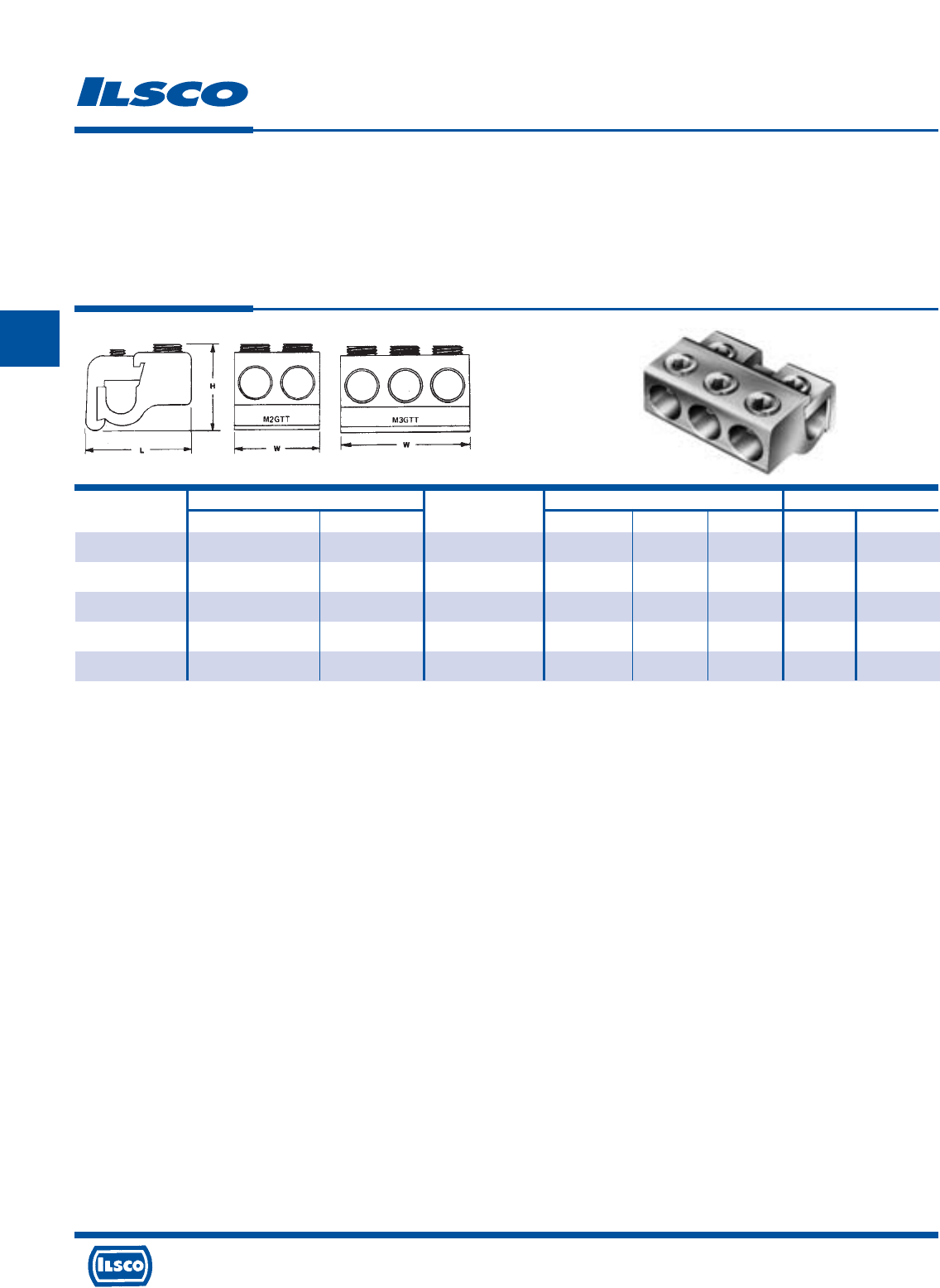
4730 Madison Road, Cincinnati, Ohio 45227-1426 Phone 513 533-6200 Fax 513 871-4084 Web site www.ilsco.com
Canada 1050 Lakeshore Road East, Mississauga, Ontario, Canada L5E1E4 Phone 905 274-2341 Fax 905 274-8763
133
C
Catalog Wire Range No. of Tap Dimensions Hex Size
Number Main Tap Openings L W H Main Tap
M2GTT-250-250 250kcmil-1/0 250kcmil-6 2 2 1-3/4 1-5/8 5/16 5/16
M2GTT-350-350 350kcmil-4/0 350kcmil-6 2 2-1/4 2 1-11/16 5/16 5/16
M3GTT-350-350 350kcmil-4/0 350kcmil-6 3 2-1/4 3 1-11/16 5/16 5/16
M2GTT-500-500 500kcmil-350kcmil 500kcmil-2 2 2-3/4 2-3/8 1-13/16 3/8 3/8
M3GTT-500-500 500kcmil-350kcmil 500kcmil-2 3 2-3/4 3-1/2 1-13/16 3/8 3/8
Multiple Tap Connector - Dual Rated
Lay-In
TYPE
MGTT
Features
•
Manufactured from high strength 6061-T6 aluminum
alloy
•
Electro-tin plated
•
Dual-Rated
•
Compact design
•
Range taking
•
Re-usable
•
Lay-in main conductor
•
Rated for 600 volts
Benefits
•
Suitable for use with either copper or aluminum
conductors
•
Provides low contact resistance
•
Can be used with copper and/or aluminum conductors
•
Saves space and reduces installation time
•
Permits inventories to be kept to a minimum
•
Provides efficient use and flexibility in the field
•
No need to break the feeder cable
•
Ensures reliability
DE-OX Inhibitor is recommended for all aluminum terminations.
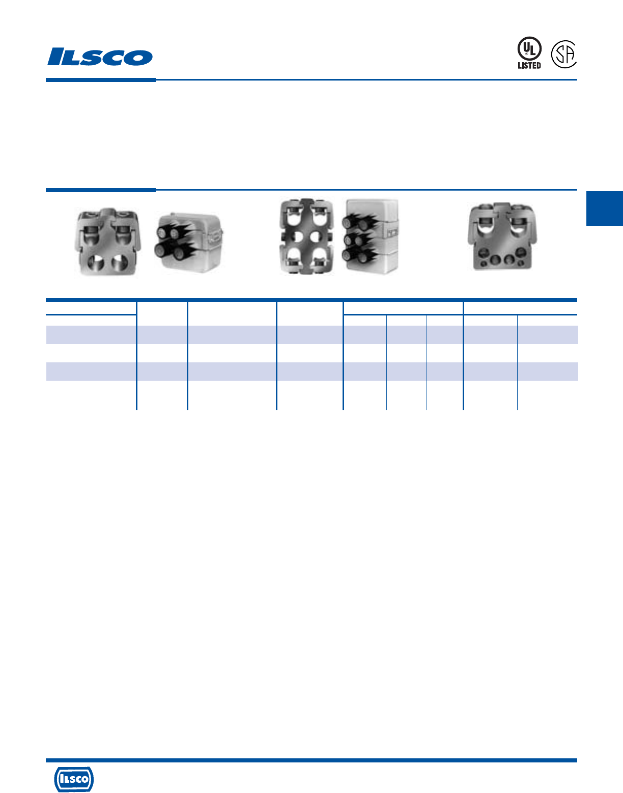
4730 Madison Road, Cincinnati, Ohio 45227-1426 Phone 513 533-6200 Fax 513 871-4084 Web site www.ilsco.com
Canada 1050 Lakeshore Road East, Mississauga, Ontario, Canada L5E1E4 Phone 905 274-2341 Fax 905 274-8763
134
C
Catalog Number Figure Main Wire Bottom Tap Wire Dimensions Hex Size
Connector Number Range Range H W D Main Tap
PTA-2-500-500-W/C 1 Two: 500kcmil-250kcmil Two: 500kcmil-4 3-15/16 3-1/2 1-1/4 3/8 3/8
PTA-2-750-500-W/C 1 Two: 750kcmil-350kcmil Two: 500kcmil-4 3-5/8 4-3/32 1-5/16 3/8 3/8
PTA-4-750-500-W/C 2 Four: 750kcmil-350kcmil Two: 500kcmil-4 5-7/8 4-3/32 1-5/16 3/8 3/8
PTA-26-500-4/0*+ 3 Two: 500kcmil-4/0 Four: 4/0-6 3-15/16 3-1/2 1-1/4 3/8 5/16
Two: 2-14 Slotted
Multiple Tap Connector - Dual Rated
TYPE
PTA
Features
•
Manufactured from high strength 6061-T6 aluminum
alloy
•
Electro-tin plated
•
UL Listed and CSA Certified for 600 volts, 90˚ C
•
Compact design
•
Range taking
•
Re-usable
•
Lay-in main conductors
•
Supplied with insulating cover
Fig. 1 Fig. 2 Fig. 3
Benefits
•
Suitable for use with either copper or aluminum
conductors
•
Provides low contact resistance
•
Ensures reliability for copper or aluminum conductors
•
Saves space and reduces installation time
•
Permits inventories to be kept to a minimum
•
Provides efficient use and flexibility in the field
•
No need to break the feeder cables
•
Eliminates taping
Note: W/C indicates product is supplied with insulating cover.
* Not CSA Certified.
+ Cover must be ordered separately. For non UL cover, order 1 each RO614WOOA and RO615WOOA.
DE-OX Inhibitor is recommended for all aluminum terminations.
Tested to UL 486A-486B, UL File E6207
453G
L
R
-
2
9
6
0
1
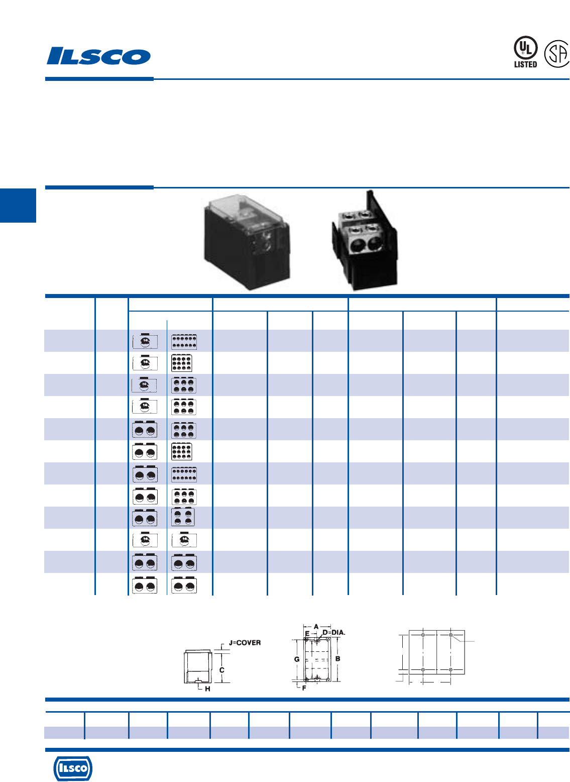
4730 Madison Road, Cincinnati, Ohio 45227-1426 Phone 513 533-6200 Fax 513 871-4084 Web site www.ilsco.com
Canada 1050 Lakeshore Road East, Mississauga, Ontario, Canada L5E1E4 Phone 905 274-2341 Fax 905 274-8763
135
C
Connector Primary Secondary Ampere
Catalog Figure Wire Openings Hex Wire Openings Hex Rating
Number Number Primary Secondary Range Per Pole Size Range Per Pole Size Per Pole
LDB-112-350 1 350kcmil-6 1 3/8 4-14 12 Slot 310
LDA-112-350 2 350kcmil-6 1 4-14 12 310
LDB-112A-350 1 350kcmil-6 1 3/8 4-14 12 Slot 310
LDA-112A-350 2 350kcmil-6 1 4-14 12 310
LDB-16-350 1 350kcmil-6 1 3/8 2/0-14 6 3/16 310
LDA-16-350 2 350kcmil-6 1 2/0-14 6 310
LDB-16-500 1 500kcmil-4 1 3/8 2/0-14 6 3/16 380
LDA-16-500 2 500kcmil-4 1 2/0-14 6 380
LDB-26-350 1 350kcmil-6 2 3/8 2/0-14 6 3/16 620
LDA-26-350 2 350kcmil-6 2 2/0-14 6 620
LDB-212-4/0 1 4/0-6 2 1/4 4-14 12 Slot 460
LDA-212-4/0 2 4/0-6 2 4-14 12 460
LDB-212-500 1 500kcmil-4 2 3/8 4-14 12 Slot 760
LDA-212-500 2 500kcmil-4 2 4-14 12 760
LDB-26-500 1 500kcmil-4 2 3/8 2/0-14 6 3/16 760
LDA-26-500 2 500kcmil-4 2 2/0-14 6 760
LDB-24-500 1 500kcmil-4 2 3/8 4/0-6 4 5/16 760
LDA-24-500 2 500kcmil-4 2 4/0-6 4 760
LDB-11-500 1 500kcmil-4 1 3/8 500kcmil-4 1 3/8 380
LDA-11-500 2 500kcmil-4 1 500kcmil-4 1 380
LDB-22-350 1 350kcmil-6 2 3/8 350kcmil-6 2 3/8 620
LDA-22-350 2 350kcmil-6 2 350kcmil-6 2 620
LDB-22-500 1 500kcmil-4 2 3/8 500kcmil-4 2 3/8 760
LDA-22-500 2 500kcmil-4 2 500kcmil-4 2 760
Snapbloc®Power Distribution Blocks
Modular Design - Dual Rated
TYPE
LDA
LDB
Features
•
Modular design
•
Easy to assemble
•
UL listed 90˚ C 600 Volts and is CSA Certified
•
Electro-tin plated 6061-T6 aluminum alloy
•
Clear cover
•
Multiple conductor capability
Benefits
•
Simplifies stocking. Combines any number of blocks with multiple
conductor ranges into the specific configuration required for the job.
•
Unique locking feature allows individual blocks to be combined quickly
without special tools
•
Ensures reliability
•
Suitable for use with both copper and aluminum conductors in any
combination
•
Permits visual inspection
•
Individual blocks supplied in a variety of configurations with one or two
main cable ports and four, six, or twelve taps. All are range taking.
45U4
L
R
-
2
9
6
0
1
Dimensions
A B C D=Dia. E F G H J = Cover K L M N
3 5-1/2 3-7/16 .28 Slot 1-1/2 5/16 4-7/8 1/4 1/2 4.75 2.69 .38 1.50
Side Panel can be ordered separately Cat. No. LDS-1
Tested to UL 1059, UL File E112158
K
TYP.
L
1/4 BOLT
N
M
Fig. 1 Fig. 2
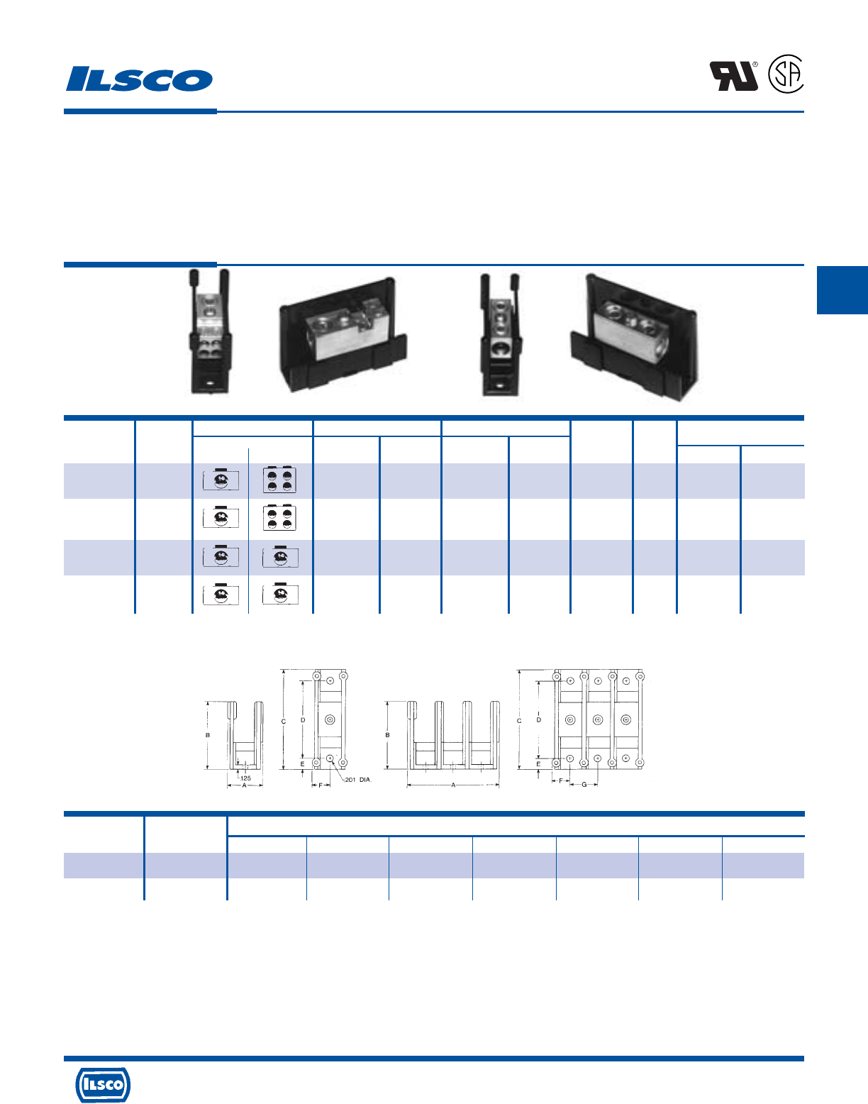
4730 Madison Road, Cincinnati, Ohio 45227-1426 Phone 513 533-6200 Fax 513 871-4084 Web site www.ilsco.com
Canada 1050 Lakeshore Road East, Mississauga, Ontario, Canada L5E1E4 Phone 905 274-2341 Fax 905 274-8763
136
C
Connector Primary Secondary Ampere No.
Catalog Figure Wire Openings Wire Openings Rating of Hex Size
Number Number Primary Secondary Range Per Pole Range Per Pole Per Pole Poles Primary Secondary
PDC-14-2/0-1 1 2/0-14 1 4-14 4 175 1 3/16 Slot
PDA-14-2/0-1 2 2/0-14 1 4-14 4 175 Adder 3/16 Slot
PDC-11-2/0-1 3 2/0-14 1 2/0-14 1 175 1 3/16 3/16
PDA-11-2/0-1 4 2/0-14 1 2/0-14 1 175 Adder 3/16 3/16
Modular Type Power Distribution Blocks
Dual Rated
TYPE
PDA
PDC
Features
•
Modular design
•
Easy to assemble
•
UL Recognized 90˚ C 600 Volts and is CSA Certified
•
Electro-tin plated
•
Lexan* insulating base
•
Manufactured from high strength 6061-T6 aluminum
alloy
Fig. 1 Fig. 2 Fig. 3 Fig. 4
Benefits
•
Simplifies stocking. Combines any number of blocks
with multiple conductor ranges into the specific
configuration required for the job.
•
Unique locking feature allows individual blocks to be
combined quickly without special tools
•
Ensures reliability
•
Provides low contact resistance
•
Provides a high degree of impact resistance with
superior insulating qualities
•
Suitable for use with either copper or aluminum
conductors
Block No. of Dimensions
Size Poles A B C D E F G
S 1 1.05 1.94 2.88 2.25 .31 .53 .80
S 2 1.85 1.94 2.88 2.25 .31 .53 .80
"A" Dimension increases by .80 per additional pole.
Covers available 1-10 Poles. Specify length.
*Lexan is a registered trademark of SABIC INNOVATIVE PLASTICS HOLDINGS BV.
Tested to UL 486A-486B, UL File E84782
L
R
-
2
9
6
0
1
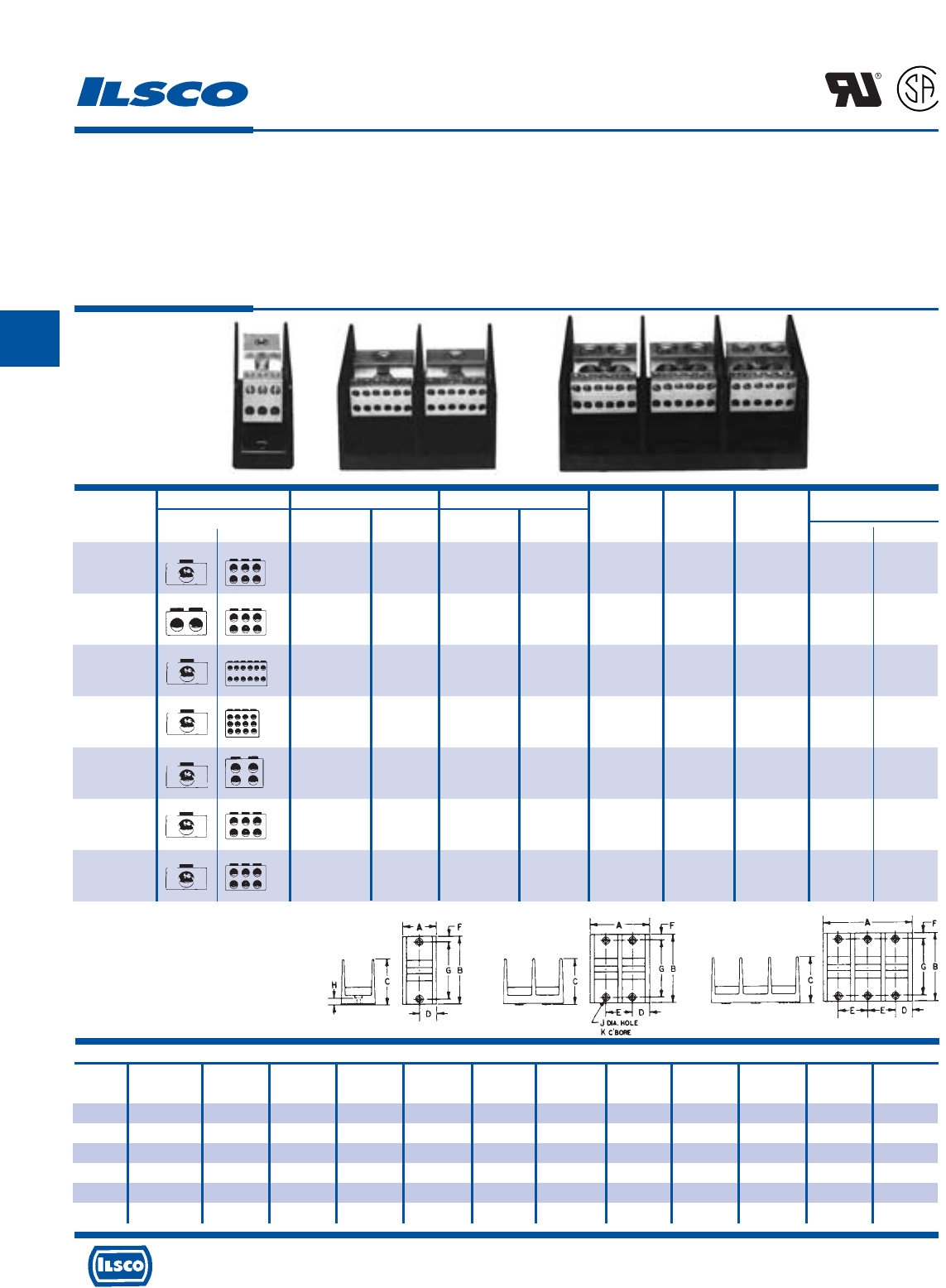
4730 Madison Road, Cincinnati, Ohio 45227-1426 Phone 513 533-6200 Fax 513 871-4084 Web site www.ilsco.com
Canada 1050 Lakeshore Road East, Mississauga, Ontario, Canada L5E1E4 Phone 905 274-2341 Fax 905 274-8763
137
C
Connector Primary Secondary Ampere
Catalog Wire Openings Wire Openings Rating Number Block Hex Size
Number Primary Secondary Range Per Pole Range Per Pole Per Pole Of Poles Size Primary Secondary
PDB-16-2/0-1 2/0-12 1 4-14 6 175 1 M
PDB-16-2/0-2 2/0-12 1 4-14 6 175 2 M 3/16 Slot
PDB-16-2/0-3 2/0-12 1 4-14 6 175 3 M
PDB-26-2/0-1 2/0-12 2 2-14 6 350 1 M
PDB-26-2/0-2 2/0-12 2 2-14 6 350 2 M 3/16 Slot
PDB-26-2/0-3 2/0-12 2 2-14 6 350 3 M
PDB-112-350-1 350kcmil-6 1 4-14 12 310 1 L
PDB-112-350-2 350kcmil-6 1 4-14 12 310 2 L 3/8 Slot
PDB-112-350-3 350kcmil-6 1 4-14 12 310 3 L
PDB-112A-350-1 350kcmil-6 1 4-14 12 310 1 M
PDB-112A-350-2 350kcmil-6 1 4-14 12 310 2 M 3/8 Slot
PDB-112A-350-3 350kcmil-6 1 4-14 12 310 3 M
PDB-14-500-1 500kcmil-4 1 2/0-14 4 380 1 M
PDB-14-500-2 500kcmil-4 1 2/0-14 4 380 2 M 3/8 3/16
PDB-14-500-3 500kcmil-4 1 2/0-14 4 380 3 M
PDB-16-350-1 350kcmil-6 1 2/0-14 6 310 1 L
PDB-16-350-2 350kcmil-6 1 2/0-14 6 310 2 L 3/8 3/16
PDB-16-350-3 350kcmil-6 1 2/0-14 6 310 3 L
PDB-162-500-1 500kcmil-4 1 2-14 6 380 1 M
PDB-162-500-2 500kcmil-4 1 2-14 6 380 2 M 3/8 Slot
PDB-162-500-3 500kcmil-4 1 2-14 6 380 3 M
Dimensions
Block Number Figure
Size Of Poles Number A B C D E F G H J K
M 1 1 1-27/32 4 2-5/8 31/32 - 5/16 3-3/8 3/8 13/64 13/32
M 2 2 3-13/32 4 2-5/8 31/32 1-17/32 5/16 3-3/8 3/8 13/64 13/32
M3 3542-5/831/32 1-17/32 5/16 3-3/8 3/8 13/64 13/32
L 1 1 3 5-1/2 3-1/2 1-1/2 - 3/8 4-3/4 7/16 9/32 1/2
L 2 2 5-11/16 5-1/2 3-1/2 1-1/2 2-11/16 3/8 4-3/4 7/16 9/32 1/2
L 3 3 8-3/8 5-1/2 3-1/2 1-1/2 2-11/16 3/8 4-3/4 7/16 9/32 1/2
Power Distribution Blocks - Dual Rated
TYPE
PDB
Features
•
Range taking
•
Valox* insulating base
•
Electro-tin plated
•
Manufactured from high strength 6061-T6
aluminum alloy
•
UL Recognized rated 90˚ C and is CSA Certified,
rated for 600 volts
Benefits
•
Provides great flexibility in using the connector as an in line
splice or to reduce conductor size
•
Provides a high degree of impact resistance with superior
insulating qualities
•
Provides low contact resistance
•
Suitable for use with either copper or aluminum conductors
•
Ensures reliability
L
R
-
2
9
6
0
1
Fig. 1 Fig. 2 Fig. 3
* Valox®is a registered trade name of the General Electric Company.
Tested to UL 486A-486B, UL File E84782
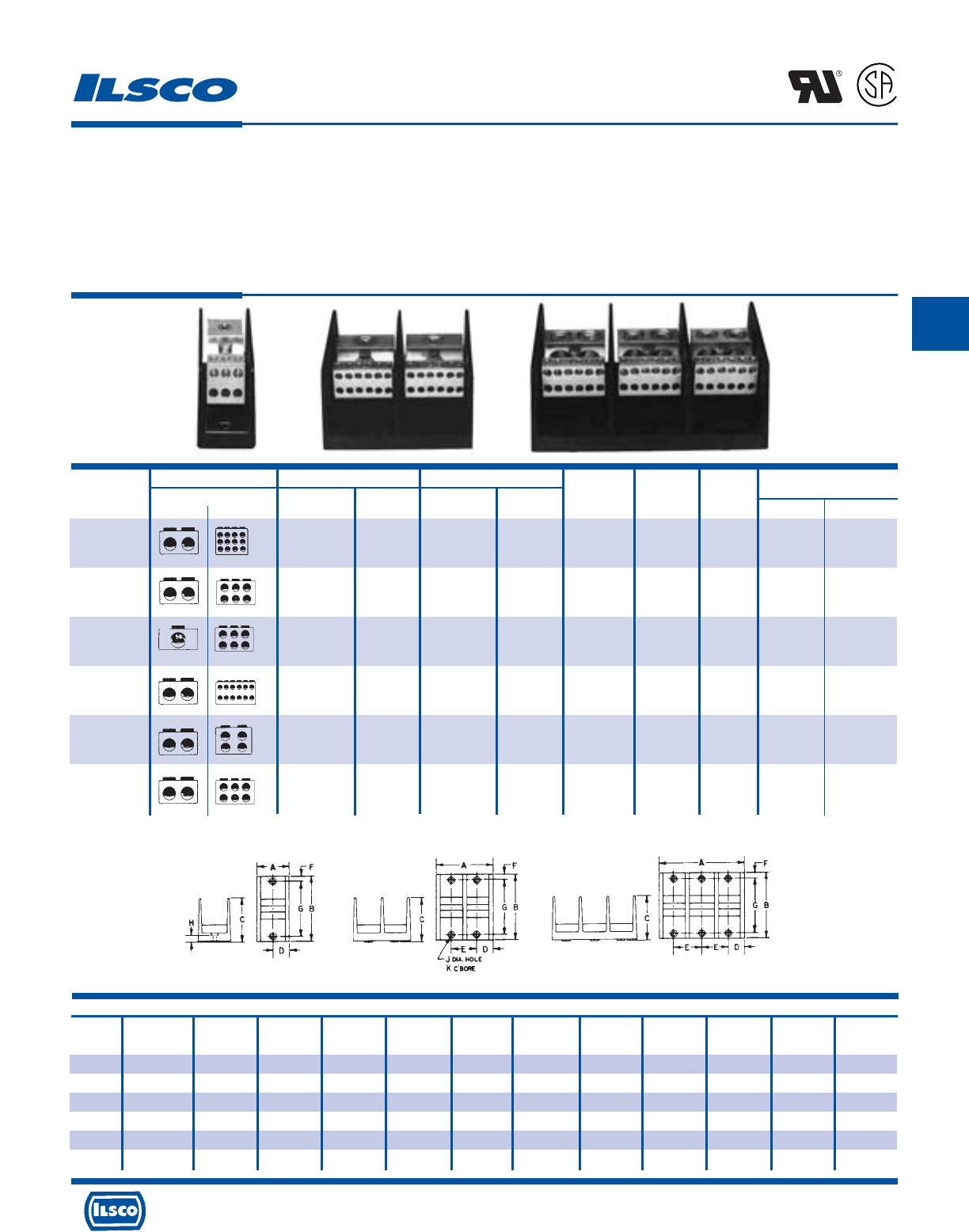
4730 Madison Road, Cincinnati, Ohio 45227-1426 Phone 513 533-6200 Fax 513 871-4084 Web site www.ilsco.com
Canada 1050 Lakeshore Road East, Mississauga, Ontario, Canada L5E1E4 Phone 905 274-2341 Fax 905 274-8763
138
C
Dimensions
Block Number Figure
Size Of Poles Number A B C D E F G H J K
M 1 1 1-27/32 4 2-5/8 31/32 - 5/16 3-3/8 3/8 13/64 13/32
M 2 2 3-13/32 4 2-5/8 31/32 1-17/32 5/16 3-3/8 3/8 13/64 13/32
M3 3542-5/831/32 1-17/32 5/16 3-3/8 3/8 13/64 13/32
L 1 1 3 5-1/2 3-1/2 1-1/2 - 3/8 4-3/4 7/16 9/32 1/2
L 2 2 5-11/16 5-1/2 3-1/2 1-1/2 2-11/16 3/8 4-3/4 7/16 9/32 1/2
L 3 3 8-3/8 5-1/2 3-1/2 1-1/2 2-11/16 3/8 4-3/4 7/16 9/32 1/2
Connector Primary Secondary Ampere
Catalog Wire Openings Wire Openings Rating Number Block Hex Size
Number Primary Secondary Range Per Pole Range Per Pole Per Pole Of Poles Size Primary Secondary
PDB-212-4/0-1 4/0-6 2 4-14 12 460 1 M
PDB-212-4/0-2 4/0-6 2 4-14 12 460 2 M 3/8 Slot
PDB-212-4/0-3 4/0-6 2 4-14 12 460 3 M
PDB-26-350-1 350kcmil-6 2 2/0-14 6 620 1 L
PDB-26-350-2 350kcmil-6 2 2/0-14 6 620 2 L 3/8 3/16
PDB-26-350-3 350kcmil-6 2 2/0-14 6 620 3 L
PDB-16-500-1 500kcmil-4 1 2/0-14 6 380 1 L
PDB-16-500-2 500kcmil-4 1 2/0-14 6 380 2 L 3/8 3/16
PDB-16-500-3 500kcmil-4 1 2/0-14 6 380 3 L
PDB-212-500-1 500kcmil-4 2 4-14 12 760 1 L
PDB-212-500-2 500kcmil-4 2 4-14 12 760 2 L 3/8 Slot
PDB-212-500-3 500kcmil-4 2 4-14 12 760 3 L
PDB-24-500-1 500kcmil-4 2 4/0-6 4 760 1 L
PDB-24-500-2 500kcmil-4 2 4/0-6 4 760 2 L 3/8 5/16
PDB-24-500-3 500kcmil-4 2 4/0-6 4 760 3 L
PDB-26-500-1 500kcmil-4 2 2/0-14 6 760 1 L
PDB-26-500-2 500kcmil-4 2 2/0-14 6 760 2 L 3/8 3/16
PDB-26-500-3 500kcmil-4 2 2/0-14 6 760 3 L
Power Distribution Blocks - Dual Rated
TYPE
PDB
Features
•
Range taking
•
Valox* insulating base
•
Electro-tin plated
•
Manufactured from high strength 6061-T6
aluminum alloy
•
UL Recognized rated 90˚ C and is CSA Certified,
rated for 600 volts
Benefits
•
Provides great flexibility in using the connector as an in line
splice or to reduce conductor size
•
Provides a high degree of impact resistance with superior
insulating qualities
•
Provides low contact resistance
•
Suitable for use with either copper or aluminum conductors
•
Ensures reliability
* Valox®is a registered trade name of the General Electric Company.
Tested to UL 486A-486B, UL File E84782
L
R
-
2
9
6
0
1
Fig. 1 Fig. 2 Fig. 3
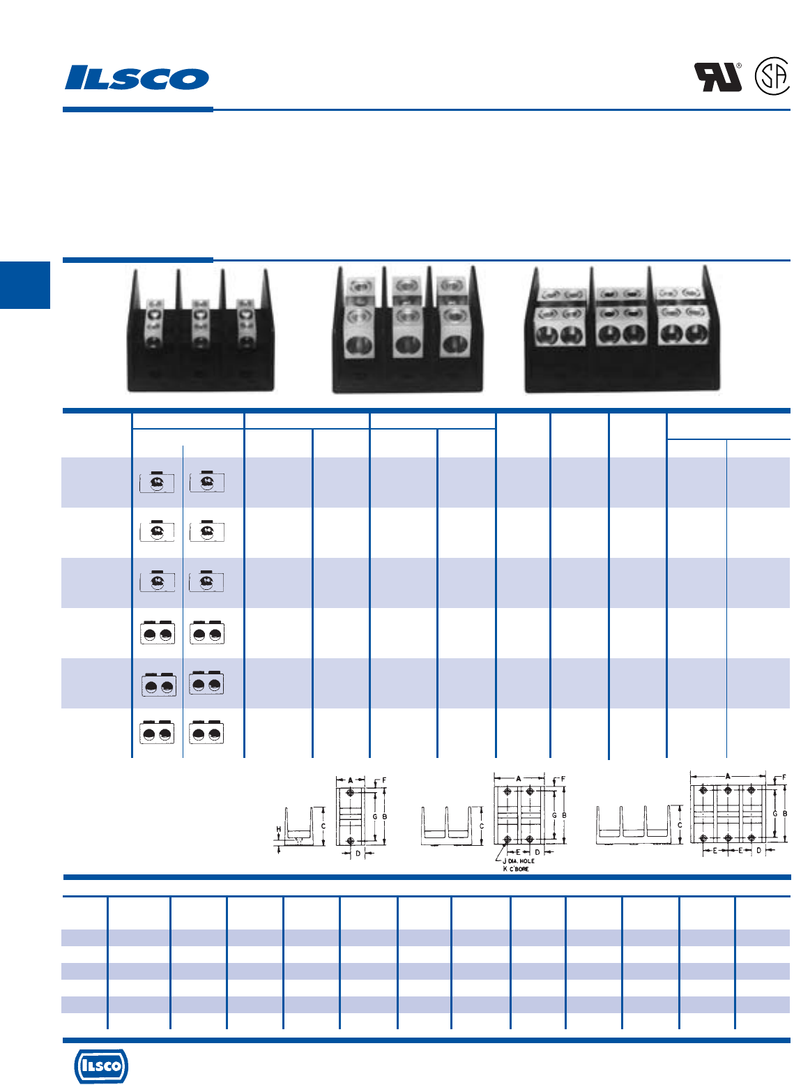
4730 Madison Road, Cincinnati, Ohio 45227-1426 Phone 513 533-6200 Fax 513 871-4084 Web site www.ilsco.com
Canada 1050 Lakeshore Road East, Mississauga, Ontario, Canada L5E1E4 Phone 905 274-2341 Fax 905 274-8763
139
C
Dimensions
Block Number Figure
Size Of Poles Number A B C D E F G H J K
M 1 1 1-27/32 4 2-5/8 31/32 - 5/16 3-3/8 3/8 13/64 13/32
M 2 2 3-13/32 4 2-5/8 31/32 1-17/32 5/16 3-3/8 3/8 13/64 13/32
M3 3542-5/831/32 1-17/32 5/16 3-3/8 3/8 13/64 13/32
L 1 1 3 5-1/2 3-1/2 1-1/2 - 3/8 4-3/4 7/16 9/32 1/2
L 2 2 5-11/16 5-1/2 3-1/2 1-1/2 2-11/16 3/8 4-3/4 7/16 9/32 1/2
L 3 3 8-3/8 5-1/2 3-1/2 1-1/2 2-11/16 3/8 4-3/4 7/16 9/32 1/2
Connector Primary Secondary Ampere
Catalog Wire Openings Wire Openings Rating Number Block Hex Size
Number Primary Secondary Range Per Pole Range Per Pole Per Pole Of Poles Size Primary Secondary
PDB-11-2/0-1 2/0-14 1 2/0-14 1 175 1 M
PDB-11-2/0-2 2/0-14 1 2/0-14 1 175 2 M 3/16 3/16
PDB-11-2/0-3 2/0-14 1 2/0-14 1 175 3 M
PDB-11-350-1 350kcmil-6 1 350kcmil-6 1 310 1 M
PDB-11-350-2 350kcmil-6 1 350kcmil-6 1 310 2 M 3/8 3/8
PDB-11-350-3 350kcmil-6 1 350kcmil-6 1 310 3 M
PDB-11-500-1 500kcmil-4 1 500kcmil-4 1 380 1 L
PDB-11-500-2 500kcmil-4 1 500kcmil-4 1 380 2 L 3/8 3/8
PDB-11-500-3 500kcmil-4 1 500kcmil-4 1 380 3 L
PDB-22-2/0-1 2/0-14 2 2/0-14 2 350 1 M
PDB-22-2/0-2 2/0-14 2 2/0-14 2 350 2 M 3/16 3/16
PDB-22-2/0-3 2/0-14 2 2/0-14 2 350 3 M
PDB-22-350-1 350kcmil-6 2 350kcmil-6 2 620 1 L
PDB-22-350-2 350kcmil-6 2 350kcmil-6 2 620 2 L 3/8 3/8
PDB-22-350-3 350kcmil-6 2 350kcmil-6 2 620 3 L
PDB-22-500-1 500kcmil-4 2 500kcmil-4 2 760 1 L
PDB-22-500-2 500kcmil-4 2 500kcmil-4 2 760 2 L 3/8 3/8
PDB-22-500-3 500kcmil-4 2 500kcmil-4 2 760 3 L
Power Distribution Blocks - Dual Rated
TYPE
PDB
Features
•
Multiple taps
•
Range taking
•
Valox* insulating base
•
Electro-tin plated
•
Manufactured from high strength 6061-T6
aluminum alloy
•
UL Recognized rated 90˚ C and is CSA Certified,
rated for 600 volts
Benefits
•
Depending on product selected, up to twelve taps can be
taken from one or two mains
•
Provides tapping flexibility over a broad wire range
•
Provides a high degree of impact resistance with superior
insulating qualities
•
Provides low contact resistance
•
Suitable for use with either copper or aluminum conductors
•
Ensures reliability
* Valox®is a registered trade name of the
General Electric Company.
Tested to UL 486A-486B, UL File E84782
L
R
-
2
9
6
0
1
Fig. 1 Fig. 2 Fig. 3
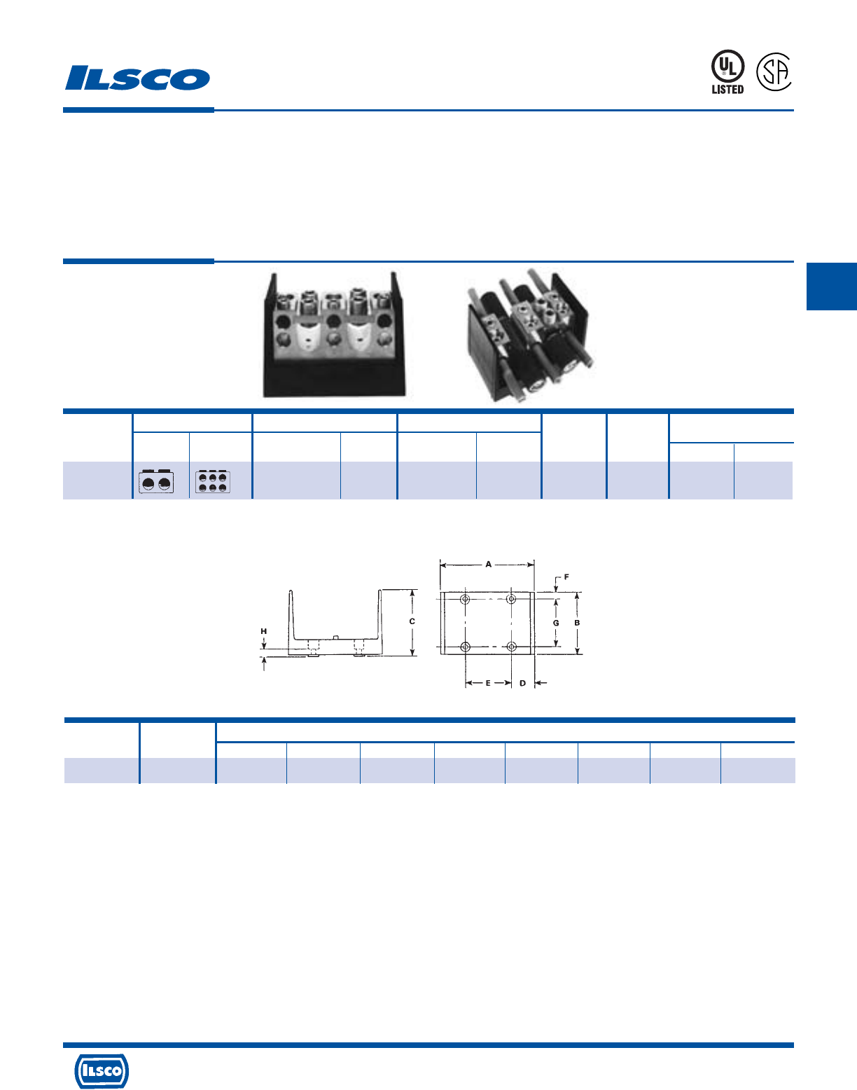
4730 Madison Road, Cincinnati, Ohio 45227-1426 Phone 513 533-6200 Fax 513 871-4084 Web site www.ilsco.com
Canada 1050 Lakeshore Road East, Mississauga, Ontario, Canada L5E1E4 Phone 905 274-2341 Fax 905 274-8763
140
C
Connector Primary Secondary Ampere Number
Catalog Wire Openings Wire Openings Rating Of Hex Size
Number Primary Secondary Range Per Pole Range Per Pole Per Pole Poles Primary Secondary
PDB-26-750-1 750kcmil-250kcmil 2 250kcmil-6 6 950 1 3/8 1/4
Lay-In Type Power Distribution Blocks
Dual Rated
TYPE
PDB
Features
•
Lay-In primary cable ports
•
Valox insulating base
•
Clear cover
•
UL 1953 Listed and CSA Certified for 600 volts
•
Electro-tin plated
•
Manufactured from high strength 6061-T6 aluminum
alloy
Benefits
•
Designed for feed through of two primary conductors and up to six taps
with no need to break the main feeder cable
•
Provides a high degree of impact resistance with superior insulating
qualities
•
Permits visual inspection
•
Ensures reliability
•
Provides low contact resistance
•
Suitable for use with either copper or aluminum conductors
Tested to UL 486A-486B, UL File E112158
* Valox®is a registered trade name of the General Electric Company.
45U4
L
R
-
2
9
6
0
1
Block No. of Dimensions
Size Poles A B C D E F G H
W 1 6-7/32 4 4-3/8 1-19/32 3 3/8 3-1/4 7/16
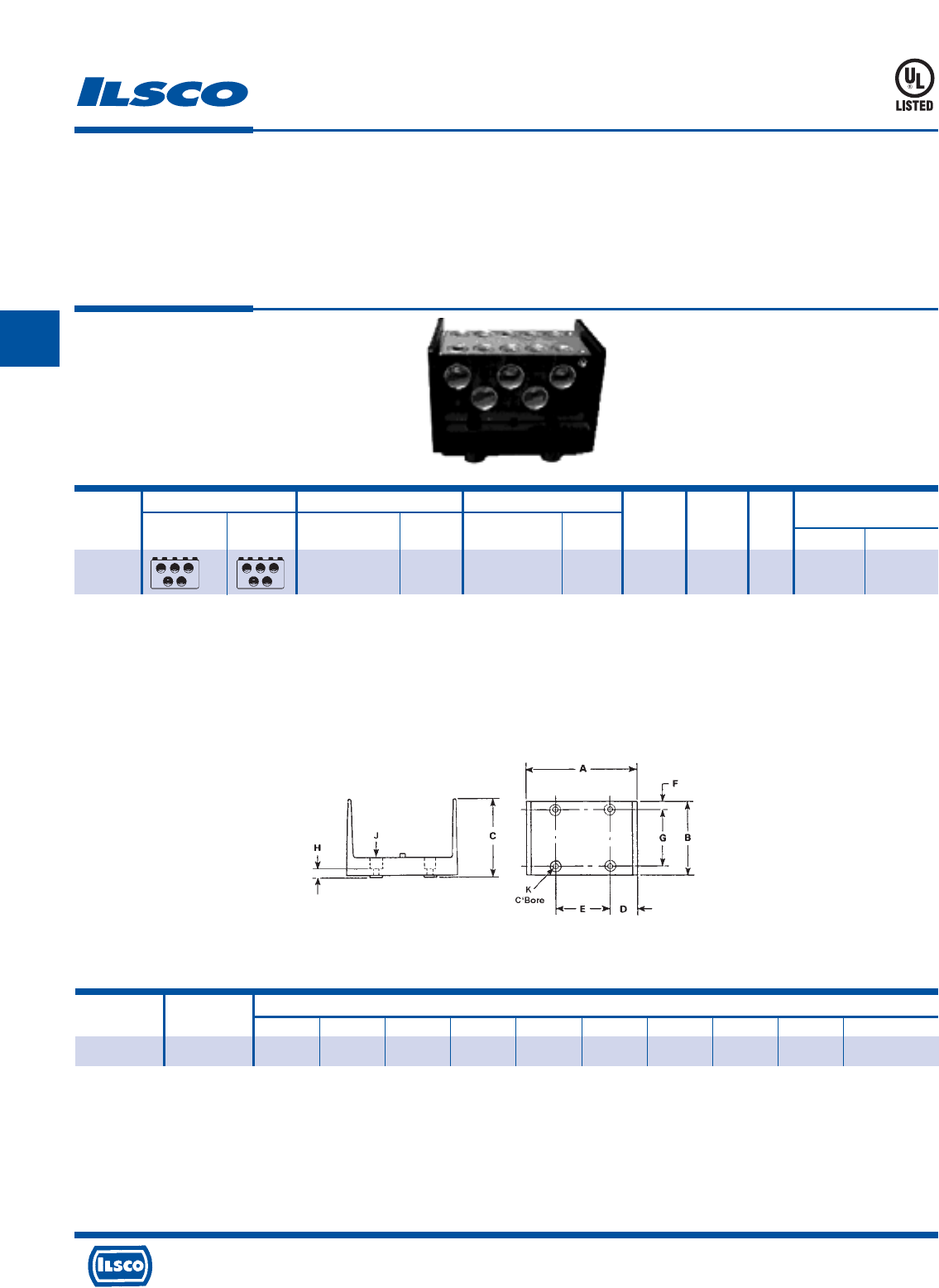
4730 Madison Road, Cincinnati, Ohio 45227-1426 Phone 513 533-6200 Fax 513 871-4084 Web site www.ilsco.com
Canada 1050 Lakeshore Road East, Mississauga, Ontario, Canada L5E1E4 Phone 905 274-2341 Fax 905 274-8763
141
C
Connector Primary Secondary Ampere Number
Catalog Wire Openings Wire Openings Rating Of Block Hex Size
Number Primary Secondary Range Per Pole Range Per Pole Per Pole Poles Size Primary Secondary
PDB-55-600
-1 600kcmil-250kcmil 5 600kcmil-250kcmil 5 1900 1 W 3/8 3/8
Aluminum Power Distribution Blocks
Copper Only
Features
•
Manufactured from high strength 6061-T6 aluminum
alloy
•
Valox* insulating base
•
UL 1953 Listed 90˚ C 600 volts
•
Electro-tin plated
•
Clear cover
Benefits
•
Reliable use for copper conductor only
•
Provides a high degree of impact resistance with superior
insulating qualities
•
Ensures reliability
•
Provides low contact resistance
•
Provides visual inspection
45U4
Valox®is a registered trade name of the General Electric Company.
A versatile tap hole, wire range 8-14 AWG included on the connector.
Tested to UL 486A-486B, UL File E112158
Block No. of Dimensions
Size Poles A B C D E F G H J K
W 1 6-7/32 4 4-3/8 1-19/32 3 3/8 3-1/4 7/16 9/32 9/16
TYPE
PDB
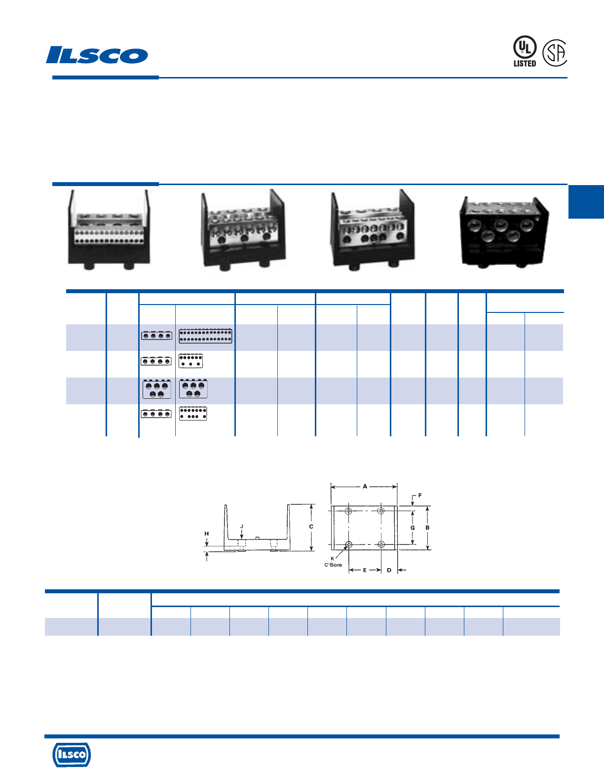
4730 Madison Road, Cincinnati, Ohio 45227-1426 Phone 513 533-6200 Fax 513 871-4084 Web site www.ilsco.com
Canada 1050 Lakeshore Road East, Mississauga, Ontario, Canada L5E1E4 Phone 905 274-2341 Fax 905 274-8763
142
C
Connector Primary Secondary Ampere Number
Catalog Figure Wire Openings Wire Openings Rating of Block Hex Size
Number Number Primary Secondary Range Per Pole Range Per Pole Per Pole Poles Size Primary Secondary
PDB-428-500
-1 1 500kcmil-4 4 4-14 28 1520 1 W 3/8 Slot
PDB-49-500
-1 2 500kcmil-4 4 350kcmil-6 6 1520 1 W 3/8 3/8
4/0-6 3 5/16
PDB-55-500-1
4 500kcmil-3/0 5 500kcmil-3/0 5 1600 1 W 3/8 3/8
PDB-412-500-1
3 500kcmil-4 4 4/0-6 12 1520 1 W 3/8 5/16
Power Distribution Blocks - Dual Rated
Features
•
Multiple taps
•
Valox* insulating base
•
Clear cover
•
UL 1953 Listed 90˚ C 600 Volts and is CSA Certified
•
Electro-tin plated
•
Manufactured from high strength 6061-T6 aluminum
alloy
Benefits
•
Three different connector configurations provide a wide range of tapping
capabilities for up to four primary conductors
•
Provides a high degree of impact resistance with superior insulating
qualities
•
Permits visual inspection
•
Ensures reliability
•
Provides low contact resistance
•
Suitable for use with either copper or aluminum conductors
45U4
L
R
-
2
9
6
0
1
Valox®is a registered trade name of the General Electric Company.
° A versatile tap hole, wire range 8-14 AWG included on the connector.
‡ Not CSA Certified
Tested to UL 486A-486B, UL File E112158
TYPE
PDB
‡°
Fig. 1 Fig. 2 Fig. 3 Fig. 4
Block No. of Dimensions
Size Poles A B C D E F G H J K
W 1 6-7/32 4 4-3/8 1-19/32 3 3/8 3-1/4 7/16 9/32 9/16
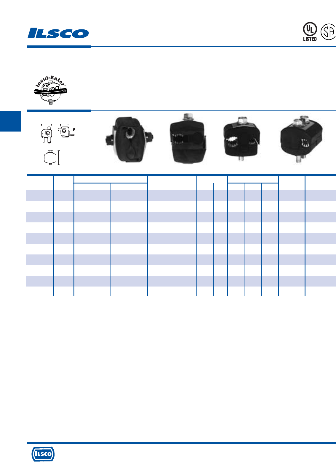
4730 Madison Road, Cincinnati, Ohio 45227-1426 Phone 513 533-6200 Fax 513 871-4084 Web site www.ilsco.com
Canada 1050 Lakeshore Road East, Mississauga, Ontario, Canada L5E1E4 Phone 905 274-2341 Fax 905 274-8763
143
C
WL
H
Catalog Figure Wire Range Current Rating Dimensions Torque Bolt Head
Number Number Main Tap Volts CU AL L W H Ft. Lbs. Size
IPC-1/0-2 3 1/0-8 2-8 300
(480 Grounded Y System)
130 100 1-7/32 1-15/32 2-5/16 16 1/2
IPC-4/0-6 2 4/0-4 6-14 600 75 60 1-27/64 1 1-7/8 13 1/2
IPC-4/0-2/0 3 4/0-2 2/0-6 600 195 150 1-21/32 1-7/8 2-7/8 25 1/2
IPC-250-4/0 2 250kcmil-1 4/0-6 600 260 205 1-7/8 2-11/32 3-11/32 30 5/8
IPC-350-4/0 3 350kcmil-4/0 4/0-10 300
(480 Grounded Y System)
260 205 1-43/64 2-7/16 3-1/8 25 5/8
IPC-350-350 4 350kcmil-4/0 350kcmil-4/0 300
(480 Grounded Y System)
350 280 2-43/64 2-23/32 3-1/4 25 5/8
IPC-500-12 1 500kcmil-250kcmil 10-12 300
(480 Grounded Y System)
40 35 1-43/64 2-7/16 3-1/4 25 5/8
IPC-500-250 1 500kcmil-250kcmil 250kcmil-4 600 290 230 2-27/64 2-29/32 3-3/4 55 5/8-11/16
IPC-500-500 1 500kcmil-300kcmil 500kcmil-250kcmil 600 430 350 3-3/16 3-5/8 5 75 7/8-7/8
IPC-750-500 1 750kcmil-500kcmil 500kcmil-350kcmil 600 430 350 3-3/16 3-5/8 5 75 7/8-7/8
KUP-L-Tap®Insulation Piercing Connectors
Dual Rated
TYPE
IPC
Features
•
Body is molded from tough, resilient glass-filled nylon
•
Compact design
•
Tin plated copper contact teeth
•
Insulation piercing
•
Perforated end tabs
•
Pre-filled with silicone lubricant
•
Versatile
•
Increased safety
•
Horizontal line grid
•
Temperature rating 90˚ C
Fig. 1 Fig. 2 Fig. 3 Fig. 4
Benefits
•
Provides high degree of breakage resistance and long dependable use
•
Saves space
•
Easily penetrates most types of insulation
•
No need to strip the conductor which saves installation time
•
Break out easily by hand
•
Prevents oxidation and moisture from entering the contact area
•
Can be used as a splice or tap connector
•
Contains no external energized parts. Can be installed “hot” on energized
conductors providing tap conductor is not under load.
•
Provides a visual guide for proper installation of conductors
923F
L
R
-
2
4
3
5
9
Tested to UL 486A-486B, UL File E6207
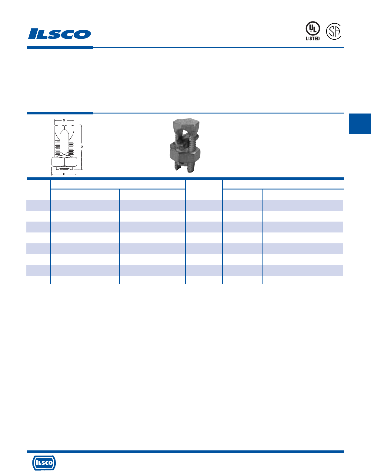
4730 Madison Road, Cincinnati, Ohio 45227-1426 Phone 513 533-6200 Fax 513 871-4084 Web site www.ilsco.com
Canada 1050 Lakeshore Road East, Mississauga, Ontario, Canada L5E1E4 Phone 905 274-2341 Fax 905 274-8763
144
C
Wire Range Recommended Dimensions
Catalog Tightening
Number Main Tap Torque B C D
AK-6 6 str-10 sol 6 str-10 sol 165 .56 .75 1.88
AK-4 4 str-8 sol 4 str-10 sol 165 .62 .81 1.38
AK-2 2 str-6 str Compact 2 str-8 str 275 .69 .94 1.58
AK-1/0 1/0 str-2 str Compact 1/0 str-8 str 385 .75 1.00 1.92
AK-2/0 2/0 str-2 str Compact 2/0 str-8 str 385 .88 1.12 1.92
AK-4/0 4/0 str-2 str Compact 4/0 str-6 str 500 1.13 1.49 2.54
AK-350 350kcmil-1/0 str Compact 350kcmil-4 str 650 1.50 1.69 3.24
AK-500 500kcmil-400kcmil Compact 500kcmil-2 str Compact 825 1.73 2.00 3.62
Aluminum Split Bolt - Dual Rated
TYPE
AK
Features
•
Manufactured from heat treated aluminum alloy
•
Triangular edges
•
UL Listed and CSA Certified for 600 volts, 90˚ C
•
Electro-tin plated
•
Spacer bar
•
Hex Head
Benefits
•
Provides maximum conductivity and strength for
copper and aluminum conductors
•
Bite into the conductor to break through surface oxides
which eliminates wire brushing
•
Ensures reliability for copper or aluminum conductors
•
Provides low contact resistance
•
Separates dissimilar metals which prevents galvanic
corrosion
•
Provides ease of installation with standard wrenches
670B
7
2
6
3
2
DE-OX Inhibitor is recommended for all aluminum terminations.
UL File E9998
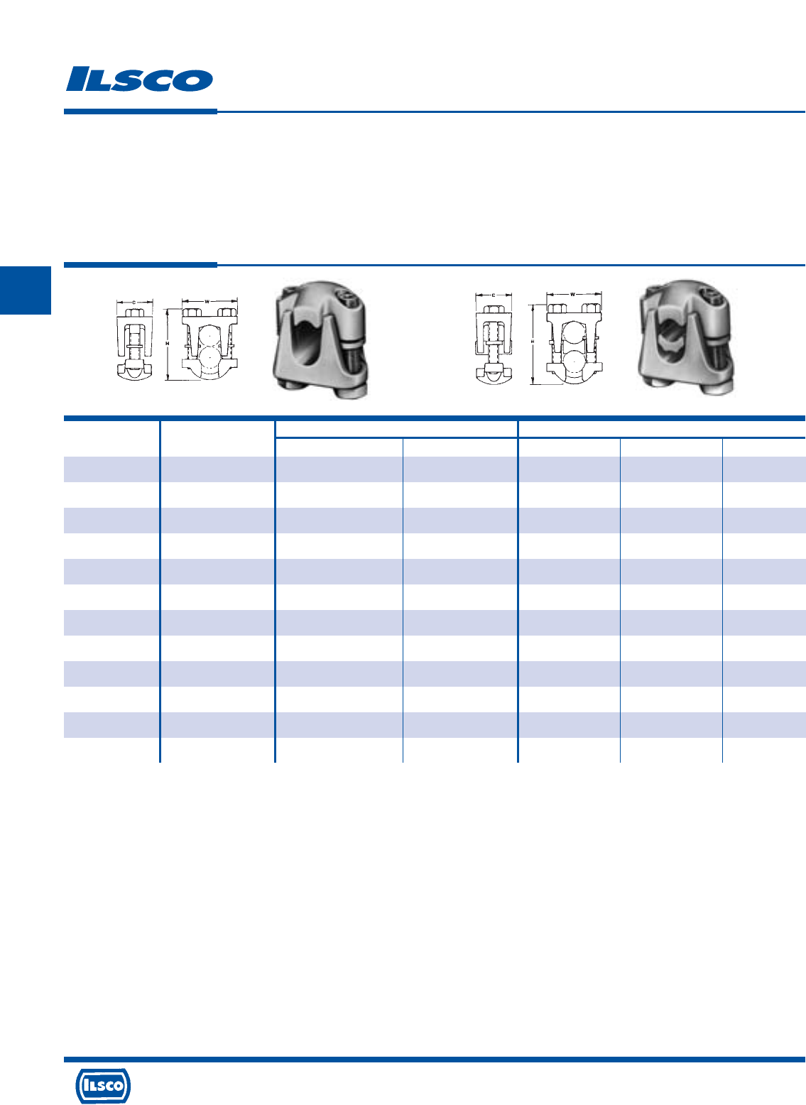
4730 Madison Road, Cincinnati, Ohio 45227-1426 Phone 513 533-6200 Fax 513 871-4084 Web site www.ilsco.com
Canada 1050 Lakeshore Road East, Mississauga, Ontario, Canada L5E1E4 Phone 905 274-2341 Fax 905 274-8763
145
C
Fig. 1 Fig. 2
Catalog Figure Wire Range Dimensions
Number Number Main Tap C W H
DBA-2/0 1 2/0-2 2/0-10 1-1/8 1-5/8 1-5/8
DBA-250 1 250kcmil-1/0 250kcmil-10 1-5/16 2 2
DBA-350 1 350kcmil-4/0 350kcmil-10 1-9/16 2-11/32 2-1/4
DBA-500 1 500kcmil-350kcmil 500kcmil-10 1-3/4 2-1/2 2-3/4
DBA-800 1 800kcmil-400kcmil 800kcmil-3/0 1-7/8 2-7/8 3
DBA-1000 1 1000kcmil-500kcmil 1000kcmil-3/0 2-1/4 3-3/16 3-1/2
DBA-2/0S 2 2/0-2 2/0-10 1-1/8 1-5/8 1-5/8
DBA-250S 2 250kcmil-1/0 250kcmil-10 1-5/16 2 2
DBA-350S 2 350kcmil-4/0 350kcmil-10 1-9/16 2-11/32 2-1/4
DBA-500S 2 500kcmil-350kcmil 500kcmil-10 1-3/4 2-1/2 2-3/4
DBA-800S 2 800kcmil-400kcmil 800kcmil-3/0 1-7/8 2-7/8 3
DBA-1000S 2 1000kcmil-500kcmil 1000kcmil-3/0 2-1/4 3-3/16 3-1/2
Aluminum Two Bolt Connectors - Dual Rated
TYPE
DBA
DBA-S
Features
•
Manufactured from high strength aluminum alloy
•
Heat treated
•
Wax plated
•
Neoprene washers
•
Range taking
•
Re-usable
•
Type DBA-S - Spacer bar
•
Rated for 600 volts
Benefits
•
Type DBA - Suitable for copper to copper or aluminum to aluminum
conductors
Type DBA-S - Suitable for copper and/or aluminum conductors in any
combination
•
Provides maximum strength
•
Provides low contact resistance
•
Hold the bolts captive and eliminates the possibility of loose hardware
•
Permits inventories to be kept to a minimum
•
Provides efficient use and flexibility in the field
•
Separates dissimilar metals
•
Ensures reliability
DE-OX Inhibitor is recommended for all aluminum terminations.
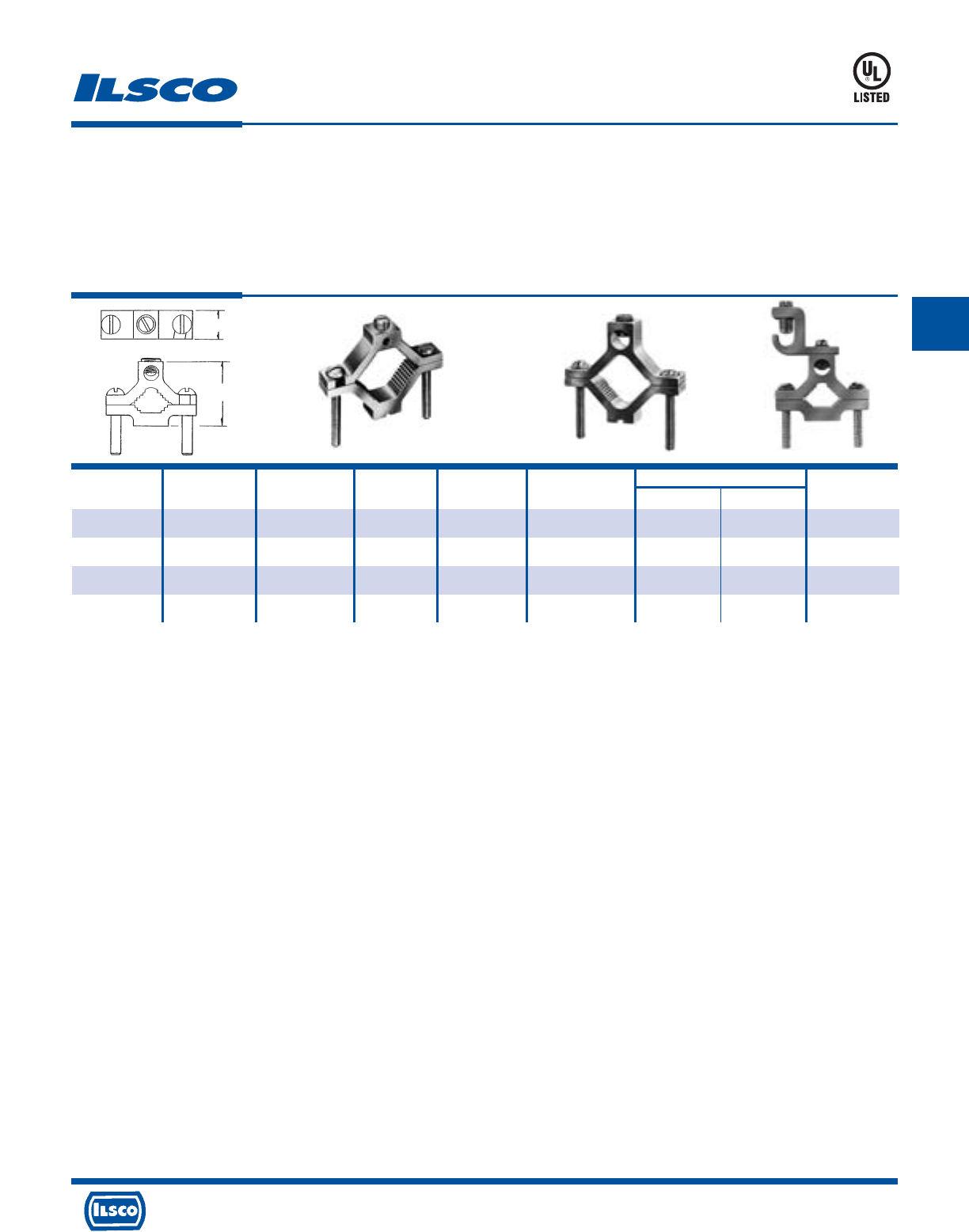
4730 Madison Road, Cincinnati, Ohio 45227-1426 Phone 513 533-6200 Fax 513 871-4084 Web site www.ilsco.com
Canada 1050 Lakeshore Road East, Mississauga, Ontario, Canada L5E1E4 Phone 905 274-2341 Fax 905 274-8763
146
C
Catalog Figure Pipe Rebar Ground Wire Screw Dimensions Hex
Number Number Size Size Range Type L W Size
AGC-1 1 1/2-3/4-1 4, 5, 6 1/0-14 Slot 2-1/4 11/16 Slot
AGC-2 2 1 1/4-1 1/2-2 - 250kcmil-6 Hex Socket 3-3/4 13/16 5/16
AGC-4 2 2 1/2-3-3 1/2-4 - 250kcmil-6 Hex Socket 6-5/16 1 5/16
SGC-1/0* 3 1/2-3/4-1” - 1/0-14 Slot 2-1/4 11/16 Slot
Dual Rated Ground Clamp
TYPE
AGC
SGC
Features
•
Manufactured from high strength 6061-T6 aluminum
alloy
•
Clear plated
•
UL Listed
•
Versatile
•
Range taking
•
SGC Lay-In feature
Fig. 1 Fig. 2 Fig. 3
Benefits
•
Suitable for use with either copper or aluminum
conductors
•
Provides low contact resistance
•
Ensures reliability
•
Effectively grounds aluminum or copper conductors to
copper water pipe, galvanized pipe or steel conduit
•
Three sizes cover a range from 1/2" to 4" pipe with a
ground wire range of 250 kcmil - #14 which reduces
inventory
•
Provides ease of installation for long ground wire runs
DE-OX Inhibitor is recommended for all aluminum terminations.
* Typical application would be grounding computer floor room system.
UL File E34440
W
L
667P
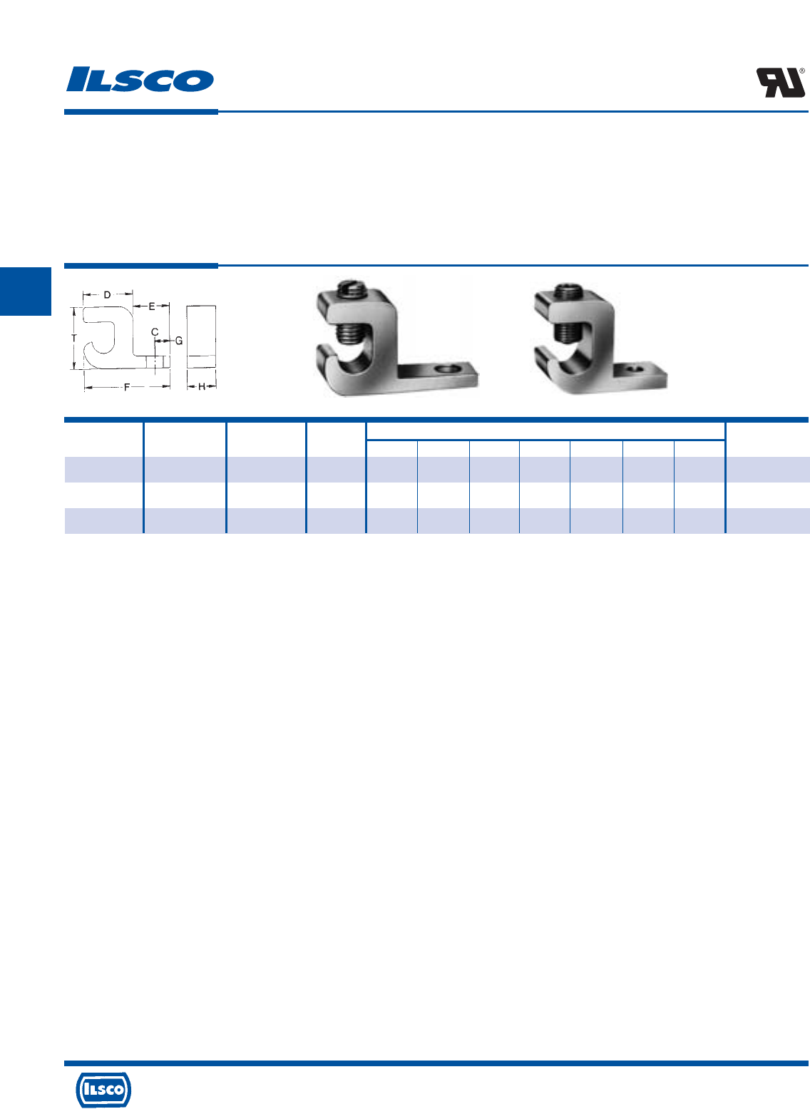
4730 Madison Road, Cincinnati, Ohio 45227-1426 Phone 513 533-6200 Fax 513 871-4084 Web site www.ilsco.com
Canada 1050 Lakeshore Road East, Mississauga, Ontario, Canada L5E1E4 Phone 905 274-2341 Fax 905 274-8763
147
C
Catalog Figure Ground Wire Bolt Dimensions Hex
Number Number Range Size C D E F G H T Size
*GBL-4 1 4-14 10 7/32 5/8 31/64 1-3/32 13/64 25/64 51/64 Slot
+GBL-1/0 1 1/0-14 1/4 9/32 51/64 27/32 1-5/8 7/16 5/8 1-5/32 Slot
+GBL-250 2 250kcmil-6 1/4 9/32 31/64 1 2-3/16 29/64 7/8 1-23/32 7/32
Dual Rated Lay-In Ground Lug
TYPE
GBL
Features
•
Manufactured from high strength 6061-T6 aluminum
alloy
•
Electro-tin plated
•
UL Recognized for grounding and bonding
•
Lay-in feature
•
Rated for 600 volts
Fig. 1 Fig. 2
Benefits
•
Suitable for use with either copper or aluminum
conductors
•
Provides low contact resistance
•
Ensures reliability
•
Provides ease of installation
•
Ensures reliability
+ U.L. 467 recognized for grounding and bonding only.
DE-OX Inhibitor is recommended for all aluminum terminations.
+ UL File E34440/E6207
* UL 467 Listed
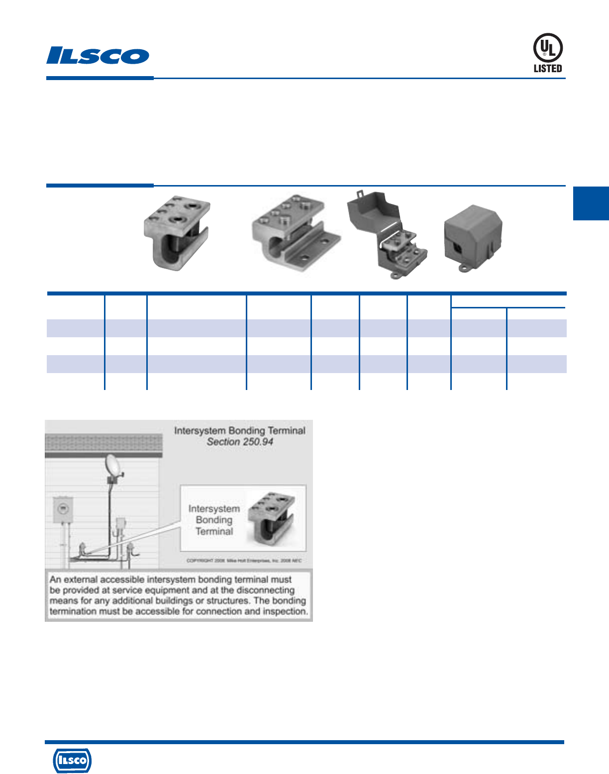
4730 Madison Road, Cincinnati, Ohio 45227-1426 Phone 513 533-6200 Fax 513 871-4084 Web site www.ilsco.com
Canada 1050 Lakeshore Road East, Mississauga, Ontario, Canada L5E1E4 Phone 905 274-2341 Fax 905 274-8763
148
C
Features
•
Approved for UL 467 (Grounding & Bonding)
•
Lay in style
•
No mounting required
•
Dual rated
•
4 Taps (#2-14) stranded or solid
•
Stainless steel screws
•
Serrations in conductor wire way
•
Patent Pending
Benefits
•
Meets NEC 250.94 installation requirements.
•
Eliminates the need to cut or splice into existing conductor
•
Allows fast simple installation on ground conductor below meter
•
For use with copper and aluminum conductors
•
For bonding multiple communication systems (Phone, TV, Cable, etc.)
•
For corrosion resistance
•
Cuts oxidation
ClearGround™
Intersystem Ground Tap
TYPE
GBT
Catalog Figure Wire Range Wire Range Hex Size
Number Number Main Tap Length Width Height Main Tap
GBT-1/0 1 1/0-8 2-14str-sol 2.250 1.125 1.160 S S
GBT-250 1 250kcmil-8str - 1/0-8sol 2-14str-sol 2.250 1.375 1.587 7/32 S
GBT-1/0-M 2 1/0-8 2-14str-sol 2.250 1.750 1.160 S S
GBT-1/0-M-W/C 3 1/0-8 2-14str-sol 2.730 3.930 2.110 S S
UL File E34440
250-94 01 reproduced with approval from Mike Holt Enterprises, www.mikeholt.com
Fig. 1 Fig. 2 Fig. 3
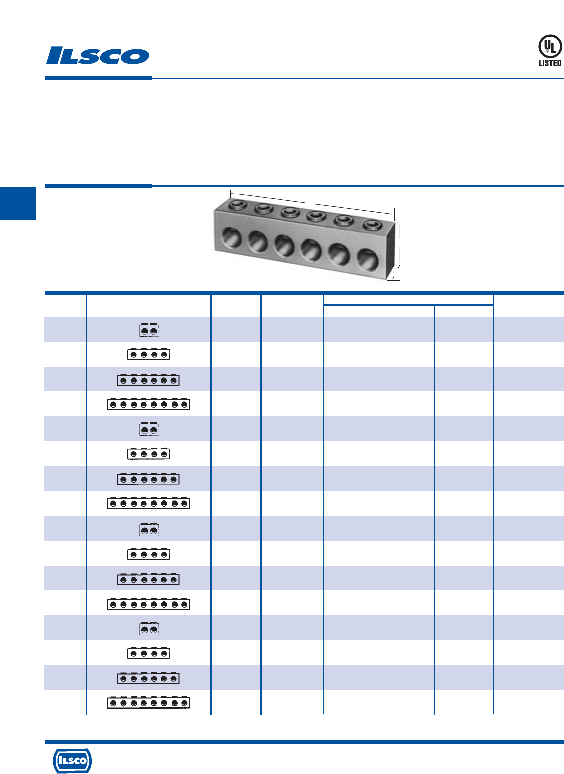
4730 Madison Road, Cincinnati, Ohio 45227-1426 Phone 513 533-6200 Fax 513 871-4084 Web site www.ilsco.com
Canada 1050 Lakeshore Road East, Mississauga, Ontario, Canada L5E1E4 Phone 905 274-2341 Fax 905 274-8763
149
C
Aluminum Multi-Tap Connectors - Dual Rated
TYPE
PED-Z
Features
•
Available in two, four, six, or eight
conductor configurations in four wire ranges
•
Manufactured from high strength 6061-T6
aluminum alloy
•
UL Listed
•
Compact size
•
Rated for 600 volts, 90˚ C
Benefits
•
Provides multiple conductor installation for a wide range
of conductors
•
Suitable for use with either copper or aluminum conductors
•
Ensures reliability
•
Suitable for pedestal applications
•
Ensures reliability
Catalog Connector Number Wire Dimensions
Number Design Of Ports Range L W H Hex Size
PED-2-2/0-Z 2 2/0-14 2.09 .56 .73 3/16
PED-4-2/0-Z 4 2/0-14 3.78 .56 .73 3/16
PED-6-2/0-Z 6 2/0-14 5.46 .56 .73 3/16
PED-8-2/0-Z 8 2/0-14 7.15 .56 .73 3/16
PED-2-4/0-Z 2 4/0-6 1.78 .75 1.00 5/16
PED-4-4/0-Z 4 4/0-6 3.64 .75 1.00 5/16
PED-6-4/0-Z 6 4/0-6 5.50 .75 1.00 5/16
PED-8-4/0-Z 8 4/0-6 7.36 .75 1.00 5/16
PED-2-350-Z 2 350kcmil-6 2.22 1.00 1.25 5/16
PED-4-350-Z 4 350kcmil-6 4.53 1.00 1.25 5/16
PED-6-350-Z 6 350kcmil-6 6.84 1.00 1.25 5/16
PED-8-350-Z 8 350kcmil-6 9.15 1.00 1.25 5/16
PED-2-600-Z 2 600kcmil-4 2.47 1.25 1.63 3/8
PED-4-600-Z 4 600kcmil-4 5.03 1.25 1.63 3/8
PED-6-600-Z 6 600kcmil-4 7.59 1.25 1.63 3/8
PED-8-600-Z 8 600kcmil-4 10.16 1.25 1.63 3/8
Covers not available.
DE-OX Inhibitor is recommended for all aluminum terminations.
453G
W
H
L
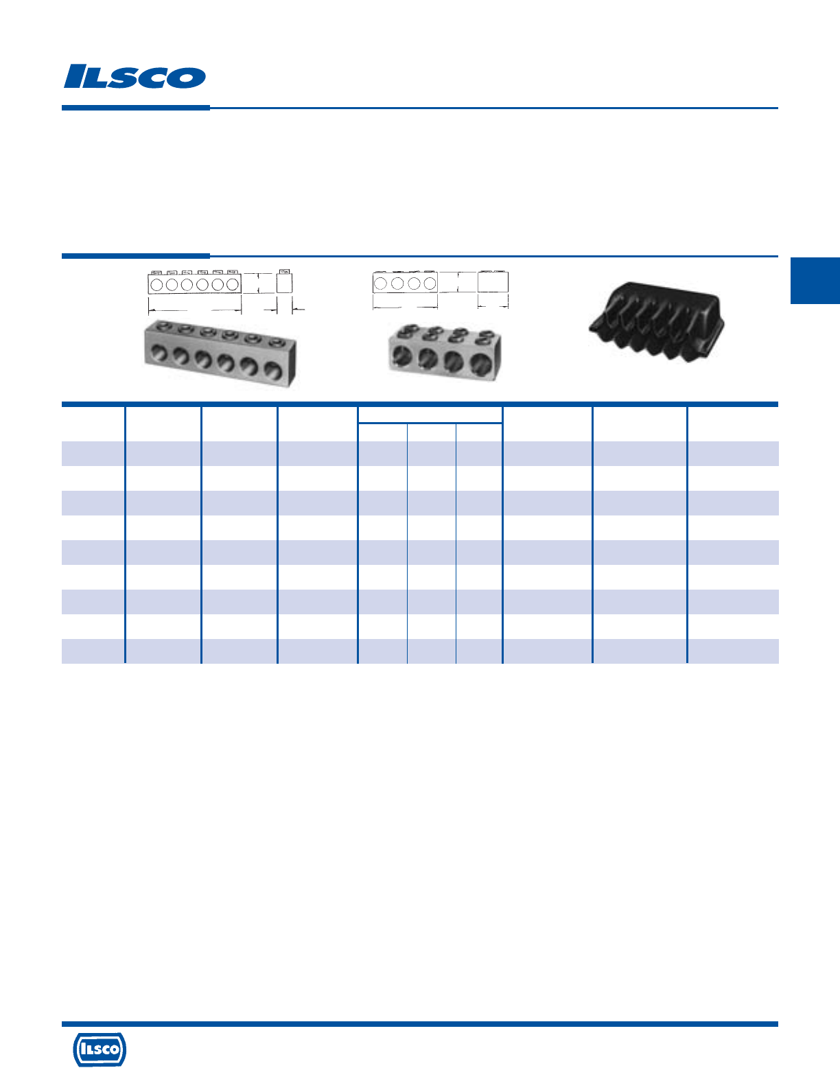
4730 Madison Road, Cincinnati, Ohio 45227-1426 Phone 513 533-6200 Fax 513 871-4084 Web site www.ilsco.com
Canada 1050 Lakeshore Road East, Mississauga, Ontario, Canada L5E1E4 Phone 905 274-2341 Fax 905 274-8763
150
C
Catalog Figure Wire No. of Dimensions Hex Recommended Insulating
Number Number Range Cond. L W H Size Torque Cover
PED-4-350-X 1 350kcmil-6 4 3-7/8 1 1-3/8 5/16 350 PEC-4-350
PED-6-350-X 1 350kcmil-6 6 5-11/16 1 1-3/8 5/16 350 PEC-6-350
PED-8-350-X 1 350kcmil-6 8 7-1/2 1 1-3/8 5/16 350 PEC-8-350
PED-4-500-X 1 500kcmil-2 4 4-3/4 1 1-5/8 5/16 450 PEC-4-500
PED-6-500-X 1 500kcmil-2 6 7-1/4 1 1-5/8 5/16 450 PEC-6-500
PED-8-500-X 1 500kcmil-2 8 9-11/16 1 1-5/8 5/16 450 PEC-8-500
‡PSA-4-750-Z 2 750kcmil-1/0 4 6-9/16 2 2-1/2 3/8 500 PSC-4-750
‡PSA-6-750-Z 2 750kcmil-1/0 6 9-7/8 2 2-1/2 3/8 500 PSC-6-750
‡PSA-8-750-Z 2 750kcmil-1/0 8 13-3/16 2 2-1/2 3/8 500 PSC-8-750
Aluminum Multi-Tap Connectors - Dual Rated
TYPE
PED-X
PSA-Z
PEC
Features
•
Available in four, six, or eight conductor configurations
in four wire ranges
•
Plastisol insulating cover available with a nominal
thickness of 156 Mils
•
Manufactured from high strength 6061-T6 aluminum
alloy
•
Compact size
•
Rated for 600 volts
Benefits
•
Provides multiple conductor installation for a wide
range of conductors
•
Eliminates the need for taping. Plastisol covers have
dielectric strength of 120 volts per Mil
•
Suitable for use with either copper or aluminum
conductors
•
Suitable for pedestal applications
•
Ensures reliability
‡ Consult factory for availability.
DE-OX Inhibitor is recommended for all aluminum terminations.
HH
WW
LL
Fig. 1 Fig. 2 Insulating Cover
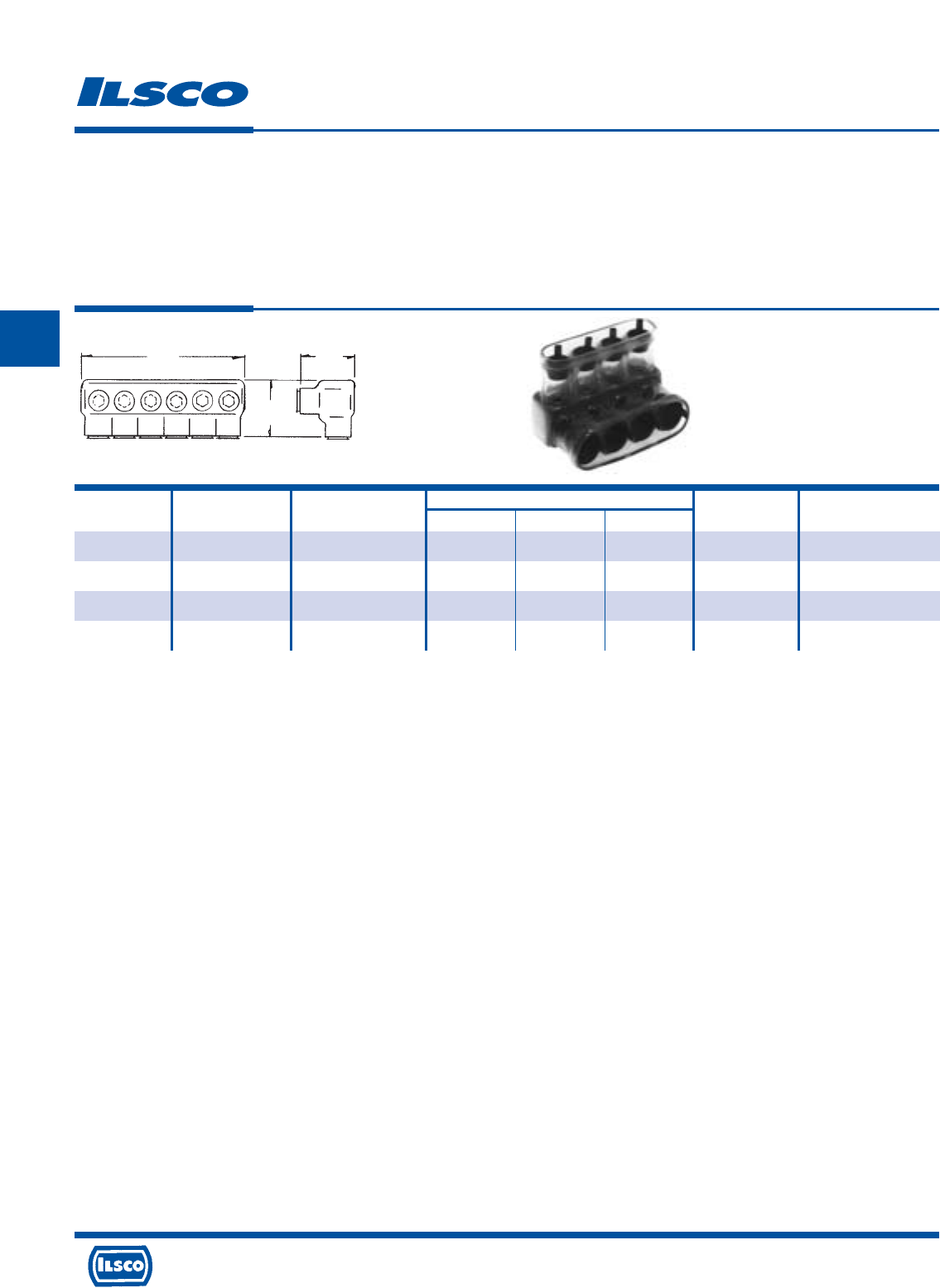
4730 Madison Road, Cincinnati, Ohio 45227-1426 Phone 513 533-6200 Fax 513 871-4084 Web site www.ilsco.com
Canada 1050 Lakeshore Road East, Mississauga, Ontario, Canada L5E1E4 Phone 905 274-2341 Fax 905 274-8763
151
C
Catalog Wire Number of Dimensions Hex Recommended
Number Range Conductors L W H Size Torque-Inch Lbs.
PED3-350-CP-Z 350kcmil-10 3 3.406 2-1/4 2-1/8 5/16 350
PED4-350-CP-Z 350kcmil-10 4 4.562 2-1/4 2-1/8 5/16 350
PED5-350-CP-Z 350kcmil-10 5 5.718 2-1/4 2-1/8 5/16 350
PED6-350-CP-Z 350kcmil-10 6 6.875 2-1/4 2-1/8 5/16 350
Insulated Multi-Tap Connectors - Dual Rated
TYPE
PED-CP
Features
•
Available in three, four, five, and six conductor
configurations in two wire ranges
•
Connector is encapsulated in 125 Mils of clear PVC rated
at 1000 amps
•
Manufactured from high strength 6061-T6 aluminum
alloy
•
Rated for 600 volts
Benefits
•
Provides multiple conductor installation for a broad wire
range
•
Clear cover allows visual inspection of conductors
during installation. Removable caps permit easy access
to conductor ports and set screws. No taping is
required.
•
Suitable for use with either copper or aluminum
conductors.
•
Ensures reliability
LH
W
DE-OX Inhibitor is recommended for all aluminum terminations.
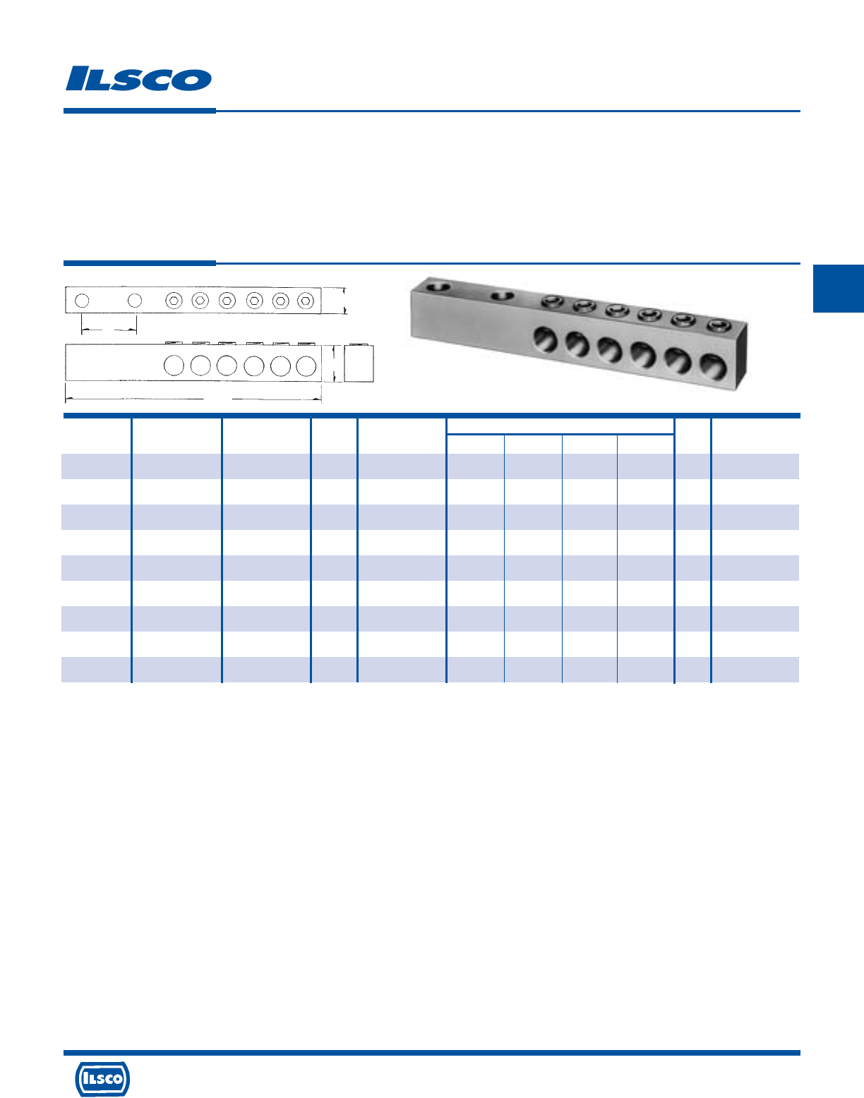
4730 Madison Road, Cincinnati, Ohio 45227-1426 Phone 513 533-6200 Fax 513 871-4084 Web site www.ilsco.com
Canada 1050 Lakeshore Road East, Mississauga, Ontario, Canada L5E1E4 Phone 905 274-2341 Fax 905 274-8763
152
C
Catalog Wire Number of Bolt Diameter of Dimensions Hex Recommended
Number Range Conductors Size Mounting Hole H J W L Size Torque-Inch Lbs.
PET-4-350-Z 350kcmil-12 4 1/2 9/16 1-3/8 1-3/4 1 6-7/8 5/16 350
PET-6-350-Z 350kcmil-12 6 1/2 9/16 1-3/8 1-3/4 1 8-11/16 5/16 350
PET-8-350-Z 350kcmil-12 8 1/2 9/16 1-3/8 1-3/4 1 10-1/2 5/16 350
PET-4-500-Z 500kcmil-2 4 1/2 9/16 1-5/8 1-3/4 1 7-15/16 5/16 450
PET-6-500-Z 500kcmil-2 6 1/2 9/16 1-1/8 1-3/4 1 10-3/16 5/16 450
PET-8-500-Z 500kcmil-2 8 1/2 9/16 1-5/8 1-3/4 1 12-7/16 5/16 450
PET-4-750-Z 750kcmil-1/0 4 1/2 9/16 1-3/4 1-3/4 1-3/16 8-11/16 3/8 500
PET-6-750-Z 750kcmil-1/0 6 1/2 9/16 1-3/4 1-3/4 1-3/16 11-15/16 3/8 500
PET-8-750-Z 750kcmil-1/0 8 1/2 9/16 1-3/4 1-3/4 1-3/16 13-15/16 3/8 500
Aluminum Spade Type Transformer Lugs - Dual Rated
TYPE
PET
Features
•
Available in four, six, or eight conductor configurations
in four wire ranges
•
Predrilled 1/2" mounting holes
•
Manufactured from high strength 6061-T6 aluminum alloy
•
Rated for 600 volts
Benefits
•
Provides multiple conductor installation for a wide
range of conductors
•
Allows easy attachment. May be bolted back to back for
heavy duty applications
•
Suitable for use with either copper or aluminum
conductors
•
Ensures reliability
W
H
L
J
DE-OX Inhibitor is recommended for all aluminum terminations.
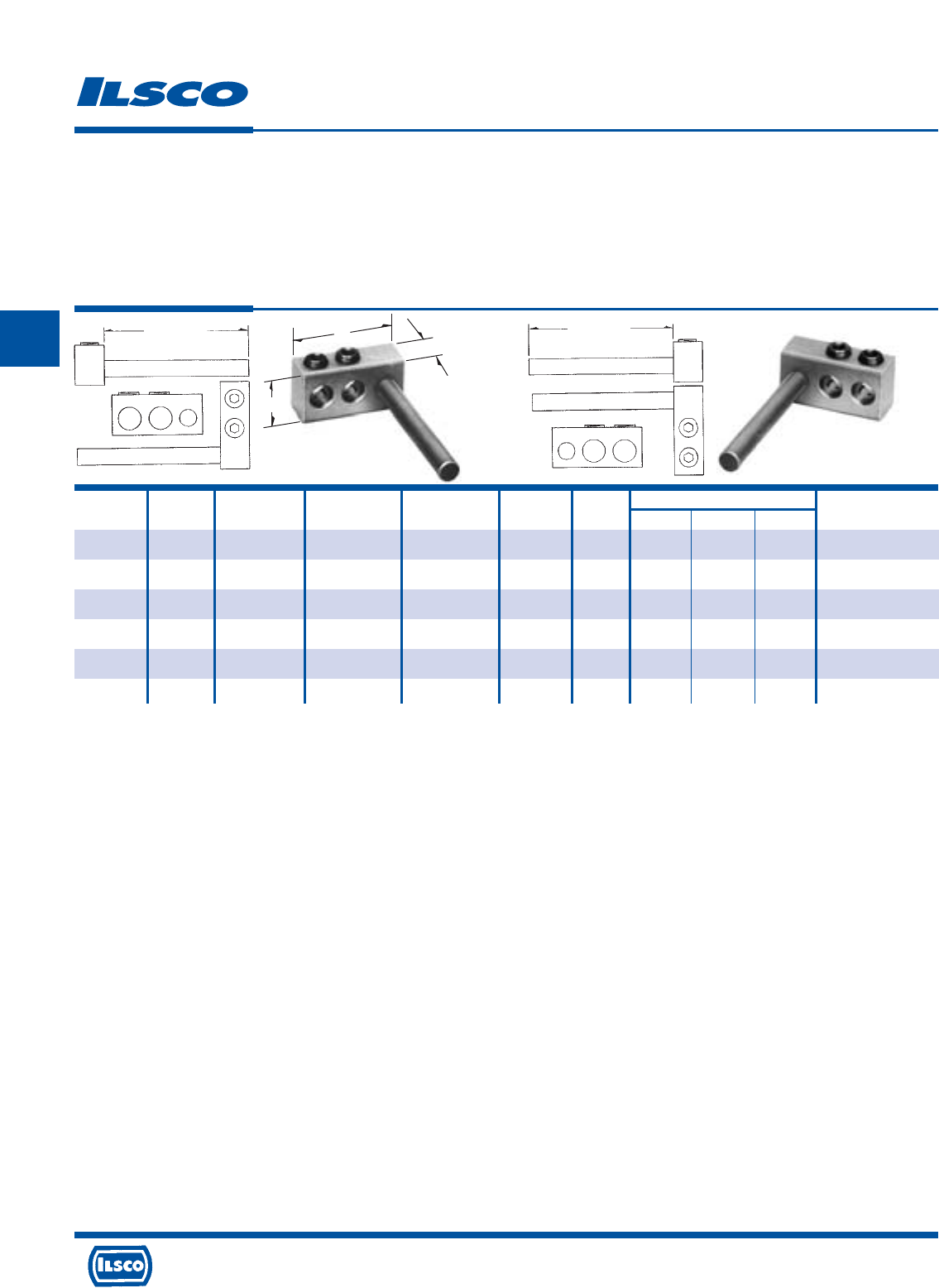
4730 Madison Road, Cincinnati, Ohio 45227-1426 Phone 513 533-6200 Fax 513 871-4084 Web site www.ilsco.com
Canada 1050 Lakeshore Road East, Mississauga, Ontario, Canada L5E1E4 Phone 905 274-2341 Fax 905 274-8763
153
C
Catalog Figure Wire Number of Copper Stud Stud Hex Dimensions Recommended
Number Number Range Conductors Diameter Length Size L W H Torque-Inch Lbs.
PTT-2R-0-Z 1 1/0-14 2 3/8 3" 3/16 1.87 .75 1.00 200
PTT-2L-0-Z 2 1/0-14 2 3/8 3" 3/16 1.87 .75 1.00 200
PTT-2R-250-Z 1 250kcmil-10 2 1/2 4" 5/16 2.39 .90 1.12 300
PTT-2L-250-Z 2 250kcmil-10 2 1/2 4" 5/16 2.39 .90 1.12 300
PTT-2R-350-Z 1 350kcmil-10 2 5/8 4" 5/16 3.25 1.25 1.25 350
PTT-2L-350-Z 2 350kcmil-10 2 5/8 4" 5/16 3.25 1.25 1.25 350
Aluminum Multi-Tap Adaptor Lugs - Dual Rated
(Pole Type Transformer Lugs)
TYPE
PTT
Features
•
Connector manufactured from high strength 6061-T6
aluminum alloy
•
Stud manufactured from electrolytic pure copper rod
•
Two conductor ports
•
Range taking
•
Left or Right handed
•
Clear Plated
•
Rated for 600 volts
Benefits
•
Suitable for use with either copper or aluminum
conductors
•
Provides maximum conductivity and can be used on
equipment with copper or aluminum connectors
•
Allows parallel conductors to be connected to
equipment supplied with single conductor terminals
•
A wide range of conductor sizes can be used in each
connector
•
Provides ease of installation
•
Provides low contact resistance
•
Ensures reliability
Fig. 1 Fig. 2
Stud Length
Stud Length
H
L
W
DE-OX Inhibitor is recommended for all aluminum terminations.
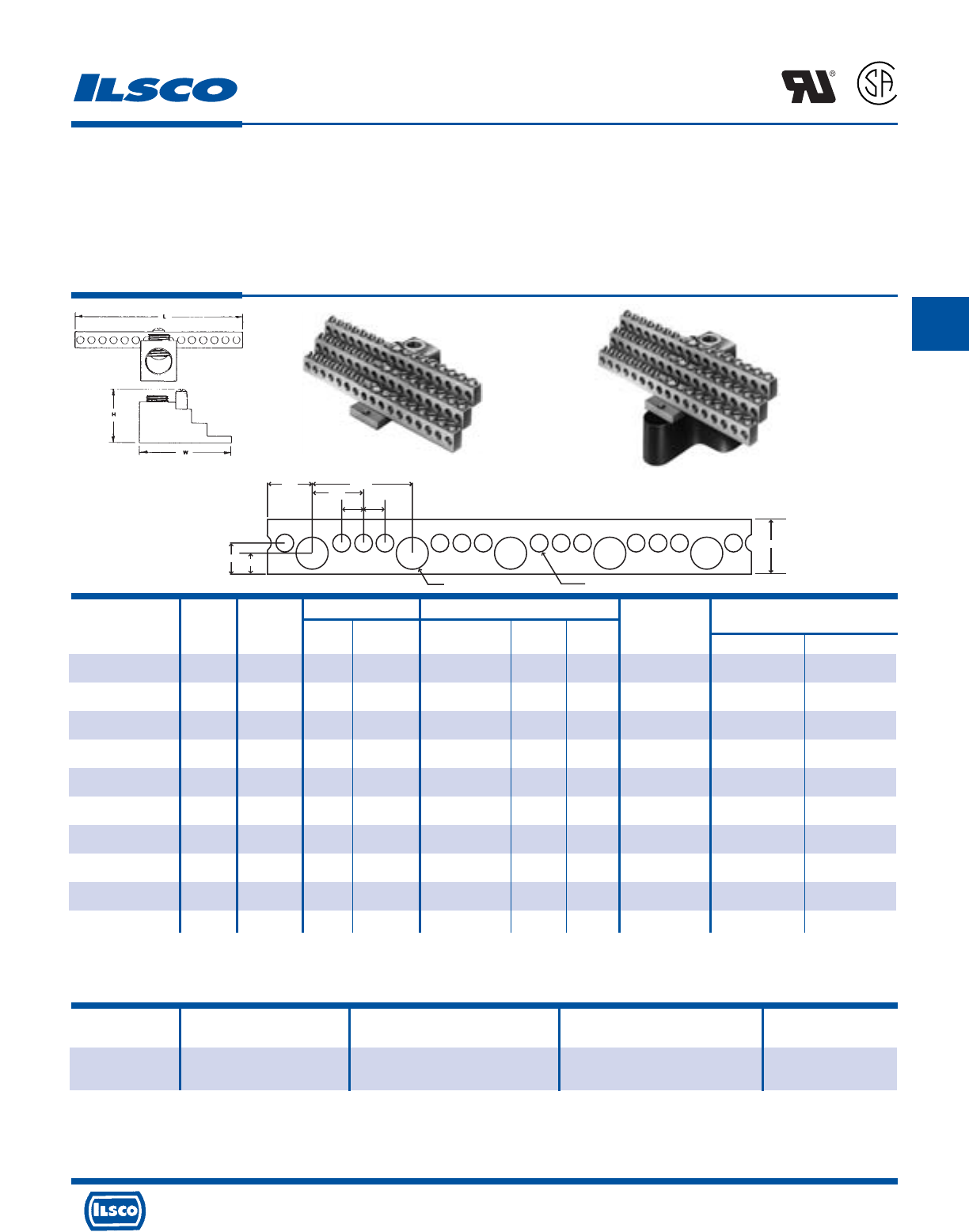
4730 Madison Road, Cincinnati, Ohio 45227-1426 Phone 513 533-6200 Fax 513 871-4084 Web site www.ilsco.com
Canada 1050 Lakeshore Road East, Mississauga, Ontario, Canada L5E1E4 Phone 905 274-2341 Fax 905 274-8763
154
C
.391
.620
.391 Dia. .209 Dia.
.547 1.172
.586
.250 .250
.250
Number Wire Range Dimensions Two Tapped
Catalog Figure Of Circuit Circuit Line Approx. Height Mounting
Number Number Taps Taps Loads with Max. Wire L W Holes Main Tap
NB-350-12 1 12 14-4 350kcmil-6 1-17/32 4-23/32 2-17/32 10-32 3/8 S
NB-350-12-W/R16* 2 12 14-4 350kcmil-6 2-17/32 4-23/32 2-17/32 10-32 3/8 S
NB-350-24 1 24 14-4 350kcmil-6 1-17/32 4-23/32 2-17/32 10-32 3/8 S
NB-350-24-W/R16* 2 24 14-4 350kcmil-6 2-17/32 4-23/32 2-17/32 10-32 3/8 S
NB-350-30 1 30 14-4 350kcmil-6 1-17/32 4-3/32 2-17/32 10-32 3/8 S
NB-350-30-W/R16* 2 30 14-4 350kcmil-6 2-17/32 4-3/32 2-17/32 10-32 3/8 S
NB-350-36 1 36 14-4 350kcmil-6 1-17/32 4-23/32 2-17/32 10-32 3/8 S
NB-350-36-W/R16* 2 36 14-4 350kcmil-6 2-17/32 4-23/32 2-17/32 10-32 3/8 S
NB-350-42 1 42 14-4 350kcmil-6 1-17/32 5-11/32 2-17/32 10-32 3/8 S
NB-350-42-W/R16* 2 42 14-4 350kcmil-6 2-17/32 5-11/32 2-17/32 10-32 3/8 S
Catalog Figure Number of Wire
Number Number Outlets Range Length
NB-120 3 120 30 outlets 1/0-14 3.25'
90 outlets 6-14
Aluminum Neutral Bars - Dual Rated
TYPE
NB
Features
•
Preassembled, stacked neutral bars
•
Available with phenolic base
•
Electro-tin plated
•
Fabricated from high strength 6061-T6 aluminum alloy
•
UL Recognized and CSA Certified for 600 volts, 90˚ C
Benefits
•
Compact, space saving design offers multiple range taking
flexibility and is suitable for grounding applications
•
Provides insulation from mounting surface
•
Provides low contact resistance
•
Suitable for use with either copper or aluminum conductors
•
Ensures reliability
L
R
-
2
9
6
0
1
Fig. 1 Fig. 2
Fig. 3
Hex Size
“S” indicates slotted screw
* Part includes phenolic mounting block R-16
Tested to UL 486A-486B, UL File E81652
UL File E81652
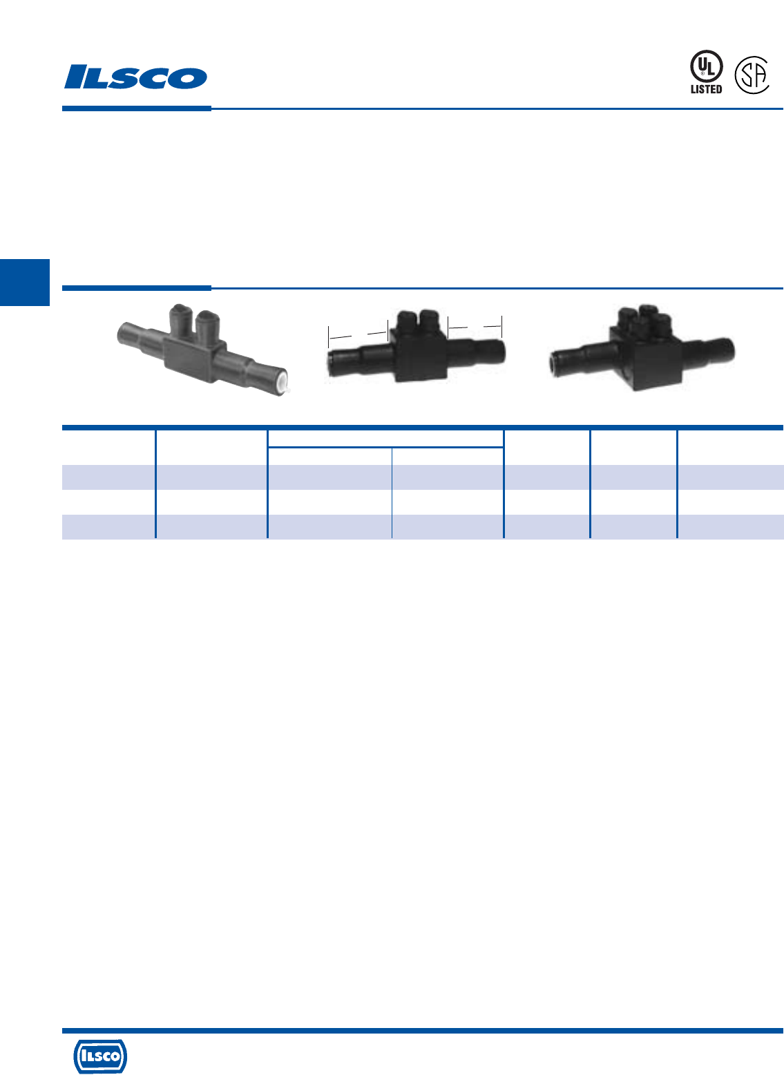
4730 Madison Road, Cincinnati, Ohio 45227-1426 Phone 513 533-6200 Fax 513 871-4084 Web site www.ilsco.com
Canada 1050 Lakeshore Road East, Mississauga, Ontario, Canada L5E1E4 Phone 905 274-2341 Fax 905 274-8763
155
C
Catalog Figure Wire Range Hex Recommended
Number Number Barrel A Barrel B Length Size Torque-Inch Lbs.
USPA-350SS-DB +1 350kcmil-10str 350kcmil-10str 8- 5/8 5/16 350
USPA-500SS-DB* 2 500kcmil-10 500kcmil-10 9-13/16 5/16 450
USPA-750SS-DB 3 750kcmil-2 750kcmil-2 9-13/16 5/16 500
Watertight, Underground In-Line Splice
TYPE
USPA-SS
Features
•
Encapsulated in EPDM rubber with a nominal thickness
of 125 Mils and a dielectric strength of 240 Volts per Mil
•
Pre-marked end inserts
•
O-Ring design screw cap inserts
•
Connector is produced from high strength 6061-T6
aluminum alloy
•
Connector rated for 600 volts, 90˚ C
•
Range taking
•
UL Listed and CSA Certified for direct burial in earth or
concrete
Fig. 1 Fig. 2 Fig. 3
Benefits
•
Completely watertight in line splice. Ready for installation.
(not a mold for use with mixed compounds) No taping
required. No temperature or humidity restrictions.
•
Simply cut end inserts to appropriate marked wire size
and insert conductor into connector
•
Ensures connector integrity while allowing ease of access
to set screws, ensuring excellent sealing
•
Suitable for use with either copper or aluminum
conductors
•
Ensures reliability
•
Reduces inventory
+ REA listed
* Not UL Listed
Tested to UL 486D, UL File E125087
AB
88X4
L
R
-
2
9
6
0
1
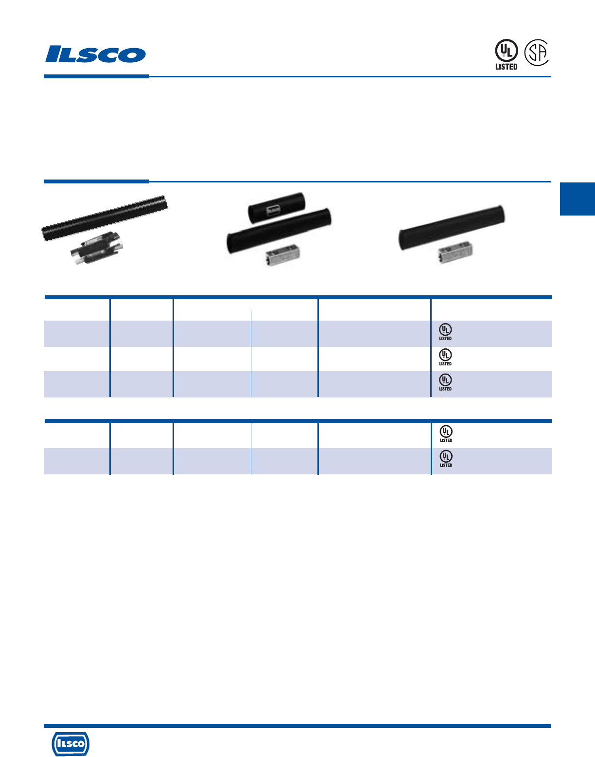
4730 Madison Road, Cincinnati, Ohio 45227-1426 Phone 513 533-6200 Fax 513 871-4084 Web site www.ilsco.com
Canada 1050 Lakeshore Road East, Mississauga, Ontario, Canada L5E1E4 Phone 905 274-2341 Fax 905 274-8763
156
C
Catalog Figure UF Cable Range Wire Testing
Number Number Minimum Maximum Range Certification
DBK-1 1 14/2 with Ground 8/3 with Ground -
DBK-2 2 - - 2-8
DBK-250 2 - - 250kcmil-1
ASK-2* 3 - - 2-8
ASK-250* 3 - - 250kcmil-1
Direct Burial and Above Grade Splice Kits
TYPE
DBK
ASK
Features
•
DBK-1 connectors manufactured from electrolytic
copper
•
All other connectors manufactured from high strength
aluminum alloy
•
Heavy wall heat shrink tubing with sealant
•
Connector and heat shrink packaged together
•
UL listed, rated for 600 volts, 90˚ C
Benefits
•
Provides maximum conductivity for UF cable
•
Provides high conductivity and can be used with either
aluminum or copper conductors
•
Provides watertight splice. Kits with heat shrink are
designed to withstand abrasions due to direct burial in
rocky soil.
•
Provides ease of ordering
•
Ensures reliability
453G
453G
88X4
88X4
88X4
*Not UL Listed for direct burial.
Tested to UL 486A-486B, UL File E6207
ABOVE GRADE SPLICE KITS
Tested to UL 486D, UL File E125087
Fig. 1 Fig. 2 Fig. 3
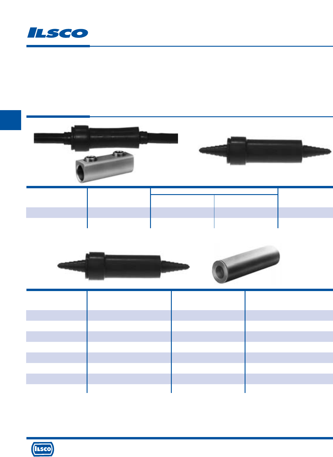
4730 Madison Road, Cincinnati, Ohio 45227-1426 Phone 513 533-6200 Fax 513 871-4084 Web site www.ilsco.com
Canada 1050 Lakeshore Road East, Mississauga, Ontario, Canada L5E1E4 Phone 905 274-2341 Fax 905 274-8763
157
C
Wire Range
Catalog Figure Bolted Compression
Number Number Connector Sleeves L
SSK-350-Z 1 350kcmil-6 - 5-1/2
SS-350-Z 2 350kcmil-6 500kcmil-6 5-1/2
Watertight Underground Splice Kits
TYPE
SS
SSK
SSKC
Features
•
Watertight EPDM rubber splice cover
•
Tapered ends
•
Ready for installation
•
Type SS is cover only supplied with lubricant
•
Type SSK kit is supplied with both connector and
lubricant
•
Connector rated for 600 volts
Fig. 1 Fig. 2
Benefits
•
No taping required. Suitable for direct burial
•
Fits a wide range of conductor sizes
•
Not a mold, can be used in any type of weather. (moisture and humidity are
not a factor)
•
Can be used with standard aluminum or copper compression from 500kcmil -
6. Lubricant permits easy insertion of conductors into sleeve.
•
Supplied with dual-rated mechanical splice connector with a wire range of
350kcmil - 6
•
Ensures reliability
Temperature rating 90˚ C
Wire Range
Catalog Connector Wire When Installed
Number Catalog Number Size With IDT-12 Tool
SSKC-6-Z AS-6 6 6
SSKC-4-Z AS-4 4 4-6
SSKC-2-Z AS-2 2 2-6
SSKC-1/0-Z AS-1/0 1/0 1/0-1
SSKC-2/0-Z AS-2/0 2/0 2/0-1
SSKC-3/0-Z AS-3/0 3/0 3/0-1
SSKC-4/0-Z AS-4/0 4/0 4/0-1
SSKC-250-Z AS-250 250kcmil 250kcmil-1/0
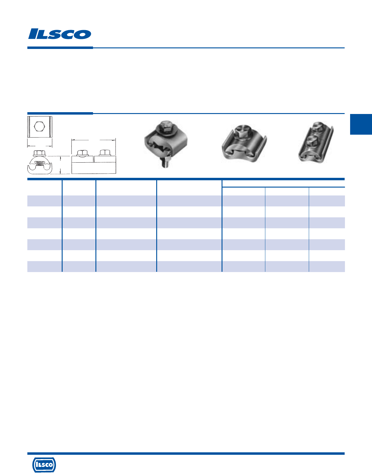
4730 Madison Road, Cincinnati, Ohio 45227-1426 Phone 513 533-6200 Fax 513 871-4084 Web site www.ilsco.com
Canada 1050 Lakeshore Road East, Mississauga, Ontario, Canada L5E1E4 Phone 905 274-2341 Fax 905 274-8763
158
C
Catalog Figure Wire Range Type and Dimensions
Number Number Both Grooves Bolt Size L H W
PG810-S-Z 1 1/0-8 sol 3/8, Steel 1-1/8 1-5/8 1-3/16
PG620-Z 2 2/0-6 sol 7/16, AL 1-3/8 1-5/8 1-1/4
PG620-S-Z 2 2/0-6 sol 3/8, Steel 1-3/16 1-5/8 1-1/8
PG620-2A-Z 3 2/0-6 sol 3/8, AL 2-7/16 1-5/8 1-1/4
PG620-2S-Z 3 2/0-6 sol 3/8, Steel 2-7/16 1-5/8 1-1/4
PG402-S-Z 2 4/0-2 3/8, Steel 1-1/2 1-3/4 1-3/8
PG402-2S-Z 3 4/0-2 3/8, Steel 3-1/16 1-3/4 1-3/8
Parallel Groove Clamps - Dual Rated
TYPE
PG
Features
•
Manufactured from high strength 6061-T6 aluminum
alloy
•
Clear plated
•
Range taking
•
Rated for 600 volts
Benefits
•
Suitable for use with either copper or aluminum
conductors
•
Provides low contact resistance
•
Permits inventories to be kept to a minimum
•
Ensures reliability
DE-OX Inhibitor is recommended for all aluminum terminations.
W
H
L
Fig. 1 Fig. 2 Fig. 3
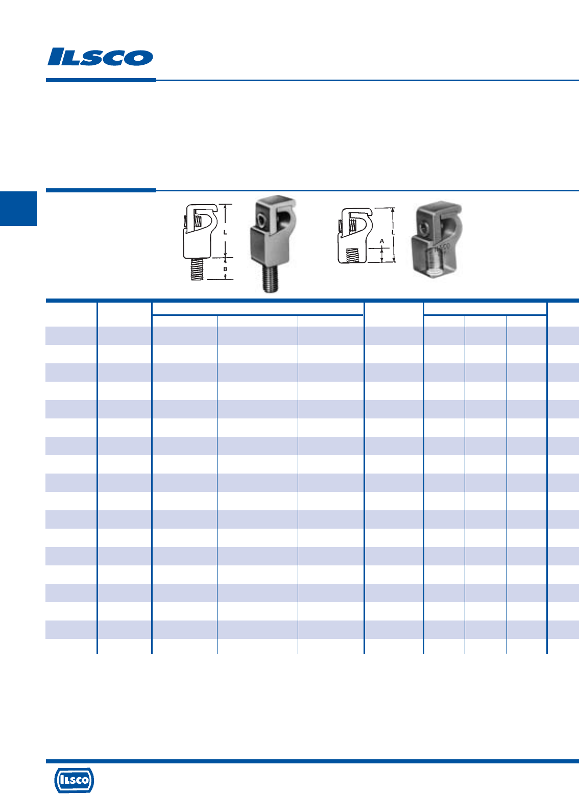
4730 Madison Road, Cincinnati, Ohio 45227-1426 Phone 513 533-6200 Fax 513 871-4084 Web site www.ilsco.com
Canada 1050 Lakeshore Road East, Mississauga, Ontario, Canada L5E1E4 Phone 905 274-2341 Fax 905 274-8763
159
C
Catalog Figure Wire Range Single Cable Dimensions Hex
Number Number Max. Min. Steel Strand Dia. Thread A B L Size
GRM-2A 1 2str 12sol/str 5/16 1/4"-20 - 11/16 1-1/4 Slot
GRM-2B 1 2str 12sol/str 5/16 5/16"-18 - 3/8 1-1/4 Slot
GRM-2C 1 2str 12sol/str 5/16 3/8"-16 - 9/16 1-1/4 Slot
GRM-0 1 1/0str 2str 3/8 1/2"-13 - 1 1-9/16 Slot
GRM-250A 1 250kcmil 1/0 9/16 1/2"-13 - 1 2-1/8 5/16
GRM-250B 1 250kcmil 1/0 9/16 5/8"-11 - 1 2-1/8 5/16
GRM-350 1 350kcmil 4/0 - 5/8"-11 - 1 2-1/2 3/8
GRM-500 1 500kcmil 350kcmil - 3/4"-10 - 1-3/8 2-15/16 3/8
GRM-750 1 750kcmil 500kcmil - 3/4"-10 - 1-3/8 3-3/8 1/2
GRF-2A 2 2str 12sol/str 5/16 1/4"-20 5/16 - 1-1/4 Slot
GRF-2B 2 2str 12sol/str 5/16 5/16"-18 3/8 - 1-1/4 Slot
GRF-2C 2 2str 12sol/str 5/16 3/8"-16 7/16 - 1-1/4 Slot
GRF-0 2 1/0str 2str 3/8 1/2"-13 1/2 - 1-9/16 Slot
GRF-250A 2 250kcmil 1/0 9/16 1/2"-13 1/2 - 2-1/8 5/16
GRF-250B 2 250kcmil 1/0 9/16 5/8"-11 3/4 - 2-1/8 5/16
GRF-350 2 350kcmil 4/0 - 5/8"-11 3/4 - 2-1/2 3/8
GRF-500 2 500kcmil 350kcmil - 3/4"-10 7/8 - 2-15/16 3/8
GRF-750 2 750kcmil 500kcmil - 3/4"-10 7/8 - 3-3/8 1/2
Aluminum Grounding Connectors - Dual Rated
TYPE
GRM
GRF
Features
•
Manufactured from high strength 6061-T6 aluminum
alloy
•
Electro-tin plated
•
Type GRM - Elongated steel stud
•
Type GRF - Threaded female design
Fig. 1 Fig. 2
Benefits
•
Suitable for use with either copper or aluminum
conductors
•
Provides low contact resistance
•
Provides ease of grounding a single conductor to steel
structures or to tap a single conductor from bus bar
•
Provides ease of installation for a variety of standard
stud sizes
DE-OX Inhibitor is recommended for all aluminum terminations.
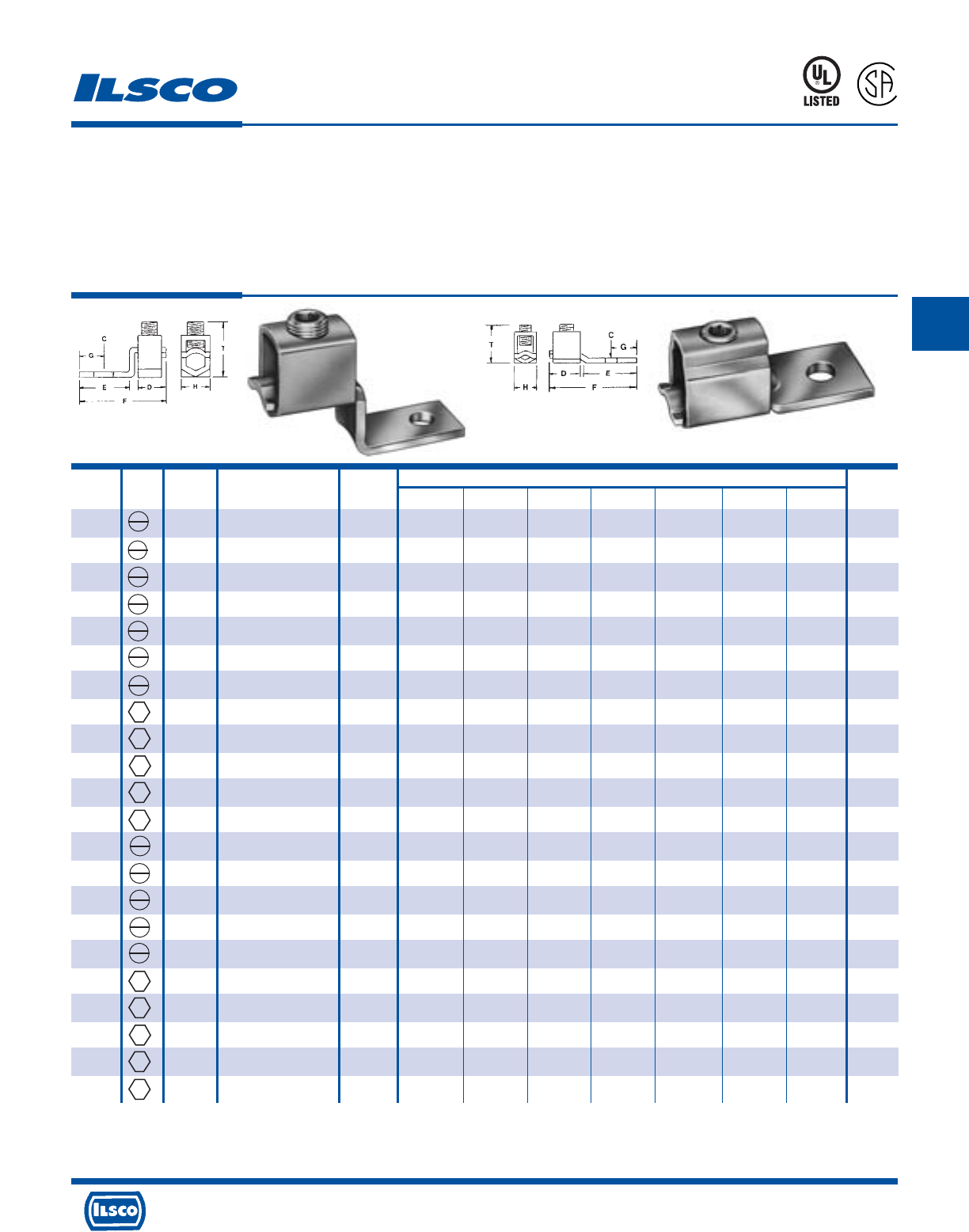
4730 Madison Road, Cincinnati, Ohio 45227-1426 Phone 513 533-6200 Fax 513 871-4084 Web site www.ilsco.com
Canada 1050 Lakeshore Road East, Mississauga, Ontario, Canada L5E1E4 Phone 905 274-2341 Fax 905 274-8763
160
C
Catalog Screw Figure Wire Range Bolt Dimensions Hex
Number Type Number Copper Size C D E F G H T Size
SLU-25 1 10-14 #6 5/32 9/32 7/16 1 3/16 5/16 21/32 Slot
SLU-35 1 6-14 & List Comb. (A) #10 13/64 7/16 15/32 1-3/16 7/32 3/8 3/4 Slot
SLU-35DB 1 6-14 & List Comb. (A) #10 13/64 7/16 15/32 1-3/16 7/32 3/8 3/4 Slot
SAU-70 1 4-14 1/4 17/64 7/16 17/32 1-5/16 1/4 3/8 13/16 Slot
SLU-70 1 2-8 & List Comb. (B) 1/4 17/64 1/2 21/32 1-17/32 1/4 1/2 1 Slot
SLU-70DB 1 2-8 & List Comb. (B) 1/4 17/64 1/2 21/32 1-17/32 1/4 1/2 1 Slot
SLU-125 1 1/0-6 1/4 17/64 5/8 13/16 1-31/32 7/16 5/8 1-11/32 Slot
SLU-175 1 3/0-4 3/8 13/32 3/4 15/16 2-3/16 7/16 3/4 1-9/16 3/16
SLU-225 1 4/0-2 5/16 11/32 1 1-5/32 2-5/8 1/2 1 1-13/16 7/32
SLU-300 1 350kcmil-1/0 3/8 13/32 1-1/4 1-1/2 3-3/16 1/2 1 2-5/8 5/16
SLU-400 1 500kcmil-1/0 3/8 13/32 1-1/2 1-15/16 4-14 15/16 1-1/2 2-3/4 5/16
SLU-650 1 1000kcmil-600kcmil 1/2 17/32 1-7/8 1-7/8 4-5/8 1-7/64 2 3-11/16 3/8
SLS-25 2 10-14 #6 5/32 9/32 19/32 61/64 3/16 5/16 19/32 Slot
SLS-35 2 6-14 & List Comb. (A) #10 13/64 7/16 41/64 1-9/64 7/32 3/8 11/16 Slot
SAS-70 2 4-14 1/4 17/64 7/16 23/32 1-1/4 1/4 1/2 27/32 Slot
SLS-70 2 2-8 & List Comb. (B) 1/4 17/64 1/2 13/16 1-15/32 1/4 1/2 31/32 Slot
SLS-125 2 1/0-6 1/4 17/64 5/8 1-3/16 1-15/16 7/16 5/8 1-1/4 Slot
SLS-175 2 3/0-4 3/8 13/32 3/4 1-1/4 2-3/16 7/16 3/4 1-9/16 3/16
SLS-225 2 4/0-2 5/16 11/32 1 1-7/32 2-3/8 1/2 1 1-21/32 7/32
SLS-300 2 350kcmil-1/0 3/8 13/32 1-1/4 1-1/2 3-3/16 1/2 1 2-3/8 5/16
SLS-400 2 500kcmil-1/0 3/8 13/32 1-1/2 2-3/16 3-7/8 15/16 1-1/2 2-9/16 5/16
SLS-650 2 1000kcmil-600kcmil 1/2 17/32 1-7/8 3 5-1/8 1-3/16 2 3-11/16 3/8
Copper Mechanical Lugs
One Conductor, One Hole
TYPE
SLU
SLS
SAS
SAU
Features
•
Manufactured from electrolytic copper tubing and strip
stock
•
Compact design
•
Range taking
•
Re-usable
•
UL Listed and CSA Certified for 600 volts
•
V-bottom collar
•
SLU-35DB and SLU-70DB are UL 467 Listed and
suitable for direct burial
Fig. 1 Fig. 2
Benefits
•
Provides maximum conductivity and strength
•
Saves space and reduces installation time
•
Permits inventories to be kept to a minimum
•
Provides efficient use and flexibility in the field
•
Ensures reliability for copper conductor
•
Wires are wedged between arched pressure bar and collar
establishing positive contact and firm permanent grip
453G
L
R
-
2
9
6
0
1
(A) UL Listed wire combinations: (2) #10; (2) #12; (2) #14; (1) #12 and (1) #14; (1) #10 and (1) #12
(B) UL Listed wire combinations: (1) #8 and (1) #4; (1) #8 and (1) #6; (2) #4; (3) #8; (3) #6; (2) #8 and (1) #4; (2) #8 and (1) #6; (1) #6 and (1) #4; (2) #6
Tested to UL 486A-486B, UL File E6207
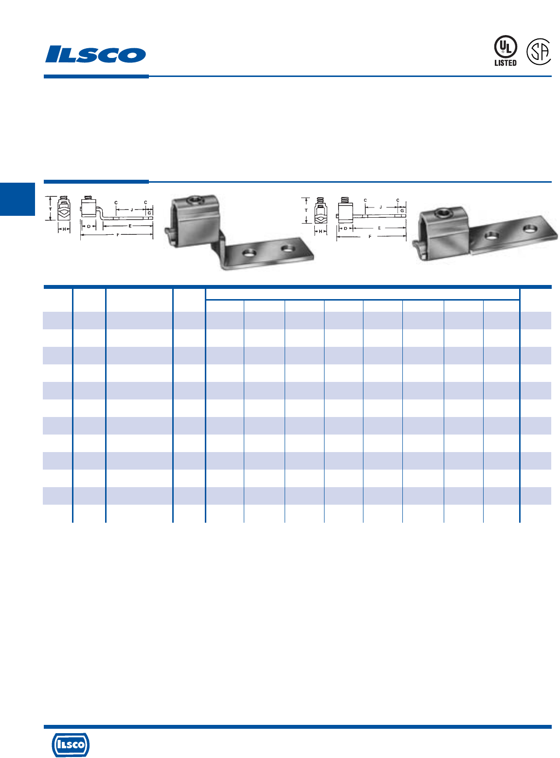
4730 Madison Road, Cincinnati, Ohio 45227-1426 Phone 513 533-6200 Fax 513 871-4084 Web site www.ilsco.com
Canada 1050 Lakeshore Road East, Mississauga, Ontario, Canada L5E1E4 Phone 905 274-2341 Fax 905 274-8763
161
C
Catalog Figure Wire Range Bolt Dimensions Hex
Number Number Copper Size C D E F G H J T Size
E-35 1 6-14 & List Comb. (A) #10 13/64 7/16 1-1/2 2-1/4 7/32 3/8 1 3/4 Slot
E-70 1 2-8 & List Comb. (B) 1/4 17/64 1/2 1-1/2 2-7/16 1/4 1/2 1 1 Slot
E-125 1 1/0-6 1/4 17/64 5/8 1-7/8 2-15/16 7/16 5/8 1 1-11/32 Slot
E-225 1 4/0-2 5/16 11/32 1 2-5/32 3-19/32 1/2 1 1 1-13/16 7/32
E-300 1 350kcmil-1/0 3/8 13/32 1-1/4 3-11/16 5-11/16 13/16 1 1-7/8 2-5/8 5/16
E-400 1 500kcmil-1/0 3/8 13/32 1-1/2 3-13/16 6 15/16 1-1/2 1-3/4 2-3/4 5/16
E-650 1 1000kcmil-600kcmil 1/2 17/32 1-7/8 3-9/16 6-1/4 1-3/16 2 1-3/4 3-11/16 3/8
H-35 2 6-14 & List Comb. (A) #10 13/64 7/16 1-5/8 2-1/8 7/32 3/8 1 11/16 Slot
H-70 2 2-8 & List Comb. (B) 1/4 17/64 1/2 1-7/8 2-1/2 1/4 1/2 1 31/32 Slot
H-225 2 4/0-2 5/16 11/32 1 2-7/32 3-3/8 1/2 1 1 1-21/32 7/32
H-400 2 500kcmil-1/0 3/8 13/32 1-1/2 3-15/16 5-5/8 15/16 1-1/2 1-3/4 2-9/16 5/16
H-650 2 1000kcmil-600kcmil 1/2 17/32 1-7/8 4-3/4 6-7/8 1-3/16 2 1-3/4 3-11/16 3/8
Copper Mechanical Lugs
One Conductor, Two Hole
TYPE
E
H
Features
•
Manufactured from electrolytic copper tubing and strip
stock
•
Compact design
•
Range taking
•
Re-usable
•
UL Listed and CSA Certified for 600 volts
•
V-bottom collar
•
Two mounting holes
Benefits
•
Provides maximum conductivity and strength
•
Saves space and reduces installation time
•
Permits inventories to be kept to a minimum
•
Provides efficient use and flexibility in the field
•
Ensures reliability for copper conductor
•
Wires are wedged between arched pressure bar and collar establishing
positive contact and firm permanent grip
•
Acts as anti-rotation device and prevents turning in safety switches, control
equipment etc.
453G
L
R
-
2
9
6
0
1
(A) UL Listed wire combinations: (2) #10; (2) #12; (2) #14; (1) #12 and (1) #14; (1) #10 and (1) #12
(B) UL Listed wire combinations: (1) #8 and (1) #4; (1) #8 and (1) #6; (2) #4; (3) #8; (3) #6; (2) #8 and (1) #4; (2) #8 and (1) #6; (1) #6 and (1) #4; (2) #6
Tested to UL 486A-486B, UL File E6207
Fig. 1 Fig. 2
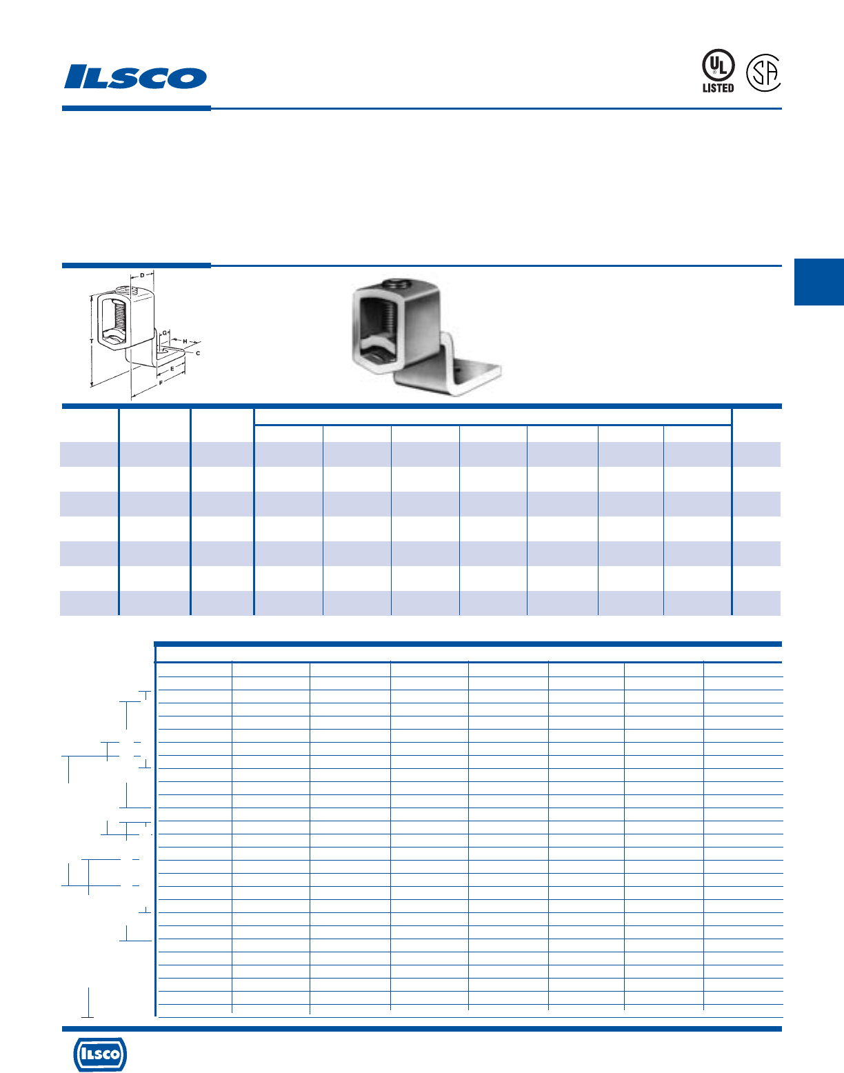
4730 Madison Road, Cincinnati, Ohio 45227-1426 Phone 513 533-6200 Fax 513 871-4084 Web site www.ilsco.com
Canada 1050 Lakeshore Road East, Mississauga, Ontario, Canada L5E1E4 Phone 905 274-2341 Fax 905 274-8763
162
C
Catalog Wire Bolt Dimensions Hex
Number Range Size C D E F G H T Size
SLUH-35 6-14 #10 13/64 7/16 1/2 1-1/8 7/32 3/8 11/16 Slot
SLUH-90 2-14 1/4 17/64 9/16 5/8 1-31/64 1/4 1/2 27/32 Slot
SLUH-125 1/0-8 1/4 17/64 11/16 13/16 1-7/8 7/16 5/8 63/64 Slot
SLUH-225 250kcmil-6 5/16 11/32 1 1-5/32 2-7/16 1/2 1 1-17/64 1/4
SLUH-300 350kcmil-1/0 3/8 13/32 1-3/16 1-1/2 3-1/16 1/2 1 2-1/4 5/16
SLUH-400 500kcmil-1/0 3/8 13/32 1-3/8 1-15/16 3-13/16 15/16 1-1/2 2-15/32 5/16
SLUH-650 1000kcmil-4/0 1/2 17/32 1-57/64 1-7/8 4-5/16 1-3/16 2 3-3/32 3/8
Copper, Heavy Duty, Mechanical Lugs
One Conductor, One Hole
TYPE
SLUH
Features
•
Manufactured from electrolytic copper tubing and strip
stock
•
Compact design
•
Range taking
•
Re-usable
•
UL Listed and CSA Certified for fine stranded CU wire
•
Electro-tin plated
•
Captive tang
•
V-bottom collar
•
Rated for 600 volts
Benefits
•
Provides maximum conductivity and strength
•
Saves space and reduces installation time
•
Permits inventories to be kept to a minimum
•
Provides efficent use and flexibility in the field
•
Ensures reliability for copper conductor
•
Provides low contact resistance
•
Suited for heavy duty applications requiring high torque to
withstand vibration and high ambient heat
•
Wires are wedged between arched pressure bar and collar
establishing positive contact and firm permanent grip
•
Ensures reliability
453G
L
R
-
2
9
6
0
1
Conductor Class
BCG HI KM
Locomotive
Cable
- - 14/49 - - 14/41 14/104 14/19
14/7 14/19 12/49 - - 12/65 12/168 12/19
12/7 12/19 - - - - - -
10/7 10/19 10/49 - 10/26 10/104 10/259 10/27
- - 8/49 8/133 8/41 8/168 8/420 8/37
8/7 8/19 - - - - - -
6/7 6/19 - - - - - -
4/7 4/19 6/49 6/133 6/63 6/266 6/665 6/61
3/7 3/19 4/49 4/133 4/105 4/420 4/1064 4/105
2/7 2/19 3/49 3/133 3/133 3/532 3/1323 3/125
1/19 1/37 2/49 2/133 2/161 2/665 2/1666 2/150
1/0/19 1/0-37 1/133 1/259 1/210 1/836 1/2107 1/225
2/0-19 2/0-37 1/0-133 1/0-259 - - 1/0/2646 1/0/275
3/0-19 3/0-37 2/0-133 2/0-259 1/0/266 1/0/1064 - 2/0/325
/0-19 4/0-37 3/0-133 3/0-259 2/0/342 2/0/1323 2/0/3325 -
250kcmil/37 250kcmil/61 - - 3/0/418 3/0/1666 3/0/4256 3/0/450
300kcmil/37 300kcmil/61 4/0-133 4/0-259 4/0/532 - - 222.2kcmil/550
350kcmil/37 350kcmil/61 250kcmil/259 250kcmil/427 250kcmil/637 4/0/2107 4/0/5320 262.6kcmil/650
400kcmil/37 400kcmil/61 300kcmil/259 300kcmil/427 300kcmil/735 250kcmil/2499 250kcmil/6384 313.1kcmil/775
500kcmil/37 500kcmil/61 350kcmil/259 350kcmil/427 350kcmil/882 300kcmil/2989 300kcmil/7581 -
- - 400kcmil/259 400kcmil/427 400kcmil/980 350kcmil/3458 350kcmil/8806 373.7kcmil/925
600kcmil/61 600kcmil/91 - - - - - 444kcmil/1100
700kcmil/61 700kcmil/91 500kcmil/259 500kcmil/427 500/kcmil/1225 450kcmil/4522 450kcmil/11396 535.3kcmil/1325
750kcmil/61 750kcmil/91 550kcmil/259 500kcmil/703 550kcmil/1372 500kcmil/5054 500kcmil/12691 -
- - 600kcmil/259 500kcmil/703 600kcmil/1470 550kcmil/5453 550kcmil/13664 646.4kcmil/1591
1000kcmil/61 1000kcmil/91 750kcmil/259 500kcmil/703 650kcmil/1596 600kcmil/5985 600kcmil/14945 -
SLUH-225 250kcmil-6
SLUH-650 1000kcmil-4/0
SLUH-125 1/0-8
SLUH-400 500kcmil-1/0 SLUH-90 2-14
SLUH-300 350kcmil-1/0
SLUH-35 6-14
UL Listed for use with fine stranded conductors. See chart below.
Tested to UL 486A-486B, UL File E6207
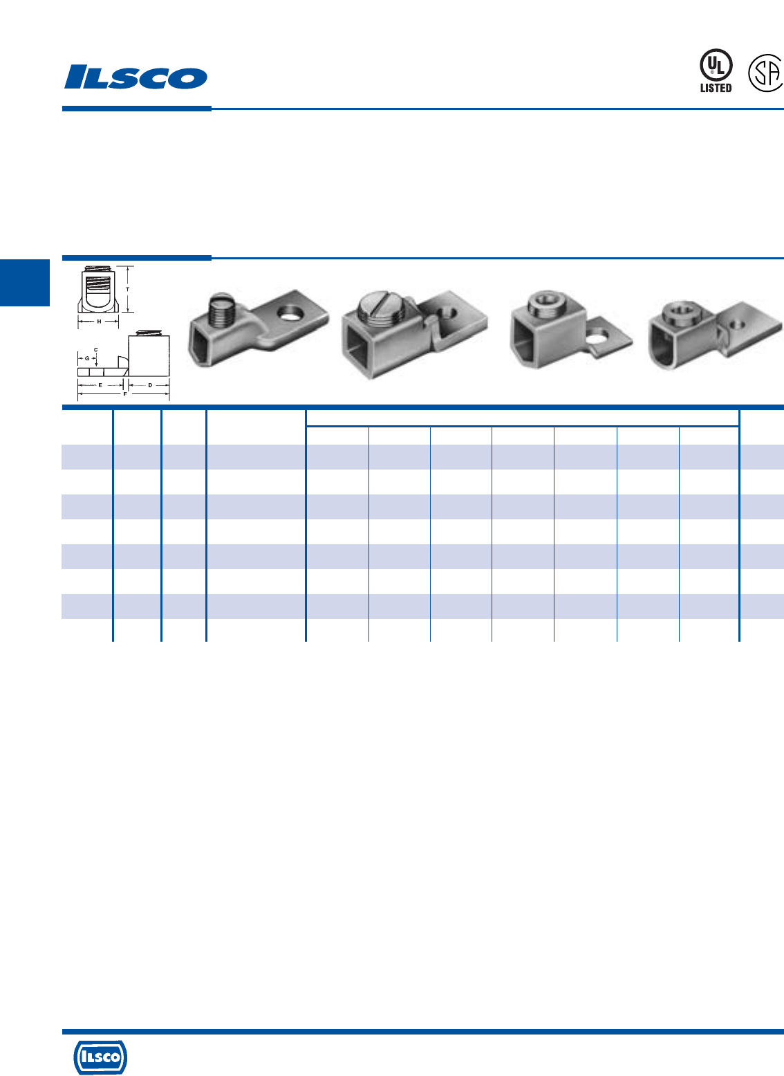
4730 Madison Road, Cincinnati, Ohio 45227-1426 Phone 513 533-6200 Fax 513 871-4084 Web site www.ilsco.com
Canada 1050 Lakeshore Road East, Mississauga, Ontario, Canada L5E1E4 Phone 905 274-2341 Fax 905 274-8763
163
C
Catalog Figure Bolt Wire Dimensions Hex
Number Number Size Range C D E F G H T Size
LO-4 1 1/4 4-14 17/64 3/4 5/8 1-3/8 9/32 1/2 25/32 Slot
LO-0 2 1/4 1/0-14 9/32 11/16 27/32 1-3/4 13/32 3/4 11/16 Slot
LO-250 4 5/16 250kcmil-6 21/64 1 1-1/4 2-9/32 7/16 63/64 7/8 3/8
LO-350SH 3 1/2 350kcmil-4 17/32 7/8 1 2-7/32 1/2 1-1/8 1-3/16 3/8
LO-350STD 3 3/8 350kcmil-4 13/32 1-1/4 1-1/8 2-5/8 1/2 1-1/8 1-1/16 3/8
LO-500 4 3/8 500kcmil-4/0 25/64 1-1/4 1-9/16 3-5/16 7/8 1-1/2 1-1/2 3/8
LO-600 4 3/8 600kcmil-1 13/32 1-7/16 1-11/16 3-5/8 7/8 1-1/2 1-1/2 3/8
LO-1000 4 1/2 1000kcmil-500kcmil 17/32 1-17/32 1-7/8 3-15/16 27/32 2 2-1/16 3/8
Copper Mechanical Lugs
One Conductor, One Hole
TYPE
LO
Features
•
Manufactured from electrolytic seamless copper tubing
•
Compact design
•
Range taking
•
Re-usable
•
UL Listed and CSA Certified for 600 volts
Fig. 1 Fig. 2 Fig. 3 Fig. 4
Benefits
•
Provides maximum conductivity and strength
•
Saves space and reduces installation time
•
Permits inventories to be kept to a minimum
•
Provides efficient use and flexibility in the field
•
Ensures reliability for copper conductor
453G
L
R
-
2
9
6
0
1
Tested to UL 486A-486B, UL File E6207
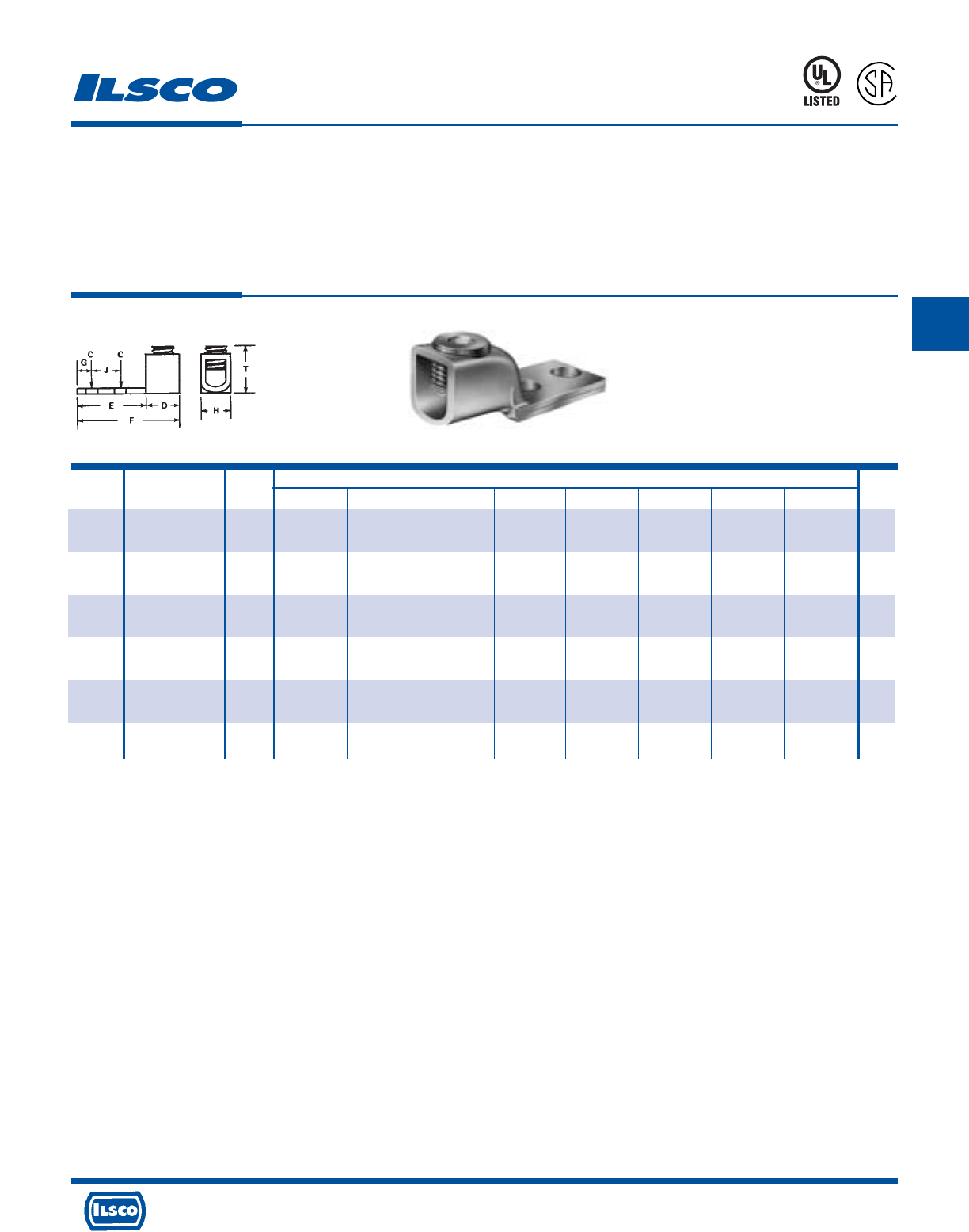
4730 Madison Road, Cincinnati, Ohio 45227-1426 Phone 513 533-6200 Fax 513 871-4084 Web site www.ilsco.com
Canada 1050 Lakeshore Road East, Mississauga, Ontario, Canada L5E1E4 Phone 905 274-2341 Fax 905 274-8763
164
C
Catalog Wire Bolt Dimensions Hex
Number Range Size C D E F G H J T Size
VT-4-S 4-14 #10 15/64 9/16 1 1-3/4 1/4 1/2 1/2 25/32 Slot
LO-0-S 1/0-14 1/4 9/32 11/16 1-9/16 2-1/2 3/8 3/4 7/8 19/32 Slot
LO-250-S 250kcmil-6 3/8 13/32 1 1-3/4 3-3/32 3/8 1 1 7/8 3/8
LO-350-S 350kcmil-4 3/8 7/16 7/8 2 3-1/2 3/8 1-1/8 1-1/16 1-1/4 3/8
LO-600-S 600kcmil-1 1/2 9/16 1-7/16 2 3-7/8 3/8 1-1/4 1-1/16 1-1/2 3/8
LO-1000-S 1000kcmil-500kcmil 1/2 9/16 1-9/16 2-1/2 4-1/2 3/8 1-5/8 1-3/16 2-1/16 3/8
Copper Mechanical Lugs
One Conductor, Two Hole
TYPE
VT
LO-S
Features
•
Manufactured from electrolytic seamless copper tubing
•
Compact design
•
Range taking
•
Re-usable
•
UL Listed and CSA Certified for 600 volts
Benefits
•
Provides maximum conductivity and strength
•
Saves space and reduces installation time
•
Permits inventories to be kept to a minimum
•
Provides efficient use and flexibility in the field
•
Ensures reliability for copper conductor
453G
L
R
-
2
9
6
0
1
Tested to UL 486A-486B, UL File E6207
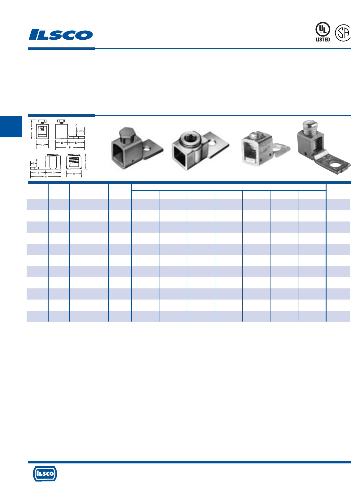
4730 Madison Road, Cincinnati, Ohio 45227-1426 Phone 513 533-6200 Fax 513 871-4084 Web site www.ilsco.com
Canada 1050 Lakeshore Road East, Mississauga, Ontario, Canada L5E1E4 Phone 905 274-2341 Fax 905 274-8763
165
C
Catalog Figure Wire Bolt Dimensions Hex
Number Number Range Size C D E F G H T Size
XT-10 3 10-14 #6 5/32 9/32 17/32 7/8 3/16 5/16 17/32 Slot
XT-6 4 6-18 #10 13/64 3/8 17/32 1 7/32 3/8 3/4 Slot
XT-6DB 3 6-14 #10 13/64 3/8 17/32 1 7/32 3/8 3/4 Slot
XT-4 3
4-14 & List Comb. (A)
1/4 17/64 1/2 5/8 1-1/8 1/4 1/2 5/8 Slot
XT-4DB 3
4-14 & List Comb. (A)
1/4 17/64 1/2 5/8 1-1/8 1/4 1/2 5/8 Slot
XT-0 3
1/0-6 & List Comb. (B)
1/4 17/64 5/8 29/32 1-17/32 7/16 5/8 1 Slot
XT-40 1 4/0-6 5/16 11/32 1 1-1/16 2-3/16 9/16 .81 1-5/8 EH 5/8
XT-500* 1 500kcmil-2/0 3/8 7/16 1-3/8 1-11/16 3-3/16 7/8 1-1/2 2-9/16 EH 3/4
LY-250-S 2 250kcmil-6 1/4 17/64 1 13/16 1-13/16 3/8 1 1 3/8
LY-600 2 600kcmil-1/0 (C) 3/8 13/32 1-7/16 1-7/8 3-5/16 7/8 1-1/2 1-3/8 3/8
LY-600-S 2 600kcmil-1/0 (C) 5/16 21/64 1-7/16 1-1/8 2-9/16 1/2 1-3/8 1-3/8 3/8
Copper Mechanical Lugs
One Conductor, One Hole
TYPE
XT
LY
Features
•
Manufactured from electrolytic copper tubing and strip
stock
•
Compact design
•
Range taking
•
Re-usable
•
UL Listed and CSA Certified for 600 volts
•
XT-6DB and XT-4DB are UL 467 Listed and suitable for
direct burial
Benefits
•
Provides maximum conductivity and strength
•
Saves space and reduces installation time
•
Permits inventories to be kept to a minimum
•
Provides efficient use and flexibility in the field
•
Ensures reliability for copper conductor
453G
L
R
-
2
9
6
0
1
*Furnished with Pressure Plate
EH External Hex
(A) UL Listed wire combinations: (2) #14; (2) #12; (2) #10; (2) #8 and (4) #16
(B) UL Listed wire combinations: (2) #6 and (2) #8
(C) UL Listed wire combinations: (2) #4/0; (2) #3/0; (2) #2/0, and (2) #1/0
Tested to UL 486A-486B, UL File E6207
Fig. 1 Fig. 2 Fig. 3 Fig. 4
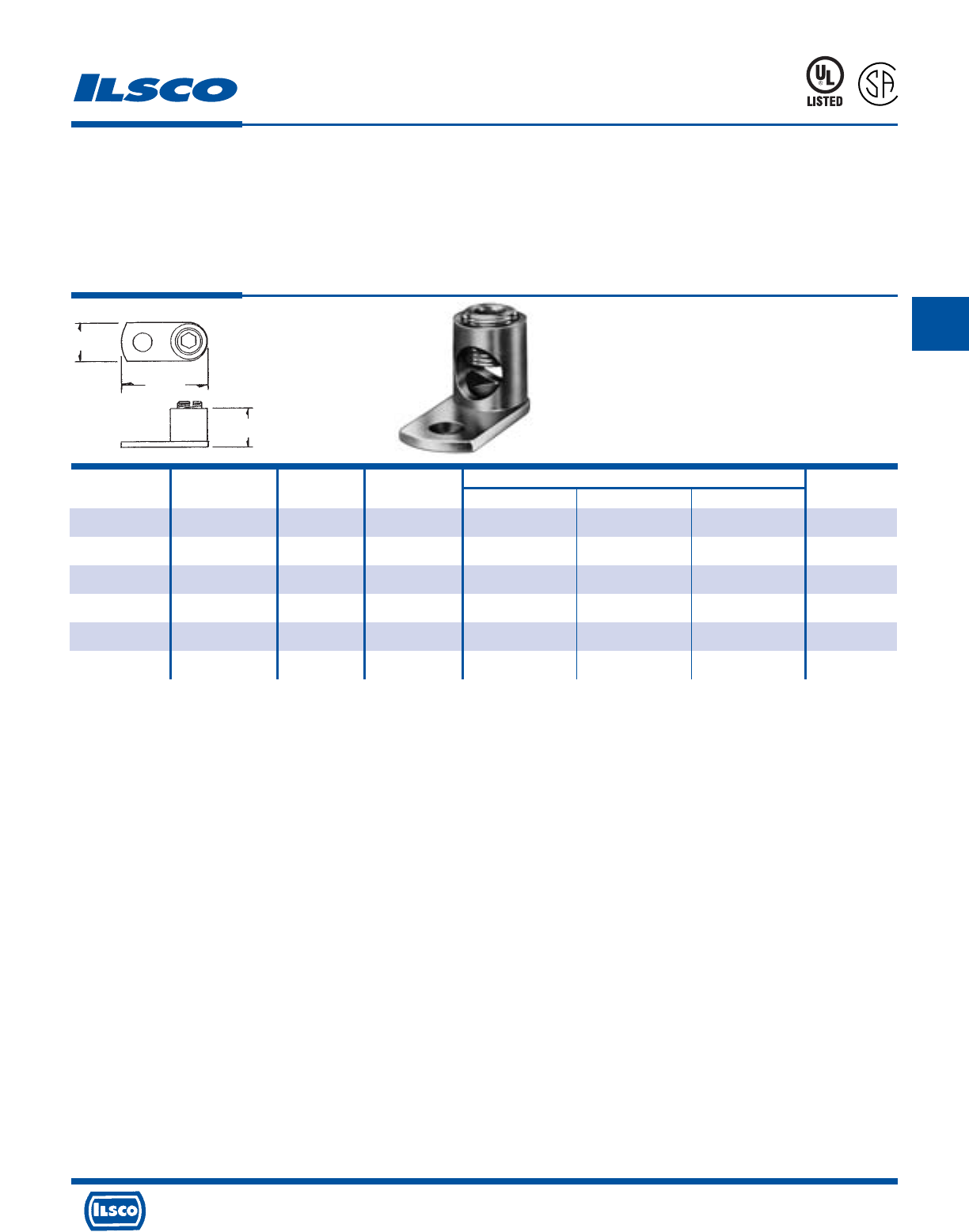
4730 Madison Road, Cincinnati, Ohio 45227-1426 Phone 513 533-6200 Fax 513 871-4084 Web site www.ilsco.com
Canada 1050 Lakeshore Road East, Mississauga, Ontario, Canada L5E1E4 Phone 905 274-2341 Fax 905 274-8763
166
C
Catalog Wire Bolt Stud Hole Dimensions Hex
Number Range Size Size L W H Size
CP-8 8-14 10 13/64 51/64 3/8 27/64 Slot
CP-4 4-14 1/4 17/64 1-3/32 17/32 35/64 Slot
CP-0 1/0-8 5/16 11/32 1-1/2 3/4 5/8 1/4
CP-250 250kcmil-6 3/8 13/32 1-31/32 15/16 1-1/16 1/4
CP-500* 500kcmil-4/0 1/2 17/32 2-31/32 1-3/8 1-7/16 3/8
CP-1000* 1000kcmil-500kcmil 1/2 17/32 3-31/32 2-1/32 2-3/16 1/2
Copper Post Connectors
TYPE
CP
Features
•
Manufactured from high conductivity copper alloy
•
Compact design
•
Range taking
•
Re-usable
•
UL Listed and CSA Certified for 600 volts
Benefits
•
Provides long lasting reliable contact
•
Saves space and reduces installation time
•
Permits inventories to be kept to a minimum
•
Provides efficient use and flexibility in the field
•
Ensures reliability for copper conductor
* Not CSA Certified
Tested to UL 486A-486B, UL File E6207
L
R
-
2
9
6
0
1
W
L
H
453G
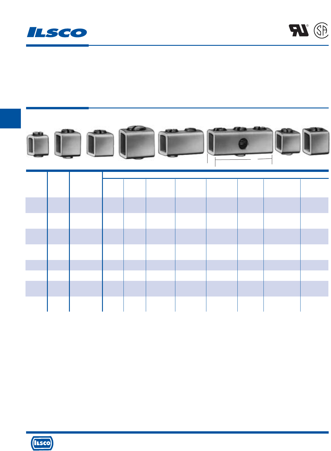
4730 Madison Road, Cincinnati, Ohio 45227-1426 Phone 513 533-6200 Fax 513 871-4084 Web site www.ilsco.com
Canada 1050 Lakeshore Road East, Mississauga, Ontario, Canada L5E1E4 Phone 905 274-2341 Fax 905 274-8763
167
C
Dimensions
Height With Bossed Style Boss Top Top Hole Bottom
Catalog Figure Wire Maximum Mounting And Outside Hole And Inner Side Clearance
Number Number Range L W Wire Hole Tapped Dimensions Tapped Walls Tapped Hole
CO3RP 1 6-14 3/8 11/32 21/32 8-32 Round 1/4-28 - -
.216-.220
CO3SP 1 6-14 3/8 11/32 21/32 10-32 Square 1/4-28 - -
.216-.220
CO4RP 2 4-14 15/32 29/64 19/32 10-32 Round 5/16-24 - -
.227-.231
CO4SP 2 4-14 15/32 29/64 19/32 10-32 Square 5/16-24 - -
.227-.231
CO4CW 3 4-14 15/32 29/64 3/4 - - - 3/8-27 .203
CO4CP 8 4-14 15/32 29/64 21/32 - - 5/16-24 - .265
CO4DD 5 4-14 29/32 29/64 19/32 10-32 Round 5/16-24 - -
.227-.231
CO4-3 6 4-14 1-29/64 29/64 19/32 10-32 Square 5/16-24 - -
.227-.231
TYPE
CO
Features
•
Manufactured from electrolytic seamless copper tubing
•
Compact design
•
Range taking
•
Re-usable
•
UL Recognized and CSA Certified for 600 volts
•
Bossed mounting holes
Benefits
•
Provides maximum conductivity and strength
•
Saves space and reduces installation time
•
Permits inventories to be kept to a minimum
•
Provides efficient use and flexibility in the field
•
Ensures reliability for copper conductor
•
Acts as an anti-rotation device and prevents the connector
from turning
L
R
-
2
9
6
0
1
Contact Factory for Availability and Minimum Order Requirements
Tested to UL 486A-486B, UL File E6207
Fig. 1 Fig. 2 Fig. 3 Fig. 4 Fig. 5 Fig. 6 Fig. 7 Fig. 8
Copper, Box Type Mechanical Lugs
L
W
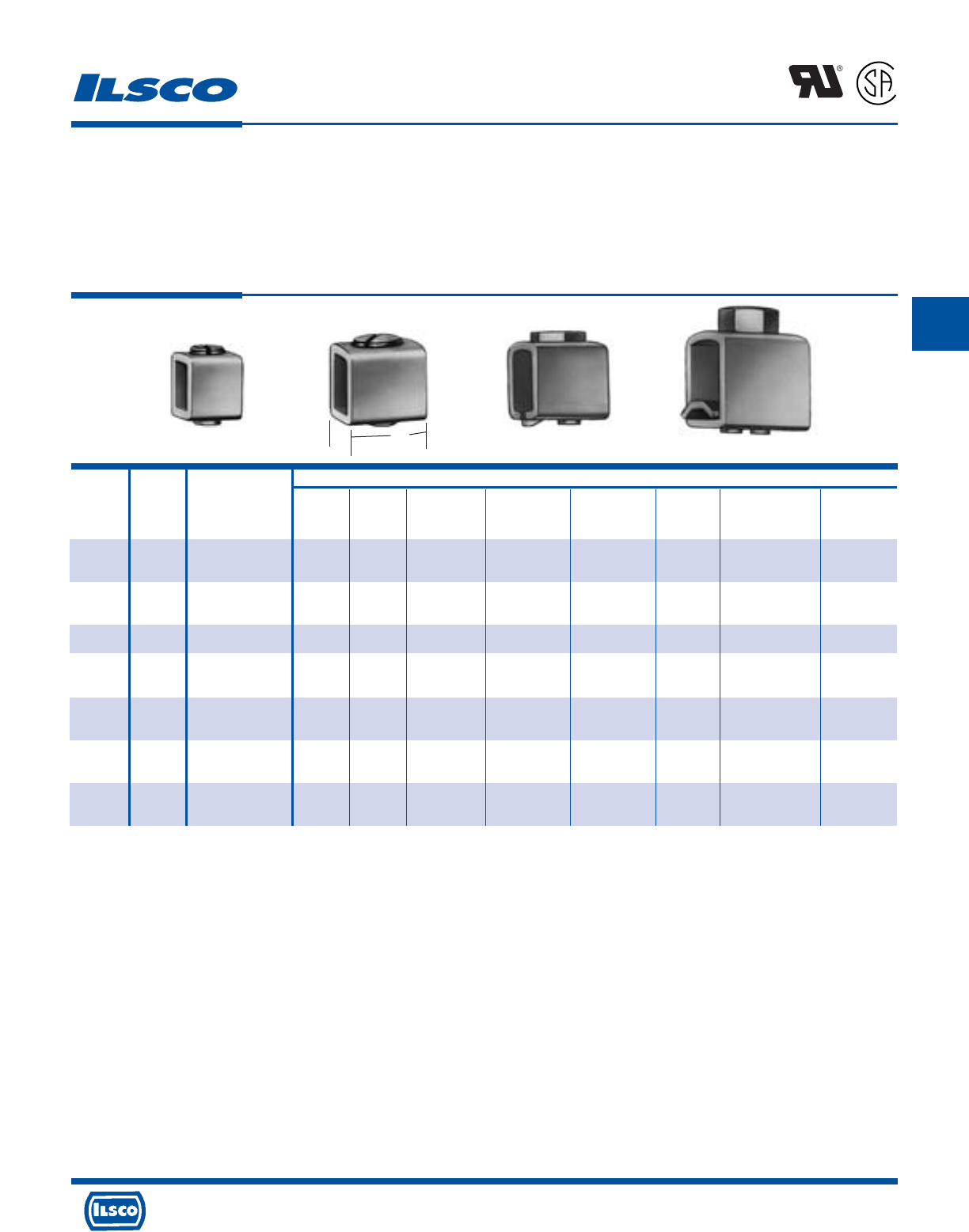
4730 Madison Road, Cincinnati, Ohio 45227-1426 Phone 513 533-6200 Fax 513 871-4084 Web site www.ilsco.com
Canada 1050 Lakeshore Road East, Mississauga, Ontario, Canada L5E1E4 Phone 905 274-2341 Fax 905 274-8763
168
C
Dimensions
Height With Bossed Style Boss Top Top Hole Bottom
Catalog Figure Wire Maximum Mounting And Outside Hole And Inner Side Clearance
Number Number Range L W Wire Hole Tapped Dimensions Tapped Walls Tapped Hole
CO5RP 1 1/0-6 5/8 9/16 29/32 10-32 Round 3/8-27 - -
.227-.231
CO5SP 1 1/0-6 5/8 9/16 29/32 10-32 Square 3/8-27 - -
.227-.231
CO5CW 1 1-14 5/8 17/32 3/4 - - - 7/16-20 .205
CO5SW 2 1/0-14 5/8 17/32 11/16 12-24 Square - 7/16-20 -
.248-.252
CO6RP 3 4/0-2 1 13/16 1-9/16 1/4-20 Round 9/16-24 - -
.2825-.2875
CO7 4 500kcmil-1/0 1-3/8 1-1/8 2-3/8 1/4-20 Round 5/8-18 - -
.3025-.3225
CO8 4 1000kcmil-250kcmil 1-15/16 1-33/64 3-1/2 5/16-18 Round 3/4-16 - -
.365-.380
Copper, Box Type Mechanical Lugs
TYPE
CO
Features
•
Manufactured from electrolytic seamless copper tubing
•
Compact design
•
Range taking
•
Re-usable
•
UL Recognized and CSA Certified for 600 volts
•
Bossed mounting holes
Benefits
•
Provides maximum conductivity and strength
•
Saves space and reduces installation time
•
Permits inventories to be kept to a minimum
•
Provides efficient use and flexibility in the field
•
Ensures reliability for copper conductor
•
Acts as an anti-rotation device and prevents the connector
from turning
L
R
-
2
9
6
0
1
Contact Factory for Availability and Minimum Order Requirements
Tested to UL 486A-486B, UL File E6207
Fig. 1 Fig. 2 Fig. 3 Fig. 4
L
W
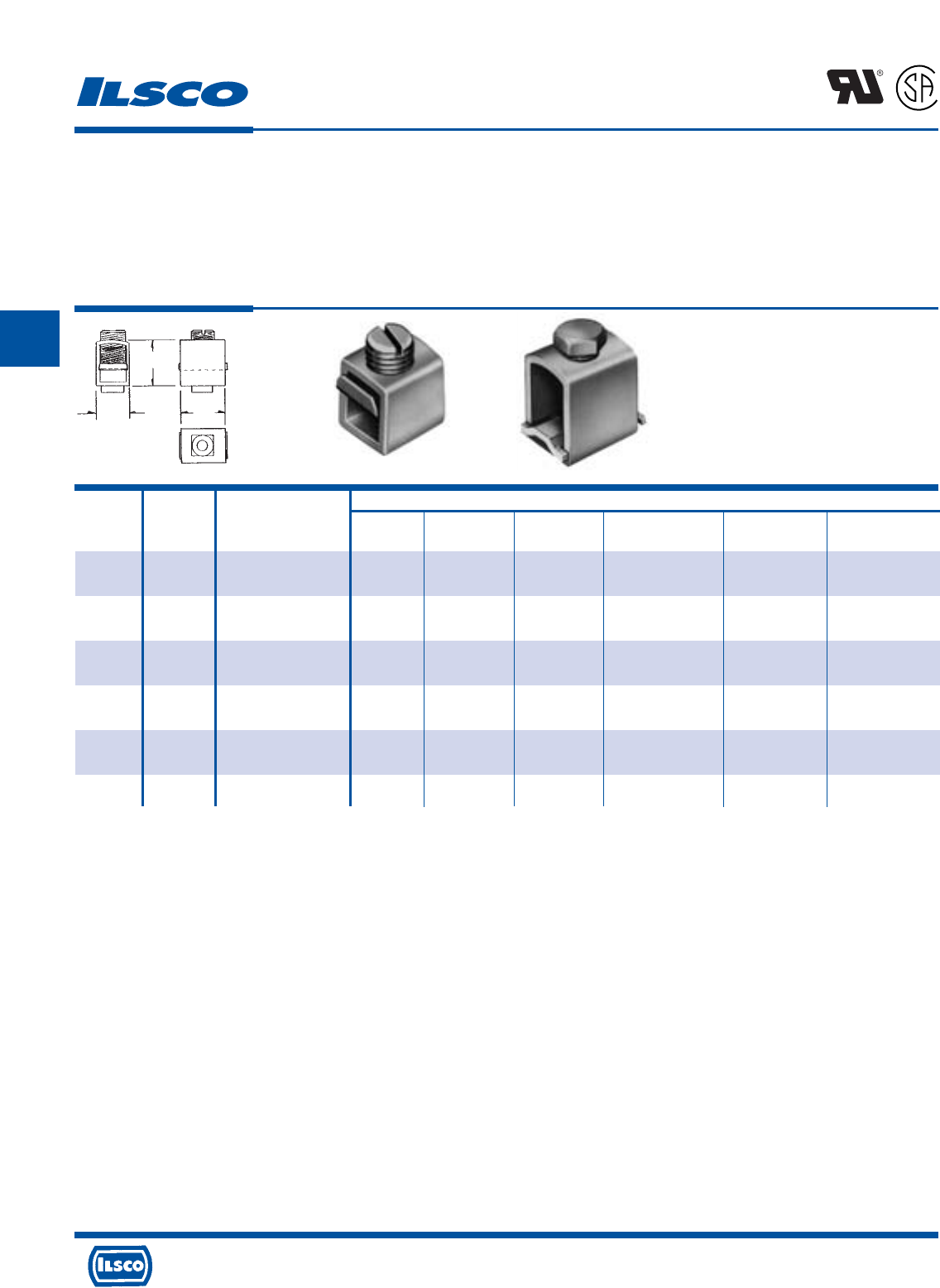
4730 Madison Road, Cincinnati, Ohio 45227-1426 Phone 513 533-6200 Fax 513 871-4084 Web site www.ilsco.com
Canada 1050 Lakeshore Road East, Mississauga, Ontario, Canada L5E1E4 Phone 905 274-2341 Fax 905 274-8763
169
C
Dimensions
Catalog Figure Wire Bottom Boss Bottom Boss Set Screw
Number Number Range L W H Size Outside Tapped In Top
CO4RPP* 1 4-14 9/16 29/64 41/64 Round 10-32 5/16-24
.227-.231 Steel Headless
D-2742+ 1 1/0-6 47/64 9/16 61/64 Round 10-32 3/8-27
.227-.231 Steel Headless
D-2741+ 1 1/0-6 47/64 9/16 61/64 Square 10-32 3/8-27
.227-.231 Steel Headless
D-2740+ 2 4/0-2 1-9/64 13/16 1-5/8 Round 1/4-20 9/16-24
.2825-.2875 Steel Hex Head
D-2738+ 2 500kcmil-1/0 1-21/32 1-1/8 2-3/8 Round 1/4-20 5/8-18
.3025-.3225 Steel-Cap Hex Head
D-2739+ 2 1000kcmil-500kcmil 2-1/4 1-33/64 3-1/2 Round 5/16-18 3/4-16
.365-.380 Steel-Cap Hex Head
Copper, Box-Type Mechanical Lugs
with Pressure Plate
TYPE
CO-PP
Features
•
Manufactured from electrolytic seamless copper tubing
•
Compact design
•
Range taking
•
Re-usable
•
UL Recognized and CSA Certified for 600 volts
•
Bossed mounting holes
•
Pressure plate
•
Electro Tin Plated
Benefits
•
Provides maximum conductivity and strength
•
Saves space and reduces installation time
•
Permits inventories to be kept to a minimum
•
Provides efficient use and flexibility in the field
•
Ensures reliability for copper conductor
•
Acts as an anti-rotation rotation device and prevents
the connector from turning
•
Prevents screw damage to the conductor
•
Provides low contact resistance
L
R
-
2
9
6
0
1
* UL Recognized for both aluminum and copper conductor, 75˚ C rating.
+ UL Recognized for copper conductors only
Tested to UL 486B, UL File E6207
Fig. 1 Fig. 2
H
WL
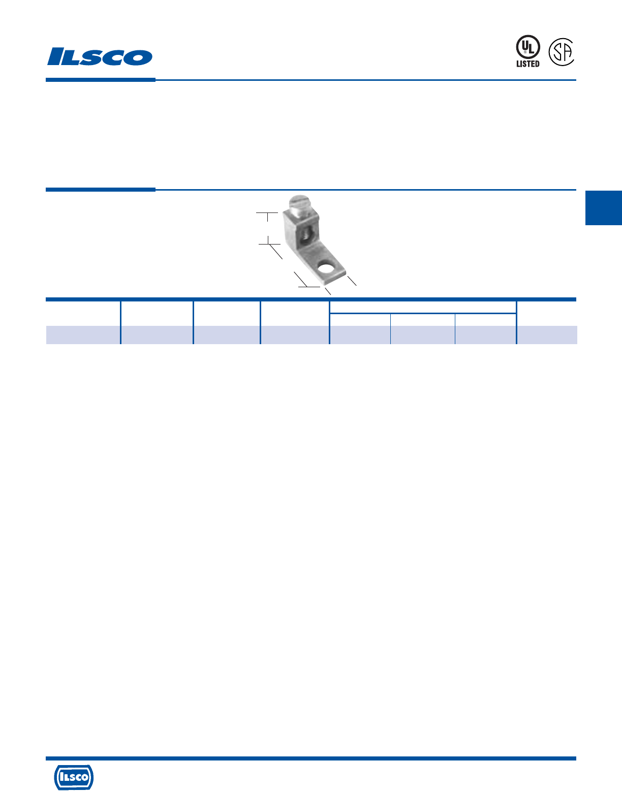
4730 Madison Road, Cincinnati, Ohio 45227-1426 Phone 513 533-6200 Fax 513 871-4084 Web site www.ilsco.com
Canada 1050 Lakeshore Road East, Mississauga, Ontario, Canada L5E1E4 Phone 905 274-2341 Fax 905 274-8763
170
C
Catalog Wire Bolt Hole Dimensions Hex
Number Range Size Dia. L W H Size
TC-6 6-14, (2) #8 #10 13/64 13/16 5/16 1/2 Slot
Copper Mechanical Lugs
One Conductor, One Hole
TYPE
TC
Features
•
Manufactured from solid copper alloy
•
Compact design
•
Range taking
•
Re-usable
•
UL Listed and CSA Certified for 600 volts
Benefits
•
Provides maximum conductivity and strength
•
Space saving
•
Permits inventories to be kept to a minimum
•
Provides efficient use and flexibility in the field
•
Ensures reliability for copper conductor
453G
L
R
-
2
9
6
0
1
Tested to UL 486A-486B, UL File E6207
L
W
H
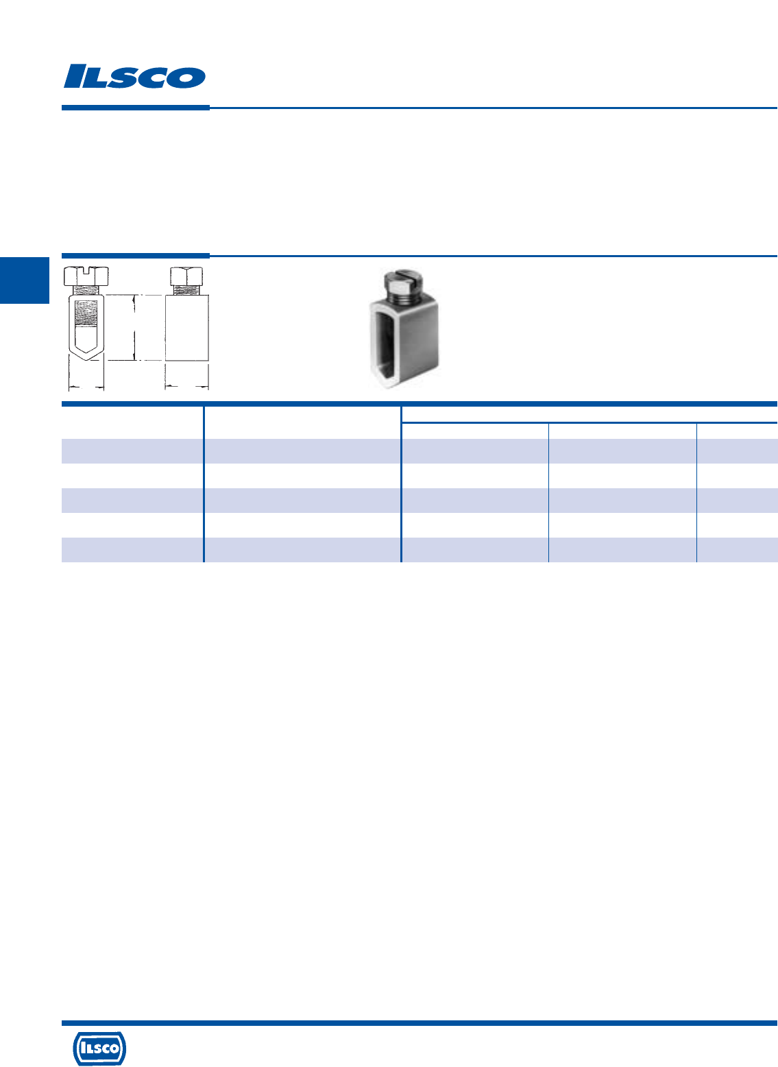
4730 Madison Road, Cincinnati, Ohio 45227-1426 Phone 513 533-6200 Fax 513 871-4084 Web site www.ilsco.com
Canada 1050 Lakeshore Road East, Mississauga, Ontario, Canada L5E1E4 Phone 905 274-2341 Fax 905 274-8763
171
C
Catalog Wire Dimensions
Number Range L W H
SX-12 12str 9/32 1/4 3/8
SX-10-8 8-10str 5/16 1/4 31/64
SX-6+ 6str 7/16 11/32 11/16
SX-4+ 4str 1/2 13/32 25/32
SX-2 2str 3/4 31/64 15/16
Copper Service Entrance Mechanical Lugs
TYPE
SX
Features
•
Manufactured from high strength copper tubing
•
Compact design
•
Versatile
Benefits
•
Provides maximum conductivity for copper conductors
•
Requires very little space
•
Can be installed with either screwdriver, wrench,
or pliers
H
WL
+ REA Listed
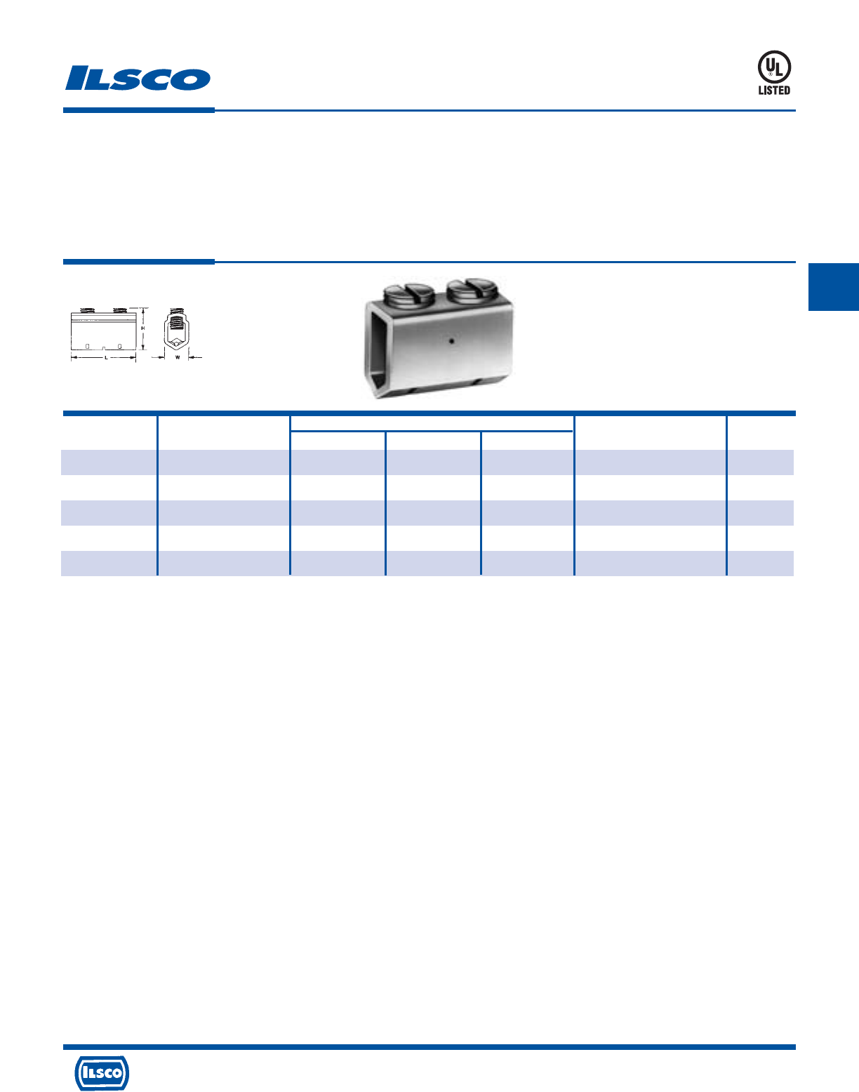
4730 Madison Road, Cincinnati, Ohio 45227-1426 Phone 513 533-6200 Fax 513 871-4084 Web site www.ilsco.com
Canada 1050 Lakeshore Road East, Mississauga, Ontario, Canada L5E1E4 Phone 905 274-2341 Fax 905 274-8763
172
C
Catalog Dimensions Hex
Number Wire Range L W H Screw Size
2SC-35 6-14 7/8 21/64 11/16 Slotted Headless Slot
2SC-50 4-14 7/8 3/8 3/4 Slotted Headless Slot
2SC-70 2-4 1 15/32 29/32 Slotted Headless Slot
2SC-125 2/0-1/0 1-1/16 39/64 13/16 Slotted Hex Head Slot
2SC-225 250kcmil-3/0 2-5/16 49/64 1-7/16 Hex Head 7/32
Copper Splicer/Reducer
TYPE
2SC
Features
•
Manufactured from electrolytic seamless copper tubing
•
Compact design
•
Range taking
•
Re-usable
•
UL Listed for 600 volts
•
V-bottom collar with serrations
•
Two screw design
Benefits
•
Provides maximum conductivity and strength
•
Saves space and reduces installation time
•
Permits inventories to be kept to a minimum
•
Provides efficient use and flexibility in the field
•
Ensures reliability for copper conductor
•
Wires are held securely between set screws and
v-bottom providing superior pullout strength
•
For light duty applications
453G
Tested to UL 486A-486B, UL File E6207
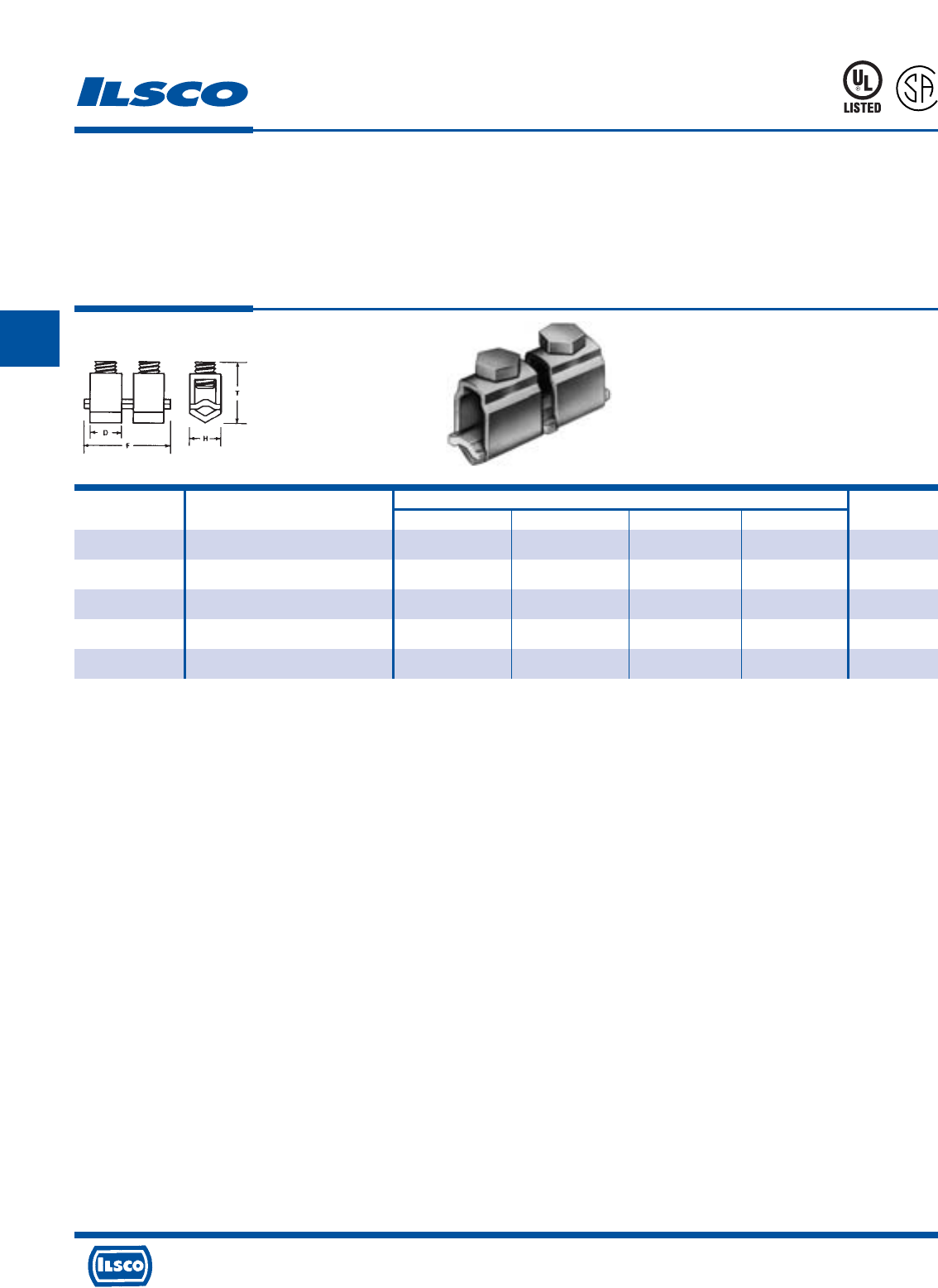
4730 Madison Road, Cincinnati, Ohio 45227-1426 Phone 513 533-6200 Fax 513 871-4084 Web site www.ilsco.com
Canada 1050 Lakeshore Road East, Mississauga, Ontario, Canada L5E1E4 Phone 905 274-2341 Fax 905 274-8763
173
C
Catalog Wire Dimensions Hex
Number Range D F H T Size
N-25 10-14 9/32 13/16 1-4 19/32 Slot
N-35 6-14 & List Combination (A) 7/16 1-3/16 3/8 11/16 Slot
N-70 2-8 & List Combination (B) 1/2 1-3/8 1/2 31/32 Slot
N-125 1/0-2 5/8 1-3/4 5/8 1-1/4 Slot
N-225 4/0-2 1 2-9/16 1 1-21/32 7/32
Copper Splicer/Reducer
TYPE
N
Features
•
Manufactured from electrolytic copper tubing and strip
stock
•
Compact design
•
Range taking
•
Re-usable
•
UL Listed and CSA Certified for 600 volts
•
V-bottom collar
Benefits
•
Provides maximum conductivity and strength
•
Saves space and reduces installation time
•
Permits inventories to be kept to a minimum
•
Provides efficient use and flexibility in the field
•
Ensures reliability for copper conductor
•
Wires are wedged between arched pressure bar and
collar establishing positive contact and firm permanent
grip
L
R
-
2
9
6
0
1
453G
(A) UL Listed wire combinations: (2) #10; (2) #12; (2) #14; (1) #12 and (1) #14; (1) #10 and (1) #12
(B) UL Listed wire combinations: (1) #8 and (1) #4; (1) #8 and (1) #6; (2) #4; (3) #8; (3) #6; (2) #8 and (1) #4; (2) #8 and (1) #6; (1) #6 and (1) #4; (2) #6
Tested to UL 486A-486B, UL File E6207
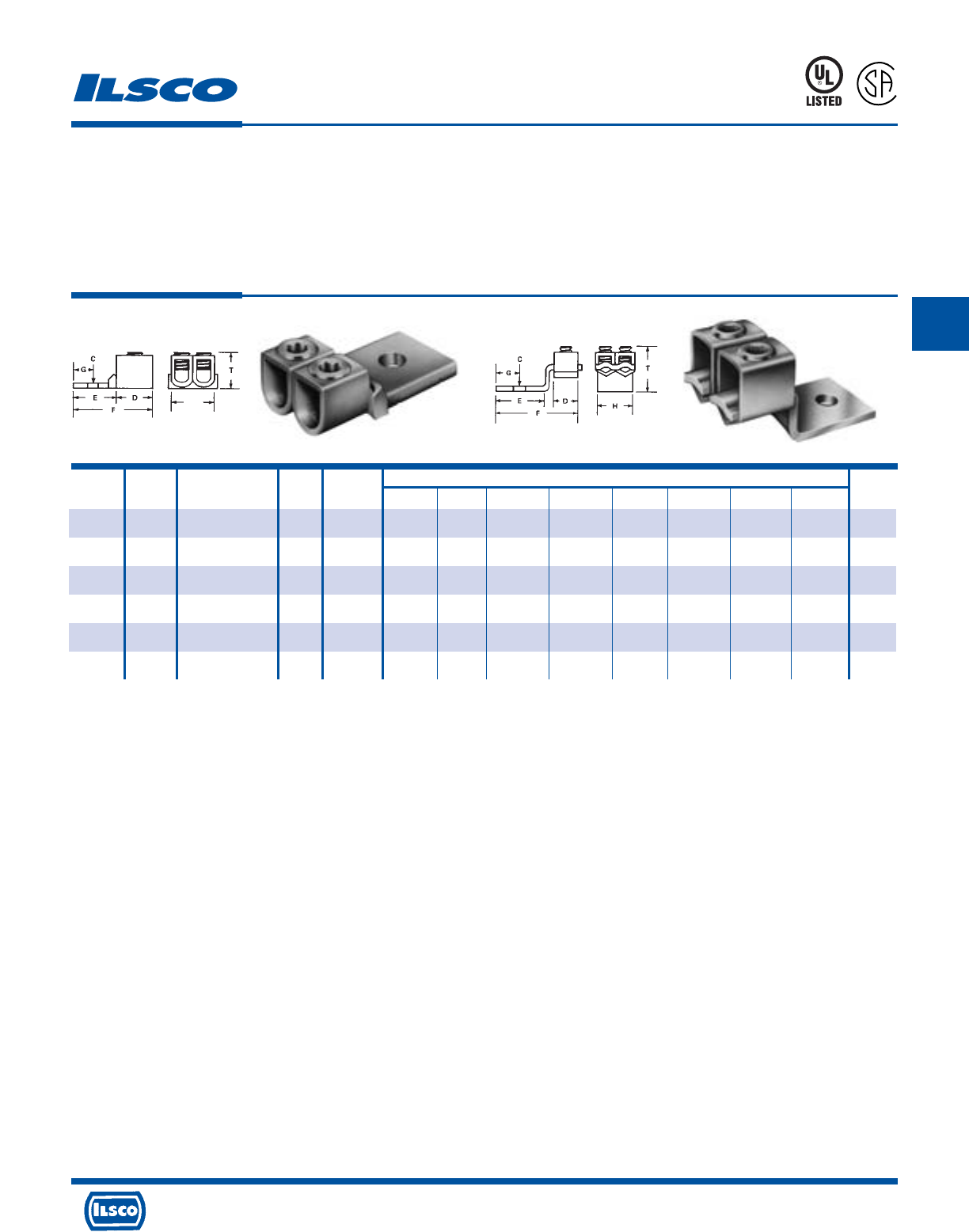
4730 Madison Road, Cincinnati, Ohio 45227-1426 Phone 513 533-6200 Fax 513 871-4084 Web site www.ilsco.com
Canada 1050 Lakeshore Road East, Mississauga, Ontario, Canada L5E1E4 Phone 905 274-2341 Fax 905 274-8763
174
C
Catalog Figure Wire Bolt Collar Dimensions Hex
Number Number Range Size Style C D E F G H K T Size
MU-250 1 Two: 250kcmil-6 3/8 Square 25/64 1 1-9/16 2-15/16 7/8 1-1/2 1-5/8 15/16 1/4
MU-350 1 Two: 350kcmil-1/0 1/2 Round 9/16 1-9/16 1-13/16 3-5/16 7/8 1-3/4 1-7/8 1-9/16 3/8
MU-600 1 Two: 600kcmil-4/0 1/2 Round 9/16 1-1/4 1-13/16 3-5/8 7/8 2-1/4 2-1/2 1-3/4 3/8
LU-2 2 Two: 4/0-2 3/8 V-bottom 13/32 1 1-15/16 3-11/32 15/16 1-1/2 1-5/8 1-7/8 7/32
LU-4 2 Two: 350kcmil-1/0 3/8 V-bottom 13/32 1-1/4 1-3/4 3-1/2 21/32 1-3/4 2 2-7/32 5/16
LU-6 2 Two: 500kcmil-1/0 1/2 V-bottom 17/32 1-1/2 2-3/16 4-7/16 27/32 2 2-1/4 2-9/16 5/16
Copper Mechanical Lugs
Two Conductor, One Hole
TYPE
MU
LU
Features
•
Manufactured from electrolytic copper tubing and strip
stock
•
Compact design
•
Range taking
•
Re-usable
•
UL Listed and CSA Certified for 600 volts
•
V-bottom collar (Type LU)
Benefits
•
Provides maximum conductivity and strength
•
Saves space and reduces installation time
•
Permits inventories to be kept to a minimum
•
Provides efficient use and flexibility in the field
•
Ensures reliability for copper conductor
•
Wires are wedged between arched pressure bar and
collar establishing positive contact and firm permanent
grip
453G
L
R
-
2
9
6
0
1
Fig. 1 Fig. 2
K
Tested to UL 486A-486B, UL File E6207
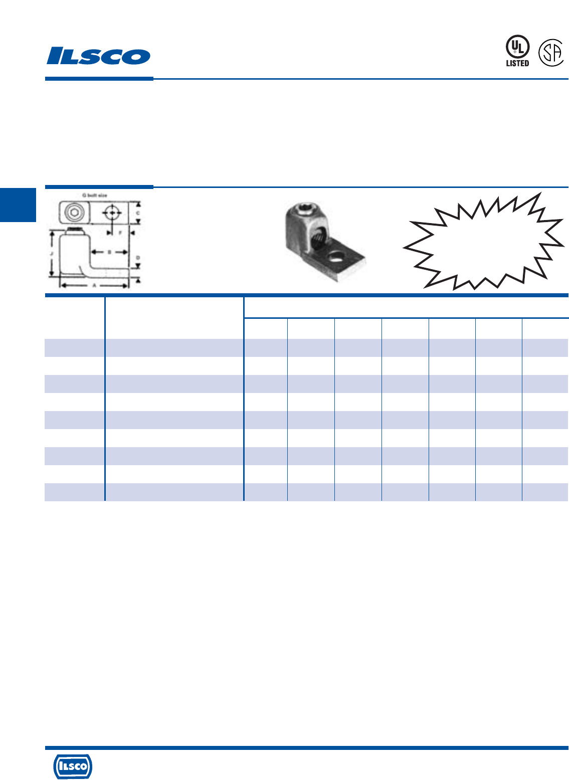
4730 Madison Road, Cincinnati, Ohio 45227-1426 Phone 513 533-6200 Fax 513 871-4084 Web site www.ilsco.com
Canada 1050 Lakeshore Road East, Mississauga, Ontario, Canada L5E1E4 Phone 905 274-2341 Fax 905 274-8763
175
C
Dimensions
Catalog
Number Wire Range G A B C D J F
CL-1-8† 8-14 1/4 1-1/8 9/16 1/2 1/8 17/32 9/32
CL-1-4† 4-8 1/4 1-1/8 5/8 1/2 1/8 17/32 9/32
CL-1-1 1-4 1/4 1-5/8 13/16 5/8 7/32 1 11/32
CL-1-2/0 2/0-1 3/8 1-15/16 1 13/16 1/4 1-3/16 7/16
CL-1-4/0 4/0-2/0 3/8 2-3/8 1-1/4 1 9/32 1-13/32 17/32
CL-1-300 300kcmil-4/0 1/2 2-3/4 1-1/2 1-3/16 5/16 1-17/32 5/8
CL-1-500 500kcmil-300kcmil 1/2 3-1/16 1-11/16 1-3/8 11/32 1-13/16 3/4
CL-1-750 750kcmil-500kcmil 1/2 3-25/32 2-3/16 1-5/8 13/32 2-1/8 1
CL-1-1000 1000kcmil-750kcmil 5/8 4-5/16 2-15/32 1-7/8 15/32 2-11/32 1-3/16
Bronze, One Conductor Mechanical Lugs
One Mounting Hole
TYPE
CL
Features
•
Range taking
•
Easily installed with a key wrench
•
Convenient peep hole
•
Re-usable
•
UL Listed and CSA Certified for 600 volts
Benefits
•
Permits inventories to be kept to a minimum
•
Time savings
•
Easy inspection
•
Provides efficient use and flexibility in the field
•
Ensures reliability
† With Filister head screw. All other, hex socket screw.
UL File E158587
8M24
A
P
-
1
0
0
9
7
3
-
1
Replaces
VL Series
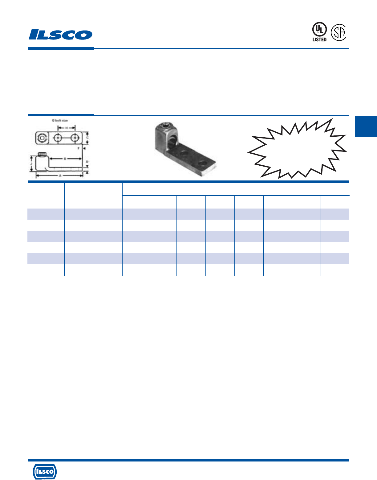
4730 Madison Road, Cincinnati, Ohio 45227-1426 Phone 513 533-6200 Fax 513 871-4084 Web site www.ilsco.com
Canada 1050 Lakeshore Road East, Mississauga, Ontario, Canada L5E1E4 Phone 905 274-2341 Fax 905 274-8763
176
C
Dimensions
Catalog
Number Wire Range G A B C D J F H
CL-1-2/0N 2/0-1 1/2 3-15/16 3 1 1/4 11/16 9/16 1-3/4
CL-1-4/0N 4/0-2/0 1/2 4-1/8 3 1 9/32 1-9/32 9/16 1-3/4
CL-1-300N 300kcmil-4/0 1/2 4-3/16 3 1-3/16 5/16 1-15/32 9/16 1-3/4
CL-1-500N 500kcmil-300kcmil 1/2 4-7/8 3-1/2 1-3/8 11/32 1-13/16 9/16 1-3/4
CL-1-750N 750kcmil-500kcmil 1/2 5-3/32 3-1/2 1-3/4 13/32 2-1/8 9/16 1-3/4
CL-1-1000N 1000kcmil-750kcmil 1/2 5-1/4 3-1/2 3 15/32 2-1/8 9/16 1-3/4
Bronze, One Conductor Mechanical Lugs
Two Mounting Hole
TYPE
CL
Features
•
Range taking
•
Easily installed with a key wrench
•
Convenient peep hole
•
Re-usable
•
UL Listed and CSA Certified for 600 volts
Benefits
•
Permits inventories to be kept to a minimum
•
Time savings
•
Easy inspection
•
Provides efficient use and flexibility in the field
•
Ensures reliability
Furnished with bolt holes and spacing to fit equipment supplied with NEMA type connector mounting pads.
UL File E158587
8M24
A
P
-
1
0
0
9
7
3
-
1
Replaces
VL Series
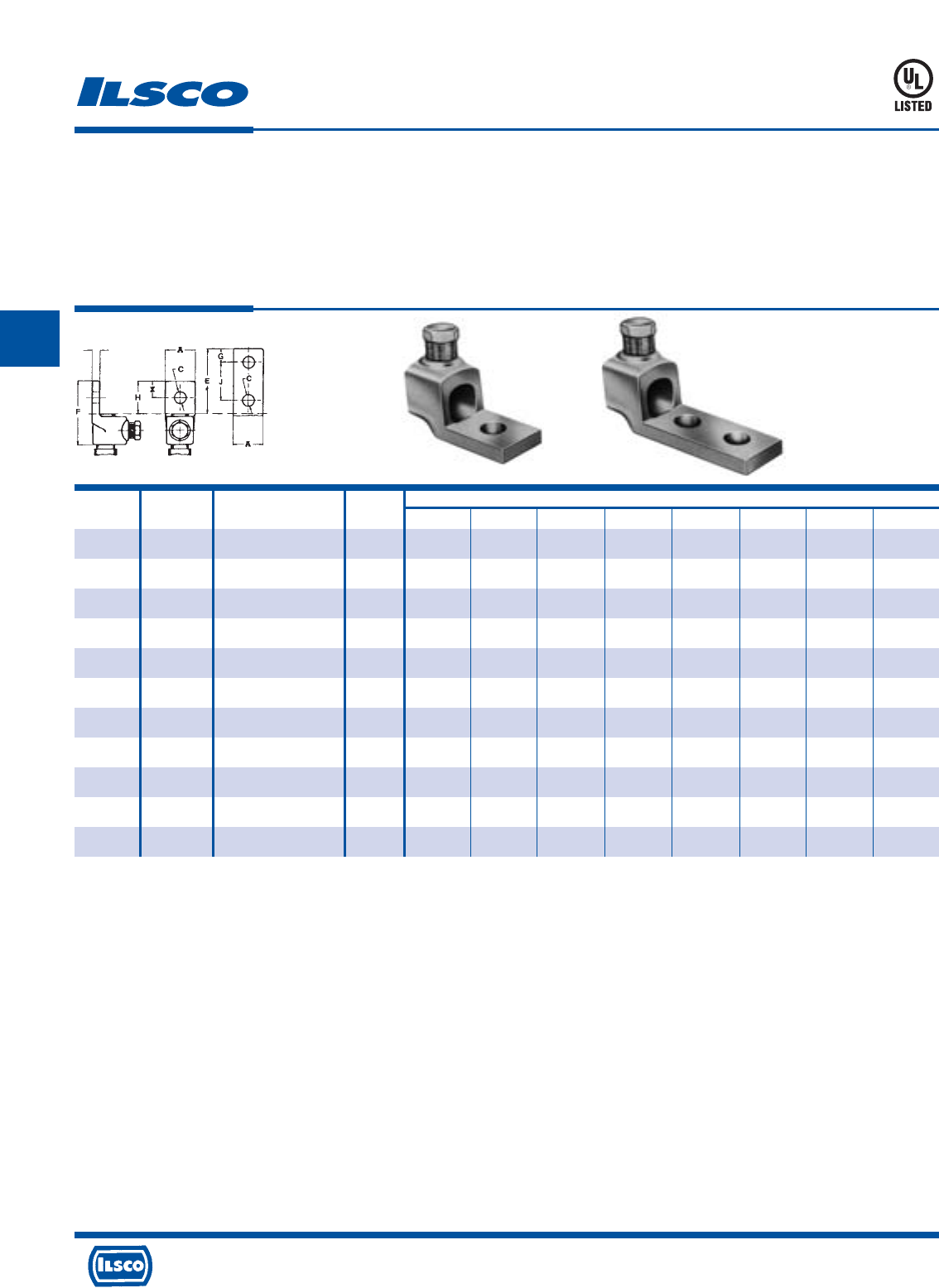
4730 Madison Road, Cincinnati, Ohio 45227-1426 Phone 513 533-6200 Fax 513 871-4084 Web site www.ilsco.com
Canada 1050 Lakeshore Road East, Mississauga, Ontario, Canada L5E1E4 Phone 905 274-2341 Fax 905 274-8763
177
C
Catalog Figure Wire Bolt Dimensions
Number Number Range Size A C E F G H J K
HL4-1 1 4 str-8 sol 1/4 9/16 9/32 5/8 1-1/4 5/16 5/8 - 3/16
HL8-1 1 1str-4 sol 1/4 3/4 9/32 11/16 1-9/16 11/32 11/16 - 7/32
HL13-1 1 2/0 str-1 str 3/8 13/16 13/32 7/8 1-7/8 7/16 7/8 - 7/32
HL21-1 1 4/0 str-2/0 str 3/8 1 7/16 1 2-3/16 1/2 1 - 1/4
HL30-1 1 300kcmil-4/0 str 1/2 1-1/16 9/16 1-1/4 2-1/2 5/8 1-1/4 - 5/16
HL35-1 1 350kcmil-250kcmil 1/2 1-3/16 9/16 1-1/4 2-9/16 5/8 1-1/4 - 5/16
HL50-1 1 500kcmil-300kcmil 1/2 1-3/8 9/16 1-1/2 3 3/4 1-3/8 - 11/32
HL75-1 1 750kcmil-500kcmil 5/8 1-5/8 11/16 1-3/4 3-7/16 7/8 1-3/4 - 3/8
HL35-2N 2 350kcmil-250kcmil 1/2 1-1/2 9/16 3 4-1/4 5/8 3 1-3/4 5/16
HL50-2N 2 500kcmil-300kcmil 1/2 1-1/2 9/16 3 4-7/16 5/8 3 1-3/4 11/32
HL75-2N 2 750kcmil-500kcmil 1/2 1-5/8 9/16 3 4-11/16 5/8 3 1-3/4 3/8
Bronze Mechanical Lugs
One Conductor
TYPE
HL
Features
•
Manufactured from high strength cast bronze
•
Range taking
•
Re-usable
•
UL Listed for 600 volts
•
Pressure pad/saddle
Benefits
•
Provides maximum conductivity and a high degree of
breakage resistance
•
Permits inventories to be kept to a minimum
•
Provides efficient use and flexibility in the field
•
Ensures reliability for copper conductor
•
Provides positive grip and low contact resistance.
Fig. 1 Fig. 2
Contact Factory for Availability and Minimum Order Requirements
UL File E158587
8M24
K
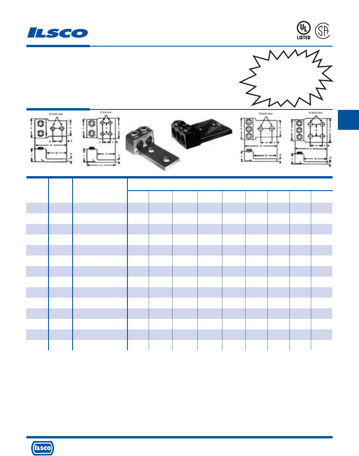
4730 Madison Road, Cincinnati, Ohio 45227-1426 Phone 513 533-6200 Fax 513 871-4084 Web site www.ilsco.com
Canada 1050 Lakeshore Road East, Mississauga, Ontario, Canada L5E1E4 Phone 905 274-2341 Fax 905 274-8763
178
C
Dimensions
Catalog Figure Wire
Number Number Range G A B C D E F H J
CL-2-8† 1 8-14 1/4 2-3/16 1-3/4 5/8 1/8 11/16 9/32 5/8 15/32
CL-2-4† 1 4-8 1/4 2-1/2 2 1 1/8 1 9/32 5/8 17/32
CL-2-1 1 1-4 3/8 2-13/16 2 1-1/4 7/32 1-1/4 7/16 1 19/32
CL-2-2/0 1 2/0-1 1/2 4-7/16 3-1/2 1-1/2 1/4 1-9/16 5/8 1-3/4 13/32
CL-2-4/0 1 4/0-2/0 1/2 4-5/8 3-1/2 1-3/4 9/32 1-3/4 5/8 1-3/4 15/16
CL-2-300 1 300kcmil-4/0 1/2 4-3/4 3-1/2 2 5/16 2-1/8 5/8 13-3/4 1-9/16
CL-2-500 1 500kcmil-300kcmil 1/2 5-3/8 3-15/16 2-1/2 11/32 2-1/2 5/8 1-3/4 1-13/16
CL-2-700 2 700kcmil-500kcmil 1/2 5-19/32 4 4 13/32 2-15/16 5/8 1-3/4 2-1/8
CL-2-1000 2 1000kcmil-750kcmil 1/2 5-27/32 4 4 15/32 3-1/4 5/8 1-3/4 2-11/32
CL-3-4/0 3 4/0-2/0 1/2 4-5/8 3-3/8 2-1/2 9/32 2-3/4 5/8 1-3/4 15/16
CL-3-300 3 300kcmil-4/0 1/2 4-3/4 3-1/2 3 5/16 3-1/4 5/8 1-3/4 1-17/32
CL-3-500 4 500kcmil-300kcmil 1/2 5-3/8 4 4 11/32 3-3/4 5/8 1-3/4 1-13/16
CL-3-750 4 750kcmil-500kcmil 1/2 5-19/32 4 4 13/32 4-3/8 5/8 1-3/4 2-1/8
CL-3-1000 4 1000kcmil-750kcmil 1/2 5-27/32 4 4 15/32 4-13/16 5/8 1-3/4 2-11/32
Bronze, Two and Three Conductor
Mechanical Lugs
TYPE
CL
Features
•
Range taking
•
Easily installed with a key wrench
•
Convenient peep hole
•
Re-usable
•
UL Listed and CSA Certified for 600 volts
Benefits
•
Permits inventories to be
kept to a minimum
•
Time savings
•
Easy inspection
•
Provides efficient use
and flexibility in the
field
•
Ensures reliability
† With Filister Head Screw
UL File E158587
Fig. 1 Fig. 2 Fig. 3 Fig. 4
8M24
A
P
-
1
0
0
9
7
3
-
1
Replaces
VL2 & VL3
Series
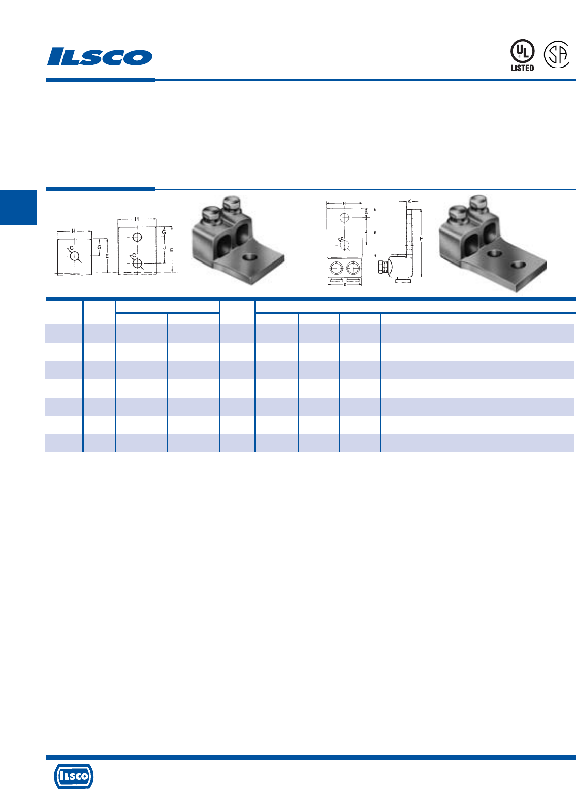
4730 Madison Road, Cincinnati, Ohio 45227-1426 Phone 513 533-6200 Fax 513 871-4084 Web site www.ilsco.com
Canada 1050 Lakeshore Road East, Mississauga, Ontario, Canada L5E1E4 Phone 905 274-2341 Fax 905 274-8763
179
C
Catalog Figure Wire Range Bolt Dimensions
Number Number Minimum Maximum Size C D E F G H J K
H2L-13-1 1 1 str 2/0 str 1/2 9/16 1-5/8 1-1/2 2-1/2 3/4 1-5/8 - 7/32
H2L-21-1 1 2/0 str 4/0 str 1/2 9/16 1-3/4 1-3/4 2-15/16 7/8 1-7/8 - 5/16
H2L-21-2N 2 2/0 str 4/0 str 1/2 9/16 1-3/4 3 4-3/16 5/8 1-7/8 1-3/4 5/16
H2L-30-2N 2 4/0 str 300kcmil 1/2 9/16 2 3 4-3/8 5/8 2 1-3/4 5/16
H2L-35-2N 2 250kcmil 350kcmil 1/2 9/16 2-1/8 3 4-7/16 5/8 2-1/4 1-3/4 5/16
H2L-50-2N 2 300kcmil 500kcmil 1/2 9/16 2-7/16 3 4-1/2 5/8 2-1/2 1-3/4 3/8
H2L-75-2N 2 500kcmil 750kcmil 1/2 9/16 3-1/16 3 4-11/16 5/8 3 1-3/4 7/16
Bronze Mechanical Lugs
Two Conductor
TYPE
H2L
Features
•
Manufactured from high strength cast bronze
•
Range taking
•
Re-usable
•
UL Listed for 600 volts
•
Compact design
•
Pressure pad/saddle
Benefits
•
Provides maximum conductivity and a high degree of
breakage resistance
•
Permits inventories to be kept to a minimum
•
Provides efficient use and flexibility in the field
•
Ensures reliability for copper conductor
•
Requires less space than two individual connectors
•
Provides positive grip and low contact resistance
Fig. 1 Fig. 2
UL File E158587
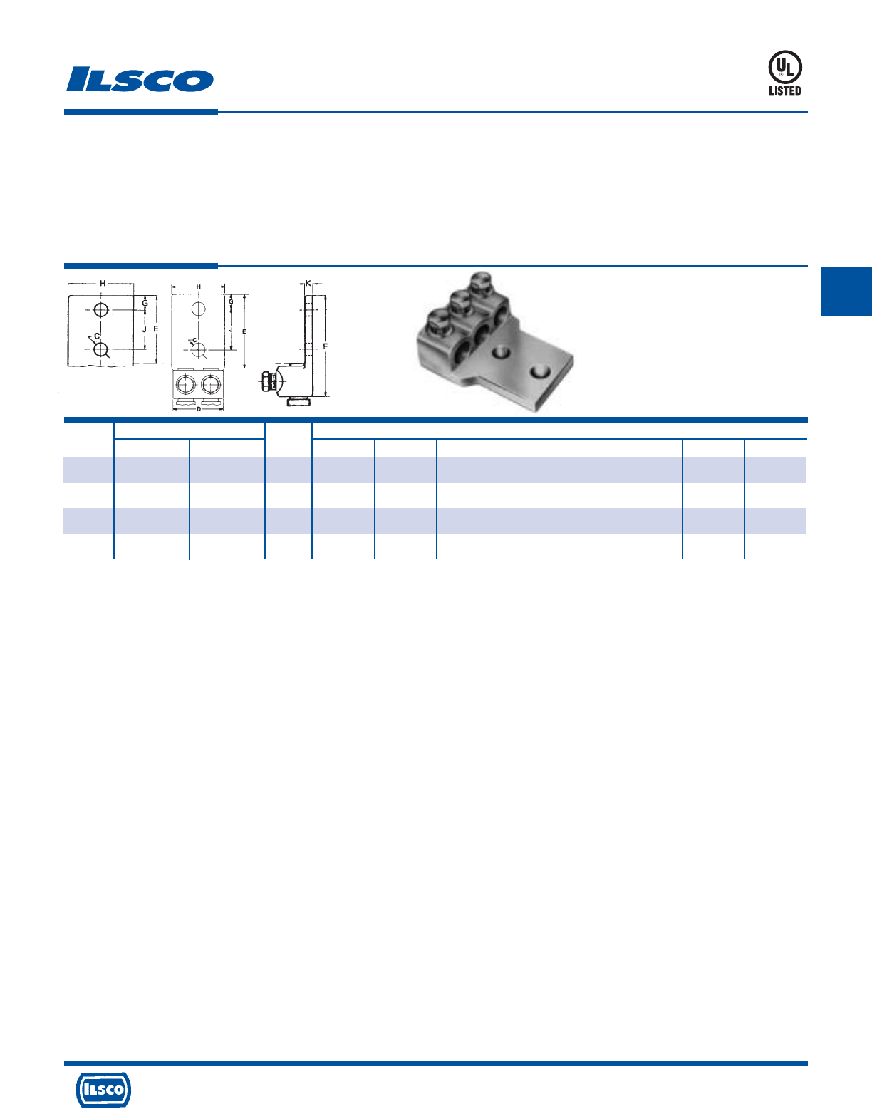
4730 Madison Road, Cincinnati, Ohio 45227-1426 Phone 513 533-6200 Fax 513 871-4084 Web site www.ilsco.com
Canada 1050 Lakeshore Road East, Mississauga, Ontario, Canada L5E1E4 Phone 905 274-2341 Fax 905 274-8763
180
C
Catalog Wire Range Bolt Dimensions
Number Minimum Maximum Size C D E F G H J K
H3L-21-2N 2/0 str 4/0 str 1/2 9/16 2-5/8 3 4-3/16 5/8 1-7/8 1-3/4 5/16
H3L-30-2N 4/0 str 300kcmil 1/2 9/16 3-1/16 3 4-3/8 5/8 2-3/8 1-3/4 5/16
H3L-35-2N 250kcmil 350kcmil 1/2 9/16 3-3/16 3 4-7/16 5/8 2-3/8 1-3/4 5/16
H3L-50-2N 300kcmil 500kcmil 1/2 9/16 3-5/8 3 4-1/2 5/8 2-1/2 1-3/4 3/8
Bronze Mechanical Lugs
Three Conductor, Two Mounting Hole
TYPE
H3L
Features
•
Manufactured from high strength cast bronze
•
Range taking
•
Re-usable
•
UL Listed for 600 volts
•
Compact design
•
Pressure pad/saddle
Benefits
•
Provides maximum conductivity and a high degree of
breakage resistance
•
Permits inventories to be kept to a minimum
•
Provides efficient use and flexibility in the field
•
Ensures reliability for copper conductor
•
Requires less space than three individual connectors
•
Provides positive grip and low contact resistance
8M24
UL File E158587
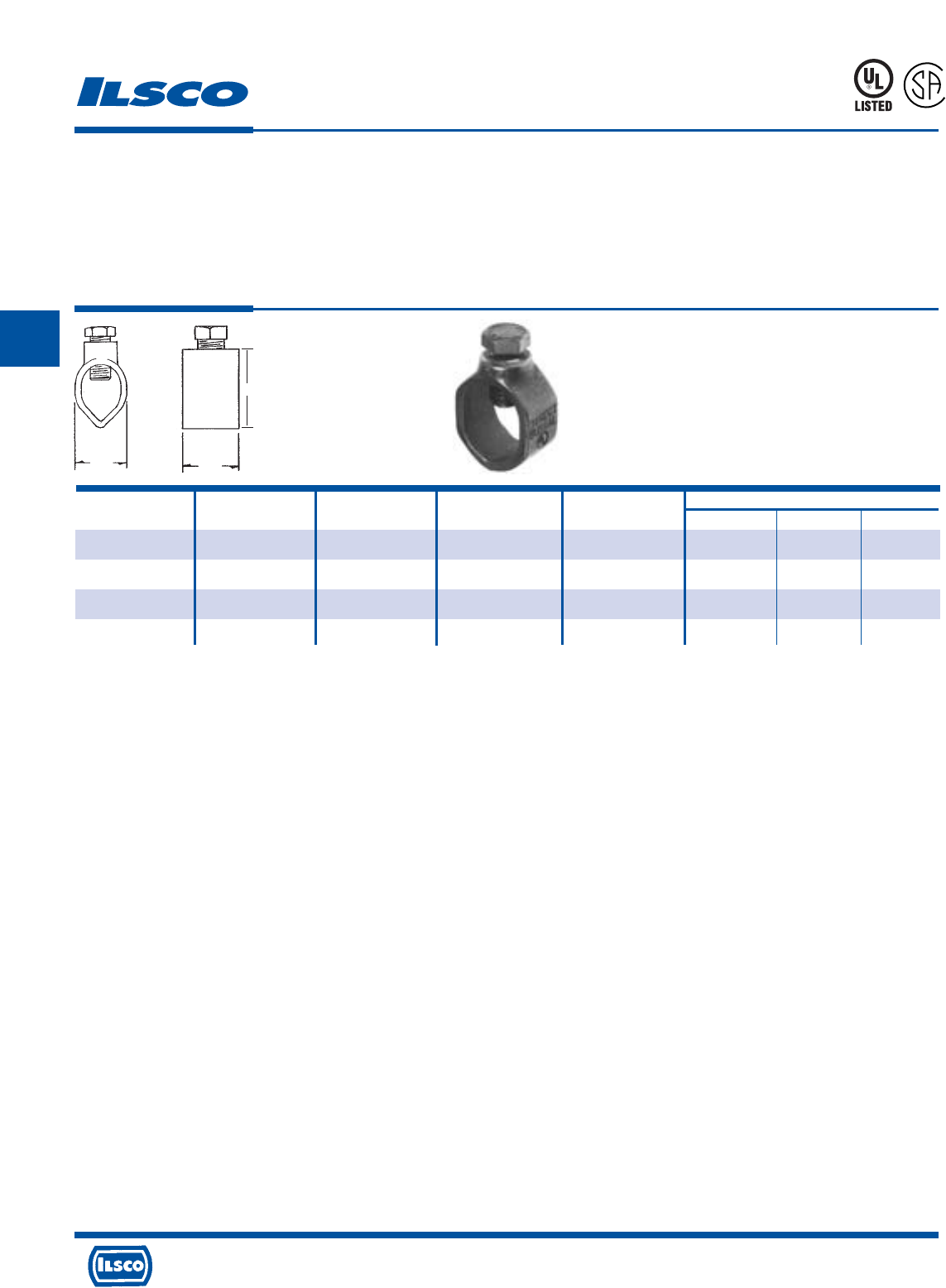
4730 Madison Road, Cincinnati, Ohio 45227-1426 Phone 513 533-6200 Fax 513 871-4084 Web site www.ilsco.com
Canada 1050 Lakeshore Road East, Mississauga, Ontario, Canada L5E1E4 Phone 905 274-2341 Fax 905 274-8763
181
C
Economy Cast Bronze Ground Rod Clamps
TYPE
CGRC
Features
•
Manufactured from cast bronze
•
Supplied with stainless steel hardware
•
UL Listed and CSA Certified for 600 volts
•
Suitable for grounding and bonding in applications such
as swimming pools and spas
Benefits
•
Ensures maximum strength and durability
•
Suitable for direct burial in earth or concrete
•
Ensures reliability for copper conductor
667P
L
R
-
2
9
6
0
1
Catalog Ground Rod Rebar Ground Rod Rebar Dimensions
Number Size Size Wire Range Wire Range L W H
CGRC-38 3/8 #3 4-10 4-10 1/2 11/16 1
CGRC-48 1/2 #4 2-10 2-10 9/16 27/32 1-3/16
CGRC-58 5/8 #5 2-10 4-10 9/16 15/16 1-9/32
CGRC-68 3/4 #6 2-10 4-10 9/16 1-1/16 1-13/32
Plain copper finish.
Tested to UL 467, UL File E34440
L
W
H
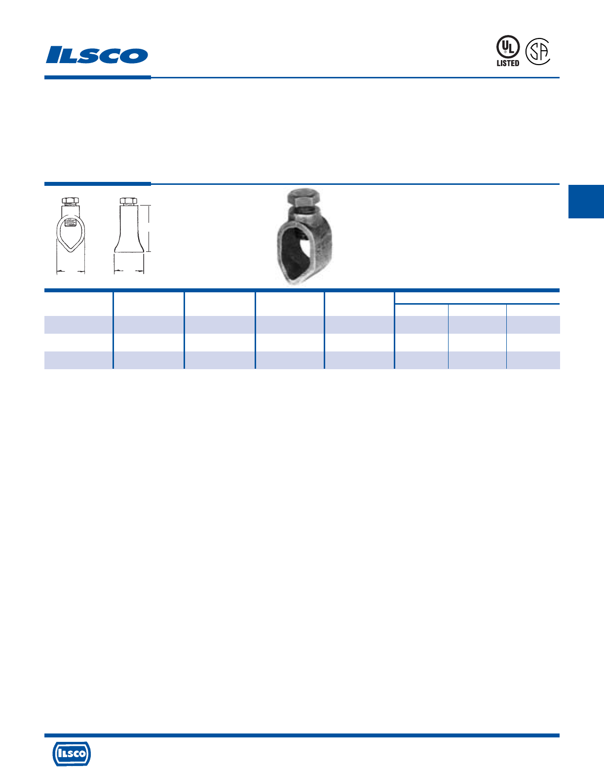
4730 Madison Road, Cincinnati, Ohio 45227-1426 Phone 513 533-6200 Fax 513 871-4084 Web site www.ilsco.com
Canada 1050 Lakeshore Road East, Mississauga, Ontario, Canada L5E1E4 Phone 905 274-2341 Fax 905 274-8763
182
C
Cast Bronze Ground Rod Clamps
TYPE
BGRC
Features
•
Manufactured from cast bronze
•
Supplied with stainless steel or silicone bronze
hardware
•
UL Listed and CSA Certified for 600 volts
Benefits
•
Ensures maximum strength and durability
•
Suitable for direct burial in earth or concrete
•
Ensures reliability for copper conductor
667P
L
R
-
2
9
6
0
1
Catalog Ground Rod Rebar Ground Rod Rebar Dimensions
Number Size Size Wire Range Wire Range L W H
BGRC-48 1/2 - 2-10 - 7/8 3/4 1-1/4
BGRC-58 5/8 #5 1/0-8 1/0-8 1-1/32 29/32 1-13/32
BGRC-68 3/4 - 1/0-8 - 1 1 1-5/8
WL
H
Tested to UL 467, UL File E34440
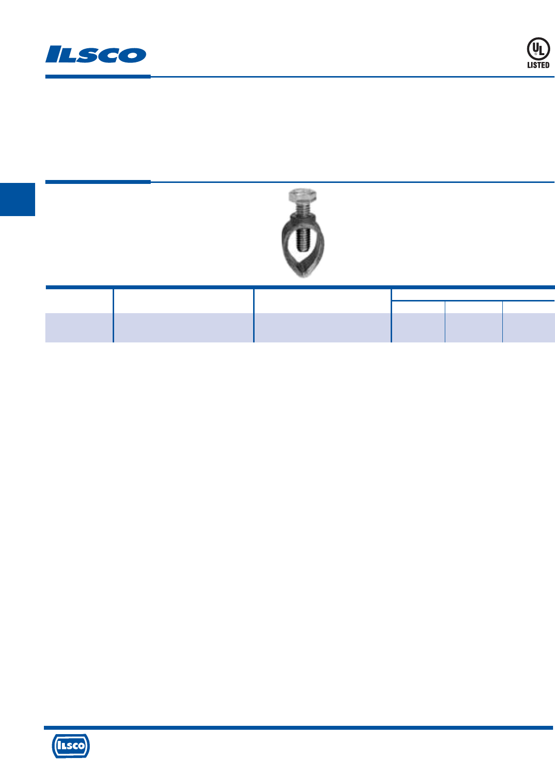
4730 Madison Road, Cincinnati, Ohio 45227-1426 Phone 513 533-6200 Fax 513 871-4084 Web site www.ilsco.com
Canada 1050 Lakeshore Road East, Mississauga, Ontario, Canada L5E1E4 Phone 905 274-2341 Fax 905 274-8763
183
C
Cast Bronze Ground Rod Clamp
TYPE
SRC
Features
•
Manufactured from bronze alloy
•
Stainless steel bolt
•
UL Listed for both copper clad and galvanized ground
rods
•
Range taking
Benefits
•
Provides maximum strength and superior conductivity
•
For direct burial
•
Ensures reliability
•
Reduces inventory requirement
Catalog Ground Rod Ground Rod Dimensions
Number Size Wire Range L W H
SRC-1/0 3/8, 1/2, 5/8 10 sol - 1/0 str 13/16 1 1-1/2
3/4 8 sol - 1/0 str
UL File E198108
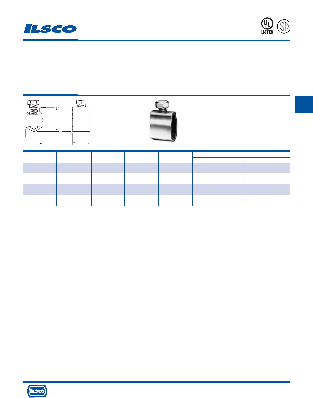
4730 Madison Road, Cincinnati, Ohio 45227-1426 Phone 513 533-6200 Fax 513 871-4084 Web site www.ilsco.com
Canada 1050 Lakeshore Road East, Mississauga, Ontario, Canada L5E1E4 Phone 905 274-2341 Fax 905 274-8763
184
C
Catalog Ground Ground Wire Rebar Rebar Dimensions
Number Rod Size Range Size Wire Range L W
GRC-38 3/8 4-10 #3 4-10 5/8 5/8
GRC-58+ 5/8 2-8 - - 15/16 7/8
GRC-68 3/4, 5/8 2-8 for 3/4 rod, #5 1/0-8 1 1
1/0-8 for 5/8 rod
GRC-75* 3/4 3/0-8 - - 3/4 1-5/32
Ground Rod Clamps
TYPE
GRC
Features
•
Manufactured from seamless bronze tubing
•
Supplied with silicon bronze screw
•
UL Listed and CSA Certified for 600 volts except
GRC-75
•
Suitable for grounding and bonding in applications such
as swimming pools and spas
Benefits
•
Provides maximum strength and superior conductivity
•
Ground rod clamp is suitable for direct burial in earth or
concrete
•
Ensures reliability for copper conductor
Plain copper finish.
+ REA Listed.
* Not UL Listed.
Tested to UL 467, UL File E34440
L
R
-
2
9
6
0
1
667P
W
L
H
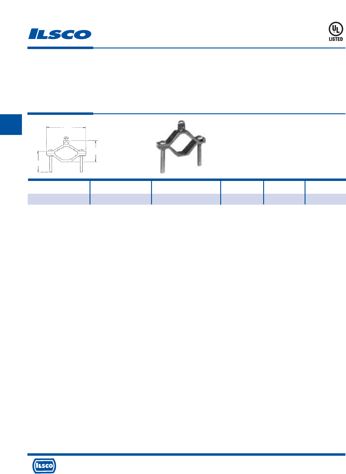
4730 Madison Road, Cincinnati, Ohio 45227-1426 Phone 513 533-6200 Fax 513 871-4084 Web site www.ilsco.com
Canada 1050 Lakeshore Road East, Mississauga, Ontario, Canada L5E1E4 Phone 905 274-2341 Fax 905 274-8763
185
C
Die Cast Ground Clamp
TYPE
DCGC
Features
•
Manufactured from die cast zinc alloy
•
UL Listed for 600 volts
•
Assembled with zinc plated steel hardware
Benefits
•
Provides maximum durability while providing economy
•
Ensures reliability for copper conductor
•
Provides corrosion resistance
Catalog Conduit Ground
Number Size Wire Range L W H
DCGC-1 1/2, 3/4, 1 2-8 2-13/64 1-3/8 1-1/2
H
L
W
8M24
UL File E158587
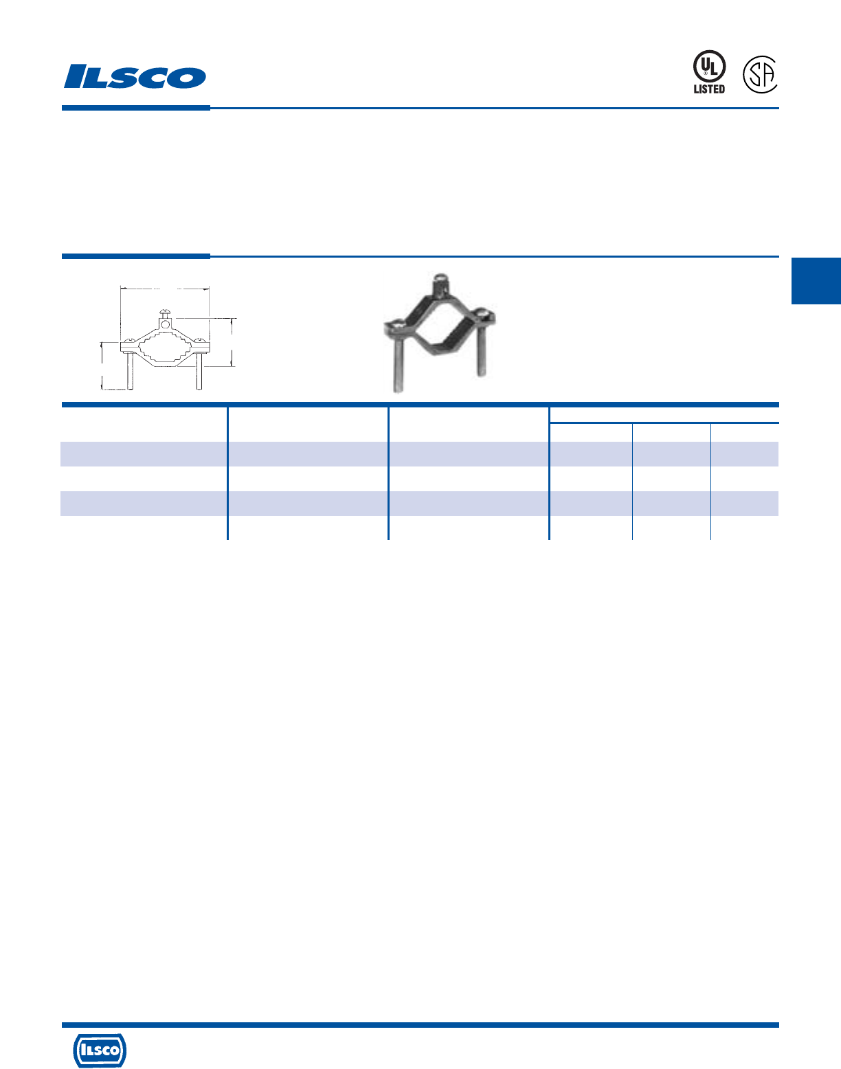
4730 Madison Road, Cincinnati, Ohio 45227-1426 Phone 513 533-6200 Fax 513 871-4084 Web site www.ilsco.com
Canada 1050 Lakeshore Road East, Mississauga, Ontario, Canada L5E1E4 Phone 905 274-2341 Fax 905 274-8763
186
C
Catalog Pipe Ground Wire Dimensions
Number Size Range L W H
BGC-1 1/2, 3/4, 1 2-10 2-9/32 2-17/32 1-1/2
BGC-2 1-1/4, 1-1/2, 2 2-10 3-9/16 2-1/4 2
BGC-1DB* 1/2, 3/4, 1 2-10 2-9/32 2-17/32 1-1/2
BGC-2DB* 1-1/4, 1-1/2, 2 2-10 3-8/16 2-1/4 2
Cast Brass Ground Clamp
TYPE
BGC
Features
•
Manufactured from cast brass
•
UL Listed and CSA Certified for 600 volts
•
Type BGC-DB supplied with stainless steel or silicone
bronze hardware
Benefits
•
Provides maximum conductivity and strength
•
Ensures reliability for copper conductor
•
BGC-1DB and BGC-2DB are suitable for direct burial in
earth or concrete. Can be used to ground swimming pools
and spas.
* Suitable for direct burial in earth or concrete.
UL File E158587
L
H
W
8M24
L
R
-
7
0
1
5
7
0
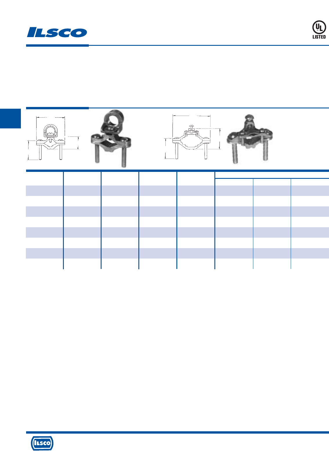
4730 Madison Road, Cincinnati, Ohio 45227-1426 Phone 513 533-6200 Fax 513 871-4084 Web site www.ilsco.com
Canada 1050 Lakeshore Road East, Mississauga, Ontario, Canada L5E1E4 Phone 905 274-2341 Fax 905 274-8763
187
C
Catalog Figure Pipe Conduit Hub Wire Dimensions
Number Number Size Size Range H W L
BGC1-50 1 1/2–1 1/2 4str-8sol 1-1/2 1-1/32 2-1/4
BGC1-75 1 1/2–1 3/4 4str-8sol 1-1/2 1-1/32 2-1/4
BGC1-10 1 1/2–1 1 4str-8sol 1-1/2 1-1/32 2-1/4
BGC2-50 1 1-1/4–2 1/2 4str-8sol 2 1-3/4 3-19/32
BGC2-75 1 1-1/4–2 3/4 4str-8sol 2 1-3/4 3-19/32
BGC2-10 1 1-1/4–2 1 4str-8sol 2 1-3/4 3-19/32
BGC-1A* 2 1/2–1 - 4str-8sol 1-1/2 1-3/8 2-1/4
BGC-2A 2 1-1/4–2 - 4str-8sol 2 2-3/32 3-19/32
Cast Bronze Ground Clamps
TYPE
BGC
Features
•
Manufactured from cast bronze
•
UL Listed for 600 volts
•
Versatile
Benefits
•
Provides maximum conductivity and strength
•
Ensures reliability for copper conductor
•
Type BGC supplied with conduit hub for 1/2"-1" rigid
conduit; type BGC-A can be used for bare or armoured
cable
* CSA Certified
UL File E158587
Fig. 1 Fig. 2
HH
W
W
LL
8M24
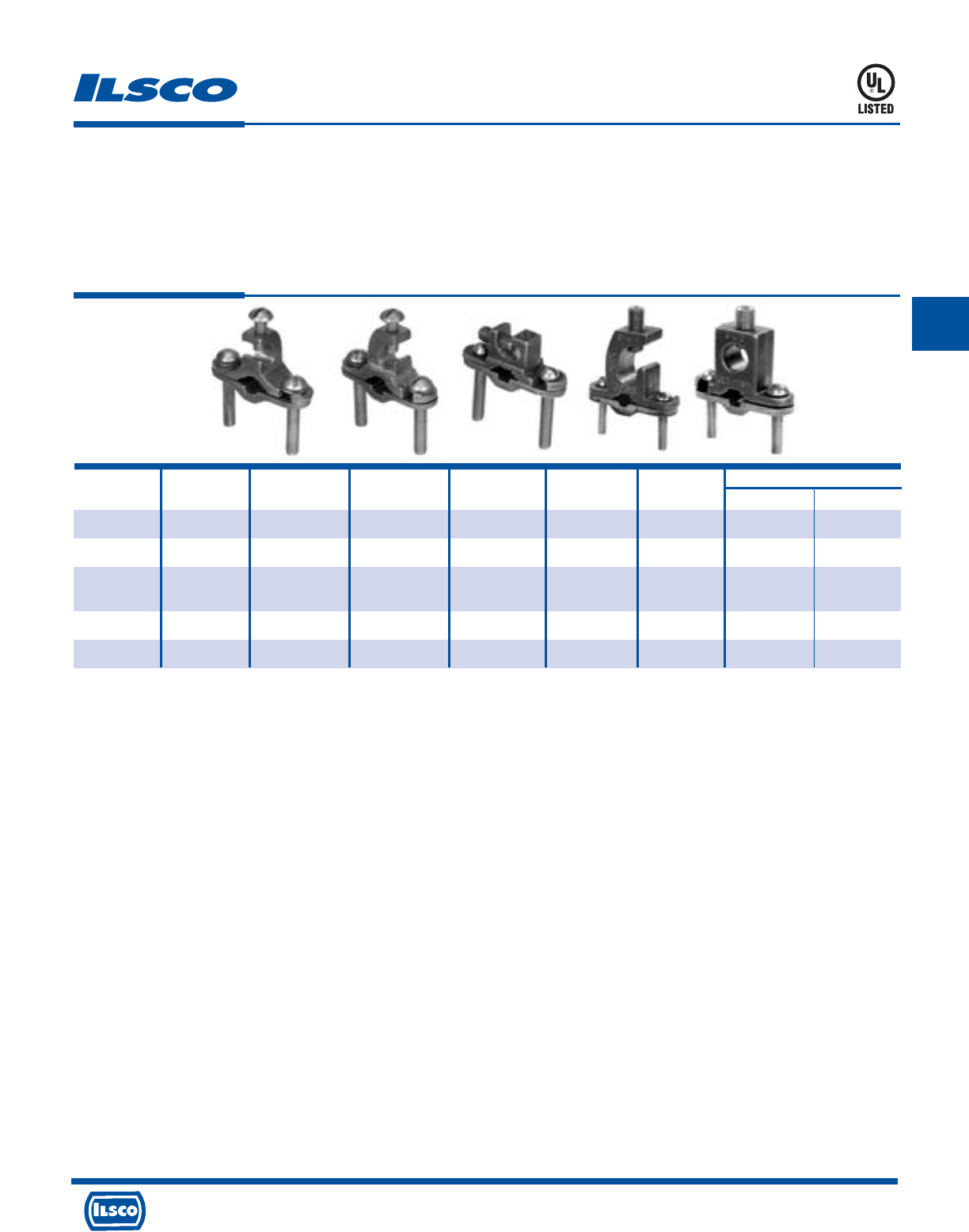
4730 Madison Road, Cincinnati, Ohio 45227-1426 Phone 513 533-6200 Fax 513 871-4084 Web site www.ilsco.com
Canada 1050 Lakeshore Road East, Mississauga, Ontario, Canada L5E1E4 Phone 905 274-2341 Fax 905 274-8763
188
C
Catalog Figure Pipe Rebar Ground Rod Ground Screw Dimensions
Number Number Size Size Size Wire Range Material L W
BGC-2T-DB* 1 1/2-1 3/8-1 1/2-1 2str-10sol silicon bronze 2-3/4 2-1/4
BGC-2P-DB* 2 1/2-1 3/8-1 1/2-1 2str-10sol silicon bronze 2-3/4 2-1/4
BGC-2PS-DB+ 3 1/2-1 3/8-1 1/4-1 2str-10sol stainless steel 2-1/4 2-1/4
2 #8sol
BGC-4/0P-DB= 4 1/2-1 3/8-1 1/2-1 4/0-8str stainless steel 3 2-1/4
BGC-4/0S-DB= 5 1/2-1 3/8-1 1/2-1 4/0-8str stainless steel 2-3/4 2-1/4
Cast Bronze Ground Clamps
TYPE
BGDB
Features
•
Manufactured from bronze alloy
•
UL Listed for direct burial in earth or concrete
•
Lay-In feature
Benefits
•
Ensures maximum strength and superior conductivity
•
Ensures reliability
•
Reduces installation time
* UL File E207816
+ UL File E198108
= UL File E178441
Fig. 1 Fig. 2 Fig. 3 Fig. 4 Fig. 5
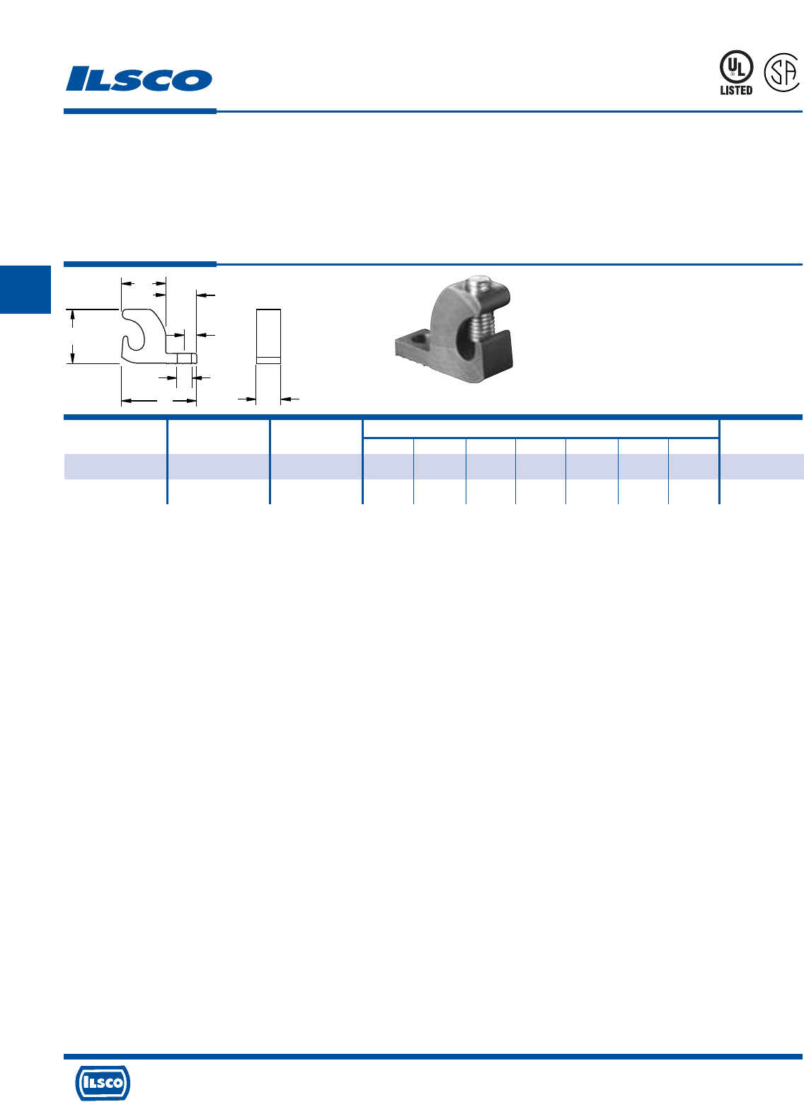
4730 Madison Road, Cincinnati, Ohio 45227-1426 Phone 513 533-6200 Fax 513 871-4084 Web site www.ilsco.com
Canada 1050 Lakeshore Road East, Mississauga, Ontario, Canada L5E1E4 Phone 905 274-2341 Fax 905 274-8763
189
C
D
E
G
C
F
T
H
Catalog Ground Wire Bolt Dimensions Screw
Number Range Size C D E F G H T Type
GBL-4DB 4-14 10 .218 .680 .470 1.150 .190 .375 .825 Slot
GBL-4DB-14 4-14 10 .265 .680 .470 1.150 .210 .472 .825 Slot
Copper Lay-In Ground Lug
Direct Burial
TYPE
GBL-DB
Features
•
Lay-in feature
•
Manufactured from high strength copper
•
Stainless steel 1/4-28 torque screw
•
Rated for 600 volts
Benefits
•
Provides ease of installation of continuous loop
grounding conductor
•
Suitable for direct burial and for use with copper
conductors
•
Resists oxidation and corrosion in earth or concrete
•
Ensures reliability
667P
L
R
-
2
9
6
0
1
* Add T to order tin plating
Tested to UL 467, UL File E34440
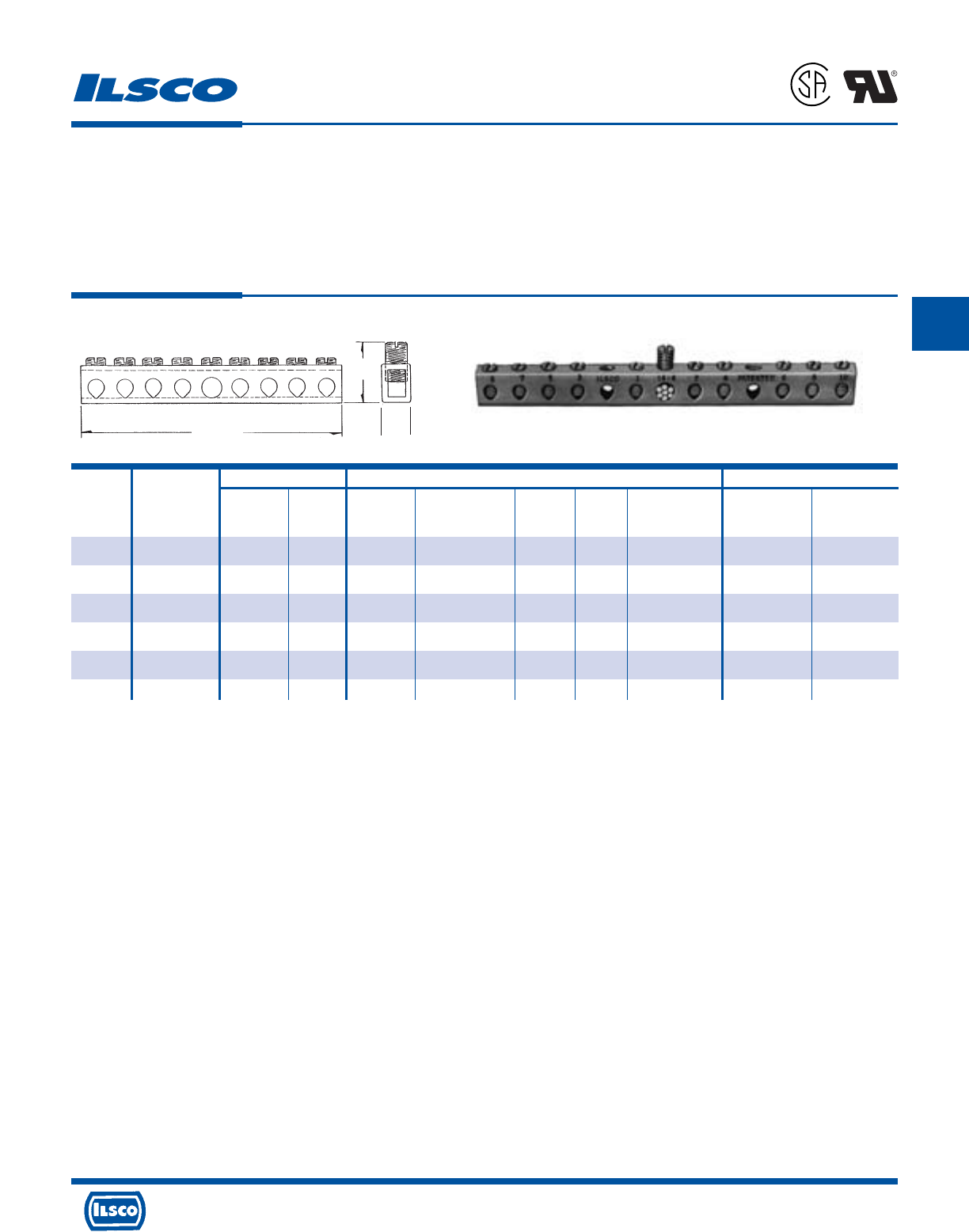
4730 Madison Road, Cincinnati, Ohio 45227-1426 Phone 513 533-6200 Fax 513 871-4084 Web site www.ilsco.com
Canada 1050 Lakeshore Road East, Mississauga, Ontario, Canada L5E1E4 Phone 905 274-2341 Fax 905 274-8763
190
C
Wire Range Dimensions Mounting Hole Positions
From End Of Distance
Catalog Number Of Height With Bolt Two Mounting Bar To First Between
Number Taps Main Tap L Maximum Wire W Size Holes Mounting Hole Holes
D167-4 4 4-14 6-14 2-3/4 3/4 11/32 #10 13/64 .581 (2nd hole) 1.98
D167-6 6 4-14 6-14 3-1/2 3/4 11/32 #10 13/64 .978 (3rd hole) 1.98
D167-8 8 4-14 6-14 4-7/16 3/4 11/32 #10 13/64 1.375 (4th hole) 1.98
D167-10 10 4-14 6-14 5-1/8 3/4 11/32 #10 13/64 1.772 (5th hole) 1.98
D167-12 12 4-14 6-14 5-15/16 3/4 11/32 #10 13/64 2.169 (6th hole) 1.98
D167-14 14 4-14 6-14 6-23/32 3/4 11/32 #10 13/64 2.566 (7th hole) 1.98
Copper Neutral Bars
TYPE
D167
Features
•
Manufactured from high strength copper tubing
•
Range taking
•
UL Recognized for 600 volts
Benefits
•
Provides maximum conductivity
•
A wide range of conductor sizes can be used in the
same connector
•
Ensures reliability for copper conductor
L
H
W
Tested to UL 486A-486B, UL File E6207
L
1
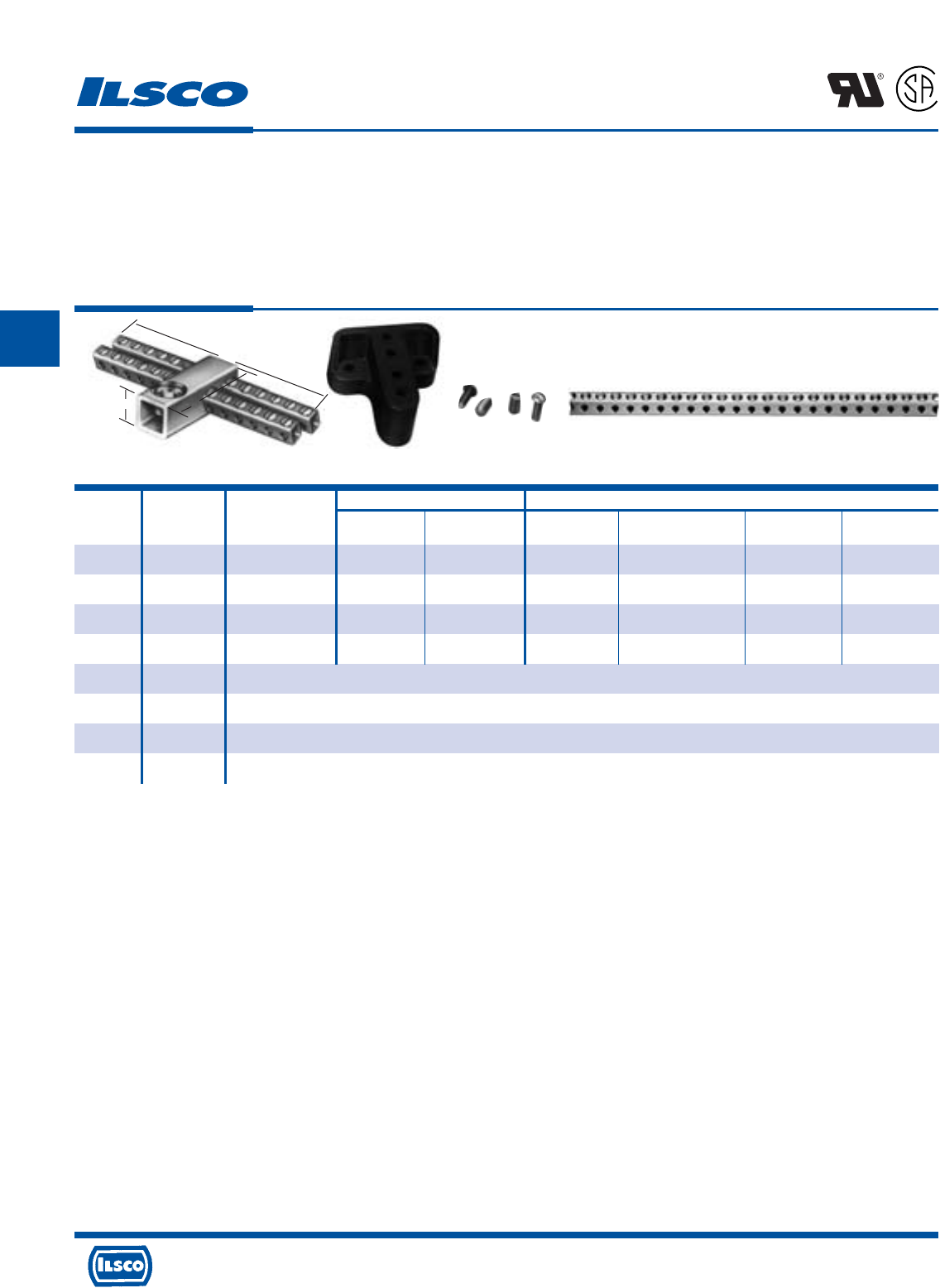
4730 Madison Road, Cincinnati, Ohio 45227-1426 Phone 513 533-6200 Fax 513 871-4084 Web site www.ilsco.com
Canada 1050 Lakeshore Road East, Mississauga, Ontario, Canada L5E1E4 Phone 905 274-2341 Fax 905 274-8763
191
C
Wire Range Dimensions
Catalog Figure Number Of Height With Two Tapped
Number Number Taps Main Tap L Maximum Wire W Mounting Holes
CAN-300 1 24 250kcmil-6 6-14 2-5/16 1-5/16 5-1/8 10-32
CAN-301 1 30 250kcmil-6 6-14 3 1-5/16 4-13/32 10-32
CAN-302 1 36 250kcmil-6 6-14 3 1-5/16 5-1/8 10-32
CAN-303 1 42 250kcmil-6 6-14 3 1-7/16 5-1/2 10-32
R-16 2 Mounting block of general purpose (phenolic black) suitable for mounting any of CAN Neutrals. 2-1/2" wide x 2-1/2" long x 1" thick.
E-223 3 10-32 x 1/2" round head steel machine screws for fastening neutrals to mounting blocks. (Use lock washer to provide rigid assembly.)
E-153 3 1/4-28 wire pressure screw 7/16" long. Screw is steel, zinc plated and chromate dipped.
N-174 4 Supplied in 5' 9" lengths. Approximately 174 outlets. Wire range 14-6.
Copper Neutral Bars
TYPE
CAN
Features
•
Manufactured from high strength copper tubing
•
Compact design
•
Range taking
•
UL Recognized and CSA Certified
•
Circuit bars inserted at a 20 angle
Benefits
•
Provides maximum conductivity
•
Up to 42 circuit taps can be made in just 5 1/2" of space
•
A wide range of conductor sizes can be used in the
same connector
•
Ensures reliability for copper conductor
•
Provides easy wire insertion
L
R
-
2
9
6
0
1
Fig. 1 Fig. 2 Fig. 3 Fig. 4
W
HL
Tested to UL 486A-486B, UL File E6207
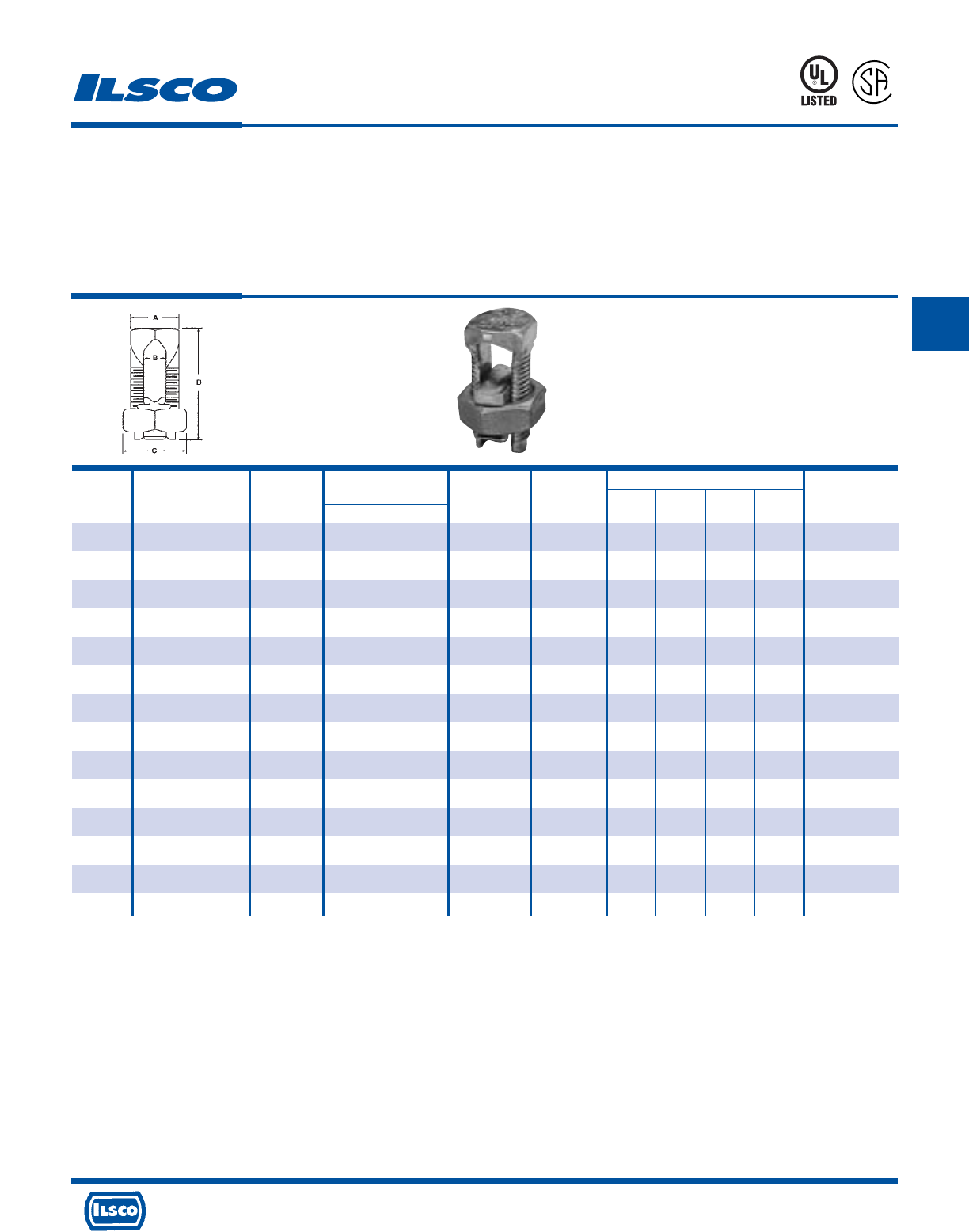
4730 Madison Road, Cincinnati, Ohio 45227-1426 Phone 513 533-6200 Fax 513 871-4084 Web site www.ilsco.com
Canada 1050 Lakeshore Road East, Mississauga, Ontario, Canada L5E1E4 Phone 905 274-2341 Fax 905 274-8763
192
C
Copper Split Bolts
TYPE
IK
Features
•
Manufactured from high strength copper alloy.
•
Precision tooled threads.
•
UL 467 Listed for Grounding and Bonding 8 thru 500kcmil
•
CSA certified for Grounding and Bonding 8 thru 250kcmil
•
UL listed and CSA Certified for 600 volts, 90° C
•
RUS Accepted 8 thru 1/0 AWG
•
For use with copper conductor types: Solid, Compact,
Compressed, Concentric.
•
ROHS compliant.
Benefits
•
Provides maximum conductivity and high breakage
resistance.
•
Allows maximum torque to be applied.
•
Suitable for direct burial and earth and concrete.
453G
7
0
1
5
7
0
Min. Tap Max. Cond Dimensions
Catalog Range For Equal With One Copperweld Rebar With Wire Recommended
Number Main & Tap Max. Main Str Type A 6 or 8 AWG Diameter A B C D Torque (IN-LB)
IK-10 10str - 16str 16str - - N/A .057 - .125 .125 0.344 0.500 0.719 80
IK-8 8str - 16str 16str - - N/A .057 - .145 .145 0.375 0.500 0.844 80
IK-6 6sol - 10sol 16sol - - N/A .102 - .162 .165 0.500 0.625 1.047 165
IK-4 4sol - 8sol 16sol 3 No. 12 8A N/A .128 - .204 .215 0.562 0.688 1.047 165
IK-3 2sol - 6sol 12sol 3 No. 9 5A N/A .162 - .258 .328 0.688 0.812 1.312 275
IK-2 2str - 6sol 14str 3 No. 7 3A N/A .162 - .292 .328 0.688 0.812 1.312 275
IK-1/0 1/0str - 4sol 14sol 3 No. 6 2A N/A .204 - .375 .377 0.750 0.875 1.641 385
IK-2/0 2/0str - 2sol 14str 3 No. 5 - #3 (3/8) .258 - .418 .420 0.812 1.000 1.812 385
IK-3/0 3/0str - 2sol 12sol 7 No. 7 - N/A .258 - .470 0.466 0.875 1.125 2.000 500
IK-250 250kcmil - 1/0sol 10sol 7 No. 5 - #4 (1/2) .325 - .575 0.579 1.000 1.312 2.078 650
IK-350 350kcmil - 4/0str 8sol 19 No. 7 - #5 (5/8 .528 - .682 0.746 1.500 1.625 2.625 650
IK-500 500kcmil - 250kcmil 8sol 19 No. 6 - #6 (3/4) .575 - .815 0.834 1.625 1.812 3.000 825
IK-750 750kcmil - 350kcmil 8sol 19 No. 5 - N/A .682 - .999 1.030 1.938 2.125 3.750 1000
IK-1000 1000kcmil - 500kcmil 8sol - - N/A .815 - 1.153 1.222 2.250 2.500 4.000 1100
UL File E6207
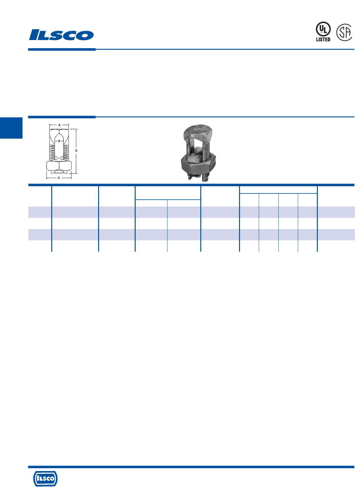
4730 Madison Road, Cincinnati, Ohio 45227-1426 Phone 513 533-6200 Fax 513 871-4084 Web site www.ilsco.com
Canada 1050 Lakeshore Road East, Mississauga, Ontario, Canada L5E1E4 Phone 905 274-2341 Fax 905 274-8763
193
C
TYPE
IK3
Three Wire Copper Split Bolts
Features
•
Manufactured from high strength copper alloy.
•
Precision tooled threads.
•
UL 467 Listed for Grounding and Bonding thru 500kcmil
•
CSA certified for Grounding and Bonding thru 250kcmil
•
UL listed and CSA Certified for 600 volts, 90° C
•
RUS Accepted
•
For use with copper conductor types: Solid, Compact,
Compressed, Concentric.
•
ROHS compliant.
Benefits
•
Provides maximum conductivity and high breakage
resistance.
•
Allows maximum torque to be applied.
•
Suitable for direct burial and earth and concrete.
453G
7
0
1
5
7
0
Min. Tap Max Cond Dimensions
Catalog Range For Equal With One Copperweld Wire Diameter Recommended
Number Main & Tap Max. Main Str Type A Range A B C D Torque (IN-LB)
IK3-8 8str - 16str 16str - - .057 - .145 0.144 0.375 0.500 0.844 80
IK3-6 6sol - 10sol 16sol - - .102 - .162 0.166 0.500 0.625 1.109 165
IK3-4 4sol - 8sol 16sol 3 No. 12 8A .128 - .204 0.217 0.562 0.688 1.266 165
IK3-2 2str - 6sol 14str 3 No. 7 3A .162 - .258 0.326 0.688 0.812 1.547 275
UL File E6207
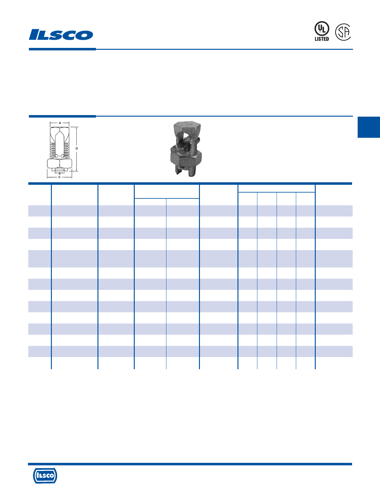
4730 Madison Road, Cincinnati, Ohio 45227-1426 Phone 513 533-6200 Fax 513 871-4084 Web site www.ilsco.com
Canada 1050 Lakeshore Road East, Mississauga, Ontario, Canada L5E1E4 Phone 905 274-2341 Fax 905 274-8763
194
C
Tin Plated Copper Split Bolts
TYPE
SK
Features
•
Manufactured from high strength copper alloy.
•
Electro-tin plated bolt, nut, spacer and pressure bar
•
Precision tooled threads.
•
UL listed and CSA Certified for 600 volts, 90° C
•
SK-10, SK-8, SK3, SK-2 SK-1/0, SK-2/0 are RUS Accepted.
•
For use with copper conductor types: Solid, Compact,
Compressed, Concentric.
•
ROHS compliant.
Benefits
•
Provides maximum conductivity and high breakage
resistance.
•
Provides low contact resistance.
•
Suitable for direct burial and earth and concrete.
460C
7
0
1
5
7
0
Min. Tap Max Cond Dimensions
Catalog Range For Equal With One Copperweld Wire Diameter Recommended
Number Main & Tap Max. Main Str Type A Range A B C D Torque (IN-LB)
SK-10 10str - 16str 16str - - .057 - .116 .144 0.375 0.500 0.844 80
SK-8 8str - 16str 16str - - .057 - .145 0.144 0.375 0.500 0.844 80
SK-6 8str - 14str 14str - - .073 - .146 .166 0.500 0.625 1.109 165
SK-4 6str - 10str 10sol 3 No. 12 8A .116 - .184 0.217 0.562 0.688 1.266 165
SK-3 4str - 8sol AL 8sol AL 3 No. 9 5A .128 - .258 0.326 0.688 0.812 1.547 275
2sol - 8sol CU 8sol CU
SK-2 2str - 8sol 8sol 3 No. 7 3A .128 - .316 0.326 0.688 0.812 1.547 275
SK-1/0 1/0str - 6sol 10sol 3 No. 6 - .162 - .375 0.376 0.750 0.875 1.641 385
SK-2/0 2/0str - 6str 10sol 3 No. 5 - .184 - .419 .420 0.812 1.000 1.812 385
SK-3/0 3/0str - 4str 6sol 7 No. 7 - .198 - .470 0.466 0.875 1.125 2.000 500
SK-250 250kcmil - 4str 4str 7 No. 5 - .232 - .575 0.577 1.000 1.312 2.328 650
SK-350 350kcmil - 3/0str 1sol 19 No. 7 - .447 - .682 0.746 1.500 1.625 2.625 650
SK-500 500kcmil - 3/0str 1/0str 19 No. 6 - .447 - .815 0.834 1.625 1.812 3.000 825
SK-750 750kcmil - 250kcmil 2/0str 19 No. 5 - .563 - .999 1.030 1.938 2.125 3.750 1000
SK-1000 1000kcmil - 350kcmil 4/0str - - .682 - .1.162 1.222 2.250 2.500 4.000 1100
UL File E12822

4730 Madison Road, Cincinnati, Ohio 45227-1426 Phone 513 533-6200 Fax 513 871-4084 Web site www.ilsco.com
Canada 1050 Lakeshore Road East, Mississauga, Ontario, Canada L5E1E4 Phone 905 274-2341 Fax 905 274-8763
195
C
Catalog Copper Wire Range Dimensions
Number Main Tap C H W
IKB-4/0 + 1/0-4/0 4/0-10 1.10 1.97 1.72
IKB-350 + 350kcmil-250kcmil 350kcmil-10 1.38 2.48 1.12
IKB-500 500kcmil-400kcmil 500kcmil-10 1.50 2.80 2.25
IKB-800 800kcmil-400kcmil 800kcmil-3/0 1.62 3.32 2.50
IKB-1000 1000kcmil-500kcmil 1000kcmil-3/0 2.00 3.78 3.03
Copper Two Bolt Connectors
TYPE
IKB
Features
•
Manufactured from high strength copper alloy
•
Two bolt design
•
Longer peened bolt
•
UL Listed, rated for 600 volts
•
For copper conductor only
Benefits
•
Allows maximum conductivity and high breakage
resistance
•
Allows maximum pressure to be applied directly to the
conductor strands
•
Permits a swivel action for easier installation
•
Ensures reliability
+ REA Listed
Tested to UL 486A-486B, UL File E6207
453G
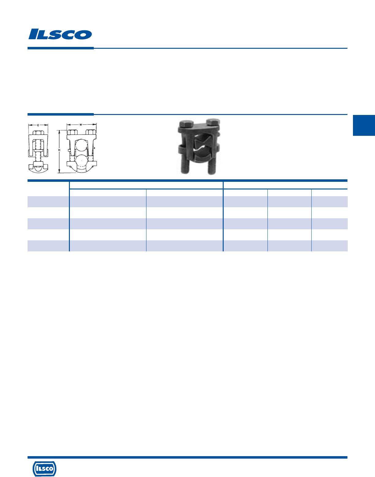
4730 Madison Road, Cincinnati, Ohio 45227-1426 Phone 513 533-6200 Fax 513 871-4084 Web site www.ilsco.com
Canada 1050 Lakeshore Road East, Mississauga, Ontario, Canada L5E1E4 Phone 905 274-2341 Fax 905 274-8763
196
C
Catalog Wire Range Dimensions
Number Main Tap C H W
IKS-4/0 4/0-1/0 4/0-6 1.12 2.31 1.72
IKS-350 350kcmil-250kcmil 350kcmil-6 1.38 2.62 2.12
IKS-500 500kcmil-400kcmil 500kcmil-4 1.50 3.00 2.26
IKS-800 800kcmil-400kcmil 800kcmil-4/0 1.62 3.50 2.50
IKS-1000 1000kcmil-500kcmil 1000kcmil-4/0 2.00 4.03 3.03
Two Bolt Connectors
TYPE
IKS
Features
•
Manufactured from high strength copper alloy
•
Electro-tin plated
•
Two bolt design
•
Longer peened bolt
•
Serrated spacer bar
•
For copper conductor only
•
Rated for 600 volts
Benefits
•
Allows maximum conductivity and high breakage
resistance
•
Provides low contact resistance
•
Allows maximum pressure to be applied directly to the
conductor strands
•
Permits a swivel action for easier installation
•
Makes a secure connection
•
Ensures reliability
4730 Madison Road, Cincinnati, Ohio 45227-1426 Phone 513 533-6200 Fax 513 871-4084 Web site www.ilsco.com
Canada 1050 Lakeshore Road East, Mississauga, Ontario, Canada L5E1E4 Phone 905 274-2341 Fax 905 274-8763
197
C
Torque Index
TIGHTENING TORQUE VALUES FOR
ILSCO MECHANICAL SCREW CONNECTORS
AWG. OR TIGHTENING TORQUE IN INCH POUNDS
CIRCULAR EXTERNAL DRIVE
MILL SIZE SCREW DRIVER WRENCH
14 35 75
12 35 75
10 35 75
840 75
6 45 110
4 45 110
2 50 150
1 50 150
1/0 50 180
2/0 50 180
3/0 250
4/0 250
250 325
350 325
500 375
600 375
700 375
750 375
800 500
1000 500
TIGHTENING TORQUE VALUES FOR
ILSCO SOCKETHEAD SCREW CONNECTORS
INTERNAL
SOCKET SIZE
ACROSS FLATS
INCHES
1/8 45
5/32 100
3/16 120
7/32 150
1/4 200
5/16 275
3/8 375
1/2 500
9/16 600
TIGHTENING TORQUE IN INCH POUNDS
Please reference the instruction sheet included with your connector for specific torque values.
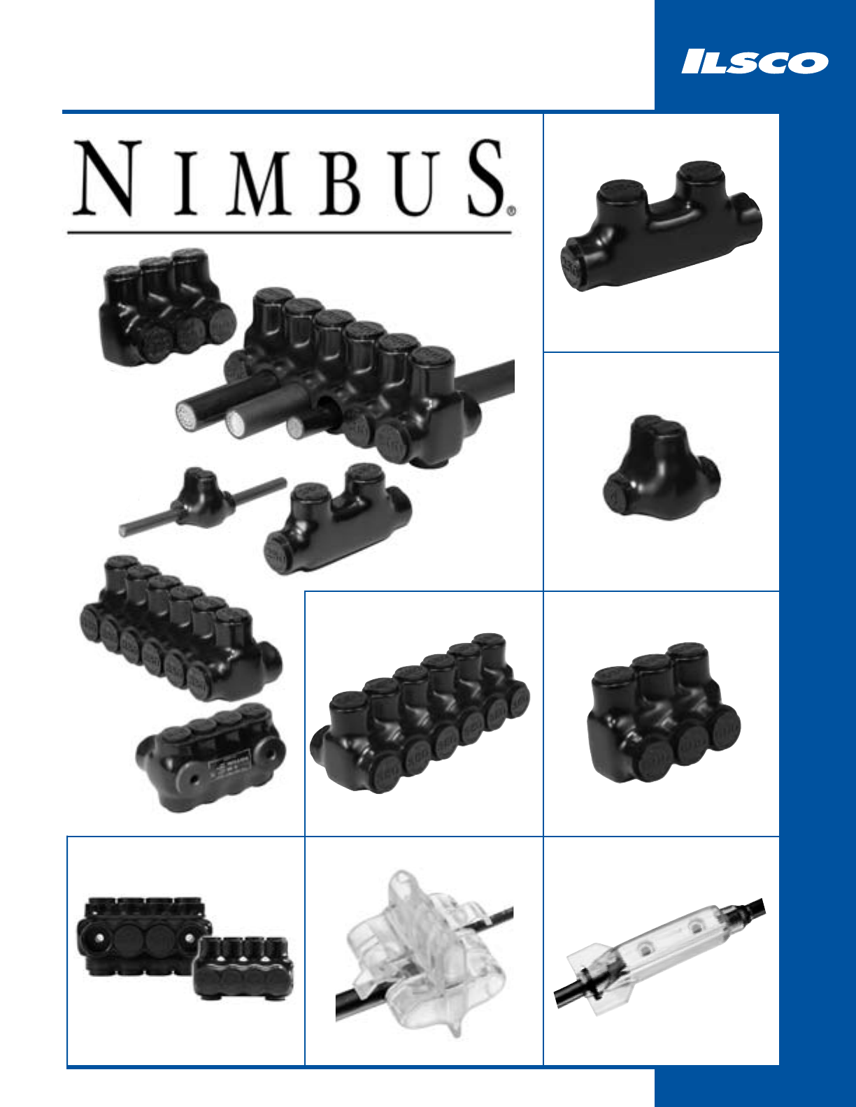
198
Insulated Mechanical
200 - 202
PBTD
208
PCT
206 - 207
PBTM
199
PBT
199
PBTO
203 - 205
PBTS
209
SPAR
4730 Madison Road, Cincinnati, Ohio 45227-1426 Phone 513 533-6200 Fax 513 871-4084 Web site www.ilsco.com
Canada 1050 Lakeshore Road East, Mississauga, Ontario, Canada L5E1E4 Phone 905 274-2341 Fax 905 274-8763
199
D
Catalog Figure No. Wire Dimensions Hex
Number No. Of Ports Range L W H Size
PBT-1/0 1 - 1/0-14 3.11 0.94 1.44 3/16
PBT-250 1 - 250kcmil-6 4.28 1.06 2.04 5/16
PBT-350 1 - 350kcmil-6 4.75 1.31 2.43 5/16
PBT-500 1 - 500kcmil-4 5.38 1.44 3.03 3/8
PBT-750 3 - 750kcmil-250kcmil 7.25 1.75 3.31 3/8
PBTO-4 2 2 4-14 1.17 1.25 1.31 1/8
PBTO-1/0 2 2 1/0-14 1.63 1.63 1.63 3/16
PBTO-3/0 2 2 3/0-6 1.89 1.68 1.86 3/16
NIMBUS®Two Wire In-Line and Offset
Insulated Splicer-Reducer Connectors
TYPE
PBT
453G
Features
•
Broad wire range: 750kcmil-14
•
UL Listed and CSA Certified for 600 volts, 90˚ C
•
Dual rated
•
Cold temperature rated to -45˚ C
•
High dielectric strength plastisol
•
Black cover
•
Removable plugs
•
Prefilled with De-ox®
Benefits
•
Flexibility in the field
•
Ensures reliability
•
For copper or aluminum conductor
•
Application variability
•
Chemical resistant
•
UV Rated
•
Entry port closure
•
Prevents oxides from forming
Per NEC Article 310-316, allowable ampacities are as follows: #4-95 Amps, 1/0-170 Amps, 3/0-225 Amps, 250-290 Amps, 350-350 Amps, 500-430 Amps, 750-535 Amps
Replacement caps & plugs available. Consult Factory
Tested to UL 486A-486B, UL File E6207
H
W
L
L
H
W
Fig. 1 Fig. 2 Fig. 3
L
R
-
2
9
6
0
1
Catalog No. Wire Dimensions Hex
Number Of Ports Range L W H Size
PBTD-2-4 2 4-14 1.24 1.25 1.42 1/8
PBTD-3-4 3 4-14 1.70 1.25 1.42 1/8
PBTD-4-4 4 4-14 2.16 1.25 1.42 1/8
PBTD-5-4 5 4-14 2.61 1.25 1.42 1/8
PBTD-6-4 6 4-14 3.07 1.25 1.42 1/8
PBTD-7-4 7 4-14 3.53 1.25 1.42 1/8
PBTD-8-4 8 4-14 3.99 1.25 1.42 1/8
PBTD-9-4 9 4-14 4.45 1.25 1.42 1/8
PBTD-10-4 10 4-14 4.90 1.25 1.42 1/8
PBTD-11-4 11 4-14 5.36 1.25 1.42 1/8
PBTD-12-4 12 4-14 5.82 1.25 1.42 1/8
PBTD-13-4 13 4-14 6.28 1.25 1.42 1/8
PBTD-14-4 14 4-14 6.74 1.25 1.42 1/8
PBTD-2-1/0 2 1/0-14 1.67 1.63 1.63 3/16
PBTD-3-1/0 3 1/0-14 2.29 1.63 1.63 3/16
PBTD-4-1/0 4 1/0-14 2.92 1.63 1.63 3/16
PBTD-5-1/0 5 1/0-14 3.54 1.63 1.63 3/16
PBTD-6-1/0 6 1/0-14 4.17 1.63 1.63 3/16
PBTD-7-1/0 7 1/0-14 4.79 1.63 1.63 3/16
PBTD-8-1/0 8 1/0-14 5.42 1.63 1.63 3/16
PBTD-9-1/0 9 1/0-14 6.04 1.63 1.63 3/16
PBTD-10-1/0 10 1/0-14 6.67 1.63 1.63 3/16
PBTD-11-1/0 11 1/0-14 7.29 1.63 1.63 3/16
PBTD-12-1/0 12 1/0-14 7.92 1.63 1.63 3/16
PBTD-13-1/0 13 1/0-14 8.54 1.63 1.63 3/16
PBTD-14-1/0 14 1/0-14 9.17 1.63 1.63 3/16
PBTD-2-3/0 2 3/0-6 1.89 1.68 1.86 3/16
PBTD-3-3/0 3 3/0-6 2.65 1.68 1.86 3/16
PBTD-4-3/0 4 3/0-6 3.42 1.68 1.86 3/16
PBTD-5-3/0 5 3/0-6 4.18 1.68 1.86 3/16
PBTD-6-3/0 6 3/0-6 4.95 1.68 1.86 3/16
PBTD-7-3/0 7 3/0-6 5.71 1.68 1.86 3/16
PBTD-8-3/0 8 3/0-6 6.48 1.68 1.86 3/16
PBTD-9-3/0 9 3/0-6 7.24 1.68 1.86 3/16
NIMBUS®
Insulated Multi-Tap Connectors - Dual Sided Entry
TYPE
PBTD
Features
•
Broad wire range: 750kcmil-14
•
UL Listed and CSA Certified for 600 volts, 90˚ C
•
Dual rated
•
Cold temperature rated to -45˚ C
•
High dielectric strength plastisol
•
Black cover
•
Removable plugs
•
Prefilled with De-ox®
Benefits
•
Flexibility in the field
•
Ensures reliability
•
For copper or aluminum conductor
•
Application variability
•
Chemical resistant
•
UV Rated
•
Entry port closure
•
Prevents oxides from forming
W
L
H
Per NEC Article 310-316, allowable ampacities are as follows: #4-95 Amps, 1/0-170 Amps, 3/0-225 Amps, 250-290 Amps, 350-350 Amps, 500-430 Amps, 750-535 Amps
Replacement caps & plugs available. Consult Factory Tested to UL 486A-486B, UL File E6207
4730 Madison Road, Cincinnati, Ohio 45227-1426 Phone 513 533-6200 Fax 513 871-4084 Web site www.ilsco.com
Canada 1050 Lakeshore Road East, Mississauga, Ontario, Canada L5E1E4 Phone 905 274-2341 Fax 905 274-8763
200
D
453G
L
R
-
2
9
6
0
1
4730 Madison Road, Cincinnati, Ohio 45227-1426 Phone 513 533-6200 Fax 513 871-4084 Web site www.ilsco.com
Canada 1050 Lakeshore Road East, Mississauga, Ontario, Canada L5E1E4 Phone 905 274-2341 Fax 905 274-8763
201
D
Catalog No. Wire Dimensions Hex
Number Of Ports Range L W H Size
PBTD-10-3/0 10 3/0-6 8.01 1.68 1.86 3/16
PBTD-11-3/0 11 3/0-6 8.77 1.68 1.86 3/16
PBTD-12-3/0 12 3/0-6 9.54 1.68 1.86 3/16
PBTD-13-3/0 13 3/0-6 10.30 1.68 1.86 3/16
PBTD-14-3/0 14 3/0-6 11.07 1.68 1.86 3/16
PBTD-2-250 2 250kcmil-6 2.17 2.13 2.17 5/16
PBTD-3-250 3 250kcmil-6 3.07 2.13 2.17 5/16
PBTD-4-250 4 250kcmil-6 3.96 2.13 2.17 5/16
PBTD-5-250 5 250kcmil-6 4.85 2.13 2.17 5/16
PBTD-6-250 6 250kcmil-6 5.75 2.13 2.17 5/16
PBTD-7-250 7 250kcmil-6 6.64 2.13 2.17 5/16
PBTD-8-250 8 250kcmil-6 7.53 2.13 2.17 5/16
PBTD-9-250 9 250kcmil-6 8.42 2.13 2.17 5/16
PBTD-10-250 10 250kcmil-6 9.32 2.13 2.17 5/16
PBTD-11-250 11 250kcmil-6 10.21 2.13 2.17 5/16
PBTD-12-250 12 250kcmil-6 11.10 2.13 2.17 5/16
PBTD-13-250 13 250kcmil-6 12.00 2.13 2.17 5/16
PBTD-14-250 14 250kcmil-6 12.89 2.13 2.17 5/16
PBTD-2-350 2 350kcmil-6 2.51 2.25 2.62 5/16
PBTD-3-350 3 350kcmil-6 3.56 2.25 2.62 5/16
PBTD-4-350 4 350kcmil-6 4.61 2.25 2.62 5/16
PBTD-5-350 5 350kcmil-6 5.67 2.25 2.62 5/16
PBTD-6-350 6 350kcmil-6 6.71 2.25 2.62 5/16
PBTD-7-350 7 350kcmil-6 7.76 2.25 2.62 5/16
PBTD-8-350 8 350kcmil-6 8.81 2.25 2.62 5/16
PBTD-9-350 9 350kcmil-6 9.86 2.25 2.62 5/16
PBTD-10-350 10 350kcmil-6 10.91 2.25 2.62 5/16
PBTD-11-350 11 350kcmil-6 11.96 2.25 2.62 5/16
PBTD-12-350 12 350kcmil-6 13.01 2.25 2.62 5/16
PBTD-13-350 13 350kcmil-6 14.06 2.25 2.62 5/16
PBTD-14-350 14 350kcmil-6 15.11 2.25 2.62 5/16
PBTD-2-500 2 500kcmil-4 2.97 2.63 3.04 3/8
PBTD-3-500 3 500kcmil-4 4.12 2.63 3.04 3/8
PBTD-4-500 4 500kcmil-4 5.28 2.63 3.04 3/8
NIMBUS®
Insulated Multi-Tap Connectors - Dual Sided Entry
TYPE
PBTD
Features
•
Broad wire range: 750kcmil-14
•
UL Listed and CSA Certified for 600 volts, 90˚ C
•
Dual rated
•
Cold temperature rated to -45˚ C
•
High dielectric strength plastisol
•
Black cover
•
Removable plugs
•
Prefilled with De-ox®
Benefits
•
Flexibility in the field
•
Ensures reliability
•
For copper or aluminum conductor
•
Application variability
•
Chemical resistant
•
UV Rated
•
Entry port closure
•
Prevents oxides from forming
W
L
H
Per NEC Article 310-316, allowable ampacities are as follows: #4-95 Amps, 1/0-170 Amps, 3/0-225 Amps, 250-290 Amps, 350-350 Amps, 500-430 Amps, 750-535 Amps
Replacement caps & plugs available. Consult Factory Tested to UL 486A-486B, UL File E6207
453G
L
R
-
2
9
6
0
1
Catalog No. Wire Dimensions Hex
Number Of Ports Range L W H Size
PBTD-5-500 5 500kcmil-4 6.44 2.63 3.04 3/8
PBTD-6-500 6 500kcmil-4 7.59 2.63 3.04 3/8
PBTD-7-500 7 500kcmil-4 8.75 2.63 3.04 3/8
PBTD-8-500 8 500kcmil-4 9.90 2.63 3.04 3/8
PBTD-9-500 9 500kcmil-4 11.06 2.63 3.04 3/8
PBTD-10-500 10 500kcmil-4 12.22 2.63 3.04 3/8
PBTD-11-500 11 500kcmil-4 13.37 2.63 3.04 3/8
PBTD-12-500 12 500kcmil-4 14.53 2.63 3.04 3/8
PBTD-13-500 13 500kcmil-4 15.68 2.63 3.04 3/8
PBTD-14-500 14 500kcmil-4 16.84 2.63 3.04 3/8
PBTD-2-750 2 750kcmil-250kcmil 3.47 3.25 3.31 1/2
PBTD-3-750 3 750kcmil-250kcmil 4.89 3.25 3.31 1/2
PBTD-4-750 4 750kcmil-250kcmil 6.32 3.25 3.31 1/2
PBTD-5-750 5 750kcmil-250kcmil 7.74 3.25 3.31 1/2
PBTD-6-750 6 750kcmil-250kcmil 9.16 3.25 3.31 1/2
PBTD-7-750 7 750kcmil-250kcmil 10.58 3.25 3.31 1/2
PBTD-8-750 8 750kcmil-250kcmil 12.00 3.25 3.31 1/2
PBTD-9-750 9 750kcmil-250kcmil 13.43 3.25 3.31 1/2
PBTD-10-750 10 750kcmil-250kcmil 14.85 3.25 3.31 1/2
PBTD-11-750 11 750kcmil-250kcmil 16.27 3.25 3.31 1/2
PBTD-12-750 12 750kcmil-250kcmil 17.69 3.25 3.31 1/2
PBTD-13-750 13 750kcmil-250kcmil 19.11 3.25 3.31 1/2
PBTD-14-750 14 750kcmil-250kcmil 20.54 3.25 3.31 1/2
NIMBUS®
Insulated Multi-Tap Connectors - Dual Sided Entry
TYPE
PBTD
Features
•
Broad wire range: 750kcmil-14
•
UL Listed and CSA Certified for 600 volts, 90˚ C
•
Dual rated
•
Cold temperature rated to -45˚ C
•
High dielectric strength plastisol
•
Black cover
•
Removable plugs
•
Prefilled with De-ox®
Benefits
•
Flexibility in the field
•
Ensures reliability
•
For copper or aluminum conductor
•
Application variability
•
Chemical resistant
•
UV Rated
•
Entry port closure
•
Prevents oxides from forming
W
L
H
Per NEC Article 310-316, allowable ampacities are as follows: #4-95 Amps, 1/0-170 Amps, 3/0-225 Amps, 250-290 Amps, 350-350 Amps, 500-430 Amps, 750-535 Amps
Replacement caps & plugs available. Consult Factory
Tested to UL 486A-486B, UL File E6207
4730 Madison Road, Cincinnati, Ohio 45227-1426 Phone 513 533-6200 Fax 513 871-4084 Web site www.ilsco.com
Canada 1050 Lakeshore Road East, Mississauga, Ontario, Canada L5E1E4 Phone 905 274-2341 Fax 905 274-8763
202
D
453G
L
R
-
2
9
6
0
1
4730 Madison Road, Cincinnati, Ohio 45227-1426 Phone 513 533-6200 Fax 513 871-4084 Web site www.ilsco.com
Canada 1050 Lakeshore Road East, Mississauga, Ontario, Canada L5E1E4 Phone 905 274-2341 Fax 905 274-8763
203
D
Catalog No. Wire Dimensions Hex
Number Of Ports Range L W H Size
PBTS-2-4 2 4-14 1.24 1.22 1.42 1/8
PBTS-3-4 3 4-14 1.70 1.22 1.42 1/8
PBTS-4-4 4 4-14 2.16 1.22 1.42 1/8
PBTS-5-4 5 4-14 2.61 1.22 1.42 1/8
PBTS-6-4 6 4-14 3.07 1.22 1.42 1/8
PBTS-7-4 7 4-14 3.53 1.22 1.42 1/8
PBTS-8-4 8 4-14 3.99 1.22 1.42 1/8
PBTS-9-4 9 4-14 4.45 1.22 1.42 1/8
PBTS-10-4 10 4-14 4.90 1.22 1.42 1/8
PBTS-11-4 11 4-14 5.36 1.22 1.42 1/8
PBTS-12-4 12 4-14 5.82 1.22 1.42 1/8
PBTS-13-4 13 4-14 6.28 1.22 1.42 1/8
PBTS-14-4 14 4-14 6.74 1.22 1.42 1/8
PBTS-2-1/0 2 1/0-14 1.67 1.53 1.63 3/16
PBTS-3-1/0 3 1/0-14 2.29 1.53 1.63 3/16
PBTS-4-1/0 4 1/0-14 2.92 1.53 1.63 3/16
PBTS-5-1/0 5 1/0-14 3.54 1.53 1.63 3/16
PBTS-6-1/0 6 1/0-14 4.17 1.53 1.63 3/16
PBTS-7-1/0 7 1/0-14 4.79 1.53 1.63 3/16
PBTS-8-1/0 8 1/0-14 5.42 1.53 1.63 3/16
PBTS-9-1/0 9 1/0-14 6.04 1.53 1.63 3/16
PBTS-10-1/0 10 1/0-14 6.67 1.53 1.63 3/16
PBTS-11-1/0 11 1/0-14 7.29 1.53 1.63 3/16
PBTS-12-1/0 12 1/0-14 7.92 1.53 1.63 3/16
PBTS-13-1/0 13 1/0-14 8.54 1.53 1.63 3/16
PBTS-14-1/0 14 1/0-14 9.17 1.53 1.63 3/16
PBTS-2-3/0 2 3/0-6 1.89 1.58 1.86 3/16
PBTS-3-3/0 3 3/0-6 2.65 1.58 1.86 3/16
PBTS-4-3/0 4 3/0-6 3.42 1.58 1.86 3/16
PBTS-5-3/0 5 3/0-6 4.18 1.58 1.86 3/16
PBTS-6-3/0 6 3/0-6 4.95 1.58 1.86 3/16
PBTS-7-3/0 7 3/0-6 5.71 1.58 1.86 3/16
PBTS-8-3/0 8 3/0-6 6.48 1.58 1.86 3/16
PBTS-9-3/0 9 3/0-6 7.24 1.58 1.86 3/16
NIMBUS®
Insulated Multi-Tap Connectors - Single Sided Entry
TYPE
PBTS
Features
•
Broad wire range: 750kcmil-14
•
UL Listed and CSA Certified for 600 volts, 90˚ C
•
Dual rated
•
Cold temperature rated to -45˚ C
•
High dielectric strength plastisol
•
Black cover
•
Removable plugs
•
Prefilled with De-ox®
Benefits
•
Flexibility in the field
•
Ensures reliability
•
For copper or aluminum conductor
•
Application variability
•
Chemical resistant
•
UV Rated
•
Entry port closure
•
Prevents oxides from forming
W
L
H
Per NEC Article 310-316, allowable ampacities are as follows: #4-95 Amps, 1/0-170 Amps, 3/0-225 Amps, 250-290 Amps, 350-350 Amps, 500-430 Amps, 750-535 Amps
Replacement caps & plugs available. Consult Factory Tested to UL 486A-486B, UL File E6207
453G
L
R
-
2
9
6
0
1
Catalog No. Wire Dimensions Hex
Number Of Ports Range L W H Size
PBTS-10-3/0 10 3/0-6 8.00 1.58 1.86 3/16
PBTS-11-3/0 11 3/0-6 8.77 1.58 1.86 3/16
PBTS-12-3/0 12 3/0-6 9.54 1.58 1.86 3/16
PBTS-13-3/0 13 3/0-6 10.30 1.58 1.86 3/16
PBTS-14-3/0 14 3/0-6 11.07 1.58 1.86 3/16
PBTS-2-250 2 250kcmil-6 2.17 1.91 2.17 5/16
PBTS-3-250 3 250kcmil-6 3.07 1.91 2.17 5/16
PBTS-4-250 4 250kcmil-6 3.96 1.91 2.17 5/16
PBTS-5-250 5 250kcmil-6 4.85 1.91 2.17 5/16
PBTS-6-250 6 250kcmil-6 5.75 1.91 2.17 5/16
PBTS-7-250 7 250kcmil-6 6.64 1.91 2.17 5/16
PBTS-8-250 8 250kcmil-6 7.53 1.91 2.17 5/16
PBTS-9-250 9 250kcmil-6 8.42 1.91 2.17 5/16
PBTS-10-250 10 250kcmil-6 9.32 1.91 2.17 5/16
PBTS-11-250 11 250kcmil-6 10.21 1.91 2.17 5/16
PBTS-12-250 12 250kcmil-6 11.10 1.91 2.17 5/16
PBTS-13-250 13 250kcmil-6 12.00 1.91 2.17 5/16
PBTS-14-250 14 250kcmil-6 12.89 1.91 2.17 5/16
PBTS-2-350 2 350kcmil-6 2.51 2.03 2.62 5/16
PBTS-3-350 3 350kcmil-6 3.56 2.03 2.62 5/16
PBTS-4-350 4 350kcmil-6 4.61 2.03 2.62 5/16
PBTS-5-350 5 350kcmil-6 5.66 2.03 2.62 5/16
PBTS-6-350 6 350kcmil-6 6.71 2.03 2.62 5/16
PBTS-7-350 7 350kcmil-6 7.76 2.03 2.62 5/16
PBTS-8-350 8 350kcmil-6 8.81 2.03 2.62 5/16
PBTS-9-350 9 350kcmil-6 9.86 2.03 2.62 5/16
PBTS-10-350 10 350kcmil-6 10.91 2.03 2.62 5/16
PBTS-11-350 11 350kcmil-6 11.96 2.03 2.62 5/16
PBTS-12-350 12 350kcmil-6 13.01 2.03 2.62 5/16
PBTS-13-350 13 350kcmil-6 14.06 2.03 2.62 5/16
PBTS-14-350 14 350kcmil-6 15.11 2.03 2.62 5/16
PBTS-2-500 2 500kcmil-4 2.97 2.28 3.04 3/8
PBTS-3-500 3 500kcmil-4 4.12 2.28 3.04 3/8
PBTS-4-500 4 500kcmil-4 5.28 2.28 3.04 3/8
NIMBUS®
Insulated Multi-Tap Connectors - Single Sided Entry
TYPE
PBTS
Features
•
Broad wire range: 750kcmil-14
•
UL Listed and CSA Certified for 600 volts, 90˚ C
•
Dual rated
•
Cold temperature rated to -45˚ C
•
High dielectric strength plastisol
•
Black cover
•
Removable plugs
•
Prefilled with De-ox®
Benefits
•
Flexibility in the field
•
Ensures reliability
•
For copper or aluminum conductor
•
Application variability
•
Chemical resistant
•
UV Rated
•
Entry port closure
•
Prevents oxides from forming
W
L
H
Per NEC Article 310-316, allowable ampacities are as follows: #4-95 Amps, 1/0-170 Amps, 3/0-225 Amps, 250-290 Amps, 350-350 Amps, 500-430 Amps, 750-535 Amps
Replacement caps & plugs available. Consult Factory Tested to UL 486A-486B, UL File E6207
4730 Madison Road, Cincinnati, Ohio 45227-1426 Phone 513 533-6200 Fax 513 871-4084 Web site www.ilsco.com
Canada 1050 Lakeshore Road East, Mississauga, Ontario, Canada L5E1E4 Phone 905 274-2341 Fax 905 274-8763
204
D
453G
L
R
-
2
9
6
0
1
4730 Madison Road, Cincinnati, Ohio 45227-1426 Phone 513 533-6200 Fax 513 871-4084 Web site www.ilsco.com
Canada 1050 Lakeshore Road East, Mississauga, Ontario, Canada L5E1E4 Phone 905 274-2341 Fax 905 274-8763
205
D
Catalog No. Wire Dimensions Hex
Number Of Ports Range L W H Size
PBTS-5-500 5 500kcmil-4 6.44 2.28 3.04 3/8
PBTS-6-500 6 500kcmil-4 7.59 2.28 3.04 3/8
PBTS-7-500 7 500kcmil-4 8.75 2.28 3.04 3/8
PBTS-8-500 8 500kcmil-4 9.90 2.28 3.04 3/8
PBTS-9-500 9 500kcmil-4 11.06 2.28 3.04 3/8
PBTS-10-500 10 500kcmil-4 12.22 2.28 3.04 3/8
PBTS-11-500 11 500kcmil-4 13.37 2.28 3.04 3/8
PBTS-12-500 12 500kcmil-4 14.53 2.28 3.04 3/8
PBTS-13-500 13 500kcmil-4 15.68 2.28 3.04 3/8
PBTS-14-500 14 500kcmil-4 16.84 2.28 3.04 3/8
PBTS-2-750 2 750kcmil-250kcmil 3.47 2.75 3.31 1/2
PBTS-3-750 3 750kcmil-250kcmil 4.89 2.75 3.31 1/2
PBTS-4-750 4 750kcmil-250kcmil 6.32 2.75 3.31 1/2
PBTS-5-750 5 750kcmil-250kcmil 7.74 2.75 3.31 1/2
PBTS-6-750 6 750kcmil-250kcmil 9.16 2.75 3.31 1/2
PBTS-7-750 7 750kcmil-250kcmil 10.58 2.75 3.31 1/2
PBTS-8-750 8 750kcmil-250kcmil 12.00 2.75 3.31 1/2
PBTS-9-750 9 750kcmil-250kcmil 13.43 2.75 3.31 1/2
PBTS-10-750 10 750kcmil-250kcmil 14.85 2.75 3.31 1/2
PBTS-11-750 11 750kcmil-250kcmil 16.27 2.75 3.31 1/2
PBTS-12-750 12 750kcmil-250kcmil 17.69 2.75 3.31 1/2
PBTS-13-750 13 750kcmil-250kcmil 19.11 2.75 3.31 1/2
PBTS-14-750 14 750kcmil-250kcmil 20.54 2.75 3.31 1/2
NIMBUS®
Insulated Multi-Tap Connectors - Single Sided Entry
TYPE
PBTS
Features
•
Broad wire range: 750kcmil-14
•
UL Listed and CSA Certified for 600 volts, 90˚ C
•
Dual rated
•
Cold temperature rated to -45˚ C
•
High dielectric strength plastisol
•
Black cover
•
Removable plugs
•
Prefilled with De-ox®
Benefits
•
Flexibility in the field
•
Ensures reliability
•
For copper or aluminum conductor
•
Application variability
•
Chemical resistant
•
UV Rated
•
Entry port closure
•
Prevents oxides from forming
W
L
H
Per NEC Article 310-316, allowable ampacities are as follows: #4-95 Amps, 1/0-170 Amps, 3/0-225 Amps, 250-290 Amps, 350-350 Amps, 500-430 Amps, 750-535 Amps
Replacement caps & plugs available. Consult Factory
Tested to UL 486A-486B, UL File E6207
453G
L
R
-
2
9
6
0
1
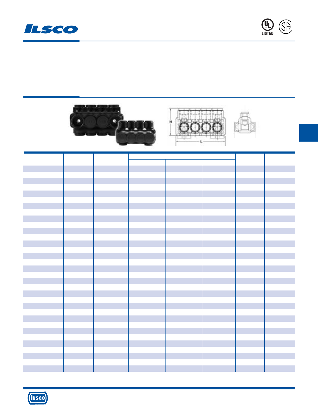
4730 Madison Road, Cincinnati, Ohio 45227-1426 Phone 513 533-6200 Fax 513 871-4084 Web site www.ilsco.com
Canada 1050 Lakeshore Road East, Mississauga, Ontario, Canada L5E1E4 Phone 905 274-2341 Fax 905 274-8763
206
D
Catalog No. Wire Dimensions Hex Mounting
Number Of Ports Range L W H Size Holes
PBTD-2-3/0-M 2 3/0-6 3.42 1.68 1.86 3/16 1/4
PBTD-3-3/0-M 3 3/0-6 4.18 1.68 1.86 3/16 1/4
PBTD-4-3/0-M 4 3/0-6 4.95 1.68 1.86 3/16 1/4
PBTD-5-3/0-M 5 3/0-6 5.71 1.68 1.86 3/16 1/4
PBTD-6-3/0-M 6 3/0-6 6.48 1.68 1.86 3/16 1/4
PBTD-7-3/0-M 7 3/0-6 7.24 1.68 1.86 3/16 1/4
PBTD-8-3/0-M 8 3/0-6 8.01 1.68 1.86 3/16 1/4
PBTD-9-3/0-M 9 3/0-6 8.77 1.68 1.86 3/16 1/4
PBTD-10-3/0-M 10 3/0-6 9.54 1.68 1.86 3/16 1/4
PBTD-11-3/0-M 11 3/0-6 10.30 1.68 1.86 3/16 1/4
PBTD-12-3/0-M 12 3/0-6 11.07 1.68 1.86 3/16 1/4
PBTD-2-250-M 2 250kcmil-6 3.96 2.13 2.17 5/16 1/4
PBTD-3-250-M 3 250kcmil-6 4.85 2.13 2.17 5/16 1/4
PBTD-4-250-M 4 250kcmil-6 5.75 2.13 2.17 5/16 1/4
PBTD-5-250-M 5 250kcmil-6 6.64 2.13 2.17 5/16 1/4
PBTD-6-250-M 6 250kcmil-6 7.53 2.13 2.17 5/16 1/4
PBTD-7-250-M 7 250kcmil-6 8.42 2.13 2.17 5/16 1/4
PBTD-8-250-M 8 250kcmil-6 9.32 2.13 2.17 5/16 1/4
PBTD-9-250-M 9 250kcmil-6 10.21 2.13 2.17 5/16 1/4
PBTD-10-250-M 10 250kcmil-6 11.10 2.13 2.17 5/16 1/4
PBTD-11-250-M 11 250kcmil-6 12.00 2.13 2.17 5/16 1/4
PBTD-12-250-M 12 250kcmil-6 12.89 2.13 2.17 5/16 1/4
PBTD-2-350-M 2 350kcmil-6 4.61 2.25 2.62 5/16 5/16
PBTD-3-350-M 3 350kcmil-6 5.67 2.25 2.62 5/16 5/16
PBTD-4-350-M 4 350kcmil-6 6.71 2.25 2.62 5/16 5/16
PBTD-5-350-M 5 350kcmil-6 7.76 2.25 2.62 5/16 5/16
PBTD-6-350-M 6 350kcmil-6 8.81 2.25 2.62 5/16 5/16
PBTD-7-350-M 7 350kcmil-6 9.86 2.25 2.62 5/16 5/16
PBTD-8-350-M 8 350kcmil-6 10.91 2.25 2.62 5/16 5/16
PBTD-9-350-M 9 350kcmil-6 11.96 2.25 2.62 5/16 5/16
PBTD-10-350-M 10 350kcmil-6 13.01 2.25 2.62 5/16 5/16
PBTD-11-350-M 11 350kcmil-6 14.06 2.25 2.62 5/16 5/16
PBTD-12-350-M 12 350kcmil-6 15.11 2.25 2.62 5/16 5/16
NIMBUS®Mountable
Insulated Multi-Tap Connectors - Dual Sided Entry
TYPE
PBTM
Features
•
Mountable
•
Broad wire range: 750kcmil-6
•
UL Listed and CSA Certified for 600 volts, 90˚ C
•
Dual rated
•
Cold temperature rated to -45˚ C
•
High dielectric strength plastisol
•
Black cover
•
Removable plugs
•
Prefilled with De-ox®
Benefits
•
Isolated mounting in trough, wire way or panels
•
Flexibility in the field
•
Ensures reliability
•
For copper or aluminum conductor
•
Application variability
•
Chemical resistant
•
UV Rated
•
Entry port closure
•
Prevents oxides from forming
W
Per NEC Article 310-316, allowable ampacities are as follows: #4-95 Amps, 1/0-170 Amps, 3/0-225 Amps, 250-290 Amps, 350-350 Amps, 500-430 Amps, 750-535 Amps
Replacement caps & plugs available. Consult Factory. Tested to UL 486A-486B, UL File E6207
453G
L
R
-
2
9
6
0
1
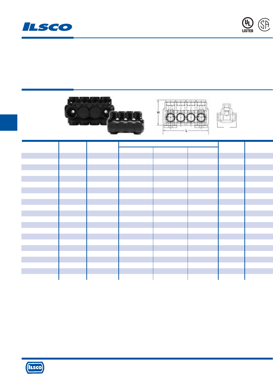
4730 Madison Road, Cincinnati, Ohio 45227-1426 Phone 513 533-6200 Fax 513 871-4084 Web site www.ilsco.com
Canada 1050 Lakeshore Road East, Mississauga, Ontario, Canada L5E1E4 Phone 905 274-2341 Fax 905 274-8763
207
D
Catalog No. Wire Dimensions Hex Mounting
Number Of Ports Range L W H Size Holes
PBTD-2-500-M 2 500kcmil-4 5.28 2.63 3.04 3/8 5/16
PBTD-3-500-M 3 500kcmil-4 6.44 2.63 3.04 3/8 5/16
PBTD-4-500-M 4 500kcmil-4 7.59 2.63 3.04 3/8 5/16
PBTD-5-500-M 5 500kcmil-4 8.75 2.63 3.04 3/8 5/16
PBTD-6-500-M 6 500kcmil-4 9.90 2.63 3.04 3/8 5/16
PBTD-7-500-M 7 500kcmil-4 11.06 2.63 3.04 3/8 5/16
PBTD-8-500-M 8 500kcmil-4 12.22 2.63 3.04 3/8 5/16
PBTD-9-500-M 9 500kcmil-4 13.37 2.63 3.04 3/8 5/16
PBTD-10-500-M 10 500kcmil-4 14.53 2.63 3.04 3/8 5/16
PBTD-11-500-M 11 500kcmil-4 15.68 2.63 3.04 3/8 5/16
PBTD-12-500-M 12 500kcmil-4 16.84 2.63 3.04 3/8 5/16
PBTD-2-750-M* 2 750kcmil-250kcmil 6.32 3.25 3.31 1/2 3/8
PBTD-3-750-M* 3 750kcmil-250kcmil 7.74 3.25 3.31 1/2 3/8
PBTD-4-750-M* 4 750kcmil-250kcmil 9.16 3.25 3.31 1/2 3/8
PBTD-5-750-M* 5 750kcmil-250kcmil 10.58 3.25 3.31 1/2 3/8
PBTD-6-750-M* 6 750kcmil-250kcmil 12.00 3.25 3.31 1/2 3/8
PBTD-7-750-M* 7 750kcmil-250kcmil 13.43 3.25 3.31 1/2 3/8
PBTD-8-750-M* 8 750kcmil-250kcmil 14.85 3.25 3.31 1/2 3/8
PBTD-9-750-M* 9 750kcmil-250kcmil 16.27 3.25 3.31 1/2 3/8
PBTD-10-750-M* 10 750kcmil-250kcmil 17.69 3.25 3.31 1/2 3/8
PBTD-11-750-M* 11 750kcmil-250kcmil 19.11 3.25 3.31 1/2 3/8
PBTD-12-750-M* 12 750kcmil-250kcmil 20.54 3.25 3.31 1/2 3/8
NIMBUS®Mountable
Insulated Multi-Tap Connectors - Dual Sided Entry
TYPE
PBTM
Features
•
Mountable
•
Broad wire range: 750kcmil-6
•
UL Listed and CSA Certified for 600 volts, 90˚ C
•
Dual rated
•
Cold temperature rated to -45˚ C
•
High dielectric strength plastisol
•
Black cover
•
Removable plugs
•
Prefilled with De-ox®
Benefits
•
Isolated mounting in trough, wire way or panels
•
Flexibility in the field
•
Ensures reliability
•
For copper or aluminum conductor
•
Application variability
•
Chemical resistant
•
UV Rated
•
Entry port closure
•
Prevents oxides from forming
Per NEC Article 310-316, allowable ampacities are as follows: #4-95 Amps, 1/0-170 Amps, 3/0-225 Amps, 250-290 Amps, 350-350 Amps, 500-430 Amps, 750-535 Amps
Replacement caps & plugs available. Consult Factory.
* Not UL Listed
Tested to UL 486A-486B, UL File E6207
W
453G
L
R
-
2
9
6
0
1
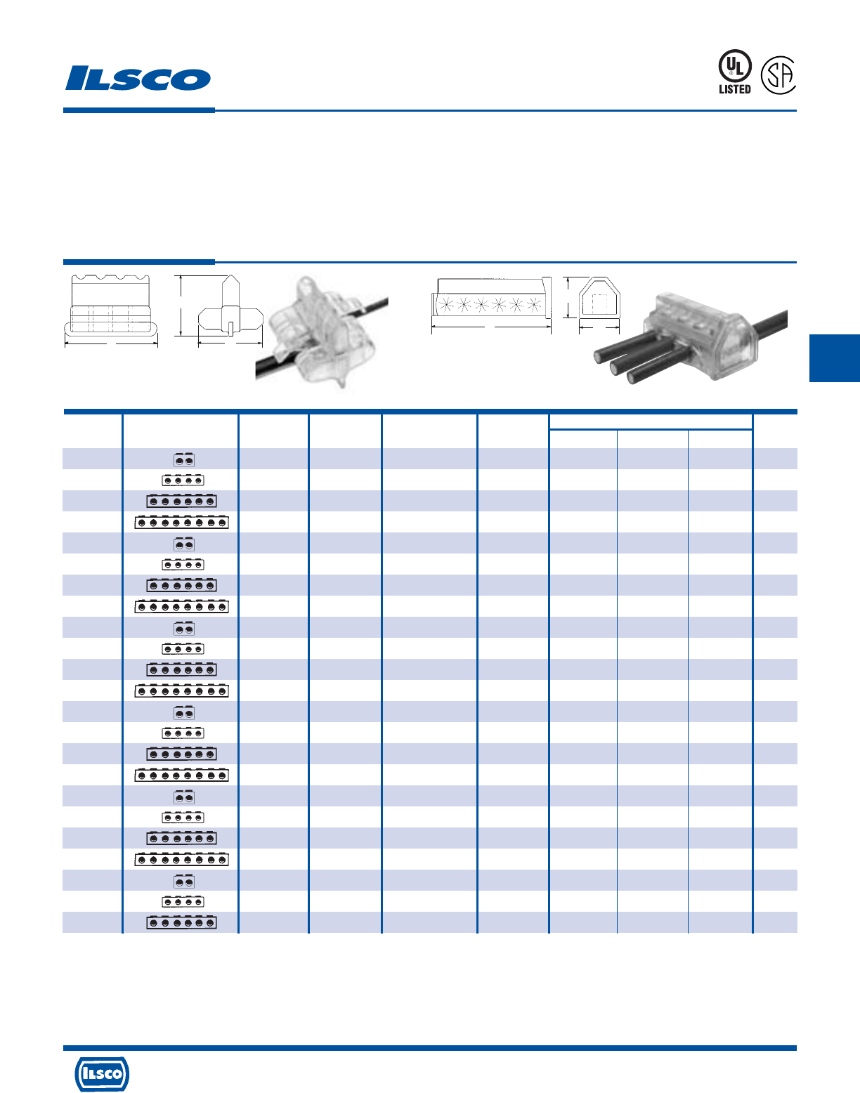
Catalog Figure No. Wire Ampere Dimensions Hex
Number Connector Shape No. Of Ports Range Rating L W H Size
PCT-2-4 1 2 4-14 95 1.46 1.57 1.43 slot
PCT-4-4 1 4 4-14 95 2.46 1.57 1.43 slot
PCT-6-4 1 6 4-14 95 3.46 1.57 1.43 slot
PCT-8-4 1 8 4-14 95 4.46 1.57 1.43 slot
PCT-2-2/0 2 2 2/0-14 195 2.61 2.30 1.97 3/16
PCT-4-2/0 2 4 2/0-14 195 4.30 2.30 1.97 3/16
PCT-6-2/0 2 6 2/0-14 195 5.98 2.30 1.97 3/16
PCT-8-2/0 2 8 2/0-14 195 7.67 2.30 1.97 3/16
PCT-2-4/0 2 2 4/0-6 260 2.33 2.49 2.25 5/16
PCT-4-4/0 2 4 4/0-6 260 4.19 2.49 2.25 5/16
PCT-6-4/0 2 6 4/0-6 260 6.05 2.49 2.25 5/16
PCT-8-4/0 2 8 4/0-6 260 7.91 2.49 2.25 5/16
PCT-2-350 2 2 350 kcmil-6 350 2.75 2.69 2.65 5/16
PCT-4-350 2 4 350 kcmil-6 350 5.06 2.69 2.65 5/16
PCT-6-350 2 6 350 kcmil-6 350 7.37 2.69 2.65 5/16
PCT-8-350 2 8 350 kcmil-6 350 9.68 2.69 2.65 5/16
PCT-2-600 2 2 600 kcmil-4 475 3.17 3.20 3.27 3/8
PCT-4-600 2 4 600 kcmil-4 475 5.73 3.20 3.27 3/8
PCT-6-600 2 6 600 kcmil-4 475 8.29 3.20 3.27 3/8
PCT-8-600 2 8 600 kcmil-4 475 10.86 3.20 3.27 3/8
PCT-2-800 2 2 800kcmil-250kcmil 555 3.91 3.34 3.30 1/2
PCT-4-800 2 4 800kcmil-250kcmil 555 7.03 3.34 3.30 1/2
PCT-6-800 2 6 800kcmil-250kcmil 555 10.15 3.34 3.30 1/2
ClearTap®Insulated Multi-Tap Connectors
TYPE
PCT
453G
Features
•
Transparent flexible insulating cover
•
Captive pressure screws
•
Self-closing openings
•
Access from both sides of connector
•
Broad wire range: 800kcmil-14
•
UL Listed for 600 volts, 90˚ C
•
Dual Rated
Benefits
•
No taping and allows visual inspection of connection
•
No wasted time finding screws
•
No lost or loose caps and plugs
•
Provides greater versatility
•
Reduces inventory
•
Ensures reliability
•
For copper or aluminum conductor
L
Fig. 1 (Patented) Fig. 2
H
W
L
H
W
Not suitable for direct burial.
Tested to UL 486A-486B, UL File E6207
L
R
-
2
9
6
0
1
4730 Madison Road, Cincinnati, Ohio 45227-1426 Phone 513 533-6200 Fax 513 871-4084 Web site www.ilsco.com
Canada 1050 Lakeshore Road East, Mississauga, Ontario, Canada L5E1E4 Phone 905 274-2341 Fax 905 274-8763
208
D
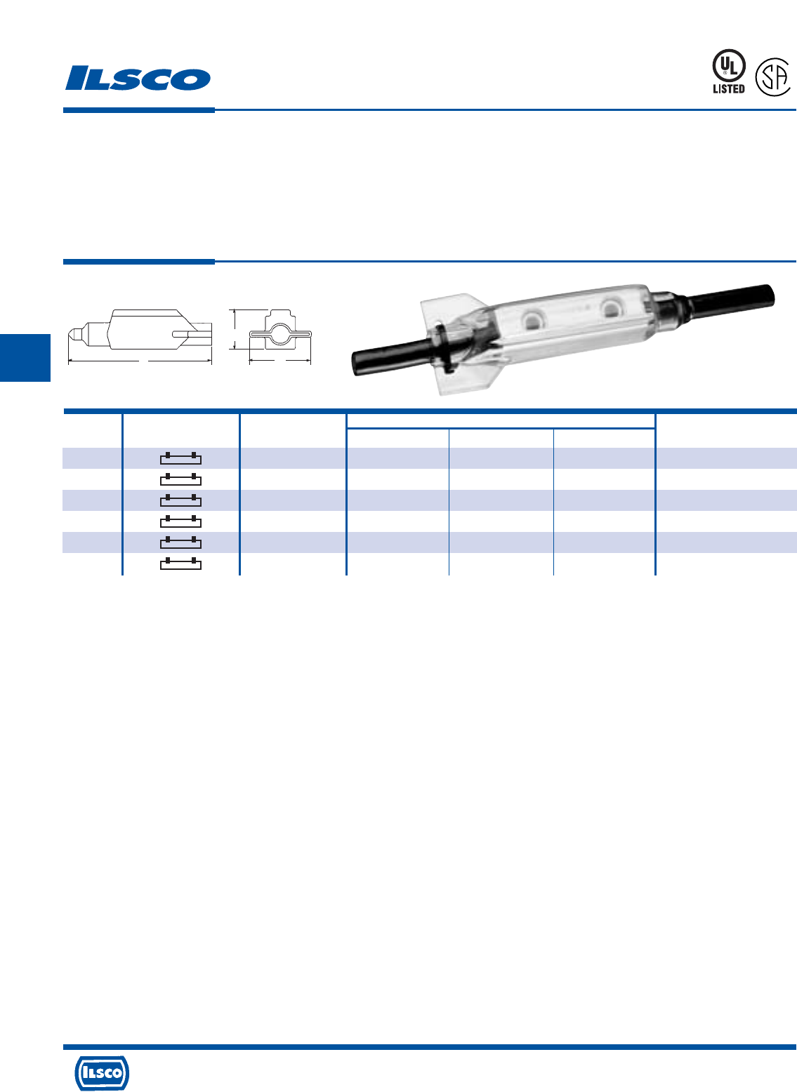
4730 Madison Road, Cincinnati, Ohio 45227-1426 Phone 513 533-6200 Fax 513 871-4084 Web site www.ilsco.com
Canada 1050 Lakeshore Road East, Mississauga, Ontario, Canada L5E1E4 Phone 905 274-2341 Fax 905 274-8763
209
D
Catalog Wire Dimensions Screw
Number Connector Shape Range L W H Size & Shape
SPAR-4 4-14 3.30 1.55 .76 slotted
SPAR-2 2-14 3.83 1.75 .95 slotted
SPAR-1/0 1/0-14 4.80 1.94 1.14 3/16” socket head
SPAR-250 250kcmil-6 5.67 2.41 1.29 5/16” socket head
SPAR-350 350kcmil-6 6.17 3.29 1.79 5/16” socket head
SPAR-500 500kcmil-4 7.94 3.66 2.28 3/8” socket head
RocketSplice®
Insulated Splicer-Reducer Connector
TYPE
SPAR
L
R
-
2
9
6
0
1
453G
Features
•
Transparent flexible insulating cover
•
Range adjustable trim-to-fit tip
•
Unique shape and compact design
•
Connector, cover and cable tie packaged together
•
UL Listed and CSA Certified for 600 volts
•
Dual Rated
Benefits
•
No taping and allows visual inspection of splice
•
Ensures proper fit of cover to cable
•
Provides ease of installation, versatility and
serviceability of connections made in tight spaces
•
Provides ease of ordering
•
Ensures reliability
•
Use with copper or aluminum conductor
L
H
W
DE-OX Oxide Inhibitor is recommended for all aluminum terminations.
Tested to UL 486A-486B, UL File E6207
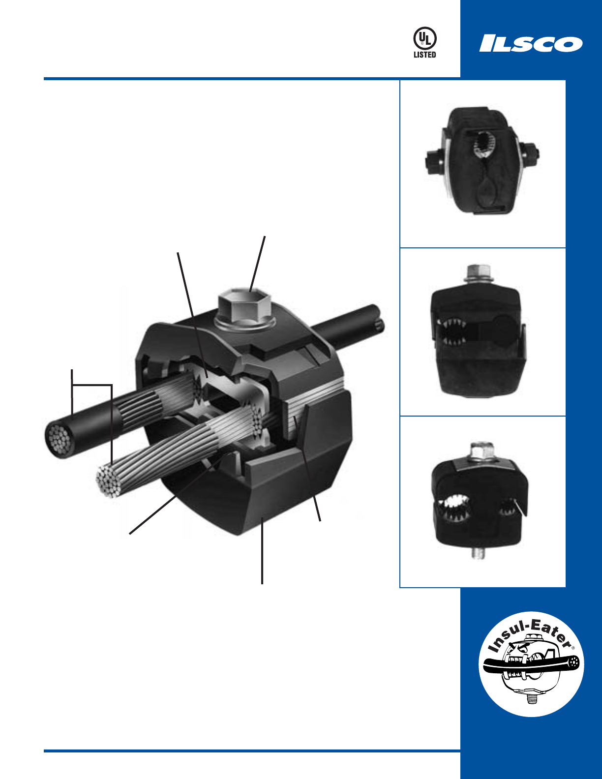
210
Insulation Piercing
KUP-L-TAP®
Insulation Piercing Connectors
Save Time And Money
Tin plated, hardened copper
contact teeth easily penetrate
most types of conductor
insulation.
Bolt tightens with just a wrench.
Available in stainless steel for
corrosive environments.
A horizontal line grid
provides a visual guide
for proper alignment of
connector body.
End tabs
knock out
easily by
hand.
KUP-L-TAP®body is molded of
tough, resilient glass-filled
nylon. Silicone compound acts
as a blocking agent to protect
connection from oxidation
KUP-L-TAP®is dual-
rated for copper and
aluminum
conductors.
923F
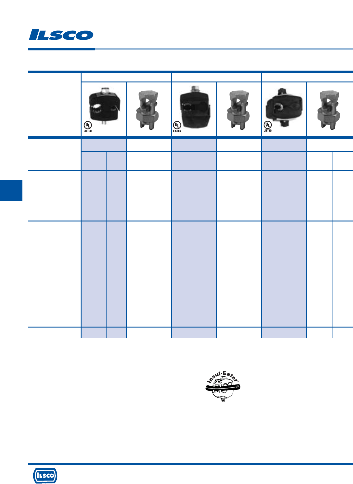
4730 Madison Road, Cincinnati, Ohio 45227-1426 Phone 513 533-6200 Fax 513 871-4084 Web site www.ilsco.com
Canada 1050 Lakeshore Road East, Mississauga, Ontario, Canada L5E1E4 Phone 905 274-2341 Fax 905 274-8763
211
E
Product KUP-L-TAP®Split Bolt KUP-L-TAP®Split Bolt KUP-L-TAP®Split Bolt
Catalog Number IPC-1/0-2 AK-1/0 IPC 250-4/0 AK-4/0 IPC 500-250 AK-500
Connector Wire Range Main Tap Main Tap Main Tap Main Tap Main Tap Main Tap
1/0-8 2-8 1/0-2 1/0-8 250-1 4/0-6 4/0-2 4/0-6 500-250 250-4 500-350 500-2
Material Cost*
Connector $12.54 $10.73 $27.83 $29.16 $67.14 $71.04
Insulating Material 0 1.54 0 2.97 0 5.17
Oxide Inhibitor 0 .12 0 .14 0 .16
TOTAL MATERIAL COST $12.54 $12.39 $27.83 $32.27 $67.14 $76.37
Installation Cost
Stripping Insulation 0 1 Minute 0 2 Minutes 0 3 Minutes
Wire Brush Conductor 0 1/2 Minute 0 1/2 Minute 0 1/2 Minute
Applying Oxide Inhibitor
0 1/2 Minute 0 1/2 Minute 0 1/2 Minute
Assemble and Tighten 1 Minute 1 Minute 1 Minute 2 Minutes 2 Minutes 3 Minutes
Insulate Connector 0 12 Minutes 0 15 Minutes 0 25 Minutes
Total Installation Time** 1 Minute 15 Minutes 1 Minute 20 Minutes 2 Minutes 32 Minutes
Direct Labor Cost***
At $60.00 per hour $1.00 $15.00 $1.00 $20.00 $2.00 $32.00
TOTAL MATERIAL & LABOR
$13.54 $27.39 $28.83 $52.27 $69.14 $108.37
Work It Hot Yes No Yes No Ye s No
Compare: Time…Parts…Tools…Total Costs…
*Material cost based upon current manufacturers suggested trade price.
** Installation time based upon average for installation indoors in gutter or trough (National Electrical Contractors Association Instruction Manual of Labor Units shows
respective time for split bolt installation for Example A, 1 hr., Example B, 2 hrs., Example C, 6 hrs.).
***Actual hourly rate for specific areas should be substituted.
Installed Cost
Comparison:
KUP-L-TAP®vs.
Dual Rated
Split Bolt
EXAMPLE A EXAMPLE B EXAMPLE C
THERE IS REALLY NO COMPARISON!
KUP-L-TAP®is your best choice for lower costs, easier installation, and increased safety.
KUP-L-TAP®, for indoor/outdoor use are dual rated for copper and aluminum wire and can be installed on energized conductors. They run cooler than the conductor yet require
no cover or tape over the connectors. No need for stripping or oxide inhibitor.
Molded of tough, resilient, glass-filled nylon, KUP-L-TAP®can be used as a dead-end non-tension splice or a tap splice. Precisely designed, extra-hard copper contact teeth
assure proper penetration into either copper or aluminum conductors.
KUP-L-TAP®can be installed “hot” on energized conductors.
923F 923F 923F
Save 40-50% with KUP-L-TAP®
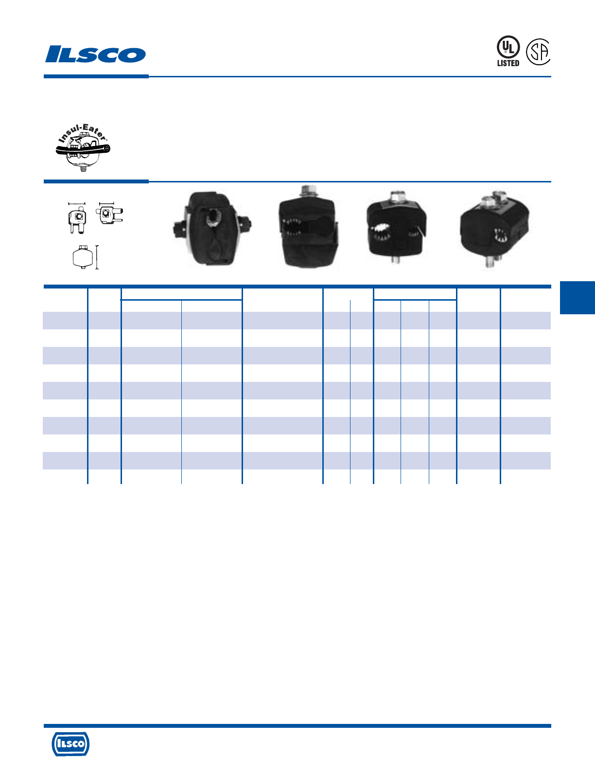
WL
H
Catalog Figure Wire Range Current Rating Dimensions Torque Bolt Head
Number Number Main Tap Volts CU AL L W H Ft. Lbs. Size
IPC-1/0-2 3 1/0-8 2-8 300
(480 Grounded Y System)
130 100 1-7/32 1-15/32 2-5/16 16 1/2
IPC-4/0-6 2 4/0-4 6-14 600 75 60 1-27/64 1 1-7/8 13 1/2
IPC-4/0-2/0 3 4/0-2 2/0-6 600 195 150 1-21/32 1-7/8 2-7/8 25 1/2
IPC-250-4/0 2 250kcmil-1 4/0-6 600 260 205 1-7/8 2-11/32 3-11/32 30 5/8
IPC-350-4/0 3 350kcmil-4/0 4/0-10 300
(480 Grounded Y System)
260 205 1-43/64 2-7/16 3-1/8 25 5/8
IPC-350-350 4 350kcmil-4/0 350kcmil-4/0 300
(480 Grounded Y System)
350 280 2-43/64 2-23/32 3-1/4 25 5/8
IPC-500-12 * 1 500kcmil-250kcmil 10-12 300
(480 Grounded Y System)
40 35 1-43/64 2-7/16 3-1/4 25 5/8
IPC-500-250 1 500kcmil-250kcmil 250kcmil-4 600 290 230 2-27/64 2-29/32 3-3/4 55 5/8-11/16
IPC-500-500 1 500kcmil-300kcmil 500kcmil-250kcmil 600 430 350 3-3/16 3-5/8 5 75 7/8-7/8
IPC-750-500 1 750kcmil-500kcmil 500kcmil-350kcmil 600 430 350 3-3/16 3-5/8 5 75 7/8-7/8
KUP-L-Tap®Insulation Piercing Connectors
Dual Rated
TYPE
IPC
Features
•
Body is molded from tough, resilient glass-filled nylon
•
Compact design
•
Tin plated copper contact teeth
•
Insulation piercing
•
Perforated end tabs
•
Pre-filled with silicone lubricant
•
Versatile
•
Increased safety
•
Horizontal line grid
•
Temperature rating 90˚ C
Fig. 1 Fig. 2 Fig. 3 Fig. 4
Benefits
•
Provides high degree of breakage resistance and long dependable use
•
Saves space
•
Easily penetrates most types of insulation
•
No need to strip the conductor which saves installation time
•
Break out easily by hand
•
Prevents oxidation and moisture from entering the contact area
•
Can be used as a splice or tap connector
•
Contains no external energized parts. Can be installed “hot” on energized
conductors providing tap conductor is not under load.
•
Provides a visual guide for proper installation of conductors
923F
L
R
-
2
4
3
5
9
* Not CSA Certified
Tested to UL 486A-486B, UL File E6207
4730 Madison Road, Cincinnati, Ohio 45227-1426 Phone 513 533-6200 Fax 513 871-4084 Web site www.ilsco.com
Canada 1050 Lakeshore Road East, Mississauga, Ontario, Canada L5E1E4 Phone 905 274-2341 Fax 905 274-8763
212
E
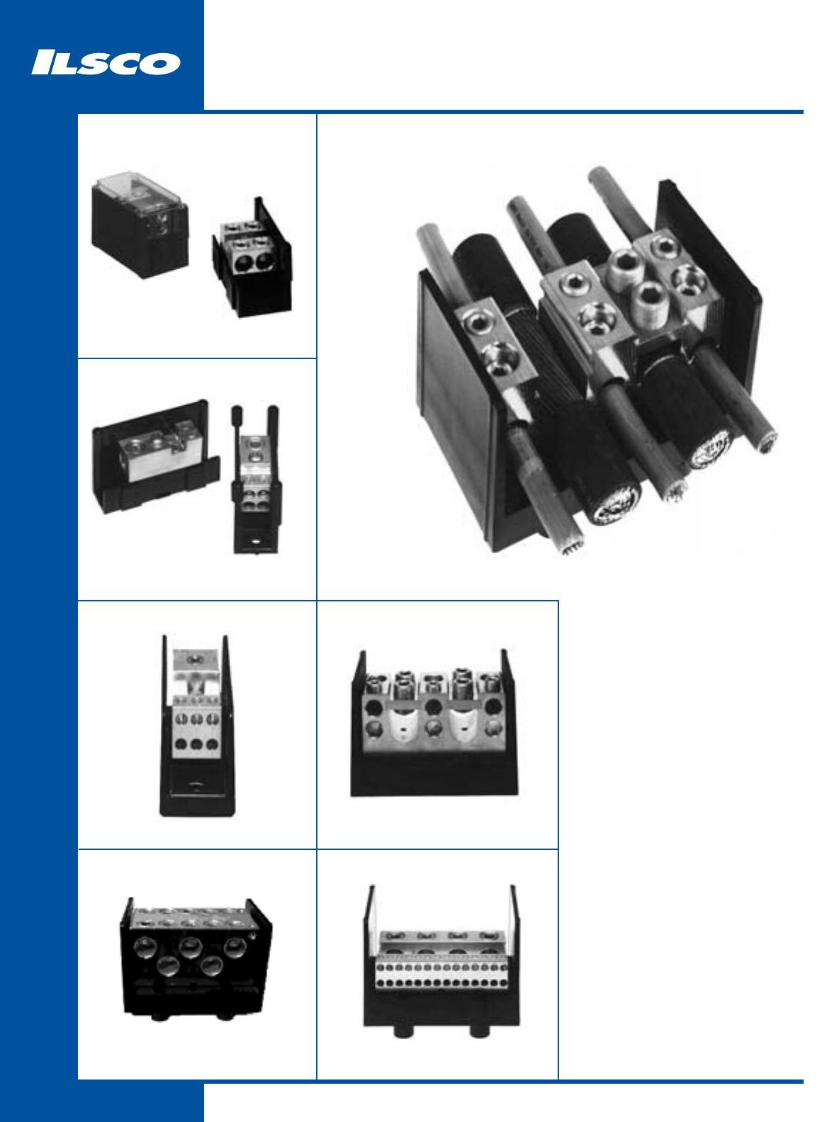
213
Power Distribution Blocks
214
LDA/LDB Snap Bloc®
215
PDA/PDC
221
PDB
219
PDB
216 - 218
PDB
220
PDB
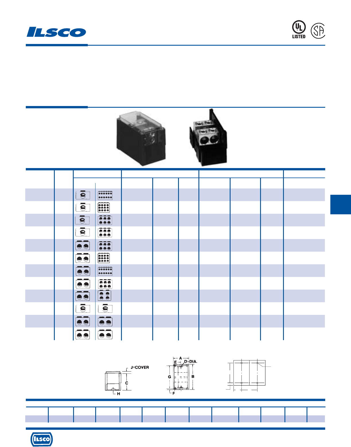
4730 Madison Road, Cincinnati, Ohio 45227-1426 Phone 513 533-6200 Fax 513 871-4084 Web site www.ilsco.com
Canada 1050 Lakeshore Road East, Mississauga, Ontario, Canada L5E1E4 Phone 905 274-2341 Fax 905 274-8763
214
F
Connector Primary Secondary Ampere
Catalog Figure Wire Openings Hex Wire Openings Hex Rating
Number Number Primary Secondary Range Per Pole Size Range Per Pole Size Per Pole
LDB-112-350 1 350kcmil-6 1 3/8 4-14 12 Slot 310
LDA-112-350 2 350kcmil-6 1 4-14 12 310
LDB-112A-350 1 350kcmil-6 1 3/8 4-14 12 Slot 310
LDA-112A-350 2 350kcmil-6 1 4-14 12 310
LDB-16-350 1 350kcmil-6 1 3/8 2/0-14 6 3/16 310
LDA-16-350 2 350kcmil-6 1 2/0-14 6 310
LDB-16-500 1 500kcmil-4 1 3/8 2/0-14 6 3/16 380
LDA-16-500 2 500kcmil-4 1 2/0-14 6 380
LDB-26-350 1 350kcmil-6 2 3/8 2/0-14 6 3/16 620
LDA-26-350 2 350kcmil-6 2 2/0-14 6 620
LDB-212-4/0 1 4/0-6 2 1/4 4-14 12 Slot 460
LDA-212-4/0 2 4/0-6 2 4-14 12 460
LDB-212-500 1 500kcmil-4 2 3/8 4-14 12 Slot 760
LDA-212-500 2 500kcmil-4 2 4-14 12 760
LDB-26-500 1 500kcmil-4 2 3/8 2/0-14 6 3/16 760
LDA-26-500 2 500kcmil-4 2 2/0-14 6 760
LDB-24-500 1 500kcmil-4 2 3/8 4/0-6 4 5/16 760
LDA-24-500 2 500kcmil-4 2 4/0-6 4 760
LDB-11-500 1 500kcmil-4 1 3/8 500kcmil-4 1 3/8 380
LDA-11-500 2 500kcmil-4 1 500kcmil-4 1 380
LDB-22-350 1 350kcmil-6 2 3/8 350kcmil-6 2 3/8 620
LDA-22-350 2 350kcmil-6 2 350kcmil-6 2 620
LDB-22-500 1 500kcmil-4 2 3/8 500kcmil-4 2 3/8 760
LDA-22-500 2 500kcmil-4 2 500kcmil-4 2 760
Snapbloc®Power Distribution Blocks
Modular Design - Dual Rated
TYPE
LDA
LDB
Features
•
Modular design
•
Easy to assemble
•
UL listed 90˚ C 600 Volts and is CSA Certified
•
Electro-tin plated 6061-T6 aluminum alloy
•
Clear cover
•
Multiple conductor capability
Benefits
•
Simplifies stocking. Combines any number of blocks with multiple
conductor ranges into the specific configuration required for the job.
•
Unique locking feature allows individual blocks to be combined quickly
without special tools
•
Ensures reliability
•
Suitable for use with both copper and aluminum conductors in any
combination
•
Permits visual inspection
•
Individual blocks supplied in a variety of configurations with one or two
main cable ports and four, six, or twelve taps. All are range taking.
45U4
L
R
-
2
9
6
0
1
Dimensions
A B C D=Dia. E F G H J = Cover K L M N
3 5-1/2 3-7/16 .28 Slot 1-1/2 5/16 4-7/8 1/4 1/2 4.75 2.69 .38 1.50
Side Panel can be ordered separately Cat. No. LDS-1
Tested to UL 1059, UL File E112158
K
TYP.
L
1/4 BOLT
N
M
Fig. 1 Fig. 2
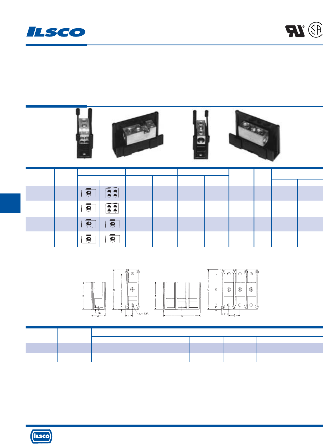
4730 Madison Road, Cincinnati, Ohio 45227-1426 Phone 513 533-6200 Fax 513 871-4084 Web site www.ilsco.com
Canada 1050 Lakeshore Road East, Mississauga, Ontario, Canada L5E1E4 Phone 905 274-2341 Fax 905 274-8763
215
F
Connector Primary Secondary Ampere No.
Catalog Figure Wire Openings Wire Openings Rating of Hex Size
Number Number Primary Secondary Range Per Pole Range Per Pole Per Pole Poles Primary Secondary
PDC-14-2/0-1 1 2/0-14 1 4-14 4 175 1 3/16 Slot
PDA-14-2/0-1 2 2/0-14 1 4-14 4 175 Adder 3/16 Slot
PDC-11-2/0-1 3 2/0-14 1 2/0-14 1 175 1 3/16 3/16
PDA-11-2/0-1 4 2/0-14 1 2/0-14 1 175 Adder 3/16 3/16
Modular Type Power Distribution Blocks
Dual Rated
TYPE
PDA
PDC
Features
•
Modular design
•
Easy to assemble
•
UL Recognized 90˚ C 600 Volts and is CSA Certified
•
Electro-tin plated
•
Lexan* insulating base
•
Manufactured from high strength 6061-T6 aluminum
alloy
Fig. 1 Fig. 2 Fig. 3 Fig. 4
Benefits
•
Simplifies stocking. Combines any number of blocks
with multiple conductor ranges into the specific
configuration required for the job.
•
Unique locking feature allows individual blocks to be
combined quickly without special tools
•
Ensures reliability
•
Provides low contact resistance
•
Provides a high degree of impact resistance with
superior insulating qualities
•
Suitable for use with either copper or aluminum
conductors
Block No. of Dimensions
Size Poles A B C D E F G
S 1 1.05 1.94 2.88 2.25 .31 .53 .80
S 2 1.85 1.94 2.88 2.25 .31 .53 .80
"A" Dimension increases by .80 per additional pole.
Covers available 1-10 Poles. Specify length.
*Lexan is a registered trademark of SABIC INNOVATIVE PLASTICS HOLDINGS BV.
Tested to UL 486A-486B, UL File E84782
L
R
-
2
9
6
0
1
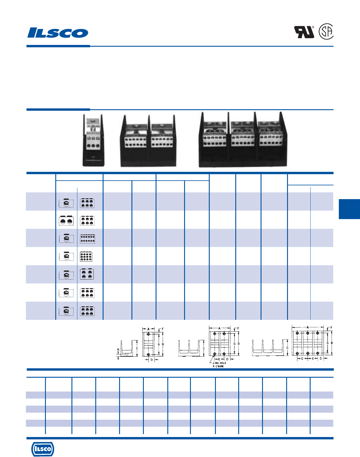
4730 Madison Road, Cincinnati, Ohio 45227-1426 Phone 513 533-6200 Fax 513 871-4084 Web site www.ilsco.com
Canada 1050 Lakeshore Road East, Mississauga, Ontario, Canada L5E1E4 Phone 905 274-2341 Fax 905 274-8763
216
F
Connector Primary Secondary Ampere
Catalog Wire Openings Wire Openings Rating Number Block Hex Size
Number Primary Secondary Range Per Pole Range Per Pole Per Pole Of Poles Size Primary Secondary
PDB-16-2/0-1 2/0-12 1 4-14 6 175 1 M
PDB-16-2/0-2 2/0-12 1 4-14 6 175 2 M 3/16 Slot
PDB-16-2/0-3 2/0-12 1 4-14 6 175 3 M
PDB-26-2/0-1 2/0-12 2 2-14 6 350 1 M
PDB-26-2/0-2 2/0-12 2 2-14 6 350 2 M 3/16 Slot
PDB-26-2/0-3 2/0-12 2 2-14 6 350 3 M
PDB-112-350-1 350kcmil-6 1 4-14 12 310 1 L
PDB-112-350-2 350kcmil-6 1 4-14 12 310 2 L 3/8 Slot
PDB-112-350-3 350kcmil-6 1 4-14 12 310 3 L
PDB-112A-350-1 350kcmil-6 1 4-14 12 310 1 M
PDB-112A-350-2 350kcmil-6 1 4-14 12 310 2 M 3/8 Slot
PDB-112A-350-3 350kcmil-6 1 4-14 12 310 3 M
PDB-14-500-1 500kcmil-4 1 2/0-14 4 380 1 M
PDB-14-500-2 500kcmil-4 1 2/0-14 4 380 2 M 3/8 3/16
PDB-14-500-3 500kcmil-4 1 2/0-14 4 380 3 M
PDB-16-350-1 350kcmil-6 1 2/0-14 6 310 1 L
PDB-16-350-2 350kcmil-6 1 2/0-14 6 310 2 L 3/8 3/16
PDB-16-350-3 350kcmil-6 1 2/0-14 6 310 3 L
PDB-162-500-1 500kcmil-4 1 2-14 6 380 1 M
PDB-162-500-2 500kcmil-4 1 2-14 6 380 2 M 3/8 Slot
PDB-162-500-3 500kcmil-4 1 2-14 6 380 3 M
Dimensions
Block Number Figure
Size Of Poles Number A B C D E F G H J K
M 1 1 1-27/32 4 2-5/8 31/32 - 5/16 3-3/8 3/8 13/64 13/32
M 2 2 3-13/32 4 2-5/8 31/32 1-17/32 5/16 3-3/8 3/8 13/64 13/32
M3 3542-5/831/32 1-17/32 5/16 3-3/8 3/8 13/64 13/32
L 1 1 3 5-1/2 3-1/2 1-1/2 - 3/8 4-3/4 7/16 9/32 1/2
L 2 2 5-11/16 5-1/2 3-1/2 1-1/2 2-11/16 3/8 4-3/4 7/16 9/32 1/2
L 3 3 8-3/8 5-1/2 3-1/2 1-1/2 2-11/16 3/8 4-3/4 7/16 9/32 1/2
Power Distribution Blocks - Dual Rated
TYPE
PDB
Features
•
Range taking
•
Valox* insulating base
•
Electro-tin plated
•
Manufactured from high strength 6061-T6
aluminum alloy
•
UL Recognized rated 90˚ C and is CSA Certified,
rated for 600 volts
Benefits
•
Provides great flexibility in using the connector as an in line
splice or to reduce conductor size
•
Provides a high degree of impact resistance with superior
insulating qualities
•
Provides low contact resistance
•
Suitable for use with either copper or aluminum conductors
•
Ensures reliability
L
R
-
2
9
6
0
1
Fig. 1 Fig. 2 Fig. 3
* Valox®is a registered trade name of the General Electric Company.
Tested to UL 1059, UL File E84782
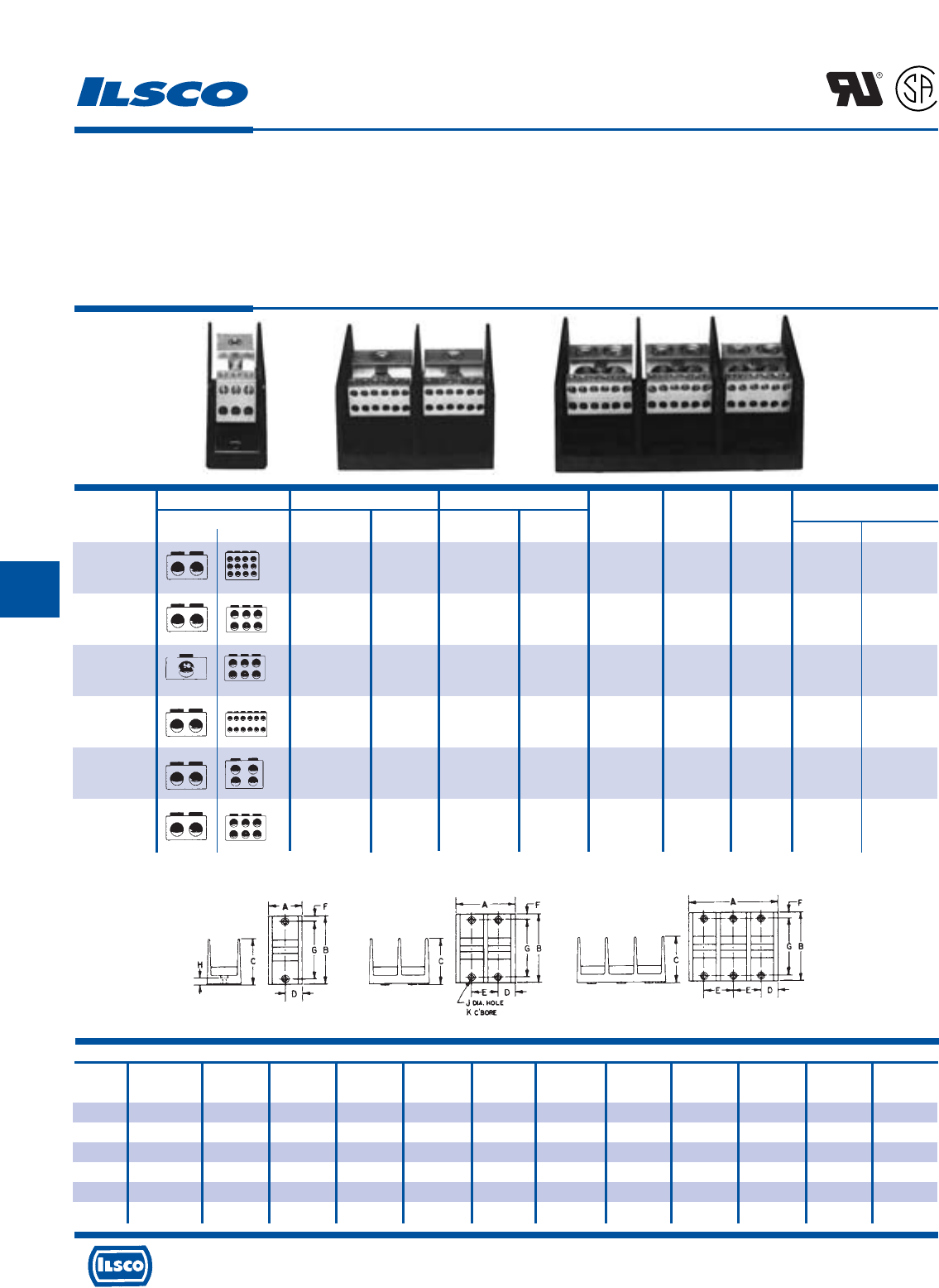
4730 Madison Road, Cincinnati, Ohio 45227-1426 Phone 513 533-6200 Fax 513 871-4084 Web site www.ilsco.com
Canada 1050 Lakeshore Road East, Mississauga, Ontario, Canada L5E1E4 Phone 905 274-2341 Fax 905 274-8763
217
F
Dimensions
Block Number Figure
Size Of Poles Number A B C D E F G H J K
M 1 1 1-27/32 4 2-5/8 31/32 - 5/16 3-3/8 3/8 13/64 13/32
M 2 2 3-13/32 4 2-5/8 31/32 1-17/32 5/16 3-3/8 3/8 13/64 13/32
M3 3542-5/831/32 1-17/32 5/16 3-3/8 3/8 13/64 13/32
L 1 1 3 5-1/2 3-1/2 1-1/2 - 3/8 4-3/4 7/16 9/32 1/2
L 2 2 5-11/16 5-1/2 3-1/2 1-1/2 2-11/16 3/8 4-3/4 7/16 9/32 1/2
L 3 3 8-3/8 5-1/2 3-1/2 1-1/2 2-11/16 3/8 4-3/4 7/16 9/32 1/2
Connector Primary Secondary Ampere
Catalog Wire Openings Wire Openings Rating Number Block Hex Size
Number Primary Secondary Range Per Pole Range Per Pole Per Pole Of Poles Size Primary Secondary
PDB-212-4/0-1 4/0-6 2 4-14 12 460 1 M
PDB-212-4/0-2 4/0-6 2 4-14 12 460 2 M 3/8 Slot
PDB-212-4/0-3 4/0-6 2 4-14 12 460 3 M
PDB-26-350-1 350kcmil-6 2 2/0-14 6 620 1 L
PDB-26-350-2 350kcmil-6 2 2/0-14 6 620 2 L 3/8 3/16
PDB-26-350-3 350kcmil-6 2 2/0-14 6 620 3 L
PDB-16-500-1 500kcmil-4 1 2/0-14 6 380 1 L
PDB-16-500-2 500kcmil-4 1 2/0-14 6 380 2 L 3/8 3/16
PDB-16-500-3 500kcmil-4 1 2/0-14 6 380 3 L
PDB-212-500-1 500kcmil-4 2 4-14 12 760 1 L
PDB-212-500-2 500kcmil-4 2 4-14 12 760 2 L 3/8 Slot
PDB-212-500-3 500kcmil-4 2 4-14 12 760 3 L
PDB-24-500-1 500kcmil-4 2 4/0-6 4 760 1 L
PDB-24-500-2 500kcmil-4 2 4/0-6 4 760 2 L 3/8 5/16
PDB-24-500-3 500kcmil-4 2 4/0-6 4 760 3 L
PDB-26-500-1 500kcmil-4 2 2/0-14 6 760 1 L
PDB-26-500-2 500kcmil-4 2 2/0-14 6 760 2 L 3/8 3/16
PDB-26-500-3 500kcmil-4 2 2/0-14 6 760 3 L
Power Distribution Blocks - Dual Rated
TYPE
PDB
Features
•
Range taking
•
Valox* insulating base
•
Electro-tin plated
•
Manufactured from high strength 6061-T6
aluminum alloy
•
UL Recognized rated 90˚ C and is CSA Certified,
rated for 600 volts
Benefits
•
Provides great flexibility in using the connector as an in line
splice or to reduce conductor size
•
Provides a high degree of impact resistance with superior
insulating qualities
•
Provides low contact resistance
•
Suitable for use with either copper or aluminum conductors
•
Ensures reliability
* Valox®is a registered trade name of the General Electric Company.
Tested to UL 1059, UL File E84782
L
R
-
2
9
6
0
1
Fig. 1 Fig. 2 Fig. 3
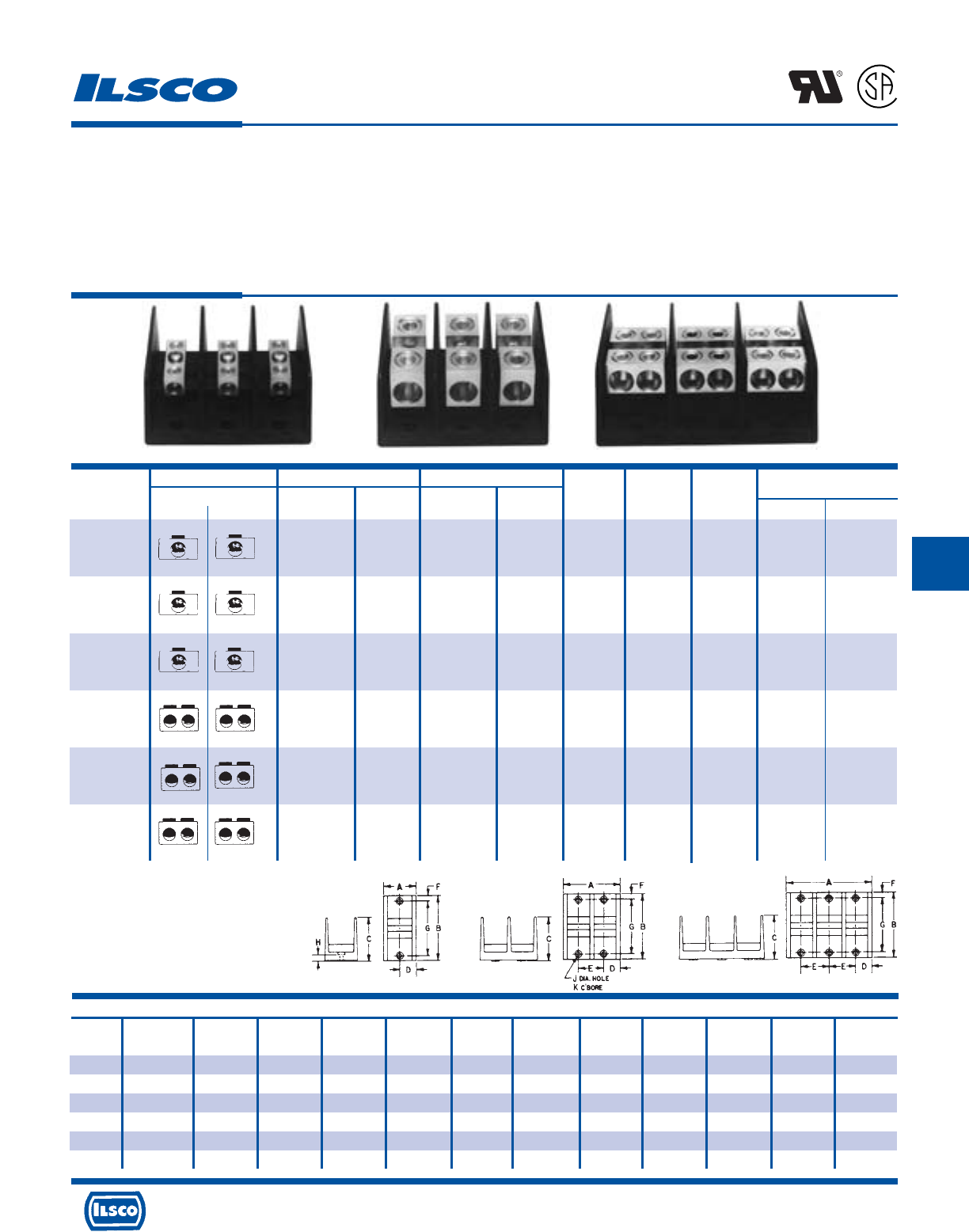
4730 Madison Road, Cincinnati, Ohio 45227-1426 Phone 513 533-6200 Fax 513 871-4084 Web site www.ilsco.com
Canada 1050 Lakeshore Road East, Mississauga, Ontario, Canada L5E1E4 Phone 905 274-2341 Fax 905 274-8763
218
F
Dimensions
Block Number Figure
Size Of Poles Number A B C D E F G H J K
M 1 1 1-27/32 4 2-5/8 31/32 - 5/16 3-3/8 3/8 13/64 13/32
M 2 2 3-13/32 4 2-5/8 31/32 1-17/32 5/16 3-3/8 3/8 13/64 13/32
M3 3542-5/831/32 1-17/32 5/16 3-3/8 3/8 13/64 13/32
L 1 1 3 5-1/2 3-1/2 1-1/2 - 3/8 4-3/4 7/16 9/32 1/2
L 2 2 5-11/16 5-1/2 3-1/2 1-1/2 2-11/16 3/8 4-3/4 7/16 9/32 1/2
L 3 3 8-3/8 5-1/2 3-1/2 1-1/2 2-11/16 3/8 4-3/4 7/16 9/32 1/2
Connector Primary Secondary Ampere
Catalog Wire Openings Wire Openings Rating Number Block Hex Size
Number Primary Secondary Range Per Pole Range Per Pole Per Pole Of Poles Size Primary Secondary
PDB-11-2/0-1 2/0-14 1 2/0-14 1 175 1 M
PDB-11-2/0-2 2/0-14 1 2/0-14 1 175 2 M 3/16 3/16
PDB-11-2/0-3 2/0-14 1 2/0-14 1 175 3 M
PDB-11-350-1 350kcmil-6 1 350kcmil-6 1 310 1 M
PDB-11-350-2 350kcmil-6 1 350kcmil-6 1 310 2 M 3/8 3/8
PDB-11-350-3 350kcmil-6 1 350kcmil-6 1 310 3 M
PDB-11-500-1 500kcmil-4 1 500kcmil-4 1 380 1 L
PDB-11-500-2 500kcmil-4 1 500kcmil-4 1 380 2 L 3/8 3/8
PDB-11-500-3 500kcmil-4 1 500kcmil-4 1 380 3 L
PDB-22-2/0-1 2/0-14 2 2/0-14 2 350 1 M
PDB-22-2/0-2 2/0-14 2 2/0-14 2 350 2 M 3/16 3/16
PDB-22-2/0-3 2/0-14 2 2/0-14 2 350 3 M
PDB-22-350-1 350kcmil-6 2 350kcmil-6 2 620 1 L
PDB-22-350-2 350kcmil-6 2 350kcmil-6 2 620 2 L 3/8 3/8
PDB-22-350-3 350kcmil-6 2 350kcmil-6 2 620 3 L
PDB-22-500-1 500kcmil-4 2 500kcmil-4 2 760 1 L
PDB-22-500-2 500kcmil-4 2 500kcmil-4 2 760 2 L 3/8 3/8
PDB-22-500-3 500kcmil-4 2 500kcmil-4 2 760 3 L
Power Distribution Blocks - Dual Rated
TYPE
PDB
Features
•
Multiple taps
•
Range taking
•
Valox* insulating base
•
Electro-tin plated
•
Manufactured from high strength 6061-T6
aluminum alloy
•
UL Recognized rated 90˚ C and is CSA Certified,
rated for 600 volts
Benefits
•
Depending on product selected, up to twelve taps can be
taken from one or two mains
•
Provides tapping flexibility over a broad wire range
•
Provides a high degree of impact resistance with superior
insulating qualities
•
Provides low contact resistance
•
Suitable for use with either copper or aluminum conductors
•
Ensures reliability
* Valox®is a registered trade name of the General Electric Company.
Tested to UL 1059, UL File E84782
L
R
-
2
9
6
0
1
Fig. 1 Fig. 2 Fig. 3
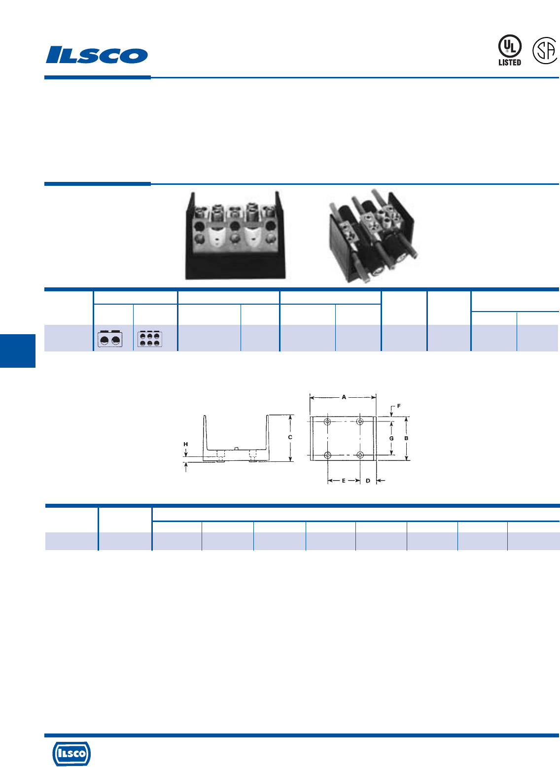
4730 Madison Road, Cincinnati, Ohio 45227-1426 Phone 513 533-6200 Fax 513 871-4084 Web site www.ilsco.com
Canada 1050 Lakeshore Road East, Mississauga, Ontario, Canada L5E1E4 Phone 905 274-2341 Fax 905 274-8763
219
F
Block No. of Dimensions
Size Poles A B C D E F G H
W 1 6-7/32 4 4-3/8 1-19/32 3 3/8 3-1/4 7/16
Connector Primary Secondary Ampere Number
Catalog Wire Openings Wire Openings Rating Of Hex Size
Number Primary Secondary Range Per Pole Range Per Pole Per Pole Poles Primary Secondary
PDB-26-750-1 750kcmil-250kcmil 2 250kcmil-6 6 950 1 3/8 1/4
Lay-In Type Power Distribution Blocks
Dual Rated
TYPE
PDB
Features
•
Lay-In primary cable ports
•
Valox insulating base
•
Clear cover
•
UL 1953 Listed and CSA Certified for 600 volts
•
Electro-tin plated
•
Manufactured from high strength 6061-T6 aluminum
alloy
Benefits
•
Designed for feed through of two primary conductors and up to six taps
with no need to break the main feeder cable
•
Provides a high degree of impact resistance with superior insulating
qualities
•
Permits visual inspection
•
Ensures reliability
•
Provides low contact resistance
•
Suitable for use with either copper or aluminum conductors
Tested to UL 1059, UL File E112158
* Valox®is a registered trade name of the General Electric Company.
45U4
L
R
-
2
9
6
0
1
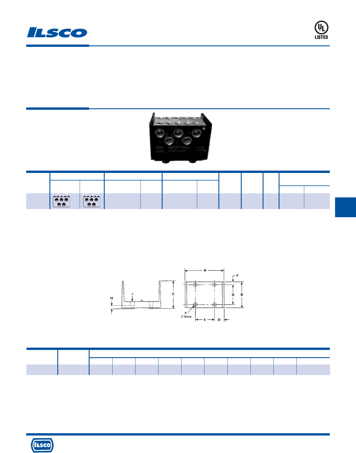
4730 Madison Road, Cincinnati, Ohio 45227-1426 Phone 513 533-6200 Fax 513 871-4084 Web site www.ilsco.com
Canada 1050 Lakeshore Road East, Mississauga, Ontario, Canada L5E1E4 Phone 905 274-2341 Fax 905 274-8763
220
F
Connector Primary Secondary Ampere Number
Catalog Wire Openings Wire Openings Rating Of Block Hex Size
Number Primary Secondary Range Per Pole Range Per Pole Per Pole Poles Size Primary Secondary
PDB-55-600
-1 600kcmil-250kcmil 5 600kcmil-250kcmil 5 1900 1 W 3/8 3/8
Power Distribution Block
Copper Only
Features
•
Manufactured from high strength 6061-T6 aluminum
alloy
•
Valox* insulating base
•
UL 1953 Listed 90˚ C 600 volts
•
Electro-tin plated
•
Clear cover
Benefits
•
Reliable use for copper conductor only
•
Provides a high degree of impact resistance with superior
insulating qualities
•
Ensures reliability
•
Provides low contact resistance
•
Provides visual inspection
45U4
Valox®is a registered trade name of the General Electric Company.
A versatile tap hole, wire range 8-14 AWG included on the connector.
Tested to UL 1059, UL File E112158
TYPE
PDB
Block No. of Dimensions
Size Poles A B C D E F G H J K
W 1 6-7/32 4 4-3/8 1-19/32 3 3/8 3-1/4 7/16 9/32 9/16
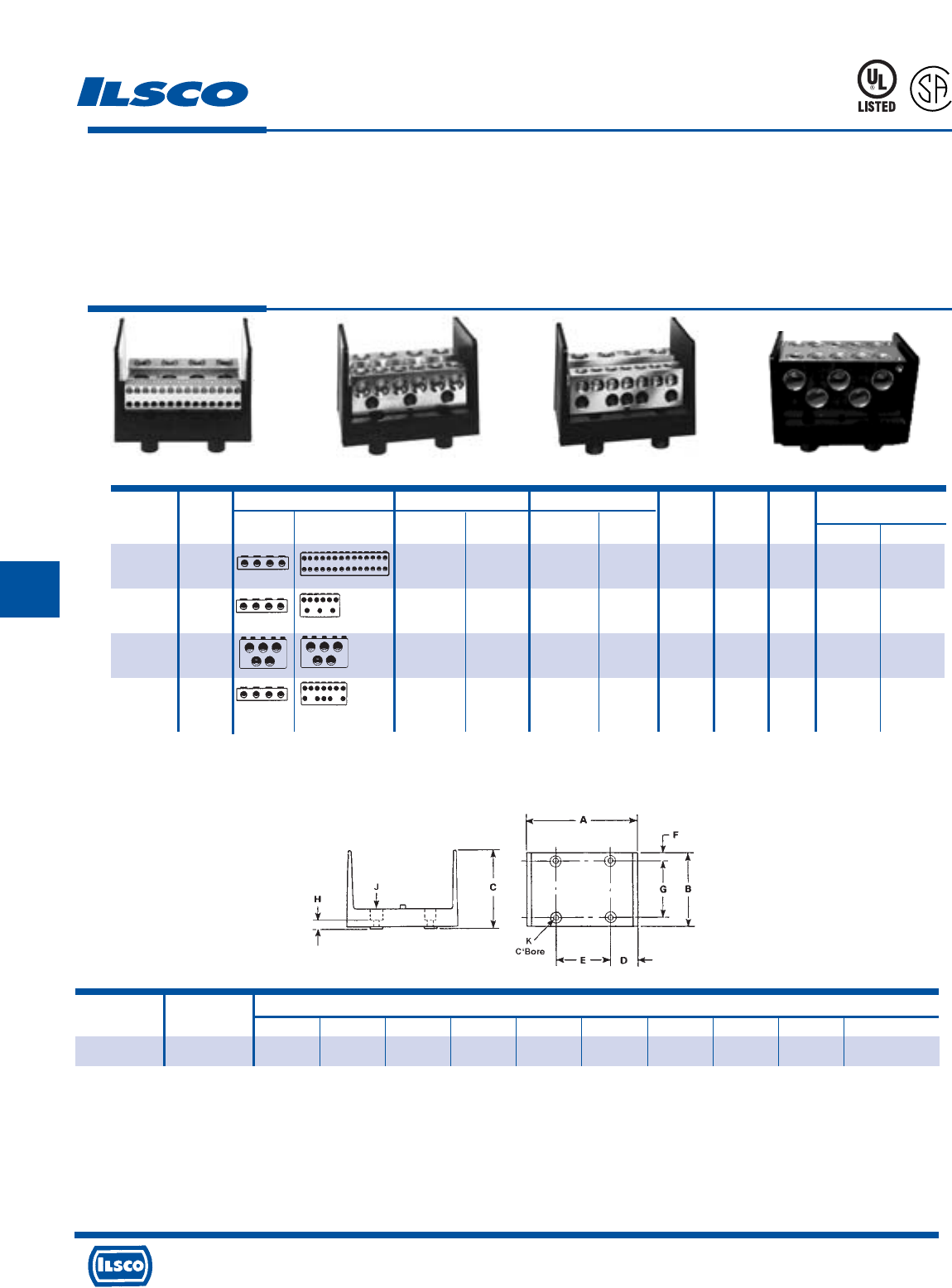
4730 Madison Road, Cincinnati, Ohio 45227-1426 Phone 513 533-6200 Fax 513 871-4084 Web site www.ilsco.com
Canada 1050 Lakeshore Road East, Mississauga, Ontario, Canada L5E1E4 Phone 905 274-2341 Fax 905 274-8763
221
F
Connector Primary Secondary Ampere Number
Catalog Figure Wire Openings Wire Openings Rating of Block Hex Size
Number Number Primary Secondary Range Per Pole Range Per Pole Per Pole Poles Size Primary Secondary
PDB-428-500
-1 1 500kcmil-4 4 4-14 28 1520 1 W 3/8 Slot
PDB-49-500
-1 2 500kcmil-4 4 350kcmil-6 6 1520 1 W 3/8 3/8
4/0-6 3 5/16
PDB-55-500-1
4 500kcmil-3/0 5 500kcmil-3/0 5 1600 1 W 3/8 3/8
PDB-412-500-1
3 500kcmil-4 4 4/0-6 12 1520 1 W 3/8 5/16
Power Distribution Blocks - Dual Rated
Features
•
Multiple taps
•
Valox* insulating base
•
Clear cover
•
UL 1953 Listed 90˚ C 600 Volts and is CSA Certified
•
Electro-tin plated
•
Manufactured from high strength 6061-T6 aluminum
alloy
Benefits
•
Three different connector configurations provide a wide range of tapping
capabilities for up to four primary conductors
•
Provides a high degree of impact resistance with superior insulating
qualities
•
Permits visual inspection
•
Ensures reliability
•
Provides low contact resistance
•
Suitable for use with either copper or aluminum conductors
45U4
L
R
-
2
9
6
0
1
Valox®is a registered trade name of the General Electric Company.
° A versatile tap hole, wire range 8-14 AWG included on the connector.
‡ Not CSA Certified
Tested to UL 1059, UL File E112158
TYPE
PDB
‡°
Fig. 1 Fig. 2 Fig. 3 Fig. 4
Block No. of Dimensions
Size Poles A B C D E F G H J K
W 1 6-7/32 4 4-3/8 1-19/32 3 3/8 3-1/4 7/16 9/32 9/16
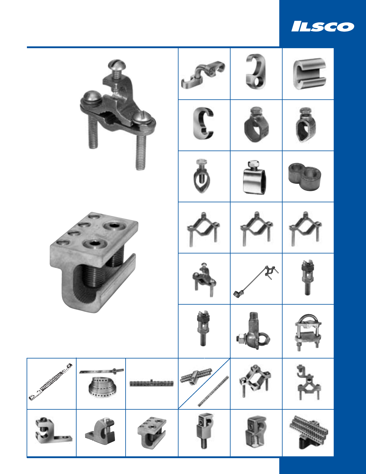
222
Grounding
GGA
224
GGC
225
GRC
231
BGRC
229
BGCS
237
SPD
240 - 241
GS/GSR
252
T
244 - 251
GBL
256
GBL-DB
257
GRM
259
DCGC
233
BGDB
236
ULT
226
RLT
232
BGC
234
BGC
235
SPS
238 - 239
D167
253
GBT
258
NB
260
Bronze Ground Clamps
Type BGDB
ClearGround™
Intersystem Ground Tap
Type GBT
SGC
255
GRF
259
SRC
230
CGRC
228
ELT
227
AGC
255
CAN, N-174
254
GUB
243
TTGC
242
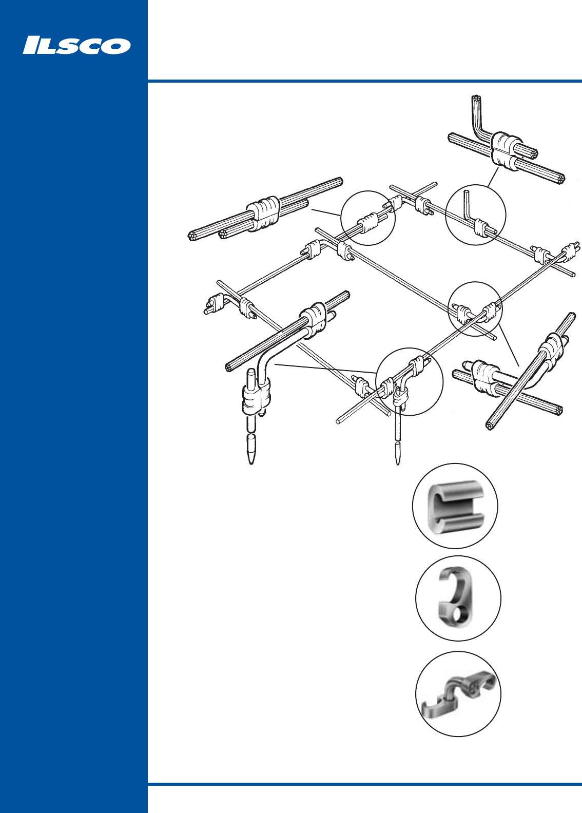
223
Grounding Grid System
Pure wrought copper extrusions
prevent corrosion due to dissimilar
metals, have the same conductivity
as copper conductors, and are
pre-filled with inhibiting compound
1
2
3
•
ULT
Compression Line Tap/C-Crimp
Applications: Tap Connector, Lap Splice Connector
Conductor Range: #6 solid – 4/0
GGC
Compression Ground Tap Connector
Applications: Tap Connector, Lap Splice Connector
Conductor Range: #6 solid – 500kcmil
Copper Ground Rods: 1/2", 5/8", 3/4"
GGA
Compression Ground Grid Cross Connector
Compression elements can be rotated or
adjusted prior to installation
Applications: Cross Connector, Ground Rod Connector
Conductor Range: #6 solid – 500kcmil
Copper Ground Rods: 1/2", 5/8", 3/4"
1
2
3
12
3
3
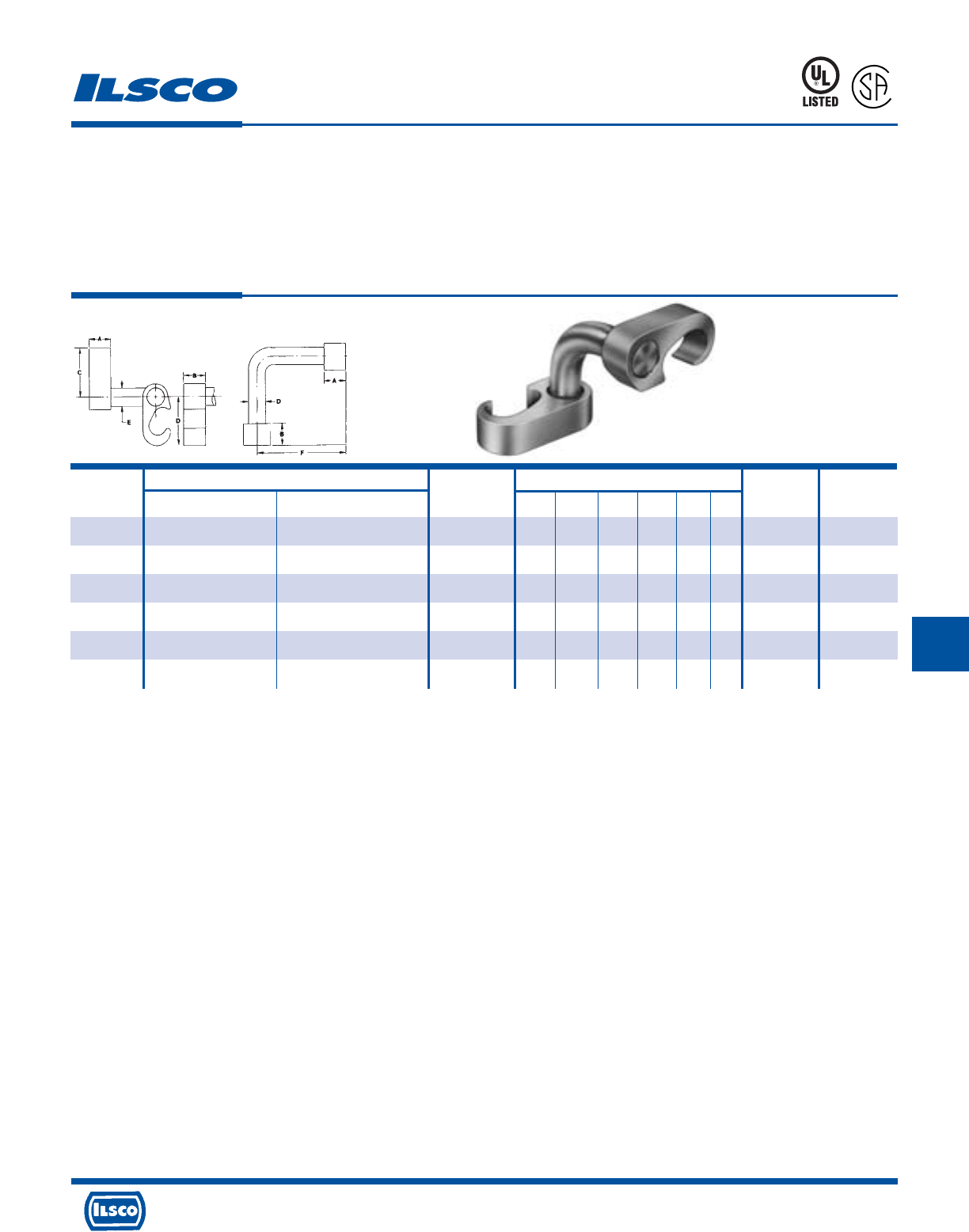
4730 Madison Road, Cincinnati, Ohio 45227-1426 Phone 513 533-6200 Fax 513 871-4084 Web site www.ilsco.com
Canada 1050 Lakeshore Road East, Mississauga, Ontario, Canada L5E1E4 Phone 905 274-2341 Fax 905 274-8763
224
G
Wire Range Dimensions A B
Catalog Rod Die Die
Number Main Tap Size A B C D E F Index Index
GGA-1 2str-6sol 2str-6sol - .75 .75 1.09 1.09 .313 2.50 O O
GGA-2 250kcmil-1str 2str-6sol 1/2, 5/8 .75 .75 1.66 1.09 .313 2.50 997 O
GGA-3 250kcmil-2str 250kcmil-2str 1/2, 5/8 .75 .75 1.66 1.66 .500 2.50 997 997
GGA-4 500kcmil-250kcmil 2str-6sol 5/8, 3/4 .75 .75 2.09 1.09 .313 2.50 998 O
GGA-5 500kcmil-250kcmil 250kcmil-2str 5/8, 3/4 .75 .75 2.09 1.66 .500 2.50 998 997
GGA-6 500kcmil-250kcmil 500kcmil-250kcmil 5/8, 3/4 .75 .75 2.28 2.28 .750 2.50 999/1011 999/1011
Grounding Grid Connectors
TYPE
GGA
Features
•
Manufactured from high strength copper alloy
•
Clearly marked with wire size and die index
•
Range taking
•
Connector can be adjusted prior to installation
•
Non-hazardous installation
•
Prefilled with inhibiting compound
•
Temp. Rating 90˚ C
Benefits
•
Provides maximum conductivity and eliminates the possibility
of corrosion. Suitable for direct burial in earth or concrete
•
Provides easy identification and tooling recommendation
•
Reduces inventory. Six sizes cover a wire range from 500kcmil
to #6, and 1/2" to 3/4" ground rods.
•
Permits adjustments to be made for misaligned cross grids
•
Can be installed in all types of weather with no need for
protective equipment or clothing. Does not produce heat or
dangerous particles.
•
Prevents oxides from forming
•
Ensures reliability
NOTE: Hydraulic tools required on all sizes except GGA-1
Dieless tools can not be used
ILC-15H or similar required for GGA-4, GGA-5 and GGA-6
Tested to UL 467, UL File E34440
L
R
-
5
4
6
5
667P
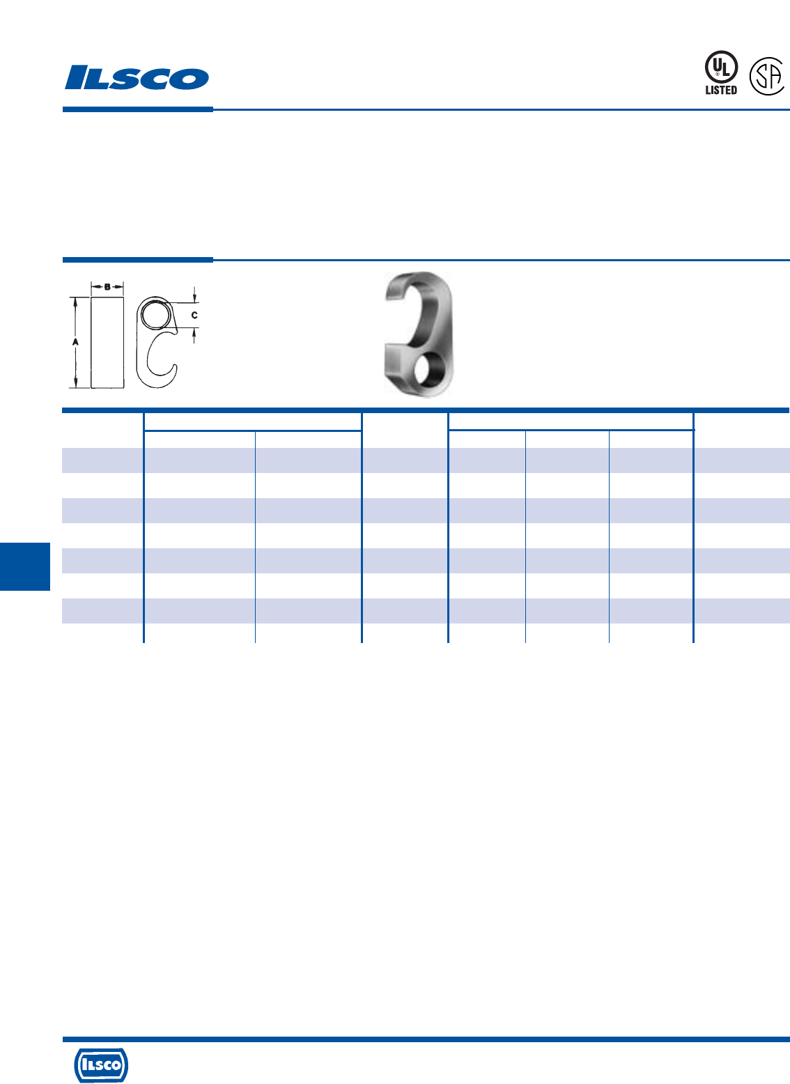
4730 Madison Road, Cincinnati, Ohio 45227-1426 Phone 513 533-6200 Fax 513 871-4084 Web site www.ilsco.com
Canada 1050 Lakeshore Road East, Mississauga, Ontario, Canada L5E1E4 Phone 905 274-2341 Fax 905 274-8763
225
G
Catalog Wire Range Rod Dimensions
Number Main Tap Size A B C Index
GGC-1 2str-6sol 2str-6sol - 1.4 .75 .33 0
GGC-2 250kcmil-1/0str 2str-4sol 1/2, 5/8 2.1 .75 .33 997
GGC-3 250kcmil-1/0str 2/0str-1/0str 1/2, 5/8 2.1 .75 .44 997
GGC-4 250kcmil-1/0str 250kcmil-3/0str 1/2, 5/8 2.1 .75 .61 997
GGC-5 500kcmil-250kcmil 2str-4sol 5/8, 3/4 2.6 .75 .33 998
GGC-6 500kcmil-250kcmil 2/0str-1/0str 5/8, 3/4 2.6 .75 .44 998
GGC-7 500kcmil-250kcmil 250kcmil-3/0str 5/8, 3/4 2.6 .75 .61 998
GGC-8 500kcmil-250kcmil 500kcmil-350kcmil 5/8, 3/4 2.9 .75 .84 999/1011
Grounding Grid Connectors
TYPE
GGC
Features
•
Manufactured from high strength copper alloy
•
Clearly marked with wire size and die index
•
Range taking
•
Versatile
•
Non-hazardous installation
•
Prefilled with inhibiting compound
•
Temp. Rating 90˚ C
Benefits
•
Provides maximum conductivity and eliminates the possibility
of corrosion. Suitable for direct burial in earth or concrete
•
Provides easy identification and tooling recommendation
•
Reduces inventory. Eight sizes cover a wire range from
500kcmil to #6, and 1/2" to 3/4" ground rods.
•
Can be used as a tap connector or as a lap splice connector
•
Can be installed in all types of weather with no need for
protective equipment or clothing. Does not produce heat or
dangerous particles.
•
Prevents oxides from forming
•
Ensures reliability
NOTE: Hydraulic tools required on all sizes except GGC-1
Dieless tools can not be used
ILC-15H or similar required for GGC-5, GGC-6, GGC-7 and GGC-8
L
R
-
5
4
6
5
667P
Tested to UL 467, UL File E34440
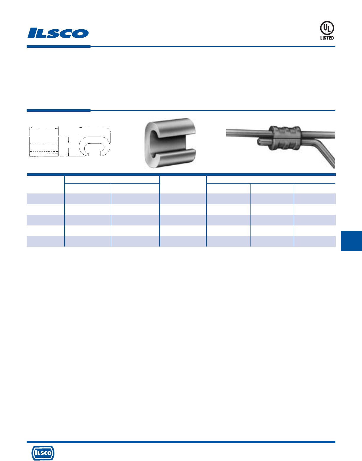
4730 Madison Road, Cincinnati, Ohio 45227-1426 Phone 513 533-6200 Fax 513 871-4084 Web site www.ilsco.com
Canada 1050 Lakeshore Road East, Mississauga, Ontario, Canada L5E1E4 Phone 905 274-2341 Fax 905 274-8763
226
G
Wire Range Dimensions
Catalog Die
Number Main Tap Index L W H
ULT-4-Z 4str-6sol 6str-6sol BG or 5/8 3/4 15/32 49/64
ULT-5-Z 4str-6sol 4str-4sol BG or 5/8 3/4 15/32 27/32
ULT-6-Z 2str-2sol 6str-8sol C 7/8 5/8 1
ULT-7-Z 2str-2sol 2str-2sol C 7/8 39/64 1-1/16
ULT-12-Z 4/0str-3/0str 4/0str-3/0str F or D3 1-1/8 1 1-5/8
Copper C Crimps
TYPE
ULT
Features
•
Manufactured from high strength copper alloy
•
Clearly marked with wire size and die index
•
Range taking
•
UL Listed for 600 volts, 90˚ C
Benefits
•
Provides maximum conductivity and eliminates the
possibility of corrosion
•
Provides easy identification and tooling
recommendation
•
Reduces inventory
•
Ensures reliability
453G
L
H
W
Tested to UL 486A-486B, UL File E6207
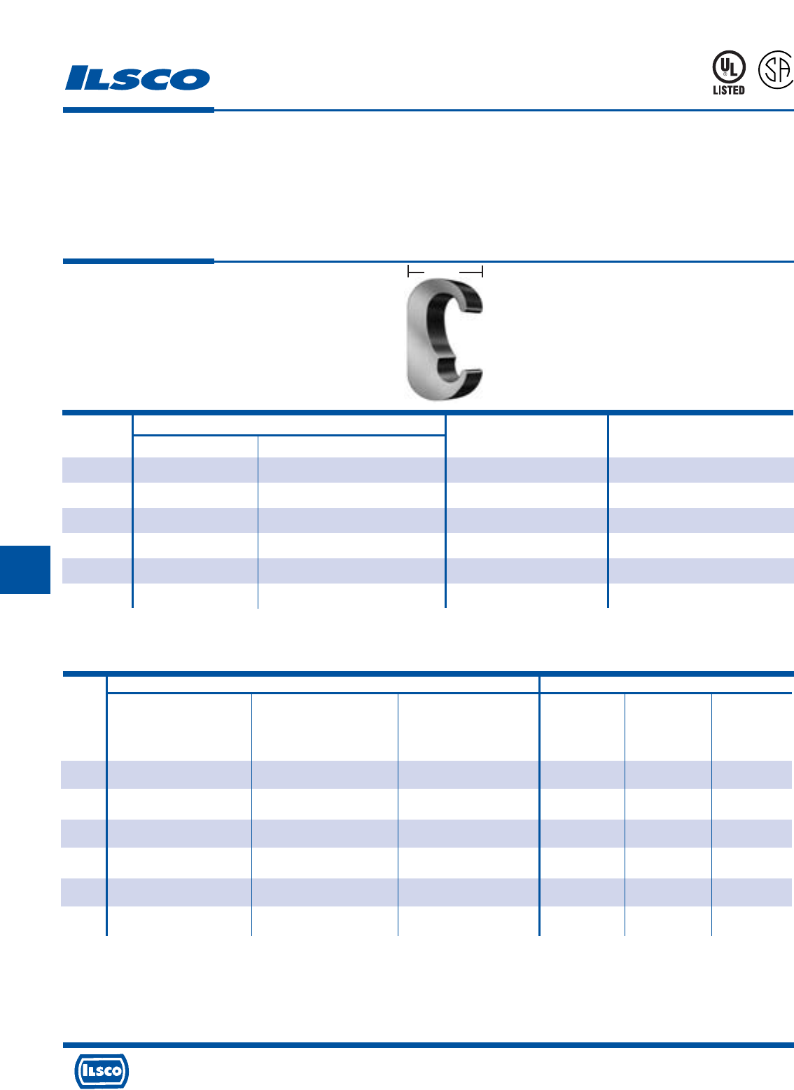
4730 Madison Road, Cincinnati, Ohio 45227-1426 Phone 513 533-6200 Fax 513 871-4084 Web site www.ilsco.com
Canada 1050 Lakeshore Road East, Mississauga, Ontario, Canada L5E1E4 Phone 905 274-2341 Fax 905 274-8763
227
G
Width
ILSCO Burndy
ILC-12H-N ILCB-12-N ILC-15H Y-35 Y-45 Y-46
ILC-12-N
Die No. Die No. Die No.
Die Index Die Index Die Index
Catalog No. of No. of No. of No. of No. of No. of
Number Crimps Crimps Crimps Crimps Crimps Crimps
ELT-1 ILD-C ILD-C - C (U Type) C (U Type) C (U Type)
(1) (1) - (1) (1) (1)
ELT-4 ILD-O ILD-O - O (U Type) O (U Type) O (U Type)
(1) (1) - (1) (1) (1)
ELT-2 ILD-O ILD-O - O (U Type) O (U Type) O (U Type)
(1) (1) - (1) (1) (1)
ELT-5 ILD-U997 ILD-U997 - 997 (U Type) 997 (U Type) 997 (U Type)
(1) (1) - (1) (1) (1)
ELT-3 ILD-U997 ILD-U997 - 997 (U Type) 997 (U Type) 997 (U Type)
(1) (1) - (1) (1) (1)
ELT-6 - - ILD-P1011 - 1011 (U Type) 1011 (U Type)
- - (2) - (2) (1)
Copper E Crimps
Grounding Connectors
TYPE
ELT
Features
•
Manufactured from copper alloy
•
Clearly marked with wire size and die index
•
Range taking
•
UL Listed and CSA Certified for grounding and bonding,
rated for 600 volts
•
May be used in ground grid applications
Benefits
•
Provides maximum conductivity and eliminates the
possibility of corrosion. Suitable for direct burial in earth
or concrete
•
Provides easy identification and tooling
recommendation
•
Reduces inventory
•
Ensures reliability
•
Flexibility in application
A
P
-
5
4
6
5
Copper Wire Range
Catalog Die
Number Main Tap Width Index
ELT-1 2str-6sol 2str-6sol .75 C (U Type)
ELT-4 2/0str-1str 2str-6str .75 0 (U Type)
ELT-2 2/0str-1str 2/0str-1str .75 0 (U Type)
ELT-5 250kcmil-3/0str 2/0str-6sol .75 997 (U Type)
ELT-3 250kcmil-3/0str 250kcmil-3/0str .900 997 (U Type)
ELT-6 500kcmil-300kcmil 250kcmil-3/0str .875 1011 (U Type)
Tooling Information
667P
See stuffer sheet for complete information on tooling.
Tested to UL 467, UL File E34440
G
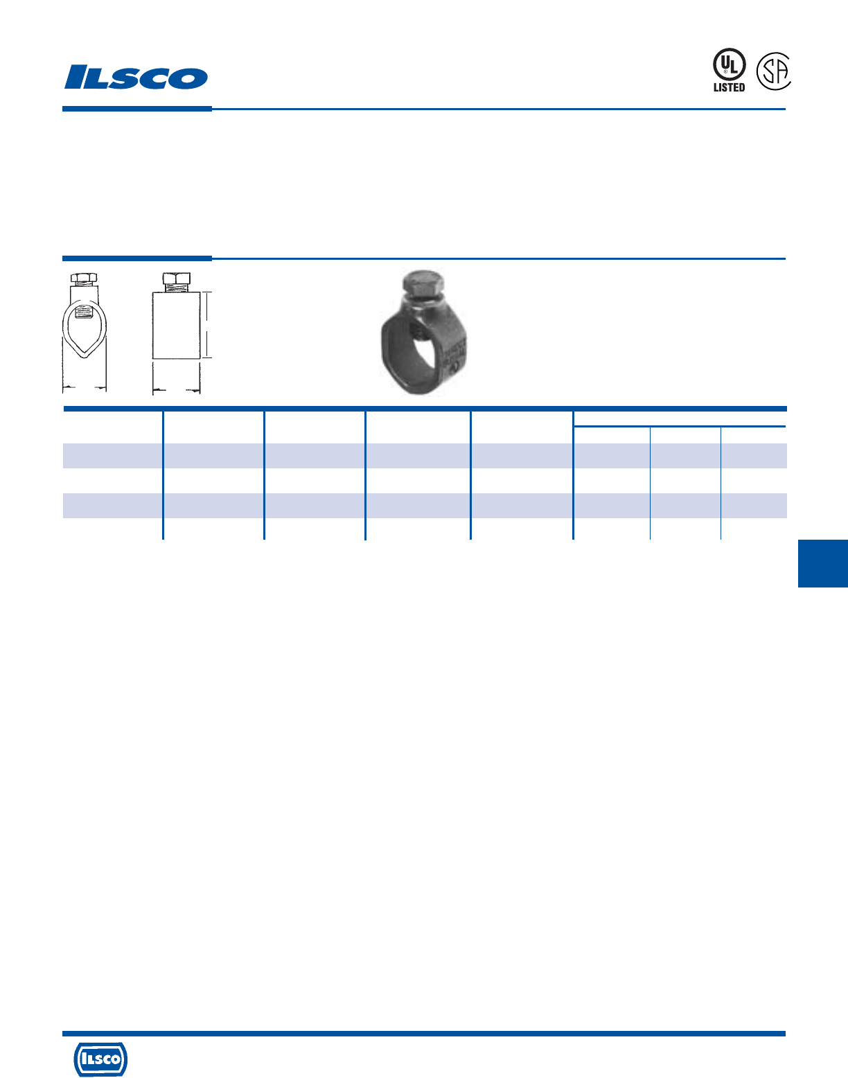
4730 Madison Road, Cincinnati, Ohio 45227-1426 Phone 513 533-6200 Fax 513 871-4084 Web site www.ilsco.com
Canada 1050 Lakeshore Road East, Mississauga, Ontario, Canada L5E1E4 Phone 905 274-2341 Fax 905 274-8763
228
GG
Economy Cast Bronze Ground Rod Clamps
TYPE
CGRC
Features
•
Manufactured from cast bronze
•
Supplied with stainless steel hardware
•
UL Listed and CSA Certified for 600 volts except for
CGRC-38
•
Suitable for grounding and bonding in applications such
as swimming pools and spas
Benefits
•
Ensures maximum strength and durability
•
Suitable for direct burial in earth or concrete
•
Ensures reliability for copper conductor
667P
L
R
-
2
9
6
0
1
Catalog Ground Rod Rebar Ground Rod Rebar Dimensions
Number Size Size Wire Range Wire Range L W H
CGRC-38 3/8 #3 4-10 4-10 1/2 11/16 1
CGRC-48 1/2 #4 2-10 2-10 9/16 27/32 1-3/16
CGRC-58 5/8 #5 2-10 4-10 9/16 15/16 1-9/32
CGRC-68 3/4 #6 2-10 4-10 9/16 1-1/16 1-9/32
Plain copper finish.
Tested to UL 467, UL File E34440
L
W
H
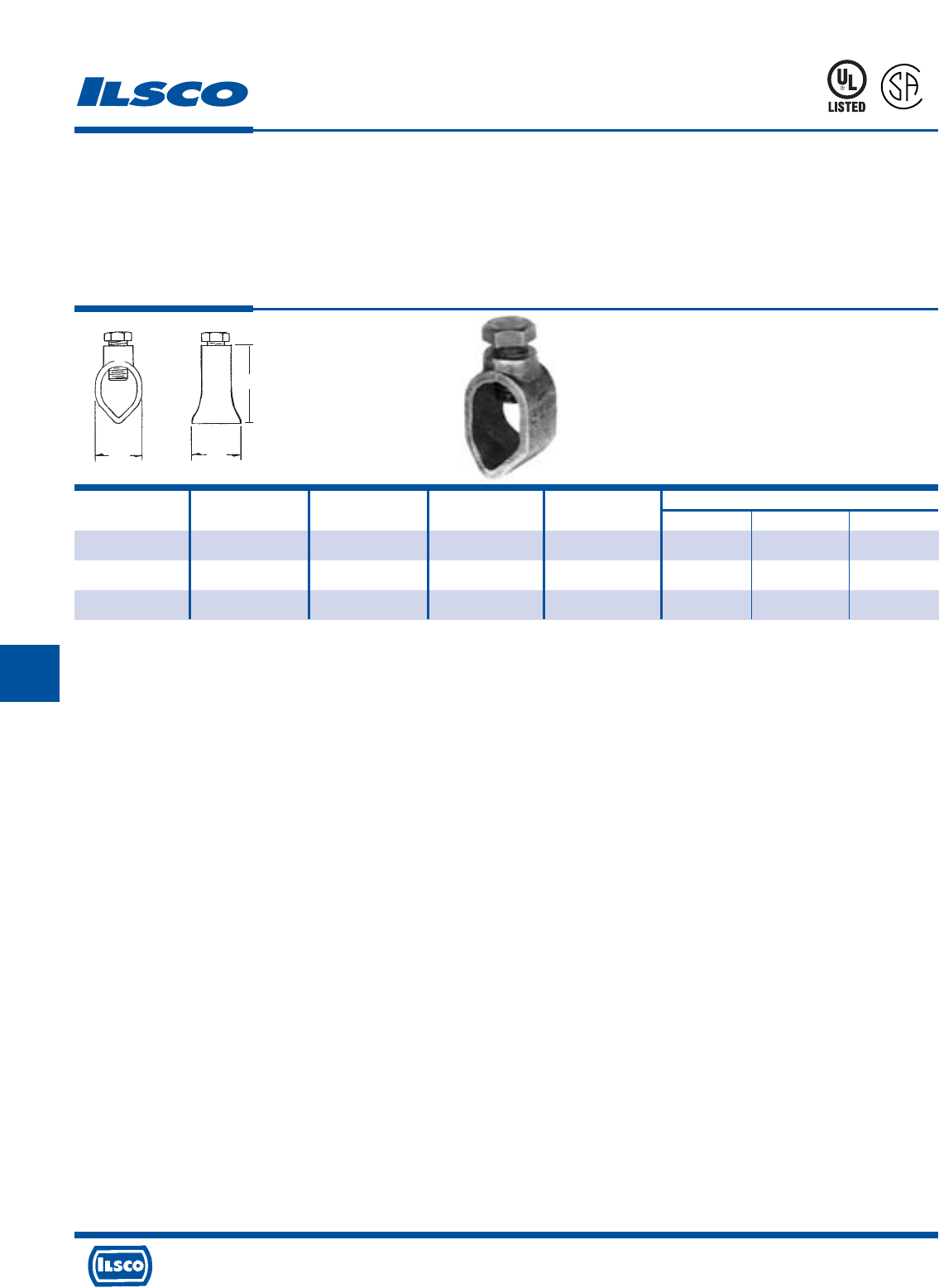
4730 Madison Road, Cincinnati, Ohio 45227-1426 Phone 513 533-6200 Fax 513 871-4084 Web site www.ilsco.com
Canada 1050 Lakeshore Road East, Mississauga, Ontario, Canada L5E1E4 Phone 905 274-2341 Fax 905 274-8763
229
G G
Cast Bronze Ground Rod Clamps
TYPE
BGRC
Features
•
Manufactured from cast bronze
•
Supplied with stainless steel hardware
•
UL Listed and CSA Certified for 600 volts
Benefits
•
Ensures maximum strength and durability
•
Suitable for direct burial in earth or concrete
•
Ensures reliability for copper conductor
667P
L
R
-
2
9
6
0
1
Catalog Ground Rod Rebar Ground Rod Rebar Dimensions
Number Size Size Wire Range Wire Range L W H
BGRC-48 1/2 - 2-10 - 7/8 3/4 1-1/4
BGRC-58 5/8 #5 1/0-8 1/0-8 1-1/32 29/32 1-13/32
BGRC-68 3/4 - 1/0-8 - 1 1 1-5/8
WL
H
Tested to UL 467, UL File E34440
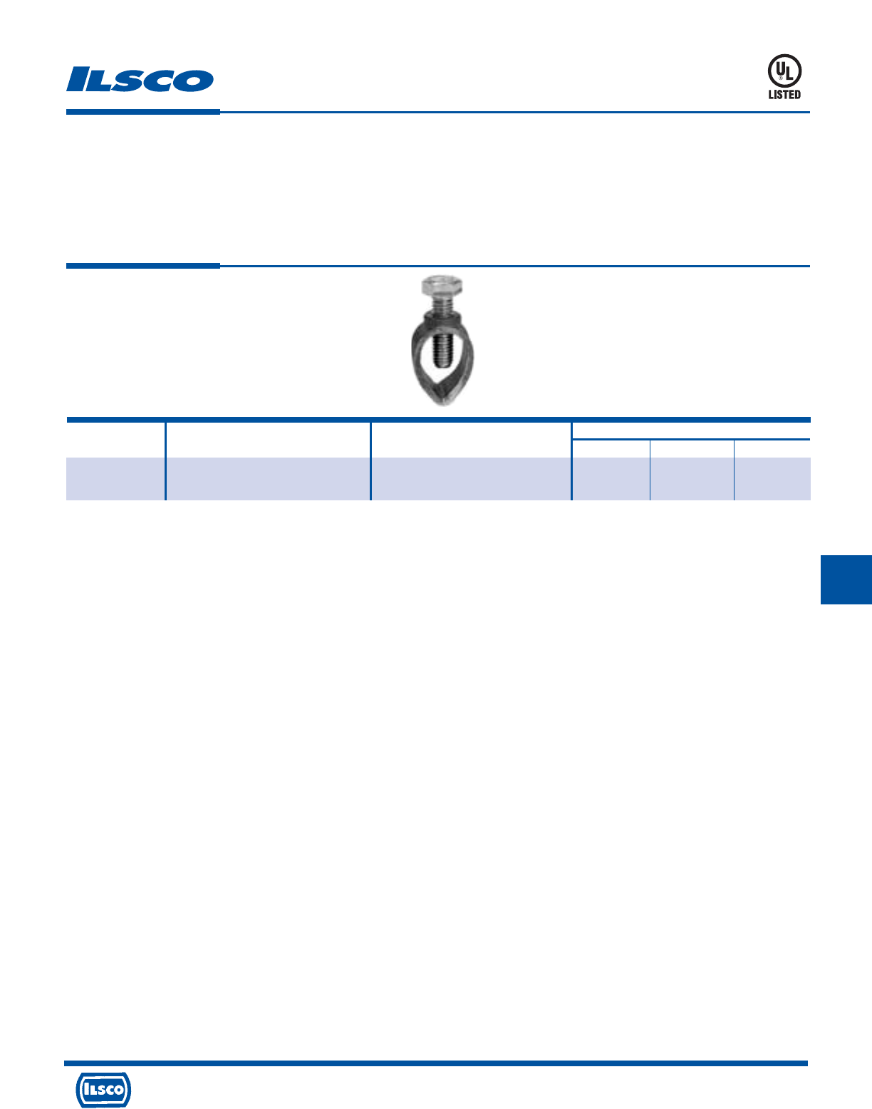
4730 Madison Road, Cincinnati, Ohio 45227-1426 Phone 513 533-6200 Fax 513 871-4084 Web site www.ilsco.com
Canada 1050 Lakeshore Road East, Mississauga, Ontario, Canada L5E1E4 Phone 905 274-2341 Fax 905 274-8763
230
G
Cast Bronze Ground Rod Clamp
TYPE
SRC
Features
•
Manufactured from bronze alloy
•
Stainless steel bolt
•
UL Listed for both copper clad and galvanized ground
rods
•
Range taking
Benefits
•
Provides maximum strength and superior conductivity
•
For direct burial
•
Ensures reliability
•
Reduces inventory requirement
Catalog Ground Rod Ground Rod Dimensions
Number Size Wire Range L W H
SRC-1/0 3/8, 1/2, 5/8 10 sol - 1/0 str 13/16 1 1-1/2
3/4 8 sol - 1/0 str
UL File E198108
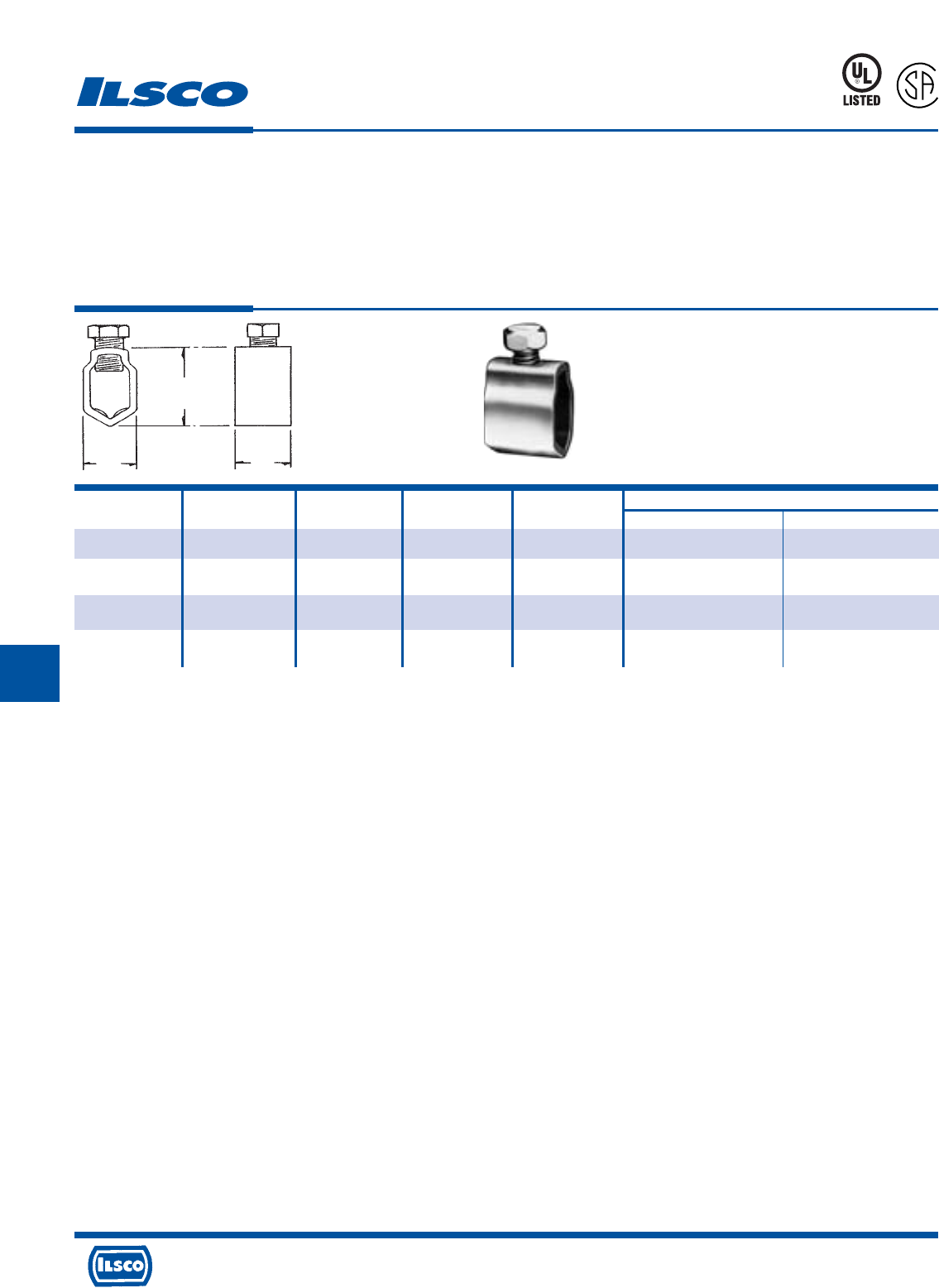
4730 Madison Road, Cincinnati, Ohio 45227-1426 Phone 513 533-6200 Fax 513 871-4084 Web site www.ilsco.com
Canada 1050 Lakeshore Road East, Mississauga, Ontario, Canada L5E1E4 Phone 905 274-2341 Fax 905 274-8763
231
GG
Catalog Ground Ground Wire Rebar Rebar Dimensions
Number Rod Size Range Size Wire Range L W
GRC-38 3/8 4-10 #3 4-10 5/8 5/8
GRC-58+ 5/8 2-8 - - 15/16 7/8
GRC-68 3/4, 5/8 2-8 for 3/4 rod, #5 1/0-8 1 1
1/0-8 for 5/8 rod
GRC-75* 3/4 3/0-8 - - 3/4 1-5/32
Ground Rod Clamps
TYPE
GRC
Features
•
Manufactured from seamless bronze tubing
•
Supplied with silicon bronze screw
•
UL Listed and CSA Certified for 600 volts except
GRC-75
•
Suitable for grounding and bonding in applications such
as swimming pools and spas
Benefits
•
Provides maximum strength and superior conductivity
•
Ground rod clamp is suitable for direct burial in earth or
concrete
•
Ensures reliability for copper conductor
Plain copper finish.
+ REA Listed.
* Not UL Listed
Tested to UL 467, UL File E34440
L
R
-
2
9
6
0
1
667P
W
L
H
G
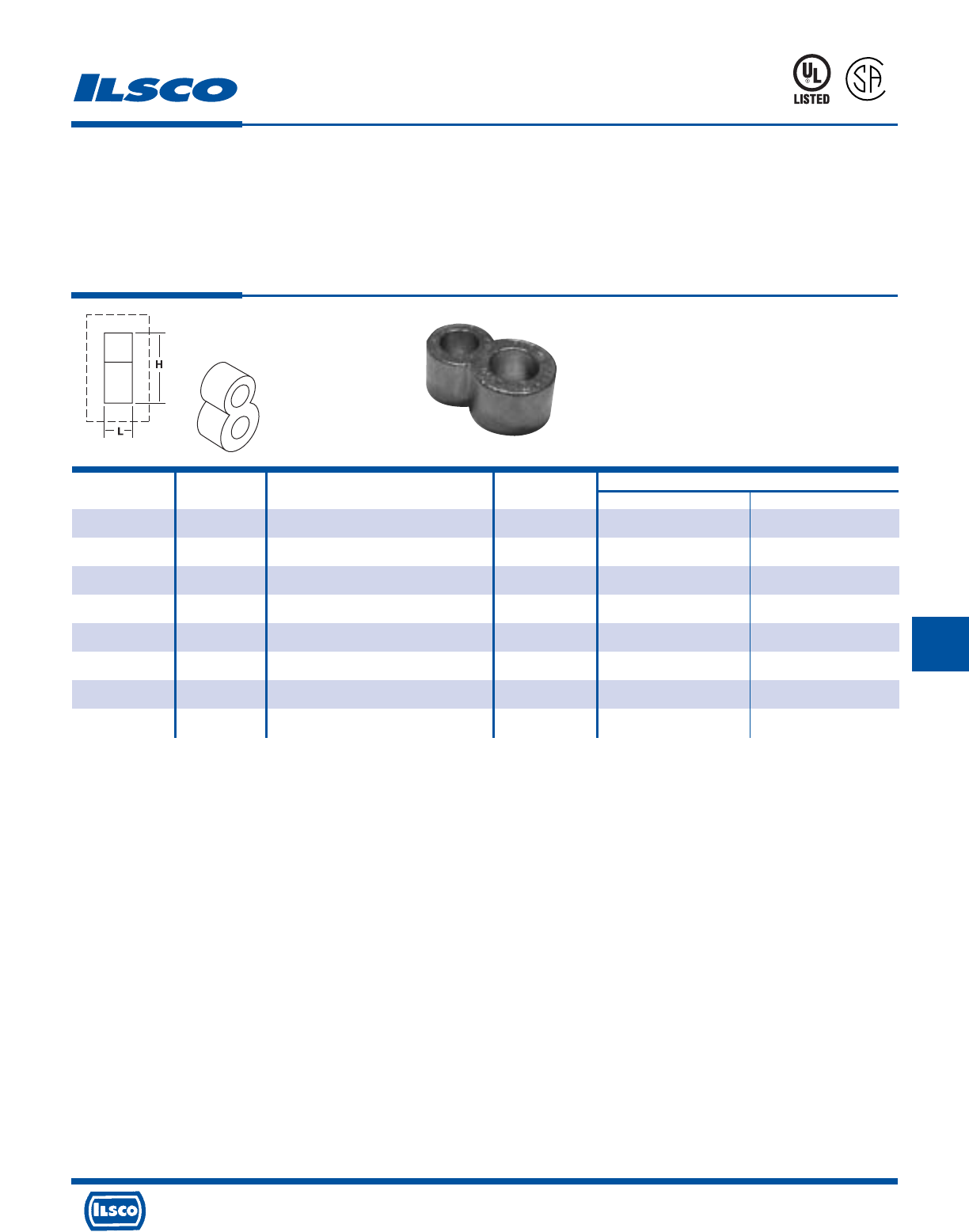
4730 Madison Road, Cincinnati, Ohio 45227-1426 Phone 513 533-6200 Fax 513 871-4084 Web site www.ilsco.com
Canada 1050 Lakeshore Road East, Mississauga, Ontario, Canada L5E1E4 Phone 905 274-2341 Fax 905 274-8763
232
GG
Grounding Connectors
For Copper Conductor Only
TYPE
RLT
Features
•
Prefilled with oxide inhibitor and bagged
•
Clearly marked with wire size and die index
•
UL Listed for 600 Volts and CSA Certified for
direct burial in earth or concrete
•
Range taking
•
Manufactured from high strength copper alloy
Benefits
•
Prevents oxides from forming
•
Provides easy identification and tooling recommendation
•
Ensures reliability
•
Reduces inventory. Eight sizes cover a wire range
of #2-500kcmil
•
Provides maximum conductivity and eliminates the possibility
of corrosion
Catalog Ground Wire Die Dimensions
Number Rod Size Range Index H L
RLT-2 1/2 2 (.292 Dia.) - 2/0 (.419 Dia.) 998/1011 1.94 .88
RLT-3 5/8 2 (.292 Dia.) - 2/0 (.419 Dia.) 998/1011 1.97 .88
RLT-4 3/4 2 (.292 Dia.) - 2/0 (.419 Dia.) 998/1011 2.19 .88
RLT-5 1/2 4/0 (.528 Dia.) - 250kcmil (.575 Dia.) 998/1011 1.94 .88
RLT-6 5/8 4/0 (.528 Dia.) - 250kcmil (.575 Dia.) 998/1011 2.14 .88
RLT-7 3/4 4/0 (.528 Dia.) - 250kcmil (.575 Dia.) 998/1011 2.19 .88
RLT-8 5/8 300kcmil (.630 Dia.) - 500kcmil (.813 Dia.) 998/1011 2.14 .88
RLT-9 3/4 300kcmil (.630 Dia.) - 500kcmil (.813 Dia.) 998/1011 2.44 .88
L
667P
UL File E158587
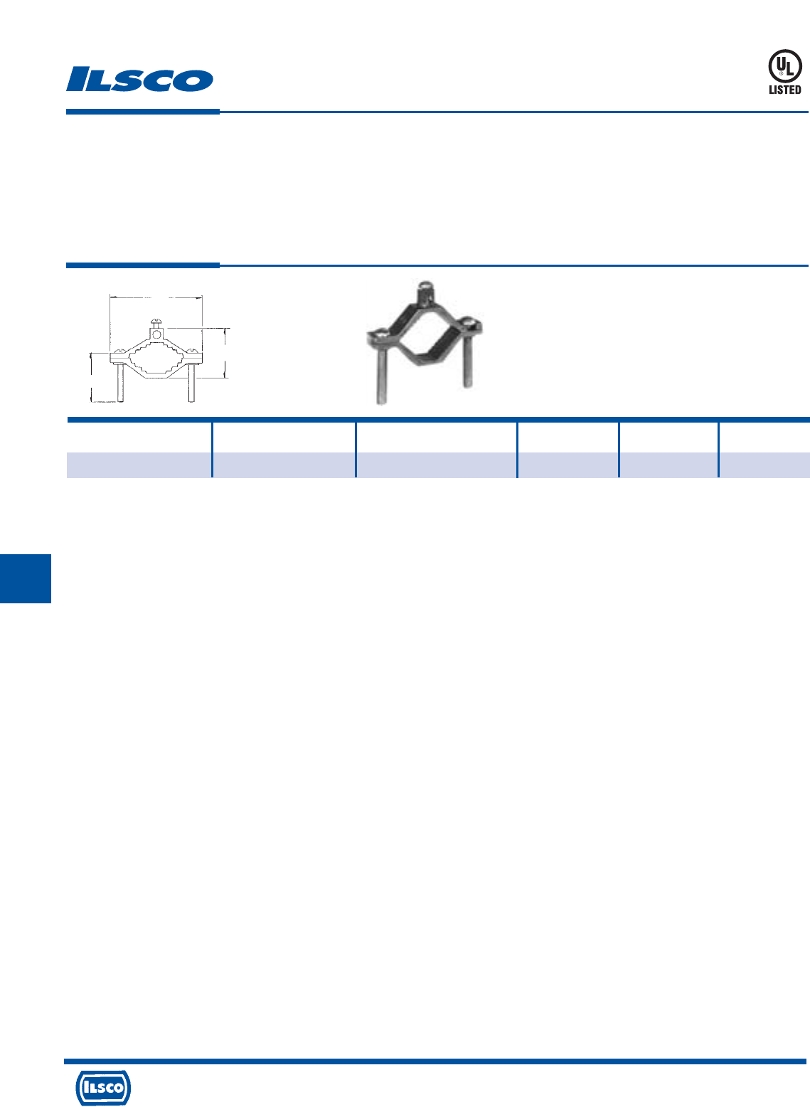
4730 Madison Road, Cincinnati, Ohio 45227-1426 Phone 513 533-6200 Fax 513 871-4084 Web site www.ilsco.com
Canada 1050 Lakeshore Road East, Mississauga, Ontario, Canada L5E1E4 Phone 905 274-2341 Fax 905 274-8763
233
G GG
Die Cast Ground Clamp
TYPE
DCGC
Features
•
Manufactured from die cast zinc alloy
•
UL Listed for 600 volts
•
Assembled with zinc plated steel hardware
Benefits
•
Provides maximum durability while providing economy
•
Ensures reliability for copper conductor
•
Provides corrosion resistance
Catalog Conduit Ground
Number Size Wire Range L W H
DCGC-1 1/2, 3/4, 1 2-8 2-13/64 1-3/8 1-1/2
H
L
W
8M24
UL File E158587
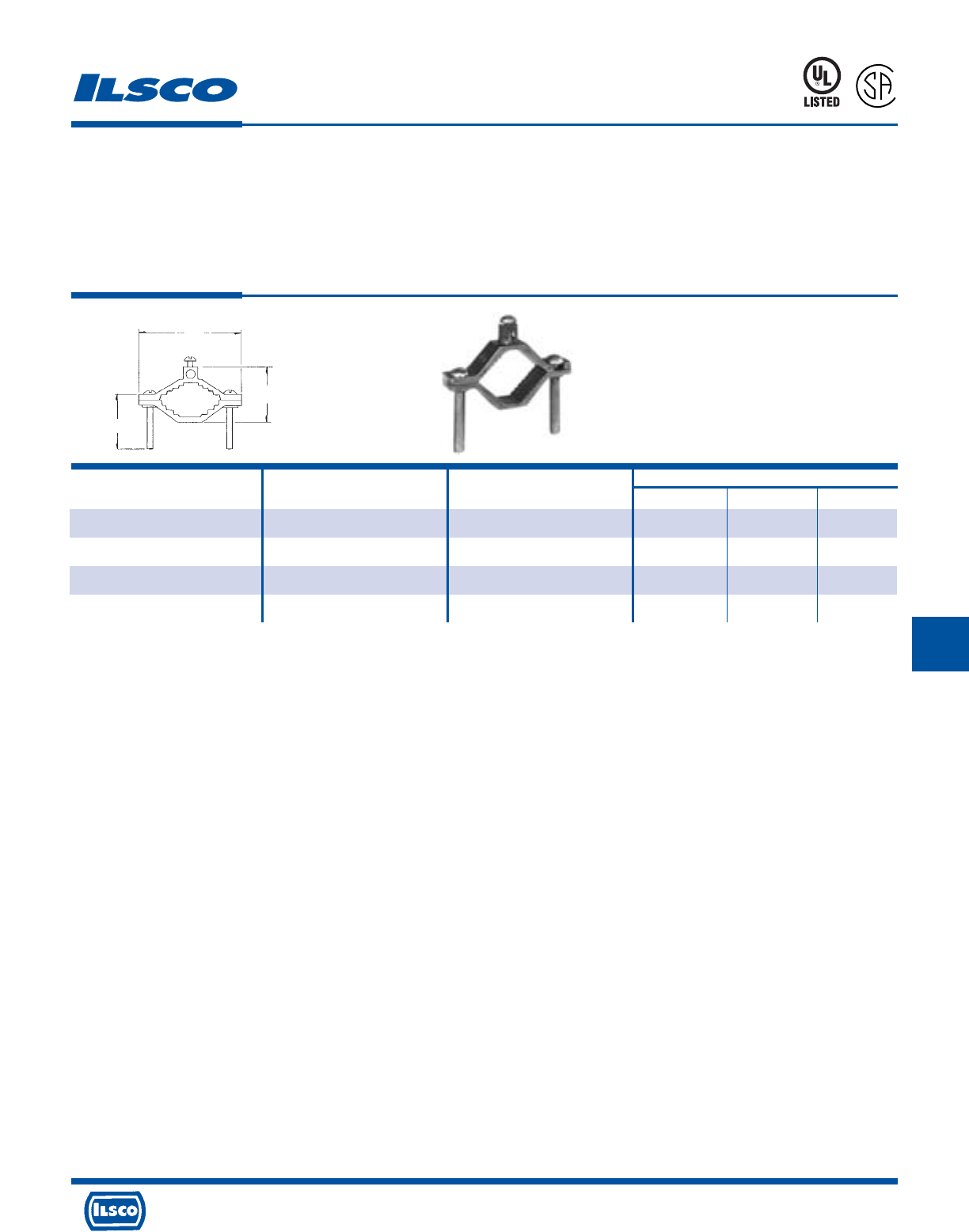
4730 Madison Road, Cincinnati, Ohio 45227-1426 Phone 513 533-6200 Fax 513 871-4084 Web site www.ilsco.com
Canada 1050 Lakeshore Road East, Mississauga, Ontario, Canada L5E1E4 Phone 905 274-2341 Fax 905 274-8763
234
GG G
Catalog Pipe Ground Wire Dimensions
Number Size Range L W H
BGC-1 1/2, 3/4, 1 2-10 2-9/32 2-17/32 1-1/2
BGC-2 1-1/4, 1-1/2, 2 2-10 3-9/16 2-1/4 2
BGC-1DB* 1/2, 3/4, 1 2-10 2-9/32 2-17/32 1-1/2
BGC-2DB* 1-1/4, 1-1/2, 2 2-10 3-8/16 2-1/4 2
Cast Brass Ground Clamp
TYPE
BGC
Features
•
Manufactured from cast brass
•
UL Listed and CSA Certified for 600 volts
•
Type BGC-DB supplied with stainless steel or silicone
bronze hardware
Benefits
•
Provides maximum conductivity and strength
•
Ensures reliability for copper conductor
•
BGC-1DB and BGC-2DB are suitable for direct burial in
earth or concrete. Can be used to ground swimming pools
and spas.
* Suitable for direct burial in earth or concrete.
UL File E158587
L
H
W
8M24
L
R
-
7
0
1
5
7
0
4730 Madison Road, Cincinnati, Ohio 45227-1426 Phone 513 533-6200 Fax 513 871-4084 Web site www.ilsco.com
Canada 1050 Lakeshore Road East, Mississauga, Ontario, Canada L5E1E4 Phone 905 274-2341 Fax 905 274-8763
235
G GG
Catalog Figure Pipe Conduit Hub Wire Dimensions
Number Number Size Size Range H W L
BGC1-50 1 1/2–1 1/2 4str-8sol 1-1/2 1-1/32 2-1/4
BGC1-75 1 1/2–1 3/4 4str-8sol 1-1/2 1-1/32 2-1/4
BGC1-10 1 1/2–1 1 4str-8sol 1-1/2 1-1/32 2-1/4
BGC2-50 1 1-1/4–2 1/2 4str-8sol 2 1-3/4 3-19/32
BGC2-75 1 1-1/4–2 3/4 4str-8sol 2 1-3/4 3-19/32
BGC2-10 1 1-1/4–2 1 4str-8sol 2 1-3/4 3-19/32
BGC-1A* 2 1/2–1 - 4str-8sol 1-1/2 1-3/8 2-1/4
BGC-2A 2 1-1/4–2 - 4str-8sol 2 2-3/32 3-19/32
Cast Bronze Ground Clamps
TYPE
BGC
Features
•
Manufactured from cast bronze
•
UL Listed for 600 volts
•
Versatile
Benefits
•
Provides maximum conductivity and strength
•
Ensures reliability for copper conductor
•
Type BGC supplied with conduit hub for 1/2"-1" rigid
conduit; type BGC-A can be used for bare or armoured
cable
* CSA Certified
UL File E158587
Fig. 1 Fig. 2
HH
W
W
LL
8M24
4730 Madison Road, Cincinnati, Ohio 45227-1426 Phone 513 533-6200 Fax 513 871-4084 Web site www.ilsco.com
Canada 1050 Lakeshore Road East, Mississauga, Ontario, Canada L5E1E4 Phone 905 274-2341 Fax 905 274-8763
236
G
Catalog Figure Pipe Rebar Ground Rod Ground Screw Dimensions
Number Number Size Size Size Wire Range Material L W
BGC-2T-DB* 1 1/2-1 3/8-1 1/2-1 2str-10sol silicon bronze 2-3/4 2-1/4
BGC-2P-DB* 2 1/2-1 3/8-1 1/2-1 2str-10sol silicon bronze 2-3/4 2-1/4
BGC-2PS-DB+ 3 1/2-1 3/8-1 1/4-1 2str-10sol stainless steel 2-1/4 2-1/4
2 #8sol
BGC-4/0P-DB= 4 1/2-1 3/8-1 1/2-1 4/0-8str stainless steel 3 2-1/4
BGC-4/0S-DB= 5 1/2-1 3/8-1 1/2-1 4/0-8str stainless steel 2-3/4 2-1/4
Cast Bronze Ground Clamps
TYPE
BGDB
Features
•
Manufactured from bronze alloy
•
UL Listed for direct burial in earth or concrete
•
Lay-In feature
Benefits
•
Ensures maximum strength and superior conductivity
•
Ensures reliability
•
Reduces installation time
* UL File E207816
+ UL File E198108
= UL File E178441
Fig. 1 Fig. 2 Fig. 3 Fig. 4 Fig. 5
Benefits
•
Ensures reliability
•
Range taking
•
Corrosion resistance
•
Protects conduit system from vibrations
and provides maximum conductivity
4730 Madison Road, Cincinnati, Ohio 45227-1426 Phone 513 533-6200 Fax 513 871-4084 Web site www.ilsco.com
Canada 1050 Lakeshore Road East, Mississauga, Ontario, Canada L5E1E4 Phone 905 274-2341 Fax 905 274-8763
237
G
Ground Clamp with Strap
TYPE
BGCS
Features
•
UL Listed and CSA Certified for 600 Volts
•
Conduit hub for 1/2" thru 1" rigid conduit
•
Zinc plated screws
•
ETP copper strap
•
For copper conductor only
Catalog Figure Water Pipe Conduit Ground
Number Number Range Hub Size Wire Range
CH-1 1 - 1 3/0 AWG - 10sol
CH-34 1 - 3/4 2/0 AWG - 10sol
J2124 2 2-1/2-4 - 4str - 10sol
J6 2 4-1/2-6 - 4str - 10sol
BGC-1-50S 3 1/2-1 1/2 8sol - 4str
BGC-1-75S 3 1/2-1 3/4 8sol - 4str
BGC-1-10S 3 1/2-1 1 8sol - 4str
BGC-1-50SH 4 1/2-1 1/2 2/0 - 10
BGC-1-75SH 4 1/2-1 3/4 2/0 - 10
BGC-1-10SH 4 1/2-1 1 2/0 - 10
UL File E207816
Fig. 1 Fig. 2 Fig. 3 Fig. 4
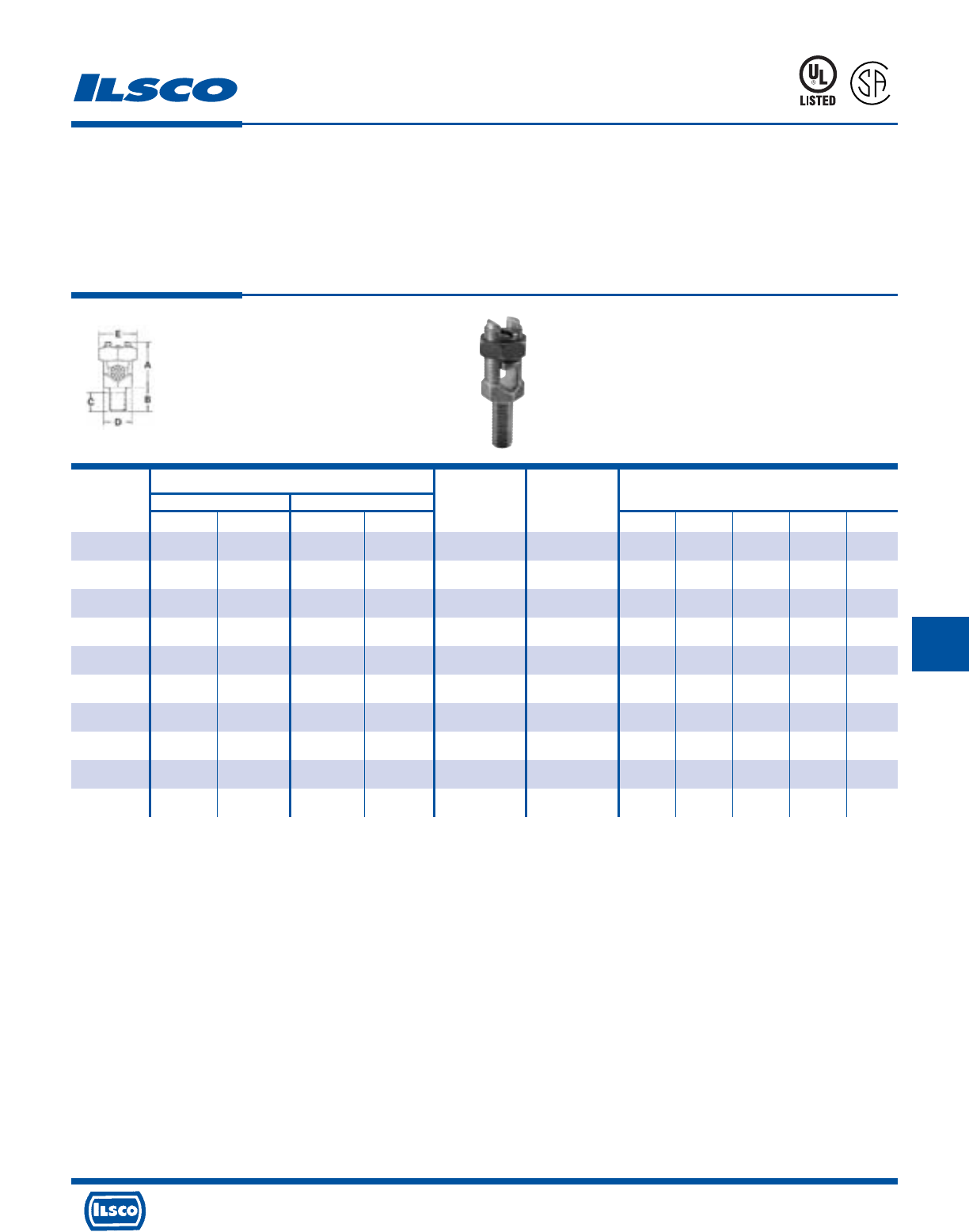
4730 Madison Road, Cincinnati, Ohio 45227-1426 Phone 513 533-6200 Fax 513 871-4084 Web site www.ilsco.com
Canada 1050 Lakeshore Road East, Mississauga, Ontario, Canada L5E1E4 Phone 905 274-2341 Fax 905 274-8763
238
GGG G
Conductor Range AWG MM 2
Maximum
Catalog Stranded Solid Diameter Dimensions
Number Max. Min. Max. Min. Range Stud Size A B C D E
SPSS-0 8 12 (4mm
2
) 8 (10mm
2
) 12 (4mm
2
) .146-.080 1/4-20 x 1/2 11/16 1/2 23/64 15/32 1/2
SPSS-1 7 (10mm
2
) 10 (6mm
2
) 6 (10mm
2
) 10 (6mm
2
) .170-.102 1/4-20 x 1/2 13/16 1/2 23/64 15/32 21/32
SPSS-2 5 (16mm
2
) 10 (6mm
2
) 4 (16mm
2
) 10 (6mm
2
) .217-.102 5/16-18 x 5/8 15/16 5/8 25/64 17/32 23/32
SPSS-3 3 (25mm
2
) 10 (6mm
2
) 2 (35mm
2
) 10 (6mm
2
) .271-.102 3/8-16 x 5/8 1/2 5/8 29/64 5/8 25/32
SPSS-4 1 (35mm
2
)8 (6mm
2
) 2 (35mm
2
) 8 (10mm
2
) .332-.128 3/8-16 x 5/8 1-1/16 5/8 29/64 11/16 7/8
SPSS-5 1/0 (50mm
2
) 2 (35mm
2
) 2 (35mm
2
) – .385-.258 1/2-13 x 3/4 1-1/4 3/4 37/64 3/4 15/16
SPSS-6 2/0 (70mm
2
) 2 (35mm
2
) 2 (35mm
2
) – .443-.258 1/2-13 x 3/4 1-13/32 3/4 37/64 7/8 1-1/16
SPSS-8 4/0 (95mm
2
) 1 (35mm
2
) – – .570-.289 5/8-11 x 1 1-9/16 1 51/64 1 1-5/16
SPSS-9 350 (150mm
2
) 1/0 (70mm
2
) – – .715-.373 5/8-11 x 1 2 1-1/4 51/64 1-5/16 1-11/16
SPSS-10 500 (240mm
2
) 3/0 (95mm
2
) – – .840-.464 3/4-10 x 1-1/4 2-1/4 1-3/4 63/64 1-1/2 1-7/8
Bronze, Service Post Connectors
Single Conductor Type - Short Stud, Male
TYPE
SPS
Features
•
Range taking
•
Re-usable
•
UL 486A and UL 467 Listed
•
For grounding of steel structures, fence posts and
tapping cables from bus bar
•
For copper to copper connections
Benefits
•
Permits inventories to be kept to a minimum
•
Provides efficient use and flexibility in the field
•
Ensures reliability
•
Flexibility in the field
UL File E158587
8M24
A
P
-
1
0
0
9
7
3
-
1
G
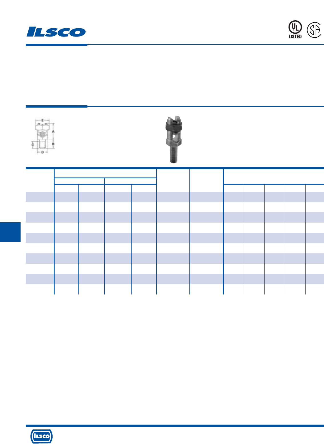
4730 Madison Road, Cincinnati, Ohio 45227-1426 Phone 513 533-6200 Fax 513 871-4084 Web site www.ilsco.com
Canada 1050 Lakeshore Road East, Mississauga, Ontario, Canada L5E1E4 Phone 905 274-2341 Fax 905 274-8763
239
G GG GG
Conductor Range AWG MM 2
Maximum
Catalog Stranded Solid Diameter Dimensions
Number Max. Min. Max. Min. Range Stud Size A B C D E
SPSL-0 8 12 (4mm
2
) 8 (10mm
2
) 12 (4mm
2
) .146-.080 1/4-20 x 1 11/16 1 55/64 15/32 1/2
SPSL-1 7 (10mm
2
) 10 (6mm
2
) 6 (10mm
2
) 10 (6mm
2
) .170-.102 1/4-20 x 1 13/16 1 55/64 15/32 21/32
SPSL-2 5 (16mm
2
) 10 (6mm
2
) 4 (16mm
2
) 10 (6mm
2
) .217-.102 5/16-18 x 1 15/16 1 53/64 17/32 23/32
SPSL-3 3 (25mm
2
) 10 (6mm
2
) 2 (35mm
2
) 10 (6mm
2
) .271-.102 3/8-16 x 1-1/8 1/2 1-1/8 61/64 5/8 25/32
SPSL-4 1 (35mm
2
)8 (6mm
2
) 2 (35mm
2
) 8 (10mm
2
) .332-.128 3/8-16 x 1-1/8 1-1/16 1-1/8 61/64 11/16 7/8
SPSL-5 1/0 (50mm
2
) 2 (35mm
2
) 2 (35mm
2
) – .385-.258 1/2-13 x 1-1/4 1-1/4 1-1/4 1-5/64 3/4 15/16
SPSL-6 2/0 (70mm
2
) 2 (35mm
2
) 2 (35mm
2
) – .443-.258 1/2-13 x 1-1/4 1-13/32 1-1/4 1-5/64 7/8 1-1/16
SPSL-8 4/0 (95mm
2
) 1 (35mm
2
) – – .570-.289 5/8-11 x 1-1/2 1-9/16 1-1/2 1-19/64 1 1-5/16
SPSL-9 350 (150mm
2
) 1/0 (70mm
2
) – – .715-.373 5/8-11 x 1-1/2 2 1-1/2 1-19/64 1-5/16 1-11/16
SPSL-10 500 (240mm
2
) 3/0 (95mm
2
) – – .840-.464 3/4-10 x 1-3/4 2-1/4 1-1/2 1-31/64 1-1/2 1-7/8
Bronze, Service Post Connectors
Single Conductor Type - Long Stud, Male
TYPE
SPS
Features
•
Range taking
•
Re-usable
•
UL 486A and UL 467 Listed
•
For grounding of steel structures, fence posts and
tapping cables from bus bar
•
For copper to copper connections
Benefits
•
Permits inventories to be kept to a minimum
•
Provides efficient use and flexibility in the field
•
Ensures reliability
•
Flexibility in the field
UL File E158587
8M24
A
P
-
1
0
0
9
7
3
-
1
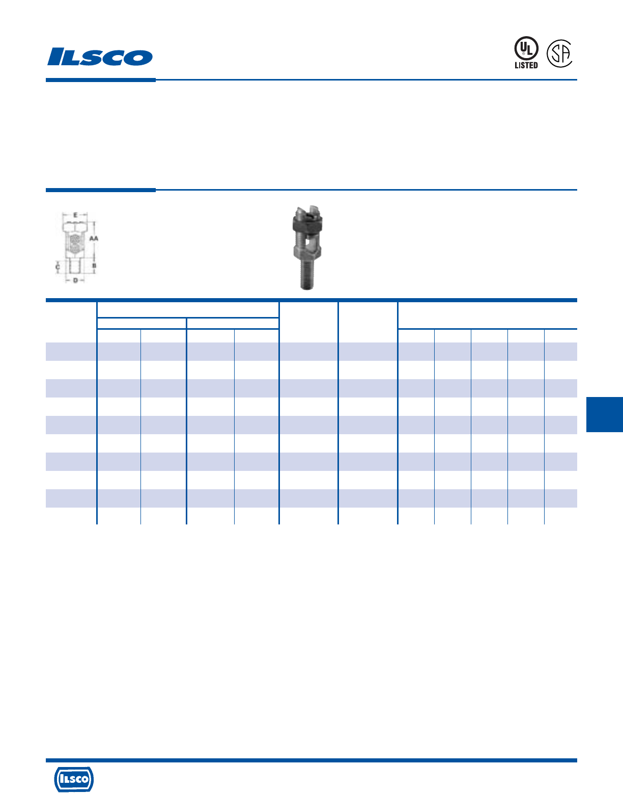
4730 Madison Road, Cincinnati, Ohio 45227-1426 Phone 513 533-6200 Fax 513 871-4084 Web site www.ilsco.com
Canada 1050 Lakeshore Road East, Mississauga, Ontario, Canada L5E1E4 Phone 905 274-2341 Fax 905 274-8763
240
GG GG G
Conductor Range AWG MM 2
Maximum
Catalog Stranded Solid Diameter Dimensions
Number Max. Min. Max. Min. Range Stud Size AA B C D E
SPDS-0 8 12 (4mm
2
) 8 (10mm
2
) 12 (4mm
2
) .146-.080 1/4-20 x 1/2 13/16 1/2 23/64 15/32 1/2
SPDS-1 7 (10mm
2
) 10 (6mm
2
) 6 (10mm
2
) 10 (6mm
2
) .170-.102 1/4-20 x 1/2 31/32 1/2 23/64 15/32 21/32
SPDS-2 5 (16mm
2
) 10 (6mm
2
) 4 (16mm
2
) 10 (6mm
2
) .217-.102 5/16-18 x 5/8 1-1/8 5/8 25/64 17/32 23/32
SPDS-3 3 (25mm
2
) 10 (6mm
2
) 2 (35mm
2
) 10 (6mm
2
) .271-.102 3/8-16 x 5/8 1-1/4 5/8 29/64 5/8 25/32
SPDS-4 1 (35mm
2
)8 (6mm
2
) 2 (35mm
2
) 8 (10mm
2
) .332-.128 3/8-16 x 5/8 1-3/8 5/8 29/64 11/16 7/8
SPDS-5 1/0 (50mm
2
) 2 (35mm
2
) 2 (35mm
2
) – .385-.258 1/2-13 x 3/4 1-19/32 3/4 37/64 3/4 15/16
SPDS-6 2/0 (70mm
2
) 2 (35mm
2
) 2 (35mm
2
) – .443-.258 1/2-13 x 3/4 1-13/16 3/4 37/64 7/8 1-1/16
SPDS-8 4/0 (95mm
2
) 1 (35mm
2
) – – .570-.289 5/8-11 x 1 2-1/16 1 51/64 1 1-5/16
SPDS-9 350 (150mm
2
) 1/0 (70mm
2
) – – .715-.373 5/8-11 x 1 2-3/4 1-1/4 51/64 1-5/16 1-11/16
SPDS-10 500 (240mm
2
) 3/0 (95mm
2
) – – .840-.464 3/4-10 x 1-1/4 3-1/8 1-3/4 63/64 1-1/2 1-7/8
Bronze, Service Post Connectors
Double Conductor Type - Short Stud, Male
TYPE
SPD
Features
•
Range taking
•
Re-usable
•
UL 486A and UL 467 Listed
•
For grounding of steel structures, fence posts and
tapping cables from bus bar
•
For copper to copper connections
Benefits
•
Permits inventories to be kept to a minimum
•
Provides efficient use and flexibility in the field
•
Ensures reliability
•
Flexibility in the field
UL File E158587
8M24
A
P
-
1
0
0
9
7
3
-
1
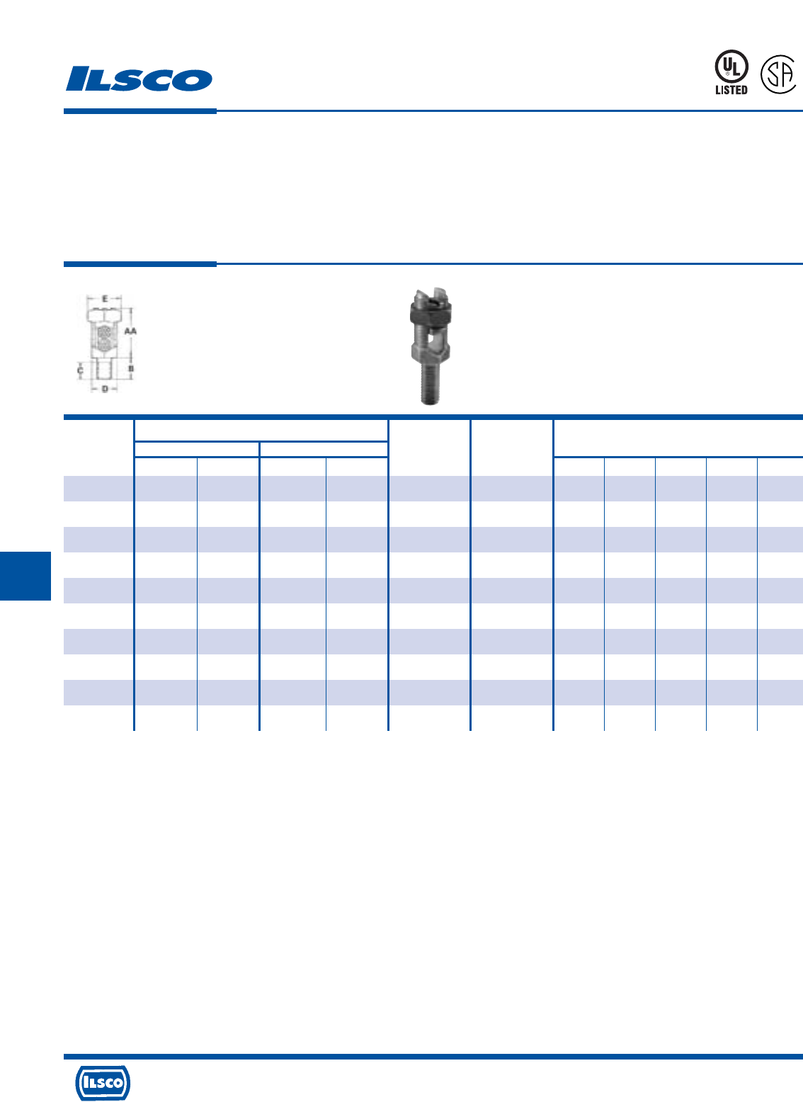
4730 Madison Road, Cincinnati, Ohio 45227-1426 Phone 513 533-6200 Fax 513 871-4084 Web site www.ilsco.com
Canada 1050 Lakeshore Road East, Mississauga, Ontario, Canada L5E1E4 Phone 905 274-2341 Fax 905 274-8763
241
G GG GG
Conductor Range AWG MM 2
Maximum
Catalog Stranded Solid Diameter Dimensions
Number Max. Min. Max. Min. Range Stud Size AA B C D E
SPDL-0 8 12 (4mm
2
) 8 (10mm
2
) 12 (4mm
2
) .146-.080 1/4-20 x 1 13/16 1 55/64 15/32 1/2
SPDL-1 7 (10mm
2
) 10 (6mm
2
) 6 (10mm
2
) 10 (6mm
2
) .170-.102 1/4-20 x 1 31/32 1 55/64 15/32 21/32
SPDL-2 5 (16mm
2
) 10 (6mm
2
) 4 (16mm
2
) 10 (6mm
2
) .217-.102 5/16-18 x 1 1-1/8 1 53/64 17/32 23/32
SPDL-3 3 (25mm
2
) 10 (6mm
2
) 2 (35mm
2
) 10 (6mm
2
) .271-.102 3/8-16 x 1-1/8 1-1/4 1-1/8 61/64 5/8 25/32
SPDL-4 1 (35mm
2
)8 (6mm
2
) 2 (35mm
2
) 8 (10mm
2
) .332-.128 3/8-16 x 1-1/8 1-3/8 1-1/8 61/64 11/16 7/8
SPDL-5 1/0 (50mm
2
) 2 (35mm
2
) 2 (35mm
2
) – .385-.258 1/2-13 x 1-1/4 1-19/32 1-1/4 1-5/64 3/4 15/16
SPDL-6 2/0 (70mm
2
) 2 (35mm
2
) 2 (35mm
2
) – .443-.258 1/2-13 x 1-1/4 1-13/16 1-1/4 1-5/64 7/8 1-1/16
SPDL-8 4/0 (95mm
2
) 1 (35mm
2
) – – .570-.289 5/8-11 x 1-1/2 2-1/16 1-1/2 1-19/64 1 1-5/16
SPDL-9 350 (150mm
2
) 1/0 (70mm
2
) – – .715-.373 5/8-11 x 1-1/2 2-3/4 1-1/2 1-19/64 1-5/16 1-11/16
SPDL-10 500 (240mm
2
) 3/0 (95mm
2
) – – .840-.464 3/4-10 x 1-3/4 3-1/8 1-1/2 1-31/64 1-1/2 1-7/8
Bronze, Service Post Connectors
Double Conductor Type - Long Stud, Male
TYPE
SPD
Features
•
Range taking
•
Re-usable
•
UL 486A and UL 467 Listed
•
For grounding of steel structures, fence posts and
tapping cables from bus bar
•
For copper to copper connections
Benefits
•
Permits inventories to be kept to a minimum
•
Provides efficient use and flexibility in the field
•
Ensures reliability
•
Flexibility in the field
UL File E158587
8M24
A
P
-
1
0
0
9
7
3
-
1
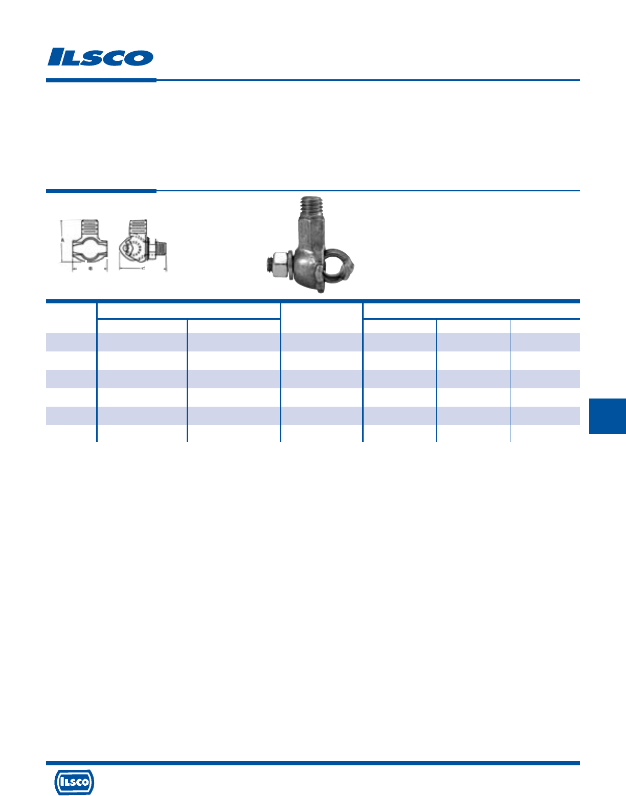
4730 Madison Road, Cincinnati, Ohio 45227-1426 Phone 513 533-6200 Fax 513 871-4084 Web site www.ilsco.com
Canada 1050 Lakeshore Road East, Mississauga, Ontario, Canada L5E1E4 Phone 905 274-2341 Fax 905 274-8763
242
GG GG G
Catalog Conductor Range Stud Thread Dimensions
Number Max. Min. Size UNC - 2A A B C
TTGC2 2/0 8 sol 1/2-13 1-51/64 1-9/64 1-21/32
TTGC3 1 str 10 sol 1/2-13 1-3/8 1-3/64 1-9/16
TTGC4+ 1 str 10 sol 1/2-13 1-1/4 7/8 1-3/8
TTGC2TN+ 2/0 8 sol 1/2-13 1-51/64 1-9/64 1-21/32
TTGC3TN* 1 str 10 sol 1/2-13 1-3/8 1-3/64 1-9/16
TTGC4TN* 1 str 10 sol 1/2-13 1-1/4 7/8 1-3/8
Bronze, Transformer Tank Ground Connectors
TYPE
TTGC
Features
•
Manufactured from bronze
•
Eye bolt on TTGC2 rotates to accommodate cable in
vertical or horizontal direction
•
Range taking
•
Stud fits all standard EEI-NEMA distribution
transformers
Benefits
•
Provides maximum strength and superior conductivity
•
Flexibility
•
Permits inventories to be kept to a minimum
•
Reliability
+ RUS Listed
* Tin Plated
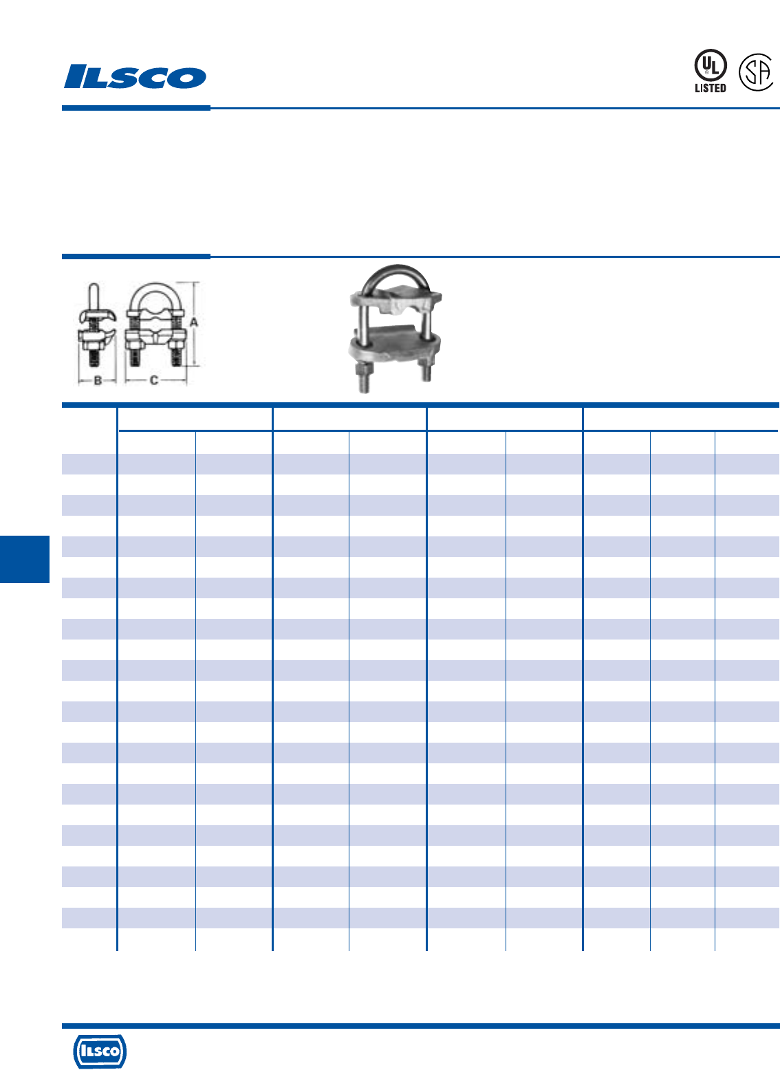
4730 Madison Road, Cincinnati, Ohio 45227-1426 Phone 513 533-6200 Fax 513 871-4084 Web site www.ilsco.com
Canada 1050 Lakeshore Road East, Mississauga, Ontario, Canada L5E1E4 Phone 905 274-2341 Fax 905 274-8763
243
G GG GG
Conductor Nominal Rod IPS Pipe Size Dimensions
Catalog
Number Max. Min. Max. Min. Max. Min. A B C
GUB-1 4 8 3/4 5/8 3/8 - 2-13/16 1-9/16 2-1/4
GUB-2 2/0 4 3/4 5/8 3/8 - 2-13/16 1-9/16 2-1/4
GUB-3 250kcmil 2/0 3/4 5/8 3/8 - 2-13/16 1-9/16 2-1/4
GUB-4 4 8 1 7/8 3/4 1/2 2-3/4 1-9/16 2-5/8
GUB-5 2/0 4 1 7/8 3/4 1/2 2-3/4 1-9/16 2-5/8
GUB-6 250kcmil 2/0 1 7/8 3/4 1/2 2-3/4 1-9/16 2-5/8
GUB-7 4 8 1-1/4 1-1/8 1 - 3-5/16 1-9/16 2-3/4
GUB-8 2/0 4 1-1/4 1-1/8 1 - 3-5/16 1-9/16 2-3/4
GUB-9 4 8 1-1/2 1-3/8 1-1/4 - 3-7/16 1-9/16 2-15/16
GUB-10 2/0 4 1-1/2 1-3/8 1-1/4 - 3-7/16 1-9/16 2-15/16
GUB-11 250kcmil 2/0 1-1/2 1-3/8 1-1/4 - 3-7/16 1-9/16 2-15/16
GUB-12 4 8 1-7/8 1-5/8 1-1/2 - 3-15/16 1-9/16 3-3/16
GUB-13 2/0 4 1-7/8 1-5/8 1-1/2 - 3-15/16 1-9/16 3-3/16
GUB-14 250kcmil 2/0 1-7/8 1-5/8 1-1/2 - 3-15/16 1-9/16 3-3/16
GUB-15 4 8 2-3/8 2 2 - 4-7/16 1-9/16 3-11/16
GUB-16 2/0 4 2-3/8 2 2 - 4-7/16 1-9/16 3-11/16
GUB-17 250kcmil 2/0 2-3/8 2 2 - 4-7/16 1-9/16 3-11/16
GUB-18 2/0 4 2-7/8 2-1/2 2-1/2 - 4-15/16 1-9/16 4-3/16
GUB-19 250kcmil 2/0 2-7/8 2-1/2 2-1/2 - 4-15/16 1-9/16 4-3/16
GUB-20 2/0 4 3-1/2 3 3 - 5-9/16 1-9/16 4-13/16
GUB-21 250kcmil 2/0 3-1/2 3 3 - 5-9/16 1-9/16 4-13/16
GUB-22 2/0 4 4 3-1/2 3-1/2 - 6-1/16 1-9/16 5-1/2
GUB-23 2/0 4 4-1/2 4 4 - 6-5/16 1-9/16 5-11/16
GUB-24 250kcmil 2/0 4-1/2 4 4 - 6-5/16 1-9/16 5-11/16
Bronze, U-Bolt Ground Clamp
TYPE
GUB
Features
•
Components are cast or forged from copper alloy
•
Specially designed spacer
•
Range taking
•
Re-usable
•
UL 467 Listed for direct burial and CSA Certified
Benefits
•
Provides maximum conductivity
•
Affords more positive contact area
•
Permits inventories to be kept to a minimum
•
Provides efficient use and flexibility in the field
•
Ensures reliability
UL File E158587
8M24
A
P
-
1
0
0
9
7
3
-
1
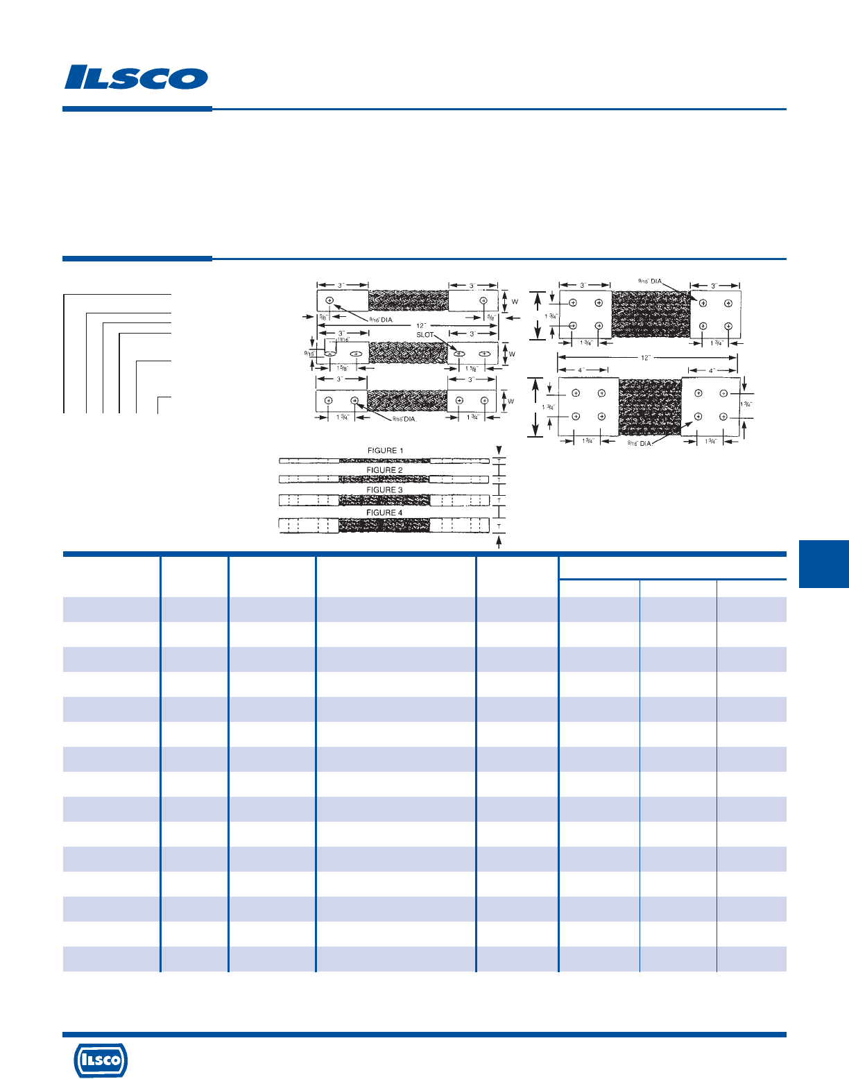
4730 Madison Road, Cincinnati, Ohio 45227-1426 Phone 513 533-6200 Fax 513 871-4084 Web site www.ilsco.com
Canada 1050 Lakeshore Road East, Mississauga, Ontario, Canada L5E1E4 Phone 905 274-2341 Fax 905 274-8763
244
GG GG G
Dimensions
Catalog Figure Drawing Ampere Rating Circular Mils.
Number Number Number (Indoors)* of Braids L T W
T252/11N12 1 A 200 77,184 12 0.19 1.00
T252/11N18 1 A 200 77,184 18 0.25 1.00
T252/11N24 1 A 200 77,184 24 0.25 1.00
T252/21N12 2 A 340 154,386 12 0.25 1.00
T252/21N18 2 A 340 154,386 18 0.25 1.00
T252/21N24 2 A 340 154,386 24 0.25 1.00
T252/31N12 3 A 470 231,552 12 0.38 1.00
T252/31N18 3 A 470 231,552 18 0.38 1.00
T252/31N24 3 A 470 231,552 24 0.38 1.00
T252/41N12 4 A 600 308,734 12 0.38 1.25
T252/41N18 4 A 600 308,734 18 0.38 1.25
T252/41N24 4 A 600 308,734 24 0.38 1.25
T282/11N12 1 A 340 153,600 12 0.25 1.63
T282/11N18 1 A 340 153,600 18 0.25 1.63
T282/11N24 1 A 340 153,600 24 0.25 1.63
Tin Plated Copper Flexible Braid
TYPE
T
Features
•
Manufactured from pure copper braid
•
Electro-tin plated
•
Seamless pure copper ferrules
•
Inside ferrule ends are rounded
•
Swedged terminal to copper braid
by cold forming
•
Extra flexible braided connector
•
Rated for 600 volts
Benefits
•
Provides high conductivity
•
Provides low contact resistance
•
Provides superior contact
•
Prevents chafing of strands
•
Provides a reduced resistance form point to point; much lower than standard
power cables or loose - piece type terminals
•
Multi-purpose use for bonding, grounding and connecting moving parts
•
Ensures reliability
Finish
End Contact - Tinned
Braid Number
Figure No.
Hole 1-1 Hole
2-2 Hole
4-4 Hole
Drilling: N - Nema
Overall Length
In Inches
T 252 1 2 N 12
Standard Specifications
Hole Size: 9/16"
Drilling: Nema Standard
End Contacts: Electro-Tin Plated Copper
Braid: Tinned Copper Flat Braid
Dwg
D
4 Hole
NEMA
Dwg
E
4 Hole
NEMA
Dwg
C
2 Hole
NEMA
Dwg
B
2 Hole
Slot
Dwg
A
1 Hole W
W
* Ampere ratings are suggested for use as a guide only. Actual values used for a given application will depend on such factors as permissible temperature rise, permissible voltage
drop, number of cables together and other conditions of service. For outdoor use, these ratings may be increased from 22% to 40% depending upon the size and position of the
braid.

4730 Madison Road, Cincinnati, Ohio 45227-1426 Phone 513 533-6200 Fax 513 871-4084 Web site www.ilsco.com
Canada 1050 Lakeshore Road East, Mississauga, Ontario, Canada L5E1E4 Phone 905 274-2341 Fax 905 274-8763
245
G GG GG
Dimensions
Catalog Figure Drawing Ampere Rating Circular Mils.
Number Number Number (Indoors)* of Braids L T W
T282/21N12 2 A 530 307,000 12 0.25 1.63
T282/21N18 2 A 530 307,000 18 0.25 1.63
T282/21N24 2 A 530 307,000 24 0.25 1.63
T282/31N12 3 A 700 460,800 12 0.31 1.63
T282/31N18 3 A 700 460,800 18 0.31 1.63
T282/31N24 3 A 700 460,800 24 0.31 1.63
T282/41N12 4 A 800 614,400 12 0.38 1.63
T282/41N18 4 A 800 614,400 18 0.38 1.63
T282/41N24 4 A 800 614,400 24 0.38 1.63
T252/12N12 1 C 200 77,184 12 0.19 1.00
T252/12N18 1 C 200 77,184 18 0.25 1.00
T252/12N24 1 C 200 77,184 24 0.25 1.00
T252/22N12 2 C 340 154,386 12 0.25 1.00
T252/22N18 2 C 340 154,386 18 0.25 1.00
T252/22N24 2 C 340 154,386 24 0.25 1.00
Tin Plated Copper Flexible Braid
TYPE
T
Features
•
Manufactured from pure copper braid
•
Electro-tin plated
•
Seamless pure copper ferrules
•
Inside ferrule ends are rounded
•
Swedged terminal to copper braid
by cold forming
•
Extra flexible braided connector
•
Rated for 600 volts
Benefits
•
Provides high conductivity
•
Provides low contact resistance
•
Provides superior contact
•
Prevents chafing of strands
•
Provides a reduced resistance form point to point; much lower than standard
power cables or loose - piece type terminals
•
Multi-purpose use for bonding, grounding and connecting moving parts
•
Ensures reliability
Finish
End Contact - Tinned
Braid Number
Figure No.
Hole 1-1 Hole
2-2 Hole
4-4 Hole
Drilling: N - Nema
Overall Length
In Inches
T 252 1 2 N 12
Standard Specifications
Hole Size: 9/16"
Drilling: Nema Standard
End Contacts: Electro-Tin Plated Copper
Braid: Tinned Copper Flat Braid
Dwg
D
4 Hole
NEMA
Dwg
E
4 Hole
NEMA
Dwg
C
2 Hole
NEMA
Dwg
B
2 Hole
Slot
Dwg
A
1 Hole W
W
* Ampere ratings are suggested for use as a guide only. Actual values used for a given application will depend on such factors as permissible temperature rise, permissible voltage
drop, number of cables together and other conditions of service. For outdoor use, these ratings may be increased from 22% to 40% depending upon the size and position of the
braid.

4730 Madison Road, Cincinnati, Ohio 45227-1426 Phone 513 533-6200 Fax 513 871-4084 Web site www.ilsco.com
Canada 1050 Lakeshore Road East, Mississauga, Ontario, Canada L5E1E4 Phone 905 274-2341 Fax 905 274-8763
246
GG GG G
Dimensions
Catalog Figure Drawing Ampere Rating Circular Mils.
Number Number Number (Indoors)* of Braids L T W
T252/32N12 3 C 470 231,552 12 0.38 1.00
T252/32N18 3 C 470 231,552 18 0.38 1.00
T252/32N24 3 C 470 231,552 24 0.38 1.00
T252/42N12 4 C 600 308,734 12 0.38 1.25
T252/42N18 4 C 600 308,734 18 0.38 1.25
T252/42N24 4 C 600 308,734 24 0.38 1.25
T282/12N12 1 C 340 153,600 12 0.25 1.63
T282/12N18 1 C 340 153,600 18 0.25 1.63
T282/12N24 1 C 340 153,600 24 0.25 1.63
T282/22N12 2 C 530 307,000 12 0.25 1.63
T282/22N18 2 C 530 307,000 18 0.25 1.63
T282/22N24 2 C 530 307,000 24 0.25 1.63
T282/32N12 3 C 700 460,800 12 0.31 1.63
T282/32N18 3 C 700 460,800 18 0.31 1.63
T282/32N24 3 C 700 460,800 24 0.31 1.63
Tin Plated Copper Flexible Braid
TYPE
T
Features
•
Manufactured from pure copper braid
•
Electro-tin plated
•
Seamless pure copper ferrules
•
Inside ferrule ends are rounded
•
Swedged terminal to copper braid
by cold forming
•
Extra flexible braided connector
•
Rated for 600 volts
Benefits
•
Provides high conductivity
•
Provides low contact resistance
•
Provides superior contact
•
Prevents chafing of strands
•
Provides a reduced resistance form point to point; much lower than standard
power cables or loose - piece type terminals
•
Multi-purpose use for bonding, grounding and connecting moving parts
•
Ensures reliability
Finish
End Contact - Tinned
Braid Number
Figure No.
Hole 1-1 Hole
2-2 Hole
4-4 Hole
Drilling: N - Nema
Overall Length
In Inches
T 252 1 2 N 12
Standard Specifications
Hole Size: 9/16"
Drilling: Nema Standard
End Contacts: Electro-Tin Plated Copper
Braid: Tinned Copper Flat Braid
Dwg
D
4 Hole
NEMA
Dwg
E
4 Hole
NEMA
Dwg
C
2 Hole
NEMA
Dwg
B
2 Hole
Slot
Dwg
A
1 Hole W
W
* Ampere ratings are suggested for use as a guide only. Actual values used for a given application will depend on such factors as permissible temperature rise, permissible voltage
drop, number of cables together and other conditions of service. For outdoor use, these ratings may be increased from 22% to 40% depending upon the size and position of the
braid.

4730 Madison Road, Cincinnati, Ohio 45227-1426 Phone 513 533-6200 Fax 513 871-4084 Web site www.ilsco.com
Canada 1050 Lakeshore Road East, Mississauga, Ontario, Canada L5E1E4 Phone 905 274-2341 Fax 905 274-8763
247
G GG GG
Dimensions
Catalog Figure Drawing Ampere Rating Circular Mils.
Number Number Number (Indoors)* of Braids L T W
T282/42N12 4 C 800 614,400 12 0.38 1.63
T282/42N18 4 C 800 614,400 18 0.38 1.63
T282/42N24 4 C 800 614,400 24 0.38 1.63
T287/12N12 1 C 360 230,000 12 0.25 1.50
T287/12N18 1 C 360 230,000 18 0.25 1.50
T287/12N24 1 C 360 230,000 24 0.25 1.50
T287/22N12 2 C 700 460,000 12 0.38 1.50
T287/22N18 2 C 700 460,000 18 0.38 1.50
T287/22N24 2 C 700 460,000 24 0.38 1.50
T287/32N12 3 C 820 690,000 12 0.50 1.50
T287/32N18 3 C 820 690,000 18 0.50 1.50
T287/32N24 3 C 820 690,000 24 0.50 1.50
T287/42N12 4 C 1000 920,000 12 0.75 1.63
T287/42N18 4 C 1000 920,000 18 0.75 1.63
T287/42N24 4 C 1000 920,000 24 0.75 1.63
Tin Plated Copper Flexible Braid
TYPE
T
Features
•
Manufactured from pure copper braid
•
Electro-tin plated
•
Seamless pure copper ferrules
•
Inside ferrule ends are rounded
•
Swedged terminal to copper braid
by cold forming
•
Extra flexible braided connector
•
Rated for 600 volts
Benefits
•
Provides high conductivity
•
Provides low contact resistance
•
Provides superior contact
•
Prevents chafing of strands
•
Provides a reduced resistance form point to point; much lower than standard
power cables or loose - piece type terminals
•
Multi-purpose use for bonding, grounding and connecting moving parts
•
Ensures reliability
Finish
End Contact - Tinned
Braid Number
Figure No.
Hole 1-1 Hole
2-2 Hole
4-4 Hole
Drilling: N - Nema
Overall Length
In Inches
T 252 1 2 N 12
Standard Specifications
Hole Size: 9/16"
Drilling: Nema Standard
End Contacts: Electro-Tin Plated Copper
Braid: Tinned Copper Flat Braid
Dwg
D
4 Hole
NEMA
Dwg
E
4 Hole
NEMA
Dwg
C
2 Hole
NEMA
Dwg
B
2 Hole
Slot
Dwg
A
1 Hole W
W
* Ampere ratings are suggested for use as a guide only. Actual values used for a given application will depend on such factors as permissible temperature rise, permissible voltage
drop, number of cables together and other conditions of service. For outdoor use, these ratings may be increased from 22% to 40% depending upon the size and position of the
braid.

4730 Madison Road, Cincinnati, Ohio 45227-1426 Phone 513 533-6200 Fax 513 871-4084 Web site www.ilsco.com
Canada 1050 Lakeshore Road East, Mississauga, Ontario, Canada L5E1E4 Phone 905 274-2341 Fax 905 274-8763
248
GG GG G
Dimensions
Catalog Figure Drawing Ampere Rating Circular Mils.
Number Number Number (Indoors)* of Braids L T W
T294/12N12 1 C 415 300,000 12 0.25 1.50
T294/12N18 1 C 415 300,000 18 0.25 1.50
T294/12N24 1 C 415 300,000 24 0.25 1.50
T294/22N12 2 C 700 600,000 12 0.50 1.50
T294/22N18 2 C 700 600,000 18 0.50 1.50
T294/22N24 2 C 700 600,000 24 0.50 1.50
T294/32N12 3 C 960 900,000 12 0.75 1.63
T294/32N18 3 C 960 900,000 18 0.75 1.63
T294/32N24 3 C 960 900,000 24 0.75 1.63
T294/42N12 4 C 1200 1,200,000 12 1.00 1.63
T294/42N18 4 C 1200 1,200,000 18 1.00 1.63
T294/42N24 4 C 1200 1,200,000 24 1.00 1.63
T278/14N12-4 1 E 625 422,000 12 0.25 4.00
T278/14N18-4 1 E 625 422,000 18 0.25 4.00
T278/14N24-4 1 E 625 422,000 24 0.25 4.00
Tin Plated Copper Flexible Braid
TYPE
T
Features
•
Manufactured from pure copper braid
•
Electro-tin plated
•
Seamless pure copper ferrules
•
Inside ferrule ends are rounded
•
Swedged terminal to copper braid
by cold forming
•
Extra flexible braided connector
•
Rated for 600 volts
Benefits
•
Provides high conductivity
•
Provides low contact resistance
•
Provides superior contact
•
Prevents chafing of strands
•
Provides a reduced resistance form point to point; much lower than standard
power cables or loose - piece type terminals
•
Multi-purpose use for bonding, grounding and connecting moving parts
•
Ensures reliability
Finish
End Contact - Tinned
Braid Number
Figure No.
Hole 1-1 Hole
2-2 Hole
4-4 Hole
Drilling: N - Nema
Overall Length
In Inches
T 252 1 2 N 12
Standard Specifications
Hole Size: 9/16"
Drilling: Nema Standard
End Contacts: Electro-Tin Plated Copper
Braid: Tinned Copper Flat Braid
Dwg
D
4 Hole
NEMA
Dwg
E
4 Hole
NEMA
Dwg
C
2 Hole
NEMA
Dwg
B
2 Hole
Slot
Dwg
A
1 Hole W
W
* Ampere ratings are suggested for use as a guide only. Actual values used for a given application will depend on such factors as permissible temperature rise, permissible voltage
drop, number of cables together and other conditions of service. For outdoor use, these ratings may be increased from 22% to 40% depending upon the size and position of the
braid.
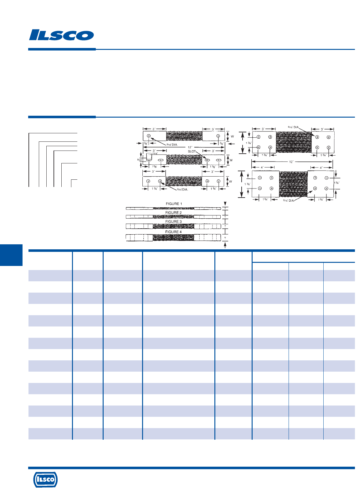
4730 Madison Road, Cincinnati, Ohio 45227-1426 Phone 513 533-6200 Fax 513 871-4084 Web site www.ilsco.com
Canada 1050 Lakeshore Road East, Mississauga, Ontario, Canada L5E1E4 Phone 905 274-2341 Fax 905 274-8763
249
G GG GG
Dimensions
Catalog Figure Drawing Ampere Rating Circular Mils.
Number Number Number (Indoors)* of Braids L T W
T278/24N12-4 2 E 940 844,000 12 0.31 4.00
T278/24N18-4 2 E 940 844,000 18 0.31 4.00
T278/24N24-4 2 E 940 844,000 24 0.31 4.00
T278/34N12-4 3 E 1200 1,266,000 12 0.38 4.00
T278/34N18-4 3 E 1200 1,266,000 18 0.38 4.00
T278/34N24-4 3 E 1200 1,266,000 24 0.38 4.00
T278/44N12-4 4 E 1600 1,688,000 12 0.50 4.00
T278/44N18-4 4 E 1600 1,688,000 18 0.50 4.00
T278/44N24-4 4 E 1600 1,688,000 24 0.50 4.00
T278/14N12-3 1 D 370 211,200 12 0.25 3.00
T278/14N18-3 1 D 370 211,200 18 0.25 3.00
T278/14N24-3 1 D 370 211,200 24 0.25 3.00
T278/24N12-3 2 D 625 422,400 12 0.31 3.00
T278/24N18-3 2 D 625 422,400 18 0.31 3.00
T278/24N24-3 2 D 625 422,400 24 0.31 3.00
Tin Plated Copper Flexible Braid
TYPE
T
Features
•
Manufactured from pure copper braid
•
Electro-tin plated
•
Seamless pure copper ferrules
•
Inside ferrule ends are rounded
•
Swedged terminal to copper braid
by cold forming
•
Extra flexible braided connector
•
Rated for 600 volts
Benefits
•
Provides high conductivity
•
Provides low contact resistance
•
Provides superior contact
•
Prevents chafing of strands
•
Provides a reduced resistance form point to point; much lower than standard
power cables or loose - piece type terminals
•
Multi-purpose use for bonding, grounding and connecting moving parts
•
Ensures reliability
Finish
End Contact - Tinned
Braid Number
Figure No.
Hole 1-1 Hole
2-2 Hole
4-4 Hole
Drilling: N - Nema
Overall Length
In Inches
T 252 1 2 N 12
Standard Specifications
Hole Size: 9/16"
Drilling: Nema Standard
End Contacts: Electro-Tin Plated Copper
Braid: Tinned Copper Flat Braid
Dwg
D
4 Hole
NEMA
Dwg
E
4 Hole
NEMA
Dwg
C
2 Hole
NEMA
Dwg
B
2 Hole
Slot
Dwg
A
1 Hole W
W
* Ampere ratings are suggested for use as a guide only. Actual values used for a given application will depend on such factors as permissible temperature rise, permissible voltage
drop, number of cables together and other conditions of service. For outdoor use, these ratings may be increased from 22% to 40% depending upon the size and position of the
braid.
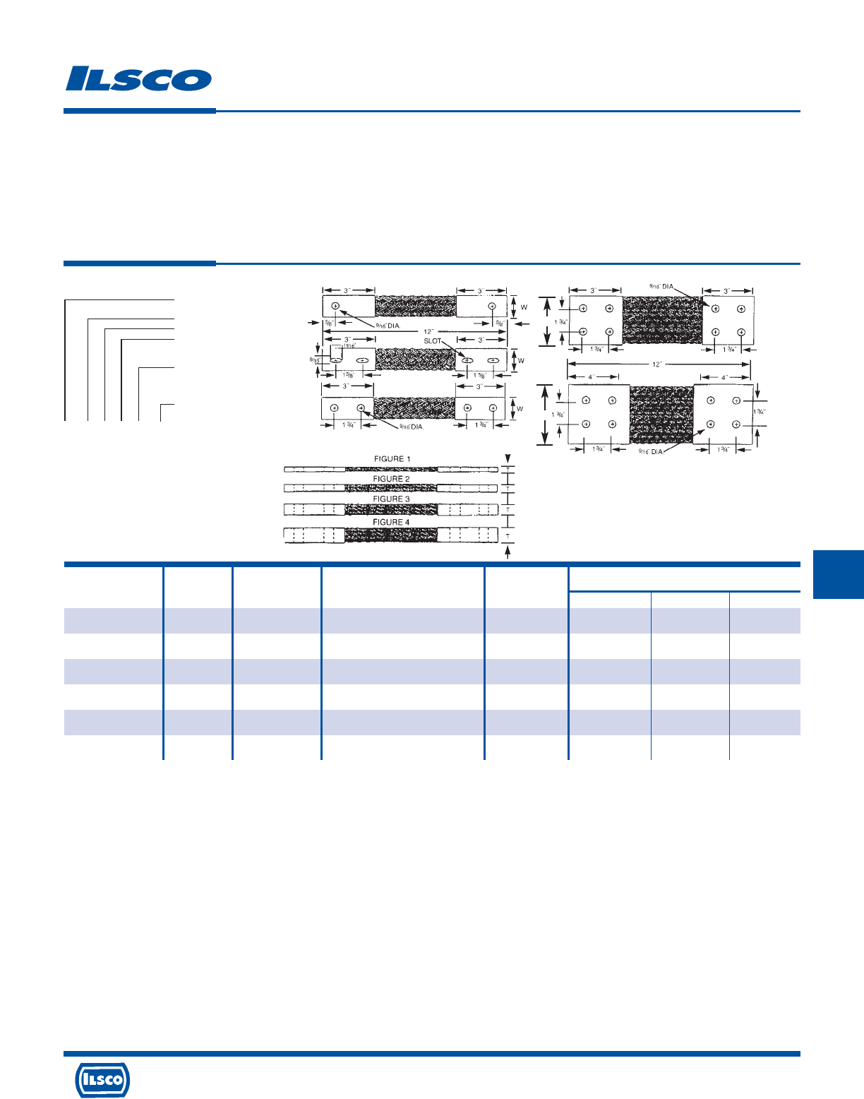
4730 Madison Road, Cincinnati, Ohio 45227-1426 Phone 513 533-6200 Fax 513 871-4084 Web site www.ilsco.com
Canada 1050 Lakeshore Road East, Mississauga, Ontario, Canada L5E1E4 Phone 905 274-2341 Fax 905 274-8763
250
GG GG G
Dimensions
Catalog Figure Drawing Ampere Rating Circular Mils.
Number Number Number (Indoors)* of Braids L T W
T278/34N12-3 3 D 800 633,600 12 0.38 3.00
T278/34N18-3 3 D 800 633,600 18 0.38 3.00
T278/34N24-3 3 D 800 633,600 24 0.38 3.00
T278/44N12-3 4 D 940 844,900 12 0.50 3.00
T278/44N18-3 4 D 940 844,900 18 0.50 3.00
T278/44N24-3 4 D 940 844,900 24 0.50 3.00
Tin Plated Copper Flexible Braid
TYPE
T
Features
•
Manufactured from pure copper braid
•
Electro-tin plated
•
Seamless pure copper ferrules
•
Inside ferrule ends are rounded
•
Swedged terminal to copper braid
by cold forming
•
Extra flexible braided connector
•
Rated for 600 volts
Benefits
•
Provides high conductivity
•
Provides low contact resistance
•
Provides superior contact
•
Prevents chafing of strands
•
Provides a reduced resistance form point to point; much lower than standard
power cables or loose - piece type terminals
•
Multi-purpose use for bonding, grounding and connecting moving parts
•
Ensures reliability
Finish
End Contact - Tinned
Braid Number
Figure No.
Hole 1-1 Hole
2-2 Hole
4-4 Hole
Drilling: N - Nema
Overall Length
In Inches
T 252 1 2 N 12
Standard Specifications
Hole Size: 9/16"
Drilling: Nema Standard
End Contacts: Electro-Tin Plated Copper
Braid: Tinned Copper Flat Braid
Dwg
D
4 Hole
NEMA
Dwg
E
4 Hole
NEMA
Dwg
C
2 Hole
NEMA
Dwg
B
2 Hole
Slot
Dwg
A
1 Hole W
W
* Ampere ratings are suggested for use as a guide only. Actual values used for a given application will depend on such factors as permissible temperature rise, permissible voltage
drop, number of cables together and other conditions of service. For outdoor use, these ratings may be increased from 22% to 40% depending upon the size and position of the
braid.
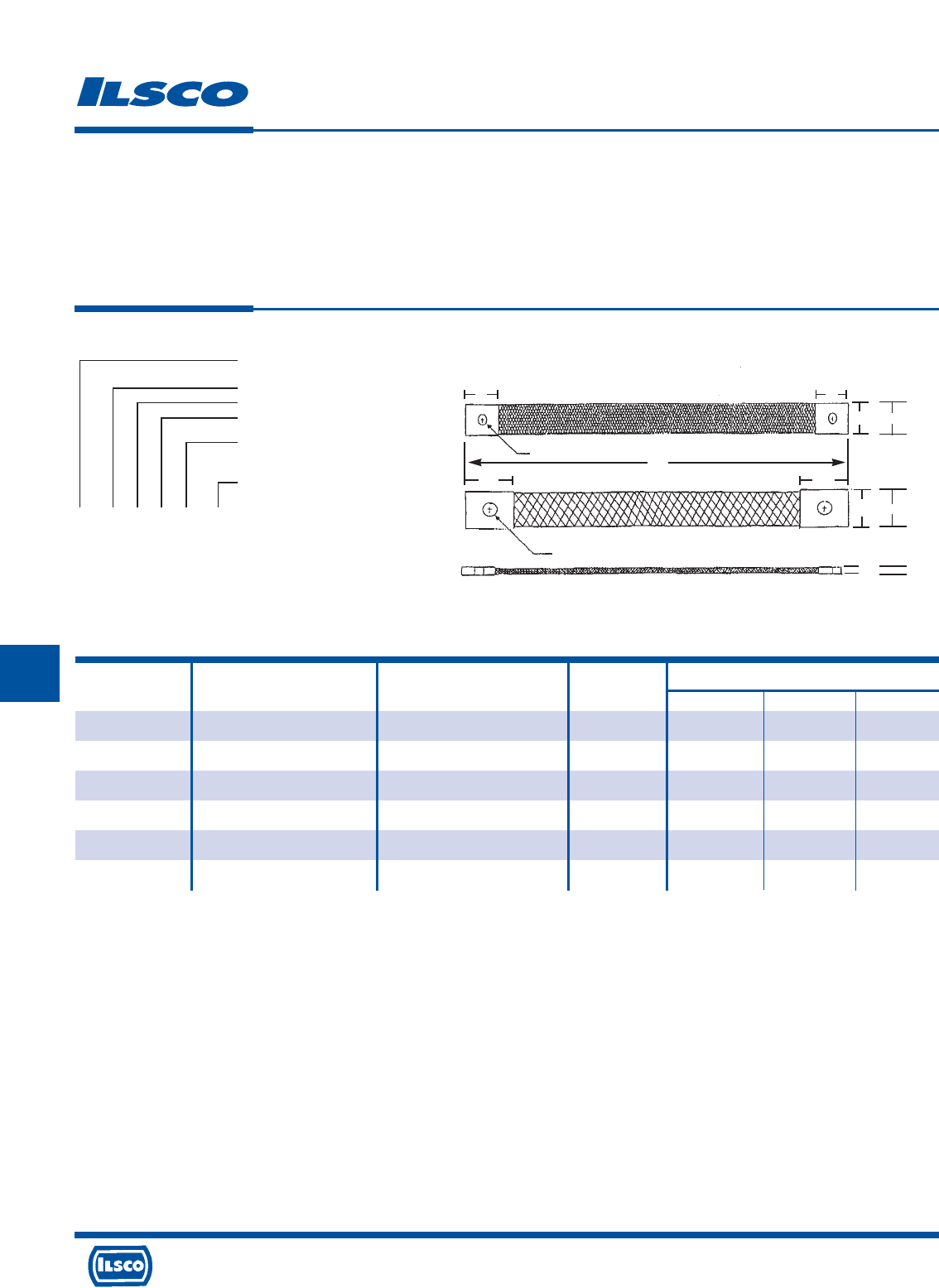
4730 Madison Road, Cincinnati, Ohio 45227-1426 Phone 513 533-6200 Fax 513 871-4084 Web site www.ilsco.com
Canada 1050 Lakeshore Road East, Mississauga, Ontario, Canada L5E1E4 Phone 905 274-2341 Fax 905 274-8763
251
G GG GG
Dimensions
Catalog Figure Ampere Rating Circular Mils.
Number Number (Indoors)* of Braids L T W
T240/11C12 1 95 24,000 12 0.13 0.63
T240/11C18 1 95 24,000 18 0.13 0.63
T240/11C24 1 95 24,000 24 0.13 0.63
T244/21C12 2 145 48,000 12 0.13 1.00
T244/21C18 2 145 48,000 18 0.13 1.00
T244/21C24 2 145 48,000 24 0.13 1.00
Tin Plated Copper Flexible Braid
Custom Drilling
TYPE
T
Features
•
Manufactured from pure copper braid
•
Electro-tin plated
•
Seamless pure copper ferrules
•
Inside ferrule ends are rounded
•
Swedged terminal to copper braid
by cold forming
•
Extra flexible braided connector
•
Rated for 600 volts
Benefits
•
Provides high conductivity
•
Provides low contact resistance
•
Provides superior contact
•
Prevents chafing of strands
•
Provides a reduced resistance form point to point; much lower than standard
power cables or loose - piece type terminals
•
Multi-purpose use for bonding, grounding and connecting moving parts
•
Ensures reliability
Finish
End Contact - Tinned
Braid Number
Figure No.
Hole 1-1 Hole
Drilling: C - Custom
Overall Length
In Inches
T 240 1 1 C 12
Standard Specifications
End Contacts: Electro-Tin Plated Copper
Braid: Tinned Copper Flat Braid
Options: - Custom drilling pattern
(drawing must be supplied)
12˝
3/4˝
11/4˝
3/4˝
5/8˝
FIGURE 1
FIGURE 2
11/4˝
1˝
1/4˝ DIA. HOLE
7/16˝ DIA. HOLE
1/8˝
W
T
W
* Ampere ratings are suggested for use as a guide only. Actual values used for a given application will depend on such factors as permissible temperature rise, permissible voltage
drop, number of cables together and other conditions of service. For outdoor use, these ratings may be increased from 22% to 40% depending upon the size and position of the
braid.
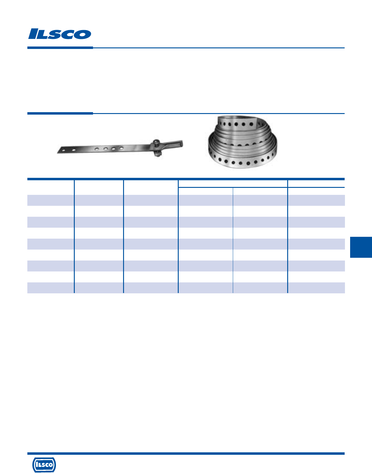
4730 Madison Road, Cincinnati, Ohio 45227-1426 Phone 513 533-6200 Fax 513 871-4084 Web site www.ilsco.com
Canada 1050 Lakeshore Road East, Mississauga, Ontario, Canada L5E1E4 Phone 905 274-2341 Fax 905 274-8763
252
GG GG G
Catalog Figure Pipe Dimensions
Number Number Size L W Type
GS-1 1 3/8-1 5-17/32 3/4 Heavy .050 thick
GS-2 1 3/8-2 9-5/16 3/4 Heavy .050 thick
GS-3 1 3/8-3 12-3/4 3/4 Heavy .050 thick
GS-4 1 3/8-4 15-3/4 3/4 Heavy .050 thick
GS-10 1 3/8-1 5-17/32 3/4 Light .025 thick
GS-20 1 3/8-2 9-5/16 3/4 Light .025 thick
GS-30 1 3/8-3 12-3/4 3/4 Light .025 thick
GS-40 1 3/8-4 15-3/4 3/4 Light .025 thick
GSR-Plain* 2 - 10 ft. 3/4 Light .030 thick
Copper Ground Straps
TYPE
GS
GSR
Features
•
Manufactured from annealed copper sheet
•
Two styles available
•
Type GSR supplied in 10' coils with 1/4" holes
Benefits
•
Provides maximum conductivity and greater flexibility
•
Heavy-Duty or lightweight in four different lengths
•
Can be cut to desired length which reduces inventory
* 1/4" Holes
Fig. 1 Fig. 2
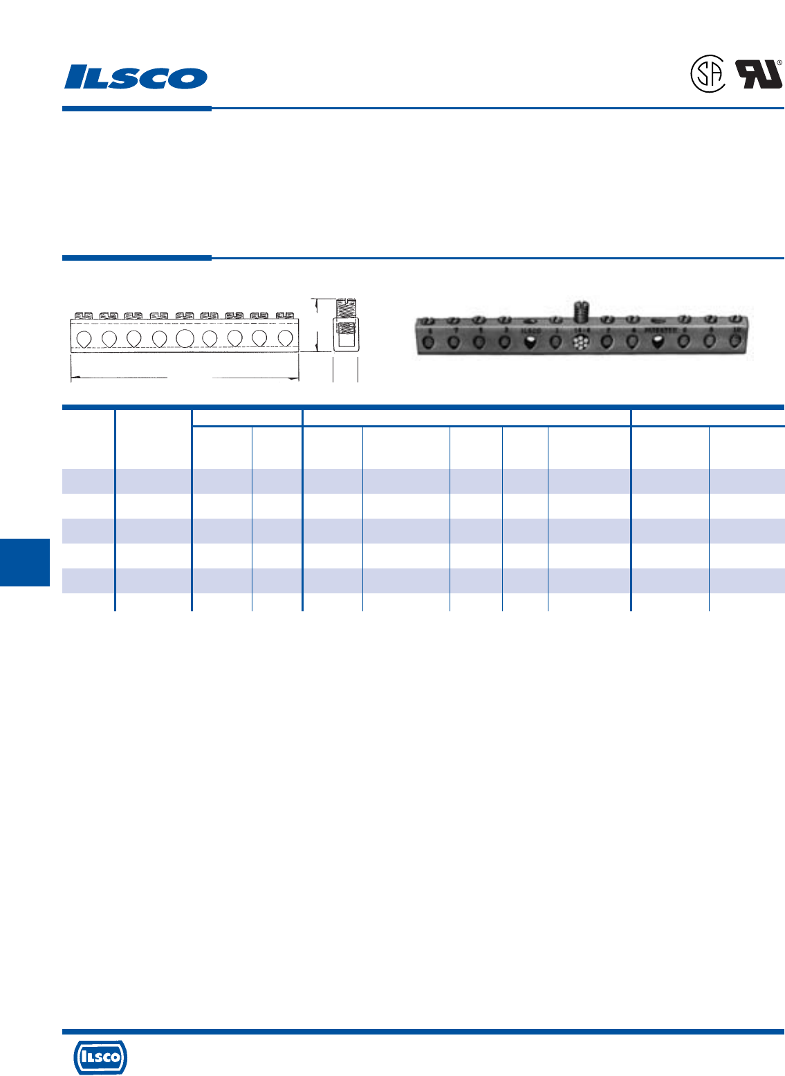
4730 Madison Road, Cincinnati, Ohio 45227-1426 Phone 513 533-6200 Fax 513 871-4084 Web site www.ilsco.com
Canada 1050 Lakeshore Road East, Mississauga, Ontario, Canada L5E1E4 Phone 905 274-2341 Fax 905 274-8763
253
G GG GG
Wire Range Dimensions Mounting Hole Positions
From End Of Distance
Catalog Number Of Height With Bolt Two Mounting Bar To First Between
Number Taps Main Tap L Maximum Wire W Size Holes Mounting Hole Holes
D167-4 4 4-14 6-14 2-3/4 3/4 11/32 #10 13/64 .581 (2nd hole) 1.98
D167-6 6 4-14 6-14 3-1/2 3/4 11/32 #10 13/64 .978 (3rd hole) 1.98
D167-8 8 4-14 6-14 4-7/16 3/4 11/32 #10 13/64 1.375 (4th hole) 1.98
D167-10 10 4-14 6-14 5-1/8 3/4 11/32 #10 13/64 1.772 (5th hole) 1.98
D167-12 12 4-14 6-14 5-15/16 3/4 11/32 #10 13/64 2.169 (6th hole) 1.98
D167-14 14 4-14 6-14 6-23/32 3/4 11/32 #10 13/64 2.566 (7th hole) 1.98
Copper Neutral Bars
TYPE
D167
Features
•
Manufactured from high strength copper tubing
•
Range taking
•
UL Recognized for 600 volts
Benefits
•
Provides maximum conductivity
•
A wide range of conductor sizes can be used in the
same connector
•
Ensures reliability for copper conductor
L
H
W
Tested to UL 486A-486B, UL File E6207
L
1
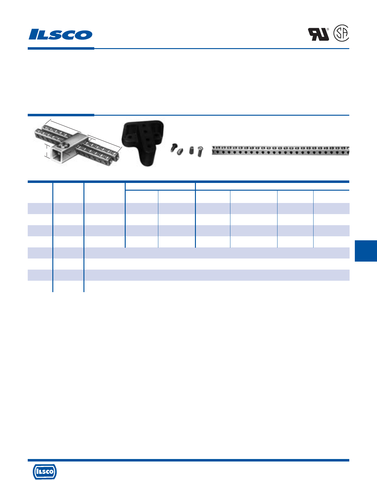
4730 Madison Road, Cincinnati, Ohio 45227-1426 Phone 513 533-6200 Fax 513 871-4084 Web site www.ilsco.com
Canada 1050 Lakeshore Road East, Mississauga, Ontario, Canada L5E1E4 Phone 905 274-2341 Fax 905 274-8763
254
GG GG G
Wire Range Dimensions
Catalog Figure Number Of Height With Two Tapped
Number Number Taps Main Tap L Maximum Wire W Mounting Holes
CAN-300 1 24 250kcmil-6 6-14 2-5/16 1-5/16 5-1/8 10-32
CAN-301 1 30 250kcmil-6 6-14 3 1-5/16 4-13/32 10-32
CAN-302 1 36 250kcmil-6 6-14 3 1-5/16 5-1/8 10-32
CAN-303 1 42 250kcmil-6 6-14 3 1-7/16 5-1/2 10-32
R-16 2 Mounting block of general purpose (phenolic black) suitable for mounting any of CAN Neutrals. 2-1/2" wide x 2-1/2" long x 1" thick.
E-223 3 10-32 x 1/2" round head steel machine screws for fastening neutrals to mounting blocks. (Use lock washer to provide rigid assembly.)
E-153 3 1/4-28 wire pressure screw 7/16" long. Screw is steel, zinc plated and chromate dipped.
N-174 4 Supplied in 5' 9" lengths. Approximately 174 outlets. Wire range 14-6.
Copper Neutral Bars
TYPE
CAN
Features
•
Manufactured from high strength copper tubing
•
Compact design
•
Range taking
•
UL Recognized and CSA Certified
•
Circuit bars inserted at a 20 angle
Benefits
•
Provides maximum conductivity
•
Up to 42 circuit taps can be made in just 5 1/2" of space
•
A wide range of conductor sizes can be used in the
same connector
•
Ensures reliability for copper conductor
•
Provides easy wire insertion
L
R
-
2
9
6
0
1
Fig. 1 Fig. 2 Fig. 3 Fig. 4
W
HL
Tested to UL 486A-486B, UL File E6207
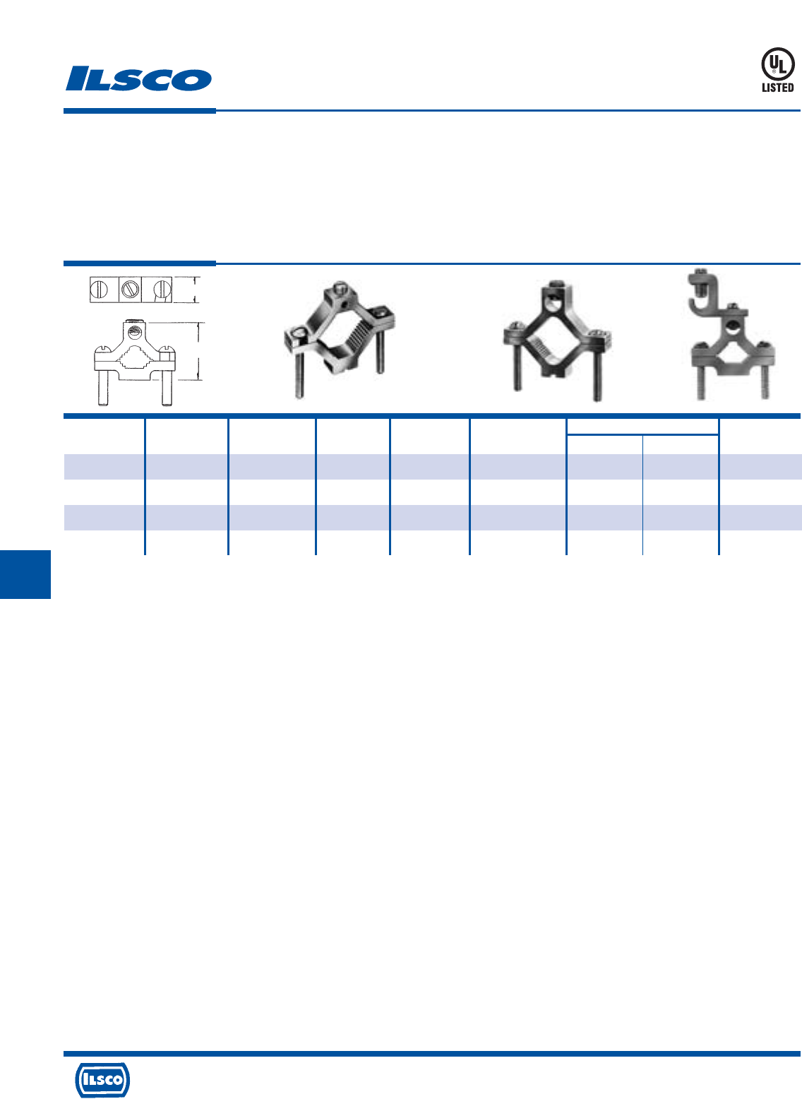
4730 Madison Road, Cincinnati, Ohio 45227-1426 Phone 513 533-6200 Fax 513 871-4084 Web site www.ilsco.com
Canada 1050 Lakeshore Road East, Mississauga, Ontario, Canada L5E1E4 Phone 905 274-2341 Fax 905 274-8763
255
G GGG
Catalog Figure Pipe Rebar Ground Wire Screw Dimensions Hex
Number Number Size Size Range Type L W Size
AGC-1 1 1/2-3/4-1 4, 5, 6 1/0-14 Slot 2-1/4 11/16 Slot
AGC-2 2 1 1/4-1 1/2-2 - 250kcmil-6 Hex Socket 3-3/4 13/16 5/16
AGC-4 2 2 1/2-3-3 1/2-4 - 250kcmil-6 Hex Socket 6-5/16 1 5/16
SGC-1/0* 3 1/2-3/4-1” - 1/0-14 Slot 2-1/4 11/16 Slot
Dual Rated Ground Clamp
TYPE
AGC
SGC
Features
•
Manufactured from high strength 6061-T6 aluminum
alloy
•
Clear plated
•
UL Listed
•
Versatile
•
Range taking
•
SGC Lay-In feature
Fig. 1 Fig. 2 Fig. 3
Benefits
•
Suitable for use with either copper or aluminum
conductors
•
Provides low contact resistance
•
Ensures reliability
•
Effectively grounds aluminum or copper conductors to
copper water pipe, galvanized pipe or steel conduit
•
Three sizes cover a range from 1/2" to 4" pipe with a
ground wire range of 250 kcmil - #14 which reduces
inventory
•
Provides ease of installation for long ground wire runs
DE-OX Inhibitor is recommended for all aluminum terminations.
* Typical application would be grounding computer floor room system.
UL File E34440
W
L
667P
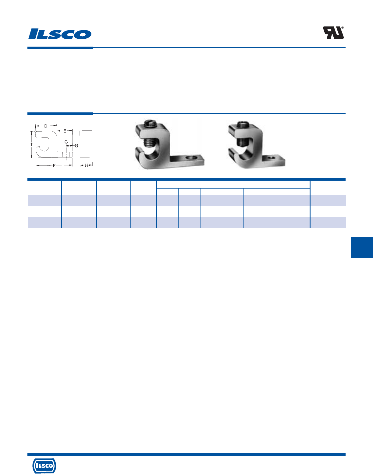
4730 Madison Road, Cincinnati, Ohio 45227-1426 Phone 513 533-6200 Fax 513 871-4084 Web site www.ilsco.com
Canada 1050 Lakeshore Road East, Mississauga, Ontario, Canada L5E1E4 Phone 905 274-2341 Fax 905 274-8763
256
GG GG
Catalog Figure Ground Wire Bolt Dimensions Hex
Number Number Range Size C D E F G H T Size
*GBL-4 1 4-14 10 7/32 5/8 31/64 1-3/32 13/64 25/64 51/64 Slot
+GBL-1/0 1 1/0-14 1/4 9/32 51/64 27/32 1-5/8 7/16 5/8 1-5/32 Slot
+GBL-250 2 250kcmil-6 1/4 9/32 31/64 1 2-3/16 29/64 7/8 1-23/32 7/32
Dual Rated Lay-In Ground Lug
TYPE
GBL
Features
•
Manufactured from high strength 6061-T6 aluminum
alloy
•
Electro-tin plated
•
UL Recognized for grounding and bonding
•
Lay-in feature
•
Rated for 600 volts
Fig. 1 Fig. 2
Benefits
•
Suitable for use with either copper or aluminum
conductors
•
Provides low contact resistance
•
Ensures reliability
•
Provides ease of installation
•
Ensures reliability
+ U.L. 467 recognized for grounding and bonding only.
DE-OX Inhibitor is recommended for all aluminum terminations.
+ UL File E34440/E6207
* UL 467 Listed
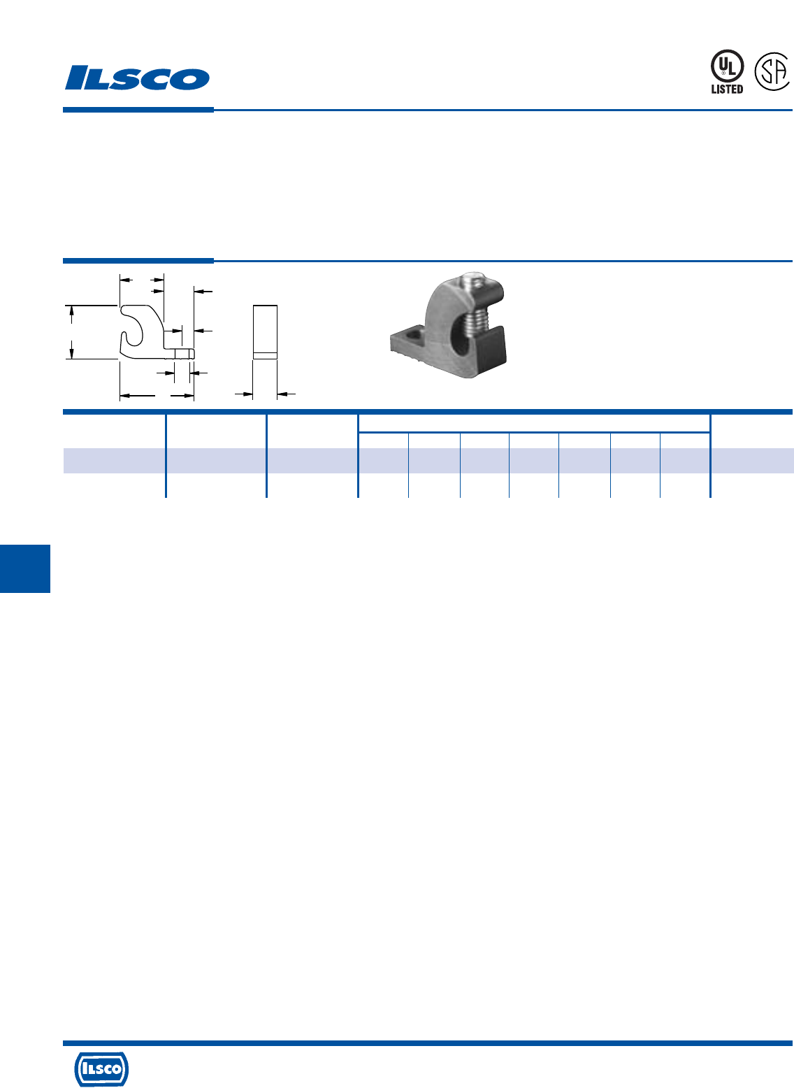
4730 Madison Road, Cincinnati, Ohio 45227-1426 Phone 513 533-6200 Fax 513 871-4084 Web site www.ilsco.com
Canada 1050 Lakeshore Road East, Mississauga, Ontario, Canada L5E1E4 Phone 905 274-2341 Fax 905 274-8763
257
G GG GG
D
E
G
C
F
T
H
Catalog Ground Wire Bolt Dimensions Screw
Number Range Size C D E F G H T Type
GBL-4DB 4-14 10 .218 .680 .470 1.15 .19 .375 .825 Slot
GBL-4DB-14 4-14 10 .265 .680 .470 1.150 .210 .472 .825 Slot
Copper Lay-In Ground Lug
Direct Burial
TYPE
GBL-DB
Features
•
Lay-in feature
•
Manufactured from high strength copper
•
Stainless steel 1/4-28 torque screw
•
Rated for 600 volts
Benefits
•
Provides ease of installation of continuous loop
grounding conductor
•
Suitable for direct burial and for use with copper
conductors
•
Resists oxidation and corrosion in earth or concrete
•
Ensures reliability
667P
L
R
-
2
9
6
0
1
* Add T to order tin plating
Tested to UL 467, UL File E34440
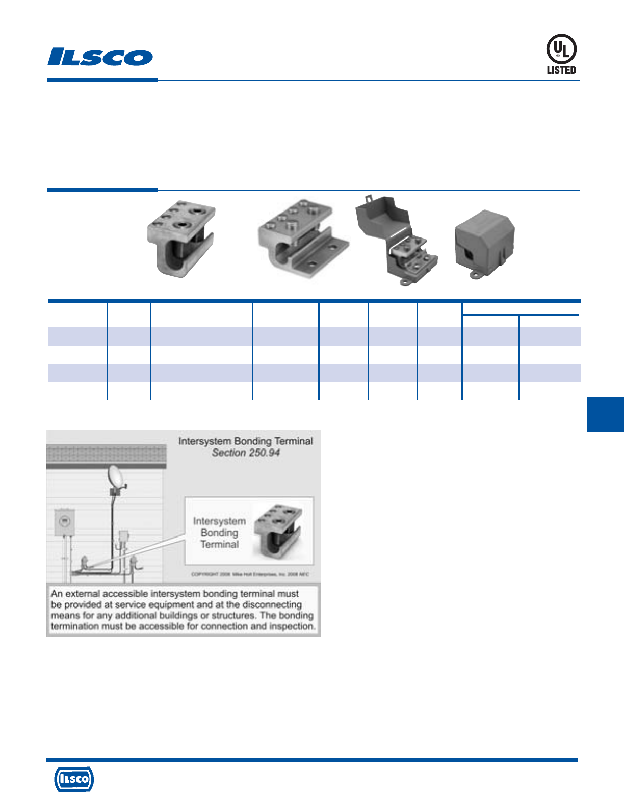
4730 Madison Road, Cincinnati, Ohio 45227-1426 Phone 513 533-6200 Fax 513 871-4084 Web site www.ilsco.com
Canada 1050 Lakeshore Road East, Mississauga, Ontario, Canada L5E1E4 Phone 905 274-2341 Fax 905 274-8763
258
G
Features
•
Approved for UL 467 (Grounding & Bonding)
•
Lay in style
•
No mounting required
•
Dual rated
•
4 Taps (#2-14) stranded or solid
•
Stainless steel screws
•
Serrations in conductor wire way
•
Patent Pending
Benefits
•
Meets NEC 250.94 installation requirements.
•
Eliminates the need to cut or splice into existing conductor
•
Allows fast simple installation on ground conductor below meter
•
For use with copper and aluminum conductors
•
For bonding multiple communication systems (Phone, TV, Cable, etc.)
•
For corrosion resistance
•
Cuts oxidation
ClearGround™
Intersystem Ground Tap
TYPE
GBT
Catalog Figure Wire Range Wire Range Hex Size
Number Number Main Tap Length Width Height Main Tap
GBT-1/0 1 1/0-8 2-14str-sol 2.250 1.125 1.160 S S
GBT-250 1 250kcmil-8str - 1/0-8sol 2-14str-sol 2.250 1.375 1.587 7/32 S
GBT-1/0-M 2 1/0-8 2-14str-sol 2.250 1.750 1.160 S S
GBT-1/0-M-W/C 3 1/0-8 2-14str-sol 2.730 3.930 2.110 S S
UL File E34440
250-94 01 reproduced with approval from Mike Holt Enterprises, www.mikeholt.com
Fig. 1 Fig. 2 Fig. 3
4730 Madison Road, Cincinnati, Ohio 45227-1426 Phone 513 533-6200 Fax 513 871-4084 Web site www.ilsco.com
Canada 1050 Lakeshore Road East, Mississauga, Ontario, Canada L5E1E4 Phone 905 274-2341 Fax 905 274-8763
259
G GG GG G
Catalog Figure Wire Range Single Cable Dimensions Hex
Number Number Max. Min. Steel Strand Dia. Thread A B L Size
GRM-2A 1 2str 12sol/str 5/16 1/4"-20 - 11/16 1-1/4 Slot
GRM-2B 1 2str 12sol/str 5/16 5/16"-18 - 3/8 1-1/4 Slot
GRM-2C 1 2str 12sol/str 5/16 3/8"-16 - 9/16 1-1/4 Slot
GRM-0 1 1/0str 2str 3/8 1/2"-13 - 1 1-9/16 Slot
GRM-250A 1 250kcmil 1/0 9/16 1/2"-13 - 1 2-1/8 5/16
GRM-250B 1 250kcmil 1/0 9/16 5/8"-11 - 1 2-1/8 5/16
GRM-350 1 350kcmil 4/0 - 5/8"-11 - 1 2-1/2 3/8
GRM-500 1 500kcmil 350kcmil - 3/4"-10 - 1-3/8 2-15/16 3/8
GRM-750 1 750kcmil 500kcmil - 3/4"-10 - 1-3/8 3-3/8 1/2
GRF-2A 2 2str 12sol/str 5/16 1/4"-20 5/16 - 1-1/4 Slot
GRF-2B 2 2str 12sol/str 5/16 5/16"-18 3/8 - 1-1/4 Slot
GRF-2C 2 2str 12sol/str 5/16 3/8"-16 7/16 - 1-1/4 Slot
GRF-0 2 1/0str 2str 3/8 1/2"-13 1/2 - 1-9/16 Slot
GRF-250A 2 250kcmil 1/0 9/16 1/2"-13 1/2 - 2-1/8 5/16
GRF-250B 2 250kcmil 1/0 9/16 5/8"-11 3/4 - 2-1/8 5/16
GRF-350 2 350kcmil 4/0 - 5/8"-11 3/4 - 2-1/2 3/8
GRF-500 2 500kcmil 350kcmil - 3/4"-10 7/8 - 2-15/16 3/8
GRF-750 2 750kcmil 500kcmil - 3/4"-10 7/8 - 3-3/8 1/2
Aluminum Grounding Connectors - Dual Rated
TYPE
GRM
GRF
Features
•
Manufactured from high strength 6061-T6 aluminum
alloy
•
Electro-tin plated
•
Type GRM - Elongated steel stud
•
Type GRF - Threaded female design
Fig. 1 Fig. 2
Benefits
•
Suitable for use with either copper or aluminum
conductors
•
Provides low contact resistance
•
Provides ease of grounding a single conductor to steel
structures or to tap a single conductor from bus bar
•
Provides ease of installation for a variety of standard
stud sizes
DE-OX Inhibitor is recommended for all aluminum terminations.
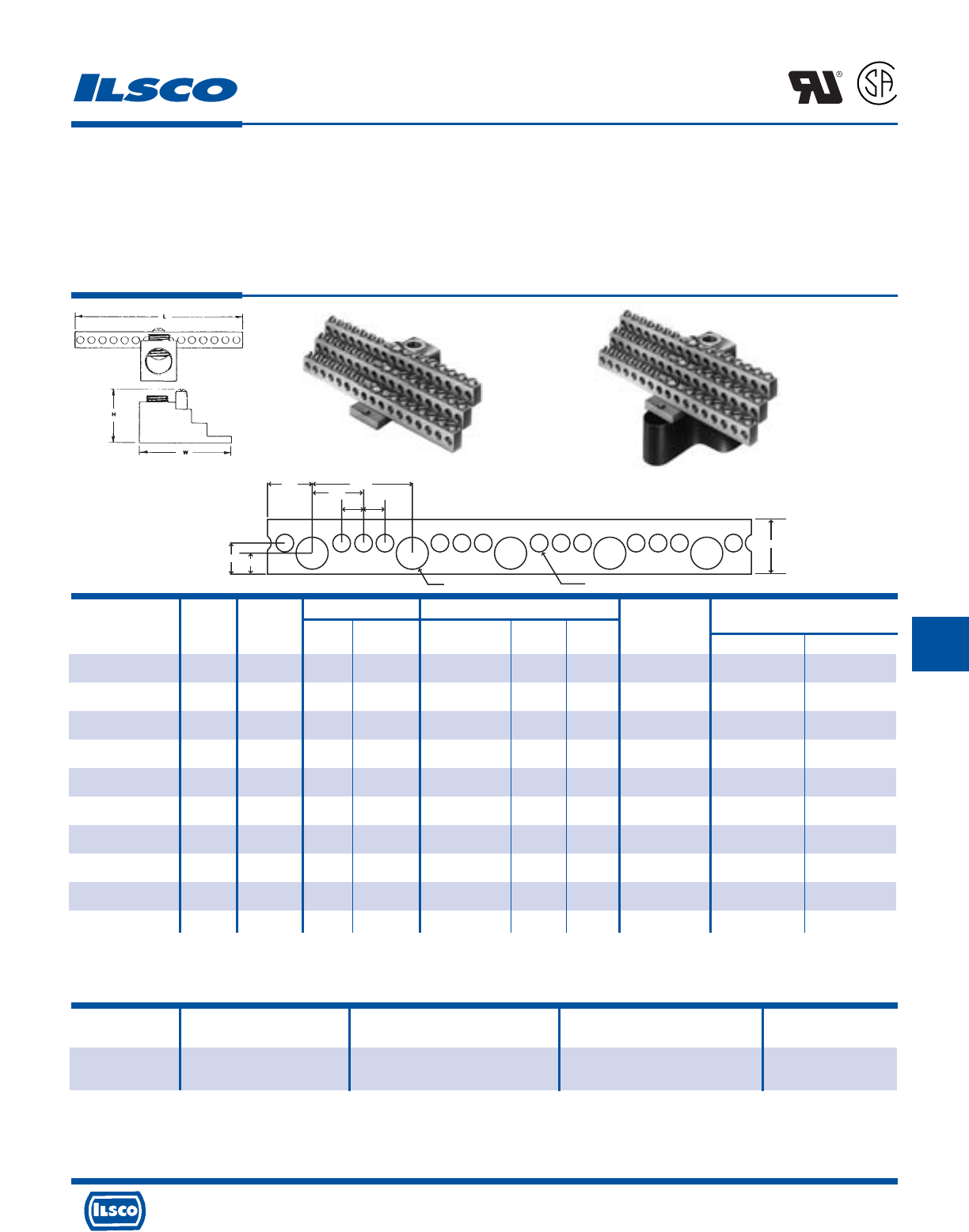
4730 Madison Road, Cincinnati, Ohio 45227-1426 Phone 513 533-6200 Fax 513 871-4084 Web site www.ilsco.com
Canada 1050 Lakeshore Road East, Mississauga, Ontario, Canada L5E1E4 Phone 905 274-2341 Fax 905 274-8763
260
GG GG GG
.391
.620
.391 Dia. .209 Dia.
.547 1.172
.586
.250 .250
.250
Number Wire Range Dimensions Two Tapped
Catalog Figure Of Circuit Circuit Line Approx. Height Mounting
Number Number Taps Taps Loads with Max. Wire L W Holes Main Tap
NB-350-12 1 12 14-4 350kcmil-6 1-17/32 4-23/32 2-17/32 10-32 3/8 S
NB-350-12-W/R16* 2 12 14-4 350kcmil-6 2-17/32 4-23/32 2-17/32 10-32 3/8 S
NB-350-24 1 24 14-4 350kcmil-6 1-17/32 4-23/32 2-17/32 10-32 3/8 S
NB-350-24-W/R16* 2 24 14-4 350kcmil-6 2-17/32 4-23/32 2-17/32 10-32 3/8 S
NB-350-30 1 30 14-4 350kcmil-6 1-17/32 4-3/32 2-17/32 10-32 3/8 S
NB-350-30-W/R16* 2 30 14-4 350kcmil-6 2-17/32 4-3/32 2-17/32 10-32 3/8 S
NB-350-36 1 36 14-4 350kcmil-6 1-17/32 4-23/32 2-17/32 10-32 3/8 S
NB-350-36-W/R16* 2 36 14-4 350kcmil-6 2-17/32 4-23/32 2-17/32 10-32 3/8 S
NB-350-42 1 42 14-4 350kcmil-6 1-17/32 5-11/32 2-17/32 10-32 3/8 S
NB-350-42-W/R16* 2 42 14-4 350kcmil-6 2-17/32 5-11/32 2-17/32 10-32 3/8 S
Catalog Figure Number of Wire
Number Number Outlets Range Length
NB-120 3 120 30 outlets 1/0-14 3.25'
90 outlets 6-14
Aluminum Neutral Bars - Dual Rated
TYPE
NB
Features
•
Preassembled, stacked neutral bars
•
Available with phenolic base
•
Electro-tin plated
•
Fabricated from high strength 6061-T6 aluminum alloy
•
UL Recognized and CSA Certified for 600 volts, 90˚ C
Benefits
•
Compact, space saving design offers multiple range taking
flexibility and is suitable for grounding applications
•
Provides insulation from mounting surface
•
Provides low contact resistance
•
Suitable for use with either copper or aluminum conductors
•
Ensures reliability
L
R
-
2
9
6
0
1
Fig. 1 Fig. 2
Fig. 3
Hex Size
“S” indicates slotted screw
* Part includes phenolic mounting block R-16
Tested to UL 486A-486B, UL File E6207
UL File E81652
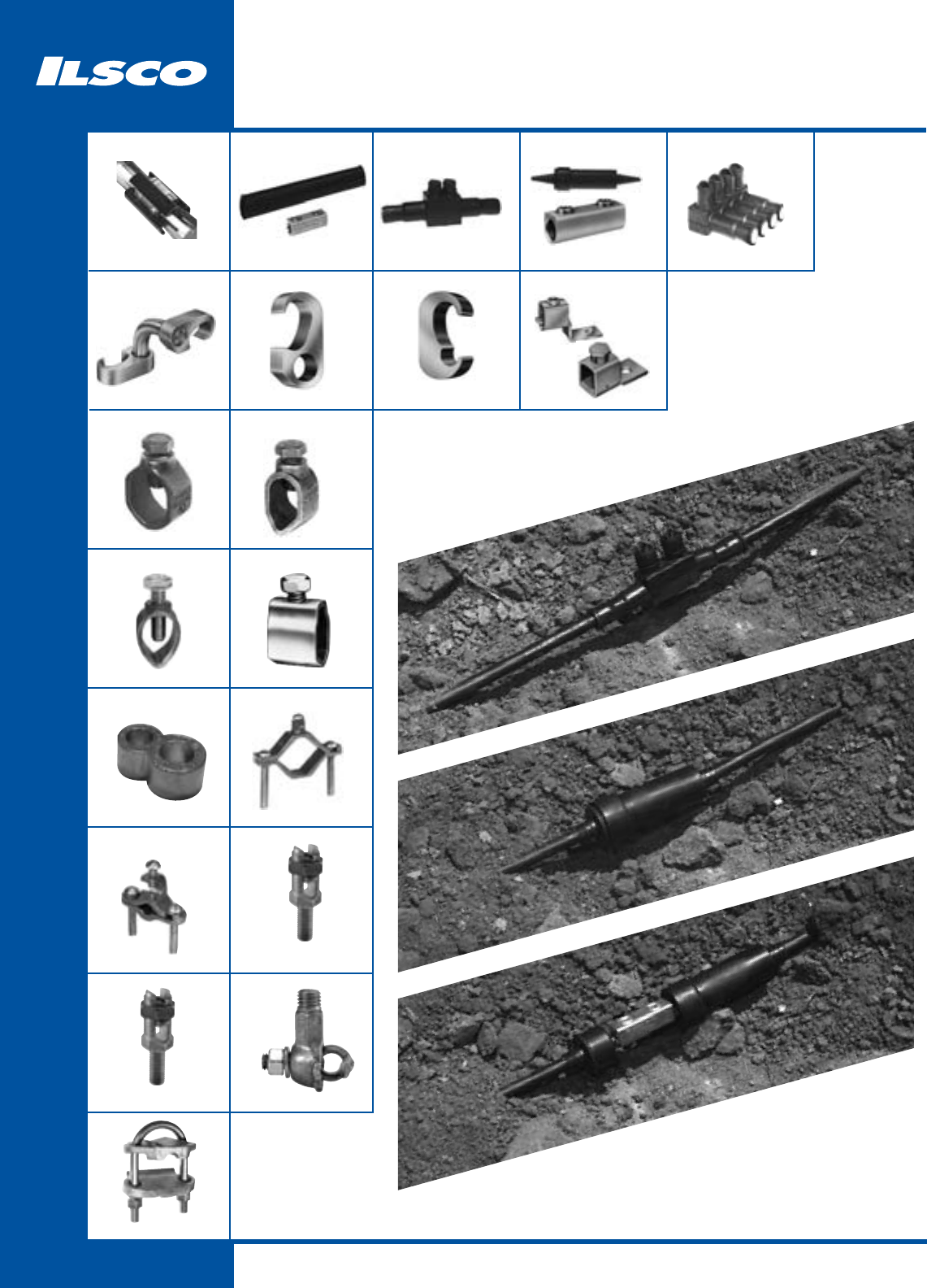
261
Underground
DBK
262
ASK
262
USPA-SS
263
GGC
267
PED-SS
265
GGA
266
ELT
268
BGRC
270
SPS
276 - 277
BGC
274
SPD
278 – 279
GUB
281
RLT
273
SS, SSK, SSKC
264
GRC
272
SRC
271
BGDB
275
CGRC
270
SLU-DB, XT-DB
269
TTGC
280
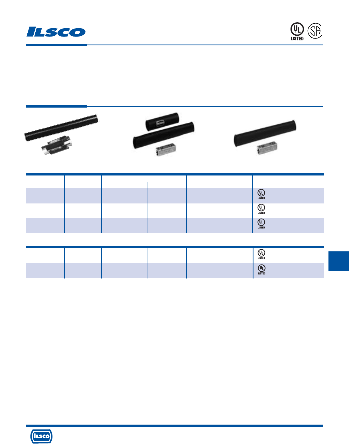
4730 Madison Road, Cincinnati, Ohio 45227-1426 Phone 513 533-6200 Fax 513 871-4084 Web site www.ilsco.com
Canada 1050 Lakeshore Road East, Mississauga, Ontario, Canada L5E1E4 Phone 905 274-2341 Fax 905 274-8763
262
Catalog Figure UF Cable Range Wire Testing
Number Number Minimum Maximum Range Certification
DBK-1 1 14/2 with Ground 8/3 with Ground -
DBK-2 2 - - 2-8
DBK-250 2 - - 250kcmil-1
ASK-2* 3 - - 2-8
ASK-250* 3 - - 250kcmil-1
Direct Burial and Above Grade Splice Kits
TYPE
DBK
ASK
Features
•
DBK-1 connectors manufactured from electrolytic
copper
•
All other connectors manufactured from high strength
aluminum alloy
•
Heavy wall heat shrink tubing with sealant
•
Connector and heat shrink packaged together
•
UL listed, rated for 600 volts, 90˚ C
Benefits
•
Provides maximum conductivity for UF cable
•
Provides high conductivity and can be used with either
aluminum or copper conductors
•
Provides watertight splice. Kits with heat shrink are
designed to withstand abrasions due to direct burial in
rocky soil.
•
Provides ease of ordering
•
Ensures reliability
453G
453G
88X4
88X4
88X4
*Not UL Listed for direct burial.
Tested to UL 486A-486B, UL File E6207
Fig. 1 Fig. 2 Fig. 3
ABOVE GRADE SPLICE KITS
Tested UL 486D, UL File E125087
H
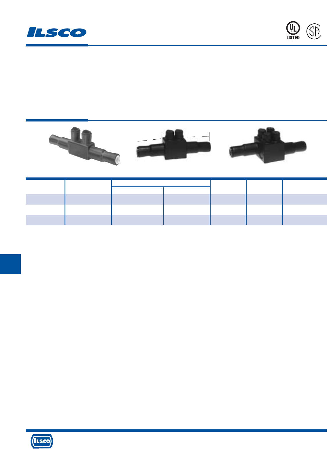
4730 Madison Road, Cincinnati, Ohio 45227-1426 Phone 513 533-6200 Fax 513 871-4084 Web site www.ilsco.com
Canada 1050 Lakeshore Road East, Mississauga, Ontario, Canada L5E1E4 Phone 905 274-2341 Fax 905 274-8763
263
H
Catalog Figure Wire Range Hex Recommended
Number Number Barrel A Barrel B Length Size Torque-Inch Lbs.
USPA-350SS-DB +1 350kcmil-10str 350kcmil-10str 8- 5/8 5/16 350
USPA-500SS-DB* 2 500kcmil-10 500kcmil-10 9-13/16 5/16 450
USPA-750SS-DB 3 750kcmil-2 750kcmil-2 9-13/16 5/16 500
Watertight, Underground In-Line Splice
TYPE
USPA-SS
Features
•
Encapsulated in EPDM rubber with a nominal thickness
of 125 Mils and a dielectric strength of 240 Volts per Mil
•
Pre-marked end inserts
•
O-Ring design screw cap inserts
•
Connector is produced from high strength 6061-T6
aluminum alloy
•
Connector rated for 600 volts, 90˚ C
•
Range taking
•
UL Listed and CSA Certified for direct burial in earth or
concrete
Fig. 1 Fig. 2 Fig. 3
Benefits
•
Completely watertight in line splice. Ready for installation.
(not a mold for use with mixed compounds) No taping
required. No temperature or humidity restrictions.
•
Simply cut end inserts to appropriate marked wire size
and insert conductor into connector
•
Ensures connector integrity while allowing ease of access
to set screws, ensuring excellent sealing
•
Suitable for use with either copper or aluminum
conductors
•
Ensures reliability
•
Reduces inventory
+ REA listed
* Not UL Listed
Tested to UL 486D, UL File E125087
AB
88X4
L
R
-
2
9
6
0
1
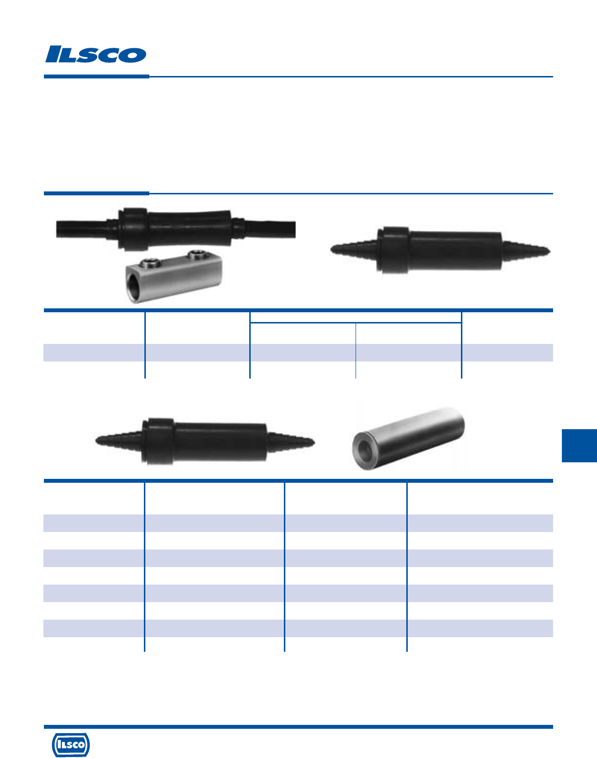
4730 Madison Road, Cincinnati, Ohio 45227-1426 Phone 513 533-6200 Fax 513 871-4084 Web site www.ilsco.com
Canada 1050 Lakeshore Road East, Mississauga, Ontario, Canada L5E1E4 Phone 905 274-2341 Fax 905 274-8763
264
H
Temperature rating 90˚ C
Wire Range
Catalog Figure Bolted Compression
Number Number Connector Sleeves L
SSK-350-Z 1 350kcmil-6 - 5-1/2
SS-350-Z 2 350kcmil-6 500kcmil-6 5-1/2
Watertight Underground Splice Kits
TYPE
SS
SSK
SSKC
Features
•
Watertight EPDM rubber splice cover
•
Tapered ends
•
Ready for installation
•
Type SS is cover only supplied with lubricant
•
Type SSK kit is supplied with both connector and
lubricant
•
Connector rated for 600 volts
Fig. 1 Fig. 2
Benefits
•
No taping required. Suitable for direct burial
•
Fits a wide range of conductor sizes
•
Not a mold, can be used in any type of weather. (moisture and humidity are
not a factor)
•
Can be used with standard aluminum or copper compression from 500kcmil -
6. Lubricant permits easy insertion of conductors into sleeve.
•
Supplied with dual-rated mechanical splice connector with a wire range of
350kcmil - 6
•
Ensures reliability
Wire Range
Catalog Connector Wire When Installed
Number Catalog Number Size With IDT-12 Tool
SSKC-6-Z AS-6 6 6
SSKC-4-Z AS-4 4 4-6
SSKC-2-Z AS-2 2 2-6
SSKC-1/0-Z AS-1/0 1/0 1/0-1
SSKC-2/0-Z AS-2/0 2/0 2/0-1
SSKC-3/0-Z AS-3/0 3/0 3/0-1
SSKC-4/0-Z AS-4/0 4/0 4/0-1
SSKC-250-Z AS-250 250kcmil 250kcmil-1/0
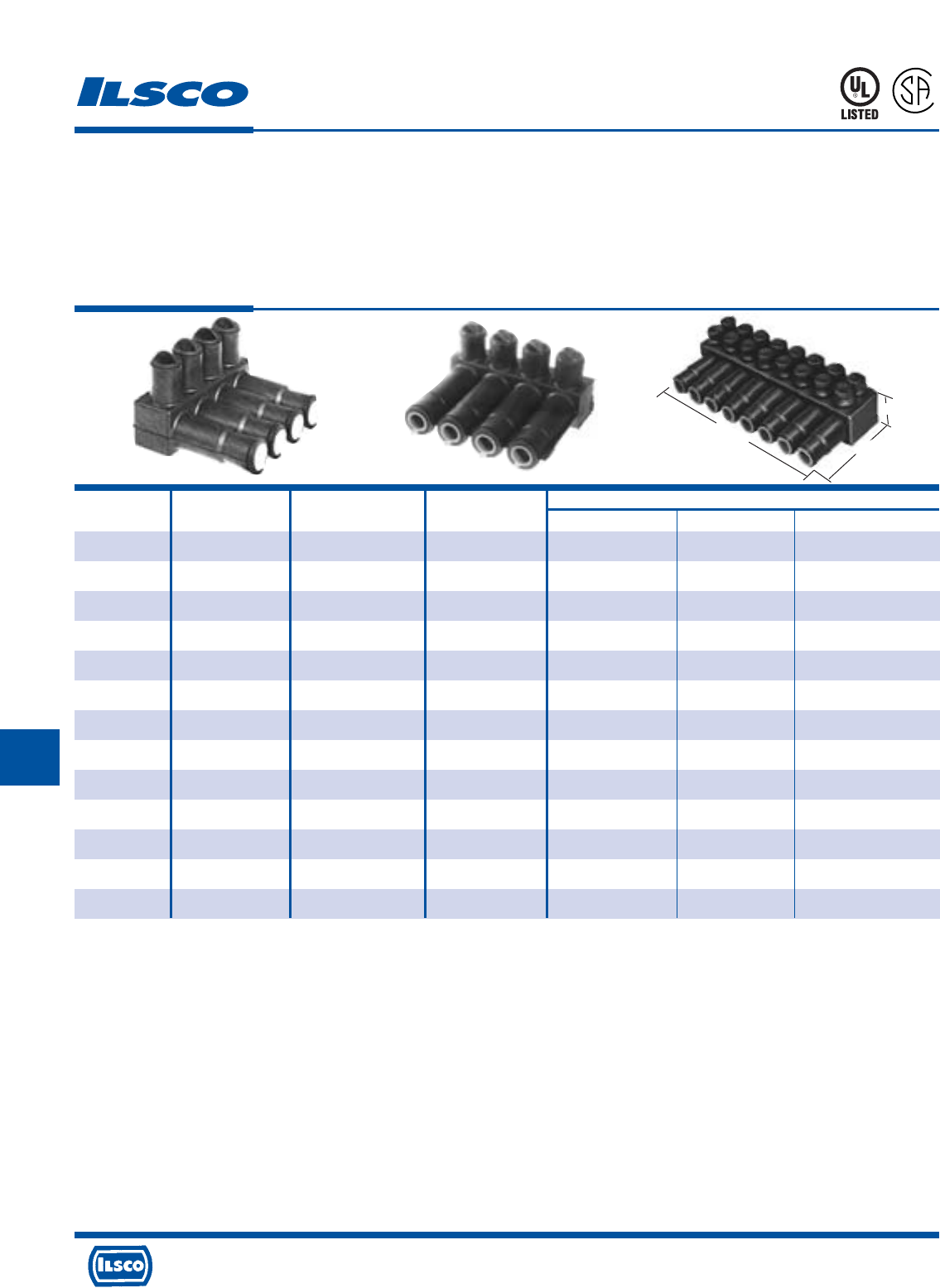
4730 Madison Road, Cincinnati, Ohio 45227-1426 Phone 513 533-6200 Fax 513 871-4084 Web site www.ilsco.com
Canada 1050 Lakeshore Road East, Mississauga, Ontario, Canada L5E1E4 Phone 905 274-2341 Fax 905 274-8763
265
H
Catalog Figure Wire Number of Dimensions
Number Number Range Ports W H L
PED3-350SS-DB 1 350kcmil-10str 3 4.40 2.70 3.67
PED4-350SS-DB 1 350kcmil-10str 4 4.40 2.70 4.82
PED5-350SS-DB 1 350kcmil-10str 5 4.40 2.70 6.04
PED6-350SS-DB 1 350kcmil-10str 6 4.40 2.70 7.14
PED8-350SS-DB 1 350kcmil-10str 8 4.40 2.70 9.45
PED-3-500-SS-Z 2 500kcmil-10 3 5.06 2.82 4.57
PED-4-500-SS-Z 2 500kcmil-10 4 5.06 2.82 6.04
PED-5-500-SS-Z 2 500kcmil-10 5 5.06 2.82 7.50
PED-6-500-SS-Z 2 500kcmil-10 6 5.06 2.82 8.98
PED-8-500-SS-Z 2 500kcmil-10 8 5.06 2.82 11.92
PED-4-750-SS-Z 3 750kcmil-2 4 6.50 3.53 6.97
PED-6-750-SS-Z 3 750kcmil-2 6 6.50 3.53 10.35
PED-8-750-SS-Z 3 750kcmil-2 8 6.50 3.53 13.73
Connector for Direct Burial
and Hand Holes
TYPE
PED-SS
Rated for 600 Volts
Features
•
Available in a variety of conductor configurations and
three wire ranges
•
Manufactured from high strength aluminum alloy
•
Clear plated
•
Dual rated
•
EPDM cover has dielectric strength of 240 volts per mil
and nominal thickness of 125 mils
•
UL Listed and CSA Certified for direct burial in earth or
concrete
•
Rated for 600 volts
Benefits
•
Provides multiple conductor installation for a broad wire
range
•
Provides maximum conductivity
•
Low contact resistance
•
Use with both copper and aluminum conductors
•
Completely watertight, no taping required. Suitable for
direct burial in earth or concrete
Extra screw closure caps and extra conductor plugs available.
* Not UL Listed or CSA Certified.
Tested to UL 486D, UL File E125087
*
*
*
*
*
*
*
*
Fig. 1 Fig. 2 Fig. 3
W
H
L
L
1
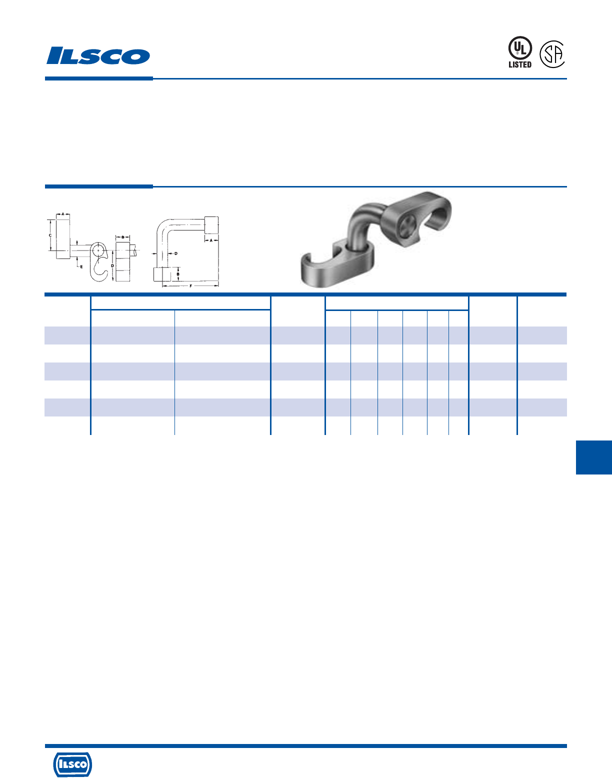
4730 Madison Road, Cincinnati, Ohio 45227-1426 Phone 513 533-6200 Fax 513 871-4084 Web site www.ilsco.com
Canada 1050 Lakeshore Road East, Mississauga, Ontario, Canada L5E1E4 Phone 905 274-2341 Fax 905 274-8763
266
H
Wire Range Dimensions A B
Catalog Rod Die Die
Number Main Tap Size A B C D E F Index Index
GGA-1 2str-6sol 2str-6sol - .75 .75 1.09 1.09 .313 2.50 O O
GGA-2 250kcmil-1str 2str-6sol 1/2, 5/8 .75 .75 1.66 1.09 .313 2.50 997 O
GGA-3 250kcmil-2str 250kcmil-2str 1/2, 5/8 .75 .75 1.66 1.66 .500 2.50 997 997
GGA-4 500kcmil-250kcmil 2str-6sol 5/8, 3/4 .75 .75 2.09 1.09 .313 2.50 998 O
GGA-5 500kcmil-250kcmil 250kcmil-2str 5/8, 3/4 .75 .75 2.09 1.66 .500 2.50 998 997
GGA-6 500kcmil-250kcmil 500kcmil-250kcmil 5/8, 3/4 .75 .75 2.28 2.28 .750 2.50 999/1011 999/1011
Grounding Grid Connectors
TYPE
GGA
Features
•
Manufactured from high strength copper alloy
•
Clearly marked with wire size and die index
•
Range taking
•
Connector can be adjusted prior to installation
•
Non-hazardous installation
•
Prefilled with inhibiting compound
•
Temp. Rating 90˚ C
Benefits
•
Provides maximum conductivity and eliminates the possibility
of corrosion. Suitable for direct burial in earth or concrete
•
Provides easy identification and tooling recommendation
•
Reduces inventory. Six sizes cover a wire range from 500kcmil
to #6, and 1/2" to 3/4" ground rods.
•
Permits adjustments to be made for misaligned cross grids
•
Can be installed in all types of weather with no need for
protective equipment or clothing. Does not produce heat or
dangerous particles.
•
Prevents oxides from forming
•
Ensures reliability
NOTE: Hydraulic tools required on all sizes except GGA-1
Dieless tools can not be used
ILC-15H or similar required for GGA-4, GGA-5 and GGA-6
Tested to UL 467, UL File E34440
667P
L
R
-
5
4
6
5
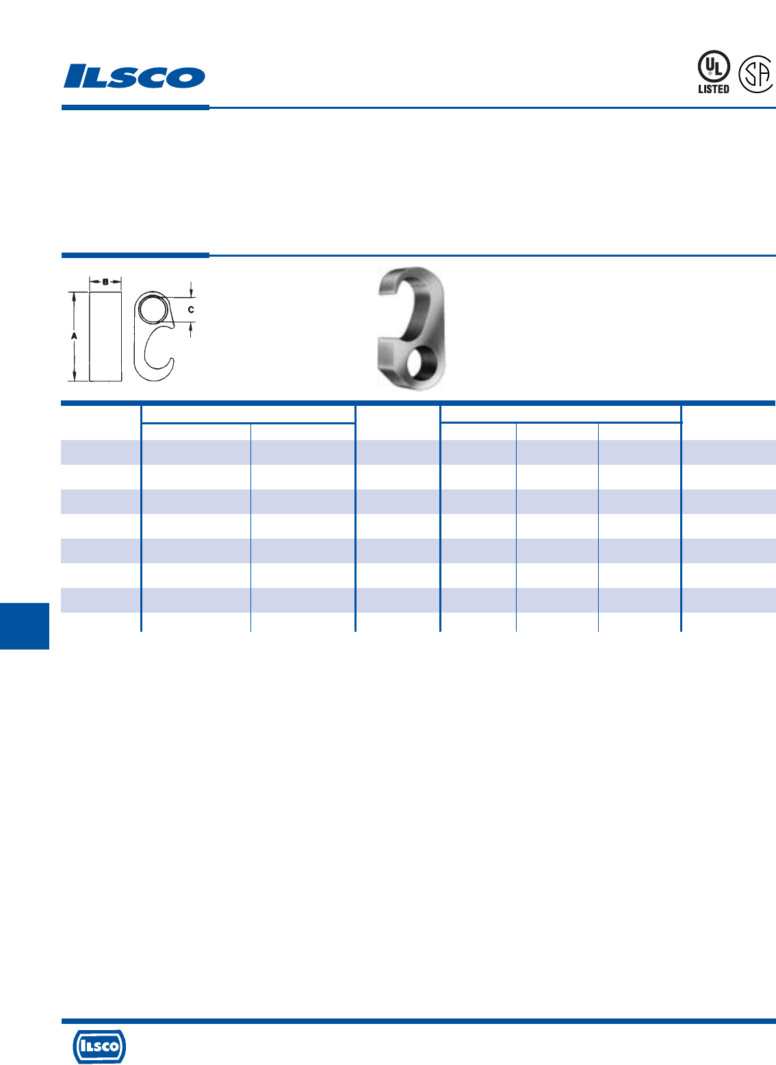
4730 Madison Road, Cincinnati, Ohio 45227-1426 Phone 513 533-6200 Fax 513 871-4084 Web site www.ilsco.com
Canada 1050 Lakeshore Road East, Mississauga, Ontario, Canada L5E1E4 Phone 905 274-2341 Fax 905 274-8763
267
H
667P
L
R
-
5
4
6
5
Catalog Wire Range Rod Dimensions
Number Main Tap Size A B C Index
GGC-1 2str-6sol 2str-6sol - 1.4 .75 .33 0
GGC-2 250kcmil-1/0str 2str-4sol 1/2, 5/8 2.1 .75 .33 997
GGC-3 250kcmil-1/0str 2/0str-1/0str 1/2, 5/8 2.1 .75 .44 997
GGC-4 250kcmil-1/0str 250kcmil-3/0str 1/2, 5/8 2.1 .75 .61 997
GGC-5 500kcmil-250kcmil 2str-4sol 5/8, 3/4 2.6 .75 .33 998
GGC-6 500kcmil-250kcmil 2/0str-1/0str 5/8, 3/4 2.6 .75 .44 998
GGC-7 500kcmil-250kcmil 250kcmil-3/0str 5/8, 3/4 2.6 .75 .61 998
GGC-8 500kcmil-250kcmil 500kcmil-350kcmil 5/8, 3/4 2.9 .75 .84 999/1011
Grounding Grid Connectors
TYPE
GGC
Features
•
Manufactured from high strength copper alloy
•
Clearly marked with wire size and die index
•
Range taking
•
Versatile
•
Non-hazardous installation
•
Prefilled with inhibiting compound
•
Temp. Rating 90˚ C
Benefits
•
Provides maximum conductivity and eliminates the possibility
of corrosion. Suitable for direct burial in earth or concrete
•
Provides easy identification and tooling recommendation
•
Reduces inventory. Eight sizes cover a wire range from
500kcmil to #6, and 1/2" to 3/4" ground rods.
•
Can be used as a tap connector or as a lap splice connector
•
Can be installed in all types of weather with no need for
protective equipment or clothing. Does not produce heat or
dangerous particles.
•
Prevents oxides from forming
•
Ensures reliability
NOTE: Hydraulic tools required on all sizes except GGC-1
Dieless tools can not be used
ILC-15H or similar required for GGC-5, GGC-6, GGC-7 and GGC-8
Tested to UL 467, UL File E34440
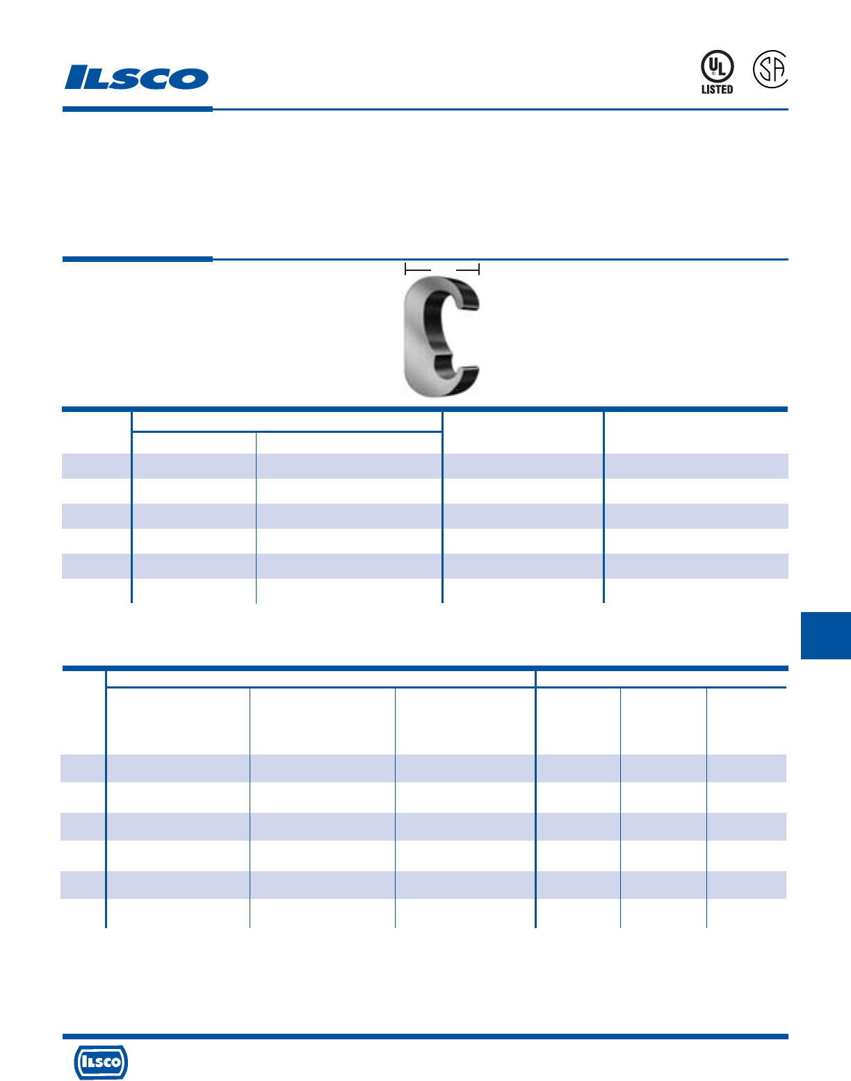
4730 Madison Road, Cincinnati, Ohio 45227-1426 Phone 513 533-6200 Fax 513 871-4084 Web site www.ilsco.com
Canada 1050 Lakeshore Road East, Mississauga, Ontario, Canada L5E1E4 Phone 905 274-2341 Fax 905 274-8763
268
H
W
ILSCO Burndy
ILC-12H-N ILCB-12-N ILC-15H Y-35 Y-45 Y-46
ILC-12-N
Die No. Die No. Die No.
Die Index Die Index Die Index
Catalog No. of No. of No. of No. of No. of No. of
Number Crimps Crimps Crimps Crimps Crimps Crimps
ELT-1 ILD-C ILD-C - C (U Type) C (U Type) C (U Type)
(1) (1) - (1) (1) (1)
ELT-4 ILD-O ILD-O - O (U Type) O (U Type) O (U Type)
(1) (1) - (1) (1) (1)
ELT-2 ILD-O ILD-O - O (U Type) O (U Type) O (U Type)
(1) (1) - (1) (1) (1)
ELT-5 ILD-U997 ILD-U997 - 997 (U Type) 997 (U Type) 997 (U Type)
(1) (1) - (1) (1) (1)
ELT-3 ILD-U997 ILD-U997 - 997 (U Type) 997 (U Type) 997 (U Type)
(1) (1) - (1) (1) (1)
ELT-6 - - ILD-P1011 - 1011 (U Type) 1011 (U Type)
- - (2) - (2) (1)
Copper E Crimps
Grounding Connectors
TYPE
ELT
Features
•
Manufactured from copper alloy
•
Clearly marked with wire size and die index
•
Range taking
•
UL Listed and CSA Certified for grounding and bonding,
rated for 600 volts
•
May be used in ground grid applications
Benefits
•
Provides maximum conductivity and eliminates the
possibility of corrosion. Suitable for direct burial in earth
or concrete
•
Provides easy identification and tooling
recommendation
•
Reduces inventory
•
Ensures reliability
•
Flexibility in application
A
P
-
5
4
6
5
Copper Wire Range
Catalog Die
Number Main Tap W Index
ELT-1 2str-6sol 2str-6sol .75 C (U Type)
ELT-4 2/0str-1str 2str-6str .75 0 (U Type)
ELT-2 2/0str-1str 2/0str-1str .75 0 (U Type)
ELT-5 250kcmil-3/0str 2/0str-6sol .75 997 (U Type)
ELT-3 250kcmil-3/0str 250kcmil-3/0str .900 997 (U Type)
ELT-6 500kcmil-300kcmil 250kcmil-3/0str .875 1011 (U Type)
Tooling Information
667P
See stuffer sheet for complete information on tooling.
Tested to UL 467, UL File E34440
H
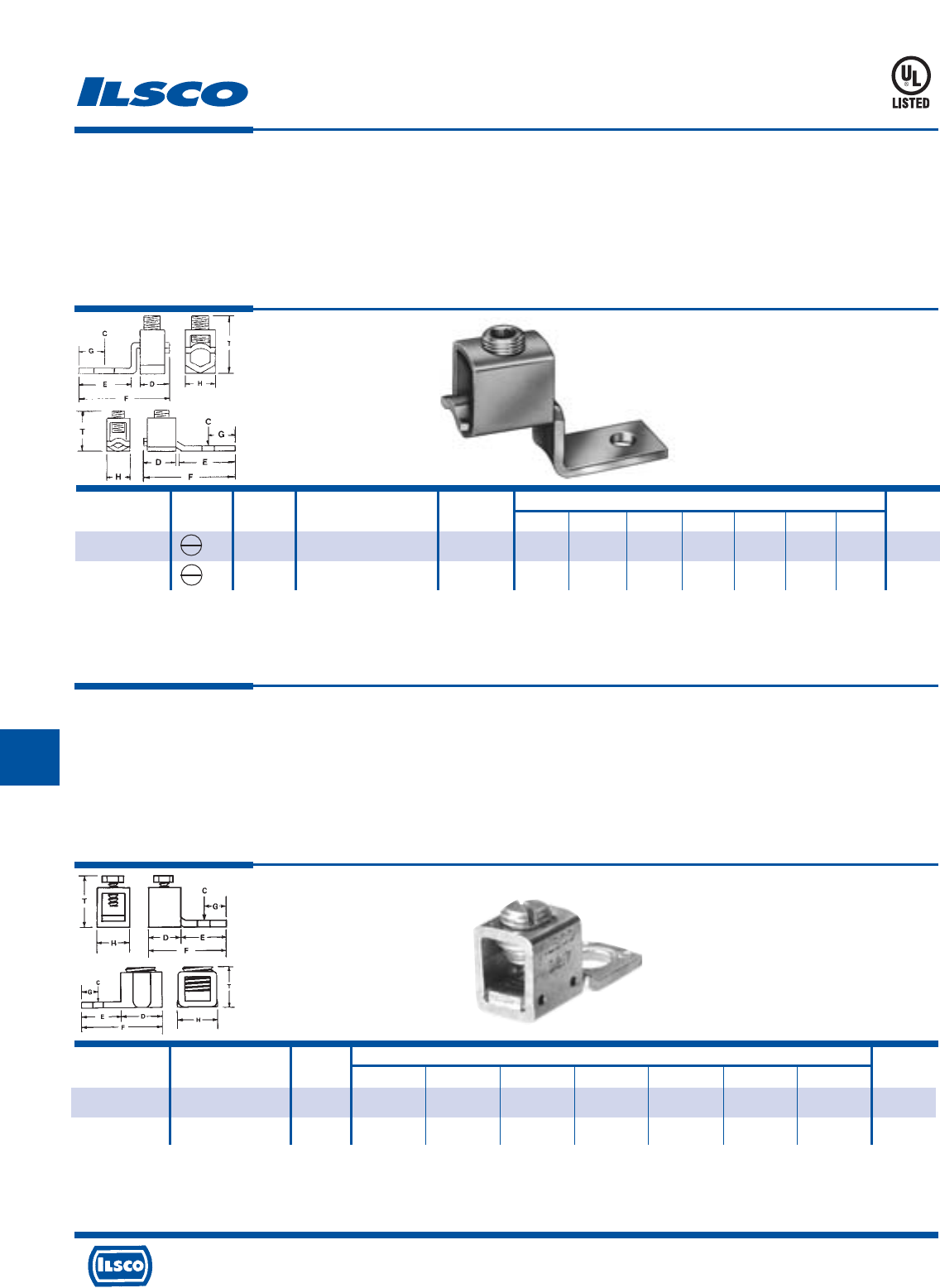
4730 Madison Road, Cincinnati, Ohio 45227-1426 Phone 513 533-6200 Fax 513 871-4084 Web site www.ilsco.com
Canada 1050 Lakeshore Road East, Mississauga, Ontario, Canada L5E1E4 Phone 905 274-2341 Fax 905 274-8763
269
HH
Direct Burial Copper Mechanical Lugs
TYPE
SLU
Features
•
Manufactured from electrolytic copper tubing and strip
stock
•
Compact design
•
Range taking
•
Re-usable
•
UL Listed
•
V-bottom collar
Benefits
•
Provides maximum conductivity and strength
•
Saves space and reduces installation time
•
Permits inventories to be kept to a minimum
•
Provides efficient use and flexibility in the field
•
Ensures reliability
•
Wires are wedged between arched pressure bar and collar
establishing positive contact and firm permanent grip
Catalog Screw Figure Wire Range Bolt Dimensions Hex
Number Type Number Copper Size C D E F G H T Size
SLU-35DB* 1 6-14 & List Comb. (A) #10 13/64 7/16 15/32 1-3/16 7/32 3/8 3/4 S
SLU-70DB* 1 2-8 & List Comb. (B) 1/4 17/64 1/2 21/32 1-17/32 1/4 1/2 1 S
(A) UL Listed wire combinations: (2) 14; (2) 12; (2) 10; (2) 8 and (4) 16
(B) UL Listed wire combinations: (2) 6 and (2) 8
Tested to UL 467, UL File E34440
667P
Catalog Wire Bolt Dimensions Hex
Number Range Size C D E F G H T Size
XT-6DB* 6-18 #10 13/64 3/8 17/32 1 7/32 3/8 3/4 Slot
XT-4DB*
4-14 & List Comb. (A)
1/4 17/64 1/2 5/8 1-1/8 1/4 1/2 5/8 Slot
TYPE
XT
Features
•
Manufactured from electrolytic copper tubing and strip
stock
•
Compact design
•
Range taking
•
Re-usable
•
UL Listed, rated for 600 volts
Benefits
•
Provides maximum conductivity and strength
•
Saves space and reduces installation time.
•
Permits inventories to be kept to a minimum
•
Provides efficient use and flexibility in the field
•
Ensures reliability
(A) UL Listed wire combinations: (2) 14; (2) 12; (2) 10; (2) 8 and (4) 16
Tested to UL 467, UL File E34440
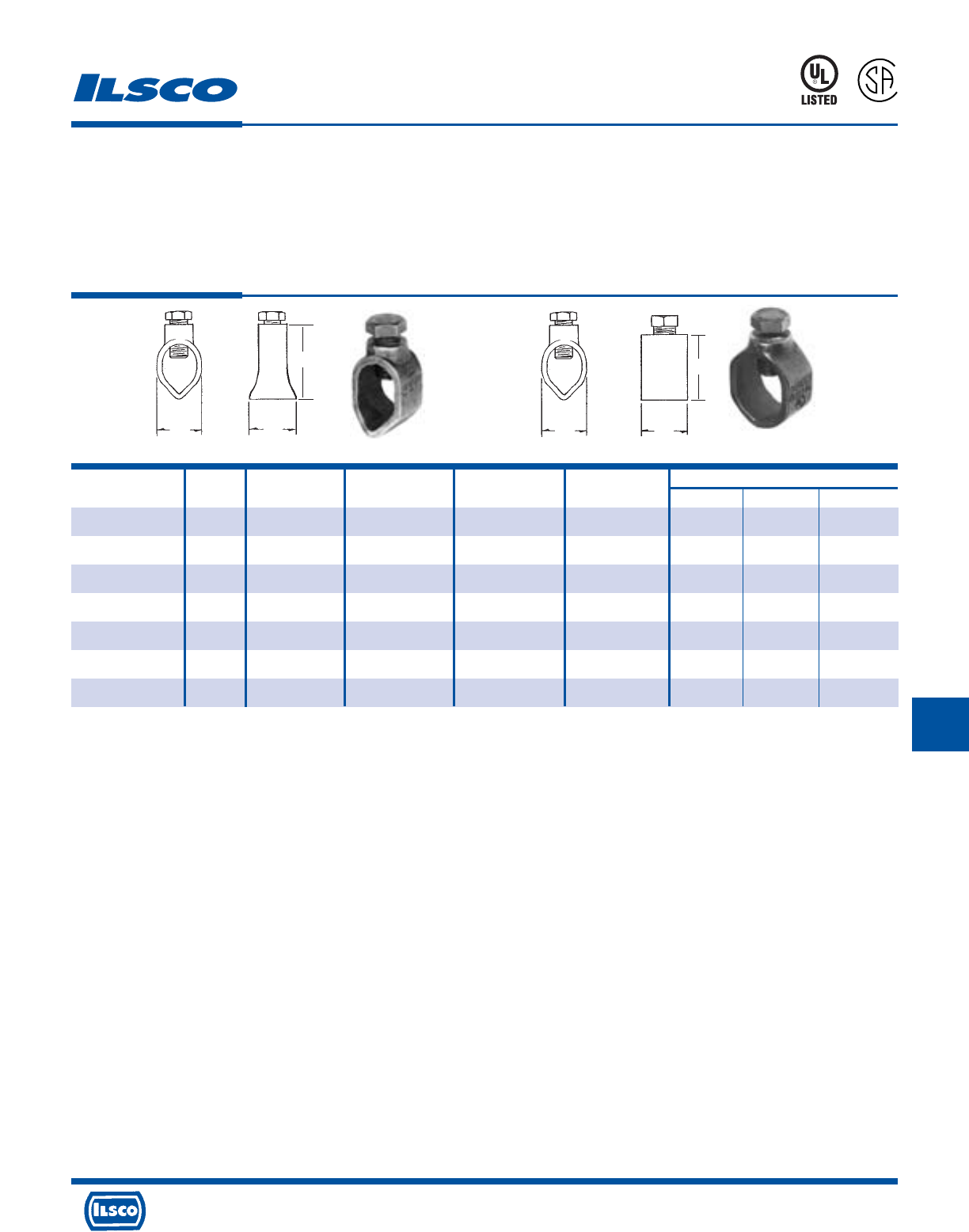
4730 Madison Road, Cincinnati, Ohio 45227-1426 Phone 513 533-6200 Fax 513 871-4084 Web site www.ilsco.com
Canada 1050 Lakeshore Road East, Mississauga, Ontario, Canada L5E1E4 Phone 905 274-2341 Fax 905 274-8763
270
HH
Catalog Figure Ground Rod Ground Rod Rebar Rebar Dimensions
Number Number Size Wire Range Size Wire Range L W H
BGRC-48 1 1/2 2-10 - - 7/8 3/4 1-1/4
BGRC-58 1 5/8 1/0-8 #5 1/0-8 1-1/32 29/32 1-13/32
BGRC-68 1 3/4 1/0-8 - - 1 1 1-5/8
CGRC-38* 2 3/8 4-10 #3 4-10 1/2 11/16 1
CGRC-48* 2 1/2 2-10 #4 2-10 9/16 27/32 1-3/16
CGRC-58* 2 5/8 2-10 #5 4-10 9/16 15/16 1-9/32
CGRC-68* 2 3/4 2-10 #6 4-10 9/16 1-1/16 1-9/32
Cast Bronze Ground Rod Clamps
TYPE
BGRC
CGRC
Features
•
Manufactured from cast bronze
•
Supplied with stainless steel or silicone bronze
hardware
•
UL Listed and CSA Certified for 600 volts
Benefits
•
Insures maximum strength and durability
•
Suitable for direct burial in earth or concrete
•
Ensures reliability
667P
WL
L
R
-
2
9
6
0
1
* Plain copper finish.
Tested to UL 467, UL File E34440
L
W
Fig. 1 Fig. 2
HH
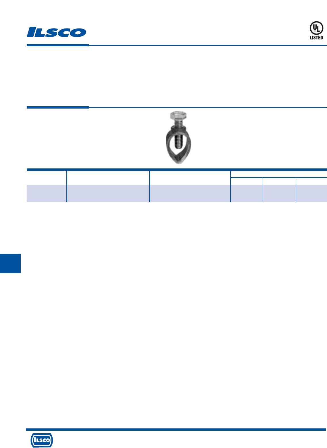
4730 Madison Road, Cincinnati, Ohio 45227-1426 Phone 513 533-6200 Fax 513 871-4084 Web site www.ilsco.com
Canada 1050 Lakeshore Road East, Mississauga, Ontario, Canada L5E1E4 Phone 905 274-2341 Fax 905 274-8763
271
H
Cast Bronze Ground Rod Clamp
TYPE
SRC
Features
•
Manufactured from bronze alloy
•
Stainless steel bolt
•
UL Listed for both copper clad and galvanized ground
rods
•
Range taking
Benefits
•
Provides maximum strength and superior conductivity
•
For direct burial
•
Ensures reliability
•
Reduces inventory requirement
Catalog Ground Rod Ground Rod Dimensions
Number Size Wire Range L W H
SRC-1/0 3/8, 1/2, 5/8 10 sol - 1/0 str 13/16 1 1-1/2
3/4 8 sol - 1/0 str
UL File E198108
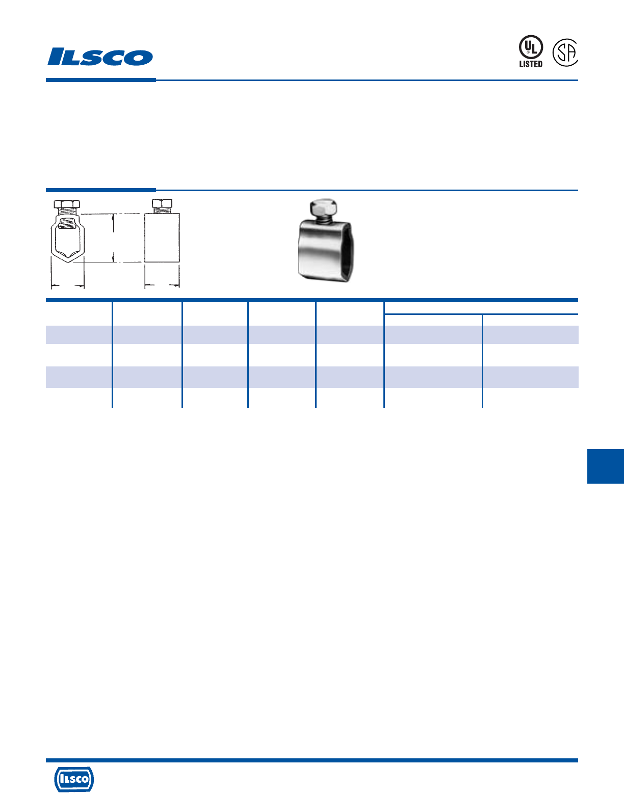
4730 Madison Road, Cincinnati, Ohio 45227-1426 Phone 513 533-6200 Fax 513 871-4084 Web site www.ilsco.com
Canada 1050 Lakeshore Road East, Mississauga, Ontario, Canada L5E1E4 Phone 905 274-2341 Fax 905 274-8763
272
H
Catalog Ground Ground Wire Rebar Rebar Dimensions
Number Rod Size Range Size Wire Range L W
GRC-38 3/8 4-10 #3 4-10 5/8 5/8
GRC-58+ 5/8 2-8 - - 15/16 7/8
GRC-68 3/4, 5/8 2-8 for 3/4 rod, #5 1/0-8 1 1
1/0-8 for 5/8 rod
GRC-75* 3/4 3/0-8 - - 3/4 1-5/32
Ground Rod Clamps
TYPE
GRC
Features
•
Manufactured from seamless bronze tubing
•
Supplied with silicon bronze screw
•
UL Listed and CSA Certified for 600 volts except
GRC-75
•
Suitable for grounding and bonding in applications such
as swimming pools and spas
Benefits
•
Provides maximum strength and superior conductivity
•
Ground rod clamp is suitable for direct burial in earth or
concrete
•
Ensures reliability for copper conductor
Plain copper finish.
+ REA Listed.
* Not UL Listed
Tested to UL 467, UL File E34440
L
R
-
2
9
6
0
1
667P
W
L
H
H
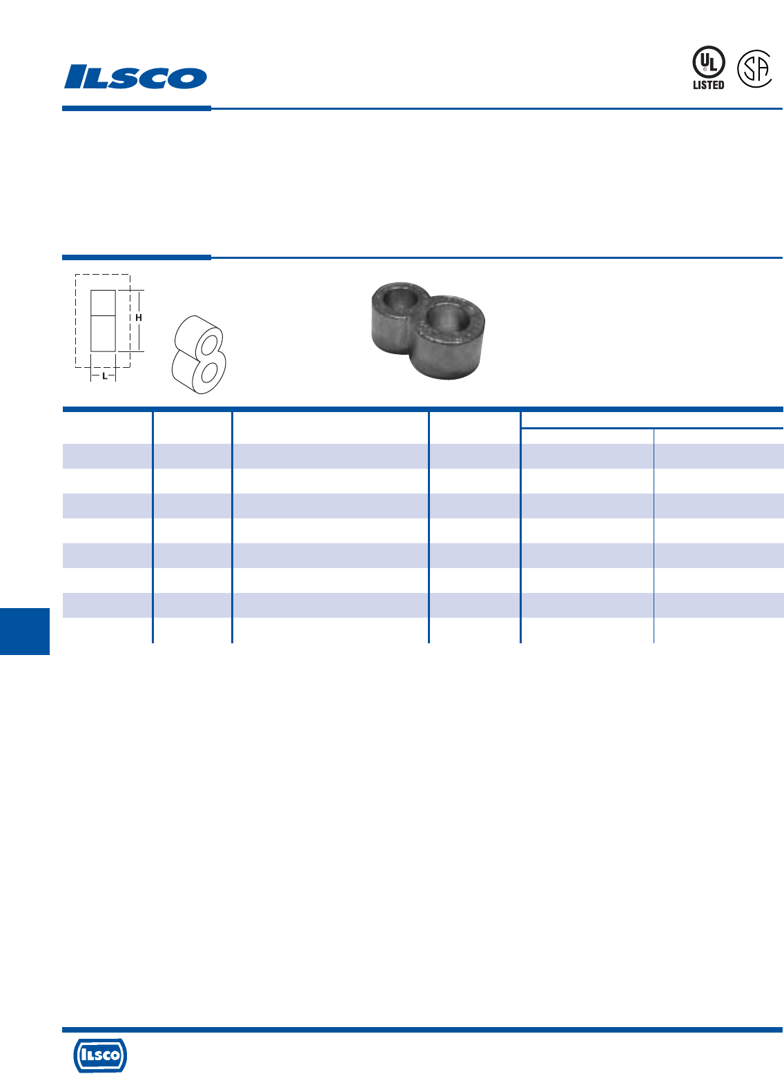
4730 Madison Road, Cincinnati, Ohio 45227-1426 Phone 513 533-6200 Fax 513 871-4084 Web site www.ilsco.com
Canada 1050 Lakeshore Road East, Mississauga, Ontario, Canada L5E1E4 Phone 905 274-2341 Fax 905 274-8763
273
HH
Grounding Connectors
For Copper Conductor Only
TYPE
RLT
Features
•
Prefilled with oxide inhibitor and bagged
•
Clearly marked with wire size and die index
•
UL Listed for 600 Volts and CSA Certified for
direct burial in earth or concrete
•
Range taking
•
Manufactured from high strength copper alloy
Benefits
•
Prevents oxides from forming
•
Provides easy identification and tooling recommendation
•
Ensures reliability
•
Reduces inventory. Eight sizes cover a wire range
of #2-500kcmil
•
Provides maximum conductivity and eliminates the possibility
of corrosion
Catalog Ground Wire Die Dimensions
Number Rod Size Range Index H L
RLT-2 1/2 2 (.292 Dia.) - 2/0 (.419 Dia.) 998/1011 1.94 .88
RLT-3 5/8 2 (.292 Dia.) - 2/0 (.419 Dia.) 998/1011 1.97 .88
RLT-4 3/4 2 (.292 Dia.) - 2/0 (.419 Dia.) 998/1011 2.19 .88
RLT-5 1/2 4/0 (.528 Dia.) - 250kcmil (.575 Dia.) 998/1011 1.94 .88
RLT-6 5/8 4/0 (.528 Dia.) - 250kcmil (.575 Dia.) 998/1011 2.14 .88
RLT-7 3/4 4/0 (.528 Dia.) - 250kcmil (.575 Dia.) 998/1011 2.19 .88
RLT-8 5/8 300kcmil (.630 Dia.) - 500kcmil (.813 Dia.) 998/1011 2.14 .88
RLT-9 3/4 300kcmil (.630 Dia.) - 500kcmil (.813 Dia.) 998/1011 2.44 .88
L
667P
UL File E158587
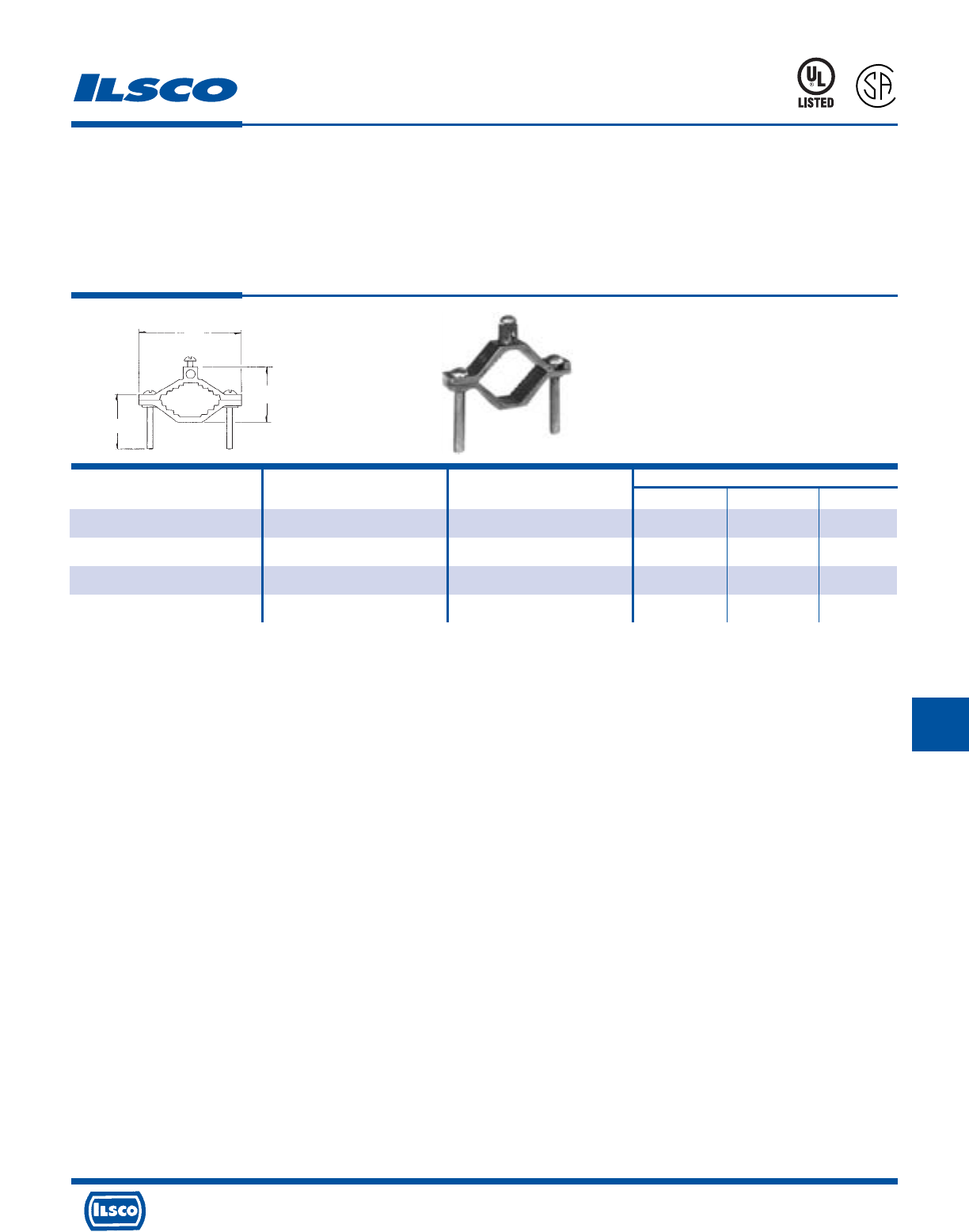
4730 Madison Road, Cincinnati, Ohio 45227-1426 Phone 513 533-6200 Fax 513 871-4084 Web site www.ilsco.com
Canada 1050 Lakeshore Road East, Mississauga, Ontario, Canada L5E1E4 Phone 905 274-2341 Fax 905 274-8763
274
HH
Catalog Pipe Ground Wire Dimensions
Number Size Range L W H
BGC-1 1/2, 3/4, 1 2-10 2-9/32 2-17/32 1-1/2
BGC-2 1-1/4, 1-1/2, 2 2-10 3-9/16 2-1/4 2
BGC-1DB* 1/2, 3/4, 1 2-10 2-9/32 2-17/32 1-1/2
BGC-2DB* 1-1/4, 1-1/2, 2 2-10 3-8/16 2-1/4 2
Cast Brass Ground Clamp
TYPE
BGC
Features
•
Manufactured from cast brass
•
UL Listed and CSA Certified for 600 volts
•
Type BGC-DB supplied with stainless steel or silicone
bronze hardware
Benefits
•
Provides maximum conductivity and strength
•
Ensures reliability for copper conductor
•
BGC-1DB and BGC-2DB are suitable for direct burial in
earth or concrete. Can be used to ground swimming pools
and spas.
* Suitable for direct burial in earth or concrete. UL467
UL File E158587
L
H
W
8M24
L
R
-
7
0
1
5
7
0
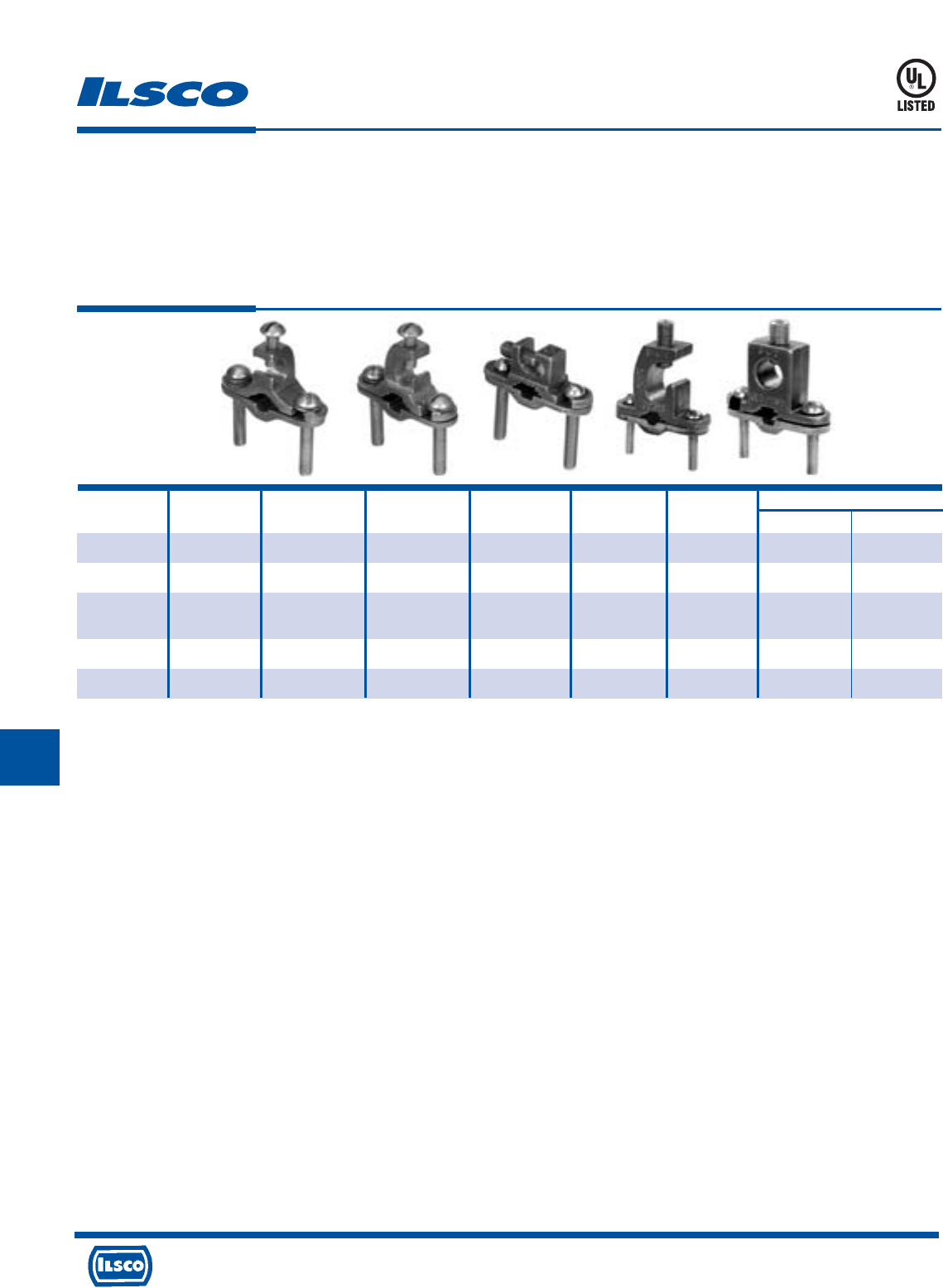
4730 Madison Road, Cincinnati, Ohio 45227-1426 Phone 513 533-6200 Fax 513 871-4084 Web site www.ilsco.com
Canada 1050 Lakeshore Road East, Mississauga, Ontario, Canada L5E1E4 Phone 905 274-2341 Fax 905 274-8763
275
H
Catalog Figure Pipe Rebar Ground Rod Ground Screw Dimensions
Number Number Size Size Size Wire Range Material L W
BGC-2T-DB* 1 1/2-1 3/8-1 1/2-1 2str-10sol silicon bronze 2-3/4 2-1/4
BGC-2P-DB* 2 1/2-1 3/8-1 1/2-1 2str-10sol silicon bronze 2-3/4 2-1/4
BGC-2PS-DB+ 3 1/2-1 3/8-1 1/4-1 2str-10sol stainless steel 2-1/4 2-1/4
2 #8sol
BGC-4/0P-DB= 4 1/2-1 3/8-1 1/2-1 4/0-8str stainless steel 3 2-1/4
BGC-4/0S-DB= 5 1/2-1 3/8-1 1/2-1 4/0-8str stainless steel 2-3/4 2-1/4
Cast Bronze Ground Clamps
TYPE
BGDB
Features
•
Manufactured from bronze alloy
•
UL Listed for direct burial in earth or concrete
•
Lay-In feature
Benefits
•
Ensures maximum strength and superior conductivity
•
Ensures reliability
•
Reduces installation time
* UL File E207816
+ UL File E198108
= UL File E178441
Fig. 1 Fig. 2 Fig. 3 Fig. 4 Fig. 5
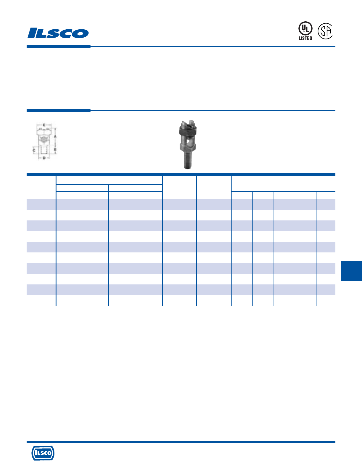
4730 Madison Road, Cincinnati, Ohio 45227-1426 Phone 513 533-6200 Fax 513 871-4084 Web site www.ilsco.com
Canada 1050 Lakeshore Road East, Mississauga, Ontario, Canada L5E1E4 Phone 905 274-2341 Fax 905 274-8763
276
HH
Conductor Range AWG MM 2
Maximum
Catalog Stranded Solid Diameter Dimensions
Number Max. Min. Max. Min. Range Stud Size A B C D E
SPSS-0 8 12 (4mm
2
) 8 (10mm
2
) 12 (4mm
2
) .146-.080 1/4-20 x 1/2 11/16 1/2 55/64 15/32 1/2
SPSS-1 7 (10mm
2
) 10 (6mm
2
) 6 (10mm
2
) 10 (6mm
2
) .170-.102 1/4-20 x 1/2 13/16 1/2 55/64 15/32 21/32
SPSS-2 5 (16mm
2
) 10 (6mm
2
) 4 (16mm
2
) 10 (6mm
2
) .217-.102 5/16-18 x 5/8 15/16 5/8 53/64 17/32 23/32
SPSS-3 3 (25mm
2
) 10 (6mm
2
) 2 (35mm
2
) 10 (6mm
2
) .271-.102 3/8-16 x 5/8 1/2 5/8 61/64 5/8 25/32
SPSS-4 1 (35mm
2
)8 (6mm
2
) 2 (35mm
2
) 8 (10mm
2
) .332-.128 3/8-16 x 5/8 1-1/16 5/8 61/64 11/16 7/8
SPSS-5 1/0 (50mm
2
) 2 (35mm
2
) 2 (35mm
2
) – .385-.258 1/2-13 x 3/4 1-1/4 3/4 1-5/64 3/4 15/16
SPSS-6 2/0 (70mm
2
) 2 (35mm
2
) 2 (35mm
2
) – .443-.258 1/2-13 x 3/4 1-13/32 3/4 1-5/64 7/8 1-1/16
SPSS-8 4/0 (95mm
2
) 1 (35mm
2
) – – .570-.289 5/8-11 x 1 1-9/16 1 1-19/64 1 1-5/16
SPSS-9 350 (150mm
2
) 1/0 (70mm
2
) – – .715-.373 5/8-11 x 1 2 1-1/4 1-19/64 1-5/16 1-11/16
SPSS-10 500 (240mm
2
) 3/0 (95mm
2
) – – .840-.464 3/4-10 x 1-1/4 2-1/4 1-3/4 1-31/64 1-1/2 1-7/8
Bronze, Service Post Connectors
Single Conductor Type - Short Stud, Male
TYPE
SPS
Features
•
Range taking
•
Re-usable
•
UL 486A and UL 467 Listed
•
For grounding of steel structures, fence posts and
tapping cables from bus bar
•
For copper to copper connections
Benefits
•
Permits inventories to be kept to a minimum
•
Provides efficient use and flexibility in the field
•
Ensures reliability
•
Flexibility in the field
UL File E158587
8M24
A
P
-
1
0
0
9
7
3
-
1
H
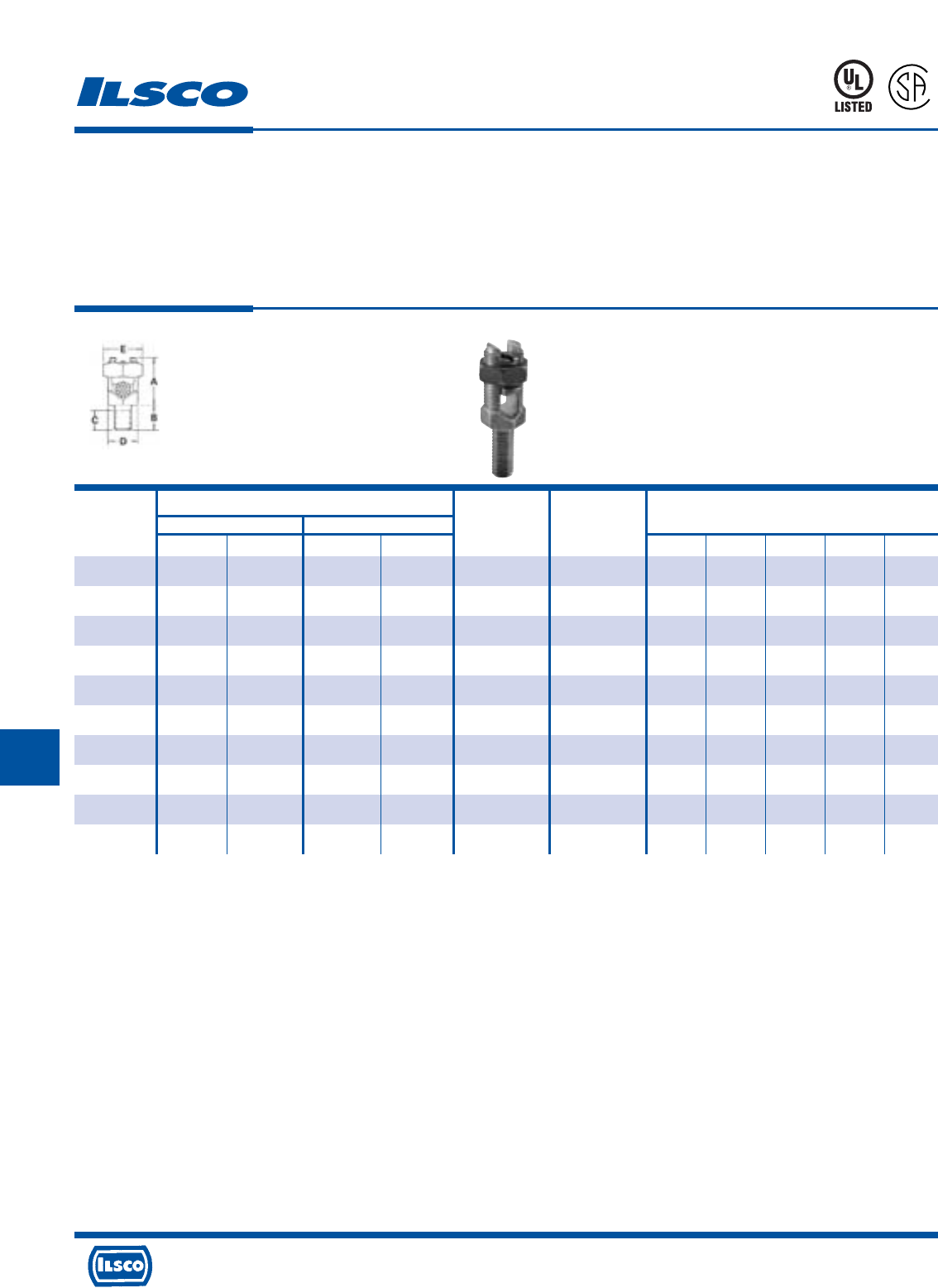
4730 Madison Road, Cincinnati, Ohio 45227-1426 Phone 513 533-6200 Fax 513 871-4084 Web site www.ilsco.com
Canada 1050 Lakeshore Road East, Mississauga, Ontario, Canada L5E1E4 Phone 905 274-2341 Fax 905 274-8763
277
HHH
Conductor Range AWG MM 2
Maximum
Catalog Stranded Solid Diameter Dimensions
Number Max. Min. Max. Min. Range Stud Size A B C D E
SPSL-0 8 12 (4mm
2
) 8 (10mm
2
) 12 (4mm
2
) .146-.080 1/4-20 x 1 11/16 1 55/64 15/32 1/2
SPSL-1 7 (10mm
2
) 10 (6mm
2
) 6 (10mm
2
) 10 (6mm
2
) .170-.102 1/4-20 x 1 13/16 1 55/64 15/32 21/32
SPSL-2 5 (16mm
2
) 10 (6mm
2
) 4 (16mm
2
) 10 (6mm
2
) .217-.102 5/16-18 x 1 15/16 1 53/64 17/32 23/32
SPSL-3 3 (25mm
2
) 10 (6mm
2
) 2 (35mm
2
) 10 (6mm
2
) .271-.102 3/8-16 x 1-1/8 1/2 1-1/8 61/64 5/8 25/32
SPSL-4 1 (35mm
2
)8 (6mm
2
) 2 (35mm
2
) 8 (10mm
2
) .332-.128 3/8-16 x 1-1/8 1-1/16 1-1/8 61/64 11/16 7/8
SPSL-5 1/0 (50mm
2
) 2 (35mm
2
) 2 (35mm
2
) – .385-.258 1/2-13 x 1-1/4 1-1/4 1-1/4 1-5/64 3/4 15/16
SPSL-6 2/0 (70mm
2
) 2 (35mm
2
) 2 (35mm
2
) – .443-.258 1/2-13 x 1-1/4 1-13/32 1-1/4 1-5/64 7/8 1-1/16
SPSL-8 4/0 (95mm
2
) 1 (35mm
2
) – – .570-.289 5/8-11 x 1-1/2 1-9/16 1-1/2 1-19/64 1 1-5/16
SPSL-9 350 (150mm
2
) 1/0 (70mm
2
) – – .715-.373 5/8-11 x 1-1/2 2 1-1/2 1-19/64 1-5/16 1-11/16
SPSL-10 500 (240mm
2
) 3/0 (95mm
2
) – – .840-.464 3/4-10 x 1-3/4 2-1/4 1-1/2 1-31/64 1-1/2 1-7/8
Bronze, Service Post Connectors
Single Conductor Type - Long Stud, Male
TYPE
SPS
Features
•
Range taking
•
Re-usable
•
UL 486A and UL 467 Listed
•
For grounding of steel structures, fence posts and
tapping cables from bus bar
•
For copper to copper connections
Benefits
•
Permits inventories to be kept to a minimum
•
Provides efficient use and flexibility in the field
•
Ensures reliability
•
Flexibility in the field
UL File E158587
8M24
A
P
-
1
0
0
9
7
3
-
1
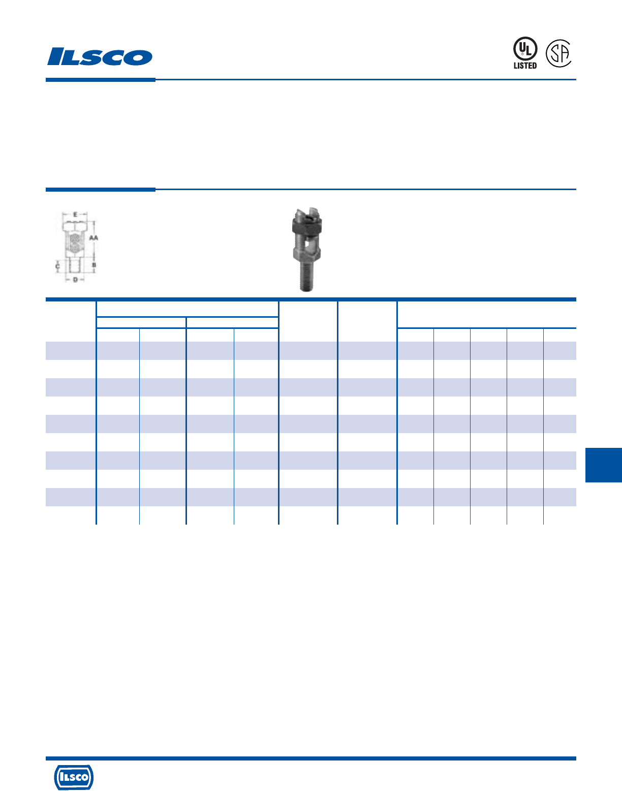
4730 Madison Road, Cincinnati, Ohio 45227-1426 Phone 513 533-6200 Fax 513 871-4084 Web site www.ilsco.com
Canada 1050 Lakeshore Road East, Mississauga, Ontario, Canada L5E1E4 Phone 905 274-2341 Fax 905 274-8763
278
HHH
Conductor Range AWG MM 2
Maximum
Catalog Stranded Solid Diameter Dimensions
Number Max. Min. Max. Min. Range Stud Size AA B C D E
SPDS-0 8 12 (4mm
2
) 8 (10mm
2
) 12 (4mm
2
) .146-.080 1/4-20 x 1/2 13/16 1/2 55/64 15/32 1/2
SPDS-1 7 (10mm
2
) 10 (6mm
2
) 6 (10mm
2
) 10 (6mm
2
) .170-.102 1/4-20 x 1/2 31/32 1/2 55/64 15/32 21/32
SPDS-2 5 (16mm
2
) 10 (6mm
2
) 4 (16mm
2
) 10 (6mm
2
) .217-.102 5/16-18 x 5/8 1-1/8 5/8 53/64 17/32 23/32
SPDS-3 3 (25mm
2
) 10 (6mm
2
) 2 (35mm
2
) 10 (6mm
2
) .271-.102 3/8-16 x 5/8 1-1/4 5/8 61/64 5/8 25/32
SPDS-4 1 (35mm
2
)8 (6mm
2
) 2 (35mm
2
) 8 (10mm
2
) .332-.128 3/8-16 x 5/8 1-3/8 5/8 61/64 11/16 7/8
SPDS-5 1/0 (50mm
2
) 2 (35mm
2
) 2 (35mm
2
) – .385-.258 1/2-13 x 3/4 1-19/32 3/4 1-5/64 3/4 15/16
SPDS-6 2/0 (70mm
2
) 2 (35mm
2
) 2 (35mm
2
) – .443-.258 1/2-13 x 3/4 1-13/16 3/4 1-5/64 7/8 1-1/16
SPDS-8 4/0 (95mm
2
) 1 (35mm
2
) – – .570-.289 5/8-11 x 1 2-1/16 1 1-19/64 1 1-5/16
SPDS-9 350 (150mm
2
) 1/0 (70mm
2
) – – .715-.373 5/8-11 x 1 2-3/4 1-1/4 1-19/64 1-5/16 1-11/16
SPDS-10 500 (240mm
2
) 3/0 (95mm
2
) – – .840-.464 3/4-10 x 1-1/4 3-1/8 1-3/4 1-31/64 1-1/2 1-7/8
Bronze, Service Post Connectors
Double Conductor Type - Short Stud, Male
TYPE
SPD
Features
•
Range taking
•
Re-usable
•
UL 486A and UL 467 Listed
•
For grounding of steel structures, fence posts and
tapping cables from bus bar
•
For copper to copper connections
Benefits
•
Permits inventories to be kept to a minimum
•
Provides efficient use and flexibility in the field
•
Ensures reliability
•
Flexibility in the field
UL File E158587
8M24
A
P
-
1
0
0
9
7
3
-
1
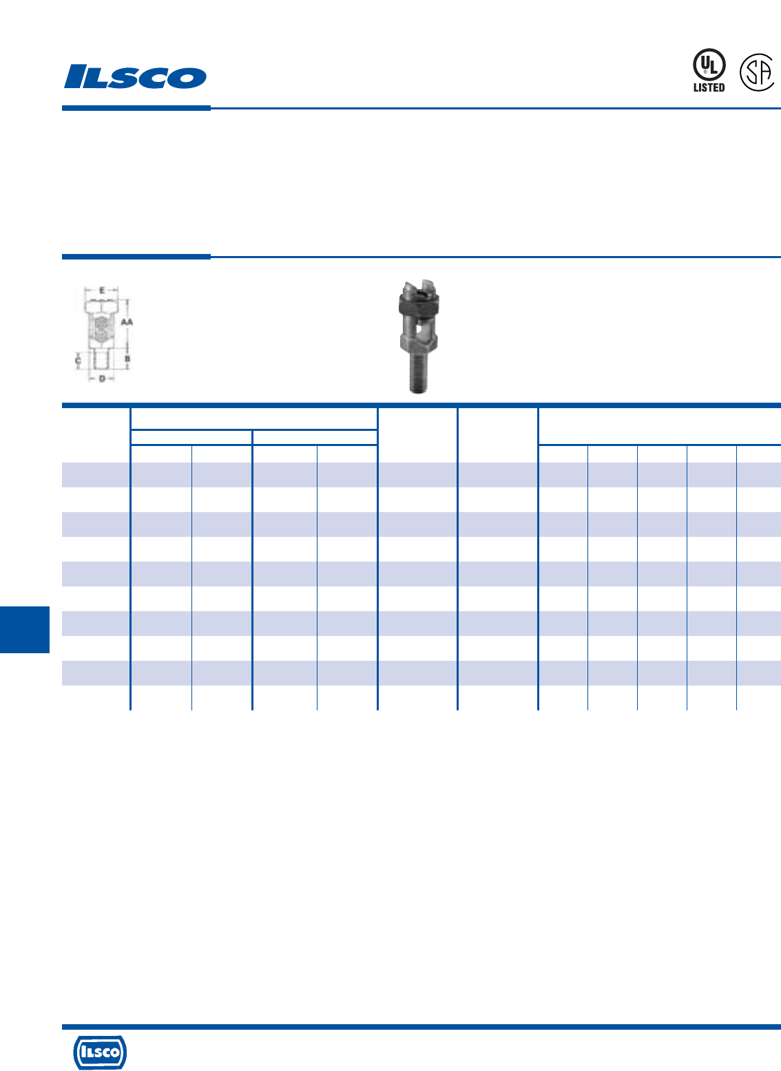
4730 Madison Road, Cincinnati, Ohio 45227-1426 Phone 513 533-6200 Fax 513 871-4084 Web site www.ilsco.com
Canada 1050 Lakeshore Road East, Mississauga, Ontario, Canada L5E1E4 Phone 905 274-2341 Fax 905 274-8763
279
HHH
Conductor Range AWG MM 2
Maximum
Catalog Stranded Solid Diameter Dimensions
Number Max. Min. Max. Min. Range Stud Size AA B C D E
SPDL-0 8 12 (4mm
2
) 8 (10mm
2
) 12 (4mm
2
) .146-.080 1/4-20 x 1 13/16 1 55/64 15/32 1/2
SPDL-1 7 (10mm
2
) 10 (6mm
2
) 6 (10mm
2
) 10 (6mm
2
) .170-.102 1/4-20 x 1 31/32 1 55/64 15/32 21/32
SPDL-2 5 (16mm
2
) 10 (6mm
2
) 4 (16mm
2
) 10 (6mm
2
) .217-.102 5/16-18 x 1 1-1/8 1 53/64 17/32 23/32
SPDL-3 3 (25mm
2
) 10 (6mm
2
) 2 (35mm
2
) 10 (6mm
2
) .271-.102 3/8-16 x 1-1/8 1-1/4 1-1/8 61/64 5/8 25/32
SPDL-4 1 (35mm
2
)8 (6mm
2
) 2 (35mm
2
) 8 (10mm
2
) .332-.128 3/8-16 x 1-1/8 1-3/8 1-1/8 61/64 11/16 7/8
SPDL-5 1/0 (50mm
2
) 2 (35mm
2
) 2 (35mm
2
) – .385-.258 1/2-13 x 1-1/4 1-19/32 1-1/4 1-5/64 3/4 15/16
SPDL-6 2/0 (70mm
2
) 2 (35mm
2
) 2 (35mm
2
) – .443-.258 1/2-13 x 1-1/4 1-13/16 1-1/4 1-5/64 7/8 1-1/16
SPDL-8 4/0 (95mm
2
) 1 (35mm
2
) – – .570-.289 5/8-11 x 1-1/2 2-1/16 1-1/2 1-19/64 1 1-5/16
SPDL-9 350 (150mm
2
) 1/0 (70mm
2
) – – .715-.373 5/8-11 x 1-1/2 2-3/4 1-1/2 1-19/64 1-5/16 1-11/16
SPDL-10 500 (240mm
2
) 3/0 (95mm
2
) – – .840-.464 3/4-10 x 1-3/4 3-1/8 1-1/2 1-31/64 1-1/2 1-7/8
Bronze, Service Post Connectors
Double Conductor Type - Long Stud, Male
TYPE
SPD
Features
•
Range taking
•
Re-usable
•
UL 486A and UL 467 Listed
•
For grounding of steel structures, fence posts and
tapping cables from bus bar
•
For copper to copper connections
Benefits
•
Permits inventories to be kept to a minimum
•
Provides efficient use and flexibility in the field
•
Ensures reliability
•
Flexibility in the field
UL File E158587
8M24
A
P
-
1
0
0
9
7
3
-
1
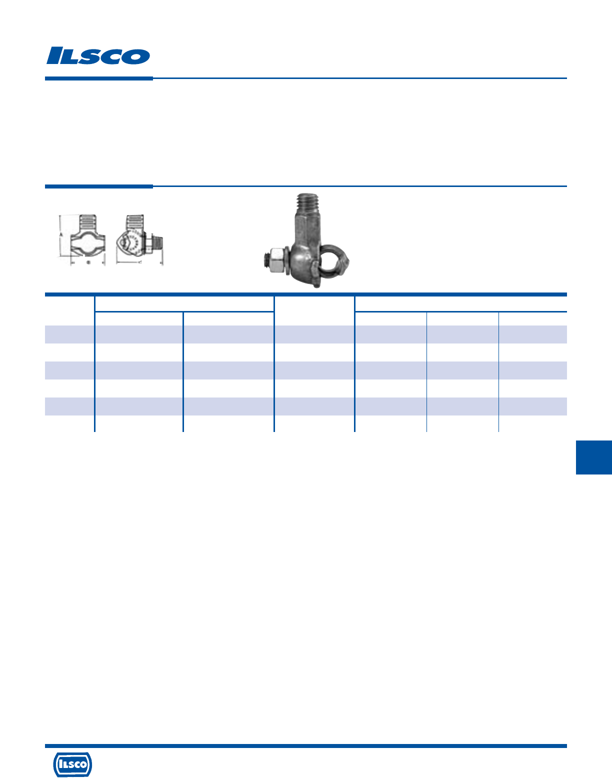
4730 Madison Road, Cincinnati, Ohio 45227-1426 Phone 513 533-6200 Fax 513 871-4084 Web site www.ilsco.com
Canada 1050 Lakeshore Road East, Mississauga, Ontario, Canada L5E1E4 Phone 905 274-2341 Fax 905 274-8763
280
HHH
Catalog Conductor Range Stud Thread Dimensions
Number Max. Min. Size UNC - 2A A B C
TTGC2 2/0 8 sol 1/2-13 1-51/64 1-9/64 1-21/32
TTGC3 1 str 10 sol 1/2-13 1-3/8 1-3/64 1-9/16
TTGC4+ 1 str 10 sol 1/2-13 1-1/4 7/8 1-3/8
TTGC2TN+ 2/0 8 sol 1/2-13 1-51/64 1-9/64 1-21/32
TTGC3TN* 1 str 10 sol 1/2-13 1-3/8 1-3/64 1-9/16
TTGC4TN* 1 str 10 sol 1/2-13 1-1/4 7/8 1-3/8
Bronze, Transformer Tank Ground Connectors
TYPE
TTGC
Features
•
Manufactured from bronze
•
Eye bolt on TTGC2 rotates to accommodate cable in
vertical or horizontal direction
•
Range taking
•
Stud fits all standard EEI-NEMA distribution
transformers
Benefits
•
Provides maximum strength and superior conductivity
•
Flexibility
•
Permits inventories to be kept to a minimum
•
Reliability
+ RUS Listed
* Tin Plated
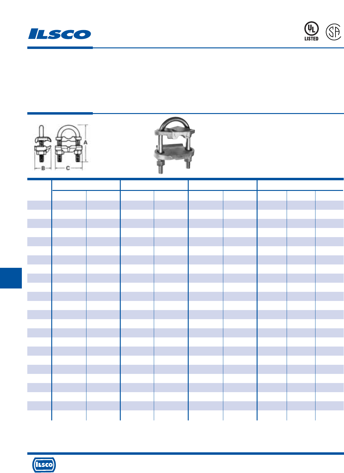
4730 Madison Road, Cincinnati, Ohio 45227-1426 Phone 513 533-6200 Fax 513 871-4084 Web site www.ilsco.com
Canada 1050 Lakeshore Road East, Mississauga, Ontario, Canada L5E1E4 Phone 905 274-2341 Fax 905 274-8763
281
HHH
Conductor Nominal Rod IPS Pipe Size Dimensions
Catalog
Number Max. Min. Max. Min. Max. Min. A B C
GUB-1 4 8 3/4 5/8 3/8 - 2-13/16 1-9/16 2-1/4
GUB-2 2/0 4 3/4 5/8 3/8 - 2-13/16 1-9/16 2-1/4
GUB-3 250kcmil 2/0 3/4 5/8 3/8 - 2-13/16 1-9/16 2-1/4
GUB-4 4 8 1 7/8 3/4 1/2 2-3/4 1-9/16 2-5/8
GUB-5 2/0 4 1 7/8 3/4 1/2 2-3/4 1-9/16 2-5/8
GUB-6 250kcmil 2/0 1 7/8 3/4 1/2 2-3/4 1-9/16 2-5/8
GUB-7 4 8 1-1/4 1-1/8 1 - 3-5/16 1-9/16 2-3/4
GUB-8 2/0 4 1-1/4 1-1/8 1 - 3-5/16 1-9/16 2-3/4
GUB-9 4 8 1-1/2 1-3/8 1-1/4 - 3-7/16 1-9/16 2-15/16
GUB-10 2/0 4 1-1/2 1-3/8 1-1/4 - 3-7/16 1-9/16 2-15/16
GUB-11 250kcmil 2/0 1-1/2 1-3/8 1-1/4 - 3-7/16 1-9/16 2-15/16
GUB-12 4 8 1-7/8 1-5/8 1-1/2 - 3-15/16 1-9/16 3-3/16
GUB-13 2/0 4 1-7/8 1-5/8 1-1/2 - 3-15/16 1-9/16 3-3/16
GUB-14 250kcmil 2/0 1-7/8 1-5/8 1-1/2 - 3-15/16 1-9/16 3-3/16
GUB-15 4 8 2-3/8 2 2 - 4-7/16 1-9/16 3-11/16
GUB-16 2/0 4 2-3/8 2 2 - 4-7/16 1-9/16 3-11/16
GUB-17 250kcmil 2/0 2-3/8 2 2 - 4-7/16 1-9/16 3-11/16
GUB-18 2/0 4 2-7/8 2-1/2 2-1/2 - 4-15/16 1-9/16 4-3/16
GUB-19 250kcmil 2/0 2-7/8 2-1/2 2-1/2 - 4-15/16 1-9/16 4-3/16
GUB-20 2/0 4 3-1/2 3 3 - 5-9/16 1-9/16 4-13/16
GUB-21 250kcmil 2/0 3-1/2 3 3 - 5-9/16 1-9/16 4-13/16
GUB-22 2/0 4 4 3-1/2 3-1/2 - 6-1/16 1-9/16 5-1/2
GUB-23 2/0 4 4-1/2 4 4 - 6-5/16 1-9/16 5-11/16
GUB-24 250kcmil 2/0 4-1/2 4 4 - 6-5/16 1-9/16 5-11/16
Bronze, U-Bolt Ground Clamp
TYPE
GUB
Features
•
Components are cast or forged from copper alloy
•
Specially designed spacer
•
Range taking
•
Re-usable
•
UL 467 Listed for direct burial and CSA Certified
Benefits
•
Provides maximum conductivity
•
Affords more positive contact area
•
Permits inventories to be kept to a minimum
•
Provides efficient use and flexibility in the field
•
Ensures reliability
UL File E158587
8M24
A
P
-
1
0
0
9
7
3
-
1
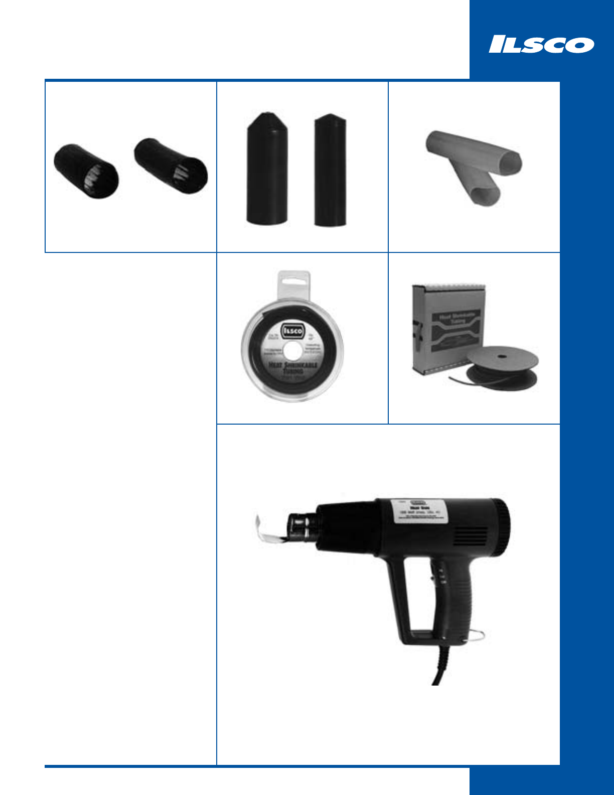
282
Heat Shrinkable Products
283
HEAVY WALL
284
HEAVY WALL END CAPS
285
MEDIUM WALL
286
THIN WALL
287
THIN WALL BULK REELS
288
HEAT GUN
4730 Madison Road, Cincinnati, Ohio 45227-1426 Phone 513 533-6200 Fax 513 871-4084 Web site www.ilsco.com
Canada 1050 Lakeshore Road East, Mississauga, Ontario, Canada L5E1E4 Phone 905 274-2341 Fax 905 274-8763
283
I
Catalog Wire Recovered Wall
Number Range Exp. Id. Rec. Id. Thickness L
21106-B3* 6-14 0.400 0.150 0.060 6"
21112-B3* 6-14 0.400 0.150 0.060 12"
21206-B3 1-8 0.750 0.220 0.090 6"
21209-B3 1-8 0.750 0.220 0.090 9"
21212-B3 1-8 0.750 0.220 0.090 12"
21230 1-8 0.750 0.220 0.090 30"
21406-B2 4/0-2 1.100 0.375 0.120 6"
21409-B2 4/0-2 1.100 0.375 0.120 9"
21412-B2 4/0-2 1.100 0.375 0.120 12"
21448 4/0-2 1.100 0.375 0.120 48"
21609-B2 400kcmil-4/0 1.500 0.500 0.140 9"
21612-B2 400kcmil-4/0 1.500 0.500 0.140 12"
21648 400kcmil-4/0 1.500 0.500 0.140 48"
21709-B 1000kcmil-500kcmil 2.000 0.750 0.155 9"
21712-B 1000kcmil-500kcmil 2.000 0.750 0.155 12"
21748 1000kcmil-500kcmil 2.000 0.750 0.155 48"
Heat Shrinkable Tubing - Heavy Wall
with Adhesive Liner
TYPE
Heavy
Wall
Features
•
3:1 shrink ratio
•
UL Listed 486D and CSA Certified for 600 volts
•
Inner adhesive liner
•
Flame retardant
Benefits
•
Provides a wide range of coverage when used on
connectors and cable
•
Ensures reliability for insulating terminations and
splices
•
Melts to form intimate contact with part to seal out
elements and produce a watertight seal suitable for
above ground, direct burial and underwater
applications
•
Meets Mil Spec 23053/15 rigid requirements for
flame retardancy
8M24
A
P
-
1
0
0
9
7
3
-
1
*UL Listed wire range 12 - 6.
UL File E158587
4730 Madison Road, Cincinnati, Ohio 45227-1426 Phone 513 533-6200 Fax 513 871-4084 Web site www.ilsco.com
Canada 1050 Lakeshore Road East, Mississauga, Ontario, Canada L5E1E4 Phone 905 274-2341 Fax 905 274-8763
284
I
Catalog Wire Recovered Wall
Number Range Exp. Id. Rec. Id. Thickness L
23081-B2 4/0-8 .75 0.22 .08 3.5"
23125-B2 500kcmil-4/0 1.30 0.43 .08 4.5"
23210-B2 1000kcmil-400kcmil 2.05 0.75 .08 4.5"
Heat Shrinkable End Caps - Heavy Wall
with Adhesive Liner
TYPE
Heavy
Wall
Features
•
3:1 shrink ratio
•
Inner adhesive liner
•
Rated for 600 volts
Benefits
•
Provides a wide range of coverage when used on
connectors and cable
•
Melts to form intimate contact with part to seal out
elements and produce a watertight seal suitable for
above ground, direct burial and underwater
applications
•
Ensures reliability
4730 Madison Road, Cincinnati, Ohio 45227-1426 Phone 513 533-6200 Fax 513 871-4084 Web site www.ilsco.com
Canada 1050 Lakeshore Road East, Mississauga, Ontario, Canada L5E1E4 Phone 905 274-2341 Fax 905 274-8763
285
I
Catalog Wire Recovered Wall
Number Range Exp. Id. Rec. Id. Thickness L
22106-B3 14-18 0.290 0.080 0.047 6"
22112-B3 14-18 0.290 0.080 0.047 12"
22206-B3 8-12 0.375 0.135 0.050 6"
22212-B3 8-12 0.375 0.135 0.050 12"
22306-B3 2-8 0.500 0.195 0.055 6"
22312-B3 2-8 0.500 0.195 0.055 12"
22406-B2 4/0-1 1.000 0.400 0.075 6"
22412-B2 4/0-1 1.000 0.400 0.075 12"
Heat Shrinkable Tubing - Medium Wall
with Adhesive Liner
TYPE
Medium
Wall
Features
•
Clear tubing
•
2.5:1 shrink ratio
•
Inner adhesive liner
•
Rated for 600 volts
Benefits
•
Provides convenient see through capability which
gives assurance that termination was made
properly after shrink process has been performed
•
Provides a wide range of coverage when used on
connectors and cable
•
Melts to form intimate contact with part to seal out
elements and produce a watertight seal suitable for
above ground, direct burial and underwater
applications
•
Ensures reliability
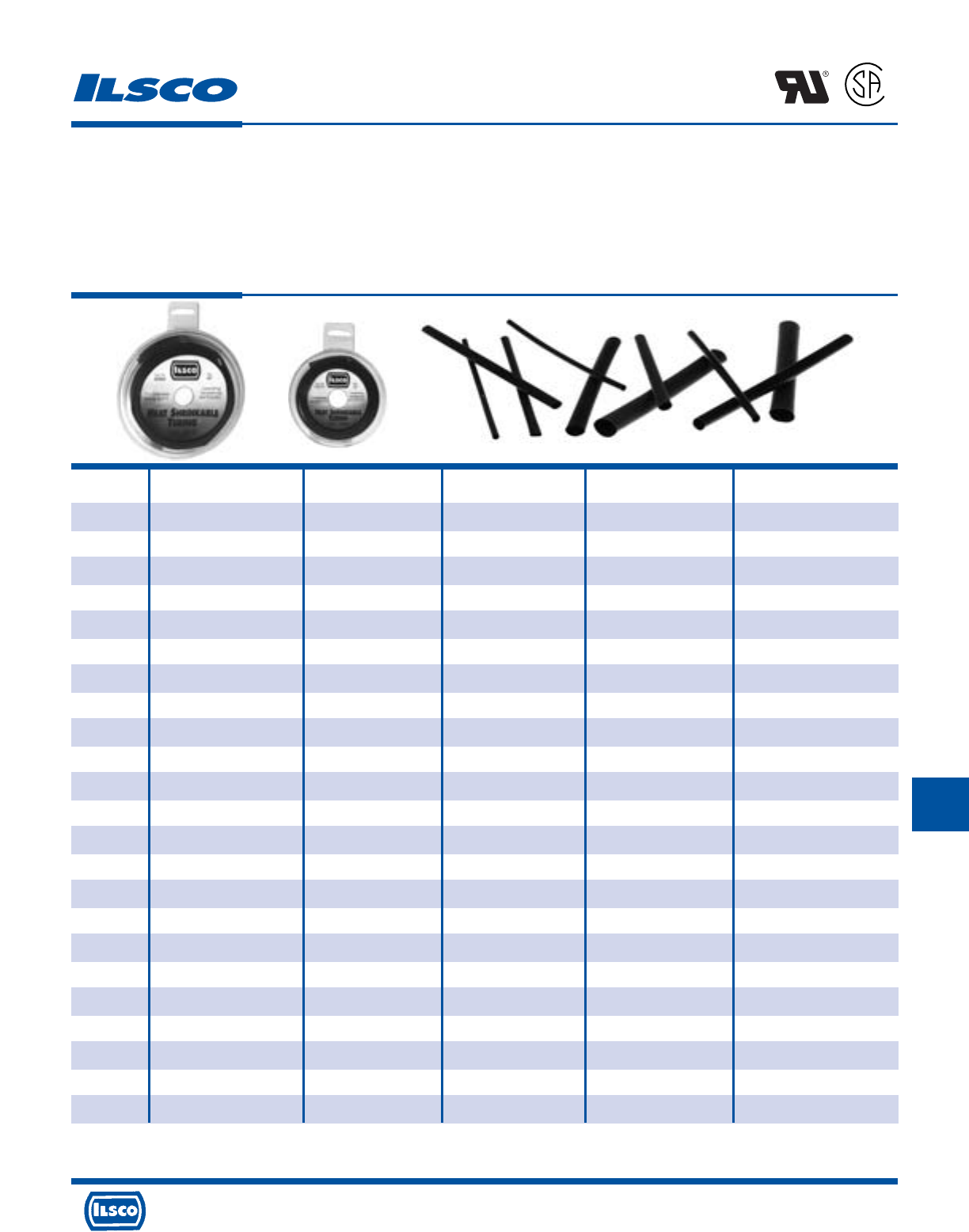
4730 Madison Road, Cincinnati, Ohio 45227-1426 Phone 513 533-6200 Fax 513 871-4084 Web site www.ilsco.com
Canada 1050 Lakeshore Road East, Mississauga, Ontario, Canada L5E1E4 Phone 905 274-2341 Fax 905 274-8763
286
I
Catalog Wire Recovered Wall
Number Range Exp. Id. Rec. Id. Thickness L
24001-B10 26-34 0.046 0.023 0.016 6"
24002-B10 24-30 0.063 0.031 0.017 6"
24003-B10 22-28 0.093 0.046 0.020 6"
24004-B10 20-26 0.125 0.062 0.020 6"
24005-B10 18-22 0.187 0.093 0.020 6"
24006-B10 14-16 0.250 0.125 0.025 6"
24007-B5 10-12 0.312 0.156 0.025 6"
24008-B5 6-8 0.375 0.187 0.025 6"
24009-B5 4-6 0.500 0.250 0.025 6"
24010-B5 2/0-2 0.750 0.375 0.030 6"
24011-B5 4/0-1 1.000 0.500 0.035 6"
24999-B12+ - - - - -
25001 26-34 0.046 0.023 0.016 96" Disk
25002 24-30 0.063 0.031 0.017 96" Disk
25003 22-28 0.093 0.046 0.020 96" Disk
25004 20-26 0.125 0.062 0.020 96" Disk
25005 18-22 0.187 0.093 0.020 96" Disk
25006 14-16 0.250 0.125 0.025 96" Disk
25007 10-12 0.3112 0.156 0.025 96" Disk
25008 6-8 0.375 0.187 0.025 96" Disk
25009 4-6 0.500 0.250 0.025 96" Disk
25010 2/0-2 0.750 0.375 0.030 96" Disk
25011 4/0-1 1.000 0.500 0.035 96" Disk
Heat Shrinkable Tubing - Thin Wall
TYPE
Thin
Wall
Features
•
2:1 shrink ratio
•
UL Recognized and CSA Certified
•
Rated for 600 volts
•
Convenient disk dispenser
Benefits
•
Provides a wide range of coverage when used on
connectors and cable
•
Assures product reliability for insulating and
protecting terminations and splices
•
Ensures reliability
•
Protects tubing from damage and keeps it clean
A
P
-
1
0
0
9
7
3
-
1
+ 24999-B12 contains 3 ea. 24005, 24006, 24008, 24009
UL File E158587
4730 Madison Road, Cincinnati, Ohio 45227-1426 Phone 513 533-6200 Fax 513 871-4084 Web site www.ilsco.com
Canada 1050 Lakeshore Road East, Mississauga, Ontario, Canada L5E1E4 Phone 905 274-2341 Fax 905 274-8763
287
I
Catalog Recovered Wall
Number Wire Range Exp. Id. Rec. Id. Thickness Cut Length
26001 26-34 0.046 0.023 0.016 1000'
26002 24-30 0.063 0.031 0.017 1000'
26003 22-28 0.093 0.046 0.020 500'
26004 20-26 0.125 0.062 0.020 500'
26005 18-22 0.187 0.093 0.020 200'
26006 14-16 0.250 0.125 0.025 200'
26007 10-12 0.312 0.156 0.025 500'
26008 6-8 0.375 0.187 0.025 200'
26009 4-6 0.500 0.250 0.025 200'
26010 2/0-2 0.750 0.375 0.030 200'
26011 4/0-1 1.000 0.500 0.035 200'
Heat Shrinkable Tubing - Thin Wall
TYPE
Thin
Wall
Features
•
2:1 shrink ratio
•
UL Recognized and CSA Certified
•
Rated for 600 volts
Benefits
•
Provides a wide range of coverage when used on
connectors and cable
•
Assures product reliability for insulating and protecting
terminations and splices
•
Ensures reliability
A
P
-
1
0
0
9
7
3
-
1
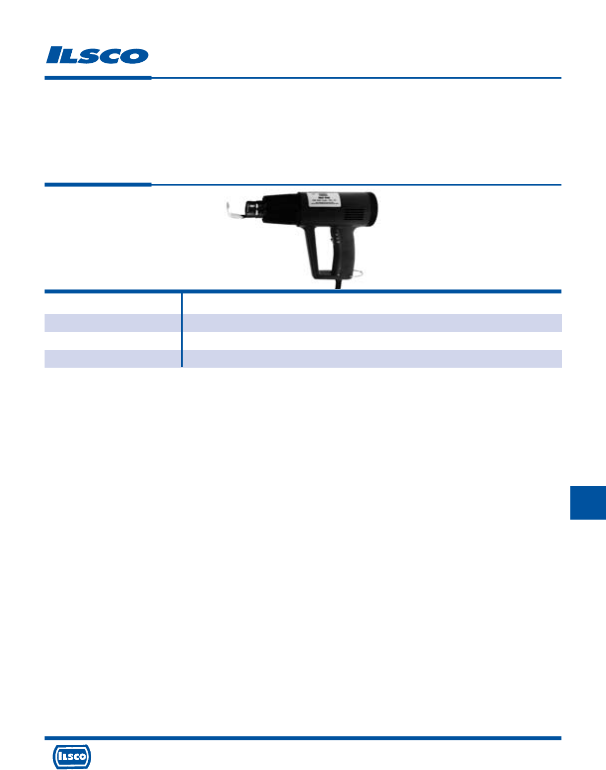
4730 Madison Road, Cincinnati, Ohio 45227-1426 Phone 513 533-6200 Fax 513 871-4084 Web site www.ilsco.com
Canada 1050 Lakeshore Road East, Mississauga, Ontario, Canada L5E1E4 Phone 905 274-2341 Fax 905 274-8763
288
I
Catalog
Number Description
27001 Heat Gun, 11 Disks Thin Wall Heat Shrink
94502 Electric Heat Gun 120v
94504 Replacement Adaptor for 94502
Heat Gun
TYPE
Electric
Heat Gun
Features
•
Two temperature settings 750F and 1100F
•
Three way switch OFF/HI/LO
•
Built-in fold down stand
•
1200 Watt 120 V AC
•
Heat deflector
•
Impact resistant
•
Six foot cord
Benefits
•
Provides versatility in applying recommended heat,
deliverable in seconds
•
Aids in producing proper air flow from heat gun
•
Provides hands free operation
•
Provides high output of air and heat
•
Allows for concentration of heat for rapid heat
shrink process
•
Provides extra durability in harsh environments
•
Provides operator convenience
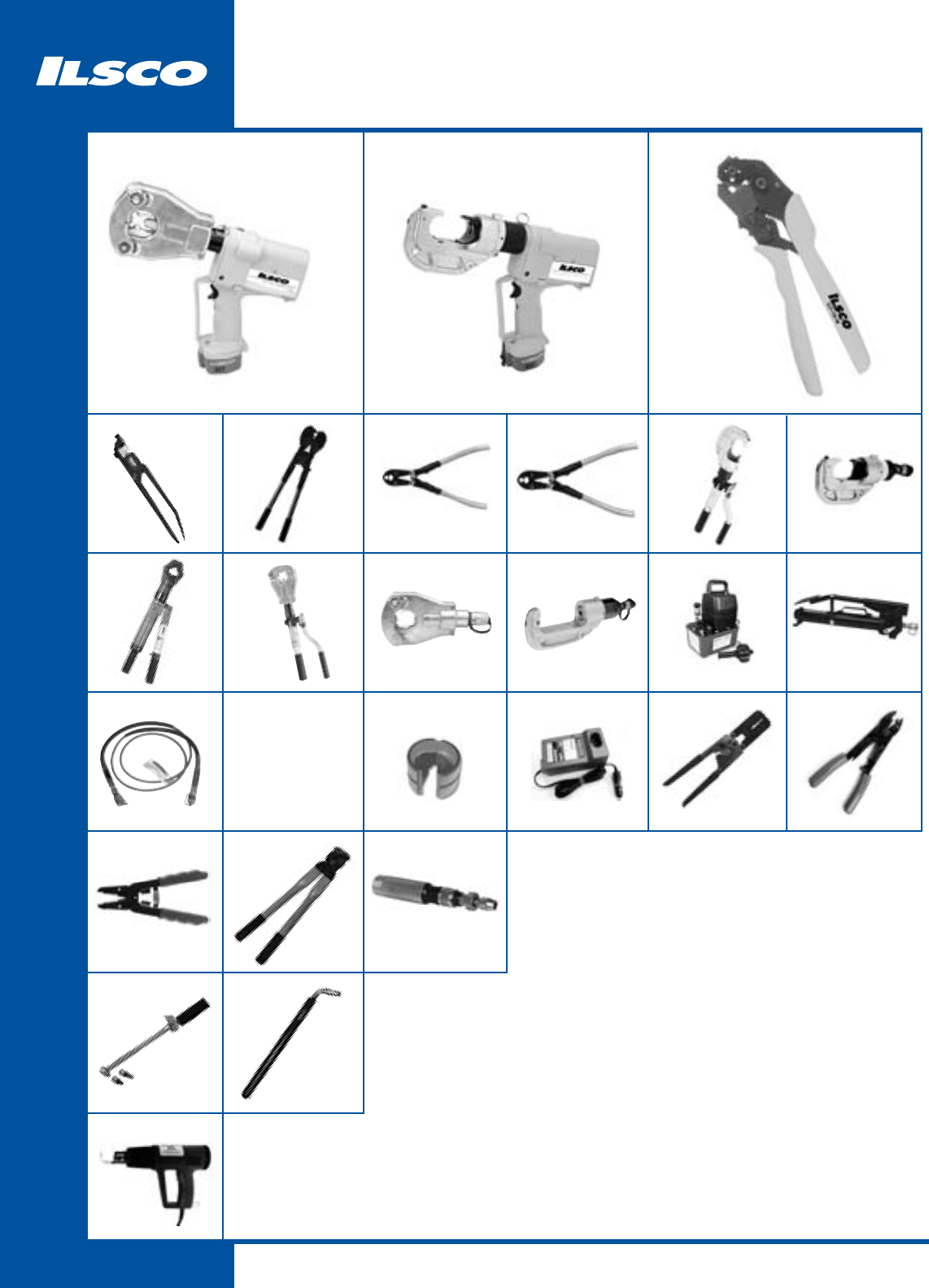
289
Tools
IDTB-6
290
94130
316
TS
318
94502
319
ILC-10-N
292
ILCB-12-N
291
ND-60
296
ILC-12-N
297
HH-10N
305
WS-1
316
COMPRESSION DIES
AND ADAPTORS
313 - 314
WR
318
TW
318
ND-58
295
FP-1
304
CTR
317
94285
294
MT-25
293
ILC-12H-N
298
COMPRESSION
INDEX
306 - 312
94140
316
TOOL ACCESSORIES
315
ILC-15H
302
IDT-6H
301
IDT-6
300
IDT-12-N
299
5ACR
303
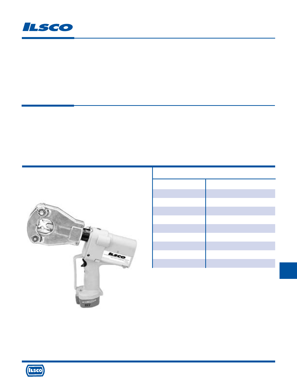
4730 Madison Road, Cincinnati, Ohio 45227-1426 Phone 513 533-6200 Fax 513 871-4084 Web site www.ilsco.com
Canada 1050 Lakeshore Road East, Mississauga, Ontario, Canada L5E1E4 Phone 905 274-2341 Fax 905 274-8763
290
J
L
Battery Powered Dieless Crimping Tool
TYPE
IDTB-6
Features
•
Dieless operation
•
Battery powered
•
No set-up time
•
Flip top head
•
Head rotates 360 degrees, angled pistol grip
•
Lightweight - only 10.8 lbs.
•
Battery provides up to 35 crimps per charge
•
One-hour 120 volt charger and two 12 volt
batteries included
Benefits
•
No dies to lose or replace, one tool does it all
•
Flexibility in use - can use where power access is limited
•
Speeds installation
•
Easy connector loading and unloading
•
Convenience when working in tight areas
•
Easy to hold, less tiring for numerous crimps
•
Easy to charge, dependable performance
•
Convenience
For Use with
Aluminum Copper
Connectors Connectors
ACL, ACN Series thru 750kcmil CLN4, CLN9, CLND,
2ACL, 2ACN Series thru 750kcmil CLNF, CLNN, CLNS,
AS Series thru 750kcmil CLNU, CLW4, CLW9,
IACL Series thru 500kcmil CLWD, CLWF, CLWN,
2IACL Series thru 500kcmil CLWS, CSN4, CSN9,
CSND, CSNF, CSNN,
CSNS, CSW4, CSW9,
CSWD, CSWF, CSWN,
CSWS 750kcmil thru 6
Specifications
Force developed: 6.2 Tons
Weight: 10.8 lbs.
Overall Length: 14-7/8"
Connector Range: 750kcmil-#6
Includes:
2 Batteries
1 Battery Charger
Steel Carrying Case
Instruction Manual
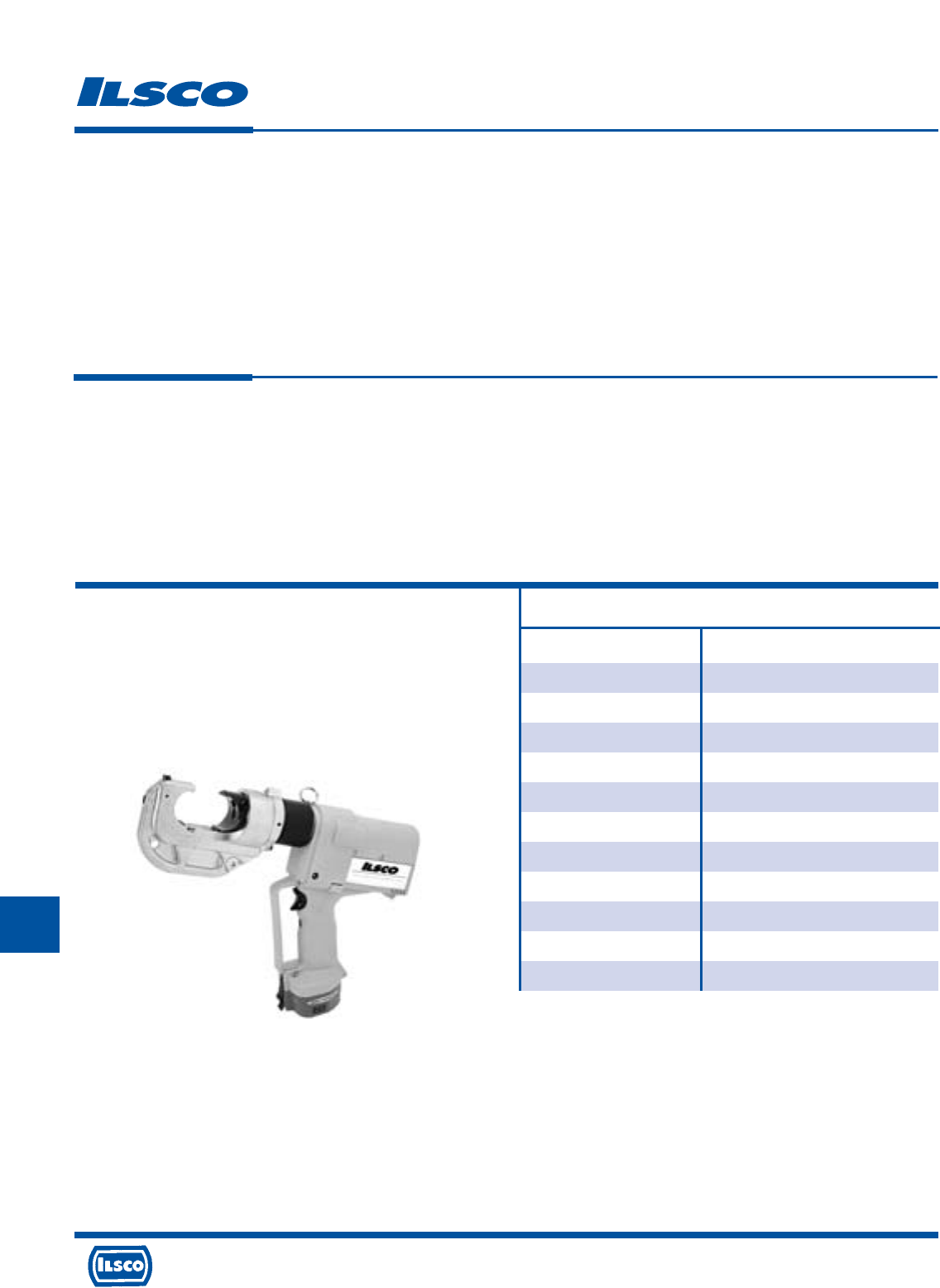
4730 Madison Road, Cincinnati, Ohio 45227-1426 Phone 513 533-6200 Fax 513 871-4084 Web site www.ilsco.com
Canada 1050 Lakeshore Road East, Mississauga, Ontario, Canada L5E1E4 Phone 905 274-2341 Fax 905 274-8763
291
J
Battery Powered Crimping Tool
TYPE
ILCB-12-N
Features
•
Head tested to 50,000 crimp cycles
•
Accepts industry standard “U” dies
•
Light weight - 14.9 lbs.
•
Two speed pump
•
Ram automatically retracts when crimp
cycle is complete
•
Head rotates 360 degrees
•
Battery provides up to 35 crimps per charge
•
One-hour 120 volt charger and two 12 volt
batteries included
Benefits
•
Durable and dependable
•
Flexibility and economy
•
Easy to hold, less tiring for numerous crimps
•
Reduces cycle time
•
Confirms crimp was completed
•
Convenience when working in tight areas
•
Easy to charge, dependable performance
•
Convenience
For Use with*
Aluminum Copper
Connectors Connectors
CPM Series CLN4, CLN9, CLND,
ACM Series CLNF, CLNN, CLNS,
ACO Series CLNU, CLW4, CLW9,
ACO-90 Series CLWD, CLWF, CLWN,
ACL, ACN Series thru 750kcmil CLWS, CSN4, CSN9,
2ACL, 2ACN Series thru 750kcmil CSND, CSNF, CSNN,
AS Series thru 750kcmil CSNS, CSW4, CSW9,
AH 1-4 CSWD, CSWF, CSWN,
HT Series CSWS 1000kcmil thru 8
IACL Series thru 750kcmil
2IACL Series thru 750kcmil
Specifications
Force developed: 12 Tons
Weight: 14.9 lbs.
Overall length: 15-1/4"
Jaw Opening: 1.65"
Connector Range: 1000kcmil-#8
*See page 312 for required compression dies
Includes:
2 Batteries
1 Battery Charger
Steel Carrying Case
Instruction Manual
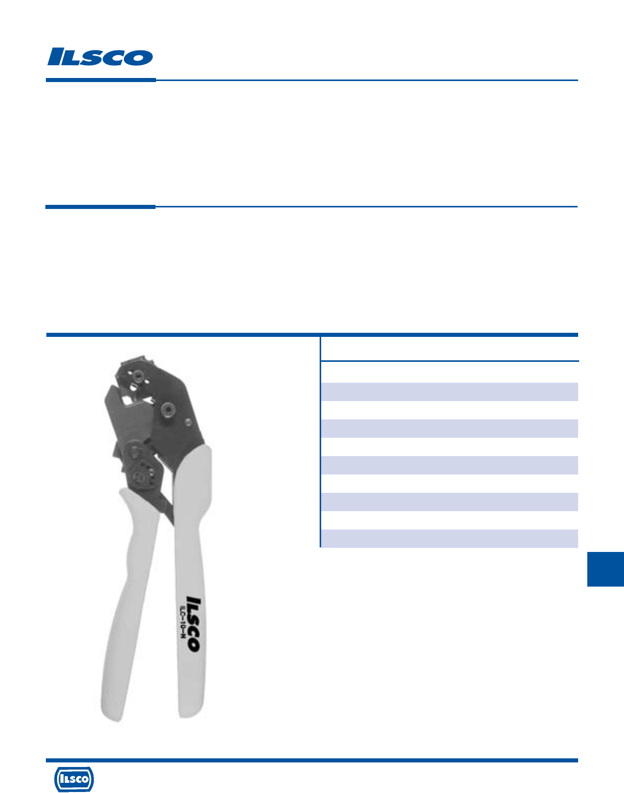
4730 Madison Road, Cincinnati, Ohio 45227-1426 Phone 513 533-6200 Fax 513 871-4084 Web site www.ilsco.com
Canada 1050 Lakeshore Road East, Mississauga, Ontario, Canada L5E1E4 Phone 905 274-2341 Fax 905 274-8763
292
J
Hand Operated Crimping Tool
TYPE
ILC-10-N
Features
•
Rotatable die
•
Additional die affixed to frame
•
Crimp cavities are color coded to industry
standards
•
Ratchet control mechanism
•
Heat treated frame and dies
•
Long, molded handles
Benefits
•
Crimps #2, #4, #6 and #8 copper compression connectors
•
Crimps 1/0 and #1 copper compression connectors
•
Reduces the possibility of improper die selection
•
Assures a complete crimp
•
Dependable, long lasting tool
•
Ergonomic design to reduce hand stress
Specifications
Weight: 1-3/8 lbs.
Overall Length: 11"
Width: 3.75"
Jaw Opening: .5"
Conductor Range: 1/0-8 CU
For Use with
Copper
Connectors
CLN4, CLN9, CLND,
CLNF, CLNN, CLNS,
CLNU, CLW4, CLW9,
CLWD, CLWF, CLWN,
CLWS, CSN4, CSN9,
CSND, CSNF, CSNN,
CSNS, CSW4, CSW9,
CSWD, CSWF, CSWN,
CSWS 1/0 thru 8
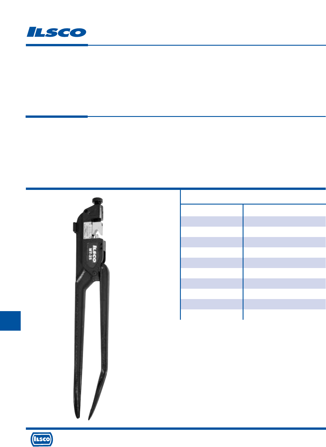
4730 Madison Road, Cincinnati, Ohio 45227-1426 Phone 513 533-6200 Fax 513 871-4084 Web site www.ilsco.com
Canada 1050 Lakeshore Road East, Mississauga, Ontario, Canada L5E1E4 Phone 905 274-2341 Fax 905 274-8763
293
J
L
Manually Operated Compression Tool
TYPE
MT-25
Features
•
Dieless single indent compressor
•
Steel adjusting knob
•
UL Listed terminals and splices
•
Broad wire range
•
Mounting hole for bench mounting
applications
Benefits
•
Reduces installed cost by having no separate dies to purchase, change or lose
•
Provides fast and easy setting. Simply align the line on the die nest with the
wire size gauge for proper crimping results.
•
Ensures reliability. ILSCO’s standard line of connectors are UL Listed when
crimped with the MT-25 tool
•
Convenience
Specifications
Length: 22.65"
Weight: 6 lbs.
Depth: 4.86"
Width: 1.12"
Conductor Range: 250kcmil-8 CU
4/0-8 AL
For Use with
Aluminum Copper
Connectors Connectors
ACL, ACN 4/0-8 CLN4, CLN9, CLND,
2ACL, 2ACN 4/0-8 CLNF, CLNN, CLNS,
AS 4/0-8 CLNU, CLW4, CLW9,
CLWD, CLWF, CLWN,
CLWS, CSN4, CSN9,
CSND, CSNF, CSNN,
CSNS, CSW4, CSW9,
CSWD, CSWF, CSWN,
CSWS 250kcmil thru 8
CCL, CRAM
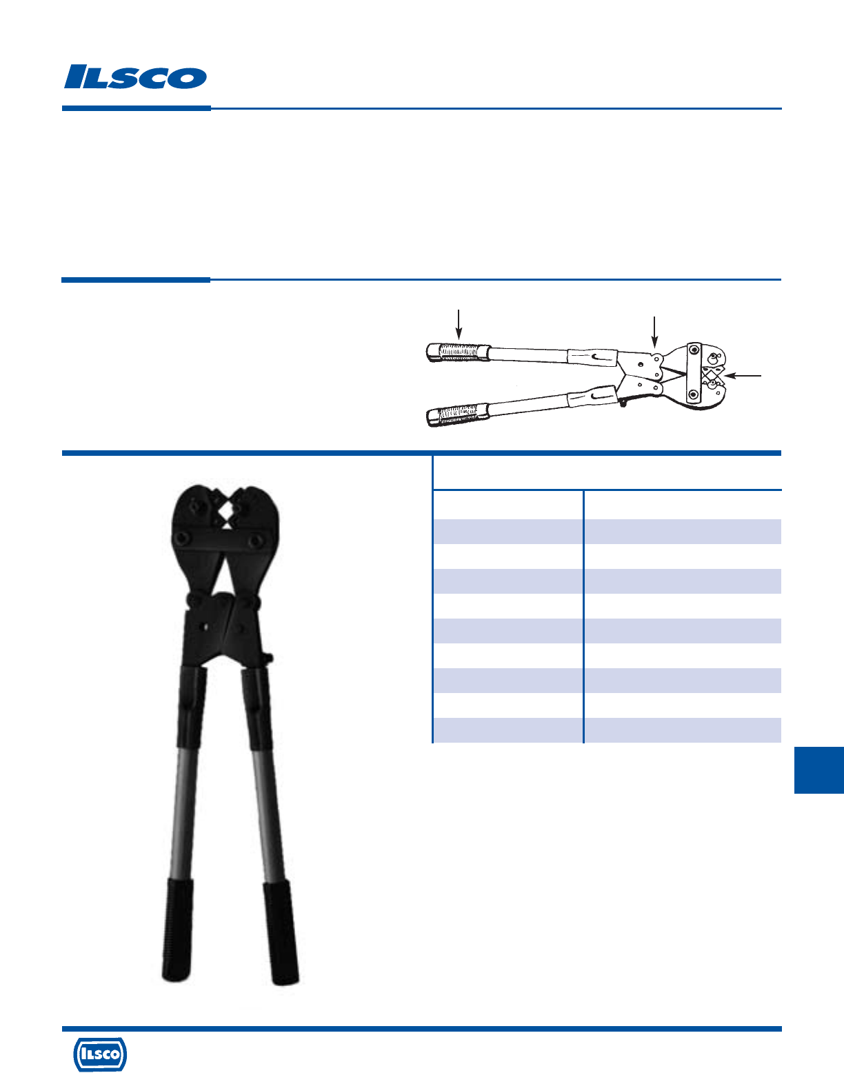
L
For Use with
Aluminum Copper
Connectors Connectors
ACL, ACN 3/0-8 CLN4, CLN9, CLND,
2ACL, 2ACN 3/0-8 CLNF, CLNN, CLNS,
AS 3/0-8 CLNU, CLW4, CLW9,
CLWD, CLWF, CLWN,
CLWS, CSN4, CSN9,
CSND, CSNF, CSNN,
CSNS, CSW4, CSW9,
CSWD, CSWF, CSWN,
CSWS 250kcmil thru 8
Manually Operated Compression Tool
TYPE
94285
Features
•
Controlled cycle ratchet mechanism
•
Built in rotatable dies
•
Comfort grip handles
•
UL Listed terminals and splices
Benefits
•
Acts as a quality control device, once a crimp is started, the tool will not open
until it is completed. (Tool has emergency release mechanism.)
•
No separate dies to purchase or lose
•
Helps ease fatigue with continuous use
•
Ensures reliability. ILSCO’s standard line of connectors are UL Listed when
crimped with the 94285 tool
Specifications
Length: 25-1/4"
Weight: 6.1 lbs.
Conductor Range: 250kcmil-8 CU
3/0-8 AL
1
2
3
1
2
3
4730 Madison Road, Cincinnati, Ohio 45227-1426 Phone 513 533-6200 Fax 513 871-4084 Web site www.ilsco.com
Canada 1050 Lakeshore Road East, Mississauga, Ontario, Canada L5E1E4 Phone 905 274-2341 Fax 905 274-8763
294
J
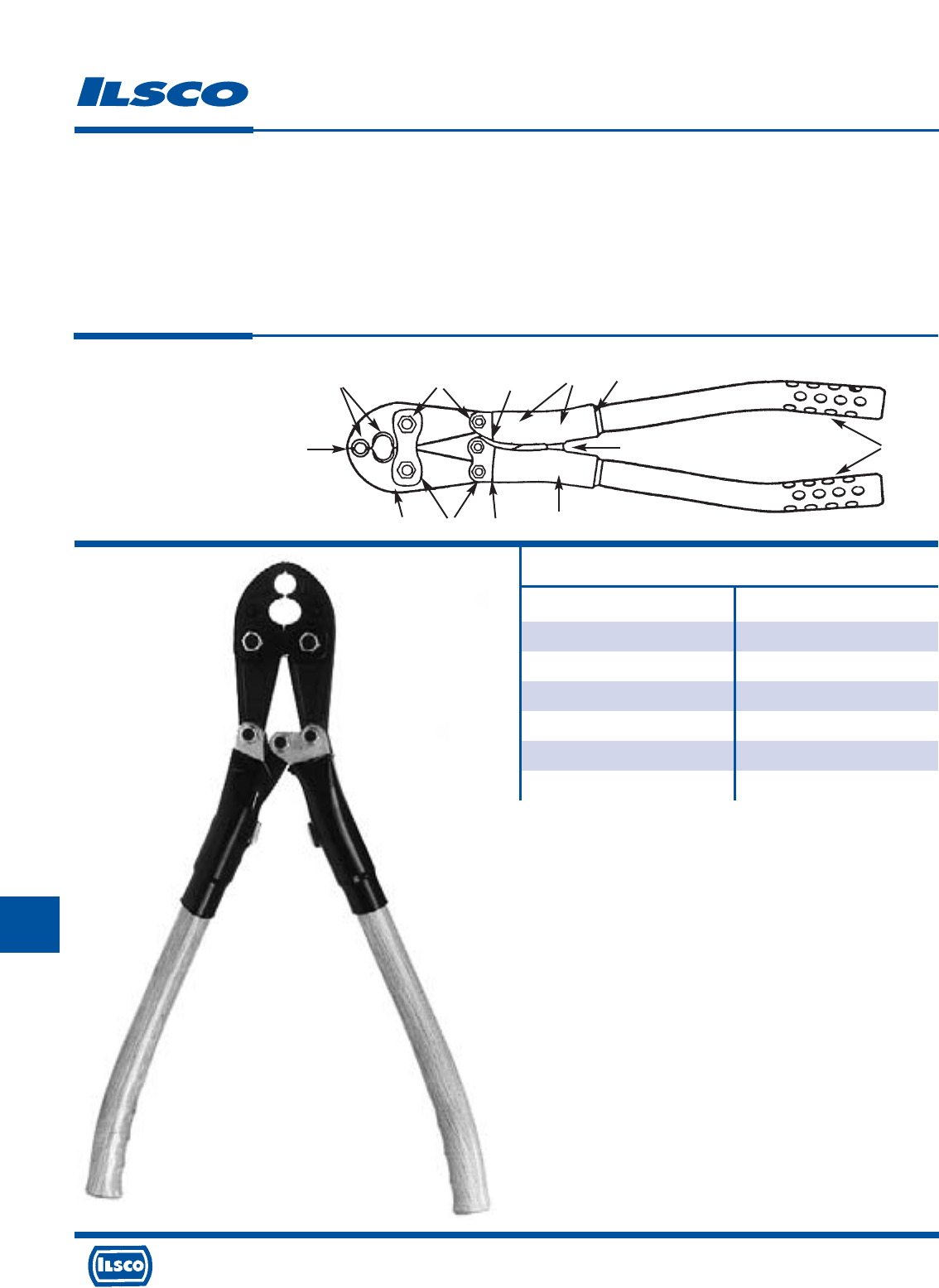
4730 Madison Road, Cincinnati, Ohio 45227-1426 Phone 513 533-6200 Fax 513 871-4084 Web site www.ilsco.com
Canada 1050 Lakeshore Road East, Mississauga, Ontario, Canada L5E1E4 Phone 905 274-2341 Fax 905 274-8763
295
J
L
For Use with
Aluminum Copper
Connectors Connectors
PICS Series GGA-1
P840 Series GGC-1
UCL 1/0-4 ULT 4-7
UCS 1/0-4
HT Series
AH 1-4
Manually Operated Compression Tool
TYPE
ND-58
Features
•
High strength, butting, forged steel jaw
•
Two permanent die grooves
•
Large diameter hardened steel bolts
•
Spring loaded positive lock die retainer buttons
•
Orange alignment grooves
•
PTFE®impregnated steel backed bronze bushings
•
Over center cam action
•
Adjustment screws
•
Handle butt stops and heat shrink tubing
•
High quality clear hickory handles
•
Bent handles and anti-slip handle grips
Benefits
•
Assures proper crimps
•
No additional dies required for “0” and “D3” size tap connectors. The “D3”
groove accommodates the complete line of type “W-” die inserts.
•
Provides increased strength and greater bearing area
•
Allows fast, easy, one-hand die insertion. No lost dies.
•
Allows easy visual field check for proper tool adjustment
•
Over 90,000 crimps provided with Teflon impregnated steel backed bronze
bushings
•
Assures full crimp force
•
Easy tool adjustment with allen wrench screws
•
Operator protection provided with butt stops and heat shrink tubing
•
Long life expectancy provided with select clear hickory handles and light weight
high strength aluminum alloy castings
•
Easier tool operation is provided with bent handles and anti-slip grips
Specifications
Crimp Force: 9,000 lbs.
Length: 25-3/8"
Weight: 9 lbs.
1
2
3
4
5
6
7
8
9
bk
bl
1
23789
9
bk
456
bl
Accessories:
• Carrying bag included
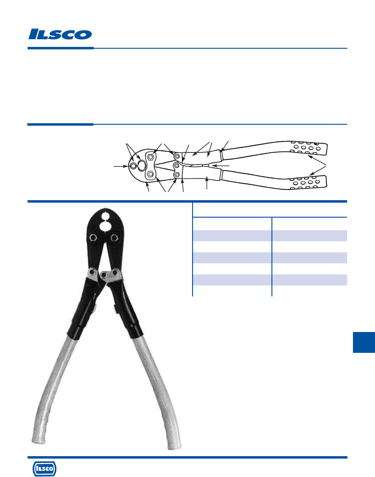
L
For Use with
Aluminum Copper
Connectors Connectors
PICS Series GGA-1
P840 Series GGC-1
UCL 1/0-4 ULT 4-7
UCS 1/0-4
HT Series
AH 1-4
Manually Operated Compression Tool
TYPE
ND-60
Features
•
High strength, butting, forged steel jaw
•
Two permanent die grooves
•
Large diameter hardened steel bolts
•
Spring loaded positive lock die retainer buttons
•
Orange alignment grooves
•
PTFE®impregnated steel backed bronze bushings
•
Over center cam action
•
Adjustment screws
•
Handle butt stops and heat shrink tubing
•
High quality clear hickory handles
•
Bent handles and anti-slip handle grips
Benefits
•
Assures proper crimps
•
No additional dies required for “BG” and “D3” size tap connectors. The “D3”
groove accommodates the complete line of type “W-” die inserts.
•
Provides increased strength and greater bearing area
•
Allows fast, easy, one-hand die insertion. No lost dies.
•
Allows easy visual field check for proper tool adjustment
•
Over 90,000 crimps provided with Teflon impregnated steel backed bronze
bushings
•
Assures full crimp force
•
Easy tool adjustment with allen wrench screws
•
Operator protection provided with butt stops and heat shrink tubing
•
Long life expectancy provided with select clear hickory handles and light weight
high strength aluminum alloy castings
•
Easier tool operation is provided with bent handles and anti-slip grips
Specifications
Crimp Force: 9,000 lbs.
Length: 25-3/8"
Weight: 9 lbs.
1
2
3
4
5
6
7
8
9
bk
bl
1
23789
9
bk
456
bl
Accessories:
• Carrying bag included
4730 Madison Road, Cincinnati, Ohio 45227-1426 Phone 513 533-6200 Fax 513 871-4084 Web site www.ilsco.com
Canada 1050 Lakeshore Road East, Mississauga, Ontario, Canada L5E1E4 Phone 905 274-2341 Fax 905 274-8763
296
J
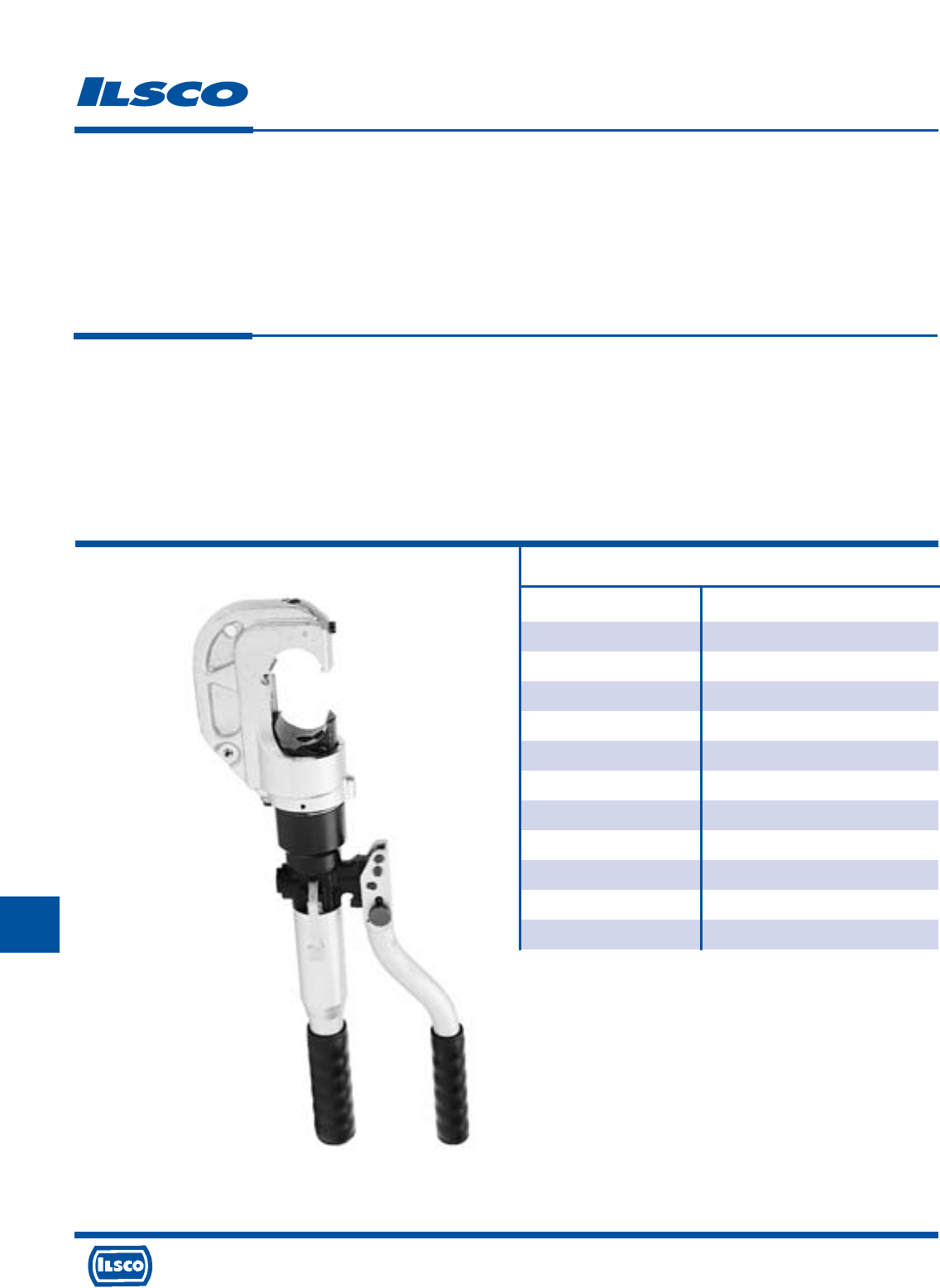
4730 Madison Road, Cincinnati, Ohio 45227-1426 Phone 513 533-6200 Fax 513 871-4084 Web site www.ilsco.com
Canada 1050 Lakeshore Road East, Mississauga, Ontario, Canada L5E1E4 Phone 905 274-2341 Fax 905 274-8763
297
J
Hand Operated Hydraulic Tool
TYPE
ILC-12-N
Features
•
Head tested to 50,000 crimp cycles
•
Accepts industry standard “U” dies
•
Light head - 13.2 lbs.
•
Two speed pump
•
Ram automatically retracts when crimp
cycle is complete
•
Head rotates 360 degrees
Benefits
•
Durable and dependable
•
Flexibility and economy
•
Easy to hold, less tiring for numerous crimps
•
Reduces cycle time
•
Confirms crimp was completed
•
Convenience when working in tight areas
Specifications
Force developed: 12 Tons
Operating pressure: 10,000 PSI
Weight: 13.2 lbs.
Overall length: 21-1/2"
Jaw Opening: 1.65"
Conductor Range: 1000kcmil-#8
For Use with*
Aluminum Copper
Connectors Connectors
CPM Series CLN4, CLN9, CLND,
ACM Series CLNF, CLNN, CLNS,
ACO Series CLNU, CLW4, CLW9,
ACO-90 Series CLWD, CLWF, CLWN,
ACL, ACN 750kcmil-8 CLWS, CSN4, CSN9,
2ACL, 2ACN 750kcmil-1/0 CSND, CSNF, CSNN,
AS 750kcmil-8 CSNS, CSW4, CSW9,
AH 1-4 CSWD, CSWF, CSWN,
HT Series CSWS 1000kcmil thru 8
IACL Series thru 750kcmil
2IACL Series thru 750kcmil
*See page 312 for required compression dies
Includes:
Steel Carrying Case
Instruction Manual
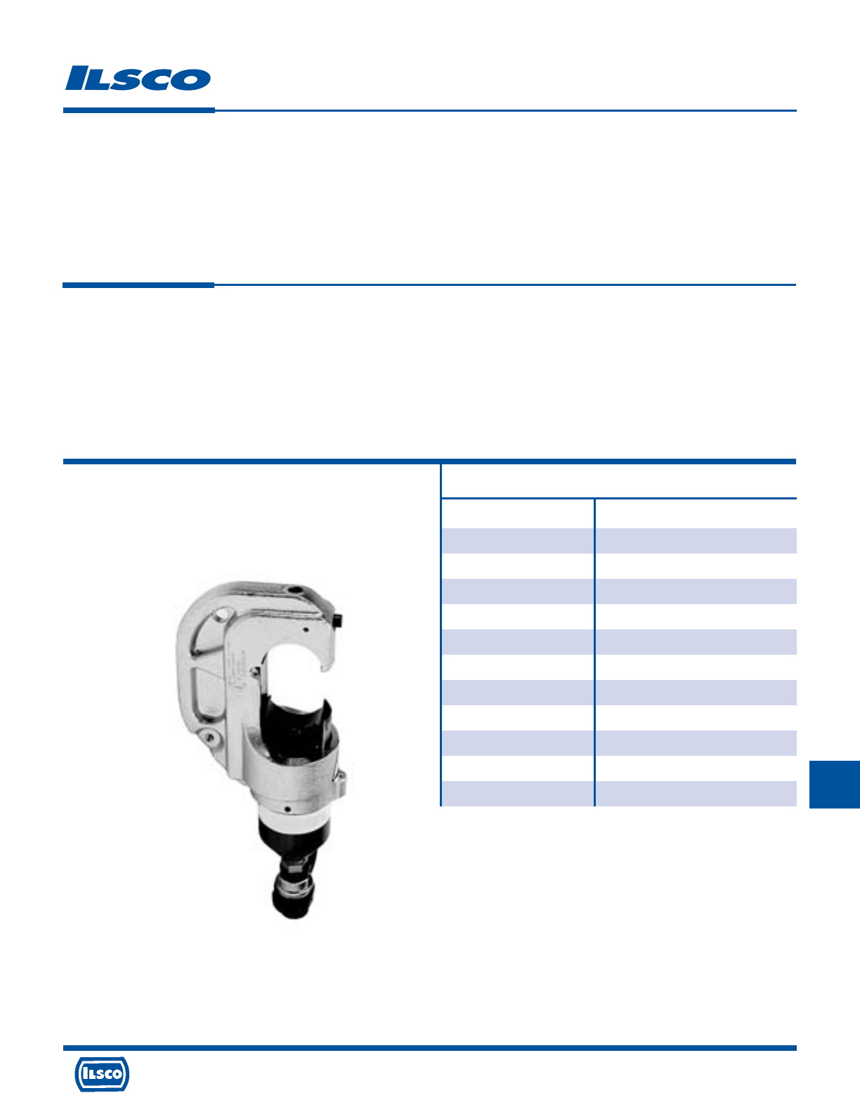
For Use with*
Aluminum Copper
Connectors Connectors
CPM Series CLN4, CLN9, CLND,
ACM Series CLNF, CLNN, CLNS,
ACO Series CLNU, CLW4, CLW9,
ACO-90 Series CLWD, CLWF, CLWN,
ACL 750kcmil-8 CLWS, CSN4, CSN9,
2ACL 750kcmil-1/0 CSND, CSNF, CSNN,
AS 750kcmil-8 CSNS, CSW4, CSW9,
AH 1-7 CSWD, CSWF, CSWN,
HT Series CSWS 1000kcmil thru 8
IACL Series
2IACL Series
Remote Power Operated Compression Tool
TYPE
ILC-12H-N
Features
•
Head tested to 50,000 crimp cycles
•
Accepts industry standard “U” dies
•
Hot stick attachment point
•
Light head - 9.7 lbs
•
Equipped with 3/8" male screw coupler
•
Ram automatically retracts when crimp
cycle is complete
Benefits
•
Durable and dependable
•
Flexibility and economy
•
Offers the option of performing line maintenance when
properly protected
•
Easy to hold, less tiring for numerous crimps
•
For use with standard industry hoses
•
Confirms crimp was completed
Specifications
Force developed: 12 Tons
Operating pressure: 10,000 PSI
Weight: 9.7 lbs.
Overall Length: 11-7/8"
Jaw Opening: 1.65"
Conductor Range: 1000kcmil-#8
*See page 312 for required compression dies
Additional Requirements:
• Hose
• Pump
Includes:
Steel Carrying Case
Instruction Manual
4730 Madison Road, Cincinnati, Ohio 45227-1426 Phone 513 533-6200 Fax 513 871-4084 Web site www.ilsco.com
Canada 1050 Lakeshore Road East, Mississauga, Ontario, Canada L5E1E4 Phone 905 274-2341 Fax 905 274-8763
298
J
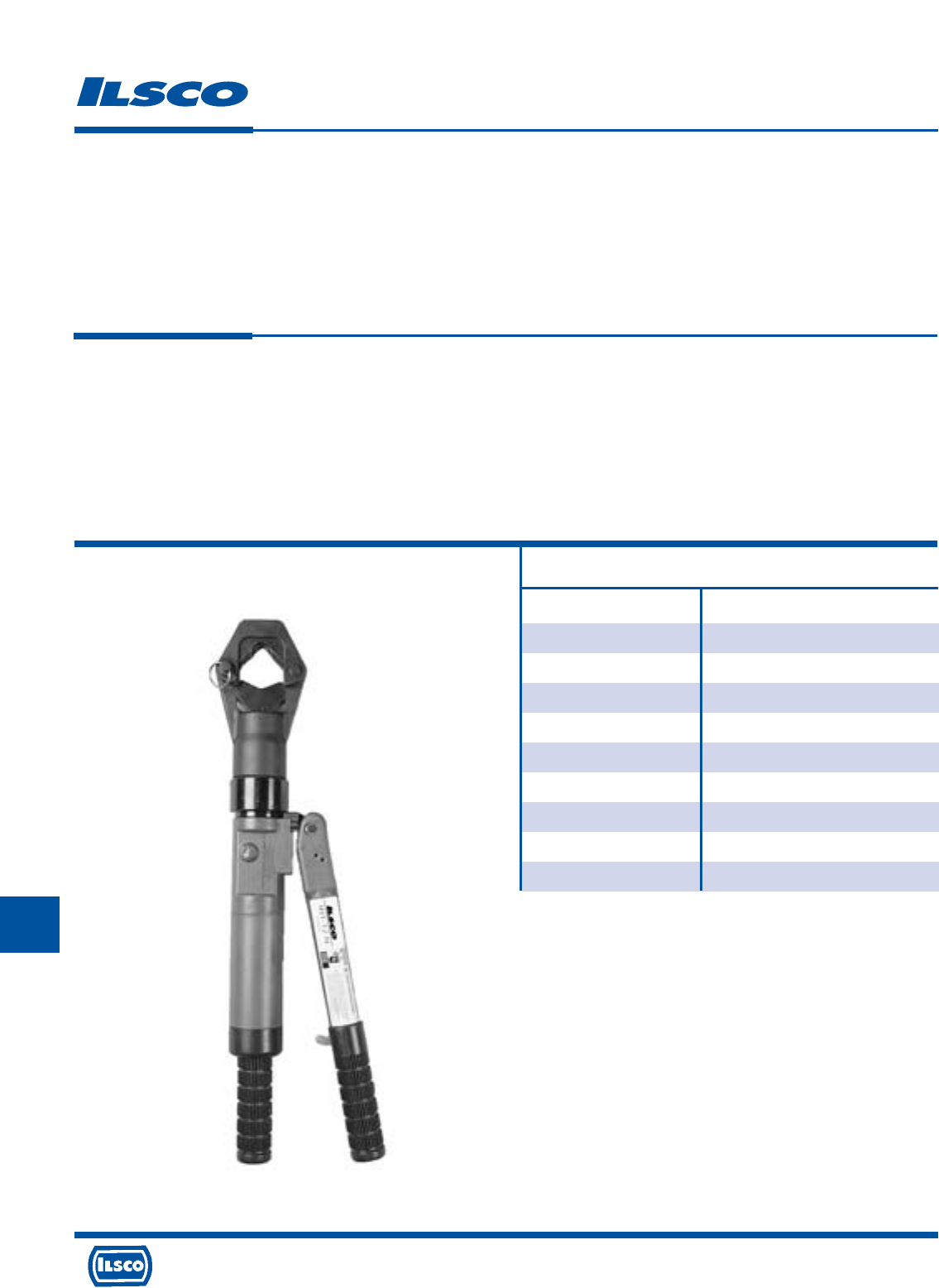
4730 Madison Road, Cincinnati, Ohio 45227-1426 Phone 513 533-6200 Fax 513 871-4084 Web site www.ilsco.com
Canada 1050 Lakeshore Road East, Mississauga, Ontario, Canada L5E1E4 Phone 905 274-2341 Fax 905 274-8763
299
J
L
For Use with
Aluminum Copper
Connectors Connectors
ACL, ACN Series CLN4, CLN9, CLND,
2ACL, 2ACN Series CLNF, CLNN, CLNS,
AS Series CLNU, CLW4, CLW9,
IACL Series CLWD, CLWF, CLWN,
2IACL Series CLWS, CSN4, CSN9,
CSND, CSNF, CSNN,
CSNS, CSW4, CSW9,
CSWD, CSWF, CSWN,
CSWS 1000kcmil thru 4
Dieless Hand Operated Hydraulic Tool
TYPE
IDT-12-N
Features
•
Dieless operation
•
Pressure system automatically changes
crimping force for each connector and
size
•
Seven indent profiles
•
Automatic two speed pump
•
15 ton maximum crimping force
•
Head rotates 180 degrees
•
Hinged head
Benefits
•
No dies to lose or replace, one tool does it all
•
Eliminates crimping errors
•
Requires fewer crimps per connector
•
Rapid advance, reduces cycle time
•
Ability to crimp 1000 kcmil
•
Convenience when working in tight areas
•
Easy connector loading and unloading
Specifications
Force developed: 15 Tons
Overall length: 26.5"
Weight: 16.5 lbs.
Conductor Range: 1000kcmil - #4 CU
1000kcmil - #6 AL
Includes:
Steel Carrying Case
Instruction Manual
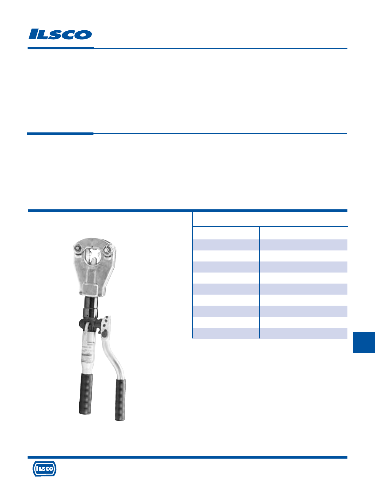
L
Hand Operated Dieless Crimping Tool
TYPE
IDT-6
Features
•
Dieless operation
•
Automatic two speed pump
•
Ram automatically retracts when crimp cycle is
complete
•
Head rotates 360 degrees
•
Flip top head
•
Lightweight - 9.0 lbs.
Benefits
•
No dies to lose or replace, one tool does it all
•
Rapid advance, reduces cycle time
•
Confirms crimp was completed
•
Convenience when working in tight areas
•
Easy connector loading and unloading
•
Easy to hold, less tiring for numerous crimps
For Use with
Aluminum Copper
Connectors Connectors
ACL, ACN Series thru 750kcmil CLN4, CLN9, CLND,
2ACL, 2ACN Series thru 750kcmil CLNF, CLNN, CLNS,
AS Series thru 750kcmil CLNU, CLW4, CLW9,
IACL Series thru 500kcmil CLWD, CLWF, CLWN,
2IACL Series thru 500kcmil CLWS, CSN4, CSN9,
CSND, CSNF, CSNN,
CSNS, CSW4, CSW9,
CSWD, CSWF, CSWN,
CSWS 1000kcmil thru 6
Specifications
Force developed: 6.2 Tons
Weight: 9.0 lbs.
Overall Length: 21-1/16"
Connector Range: 750kcmil-#6
Includes:
Steel Carrying Case
Instruction Manual
4730 Madison Road, Cincinnati, Ohio 45227-1426 Phone 513 533-6200 Fax 513 871-4084 Web site www.ilsco.com
Canada 1050 Lakeshore Road East, Mississauga, Ontario, Canada L5E1E4 Phone 905 274-2341 Fax 905 274-8763
300
J
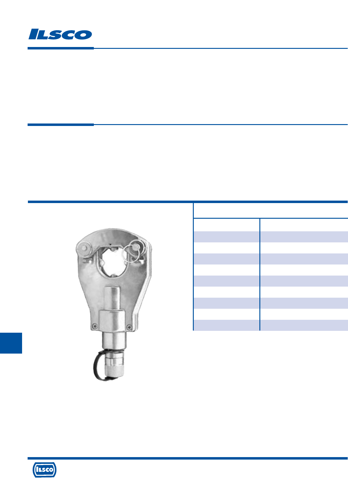
4730 Madison Road, Cincinnati, Ohio 45227-1426 Phone 513 533-6200 Fax 513 871-4084 Web site www.ilsco.com
Canada 1050 Lakeshore Road East, Mississauga, Ontario, Canada L5E1E4 Phone 905 274-2341 Fax 905 274-8763
301
J
For Use with
Aluminum Copper
Connectors Connectors
ACL, ACN Series thru 750kcmil CLN4, CLN9, CLND,
2ACL, 2ACN Series thru 750kcmil CLNF, CLNN, CLNS,
AS Series thru 750kcmil CLNU, CLW4, CLW9,
IACL Series thru 500kcmil CLWD, CLWF, CLWN,
2IACL Series thru 500kcmil CLWS, CSN4, CSN9,
CSND, CSNF, CSNN,
CSNS, CSW4, CSW9,
CSWD, CSWF, CSWN,
CSWS 750kcmil thru 6
Dieless Remote Power Operated Compression
TYPE
IDT-6H
Features
•
Dieless operation
•
Flip top head
•
Lightweight - 6.2 lbs
•
Equipped with 3/8" male screw coupler
Benefits
•
No dies to lose or replace, one tool does it all
•
Easy connector loading and unloading
•
Easy to hold, less tiring for numerous crimps
•
For use with standard industry hoses
Specifications
Force developed: 6.2 Tons
Operating pressure: 10,000 PSI
Overall Length: 10-1/2"
Weight: 6.2 lbs.
Conductor Range: 750kcmil-#6
Additional Requirements:
• Hose
• Pump
Includes:
Steel Carrying Case
Instruction Manual
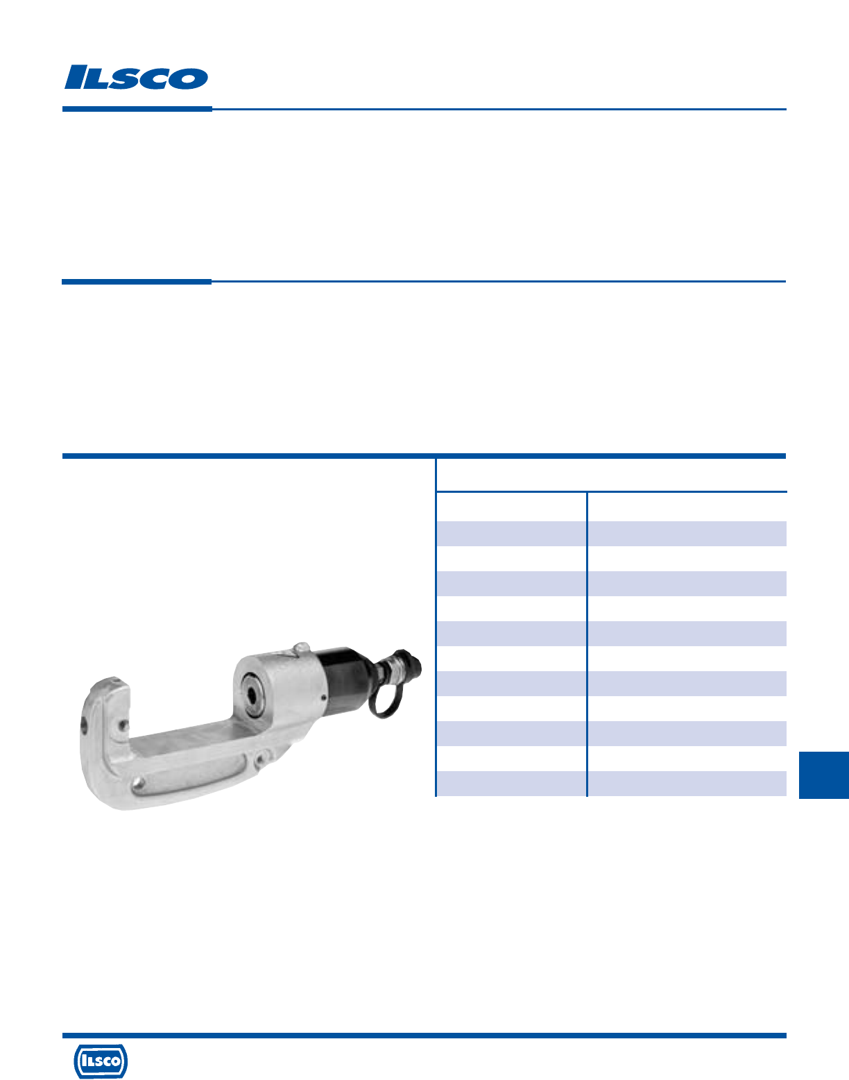
Remote Power Operated Compression Tool
TYPE
ILC-15H
Features
•
Lightweight - only 14.1 lbs
•
Accepts P or U dies with adaptor
•
Hot stick attachment point
•
Equipped with 3/8" male screw coupler
•
Zinc plated head
Benefits
•
Easy to hold, less tiring for numerous crimps
•
Versatility and efficiency. Use your current dies with this
tool
•
Offers the option of performing line maintenance when
properly protected
•
For use with standard industry hoses
•
Excellent corrosion resistance for long tool life
Specifications
Force developed: 15 Tons
Operating pressure: 10,000 PSI
Weight (with case): 14.1 lbs.
Overall length: 15"
Maximum width: 3"
Conductor Range: 1000kcmil-#8
1
2
3
4
For Use with*
Aluminum Copper
Connectors Connectors
CPM Series CLN4, CLN9, CLND,
ACM Series CLNF, CLNN, CLNS,
ACO Series CLNU, CLW4, CLW9,
ACO-90 Series CLWD, CLWF, CLWN,
ACL, ACN 1000kcmil-8 CLWS, CSN4, CSN9,
2ACL, 2ACN 1000kcmil-1/0 CSND, CSNF, CSNN,
AS 1000kcmil-8 CSNS, CSW4, CSW9,
HT Series CSWD, CSWF, CSWN,
AH Series CSWS 1000kcmil thru 8
IACL Series
2IACL Series
*See page 312 for required compression dies
Note: If using “P” dies, an ILD-PADP must be used.
Note: If using “U” dies, an ILD-UADP must be used.
Additional Requirements:
• Hose
• Pump
• Adaptor required with all dies
4730 Madison Road, Cincinnati, Ohio 45227-1426 Phone 513 533-6200 Fax 513 871-4084 Web site www.ilsco.com
Canada 1050 Lakeshore Road East, Mississauga, Ontario, Canada L5E1E4 Phone 905 274-2341 Fax 905 274-8763
302
J
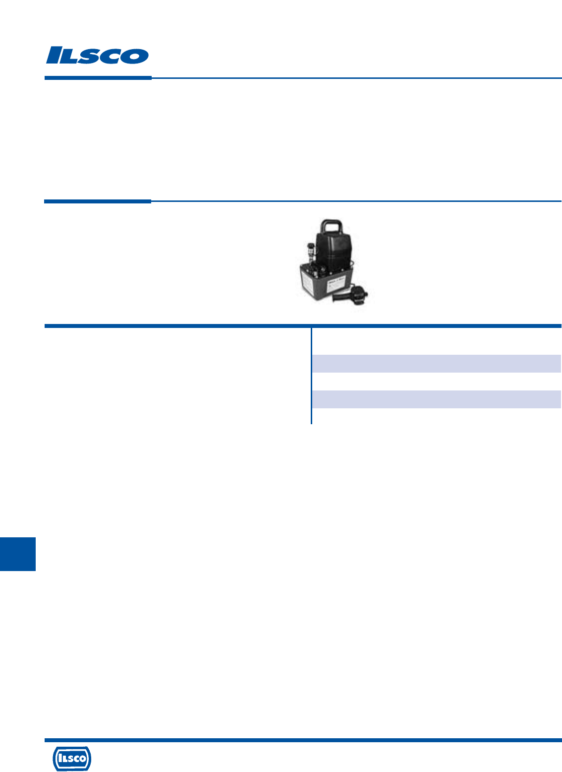
4730 Madison Road, Cincinnati, Ohio 45227-1426 Phone 513 533-6200 Fax 513 871-4084 Web site www.ilsco.com
Canada 1050 Lakeshore Road East, Mississauga, Ontario, Canada L5E1E4 Phone 905 274-2341 Fax 905 274-8763
303
J
L
For Use with
ILC-12H ILC-12H-N
IDT-12H IDT-6H
ILC-14H ILC-15H
ILC-15
Electric/Hydraulic Pump
TYPE
5ACR
Features
•
1/2 HP, 115VSC 50/60 Hz Motor
•
Lightweight, compact design with carrying handle
•
10,000 PSI high-pressure pump with high-pressure
relief valve
•
Two-stage pump for rapid advance
•
Pressure matched quick coupler
Benefits
•
Convenient 115 V-AC electric powered motor and run on as low as 60 VAC
•
Easy to lift, carry and transport tool around job site with lightweight body
and handle
•
High quality crimps are achieved with built in, factory set pressure release
valve
•
Two-stage pumping system of the unique, intermittent duty pump is
designed for years of dependable service
•
Saves time with quick disconnect hydraulic fitting
Technical Data:
Motor: 1/2 HP single phase, 115VAC 9 amps
Electric Control: Remote control with 10' cord
Oil Delivery per minute: 250 cu in @ 200 PSI,
19 cu in @ 10,000 PSI
Oil Reservoir: 1 gallon (3.7 liters)
Overall Length: 10.52"
Overall Width: 8.10"
Overall Height: 15.95"
Pump Weight (with oil): 29 lbs
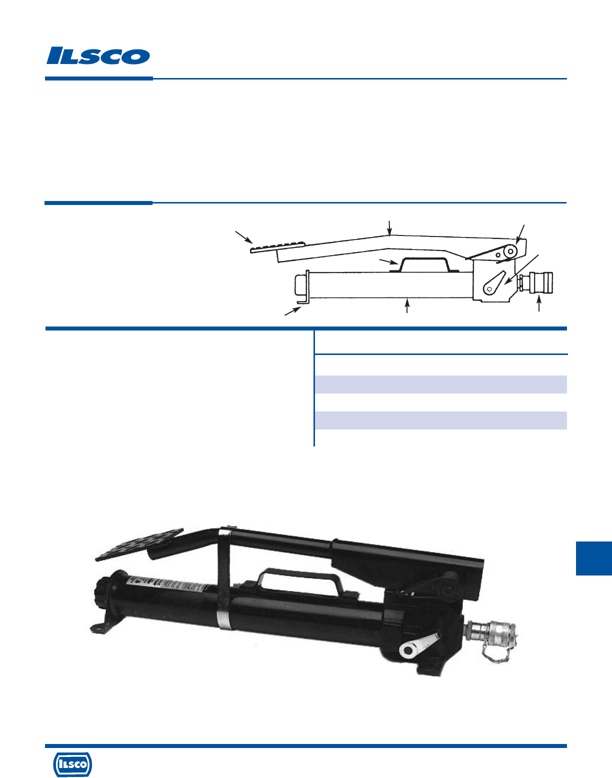
L
Hydraulic Foot Pump
TYPE
FP-1
Features
•
Lightweight rugged design, portable
•
Built in handle
•
Spring loaded arm
•
Long arm
•
Diamond plate steel foot pad
•
Sturdy leg stabilizers
•
Quick-disconnect hydraulic fitting, uses only Pioneer fittings
•
Built-in factory set pressure relief valve
Benefits
•
Easy to lift and carry
•
Easy to transport and move tool around job site with built in handle
•
Easy operation provided with spring assisted return arm
•
Maximum mechanical advantage provided with long arm extending beyond
pump body
•
Quality, heavy duty foot pad provided with diamond plate steel. (slip resistant)
•
Solid tool base provided with sturdy broad leg stabilizers
•
Time saving quick disconnect hydraulic fitting
•
High quality crimps provided with factory set pressure release valve with
audible click to signal completion of crimp
Specifications
Reservoir volume: 1-1/8 qts.
Length: 24-3/4"
Width: 5"
Weight: 19 lbs.
Closed Height: 6-1/2"
Height (with arm open): 17"
Output Pressure: 10,000 PSI
1
2
3
4
5
6
7
8
7
3
2
8
4
61
5
For Use on
Hydraulic
Tools
ILC-12H ILC-12H-N
IDT-12H IDT-6H
ILC-14H ILC-15H
ILC-15
4730 Madison Road, Cincinnati, Ohio 45227-1426 Phone 513 533-6200 Fax 513 871-4084 Web site www.ilsco.com
Canada 1050 Lakeshore Road East, Mississauga, Ontario, Canada L5E1E4 Phone 905 274-2341 Fax 905 274-8763
304
J
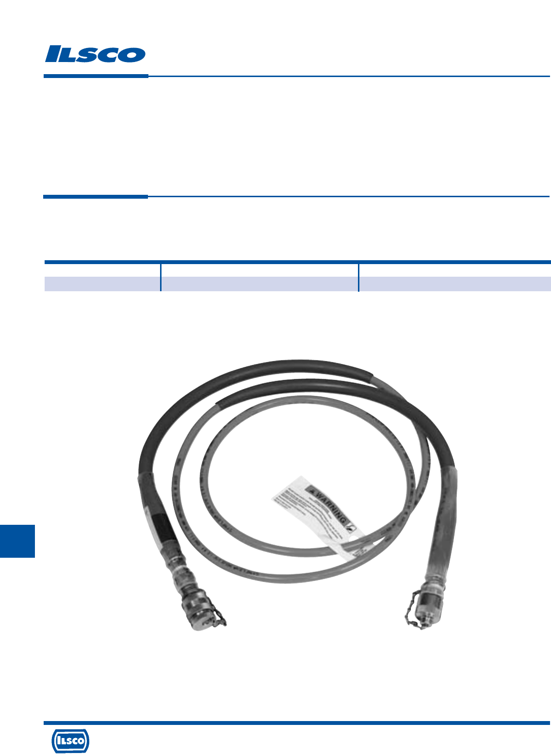
4730 Madison Road, Cincinnati, Ohio 45227-1426 Phone 513 533-6200 Fax 513 871-4084 Web site www.ilsco.com
Canada 1050 Lakeshore Road East, Mississauga, Ontario, Canada L5E1E4 Phone 905 274-2341 Fax 905 274-8763
305
J
L
For use with Ilsco and other hydraulic tools,
Ilsco 5ACR pump and FP-1 foot pump.
Hydraulic Hoses
TYPE
HH-10N
Features
•
Pre-filled with oil
•
Strain reliefs
•
Insulated hose
•
Rated 10,000 PSI
•
Pioneer fittings
•
10 ft. Hose length
Benefits
•
Convenience
•
Safety
•
Safety
•
Powers most remote heads
•
Standard for most hydraulic tools
•
Convenience
Catalog Number Coupler Type For Use With
HH-10N Male - Female IDT-6H, ILC-12H-N, ILC-15H
L
4730 Madison Road, Cincinnati, Ohio 45227-1426 Phone 513 533-6200 Fax 513 871-4084 Web site www.ilsco.com
Canada 1050 Lakeshore Road East, Mississauga, Ontario, Canada L5E1E4 Phone 905 274-2341 Fax 905 274-8763
306
J
4730 Madison Road, Cincinnati, Ohio 45227-1426 Phone 513 533-6200 Fax 513 871-4084 Web site www.ilsco.com
Canada 1050 Lakeshore Road East, Mississauga, Ontario, Canada L5E1E4 Phone 905 274-2341 Fax 905 274-8763
306
ILC-12-N,
IDT-6, ILC-12H-N,
IDT-6H ILC-12,
6.2 Ton ILC-12H,
Dieless, ILC-14, IDT-12,
IDTB-6 ILC-14H 12 Ton, IDT-12H, ILC-15H
6.2 Ton ILCB-12-N, IDT-12-N IDTB-12 15 Ton,
Dieless ILCB-12 15 Ton 11 Ton ILC-30H
Lug Class B/C Color Die 94285 MT-25 ILC-10-N Battery 12 Ton Battery Dieless Dieless 30 Ton ILC-750
Size Wire Size Code Index Left Die Right Die Crimps Crimps Index Crimps Crimps Crimps Crimps Crimps Crimps Crimps
8 8 AWG Red 21 M K 2 1 Red 1 1 1 1
6 6 AWG Blue 24 K K 2 1 Blue 2 1 1 1 1
4 4 AWG Gray 29 K K 2 1 Gray 2 1 1 1 1 1 1
3 3 AWG White 29 K K 2 1 Gray 2 1 1 1 1 1 1
2 2 AWG Brown 33 H H 2 2 Brown 2 1 1 1 1 1 1
1 1 AWG Green 37 H H 2 2 Green 2 1 1 1 1 1 1
1/0 1/0 AWG Pink 42 E A 2 2 Pink 4 1 1 1 1 1 1
2/0 2/0 AWG Black 45 E A 3 2 1 1 1 1 1 1
3/0 3/0 AWG Orange 50 A C 3 2 2 1 1 1 1 1
4/0 4/0 AWG Purple 54 A B 3 2 2 1 1 1 1 1
250 250kcmil Yellow 62 A A 3 2 2 1 1 1 1 1
300 300kcmil White 66 221122
350 350kcmil Red 71 221122
400 400kcmil Blue 76 221122
500 500kcmil Brown 87 221122
600 600kcmil Green 94 221122
700 700kcmil Pink 99 321122
750 750kcmil Black 106 321122
1000 1000kcmil White 125 2112
Series CS, CL Compression Connectors
for Class B/C Copper Wire Only
L
R
-
2
9
6
0
1
453G
ILSCO TOOLS -
Tooling Information
UL Listed and CSA Certified when installed with tools and dies shown above
a) Connectors are marked with color, die numbers and required number of crimps for ILSCO hydraulic tools. When using other listed tools, consult chart for crimps
required. Crimps should be evenly spaced on connector.
b) The ILSCO 94285, MT-25 and all dieless tools are not color coded or do not contain the die index.
c) Strip Length = Barrel Length + 1/16 Inch
d) For long barrel connectors double the amount of crimps indicated on chart except for 1000kcmil add only one additional crimp.
WARNING! Do Not Use with Aluminum Wire
Manual Hand Tools
Hydraulic Tools
RANGE TAKING
Lug Standard Expanded No. Crimps for ILSCO IDT-12,IDT-12-N No. Crimps for ILSCO IDTB-6,
Size Wire Size Wire Size and Burndy Y644M, PAT644 IDT-6 and IDT-6H
44 AWG 4 - 6 AWG 1
33 AWG 3 - 6 AWG 1 1
22 AWG 2 - 6 AWG 1 1
11 AWG 1 - 6 AWG 1 1
1/0 1/0 AWG 1/0 - 6 AWG 1 1
2/0 2/0 AWG 2/0 - 4 AWG 1 1
3/0 3/0 AWG 3/0 - 2 AWG 1 2
4/0 4/0 AWG 4/0 - 1 AWG 1 2
250 250kcmil 250kcmil - 1/0 AWG 1 2
300 300kcmil 300kcmil - 2/0 AWG 1 2
350 350kcmil 350kcmil - 3/0 AWG 1 2
400 400kcmil 400kcmil - 4/0 AWG 1 2
500 500kcmil 500kcmil - 250kcmil 1 2
600 600kcmil 600kcmil - 250kcmil 1 2
700 700kcmil 700kcmil - 350kcmil 1 3
750 750kcmil 750kcmil - 500kcmil 1 3
1000 1000kcmil 1000kcmil - 750kcmil 1
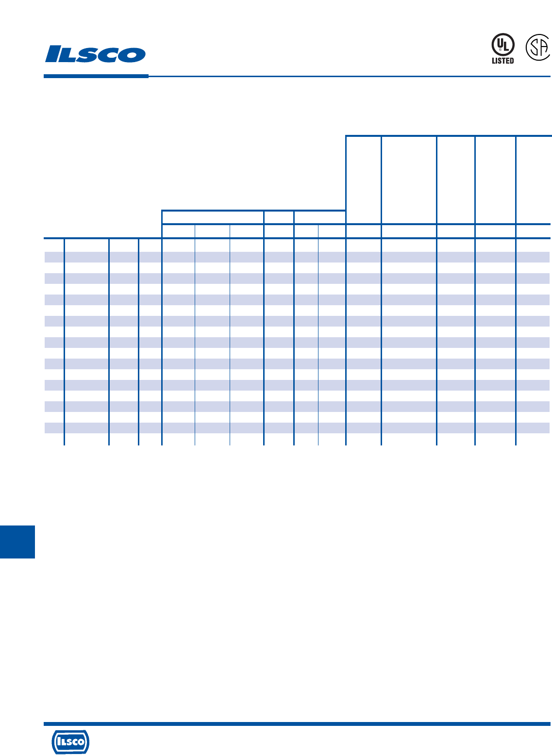
4730 Madison Road, Cincinnati, Ohio 45227-1426 Phone 513 533-6200 Fax 513 871-4084 Web site www.ilsco.com
Canada 1050 Lakeshore Road East, Mississauga, Ontario, Canada L5E1E4 Phone 905 274-2341 Fax 905 274-8763
307
J
ILC-12-N,
IDT-6, ILC-12H-N,
IDT-6H ILC-12,
6.2 Ton ILC-12H,
Dieless, ILC-14, IDT-12,
IDTB-6 ILC-14H 12 Ton, IDT-12H, ILC-15H
6.2 Ton ILCB-12-N, IDT-12-N IDTB-12 15 Ton,
Dieless ILCB-12 15 Ton 11 Ton ILC-30H
Lug Class B/C Color Die 94285 MT-25 ILC-10-N Battery 12 Ton Battery Dieless Dieless 30 Ton
Size Wire Size Code Index Left Die Right Die Crimps Crimps Index Crimps Crimps Crimps Crimps Crimps Crimps
8 8 AWG Red 21 M K 2 1 Red 1 1 1
6 6 AWG Blue 24 K K 2 1 Blue 2 1 1 1 1
4 4 AWG Gray 29 K K 2 1 Gray 2 1 1 1 1 1
3 3 AWG White 29 K K 2 1 Gray 2 1 1 1 1 1
2 2 AWG Brown 33 H H 2 2 Brown 2 1 1 1 1 1
1 1 AWG Green 37 H H 2 2 Green 2 1 1 1 1 1
1/0 1/0 AWG Pink 42 E A 2 2 Pink 4 1 1 1 1 1
2/0 2/0 AWG Black 45 E A 3 2 1 1 1 1 1
3/0 3/0 AWG Orange 50 A C 3 2 2 1 1 1 1
4/0 4/0 AWG Purple 54 A B 3 2 2 1 1 1 1
250 250kcmil Yellow 62 A A 3 2 2 1 1 1 1
300 300kcmil White 66 22112
350 350kcmil Red 71 22112
400 400kcmil Blue 76 22112
500 500kcmil Brown 87 22112
600 600kcmil Green 94 22112
700 700kcmil Pink 99 32112
750 750kcmil Black 106 32112
1000 1000kcmil White 125 2112
Series CT, CTL Compression Connectors
for Class B/C Copper Wire Only
L
R
-
2
9
6
0
1
453G
ILSCO TOOLS -
Tooling Information
UL Listed and CSA Certified when installed with tools and dies shown above
a) Number of crimps shown on chart must be on each end of the CT splicer connectors.
b) The CT connectors are marked with color, the die numbers and required number of crimps for ILSCO hydraulic tools. When using other listed tools, consult chart for crimps
required. Crimps should be evenly spaced on connector.
c) The ILSCO 94285, MT-25 and all dieless tools are not color coded or do not contain the die index.
d) For long barrel (CTL) connectors add one additional crimp to each side of barrel.
WARNING! Do Not Use with Aluminum Wire
Manual Hand Tools
Hydraulic Tools
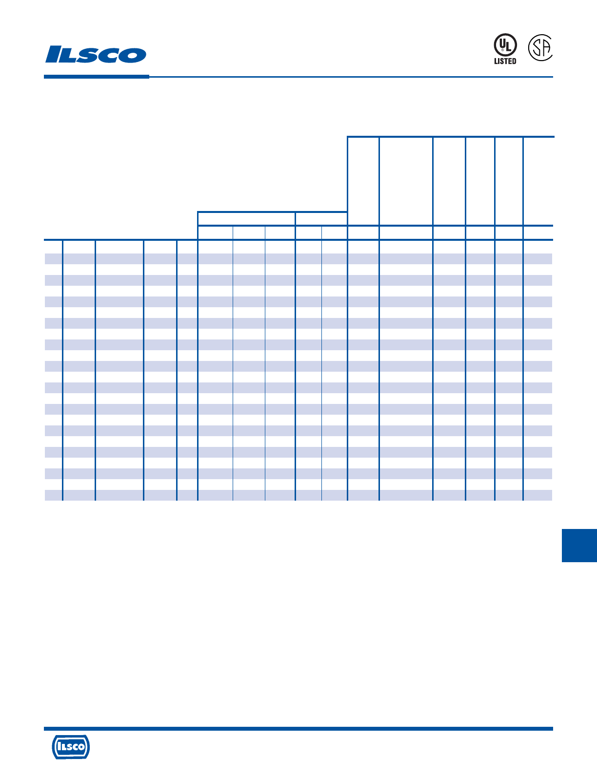
4730 Madison Road, Cincinnati, Ohio 45227-1426 Phone 513 533-6200 Fax 513 871-4084 Web site www.ilsco.com
Canada 1050 Lakeshore Road East, Mississauga, Ontario, Canada L5E1E4 Phone 905 274-2341 Fax 905 274-8763
308
J
ILC-12-N,
IDT-6, ILC-12H-N,
IDT-6H ILC-12,
6.2 Ton ILC-12H,
Dieless, ILC-14, IDT-12,
IDTB-6 ILC-14H 12 Ton, IDT-12H, ILC-15H
6.2 Ton ILCB-12-N, IDT-12-N IDTB-12 15 Ton,
Fine Dieless ILCB-12 15 Ton 11 Ton ILC-30H
Lug Strand Approved Color Die 94285 ILC-10-N Battery 12 Ton Battery Dieless Dieless 30 Ton ILC-750
Size Wire Size Wire Classes Code Index Left Die Right Die Crimps Index Crimps Crimps Crimps Crimps Crimps Crimps Crimps
8 8 G,H,I,K,M,DLO Red 21 Red 1 1 1 1
4 6 G,H,I,K,M,DLO Gray 29 Blue 2 1 1 1
3 4 G,H,I,K,M,DLO White 29 K K 2 Gray 2 1 1 1 1 1 1
1 2 G,H,I,K,M,DLO Green 37 H H 2 Green 2 1 1 1 1 1 1
1/0 1 G,H,I,K,M,DLO Pink 42 H H 2 Pink 4 1 1 1 1 1 1
2/0 1/0 G,H,I,K,M,DLO Black 45 E A 3 1 1 1 1 1 1
3/0 2/0 G,H,I,K,M,DLO Orange 50 E A 3 1 1 1 1 1 1
4/0 3/0 G,H,I,K,M,DLO Purple 54 A B 3 1 1 1 1 1 1
250 4/0 G,H,I,K,M,DLO Yellow 62 A B 3 1 1 1 1 1 1
300 250 G,H White 66 1 2 1 1 2 2
350 250 I,K,M Red 71 1 2 1 1 2 2
350 262 DLO Red 71 1 2 1 1 2 2
400 300 G,H,I,K,M Blue 76 2 2 1 1 2 2
400 313 DLO Blue 76 2 2 1 1 2 2
500 350 G,H,I,K,M Brown 87 2 2 1 1 2 2
500 373 DLO Brown 87 2 2 1 1 2 2
600 400 G,H,I,K,M Green 94 2 2 1 1 2 2
600 444 DLO Green 94 2 2 1 1 2 2
700 500 G,H,I,K,M Pink 99 3 2 1 1 2 2
700 535 DLO Pink 99 3 2 1 1 2 2
750 600 G,H,I,M Black 106 3 2 1 1 2 2
750 646 DLO Black 106 3 2 1 1 2 2
1000 750 G,H,I White 125 3113
1000 777 DLO White 125 3113
Series CS, CL Compression Connectors
for Fine Strand Copper Wire Only
L
R
-
2
9
6
0
1
453G
ILSCO TOOLS -
Tooling Information
UL Listed and CSA Certified when installed with tools and dies shown above
a) Connectors are marked with color, die numbers and required number of crimps for ILSCO hydraulic tools. When using other listed tools, consult chart for crimps
required. Crimps should be evenly spaced on connector.
b) The ILSCO 94285, MT-25 and all dieless tools are not color coded or do not contain the die index.
c) Strip Length = Barrel Length + 1/16 Inch
d) For long barrel connectors double the amount of crimps indicated on chart except for 1000kcmil add only one additional crimp.
WARNING! Do Not Use with Aluminum Wire
Manual Hand Tools
Hydraulic Tools
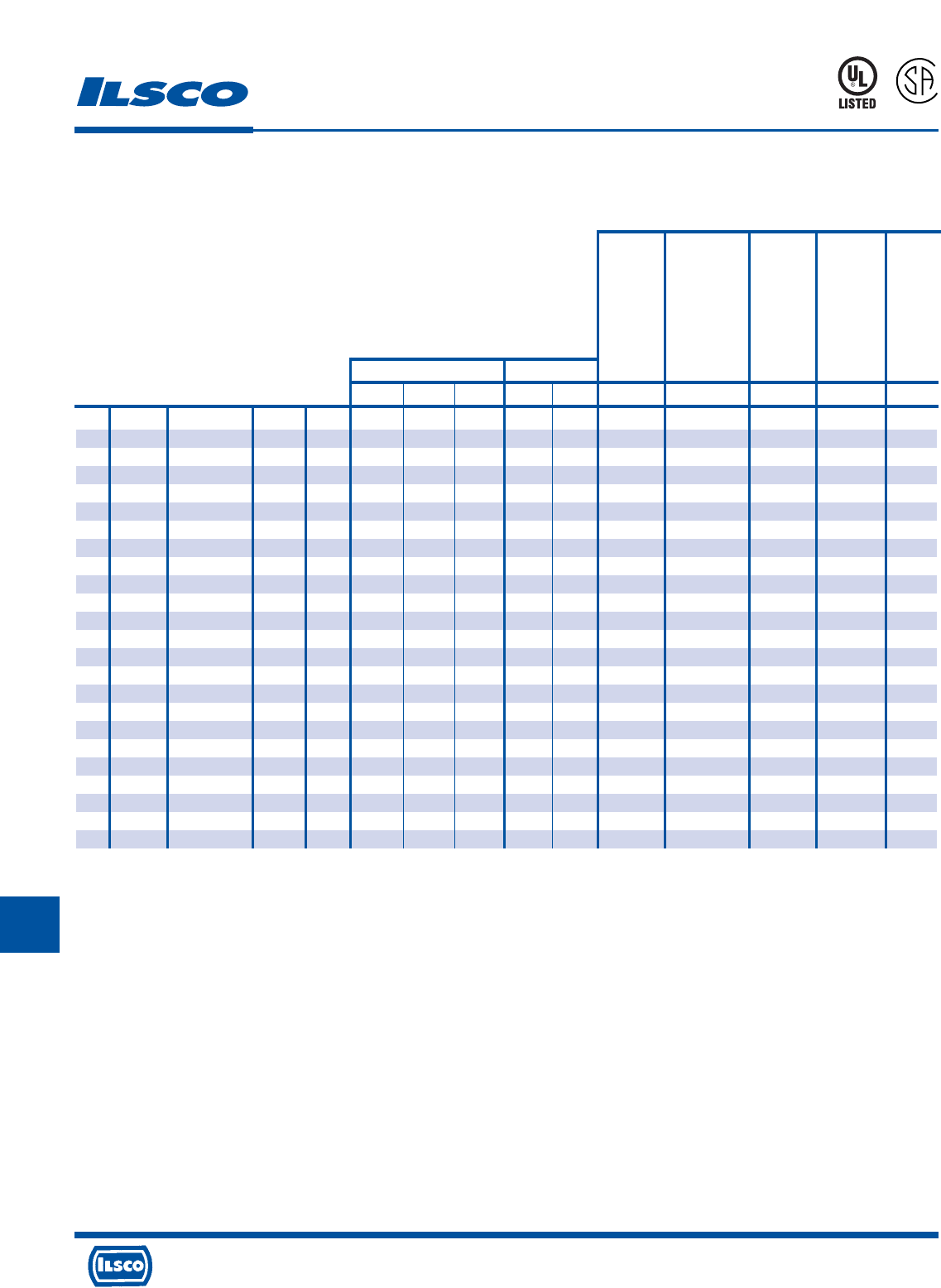
4730 Madison Road, Cincinnati, Ohio 45227-1426 Phone 513 533-6200 Fax 513 871-4084 Web site www.ilsco.com
Canada 1050 Lakeshore Road East, Mississauga, Ontario, Canada L5E1E4 Phone 905 274-2341 Fax 905 274-8763
309
J
Series CT, CTL - Compression Connectors
for Fine Strand Copper Wire Only
L
R
-
2
9
6
0
1
453G
ILC-12-N,
IDT-6, ILC-12H-N,
IDT-6H ILC-12,
6.2 Ton ILC-12H,
Dieless, ILC-14, IDT-12,
IDTB-6 ILC-14H 12 Ton, IDT-12H, ILC-15H
6.2 Ton ILCB-12-N, IDT-12-N IDTB-12 15 Ton,
Fine Dieless ILCB-12 15 Ton 11 Ton ILC-30H
Lug Strand Approved Color Die 94285 ILC-10-N Battery 12 Ton Battery Dieless Dieless 30 Ton
Size Wire Size Wire Classes Code Index Left Die Right Die Crimps Index Crimps Crimps Crimps Crimps Crimps Crimps
8 8 G,H,I,K,M,DLO Red 21 M K 2 Red 1 1 1
4 6 G,H,I,K,M,DLO Gray 29 K K 2 Blue 2 1 1
3 4 G,H,I,K,M,DLO White 29 K K 2 Gray 2 1 1 1 1 1
1 2 G,H,I,K,M,DLO Green 37 H H 2 Green 2 1 1 1 1 1
1/0 1 G,H,I,K,M,DLO Pink 42 H H 2 Pink 4 1 1 1 1 1
2/0 1/0 G,H,I,K,M,DLO Black 45 E A 3 1 1 1 1 1
3/0 2/0 G,H,I,K,M,DLO Orange 50 E A 3 2 1 1 1 1
4/0 3/0 G,H,I,K,M,DLO Purple 54 A B 3 2 1 1 1 1
250 4/0 G,H,I,K,M,DLO Yellow 62 A B 3 2 1 1 1 1
300 250 G,H White 66 2 2 1 1 2
350 250 I,K,M Red 71 2 2 1 1 2
350 262 DLO Red 71 2 2 1 1 2
400 300 G,H,I,K,M Blue 76 2 2 1 1 2
400 313 DLO Blue 76 2 2 1 1 2
500 350 G,H,I,K,M Brown 87 2 2 1 1 2
500 373 DLO Brown 87 2 2 1 1 2
600 400 G,H,I,K,M Green 94 2 2 1 1 2
600 444 DLO Green 94 2 2 1 1 2
700 500 G,H,I,K,M Pink 99 3 3 1 1 3
700 535 DLO Pink 99 3 3 1 1 3
750 600 G,H,I,M Black 106 3 3 1 1 3
750 646 DLO Black 106 3 3 1 1 3
1000 750 G,H,I White 125 3113
1000 777 DLO White 125 3113
ILSCO TOOLS -
Tooling Information
WARNING! Do Not Use with Aluminum Wire
Manual Hand Tools
Hydraulic Tools
UL Listed and CSA Certified when installed with tools and dies shown above
a) Number of crimps shown on chart must be on each end of the CT splicer connectors.
b) The CT connectors are marked with color, the die numbers and required number of crimps for ILSCO hydraulic tools. When using other listed tools, consult chart for crimps
required. Crimps should be evenly spaced on connector.
c) The ILSCO 94285, MT-25 and all dieless tools are not color coded or do not contain the die index.
d) For long barrel (CTL) connectors add one additional crimp to each side of barrel.
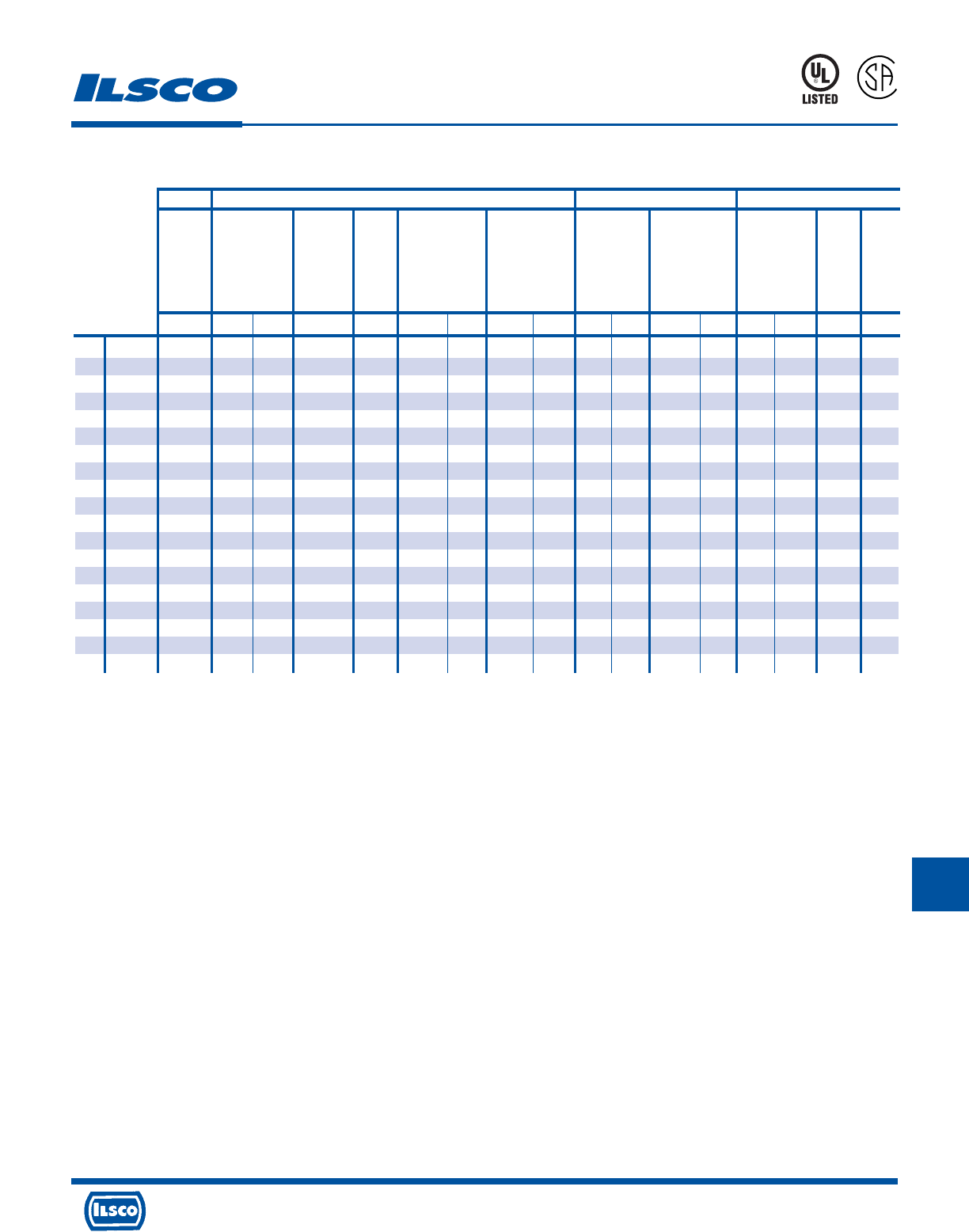
4730 Madison Road, Cincinnati, Ohio 45227-1426 Phone 513 533-6200 Fax 513 871-4084 Web site www.ilsco.com
Canada 1050 Lakeshore Road East, Mississauga, Ontario, Canada L5E1E4 Phone 905 274-2341 Fax 905 274-8763
310
J
Anderson Burndy T&B Greenlee
VC6-FT,
VC6-FTR,
VC6-FT-BP PAT81KFT, ‡ HK06FT,
VC7-FT, Y81KFT, Y644M, Y35, Y35BH, Y46, Y46C 13100A, RK06FT,
VC7-FTR Y81KFTMBH PAT644 Y39, Y750, Requires TBM14M, EK06FT 1990
Lug Class B/C Dieless Y1MR, Y1MRTC Dieless Dieless Y750BH, PAT750 Die Adaptor TBM25S TBM14BSCR K111 Dieless Dieless
Size Wire Size Crimps Index Crimps Crimps Crimps Die Part Crimps Die Part Crimps Index Crimps Die Part Crimps Index Crimps Crimps Crimps
8 8 AWG 1 Red 1 1 U8CRT 1 U8CRT 1 Red 1 15520 1 Red 1
6 6 AWG 1 Blue 1 1 U5CRT 1 U5CRT 1 Blue 1 15522 1 Blue 2 1
4 4 AWG 1 Gray 2 1 1 U4CRT 1 U4CRT 1 Gray 2 15527-CK 1 Gray 2 1 1
3 3 AWG 1 White 2 1 1 U3CRT 1 U3CRT 1 Gray 2 1 1
2 2 AWG 1 Brown 2 1 1 U2CRT 1 U2CRT 1 Brown 2 15528 1 Brown 2 1 1
1 1 AWG 1 1 1 U1CRT-1 1 U1CRT-1 1 15513-CK 1 Green 2 1 1
1/0 1/0 AWG 1 1 1 U25RT 1 U25RT 1 15508 1 Pink 4 1 1
2/0 2/0 AWG 1 1 1 U26RT 1 U26RT 1 15526 1 1 1
3/0 3/0 AWG 1 1 1 U27RT 1 U27RT 1 15530 1 2 1
4/0 4/0 AWG 1 1 1 U28RT 1 U28RT 1 15511 1 2 1
250 250kcmil 2 2 1 U29RT 1 U29RT 1 15510-CK 1 2 1
300 300kcmil 2 2 1 U30RT 2 U30RT 2 15534 2 2 1
350 350kcmil 3* 2 1 U31RT 2 U31RT 2 15514-CK 2 2 1
400 400kcmil 3* 2 1 U32RT 2 U32RT 2 15512 2 2 1
500 500kcmil 3* 2 1 U34RT 2 U34RT 2 15506 2 2 1
600 600kcmil 4* 2 1 U36RT 2 U36RT 2 15536-CK 2 2 1
700 700kcmil 4* 3 1 U38RT 2 U38RT 2 15505 2 3 1
750 750kcmil 4* 3 1 U39RT 2 U39RT 2 15515-CK 2 3 1
1000 1000kcmil 3 1 P44RT 3 15504 2 1
Series CS, CL - Compression Connectors
for Class B/C Copper Wire Only
L
R
-
2
9
6
0
1
453G
COMPETITOR’S TOOLS -
Tooling Information
Dieless* - Crimps will overlap
WARNING! Do Not Use with Aluminum Wire
UL Listed and CSA Certified when installed with tools and dies shown above
a) Connectors are marked with color, die numbers and required number of crimps for ILSCO hydraulic tools. When using other listed tools, consult chart for crimps
required. Crimps should be evenly spaced on connector.
b) The ILSCO 94285, MT-25 and all dieless tools are not color coded or do not contain the die index.
c) Consult manufacturers data for catalog numbers of dies for each tool.
d) Strip Length = Barrel Length + 1/16 Inch
e) For long barrel connectors double the amount of crimps indicated on chart except for 1000kcmil add only one additional crimp.
‡ Allows expanded wire range to be used.
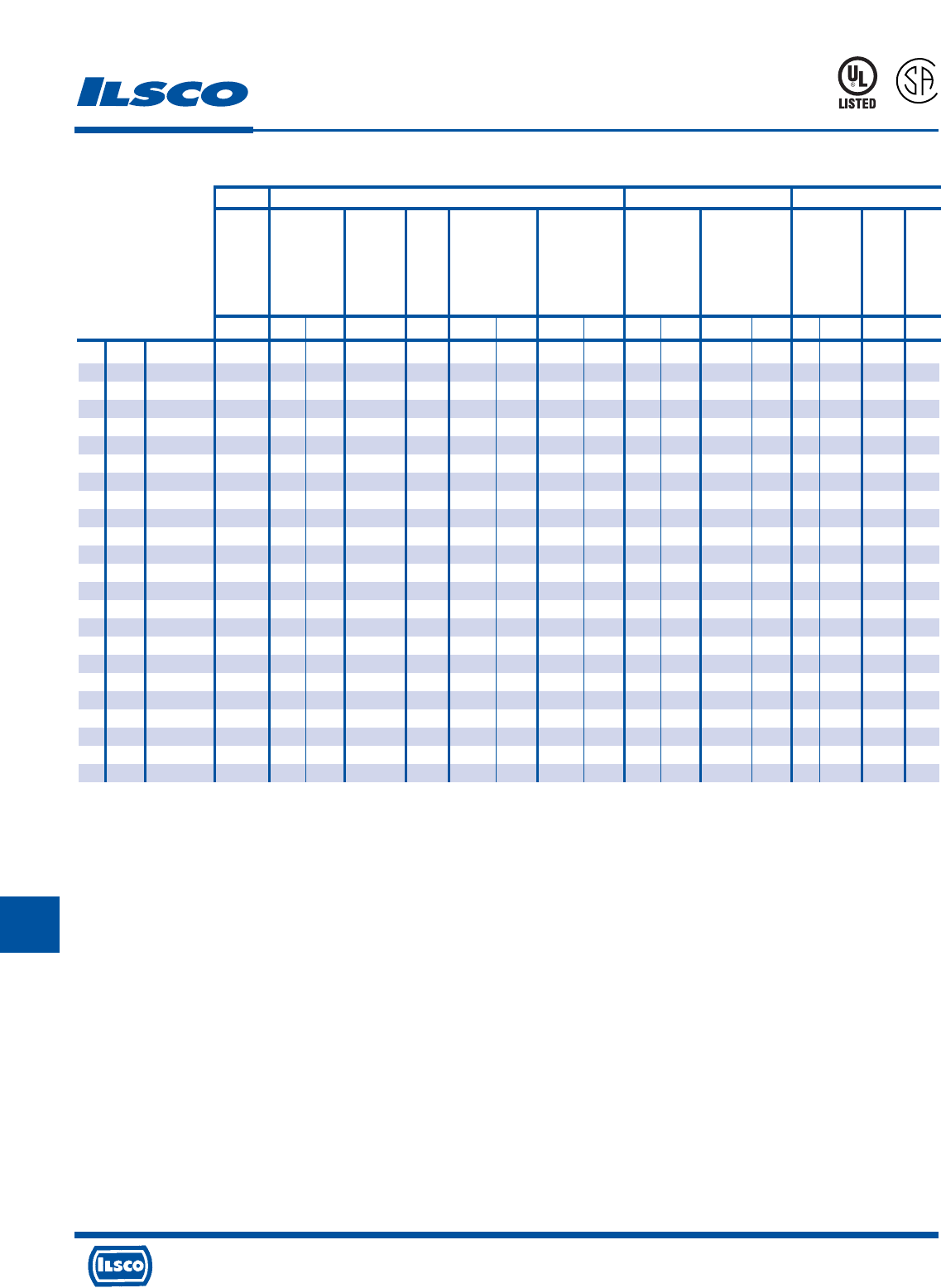
4730 Madison Road, Cincinnati, Ohio 45227-1426 Phone 513 533-6200 Fax 513 871-4084 Web site www.ilsco.com
Canada 1050 Lakeshore Road East, Mississauga, Ontario, Canada L5E1E4 Phone 905 274-2341 Fax 905 274-8763
311
J
Anderson Burndy T&B Greenlee
VC6-FT,
VC6-FTR,
VC6-FT-BP, PAT81KFT,
‡
HK06FT,
Fine VC7-FT, Y81KFT, Y644M, Y35, Y35BH, Y46, Y46C 13100A, RK06FT,
Strand VC7-FTR Y81KFTMBH PAT644 Y39, Y750, Requires TBM14M, EK06FT 1990
Lug Wire Approved Dieless Y1MR, Y1MRTC Dieless Dieless Y750BH, PAT750 Die Adaptor TBM25S TBM14BSCR K111 Dieless Dieless
Size Size Wire Classes Crimps Index Crimps Crimps Crimps Die Part Crimps Die Part Crimps Index Crimps Die Part Crimps Index Crimps Crimps Crimps
8 8 G,H,I,K,M,DLO 1 Red 1 1 U8CRT 1 U8CRT 1 Red 1 15520 1 Red 1
4 6 G,H,I,K,M,DLO 1 Blue 2 1 U5CRT 1 U5CRT 1 Blue 2 15522 1 Blue 2
3 4 G,H,I,K,M,DLO 1 Gray 2 1 1 U4CRT 1 U4CRT 1 Gray 2 15528 1 Gray 2 1 1
1 2 G,H,I,K,M,DLO 1 Brown 2 1 1 U2CRT 1 U2CRT 1 Brown 3 15513-CK 1 Green 2 1 1
1/0 1 G,H,I,K,M,DLO 1 1 1 U1CRT-1 1 U1CRT-1 1 15508 1 Pink 4 1 1
2/0 1/0 G,H,I,K,M,DLO 1 1 1 U25RT 1 U25RT 1 15526 1 1 1
3/0 2/0 G,H,I,K,M,DLO 2 2 1 U26RT 1 U26RT 1 15530 1 1 1
4/0 3/0 G,H,I,K,M,DLO 2 2 1 U27RT 1 U27RT 1 15511 1 1 1
250 4/0 G,H,I,K,M,DLO 2 2 1 U28RT 1 U28RT 1 15510-CK 2 1 1
300 250 G,H 2 2 1 U29RT 2 U29RT 2 15534 2 1 1
350 250 I,K,M 3* 2 1 U30RT 2 U30RT 2 2 1 1
350 262 DLO 3* 2 1 2 2 2 1 1
400 300 G,H,I,K,M 3* 2 1 U31RT 2 U31RT 2 15514-CK 2 2 1
400 313 DLO 3* 2 1 2 2 2 2 1
500 350 G,H,I,K,M 3* 2 1 U32RT 2 U32RT 2 15512 2 2 1
500 373 DLO 3* 2 1 2 2 15517 2 2 1
600 400 G,H,I,K,M 4* 2 1 U34RT 2 U34RT 2 15536-CK 2 2 1
600 444 DLO 4* 2 1 2 2 2 2 1
700 500 G,H,I,K,M 4* 3 1 U38XRT 2 U38XRT 2 15505 2 3 1
700 535 DLO 4* 3 1 2 2 2 3 1
750 600 G,H,I,M 4* 3 1 U39RT 2 U39RT 2 15515-CK 2 3 1
750 646 DLO 4* 3 1 2 2 2 3 1
1000 750 G,H,I 3 1 U44XRT 3 15504 3 1
1000 777 DLO 3 1 3 3 1
Series CS, CL - Compression Connectors
for Fine Strand Copper Wire Only
L
R
-
2
9
6
0
1
453G
COMPETITOR’S TOOLS -
Tooling Information
Dieless* - Crimps will overlap
WARNING! Do Not Use with Aluminum Wire
UL Listed and CSA Certified when installed with tools and dies shown above
a) Connectors are marked with color, die numbers and required number of crimps for ILSCO hydraulic tools. When using other listed tools, consult chart for crimps
required. Crimps should be evenly spaced on connector.
b) The ILSCO 94285, MT-25 and all dieless tools are not color coded or do not contain the die index.
c) Strip Length = Barrel Length + 1/16 Inch
d) For long barrel connectors double the amount of crimps indicated on chart except for 1000kcmil add only one additional crimp.
‡ Allows expanded wire range to be used.
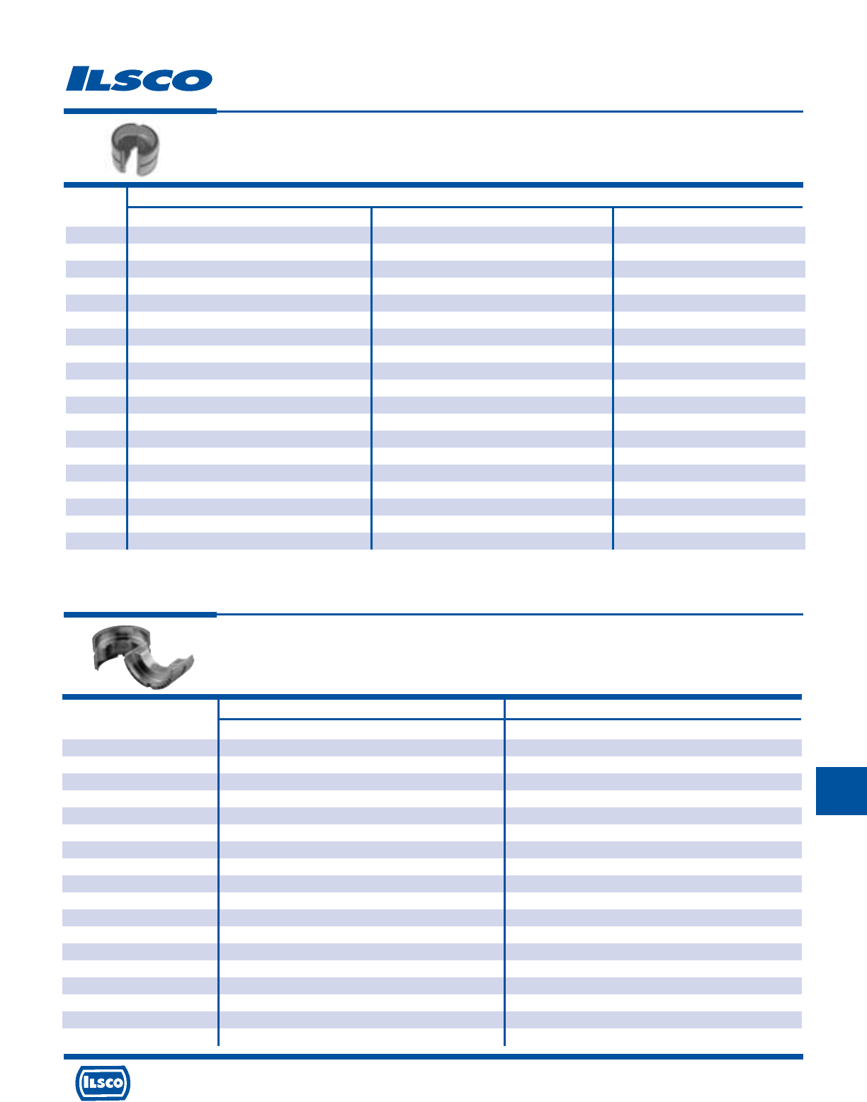
4730 Madison Road, Cincinnati, Ohio 45227-1426 Phone 513 533-6200 Fax 513 871-4084 Web site www.ilsco.com
Canada 1050 Lakeshore Road East, Mississauga, Ontario, Canada L5E1E4 Phone 905 274-2341 Fax 905 274-8763
312
J
L
Catalog Wire Size
Number Aluminum Terminals and Splices ACM and ACO Pin Connectors CPM Pin Connectors
ILD-1
ILD-2 8
ILD-3 6
ILD-4 4
ILD-5
ILD-6
ILD-7 2, 1
ILD-8 1/0 6, 4, 2, 1
ILD-9 6, 4, 2, 1
ILD-10 2/0, 3/0
ILD-11
ILD-12 4/0 1/0, 2/0, 3/0, 4/0 1/0, 2/0, 3/0, 4/0
ILD-13 250kcmil
ILD-14 300kcmil, 350kcmil 250kcmil, 300kcmil, 350kcmil 250kcmil, 300kcmil, 350kcmil
ILD-15
ILD-16 400kcmil
ILD-16A *500kcmil 400kcmil, 500kcmil 400kcmil,500 kcmil
ILD-17 *600kcmil, *700 kcmil
ILD-18 *700kcmil 600kcmil, 750kcmil 600 kcmil,750 kcmil
Compression Die Index
Compressor Dies For ILC-12-N, ILC-12H-N, ILCB-12-N, ILC-15H,
ILC-12, ILC-12H, ILC-14, ILC-14H, ILCB-12, ILC-15, ILC-750
* Cannot be used on Sleeves with ILC-12-N, ILC-12H-N, ILC-12 and ILC-12H tools
Catalog Class B/C Copper Wire Only Fine Strand Copper Wire Only
Number Series CS, CL, CT, CTL Series CS, CL, CT, CTL
ILD-21 8 AWG 8 FLEX CLASS G,H,I,K,M,DLO
ILD-24 6 AWG -
ILD-29 4-3 AWG 6-4 FLEX CLASS G,H,I,K,M,DLO
ILD-33 2 AWG -
ILD-37 1 AWG 2 FLEX CLASS G,H,I,K,M,DLO
ILD-42 1/0 AWG 1 FLEX CLASS G,H,I,K,M,DLO
ILD-45 2/0 AWG 1/0 FLEX CLASS G,H,I,K,M,DLO
ILD-50 3/0 AWG 2/0 FLEX CLASS G,H,I,K,M,DLO
ILD-54 4/0 AWG 3/0 FLEX CLASS G,H,I,K,M,DLO
ILD-62 250kcmil 4/0 FLEX CLASS G,H,I,K,M,DLO
ILD-66 300kcmil 250 G,H
ILD-71 350kcmil 250 I,K,M, 262 DLO
ILD-76 400kcmil 300 G,H,I,K,M, 313 DLO
ILD-87 500kcmil 350 G,H,I,K,M, 373 DLO
ILD-94 600kcmil 400 G,H,I,K,M, 444 DLO
ILD-99 700kcmil 500 G,H,I,K,M, 535 DLO
ILD-106 750kcmil 600 G,H,I,M, 646 DLO
ILD-125 1000kcmil 750 G,H,I, 777 DLO
Compressor Dies For ILC-12, ILC-12-N, ILC-12H, ILC-12H-N,
ILCB-12, ILCB-12-N, ILC-14, ILC-14H, ILC-15, ILC-15H, ILC-750
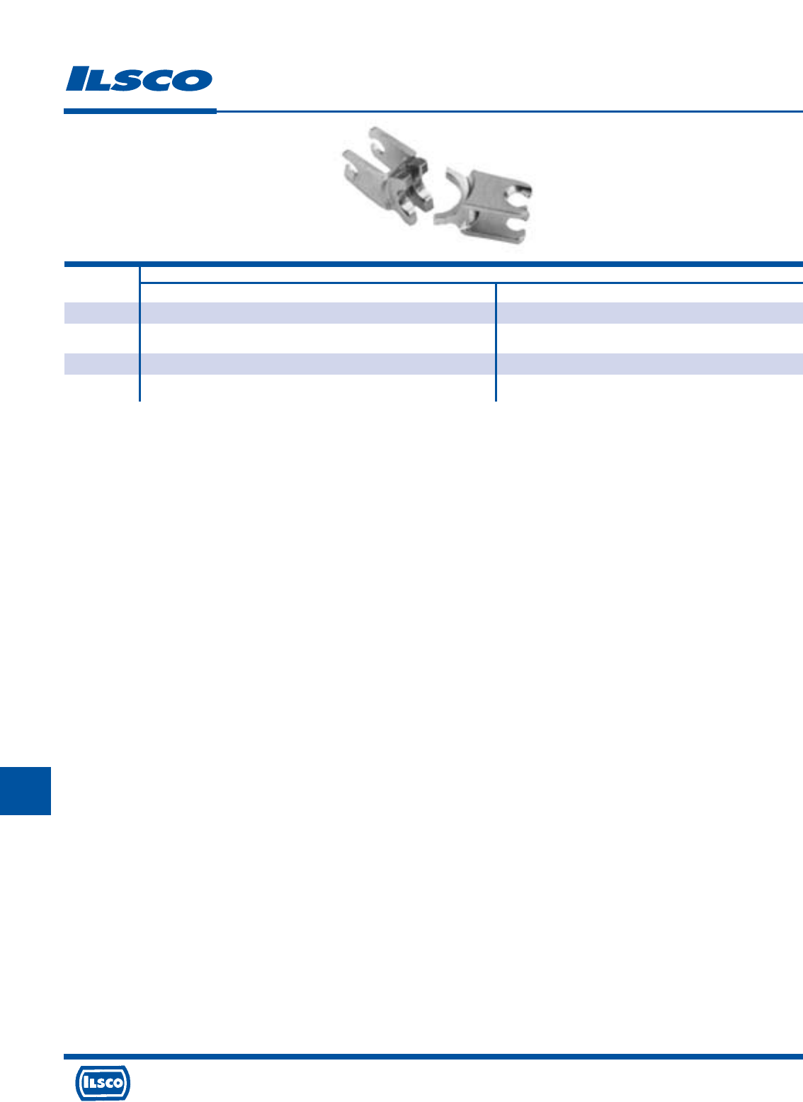
4730 Madison Road, Cincinnati, Ohio 45227-1426 Phone 513 533-6200 Fax 513 871-4084 Web site www.ilsco.com
Canada 1050 Lakeshore Road East, Mississauga, Ontario, Canada L5E1E4 Phone 905 274-2341 Fax 905 274-8763
313
J
L
Catalog For Use With
Number Aluminum Compression Connectors Copper Compression Connectors
ND-0 HT-1, HT-2, AH-1 GGC-1, GGA-1, GGA-2, GGA-4
ND-BG PICS-61 thru PICS-78 ULT-4, ULT-5
ND-C ULT-6, ULT-7
ND-K-840 UCS-2/0, UCS-3/0, UCS-4/0, UCS-250, PICS-834 thru PICS-869
Compression Dies
TYPE W DIES FOR
ND-60
ND-58
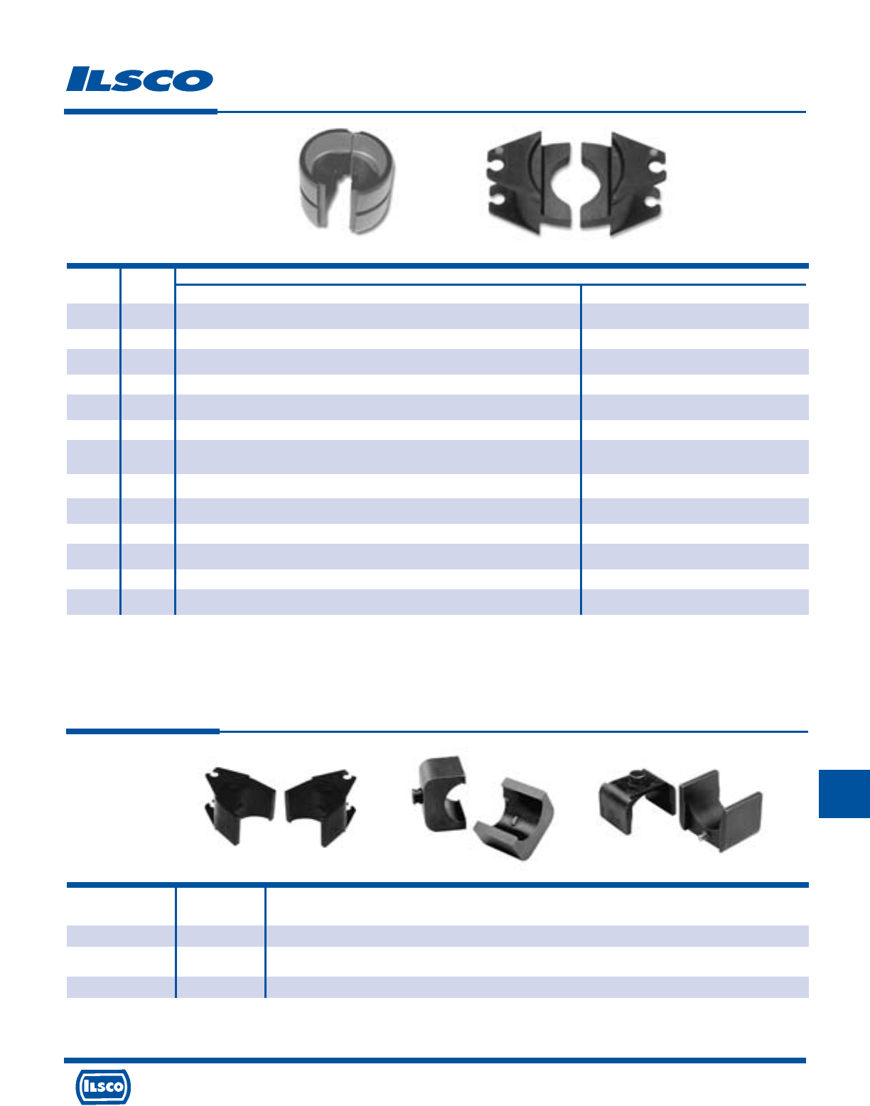
4730 Madison Road, Cincinnati, Ohio 45227-1426 Phone 513 533-6200 Fax 513 871-4084 Web site www.ilsco.com
Canada 1050 Lakeshore Road East, Mississauga, Ontario, Canada L5E1E4 Phone 905 274-2341 Fax 905 274-8763
314
J
L
Catalog Figure
Number Number Description
ILD-ADP 1 Permits ILD-1 to ILD-18 to be inserted in ILC-15 tool
ILD-UADP 2 Permits ILD-1 to ILD-18 to be inserted in ILC-15H tool
ILD-PADP 3 Permits “P” style dies to be inserted in ILC-15H tool
Compression Dies
Die Adaptors
Figure 1
Catalog Figure For Use With
Number Number Aluminum Compression Connectors Copper Compression Connectors
ILD-K-840*+ 1 UCS-2/0, UCS-3/0, UCS-4/0, UCS-250, PICS-834 thru PICS-869
ILD-C*+ 1 ULT-6, ULT-7, ELT-1
ILD-D3*+ 1 HT-2, HT-3, HT-4, HT-5, HT-7, AH-2, AH-3, AH-4 ULT-12
ILD-0* 1 HT-1, HT-6, HT-8, AH-1 GGC-1, GGA-1, GGA-2, GGA-4, ELT-2, ELT-4
ILD-N*+ 1 AH-5, AH-6, AH-7
ILD-KR+ 2 AH-8, AH-9, AH-10, AH-11, AH-12 AH-10, AH-11, AH-12
ILD-U997*+ 1 GGA-2, GGA-3, GGA-5, GGC-2, GGC-3, GGC-4
ELT-3, ELT-5
ILD-U998+ 1 GGA-4, GGA-5, GGC-5, GGC-6, GGC-7, RLT
ILD-P998 2 Can only be used with ILC-15 or ILC-15H GGA-4, GGA-5, GGC-5, GGC-6, GGC-7, RLT
ILD-P999 2 Can only be used with ILC-15 or ILC-15H GGA-6, GGC-8
ILD-U1011+ 1 GGA-6, GGC-8, ELT-6, RLT
ILD-P1011o2GGA-6, GGC-8, RLT
ILD-UBG 1 PICS-61 thru PICS-78 ULT-4, ULT-5
FOR TYPE
ILC-15
ILC-15H
ILC-750
FOR TYPE
ILC-15
ILC-15H
* May also be used with ILC-12-N, ILC-12H-N, ILCB-12-N, ILC-12, ILC-12H, ILCB-12
+ Must be used with ILD-ADP when using ILC-15, must be used with ILD-PADP when using ILC-15H
o Must be used with ILD-PADP when using ILC-15H
Figure 1 Figure 3
Figure 2
Figure 2
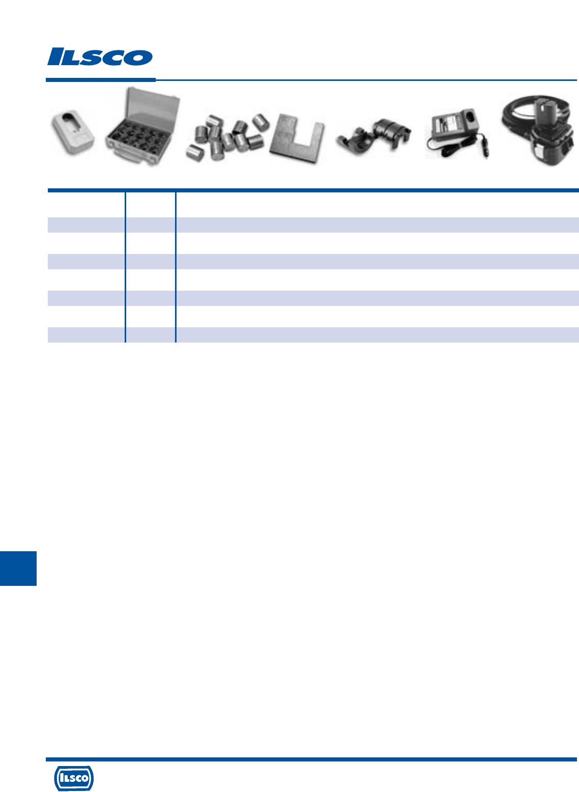
4730 Madison Road, Cincinnati, Ohio 45227-1426 Phone 513 533-6200 Fax 513 871-4084 Web site www.ilsco.com
Canada 1050 Lakeshore Road East, Mississauga, Ontario, Canada L5E1E4 Phone 905 274-2341 Fax 905 274-8763
315
J
L
Tool Accessories
Catalog Figure
Number Number Description
TOOL-STAND 1 Battery Tool Stand
ILD-DIE-CASE 2 Crimping die carrying case (dies not included)
IDT-6-TON-TEST-KIT 3 10 Test slugs and gauge
IDT-12-TON-TEST-KIT 3 30 Test slugs and gauge
CUTTER-DIES 4 Guy wire cutting dies
CAR-CHARGER(12v) 5 Car charger for battery tools
AC-ADAPTOR(120v) 6 AC adaptor for battery tools
AC-ADAPTOR(230v) 6 AC adaptor for battery tools
Fig. 1 Fig. 2 Fig. 3 Fig. 4 Fig. 5 Fig. 6
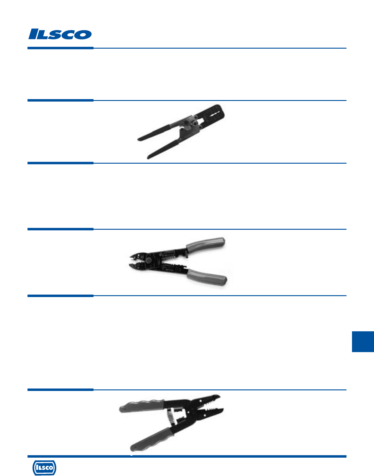
4730 Madison Road, Cincinnati, Ohio 45227-1426 Phone 513 533-6200 Fax 513 871-4084 Web site www.ilsco.com
Canada 1050 Lakeshore Road East, Mississauga, Ontario, Canada L5E1E4 Phone 905 274-2341 Fax 905 274-8763
316
J
L
Crimping Tools
TYPE
94130
Controlled-Cycle
Crimper
Features
•
Dieless tool
•
Ratchet mechanism
•
Compound action
•
Cushion grip handles
•
Crimps insulated wire terminals
•
Wire Range: 10-22 AWG, Weight .8 lb
Benefits
•
No need to purchase and maintain dies
•
Assures proper crimp force every time
•
Delivers maximum crimp force with minimum effort
•
Provides user comfort
•
Provides flexibility in use
TYPE
94140
Multi Purpose
Crimp Tool
Features
•
Heavy duty carbon steel construction
•
Comfort grip handles
•
Spring loaded action
•
Safety lock mechanism
•
Color coded crimp nest
•
Crimp nest
•
Wire cutter
•
Machine screw cutters
•
Wire stripper/wire gauge
Benefits
•
Provides durable rugged reliability
•
Provides user comfort
•
Enables multiple crimps
•
Provides for compact storage
•
For insulated terminals
•
For uninsulated terminals
•
Easily cuts solid and stranded wire
•
Cuts and rethreads 4-40, 6-32, 8-32, 10-24, and 10-32 machine screws
•
26-8 AWG
TYPE
WS-1
Wire Stripper
Features
•
Cushion grip handles
•
Crimp die
•
Wire strip gauge
•
Plier nose
•
Wire loop holes
•
Wire cutter
•
“Open” spring
•
Metric markings
•
Precision stripping
•
Wire crimp range: 14-20 AWG
Benefits
•
Eases pressure on hands when working for long periods or with larger
conductor
•
Built in crimp die allows you to crimp insulated terminals from 20AWG to
14AWG
•
Convenient stamped wire strip gauge makes it easy to strip conductors to
specific length consistently
•
Flat plier nose allows you to conveniently punch and twist knock outs
•
Built in looping holes allow you to conveniently bend eye loop into end of
conductor
•
Built in cutter is precision ground to cut small conductor copper intended to be
stripped (Strips #10 - 18 AWG)
•
Conveniently holds tool in open position to facilitate wire insertion
•
Metric markings provide for use of tool on products that have been sized
metrically
•
Precision ground wire stripping holes provide a clean cutting and stripping
action of insulation
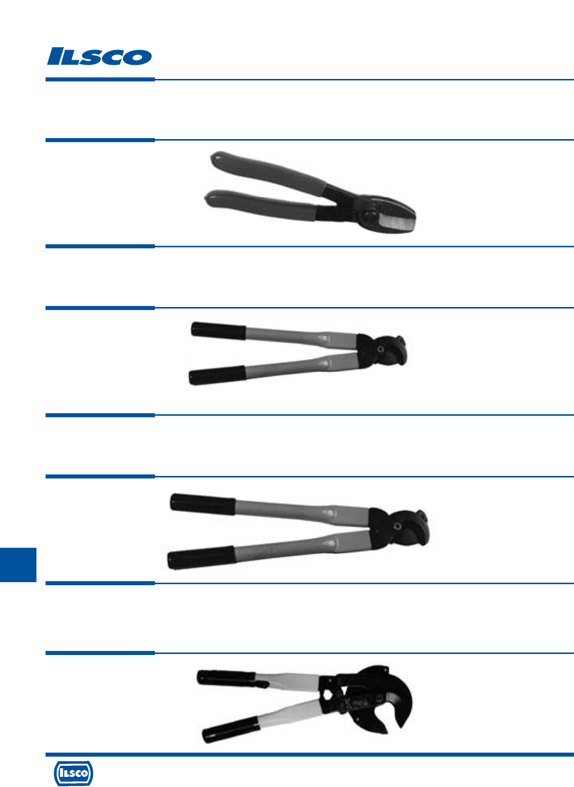
4730 Madison Road, Cincinnati, Ohio 45227-1426 Phone 513 533-6200 Fax 513 871-4084 Web site www.ilsco.com
Canada 1050 Lakeshore Road East, Mississauga, Ontario, Canada L5E1E4 Phone 905 274-2341 Fax 905 274-8763
317
J
L
Cable Cutters
TYPE
CTR-2/0
Features
•
7-1/2" overall length
•
Sharp precision ground blades
•
Heat treated blades
•
Narrow head design
•
Cuts up to 2/0 copper or aluminum cable
Benefits
•
Better leverage for easier cutting
•
Clean, distortion-free cuts
•
Long, dependable and durable operation
•
Provides easy access to confined areas
•
Wide cutting range for a pouch tool
TYPE
CTR-350
Features
•
Sharp precision ground blades
•
Moly steel blades
•
Durable 16" metal handles
•
Cuts copper and aluminum cable up to 350kcmil
Benefits
•
Provides clean distortion-free cuts
•
Offers extra strength to prevent blade breakage, blades stay sharper longer
•
Provides easy handling
•
Provides wide cutting range
TYPE
CTR-500
Features
•
Sharp precision ground blades
•
Moly steel blades
•
Durable 20-3/4" fiberglass handles
•
Cuts copper and aluminum cable up to 500kcmil
Benefits
•
Provides clean, distortion-free cuts
•
Offers extra strength to prevent blade breakage, blades stay sharper longer
•
Provides easy handling
•
Provides wide cutting range
TYPE
CTR-750
Features
•
Cuts copper and aluminum cable up to 750kcmil
•
Lightweight
•
Ratchet mechanism
•
16" length
•
Open/close lever
•
Alloy steel precision ground replaceable blades
Benefits
•
Provides large cutting capacity
•
Weight of only 3 lbs. prevents operator fatigue
•
Allows large cables to be cut with minimum effort
•
Compact size provides ease of use in cramped spaces
•
Lever that controls cutting blade direction makes the tool easy to use
•
Provides years of service by being able to replace blades when necessary
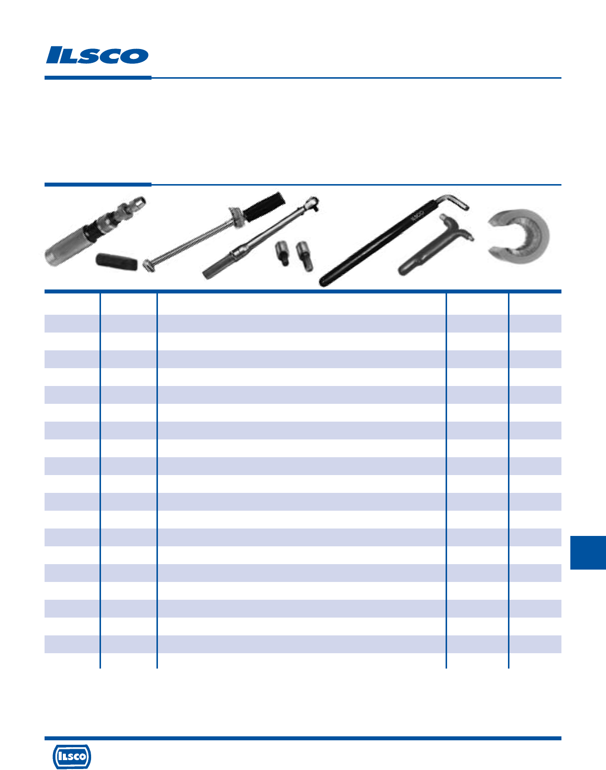
4730 Madison Road, Cincinnati, Ohio 45227-1426 Phone 513 533-6200 Fax 513 871-4084 Web site www.ilsco.com
Canada 1050 Lakeshore Road East, Mississauga, Ontario, Canada L5E1E4 Phone 905 274-2341 Fax 905 274-8763
318
J
L
Mechanical Tools
TYPE
MECHANICAL
TOOLS
Catalog Figure
Number Number Description Hex Size Length
DR-516 5 Driver for Torque Wrench 5/16 -
DR-38 5 Driver for Torque Wrench 3/8 -
DR-12 5 Driver for Torque Wrench 1/2 -
HW-13 2 Screwdriver Bit for TS-35, .214 x .040 - -
HW-14 2 Screwdriver Bit for TS-35, .250 x .042 - -
TK-1 - Torque Kit with TS-35, HW-13, HW-14, TW-1, DR-516, DR-38, Case - -
TK-2 - Torque Kit with TS-35, HW-13, HW-14, TW-750R, TW-150R, DR-516, DR-38, Case - -
TS-35 1 Torque Screwdriver 0-36 lbs. --
TW-1 3 Torque Wrench 0-600 in. lbs. --
TW-150R 4 Torque Wrench (Rachet type) 5-150 in. lbs. - -
TW-750R 4 Torque Wrench (Rachet type) 100-750 in. lbs. - -
WR-1 7 Double Wrench 3/16, 5/16 4
WR-1A 6 Wrench 3/16 4-1/2
WR-3 6 Wrench 1/4 5-1/4
WR-4 6 Wrench 5/16 3-3/16
WR-5 6 Wrench 3/8 4-1/2
WR-9 6 Wrench 5/16 10
WR-10 6 Wrench 3/8 10
WR-12 6 Wrench 1/2 5-1/2
WC 8 Wire Brush --
Fig. 1 Fig. 2 Fig. 3 Fig. 4 Fig. 5 Fig. 6 Fig. 7 Fig. 8
4730 Madison Road, Cincinnati, Ohio 45227-1426 Phone 513 533-6200 Fax 513 871-4084 Web site www.ilsco.com
Canada 1050 Lakeshore Road East, Mississauga, Ontario, Canada L5E1E4 Phone 905 274-2341 Fax 905 274-8763
319
J
L
Catalog
Number Description
27001 Heat Gun, 11 Disks Thin Wall Heat Shrink
94502 Electric Heat Gun 120v
94504 Replacement Adaptor for 94502
Heat Gun
TYPE
Electric
Heat Gun
Features
•
Two temperature settings 750F and 1100F
•
Three way switch OFF/HI/LO
•
Built-in fold down stand
•
1200 Watt 120 V AC
•
Heat deflector
•
Impact resistant case
•
Six foot cord
•
Supplied in plastic carrying case
Benefits
•
Provides versatility in applying recommended heat,
deliverable in seconds
•
Aids in producing proper air flow from heat gun
•
Provides hands free operation
•
Provides high output of air and heat
•
Allows for concentration of heat for rapid heat
shrink process
•
Provides extra durability in harsh environments
•
Provides operator convenience
•
Provides ease of storage and accessibility
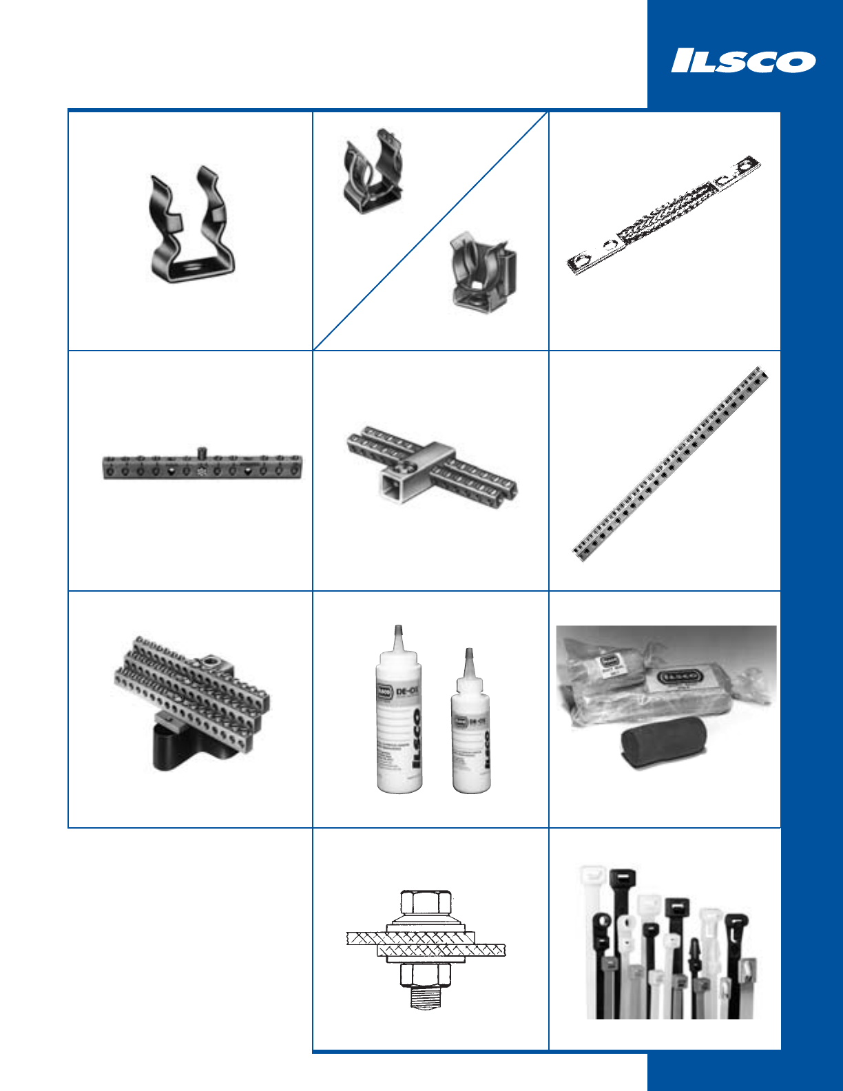
320
Specialty
C
321
M
322
T
M
323 324 - 331
N-174
333
DUCT SEAL
336
NB
334
D167
332
CAN
333
DE-OX
335
Cable Ties
338 - 342
NBW
337
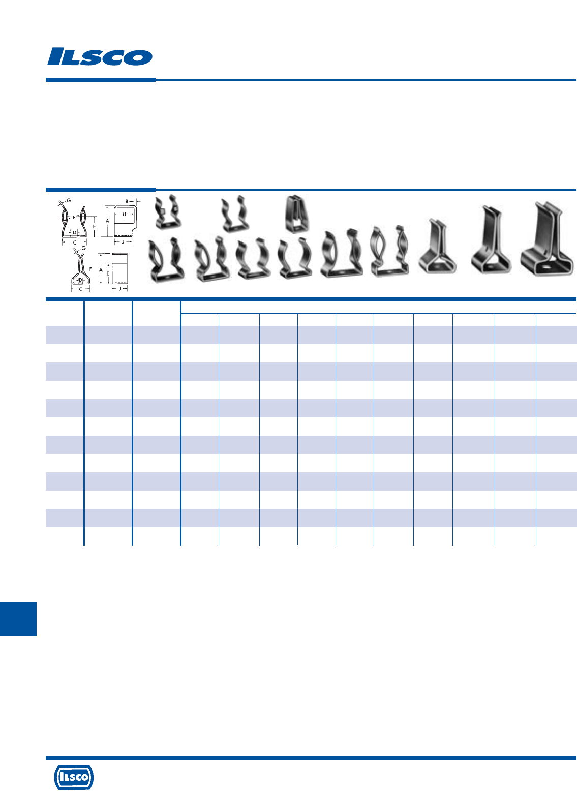
4730 Madison Road, Cincinnati, Ohio 45227-1426 Phone 513 533-6200 Fax 513 871-4084 Web site www.ilsco.com
Canada 1050 Lakeshore Road East, Mississauga, Ontario, Canada L5E1E4 Phone 905 274-2341 Fax 905 274-8763
321
K
Catalog Figure Dimensions
Number Number Amp-Volts A B C Bolt Size D E F G H J
C-10 1 30-250 7/8 3/64 19/32 #10 13/64 17/32 9/16 1/32 19/32 1/2
C-11 4 60-250 1-1/8 1/16 51/64 #10 15/64 51/64 13/16 3/64 21/32 5/8
C-12 5 60-250 1-1/8 1/16 13/16 #8 3/16 47/64 13/16 3/64 21/32 5/8
C-13 9 60-600 1-9/32 1/16 1-1/8 1/4 17/64 13/16 1-1/16 3/64 21/32 5/8
C-14 6 60-350 1 - 51/64 * * 5/8 13/16 3/64 - 5/8
C-15 7 60-250 1-1/32 - 51/64 #10 13/64 5/8 13/16 3/64 - 5/8
C-16 11 100-250 1-43/64 - 29/32 1/4 17/64 1-11/64 1/8 5/64 - 7/8
C-17 10 100-250 1-23/64 - 15/16 1/4 17/64 57/64 1/8 5/64 - 7/8
C-19 2 30-250 7/8 - 39/64 #8 11/64** 17/32 9/16 1/32 - 1/2
C-23 8 60-600 1-5/16 1/16 31/32 #8 3/16 29/32 1-1/16 3/64 21/32 23/32
C-24 12 200-250/600 1-15/16 - 1-1/4 5/16 11/32 1-1/8 3/16 3/32 - 1-1/4
C-28 3 50-250 61/64 - 1/2 #8 3/16 23/32 7/64 3/64 - 1/2
Fuse Clips
TYPE
C
Features
•
Manufactured from special bronze alloy except 100 and
200 amp styles. Arched bottoms
•
All formed corners are designed with a radius
Benefits
•
Spring type material ensures positive contact. Provide
firm and secure mounting, and prevents expansion after
fuse is inserted.
•
Prevents fracturing
Fig. 1 Fig. 2 Fig. 3
Fig. 4 Fig. 5 Fig. 6 Fig. 7 Fig. 8 Fig. 9 Fig. 10 Fig. 11 Fig. 12
** Stud hole center 9/32 from one side and 7/32 from other side.
* Slotted 13/64 x 13/32.
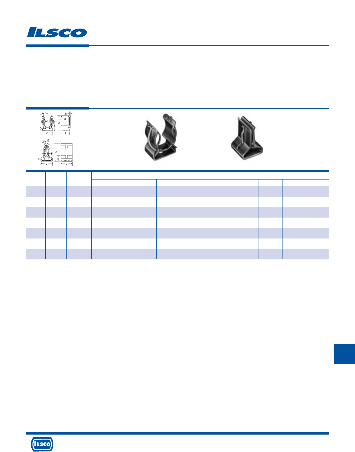
4730 Madison Road, Cincinnati, Ohio 45227-1426 Phone 513 533-6200 Fax 513 871-4084 Web site www.ilsco.com
Canada 1050 Lakeshore Road East, Mississauga, Ontario, Canada L5E1E4 Phone 905 274-2341 Fax 905 274-8763
322
K
Catalog Figure Dimensions
Number Number Amp-Volts A B C Bolt Size D E F G H J
M-161 1 30-250 27/32 1/16 19/32 #10 13/64 17/32 9/16 1/32 17/32 1/2
M-162 1 30-600 1-1/32 1/16 3/4 1/4 1/4 21/32 13/16 1/32 17/32 1/2
M-163 1 60-250 1-13/64 1/16 51/64 #10 7/32 51/64 13/16 3/64 21/32 21/32
M-164 1 60-600 1-3/8 1/16 31/32 #8 3/16 29/32 1-1/16 3/64 21/32 5/8
M-165 2 100-250/600 1-23/64 - 29/32 1/4 17/64-Slot - 1/8 5/64 - 7/8
M-233 2 200-250/600 1-15/16 - 1-1/4 5/16 11/32-Slot - 3/16 3/32 - 1-1/4
M-628 2 400-600 2-7/16 - 1-1/2 - 5/16-18 (2) - 1/4 1/8 - 1-3/4
Wire Reinforced Fuse Clips
TYPE
M
Features
•
Manufactured from copper alloy
•
Supplied with permanently installed steel spring
•
Spring is heat treated and plated
Benefits
•
Ensures high conductivity
•
Ensures tighter grip and positive contact with either
knife or ferrule type fuses.
•
Prevents hydrogen embrittlement
Fig. 1 Fig. 2
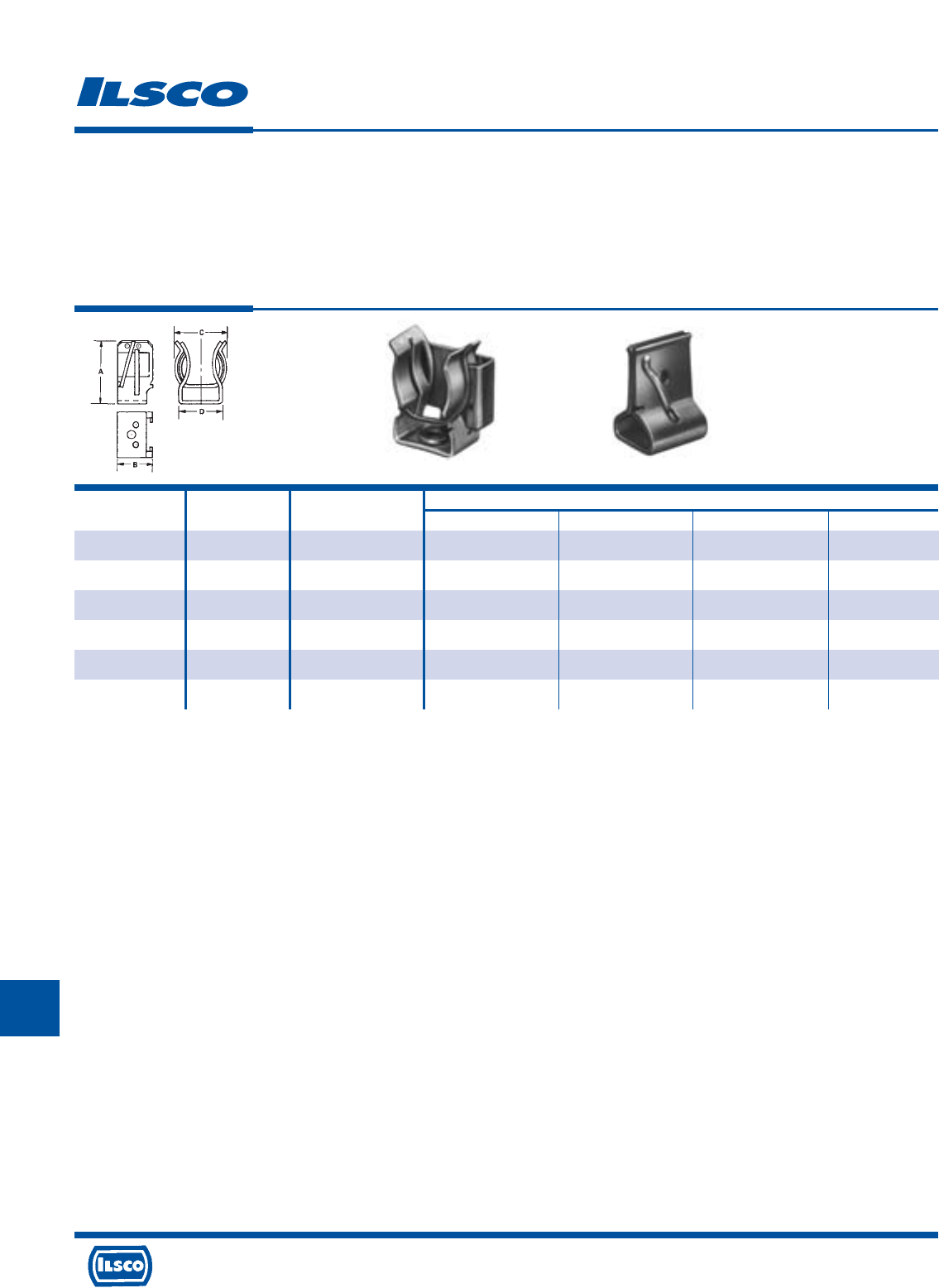
4730 Madison Road, Cincinnati, Ohio 45227-1426 Phone 513 533-6200 Fax 513 871-4084 Web site www.ilsco.com
Canada 1050 Lakeshore Road East, Mississauga, Ontario, Canada L5E1E4 Phone 905 274-2341 Fax 905 274-8763
323
K
Catalog Figure Dimensions
Number Number Amp-Volts A B C D
M-2432 1 30-250 7/8 19/32 21/32 19/32
M-2433 1 60-250 1.200 23/32 59/64 51/64
M-2434 1 30-600 1-1/32 19/32 59/64 3/4
M-2435 1 60-600 1.390 23/32 1-5/64 31/32
M-2398 2 100-250/600 1-23/64 7/8 1/8 29/32
M-2399 2 200-250/600 1-15/16 1-1/4 3/16 1-15/64
Class R Wire Reinforced Fuse Clips
TYPE
M
Features
•
Manufactured from copper alloy
•
Supplied with permanently installed steel spring
•
Spring is heat treated and plated
•
Supplied with a slot or a hole for a steel rejection device.
•
Electro-tin plated
Benefits
•
Ensures high conductivity
•
Ensures tighter grip and positive contact with either
knife or ferrule type fuses.
•
Prevents hydrogen embrittlement
•
Prevents the insertion of any other type fuse except
class R
•
Provides low contact resistance
Fig. 1 Fig. 2

4730 Madison Road, Cincinnati, Ohio 45227-1426 Phone 513 533-6200 Fax 513 871-4084 Web site www.ilsco.com
Canada 1050 Lakeshore Road East, Mississauga, Ontario, Canada L5E1E4 Phone 905 274-2341 Fax 905 274-8763
324
K
Dimensions
Catalog Figure Drawing Ampere Rating Circular Mils.
Number Number Number (Indoors)* of Braids L T W
T252/11N12 1 A 200 77,184 12 0.19 1.00
T252/11N18 1 A 200 77,184 18 0.25 1.00
T252/11N24 1 A 200 77,184 24 0.25 1.00
T252/21N12 2 A 340 154,386 12 0.25 1.00
T252/21N18 2 A 340 154,386 18 0.25 1.00
T252/21N24 2 A 340 154,386 24 0.25 1.00
T252/31N12 3 A 470 231,552 12 0.38 1.00
T252/31N18 3 A 470 231,552 18 0.38 1.00
T252/31N24 3 A 470 231,552 24 0.38 1.00
T252/41N12 4 A 600 308,734 12 0.38 1.25
T252/41N18 4 A 600 308,734 18 0.38 1.25
T252/41N24 4 A 600 308,734 24 0.38 1.25
T282/11N12 1 A 340 153,600 12 0.25 1.63
T282/11N18 1 A 340 153,600 18 0.25 1.63
T282/11N24 1 A 340 153,600 24 0.25 1.63
Tin Plated Copper Flexible Braid
TYPE
T
Features
•
Manufactured from pure copper braid
•
Electro-tin plated
•
Seamless pure copper ferrules
•
Inside ferrule ends are rounded
•
Swedged terminal to copper braid
by cold forming
•
Extra flexible braided connector
•
Rated for 600 volts
Benefits
•
Provides high conductivity
•
Provides low contact resistance
•
Provides superior contact
•
Prevents chafing of strands
•
Provides a reduced resistance form point to point; much lower than standard
power cables or loose - piece type terminals
•
Multi-purpose use for bonding, grounding and connecting moving parts
•
Ensures reliability
Finish
End Contact - Tinned
Braid Number
Figure No.
Hole 1-1 Hole
2-2 Hole
4-4 Hole
Drilling: N - Nema
Overall Length
In Inches
T 252 1 2 N 12
Standard Specifications
Hole Size: 9/16"
Drilling: Nema Standard
End Contacts: Electro-Tin Plated Copper
Braid: Tinned Copper Flat Braid
Dwg
D
4 Hole
NEMA
Dwg
E
4 Hole
NEMA
Dwg
C
2 Hole
NEMA
Dwg
B
2 Hole
Slot
Dwg
A
1 Hole W
W
* Ampere ratings are suggested for use as a guide only. Actual values used for a given application will depend on such factors as permissible temperature rise, permissible voltage
drop, number of cables together and other conditions of service. For outdoor use, these ratings may be increased from 22% to 40% depending upon the size and position of the
braid.

4730 Madison Road, Cincinnati, Ohio 45227-1426 Phone 513 533-6200 Fax 513 871-4084 Web site www.ilsco.com
Canada 1050 Lakeshore Road East, Mississauga, Ontario, Canada L5E1E4 Phone 905 274-2341 Fax 905 274-8763
325
K
Dimensions
Catalog Figure Drawing Ampere Rating Circular Mils.
Number Number Number (Indoors)* of Braids L T W
T282/21N12 2 A 530 307,000 12 0.25 1.63
T282/21N18 2 A 530 307,000 18 0.25 1.63
T282/21N24 2 A 530 307,000 24 0.25 1.63
T282/31N12 3 A 700 460,800 12 0.31 1.63
T282/31N18 3 A 700 460,800 18 0.31 1.63
T282/31N24 3 A 700 460,800 24 0.31 1.63
T282/41N12 4 A 800 614,400 12 0.38 1.63
T282/41N18 4 A 800 614,400 18 0.38 1.63
T282/41N24 4 A 800 614,400 24 0.38 1.63
T252/12N12 1 C 200 77,184 12 0.19 1.00
T252/12N18 1 C 200 77,184 18 0.25 1.00
T252/12N24 1 C 200 77,184 24 0.25 1.00
T252/22N12 2 C 340 154,386 12 0.25 1.00
T252/22N18 2 C 340 154,386 18 0.25 1.00
T252/22N24 2 C 340 154,386 24 0.25 1.00
Tin Plated Copper Flexible Braid
TYPE
T
Features
•
Manufactured from pure copper braid
•
Electro-tin plated
•
Seamless pure copper ferrules
•
Inside ferrule ends are rounded
•
Swedged terminal to copper braid
by cold forming
•
Extra flexible braided connector
•
Rated for 600 volts
Benefits
•
Provides high conductivity
•
Provides low contact resistance
•
Provides superior contact
•
Prevents chafing of strands
•
Provides a reduced resistance form point to point; much lower than standard
power cables or loose - piece type terminals
•
Multi-purpose use for bonding, grounding and connecting moving parts
•
Ensures reliability
Finish
End Contact - Tinned
Braid Number
Figure No.
Hole 1-1 Hole
2-2 Hole
4-4 Hole
Drilling: N - Nema
Overall Length
In Inches
T 252 1 2 N 12
Standard Specifications
Hole Size: 9/16"
Drilling: Nema Standard
End Contacts: Electro-Tin Plated Copper
Braid: Tinned Copper Flat Braid
Dwg
D
4 Hole
NEMA
Dwg
E
4 Hole
NEMA
Dwg
C
2 Hole
NEMA
Dwg
B
2 Hole
Slot
Dwg
A
1 Hole W
W
* Ampere ratings are suggested for use as a guide only. Actual values used for a given application will depend on such factors as permissible temperature rise, permissible voltage
drop, number of cables together and other conditions of service. For outdoor use, these ratings may be increased from 22% to 40% depending upon the size and position of the
braid.

4730 Madison Road, Cincinnati, Ohio 45227-1426 Phone 513 533-6200 Fax 513 871-4084 Web site www.ilsco.com
Canada 1050 Lakeshore Road East, Mississauga, Ontario, Canada L5E1E4 Phone 905 274-2341 Fax 905 274-8763
326
K
Dimensions
Catalog Figure Drawing Ampere Rating Circular Mils.
Number Number Number (Indoors)* of Braids L T W
T252/32N12 3 C 470 231,552 12 0.38 1.00
T252/32N18 3 C 470 231,552 18 0.38 1.00
T252/32N24 3 C 470 231,552 24 0.38 1.00
T252/42N12 4 C 600 308,734 12 0.38 1.25
T252/42N18 4 C 600 308,734 18 0.38 1.25
T252/42N24 4 C 600 308,734 24 0.38 1.25
T282/12N12 1 C 340 153,600 12 0.25 1.63
T282/12N18 1 C 340 153,600 18 0.25 1.63
T282/12N24 1 C 340 153,600 24 0.25 1.63
T282/22N12 2 C 530 307,000 12 0.25 1.63
T282/22N18 2 C 530 307,000 18 0.25 1.63
T282/22N24 2 C 530 307,000 24 0.25 1.63
T282/32N12 3 C 700 460,800 12 0.31 1.63
T282/32N18 3 C 700 460,800 18 0.31 1.63
T282/32N24 3 C 700 460,800 24 0.31 1.63
Tin Plated Copper Flexible Braid
TYPE
T
Features
•
Manufactured from pure copper braid
•
Electro-tin plated
•
Seamless pure copper ferrules
•
Inside ferrule ends are rounded
•
Swedged terminal to copper braid
by cold forming
•
Extra flexible braided connector
•
Rated for 600 volts
Benefits
•
Provides high conductivity
•
Provides low contact resistance
•
Provides superior contact
•
Prevents chafing of strands
•
Provides a reduced resistance form point to point; much lower than standard
power cables or loose - piece type terminals
•
Multi-purpose use for bonding, grounding and connecting moving parts
•
Ensures reliability
Finish
End Contact - Tinned
Braid Number
Figure No.
Hole 1-1 Hole
2-2 Hole
4-4 Hole
Drilling: N - Nema
Overall Length
In Inches
T 252 1 2 N 12
Standard Specifications
Hole Size: 9/16"
Drilling: Nema Standard
End Contacts: Electro-Tin Plated Copper
Braid: Tinned Copper Flat Braid
Dwg
D
4 Hole
NEMA
Dwg
E
4 Hole
NEMA
Dwg
C
2 Hole
NEMA
Dwg
B
2 Hole
Slot
Dwg
A
1 Hole W
W
* Ampere ratings are suggested for use as a guide only. Actual values used for a given application will depend on such factors as permissible temperature rise, permissible voltage
drop, number of cables together and other conditions of service. For outdoor use, these ratings may be increased from 22% to 40% depending upon the size and position of the
braid.
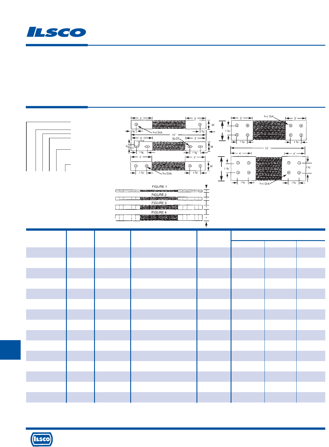
4730 Madison Road, Cincinnati, Ohio 45227-1426 Phone 513 533-6200 Fax 513 871-4084 Web site www.ilsco.com
Canada 1050 Lakeshore Road East, Mississauga, Ontario, Canada L5E1E4 Phone 905 274-2341 Fax 905 274-8763
327
K
Dimensions
Catalog Figure Drawing Ampere Rating Circular Mils.
Number Number Number (Indoors)* of Braids L T W
T282/42N12 4 C 800 614,400 12 0.38 1.63
T282/42N18 4 C 800 614,400 18 0.38 1.63
T282/42N24 4 C 800 614,400 24 0.38 1.63
T287/12N12 1 C 360 230,000 12 0.25 1.50
T287/12N18 1 C 360 230,000 18 0.25 1.50
T287/12N24 1 C 360 230,000 24 0.25 1.50
T287/22N12 2 C 700 460,000 12 0.38 1.50
T287/22N18 2 C 700 460,000 18 0.38 1.50
T287/22N24 2 C 700 460,000 24 0.38 1.50
T287/32N12 3 C 820 690,000 12 0.50 1.50
T287/32N18 3 C 820 690,000 18 0.50 1.50
T287/32N24 3 C 820 690,000 24 0.50 1.50
T287/42N12 4 C 1000 920,000 12 0.75 1.63
T287/42N18 4 C 1000 920,000 18 0.75 1.63
T287/42N24 4 C 1000 920,000 24 0.75 1.63
Tin Plated Copper Flexible Braid
TYPE
T
Features
•
Manufactured from pure copper braid
•
Electro-tin plated
•
Seamless pure copper ferrules
•
Inside ferrule ends are rounded
•
Swedged terminal to copper braid
by cold forming
•
Extra flexible braided connector
•
Rated for 600 volts
Benefits
•
Provides high conductivity
•
Provides low contact resistance
•
Provides superior contact
•
Prevents chafing of strands
•
Provides a reduced resistance form point to point; much lower than standard
power cables or loose - piece type terminals
•
Multi-purpose use for bonding, grounding and connecting moving parts
•
Ensures reliability
Finish
End Contact - Tinned
Braid Number
Figure No.
Hole 1-1 Hole
2-2 Hole
4-4 Hole
Drilling: N - Nema
Overall Length
In Inches
T 252 1 2 N 12
Standard Specifications
Hole Size: 9/16"
Drilling: Nema Standard
End Contacts: Electro-Tin Plated Copper
Braid: Tinned Copper Flat Braid
Dwg
D
4 Hole
NEMA
Dwg
E
4 Hole
NEMA
Dwg
C
2 Hole
NEMA
Dwg
B
2 Hole
Slot
Dwg
A
1 Hole W
W
* Ampere ratings are suggested for use as a guide only. Actual values used for a given application will depend on such factors as permissible temperature rise, permissible voltage
drop, number of cables together and other conditions of service. For outdoor use, these ratings may be increased from 22% to 40% depending upon the size and position of the
braid.
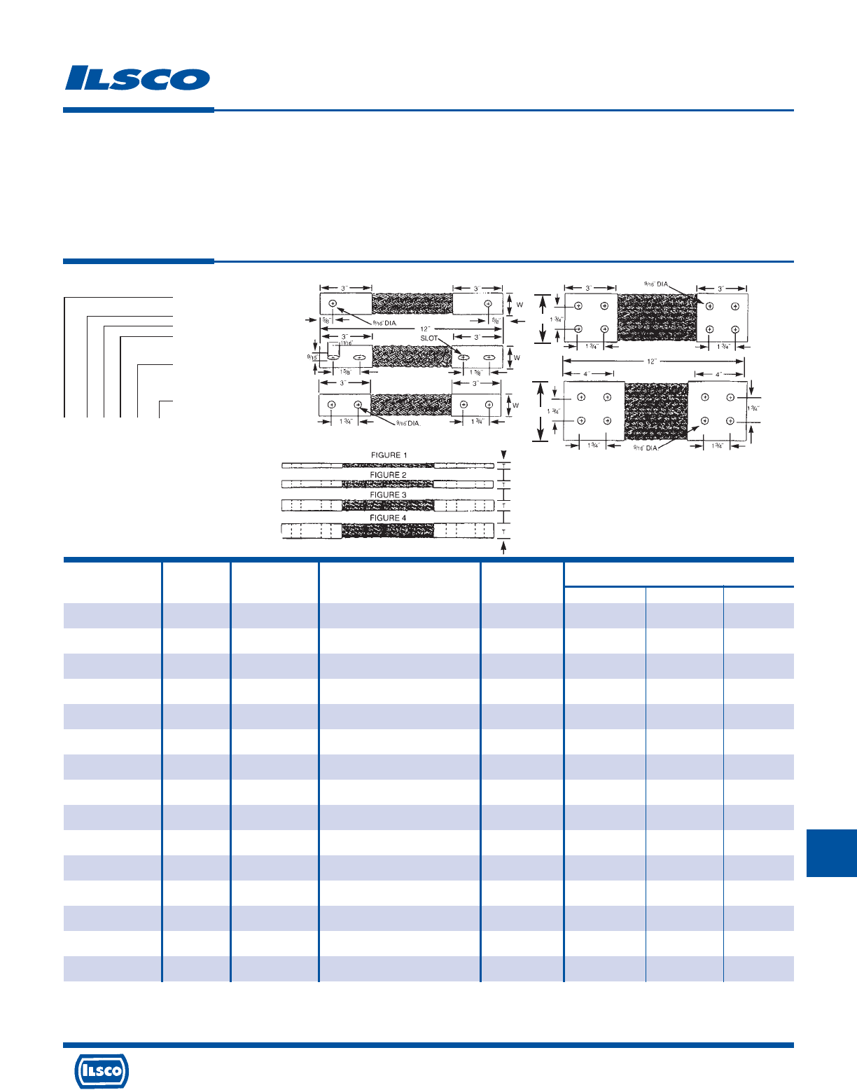
4730 Madison Road, Cincinnati, Ohio 45227-1426 Phone 513 533-6200 Fax 513 871-4084 Web site www.ilsco.com
Canada 1050 Lakeshore Road East, Mississauga, Ontario, Canada L5E1E4 Phone 905 274-2341 Fax 905 274-8763
328
K
4730 Madison Road, Cincinnati, Ohio 45227-1426 Phone 513 533-6200 Fax 513 871-4084 Web site www.ilsco.com
Canada 1050 Lakeshore Road East, Mississauga, Ontario, Canada L5E1E4 Phone 905 274-2341 Fax 905 274-8763
328
Dimensions
Catalog Figure Drawing Ampere Rating Circular Mils.
Number Number Number (Indoors)* of Braids L T W
T294/12N12 1 C 415 300,000 12 0.25 1.50
T294/12N18 1 C 415 300,000 18 0.25 1.50
T294/12N24 1 C 415 300,000 24 0.25 1.50
T294/22N12 2 C 700 600,000 12 0.50 1.50
T294/22N18 2 C 700 600,000 18 0.50 1.50
T294/22N24 2 C 700 600,000 24 0.50 1.50
T294/32N12 3 C 960 900,000 12 0.75 1.63
T294/32N18 3 C 960 900,000 18 0.75 1.63
T294/32N24 3 C 960 900,000 24 0.75 1.63
T294/42N12 4 C 1200 1,200,000 12 1.00 1.63
T294/42N18 4 C 1200 1,200,000 18 1.00 1.63
T294/42N24 4 C 1200 1,200,000 24 1.00 1.63
T278/14N12-4 1 E 625 422,000 12 0.25 4.00
T278/14N18-4 1 E 625 422,000 18 0.25 4.00
T278/14N24-4 1 E 625 422,000 24 0.25 4.00
Tin Plated Copper Flexible Braid
TYPE
T
Features
•
Manufactured from pure copper braid
•
Electro-tin plated
•
Seamless pure copper ferrules
•
Inside ferrule ends are rounded
•
Swedged terminal to copper braid
by cold forming
•
Extra flexible braided connector
•
Rated for 600 volts
Benefits
•
Provides high conductivity
•
Provides low contact resistance
•
Provides superior contact
•
Prevents chafing of strands
•
Provides a reduced resistance form point to point; much lower than standard
power cables or loose - piece type terminals
•
Multi-purpose use for bonding, grounding and connecting moving parts
•
Ensures reliability
Finish
End Contact - Tinned
Braid Number
Figure No.
Hole 1-1 Hole
2-2 Hole
4-4 Hole
Drilling: N - Nema
Overall Length
In Inches
T 252 1 2 N 12
Standard Specifications
Hole Size: 9/16"
Drilling: Nema Standard
End Contacts: Electro-Tin Plated Copper
Braid: Tinned Copper Flat Braid
Dwg
D
4 Hole
NEMA
Dwg
E
4 Hole
NEMA
Dwg
C
2 Hole
NEMA
Dwg
B
2 Hole
Slot
Dwg
A
1 Hole W
W
* Ampere ratings are suggested for use as a guide only. Actual values used for a given application will depend on such factors as permissible temperature rise, permissible voltage
drop, number of cables together and other conditions of service. For outdoor use, these ratings may be increased from 22% to 40% depending upon the size and position of the
braid.

4730 Madison Road, Cincinnati, Ohio 45227-1426 Phone 513 533-6200 Fax 513 871-4084 Web site www.ilsco.com
Canada 1050 Lakeshore Road East, Mississauga, Ontario, Canada L5E1E4 Phone 905 274-2341 Fax 905 274-8763
329
K
Dimensions
Catalog Figure Drawing Ampere Rating Circular Mils.
Number Number Number (Indoors)* of Braids L T W
T278/24N12-4 2 E 940 844,000 12 0.31 4.00
T278/24N18-4 2 E 940 844,000 18 0.31 4.00
T278/24N24-4 2 E 940 844,000 24 0.31 4.00
T278/34N12-4 3 E 1200 1,266,000 12 0.38 4.00
T278/34N18-4 3 E 1200 1,266,000 18 0.38 4.00
T278/34N24-4 3 E 1200 1,266,000 24 0.38 4.00
T278/44N12-4 4 E 1600 1,688,000 12 0.50 4.00
T278/44N18-4 4 E 1600 1,688,000 18 0.50 4.00
T278/44N24-4 4 E 1600 1,688,000 24 0.50 4.00
T278/14N12-3 1 D 370 211,200 12 0.25 3.00
T278/14N18-3 1 D 370 211,200 18 0.25 3.00
T278/14N24-3 1 D 370 211,200 24 0.25 3.00
T278/24N12-3 2 D 625 422,400 12 0.31 3.00
T278/24N18-3 2 D 625 422,400 18 0.31 3.00
T278/24N24-3 2 D 625 422,400 24 0.31 3.00
Tin Plated Copper Flexible Braid
TYPE
T
Features
•
Manufactured from pure copper braid
•
Electro-tin plated
•
Seamless pure copper ferrules
•
Inside ferrule ends are rounded
•
Swedged terminal to copper braid
by cold forming
•
Extra flexible braided connector
•
Rated for 600 volts
Benefits
•
Provides high conductivity
•
Provides low contact resistance
•
Provides superior contact
•
Prevents chafing of strands
•
Provides a reduced resistance form point to point; much lower than standard
power cables or loose - piece type terminals
•
Multi-purpose use for bonding, grounding and connecting moving parts
•
Ensures reliability
Finish
End Contact - Tinned
Braid Number
Figure No.
Hole 1-1 Hole
2-2 Hole
4-4 Hole
Drilling: N - Nema
Overall Length
In Inches
T 252 1 2 N 12
Standard Specifications
Hole Size: 9/16"
Drilling: Nema Standard
End Contacts: Electro-Tin Plated Copper
Braid: Tinned Copper Flat Braid
Dwg
D
4 Hole
NEMA
Dwg
E
4 Hole
NEMA
Dwg
C
2 Hole
NEMA
Dwg
B
2 Hole
Slot
Dwg
A
1 Hole W
W
* Ampere ratings are suggested for use as a guide only. Actual values used for a given application will depend on such factors as permissible temperature rise, permissible voltage
drop, number of cables together and other conditions of service. For outdoor use, these ratings may be increased from 22% to 40% depending upon the size and position of the
braid.
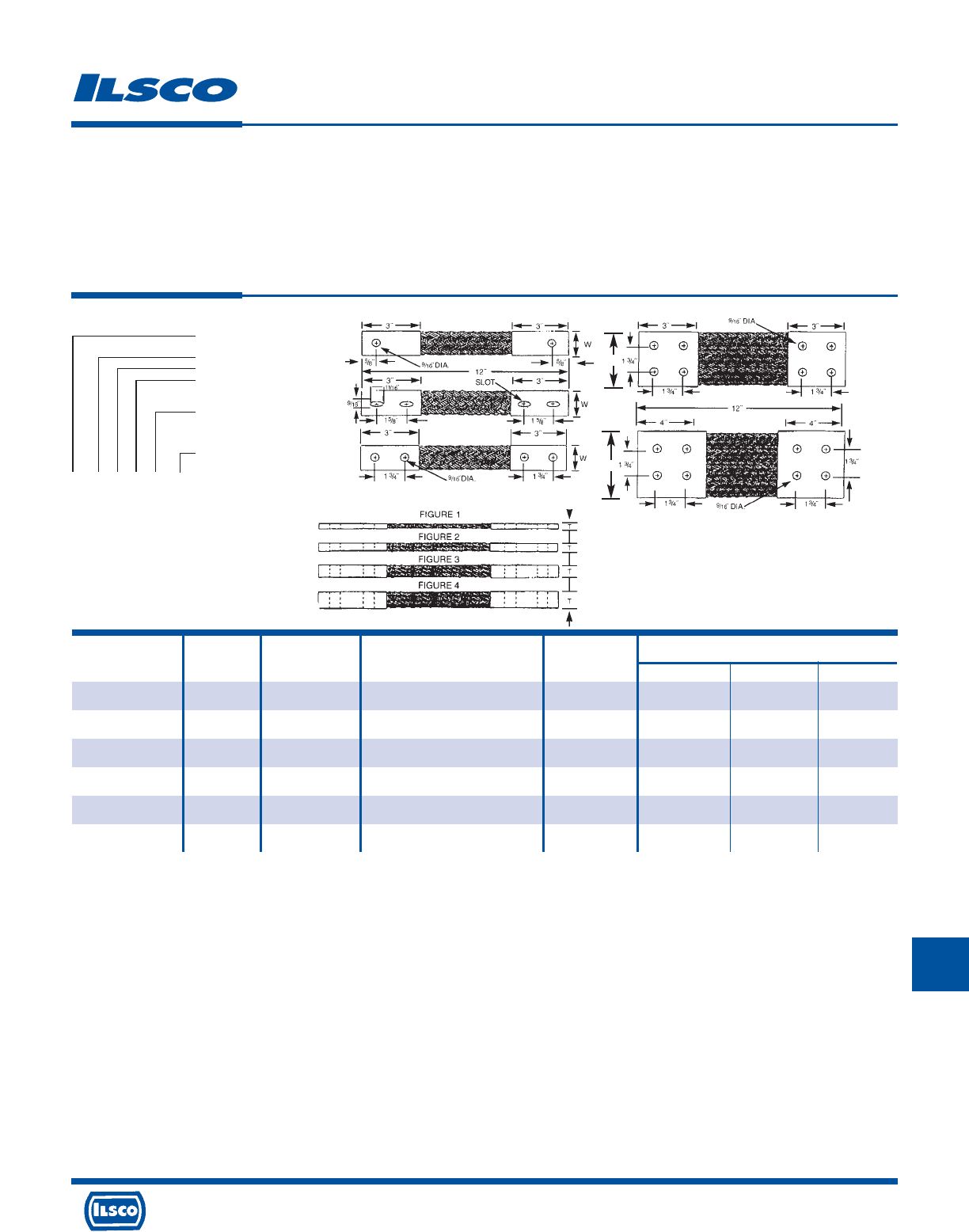
4730 Madison Road, Cincinnati, Ohio 45227-1426 Phone 513 533-6200 Fax 513 871-4084 Web site www.ilsco.com
Canada 1050 Lakeshore Road East, Mississauga, Ontario, Canada L5E1E4 Phone 905 274-2341 Fax 905 274-8763
330
K
Dimensions
Catalog Figure Drawing Ampere Rating Circular Mils.
Number Number Number (Indoors)* of Braids L T W
T278/34N12-3 3 D 800 633,600 12 0.38 3.00
T278/34N18-3 3 D 800 633,600 18 0.38 3.00
T278/34N24-3 3 D 800 633,600 24 0.38 3.00
T278/44N12-3 4 D 940 844,900 12 0.50 3.00
T278/44N18-3 4 D 940 844,900 18 0.50 3.00
T278/44N24-3 4 D 940 844,900 24 0.50 3.00
Tin Plated Copper Flexible Braid
TYPE
T
Features
•
Manufactured from pure copper braid
•
Electro-tin plated
•
Seamless pure copper ferrules
•
Inside ferrule ends are rounded
•
Swedged terminal to copper braid
by cold forming
•
Extra flexible braided connector
•
Rated for 600 volts
Benefits
•
Provides high conductivity
•
Provides low contact resistance
•
Provides superior contact
•
Prevents chafing of strands
•
Provides a reduced resistance form point to point; much lower than standard
power cables or loose - piece type terminals
•
Multi-purpose use for bonding, grounding and connecting moving parts
•
Ensures reliability
Finish
End Contact - Tinned
Braid Number
Figure No.
Hole 1-1 Hole
2-2 Hole
4-4 Hole
Drilling: N - Nema
Overall Length
In Inches
T 252 1 2 N 12
Standard Specifications
Hole Size: 9/16"
Drilling: Nema Standard
End Contacts: Electro-Tin Plated Copper
Braid: Tinned Copper Flat Braid
Dwg
D
4 Hole
NEMA
Dwg
E
4 Hole
NEMA
Dwg
C
2 Hole
NEMA
Dwg
B
2 Hole
Slot
Dwg
A
1 Hole W
W
* Ampere ratings are suggested for use as a guide only. Actual values used for a given application will depend on such factors as permissible temperature rise, permissible voltage
drop, number of cables together and other conditions of service. For outdoor use, these ratings may be increased from 22% to 40% depending upon the size and position of the
braid.
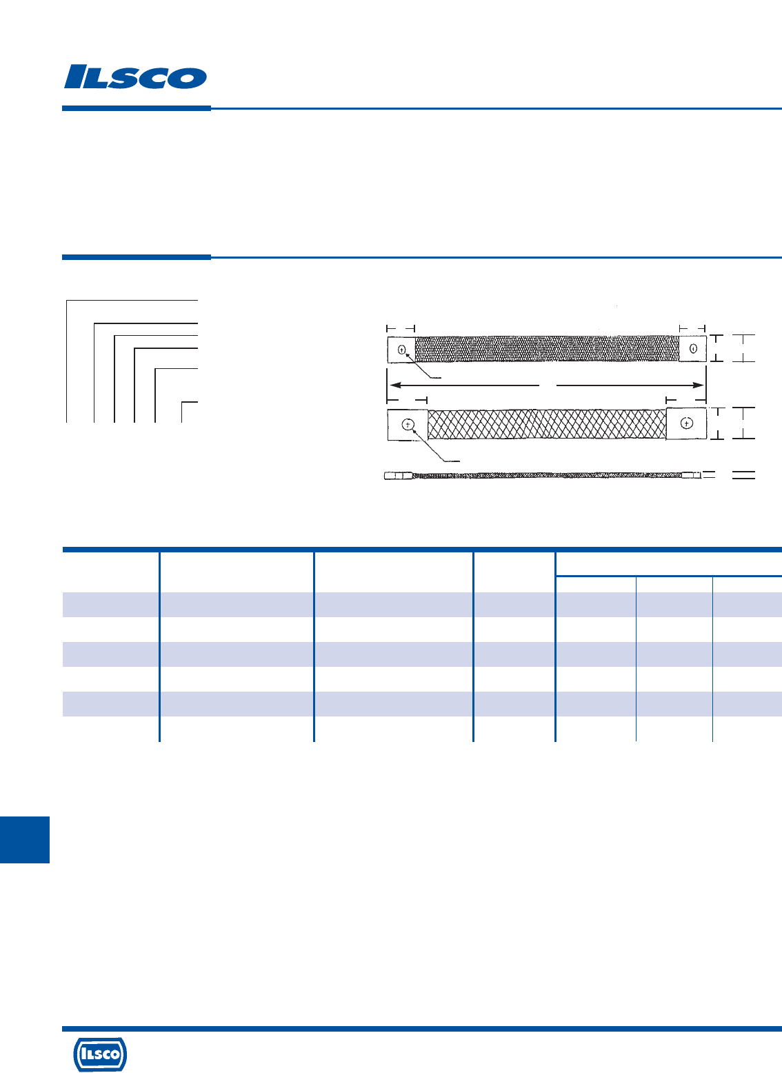
4730 Madison Road, Cincinnati, Ohio 45227-1426 Phone 513 533-6200 Fax 513 871-4084 Web site www.ilsco.com
Canada 1050 Lakeshore Road East, Mississauga, Ontario, Canada L5E1E4 Phone 905 274-2341 Fax 905 274-8763
331
K
Dimensions
Catalog Figure Ampere Rating Circular Mils.
Number Number (Indoors)* of Braids L T W
T240/11C12 1 95 24,000 12 0.13 0.63
T240/11C18 1 95 24,000 18 0.13 0.63
T240/11C24 1 95 24,000 24 0.13 0.63
T244/21C12 2 145 48,000 12 0.13 1.00
T244/21C18 2 145 48,000 18 0.13 1.00
T244/21C24 2 145 48,000 24 0.13 1.00
Tin Plated Copper Flexible Braid
Custom Drilling
TYPE
T
Features
•
Manufactured from pure copper braid
•
Electro-tin plated
•
Seamless pure copper ferrules
•
Inside ferrule ends are rounded
•
Swedged terminal to copper braid
by cold forming
•
Extra flexible braided connector
•
Rated for 600 volts
Benefits
•
Provides high conductivity
•
Provides low contact resistance
•
Provides superior contact
•
Prevents chafing of strands
•
Provides a reduced resistance form point to point; much lower than standard
power cables or loose - piece type terminals
•
Multi-purpose use for bonding, grounding and connecting moving parts
•
Ensures reliability
Finish
End Contact - Tinned
Braid Number
Figure No.
Hole 1-1 Hole
Drilling: C - Custom
Overall Length
In Inches
T 240 1 1 C 12
Standard Specifications
End Contacts: Electro-Tin Plated Copper
Braid: Tinned Copper Flat Braid
Options: - Custom drilling pattern
(drawing must be supplied)
12˝
3/4˝
11/4˝
3/4˝
5/8˝
FIGURE 1
FIGURE 2
11/4˝
1˝
1/4˝ DIA. HOLE
7/16˝ DIA. HOLE
1/8˝
W
T
W
* Ampere ratings are suggested for use as a guide only. Actual values used for a given application will depend on such factors as permissible temperature rise, permissible voltage
drop, number of cables together and other conditions of service. For outdoor use, these ratings may be increased from 22% to 40% depending upon the size and position of the
braid.
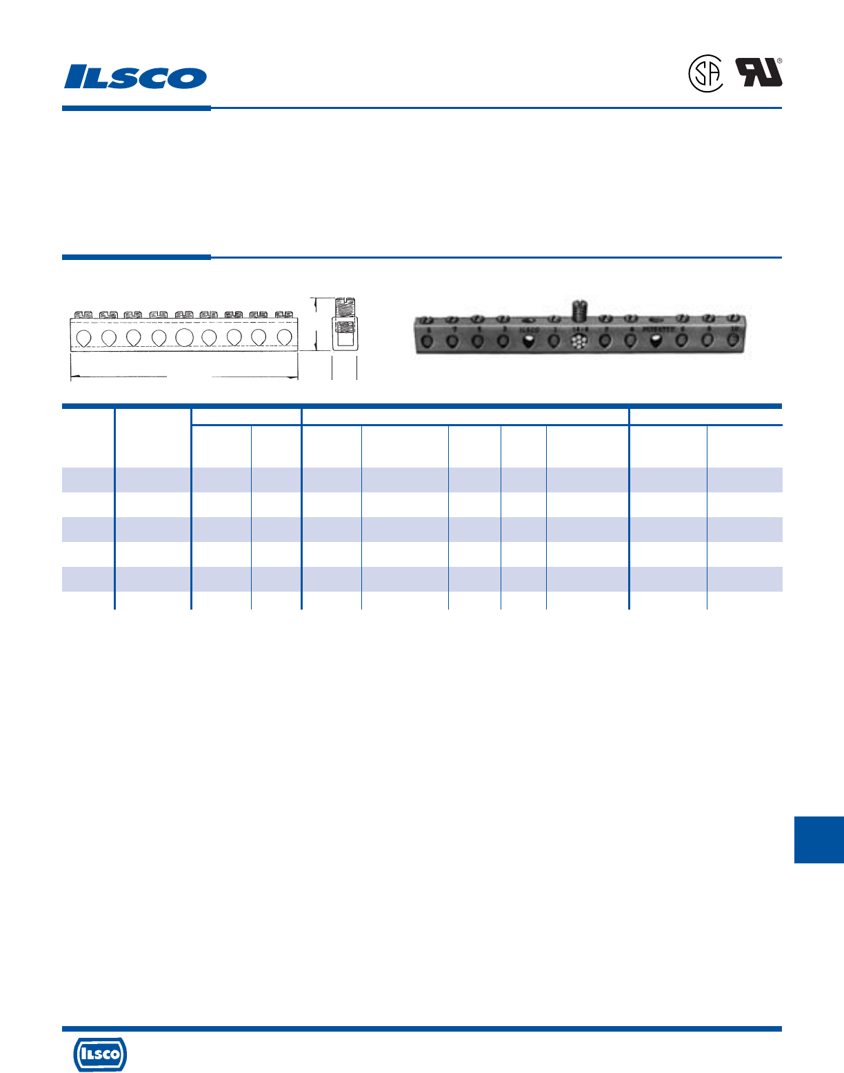
4730 Madison Road, Cincinnati, Ohio 45227-1426 Phone 513 533-6200 Fax 513 871-4084 Web site www.ilsco.com
Canada 1050 Lakeshore Road East, Mississauga, Ontario, Canada L5E1E4 Phone 905 274-2341 Fax 905 274-8763
332
K
Wire Range Dimensions Mounting Hole Positions
From End Of Distance
Catalog Number Of Height With Bolt Two Mounting Bar To First Between
Number Taps Main Tap L Maximum Wire W Size Holes Mounting Hole Holes
D167-4 4 4-14 6-14 2-3/4 3/4 11/32 #10 13/64 .581 (2nd hole) 1.98
D167-6 6 4-14 6-14 3-1/2 3/4 11/32 #10 13/64 .978 (3rd hole) 1.98
D167-8 8 4-14 6-14 4-7/16 3/4 11/32 #10 13/64 1.375 (4th hole) 1.98
D167-10 10 4-14 6-14 5-1/8 3/4 11/32 #10 13/64 1.772 (5th hole) 1.98
D167-12 12 4-14 6-14 5-15/16 3/4 11/32 #10 13/64 2.169 (6th hole) 1.98
D167-14 14 4-14 6-14 6-23/32 3/4 11/32 #10 13/64 2.566 (7th hole) 1.98
Copper Neutral Bars
TYPE
D167
Features
•
Manufactured from high strength copper tubing
•
Range taking
•
UL Recognized for 600 volts
Benefits
•
Provides maximum conductivity
•
A wide range of conductor sizes can be used in the
same connector
•
Ensures reliability for copper conductor
L
H
W
Tested to UL 486A-486B, UL File E6207
L
1
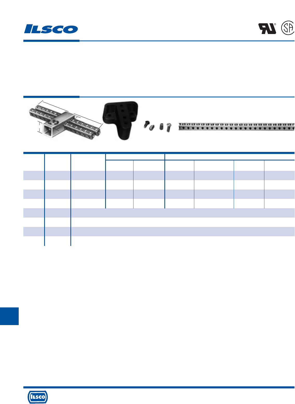
4730 Madison Road, Cincinnati, Ohio 45227-1426 Phone 513 533-6200 Fax 513 871-4084 Web site www.ilsco.com
Canada 1050 Lakeshore Road East, Mississauga, Ontario, Canada L5E1E4 Phone 905 274-2341 Fax 905 274-8763
333
K
Wire Range Dimensions
Catalog Figure Number Of Height With Two Tapped
Number Number Taps Main Tap L Maximum Wire W Mounting Holes
CAN-300 1 24 250kcmil-6 6-14 2-5/16 1-5/16 5-1/8 10-32
CAN-301 1 30 250kcmil-6 6-14 3 1-5/16 4-13/32 10-32
CAN-302 1 36 250kcmil-6 6-14 3 1-5/16 5-1/8 10-32
CAN-303 1 42 250kcmil-6 6-14 3 1-7/16 5-1/2 10-32
R-16 2 Mounting block of general purpose (phenolic black) suitable for mounting any of CAN Neutrals. 2-1/2" wide x 2-1/2" long x 1" thick.
E-223 3 10-32 x 1/2" round head steel machine screws for fastening neutrals to mounting blocks. (Use lock washer to provide rigid assembly.)
E-153 3 1/4-28 wire pressure screw 7/16" long. Screw is steel, zinc plated and chromate dipped.
N-174 4 Supplied in 5' 9" lengths. Approximately 174 outlets. Wire range 14-6.
Copper Neutral Bars
TYPE
CAN
Features
•
Manufactured from high strength copper tubing
•
Compact design
•
Range taking
•
UL Recognized and CSA Certified
•
Circuit bars inserted at a 20 angle
Benefits
•
Provides maximum conductivity
•
Up to 42 circuit taps can be made in just 5 1/2" of space
•
A wide range of conductor sizes can be used in the
same connector
•
Ensures reliability for copper conductor
•
Provides easy wire insertion
L
R
-
2
9
6
0
1
Fig. 1 Fig. 2 Fig. 3 Fig. 4
W
HL
Tested to UL 486A-486B, UL File E6207
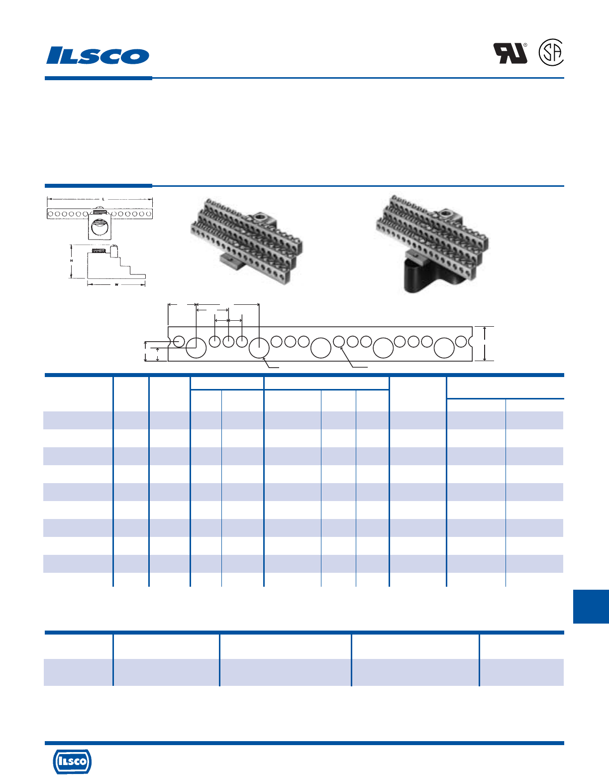
4730 Madison Road, Cincinnati, Ohio 45227-1426 Phone 513 533-6200 Fax 513 871-4084 Web site www.ilsco.com
Canada 1050 Lakeshore Road East, Mississauga, Ontario, Canada L5E1E4 Phone 905 274-2341 Fax 905 274-8763
334
K
.391
.620
.391 Dia. .209 Dia.
.547 1.172
.586
.250 .250
.250
Number Wire Range Dimensions Two Tapped
Catalog Figure Of Circuit Circuit Line Approx. Height Mounting
Number Number Taps Taps Loads with Max. Wire L W Holes Main Tap
NB-350-12 1 12 14-4 350kcmil-6 1-17/32 4-23/32 2-17/32 10-32 3/8 S
NB-350-12-W/R16* 2 12 14-4 350kcmil-6 2-17/32 4-23/32 2-17/32 10-32 3/8 S
NB-350-24 1 24 14-4 350kcmil-6 1-17/32 4-23/32 2-17/32 10-32 3/8 S
NB-350-24-W/R16* 2 24 14-4 350kcmil-6 2-17/32 4-23/32 2-17/32 10-32 3/8 S
NB-350-30 1 30 14-4 350kcmil-6 1-17/32 4-3/32 2-17/32 10-32 3/8 S
NB-350-30-W/R16* 2 30 14-4 350kcmil-6 2-17/32 4-3/32 2-17/32 10-32 3/8 S
NB-350-36 1 36 14-4 350kcmil-6 1-17/32 4-23/32 2-17/32 10-32 3/8 S
NB-350-36-W/R16* 2 36 14-4 350kcmil-6 2-17/32 4-23/32 2-17/32 10-32 3/8 S
NB-350-42 1 42 14-4 350kcmil-6 1-17/32 5-11/32 2-17/32 10-32 3/8 S
NB-350-42-W/R16* 2 42 14-4 350kcmil-6 2-17/32 5-11/32 2-17/32 10-32 3/8 S
Catalog Figure Number of Wire
Number Number Outlets Range Length
NB-120 3 120 30 outlets 1/0-14 3.25'
90 outlets 6-14
Aluminum Neutral Bars - Dual Rated
TYPE
NB
Features
•
Preassembled, stacked neutral bars
•
Available with phenolic base
•
Electro-tin plated
•
Fabricated from high strength 6061-T6 aluminum alloy
•
UL Recognized and CSA Certified for 600 volts, 90˚ C
Benefits
•
Compact, space saving design offers multiple range taking
flexibility and is suitable for grounding applications
•
Provides insulation from mounting surface
•
Provides low contact resistance
•
Suitable for use with either copper or aluminum conductors
•
Ensures reliability
L
R
-
2
9
6
0
1
Fig. 1 Fig. 2
Fig. 3
Hex Size
“S” indicates slotted screw
* Part includes phenolic mounting block R-16
Tested to UL 486A-486B, UL File E6207
UL File E81652
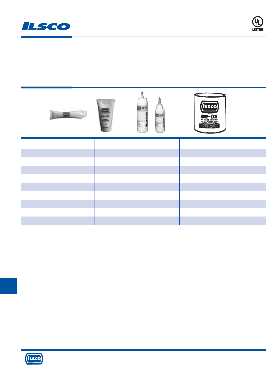
4730 Madison Road, Cincinnati, Ohio 45227-1426 Phone 513 533-6200 Fax 513 871-4084 Web site www.ilsco.com
Canada 1050 Lakeshore Road East, Mississauga, Ontario, Canada L5E1E4 Phone 905 274-2341 Fax 905 274-8763
335
K
Catalog Container
Number Size & Type Packaging
DE-OX -5CC 5cc Packet Display Carton of 150
DE-OX-5CC-B4 5cc Packet 4 Per Bag, 25 Bags Per Carton
DE-OX-1OZ 1 oz. Tube Display Carton of 50
DE-OX -4OZ 4 oz. Bottle Display Carton of 12
DE-OX-8OZ 8 oz. Bottle Display Carton of 12
DE-OX-1GAL 1 Gallon Can 1 Can
DE-OX -5GAL 5 Gallon Bucket 1 Bucket
UDE-OX-V-4OZ*+ 4 oz. Bottle Display Carton of 12
UDE-OX-V-8OZ*+ 8 oz. Bottle Display Carton of 12
Oxide Inhibitor
TYPE
DE-OX®
Features
•
Provides air-tight seal around conductor
•
Available in a variety of packages
•
Broad working temperature range
•
Conductor versatile
Benefits
•
Prevents oxides from forming
•
Provides convenience of selecting the right size for
the job
•
May be used from -30˚ F to 200˚ F
•
May be used on copper or aluminum conductors
* V denotes synthetic base, chalk color, doesn’t stain blankets, etc.
+ Not UL Listed
UL File E312012
35CD
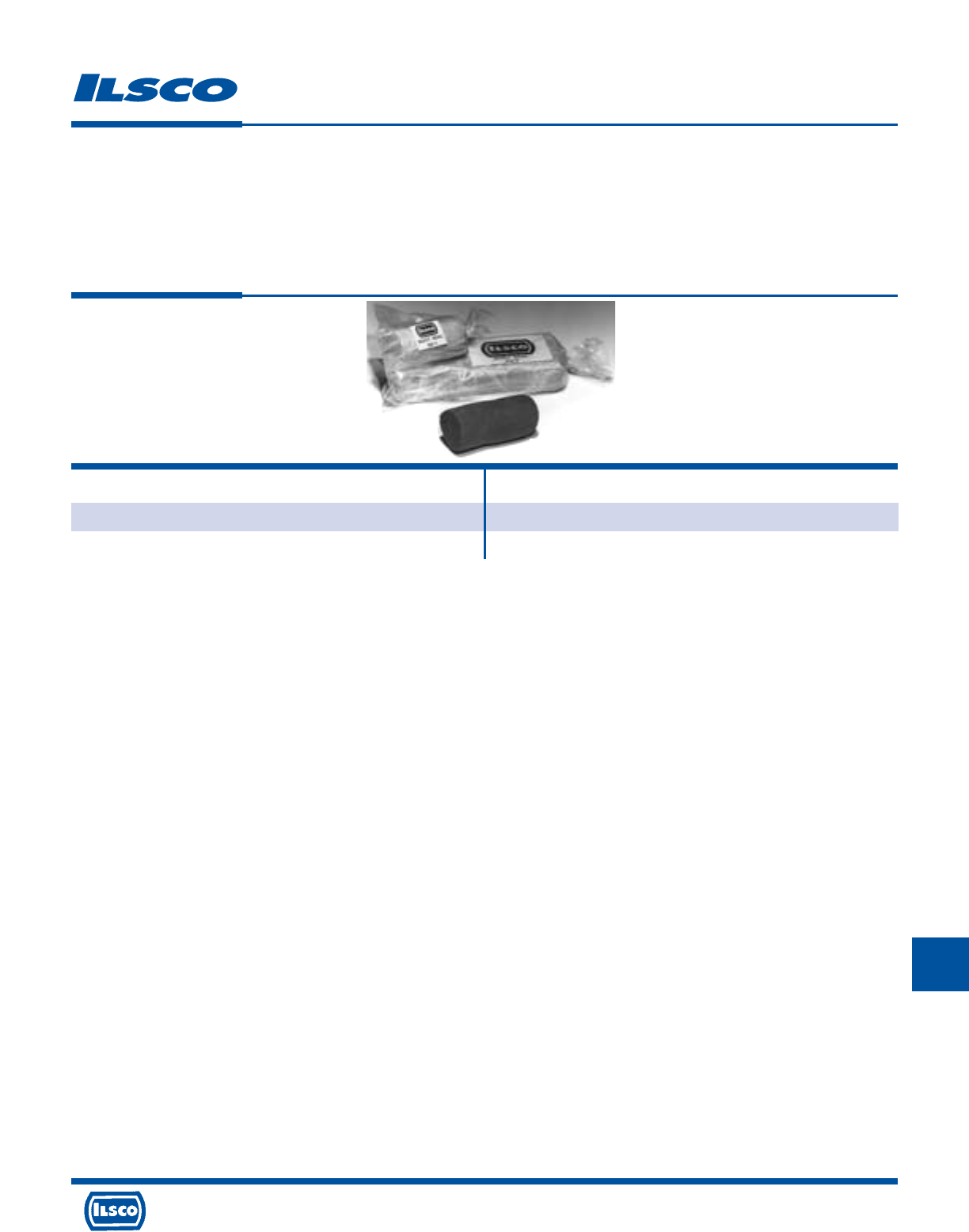
4730 Madison Road, Cincinnati, Ohio 45227-1426 Phone 513 533-6200 Fax 513 871-4084 Web site www.ilsco.com
Canada 1050 Lakeshore Road East, Mississauga, Ontario, Canada L5E1E4 Phone 905 274-2341 Fax 905 274-8763
336
K
Catalog
Number Packaging
DS-1 10 1 lb. bags
DS-5 5 5 lb. bags
Duct Seal
TYPE
DS
Features
•
Available in 1 LB and 5 LB packages
•
Remains pliable
•
Non-corrosive
•
Can be painted immediately
Benefits
•
Provides convenience of selecting the right size for
the job
•
Will not dry out, crack and fall out of installation
•
Will not irritate skin, or corrode metals, or have
harmful effects on plastics
•
No need to wait for product to dry
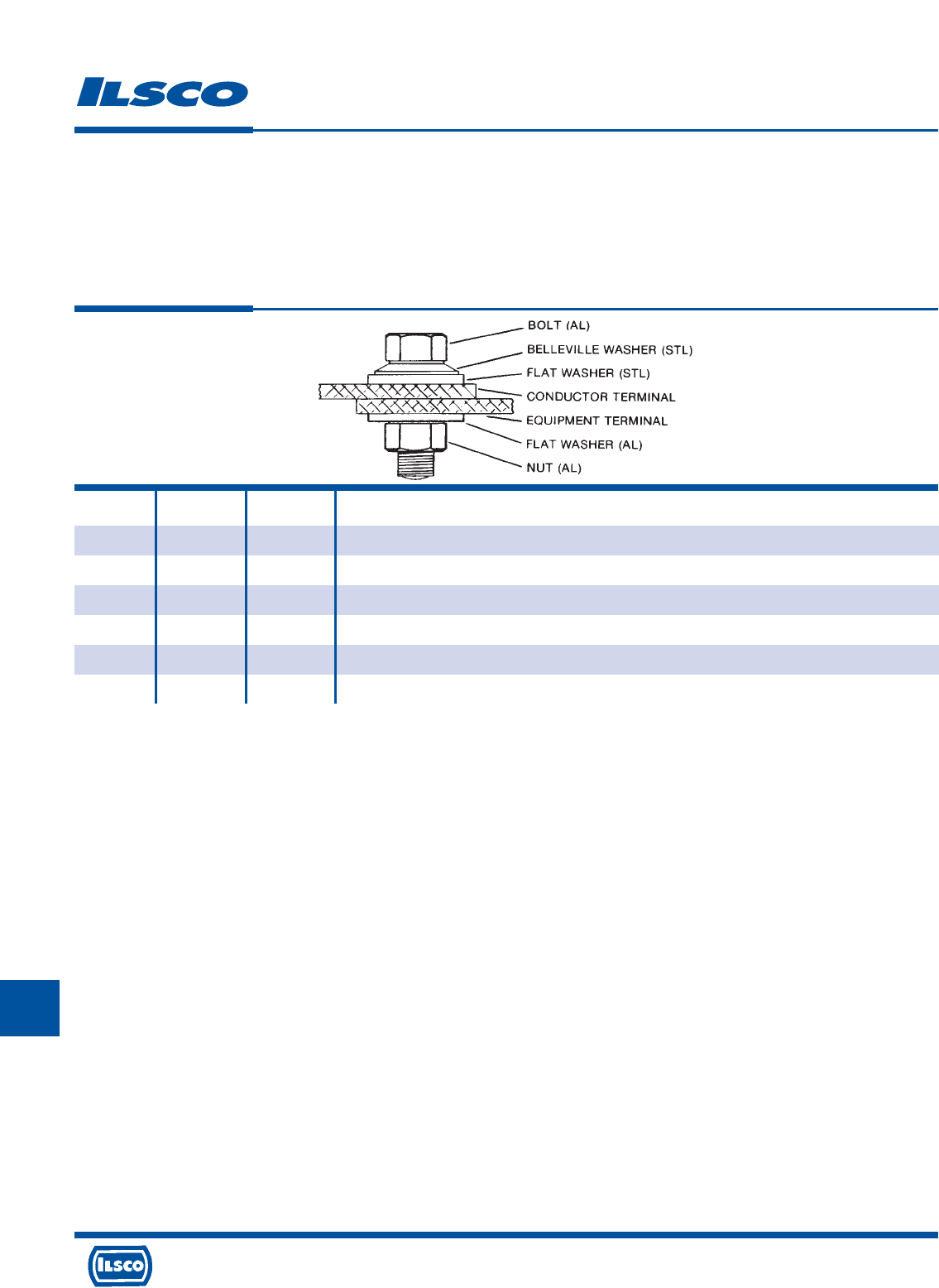
4730 Madison Road, Cincinnati, Ohio 45227-1426 Phone 513 533-6200 Fax 513 871-4084 Web site www.ilsco.com
Canada 1050 Lakeshore Road East, Mississauga, Ontario, Canada L5E1E4 Phone 905 274-2341 Fax 905 274-8763
337
K
Catalog Bolt Bolt
Number Size Length Included In Kit
NBW-38-125 3/8-16 1-1/4 Aluminum Nut, Stainless Steel Belleville Washer, Aluminum Flat Washer, Stainless Steel Flat Washer, Aluminum Bolt
NBW-50-150 1/2-13 1-1/2 Aluminum Nut, Stainless Steel Belleville Washer, Aluminum Flat Washer, Stainless Steel Flat Washer, Aluminum Bolt
NBW-50-200 1/2-13 2 Aluminum Nut, Stainless Steel Belleville Washer, Aluminum Flat Washer, Stainless Steel Flat Washer, Aluminum Bolt
NBW-50-250 1/2-13 2-1/2 Aluminum Nut, Stainless Steel Belleville Washer, Aluminum Flat Washer, Stainless Steel Flat Washer, Aluminum Bolt
NBW-58-250 5/8-11 2-1/2 Aluminum Nut, Stainless Steel Belleville Washer, Aluminum Flat Washer, Stainless Steel Flat Washer, Aluminum Bolt
NBW-58-300 5/8-11 3 Aluminum Nut, Stainless Steel Belleville Washer, Aluminum Flat Washer, Stainless Steel Flat Washer, Aluminum Bolt
Mounting Hardware
TYPE
NBW
Features
•
Individually packaged
•
Aluminum nut and bolt
•
Belleville washer
Benefits
•
All components for mounting one connector are kept
together to avoid mismatched hardware
•
Provides consistent and even thermal expansion and
contraction to prevent loosening of mounting hardware
due to heat cycling
•
Maintains tension on connection through thermal
expansion and contraction
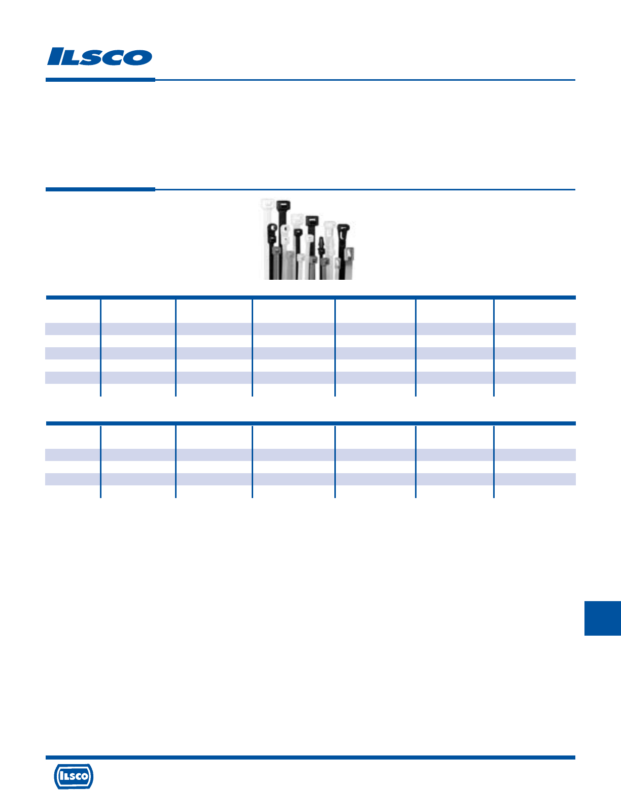
4730 Madison Road, Cincinnati, Ohio 45227-1426 Phone 513 533-6200 Fax 513 871-4084 Web site www.ilsco.com
Canada 1050 Lakeshore Road East, Mississauga, Ontario, Canada L5E1E4 Phone 905 274-2341 Fax 905 274-8763
338
K
Catalog Tensile Bundle Bag
Number Length Width Color Strength Diameter Qty
93180 25.0 0.35 NATURAL 175 LBS. 7.0 100
93280 25.0 0.35 UV BLACK 175 LBS. 7.0 100
93195 36.5 0.35 NATURAL 175 LBS. 10.7 50
93295 36.5 0.35 UV BLACK 175 LBS. 10.7 50
93199 48.0 0.35 NATURAL 175 LBS. 15.0 50
93299 48.0 0.35 UV BLACK 175 LBS. 15.0 50
Cable Ties
Heavy Duty, Super Heavy Duty
TYPE
TIES
Features
•
Quick & Easy
•
Strong & Flexible
•
Nylon 6/6
Benefits
•
Can accommodate .75" to 15" bundle diameter
•
Tensile strengths from 18 lbs to 250 lbs
•
Resists weather & chemicals
Heavy Duty Cable Ties
Catalog Tensile Bundle Bag
Number Length Width Color Strength Diameter Qty
93190 22.0 0.50 NATURAL 250 LBS. 6.0 100
93290 22.0 0.50 UV BLACK 250 LBS. 6.0 100
93196 34.0 0.50 NATURAL 250 LBS. 10.1 50
93296 34.0 0.50 UV BLACK 250 LBS. 10.1 50
Super Heavy Duty Cable Ties

4730 Madison Road, Cincinnati, Ohio 45227-1426 Phone 513 533-6200 Fax 513 871-4084 Web site www.ilsco.com
Canada 1050 Lakeshore Road East, Mississauga, Ontario, Canada L5E1E4 Phone 905 274-2341 Fax 905 274-8763
339
K
Catalog Tensile Bundle Bag
Number Length Width Color Strength Diameter Qty
93110 4.0 0.10 NATURAL 18 LBS. .75 100
93110M 4.0 0.10 NATURAL 18 LBS. .75 1000
93210 4.0 0.10 UV BLACK 18 LBS. .75 100
93210M 4.0 0.10 UV BLACK 18 LBS. .75 1000
93120 5.7 0.14 NATURAL 40 LBS. 1.25 100
93120M 5.7 0.14 NATURAL 40 LBS. 1.25 1000
93220 5.7 0.14 UV BLACK 40 LBS. 1.25 100
93220M 5.7 0.14 UV BLACK 40 LBS. 1.25 1000
93130 8 0.19 NATURAL 50 LBS. 2.0 100
93130M 8 0.19 NATURAL 50 LBS. 2.0 1000
93230 8 0.19 UV BLACK 50 LBS. 2.0 100
93230M 8 0.19 UV BLACK 50 LBS. 2.0 1000
93150 11.8 0.19 NATURAL 50 LBS. 3.0 100
93150M 11.8 0.19 NATURAL 50 LBS. 3.0 1000
93250 11.8 0.19 UV BLACK 50 LBS. 3.0 100
93250M 11.8 0.19 UV BLACK 50 LBS. 3.0 1000
93160 14.6 0.19 NATURAL 50 LBS. 4.0 100
93160M 14.6 0.19 NATURAL 50 LBS. 4.0 1000
93260 14.6 0.19 UV BLACK 50 LBS. 4.0 100
93260M 14.6 0.19 UV BLACK 50 LBS. 4.0 1000
93170 14.5 0.30 NATURAL 120 LBS. 4.0 100
93170D 14.5 0.30 NATURAL 120 LBS. 4.0 500
93270 14.5 0.30 UV BLACK 120 LBS. 4.0 100
93270D 14.5 0.30 UV BLACK 120 LBS. 4.0 500
93185 28 0.30 NATURAL 120 LBS. 8.0 100
93185D 28 0.30 NATURAL 120 LBS. 8.0 500
93285 28 0.30 UV BLACK 120 LBS. 8.0 100
93285D 28 0.30 UV BLACK 120 LBS. 8.0 500
Cable Ties
Standard
TYPE
TIES
Features
•
Quick & Easy
•
Strong & Flexible
•
Nylon 6/6
Benefits
•
Can accommodate .75" to 15" bundle diameter
•
Tensile strengths from 18 lbs to 250 lbs
•
Resists weather & chemicals
Standard Cable Ties
4730 Madison Road, Cincinnati, Ohio 45227-1426 Phone 513 533-6200 Fax 513 871-4084 Web site www.ilsco.com
Canada 1050 Lakeshore Road East, Mississauga, Ontario, Canada L5E1E4 Phone 905 274-2341 Fax 905 274-8763
340
K
Catalog Bolt Tensile Bundle Bag
Number Length Width Size Color Strength Diameter Qty
93310 4.5 .10 #4 NATURAL 18 LBS. .62 100
93410 4.5 .10 #4 UV BLACK 18 LBS. .62 100
93320 5.9 .14 #8 NATURAL 40 LBS. 1.25 100
93420 5.9 .14 #10 UV BLACK 40 LBS. 1.25 100
93340 8 .19 #10 NATURAL 50 LBS. 2 100
93440 8 .19 #10 UV BLACK 50 LBS. 2 100
93350 12.6 .19 #10 NATURAL 50 LBS. 3 100
93450 12.6 .19 #10 UV BLACK 50 LBS. 3 100
93380 15 .19 #10 NATURAL 50 LBS. 4 100
93480 15 .19 #10 UV BLACK 50 LBS. 4 100
93390 15 .30 #10 NATURAL 120 LBS. 4 100
93490 15 .30 #10 UV BLACK 120 LBS. 4 100
Cable Ties
Mounting Head, Push Mount, Releasable
TYPE
TIES
Features
•
Quick & Easy
•
Strong & Flexible
•
Nylon 6/6
Benefits
•
Can accommodate .75" to 15" bundle diameter
•
Tensile strengths from 18 lbs to 250 lbs
•
Resists weather & chemicals
Mounting Head Cable Ties
Catalog Tensile Bundle Bag
Number Length Width Color Strength Diameter Qty
93345 7.9 .19 NATURAL 50 LBS. 2 100
93445 7.9 .19 UV BLACK 50 LBS. 2 100
Push Mount Cable Ties
Catalog Tensile Bundle Bag
Number Length Width Color Strength Diameter Qty
93620 5.9 .30 NATURAL 50 LBS. 1.2 100
93720 5.9 .30 UV BLACK 50 LBS. 1.2 100
93640 7.8 .30 NATURAL 50 LBS. 2 100
93740 7.8 .30 UV BLACK 50 LBS. 2 100
93650 10.5 .30 NATURAL 50 LBS. 3 100
93750 10.5 .30 UV BLACK 50 LBS. 3 100
Releasable Cable Ties
4730 Madison Road, Cincinnati, Ohio 45227-1426 Phone 513 533-6200 Fax 513 871-4084 Web site www.ilsco.com
Canada 1050 Lakeshore Road East, Mississauga, Ontario, Canada L5E1E4 Phone 905 274-2341 Fax 905 274-8763
341
K
Catalog Tensile Bundle Bag
Number Length Width Color Strength Diameter Qty
93110-R 4.0 0.10 RED 18 LBS. .75 100
93230-R 8 0.19 RED 50 LBS. 2.0 100
93110-GR 4.0 0.10 GREEN 18 LBS. .75 100
93230-GR 8 0.19 GREEN 50 LBS. 2.0 100
93110-Y 4.0 0.10 YELLOW 18 LBS. .75 100
93230-Y 8 0.19 YELLOW 50 LBS. 2.0 100
93110-BL 4.0 0.10 BLUE 18 LBS. .75 100
93230-BL 8 0.19 BLUE 50 LBS. 2.0 100
93110-OR 4.0 0.10 ORANGE 18 LBS. .75 100
93230-OR 8 0.19 ORANGE 50 LBS. 2.0 100
Cable Ties
Colored, Stainless Steel
TYPE
TIES
Features
•
Quick & Easy
•
Strong & Flexible
•
Nylon 6/6
Benefits
•
Can accommodate .75" to 15" bundle diameter
•
Tensile strengths from 18 lbs to 250 lbs
•
Resists weather & chemicals
Colored Cable Ties
Catalog Tensile Bundle Bag
Number Length Width Color Strength Diameter Qty
93804 8 .18 SS Steel (302/304) 100 2 100
93808 14 .18 SS Steel (302/304) 100 4 100
93812 20 .18 SS Steel (302/304) 100 6 100
93805 8 .30 SS Steel (302/304) 250 2 100
93809 14 .30 SS Steel (302/304) 250 4 100
93813 26 .30 SS Steel (302/304) 250 8 100
Stainless Steel Cable Ties
4730 Madison Road, Cincinnati, Ohio 45227-1426 Phone 513 533-6200 Fax 513 871-4084 Web site www.ilsco.com
Canada 1050 Lakeshore Road East, Mississauga, Ontario, Canada L5E1E4 Phone 905 274-2341 Fax 905 274-8763
342
K
Catalog Bolt Slot Bag
Number Length W idth Height Color Size Size Qty
93511 .75 .75 .205 NATURAL #6 .05 100
93513 .75 .75 .205 UV BLACK #6 .05 100
93510 1.0 1.0 .215 NATURAL #8 .07 100
93512 1.0 1.0 .215 UV BLACK #8 .07 100
93514 2.0 2.0 .300 NATURAL #6 & #8 .30 100
93515 2.0 2.0 .300 UV BLACK #6 & #8 .30 100
Cable Ties
Mounting Bases, Installation Tool, Kit
TYPE
TIES
Features
•
Quick & Easy
•
Strong & Flexible
•
Nylon 6/6
•
Adhesive backed mounting bases
Benefits
•
Can accommodate .75" to 15" bundle diameter
•
Tensile strengths from 18 lbs to 250 lbs
•
Resists weather & chemicals
•
Easy Installation
Mounting Bases
Catalog
Number Color Description
94400 RED Installation and cutoff tool for standard cable ties 18-50 lbs
Cable Tie Installation Tool
Catalog
Number Qty Kit Includes
93403 1 94400 Cable Tie Installation Tool
50 93230 8 UV Black 50 LB Cable Ties
100 93120 5.7 Natural 40 LB Cable Ties
10 93510 1 X 1 Natural Mounting Bases
Cable Tie Kit
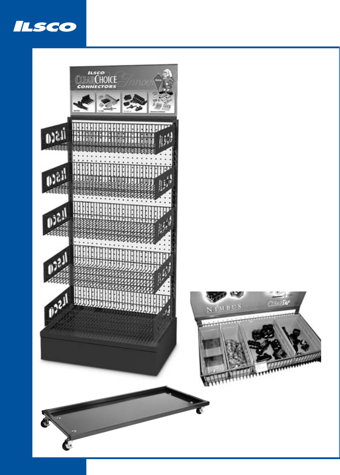
Merchandising
343
All Inclusive Merchandisers
Merchandiser-2ft:
1 Gondola
1 Header
5 Laser Engraved Wire Shelves
10 4” Blue Bins
5 6 1/2” Blue Bins
5 8” Blue Bins
20 Basket Clips for Labels
20 Basket Clip Labels *
Merchandiser-3ft:
1 Gondola
1 Header
5 Laser Engraved Wire Shelves
15 4” Blue Bins
5 6 1/2” Blue Bins
10 8” Blue Bins
25 Basket Clips for Labels
25 Basket Clip labels *
Optional (part numbers noted):
Wheel-Kit-2ft (for 2ft merchandiser)
Wheel-Kit-3ft (for 3ft merchandiser)
* Basket Clip Labels are printed on demand.
Part #’s required to print labels.
Blue-Bin-4
Blue-Bin-6
Blue-Bin-8
Wheel-Kit-2ft
Wheel-Kit-3ft
344
Canada Supplemental Catalog
CONTACT ILSCO OF CANADA
1050 Lakeshore Road East, Mississauga, Ontario, Canada L5E1E4
Phone 905 274-2341 Fax 905 274-8763

N
4730 Madison Road, Cincinnati, Ohio 45227-1426 Phone 513 533-6200 Fax 513 871-4084 Web site www.ilsco.com
Canada 1050 Lakeshore Road East, Mississauga, Ontario, Canada L5E1E4 Phone 905 274-2341 Fax 905 274-8763
345
Technical............................................ 346 - 351
Decimal Conversion Chart.......................... 352
Wire Size Charts ......................................... 353
Wire Amperage Rating Chart............. 354 - 359
(FROM NEC 2005 CODEBOOK)
Torque Index ............................................... 360
Torque Information ..................................... 361
RoHS Compliance ....................................... 362
Cross Reference Guide ............................... 363
Technical Information
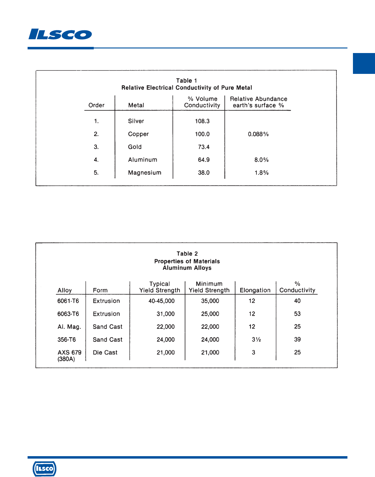
4730 Madison Road, Cincinnati, Ohio 45227-1426 Phone 513 533-6200 Fax 513 871-4084 Web site www.ilsco.com
Canada 1050 Lakeshore Road East, Mississauga, Ontario, Canada L5E1E4 Phone 905 274-2341 Fax 905 274-8763
A brief summary of comparative properties of metals suitable for current carrying applications and required
features of the connector are listed below in Table 1.
The commercial use of copper and aluminum for electrical application are obvious, in terms of economic
justifications. The accelerated use of aluminum becomes even more obvious when realized that it requires
twice the amount of copper by weight, to carry a specified amount of current. At the unit price per pound of
prime metal it is readily seen why aluminum is increasing in electrical application.
As the next logical step, and examination of available alloys and forms of aluminum should be made to
determine the optimum choice for the manufacture of electrical connectors. Please refer to Table 2
During the initial analysis of these materials, reference was made to the experience over many years of the
effect of stress on tensioned overhead conductors. It is well documented that in order to assure mechanical
stability of these conductors, over long periods of time, it is necessary to design the line so that the maximum
stress will not exceed 50% of the conductors rated breaking strength. In the case of aluminum conductors the
alloy most commonly used is EC-H19 having a yield strength of 22,000 psi and a tensile strength of 24,000 psi.
From the foregoing it is obvious that a maximum stress level of 12,000 psi representing 50% of ultimate tensile
strength or approximately 55% of yield strength, will result in the conductor remaining mechanically stable
throughout its life.
With this initial premise being established it was necessary to confirm whether or not a determinable stress
limit could be effectively applied to the design of connectors. The method of testing used to confirm this
premise is noted in detail in table 8.
Technical Information
346
N
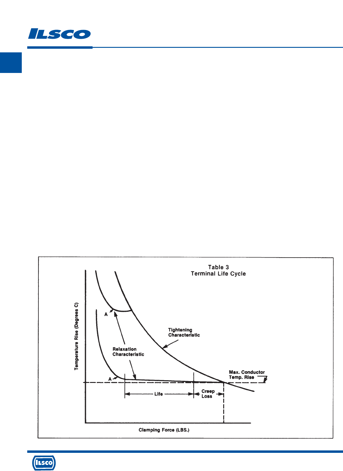
4730 Madison Road, Cincinnati, Ohio 45227-1426 Phone 513 533-6200 Fax 513 871-4084 Web site www.ilsco.com
Canada 1050 Lakeshore Road East, Mississauga, Ontario, Canada L5E1E4 Phone 905 274-2341 Fax 905 274-8763
347
N
Additional factors of design were recognized as necessary to achieve a stable and reliable connector.
Requirements of aluminum connectors for use with aluminum or copper conductors.
a. Adequate strength of the connector to prevent creep loss in the connection from exceeding the creep loss
of the conductor.
b. Strong enough clamping force (torque) to keep the connector operating temperature at a level below the
operating temperature of the maximum size conductor.
c. High enough conductivity to provide adequate efficiency (minimum of 40%).
To illustrate the significance of these requirements, Table 3 headed Terminal life Cycle, presents an
examination of terminal temperature in relation to clamping force. The horizontal dotted line indicates the
temperature of the conductor at maximum rise. The tightening characteristic curve shows a lowering of
terminal temperature rise with an increased clamping force. Terminal temperature, measured in degrees
centigrade, is used in our illustration as a measure of connector resistance. As the tightening characteristic
curve approaches the dotted conductor temperature line at the same current value, the connector and
conductor resistance approximate each other.
The curves labeled Relaxation Characteristic, merely indicate the anticipated progression a connector would
follow to failure, once clamping force has been reduced to a level where terminal resistance can no longer be
maintained at a low level. Point A on each curve represents that point where resistance is sufficiently high to
cause and elevated operating temperature of the connector which will then progress to ultimate connector
failure.
Proceeding with the assumption that stress limitation is a most critical factor in connector design it was then
necessary to select and test the alloy materials which evidence the most favorable conductivity/yield
strength/economic factors. The initial selection of aluminum alloy 6061-T6 has long since been determined to
be the best available material from which to fabricate connectors for use with both aluminum and copper
conductors.
Technical Information
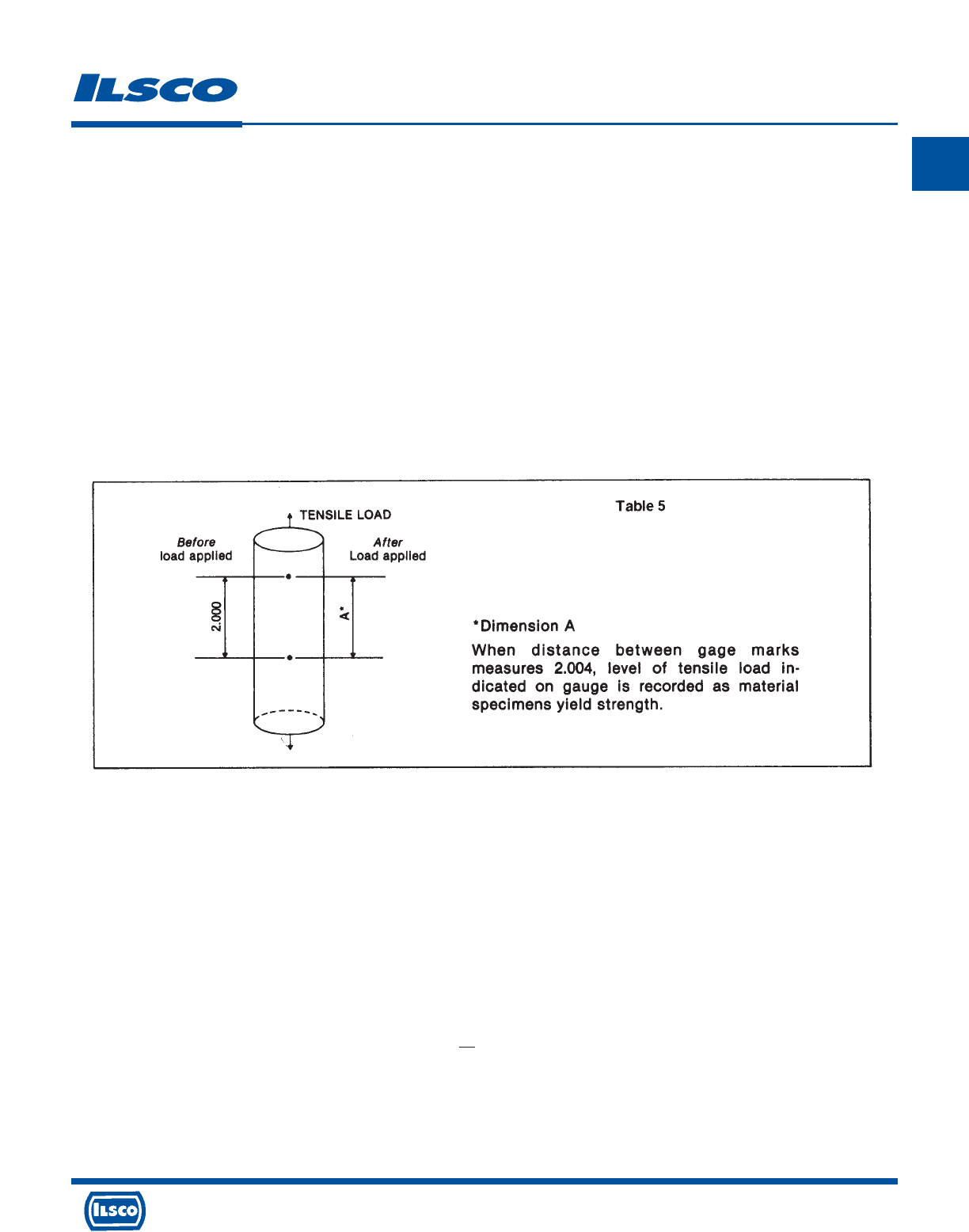
4730 Madison Road, Cincinnati, Ohio 45227-1426 Phone 513 533-6200 Fax 513 871-4084 Web site www.ilsco.com
Canada 1050 Lakeshore Road East, Mississauga, Ontario, Canada L5E1E4 Phone 905 274-2341 Fax 905 274-8763
348
N
Before proceeding further a definition of terms used, to assure understanding of the basis for the conclusions
reached later in the paper, are listed.
Physical Property of Aluminum
Tensile Strength
The maximum tensile load which a material is capable of withstanding under gradually and uniformly applied
loading, divided by the original cross-sectional area in the minimum plane perpendicular to the direction of
loading. Commonly the term is taken to mean the same as “ ultimate tensile strength” or the less accurate “
breaking strength.”
Yield Strength
The stress at which material exhibits a specified permanent set. The value of set used for aluminum and its
alloys is 0.002 inch per inch or 0.2%. For the aluminum alloys the yield strength in tension and compression
are approximately the same.
Elongation
The increase in distance between two gage marks that results from stressing the specimen in tension to
fracture. Please see table 5.
To record elongation, tensile loading is continually applied until specimen fractures, at which time two pieces
are mated and distance between gage marks accurately measured. The resultant dimension divided by the
original increment provides the value expressed in %, of the materials ability to stretch under load, or its
elongation.
Elastic Limit
The stress value below which no permanent set or permanent deformation takes place; the highest stress
which will permit return to original shape upon removal of force causing the stress.
Elasticity
The ability of a material to return to its original shape and size upon removal of a load below the elastic limit.
Creep
A precise unit of measure disclosing the increase in dimension of a unit specimen having a specified area =A,
an applied force =W with resultant constant stress=W. The initial increment of measurement L, is
effected by three factors resulting in amount of increase or creep, stress, time and temperature.
To determine and express the creep rate for a given specimen in terms of inches of creep, per inches of original
gage length, per hour, the factors of stress and temperature must be maintained constant. A change in either
or both, will result in a change in the creep rate. Please refer to Tables 6 and 7.
Technical Information
A
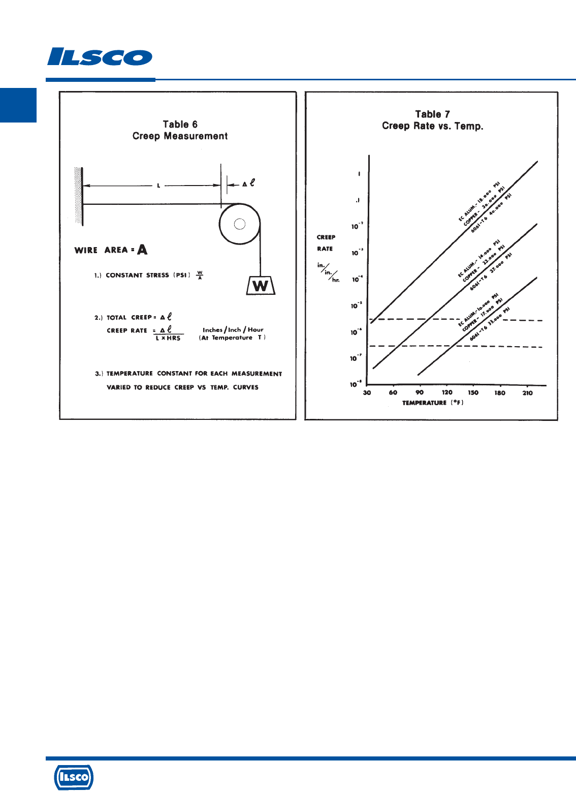
4730 Madison Road, Cincinnati, Ohio 45227-1426 Phone 513 533-6200 Fax 513 871-4084 Web site www.ilsco.com
Canada 1050 Lakeshore Road East, Mississauga, Ontario, Canada L5E1E4 Phone 905 274-2341 Fax 905 274-8763
349
N
Cold Flow
As compared to Creep, cold flow has no units of measure. The best description of cold flow relating to
application within the electrical industry, is an excessively high rate of creep i.e. normal creep rate static load
condition would be expressed in a fraction of an inch per inch of length. Cold flow, conversely if possible to
measure it in definable terms, would be expressed in terms of inches of movement per inch of length. Cold
flow then can be expressed as movement of appreciable magnitude occurring at a stress level in a very short
length of time at an ambient temperature. Neither time or temperature are critical in assessing the effecting
force of cold flow.
It is significant to realize that it is an absolute necessity to have cold flow of the conductor within a bolted
connector to develop the desired low resistance contact, required for electrical/mechanical stability of the
connection. So is it necessary to have cold flow of both the conductor and connector in the making of a
compression connection. In these two instances a mechanical union of the two components is made by means
of an externally applied force to assure both electrical and mechanical reliability. In the case of a soldered or
welded connection this component union is made metallurgically.
Creep Loss
The unit of measurement, expressed in % of the initially applied mechanical force to a connection, divided by
the resultant measured force after the unit has been subjected to controlled loadings of temperature and time.
This value is relatively easy to determine for bolted connectors by accurately measuring applied torque before
and after applying control factors of time and temperature. The resultant loss of torque is the creep loss
experienced within the connection assembly.
It is difficult and inaccurate to project anticipated creep loss within a compression assembly since there is no
way of effecting a measurement of the initially applied force and the resultant force remaining on the
connection after the mechanical or hydraulic compression tool is removed from the connector.
The maximum desired creep loss in a connector/conductor assembly stated, is that portion of the total creep
component represented by the creep component of the conductor alone.
Technical Information
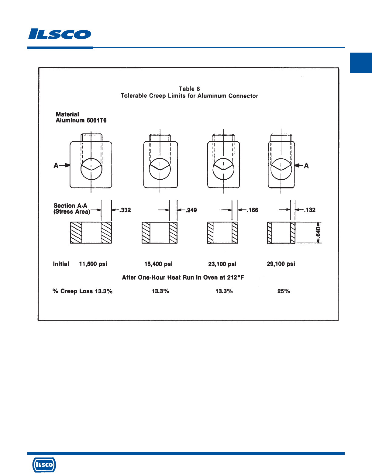
4730 Madison Road, Cincinnati, Ohio 45227-1426 Phone 513 533-6200 Fax 513 871-4084 Web site www.ilsco.com
Canada 1050 Lakeshore Road East, Mississauga, Ontario, Canada L5E1E4 Phone 905 274-2341 Fax 905 274-8763
350
N
This brings us to the threshold of the discussion of design parameters used by Ilsco in the manufacturer of
aluminum connectors.
To best understand the importance of the function of creep components in a connection assembly, recall the
definition of cold flow wherein it is stated that it is necessary to the formulation of an electrically/mechanically
stable connection to have cold flow of the conductor. Since cold flow is by definition a high rate of creep and since
creep occurs only where constant stress is applied; the connection will undergo creep movement as a result of
load cycling. It is mandatory that the connector be so designed that all creep within the assembly occur in the
conductor.
The determination of tolerable creep limits for aluminum connector design were established through the test
described below and pictured in Table 8
This test established the maximum stress which can be imposed on an aluminum connector made from Alloy
6061-T6 as being 23,000 psi which is approximately 1/2 typical yield strength. The value of creep loss for the first
three connectors were identical; 13.3% whereas the fourth exhibited a 25% creep loss. The explanation is simply
that the loads applied to the section modulus of each of the first three test connectors resulted in a stress level
below the elastic limit of the material and thereby causing no creep movement in the connector. The conductor on
the other hand must be physically moved, and this conductor movement resulted in a redistribution of strand
displacement and resultant redistribution of load. The 13.3% creep loss therefore can be stated as being that
movement occurring within the conductor.
Technical Information

4730 Madison Road, Cincinnati, Ohio 45227-1426 Phone 513 533-6200 Fax 513 871-4084 Web site www.ilsco.com
Canada 1050 Lakeshore Road East, Mississauga, Ontario, Canada L5E1E4 Phone 905 274-2341 Fax 905 274-8763
351
N
The Fourth sample, however, evidenced in higher creep loss, resulting from creep in the conductor and the
connector since the connector was stressed beyond its elastic limit and contributed to the total creep of the
assembly.
The confirmation by actual test of this limitation of stress to 1/2 the materials yield strength has been utilized
in the design of all connectors manufactured by Ilsco.
Preparation of wire
When an aluminum cable is installed, certain procedures should be followed to insure a good connection.
1. The insulation should be stripped with a whittling motion to prevent the cable from being nicked.
2. The cable should then be cleaned with a wire brush. This removes the oxides from the surface of the
conductor.
3. In many cases, an oxide inhibitor is applied to the conductor immediately prior to installation.
However, this is not absolutely necessary.
4. For mechanical connectors, the set screw should be tightened. After a few seconds, the set screw should be
retightened to insure a good connection. For compression connectors, the lug should be crimped around
the conductor using the proper tool.
Technical Information
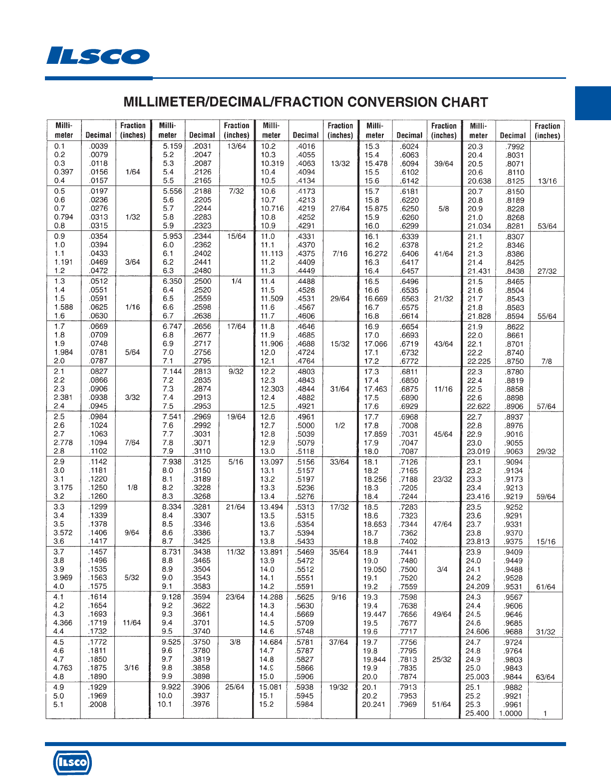
4730 Madison Road, Cincinnati, Ohio 45227-1426 Phone 513 533-6200 Fax 513 871-4084 Web site www.ilsco.com
Canada 1050 Lakeshore Road East, Mississauga, Ontario, Canada L5E1E4 Phone 905 274-2341 Fax 905 274-8763
352
N
Decimal Conversion Chart
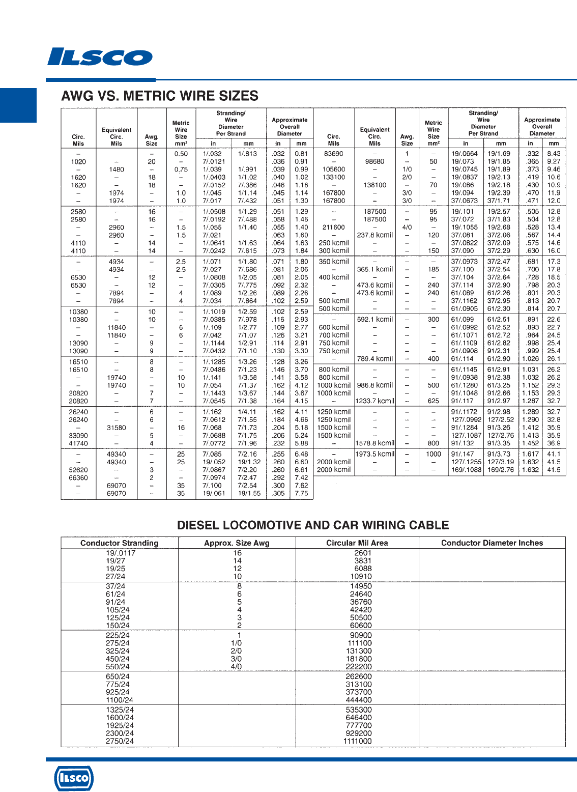
4730 Madison Road, Cincinnati, Ohio 45227-1426 Phone 513 533-6200 Fax 513 871-4084 Web site www.ilsco.com
Canada 1050 Lakeshore Road East, Mississauga, Ontario, Canada L5E1E4 Phone 905 274-2341 Fax 905 274-8763
353
N
Wire Size Charts
937
7/.030
7/.533
262.6
313.1
373.7
444.4
535.3
646.4
777.7
929.2
1111.0
.060
.096
.116
.146
.166
.226
.256
.286
.300
.366
.424
.454
.494
.604
.634
.712
.792
.852
.922
1.022
1.122
1.182
1.292
1.43
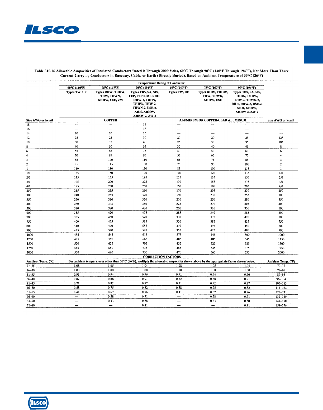
4730 Madison Road, Cincinnati, Ohio 45227-1426 Phone 513 533-6200 Fax 513 871-4084 Web site www.ilsco.com
Canada 1050 Lakeshore Road East, Mississauga, Ontario, Canada L5E1E4 Phone 905 274-2341 Fax 905 274-8763
354
N
Amperage Rating
* Reprinted with permission from NFPA 70, National Electrical Code®
National Electrical Code®and NEC®are registered trademarks of the National Fire Protection Association, Inc., Quincy, MA 02169
* Reprinted with permission from NFPA 70, National Electrical Code®Copyright © 2004, National Fire Protection Association, Quincy, MA 02169. This reprinted material is
not the complete and official position of the National Fire Protection Association on the referenced subject which is represented only by the standard in its entirety.
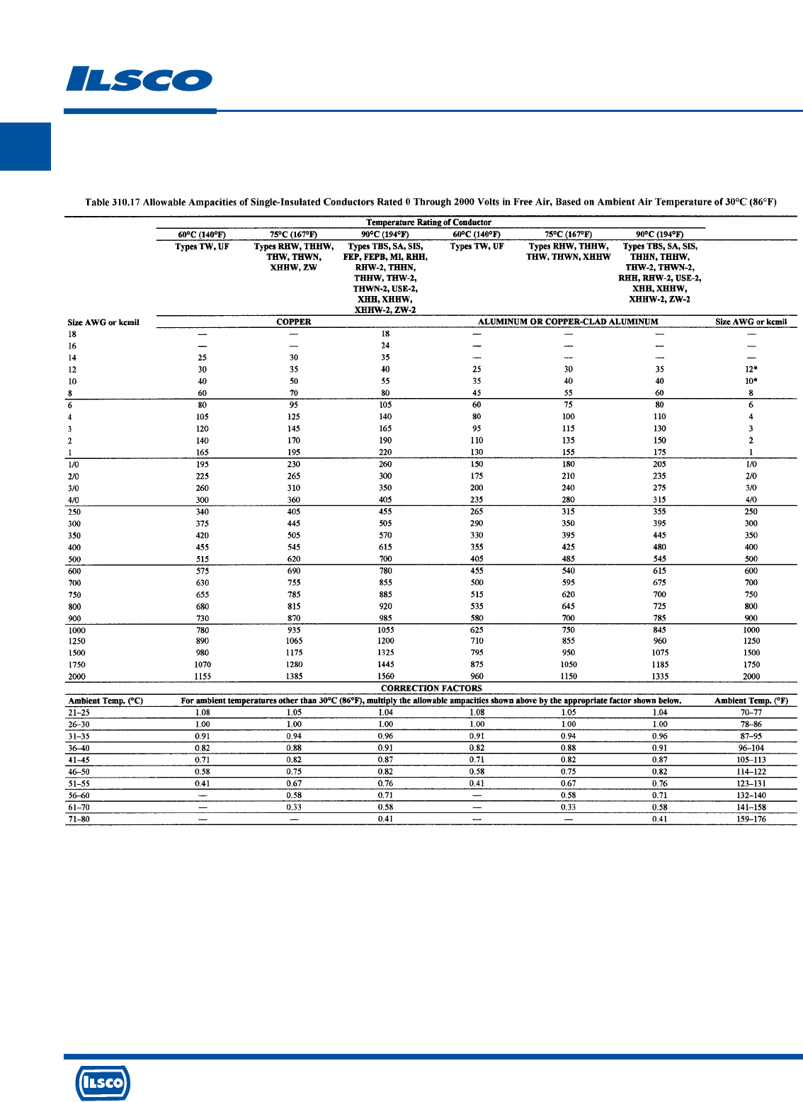
4730 Madison Road, Cincinnati, Ohio 45227-1426 Phone 513 533-6200 Fax 513 871-4084 Web site www.ilsco.com
Canada 1050 Lakeshore Road East, Mississauga, Ontario, Canada L5E1E4 Phone 905 274-2341 Fax 905 274-8763
355
N
Amperage Rating
* Reprinted with permission from NFPA 70, National Electrical Code®
National Electrical Code®and NEC®are registered trademarks of the National Fire Protection Association, Inc., Quincy, MA 02169
* Reprinted with permission from NFPA 70, National Electrical Code®Copyright © 2004, National Fire Protection Association, Quincy, MA 02169. This reprinted material is
not the complete and official position of the National Fire Protection Association on the referenced subject which is represented only by the standard in its entirety.
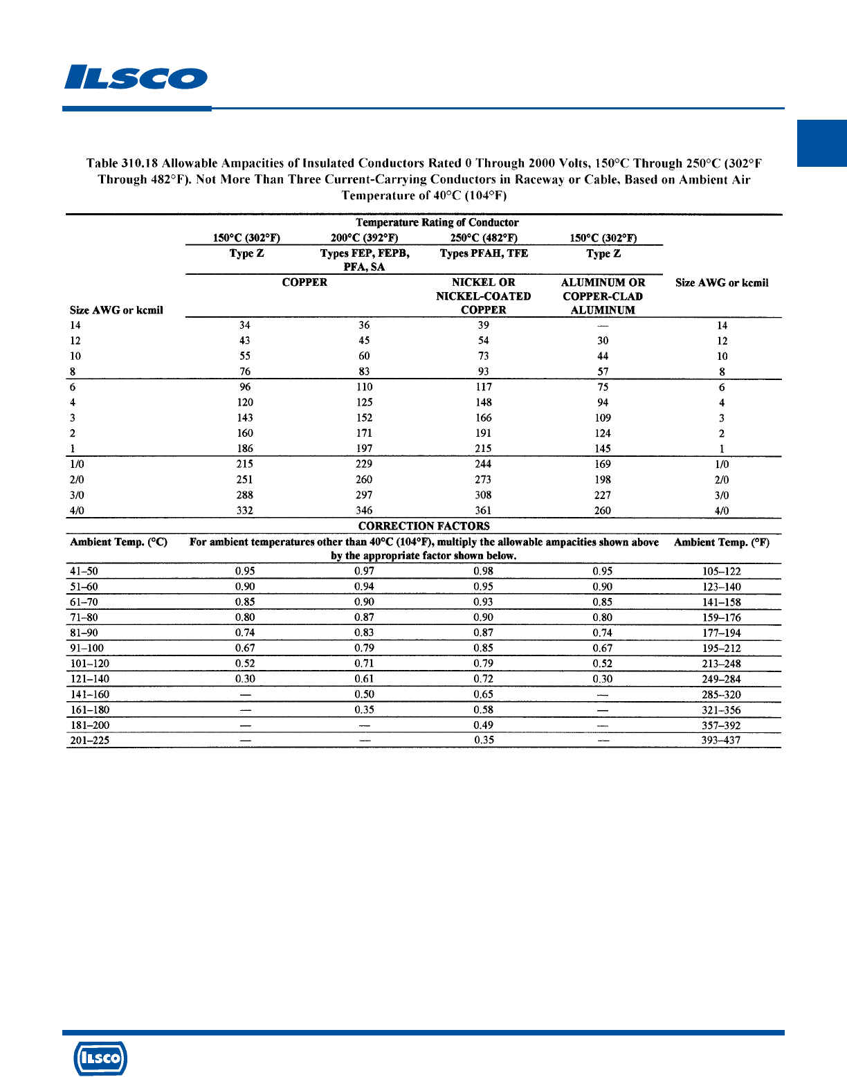
4730 Madison Road, Cincinnati, Ohio 45227-1426 Phone 513 533-6200 Fax 513 871-4084 Web site www.ilsco.com
Canada 1050 Lakeshore Road East, Mississauga, Ontario, Canada L5E1E4 Phone 905 274-2341 Fax 905 274-8763
356
N
Amperage Rating
* Reprinted with permission from NFPA 70, National Electrical Code®
National Electrical Code®and NEC®are registered trademarks of the National Fire Protection Association, Inc., Quincy, MA 02169
* Reprinted with permission from NFPA 70, National Electrical Code®Copyright © 2004, National Fire Protection Association, Quincy, MA 02169. This reprinted material is
not the complete and official position of the National Fire Protection Association on the referenced subject which is represented only by the standard in its entirety.
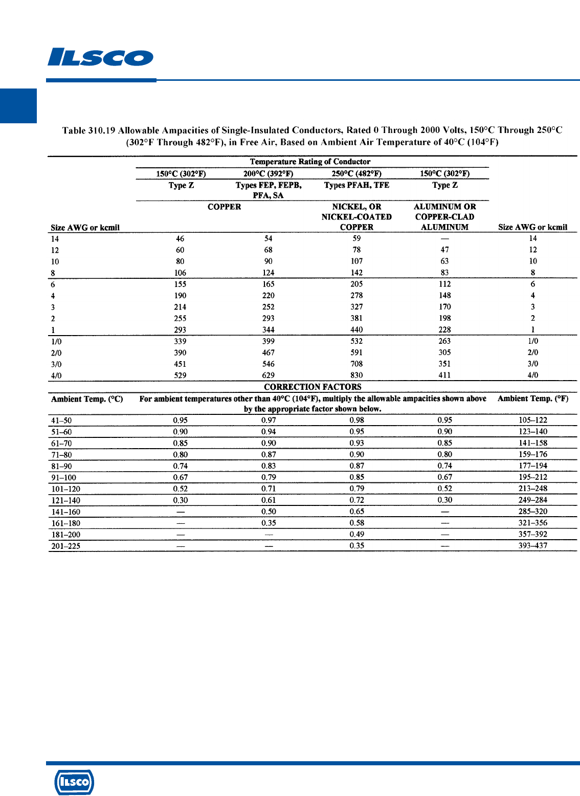
4730 Madison Road, Cincinnati, Ohio 45227-1426 Phone 513 533-6200 Fax 513 871-4084 Web site www.ilsco.com
Canada 1050 Lakeshore Road East, Mississauga, Ontario, Canada L5E1E4 Phone 905 274-2341 Fax 905 274-8763
357
N
Amperage Rating
* Reprinted with permission from NFPA 70, National Electrical Code®
National Electrical Code®and NEC®are registered trademarks of the National Fire Protection Association, Inc., Quincy, MA 02169
* Reprinted with permission from NFPA 70, National Electrical Code®Copyright © 2004, National Fire Protection Association, Quincy, MA 02169. This reprinted material is
not the complete and official position of the National Fire Protection Association on the referenced subject which is represented only by the standard in its entirety.
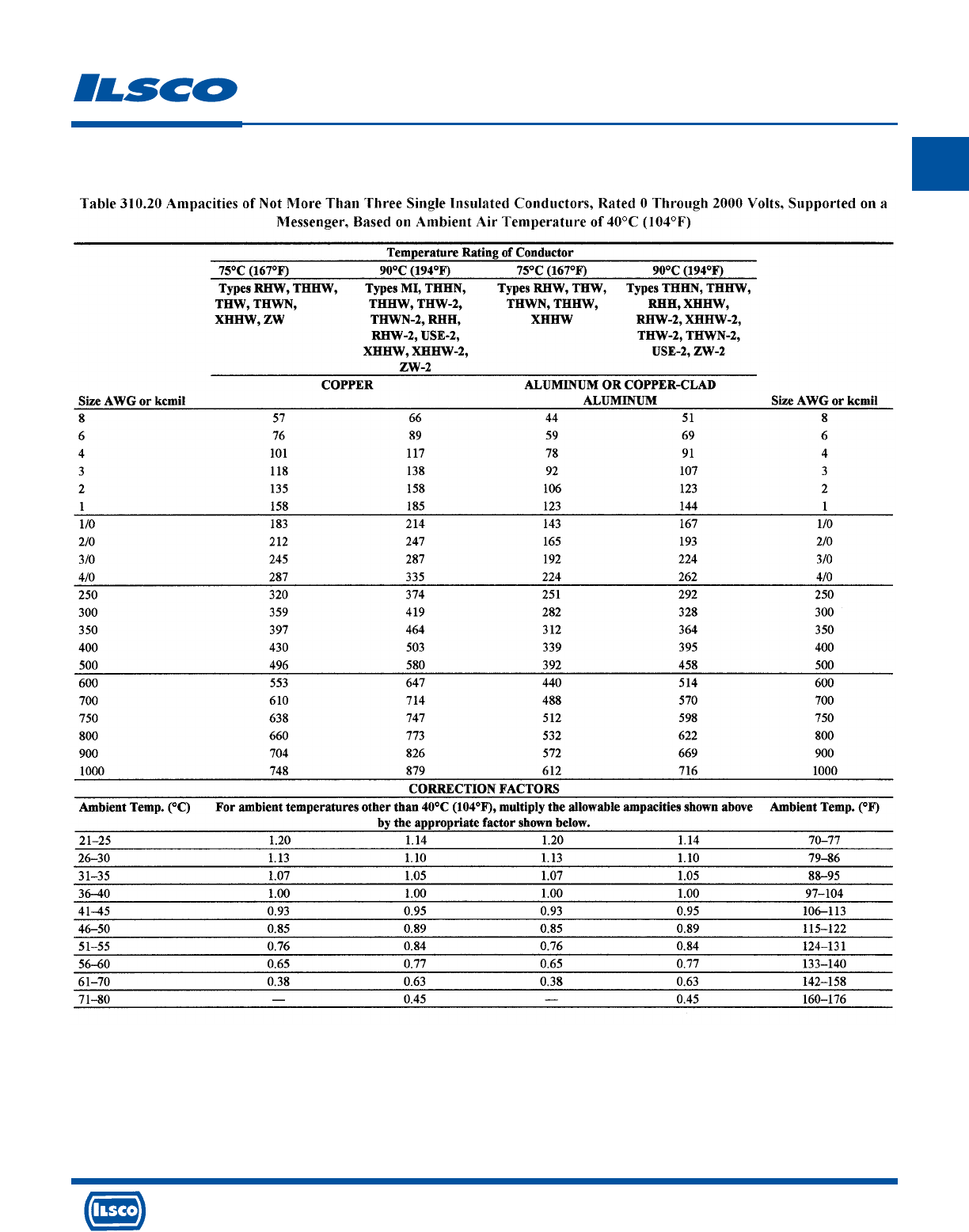
4730 Madison Road, Cincinnati, Ohio 45227-1426 Phone 513 533-6200 Fax 513 871-4084 Web site www.ilsco.com
Canada 1050 Lakeshore Road East, Mississauga, Ontario, Canada L5E1E4 Phone 905 274-2341 Fax 905 274-8763
358
N
Amperage Rating
* Reprinted with permission from NFPA 70, National Electrical Code®
National Electrical Code®and NEC®are registered trademarks of the National Fire Protection Association, Inc., Quincy, MA 02169
* Reprinted with permission from NFPA 70, National Electrical Code®Copyright © 2004, National Fire Protection Association, Quincy, MA 02169. This reprinted material is
not the complete and official position of the National Fire Protection Association on the referenced subject which is represented only by the standard in its entirety.
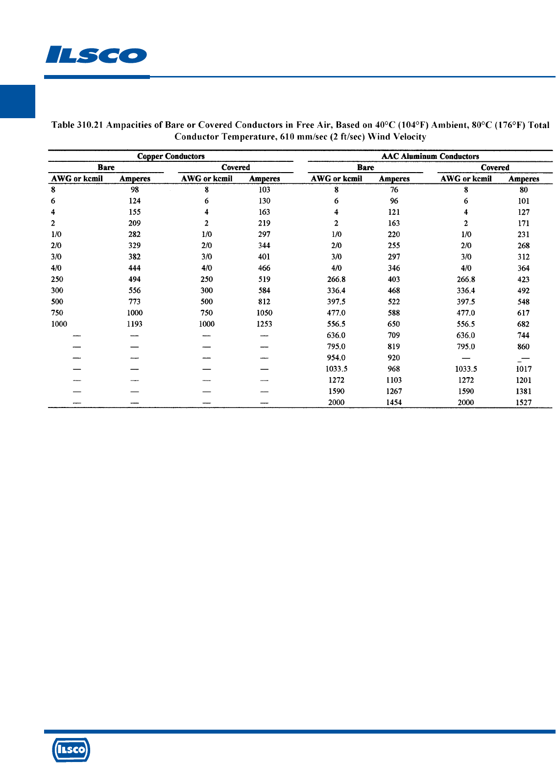
4730 Madison Road, Cincinnati, Ohio 45227-1426 Phone 513 533-6200 Fax 513 871-4084 Web site www.ilsco.com
Canada 1050 Lakeshore Road East, Mississauga, Ontario, Canada L5E1E4 Phone 905 274-2341 Fax 905 274-8763
359
N
Amperage Rating
* Reprinted with permission from NFPA 70, National Electrical Code®
National Electrical Code®and NEC®are registered trademarks of the National Fire Protection Association, Inc., Quincy, MA 02169
* Reprinted with permission from NFPA 70, National Electrical Code®Copyright © 2004, National Fire Protection Association, Quincy, MA 02169. This reprinted material is
not the complete and official position of the National Fire Protection Association on the referenced subject which is represented only by the standard in its entirety.
4730 Madison Road, Cincinnati, Ohio 45227-1426 Phone 513 533-6200 Fax 513 871-4084 Web site www.ilsco.com
Canada 1050 Lakeshore Road East, Mississauga, Ontario, Canada L5E1E4 Phone 905 274-2341 Fax 905 274-8763
360
N
Torque Index
TIGHTENING TORQUE VALUES FOR
ILSCO MECHANICAL SCREW CONNECTORS
AWG. OR TIGHTENING TORQUE IN INCH POUNDS
CIRCULAR EXTERNAL DRIVE
MILL SIZE SCREW DRIVER WRENCH
14 35 75
12 35 75
10 35 75
840 75
6 45 110
4 45 110
2 50 150
1 50 150
1/0 50 180
2/0 50 180
3/0 250
4/0 250
250 325
350 325
500 375
600 375
700 375
750 375
800 500
1000 500
TIGHTENING TORQUE VALUES FOR
ILSCO SOCKETHEAD SCREW CONNECTORS
INTERNAL
SOCKET SIZE
ACROSS FLATS
INCHES
1/8 45
5/32 100
3/16 120
7/32 150
1/4 200
5/16 275
3/8 375
1/2 500
9/16 600
TIGHTENING TORQUE IN INCH POUNDS
Please reference the instruction sheet included with your connector for specific torque values.
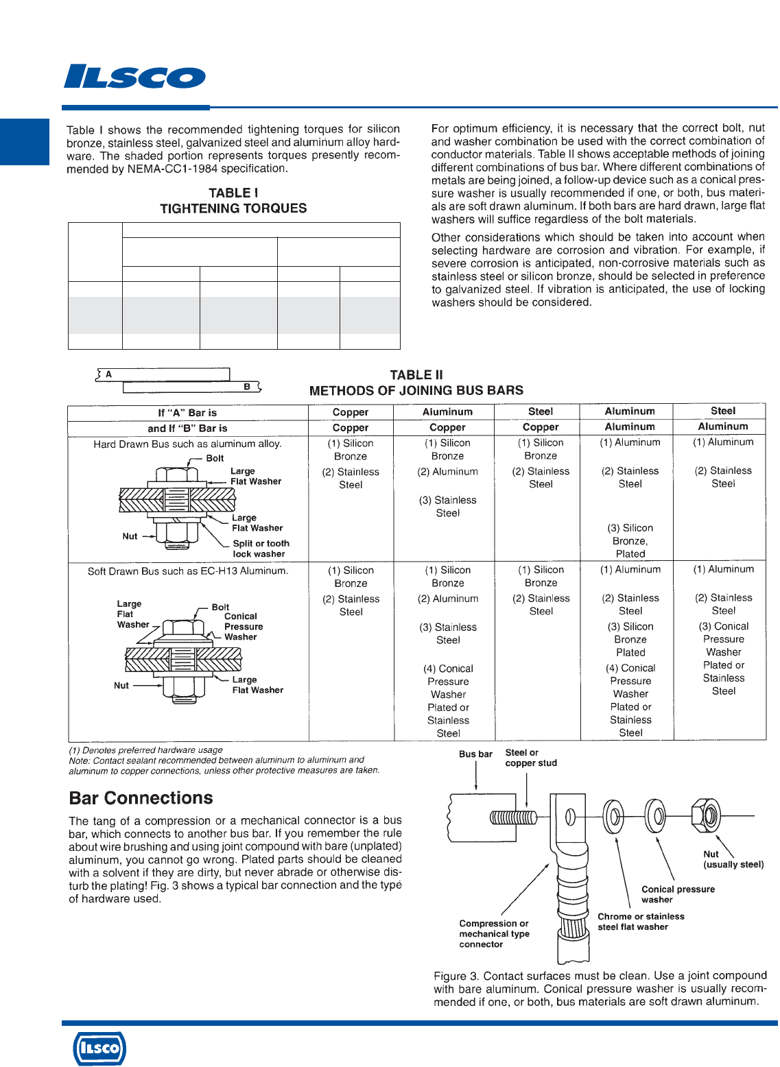
4730 Madison Road, Cincinnati, Ohio 45227-1426 Phone 513 533-6200 Fax 513 871-4084 Web site www.ilsco.com
Canada 1050 Lakeshore Road East, Mississauga, Ontario, Canada L5E1E4 Phone 905 274-2341 Fax 905 274-8763
361
N
Torque Information
Nominal Torque Values
Silicon Bronze, Aluminum Alloy
Bolt Galvanized or Stainless Steel (Lubricated)
Diameter Ft.-Lbs. Inch-Lbs. Ft.-Lbs. Inch-Lbs
5/16-18 15 180 – –
3/8-16 20 240 14 168
1/2-13 40 480 25 300
5/8-11 55 660 40 480
3/4-10 80 960 70 840

4730 Madison Road, Cincinnati, Ohio 45227-1426 Phone 513 533-6200 Fax 513 871-4084 Web site www.ilsco.com
Canada 1050 Lakeshore Road East, Mississauga, Ontario, Canada L5E1E4 Phone 905 274-2341 Fax 905 274-8763
362
N
RoHS Compliance
Restriction of Hazardous Substances ( RoHS )
European Directive 2002/95/EC
As of July 1st 2006 ILSCO Corporation is capable of
supplying all items offered for sale compliant with the
standards listed in the RoHS directive.
There are still significant amounts of assembled product
and components in inventory produced before all
processes were made compliant. During this transition
period ILSCO can only guarantee RoHS compliance on
orders specifically requesting compliant parts. These
orders will be acknowledged at full lead time.
ILSCO Corporation makes no independent
representations or a warranty, expressed or implied, and
assumes no liability in connection with the use of this
information.

4730 Madison Road, Cincinnati, Ohio 45227-1426 Phone 513 533-6200 Fax 513 871-4084 Web site www.ilsco.com
Canada 1050 Lakeshore Road East, Mississauga, Ontario, Canada L5E1E4 Phone 905 274-2341 Fax 905 274-8763
363
N
Cross Reference Guide
Access to Cross Reference can be
found under Reference Tab
at www.ILSCO.com
Two Ways to Search
1. Type in all or part of the competitive or Ilsco part number into the SEARCH box in the header, then click GO.
2. Click "Search Options" in the header. From there, you are given five ways to search.
By Keyword: Type in a keyword and click GO. For example, typing "splice" will return a list of products that can be
used to splice conductor. You can click on any of the products listed and you will be taken to the catalog page.
By Ilsco Catalog #: Type in all or part of the Ilsco part number and click GO You can click on any of the products
listed and you will be taken to the catalog page.
By UPC/NAED Part #: Type in the Ilsco UPC number and click GO. The Ilsco corporate identifier, 783669, is already
given. For example, typing "88774" will return information on "TA-2".
By Competitive Part #: Type in all or part of the competitive part number and click GO. You do not need to know
the manufacturer. You are given a list of comparable Ilsco products. You can click on any of the products listed and
you will be taken to the catalog page.
Choose a category: Select a product category from the list and click GO. You will receive a list of the product
groups in that category. You can click on any of the products listed and you will be taken to the catalog page.
If your request is not in our database, you will be sent to a screen where you can send an e-mail to Ilsco’s technical
support department. Your request will be answered promptly.
This cross reference information has been compiled from tables, catalogs and data which are generally available.
Since changes are made regularly in the industry, we cannot accept responsibility for any errors, but we will
endeavor at all times to keep these tables up-to-date. Refer to our current catalog for exact specifications on ILSCO
connectors. All connectors are not exact equals, but enough similarities exist that they can be used for the same
application.

4730 Madison Road, Cincinnati, Ohio 45227-1426 Phone 513 533-6200 Fax 513 871-4084 Web site www.ilsco.com
Canada 1050 Lakeshore Road East, Mississauga, Ontario, Canada L5E1E4 Phone 905 274-2341 Fax 905 274-8763
364
ACN . . . . . . . . . . . . . . . . . . . . . . . . . . . . . . . . . . . . . . . . . . . .48-50
ACL . . . . . . . . . . . . . . . . . . . . . . . . . . . . . . . . . . . . . . . . . . . . 48-51
2ACL . . . . . . . . . . . . . . . . . . . . . . . . . . . . . . . . . . . . . . . . . . . 52-53
ACM . . . . . . . . . . . . . . . . . . . . . . . . . . . . . . . . . . . . . . . . . . . 58-60
2ACN . . . . . . . . . . . . . . . . . . . . . . . . . . . . . . . . . . . . . . . . . . . . . .52
ACO . . . . . . . . . . . . . . . . . . . . . . . . . . . . . . . . . . . . . . . . . . . . 61-62
ACO-90 . . . . . . . . . . . . . . . . . . . . . . . . . . . . . . . . . . . . . . . . . . . . 63
5ACR . . . . . . . . . . . . . . . . . . . . . . . . . . . . . . . . . . . . . . . . . . . . 303
AGC . . . . . . . . . . . . . . . . . . . . . . . . . . . . . . . . . . . . . . . . . 146, 255
AH . . . . . . . . . . . . . . . . . . . . . . . . . . . . . . . . . . . . . . . . . . . . . . . 72
AK . . . . . . . . . . . . . . . . . . . . . . . . . . . . . . . . . . . . . . . . . . . 104, 144
AS . . . . . . . . . . . . . . . . . . . . . . . . . . . . . . . . . . . . . . . . . . . . . 66-68
ASK . . . . . . . . . . . . . . . . . . . . . . . . . . . . . . . . . . . . . . . . . . 156, 262
ASL . . . . . . . . . . . . . . . . . . . . . . . . . . . . . . . . . . . . . . . . . . . . . . . 54
AU . . . . . . . . . . . . . . . . . . . . . . . . . . . . . . . . . . . . . . . . . . . . . . 120
BGC . . . . . . . . . . . . . . . . . . . . . . . . . . . . . . . 186-187, 234-235, 274
BGCS . . . . . . . . . . . . . . . . . . . . . . . . . . . . . . . . . . . . . . . . . . . . .237
BGDB . . . . . . . . . . . . . . . . . . . . . . . . . . . . . . . . . . . . .188, 236, 275
BGRC . . . . . . . . . . . . . . . . . . . . . . . . . . . . . . . . . . . . 182, 229, 270
C . . . . . . . . . . . . . . . . . . . . . . . . . . . . . . . . . . . . . . . . . . . . . . . . 321
CA . . . . . . . . . . . . . . . . . . . . . . . . . . . . . . . . . . . . . . . . . . . . . . . 127
Cable Ties . . . . . . . . . . . . . . . . . . . . . . . . . . . . . . . . . . . . . .338-342
CAN . . . . . . . . . . . . . . . . . . . . . . . . . . . . . . . . . . . . . 191, 254, 333
CCL . . . . . . . . . . . . . . . . . . . . . . . . . . . . . . . . . . . . . . . . . . . . 32-37
CCS . . . . . . . . . . . . . . . . . . . . . . . . . . . . . . . . . . . . . . . . . . . . 42-43
CGRC . . . . . . . . . . . . . . . . . . . . . . . . . . . . . . . . . . . . .181, 228, 270
CL . . . . . . . . . . . . . . . . . . . . . . . . . . . . . . . . . . . . . . . . 175-176, 178
CLND . . . . . . . . . . . . . . . . . . . . . . . . . . . . . . . . . . . . . . . . . . .23-28
CLNF . . . . . . . . . . . . . . . . . . . . . . . . . . . . . . . . . . . . . . . . . . . .29-30
CLNS . . . . . . . . . . . . . . . . . . . . . . . . . . . . . . . . . . . . . . . . . . .14-16
CLNU . . . . . . . . . . . . . . . . . . . . . . . . . . . . . . . . . . . . . . . . . . . . . .31
CLWD . . . . . . . . . . . . . . . . . . . . . . . . . . . . . . . . . . . . . . . . . . .17-22
CLWS . . . . . . . . . . . . . . . . . . . . . . . . . . . . . . . . . . . . . . . . . . .11-13
CO . . . . . . . . . . . . . . . . . . . . . . . . . . . . . . . . . . . . . . . . . . . 167-168
Compression Dies . . . . . . . . . . . . . . . . . . . . . . . . . . . . . . 313-314
Compression Index . . . . . . . . . . . . . . . . . . . . . . . . 90-97, 306-312
COPP . . . . . . . . . . . . . . . . . . . . . . . . . . . . . . . . . . . . . . . . . . . . 169
CP . . . . . . . . . . . . . . . . . . . . . . . . . . . . . . . . . . . . . . . . . . . . . . . 166
CPM . . . . . . . . . . . . . . . . . . . . . . . . . . . . . . . . . . . . . . . . . . . . 55-57
CPML . . . . . . . . . . . . . . . . . . . . . . . . . . . . . . . . . . . . . . . . . . . . . 57
CRAM . . . . . . . . . . . . . . . . . . . . . . . . . . . . . . . . . . . . . . . . . . . . .38
Crimp ‘N Seal . . . . . . . . . . . . . . . . . . . . . . . . . . . . . . . . . . . . 87-88
CSWD . . . . . . . . . . . . . . . . . . . . . . . . . . . . . . . . . . . . . . . . . . . .5-10
CSWS . . . . . . . . . . . . . . . . . . . . . . . . . . . . . . . . . . . . . . . . . . . . .2-4
CT . . . . . . . . . . . . . . . . . . . . . . . . . . . . . . . . . . . . . . . . . . . . . . . . 40
CTL . . . . . . . . . . . . . . . . . . . . . . . . . . . . . . . . . . . . . . . . . . . . . . . 41
CTR . . . . . . . . . . . . . . . . . . . . . . . . . . . . . . . . . . . . . . . . . . . . . . 317
DCGC . . . . . . . . . . . . . . . . . . . . . . . . . . . . . . . . . . . . . . . . .185, 233
DBA . . . . . . . . . . . . . . . . . . . . . . . . . . . . . . . . . . . . . . . . . 105, 145
DBA-S . . . . . . . . . . . . . . . . . . . . . . . . . . . . . . . . . . . . . . . . 105, 145
DBK . . . . . . . . . . . . . . . . . . . . . . . . . . . . . . . . . . . . . . . . . . 156, 262
D167 . . . . . . . . . . . . . . . . . . . . . . . . . . . . . . . . . . . . . 190, 253, 332
DE-OX . . . . . . . . . . . . . . . . . . . . . . . . . . . . . . . . . . . . . . . . . . . . 335
DR . . . . . . . . . . . . . . . . . . . . . . . . . . . . . . . . . . . . . . . . . . . . . . .318
Duct Seal . . . . . . . . . . . . . . . . . . . . . . . . . . . . . . . . . . . . . . . . . 336
E . . . . . . . . . . . . . . . . . . . . . . . . . . . . . . . . . . . . . . . . . . . . . . . . 161
E (Screws) . . . . . . . . . . . . . . . . . . . . . . . . . . . . . . . . 191, 254, 333
ELT . . . . . . . . . . . . . . . . . . . . . . . . . . . . . . . . . . . . . . . .47, 227, 268
FP-1 . . . . . . . . . . . . . . . . . . . . . . . . . . . . . . . . . . . . . . . . . . . . . 304
GBL . . . . . . . . . . . . . . . . . . . . . . . . . . . . . . . . . . . . . . . . . . 147, 256
GBL-DB . . . . . . . . . . . . . . . . . . . . . . . . . . . . . . . . . . . . . . .189, 257
GBT . . . . . . . . . . . . . . . . . . . . . . . . . . . . . . . . . . . . . . . . . .148, 258
GGA . . . . . . . . . . . . . . . . . . . . . . . . . . . . . . . . . . . . . . 44, 224, 266
GGC . . . . . . . . . . . . . . . . . . . . . . . . . . . . . . . . . . . . . . 45, 225, 267
GRC . . . . . . . . . . . . . . . . . . . . . . . . . . . . . . . . . . . . . . 184, 231, 272
GRF . . . . . . . . . . . . . . . . . . . . . . . . . . . . . . . . . . . . . . . . . . 159, 259
GRM . . . . . . . . . . . . . . . . . . . . . . . . . . . . . . . . . . . . . . . . .159, 259
GS . . . . . . . . . . . . . . . . . . . . . . . . . . . . . . . . . . . . . . . . . . . . . . . 252
GSR . . . . . . . . . . . . . . . . . . . . . . . . . . . . . . . . . . . . . . . . . . . . . 252
GTA . . . . . . . . . . . . . . . . . . . . . . . . . . . . . . . . . . . . . . . . . . 107, 128
GTT . . . . . . . . . . . . . . . . . . . . . . . . . . . . . . . . . . . . . . . . . . 109, 129
GTC . . . . . . . . . . . . . . . . . . . . . . . . . . . . . . . . . . . . . . . . . . 110, 130
GT2 . . . . . . . . . . . . . . . . . . . . . . . . . . . . . . . . . . . . . . . . . . 111, 131
GT4T . . . . . . . . . . . . . . . . . . . . . . . . . . . . . . . . . . . . . . . . . 112, 132
GTA/GTT KIT . . . . . . . . . . . . . . . . . . . . . . . . . . . . . . . . . . . . . .113
GUB . . . . . . . . . . . . . . . . . . . . . . . . . . . . . . . . . . . . . . . . . 243, 281
H . . . . . . . . . . . . . . . . . . . . . . . . . . . . . . . . . . . . . . . . . . . . . . . . 161
Hardware . . . . . . . . . . . . . . . . . . . . . . . . . . . . . . . . . . . . . . . . . 337
Heat Shrink . . . . . . . . . . . . . . . . . . . . . . . . . . . . . . . . . . . . 282-288
HH-10N . . . . . . . . . . . . . . . . . . . . . . . . . . . . . . . . . . . . . . . . . . . 305
HL . . . . . . . . . . . . . . . . . . . . . . . . . . . . . . . . . . . . . . . . . . . . . . . 177
H2L . . . . . . . . . . . . . . . . . . . . . . . . . . . . . . . . . . . . . . . . . . . . . . 179
H3L . . . . . . . . . . . . . . . . . . . . . . . . . . . . . . . . . . . . . . . . . . . . . . 180
HT . . . . . . . . . . . . . . . . . . . . . . . . . . . . . . . . . . . . . . . . . . . . . 73-74
HW . . . . . . . . . . . . . . . . . . . . . . . . . . . . . . . . . . . . . . . . . . . . . . 318
2IACL . . . . . . . . . . . . . . . . . . . . . . . . . . . . . . . . . . . . . . . . . . . . . .65
IACL . . . . . . . . . . . . . . . . . . . . . . . . . . . . . . . . . . . . . . . . . . . . . . .64
IDT-12-N . . . . . . . . . . . . . . . . . . . . . . . . . . . . . . . . . . . . . . . . . .299
IDT-6 . . . . . . . . . . . . . . . . . . . . . . . . . . . . . . . . . . . . . . . . . . . . .300
IDT-6H . . . . . . . . . . . . . . . . . . . . . . . . . . . . . . . . . . . . . . . . . . . .301
IDTB-6 . . . . . . . . . . . . . . . . . . . . . . . . . . . . . . . . . . . . . . . . . . . .290
IK . . . . . . . . . . . . . . . . . . . . . . . . . . . . . . . . . . . . . . . . . . . . 99, 192
IK3 . . . . . . . . . . . . . . . . . . . . . . . . . . . . . . . . . . . . . . . . . . . 100, 193
IKB . . . . . . . . . . . . . . . . . . . . . . . . . . . . . . . . . . . . . . . . . . 102, 195
IKS . . . . . . . . . . . . . . . . . . . . . . . . . . . . . . . . . . . . . . . . . . 103, 196
ILC-10-N . . . . . . . . . . . . . . . . . . . . . . . . . . . . . . . . . . . . . . . . . . .292
ILC-12-N . . . . . . . . . . . . . . . . . . . . . . . . . . . . . . . . . . . . . . . . . . .297
ILC-12H-N . . . . . . . . . . . . . . . . . . . . . . . . . . . . . . . . . . . . . . . . . 298
ILC-15H . . . . . . . . . . . . . . . . . . . . . . . . . . . . . . . . . . . . . . . . . . .302
ILCB-12-N . . . . . . . . . . . . . . . . . . . . . . . . . . . . . . . . . . . . . . . . .291
ILD . . . . . . . . . . . . . . . . . . . . . . . . . . . . . . . . . . . . . . . . . . . . . . 314
Ilscons . . . . . . . . . . . . . . . . . . . . . . . . . . . . . . . . . . . . . . . . . . 76-86
Ilscon Tools . . . . . . . . . . . . . . . . . . . . . . . . . . . . . . . . . . . . . . . . .89
IPC . . . . . . . . . . . . . . . . . . . . . . . . . . . . . . . . . . . 106, 143, 210-212
LDA . . . . . . . . . . . . . . . . . . . . . . . . . . . . . . . . . . . . . . . . . . 135, 214
LDB . . . . . . . . . . . . . . . . . . . . . . . . . . . . . . . . . . . . . . . . . . 135, 214
LO . . . . . . . . . . . . . . . . . . . . . . . . . . . . . . . . . . . . . . . . . . . . . . . 163
LO-S . . . . . . . . . . . . . . . . . . . . . . . . . . . . . . . . . . . . . . . . . . . . . .164
LU . . . . . . . . . . . . . . . . . . . . . . . . . . . . . . . . . . . . . . . . . . . . . . . 174
LY . . . . . . . . . . . . . . . . . . . . . . . . . . . . . . . . . . . . . . . . . . . . . . . 165
Catalog No. Page No. Catalog No. Page No.
Alpha Numeric Index

4730 Madison Road, Cincinnati, Ohio 45227-1426 Phone 513 533-6200 Fax 513 871-4084 Web site www.ilsco.com
Canada 1050 Lakeshore Road East, Mississauga, Ontario, Canada L5E1E4 Phone 905 274-2341 Fax 905 274-8763
365
M . . . . . . . . . . . . . . . . . . . . . . . . . . . . . . . . . . . . . . . . . . . . 322-323
Merchandising . . . . . . . . . . . . . . . . . . . . . . . . . . . . . . . . . . . . . 343
MGTT . . . . . . . . . . . . . . . . . . . . . . . . . . . . . . . . . . . . . . . . 114, 133
MT-25 . . . . . . . . . . . . . . . . . . . . . . . . . . . . . . . . . . . . . . . . . . . . 293
MU . . . . . . . . . . . . . . . . . . . . . . . . . . . . . . . . . . . . . . . . . . . . . . 174
N . . . . . . . . . . . . . . . . . . . . . . . . . . . . . . . . . . . . . . . . . . . . . . . . 173
NB . . . . . . . . . . . . . . . . . . . . . . . . . . . . . . . . . . . . . . . 154, 260, 334
NBW . . . . . . . . . . . . . . . . . . . . . . . . . . . . . . . . . . . . . . . . . . . . . 337
ND . . . . . . . . . . . . . . . . . . . . . . . . . . . . . . . . . . . . . . . . . . . 295-296
N-174 . . . . . . . . . . . . . . . . . . . . . . . . . . . . . . . . . . . . 191, 254, 333
P840 . . . . . . . . . . . . . . . . . . . . . . . . . . . . . . . . . . . . . . . . . . . . . . 71
PB . . . . . . . . . . . . . . . . . . . . . . . . . . . . . . . . . . . . . . . . . . . . . . . 123
PBT . . . . . . . . . . . . . . . . . . . . . . . . . . . . . . . . . . . . . . . . . . . . . . 199
PBTD . . . . . . . . . . . . . . . . . . . . . . . . . . . . . . . . . . . . . . . . . 200-202
PBTM . . . . . . . . . . . . . . . . . . . . . . . . . . . . . . . . . . . . . . . . .206-207
PBTO . . . . . . . . . . . . . . . . . . . . . . . . . . . . . . . . . . . . . . . . . . . . 199
PBTS . . . . . . . . . . . . . . . . . . . . . . . . . . . . . . . . . . . . . . . . . 203-205
PCT . . . . . . . . . . . . . . . . . . . . . . . . . . . . . . . . . . . . . . . . . .116, 208
PDA . . . . . . . . . . . . . . . . . . . . . . . . . . . . . . . . . . . . . . . . . . 136, 215
PDB . . . . . . . . . . . . . . . . . . . . . . . . . . . . . . . . . . . 137-142, 216-221
PDC . . . . . . . . . . . . . . . . . . . . . . . . . . . . . . . . . . . . . . . . . . 136, 215
PEC . . . . . . . . . . . . . . . . . . . . . . . . . . . . . . . . . . . . . . . . . . . . . . 150
PED-Z . . . . . . . . . . . . . . . . . . . . . . . . . . . . . . . . . . . . . . . . . . . . 149
PED-CP . . . . . . . . . . . . . . . . . . . . . . . . . . . . . . . . . . . . . . . . . . . 151
PED-SS . . . . . . . . . . . . . . . . . . . . . . . . . . . . . . . . . . . . . . . . . . .265
PED-X . . . . . . . . . . . . . . . . . . . . . . . . . . . . . . . . . . . . . . . . . . . .150
PET . . . . . . . . . . . . . . . . . . . . . . . . . . . . . . . . . . . . . . . . . . . . . . 152
PG . . . . . . . . . . . . . . . . . . . . . . . . . . . . . . . . . . . . . . . . . . . . . . . 158
PICS . . . . . . . . . . . . . . . . . . . . . . . . . . . . . . . . . . . . . . . . . . . . . . 70
PSA-Z . . . . . . . . . . . . . . . . . . . . . . . . . . . . . . . . . . . . . . . . . . . . 150
PTA . . . . . . . . . . . . . . . . . . . . . . . . . . . . . . . . . . . . . . . . . . 115, 134
PTT . . . . . . . . . . . . . . . . . . . . . . . . . . . . . . . . . . . . . . . . . . . . . . 153
R-16 . . . . . . . . . . . . . . . . . . . . . . . . . . . . . . . . . . . . . . 190, 254, 333
RLT . . . . . . . . . . . . . . . . . . . . . . . . . . . . . . . . . . . . . . . 75, 232, 273
SAU . . . . . . . . . . . . . . . . . . . . . . . . . . . . . . . . . . . . . . . . . . . . . 160
SAS . . . . . . . . . . . . . . . . . . . . . . . . . . . . . . . . . . . . . . . . . . . . . 160
2SC . . . . . . . . . . . . . . . . . . . . . . . . . . . . . . . . . . . . . . . . . . . . . . 172
SGC . . . . . . . . . . . . . . . . . . . . . . . . . . . . . . . . . . . . . . . . . 146, 255
SK . . . . . . . . . . . . . . . . . . . . . . . . . . . . . . . . . . . . . . . . . . . 101, 194
SLS . . . . . . . . . . . . . . . . . . . . . . . . . . . . . . . . . . . . . . . . . . . . . . 160
SLU . . . . . . . . . . . . . . . . . . . . . . . . . . . . . . . . . . . . . . . . . . . . . . 160
SLU-DB . . . . . . . . . . . . . . . . . . . . . . . . . . . . . . . . . . . . . . .160, 269
SLUH . . . . . . . . . . . . . . . . . . . . . . . . . . . . . . . . . . . . . . . . . . . . 162
Solder Lugs . . . . . . . . . . . . . . . . . . . . . . . . . . . . . . . . . . . . . . . . 39
SPA . . . . . . . . . . . . . . . . . . . . . . . . . . . . . . . . . . . . . . . . . . . . . . 126
SPAR . . . . . . . . . . . . . . . . . . . . . . . . . . . . . . . . . . . . . . . . .108, 209
SPD . . . . . . . . . . . . . . . . . . . . . . . . . . . . . . . . . . . 240-241, 278-279
SPS . . . . . . . . . . . . . . . . . . . . . . . . . . . . . . . . . . . 238-239, 276-277
SRC . . . . . . . . . . . . . . . . . . . . . . . . . . . . . . . . . . . . . .183, 230, 271
SS . . . . . . . . . . . . . . . . . . . . . . . . . . . . . . . . . . . . . . . . . . . 157, 264
SSK . . . . . . . . . . . . . . . . . . . . . . . . . . . . . . . . . . . . . . . . . . 157, 264
SSKC . . . . . . . . . . . . . . . . . . . . . . . . . . . . . . . . . . . . . . . . .157, 264
SX . . . . . . . . . . . . . . . . . . . . . . . . . . . . . . . . . . . . . . . . . . . . . . . 171
T . . . . . . . . . . . . . . . . . . . . . . . . . . . . . . . . . . . . . .244-251, 324-331
TA . . . . . . . . . . . . . . . . . . . . . . . . . . . . . . . . . . . . . . . . . . . . . . . 119
T3A . . . . . . . . . . . . . . . . . . . . . . . . . . . . . . . . . . . . . . . . . . . . . . 121
T4A4 . . . . . . . . . . . . . . . . . . . . . . . . . . . . . . . . . . . . . . . . . . . . . 122
TC . . . . . . . . . . . . . . . . . . . . . . . . . . . . . . . . . . . . . . . . . . . . . . .170
Technical Information . . . . . . . . . . . . . . . . . . . . . . . . . . . .346-363
TK . . . . . . . . . . . . . . . . . . . . . . . . . . . . . . . . . . . . . . . . . . . . . . . 318
TLK . . . . . . . . . . . . . . . . . . . . . . . . . . . . . . . . . . . . . . . . . . . . . . 124
Torque Index . . . . . . . . . . . . . . . . . . . . . . . . . . . . . . . . . . 197, 360
TS . . . . . . . . . . . . . . . . . . . . . . . . . . . . . . . . . . . . . . . . . . . . . . . 318
TTGC . . . . . . . . . . . . . . . . . . . . . . . . . . . . . . . . . . . . . . . . 242, 280
TW . . . . . . . . . . . . . . . . . . . . . . . . . . . . . . . . . . . . . . . . . . . . . . 318
Tool Accessories . . . . . . . . . . . . . . . . . . . . . . . . . . . . . . . . . . . .315
Tools . . . . . . . . . . . . . . . . . . . . . . . . . . . . . . . . . . . . . . . . . .289-319
UCS . . . . . . . . . . . . . . . . . . . . . . . . . . . . . . . . . . . . . . . . . . . . . . 69
ULT . . . . . . . . . . . . . . . . . . . . . . . . . . . . . . . . . . . . . . . . . . . 46, 226
USGL . . . . . . . . . . . . . . . . . . . . . . . . . . . . . . . . . . . . . . . . . . . . .125
USPA-SS . . . . . . . . . . . . . . . . . . . . . . . . . . . . . . . . . . . . . 155, 263
VT . . . . . . . . . . . . . . . . . . . . . . . . . . . . . . . . . . . . . . . . . . . . . . . 164
WC . . . . . . . . . . . . . . . . . . . . . . . . . . . . . . . . . . . . . . . . . . . . . . .318
WR . . . . . . . . . . . . . . . . . . . . . . . . . . . . . . . . . . . . . . . . . . . . . . 318
WS . . . . . . . . . . . . . . . . . . . . . . . . . . . . . . . . . . . . . . . . . . . 89, 316
XT . . . . . . . . . . . . . . . . . . . . . . . . . . . . . . . . . . . . . . . . . . . . . . . 165
XT-DB . . . . . . . . . . . . . . . . . . . . . . . . . . . . . . . . . . . . . . . .165, 269
21000 . . . . . . . . . . . . . . . . . . . . . . . . . . . . . . . . . . . . . . . . . . . . 283
22000 . . . . . . . . . . . . . . . . . . . . . . . . . . . . . . . . . . . . . . . . . . . . 285
23000 . . . . . . . . . . . . . . . . . . . . . . . . . . . . . . . . . . . . . . . . . . . . 284
24000 . . . . . . . . . . . . . . . . . . . . . . . . . . . . . . . . . . . . . . . . . . . . 286
25000 . . . . . . . . . . . . . . . . . . . . . . . . . . . . . . . . . . . . . . . . . . . . 286
26000 . . . . . . . . . . . . . . . . . . . . . . . . . . . . . . . . . . . . . . . . . . . . 287
27000 . . . . . . . . . . . . . . . . . . . . . . . . . . . . . . . . . . . . . . . . 288, 319
30000 . . . . . . . . . . . . . . . . . . . . . . . . . . . . . . . . . . . . . . . . . . . . . 88
31000 . . . . . . . . . . . . . . . . . . . . . . . . . . . . . . . . . . . . . . . . . . . 87-88
44000 . . . . . . . . . . . . . . . . . . . . . . . . . . . . . . . . . . . . . . . . . . . 76-85
45000 . . . . . . . . . . . . . . . . . . . . . . . . . . . . . . . . . . . . . . . . . . . . . 86
94130 . . . . . . . . . . . . . . . . . . . . . . . . . . . . . . . . . . . . . . . . . 89, 316
94140 . . . . . . . . . . . . . . . . . . . . . . . . . . . . . . . . . . . . . . . . . 89, 316
94285 . . . . . . . . . . . . . . . . . . . . . . . . . . . . . . . . . . . . . . . . . . . . 294
94502 . . . . . . . . . . . . . . . . . . . . . . . . . . . . . . . . . . . . . . . . 288, 319
94504 . . . . . . . . . . . . . . . . . . . . . . . . . . . . . . . . . . . . . . . . 288, 319
Catalog No. Page No. Catalog No. Page No.
Alpha Numeric Index
