280523 Catalog
136144-Catalog 136144-Catalog 136144-Catalog Batch9 unilog cesco-content
2014-07-05
: Pdf 280523-Catalog 280523-Catalog 782683 Batch5 unilog
Open the PDF directly: View PDF ![]() .
.
Page Count: 149 [warning: Documents this large are best viewed by clicking the View PDF Link!]
1
INTRODUCTION
TABLE OF CONTENTS
Company Profile ....................2-3
Technological Development ............4-5
MR16 LED
Nexus® System .....................6-7
Spec Grade Products
Table of Contents ....................8-9
What are Spec Grade Products ......... 10
Architectural
Table of Contents .................... 11
Lux-Ray™ LED Series ..............12-13
Revelation™ Series .................. 14
Mini-Revelation™ Series .............. 15
PS Series ......................... 16
RS Series ......................... 17
TS Series ........................18-19
EFR2 Distinction Series ............... 20
GS Series ......................... 21
Prestige™ Edge-Lit Series ...........22-23
Prestige™ X40 Edge-Lit Series ......... 24
Prestige™ DX Series ................. 25
Prestige™ Floor Proximity Series ......26-27
Commercial
Table of Contents .................... 29
Premier™ Battery Series .............. 30
Premier™ Combo Series .............. 31
Premier™ Exit Series ................. 32
Provider™ PRO-2N/PRO-3N Series ..... 33
EC-2 Series ........................ 34
ECC and ECM Series ................ 35
JC Series .......................... 36
JA Series .......................... 37
JS Series ........................38-39
LSE Series ......................... 40
LC Series .......................... 41
LS Series ........................42-43
24 LS & 24 LC Series ................ 44
X10 LED Series ..................... 45
Prestige™ Recessed Economizer Series .. 46
Prestige™ Economizer Series .......... 47
Preceptor™ Die-Cast Series ........... 48
Preceptor™ Recessed Series .......... 49
Preceptor™ Remote Capacity Series .... 50
Special Wording Configurations ......... 51
Industrial
Table of Contents .................... 53
Hazardous Locations ................. 54
Survive-All™ SV Series ............... 55
Survive-All™ SVX Combo Series ........ 56
Survive-All™ SVX Exit Series ........... 57
Survive-All™ EF39 & EF40 Series ....... 58
HZM Series, Class 1 Division 2 ......... 59
Survive-All™ SVH Series, ............. 60
Class 1 Division 2
Survive-All™ SVXH Series, ............ 61
Class 1 Division 2
Survive-All™ SVX-HZ Series, ........... 62
Class 1 Division 2
Survive-All™ EF41 Series, ............. 63
Class 1 Division 2
IL Series ........................64-65
KS Steel Series ...................66-67
KS Series .......................68-69
EXC Series ......................70-71
EFEP Series ........................ 72
EFXP Series ........................ 73
EverLite™ Self Luminous Series ........ 74
Remote Fixtures
Table of Contents .................... 77
Lux-Ray™ LED Remote Series ......... 78
Literay™ Series ..................... 79
Revelation™ Remote Series ............ 80
Mini-Revelation™ Remote Series ........ 81
Distinction™ EF150 Series ............ 82
Distinction™ Recessed Designer Series .. 83
Surface Mounted EF9 Series ........... 84
Surface Mounted EF10 Series .......... 85
Surface Mounted EF14 Series .......... 86
Surface Mounted EF18 Series .......... 87
Surface Mounted EF23 Series .......... 88
Surface Mounted EF24 Series .......... 89
Surface Mounted EF28 Series .......... 90
Surface Mounted EF32 Series .......... 91
Recessed Mounted EF13 & EF17 Series .. 92
Recessed Mounted EF15 Series ......... 93
Recessed Mounted EF21R Series ....... 94
Recessed Mounted EF35 Series ........ 95
Weather Proof EF11 Series ............ 96
Weather Proof EF11X Series ........... 97
Survive-All™ EF39 & EF40 Series ........ 98
Survive-All™ EF41 Series .............. 99
Distributor Select
What are Distributor Select Products .... 100
Table of Contents .................. 101
Prestige™ Thin Die-Cast ............. 102
Total™ Edge-Lit Series .............. 103
Micro LED Battery Series ............. 104
Micro LED Combo Series ............. 105
EF43D & EF44D Series ............... 105
DLM-2 Series ..................... 106
GS Series ........................ 107
EL-2SQ Series ..................... 108
ELX400 SQ Series .................. 109
EL-2MRS & 12EL-2MRS50 Series ...... 110
ELX-MRS Series ................... 111
ELX Series ........................ 112
Quick Switch Series ................. 113
Emergency Ballasts
Table of Contents .................. 115
FPDL Series ...................... 116
FPS Series ........................ 117
FPS-R & FPS-T Series ............... 118
FTS Series ........................ 119
ELMR-E Series ..................... 120
Emergency Ballast Reference Chart ..... 121
Central & Inverter
Systems
Table of Contents ................... 123
Mini-Inverter ...................124-125
Systems Feature & Benefits ........126-127
Compact Series .................128-129
IPS 1-Ph Series .................130-131
FTC 1-Ph Series .................132-133
3FTC 3-Ph Series ................134-135
FTC3R & 3FTC3R Series ............. 136
Systems Options Series .............. 137
Control Panel & Display Functions ...... 138
Central System Request Data .......... 139
Accessories and
General Information
Table of Contents .................. 141
Wire Guards ...................142-143
Unit Accessories ................... 144
Mounting Plates .................... 145
Lamp Data ....................146-147
Wire Size Guide .................... 148
National Electrical Code ...........149-151
Life Safety Code ................152-154
Limited Warranty ................... 155
Product Index ..................... 156
2
INTRODUCTION
NORTH AMERICAN
Manufacturing Facility
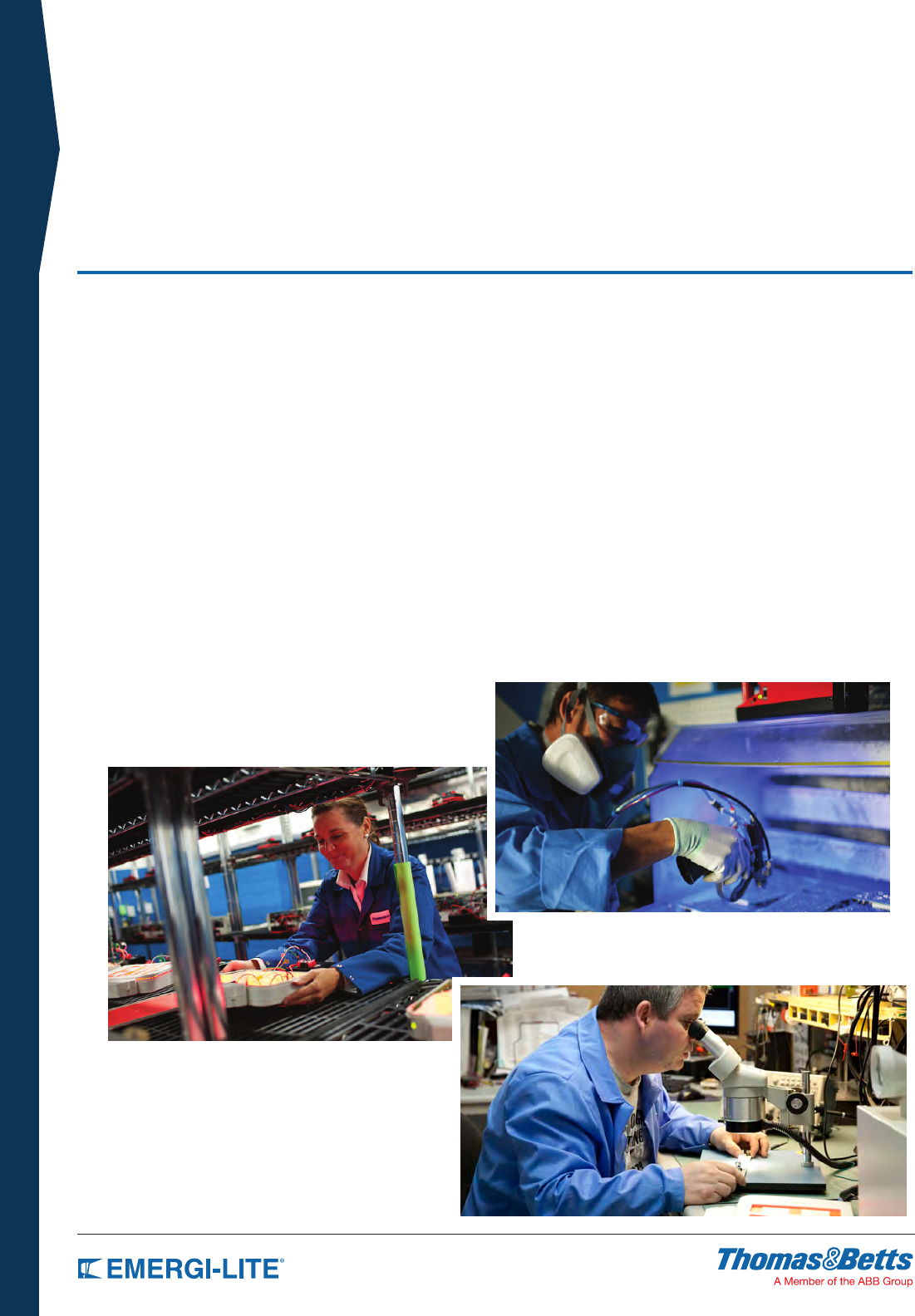
Leading-Edge Research And Development
The multi-disciplinary in-house research and development team at
Thomas & Betts/Emergi-Lite® includes many individuals with over
twenty-five years of experience in the emergency lighting industry.
Our highly skilled professional electrical and mechanical engineers,
designers, and technicians pioneer innovative emergency lighting
solutions by using state-of-the-art technology in all specialties from
mechanical design to operating system software, lighting design, RF
and power electronic design and LED drivers. Unique requests from
customers for specific applications are managed in-house with our
engineering service capabilities. We implement safety and quality into
each product starting at the initial concept and design. To ensure that
each unit is code-compliant, and meets the Emergi-Lite® quality
standards including easy installation and long-term reliability, we create
our own specialized testing equipment.
The Thomas & Betts North American facility is an
emergency lighting center of excellence thanks to the
commitment, expertise, and creativity of every employee.
Thomas & Betts has unique North American manufacturing and production capabilities that allow
Emergi-Lite® to produce exactly what we need when we need it, without waiting for big production
runs or imported goods to arrive.
Advanced Circuit Board Production
Thousands of universal SMT (surface mount technology) boards and TH
(through-hole) insertion boards are produced daily at the Thomas & Betts
manufacturing facility on technologically advanced printed circuit board
production lines. Our ROHS-compliant wave soldering machine meets
lead-free criteria, and every station is ESD (electro-static discharge)
protected to eliminate static hazards.
Trained according to IPC standards, our skilled production personnel
ensure quality by using board traceability and tracking software. High
productivity and quality are ensured with the use of automatic silicone
coating application and insertion equipment.
The new AOI (automated optical inspection) machine added to
the Thomas & Betts printed circuit board operation in 2012 is
one of the first of its kind in use in North America.

3
INTRODUCTION
NORTH AMERICAN
Manufacturing Facility
With everything under one roof, we have total control over service, quality and lead time, and we
can ensure that our strict quality standards are met at every stage in the process from design to
assembly to order completion.
Streamlined & Environmentally Conscious
Strategically located warehouses throughout the United States hold
large inventories ready to ship for fast delivery to customers across the
country.
A Sustainable Development policy is in effect at the Thomas & Betts
manufacturing facility to minimize the environmental impact and reduce
the carbon footprint of operations. Reductions in usage of electricity and
natural gas, packaging, pallets, water, and water bottles have already
been accomplished through a series of initiatives. Forward-looking
objectives include increased pallet recycling, paper usage reductions,
and the implementation of an eco-delivery schedule.
Production & Quality Control
Our electro-mechanical assembly lines are optimized for highly efficient
low-volume, high-mix production runs with thousands of final assemblies
produced on a daily basis. Color matching, exact wording, specific
punching, and other special requests can be completed quickly using
our on-site painting capabilities and machine shop.
All central power systems undergo high-voltage, high-amperage power
outage simulations to test for each customer’s specific requirements,
and every order must pass functional testing and quality inspection.
Specialized in-house facilities such as temperature and humidity
controlled environments; a dark room for color contrast measurement;
wall, ceiling and suspended ceiling installation simulations; and cycle
testing automation are used to ensure quality.
Since 2001, the Thomas & Betts manufacturing facility has been ISO
9001 compliant.
4
INTRODUCTION
MR16 LED
Emergency Lighting
MR16 LED Illumination
With the remarkable technology technological developments in the
last few years, the light-emitting diode (LED) is becoming the preferred
solution in low- and medium-power lighting applications. The emergency
lighting industry is no exception: today virtually every new product
introduced to market includes “white” LEDs for emergency illumination.
Extremely efficient and long-lasting, LED lamps become the natural
alternative to incandescent lamps due to three main advantages:
• lamp efcacy: 50 - 90 lumens per watt compared to 15 - 30 lumens
per watt of the best halogen lamp.
• operational life: 30,000+ hours, equivalent to a lifetime warranty in
emergency lighting.
• lower lamp temperature 80-120°C (176-248°F) is a huge benet for
lighting in hazardous locations.
MR16 LED Lamp Benefits
• UL- recognized components CSA C22.2 No. 141 certied.
• Energy-efcient LED MR16 lamp provides equivalent lighting
performance to a much higher watt halogen MR16 lamp.
• Reduces required battery capacity by 75-85%, providing necessary
illumination with fewer remote heads and battery units for project
cost savings.
• Small prole, compact white lighting is ideal for architectural
applications.
• Vibration-resistant LED stands up to industrial environments.
• Ideal for indoor and outdoor use.
200-Lumen 4W MR16 LED
Leading the technology trend, Emergi-Lite® offers a complete series
of 4W MR16 LED lamps available for all the standard battery voltages:
6V, 12V, 24V and 120V. With up to 30,000 hours of operational life
and a luminous flux of typically 200 lumens, they are available with
most emergency heads designed to hold an MR16 lamp and meet
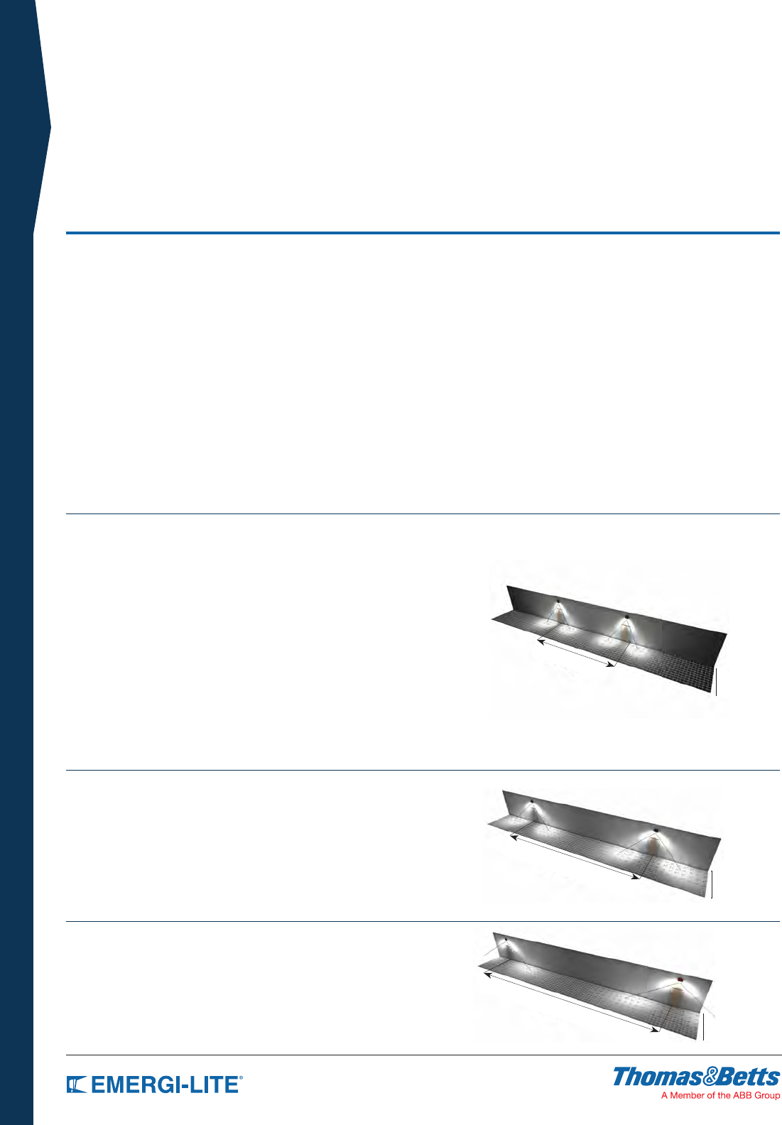
the majority of illumination specifications. For example: one pair of LED
emergency heads installed at a height of 7.5 ft illuminates a 6 ft by 40 ft
path of egress.
Compared to halogen lamps (16-20W), these 4W MR16 LED lamps
illuminate the same area of egress during an emergency situation by
using 75% less power. This has a direct impact on the battery size,
reducing the back-up capacity needs by 75%. Consequently, it also
reduces the total cost of the application, with the use of smaller battery
capacity units, the possibility of using fewer fixtures due to superior
illumination, thus also reducing electrical wiring, and the environmental
footprint.
340-Lumen 5W MR16 LED
Keeping pace with technology, in 2012 we introduced a 12V-5W MR16
LED lamp. With a typical luminous flux of 340 lumens, this lamp has the
same lighting performance as a 20W high-output halogen MR16. A twin
emergency head installed at a height of 7.5 ft illuminates more than 70ft
of path of egress.
540-Lumen 6W MR16 LED
A 6W MR16 LED lamp delivers 540 lumens for an average spacing in
emergency lighting of 100 feet with an efficacy of 91.9 Lm/w, it is over
6 times the efficacy of a MR16 35W halogen with similar light output.
This lamp can deliver the highest linear foot of illumination per watt on
a path of egress! (spacing in feet / watt) 16.7 ft compare to 2.7 ft for a
MR16 35W.
40 ft.
6 ft.
70 ft.
100 ft.
6 ft.
6 ft.
Spacing
Spacing
Spacing
5
INTRODUCTION
MR16 LED
Emergency Lighting
5W MR16 LED lamps
LAMP SUFFIX VOLTAGE WATTAGE LUMENS REPLACEMENT #
LI 12 5 340 580.0104-E
4W MR16 LED lamps
Same Standard Emergency Lighting Units with 4W MR16 LED Lamps
LAMP SUFFIX VOLTAGE WATTAGE LUMENS REPLACEMENT #
LA 6 4 130 580.0097-E
LG 12 4 170 580.0093-E
LL 24 4 200 580.0098-E
Standard wedge-base 9W incandescent lamp
Standard Emergency Lighting Units with 9W wedge-base incandescent
lamps
Compare
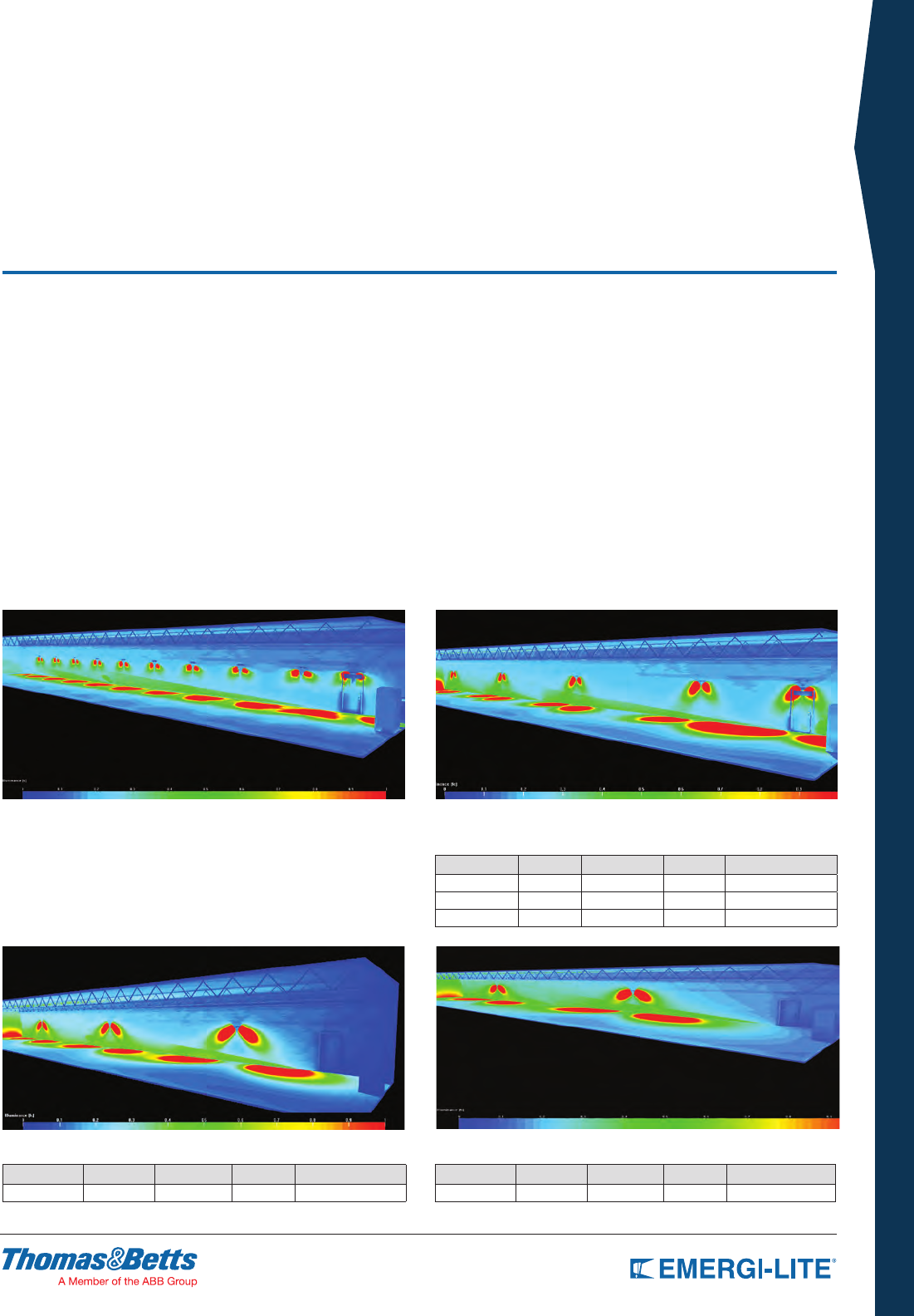
Where the building code requires an average of 1 foot-candle and a minimum of 0.1 foot-candle at floor level along the path of egress on a 150 ft x
9 ft x 9 ft corridor with an egress door at one end, a 150 ft x 6 ft path of egress, and a 7.5 ft unit mounting height, using high-efficiency LED lamps
can reduce the emergency lighting units required from 9 dual-head units down to only 2 dual-head units:
Case Study: Fewer MR16 LED units required
Emergency lighting units with MR16 LED lamps provide the same
illumination at floor level using significantly with many additional benefits:
• Reduced Installation Costs, due to reduced product and labor
requirements.
• Reduced Energy Costs, keeping fewer batteries charged at full
capacity to be ready to respond to an emergency situation at any
time.
• Reduced Maintenance and Testing Costs, with fewer units to
maintain and test in the Emergency Lighting System.
• Reduced Lamp Replacement Costs. LED lamps have a 30,000+
hour lamp life compared to only a few hundred hours typical with
incandescent lamps.
• Reduced Environmental Impact, with less product materials, less
batteries, less transportation, less packaging, less labor, and less
waste.
NEW! 6W MR16 LED lamps
LAMP SUFFIX VOLTAGE WATTAGE LUMENS REPLACEMENT #
LJ 12 6 540 580.0106-E
9 twin lamp heads required.
Only 3 dual lamp heads required.
Only 5 dual lamp heads required.
Only 2 dual lamp heads required.
6
INTRODUCTION
Are you prepared for a safety inspection?
Building & Life Safety Codes oblige building owners/managers to ensure
the safe evacuation of a building in the event of an emergency. In the
interest of public safety, building owners/managers must meet the
outlined requirements for exit signs and emergency lighting equipment,
including the following:
• Conduct a discharge test every month
• Conduct functional tests annually
• Keep a log book of maintenance information
Complying with these requirements can be labor intensive and costly,
especially in large buildings where testing every emergency light
requires many man-hours. Disrupting the power supply during lengthy
inspections can also put public safety at risk.
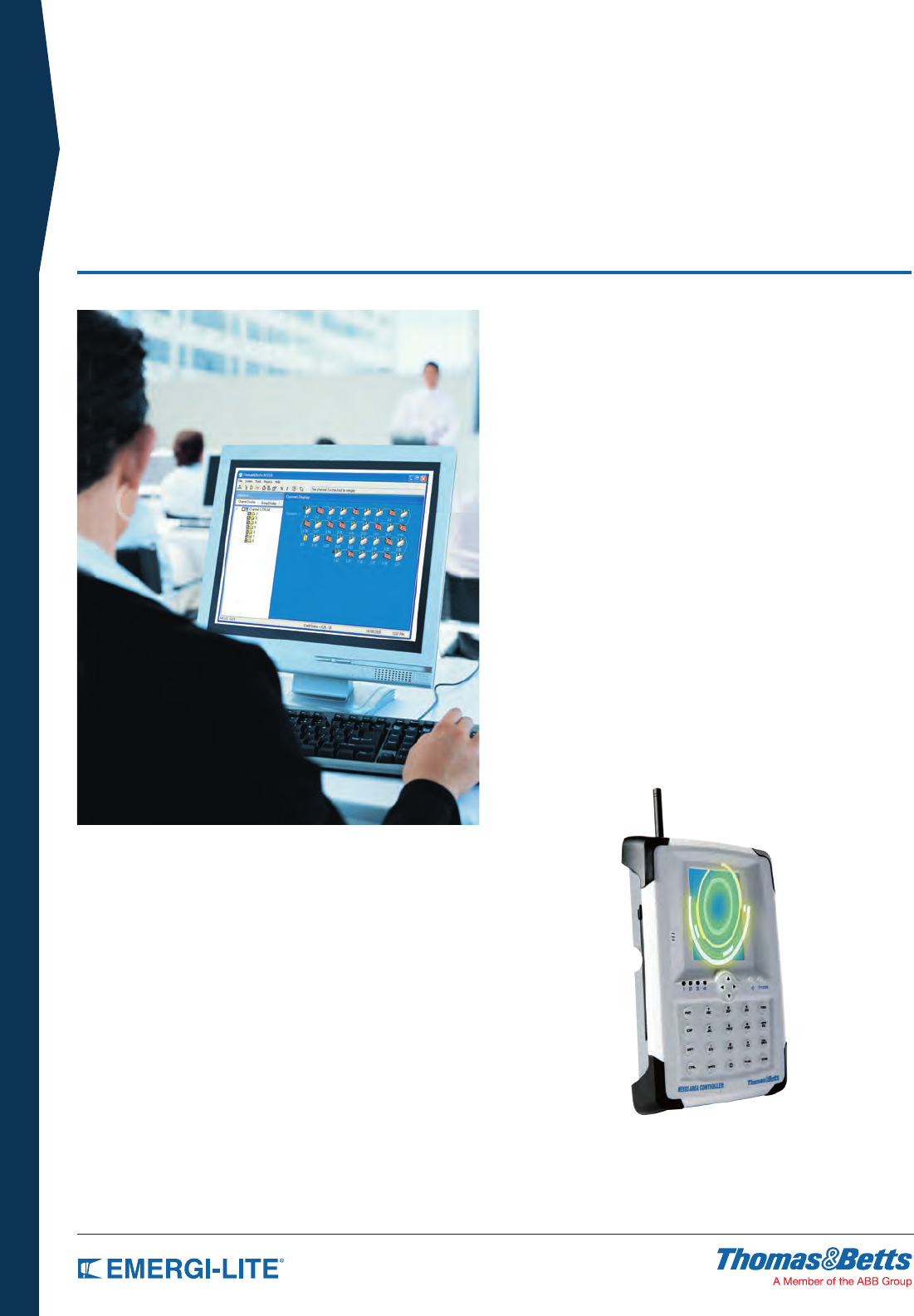
Manage Testing with Nexus® to Save Time
and Costs
Nexus® is a real-time monitoring system that manages the status of
your entire emergency lighting and exit sign system from a central
control unit. Nexus® runs diagnostics, performs required monthly
and annual functional tests, generates maintenance logs and runs
compliance reports.
Available in wired or wireless (RF) versions, Nexus® installations often
pay for themselves in less than two (2) years. In addition to operational
savings, Nexus® helps increase system reliability and performance
and reduces the risk of failed inspections. One building or a group
of properties under the same management can be monitored with
Nexus®.
Maximize System Availability
By allowing maintenance personnel to easily maintain and monitor the
emergency lighting system without having to manually check each unit,
Nexus® reduces the hours required to disrupt the power supply for
inspections. With Nexus®, monthly tests and reports on the status of
all emergency lights and exit signs can be done individually, in groups,
or together. Advantages of the Nexus® system include saving labor;
maximizing system availability by testing units in groups and stages
rather than setting all units in recovery mode; and the convenience
of self-monitoring. Nexus® indicates the location of a faulty unit and
reports it instantly without requiring a manual search.
NEXUS® EMERGENCY LIGHTING
Management System
7
INTRODUCTION
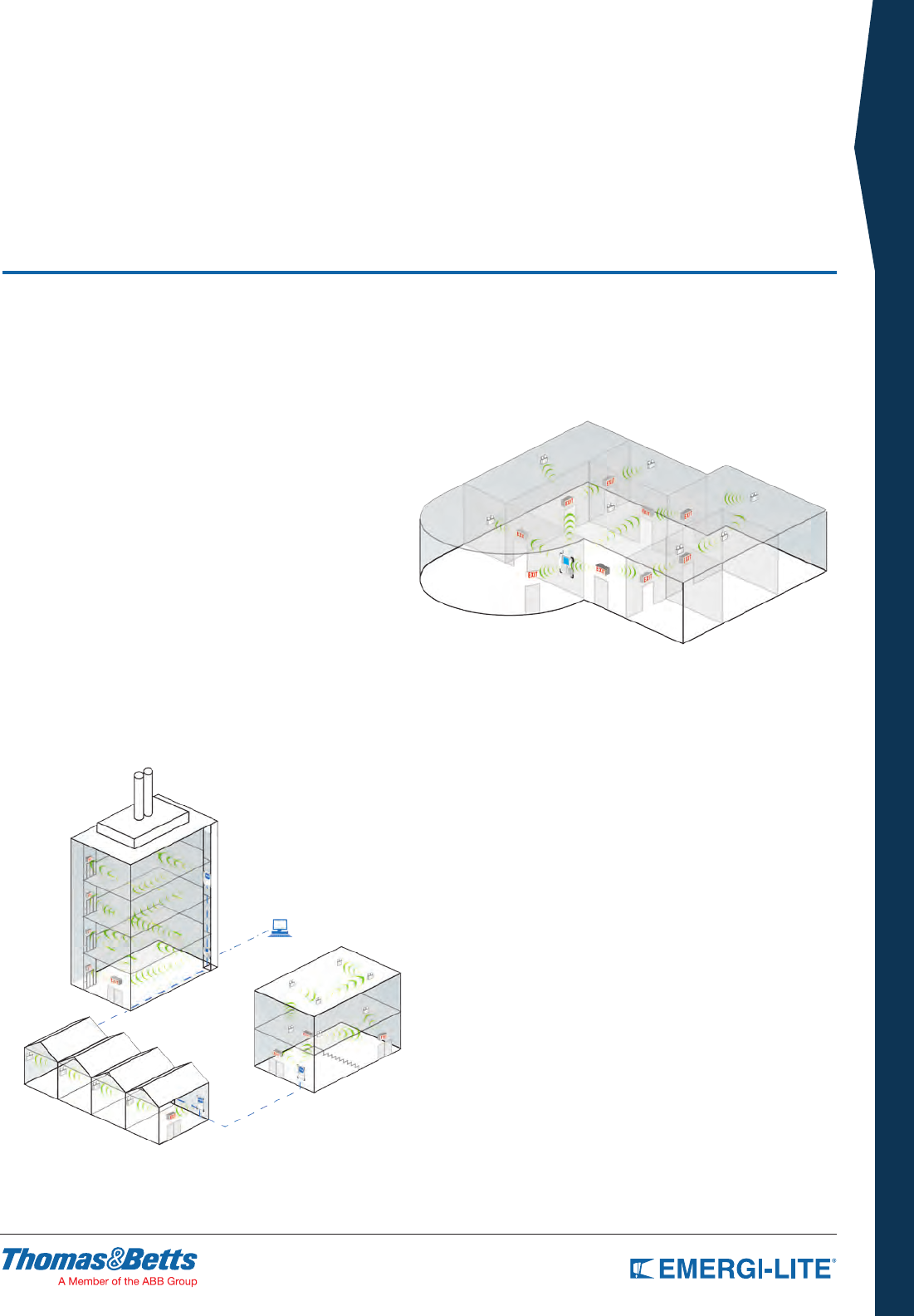
Large System Example
The Nexus® RF system has been designed to be extremely flexible
and provide a range of system options. Each large site will need
to be assessed for the best system solution with the assistance of
Thomas & Betts technical staff.
The basic Nexus® RF system is designed to run on an Ethernet
network which is present in most modern buildings. However through
a range of interface cards, the backbone of the network could be
WLAN. As with the small system example, site performance will
be optimized through the careful selection and placement of Area
Controller Routers and the Area Controller to form efficient clusters.
Building layout and materials will also play some role in determining
the best solution to deliver a highly effective means of meeting testing
and maintenance requirements.
NEXUS® EMERGENCY LIGHTING
Management System
Update Status Instantly
Nexus® passes messages both to and from the emergency units to
instruct the units to perform all mandatory testing by communicating
between the emergency units and a centrally located controller.
Nexus® is a proven system supported by a 5-year warranty, and can
contribute to LEED certification and support green building initiatives.
Small System Example
In a system of less than 100 units it is most likely that the only hardware
required, other than the emergency units themselves, is a controller. All
communication would occur wirelessly and installation would not vary
greatly from a non-monitored system. Once the units are in place, the
system will establish the mesh network. The building itself could be
quite large as each unit only needs to be able to communicate with its
close neighbors and does not need to communicate directly with the
controller.
8
INTRODUCTION
SPEC GRADE PRODUCTS
Table of Contents
ARCHITECTURAL
Lux-Ray™ LED Series 12-13
Revelation™ Series 14
Mini-Revelation™ Series 15
PS Series 16
RS Series 17
TS Series 18-19
EFR2 Series 20
GS Series 21
Prestige™ Edge-Lit Series 22-23
Prestige™ X40 Series 24
Prestige™ DX Series 25
Prestige™ Floor Proximity Series 26-27
COMMERCIAL
Premier™ Battery Series 30
Premier™ Combo Series 31
Premier™ Exit Series 32
Provider™ PRO-2N Series 33
EC-2/ECX-2 Series 34
ECC & ECM Series 35
JC Series 36
JA Series 37
JS Series 38-39
LSE Series 40
LC Series 41
LS Series 42-43
24 LS & 24 LC Series 44
9
INTRODUCTION
SPEC GRADE PRODUCTS
Table of Contents
X10 LED Series 45
Prestige™ Recessed Economizer Series 46
Prestige™ Economizer Series 47
Preceptor™ Die-Cast Series 48
Preceptor™ Recessed Series 49
Preceptor™ Remote Capacity Series 50
Special Wording Configuration 51
INDUSTRIAL
Hazardous Location 54
Survive-All™ SV Series 55
Survive-All™ SVX Combo Series 56
Survive-All™ SVX Exit Series 57
Survive-All™ EF39 & EF40 Series 58
HZM Series 59
Survive-All™ SVH Series 60
Survive-All™ SVXH Series 61
Survive-All™ SVXHZ Series 62
Survive-All™ EF41 Series 63
IL Series 64-65
KS Steel Series 66-67
KS Series 68-69
EXC Series 70-71
EFEP Series 72
EFXP Series 73
Ever-Lite™ Self-Luminous Series 74

Specification Grade
For demanding applications such as high-visibility areas
in retail spaces, high-traffic areas in hotel lobbies, and the
intense heat in foundries and mills, Emergi-Lite® Specification
Grade products provide a vast array of specialty emergency
lighting equipment and exit signs.
Architects, contractors and designers will find a selection
of modern styles and mounting options to suit virtually any
application where emergency lighting and exit signs must be
aesthetically pleasing as well as functional.
The high-quality die-cast aluminum, steel, and thermoplastic
housings on Emergi-Lite® Specification Grade products
can be provided in all colors and finishes to complement
any interior. A choice of battery options, lamp types, and
configurations are available to meet your photometric
requirements and specifications.
For heavy-duty industrial areas with stringent requirements,
NEMA-certified models, NSF-approved products, explosion-
proof units, and more are available for highly demanding
locations.
Make Emergi-Lite® your source for modern, stylish, high-
performance emergency lighting equipment and exit signs.
What are
SPEC GRADE PRODUCTS?
INTRODUCTION
11
ARCHITECTURAL
SPEC GRADE
Lux-Ray™ LED Series 12-13
Revelation™ Series 14
Mini-Revelation™ Series 15
PS Series 16
RS Series 17
TS Series 18-19
EFR2 Series 20
GS Series 21
Prestige™ Edge-Lit Series 22-23
Prestige™ X40 Series 24
Prestige™ DX Series 25
Prestige™ Floor Proximity Series 26-27
SPEC GRADE
ARCHITECTURAL
Table of Contents
12
SPEC GRADE
ARCHITECTURAL
TYPE:
CATALOG #:
NOTES:
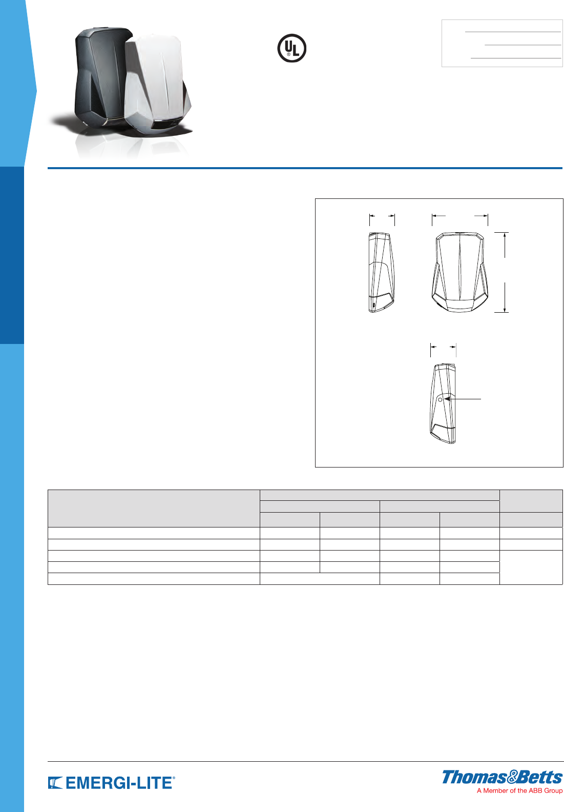
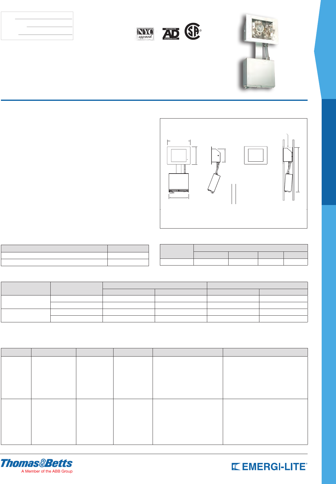
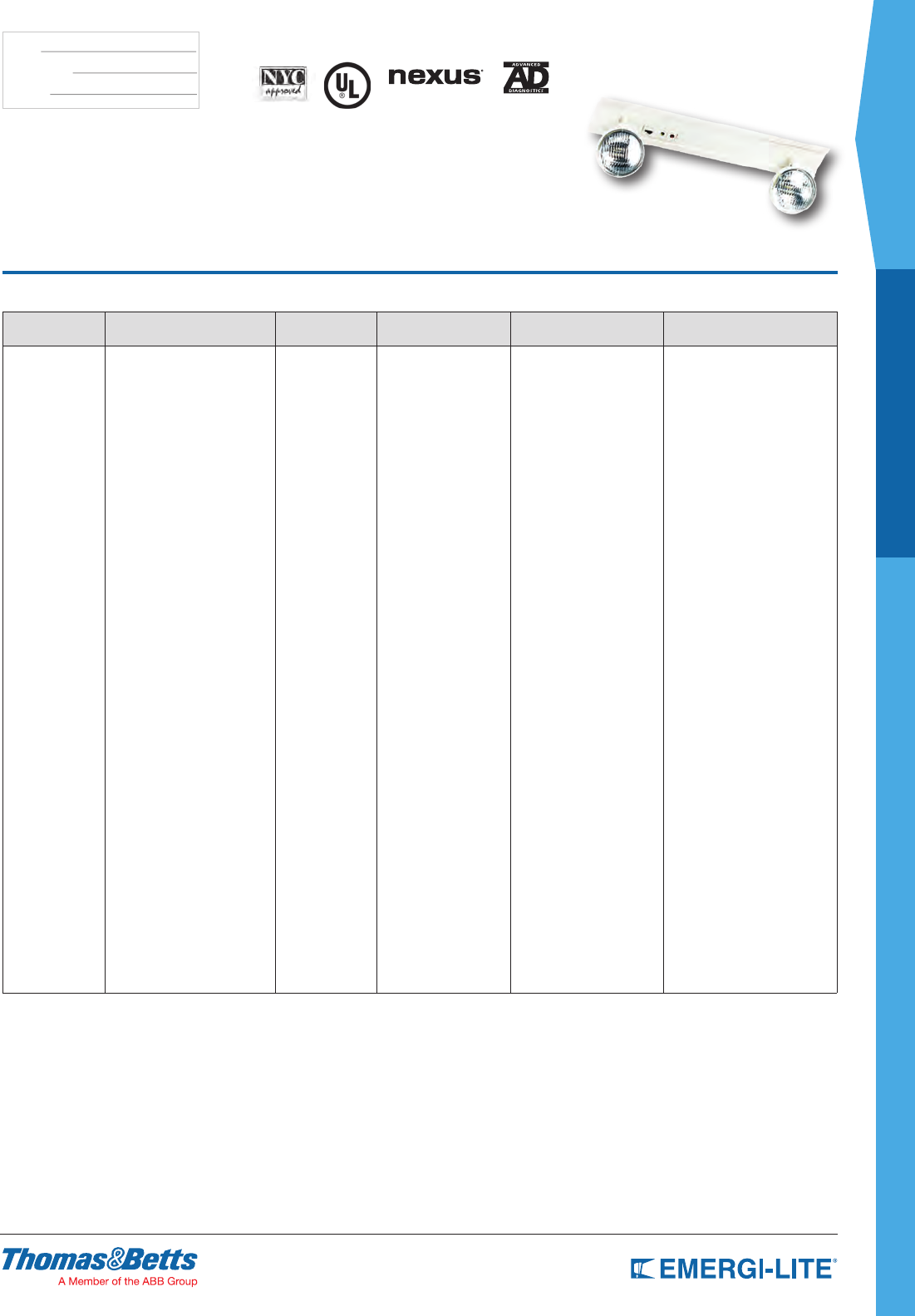
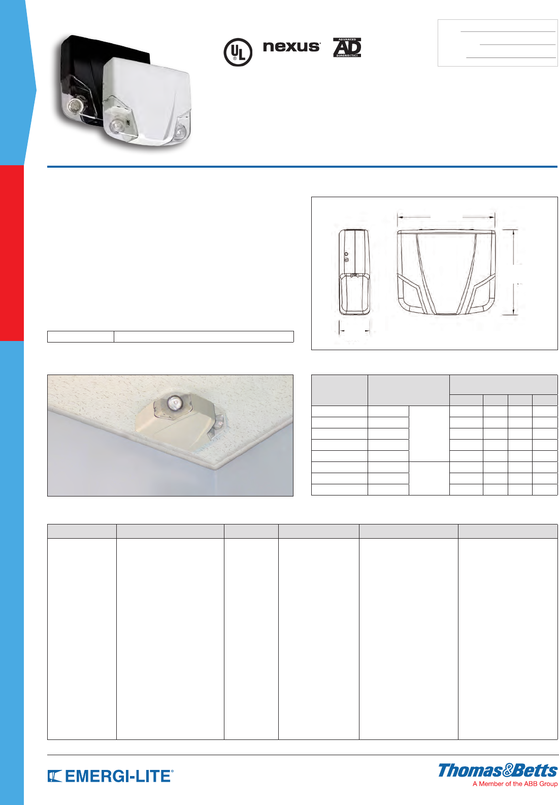
Lux-Ray™ LED Series
Dimensions
Dimensions are approximate and subject to change.
6-5/8”
9-1/2”
3”
Window for
photo-switch (optional)
3”
Features
•Die-Castaluminumhousing,availableinfournishes:darkbronze,off-white,
black,andplatinumgray
•Nema-3Rratedforindoor/outdoorwet,damp&coldlocations:
-20to50°C(-4to122°F),SDModel
-20to40°C(-4to104°F),ACSDModel
•Wall-mountinstallationonvariousjunctionboxesorviarigidconduit
•Patent-Pendingdesignforeasyinstallation:wall-mountbackplateincludes
electricalwireboxwithsnap-onconnector
•Patent-Pendinglightengine:fourpowerLEDswithredundantconnections
andwidebeam
•Clearpolycarbonatelensofreducedsize(3”X1.5”),shockabsorbentand
UV-resistant
•Battery:environmentallyfriendlyhigh-temperaturerated,
Nickel-MetalHydridetechnology
•Powerconsumptioninstand-by:lessthan5W
•Optionalself-testanddiagnosticfunctions,operatedbymicro-controller
•5-yearlimitedwarranty
Optional Features
•Coldweather:-40°F/-40°C
•Forward-throwlightdistribution,forapplicationsofoutdoorexitdischarge
(OSHA1910.36)
•High-lumenoutput:25to50%additionallevelofilluminationcomparedtothe
regularunit
•Dual-modeoperation:normallightingand/oremergencylightingwithseparate
ACinputs
•Photo-switch:dusk-to-dawncontrolofnormallighting
•Remotetest:infraredremotecontrol(keypadorderedseparately)
•TimeDelay:5,10,15minutes
Power Consumption
Model Type
AC SPECS: 120/277VAC 6-12VDC remote
Normal lighting Emergency lighting
Current (max) Power
(max) Current (max) Power (max) Power (max)
AC, 2AC, ACDC, DC 0.12/0.08A 12W 0.12/0.08A 12W 8W
AC, 2AC, ACDC, DC, -H 0.18/0.11A 18W 0.18/0.11A 18W 14W
ACSD, SD, SD-H 0.12/0.06A 12W 0.05/0.02A 5W n/a*
SD-CW - - 0.15/0.07A 16W
ACSD-CWP, -CWRC n/r* 0.22/0.10A 24W
* Note: Only unswitched AC input; normal lighting with photo-switch or remote control
Patent-Pending
NEMA-3R
13
ARCHITECTURAL
SPEC GRADE
TYPE:
CATALOG #:
NOTES:
Die-Cast Aluminum LED Emergency Lighting
How to Order
COLOR SERIES MODEL OPTIONS
B= Black
BZ= Dark bronze
OW= Off-white
PG= Platinum gray
LUX= Lux-Ray LED SD= Self-Powered & diagnostic
[-4... 122°F (-20… 50°C)]
ACSD= Dual-mode AC /
Self-Powered
[-4... 104°F (-20… 40°C)]
-CW= Cold weather [-40… 86°F (-40…30°C)
N/A with option -H]
-D1= Time Delay (5 minutes)
-D2= Time Delay (10 minutes)
-D3= Time Delay (15 minutes)
-FT= Forward throw lighting
-H= High lumen output
(max. 86°F/30°C; model SD only)
-P= Photocell Test Switch (ACSD only)
-RC= Remote control - infrared*
* Remote control keypad (TB-RC1-E) ordered separately
Example: BZLUXACSD-RC
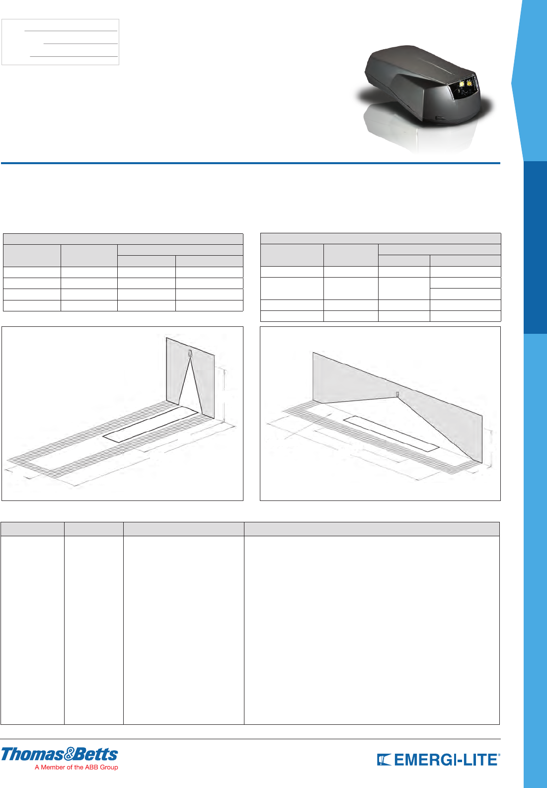
Average of 1 foot-candle
TABLE A: SPACING FOR NFPA101 (AVERAGE = 1FC, SEE NOTE)
Model Type Mouting Height Width X Lenght (ft)
Single Unit Center-To-Center
Standard 9’ 6’ X 50’ 6’ X 50’
With option -H
11’
6’ X 60’ 6’ X 60’
3’ X 70’
With option -FT 12’ 6’ X 40’ —
With option -FTH 15’ 6’ X 50’ —
Minimum of 1 foot-candle
TABLE B: SPACING FOR MINIMUM ILLUMINATION = 1FC
Model Type Mouting Height Width X Lenght (ft)
Single Unit Center-To-Center
Standard 9’ 4’ x 28’ 4’ x 32’
With option -H 11’ 4’ x 32’ 4’ x 40’
With option -FT 12’ 4’ x 22’ —
With option -FTH 15’ 4’ x 27’ —
1fc average
1fc minimum
6’
40’
20’
10’
1fc average
1fc minimum
50’
28’ 9’
6’
Photometry performance
Whetherinstalledindoorsoroutdoors,withspacingmeasurementsforasingleunitorbetweentwounitscenter-to-center,theCamray®SeriesLEDdeliversastable
andconsistentilluminationmakingiteasytospecifyinawiderangeofapplications.Theoutstandingspacingofilluminationrangesfrom50to70feetforstandardunits
(widebeam)andfrom40to50feetwiththeforward-throwbeamoption.
ForwardThrow WideBeam
14
SPEC GRADE
ARCHITECTURAL
TYPE:
CATALOG #:
NOTES:
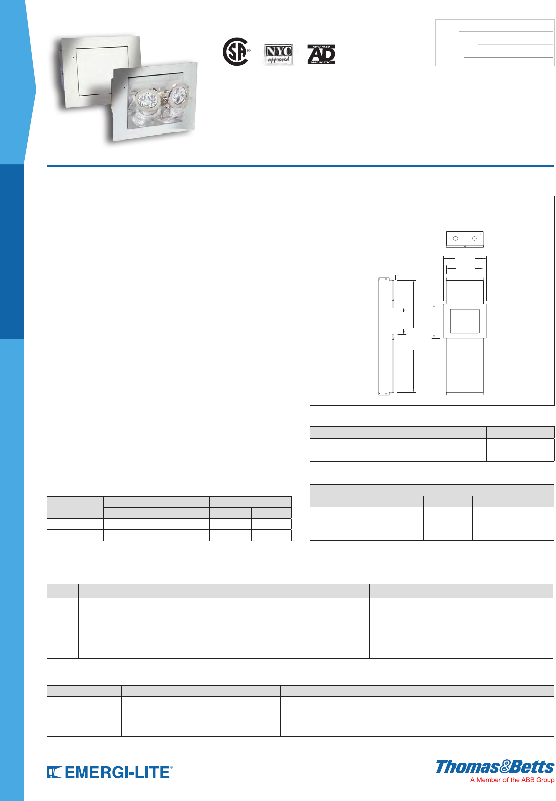
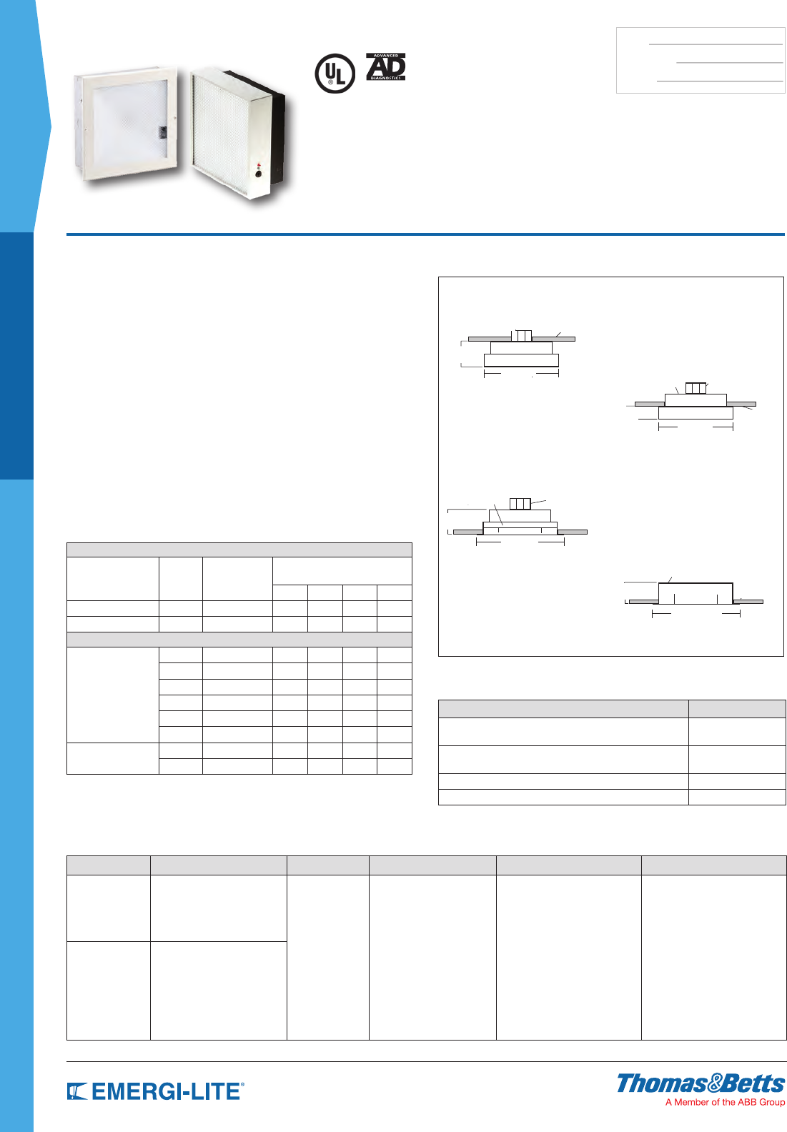
Revelation™ Series
Virtually Invisible Emergency Lighting
Dimensions
Dimensions are approximate and subject to change.
9-1/8”
Charger&BatteryCompartment:Foruseinwallsorceilings
withacavity,notforuseinblockwallsorsolidceilings.
7-7/8”
5-1/2”
7-1/4”
23-7/8”
Features
•Fullyconcealedinopencavitywallsorceiling
•Onlyvisiblewhenneeded:duringapowerfailure
•Eachunitcomeswithtwo(2)MR16halogenlampsrangingfrom12to50W
eachor2MR16styleLEDlamps
•TheSelf-Poweredunitiscontainedinaheavy-dutygalvanizedsteelback
boxthatcanbeconcealedinthewallorceilingandincludesacombinedtest
switchandpilotlightthatisaccessiblethroughtheframe
•Thenormallyexposedpartsoftheunit(atdoorandframe)arecoveredwith
ahigh-qualitypowder-coated,texturedoff-whitenishthatintegrateswell
withmostwallandceilingpaints.Thesurfacenishcanalsobecustomized
onsitewithpaint,wallpaperorothercoverings
•Powerrequirements:120/277VAC,60Hz,0.25/0.12A
•PulsePlusChargercircuitryoffers120/277VAC60Hz,0.25/0.12A,automatic
charger,builtaroundamicro-controllerintegratedcircuit.Circuitstandard
featuresincludecurrentlimiting,temperature-compensatedcut-offvoltage,
brownouttransfer,low-voltagebatterydisconnectandbatterylockout
(preventsactivationinDCmodeuntilinitialACactivation)
•SpecialbarhangersforinstallationinsheetrockorT-barceilingsareincluded.
Theincludedelectricaljunctionboxcanbeinstalledonawallstudorceiling
beamwithasimpleU-shapebracket
•5-yearwarrantyonelectricalparts(motor,electroniccircuitry).Eachunitis
fullycomputer-testedandalignedmechanicallyforoptimumoperation
Diagnostic/Self Test Feature (optional)
Diagnostic/Self-TestcircuitryisoptionalonallSelf-Poweredmodels.Thiscircuitry
is programmed to ensure equipment readiness and reliability by continuously
monitoringeverycriticalfunctionoftheunit.Ifaproblemoccurs,thepilotlight
locatedonthefrontoftheunitwillchangecolorfromsolidgreentoflashingred,
indicating a fault. A detailed diagnostic legend is available on the door back
andprovidesfaultidentification(battery,chargercircuitry,lamps)formaintenance
personnel.Theself-testfeaturewillsimulateapowerlossforaminimumof30
secondsevery30days,30minutesevery6monthsand90minutesannually.
Accessories (order as a separate item)
DESCRIPTION SUFFIX
Remote Test Switch (metal face plate) RTS
Remote Text Switch (plastic face plate) RTS-1
Power Consumption
Model Maximum Stand-By*
Input Current Input Power Input Current Input Power
120V 0.25A 30W 0.1A 11W
277V 0.12A 30W 0.05A 11W
* Stand-by power consumption is 50% lower for Lead-Calcium batteries.
Unit Rating
Model Watts to 87-1/2% of rated battery voltage*
1-1/2 hrs 2 hrs 4 hrs 8 hrs
RTM40, RTN40 40 30 24 -
RTM70, RTN70 70 50 40 24
RTM100, RTN100 100 70 50 40
* National Electrical Code Specification
How to Order
Battery Unit
SERIES BATTERY TYPE UNIT CAPACITY LAMP TYPE/WATTAGE OPTIONS
RT M= Lead-Cadmium
N= Ni-Cd
40= 12V-40W
70= 12V-70W
100= 12V-100W
-2(12)= 12W, MR16 each head
-2(20)= 20W, MR16 each head
-2(35)= 35W, MR16 each head
-2(50)= 50W, MR16 each head
-2 (20H)= 20W, MR16 high
lumen output
-2 (35H)= 35W, MR16 high
lumen output
-2 (50H)= 50W, MR16 high
lumen output
-2 (LG)= 12V-4W, MR16 LED
-2 (LI)= 12V-5W, MR16 LED
-2 (LJ)= 12V-6W, MR16 LED
AD= Advanced Diagnostics
(audible)*
ADNA= Advanced Diagnostics
(non-audible)*
DL= Damp Location**
D1= Time Delay (5 minutes)
D2= Time Delay (10 minutes)
D3= Time Delay (15 minutes)
X= Back box shipped
separately
* Available on all models except Ni-Cd 100W
** Minimum lamp load required: 20% of unit capacity
Example: RTM100-2(50)-D3
AC Remote Fixture
SERIES INPUT VOLTAGE # OF LAMPS LAMP TYPE/WATTAGE OPTIONS
RTG= Remote AC
Generator
1= 120VAC, 60Hz
2= 277VAC, 60Hz
-2= Two lamps standard (LG)= 12V-4W, MR16 LED
(LI)= 12V-5W, MR16 LED
(LJ)= 12V-6W, MR16 LED
(12)= 12W each head
(20)= 20W each head
(35)= 35W each head
(50)= 50W each head
(20H)= 20W, high lumen output
(35H)= 35W, high lumen output
(50H)= 50W, high lumen output
-DL= Damp Location
X= Back box shipped
separately
Example: RTG2-2(LG)-DL
US
3-7/16”
15
ARCHITECTURAL
SPEC GRADE
TYPE:
CATALOG #:
NOTES:
Mini-Revelation™ Series
THE UNSEEN SOLUTION
Virtually Invisible Emergency Lighting
How to Order
SERIES BATTERY TYPE UNIT CAPACITY AC INPUT LAMP TYPE/WATTAGE OPTIONS
Battery
Unit= MRT
M= Lead-Calcium
N= Nickel-Cadmium
H= Nickel-Metal Hydride
40= 12V-40W Blank= 120/277VAC -2 (12)= 12W each head
-2 (20)= 20W each head
-2 (20H)= 20W, high lumen output
-2 (LG)= MR16 LED, 12V-4W
-2 (LI)= MR16 LED, 12V-5W
-2 (LJ)= MR16 LED, 12V-6W
-AD= Advanced Diagnostics (audible)*
-ADNA= Advanced Diagnostics (non-audible)*
-D1= Time Delay (5 minutes)
-D2= Time Delay (10 minutes)
-D3= Time Delay (15 minutes)
-DL= Damp Location (only MRTN40, MRTH40)
* Minimum lamp load required: 20% of unit capacity
Generator
Unit= MRT
G= Remote AC generator Blank= Max. 100W 1= 120VAC
2= 277VAC
-2 (12)= 12W each head
-2 (20)= 20W each head
-2 (35)= 35W each head
-2 (50)= 50W each head
-2 (20H)= 20W, high lumen output
-2 (35H)= 35W, high lumen output
-2 (50H)= 50W, high lumen output
-2 (LG)= 12V-4W, MR16 LED
-2 (LI)= 12V-5W, MR16 LED
-2 (LJ)= 12V-6W, MR16 LED
-DL= Damp Location
Example: MRTM40-2(20)-ADNA
Dimensions
Dimensions are approximate and subject to change.
9-1/8”
7-3/4”
CompleteUnit InstalledUnit
5-1/4”
17-5/8”
MountingBracket
7”
Power Consumption
Model AC Input Maximum Stand-By (Ni-Cd, NiMH)*
Input Current Input Power Input Current Input Power
MRT40 120VAC 0.25A 30W 0.1A 11W
277VAC 0.12A 30W 0.05A 11W
MRTG 120VAC 0.95A 110W** – –
277VAC 0.45A 110W** – –
* Stand-by power consumption is 50% lower for Lead-Calcium batteries
** Maximum power when equipped with 2 x 50W lamps (generator unit)
Unit Rating
Model Watts to 87-1/2% of rated battery voltage*
1-1/2 hrs 2 hrs 3 hrs 4 hrs
MRT_40 40 30 24 -
* National Electrical Code Specification
Features
•Eachunitcomeswithtwo(2)MR16halogenlampsor2MR16styleLEDlamps
•TheSelf-Poweredbatteryunitiscontainedinaheavy-dutygalvanized
steelbackboxthatcanbeconcealedinthewallorceilingandincludesa
combinedtestswitchandpilotlightthatisaccessiblethroughtheframe
•Thenormallyexposedpartsoftheunit(atdoorandframe)arecoveredwith
ahigh-qualitypowder-coated,texturedoff-whitenishthatintegrateswell
withmostwallandceilingpaints.Thesurfacenishcanalsobecustomized
onsitewithpaint,wallpaperorothercoverings
•Powerrequirements:120/277VAC,60Hz,0.25/0.12A
•PulsePlusCharger-thisautomaticchargerisbuiltaroundamicro-
controllerintegratedcircuit.Circuitstandardfeaturesincludecurrentlimiting,
temperature-compensatedcut-offvoltage,brownouttransfer,low-voltage
batterydisconnectandbatterylockout(preventsactivationinDCmodeuntil
initialACactivation)
•Theequipmentincludesanelectricaljunctionboxandcanbeinstalledona
wallstudorceilingbeamwithasimpleU-shapebracket.
•EvaluatedtoUL924Standard
•5-yearwarrantyonelectricalparts(motor,electroniccircuitry).Eachunitis
fullycomputer-testedandalignedmechanicallyforoptimumoperation
•ADorADNAoptionsincludeincludesaTimeDelayfunction.Ifneeded,itcan
beenabled/disabledintheeldoritcanbepresetatthefactorybyincluding
thesufxAD-D_orADNA-D_
US
Accessories (order as a separate item)
DESCRIPTION SUFFIX
Remote Test Switch (metal face plate) RTS
Remote Text Switch (plastic face plate) RTS-1
16
SPEC GRADE
ARCHITECTURAL
TYPE:
CATALOG #:
NOTES:
PS Series
6 and 12 Volt Square Shooter
Dimensions
Dimensions are approximate and subject to change.
SurfaceMountPlasticSquare
Semi-RecessedPlasticSquare
RequiresOptionalMountingKit
Fully-RecessedPlasticSquare
RequiresOptionalMountingKit
Fully-RecessedMetal
SquareOptional
Features
•Eachunit(standard)comeswithone(1)halogenlamp
(6V-6W or 12V-8W)
•Surfacemount,semi-recessedunitsandfullyrecessedkitsareconstructedof
anoff-white,impactresistant,ameretardant,polymericmaterial.
Fully-recessed,“FRM”optionunitshaveanall-metalbackbox
•Availablewithsealed,maintenance-freeNickel-Cadmium,LongLifeLead,
orLead-Calciumbatteries
•PulsePlusChargercircuitryoffers120/277VAC60Hz.,0.3/0.15A(otherinputs
available),fusedoutputcircuit(s),temperaturecompensatedcharger,sealed
relay,lowvoltagebatterydisconnect,brownoutprotectionandlockout
(automaticbatteryconnect)
•Allmodelsaresuppliedwithaspecularreectorandaredesignedtomount
directlytoastandardoctagonalelectricbox
•ULListed.ComplieswithNEC,LifeSafetyCodeandOSHA.Approvedusein
theCommonwealthofPennsylvania
•3-yearfullwarranty,excludinglamps,pilotlightsandfuses
Unit Rating
6 volt unit furnished with 6 watt Halogen lamp(s).
12 volt unit furnished with 8 watt Halogen lamp(s).
UNIT EQUIPMENT – NO REMOTE CAPABILITY
Sealed Maintenance-
Free Battery Types
D.C.
Voltage Model Number
Watts to 87-1/2% of rated
battery voltage*
1-1/2 hrs 2 hrs 3 hrs 4 hrs
Long Life Lead 6 PSE9 9 7 – –
Lead-Calcium 6 PSM9 9 6 – –
UNIT EQUIPMENT – WITH REMOTE CAPABILITY
Nickel-Cadmium 6 PSC18 18 12 9 6
6 PSC18-2 18 12 9 6
6 PSC25 25 18 12 9
6 PSC25-2 25 18 12 9
12 12PSC36 36 21 15 12
12 12PSC36-2 36 21 15 12
Long Life Lead 6 PSE18 18 11 8 6
6 PSE18-2 18 11 8 6
* National Electrical Code Specification
-2 indicates two lamp version
Accessories (order as a separate item)
DESCRIPTION SUFFIX
Semi-Recessed Kit (converts a surface
mount unit to semi-recessed) PS-SRKIT*
Fully-Recessed Kit (converts a surface
mount unit to fully-recessed) PS-FRKIT*
Wire Guard (Surface or Semi-Recessed) WG1-E
Wire Guard (Fully-Recessed) WG11-E
* Bar hangers included. For standard units without options only order Model Number. Options are added to
units by listing suffix at end of model #
How to Order
SERIES BATTERY TYPE/CAPACITY # OF LAMPS LAMP TYPE DIAGNOSTIC OPTION OPTIONS
PS= 6V Series C18= 6V-18W Ni-Cd
C25= 6V-25W Ni-Cd
E9= 6V-9W Long Life Lead
E18= 6V-18W Long Life Lead
M9= 6V-9W Lead-Calcium
Blank= One lamp
-2= Two lamps
Blank= 6V-6W or 12V-8W
halogen bi-pin
HB= 6V-8W halogen bi-pin
HC= 6V-10W halogen bi-pin
HD= 6V-12W halogen bi-pin
HG= 12V-12W halogen bi-pin
Blank= Standard unit
-AD= Advanced Diagnostics
(audible)
-ADNA= Advanced Diagnostics
(non-audible)
Blank= No options
-V= Voltmeter*
-A= Ammeter
-D1= Time Delay (5 minutes)
-D2= Time Delay (10 minutes)
-D3= Time Delay (15 minutes)
-J= Polycarbonate lens
-FRM= Fully-recessed
all-metal unit
12PS= 12V Series C36= 12V-36W Ni-Cd
Note: See lamp data sheet in general
information section for details
* Voltmeter not available with -FRM fully
recessed and PS-FR kit
Example: PSC18-2HA-AD-FRM
Junction Box
by others
Semi-Recessed
Option
Fully-Recessed
Option
Junction Box
by others
Junction Box
by others
Metal Back Box
Ceiling
Ceiling
Ceiling
Ceiling
2-1/4”
3-1/4”
4”
4”
9” Sq.
9” Sq.
10” Sq.
10-5/8” Sq.
17
ARCHITECTURAL
SPEC GRADE
TYPE:
CATALOG #:
NOTES:
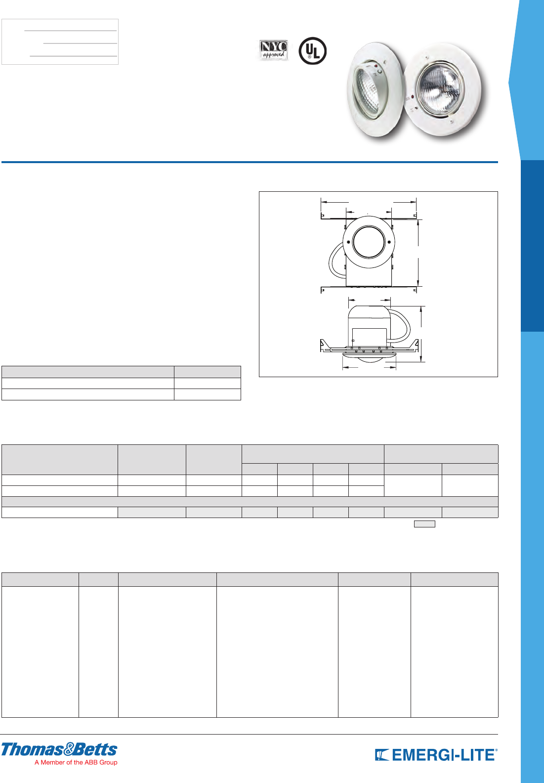
RS Series
6 and 12 Volt Decorator Recessed
Emergency Lighting
Dimensions
Dimensions are approximate and subject to change.
BackBox EF18 EF9
Features
•Eachunitcomeswithtwo(2)6or12V-9Whigh-intensityincandescent
EF-9lampheads(standard).EF-10,EF-18,EF-32andEF-150lampheads
areoptional
•Constructedof20-gaugesteelwithanoff-whitebakedenamelnish
•Availablewithsealed,maintenance-freeNickel-Cadmium,LongLifeLead,or
Lead-Calciumbatteries
•PulsePlusChargercircuitryoffers120/277Vinput60Hz.,0.3/0.15A(other
inputsavailable),fusedoutputcircuit(s),dualdiagnosticindicatorlights,
temperaturecompensatedcharger,sealedrelay,lowvoltagebattery
disconnect,brownoutprotectionandlockout(automaticbatteryconnect)
•Fully-recessedassemblyforceilingorwallmount.Includesadjustablebar
hangersforgridceilings.Canbeframedintostuds/joists
•UL924Listed.ComplieswithNEC,LifeSafetyCodeandOSHA
ApproveduseintheCommonwealthofPennsylvaniaandNewYorkCity
•3-yearfullwarranty,excludinglampsandfuses
Unit Rating
EF-9 lamp heads: 6 or 12 volt 9 watt High Intensity Incandescent lamps.
UNIT EQUIPMENT – NO REMOTE CAPABILITY
Sealed
Maintenance-
Free Battery
Types
D.C.
Voltage
Model Number Watts to 87-1/2% of
rated battery voltage*
EF-150 Deco EF-9 Lamp
Heads
11⁄2
hrs
2
hrs
3
hrs
4
hrs
Ni-Cd 6 RSC18-2150 RSC18-2 18 12 10 –
Long Life Lead 6 RSE18-2150 RSC18-2 18 11 8 –
Lead-Calcium 6 RSM18-2150 RSM18-2 18 12 9 –
UNIT EQUIPMENT – WITH REMOTE CAPABILITY
Nickel-
Cadmium
6 RSC25-2150 RSC25-2 25 18 12 9
12 12RSC36-2150 12RSC36-2 36 21 15 12
12 12RSC50-2150 12RSC50-2 50 36 25 18
Long Life
Lead
6 RSE27-2150 RSE27-2 27 19 14 10
6 RSE36-2150 RSE36-2 36 24 17 13
12 12RSE36-2150 12RSE36-2 36 24 17 13
Lead-
Calcium
6 RSM27-2150 RSM27-2 27 18 14 10
6 RSM36-2150 RSM36-2 36 25 20 14
12 12RSM36-2150 12RSM36-2 36 25 20 14
* National Electrical Code Specification
Optional Features
DESCRIPTION SUFFIX
New York City (EF-18 12 Watt Lamps) -NYC
ACCESSORIES
Wire Guard (Units with EF-9, EF-10 or EF-18, EF-150 Heads) WG6-E
Remote Test Switch (metal face plate) RTS
Remote Test Switch (plastic face plate) RTS-1
How to Order
COLOR SERIES/BATTERY TYPE WATTS HEADS LAMP TYPE OPTIONS
Blank= Factory
white
B= Black enclosure
RSC18= 6V-18W Ni-Cd
RSC25= 6V-25W Ni-Cd
RSE18= 6V-18W Long Life Lead
RSE27= 6V-27W Long Life Lead
RSE36= 6V-36W Long Life Lead
RSM18= 6V-18W Lead-Acid
RSM27= 6V-27W Lead-Acid
RSM36= 6V-36W Lead-Acid
12RSC36= 12V-36W Ni-Cd
12RSC50= 12V-50W Ni-Cd
12RSE36= 12V-36W
Long Life Lead
12RSM36= 12V-36W Lead-Acid
-0= No head
-1= One head
-2= Two heads
Blank= EF9 Mini PAR
18 style
10= EF10 Mini
plastic MR16
18= EF18 (PAR 36 plastic)
28= EF28 (PAR 36 metal)
150= EF150 Deco
heads MR16
Blank= 6V-9W or 12V-9W Inc. wedge base
LA= 6V-4W, MR16 LED*
LG= 12V-4W, MR16 LED*
LI= 12V-5W, MR16 LED*
LJ= 12V-6W, MR16 LED*
H_= Halogen bi-pin
I_= Inc. DC-bayonet
U_= Inc. sld-beam**
X_= Halogen sld-beam**
Z_= Inc. wedge
M_= Halogen MR16*
NOTE: For a complete list of available lamp types, please
refer to the lamp data on pages 146-147
Blank= No options
-AD= Advanced Diagnostics
(audible)
-ADNA= Advanced Diagnostics
(non-audible)
-V= Voltmeter
-A= Ammeter
-D1= Time Delay (5 minutes)
-D2= Time Delay (10 minutes)
-D3= Time Delay (15 minutes)
* Available with EF10 and EF150 lamp heads only
** Available with the EF18 lamp head only
Example: BRSC18-210LA-AD
18
SPEC GRADE
ARCHITECTURAL
TYPE:
CATALOG #:
NOTES:
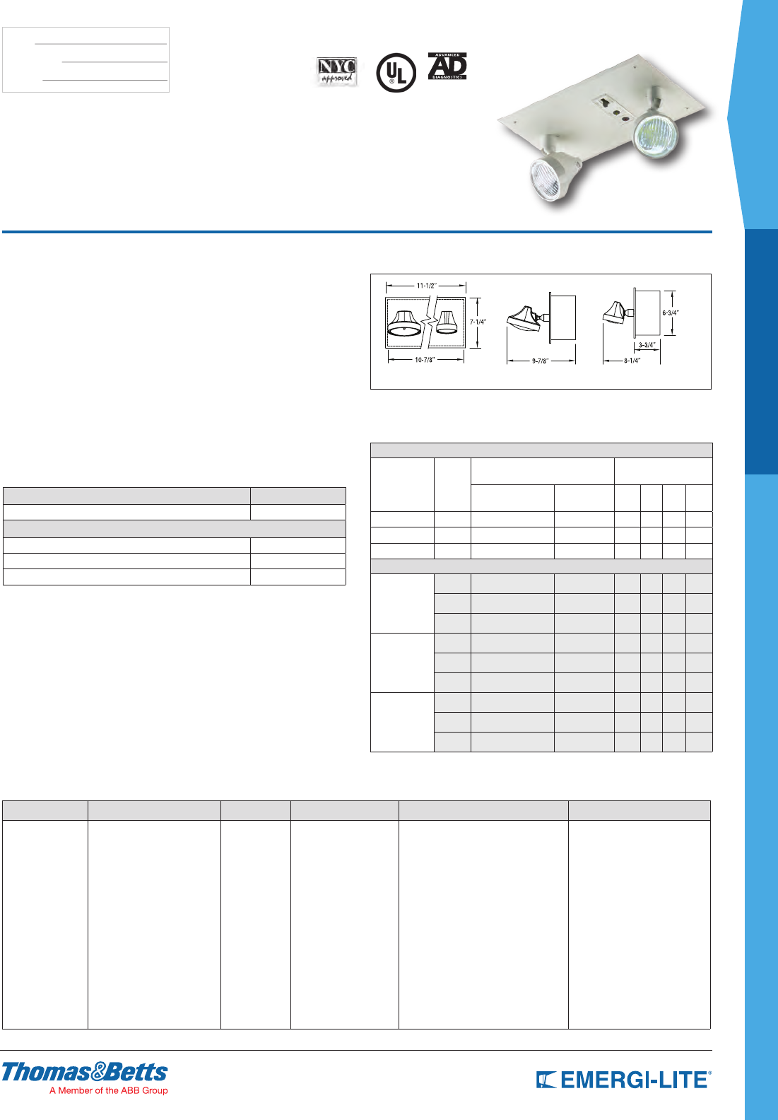
TS Series
6, 12 and 24 Volt T-Bar Units
Dimensions
Dimensions are approximate and subject to change.
EF18 EF9
Features
•Eachunitcomeswithtwo(2)off-whiteEF-18lampheads(standard)withone
9Wwedge-basedlampperhead.Provisionsformountingthreeheadsare
included
•Constructedof20-gaugesteelwithanoff-whitebakedenamelnish
•Availablewithsealed,maintenance-freeNickel-Cadmium,LongLifeLead,or
Lead-Calciumbatteries
•PulsePlusChargercircuitryoffers120/277Vinput60Hz.,0.3/0.15A
(otherinputsavailable),fusedoutputcircuit(s),dualdiagnosticindicator
lights,temperaturecompensatedcharger,sealedrelay,lowvoltagebattery
disconnect,brownoutprotectionandlockout(automaticbatteryconnect)
•Fully-recessedhousingforunobtrusiveuseinT-Barceilings.Aremovable
coveronthebackboxallowsforeaseofinstallationandfullaccesstothe
batteryandcharger
•ULListed.ComplieswithNEC,LifeSafetyCodeandOSHA.Approvedusein
theCommonwealthofPennsylvaniaandNewYorkCity
•3-yearfullwarranty,excludinglamps,pilotlightsandfuses
Unit Rating
Furnished standard with two 9 watt High Intensity Incandescent lamps.
UNIT EQUIPMENT – NO REMOTE CAPABILITY
Sealed
Maintenance-
Free Battery
Types
D.C.
Voltage
Model
Number
Watts to 87-1/2% of rated
battery voltage* Cabinet
Size
11⁄2 hrs 2 hrs 3 hrs 4 hrs
Nickel-Cadmium 6 TSC18-2 18 12 9 6 S
Long Life Lead 6 TSE18-2 18 11 8 6 S
Lead-Calcium 6 TSM18-2 18 12 10 7 S
UNIT EQUIPMENT – WITH REMOTE CAPABILITY
Nickel-Cadmium
6 TSC25-2 25 18 12 9 S
12 12TSC36-2 36 21 15 12 S
12 12TSC50-2 50 36 25 18 S
24 24TSC100-2** 100 73 50 37 S**
Long Life Lead
6 TSE27-2 27 19 14 10 S
6 TSE36-2 36 24 17 13 S
6 TSE54-2 50 32 22 16 S
6 TSE110-2 110 74 57 43 L
12 12TSE36-2 36 24 17 13 S
12 12TSE54-2 54 37 28 21 S
12 12TSE72-2 72 62 43 33 L
12 12TSE110-2 110 74 57 43 L
24 24TSE72-2 72 48 34 26 L
24 24TSE110-2 110 74 57 43 L
Lead-Calcium
6 TSM27-2 27 18 14 10 S
6 TSM36-2 36 25 20 14 S
6 TSM54-2 54 37 28 21 S
6 TSM81-2 81 54 42 30 L
6 TSM110-2 110 72 56 40 L
12 12TSM36-2 36 25 20 14 S
12 12TSM54-2 54 37 28 21 S
12 12TSM110-2 110 72 56 40 L
24 24TSM110-2 110 72 56 40 L
* National Electrical Code Specification
** AD & ADNA not available = New York City Approved
Cabinet Size Dimensions
a b
S 3-1/4” 4-5/8”
L 5-5/8” 7-1/8”
23-3/4”
13-1/8”
11-1/2”
7-1/4”
Accessories (order as a separate item)
DESCRIPTION SUFFIX
Remote Test Switch (metal face plate) RTS
Remote Test Switch (plastic face plate) RTS-1
19
ARCHITECTURAL
SPEC GRADE
TYPE:
CATALOG #:
NOTES:
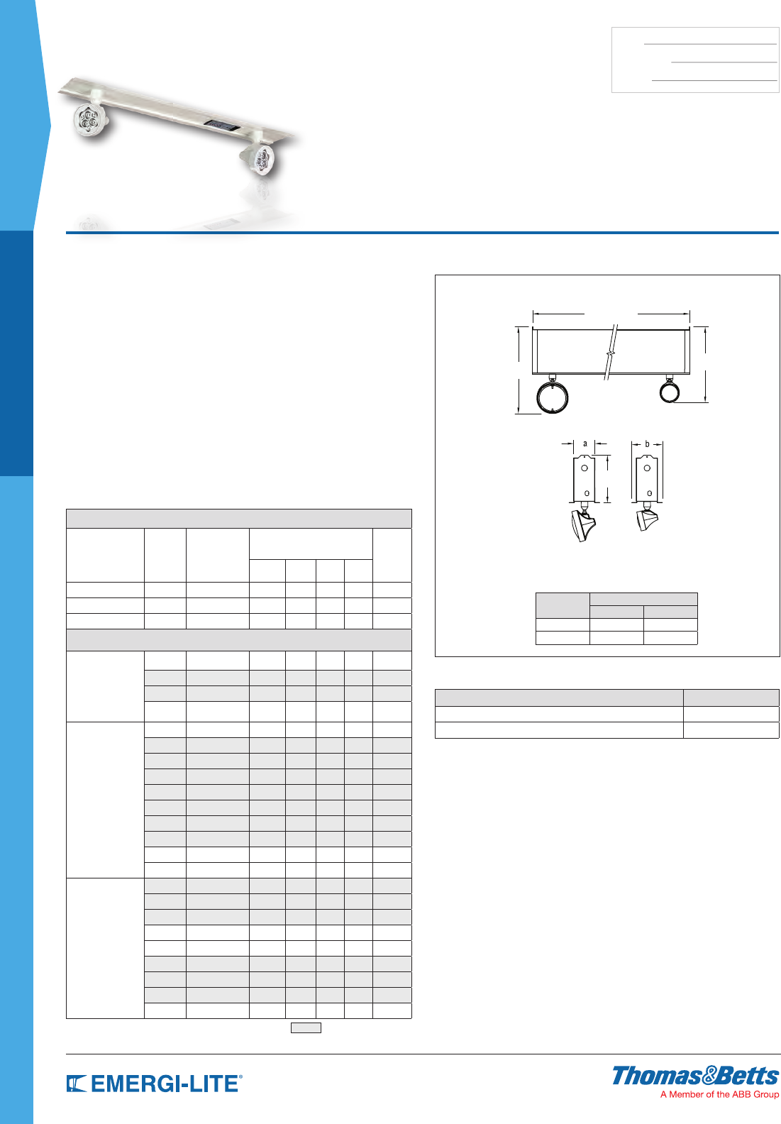
TS Series
6, 12 and 24 Volt T-Bar Units
How to Order
SERIES SERIES/BATTERY TYPE/
CAPACITY # OF HEADS HEAD STYLE LAMP TYPE/WATTAGE OPTIONS
Blank= Factory
white
B= Black enclosure
TSC18= 6V-18W Ni-Cd
TSC25= 6V-25W Ni-Cd
TSE18= 6V-18W Long Life Lead
TSE27= 6V-27W Long Life Lead
TSE36= 6V-36W Long Life Lead
TSE54= 6V-54W Long Life Lead
TSE110= 6V-110W Long Life Lead
TSM18= 6V-18W Lead-Acid
TSM27= 6V-27W Lead-Acid
TSM36= 6V-36W Lead-Acid
TSM54= 6V-54W Lead-Acid
TSM81= 6V-81W Lead-Acid
TSM110= 6V-110W Lead-Acid
12TSC36= 12V-36W Ni-Cd
12TSC50= 12V-50W Ni-Cd
12TSE36= 12V-36W Long Life Lead
12TSE54= 12V-54W Long Life Lead
12TSE72= 12V-72W Long Life Lead
12TSE110= 12V-110W
Long Life Lead
12TSM36= 12V-36W Long Life Lead
12TSM54= 12V-54W Long Life Lead
12TSM110= 12V-110W
Long Life Lead
24TSC100= 24V-100W Ni-Cd
24TSE72= 24V-72W Long Life Lead
24TSE110= 24V-110W
Long Life Lead
24TSM110= 24V-110W Lead-Acid
-0= No head
-1= One head
-2= Two heads
-3= Three heads
Blank= EF18
(PAR 36 plastic)
28= EF28 (PAR 36 metal)
9= EF9 mini plastic
10= EF10 Mini
plastic MR16
150= EF150 MR16
lamp heads
Blank= 6V-9W or 12V-9W
Inc. wedge base
LA= 6V-4W, MR16 LED*
LG= 12V-4W, MR16 LED*
LL= 24V-4W, MR16 LED*
LI= 12V-5W, MR16 LED*
LJ= 12V-6W, MR16 LED*
H_= Halogen bi-pin
I_= Inc. DC-bayonet
U_= Inc. Sld-beam**
X_= Halogen sld-beam**
Z_= Inc. wedge
M_= Halogen MR16*
-AD= Advanced Diagnostics
(audible)*
-ADNA= Advanced Diagnostics
(non-audible)*
-V= Voltmeter
-A= Ammeter
-D1= Time Delay (5 minutes)
-D2= Time Delay (10 minutes)
-D3= Time Delay (15 minutes)
-NEX= Nexus® wired
(consult your sales
representative)
-NEXRF= Nexus® wireless
(consult your sales
representative)
NOTE: For a complete list of available
lamp types, please refer to the
lamp data on pages 146-147
* Available with EF10 and EF150
lamp heads only
** Available with the EF18 lamp head only
* Minimum lamp load required: 20% of unit
capacity Not available with 100W Ni-Cd 24V
Example: BTSC17-210L_-AD
20
SPEC GRADE
ARCHITECTURAL
TYPE:
CATALOG #:
NOTES:
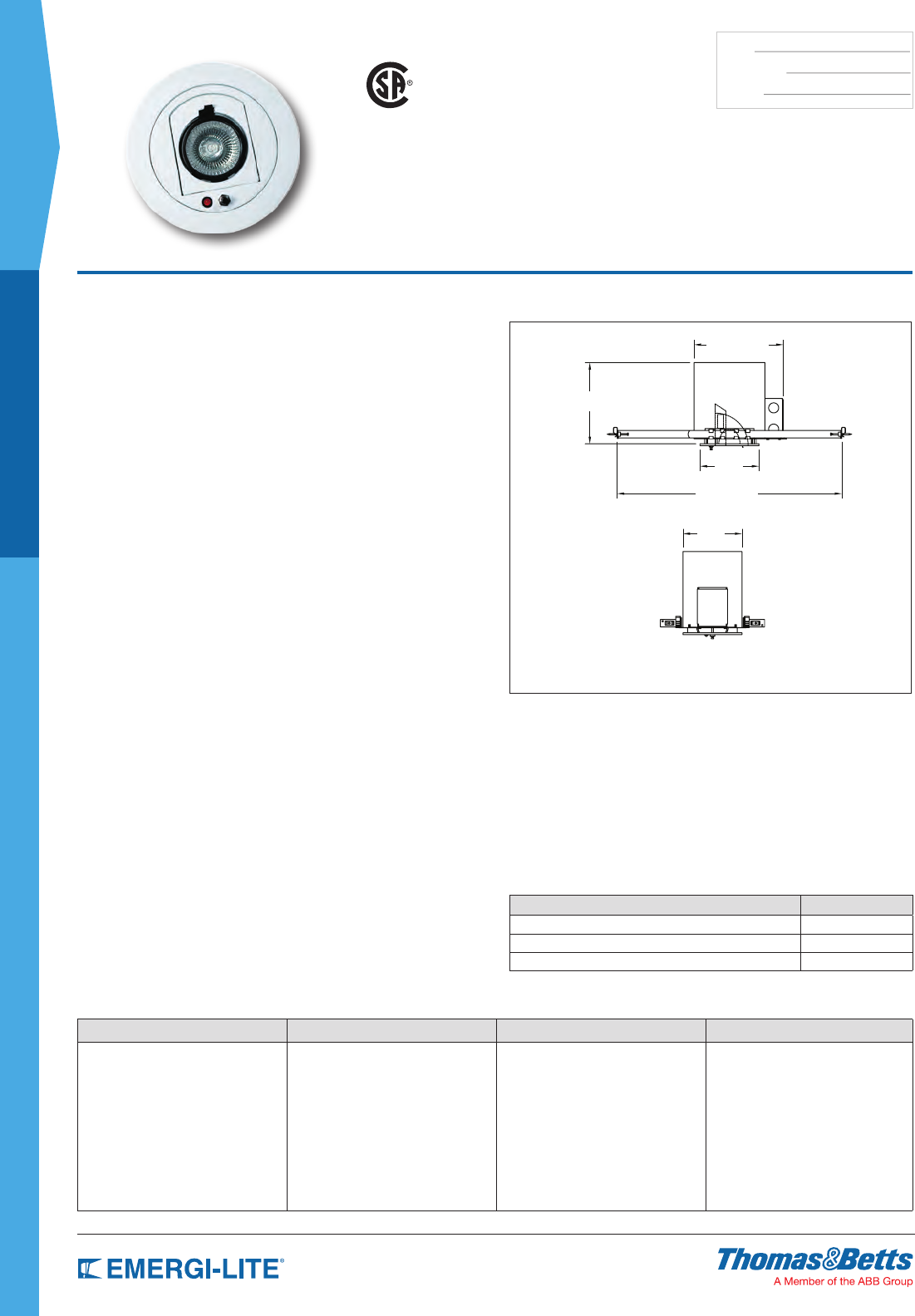
EFR2™ Distinction Series
Self-Powered Recessed Down Light
How to Order
SERIES COLOR STANDARD MODEL
EFR2= Distinction WH= White
BK= Black
BN= Brushed nickel
CH= Chrome
PB= Polished brass
SP= Self-Powered -U= USA model
Example: EFR2WHSP-U
Dimensions
Dimensions are approximate and subject to change.
EFR2Seriesincludingbackbox
US
Standard Features
•One6V-6WMR16halogenlampcanbeadjustedbyrotatingthegimbal
through359°inazimuthandorpositioningthelampthrough90°inpitch
•Therecessedgimbalisconstructedofdurable,powder-coated,Die-Cast
aluminum.Ametal,fully-recessedbackboxhousestheelectronics,battery
andwiring
•Self-Powered.Sealedlong-lifeNickel-Cadmiumbatteryforoperationofat
least90minutesasrequiredbyNFPA101LifeSafetyCode
•Powerrequirements:120V,60Hz,0.046A,4.17W;277V,60Hz,0.024A,
4.76W
•Operationiscompletelyautomatic.Abrownoutsensitivetransfercircuit
automaticallyconnectstheemergencylampuponeithercompletelossof
normalACpowerorwhentheACvoltagedropsdowntoapointwhere
normalAClightingwillnotfunction.TheunitalsomonitorsDCbatteryvoltage
anddisconnectsthelampsbeforethebatterycangointodeepdischarge
(inconditionsofextendedpowerfailures).WhentheACpowerisrestored
thechargerautomaticallyreturnsthebatterytofullchargein24hours,and
monitorsthebatterytomaintainfullcharge
•Includesbarhangerkit.Quickdisconnectfeatureallowsthecontractorto
easilyinstallthetrimonthehousing
•Easytoaccessformaintenancepersonnel
•EvaluatedtoUL924standards
Unit Data
Therecessedgimbalisconstructedofadurable,powdercoated,Die-Cast
aluminumandisfurnishedwithanMR16lampsourcepoweredby
asealedNickel-Cadmiumbattery.Theunitwillbefurnishedwitha
metal,fullyrecessedbackboxtohousetheelectronics,batteryand
allassociatedwiring.Furnishedstandardwithbarhangerkit.
Thelightsourceshallbeadjustedbyrotatingthegimbalthrough
359°inazimuthandorpositioningthelampthrough90°inpitch.
Thelightsourcewillbe6volts6wattsMR16halogenlamp.The
emergencylightingfixturewillprovideilluminationintheemergency
modedirectlyfromtheinternallymountedNickel-Cadmiumbattery.The
durationofoperationprovidedbytheNickel-Cadmiumbatterywillbe
nolessthan90minutesasrequiredbyNFPA101LifeSafetyCode.
Charger
Electricalpowerrequirements: 120V,60Hz,0.046A,4.17W
277V,60Hz,0.024A,4.76W
Transfer:Dusttightrelayautomaticallyandinstantly
energizeslamploaduponfailureofACsupply.
Batteryprotectioncircuitautomaticallyshutsdownlampload
whenbatteryreaches87-1/2%ofitsratedvoltage.Charger
is100%solidstate,includesauto-equalize,temperature
compensationandiscontrolledbya1%Zenerreference.
Accessories (order as a separate item)
DESCRIPTION SUFFIX
Remote Test Switch (metal face plate) RTS
Remote Test Switch (plastic face plate) RTS-1
Replacement lamp number (6V-6W) 580.0074-E
7-9/16”
6-7/8”
14”
5”
5”
21
ARCHITECTURAL
SPEC GRADE
TYPE:
CATALOG #:
NOTES:
GS Series
6 Volt Recessed Down Light
Dimensions
Dimensions are approximate and subject to change.
14” to 24”
10-1/4”
6-1/2”
7-3/4”
8-1/2”
7”
How to Order
For standard units without options only order Series, Battery and Watts. Options are added to units by listing suffix at end of model number.
NOTE: Includes standard lamp (570.0016)
COLOR SERIES BATTERY TYPE LAMP OPTION MOUTING OPTION MODEL
Blank= White
B= Black*
GS= Series M10= 10W Lead-Calcium
E9= 9W Long Life Lead
C18= Nickel-Cadmium
Wedge Base 9W standard* BH= Bar hanger
(standard)
-NYC=Approved model*
* Black not available on GSM10-BH
* Only C18 has other lamps available. For a complete list
of available lamp types, please refer to the lamp data on
pages 146-147. * Includes 12 watt lamp and metal trim.
Example: GSM10BH-NYC
Standard Features
•Anadjustablegimbaldirectsthelightfromone(1)6Vwedge-basePAR36
lamphead
•Thelow-proletrimringismoldedintoughpolycarbonatewithasemi-gloss
whitenishtocomplementavarietyofceilings.Thefully-recessedbackbox
isconstructedof20-gaugesteel
•Availablewithsealed,maintenance-freeNickel-Cadmium,LongLifeLead,or
Lead-Calciumbatteries
•PulsePlusChargercircuitryoffers120/277VAC60Hz.,0.3/0.15Amp,fused
outputcircuit(s),longlifeLEDpilotindicator,temperaturecompensated,
sealedrelay,lowvoltagebatterydisconnect,brownoutprotectionandlock
out(automaticbatteryconnect)
•Inconspicuouslymountedandeasilyaccessed.ThetestswitchandLEDpilot
lightarelocatedonthesideofthelampringonthestandardunit
•Aslide-outchassisandtwoquick-connectplugsmakeinstallationand
servicingeasy.Adjustablebarhangersincluded
•ULListed.ComplieswithNEC,LifeSafetyCodeandOSHA
•3-yearfullwarranty,excludinglamps,pilotlightsandfuses
Unit Rating
The GSM10 unit is furnished with one 6V-10W wedge-base lamp. Other wattages available, see lamp data sheet for selection of PAR lamps.
Sealed Maintenance-Free Battery Types D.C. Voltage Model Number
Watts to 87-1/2% of rated
battery voltage* A.C. Voltage
11⁄2 hrs 2 hrs 3 hrs 4 hrs Unit Dual Voltage Current Maximum
Lead-Calcium 6 GSM10-BH 10 8 – – 120VAC .3A
Long Life Lead 6 GSE9-BH 8 – – –
UNIT EQUIPMENT – WITH REMOTE CAPABILITY
Nickel-Cadmium 6 GSC18-BH 18 12 9 – 277VAC .15A
* National Electrical Code Specification = New York City Approved
Accessories (order as separate item)
DESCRIPTION SUFFIX
Remote Test Switch (metal face plate) RTS
Remote Test Switch (plastic face plate) RTS-1
22
SPEC GRADE
ARCHITECTURAL
TYPE:
CATALOG #:
NOTES:
Design upgrade: introducing new features
1.Easierinstallation:component-freeback-boxhousingandcanopycanbe
installedinadvance,likearegularjunctionbox.
2.20–30%lesspowerconsumption:max.1.4W(AC-onlymodels)andmax.
2.3W(Self-Powered)
3.Bi-colorLEDpilotlightallowsvisualdiagnosticwithouttheneedtoopenthe
unit(self-testanddiagnosticoption)
4.ListedbytheUnderwritingLaboratoriesULListed
5.AlsoavailablewithwhiteLEDsforcustom-designlegends:pictograms,
specialwording,etc.(Askyoursalesrepresentatives)
Features
•Designedtoachievesuperiorvisualclarityandperformancewitharedand
greenLEDlightsource.
•Clearacrylicpanelprovidesoptimumlighttransmission.Illuminationis100%
inbothACandemergencymode.
•Computerengravingisusedtocrisplydeneeachletterandchevron.LED
sensitiveinksareformulatedtoprovidearichcolorinredorgreen.Choiceof
legendbackgroundincludesclear(forsingleface),whiteormirror(forsingle
ordoublefacesigns).
•Cleantrimplatedesigneliminatesvisiblefasteners.Choiceoftrimplates:
circularorangular.Standardnishisbrushedaluminumforthehousing,
trimplate,trimringandcanopy.
•Self-Poweredmodelscontainasealedmaintenance-freeNickel-Cadmium
batterythatprovides90minutesofemergencyillumination.
•Two-wireuniversal120through277VAC,50/60HzforAC-onlyand
Self-Poweredmodels.AC-onlysignsconsumemaximum1.4W.Self-
Poweredsignsuse2.3Wmaxwhilerechargingbatteries.Solidstatetransfer
automaticallyandinstantlysuppliestheLEDlampsfromtheback-up
batteryuponfailureofACsupply.Closetoleranceelectroniccircuitactivates
emergencyunitwhenutilitypowerdipsbelownominalvoltageforbrownout
protection.Current-limitedandshort-circuit-proofcharger.Fullbattery
rechargeismadeincompliancewithUL924specications.Testswitch
incorporatesagreenLEDACpilotlight.
•Self-testandsilentdiagnosticisoptionalonallSelf-Poweredmodels.Itis
programmedtoensureproductreadinessandreliabilitybycontinuously
monitoringeverycriticalfunctionoftheunit.Theunitisself-testedforone
minuteevery30days,30minutesevery60daysand90minutesannually.
Whenafaultisdetectedthepilotlightwillchangecolorfromgreentored
andblinkfollowingaparticularcode,identifyingthecause:battery,charger
circuitry,orLEDlamps.
•Modulardesignallowsforseveralmountingcongurations.Atrimring
andtwo27-inchbarhangersareusedforrecessedmountingonwallsor
ceilings.Acanopyallowsforsurfacemountingonceilingsorwallsasback-
orend-mount.Facepanelssnapsecurelyintotrimplateonallmounting
congurations.
•ULlistedtoUL924Standard.
•5-yearfullwarranty.
Electrical
Powerrequirements:120to277VAC,50/60Hz.AC-onlysignsuse1.4watts
max,Self-Poweredsignsuse2.3wattsmaxwhilerechargingbatteries
Available Models
Circulartrimplatemodelsshown.
optionalAngulartrimplateavailable.
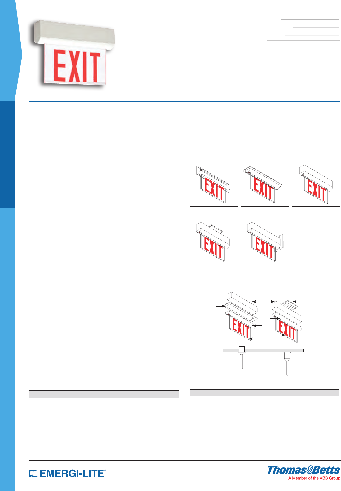
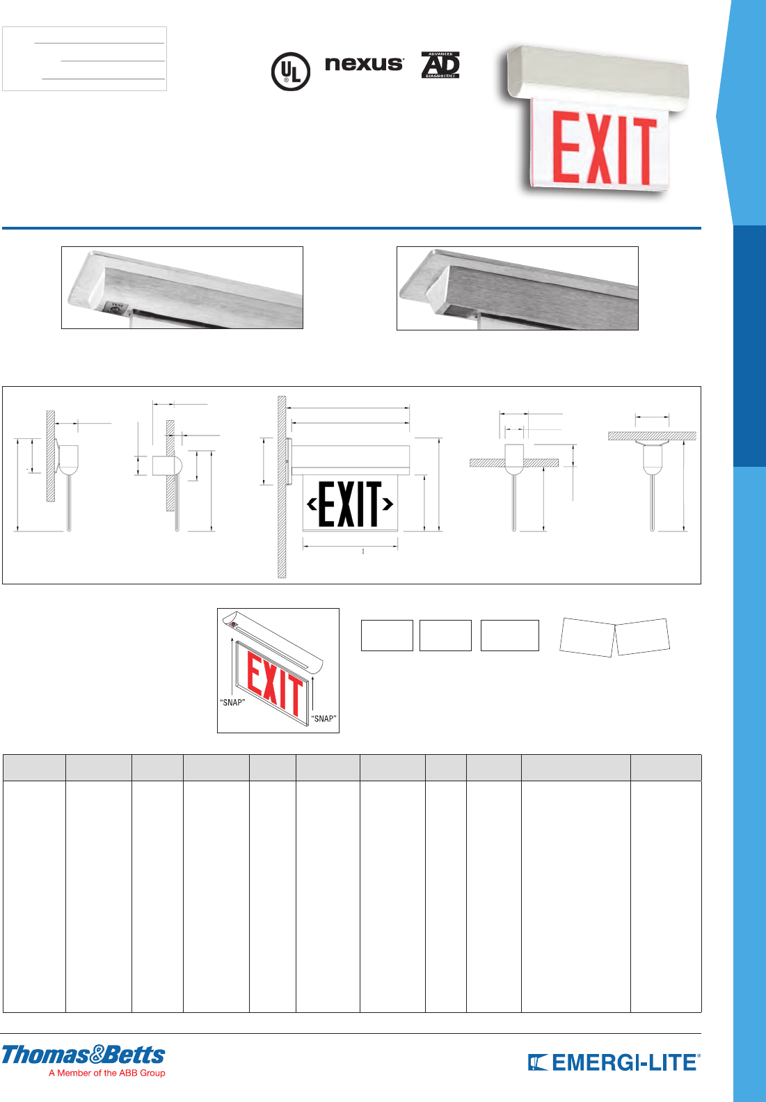
Prestige™ Edge-Lit Series
Die-Cast Aluminum Edge-Lit Exit Sign
Recessed Wall Mount Recessed Ceiling Mount Surface Wall Mount
Surface Ceiling Mount Surface End Mount
Accessories (order as a separate item)
DESCRIPTION SUFFIX
White Pendant P*-WT
Black Pendant P-*BK
Gray Pendant P*-GY
* Custom pendant lengths and colors available, specify (12”, 24”, 36”, etc)
Power Consumption
Model AC Specs DC Specs
AC-only 120 to 277VAC Less than 1.4W
AC/DC-remote 120 to 277VAC Less than 1.4W 6 to 24VDC Less than 1.4W
Self-Powered 120 to 277VAC Less than 2.3W Ni-Cd battery Min. 90 minutes
Self-Powered
diagnostic 120 to 277VAC Less than 2.3W Ni-Cd battery Min. 90 minutes
RecessedModels SurfaceModels
Canopy
Housing
Trim Ring
Trim Plate
Exit Plate
23
ARCHITECTURAL
SPEC GRADE
TYPE:
CATALOG #:
NOTES:
Prestige™ Edge-Lit Series
Die-Cast Aluminum Edge-Lit Exit Sign
Optional
Angular Trim Plate
Standard
Circular Trim Plate
Dimensions
Dimensions are approximate and subject to change.
3-1/4”
2-7/8” 16-3/4” 4” 4-5/8”
2-1/2”
13”
16”
1-1/8”
4-5/8”
12-1/4”
2-1/2”
10-5/8”
6-1/4”
7-1/2”
12-3/8”
8-5/8”
2-7/8”
12-1/8”
4”
Mounting Configurations
Allmountingcongurationsusethesame
basiccomponents.Insertingatrimringallows
forrecessedmountingonwallsorceilings.
Applyingacanopyallowsforsurface
mountingonceilingsorwallsasbackorend
mount.
Arrow (Chevron) Designation
Arrow Right
(R)
Arrow Left
(L)
Double Arrow
(D)
Arrow Right & Left (RL)
Represents each side of a double face panel.
EXIT>
*Wording and chevrons not to scale. For illustration purposes only.
<EXIT <EXIT>
EXIT>
<EXIT
How to Order
HOUSING
COLOR SERIES FACES DESIGNATION LEGEND
COLOR
BACKGROUND
COLOR ARROWS TRIM MOUNTING OPTIONS LEGEND SIZE
Blank=
Brushed
aluminum
W= White
B= Black
PB= Polished
brass
CH= Polished
chrome
BR= Bronze
LX= AC-only
LXN= Self-
Powered
1= Single
face
2= Double
face
N= New
design
R= Red
G= Green
C= Clear
(single
face only)
W= White
M= Mirror
Blank= No
arrow
L= Arrow left
R= Arrow right
RL= Right
and left
(double
face)
D= Double
arrow
UA= Universal
filled
installed
arrows
-A=
Angular
-C=
Circular
Blank=
Universal
mount
S= Surface
mount
(canopy)
Blank= No option
-NEX= Nexus® Wired
(consult your sales
representative)
-NEXRF= Nexus® Wireless
(consult
your sales
representative)
-FA= Fire alarm
-D= Self-Test and
diagnostic
-DC= AC/DC remote
6-24 VDC
-2CKT= Two circuit,
AC only
-FZ= Flasher & buzzer
(Self-Powered only)
-X= Back box shipped
separately
Blank= 6” EXIT
legend
-8= 8” EXIT
legend
(red only)
-LP= Panel
shipped
separately
Example: WLXN2NRWR-A-D
24
SPEC GRADE
ARCHITECTURAL
TYPE:
CATALOG #:
NOTES:
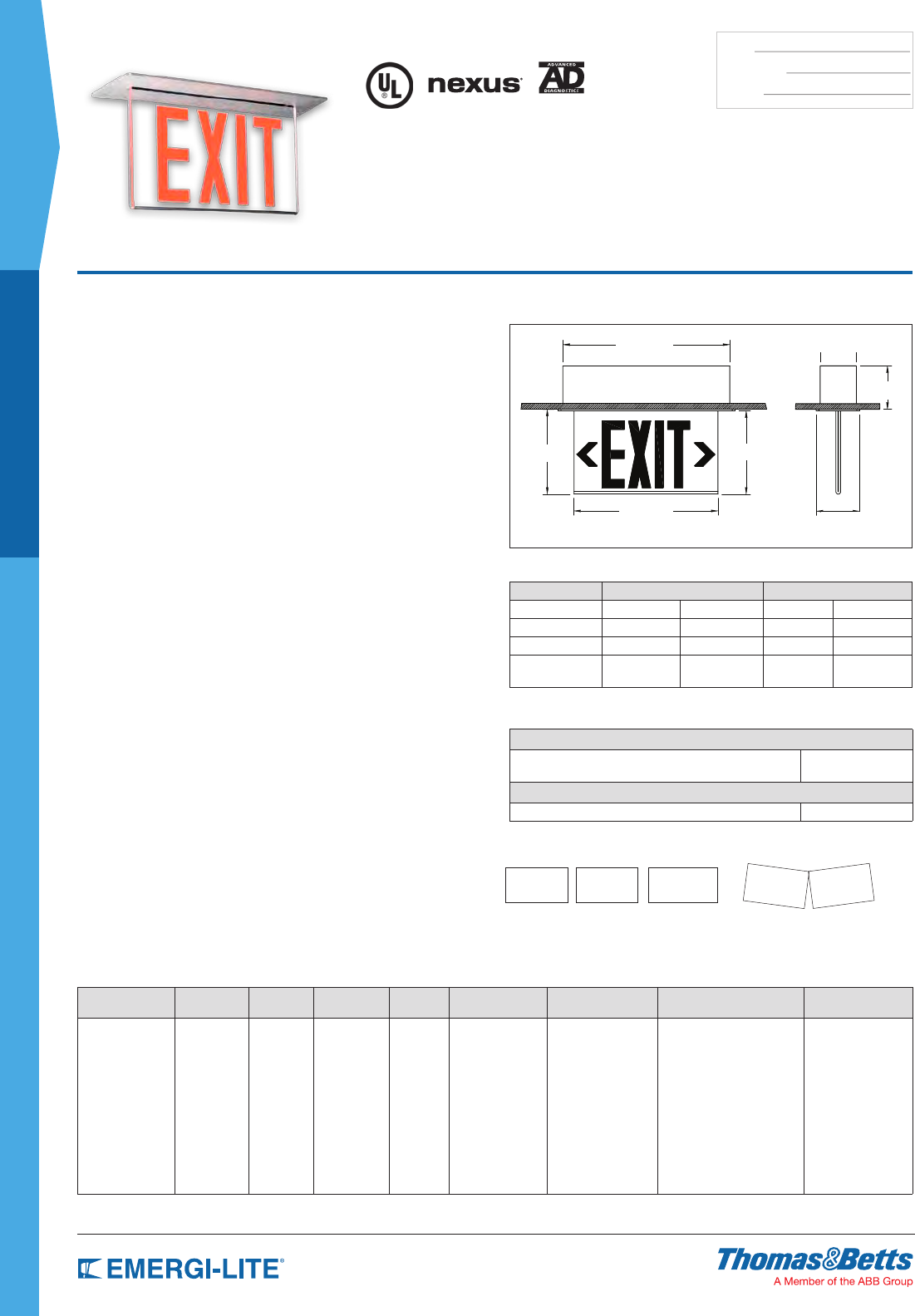
Prestige™ X40 Series
Edge-Lit Recessed Ceiling-Mount Only
Exit Sign
How to Order
HOUSING SERIES FACES DESIGNATION LEGEND
COLOR
BACKGROUND
COLOR ARROWS OPTIONS LEGEND SIZE
Blank= Brushed
aluminum
W= White
B= Black
PB= Polished brass
CH= Polished
chrome
BR= Bronze
LX= AC
LSNX=
Self-Powered
40= Less
panel
42= Single
face
43= Double
face
N= New
design
R= Red
G= Green
C= Clear
(single face
only)
W= White
M= Mirror
Blank= No arrow
L= Arrow left
R= Arrow right
RL = Right & left
(double face)
D= Double arrow
UA= Universal field
installed arrows
Blank= No option
-AD= Advanced Diagnostics
(audible)
-FA= Fire Alarm
-DC= AC/DC remote 6-24 VDC
-2CKT= Two circuit, AC only
-FZ= Flasher & buzzer
(Self-Powered only)
-NEX= Nexus® Wired*
-NEXRF= Nexus® Wireless*
Blank= 6” EXIT
legend
-8= 8” EXIT legend
(red only)
-L= 6” EXIT low
profile panel
-LP= Panel shipped
separately
-X= Back box
shipped
separately
* Consult your sales representative.
Example: WLSNX42NRWR-AD
Dimensions
Dimensions are approximate and subject to change.
Design upgrade: introducing new features
1.Easierinstallation:component-freeback-boxcanbeinstalledinadvance,like
aregularjunctionbox
2.20–30%lesspowerconsumption:max.1.4W(AC-only)andmax.2.3W
(Self-Powered)
3.Bi-colorLEDpilotlightallowsvisualdiagnosticwithouttheneedtoopenthe
unit(self-testanddiagnosticoption)
4.ListedbytheUnderwritingLaboratoriesULListed
5.AlsoavailablewithwhiteLEDsforcustom-designlegends:pictograms,
specialwording,etc.(Askyoursalesrepresentative)
Features
•DesignedtoachievesuperiorvisualclarityandperformancewithanLED
lightsource.HighbrightnessredorgreenLEDstransmitlightdirectlyinto
bothendsofauniqueU-shapedpanel.LEDsensitiveinksareformulatedto
providearichcolorinredorgreen
•Clearacrylicpanelprovidesoptimumlighttransmission.Illuminationis100%
inbothACandemergencymode
•Clearacrylicpanelissilkscreenedandcomputerengraved.Computer
engravingisusedtocrisplydeneeachletterandchevron.LEDsensitive
inksareformulatedtoprovidearichcolorinredorgreen.Choiceoflegend
background:clear(forsingleface),whiteormirror(forsingleordoubleface
signs)
•Ruggedcastbrushedaluminumtrimplate(optionalcolorsavailable).
•LowenergyconsumptionLEDlampsconsumelessthan2.3Wpersign,
singleordoubleface,AC-onlyorSelf-Powered
•Availablewithsealedmaintenance-freeNickel-Cadmiumbatteries.
•Fullyautomaticchargercircuitryofferstwo-wireuniversal120to277VAC
input,temperaturecompensatedcharger,solidstatetransfer,lowvoltage
batterydisconnect,andbrownoutprotection
•Self-testandsilentdiagnosticsareoptionalonallSelf-Poweredmodels.
Diagnosticsareprogrammedtoensureproductreadinessandreliability
bycontinuouslymonitoringeverycriticalfunctionoftheunit.Theunitis
self-testedforoneminuteevery30days,30minutesevery60daysand90
minutesannually.Whenafaultisdetectedthepilotlightwillchangecolor
fromgreentoredandashfollowingaparticularcode,identifyingthecause:
battery,chargercircuitry,orLEDlamps
•Designedtotintegrallywitha20gaugesteelbackbox.Eachunitincludesa
barhangerkit
•ULlistedtoUL924Standard
•PrestigeLEDSeriessignsareunaffectedbythevibrations,ambient
temperatureswingsandtypicalpowersurgesdetrimentaltostandardexit
lightsources
•5-yearfullwarranty
Power Consumption Chart
Model AC Specs DC Specs
AC-only 120 to 277VAC Less than 1.4W
AC/DC-remote 120 to 277VAC Less than 1.4W 6 to 24VDC Less than 1.4W
Self-Powered 120 to 277VAC Less than 2.3W Ni-Cd battery Min. 90 minutes
Self-Powered
diagnostic 120 to 277VAC Less than 2.3W Ni-Cd battery Min. 90 minutes
Accessories (order as a separate item)
DESCRIPTION
Special wording Contact your sales
representative
DESCRIPTION
Two 27-inch adjustable bar hangers* TBH
* Bar hangers supplied with unit, order as replacement only
Arrow (Chevron) Designation
Arrow Right
(R)
Arrow Left
(L)
Double Arrow
(D)
Arrow Right & Left (RL)
Represents each side of a double face panel.
EXIT>
*Wording and chevrons not to scale. For illustration purposes only.
<EXIT <EXIT>
EXIT>
<EXIT
15” 3-1/4”
3-15/16”
7-1/2”
7-5/8”
12-15/16”
3-7/8”
25
ARCHITECTURAL
SPEC GRADE
TYPE:
CATALOG #:
NOTES:
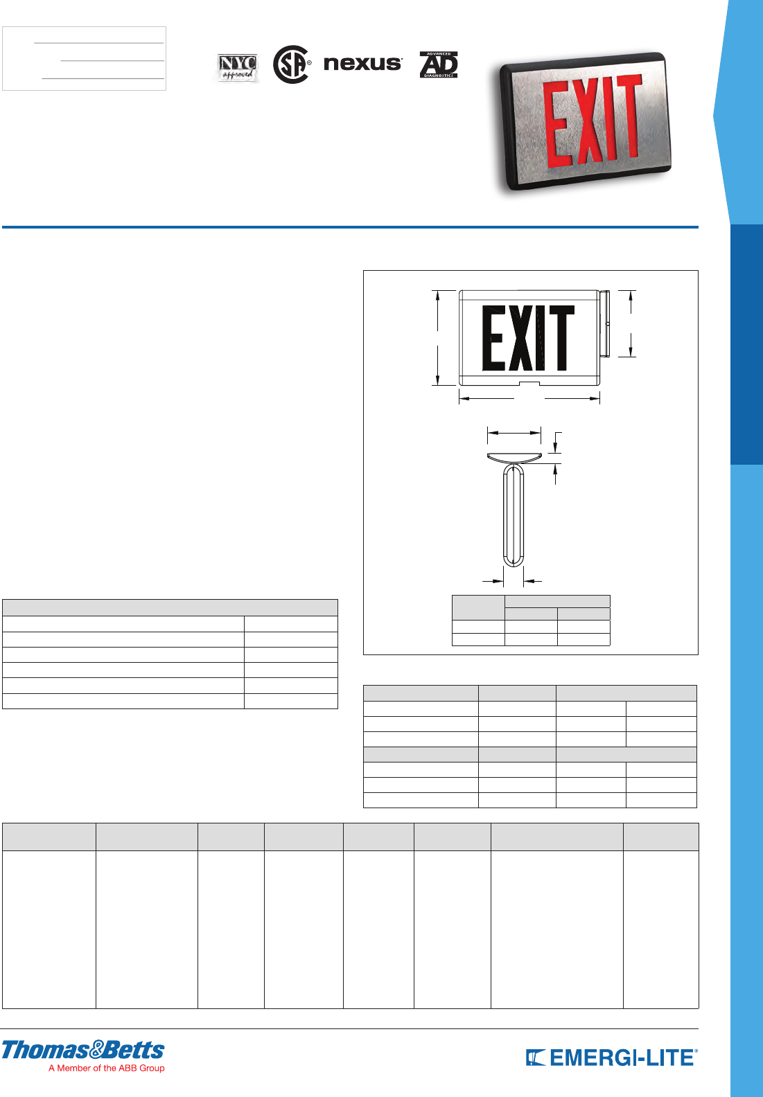
Prestige™ DX Series
Die-Cast Exit Sign
How to Order
COLOR FRAME/
FACEPLATE SERIES # OF FACE LEGEND COLOR LETTERS DIAGNOSTIC
OPTIONS OPTIONS VERSION
Blank= Black/brushed
aluminum
WW= White/white
WA= White/brushed
aluminum
BZ= Bronze/bronze
BB= Black/black
AA= All brushed
aluminum
DXN= Self-Powered unit
DX= AC/DC*
1= Single face
2= Double face
R= Red
G= Green
Open face
RW= Red on white
GW= Green
on white
Blank= 6”
letters
8= 8” letters
Blank= Standard
NEX= NEXUS®
wired (consult
your sales
representative)
Blank= Standard
DL= Damp Location
FA= Fire alarm activated flasher
FZ= Flasher buzzer
(Self-Powered only)*
VR= Vandal Resistant screws
VR1= Polycarbonate shield with
tamper proof screws
2CKT= 2 Circuit (120/120 or
277/277, AC only)*
-N= New design*
* Not available with
Nexus® Wireless option
* Open face required for
special wording *Not available with Nexus® option
* Not required for
8” letters
Example: DXN1R-N
Dimensions
Dimensions are approximate and subject to change.
4-5/8”
1-3/4”
7/8”
6-1/4”
a
b
Letters Dimensions
a b
6” 8-7/8” 13-1/16”
8” 10-1/2” 15-1/4”
Features
•RedandgreenLEDlightsource
•ConstructedofDie-Castaluminum.Finishedwithadeepbrushedfaceand
blackbody.Optionalnishesavailable.SelfContained.Batteriesandcircuitry
arelocatedinsidetheexithousing
•Availablewithsealedmaintenance-freeNickel-Cadmiumbatteriesthat
provide90minutesofemergencyoperation.BatteriesrechargeperUL924
requirements
•Fullyautomaticchargerissolidstate.AllmodelsareUniversal2-wire,
120through277VAC,50/60Hz
•Continuousself-diagnosticmonitoring.Self-testingperLifeSafetyCode
requirements.Diagnostic/SelfTestcircuitryisstandardonallSelf-Powered
models.Thiscircuitryisprogrammedtoensuretheexit’sreadinessand
reliabilitybycontinuouslymonitoringeverycriticalfunctionoftheunit.Ifa
problemoccurs,asingle“servicerequired”indicatorilluminatesimmediately.
Adetaileddiagnosticdisplaythatwillfurtherindicatethenatureofthefaultis
locatedontheinsideoftheexitsign,outofsightfromthegeneralpublic.
Theselftestwilltesttheunitforaminimumof30secondsevery30days,30
minutesevery60daysand90minutesannually
•Canbewall,endorceilingmounted
•EvaluatedtoUL924Standard.AC-OnlySignsareListedforuseindamp
locations
•Unaffectedbythevibrations,ambienttemperatureswingsandtypicalpower
surgesdetrimentaltostandardexitlightsources
•Universaldirectionalchevronknockoutsarecompletelyconcealedandeasily
removedfromthefaceplate
•5-yearfullwarranty
Power Consumption
Model 6” AC Specs DC Specs
AC-only 120 to 277VAC – –
AC/DC-remote 120 to 277VAC 6 to 48VDC Less than 1.5W
Self-Powered 120 to 277VAC Ni-Cd battery Min. 90 minutes
Model 8” AC Specs DC Specs
AC-only 120 to 277VAC – –
AC/DC 120 to 277VAC 6 to 24VDC 1.6W
Self-Powered 120 to 277VAC Ni-Cd battery Min. 90 minutes
Accessories (order as a separate item)
DESCRIPTION SUFFIX
White Pendant PD**W
Black Pendant PD**B
Pendant Mount Gray PD**GY
Wire Guard (Wall Mount) (6 in.) WG12-E
Wire Guard (Ceiling Mount) (6 in.) WG5-E
Wire Guard (End Mount) (6 in.) WG5-E
* Specify Pendant Length (12”, 24”, 36”, etc)
US
26
SPEC GRADE
ARCHITECTURAL
TYPE:
CATALOG #:
NOTES:
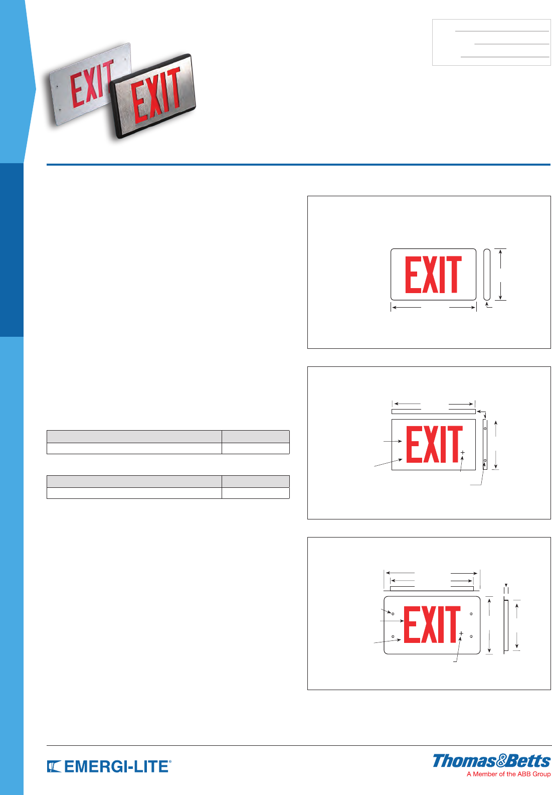
Prestige™ Floor
Proximity Series
Master with Remote Exit Sign
Dimensions
Dimensions are approximate and subject to change.
FloorProximitySlaveSurfaceMount
LLGS
LLRS
FloorProximitySlaveRecessedMount
LLGR
LLRR
Self-Powered/AC-OnlyMaster
DXN1G-M-N
DX1G-M-N
Standard Features
•LowenergyconsumptionLEDlightsource(seePowerConsumptionchart).
RedandgreenLEDsprovideexcellentvisualperformance,highreliabilityand
lowmaintenancecosts
•Self-PoweredMasterUnitshaveself-containedbatteriesandcircuitryinside
thehousing
•Availablewithsealedmaintenance-freeNickel-Cadmiumbatteriesforsuperior
performanceandlonglife.Provides90minutesofemergencyoperationand
remotepowerforProximityEXITsign
•RemoteFloorProximityEXITsignshavepoweranddiagnosticssuppliedfrom
theDX/DXNSeriesMasterUnitsonly
•StandaloneAC-OnlyandSelf-PoweredUnits:120/277VACdualvoltage
•MasterEXITsigncomesstandardwiththeSelf-Test/DiagnosticFeature.Its
circuitryalsomonitorsandsuppliesdiagnosticstotheRemoteFloorProximity
EXITsign.Theself-test/diagnosticfeaturecontinuouslymonitorsthecharger
assembly,batteryandLEDassemblycurrent.Ifafaultisindicated,the
“externalservice”requiredindicatorwillilluminate.Theinternalfaultindicators
willthenindicatethenatureofthefault.Theself-testdiagnosticwillselftest
forminimum30secondsevery30days,30minutesevery60daysand90
minutesannually.MeetsNFPA101LifeSafetyCoderequirementsforperiodic
testing
•Availableforsurfaceorrecessedmountingatoorlevel
•EvaluatedtoUL924Standardforoorproximityapplications
•5-yearfullwarranty.Eachunitisfullytested
8-7/8”
1-5/8”
13-1/4”
14-1/8”
Red or Green
LED Light Source
Red or Green
LED Light Source
4 Vandal-resistant screws
Mounting Center
4 Vandal-resistant screws
Polycarbonate
Lens
Polycarbonate
Lens
Mounting Center
1-1/8”
1-1/8”
9-3/4” 8-1/16”
8-5/8”
15-1/2”
13-7/8”
Accessories (order as a separate item)
DESCRIPTION SUFFIX
Wire Guard (for floor proximity recessed) WG11-E
Features (optional)
DESCRIPTION SUFFIX
Vandal-Resistant shield and screws VR1
27
ARCHITECTURAL
SPEC GRADE
TYPE:
CATALOG #:
NOTES:
Prestige™ Floor
Proximity Series
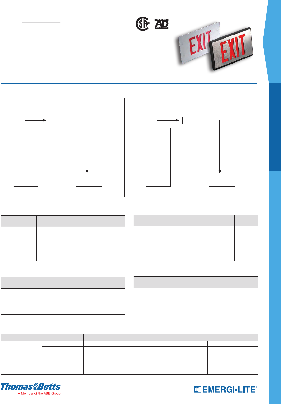
How to Order for a Typical Application
Self-PoweredMasterwithFloorProximityUnit AC-OnlyMasterwithFloorProximityUnit2CircuitApplication
Low
Voltage Wire
Low
Voltage Wire
120/277
Volt Input
120/277
Volt Input
2 Circuit
Self-Powered Master
Example Model #:
DXN1G-M-N
AC-Only Master
Example Model #:
DX1G-M-2CKT-N
Example Model #: LLGS Example Model #: LLGS
Floor Proximity
Surface or
Recessed
Floor Proximity
Surface or
Recessed
EXIT EXIT
EXIT EXIT
How to Order
Self-Powered Master (Unit for above door)
COLOR
OPTION
PREFIX
SERIES FACES STENCIL FACE
LAMP COLOR
MASTER
UNIT
STANDARD
SERIES
DESIGNATOR
Blank=
Brushed
alum. face,
black body
WW= All
white
BB= All
black
DXN 1= Single
face
2= Double
face
R= Red
G= G reen open
face*
RW= Red/white
GW= Green/white
-M -N
Example: DXN1G-M-N
Floor Proximity Unit (Unit on side of door)
COLOR
OPTION
PREFIX
SERIES STENCIL FACE
LAMP COLOR MOUNTING OPTION
Blank=
Brushed
alum. face,
black body
W= All white
B= All black
LL R= Red
G= Green
RW= Red/white
GW= Green/white
R= Recessed
S= Surface
-VR1= Vandal-
resistant screws/
polycarbonate shield
Example: LLGS-VR1
* Open face required for special wording (please contact your sales representative)
How to Order
AC-Only Master (Unit for above door)
COLOR
OPTION
PREFIX
SERIES FACES STENCIL FACE MASTER
UNIT CIRCUIT
STANDARD
SERIES
DESIGNATOR
Blank=
Brushed
alum. face,
black body
WW= All
white
BB= All
black
DX 1= Single
face
2= Double
face
R= Red
G= Green open
face*
RW= Red/white
GW= Green/white
-M -2CKT -N
Example: DX1G-M-2CKT-N
Floor Proximity Unit (Unit on side of door)
COLOR
OPTION
PREFIX
SERIES STENCIL FACE
LAMP COLOR MOUNTING OPTION
Blank=
Brushed
alum. face,
black body
W= All white
B= All black
LL R= Red
G= Green
R= Recessed
S= Surface
-VR1= Vandal-
resistant screws/
polycarbonate shield
Example: LL-GS-VR1
* Open face required for special wording (please contact your sales representative)
Power Consumption Chart
Color Model AC Specs DC Specs
Red
AC-only 120/277VAC 1.3W – –
AC-2 circuit 120/277 and 277/277VAC 2.6W – –
Self-Powered 120/277VAC 3.8W Ni-Cd battery Min. 90 minutes
Green
AC-only 120/277VAC 1W – –
AC-2 circuit 120/277 and 277/277 VAC 3.3W – –
Self-Powered 120/277VAC 5W Ni-Cd battery Min. 90 minutes
US
SPEC GRADE
29
COMMERCIAL
X10 LED Series 45
Prestige™ Recessed
Economizer Series 46
Prestige™ Economizer Series 47
Preceptor™ Die-Cast Series 48
Preceptor™ Recessed Series 49
Preceptor™ Remote
Capacity Series 50
Special Wording Configuration 51
Premier™ Battery Series 30
Premier™ Combo Series 31
Premier™ Exit Series 32
Provider™ PRO-2N/ PRO-3N Series 33
EC-2/ECX-2 Series 34
ECC & ECM Series 35
JC Series 36
JA Series 37
JS Series 38-39
LSE Series 40
LC Series 41
LS Series 42-43
24 LS & 24 LC Series 44
SPEC GRADE
COMMERCIAL
Table of Contents
30
SPEC GRADE
COMMERCIAL
TYPE:
CATALOG #:
NOTES:
How to Order
HOUSING COLOR SERIES/CAPACITY # OF LAMPS LAMP TYPE/WATTAGE UNIT TYPE OPTIONS
Blank= White
B= Black
PR18M= 6V-18W Lead-Calcium
PR30M= 6V-30W Lead-Calcium
PR60M= 6V-60W Lead-Calcium
12PR40M= 12V-40W Lead-Calcium
12PR60M= 12V-60W Lead-Calcium
12PR72M= 12V-72W Lead-Calcium
PR20NC= 6V-20W Ni-Cd
12PR40NC= 12V-40W Ni-Cd
12PR50NC= 12V-50W Ni-Cd
Blank= No head
2= 2 heads
LA= 6V-4W, MR16 LED
LG= 12V-4W, MR16 LED
LI= 12V-5W, MR16 LED
LJ= 12V-6W, MR16 LED
MI= 6V-6W MR16
MJ= 6V-10W MR16
MO= 12V-10W MR16
MK= 12V-12W MR16
MG=12V-20W MR16*
Blank= Standard
-D= Advanced Diagnostics
(non-audible)*
-DA= Advanced Diagnostics
(audible)
-NEX= Nexus® Wired (consult
your sales representative)
-NEXRF= NEXUS® wireless
(consult your sales
representative)
Blank= No option
-D1= Time Delay (5 minutes)
-D2= Time Delay (10 minutes)
-D3= Time Delay (15 minutes)
-CM= Ceiling mount
-DL= Damp Location
-PM= Pendant mount
* Not available with Damp Location
* Minimum lamp load required: 20% of
unit capacity
Example: PR18M2MI
Dimensions
Dimensions are approximate and subject to change.
37⁄8”
Premier™ Series
Thermoplastic Housing 6V up to 60W & 12V
up to 72W Capacities Emergency Light
Features
• Simple, compact and contemporary design
• Wall-mount or ceiling-mount installation (optional)
• Two-piece housing of injection-molded thermoplastic
• MR16 halogen or LED lamps, shielded by clear
polycarbonate covers
• Sealed, maintenance-free, Lead-Calcium or Nickel-Cadmium batteries
• Dual voltage input: 120/277VAC.
• Total load capacity up to 72W
• UL924 Listed
• Advanced Diagnostic-Audible (optional)
• Certied for Damp Locations (optional)
• NEXUS® interface (optional)
• 5-year full warranty (excluding lamps and fuses)
Power Consumption and Unit Rating
Model AC Specs
Watts to 87-1/2% of rated
battery voltage*
1-1/2 hrs 2 hrs 3 hrs 4 hrs
18M 6V
120/277VAC
18 14 9 -
30M 6V 30 20 15 10
40M 6V 40 30 20 15
60M 6/12V 60 40 30 20
72M 12V 72 54 36 27
20NC 6V
120/277VAC
20 15 10 8
40NC 12V 40 30 20 15
50NC 12V 50 36 24 18
* National Electrical Code Specification
Wire Guards
WG1-E Wall or flat ceiling mount
Flat Ceiling Mount
12-1/4”
10-5/8”
3-7/8”
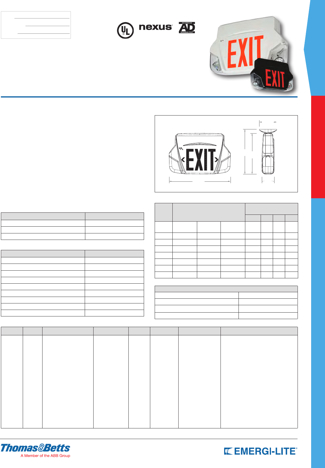
SPEC GRADE
31
COMMERCIAL
TYPE:
CATALOG #:
NOTES:
How to Order
HOUSING
COLOR SERIES VOLTAGE/CAPACITY/
BATTERY FACES LEGEND
COLOR # OF HEADS LAMP TYPE/
WATTAGE OPTIONS
W= White
B= Black
PR=
Series
Lead-Calcium
612M= 6V-12W,
Lead-Calcium
624M= 6V-24W,
Lead-Calcium
1224M= 12V-24W,
Lead-Calcium
Nickel-Metal Hydride
612H= 6V-12W, NiMH,
rated Damp Location
1224H= 12V-24W, NiMH,
rated Damp Location
1240H= 12V-40W, NiMH,
rated Damp Location
1250H= 12V-50W, NiMH,
rated Damp Location
1= single face
(ceiling or
wall mount)
2= double face
(ceiling mount)
1N= single face
no canopy
(wall mount)
4= universal (2
faces, back
plate and
canopy)
G= Green
legend
R= Red
legend
Blank= No
heads
2= Two heads
LA= 6V-4W, MR16 LED
LG= 12V-4W, MR16 LED
LI= 12V-5W, MR16 LED
LJ= 12V-6W, MR16 LED
MI= 6V-6W, MR16
MJ= 6V-10W, MR16
MO= 12V-10W, MR16
MK= 12V-12W, MR16
MG= 12V-20W, MR16
Blank= No option
-AD= Advanced Diagnostics (audible)
not available with 1250H*
-ADNA= Advanced Diagnostics (non-audible)
not available with 1250H*
-BA= Brushed aluminum exit stencil
-FZ= Flasher buzzer
-FL= Flasher
-FA= Fire alarm activated flasher
-FBF= Flasher buzzer + fire alarm
activated flasher
-D3= Time Delay (15 minutes)
-VR= Tamper-proof screws
-VR1= Polycarbonate shield with
tamper-proof screws
-NEX= NEXUS® wired
(consult your sales representative)*
-NEXRF= NEXUS® wireless
(consult your sales representative)*
*Not available for 612M with “MI” lamp.
Example: WPR612M1R2MI
Features
• Indirect refractive technology provides bright, even illumination
• Choice of MR16 Halogen Lamps, shielded by a clear polycarbonate cover
Optional MR16 LED lamps with a life expectancy of 50,000+ hours
• Exit sign long-life LED light source for low maintenance costs and superior
illumination
• Durable injection-molded thermoplastic housing with push-to-snap design.
Optional vandal-resistant shield with tamper-proof screws
• Available with sealed, maintenance-free, Lead-Calcium or Nickel-Metal
Hydride batteries
• Dual voltage input: 120/277 VAC. Optional advanced diagnostic circuitry,
asher/buzzer, re alarm activated asher
• Remote load capacity up to 50 watts when supplied with no heads
• Available in single or double face congurations both with means for ceiling
mounting. Easy-to-install canopy and eld-selectable snap-in/out chevrons
for quick and easy installation
• UL924 Listed
• 5-year full warranty (excluding lamps and fuses)
Dimensions
Dimensions are approximate and subject to change.
Premier™ Series Combo
Thermoplastic Combination Unit
Accessories (order as a separate item)
DESCRIPTION SUFFIX
Wire Guard (Wall mount) WG2-E
Pendant White 081439-E
Pendant Black 081439-E
* Specify pendant length
REPLACEMENT BATTERIES REPLACEMENT LAMPS
860.0004-E Lead-Calcium 580.0074-E 6V-6W, MR16
022318-E NiMH 6V-12W 580.0079-E 6V-10W, MR16
022319-E NiMH 12V-24W 580.0097-E 6V-4W, MR16 LED
022320-E NiMH 12V-40W, 50W 580.0099-E 12V-10W, MR16
–580.0080-E 12V-12W, MR16
– 580.0075-E 12V-20W, MR16 LED
– 580.0093-E 12V-4W, MR16 LED
– 580.0104-E 12V-5W, MR16 LED
– 580.0106-E 12V-6W, MR16 LED
Power Consumption and Unit Rating
Model AC Specs
Watts to 87-1/2% of rated
battery voltage*
1-1/2 hrs 2 hrs 3 hrs 4 hrs
Exit Sign
Module Battery Type 120/277VAC Less than 2W – – – –
612M Lead-Calcium 120/277VAC 0.11 / 0.05 A 12 8 – –
612H NiMH 120/277VAC 0.11 / 0.05 A 12 9 – –
624M Lead-Calcium 120/277VAC 0.11 / 0.05 A 24 16 12 9
1224M Lead-Calcium 120/277VAC 0.22 / 0.08 A 24 16 12 9
1224H NiMH 120/277VAC 0.22 / 0.08 A 24 18 12 9
1240H NiMH 120/277VAC 0.22 / 0.08 A 40 30 20 15
1250H NiMH 120/277VAC 0.22 / 0.08 A 50 36 24 18
*National Electrical Code Specification
CONVERT SINGLE FACE TO DOUBLE FACE IN THE FIELD
Red/White 005715-E
Red/Black 005716-E
Green/White 005717-E
Green/Black 005718-E
4-7/8”
3-3/8”
12-3/8”
17”
11-1/4”
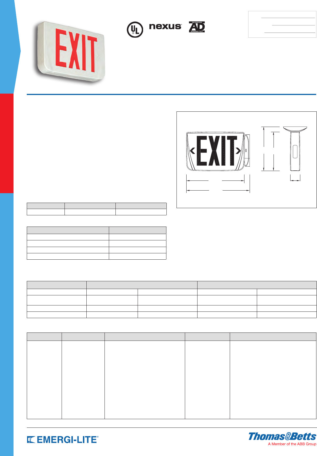
32
SPEC GRADE
COMMERCIAL
TYPE:
CATALOG #:
NOTES:
How to Order
HOUSING COLOR SERIES UNIT TYPE COLOR OPTIONS
W= White
B= Black
PREM= LED plastic EXIT Standard models
AC= AC only (120/277V)
U= 120/277VAC & 6 to 48VDC
SNX= Self-Powered Ni-Cd
Optional models
2C1= Dual AC circuit (2x120V)
2C2= Dual AC circuit (2x277V)
DN= Self-Powered advanced diagnostic circuitry
NEX= NEXUS® wired
(consult your sales representative)
NEXRF= NEXUS® wireless
(consult your sales representative)
R= Red universal
R1= Red single face*
R2= Red double face*
G= Green universal
G1= Green single face*
G2= Green double face*
Open face
RW= Red on white
GW= Green on white
(Open face required with
special wording legends)
Blank= No option
BA= Brushed aluminum exit stencil
FZ= Flasher buzzer (DN model only)
FL= Flasher (DN model only)
FA= Fire alarm activated flasher
(AC, U, 2C1, 2C2 and DN models only)
FBF= Flasher buzzer + fire alarm activated
flasher (DN model only)
VR= Vandal-resistant screws*
VR1= Polycarbonate shield with tamper proof screws*
* Available with VR & VR2
options only * Please specify single or double face, red or green
Example: WPREMACR
Dimensions
Dimensions are approximate and subject to change.
Features
• Indirect reective technology provides bright, even illumination
• Long-life LED light source for low maintenance costs and superior
illumination
• Durable, injection-molded, thermoplastic housing. Optional vandal-resistant
shield with tamper-proof screws
• Energy efcient power consumption: less than 3.5 watts for
Self-Powered version and less than 3W for AC only single or double face
• Available with a sealed, maintenance-free Nickel-Cadmium battery
• Dual voltage input: 120/277VAC. Optional Advanced Diagnostic circuitry,
asher/buzzer, and re alarm-activated asher
• Standard Universal, supplied with two faceplates, back plate for wall mount
and easy install canopy for end and ceiling mounting. Universal, eld-
selectable snap in/out chevrons
• UL924 Listed. All models are UL Listed for damp locations
• 5-year full warranty
Premier™ Series
LED Thermoplastic, universal-mount &
snap-fit Exit Sign
Wire Guards
WALL CEILING END
WG1-E WG5-E WG5-E
Accessories (order as a separate item)
DESCRIPTION SUFFIX
Pendant White PRE-P-WH*
Pendant Black PRE-P-BK*
Wire Guard (wall mount) WG1-E
Wire Guard (ceiling mount and end mount) WG5-E
* Specify pendant length
Optional Self-Test/Self-Diagnostic
Continuous self-diagnostic monitoring. Self-testing per Life Safety Code
requirements. This circuitry is programmed to ensure the exit sign’s readiness
and reliability by continuously monitoring every critical function of the
unit. If a problem occurs, a single “service required” indicator illuminates
immediately. A detailed diagnostic display that will further indicate the
nature of the fault is located on the inside of the exit sign, out of sight from
the general public. The self-test will test the unit a minimum of 30 seconds
every 30 days, 30 minutes every 60 days and 90 minutes annually.
Power Consumption
Each unit is furnished with one HIT lamp per head.
MODEL AC SPECS DC SPECS
AC-Only 120/277VAC, 60Hz Less than 2.5W – –
AC / DC-remote 120/277VAC, 60Hz Less than 2W 6 to 48VDC Less than 1.5W
Self-Powered 120/277VAC, 60Hz Less than 3.3W Ni-Cd battery Min. 90 minutes
Self-Powered with Diagnostic 120/277VAC, 60Hz Less than 2.8W Ni-Cd battery Min. 90 minutes
9” 8”
2”
11-7/8”
12-7/8”
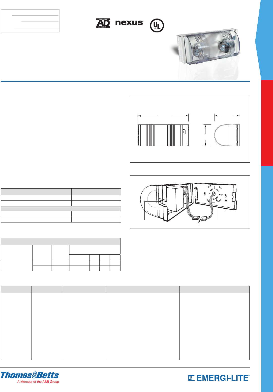
SPEC GRADE
33
COMMERCIAL
TYPE:
CATALOG #:
NOTES:
How to Order
COLOR SERIES LAMP TYPE UNIT TYPE OPTIONS
Blank= Off white
B= Black
PRO-2N= 6V-10.8W
PRO-3N= 6V-18W
-LA= 6V-4W, MR16 LED
-ZP= mini tungesten, 6V-5.4W
Blank= Standard Unit
-AD= Advanced Diagnostics (audible)
-ADNA= Advanced Diagnostics (non-audible)
NEX= NEXUS® wired
(consult your sales representative)*
NEXRF= NEXUS® wireless
(consult your sales representative)*
V= Voltmeter *
DL= Damp Location
VR= Vandal-resistant screws
C= Line Cord 120V - Supplied but not installed
CM= Ceiling mount - Supplied with metal harness
* Available with PRO-2N only. * Available with Standard unit type only.
Example: BPRO-2N-LADL
Dimensions
Dimensions are approximate and subject to change.
113
4"5
7
8"
5"
SCALE 1:3
11-3/4” 5-7/8”
Features
• Completely self-contained, thermoplastic construction with a polycarbonate
lens that protects the fully-adjustable self-locking heads
• Available with sealed, maintenance-free Lead-Calcium batteries
• Integrated circuitry offers 120/277VAC 60Hz standard operation, LED pilot
light rocker type, test switch, temperature compensated, low voltage battery
disconnect, brownout protection and lock out (automatic battery connect)
• Optional MR16 LED lamps with life expectancy 50,000+ hours
• Optional advanced diagnostic circuitry monitors every critical function of the
unit and provides an audible and visual indicator when a fault is detected
(non-audible versions available)
• Optional tamper-proof screws
• Optional NEXUS® wired and NEXUS® wireless systems
• Universal wall mounting pattern keyhole slots and a conduit
knockout provide alternate mounting methods
• Optional ceiling mount includes safety wire and pre-machined housing to
receive a securement screw.
• UL Listed. Complies with NEC, Life Safety Code and OSHA
UL Listed for use in Damp Locations
• 3-year full warranty, excluding lamps, pilot lights, and fuses.
Provider™
PRO-2N/PRO-3N Series
6 Volt Thermoplastic Housing
Accessories (order as a separate item)
DESCRIPTION SUFFIX
Replacement lamps 570.0012-E
Additional special bit for tamper-proof screws 690.0454-E
REPLACEMENTS LAMPS
570.0012-E HIT 6V-5.4W
580.0097-E MR16 LED 6V-4W
Power Consumption and Unit Rating
Each unit are furnished with one HIT lamp per head.
PROVIDER™ BATTERY UNIT
Sealed Maintenance-
Free Battery Types D.C. Voltage Model
Number
Watts to 87-1/2% of rated battery
voltage
1-1/2 hrs 2 hrs 3 hrs 4 hrs
Lead-Calcium 6 PRO-2N 10.8 8.5 – –
6 PRO-3N 18 12 10 7
*National Electrical Code Specification
5”
Fast and Easy Installation
Provider’s AC quick-connect plug, battery lock out feature and
snap-together design make installation fast and easy.
With the AC quick-connect plug, contractors simply make the AC
connection to the plug, mount the back plate and plug in the unit.
The battery lock out feature is an AC activated load switch that
prevents the batteries from discharging until the unit is energized
with AC power. This allows the contractor to install the Provider™
and connect the batteries in one convenient operation.
Universal mounting pattern keyhole slots and a conduit
knock out provide alternate mounting methods.
Keyhole slot
Conduit knockout
AC-quick connect plug
Universal mounting pattern
Snap-together design eliminates screws.
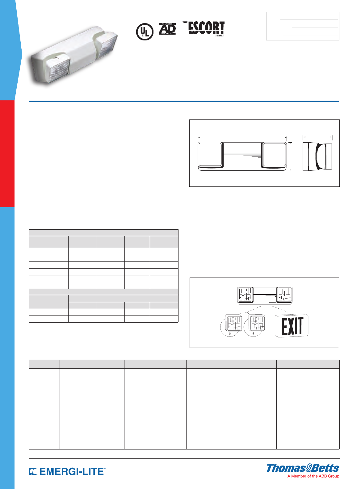
34
SPEC GRADE
COMMERCIAL
TYPE:
CATALOG #:
NOTES:
How to Order
COLOR SERIES HEADS/LAMPS OPTIONS BATTERY OPTION
B= Black housing
Blank= Off white
EC= 6V-12W battery unit
ECX= 6V-24W battery unit
Heads
-2= Two heads (12W remote)
-EG= Standard unit
-AD= Advanced Diagnostics (audible)
-ADNA= Advanced Diagnostics (non-audible)
-D1= Time Delay (5 minutes)
-D2= Time Delay (10 minutes)
-D3= Time Delay (15 minutes)
-DL= Damp Location listed (AD/ADNA units only)
Blank= Lead-Calcium
-N= Nickel-Cadmium battery
(AD/ADNA units only)
Lamps
-2HA= 6V-6W bi-pin halogen
-2HB= 6V-8W bi-pin halogen
-2HC= 6V-10W bi-pin halogen
-2HD= 6V-12W bi-pin halogen
Example: BEC-2-EG-N
Features
• Each self-contained unit comes with two (2) 5.4W high intensity
incandescent lamps mounted in polished reectors
• Housing and heads are constructed of high-impact UL 94, 5VA ame
classication, off-white thermoplastic. Resists denting, peeling, scratching
and corrosion
• Available with sealed, maintenance-free Lead-Calcium batteries
• Integrated circuitry offers 120/277VAC 60 Hz, 0.3/0.15A standard operation,
LED pilot light, automatic charging, instantaneous transfer, temperature
compensated charger, low voltage battery disconnect, brownout protection,
lock out (automatic battery connect) and reverse polarity protection
• Universal mounting pattern, keyhole slots and conduit entry provide alternate
mounting capability. The housing and back plate snap together for ease of
installation
• UL Listed. Complies with NEC, Life Safety Code and OSHA. UL Listed for
use in damp locations
• The EC-2 (12W max.) and ECX-2 (24W max.) Series have a
3-year full warranty, excluding lamps and fuses
Dimensions
Dimensions are approximate and subject to change.
EC-2/ECX-2 Series
Thermoplastic Housing 6V-12W Capacity
Lead-Calcium Battery
Flexibility in an emergency lighting unit
• On the specification...
Its contemporary design allows you to coordinate the aesthetics of emergency
specications with matching models – an emergency unit and a remote head.
• On the job...
Changes on the job are never a problem with the EC Series. Its modular
design allows you to eld upgrade the basic model to a master unit for
powering matching remote lighting heads or AC/DC exit signs, including the
new LED even illumination models.
• On the shelf...
The modular design of the EC Series gives you a contemporary family of
decorative emergency lighting units, matching exit signs and remotes.
ECX - 12W Remote Capacity
Matching EF23 Remote Heads LED Exit Signs
Unit Rating Chart
Furnished with two 5.4W high intensity incandescent lamps.
UNIT EQUIPMENT
Sealed Maintenance-
Free Battery Types D.C. Voltage Model
Number
Watts to 90
minutes
Remote Watts
Lead-Calcium 6 EC-2 12 –
Lead-Calcium 6 ECX-2 12 12
Lead-Calcium 6 EC-2-AD 12 –
Lead-Calcium 6 ECX-2-AD 12 12
Nickel-Cadmium 6 EC-2-AD-N 12 –
Nickel-Cadmium 6 ECX-2-AD-N 12 12
ECX-2 SERIES UNIT EQUIPMENT - WITH REMOTE CAPABILITY
Sealed Maintenance-
Free Battery Types
Watts to 87-1/2% of rated battery voltage*
1-1/2 hrs 2 hrs 3 hrs 4 hrs
Lead-Calcium 24 15 – –
Nickel-Cadmium** 24 18 12 –
* National Electrical Code Specification
** Only available with Diagnostics
16” 5”
5”
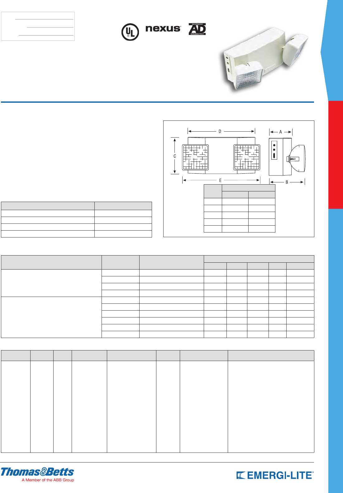
SPEC GRADE
35
COMMERCIAL
TYPE:
CATALOG #:
NOTES:
How to Order
COLOR DC
VOLTAGE SERIES BATTERY TYPE WATTAGES # OF
HEADS LAMP TYPE OPTIONS
Blank= Off
white
B= Black
Blank= 6V
12= 12V
EC C= Ni-Cd
M= Lead-Calcium
18= 6V-18W Nickel or
Lead-Calcium
25= 6V-25W
Nickel-Cadmium
27= 6V- 27W Lead-Calcium
36= 6V, 12V-36W Nickel
or Lead-Calcium
50= 12V-50W
Nickel-Cadmium
54= 6V, 12V-54W
Lead-Calcium
-1= One
head
-2= Two
heads
Blank= 6V, 12V-9W
wedge
H_= Bi-pin halogen lamps
Z_= High intensity
incandescent
wedge base
Blank= No options
-AD= Advanced Diagnostics (audible)
-ADNA= Advanced Diagnostics (non-audible)
-NEX= Nexus® wired
(consult your sales representative)
-NEXRF= Nexus® wireless
(consult your sales representative)
-V= Voltmeter
-A= Ammeter (S cabinet units.
choose only one meter)
-D1= Time Delay (5 minutes)
-D2= Time Delay (10 minutes)
-D3= Time Delay (15 minutes)
-K= Lamp Disconnect Switch
NOTE: For a complete list of
available lamp types, please
refer to the lamp data on
pages 146-147.
For units without heads please see
the JS series
Example: B12ECC50-2HG
Features
• Each unit comes with two (2) front-mounted EF-23 heads with
9W high intensity incandescent lamps (standard)
• Constructed of 20-gauge steel with an off-white baked enamel nish
• Available with sealed, maintenance-free Nickel-Cadmium or
Lead-Calcium batteries
• PulsePlus Charger circuitry offers 120/277VAC 60 Hz., 0.3/0.15A (other
inputs available), fused output circuit(s), dual diagnostic indicator lights,
temperature compensation, sealed relay, low voltage battery disconnect,
brownout protection and lock out (automatic battery connect)
• Hinged front door
• UL Listed. Complies with NEC, Life Safety Code and OSHA. Approved for
use in the Commonwealth of Pennsylvania and New York City
• 3-year full warranty, excluding lamps and fuses
Dimensions
Dimensions are approximate and subject to change.
Letters Cabinet Size
S L
A 3-1/2” 4”
B 6-1/8” 6-3/4”
C 5-1/4” 6-1/4”
D 11” 12-1/2”
E 15-1/4” 16-1/2”
ECC and ECM Series
6 and 12V Steel Unit
Accessories (order as a separate item)
DESCRIPTION SUFFIX
Mounting bracket (S cabinet only) BJ-EG
Wire guard WG10-E
Clear polycarbonate vandal-resistant shield VRS-BB**
Clear NEMA 4X polycarbonate vandal-resistant shield VRSBB-4X**
** S cabinet only, order on separate line.
Unit Rating
Sealed Maintenance-Free Battery Types D.C. Voltage Model Number Watts to 87-1/2% of rated battery voltage
1-1/2 hrs 2 hrs 3 hrs 4 hrs Cabinet Size
Nickel-Cadmium
6 ECC18-2 18 12 – – S
6 ECC25-2 25 18 12 9 S
12 12ECC36-2 36 21 15 12 S
12 12ECC50-2 50 36 25 18 S
Lead-Calcium
6 ECM18-2 18 12 10 7 S
6 ECM27-2 27 18 14 10 S
6 ECM36-2 36 24 20 14 S
6 ECM54-2 54 37 28 21 L
12 12ECM36-2 36 25 20 14 S
12 12ECM54-2 54 37 28 21 L
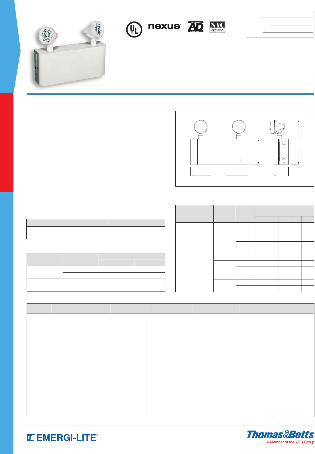
36
SPEC GRADE
COMMERCIAL
TYPE:
CATALOG #:
NOTES:
How to Order
COLOR SERIES DC VOLTAGE/CAPACITY # OF HEADS HEAD STYLE LAMP TYPE/WATTAGE OPTIONS
Blank=
Off white
B= Black
JCM18= 6V-18W, Lead-Calcium
JCM20= 6V-20W, Lead-Calcium
JCM27= 6V-27W, Lead-Calcium
JCM30= 6V-30W, Lead-Calcium
JCM36= 6V-36W, Lead-Calcium
JCM40= 6V-40W, Lead-Calcium
12JCM36= 12V-36W, Lead-Calcium
12JCM40= 12V-40W, Lead-Calcium
JCC20= 6V-20W, Ni-Cd
12JCC36= 12V-36W, Ni-Cd
12JCC50= 12V-50W, Ni-Cd
-0= No head
-2= Two heads
10= EF10 mini
plastic MR16
150= EF150 lamp heads
LA= 6V-4W, MR16 LED
LG= 12V-4W, MR16 LED
LI= 12V-5W, MR16 LED
LJ= 12V-6W, MR16 LED
MH= 6V-5W, MR16
MI= 6V-6W, MR16
MJ= 6V-10W, MR16
MK= 12V-12W, MR16
MA= 12V-20W, MR16
MW= 12V-20W high
output IR
-AD= Advanced Diagnostics (audible)*
-ADNA= Advanced Diagnostics (non-audible)*
-NEX= NEXUS® wired
(consult your sales representative)*
-NEXRF= NEXUS® wireless
(consult your sales representative)*
-FM= Front mount heads
* Not available with 6V - 40W unit (JCM40)
Example: JCM18-210MI-AD
Dimensions
Dimensions are approximate and subject to change.
5-1/2”
12-3/4”
9-5/8”
3-3/8”
Features
• Each unit comes with two (2) impact-resistant, ame retardant thermoplastic
EF10 heads with 6W MR16 halogen or MR16 LED lamps (standard).
Available with up to 20W(MW) high-output illumination heads
• Compact steel cabinet with corrosion-resistant undercoating in white
(standard). Black available as an option
• Available with sealed, maintenance-free Nickel-Cadmium, or
Lead-Calcium batteries
• Power Requirements: 120/277VAC 60Hz, 0.3/0.15 Amp
• Automatic, temperature-compensated solid state charger with a high
capacity, automatic, dust-tight instantaneous transfer relay. Low voltage
disconnect prevents over discharge of battery. Automatic brown out
protection. Labor saving AC line latch prevents battery discharge during
installation to a non-energized circuit. Fused output circuit. Optional
Advanced Diagnostics comes with a micro controller based pulse-type
charger
• Rear keyhole mounting slots. Designed to mount directly to any standard 4”
junction box
• UL Listed
• 3-year full warranty, excluding lamps and fuses
JC Series
Steel Housing 6V up to 40W & 12V
up to 50W Capacities
Power Consumption Chart
Model # AC Input Maximum
Input Current Input Power
JC 120VAC 0.20A 24W
277VAC 0.08A 24W
12JC 120VAC 0.24A 30W
277VAC 0.12A 30W
Unit Rating
Furnished standard with two MR16 6V-6W.
Sealed Maintenance-
Free Battery Types D.C. Voltage Model
Number
Watts to 87-1/2% of rated battery
voltage
1-1/2 hrs 2 hrs 3 hrs 4 hrs
Lead-Calcium
6
JCM 18 12 – –
JCM20 20 15 12 –
JCM27 27 18 15 –
JCM30 30 20 18 –
JCM36 36 27 20 12
JCM40 40 30 24 15
12 12JCM36 36 27 20 12
12JCM40 40 30 24 15
Nickel-Cadmium
6 JCC20 20 18 12 –
12 12JCC36 36 24 15 12
12JCC50 50 36 24 18
* National Electrical Code Specification
Accessories (order as a separate item)
DESCRIPTION SUFFIX
Wire Guard (EF10, EF9 and EF150) WG1-E
Wire Guard (EF18, EF23 and EF28) WG2-E
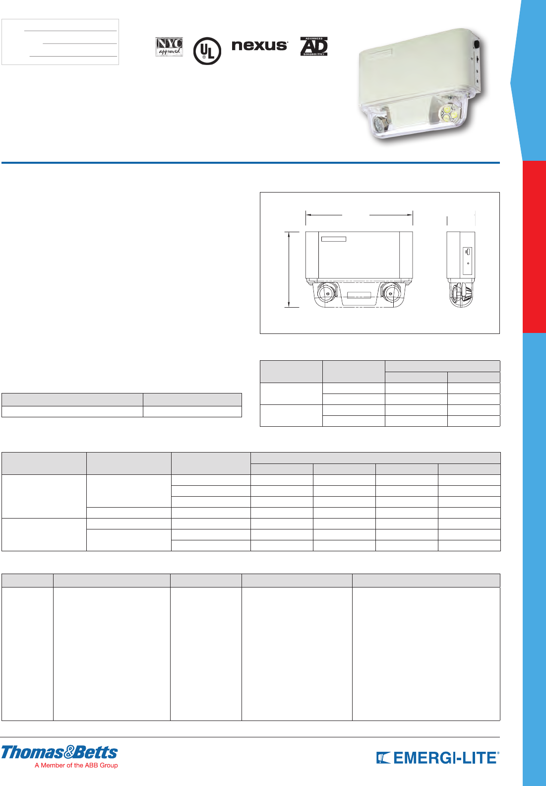
SPEC GRADE
37
COMMERCIAL
TYPE:
CATALOG #:
NOTES:
Features
• Each unit comes with two (2) emergency heads with adjustable swivels and
long-life MR16 halogen or LED lamps 6V or 12V, available with up to 20W
high output illumination
• Steel cabinet with an anti-corrosion undercoating. The emergency heads
are protected by a shock-absorbent, transparent polycarbonate cover. The
cover is attached to the cabinet with two screws
• Available with sealed, maintenance-free Nickel-Cadmium or
Lead-Calcium batteries
• Power requirements: 120/277 VAC 60Hz, 0.3/0.15 Amp
• Solid State Charger is an automatic, temperature compensated type
charger with high capacity, dust-tight instantaneous transfer relay and
automatic brownout protection. Low voltage disconnect prevents over
discharge of battery. Labor saving AC line latch prevents battery discharge
during installation to a non-energized circuit. Fused output circuit. Optional
Advanced Diagnostics comes with a micro controller based pulse type
charger
• The emergency heads are installed at the bottom of the unit, providing
illumination in any downward direction and do not require a tool for adjusting
or aiming
• UL Listed
• 3-year full warranty, excluding lamps and fuses.
Dimensions
Dimensions are approximate and subject to change.
JA Series
Steel Housing with Protected Lighting Heads
6V up to 40W & 12V up to 50W Capacities
How to Order
COLOR SERIES DC VOLTAGE/CAPACITY # OF HEADS LAMP TYPE OPTIONS
Blank= Off
white
B= Black
JAM20= 6V-20W, Lead-Calcium
JAM30= 6V-30W, Lead-Calcium
JAM40= 6V-40W, Lead-Calcium
12JAM40= 12V-40W, Lead-Calcium
JAC20= 6V-20W, Ni-Cd
12JAC36= 12V-36W, Ni-Cd
12JAC50= 12V-50W, Ni-Cd
-2= Two heads LA= 6V-4W, MR16 LED
LG= 12V-4W, MR16 LED
LI= 12V-5W, MR16 LED
LJ= 12V-6W, MR16 LED
MI= 6V-6W, MR16
MH= 6V-5W, MR16
MJ= 6V-10W, MR16
MK= 12V-12W, MR16
MA= 12V-20W, MR16
MW= 12V-20W IR high output
-AD= Advanced Diagnostics (audible)*
-ADNA= Advanced Diagnostics (non-audible)*
-NEX= NEXUS® wired
(consult your sales representative)*
-NEXRF= NEXUS® wireless
(consult your sales representative)*
* Not available with 6V-40W unit (JAM40)
Example: JAM20-2MI-AD
Unit Rating
Furnished standard with two MR16 6V-6W.
Sealed Maintenance-Free
Battery Types Voltage Model Number Watts to 87-1⁄2% of rated battery voltage
1-1/2 hrs 2 hrs 3 hrs 4 hrs
Lead-Calcium 6
JAM20 20 – – –
JAM30 30 20 – –
JAM40 40 30 24 –
12 12JAM40 40 30 24 –
Nickel-Cadmium
6 JAC20 20 – – –
12 12JAC36 36 24 – –
12JAC50 50 36 24 –
Power Consumption
Model # AC Input Maximum
Input Current Input Power
JA 120VAC 0.20A 24W
277VAC 0.08A 24W
12JA 120VAC 0.24A 30W
277VAC 0.12A 30W
12-3/4”
9”
3-3/8”
Accessories (order as a separate item)
DESCRIPTION SUFFIX
Wire Guard WG1-E
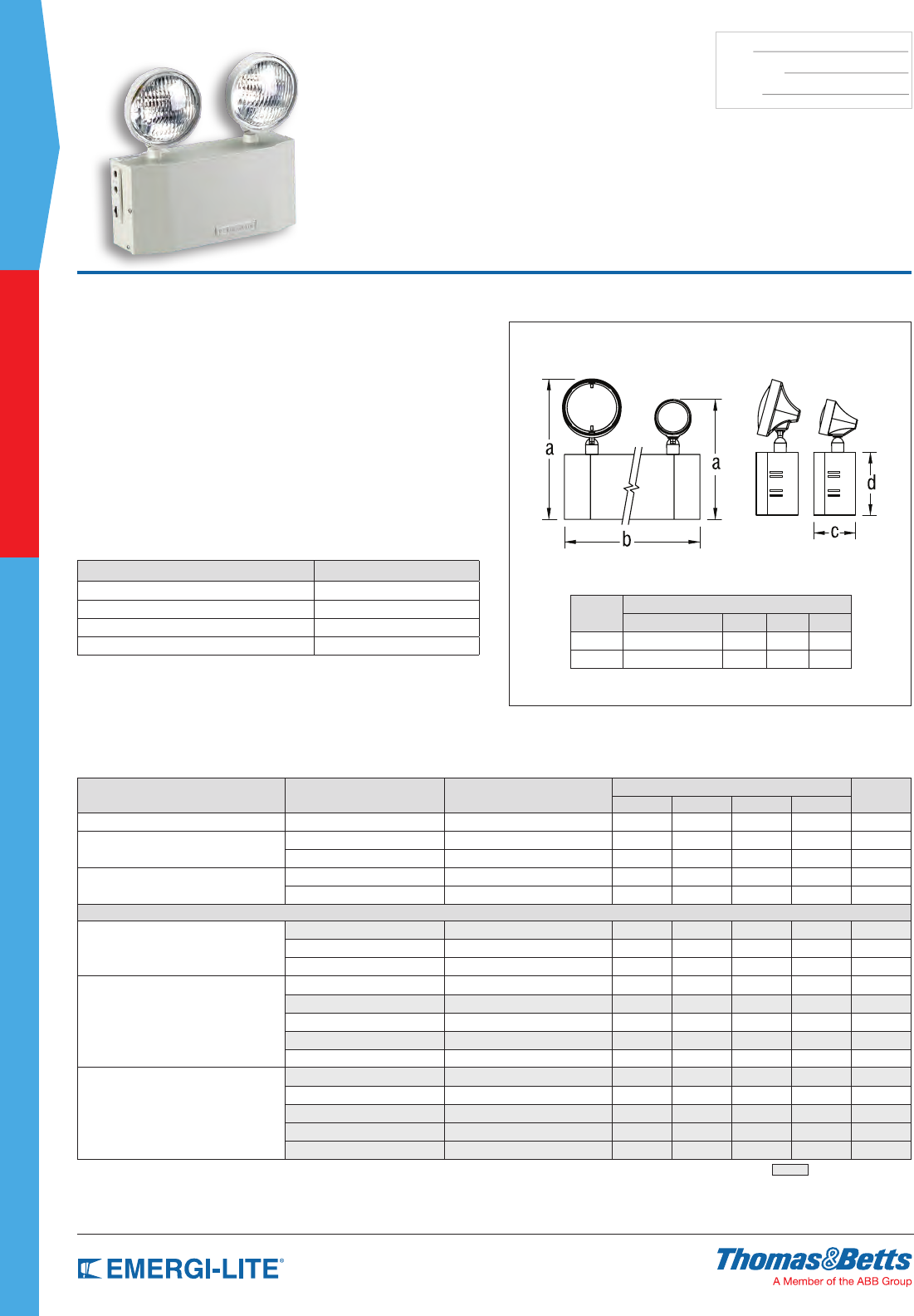
38
SPEC GRADE
COMMERCIAL
TYPE:
CATALOG #:
NOTES:
Dimensions
Dimensions are approximate and subject to change.
EF18 EF9
Cabinet
Size
Dimensions
a b c d
S 11-3/8” // 9-3/4” 11” 3-1/2” 5-1/4”
L 12-3/8” // 10-3/4” 12-3/4” 4” 6-1/4”
Features
• Each unit comes with two (2) EF18 heads with 9W high intensity
incandescent lamps (standard)
• Constructed of 20-gauge steel with an off-white baked enamel nish
• Available with sealed, maintenance-free Nickel-Cadmium, Long Life Lead or
Lead-Calcium batteries
• PulsePlus Charger circuitry offers 120/277VAC 60 Hz., 0.3/0.15A (other
inputs available), fused output circuit(s), dual diagnostic indicator lights,
temperature compensation, sealed relay, low voltage battery disconnect,
brown out protection and lock out (automatic battery connect)
• Hinged cabinet door for easy access
• UL Listed. Complies with NEC, Life Safety Code and OSHA. Approved for
use in the Commonwealth of Pennsylvania and New York City
• 3-year full warranty, excluding lamps and fuses
JS Series
Steel Housing 6V & 12V
up to 54W Capacities
Accessories (order as a separate item)
DESCRIPTION SUFFIX
Mounting Bracket (S cabinet only) BJ-E
Wire Guard (S cabinet only) WG1-E
Wire Guard (L cabinet only) WG2-E
Wire Guard (front mounted heads) WG10-E
**S cabinet only, order on separate line.
Unit Rating
Furnished standard with two 9 watt High Intensity Incandescent lamps.
Sealed Maintenance-Free Battery Types D.C. Voltage Model Number Watts to 87-1/2% of rated battery voltage* Cabinet
size
1-1/2 hrs 2 hrs 3 hrs 4 hrs
Nickel-Cadmium 6 JSC18-2 18 12 – – S
Long Life Lead 6 JSE9-1 9 7 – – S
6 JSE18-2 18 11 8 6 S
Lead-Calcium 6 JSM9-1 9 6 – – S
6 JSM18-2* 18 12 10 S
UNIT EQUIPMENT - WITH REMOTE CAPABILITY
Nickel-Cadmium
6 JSC25-2 25 18 12 9 S
12 12JSC36-2 36 21 15 12 S
12 12JSC50-2 50 36 25 18 S
Long Life Lead
6 JSE27-2 27 16 12 10 S
6 JSE36-2 36 24 17 13 S
6 JSE54-2 54 37 28 21 L
12 12JSE36-2 36 24 17 13 S
12 12JSE54-2 54 37 28 21 L
Lead-Calcium
6 JSM27-2 27 18 14 10 S
6 JSM36-2 36 25 20 14 S
6 JSM54-2 54 37 28 21 L
12 12JSM36-2 36 25 20 14 S
12 12JSM54-2 54 37 28 21 L
* National Electrical Code Specification = New York City Approved
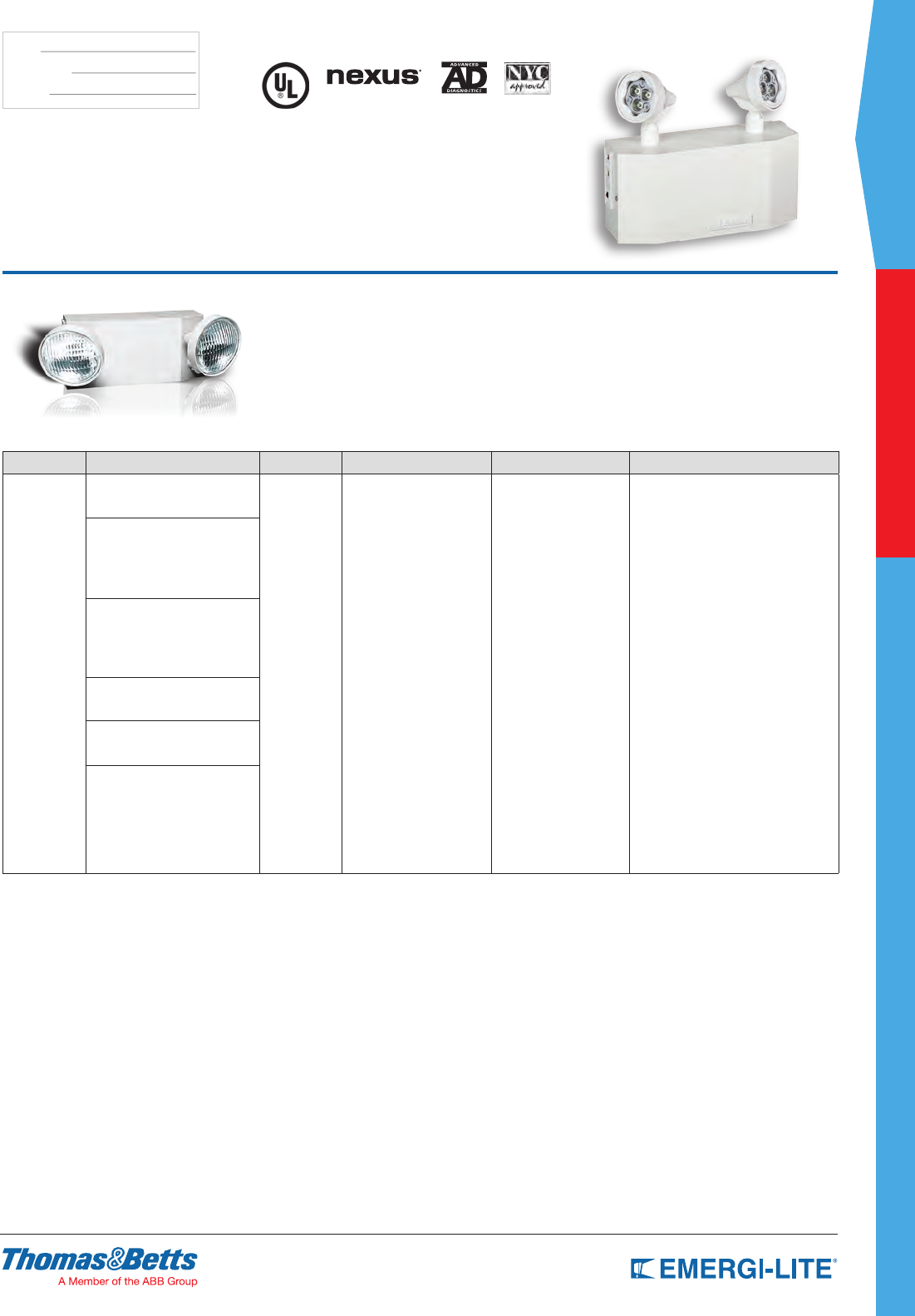
SPEC GRADE
39
COMMERCIAL
TYPE:
CATALOG #:
NOTES:
JS Series
A complete range of high performance
and labor saving features
How to Order
COLOR SERIES/CAPACITY # OF LAMPS HEAD STYLE LAMP TYPE/WATTAGE OPTIONS
Blank= Off
white
B= Black
JSC18= 6V-18W, Ni-Cd
JSC25= 6V-25W, Ni-Cd
-0= No head
-1= One head
-2= Two heads
Blank= (EF18 PAR 36 style )
9= mini plastic
10= mini plastic MR16
28= EF28 Metal lamp heads
150= EF150 lamp heads
Blank_= 6V-9W and 12V-
9W incandescent
wedge base
H_= Halogen bi-pin
I_= Incandescent
DC-bayonet
U_= Incandescent
sealed-beam
X_= Halogen sealed-beam
Z_= Incandescent wedge
M_= Halogen MR16*
LA= 6V-4W, MR16 LED*
LG= 12V-4W, MR16 LED*
LI= 12V-5W, MR16 LED*
LJ= 12V-6W, MR16 LED*
-AD= Advanced Diagnostics (audible)
-ADNA= Advanced Diagnostics (non-audible)
-NEX= NEXUS® wired
(consult your sales representative)
-NEXRF= NEXUS® wireless
(consult your sales representative)
-V= Voltmeter (or ammeter)*
-A= Ammeter (or voltmeter)*
-D1= Time Delay (5 minutes)
-D2= Time Delay (10 minutes)
-D3= Time Delay (15 minutes)
-K= Lamp disconnect switch
-FM= Front mounted heads
-CP= 120VAC cord & plug **
-E= Cord & plug (277VAC) **
JSE9= 6V-9W, Long Life Lead
JSE18= 6V-18W, Long Life Lead
JSE27= 6V-27W, Long Life Lead
JSE36= 6V-36W, Long Life Lead
JSE54= 6V-54W, Long Life Lead
JSM9= 6V-9W, Lead-Calcium
JSM18= 6V-18W, Lead-Calcium
JSM27= 6V-27W, Lead-Calcium
JSM36= 6V-36W, Lead-Calcium
JSM54= 6V-54W, Lead-Calcium
12JSC36= 12V-36W, Ni-Cd
12JSC50= 12V-50W, Ni-Cd
12JSE36= 12V-36W, Long Life Lead
12JSE54= 12V-54W, Long Life Lead
12JSM36= 12V-36W, Long Life Lead
12JSM54= 12V-54W, Long Life Lead
* Available with EF10 and EF150
Lamp heads only.
NOTE: For a complete list of available
lamp types, please refer to the
lamp data on pages 146-147
* Not available with AD or ADNA options.
** Standard cord is 3ft.
Example: JSC18-110LA
Optional (FM suffix) Front Mounted Heads for low ceiling applications.
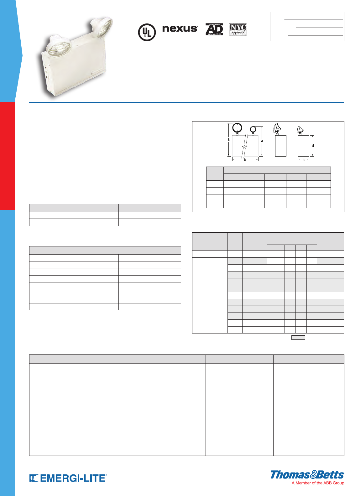
40
SPEC GRADE
COMMERCIAL
TYPE:
CATALOG #:
NOTES:
How to Order
COLOR SERIES/CAPACITY # OF LAMPS HEAD STYLE LAMP TYPE/WATTAGE OPTIONS
Blank= Off white
B= Black
enclosure
LSE18= 6V-18W Long Life Lead
LSE27= 6V-27W Long Life Lead
LSE36= 6V-36W Long Life Lead
LSE54= 6V-54W Long Life Lead
LSE80= 6V-80W Long Life Lead
LSE110= 6V-110W Long Life Lead
LSE160= 6V-160W Long Life Lead
12LSE36= 12V-36W Long Life Lead
12LSE54= 12V-54W Long Life Lead
12LSE72= 12V-72W Long Life Lead
12LSE110= 12V-110W
Long Life Lead
12LSE160= 12V-160W
Long Life Lead
12LSE320= 12V-320W
Long Life Lead
-0= No head
-1= 1 head
-2= 2 heads
-3= 3 heads
Blank= EF18
(PAR 36 plastic)
28= EF28 (PAR 36 metal)
9= EF9 (mini plastic)
10= EF10 (small
plastic MR16)
150= EF150 (MR16
lamp heads)
Blank= 6V-9W and 12V-9W
incandescent wedge base
H_= Halogen bi-pin
I_= Incandescent DC-bayonet
U_= Incandescent sealed-beam**
X_= Halogen sealed-beam**
Z_= Incandescent wedge
M_= Halogen MR16*
LA= 6V-4W, MR16 LED*
LG= 12V-4W, MR16 LED*
LI= 12V-5W, MR16 LED*
LJ= 12V-6W, MR16 LED*
Blank= No options
-AD= Advanced Diagnostics (audible)*
-ADNA= Advanced Diagnostics
(non-audible)*
-NEX= NEXUS® Wired**
-NEXRF= NEXUS® Wireless **
-V= Voltmeter
(A cabinet units. Choose only one )
-A= Ammeter
(A cabinet units. Choose only one)
-D1= Time Delay (5 minutes)
-D2= Time Delay (10 minutes)
-D3= Time Delay (15 minutes)
-FM= Front mounted lamp heads
-CP= Cord and plug 120V
-E= Cord and plug 277V
* Available with EF10 & 150 only
** Available with EF18 & EF28 only
NOTE: For a complete list of available lamp types,
please refer to the lamp data on pages 146-147
* Minimum lamp load required: 20% of unit capacity
** Consult your sales representative
Example: BLSE18-128H-A
Features
• Each unit comes with two (2) EF-18 heads with 9 watt high intensity
incandescent lamps (standard). One or three heads available as options
• All-steel construction with an off-white baked enamel nish
• Contains sealed, maintenance-free Long Life Lead batteries
• Constructed of 20-gauge steel with an off-white baked enamel nish
• PulsePlus Charger circuitry offers 120/277VAC, input 60 Hz., 0.3/0.15A
(other inputs available), fused output circuit(s), dual diagnostic indicator
lights, temperature compensation, sealed relay, low voltage battery
disconnect, brownout protection and lock out (automatic battery connect)
• Removable front panel
• UL Listed. Complies with NEC, Life Safety Code and OSHA. Approved for
use in the Commonwealth of Pennsylvania and New York City
• 3-year full warranty, excluding lamps and fuses
Dimensions
Dimensions are approximate and subject to change.
Cabinet
Size
Dimensions
a b c d
A 14-5/8” // 13” 13-3/4” 3-1/8” 8-1/2”
B 16-3/8” // 14-3/4” 16-1/8” 5-7/16” 10-1/4”
C 18-3/8” // 16-3/4” 16-1/2” 7-1/4” 12-1/4”
D 18-3/8” // 16-3/4” 27” 7-1/4” 12-1/4”
EF18 EF9
LSE Series
6 and 12 Volt Steel Enclosure
Optional Features
DESCRIPTION SUFFIX
Cord set - 120V -C*
Special-voltage CP (TL 277V) -E*
* Standard cord is 3 ft.
Accessories (order as a separate item)
DESCRIPTION SUFFIX
Mounting bracket (cabinet A) B1
Mounting bracket (cabinet B) B2
Mounting shelves (cabinet B) MP3-EG
Mounting shelves (cabinet C) MP6-EG
Mounting shelves (cabinet D) MP12
Wire Guard (cabinet A) WG2-E
Wire Guard (cabinet B & cabinet C) WG3-E
Wire Guard (cabinet D) WG4-E
Unit Rating
Furnished standard with two 9 watt High Intensity Incandescent lamps.
Sealed
Maintenance-Free
Battery Types
D.C.
Voltage
Model
Number
Watts to 87-1/2% of rated
battery voltage*
# of
Load
Fuses
Cabinet
size
1-1/2 hrs 2 hrs 3 hrs 4 hrs
Long Life Lead 6 LSE18-2 18 11 8 6 1 A
Long Life Lead
1-1/2 hrs 2 hrs 4 hrs 8 hrs
6 LSE27-2 27 19 10 5 1 A
6 LSE36-2 36 24 13 7 1 A
6 LSE54-2 54 36 20 11 1 A
6 LSE80-2 80 65 35 19 2 B
6 LSE110-2 110 74 43 21 2 B
12 12LSE36-2 36 24 13 7 1 A
12 12LSE54-2 54 37 21 10 2 A
12 12LSE72-2 72 48 26 14 2 B
12 12LSE110-2 110 74 43 21 2 B
12 12LSE320-2 320 210 120 60 2 D
* National Electrical Code Specification = New York City Approved
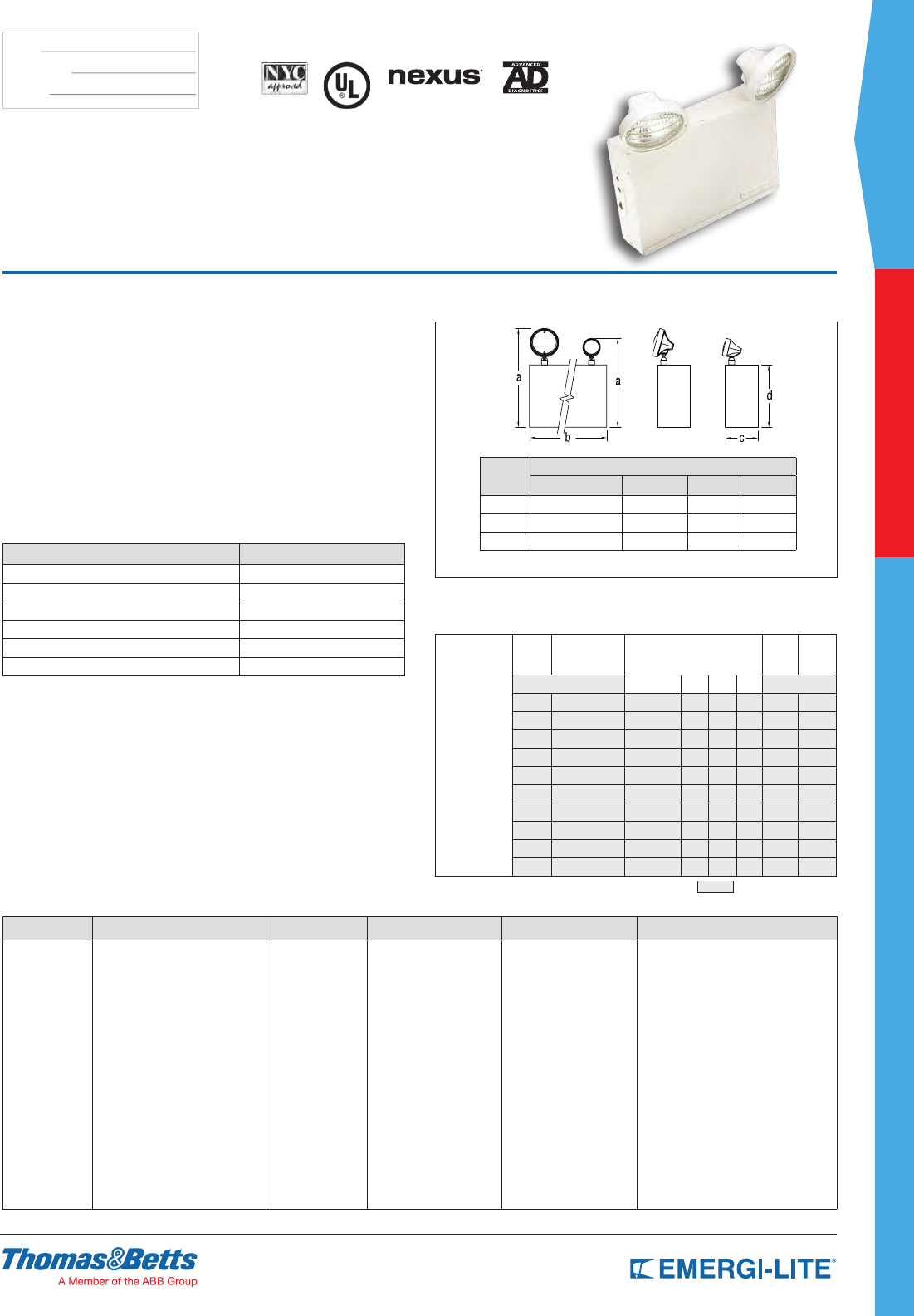
SPEC GRADE
41
COMMERCIAL
TYPE:
CATALOG #:
NOTES:
Dimensions
Dimensions are approximate and subject to change.
EF18 EF9
Cabinet
Size
Dimensions
a b c d
B 16-3/8” // 14-3/4” 16-1/8” 5-7/16” 10-1/4”
C 18-3/8” // 16-3/4” 16-1/2” 7-1/4” 12-1/4”
D 18-3/8” // 16-3/4” 27” 7-1/4” 12-1/4”
Features
• Each unit comes with two (2) EF-18 heads with 9 watt high intensity
incandescent lamps (standard). One or three heads available as options
• All-steel construction with an off-white baked enamel nish
• Contains sealed maintenance-free Lead-Calcium (Immobilized Electrolyte)
batteries
• PulsePlus Charger circuitry offers 120/277VAC, input 60 Hz., 0.3/0.15
Amps (other inputs available), fused output circuit(s), dual diagnostic
indicator lights, temperature compensation, sealed relay, low voltage battery
disconnect, brownout protection and lock out (automatic battery connect)
• Removable front panel
• UL Listed. Complies with NEC, Life Safety Code and OSHA. Approved for
use in the Commonwealth of Pennsylvania and New York City
• 3-year full warranty, excluding lamps and fuses
LC Series
6 and 12 Volt Steel Enclosure
How to Order
COLOR SERIES/CAPACITY # OF LAMPS HEAD STYLE LAMP TYPE OPTIONS
Blank= Off white
B= Black
LC87= 6V-87W Lead-Calcium
LC100= 6V-100W Lead-Calcium
LC175= 6V-175W Lead-Calcium
LC200= 6V-200W Lead-Calcium
12LC150= 12V-150W Lead-Calcium
12LC175= 12V-175W Lead-Calcium
12LC200= 12V-200W Lead-Calcium
12LC300= 12V-300W Lead-Calcium
12LC350= 12V-350W Lead-Calcium
12LC400= 12V-400W Lead-Calcium
-0= No head
-1= 1 head
-2= 2 heads
-3= 3 heads
Blank= EF18
(PAR 36 plastic)
28= EF28 (PAR 36 metal)
9= EF9 (mini plastic)
10= EF10
(small plastic MR16)
150= EF150
(MR16 lamp heads)
H_= Halogen bi-pin
I_= Incandescent
DC-bayonet
U_= Incandescent
sealed-beam**
X_= Halogen sealed-
beam**
Z_= Incandescent wedge
M_= Halogen MR16*
LA= 6V-4W, LED MR16*
LG= 12V-4W, LED MR16*
LI= 12V-5W, LED MR16*
LJ= 12V-6W, LED MR16*
* Available with EF10 & 150 only
** Available with EF18 & EF28 only
Blank= No options
-AD= Advanced Diagnostics (audible)*
-ADNA= Advanced Diagnostics
(non-audible)*
-NEX= NEXUS® wired**
-NEXRF= NEXUS® wireless**
-A= Ammeter
-V= Voltmeter
-D1= Time Delay (5 minutes)
-D2= Time Delay (10 minutes)
-D3= Time Delay (15 minutes)
-K= Lamp Disconnect Switch
-CP= Cord and plug 120V***
-E= Cord and plug 277V***
NOTE: For a complete list of
available lamp types, please refer to
the lamp data on pages 146-147
* Minimum lamp head required: 20% of unit capacity
** Consult your sales representative
** * Standard cord is 3 ft.
Example: BLC87-128HB-A
Unit Rating
Furnished standard with two 9 watt High Intensity Incandescent lamps.
Lead-Calcium
(immobilized
electrolyte)
D.C.
Voltage Model Number Watts to 87-1/2% of rated
battery voltage*
# of
Load
Fuses
Cabinet
size
1-1/2 hrs 2 hrs 4 hrs 8 hrs
6 LC87-2 87 70 41 24 2 B
6 LC100-2 100 77 47 24 2 C
6 LC175-2 175 140 82 48 2 C
6 LC200-2 200 168 96 48 2 C
12 12LC150-2 150 120 66 36 2 C
12 12LC175-2 175 140 85 48 2 C
12 12LC200-2 200 168 96 48 2 C
12 12LC300-2 300 240 132 72 2 D
12 12LC350-2 350 280 170 96 2 D
12 12LC400-2 400 336 192 95 2 D
* National Electrical Code Specification = New York City Approved
Accessories (order as a separate item)
DESCRIPTION SUFFIX
Mounting bracket (cabinet B) B2
Mounting shelves (cabinet B) MP3-EG
Mounting shelves (cabinet C) MP6-EG
Mounting shelves (cabinet D) MP12
Wire Guard (cabinet B & cabinet C) WG3-E
Wire Guard (cabinet D) WG4-E
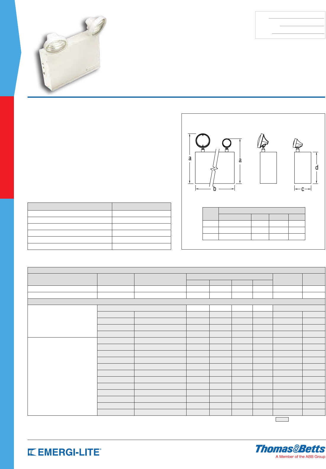
42
SPEC GRADE
COMMERCIAL
TYPE:
CATALOG #:
NOTES:
Features
• Each unit comes with two (2) EF-18 heads with 9 watt high intensity
incandescent lamps (standard). One or three heads available as options
• Constructed of 20-gauge steel with an off-white baked enamel nish
• Available with sealed, maintenance-free Nickel-Cadmium, or Lead-Calcium
batteries
• Power Requirements: 120/277 VAC 60Hz, 0.3/0.15A
• PulsePlus Charger circuitry offers 120/277 VAC 60 Hz., 0.3/0.15A (other
inputs available), fused output circuit(s), dual diagnostic indicator lights,
temperature compensation, sealed relay, low voltage battery disconnect,
brownout protection and lock out (automatic battery connect)
• Removable front panel
• UL Listed. Complies with NEC, Life Safety Code and OSHA. Approved for
use in the Commonwealth of Pennsylvania and
New York City
• 3-year full warranty, excluding lamps and fuses
Dimensions
Dimensions are approximate and subject to change.
EF18 EF9
Cabinet
Size
Dimensions
a b c d
A 14-5/8” // 13” 12-3/4” 3-1/8” 8-1/2”
B 16-3/8” // 14-3/4” 16-1/8” 5-7/16” 10-1/4”
C 18-3/8” // 16-3/4” 16-1/2” 7-1/4” 12-1/4”
LS Series
6 and 12 Volt Steel Enclosure
Unit Rating
Furnished standard with two 9 watt High Intensity Incandescent lamps.
UNIT EQUIPMENT - NO REMOTE CAPABILITY
Sealed Maintenance-Free Battery Types D.C. Voltage Model Number Watts to 87-1/2% of rated battery voltage* # of Load Fuses Cabinet size
1-1/2 hrs 2 hrs 4 hrs 4 hrs
Nickel-Cadmium 6 LSC18-2 18 12 9 6 1 A
Lead-Calcium 6 LSM18-2 12 12 10 7 1 A
UNIT EQUIPMENT - WITH REMOTE CAPABILITY
Nickel-Cadmium
1-1/2 hrs 2 hrs 3 hrs 8 hrs
6 LSC25-2 25 18 9 – 1 A
12 12LSC36-2 36 21 12 6 1 A
12 12LSC50-2 50 36 18 10 1 A
24 24LSC100-2 100 73 37 20 2 B
Lead-Calcium
6 LSM27-2 27 18 10 6 1 A
6 LSM36-2 36 25 14 7 1 A
6 LSM54-2 54 37 21 12 1 A
6 LSM81-2 81 54 36 18 2 B
6 LSM110-2 110 72 40 24 2 B
6 LSM162-2 162 108 60 48 2 C
6 LSM200-2 200 144 80 48 2 C
12 12LSM36-2 36 25 14 7 1 A
12 12LSM54-2 54 37 21 12 1 A
12 12LSM110-2 110 72 40 24 2 B
12 12LSM162-2 162 108 60 36 2 C
12 12LSM220-2 220 144 80 48 2 C
* National Electrical Code Specification = New York City Approved
Accessories (order as a separate item)
DESCRIPTION SUFFIX
Mounting bracket (cabinet A) B1
Mounting bracket (cabinet B) B2
Mounting shelves (cabinet B) MP3-EG
Mounting shelves (cabinet C) MP6-EG
Wire Guard (cabinet A) WG2-E
Wire Guard (cabinet B & cabinet C) WG3-E
SPEC GRADE
43
COMMERCIAL
TYPE:
CATALOG #:
NOTES:
How to Order
COLOR SERIES/CAPACITY # OF LAMPS HEAD STYLE LAMP TYPE/WATTAGE OPTIONS
Blank= Off
white
B= Black
enclosure
LSC Series
LSC18= 6V-18W Ni-Cd
LSC25= 6V-25W Ni-Cd
12LSC36= 12V-36W Ni-Cd
12LSC50= 12V-50W Ni-Cd
12LSC72= 12V-72W Ni-Cd
LSM Series
LSM18= 6V-18W Lead-Calcium
LSM27= 6V-27W Lead-Calcium
LSM36= 6V-36W Lead-Calcium
LSM54= 6V-54W Lead-Calcium
LSM81= 6V-81W Lead-Calcium
LSM110= 6V-110W Lead-Calcium
LSM162= 6V-162W Lead-Calcium
LSM200= 6V-200W Lead-Calcium
12LSM36= 12V-36W Lead-Calcium
12LSM54= 12V-54W Lead-Calcium
12LSM105= 12V-105W Lead-Calcium
12LSM110= 12V-110W Lead-Calcium
12LSM162= 12V-162W Lead-Calcium
12LSM220= 12V-220W Lead-Calcium
-0= No head
-1= 1 head
-2= 2 heads
-3= 3 heads
Blank= EF18 (PAR 36 plastic)
28= EF28 (PAR 36 metal)
9= EF9 (mini plastic)
10= EF10 (small plastic MR16)
150= EF150 (MR16 lamp heads)
Blank_= 6V-9W and
12V-9W
incandescent
wedge base
H_= Halogen bi-pin
I_= Incandescent
DC-bayonet
U_= Incandescent
sealed-beam**
X_= Halogen sealed-beam**
Z_= Incandescent wedge
M_= Halogen MR16*
LA= 6V-4W, MR16 LED*
LG= 12V-4W, MR16 LED*
LL= 24V-4W, MR16 LED*
LI= 12V-5W, MR16 LED*
LJ= 12V-6W, MR16 LED*
Blank= No options
-AD= Advanced Diagnostics (audible)*
-ADNA= Advanced Diagnostics
(non-audible)*
-NEX= NEXUS® wired
(consult your sales representative)*
-NEXRF= NEXUS® wireless (consult
your sales representative)*
-V= Voltmeter
-A= Ammeter
-CP= Cord and plug 120V only**
-D1= Time Delay (5 minutes)
-D2= Time Delay (10 minutes)
-D3= Time Delay (15 minutes)
-E= Cord and plug 277V
* Available with EF10 & EF150 only
** Available with EF18 & EF28 only
NOTE: For a complete list of available
lamp types, please refer to the
lamp data on pages 146-147
* Minimum lamp load required: 20% of unit
capacity. Not available with 12V-72W Ni-Cd
** Standard cord is 3 ft.
Example: BLSC18-110LA-AD
LS Series
6 and 12 Volt Steel Enclosure
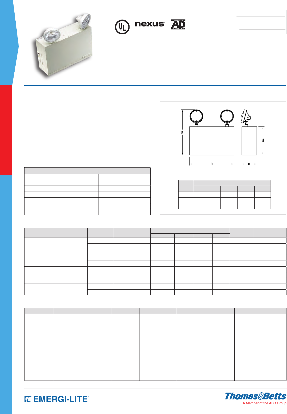
44
SPEC GRADE
COMMERCIAL
TYPE:
CATALOG #:
NOTES:
Dimensions
Dimensions are approximate and subject to change.
Cabinet
Size
Dimensions
a b c d
B 16-3/8” 16-1/8” 5-7/16” 10-1/4”
C 18-3/8” 16-1/2” 7-1/4” 12-1/4”
D 18-3/8” 27” 7-/4” 12-1/4”
Features
• Each unit comes with two (2) EF-18 heads with 9 watt high intensity
incandescent lamps (standard)
• All-steel construction with an off-white baked enamel nish
• Available with sealed, maintenance-free Nickel-Cadmium, Long Life Lead,
Lead-Calcium (Immobilized Electrolyte), or Lead-Calcium batteries
• PulsePlus Charger circuitry offers 120/277VAC, input 60 Hz., 0.3/0.15A
(other inputs available), fused output circuit(s), dual diagnostic indicator
lights, temperature compensation, sealed relay, low voltage battery
disconnect, brownout protection and lock out (automatic battery connect)
• Removable front panel
• UL Listed. Complies with NEC, Life Safety Code and OSHA. Approved for
use in the Commonwealth of Pennsylvania
• 3-year full warranty, excluding lamps and fuses
24 LS & 24 LC Series
24 Volt Steel Enclosure
Unit Rating
Furnished standard with two 9 watt High Intensity Incandescent lamps.
Sealed Maintenance-Free Battery Types D.C. Voltage Model Number Watts to 87-1/2% of rated battery voltage* # of Load Fuses Cabinet size
1-1/2 hrs 2 hrs 3 hrs 4 hrs
Nickel-Cadmium 24 24LSC72-2 72 42 24 12 2 B
24 24LSC100-2 100 73 37 20 2 B
Long Life Lead
24 24LSE72-2 72 48 26 14 2 B
24 24LSE110-2 110 74 43 21 2 B
24 24LSE320-2 320 300 148 76 2 D
Lead-Calcium
(Immobilized Electrolyte)
24 24LC300-2 300 240 132 72 2 D
24 24LC350-2 350 280 168 96 2 D
24 24LC400-2 400 336 192 96 2 D
Lead-Calcium 24 24LSM110-2 110 72 40 24 2 B
24 24LSM220-2 220 144 80 48 2 C
*National Electrical Code Specification.
How to Order
COLOR SERIES/CAPACITY # OF LAMPS HEAD STYLE LAMP TYPE OPTIONS
Blank= Off white
B= Black
enclosure
LSC Series
24LSC100= 24V-100W Ni-Cd
LSE Series
24LSE72= 24V-72W Long Life Lead
24LSE110= 24V-110W Long Life Lead
24LSE320= 24V-320W Long Life Lead
LSM Series
24LSM110= 24V-110W Lead-Calcium
24LSM220= 24V-220W Lead-Calcium
LC Series
24LC300= 24V-300W Lead-Calcium
24LC350= 24V-350W Lead-Calcium
24LC400= 24V-400W Lead-Calcium
-0= No heads
-1= 1 head
-2= 2 heads
-3= 3 heads
Blank= EF18
(PAR 36 plastic)
28= EF28
(PAR 36 metal)
9= EF9 mini plastic
10= EF10 mini
plastic MR16
32= EF32 cylinder
lamp heads
150= EF150 MR16
lamp heads
I_= Incandescent DC-bayonet
Z_= Incandescent wedge
M_= Halogen MR16*
LL= 24V-4W, MR16 LED
Blank= No options
-AD= Advanced diagnostics*
-ADNA= Diagnostics non-audible*
-NEX= Nexus® wired
-NEXRF= Nexus® wireless
-V= Voltmeter (A cabinet units.
Choose A or V only)
-A= Ammeter*
-D1= Time Delay (5 minutes)
-D2= Time Delay (10 minutes)
-D3= Time Delay (15 minutes)
-CP= Cord and plug 120V**
-E= Cord and plug 277V
* Available with EF10 & 150 only
** Available with EF18 & EF28 only
NOTE: For a complete list of available lamp types,
please refer to the lamp data on pages 146-147
* Minimum lamp load required:
20% of unit capacity. Not available with
24V-100W Ni-Cd
** Standard cord is 3 ft.
Example: 24LSC100-2150MH
Accessories (order as a separate item)
DESCRIPTION SUFFIX
Mounting bracket (cabinet B) B2
Mounting shelves (cabinet B) MP3-EG
Mounting shelves (cabinet C) MP6-EG
Mounting shelves (cabinet D) MP12
Wire Guard (cabinet A) WG2-E
Wire Guard (cabinet B & C) WG3-E
Wire Guard (cabinet D) WG4-E
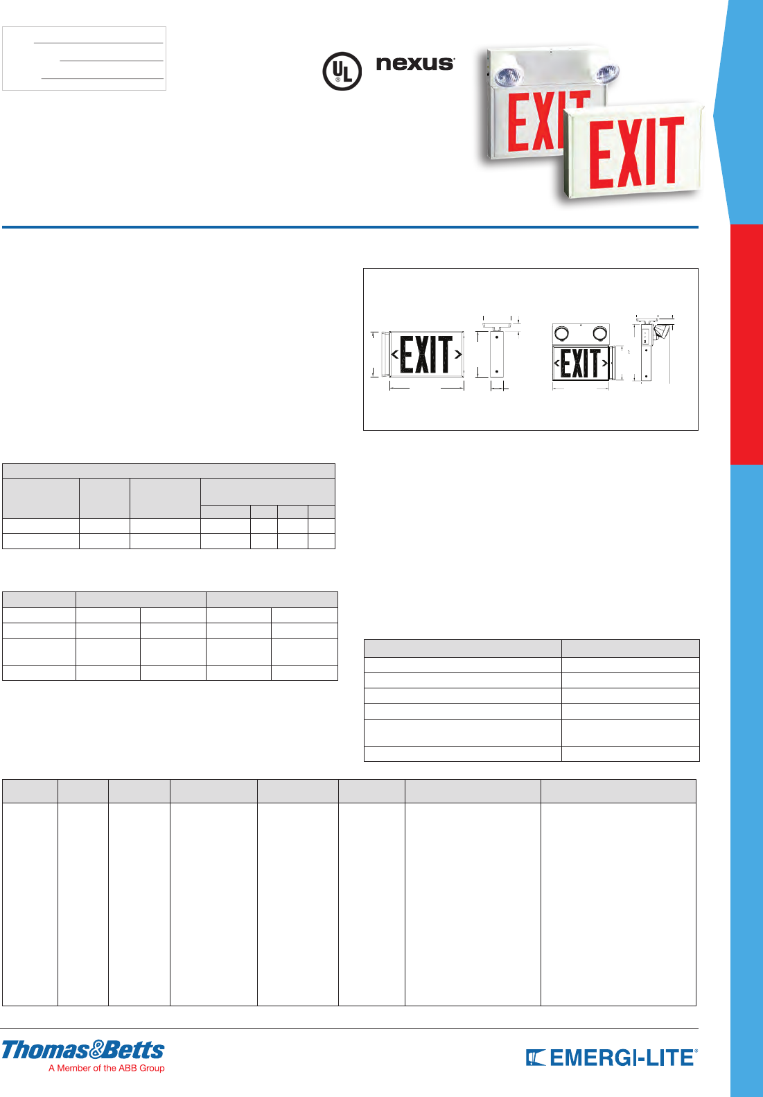
SPEC GRADE
45
COMMERCIAL
TYPE:
CATALOG #:
NOTES:
How to Order
DC INPUT SERIES HOUSING
COLOR BATTERY TYPE LEGEND COLORS # OF HEADS LAMP TYPE OPTIONS
Blank= No
DC input
DC= 6V to
24VDC*
L= LED
Exit sign W= White
B= Black
A= Textured
aluminum
Exit Sign Models
X14= AC only or
AC/DC
SNX14= Ni-Cd
120/277VAC input
(only for DC)
Mini System
Models
SBX14= 6V-30W
Lead-Calcium
STX14= 6V-24W
Nickel-Cadmium
R= Red
G= Green
Open face
RW= Red/white
WR= White/red
GW= Green/white
WG= White/green
Blank=
No head
-1= 1 head
-2= 2 heads
H_= Halogen bi-pin
I_= Incandescent DC-bayonet
U_= Incandescent sealed-beam**
X_= Halogen sealed-beam**
Z_= Incandescent wedge
M_= Halogen MR16*
L_= MR16 LED*
Blank= No options
-NEX= NEXUS® wired
(consult your sales representative)*
-NEXRF= NEXUS® wireless
(consult your sales representative)*
D1= Time Delay (5 minutes)
D2= Time Delay (10 minutes)
D3= Time Delay (15 minutes)
-2CKT= Dual circuit (AC Only)
-FL= Flasher*
-FZ= Flasher buzzer combination*
-FA= Fire alarm activated flasher*
-L= Brushed aluminum face
-VR= Vandal-resistant screws
* Only available
on Exit Sign
models #- Other color
(Open face required with
special wording legends)
* Available with 10 & 150 lamp head only
** Available with EF18 only
NOTE: For a complete list of available lamp
types, please refer to the lamp data
on pages 146-147 * Mini-System Combination Units only
Example: DCLWX14R-VR
Dimensions
Dimensions are approximate and subject to change.
Mini System Model Dimensions
Exit Sign (SNX) Model Dimensions
4-5/8”
7-3/8”
7-5/8”
12-1/8” 2-1/8”
1-1/4” 4-5/8” 1-1/4”
7-3/8”
12-1/4”
12-1/8” 6-1/8”
Features
• Red or green LED light sources.
• Constructed of rugged 20 gauge steel. Off-white or black epoxy powder
nish
• Available with sealed, maintenance-free Nickel-Cadmium, Long Life Lead or
Lead-Calcium batteries
• PulsePlus charger circuitry offers 120/277VAC 60Hz, 0.3/0.15A (other inputs
available), fused output circuit, pilot and charge indicator lights, temperature
compensation, sealed relay, low voltage battery disconnect, brownout
protection and lock out (automatic battery connect)
• Universal mounting, single or double face, stencil or open face are available
• UL Listed. Exceeds UL Exit Visibility Requirement
• 3-year full warranty
X10 LED Series
Steel LED Exit & Mini- System
Combination Units
Accessories (order as a separate item)
DESCRIPTION SUFFIX
White Pendant P-WT*
Black Pendant P-BK*
Wire Guard Ceiling Mount (Exit Only) WG5-E
Wire Guard End Mount (Exit Only) WG5-E
Wire Guard For Wall Mount (AC Only, AC/
DC & Self-Powered Exit Signs) WG12-E
Wire Guard For Wall Mount (Mini System or Combo) WG6-E
Power Consumption (Mini-System Combination Units)
120/277VAC 60Hz, 03/0.15 Amp.
Unit Rating
(Total DC power available for local and remote emergency lights.)
UNIT EQUIPMENT - MINI-SYSTEM
Battery Type D.C. Voltage Model Number
Watts to 87-1/2% of rated battery
voltage*
1-1/2 hrs 2 hrs 3 hrs 4 hrs
Lead-Calcium 6 SBX14 30 20 15 10
Nickel-Cadmium 6 STX14 24 18 12 9
*National Electrical Code Specification
Power Consumption (LED Exit Signs)
Model AC Specs DC Specs
AC-only: L-X14 120 to 277 VAC Less than 1.5W – –
AC/DC: DCL-X14 120 to 277 VAC Less than 1.5W 6 to 24 VDC Less than 1.5W
Self-Powered:
L-SNX14 120 to 277 VAC Less than 3W Nickel-
Cadmium Min. 90 minutes
Mini-System 120/277VAC 0.3/0.15 Amp
*National Electrical Code Specification
Choice of Models
Mini-systems
Remote capacity L-SBX14 models
No EF9 mounted heads = 30W remote capacity
Two 5.4-watt EF9 mounted heads = 19W remote capacity
Remote capacity L-STX14 models
No EF9 mounted heads = 24W remote capacity
Two 5.4-watt EF9 mounted heads = 13W remote capacity
Exit Sign
AC input: universal 2-wire 120 to 277VAC 50/60Hz
AC/DC models: universal 2-wire 6 to 24VDC
Self-Powered models: long-life, sealed Nickel-Cadmium battery
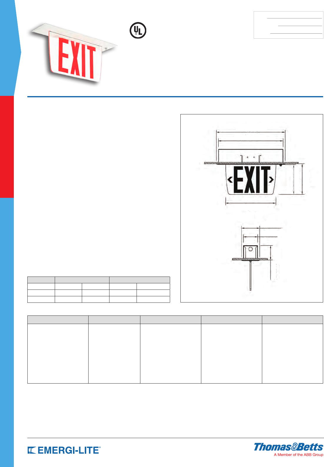
46
SPEC GRADE
COMMERCIAL
TYPE:
CATALOG #:
NOTES:
How to Order (Surface Mount Series)
HOUSING COLOR SERIES TRIM FACE LEGEND COLOR
TA= Textured aluminum
OW= Off white
PE= AC
PES= AC/DC
PEN= Self-Powered
F= Recessed flat trim 1= Single face
2= Double face
RC= Red on clear*
RW= Red on white
RM= Red on mirror
GC= Green on clear*
GM= Green on mirror
*Single face only
Example: TAPEF1RC
Features
• Rugged, 20-gauge steel back box
• Equipped with bar hanger kit for easy installation
• Formed steel at trim plate
• Choice of nishes: textured aluminum or off-white
• Acrylic panel with curved contour provides superior clarity
and illumination
• Legend with a choice of red or green letters
• Choice of legend background: clear, white (red legend only) or mirror
• Stick-on translucent directional chevrons for eld installation
• Simple, two-wire universal AC input (120V to 277VAC 50/60Hz) prevents
installation errors
• Sealed Nickel-Cadmium batteries provide 90 minutes of emergency lighting
• Simple, two-wire universal DC input: 6V to 24 VDC
• Long-life LED light for low maintenance costs and superior illumination
• Energy efcient power consumption: less than 2.5W for single or double face
legends
• UL 924 Listed
Dimensions
Dimensions are approximate and subject to change.
15-1/8”
16”
11-3/4”
7”
7-1/8”
4-1/4”
3-3/8”
3-3/8”
Prestige™
Economizer Series
Recessed Mount Edge-Lit Exit Sign
Power Consumption
Model AC Specs DC Specs
AC-only 120 to 277VAC Less than 1.5W – –
AC/DC-remote 120 to 277VAC Less than 1.5W 6 to 24VDC Less than 1.5W
Self-Powered 120 to 277VAC Less than 2.5W Ni-Cd battery Min. 90 minutes
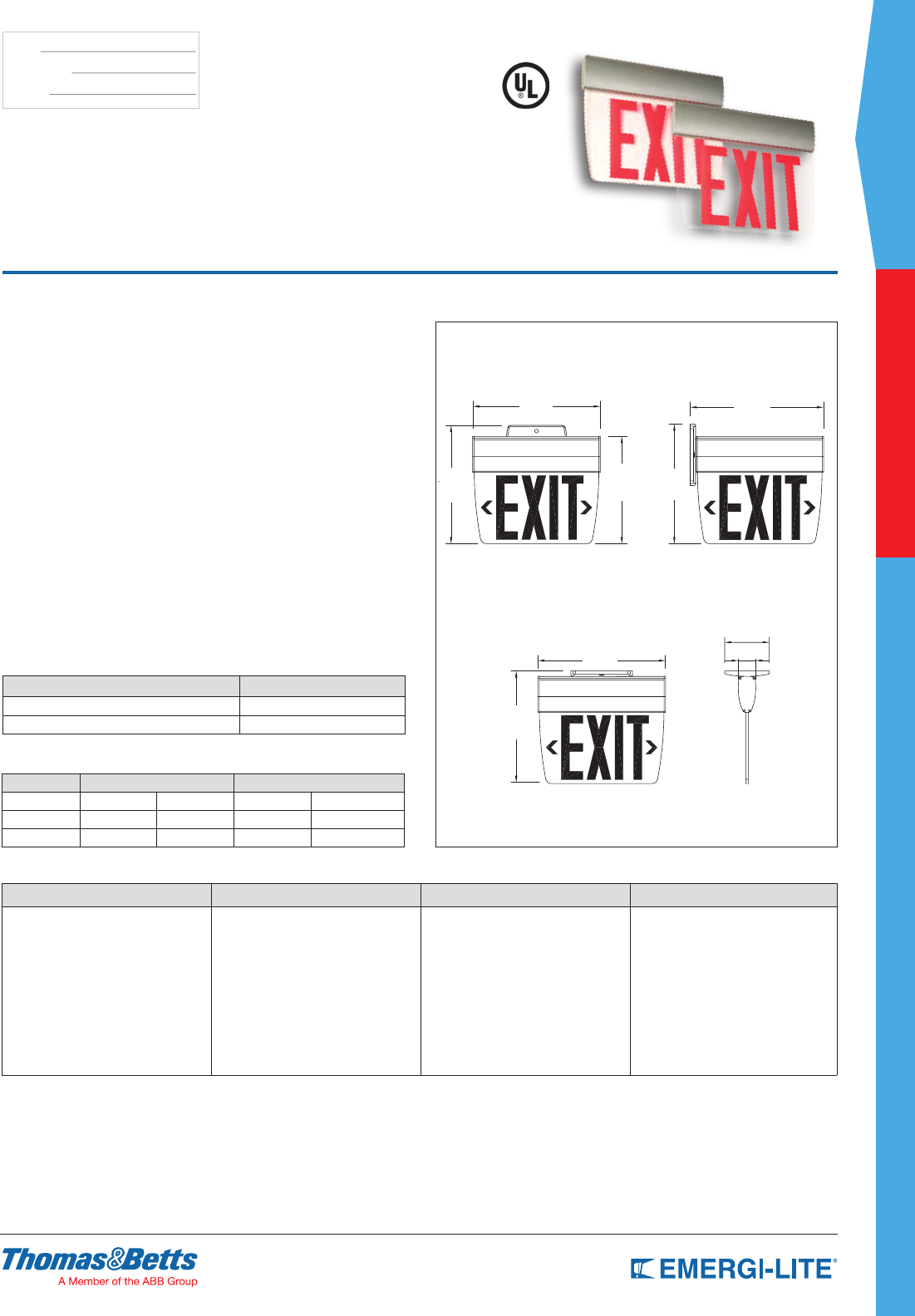
SPEC GRADE
47
COMMERCIAL
TYPE:
CATALOG #:
NOTES:
How to Order (Surface Mount Series)
HOUSING COLOR SERIES FACE LEGEND COLOR
TA= Textured aluminum
OW= Off white
PE= AC
PES= AC/DC
PEN= Self-Powered
1= Single face
2= Double face
RC= Red on clear*
RW= Red on white
RM= Red on mirror
GC= Green on clear*
GM= Green on mirror
* Single face only
Example: TAPE1RC
Features
• Acrylic panel with curved contour provides superior clarity and illumination.
Long-life LED light for low maintenance costs and superior illumination
• Legend with a choice of red or green six-inch letters, and easy-to-add
eld-installed stick-on translucent directional arrows. Choice of legend
background: clear, white or mirror
• Slim-prole extruded aluminum housing with slim-prole Die-Cast aluminum
canopy. Choice of nishes: textured aluminum or off-white
• Energy efcient power consumption: less than 3W for Self-Powered version
and less than 2 watts for AC only single or double face
• Available with sealed Nickel-Cadmium batteries that provide 90 minutes of
emergency lighting
• Simple, two-wire universal AC input (120V to 277VAC 60Hz) prevents
installation errors. Simple, two-wire universal DC input: 6V to 24VDC
• Universal surface mounting: wall, ceiling or end mount. Click-to-open
housing door allows easy access to the panel and electrical wiring.
For recessed mount please consult your sales representative
• UL 924 Listed
• 3-year full warranty, subject to proper installation and maintenance
Dimensions
Dimensions are approximate and subject to change.
Ceiling Mount
End Mount
Wall Mount
10-5/8”
4-1/4”
1-5/8”
12”
11-1/8”
10-1/8”
11-1/4”
12-1/2”
12”
Prestige™
Economizer Series
Slim Profile Surface Mount LED Edge-Lit Exit Sign
Power Consumption
Model AC Specs DC Specs
AC-only 120 to 277VAC Less than 2W – –
AC/DC 120 to 277VAC Less than 2W 6 to 24VDC Less than 1.5W
Self-Powered 120 to 277VAC Less than 3W Ni-Cd battery Min. 90 minutes
Accessories (order as a separate item)
DESCRIPTION SUFFIX
White PE-P-WH*
Black PE-P-BK*
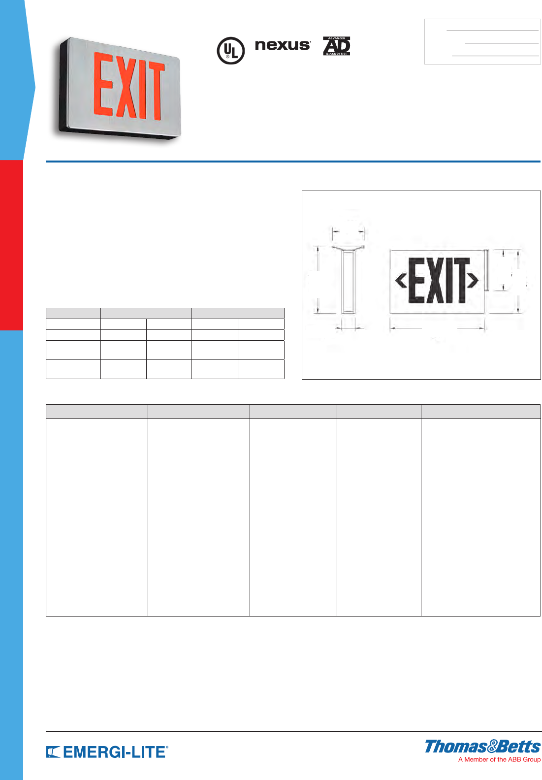
48
SPEC GRADE
COMMERCIAL
TYPE:
CATALOG #:
NOTES:
How to Order
HOUSING COLOR SERIES/MODELS # OF FACES LEGEND COLOR OPTIONS
BA= Black body/aluminum face
WW= White body/white face
WA= White body/aluminum face
BB= Black body/black face
AA= Brushed aluminum
body and face
Standard Models
P= AC only (120/277 volts )
PU= 120/277VAC & 6 to 24VDC
PXN= Self-Powered
diagnostic Ni-Cd
PDN= Self-Powered Ni-Cd, No AD
Optional Models
P2C1= Dual AC circuit (2 x 120V)
P2C2= Dual AC circuit (2 x 277V)
PNEX= NEXUS® wired
(consult your sales representative)
PNEXRF= NEXUS® wireless
(consult your sales representative)
1= Single face
2= Double face
R= Red
G= Green
Open Face
RW= Red on white
GW= Green on white
Blank= No options
DL= Damp Location
FZ= Flasher buzzer*
FL= Flasher*
FA= Fire alarm activated flasher
(Not available with PDN)
FBF= Flasher buzzer + fire alarm
activated flasher*
VR= Tamper-proof screws**
VR1= Polycarbonate shield with
tamper-proof screws**
Other colors available
Note: Open face required with special
wording legends
* PXN, PNEX and PNEXFR models only
** Please specify single or double face red or green
Example: BAPU2R
Features
• Housing of Die-Cast aluminum in a variety of nishes
• Slim-line canopy for top and end mounting
• Universal mounting for wall, end, or ceiling
• Universal, eld-selectable knock-out chevrons
• Long-life red or green LED light source.
• Dual voltage input: 120/277VAC 60Hz
• Low power consumption: less than 3W in any conguration
• Self-Powered models with sealed maintenance-free
Nickel-Cadmium batteries
• UL 924 Listed
• 5-year full warranty
Dimensions
Dimensions are approximate and subject to change.
4-3/8”
1-7/8” 12-7/8”
9-1/8”
5-1/2”
8-5/8”
Preceptor™ Series
Die-Cast Aluminum LED Exit Sign
Power Consumption
Model AC Specs DC Specs
AC-only 120/277VAC Less than 2.5W – –
AC/DC-remote 120/277VAC Less than 2W 6 to 24VDC Less than 1.5W
Self-Powered 120/277VAC Less than 3W Ni-Cd battery Min. 90
minutes
Self-Powered
with Diagnostic 120/277VAC Less than 2.8W Ni-Cd battery Min. 90
minutes
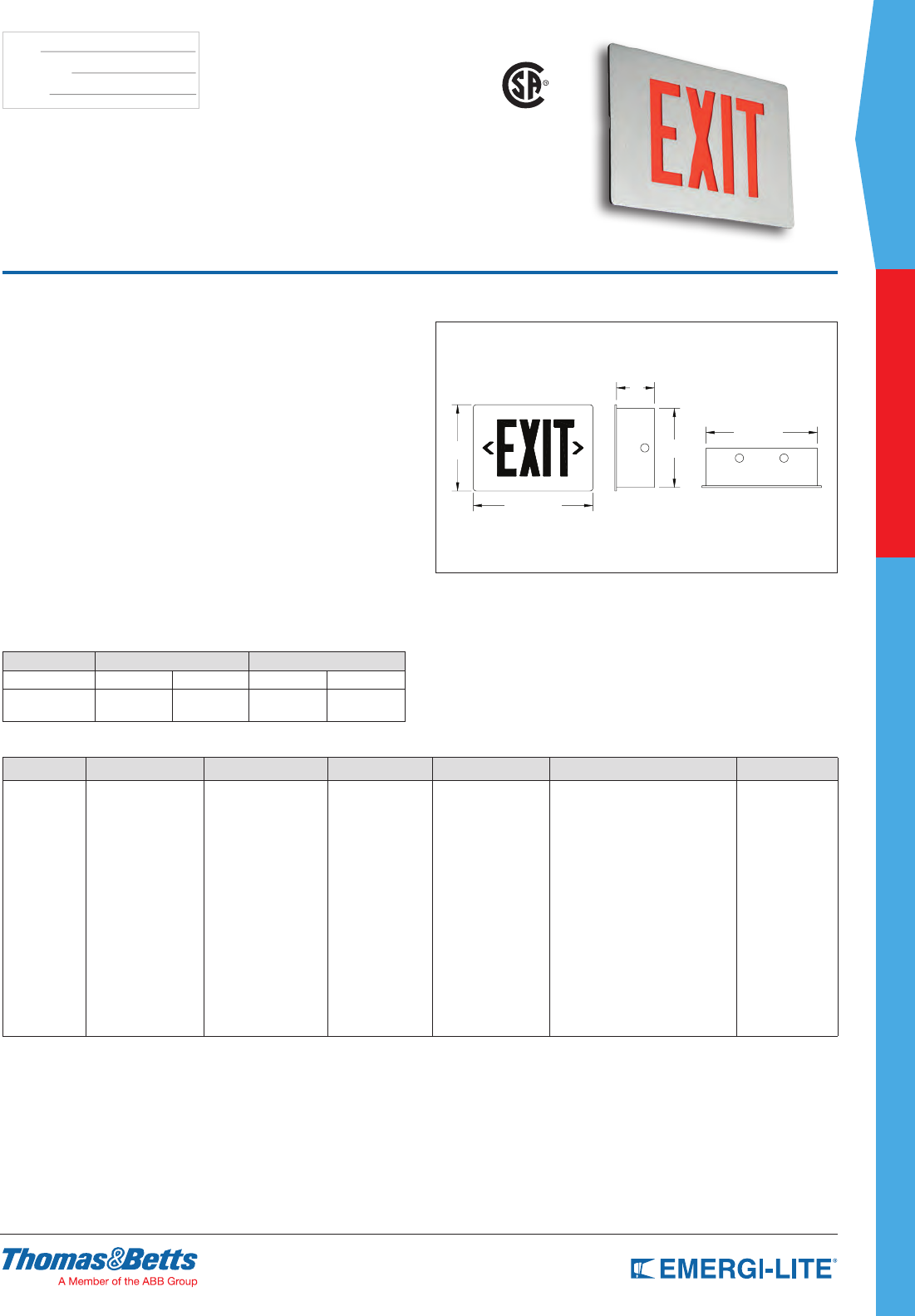
SPEC GRADE
49
COMMERCIAL
TYPE:
CATALOG #:
NOTES:
How to Order
RECESSED FACE COLOR SERIES # OF FACES LEGEND COLOR OPTIONS VERSION
FR= Fully
recessed
Blank= Aluminum face
B= Black face
W= White face
PB= Polished
brass face
CH= Polished
chrome face
BZ= Dark bronze face
LEDP= AC only
LEDPXN= Self-Powered
Ni-Cd
1= Single face R= Red
G= Green
RW= Red on white
(Open face)
GW= Green on white
(Open face)
FZ= Flasher buzzer (Self-Powered)
FA= Fire alarm activated
flasher (Self-Powered)
DL= Damp Location
VR= Vandal-resistant screws
VR1= Polycarbonate shield with
tamper-proof screws
-2CKT= Dual circuit operation
(AC models only)
-N= New design
Custom color vailable, consult
your sales representative
Example: FRBLEDP1R-VR1-N
Features
• LED light sources. Long life LEDs eliminate the twice-a-year re-lamping
typical of incandescent lamps
• Self-Powered models are self contained; batteries and circuitry are located
inside the exit housing
• Available with sealed maintenance-free Nickel-Cadmium batteries to provide
90 minutes of emergency illumination
• Two-wire universal input 120 through 277VAC, 60Hz
• Diagnostic / Self Test circuitry is standard on all Self-Powered models. This
circuitry is programmed to ensure the exit sign’s readiness and reliability
by continuously monitoring every critical function of the unit. If a problem
occurs, a single “service required” indicator illuminates immediately. A
detailed diagnostic display sign that will further indicate the nature of the fault
is located on the inside of the exit sign, out of sight from the general public.
The self test will test the unit for 30 seconds every 30 days, 30 minutes every
60 days and 90 minutes annually
• Unaffected by the vibrations, ambient temperature swings and typical power
surges detrimental to standard exit light sources
• 5-year full warranty
• UL Listed
Dimensions
Dimensions are approximate and subject to change.
Fully Recessed Mount
9-1/4”
11-7/8”
8-1/2”
4”
12-3/4”
Preceptor™ Recessed Series
Die-Cast LED Exit Sign
US
Power Consumption
Model AC Specs DC Specs
AC-only 120 to 277VAC 1.4W – –
Self-Powered 120 to 277VAC 1.7W Ni-Cd battery Min. 90
minutes
Choice of Models
AC-Only Models:
120 through 277VAC, 60Hz universal input.
“Self-Powered Models are self contained, batteries and circuitry are located
inside the exit housing”: 120 through 277VAC, 50/60Hz universal input.
Sealed maintenance free Nickel-Cadmium battery
provides 90 minutes of emergency illumination.
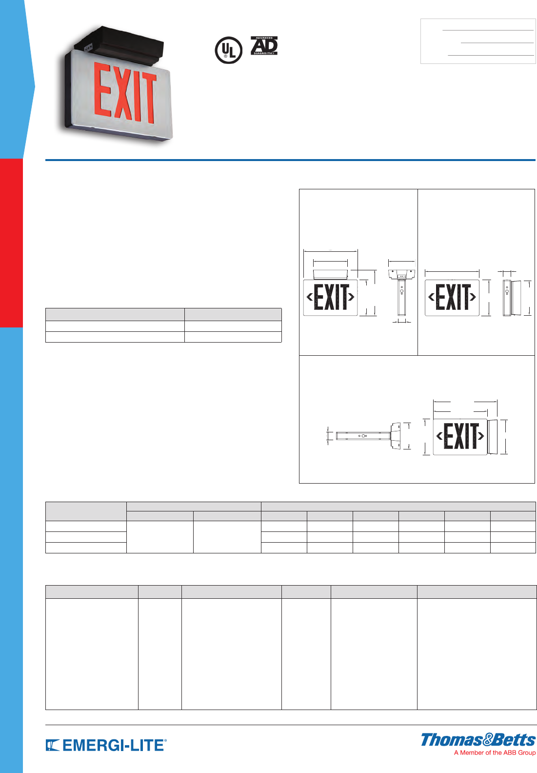
50
SPEC GRADE
COMMERCIAL
TYPE:
CATALOG #:
NOTES:
How to Order
HOUSING COLOR SERIES BATTERY TYPE # OF FACES LEGEND COLOR OPTIONS
BA= Black body/aluminum face
BB= Black body/black face
WW= White body/white face
WA= White body/aluminum face
AA= Brushed aluminum
body and face
P= Preceptor RCL= Sealed Lead-Calcium,
9W remote capacity
RCN= Sealed Nickel-Metal Hydride,
12W remote capacity
RCX= Sealed Nickel-Metal Hydride,
24W remote capacity
1= Single face
2= Double face
R= Red
G= Green
RW= Red on white
(Open face required
for special wording)
GW= Green on white
(Open face required
for special wording)
AD= Advanced Diagnostics (audible)
ADNA= Advanced Diagnostics (non-audible)
D1= Time Delay (5 minutes)
D2= Time Delay (10 minutes)
D3= Time Delay (15 minutes)
FZ= Flasher buzzer
FA= Fire alarm activated flasher
DL= Damp Location
VR= Vandal-resist screws
VR1= Vandal-resistant polycarbonate
lens and screws
Example: BAPRCL2R
Features
• Long-life, high-performance, low power consumption, red or green LEDs
provide even illumination in normal and emergency modes.
• Constructed of Die-Cast aluminum with a power canopy that houses the
battery, input transformer and printed circuit board. The standard unit color is
a black frame with a brushed aluminum face. Specify single or double face
as required.
• Available with sealed maintenance-free Lead-Calcium or Nickel-Metal
Hydride (cadmium-free, environmentally friendly) batteries.
• Can be ceiling, end or back mounted to the power canopy. The power
canopy surface mounts directly to the junction box (supplied by others).
• UL Listed. Complies with NEC, Life Safety Code and OSHA.
• 5-year full warranty.
Dimensions
Dimensions are approximate and subject to change.
12-7/8” 1-7/8”
8-1/2”
8-1/8”
Ceiling Mount Back Mount
12-7/8”
8-1⁄8” 6-1/4”
1-7/8”
8-1/2”
10-7/8”
End Mount
12-7/8”
15-1/4”
1-7/8”
6-1/4”
8-1/2”
8-1/8”
Preceptor™
Remote Capacity Series
Die-Cast Aluminum Remote Capacity Exit Sign
Application Flexibility
Lead-Calcium Models (RCL) - Sealed, maintenance-free Lead-Calcium
batteries power the exit sign for an estimated period of 20+ hours minimum
with no remote load or 90-minutes run time with 9 watts remote load.
Nickel-Metal Hydride Models (RCN) - Sealed, maintenance-free
Nickel-Metal Hydride batteries power the exit sign for an
estimated period of 20+ hours minimum with no remote load
or 90-minutes run time with 12 watts remote load.
Nickel-Metal Hydride Models (RCX) - Sealed, maintenance-free
Nickel-Metal Hydride batteries power the exit sign for an estimated
period of 40+ hours minimum with no remote load or 90-minutes
run time with 24 watts remote load.
Power Consumption & Unit Rating Chart
Series AC Specs DC SPECS - WATTS TO 87-1/2% OF RATED BATTERY VOLTAGE*
AC Input Maximum Voltage Battery 1-1/2 hrs. 2 hrs. 3 hrs. 4 hrs.
RCL
120/277VAC, 60Hz 0.13/0.06A 15W
6V Lead-Calcium 9 – – –
RCN 6V NiMH 12 9 – –
RCX 6V NiMH 24 18 12 9
* National Electrical Code Specification
Accessories (order as a separate item)
DESCRIPTION SUFFIX
Wire Guard, Back Mount WG13-E
Wire Guard, Ceiling Mount WG14-E
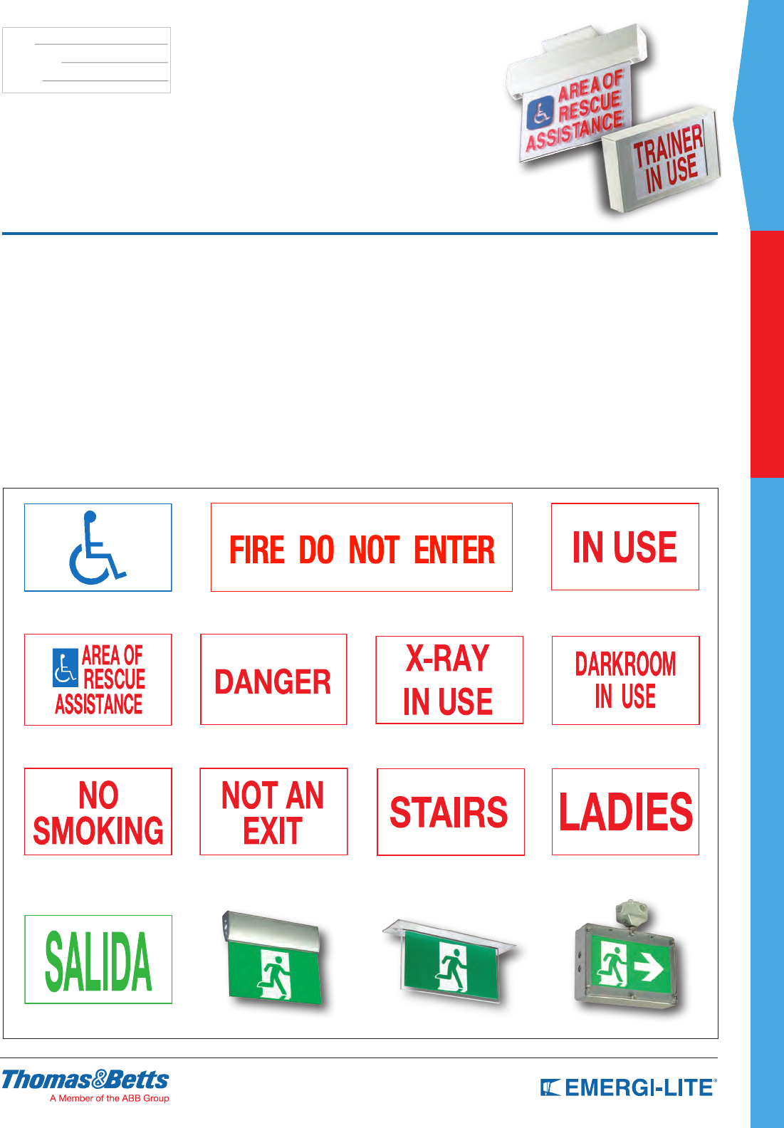
SPEC GRADE
51
COMMERCIAL
TYPE:
CATALOG #:
NOTES:
Special Wording Series
Custom Illuminated Signage
Features
• The same sturdy construction and electrical design used in our exit signs is
used to produce our custom-worded, illuminated signage
• Sign bodies are available in steel, extruded and Die-Cast aluminum,
weatherproof, ame-retardant polycarbonate, high impact thermoplastic and
recessed housing
• Also available with combination units
• Custom wording with available in any style of lettering, any language, and
alphabet, any special characters
• Graphics can include logos, standard symbols and custom art
• Color choices for sign bodies, message and faceplate panel
• llumination from LED (light-emitting diodes); other light sources available
• Contact your local Emergi-Lite® sales representative to discuss your specic
requirements
Illuminated Signage
Custom-worded, illuminated signage is available using the same sturdy
construction and electrical design as Emergi-Lite® exit signage. A wide range
of sign body options and color choices are available to suit any application.
SPEC GRADE
53
INDUSTRIAL
SPEC GRADE
INDUSTRIAL
Table of Contents
Hazardous Location Information 54
Survive-All™ SV Series 55
Survive-All™ SVX Combo Series 56
Survive-All™ SVX Exit Series 57
Survive-All™ EF39 & EF40 Series 58
HZM Series 59
Survive-All™ SVH Series 60
Survive-All™ SVXH Series 61
Survive-All™ SVXHZ Series 62
Survive-All™ EF41 Series 63
IL Series 64-65
KS Steel Series 66-67
KS Series 68-69
EXC Series 70-71
EFEP Series 72
EFXP Series 73
Ever-Lite™ Self-Luminous Series 74
HAZARDOUS LOCATION INFORMATION
Typical Class l Locations:
• Petroleum reneries, and gasoline storage and dispensing areas.
• Industrial rms that use ammable liquids in dip tanks for cleaning parts or other
operations
• Petrochemical companies that manufacture chemicals from gas and oil.
• Dry cleaning plants where vapors from cleaning uids can be present.
• Companies that have areas dedicated for spraying products with paint or plastics.
• Aircraft hangars and fuel servicing areas.
• Utility gas plants, and operations involving storage and handling of liquied petroleum gas
or natural gas.
Typical Class ll Locations:
• Grain elevators, our and feed mills.
• Plants that manufacture, use or store magnesium or aluminum powders.
• Plants that have chemical or metallurgical processes, producers of plastics, medicines,
and reworks etc.
• Producers of starch or candies.
• Spice grinding plants, sugar plants and cocoa plants.
• Coal preparation plants and other carbon handling or processing areas.
Typical Class lll Locations:
• Textile mills, cotton gins, cotton seed mills and ax processing plants.
• Clothing manufacturing plants
• Any plant that shapes pulverizes or cuts wood and creates saw dust or shavings.
FOR MORE INFORMATION CONSULT NEC CODE.
Hazardous locations are areas where a potential for explosion or fire exists due to the presence of
certain gases, liquid vapors, combustible dusts or fiber particles suspended in the air. The National
Electrical Code®, NEMA, OSHA, UL, NFPA Life Safety Standards, as well as State and Local codes
prescribe the use of emergency lighting equipment. This equipment itself must not contribute to
the ignition of flammable or explosive substances present in the location. Emergi-Lite® offers a
complete line of emergency lighting equipment for use in hazardous locations.
Hazardous Location Classifications
Class l
(NEC-500-5)
Areas in which flammable gases or vapors may be present
in sufficient quantities to be explosive or ignitable.
Class ll
(NEC-500-6) Areas made hazardous by the presence of combustible dust.
Class lll
(NEC-500-7)
Areas in which there are easily ignitable fibers or flyings present,
due to the type of material being handled, stored or processed-but
in which such fibers or flyings are not likely to be in suspension
in the air in quantities sufficient to produce ignitable mixtures.
Division 1
(NEC-500-5,6 & 7)
Normal Situation: A hazard is present in the everyday normal production
operation or during frequent repair and/or maintenance activity.
Division 2
(NEC-500-5,6 & 7)
Abnormal Situation: Potentially hazardous material is expected
to be safely confined within closed containers or closed
systems, and will be present in the atmosphere only through
accidental rupture, breakage, or abnormal operation.
Group A, B, C &
D (NEC-500-3)
Gases and vapors in Class l locations are classified into four
groups, by the code A, B, C, and D. These materials are grouped
according to the ignition temperature of the substance, its
explosion pressure and other flammability characteristics.
Groups E F & G
(NEC-500-3)
Combustible dust in Class ll locations are classified according
to ignition temperature and the conductivity
of the hazardous substance.
NEMA Enclosure
Type 1 - Intended for use indoors primarily to prevent accidental contact of personnel with the enclosed equipment.
Type 2 - Intended for use indoors to protect the enclosed equipment against falling non-corrosive liquids and falling dirt.
Type 3 - Intended for use outdoors to protect the enclosed equipment against rain, windblown dust, sleet and external ice formation.
Type 3R - Intended for use outdoors to protect the enclosed equipment against falling rain, sleet and external ice formation.
Type 4 - Intended for use indoors and outdoors to protect the enclosed equipment against windblown dust, rain, splashing water and hose directed water.
Type 5 - Intended for indoor use primarily to protect against dust and falling dirt.
Type 6 - Intended for indoor or outdoor use primarily to provide a degree of protection against the entry of water during occasion al temporary submersion at a limited depth.
Type 6P Intended for indoor or outdoor use primarily to provide a degree of protection against the entry of water during prolonged s ubmersion at a limited depth.
Type 7 - Intended for use indoors in locations classified as Class l, Groups A, B, C, or D as defined in the National Electrical Code®.
Type 8 - Intended for indoor or outdoor use in locations classified as Class l, Groups A, B, C, & D as defined in the National Electrical Code®.
Type 9 - Intended for indoor locations classified as Class ll, Groups E, F & G, as defined in the National Electrical Code®.
Type 10 - Enclosures are constructed to meet the applicable requirements of the Mine Safety and Health Administration.
Type 11 - Intended for indoor use primarily to provide, by oil immersion, a degree of protection to enclosed equipment against the corrosive effects of liquids and gases.
Type 12 - Intended for indoor use primarily to provide a degree of protection against dust, falling dirt, and dripping noncorrosive liquids.
Type 12K - Enclosure with knockouts intended for indoor use primarily to provide a degree of protection against
dust, falling dirt, and dripping non-corrosive liquids other than at knockouts.
Type 13 - Intended for indoor use primarily to provide a degree of protection against dust, spraying of water, oil, and noncorrosive coolant.
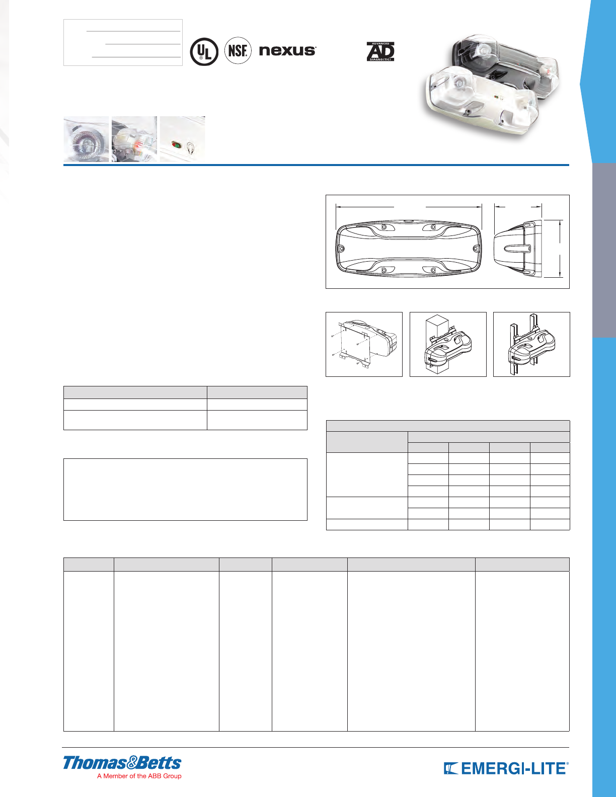
SPEC GRADE
55
INDUSTRIAL
TYPE:
CATALOG #:
NOTES:
How to Order
COLOR SERIES # OF LAMPS LAMPS DIAGNOSTICS OPTIONS
B= Black
G= Gray
W= White
SV18M= 6V-18W Lead-Calcium
12SV24M= 12V-24W Lead-Calcium
12SV36M= 12V-36W Lead-Calcium
12SV54M= 12V-54W Lead-Calcium
12SV24N= 12V-24W
Nickel-Cadmium*
12SV40N= 12V-40W
Nickel-Cadmium*
12SV60H= 12V-60W NiMH*
-2= 2 Lamps LA= 6V-4W, MR16 LED
LG= 12V-4W, MR16 LED
LI= 12V-5W, MR16 LED
LJ= 12V-6W, MR16 LED
MI= 6V-6W, MR16
MK= 12V-12W, MR16
MW= 12V-20W, MR16-IR
-DA= Advanced Diagnostics (audible)*
-D= Advanced Diagnostics (non-audible)*
-NEX= NEXUS® wired
(consult your sales representative)
-NEXRF= NEXUS® wireless
(consult your sales representative)
Blank= No options
CW4= Cold weather
-40°F to 104°F
(-40°C to +40°C)*
*= Suitable for Damp-Locations
50°F to 104°F (10°C to 40°C) * Minimum lamp load: 20% of unit capacity
* Only available with
12SV24M & 12SV36M
Not available with NEX and NEXRF option
Example: B12SV36M-2LG-DCW4
Features
• Equipped with a tool-less MR16 swivel lamp assembly to provide precise
beam control. Choice of MR16 LED or halogen lamps of 6V and 12V
• Fully gasketed cast aluminum back plate with clear, UV resistant
polycarbonate cover. Tamper-proof screws and bit are included. Available in
black, white or gray
• Standard temperature 50°F to 104°F (10°C to 40°C).
• Available with sealed, maintenance-free Nickel-Cadmium (UL Listed for damp
and wet locations), or Lead-Calcium batteries
• Standard 120/277VAC 0.3/0.15A input. Non-audible advanced diagnostic
charger board, 15 minute Time Delay and lamp disconnect. Audible warning
and Time Delay functions can be enabled or disabled during installation. Non-
obtrusive, magnetic test switch. Micro-controller diagnostic system tests,
detects and indicates battery, charger circuitry or MR16 lamp failures.
• Wall, strut or beam mounting
• UL Listed. Certied to meet UL924 standards, 90 minutes of emergency
operation, NEMA-4X rated for high abuse areas, wet locations and cold
weather (-40°F/-40°C) applications, NSF Certied for use in food processing
plants
• 3-year full warranty, excluding lamps and fuses
Dimensions
Dimensions are approximate and subject to change.
17-3⁄4” 5-3⁄4”
7”
Universal Bracket
PMK KIT
(screws included)
BEAM MOUNTING STRUT MOUNTING
Survive-All™ SV Series
NEMA-4X, NSF, Vandal-Resistant Housing
Battery Unit
NEMA-4X
Accessories (order as a separate item)
DESCRIPTION PART NUMBER
Additional special bit for tamper-proof screws 690.0454-E
Universal bracket (for mounting on poles,
I-beams or strut metal framing) PMK-E
Applications
• Hosedown areas / car washes
• Food processing / preparation facilities
• Marine locations
• Chemical plants
• Schools and other public facilities
• Parking garages
• Food processing / preparation facilities
• Transit platforms
• Sports arenas / swimming pools
• Security areas / prisons
• Warehouse and cold
storage facilities
• Heavy industrial facilities
Note: Units installed outdoors must be in a shaded area (Lead-Calcium batteries)
Unit Rating
UNIT EQUIPMENT - WITH REMOTE CAPABILITY
Sealed Maintenance-Free
Battery Types
Watts to 87-1/2% of rated battery voltage*
1-1/2 hrs 2 hrs 3 hrs 4 hrs
Lead-Calcium
18 12 8 –
24 16 12 8
36 24 20 14
54 36 27 20
Nickel-Cadmium 24 18 12 8
40 27 20 14
Nickel-Metal Hydride 60 40 30 20
* National Electrical Code Specication.
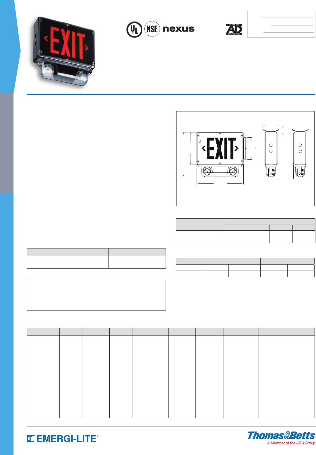
56
SPEC GRADE
INDUSTRIAL
TYPE:
CATALOG #:
NOTES:
How to Order
HOUSING/FACE
COLOR
SERIES/
CAPACITY FACES LEGEND
COLOR DIAGNOSTICS HOUSING # OF HEADS LAMP TYPE/
WATTAGE OPTIONS
WW= White/white
WB= White/black
WA= White/
aluminum
BB= Black/black
BW= Black/white
BA= Black/
aluminum
GA= Gray/
aluminum
GW= Gray/white
GB= Gray/black
SVX12N=
6V-12W
SVX24N=
12V-24W
1= Single face
2= Doubleface
R= Red
legend
G= Green
legend
Blank= Standard
DA= Advanced
Diagnostics
(audible)
D= Advanced
Diagnostics
(non-audible)
NEX= NEXUS®
wired *
NEXRF= NEXUS®
wireless*
4X= Wet/
Damp
Locations
Blank= 0
heads*
2= Two heads
LA= 6V-4W,
MR16 LED
LG= 12V-4W,
MR16 LED
LI= 12V-5W,
MR16 LED
LJ= 12V-6W,
MR16 LED
MI= 6V-6W, MR16
MK= 12V-12W,
MR16
Blank= No options
CW4= Cold weather
(-40°F/-40°C)*
FA= Flasher (fire alarm activated)
F/B= Flasher/buzzer (AC
power failure)**
FL= Flasher (AC power failure)
-208V= 208VAC, 60Hz input
-240V= 240VAC, 60Hz input
-208V50HZ= 208VAC, 50Hz input
-CM= Canopy pendant mount
* Consult your sales
representative
* A remote
load must be
connected
* Single face only
** Not available with “D or DA” diagnostics
Example: WWSVX12N1RD4X2LGCW4
Features
• Each unit comes with two (2) MR16 high intensity lamps (standard). Fully eld-
adjustable lamp head assembly offers the option of selecting either a halogen
lamp or a high efciency white LED light source for optimum illumination over
the path of egress. Exit light source LED
• Rugged PVC body will not dent, peel or corrode. The sealed faceplate is
constructed with a heavy duty, vandal-resistant polycarbonate cover and
fastened with stainless steel tamper-resistant screws
• Available with sealed, maintenance-free Nickel-Cadmium batteries
• Advanced Diagnostic circuitry is standard on all Self-Powered models This
circuitry is programmed to ensure the exit combination unit’s readiness and
reliability by continuously monitoring every critical function of the unit. If a
problem occurs, a single “Service Required” indicator illuminates immediately.
A detailed diagnostic display that will further indicate the nature of the fault is
located on the inside of the exit sign, out of sight from the general public. The
self test will check the unit for a minimum of 30 seconds every 30 days, 30
minutes every 60 days and 90 minutes annually. PulsePlus Charger circuitry
offers 120/277 volt input 60 Hz, 0.3/0.15 Amps (other inputs available), fused
output circuit(s), dual diagnostic indicator lights, temperature compensated
charger, sealed relay, low voltage battery disconnect, brownout protection
and lockout (automatic battery connect). Magnetically operated test switch
• Can be wall, end or ceiling mounted
• NEMA 4X* Rated. UL Listed. Listed for wet and Damp Locations 50°F to
104°F (+10°C/+40°C)
• 5-year full warranty, excluding lamps and fuses
* Nema-4X Certied for wall or ceiling mounting only
Dimensions
Dimensions are approximate and subject to change.
Dimensions without heads Double Face Single Face
9-3/16”
13-1/4”
4-5/8”
3-7/8” 3-7/16”
3/4”
6-1/4”
12-5/8”
Survive-All™ SVX Series
NEMA-4X, Vandal Resistant and Harsh
Environment Combination Unit
Unit Rating
Sealed Maintenance-Free
Battery Types
Watts to 87-1/2% of rated battery voltage*
1-1/2 hrs 2 hrs 3 hrs 4 hrs
Nickel-Cadmium 12 9 – –
24 18 12 9
* National Electrical Code Specication.
Power Consumption
Model AC Specs DC Specs (90 minutes)
SVX12N 120/277VAC 0.12/0.06A 13W 6V 12W
SVX24N 120/277VAC 0.17/0.08A 19W 12V 24W
NEMA-4X
Accessories (order as a separate item)
DESCRIPTION PART NUMBER
Additional special bit for tamper-proof screws 690.0454-E
Additional test magnet 199.0133-E
Applications
• Hosedown areas / car washes
• Food processing / preparation facilities
• Marine locations
• Chemical plants
• Schools and other public facilities
• Parking garages
• Transit platforms
• Sports arenas / swimming pools
• Security areas / prisons
• Warehouse and cold
storage facilities
• Heavy industrial facilities
Note: Units installed outdoors must be in a shaded area (Lead-Calcium batteries)
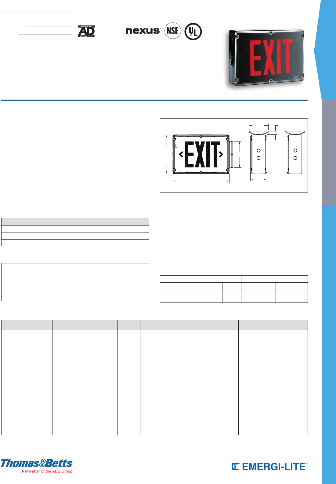
SPEC GRADE
57
INDUSTRIAL
TYPE:
CATALOG #:
NOTES:
How to Order
HOUSING COLOR SERIES FACE LEGEND DIAGNOSTIC HOUSING OPTIONS
BB= Black/black
BW= Black/white
BA= Black/aluminum
GB= Gray/black
GW= Gray/white
GA= Gray/aluminum
WB= White/black
WW= White/white
WA= White/aluminum
SVX= AC only
SVXN= Self-Powered
Ni-Cd
1= Single
2= Double
R= Red
G= Green
Blank= Standard
D= Diagnostic
(Self-Powered only)
NEX= NEXUS® wired
(consult your sales representative)
NEXRF= NEXUS® wireless
(consult your sales representative)
4X= Wet/Damp
Locations*
Blank= No options
2CKT= Dual circuit (AC only)*
CW= Cold weather
(Self-Powered -4°F to 77°F /
-20°C to 25°C – AC/DC -40°F
to 77°F / -40°C to 25°C)
DC= 6 to 48 VDC**
FA= Fire alarm activated flasher*
FL= Flasher only*
FZ= Flasher/buzzer (Self-Powered only)*
* NEMA 4X rated for wall or
ceiling mount only
*Not available with Nexus® option
**Not available with Self-Power
Example: BBSVXN1RD4X-FA
Features
Reliability
The Survive-All™ SVX Series has a 5-year full warranty.
Unit Data - NEMA-4X* Rated
Rugged polyvinyl chloride body will not dent, peel, rust or corrode. The sealed
faceplate is constructed of heavy duty, vandal-resistant polycarbonate and
features an evenly illuminated legend. The fully gasketed faceplate is fastened
with stainless steel tamper-resistant screws. Magnetically operated test switch.
Models can be wall, end or ceiling mounted. Legend and chevron complies
with UL and CSA requirements.
Survive-All™ SVX Series signs are unaffected by the vibrations, ambient
temperature swings and typical power surges detrimental to standard exit light
sources.
NEMA 4X* Rated. UL Listed. Listed for wet and Damp Locations 50°F to 104°F
(+10°C/+40°C)
* Nema-4X Certied for wall or ceiling mounting only
Accessories (order as a separate item)
DESCRIPTION PART NUMBER
Tamper-proof bit 690.0454-E
Convert single to double face, red DFKR*
Convert single face to double face, green DFKG*
* Colors available AL-BK-WT
Applications
• Hosedown areas / car washes
• Food processing / preparation facilities
• Marine locations
• Chemical plants
• Schools and other public facilities
• Parking garages
• Food processing / preparation facilities
• Transit platforms
• Sports arenas / swimming pools
• Security areas / prisons
• Warehouse and cold
storage facilities
• Heavy industrial facilities
Note: Units installed outdoors must be in a shaded area (Lead-Calcium batteries)
Dimensions
Dimensions are approximate and subject to change.
Double Face Single Face
9-3/16”
13-1/4”
6-1/4”
4-5/8”
3-7/8” 3-7/16”
3/4”
Survive-All™ SVX Exit Series
NEMA-4X Rated and UL Listed for Wet
and Damp Locations
High Performance Circuitry
• Self Contained – Batteries and circuitry located inside the
exit housing.
• Continuous self-diagnostic monitoring and monthly self testing.
• Fully automatic charger is solid state.
• AC, AC/DC and Self-Powered Models have universal, 2-wire input 120V to
277VAC 50/60 Hz.
• Sealed, maintenance-free Nickel-Cadmium battery provides
90 minutes of emergency operation.
• Battery recharges per UL924 requirements.
• Each unit comes standard with one tamper-proof driver bit.
Power Consumption (LED Exit Signs)
Model AC Specs DC Specs
AC-only 120 to 277VAC 1.2W – –
AC/DC 120 to 277VAC 1.2W 6 to 24VDC Less than 1.5W
Self-Powered 120 to 277VAC 3.7W Nickel-Cadmium Min. 90 minutes
NEMA-4X
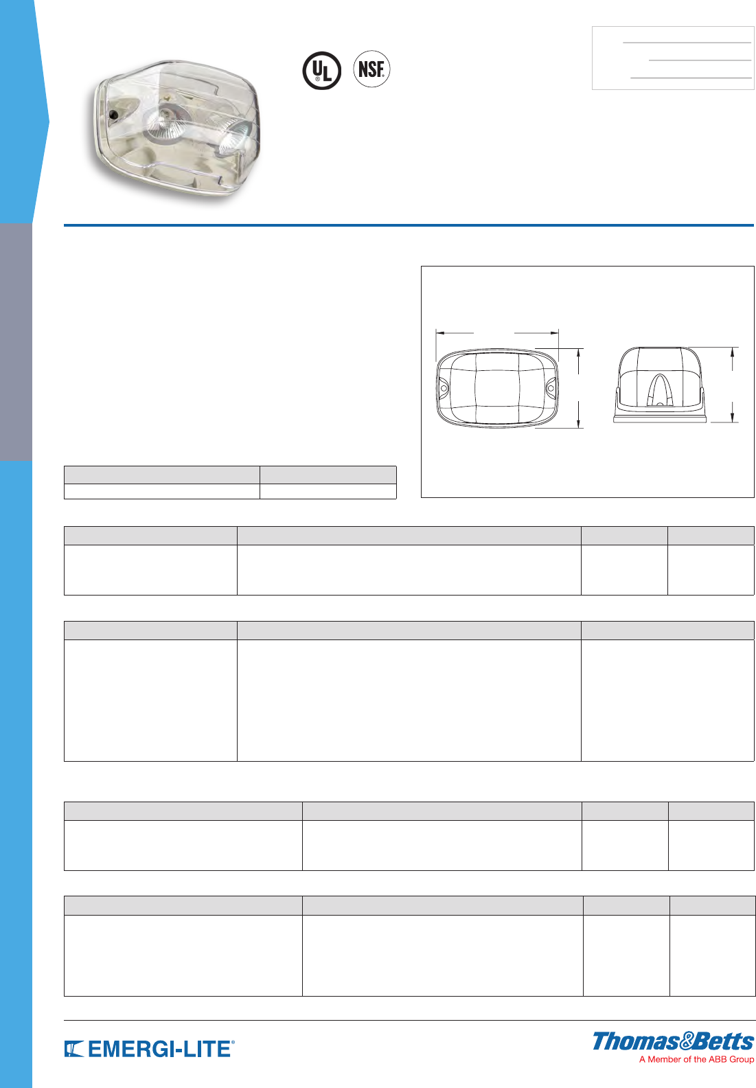
58
SPEC GRADE
INDUSTRIAL
TYPE:
CATALOG #:
NOTES:
Dimensions
Dimensions are approximate and subject to change.
4-5/8” 3-3/4”
Survive-All™
EF39 & EF40 Series
EF39: NEMA-4X & NSF Certified
EF40: Vandal Resistant
NEMA-4X
7-1/8”
Features
• Fully gasketed with a selection of cast aluminum or polycarbonate back plate
• Clear polycarbonate UV and impact resistant-lens
• Choice of single or double lamp models
• Available in 6, 12 and 24V models MR16 or LED
• Easy lamp replacement
• EF39 comes standard with tamper-proof screws and bit
• NSF Certied for food processing plants
• NEMA-4X Certied
• EF39P and EF40P require mounting plate option when installed on surface
mount junction box
• CSA Certied to C22.2 No. 141
• Suitable for indoor/outdoor installation
Accessories (order as a separate item)
DESCRIPTION PART NUMBER
Additional special bit for tamper-proof screws 690.0454-E
How to Order EF40 Series
SERIES LAMP TYPE/WATTAGE LAMP TYPE OPTIONS
EF40P= All polycarbonate single head for dry location
EF40PD= All polycarbonate double head for dry location
(MI)= 6V-6W, MR16
(MJ)= 6V-10W, MR16
(MK)= 12V-12W, MR16
(MS)= 24V-12W, MR16
(LA)= 6V-4W, MR16 LED
(LG)= 12V-4W, MR16 LED
(LL)= 24V-4W, MR16 LED
Blank= White
-BK= Black
-GY= Gray
Blank= No options
T= Tamper proof
screws
SM= Mounting plate
Example: EF40P(MK)
SERIES LAMP TYPE/WATTAGE LAMP TYPE OPTIONS
EF40= Die-Cast back plate single head for dry location
EF40D= Die-Cast back plate double head for dry location
(MI)= 6V-6W, MR16
(MJ)= 6V-10W, MR16
(MK)= 12V-12W, MR16
(MS)= 24V-12W , MR16
(MD)= 24V-20W, MR16
(MW)= 12V-20W, MR16-IR
(LA)= 6V-4W, MR16 LED
(LG)= 12V-4W, MR16 LED
(LI)= 12V-5W, MR16 LED
(LL)= 24V-4W, MR16 LED
(LJ)= 12V-6W, MR16 LED
Blank= White
-BK= Black
-GY= Gray
Blank= No options
T= Tamper
proof screws
Example: EF40D(MD)
How to Order EF39 Series
SERIES LAMP TYPE/WATTAGE LAMP TYPE OPTION
EF39P= All polycarbonate single
head NEMA-4X
EF39PD= All polycarbonate double
head NEMA-4X
(MI)= 6V-6W, MR16
(MJ)= 6V-10W, MR16
(MK)= 12V-12W, MR16
(MS)= 24V-12W, MR16
(LA)= 6V-4W, MR16 LED
(LG)= 12V-4W, MR16 LED
(LL)= 24V-4W, MR16 LED
Blank= White
-BK= Black
-GY= Gray
SM= Mounting plate
Example: EF39P(LG)-BK
SERIES LAMP TYPE/WATTAGE LAMP TYPE
EF39= Die-Cast back plate single
head NEMA-4X
EF39D= Die-Cast back plate double
head NEMA-4X
(MI)= 6V-6W, MR16
(MJ)= 6V-10W, MR16
(MK)= 12V-12W, MR16
(MS)= 24V-12W , MR16
(MD)= 24V-20W, MR16
(MW)= 12V-20W, MR16-IR
(LA)= 6V-4W, MR16 LED
(LG)= 12V-4W, MR16 LED
(LI)= 12V-5W, MR16 LED
(LL)= 24V-4W, MR16 LED
(LJ)= 12V-6W, MR16 LED
Blank= White
-BK= Black
-GY= Gray
Example: EF39(LG)-BK
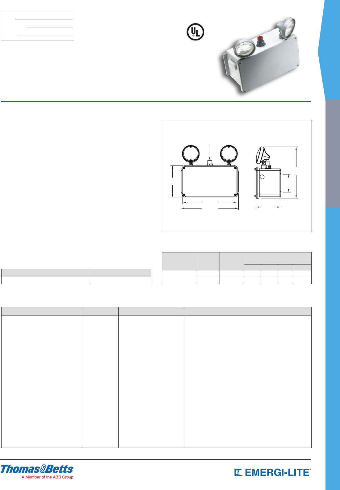
SPEC GRADE
59
INDUSTRIAL
TYPE:
CATALOG #:
NOTES:
How to Order
Note: Includes standard lamps. For standard units without options only order Series Number.
SERIES # OF HEADS LAMP TYPE OPTIONS
6HZM24= 6V-24W, Lead-Calcium
12HZM56= 12V-56W, Lead-Calcium
-0= No head
-1= One head
-2= Two heads
XB= 6V-8W halogen sealed beam
XD= 6V-12W halogen sealed beam
XF= 12V-8W halogen sealed beam
XG= 12V-12W halogen sealed beam
-D1= Time Delay (5 minutes)
-D2= Time Delay (10 minutes)
-D3= Time Delay (15 minutes)
-H1= 120V Thermal Jacket Heater (recommended for ambient temperature)
-H2= 277V Thermal Jacket Heater (recommended for ambient temperature)
-TC= Shatter resistant teflon coated lens
Temperature code: T4A (max. 248ºF/120ºC)
No other lamp type available
Example: 6HZM24-2XB-H1
Features
• Each unit comes with two (2) weather-resistant, impact-resistant, ame-
retardant thermoplastic EF-11 lamp heads with 12 watt high intensity sealed
beam tungsten halogen lamps (standard)
• Temperature code: T4A (max. 248ºF/120ºC)
• Water and corrosion-resistant cabinet is made of berglass-reinforced
polyester. Industrial gray cabinet is fully gasketed around the cover. Battery
compartment is vented with a breather vent designed to permit exhaust of
battery gases without admitting external moisture or corrosives
• Available with sealed, maintenance-free Lead-Calcium batteries
• Fully automatic pulse charger offers 120/277VAC, 60Hz,
0.43/0.2 A, limited current temperature compensation, short circuit proof,
reverse polarity protected, low voltage battery disconnect, brownout
protection and standard solid state transfer feature
• PAR36 sealed-beam halogen lamps (see lamp selection chart below)
• Standard Self-Diagnostic circuitry continuously monitors every critical function
of the unit. If a problem occurs, a single fault indicator on the outside of the
fixture flashes immediately. A detailed diagnostic display is located internally.
The detailed display will further indicate the nature of the fault as either a
battery fault, load fault or a charger fault
• UL Listed. Complies with NEC, Life Safety Code and OSHA. The test switch
and AC pilot light are explosion proof in design and exceed requirements for
Class I, Division 2, Group A, B, C & D
• 3-year full warranty, excluding lamps, pilot lights and fuses.
Dimensions
Dimensions are approximate and subject to change.
HZM Series
6 and 12 Volt, Class I Division 2,
Group A, B, C & D
Accessories (order as a separate item)
DESCRIPTION PART NUMBER
Wire Guard WG3-E
Unit Rating
Furnished standard with two 12W High Intensity Sealed Beam Halogen lamps.
Sealed
Maintenance-Free
Battery Types
D.C Voltage Model
Number
Watts to 87-1/2% of rated battery
voltage*
1-1/2 hrs 2 hrs 3 hrs 4 hrs
Lead-Calcium 6 6HZM24-2 24 18 10 6
12 12HZM56-2 56 37 21 12
* National Electrical Code Specication.
Conduit Fitting
8-3/4”
15”
16” 6-7/8”
14-3/8
5”
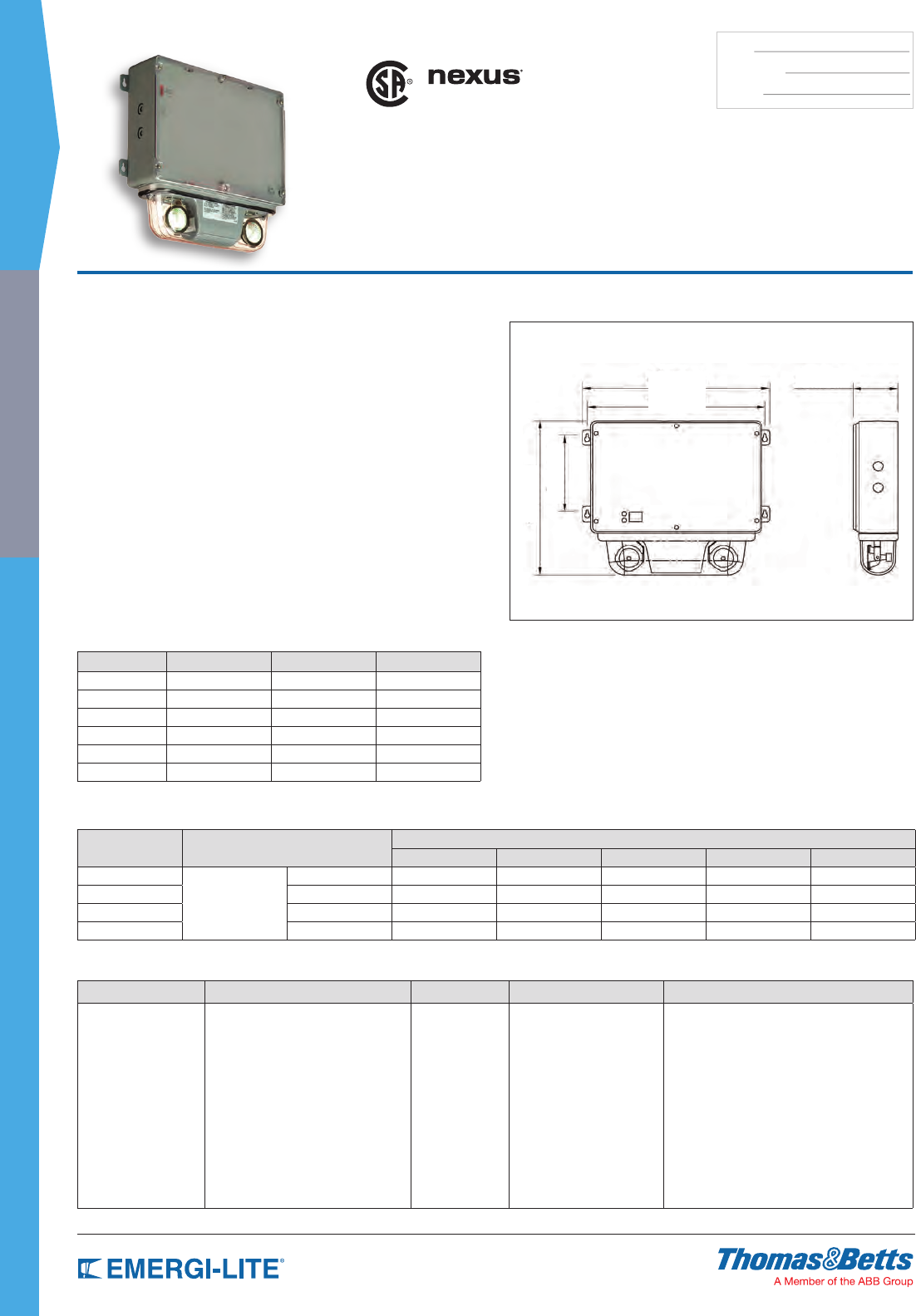
60
SPEC GRADE
INDUSTRIAL
TYPE:
CATALOG #:
NOTES:
How to Order
COLOR VOLTAGE AND POWER # OF HEADS LAMPS OPTIONS
G= Gray SVH18M= 6V-18W, Lead-Calcium
12SVH36M= 12V-36W, Lead-Calcium
12SVH60M= 12V-60W, Lead-Calcium
12SVH72M= 12V-72W, Lead-Calcium
-2= Two heads
-0= No heads
LA= 6V-4W, 2 X MR16 LED
LG= 12V-4W, 2 X MR16 LED
LI= 12V-5W, 2 X MR16 LED
MK= 12V-12W, MR16
MW= 12V-20W, MR16-IR
high-output
-DA= Advanced Diagnostics (audible)*
-D= Advanced Diagnostics (non-audible)*
-D3= Time delay (15 minutes)
-NEX= NEXUS® wired
(consult your sales representative)*
-NEXRF= NEXUS® wireless
(consult your sales representative)*
(12SVH only)
* Minimum lamp load required: 20% of unit capacity
Example: G12SVH72M-2MK-DA
Dimensions
Dimensions are approximate and subject to change.
14-1/2”
12-5/8”
6-1/4”
13-3/4”
3-1/2”
US
Survive-All™ SVH Series
Hazardous Location Battery Unit
Features
• Evaluated to the UL 844 Standard for Class I Division 2, Groups A, B, C
and D
• A range of lamp ratings are available for different temperature codes
• Evaluated to the UL924 Standard
• Certied for use in Damp and Wet locations.
• Ambient temperature: 10… 40°C (50… 104°F)
• Advanced Diagnostics option available
• Lead-Calcium batteries are sealed, maintenance-free, with up to 72W
emergency power
• Choice of MR16 LED or halogen lamps, shielded by a clear polycarbonate
cover
• Two MR16 LED lamps illuminate up to a 60 ft path of egress
• Remote load capacity: illuminate up to a 420 ft path of egress with LED
remote heads
• Polyvinyl chloride frame, with built-in gasket to prevent water inltration
• Heavy-duty 1/8-inch thick aluminum back plate with keyholes for secure wall-
mount installation
• Built-in microcontroller-based battery charger and self-test/
self-diagnostic circuitry
• 3/4-inch electrical conduit entry on both sides and at the top
Power Consumption
Model AC Specs Wattage Capacity
1-1/2 hrs 2 hrs 3 hrs 4 hrs 8 hrs
SVH18
120/277VAC
0.17 / 0.09 Amp 18 12 9 – –
12SVH36 0.30 / 0.15 Amp 36 27 18 14 –
12SVH60 0.30 / 0.15 Amp 60 45 30 24 12
12SVH72 0.30 / 0.15 Amp 72 54 36 28 14
Temperature Codes
Lamp Rating Temperature Code Max. Temperature Replacement Part #
6V-4W T4A 120°C 580.0097
6V-10W T3C 160°C 580.0079
12V-4W T4A 120°C 580.0080
12V-5W T4A 120°C 580.0104
12V-12W T3A 180°C 580.0080
12V-20W-H T2D 215°C 580.0068
Note: Use qualied replacement lamps to avoid risk of over-heating
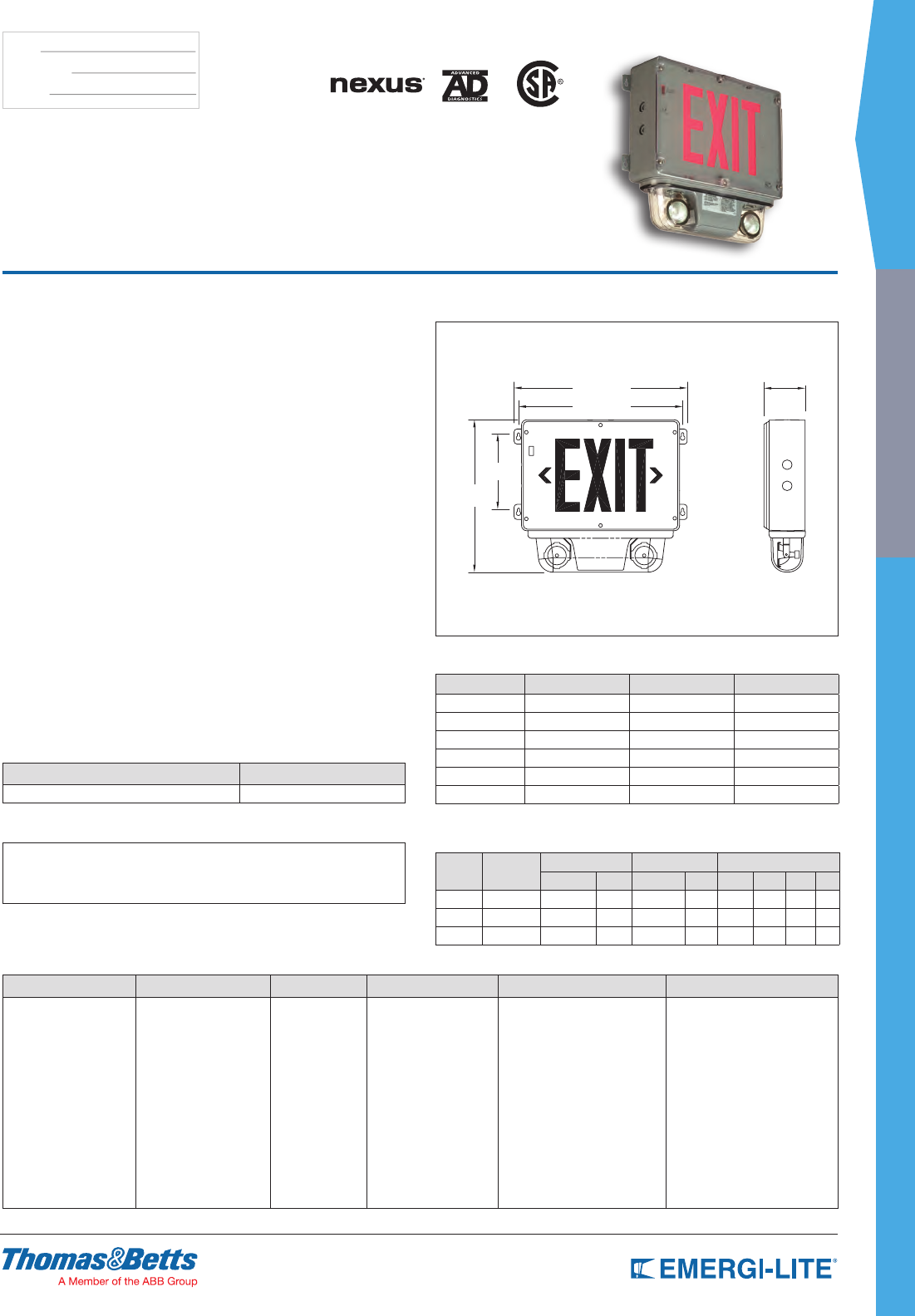
SPEC GRADE
61
INDUSTRIAL
TYPE:
CATALOG #:
NOTES:
How to Order
HOUSING/FACE COLOR SERIES/CAPACITY LEGEND COLOR DIAGNOSTICS # OF HEADS LAMP TYPE/WATTAGE*
GG= Gray/gray SVXH= 6V-20W, Ni-Cd
SVXH12N= 12V-24W, Ni-Cd
SVXH12H= 12V-40W, NiMH
R= Red
G= Green
DA= Advanced Diagnostics
(audible)
D= Advanced Diagnostics
(non-audible)
NEX= NEXUS® wired*
NEXRF= NEXUS® wireless*
Blank= 0 head*
2= Two heads
LA= 6V-4W, MR16 LED
LG= 12V-4W, MR16 LED
LI= 12V-5W, MR16 LED
MK= 12V-12W MR16
MJ= 6V-10W MR16
MW= 12V-20W MR16 IR high output
* Consult your sales representative * A remote load must be connected * No other lamp option available
Example: GGSVXHRD2MJ
Features
• Exit sign module is illuminated by long-life, energy-efcient LEDs. Fully eld
adjustable lamp head assembly comes standard with a selection of two (2)
MR16 halogen lamps for optimum illumination over the path of egress. Lamps
are shielded by a cast aluminum housing and a polycarbonate cover
• Rugged PVC body will not dent, peel or corrode. The sealed faceplate has
a heavy-duty, vandal-resistant polycarbonate cover and is fastened with
stainless steel tamper-resistant screws. The polyvinyl chloride frame has
a built-in gasket to prevent water inltration. The heavy-duty 1/8” thick
aluminum back plate has keyholes for secure wall mount installation
• Available with sealed, maintenance-free Nickel-Cadmium, or Nickel-Metal
Hydride batteries
• Fully automatic pulse charger offers 120/277VAC, 60Hz, current limiting
temperature compensation, short circuit proof, low voltage battery
disconnect, brownout protection and standard solid state transfer feature.
The test switch is magnetically operated
• Advanced Diagnostic circuitry is standard on all Self-Powered models. This
circuitry is programmed to ensure the combination unit’s readiness and
reliability by continuously monitoring every critical function of the unit. If a
problem occurs, a single “Service Required” indicator illuminates immediately.
A detailed diagnostic display that will further indicate the nature of the fault
is located on the inside of the exit sign, out of sight from the general public.
The self test will test the unit for a minimum of 30 seconds every 30 days, 30
minutes every 60 days and 90 minutes annually
• Designed for wall-mount installation only with a 1/2” electrical conduit entry
on both sides and at the top.
• Evaluated to UL 924 standard and to UL 844 standard for hazardous
locations: Class I Division 2, Groups A, B, C and D. A range of lamp ratings
are available for different temperature codes
• 5-year full warranty, excluding lamps and fuses
Accessories (order as a separate item)
DESCRIPTION PART NUMBER
Additional special bit for tamper-proof screws 690.0454-E
Applications
• Manufacturing Plants
• Chemical plants
• Paint Shops
• Gas Stations
• Moisture, Dirt or Dust Concerns
• Oil Refineries
• Wet or Corrosive Conditions
Dimensions
Dimensions are approximate and subject to change.
14-1/2”
12-5/8”
6-1/4”
13-3/4”
3-1/2”
Survive-All™ SVXH Series
Hazardous Location Combination
and Emergency Battery Unit
US
Temperature Codes
Lamp Rating Temperatude Code Max. Temperature Replacement Part #
6V-10W T3C 320°F/160°C 580.0079-E
12V-12W T3A 356°F/180°C 580.0080-E
12V-20W T2D 419°F/215°C 580.0068-E
6V-4W LED T4A 248°F/120°C 580.0097-E
12V-4W LED T4A 248°F/120°C 580.0093-E
12V-5W LED T4A 248°F/120°C 580.0104-E
Note: Use qualied replacement lamps to avoid risk of over-heating
Power Consumption Chart
Model AC Input Maximum Stand-by Unit Rating*
Current Power Current Power 11/2 hrs 2 hrs 3 hrs 4 hrs
SVXH 120/277VAC 0.15/0.07A 16W 0.09/0.03A 8W 20 15 – –
SVXH12N 120/277VAC 0.30/0.08A 29W 0.13/0.05A 10W 24 18 12 –
SVXH12H 120/277VAC 0.30/0.08A 29W 0.13/0.05A 10W 40 30 20 12
* Watts to 87-1/2% of rated battery voltage

62
SPEC GRADE
INDUSTRIAL
TYPE:
CATALOG #:
NOTES:
How to Order
COLOR OF BODY/FACE SERIES FACE LEGEND DIAGNOSTIC OPTIONS
GG= Gray/gray SVXHZ= AC only
SVXNHZ= Self-Powered
Ni-Cd
1= Single (ceiling/
wall mount)
2= Double (ceiling
mount only)
R= Red
G= Green
-D= Diagnostic (Self-Powered only)
-NEX= NEXUS® wired
(consult your sales representative)
Blank= AC only
CW= Cold weather (-4°F/-20°C for
Self-Powered and -40°F/
-40°C for AC only)
Example: GGSVXNHZ2R-DCW
Features
• Energy efcient: consumes less than 2.5 watts in any conguration. Exit sign
illuminated by long-life, energy-efcient LEDs.
• Single face heavy-duty 1/8” thick aluminum back plate. Polyvinyl chloride
frame, with built-in gasket to prevent water inltration. Will not dent, peel, rust
or corrode. The sealed, heavy-duty, vandal-resistant polycarbonate faceplate
features an evenly illuminated legend. The fully gasketed faceplate is fastened
with stainless steel tamper-resistant screws. Self contained; batteries and
circuitry are located inside the exit housing.
• Available with sealed, maintenance-free Nickel-Cadmium batteries that
provide 90 minutes of emergency operation. Batteries recharge per UL924
requirements.
• AC and Self-Powered models have universal, 2-wire input 120V to 277VAC
50/60Hz.
• Tamper-resistant, hermetically sealed magnetic test switch for
Self-Powered models.
• Diagnostic / Self Test circuitry is standard on all Self-Powered models. This
circuitry is programmed to ensure the exit sign’s readiness and reliability
by continuously monitoring every critical function of the unit. If a problem
occurs, a single “service required” indicator illuminates immediately. A detailed
diagnostic display that will further indicate the nature of the fault is located
on the inside of the exit sign, out of sight from the general public. The self
test will test the unit for a minimum of 30 seconds every 30 days, 30 minutes
every 60 days and 90 minutes annually.
• Can be wall, end or ceiling mounted. Comes standard with an industrial-
grade, Die-Cast aluminum electrical box. 1/2” electrical conduit entry on both
sides and at the top. Each unit comes standard with one tamper-proof driver
bit.
• Legend and chevron comply with UL requirements. Evaluated to the UL 844
standard for Class I Division 2, Groups A, B, C and D, Temperature Code:
T6 (maximum 185°F/85°C). Evaluated to UL 924 and UL1598 standards.
Suitable for cold-weather: -4°F/-20°C (Self-Powered model, “CW” option) and
-40°F/-40°C (AC only).
• 5-year full warranty
Dimensions
Dimensions are approximate and subject to change.
9-1/4”
13-1/4”
3-1/2”
4-3/4”
4-3/8” 2-1/4”
Survive-All™ SVX-HZ Series
Hazardous Location Exit Sign
Power Consumption
Model AC Specs DC Specs
AC-only red 120 to 277VAC Less than 2W – –
AC-only green 120 to 277VAC Less than 1.5W – –
Self-Powered red 120 to 277VAC Less than 2W Ni-Cd battery Min. 90 minutes
Self-Powered green 120 to 277VAC Less than 2.5W Ni-Cd battery Min. 90 minutes
* Note: Cold-weather option does not consume additional power
Accessories (order as a separate item)
DESCRIPTION PART NUMBER
Tamper-Proof Bit (extra) 690.0454-E
Convert single to double face, red* DFKR-GY
Convert single face to double face, green* DFKG-GY
* In the eld
Applications
• Manufacturing Plants
• Chemical plants
• Paint Shops
• Gas Stations
• Moisture, Dirt or Dust Concerns
• Oil Refineries
• Wet or Corrosive Conditions
US
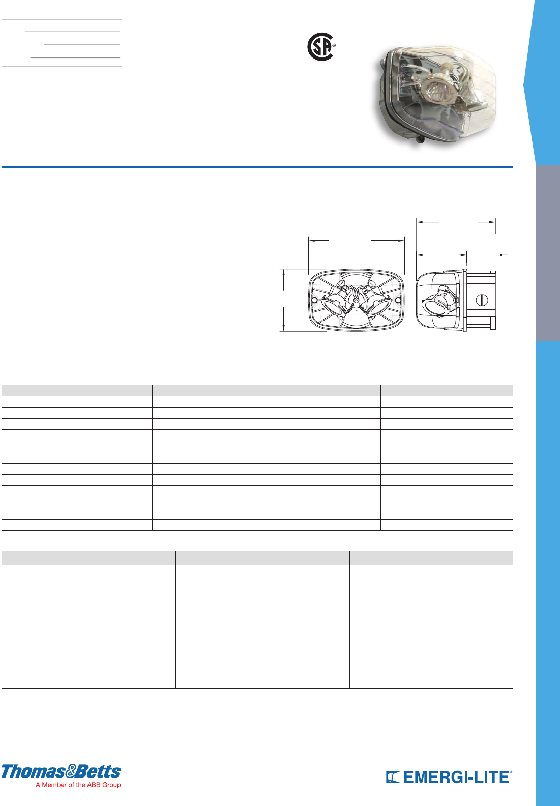
SPEC GRADE
63
INDUSTRIAL
TYPE:
CATALOG #:
NOTES:
Lamp Selection Chart and Temperature Code
Lamp Suffix Voltage Wattage Lumens Replacement # Temperature Code Max Temperature
MJ 6 10 74 580.0079-E T3B 165°C
MK 12 12 80 580.0080-E T3B 165°C
MW 12 20-H 400 580.0068-E T2C 230°C
MS 24 12 82 580.0070-E T3B 165°C
MD 24 20 240 580.0077-E T2C 230°C
MT 120 20 100 580.0065-E T2C 230°C
LA 6 4 200 580.0097-E T4A 120°C
LG 12 4 220 580.0093-E T5 100°C
LI 12 5 340 580.0104-E T4A 120°C
LJ 12 6 540 580.0106-E T4 135°C
LL 24 4 220 580.0098-E T5 100°C
LW 120 4 230 580.0113-E T4A 120°C
How to Order
SERIES LAMP TYPE/WATTAGE COLOR
EF41= Single
EF41D= Double
(LA)= 6V-4W, MR16 LED
(LG)= 12V-4W, MR16 LED
(LI)= 12V-5W, MR16 LED
(LJ)= 12V-6W, MR16 LED
(LL)= 24V-4W, MR16 LED
(LW)= 120V-4W, MR16 LED
(MJ)= 6V-10W, MR16
(MK)= 12V-12W, MR16
(MW)= 12V-20W, MR16 IR high output
(MS)= 24V-12W, MR16
(MD)= 24V-20W, MR16
(MT)= 120 VAC/VDC-20W MR16 (GU10)
-GY= Gray
Example: EF41(MJ)-GY
Features
• Available with single or double lamp heads with high-efciency MR16 halogen
lamps of 10W, 12W or 20W (see How to Order information) and MR16
high-output LEDs (4W, 5W and 6W)
• Die-Cast aluminum back plate with gasket. Clear polycarbonate cover, UV
and impact resistant
• Input voltage: 6V, 12V, 24V or 120V
• Easy installation on a 4” octagonal box (included). Comes standard with
tamper-proof screws and bit
• Evaluated to UL 844 Standard for Class I Division 2, Groups A, B, C and D.
Temperature Codes: T3B (10W and 12W MR16 lamps) and T2C (20W MR16
lamps) and T4A and T5 MR16 LED.
• Extreme operational temperature range: -40ºF to +104ºF (-40ºC to +40ºC)
• Indoor use
• Fully adjustable tool-less aiming swivel
• Tool-less easy lamp replacement
• Surface mount
• Conduit entry 1/2” NPT
Dimensions
Dimensions are approximate and subject to change.
4-5/8”
7-1/8”
5-7/8”
Junction box
3-3/4” 2-1/8”
Survive-All™ EF41 Series
Remote Fixture for Hazardous Locations
US
4” Junction Box
Remote
Fixture
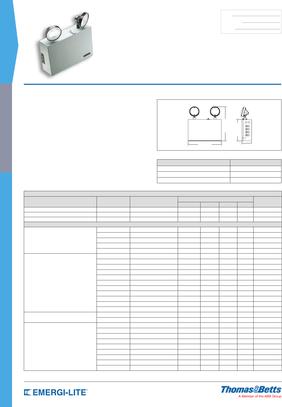
64
SPEC GRADE
INDUSTRIAL
TYPE:
CATALOG #:
NOTES:
Features
• Each unit comes with two (2) impact resistant, ame retardant thermoplastic
EF-18 lamp heads with 9 watt high intensity incandescent lamps (standard).
• All 20 gauge in steel construction ASA61 gray baked enamel nish.
• Available with sealed, maintenance-free Nickel-Cadmium, Long Life Lead,
Lead-Calcium (Free Electrolyte) or Lead-Calcium batteries.
• PulsePlus Charger circuitry offers 120/277 volt input 60 Hz, 0.3/0.15A (other
inputs available), fused output circuit(s), dual diagnostic indicator lights,
temperature compensation, sealed relay, low voltage battery disconnect,
brownout protection and lockout (automatic battery connect).
• Provision for mounting to any standard 4” octagonal electrical box. The
hinged and lockable front door allows easy access for maintenance and
provides security against unauthorized access and vandalism.
• UL Listed. Complies with NEC, Life Safety Code and OSHA. Approved for
use in the Commonwealth of Pennsylvania.
• 3-year full warranty, excluding lamps and fuses.
Dimensions
Dimensions are approximate and subject to change.
Knockouts for 1/2” Conduit: -2 each side, 1 rear (7/8” Dia) knockout
Accessories (order as a separate item)
DESCRIPTION SUFFIX
Mounting bracket B2
Mounting shelves (gray) MP3-GY
Wire Guard WG3-E
IL Series
6, 12 & 24 Volt Heavy Duty Industrial
Emergency Power Unit
Unit Rating Chart
Furnished standard with two 9 watt High Intensity Incandescent lamps.
UNIT EQUIPMENT - NO REMOTE CAPABILITY
Sealed Maintenance-Free Battery Types D.C. Voltage Model Number Watts to 87-1/2% of rated battery voltage* # of Load Fuses
1-1/2 hrs 2 hrs 4 hrs 8 hrs
Nickel-Cadmium 6 ILSC18-2 18 12 6 – –
Long Life Lead 6 ILSE18-2 18 11 6 – –
Lead-Calcium 6 ILSM18-2 18 12 7 – –
UNIT EQUIPMENT - WITH REMOTE CAPABILITY
Nickel-Cadmium
6 ILSC25-2 25 18 9 – –
12 12ILSC36-2 36 21 12 6 1
12 12ILSC50-2 50 36 18 10 1
24 24ILSC72-2 72 42 24 12 2
24 24ILSC100-2 100 73 36 20 2
Long Life Lead
6 ILSE27-2 27 16 10 6 –
6 ILSE36-2 36 24 13 7 –
6 ILSE54-2 54 36 20 11 –
6 ILSE80-2 80 65 35 19 –
6 ILSE110-2 110 72 40 24 –
12 12ILSE36-2 36 24 13 7 1
12 12ILSE54-2 54 37 21 10 1
12 12ILSE72-2 72 48 26 14 2
12 12ILSE110-2 110 74 43 21 2
24 24ILSE72-2 72 48 26 14 2
24 24ILSE110-2 110 74 43 21 2
Lead-Calcium (Immobilized Electrolyte) 6 ILC87-2 87 70 41 24 –
6 ILC100-2 100 77 47 24 –
Lead-Calcium
6 ILSM27-2 27 18 10 6 –
6 ILSM36-2 36 25 14 7 –
6 ILSM54-2 54 37 21 12 –
6 ILSM81-2 81 54 36 18 –
6 ILSM110-2 110 72 40 24 –
12 12ILSM36-2 36 25 14 7 1
12 12ILSM54-2 54 37 21 12 1
12 12ILSM110-2 110 72 40 24 2
24 24ILSM110-2 110 72 40 24 2
* National Electrical Code Specication
16-1/8”
16-1/2”
10-3/8”
4-3/4”
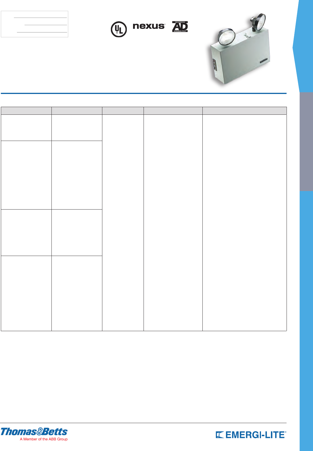
SPEC GRADE
65
INDUSTRIAL
TYPE:
CATALOG #:
NOTES:
How to Order
SERIES/VOLTAGE UNIT CAPACITY # OF HEADS LAMP OPTIONS
ILC= 6V 87= 87W Lead-Calcium
100= 100W Lead-Calcium
-0= No head
-1= One head
-2= Two heads
-3= Three heads
Blank= 6V-9W, 12V-9W,
24V-9W incandescent
wedge base
H_= Halogen bi-pin
Z_= Tungsten incandescent
U_= Tungsten sealed beam
X_= Halogen sealed beam
-AD= Advanced Diagnostics (audible)*
-ADNA= Advanced Diagnostics (non-audible)*
NEX= NEXUS® wired
(consult your sales representative)*
NEXRF= NEXUS® wireless
(consult your sales representative)*
-A= Ammeter
-V= Voltmeter
-CP= Cord and plug 120V only
-D1= Time Delay (5 minutes)
-D2= Time Delay (10 minutes)
-D3= Time Delay (15 minutes)
-E= Cord and plug 277V**
-OW= Off-white cabinet and heads
ILS= 6V C18= 18W Ni-Cd
C25= 25W Ni-Cd
E18= 18W Long Life Lead
E27= 27W Long Life Lead
E36= 36W Long Life Lead
E50= 50W Long Life Lead
E80= 80W Long Life Lead
E110= 110W Long Life Lead
M18= 18W Lead-Calcium
M27= 27W Lead-Calcium
M36= 36W Lead-Calcium
M54= 54W Lead-Calcium
M81= 81W Lead-Calcium
M110= 110W Lead-Calcium
12ILS= 12V C36= 36W Ni-Cd
C50= 50W Ni-Cd
E36= 36W Long Life Lead
E54= 54W Long Life Lead
E80= 80W Long Life Lead
E110= 110W Long Life Lead
M36= 36W Lead-Calcium
M54= 54W Lead-Calcium
M110= 110W Lead-Calcium
24ILS= 24V C100= 100W Ni-Cd
E72= 72W Long Life Lead
E110= 110W Long Life Lead
M110= 110W Lead-Calcium
C72= 72W Ni-Cd
NOTE: For a complete list of available lamp
types, please refer to the lamp data on
pages 146-147
* Minimum lamp load required: 20% of unit capacity
Option not available with 24V-100W Ni-Cd units
** Standard cord is 3 ft
Example: ILC87-2HB-A
IL Series
6, 12 & 24 Volt Heavy Duty Industrial
Emergency Power Unit
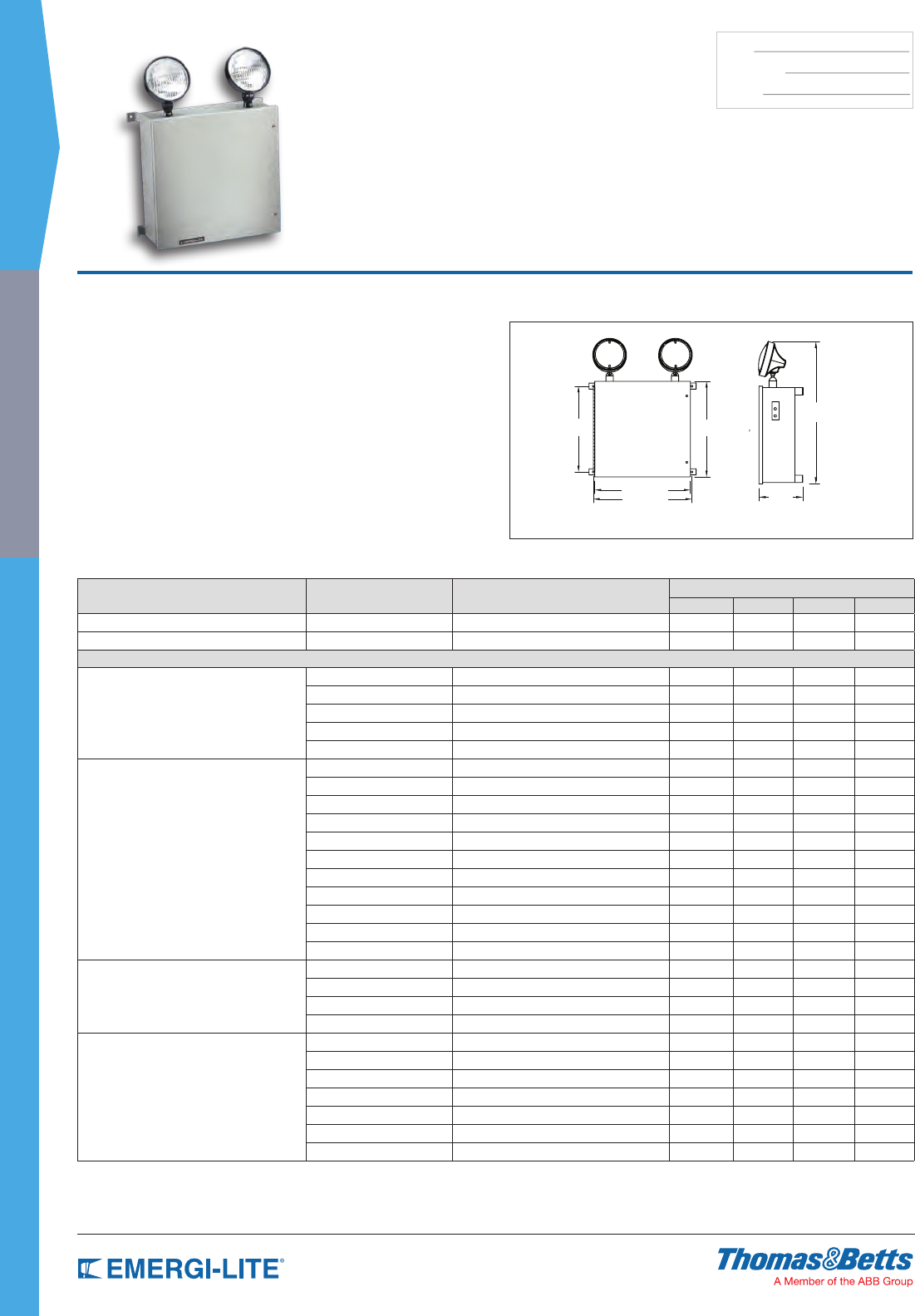
66
SPEC GRADE
INDUSTRIAL
TYPE:
CATALOG #:
NOTES:
Features
• Up to three weather-resistant thermoplastic heads can be mounted on the
enclosure. Each unit comes with two (2) 9W high intensity incandescent
lamps (standard)
• Constructed of 14 gauge steel with a fully gasketed hinged door and separate
battery compartment. Gray baked epoxy enamel nish
• Available with sealed, maintenance-free Nickel-Cadmium, Long Life Lead,
Lead-Calcium (Free Electrolyte), or Lead-Calcium batteries
• PulsePlus Charger circuitry offers 120/277V input 60Hz, 0.3/0.15A
(other inputs available), fused output circuit(s), dual diagnostic indicator lights,
temperature compensation, sealed relay, low voltage battery disconnect,
brownout protection and lockout (automatic battery connect)
• UL Listed. Complies with NEC, Life Safety Code and OSHA
• 3-year full warranty, excluding lamps and fuses
Dimensions
Dimensions are approximate and subject to change.
13-1/2”
13-7/8”
12-1/8” 13-1/2”
19-3/8”
6”
KS Steel Series
6, 12, 24 Volt
Harsh Environment Enclosure Power Unit
Unit Rating Chart
Furnished standard with two 9 watt High Intensity Incandescent lamps.
Sealed Maintenance-Free Battery Types D.C. Voltage Model Number Watts to 87-1/2% of rated battery voltage*
11⁄2 hrs 2 hrs 3 hrs 4 hrs
Nickel-Cadmium 6 KSC18-2 18 12 10 7
Long Life Lead 6 KSE18-2 18 11 8 6
UNIT EQUIPMENT - WITH REMOTE CAPABILITY
Nickel-Cadmium
6 KSC25-2 25 18 9 5
12 12KSC36-2 36 21 21 6
12 12KSC50-2 50 36 18 10
12 12KSC100-2 100 73 37 20
24 24KSC100-2 100 73 37 20
Long Life Lead
6 KSE27-2 27 19 10 5
6 KSE36-2 36 24 13 7
6 KSE54-2 54 36 20 11
6 KSE80-2 80 65 35 19
6 KSE110-2 110 74 43 21
6 KSE160-2 160 130 70 38
12 12KSE36-2 36 24 13 7
12 12KSE54-2 54 37 21 10
12 12KSE110-2 110 74 43 21
12 12KSE160-2 160 130 70 38
24 24KSE110-2 110 74 43 21
Lead-Calcium (Immobilized Electrolyte)
6 KC87-2 87 70 41 24
6 KC100-2 100 77 47 24
6 KC175-2 175 140 85 48
12 12KC175-2 175 140 85 48
Lead-Calcium
6 KSM27-2 27 18 10 6
6 KSM54-2 54 37 21 12
6 KSM81-2 81 54 30 18
6 KSM110-2 110 72 40 24
12 12KSM54-2 54 37 21 12
12 12KSM110-2 110 72 40 24
24 24KSM110-2 110 72 40 24
*National Electrical Code Specication
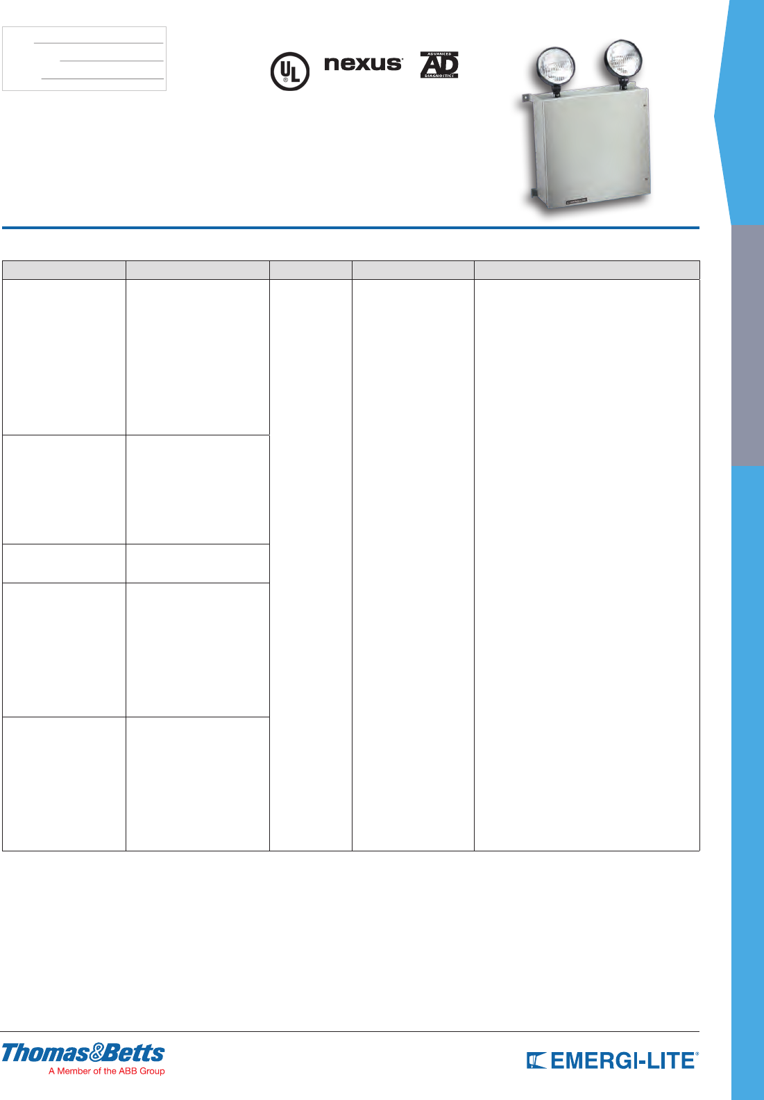
SPEC GRADE
67
INDUSTRIAL
TYPE:
CATALOG #:
NOTES:
KS Steel Series
6, 12, 24 Volt
Harsh Environment Enclosure Power Unit
How to Order
SERIES/VOLTAGE UNIT CAPACITY # OF HEADS LAMP OPTIONS
KS= 6V C18= 6V-18W Ni-Cd
C25= 6V-25W Ni-Cd
E18= 6V-18W Long Life Lead
E27= 6V-27W Long Life Lead
E36= 6V-36W Long Life Lead
E54= 6V-54W Long Life Lead
E80= 6V-80W Long Life Lead
E110= 6V-110W Long Life Lead
E160= 6V-160W Long Life Lead
M27= 6V-27W Lead-Acid
M54= 6V-54W Lead-Acid
M81= 6V-81W Lead-Acid
M110= 6V-110W Lead-Acid
-0= No head
-1= 1 head
-2= 2 heads
Blank= 6V-9W, 12V-9W,
24V-9W incandescent
wedge base
H_= Halogen bi-pin
I_= Incandescent DC-bayonet
U_= Incandescent
sealed-beam
X_= Halogen sealed-beam
Z_= Incandescent wedge
-AD= Advanced Diagnostics (audible)*
-ADNA= Advanced Diagnostics (non-audible)*
NEX= Nexus® wired
(consult your sales representative)*
NEXRF= Nexus® wireless
(consult your sales representative)*
-V= Voltmeter
-A= Ammeter
-TD= Time Delay
-D1= Time Delay (5 minutes)
-D2= Time Delay (10 minutes)
-D3= Time Delay (15 minutes)
-K= Lamp Disconnect Switch
-CP= Cord and plug 120V for fiberglass enclosure**
-E= Cord and plug 277V**
-S= Photometric test switch
-VR= Tamper proof screws
-FL= Large cabinet
-TM= Top mounted heads
-208V= Input 208VAC, 50/60Hz
12KS= 12V C36= 12V-36W Ni-Cd
C50= 12V-50W Ni-Cd
C100= 12V-100W Ni-Cd
E36= 12V-36W Long Life Lead
E54= 12V-36W Long Life Lead
E110= 12V-110W Long Life Lead
E160= 12V-160W Long Life Lead
M54= 12V-54W Lead-Acid
M110= 12V-110W Lead-Acid
24KS= 24V C100= 24V-100W Ni-Cd
E110= 24V-110W Long Life Lead
M110= 24V-110W Lead-Calcium
K= 6V C87= 6V-87W Lead-Calcium
(free electrolytes)
C100= 6V-100W Lead-Calcium
(free electrolytes)
C175= 6V-175W Lead-Calcium
(free electrolytes)
NOTE: For a complete list of available
lamp types, please refer to the
lamp data on pages 146-147
* Minimum lamp load required: 20% of unit capacity
Option not available on 24V-100W Ni-Cd units
** Standard cord is 3 ft.
12K= 12V C175-2= 12V-175W Lead-Calcium
(free electrolytes)
Example: KSC18-2HB-AD
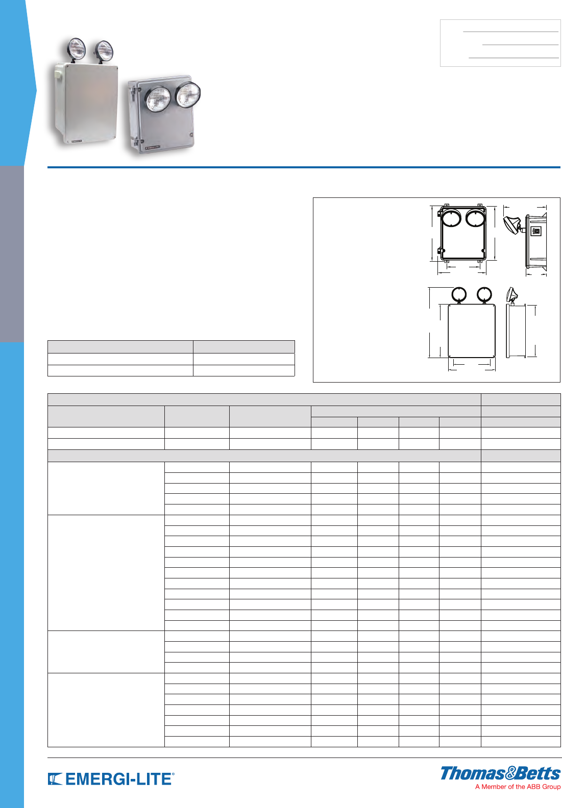
68
SPEC GRADE
INDUSTRIAL
TYPE:
CATALOG #:
NOTES:
Features
• Each unit comes with two (2) 9W high intensity incandescent lamps
(standard).
• Both the “S” and “L” enclosure are corrosion resistant. Both include separate
battery compartments, fully gasketed door and stainless steel hardware.
The “S” enclosure is constructed of high impact thermoplastic and the “L”
enclosure is constructed of berglass and is NEMA 3R
• Available with sealed, maintenance-free Nickel-Cadmium, Long Life Lead,
Lead-Calcium (Free Electrolyte) or Lead-Calcium batteries.
• PulsePlus Charger circuitry offers 120/277 volt input 60 Hz, 0.3/0.15A (other
inputs available), fused output circuit(s), dual diagnostic indicator lights,
temperature compensation, sealed relay, low voltage battery disconnect,
brownout protection and lockout (automatic battery connect).
• UL Listed. Complies with NEC, Life Safety Code and OSHA.
• 3-year full warranty, excluding lamps and fuses.
Dimensions
Dimensions are approximate and subject to change.
17-1/2”
16-3/4”
15-5/8”
6-1/4”
23”
12”
13-3/8”
10-3/8”
11-5/8”
13”
5”
8”
Small “S” Enclosure
High Impact Thermoplastic
Construction
Large “L” Enclosure
Fiberglass Construction
NEMA-3R
KS Series
6, 12 & 24 Volt
High Impact Enclosure Power Unit
Unit Rating
UNIT EQUIPMENT - NO REMOTE CAPABILITY
Sealed Maintenance-Free Battery Types D.C. Voltage Model Number Watts to 87-1/2% of rated battery voltage* Enclosure Size
1-1/2 hrs 2 hrs 3 hrs 4 hrs
Nickel-Cadmium 6 KSC18-2-F 18 12 10 7 S
Long Life Lead 6 KSE18-2-F 18 11 8 6 S
UNIT EQUIPMENT - WITH REMOTE CAPABILITY
Nickel-Cadmium
6 KSC25-2-F 25 18 9 5 S
12 12KSC36-2-F 36 21 21 6 S
12 12KSC50-2-F 50 36 18 10 S
12 12KSC100-2-F 100 73 37 20 S
24 24KSC100-2-F 100 73 37 20 S
Long Life Lead
6 KSE27-2-F 27 19 10 5 S
6 KSE36-2-F 36 24 13 7 S
6 KSE54-2-F 54 36 20 11 S
6 KSE80-2-F 80 65 35 19 S
6 KSE110-2-F 110 74 43 21 S
6 KSE160-2-F 160 130 70 38 L
12 12KSE36-2-F 36 24 13 7 S
12 12KSE54-2-F 54 37 21 10 S
12 12KSE110-2-F 110 74 43 21 S
12 12KSE160-2-F 160 130 70 38 L
24 24KSE110-2-F 110 74 43 21 S
Lead-Calcium
(Free Electrolyte)
6 KC87-2-F 87 70 41 24 S
6 KC100-2-F 100 77 47 24 L
6 KC175-2-F 175 140 82 48 L
12 12KC175-2-F 175 140 85 48 L
Lead-Calcium
6 KSM27-2-F 27 18 10 6 S
6 KSM54-2-F 54 37 21 12 S
6 KSM81-2-F 81 54 30 18 S
6 KSM110-2-F 110 72 40 24 S
12 12KSM54-2-F 54 37 21 12 S
12 12KSM110-2-F 110 72 40 24 S
24 24KSM110-2-F 110 72 40 24 S
*National Electrical Code Specication
Accessories (order as a separate item)
DESCRIPTION SUFFIX
Wire Guard (Small enclosure) WG3-E
Wire Guard (Large enclosure) WG4-E
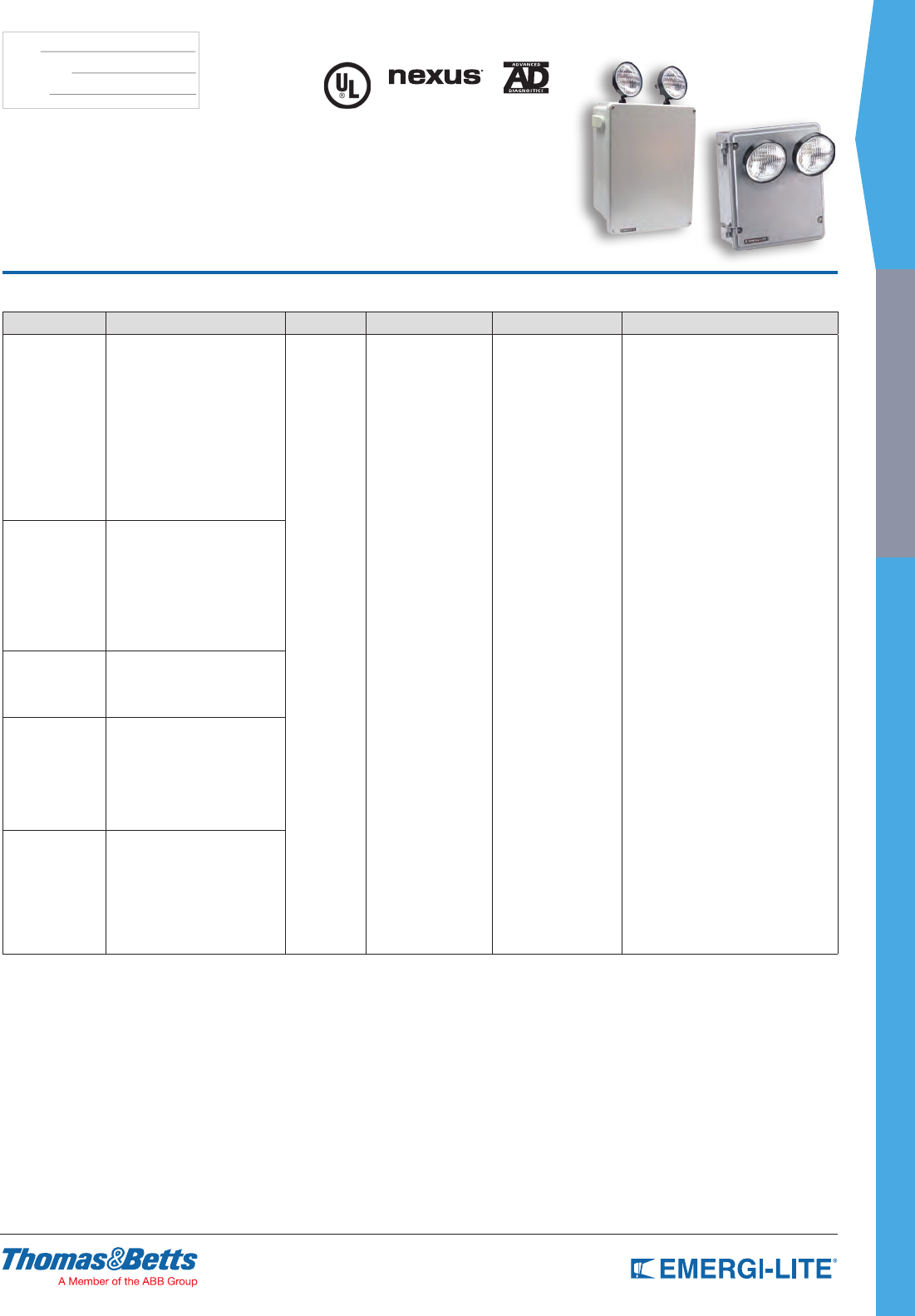
SPEC GRADE
69
INDUSTRIAL
TYPE:
CATALOG #:
NOTES:
KS Series
6, 12 & 24 Volt
High Impact Enclosure Power Unit
NEMA-3R
How to Order
SERIES/VOLTAGE UNIT CAPACITY # OF HEADS LAMP ENCLOSURE TYPE OPTIONS
KS= 6V C18= 6V-18W Ni-Cd
C25= 6V-25W Ni-Cd
E18= 6V-18W Long Life Lead
E27= 6V-27W Long Life Lead
E36= 6V-36W Long Life Lead
E54= 6V-54W Long Life Lead
E80= 6V-80W Long Life Lead
E110= 6V-110W Long Life Lead
E160= 6V-160W Long Life Lead
M27= 6V-27W Lead-Acid
M54= 6V-54W Lead-Acid
M81= 6V-81W Lead-Acid
M110= 6V-110W Lead-Acid
-0= No head
-1= 1 head
-2= 2 heads
Blank= 6V-9W,
12V-9W, 24V-9W
incandescent
wedge base
H_= Halogen bi-pin
I_= Incandescent
DC-bayonet
U_= Incandescent
sealed-beam
X_= Halogen sealed-
beam
Z_= Incandescent wedge
F= Fiber glass or high
impact thermoplastic
-AD= Advanced Diagnostics (audible)*
-ADNA= Advanced Diagnostics (non-audible)*
NEX= Nexus® wired
(consult your sales representative)*
NEXRF= Nexus® wireless
(consult your sales representative)*
-V= Voltmeter
-A= Ammeter
-TD= Time Delay
-D1= Time Delay (5 minutes)
-D2= Time Delay (10 minutes)
-D3= Time Delay (15 minutes)**
-K= Disconnect Switch
-CP= Cord and plug 120V for
fiberglass enclosure**
-E= Cord and plug 277V**
-S= Photometric test switch
-VR= Tamper-proof screws
-FL= Large cabinet
-TM= Top mounted heads
-208V= Input 208VAC, 50/60Hz
12KS= 12V C36= 12V-36W Ni-Cd
C50= 12V-50W Ni-Cd
C100= 12V-100W Ni-Cd
E36= 12V-36W Long Life Lead
E54= 12V-36W Long Life Lead
E110= 12V-110W Long Life Lead
E160= 12V-160W Long Life Lead
M54= 12V-54W Lead-Acid
M110= 12V-110W Lead-Acid
24KS= 24V C100= 24V-100W Ni-Cd
E110= 24V-110W Long Life Lead
M110= 24V-110W Lead-Calcium
K= 6V C87-2-F= 6V-87W Lead-Calcium
(free electrolytes)
C100-2-F= 6V-100W Lead-Calcium
(free electrolytes)
C175-2-F= 6V-175W Lead-Calcium
(free electrolytes)
NOTE: For a complete list of
available lamp types,
please refer to the lamp
data on pages 146-147
* Minimum lamp load required: 20% of unit capacity
Not available on 24V-100W Ni-Cd units
** Standard cord is 3 ft.
12K= 12V C175-2= 12V-175W Lead-Calcium
(free electrolytes)
Example: KS18-2HB-AD
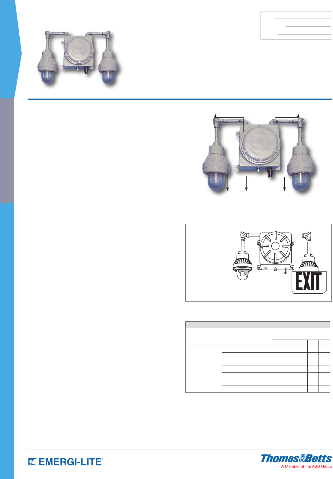
70
SPEC GRADE
INDUSTRIAL
TYPE:
CATALOG #:
NOTES:
Features
• Allows mounting up to 3 hazardous area xtures directly on the power unit or
remotely.
• Corrosion-resistant, copper-free cast aluminum construction. A weatherproof
gasketed spinoff cover, UL listed stainless steel vent/drain and silicone
conformal coating on the circuit board protect the electronics against
humidity. Comes standard with epoxy finish for added corrosion protection in
harsh environments.
• Available with sealed, maintenance-free Nickel-Cadmium batteries.
• Charger offers 120/277 VAC, 60 Hz, 0.3/0.15A, 36 watt (other inputs
available), fused DC output circuit, AC pilot light supervision, temperature
compensation, sealed relay, low voltage battery disconnect, brownout
protection, lockout (automatic battery connect), solid state, current limited,
constant current short circuit proof and reverse polarity protection.
• Meets hazardous location requirements: Class I Division 1 & 2 (Groups C &
D), Class II Division 1 & 2 (Groups E, F & G).
• 3-year full warranty, excluding lamps, pilot lights, and fuses.
Dimensions
Dimensions are approximate and subject to change.
Housing:
12” X 12” X 91⁄2”
(4) Mounting Lugs:
10” and 131⁄2” on center
Overall dimensions
(including fixtures):
38” X 38” X 10”
Note: Dimensions are
approximate and are
subject to change.
EXC Series
6 and 12 Volt – Class I, Div. 1 & 2, Groups C & D
and Class II, Div. 1 & 2, Groups E, F & G Power Unit
Fixtures
The EXC Series may be supplied with 1 or 2 hazardous fixtures mounted
directly on the power unit and/or remotely as the application dictates
(for remote fixtures, consult hazardous area fixture data sheet).
Lamp Fixtures (EP Series) See page 72: Fully directional U.L.
listed copper-free cast aluminum construction, swivel-mounted,
Pyrex® lens, complete with either 9, 18, or 25 watt HIT lamps
(halogen optional). Available with optional guard or reflectors.
Pyrex® is a registered trademark of Corning Glass.
Exit Fixtures (XP Series) See page 73: Mounted to the power unit, these exit
signs are supplied standard with our unique integral transfer switch (TS) and
utilize either a 6V-15W XX6 lamp or 12V-25W XX12 lamp. This enables the
exit to operate in both the normal AC mode as well as DC mode. The exit
sign consists of an EP fixture coupled with a heavy duty steel, baked enamel
finish exit shroud with ample downlight. Supplied standard as a single face
sign, red stencil faceplate; double face and green stencil also available.
For other legends, please consult your sales representative.
Spinoff Gasketed Cover Copper-Free Cast Aluminum
3/4” NPT Conduit
Entrance
Stainless Steel
Vent/Drain
Combination Test Switch
& Pilot Light
Unit Rating
UNIT EQUIPMENT - WITH REMOTE CAPABILITY
Sealed
Maintenance-Free
Battery Types
D.C. Voltage Model Number
Watts to 87-1/2% of rated battery
voltage*
1-1/2 hrs 2 hrs 4 hrs 8 hrs
Nickel-Cadmium
6 EXC1 18 12 – –
6 EXC2 25 18 9 –
6 EXC3 36 21 12 6
6 EXC5 50 36 18 10
12 1EXC3 36 21 12 6
12 1EXC5 50 36 18 10
12 1EXC7 72 42 24 12
*National Electrical Code Specication
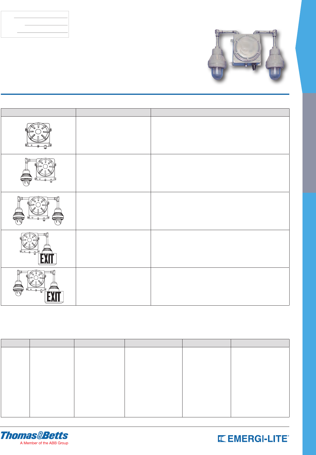
SPEC GRADE
71
INDUSTRIAL
TYPE:
CATALOG #:
NOTES:
Standard Configurations for EXC Series
UNIT CATALOG NUMBER DESCRIPTION
1EXC5-0 12 volt, 50 watt self-contained hazardous area emergency lighting
power unit complete with battery and charger. (No heads)
1EXC5-TS 12 volt, 50 watt self-contained hazardous area emergency lighting power
unit complete with battery, charger and transfer switch. (No heads)
1EXC5-1IG 12 volt, 50 watt, single head unit with 12 volt, 25 watt HIT lamp. (One head)
1EXC5-1IG-TS 12 volt, 50 watt, single head unit with built-in transfer switch
and 12 volt, 25 watt HIT lamp. (One head)
EXC3-2IB 6 volt, 36 watt, self-contained hazardous area emergency lighting
power units complete with battery and charger.
Fixture supplied with one (IB) 18 watt HIT lamp (Two heads)
EXC5-2IB-TS 6 volt, 50 watt, double head unit with built-in transfer switch and
12 volt, 25 watt HIT lamp (Two heads)
EXC2-T1SR 6 volt, 15 watt, self-contained unit with integral low voltage transfer circuit
(TS) to operate exit lamp in both normal and emergency modes. Suggested
catalog number shown indicates single face exit with red stencil faceplate.
For green, substitute G for R. For double face, substitute D for S. (One Exit sign)
EXC-1HD-T1SR 6 volt, 50 watt unit.
In addition to the exit lamp which operates in both normal and
emergency modes, emergency lighting can be achieved with (1) additional
emergency lighting head. (Example: HD = 6V-12W). (One head & one Exit sign)
Note: Above units are supplied with appropriate wattage (HIT) High Intensity Tungsten lamps (unless otherwise specied). Alternate wattages lamps or halogen lamps may be substituted as required.
Exit provided with 25 watt lamps only.
EXC Series
6 and 12 Volt – Class I, Div. 1 & 2, Groups C & D
And Class II, Div. 1 & 2, Groups E, F & G Power Unit
How to Order
The EXC Series is available with a wide variety of xtures, mountings, voltages, etc. To make your selection easier, we have listed the standard congurations in the chart above. When ordering exit xtures, additional to the
basic catalog number, you must specify single or double face and color of faceplate.
Insert these sufx letters at the end of model number.
SERIES CAPACITY NO. OF FIXTURES LAMPS* EXIT SIGN* OPTIONS
EXC= 6V
1EXC= 12V
1= 18W (6V only)
2= 25W (6V only)
3= 36W (6V, 12V)
5= 50W (6V, 12V)
7= 72W (12V only)
-0= No remote
-1= One remote
-2= Two remotes
Blank= No lamps
HB= 6V-8W bi-pin halogen
HD= 6V-12W bi-pin halogen
HF= 12V-8W bi-pin halogen
HG= 12V-12W bi-pin halogen
Blank= No exits
-T1SR= Single face red
-T1SG= Single face green
-T1DR= Double face red
-T1DG= Double face green
Blank= No options
TS= Transfer switch
-D1= Time Delay (5 minutes)
-D2= Time Delay (10 minutes)
-D3= Time Delay (15 minutes)
-RD= Dome reflector
-RA= Angle reflector
-GXP= Aluminum guard
* Lamps for emergency lights * Exit lamp included
Example: 1EXC7-1HG-T1SR-D1
(Remote Capability)
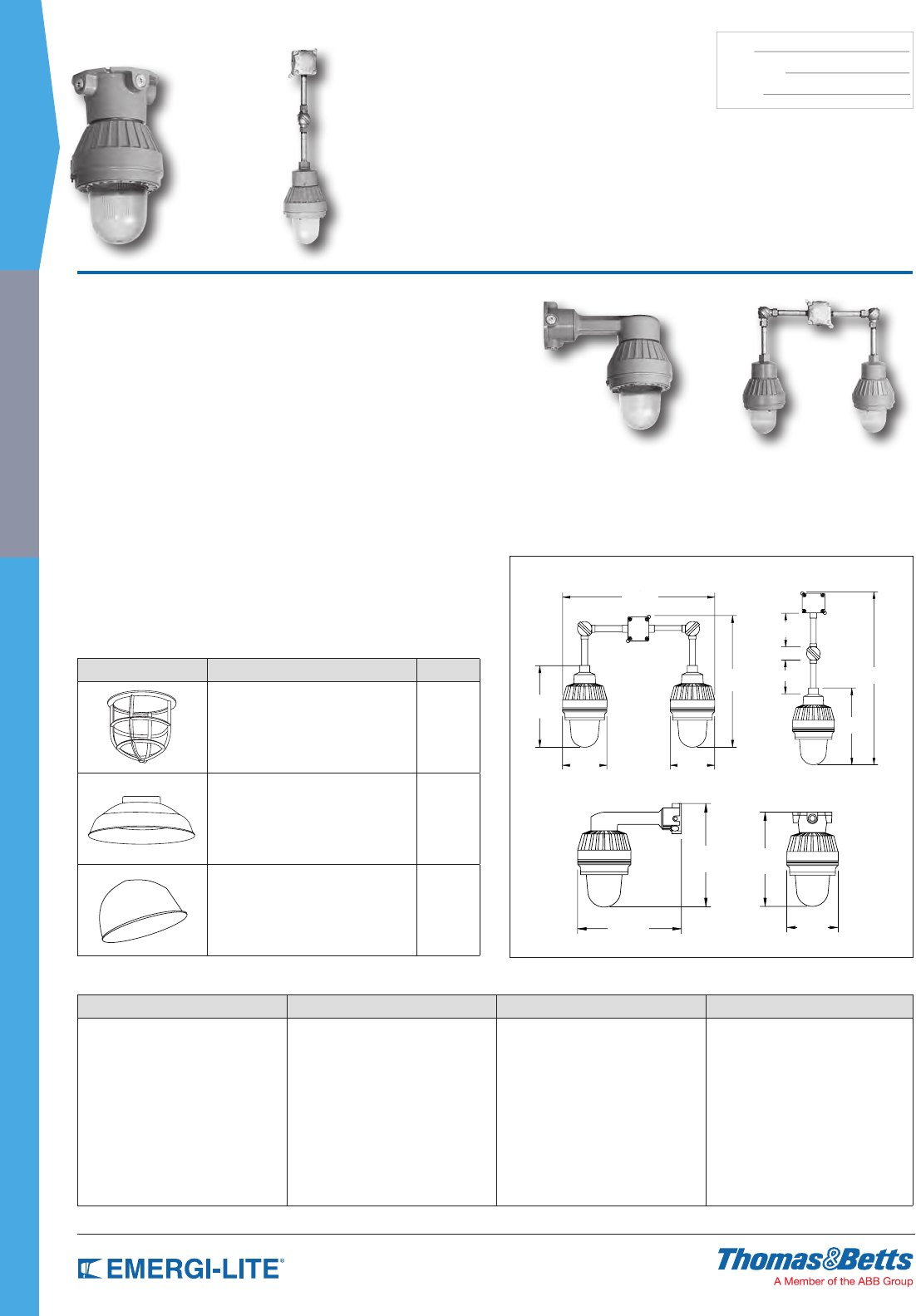
72
SPEC GRADE
INDUSTRIAL
TYPE:
CATALOG #:
NOTES:
EFEP Series
Remote Explosion-Proof Lighting Fixtures
How to Order
SERIES MOUNTING LAMPS OPTIONS
EFEP= Remote series C= Ceiling mount
P= Pendant
W= Wall
2= Double pendant mount
(HB)= 6V-8W bi-pin halogen
(HD)= 6V-12W bi-pin halogen
(XX6)= 6V-15W bi-pin halogen
(HF)= 12V-8W bi-pin halogen
(HG)= 12V-12W bi-pin halogen
(AC)= 120v-25W A19
Blank= No options
-GXP= Aluminum guard
-RD= Dome reflector
-RA= Angle reflector
Example: EFEPC(HB)-GXP
Features
• Available with 6, 12 and 24V lamps for DC operation or 120V AC xtures.
• Manufactured of heavy cast aluminum with an epoxy nish and a Pyrex® lens.
All attached hardware has been designed for explosion-proof applications.
• Designed for mounting in locations that are remote from the power source.
If the power source is installed outside hazardous areas, the length of
connection wires should be carefully considered to ensure that the voltage
of the emergency power unit and the wire size of the connecting circuit are
adequate to offset the voltage drop in the circuit.
• EFEPP and EFEP1, 2 and 3 xtures include elbows swivels, a conduit
extension pipe (6” increments), and a combination explosion-proof junction
box/mounting plate (4” box, 6 1/4” mounting center).
• Complies with NEC, OSHA and NEMA specications for the following Classes
and Groups:
Class I, Division 1 & 2, Groups C & D (300W PS-25 max)
Class II, Division 1 & 2, Groups E, F & G (60W max)
Class III, Division 1 & 2 (150 watt max)
UL Listed for use in Paint Spray Areas (75W max)
Suitable for Wet Locations
Pyrex® is a registered trademark of Corning Glass.
Dimensions
Dimensions are approximate and subject to change.
30-7/8”
13-3/4”
6”
6”
25-1/2”
22-1/8”
13-5/8”
7-1/2”
7-1/2”
Double Pendant Mount Pendant Mount
14-1/2”
14-1/2”
Wall Mount
13-5/8”
7-1/2”
Ceiling Mount
EFEPC= Ceiling mount – 11 lbs.
EFEPP= Pendant
Mount with hanger box
& pendant – 14 lbs
EFEPW= Wall bracket mount 14 lbs. EFEP1= Single 12 lbs.
EFEP2= Double 21 lbs.
EFEP3= Triple 30 lbs.
Standard Configurations for EXC Series
UNIT DESCRIPTION SUFFIX
Guard
One-piece aluminum casting
construction, attaches to globe
holder ring with four screws.
GXP
Dome Reflector
Highly reflective white finish
inside and out, attaches to globe
holder ring with four screws.
RD
Angle Reflector
Highly reflective white finish
inside and out, attaches to globe
holder ring with four screws.
RA
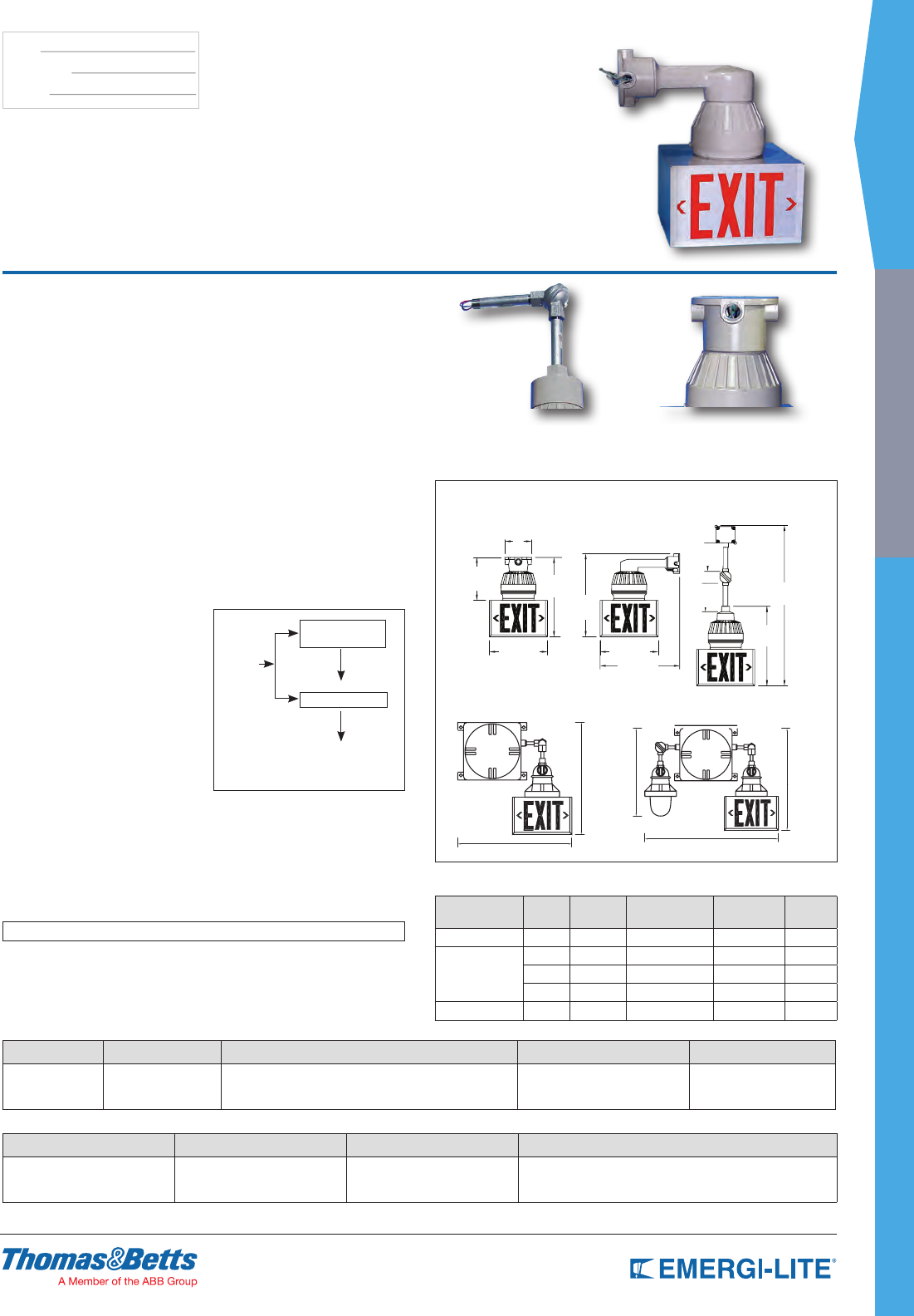
SPEC GRADE
73
INDUSTRIAL
TYPE:
CATALOG #:
NOTES:
Dimensions
Dimensions are approximate and subject to change.
34-1/8”
[86.67 cm]
16-7/8”
[42.86 cm]
12-3/8”
[31.43 cm]
12-3/8”
[31.43 cm]
9-1/8”
2
3.17 cm]
5-3/4”
[14.6 cm]
17-3/4”
[45.08 cm]
16-7/8”
[42.86 cm]
17”
[43.18 cm]
6”
[15.24 cm]
6”
[15.24 cm]
23-3/4” [60.4 cm]
23-3/4” [60.4 cm]
23-3/8”
[59.2 cm]
30-5/8” [77.8 cm]
20-1/8”
[51.0 cm]
5-3/4”
9-1/8” 16-7/8”
6”
6”
12-3/8” 12-3/8”
34-1/8”
16-7/8”
23-3/4”
17”
17-3/4”
23-3/4” 30-5/8”
20-1/8”
23-3/8”
Ceiling Mount
AC-Only and AC/DC Exit Signs
Self-Powered Exit Sign Combination Units
Wall Mount Pendant Mount
EFXP Series
Explosion-Proof Remote Exit Signs
How to Order
SERIES MOUTING LAMP TYPE # OF FACES LETTERS
EFXP= Exit series C= Ceiling mount
P= Pendant
W= Wall
XX6= 6V-15W (DC only)
XX12= 12V-25W (DC only)
XX24= 24V-25W (DC only)
AC120= 120V-25W (AC only)
XX120= 120V-5W LED
1= Single face
2= Double face
3= Triple face
-R= Red
-G= Green
Example: EFXPC(XX6)-2R
AC VOLTAGE DC VOLTAGE SERIES LOAD WATTAGE
120= 120VAC
277= 277VAC
-6= 6VDC
-12= 12VDC
-24= 24VDC
-TS= Transfer circuit -25= 25W
-50= 50W
-75= 75W
-100= 100W
Example: 120-6-TS-25
EFXPP= Adjustable Pendant
Mount
EFXPC= Ceiling Mount
EFXPW= Wall Bracket Mount
Standard Features
• Available with 6, 12 and 24 volt lamps for DC operation or 120 volt AC xtures
• Exits shown are explosion-proof xtures of heavy cast aluminum construction
with Pyrex® lenses. Exit housing is an 18 gauge fabricated steel box with a
baked enamel nish. Stenciled exit lettering is available on one or two faces.
All EFXP Series have extra large downlight openings
• EFXP units are designed for mounting in locations that are remote from the
power source. If the power source is installed outside hazardous areas, the
length of the connection wires should be carefully considered to ensure that
the voltage of the emergency power unit and the wire size of the connecting
circuit are adequate to offset the voltage drop in the circuit
• Complies with NEC, OSHA and NEMA specications for the following Classes
and Groups:
Class I, Division 1 & 2, Groups C & D (300W PS-25 max)
Class II, Division 1 & 2, Groups E, F & G (60W max)
Class III, Division 1 & 2 (150W max)
U.L. listed for use in Paint Spray Areas (75W max)
Suitable for Wet Locations
Pyrex® is a registered trademark of Corning Glass.
Mounting
The transfer circuit is not designed for
use in hazardous or explosive areas.
The transfer circuit is to be mounted
remotely from hazardous areas.
Electrical Specifications
for Transfer Panel
Input Voltage:
From AC - 120 Volt, 60Hz, 1 phase
(other voltages available).
From DC - 6, 12, 24 or 120 Volt (select).
Output Voltage: Must be
identical to DC Input Voltage
Wattage: Panel oversized 10-20%
greater than total connected load.
AC Input
assigned
to same
breaker
and/or
phase
Emergency
Lighting Unit
TS Transfer Panel
DC Output
Output
To Lighting Loads
AC - Normal Operation
DC - Emergency Operation
Lamp Selection
Lamp Type Voltage Power Lamp Type Average Life
(hours)
Suffix
Quartz Bi-Pin 6V 15W JC-6V15W 2,000 XX6
Medium Base
12V 25W 25A-12 1,000 XX12
24V 25W 143A 1,000 XX24
120V 25W A19 2,500 AC/20
LED Lamp, Red 120V 5W –100,000 XX120
Power Consumption Chart
120/277VAC, 60Hz maximum 0.3/0.15A
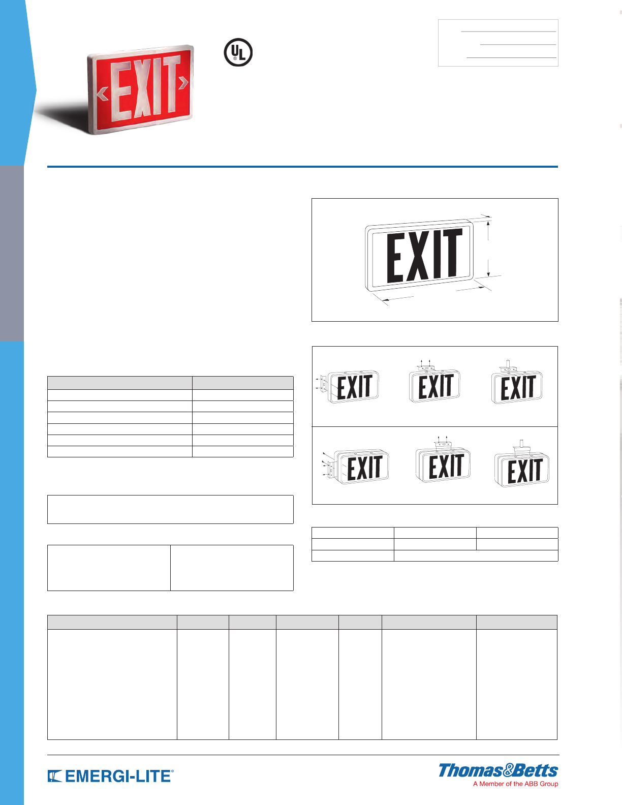
74
SPEC GRADE
INDUSTRIAL
TYPE:
CATALOG #:
NOTES:
How to Order
FRAME COLOR SERIES SIGN LIFE # OF FACES LEGEND OPTIONS NEW
W= Off white
B= Black
G= Gray
SLX= Series -10= 10 years
-20= 20 years
61= Single face
62= Double face
R= Red
G= Green
-AF= Aluminum frame
-AFPC= Aluminum frame and
Polycarbonate shield
-N= NEW
Example: WSLX-1061R-AF-N
Features
• Legend is constructed of non-glare polycarbonate, with 0.015 thick, open
letters, eld programmable arrows, and white letters with background colors
of red or green. Contrast ratio for both conditions exceeds .5, and meets
requirements of UL 924 and NFPA 101
• Constructed of rugged thermoplastic, the EverLite™ Series offers
contemporary slim line design with smooth rounded corners, and a vibrant
faceplate color. Frame nishes include off-white, black or gray. The entire unit
is tamperproof and completely self-contained
• Tritium gas energizes the phosphor-coated borosilicate tubes in the
EverLite™ sign. The low energy beta emission of tritium striking the phosphor
coating inside the Pyrex® glass tubes causes illumination to be generated
• Signs mount ush to wall or ceiling surfaces, a canopy is not required.
• UL Listed. Complies with NFPA, Life Safety Code and OSHA
• EverLite™ signs are spark free and suitable for use in hazardous, explosive,
corrosive, humid or any other harsh environment. Emergi-Lite® will replace
free of charge any product in which the luminosity is found to be defective
during its specified luminous life, or which falls below specified luminous life
Pyrex® is a registered trademark of Corning Glass.
Dimensions
Dimensions are approximate and subject to change.
1”
8-1/4”
14”
EverLite™ Series
Self Luminous Exit
Accessories (order as a separate item)
DESCRIPTION SUFFIX
White Pendant P*-WT
Black Pendant P*-BK
Gray Pendant P*-GY
Wire Guard-Wall Mount WG13-E
Wire Guard-Ceiling Mount WG5-E
Wire Guard-End Mount WG15-E
* Specify length in inches (12, 24, 36, etc)
Applications
(For use in harsh or dangerous environments)
• Meets full test specifications of ANSI (American National Standards Institute)
• Meets requirements of National Electrical Codes, Class I and II conditions
• Licensed for distribution by U.S. Nuclear Regulatory Commission
Licenses and Codes
• NFPA Life Safety Code 101
• UL 924
• City of Los Angeles
• State of California
• Council of American Building
• Officials (ICBO, SBCCI)
• OSHA
• USNRC
• ISO 9001
Mounting
Double Face Signs
Ceiling Mount
(flush ceiling) Pendant Mount
Wall Mount (flush end) Pendant Mount
Ceiling Mount (flush ceiling)
Single Face Signs
Wall Mount
(flush wall or end)
Harsh
Mines Spray Booth Areas Refineries
Off Shore Rigs Paper Mills Chemical Plants
Food Processing Plants Grain Elevators
77
REMOTE FIXTURES
Luxray™ LED Series 78
Lite-Ray™ Series 79
Revelation™ Series 80
Mini-Revelation™ Series 81
Distinction™ EF150 Series 82
Distinction™ Recessed Designer Series 83
EF9 Series 84
EF10 Series 85
EF14 Series 86
EF18 Series 87
EF23 Series 88
REMOTE FIXTURES
Table of Contents
EF24 Series 89
EF28 Series 90
EF32 Series 91
EF13 & EF17 Series 92
EF15 Series 93
EF21R Series 94
EF35 Series 95
EF11 Series 96
EF11X Series 97
EF39, EF39P, EF40 & EF40P Series 98
EF41 Series 99
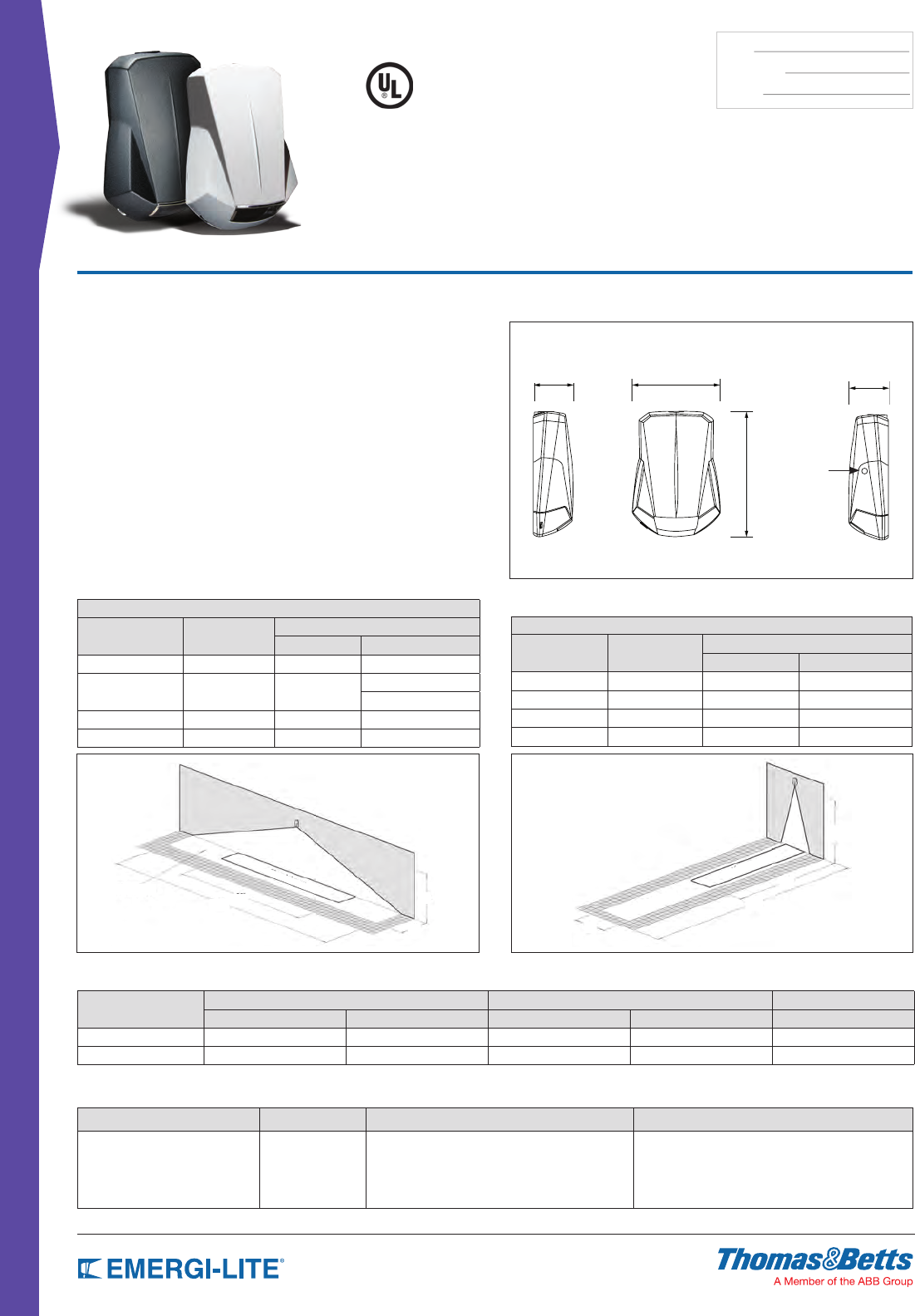
78
REMOTE FIXTURES
TYPE:
CATALOG #:
NOTES:
Dimensions
Dimensions are approximate and subject to change.
6-5/8”
9-1/2”
3” 3”
Window for
photo-switch
(optional)
Features
• Die-Cast aluminum housing, available in four nishes: dark bronze, off-white,
black, and platinum gray
• Nema-3R rated for indoor / outdoors wet and Damp Locations:
0-40°C (32-104°F)
• Wall-mount installation on various junction boxes or via rigid conduit
• Patent-pending design for easy installation: wall-mount back-plate includes
electrical wire box with snap-on connector
• Patent pending light engine: four power LEDs with redundant connections
and very wide beam
• Clear polycarbonate lens of reduced size (3” X 1.5”), shockabsorbent and
UV-resistant
• Power consumption in stand-by: less than 5W
• 5-year limited warranty
NEMA-3R
Patent-Pending
Luxray™ LED Series
Low-Profile, Slim Look Light Fixture
How to Order
COLOR SERIES MODEL [ -40°F ... +122°F (-40°C ... +50°C)] OPTIONS
B= Black
BZ= Dark bronze
OW= Off-white
PG= Platinum gray
LUX= Lux-Ray LED AC= AC-only
ACDC= AC/6-12VDC remote
DC= 6-12VDC remote fixture
2AC= AC-only two circuits: 120/120 or 277/277V
-FT= Forward throw lighting
-H= High lumen output (-40... 86°F/-40…30°C)
-P= Photocell Test Switch (AC, ACDC only)
-RC= Remote control - infrared* (AC, ACDC only)
* Remote control keypad (TB-RC1-E) ordered separately
Example: BZLUXDC-FTH
Power Consumption Chart
Model Type Normal Lighting (120/277VAC) Emergency Lighting (120/277VAC) 6-12VDC Remote
Current (max) Power (max) Current (max) Power (max) Power (max)
AC, 2AC, ACDC, DC 0.12/0.08A 12W 0.12/0.08A 12W 8W
AC, 2AC, ACDC, DC, -H 0.18/0.11A 18W 0.18/0.11A 18W 14W
* Note: Only unswitched AC input; normal lighting with photo-switch or remote control
Average of 1 foot-candle
TABLE A: SPACING FOR NFPA101 (AVERAGE = 1FC, SEE NOTE)
Model Type Mouting Height Width X Length (ft)
Single Unit Center-To-Center
Standard 9’ 6’ X 50’ 6’ X 50’
With option -H
11’
6’ X 60’ 6’ X 60’
3’ X 70’
With option -FT 12’ 6’ X 40’ –
With option -FTH 15’ 6’ X 50’ –
Minimum of 1 foot-candle
TABLE B: SPACING FOR MINIMUM ILLUMINATION = 1FC
Model Type Mouting Height Width X Length (ft)
Single Unit Center-to-Center
Standard 9’ 4’ x 28’ 4’ x 32’
With option -H 11’ 4’ x 32’ 4’ x 40’
With option -FT 12’ 4’ x 22’ –
With option -FTH 15’ 4’ x 27’ –
1fc average
1fc average
1fc minimum
50’ 28’ 9’
6’
1fc minimum
6’
40’
20’
10’
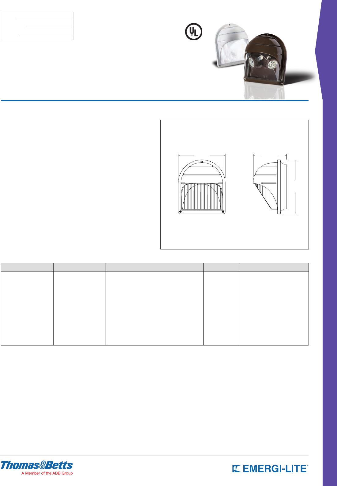
79
REMOTE FIXTURES
TYPE:
CATALOG #:
NOTES:
How to Order
SERIES # OF LAMPS LAMP TYPE/WATTAGE COLOR OPTIONS
LITE= Exterior remote -2= 2 lamps (standard)
-1= 1 lamp (AC only)
(LA)= 6V-4W, MR16 LED
(LG)= 2V-4W, MR16 LED
(LL)= 24V-4W, MR16 LED
(LV)= 120V-4W, MR16 LED
(LI)= 12V-5W, MR16 LED
(LJ)= 12V-6W, MR16 LED
(MI)= 6V-6W, MR16
(MJ)= 6V-10W, MR16
(MK)= 12V-12W, MR16
(MD)= 24V-20W, MR16
(MS)= 24V-12W, MR16
(MA)= 12V-20W, MR16
(AC)= 1 med. base socket only (max. 60W),
no lamp included, for non-emergency
-WT= White
-BK= Black
-DG= Dark gray
-BZ= Dark bronze
Blank= No options
-VR= Vandal-resistant screws
-N= Clear lens
Example: LITE-2(MI)-WT-VR
Features
• Indoor or Outdoor use
• Die-Cast aluminum construction
• Fully gasketed cover available with (optional) Tamper Proof Screws
• Adjustable tool-less aiming swivel head rotates side to side and tilts in and out
• Surface Wall Mount
• Universal knock-outs for mounting to a standard 4” octagonal electrical box
• Precise beam control is provided with two fully adjustable MR16 halogen or
LED lamps secured in an attractive molded swivel assembly for maximum
light output
• Provides an average of one-foot candle along the path of egress
• Specially manufactured polycarbonate diffuser maximizes light output, and
completes the wall sconce’s decorative lines
• Available in four textured powder coat paint nishes: white, black, dark bronze
and dark gray
Dimensions
Dimensions are approximate and subject to change.
7” 5”
8”
Literay™ Series
Wall Mount Remote Head for
Damp and Wet Locations
NEMA-3R
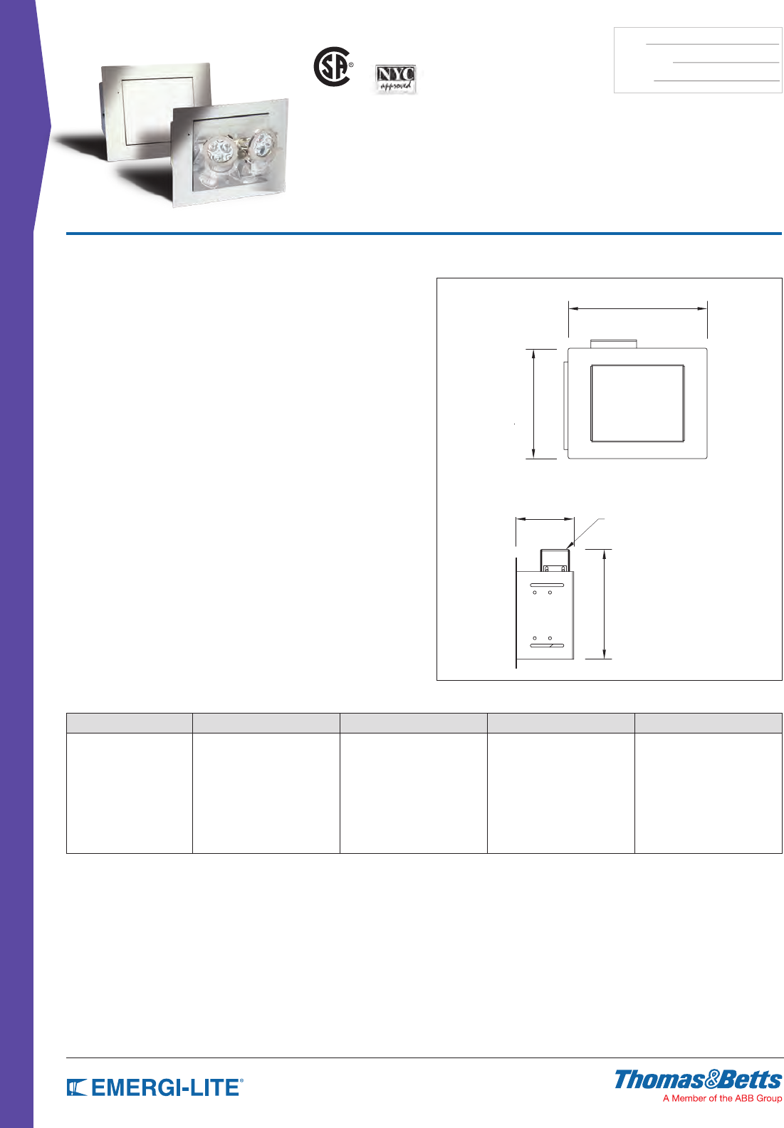
80
REMOTE FIXTURES
TYPE:
CATALOG #:
NOTES:
How to Order
INPUT VOLTAGE SERIES # OF LAMPS LAMP TYPE/WATTAGE OPTIONS
12= 12VDC
24= 24VDC
RTR= Revelation remote 2= Two lamps standard -12= 12W MR16
-20= 20W MR16
-35= 35W MR16
-50= 50W MR16
-LG= 12V-4W, MR16 LED
-LL= 24V-4W, MR16 LED
-LI= 12V-5W, MR16 LED
-LJ= 12V-6W, MR16 LED
Blank= No options
-DL= Damp Location
Example: 12RTL2-12-DL
Dimensions
Dimensions are approximate and subject to change.
9-1/8”
3-3/4”
7-1/4”
7-1/4”
DC voltage junction box
Features
• Indoor use
• Two lamp MR16 remote xture with a choice of halogen or LED lamps
• One-piece all-metal module design (does not require large galvanized steel
back box as does the battery back-up unit)
• Complete 360° door rotation, 180° to open, 180° to close
• Slip gear mechanism protects the unit from objects that would cause the
door rotation to be forcibly stopped.
• Flat door and frame are covered with a high-quality, powder coated textured
off-white nish
• Surface nish can be customized on site with paint, wallpaper or other
coverings.
• Recessed ceiling or wall mount with cavity space; special bar hangers for
installation in sheet rock or T-bar ceilings are included.
• The module includes the electrical junction box and is installed on the wall
stud or ceiling beam with the help of a simple, U-shape bracket.
• Key-hole slot for ease of installation
Revelation™
DC-Remote Series
Virtually Invisible, Architecturally Pleasing
US
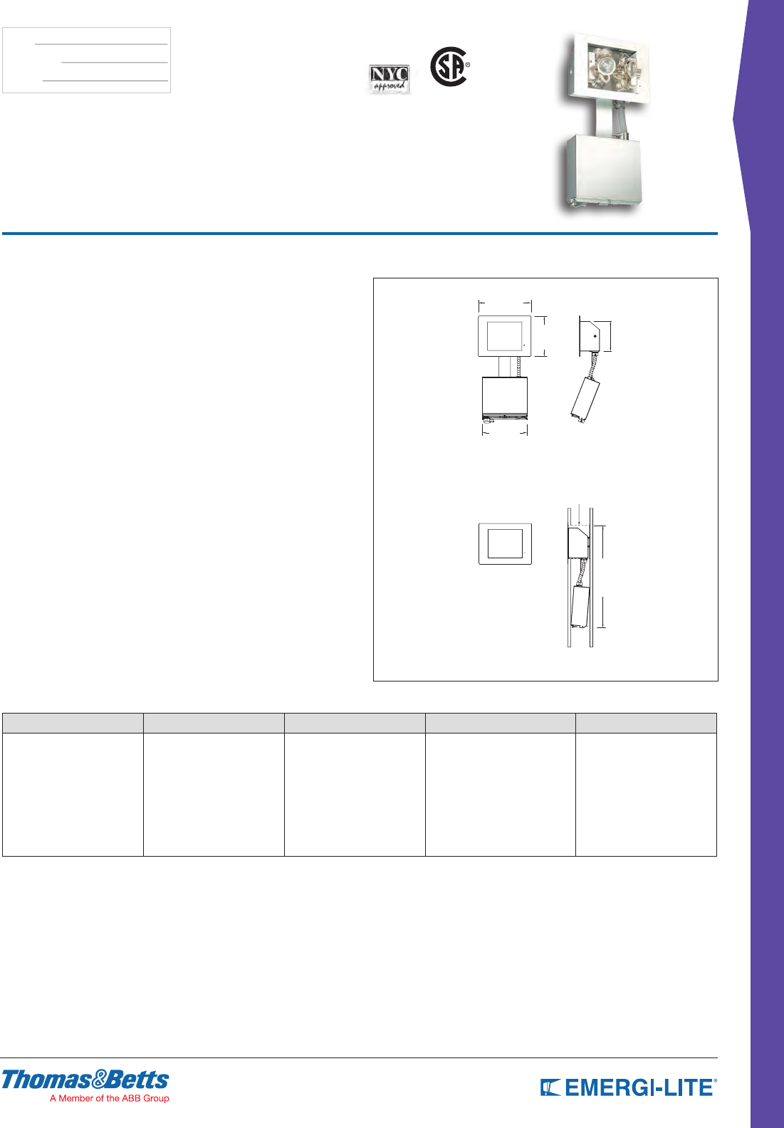
81
REMOTE FIXTURES
TYPE:
CATALOG #:
NOTES:
How to Order
SERIES AC INPUT LAMP TYPE/WATTAGE OPTIONS
MRT G= Remote AC generator 1= 120 VAC
2= 277 VAC
-2(12)= 12W each head
-2(20)= 20W each head
-2(35)= 35W each head
-2(50)= 50W each head
-2(20H)= 20W, high lumen output
-2(35H)= 35W, high lumen output
-2(50H)= 50W, high lumen output
-2(-LG)= 12V-4W, MR16 LED
-2(-LI)= 12V-5W, MR16 LED
-2(-LJ)= 12V-6W, MR16 LED
Blank= No options
DL= Damp Location
Example: MRTG1-2(20)DL
Dimensions
Dimensions are approximate and subject to change.
7”
9-1/8”
7-3/4”
5-1/4”
Complete unit
Installed unit
Mounting Bracket
17-5/8”
Features
• 20 gauge galvanized steel back-box
• Head assembly designed for easy access to internal components
• Head assembly door and trim plate powder coated in a white nish
• Finish can be customized on site with paint or wallpaper
• Provision for 2 lighting heads
• Choice of MR16 Halogen or MR16 LED lamp types and wattages
• Complete 360° head assembly door rotation: 180° to open,
180° to close
• Recessed mount into ceiling or wall with cavities
• Special bar hangers included for installation in dry wall or T-bar ceilings
• Includes the electrical junction box
• Installed on the wall stud or ceiling beam with simple, U-shape bracket
• Head assembly includes keyhole slot and quick-connect plugs for easy
installation
Mini-Revelation™
AC Generator Remote Series
THE UNSEEN SOLUTION
Virtually Invisible Emergency Lighting
US
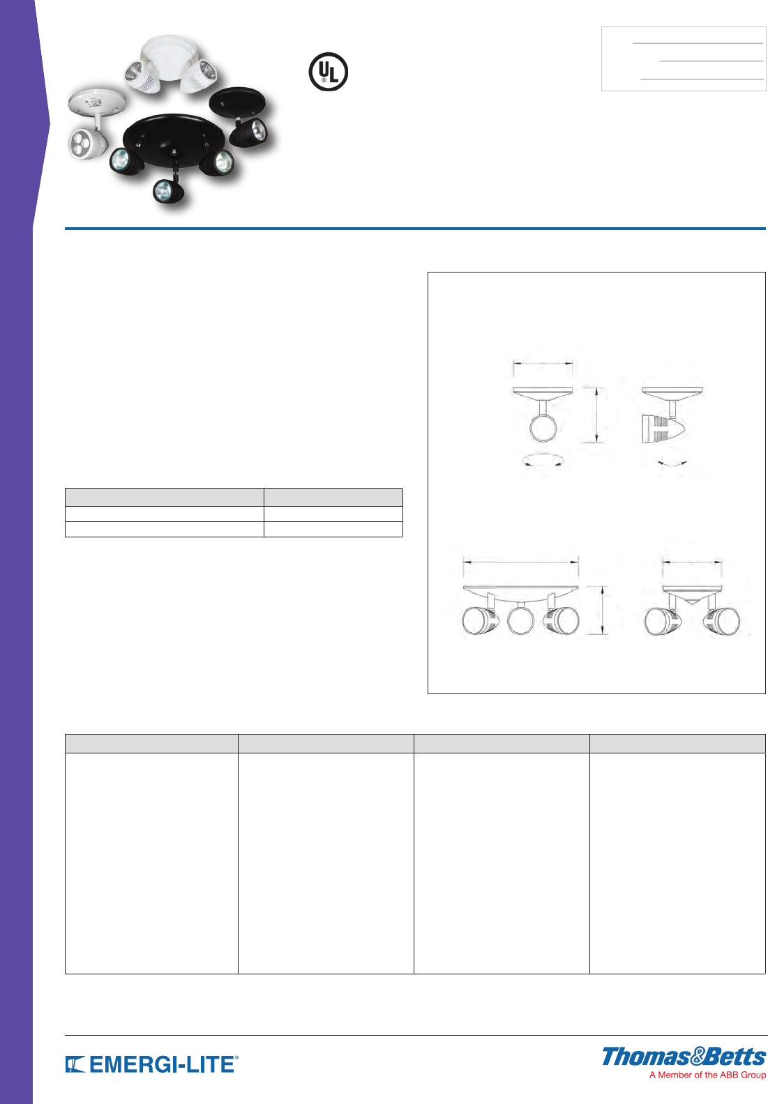
82
REMOTE FIXTURES
TYPE:
CATALOG #:
NOTES:
How to Order
SERIES # OF HEADS COLOR LAMP TYPE/WATTAGE
EF150= Decorative MR16 remote head Blank= Single head
D= Double head
T= Triple head
Blank= White
-B= Black
(LA)= 6V-4W, MR16 LED
(LG)= 12V-4W, MR16 LED
(LL)= 24V-4W, MR16 LED
(LI)= 12V-5W, MR16 LED
(LJ)= 12V-6W, MR16 LED
(LV)= 120V-4W, MR16 LED
(M_)= Halogen MR16 50W max*
* See lamp chart for lamp code 50W use heat shield
Example: EF150D-B(MK)
Features
• White or black nish available.
• EF150: Single compact adjustable decorative lighting head.
Dimensions: 4.48” diameter base, 5.2” height
• EF150D: Double compact adjustable decorative lighting heads.
Dimensions: 4.48” diameter base, 4.0” height
• EF150T: Triple compact adjustable decorative lighting heads.
Dimensions: 11.0” diameter base, 5.2” height
• Indoor use
• Die-Cast aluminum
• Fully tool-less adjustable aiming swivel head
• Clear glass lense
• Surface mount
• Includes canopy plate for mounting to a standard 4” octogonal electrical box
Dimensions
Dimensions are approximate and subject to change.
320°
5”
4”
5”
4-5/8”
9-5/8”
80°
EF150T
EF150
EF150D
Distinction™ EF150,
EF150D & EF150T Series
Surface Mounted Designer Light Fixtures
Accessories (order as a separate item)
DESCRIPTION PART NUMBER
Wire Guard for EF150, EF150D WG8-E
Wire Guard for EF150T WG2-E
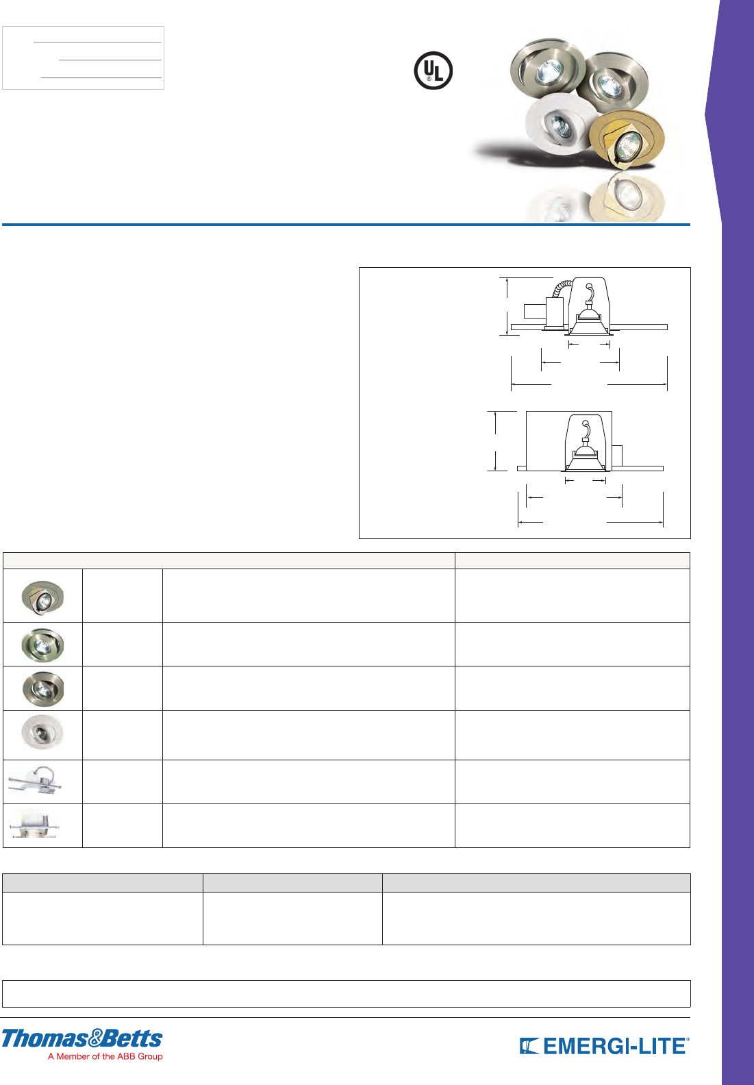
83
REMOTE FIXTURES
TYPE:
CATALOG #:
NOTES:
How to Order
SERIES COLOR* LAMP TYPE/WATTAGE
EFR2
EFR8NB
EFR8R
EFR9WH
* Choose color from the above table -(L_)= LED MR16 (see table above)*
-(M_)= Halogen MR16*
* For a complete list of available lamp types, please refer to the lamp data on pages 144-145
Example: EFR8R-BK-(MA)
HOUSING
EL-GRHR03= New Construction
EL-GRHR06= Insulated Ceilings
Dimensions
Dimensions are approximate and subject to change.
EL-GRHR03
EL-GRHR06
New construction housing.
Total height: 5.6”.
Insulated ceilings housing
Total height: 7.25”
4”
11-1/4”
14-1/4”
7-1/4”
5-3/5”
7-4/5”
14-1/4”
4”
Features
• Indoor Use
• Powder-coated Die-Cast aluminum construction
• Tool-less lamp head adjust ability
• Glass MR16 lamp lens
• Choice of MR16 Halogen or LED lamp
• Choice of White, Black, Chrome, Brushed Nickel or Polished Brass
• Recessed ceiling mount
• Must order appropriate housing with decorative head selection for installation
into new construction ceiling (EL-GRHR03) or insulated ceiling (EL-GRHR06)
Distinction™ Series
Remote Recessed Designer Light Fixtures
SERIES LED LAMP SUFFIX
EFR2 Description: Decorative pop-up adjustable lighting head
Dimensions: 4.0” diameter base
Color Suffix: - WH= White, -BK= Black, -CH= Chrome,
-PB= Polished brass, -BN= Brushed Nickel
Required recessed housing
N/A
EFR8NB Description: Decorative adjustable lighting head
Dimensions: 4.0” diameter base
Color Suffix: - WH= White or -BN= Brushed nickel
Requires recessed housing
LA= 6V-4W, MR16 LED
LG= 12V-4W, MR16 LED
LL= 24V-4W, MR16 LED
EFR8R Description: Decorative adjustable lighting head
Dimensions: 4.0” diameter base
Color Suffix: -WH = White or -BN = Brushed nickel
Requires recessed housing
LA= 6V-4W, MR16 LED
LG= 12V-4W, MR16 LED
LL= 24V-4W, MR16 LED
LI= 12V-5W, MR16 LED
LJ= 12V-6W, MR16 LED
LV= 120V-4W, MR16 LED
EFR9WH Description: Decorative adjustable lighting head
Dimensions: 4.0” diameter base
Color Suffix: -WH = White
Requires recessed housing
LA= 6V-4W, MR16 LED
LG= 12V-4W, MR16 LED
LL= 24V-4W, MR16 LED
LI= 12V-5W, MR16 LED
LJ= 12V-6W, MR16 LED
LV= 120V-4W, MR16 LED
EL-GRHR03 Housing Enclosure
Description: New construction housing
Dimensions: 5.6” x 14.24”
New construction housing
–
EL-GRHR06 Housing Enclosure
Description: Insulated ceilings housing
Dimensions: 7.25” x 14.24”
Insulated ceilings housing
–
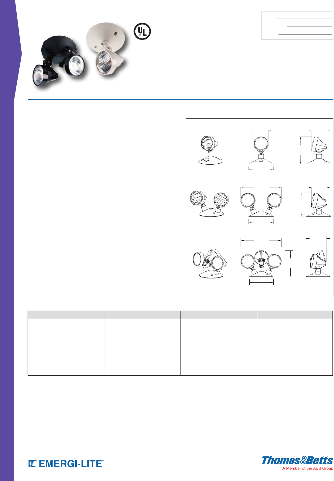
84
REMOTE FIXTURES
TYPE:
CATALOG #:
NOTES:
Features
• Off-white nish; black (BK) optional
• Surface (wall or ceiling) mounting direct to 4” octagonal or
single-gang box
• Lamps (for alternate lamp selection, see lamp data sheet):
lamp type H: BI-PIN halogen or lamp type Z: High intensity incandescent
wedge base
• Thermoplastic construction
• Indoor use
• Fully adjustable tool-less aiming swivel head
• Specular parabolic reector and prismatic lens for wide-beam, even light
distribution
• Snap-out lens for easy lamp replacement
• Surface mount
• Includes a 5” round universal canopy plate with 3 knock-outs (supplied with 2
plugs) for use with single, double or triple head mounting
Dimensions
Dimensions are approximate and subject to change.
2-15/16” 3-3/16
3-3/16”
3-3/16”
8-5/16”
8-1/2”
5”
5”
5-5/8”
5-9/16”
4-13/16”
5”
EF9
EF9D
EF9T
Surface Mounted
EF9, EF9D & EF9T Series
Thermoplastic PAR 18 Size Lamp Head
How to Order
SERIES # OF HEADS LAMPT TYPE/WATTAGE COLOR
EF9= PAR 18 remote head Blank= Single head
D= Double head
T= Triple head
(H_)= Halogen bi-pin 12W max*
(Z_)= Tungsten wedge 18W max*
Blank= Off white
BK= Black
* For a complete list of available lamp types, please refer to
the lamp data on pages 144-145
Example: EF9D(HB)BK
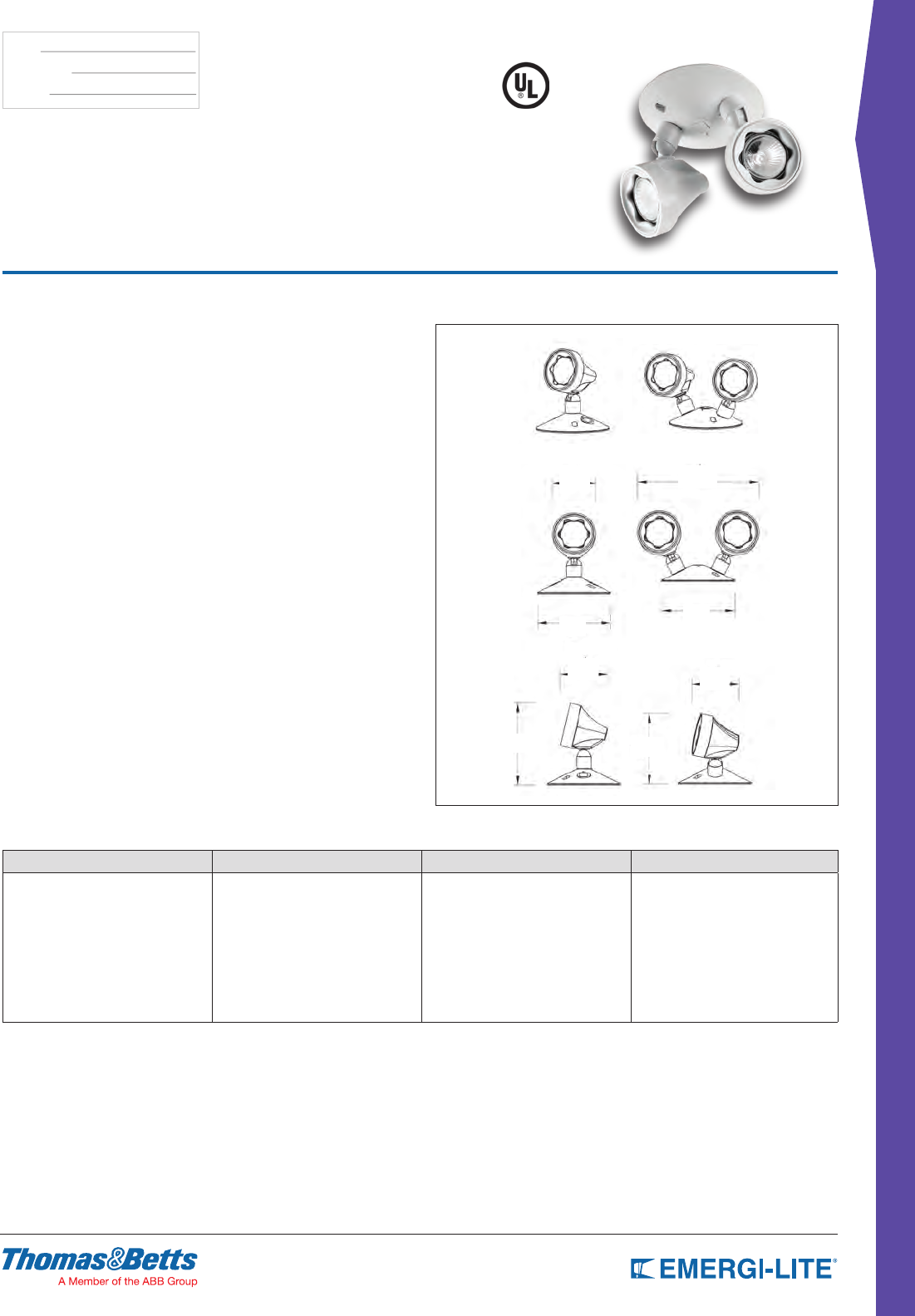
85
REMOTE FIXTURES
TYPE:
CATALOG #:
NOTES:
Features
• Thermoplastic construction with off-white nish; black (BK)
• Direct mounting to 4” octagonal electrical box
• Series M Lamps: MR16
• Indoor use
• Available as a single, double or triple PAR 18 size MR16 lighting head
• Fully adjustable tool less aiming swivel head
• Specular parabolic reector and prismatic lens for wide-beam, even light
distribution
• Snap-out lens for easy lamp replacement.
• Surface Mount
• Includes a 5” round universal canopy plate with 3 knock-outs (supplied with 2
plugs) for use with single, double or triple head mounting
Dimensions
Dimensions are approximate and subject to change.
2-7/8” 8-1/4”
5”
5”
3-1/4” 3-1/4”
5-5/8” 4-7/8”
Surface Mounted
EF10, EF10D & EF10T Series
Thermoplastic MR16 Lamp Head
How to Order
SERIES # OF HEADS LAMP TYPE/WATTAGE COLOR
EF10= MR16 PAR18 remote head Blank= Single head
D= Double head
T= Triple head
(LA)= 6V-4W, MR16 LED
(LG)= 12V-4W, MR16 LED
(LL)= 24V-4W, MR16 LED
(LI)= 12V-5W, MR16 LED
(LJ)= 12V-6W, MR16 LED
(M_)= Halogen MR16 20W max*
Blank= Off-white
BK= Black
* 20W Halogen is only available in 12V (MA)
Example: EF10D(LA)BK
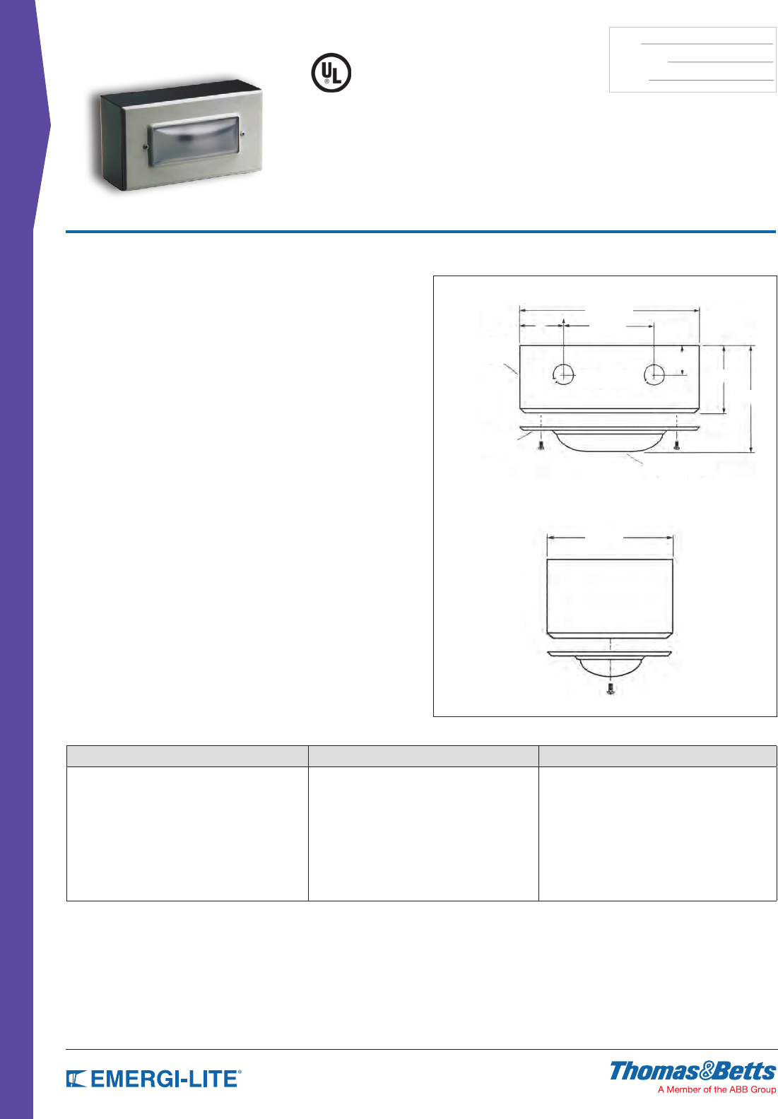
86
REMOTE FIXTURES
TYPE:
CATALOG #:
NOTES:
Features
• Rectangular xture with diffused polycarbonate lens
• White baked enamel nish (specify other)
• Surface wall or ceiling mounting
• Lamps (for alternate lamp selection, see lamp data sheet page 146-147):
Series I - High intensity tungsten (HIT) double contact bayonet base
Lamp type(s), voltage and maximum wattage available for xture are shown
under lamp description. Determine lamp type, voltage and wattage required for
your application, then select lamp from Lamp Chart in the Charts & Diagrams
in the Accessories & General Information Section on page 146-147 section. Do
not exceed xture wattage rating. Include lamp sufx and voltage as sufx to
model number. Voltage must be stated.
Dimensions
Dimensions are approximate and subject to change.
Diffusion Lens
Knock-outs
Cover
Steel Housing
8-1/4”
4-1/4”
4-1/2”
3-1/4”
3”
4”
Surface Mounted
EF14 Series
Remote Fixture
How to Order
SERIES LAMP TYPE/WATTAGE COLOR
EF14= Remote fixture (I_)= Tungsten double contact bayonet base
25W max, (6, 12, 24 Volts)*
(I_)= Tungsten double contact bayonet
base 15W max, (120 VAC)*
Blank= Off white
BK= Black
* For a complete list of available lamp types, please refer to the lamp data on
pages 146-147
Example: EF14(IA)BK
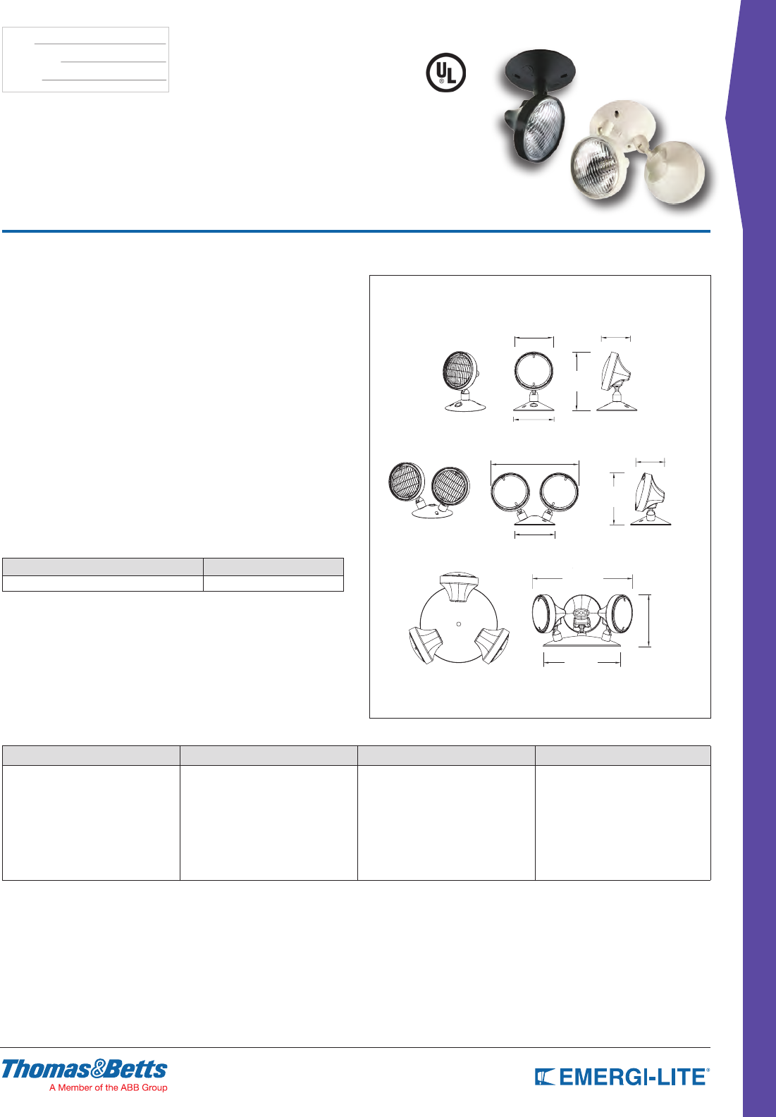
87
REMOTE FIXTURES
TYPE:
CATALOG #:
NOTES:
Surface Mounted
EF18, EF18D & EF18T Series
Thermoplastic PAR 36 Lamp Head
Features
• Thermoplastic construction with off-white nish; black (BK) optional
• Lamps (for alternate lamp selection,
see lamp data sheet):
Type H: BI-PIN halogen.
Type I: High intensity tungsten (HIT) double contact bayonet base.
Type U: Sealed beam tungsten.
Type X: Sealed beam halogen
or Type Z: High intensity incandescent wedge base
• Indoor use
• Available as a single, double or triple PAR 36 size lighting head
• Fully adjustable tool less aiming swivel head
• Specular parabolic reector and prismatic lens for wide-beam, even light
distribution
• Snap-out lens for easy lamp replacement.
• Surface Mount
• Includes a 5” round universal canopy plate with 3 knock-outs (supplied with 2
plugs) for use with single, double or triple head mounting
• Mounts to either a standard 4” octagonal or a single gang electrical box
(4-gang plate for EF18T optional)
Dimensions
Dimensions are approximate and subject to change.
3-1/2”
4-3/4” 3-5/8”
6-3/8”
5”
5”
7-1/4”
6-3/8”
9-1/2”
13-3/8”
10-7/8”
EF18
EF18D
EF18T
How to Order
SERIES # OF HEADS LAMP TYPE/WATTAGE COLOR
EF18= PAR 36 remote head Blank= Single head
D= Double head
T= Triple head
(H_)= Halogen bi-pin 20W max*
(I_)= Tungsten wedge 25W max*
(Z_)= Tungsten wedge 18W max*
(U_)= Tungsten sealed beam 30W max*
(X_)= Halogen sealed beam* 50W max**
Blank= Off white
BK= Black
* For a complete list of available lamp types,
please refer to the lamp data on pages 146-147
** Use high temp enclosure
Example: EF18D(ZD)BK
Accessories (order as a separate item)
DESCRIPTION PART NUMBER
Wire Guard WG9-E
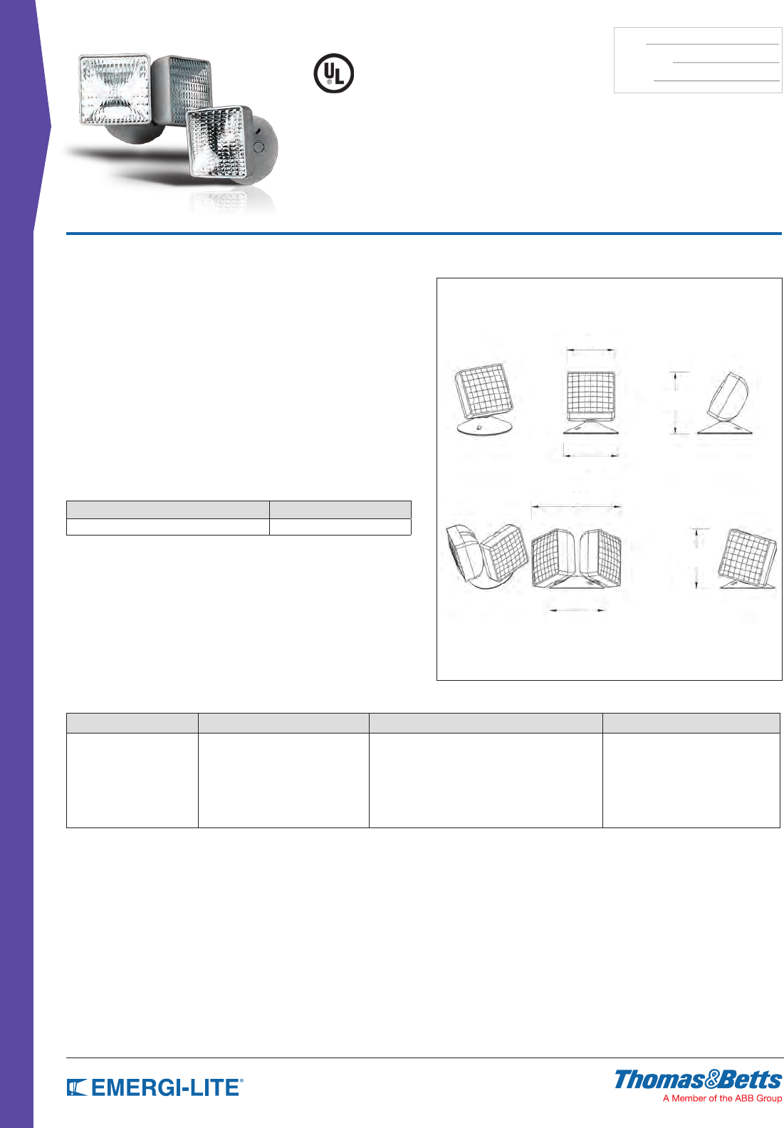
88
REMOTE FIXTURES
TYPE:
CATALOG #:
NOTES:
Features
• Thermoplastic construction with off-white or black (BK) nish.
• Available as a single, or double square lighting head
• Fully adjustable tool less aiming swivel
• Specular parabolic reector and prismatic lens for wide-beam, even light
distribution
• Snap-out lens for easy lamp replacement
• Surface Mount
• Mounts to either a standard 4” octagonal or a single gang electrical box. (4-
gang plate for EF23D optional)
• Round mounting canopy standard.
• Lamps (for alternate lamp selection,
see lamp data sheet):
Series H: BI-PIN halogen 6, 8 and 12 watt lamps only.
or Series Z: High intensity incandescent wedge base 5.4, 9 and 12 watt
lamps only.
Dimensions
Dimensions are approximate and subject to change.
4-3/8”
8-1/8” [20.63cm]
5-5/8”
5-1/2”
[13.97cm]
5” [12.7cm]
5”
EF23
8-1/8”
5-1/2”
5”
EF23D
Surface Mounted
EF23 & EF23D Series
Thermoplastic square Lamp Head
How to Order
SERIES # OF HEADS LAMP TYPE/WATTAGE COLOR
EF23= Remote SQ Fixture Blank= Single head
D= Double head
(Z_)= Wedge base, 12W Max, (6, 12, 24 Volts)*
(H_)= Bi-pin halogen, 12W max, (6, 12 Volts)*
Blank= Off white
BK= Black
* For a complete list of available lamp types, please refer to the lamp data on
pages 146-147
Example: EF23D(HB)BK
Accessories (order as a separate item)
DESCRIPTION PART NUMBER
Wire Guard WG8-E
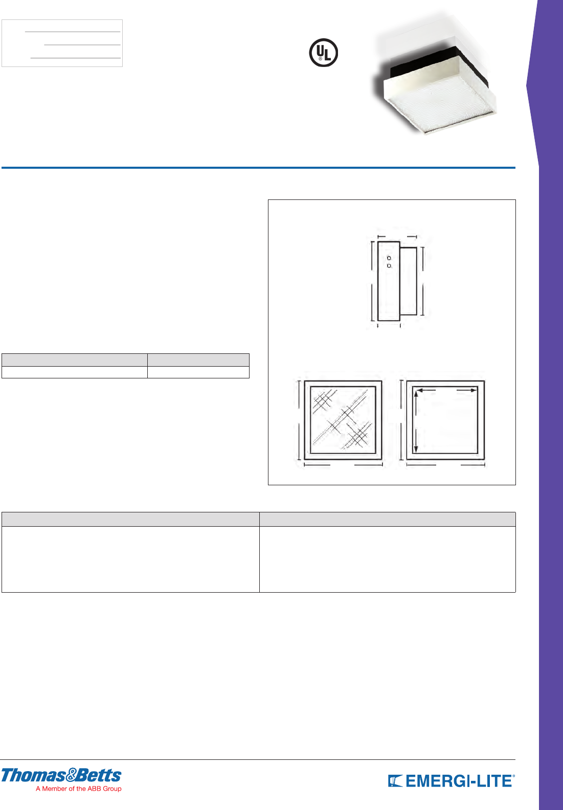
89
REMOTE FIXTURES
TYPE:
CATALOG #:
NOTES:
Features
• Decorative square thermoplastic light with prismatic diffusing lens and metal
reector
• Off-white front trim; black back-box
• Dimensions: 9” X 9” X 4” deep
• Surface (wall or ceiling) mounting
• For semi-recessed mounting, order EF24R, semi-recessed deep mounting
box included (8-1/2” X 8-1/2” X 1-3/4” deep)
• Plated steel reector for wide-beam, even light distribution
• Snap-out lens for easy lamp replacement
• Lamps (for alternate lamp selection, see lamp data sheet):
Type H: BI-PIN halogen
Type I: High intensity tungsten (HIT) double contact bayonet base
or Type Z: High intensity incandescent wedge base
Dimensions
Dimensions are approximate and subject to change.
9” 9”
9” 9”
Side
Front Rear
4”
2-1/4”
9” 7-7/8”
8-1/4”
8-1/4”
Surface Mounted
EF24 & EF24-2 Series
Surface Mount square
How to Order
SERIES LAMP TYPE/WATTAGE
EF24= Remote fixture
EF24-2= Remote fixture lamp double*
(Z_)= Wedge base, 20W max, (6, 12, 24 Volts)*
(H_)= Bi-Pin halogen, 20W max, (6, 12 Volts)*
(I_)= Double contact bayonet, 20W max, (6, 12, 24 Volts)*
*Only available with Bi-pin halogen lamps * For a complete list of available lamp types, please refer to the lamp data on pages 146-147
Example: EF24-2(HA)
Accessories (order as a separate item)
DESCRIPTION PART NUMBER
Wire Guard WG1-E
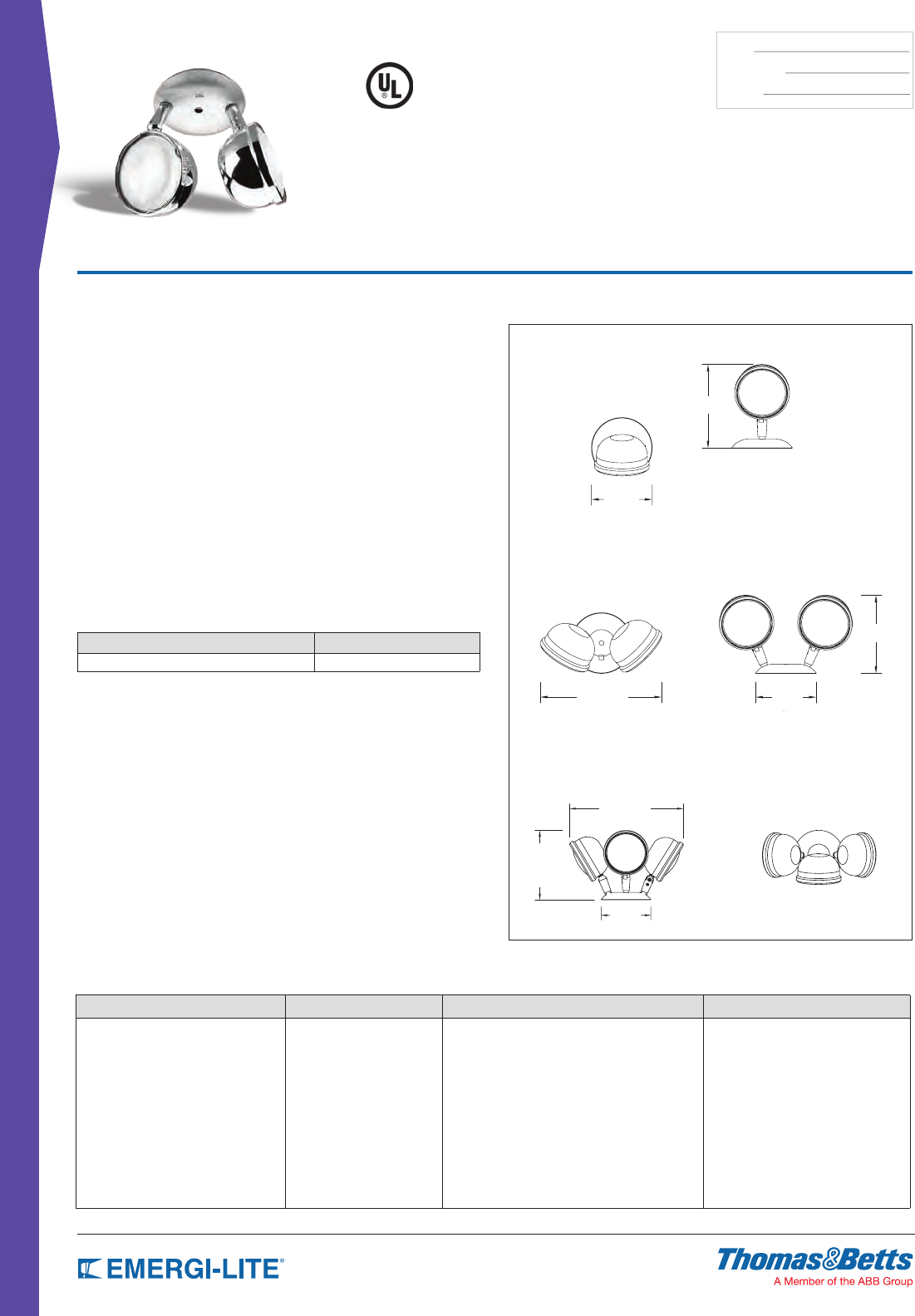
90
REMOTE FIXTURES
TYPE:
CATALOG #:
NOTES:
Features
• Single or double metal housing head with fully adjustable swivel
• Spectacular parabolic reector and prismatic lens for wide-beam, even light
distribution
• Include a circular universal canopy plate for mounts a standard 4” octogonal
or a single gang electrical box (4-gang plate for EF28T optional.
See page 146-147 for detail)
• Chrome nish head (off-white optional)
• EF28: surface mounting; 1 MPC - 1 plate supplied
• EF28D: surface mounting; 3 MPC - 2 plate supplied
• EF28: mounting plate dimensions: 2-1/2” X 4-1/4”
• EF28D: mounting plate dimensions: 6-7/16” X 4-1/2”
• Lamps (for alternate lamp selection, see lamp data sheet):
Type H: BI-PIN halogen
Type I: High intensity tungsten (HIT) double
contact bayonet base
Type U: Sealed beam tungsten
Type X: Sealed beam halogen or Type Z: High intensity incandescent wedge
base
Dimensions
Dimensions are approximate and subject to change.
EF28
EF28D
7-1/8”
5-1/8”
6-5/8”
10-1/4” 5-1/8”
11-7/8”
7-1/4”
5-1/8”
Surface Mounted
EF28, EF28D, EF28T
& EF28D Series
Aluminum PAR 36 Lamp Head
How to Order
SERIES # OF HEADS LAMP TYPE/WATTAGE COLOR
EF28= Aluminum Remote Fixture Blank= Single head
D= Double head
T= Triple head
(Z_)= Wedge base, 18W max, (6, 12, 24 Volts)*
(H_)= Bi-pin halogen, 20W max, (6, 12 Volts)*
(I_)= Double contact bayonet, 25W max, (6, 12, 24 Volts)*
(U_)= Sealed beam incandescent,
30W max, (6, 12 Volts)*
(X_)= Sealed beam halogen, 50W max, (6, 12 Volts)*
Blank= Chrome
WT= Off-white
* For a complete list of available lamp types, please refer to the lamp data
on pages 146-147
Example: EF28D(ZD)WT
Accessories (order as a separate item)
DESCRIPTION PART NUMBER
Wire Guard WG9-E
EF28T
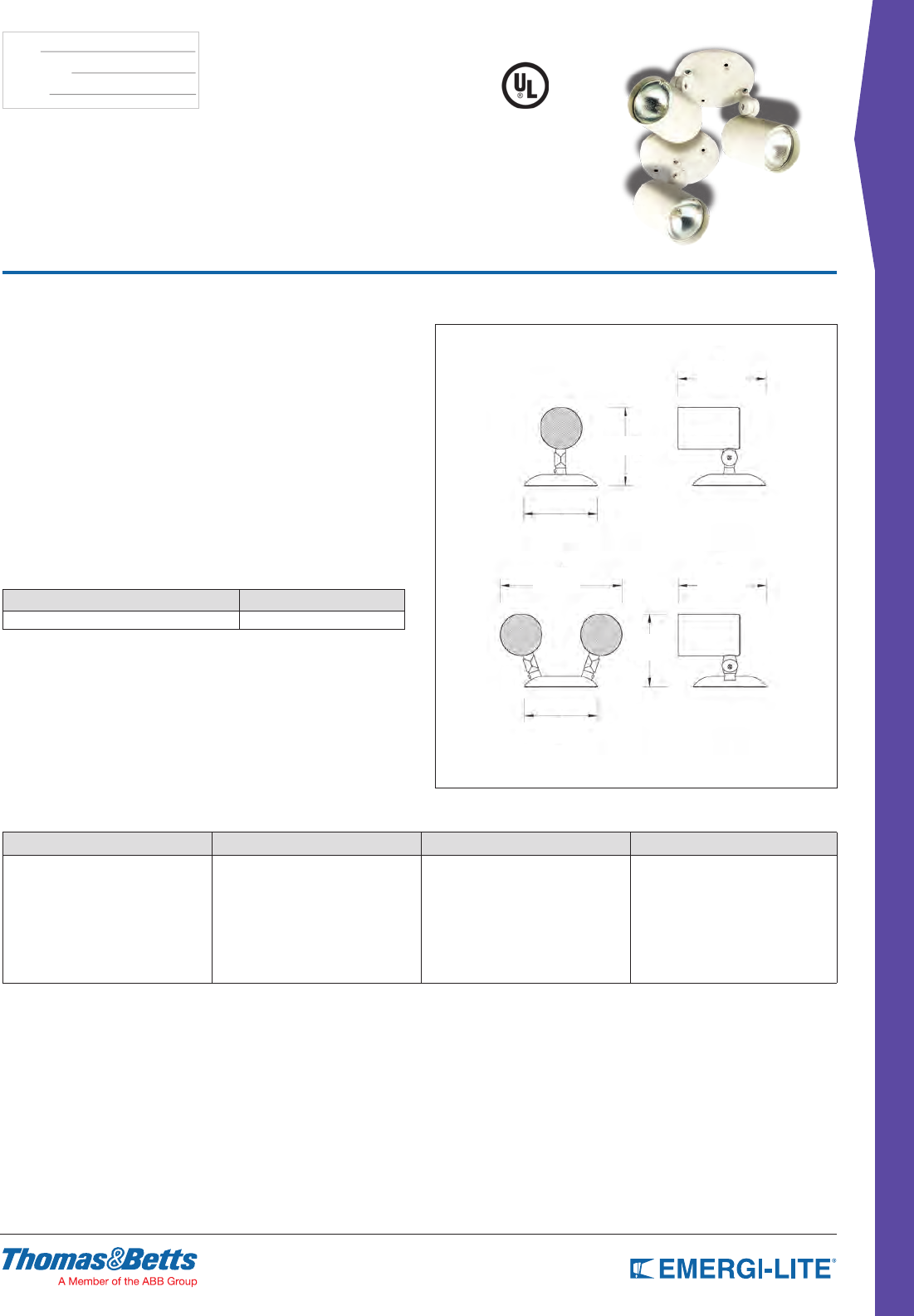
91
REMOTE FIXTURES
TYPE:
CATALOG #:
NOTES:
Features
• Single miniature fully adjustable aluminum cylinder complete with matching
round mounting plate
• Off-white baked enamel nish standard, black (BK) optional.
• Cylinder dimensions: 3” diameter x 4-1/4”
• Lamps (for alternate lamp selection, see lamp data sheet refer
to page 146-147 ):
Series H: BI-PIN halogen 6 or 12 VDC only
• Indoor use
• Fully adjustable aiming swivel head
• Mirror nished reector and prismatic lens for wide-beam, even light
distribution
• Surface mount
• Includes a round universal canopy plate
• Mounts to a standard 4” octogonal electrical box
Dimensions
Dimensions are approximate and subject to change.
6-1/4”
6-1/4”8-1/2”
5-1/8”
5-1/8”
5-1/2”
5-1/8”
Surface Mounted
EF32 & EF32D Series
Aluminum Cylinder Lamp Head
How to Order
SERIES # OF HEADS LAMP TYPE/WATTAGE COLOR
EF32= Remote Fixture Blank= Single head
D= Double head
(H_)= Bi-pin halogen, 20W max, (6, 12 Volts)* Blank= Off-white
BK= Black
* For a complete list of available lamp types, please refer to
the lamp data on pages 146-147
Example: EF32D(HB)BK
EF32
EF32D
Accessories (order as a separate item)
DESCRIPTION PART NUMBER
Wire Guard WG8-E
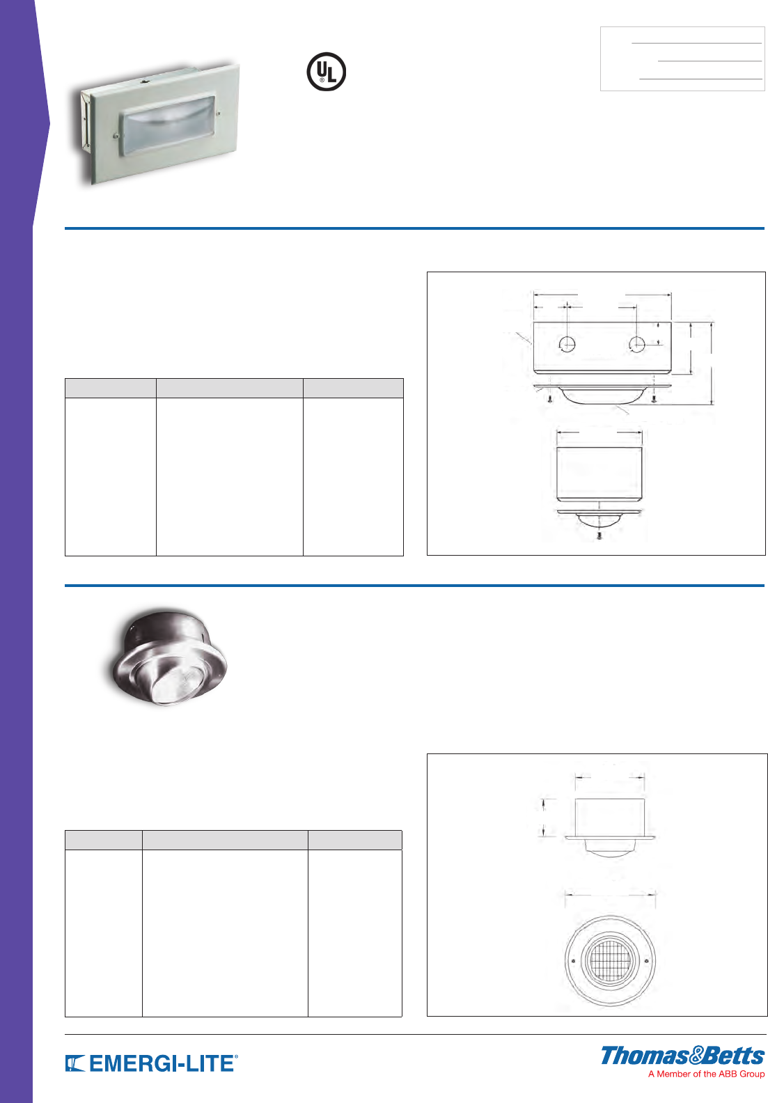
92
REMOTE FIXTURES
TYPE:
CATALOG #:
NOTES:
Features
• Rectangular xture with diffused polycarbonate lens
• White baked enamel nish; black also available
• Recessed wall or ceiling mounting
• Trim plate dimensions: 8-1/4” X 4-1/2”
• Back box dimensions: 6-3/8” X 3” X 2-5/8” deep
• Lamps (for alternate lamp selection, see lamp data sheet on page 144):
Series I - High intensity tungsten (HIT) double contact bayonet base
Dimensions
Dimensions are approximate and subject to change.
Diffusion Lens
Knock-outs
Cover
Steel Housing
8-1/4”
4-1/4”
4-1/2”
3-1/4”
3”
4”
Dimensions
Dimensions are approximate and subject to change.
6-1/2”
3-1/2”
8-1/2”
Recessed Mounted
EF13 Series
Remote Fixture
How to Order
SERIES LAMP TYPE/WATTAGE COLOR
EF13= Remote fixture (I_)= tungsten double contact
bayonet base 25W max,
(6, 12, 24 Volts )*
(I_)= tungsten double contact
bayonet base 15W
max, (120 VAC)*
Blank= Off-white
BK= Black
* For a complete list of available lamp types,
please refer to the lamp data on pages
146-147
Example: EF13(IC)BK
Recessed Mounted
EF17 Series
Remote Fixture
Features
• Recessed adjustable eyeball PAR 36.
• Brushed aluminum nish (specify others).
• Recessed wall or ceiling mounting.
• Trim ring dimensions: 8-3/4” diameter.
• Back dimensions: 6-3/4” X 3-1/2” deep.
How to Order
SERIES LAMP TYPE/WATTAGE COLOR
EF17= Recessed
adjustable eyeball
(Z_)= Wedge base, 18W max, (6, 12, 24V)*
(H_)= Bi-pin halogen, 20W max, (6, 12V)*
(I_)= Double contact bayonet,
25W max, (6, 12, 24V)*
(U_)= Sealed beam inc, 30W
max, (6, 12V)*
(X_)= Sealed beam halogen,
50W max, (6, 12V)*
Blank= Aluminum
WT= Off- white
NOTE: For a complete list of available lamp types,
please refer to the lamp data on pages
146-147
Example: EF17(ZL)WT
2”
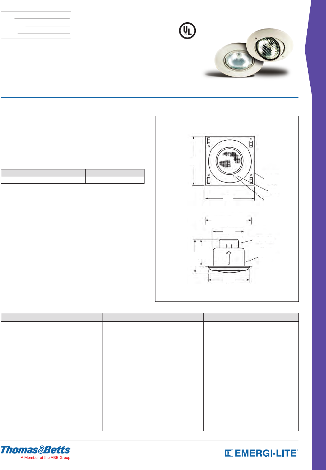
93
REMOTE FIXTURES
TYPE:
CATALOG #:
NOTES:
Features
• Indoor use
• A single lamp recessed round Gimbal PAR 36 lighting head
• Lamp has horizontal rotation of 358° and vertical angle adjustable to 42°
• Snapout lens for easy lamp replacement
• Recessed gimbal ring xture PAR 36 - adjustable in two planes to 45°
• Off-white thermoplastic housing
• Recessed wall or ceiling mounting
• Complete unit, no additional housing needed
Dimensions
Dimensions are approximate and subject to change.
6-1/4” Min.
Ceiling Opening
WIRE BOX
BACK BOX
5-1/4”
4-1/2”
5-1/2”
9”
9”
PLASTER
FRAME
TRIM
GIMBAL
RING
Recessed Mounted
EF15 Series
Remote Gimbal Fixture
How to Order
SERIES LAMP TYPE/WATTAGE COLOR
EF15= Remote Gimbal Fixture (Z_)= Wedge base, 18W Max, (6, 12, 24V)*
(H_)= Bi-pin halogen, 20W Max, (6, 12V)*
(I_)= Double contact bayonet, 25W Max, (6, 12, 24V)*
(U_)= Sealed beam incandescent 30W Max, (6, 12V)*
(X_)= Sealed beam halogen, 20W Max, (6, 12V)*
Blank= Off-white
BK= Black
* See lamp chart on page 146 for lamp code
Example: EF15(ZD)BK
Accessories (order as a separate item)
DESCRIPTION PART NUMBER
Wire Guard WG11-E
5-1/2”
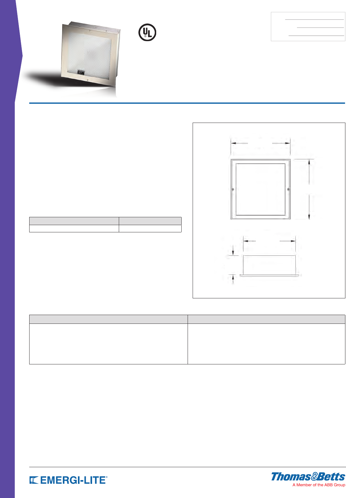
94
REMOTE FIXTURES
TYPE:
CATALOG #:
NOTES:
Features
• Fully recessed metal decorator square housing with prismatic diffusing lens
and metal reector
• Off-white baked enamel nish
• Recessed wall or ceiling mounting
• Fully recessed frame, metal construction
• Available as a single, or double lamp lighting head
• Prismatic acrylic lens
• Plated steel reector for a wide-beam, even light, distribution
• Universal knock-outs to mount a standard 4” octagonal electrical box
• Support bars or rods supplied by others
• Lamps (for alternate lamp selection, see lamp data sheet on page 144):
Type H: BI-PIN halogen (available at additional cost)
Type I: High intensity tungsten (HIT) double contact bayonet base
or Type Z: High intensity incandescent wedge base
Dimensions
Dimensions are approximate and subject to change.
9-7/8”
9-7/8”
8-11/16”
3-1/16”
Recessed Mounted
EF21R Series
Fully Recessed Metal Decorator Square
How to Order
SERIES LAMP TYPE/WATTAGE
EF21R= Remote recessed metal square decorator fixture (Z_)= Wedge base, 20W max, (6, 12, 24 Volts)*
(H_)= Bi-pin halogen, 20W max, (6, 12 Volts)*
(I_)= Double contact bayonet, 20W max, (6, 12, 24 Volts)*
* For a complete list of available lamp types, please refer to the lamp data on pages 146-147
Example: EF21R(ZD)
Accessories (order as a separate item)
DESCRIPTION PART NUMBER
Wire Guard WG11-E
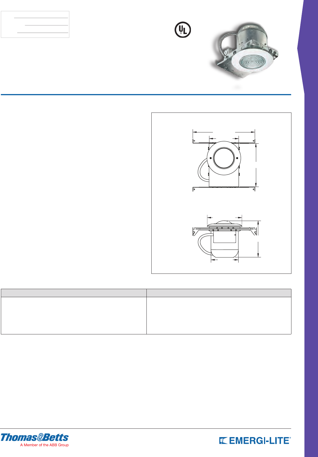
95
REMOTE FIXTURES
TYPE:
CATALOG #:
NOTES:
Features
• Gasketed, fully recessed, with fresnel lens; suitable for Damp locations
• Off-white nish
• Fully recessed ceiling mounting
• Trim: plastic, off-white
• Recessed (wall or ceiling). Plaster frame and standard 4” wire box provided
• Trim ring: 8-1/2” diameter
• EF35 Series: Wedge base incandescent 18W MAX
Double contact Bayonet base 25W MAX
Bi-pin halogen 20W MAX
• 6, 12, 24VDC
• Maximum power: 25W low voltage
Dimensions
Dimensions are approximate and subject to change.
14” to 24”
8-1/2”
7-3/4”
6-1/2”
7”
10-1/4”
Recessed Mounted
EF35 Series
Remote Fixture
How to Order
SERIES LAMP TYPE/WATTAGE
EF35= Remote Metal Fixture (Z_)= Wedge base, 20W max, (6, 12, 24V)*
(H_)= Bi-pin halogen, 20W max, (6, 12V)*
(I_)= Double contact bayonet, 20W max, (6, 12, 24V)*
Only available with Bi-pin halogen lamps * For a complete list of available lamp types, please refer to the lamp data on pages 146-147
Example: EF35(IA)
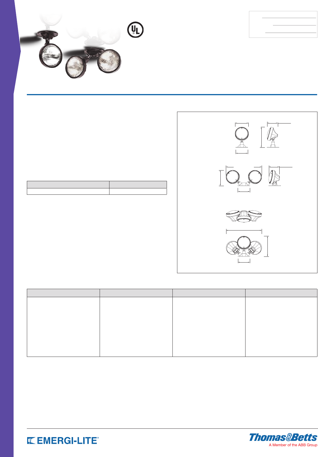
96
REMOTE FIXTURES
TYPE:
CATALOG #:
NOTES:
Features
• Outdoor use
• Available as a single, double or triple PAR 36 size lighting head
• Thermoplastic construction with aluminum canopy plate
• Fully adjustable aiming swivel head
• Specular parabolic reector and prismatic lens for a wide-beam, even light
distribution
• Sealed for rain; dust-tight; corrosion resistant
• Off-white, black or gray
• Surface mount
• Mounts to a standard 4” octagonal electrical box
Dimensions
Dimensions are approximate and subject to change.
4-3/4” 3-3/4”
3-3/4”
4-1/4”
4-1/4”
4-1/4”
12-1/2”
12-1/2”
7-1/4”
7-1/4”
5-1/2”
EF11D
EF11T
EF11
Weatherproof EF11,
EF11D & EF11T Series
Thermoplastic Weather-Resistant
PAR 36 Lamp Head
How to Order
SERIES # OF HEADS LAMP TYPE/WATTAGE COLOR
EF11= PAR 36 remote head (Weatherproof) Blank= Single head
D= Double heads
T= Triple heads
(H_)= Halogen bi-pin 20W max*
(I_)= Tungsten wedge 25W max*
(Z_)= Tungsten wedge 18W max*
(U_)= Tungsten sealed beam 30W max*
(X_)= Halogen sealed beam* 50W max**
Blank= Black*
WT= Off-white
* For a complete list of available lamp types, please refer to
the lamp data on pages 146-147
** Use high temp enclosure * XI lamps available in gray only heads
Example: EF11D(HD)WT
Accessories (order as a separate item)
DESCRIPTION PART NUMBER
Wire Guard WG9-E
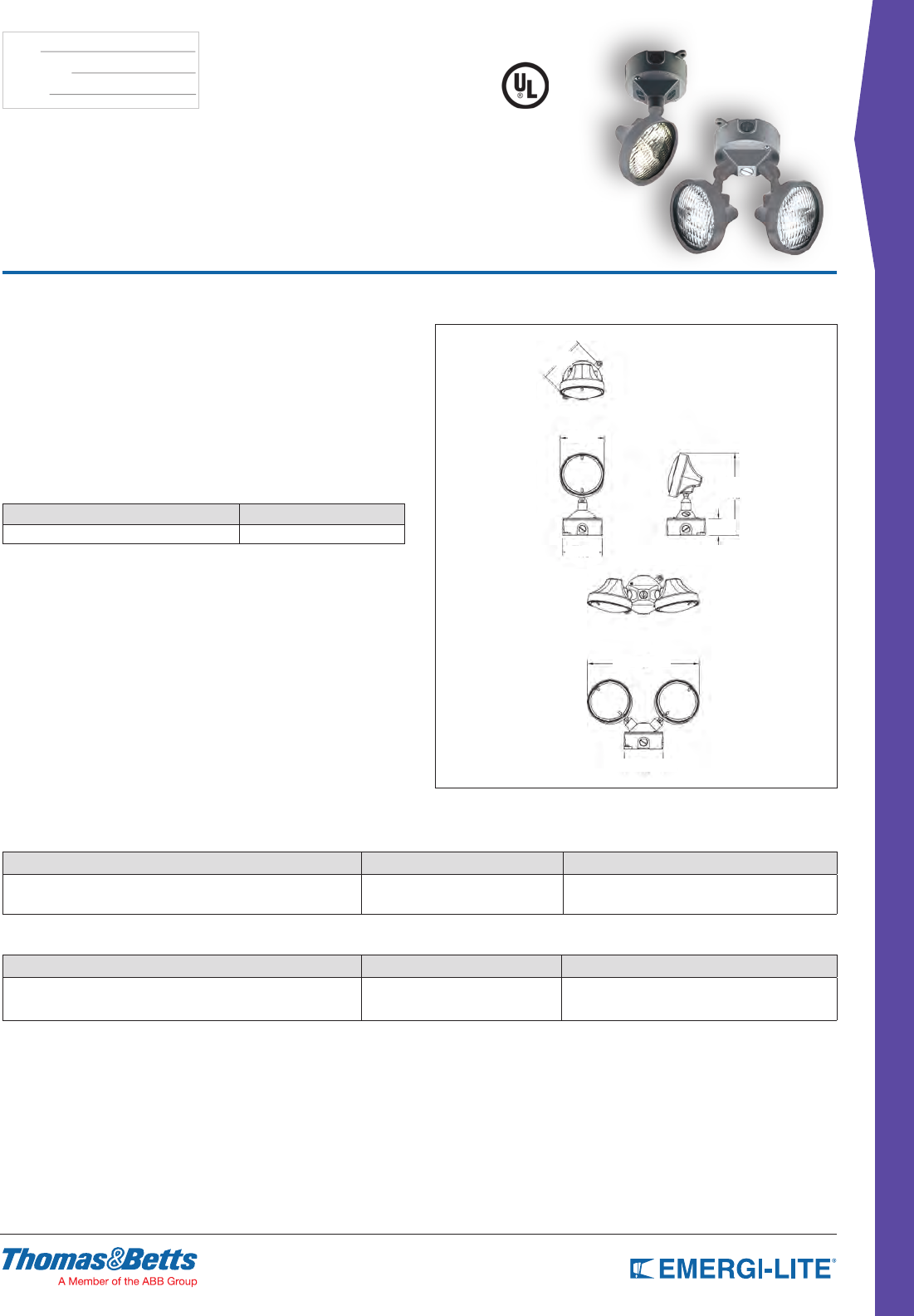
97
REMOTE FIXTURES
TYPE:
CATALOG #:
NOTES:
Features
• Class I Division 2 - Groups A, B, C, D
• Single lighting head with fully adjustable swivel with gray lamp heads
• Gasketed aluminum canopy and junction box
• Indoor use
• Available as a single or double PAR 36 size
• Surface mount
• Includes a universal aluminum canapy and junction box
• Conduit entry 1/2” NPT
• Lamps: PAR 36 sealed beam (6 or 12VDC maximum 12W)
Dimensions
Dimensions are approximate and subject to change.
4-3/16”
4-3/16”
4-3/4”
5”
12”
1-3/4”
8-7/8”
EF11X
EF11DX
Weatherproof
EF11X & EF11DX Series
Class I Division 2 Certified Remote Fixture
How to Order
EF11X SERIES
SERIES MODEL LAMP TYPE/WATTAGE
EF11= Hazardous locations Class.I Div.2 Groups A, B, C and D X= Single head (XD)= 6V-12W halogen sealed beam
(XG)= 12V-12W halogen sealed beam
Example: EF11X(XD)
EF11DX SERIES
SERIES MODEL LAMP TYPE/WATTAGE
EF11= Hazardous locations Class.I Div.2 Groups A, B, C and D DX= Double head (XD)= 6V-12W halogen sealed beam
(XG)= 12V-12W halogen sealed beam
Example: EF11DX(XG)
Accessories (order as a separate item)
DESCRIPTION PART NUMBER
Wire Guard WG6-E
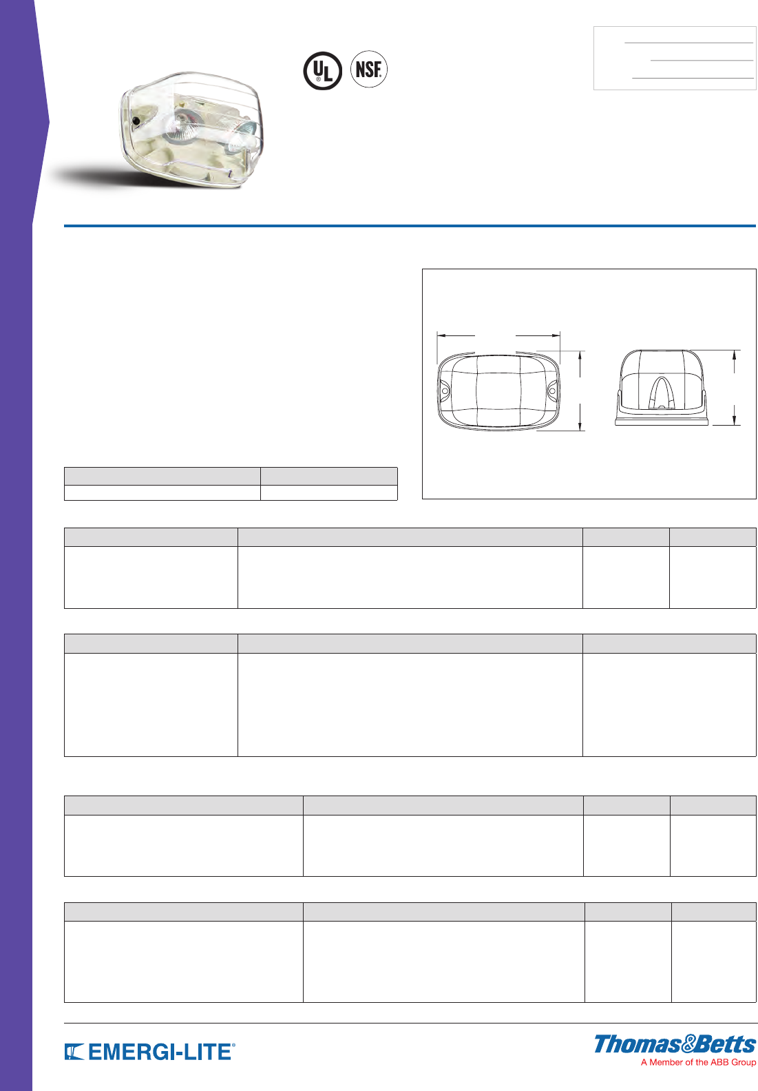
98
REMOTE FIXTURES
TYPE:
CATALOG #:
NOTES:
NEMA-4X
Survive-All™
EF39 & EF40 Series
EF39 NEMA-4X & NSF Certified
EF40 Vandal Resistant
Features
• Fully gasketed with a selection of cast aluminum or polycarbonate back plate
• Clear polycarbonate UV and impact resistant lens
• Choice of single or double lamp models
• Available in 6, 12 and 24V models MR16 or LED
• Easy lamp replacement
• EF39 comes standard with tamper-proof screws and bit
• NSF Certied for food processing plants
• NEMA-4X Certied
• EF39P and EF40P require mounting plate option when installed on surface
mount junction box
• CSA Certied to C22.2 No. 141
• Suitable for indoor/outdoor installation
Dimensions
Dimensions are approximate and subject to change.
4-5/8” 3-3/4”
Accessories (order as a separate item)
DESCRIPTION SUFFIX
Additional special bit for tamper-proof screws 690.0454-E
7-1/8”
How to Order EF40 Series
SERIES LAMP TYPE/WATTAGE COLOR OPTIONS
EF40P= All polycarbonate single head for dry locations
EF40PD= All polycarbonate double head for dry locations
(MI)= 6V-6W, MR16
(MJ)= 6V-10W, MR16
(MK)= 12V-12W, MR16
(MS)= 24V-12W, MR16
(LA)= 6V-4W, MR16 LED
(LG)= 12V-4W, MR16 LED
(LI)= 12V-5W, MR16 LED
(LL)= 24V-4W, MR16 LED
(LJ)= 12V-6W, MR16 LED
Blank= White
-BK= Black
-GY= Gray
Blank= No options
T= Tamper proof
screws
SM= Mounting plate
Example: EF40P(MK)
SERIES LAMP TYPE/WATTAGE COLOR OPTIONS
EF40= Die-Cast back plate single head for dry locations
EF40D= Die-Cast back plate double head for dry locations
(MI)= 6V-6W, MR16
(MJ)= 6V-10W, MR16
(MK)= 12V-12W, MR16
(MS)= 24V-12W , MR16
(MD)= 24V-20W, MR16
(MW)= 12V-20W, MR16-IR
(LA)= 6V-4W, MR16 LED
(LG)= 12V-4W, MR16 LED
(LI)= 12V-5W, MR16 LED
(LL)= 24V-4W, MR16 LED
(LJ)= 12V-6W, MR16 LED
Blank= White
-BK= Black
-GY= Gray
Blank= No options
T= Tamper-
proof screws
Example: EF40D(MD)
How to Order EF39 Series
SERIES LAMP TYPE/WATTAGE LAMP TYPE OPTION
EF39P= All polycarbonate single
head NEMA-4X
EF39PD= All polycarbonate double
head NEMA-4X
(MI)= 6V-6W, MR16
(MJ)= 6V-10W, MR16
(MK)= 12V-12W, MR16
(MS)= 24V-12W, MR16
(LA)= 6V-4W, MR16 LED
(LG)= 12V-4W, MR16 LED
(LI)= 12V-5W, MR16 LED
(LL)= 24V-4W, MR16 LED
(LJ)= 12V-6W, MR16 LED
Blank= White
-BK= Black
-GY= Gray
SM= Mounting plate
Example: EF39P(LG)-BK
SERIES LAMP TYPE/WATTAGE LAMP TYPE
EF39= Die-Cast back plate single
head NEMA-4X
EF39D= Die-Cast back plate double
head NEMA-4X
(MI)= 6V-6W, MR16
(MJ)= 6V-10W, MR16
(MK)= 12V-12W, MR16
(MS)= 24V-12W , MR16
(MD)= 24V-20W, MR16
(MW)= 12V-20W, MR16-IR
(LA)= 6V-4W, MR16 LED
(LG)= 12V-4W, MR16 LED
(LI)= 12V-5W, MR16 LED
(LL)= 24V-4W, MR16 LED
(LJ)= 12V-6W, MR16 LED
Blank= White
-BK= Black
-GY= Gray
Example: EF39(LG)-BK
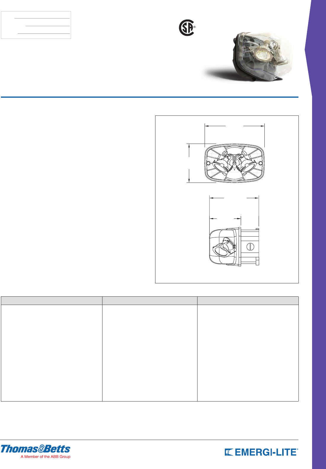
99
REMOTE FIXTURES
TYPE:
CATALOG #:
NOTES:
Survive-All™ EF41 Series
Class I Division II Certified Remote Fixture
US
How to Order
SERIES LAMP TYPE/WATTAGE COLOR
EF41= Single lamp
EF41D= Double lamp
(MJ)= 6V-10W, MR16
(MK)= 12V-12W, MR16
(MW)= 12V-20W, MR16-IR
(MS)= 24V-12W, MR16
(MD)= 24V-20W, MR16
(MT)= 120VAC/VDC-20W MR16(GU10)
(LA)= 6V-4W, MR16 LED
(LG)= 12V-4W, MR16 LED
(LI)= 12V-5W, MR16 LED
(LJ)= 12V-6W, MR16 LED
(LL)= 24V-4W, MR16 LED
(LW)= 12V-4W, MR16 LED (C/W wires)
-GY= Gray
* Wattage doubles for “D” 2-lamp version
Example: EF41(MJ)-GY
Features
• Available with single or double lamp heads with high-efciency MR16 halogen
lamps of 10W, 12W or 20W (see How to Order information)
• Die-Cast aluminum back plate with gasket. Clear polycarbonate cover, UV
and impact resistant
• Input voltage: 6V, 12V or 24V
• Easy installation on a 4” octagonal box (included). Comes standard with
tamper-proof screws and bit
• Evaluated to UL 844 Standard for Class I Division 2, Groups A, B, C and D
Temperature Codes: T3B (10W and 12W MR16 lamps) and T2C (20W MR16
lamps). Extreme operational temperature range: -40ºF to 104ºF
(-40ºC to +40ºC)
• Fully adjustable tool-less aiming swivel
• Indoor use
• Conduit entry 1/2” NPT
Dimensions
Dimensions are approximate and subject to change.
4-5/8”
7-1/8”
5-7/8”
junction box
remote
fixture
3-3/4” 2-1/8”
4” junction box

Distributor Select
Replenishing your stock of popular emergency lighting
equipment and exit signs is easy with Emergi-Lite® Distributor
Select products. Our catalog numbers allow you to order
each item with the exact specications you need from the
many standard options available.
Large inventories of Emergi-Lite® Distributor Select products
are quick to ship from multiple warehouses across the United
States for next day delivery, and our picking, packing and
shipping process has been streamlined to fulll distributor
orders without delay.
Offer your customers a wide range of Emergi-Lite® emergency
lighting equipment and exit signs, including decorative battery
units, 6-24 volt units, exit signs and combo units, remote
heads, environmentally-friendly LED models, and more.
What are
DISTRIBUTOR SELECT
PRODUCTS?
DISTRIBUTOR SELECT
DISTRIBUTOR SELECT
101
Prestige™ Thin Series 102
Total™ Edge-Lit Series 103
EL-2LED Series 104
ELXN400 LED Series 105
EF43D & EF44D Series 105
DLM-2 Series 106
GS Series 107
EL-2SQ Series 108
ELX400 SQ Series 109
EL-2MRS & 12EL50-2MRS Series 110
ELX-MRS Series 111
ELX Series 112
Quick Switch Series 113
DISTRIBUTOR SELECT
Table of Contents
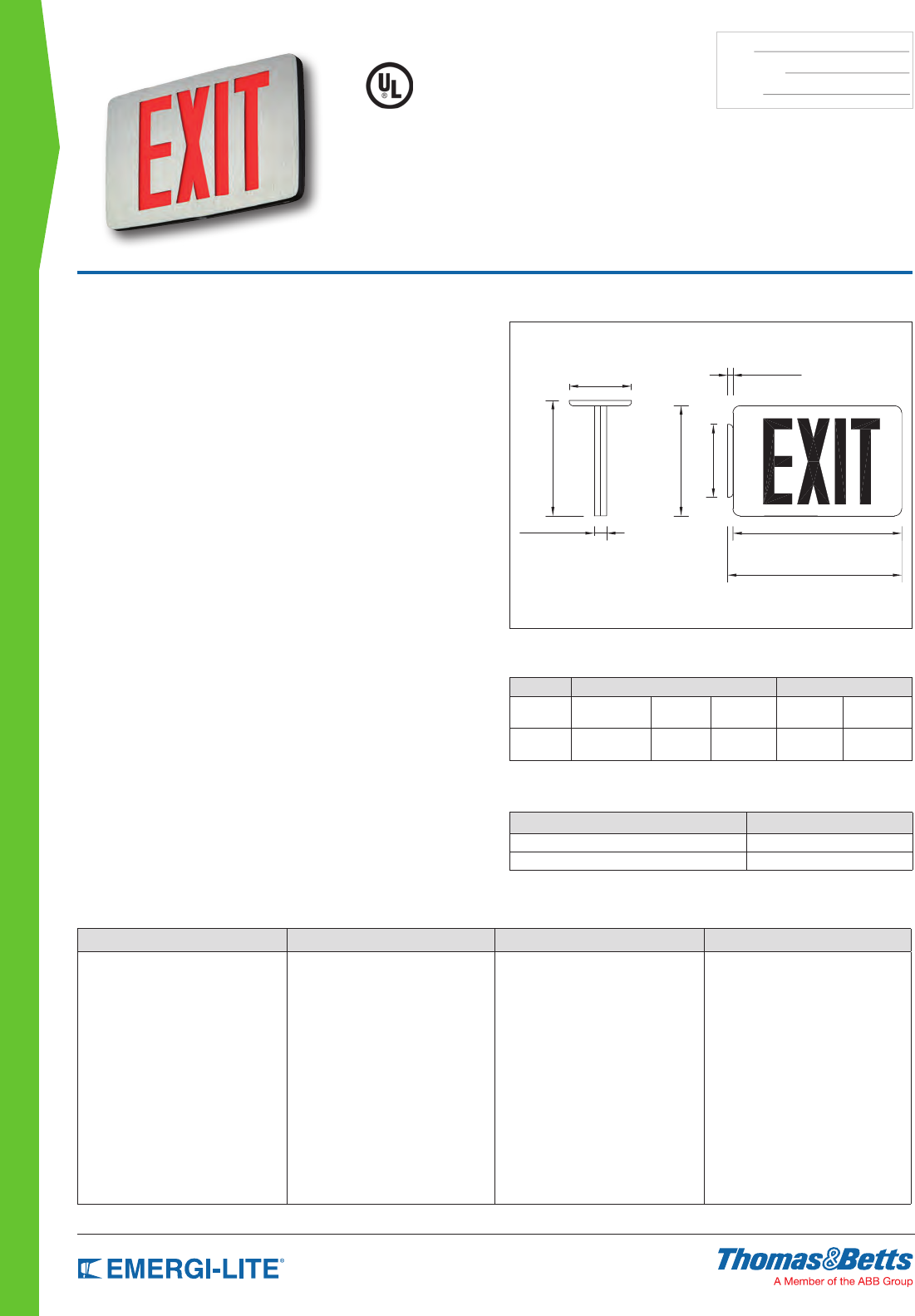
102
DISTRIBUTOR SELECT
TYPE:
CATALOG #:
NOTES:
How to Order
FRAME COLOR/FACE PLATE SERIES # OF LAMPS LEGEND COLOR
BA= Black body/brushed aluminum face
WW= White/white
TX= AC only
TXN= Self-Powered unit (90 min.)
1= Single face
2= Double face
R= Red
G= Green
Example: BATXN1R
Dimensions
Dimensions are approximate and subject to change.
4-3/8” [11.1cm]
8-1/8” [20.6cm]
7-3/4” [19.7cm]
5-1/8” [13.0cm]
7/8” [2.2cm] 11-7/8” [30.2cm]
12-1/4” [31.1cm]
3/8” [1.0cm]
Prestige™ Thin Series
Die-Cast Aluminum Slim Profile Exit Sign
With Long-Lasting LED Performance
Standard Features
• Easy to install
• Two popular nishes (see below)
• Self-Powered models with Nickel-Cadmium battery
• Low power consumption
• Field-selectable, knockouts chevrons
• Universal installation: top, end and back-mounting
• UL 924 Damp Location listed
• Meets UL 924, NFPA 101, NFPA 70-NEC and OSHA illumination standards
• Five-year full warranty
Construction
• Die-Cast aluminum housing, thin prole
• Clear lacquer, brushed aluminum inhibits ngerprints and other surface
contaminants. Also available with white nish
• Universal directional chevron knockout are completely concealed and easily
removed from face-plate
• Letters are 6” high with 3/4” stroke and 100 ft viewing distance rating
Electrical
• Dual-voltage input capability 120/277VAC
• Self-Powered models are provided with test switch, LED pilot light and
rechargeable Nickel-Cadmium battery
• Battery: Sealed, maintenance-free, Nickel-Cadmium battery delivers
90 minutes of emergency power on all Self-Powered models
Installation
Universal mounting – top, back or end. Mounting knockout and hole plugs
are easily removed. Die-Cast aluminum canopy is provided (white canopy with
white frame and black canopy with black frame)
Listings
UL Listed. Damp Location listing 32°F to 122°F (Ø°C to 50°C). Meets UL 924,
NFPA 101 (Life Safety Code), NFPA 70-NEC and OSHA illumination standards.
Warranty
Five-year full warranty
Power Consumption Chart
Model AC Specs DC Specs
AC-only 120/277
VAC 60Hz Typical 1W Less than
1.5W – –
Self-
Powered
120/277
VAC 60Hz Typical 1W Less than
1.5W
Ni-Cd
battery
Min. 90
minutes
Accessories (order as a separate item)
DESCRIPTION SUFFIX
Wire Guard (wall mount) WG1-E
Wire Guard (ceiling mount and end mount) WG5-E
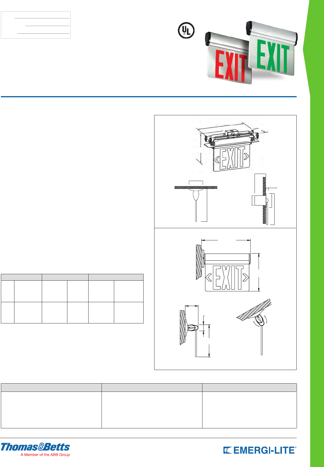
DISTRIBUTOR SELECT
103
TYPE:
CATALOG #:
NOTES:
Dimensions
Dimensions are approximate and subject to change.
14-1/2”
3-1/2”
3/4”
2-7/8”
9-1/8”
4”
4-3/8”
13"
9-5/8"
3-1/2"
1-5/8"
8-11/16"
13"
9-5/8"
3-1/2"
1-5/8"
8-11/16"
3-1/2”
1-5/8”
7-1/8”
8-3/4”
13”
3-1/2”
9-5/8”
11-1/2”
4-3/8”
10-3/8”
Total Edge™ Series
Single and Double Face, Surface
and Recessed Mount Edge-Lit Exit Sign
Standard Features
• Surface, recessed* or end-mount
• High performance low power consumption LEDs
• Peel-off chevrons
• Special wording panel not available
Construction
• Brushed aluminum housing and black plastic
end-caps, with high grade acrylic panel.
• Choice of legend colors: red on mirror or green
on mirror
Electrical
• Dual-voltage input capability 120/277VAC
• Self-powered models feature battery delivering more than 90 minutes
capacity in emergency mode
Installation
Surface mount: Pivoting panel design allows for surface installation in any
applications, including ceilings and walls.
Semi recessed* mount: Includes back box and necessary hardware for joist
or T-Bar ceilings and is vertically adjustable to install in most ceiling thickness.
Mounting bars lock in place with two screws.
Listings
UL924 listed
Warranty
3 year full warranty, excluding lamps and fuses
* Not intended for closed ceilings such as sheet-rock or plaster.
Power Consumption
Model AC Specs DC Specs
Red
AC Only
Self-Powered
120VAC, 60Hz
277VAC, 60Hz
120VAC, 60Hz
277VAC, 60Hz
2.0-2.6W
2.6-3.1W
2.0-2.6W
2.6-3.1W
-
-
Ni-Cd battery
Ni-Cd battery
-
-
Min. 90 Minutes
Min. 90 Minutes
Green
AC Only
Self-Powered
120VAC, 60Hz
277VAC, 60Hz
120VAC, 60Hz
277VAC, 60Hz
2.8-3.3W
3.5-4W
2.8-3.3W
3.5-4W
-
-
Ni-Cd battery
Ni-Cd battery
-
-
Min. 90 Minutes
Min. 90 Minutes
How to Order
SERIES COLOR LEGEND
PA= AC Only
PN= Self-Powered
PA2= AC only Dual Circuit
R= Red on mirror
G= Green on mirror
6= 6” EXIT Single & Double face with universal chevrons
Example: PAR6
104
DISTRIBUTOR SELECT
TYPE:
CATALOG #:
NOTES:
How to Order
SERIES LAMP OPTION OPTIONS
EL _2LED= round LED array R= One double head dedicated remote
Note: Remote capacity can only be used to power the EF43D or EF44D remote fixtures or to extend the battery units emergency run
time beyond the standard 90 minutes.
Example: EL_2LEDR
Features
• Fully adjustable LED glare-free heads
• 3.6V-3.6W long-life LED illumination with life expectancy of 50,000 hrs
Construction
• Injection-molded, UV stabilized thermoplastic
• UL94, 5VA ame rated body
• Snap-together design
• Corrosion and scratch-resistant in mist white color
Electrical
• Automatic, temperature compensated, pulse type charger
• High capacity, automatic, dust-tight instantaneous
transfer relay
• Low voltage disconnect prevents over discharge of battery
• Automatic brownout protection
• Battery lock-out prevents discharge during installation
• Sealed maintenance free 3.6V Nickel-Metal Hydride battery
• Red charger monitor LED indicates charging of the battery
• Momentary test switch allows for quick operational check of entire system
Installation
• Ceiling or wall mount
• Rear keyhole slots and universal knock-outs to mount to any standard 4’’
junction box
Listings
• UL Listed to UL924 Listed
• Damp location listing is standard (68º F to 86º F)
Warranty
• 3 year full warranty, excluding lamps and fuses
Dimensions
Dimensions are approximate and subject to change.
9” [22.86cm]
2-3/4” [5.08cm]
4” [10.16cm]
9” [22.86cm]
2-3/4” [5.08cm]
4” [10.16cm]
9” 2-3/4”
4”
EL-2LED Series
Low Energy, Low Maintenance Emergency
Lighting for Moderate Budget Applications
Power Consumption
Model Current (A) / Power (W)
EL_2LEDR 120VAC, 60Hz 277VAC, 60Hz
0.191/0.92 0.129/1.62
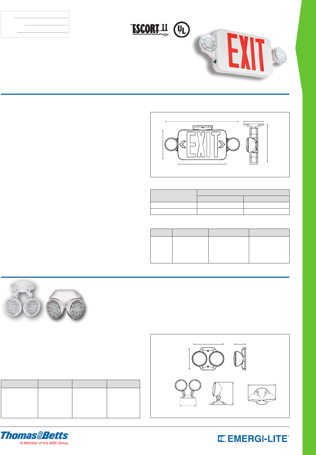
DISTRIBUTOR SELECT
105
TYPE:
CATALOG #:
NOTES:
Dimensions
Dimensions are approximate and subject to change.
17-7/8” [43.18cm]
4-2/8” [10.16cm]
2” [5.08cm]11-5/8” [27.94cm]
7-2/8” [17.78cm]
8-2/8” [20.32cm]
17-7/8”
8-2/8”
11-5/8”
7-2/8”
2”
4-2/8”
ELXN400 LED Series
Low energy and low maintenance for
moderate budget application
How to Order - Combination Unit
SERIES LEGEND COLOR LAMP OPTIONS
ELXN400=
ELX Combo
Series
R= Red exit
G= Green exit
-2LED= Round
LED array
R= One double head
dedicated remote
Example: ELXN400R-2LED
How to Order - Remote Heads
SERIES NO. OF HEADS LAMP OPTIONS
EF43= Indoor series
EF44= Outdoor
weatherproof
series
D= 2 -LED= round LED
array
Blank= Indoor
remote
WP= Outdoor
weather
proof remote
Example: EF43D-LED
Features
• Plastic housing and high output LED lamp source only available in 2-heads
congurations
• Can only be powered from the EL-2LEDR battery or ELXN400-LEDR Combo exit
unit
• 3 year full warranty
• EF43D is for remote indoor applications; draws 3.6V-3.36W
• EF44D is for remote outdoor applications; draws 3.8W
Dimensions
Dimensions are approximate and subject to change.
6-11/16” 2-1/16”
4-1/6”
4.53” [11.13cm]
7.38” [18.74cm]
5.63” [14.31cm]
EF43D & EF44D Series
Dedicated Indoor and Outdoor Remote
Emergency Lighting
Features
• Fully adjustable LED glare-free heads
• 3.6V-3.6W long-life LED illumination with life expectancy of
50,000 hrs
• Legend illumination by red or green long-life LEDs
Construction
• Frame, faceplate, backplate and canopy are made of
injection-molded, UV stabilized thermoplastic
• UL94, 5VA ame rated body
• Snap-together design
• Corrosion and scratch-resistant of mist white color
Electrical
• 3.6V Nickel-Metal Hydride battery
• Dual-voltage input capability 120/277VAC
• Self-diagnostics is not available
Installation
• Surface mount ceiling or wall
• Canopy included for ceiling installation
• Backplate features universal knockouts for a standard 4’’ junction box, used
in wall mount applications
Listings
• UL Listed to UL 924 Listed
• Damp location listing is standard (68°F to 86°F)
• NFPA101 (Life Safety Code), NFPA70 NEC and OSHA illumination standard
Warranty
• 3 year full warranty, excluding lamps and fuses
Power Consumption
Model Current (A) / Power (W)
120VAC, 60Hz 277VAC, 60Hz
ELXN400R-2LEDR 0.044/3.56 0.037/4.06
ELXN400G-2LEDR 0.042/3.2 0.036/3.8
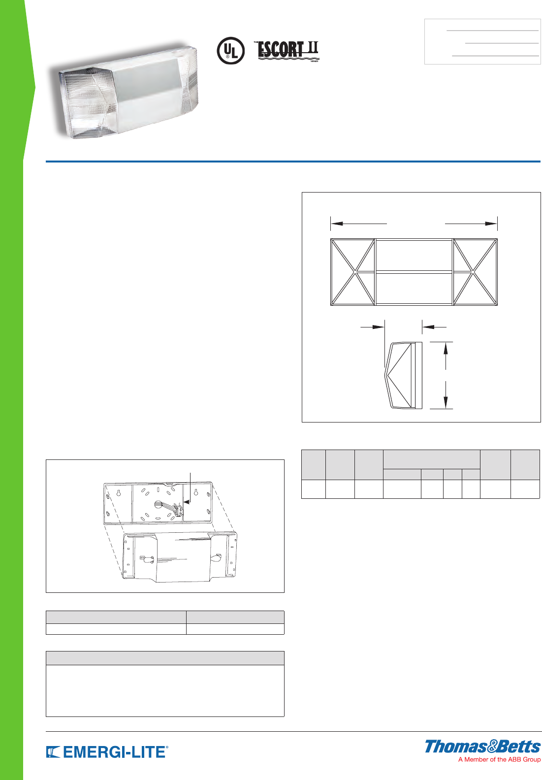
106
DISTRIBUTOR SELECT
TYPE:
CATALOG #:
NOTES:
DLM-2 Series
Thermoplastic Housing 6V-12W Capacity
Lead-Calcium Battery Unit
Dimensions
Dimensions are approximate and subject to change.
12”
2-3/4”
5”
Standard Features
• Each self-contained unit comes with two (2) 6V high intensity glass wedge
based incandescent lamps.
• Constructed of high-impact UL recognized 94V 5VA thermoplastic. Resists
denting, peeling, scratching and corrosion. Transparent polycarbonate lens.
• Sealed, maintenance-free Lead-Calcium batteries.
• Integrated circuitry offers 120/277VAC 0.08/0.04A standard, automatic
charging, instantaneous transfer, test switch, long life LED AC charge monitor
light, temperature compensated charger, short-circuit proof and reverse
polarity protected. Low battery voltage disconnect, brownout protection, and
lockout (automatic battery connection).
• Can be mounted in any orientation on walls or ceilings. No screws or other
mounting hardware is visible.
• Listed to UL 924 Standard. Complies with NEC, Life Safety Code and OSHA.
• 3-year full warranty, excluding lamps, pilot lamps and fuses.
• Damp location standard.
Performance
In both mechanical and electrical performance, the DLM-2 is a superior
value in its class.
Its tough thermoplastic body and flush mounted heads will not dent, peel or
corrode. The snap-together lens and body and self-connecting power plug
make installation quick and easy.
Electrical performance is assured by a 6 volt maintenance-free Lead-Calcium
battery and a solid state charger with premium features such as:
lockout, Temperature compensation, and low voltage disconnect.
Selectable 120/277 standard operation.
Snap-on housing Self-connecting power plug
Accessories (order as a separate item)
DESCRIPTION PART NUMBER
Wire Guard WG3-E
How to Order
SERIES
DLM-2= DLM-2 Battery-Powered Emergency Lighting
Example: DLM-2
Power Consumption/Unit Rating
Series Battery
Type
DC
Voltage
Watts to 87-1/2% of rated battery
voltage* Units Dual
Voltage*
Current
Maximum
1-1/2 hrs 2 hrs 3 hrs 4 hrs
DLM-2 Lead-
Calcium 6V 12 – – – 120VAC
277VAC
08A
.04A
* Stand-by power consumption is 50% lower for Lead-Calcium batteries.
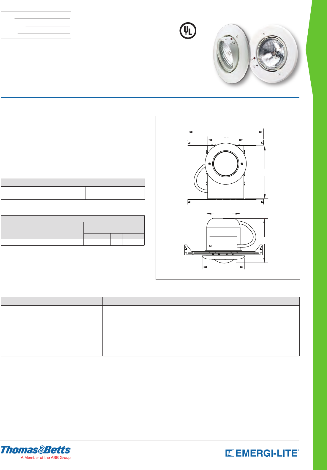
DISTRIBUTOR SELECT
107
TYPE:
CATALOG #:
NOTES:
Features
• An adjustable gimbal directs the light from one (1) 6 volt 10 watt wedge-base
PAR 36 lamp head.
• The low-prole trim ring is molded in polycarbonate with a semi-gloss white
nish to complement a variety of ceilings. The fully recessed back box is
constructed of 20-gauge steel.
• Contains a sealed, maintenance-free Lead-Calcium battery.
• A slide out chassis and two quick-connect plugs make installation and
servicing easy. Adjustable bar hangers included.
• UL Listed. Complies with NEC, Life Safety Code and OSHA.
• 3-year full warranty, excluding lamps, pilot lights and fuses.
Dimensions
Dimensions are approximate and subject to change.
14” to 24”
10-1/4”
6-1/2”
7-3/4”
8-1/2”
GS Series
Recessed Gimbal 6V up to 18W Capacity
Lead-Calcium or Nickel-Cadmium Battery Unit
Accessories (order as a separate item)
DESCRIPTION SUFFIX
Remote Test Switch (metal face plate) RTS-S
Remote Test Switch (plastic face plate) RTS-1
Unit Rating
UNIT EQUIPMENT - NO REMOTE CAPABILITY
Sealed
Maintenance-Free
Battery Types
D.C.
Voltage Model Number
Watts to 87-1/2% of rated battery
voltage*
1-1/2 hrs 2 hrs 3 hrs 4 hrs
Lead-Calcium 6 GSM10-BH 10 – – –
* Stand-by power consumption is 50% lower for Lead-Calcium batteries.
How to Order
SERIES BATTERY/WATTAGE TYPE OPTIONS
GS= 6V series M10= Lead calcium 10W -BH= Bar hangers
Example: GSM10-BH
7”
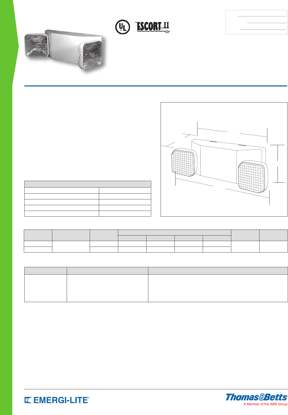
108
DISTRIBUTOR SELECT
TYPE:
CATALOG #:
NOTES:
Features
• Two (2) fully adjustable glare-free 6V-5.4W DC T5 wedge base lamps for
emergency mode egress light.
• Injection-molded UV stabilized thermoplastic housing and back plate. UL 94
Liste, 5VA ame rated.
• Sealed, maintenance-free Lead-Calcium batteries. Designed to power 11
watts remote load or extended unit run time.
• 120/277 VAC dual voltage operation. LED indicator light and push button test
switch. Remote capacity may power additional remote heads (up to 6V-11W).
Low voltage battery disconnect.
• Innovative, snap-together design allows for fast installation. Wall or ceiling
mounting. Universal knock-out pattern on the back plate allows for junction
box mounting.
• UL Listed. Complies with NEC, Life Safety Code and OSHA. Damp location
listing is standard in all models.
• 3-year full warranty, excluding lamps and fuses.
Dimensions
Dimensions are approximate and subject to change.
4-3/8”
16-1/4”
12-1/4”
5-1/8”
EL-2SQ Series
Thermoplastic Housing 6V up to 23W Capacity
Lead-Calcium Battery Unit
Accessories (order as a separate item)
DESCRIPTION SUFFIX
Replacement battery 860.0018-E
Replacement lamp (standard) 570.0012-E
Vandal shield VRS.BB
Vandal shield (NEMA 4X) VRSBB.4X
Wire Guard (heads in any position) WG10-E
How to Order
SERIES LIGHT HEADS CAPACITY INDICATOR
EL= Self-Powered -2SQ= Standard lamp 6V-5.4W Incandescent Blank= No remote capacity
R= 11 watts remote capacity*
* Do not exceed rated unit capacity.
Example: EL-2SQR
Unit Rating
Series Battery Type DC Voltage Watts to 87-1/2% of rated battery voltage* Units Dual Voltage* Current Maximum
1-1/2 hrs 2 hrs 3 hrs 4 hrs
EL-2SQ Lead-Calcium 6V 12 – – – 120VAC
277VAC
08A
.04A
EL-2SQR 6V 23 16 – –
* National Electrical Code Specification
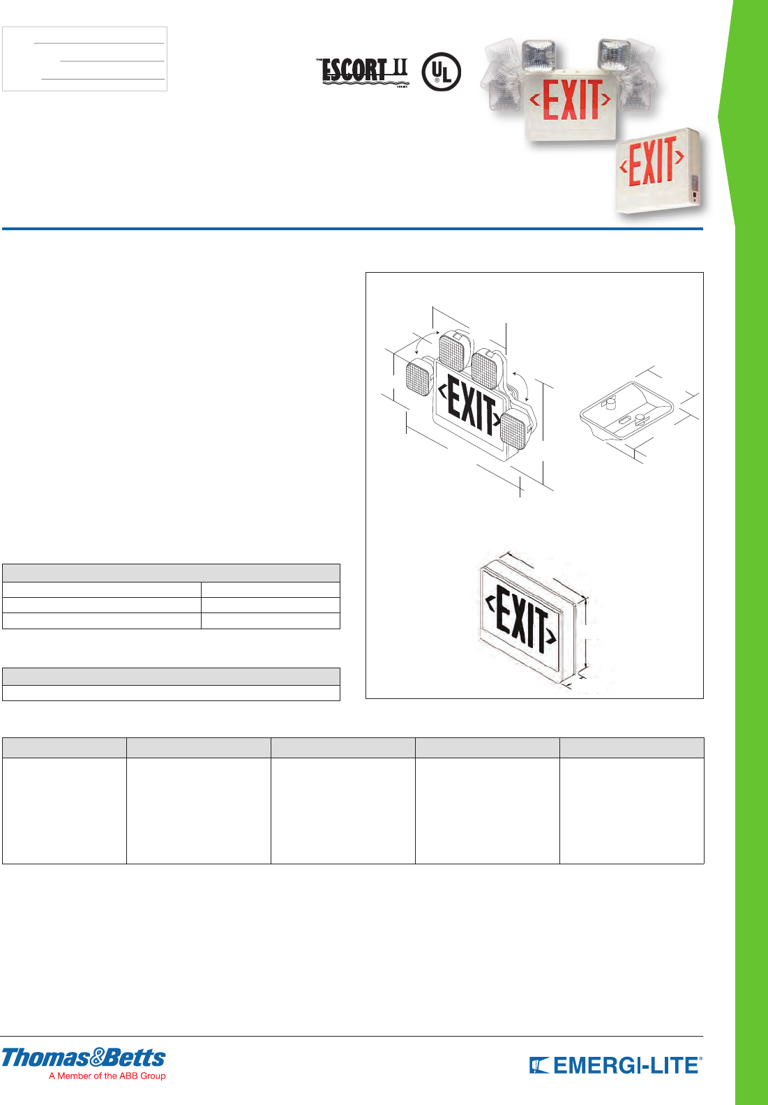
DISTRIBUTOR SELECT
109
TYPE:
CATALOG #:
NOTES:
How to Order
SERIES LEGEND LIGHT HEADS CAPACITY INDICATOR OPTION
ELXN400 R= Red
G= Green
-0= Combo no heads*
-2SQ= Lamp standard 6V-5.4W
Blank= No remote capacity
R= 12W remote capacity*
Blank= No options
-AD= Advanced Diagnostics
(audible)*
* Only available with remote capacity AD and
red legend *Do not exceed rated unit capacity
* Only available with remote capacity and
red stencil
Example: ELXN400R-2SQR-AD
Standard Features
• Comes with two fully adjustable glare-free SQ light heads for egress lighting,
with two (2) 6V-5.4 watts DC T5 wedge base lamps.
• Low power consumption – LED lamps are operated in normal
(AC input) and emergency (DC input) modes.
• Injection-molded UV stabilized thermoplastic housing, faceplates, and
canopy. UL 94, 5VA ame rating. Two faces, backplate,
and canopy.
• Available with a sealed, maintenance-free Lead-Calcium battery. Additional
battery available for 12 watts remote load or extended unit run time (see How
To Order).
• 120/277 VAC dual voltage operation. LED indicator light and push button
test switch. Remote capacity exit with two heads may power additional
remote heads up to 6 Volt, 12 watts. Remote capacity exit with no heads may
power additional remote heads up to 6 Volt, 22 Watts. Low voltage battery
disconnect.
• Innovative, snap-together design allows for fast installation. Wall or ceiling
mounting. Canopy snaps to housing with a twist-lock feature tightly securing
the canopy to the housing. Replaceable directional chevron inserts are easily
removed and reinserted.
• UL Listed. Complies with NEC, Life Safety Code and OSHA. Damp location
listing is standard on all models.
• 3-year full warranty, excluding lamps, pilot lights and fuses.
Dimensions
Dimensions are approximate and subject to change.
4-5/8”
5-7/8”
21-3⁄4” 14-5⁄8”
6-5/16”
1”
Units with no heads: 10-1⁄8” x 13”
Note: Heads move from side to top in field
ELX400 SQ Series
Thermoplastic Combination Units and
Remote Capacity Exit Sign
Accessories (order as a separate item)
DESCRIPTION SUFFIX
Wire Guard (heads in any position) WG10-E
Replacement battery 860.0004-E
Replacement lamp 570.0012-E
* Do not exceed rated unit capacity.
16-1/8”
15-5/8”
21-5/8” 10-1/8”
Power Consumption Chart
DESCRIPTION
120/277VAC, 60Hz maximum 0.11/0.05A
Combination Unit
Canopy
13”
10-1/8”
2-9/16”
Remote Capacity Unit
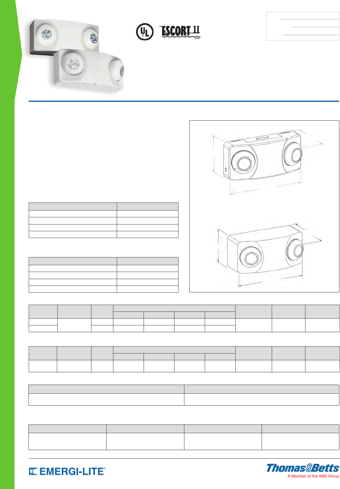
110
DISTRIBUTOR SELECT
TYPE:
CATALOG #:
NOTES:
Features
• Each self-contained unit comes with two (2) 6V MR16 halogen or LED lamps
housed in adjustable, gimbal-type assemblies to provide clean, adequate lighting
• High impact thermoplastic construction is UL recognized 94, 5VA
• Sealed, maintenance-free Lead-Calcium batteries
• Reliable integrated circuitry offers 120/277VAC 0.1/0.05A input standard,
automatic charging, instantaneous transfer, test switch, long-life LED AC
charge monitor, temperature compensated charger, short circuit protection,
low battery voltage disconnect, brownout protection, and lock out (automatic
battery detection during installation)
• Snap-together thermoplastic housing facilitates mounting in any orientation
• UL Listed. Complies with NEC, Life Safety Code and OSHA
Damp location listing is standard
• 3-year full warranty, excluding lamps and fuses
Dimensions
Dimensions are approximate and subject to change.
EL-2MRS
5-1/2”
12-1/8”
3-3/4”
5-1/2”
5-7/8”
12-1/8”
12EL50-2MRS
EL-2MRS &
12EL50-2MRS Series
Completely Self-Contained or Heavy Duty
Thermoplastic Battery Unit
Accessories (order as a separate item)
EL-2MRS
DESCRIPTION PART NUMBER
Replacement MR16 lamp 6V-5W 580.0072-E
Wire Guard WG13-E
Replacement Battery 860.0004-E
Replacement MR16 LED lamp 6V-4W 580.0097-E
Accessories (order as a separate item)
12EL50-2MRS
DESCRIPTION PART NUMBER
Wire Guard WG13-E
Replacement MR16 lamp 12V-4W LED 580.0093-E
Replacement MR16 lamp 12V-12W Halogen 580.0080-E
Replacement MR16 lamp 12V-20W Halogen 580.0064-E
Power Consumption: EL2MRS
Series Battery Type DC Voltage Watts to 87-1/2% of rated battery voltage Dual Voltage Current Maximum Power Maximum
1-1/2 hrs 2 hrs 3 hrs 4 hrs
EL-2MRS Lead-Calcium 6V 12 – – – 120VAC
277VAC
.1A
.05A
7.5W
7.5W
EL-2MRS-LA 6V 12 – – –
Power Consumption: 12EL50-2MRS
Series Battery Type DC Voltage Watts to 87-1/2% of rated battery voltage Dual Voltage Current Maximum Maximum
1-1/2 hrs 2 hrs 3 hrs 4 hrs
12EL50-2MRS Lead-Calcium 12V 50 32 25 16 120VAC
277VAC
.21A
.1A
23W
23W
How to Order: EL-2MRS
SERIES LAMP OPTION
EL= Series -2MRS= 6V-5W MR16
-2MRS-LA= 6V-4W, MR16 LED
Example: EL-2MRS-LA
How to Order: 12EL50-2MRS
VOLTAGE SERIES CAPACITY (W) LAMP
12= 12 Volts EL 50 -2MRS-MK= 12V-12W Halogen (Standard)
-2MRS-LG= 12V-4W, MR16 LED
-2MRS-MG= 12V-20W Halogen
Example: 12EL50-2MRS-MK
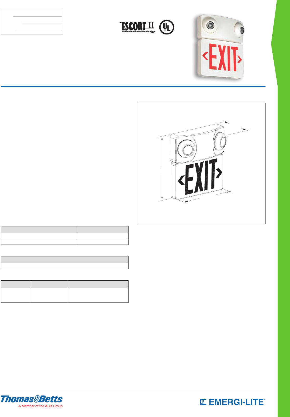
DISTRIBUTOR SELECT
111
TYPE:
CATALOG #:
NOTES:
ELX-MRS Series
Thermoplastic Exit Sign and Combination Unit
Features
• Rugged off-white thermoplastic construction
• Even illumination for excellent legibility
• Snap-together design for quick and easy installation
• Universal mounting, complete with 2 faces, backplate, and canopy
• Replaceable knockout directional chevrons
• Energy efcient, long-life red or green LEDs
• Listed to UL 924 Listed
• Complies with NEC, Life Safety Code and OSHA.
• Damp location listing is standard on all models.
• 6 volt, sealed, maintenance-free Lead-Calcium battery
• Fully adjustable, glare-free, 6 volt MR16 lamps
• 3-year full warranty, excluding lamps and fuses
• 4 watt LED lamps available
Charger
• 120/277VAC input
• Fully automatic charger
• Temperature compensated
• Brownout protection
• Short circuit protected
• Low voltage battery disconnect
• Push to test switch
• AC pilot light
Dimensions
Dimensions are approximate and subject to change.
12-7/8”
11-3/4”
4-1/16”
Accessories (order as a separate item)
DESCRIPTION SUFFIX
Replacement MR16 lamp 6V-5W 580.0072-E
Wire Guard Wall Mount WG6-E
Power Consumption
DESCRIPTION
120/277VAC, 60Hz 0.11/0.05A
How to Order
SERIES STENCIL FACE LIGHT HEADS
ELXN400 R= Red
G= Green
-2MRSN= 6V-5W MR16
-2MRSN-LA= 6V-4W, LED MR16
Example: ELXN400R-2MRSN
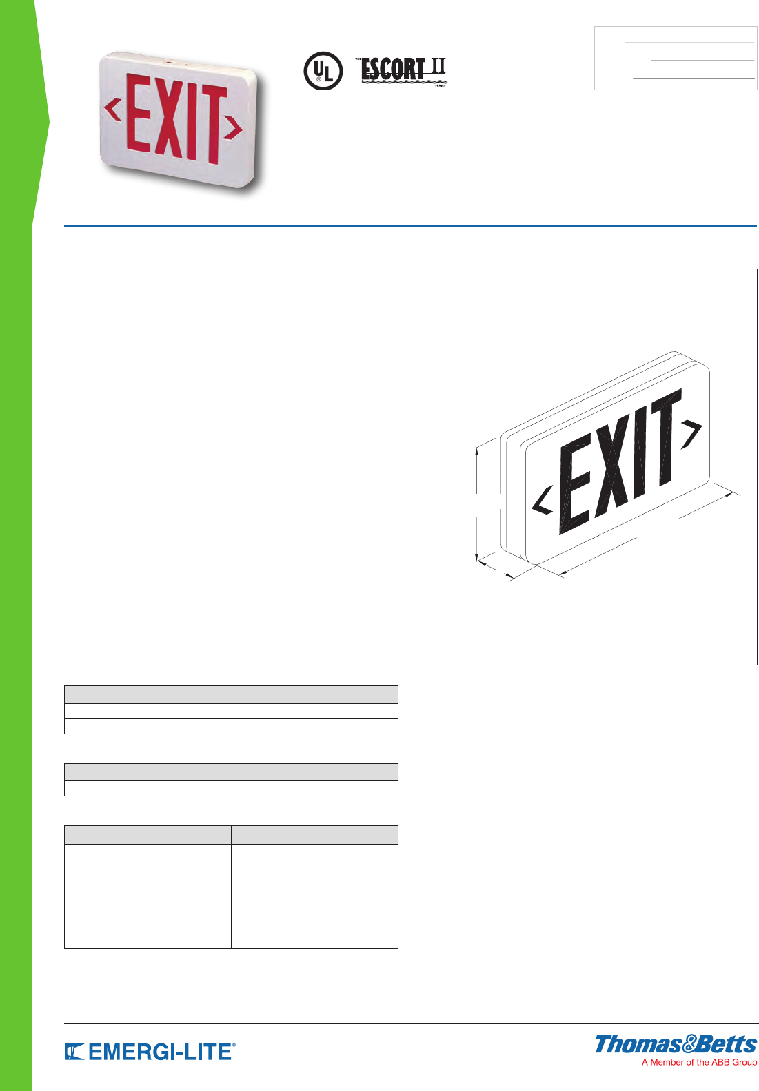
112
DISTRIBUTOR SELECT
TYPE:
CATALOG #:
NOTES:
Dimensions
Dimensions are approximate and subject to change.
7-1/4”
1-13/16”
11-13/16”
ELX Series
Economical, Thermoplastic LED Exit Signs
Features
• Rugged off-white thermoplastic construction
• Even illumination for excellent legibility
• Snap-together design for quick and easy installation
• Universal mounting, complete with 2 faces, backplate, and canopy
• Replaceable knockout directional chevrons
• Energy efcient, long-life red or green LEDs
• Listed to UL 924 Listed
• Complies with NEC, Life Safety Code and OSHA.
• Damp location listing is standard on all models
• 3-year full warranty, excluding lamps and fuses
ELX Series Models
AC-only exit signs, red or green
Self-powered exit signs, red or green
Self-Powered Emergency Models
• Replaceable, sealed Nickel-Cadmium battery
• Provides a minimum 90 minutes of continuous
emergency illumination
• Energy star compliant
• Batteries recharge per UL924 specications
• Consumes less than 5W
Charger
• 120/277VAC input
• Fully automatic
• Temperature compensated
• Brownout protection
• Short circuit protected
• Low voltage battery disconnect
• Push to test switch
• AC pilot light
Accessories (order as a separate item)
DESCRIPTION SUFFIX
Wire Guard - Wall Mount WG1-E
Ceiling or end mount WG5-E
Power Consumption
DESCRIPTION
120/277VAC, 60Hz maximum 2.5W
How to Order
SERIES STENCIL FACE
ELX400= AC-only
ELXN400= Self-Powered
RN= Red
GN= Green
Example: ELXN400RN
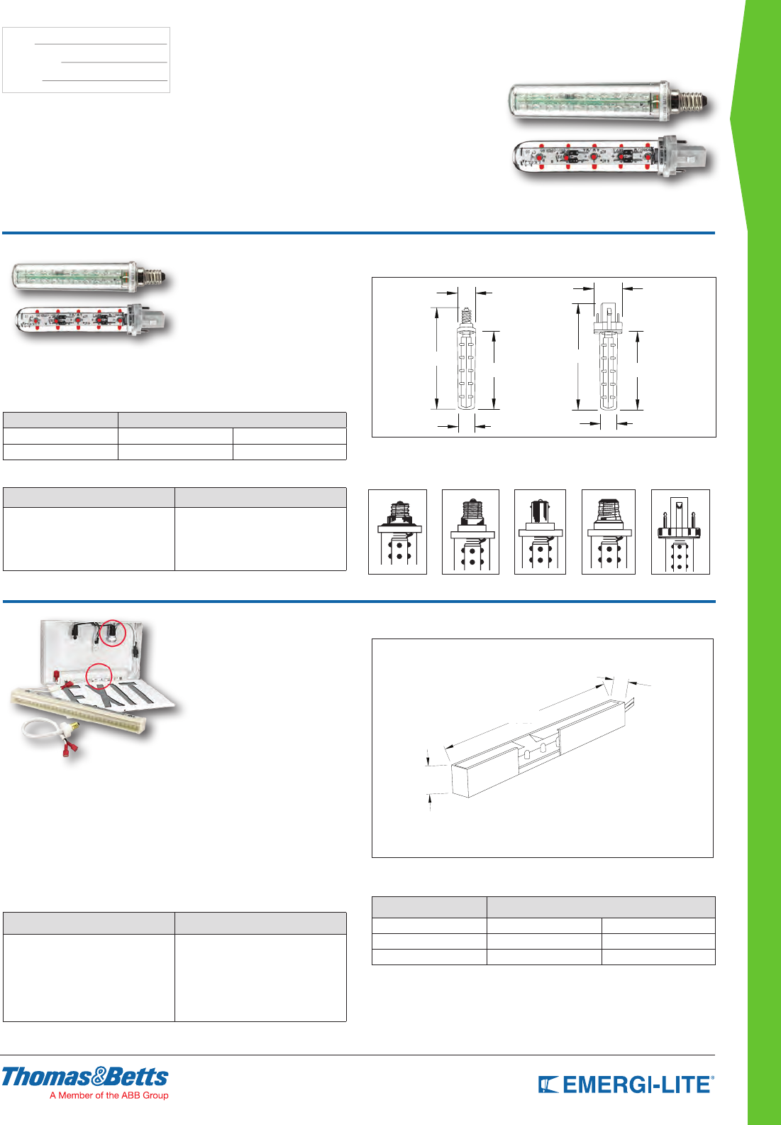
DISTRIBUTOR SELECT
113
TYPE:
CATALOG #:
NOTES:
Dimensions
Dimensions are approximate and subject to change.
15/16” 1-1/4”
4-3/4”
3-3/4” 3-3/4”
5-1/8”
7/8” 7/8”
Dimensions
Dimensions are approximate and subject to change.
9-1/4”
1-1/4”
7/8”
Quick Switch Series
LED Replacement Lamps LED Retrofit Kits
Quick Switch
• Quick and easy to install
• Available with wide range of lamp
bases for quick lamp to lamp
replacement
• High brightness LEDs
• 120 VAC only
• Two bulbs per pack
Power Consumption (LED Exit Signs)
Model AC Specs
QS 120VAC 0.9W
QS-F 120VAC 1.6W
How to Order
SERIES BASE
QS -C= Candelabra
-I= Intermediate
-M= Medium
-B= Bayonet
-F30= Compact fluorescent
Example: QS-C
How to Order
NOTE: Please consult your sales representative for Green LED option.
SERIES BASE
LED-RX -C= Candelabra
-I= Intermediate
-M= Medium
-B= Bayonet
-F= Compact fluorescent
-120-HW= Hard wired
-277-HW= Hard wired
Example: LED-RX-C
QS-C
Candelabra
Base
QS-I
Intermediate
Screw Base
QS-B
D.C. Bayonet
Base
QS-M
Medium Screw
Base
LED Retrofit Kit – Standard Features
• Easiest to install in its class
• Compact size makes it ideal for virtually all exit signs
• Can be retrotted directly on uorescent ballast
• Long-Life, energy-efcient red LED technology
• Available with AC adaptor for all type of lamp sockets
QS-F30
PL 5, 7 or 9 Watt
Base
Power Consumption (LED Exit Signs)
MODEL AC SPECS
LED-RX 120VAC 0.7W
LED-RX-120-HW 120VAC 0.7W
LED-RX-277 HW 277VAC 0.7W

115
EMERGENCY BALLASTS
FPDL Series 116
FPS Series 117
FPS-R & FPS-T Series 118
FTS Series 119
ELMR-E Series 120
Emergency Ballasts
Reference Chart 121
EMERGENCY BALLASTS
Table Of Contents
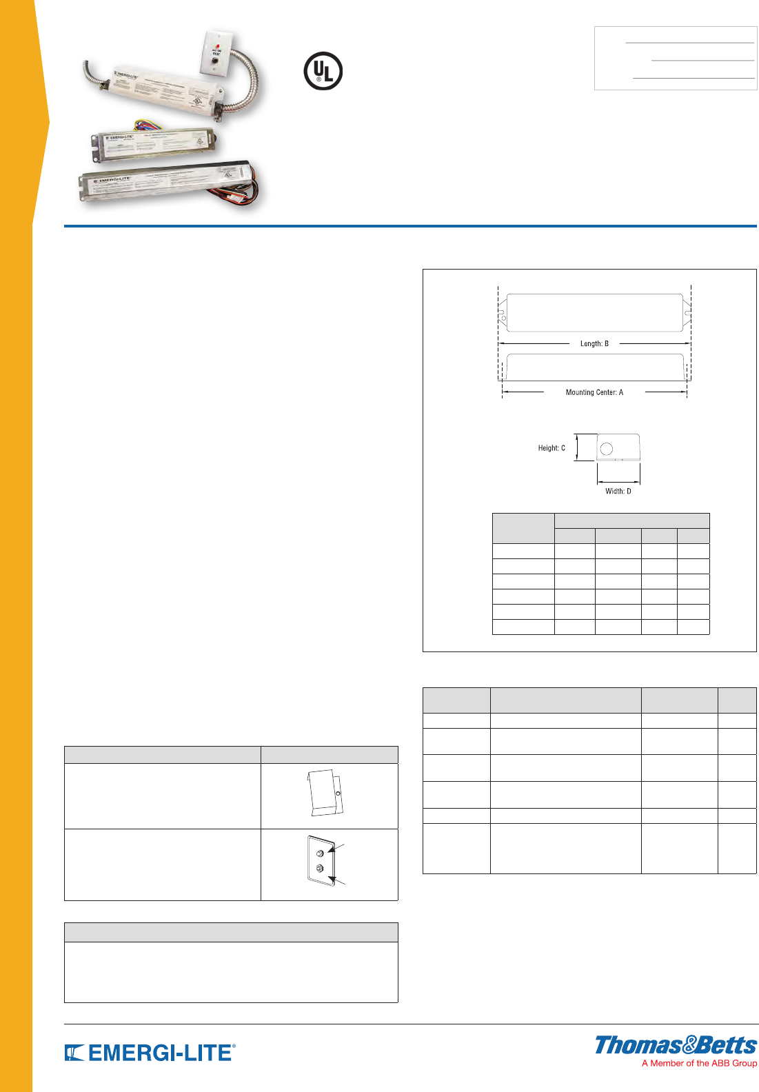
116
TYPE:
CATALOG #:
NOTES:
EMERGENCY BALLASTS
Six models meet different application requirements:
• FPDL-32 500 lumens emergency ballast operates with most 2’-4’ T8 linear
uorescent lamps and also with 28W T5 lamps
• FPDL/U 1400 lumens emergency ballast operates with most 2’-4’ T8 and
T5 linear uorescent lamps and also with most 4-pin compact
uorescent lamps
• FPDL13-42-N 650 lumens emergency ballast operates with most
13-42W 4-pin quad and triple tube uorescent lamps with one
or two lamps (max. 18W)
• FPDL-28 700 lumens emergency ballast operates with most 2’-4’ T8 and T5
linear uorescent lamps
• FPDL-10-26 650 lumens emergency ballast operates with most 10-26W
2-pin compact uorescent lamps
• FPDL-HL-N is a high-output emergency ballast capable of producing up to
3000 lumens
Features
• Compatible with standard, energy-saving, dimming and electronic AC ballasts
• Can be wired to operate with switched, un-switched or normally-off xtures
without affecting normal operation
• Sealed, maintenance-free Nickel-Cadmium batteries
• Upon failure of AC power, the FPDL-32 and FPDL10-26 models automatically
switch to emergency mode, maintaining illumination of one lamp within the
xture. FPDL/U, FPDL13-42-N, FPDL-28 and FPDL-HL-N units will maintain
operation of one or two lamps when switched to the emergency mode
• When AC power is restored, the FPDL Series automatically returns the
uorescent lamps to normal operating mode and the solid state charger
begins recharging the battery
• Self-contained in one compact housing for easy installation and maximum
mounting exibility
• UL Listed for damp locations to Standard 924; complies with NEC, Life Safety
Code and OSHA, and eld installation
• 3-year full warranty
• Each unit is fully computer tested
Dimensions
Dimensions are approximate and subject to change.
Cabinet Size Dimensions
ab c d
FPDL-32 9-1/2” 10-1/8” 1-1/8” 2-1/8”
FPDL/U 13-3/4” 14-1/4” 1-1/8” 2-1/8”
FPDL13-42-N 8-7/8” 9-3/8” 1-1⁄/” 2-3/8”
FPDL-28 13-3/4” 14-1/4” 1-1/8” 2-1/8”
FPDL10-26 8-7/8” 9-3/8” 1-1/2” 2-3/8”
FPDL-HL-N 15-3/4” 16-1/4” 1-3/4” 5-1/2”
FPDL Series
Fluorescent Emergency Lighting Ballasts
Accessories (order as a separate item)
DESCRIPTION PART NUMBER
External mounting kit includes wire bundle
cover for external mounting (not needed for
FPDL13-42-N, FPDL10-26 and FPDL-HL-N)
EC6
Remote test switch comes with single
gang plastic mounting plate (included
in FPDL13-42-N and FPDL10-26)
RTS-1
Charging
Indicator
Light
Push Button
Test Switch
Power Consumption
Series Lamp Operated in Emergency Mode* Emergency
Illumination Time Lumens
FPDL-32 1 lamp 2’-4’ (20W-40W) 90 minutes 500
FPDL/U 1 lamp 2’-8’ (20W-60W) or 2
lamps 2’-4’ (20W-32W)
90 minutes 1400
FPDL13-42-N 1 compact 4-pin (13W-42W) or
2 compact 4-pin (13W-18W)
90 minutes 650
FPDL-28 1 lamp 2’-4’ (20W-54W)
or 2 lamps 2’-4’ (20W-32W)
90 minutes 700
FPDL10-26 1 compact 2-pin (10W-26W) 90 minutes 650
FPDL-HL-N - 1 lamp 2’-8’ or
- 2 lamps 2’-4’ or
- 1 compact 4-pin (18W-70W) or
- 2 compact 4-pin (18W-32W)
90 minutes 3000
How to Order
SERIES
FPDL-32
FPDL-U
FPDL13-42-N
FPDL-28
FPDL10-26
FPDL-HL-N
Example: FPDL-32
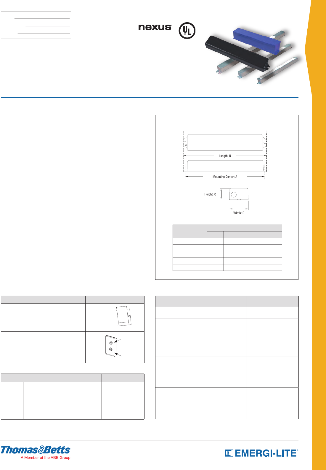
117
TYPE:
CATALOG #:
NOTES:
EMERGENCY BALLASTS
Seven models are offered to satisfy different
applications requirements and lumen output:
• FPS-500 and FPS-825 operate with most 2’-4’ T5 or T8 PL lamps. The
FPS-825 also operates HO and 4 pin long compact uorescent
lamps from 40 through 55 watts.
• FPS-540 operates T5 or T8 lamps, including HO and 4-pin long compact
uorescent lamps of 40-55 watts, with an initial output of up to
1300 lumens. Testing the FPS-540 is made easy with a one-piece
indicator and test switch.
Features
• FPS-80 is offered with Nexus® wired and wireless monitoring system which
includes Nexus® uorescent emergency ballast as well as Nexus® (wired or
wireless) communication modem
• Compatible with standard, energy-saving, dimming and electronic AC ballasts
• Can be wired to operate with switched, un-switched or normally-off xtures
without affecting normal operation
• Sealed, maintenance-free Nickel-Cadmium batteries
• Upon failure of AC power, the FPS-500, FPS-825 and FPS-540 models
automatically switch to emergency mode, maintaining illumination of one lamp
within the xture. FPS-80 units will maintain operation of one or two lamps
when switched to the emergency mode
• When AC power is restored, the FPS Series automatically returns the
uorescent lamps to normal operating mode and the solid state charger
begins recharging the battery
• Self-contained in one compact housing for easy installation and maximum
mounting exibility
• UL Listed to Standard 924; complies with NEC, Life Safety Code and OSHA
• 3-year full warranty
• Each unit is fully computer tested
Dimensions
Dimensions are approximate and subject to change.
Cabinet Size Dimensions
AB C D
FPS-500 13-3/4” 14-1/4” 1-3/16” 1-3/16”
FPS-825 17” 17-1/2” 13/16” 1-3/16”
FPS-540 12-1/2” 13-1/8” 11/2” 2-1/4”
FPS-80D 12-3/4” 12-3/4” 11/2” 2-3/8”
FPS-80NEXUS-N 12-3/4” 12-3/4” 11/2” 2-3/8”
FPS Series
Fluorescent Emergency Lighting Ballasts
Accessories (order as a separate item)
DESCRIPTION PART NUMBER
External mounting kit includes wire
bundle cover for external mounting
Damp Location listing
-R
-DL
Remote test switch includes single gang
chrome finished mounting plate
Test switch kit for fluorescent
Test switch kit for FPS80D/Nexus®
RTS-1
-TBTS
LPTS
Charging
Indicator
Light
Push Button
Test Switch
Power Consumption
Series Lamp Operated in
Emergency Mode*
Emergency
Illumination Time Lumens Wire End Caps
FPS-500 1 lamp 2’-4’ 90 minutes 500 Optional, order
#EC54
FPS-825 1 lamp 2’-4’ 90 minutes 825 Optional, order
#EC54
FPS-540 1 lamp 2’-4’
(40W-50W)
Most 2’-4’ T5 or T8
and 40-55W 4 pin
compact fluorescent
90 minutes 1300 Not required
FPS-80D Most 2’ - 4’ single,
bi-pin T8 & T12HO
and VHO, including
long compacts
and 2’ - 4’ 14W to
54W T5 lamps
90 minutes 1100 Not required
FPS-
80NEX-N
FPS-
80NEXRF-N
Most 2’ - 4’ single,
bi-pin T8 & T12HO
and VHO, including
long compacts
and 2’ - 4’ 14W to
54W T5 lamps
90 minutes 1100 Not required
How to Order
SERIES OPTION SUFFIX
FPS-500
FPS-825
FPS-540
FPS-80D
FPS-80NEX-N*
FPS-80NEXRF-N*
* Including Nexus® communcation module
External Mounting Kit
Example: FPS-80D
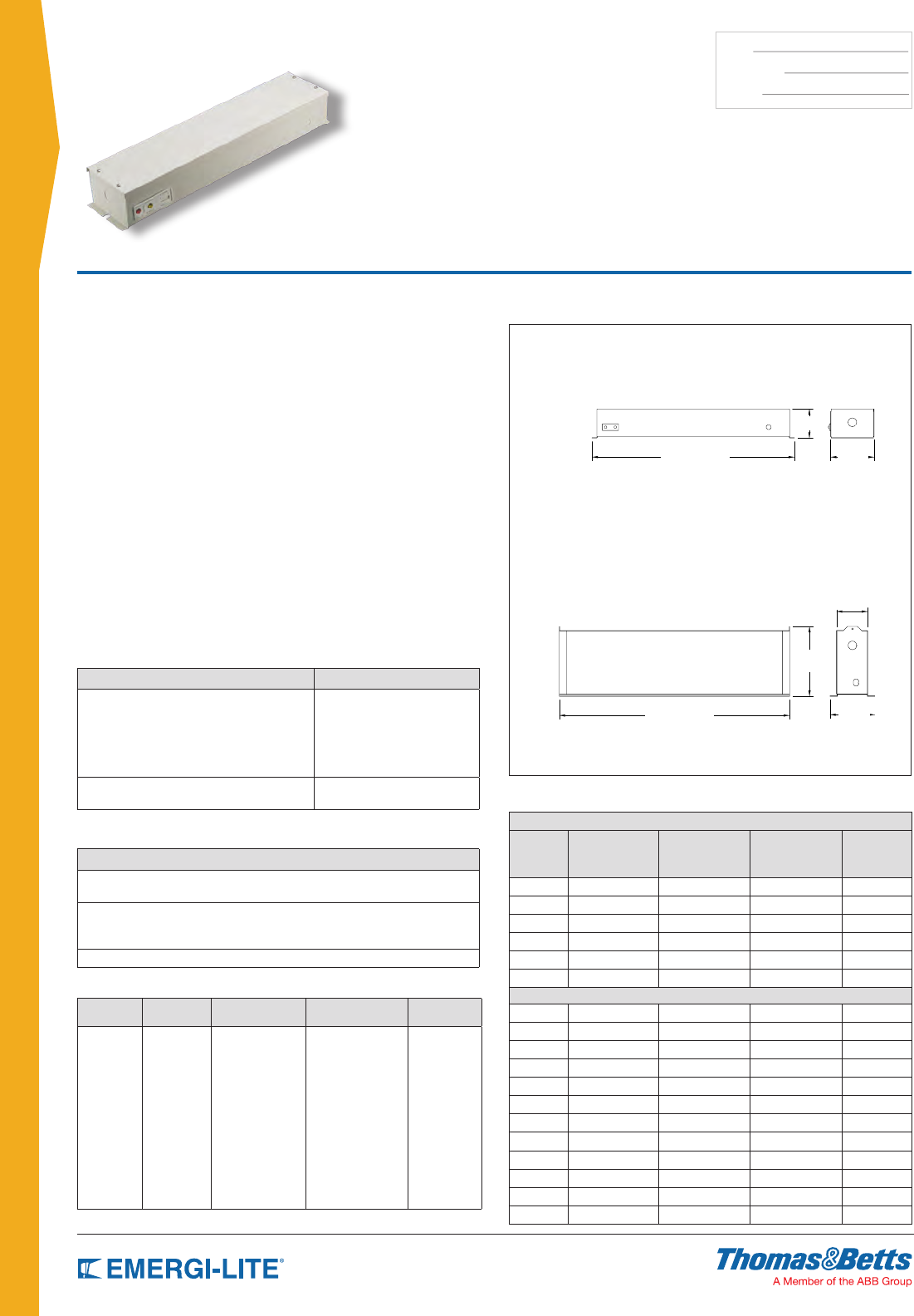
118
TYPE:
CATALOG #:
NOTES:
EMERGENCY BALLASTS
Features
• All-metal construction with off white baked enamel nish and 3” pre-wired
xture whip
• Sealed, maintenance-free Nickel-Cadmium, Long Life Lead, or
Lead-Calcium batteries
• During normal operation, when the AC line voltage is present, the xture
will fully illuminate by means of the regular ballast. While supplied with AC,
the emergency ballast transforms AC into a low DC voltage to recharge the
battery and maintain it fully charged
• When the AC fails, a solid state voltage sensor instantly turns on a high
frequency inverter which supplies one or two lamps in the xture for a
minimum of 90 minutes. Only FPS-T can run 2 lamps in a 2 or 4 lamp xture.
• At the end of the rated time a low voltage sensor disconnects the battery to
prevent over-discharging
• When the AC returns, the inverter switches off and the battery begins to
recharge
• Charger circuitry offers 120/277VAC, 60 Hz., 0.3/0.15A (other inputs
available), fused output circuit(s), dual diagnostic indicator lights, temperature
compensation, sealed relay, low voltage battery disconnect, brownout
protection and lockout (automatic battery connect).
• 3-year full warranty
• Each unit is fully computer tested
Dimensions
Dimensions are approximate and subject to change.
REMOTE (FPS-R)
T-BAR (FPS-T)
20-7/8”
23-3/4”
7-1/4”
3-1/4”
4-5/8”
4-1/2”
3”
FPS-R & FPS-T Series
Fluorescent Emergency Packs
Accessories (order as a separate item)
DESCRIPTION PART NUMBER
Remote test switch
Available for installation where routine testing via the
units standard integral test switch would be difficult due
to either fixture location or inaccessibility. This option
consists of a push button test switch and pilot light,
mounted on a single gang switch plate plastic white
RTS-1
Test switch and charging indicator on
a single gang chrome mounting plate RTS
Cabinets
DESCRIPTION
Remote: (external) mounts on top or beside fixture. #18 gauge steel, finish
white baked enamel finish and pre-wired 3” flexible conduit fixture whip.
T-Bar: mounts in T-Bar struts beside fixture. #18 Gauge steel,
finish white baked enamel finish and mounting eyes for fixture
suspension and a pre-wired 3” flexible conduit fixture whip.
Servicing: Backplate lifts off for full access to battery and input/output wires.
Unit Rating
REMOTE MOUNTED (FPS-R)
Series Lumens Battery Suffix
Sealed
Maintenance-Free
Battery Types
Number of
lamps
FPS-R 720 C Nickel-Cadmium 1
FPS-R 720 E Long Life Lead 1
FPS-R 720 M Lead-Calcium 1
FPS-R 1800 C Nickel-Cadmium 1
FPS-R 1800 E Long Life Lead 1
FPS-R 1800 M Lead-Calcium 1
T-BAR MOUNTED (FPS-T)
FPS-T 720 C Nickel-Cadmium 1
FPS-T 720 E Long Life Lead 1
FPS-T 720 M Lead-Calcium 1
FPS-T 1800 C Nickel-Cadmium 1
FPS-T 1800 E Long Life Lead 1
FPS-T 1800 M Lead-Calcium 1
FPS-T 720 C Nickel-Cadmium 2
FPS-T 720 E Long Life Lead 2
FPS-T 720 M Lead-Calcium 2
FPS-T 1800 C Nickel-Cadmium 2
FPS-T 1800 E Long Life Lead 2
FPS-T 1800 M Lead-Calcium 2
How to Order
SERIES CABINET
TYPE LUMENS BATTERY TYPE # OF LAMPS
FPS=
Fluorescent
series
-R= Remote
-T= T-Bar
-720= 720 lumens
-1800= 1800
lumens
-C= Ni-Cd
-E= Long life lead
-M= Lead-Calcium
-1= One lamp
-2= 2 lamps*
* Only available
with FPS-T
Example: FPS-T-720-M-1
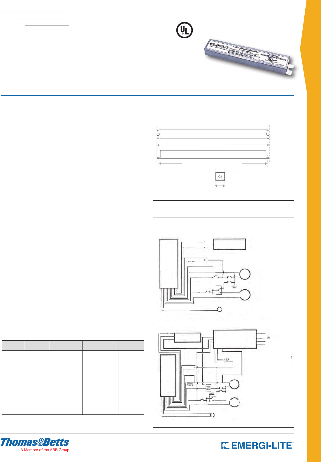
119
TYPE:
CATALOG #:
NOTES:
EMERGENCY BALLASTS
Features
• Compatible with standard, energy-saving, dimming and electronic AC ballasts
• UL Listed
• Will cold start and operate all specied lamps
• Galvanized steel case
• Dual Voltage 120/277V 60hz
• Available in ex or non-ex conguration
• Meets or exceeds all National Electrical Code and Life Safety Code
Emergency Lighting Requirements
• 5-Year Warranty. See Warranty page for details.
Advantages
• Full light output
• Allows auxiliary generator power on a switched xture.
Lamps Operated
Will operate any lamp in the designated circuit for the duration of the generator
supply
Technical Specifications
Input Voltage ............................................................ (Dual) 120/277V, 60Hz
Input Current .................................................................................. 250 mA
Maximum Switching Voltage:
• 3A @ 120V
• 3A @ 277V Circuit Protection
• 3A on Control Input
• 3A on Neutral and 120/277V Outputs
Emergency Operation
The FTS will operate any lamp type in the designated xture for the duration of
the generator supply
Initial Illumination
The FTS will operate the designated lamp at full light output
Weight .............................................................................................. 1.0 lbs.
Approval ...................................................................................... UL Listed
Options
Configuration
• FTS (no ex)
• FTS-R (w/ ex)
Dimensions
Dimensions are approximate and subject to change.
TOP
SIDE
LENGTH 8”
MOUNTING CENTER 7.5”
WIDTH 1.18”
END
HEIGHT
1.125”
Wiring Diagrams
TYPICAL BALLASTS/GENERATOR APPLICATION
TYPICAL DIMMING BALLASTS/GENERATOR APPLICATION
WHT/BLACK
BLK/ORG
White
Black
ORG (120V)
BLK (120V)
White
Normal Common
Yellow
Yellow
Yellow/White
Yellow/White
Normal Hot
Generator Common
Generator Hot
Wall Switch
Neutral
Neutral
Normal
Power
Generator
Power
Red LED Normal Power
Indicator (Opt)
1) Select Proper Voltage
Lead. Cap Unused Lead.
2) Cap Unused Leads
1) Select Porper Voltage
Lead. Cap Unused Leads
Hot
Hot
WHT/BLK
AC BALLAST FTS TRANSFER
SWITCH
FTS
TRANSFER
SWITCH
FTS TRANSFER
SWITCH
AC BALLAST
WHT
Blue
White
Neutral
Hot
Hot
Neutral
Blk
Yel
Red
Red
BLK/ORG
BLKBLKORG
Orange
RED
Emergency Panel
Transfer
Switch
BLU/WHT
RED/WHT
RED/BLK
RED/WHT
YELLOW
YELLOW/WHT
ALL WHT
BLUE
ORG
(277V)
ORG (277V)
BLK (120V)
White
Blue
Blue/Wht
Red
Normal
Hot
Generator Hot
Generator Common
RED/WHT
Emergency
Panel Normal
Panel
BLK
(120V)
Red LED Normal Power
Indicator (Opt)
Normal
Power
Generator
Power
FTS Series
Emergency Transfer Switch
for Generator Supplies
How to Order
SERIES CABINET
TYPE LUMENS BATTERY TYPE # OF LAMPS
FTS=
Flourescent
series
-R= Remote
-T= T-Bar
-720= 720 lumens
-1800= 1800
lumens
-C= Ni-Cd
-E= Long life lead
-M= Lead-Calcium
-1= One lamp
-2= 2 lamps*
* Only available
with FPS-T
Example: FPS-T-720-M-1
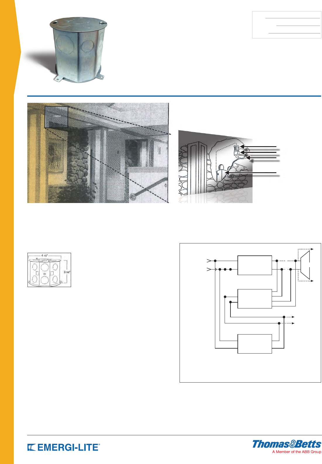
120
TYPE:
CATALOG #:
NOTES:
EMERGENCY BALLASTS
ELMR-E Interface
Module Series
Enables Normally-On Low Voltage (12V) Lamps
To be Used as Emergency Lighting
ELMR-E Unit
Fixture Transformer
12V Lamp
12V Emergency
Lighting Unit
Module Information
The Emergi-Lite® “ELMR-E” interface module
consists of a relay transfer panel enclosed in an
octagonal electrical box which measures
4-1/2 inches in diameter by 3-5/8 inches deep. The
module is designed to operate 12 volt lamps up to a
total of 200 watts. A remotely located Emergi-Lite®
12 volt emergency lighting unit, in conjunction with
the “ELMR-E”, supplies 12 volt during an emergency
situation regardless if the xture is switched on or off.
Installation
The “ELMR-E” interface module is provided with a 1/2 inch threaded conduit
nipple for fast, easy, eld installation and mounts directly to the step-down
transformer junction box of the low voltage lighting xture. For applications
requiring remote mounting, not only is a xture “stud plate” is provided, as well
as two mounting tabs with 3/16 inch diameter holes on 4-9/16 inch centers.
Electrical connection is made by splicing to the secondary winding of the
step-down transformer and connecting it and the remote feed from the 12 volt
battery pack to the “ELMR-E” module. One “ELMR-E” is required for each
xture that contains an internally mounted step-down transformer. However, if
several low-voltage lamps are assigned to a single, centrally-located step-down
transformer, only one “ELMR-E” is needed to operate all lamp xtures, up to
200W.
Operation
In the event of a power failure the 12 volt Emergi-Lite® battery unit would
supply the “ELMR-E” module with 12 volt DC power. The “ELMR-E” module
would then transfer the lighting xture from its normal 12 volt AC source
(transformer) to the 12 volt DC battery power. Upon restoration of the normal
AC power supply, the module will transfer the lighting xture back to its normal
operating mode.
Note: Remote battery pack must have sufcient capacity to support the
connected load for a minimum of 90 minutes.
Consult Emergi-Lite®’s technical data section for wire run length and wire
size requirements. Emergency lighting unit must be capable of supplying
total wattage lamp loads for a minimum of 90 minutes. Applications may
require longer time durations. Consult NFPA Life Safety Code and National
Electric Code and National Electric Code Article 700 with regard to standard
engineering practices. Local codes may vary.
# # #
FIXTURE
TRANSFORMER
(SUPPLIED BY OTHERS)
NORMALLY-ON
AC
INPUT
TO OTHER
MODULES
WITH FIXTURES
ON SAME
AC CIRCUIT
CONNECT TO DC
OUTPUT LOAD
TERMINALS
RED YEL
WHT
BLK
GRY
N12V
LL
L
N
NX
X
BLUE
*
*
12V LAMP
12 VOLT
EMERGENCY
LIGHTING UNIT }
Notes: X Denotes “Cut Original Wiring”
*: “To other low-voltage lamps” (multiple-lamp, single transformer arrangements only)
#: Install wall switch here, (if required)
IMPORTANT: Emergency lighting units must be fed from
same branch feeder circuit (normally-on circuit)
Application: To maintain the integrity of lighting decor, Emergi-Lite® offers an interface module, “ELMR-E”; which
is designed to be incorporated with MR16, PAR36, R12, or R14 low voltage lighting xtures that are being used as
both normal lighting xtures, and as emergency lighting xtures.
These dual-function xtures are used in a variety of accent applications, especially in retail store lighting.
121
TYPE:
CATALOG #:
NOTES:
EMERGENCY BALLASTS
Emergency Ballast Series
Reference Chart
EMERGI-LITE® MODEL # FPDL-32 FPDL/U FPDL13-42 FPDL-28 FPDL10-26 FPDL-HL FPS500 FPS80D FPS825 FPS540
Lumens 500 1400 650 700 650 3000 500 1300 825 1300
LAMP TYPE (# OF LAMPS) LINEAR LAMPS
2’-4’ Rapid, Instant, Energy Saving,
T8 thru T12 (1) X X X X X X X X
2’-4’ Rapid, Instant, Energy Saving,
T8 thru T12, HO & VHO (2) X X X X
2’-8’ Rapid, Instant, Energy Saving,
T8 thru T12, HO & VHO (1) X X X
F17 T8 (1) X X X X X X X X
F17 T8 (2) X X X X
F25 T8 (1) X X X X X X X X
F25 T8 (2) X X X X
F32 T8 (1) X X X X X X X X
F32 T8 (2) X X X X
F40 T8 (1) X X X X X
FO96 T8 59W (1) X X
14W T5 (1) X X X X X X
21W T5 (1) X X X X X X X
24W T5 (1) X X X X X X X
28W T5 (1) X X X X X X X X
39W T5 (1) X X X X X X
54W T5 HO (1) X X X X X X
F20 T12 (1) X X X X X
F20 T12 (2) XXX
F40 T12 (1) X X X X X
F40 T12 (2) X X
F48 T12 (1) X X X
F96 T12 60W (1) X X X
LAMP TYPE (# OF LAMPS) COMPACT LAMPS
18W Long Compact (1) X X XX
24W Long Compact (1) X X XX
36W Long Compact (1) X X XX X X X
40W Long Compact (1) X X XX X X X
40W Long Compact (2) X
50W Long Compact (1) X XX X X X
55W Long Compact (1) X X X X X
7W PL CF 2-Pin (1) X
9W PL CF 2-Pin (1) X
13W PL CF 2-Pin (1) X
18W PL CF 2-Pin (1) X
26W PL CF 2-Pin (1) X
13W PL CF 4-Pin (1 or 2) X X X
18W PL CF 4-Pin (1 or 2) X X X
26W PL CF 4-Pin (1) X X X X
26W PL CF 4-Pin (2) X
32W PL CF 4-Pin (1) X X X X
32W PL CF 4-Pin (2) X
42W PL CF 4-Pin (1) X X X
42W PL CF 4-Pin (2)
57W PL CF 4-Pin (1) X X X
57W PL CF 4-Pin (2)
70W PL CF 4-Pin (1) X X X
20W Circline (1) X X X X X X X X
22W Circline T9 (1) X X X X X
22W Circline T5 (1) X X X X X X X
40W Circline T8 (1) X X X X X
40W Circline T5 (1) X X X
55W Circline T5 (1) X X
F28 2D (1) X
F28 2D (2)
F38 2D (1)
F38 2D (2)
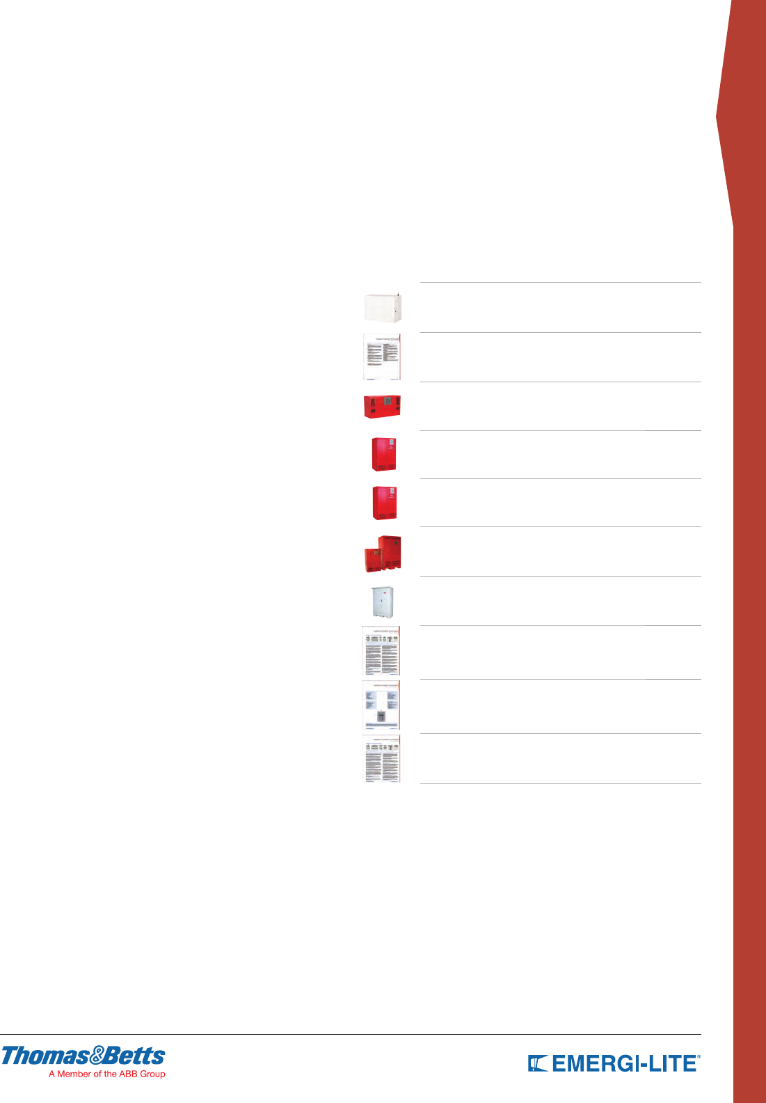
123
CENTRAL & INVERTER
SYSTEMS
Mini-Inverters 124-125
Emerg-Power Systems
Feature & Benefits 126-127
Emerg-Power
Compact Series 128-129
Emerg-Power
IPS Single Phase Series 130-131
Emerg-Power
FTC Single Phase Series 132-133
Emerg-Power
3FTC Three Phase Series 134
Emerg-Power
FTC3R & 3FTC3R Series 135
Emerg-Power System Options 136
Emerg-Power Control Panel &
Display Functions 137
Emerg-Power Central System
Request Data 138
CENTRAL &
INVERTER SYSTEMS
Table of Contents
124
CENTRAL & INVERTER
SYSTEMS
TYPE:
CATALOG #:
NOTES:
Highlights
The Mini-Inverter is a UL Listed stand-alone simulated sine wave
output inverter designed to provide power to designated emergency
lighting fixtures. In a power loss situation, it will supply power from the
onboard battery supply.
The Mini-Inverter works in conjunction with incandescent, LED, and
fluorescent fixture types and will automatically run switched, normally-
on, or normally-off designated emergency fixtures.
The Mini-Inverter is ideal for applications requiring an emergency
source for lighting arrangements that utilize multiple lamp and fixture
types and is available in surface mount and comes with a one year
warranty and nine-year pro-rata battery warranty.
Features
• Lamps operated: Incandescent LED, uorescent lamps and ballast
combinations, including dimming ballasts
• Components: High-efciency pure sine wave inverter, temperature-
compensated charger 12V oversized Valve Regulated Acid (VRLA)
battery
• Construction: 14-gauge steel housing
• Emergency lighting supplied from one convenient source
• Input/Output voltage 120V 60 Hz or 277V 60 Hz
• Replacable output fuse protection
• Line voltage allows for remote mounting of emergency xtures at
distances up to 1000 feet
• Low Voltage Battery Disconnect
• Unit comes standard with electronic lockout and brownout circuits
• Meets or exceeds all National Electrical Code and Life Safety Code
Emergency Lighting Requirements
• Cabinet in factory white semi-gloss powder-coat paint nish
• May accept load to it’s full capacity when load feature power factor
of 0.9 or more
• Optional auto-diagnostic available, including Nexus system interface
with an improved minimum load lost detection of 10%
Suggested Specification
Emergency lighting shall be provided by inverter unit equipment
designed to operate designated incandescent, fluorescent and
LED fixtures on emergency power at their full nominal lumen rating
during the full 90 minutes emergency discharge cycle. System
output will be rated at watts for 90 minutes and provide used
output connections to the load. The system’s voltage rating shall be
VAC input/output. The inverter unit shall allow for connected
emergency fixture(s) to be normally on, normally off, switched or
dimmed without affecting lamp operation during a power failure.
Upon utility power loss, the inverter unit shall deliver 100% of its
rated output to the emergency fixtures regardless of the local switch
or dimmer position, and will provide power to emergency fixtures
at distances of up to 1000 feet. The housing shall be manufactured
using 14-gauge steel with a white baked-on powder coat paint finish.
The unit’s electronics shall include a self-contained inverter section
with a fully automatic, thermal-compensating variable-rate battery
charger, AC lockout feature, low voltage battery disconnect, DC
overload, short circuit and brownout protection as standard. The unit
shall utilize a sealed lead calcium batter y with a 10-year design life.
The inverter system shall be UL 924 Listed and labeled. The unit shall
be covered under a 3-year warranty on the electronics and battery
and a 7-year pro-rata warranty on the battery.
Specifications
Transfer Time less than 1 second
Voltage Regulation on Emergency +/- 3%
Frequency Regulation on Emergency 60 Hz +/- 1%
Load Power Factor Range .9 leading to .9 lagging
Operating Temperature 68° to 86°F (20° to 30°C)
Warranty
All Emergi-Lite® inverter products receive 100% quality inspection
before shipment to insure proper and satisfactory operation. When
operated under normal conditions, Emergi-Lite® inverter products
will provide years of dependable service. This unit is backed by a 3/7
year warranty. The unit is covered by a complete 3-year warranty
against defects in material or workmanship, and a 7-year prorata
battery warranty.
The inverter unit shall be Emergi-Lite® model:
Mini-Inverter Series
Interruptible Unit Equipment
Electrical Characteristics & Dimensions
POWER
RATING SINE WAVE INSTALLATION
CABINET DIMENSIONS
NO. OF BATTERY
WEIGHT WEIGHT W/O BATTERY
W” H” D” 120V & 277V 120V & 277V
125W Modified T-Bar 24” 6.5” 8” 1 43 lbs 20 lbs
125W Modified Wall 16.5” 12.2” 7.3” 1 41 lbs 18.5 lbs
250W Pure Wall 27” 12.2” 7.3” 2 76 lbs 30 lbs
400W Pure Wall 24” 10.5” 20” 2 128 lbs 50 lbs
720W Pure Wall 24” 14.5” 20” 2 185 lbs 72 lbs
NEW!
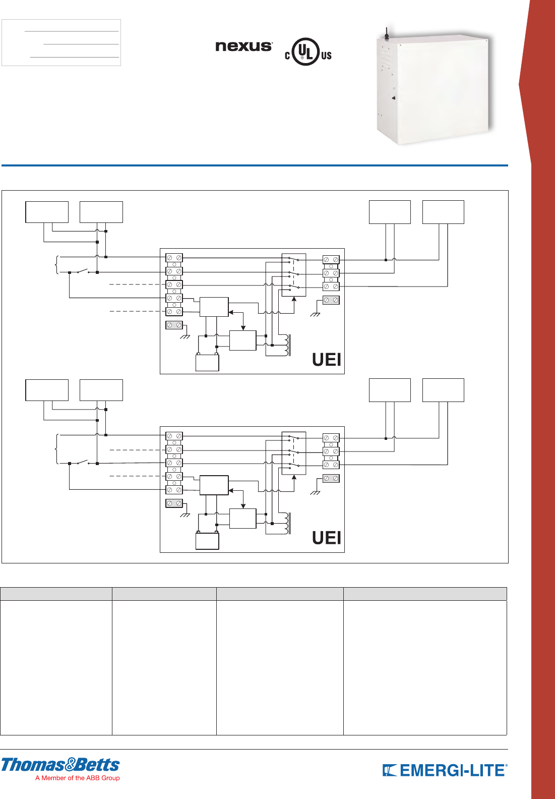
125
CENTRAL & INVERTER
SYSTEMS
TYPE:
CATALOG #:
NOTES:
Mini-Inverter Series
Interruptible Unit Equipment
Wiring Diagram
(PHUJHQF\
IL[WXUH
9DF
(PHUJHQF\
IL[WXUH
9DFVZLWFKHG
85*(1&<9
&20021
+279
9DF6:,7&+('+27
&20021
9DF816:,7&+('+27
1RUPDO
IL[WXUH
1RUPDO
IL[WXUH
9DF
3URSRVDO,QVWDOODWLRQ8(,B5HY
&KDUJHU
%DWWHU\
,QYHUWHU
9DF816:,7&+('+27
9DF6:,7&+('+27
,QYHUWHU
&75/
5HOD\&75/
(PHUJHQF\
IL[WXUH
9DFVZLWFKHG
(PHUJHQF\
IL[WXUH
9DF
+279
&20021
85*(1&<9
9DF6:,7&+('+27
&20021
9DF816:,7&+('+27
1RUPDO
IL[WXUH
1RUPDO
IL[WXUH
9DF
&KDUJHU
%DWWHU\
,QYHUWHU
9DF816:,7&+('+27
9DF6:,7&+('+27
,QYHUWHU
&75/
5HOD\&75/
Common
Common
HOT 120V
HOT 120V
EMERGENCY ONLY 277V
EMERGENCY ONLY 277V
How to Order
SERIES BATTERY TYPE/CAPACITY VOLTAGE OPTIONS
EMIU -125= 125W
-250= 250W
-400= 400W
-720= 720W
-MT= (120/120 or 277/277)* -NEX= Nexus® wired
-NEXRF= Nexus® wireless
-D3= Time Delay (15 minutes)
-T= Recessed T-Bar mounting (125W unit only)
-AD= Advanced-Diagnostic, audible*
-ML= Mix normally on and off loads
-SAC= Service Alarm Contact**
* Minimum load required: 10% of unit capacity
** Not available with 720 capacity
Example: EMIU-720-1
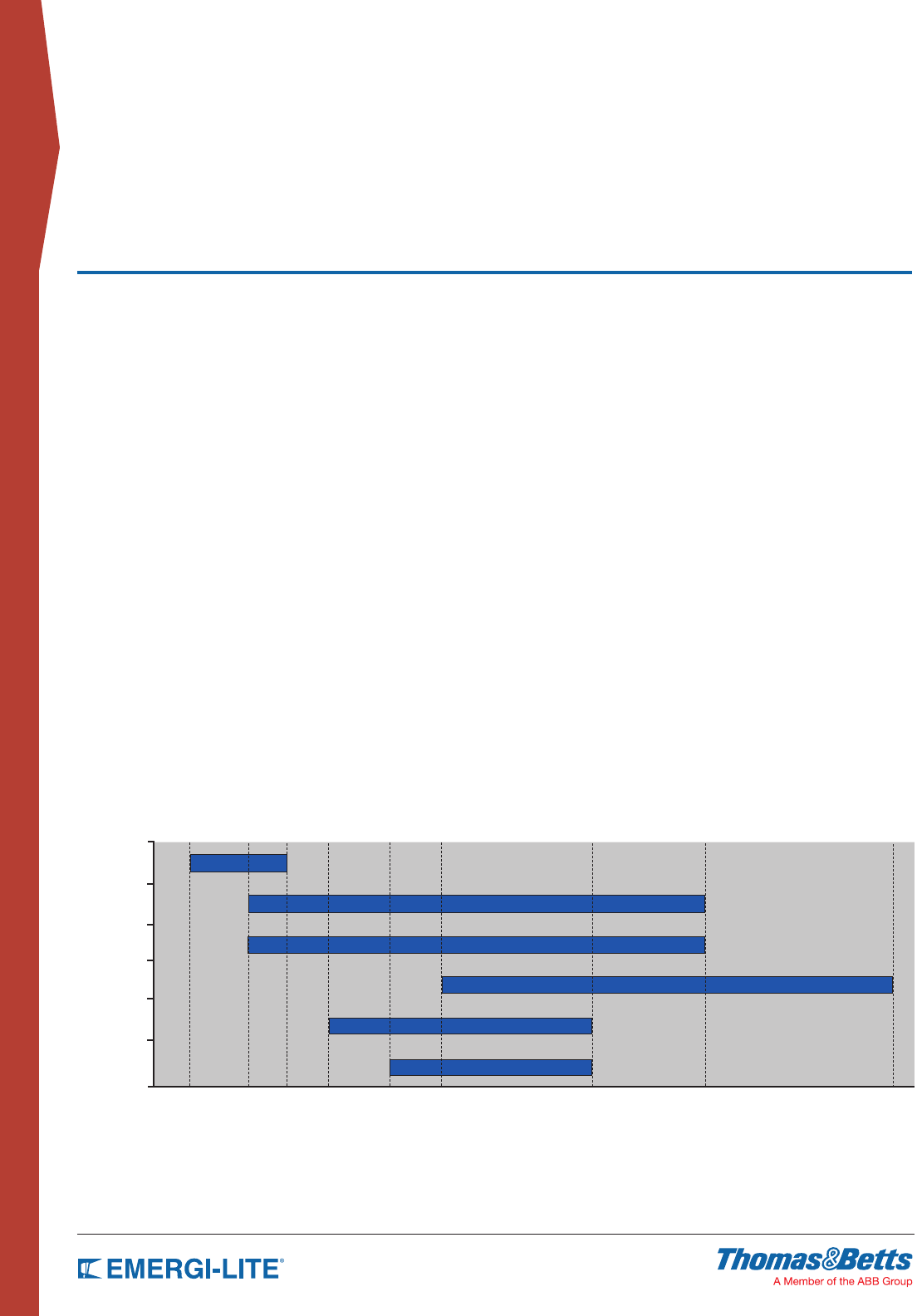
126
CENTRAL & INVERTER
SYSTEMS
EMERG-POWER SYSTEMS
Features & Benefits
Highlights
PERFORMANCE
Emerg-Power Systems work with any type of lighting load to provide full light
output for a minimum of 90 min. They are designed to support incandescent,
uorescent, HID*, quartz re-strike, LED or halogen lamps. They will work to
power into these loads at cold starts for all normally off circuits or normally on
circuits.
* Except IPS systems
TRUE SINE WAVEFORM
Using a solid-state, pulse width modulation (PWM) inverter the systems
produce pure sinusoidal output waveform with less than 3% maximum
Total Harmonic Distortion (THD) for linear loads. Microprocessor and crystal
controlled.
RELIABILITY
Emerg-Power Systems use third generation inverter technology. The proven
solid design and double ratings of all critical components. LVD (Low Voltage
Disconnect) for long power outages eliminates battery drain.
BATTERIES
Front access connections for easy installation significantly reduce the footprint,
installation and maintenance time while increasing safety. Automatic restart and
recharge upon restoration of utility.
APPROVALS
UL listed to UL924. Meets UL 924 Listed, NFPA101, NFPA70, NFPA 110,
OSHA, UBC, SBCCI.
New York City approved.
Compact Series
1PH IPS
1PH FTC
3PH FTC
Outdoor 1 PH FTC
Outdoor 3 PH
FTC
System type
APPLICATIONS
Emerg-Power Systems can be used in almost every type of building, and are
well-suited for architecturally sensitive applications or areas where maintenance
costs and individual testing of unit equipment becomes significant.
Emerg-Power Systems are designed to work with power factor corrected as
well as the most recent T5 and T5-HO electronic ballasts.
OPTIONS
The full range of options available, such as integrated output circuit breakers,
bypass relays, dry contacts, etc., makes Emerg-Power Systems an industry
leader in emergency lighting central systems.
500VA 1500VA 2000VA 3KVA 4KVA 4.8KVA 8KVA 16.7KVA 50KVA
Capacity (KVA=KW)
127
CENTRAL & INVERTER
SYSTEMS
EMERG-POWER SYSTEMS
Features & Benefits
Features
SELF-DIAGNOSTIC/SELF-TESTING
• Programmable monthly and annual self-testing. Proven self-diagnostic with
over 120 parameters stored in separate memory logs for Test, Event and
Alarm.
• Microprocessor monitoring and control.
LOW HEAT DISSIPATION
• Very low heat loss technology in normal operating mode (see specications
for exact values). Convection cooling in normal mode with forced air during
emergency mode.
• Battery cabinets: convection cooling only.
MAXIMUM EFFICIENCY
• Highest efciency in the industry, 98% at 100% load with no requirement for
cooling in normal operating mode.
• Low input harmonic distortion <10%.
VERSATILE INSTALLATION
• Modular design, easy front access freestanding cabinets, fasten together
when more than one cabinet is required.
• Optional seismic kit available.
• All wiring provided is pre-cut and terminated, along with the necessary
hardware and electrical fittings, for proper installation.
COMPLETE PROTECTION
• Input circuit breaker and fused battery circuit are standard.
• Systems offer overload capacity, short-circuit protection, current-limiting,
low-battery disconnect, reverse polarity and brownout protection as
standard.
THERMAL PERFORMANCE
• Bonded n heat sink technology for maximum thermal performance.
• Cooling fans are energized only in inverter mode.
MONITORING AND CONTROL
• User-friendly programmable interface with LED indicators and LCD display
provides full metering values, easy program and control functions and a wide
range of visual and audible alarms.
Benefits
COMPLIANCE WITH NFPA101
• Self-testing meets the requirements of NFPA and UL. User programmable
time of testing.
• Test results, events and alarms can be downloaded from history logs. Load
monitoring. Reduced testing/service time.
LESS AIR-CONDITIONING
• Reduced costs for air-conditioning required to ensure the optimum
operating temperature when compared with equivalent systems that
dissipate much more heat.
• Higher reliability of fans and the electronic components.
LOWER ENERGY BILLS
• Low consumption of the system itself will result in lower energy bills paid
over the system life time. Comparative analysis available on request.
EASY TO INSTALL
• Quick installation and connection through exible cable entries and fast
access terminal blocks.
• Reduced footprint for systems with stackable cabinets.
• Low MTTR (<15 min.) due to modular design, quick disconnect means and
frontal access.
REDUCED DAMAGE RISKS
• Full system protection eliminates damage created by external events and
increases the lifetime of the electronics and batteries. Also will provide safety
during maintenance.
INCREASED MTBF
• Increased reliability and reduced preventative maintenance.
• No air lters needed.
EASY MAINTENANCE
• Easier diagnostic, troubleshooting, preventative maintenance and service
through the indicators and display or by using the history logs.
• Remote versions available.
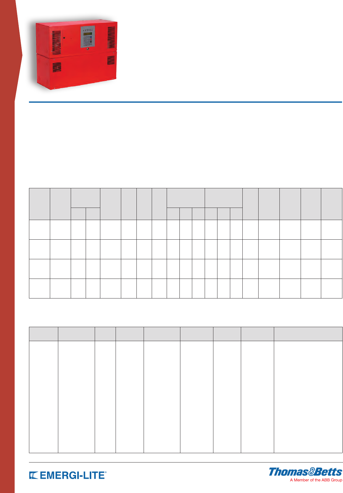
128
CENTRAL & INVERTER
SYSTEMS
How to Order
INPUT
VOLTAGE* BATTERY TYPE VA/W SYSTEM
TYPE
OUTPUT
VOLTAGE* RUN TIME* INPUT
BREAKER
OUTPUT
BREAKERS* OPTIONS*
120
277
SG= Lead-Calcium 500
1000
1500
2000
-FTCM -120
-277
-90 -ICB -OCBxxxx=
No trip alarm*
-OCAxxxx=
With trip alarm*
-NOFF= Normally OFF output
-WB= Wall mount bracket
-DCS= Dry summary alarm contacts
-INVON= Inverter on dry contact
-VTD= Variable time delay
-BPR= Bypass relay
-RMP= Remote metering panel
-RSAP= Remote summary alarm panel
-RS232= Communication interface
-MOD= Modem
-FLR= Floor blanket
* Special voltages
may change
the size, weight
or number of
cabinets
* Special voltages may
change the size, weight
or number of cabinets
* Other run times
available
* Max. 3 more
additional output
breakers for a total
of 4. See page 137
for output breakers
details. * See page 137 for options description
Example: 120SG1500-FTCM-120-90-ICB-OCB0420-WB
Emerg-Power Systems
Compact Series
• 90 min. standard run time
• Electronic and magnetic ballast compatible
• Automatic event, test and alarm log
• LCD display
• Small footprint (stackable cabinets)
• Maintenance-free standard batteries
• Forced air cooling during emergency mode only
UL listed to UL924. Meets NFPA101, NFPA70, NFPA 110, OSHA, UBC, SBCCI. N.Y City approved.
Features
• 98% efcient at full load
• PWM/MOSFET technology
• Self-testing/Self-diagnostic
• User programmable with password protection
• Standard input circuit breaker
• Standard output circuit breaker
• Micro-processor controlled
• Floor or wall mountable
• Field upgradeable (500VA steps)
Electrical/Mechanical Characteristics4
(data provided for standard Lead Calcium batteries)1,4
POWER
RATING1
VA= W
EFFIC.
AT FULL
LOAD
%
MAX. INPUT
CURRENT (A)
HEAT
LOSS IN
NORMAL
MODE
(BTU/HR)
BATT.
VDC
BATT.
A
NO. OF
BATT.
UPS CABINET
DIMENSIONS
BATTERY CABINET
DIMENSIONS2,3 NO. OF
BATT
CAB.
BATT.
CAB.
WEIGHT
LBS
UPS CAB.
WEIGHT
LBS
BATT.
WEIGHT
LBS
TOTAL
SYSTEM
WEIGHT
LBS
120V 277V W” H” D” W” H” D”
500 98 5.2 2.3 34 48 13.5 4 26 10 10 26 10 10 1 22 lbs 77 lbs 107 lbs 206 lbs
1000 98 10.5 4.5 68 48 26.5 8 26 10 10 26 10 10 2 22 lbs 77 lbs 214 lbs 335 lbs
1500 98 15.6 6.8 102 48 40 12 26 10 10 26 10 10 3 22 lbs 77 lbs 321 lbs 464 lbs
2000 98 20.8 9 136 48 52 16 26 10 10 26 10 10 4 22 lbs 77 lbs 428 lbs 592 lbs
1 System capacity can be upgraded in the field up to 2000VA by adding more battery cabinets.
Re-programming required by factory service technician.
2 Batteries are installed in separate modular cabinets
3 Battery cabinets are stackable. Must be installed under the electronics cabinet
4 Special voltages can change the size, weight or number of cabinets
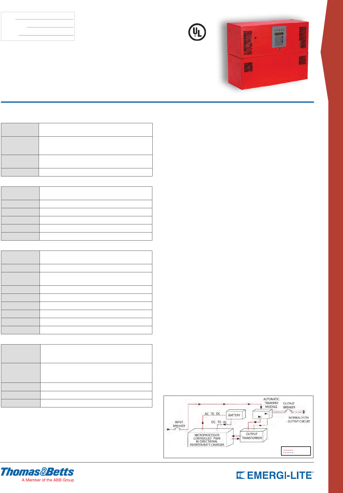
129
CENTRAL & INVERTER
SYSTEMS
TYPE:
CATALOG #:
NOTES:
Uninterruptible Emergency Lighting, 1PH,
Inverter System 500VA – 2000VA
System Specifications
GENERAL
Design Stand-by no break. PWM inverter type utilizing
MOSFET technology with 2ms transfer time
Control
•
Microprocessor controlled, 2 x 20-character
display with touch pad controls & functions
• 5 LED indicators & alarm with ring-back feature
Metering Input & Output Voltage, Battery Voltage, Battery & Output
Current, Output VA, Temperature, Inverter Wattage
Communications Optional RS-232 port (DB9)
ELECTRICAL INPUT
Voltage 120 or 277VAC, 1-phase 2-wire, +10%/ -15%
Contact factory for all other voltage.
Input Power Walk-In Limiting inrush current to less than 125%, 10 times for 1 line cycle
Input Frequency 60Hz, +/-3Hz
Protection Standard Input Circuit Breaker
Harmonic Distortion <10%
Power Factor 0.5 lag/lead
ELECTRICAL OUTPUT
Voltage 120 or 277VAC, 1-phase 2-wire
Contact factory for all other voltage.
Static Voltage Load current change +/-2%, battery discharge +/-12.5%
Dynamic Voltage +/-2% for +/-25% load step change, +/-3% for a
50% load step change, recovery within 3 cycles
Harmonic Distortion <3% THD for linear load
Output Frequency 60Hz +/- 0.05Hz during emergency mode
Load Power Factor 0.5 lag to 0.5 lead
Inverter Overload 115% for 5 minutes
Protection Standard Output Circuit Breaker (normally on)
Crest Factor 2.8
ENVIRONMENTAL CONDITIONS
Storage/Transport
• -4ºF to 158ºF (-20ºC to 70ºC) without batteries
• 0ºF to 104ºF (-18ºC to 40ºC) with batteries
(max. 3 months at 104° F (40° C)
Operating
Temperature
System operates safely from 32°F to 104°F (0°C to 40°C)
but optimum operation is between 68° F and 86°F (20°C to
30°C). Battery performance can be affected by temperature
Altitude <10,000 feet (above sea level) without de-rating
Relative Humidity 0 to 95% non-condensing
Audible Noise 45 dBA @ 1m from surface in emergency mode
CABINETS
Modular design, freestanding or wall mount NEMA Type 1 steel cabinets powder
coated for corrosion and scratch resistance. Front access design. Cabinets are
stackable. Top and left side conduit entry with knockouts.
INVERTER
Using MOSFET/PWM technology the inverter converts the DC voltage supplied by
the batteries to AC voltage of a precise stabilized amplitude and frequency, suitable
for most sophisticated electrical equipment. True sinusoidal output waveform with
very low distortion (less than 3% for linear loads). Overload capability of up to
150% for 12 line cycles.
CHARGER
Fully automatic, temperature compensated, microprocessor controlled charger
recharges fully discharged batteries in maximum 24 hours at nominal AC input
voltage. AC input current limiting and over-voltage protection included.
BATTERY
System is provided with 10 year, maintenance free, sealed valve regulated Lead-
Calcium batteries. 90 min. standard discharge time at full load under normal
operating temperature. Low Voltage Disconnect protection included. No special
ventilation required.
SELF-DIAGNOSTIC
Automatic self-test consists of a 5-minute monthly and 90-minute annual function.
The front-mounted control panel includes 5 LED indicators, a 2-line 20-character
LCD display, a keypad to control and monitor the internal operation of the system.
This allows the operator to easily “watch” system functions as they occur and
check on virtually any aspect of the system’s operation. Self-diagnostic function
monitors, controls, generates alarms and memorizes events.
ALARMS
High/Low Battery Charger Voltage, High/Low AC Input Voltage, Near Low Battery,
Low Battery, Load Reduction Fault, Output Overload, High Ambient Temperature,
Inverter Fault, Output Fault, Optional Output Circuit Breaker Trip
OPTIONAL FEATURES
Normally OFF output, Output Circuit Breakers, Output Trip Alarm, RS232
communication port, 12 Hours Fast Recharge, Remote Meter Panel, Remote
Summary Alarm Panel, Summary Alarm Dry Form C Contact, Inverter on Dry
Contacts, Variable Time Delay, Modem, Bypass Relays, Wall mount bracket
FACTORY START-UP
Includes one additional year of warranty. See warranty conditions.
WARRANTY
(full limited warranty conditions available upon request)
Limited manufacturer warranty is one-year, parts and labor, for system electronics
or two-year with factory start-up program. Battery warranty is one year full plus 9
years pro-rata for a total of 10 years, under normal operating conditions.
System must be put in service within 180 days from ship date in order to validate
warranty.
NORMAL
EMERGENCY
Characteristics, specifications and dimensions subject to change without notice.
SINGLE LINE DIAGRAM
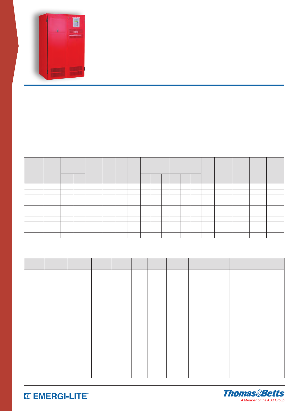
130
CENTRAL & INVERTER
SYSTEMS
Emerg-Power Systems IPS
Single Phase Series
How to Order
INPUT
VOLTAGE*
BATTERY
TYPE VA/W RATING SYSTEM
TYPE
OUTPUT
VOLTAGE*
RUN
TIME*
INPUT
BREAKER RS232 PORT OUTPUT BREAKERS* OPTIONS*
120
208
240
277
SG= Sealed
Lead-Calcium
NC= Wet
Ni-Cd
1500
2250
3000
3750
5000
6000
8000
10000
12500
16700
-IPS -120
-277
-208
-120/140
-120/277
-90 -ICB -RS232 -OCBxxxx = no trip alarm*
-OCAxxxx = with trip
alarm*
-20Y= 20 yr sealed batteries
-12HR= 12 hr fast recharge
-MBYP= Internal bypass switch
-EMBP= External bypass switch**
-RMP= Remote metering panel
-RSAP= Remote summary
alarm panel
-DCS= Dry summary alarm contacts
-INVON= Inverter on dry contacts
-VTD= Variable time delay
-MOD= External modem
-FAX= Fax modem
-BPR= Bypass relays
-DIAL= Autodialer
-SEIS= Seismic mounting
-ZONEM= Zone monitoring
-BATM= Battery cycle
warranty monitor
*
Special
voltages may
change the
size, weight
or number of
cabinets
* Special
voltages may
change the
size, weight
or number of
cabinets
*
Other
run times
available
* Max. 12 unsupervised single pole
positions or 8 with trip alarm.
For more output breakers please
consult factory. See page 137 for
output breakers option details.
* See page 137 for options description
** External bypass switch is not compatible with
integrated output circuit breakers. Input/output
voltage has to be the same.
Example: 277SG6000-IPS-277-90-ICB-RS232-OCB0420-DCS-20Y
• 90 min. standard run time
• Generator compatibility
• Electronic and magnetic ballast compatible
• Custom voltages available
• Automatic event, test and alarm log
• LCD display
• Reduced footprint (stackable cabinets)
• Maintenance free standard batteries
• Forced air cooling during emergency mode only
UL listed to UL924. Meets NFPA101, NFPA70, NFPA 110, OSHA, UBC, SBCCI. N.Y City approved.
Features
• 98% efcient at full load
• PWM/IGBT technology
• Self-testing/Self-diagnostic
• User programmable with password protection
• Standard input circuit breaker
• Standard Normally Off and on output
• RS232 communication port
• Micro-processor controlled
• Automatic event and alarm log
Electrical/Mechanical Characteristics4
(Data provided for standard Lead Calcium batteries)1,
POWER
RATING1
KVA= KW
EFFIC.
AT FULL
LOAD
%
MAX. INPUT
CURRENT (A)
HEAT
LOSS IN
NORMAL
MODE
(BTU/HR)
BATT.
VDC
BATT.
A
NO. OF
BATT.
UPS CABINET
DIMENSIONS
BATTERY CABINET
DIMENSIONS2, 3 NO. OF
BATT
CAB.
BATT.
CAB.
WEIGHT
LBS
(EMPTY)
UPS CAB.
WEIGHT
LBS
BATT.
WEIGHT
LBS
TOTAL
SYSTEM
WEIGHT
LBS
120V 277V W” H” D” W” H” D”
1.5 98 16 7 102 48 39 4 30 47 25 NA NA NA NA NA 250 lbs 296 lbs 546 lbs
2.25 98 24 11 153 72 38 6 30 47 25 NA NA NA NA NA 265 lbs 444 lbs 709 lbs
3 98 32 14 204 96 38 8 30 47 25 NA NA NA NA NA 295 lbs 592 lbs 887 lbs
3.75 98 39 17 255 120 37 10 30 47 25 NA NA NA NA NA 305 lbs 740 lbs 1045 lbs
5 98 50 22 340 144 40 12 30 47 25 NA NA NA NA NA 315 lbs 888 lbs 1203 lbs
6 98 63 27 408 180 40 15 30 47 25 30 47 25 1 210 lbs 350 lbs 1110 lbs 1670 lbs
8 98 84 36 544 240 39 20 30 47 25 30 47 25 1 232 lbs 375 lbs 1480 lbs 2087 lbs
10 98 105 45 680 144 82 24 30 47 25 30 47 25 2 420 lbs 435 lbs 1776 lbs 2631 lbs
12.5 98 131 57 850 180 82 30 30 47 25 30 47 25 2 420 lbs 465 lbs 2220 lbs 3105 lbs
16.7 98 174 76 1136 240 80 40 30 47 25 30 47 25 2 464 lbs 530 lbs 2960 lbs 3954 lbs
1 Consult factory for 20 year type batteries or for wet nickel cadmium batteries.
2 Batteries are installed in the electronics cabinet for 1.5 to 5kVA systems
3 Battery cabinets are stackable. To be installed on the right side of the electronics cabinet
4 Special voltages or batteries may change the size, weight or number of cabinets

131
CENTRAL & INVERTER
SYSTEMS
TYPE:
CATALOG #:
NOTES:
Interruptible Emergency Lighting
Inverter System 1.5Kva –16.7Kva
System Specifications
GENERAL
Design Stand-by. PWM inverter type utilizing IGBT
technology with 50ms transfer time.
Control
•
Microprocessor controlled , 2 x 20-character
display with touch pad controls & functions
•5 LED indicators & alarm with ring-back feature
Metering Input & Output Voltage, Battery Voltage, Battery & Output
Current, Output VA, Temperature, Inverter Wattage
Communications RS-232 port (DB9)
ELECTRICAL INPUT
Voltage 120 or 277VAC 1-phase 2-wire +10% - 15%.
Contact factory for all other voltages
Input Power Walk-In Limiting inrush current to less than 125%, 10 times for 1 line cycle
Input Frequency 60Hz, +/-3%, 50Hz available upon request
Protection Input circuit breaker
Harmonic Distortion <10%
Power Factor 0.5 lag/lead
ELECTRICAL OUTPUT
Voltage 120 or 277VAC 1-phase 2-wire.
Contact factory for all other voltages.
Static Voltage Load current change +/-2%, battery discharge +/-12.5%
Dynamic Voltage +/-2% for +/-25% load step change
+/-3% for a 50% load step change, recovery within 3 cycles
Harmonic Distortion <3% THD for linear load
Output Frequency 60Hz +/- 0.05Hz during emergency mode
Load Power Factor 0.5 lag to 0.5 lead
Inverter Overload 115% for 10 minutes, 150% for 16 line cycles
Protection Optional Distribution Circuit Breaker
Crest Factor 2.8
ENVIRONMENTAL CONDITIONS
Storage/Transport
•-4ºF to 158ºF (-20ºC to 70ºC) without batteries
• 0ºF to 104ºF (-18ºC to 40ºC) with batteries
(max. 3 months at 104° F (40° C)
Operating
Temperature
System operates safely from 32°F to 104°F (0°C to 40°C)
but optimum operation is between 68° F and 86°F (20°C to
30°C). Battery performance can be affected by temperature
Altitude <10,000 feet (above sea level) without de-rating
Relative Humidity 0 to 95% non-condensing
Audible Noise Audible noise 45 dBA @ 1m from surface in emergency mode
CABINETS
Modular design, freestanding NEMA Type 1 steel cabinets powder coated for
corrosion and scratch resistance. Front access design through hinged lockable
doors requires only 39” front clearance and 12” top clearance. Cabinets are
stackable if required to further reduce the footprint. Top and left side conduit entry
with knockouts.
INVERTER
Using IGBT/PWM technology the inverter converts DC voltage supplied by the
batteries to AC voltage of a precise stabilized amplitude and frequency, suitable
for most sophisticated electrical equipment. True sinusoidal output waveform with
very low distortion (less than 3% for linear loads). Overload capability of up to
150% for 12 line cycles.
CHARGER
Fully automatic, temperature compensated, microprocessor controlled charger
recharges fully discharged batteries in maximum 24 hours at nominal AC input
voltage. AC input current limiting and over-voltage protection included.
BATTERY
System is provided standard with 10 year, maintenance free, sealed valve
regulated, front terminals Lead-Calcium batteries. 20 year sealed Lead-Calcium
or wet Nickel-Cadmium batteries also available. 90 min. standard discharge time at
full load under normal operating temperature. Low Voltage Disconnect protection
included. No special ventilation required.
SELF-DIAGNOSTICS
Automatic self tests consist of a 5-minute monthly and 90-minute annual function.
The front-mounted control panel includes 5 LED indicators, a 2-line 20-character
LCD display, a keypad to control and monitor the internal operation of the system.
This allows the operator to easily “watch” system functions as they occur and
check on virtually any aspect of the system’s operation.
Standard RS232 diagnostic interface.
ALARMS
High/Low Battery Charger Voltage, High/Low AC Input Voltage, Near Low Battery,
Low Battery, Load Reduction Fault, Output Overload, High Ambient Temperature,
Inverter Fault, Output Fault, Optional Output Circuit Breaker Trip
OPTIONAL FEATURES
Output Circuit Breakers, Output Trip Alarms, 20 Years Sealed Batteries, 12 Hours
Fast Recharge, Internal/External Maintenance Bypass Switch, Remote Meter
Panel, Remote Summary Alarm Panel, Summary Alarm Dry Form C Contact,
Inverter on Dry Contacts, Fax/Modem, Bypass Relays, Auto Dialer, Seismic
Mounting.
FACTORY START-UP
Includes one additional year of warranty. See warranty conditions.
WARRANTY
(full limited warranty conditions available upon request)
Limited manufacturer warranty is one-year, parts and labor, for system electronics
or two-year with factory start-up program. Battery warranty is one year full plus 9
years pro-rata for a total of 10 years, under normal operating conditions. System
must be put in service within 6 months from ship date in order to validate warranty.
2-Consult factory for other type batteries than the standard one.
SINGLE LINE DIAGRAM
Output breakers are optional
Characteristics, specifications or dimensions subject to change without notice.
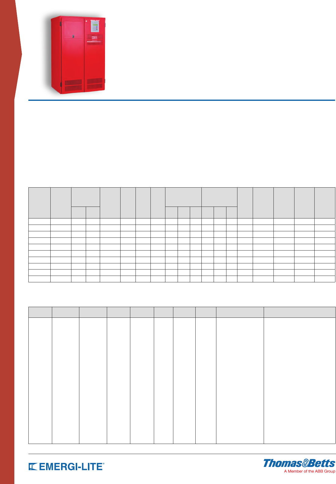
132
CENTRAL & INVERTER
SYSTEMS
Emerg-Power Systems
FTC Single Phase Series
• Generator compatibility
• Electronic and magnetic ballast compatible
• Custom voltages available
• Automatic event, test and alarm log
• LCD display
• Reduced footprint (stackable cabinets)
• Maintenance free standard batteries
• Forced air cooling during emergency mode only
UL listed to UL924. Meets NFPA101, NFPA70, NFPA 110, OSHA, UBC, SBCCI. N.Y City approved.
Features
• 98% efcient at full load
• PWM/IGBT technology
• Self-testing/Self-diagnostic
• User programmable with password protection
• Standard input circuit breaker
• RS232 communication port
• Micro-processor controlled
• Automatic event and alarm log
• 90 min. standard run time
How to Order
INPUT
VOLTAGE*
BATTERY
TYPE VA/W RATING SYSTEM
TYPE
OUTPUT
VOLTAGE*
RUN
TIME*
INPUT
BREAKER
RS232
PORT OUTPUT BREAKERS* OPTIONS*
120
208
240
277
SG= Sealed
Lead-Calcium
NC= Wet
Nickel-
Cadmium
1500
2250
3000
3750
5000
6000
8000
10000
12500
16700
-FTC -120
-277
-208
-120/140
-120/277
-90 -ICB -RS232 OCBxxxx= no trip alarm*
OCAxxxx= with trip alarm*
-20Y= 20 yr sealed batteries
-12HR= 12 hr fast recharge
-MBYP= internal bypass switch
-EMBP= external bypass switch**
-RMP= remote metering panel
-RSAP= remote summary alarm panel
-DCS= dry summary alarm contacts
-INVON= inverter on dry contacts
-NOFF= normally OFF output***
-MOD= external modem
-FAX= fax modem
-BPR= bypass relays
-DIAL= autodialer
-SEIS= seismic mounting
-ZONEM= zone monitoring
-BATM= battery cycle warranty monitor
* Special
voltages may
change the
size, weight
or number of
cabinets
*
Special
voltages may
change the
size, weight
or number of
cabinets
*
Other
run times
available
*
Max. 12 unsupervised single pole
positions or 8 with trip alarm.
For more output breakers please
consult factory. See page 181 for
output breakers option details.
* See page 137 for options description
** External bypass switch is not compatible with
integrated output circuit breakers. Input/output
voltage has to be the same.
*** Normally off loads cannot exceed 20% of total KVA
rating with any combination of H.I.D. loads
Example: 277SG6000-FTC-277-90-ICB-RS232-OCB0420-DCS-20Y
Electrical/Mechanical Characteristics4
(Data provided for standard Lead Calcium batteries)1,4
POWER
RATING1
KVA= KW
EFFIC.
AT FULL
LOAD
%
MAX. INPUT
CURRENT (A)
HEAT
LOSS IN
NORMAL
MODE
(BTU/HR)
BATT.
VDC
BATT.
A
NO. OF
BATT.
UPS CABINET
DIMENSIONS
BATTERY CABINET
DIMENSIONS2, 3 NO. OF
BATT
CAB.
BATT.
CAB.
WEIGHT
LBS
(EMPTY)
UPS CAB.
WEIGHT
LBS
BATT.
WEIGHT
LBS
TOTAL
SYSTEM
WEIGHT
LBS
120V 277V W” H” D” W” H” D”
1.5 98 16 7 102 48 39 4 30 47 25 NA NA NA NA NA 250 lbs 296 lbs 546 lbs
2.25 98 24 11 153 72 38 6 30 47 25 NA NA NA NA NA 265 lbs 444 lbs 709 lbs
3 98 32 14 204 96 38 8 30 47 25 NA NA NA NA NA 295 lbs 592 lbs 887 lbs
3.75 98 39 17 255 120 37 10 30 47 25 NA NA NA NA NA 305 lbs 740 lbs 1045 lbs
5 98 50 22 340 144 40 12 30 47 25 NA NA NA NA NA 315 lbs 888 lbs 1203 lbs
6 98 63 27 408 180 40 15 30 47 25 30 47 25 1 210 lbs 350 lbs 1110 lbs 1670 lbs
8 98 84 36 544 240 39 20 30 47 25 30 47 25 1 232 lbs 375 lbs 1480 lbs 2087 lbs
10 98 105 45 680 144 82 24 30 47 25 30 47 25 2 420 lbs 435 lbs 1776 lbs 2631 lbs
12.5 98 131 57 850 180 82 30 30 47 25 30 47 25 2 420 lbs 465 lbs 2220 lbs 3105 lbs
16.7 98 174 76 1136 240 80 40 30 47 25 30 47 25 2 464 lbs 530 lbs 2960 lbs 3954 lbs
1 Consult factory for 20 year type batteries or for wet nickel cadmium batteries.
2 Batteries are installed in the electronics cabinet for 1.5 to 5kVA systems
3 Battery cabinets are stackable. To be installed on the right side of the electronics cabinet
4 Special voltages or batteries may change the size, weight or number of cabinets
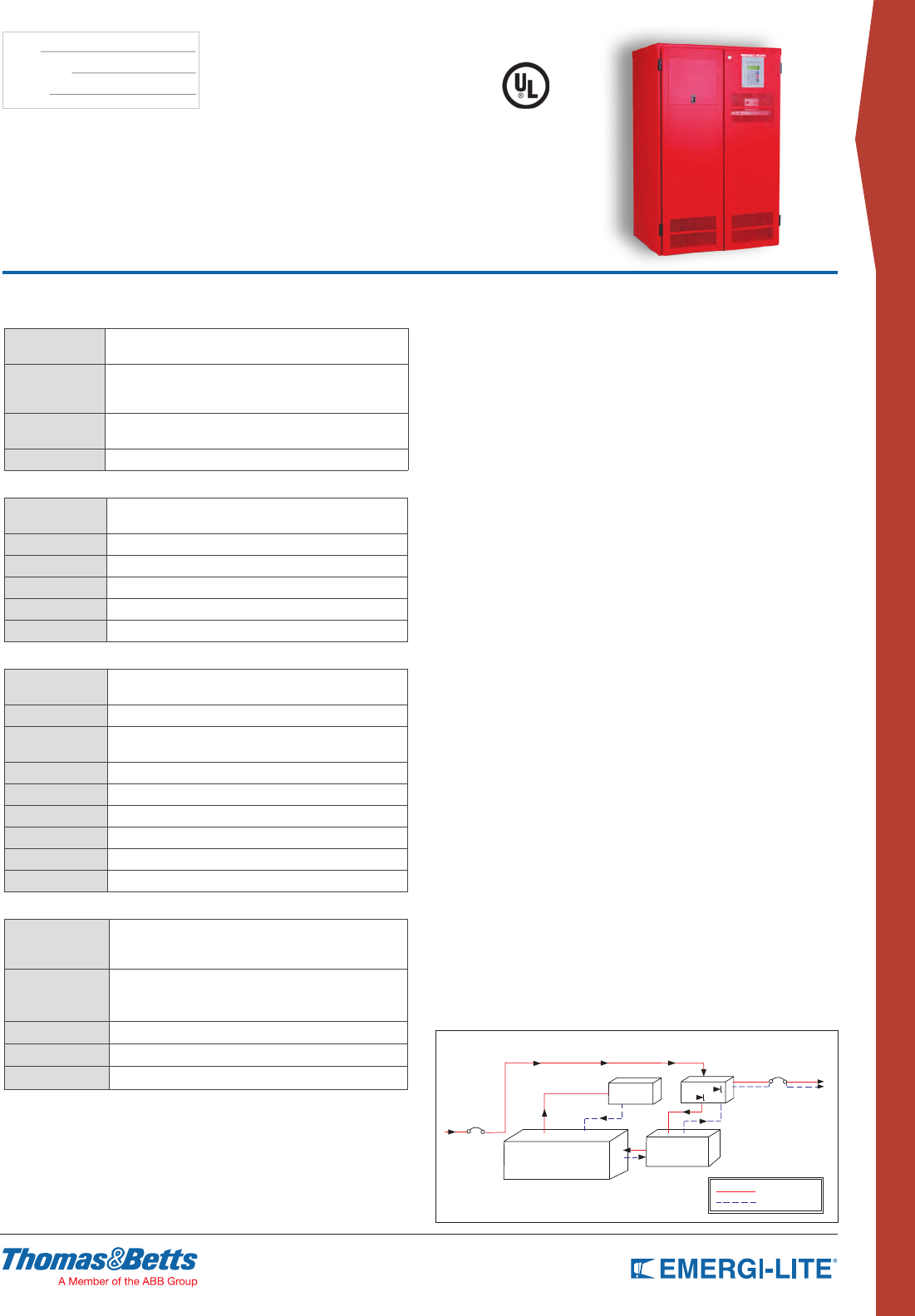
133
CENTRAL & INVERTER
SYSTEMS
TYPE:
CATALOG #:
NOTES:
System Specifications
GENERAL
Design Stand-by. PWM inverter type utilizing IGBT
technology with 2ms transfer time
Control
•
Microprocessor controlled , 2 x 20-character
display with touch pad controls & functions
• 5 LED indicators & alarm with ring-back feature
Metering Input & Output Voltage, Battery Voltage, Battery & Output
Current, Output VA, Temperature, Inverter Wattage
Communications RS-232 port (DB9)
ELECTRICAL INPUT
Voltage 120 or 277VAC 1-phase 2-wire +10% - 15%.
Contact factory for all other voltages
Input Power Walk-In Limiting inrush current to less than 125%, 10 times for 1 line cycle
Input Frequency 60Hz, +/-3%, 50Hz available upon request
Protection Input Circuit Breaker
Harmonic Distortion <10%
Power Factor 0.5 lag/lead
ELECTRICAL OUTPUT
Voltage 120 or 277VAC 1-phase 2-wire.
Contact factory for all other voltages.
Static Voltage Load current change +/-2%, battery discharge +/-12.5%
Dynamic Voltage +/-2% for +/-25% load step change
+/-3% for a 50% load step change, recovery within 3 cycles
Harmonic Distortion <3% THD for linear load
Output Frequency 60Hz +/- 0.05Hz during emergency mode
Load Power Factor 0.5 lag to 0.5 lead
Inverter Overload 115% for 10 minutes, 125% for 5 minutes, 150% for 12 cycles
Protection Optional Distribution Circuit Breakers
Crest Factor 2.8
ENVIRONMENTAL CONDITIONS
Storage/Transport
• -4ºF to 158ºF (-20ºC to 70ºC) without batteries
• 0ºF to 104ºF (-18ºC to 40ºC) with batteries
(max. 3 months at 104° F (40° C)
Operating
Temperature
System operates safely from 32°F to 104°F (0°C to 40°C)
but optimum operation is between 68° F and 86°F (20°C to
30°C). Battery performance can be affected by temperature
Altitude <10,000 feet (above sea level) without de-rating
Relative Humidity 0 to 95% non-condensing
Audible Noise Audible noise 45 dBA @ 1m from surface in emergency mode
Uninterruptible Emergency Lighting
Inverter System 1.5KVA –16.7KVA
CABINETS
Modular design, freestanding NEMA Type 1 steel cabinets powder coated for
corrosion and scratch resistance. Front access design through hinged lockable
doors requires only 39” front clearance and 12” top clearance. Cabinets are
stackable if required to further reduce the footprint. Top and left side conduit entry
with knockouts.
INVERTER
Using IGBT/PWM technology the inverter converts the DC voltage supplied by the
batteries to AC voltage of a precise stabilized amplitude and frequency, suitable
for most sophisticated electrical equipment. True sinusoidal output waveform with
very low distortion (less than 3% for linear loads). Overload capability of up to
150% for 12 line cycles.
CHARGER
Fully automatic, temperature compensated, microprocessor controlled charger
recharges fully discharged batteries in maximum 24 hours at nominal AC input
voltage. AC input current limiting and over-voltage protection included.
BATTERY
System is provided standard with 10 year, maintenance free, sealed valve
regulated, front terminals Lead Calcium batteries. 20 year sealed Lead Calcium or
wet Nickel Cadmium batteries also available. 90 min. standard discharge time at
full load under normal operating temperature. Low Voltage Disconnect protection
included. No special ventilation required.
SELF-DIAGNOSTICS
Automatic self tests consist of a 5-minute monthly and 90-minute annual function.
The front-mounted control panel includes 5 LED indicators, a 2-line 20-character
LCD display, and a keypad to control and monitor the internal operation of the
system. This control panel allows the operator to easily “watch” system functions
as they occur and check on virtually any aspect of the system’s operation. Standard
RS232 diagnostic interface.
ALARMS
High/Low Battery Charger Voltage, High/Low AC Input Voltage, Near Low Battery,
Low Battery, Load Reduction Fault, Output Overload, High Ambient Temperature,
Inverter Fault, Output Fault, Optional Output Circuit Breaker Trip
OPTIONAL FEATURES
Output Circuit Breakers, Output Trip Alarms, 20 Years Sealed Batteries, 12 Hours
Fast Recharge, Internal/External Maintenance Bypass Switch, Remote Meter
Panel, Remote Summary Alarm Panel, Summary Alarm Dry Form C Contact,
Inverter on Dry Contacts, Normally OFF output, Fax/Modem, Bypass Relays, Auto
Dialer, Seismic Mounting.
FACTORY START-UP
Includes one additional year of warranty. See warranty conditions.
WARRANTY
(full limited warranty conditions available upon request)
Limited manufacturer warranty is one-year, parts and labor, for system electronics
or two-year with factory start-up program. Battery warranty is one year full plus 9
years pro-rata for a total of 10 years, under normal operating conditions. System
must be put in service within 6 months from ship date in order to validate warranty.
2-Consult factory for other type batteries than the standard one.
Output breakers are optional
INPUT
BREAKER
MICROPROCESSOR
CONTROLLED PWM
BI-DIRECTIONAL
INVERTER/BAT T. CHARGER
AC TO DC
DC TO AC
BATTERY
OUTPUT
TRANSFORMER
AUTOMATIC
TRANSFER
MODULE
OUTPUT
BREAKER
NORMALLY ON
OUTPUT CIRCUIT
Normally On Output Circuit
NORMAL
EMERGENCY
SINGLE LINE DIAGRAM
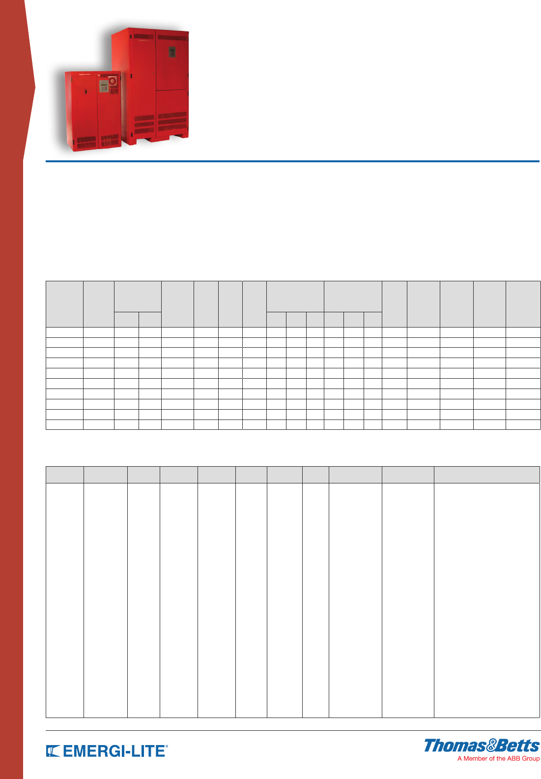
134
CENTRAL & INVERTER
SYSTEMS
Emerg-Power Systems
3FTC Three Phase Series
• 90 min. standard run time
• Generator compatibility
• Available in Y or ∆ input conguration
• Custom voltages available
• Automatic event, test and alarm log
• LCD display
• Reduced footprint
• Maintenance free standard batteries
• Forced air cooling during emergency only
UL listed to UL924. Meets NFPA101, NFPA70, NFPA 110, OSHA, UBC, SBCCI. N.Y City approved.
Features
• 98% efcient at full load
• PWM/IGBT technology
• Self-testing/Self-diagnostic
• User programmable with password protection
• Standard input circuit breaker
• Standard internal bypass switch
• RS232 communication port
• Micro-processor controlled
• Automatic event and alarm log
Electrical/Mechanical Characteristics4
(Data provided for standard Lead Calcium batteries)1,4
POWER
RATING1
KVA= KW
EFFIC.
AT FULL
LOAD
%
MAX. INPUT
CURRENT (A)
HEAT
LOSS IN
NORMAL
MODE
(BTU/HR)
BATT.
VDC
BATT.
A
NO. OF
BATT.
UPS CABINET
DIMENSIONS
BATTERY CABINET
DIMENSIONS3NO. OF
BATT
CAB.
BATT.
CAB.
WEIGHT
LBS
(EMPTY)
UPS CAB.
WEIGHT
LBS
BATT.
WEIGHT
LBS
TOTAL
SYSTEM
WEIGHT
LBS
120V/
208V
277V/
480V W” H” D” W” H” D”
4.8 98 17 7 326 144 39 12 30 47 25 30 47 25 1 NA 535 888 1633
6 98 21 9 408 180 39 15 30 47 25 30 47 25 1 NA 535 1110 1855
8 98 28 12 544 240 39 20 30 47 25 30 47 25 1 NA 535 1480 2247
10 98 35 15 680 144 81 24 30 47 25 30 47 25 2 NA 639 1776 2835
12.5 98 43 19 850 180 81 30 30 47 25 30 47 25 2 NA 639 2220 3279
16.7 98 58 25 1136 240 81 40 30 47 25 30 47 25 2 210 lbs 639 2960 4063
24 98 84 36 1632 240 117 60 48 72 31 48 72 31 1 232 lbs 1250 4440 6390
33 98 115 50 2244 240 160 40 48 72 31 48 72 31 2 420 lbs 1250 6080 8630
40 98 139 60 2720 240 194 100 48 72 31 48 72 31 2 420 lbs 1450 7400 10150
50 98 174 75 3400 240 243 60 48 72 31 48 72 31 2 464 lbs 1450 9120 11980
1 Consult factory for 20 year type batteries or for wet Nickel-Cadmium batteries.
2 KVA=KW
3 Battery cabinets up to 16.7KVA are stackable. To be installed on the right side of the electronics cabinet
4 Special voltages or batteries may change the size, weight or number of cabinets
How to Order
INPUT
VOLTAGE*
BATTERY
TYPE
VA/W
RATING
SYSTEM
TYPE
OUTPUT
VOLTAGE*
RUN
TIME*
INPUT
BREAKER
RS232
PORT
INTERNAL
BYPASS SWITCH
OUTPUT
BREAKERS* OPTIONS*
120/208
277/480
SG= Sealed
Lead-Calcium
NC= Wet
Ni-Cd
4800
6000
8000
10000
12500
16700
24000
33000
40000
50000
-3FTC 120/208
277/480
90 ICB RS232 MBYP OCBxxxx= no
trip alarm*
OCAxxxx= with
trip alarm*
-20Y= 20 yr sealed batteries
-12HR= 12 hr fast recharge
-NOFF= normally off output 1PH**
-EMBP= external bypass switch***
-RMP= remote metering panel
-RSAP= remote summary
alarm panel
-DCS= dry summary alarm contacts
-INVON= inverter on dry contacts
-NOFF3= normally OFF output 3PH**
-MOD= external modem
-FAX= fax modem
-BPR= bypass relays
-DIAL= autodialer
-SEIS= seismic mounting
-ZONEM= zone monitoring
-BATM= battery cycle
warranty monitor
* Special
voltages may
change the
size, weight
or number of
cabinets
* Special
voltages may
change the
size, weight
or number of
cabinets
*
Other
run times
available
4
Max. 12
unsupervised single
pole positions or 8
with trip alarm, up to
16.7kVA systems.
24 unsupervised or
16 with trip alarm for
systems 24kVA to
50kVA.
For more output
breakers please
consult factory.
See page 137 for
output breakers option
details.
*
See page 137 for options description
**
External bypass switch is not compatible with
integrated output circuit breakers. Input/output
voltage has to be the same.
*** Normally off loads cannot exceed 20% of
total KVA rating with any combination of
H.I.D. loads
Example: 277SG6000-FTC-277-90-ICB-RS232-OCB0420-DCS-20Y
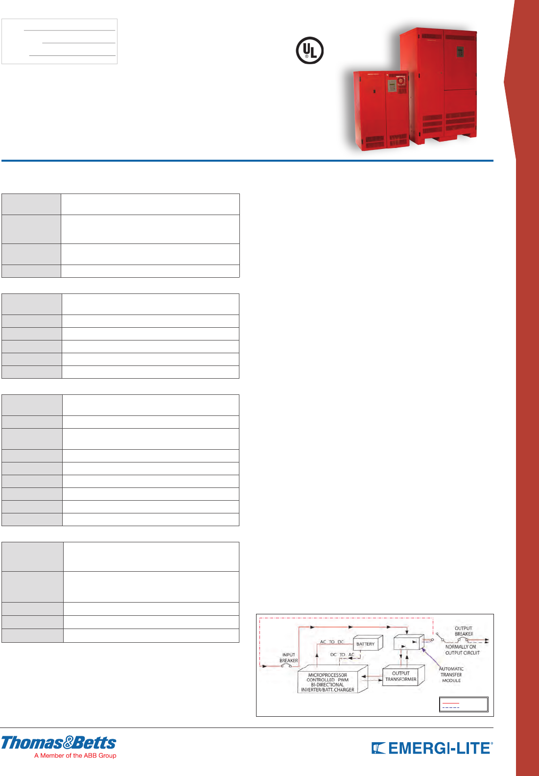
135
CENTRAL & INVERTER
SYSTEMS
TYPE:
CATALOG #:
NOTES:
Uninterruptible Emergency Lighting
Inverter System 4.8KVA – 50KVA
System Specifications
GENERAL
Design Stand-by. PWM inverter type utilizing IGBT
technology with 2ms transfer time
Control
•
Microprocessor controlled , 2 x 20-character
display with touch pad controls & functions
• 5 LED indicators & alarm with ring-back feature
Metering Input & Output Voltage, Battery Voltage, Battery & Output
Current, Output VA, Temperature, Inverter Wattage
Communications RS-232 port (DB9)
ELECTRICAL INPUT
Voltage 120/208 or 277/480 3 phase 4-wire +10% - 15%.
Contact factory for all other voltages
Input Power Walk-In Limiting inrush current to less than 125%, 10 times for 1 line cycle
Input Frequency 60Hz, +/-3%, 50Hz available upon request
Protection Input Circuit Breaker
Harmonic Distortion <10%
Power Factor 0.5 lag/lead
ELECTRICAL OUTPUT
Voltage 120/208 or 277/480VAC 3-phase 4-wire
Contact factory for all other voltages.
Static Voltage Load current change +/-4%, battery discharge +/-4%
Dynamic Voltage +/-3% for +/-25% load step change
+/-6% load step change, recovery within 3 cycles
Harmonic Distortion <3% THD for linear load
Output Frequency 60Hz +/- 0.05Hz during emergency mode
Load Power Factor 0.5 lag to 0.5 lead
Inverter Overload 115% for 5 minutes, 125% for 10 minutes, 280% for line cycles
Protection Optional Distribution Circuit Breakers
Crest Factor 2.8
ENVIRONMENTAL CONDITIONS
Storage/Transport
-4ºF to 158ºF (-20ºC to 70ºC) without batteries
(max. 3 months at 104° F (40° C)
-0ºF to 104ºF (-18ºC to 40ºC) with batteries
Operating
Temperature
System operates safely from 32°F to 104°F (0°C to 40°C)
but optimum operation is between 68° F and 86°F (20°C to
30°C). Battery performance can be affected by temperature
Altitude <10,000 feet (above sea level) without de-rating
Relative Humidity 0 to 95% non-condensing
Audible Noise 45 dBA @ 1m from surface in emergency mode
CABINETS
Modular design, freestanding NEMA Type 1 steel cabinets powder coated for
corrosion and scratch resistance. Front access design through hinged lockable
doors requires only 39” front clearance and 12” top clearance. Cabinets are
stackable up to 16.7kVA, if required to further reduce the footprint. Top and left
side conduit entry with knockouts up to 16.7kVA. Left side only for 24kVA and up.
INVERTER
Using IGBT/PWM technology the inverter converts the DC voltage supplied by the
batteries to AC voltage of a precise stabilized amplitude and frequency, suitable
for most sophisticated electrical equipment. True sinusoidal output waveform with
very low distortion (less than 3% for linear loads). Overload capability of up to
150% for 12 line cycles
CHARGER
Fully automatic, temperature compensated, microprocessor controlled charger
recharges fully discharged batteries in maximum 24 hours at nominal AC input
voltage. AC input current limiting and over-voltage protection included.
BATTERY
System is provided standard with 10 year, maintenance free, sealed valve regulated, front terminals
lead calcium batteries. 20 year sealed Lead Calcium or wet Nickel Cadmium batteries also available.
90 min. standard discharge time at full load under normal operating temperature. Low Voltage
Disconnect protection included. No special ventilation or filters required
SUPERVISION
Automatic self tests consist of a 5-minute monthly and 90-minute annual function.
The front-mounted control panel includes 5 LED indicators, a 2-line 20-character
LCD display, a keypad to control and monitor the internal operation of the
system. This allows the operator to easily “watch” system functions as they occur
and check on virtually any aspect of the system’s operation. Standard RS232
diagnostic interface.
ALARMS
High/Low Battery Charger Voltage, High/Low AC Input Voltage, Near Low Battery,
Low Battery, Load Reduction Fault, Output Overload, High Ambient Temperature,
Inverter Fault, Output Fault, Optional Output Circuit Breaker Trip.
OPTIONAL FEATURES
Output Circuit Breakers, Output Trip Alarms, 20 Years Sealed Batteries, 12 Hours
Fast Recharge, External Maintenance Bypass Switch, Remote Meter Panel,
Remote Summary Alarm Panel, Summary Alarm Dry Form C Contact, Inverter
on Dry Contacts, Normally OFF output, Fax/Modem, Bypass Relays, Auto Dialer,
Seismic Mounting.
FACTORY START-UP
Includes one additional year of warranty. See warranty conditions.
WARRANTY
(full limited warranty conditions available upon request)
Limited manufacturer warranty is one-year, parts and labor, for system electronics
or two-year with factory start-up program. Battery warranty is one year full plus 9
years pro-rata for a total of 10 years, under normal operating conditions. System
must be put in service within 6 months from ship date in order to validate warranty.
2- Consult factory for other type batteries than the standard one.
Characteristics, specifications or dimensions subject to change without notice.
SINGLE LINE DIAGRAM
NORMAL
EMERGENCY
Output breakers are optional
Normally On Output Circuit
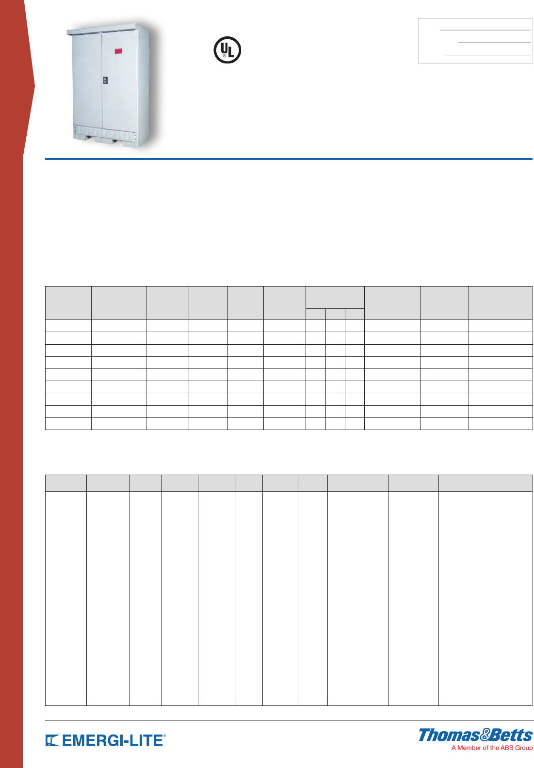
136
CENTRAL & INVERTER
SYSTEMS
TYPE:
CATALOG #:
NOTES:
Emerg-Power Systems
FTC3R & 3FTC3R
Outdoor Uninterruptible Emergency
Lighting Inverter System 3KVA-8KVA
• NEMA 3R cabinet for outdoors
• 90 min. standard run time
• Generator compatibility
• Custom voltages available
• Automatic event, test and alarm log
• LCD display
• One size cabinet
• Maintenance free standard 5 year batteries
• Temperature controlled cooling fans
UL listed to UL924. Meets NFPA101, NFPA70, NFPA 110, OSHA, UBC, SBCCI. N.Y City approved.
Features
• 98% efcient at full load
• PWM/IGBT technology
• Self-testing/Self-diagnostic
• Standard input circuit breaker
• Standard internal bypass switch
• RS232 communication port
• Standard seismic zone 4 brackets
• Standard summary dry contacts
• Automatic event and alarm log
Electrical/Mechanical Characteristics3, 4
POWER
RATING
KVA= KW
EFFIC. AT FULL
LOAD %
HEAT LOSS
(BTU) BATT. VDC BATT. A NO. OF
BATT.2
UPS CABINET
DIMENSIONS UPS CAB. WEIGHT
LBS
BATT. CAB.
WEIGHT LBS
TOTAL SYSTEM
WEIGHT LBS
W”1H” D”
3 (1PH) 98 255 120 37 10 48 76 30 535 lbs 888 lbs 1633 lbs
4 (1PH) 98 340 144 40 12 48 76 30 535 lbs 1110 lbs 1855 lbs
5 (1PH) 98 408 180 40 15 48 76 30 535 lbs 1480 lbs 2247 lbs
6.5 (1PH) 98 544 240 39 20 48 76 30 639 lbs 1776 lbs 2835 lbs
8 (1PH) 98 680 144 82 24 48 76 30 639 lbs 2220 lbs 3279 lbs
4 ( 3PH) 98 326 144 39 12 48 76 30 639 lbs 2960 lbs 4063 lbs
5 ( 3PH) 98 408 180 39 15 48 76 30 1250 lbs 4440 lbs 6390 lbs
6.5 (3PH) 98 544 240 39 20 48 76 30 1250 lbs 6080 lbs 8630 lbs
8 (3PH) 98 680 144 81 24 48 76 30 1450 lbs 7400 lbs 10150 lbs
1 Factory installed floor mount brackets; add 2.5” to each side (total 53”)
2 Standard batteries are 5 year life expectancy. Batteries are installed in the same cabinet with electronics
3 UL rated for 90 min. run time for temperatures: 50ºF to 104ºF (10ºC to 40ºC) or -4ºF to 104ºF (-20ºC to
40ºC) with optional heater
4 NEMA type 3R, freestanding, two-door powder coat cold rolled steel cabinet standard. Stainless steel enclosure
is optional
How to Order
INPUT
VOLTAGE*
BATTERY
TYPE
VA/W
RATING*
SYSTEM
TYPE
OUTPUT
VOLTAGE*
RUN
TIME*
INPUT
BREAKER
RS232
PORT
INTERNAL BYPASS
SWITCH
OUTPUT
BREAKERS* OPTIONS*
120, 1PH
208, 1PH
240, 1PH
277, 1PH
120/208,
3PH
277/480,
3PH
SG= Sealed
Lead-Calcium
3000
4000
5000
6500
8000
FTC3R=
single
phase
3FTC3R=
3 phase
120
208
277
120/208
277/480
90 ICB RS232 MBYB OCBxxxx= no
trip alarm*
OCAxxxx= with
trip alarm*
10Y= 10 yr sealed batteries
12HR= 12 hr fast recharge
NOFF= normally off output**
EMBP= external bypass switch***
RMP= remote metering panel
RSAP= remote summary
alarm panel
HTR= heater
INVON= inverter on dry contacts
MOD= external modem
FAX= fax modem
BPR= bypass relays
SS= stainless steel enclosure
* 1PH are
input voltages
available for 1
phase systems.
3PH are
input voltages
available
for 3phase
systems.
* Not
available
in 3 phase
version
* 1PH are
input voltages
available
for 1 phase
systems. 3PH
are input
voltages
available
for 3phase
systems.
* Other
run times
available
* Max. 14
unsupervised single
pole positions or
8 with trip alarm.
For more output
breakers please
consult factory.
See page 137 for
output breakers
option details.
*
See page 137 for options description
Summary alarm dry contacts and seismic
brackets are standard.
** Normally off loads cannot exceed 20%
of total KVA rating with any combination
of H.I.D. loads
*** Not available in 3 phase version.
Example: 120SG4000-FTC3R-120-90-ICB-RS232-MBYB-OCB0420-10Y

137
CENTRAL & INVERTER
SYSTEMS
EMERG-POWER SYSTEMS
Option Details
Distribution circuit breakers are for output load protection. Protection for the normally on and/or for the normally off loads.
All circuit breakers are rated for 10,000 AIC.
If ordered, an audible and visual alarm activates when an output distribution circuit breaker is open or has tripped.
INTEGRATED OUTPUT CIRCUIT BREAKERS:
Trip Alarm
OCB - No
Breaker Trip
Alarm
OCA - With
Breaker Trip
Alarm
-OCB 2012
Breaker
Rating
(Amps)
* Various
ratings
available
Number
of poles
Blank - 1 pole
-2P - 2 poles
-3P - 3 poles
Operation Mode
Blank:
Normally-On
-NOFF:
Normally-Off
Number of Circuit Breakers
Combination of 1 pole, 2 pole
and 3 pole breakers available.
* For max. number of
circuit breakers available
please consult factory
Breaker Voltage
Blank- matches
system output voltage
-120VAC
-208VAC
-240VAC
-277VAC
-480VAC
(-NOFF) NORMALLY OFF OUTPUT
This output circuit is dedicated for the “emergency only” equipment. Emergency
only equipment operates during power outages and when the system is on
battery back up. This option leaves the normally off load circuits off during
normal utility power conditions. A 1-pole circuit breaker is provided. For 3
phase systems, 3 pole normally off circuits are available as well.
(-MOD) EXTERNAL MODEM
External modem device is designed to boost the signal level of the RS-232
diagnostic interface to remote monitoring locations located more than 100 feet
away from the system.
(-FAX) INTERNAL FAX MODEM
The internal fax modem enables the system to send a fax automatically to
several pre-programmed numbers when one of the following conditions occurs:
utility failure, output failure or any alarm. The Fax Modem option requires a user
supplied dedicated phone line.
(-BPR) BYPASS RELAYS
Internal bypass relays will allow overriding circuits that can be switched on/off,
so in case of a power failure the emergency circuits will be supplied from the
inverter system whatever the position of the switching device. Please consult
factory for more details.
(-DIAL) AUTO DIALER
The Auto Dialer modem option automatically dials up to four user-
programmable phone numbers in the event of any system alarm condition. The
option is designed to deliver a predetermined digital or audible message when
activated. The Auto Dialer option requires a user supplied dedicated digital or
analog phone line.
(-SEIS) SEISMIC MOUNTING KIT
The seismic mounting kit option is designed to prevent system movement
during seismic events. Heavy-duty brackets are provided to secure system
cabinetry to oor surfaces. Meets Zone 4 requirements.
(-ZONEM) ZONE MONITORING
Allows voltage monitoring of different circuits than the standard AC utility input.
When the voltage of one of these circuits drops, the inverter system will go into
battery back-up operation mode. Number and voltage of the monitored circuits
to be specified.
(-RS232) DIAGNOSTIC INTERFACE
A microprocessor-based data acquisition system designed to monitor all the
system parameters remotely. Monitors alarm log, event log and automatic test
log. User can command the system to perform a battery test and review all
system parameters. Access is through a DB9 connector and transmits at 9600
baud.
(-BATM) BATTERY CYCLE WARRANTY MONITOR
Device providing battery monitoring at string level or cell level. Please consult
factory for more details.
(-20YR) 20 YEAR SEALED LEAD CALCIUM BATTERIES
Maintenance free battery requires no addition of water over the life of the
battery. The battery cells are housed in protective, modular steel trays. Life
expectancy is designed for 20-years at 77ºF (25ºC).
(-12HR) 12 HOUR FAST RECHARGE
Battery charger upgrade option which decreases the time required to return a
fully discharged battery to the fully charged state. The normal 24 hour recharge
cycle is reduced to a 12 hour period.
(-MBYP) INTERNAL MAINTENANCE BYPASS SWITCH
Internally mounted device permits maintenance personnel to easily bypass the
protected equipment directly to the AC utility power. The manual make before
break switch isolates the system to perform routine maintenance or servicing
without interruption of utility power to the connected load.
(-EMBP) EXTERNAL MAINTENANCE BYPASS SWITCH
The external maintenance bypass switch is mounted in a 20”H x 16”W x 9”D
NEMA 1 separate enclosure, used to completely isolate the inverter system
from the connected load and AC utility input. This option allows the system to
be safely powered down for maintenance or service. The option may not be
used on systems with more than one single pole output circuit breaker which
must be sized for the total system output current.
(-RMP) REMOTE METER PANEL
The panel allows monitoring of parameters and control from remote locations
up to 150 feet away from the inverter system. Also, the remote panel provides a
complete touch pad interface allowing the user to monitor, control and program
the inverter system.
(-RSAP) REMOTE SUMMARY ALARM PANEL
Wall mountable box provides visual and audible alarms with silent switch. The
panel consists of LED indicators and built-in audible alarm and may be located
up to 1,000 feet away from the inverter system.
(-DCS) SUMMARY ALARM DRY CONTACTS
Form C dry contacts for remote monitoring purposes. Rated at 5 amps max.
(250VAC/30VDC), the contacts will change state when any of the following
alarms: are tripped High/Low Battery Charger Voltage, High/Low AC Input
Voltage, Near Low Battery Voltage, Low Battery Voltage, Load Reduction Fault,
High Ambient Temperature, Inverter Fault, Output Fault, Output Overload or
Optional circuit breaker.
(-INVON) INVERTER ON DRY CONTACTS
Form C dry contacts that will change state when the system transfers to
battery operation
(-VTD) VARIABLE TIME DELAY (FOR NORMALLY OFF CIRCUITS)
After a return of AC utility power, delays retransfer of the inverter for up to 15
min. and continues to supply emergency power to the normally off circuits.
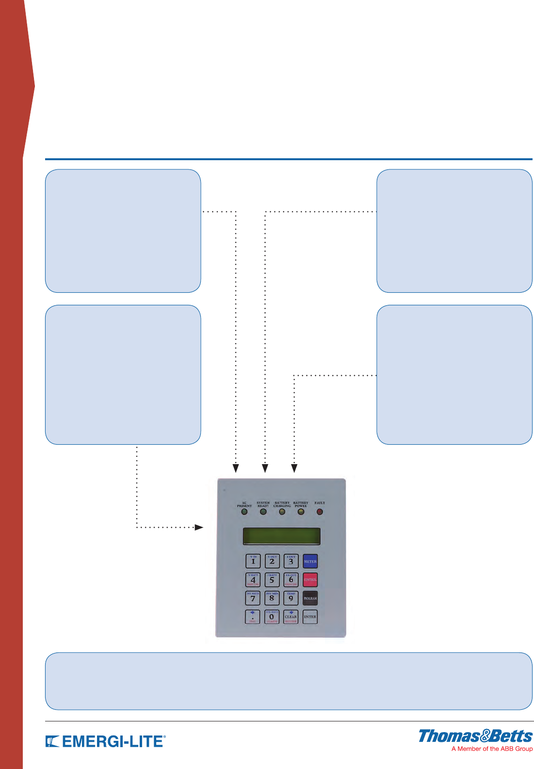
138
CENTRAL & INVERTER
SYSTEMS
EMERG-POWER SYSTEMS
Control Panel & Display
Meter Functions
• AC Voltage Input
• AC Voltage Output
• AC Current output
• Battery Voltage
• Battery Current
• VA Output
• Inverter Watts
• Ambient Temperature
• System Days (cumulative)
• Inverter Minutes (cumulative)
Alarms
• High Battery Charger Voltage
• Low Battery Charger Voltage
• High AC Input Voltage
• Low AC Input Voltage
• Near Low Battery Voltage
• Low Battery Voltage
• Load Reduction Fault
• High Ambient Temperature
• Inverter Fault
• Output Fault
• Output Overload
System Testing
Manual tests of system may be performed at any time using the control panel test key. Automatic self-diagnostic tests consist of a 5-minute monthly and
90-minute annual function (the user can program the date and time of day the test is to take place). The microprocessor automatically records the last 75 test
events in its own separate test result log.
Program Functions
• Set Date
• Set Time
• Set Monthly Test Date and Time
• Set Annual Test Date and Time
• Set Load Fault Reduction Setting
• Set Low Battery Alarm
• Set Near Low Battery Alarm
• Set Low AC Voltage Alarm
• Set High AC Alarm
• Set Ambient Temperature Alarm
Control Functions
• Test and Event Logs (75 logs stored) Logs
record the following data: Date, Time, Duration,
Output Voltage, Output Current, Ambient
Temperature and Alarms Present.
• Alarm Logs (50 logs stored) Logs record the
following data: Date,Time and Alarm type
• Buzzer On/Off (toggle)
• 5 LED Indicators and Alarms with Ringback
Feature
139
CENTRAL & INVERTER
SYSTEMS
EMERG-POWER SYSTEMS
Central Systems Request Data
1) Input voltage
Single phase
(2 wire + ground) 120VAC 208VAC 240VAC 277VAC
Three phase
(4 wire + ground, Y) 120/208VAC 277/480VAC 347/600VAC
Three phase
(3 wire + ground, Δ) 208VAC 480VAC 600VAC
2) Output voltage
Single phase
(2 wire + ground) 120VAC 208VAC 277VAC
Single phase
(3 wire + ground) 120/240VAC 120/277VAC
Three phase
(4 wire + ground, Y) 120/208VAC 277/480VAC
3) System capacity
KVA rating: System Series Type:
a) Please consider power consumption and maximum current of the complete lamp fixture not just the lamp wattage (ie: ballasts consumption)
b) Please consider loads power factor
c) Even if the systems can run with 100% load, it is recommended as standard practice to use a system with a capacity at least 10% over
maximum connected load
4) Type of loads
Incandescent Fluorescent H.I.D (metal halide, high pressure sodium, etc.)
Other
5) Mode of operation
Normally ON (24/7) Normally OFF (emergency only) Switched loads ON/OFF LED
Please consider internal bypass relays or external override relays for switched On/Off loads.
Each switched output circuit will require a bypass relay. Maximum 20 A per circuit.
6) Integrated output circuit breakers
# of CB Amps Voltage # of poles NON NOFF Trip alarm
# of CB Amps Voltage # of poles NON NOFF Trip alarm
7) Type of Batteries (check availability for each type system)
10 yr sealed lead calcium 20 yr sealed lead calcium wet nickel cadmium
8) Options (refer to available options for each system type)
(12HR-) 12 Hour Fast Recharge RS232- diagnostic interface ZONEM- zone monitoring
MBYP- internal bypass switch NOFF – normally OFF output VTD- variable time delaye
EMBP- external bypass switch MOD- external modem BATM – battery cycle warranty monitor
RMP- remote meteing panel FAX- fax modem
RSAP- remote summary alarm panel BPR- bypass relays How many ____
DCS- dry summary alarm contacts DIAL- auto-dialer
INVON- inverter on dry contacts SEIS- seismic mounting kit
141
ACCESSORIES & GENERAL INFO.
ACCESSORIES &
GENERAL INFORMATION
Table of Contents
Wire Guards 142-143
Accessories 144-145
Lamp Data 146-147
Wire Size Guard 148
National Electrical Code 149-151
Life Safety Code 152-154
Limited Warranty 155
Product Index 156
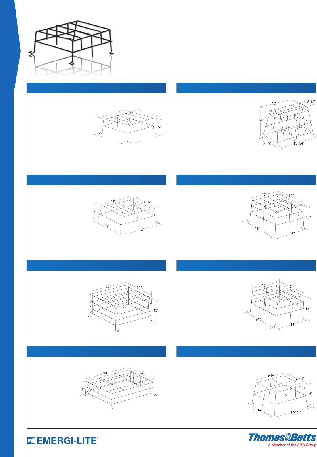
142
ACCESSORIES & GENERAL INFO
Wire Guards
Catalog Number WG2-E
Application
• JS Series (large cabinet)
• All A cabinets
• Premier™ Combo Series
(wall mount)
Catalog Number WG6-E
Application
• Single EF22 head
• X10 mini systems (wall mounted)
with front mounted EF9 head(s)
(wall mounted)
• KS Series with front
mounted heads
Catalog Number WG3-E
Application
• IL Series
• All B and C cabinets
Catalog Number WG7-E
Application
• EF22D heads
• RS Series with cylinder
• EF32 heads
Catalog Number WG4-E
Application
• All D cabinets
• KS Series (not for front
mounted heads)
Catalog Number WG8-E
Application
• Single remote EF9, EF11,
• EF16, EF18, EF28, or
• EF32 lighting head
Catalog Number WG1-E
Application
• JS Series (small cabinet)
• PS Series (surface or
semi-recessed)
• EF24 or EF24R remote lighting xture
• Premier™ Battery Unit
• Premier™ Exit Sign
(wall mount)
Catalog Number WG5-E
Application
• X10 (end or ceiling mounted) AC and AC/
DC or Self-Powered exit with no mounted
heads
• ECL & ECLXN Series LED
(end or ceiling mounted) AC and AC/DC
or Self-Powered
• Preceptor™ Series LED (AC and AC/DC or
Self-Powered) (end or ceiling mounted)
• Prestige™ DX Series LED and
Thin Die-Cast Series (end or ceiling
mount)
• Premier™ Exit Sign (end or ceiling mount)
14” 12”
16”
13-3/4”
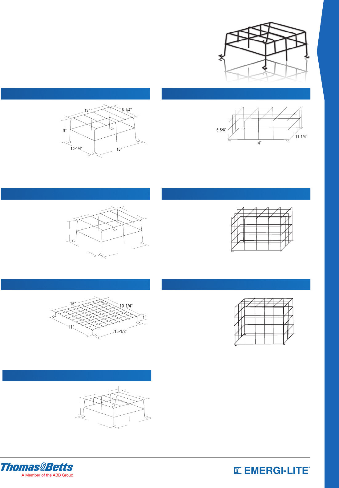
143
ACCESSORIES & GENERAL INFO.
Wire Guards
Catalog Number WG10-E
Application
• JS Series with
front mounted heads
Catalog Number WG11-E
Application
• Fully recessed
PS Series
• GS Series
• EF15, EF20, EF21R,
EF35 lighting xtures
• Fully recessed
Preceptor™ Series
• Prestige™ Thin Die
Cast Exit Sign (wall mounted)
Catalog Number WG13-E
Application
• PRO-2N Series
• Preceptor™ Series
Self-Powered
(wall mount)
Catalog Number WG14-E
Catalog Number WG15-E
Catalog Number WG9-E
Application
• Double or triple remote
EF9, EF11, EF18, EF28 or
EF32 lighting heads
• RS Series with EF9 or
EF18 heads
• ECS-2 Series
Catalog Number WG12-E
Application
• X10 Series LED
(AC and AC/DC or Self-Powered)
(wall mount)
• ECL & ECLXN Series LED AC
and AC/DC or Self-Powered
(wall mount)
• Preceptor™ Series LED (AC and
AC/DC or Self-Powered) (wall
mount)
• Prestige™ DX Series LED AC and AC/DC or
Self-Powered (wall mount)
• Remote EF13, EF14, or EF17 xtures
13-1/2” 9”
15”
10-1/4”
4-1/2”
11-7/8”
13-3/4”
9-5/8”
15-5/16”
10-1/4”
8-3/8”
20” 12”
23”
15”
12” 11-7/8”
15-5/16”
9-5/8”
8-3/8”
13-3/4”
10-1/4”
Application
Exit Signs (Ceiling
Mount)
• Prestige™ Floor Proximity
Series (6” & 8”);
• Preceptor™ Die-Cast
Series;
• Prestige™ Thin Die-Cast
Series;
• X10 LED Series,
• Premier™ Exit Series;
Application
Exit Signs (Ceiling
Mount)
• Prestige™ Floor Proximity
Series (6” & 8”);
• Preceptor™ Die-Cast
Series;
• Prestige™ Thin Die-Cast
Series;
• X10 LED Series,
• Premier™ Exit Series;
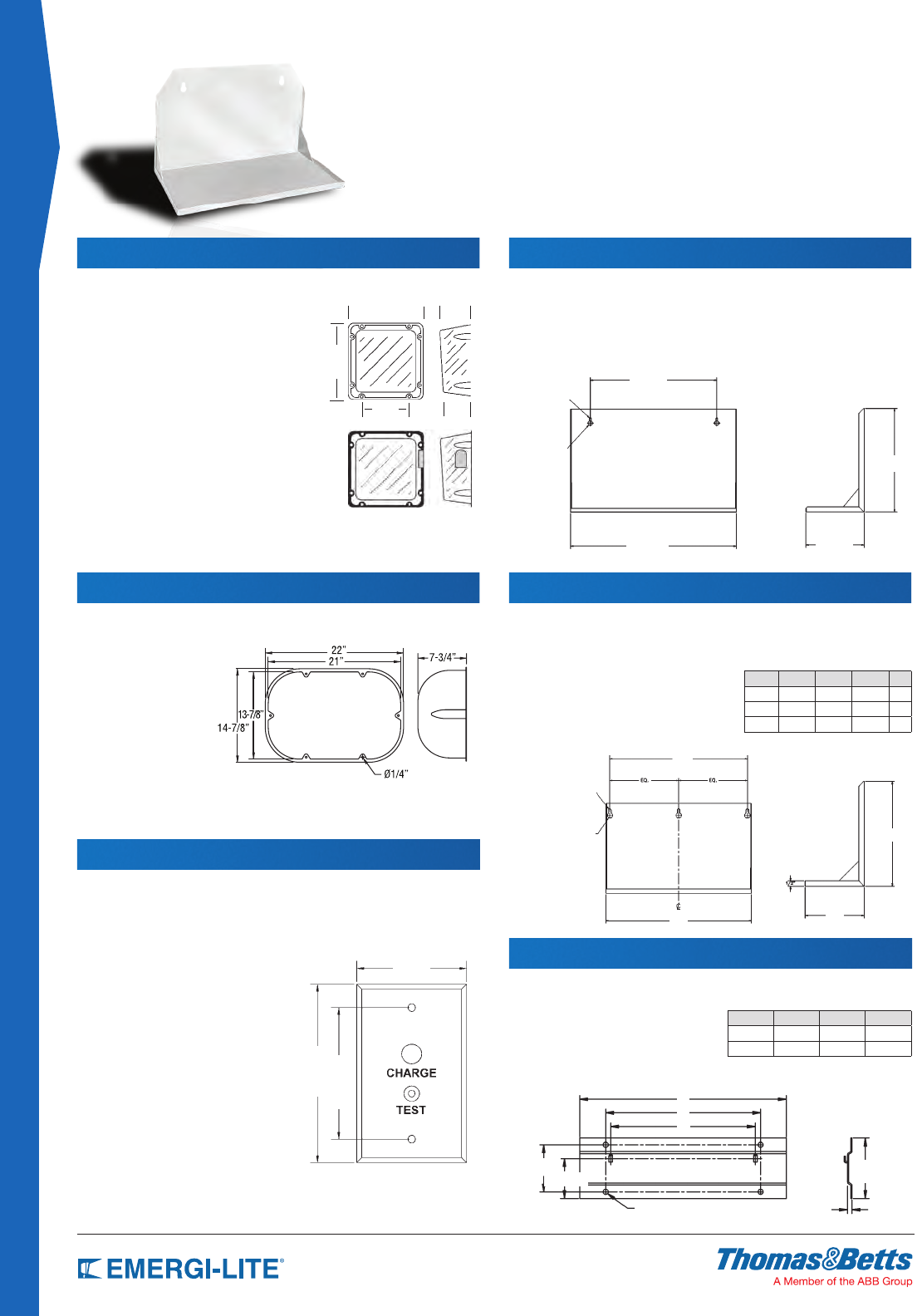
144
ACCESSORIES & GENERAL INFO
Accessories
2-1/4”
11-5/16” 21-5/16”
ø1/4” (4 PLCS)
A
B
C
1/2”
Catalog Number VRS or VRS-4X
Application
• ME Series with top mounted heads
• PS Series all mountings
• X10 LED, (wall mounted) AC and
AC/DC or Self-Powered exit with
no mounted heads
• ECL Series LED (wall mounted)
AC and AC/DC or Self-Powered
• Preceptor™ Series LED,
(wall mounted) AC and AC/DC
MP3 Mounting Platform
Constructed of 18 gauge. steel, the MP3 mounting platform will accommodate
all our unit equipment in our ‘B’ cabinet.
How To Order
Mounting platform MP3-EG
Mounting platform, gray MP3-GY
MP6, MP12, MP24 Mounting Platform
Constructed of 18 gauge. steel, the MP6, MP12, and MP24 mounting
platform will accommodate our unit equipment in our ‘C’, ‘D’, and ‘E’ cabinets
respectively.
How To Order
Mounting platform (off white) MP6-EG
Mounting platform (off white) MP12
Mounting platform (off white) MP24
Optional colors available,
contact your sales representative
NEMA-4X
Catalog Number VRS-BB or VRSBB-4X
Application
• JS Series (small cabinet)
top or front mounted heads
• ECC & ECM Series
(small cabinet)
Remote Test Switch
Make testing your ceiling mounted equipment easier with the remote test
switch. Compatible with 120 or 277 VAC circuits, the remote test switch will
interrupt the line voltage to your equipment by means of a momentary push
button switch. AC on/Charge status indicator lamp assures that power is going
to your emergency lighting.
How To Order
Metal faceplate, chrome RTS
Plastic Faceplate plastic, off white RTS-1
NEMA-4X
15-1/8”
9-1/8”
8” 5-1/4”
6”
10-1⁄4”
5-3⁄4”
14-1⁄2”
3/16” DIAM.
7/16” DIAM.
16-3⁄8”
2-3/4”
4-1/2”
Part # A B C D
MP6 17” 7.75” 12.25” 16”
MP12 27.5” 7.75” 12.25” 16”
MP24 27.5” 11.63” 12.25” 16”
B1 and B12 Mounting Brackets
Constructed of 16 gauge. steel, the B1 and B2 mounting bracket will
accommodate our unit equipment in our ‘A’ and ‘B’ cabinets respectively.
How To Order
Mounting bracket (off white) B1
Mounting bracket (off white) B2
5/8” DIAM.
5/16” DIAM.
A
D
B
C
3-5⁄16”
Part # A B C
B1 10” 7” 7 1/2”
B2 14 1/4” 11 3/4” 12 5/8”
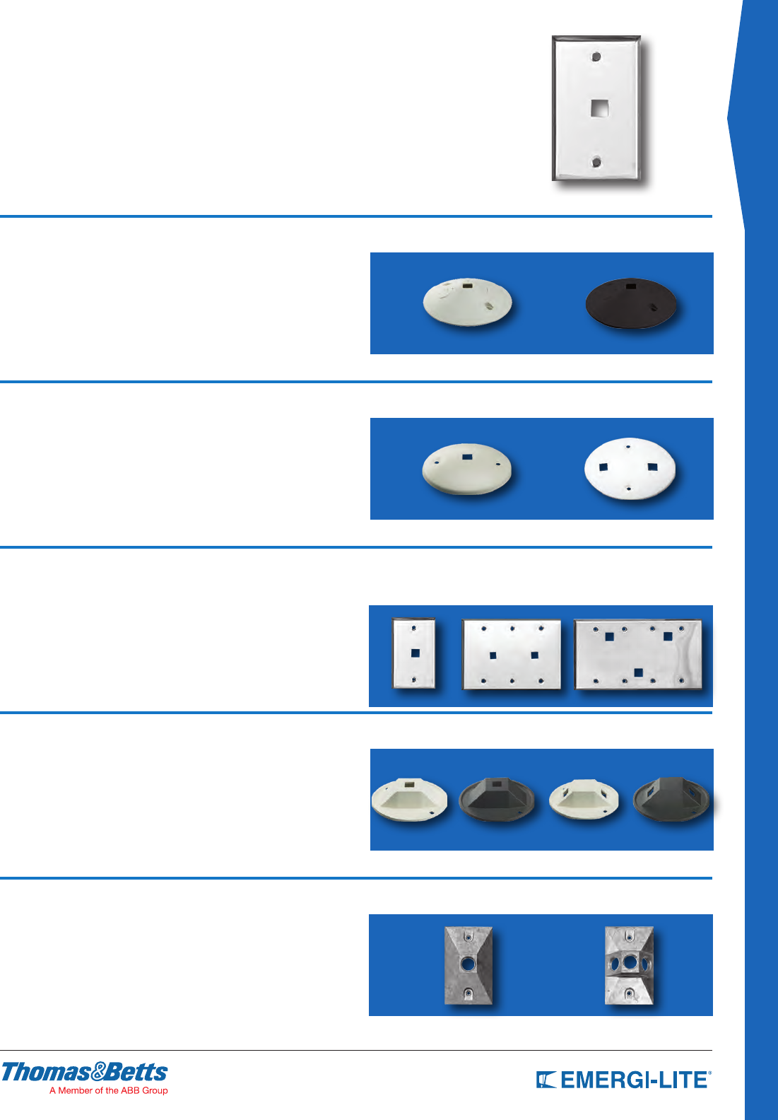
145
ACCESSORIES & GENERAL INFO.
Specify mounting plate designation as a suffix
to fixture type model number. Plates ordered
separately, specify plate designation
and fixture type.
230.1238-E & 230.1239-E
• Single, Double or Triple Round
• Thermoplastic Construction
• Off-white or black nish only
• Mount direct to 4” octagonal box
Dimensions: 5” diameter - slotted mounting holes
3 to 3 9/16” mounting center
Standard: EF18, EF18D; and EF9, EF9D
430.0765-E & 430.0766-E
• Single or double round
• Aluminum construction
• Matte white baked enamel nish
• Black nish optional
• Mount direct to 4” octagonal box
Dimensions: 5 1/4” diameter
3 7/16” mounting center
Standard: EF32 and EF32D
450.0129-E, 450.0397-E & 450.0398-E
• Single, double or triple rectangular
• Single, triple or 4-gang steel construction
• Chrome plated nish only
• Mount direct to standard outlet box
Dimensions: single - 2 3/4” X 4 1/2” (for 1 xture)
3-gang - 6 7/16” X 4 1/2” (for 2 xtures)
4-gang - 8 3/8” X 4 1/2” (for 3 xtures)
Standard: EF28, EF28D; EF18T and EF28T
330.7583-E & 330.7584-E
• Single or double round
• Die-cast aluminum construction
• Gasketed weatherproof
• Off-white or black powder paint nish only
• Mount direct to 4” octagonal box
Dimensions: 4 1/8” diameter
3 9/16” mounting center
Standard: EF11 and EF11D
12804-E & 12805-E
• Single or double rectangular
• Die-cast aluminum construction
• Gasketed weatherproof
• Silver gray enamel nish only
• Mount direct to standard outlet box
Dimensions: 4 5/8” X 2 7/8”
3 1/4” mounting center
Standard: Non standard mounting plate
Gasket - 245.0100-E
Off-White - 230.1238-E
Off-White Single - 430.0765-E
450.0129-E - No Square Hole
450.0194-E - 1/2”
Square Hole
Off-White Single
330.7583-E
12804-E 12805-E
Black Single
330.7577-E
Off-White Double
330.7584-E
Black Double
330.7578-E
450.0397-E - No Square Hole
450.1153-E - 1/2”
Square Hole
450.0398-E - No Square Hole
450.1155-E - 1/2” Square Hole
Black - 230.1239-E
Off-White Double - 430.0766-E
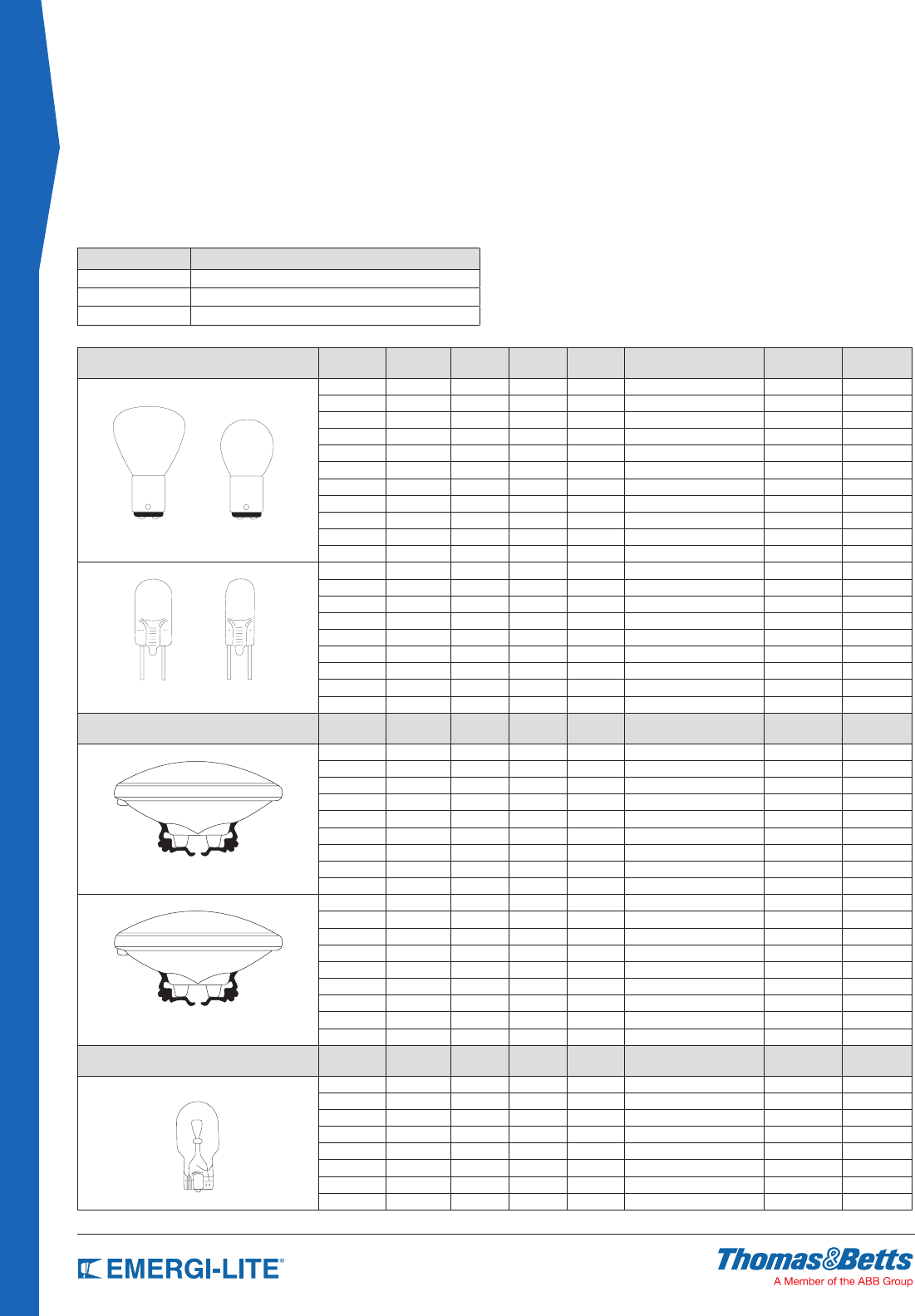
146
ACCESSORIES & GENERAL INFO
Lamp Data
General Information
LAMP TYPE PART
NUMBER LAMP CODE VOLTAGE
(V)
POWER
(W)
AVERAGE
LUMEN
TOTAL CANDLE POWER
(CP) LAMP # BULB TYPE
570.0010 IA 6 9 126 10 135 S-8
570.0020 IM 6 13 188 15 88 S-8
570.0037 IB 6 18 300 24 1130 S-8
570.0038 IC 6 25 400 32 1134 RP-11
570.0011 IE 12 9 126 10 138 S-8
570.0022 IN 12 13 188 15 94 S-8
570.0030 IF 12 18 276 22 139 S-8
570.0031 IG 12 25 400 32 1076 S-8
570.0058 II 24 9 75 6 304 C-2F
570.0040 IJ 24 18 250 20 142 S-8
570.0061 IK 24 25 400 32 1638 S-8
580.0012 HA 6 6 113 9 784 T-2 1/4
580.0013 HB 6 8 163 13 785 T-2 1/4
580.0017 HC 6 10 200 16 787 T-2 1/4
580.0011 HD 6 12 240 19 786 T-2 1/4
580.0022 HE 6 20 400 32 788 T-2 1/4
580.0014 HF 12 8 163 13 774 T-2 1/4
580.0015 HG 12 12 276 22 783 T-2 1/4
580.0016 HH 12 14 300 24 789 T-2 3/4
580.0027 HI 12 20 314 25 782 T-2 3/4
LAMP TYPE PART
NUMBER
CATALOG
SUFFIX VOLTAGE WATTS AVERAGE
LUMEN
CENTER-BEAM CANDLE
POWER (CBCP) LAMP # BULB TYPE
550.0022 XA 6 6 107 400 H7556 PAR 36
550.0036 XB 6 8 155 550 H7551 PAR 36
550.0037 XC 6 10 190 650 H7552 PAR 36
550.0019 XD 6 12 225 850 H7553 PAR 36
550.0021 XE 6 20 380 1,400 H7554 PAR 36
550.0024 XF 12 8 130 550 H7555 PAR 36
550.0025 XG 12 12 240 850 H7557 PAR 36
550.0047 XH 12 37 700 70,000 H7616 PAR 36
550.0012 XI 12 50 950 2,000 H7614 PAR 36
550.0018 UA 6 8 130 400 7613 PAR 36
550.0030 UI 6 12 180 1,100 4042 PAR 36
550.0016 UB 6 18 270 1,500 4014 PAR 36
550.0017 UC 6 25 400 800 4510 PAR 36
550.0035 UD 6 30 460 5,500 4515 PAR 36
550.0026 UE 12 12 190 1,110 4044 PAR 36
550.0027 UF 12 18 210 1,500 4414 PAR 36
550.0023 UG 12 25 395 400 4446 PAR 36
550.0034 UH 12 30 430 35,000 4416 PAR 36
LAMP TYPE PART
NUMBER
CATALOG
SUFFIX VOLTAGE WATTS AVERAGE
LUMEN
TOTAL CANDLE POWER
(CP) LAMP # BULB TYPE
570.0012 ZP 6 5.4 68 5.4 939 T-5
570.0026 ZL 6 7.2 100 8 927 T-5
570.0016 ZD 6 9 150 12 908 T-5
570.0025 ZF 12 9 138 11 915 T-5
570.0028 ZG 12 12 150 12 912 T-5
570.0029 ZH 12 18 264 21 921 T-5
570.0045 ZN 24 9 113 9 EMS2209W T-5
570.0046 ZO 24 18 240 19 EMS2218W T-5
All Emergi-Lite® Lighting Fixtures are furnished complete with lamps; however,
all fixtures and unit model numbers must include a lamp designation.
Unless otherwise noted, the standard lamp furnished with each lighting xture is
a 9W High Intensity Incandescent lamp of the designated voltage.
Example
FIXTURES PART NUMBER
EF18 (ZD) LSM 110-2Z (6V-9W)
EF18 (ZF) 12LSM 110-2Z (12V-9W)
EF18 (ZN) 24LSM 110-2Z (24V-9W)
When an alternate lamp is required, refer to the lamp selection charts below,
select the lamp type, the voltage and wattage required and add the symbol
designation to the catalog number. Not all lighting xtures and lamp types are
compatible, always check individual lighting xture “How to Order” information.
Example:
A Normally Furnished Lamp: EF18 (ZD)
(6V-9W Wedge Base Incandescent)
Lighting Head Requiring different Lamp: (6V-25W Sealed Beam Lamp)
Change Catalog Number to: EF18 (UC)
Sealed Beam Halogen Lamps
Sealed Beam Incandescent Lamps
High Intensity Incandescent, Wedge Base
PAR 36
PAR 36
T-5
S-8
High Intensity Tungsten (HIT) Lamps
Bi-Pin Halogen Lamps
Double Contact Bayonet Base
T-2 3/4
RP-11
T-2 1/4
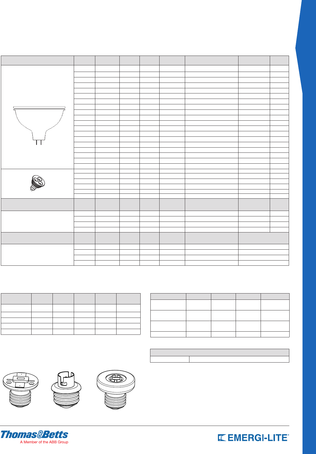
147
ACCESSORIES & GENERAL INFO.
Lamp Data
General Information
LAMP TYPE PART
NUMBER
CATALOG
SUFFIX VOLTAGE WATTS AVERAGE
LUMEN
CENTER-BEAM CANDLE
POWER (CBCP)
BEAM ANGLE
(DEGREES)
BULB
TYPE
580.0072 MH 6 5.4 34 73 36 MR16
580.0074 MI 6 6 40 130 24 MR16
580.0079 MJ 6 10 77 790 16 MR16
580.0099 MO 12 10 86 200 36 MR16
580.0080 MK 12 12 135 320 36 MR16
580.0064 MG 12 20 270 525 36 MR16
580.0075 MA 12 20-A 245 600 36 MR16
580.0068 MW 12 20-H 417 950 36 MR16
580.0083 MB 12 35 490 3300 24 MR16
580.0076 MC 12 50 785 2800 24 MR16
580.0089 MM 12 50-H 1550 5700 24 MR16
580.0070 MS 24 12 95 280 36 MR16
580.0077 MD 24 20 240 740 24 MR16
580.0094 MN 24 20-A 195 890 24 MR16
580.0084 ME 24 35 460 990 36 MR16
580.0078 MF 24 50 875 3200 24 MR16
580.0065 MT 120 20 100 240 36 MR16
580.0066 MU 120 35 230 520 36 MR16
580.0067 MV 120 50 460 1100 36 MR16
580.0097 LA 6 4 130 600 24 MR16
580.0093 LG 12 4 170 440 30 MR16
580.0104 LI 12 5 340 900 24 MR16
580.0106 LJ 12 6 540 1800 25 MR16
580.0098 LL 24 4 200 900 24 MR16
580.0095 LV 120 4 200 900 24 MR16
LAMP TYPE PART
NUMBER
CATALOG
SUFFIX VOLTAGE WATTS AVERAGE
LUMEN
TOTAL CANDLE
POWER (CP) LAMP # BULB
TYPE
EXIT Signs, Hazardous Locations
Incandescent Lamps
580.0086 XX6 6 15 210 17 JC6V-15W2KG4 Bi-Pin G4
570.0071 XX12 12 25 220 18 13769 A19
570.0118 XX24 24 25 220 18 24227-1 A19
570.0136 AC 120 25 215 17 97478 A19
LAMP TYPE PART
NUMBER VOLTAGE WATTS AVERAGE
LUMEN
TOTAL
CANDLE
POWER (CP)
LAMP # BASE TYPE
EXIT Signs, 120VAC Incandescent
570.0013 145 15 150 12 15T6145 Candelabra Screw Base
570.0024 120 20 90 7 20T61/2 Intermediate Screw Base
570.0035 145 15 150 12 15T6 Intermediate Screw E17
595.0010 120 7 330 26 PL7-T4 G23
Important: Lumen rating and candle power values are only for general reference.
The data was obtained from the manufacturer’s catalogs, calculations or third-party laboratory measurements. Actual performance in the field may and will vary.
MR16 Halogen Lamps
MR16 LED Lamps
MSA Incandescent Lamp Adapter
For HIT, DCBB or Bi-Pin Halogen Lamps
DC lamp plus adapter for medium Edison screw base socket. This device
converts any incandescent xture into an emergency xture.
MSA Bi-Pin MSA Double Contact MSA Wedge Base
Note:
Lumen figures based on information supplied by lamp manufacturers.
Lamp drawings shown are for shape comparison only, not actual size.
How to Order (example)
PRODUCT CODE LAMP SYMBOL
MSA HB
Explosion-Proof Incandescent Lamps
ITEM P/N CATALOG
SUFFIX VOLTAGE WATTS LUMEN
RATING LAMP #
580.0086 XX6 615 225 JC-6V15W
570.0071 XX12 12 25 378 –
570.0118 XX24 24 25 345 –
570.0136 AC 120 25 215 –
540.0180 XX120 120 5 – Red LED
120 Volt AC Exit Lamps
LAMP TYPE CATALOG WATTS LAMP # BASE
Incandescent 570.0013 15 15T6145 Candelabra
Screw Base
Incandescent 570.0024 20 20T61/2 Intermediate
Screw Base
Incandescent 570.0035 15 15T6 Intermediate
Screw Base
Fluorescent 595.0010 7 PL7-T4 G23
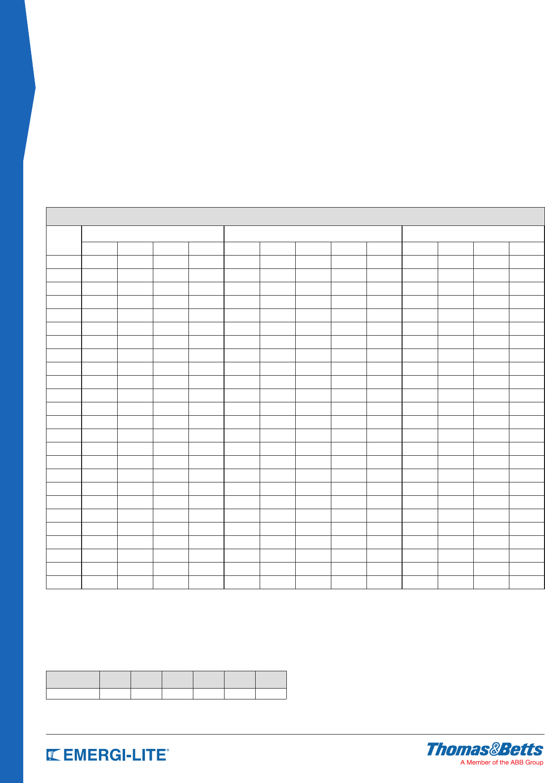
148
ACCESSORIES & GENERAL INFO
Wire Size Guard
Determining Wire Size
The following information is provided to assist in designing proper emergency lighting systems effectively and economically by using the smallest permissible wire size
for load circuits. When remote lighting xtures and/or exit signs are connected to emergency lighting units, circuit runs must be of sufcient size to maintain a proper
operating voltage to all lamps. The National Electrical Code limits voltage to drop to a maximum of 5% of nominal. The table below gives the maximum length or wire
run based on systems voltage, wire gauge and total wattage on the run. To determine the maximum length of a wire run not listed, divide the value of the load in
watts into the constant listed at the bottom of each row. Example, the maximum wire run for #10 wire on a 12 volt system, with a 54 watt load, is 3397 ÷ 54 or, or 62
feet.
Conversely, to determine the maximum load on a run of known length, divide the length into the constant. Example, a 36 foot run of #12 wire on a 6 volt systems can
be loaded to, 534 ÷ 36, or 14 watts; on #10 wire, 23 watts.
WIRING DISTANCE IN FEET (MAXIMUM VOLTAGE DROP 5%)
Total watts
on wire
run
6 volt wire size 12 volt wire size 24 volt wire size
#12 #10 #8 #6 #12 #10 #8 #6 #4 #12 #10 #8 #6
6 89 141 225 357 356 566 900 1431 + 1425 + + +
8 66 106 168 268 267 424 675 1073 1707 1068 1698 + +
9 59 94 150 238 237 377 600 954 1517 949 1509 + +
10 53 84 135 214 213 339 540 859 1366 854 1358 + +
12 44 70 112 178 178 283 450 715 1138 712 1132 1801 +
16 33 53 84 134 133 212 337 536 853 534 849 1350 +
18 29 47 75 119 118 188 300 477 758 474 754 1200 1909
24 22 35 56 89 89 141 225 357 569 356 566 900 1431
25 21 33 54 85 85 135 216 343 546 341 543 864 1374
27 19 31 50 79 79 125 200 318 505 316 503 800 1272
30 17 28 45 71 71 113 180 286 455 284 452 720 1145
36 14 23 37 59 59 94 150 238 379 237 377 600 954
42 12 20 32 51 50 80 128 204 325 203 323 514 818
45 11 18 30 47 47 75 120 190 303 189 301 480 763
48 11 17 28 44 44 70 112 178 284 178 283 450 715
50 10 16 27 42 42 67 108 171 273 170 271 432 687
75 7 11 18 28 28 45 72 114 182 113 181 288 458
100 5 8 13 21 21 33 54 85 136 85 135 216 343
150 — 5 9 14 14 22 36 57 91 56 90 144 229
200 — — 6 10 10 16 27 42 68 42 67 108 171
250 — — 5 8 8 13 21 34 54 34 54 86 137
300 — — — 7 7 11 18 28 45 28 45 72 114
400 — — — 5 5 8 13 21 34 21 33 54 85
500 — — — — — 6 10 17 27 17 27 43 68
Constant 534 849 1350 2148 2137 3397 5403 8590 13660 8548 13588 21613 34363
Longer Wire Runs
The wiring distances give the maximum length of a battery circuit, assuming
that the entire load is concentrated at the end of the circuit. If loads are
uniformly spaced along the circuit path (equal watts, equal distances), the
lengths in the table may be increased, based on number of xtures on a given
circuit, by means of the chart and formula below.
For example, a 36 foot long, 6 volt circuit has (3) 9 watt heads spaced 12 feet
apart. According to the wire run table, # 8 wire must be used (at 50 feet for a
5% voltage drop.) but, by multiplying the
31 feet for #10 wire by 1.5, a 461/2 foot wire run is acceptable, so #10 wire
may be used and still meet the 5% voltage drop limitation.
Note: According to the National Electrical Code, Article 720-Y, the smallest
permissible wire size for systems under 50 volts is the
#12 wire gauge.
NUMBER OF
FIXTURES 23456N
Multiply by Feet 1.33 1.5 1.6 1.67 1.71 2N/ (n+1)

149
ACCESSORIES & GENERAL INFO.
National Electrical Code
ARTICLE 700 – EMERGENCY SYSTEMS
I. General
700.1. Scope.
The provisions of this article apply to the electrical safety of the installation, operation, and
maintenance of emergency systems consisting of circuits and equipment intended to supply,
distribute, and control electricity for illumination or power, or both, to required facilities when
the normal electrical supply or system is interrupted.
(FPN No. 1): For further information regarding wiring and installation of emergency systems in
health care facilities, see Article 517.
(FPN No. 2): For further information regarding performance and maintenance of emergency
systems in health care facilities, see Standard for Health Care Facilities, NFPA 99-1999.
(FPN No. 3): Emergency systems are generally installed in places of assembly where artificial
illumination is required for safe exiting and for panic control in buildings subject to occupancy
by large numbers of persons, such as hotels, theaters, sports arenas, health care facilities,
and similar institutions. Emergency systems may also provide power for such functions as
ventilation where essential to maintain life, fire detection and alarm systems, elevators, fire
pumps, public safety communications systems, industrial processes where current interruption
would produce serious life safety or health hazards, and similar functions.
(FPN No. 4): For specification of locations where emergency lighting is considered essential to
life safety, see Life Safety Code, NFPA 101-2000.
(FPN No. 5): For further information regarding performance of emergency and standby power
systems, see Standard for Emergency and Standby Power Systems, NFPA 110-
1999.
700.2. Definitions
Emergency Systems. Those systems legally required and classed as emergency by municipal,
state, federal or other codes, or by any governmental agency having jurisdiction. These
systems are intended to automatically supply illumination, power or both, to designated
areas and equipment in the event of failure of the normal supply or in the event of accident
to elements of a system intended to supply, distribute, and control power and illumination
essential for safety to human life.
Informational Note: Emergency systems are generally installed in places of assembly where
artificial illumination is required for safe exiting and for panic control in buildings subject
to occupancy by large numbers of persons, such as hotels, theatres, sports, arenas, health
care facilities, and similar institutions. Emergency systems may also provide power for such
functions as ventilation where essential to maintain life, fire detection and alarm systems,
elevators, fire pumps, public safety communications systems, industrial processes where
current interruption would produce serious life safety or health hazards, and similar functions.
Relay automatic Load Control. A device used to energize switched or normally-off lighting
equipment from an emergency supply in the vent of loss of the normal supply, and to de-
energize or return the equipment to normal status when the normal supply is restored.
Informational Note: For requirements covering automatic load control relays, see ANSI/UL 924,
Emergency Lighting and Power Equipment
700.3.Tests and Maintenance.
(A) Conduct or Witness Test. The authority having jurisdiction shall conduct or witness a test
of the complete system upon installation and periodically afterward.
(B) Tested Periodically. Systems shall be tested periodically on a schedule acceptable to the
authority having jurisdiction to ensure the systems are maintained in proper operating
condition.
(C) Battery Systems Maintenance. Where battery systems or unit equipment are involved,
including batteries used for starting, control, or ignition in auxiliary engines, the authority
having jurisdiction shall require periodic maintenance.
(D) Written Record. A written record shall be kept of such tests and maintenance.
(E) Testing Under Load. Means for testing all emergency lighting and power systems during
maximum anticipated load conditions shall be provided.
Informational Note: For requirements covering automatic load control relays, see ANSI/UL 024,
Emergency Lighting and Power Equipment.
700.4. Capacity.
(A) Capacity and Rating. An emergency system shall have adequate capacity and rating for all
loads to be operated simultaneously. The emergency system equipment shall be suitable
for the maximum available fault current at its terminals.
(B) Selective Load Pickup, Load Shedding, and Peak Load Shaving. The alternate power
source shall be permitted to supply emergency, legally required standby, and optional
standby system loads where the source has adequate capacity or where automatic
selective load pickup and load shedding is provided as needed to ensure adequate power
to (1) the emergency circuits; (2) the legally required standby circuits; and (3) the optional
standby circuits, in that order of priority. The alternate power source shall be permitted to
be used for peak load shaving, provided the above conditions are met.
Peak load shaving operation shall be permitted for satisfying the test requirement of Section
700.3(B), provided all other conditions of Section 700.3 are met. A portable or temporary
alternate source shall be available whenever the emergency generator is out of service for
major maintenance or repair.
700.5. Transfer Equipment.
(A) General. Transfer equipment, including automatic transfer switches, shall be automatic and
identified for emergency use and approved by the authority having jurisdiction. Transfer
equipment shall be designed and installed to prevent the inadvertent interconnection of
normal and emergency sources of supply in any operation of the transfer equipment.
Transfer equipment and electric power production systems installed to permit operation in
parallel with the normal source shall meet the requirements of article 705.
(B) Bypass Isolation Switches. Means shall be permitted to bypass and isolate the transfer
equipment. Where bypass isolation switches are used, inadvertent parallel operation shall
be avoided.
(C) Automatic transfer switches shall be electrically operated and mechanically held.
(D) Use. Transfer equipment shall supply only emergency loads.
700-6. Signals. Audible and visual signal devices shall be provided, where practicable, for the
following purposes described in 700.6(A) through (D).
(A) Derangement. To indicate derangement of the emergency source.
(B) Carrying Load. To indicate that the battery is carrying load.
(C) Not Functioning. To indicate that the battery charger is not functioning.
(D) Ground Fault. To indicate a ground fault in solidly grounded wye emergency systems of
more than 150 volts to ground and circuit protective devices rated 1000 amperes or more.
The sensor for the ground-fault signal devices shall be located at, or ahead of, the main
system disconnecting means for the emergency source, and the maximum setting of the
signal devices shall be for a ground-fault current of 1200 amperes. Instructions on the
course of action to be taken in event of indicated ground fault shall be located at or near
the sensor location.
Informational Note: For signals for generator sets, see NFPA 110-2010, Standard for Emergency
and Standby Power Systems
700.7. Signs.
(A) Emergency Sources. A sign shall be placed at the service entrance equipment indicating
type and location of on-site emergency power sources.
Exception: A sign shall not be required for individual unit equipment as specified in
Section 700-12(F).
(B) Grounding. Where removal of a grounding or bonding connection in the normal power
source equipement interrupts the grounding electrode conductor connection to the alternate
power source(s) grounded conductor, a warning sign shall be installed at the normal power
source equipment stating:
WARNING
SHOCK HAZARD EXISTS IF GROUNDING ELECTRODE CONDUCTOR OR BONDING
JUMPER CONNECTION IN THIS EQUIPMENT IS REMOVED WHILE ALTERNATE SOURCE(S) IS
ENERGIZED.
II. Circuit Wiring
700-10. Wiring, Emergency System.
(A) Identification. All boxes and enclosures (including transfer switches, generators, and
power panels) for emergency circuits shall be permanently marked so they will be readily
identified as a component of an emergency circuit or system.
(B) Wiring. Wiring of two or more emergency circuits supplied from the same source shall be
permitted in the same raceway, cable, box, or cabinet. Wiring from an emergency source
distribution overcurrent protection to emergency loads shall be kept entirely independent of
all other wiring and equipment, unless otherwise permitted in (1) through (5):
(1) Wiring from the normal power source located in transfer equipment enclosures.
(2) Wiring supplied from two sources in exit or emergency luminaires
(3) Wiring from two sources in a listed load control relay supplying exit or emergency
luminaires, or in a common junction box, attached to exit or emergency luminaires
(4) Wiring within a common junction box attached to unit equipment, containing only the
branch circuit supplying the unit equipment and the emergency circuit supplied by the
unit equipment.
(5) Wiring from an emergency source to supply any combination of emergency, legally required,
or optional loads in accordance with (a), (b), (c) and (d):
a. From separate vertical switchboard sections, with or without a common bus, or from
individual disconnects mounted in separate enclosures.

150
ACCESSORIES & GENERAL INFO
b. The common bus or separate sections of the switchboard or the individual enclosures shall
be permitted to be supplied by single or multiple feeders without overcurrent protection at
the source Exception to (5)(b): Overcurrent protection shall be permitted at the source or
for the equipment, provided the overcurrent protection complies with the requirements of
700.27
c. Legally required and optional standby circuits shall not originate from the same vertical
switchboard section, panel board enclosure, or individual disconnect enclosure as
emergency circuits.
d. It shall be permissible to utilize single or multiple feeders to supply distribution equipment
between an emergency source and the point where the combination of emergency, legally
required, or optional loads are separated.
(C) Wiring Design and Location. Emergency wiring circuits shall be designed and located to
minimize the hazards that might cause failure due to flooding, fire, icing, vandalism, and
other adverse conditions.
(D) Fire Protection. Emergency systems shall meet the following additional requirements (D)
(1) through (D)(3) in assembly occupancies for not less than 1000 persons or in buildings
above 23 m (75 ft) in height with any of the following occupancy classes: assembly,
educational, residential, detention and correctional, business, and mercantile.
Informational Note: For the definition of Occupancy Classification, see Section 6.1 of NFPA
101-2009, Life Safety Code
(1) Feeder-circuit wiring shall meet one of the following conditions:
(1) Be installed in spaces or areas that are fully protected by an approved automatic fire
suppression system.
(2) Be listed electrical circuit protective system with a minimum 2-hour fire rating.
Informational note: UL guide information for electrical circuit protective systems (FHIT)
contains information on proper installation requirements to maintain the fire rating
(3) Be protected by a listed thermal barrier system for electrical system components with a
minimum 2-hour fire rating.
(4) Be protected by a listed fire-rated assembly that has a minimum fire rating of 2 hours and
contains only emergency wiring circuits
(5) Be encased in a minimum of 50 mm (2 in) of concrete
(2) Feeder-Circuit Equipment. Equipment for feeder circuits (transfer switches, transformers,
panel boards) shall be either located in spaces fully protected by approved automatic fire
suppression systems ( including sprinklers and carbon dioxide systems) or in spaces with
a 2-hour fire resistance rating.
(3) Generator Control Wiring. Control conductors installed between the transfer equipment and
the emergency generator shall be kept entirely independent of all other wiring and shall
meet the conditions of 700.10(D)(1)
III. Sources of Power
700.12. General Requirements. Current supply shall be such that, in the event of failure of the
normal supply to, or within, the building or group of buildings concerned, emergency lighting,
emergency power, or both will be available within the time required for the application but not
to exceed 10 seconds. The supply system for emergency purposes, in addition to the normal
services to the building and meeting the general requirements of this section, shall be one
or more of the types of systems described in 700.12(A) through (D) below. Unit equipment
in accordance with Section 700.12(E) shall satisfy the applicable requirements of this article.
In selecting an emergency source of power, consideration shall be given to the occupancy and
the type of service to be rendered, whether of minimum duration, as for evacuation of a theater,
or longer duration, as for supplying emergency power and lighting due to an indefinite period of
current failure from trouble either inside or outside the building.
Equipment shall be designed and located to minimize the hazards that might cause complete
failure due to flooding, fires, icing, and vandalism.
Equipment for sources of power as described in Sections 700.12(A) through (E) where located
within assembly occupancies for greater than 1000 persons or in buildings above 23 m (75
ft) in height with any of the following occupancy classes: assembly, educational, residential,
detention and correctional, business, and mercantile, shall be installed either in spaces fully
protected by approved automatic fire suppression systems (sprinklers, carbon dioxide systems,
and so forth), or in spaces with a 1-hour fire rating.
Informational note No. 1: For definition of Occupancy Classification, see Section 6.1of NFPA
101-2009, Life Safety Code.
Informational note No. 2: Assignment of degree of reliability of the recognized emergency
supply system depends on the careful evaluation of the variables at each particular installation.
For further information, see ANSI/IEEE 493-2007, Recommended Practice for the Design of
Reliable Industrial and Commercial Power Systems.
(A) Storage Battery.
Storage batteries used as source of power for emergency systems shall be of suitable rating
and capacity to supply and maintain the total load for a period of 1 1/2 hours minimum, without
the voltage applied to the load falling below 87 1/2 percent of normal.
Batteries, whether of the acid or alkali type, shall be designed and constructed to meet the
requirements of emergency service and shall be compatible with the charger for that particular
installation.
For a sealed battery, the container shall not be required to be transparent. However, for the lead
acid battery that requires water additions, transparent or translucent jars shall be furnished.
Automotive-type batteries shall not be used.
An automatic battery charging means shall be provided.
(B) Generator Set.
(1) Prime Mover-Driven. For a generator set driven by a prime mover acceptable to the
authority having jurisdiction and sized in accordance with Section 700-5. Means shall be
provided for automatically starting the prime mover on failure of the normal service and
for automatic transfer and operation of all required electrical circuits. A time-delay feature
permitting a 15-minute setting shall be provided to avoid retransfer in case of short-time
reestablishment of the normal source.
(2) Internal Combustion Engines as Prime Movers. Where internal combustion engines are used
as the prime mover an on-site fuel supply shall be provided with an on-premise fuel supply
sufficient for not less than 2 hours full-demand operation of the system. Where power is
needed for the operation of the fuel transfer pumps to deliver fuel to a generator set dry
tank, this pump shall be connected to the emergency power system.
(3) Dual Supplies. Prime movers shall not be solely dependent upon a public utility gas system
for their fuel supply or municipal water supply for their cooling systems. Means shall be
provided for automatically transferring from one fuel supply to another where dual fuel
supplies are used.
Exception: Where acceptable to the authority having jurisdiction, the use of other than on-site
fuels shall be permitted where there is a low probability of a simultaneous failure of both the
off-site fuel delivery system and power from the outside electrical utility company.
(4) Where a storage battery is used for control or signal power, or as the means of starting the
prime mover, it shall be suitable for the purpose and shall be equipped with an automatic
charging means independent of the generator set. Where the battery charger is required for
the operation of the generator set, it shall be connected to the emergency system. Where
power is required for the operation of dampers used to ventilate the generator set, the
dampers shall be connected to the emergency system.
(5) Auxiliary Power Supply. Generator sets that require more than 10 seconds to develop
power shall be permitted is an auxiliary power supply energizes the emergency system until
the generator can pick up the load.
(6) Outdoor Generator Sets. Where an outdoor housed generator set is equipped with a readily
accessible disconnecting means located within sight of the building or structure supplied,
an additional disconnecting means shall not be required where ungrounded conductors
serve or pass through the building or structure. The disconnecting means shall meet the
requirements of 225.36.
Exception: For installations under single management where conditions of maintenance
and supervision ensure that only qualified persons will monitor and service the installation
and where documented safe switching procedures are established and maintained for
disconnection, the generator set disconnecting means shall not be required to be located
within sight of the building of structure served.
(C) Uninterruptible Power Supplies. Uninterruptible power supplies used to provide power
for emergency systems shall comply with the applicable provisions of Sections 700-12(A)
and (B).
(D) Separate Service. Where acceptable to the authority having jurisdiction as suitable for use
as an emergency source of power, an additional service shall be permitted. This service
shall be in accordance with the applicable provisions of Article 230 and following additional
requirements.
(1) Separate service drop or service lateral
(2) Service conductors sufficiently remote electrically and physically from any other service
conductors to minimize the possibility of simultaneous interruption of supply
(E) Fuel Cell System. Fuel Cell Systems used as a source of power for emergency systems
shall be of suitable rating and capacity to supply and maintain the total load for not less than
2 hours of full demand operation.
Installation of a fuel cell system shall meet the requirements of Parts II through VIII of Article
692. Where a single fuel cell system serves as the normal supply for the building or group of
buildings concerned, it shall not serve as the sole source of power for the emergency standby
system.
(F) Unit Equipment. Individual unit equipment for emergency illumination shall consist of the
following:
(1) A rechargeable battery
(2) A battery charging means
(3) Provisions for one or more lamps mounted on the equipment, or shall be permitted to have
terminals for remote lamps, or both and
National Electrical Code

151
ACCESSORIES & GENERAL INFO.
(4) A relaying device arranged to energize the lamps automatically upon failure of the supply
to the unit equipment.
The batteries shall be of suitable rating and capacity to supply and maintain at not less than
87 1/2 percent of the nominal battery voltage for the total lamp load associated with the unit for
a period of at least 1 1/2 hours, or the unit equipment shall supply and maintain not less than
60 percent of the initial emergency illumination for a period of at least 1 1/2 hours. Storage
batteries, whether of the acid or alkali type, shall be designed and constructed to meet the
requirements of emergency service.
Unit equipment shall be permanently fixed in place (i.e., not portable) and shall have all wiring
to each unit installed in accordance with the requirements of any of the wiring methods in
Chapter 3.
Flexible cord and plug connection shall be permitted, provided that the cord does not exceed
3 ft (900 mm) in length. The branch circuit feeding the unit equipment shall be the same
branch circuit as that serving the normal lighting in the area and connected ahead of any
local switches. The branch circuit that feeds unit equipment shall be clearly identified at the
distribution panel. Emergency luminaire’s (illumination fixtures) that obtain power from a unit
equipment and are not part of the unit equipment shall be wired to the unit equipment as
required by Section 700-10 and by one of the wiring methods of Chapter 3.
Exception No. 1: In a separate and uninterrupted area supplied by a minimum of three
normal lighting circuits, a separate branch circuit for unit equipment shall
be permitted if it originates from the same panelboard as that of the normal
lighting circuits and is provided with a lock-on feature.
Exception No. 2: Remote heads providing lighting for the exterior of an exit door shall be
permitted to be supplied by the unit equipment serving the area immediately
inside the exit door.
IV. Emergency System Circuits for Lighting and Power
700.15. Loads on Emergency Branch Circuits. No appliances and no lamps, other than those
specified as required for emergency use, shall be supplied by emergency lighting
circuits.
700.16. Emergency illumination. Emergency illumination shall include all required means of
egress lighting, illuminated exit signs, and all other lights specified as necessary to
provide required illumination.
Emergency lighting systems shall be designed and installed so that the failure of any individual
lighting element, such as the burning out of a light bulb, cannot leave in total darkness any
space that requires emergency illumination.
Where high-intensity discharge lighting such as high- and low-pressure sodium mercury
vapor, and metal halide is used as the sole source of normal illumination, the emergency
lighting system shall be required to operate until normal illumination has been restored.
Exception: Where alterative means that ensure the emergency lighting illumination level is
maintained shall be permitted.
700.17. Branch Circuits for Emergency Lighting. Branch circuits that supply emergency
lighting shall be installed to provide service from a source complying with Section
700-12 when the normal supply for lighting is interrupted. Such installations shall
provide either one of the following:
(1) An emergency lighting supply, independent of the normal lighting supply, with provisions
for automatically transferring the emergency lights upon the event of failure of the normal
lighting branch circuit
(2) Two or more branch circuits supplied from separate and complete systems with independent
power sources. One of the two power sources and systems shall be part of the emergency
system and the other shall be permitted to be part of the normal power source and system.
Each system shall provide sufficient power for emergency lighting purposes.
Unless both systems are used for regular lighting purposes and are both kept lighted, means
shall be provided for automatically energizing either system upon failure of the other. Either or
both systems shall be permitted to be a part of the general lighting of the protected occupancy
if circuits supplying lights for emergency illumination arc installed in accordance with other
sections of this article.
700.18. Circuits for Emergency Power. For branch circuits that supply equipment classed
as emergency, there shall be an emergency supply source to which the load will be
transferred automatically upon the failure of the normal supply.
V. Control—Emergency Lighting Circuits
700.20. Switch Requirements. The switch or switches installed in emergency lighting circuits
shall be arranged so that only authorized persons will have control of emergency
lighting.
Exception No. 1: Where two or more single-throw switches are connected in parallel to control
a single circuit, at least one of these switches shall be accessible only to authorized persons.
Exception No. 2: Additional switches that act only to put emergency lights into operation but not
disconnect them shall be permissible.
Switches connected in series or 3- and 4-way switches shall not be used.
700.21. Switch Location. All manual switches for controlling emergency circuits shall be in
locations convenient to authorized persons responsible for their actuation. In facilities covered
by Articles 518 and 520, a switch for controlling emergency lighting systems shall be located
in the lobby or at a place conveniently accessible thereto. In no case shall a control switch for
emergency lighting be placed in a motion-picture projection booth or on a stage or platform.
Exception: Where multiple switches are provided, one such switch shall be permitted in such
locations where arranged so that it can energize the circuit only, but cannot deenergize the
circuit.
700.22. Exterior Lights. Those lights on the exterior of a building that are not required
for illumination when there is sufficient daylight shall be permitted to be controlled by an
automatic light-actuated device.
700.23 Dimmer Systems. A dimmer system containing more than one dimmer and listed for
use in emergency systems shall be permitted to be used as a control device for energizing
emergency lighting circuits. Upon failure of normal power, the dimmer system shall be
permitted to selectively energize only those branch circuits required to provide minimum
emergency illumination. All branch circuits supplied by the dimmer system cabinet shall
comply with the wiring methods of Article 700.
700.24 Automatic Load Control Relay. If an emergency lighting load is automatically energized
upon loss of the normal supply, a listed automatic load control relay shall be permitted to
energize the load. The load control relay shall not be used to transfer equipment.
VI. Overcurrent Protection
700-25. Accessibility. The branch-circuit overcurrent devices in emergency circuits shall be
accessible to authorized persons only.
(FPN): Fuses and circuit breakers for emergency circuit overcurrent protection where
coordinated to ensure selective clearing of fault currents, increase overall reliability of the
system.
700-26. Ground-Fault Protection of Equipment. The alternate source for emergency
systems shall not be required to have ground-fault protection of equipment with automatic
disconnecting means. ground-fault indication of the emergency source shall be provided in
accordance with Section 700.6(D).
700-27. Coordination. Emergency system(s) overcurrent devices shall be selectively
coordinated with all supply side overcurrent protective devices.
Exception: Selective coordination shall not be required between two overcurrent devices
located in series if no loads are connected in parallel with the downstream device.
National Electrical Code© 2011
National Electrical Code® is a registered trademark of the National Fire Protection Association
National Electrical Code

152
ACCESSORIES & GENERAL INFO
Life Safety Code
7.8 Illumination of Means of Egress.
7.8.1 General.
7.8.1.1* Illumination of means of egress shall be provided in accordance with Section 7.8
for every building and structure where required in Chapters 11 through 43. For the purposes
of this requirement, exit access shall include only designated stairs, aisles, corridors, ramps,
escalators, and passageways leading to an exit. For the purposes of this requirement, exit
discharge shall include only designated stairs, aisles, corridors, ramps, escalators, walkways,
and exit passageways leading to a public way.
7.8.1.2 Illumination of means of egress shall be continuous during the time that the conditions
of occupancy require that the means of egress be available for use, unless otherwise provided
in 7.8.1.2.2.
7.8.1.2.1 Artificial lighting shall be employed at such locations and for such periods of time
as are necessary to maintain the illumination to the minimum criteria values herein specified.
7.8.1.2.2 Unless prohibited by Chapters 11 through 43, automatic, motion sensor–type lighting
switches shall be permitted within the means of egress, provided that the switch controllers
comply with all of the following:
(1) The switch controllers are listed.
(2) The switch controllers are equipped for fail-safe operation, the and evaluated for this
purpose.
(3) The illumination timers are set for a minimum 15-minute duration, and the duration.
(4) The motion sensor is activated by any occupant movement in the area served by the lighting
units.
(5) The switch controller is activated by activation of the building fire alarm system,
if provided.
7.8.1.2.3* Energy-saving sensors, switches, timers, or controllers shall be approved and shall
not compromise the continuity of illumination of the means of egress required by 7.8.1.2.
7.8.1.3* The floors and other walking surfaces within an exit and within the portions of the exit
access and exit discharge designated in 7.8.1.1 shall be illuminated as follows:
(1) During conditions of stair use, the minimum illumination for new stairs shall be at least 10
ft-candle (108 lux), measured at the walking surfaces.
(2) The minimum illumination for floors and walking surfaces, other than new stairs during
conditions of stair use, shall be to values of at least 1 ft-candle (10.8 lux), measured at
the floor.
(3) In assembly occupancies, the illumination of the walking surfaces of exit access shall be at
least 0.2 ft-candle (2.2 lux) during periods of performances or projections involving directed
light.
(4)* The minimum illumination requirements shall not apply where operations or processes
require low lighting levels.
7.8.1.4* Required illumination shall be arranged so that the failure of any single lighting unit
does not result in an illumination level of less than 0.2 ft-candle (2.2 lux) in any designated
area.
7.8.1.5 The equipment or units installed to meet the requirements of Section 7.10 also
shall be permitted to serve the function of illumination of means of egress, provided that all
requirements of Section 7.8 for such illumination are met.
7.8.2 Sources of Illumination.
7.8.2.1* Illumination of means of egress shall be from a source considered reliable by the
authority having jurisdiction.
7.8.2.2 Battery-operated electric lights and other types of portable lamps or lanterns shall
not be used for primary illumination of means of egress. Battery-operated electric lights shall
be permitted to be used as an emergency source to the extent permitted under Section 7.9.
7.9 Emergency Lighting.
7.9.1 General.
7.9.1.1* Emergency lighting facilities for means of egress shall be provided in accordance with
Section 7.9 for the following:
(1) Buildings or structures where required in Chapters 11 through 43
(2) Underground and limited access structures as addressed in Section 11.7
(3) High-rise buildings as required by other sections of this Code
(4) Doors equipped with delayed-egress locks
(5) Stair shafts and vestibules of smoke proof enclosures, for which the following also apply:
(a) The stair shaft and vestibule shall be permitted to include a standby generator that is
installed for the smoke proof enclosure mechanical ventilation equipment.
(b) The standby generator shall be permitted to be used for the stair shaft and vestibule
emergency lighting power supply.
(6) New access-controlled egress doors in accordance with 7.2.1.6.2.
7.9.1.2 For the purposes of 7.9.1.1, exit access shall include only designated stairs, aisles,
corridors, ramps, escalators, and passageways leading to an exit. For the purposes of 7.9.1.1,
exit discharge shall include only designated stairs, ramps, aisles, walkways, and escalators
leading to a public way.
7.9.1.3 Where maintenance of illumination depends on changing from one energy source to
another, a delay of not more than 10 seconds shall be permitted.
7.9.2 Performance of System.
7.9.2.1* Emergency illumination shall be provided for a minimum of 11⁄2 hours in the event
of failure of normal lighting. Emergency lighting facilities shall be arranged to provide initial
illumination that is not less than an average of 1 ft-candle (10.8 lux) and, at any point, not less
than 0.1 ft-candle (1.1 lux), measured along the path of egress at floor level. Illumination levels
shall be permitted to decline to not less than an average of 0.6 ft-candle (6.5 lux) and, at any
point, not less than 0.06 ft-candle (0.65 lux) at the end of 11⁄2 hours. A maximum-to-minimum
illumination uniformity ratio of 40 to 1 shall not be exceeded.
7.9.2.2 New emergency power systems for emergency lighting shall be at least Type 10,
Class 1.5, Level 1, in accordance with NFPA110, Standard for Emergency and Standby Power
Systems.
7.9.2.3* The emergency lighting system shall be arranged to provide the required illumination
automatically in the event of any interruption of normal lighting due to any of the following:
(1) Failure of a public utility or other outside electrical power supply
(2) Opening of a circuit breaker or fuse
(3) Manual act(s), including accidental opening of a switch controlling normal lighting facilities
7.9.2.4 Emergency generators providing power to emergency lighting systems shall be
installed, tested, and maintained in accordance with NFPA 110, Standard for Emergency and
Standby Power Systems. Stored electrical energy systems, where required in this Code, other
than battery systems for emergency luminaires
in accordance with 7.9.2.5, shall be installed and tested in accordance with NFPA 111,
Standard on Stored Electrical Energy Emergency and Standby Power Systems.
7.9.2.5 Unit equipment and battery systems for emergency luminaires shall be listed to ANSI/
UL 924, Standard for Emergency Lighting and Power Equipment.
7.9.2.6* Existing battery-operated emergency lights shall use only reliable types of rechargeable
batteries provided with suitable facilities for maintaining them in properly charged condition.
Batteries used in such lights or units shall be approved for their intended use and shall comply
with NFPA 70, National Electrical Code.
7.9.2.7 The emergency lighting system shall be either continuously in operation or shall be
capable of repeated automatic operation without manual intervention.
7.9.3 Periodic Testing of Emergency Lighting Equipment.
7.9.3.1 Required emergency lighting systems shall be tested in accordance with one of the
three options offered by 7.9.3.1.1, 7.9.3.1.2, or 7.9.3.1.3.
7.9.3.1.1 Testing of required emergency lighting systems shall be permitted to be conducted
as follows:
(1) Functional testing shall be conducted monthly, with a minimum of 3 weeks and a maximum
of 5 weeks between tests, for not less than 30 seconds, except as otherwise permitted by
7.9.3.1.1(2).
(2)* The test interval shall be permitted to be extended beyond 30 days with the approval of
the authority having jurisdiction.
(3) Functional testing shall be conducted annually for a minimum of 11⁄2 hours if the emergency
lighting system is battery powered.
(4) The emergency lighting equipment shall be fully operational for the duration of the tests
required by 7.9.3.1.1(1) and (3).
(5) Written records of visual inspections and tests shall be kept by the owner for inspection by
the authority having jurisdiction.

153
ACCESSORIES & GENERAL INFO.
Life Satefy Code
7.9.3.1.2 Testing of required emergency lighting systems shall be permitted to be conducted
as follows:
(1) Self-testing/self-diagnostic battery-operated emergency lighting equipment shall
be provided.
(2) Not less than once every 30 days, self-testing/self-diagnostic battery-operated emergency
lighting equipment shall automatically perform a test with a duration of a minimum of 30
seconds and a diagnostic routine.
(3) Self-testing/self-diagnostic battery-operated emergency lighting equipment shall indicate
failures by a status indicator.
(4) A visual inspection shall be performed at intervals not exceeding 30 days.
(5) Functional testing shall be conducted annually for a minimum of 1-1/2 hours.
(6) Self-testing/self-diagnostic battery-operated emergency lighting equipment shall be fully
operational for the duration of the 11⁄2-hour test.
(7) Written records of visual inspections and tests shall be kept by the owner for inspection by
the authority having jurisdiction.
7.9.3.1.3 Testing of required emergency lighting systems shall be permitted to be conducted
as follows:
(1) Computer-based, self-testing/self-diagnostic battery-operated emergency lighting
equipment shall be provided.
(2) Not less than once every 30 days, emergency lighting equipment shall automatically
perform a test with a duration of a minimum of 30 seconds and a diagnostic routine.
(3) The emergency lighting equipment shall automatically perform annually a test for a
minimum of 11⁄2 hours.
(4) The emergency lighting equipment shall be fully operational for the duration of the tests
required by 7.9.3.1.3(2) and (3).
(5) The computer-based system shall be capable of providing a report of the history of tests
and failures at all times.
7.10 Marking of Means of Egress.
7.10.1 General.
7.10.1.1 Where Required. Means of egress shall be marked in accordance with Section 7.10
where required in Chapters 11 through 43.
7.10.1.2 Exits.
7.10.1.2.1* Exits, other than main exterior exit doors that obviously and clearly are identifiable
as exits, shall be marked by an approved sign that is readily visible from any direction of exit
access.
7.10.1.2.2*
Horizontal components of the egress path within an exit enclosure shall be marked by approved
exit or directional exit signs where the continuation of the egress path is not obvious.
7.10.1.3 Exit Door Tactile Signage. Tactile signage shall be provided to meet all of the
following criteria, unless otherwise provided in 7.10.1.4:
(1) Tactile signage shall be located at each exit door requiring an exit sign.
(2) Tactile signage shall read as follows: EXIT.
(3) Tactile signage shall comply with ICC/ANSI A117.1, American National Standard for
Accessible and Usable Buildings and Facilities.
7.10.1.4 Existing Exemption. The requirements of 7.10.1.3 shall not apply to existing
buildings, provided that the occupancy classification does not change.
7.10.1.5 Exit Access.
7.10.1.5.1 Access to exits shall be marked by approved, readily visible signs in all cases where
the exit or way to reach
the exit is not readily apparent to the occupants.
7.10.1.5.2* New sign placement shall be such that no point in an exit access corridor is in
excess of the rated viewing distance or 100 ft (30 m), whichever is less, from the nearest sign.
7.10.1.6* Floor Proximity Exit Signs. Where floor proximity exit signs are required in Chapters
11 through 43, such signs shall comply with 7.10.3, 7.10.4, 7.10.5, and 7.10.6 for externally
illuminated signs and 7.10.7 for internally illuminated signs. Such signs shall be located near
the floor level in addition to those signs required for doors or corridors. The bottom of the sign
shall be not less than 6 in. (150 mm), but not more than 18 in.(455 mm), above the floor. For
exit doors, the sign shall be mounted on the door or adjacent to the door, with the nearest edge
of the sign within 4 in. (100 mm) of the door frame.
7.10.1.7* Floor Proximity Egress Path Marking. Where floor proximity egress path marking
is required in Chapters 11
through 43, an approved floor proximity egress path marking system that is internally
illuminated shall be installed within 18 in. (455 mm) of the floor. Floor proximity egress path
marking systems shall be listed in accordance with ANSI/UL 1994, Standard for Luminous
Egress Path Marking Systems. The system shall provide a visible delineation of the path of travel
along the designated exit access and shall be essentially continuous, except as interrupted by
doorways, hallways, corridors, or other such architectural features. The system shall operate
continuously or at any time the building fire alarm system is activated. The activation, duration,
and continuity of operation of the system shall be in accordance with 7.9.2. The system shall
be maintained in accordance with the product manufacturing listing.
7.10.1.8* Visibility. Every sign required in Section 7.10 shall be located and of such size,
distinctive color, and design that it is readily visible and shall provide contrast with decorations,
interior finish, or other signs. No decorations, furnishings, or equipment that impairs visibility
of a sign shall be permitted. No brightly illuminated sign (for other than exit purposes), display,
or object in or near the line of vision of the required exit sign that could detract attention from
the exit sign shall be permitted.
7.10.1.9 Mounting Location. The bottom of new egress markings shall be located at a vertical
distance of not more than 6 ft 8 in. (2030 mm) above the top edge of the egress opening
intended for designation by that marking. Egress markings shall be located at a horizontal
distance of not more than the required width of the egress opening, as measured from the
edge of the egress opening intended for designation by that marking to the nearest edge of
the marking.
7.10.2 Directional Signs.
7.10.2.1* A sign complying with 7.10.3, with a directional indicator showing the direction of
travel, shall be placed in every location where the direction of travel to reach the nearest exit
is not apparent.

154
ACCESSORIES & GENERAL INFO
7.10.2.2 Directional exit signs shall be provided within horizontal components of the egress
path within exit enclosures as required by 7.10.1.2.2.
7.10.3* Sign Legend.
7.10.3.1 Signs required by 7.10.1 and 7.10.2 shall read as follows in plainly legible letters, or
other appropriate wording shall be used:
EXIT
7.10.3.2* Where approved by the authority having jurisdiction, pictograms in compliance with
NFPA 170, Standard for
Fire Safety and Emergency Symbols, shall be permitted.
7.10.4* Power Source. Where emergency lighting facilities are required by the applicable
provisions of Chapters 11 through 43 for individual occupancies, the signs, other than approved
self-luminous signs and listed photoluminescent signs in accordance with 7.10.7.2, shall be
illuminated by the emergency
lighting facilities. The level of illumination of the signs shall be in accordance with 7.10.6.3
or 7.10.7 for the required emergency lighting duration as specified in 7.9.2.1. However, the
level of illumination shall be permitted to decline to 60 percent at the end of the emergency
lighting duration.
7.10.5 Illumination of Signs.
7.10.5.1* General. Every sign required by 7.10.1.2, 7.10.1.5, or 7.10.8.1, other than where
operations or processes require low lighting levels, shall be suitably illuminated by a reliable
light source. Externally and internally illuminated signs shall be legible in both the normal and
emergency lighting mode.
7.10.5.2* Continuous Illumination.
7.10.5.2.1 Every sign required to be illuminated by 7.10.6.3, 7.10.7, and 7.10.8.1 shall be
continuously illuminated as required under the provisions of Section 7.8, unless otherwise
provided in 7.10.5.2.2.
7.10.5.2.2* Illumination for signs shall be permitted to flash on and off upon activation of the
fire alarm system.
7.10.6 Externally Illuminated Signs.
7.10.6.1* Size of Signs.
7.10.6.1.1 Externally illuminated signs required by 7.10.1 and 7.10.2, other than approved
existing signs, unless otherwise provided in 7.10.6.1.2, shall read EXIT or shall use other
appropriate wording in plainly legible letters sized as follows:
(1) For new signs, the letters shall be not less than 6 in. (150 mm) high, with the principal
strokes of letters not less than 3⁄4 in. (19 mm) wide.
(2) For existing signs, the required wording shall be permitted to be in plainly legible letters not
less than 4 in. (100 mm) high.
(3) The word EXIT shall be in letters of a width not less than 2 in. (51 mm), except
the letter I, and the minimum spacing between letters shall be not less than 3⁄8 in. (9.5 mm).
(4) Sign legend elements larger than the minimum established in 7.10.6.1.1(1) through (3) shall
use letter widths, strokes, and spacing in proportion to their height.
7.10.6.1.2 The requirements of 7.10.6.1.1 shall not apply to marking required by 7.10.1.3
and 7.10.1.7.
7.10.6.2* Size and Location of Directional Indicator.
7.10.6.2.1 Directional indicators, unless otherwise provided in 7.10.6.2.2, shall comply with
all of the following:
(1) The directional indicator shall be located outside of the EXIT legend, not less than 3⁄8 in.
(9.5 mm) from any letter.
(2) The directional indicator shall be of a chevron type, as shown in Figure 7.10.6.2.1.
(3) The directional indicator shall be identifiable as a directional indicator at a distance of 40 ft (12 m).
(4) A directional indicator larger than the minimum established for compliance with
7.10.6.2.1(3) shall be proportionately increased in height, width, and stroke.
(5) The directional indicator shall be located at the end of the sign for the direction indicated.
Life Safety Code
7.10.6.2.1 Chevron Type Indicator.
7.10.6.2.2 The requirements of 7.10.6.2.1 shall not apply to approved existing signs.
7.10.6.3* Level of Illumination. Externally illuminated signs shall be illuminated by not less
than 5 ft-candles (54 lux) at the illuminated surface and shall have a contrast ratio of not less
than 0.5.
7.10.7 Internally Illuminated Signs.
7.10.7.1 Listing. Internally illuminated signs shall be listed in accordance with ANSI/UL 924,
Standard for Emergency Lighting and Power Equipment, unless they meet one of the following
criteria:
(1) They are approved existing signs.
(2) They are existing signs having the required wording in legible letters not less than
4 in. (100 mm) high.
(3) They are signs that are in accordance with 7.10.1.3 and 7.10.1.6.
7.10.7.2* Photoluminescent Signs. The face of a photoluminescent sign shall be continually
illuminated while the building is occupied. The illumination levels on the face of the
photoluminescent sign shall be in accordance with its listing. The charging illumination shall
be a reliable light source, as determined by the authority having jurisdiction. The charging light
source, shall be of a type specified in the product markings.
7.10.8 Special Signs.
7.10.8.1 Sign Illumination.
7.10.8.1.1 Where required by other provisions of this Code, special signs shall be illuminated
in accordance with 7.10.5, 7.10.6.3, and 7.10.7.
7.10.8.1.2 Where emergency lighting facilities are required by the applicable provisions of
Chapters 11 through 43, the required illumination of special signs shall additionally be provided
under emergency lighting conditions.
7.10.8.2 Characters. Special signs, where required by other provisions of this Code, shall
comply with the visual character requirements of ICC/ANSI A117.1, American National
Standard for Accessible and Usable Buildings and Facilities.
7.10.8.3* No Exit.
7.10.8.3.1 Any door, passage, or stairway that is neither an exit nor a way of exit access and
that is located or arranged so that it is likely to be mistaken for an exit shall be identified by a
sign that reads as follows:
NO EXIT
7.10.8.3.2 The NO EXIT sign shall have the word NO in letters 2 in. (51 mm) high, with a stroke
width of 3⁄8 in. (9.5 mm), and the word EXIT in letters 1 in. (25 mm) high, with the word EXIT
below the word NO, unless such sign is an approved existing sign.
7.10.8.4 Elevator Signs. Elevators that are a part of a means of egress (see 7.2.13.1) shall
have both of the following signs with a minimum letter height of 5⁄8 in. (16 mm) posted in
every elevator lobby:
(1) *Signs that indicate that the elevator can be used for egress, including any restrictions
on use
(2) *Signs that indicate the operational status of elevators
7.10.8.5* Evacuation Diagram. Where a posted floor evacuation diagram is required in
Chapters 11 through 43, floor
evacuation diagrams reflecting the actual floor arrangement and exit locations shall be posted
and oriented in a location and manner acceptable to the authority having jurisdiction.
7.10.9 Testing and Maintenance.
7.10.9.1 Inspection. Exit signs shall be visually inspected for operation of the illumination
sources at intervals not to exceed 30 days or shall be periodically monitored in accordance
with 7.9.3.1.3.
7.10.9.2 Testing. Exit signs connected to, or provided with, a battery-operated emergency
illumination source, where required in 7.10.4, shall be tested and maintained in accordance
with 7.9.3.

155
ACCESSORIES & GENERAL INFO.
Limited Warranty
1.0 EMERGI-LITE® 6, 12 and 24 volt Emergency Lighting Unit Equipment (excluding lamps and fuses) are fully warranted to be free of defects in material and workmanship under
normal use for a period of three years from date of installation (see Paragraph 2.0).
1.1 EMERGI-LITE® 6, 12 and 24 volt Unit Equipment Batteries are warranted as follows (Warrant below includes the 3-year full warranty on entire unit as called out in Paragraph 1.0).
1.2 EMERGI-LITE® volt Emergency Lighting Unit Equipment (excluding lamps, and fuses) is fully warranted to be free of defects in material and workmanship under normal use for a
period of one year from date of installation (see Paragraph 2.0).
*Maximum Storage life. Must Be Recharged If Not Placed in Service Or Battery Warranty Void
2.0 The full warranty period begins on the date of installation or 90 days from date of shipment, whichever date is earlier.
2.1 Should a defect appear in the equipment or batteries listed in Paragraphs 1.0, 1.1 or 1.2 above within the specified full warranty period, Emergi-Lite® will repair or replace
equipment without charge (see Paragraph 3.3). Such repair or replacement shall be the purchaser’s exclusive remedy.
2.2 The Pro Rata Warranty Period for batteries begins on the date the full warranty period ends.
2.3 A battery determined to be defective during the Pro Rata Warranty Period shall be repaired or replaced at a cost equal to the net price in effect at the time, reduced by the
percentage obtained in multiplying 10% by the number of full years remaining in the total warranty period. Such repair or replacement at this adjusted price shall be the purchaser’s
exclusive remedy.
3.0 All warranties are subject to proper installation and maintenance in accordance with the instructions supplied.
3.1 Any material deemed defective must be returned, freight prepaid, to the factory for evaluation (see Paragraph 5.0-5.3). Any changes in circuitry or components by other than
authorized Emergi-Lite® personnel or its service companies will void the warranty.
3.2 All warranties are limited to the repair and/or replacement or parts or equipment, which, upon examination at our plant, are determined to be defective and in our judgement are
subject to repair or replacement under warranty. Replacement of lamps and fuses is not included in the warranty.
3.3 If new replacement parts are shipped before defective goods are received for evaluation, the replacement parts will be invoiced at the net price in effect at that time. These charges
will be credited if, upon receipt and evaluation of goods, a defect is determined. Only replacement parts will be shipped under these circumstances, if field replacement is possible.
EMERGI-LITE® FACTORY ONLY RESERVES THE RIGHT TO SHIP NEW UNIT EQUIPMENT FOR REPLACEMENT PURPOSES. Units returned after installation cannot be restored to 100%
saleable condition.
4.0 In no event shall Emergi-Lite® be liable for backcharges of any kind, including, without limitation, labor charges for field repair or late penalties.
4.1 This warranty does not cover damages caused by improper maintenance of installation or damage due to installation in areas with other than normal temperatures and
environmental conditions per application specifications. Emergi-Lite® assumes no responsibility for any damage to people, property, apparatus or otherwise resulting from improper
installation or maintenance of its Emergency Lighting Unit Equipment.
4.2 This warranty does not cover damages caused by abuse, fire or Act of God.
4.3 In no event shall Emergi-Lite® be liable for incidental or consequential damages.
4.4 The foregoing warranty is in lieu of all other warranties, expressed or implied, or merchantability, fitness for a particular purpose or any other thing. Except as stated in this warranty,
Emergi-Lite® shall not be liable for any defects in, or breach of any contract relating to, the quality of performance of Emergi-Lite® Equipment under any theory of law including,
without limitation, contract, negligence, strict liability or misrepresentation.
4.5 Emergi-Lite® warranty coverage shall not apply to any equipment of another manufacturer used in conjunction with Emergi-Lite® Equipment.
4.6 Some states do not allow limitation on how long an implied warranty lasts, so the above limitation may not apply to you. Some states do not allow the exclusion or limitation of
incidental or consequential damages, so the above limitation or exclusion may not apply to you. This written warranty gives you specific legal rights and you may also have other
rights which vary from state to state.
5.0 No returned defective materials will be accepted without a Returned Goods Authorization issued in writing by an authorized Emergi-Lite® employee.
5.1 Purchaser is responsible for secure packing of returned materials to provide best possible assurance against damage in shipment.
5.2 Defective batteries of any kind must not be returned to Emergi-Lite’s® factory without strict adherence to special instructions for handling and shipping. WARNING Never ship a
refillable wet battery in any type of emergency lighting equipment. Failure to adhere to this policy will void warranty.
5.3 Defective goods returned to the factory must be shipped prepaid. COLLECT RETURNED SHIPMENT WILL BE REFUSED. Freight charges to return repaired equipment or ship
replacement equipment to the purchaser to be paid by Emergi-Lite®. Factory will return repaired goods via same shipping method
as received.
FAILURE TO COMPLY WITH ANY OF THE STIPULATIONS SET FORTH WILL VOID THE WARRANTY. ANY EXCEPTIONS TO THE FOREGOING WARRANTY MUST BE REQUESTED AND ACCEPTED
IN WRITING PRIOR TO SHIPMENT. Emergi-lite® EQUIPMENT NOT LISTED IN PARAGRAPHS 1.0, 1.1 OR 1.2 IS WARRANTED AS DESCRIBED ON ITS INDIVIDUAL DATA SHEET WITH THE
STIPULATIONS AS STATED IN PARAGRAPHS 2.0-5.3.
BATTERY TYPE LIFE EXPECTANCY SHELF LIFE* FULL WARRANTY PRO RATA WARRANTY
Sealed Lead-Calcium 8 years 6 months 3 years 3 years
Sealed Lead-Calcium (Immobilized Electrolyte) 12 years 6 months 5 years 5 years
Sealed Long Life Lead 12 years 6 months 5 years 5 years
Sealed Nickel-Cadmium 15 years 1 year 5 years 7 years
Refillable Lead-Calcium 15 years 6 months 3 years 8 years
Refillable Nickel-Cadmium 15 years 2 years 5 years 7 years

156
ACCESSORIES & GENERAL INFO
Series ......................Page
(negative)TS ...................... 71
12804-E ........................ 145
12805-E ........................ 145
12HZM .......................... 59
12ILS ........................... 65
12JAC .......................... 37
12JAM .......................... 37
12JCC .......................... 36
12JCM .......................... 36
12JSC .......................... 39
12JSE .......................... 39
12JSM .......................... 39
12K ............................ 66
12KS ........................ 68-69
12LC ........................... 41
12LSC .......................... 43
12LSE .......................... 40
12LSM .......................... 43
12PR ........................... 30
12PS ........................... 16
12RSC .......................... 17
12RSE .......................... 17
12RSM .......................... 17
12SV ........................... 55
12TSC .......................... 19
12TSE .......................... 19
12TSM .......................... 19
1EXC ........................... 71
230.1238-E ..................... 145
230.1239-E ..................... 145
24ILS ........................... 65
24KS ........................ 66, 67
24LC ........................... 41
24LSC ....................... 42, 43
24LSE .......................... 40
24LSM ....................... 42, 43
24TSC ....................... 18, 19
24TSE ....................... 18, 19
24TSM ....................... 18, 19
330.7583-E ..................... 145
330.7584-E ..................... 145
430.0765-E ..................... 145
430.0766-E ..................... 145
450.0129-E ..................... 145
450.0397-E ..................... 145
450.0398-E ..................... 145
6HZM24 ......................... 59
B1 ............................ 144
B12 ........................... 144
DLM-2 ......................... 106
DX ............................. 25
DXN ............................ 25
EC .......................... 34, 35
ECX ............................ 34
EF10 ........................... 85
EF11 ........................... 96
EF13 ........................... 92
EF14 ........................... 86
EF15 ........................... 93
EF150 .......................... 82
Series ......................Page
EF17 ........................... 92
EF18 ........................... 86
EF21R .......................... 93
EF23 ........................... 88
EF24 ........................... 89
EF24-2 .......................... 89
EF28 ........................... 90
EF32 ........................... 91
EF35 ........................... 95
EF39 ........................... 98
EF39 ........................... 98
EF39D .......................... 98
EF39D .......................... 98
EF41 ........................... 99
EF41D .......................... 99
EF9 ............................ 84
EFEP ........................... 72
EFR2 ........................... 20
EFR8R .......................... 83
EFXP ........................... 73
EL-2MRS ....................... 110
EL-2MRS-LA .................... 110
EL-2SQ ........................ 108
ELX400 ........................ 105
ELXN400 ....................... 112
EXC ..........................70-71
FPDL .......................... 116
FPS ........................... 117
GS ............................ 107
GS ............................ 107
ILC .......................... 64, 65
ILS .......................... 64, 65
JAC ............................ 37
JAM ............................ 37
JCC ............................ 36
JCM ............................ 36
JSC ............................ 39
JSE ............................ 39
JSM ............................ 39
K .............................. 69
KS .......................... 65, 67
LS ............................. 43
LC ............................. 41
LEDP ........................... 49
LEDPXN ......................... 49
LED-RX ........................ 113
LL .............................. 27
LSC ......................... 42, 43
LSE ......................... 42, 43
LSM ......................... 42, 43
LSNX ........................... 24
LUX ............................ 13
LUXL ........................... 13
LUXN ........................... 13
LUXN2 .......................... 13
LX ........................ 22, 23, 24
LXN ............................ 23
Series ......................Page
MP12 .......................... 144
MP24 .......................... 144
MP3 ........................... 144
MP6 ........................... 144
MRT ......................... 15, 81
MRT ............................ 81
P ........................... 48, 50
P2C1 ........................... 48
P2C2 ........................... 48
PDN ............................ 48
PE .......................... 46, 47
PEN ......................... 46, 47
PES ......................... 46, 47
PNEX ........................... 48
PNEXRF ......................... 48
PR .......................... 30, 31
PREM ........................... 32
PRO ............................ 33
PS ............................. 16
PU ............................. 48
PXN ............................ 48
RSC ............................ 17
RSE ............................ 17
RSM ............................ 17
RT ............................. 14
RTG ............................ 14
RTS ........................... 144
RTS-1 .......................... 144
SLX ............................ 74
SV ............................. 55
SVX ............................ 56
SVX12N ......................... 57
SVX24N ......................... 57
SVXH ........................... 61
SVXHZ .......................... 62
SVXN ........................... 56
SVXNHZ ......................... 62
TSC ............................ 19
TSE ............................ 19
TSM ............................ 19
TX ............................ 102
TXN ........................... 102
VRS ........................... 144
VRS-4X ........................ 144
VRS-BB ........................ 144
VRSBB-4X ...................... 144
WG10-E ........................ 143
WG11-E ........................ 143
WG12-E ........................ 143
WG13-E ........................ 143
WG1-E ......................... 142
WG2-E ......................... 142
WG3-E ......................... 142
WG4-E ......................... 142
WG5-E ......................... 142
WG6-E ......................... 142
WG7-E ......................... 142
WG8-E ......................... 142
WG9-E ......................... 143
Product Index
