TS 450 Hardware 31715002 TRACE 1300 Series GC Manual
2016-05-17
: Pdf 31715002 Trace 1300 Series Gc Hardware Manual 31715002 TRACE 1300 Series GC Hardware Manual TRACE 1300 TRACE 1310 GC AS Manuals User ation
Open the PDF directly: View PDF ![]() .
.
Page Count: 624 [warning: Documents this large are best viewed by clicking the View PDF Link!]
- Contents
- Preface
- Installation
- Positioning the TRACE 1300/TRACE 1310
- Installing the External Accessories
- Installing the Injector and Detector Modules
- Making the Gas Supply Plumbing Connections
- Connecting the Oven Cryogenic System
- Connecting the PTV/PTVBKF Cryogenic System
- Coupling to a Mass Spectrometer
- Installing the Autosampler
- Installing the Data System Software
- Making Power Connections
- Setting the LAN Communication
- Column Installation Requirements
- Installing the Column the First Time
- Performing Routine Maintenance
- Performing Injectors Routine Maintenance
- Maintaining a Split/Splitless Injector (SSL)
- Maintaining a Split/Splitless Injector with Backflush (SSLBKF)
- Maintaining a Gas Sampling Valve Injector (GSV)
- Maintaining an Instant Connect Helium Saver Injector (HeS-S/SL)
- Maintaining a Programmable Temperature Vaporizing Injector (PTV)
- Maintaining a Programmable Temperature Vaporizing Injector with Backflush (PTVBKF)
- Performing Detectors Routine Maintenance
- GC Main Frame Advanced Maintenance
- Removing/Replacing the GC Top Cover
- Removing/Replacing the GC Left Side Panel
- Removing/Replacing the GC Right Side Panel
- Removing/Replacing the GC Back Cover
- Removing/Replacing the GC Front Door Cover
- Removing/Replacing the Electronic Module
- Replacing the Oven Heater Baffle
- Replacing the Oven Heater Temperature Sensor
- Replacing the Oven Motor
- Replacing the Flap Motor
- Injectors Advanced Maintenance
- Detectors Advanced Maintenance
- Removing/Replacing a Detector Module
- Measuring the FID Gas Flows
- Cleaning or Replacing the FID Jet
- Measuring the NPD Gas Flows
- Cleaning or Replacing the NPD Jet
- Measuring the FPD Gas Flows
- Cleaning or Replacing the FPD Mirror Metal Plug
- Cleaning or Replacing the FPD Filter-side Heat Shields
- Cleaning or Replacing the FPD Flame-side Heat Shields
- Replacing the FPD Photomultiplier Tube
- Installing Optional Kits
- Installing the Oven Exhaust Kit
- Installing the Merlin Microseal High Pressure Valve Kit
- Installing the Purge & Trap Adapter Kit on the SSL/SSLBKF Injector
- Installing the Packed Column Adapters
- Installing the HS Adapter Kit on the SSL/SSLBKF Injector
- Installing the Large Volume Splitless Kit
- Installing the Manual On/Off Valve for Single Gas Line
- Connecting a SSL/PTV Backflush System
- Connecting a SSL/PTV Backflush System for High Temperature
- Connecting a GSV Backflush System
- Installing the NoVent Microfluidics
- Connecting the NoVent Microfludics Module to the TRACE 1300/1310
- Installing the Mounting Bracket
- Preparing the NoVent Microfluidics Restrictor Tubing
- Attaching the Ferrule and Nut to the GC Column
- Attaching the New Tubing to the Transfer Line
- Connecting the Capillaries to the Microfluidics Splitter
- Configuring the Post-Column
- Using the Module
- Installing a FTIR Make-up Module
- Installing the Hot Injection Adapter Kit on the SSL/SSLBKF Injector
- Performing the Dual FPD Detector Configuration
- Adding Modules
- Adding a SSL, SSLBKF, PTV, or PTVBKF Injector Module
- Adding a GSV Injector Module
- Adding a FID, TCD/TCD In-Series, ECD, or FPD Detector Module
- Adding a NPD Detector Module
- Adding an Aux Temperature/Cryo Module
- Adding a Helium Saver Injector Module
- Adding a PDD Module
- Adding a Generic Detector Interface
- Preliminary Operations
- Getting Started
- Removing the GC Back Cover
- Assembling the GDI Electrical Interface
- Replacing the Encapsulated Flow Restrictors
- Installing and Connecting the GDI Electrical Interface
- Connecting a GDI Interface to the TRACE 1310 Auxiliary Oven
- Installing a GDI Mechanical Module
- Connecting the Detector Gas Tubings to the Manifolds
- Connecting Heater and Signal Cables
- Restarting the GC
- Performing the Third-party Detector Start-up and Optimization
- Configuring and Setting GDI Detector
- Adding an Analog Output Interface
- Adding Systems
- Adding the Oven Cryo System
- Adding the PTV and PTVBKF Cryo System
- Adding an Auxiliary Gas System
- Auxiliary Gas Module Overview
- Auxiliary Gas Interface Overview
- Preliminary Operations
- Getting Started
- Installing the Auxiliary Gas Interface on the Left Wall of the Oven
- Installing the Auxiliary Gas Interface on the Right Wall of the Oven
- Installing the Auxiliary Gas Interface on the Oven for HRMS
- Installing and Connecting the Auxiliary Gas Module
- Adding the Hydrogen Sensor
- Upgrade Equipment
- Troubleshooting
- Glossary

TRACE 1300 and TRACE 1310
Gas Chromatographs
Hardware Manual
PN 31715002 Revision F January 2016
© 2016 Thermo Fisher Scientific Inc. All rights reserved.
TRACE 1300 and TRACE 1310 are trademarks of Thermo Fisher Scientific. Microsoft® is a registered
trademark of Microsoft. Adobe® is a registered trademark of Adobe Systems Incorporated in the United States
and/or other countries. Swagelok® is a registered trademark of Swagelok Company. Viton® and Vespel® are
registered trademark of DuPont. SilFlow®, NoVent®, and FingerTite® are registered trademarks of SGE
Analytical Science. All other trademarks are the property of Thermo Fisher Scientific and its subsidiaries.
Published by Thermo Fisher Scientific S.p.A., Strada Rivoltana 20090 Rodano-Milan, Italy
Tel: +39 02 95059373; Fax: +39 02 95059388
Thermo Fisher Scientific Inc. provides this document to its customers with a product purchase to use in the
product operation. This document is copyright protected and any reproduction of the whole or any part of this
document is strictly prohibited, except with the written authorization of Thermo Fisher Scientific Inc.
The contents of this document are subject to change without notice. All technical information in this
document is for reference purposes only. System configurations and specifications in this document supersede
all previous information received by the purchaser.
Thermo Fisher Scientific Inc. makes no representations that this document is complete, accurate or error-
free and assumes no responsibility and will not be liable for any errors, omissions, damage or loss that might
result from any use of this document, even if the information in the document is followed properly.
This document is not part of any sales contract between Thermo Fisher Scientific Inc. and a purchaser.
This document shall in no way govern or modify any Terms and Conditions of Sale, which Terms and
Conditions of Sale shall govern all conflicting information between the two documents.
Release history:
First Edition, released March 2012 - “Original Instructions”
Second Edition September 2012; Third Edition October 2013; Fourth Edition January 2014, Fifth Edition
March 2015; Sixth Edition, January 2016
For Research Use Only. Not for use in diagnostic procedures.
fold
fold
Reader’s Survey
TRACE 1300 and TRACE 1310 Hardware Manual, PN 31715002, Revision F
If not, please comment below. Attach additional sheets if necessary.
__________________________________________________________ __________________________________________________________________
__________________________________________________________ __________________________________________________________________
__________________________________________________________ __________________________________________________________________
__________________________________________________________ __________________________________________________________________
__________________________________________________________ __________________________________________________________________
__________________________________________________________ __________________________________________________________________
__________________________________________________________ __________________________________________________________________
__________________________________________________________ __________________________________________________________________
__________________________________________________________ __________________________________________________________________
Customer Registration Card
Register now…and receive all the privileges associated with being a Thermo Fisher Scientific product user including customer
support, application reports, and technical reports.
Name __________________________________________________Title__________________________________________________________________
Company __________________________________________________ __________________________________________________________________
Address ___________________________________________________ __________________________________________________________________
City/State _________________________________________Postal Code__________________________________________________________________
Country ___________________________________________________ __________________________________________________________________
Telephone_______________________________________________ Ext. __________________________________________________________________
Serial Number __________________________________ Date purchased __________________________________________________________________
Fold and mail or e-mail to:
Strongly
Agree Agree Neutral Disagree Strongly
Disagree
The manual is well organized. 1 2 3 4 5
The manual is clearly written. 1 2 3 4 5
The manual contains all the information I need. 1 2 3 4 5
The instructions are easy to follow. 1 2 3 4 5
The instructions are complete. 1 2 3 4 5
The technical information is easy to understand. 1 2 3 4 5
Examples of operation are clear and useful. 1 2 3 4 5
The figures are helpful. 1 2 3 4 5
I was able to operate the system using this manual. 1 2 3 4 5
MY ORGANIZATION IS: (Check only one) MY PRIMARY APPLICATION IS: (Check only one)
❏Commercial (for profit) lab ❏Analytical
❏Government lab ❏Biomedical
❏Hospital/Clinic ❏Clinical/Toxicology
❏Industrial lab ❏Energy
❏Research Institute ❏Environmental
❏University/College ❏Food/Agricultural
❏Veterinary ❏Forensic/Toxicology
❏Other______________________ ❏Pharmaceutical
❏Research/Education
MY PRIMARY JOB FUNCTION IS: (Check only one) ❏Other______________________
❏Administration
❏Lab management
❏Operator
❏Other______________________
Editor, Technical Publications
Thermo Fisher Scientific S.p.A.
Strada Rivoltana km 4
20090 Rodano (MI)
Italy
Editor, Technical Publications
Thermo Fisher Scientific GC-GC/MS
2215 Grand Avenue Parkway
Austin TX 78728-3812
Unites States of America
Declaration
Manufacturer: Thermo Fisher Scientific
Thermo Fisher Scientific is the manufacturer of the instrument described in this manual and, as such, is responsible
for the instrument safety, reliability and performance only if:
•installation
•re-calibration
•changes and repairs
have been carried out by authorized personnel and if:
• the local installation complies with local law regulations
• the instrument is used according to the instructions provided and if its operation is only entrusted to qualified
trained personnel
Thermo Fisher Scientific is not liable for any damages derived from the non-compliance with the aforementioned
recommendations.
Thermo Fisher Scientific S.p.A.
Strada Rivoltana, 20090 Rodano - Milan - Italy — Tel: +39 02 950591 - Fax: +39 02 9505276
Regulatory Compliance
Thermo Fisher Scientific performs complete testing and evaluation of its products to ensure full compliance with
applicable domestic and international regulations.
When the system is delivered to you, it meets all pertinent electromagnetic compatibility (EMC) and safety
standards.
Safety
This device complies with the following safety standards according to Machinery Directive 2006/42/EC and Low
Voltage Directive 2006/95/EC.
• International Electrotechnical Commission (IEC): 61010-1:2001 (2nd edition) -61010-2-010:2003
(2nd edition)-61010-2-081:2001 (1st edition)+ A1:(2003)
• National differences: CAN/CSA C22.2 No. 61010-1 (2nd Edition)-UL 61010-1 (2nd Edition)
• EuroNorm (EN): 61010-1:2001 (2nd Edition) – 61010-2-010:2004 (2nd Edition) - 61010-2-081:2002
(1st Edition)
Electromagnetic Compatibility
This device complies with the following regulations on Electromagnetic Compatibility (EMC) and Radio
Frequency Interference (RFI) according to directive 2004/108/EC:
• CISPR 11/EN 55011: Group 1 Class A
• IEC/EN 61326-1:2012 (
IMPORTANT: Class A equipment is intended for use in an industrial environment. In others
environments there may be potential difficulties in ensuring electromagnetic compatibility, due
to the conducted as well as radiated disturbances.
FCC Compliance Statement
Notice on Lifting and Handling of
Thermo Scientific Instruments
For your safety, and in compliance with international regulations, the physical handling of this Thermo Fisher
Scientific instrument requires a team effort to lift and/or move the instrument. This instrument is too heavy and/
or bulky for one person alone to handle safely.
Notice on the Proper Use of
Thermo Scientific Instruments
In compliance with international regulations: Use of this instrument in a manner not specified by Thermo Fisher
Scientific could impair any protection provided by the instrument.
Notice on the Susceptibility
to Electromagnetic Transmissions
Do not use radio frequency transmitters, such as mobile phones, in close proximity to the instrument.
THIS DEVICE COMPLIES WITH PART 15 OF THE FCC RULES. OPERATION IS SUBJECT TO
THE FOLLOWING TWO CONDITIONS: (1) THIS DEVICE MAY NOT CAUSE HARMFUL
INTERFERENCE, AND (2) THIS DEVICE MUST ACCEPT ANY INTERFERENCE RECEIVED,
INCLUDING INTERFERENCE THAT MAY CAUSE UNDESIRED OPERATION.
CAUTION Read and understand the various precautionary notes, signs, and symbols contained
inside this manual pertaining to the safe use and operation of this product before using the device.
WEEE Compliance
This product is required to comply with the European Union’s Waste Electrical & Electronic Equipment (WEEE) Directive
2012/19/EU. It is marked with the following symbol:
Thermo Fisher Scientific has contracted with one or more recycling or disposal companies in each European Union (EU)
Member State, and these companies should dispose of or recycle this product. See www.thermoscientific.com/rohsweee for
further information on Thermo Fisher Scientific’s compliance with these Directives and the recyclers in your country.
WEEE Konformität
Dieses Produkt muss die EU Waste Electrical & Electronic Equipment (WEEE) Richtlinie 2012/19/EU erfüllen. Das Produkt
ist durch folgendes Symbol gekennzeichnet:
Thermo Fisher Scientific hat Vereinbarungen mit Verwertungs-/Entsorgungsfirmen in allen EU-Mitgliedsstaaten getroffen,
damit dieses Produkt durch diese Firmen wiederverwertet oder entsorgt werden kann. Mehr Information über die Einhaltung
dieser Anweisungen durch Thermo Fisher Scientific, über die Verwerter, und weitere Hinweise, die nützlich sind, um die
Produkte zu identifizieren, die unter diese RoHS Anweisung fallen, finden sie unter www.thermoscientific.com/rohsweee.
Conformité DEEE
Ce produit doit être conforme à la directive européenne (2012/19/EU) des Déchets d'Equipements Electriques et
Electroniques (DEEE). Il est marqué par le symbole suivant:
Thermo Fisher Scientific s'est associé avec une ou plusieurs compagnies de recyclage dans chaque état membre de l’union
européenne et ce produit devrait être collecté ou recyclé par celles-ci. Davantage d'informations sur la conformité de Thermo
Fisher Scientific à ces directives, les recycleurs dans votre pays et les informations sur les produits Thermo Fisher Scientific qui
peuvent aider la détection des substances sujettes à la directive RoHS sont disponibles sur www.thermoscientific.com/rohsweee.

Conformità RAEE
Questo prodotto è marcato con il seguente simbolo in conformità alla direttiva europea 2012/19/EU (RAEE) sui rifiuti di
apparecchiature elettriche ed elettroniche:
Thermo Fisher Scientific si è accordata con una o più società di riciclaggio in ciascun Stato Membro della Unione Europea
(EU), e queste società dovranno smaltire o riciclare questo prodotto. Per maggiori informazioni vedere il sito
www.thermoscientific.com/rohsweee.
Conformidad RAEE
Este producto es marcado con el siguiente símbolo en conformidad a la Directiva 2012/19/EU de la Unión Europea sobre los
residuos de aparatos eléctricos y electrónicos:
Thermo Fisher Scientific ha contratado una o más empresas de reciclo para tratar residuos en cada Estado Miembro de la
Unión Europea, y estas empresas deberían reciclar o eliminar este producto. Referirse a www.thermoscientific.com/rohsweee
para una mayor información sobre la conformidad de Thermo Fisher Scientific con estas Directivas y para las empresas de
reciclaje en su país.

Thermo Scientific TRACE 1300 and TRACE 1310 Hardware Manual ix
C
Preface . . . . . . . . . . . . . . . . . . . . . . . . . . . . . . . . . . . . . . . . . . . . . . . . . . . . . . . . . . . . xvii
About Your System. . . . . . . . . . . . . . . . . . . . . . . . . . . . . . . . . . . . . . . . . . . . .xviii
Power Rating . . . . . . . . . . . . . . . . . . . . . . . . . . . . . . . . . . . . . . . . . . . . . . . . .xviii
Contacting Us . . . . . . . . . . . . . . . . . . . . . . . . . . . . . . . . . . . . . . . . . . . . . . . . .xix
Related Documentation . . . . . . . . . . . . . . . . . . . . . . . . . . . . . . . . . . . . . . . . . .xix
Safety Alerts and Important Information . . . . . . . . . . . . . . . . . . . . . . . . . . . . .xix
Special Notices . . . . . . . . . . . . . . . . . . . . . . . . . . . . . . . . . . . . . . . . . . . . . . .xix
Safety Symbols and Signal Words . . . . . . . . . . . . . . . . . . . . . . . . . . . . . . . . . xx
Instrument Markings and Symbols . . . . . . . . . . . . . . . . . . . . . . . . . . . . . . . . . .xxi
Hydrogen Safety Precautions . . . . . . . . . . . . . . . . . . . . . . . . . . . . . . . . . . . . . xxii
Using Hydrogen with TRACE 1300/TRACE 1310 . . . . . . . . . . . . . . . . . .xxiii
Hydrogen Connection Guidelines . . . . . . . . . . . . . . . . . . . . . . . . . . . . . . . . xxiv
Purchasing Hydrogen . . . . . . . . . . . . . . . . . . . . . . . . . . . . . . . . . . . . . . . . . xxvi
Properly Storing Hydrogen . . . . . . . . . . . . . . . . . . . . . . . . . . . . . . . . . . . . . xxvi
Hydrogen Safety Codes, Standards and References . . . . . . . . . . . . . . . . . . xxvii
Hazardous Substances Precautions. . . . . . . . . . . . . . . . . . . . . . . . . . . . . . . . xxix
Venting Toxic Gases . . . . . . . . . . . . . . . . . . . . . . . . . . . . . . . . . . . . . . . . . . xxix
Liquid Nitrogen Safety Precautions . . . . . . . . . . . . . . . . . . . . . . . . . . . . . . . . xxix
Carbon Dioxide Safety Precautions. . . . . . . . . . . . . . . . . . . . . . . . . . . . . . . . . xxx
Chapter 1 Installation . . . . . . . . . . . . . . . . . . . . . . . . . . . . . . . . . . . . . . . . . . . . . . . . . . . . . . . . . . . .1
Positioning the TRACE 1300/TRACE 1310 . . . . . . . . . . . . . . . . . . . . . . . . . . . 3
Installing the External Accessories . . . . . . . . . . . . . . . . . . . . . . . . . . . . . . . . . . . . 3
Installing the Injector and Detector Modules . . . . . . . . . . . . . . . . . . . . . . . . . . . 4
Installing an Injector Module . . . . . . . . . . . . . . . . . . . . . . . . . . . . . . . . . . . . . 4
Installing a Detector Module. . . . . . . . . . . . . . . . . . . . . . . . . . . . . . . . . . . . . . 6
Making the Gas Supply Plumbing Connections . . . . . . . . . . . . . . . . . . . . . . . . . 7
Testing for Leaks . . . . . . . . . . . . . . . . . . . . . . . . . . . . . . . . . . . . . . . . . . . . . . 12
Connecting the Oven Cryogenic System . . . . . . . . . . . . . . . . . . . . . . . . . . . . . . 13
Oven Cryo System with Carbon Dioxide Connection. . . . . . . . . . . . . . . . . . 13
Oven Cryo System with Liquid Nitrogen Connection. . . . . . . . . . . . . . . . . . 16
Connecting the PTV/PTVBKF Cryogenic System . . . . . . . . . . . . . . . . . . . . . . 18
PTV/PTVBKF Cryo System with Carbon Dioxide Connection . . . . . . . . . . 18
PTV/PTVBKF Cryo System with Liquid Nitrogen Connection . . . . . . . . . . 21
Contents
Contents
xTRACE 1300 and TRACE 1310 Hardware Manual Thermo Scientific
Coupling to a Mass Spectrometer . . . . . . . . . . . . . . . . . . . . . . . . . . . . . . . . . . . 23
Making the Duct to Couple with an ISQ Series, TSQ 8000 Series,
DSQ II, or ITQ Mass Spectrometer. . . . . . . . . . . . . . . . . . . . . . . . . . . . . . 23
Making the Duct to Couple with a TSQ Quantum Mass
Spectrometer . . . . . . . . . . . . . . . . . . . . . . . . . . . . . . . . . . . . . . . . . . . . . . . 26
Making the Duct to Couple with a DFS, IRMS, or ICP-MS Mass
Spectrometer . . . . . . . . . . . . . . . . . . . . . . . . . . . . . . . . . . . . . . . . . . . . . . . 29
Setting Handshake Parameters. . . . . . . . . . . . . . . . . . . . . . . . . . . . . . . . . . . . 31
Installing the Autosampler. . . . . . . . . . . . . . . . . . . . . . . . . . . . . . . . . . . . . . . . . 32
Mounting an Autosampler on the GC. . . . . . . . . . . . . . . . . . . . . . . . . . . . . . 32
Connecting the Autosampler . . . . . . . . . . . . . . . . . . . . . . . . . . . . . . . . . . . . . 34
Connect the Autosampler to the GC System . . . . . . . . . . . . . . . . . . . . . . . . . 37
Setting Autosampler Handshake Parameters . . . . . . . . . . . . . . . . . . . . . . . . . 41
Installing the Data System Software . . . . . . . . . . . . . . . . . . . . . . . . . . . . . . . . . 42
Making Power Connections . . . . . . . . . . . . . . . . . . . . . . . . . . . . . . . . . . . . . . . 43
Setting the LAN Communication . . . . . . . . . . . . . . . . . . . . . . . . . . . . . . . . . . . 45
Making the LAN Setup . . . . . . . . . . . . . . . . . . . . . . . . . . . . . . . . . . . . . . . . . 46
Configuring the Data System . . . . . . . . . . . . . . . . . . . . . . . . . . . . . . . . . . . . 50
Column Installation Requirements . . . . . . . . . . . . . . . . . . . . . . . . . . . . . . . . . . 50
Using the Correct Fittings . . . . . . . . . . . . . . . . . . . . . . . . . . . . . . . . . . . . . . . 50
Installing the Adapters for Encapsulated Graphite Ferrules . . . . . . . . . . . . . . 52
Installing the Column Rack. . . . . . . . . . . . . . . . . . . . . . . . . . . . . . . . . . . . . . 56
Installing the Column the First Time . . . . . . . . . . . . . . . . . . . . . . . . . . . . . . . . 57
Chapter 2 Performing Routine Maintenance . . . . . . . . . . . . . . . . . . . . . . . . . . . . . . . . . . . . . . .65
Read Me First . . . . . . . . . . . . . . . . . . . . . . . . . . . . . . . . . . . . . . . . . . . . . . . . . . 66
Maintenance Supplies and Tools . . . . . . . . . . . . . . . . . . . . . . . . . . . . . . . . . . . . 68
Cleaning Stainless Steel Components . . . . . . . . . . . . . . . . . . . . . . . . . . . . . . 68
Maintenance Button . . . . . . . . . . . . . . . . . . . . . . . . . . . . . . . . . . . . . . . . . . . . . 69
Powering On the TRACE 1300/TRACE 1310 . . . . . . . . . . . . . . . . . . . . . . . . . 69
Shutting Down the TRACE 1300/TRACE 1310 . . . . . . . . . . . . . . . . . . . . . . . 71
Cleaning the Instrument Externally. . . . . . . . . . . . . . . . . . . . . . . . . . . . . . . . . . 72
Replacing a Column . . . . . . . . . . . . . . . . . . . . . . . . . . . . . . . . . . . . . . . . . . . . . 73
Chapter 3 Performing Injectors Routine Maintenance. . . . . . . . . . . . . . . . . . . . . . . . . . . . . . .79
Maintaining a Split/Splitless Injector (SSL) . . . . . . . . . . . . . . . . . . . . . . . . . . . . 80
Replacing the SSL Septum. . . . . . . . . . . . . . . . . . . . . . . . . . . . . . . . . . . . . . . 83
Cleaning or Replacing the SSL Glass Liner . . . . . . . . . . . . . . . . . . . . . . . . . . 84
Replacing a SSL Broken Liner . . . . . . . . . . . . . . . . . . . . . . . . . . . . . . . . . . . . 86
Replacing the SSL Carrier and Split Lines Filters. . . . . . . . . . . . . . . . . . . . . . 88
Replacing the SSL Body Head O-Rings. . . . . . . . . . . . . . . . . . . . . . . . . . . . . 89
Contents
Thermo Scientific TRACE 1300 and TRACE 1310 Hardware Manual xi
Maintaining a Split/Splitless Injector with Backflush (SSLBKF) . . . . . . . . . . . . 91
Replacing the SSLBKF Septum . . . . . . . . . . . . . . . . . . . . . . . . . . . . . . . . . . . 94
Cleaning or Replacing the SSLBKF Glass Liner. . . . . . . . . . . . . . . . . . . . . . . 95
Replacing a SSLBKF Broken Liner . . . . . . . . . . . . . . . . . . . . . . . . . . . . . . . . 97
Replacing the SSLBKF Carrier and Split Lines Filters . . . . . . . . . . . . . . . . . . 99
Replacing the SSLBKF Body Head O-Rings . . . . . . . . . . . . . . . . . . . . . . . . 100
Maintaining a Gas Sampling Valve Injector (GSV) . . . . . . . . . . . . . . . . . . . . . 102
Connecting the Sample In and Out Lines . . . . . . . . . . . . . . . . . . . . . . . . . . 103
Replacing the Carrier and Split Lines Filters . . . . . . . . . . . . . . . . . . . . . . . . 105
. . . . . . . . . . . . . . . . . . . . . . . . . . . . . . . . . . . . . . . . . . . . . . . . . . . . . . . . . . 105
Replacing the Sample Loop . . . . . . . . . . . . . . . . . . . . . . . . . . . . . . . . . . . . . 106
Maintaining an Instant Connect Helium Saver Injector (HeS-S/SL) . . . . . . . . 108
Replacing the Septum . . . . . . . . . . . . . . . . . . . . . . . . . . . . . . . . . . . . . . . . . 111
Cleaning or Replacing the Glass Liner . . . . . . . . . . . . . . . . . . . . . . . . . . . . . 112
Replacing the Carrier and Split Lines Filters . . . . . . . . . . . . . . . . . . . . . . . . 114
Replacing the Body Head O-Rings . . . . . . . . . . . . . . . . . . . . . . . . . . . . . . . 115
Maintaining a Programmable Temperature Vaporizing Injector (PTV). . . . . . 117
Replacing the PTV Septum . . . . . . . . . . . . . . . . . . . . . . . . . . . . . . . . . . . . . 120
Cleaning or Replacing the PTV Glass Liner . . . . . . . . . . . . . . . . . . . . . . . . 121
Replacing the PTV Broken Liner. . . . . . . . . . . . . . . . . . . . . . . . . . . . . . . . . 123
Replacing the PTV Carrier and Split Lines Filters . . . . . . . . . . . . . . . . . . . . 125
Maintaining a Programmable Temperature Vaporizing Injector with
Backflush (PTVBKF) . . . . . . . . . . . . . . . . . . . . . . . . . . . . . . . . . . . . . . . . . 127
Replacing the PTVBKF Septum . . . . . . . . . . . . . . . . . . . . . . . . . . . . . . . . . 130
Cleaning or Replacing the PTVBKF Glass Liner . . . . . . . . . . . . . . . . . . . . . 131
Replacing the PTVBKF Broken Liner . . . . . . . . . . . . . . . . . . . . . . . . . . . . . 133
Replacing the PTVBKF Carrier and Split Lines Filters . . . . . . . . . . . . . . . . 135
Chapter 4 Performing Detectors Routine Maintenance . . . . . . . . . . . . . . . . . . . . . . . . . . . . .137
Maintaining a Flame Ionization Detector (FID) . . . . . . . . . . . . . . . . . . . . . . . 138
Cleaning or Replacing the FID Collecting Electrode . . . . . . . . . . . . . . . . . . 141
Replacing the FID Ignition Glow-plug . . . . . . . . . . . . . . . . . . . . . . . . . . . . 144
Maintaining a Nitrogen Phosphorous Detector (NPD) . . . . . . . . . . . . . . . . . . 147
Replacing the NPD Thermionic Source . . . . . . . . . . . . . . . . . . . . . . . . . . . 150
Cleaning or Replacing the NPD Collecting Electrode . . . . . . . . . . . . . . . . . 156
Maintaining a Thermal Conductivity Detector (TCD) . . . . . . . . . . . . . . . . . . 163
Bake-out Procedure . . . . . . . . . . . . . . . . . . . . . . . . . . . . . . . . . . . . . . . . . . . 164
Measuring the Carrier Gas Flow Rate . . . . . . . . . . . . . . . . . . . . . . . . . . . . . 165
Shutting Down the TCD . . . . . . . . . . . . . . . . . . . . . . . . . . . . . . . . . . . . . . 165
Maintaining an Electron Capture Detector (ECD) . . . . . . . . . . . . . . . . . . . . . 166
Detector Chemical Contamination . . . . . . . . . . . . . . . . . . . . . . . . . . . . . . . 168
Wipe Test . . . . . . . . . . . . . . . . . . . . . . . . . . . . . . . . . . . . . . . . . . . . . . . . . . 169
Cleaning or Replacing the Collecting Electrode (Anode) . . . . . . . . . . . . . . . 169
Contents
xii TRACE 1300 and TRACE 1310 Hardware Manual Thermo Scientific
Maintaining a Flame Photometric Detector (FPD) . . . . . . . . . . . . . . . . . . . . . 172
Installing the FPD Detector . . . . . . . . . . . . . . . . . . . . . . . . . . . . . . . . . . . . 176
Removing the FPD Detector . . . . . . . . . . . . . . . . . . . . . . . . . . . . . . . . . . . . 178
Cleaning or Replacing the FPD Jet . . . . . . . . . . . . . . . . . . . . . . . . . . . . . . . 179
Cleaning or Replacing the FPD Interferential Filter . . . . . . . . . . . . . . . . . . 183
Replacing the FPD Ignition Glow-plug. . . . . . . . . . . . . . . . . . . . . . . . . . . . 187
Maintaining a Pulsed Discharge Detector (PDD) . . . . . . . . . . . . . . . . . . . . . . 193
Chapter 5 GC Main Frame Advanced Maintenance . . . . . . . . . . . . . . . . . . . . . . . . . . . . . . . .195
Removing/Replacing the GC Top Cover. . . . . . . . . . . . . . . . . . . . . . . . . . . . . 196
Removing/Replacing the GC Left Side Panel . . . . . . . . . . . . . . . . . . . . . . . . . 197
Removing/Replacing the GC Right Side Panel . . . . . . . . . . . . . . . . . . . . . . . . 199
Removing/Replacing the GC Back Cover . . . . . . . . . . . . . . . . . . . . . . . . . . . . 201
Removing/Replacing the GC Front Door Cover . . . . . . . . . . . . . . . . . . . . . . . 203
Removing/Replacing the Electronic Module . . . . . . . . . . . . . . . . . . . . . . . . . . 208
Replacing the Oven Heater Baffle . . . . . . . . . . . . . . . . . . . . . . . . . . . . . . . . . . 211
Replacing the Oven Heater Temperature Sensor . . . . . . . . . . . . . . . . . . . . . . . 215
Replacing the Oven Motor . . . . . . . . . . . . . . . . . . . . . . . . . . . . . . . . . . . . . . . 219
Replacing the Flap Motor . . . . . . . . . . . . . . . . . . . . . . . . . . . . . . . . . . . . . . . . 225
Chapter 6 Injectors Advanced Maintenance . . . . . . . . . . . . . . . . . . . . . . . . . . . . . . . . . . . . . .229
Baking-out Contaminants from SSL, SSLBKF, HeS-S/SL, PTV, and
PTVBKF Injectors. . . . . . . . . . . . . . . . . . . . . . . . . . . . . . . . . . . . . . . . . . . . 230
Removing/Replacing an Injector Module . . . . . . . . . . . . . . . . . . . . . . . . . . . . 231
Cleaning the SSL Injector Body. . . . . . . . . . . . . . . . . . . . . . . . . . . . . . . . . . . . 234
Cleaning the SSLBKF Injector Body . . . . . . . . . . . . . . . . . . . . . . . . . . . . . . . . 238
Cleaning the HeS-S/SL Injector Body . . . . . . . . . . . . . . . . . . . . . . . . . . . . . . . 242
Cleaning the PTV Injector Head Assembly . . . . . . . . . . . . . . . . . . . . . . . . . . . 246
Cleaning the PTVBKF Injector Head Assembly . . . . . . . . . . . . . . . . . . . . . . . 253
Chapter 7 Detectors Advanced Maintenance . . . . . . . . . . . . . . . . . . . . . . . . . . . . . . . . . . . . .261
Removing/Replacing a Detector Module. . . . . . . . . . . . . . . . . . . . . . . . . . . . . 262
Measuring the FID Gas Flows. . . . . . . . . . . . . . . . . . . . . . . . . . . . . . . . . . . . . 265
Cleaning or Replacing the FID Jet. . . . . . . . . . . . . . . . . . . . . . . . . . . . . . . . . . 271
Measuring the NPD Gas Flows . . . . . . . . . . . . . . . . . . . . . . . . . . . . . . . . . . . . 276
Cleaning or Replacing the NPD Jet. . . . . . . . . . . . . . . . . . . . . . . . . . . . . . . . . 285
Measuring the FPD Gas Flows . . . . . . . . . . . . . . . . . . . . . . . . . . . . . . . . . . . . 293
Cleaning or Replacing the FPD Mirror Metal Plug . . . . . . . . . . . . . . . . . . . . . 295
Cleaning or Replacing the FPD Filter-side Heat Shields . . . . . . . . . . . . . . . . . 300
Cleaning or Replacing the FPD Flame-side Heat Shields. . . . . . . . . . . . . . . . . 308
Replacing the FPD Photomultiplier Tube . . . . . . . . . . . . . . . . . . . . . . . . . . . . 317
Chapter 8 Installing Optional Kits. . . . . . . . . . . . . . . . . . . . . . . . . . . . . . . . . . . . . . . . . . . . . . . .325
Installing the Oven Exhaust Kit. . . . . . . . . . . . . . . . . . . . . . . . . . . . . . . . . . . . 326
Contents
Thermo Scientific TRACE 1300 and TRACE 1310 Hardware Manual xiii
Installing the Merlin Microseal High Pressure Valve Kit . . . . . . . . . . . . . . . . . 327
Introduction . . . . . . . . . . . . . . . . . . . . . . . . . . . . . . . . . . . . . . . . . . . . . . . . 327
Getting Started . . . . . . . . . . . . . . . . . . . . . . . . . . . . . . . . . . . . . . . . . . . . . . 327
Installing the Purge & Trap Adapter Kit on the SSL/SSLBKF Injector . . . . . . 332
Installing the Packed Column Adapters. . . . . . . . . . . . . . . . . . . . . . . . . . . . . . 338
Introduction . . . . . . . . . . . . . . . . . . . . . . . . . . . . . . . . . . . . . . . . . . . . . . . . 338
Getting Started . . . . . . . . . . . . . . . . . . . . . . . . . . . . . . . . . . . . . . . . . . . . . . 338
Installing the HS Adapter Kit on the SSL/SSLBKF Injector . . . . . . . . . . . . . . 344
Installing the Large Volume Splitless Kit . . . . . . . . . . . . . . . . . . . . . . . . . . . . . 354
Installing the Manual On/Off Valve for Single Gas Line . . . . . . . . . . . . . . . . . 357
Connecting a SSL/PTV Backflush System. . . . . . . . . . . . . . . . . . . . . . . . . . . . 360
Connecting a SSL/PTV Backflush System for High Temperature . . . . . . . . . . 367
Connecting a GSV Backflush System . . . . . . . . . . . . . . . . . . . . . . . . . . . . . . . 373
Installing the NoVent Microfluidics . . . . . . . . . . . . . . . . . . . . . . . . . . . . . . . . 376
Connecting the NoVent Microfludics Module to the TRACE
1300/1310 . . . . . . . . . . . . . . . . . . . . . . . . . . . . . . . . . . . . . . . . . . . . . . . . 376
Installing the Mounting Bracket . . . . . . . . . . . . . . . . . . . . . . . . . . . . . . . . . 379
Preparing the NoVent Microfluidics Restrictor Tubing. . . . . . . . . . . . . . . . 381
Attaching the Ferrule and Nut to the GC Column . . . . . . . . . . . . . . . . . . . 384
Attaching the New Tubing to the Transfer Line . . . . . . . . . . . . . . . . . . . . . 385
Connecting the Capillaries to the Microfluidics Splitter . . . . . . . . . . . . . . . 390
Configuring the Post-Column. . . . . . . . . . . . . . . . . . . . . . . . . . . . . . . . . . . 391
Using the Module . . . . . . . . . . . . . . . . . . . . . . . . . . . . . . . . . . . . . . . . . . . . 394
Installing a FTIR Make-up Module. . . . . . . . . . . . . . . . . . . . . . . . . . . . . . . . . 396
Installing the Hot Injection Adapter Kit on the SSL/SSLBKF Injector . . . . . . 400
Performing the Dual FPD Detector Configuration . . . . . . . . . . . . . . . . . . . . . 409
Chapter 9 Adding Modules . . . . . . . . . . . . . . . . . . . . . . . . . . . . . . . . . . . . . . . . . . . . . . . . . . . . .421
Adding a SSL, SSLBKF, PTV, or PTVBKF Injector Module . . . . . . . . . . . . . 422
Adding a GSV Injector Module. . . . . . . . . . . . . . . . . . . . . . . . . . . . . . . . . . . . 425
Adding a FID, TCD/TCD In-Series, ECD, or FPD Detector Module . . . . . . 431
Adding a NPD Detector Module . . . . . . . . . . . . . . . . . . . . . . . . . . . . . . . . . . 435
Adding an Aux Temperature/Cryo Module. . . . . . . . . . . . . . . . . . . . . . . . . . . 443
Adding a Helium Saver Injector Module . . . . . . . . . . . . . . . . . . . . . . . . . . . . . 448
Installing the Module . . . . . . . . . . . . . . . . . . . . . . . . . . . . . . . . . . . . . . . . . 448
Installing the Column . . . . . . . . . . . . . . . . . . . . . . . . . . . . . . . . . . . . . . . . . 454
Checking for Leaks . . . . . . . . . . . . . . . . . . . . . . . . . . . . . . . . . . . . . . . . . . . 456
Adding a PDD Module. . . . . . . . . . . . . . . . . . . . . . . . . . . . . . . . . . . . . . . . . . 458
Getting Started . . . . . . . . . . . . . . . . . . . . . . . . . . . . . . . . . . . . . . . . . . . . . . 458
Installing a PDD Module . . . . . . . . . . . . . . . . . . . . . . . . . . . . . . . . . . . . . . 459
Plumbing the Gas Lines. . . . . . . . . . . . . . . . . . . . . . . . . . . . . . . . . . . . . . . . 463
Connecting the High Voltage and Pulses Cables . . . . . . . . . . . . . . . . . . . . . 465
Installing the Capillary Column . . . . . . . . . . . . . . . . . . . . . . . . . . . . . . . . . 470
Installing the Packed Column . . . . . . . . . . . . . . . . . . . . . . . . . . . . . . . . . . . 470
Testing for Leaks . . . . . . . . . . . . . . . . . . . . . . . . . . . . . . . . . . . . . . . . . . . . . 470
Performing Initial Power Up . . . . . . . . . . . . . . . . . . . . . . . . . . . . . . . . . . . . 471
Adding a Generic Detector Interface . . . . . . . . . . . . . . . . . . . . . . . . . . . . . . . . 472
Preliminary Operations . . . . . . . . . . . . . . . . . . . . . . . . . . . . . . . . . . . . . . . . 472
Getting Started . . . . . . . . . . . . . . . . . . . . . . . . . . . . . . . . . . . . . . . . . . . . . . 472
Removing the GC Back Cover . . . . . . . . . . . . . . . . . . . . . . . . . . . . . . . . . . 473
Assembling the GDI Electrical Interface . . . . . . . . . . . . . . . . . . . . . . . . . . . 474
Replacing the Encapsulated Flow Restrictors. . . . . . . . . . . . . . . . . . . . . . . . 476
Installing and Connecting the GDI Electrical Interface . . . . . . . . . . . . . . . . 477
Connecting a GDI Interface to the TRACE 1310 Auxiliary Oven. . . . . . . . 481
Installing a GDI Mechanical Module . . . . . . . . . . . . . . . . . . . . . . . . . . . . . 482
Connecting the Detector Gas Tubings to the Manifolds . . . . . . . . . . . . . . . 484
Connecting Heater and Signal Cables . . . . . . . . . . . . . . . . . . . . . . . . . . . . . 488
Restarting the GC . . . . . . . . . . . . . . . . . . . . . . . . . . . . . . . . . . . . . . . . . . . . 489
Performing the Third-party Detector Start-up and Optimization . . . . . . . . 489
Configuring and Setting GDI Detector. . . . . . . . . . . . . . . . . . . . . . . . . . . . 490
Adding an Analog Output Interface . . . . . . . . . . . . . . . . . . . . . . . . . . . . . . . . 491
Chapter 10 Adding Systems . . . . . . . . . . . . . . . . . . . . . . . . . . . . . . . . . . . . . . . . . . . . . . . . . . . . . .495
Adding the Oven Cryo System . . . . . . . . . . . . . . . . . . . . . . . . . . . . . . . . . . . . 496
Oven Cryo System Overview. . . . . . . . . . . . . . . . . . . . . . . . . . . . . . . . . . . . 497
Installing the Oven Cryo System . . . . . . . . . . . . . . . . . . . . . . . . . . . . . . . . . 499
Adding the PTV and PTVBKF Cryo System. . . . . . . . . . . . . . . . . . . . . . . . . . 510
PTV/PTVBKF Cryo System Overview . . . . . . . . . . . . . . . . . . . . . . . . . . . . 511
Installing the PTV/PTVBKF Cryo System . . . . . . . . . . . . . . . . . . . . . . . . . 513
Adding an Auxiliary Gas System . . . . . . . . . . . . . . . . . . . . . . . . . . . . . . . . . . . 521
Auxiliary Gas Module Overview . . . . . . . . . . . . . . . . . . . . . . . . . . . . . . . . . 522
Auxiliary Gas Interface Overview. . . . . . . . . . . . . . . . . . . . . . . . . . . . . . . . . 522
Preliminary Operations . . . . . . . . . . . . . . . . . . . . . . . . . . . . . . . . . . . . . . . . 524
Getting Started . . . . . . . . . . . . . . . . . . . . . . . . . . . . . . . . . . . . . . . . . . . . . . 525
Installing the Auxiliary Gas Interface on the Left Wall of the Oven. . . . . . . 525
Installing the Auxiliary Gas Interface on the Right Wall of the Oven . . . . . 528
Installing the Auxiliary Gas Interface on the Oven for HRMS. . . . . . . . . . . 532
Installing and Connecting the Auxiliary Gas Module . . . . . . . . . . . . . . . . . 534
Adding the Hydrogen Sensor . . . . . . . . . . . . . . . . . . . . . . . . . . . . . . . . . . . . . 542
Chapter 11 Upgrade Equipment. . . . . . . . . . . . . . . . . . . . . . . . . . . . . . . . . . . . . . . . . . . . . . . . . . .549
Upgrading a TRACE 1300 to a TRACE 1310 . . . . . . . . . . . . . . . . . . . . . . . . 550
Contents
Thermo Scientific TRACE 1300 and TRACE 1310 Hardware Manual xv
Upgrading a Stand Alone TRACE 1300/TRACE 1310 to MS Version. . . . . . 556
Preliminary Operations . . . . . . . . . . . . . . . . . . . . . . . . . . . . . . . . . . . . . . . . 556
Getting Started . . . . . . . . . . . . . . . . . . . . . . . . . . . . . . . . . . . . . . . . . . . . . . 556
Coupling with the ISQ Series / TSQ 8000 Series Mass Spectrometer . . . . . 557
Coupling with the DSQ II Mass Spectrometer . . . . . . . . . . . . . . . . . . . . . . 561
Coupling with the ITQ Mass Spectrometer. . . . . . . . . . . . . . . . . . . . . . . . . 566
Coupling with the TSQ Quantum Mass Spectrometer . . . . . . . . . . . . . . . . 571
Updating HMI Software From USB Stick. . . . . . . . . . . . . . . . . . . . . . . . . . . . 577
Chapter 12 Troubleshooting. . . . . . . . . . . . . . . . . . . . . . . . . . . . . . . . . . . . . . . . . . . . . . . . . . . . . .581
Investigating Power Supply Issues . . . . . . . . . . . . . . . . . . . . . . . . . . . . . . . . . . 582
TRACE 1300/TRACE 1310 will not power-on . . . . . . . . . . . . . . . . . . . . . 582
Investigating Communication Issues . . . . . . . . . . . . . . . . . . . . . . . . . . . . . . . . 582
Software is not communicating with the TRACE 1300/TRACE 1310 . . . . 582
TRACE 1300/TRACE 1310 does not start or is not ready . . . . . . . . . . . . . 582
Cannot download methods to the TRACE 1300/TRACE 1310 . . . . . . . . 582
Sample data are not acquired. . . . . . . . . . . . . . . . . . . . . . . . . . . . . . . . . . . . 583
GC is not communicating with the PC . . . . . . . . . . . . . . . . . . . . . . . . . . . . 583
Autosampler is not communicating with the PC . . . . . . . . . . . . . . . . . . . . . 583
Investigating Sensitivity Issues . . . . . . . . . . . . . . . . . . . . . . . . . . . . . . . . . . . . . 583
Poor sensitivity or sudden loss in sensitivity. . . . . . . . . . . . . . . . . . . . . . . . . 583
Error Messages . . . . . . . . . . . . . . . . . . . . . . . . . . . . . . . . . . . . . . . . . . . . . . . . 584
TRACE 1300 Error Messages . . . . . . . . . . . . . . . . . . . . . . . . . . . . . . . . . . . 584
TRACE 1310 Error Messages . . . . . . . . . . . . . . . . . . . . . . . . . . . . . . . . . . . 584
Contacting Technical Support. . . . . . . . . . . . . . . . . . . . . . . . . . . . . . . . . . . . . 589
Glossary . . . . . . . . . . . . . . . . . . . . . . . . . . . . . . . . . . . . . . . . . . . . . . . . . . . . . . . . . . . .591

Thermo Scientific TRACE 1300 and TRACE 1310 Hardware Manual xvii
P
Preface
This manual contains detailed information about installing, maintaining, and
troubleshooting the TRACE 1300/TRACE 1310 gas chromatograph.
This manual is organized as follows:
Chapter 1, “Installation,” provides instructions for installing and connecting the TRACE
1300/TRACE 1310 system.
Chapter 2, “Performing Routine Maintenance,” provides instructions for performing routine
maintenance on the TRACE 1300 and TRACE 1310 modules.
Chapter 3, “Performing Injectors Routine Maintenance,” provides instructions for performing
routine maintenance on the TRACE 1300 and TRACE 1310 injector modules.
Chapter 4, “Performing Detectors Routine Maintenance,” provides instructions for
performing routine maintenance on the TRACE 1300 and TRACE 1310 detector modules.
Chapter 5, “GC Main Frame Advanced Maintenance,” describes TRACE 1300/TRACE
1310 components that do not require routine maintenance, but they need to be removed or
replaced.
Chapter 6, “Injectors Advanced Maintenance,” describes TRACE 1300/TRACE 1310
injector modules that do not require routine maintenance, but troubleshooting may indicate
they need to be cleaned or replaced.
Chapter 7, “Detectors Advanced Maintenance,” describes TRACE 1300/TRACE 1310
detector modules that do not require routine maintenance, but troubleshooting may indicate
they need to be cleaned or replaced.
Chapter 8, “Installing Optional Kits,” describes how to install the optional kits available for
the TRACE 1300/TRACE 1310.
Chapter 9, “Adding Modules,” describes how to install any added module that is available for
the TRACE 1300/TRACE 1310.
Chapter 10, “Adding Systems,” describes how to install any added system that is available for
the TRACE 1300/TRACE 1310. See the TRACE 1300 and TRACE 1310 Spare Parts Guide
for information about ordering the equipment in this chapter.
Mic rosoft O ffic e Word 2007.l nk
Preface
About Your System
xviii TRACE 1300 and TRACE 1310 Hardware Manual Thermo Scientific
Chapter 11, “Upgrade Equipment,” describes how to install any upgraded equipment that is
available for the TRACE 1300/TRACE 1310.
Chapter 12, “Troubleshooting,” describes the symptom, and the remedy for each known issue
with the TRACE 1300/TRACE 1310 gas chromatograph.
“Glossary,” contains definitions of terms used in this guide. It also includes abbreviations,
acronyms, metric prefixes, and symbols.
About Your System
Thermo Scientific systems provide high-caliber gas chromatography (GC) instrumentation.
Your TRACE 1300/TRACE 1310 GC system can be a stand-alone unit or coupled with other
instruments. GC represents a powerful analytical separation technique. Complex mixtures of
individual compounds can be injected into the GC, either manually or by using an
autosampler, and then separated the eluate for presentation to the detector. The detector
generates signals of the GC eluate and its components. These signals are then processed by a
Thermo Scientific Chromatography Data System for qualitative identification, as well as
accurate and precise quantification of the individual compounds present in the sample.
Power Rating
TRACE 1300/TRACE 1310 gas chromatograph
• 120 Vac ±10%, 50/60 Hz, 2000 VA
• 230 Vac ±10%, 50/60 Hz, 2000 VA
Detailed instrument specifications are in the Product Specifications or Product Brochure.
IMPORTANT Thermo Scientific systems optimize the separation and detection
capabilities of GC by providing high performance analytical capabilities for both research,
and routine applications. More information about the use of this system can be found in
related documentation sources, and by using the provided contact information.
WARNING Thermo Scientific systems operate safely and reliably under carefully
controlled environmental conditions. If the equipment is used in a manner not specified
by the manufacturer, the protections provided by the equipment might be impaired. If
you maintain a system outside the specifications listed in this guide, failures of many
types, including personal injury or death, might occur. The repair of instrument failures
caused by operation in a manner not specified by the manufacturer is specifically excluded
from the standard warranty and service contract coverage.
WARNING Operation of this system requires the use of chemical substances with
different hazard specifications. Before using any chemicals, read the hazard indications
and information reported in the Safety Sheet supplied by the manufacturer, referring to
the relevant CAS (Chemical Abstract Service) number.

Preface
Contacting Us
Thermo Scientific TRACE 1300 and TRACE 1310 Hardware Manual xix
Contacting Us
Thermo Fisher Scientific provides comprehensive technical assistance worldwide and is
dedicated to the quality of our customer relationships and services.
Use http://www.thermoscientific.com address for products information.
Use http://www.gc-gcms-customersupport.com/WebPage/Share/Default.aspx address to
contact your local Thermo Fisher Scientific office or affiliate GC-GC/MS Customer Support.
Related Documentation
In addition to this guide, Thermo Scientific provides the following documents for the
TRACE 1300 and TRACE 1310. These documents are also available on a
“Print-By-Request” basis.
TRACE 1300 and TRACE 1310 Document Set, PN 31715000
• TRACE 1300 and TRACE 1310 Preinstallation Requirements Guide, PN 31715001
•TRACE 1300 and TRACE 1310 Hardware Manual, PN 31715002
• TRACE 1300 and TRACE 1310 User Guide, PN 31715003
•TRACE 1300 and TRACE 1310 Spare Parts Guide, PN 31715004
Safety Alerts and Important Information
Make sure you follow the precautionary notices presented in this manual. The safety and
other special notices appear in boxes.
Special Notices
Notices includes the following:
IMPORTANT Highlights information necessary to prevent damage to software, loss of
data, or invalid test results; or might contain information that is critical for optimal
performance of the system.
Note Emphasizes important information about a task.
Tip Helpful information that can make a task easier.
Preface
Safety Alerts and Important Information
xx TRACE 1300 and TRACE 1310 Hardware Manual Thermo Scientific
Safety Symbols and Signal Words
All safety symbols are followed by WARNING or CAUTION, which indicates the degree of risk
for personal injury, instrument damage, or both. Cautions and warnings are following by a
descriptor, such as BURN HAZARD. A WARNING is intended to prevent improper actions that
could cause personal injury. Whereas, a CAUTION is intended to prevent improper actions
that might cause personal injury, instrument damage, or both. You can find the following
safety symbols on your instrument, or in this manual:
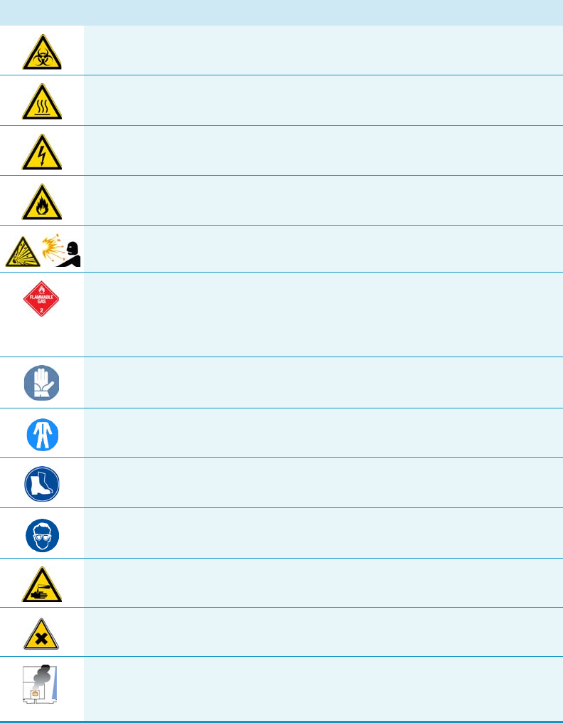
Symbol Descriptor
BIOHAZARD: Indicates that a biohazard will, could, or might occur.
BURN HAZARD: Alerts you to the presence of a hot surface that could or might
cause burn injuries.
ELECTRICAL SHOCK HAZARD: Indicates that an electrical shock could or
might occur.
FIRE HAZARD: Indicates a risk of fire or flammability could or might occur.
EXPLOSION HAZARD. Indicates an explosion hazard. This symbol indicates
this risk could or might cause physical injury.
FLAMMABLE GAS HAZARD. Alerts you to gases that are compressed,
liquefied or dissolved under pressure and can ignite on contact with an
ignition source. This symbol indicates this risk could or might cause physical
injury.
GLOVES REQUIRED: Indicates that you must wear gloves when performing a
task or physical injury could or might occur.
CLOTHING REQUIRED. Indicates that you should wear a work clothing when
performing a task or else physical injury could or might occur.
BOOTS REQUIRED. Indicates that you must wear boots when performing a
task or else physical injury could or might occur.
MATERIAL AND EYE HAZARD. Indicates you must wear eye protection when
performing a task.
HAND AND CHEMICAL HAZARD: Indicates that chemical damage or physical
injury could or might occur.
HARMFUL. Indicates that the presence of harmful material will, could, or
might occur.
INSTRUMENT DAMAGE: Indicates that damage to the instrument or
component might occur. This damage might not be covered under the
standard warranty.
Preface
Instrument Markings and Symbols
Thermo Scientific TRACE 1300 and TRACE 1310 Hardware Manual xxi
Instrument Markings and Symbols
Tabl e 1 explains the symbols used on Thermo Scientific instruments. Only a few of them are
used on the TRACE 1300/1310. See the asterisk.
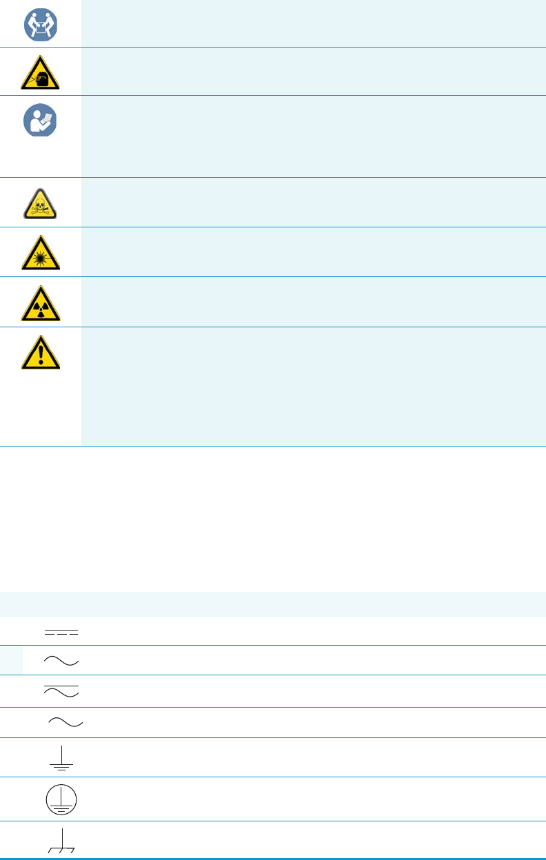
LIFTING HAZARD. Indicates that a physical injury could or might occur if two
or more people do not lift an object.
MATERIAL AND EYE HAZARD: Indicates that eye damage could or might
occur.
READ MANUAL: Alerts you to carefully read your instrument’s
documentation to ensure your safety and the instrument’s operational ability.
Failing to carefully read the documentation could or might put you at risk for a
physical injury.
TOXIC SUBSTANCES HAZARD: Indicates that exposure to a toxic substance
could occur and that exposure could or might cause personal injury or death.
LASER HAZARD. Indicates that exposure to a laser beam will, could, or might
cause personal injury.
RADIOACTIVE HAZARD. Indicates that the presence of radioactive material
could or might occur.
For the prevention of personal injury, this general warning symbol precedes
the WARNING safety alert word and meets the ISO 3864-2 standard. In the
vocabulary of ANSI Z535 signs, this symbol indicates a possible personal
injury hazard exists if the instrument is improperly used or if unsafe actions
occur. This symbol and another appropriate safety symbol alerts you to an
imminent or potential hazard that could cause personal injury.
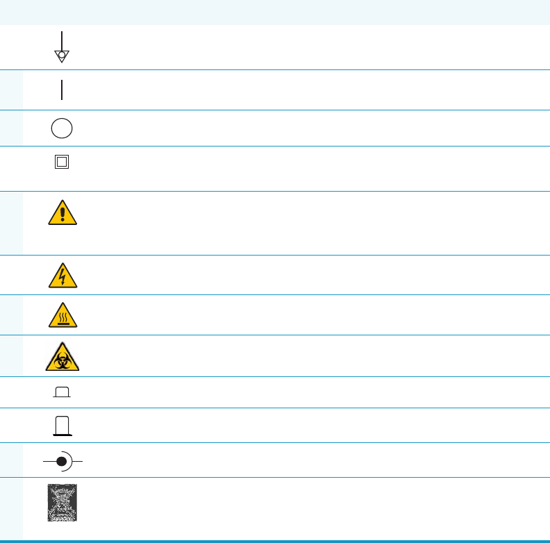
Table 1. Instrument Marking and Symbols (Sheet 1 of 2)
Symbol Description
Direct Current
*Alternating Current
Both direct and alternating current
Three-phase alternating current
Earth (ground) terminal
Protective conductor terminal
Frame or chassis terminal
3
Preface
Hydrogen Safety Precautions
xxii TRACE 1300 and TRACE 1310 Hardware Manual Thermo Scientific
Hydrogen Safety Precautions
Hydrogen is a colorless, odorless, highly flammable gas with the molecular formula H2 and an
atomic weight of 1.00794, making it the lightest element. Hydrogen gas presents a hazard, as
it is combustible over a wide range of concentrations; at ambient temperature and pressure,
the range is from about 4 to 74.2% by volume.
Hydrogen has a flash point of -423 °F (-253 °C) and an auto-ignition temperature of
1040 °F (560 °C). It has a very low ignition energy and the highest burning velocity of any
gas. If hydrogen is allowed to expand rapidly from high pressure, it can self-ignite. Hydrogen
burns with a flame that can be invisible in bright light.
Equipotentiality
*On (Supply)
*Off (Supply)
Equipment protected throughout by DOUBLE INSULATION or
REINFORCED INSULATION (Equivalent to Class II of IEC 536)
*Instruction manual symbol affixed to product. Indicates that the user must
refer to the manual for specific WARNING or CAUTION information to
avoid personal injury or damage to the product.
Caution, risk of electric shock
*Caution, hot surface
*Caution, biohazard
In-position of a bistable push control
Out-position of a bistable push control
*Jack socket
*Symbol in compliance to the Directive 2012/19/EU on Waste Electrical
and Electronic Equipment (WEEE) placed on the European market after
August, 13, 2005.
Table 1. Instrument Marking and Symbols (Sheet 2 of 2)
Symbol Description
+-

Preface
Hydrogen Safety Precautions
Thermo Scientific TRACE 1300 and TRACE 1310 Hardware Manual xxiii
Before you begin using hydrogen, conduct a risk assessment based on the quantity of
hydrogen to be used and the conditions of your laboratory. Ask yourself:
“What hydrogen hazards associated with this project are most likely to occur?”
“What hydrogen hazards associated with this project have the potential to result in the
worst consequences?”
• Try to reduce or eliminate the higher risks by using the proper ventilation to remove
hydrogen gas before an ignitable concentration can accumulate. Also consider purging the
hydrogen to further reduce hazards and ensure that anyone working with hydrogen has
basic hydrogen safety training.
• As with laboratory safety in general, be sure to wear safety glasses, laboratory coats, gloves,
and so on. Typically there are no specific requirements for gaseous hydrogen, other than
eye protection when working with a compressed gas. If working with liquid (cryogenic)
hydrogen, wear insulated gloves and protective shoes in addition to eye protection.
• Post “No Smoking” and “No Open Flames” signs to identify hydrogen sources and
cylinders. Maintain, inspect, and leak-test all hydrogen sources regularly.
• Clearly mark all hydrogen shutoff valves and label permanent hydrogen piping as such at
the supply or discharge point, and at regular intervals along its length. Where hydrogen
gas piping passes through a wall, be sure to label both sides of the wall.
• Have contingency plans in place should an incident occur.
• Ensure that site emergency response team, as well as the local fire department, knows the
location of all hydrogen storage tanks.
Using Hydrogen with TRACE 1300/TRACE 1310
The use of hydrogen as a carrier gas, or as fuel gas for certain flame detectors, requires strict
attention and compliance with special precautions due to the hazards involved.
WARNING - EXPLOSION HAZARD The use of hydrogen as a carrier gas is dangerous.
Hydrogen is potentially explosive and must be used with extreme care. Any use of
hydrogen gas must be reviewed by appropriate health and safety staff, and all installations
of hydrogen systems must be performed to applicable codes and standards. Thermo Fisher
Scientific assumes no liability for the improper use of hydrogen as a carrier gas.

Preface
Hydrogen Safety Precautions
xxiv TRACE 1300 and TRACE 1310 Hardware Manual Thermo Scientific
Hydrogen is a dangerous gas, particularly in an enclosed area when it reaches a concentration
corresponding to its lower explosion level (4% in volume). An explosion hazard could develop
in the oven when hydrogen is used as a carrier gas in the case oven elements are not perfectly
connected to each other, or when the connection materials are worn out, broken, or otherwise
faulty.
Use the following safety precautions when using hydrogen:
• Ensure that all hydrogen cylinders comply with the safety requirements for proper use
and storage. Hydrogen cylinders and delivery systems must comply with local regulations.
• Make sure the gas supply is turned completely off when connecting hydrogen lines.
• Perform a leak test to ensure that the hydrogen lines are leak-tight before using the
instrument. Repeat this test to eliminate all leaks.
• Ensure your TRACE 1300/TRACE 1310 has a Thermo Scientific hydrogen sensor
installed for continuously monitoring the hydrogen level in the oven.
Hydrogen Connection Guidelines
Use the following guidelines to safely connect hydrogen to your system:
•Piping—Hydrogen must be delivered to equipment using appropriate piping and be
done in such a way as to pose essentially no hazard to end-users. Piping systems for the
delivery of hydrogen should be designed and installed by a person qualified by specific
training and experience with hydrogen piping systems.
Stainless steel is usually recommended because it is a safe, cost-effective material. Piping
of black iron or copper must not be used, as the pipe can become brittle with age.
Elastomeric/plastic tubing of various plastics and polymers should not be used, unless the
WARNING - EXPLOSION HAZARD Hydrogen is a dangerous gas that, when mixed with
air, could create an explosive mixture. The use of hydrogen as a carrier gas requires
extreme caution. Special precautions must be taken because of the risk of explosion. When
hydrogen is used as carrier gas the gas chromatograph must be equipped with a hydrogen
sensor.
Never use hydrogen as carrier gas in your TRACE 1300/TRACE 1310 system unless your
oven has a hydrogen sensor installed. Thermo Fisher Scientific FSEs are not authorized to
install or repair any instrument using hydrogen as a carrier gas unless the instrument is
equipped with the appropriate sensor.
If your oven does not have a hydrogen sensor already installed, contact your Thermo
Fisher Scientific sales representative. To comply with instrument safety requirements, a
Thermo Fisher Scientific FSE authorized service personnel should install the sensor into
your TRACE 1300/TRACE 1310.
Preface
Hydrogen Safety Precautions
Thermo Scientific TRACE 1300 and TRACE 1310 Hardware Manual xxv
tubing is approved for use with hydrogen. If elastomeric/plastic tubing is used for
hydrogen gas delivery, the tubing should be tested for hydrogen permeability to minimize
leakage.
The hydrogen piping system must be flexible enough to endure routine thermal
expansion and contraction. The system should also include considerations for the most
severe condition of temperature and pressure expected during service. Piping and
supports must be able to withstand static loading introduced by such things as ice and
snow; and dynamic loading from high wind and earthquake.
Caution should be used if burying hydrogen piping. Proper controls should be used to
protect against damage and corrosion, and also to prevent Hydrogen from entering a
building if there is any leakage.
•Fittings—All fittings must be of the proper type approved or designed for use with
hydrogen gas. Use as few fittings as possible to minimize the potential for leaks. After
installation, ensure that leak testing is carried out prior to system use, and on a regular
basis.
There must be no PTFE tape or other things like plumber's putty used to enhance a seal, as
this actually is a detriment to a good seal. Ideally the best installation would use stainless
steel tubing with appropriate gas-tight fittings.
Welding is usually preferred for joints in hydrogen piping systems since welding provides
a better connection and reduces the potential for leaks compared to mechanical fittings.
Soft solder joints are not permitted for hydrogen systems (due to the low melting point of
soft solder and its potential for brittle failure at cryogenic temperatures). Brazed joints are
permitted, but such joints should be protected against the possibility of external fire.
Tubing connections should be clamped to barbed or press-fit type connections. Hose
clamps or jubilee clamps must not be used.
•Valves—All valves must be suitable for hydrogen service and for the specific operating
conditions. Valves, including regulators, must not be used for hydrogen, unless they are
designed and identified for such a use. Ball valves are often chosen because of their
superior leak tightness through the valve seat. Pneumatic operators are usually chosen for
remotely operated valves so that potential ignition sources (electricity) are remote from
the valve.
Manual shutoff valves should be provided near each point of use, within immediate reach.
If a hydrogen cylinder or hydrogen generation system is located within immediate reach,
a separate point-of-use shutoff valve is usually not necessary.
Line regulators that have their source away from the point of use should have a manual
shutoff valve near the point of use.
An emergency gas shutoff device in an accessible location outside the use area should be
provided in addition to the manual point-of-use valve in each educational and
instructional laboratory space that has a piped gas supply system.
Preface
Hydrogen Safety Precautions
xxvi TRACE 1300 and TRACE 1310 Hardware Manual Thermo Scientific
If necessary, the piping system should have uninterruptible pressure relief. The pressure
relief system should be designed to provide a discharge rate sufficient to avoid further
pressure increase and should vent to a safe location outside or to a ventilation system
exhaust.
Purchasing Hydrogen
Use the following guidelines when purchasing hydrogen:
• Hydrogen Generator—Because it minimizes the amount of hydrogen present and reduces
the degree of hazard, a hydrogen generator (also called an electrolyzer) is the safest way to
purchase hydrogen in the quantity used in gas chromatography/mass spectroscopy
systems.
However, to minimize the degree of hazard, operate the hydrogen generator only in a
non-explosive environment because hydrogen buildup can be ignitable. Thus, your
ventilation system for the room or lab hood where the hydrogen generator operates must
maintain an air exchange rate at least two orders of magnitude greater than the maximum
hydrogen production rate of the hydrogen generator. Follow the manufacturers'
directions about proper use and maintenance of the regulator.
To prevent the possibility of releasing hydrogen, set the hydrogen generator to shut down
if:
−There is a loss of flow to the ventilation system
−A hydrogen detector alarms at 25% of the lower flammable limit of hydrogen in air.
Vent the oxygen exhausted by the electrolyzer to the outside as well.
• Hydrogen Cylinder—Hydrogen can be delivered in standard laboratory gas bottles or
cylinders. These cylinders have a limited amount of hydrogen in them and are a safe way
to transport and store hydrogen. Always secure, compressed hydrogen gas cylinders, like
all compressed gas cylinders, in an upright position, ideally with a non-combustible chain
or cable. If the cylinder falls over, the valve can fall off, causing the pressurized cylinder to
take off like a rocket, leading to the release of hydrogen and possibly an explosion, severe
injury, or death. Never crack a hydrogen cylinder valve to remove dust or dirt from
fittings prior to attaching a regulator, as there is a risk of self-ignition.
Properly Storing Hydrogen
Storing and handling compressed hydrogen gas and cryogenic liquid hydrogen present
potential health and safety hazards. Using proper storage and handling techniques is essential
to maintaining a safe work environment.
Use the following guidelines when storing hydrogen:
Preface
Hydrogen Safety Precautions
Thermo Scientific TRACE 1300 and TRACE 1310 Hardware Manual xxvii
• Store spare hydrogen gas cylinders outside and away from doors, windows, building air
intake vents, structures, and vehicle routes. This precaution applies when the hydrogen is
or is not in use. Indoor storage of spare hydrogen cylinders has special requirements,
which are beyond the scope of this document. Documentation for each vessel should
include a description of the vessel, a list of available drawings or other documents, the
most recent inspection results, and the responsible person's name.
• Prevent spare cylinders from toppling by wrapping them with chains. The chains should
also be protected against corrosion and excessive heat.
• Separate spare hydrogen cylinders from oxidizing gases (such as oxygen) with a 5 ft.
(1.5 m) tall fire barrier with a half-hour fire rating or place the cylinders at least 20 ft.
(6 m) apart.
• When moving hydrogen cylinders:
−Remove the regulator and replace the cylinder valve cap before moving.
−Move cylinders on cylinder carts or with other appropriate transport devices.
−Never roll or drop a cylinder and never lift a cylinder by its protective cap.
• Bulk hydrogen systems include either gaseous or liquid hydrogen in fixed installations; in
some gas systems a semi-permanent trailer (tube trailer) can be used. Storage vessels for
compressed hydrogen gas or liquid hydrogen should be designed, constructed, tested, and
maintained in accordance with applicable codes and standards. Bulk hydrogen systems
represent a level of complexity again which is beyond the scope of this document;
however some general guidelines are provided.
• The bulk hydrogen storage system should not be located beneath electric power lines,
close to other flammable gases/liquids, or close to public areas. It should be readily
accessible to authorized personnel and delivery equipment, but protected from physical
damage or tampering.
• As liquid hydrogen systems also have a cryogenic hazard, additional safety considerations
for the use of cryogenic liquids might be necessary.
Hydrogen Safety Codes, Standards and References
The following list of safety codes, standards, and references is in no way an exhaustive list. In
fact, there may be federal, state, or local codes that apply to your specific location. Check with
all appropriate agencies with jurisdiction before installing or using a hydrogen system.
• Air Products Safetygram #4 Gaseous Hydrogen
• ANSI/AIAA standard for hydrogen safety guidelines is AIAA G-095-2004, Guide to
Safety of Hydrogen and Hydrogen Systems
• ASME B31.1, Power Piping Code
• ASME B31.3, Process Piping Code
Preface
Hydrogen Safety Precautions
xxviii TRACE 1300 and TRACE 1310 Hardware Manual Thermo Scientific
• ASME B31.8, Gas Transmission and Distribution Systems
• BCGA Code Of Practice CP4 Industrial Gas Cylinder Manifolds and Gas Distribution
Pipework
• BCGA Code Of Practice CP33 The Bulk Storage of Gaseous Hydrogen at Users'
Premises
• CGA G-5, Hydrogen
• CGA G-5.4, Standard for Hydrogen Piping Systems at Consumer Locations
• CGA G-5.5, Hydrogen Vent Systems
• CGA G-5.6, Hydrogen Pipeline Systems
• CGA G-5.8, High Pressure Hydrogen Piping Systems at Consumer Locations.
• FM Global Property Loss Prevention Data Sheets 7-50: Compressed Gases in Cylinders
• FM Global Property Loss Prevention Data Sheets 7-91: Hydrogen
• IGC Doc 121/04/E, Hydrogen Transportation Pipelines System Design Features
•NASA
• NSS 1740.16 Safety Standard For Hydrogen And Hydrogen Systems Guidelines for
Hydrogen System Design, Materials Selection, Operations, Storage, and Transportation
• NFPA 52, Vehicular Fuel Systems Code
• NFPA 55, Standard for the Storage, Use, and Handling of Compressed Gases and
Cryogenic Fluids in Portable and Stationary Containers, Cylinders, and Tanks, 2005
Edition
• NFPA 68, Standard on Explosion Protection by Deflagration Venting
• NFPA 70, National Electrical Code
• NFPA 497, Recommended Practice for the Classification of Flammable Liquids, Gases,
or Vapors and of Hazardous (Classified) Locations for Electrical Installations in Chemical
Process Areas
• NFPA 13, Standard for the Installation of Sprinkler Systems
• NFPA 45, Standard on Fire Protection for Laboratories Using Chemicals
• NFPA 55, Standard for the Storage, Use, and Handling of Compressed Gases and
Cryogenic Fluids in Portable and Stationary Containers, Cylinders, and Tanks
• NFPA 68, 2007 Standard on Explosion Protection by Deflagration Venting
• NFPA 69, Standard on Explosion Prevention Systems
• NFPA 91, Standard for Exhaust Systems for Air Conveying of Vapors
Preface
Liquid Nitrogen Safety Precautions
Thermo Scientific TRACE 1300 and TRACE 1310 Hardware Manual xxix
• NFPA 255, Standard Method of Test of Surface Burning Characteristics of Building
Materials
OSHA 29CFR1910.103 1910.103 Hydrogen
Hazardous Substances Precautions
Venting Toxic Gases
When analyzing toxic compounds be aware that during the normal operation of the GC some
of the sample might be vented outside the instrument through the inlet and detector exits;
therefore, make sure to vent the exhaust gases to a fume hood. Consult local Environmental
and Safety Regulations for instructions in exhausting fumes from your system.
Liquid Nitrogen Safety Precautions
Liquid nitrogen is a colorless, odorless, extremely cold liquid and gas under pressure. It can
cause rapid suffocation when concentrations are sufficient to reduce oxygen levels below
19.5%. A Self Contained Breathing Apparatus (SCBA) might be required. Contact with
liquid or cold vapors can cause severe frostbite. Cold vapors in the air will appear as a white
fog due to condensation of moisture. Oxygen concentrations must be monitored in the release
area. All cryogenic liquids produce large volumes of gas when they vaporize.
WARNING Before using hazardous substances (toxic, harmful, and so on), read the
hazard indications and information reported in the applicable Material Safety Data Sheet
(MSDS.) Use Personal protection according to the safety requirements.
WARNING Before using Liquid Nitrogen, read the hazard indications and the
instructions reported in the Safety sheet supplied by the manufacturer, with reference to
the CAS number (Chemical Abstract Service) 7727-37-9.
Use personal protection:
•Protective gloves: Loose fitting thermal-insulated or leather gloves.
•Eye protection: Full face shield and safety glasses are recommended.
•Other protective equipment: Safety shoes when handling containers. Long sleeved
shirts and trousers without cuffs. Work clothing that sufficiently prevents skin contact
should be worn.

Preface
Carbon Dioxide Safety Precautions
xxx TRACE 1300 and TRACE 1310 Hardware Manual Thermo Scientific
Carbon Dioxide Safety Precautions
Carbon dioxide is a colorless, cryogenic liquid. At low concentrations, is odorless. At higher
concentrations carbon dioxide will have a sharp, acidic odor. At concentrations between 2 and
10%, Carbon dioxide can cause nausea, dizziness, headache, mental confusion, increased
blood pressure, and increased respiratory rate. If the gas concentration reaches 10% or more,
suffocation and death can occur within minutes. Contact with the cold gas can cause freezing
of exposed tissue. Moisture in the air could lead to the formation of carbonic acid that can be
irritating to the eyes. All forms of carbon dioxide are noncombustible. Carbon dioxide is
heavier than air and should not be allowed to accumulate in low lying areas.
WARNING Before using carbon dioxide, read the indications of hazard and the
instructions reported in the Safety sheet supplied by the manufacturer with reference to
the CAS number (Chemical Abstract Service) 124-38-9.
Use personal protection:
•Protective gloves: Loose fitting thermal insulated or leather gloves.
•Eye protection: Full face shield and safety glasses are recommended.
•Other protective equipment: Safety shoes when handling containers. Long sleeved
shirts and trousers without cuffs. Work clothing that sufficiently prevents skin contact
should be worn.

Thermo Scientific TRACE 1300 and TRACE 1310 Hardware Manual 1
1
Installation
This chapter provides instructions for installing and connecting the TRACE 1300/TRACE
1310 system.
Contents
•Positioning the TRACE 1300/TRACE 1310
•Installing the External Accessories
•Installing the Injector and Detector Modules
•Making the Gas Supply Plumbing Connections
•Connecting the Oven Cryogenic System
•Connecting the PTV/PTVBKF Cryogenic System
•Coupling to a Mass Spectrometer
•Installing the Autosampler
•Installing the Data System Software
•Making Power Connections
•Setting the LAN Communication
•Column Installation Requirements
•Installing the Column the First Time
IMPORTANT Before beginning the installation process, your laboratory must be in
compliance with the guidelines and the requirements described in the TRACE
1300/TRACE 1310 Preinstallation Requirements Guide.
1 Installation
2TRACE 1300 and TRACE 1310 Hardware Manual Thermo Scientific
When you receive your TRACE 1300/TRACE 1310, an authorized Thermo Fisher Scientific
Field Service Engineer (FSE) will configure the system for you. However, if you need to
reconfigure your system, repeat the following steps:
1. Place the TRACE 1300/TRACE 1310 on the workbench.
a. See “Positioning the TRACE 1300/TRACE 1310” on page 3.
2. Place and connect the external accessories.
a. See “Installing the External Accessories” on page 3.
3. Place and connect the Injector and Detector modules.
a. See “Installing the Injector and Detector Modules” on page 4.
4. Plumb the gas supply and perform test for leaks.
a. See “Making the Gas Supply Plumbing Connections” on page 7.
b. For system test information, refer to the TRACE 1300 and TRACE 1310 User Guide
and to the User Guide of any accessories you have connected to your GC system.
5. Connect coolant to cryogenic system (if present).
a. See “Connecting the Oven Cryogenic System” on page 13.
6. Couple a TRACE 1300/TRACE 1310 version for MS to a mass spectrometer.
a. Perform this step to couple a GC MS version with a Thermo Scientific mass
spectrometer. See “Coupling to a Mass Spectrometer” on page 23.
7. Install the autosampler (optional) on the GC.
a. See “Installing the Autosampler” on page 32.
8. Install the Data System software.
a. See “Installing the Data System Software” on page 42
9. Connecting Power to the GC and the External Modules.
a. See “Making Power Connections” on page 43.
10. Set the LAN communication between TRACE 1300/TRACE 1310 and computer.
a. See “Setting the LAN Communication” on page 45.
11. Install the analytical column.
a. Install the column into GC as described in “Column Installation Requirements” on
page 50 and “Installing the Column the First Time” on page 57.
12. Perform column conditioning, leak test, and column evaluation.
a. Perform column conditioning, leak check, and carrier gas flow calibration (column
evaluation) following the instruction reported in “Installing the Column the First
Time” on page 57.
1 Installation
Positioning the TRACE 1300/TRACE 1310
Thermo Scientific TRACE 1300 and TRACE 1310 Hardware Manual 3
Positioning the TRACE 1300/TRACE 1310
Your laboratory must already be prepared according to the space requirements, and the gas
and power supplies must be accessible. Optional equipment should be placed near the
TRACE 1300/TRACE 1310 for easier connection.
To position the instrument
1. Set the TRACE 1300/TRACE 1310 on the work table. At least TWO people should
perform this operation, each standing on one side of the instrument and putting their
hands near its supporting feet.
2. Look for the yellow label located on the back of the GC under the AC Input Connector.
It indicates the power supply (120 Vac or 230 Vac) required by the GC, and must be in
compliance with your power source.
Installing the External Accessories
For additional information, refer to the TRACE 1300 and TRACE 1310 User Guide, and to
the User Guides that come with the accessories you have connected to your GC.
WARNING The main unit of the GC, without injector/detector modules, weighs
approximately 35 kg (77 lbs) when unpacked. Pay attention when lifting the instrument
onto the work table.
WARNING The oven vents at the back of the GC discharge hot air up to 450 °C (842 °F)
during cooling. Oven exhaust can cause severe burns. Avoid working behind the
instrument oven vents during cool-down cycles. There should be at least 30 cm (12 in.)
free space behind the instrument to allow the exhaust to dissipate. Do not expose gas tanks
or bottles, chemicals, regulators, electrical cables, or other temperature-sensitive items to
oven exhaust.
Note An optional oven exhaust kit can be installed to carry the hot air from the oven
vents out of the working area. See “Installing the Oven Exhaust Kit” on page 326.
CAUTION To avoid contact with the hot air from the vents, gather the electrical cables
into the cables holder.
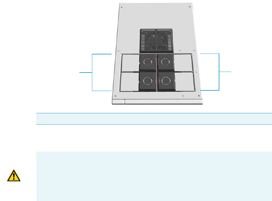
1 Installation
Installing the Injector and Detector Modules
4TRACE 1300 and TRACE 1310 Hardware Manual Thermo Scientific
Installing the Injector and Detector Modules
This section provides the instructions for installing your front/back injector and detector
modules into the relevant housing.
The GC is shipped with dummy modules installed into the injector/detector housings.
See Figure 1.
Figure 1. Injector and Detector Housings and Dummy Modules
The dummy modules must be removed and replaced by the injector and detector modules as
required by the configuration of your TRACE 1300/TRACE 1310.
To install the injector and detector modules, see the following procedures:
•Installing an Injector Module
•Installing a Detector Module
Installing an Injector Module
To install an injector module
1. Remove the dummy module from the position where the injector module will be
installed.
Note Where a dummy module is installed, the gas connection is blocked by a plug.
Injector Housing
Detector Housing
CAUTION Each housing must always be occupied by both modules. If the GC is
configured with a single injector/detector module, a dummy module must remain
inserted instead of the missing injector/detector module.
The injector and detector modules are shipped with a plug. Before installing the column,
remove the plug.
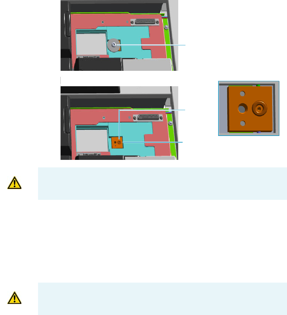
1 Installation
Installing the Injector and Detector Modules
Thermo Scientific TRACE 1300 and TRACE 1310 Hardware Manual 5
a. Open the module flap cover.
b. Using a T20 Torxhead screwdriver, unscrew the two captive fixing screws.
c. Keeping the dummy module flap cover open, lift up the module from its seat in the
injector housing. Place the dummy module on a clean surface.
d. Remove the gas block plug from the gas connection by unscrewing its fixing screw
using a T20 Torxhead screwdriver.
Figure 2. Injector Gas Block Plug
2. Plug the injector module into the main frame.
a. Open the module flap cover.
b. Keeping the module flap cover open, place it in its seat. Be sure to insert the 25-pin
male connector on the bottom of the module into the 25-pin female connector on
the injector seat of the injector housing.
c. Use a T20 Torxhead screwdriver to tighten the three captive fixing screws evenly and
carefully without overtightening.
Gas Connection Without Gas Block Plug
Gas Block Plug on Injector Seat
O-ring
WARNING Make sure the o-ring is placed into its seat on the gas connection.
See Figure 2. Do not install the module if the o-ring is missing.
CAUTION To maintain the correct alignment the screws must be tightened in turn, and
each screw must be tightened only a small amount before moving to the next screw.
Repeat until all are secure.
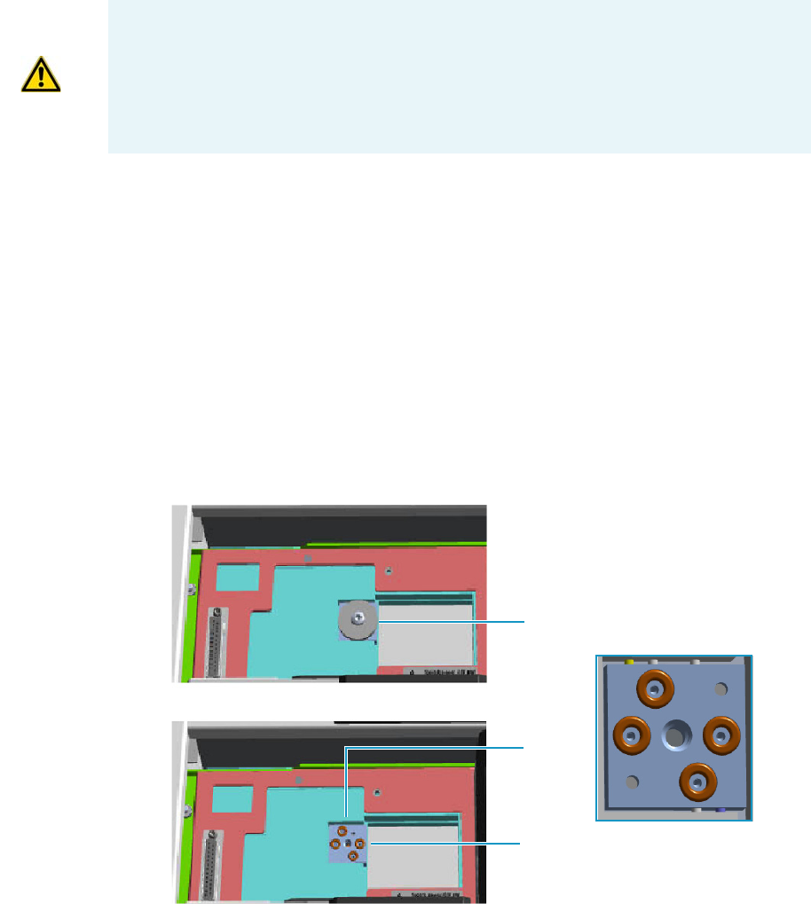
1 Installation
Installing the Injector and Detector Modules
6TRACE 1300 and TRACE 1310 Hardware Manual Thermo Scientific
d. Close the module flap cover.
3. Continue the installation following the instructions reporting in the section “Making the
Gas Supply Plumbing Connections” on page 7.
Installing a Detector Module
To install a detector module
1. Remove the dummy module from the position where the detector module will be
installed.
a. Open the module flap cover.
b. Using a T20 Torxhead screwdriver, unscrew the two captive fixing screws.
c. Keeping the dummy module flap cover open, lift up the module from its seat in the
injector/detector housing. Place the dummy module on a clean surface.
d. Remove the gas block plug from the gas connections by unscrewing its fixing screw
using a T20 Torxhead screwdriver.
Figure 3. Detector Gas Block Plug
CAUTION If you are installing a NPD detector module, the installation of the NPD
Thermionic Source Power Module is required. For the installation details see the section
“Adding a NPD Detector Module” on page 435.
CAUTION If you are installing a Generic Detector Interface see the section “Adding a
Generic Detector Interface” on page 472.
Gas Connections Without Gas Block Plug
Gas Block Plug on Detector Seat
O-rings
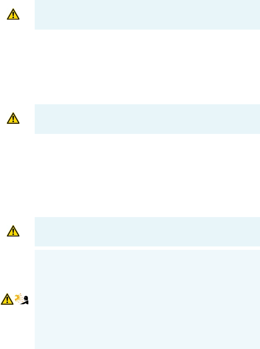
1 Installation
Making the Gas Supply Plumbing Connections
Thermo Scientific TRACE 1300 and TRACE 1310 Hardware Manual 7
2. Plug the detector module into the main frame.
a. Open the module flap cover.
b. Keeping the module flap cover open, place the module in its seat.
Be sure to insert the 25-pin male connector on the bottom of the module into the
25-pin female connector on the detector seat of the detector housing.
c. Use a T20 Torxhead screwdriver to tighten the three captive fixing screws evenly and
carefully without overtightening.
d. Close the module flap cover.
3. Continue the installation following the instructions in the section “Making the Gas
Supply Plumbing Connections” on page 7.
Making the Gas Supply Plumbing Connections
Make plumbing connections between the gas supply lines and the GC gas inlets on the
instrument back using the proper fittings
WARNING Make sure all the four o-rings are placed into their seats on the gas
connection. See Figure 3. Do not install the module if the o-rings are missing.
CAUTION To maintain the correct alignment the screws must be tightened in turn, and
each screw must be tightened only a small amount before moving to the next screw.
Repeat until all are secure.
CAUTION DO NOT loosen or remove caps from the TRACE 1300/TRACE 1310 until
you have purged gas lines, and you are ready to connect them. Loosening or removing
caps early will contaminate instruments and filters.
WARNING Before using gases, carefully read the hazard indications and information
reported in the Safety Sheet supplied by the manufacturer referring to the CAS (Chemical
Abstract Service) number. It is the user’s responsibility to see that all local safety
regulations for the use of gases are obeyed.
All Thermo Fisher Scientific gas chromatographs use an inert gas as the carrier gas. If you
wish to use hydrogen as a carrier gas, you must install a hydrogen sensor. Contact a
Thermo Fisher Scientific sales representative if you plan to use hydrogen as the carrier gas
in your new TRACE 1300/TRACE 1310. If you don’t have the hydrogen sensor, you
must use an inert carrier gas.
Thermo Fisher Scientific FSEs are not authorized to install or repair any instrument using
hydrogen as a carrier gas unless the instrument is equipped with the appropriate sensor.
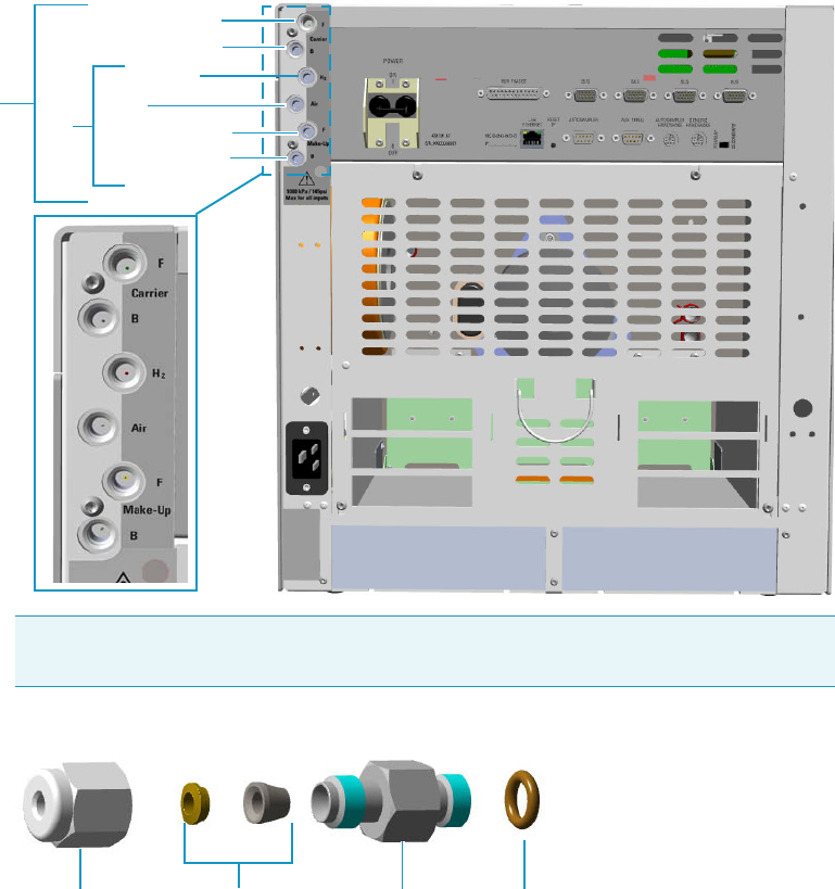
1 Installation
Making the Gas Supply Plumbing Connections
8TRACE 1300 and TRACE 1310 Hardware Manual Thermo Scientific
To plumb the gas supply
1. By now you must have done the following:
a. Completely built your gas supply lines including any traps, tees, and extra tubing to
allow about 40 cm (16 in.) of slack in the line.
b. Purged the gas line after every tube cut to remove any debris or contaminants.
c. Ensured the gas supply is turned off.
2. Connect the gas lines.
a. TRACE 1300/TRACE 1310 is provided with six gas inlet ports for the connection of
carrier and detector gases. See Figure 4.
Figure 4. Gases Inlet Connections
Figure 5. Fittings for Gas Inlets Connection
Note Use the 1/8-in. Swagelok fittings provided on the gas inlet ports (see Figure 5)
to connect the gas lines.
Gas Inlet Ports
Carrier Front
Hydrogen
Air
Make-up Back
Detector Gases
Carrier Back
Make-up Front
Gas Inlet Fitting
FerrulesNut O-Ring
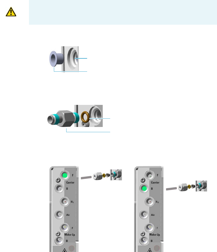
1 Installation
Making the Gas Supply Plumbing Connections
Thermo Scientific TRACE 1300 and TRACE 1310 Hardware Manual 9
b. If present, remove the cap from the gas inlet port to connect. See Figure 6.
Figure 6. Cap Removal
c. If not already installed, screw the gas inlet fitting provided into the gas inlet port
interposing the o-ring. See Figure 7.
Figure 7. Gas Inlet Fitting Installation
d. Connect the gas line to the front/back carrier gas inlet. Use a 7/16-in. wrench for
tightening the fittings. See Figure 8.
Figure 8. Carrier Gas Line Connection
e. Connect the gas line to the front/back detector gas inlet. Use a 7/16-in. wrench for
tightening the fittings. See Figure 9, Figure 10, Figure 11, and Figure 12 to properly
connect each detector.
CAUTION Inside each 1/8-in. inlet manifold is a fritted filter. To keep the gas line from
touching, and possibly damaging the filter, extend the tubing only 5-mm past the front
ferrule. This ensures the tubing does not touch the filter.
Gas Inlet Port
Cap
Gas Inlet Fitting
O-Ring
Front Carrier Gas Inlet
Back Carrier Gas Inlet
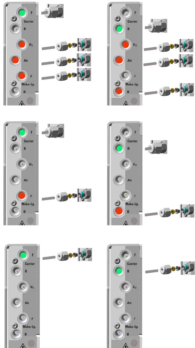
1 Installation
Making the Gas Supply Plumbing Connections
10 TRACE 1300 and TRACE 1310 Hardware Manual Thermo Scientific
Figure 9. FID/NPD Detector Gas Lines Connection
Figure 10. ECD Detector Gas Lines Connection
Figure 11. TCD Detector Gas Lines Connection
Back Detector Gas Inlets
Front Detector Gas Inlets
Back Detector Gas Inlet
Front Detector Gas Inlet
Front Carrier Gas Inlet
Back Carrier Gas Inlet
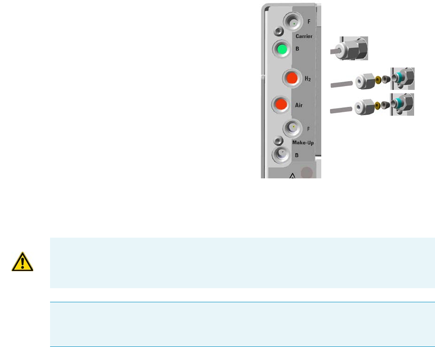
1 Installation
Making the Gas Supply Plumbing Connections
Thermo Scientific TRACE 1300 and TRACE 1310 Hardware Manual 11
Figure 12. FPD Detector Gas Lines Connection
f. Be sure to complete all inlet and detector connections before turning on the gas
supply.
3. Supply the gas lines.
Back Carrier Gas Inlet
IMPORTANT The maximum nominal inlet pressure for all the inputs is 1000 kPa
(145 psig), as indicated on the label under the gas inlets ports on the back of the GC.
The working inlet pressure range is from 400 kPa (58 psig) to 1000 kPa (145 psig).
Note If auxiliary carrier gases are required, the installation of the Auxiliary Gas module is
required. For the installation details, see the section “Adding an Auxiliary Gas System” on
page 521.

1 Installation
Making the Gas Supply Plumbing Connections
12 TRACE 1300 and TRACE 1310 Hardware Manual Thermo Scientific
Testing for Leaks
Once you have connected the gas supplies to the GC, you need to test the gas supply lines for
leaks.
To perform a leak test
1. Be sure that GC is powered off.
2. Open and set the gas supply.
a. Open the gas supply.
b. Set the carrier gas pressure to approximately 50 kPa (7 psi) higher than the maximum
pressure of the GC regulator.
c. Set the detector gas pressures to approximately 1000 kPa (145 psig) if available,
otherwise set the maximum pressure allowed, for example 500 kPa (72.5 psi).
3. Check for leaks.
a. Use a handheld electronic leak detector (Thermo Scientific GLD Pro leak detector or
equivalent) to check each fitting for leaks.
b. If you detect a leak, tighten the connection and retest it.
c. Repeat this process until all connections are leak free.
CAUTION Before performing a leak test make sure that the GC is powered off and the
power cable is unplugged from the AC Input connector (Mains socket) and from the wall
outlet.
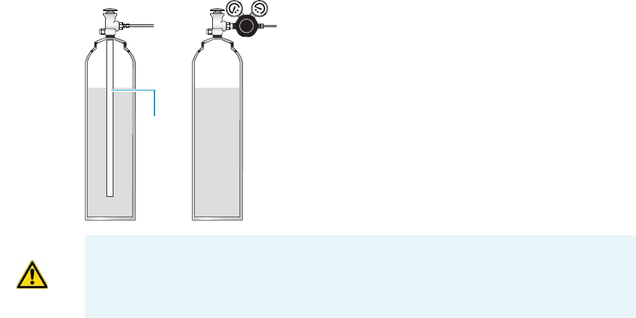
1 Installation
Connecting the Oven Cryogenic System
Thermo Scientific TRACE 1300 and TRACE 1310 Hardware Manual 13
Connecting the Oven Cryogenic System
If the oven of your TRACE 1300/TRACE 1310 is equipped with a cryogenic cooling option,
you need a supply of coolant, such as carbon dioxide (CO2) or liquid nitrogen (N2).
Oven Cryo System with Carbon Dioxide Connection
This Oven cryo system consists of a tube for carbon dioxide inserted into the oven and fitted
with a 1/8-in. solenoid valve for carbon dioxide mounted into the back of the GC.
Carbon dioxide must be supplied in a high-pressure cylinder with a dip tube. It is your
responsibility to ensure the delivery connection from the carbon dioxide cryogenic supply is
adaptable to 1/8-in. tubing. Figure 13 shows the proper carbon dioxide container
configuration.
Figure 13. Carbon Dioxide Container
To connect the cryogenic system to the carbon dioxide supply
1. Connect the proper end of the cryo supply tube to the 1/8-in. NPT connection of the
solenoid valve using the proper nut and ferrule. Use a 7/16-in. wrench to tighten the
fittings. See Figure 14.
Dip tube
WRONGCORRECT
CAUTION High pressures and extremely low temperatures make pressurized carbon
dioxide a hazardous material. High concentrations of carbon dioxide are dangerous.
To avoid injury, always follow the safety precautions and delivery system design
recommended by your gas supplier.
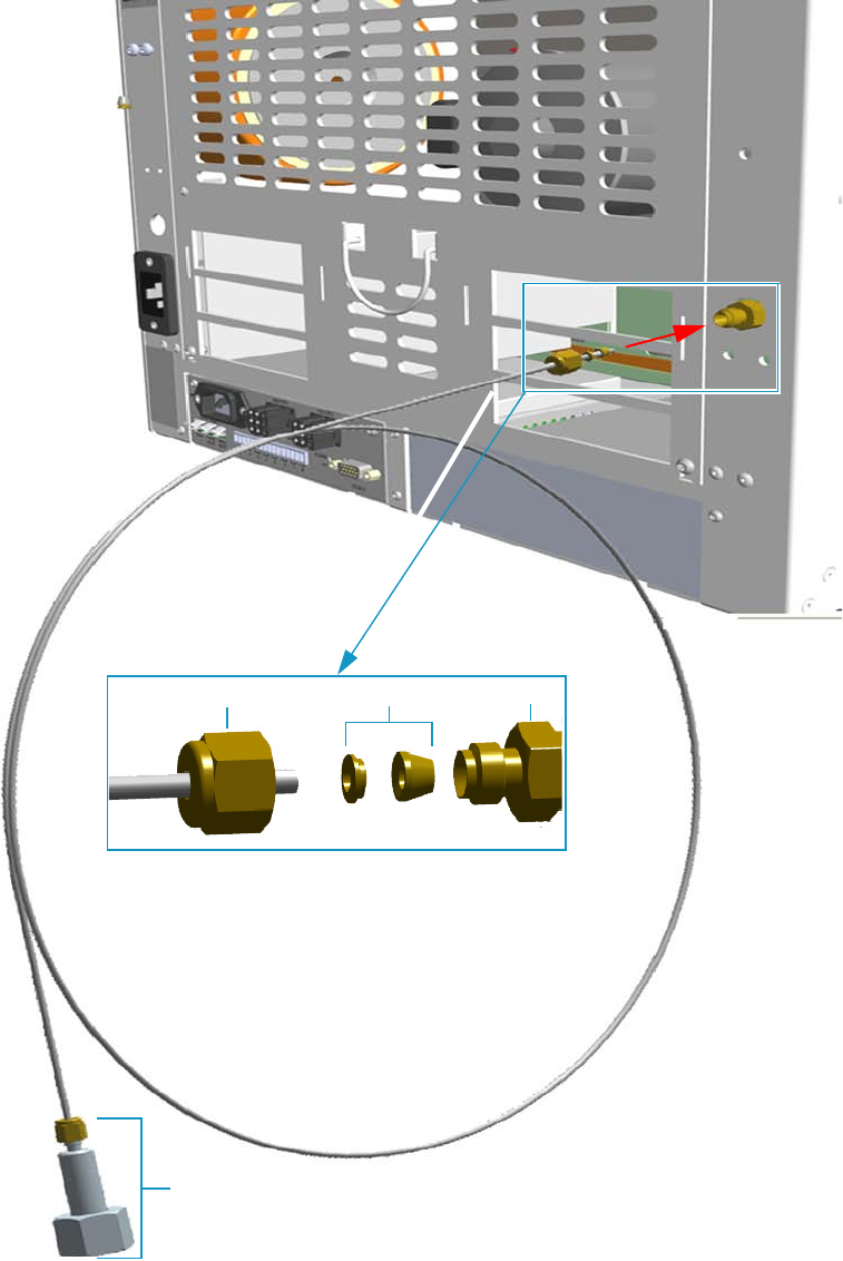
1 Installation
Connecting the Oven Cryogenic System
14 TRACE 1300 and TRACE 1310 Hardware Manual Thermo Scientific
Figure 14. Oven Cryo Supply Tube for Carbon Dioxide Connection
2. Connect the other end of the cryo supply tube to the coolant container using the
appropriate nut and ferrule.
Fittings for the connection to the carbon dioxide tank
Ferrule 1/8-in. NPT
Nut
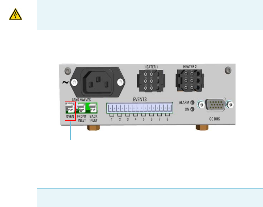
1 Installation
Connecting the Oven Cryogenic System
Thermo Scientific TRACE 1300 and TRACE 1310 Hardware Manual 15
3. Connect the cryo valve to the Aux Temperature/Cryo Module.
a. Connect the cryo solenoid valve to the 2-pin connector marked Cryo Valves - Oven
using the cable provided. See Figure 15.
Figure 15. Cryo Valves: Oven
b. Using the cable provided, connect the 15-pin female connector marked GC Bus on
the module to a Bus interface on the back of the GC.
c. Plug the power cable to the AC Input connector on the front of the module and to
the wall outlet. The LED marked On lights up after the GC power on.
IMPORTANT The Auxiliary Temperature/Cryo must be powered at the same line voltage
of the main GC system.
Note For further details regarding the installation of the Aux Temperature/Cryo module,
see the section “Adding an Aux Temperature/Cryo Module” on page 443.
Oven Cryo Valve
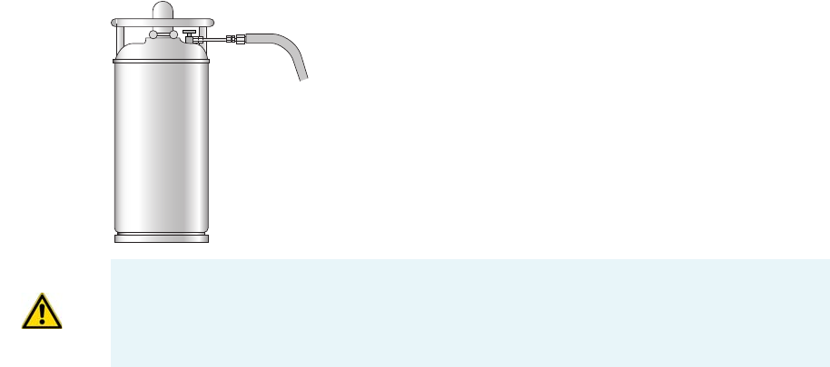
1 Installation
Connecting the Oven Cryogenic System
16 TRACE 1300 and TRACE 1310 Hardware Manual Thermo Scientific
Oven Cryo System with Liquid Nitrogen Connection
This Oven cryo system consists of a tube for liquid nitrogen inserted into the oven and fitted
with a 1/8-in. solenoid valve for liquid nitrogen mounted into the back of the GC.
The tube for liquid nitrogen is covered with an insulating material tube.
Liquid Nitrogen must be supplied at a pressure of 1.5 bar (150 kPa; 21.75 psig). Plumbing to
the GC should be 1/4-in. copper or stainless steel tubing with insulation. It is your
responsibility to ensure the delivery connection from the liquid nitrogen cryogenic supply is
adaptable to 1/4-in. tubing. The liquid nitrogen cryogenic valve on the GC is a 1/4-in.
Swagelok fitting.
Figure 24 shows the proper configuration for a liquid nitrogen tank.
Figure 16. Liquid Nitrogen Tank Configuration
To connect the cryogenic system to the liquid nitrogen supply
1. Connect the proper end of the cryo supply tube to the 1/8-in. NPT connection of the
solenoid valve using the proper nut and ferrule. Use a 7/16-in. wrench to tighten the
fittings. See Figure 17.
WARNING High pressures and extremely low temperatures make liquid nitrogen a
hazardous material. High concentrations of liquid nitrogen in the air can be an
asphyxiation hazard. To avoid injury, always follow the safety precautions and delivery
system design recommended by your gas supplier.
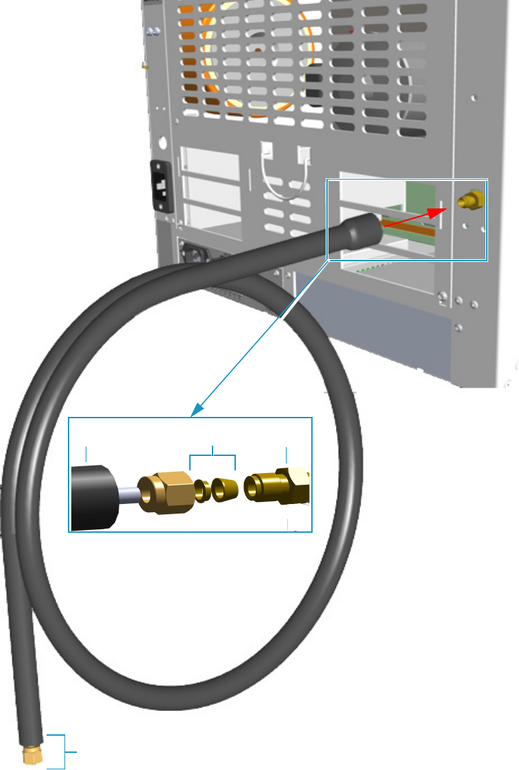
1 Installation
Connecting the Oven Cryogenic System
Thermo Scientific TRACE 1300 and TRACE 1310 Hardware Manual 17
Figure 17. Oven Cryo Supply Tube for Liquid Nitrogen Connection
2. Connect the other end of the cryo supply tube to the coolant container using the
appropriate nuts and ferrules.
Ferrule 1/8-in. NPT
Nut
Fittings for the connection to the Liquid Nitrogen Tank
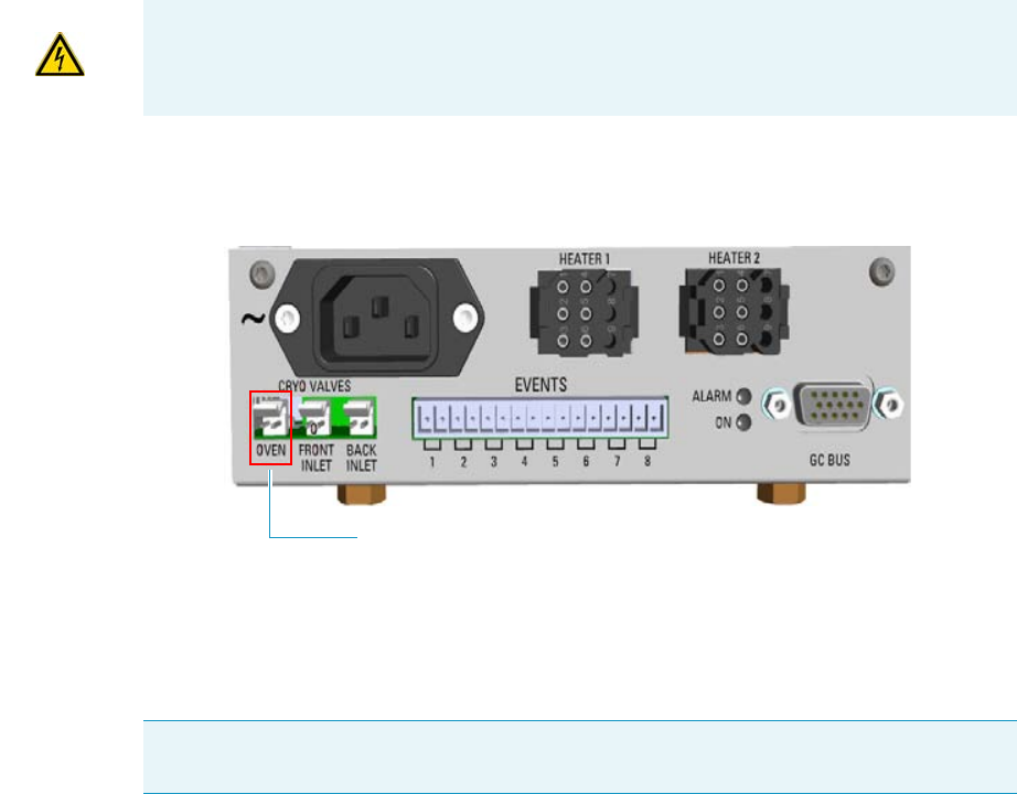
1 Installation
Connecting the PTV/PTVBKF Cryogenic System
18 TRACE 1300 and TRACE 1310 Hardware Manual Thermo Scientific
3. Connect the cryo valve to the Aux Temperature/Cryo Module.
a. Connect the cryo solenoid valve to the 2-pin connector marked Cryo Valves - Oven
using the cable provided. See Figure 18.
Figure 18. Cryo Valves: Oven
b. Using the cable provided, connect the 15-pin female connector marked GC Bus on
the module to a Bus interface on the back of the GC.
c. Plug the power cable to the AC Input connector on the front of the module and to
the wall outlet. The LED marked On lights up after the GC power on.
Connecting the PTV/PTVBKF Cryogenic System
If the PTV or PTVBKF injector of your TRACE 1300/TRACE 1310 is equipped with a
cryogenic cooling option, you need a supply of coolant, carbon dioxide (CO2) or liquid
nitrogen (LN2).
PTV/PTVBKF Cryo System with Carbon Dioxide Connection
This cryo system consists of a tube for Carbon Dioxide inserted into the PTV/PTVBKF
module, and fitted with a 1/8-in. solenoid valve for carbon dioxide mounted on a bracket
fixed on the back of the GC. See Figure 19.
IMPORTANT The Auxiliary Temperature/Cryo must be powered at the same line voltage
of the main GC system.
Note For further details regarding the installation of the Aux Temperature/Cryo module,
see the section “Adding an Aux Temperature/Cryo Module” on page 443.
Oven Cryo Valve
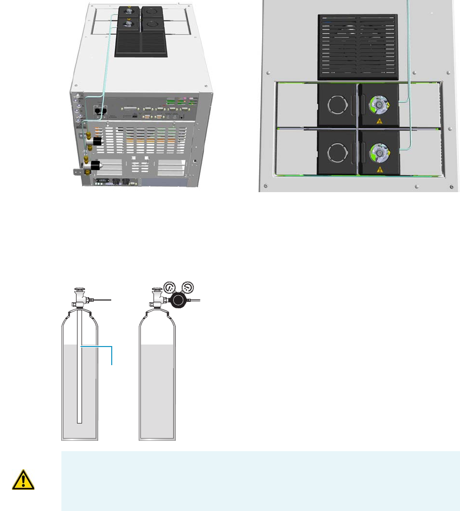
1 Installation
Connecting the PTV/PTVBKF Cryogenic System
Thermo Scientific TRACE 1300 and TRACE 1310 Hardware Manual 19
Figure 19. Front and Back PTV Cryo System with CO2
Carbon dioxide must be supplied by a high-pressure cylinder with a dip tube.
It is your responsibility to ensure the delivery connection from the carbon dioxide cryogenic
supply is adaptable to 1/8-in. tubing. Figure 20 shows the proper carbon dioxide container
configuration.
Figure 20. Carbon Dioxide Container
To connect the cryogenic system to the carbon dioxide supply
1. Connect the proper end of the cryo supply tube to the 1/8-in. NPT connection of the
solenoid valve using the proper nut and ferrule. Use a 7/16-in. wrench to tighten the
fittings. See Figure 21.
Dip tube
WRONGCORRECT
CAUTION High pressures and extremely low temperatures make pressurized CO2 a
hazardous material. High concentrations of CO2 are dangerous.
To avoid injury, always follow the safety precautions and delivery system design
recommended by your gas supplier.
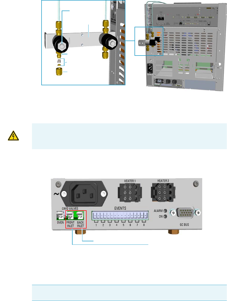
1 Installation
Connecting the PTV/PTVBKF Cryogenic System
20 TRACE 1300 and TRACE 1310 Hardware Manual Thermo Scientific
Figure 21. PTV/PTVBKF Cryo Supply Tube for Carbon Dioxide Connection
2. Connect the other end of the cryo supply tube to the coolant container using the
appropriate nuts and ferrules.
3. Connect the cryo valve to the Aux Temperature/Cryo Module.
a. Connect the 2-pin connector marked Cryo Valves - Front Inlet or Cryo Valves-Back
Inlet to the cryo solenoid valve using the cable provided. See Figure 22.
Figure 22. Cryo Valves: Front/Back Inlet
b. Using the cable provided, connect the 15-pin female connector marked GC Bus on
the module to a Bus interface on the back of the GC.
c. Plug the power cable to the AC Input connector on the front of the module and to
the wall outlet. The LED marked On lights up after the GC power on.
1/8-in. NPT
Ferrule
Nut
Solenoid Valve
Solenoid Valve
Bracket
IMPORTANT The Aux Temperature/Cryo module must be powered at the same line
voltage of the main GC system.
Note For further details regarding the installation of the Aux Temperature/Cryo module,
see the section “Adding an Aux Temperature/Cryo Module” on page 443.
Front Inlet Cryo Valve
Back Inlet Cryo Valve
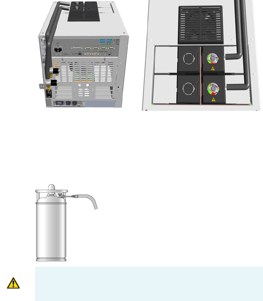
1 Installation
Connecting the PTV/PTVBKF Cryogenic System
Thermo Scientific TRACE 1300 and TRACE 1310 Hardware Manual 21
PTV/PTVBKF Cryo System with Liquid Nitrogen Connection
This cryo system consists of a tube for liquid nitrogen inserted into the PTV/PTVBKF
module and fitted with a 1/8-in. solenoid valve for liquid nitrogen mounted on a bracket
fixed on the back of the GC. The tube for liquid nitrogen is covered with an insulating
material tube. See Figure 23.
Figure 23. Front and Back PTV Cryo System with Liquid Nitrogen
Liquid nitrogen must be supplied at a pressure below 400 kPa (60 psi). Plumbing to the GC
should be 1/4-in. copper or stainless steel tubing with insulation.
It is your responsibility to ensure the delivery connection from the Liquid Nitrogen cryogenic
supply is adaptable to 1/4-in. tubing. The liquid nitrogen cryogenic valve on the GC is a
1/4-in. Swagelok fitting.
Figure 24 shows the proper configuration for a liquid nitrogen tank.
Figure 24. Liquid Nitrogen Tank Configuration
WARNING High pressures and extremely low temperatures make Liquid Nitrogen a
hazardous material. High concentrations of liquid nitrogen in the air can be an
asphyxiation hazard. To avoid injury, always follow the safety precautions and delivery
system design recommended by your gas supplier.
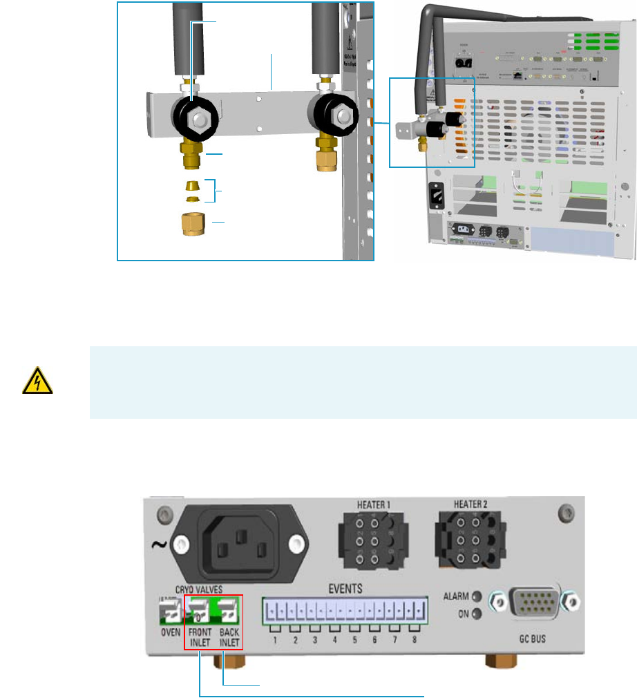
1 Installation
Connecting the PTV/PTVBKF Cryogenic System
22 TRACE 1300 and TRACE 1310 Hardware Manual Thermo Scientific
To connect the cryogenic system to the liquid nitrogen supply
1. Connect the proper end of the cryo supply tube to the 1/8-in. NPT connection of the
solenoid valve using the proper nut and ferrule. Use a 7/16-in. wrench to tighten the
fittings. See Figure 21.
Figure 25. PTV/PTVBKF Cryo Supply Tube for LN2 Connection
2. Connect the other end of the cryo supply tube to the coolant container using the
appropriate nuts and ferrules.
3. Connect the cryo valve to the Aux Temperature/Cryo Module.
a. Connect the 2-pin connector marked Cryo Valves - Front Inlet or Cryo Valves-Back
Inlet to the cryo solenoid valve using the cable provided. See Figure 26.
Figure 26. Cryo Valves: Front/Back Inlet
b. Using the cable provided, connect the 15-pin female connector marked GC Bus on
the module to a Bus interface on the back of the GC.
1/8-in. NPT
Ferrule
Nut
Solenoid Valve
Solenoid Valve
Bracket
IMPORTANT The Auxiliary Temperature/Cryo must be powered at the same line voltage
of the main GC system.
Front Inlet Cryo Valve
Back Inlet Cryo Valve
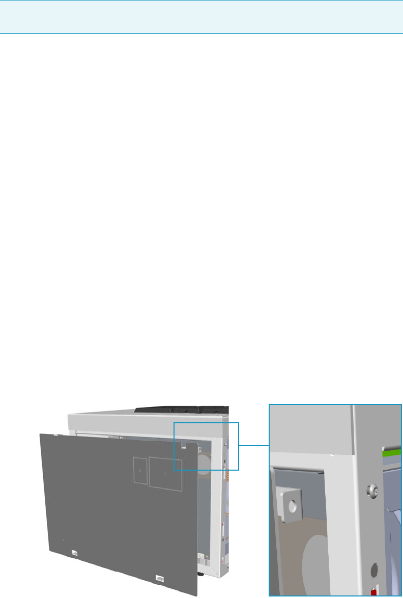
1 Installation
Coupling to a Mass Spectrometer
Thermo Scientific TRACE 1300 and TRACE 1310 Hardware Manual 23
c. Plug the power cable to the AC Input connector on the front of the module and to
the wall outlet. The LED marked On lights up after the GC power on.
]
Coupling to a Mass Spectrometer
This section provides instruction for opening the duct to introduce the transfer line inner
tube into the oven of your TRACE 1300/TRACE 1310 version for MS.
According to the mass spectrometer unit to couple, see the following sections:
•“Making the Duct to Couple with an ISQ Series, TSQ 8000 Series, DSQ II, or ITQ
Mass Spectrometer” on page 23.
•“Making the Duct to Couple with a TSQ Quantum Mass Spectrometer” on page 26.
•“Making the Duct to Couple with a DFS, IRMS, or ICP-MS Mass Spectrometer” on
page 29.
Making the Duct to Couple with an ISQ Series, TSQ 8000 Series, DSQ II, or ITQ Mass
Spectrometer
To make the duct for the transfer line
1. Remove the left side panel.
a. Open the front door of the GC.
b. Use a T20 Torxhead screwdriver to loosen the left side panel screw from the interior
front panel. See Figure 27. Save the screw because it will be reused later.
Figure 27. Left Side Panel Fixing Screw
Note For further details regarding the installation of the Aux Temperature/Cryo module,
see the section “Adding an Aux Temperature/Cryo Module” on page 443.
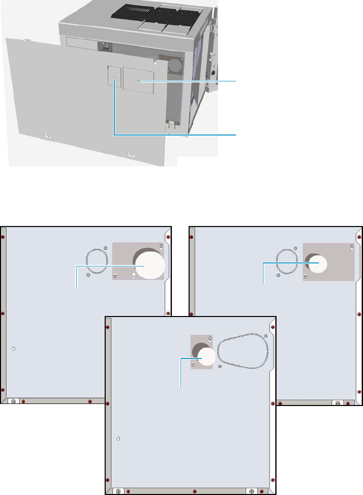
1 Installation
Coupling to a Mass Spectrometer
24 TRACE 1300 and TRACE 1310 Hardware Manual Thermo Scientific
c. Slide the panel towards the back of the instrument up to the stop.
d. Remove the panel by pulling it outward. Be aware that the ground wire is attached to
the panel.
2. Prepare the duct for the ISQ Series, TSQ 8000 Series, DSQ II, or ITQ transfer line inner
tube.
a. Remove the partial cut plate on the left panel for that corresponds to your MS.
See Figure 28.
Figure 28. Left Panel for MS Partial Cut Plate
b. On the exterior wall of the oven box, remove the pre-shaped plug of insulating
material from the duct provided. See Figure 29.
Figure 29. Pre-shaped Plug Removal
Duct for ISQ Series , TSQ 8000
Series, and DSQ II Partial Cut
Plate
Duct for ITQ Partial Cut Plate
Duct for DSQ II Pre-shaped Plug
Duct for ISQ Series /TSQ 8000
Series Pre-shaped Plug
Duct for ITQ Pre-shaped Plug
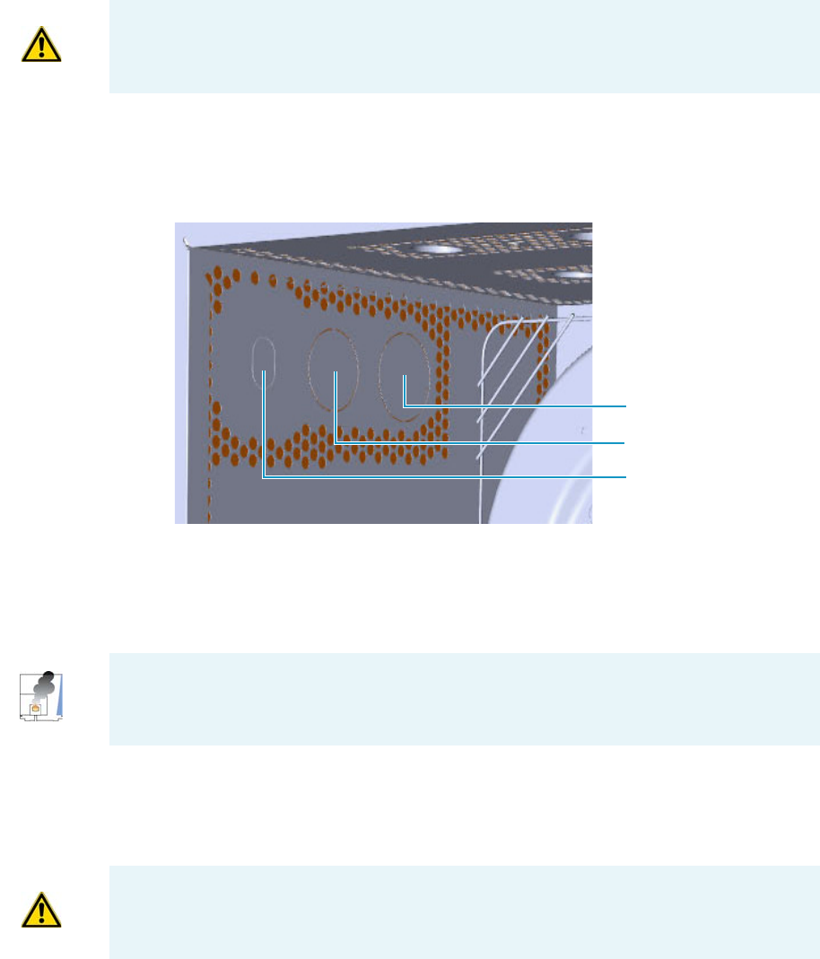
1 Installation
Coupling to a Mass Spectrometer
Thermo Scientific TRACE 1300 and TRACE 1310 Hardware Manual 25
c. On the interior of the oven box remove the partial cut plate from the corresponding
duct. See Figure 30.
Figure 30. Ducts for the Coupling with ISQ Series, TSQ 8000 Series, DSQ II and ITQ Mass
Spectrometer
d. Place the left panel for your MS and attach the screw holding it in place.
3. Introduce the transfer line inner tube into the oven through the duct provided.
4. Attach the transfer line to the GC column using the proper nut and ferrule.
5. Close the front door of the GC.
6. For DSQ II and ITQ, connect the transfer line heater to the Aux Temperature/Cryo
Module. See Figure 31.
IMPORTANT Save the pre-shaped plug of insulating material in a safe place because it
could be reused.
ISQ Series and TSQ 8000
Series
DSQ II
ITQ
CAUTION - INSTRUMENT DAMAGE: Make sure that the GC column has been
conditioned before connecting it to the transfer line. The material released from the
column, (column bleed), during conditioning may contaminate the detector.
CAUTION An extension cable transfer line is needed when connecting an ITQ mass
spectrometer to the Aux Temperature/Cryo module.
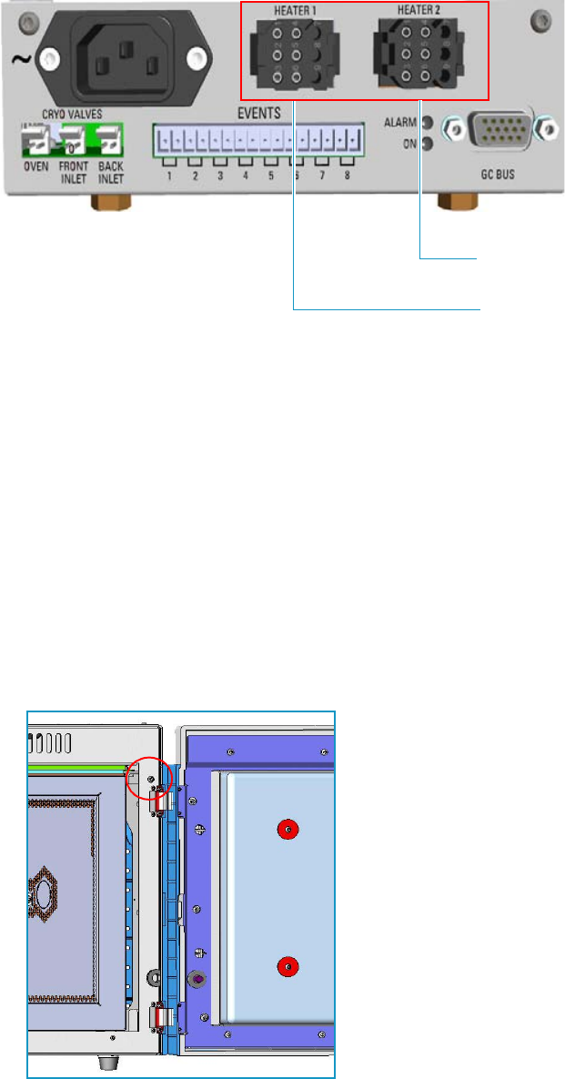
1 Installation
Coupling to a Mass Spectrometer
26 TRACE 1300 and TRACE 1310 Hardware Manual Thermo Scientific
Figure 31. Transfer Line MS Heaters
7. To tune and set the ISQ Series, TSQ 8000 Series, DSQ II, and ITQ working conditions,
refer to the relevant User Guide and Hardware Manual.
Making the Duct to Couple with a TSQ Quantum Mass Spectrometer
To make the duct for the transfer line
1. Remove the right side panel.
a. Open the front door of the GC.
b. Use a T20 Torxhead screwdriver to loosen the right side panel screw from the interior
front panel. See Figure 32. Save the screw because it will be reused later.
Figure 32. Right Side Panel Fixing Screw
c. Slide the panel towards the back of the instrument up to the stop.
Heater Connection for
Transfer Line 1
Heater Connection for
Transfer Line 2
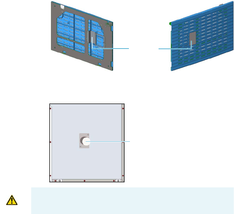
1 Installation
Coupling to a Mass Spectrometer
Thermo Scientific TRACE 1300 and TRACE 1310 Hardware Manual 27
d. Remove the panel by pulling it outward. Be aware that the ground wire is attached to
the panel.
2. Prepare the duct for the TSQ Quantum transfer line inner tube.
a. Use a T20 Torxhead screwdriver to loosen the duct plate screws from the GC right
panel of the MS. See Figure 33.
Figure 33. Right Panel for MS
b. On the exterior wall of the oven box, remove the pre-shaped plug of insulating
material from the duct provided. See Figure 34.
Figure 34. Pre-shaped Plug Removal
c. On the interior of the oven box remove the partial cut plate from the corresponding
duct. See Figure 35.
Duct Plate
Duct for TSQ Quantum Pre-shaped Plug
IMPORTANT Save the pre-shaped plug of insulating material in a safe place because it
could be reused.
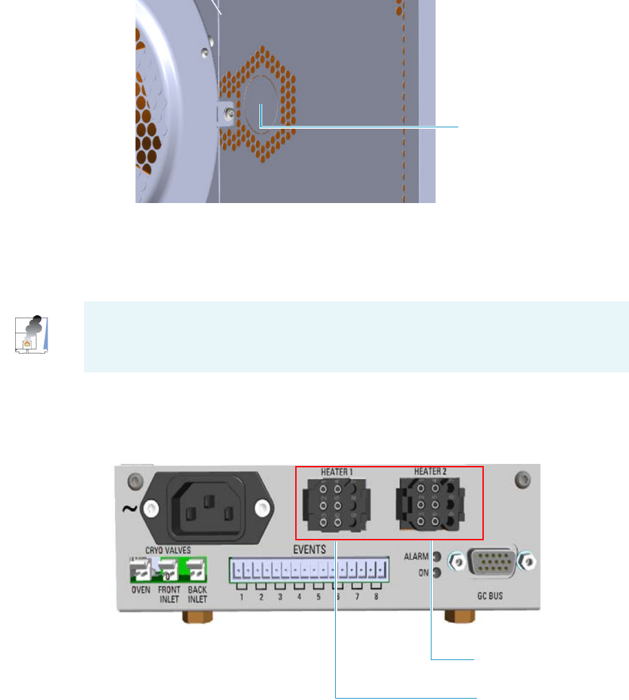
1 Installation
Coupling to a Mass Spectrometer
28 TRACE 1300 and TRACE 1310 Hardware Manual Thermo Scientific
Figure 35. Duct for the Coupling with a TSQ Quantum Mass Spectrometer
d. Place the GC right panel for your MS and attach the screw holding it in place.
3. Introduce the transfer line inner tube into the oven through the duct provided.
4. Attach the transfer line to the GC column using the proper nut and ferrule.
5. Close the front door of the GC.
6. Connect the transfer line heater to the Aux Temperature/Cryo Module. See Figure 36.
Figure 36. Transfer Line MS Heaters
7. To tune and set the TSQ Quantum working conditions, refer to the relevant User Guide
and Hardware Manual.
TSQ Quantum
CAUTION - INSTRUMENT DAMAGE: Make sure that the GC column has been
conditioned before connecting it to the transfer line. The material released from the
column, (column bleed), during conditioning may contaminate the detector.
Heater Connection for
Transfer Line 1
Heater Connection for
Transfer Line 2
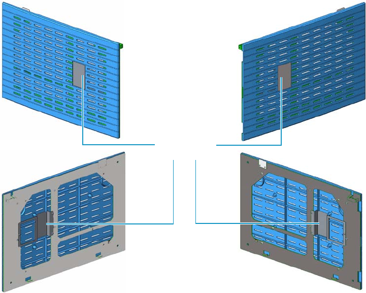
1 Installation
Coupling to a Mass Spectrometer
Thermo Scientific TRACE 1300 and TRACE 1310 Hardware Manual 29
Making the Duct to Couple with a DFS, IRMS, or ICP-MS Mass Spectrometer
To make the duct for the transfer line
1. Remove the left/right side panel according to the high resolution mass spectrometer to
couple.
a. Open the front door of the GC.
b. Use a T20 Torxhead screwdriver to loosen the left/right side panel screw from the
interior front panel. Save the screw because it will be reused later.
c. Slide the panel towards the back of the instrument up to the stop.
d. Remove the panel by pulling it outward. Be aware that the ground wire is attached to
the panel.
2. Prepare the proper duct for the transfer line inner tube.
a. Use a T20 Torxhead screwdriver to loosen the duct plate screws from the left/right
panel. See Figure 37.
Figure 37. Left/Right Side Panel
b. According to the configuration of your high resolution mass spectrometer, on the
left/right exterior wall of the oven box, remove the partial cut plate of the duct of
interest, and then the pre-shaped plug of insulating material from the duct provided.
See Figure 38.
Duct Plate
Left Side Panel Right Side Panel
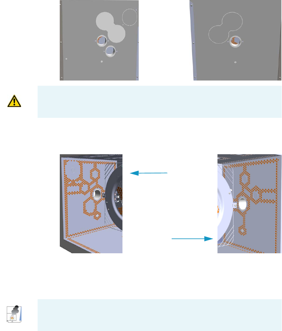
1 Installation
Coupling to a Mass Spectrometer
30 TRACE 1300 and TRACE 1310 Hardware Manual Thermo Scientific
Figure 38. Left/Right Exterior Oven Wall Box View
c. On the interior of the oven box remove the partial cut plate from the corresponding
duct. See Figure 39.
Figure 39. Left/Right Interior Oven Wall Box View
d. Place the left/right panel for MS and attach the screw holding it in place.
3. Introduce the transfer line inner tube into the oven through the duct provided.
4. Attach the transfer line to the GC column using the proper nut and ferrule.
5. Close the front door of the GC.
6. Connect the transfer line heater if required.
a. Connect the transfer line heater to the Aux Temperature/Cryo Module. See
Figure 40.
Right Oven WallLeft Oven Wall
IMPORTANT Save the pre-shaped plug of insulating material in a safe place because it
could be reused.
Left Oven Wall
Right Oven Wall
CAUTION - INSTRUMENT DAMAGE: Make sure that the GC column has been
conditioned before connecting it to the transfer line. The material released from the
column (column bleed) during conditioning may contaminate the detector.
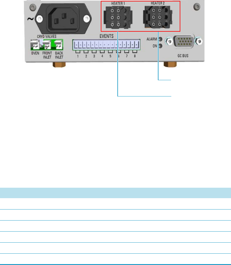
1 Installation
Coupling to a Mass Spectrometer
Thermo Scientific TRACE 1300 and TRACE 1310 Hardware Manual 31
Figure 40. Transfer Line MS Heaters
7. Tune and set the DFS, IRMS, and ICP-MS working conditions of the high resolution
mass spectrometer, referring to the relevant manuals.
Setting Handshake Parameters
When your GC is connected to a mass spectrometer, set the handshaking parameters as shown
in Table 1.
To configure handshaking parameters through the touch screen
1. In the main menu select the Configuration icon, the Configuration menu appears.
2. In the Configuration menu, select the Handshake icon to open the relevant submenu.
3. Set the Handshaking parameters as required, then return to main menu.
To configure handshaking parameters through the Chromatography Data System
1. Launch the Data System. In the relevant Configuration page specify the handshaking
parameters.
Heater Connection for
Transfer Line 1
Heater Connection for
Transfer Line 2
Table 1. GC Handshaking Parameters When A Mass Spectrometer is Connected
Parameter Set To:
Remote Start In High to Low
Inhibit Ready In When High
End of Run Out High to Low
Start of Run Out High to Low
GC Ready Out When Low
Prep Run Out When Low
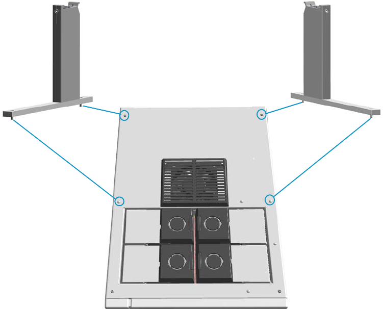
1 Installation
Installing the Autosampler
32 TRACE 1300 and TRACE 1310 Hardware Manual Thermo Scientific
Installing the Autosampler
This section provides instruction for installing and connecting a TriPlus RSH, a TriPlus 100
Liquid Sampler, a TriPlus, an AI/AS 1310 - AI/AS 3000 II, or two AI/AS 1310 - AI/AS 3000
II in Gemini configuration.
Related Topics
•“Mounting an Autosampler on the GC” on page 32
•“Connecting the Autosampler” on page 34
Mounting an Autosampler on the GC
To mount the autosampler use the appropriate support and fix it to the installation holes
provided on the top of the GC. See Figure 41 and Figure 42.
For further details please refer to the manuals of your sampling system.
Figure 41. Installation Holes and Sampler Supports for TriPlus RSH and TriPlus 100 Liquid Sampler
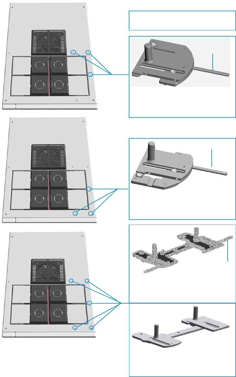
1 Installation
Installing the Autosampler
Thermo Scientific TRACE 1300 and TRACE 1310 Hardware Manual 33
Figure 42. Installation Holes and Sampler Supports for AI/AS 1310 - AI/AS 3000 II Autosampler
Support and Installation Holes for the
AI 1310/AS 1310 on the Front Injector
Module.
Support and Installation Holes for the
AI 1310/AS 1310on the Back Injector
Module.
Support and Installation Holes for Two
AI 1310/AS 1310 in Gemini Configuration.
Support and Installation Holes for One or
Two AI 1310/AS 1310 when a TSQ Quantum
Mass Spectrometer is coupled with the GC.
Support Pin
Support Pin
Note: The support pin is required when an
AS 1310 must be installed.
Support Pin
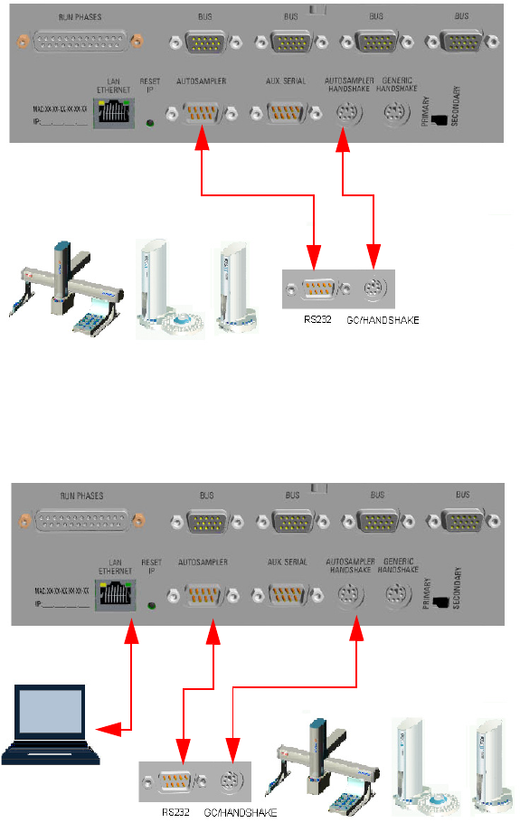
1 Installation
Installing the Autosampler
34 TRACE 1300 and TRACE 1310 Hardware Manual Thermo Scientific
Connecting the Autosampler
There are two possible cabling patterns for connecting the TRACE 1300/TRACE 1310 to a
single autosampler:
• The GC and a TriPlus, AI/AS 1310, or AI/AS 3000 II autosampler are controlled via a
single serial cable connected. In this case, a RS-232 connection is also needed between the
GC and the autosampler.
• In the Chromatography Data System (CDS) Serial Port configuration window, this
option is termed Through GC. Through GC is the default connection. See Figure 43.
Figure 43. Through GC Connection
• The GC is connected to the Chromatography Data System (CDS) via LAN cable.
The autosampler is connected to the GC via RS-232 serial line and handshake cables.
See Figure 44.
Figure 44. Separated Connections
Autosampler
Handshake Cable
Serial Cable
LAN Cable Serial Cable Handshake Cable
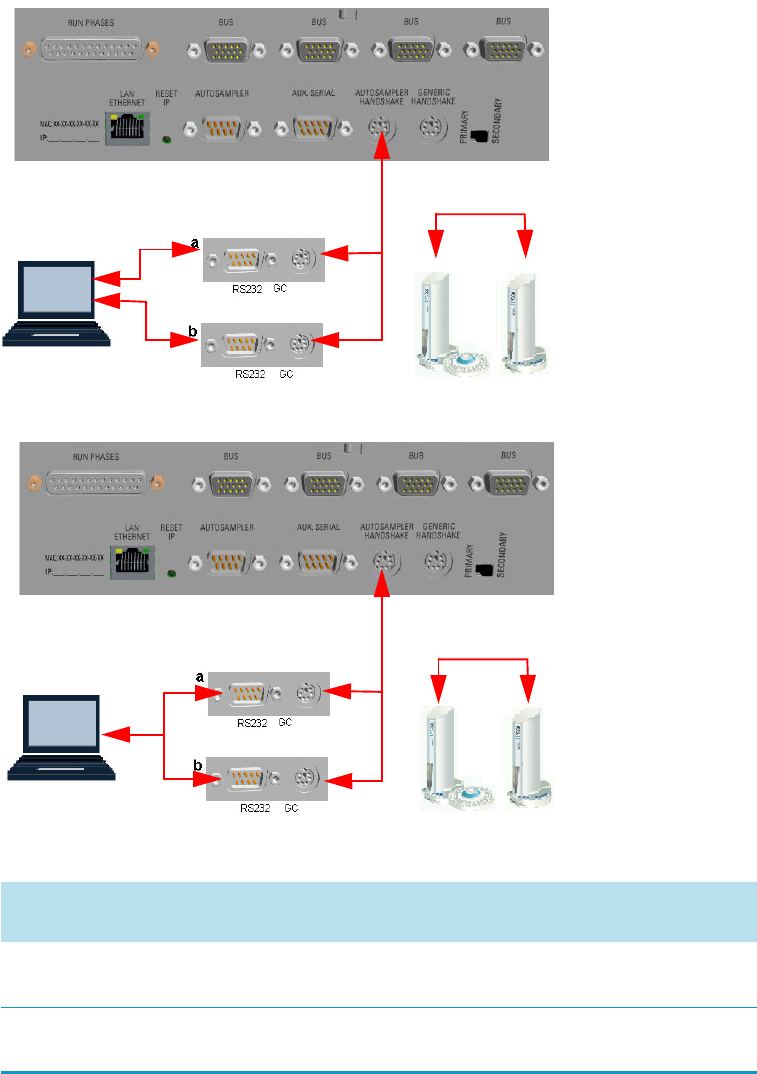
1 Installation
Installing the Autosampler
Thermo Scientific TRACE 1300 and TRACE 1310 Hardware Manual 35
When two AI/AS 1310 or AI/AS 3000 II autosamplers are in use in Gemini
configuration, perform the hardware setup (HWSetup 1 or HWSetup 2) according to
the Thermo Scientific Chromatography Data System in use, and to the High
Throughput, Single, or Confirmation operating mode. See Figure 45, Figure 46, and
Tabl e 2 .
Figure 45. Connections of Two AI/AS Autosamplers - HWSetup 1
Figure 46. Connections of Two AI/AS Autosamplers - HWSetup 2
Table 2. Hardware Setup Comparison Table (Sheet 1 of 2)
Chromatography Data System
(CDS)
High Throughput
Mode
Single
Mode1Confirmation
Mode
Chromeleon 7.2 HWSetup 1
See Figure 49
HWSetup 1
See Figure 49
HWSetup 2
See Figure 49
Xcalibur NA2HWSetup 21
See Figure 50
HWSetup 2
See Figure 50
Autosampler Gemini Y-shape Cable
Serial Cable
Serial Cable
CDS
Hardware Setup 1
Twin Cable
Gemini Y-shape Cable
Twin Cable
CDS
Autosampler
Serial Y-shape
Cable
Hardware Setup 2
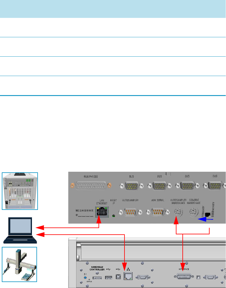
1 Installation
Installing the Autosampler
36 TRACE 1300 and TRACE 1310 Hardware Manual Thermo Scientific
• The GC and the TriPlus RSH or TriPlus 100 Liquid Sampler autosampler are connected
to the Chromatography Data System (CDS) via LAN cable.
The autosampler is connected to the GC through the Y-shape handshake cable. See
Figure 47 and Figure 48.
Figure 47. Connection of GC and TriPlus RSH/ TriPlus 100 Liquid Sampler via LAN
Tra c eFin d e r 3 . 2 NA 2HWSetup 21
See Figure 50
HWSetup 2
See Figure 50
Chrom-Card 2.12 Alternative
See Figure 50
HWSetup 21
See Figure 50
HWSetup 2
See Figure 50
ChromQuest 5; SP2015 R2 HWSetup 1
See Figure 49
HWSetup 1
See Figure 49
HWSetup 1
See Figure 49
EzChrom 3.22; SP2015 R2 HWSetup 1
See Figure 49
HWSetup 1
See Figure 49
HWSetup 1
See Figure 49
1The unplugging of the power cord from the unused AI 1310/AS 1310 autosampler could be required
2Not Applicable
Table 2. Hardware Setup Comparison Table (Sheet 2 of 2)
Chromatography Data System
(CDS)
High Throughput
Mode
Single
Mode1Confirmation
Mode
GC
CDS
Ethernet
Cable
GC 1
Y-shape Handshake Cable X
Ethernet
Cable
TriPlus RSH
TriPlus 100 LS
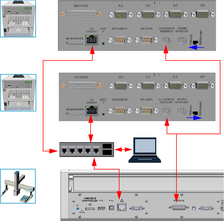
1 Installation
Installing the Autosampler
Thermo Scientific TRACE 1300 and TRACE 1310 Hardware Manual 37
Figure 48. Connection of TriPlus RSH/ TriPlus 100 Liquid Sampler to two GC via LAN
Connect the Autosampler to the GC System
To connect an autosampler to the GC system see the following procedures:
•“To connect a TriPlus RSH/TriPlus 100 Liquid Sampler autosampler” on page 38
•“To connect a second GC coupled with the same TriPlus RSH/TriPlus 100 Liquid
Sampler autosampler” on page 38
•“To connect a a TriPlus autosampler” on page 38
•“To connect a second GC is also coupled with the same TriPlus autosampler” on page 38
•“To connect an AI/AS 1310 - AI/AS 3000 II autosampler” on page 39
•“To perform the HWSetup 1 of two AI/AS 1310 - AI/AS 3000 II in Gemini
Configuration” on page 39
•“To perform the HWSetup of two AI/AS 1310 - AI/AS 3000 II in Gemini
Configuration” on page 40
Second GC
First GC
GC 1
Ethernet Cable
Ethernet Cable
CDS
Ethernet
Hub/Switch
GC 2
Ethernet Cable
TriPlus RSH
TriPlus 100 LS
Y-shape Handshake Cable
1 Installation
Installing the Autosampler
38 TRACE 1300 and TRACE 1310 Hardware Manual Thermo Scientific
To connect a TriPlus RSH/TriPlus 100 Liquid Sampler autosampler
1. Use the Ethernet cable to connect the LAN connector on the back of the TriPlus
RSH/TriPlus 100 Liquid Sampler Control Board to the computer, and verify that the
LAN control LED lights up when connected to a powered-on computer.
2. Using the Y-shape handshake cable provided, connect:
a. the main connector to the connection marked INTERFACE on the back of the
control interface of the TriPlus RSH/TriPlus 100 Liquid Sampler.
b. the first branch of the Y-shape handshake cable, labelled GC 1 to the marked
AUTOSAMPLER HANDSHAKE on the back panel of the GC.
3. Set the Primary/Secondary switch on PRIMARY position.
4. Establish communication between the TriPlus RSH/TriPlus 100 Liquid Sampler and the
GC following the instructions detailed in the Tri P lu s RSH Hardware Manu al or TriPlus
100 Liquid Sampler Hardware Manual.
To connect a second GC coupled with the same TriPlus RSH/TriPlus 100 Liquid
Sampler autosampler
1. Connect the second branch of the Y-shape handshake cable, labelled GC 2, to the
connector marked AUTOSAMPLER HANDSHAKE on the back panel of the second
GC.
2. Set the Primary/Secondary switch on SECONDARY position.
3. Establish communication between the TriPlus RSH/TriPlus 100 Liquid Sampler and the
GC following the instructions detailed in the Tri P lu s RSH Hardware Manu al or TriPlus
100 Liquid Sampler Hardware Manual.
To connect a a TriPlus autosampler
1. Using the cable provided, connect the 6-pin female connector marked HANDSHAKE
MAIN located on the back portion of the crossrail X and the connector marked
AUTOSAMPLER HANDSHAKE on the GC back panel.
2. Using the cable provided, connect the 9-pin female connector marked RS232-1 located
on the back portion of the crossrail X to 9-pin connector marked AUTOSAMPLER 1 on
the GC back panel.
3. Connect the power cable to the AC Input connector (Mains socket) on the autosampler
and to the wall outlet.
To connect a second GC is also coupled with the same TriPlus autosampler
1. Using the cable provided, connect the 6-pin female connector marked HANDSHAKE
VIRTUAL located on the back portion of the crossrail X to the connector marked
AUTOSAMPLER HANDSHAKE on the back panel of the second GC.
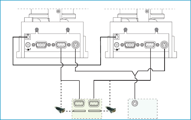
1 Installation
Installing the Autosampler
Thermo Scientific TRACE 1300 and TRACE 1310 Hardware Manual 39
2. Using the cable provided, connect the 9-pin female connector marked RS232-2 located
on the back portion of the crossrail X to the 9-pin connector marked AUTOSAMPLER 2
on the GC back panel.
3. Connect the power cable to the AC Input connector (Mains socket) on the autosampler
and to the wall outlet.
To connect an AI/AS 1310 - AI/AS 3000 II autosampler
1. Using the cable provided, connect the 6-pin female connector marked GC located on the
sampling unit back side to the connector marked AUTOSAMPLER HANDSHAKE on
the GC back panel.
2. Using the cable provided, connect the 9-pin female connector marked RS232 located on
the sampling unit back side to the 9-pin connector marked AUTOSAMPLER 1 on the
GC back panel.
3. Connect the power cable to the AC Input connector (Mains socket) on the autosampler
and to the wall outlet.
To perform the HWSetup 1 of two AI/AS 1310 - AI/AS 3000 II in Gemini Configuration
Figure 49 shows the hardware setup 1 of two AI/AS 1310 or AI/AS 3000 II in Gemini
configuration.
Figure 49. Gemini Configuration - Hardware Setup 1
1. Using the cable provided (PN 23043672), connect the 4-pin male connector marked
TWIN SYNC, on the back of the sampling unit of the sampler “a”, to the 4-pin male
connector marked TWIN SYNC on the back of the sampling unit of the sampler “b”.
2. Using the Gemini Y shape cable provided (PN 23043623), connect:
24 Vdc
-+
TR AY
TWIN
SYN C RS 232 GC 24 Vdc
-+
TR AY
TWIN
SYN C RS 232 GC
GC
PC
SAM PLER SIGNA L
COM 1
USB
COM 2
USB
USB RS232
Adapt er
USB RS232
Adapter
Ad
apter
Adapt er
AI/AS 1310 - AI/AS 3000 II (a) AI/AS 1310 - AI/AS 3000 II )
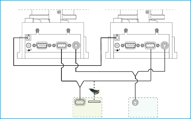
1 Installation
Installing the Autosampler
40 TRACE 1300 and TRACE 1310 Hardware Manual Thermo Scientific
a. the 6-pin main connector labelled GC to the connector marked AUTOSAMPLER
HANDSHAKE on the back of the GC.
b. the first branch of the cable, labelled AI/AS 1, to the 6-pin female connector marked
GC on the back of the sampling unit of the sampler “a”.
c. the second branch of the cable, labelled AI/AS 2, to the 6-pin female connector
marked GC on the back of the sampling unit of the sampler “b”.
3. Using the RS232 cable (PN 23043453) provided in the standard outfit of each AI/AS
1310, connect:
a. the 9-pin connector marked RS232 of the first sampler to a PC serial port (e.g. COM
1), or to an USB port, interposing an USB-RS232 adapter not provided.
b. the 9-pin connector marked RS232 of the second sampler to a second PC serial port
(e.g. COM 2), or to an second USB port, interposing a second USB-RS232 adapter
not provided.
4. Connect the power cable to the AC Input connector (Mains socket) on the autosampler
and to the wall outlet.
To perform the HWSetup of two AI/AS 1310 - AI/AS 3000 II in Gemini Configuration
Figure 50 shows the hardware setup 2 of two AI/AS 1310 or AI/AS 3000 II in Gemini
configuration.
Figure 50. Gemini Configuration - Alternative Hardware Connection (AHC)
1. Using the cable provided (PN 23043672), connect the 4-pin male connector marked
TWIN SYNC, on the back of the sampling unit of the sampler “a”, to the 4-pin male
connector marked TWIN SYNC on the back of the sampling unit of the sampler “b”.
24 Vdc
-+
TR AY
TWIN
SYN C RS 232 GC 24 Vdc
-+
TR AY
TWIN
SYN C RS 232 GC
GC
PC
SAM PLER SIGNA L
COM 1
AI/AS 1310 - AI/AS 3000 II (a)
USB Por t
AI/AS 1310 - AI/AS 3000 II )
USB RS232 Adapter
U

1 Installation
Installing the Autosampler
Thermo Scientific TRACE 1300 and TRACE 1310 Hardware Manual 41
2. Using the Gemini Y shape cable provided (PN 23043623), connect:
a. the 6-pin main connector labelled GC to the connector marked AUTOSAMPLER
HANDSHAKE on the back of the GC.
b. the first branch of the cable, labelled AI/AS 1, to the 6-pin female connector marked
GC on the back of the sampling unit of the sampler “a”.
c. the second branch of the cable, labelled AI/AS 2, to the 6-pin female connector
marked GC on the back of the sampling unit of the sampler “b”.
3. Using the Serial Y shape cable provided (PN 23043675), connect:
a. the 9-pin main connector to a PC serial port (e.g. COM 1) or to an USB port,
interposing an USB-RS232 adapter not provided.
b. the first branch of the cable, labelled AI/AS Primary, to the 9-pin female connector
marked RS232 on the back of the sampling unit of the sampler “a”.
c. the second branch of the cable, labelled AI/AS Secondary, to the 6-pin female
connector marked RS232 on the back of the sampling unit of the sampler “b”.
4. Connect the power cable to the AC Input connector (Mains socket) on the autosampler
and to the wall outlet.
Setting Autosampler Handshake Parameters
When your GC is connected to a AI/AS 1310, AI/AS 3000, TriPlus, TriPlus RSH, or TriPlus
100 Liquid Sampler set the handshaking parameters as shown in Tabl e 3 .
To configure handshaking parameters through the touch screen
1. In the main menu select the Configuration icon, the Configuration menu appears.
2. In the Configuration menu, select the Handshake icon to open the relevant submenu.
3. Set the Handshaking parameters as required, then return to main menu.
Table 3. Handshaking Parameters When An Autosampler is Connected
Parameter Set To:
Remote Start In High to Low
Inhibit Ready In Neither
End of Run Out High to Low
Start of Run Out High to Low
GC Ready Out When Low
Prep Run Out When Low

1 Installation
Installing the Data System Software
42 TRACE 1300 and TRACE 1310 Hardware Manual Thermo Scientific
To configure handshaking parameters through the Chromatography Data System
1. Launch the Data System. In the relevant Configuration page specify the handshaking
parameters.
Installing the Data System Software
The data systems as Chromeleon, Xcalibur, Chrom-Card, or ChromQuest, are designed to be
compatible with commercially available computers and requiring the use of Windows™ XP,
Windows™ Vista, or Windows™ 7 operating system.
To install the data system software
1. Remove the current version.
a. Select Control Panel > Add/Remove Programs.
b. In the dialog window displayed, select the current Data System software version to
remove.
c. Click Add/Remove.
2. Install the new version.
a. Insert the CD/DVD provided and start Setup.exe. Click Next several times.
b. Continue the installation by following the instructions displayed.
c. At the end of the installation, reboot the computer if required.
d. Start the Data System you installed selecting it in the page Start-Program of the
desktop.
e. The Main Page of the data system will be displayed.
For details about the data system in use, please refer to the relevant User Guide.
IMPORTANT Before installing the Data System, please make sure that any previous
version is removed from the PC hard drive.
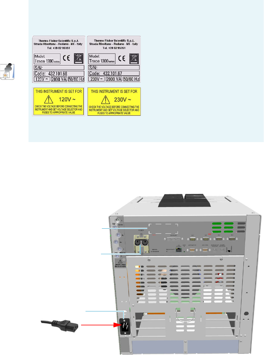
1 Installation
Making Power Connections
Thermo Scientific TRACE 1300 and TRACE 1310 Hardware Manual 43
Making Power Connections
To connect the power to the GC
1. Connect the power cable to the AC Input connector (Main socket) on the GC, and to the
wall outlet. See Figure 51.
Figure 51. GC Power Connection
INSTRUMENT DAMAGE
A label on the electronic module indicates the 120 Vac or 230 Vac power supply. If your
power supply line does not match the power supply required, DO NOT CONNECT
AND DO NOT POWER ON THE GC.
IMPORTANT The external modules must be powered at the same line voltage of the main
GC system.
Power Switch ON Position
AC Input Connector
120 Vac or 230 Vac Power
Supply Label
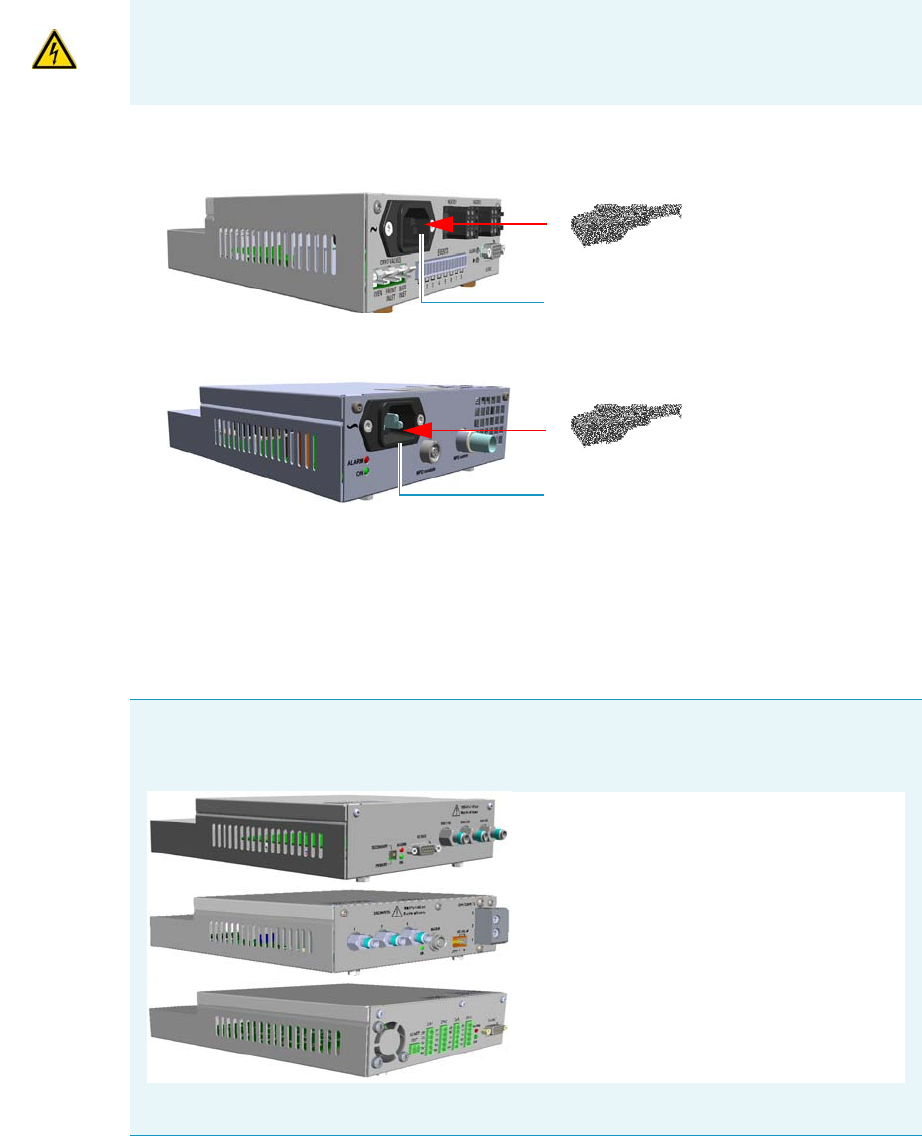
1 Installation
Making Power Connections
44 TRACE 1300 and TRACE 1310 Hardware Manual Thermo Scientific
2. If external modules as Aux Temperature/Cryo Modules, NPD Thermionic Source
Power Module, or both are present, connect the power cable to the AC Input connector
on the front of each external module, and to the wall outlet. See Figure 52.
Figure 52. External Module Power Connection
•Aux Temperature/Cryo Module — The LED marked On lights up solid green after
the GC power on.
•NPD Thermionic Source Power Module — The LED marked On blinks green at
the plug-in of the power cable, and becomes solid green at the power on of the
thermionic source.
IMPORTANT The external modules must be powered at the same line voltage of the main
GC system.
Note The modules Auxiliary Gas, Generic Detector Interface, and Analog Outputs
Interface, receive the power supply from the electronic module of the GC through the
GC Bus connection.
The LED marked On lights up solid green after the GC power on.
Aux Temperature/Cryo Module
NPD Thermionic Source Power Module
AC Input Connector
AC Input Connector
Auxiliary Gas Module
Generic Detector Interface: Electrical Interface
Analog Output Interface Module
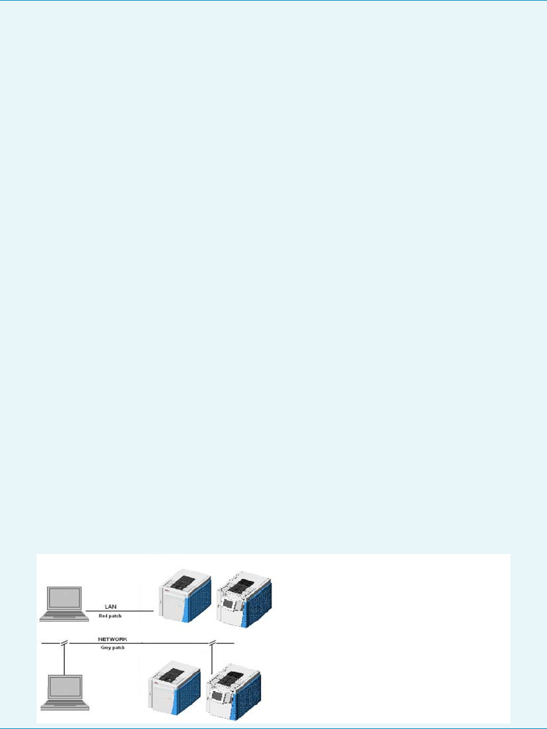
1 Installation
Setting the LAN Communication
Thermo Scientific TRACE 1300 and TRACE 1310 Hardware Manual 45
Setting the LAN Communication
This section provides instructions for setting the desired IP and the LAN communication port
for the TRACE 1300/TRACE 1310. See “Making the LAN Setup” on page 46.
Before making the LAN setup, please read the following note.
Note The TRACE 1300/TRACE 1310 allows LAN (Local Area Network) capabilities by
the presence of an RJ45 connector on the Electronic Module, and two LEDs for LAN
activity.
•IP Address —The GC is shipped with a factory IP address, which may not match the
LAN needs of the sites where the instrument will be installed. To change the default
values, contact your LAN administrator and ask for the IP address to be assigned, the
netmask, and eventually the port.
– The IP address is a 3 digits x 4 fields number given by the network administrator
- e.g. 192.168.127.10
– The netmask is a 3 digits x 4 fields number given by the network administrator -
e.g. 255.255.255.0
– The port is a number given by the network administrator - for example 2551
•Reset Button — To reset the LAN parameters (IP address, communication port, and
so on) to the default values, insert a small screwdriver into the hole, then push the
reset button for at least five seconds.
•Network Cables — Two network cables are included in the standard outfit:
–a reversed RED patch for the computer to TRACE 1300/TRACE 1310 direct
connection. This is used for the initial setup operation and when the instrument
is not connected in remote mode.
–a standard GREY patch for the TRACE 1300/TRACE 1310 to local area
network connection.
Figure 53 shows the LAN schematic connection between the TRACE 1300/TRACE
1310 and the PC.
Figure 53. LAN Schematic Connections
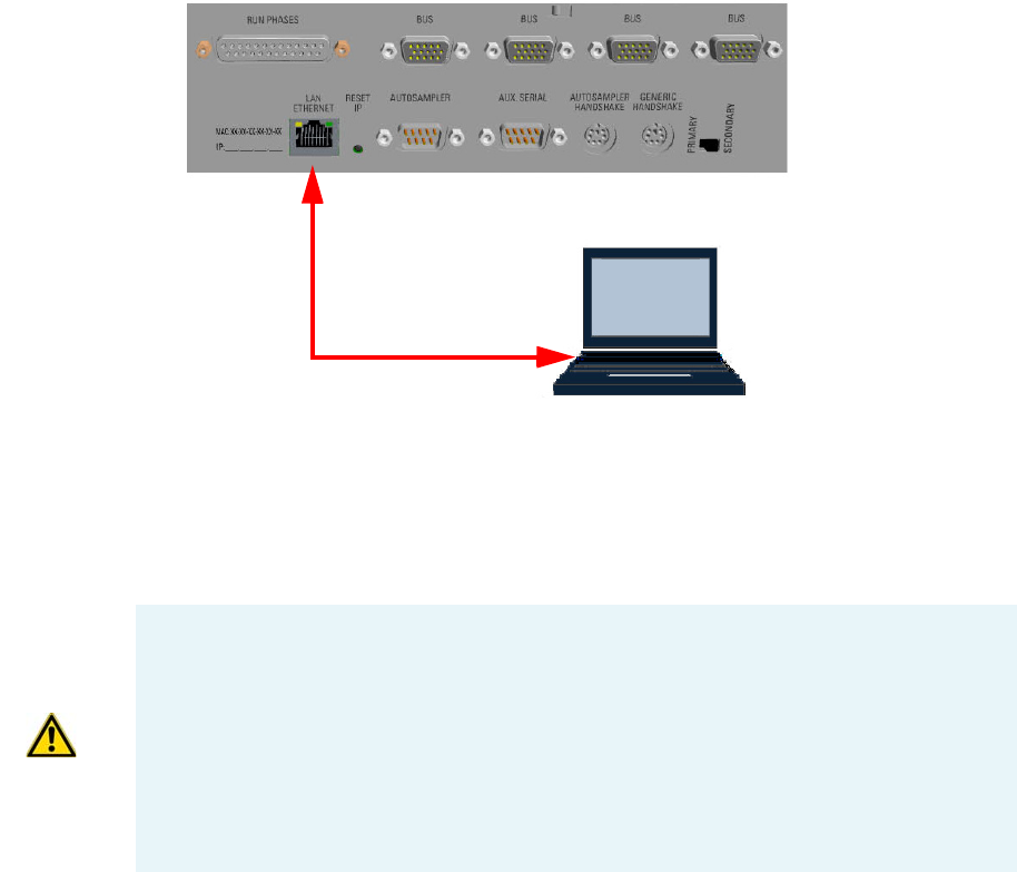
1 Installation
Setting the LAN Communication
46 TRACE 1300 and TRACE 1310 Hardware Manual Thermo Scientific
Making the LAN Setup
To set the LAN communication
1. Using the LAN RED patch, connect a desktop or laptop PC directly to the RJ45
connector marked LAN/Ethernet on the Electronic Module of the GC. See Figure 54.
Figure 54. GC/PC LAN Connection
2. Power on the GC by placing the power switch in the On (up) position marked I.
3. Power on the PC.
4. Start the TS1300ST program to begin the installation on the PC. Follow the instructions
step by step to complete the installation.
5. Run the TS1300ST program; the initial page appears and you will be prompted to enter
the password. See Figure 55.
LAN Standard RED Patch
Computer
Note The TS1300ST program is used for setting the LAN Communication parameters,
and for updating the Firmware version on the GC.
Updating the Firmware version on the GC must be carried out by a Thermo Fisher
Scientific authorized technical personnel.
Use http://www.gc-gcms-customersupport.com/WebPage/Share/Default.aspx address to
contact your local Thermo Fisher Scientific office or affiliate GC-GC/MS Customer
Support
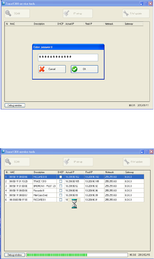
1 Installation
Setting the LAN Communication
Thermo Scientific TRACE 1300 and TRACE 1310 Hardware Manual 47
Figure 55. Initial Page and Password
6. In the text box enter the password ThermoFisher, then press OK.
7. The system starts scanning the equipment powered on and connected to the LAN.
During this stage, the three buttons on the top of the page are disabled. See Figure 56.
Figure 56. Research of the Equipment
8. At the end of the scan, all the equipment powered on and connected to the LAN is
displayed. Only the SCAN button is enabled. See the example in Figure 57.
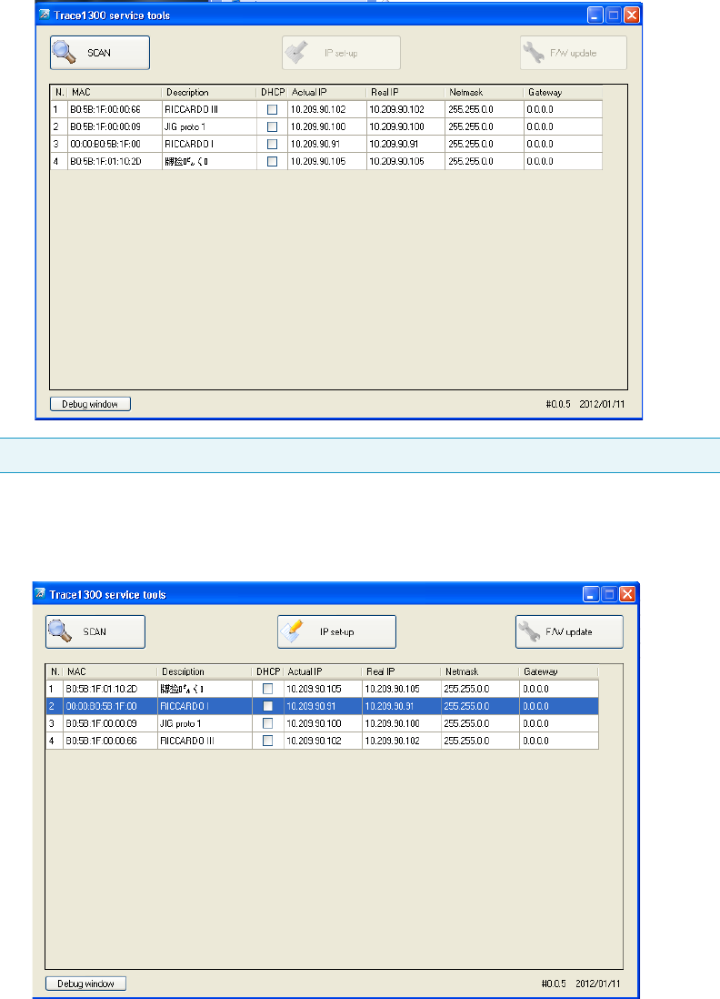
1 Installation
Setting the LAN Communication
48 TRACE 1300 and TRACE 1310 Hardware Manual Thermo Scientific
Figure 57. Equipment Connected to the LAN
9. Select the GC of interest to set up. All the three buttons on the top of the page are
enabled. See the example in Figure 58.
Figure 58. Selection of the GC of Interest
10. Click IP set-up. The Remote Settings page is displayed. See the example in Figure 59.
Note To repeat the scan, click SCAN.
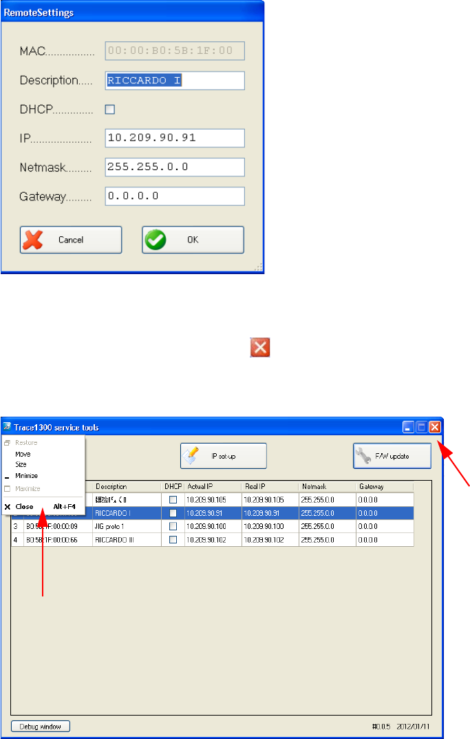
1 Installation
Setting the LAN Communication
Thermo Scientific TRACE 1300 and TRACE 1310 Hardware Manual 49
Figure 59. Remote Settings Page
The editable parameters are: Description, DHCP, IP, Netmask, and Gateway.
After changing parameters, press OK to confirm the new settings.
11. Close the TS1300ST program by pressing on the right upper corner of the page, or
selecting the command Close in the drop-down menu. See Figure 60.
Figure 60. Close Commands
12. Configure the Data System (Xcalibur, Chrom-Card, ChromQuest, or Chromeleon) in
use. See the section “Configuring the Data System” on page 50.

1 Installation
Column Installation Requirements
50 TRACE 1300 and TRACE 1310 Hardware Manual Thermo Scientific
Configuring the Data System
You should use the self adhesive labels found in the standard outfit of the Data System to
annotate the IP address and the TCP Port that are set in the instrument. Stick the label where
it can be easily found when necessary to configure the data system.
1. Launch the Data System. In the relevant Configuration page specify a direct TCP/IP
address.
2. Enter the IP address of the GC and set the socket used.
Standard operation parameters are set by default; however, your GC may be hidden
behind a Firewall that may prevent Port 2551 from being used.
You can set an alternative port number. The number of the socket entered in this box
must correspond to the port assigned to the instrument setup.
Column Installation Requirements
The column is where the separation takes place. It should be positioned inside the oven on the
column rack. The column ends should align correctly with the injector and the detector
bottom fittings. The GC oven controller accurately controls the column temperature.
Each column has a maximum recommended operating temperature. To protect the column
from excessively high temperatures, remember to set the Maximum temperature parameter
for the oven.
Related Topics
•“Using the Correct Fittings” on page 50
•“Installing the Adapters for Encapsulated Graphite Ferrules” on page 52
•“Installing the Column Rack” on page 56
Using the Correct Fittings
To connect a capillary column to the injector and detector base body, you must use the proper
column ferrules and retaining nuts.
•Retaining Nut — Dedicated retaining nuts are required to connect capillary columns to
injector and detector base bodies, and the Te e connector. See Table 4.
IMPORTANT If the connection is performed through hubs over a 10 Mbit/s network, it is
suggested that no more than five GC units be connected on the same network trunk.
If you have a switched network, this warning does not apply.
Note For detailed information on maximum operating temperature, refer to the column
manufacturer’s instructions provided with the column.
1 Installation
Column Installation Requirements
Thermo Scientific TRACE 1300 and TRACE 1310 Hardware Manual 51
•Ferrules — Graphite ferrules, graphite Vespel® ferrules, and encapsulated graphite
ferrules are used for many column connections. See Table 5.
Table 4. Column Retaining Nuts for Injectors and Detectors
Retaining Nut Type Injector/Tee Connector Detector
1/4” Hexagonal
retaining nut
SSL, SSLBKF FID, NPD, TCD,
ECD, FPD
M4 Split retaining
nut
PTV, PTVBKF,
SSLBKF
(Tee Connector)
Table 5. Ferrules for Injectors and Detectors
Ferrule Type Injector/Tee
Connector Detector Temperature
Limit
Graphite ferrule SSL, SSLBKF FID, NPD, TCD,
ECD, FPD
450 °C
Graphite Vespel®
ferrule
SSL, SSLBKF FID, NPD, TCD,
ECD, FPD
350 °C
Encapsulated
graphite ferrule
(Graphpack)
See the Note
below.
PTV, PTVBKF,
SSLBKF
(Tee Connector)
450 °C
Graphite ferrules are a soft material that is porous to oxygen, making them suitable for most
applications except GC/MS interface connections. These easy-to-use ferrules form a soft grip with the
column and provide a stable seal. Graphite ferrule are re-usable.
Graphite/Vespel® ferrules have a long lifetime and are compatible with GC/MS. These ferrules form
a strong grip with the column and cannot be reused as they form a permanent seal with the column.
They have a temperature limit of 350 °C, but must be re-tightened after initial temperature cycles.
1 Installation
Column Installation Requirements
52 TRACE 1300 and TRACE 1310 Hardware Manual Thermo Scientific
Tabl e 6 , Table 7, and Table 8 list the size of the ferrule to use depending on the internal
diameter of precolumn and capillary column.
When connecting columns, consider that overtightening compression ferrules does not
necessarily produce a stronger, leak-free joint. In fact, very often the reverse is true. Too
much pressure can cause a leak in the joint and make it very difficult to reseal the joint
when changing columns.
Installing the Adapters for Encapsulated Graphite Ferrules
This section provides instructions for installing the optional adapters for connecting the
capillary column to the SSL injector and FID, NPD, TCD, ECD, and FPD detector by using
the encapsulated graphite ferrules (Graph-pack).
The adapters are provided with the kit PN 19050759. The kit includes the parts listed in
Tabl e 9 .
Note An optional adapter kit must be installed if you want to connect the column to
the injector and detector by using the encapsulated graphite ferrule. See “Installing
the Adapters for Encapsulated Graphite Ferrules” on page 52.
Table 6. Graphite Ferrules Size ID
Ferrules Size ID Required for:
0.4 mm 0.1 - 0.32 mm ID capillary column
0.8 mm 0.45 - 0.53 mm ID capillary column
Table 7. Graphite Vespel Ferrules Size ID
Ferrules Size ID Required for:
0.4 mm 0.1/0.2/0.25 mm ID capillary column
0.5 mm 0.32 mm ID capillary column
0.8 mm 0.53 mm ID capillary column
Table 8. Encapsulated Graphite Ferrules Size ID
Ferrules Size ID Required for:
0.4 mm 0.25 mm ID capillary column
0.5 mm 0.32 mm ID capillary column
0.8 mm 0.45/0.53 mm ID capillary column
CAUTION Using the wrong size ferrules causes leaks and contamination.
1 Installation
Column Installation Requirements
Thermo Scientific TRACE 1300 and TRACE 1310 Hardware Manual 53
To install the adapters for encapsulated graphite ferrules
1. Put the GC in standby condition.
2. Cool the oven and injector to room temperature.
3. Turn the carrier gas off, and wait for the carrier pressure to go to zero.
4. Remove the analytical column.
a. Open the front door of the GC.
b. Loosen the retaining nut from the injector and detector fitting on the upper interior
wall of the GC oven.
c. Remove the analytical column with its nut and ferrule from the bottom of the
injector and the detector.
5. Remove the bottom parts of the SSL injector. See Figure 61.
Table 9. Adapters and 1/2-in. Wrench
Part Description
Adapter for connection to the SSL injector
Adapter for connection to the FID, NPD, ECD, TCD, or
FPD detector
1/2-in. wrench
Note By pressing the Maintenance button, the GC cool down is automatically
carried out.
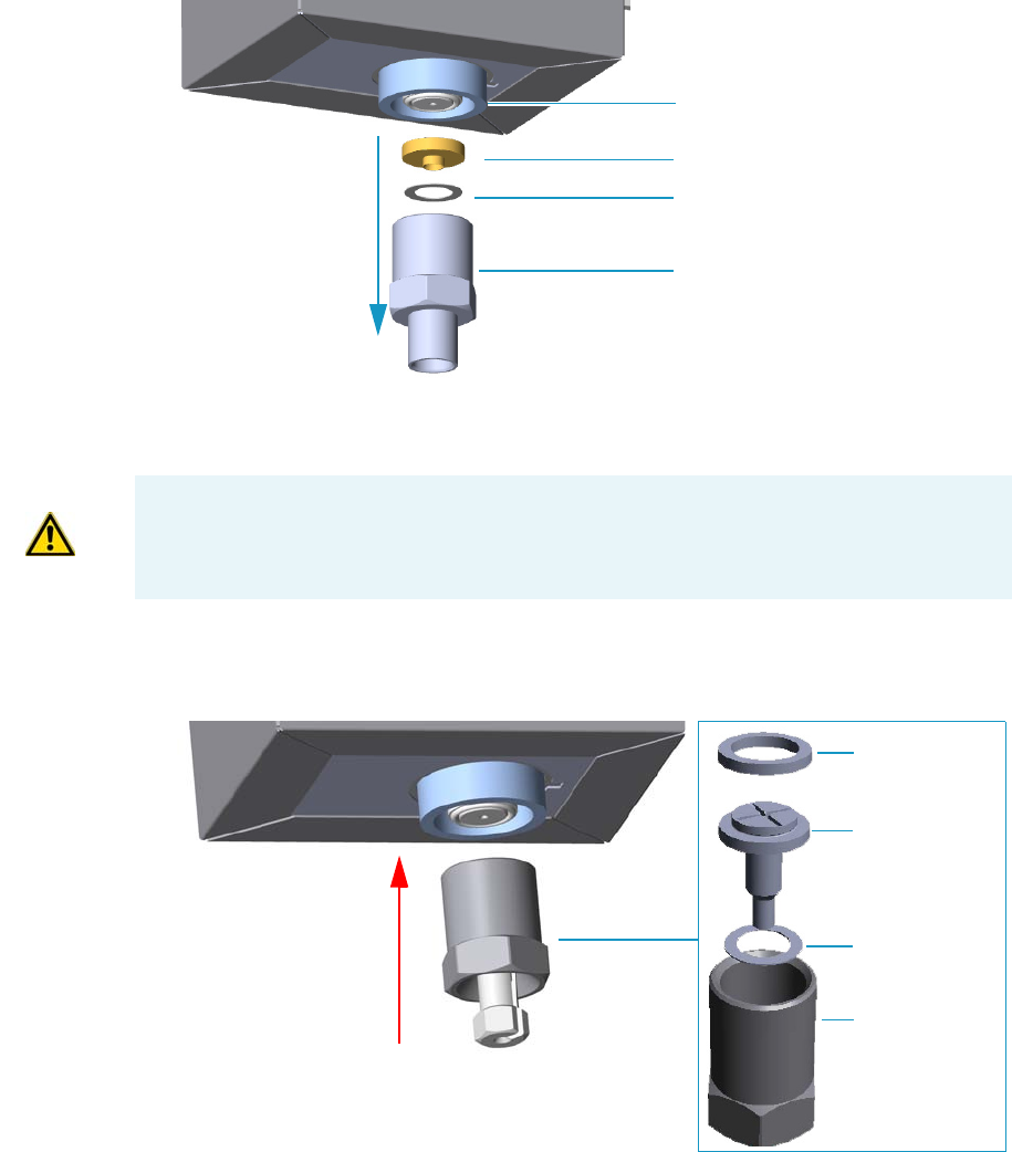
1 Installation
Column Installation Requirements
54 TRACE 1300 and TRACE 1310 Hardware Manual Thermo Scientific
Figure 61. SSL Injector Bottom Parts Removal
a. Using the 1/2-in. wrench provided, unscrew the retaining nut with the base seal and
the washer from the bottom of the injector.
6. Install the adapter on the bottom the injector. See Figure 62.
Figure 62. Adapter Installation on SSL Injector Bottom
a. Fingertighten the retaining nut of the adapter until it start to grip the bottom of the
injector.
b. Use the 1/2-in. wrench to firmly tighten the retaining nut of the adapter with the
base seal and the washer from the bottom of the injector.
7. Remove the bottom parts of the FID, NPD, ECD, TCD, or FPD detector. See Figure 63.
Base Seal
Washer
Retaining Nut
SSL Injector Bottom
CAUTION Make sure that the liner does not come from the bottom of the injector.
Save the bottom parts of the SSL injector in a safe place because will be reused when you
restore the original configuration.
Retaining Nut
Column Adapter
Nut
Silver Washer
Graphpacl SSL
Bottom
SSL Washer
Inlet
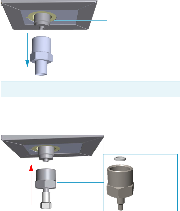
1 Installation
Column Installation Requirements
Thermo Scientific TRACE 1300 and TRACE 1310 Hardware Manual 55
Figure 63. Detector Bottom Parts Removal
a. Using the 1/2-in. wrench provided, unscrew the retaining nut from the bottom of the
detector.
8. Install the adapter on the bottom the detector. See Figure 64.
Figure 64. Adapter Installation on the Bottom of the Detector
a. Fingertighten the retaining nut of the adapter until it starts to grip the bottom of the
detector.
b. Use the 1/2-in. wrench to firmly tighten the retaining nut of the adapter with the
base seal and the washer from the bottom of the injector.
9. Connect the column.
a. Before starting, use a 1/4-5/16-in. wrench to remove the column nuts and ferrules
from the base of the injector and detector adapters. See Figure 65.
Note Save the bottom parts of the detector in a safe place because they will be reused
when you restore the original configuration.
Detector Bottom
Retaining Nut
FID Graphpack
Adapter
Silver Gasket
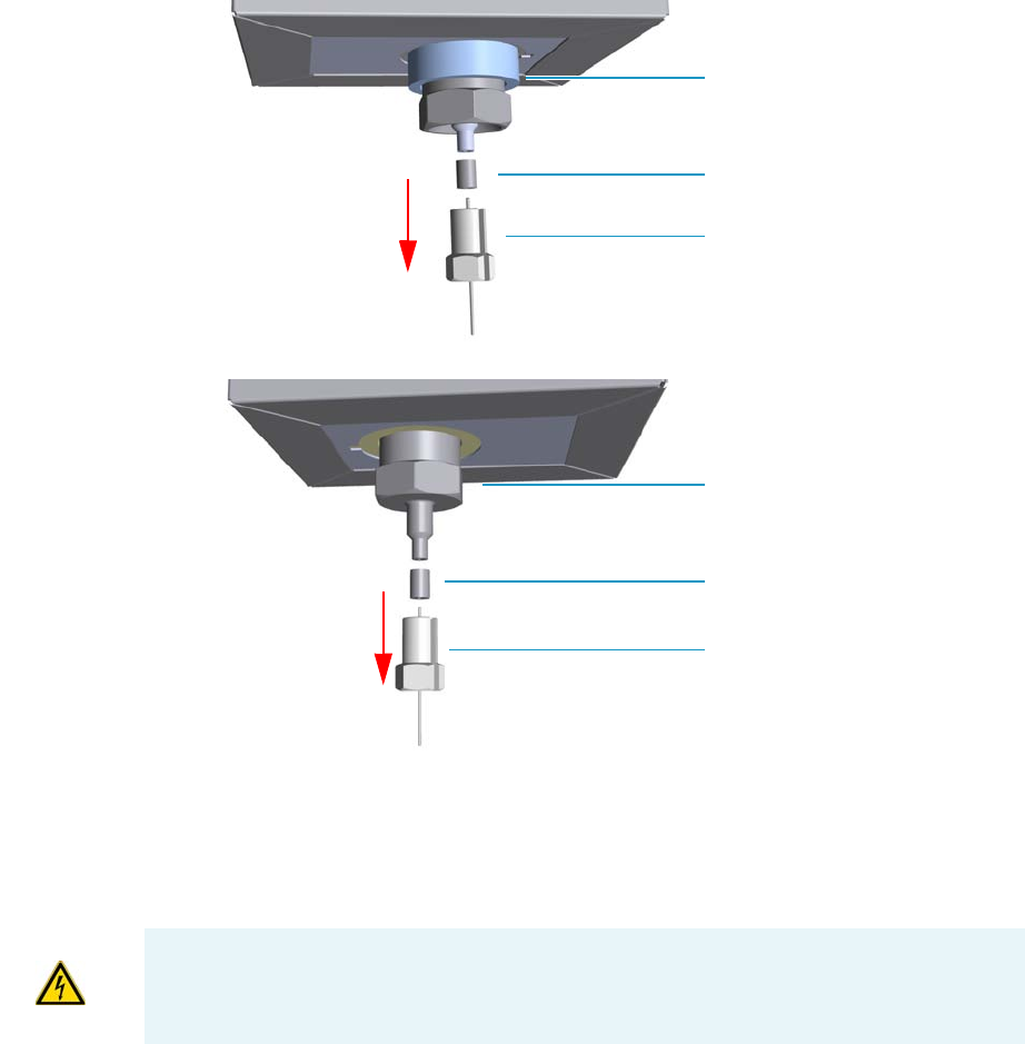
1 Installation
Column Installation Requirements
56 TRACE 1300 and TRACE 1310 Hardware Manual Thermo Scientific
Figure 65. Column Nut and Ferrules
b. Continue the installation of the capillary column following the instructions in the
section “Installing the Column the First Time” on page 57.
Installing the Column Rack
Before connecting the capillary column, make sure that the column rack is installed in the
oven. See Figure 66.
Ferrules
Column Nut
SSL Injector
Ferrules
Column Nut
Detector
WARNING Before starting the installation, make sure that the GC is powered off and the
power cable is disconnected.
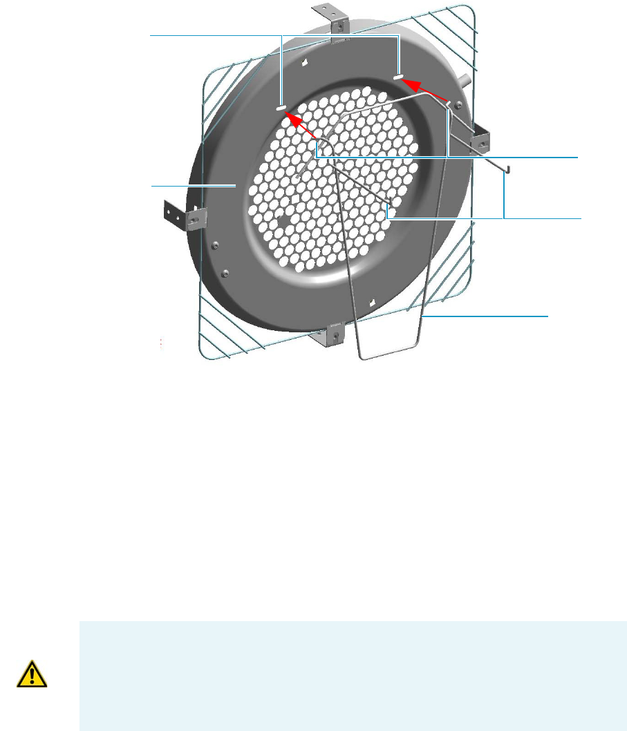
1 Installation
Installing the Column the First Time
Thermo Scientific TRACE 1300 and TRACE 1310 Hardware Manual 57
Figure 66. Column Rack
To install a column rack
1. Open the front door of the GC.
2. Slightly press the sides of the column rack and insert the two hooks into the
corresponding button-holes on the oven heater baffle.
Installing the Column the First Time
This section contains instruction for installing the capillary column into the GC oven, for
connecting the column ends to the injector and the detector and for carrying out the column
conditioning, the leak test and the column evaluation.
To install a new column the first time
1. Install the column into the GC oven.
a. Open the front door of the GC.
b. Place the column on the two arms of the rack. See Figure 67.
Column Rack
Hooks
Button-holes
Oven Heater
Baffle
Arms
CAUTION The injector and detector modules are shipped with a plug.
Before installing the column, remove the plug from the injector and detector modules.
Unscrew the column retaining nut from the bottom of the injector and the detector
modules, then remove the blind ferrule.
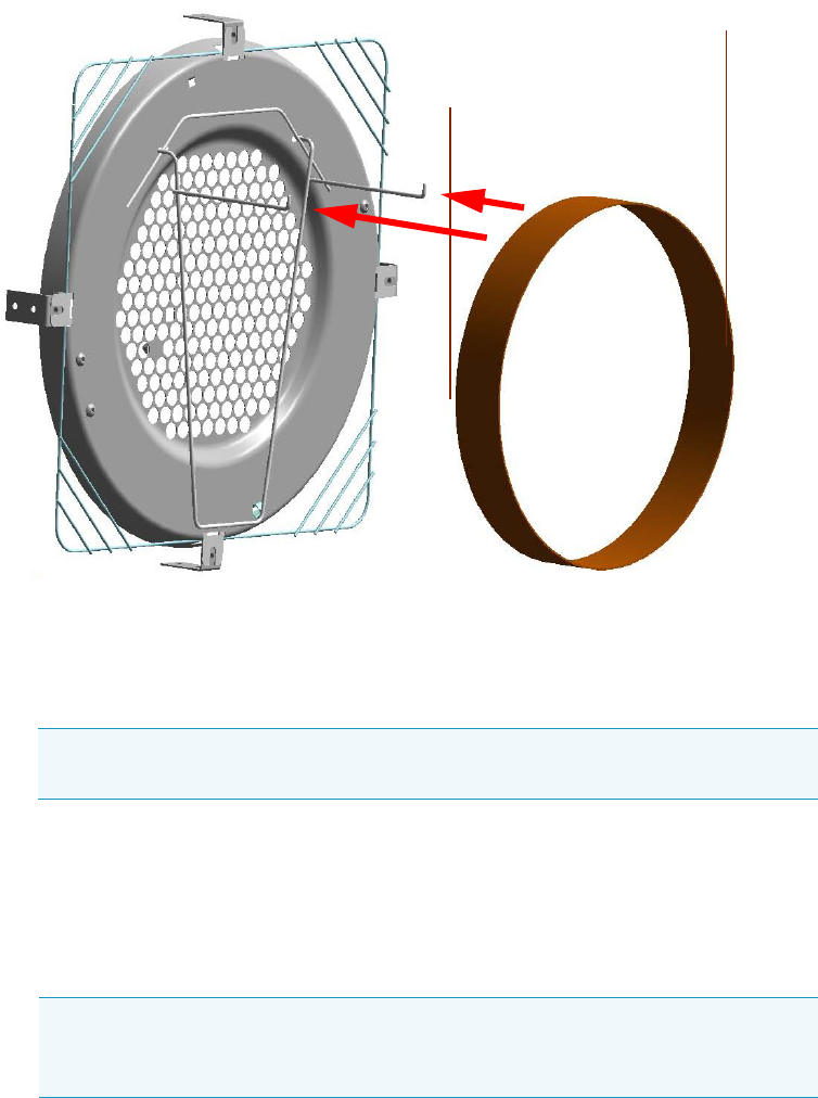
1 Installation
Installing the Column the First Time
58 TRACE 1300 and TRACE 1310 Hardware Manual Thermo Scientific
Figure 67. Column Installation
2. Connect the column to the injector inside the oven.
a. Unwind the column enough to easily connect its ends to the injector and the
detector.
b. Wipe about 100 mm (4 in.) of the column with a tissue soaked in methanol.
c. Insert the column through the injector retaining nut and the proper ferrule (open end
up). Wipe the column again with a tissue soaked in methanol.
d. Use a scoring wafer to score and break the column about 1 cm (0.4 in.) from the end.
Use a magnifying glass to check for an even, flat cut. Repeat if necessary.
e. Position the column so that the end of the column extends the proper distance above
the end of the ferrule as reported in Table 1 0 .
Note Wear clean, lint- and powder-free gloves when you handle the column and
injector ferrule.
Tip Slide a notched septum on the column before the injector retaining nut to
make it easier to measure the proper distance between the nut and end of the
column.

1 Installation
Installing the Column the First Time
Thermo Scientific TRACE 1300 and TRACE 1310 Hardware Manual 59
f. Insert the notched septum on the column to hold the retaining nut at this position.
Thread the retaining nut into the injector but do not tighten.
g. Adjust the column position so that the septum contact the bottom of the retaining
nut.
h. Finger-tighten the retaining nut until it starts to grip the column plus a quarter turn.
i. Remove the notched septum from the column.
3. Open the gas supplies.
4. Power on the GC.
a. Connect the power cable to the AC Input connector on the back of the GC and to
the wall outlet.
b. Flip up the power switch (breaker) to the position I.
5. Setup the GC.
a. Set the oven and injector temperature to 50 °C.
b. Use the column-flowmeter connector to verify that there is flow through the column.
If you do not have a flowmeter, dip the column outlet in a small vial of methanol.
Bubbles indicate there is flow through the column. If there is no flow, check that the
carrier gas is on, the GC inlet is pressurized, and the column is not plugged. If there is
still no flow, consult the section Analytical Troubleshooting in the TRACE
1300/TRACE 1310 User Guide, or contact the Technical Support.
c. Allow the column to purge for few minutes.
6. Perform a column leak check.
Table 10. Column Insertion Depth For SSL, SSLBKF, HeS-S/SL, PTV, PTVBKF, and GSV
Injectors
Injector Column Insertion Depth
SSL and HeS-S/SL • 5 mm (splitless)
• 5 mm (Helium saver)
• 10 mm (split)
SSLBKF • 5 mm (splitless)
• 10 mm (split)
PTV • 30 mm
• As far as possible into the bottom
when the PTV is used as an
On-Column injector.
PTVBKF • 30 mm
GSV • Insert the column as far as goes and
withdrawn about 2 -3 mm
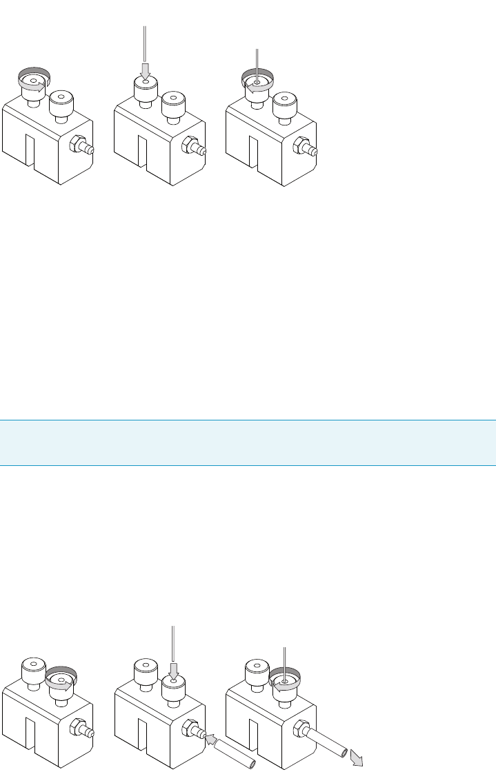
1 Installation
Installing the Column the First Time
60 TRACE 1300 and TRACE 1310 Hardware Manual Thermo Scientific
a. Carefully push the capillary column end into the column section of the
column-flowmeter connector. See Figure 68.
Figure 68. Using a Flowmeter for Leak Check
b. If your GC is equipped with the touch screen as user interface, select the Leak Check
icon in the Maintenance menu, otherwise perform the Leak Check through the
Chromatography Data System by selecting the proper function.
c. Start the leak check to begin operation. The split and purge valves of the selected
channel are automatically closed and the channel is pressurized with carrier gas to the
leak check setpoint.
d. The system monitors the pressure for one minute. If the pressure does not drop more
than the maximum allowed sensitivity value, then the leak check will pass.
e. If the leak check did not pass, you should use the leak detector to find and fix the
leaks.
f. Repeat the leak check until no leaks are indicated.
7. Calibrate the carrier gas flow (column evaluation).
a. Carefully push the capillary column end into the flow meter section of the column-
flowmeter connector. See Figure 69.
Figure 69. Column Flowmeter Connector
Tip Leaks can be caused by not tightening the fitting on the column-flowmeter
connector. We recommend that you check that fitting before looking elsewhere.
A B C
A B C
To flowmeter
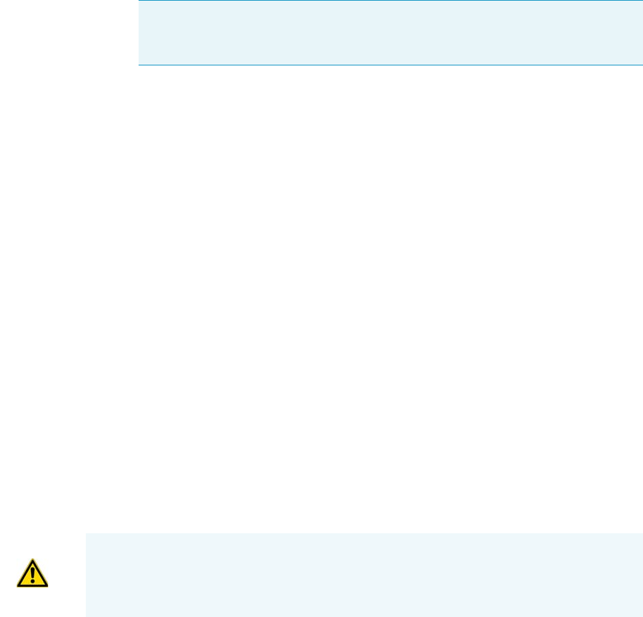
1 Installation
Installing the Column the First Time
Thermo Scientific TRACE 1300 and TRACE 1310 Hardware Manual 61
b. Connect the flowmeter to the dedicated fitting on the column-flowmeter connector.
c. If your GC is equipped with the touch screen as user interface, select Back or Front
Column icon in the Configuration menu, otherwise perform the Column
Evaluation through the Chromatography Data System by selecting the proper
function.
d. Select the column and input the physical characteristics of the column.
e. If a pre-/post-column is present, set the length and nominal internal diameter of the
pre-/post-column in the same valid ranges for the column. The following two lines
are added to the menu.
f. According to the physical characteristics of the column, the system calculates and
displays the relevant Column K-factor.
g. Start column evaluation. At the end of the routine, a message will indicate that
evaluation was successful.
h. Expect a K-factor of approximately 0.7 – 0.9 for a 15 m, 0.25 mm ID column
(1.3 – 2.0 for a 30 m, 0.25 mm ID column). If the column does not report a K-factor
within this range or within 0.1 units of the previous stored value, check for a leak or
broken column using the leak detector. The K-factor is a measured resistance for the
column. A K-factor that is too low may indicate a leak in the system, while a K-factor
that is too high may indicate a blockage.
8. Disconnect the column-flowmeter.
a. Disconnect the column from the column-flowmeter connector.
b. Remove the clear plastic component, including its fittings, from the oven and set it
aside.
c. Close the GC door.
9. Condition the column.
The column must be conditioned before inserting it into the detector.
Column conditioning consists of passing a carrier gas flow through the column heated at
a programmed temperatures as described in the column manufacturer’s instructions.
In case the column does not have any column conditioning instructions, perform the
column conditioning by setting a final temperature up to 10 °C - 20 °C below its
recommended maximum temperature.
Note For the most reproducible results, you should conduct a more detailed
column evaluation. However, the following steps, while recommended, are not
required.
CAUTION When performing column conditioning, the column should be connected only
to the injector leaving the column outlet disconnected to avoid the possibility of
contamination of the detector. Do not use hydrogen as the carrier for conditioning! It
could vent into the oven and present an explosion hazard.
a. Run the temperature program that is recommended by the manufacturer.
10. Connect the column to the detector inside the GC.
a. Lower the oven temperature to 30 °C and allow it to cool.
b. Unwind the column enough to easily connect its ends to the injector and the
detector..
c. Wipe about 100 mm (4 in.) of the column with a tissue soaked in methanol.
d. Use a scoring wafer to score and break the column outlet about 2.5cm (1 in.) from
the end. Use a magnifying glass to check for an even, flat cut. Repeat if necessary.
e. Insert the column through the proper detector retaining nut and ferrule (open end
up). Wipe the column again with a tissue soaked in methanol.
f. For FID, NPD, TCD, ECD, and FPD, position the column so that the end of the
column extends the proper distance above the end of the ferrule as reported in
Tabl e 1 1 . For PDD see the instruction described at the step g on page 63.
i. For FID, NPD, and TCD, insert the column into the detector, paying attention
to not force it further. Finger-tighten the retaining nut, then withdraw the
column 2-3 mm. Tighten the retaining nut an additional a quarter turn.
INSTRUMENT DAMAGE: Never exceed the column manufacturer’s maximum operating
temperature.
WARNING-BURN HAZARD: The injector, detector, oven, and transfer line may be hot.
Allow them to cool to room temperature before touching them.
Note Wear clean, lint- and powder-free gloves when you handle the column and
injector ferrule.
Tip Slide a notched septum on the column before the detector retaining nut to
make it easier to measure the proper distance between the bottom nut and end of
the column.
Table 11. Column Insertion Depth For FID, NPD, TCD, ECD, FPD, and PDD Detectors
Detector Column Insertion Depth
FID, NPD, and TCD Insert the column as far as goes and
withdrawn about 2 -3 mm
ECD 23 mm
FPD 125 mm
PDD 136 mm

1 Installation
Installing the Column the First Time
Thermo Scientific TRACE 1300 and TRACE 1310 Hardware Manual 63
ii. For ECD and FPD, insert the notched septum on the column to hold the
retaining nut in this position. Thread the retaining nut into the detector but do
not tighten. Adjust the column position so that the septum contact the bottom
of the retaining nut.
Finger-tighten the retaining nut until it starts to grip the column plus a quarter
turn.
iii. Remove the notched septum from the column.
g. For PDD the capillary column must enter 136 mm into the pre-installed capillary
column adapter.
i. Make a mark on the column 136 mm from the end.
ii. Remove the knurled nut column inlet at the bottom of the detector. Slide the nut
overt the end of the column, followed by the appropriate column ferrule.
iii. Seat the ferrule in the detail of the column adapter and begin sliding the column
through the capillary column adapter and into the column inlet.
iv. Get the nut started on the threads and tighten it until you feel it contact the
ferrule, then back off half a turn.
v. Slide the column into the column inlet until the mark is flush with the surface of
the knurled nut, and secure the column in the adapter by tightening the knurled
nut finger tight only.
11. End of the column installation.
a. Close the front door of the GC.
Note When inserting the capillary column into the PDD detector it might rarely
happen to feel a slight resistance. In this case, for proper column installation, pull
the column out slightly and adjust the angle before inserting it further.
IMPORTANT To install a packed column, the pre-installed capillary column adapter must
be replaced with the packed columns adapter that enters into the PDD cell for the correct
length.

Thermo Scientific TRACE 1300 and TRACE 1310 Hardware Manual 65
2
Performing Routine Maintenance
This chapter provides instructions for performing routine maintenance on the TRACE 1300
and TRACE 1310.
Contents
•Read Me First
•Maintenance Supplies and Tools
•Maintenance Button
•Powering On the TRACE 1300/TRACE 1310
•Shutting Down the TRACE 1300/TRACE 1310
•Cleaning the Instrument Externally
•Replacing a Column

2 Performing Routine Maintenance
Read Me First
66 TRACE 1300 and TRACE 1310 Hardware Manual Thermo Scientific
Read Me First
The instrument will be generally serviced by Thermo Fisher Scientific authorized technical
personnel for all the warranty period or, after warranty, possibly according to a Programmed
Service Contract. For more information contact your local Thermo Fisher Scientific office.
There are only a few TRACE 1300/TRACE 1310 components that require routine
maintenance, depending on the quantity and types of samples you are running. A frequently
used instrument will, of course, require more maintenance than an instrument that is rarely
used.
•External Cleaning — The GC needs to be cleaned when it gets dirty. See the section
“Cleaning the Instrument Externally” on page 72.
•Column — You may need to replace the column when your performance degrades and
troubleshooting indicates that the column needs maintenance. That may mean that end
of the column needs to be trimmed or the column needs to be replaced.
See “Replacing a Column” on page 73.
•Injector modules — You may need to install, replace or maintain an injector module.
See Chapter 3, “Performing Injectors Routine Maintenance.”
•Detector modules — You may need to install, replace or maintain a detector module.
See Chapter 4, “Performing Detectors Routine Maintenance.”
There are many more components in the TRACE 1300/TRACE 1310 that do not require
routine maintenance, but may need to be replaced if there is a problem with the instrument.
To replace any component not listed in this chapter, see the following chapters:
•Chapter 5, “GC Main Frame Advanced Maintenance.”
•Chapter 6, “Injectors Advanced Maintenance.”
•Chapter 7, “Detectors Advanced Maintenance.”
WARNING If, for technical reasons, it is necessary to work on parts of the machine that
may involve hazardous operations (moving parts, components under voltage, and so
on).Thermo Fisher Scientific authorized Technical Support must be called.
This situation can be identified because the access to these moving parts is possible only
using a particular tool, and because the concerned removable protective covers bear a
warning symbol that draws the operator’s attention to the specific warnings included in
the documentation accompanying the instrument. In case the work must be carried out
by the operator, the latter must prove to be adequately trained to perform the specific
maintenance operation.

2 Performing Routine Maintenance
Read Me First
Thermo Scientific TRACE 1300 and TRACE 1310 Hardware Manual 67
IMPORTANT
All the maintenance operations must be carried out at low temperature to avoid burns.
Therefore, before beginning the sequence, the GC oven, injectors and detectors must be
cooled to room temperature, and then the gases supply must be closed.
You can carry out these operations manually, or by pressing the Maintenance key. For
details refer to the TRACE 1300 and TRACE 1310 User Guide.
At the end of the maintenance operations, restore the GC normal working conditions.
Maintenance of an injector
Before opening the injector for maintenance, turn the carrier gas off, and wait for the
carrier pressure to go to zero.
When an autosampler is present:
Move the autosampler away from the injector module to create free space around it:
• If an AI 1310/AS 1310 - AI 3000/AS 3000 II is installed, pull the sampler support
plate outwards.
• If a TriPlus RSH, TriPlus 100 Liquid Sampler, or TriPlus is installed, make sure that
the standby turret position does not obstacle the injector or detector module to
maintain. If yes, change the position of the turret/head.
2 Performing Routine Maintenance
Maintenance Supplies and Tools
68 TRACE 1300 and TRACE 1310 Hardware Manual Thermo Scientific
Maintenance Supplies and Tools
To perform routine maintenance on the TRACE 1300/TRACE 1310, you will need the
following supplies and tools.
• Wrench, open-end, 1/4-in. and 5/16-in., 1/8-in.
• Flathead screwdriver
• 5.5 x 25 mm Slotted Stubby Driver
• Column cutter, wafer (5181-8836, 4/pk)
• T20 Torxhead screwdriver
• T10 Torxhead screwdriver
• T6 Torxhead screwdriver
• 3-mm Allen key wrench
• Electronic flowmeter (Thermo Scientific GFM Pro Flowmeter, or equivalent)
• Electronic leak detector (Thermo Scientific GLD Pro, or equivalent)
• Tweezers (or thin needle-nose pliers) or forceps
• Gloves, heat-resistant (for handling hot parts)
Cleaning Stainless Steel Components
To clean stainless steel components, you will need:
• Acetone, reagent grade (or other suitable polar solvent)
• Applicators, cotton-tipped
•De-ionized water
• Detergent (Alconox™, Micro®, or equivalent)
• Gas, clean and dry (N2 or He)
• Gloves, clean, lint- and powder-free, latex or nitrile
• Lint-free cloth
• Ultrasonic cleaner
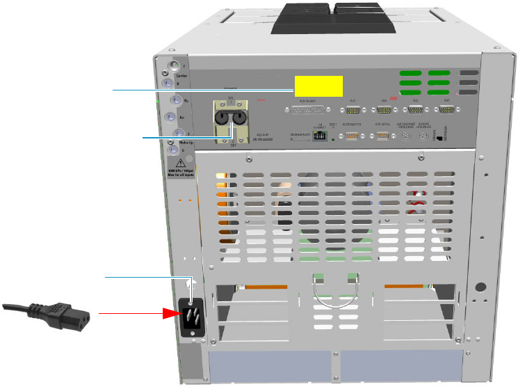
2 Performing Routine Maintenance
Maintenance Button
Thermo Scientific TRACE 1300 and TRACE 1310 Hardware Manual 69
Maintenance Button
When pressed, the Maintenance button allows cooling at 60 °C of the selected heated zones,
which allows the required maintenance. Carrier and detector gases must be closed manually.
This function also performs the following actions automatically:
• turns off the flame and the fuel gases of the FID and FPD detectors.
• turns off the thermionic source, the hydrogen, and the air flows of the NPD detector.
• turns off the filaments of the TCD detector.
Powering On the TRACE 1300/TRACE 1310
To power on the GC
1. Install the GC column (see “Replacing a Column” on page 73).
2. Open the supply gases.
3. Plug the power cable to the AC Input connector (Main socket) on the GC, and to the
wall outlet. See Figure 70.
4. Be sure the carrier gas flowing through the column and the detector gases flowing
through the detector.
Figure 70. GC Power On
Power Switch ON Position
AC Input Connector
120 Vac or 230 Vac
Power Supply Label
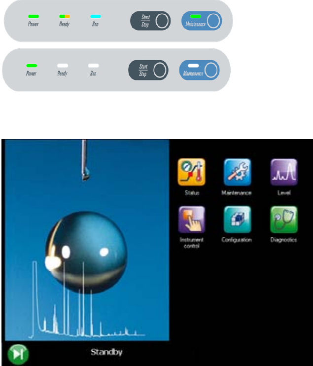
2 Performing Routine Maintenance
Powering On the TRACE 1300/TRACE 1310
70 TRACE 1300 and TRACE 1310 Hardware Manual Thermo Scientific
5. If external modules are present, plug the power cable to the AC Input connector of each
module, and to the wall outlet.
6. Flip up the power switch, located on the back side of the GC, to the On (up) position
marked I.
a. TRACE 1300 — When the GC powers on, all the LEDs on the status panel light up
simultaneously, afterward the Power light becomes a solid green while all the other
lights turn off. The GC is now in stand-by status. See Figure 71.
Figure 71. TRACE 1300 Status Panel at the GC Power On
.
b. TRACE 1310 — Check the main menu appears on the touch screen. See Figure 72.
Figure 72. TRACE 1310 Touch Screen
7. Open the Thermo Scientific Chromatography Data System installed on the computer.
8. Set the analytical parameters.
Power On Status
Stand-by Status
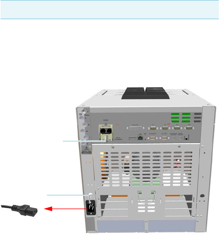
2 Performing Routine Maintenance
Shutting Down the TRACE 1300/TRACE 1310
Thermo Scientific TRACE 1300 and TRACE 1310 Hardware Manual 71
Shutting Down the TRACE 1300/TRACE 1310
To shut down the GC
1. Cool down the GC.
2. If you do not plan to replace the column or perform maintenance on the GC, you do not
have to lower the injector temperature.
3. Turn off the carrier gas supply at the tank.
4. Push down the power switch (breaker), located at the back of the instrument, to the
position O (down). See Figure 73.
Figure 73. GC Power Off
5. If external modules are present, unplug the power cable from the AC Input connector of
each module, and from the wall outlet.
6. If present, power-off the autosampler by switching off the main power switch, or by
unplugging the power cable from the AC input connector, and from the wall outlet.
7. Power-off all the remaining instruments.
Note By pressing the Maintenance button, the GC cool down is automatically
carried out.
Power Switch Off Position
AC Input Connector

2 Performing Routine Maintenance
Cleaning the Instrument Externally
72 TRACE 1300 and TRACE 1310 Hardware Manual Thermo Scientific
Cleaning the Instrument Externally
Normal usage of the TRACE 1300/TRACE 1310 can cause the exterior to get dirty.
To clean the instrument externally
1. Place the GC in stand-by condition.
2. Press the Maintenance button to cool down the GC, or switch off the heated zones
manually.
3. Power off the GC.
a. Push down the power switch (breaker), located at the back of the instrument, to the
position O.
b. Unplug the power cable from the AC Input connector on the back of the GC, and
from the wall outlet.
4. If external modules are present, unplug the power cable from the AC Input connector of
each module, and from the wall outlet.
5. Externally clean the instrument with a soap and water solution, or with a household
non-abrasive product.
• Pay special attention when cleaning the back side of the instrument. Do not spray,
but clean using a cloth imbued with the same substance.
• Carefully avoid seeping of the products used inside the instrument, particularly when
cleaning the grid of the back panel.
• If you just suspect that a substance used for cleaning or a product submitted to
analysis has penetrated inside the instrument, immediately shut down the
instrument, and call an authorized customer support engineer for proper actions.
The service engineer must be fully informed on the nature of the concerned
substance.
In the event that a hazardous material is spilled on or in the instrument, clean the
spill according to the procedures reported in the Material Data Sheet for that
substance.
6. Dry with a clean cloth.
7. If external modules are present, plug the power cable to the AC Input connector of each
module, and to the wall outlet.
8. Power on the GC.
WARNING It is your responsibility to avoid that dangerous liquids, materials or both,
seeping inside the GC during operation and maintenance.
Solvent must not be used. Do not spray on electrical parts.

2 Performing Routine Maintenance
Replacing a Column
Thermo Scientific TRACE 1300 and TRACE 1310 Hardware Manual 73
a. Plug the power cable to the AC Input connector into the back of the GC and to the
wall outlet.
b. Flip up the power switch (breaker) to the position I.
c. Set the normal injector, detector and GC working conditions.
Replacing a Column
You might need to replace the column when your performance degrades and troubleshooting
indicates that the column needs maintenance. That might mean that the end of the column
needs to be trimmed, or the column needs to be replaced.
To replace a column
1. Remove the current column.
a. Press the Maintenance button to cool down the GC.
b. Set off the carrier and detector gases of the channel of interest, and wait for the carrier
pressure to go to zero.
c. Open the front door of the GC.
d. Unscrew the injector and detector nuts, and remove the column.
e. Remove the column from the column rack, and from the GC.
2. Install the new column.
a. Place the new column on the two arms of the column rack inside the oven.
3. Connect the new column to the injector inside the GC.
a. Unwind the column enough to easily connect its ends to the injector and the
detector..
b. Wipe about 100 mm (4 in.) of the column with a tissue soaked in methanol.
c. Insert the column through the proper injector retaining nut and ferrule (open end
up). If the M4 retaining nut is used, slide it on the column through the side cut.
Wipe the column again with a tissue soaked in methanol.
d. Use a scoring wafer to score and break the column about 1 cm (0.4 in.) from the end.
Use a magnifying glass to check for an even, flat cut. Repeat if necessary.
WARNING-BURN HAZARD: The injector and the oven could be hot. Cool to room
temperature before touching them.
Note If you are running samples, stop the acquisition.
Note Wear clean, lint- and powder-free gloves when you handle the column and
injector ferrule.

2 Performing Routine Maintenance
Replacing a Column
74 TRACE 1300 and TRACE 1310 Hardware Manual Thermo Scientific
e. Position the column so that the end of the column extends the proper distance above
the end of the ferrule as reported in Table 1 2 .
f. Insert the notched septum on the column to hold the retaining nut at this position.
Thread the retaining nut into the injector but do not tighten.
g. Adjust the column position so that the septum contact the bottom of the retaining
nut.
h. Finger-tighten the retaining nut until it starts to grip the column plus a quarter turn.
i. Remove the notched septum from the column.
4. Setup the GC parameters.
a. Set the oven and injector temperature to 50 °C.
b. Use the column flowmeter connector to verify that there is flow through the column.
If you do not have a flowmeter, dip the column outlet in a small vial of methanol.
Bubbles indicate there is flow through the column. If there is no flow, check that the
carrier gas is on, the GC inlet is pressurized, and the column is not plugged. If there is
still no flow, consult the Troubleshooting section or contact Technical Support.
c. Allow the column to purge for at least 10 minutes.
5. Perform a column leak check.
Tip Slide a notched septum on the column before the injector retaining nut to
make it easier to measure the proper distance between the nut and end of the
column.
Table 12. Column Insertion Depth For SSL, SSLBKF, HeS-S/SL, PTV, PTVBKF, and GSV
Injectors
Injector Column Insertion Depth
SSL and HeS-S/SL • 5 mm (splitless)
• 5 mm (He saver
• 10 mm (split)
SSLBKF • 5 mm (splitless)
• 10 mm (split)
PTV • 30 mm
• As far as possible into the bottom
when the PTV is used as an
On-Column injector.
PTVBKF • 30 mm
GSV • Insert the column as far as goes and
withdrawn about 2 -3 mm
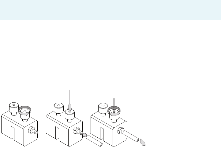
2 Performing Routine Maintenance
Replacing a Column
Thermo Scientific TRACE 1300 and TRACE 1310 Hardware Manual 75
a. If your GC is equipped with the touch screen as user interface, select the Leak Check
icon in the Maintenance menu, otherwise perform the Leak Check through the
Chromatography Data System by selecting the proper function.
b. Start the leak check to begin operation. The split and purge valves of the selected
channel are automatically closed and the channel is pressurized with carrier gas to the
leak check setpoint.
c. The system monitors the pressure for one minute. If the pressure does not drop more
than the maximum allowed sensitivity value, then the leak check will pass.
If the leak check did not pass, you should use the leak detector to find and fix the
leaks.
d. Repeat the leak check until no leaks are indicated.
6. Calibrate the carrier gas flow (column evaluation).
a. Carefully push the capillary column end into the flow meter section of the column
flowmeter connector. See Figure 74.
Figure 74. Column Flowmeter Connector
b. Connect the flowmeter to the dedicated fitting on the column flow meter connector.
c. If your GC is equipped with the touch screen as user interface, select Back or Front
Column icon in the Configuration menu, otherwise perform the Column
Evaluation through the Chromatography Data System by selecting the proper
function.
d. Select the column and input the physical characteristics of the column.
e. If a pre-/post-column is present, set the length and nominal internal diameter of the
pre-/post-column in the same valid ranges for the column. The following two lines
are added to the menu.
f. According to the physical characteristics of the column, the system calculates and
displays the relevant Column K-factor.
Tip Leaks can be caused by not tightening the fitting on the column flowmeter
connector. We recommend that you check that fitting before looking elsewhere.
A B C
To flowmeter
2 Performing Routine Maintenance
Replacing a Column
76 TRACE 1300 and TRACE 1310 Hardware Manual Thermo Scientific
g. Start column evaluation. At the end of the routine, a message will indicate that
evaluation was successful.
h. Expect a K-factor of approximately 0.7 – 0.9 for a 15 m, 0.25 mm ID column
(1.3 – 2.0 for a 30 m, 0.25 mm ID column). If the column does not report a K-factor
within this range or within 0.1 units of the previous stored value, check for a leak or
broken column using the leak detector. The K-factor is a measured resistance for the
column. A K-factor that is too low may indicate a leak in the system, while a K-factor
that is too high may indicate a blockage.
7. Disconnect the column flowmeter.
a. Disconnect the column from the column flowmeter connector.
b. Remove the clear plastic component, including its fittings, from the oven and set it
aside.
c. Close the GC door.
8. Condition the column.
The column must be conditioned before inserting it into the detector.
Column conditioning consists of passing a carrier gas flow through the column heated at
a programmed temperatures as described in the column manufacturer’s instructions.
In case the column does not have any column conditioning instructions, perform the
column conditioning by setting a final temperature up to 10 °C - 20 °C below its
recommended maximum temperature.
a. Run the slow temperature program that is recommended by the manufacturer.
9. Connect the column to the detector inside the GC.
a. Lower the oven temperature to 30 °C and allow it to cool.
Note For the most reproducible results, you should conduct a more detailed
column evaluation. However, the following steps, while recommended, are not
required.
CAUTION When performing column conditioning, connect the column only to the
injector leaving the column outlet disconnected to avoid the possibility of contamination
of the detector.
Do not use hydrogen as the carrier for conditioning! It could vent into the oven and
present an explosion hazard.
INSTRUMENT DAMAGE: Never exceed the column manufacturer’s maximum operating
temperature.

2 Performing Routine Maintenance
Replacing a Column
Thermo Scientific TRACE 1300 and TRACE 1310 Hardware Manual 77
b. Unwind the column enough to easily connect its ends to the injector and the
detector.
c. Wipe about 100 mm (4 in.) of the column with a tissue soaked in methanol.
d. Use a scoring wafer to score and break the column outlet about 2.5cm (1 in.) from
the end. Use a magnifying glass to check for an even, flat cut. Repeat if necessary.
e. Insert the column through the proper detector retaining nut and ferrule (open end
up). Wipe the column again with a tissue soaked in methanol.
f. For FID, NPD, TCD, ECD, and FPD, position the column so that the end of the
column extends the proper distance above the end of the ferrule as reported in
Tabl e 1 3 . For PDD see the instruction described at the step g on page 77.
i. For FID, NPD, and TCD, insert the column into the detector, paying attention
to not force it further. Finger-tighten the retaining nut, then withdraw the
column 2-3 mm. Tighten the retaining nut an additional a quarter turn.
ii. For ECD and FPD, insert the notched septum on the column to hold the
retaining nut in this position. Thread the retaining nut into the detector but do
not tighten. Adjust the column position so that the septum contact the bottom
of the retaining nut. Finger-tighten the retaining nut until it starts to grip the
column plus a quarter turn.
iii. Remove the notched septum from the column.
g. For PDD the column must enter 136 mm into the pre-installed capillary column
adapter.
i. Make a mark on the column 136 mm from the end.
WARNING-BURN HAZARD: The injector, detectors, oven, and transfer line may be hot.
Allow them to cool to room temperature before touching them.
Note Wear clean, lint- and powder-free gloves when you handle the column and
injector ferrule.
Tip Slide a notched septum on the column before the detector retaining nut to
make it easier to measure the proper distance between the bottom nut and end of
the column.
Table 13. Column Insertion Depth For FID, NPD, TCD, ECD, FPD, and PDD Detectors
Detector Column Insertion Depth
FID, NPD, and TCD Insert the column as far as goes and
withdrawn about 2 -3 mm
ECD 23 mm
FPD 125 mm
PDD 136 mm

2 Performing Routine Maintenance
Replacing a Column
78 TRACE 1300 and TRACE 1310 Hardware Manual Thermo Scientific
ii. Remove the knurled nut column inlet at the bottom of the detector. Slide the nut
overt the end of the column, followed by the appropriate column ferrule.
iii. Seat the ferrule in the detail of the column adapter and begin sliding the column
through the capillary column adapter and into the column inlet.
iv. Get the nut started on the threads and tighten it until you feel it contact the
ferrule, then back off half a turn.
v. Slide the column into the column inlet until the mark is flush with the surface of
the knurled nut, and secure the column in the adapter by tightening the knurled
nut finger tight only.
10. End of the column installation.
a. Close the front door of the GC.
Note When inserting the capillary column into the PDD detector it might rarely
happen to feel a slight resistance. In this case, for proper column installation, pull
the column out slightly and adjust the angle before inserting it further.
IMPORTANT To install a packed column, the pre-installed capillary column adapter must
be replaced with the packed columns adapter that enters into the PDD cell for the correct
length.

Thermo Scientific TRACE 1300 and TRACE 1310 Hardware Manual 79
3
Performing Injectors Routine Maintenance
This chapter provides instructions for performing routine maintenance on the TRACE 1300
and TRACE 1310 injector modules.
Contents
•Maintaining a Split/Splitless Injector (SSL)
•Maintaining a Split/Splitless Injector with Backflush (SSLBKF)
•Maintaining a Gas Sampling Valve Injector (GSV)
•Maintaining an Instant Connect Helium Saver Injector (HeS-S/SL)
•Maintaining a Programmable Temperature Vaporizing Injector (PTV)
•Maintaining a Programmable Temperature Vaporizing Injector with
Backflush (PTVBKF)
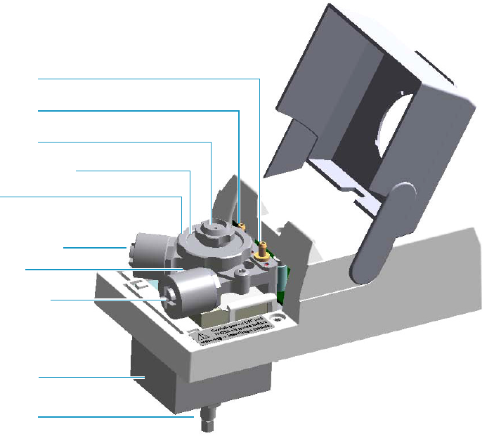
3 Performing Injectors Routine Maintenance
Maintaining a Split/Splitless Injector (SSL)
80 TRACE 1300 and TRACE 1310 Hardware Manual Thermo Scientific
Maintaining a Split/Splitless Injector (SSL)
This section provides instructions for maintaining a Split/Splitless injector (SSL).
The module and injector components are shown in Figure 75 and Figure 76.
Figure 75. SSL Module Components
Split Line Vent
Carrier Gas Line Filter
Split Gas Line Filter
Ring Nut
Purge Line Vent
Septum Cap
Injector Body
Septum Holder/Liner Cap
Insulation Cover
Bottom Fittings
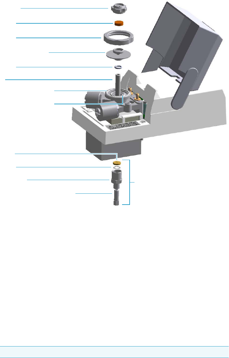
3 Performing Injectors Routine Maintenance
Maintaining a Split/Splitless Injector (SSL)
Thermo Scientific TRACE 1300 and TRACE 1310 Hardware Manual 81
Figure 76. SSL Injector: Components
The SSL injector periodic maintenance includes:
• Replacing the SSL septum
Replace the septum at least after every 200 injections, or every time a problem related to
septum damage, or wear occurs.
See “Replacing the SSL Septum” on page 83.
• Cleaning or replacing the SSL liner
Check the liner for contaminants, debris, breakage, and proper installation.
The liner must be replaced depending on the number of injections performed, and the
characteristics of the samples injected. Typical symptoms will indicate that the liner must
be replaced. The most common is the appearance of tailing peaks in the chromatogram,
particularly for polar compounds.
See“Cleaning or Replacing the SSL Glass Liner” on page 84.
Tip It is good practice to replace the septum every time you replace the glass liner.
Base Seal
Retaining Nut
Washer
Body Head Internal O-Ring
Body Head External O-Ring
Ring Nut
Liner
Liner Seal
Septum
Septum Cap
Septum Holder/Liner Cap
Terminal Fitting for Capillary Column
Bottom Fittings
3 Performing Injectors Routine Maintenance
Maintaining a Split/Splitless Injector (SSL)
82 TRACE 1300 and TRACE 1310 Hardware Manual Thermo Scientific
When replacing or removing a glass liner, it might break inside the injector. In this case
the broken parts of the liner must be removed from the injector, including the glass
splinters that might fall into the lower part of the vaporization chamber.
See “Replacing a SSL Broken Liner” on page 86.
• Replacing the active carbon filters on the carrier gas line and split line
The active carbon filters must be replaced depending on the volume of solvent injected in
the time.
See “Replacing the SSL Carrier and Split Lines Filters” on page 88.
• Replacing the body head o-rings
The internal (carrier line) and external (purge line) o-rings of the body head must be
replaced when in presence of leaks.
See “Replacing the SSL Body Head O-Rings” on page 89.
Before maintaining the injector, read the following warning:
WARNING The injector fittings could be hot. Carry out all the operation at low
temperature to avoid burns. Therefore, before beginning the sequence, the injector must
be cooled to room temperature.
CAUTION When handling organic solvents, you must take precautions to avoid health
hazards.
Materials needed to maintain a SSL injector
Septum
Tweezers
Glass liner
Liner seal (O-ring)
Ultrasonic cleaner
Mixture 1:1 methanol/acetone
Base Seal (if necessary)
Carrier gas line and/or split gas line active carbon filters
Body head internal o-ring
Body head external o-ring
T20 screwdriver
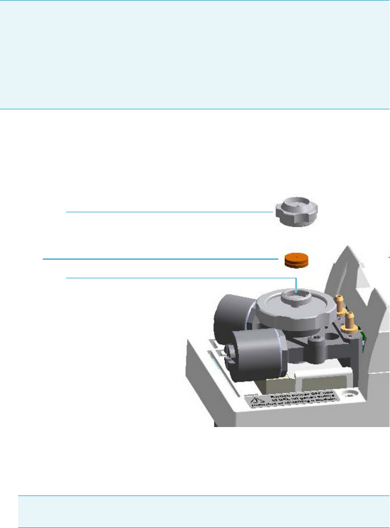
3 Performing Injectors Routine Maintenance
Maintaining a Split/Splitless Injector (SSL)
Thermo Scientific TRACE 1300 and TRACE 1310 Hardware Manual 83
Replacing the SSL Septum
To replace the septum
Figure 77. SSL Injector: Septum Replacement
1. Put the GC in standby condition.
2. Cool the oven and injector to room temperature.
3. Turn the carrier gas off, and wait for the carrier pressure to go to zero.
4. Put the autosampler away if present.
5. Open the module flap cover.
6. Replace the septum.
a. Unscrew and remove the septum cap.
Note For maintaining or replacing any other component not listed in this section, see
Chapter 6, “Injectors Advanced Maintenance.”
•“Baking-out Contaminants from SSL, SSLBKF, HeS-S/SL, PTV, and PTVBKF
Injectors” on page 230
•“Removing/Replacing an Injector Module” on page 231
•“Cleaning the SSL Injector Body” on page 234
Note By pressing the Maintenance button, the GC cool down is automatically
carried out.
Septum Holder
Septum
Septum Cap
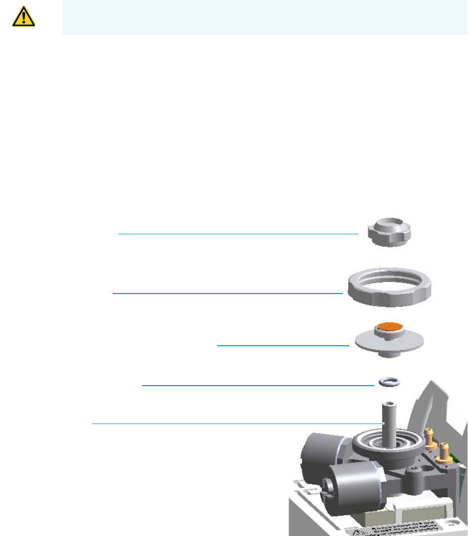
3 Performing Injectors Routine Maintenance
Maintaining a Split/Splitless Injector (SSL)
84 TRACE 1300 and TRACE 1310 Hardware Manual Thermo Scientific
b. Using tweezers, remove the septum from the septum holder.
c. Avoid touching the septum with your fingers. Insert a new septum into the septum
holder using tweezers.
d. Screw and tighten the septum cap to finger-tight.
7. Close the module flap cover.
8. If present, move the autosampler towards the module to restore the original alignment.
9. Turn the carrier gas on.
10. Set the normal injector, detector, and GC working conditions.
Cleaning or Replacing the SSL Glass Liner
To clean or replace the glass liner
Figure 78. SSL Injector: Glass Liner Replacement
1. Put the GC in standby condition.
CAUTION Do not overtighten the septum cap because you might damage the septum and
affect instrument performance.
Septum Cap
Ring Nut
Septum Holder/Liner Cap with Septum
Liner Seal (O-ring)
Liner
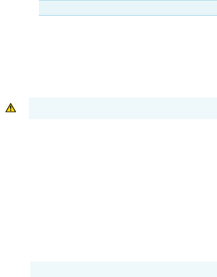
3 Performing Injectors Routine Maintenance
Maintaining a Split/Splitless Injector (SSL)
Thermo Scientific TRACE 1300 and TRACE 1310 Hardware Manual 85
2. Cool the oven and injector to room temperature.
3. Turn the carrier gas off, and wait for the carrier pressure to go to zero.
4. Put the autosampler away if present.
5. Open the module flap cover.
6. Remove the top parts of the injector.
a. Unscrew the septum cap of the injector.
b. Unscrew the ring nut.
c. Remove the septum holder/liner cap with septum from the injector body head.
7. Remove the liner.
a. Using tweezers, remove the liner with the liner seal (o-ring) from the injector.
8. Replace or clean the liner.
• If you are going to use a new liner, go directly to step 10.
• If you are going to clean the dirty liner, go to step 9.
9. Clean the liner.
a. Put the liner into an ultrasonic cleaner filled with a methanol/acetone mixture (1:1).
b. Sonicate the liner for about half an hour.
c. Using tweezers, remove the liner from the bath and dry it with compressed clean air.
10. Install the liner.
a. Holding the new (or cleaned) liner with tweezers place a new liner seal over the liner.
b. Insert the liner into the injector, and push it gently towards the bottom of the
injector.
11. Reinstall the top parts of the injector.
a. Place the septum holder/ liner cap with the septum on the body head of the injector,
and fix it by screwing the ring nut.
b. Screw and tighten the septum cap to finger-tight.
Note By pressing the Maintenance button, the GC cool down is automatically
carried out.
CAUTION Be careful not to break the glass liner when removing it. Glass splinters might
fall into the lower part of the vaporization chamber. If the glass liner breaks, see “Replacing
a SSL Broken Liner” on page 86.
CAUTION Do not overtighten the septum cap because you might damage the septum and
affect instrument performance.
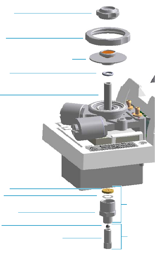
3 Performing Injectors Routine Maintenance
Maintaining a Split/Splitless Injector (SSL)
86 TRACE 1300 and TRACE 1310 Hardware Manual Thermo Scientific
12. Close the module flap cover.
13. If present, move the autosampler towards the module to restore the original alignment.
14. Turn the carrier gas on.
15. Set the normal injector, detector, and GC working conditions.
Replacing a SSL Broken Liner
To replace a broken liner
Figure 79. SSL Injector: Broken Liner Replacement
1. Put the GC in standby condition.
2. Cool the oven and injector to room temperature.
Liner
Liner Seal
Retaining Nut
Washer
Base Seal
Ferrule
Septum Cap
Ring Nut
Septum Holder/Liner Cap with Septum
Capillary Column Retaining Nut Terminal Fitting for Capillary Column
Bottom Fittings

3 Performing Injectors Routine Maintenance
Maintaining a Split/Splitless Injector (SSL)
Thermo Scientific TRACE 1300 and TRACE 1310 Hardware Manual 87
3. Turn the carrier gas off, and wait for the carrier pressure to go to zero.
4. Put the autosampler away if present.
5. Open the module flap cover.
6. Remove the top parts of the injector.
a. Unscrew the septum cap of the injector
b. Unscrew the ring nut.
c. Remove the septum holder/liner cap with septum from the injector body head.
7. Remove the broken liner.
a. Using tweezers, remove the upper part of broken liner with the liner seal from the
injector.
8. Remove the bottom parts of the injector.
a. Inside the oven, unscrew the capillary column retaining nut, then remove the
analytical column with its ferrule from the bottom of the injector.
b. From the bottom of the injector, unscrew the retaining nut with the washer and the
base seal. Glass splinters from the broken liner will fall from the injector.
c. With the aid of a pipe cleaner, remove the possible glass fragments from the
vaporization chamber.
9. Reinstall the bottom parts of the injector.
a. Reinstall the analytical column.
b. Reinstall the retaining nut with the new washer and the base seal. If necessary replace
the base seal with a new one.
10. Install a new liner.
a. Holding the new liner with tweezers, place a new liner seal over the liner.
b. Insert the liner into the injector, and push it gently towards the bottom of the
injector.
11. Reinstall the top parts of the injector.
a. Place the septum holder/liner cap with the septum on the body head of the injector
and fix them by screwing the ring nut.
b. Screw and tighten the injector cap to finger-tight.
Note By pressing the Maintenance button, the GC cool down is automatically
carried out.
CAUTION Do not overtighten the septum cap because you might damage the septum and
affect instrument performance.
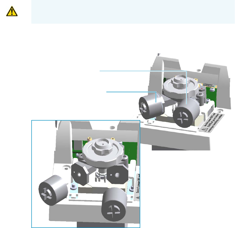
3 Performing Injectors Routine Maintenance
Maintaining a Split/Splitless Injector (SSL)
88 TRACE 1300 and TRACE 1310 Hardware Manual Thermo Scientific
12. Close the module flap cover.
13. If present, move the autosampler towards the module to restore the original alignment.
14. Turn the carrier gas on.
15. Set the normal injector, detector and GC working conditions.
Replacing the SSL Carrier and Split Lines Filters
To replace the active carbon filters on carrier gas line and split line
Figure 80. SSL Injector: Active Filters Replacement
1. Put the GC in standby condition.
2. Cool the oven and injector to room temperature.
IMPORTANT The dimensions of the filters are different. The filter on the split gas line is
bigger than the filter on the carrier gas line. Do not invert their position when you replace
them. It is not necessary to replace the filters together.
Split Gas Line Active Carbon Filter
Carrier Gas Line Active Carbon Filter
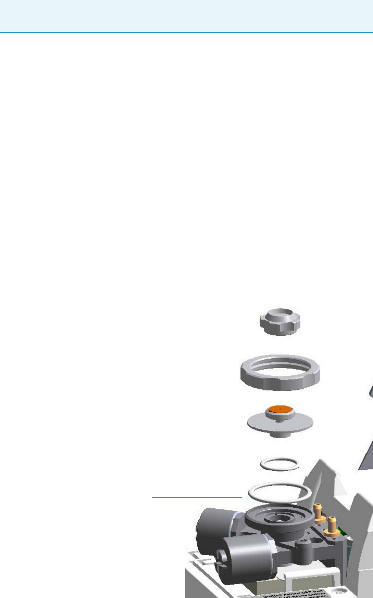
3 Performing Injectors Routine Maintenance
Maintaining a Split/Splitless Injector (SSL)
Thermo Scientific TRACE 1300 and TRACE 1310 Hardware Manual 89
3. Turn the carrier gas off, and wait for the carrier pressure to go to zero.
4. Put the autosampler away if present.
5. Open the module flap cover.
6. Replace the filter.
a. Remove the filter to replace from its seat by turning it counter-clockwise.
b. Install the new filter, with o-rings, in its seat by turning it clockwise.
7. Close the module flap cover.
8. If present, move the autosampler towards the module to restore the original alignment.
9. Turn the carrier gas on.
10. Set the normal injector, detector, and GC working conditions.
Replacing the SSL Body Head O-Rings
To replace the body head o-rings
Figure 81. SSL Injector: Body Head O-Rings Replacement
Note By pressing the Maintenance button, the GC cool down is automatically
carried out.
Body Head Internal O-ring (Carrier gas Line)
Body Head External O-ring (Purge gas Line)

3 Performing Injectors Routine Maintenance
Maintaining a Split/Splitless Injector (SSL)
90 TRACE 1300 and TRACE 1310 Hardware Manual Thermo Scientific
1. Put the GC in standby condition.
2. Cool the oven and injector to room temperature.
3. Turn the carrier gas off, and wait for the carrier pressure to go to zero.
4. Put the autosampler away if present.
5. Open the module flap cover.
6. Remove the top parts of the injector.
a. Unscrew the septum cap of the injector.
b. Unscrew the ring nut.
c. Remove the septum holder/liner cap with septum from the injector body head.
7. Replace the head body o-rings.
a. Use tweezer to remove the body head internal and external o-rings, and replace them
with new o-rings.
8. Reinstall the top parts of the injector.
a. Place the septum holder/liner cap with the septum on the body head of the injector
and fix it by screwing the ring nut.
b. Screw and tighten the injector cap to finger-tight.
9. Close the module flap cover.
10. If present, move the autosampler towards the module to restore the original alignment.
11. Turn the carrier gas on.
12. Set the normal injector, detector, and GC working conditions.
Note By pressing the Maintenance button, the GC cool down is automatically
carried out.
CAUTION Do not overtighten the septum cap because you might damage the septum and
affect instrument performance.
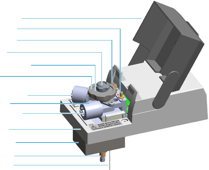
3 Performing Injectors Routine Maintenance
Maintaining a Split/Splitless Injector with Backflush (SSLBKF)
Thermo Scientific TRACE 1300 and TRACE 1310 Hardware Manual 91
Maintaining a Split/Splitless Injector with Backflush (SSLBKF)
This section provides instructions for maintaining a Split/Splitless injector for Backflush
(SSLBKF) applications.
The module and injector components are shown in Figure 82 and Figure 83.
Figure 82. SSLBKF Module Components
Module Cover
Module Flap Cover
Split Line Vent
Carrier Gas Line Filter
Split Gas Line Filter
Ring Nut
Purge Line Vent
Septum Cap
Injector Body
Septum Holder/Liner Cap
Insulation Cover
Bottom Fittings
Backflush Line
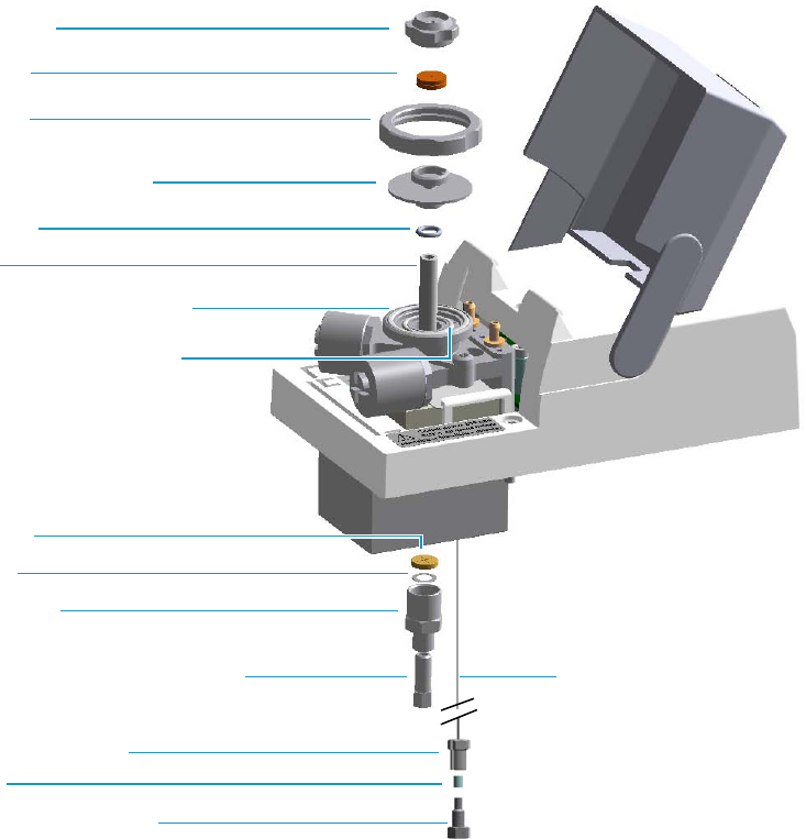
3 Performing Injectors Routine Maintenance
Maintaining a Split/Splitless Injector with Backflush (SSLBKF)
92 TRACE 1300 and TRACE 1310 Hardware Manual Thermo Scientific
Figure 83. SSLBKF Injector Components
The SSLBKF injector periodic maintenance includes:
• Replacing the SSLBKF septum
Replace the septum at least after every 200 injections, or every time a problem related to
septum damage, or wear occurs.
See “Replacing the SSLBKF Septum” on page 94.
• Cleaning or replying the SSLBKF liner
Check the liner for contaminants, debris, breakage, and proper installation. The liner
must be replaced depending on the number of injections performed, and the
characteristics of the samples injected. Typical symptoms will indicate that the liner must
be replaced. The most common is the appearance of tailing peaks in the chromatogram,
particularly for polar compounds.
See“Cleaning or Replacing the SSLBKF Glass Liner” on page 95.
Base Seal
Retaining Nut
Washer
(Terminal Fitting for Capillary Column)
Body Head Internal O-Ring
Body Head External O-Ring
Ring Nut
Liner
Liner Seal
Septum
Septum Cap
Septum Holder/Liner Cap
Ferrule
Fitting Cap, Backflush Line
Backflush Line Fitting
Backflush Line
3 Performing Injectors Routine Maintenance
Maintaining a Split/Splitless Injector with Backflush (SSLBKF)
Thermo Scientific TRACE 1300 and TRACE 1310 Hardware Manual 93
When replacing or removing a glass liner, it might break inside the injector. In this case
the broken parts of the liner must be removed from the injector, including the glass
splinters that might fall into the lower part of the vaporization chamber.
See “Replacing a SSLBKF Broken Liner” on page 97.
• Replacing the active carbon filters on the carrier gas line and split line
The active carbon filters must be replaced depending on the volume of solvent injected in
the time.
See “Replacing the SSLBKF Carrier and Split Lines Filters” on page 99.
• Replacing the body head o-rings
The internal (carrier line) and external (purge line) o-rings of the body head must be
replaced when in presence of leaks.
See “Replacing the SSLBKF Body Head O-Rings” on page 100.
Before maintaining the injector, read the following warning:
Tip It is good practice to replace the septum every time you replace the glass liner.
WARNING The injector fittings could be hot. Carry out all the operations at low
temperature to avoid burns. Therefore, before beginning the sequence, the injector must
be cooled to room temperature.
CAUTION When handling organic solvents you must take precautions to avoid health
hazards.
Materials needed to maintain a SSLBKF injector
Septum
Tweezers
Glass liner
Liner seal (O-ring)
Ultrasonic cleaner
Mixture 1:1 methanol/acetone
Base Seal (if necessary)
Carrier gas line and/or split gas line active carbon filters
Body head internal o-ring
Body head external o-ring
T20 screwdriver
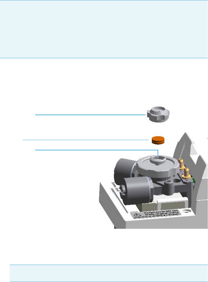
3 Performing Injectors Routine Maintenance
Maintaining a Split/Splitless Injector with Backflush (SSLBKF)
94 TRACE 1300 and TRACE 1310 Hardware Manual Thermo Scientific
Replacing the SSLBKF Septum
To replace the septum
Figure 84. SSLBKF Injector: Septum Replacement
1. Put the GC in standby condition.
2. Cool the oven and injector to room temperature.
3. Turn the carrier gas off, and wait for the carrier pressure to go to zero.
4. Put the autosampler away if present.
5. Open the module flap cover.
6. Replace the septum.
a. Unscrew and remove the septum cap.
Note For maintaining or replacing any other component not listed in this section, see
Chapter 6, “Injectors Advanced Maintenance.”
•“Baking-out Contaminants from SSL, SSLBKF, HeS-S/SL, PTV, and PTVBKF
Injectors” on page 230
•“Removing/Replacing an Injector Module” on page 231
•“Cleaning the SSLBKF Injector Body” on page 238
Note By pressing the Maintenance button, the GC cool down is automatically
carried out.
Septum Holder
Septum
Septum Cap
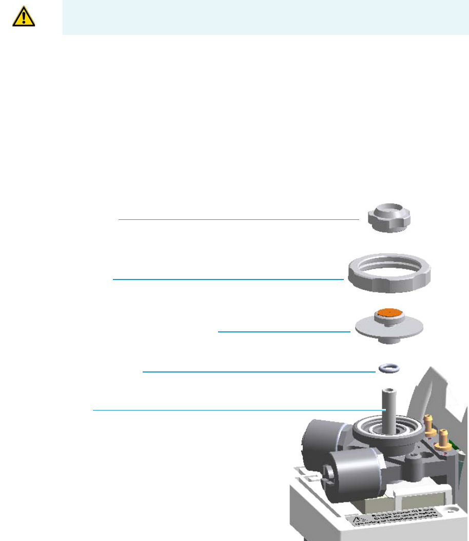
3 Performing Injectors Routine Maintenance
Maintaining a Split/Splitless Injector with Backflush (SSLBKF)
Thermo Scientific TRACE 1300 and TRACE 1310 Hardware Manual 95
b. Using tweezers, remove the septum from the septum holder.
c. Avoid touching the septum with your fingers. Insert a new septum into the septum
holder using tweezers.
d. Screw and tighten the septum cap to finger-tight.
7. Close the module flap cover.
8. If present, move the autosampler towards the module to restore the original alignment.
9. Turn the carrier gas on.
10. Set the normal injector, detector, and GC working conditions.
Cleaning or Replacing the SSLBKF Glass Liner
To clean or replace the glass liner
Figure 85. SSLBKF Injector: Glass Liner Replacement
CAUTION Do not overtighten the septum cap because you might damage the septum and
affect instrument performance.
Septum Cap
Ring Nut
Septum Holder/Liner Cap with Septum
Liner Seal (O-ring)
Liner

3 Performing Injectors Routine Maintenance
Maintaining a Split/Splitless Injector with Backflush (SSLBKF)
96 TRACE 1300 and TRACE 1310 Hardware Manual Thermo Scientific
1. Put the GC in standby condition.
2. Cool the oven and injector to room temperature.
3. Turn the carrier gas off, and wait for the carrier pressure to go to zero.
4. Put the autosampler away if present.
5. Open the module flap cover.
6. Remove the top parts of the injector.
a. Unscrew the septum cap of the injector.
b. Unscrew the ring nut.
c. Remove the septum holder/liner cap with septum from the injector body head.
7. Remove the liner.
a. Use tweezers to remove the liner with the liner seal (o-ring) from the injector.
8. Replace or clean the liner.
• If you are going to use a new liner, go directly to step 10.
• If you are going to clean the dirty liner, go to step step 9.
9. Clean the liner.
a. Put the liner into an ultrasonic cleaner filled with a methanol/acetone mixture (1:1).
b. Sonicate the liner for about half an hour.
c. Using tweezers, remove the liner from the bath, and dry it with compressed clean air.
10. Install the liner.
a. Holding the new (or cleaned) liner with tweezers place a new liner seal over the liner.
b. Insert the liner into the injector and push it gently towards the bottom of the injector.
11. Reinstall the top parts of the injector.
a. Place the septum holder/ liner cap with the septum on the body head of the injector
and fix it by screwing the ring nut.
b. Screw and tighten the septum cap to finger-tight.
Note By pressing the Maintenance button, the GC cool down is automatically
carried out.
CAUTION Be careful not to break the glass liner when removing it. Glass splinters might
fall into the lower part of the vaporization chamber. If the glass liner breaks, see “Replacing
a SSL Broken Liner” on page 86.
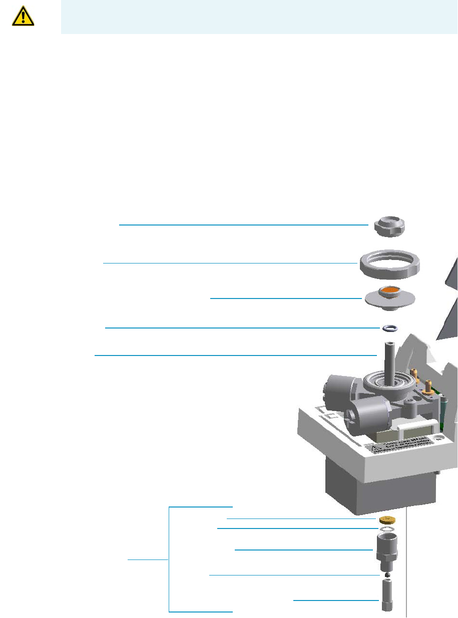
3 Performing Injectors Routine Maintenance
Maintaining a Split/Splitless Injector with Backflush (SSLBKF)
Thermo Scientific TRACE 1300 and TRACE 1310 Hardware Manual 97
.
12. Close the module flap cover.
13. If present, move the autosampler towards the module to restore the original alignment.
14. Turn the carrier gas on.
15. Set the normal injector, detector, and GC working conditions.
Replacing a SSLBKF Broken Liner
To replace a broken liner
Figure 86. SSLBKF Injector: Broken Liner Replacement
CAUTION Do not overtighten the septum cap because you might damage the septum and
affect instrument performance.
Liner
Liner Seal
Retaining Nut
Washer
Base Seal
Ferrule
Septum Cap
Ring Nut
Septum Holder/Liner Cap with Septum
Capillary Column Retaining Nut
Bottom Fittings

3 Performing Injectors Routine Maintenance
Maintaining a Split/Splitless Injector with Backflush (SSLBKF)
98 TRACE 1300 and TRACE 1310 Hardware Manual Thermo Scientific
1. Put the GC in standby condition.
2. Cool the oven and injector to room temperature.
3. Turn the carrier gas off, and wait for the carrier pressure to go to zero.
4. Put the autosampler away if present.
5. Open the module flap cover.
6. Remove the top parts of the injector.
a. Unscrew the septum cap of the injector.
b. Unscrew the ring nut.
c. Remove the septum holder/liner cap with septum from the injector body head.
7. Remove the broken liner.
a. Use tweezers to remove the upper part of broken liner with the liner seal from the
injector.
8. Remove the bottom parts of the injector.
a. Inside the oven, unscrew the capillary column retaining nut, then remove the
analytical column with its ferrule from the bottom of the injector.
b. From the bottom of the injector, unscrew the retaining nut with the washer and the
base seal. Glass splinters from the broken liner will fall from the injector.
c. With the aid of a pipe cleaner, remove the possible glass fragments from the
vaporization chamber.
9. Reinstall the bottom parts of the injector.
a. Reinstall the analytical column.
b. Reinstall the retaining nut with the new washer and the base seal (if necessary replace
the base seal with a new one).
10. Install a new liner.
a. Holding the new liner with tweezers, place a new liner seal over the liner.
b. Insert the liner into the injector and push it gently towards the bottom of the injector.
11. Reinstall the top parts of the injector.
a. Place the septum holder/liner cap with the septum on the body head of the injector
and fix them by screwing the ring nut.
b. Screw and tighten the injector cap to finger-tight
Note By pressing the Maintenance button, the GC cool down is automatically
carried out.
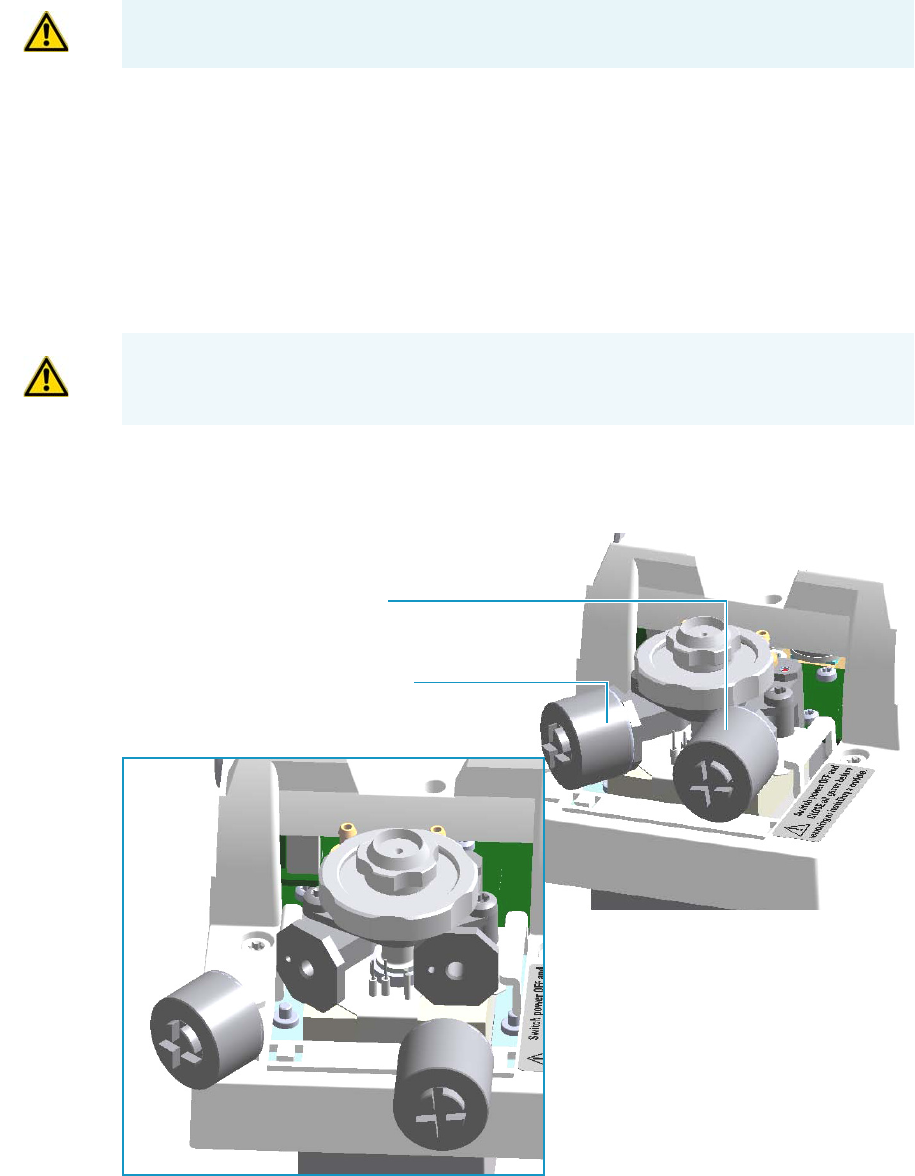
3 Performing Injectors Routine Maintenance
Maintaining a Split/Splitless Injector with Backflush (SSLBKF)
Thermo Scientific TRACE 1300 and TRACE 1310 Hardware Manual 99
12. Close the module flap cover.
13. If present, move the autosampler towards the module to restore the original alignment.
14. Turn the carrier gas on.
15. Set the normal injector, detector, and GC working conditions.
Replacing the SSLBKF Carrier and Split Lines Filters
To replace the active carbon filters on carrier gas line and split line
Figure 87. SSLBKF Injector: Active Filters Replacement
1. Put the GC in standby condition.
CAUTION Do not overtighten the septum cap because you might damage the septum and
affect instrument performance.
IMPORTANT The dimensions of the filters are different. The filter on the split gas line is
bigger than the filter on the carrier gas line. Do not invert their position when you replace
them. It is not necessary to replace the filters together.
Split Gas Line Active Carbon Filter
Carrier Gas Line Active Carbon Filter
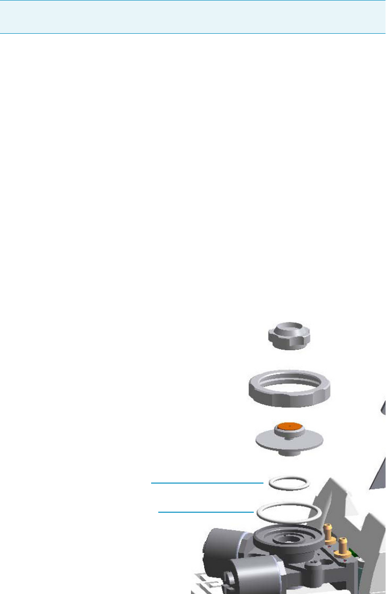
3 Performing Injectors Routine Maintenance
Maintaining a Split/Splitless Injector with Backflush (SSLBKF)
100 TRACE 1300 and TRACE 1310 Hardware Manual Thermo Scientific
2. Cool the oven and injector to room temperature.
3. Turn the carrier gas off, and wait for the carrier pressure to go to zero.
4. Put the autosampler away if present.
5. Open the module flap cover.
6. Replace the filter.
a. Remove the filter to replace from its seat by turning it counter-clockwise.
b. Install the new filter, with o-rings, in its seat by turning it clockwise.
7. Close the module flap cover.
8. If present, move the autosampler towards the module to restore the original alignment.
9. Turn the carrier gas on.
10. Set the normal injector, detector, and GC working conditions.
Replacing the SSLBKF Body Head O-Rings
To replace the body head o-rings
Figure 88. SSLBKF Injector: Body Head O-Rings Replacement
Note By pressing the Maintenance button, the GC cool down is automatically
carried out.
Body Head Internal O-ring (Carrier gas Line)
Body Head External O-ring (Purge gas Line)
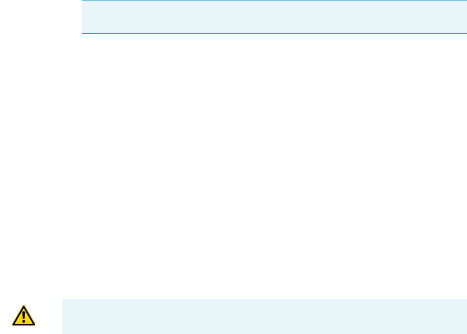
3 Performing Injectors Routine Maintenance
Maintaining a Split/Splitless Injector with Backflush (SSLBKF)
Thermo Scientific TRACE 1300 and TRACE 1310 Hardware Manual 101
1. Put the GC in standby condition.
2. Cool the oven and injector to room temperature.
3. Turn the carrier gas off, and wait for the carrier pressure to go to zero.
4. Put the autosampler away if present.
5. Open the module flap cover.
6. Remove the top parts of the injector.
a. Unscrew the septum cap of the injector.
b. Unscrew the ring nut.
c. Remove the septum holder/liner cap with septum from the injector body head.
7. Replace the head body o-rings.
a. Use tweezers to remove the body head internal and external o-rings, and replace them
with new o-rings.
8. Reinstall the top parts of the injector.
a. Place the septum holder/liner cap with the septum on the body head of the injector
and fix it by screwing the ring nut.
b. Screw and tighten the injector cap to finger-tight.
9. Close the module flap cover.
10. If present, move the autosampler towards the module to restore the original alignment.
11. Turn the carrier gas on.
12. Set the normal injector, detector, and GC working conditions.
Note By pressing the Maintenance button, the GC cool down is automatically
carried out.
CAUTION Do not overtighten the septum cap because you might damage the septum and
affect instrument performance.
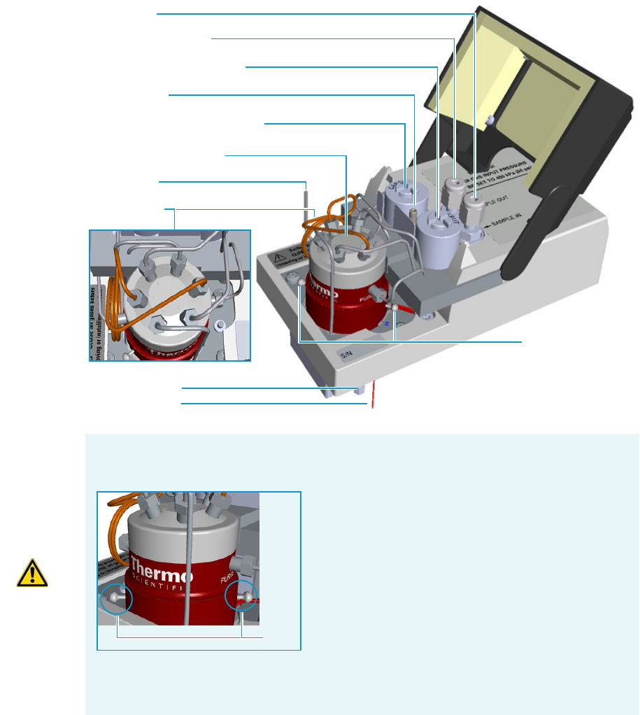
3 Performing Injectors Routine Maintenance
Maintaining a Gas Sampling Valve Injector (GSV)
102 TRACE 1300 and TRACE 1310 Hardware Manual Thermo Scientific
Maintaining a Gas Sampling Valve Injector (GSV)
This section provides instructions for maintaining a Gas Sampling Valve injector (GSV)
module.
The module and injector components are shown in Figure 89.
Figure 89. GSV Module Components
Split Line Vent
Sample OUT (WASTE)
6-ports Diaphragm Valve
Carrier Line Active Carbon
Split Line Active Carbon
Sample IN
Bottom Fittings
Backflush Line
Sample Loop
Relief Pins
Purge Tubing
IMPORTANT The valve is delivered with relief pins. These pins MUST BE removed from
the valve body before working with the valve.
Once actuation tubing has been set up, and pressure
has been adjusted to 450 kPa (65 psig), actuate the
valve and remove the pins. You may need to increase
the pressure a little to ease hand removal of the pins.
Remember, make sure to properly readjust the
actuating operating pressure after removing the pins,
if you had to change it. Keeps these pins in a safe
place. You may want to re-use them for valve
maintenance. It is good practice to re-install the relief
pins if the valve is not used for a long time.
For details refer to the instructions provided by the valve manufacturer.
Relief
Pins
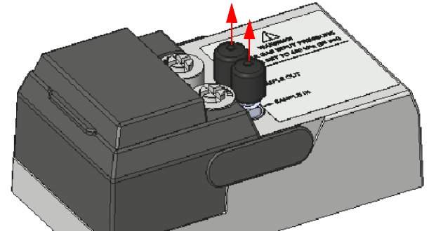
3 Performing Injectors Routine Maintenance
Maintaining a Gas Sampling Valve Injector (GSV)
Thermo Scientific TRACE 1300 and TRACE 1310 Hardware Manual 103
The Gas Sampling Valve periodic maintenance includes:
• Connecting the sample In and Out lines
See Connecting the Sample In and Out Lines.
• Replacing the active carbon filters on the carrier gas line and split line
The active carbon filters must be replaced depending on the volume of solvent injected in
the time.
See Replacing the Carrier and Split Lines Filters.
•Replacing the sample loop
Replace the sample loop when an upper volume of sample than the volume of standard
loop is required. Choose among the loops available.
See Replacing the Sample Loop.
•Replacing the gas sampling valve diaphragm
Follow the instructions provided by the manufacturer of the valve.
Connecting the Sample In and Out Lines
To connect the sample In and Out lines
1. If not already done, remove the protective caps from the Sample In and Sample Out
fittings. See Figure 90.
Figure 90. Protective Caps
1. By using the proper 1/8-in. tubing, nut and ferrule, connect the inlet sample line to the
Sample In port on the GSV module. See Figure 91.
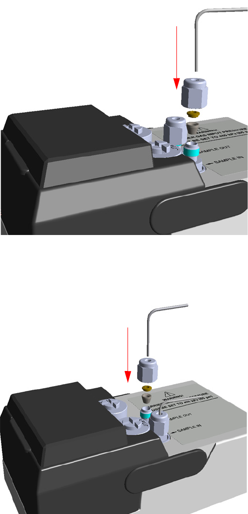
3 Performing Injectors Routine Maintenance
Maintaining a Gas Sampling Valve Injector (GSV)
104 TRACE 1300 and TRACE 1310 Hardware Manual Thermo Scientific
Figure 91. GSV Sample In Line Connection
2. By using the proper 1/8-in. tubing, nut and ferrule, connect the Sample OUT port on
the GSV module to an exhaust system. See Figure 92.
Figure 92. GSV Sample Out Line Connection
IN
OUT
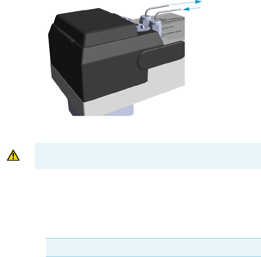
3 Performing Injectors Routine Maintenance
Maintaining a Gas Sampling Valve Injector (GSV)
Thermo Scientific TRACE 1300 and TRACE 1310 Hardware Manual 105
Figure 93. GSV Sample In and Out Lines Connection
Replacing the Carrier and Split Lines Filters
To replace the active carbon filters on carrier gas line and split line
1. Put the GC in standby condition.
2. Cool the oven and injector to room temperature.
3. Turn the carrier gas off, and wait for the carrier pressure to go to zero.
4. Put the autosampler away if present.
5. Open the module flap cover.
6. Replace the filter.
a. Remove the filter to replace from its seat by turning it counter-clockwise.
b. Install the new filter, with o-rings, in its seat by turning it clockwise.
Sample OUT /Waste
Sample IN
IMPORTANT The dimensions of the filters are different. The filter on the split gas line is
bigger than the filter on the carrier gas line. Do not invert their position when you replace
them. It is not necessary to replace the filters together.
Note By pressing the Maintenance button, the GC cool down is automatically
carried out.
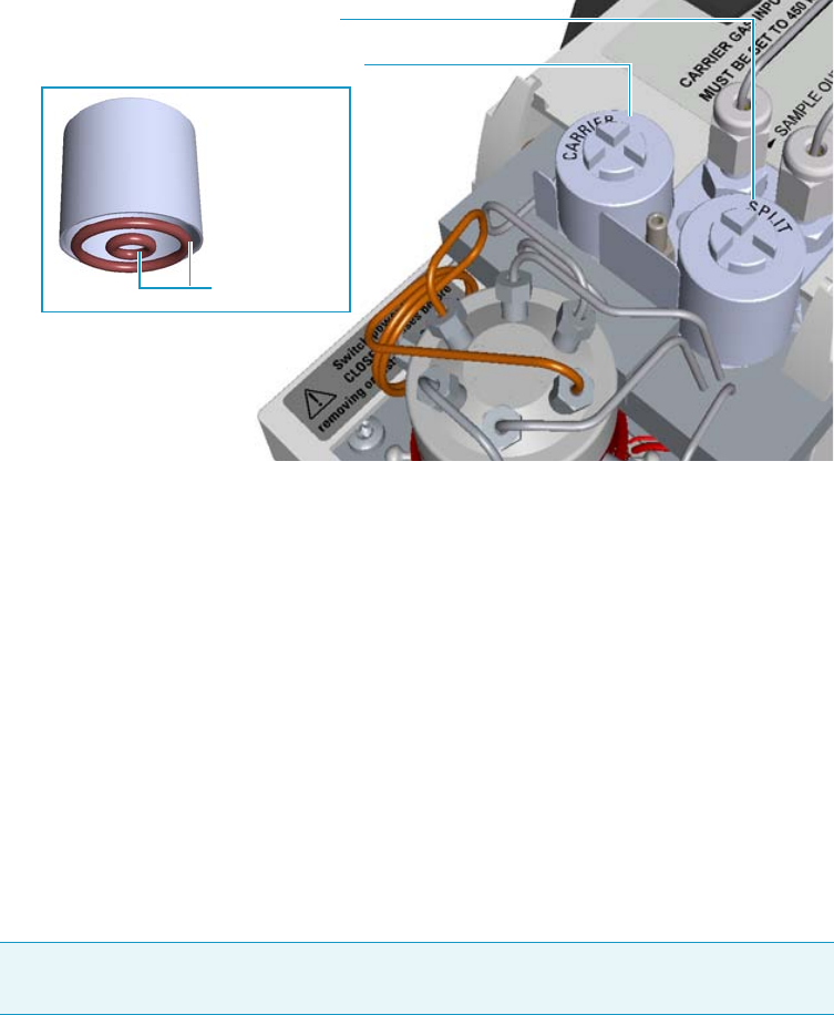
3 Performing Injectors Routine Maintenance
Maintaining a Gas Sampling Valve Injector (GSV)
106 TRACE 1300 and TRACE 1310 Hardware Manual Thermo Scientific
Figure 94. GSV Module Active Filters Replacement
7. Close the module flap cover.
8. If present, move the autosampler towards the module to restore the original alignment.
9. Turn the carrier gas on.
10. Set the normal injector, detector, and GC working conditions.
Replacing the Sample Loop
To replace the sampling loop
1. Put the GC in standby condition.
2. Cool the oven and injector to room temperature.
3. Turn the carrier gas off, and wait for the carrier pressure to go to zero.
4. Put the autosampler away if present.
5. Open the module flap cover.
6. Replace the sampling loop.
a. Use a 3/16-in.wrench to loosen the two nuts connecting the sample loop to the
six–port valve.
b. Remove the loop off the valve.
c. Mount the new loop over the valve and tighten the nuts to the six-port valve.
Carrier Gas Line Active Carbon Filter
Split Gas Line Active Carbon Filter
Filter O-rings
Note By pressing the Maintenance button, the GC cool down is automatically
carried out.
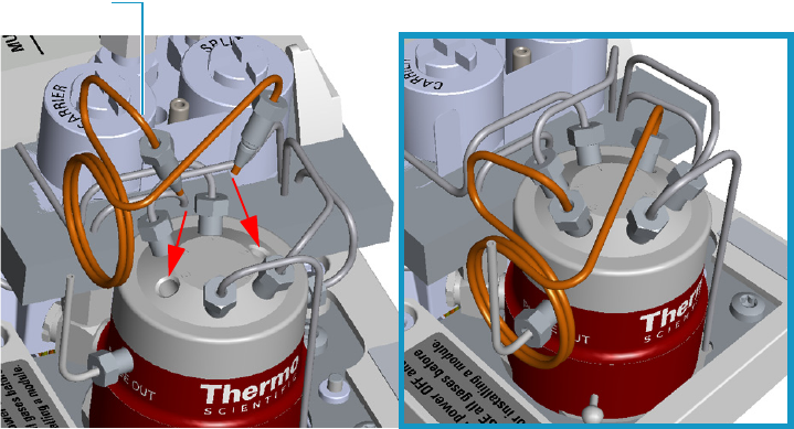
3 Performing Injectors Routine Maintenance
Maintaining a Gas Sampling Valve Injector (GSV)
Thermo Scientific TRACE 1300 and TRACE 1310 Hardware Manual 107
Figure 95. Example of Sample Loop Replacement
7. Close the module flap cover.
8. If present, move the autosampler towards the module to restore the original alignment.
9. Turn the carrier gas on.
10. Set the normal injector, detector, and GC working conditions.
Sample Loop
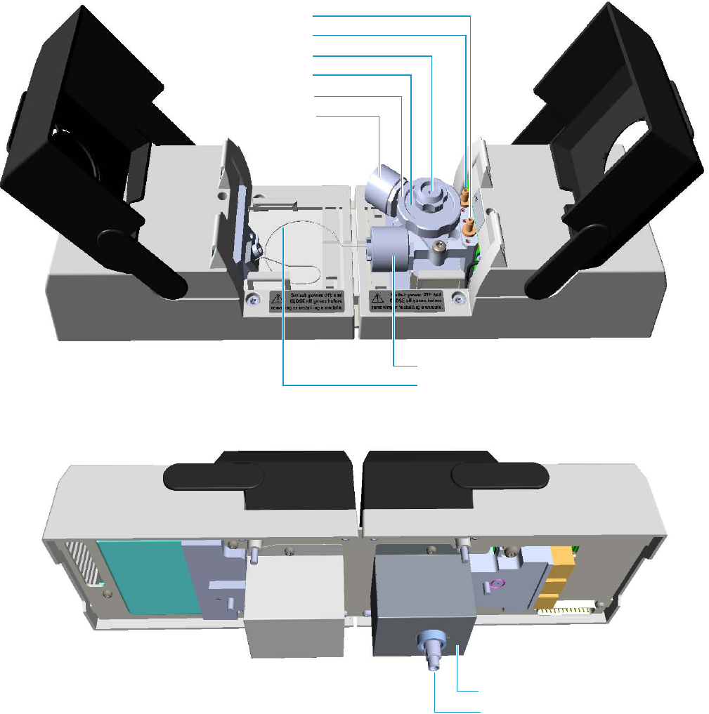
3 Performing Injectors Routine Maintenance
Maintaining an Instant Connect Helium Saver Injector (HeS-S/SL)
108 TRACE 1300 and TRACE 1310 Hardware Manual Thermo Scientific
Maintaining an Instant Connect Helium Saver Injector (HeS-S/SL)
This section provides instructions for maintaining an Instant Connect Helium Saver Injector
Module (HeS-S/SL).
The module and injector components are shown in Figure 96 and Figure 97.
Figure 96. HeS-S/SL Module Components
Split Line Vent
Purge Line Vent
Septum Cap
Septum Holder/Liner Cap
Ring Nut
Carrier Gas Line Filter
Split Gas Line Filter
Bottom Fittings
Insulation Cover
Helium Transfer Tube
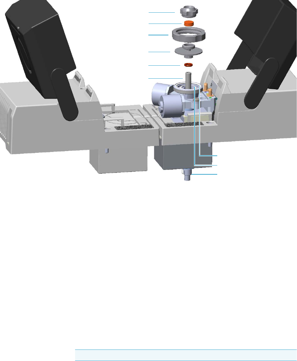
3 Performing Injectors Routine Maintenance
Maintaining an Instant Connect Helium Saver Injector (HeS-S/SL)
Thermo Scientific TRACE 1300 and TRACE 1310 Hardware Manual 109
Figure 97. HeS-S/SL Module Components
Maintaining the Instant Connect Helium Saver Injector Module is largely the same as a
conventional SSL inlet.
One advantage of the Instant Connect Helium Saver Injector Module is that routine septum
and liner changes can be accomplished without cooling the MS transfer line or ion source.
This is particularly desirable since cooling down and re-establishing stable MS temperatures
takes much longer than cooling down and re-establishing the inlet temperature.
The Instant Connect Helium Saver Injector Module periodic maintenance includes:
• Replacing the septum
The septum needs to be changed intermittently to prevent leakage. Replace the septum at
least after every 200 injections, or every time a problem related to septum damage, or
wear occurs.
See “Replacing the Septum” on page 111.
• Cleaning or replacing the liner
Injection port liner needs to be replaced or cleaned as it becomes dirty.
See“Cleaning or Replacing the Glass Liner” on page 112.
Septum Cap
Septum
Ring Nut
Septum Holder/Liner Cap
Liner Seal
Liner
Body Head External O-Ring
Body Head Internal O-Ring
Bottom Fittings
Tip It is good practice to replace the septum every time you replace the glass liner.
3 Performing Injectors Routine Maintenance
Maintaining an Instant Connect Helium Saver Injector (HeS-S/SL)
110 TRACE 1300 and TRACE 1310 Hardware Manual Thermo Scientific
• Replacing the active carbon filters on the carrier gas line and split line
The active carbon filters must be replaced depending on the volume of solvent injected in
the time.
See “Replacing the Carrier and Split Lines Filters” on page 114.
• Replacing the body head o-rings
The internal (carrier line) and external (purge line) o-rings of the body head must be
replaced when there are leaks present.
See “Replacing the Body Head O-Rings” on page 115.
Before maintaining the injector, read the following warning:
WARNING The injector fittings could be hot. Carry out all the operation at low
temperature to avoid burns. Therefore, before beginning the sequence, the injector must
be cooled to room temperature.
CAUTION When handling organic solvents, you must take precautions to avoid health
hazards.
Materials needed to maintain a HeS-S/SL
Septum
Tweezers
Glass liner
Liner seal (O-ring)
Ultrasonic cleaner
Mixture 1:1 methanol/acetone
Carrier gas line and/or split gas line active carbon filters
Body head internal o-ring
Body head external o-ring
T20 screwdriver
Note For maintaining or replacing any other component not listed in this section, see
Chapter 6, “Injectors Advanced Maintenance.”
•“Baking-out Contaminants from SSL, SSLBKF, HeS-S/SL, PTV, and PTVBKF
Injectors” on page 230
•“Cleaning the HeS-S/SL Injector Body” on page 242
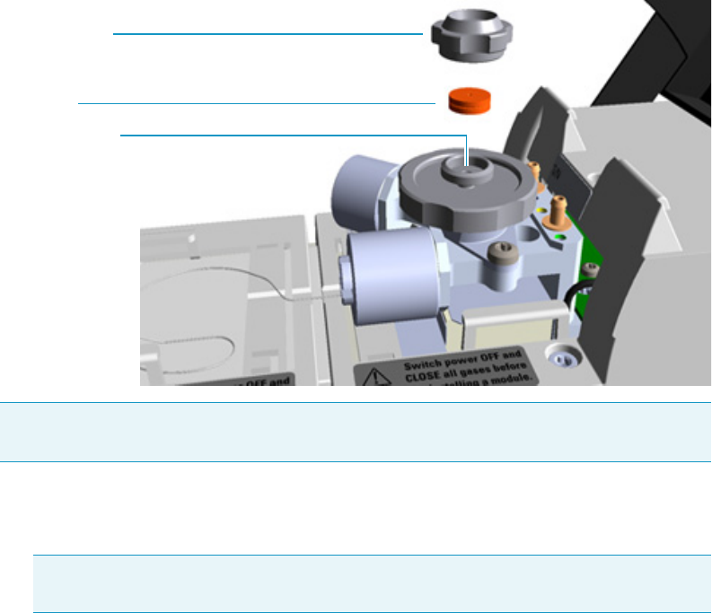
3 Performing Injectors Routine Maintenance
Maintaining an Instant Connect Helium Saver Injector (HeS-S/SL)
Thermo Scientific TRACE 1300 and TRACE 1310 Hardware Manual 111
Replacing the Septum
To replace the septum
Figure 98. HeS-S/SL Injector: Septum Replacement
1. Put the GC in standby condition.
2. Cool the oven and injector to room temperature.
3. Ensure the Enable conservation field in the configuration page of the inlet reads Yes.
4. Check that there is at least 20 mL/min split flow exiting the split line, then turn the
column flow to Off in the GC user interface and allow the inlet to depressurize.
5. Put the autosampler away if present.
6. Open the module flap cover.
7. Replace the septum.
a. Unscrew and remove the septum cap.
b. Using tweezers, remove the septum from the septum holder.
c. Avoid touching the septum with your fingers. Insert a new septum into the septum
holder using tweezers.
d. Screw and tighten the septum cap to finger-tight.
Note Care should be taken when performing this procedure in order to keep from
damaging analytical columns.
Note By pressing the Maintenance button, the GC cool down is automatically
carried out.
Septum Holder
Septum
Septum Cap
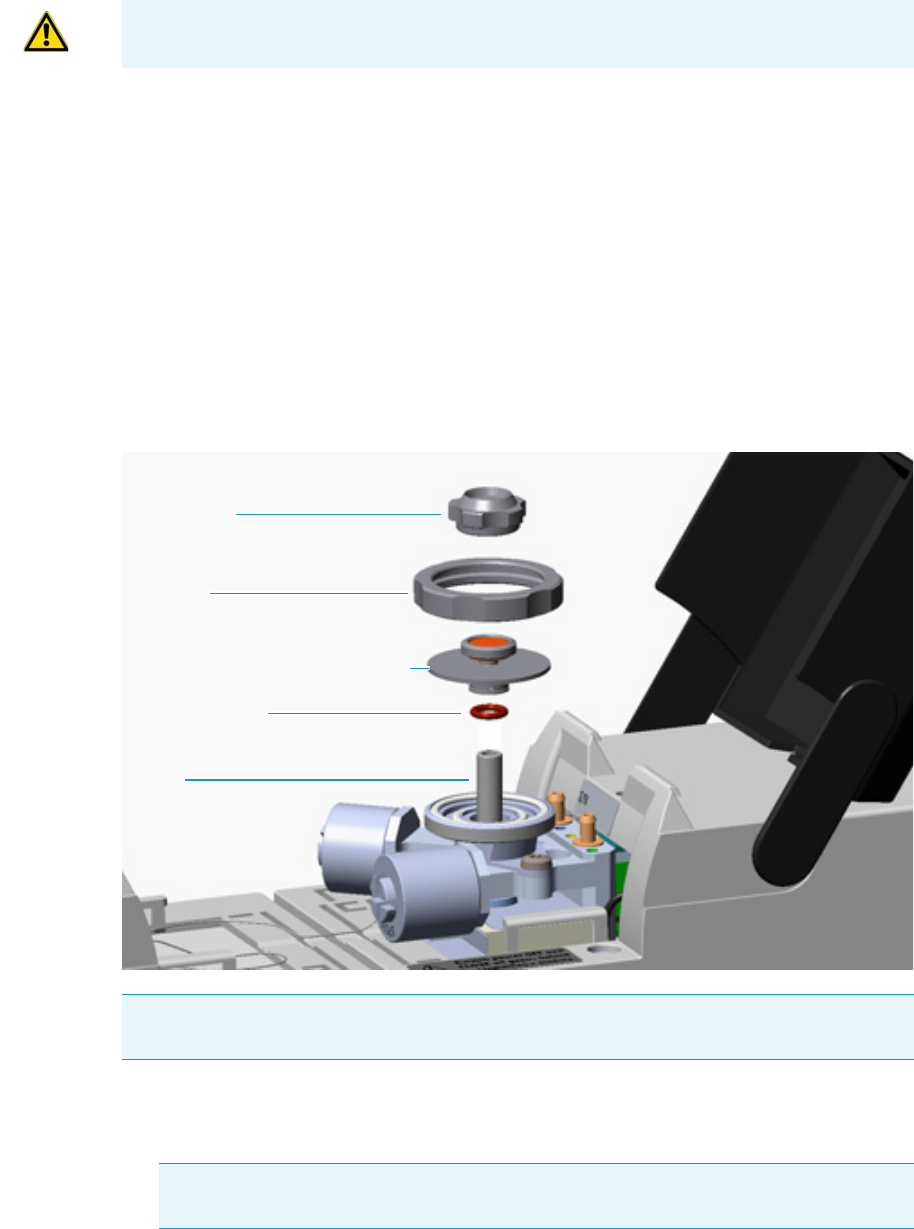
3 Performing Injectors Routine Maintenance
Maintaining an Instant Connect Helium Saver Injector (HeS-S/SL)
112 TRACE 1300 and TRACE 1310 Hardware Manual Thermo Scientific
8. Close the module flap cover.
9. If present, move the autosampler towards the module to restore the original alignment.
10. Wait two or three minutes for helium to purge the inlet.
11. Turn the inlet flow back on and enable the inlet heater.
12. Set the normal injector, detector, and GC working conditions.
Cleaning or Replacing the Glass Liner
To clean or replace the glass liner
Figure 99. HeS-S/SL Injector: Glass Liner Replacement
1. Put the GC in standby condition.
2. Cool the oven and injector to room temperature.
CAUTION Do not overtighten the septum cap because you might damage the septum and
affect instrument performance.
Note Care should be taken when performing the procedure in order to keep from
damaging analytical columns.
Note By pressing the Maintenance button, the GC cool down is automatically
carried out.
Septum Cap
Ring Nut
Septum Holder/Liner Cap with Septum
Liner Seal (O-ring)
Liner

3 Performing Injectors Routine Maintenance
Maintaining an Instant Connect Helium Saver Injector (HeS-S/SL)
Thermo Scientific TRACE 1300 and TRACE 1310 Hardware Manual 113
3. Ensure the Enable conservation field in the configuration page of the inlet reads Yes.
4. Check that there is at least 20 mL/min split flow exiting the split line, then turn the
column flow to Off in the GC user interface and allow the inlet to depressurize.
5. Put the autosampler away if present.
6. Open the module flap cover.
7. Remove the top parts of the injector.
a. Unscrew the septum cap of the injector.
b. Unscrew the ring nut.
c. Remove the septum holder/liner cap with septum from the injector body head.
8. Remove the liner.
a. Using tweezers, remove the liner with the liner seal (o-ring) from the injector.
9. Replace or clean the liner.
• If you are going to clean the dirty liner, go to step 10.
• If you are going to use a new liner, go directly to step 11.
10. Clean the liner.
a. Put the liner into an ultrasonic cleaner filled with a methanol/acetone mixture (1:1).
b. Sonicate the liner for about half an hour.
c. Using tweezers, remove the liner from the bath and dry it with compressed clean air.
11. Install the liner.
a. Hold the new (or cleaned) liner with tweezers place a new liner seal over the liner.
b. Insert the liner into the injector, and push it gently towards the bottom of the
injector.
12. Reinstall the top parts of the injector.
a. Place the septum holder/liner cap with the septum on the body head of the injector,
and fix it by screwing the ring nut.
b. Screw and tighten the septum cap to finger-tight.
13. Close the module flap cover.
14. If present, move the autosampler towards the module to restore the original alignment.
15. Wait two or three minutes for helium to purge the inlet.
CAUTION Do not overtighten the septum cap because you might damage the septum and
affect instrument performance.
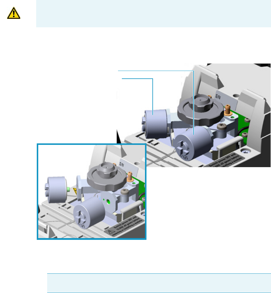
3 Performing Injectors Routine Maintenance
Maintaining an Instant Connect Helium Saver Injector (HeS-S/SL)
114 TRACE 1300 and TRACE 1310 Hardware Manual Thermo Scientific
16. Turn the inlet flow back on and enable the inlet heater.
17. Set the normal injector, detector, and GC working conditions.
Replacing the Carrier and Split Lines Filters
To replace the active carbon filters on carrier gas line and split line
Figure 100. HeS-S/SL Injector: Active Filters Replacement
1. Put the GC in standby condition.
2. Cool the oven and injector to room temperature.
3. Ensure the Enable conservation field in the configuration page of the inlet reads Yes .
4. Check that there is at least 20 mL/min split flow exiting the split line, then turn the
column flow to Off in the GC user interface and allow the inlet to depressurize.
CAUTION The dimensions of the filters are different. The filter on the split gas line is
bigger than the filter on the carrier gas line. Do not invert their position when you replace
them. It is not necessary to replace the filters together.
Note By pressing the Maintenance button, the GC cool down is automatically
carried out.
Split Gas Line Active Carbon Filter
Carrier Gas Line Active Carbon Filter
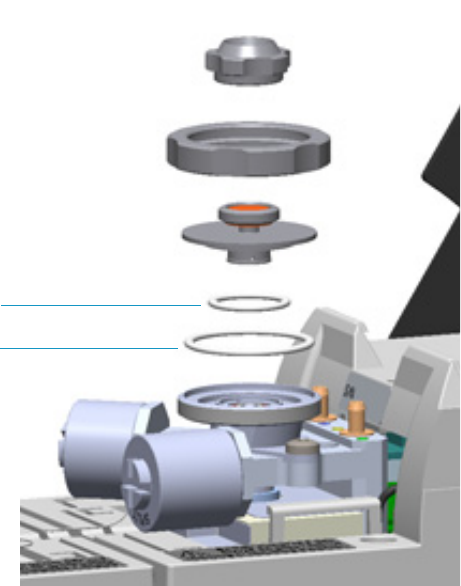
3 Performing Injectors Routine Maintenance
Maintaining an Instant Connect Helium Saver Injector (HeS-S/SL)
Thermo Scientific TRACE 1300 and TRACE 1310 Hardware Manual 115
5. Put the autosampler away if present.
6. Open the module flap cover.
7. Replace the filter.
a. Remove the filter to replace from its seat by turning it counter-clockwise.
b. Install the new filter, with o-rings, in its seat by turning it clockwise.
8. Close the module flap cover.
9. If present, move the autosampler towards the module to restore the original alignment.
10. Wait two or three minutes for helium to purge the inlet.
11. Turn the inlet flow back on and enable the inlet heater.
12. Set the normal injector, detector, and GC working conditions.
Replacing the Body Head O-Rings
To replace the body head o-rings
Figure 101. HeS-S/SL Injector: Body Head O-Rings Replacement
1. Put the GC in standby condition.
2. Cool the oven and injector to room temperature.
Body Head Internal O-ring (Carrier gas Line)
Body Head External O-ring (Purge gas Line)
3 Performing Injectors Routine Maintenance
Maintaining an Instant Connect Helium Saver Injector (HeS-S/SL)
116 TRACE 1300 and TRACE 1310 Hardware Manual Thermo Scientific
3. Ensure the Enable conservation field in the configuration page of the inlet reads Yes.
4. Check that there is at least 20 mL/min split flow exiting the split line, then turn the
column flow to Off in the GC user interface and allow the inlet to depressurize.
5. Put the autosampler away if present.
6. Open the module flap cover.
7. Remove the top parts of the injector.
a. Unscrew the septum cap of the injector.
b. Unscrew the ring nut.
c. Remove the septum holder/liner cap with septum from the injector body head.
8. Replace the head body o-rings.
a. Use tweezers to remove the body head internal and external o-rings, and replace them
with new o-rings.
9. Reinstall the top parts of the injector.
a. Place the septum holder/liner cap with the septum on the body head of the injector
and fix it by screwing the ring nut.
b. Screw and tighten the injector cap to finger-tight.
10. Close the module flap cover.
11. If present, move the autosampler towards the module to restore the original alignment.
12. Wait two or three minutes for helium to purge the inlet.
13. Turn the inlet flow back on and enable the inlet heater.
14. Set the normal injector, detector, and GC working conditions.
Note By pressing the Maintenance button, the GC cool down is automatically
carried out.
CAUTION Do not overtighten the septum cap because you might damage the septum and
affect instrument performance.
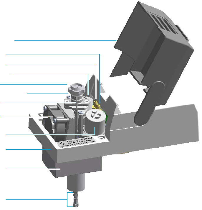
3 Performing Injectors Routine Maintenance
Maintaining a Programmable Temperature Vaporizing Injector (PTV)
Thermo Scientific TRACE 1300 and TRACE 1310 Hardware Manual 117
Maintaining a Programmable Temperature Vaporizing Injector (PTV)
This section provides instructions for maintaining a Programmable Temperature Vaporizing
injector (PTV).
The module and injector components are shown in Figure 102 and Figure 103.
Figure 102. PTV Module Components
Module Flap Cover
Split Line Vent
Purge Line Vent
Carrier Line Filter
Septum Cap
Injector Head Assembly
Cooling Fan
Split Line Filter
Injector Body
Bottom Fittings
Module Cover
Insulator Cover
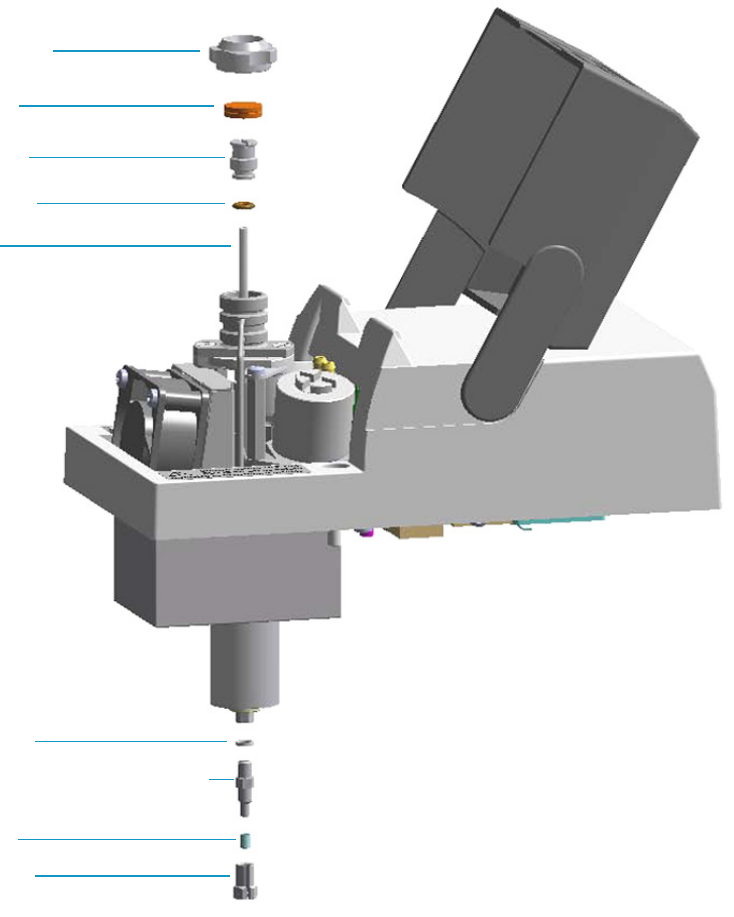
3 Performing Injectors Routine Maintenance
Maintaining a Programmable Temperature Vaporizing Injector (PTV)
118 TRACE 1300 and TRACE 1310 Hardware Manual Thermo Scientific
Figure 103. PTV Injector Components
The PTV injector periodic maintenance includes:
• Replacing the PTV septum
Replace the septum at least after every 200 injections, or every time a problem related to
septum damage, or wear occurs.
See “Replacing the PTV Septum” on page 120.
• Cleaning or replacing the PTV liner
Check the liner for contaminants, debris, breakage and proper installation.
Ferrule
Split Nut
Silver Seal
Liner
Liner Seal
Liner Cap
Septum
Septum Cap
Terminal Fitting for Capillary Column
3 Performing Injectors Routine Maintenance
Maintaining a Programmable Temperature Vaporizing Injector (PTV)
Thermo Scientific TRACE 1300 and TRACE 1310 Hardware Manual 119
The liner must be replaced depending on the number of injections performed, and the
characteristics of the samples injected. Typical symptoms will indicate that the liner must
be replaced. The most common is the appearance of tailing peaks in the chromatogram,
particularly for polar compounds.
See “Cleaning or Replacing the PTV Glass Liner” on page 121.
When replacing or removing a glass liner, it might break inside the injector. In this case
the broken parts of the liner must be removed from the injector, including the glass
splinters that might fall into the lower part of the vaporization chamber.
See “Replacing the PTV Broken Liner” on page 123.
• Replacing the active carbon filters on the carrier gas line and split line
The active carbon filters must be replaced depending on the volume of solvent injected in
the time.
See “Replacing the PTV Carrier and Split Lines Filters” on page 125.
Before maintaining the injector, read the following warning:
Tip It is good practice to replace the septum every time you replace the gas liner.
WARNING The injector fittings could be hot. Carry out all the operation at low
temperature to avoid burns. Therefore, before beginning the sequence, the injector must
be cooled to room temperature.
CAUTION When handling organic solvents you must take precautions to avoid health
hazard.
Materials needed to maintain a PTV injector
Septum
Tweezers
Glass liner
Liner seal (O-ring)
Ultrasonic cleaner
Mixture 1:1 methanol/acetone
Carrier gas line and/or split gas line active carbon filters
5.5 x 25 mm slotted stubby driver
Silver seal
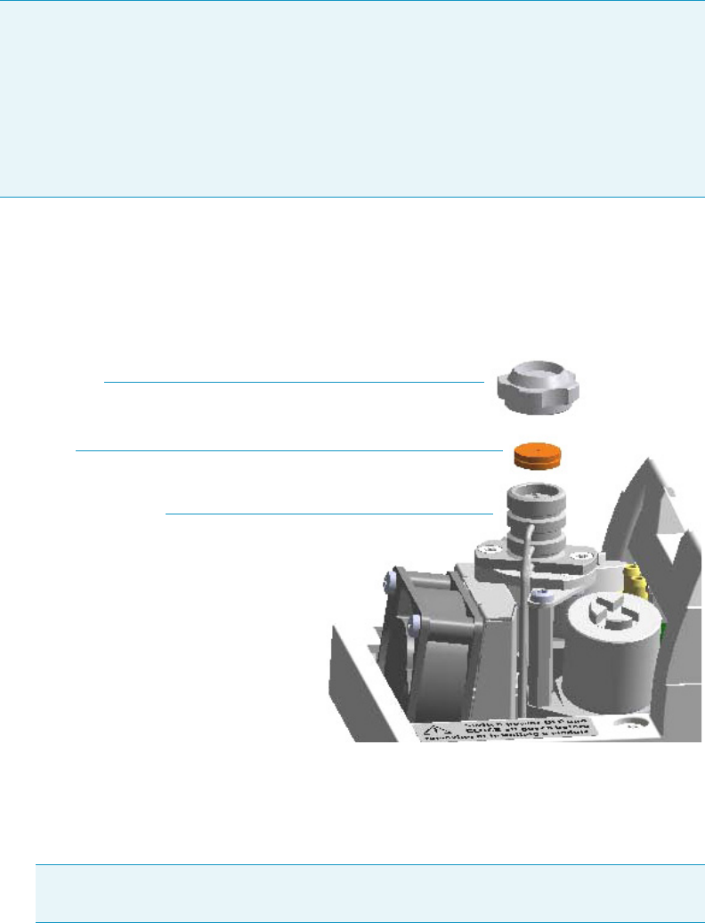
3 Performing Injectors Routine Maintenance
Maintaining a Programmable Temperature Vaporizing Injector (PTV)
120 TRACE 1300 and TRACE 1310 Hardware Manual Thermo Scientific
Replacing the PTV Septum
To replace the septum
Figure 104. PTV Injector: Septum Replacement
1. Put the GC in standby condition.
2. Cool the oven and injector to room temperature.
3. Turn the carrier gas off, and wait for the carrier pressure to go to zero.
4. Put the autosampler away if present.
5. Open the module flap cover.
6. Replace the septum.
a. Unscrew the septum cap of the injector.
b. Using tweezers, remove the septum from the injector head assembly.
Note For maintaining or replacing any other component not listed in this section, see
Chapter 6, “Injectors Advanced Maintenance.”
•“Baking-out Contaminants from SSL, SSLBKF, HeS-S/SL, PTV, and PTVBKF
Injectors” on page 230
•“Removing/Replacing an Injector Module” on page 231
•“Cleaning the PTV Injector Head Assembly” on page 246
Note By pressing the Maintenance button, the GC cool down is automatically
carried out.
Septum
Septum Cap
Injector Head Assembly
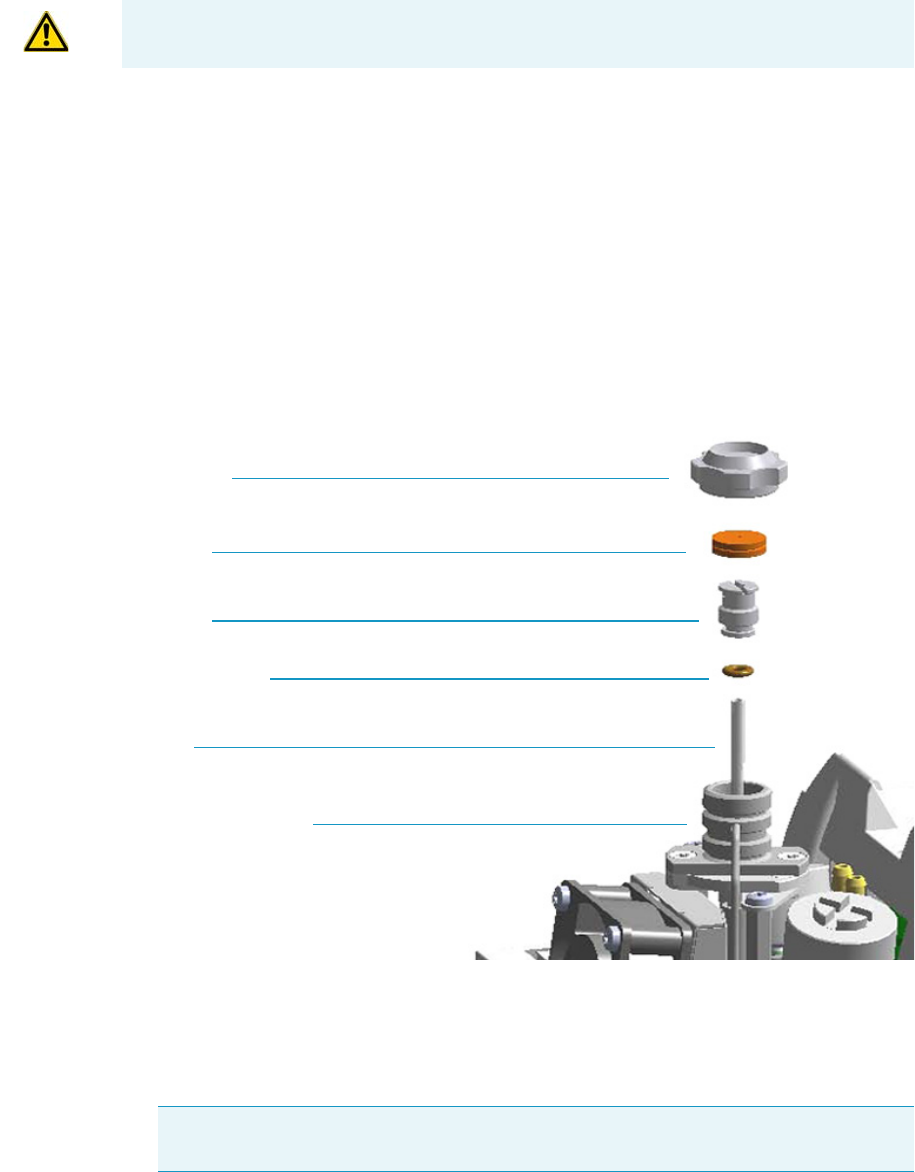
3 Performing Injectors Routine Maintenance
Maintaining a Programmable Temperature Vaporizing Injector (PTV)
Thermo Scientific TRACE 1300 and TRACE 1310 Hardware Manual 121
c. Avoid touching the septum with your fingers. Insert a new septum into the injector
head assembly using tweezers. Screw and tighten the septum cap to finger-tight.
7. Close the module flap cover.
8. If present, move the autosampler towards the module to restore the original alignment.
9. Turn the carrier gas on.
10. Set the normal injector, detector, and GC working conditions.
Cleaning or Replacing the PTV Glass Liner
To clean or replace the glass liner
Figure 105. PTV Injector: Glass Liner Replacement
1. Put the GC in standby condition.
2. Cool the oven and injector to room temperature.
3. Turn the carrier gas off, and wait for the carrier pressure to go to zero.
CAUTION Do not overtighten the septum cap because you might damage the septum and
affect instrument performance.
Note By pressing the Maintenance button, the GC cool down is automatically
carried out.
Septum Cap
Septum
Liner Cap
Liner Seal (O-ring)
Liner
Injector Head Assembly

3 Performing Injectors Routine Maintenance
Maintaining a Programmable Temperature Vaporizing Injector (PTV)
122 TRACE 1300 and TRACE 1310 Hardware Manual Thermo Scientific
4. Put the autosampler away if present.
5. Open the module flap cover.
6. Remove the top part of the injector.
a. Unscrew the septum cap of the injector.
b. Using tweezers, remove the septum from the top of the injector head assembly.
7. Remove the liner.
a. Using the slotted stubby driver provided, unscrew and remove the liner cap.
b. Use tweezers to remove the liner with the liner seal (o-ring) from the injector.
8. Replace or clean the liner.
• If you are going to use a new liner, go directly to step 10.
• If you are going to clean the dirty liner, go to step 9.
9. Clean the liner.
a. Put the liner into an ultrasonic cleaner filled with a methanol/acetone mixture (1:1).
b. Sonicate the liner for about half an hour.
c. Using tweezers, remove the liner from the bath, and dry it with compressed clean air.
10. Install the liner
a. Holding the new (or cleaned) liner with tweezers place a new liner seal over the liner.
b. Insert the liner into the injector, and push it gently towards the bottom of the
injector.
c. Reinsert and screw the liner cap using the slotted stubby driver.
11. Reinstall the top parts of the injector.
a. Place the septum into the injector head assembly.
b. Screw and tighten the septum cap to finger-tight.
12. Close the module flap cover.
CAUTION Be careful not to break the glass liner when removing it. Glass splinters might
fall into the lower part of the vaporization chamber. If the glass liner breaks, see “To
replace a broken liner” on page 86.
CAUTION It is suggested to replace the septum with a new one.
CAUTION Do not overtighten the septum cap because you might damage the septum and
affect instrument performance.
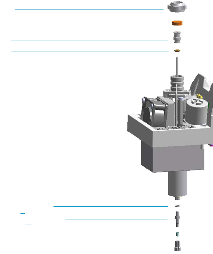
3 Performing Injectors Routine Maintenance
Maintaining a Programmable Temperature Vaporizing Injector (PTV)
Thermo Scientific TRACE 1300 and TRACE 1310 Hardware Manual 123
13. If present, move the autosampler towards the module to restore the original alignment.
14. Turn the carrier gas on.
15. Set the normal injector, detector, and GC working conditions.
Replacing the PTV Broken Liner
To replace a broken liner
Figure 106. PTV Injector: Broken Liner Replacement
1. Put the GC in standby condition.
2. Cool the oven and injector to room temperature.
3. Turn the carrier gas off, and wait for the carrier pressure to go to zero.
Liner Seal
Liner
Silver Seal
Terminal Fitting
Bottom Fittings
Septum Cap
Septum
Liner Cap
Ferrule
Split Nut

3 Performing Injectors Routine Maintenance
Maintaining a Programmable Temperature Vaporizing Injector (PTV)
124 TRACE 1300 and TRACE 1310 Hardware Manual Thermo Scientific
4. Put the autosampler away if present.
5. Open the module flap cover.
6. Remove the top part of the injector.
a. Unscrew the septum cap of the injector.
b. Using tweezers, remove the septum from the top of the injector head assembly.
7. Remove the broken liner.
a. Using the slotted stubby driver provided, unscrew and remove the liner cap.
b. Use tweezers to remove the upper part of broken liner with the liner seal from the
injector.
8. Remove the bottom parts of the injector.
a. Inside the oven, unscrew the split nut, and remove the analytical column with its
ferrule from the terminal fitting at the bottom of the injector.
b. Unscrew the terminal fitting with the silver seal. Glass splinters from the broken liner
will fall from the injector.
c. With the aid of a pipe cleaner, remove the possible glass fragments from the
vaporization chamber.
9. Reinstall the bottom part of the injector.
a. Reinstall the terminal fitting with the silver seal.
b. Reinstall the analytical column.
10. Install a new liner.
a. Holding the new liner with tweezers, place a new liner seal over the liner.
b. Insert the liner into the injector, and push it gently towards the bottom of the
injector.
c. Reinsert and screw the liner cap using the slotted stubby driver.
11. Reinstall the top parts of the injector.
a. Place the septum into the injector head assembly.
b. Screw and tighten the injector cap to finger-tight.
Note By pressing the Maintenance button, the GC cool down is automatically
carried out.
CAUTION It is suggested to replace the septum with a new one.
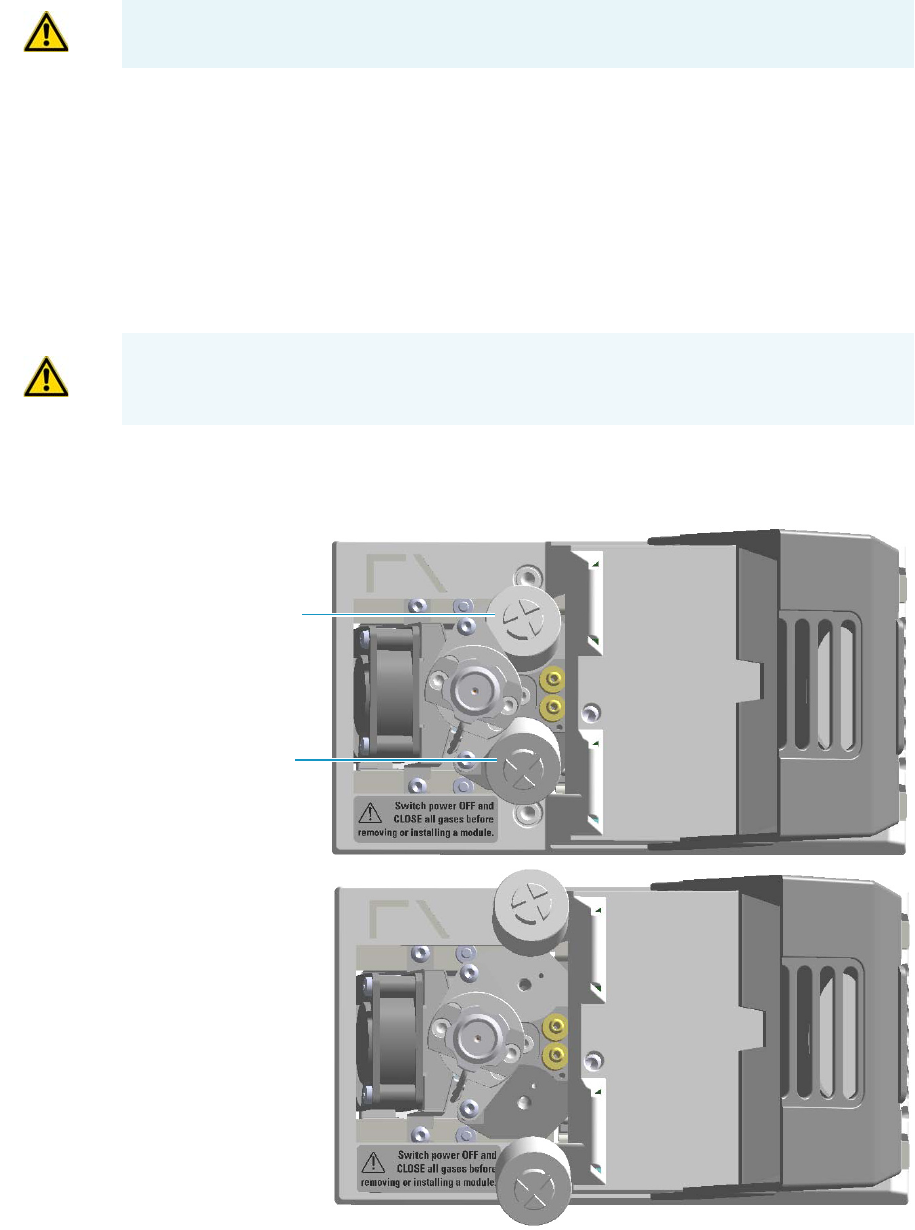
3 Performing Injectors Routine Maintenance
Maintaining a Programmable Temperature Vaporizing Injector (PTV)
Thermo Scientific TRACE 1300 and TRACE 1310 Hardware Manual 125
12. Close the module flap cover.
13. If present, move the autosampler towards the module to restore the original alignment.
14. Turn the carrier gas on.
15. Set the normal injector, detector, and GC working conditions.
Replacing the PTV Carrier and Split Lines Filters
To replace the active carbon filters on carrier gas line and split line
Figure 107. PTV Injector: Active Filters Replacement
CAUTION Do not overtighten the septum cap because you might damage the septum and
affect instrument performance.
IMPORTANT The dimensions of the filters are different. The filter on the split gas line is
bigger than the filter on the carrier gas line. Do not invert their position when you replace
them. It is not necessary to replace the filters together.
Carrier Gas Line Filter
Split Gas Line Filter

1. Put the GC in standby condition.
2. Cool the oven and injector to room temperature.
3. Turn the carrier gas off, and wait for the carrier pressure to go to zero.
4. Put the autosampler away if present.
5. Open the module flap cover.
6. Replace the filter.
a. Remove the filter to replace from its seat by turning it counter-clockwise.
b. Install the new filter, with the o-rings, in its seat by turning it clockwise.
7. Close the module flap cover.
8. If present, move the autosampler towards the module to restore the original alignment.
9. Turn the carrier gas on.
10. Set the normal injector, detector, and GC working conditions.
Note By pressing the Maintenance button, the GC cool down is automatically
carried out.
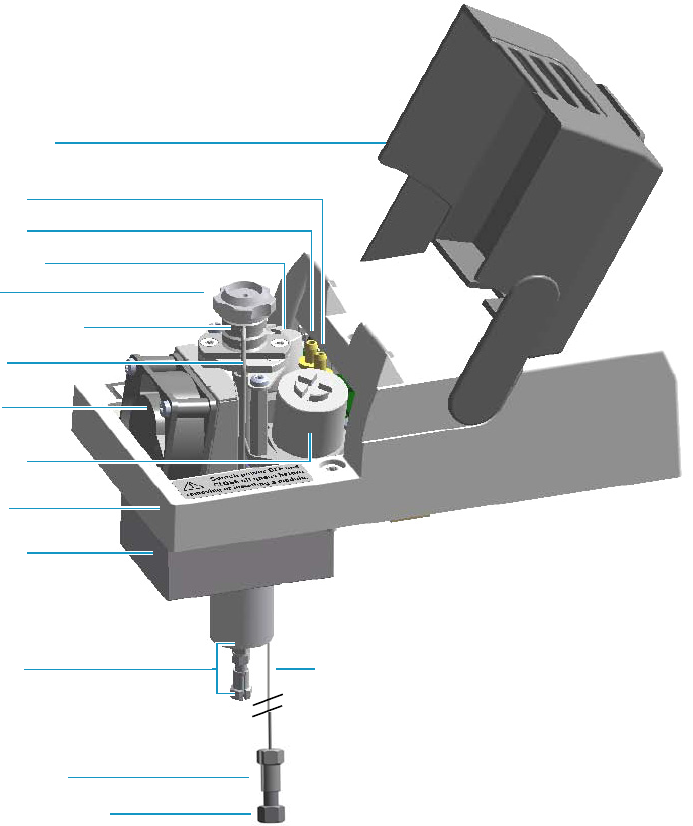
3 Performing Injectors Routine Maintenance
Maintaining a Programmable Temperature Vaporizing Injector with Backflush (PTVBKF)
Thermo Scientific TRACE 1300 and TRACE 1310 Hardware Manual 127
Maintaining a Programmable Temperature Vaporizing Injector with
Backflush (PTVBKF)
This section provides instructions for maintaining a Programmable Temperature Vaporizing
injector for backflush (PTVBKF) applications.
The module and injector components are shown in Figure 108 and Figure 109.
Figure 108. PTVBKF Module Components
Injector Body
Bottom Fittings
Module Cover
Insulator Cover
Module Flap Cover
Split Line Vent
Septum Cap
Injector Head Assembly
Cooling Fan
Purge Line Vent
Carrier Line Filter
Split Line Filter
Backflush Line
Backflush Line Fitting
Fitting Cap, Backflush Line
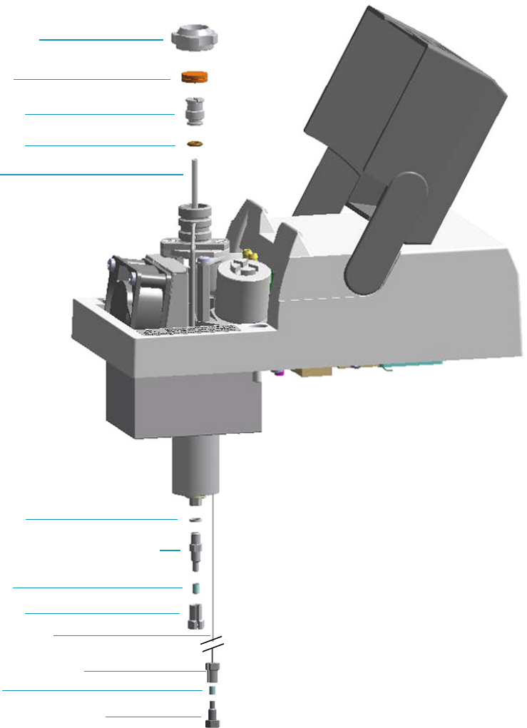
3 Performing Injectors Routine Maintenance
Maintaining a Programmable Temperature Vaporizing Injector with Backflush (PTVBKF)
128 TRACE 1300 and TRACE 1310 Hardware Manual Thermo Scientific
Figure 109. PTVBKF Injector Components
The PTVBKF injector periodic maintenance includes:
• Replacing the PTVBKF septum
Replace the septum at least after every 200 injections, or every time a problem related to
septum damage, or wear occurs.
See “Replacing the PTVBKF Septum” on page 130.
Septum Cap
Septum
Liner Cap
Liner Seal
Liner
Split Nut
Silver Seal
Ferrule
Terminal Fitting for Capillary Column
Backflush Line
Backflush Line Fitting
Ferrule
Fitting Cap, Backflush Line
3 Performing Injectors Routine Maintenance
Maintaining a Programmable Temperature Vaporizing Injector with Backflush (PTVBKF)
Thermo Scientific TRACE 1300 and TRACE 1310 Hardware Manual 129
• Cleaning or replacing the PTVBKF liner
Check the liner for contaminants, debris, breakage and proper installation. The liner
must be replaced depending on the number of injections performed, and the
characteristics of the samples injected. Typical symptoms will indicate that the liner must
be replaced. The most common is the appearance of tailing peaks in the chromatogram,
particularly for polar compounds.
See “Cleaning or Replacing the PTVBKF Glass Liner” on page 131
When replacing or removing a glass liner, it might break inside the injector. In this case
the broken parts of the liner must be removed from the injector, including the glass
splinters that might fall into the lower part of the vaporization chamber.
See “Replacing the PTVBKF Broken Liner” on page 133.
• Replacing the PTVBKF active carbon filters on the carrier gas line and split line
The active carbon filters must be replaced depending on the volume of solvent injected in
the time.
See Replacing the PTVBKF Carrier and Split Lines Filters on page 135.
Before maintaining the injector, read the following warning:
Tip It is good practice to replace the septum every time the liner is replaced.
WARNING The injector fittings could be hot. Carry out all operations at low temperature
to avoid burns. Therefore, before beginning the sequence, the injector must be cooled to
room temperature.
CAUTION When handling organic solvents you must take precautions to avoid health
hazards.
Materials needed to maintain a PTVBKF injector
Septum
Tweezers
Glass liner
Liner seal (O-ring)
Ultrasonic cleaner
Mixture 1:1 methanol/acetone
Carrier gas line and/or split gas line active carbon filters
5.5 x25 mm slotted stubby driver
Silver seal
.
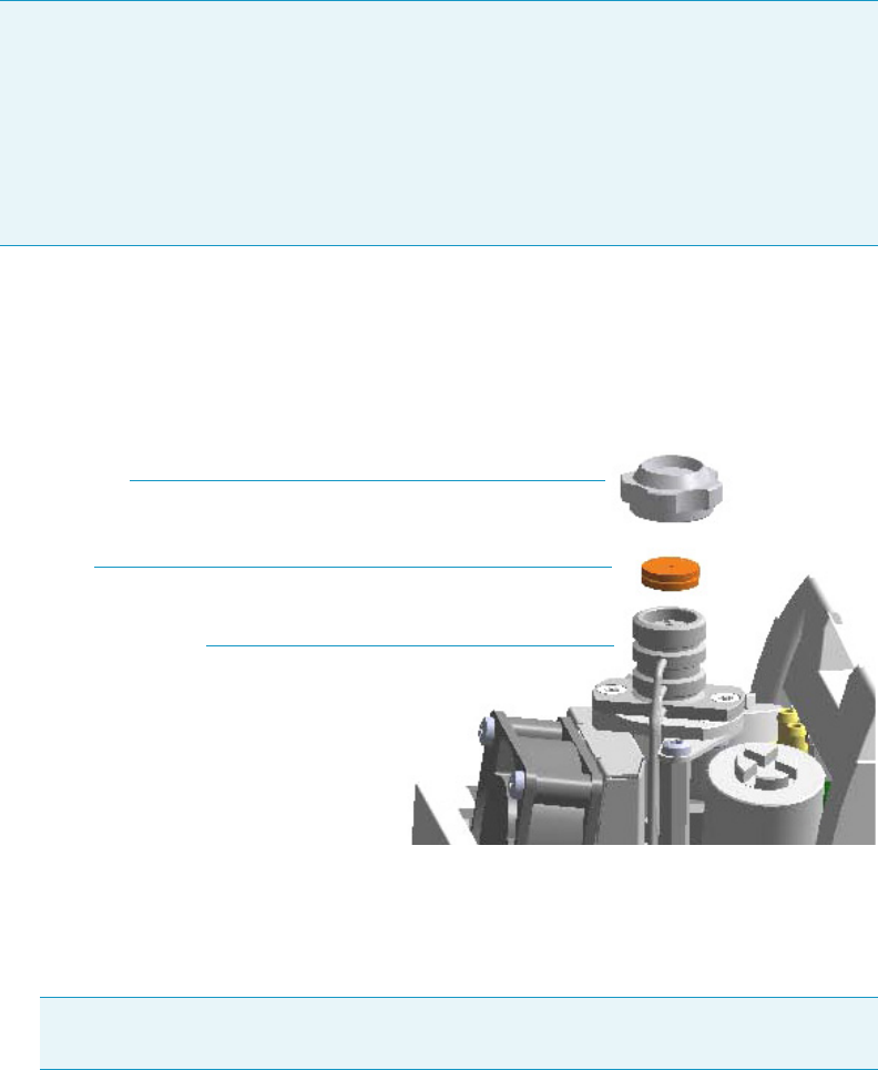
3 Performing Injectors Routine Maintenance
Maintaining a Programmable Temperature Vaporizing Injector with Backflush (PTVBKF)
130 TRACE 1300 and TRACE 1310 Hardware Manual Thermo Scientific
Replacing the PTVBKF Septum
To replace the septum
Figure 110. PTVBKF Injector: Septum Replacement
1. Put the GC in standby condition.
2. Cool the oven and injector to room temperature.
3. Turn the carrier gas off, and wait for the carrier pressure to go to zero.
4. Put the autosampler away if present.
5. Open the module flap cover.
6. Replace the septum.
a. Unscrew the septum cap of the injector.
b. Using tweezers, remove the septum from the injector head assembly.
c. Avoid touching the septum with your fingers. Insert a new septum into the injector
head assembly using tweezers. Screw and tighten the septum cap to finger-tight.
Note For maintaining or replacing any other component not listed in this section, see
Chapter 6, “Injectors Advanced Maintenance.”
•“Baking-out Contaminants from SSL, SSLBKF, HeS-S/SL, PTV, and PTVBKF
Injectors” on page 230
•“Removing/Replacing an Injector Module” on page 231
•“Cleaning the PTVBKF Injector Head Assembly” on page 253
Note By pressing the Maintenance button, the GC cool down is automatically
carried out.
Septum
Septum Cap
Injector Head Assembly
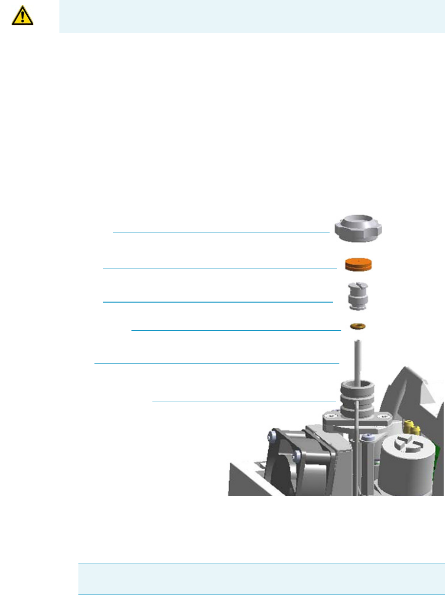
3 Performing Injectors Routine Maintenance
Maintaining a Programmable Temperature Vaporizing Injector with Backflush (PTVBKF)
Thermo Scientific TRACE 1300 and TRACE 1310 Hardware Manual 131
7. Close the module flap cover.
8. If present, move the autosampler towards the module to restore the original alignment.
9. Turn the carrier gas on.
10. Set the normal injector, detector, and GC working conditions.
Cleaning or Replacing the PTVBKF Glass Liner
To clean or replace the glass liner
Figure 111. PTVBKF Injector: Glass Liner Replacement
1. Put the GC in standby condition.
2. Cool the oven and injector to room temperature.
3. Turn the carrier gas off, and wait for the carrier pressure to go to zero.
CAUTION Do not overtighten the septum cap because you might damage the septum and
affect instrument performance.
Note By pressing the Maintenance button, the GC cool down is automatically
carried out.
Septum Cap
Septum
Liner Cap
Liner Seal (O-ring)
Liner
Injector Head Assembly
3 Performing Injectors Routine Maintenance
Maintaining a Programmable Temperature Vaporizing Injector with Backflush (PTVBKF)
132 TRACE 1300 and TRACE 1310 Hardware Manual Thermo Scientific
4. Put the autosampler away if present.
5. Open the module flap cover.
6. Remove the top part of the injector.
a. Unscrew the septum cap of the injector.
b. Using tweezers, remove the septum from the top of the injector head assembly.
7. Remove the liner.
a. Using the slotted stubby driver provided, unscrew and remove the liner cap.
b. Use tweezers to remove the liner with the liner seal (o-ring) from the injector.
8. Replace or clean the liner.
• If you are going to use a new liner, go directly to step 9.
• If you are going to clean the dirty liner, go to step 10.
9. Clean the liner.
a. Put the liner into an ultrasonic cleaner filled with a methanol/acetone mixture (1:1).
b. Sonicate the liner for about half an hour.
c. Using tweezers, remove the liner from the bath, and dry it with compressed clean air.
10. Install the liner.
a. Holding the new (or cleaned) liner with tweezers, place a new liner seal over the liner.
b. Insert the liner into the injector, and push it gently towards the bottom of the
injector.
c. Reinsert and screw the liner cap using the slotted stubby driver.
11. Reinstall the top parts of the injector.
a. Place the septum into the injector head assembly.
b. Screw and tighten the septum cap to finger-tight.
12. Close the module flap cover.
CAUTION Be careful not to break the glass liner when removing it. Glass splinters might
fall into the lower part of the vaporization chamber. If the glass liner breaks, see
“Replacing the PTVBKF Broken Liner” on page 133.
CAUTION It is suggested to replace the septum with a new one.
CAUTION Do not overtighten the septum cap because you might damage the septum and
affect instrument performance.
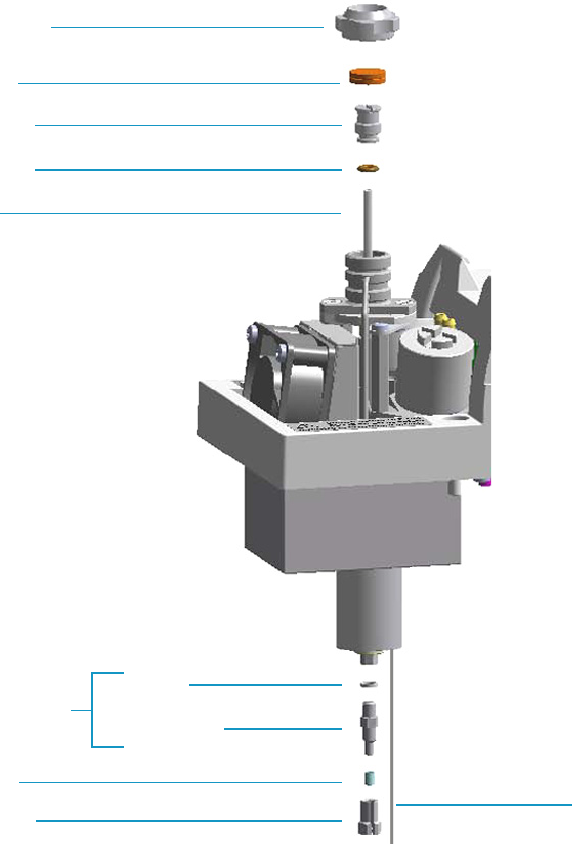
3 Performing Injectors Routine Maintenance
Maintaining a Programmable Temperature Vaporizing Injector with Backflush (PTVBKF)
Thermo Scientific TRACE 1300 and TRACE 1310 Hardware Manual 133
13. If present, move the autosampler towards the module to restore the original alignment.
14. Turn the carrier gas on.
15. Set the normal injector, detector, and GC working conditions.
Replacing the PTVBKF Broken Liner
To replace a broken liner
Figure 112. PTVBKF Injector: Broken Liner Replacement
1. Put the GC in standby condition.
2. Cool the oven and injector to room temperature.
3. Turn the carrier gas off, and wait for the carrier pressure to go to zero.
Septum
Septum Cap
Liner Cap
Liner Seal
Liner
Silver Seal
Terminal Fitting
Bottom Fittings
Split Nut
Ferrule
Backflush Line

3 Performing Injectors Routine Maintenance
Maintaining a Programmable Temperature Vaporizing Injector with Backflush (PTVBKF)
134 TRACE 1300 and TRACE 1310 Hardware Manual Thermo Scientific
4. Put the autosampler away if present.
5. Open the module flap cover.
6. Remove the top part of the injector.
a. Unscrew the septum cap of the injector.
b. Using tweezers, remove the septum from the top of the injector head assembly.
7. Remove the broken liner.
a. Using the slotted stubby driver provided, unscrew and remove the liner cap.
b. Use tweezers to remove the upper part of broken liner with the liner seal from the
injector.
8. Remove the bottom parts of the injector.
a. Inside the oven, unscrew the split nut, and remove the analytical column with its
ferrule from the terminal fitting at the bottom of the injector.
b. Unscrew the terminal fitting with the silver seal. Glass splinters from the broken liner
will fall from the injector.
c. With the aid of a pipe cleaner, remove the possible glass fragments from the
vaporization chamber.
9. Reinstall the bottom part of the injector.
a. Reinstall the terminal fitting with the silver seal (if necessary replace it with a new
one).
b. Reinstall the analytical column.
10. Install a new liner.
a. Holding the new liner with tweezers, place a new liner seal over the liner.
b. Insert the liner into the injector, and push it gently towards the bottom of the
injector.
c. Reinsert and screw the liner cap using the slotted stubby driver.
11. Reinstall the top parts of the injector.
a. Place the septum into the injector head assembly.
b. Screw and tighten the injector cap to finger-tight.
Note By pressing the Maintenance button, the GC cool down is automatically
carried out.
CAUTION It is suggested to replace the septum with a new one.
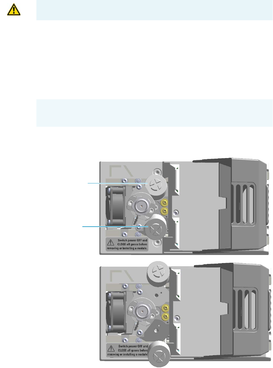
3 Performing Injectors Routine Maintenance
Maintaining a Programmable Temperature Vaporizing Injector with Backflush (PTVBKF)
Thermo Scientific TRACE 1300 and TRACE 1310 Hardware Manual 135
12. Close the module flap cover.
13. If present, move the autosampler towards the module to restore the original alignment.
14. Turn the carrier gas on.
15. Set the normal injector, detector, and GC working conditions.
Replacing the PTVBKF Carrier and Split Lines Filters
To replace the active carbon filters on carrier gas line and split line
Figure 113. PTVBKF Injector: Active Filters Replacement
CAUTION Do not overtighten the septum cap because you might damage the septum and
affect instrument performance.
IMPORTANT The dimensions of the filters are different. The filter on the split gas line is
bigger than the filter on the carrier gas line. Do not invert their position when you replace
them. It is not necessary to replace the filters together.
Carrier Gas Line Filter
Split Gas Line Filter

3 Performing Injectors Routine Maintenance
Maintaining a Programmable Temperature Vaporizing Injector with Backflush (PTVBKF)
136 TRACE 1300 and TRACE 1310 Hardware Manual Thermo Scientific
1. Put the GC in standby condition.
2. Cool the oven and injector to room temperature.
3. Turn the carrier gas off, and wait for the carrier pressure to go to zero.
4. Put the autosampler away if present.
5. Open the module flap cover.
6. Replace the filter.
a. Remove the filter to replace from its seat by turning it counter-clockwise.
b. Install the new filter, with the o-rings, in its seat by turning it clockwise.
7. Close the module flap cover.
8. If present, move the autosampler towards the module to restore the original alignment.
9. Turn the carrier gas on.
10. Set the normal injector, detector, and GC working conditions.
Note By pressing the Maintenance button, the GC cool down is automatically
carried out.

Thermo Scientific TRACE 1300 and TRACE 1310 Hardware Manual 137
4
Performing Detectors Routine Maintenance
This chapter provides instructions for performing routine maintenance on the TRACE 1300
and TRACE 1310 detectors modules.
Contents
•Maintaining a Flame Ionization Detector (FID)
•Maintaining a Nitrogen Phosphorous Detector (NPD)
•Maintaining a Thermal Conductivity Detector (TCD)
•Maintaining an Electron Capture Detector (ECD)
•Maintaining a Flame Photometric Detector (FPD)
•Maintaining a Pulsed Discharge Detector (PDD)
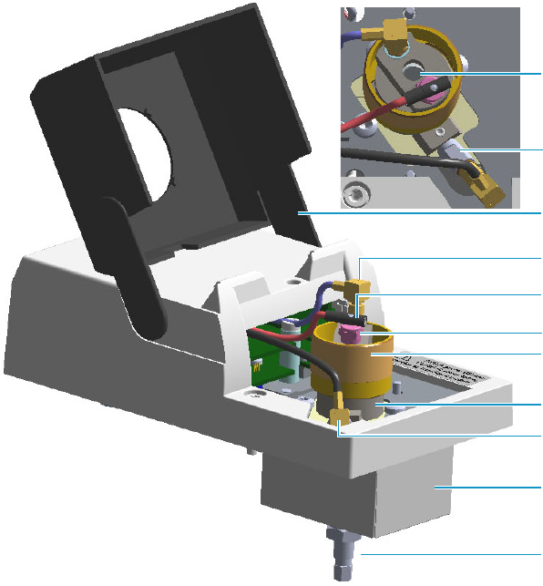
4 Performing Detectors Routine Maintenance
Maintaining a Flame Ionization Detector (FID)
138 TRACE 1300 and TRACE 1310 Hardware Manual Thermo Scientific
Maintaining a Flame Ionization Detector (FID)
This section provides instructions for maintaining a Flame Ionization Detector (FID).
The module and detector components are shown in Figure 114 and Figure 115.
Figure 114. FID: Module Components
Vent
Glow-plug
Detector Cell Assembly
Insulation Cover
Bottom Fittings
Signal Cable
Glow-plug Cable
Detector Body
Polarizing Cable
Module Flap Cover
Polarizing Electrode
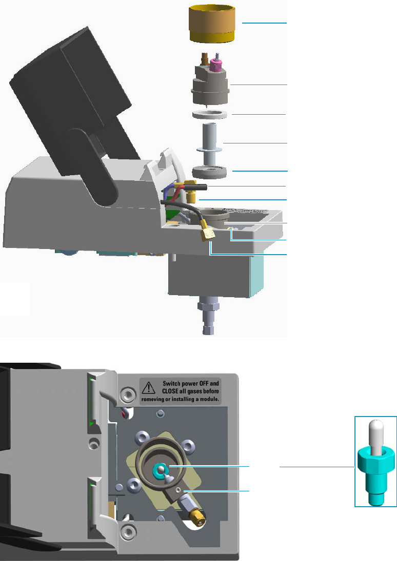
4 Performing Detectors Routine Maintenance
Maintaining a Flame Ionization Detector (FID)
Thermo Scientific TRACE 1300 and TRACE 1310 Hardware Manual 139
Figure 115. FID: Cell Assembly Components
Figure 116. FID: Jet and Polarizing Electrode
To keep optimum performance of the FID, you must keep it clean and free of dust and
deposits. Symptoms, such as reduced sensitivity and increased noise, indicate that the detector
needs cleaning.
Detector Cap
Cell Top Cover
Insulator Ring
Collecting Electrode
Collector Insulator
Signal Cable
Polarizing Electrode
Polarizing Cable
Glow-plug Cable
Detector Body (see
Jet
Polarizing Electrode
4 Performing Detectors Routine Maintenance
Maintaining a Flame Ionization Detector (FID)
140 TRACE 1300 and TRACE 1310 Hardware Manual Thermo Scientific
The FID detector periodic maintenance includes:
• Cleaning the collecting electrode
It is suggest to clean the collecting electrode annually, or when a high noise baseline is
found, due to some compounds that produce detector contamination. If necessary,
replace the collecting electrode.
See “Cleaning or Replacing the FID Collecting Electrode” on page 141.
• Replacing the FID ignition glow-plug
This operation is NOT part on the ordinary maintenance. The flame ignition element
must be replaced only when defective.
See “Replacing the FID Ignition Glow-plug” on page 144.
Before maintaining the detector, read the following precautions:
WARNING Carry out all the operations at low temperature to avoid burns. Therefore,
before beginning maintenance, cool the detector to room temperature.
CAUTION When handling organic solvents you must take precautions to avoid health
hazards.
Materials needed to maintain a FID detector
Ultrasonic cleaner
Liquid detergent
GC-grade methanol
Distilled water
FID Ignition Glow-plug
Collecting electrode (if necessary)
8-mm elbowed box wrench
T6 Torxhead screwdriver
Forceps or tweezers
Note For maintaining or replacing any other component not listed in this section, see
Chapter 7, “Detectors Advanced Maintenance.”
•“Removing/Replacing a Detector Module” on page 262
•“Cleaning or Replacing the FID Jet” on page 271
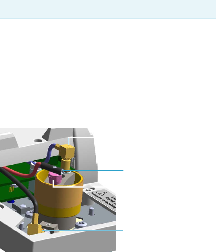
4 Performing Detectors Routine Maintenance
Maintaining a Flame Ionization Detector (FID)
Thermo Scientific TRACE 1300 and TRACE 1310 Hardware Manual 141
Cleaning or Replacing the FID Collecting Electrode
To clean or replace the collecting electrode
1. Put the GC in standby condition.
2. Turn the flame off. The fuel gases, hydrogen and air, are automatically closed.
3. Cool the detector to room temperature.
4. Turn the make-up gas off.
5. Power off the GC.
a. Push down the power switch (breaker), located at the back of the instrument, to the
position O.
b. Unplug the power cable from the AC Input connector into the back of the GC and
from the wall outlet.
6. If external modules are present, unplug the power cable from the AC Input connector of
each module, and from the wall outlet.
7. Open the module flap cover.
8. Disconnect the signal, glow-plug, and polarizing cables from their contacts on the cell.
Figure 117. FID Cables
Note By pressing the Maintenance button, the GC cool down is automatically
carried out.
Glow-plug
Polarizing Cable Straight Jack Connector
Signal Cable Straight Plug Crimp
Connector
Socket Set Screw
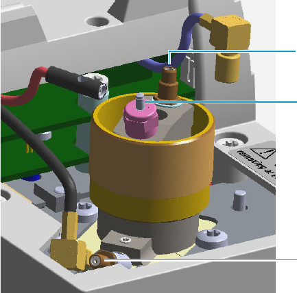
4 Performing Detectors Routine Maintenance
Maintaining a Flame Ionization Detector (FID)
142 TRACE 1300 and TRACE 1310 Hardware Manual Thermo Scientific
Figure 118. FID Cables Disconnection
a. Loosen the glow-plug cable socket set screw using a T6 Torxhead screwdriver.
Carefully pull out the terminal body of the glow-plug cable from the dowel pin on
the glow-plug element.
b. Unscrew and pull out the straight plug crimp connector of the signal cable from the
collecting electrode bulkhead jack.
c. Pull out the quick coupling straight jack connector of the polarizing cable from the
polarizing electrode bulkhead jack.
d. Carefully move the cables in order to have free space for handling the detector.
9. Remove the top parts of the detector.
Polarizing Electrode Bulkhead Jack
Collecting Electrode Bulkhead Jack
Glow-plug Dowel Pin
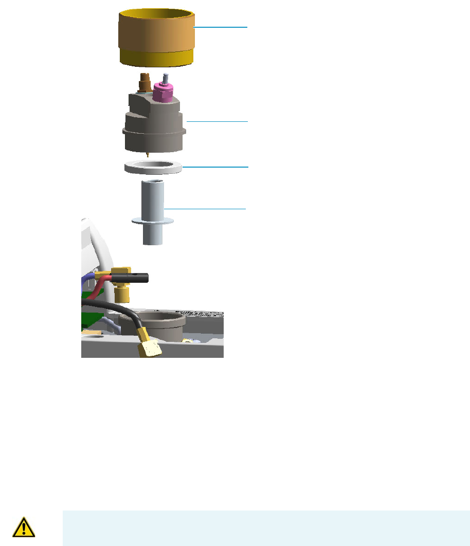
4 Performing Detectors Routine Maintenance
Maintaining a Flame Ionization Detector (FID)
Thermo Scientific TRACE 1300 and TRACE 1310 Hardware Manual 143
Figure 119. FID Collecting Electrode
a. Unscrew and remove the detector cap, paying attention to not rotate the cell top
cover.
b. Remove the cell top cover and put it on a safe place. Pay attention to not damaging
the FID collecting electrode pin.
10. Remove, clean and reinstall the collecting electrode.
a. Using forceps or tweezers, carefully extract the collecting electrode and the insulator
ring through the top of the detector cell.
b. Slip off the insulator ring from the collecting electrode.
c. Place the collecting electrode in the ultrasonic cleaner filled with liquid detergent.
d. Sonicate the collecting electrode for about five minutes.
e. Handling the collecting electrode with forceps or tweezers, rinse it using distilled
water, then methanol.
Detector Cap
Cell Top Cover
Collecting Electrode
Insulator Ring
WARNING The insulator ring must be placed carefully away in a place where it stays
clean.

4 Performing Detectors Routine Maintenance
Maintaining a Flame Ionization Detector (FID)
144 TRACE 1300 and TRACE 1310 Hardware Manual Thermo Scientific
f. Place the collecting electrode on a paper towel and let it air dry.
g. Place the cleaned (or a new) collecting electrode and the insulator ring in its housing.
11. Reinstall the top parts of the detector.
a. Remount the cell top cover, then screw the detector cap, paying attention to not
rotate the cell top cover.
b. Reconnect the signal, glow-plug, and polarizing cables.
12. Close the module flap cover.
13. If external modules are present, plug the power cable to the AC Input connector of each
external module, and to the wall outlet.
14. Power on the GC.
a. Plug the power cable to the AC Input connector into the back of the GC and to the
wall outlet.
b. Flip up the power switch (breaker) to the position I.
15. Set the make-up gas on.
16. Set the normal detector working conditions.
17. Ignite the flame.
Replacing the FID Ignition Glow-plug
To replace the ignition glow-plug
1. Put the GC in standby condition.
2. Turn the flame off. The fuel gases, hydrogen and air, are automatically closed.
3. Cool the detector to room temperature.
4. Turn the make-up gas off.
5. Power off the GC.
a. Push down the power switch (breaker), located at the back of the instrument, to the
position O.
b. Unplug the power cable from the AC Input connector into the back of the GC and
from the wall outlet.
Note If after the cleaning the physical condition of the collecting electrode does
not permit its reuse, replace the electrode with a new one.
Note By pressing the Maintenance button, the GC cool down is automatically
carried out.
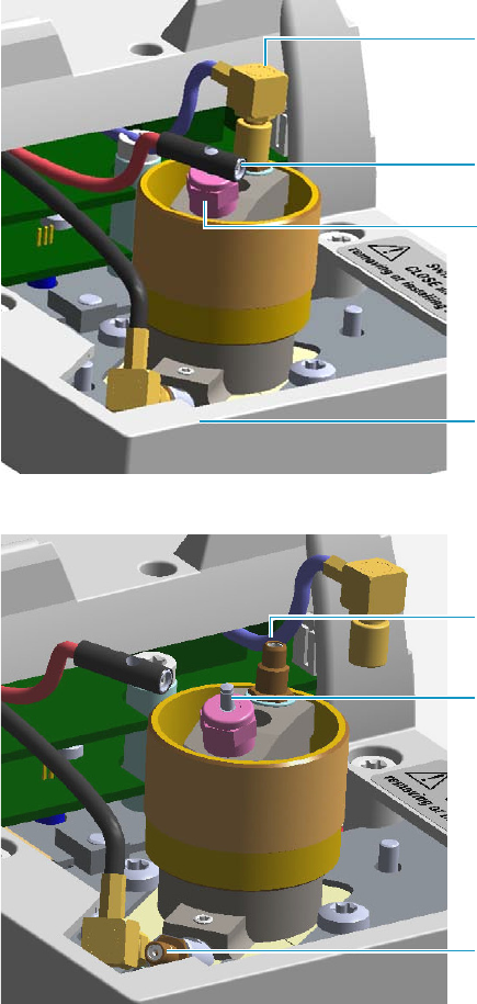
4 Performing Detectors Routine Maintenance
Maintaining a Flame Ionization Detector (FID)
Thermo Scientific TRACE 1300 and TRACE 1310 Hardware Manual 145
6. If external modules are present, unplug the power cable from the AC Input connector of
each external module, and from the wall outlet.
7. Open the module flap cover.
8. Disconnect the signal cable, glow-plug and polarizing cables from their contacts on the
cell top cover.
Figure 120. FID Cables
Figure 121. FID Cables Disconnection
a. Loosen the glow-plug cable socket set screw using a T6 Torxhead screwdriver.
Carefully pull out the terminal body of the glow-plug cable from the dowel pin on
the glow-plug element.
Glow-plug Cable Terminal body
Polarizing Cable Straight Jack Connector
Signal Cable Straight Plug Crimp
Connector
Socket Set Screw
Polarizing Electrode Bulkhead Jack
Collecting Electrode (Anode)
Bulkhead Jack
Glow-plug Dowel Pin
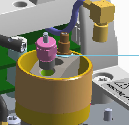
4 Performing Detectors Routine Maintenance
Maintaining a Flame Ionization Detector (FID)
146 TRACE 1300 and TRACE 1310 Hardware Manual Thermo Scientific
b. Unscrew and pull out the straight plug crimp connector of the signal cable from the
collecting electrode (anode) bulkhead jack.
c. Pull out the quick coupling straight jack connector of the polarizing cable from the
polarizing electrode bulkhead jack.
d. Carefully move the cables in order to have free space for handling the detector.
9. Replace the defective glow-plug.
Figure 122. FID Glow-plug Replacement
a. Using an 8-mm wrench, unscrew and remove the defective glow-plug with its washer.
b. Replace the glow-plug with a new one interposing the new washer.
c. Reconnect the glow-plug, signal, and polarizing cables.
10. Close the module flap cover.
11. If external modules are present, plug the power cable to the AC Input connector of each
external module, and to the wall outlet.
12. Power on the GC.
a. Plug the power cable to the AC Input connector into the back of the GC and to the
wall outlet.
b. Flip up the power switch (breaker) to the position I.
13. Turn the make-up gas on.
14. Set the normal detector working conditions.
15. Ignite the flame.
Glow-plug
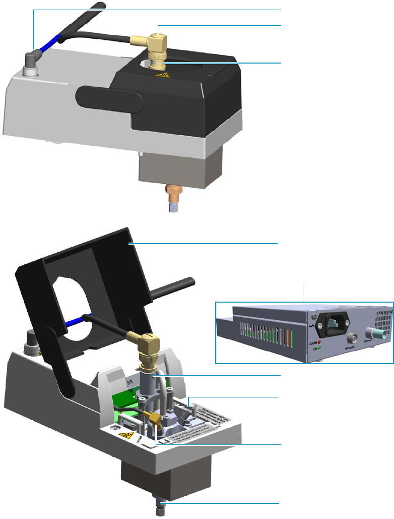
4 Performing Detectors Routine Maintenance
Maintaining a Nitrogen Phosphorous Detector (NPD)
Thermo Scientific TRACE 1300 and TRACE 1310 Hardware Manual 147
Maintaining a Nitrogen Phosphorous Detector (NPD)
This section provides instructions for maintaining a Nitrogen Phosphorous Detector (NPD).
The components of the module and detector are shown in Figure 123, Figure 124, and
Figure 125.
Figure 123. NPD Module Components
Module Flap Cover
Bottom Fittings
Vent
Thermionic Source Assembly
Collecting Electrode Cable
Thermionic Source Assembly
Cable
Signal Cable
Thermionic Source Assembly
NPD Thermionic Source Power Module
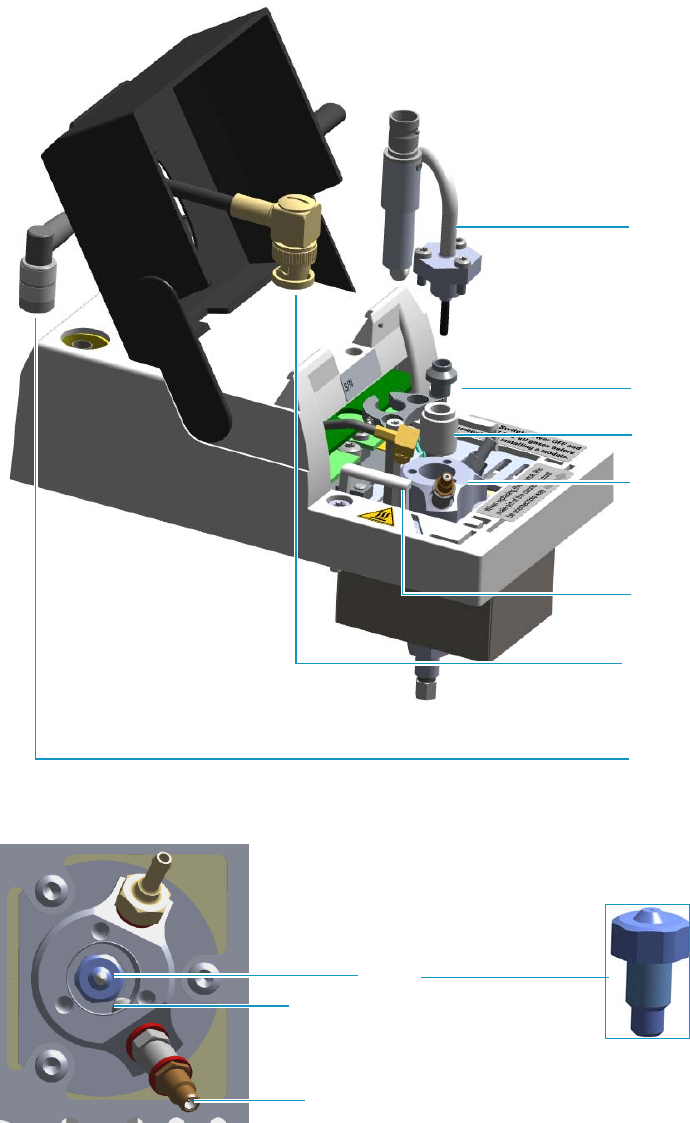
4 Performing Detectors Routine Maintenance
Maintaining a Nitrogen Phosphorous Detector (NPD)
148 TRACE 1300 and TRACE 1310 Hardware Manual Thermo Scientific
Figure 124. NPD Cell Assembly Components
Figure 125. NPD Detector: Jet and Collecting Electrode (Anode) Pin
To ensure optimum performance of the NPD, you must keep it clean and free of dust and
deposits. Symptoms such as reduced sensitivity and increased noise indicate that detector
cleaning, or thermionic source replacement could be necessary.
Insulator
Collecting Electrode
Thermionic Source
Assembly
Signal Cable
Detector Body
See Figure 125
Collecting Electrode
Cable
Thermionic Source
Assembly Cable
Collecting Electrode Straight Jack Connector
Jet
Collecting Electrode Pin
4 Performing Detectors Routine Maintenance
Maintaining a Nitrogen Phosphorous Detector (NPD)
Thermo Scientific TRACE 1300 and TRACE 1310 Hardware Manual 149
The NPD detector periodic maintenance includes:
• Replacing the thermionic source
New thermionic sources may require slightly different values of source heating current to
produce the same signal observed with a previous thermionic source.
See “Replacing the NPD Thermionic Source” on page 150.
• Cleaning the collecting electrode
We suggest cleaning the collecting electrode semiannually, or when a high noise baseline
is found, due to some compounds that produce detector contamination. If necessary,
replace the collecting electrode.
See “Cleaning or Replacing the NPD Collecting Electrode” on page 156.
Before maintaining the detector, read the following precautions:
Note The thermionic source is supplied by a separated NPD Thermionic Source Power
Module placed into an external module housing on the back of the GC.
WARNING Carry out all the operations at low temperature to avoid burns. Therefore,
before beginning maintenance, cool the detector to room temperature.
CAUTION When handling organic solvents you must take precautions to avoid health
hazards.
Materials needed to maintain a NPD detector
Thermionic Source
Gloves
Ultrasonic cleaner
Liquid detergent
GC-grade methanol
Distilled water
Collecting electrode (if necessary)
Forceps or tweezers
T6 Torxhead key
T10 Torxhead screwdriver
6 mm wrench
4 Performing Detectors Routine Maintenance
Maintaining a Nitrogen Phosphorous Detector (NPD)
150 TRACE 1300 and TRACE 1310 Hardware Manual Thermo Scientific
Replacing the NPD Thermionic Source
To replace the thermionic source
1. Put the GC in standby condition.
2. Switch off the thermionic source. Hydrogen and air are automatically closed.
3. Cool the detector to room temperature.
4. Turn the make-up gas off.
5. Power off the GC.
a. Push down the power switch (breaker), located at the back of the instrument, to the
position O.
b. Unplug the power cable from the AC Input connector into the back of the GC and
from the wall outlet.
6. Unplug the power cable from the AC input connector of the NPD Thermionic Source
Power Module and from the wall outlet.
If other external modules are present, unplug the power cable from the AC Input
connector of each module, and from the wall outlet.
7. Unplug the signal cable from the detector module. See Figure 126.
Note For maintaining or replacing any other component not listed in this section, see
Chapter 7, “Detectors Advanced Maintenance.”
•“Measuring the NPD Gas Flows” on page 276
•“Cleaning or Replacing the NPD Jet” on page 285
CAUTION The thermionic source is delicate. Be careful not to break or crack the source.
When performing maintenance on the NPD, avoid touching the source with your fingers,
and prevent it from coming in contact with other surfaces. Wear clean, lint-free gloves to
prevent contamination of parts with dirt and skin oils.
Note By pressing the Maintenance button, the GC cool down is automatically
carried out.
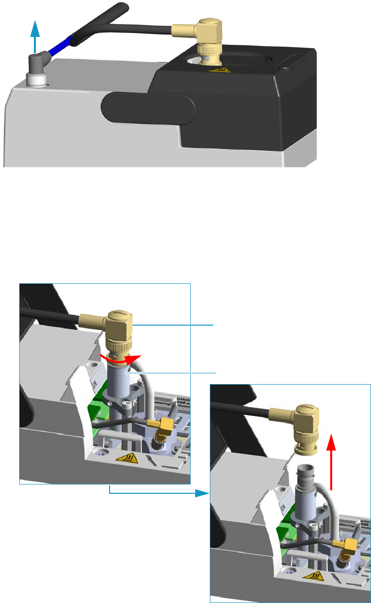
4 Performing Detectors Routine Maintenance
Maintaining a Nitrogen Phosphorous Detector (NPD)
Thermo Scientific TRACE 1300 and TRACE 1310 Hardware Manual 151
Figure 126. Unplug NPD Signal Cable
8. Open the module flap cover.
9. Remove the thermionic source assembly cable.
a. Twist the ring to disconnect the thermionic source assembly cable.
b. Push and twist the lock so that the button slides up in the groove, then pull the cable
ends apart. See Figure 127.
Figure 127. NPD Thermionic Source Cable Removal
Thermionic Source Assembly Cable
Thermionic Source Assembly
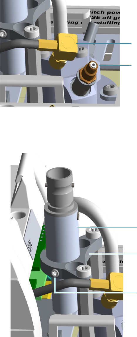
4 Performing Detectors Routine Maintenance
Maintaining a Nitrogen Phosphorous Detector (NPD)
152 TRACE 1300 and TRACE 1310 Hardware Manual Thermo Scientific
10. Unscrew and pull out the straight jack connector of the collecting electrode cable from
the collecting electrode bulkhead jack. See Figure 128.
Figure 128. Collecting Electrode Cable Removal
11. Remove the thermionic source.
a. Using a T6 Torxhead key, loosen the dowel which fix the thermionic source
connector to the thermionic source support. See Figure 129.
Figure 129. NPD Thermionic Source Removal (1)
Collecting Electrode Cable
Collecting Electrode Straight Jack
Connector
Thermionic Source Connector
Dowel
Thermionic Source Support
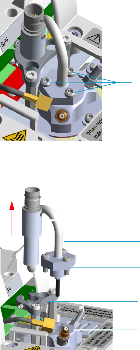
4 Performing Detectors Routine Maintenance
Maintaining a Nitrogen Phosphorous Detector (NPD)
Thermo Scientific TRACE 1300 and TRACE 1310 Hardware Manual 153
b. Using the T10 Torxhead screwdriver, remove the three T10 Torx screws from the
thermionic source assembly. See Figure 130.
Figure 130. NPD Thermionic Source Removal (2)
c. Gently lift up the thermionic source connector guiding the flexible cable from the
thermionic source support, then remove the thermionic source assembly from the
NPD body. Avoid bumping the bead on the sides of the collector. See Figure 131.
Figure 131. NPD Thermionic Source Removal (3)
T10 Torx Screw
Thermionic Source Connector
Thermionic Source Support
Thermionic Source Assembly
Thermionic Source Flexible Cable
NPD Body
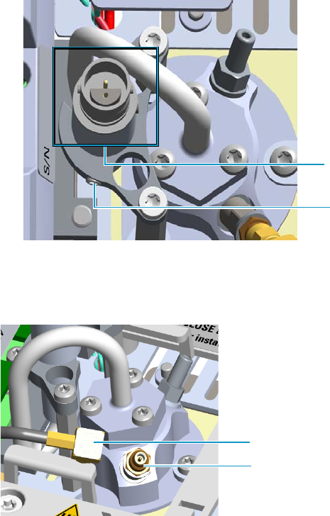
4 Performing Detectors Routine Maintenance
Maintaining a Nitrogen Phosphorous Detector (NPD)
154 TRACE 1300 and TRACE 1310 Hardware Manual Thermo Scientific
12. Replace the thermionic source.
a. Remove the protective cap covering the new thermionic source.
b. Mount and guide the new source assembly on the NPD body proceeding in the
reverse order in which it was removed. Be careful not to bump the bead on the sides
of the body and collecting electrode.
c. Rotate and align the thermionic source connector, then tighten the dowel to fix the
connector to the support using the T6 Torxhead key. See Figure 132.
Figure 132. Replace NPD Thermionic Source (1)
13. Reconnect and screw the straight jack connector of the collecting electrode cable to the
collecting electrode bulkhead jack. See Figure 133.
Figure 133. Replace NPD Thermionic Source (2)
14. Reconnect the source assembly cable to the NPD thermionic source, and twist the ring to
lock the connection. See Figure 134.
Dowel
Correct Alignment
Collecting Electrode Cable
Collecting Electrode Straight Jack Connector
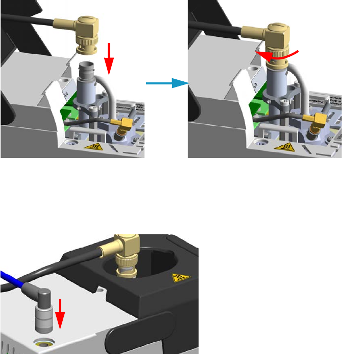
4 Performing Detectors Routine Maintenance
Maintaining a Nitrogen Phosphorous Detector (NPD)
Thermo Scientific TRACE 1300 and TRACE 1310 Hardware Manual 155
Figure 134. Reconnect Source Assemble Cable
15. Close the module flap cover.
16. Plug in the signal cable into its contact on the detector module. See Figure 135.
Figure 135. Reconnect Signal Cable
17. Plug the power cable to the AC input connector of the NPD Thermionic Source Power
Module and to the wall outlet. The LED marked On blinks green.
If other external modules are present, plug the power cable to the AC Input connector of
each module, and to the wall outlet.
18. Power on the GC.
a. Plug the power cable to the AC Input connector into the back of the GC and to the
wall outlet.
b. Flip up the power switch (breaker) to the position I.
19. Set the make-up gas on.
20. Switch on the thermionic source. Hydrogen and air are automatically opened.
The LED marked On of the NPD Thermionic Source Power Module becomes solid
green.
21. With all gases on, heat the detector to 150 °C and hold for about 15 minutes. Increase the
temperature to 250 °C and hold for 15 minutes.
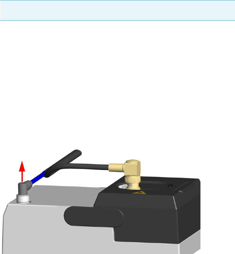
4 Performing Detectors Routine Maintenance
Maintaining a Nitrogen Phosphorous Detector (NPD)
156 TRACE 1300 and TRACE 1310 Hardware Manual Thermo Scientific
22. Increase the temperature to the operating value: 300 to 320 °C is recommended. Allow
15 minutes for equilibration.
23. Check the NPD leakage current. If > 2.0 pA, verify the installation.
Cleaning or Replacing the NPD Collecting Electrode
To clean or replace the NPD collecting electrode
1. Put the GC in standby condition.
2. Switch off the thermionic source. Hydrogen and air are automatically closed.
3. Cool the detector to room temperature.
4. Set the make-up gas off.
5. Power off the GC.
a. Push down the power switch (breaker), located at the back of the instrument, to the
position O.
b. Unplug the power cable from the AC Input connector into the back of the GC and
from the wall outlet.
6. Unplug the power cable from the AC input connector of the NPD Thermionic Source
Power Module and from the wall outlet.
If other external modules are present, unplug the power cable from the AC Input
connector of each module, and from the wall outlet.
7. Unplug the signal cable from the detector module. See Figure 136.
Figure 136. Unplug NPD Signal Cable
8. Open the module flap cover.
Note By pressing the Maintenance button, the GC cool down is automatically
carried out.
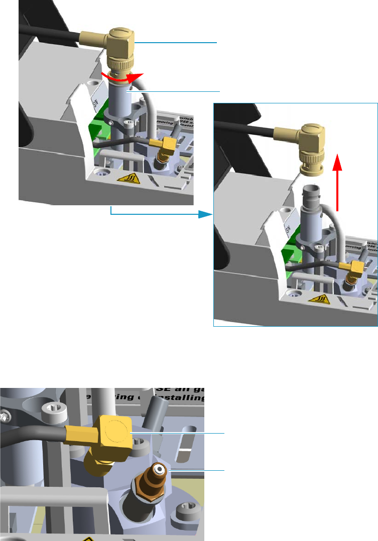
4 Performing Detectors Routine Maintenance
Maintaining a Nitrogen Phosphorous Detector (NPD)
Thermo Scientific TRACE 1300 and TRACE 1310 Hardware Manual 157
9. Remove the thermionic source assembly cable.
a. Twist the ring to disconnect the thermionic source assembly cable.
b. Push and twist the lock so that the button slides up in the groove, then pull the cable
ends apart. See Figure 137.
Figure 137. NPD Thermionic Source Cable Removal
10. Unscrew and pull out the straight jack connector of the collecting electrode cable from
the collecting electrode bulkhead jack. See Figure 138.
Figure 138. Collecting Electrode Cable Removal
Thermionic Source Assembly Cable
Thermionic Source Assembly
Collecting Electrode Cable
Collecting Electrode Straight Jack
Connector
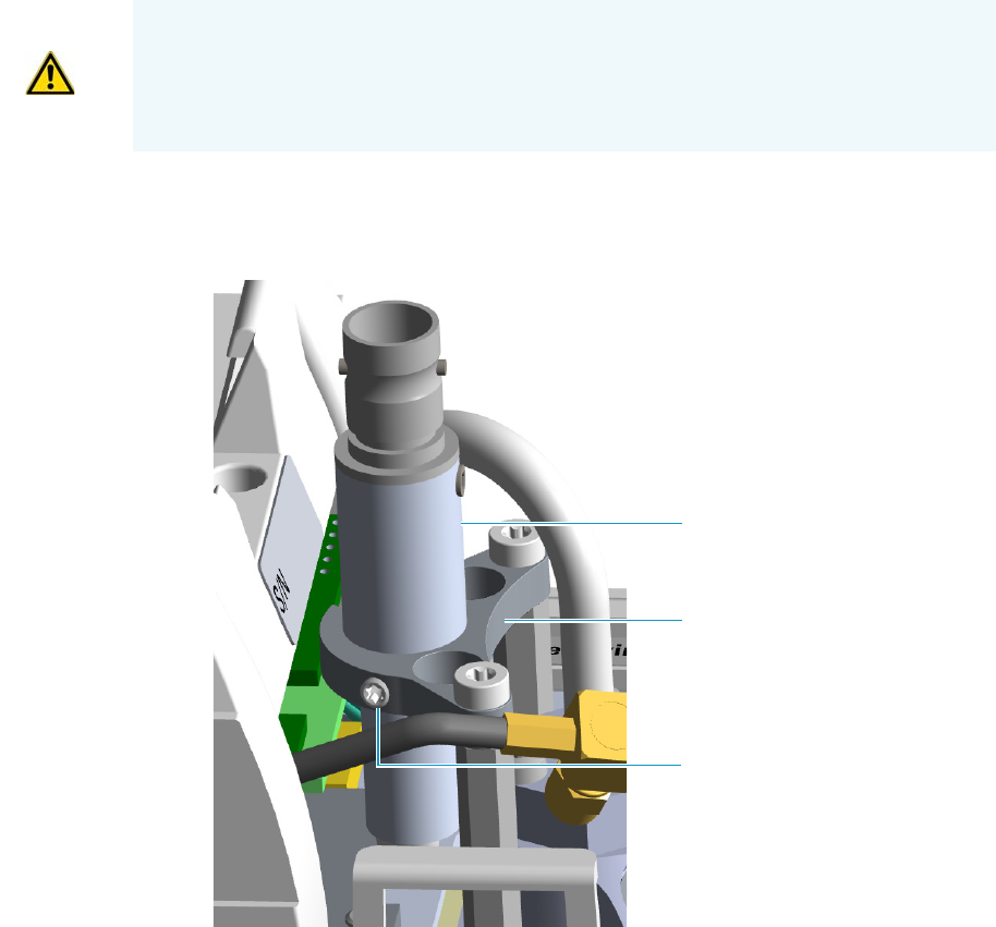
4 Performing Detectors Routine Maintenance
Maintaining a Nitrogen Phosphorous Detector (NPD)
158 TRACE 1300 and TRACE 1310 Hardware Manual Thermo Scientific
11. Remove the thermionic source.
a. Using a T6 Torxhead key, loosen the dowel which fix the thermionic source
connector to the thermionic source support. See Figure 139.
Figure 139. NPD Thermionic Source Removal (1)
b. Using the T10 Torxhead screwdriver, remove the three T10 Torx screws from the
thermionic source assembly. See Figure 140.
CAUTION The thermionic source is delicate. Be careful not to break or crack the source.
When performing maintenance on the NPD, avoid touching the source with your fingers,
and prevent it from coming in contact with other surfaces.
Wear clean, lint-free gloves to prevent contamination of parts with dirt and skin oils.
Thermionic Source Connector
Dowel
Thermionic Source Support
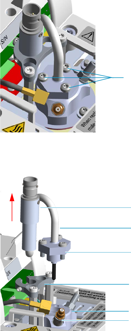
4 Performing Detectors Routine Maintenance
Maintaining a Nitrogen Phosphorous Detector (NPD)
Thermo Scientific TRACE 1300 and TRACE 1310 Hardware Manual 159
Figure 140. NPD Thermionic Source Removal (2)
c. Gently lift up the thermionic source connector guiding the flexible cable from the
thermionic source support, then remove the thermionic source assemble from the
NPD body. Avoid bumping the bead on the sides of the collector. See Figure 141.
Figure 141. NPD Thermionic Source Removal (3)
12. Remove and clean the collecting electrode.
T10 Torx Screw
Thermionic Source Connector
Thermionic Source Support
Thermionic Source Assemble
Thermionic Source Flexible Cable
NPD Body
Collecting Electrode Pin
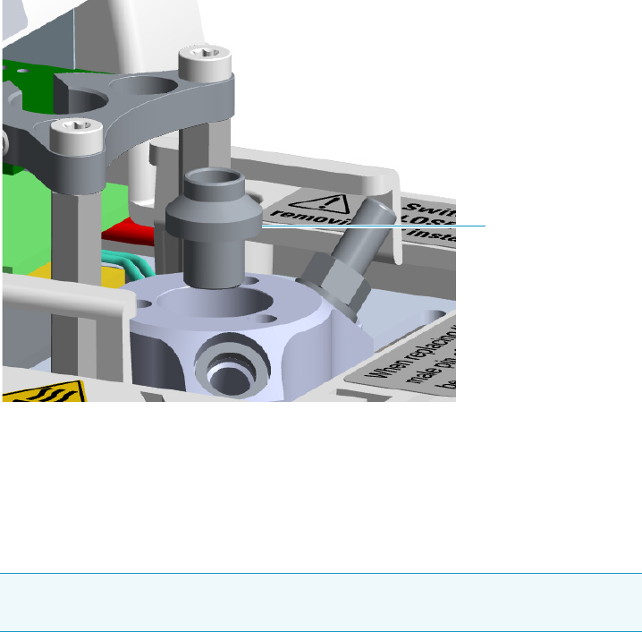
4 Performing Detectors Routine Maintenance
Maintaining a Nitrogen Phosphorous Detector (NPD)
160 TRACE 1300 and TRACE 1310 Hardware Manual Thermo Scientific
a. Using a 6-mm wrench, unscrew and remove the collecting electrode pin from its seat
on the detector body.
b. Using forceps or tweezers, extract the collecting electrode through the top of the
detector body. See Figure 142.
Figure 142. NPD Collecting Electrode Removal
c. Place the collecting electrode in the ultrasonic cleaner filled with liquid detergent.
d. Sonicate the collecting electrode for about five minutes.
e. Handling the collecting electrode with forceps or tweezers, rinse it using distilled
water, then methanol.
f. Place the collecting electrode on a paper towel and let it air dry.
13. Reinstall the collecting electrode.
a. Place the cleaned (or a new) collecting electrode in its housing.
b. Using a 6-mm wrench, screw the collecting electrode pin into its seat on the detector
body.
c. Screw the straight plug crimp connector of the collecting electrode cable to the
collecting electrode bulkhead jack.
14. Reinstall the thermionic source.
a. Remove the protective cap covering the new thermionic source.
Note If after cleaning the physical condition of the collecting electrode does not
permit its reuse, replace the electrode with a new one.
Collector Electrode
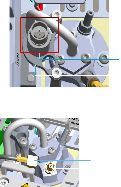
4 Performing Detectors Routine Maintenance
Maintaining a Nitrogen Phosphorous Detector (NPD)
Thermo Scientific TRACE 1300 and TRACE 1310 Hardware Manual 161
b. Mount and guide the new source assembly on the NPD body proceeding in the
reverse order in which it was removed. Be careful not to bump the bead on the sides
of the body and collecting electrode.
c. Rotate and align the thermionic source connector, then tighten the dowel to fix the
connector to the support using the T6 Torxhead key. See Figure 143.
Figure 143. Replace NPD Thermionic Source (1)
15. Reconnect and screw the straight jack connector of the collecting electrode cable to the
collecting electrode bulkhead jack. See Figure 144.
Figure 144. Replace NPD Thermionic Source (2)
16. Reconnect the source assemble cable to the NPD cable and twist the ring to lock the
connection. See Figure 145.
Dowel
Correct Alignment
Collecting Electrode Cable
Collecting Electrode Straight Jack Connector
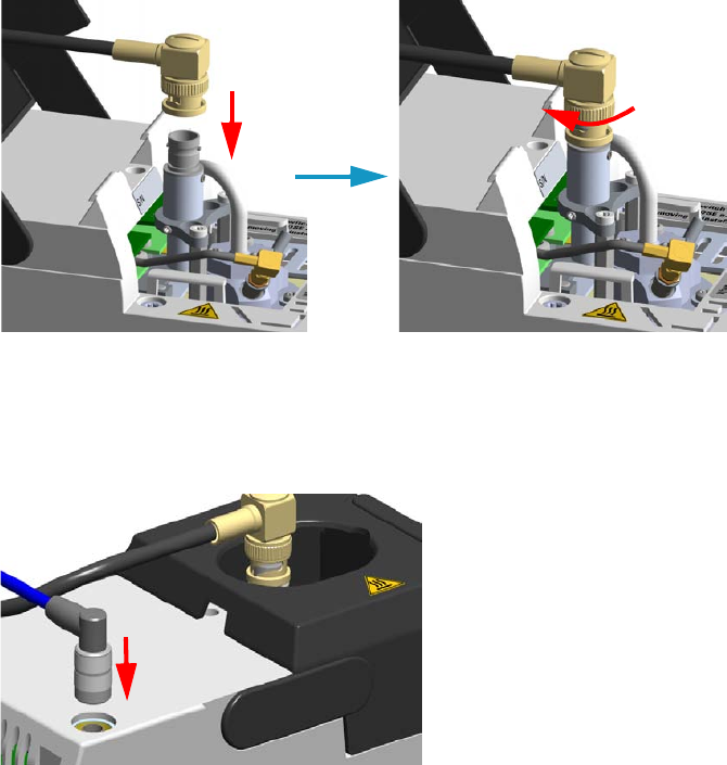
4 Performing Detectors Routine Maintenance
Maintaining a Nitrogen Phosphorous Detector (NPD)
162 TRACE 1300 and TRACE 1310 Hardware Manual Thermo Scientific
Figure 145. Reconnect Source Assemble Cable
17. Close the module flap cover.
18. Plug in the signal cable into its contact on the detector module. See Figure 146.
Figure 146. Reconnect Signal Cable
19. Plug the power cable to the AC input connector of the NPD Thermionic Source Power
Module and to the wall outlet. The LED marked On blinks green.
If other external modules are present, plug the power cable to the AC Input connector of
each module, and to the wall outlet.
20. Power on the GC.
a. Plug the power cable to the AC Input connector into the back of the GC and to the
wall outlet.
b. Flip up the power switch (breaker) to the position I.
21. Turn the make-up gas on.
22. Heat the detector at the working temperature.
23. Switch on the thermionic source. Hydrogen and air are automatically opened.
The LED marked On of the NPD Thermionic Source Power Module becomes solid
green.
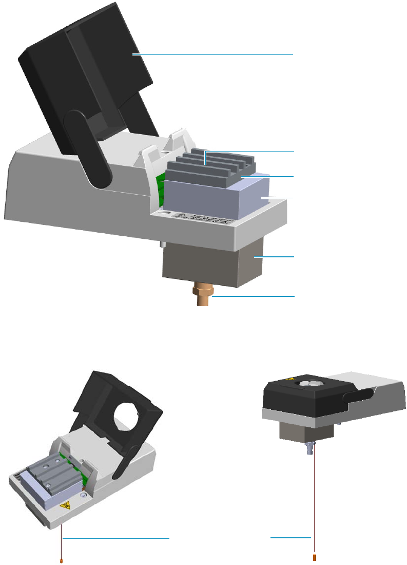
4 Performing Detectors Routine Maintenance
Maintaining a Thermal Conductivity Detector (TCD)
Thermo Scientific TRACE 1300 and TRACE 1310 Hardware Manual 163
Maintaining a Thermal Conductivity Detector (TCD)
This section provides instructions for maintaining a Thermal Conductivity Detector (TCD).
The component of module and detector are shown in Figure 147.
Figure 147. TCD Module Components
The same routine maintenance is applied to the In-Series Connection TCD Module.
See Figure 148.
Figure 148. In-Series Connection TCD Module
Module Flap Cover
Bottom Fittings
Cell Upper Insulating Cover
Cell Lower Insulating Cover
Vent
Heat Sink
Vent Line Metal Tubing

4 Performing Detectors Routine Maintenance
Maintaining a Thermal Conductivity Detector (TCD)
164 TRACE 1300 and TRACE 1310 Hardware Manual Thermo Scientific
The TCD detector does not usually need maintenance. Nevertheless, if you follow a few
simple precautions, you will avoid problems and prolong the detector’s lifetime. Pay a special
attention to avoid contamination or damage to the filaments.
The detector must be returned to the factory when filament replacement is required.
Follow these simple rules:
• Avoid switching on the filaments when unnecessary. Doing so considerably reduces the
filament’s lifetime.
• Avoid injecting samples that contain halogenated or acid compounds at high
concentrations.
• Ensure that oxygen (air) cannot enter into the filament’s cells. Oxidation will irreversibly
damage the filaments. Install traps for moisture and oxygen on the gas lines to reduce the
risk of contamination.
• Turn off the filament before disconnecting the column from the detector. When the
column is disconnected, air will enter into the cell and the filament, if powered on, will be
damaged.
• Turn on the filament only if the column is connected. It is a good practice to let the gas
flow through the cells for 5-10 minutes before powering the filaments.
See Bake-out Procedure, Measuring the Carrier Gas Flow Rate, and Shutting Down the TCD
for additional information.
Bake-out Procedure
Under normal conditions, the TCD requires no routine maintenance. However, if the
detector is exposed to chemicals which may condense or polymerize within the detector and
adversely affect performance, an attempt of filament cleaning could be baked out at high
temperatures (up to 300°C). Inert carrier gas flow should be maintained during the
reconditioning procedure.
Filament temperature should also be increased to approximate the setpoint of the bake-out
temperature.
If a 24-hour bake-out is not sufficient to remove the contamination, the unit must be
returned to the factory for disassembly and cleaning.
CAUTION Do not turn the filament on until the carrier gas is flowing through the
detector.
Do not shut off or disconnect the carrier gas when the detector is hot, even if the unit is
turned off.
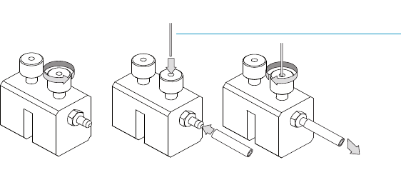
4 Performing Detectors Routine Maintenance
Maintaining a Thermal Conductivity Detector (TCD)
Thermo Scientific TRACE 1300 and TRACE 1310 Hardware Manual 165
Measuring the Carrier Gas Flow Rate
While the measuring of the carrier gas flow rate through the standard TCD detector is
performed simply connecting the flow-meter to the vent outlet, the TCD In-series detector
requires the use of the column- flowmeter connector.
To measure the TCD In-Series carrier gas flow rate
Carefully push the vent line metal tubing end into the flow meter section of the column-
flowmeter connector. See Figure 149.
Figure 149. Column Flowmeter Connector
Connect the flowmeter to the dedicated fitting on the column-flowmeter connector, then
measure the carrier gas flow rate.
Shutting Down the TCD
To shut down the detector at the end of the analytical cycle:
1. Turn off the filaments.
2. Reduce the carrier gas flow to 50% of the normal operating flow to conserve gas supplies.
A B C
To flowmeter
Vent Line Metal Tubing
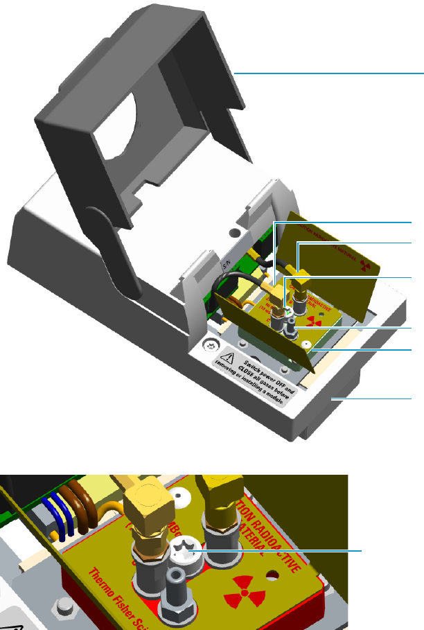
4 Performing Detectors Routine Maintenance
Maintaining an Electron Capture Detector (ECD)
166 TRACE 1300 and TRACE 1310 Hardware Manual Thermo Scientific
Maintaining an Electron Capture Detector (ECD)
This section provides instructions for maintaining an Electron Capture Detector (ECD).
The component of module and detector are shown in Figure 150 and Figure 151.
Figure 150. ECD Module Components
Figure 151. Collecting Electrode (Anode) Screw Plug
The ECD detector periodic maintenance includes:
• Cleaning the collecting electrode (Anode)
We suggest cleaning the collecting electrode annually or when a high noise baseline is
found producing detector contamination. Replace the collecting electrode if necessary.
See “Cleaning or Replacing the Collecting Electrode (Anode)” on page 169.
Module Flap Cover
Signal Cable
Excitation Cable
Chimney
Detector Cell
Insulating Cover
Collecting Electrode
(Anode) Screw Plug
See Figure 151
Collecting Electrode
(Anode) Screw Plug
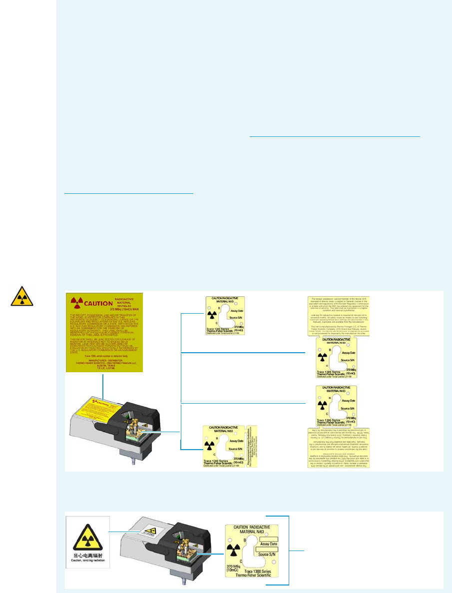
4 Performing Detectors Routine Maintenance
Maintaining an Electron Capture Detector (ECD)
Thermo Scientific TRACE 1300 and TRACE 1310 Hardware Manual 167
Before maintaining the detector, read the following precautions and notes:
CAUTION The Electron Capture Detector contains a 63Ni beta-emitting radioactive
source at 370 MBq (10 mCi). The detector should never be opened or handled by the
user. Any maintenance or service operations involving even partial disassembling of the
detector must be performed ONLY by qualified personnel at a laboratory expressly
authorized by Thermo Fisher Scientific and specifically licensed to handle radioactive
material.
IMPORTANT For customers within the jurisdiction of the United States Nuclear
Regulatory Commission (US NRC), you may find a listing of the agreement states and
the current contact information for the regulators covering both Generally and
Specifically licensed devices like an ECD at http://nrc-stp.ornl.gov/rulemaking.html.
This information is maintained by the US NRC.
IMPORTANT For customers within the jurisdiction of the Canadian Nuclear Safety
Commission, you may find current contact information for the regulators at
http://www.nuclearsafety.gc.ca
IMPORTANT The recommended working life of the detector is 15 years, after which the
user should arrange for the radioactive source to be inspected and assessed by a qualified
authority to extend its working life, or dispose of the product through a suitable disposal
route.
IMPORTANT According to International, USA, and Canada licenses, the appropriate
Radioactivity Data labels are applied on the ECD detector module.
Exclusively for ECD detector module used in China, the Caution Radioactive Material
Ni63 labels are replaced by the followings:
Canada
License
International
License
Common
Label
US General
License
US Specific
License
Caution Radioactive Material
Labels for China
4 Performing Detectors Routine Maintenance
Maintaining an Electron Capture Detector (ECD)
168 TRACE 1300 and TRACE 1310 Hardware Manual Thermo Scientific
Detector Chemical Contamination
The ECD, if properly used, has a good resistance against chemical contamination. However,
some critical operating conditions may cause, over time, contamination of the collecting
electrode (anode). This contamination is highlighted by an excessive increase of the base
frequency, and a baseline drift when the reference current or the pulse amplitude is changed.
The collecting electrode can be easily removed and cleaned without disturbing the radioactive
source.
Detector contamination could be indicated by the following effects in the chromatogram:
• Reduced signal to noise ratio
• High-noise baseline (high frequency)
• Baseline drift with changing pulse voltage
• Negative dips after peaks
If chemical contamination of the whole cell is suspected proceed as follows:
1. Heat the ECD at the maximum operating temperature with carrier and make-up gases
flowing through the detector (thermal cleaning).
2. Follows the decontamination process by monitoring the base frequency. Initially the
frequency value tends to increase to very high values, and then it decreases to acceptable
ones.
If irreversible contamination of the cell is suspected please contact your local Thermo Fisher
Scientific Technical Service office.
WARNING All the operations must be carrier out at low temperature to avoid burns.
Therefore, before conducting maintenance, cool the detector to room temperature.
Materials needed to maintain an ECD detector
Ultrasonic cleaner
GC-grade hexane
GC-grade toluene
Fine emery paper
Little flathead screwdriver
T20 Torxhead screwdriver
Forceps or tweezers
Collecting electrode (Anode) if necessary

4 Performing Detectors Routine Maintenance
Maintaining an Electron Capture Detector (ECD)
Thermo Scientific TRACE 1300 and TRACE 1310 Hardware Manual 169
Wipe Test
Before leaving the factory, each ECD is leak tested for surface radio contamination by means
of the Wipe Test method. Each detector is provided with a Wipe Test Certificate reporting
the results of the values found and the procedure followed.
Cleaning or Replacing the Collecting Electrode (Anode)
To clean or replace the collecting electrode
1. Put the GC in standby condition.
2. Cool the detector to room temperature.
3. Turn the make-up gas off.
4. Power off the GC.
a. Push down the power switch (breaker), located at the back of the instrument, to the
position O.
b. Unplug the power cable from the AC Input connector into the back of the GC and
from the wall outlet.
5. If external modules are present, unplug the power cable from the AC Input connector of
each external module, and from the wall outlet.
6. Open the module flap cover.
7. Disconnects the signal and excitation cables from their contacts on the cell top cover.
See Figure 152.
IMPORTANT The users of the ECD detector in the United States are required to perform
a Wipe Test on their ECD at intervals not exceeding 6 months, following the reported
procedure. For other countries, please refer to the appropriate agency for equivalent
requirements.
Note By pressing the Maintenance button, the GC cool down is automatically
carried out.
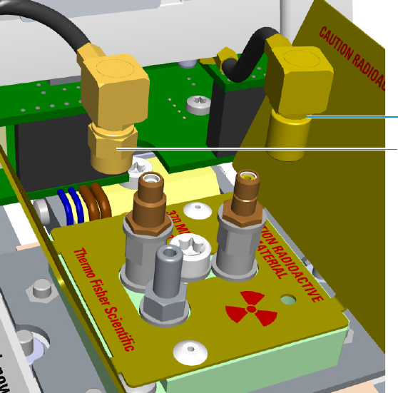
4 Performing Detectors Routine Maintenance
Maintaining an Electron Capture Detector (ECD)
170 TRACE 1300 and TRACE 1310 Hardware Manual Thermo Scientific
Figure 152. ECD Cables Disconnection
a. Unscrew and pull out the straight plug crimp connector of the signal cable from the
collecting electrode (anode) bulkhead jack.
b. Pull out the quick coupling straight jack connector of the excitation cable from the
polarizing electrode bulkhead jack.
c. Carefully move the cables in order to have free space for handling the detector.
8. Remove and clean the collecting electrode (anode).
a. Unscrew the screw plug with its seal hiding the collecting electrode (anode) using the
T20 Torxhead screwdriver.
b. Using a little flathead screwdriver, unscrew and remove the collecting electrode
(anode). See Figure 153.
Signal Cable
Excitation Cable
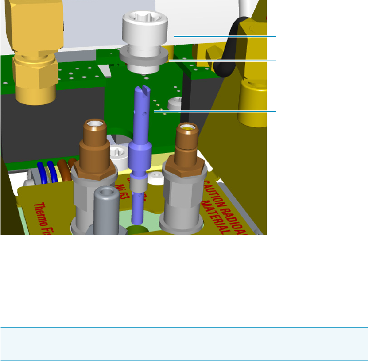
4 Performing Detectors Routine Maintenance
Maintaining an Electron Capture Detector (ECD)
Thermo Scientific TRACE 1300 and TRACE 1310 Hardware Manual 171
Figure 153. Collecting Electrode (Anode) Removal
c. Place the collecting electrode in the ultrasonic cleaner filled with liquid detergent,
and clean it for about five minutes.
d. Handling the collecting electrode (anode) with forceps or tweezers, rinse it using
distilled water, then methanol.
e. Place the collecting electrode (anode) on a paper towel and let it air dry.
9. Reinstall the collecting electrode (anode).
a. Screw the cleaned, or a new collecting electrode (anode) into its housing. Screw the
hiding screw plug and its seal.
10. Reconnect signal and excitation cables.
11. Close the module flap cover.
12. If external modules are present, plug the power cable to the AC Input connector of each
external module, and to the wall outlet.
13. Power on the GC.
a. Plug the power cable to the AC Input connector on the back of the GC, and to the
wall outlet.
b. Flip up the power switch (breaker) to the position I.
14. Set the make-up gas on.
15. Set the normal detector working conditions.
Note If after cleaning the physical condition of the collecting electrode (anode)
does not permit its reuse, replace the electrode with a new one.
Collecting Electrode
Screw Plug
Seal
Collector Electrode
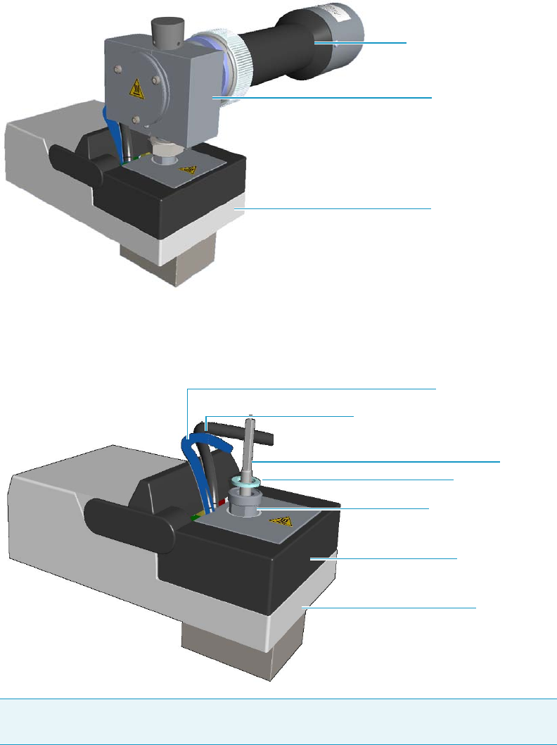
4 Performing Detectors Routine Maintenance
Maintaining a Flame Photometric Detector (FPD)
172 TRACE 1300 and TRACE 1310 Hardware Manual Thermo Scientific
Maintaining a Flame Photometric Detector (FPD)
This section provides instructions for maintaining a Flame Photometric Detector (FPD).
See Figure 154.
Figure 154. FPD Control Module
The control module and detector cell assembly components are shown in Figure 155,
Figure 156, and Figure 157.
Figure 155. FPD Control Module Components
Note The signal, excitation voltage, and ignition/heating cables will be not shown in the
next illustrations for graphic convenience.
FPD Cell Assembly
FPD Control Module
Photomultiplier Assembly
FPD Detector Base Body
Module Flap Cover
Aluminium O-Ring
Module Cover
FPD Jet
Ignition/heating Cable
Excitation Voltage and Signal Cables
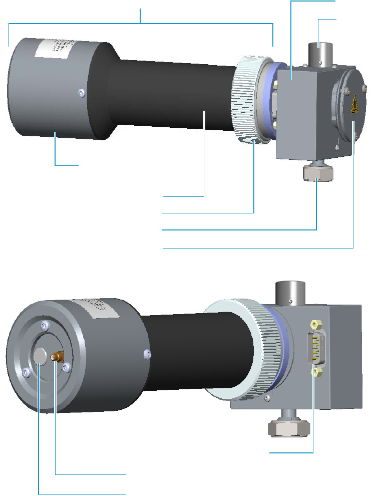
4 Performing Detectors Routine Maintenance
Maintaining a Flame Photometric Detector (FPD)
Thermo Scientific TRACE 1300 and TRACE 1310 Hardware Manual 173
Figure 156. FPD Detector Assembly Components
Mirror Plug Assembly
FPD Blocking Nut
Chimney Cap
Detector Cell
Knurled Nut
Ignition/heating Cable Connection
Signal Cable Connection
Excitation Voltage Cable Connection
Photomultiplier Tube Holder
Photomultiplier Tube Housing
Photomultiplier Assembly

4 Performing Detectors Routine Maintenance
Maintaining a Flame Photometric Detector (FPD)
174 TRACE 1300 and TRACE 1310 Hardware Manual Thermo Scientific
Figure 157. FPD Cell Assembly Components
Interferential Filter
Viton® O-ring
Filter Support
Mirror Plug
Viton® O-ring
Filter-side Heat Shield
Flange
Graphite Seal
Flame-side Heat Shield
Spacer
Chimney Cap
Chimney
Detector Body
Graphite Seal
Cover
Photomultiplier Assembly
FPD Cell Assembly
4 Performing Detectors Routine Maintenance
Maintaining a Flame Photometric Detector (FPD)
Thermo Scientific TRACE 1300 and TRACE 1310 Hardware Manual 175
To ensure optimum performance of the FPD, you must keep it clean and free of dust and
deposits. Symptoms such as reduced sensitivity and increased noise indicate that detector
cleaning could be necessary.
The FPD detector periodic maintenance includes:
• Installing the FPD detector
See “Installing the FPD Detector” on page 176.
•Removing the FPD detector
See “Removing the FPD Detector” on page 178.
• Cleaning or replacing the FPD jet
You should clean the jet semiannually when you analyze particularly dirty compounds
that the flame does not burn properly.
See “Cleaning or Replacing the FPD Jet” on page 179.
• Cleaning or replacing the FPD interferential filter
See “Cleaning or Replacing the FPD Interferential Filter” on page 183.
• Replacing the FPD ignition glow-plug
This operation is NOT part on the ordinary maintenance. The flame ignition element
must be replaced only when defective.
See “Replacing the FPD Ignition Glow-plug” on page 187.
Before maintaining the detector, read the following precautions:
WARNING Carry out all the operations at low temperature to avoid burns. Therefore,
before beginning maintenance, cool the detector to room temperature.
CAUTION When handling organic solvents you must take precautions to avoid health
hazards.
Materials needed to maintain a FPD detector
FPD fixing tool
Gloves
Ultrasonic cleaner
Liquid detergent
GC-grade methanol
Distilled water

4 Performing Detectors Routine Maintenance
Maintaining a Flame Photometric Detector (FPD)
176 TRACE 1300 and TRACE 1310 Hardware Manual Thermo Scientific
Installing the FPD Detector
Before proceeding the installation of the FPD detector assembly, make sure that the FPD
control module is properly installed into the back detector housing.
To install the FPD detector assembly on the FPD detector base body
1. Place the jet into the detector base body housing and tighten it. Ensure the jet is perfectly
vertically aligned to avoid damage. Figure 158.
2. Place the FPD on the detector base body, ensuring that the aluminium ring has been
inserted in the correct position. Tighten the fixing nut by using the FPD fixing tool.
See Figure 158.
Paper towels
Forceps or tweezers
FPD Jet (if necessary)
Interferential filter for sulphur PN 28107000 or PN 19050785, (if necessary)
Interferential filter for phosphorous PN 28107100 or PN 19050785, (if necessary)
Interferential filter for tin PN 28107001 (optional), (if necessary)
FPD Ignition Glow-plug
T6 Torxhead key
T10 Torxhead screwdriver
5 mm wrench
5/16-in tube wrench
Note For maintaining or replacing any other component not listed in this section, see
Chapter 7, “Detectors Advanced Maintenance.”
•“Measuring the FPD Gas Flows” on page 293
•“Cleaning or Replacing the FPD Mirror Metal Plug” on page 295
•“Cleaning or Replacing the FPD Filter-side Heat Shields” on page 300
•“Cleaning or Replacing the FPD Flame-side Heat Shields” on page 308
•“Replacing the FPD Photomultiplier Tube” on page 317
Materials needed to maintain a FPD detector
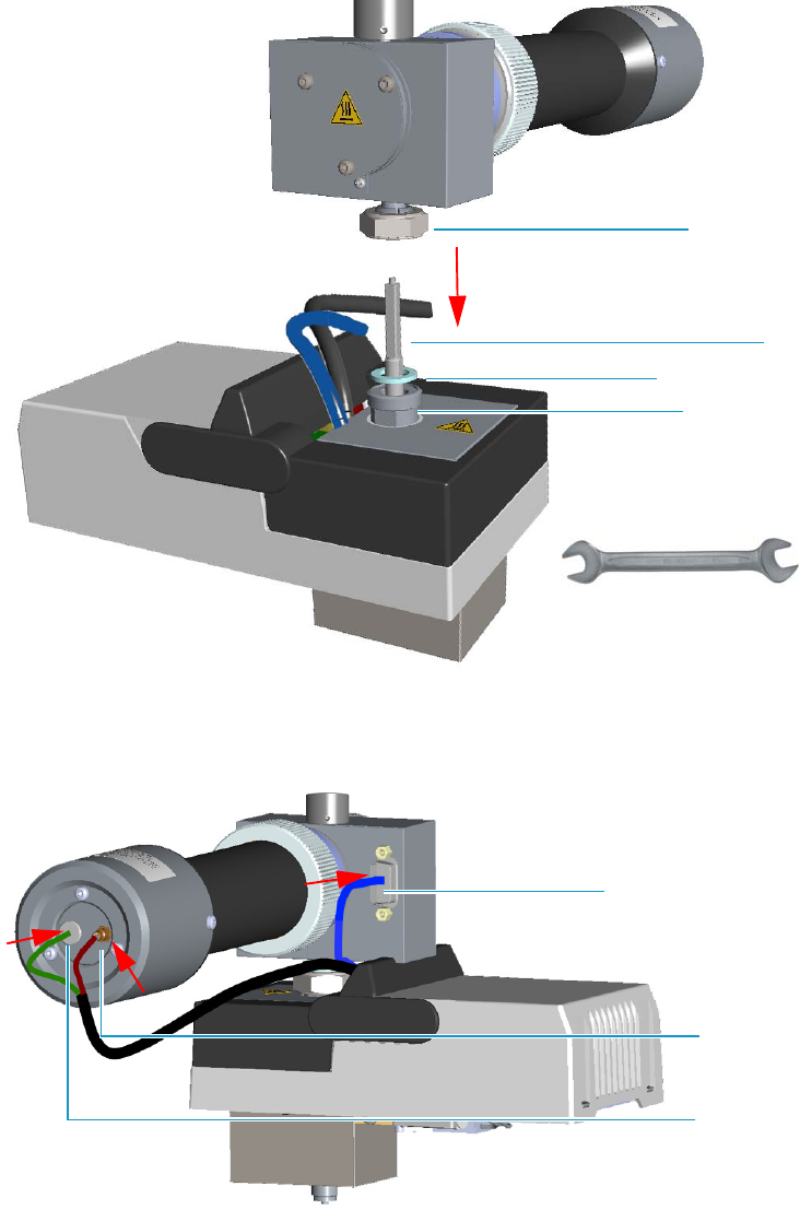
4 Performing Detectors Routine Maintenance
Maintaining a Flame Photometric Detector (FPD)
Thermo Scientific TRACE 1300 and TRACE 1310 Hardware Manual 177
Figure 158. FPD Installation
3. Carefully, connect the signal, excitation voltage, and ignition/heating cables, coming from
the FPD control module, to the FPD detector. See Figure 159.
Figure 159. FPD Cables Connection
Jet
Detector Base
FPD Fixing Nut
FPD Control Module
Aluminium Ring
FPD Detector Assembly
FPD Fixing Tool
Signal Cable
Ignition/Heating Cable
Excitation
Voltage
Cable
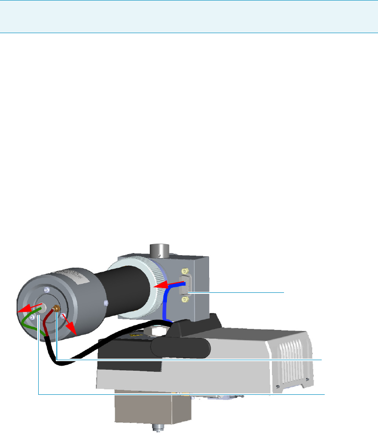
4 Performing Detectors Routine Maintenance
Maintaining a Flame Photometric Detector (FPD)
178 TRACE 1300 and TRACE 1310 Hardware Manual Thermo Scientific
Removing the FPD Detector
To remove the FPD detector assembly from the FPD detector base body
1. Put the GC in standby condition.
2. Switch off the flame. Hydrogen and air are automatically closed.
3. Cool the detector to room temperature.
4. Power off the GC.
a. Push down the power switch (breaker), located at the back of the instrument, to the
position O.
b. Unplug the power cable from the AC Input connector into the back of the GC and
from the wall outlet.
5. If other external modules are present, unplug the power cable from the AC Input
connector of each module, and from the wall outlet.
6. Remove the FPD detector from the base.
a. Disconnect the signal, excitation voltage, and ignition/heating cables from the
detector. See Figure 160
Figure 160. FPD Cable Disconnection
b. Using the tool provided with the system, loosen the fixing nut on the base of the
detector and remove it. See Figure 161.
Note By pressing the Maintenance button, the GC cool down is automatically
carried out.
Signal Cable
Excitation
Voltage
Cable
Ignition/Heating Cable
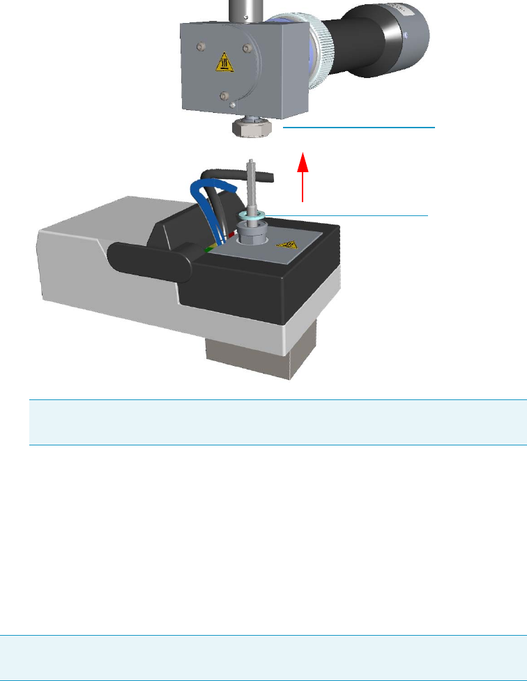
4 Performing Detectors Routine Maintenance
Maintaining a Flame Photometric Detector (FPD)
Thermo Scientific TRACE 1300 and TRACE 1310 Hardware Manual 179
Figure 161. FPD Detector Removal
Cleaning or Replacing the FPD Jet
To clean or replace the FPD jet
1. Put the GC in standby condition.
2. Switch off the flame. Hydrogen and air are automatically closed.
3. Cool the detector to room temperature.
4. Power off the GC.
a. Push down the power switch (breaker), located at the back of the instrument, to the
position O.
b. Unplug the power cable from the AC Input connector into the back of the GC and
from the wall outlet.
5. If other external modules are present, unplug the power cable from the AC Input
connector of each module, and from the wall outlet.
Note Do not lose the aluminium ring inserted between the detector head and
the base body.
FPD Fixing Nut
Aluminium Ring
Note By pressing the Maintenance button, the GC cool down is automatically
carried out.
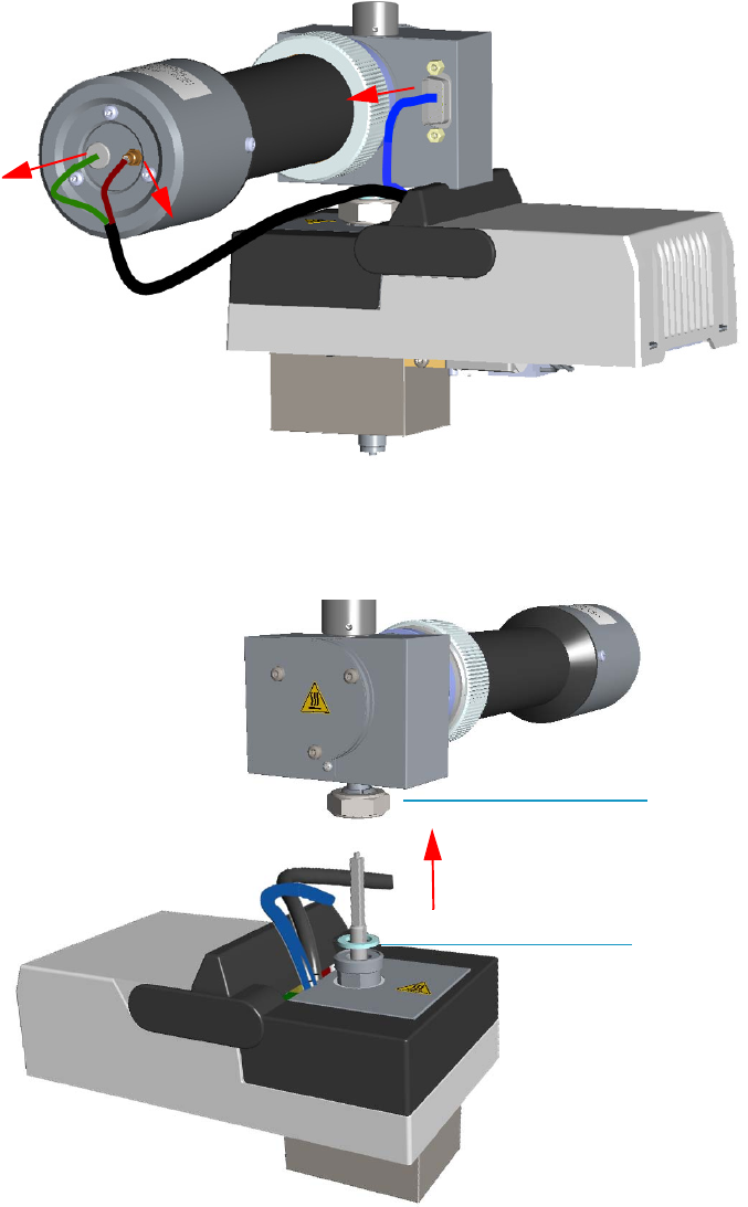
4 Performing Detectors Routine Maintenance
Maintaining a Flame Photometric Detector (FPD)
180 TRACE 1300 and TRACE 1310 Hardware Manual Thermo Scientific
6. Remove the FPD detector from the base.
a. Disconnect the signal, excitation voltage, and ignition/heating cables from the
detector. See Figure 162.
Figure 162. FPD Cable Disconnection
b. Using the tool provided with the system, loosen the fixing nut on the base of the
detector and remove it. See Figure 163.
Figure 163. FPD Detector Removal
FPD Fixing Nut
Aluminium Ring
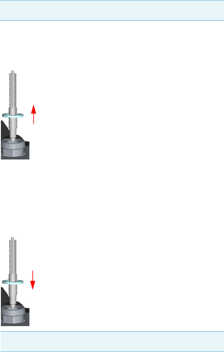
4 Performing Detectors Routine Maintenance
Maintaining a Flame Photometric Detector (FPD)
Thermo Scientific TRACE 1300 and TRACE 1310 Hardware Manual 181
7. Clean the FPD Jet.
a. Using the 5 mm wrench provided with the GC, loosen the jet and remove it from the
detector base body. See Figure 164.
Figure 164. FPD Jet Removal
b. Place the jet in the ultrasonic cleaner filled with liquid detergent and clean it for
about five minutes.
c. Handling the jet with forceps or tweezers, rinse the jet with distilled water, then with
methanol.
d. Place the jet on a paper towel and let it air dry. When the jet is dry, insert the jet into
the detector base body and tighten it. See Figure 165.
Figure 165. FPD Jet Reinstallation
8. Reinstall the FPD detector on the base.
a. Place the detector on its base body, ensuring that the aluminium ring has been
inserted in the correct position, then tighten the fixing nut. See Figure 166.
Note Do not lose the aluminium ring inserted between the detector head and the
base body.
Note If after cleaning the physical condition of the jet does not permit its reuse,
replace the jet with a new one.
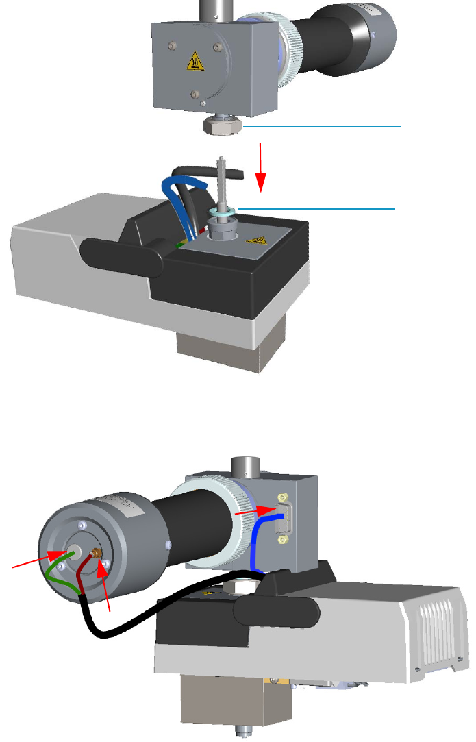
4 Performing Detectors Routine Maintenance
Maintaining a Flame Photometric Detector (FPD)
182 TRACE 1300 and TRACE 1310 Hardware Manual Thermo Scientific
Figure 166. FPD Detector Reinstallation
b. Reconnect the signal, excitation voltage and ignition/heating cables to the detector.
See Figure 167.
Figure 167. FPD Cables Connection
9. If other external modules are present, plug the power cable to the AC Input connector of
each module, and to the wall outlet.
10. Power on the GC.
FPD Fixing Nut
Aluminium Ring
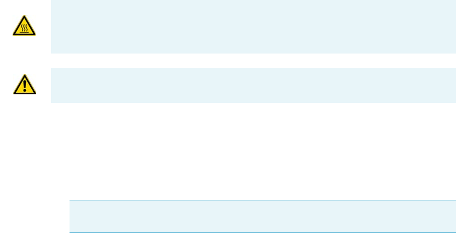
4 Performing Detectors Routine Maintenance
Maintaining a Flame Photometric Detector (FPD)
Thermo Scientific TRACE 1300 and TRACE 1310 Hardware Manual 183
a. Plug the power cable to the AC Input connector into the back of the GC and to the
wall outlet.
b. Flip up the power switch (breaker) to the position I.
11. Set the normal working conditions.
Cleaning or Replacing the FPD Interferential Filter
Before maintaining the detector, read the following precautions:
To clean or replace the FPD interferential filter
1. Put the GC in standby condition.
2. Switch off the flame. Hydrogen and air are automatically closed.
3. Cool the detector to room temperature.
4. Power off the GC.
a. Push down the power switch (breaker), located at the back of the instrument, to the
position O.
b. Unplug the power cable from the AC Input connector into the back of the GC and
from the wall outlet.
5. If other external modules are present, unplug the power cable from the AC Input
connector of each module, and from the wall outlet.
6. Disconnect the signal, excitation voltage, and ignition/heating cables from the detector.
See Figure 168.
WARNING Carry out all the operations at low temperature to avoid burns. Therefore,
before beginning maintenance, cool the detector to room temperature.
CAUTION When handling organic solvents you must take precautions to avoid health
hazards.
Note By pressing the Maintenance button, the GC cool down is automatically
carried out.
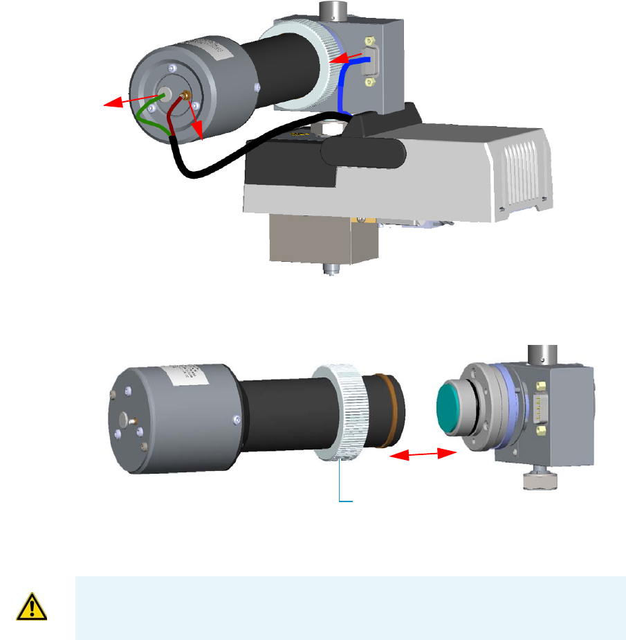
4 Performing Detectors Routine Maintenance
Maintaining a Flame Photometric Detector (FPD)
184 TRACE 1300 and TRACE 1310 Hardware Manual Thermo Scientific
Figure 168. FPD Cables Disconnection
7. Remove the photomultiplier assembly and the filter. See Figure 169.
Figure 169. Photomultiplier Assembly Removal
a. Loosen the knurled nut that fixes the photomultiplier assembly and remove it from
the detector body.
b. Remove the interferential filter from its housing, handling it very gently.
Keep it using a clean paper towel. See Figure 170.
Knurled Nut
CAUTION The photomultiplier tube could damage if exposed to ambient light with the
excitation voltage On. Make sure the power supply has been switched off before
disconnecting the tube from the detector body.
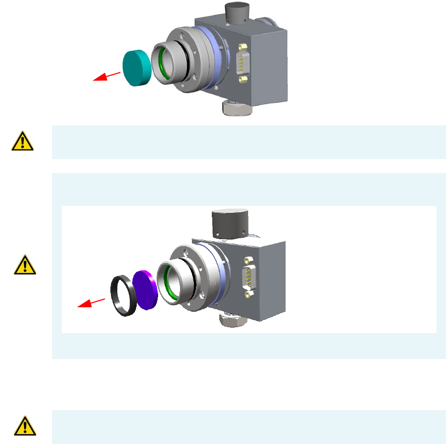
4 Performing Detectors Routine Maintenance
Maintaining a Flame Photometric Detector (FPD)
Thermo Scientific TRACE 1300 and TRACE 1310 Hardware Manual 185
Figure 170. Interferential Filter Removal
8. Clean the filter.
a. Using a clean paper towel, clean the filter on both faces.
9. Reassembly the filter and the photomultiplier assembly.
a. Insert the cleaned filter or a new filter into its housing. The mirror face must be
oriented towards the flame. See Figure 171.
CAUTION Filters are fragile. Pay attention not to let the filter fall down and damage.
CAUTION If the filter installed is equipped with the spacer (see the kits PN 19050785 and
PN 19050786), first remove the spacer, and then the interferential filter.
Keep them using a clean paper towel.
Spacer
Interferential Filter
CAUTION Avoid touching the filter with your fingers. If you see fingertips on the filter,
clean it using GC-grade methanol and air dry before remounting.
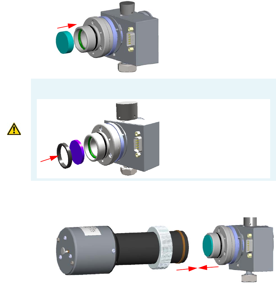
4 Performing Detectors Routine Maintenance
Maintaining a Flame Photometric Detector (FPD)
186 TRACE 1300 and TRACE 1310 Hardware Manual Thermo Scientific
Figure 171. Filter Reinstallation
b. Reassembly the photomultiplier assembly and the detector body, then fix them
together tightening the knurled nut. See Figure 172.
Figure 172. Photomultiplier Assembly Remounting
10. Reconnect the signal, excitation voltage and ignition/heating cables to the detector.
See Figure 173.
CAUTION If the filter installed is equipped with the spacer (see the kits PN 19050785 and
PN 19050786), first insert the filter, and then the spacer.
Interferential Filter
Spacer
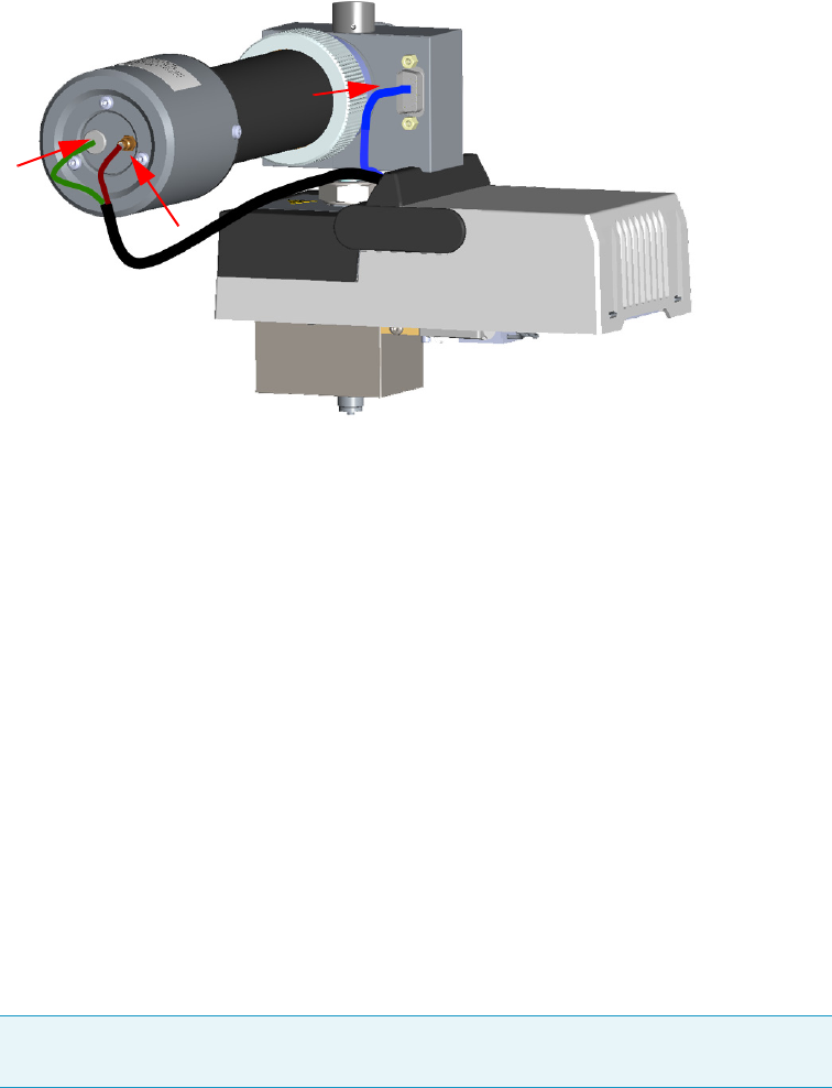
4 Performing Detectors Routine Maintenance
Maintaining a Flame Photometric Detector (FPD)
Thermo Scientific TRACE 1300 and TRACE 1310 Hardware Manual 187
Figure 173. FPD Cables Connection
11. If other external modules are present, plug the power cable to the AC Input connector of
each module, and to the wall outlet.
12. Power on the GC.
a. Plug the power cable to the AC Input connector into the back of the GC and to the
wall outlet.
b. Flip up the power switch (breaker) to the position I.
13. Set the normal working conditions.
Replacing the FPD Ignition Glow-plug
To replace the FPD ignition glow-plug
1. Put the GC in standby condition.
2. Switch off the flame. Hydrogen and air are automatically closed.
3. Cool the detector to room temperature.
4. Power off the GC.
a. Push down the power switch (breaker), located at the back of the instrument, to the
position O.
b. Unplug the power cable from the AC Input connector into the back of the GC and
from the wall outlet.
Note By pressing the Maintenance button, the GC cool down is automatically
carried out.
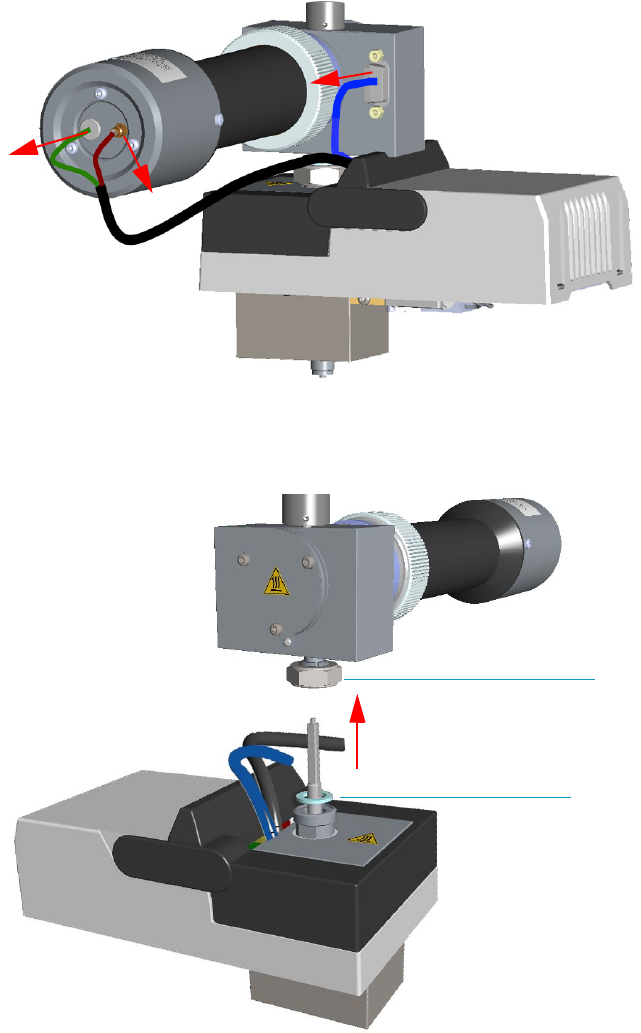
4 Performing Detectors Routine Maintenance
Maintaining a Flame Photometric Detector (FPD)
188 TRACE 1300 and TRACE 1310 Hardware Manual Thermo Scientific
5. If other external modules are present, unplug the power cable from the AC Input
connector of each module, and from the wall outlet.
6. Remove the FPD detector from the base.
a. Disconnect the signal, excitation voltage, and ignition/heating cables from the
detector. See Figure 174.
Figure 174. FPD Cables Disconnection
b. Using the tool provided with the system, loosen the fixing nut on the base of the
detector and remove it. See Figure 175.
Figure 175. FPD Detector Removal
FPD Fixing Nut
Aluminium Ring
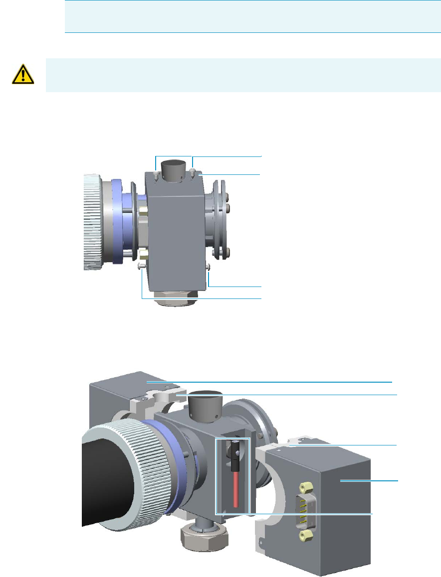
4 Performing Detectors Routine Maintenance
Maintaining a Flame Photometric Detector (FPD)
Thermo Scientific TRACE 1300 and TRACE 1310 Hardware Manual 189
7. Remove the covers of the FPD detector body.
a. Using a 5/16-in tube wrench, remove the two screws on the top of the detector body,
and the front and back screws on the lower part of the detector body. See Figure 176.
Figure 176. Detector Body Dismounting (1)
b. Remove the left and right covers of the FPD detector body and the insulating
material. The glow-plug is now accessible. See Figure 177.
Figure 177. Detector Body Dismounting (2)
8. Replace the defective glow-plug. See Figure 178.
Note Do not lose the aluminium ring inserted between the detector head and the
base body.
CAUTION Removing the covers, pay attention to the heater element and the temperature
probe.
Top Screws
Right Cover
Front Screw
Back Screw
Glow-plug Cable
Terminal body
Right Cover
Left Cover
Insulating
Material
Insulating
Material

4 Performing Detectors Routine Maintenance
Maintaining a Flame Photometric Detector (FPD)
190 TRACE 1300 and TRACE 1310 Hardware Manual Thermo Scientific
Figure 178. Glow-plug Replacing
a. Loosen the glow-plug cable socket set screw using a T6 Torxhead screwdriver.
Carefully pull out the terminal body of the glow-plug cable from the dowel pin on
the glow-plug element.
b. Using an 8-mm wrench, unscrew and remove the defective glow-plug with its washer.
c. Replace the glow-plug with a new one interposing the new washer.
9. Reinstall the left and right covers of the FPD detector body with the insulating material
in the original position, and fix them with the four fixing screws. See Figure 179.
Figure 179. Detector Body Remounting
10. Reinstall the FPD detector on the base.
a. Place the detector on its base body, ensuring that the aluminium ring has been
inserted in the correct position, then tighten the fixing nut. See Figure 180.
Glow-plug Dowel Pin
Glow-plug
Socket Set Screw
Heater Element
temperature probe
CAUTION Reinstalling the covers, pay attention to the heater element and the
temperature probe.
Top Screws
Right Cover
Front Screw
Back Screw
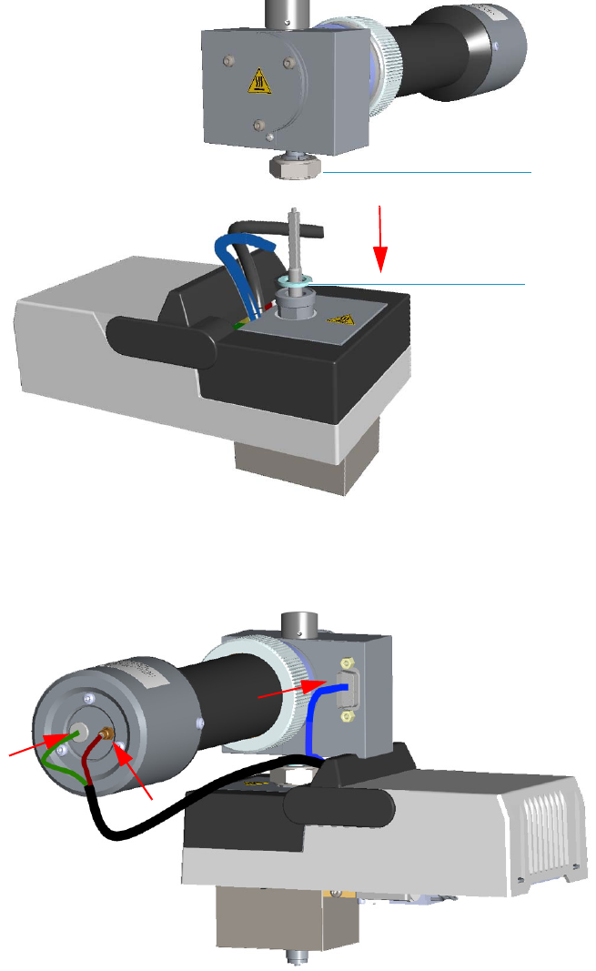
4 Performing Detectors Routine Maintenance
Maintaining a Flame Photometric Detector (FPD)
Thermo Scientific TRACE 1300 and TRACE 1310 Hardware Manual 191
Figure 180. FPD Detector Reinstallation
b. Reconnect the signal, excitation voltage and ignition/heating cables to the detector.
See Figure 181.
Figure 181. FPD Cables Connection
11. If external modules are present, plug the power cable to the AC Input connector of each
external module, and to the wall outlet.
12. Power on the GC.
FPD Fixing Nut
Aluminium Ring
4 Performing Detectors Routine Maintenance
Maintaining a Flame Photometric Detector (FPD)
192 TRACE 1300 and TRACE 1310 Hardware Manual Thermo Scientific
a. Plug the power cable to the AC Input connector into the back of the GC and to the
wall outlet.
b. Flip up the power switch (breaker) to the position I.
13. Set the normal detector working conditions.
14. Ignite the flame.

4 Performing Detectors Routine Maintenance
Maintaining a Pulsed Discharge Detector (PDD)
Thermo Scientific TRACE 1300 and TRACE 1310 Hardware Manual 193
Maintaining a Pulsed Discharge Detector (PDD)
The Pulsed Discharge Detector (PDD) does not require maintenance.
WARNING Under no circumstances should the detector be disassembled.
The components of the detector are assembled with special tooling and held under
considerable force. Disassembling of the detector may present a safety hazard and will
result in its destruction.

Thermo Scientific TRACE 1300 and TRACE 1310 Hardware Manual 195
5
GC Main Frame Advanced Maintenance
This chapter describes TRACE 1300/TRACE 1310 GC components that do not require
routine maintenance, but they need to be removed or replaced.
Contents
•Removing/Replacing the GC Top Cover
•Removing/Replacing the GC Left Side Panel
•Removing/Replacing the GC Right Side Panel
•Removing/Replacing the GC Back Cover
•Removing/Replacing the GC Front Door Cover
•Removing/Replacing the Electronic Module
•Replacing the Oven Heater Baffle
•Replacing the Oven Heater Temperature Sensor
•Replacing the Oven Motor
•Replacing the Flap Motor
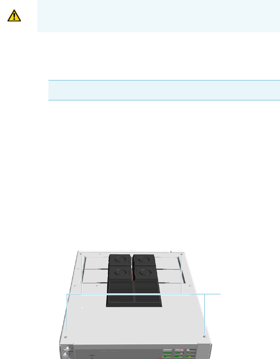
5 GC Main Frame Advanced Maintenance
Removing/Replacing the GC Top Cover
196 TRACE 1300 and TRACE 1310 Hardware Manual Thermo Scientific
Removing/Replacing the GC Top Cover
Perform this operation for accessing the internal compartments of the GC.
To remove/replace the top cover accessing the top parts of the GC
1. Put the GC in standby condition.
2. Cool the oven, injectors and detectors to room temperature.
3. Power off the GC.
a. Close the gas supplies.
b. Push down the power switch (breaker), located at the back of the instrument, to the
position O.
c. Unplug the power cable from the AC Input connector into the back of the GC and
from the wall outlet.
4. If external modules are present, unplug the power cable from the AC Input connector of
each external module, and from the wall outlet.
5. Remove the autosampler if present.
6. Remove the cover.
a. Using a T20 Torxhead screwdriver, unscrew the four screws that held it in place.
See Figure 182 and Figure 183.
Figure 182. Top Cover Removal (1)
WARNING This operation must be carried out by authorized and trained Thermo Fisher
Scientific Service Field Engineers.
Note By pressing the Maintenance button, the GC cool down is automatically
carried out.
Top Cover Screws
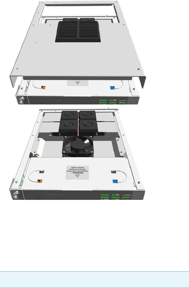
5 GC Main Frame Advanced Maintenance
Removing/Replacing the GC Left Side Panel
Thermo Scientific TRACE 1300 and TRACE 1310 Hardware Manual 197
b. Lift the top panel up and off the GC.
Figure 183. Top Cover Removal (2)
7. Replace the top cover proceeding in the reverse order in which it was removed.
Removing/Replacing the GC Left Side Panel
To remove the left side panel with the side panel molded of the GC
1. Put the GC in standby condition.
2. Cool the oven, injectors and detectors to room temperature.
Note By pressing the Maintenance button, the GC cool down is automatically
carried out.
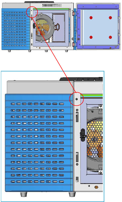
5 GC Main Frame Advanced Maintenance
Removing/Replacing the GC Left Side Panel
198 TRACE 1300 and TRACE 1310 Hardware Manual Thermo Scientific
3. Power off the GC.
a. Push down the power switch (breaker), located at the back of the instrument, to the
position O.
b. Unplug the power cable from the AC Input connector into the back of the GC and
from the wall outlet.
4. If external modules are present, unplug the power cable from the AC Input connector of
each external module, and from the wall outlet.
5. Remove the panel.
a. Open the front door of the GC. Using a T20 Torxhead screwdriver, unscrew the left
side panel screw from the interior front panel. See Figure 184.
Figure 184. Left Side Panel Fixing Screw
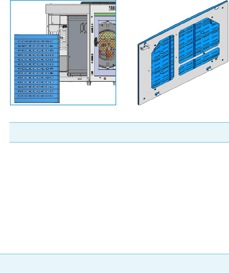
5 GC Main Frame Advanced Maintenance
Removing/Replacing the GC Right Side Panel
Thermo Scientific TRACE 1300 and TRACE 1310 Hardware Manual 199
b. Slide the panel towards the back of the instrument up to the stop.
c. Remove the panel pulling it outwards being aware that the ground wire is attached to
the panel. See Figure 185.
Figure 185. Left Panel Removal
d. Unplug the ground wire from the panel.
6. Replace the panel.
a. Plug the ground wire to the panel.
b. Reinstall the panel proceeding in the reverse order in which it was removed.
Removing/Replacing the GC Right Side Panel
To remove the right side panel with the side panel molded of the GC
1. Put the GC in standby condition.
2. Cool the oven, injectors and detectors to room temperature.
3. Power off the GC.
a. Push down the power switch (breaker), located at the back of the instrument, to the
position O.
b. Unplug the power cable from the AC Input connector into the back of the GC and
from the wall outlet.
Note Pay attention to the positioning of the ground wire plug, so it can be
reconnected in the same way it was removed.
Note By pressing the Maintenance button, the GC cool down is automatically
carried out.
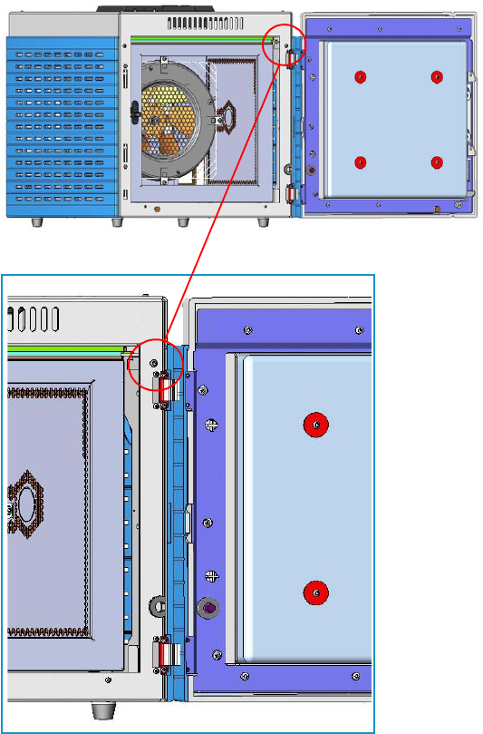
5 GC Main Frame Advanced Maintenance
Removing/Replacing the GC Right Side Panel
200 TRACE 1300 and TRACE 1310 Hardware Manual Thermo Scientific
4. If external modules are present, unplug the power cable from the AC Input connector of
each external module, and from the wall outlet.
5. Remove the AI/AS autosampler, if present.
6. Remove the panel.
a. Open the front door of the GC. Using a T20 Torxhead screwdriver, unscrew the
right side panel screw from the interior front panel. See Figure 186.
Figure 186. Right Panel Fixing Screw
b. Slide the panel towards the back of the instrument up to the stop.
c. Remove the panel pulling it outwards being aware that the ground wire is attached to
the panel. See Figure 187.
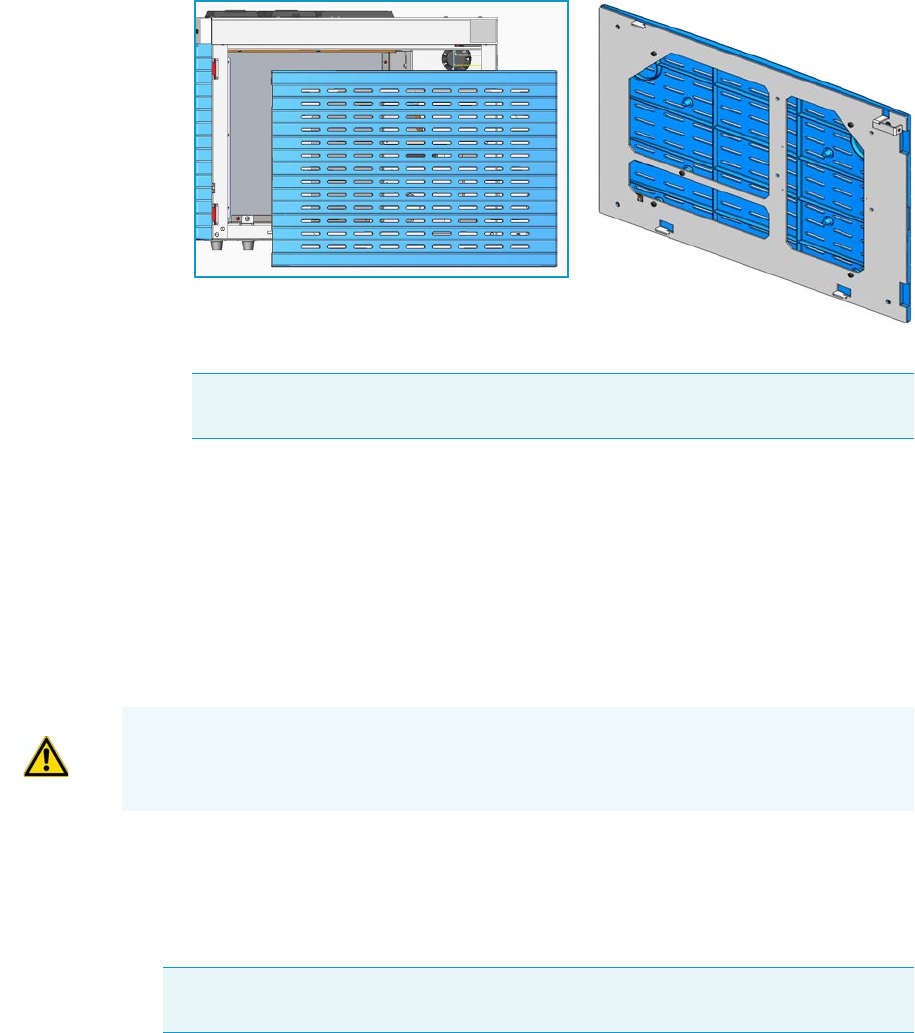
5 GC Main Frame Advanced Maintenance
Removing/Replacing the GC Back Cover
Thermo Scientific TRACE 1300 and TRACE 1310 Hardware Manual 201
Figure 187. Right Panel Removal
d. Unplug the ground wire from the panel.
7. Replace the panel.
a. Plug the ground wire to the panel.
b. Reinstall the panel proceeding in the reverse order in which it was removed.
Removing/Replacing the GC Back Cover
Remove the back cover for accessing the compartment on the back of the GC.
To remove the back cover
1. Put the GC in standby condition.
2. Cool the oven, injectors and detectors to room temperature.
3. Power off the GC.
a. Push down the power switch (breaker), located at the back of the instrument, to the
position O.
b. Unplug the power cable from the AC Input connector into the back of the GC and
from the wall outlet.
Note Pay attention to the positioning of the ground wire plug, so it can be
reconnected in the same way it was removed.
WARNING This operation must be carried out by authorized and trained Thermo Fisher
Scientific Service Field Engineers.
Note By pressing the Maintenance button, the GC cool down is automatically
carried out.
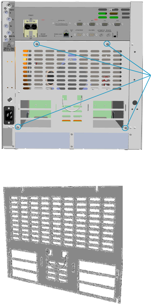
5 GC Main Frame Advanced Maintenance
Removing/Replacing the GC Back Cover
202 TRACE 1300 and TRACE 1310 Hardware Manual Thermo Scientific
4. If external modules are present, unplug the power cable from the AC Input connector of
each external module, and from the wall outlet.
5. Remove the cover.
a. Using a T20 Torxhead screwdriver, unscrew the four screws that secure the back cover
to the GC. See Figure 188.
Figure 188. Back Cover Removal
b. Lift the cover off using the cover handle. Be aware that the ground wire is attached to
the back cover. See Figure 189.
Figure 189. Back Cover
Back Cover Fixing Screws

5 GC Main Frame Advanced Maintenance
Removing/Replacing the GC Front Door Cover
Thermo Scientific TRACE 1300 and TRACE 1310 Hardware Manual 203
6. Reconnect the ground wire to the back cover terminal.
7. Replace the cover proceeding in the reverse order in which it was removed.
Removing/Replacing the GC Front Door Cover
This section provides the instruction for removing or replacing the cover of the front door.
To remove the cover of the front door of the GC
1. Put the GC in standby condition.
2. Cool the oven, injectors and detectors to room temperature.
3. Power off the GC.
a. Push down the power switch (breaker), located at the back of the instrument, to the
position O.
b. Unplug the power cable from the AC Input connector into the back of the GC and
from the wall outlet.
4. If external modules are present, unplug the power cable from the AC Input connector of
each external module, and from the wall outlet.
5. Remove the door cover.
a. Open the front door and look for the fixing screws that secure the cover and the door
handle to the door. See Figure 190.
Note Pay attention to the positioning of the ground wire plug, so it can be
reconnected in the same way it was removed.
WARNING This operation must be carried out by authorized and trained Thermo Fisher
Scientific Service Field Engineers.
Note By pressing the Maintenance button, the GC cool down is automatically
carried out.
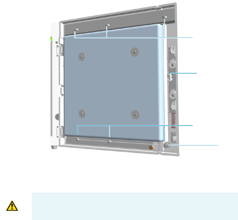
5 GC Main Frame Advanced Maintenance
Removing/Replacing the GC Front Door Cover
204 TRACE 1300 and TRACE 1310 Hardware Manual Thermo Scientific
Figure 190. Front Door Back View
b. Using a T20 Torxhead screwdriver remove the screw that secure the door handle to
the front door.
c. Pull the door handle out from the front door. See Figure 191.
Upper Fixing Screws
Lower Fixing Screws
Door Handle Fixing
Screw
Spacer
IMPORTANT Save the door handle because it must be reused.
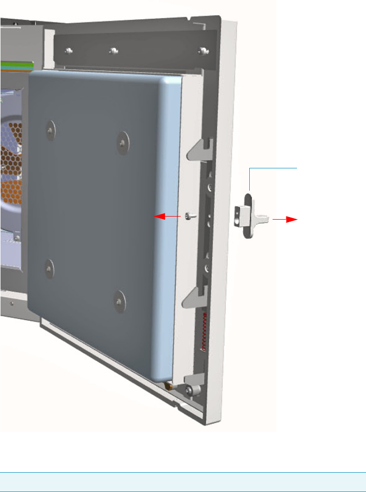
5 GC Main Frame Advanced Maintenance
Removing/Replacing the GC Front Door Cover
Thermo Scientific TRACE 1300 and TRACE 1310 Hardware Manual 205
Figure 191. Door Handle Removal
d. Using a T20 Torxhead screwdriver remove the three upper and the three lower screws
that secure the cover to the front door. See Figure 192.
Note The lower screw on the lower right corner is screwed into a spacer.
Door Handle
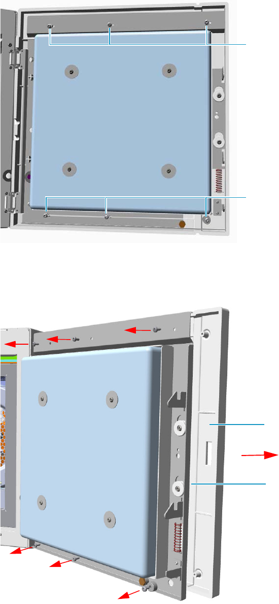
5 GC Main Frame Advanced Maintenance
Removing/Replacing the GC Front Door Cover
206 TRACE 1300 and TRACE 1310 Hardware Manual Thermo Scientific
Figure 192. Door Cover Fixing Screws Removal
e. Carefully pull the door cover off. Pay attention to the cables that connect the status
panel to the internal section of the door. See Figure 193.
Figure 193. Front Door Removal
f. Disconnect the cables from the connector located on the front of the door.
Lower Fixing Screws
Upper Fixing Screws
Door Cover
Front Door
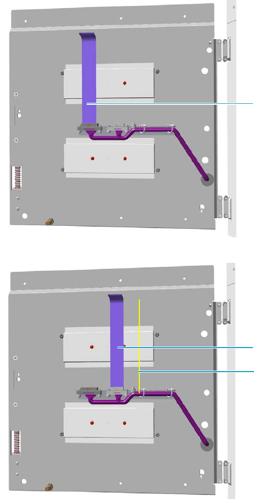
5 GC Main Frame Advanced Maintenance
Removing/Replacing the GC Front Door Cover
Thermo Scientific TRACE 1300 and TRACE 1310 Hardware Manual 207
•See Figure 194 in case of TRACE 1300.
•See Figure 195 in case of TRACE 1310.
Figure 194. TRACE 1300 Front Door Cables Removal
Figure 195. TRACE 1310 Front Door Cables Removal
6. Replace the cover proceeding in the reverse order in which it was removed.
7. If external modules are present, plug the power cable to the AC Input connector of each
external module, and to the wall outlet.
Flat Cables
Flat Cable
Ground Cable

5 GC Main Frame Advanced Maintenance
Removing/Replacing the Electronic Module
208 TRACE 1300 and TRACE 1310 Hardware Manual Thermo Scientific
8. Power on the GC.
a. Plug the power cable to the AC Input connector into the back of the GC and to the
wall outlet.
b. Flip up the power switch (breaker) to the position I.
9. Set the normal injector, detector, and GC working conditions.
Removing/Replacing the Electronic Module
The Electronic Module contains power and electronic circuits for the control of the
instrument. A proper module is installed according to 120 Vac or 230 Vac power supply.
To remove/replace the electronic module
1. Put the GC in standby condition.
2. Cool the oven, injectors and detectors to room temperature.
3. Power off the GC.
a. Push down the power switch (breaker), located at the back of the instrument, to the
position O.
b. Unplug the power cable from the AC Input connector into the back of the GC and
from the wall outlet.
4. If external modules are present, unplug the power cable from the AC Input connector of
each external module, and from the wall outlet.
5. Unplug the cables connected to the external interface of the Electronic Module.
6. Remove the autosampler if present.
7. Remove the top cover.
a. Use a T20 Torxhead screwdriver to remove the screws at the sides of the top cover.
See Figure 196.
WARNING This operation must be carried out only by authorized and trained Thermo
Fisher Scientific technical personnel.
Note By pressing the Maintenance button, the GC cool down is automatically
carried out.
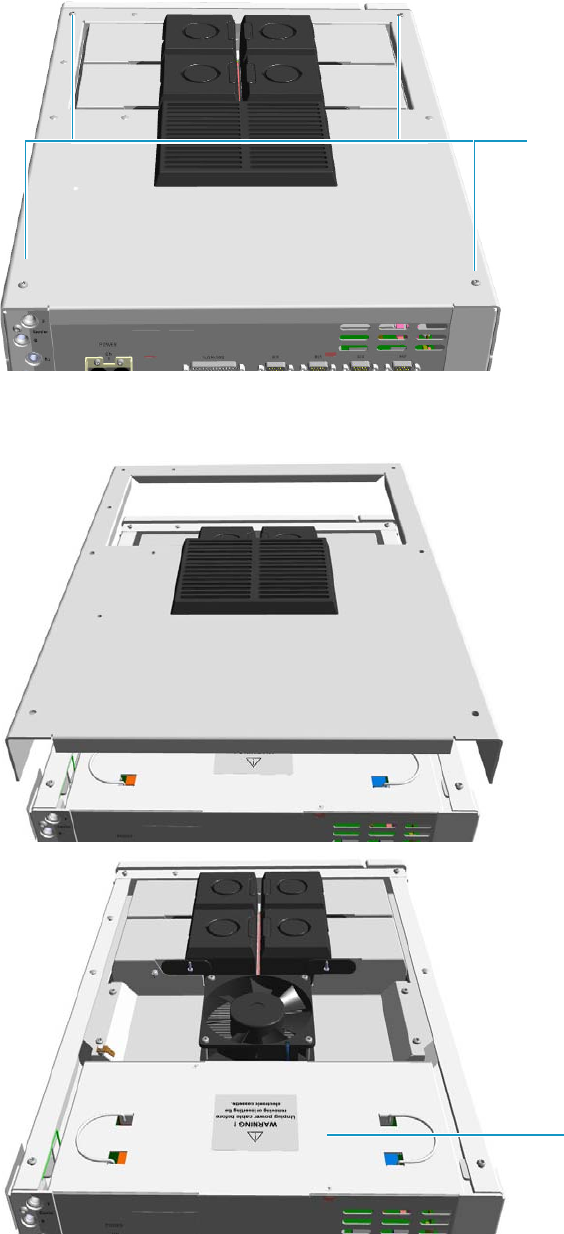
5 GC Main Frame Advanced Maintenance
Removing/Replacing the Electronic Module
Thermo Scientific TRACE 1300 and TRACE 1310 Hardware Manual 209
Figure 196. Top Cover Removal (1)
b. Slide the top panel toward the back of the instrument and lift it off. See Figure 197.
Figure 197. Top Cover Removal (2)
Top Cover Fixing Screws
Electronic Module
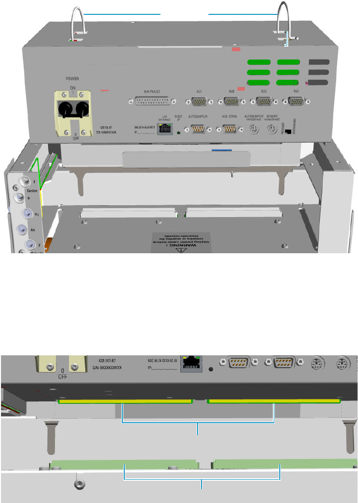
5 GC Main Frame Advanced Maintenance
Removing/Replacing the Electronic Module
210 TRACE 1300 and TRACE 1310 Hardware Manual Thermo Scientific
8. Remove the Electronic Module.
a. Using the two handles on the top cover, pull out module from its housing.
See Figure 198.
Figure 198. Electronic Module Extraction
9. Replace the Electronic Module.
a. Guide the electronic module into its housing.
b. Push down the module. Be sure to plug the terminal contacts of the mother board
into the two slots of the backplane board. See Figure 199 and Figure 200.
Figure 199. Electronic Module Replacement (1)
Handles
Electronic Module Housing
Mother Board Connectors
Backplane Board Connectors
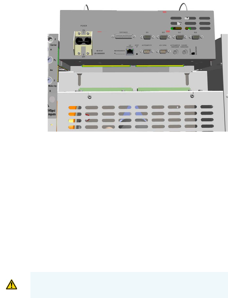
5 GC Main Frame Advanced Maintenance
Replacing the Oven Heater Baffle
Thermo Scientific TRACE 1300 and TRACE 1310 Hardware Manual 211
Figure 200. Electronic Module Replacement (2)
10. Reinstall and fix the top cover of the GC.
11. Reinstall the autosampler if present.
12. Plug the cables connected to the external interface of the Electronic Module.
13. If external modules are present, plug the power cable to the AC Input connector of each
external module, and to the wall outlet.
14. Power on the GC.
a. Plug the power cable to the AC Input connector into the back of the GC and to the
wall outlet.
b. Flip up the power switch (breaker) to the position I.
15. Set the normal injector, detector, and GC working conditions.
Replacing the Oven Heater Baffle
Removing the oven heater requires replacing the complete oven heater baffle. This includes
the plate, heaters, and temperature sensor.
WARNING This operation must be carried out by authorized and trained Thermo Fisher
Scientific Service Field Engineers.
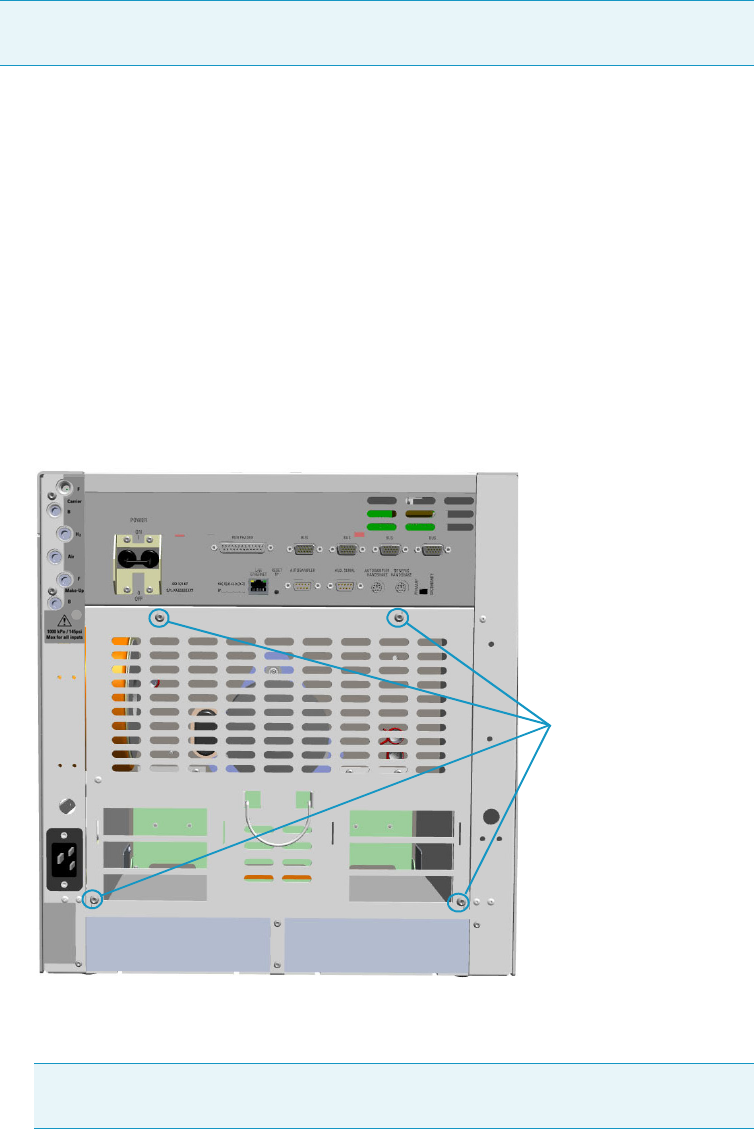
5 GC Main Frame Advanced Maintenance
Replacing the Oven Heater Baffle
212 TRACE 1300 and TRACE 1310 Hardware Manual Thermo Scientific
To replace the oven heater baffle
1. Put the GC in standby condition.
2. Cool the oven, injectors and detectors to room temperature.
3. Power off the GC.
a. Push down the power switch (breaker), located at the back of the instrument, to the
position O.
b. Unplug the power cable from the AC Input connector into the back of the GC and
from the wall outlet.
4. If external modules are present, unplug the power cable from the AC Input connector of
each external module, and from the wall outlet.
5. Remove the back cover.
a. Using a T20 Torxhead screwdriver, remove the four screws that secure the back cover
to the GC. See Figure 201.
Figure 201. Back Cover Removal
b. Lift the cover off using the cover handle. Be aware that the ground wire is attached to
the back panel.
Note By pressing the Maintenance button, the GC cool down is automatically
carried out.
Note Pay attention to the positioning of the ground wire plug, so it can be
reconnected in the same way it was removed.
Back Cover Fixing Screws
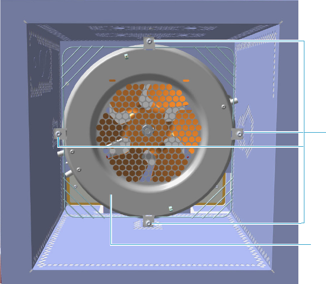
5 GC Main Frame Advanced Maintenance
Replacing the Oven Heater Baffle
Thermo Scientific TRACE 1300 and TRACE 1310 Hardware Manual 213
6. Remove the analytical column.
a. Open the front door of the GC.
b. Loosen the retaining nut from the injector and detector fitting on the upper interior
wall of the GC oven.
c. Remove the analytical column with its nut and ferrule from the bottom of the
injector and the detector.
7. Remove the oven heater baffle.
The oven heater baffle is attached to the oven wall by four adjustable tabs. These tabs are
attached to the oven heater baffle with four Torx screws. See Figure 202.
Figure 202. Oven Heater Baffle
The heater and temperature sensor wires are connected to the backplane board passing
through the three pipes provided on the oven back wall.
• The temperature sensor wire is plugged into the connector marked J4 (Oven PT100)
• The heater wires are plugged into the connector J23, J24, and J25 (Oven Heater).
The pipes are plugged by insulation material. See Figure 203.
Torx Screws
Oven Heater
Baffle
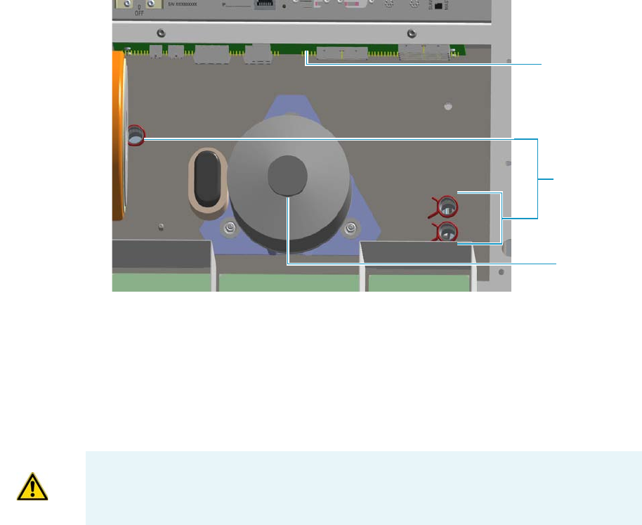
5 GC Main Frame Advanced Maintenance
Replacing the Oven Heater Baffle
214 TRACE 1300 and TRACE 1310 Hardware Manual Thermo Scientific
Figure 203. Pipes
a. Unplug the heater and temperature sensor wires from the relevant connector on the
backplane board.
b. Loosen and remove the four Torx screws that secure the tabs to the oven heater baffle.
See Figure 202.
8. Pull out the oven heater baffle from the oven, paying attention to guide the heater and
temperature sensor wires through the three pipes on the back oven wall.
9. Replace the oven heater baffle in the reverse order in which it was removed.
a. Guide the heater and temperature sensor wires through the pipes provided on the
oven back wall.
b. Reconnect the temperature sensor and heater wires to the relevant connector J4, J23,
J24, and J25 on the backplane board.
c. Plug the pipes with the insulation material.
d. Secure the oven heater baffle to the oven wall with the four Torx screws in the tabs.
The tab adjustment screws should be loose. Carefully center the oven heater baffle
inside of the oven. Be sure that the center hole in the oven heater baffle screen is
centered over the blower motor shaft. The tolerance is very small.
The oven heater baffle will not move left or right, nor up or down more than a couple
of millimeters. However, be sure that it is centered in the oven over the blower wheel.
This will ensure that whenever the GC is turned on, the blower wheel will not be
touching the heater element mounted to the oven heater baffle.
Pipes
Oven Motor
Backplane Board
IMPORTANT During this operation, parts of the insulation material drops down into the
oven. This material is reused later when a new Oven Heater Baffle is installed.

5 GC Main Frame Advanced Maintenance
Replacing the Oven Heater Temperature Sensor
Thermo Scientific TRACE 1300 and TRACE 1310 Hardware Manual 215
10. Reinstall the back cover.
a. Reconnect the ground wire to the back cover terminal.
b. Replace the cover proceeding in the reverse order in which it was removed.
11. If external modules are present, plug the power cable to the AC Input connector of each
external module, and to the wall outlet.
12. Power on the GC.
a. Plug the power cable to the AC Input connector into the back of the GC and to the
wall outlet.
b. Flip up the power switch (breaker) to the position I.
13. Close the front door of the GC. Be sure that the oven blower is running.
a. Verify that the heater heats, and the fan rotates without contacting the heater
element.
14. Open the front door of the GC.
15. Reinstall the column.
16. Set the normal injector, detector and GC working conditions.
Replacing the Oven Heater Temperature Sensor
Removing the oven heater temperature sensor requires removing the complete oven heater
baffle.
To replace the oven heater temperature sensor
1. Put the GC in standby condition.
2. Cool the oven, injectors and detectors to room temperature.
3. Power off the GC.
a. Push down the power switch (breaker), located at the back of the instrument, to the
position O.
b. Unplug the power cable from the AC Input connector into the back of the GC and
from the wall outlet.
WARNING This operation must be carried out by authorized and trained Thermo Fisher
Scientific Service Field Engineers.
Note By pressing the Maintenance button, the GC cool down is automatically
carried out.
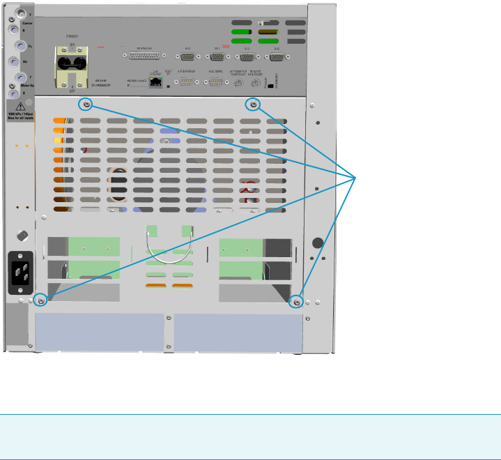
5 GC Main Frame Advanced Maintenance
Replacing the Oven Heater Temperature Sensor
216 TRACE 1300 and TRACE 1310 Hardware Manual Thermo Scientific
c. If external modules are present, unplug the power cable from the AC Input connector
of each external module, and from the wall outlet.
4. Remove the back cover.
a. Using a T20 Torxhead screwdriver remove the four screws that secure the back cover
to the GC. See Figure 204.
Figure 204. Back Cover Removal
b. Lift the cover off using the cover handle. Be aware that the ground wire is attached to
the back panel.
5. Remove the analytical column.
a. Open the front door of the GC.
b. Loosen the retaining nut from the injector and detector fitting on the upper interior
wall of the GC oven.
c. Remove the analytical column with its nut and ferrule from the bottom of the
injector and the detector.
6. Remove the oven heater baffle.
The oven heater baffle is attached to the oven wall by four adjustable tabs. These tabs are
attached to the oven heater baffle with four Torx screws. See Figure 205.
Note Pay attention to the positioning of the ground wire plug, so it can be
reconnected in the same way it was removed.
Back Cover Fixing Screws
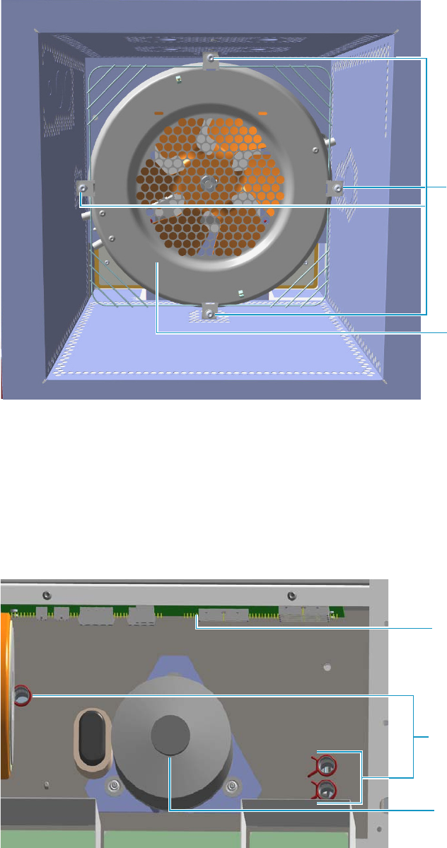
5 GC Main Frame Advanced Maintenance
Replacing the Oven Heater Temperature Sensor
Thermo Scientific TRACE 1300 and TRACE 1310 Hardware Manual 217
Figure 205. Oven Heater Baffle
The heater and temperature sensor wires are connected to the backplane board passing
through the three pipes provided on the oven back wall.
• The temperature sensor wire is plugged into the connector marked J4 (Oven PT100)
• The heater wires are plugged into the connector J23, J24, and J25 (Oven Heater).
The pipes are plugged by insulation material. See Figure 206.
Figure 206. Pipes
Torx Screws
Oven Heater
Baffle
Pipes
Oven Motor
Backplane Board
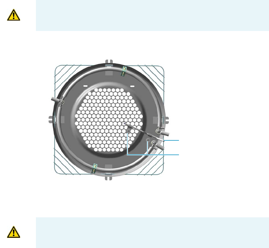
5 GC Main Frame Advanced Maintenance
Replacing the Oven Heater Temperature Sensor
218 TRACE 1300 and TRACE 1310 Hardware Manual Thermo Scientific
a. Unplug the heater and temperature sensor wires from the relevant connector on the
backplane board.
b. Loosen and remove the four Torx screws that secure the tabs to the oven heater baffle.
See Figure 205 on page 217.
c. Place the heater baffle on the roof of the oven.
7. Remove the oven heater temperature sensor. See Figure 207.
Figure 207. Oven Heater Temperature Sensor
a. Loosen the two clamps that attaches the oven heater temperature sensor to the oven
heater baffle.
b. Remove the temperature sensor.
8. Replace the oven heater temperature sensor in the reverse order in which it was removed.
9. Replace the oven heater baffle in the reverse order in which it was removed.
a. Guide the heater and temperature sensor wires through the pipes provided on the
oven back wall.
b. Reconnect the temperature sensor and heater wires to the relevant connector J4, J23,
J24, and J25 on the backplane board.
IMPORTANT During this operation, parts of the insulation material drops down into the
oven. This material is reused later when a new Oven Heater Baffle is installed.
Clamps
Temperature Sensor
WARNING Pay attention to not damage the sensitive element.

5 GC Main Frame Advanced Maintenance
Replacing the Oven Motor
Thermo Scientific TRACE 1300 and TRACE 1310 Hardware Manual 219
c. Plug the pipes with the insulation material.
d. Secure the oven heater baffle to the oven wall with the four Torx screws in the tabs.
The tab adjustment screws should be loose. Carefully center the oven heater baffle
inside of the oven. Be sure that the center hole in the oven heater baffle screen is
centered over the blower motor shaft. The tolerance is very small. The oven heater
baffle will not move left or right, nor up or down more than a couple of millimeters.
However, be sure that it is centered in the oven over the blower wheel. This will
ensure that whenever the GC is turned on, the blower wheel will not be touching the
heater element mounted to the oven heater baffle.
10. Reinstall the back cover.
a. Reconnect the ground wire to the back cover terminal.
b. Replace the cover proceeding in the reverse order in which it was removed.
11. If external modules are present, plug the power cable to the AC Input connector of each
external module, and to the wall outlet.
12. Power on the GC.
a. Plug the power cable to the AC Input connector into the back of the GC and to the
wall outlet.
b. Flip up the power switch (breaker) to the position I.
13. Close the front door of the GC. Be sure that the oven blower is running.
a. Verify that the heater heats, and the fan rotates without contacting the heater
element.
14. Open the front door of the GC.
15. Reinstall the column.
16. Set the normal detector and GC working conditions.
Replacing the Oven Motor
Removing the oven motor requires the removal of several parts and assemblies.
To replace the oven motor
1. Put the GC in standby condition.
2. Cool the oven, injectors and detectors to room temperature.
WARNING This operation must be carried out by authorized and trained Thermo Fisher
Scientific Service Field Engineers.
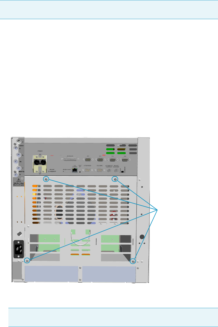
5 GC Main Frame Advanced Maintenance
Replacing the Oven Motor
220 TRACE 1300 and TRACE 1310 Hardware Manual Thermo Scientific
3. Power off the GC.
a. Push down the power switch (breaker), located at the back of the instrument, to the
position O.
b. Unplug the power cable from the AC Input connector into the back of the GC and
from the wall outlet.
4. If external modules are present, unplug the power cable from the AC Input connector of
each external module, and from the wall outlet.
5. Remove the back cover.
a. Using a T20 Torxhead screwdriver remove the four screws that secure the back cover
to the GC. See Figure 208.
Figure 208. Back Cover Removal
b. Lift the cover off using the cover handle. Be aware that the ground wire is attached to
the back panel.
6. Remove the analytical column.
a. Open the front door of the GC.
Note By pressing the Maintenance button, the GC cool down is automatically
carried out.
Note Pay attention to the positioning of the ground wire plug, so it can be
reconnected in the same way it was removed.
Back Cover Fixing Screws
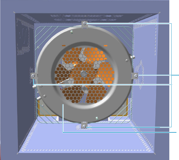
5 GC Main Frame Advanced Maintenance
Replacing the Oven Motor
Thermo Scientific TRACE 1300 and TRACE 1310 Hardware Manual 221
b. Loosen the retaining nut from the injector and detector fitting on the upper interior
wall of the GC oven.
c. Remove the analytical column with its nut and ferrule from the bottom of the
injector and the detector.
7. Remove the oven heater baffle.
The oven heater baffle is attached to the oven wall by four adjustable tabs. These tabs are
attached to the oven heater baffle with four Torx screws. See Figure 209.
Figure 209. Oven Heater Baffle
The heater and temperature sensor wires are connected to the backplane board passing
through the three pipes provided on the oven back wall.
• The temperature sensor wire is plugged into the connector marked J4 (Oven PT100)
• The heater wires are plugged into the connector J23, J24, and J25 (Oven Heater).
The pipes are plugged by insulation material. See Figure 210.
Torx Screws
Oven Heater
Baffle
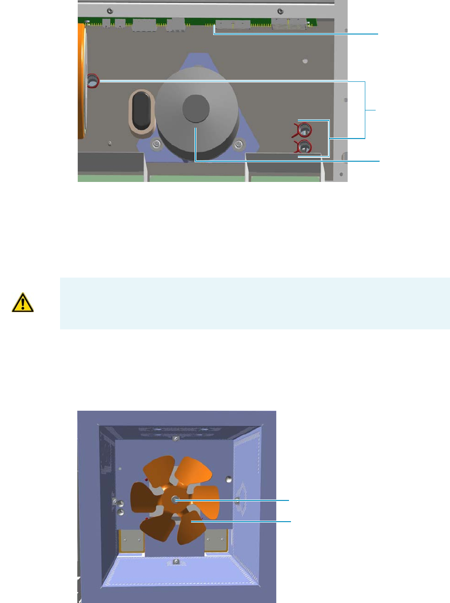
5 GC Main Frame Advanced Maintenance
Replacing the Oven Motor
222 TRACE 1300 and TRACE 1310 Hardware Manual Thermo Scientific
Figure 210. Pipes
a. Unplug the heater and temperature sensor wires from the relevant connector on the
backplane board.
b. Loosen and remove the four Torx screws that secure the tabs to the oven heater baffle.
See Figure 209 on page 221.
c. Place the heater baffle on the roof of the oven.
8. Remove the blower fan.
The oven blower fan is attached to the shaft of the oven blower motor with an Allen
screw. See Figure 211.
Figure 211. Oven Blower Fan
Pipes
Oven Motor
Backplane Board
IMPORTANT During this operation, parts of the insulation material drops down into the
oven. This material is reused later when a new Oven Heater Baffle is installed.
Oven Blower Fan
Set Screw
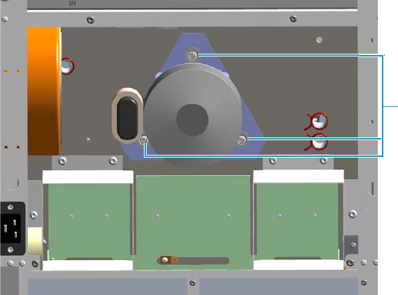
5 GC Main Frame Advanced Maintenance
Replacing the Oven Motor
Thermo Scientific TRACE 1300 and TRACE 1310 Hardware Manual 223
a. Loosen the Allen screw. Carefully remove the oven fan from the blower motor shaft.
9. Remove the blower motor.
a. The blower motor plugs into the connector marked J7 (Motor fan) on the Backplane
board. Unplug the blower motor electrical plug by pushing down on the plug tab and
pulling out.
b. The ground strap from the motor is secured to chassis ground on a terminal just
below the starting capacitor. Locate this terminal.
c. Remove the terminal nut using a 4-mm nut driver; or, unplug the connector. Remove
the ground wire.
d. The blower motor is secured to the back of the oven wall with three #4 self-locking
nuts. Remove these nuts using the same 4-mm nut driver. See Figure 212.
Figure 212. Removal the Oven Blower Motor
e. Locate and note the orientation of the six shoulder washers on each side of the three
grommets, before removing the blower motor.
f. Locate the three flat washers between the locking nut and the shoulder washers.
Remove and retain these washers for reassembly.
g. Remove the blower motor from the oven by pulling outward.
10. Assemble the oven motor
The replacement blower motor contains the mounting brackets with the three grommets
in place. The existing blower motor will have a total of six shoulder washers.
Three shoulder washers are installed on each side of the grommets.
a. Remove the all of the shoulder washers from the old blower motor.
b. Place three of the shoulder washers over the mounting studs located on the back oven
wall.
Self Locking Nuts
5 GC Main Frame Advanced Maintenance
Replacing the Oven Motor
224 TRACE 1300 and TRACE 1310 Hardware Manual Thermo Scientific
c. Install the motor on the studs.
d. Place the remaining three shoulder washers over the studs, mating them with the
grommets and the blower motor mounting bracket.
e. Place the three flat washers over the studs and against the shoulder washers.
f. Carefully screw the locking nuts back onto the studs, after all of the washers are in
place.
g. Tighten the locking nuts until the grommets are flat. Loosen each locking nut by one
complete turn.
h. Attach the ground wire to the grounding terminal on the back oven wall. Secure it
with the locking nut.
i. Connect the blower motor electrical plug to J7.
11. Reassemble the remaining components on the back of the GC in the reverse order in
which they were removed.
12. Reinstall the blower fan onto the shaft.
a. The fan should be even with the beveled edge on the motor shaft. The motor shaft
should not extend more than 3 mm beyond the blower fan.
b. Secure the fan to the motor shaft using the M4 Allen wrench. Be sure that the
setscrew is in place on the flat side of the blower motor shaft.
13. Replace the oven heater baffle in the reverse order in which it was removed.
a. Guide the heater and temperature sensor wires through the pipes provided on the
oven back wall.
b. Reconnect the temperature sensor and heater wires to the relevant connector J4, J23,
J24, and J25 on the backplane board.
c. Plug the pipes with the insulation material.
d. Secure the oven heater baffle to the oven wall with the four Torx screws in the tabs.
The tab adjustment screws should be loose. Carefully center the oven heater baffle
inside of the oven. Be sure that the center hole in the oven heater baffle screen is
centered over the blower motor shaft. The tolerance is very small. The oven heater
baffle will not move left or right, nor up or down more than a couple of millimeters.
However, be sure that it is centered in the oven over the blower wheel. This will
ensure that whenever the GC is turned on, the blower wheel will not be touching the
heater element mounted to the oven heater baffle.
14. Reinstall the back cover.
a. Reconnect the ground wire to the back cover terminal.
b. Replace the cover proceeding in the reverse order in which it was removed.
15. If external modules are present, plug the power cable to the AC Input connector of each
external module, and to the wall outlet.

5 GC Main Frame Advanced Maintenance
Replacing the Flap Motor
Thermo Scientific TRACE 1300 and TRACE 1310 Hardware Manual 225
16. Power on the GC.
a. Plug the power cable to the AC Input connector into the back of the GC and to the
wall outlet.
b. Flip up the power switch (breaker) to the position I.
17. Close the front door of the GC. Be sure that the oven blower is running.
a. Verify that the heater heats, and the fan rotates without contacting the heater
element.
18. Open the front door of the GC.
19. Reinstall the column.
20. Set the normal injector, detector and GC working conditions.
Replacing the Flap Motor
To replace the oven flap motor, you must remove the complete motor flap and cooling duct
assembly. The flap motor plugs into the motherboard on the GC. Therefore, you must
remove the right side panel of the GC.
To replace the flap motor
1. Put the GC in standby condition.
2. Cool the oven, injectors and detectors to room temperature.
3. Power off the GC.
a. Push down the power switch (breaker), located at the back of the instrument, to the
position O.
b. Unplug the power cable from the AC Input connector into the back of the GC and
from the wall outlet.
4. If external modules are present, unplug the power cable from the AC Input connector of
each external module, and from the wall outlet.
5. Remove the back cover.
a. Using a T20 Torxhead screwdriver, remove the four screws that secure the back cover
to the GC. See Figure 213.
Note By pressing the Maintenance button, the GC cool down is automatically
carried out.

5 GC Main Frame Advanced Maintenance
Replacing the Flap Motor
226 TRACE 1300 and TRACE 1310 Hardware Manual Thermo Scientific
Figure 213. Back Cover Removal
b. Lift the cover off using the cover handle. Be aware that the ground wire is attached to
the back panel.
6. Remove the AI/AS autosampler if present.
7. Remove the right panel.
a. Open the front door of the GC.
b. Using a T20 Torxhead screwdriver remove the screw located on the upper right
corner of the frontal frame.
c. Slide the panel towards the back of the instrument. Tilt the top of the right panel
outwards.
d. Continue to slide the panel towards the back of the GC and lift it off.
8. Remove the cooling duct. See Figure 214.
Note Pay attention to the positioning of the ground wire plug, so it can be
reconnected in the same way it was removed.
Back Cover Fixing Screws
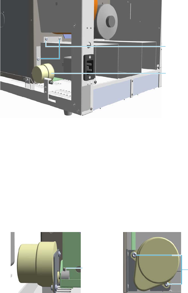
5 GC Main Frame Advanced Maintenance
Replacing the Flap Motor
Thermo Scientific TRACE 1300 and TRACE 1310 Hardware Manual 227
Figure 214. Cooling Duct Removal
a. Locate the three screws that secure the cooling duct to the oven wall. Remove these
screws.
b. Remove the cooling duct from the back of the GC.
9. Remove the flap motor.
a. Disconnect the oven flap motor electrical plug from J10 (Flap Motor) on the
backplane board.
b. Loosen the M4 Allen screw the secure the flap motor shaft to the railing that attaches
to the flaps.
c. Remove the two fixing screws that secure the flap motor to its support plate. See
Figure 215.
Figure 215. Flap Motor Removal (1)
d. Remove the flap motor paying attention to not rotate it.
10. Reinstall the new motor.
11. Align the flat side of the motor shaft with the Allen screw.
12. Reassemble the flap motor and cooling duct assembly in the reverse order in which it was
removed.
Cooling Duct
Fixing Screws
Flap Motor
M4 Allen Screw Fixing Screws
5 GC Main Frame Advanced Maintenance
Replacing the Flap Motor
228 TRACE 1300 and TRACE 1310 Hardware Manual Thermo Scientific
13. Reconnect the power plug to connector J10 on the backplane board.
14. Reinstall the back cover.
a. Reconnect the ground wire to the back cover terminal.
b. Replace the cover proceeding in the reverse order in which it was removed.
15. If external modules are present, plug the power cable to the AC Input connector of each
external module, and to the wall outlet.
16. Power on the GC.
a. Plug the power cable to the AC Input connector into the back of the GC and to the
wall outlet.
b. Flip up the power switch (breaker) to the position I.
17. Set the normal injector, detector and GC working conditions.

Thermo Scientific TRACE 1300 and TRACE 1310 Hardware Manual 229
6
Injectors Advanced Maintenance
This chapter describes TRACE 1300/TRACE 1310 injector modules that do not require
routine maintenance, but troubleshooting may indicate they need to be cleaned or replaced.
Contents
•Baking-out Contaminants from SSL, SSLBKF, HeS-S/SL, PTV, and
PTVBKF Injectors
•Removing/Replacing an Injector Module
•Cleaning the SSL Injector Body
•Cleaning the SSLBKF Injector Body
•Cleaning the HeS-S/SL Injector Body
•Cleaning the PTV Injector Head Assembly
•Cleaning the PTVBKF Injector Head Assembly
6 Injectors Advanced Maintenance
Baking-out Contaminants from SSL, SSLBKF, HeS-S/SL, PTV, and PTVBKF Injectors
230 TRACE 1300 and TRACE 1310 Hardware Manual Thermo Scientific
Baking-out Contaminants from SSL, SSLBKF, HeS-S/SL, PTV, and
PTVBKF Injectors
Perform this operation to bake-out contaminants from SSL, SSLBKF, HeS-S/SL, PTV, and
PTVBKF injectors.
To bake-out contaminants from the injector
1. Put the inlet into Split injection mode.
2. Select Constant Flow mode and enter the normal operating Column flow value.
3. Set Split flow to 200 mL/min.
4. Purge the column with carrier flow for at least 10 minutes before heating the oven.
5. If the column is connected to the detector, set the detector 25 °C above normal operating
temperature. If the column is not attached to the detector, cap the detector fitting.
In case of PDD detector, it is strongly recommended disconnecting the column from the
detector.
6. Set the injector temperature to 300 °C or 25 °C above the normal operating temperature
to bake out contaminants from the injector, mostly through the split vent.
7. Set the oven temperature 25 °C above the GC method final oven temperature to bake
contaminants from the column. Do not exceed the column manufacturer’s maximum
temperature limit.
8. Bake-out for 30 minutes or until the detector baseline is free of contamination peaks.
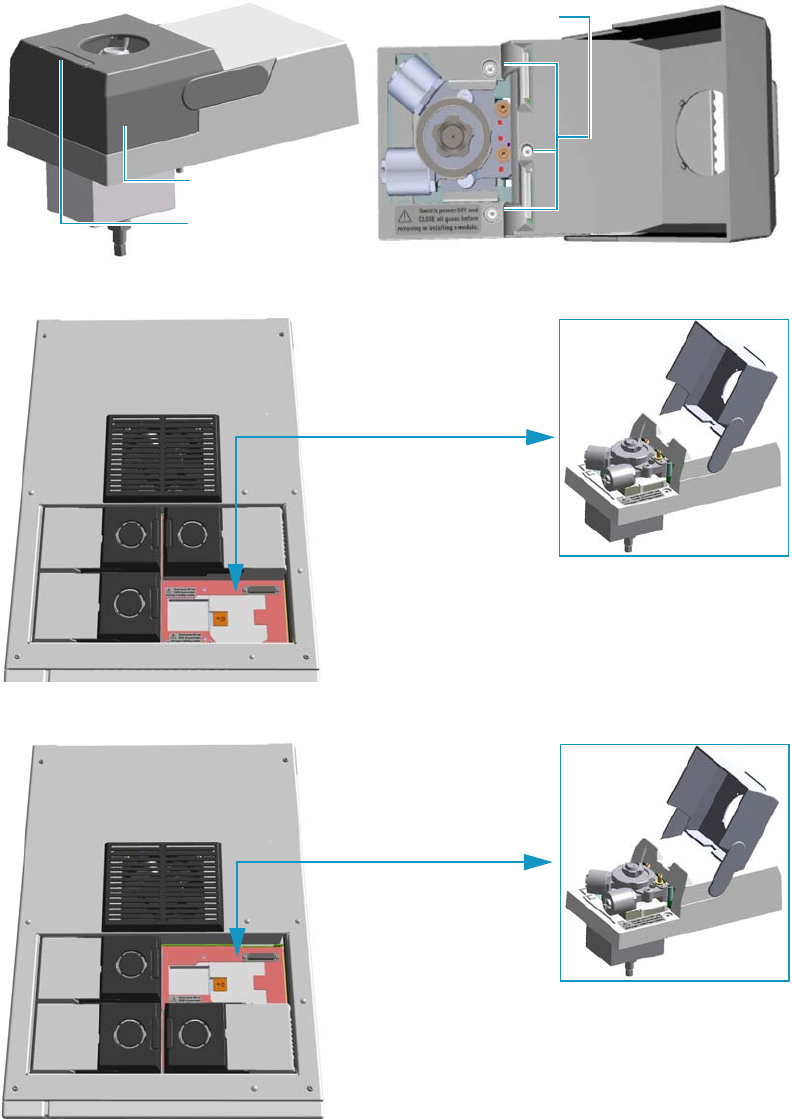
6 Injectors Advanced Maintenance
Removing/Replacing an Injector Module
Thermo Scientific TRACE 1300 and TRACE 1310 Hardware Manual 231
Removing/Replacing an Injector Module
This section provides the instructions for removing/replacing a front/back injector module.
Figure 216. Example of Injector Module
Figure 217. Replacing a Front Injector Module
Figure 218. Replacing a Back Injector Module
Captive Fixing Screws
Module Flap Cover
Lifting Handle
Example of Injector Module
Example of Injector Module
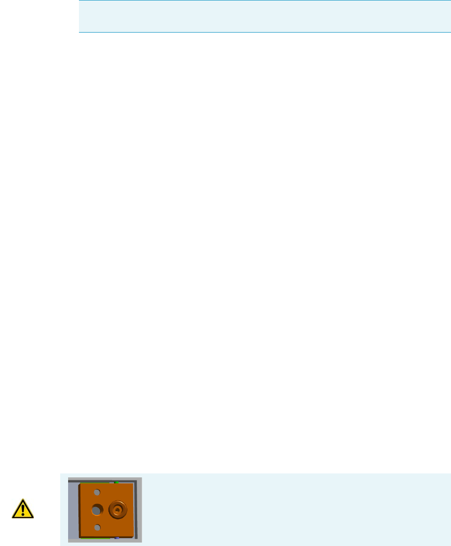
6 Injectors Advanced Maintenance
Removing/Replacing an Injector Module
232 TRACE 1300 and TRACE 1310 Hardware Manual Thermo Scientific
To remove/replace a front/back injector module
1. Put the GC in standby condition.
2. Cool the oven, injectors and detectors to room temperature.
3. Power off the GC.
a. Push down the power switch (breaker), located at the back of the instrument, to the
position O.
b. Unplug the power cable from the AC Input connector on the back of the GC, and
from the wall outlet.
4. If external modules are present, unplug the power cable from the AC Input connector of
each external module, and from the wall outlet.
5. Close the gas supplies.
6. Remove the column end from the injector.
a. Open the front door of the GC.
b. Loosen the retaining nut from the injector fitting on the upper interior wall of the
GC oven.
c. Remove the analytical column with its nut and ferrule from the bottom of the
injector.
7. Put the autosampler away if present.
a. If an AI/AS autosampler is present, move the sampler support to the right.
b. If a TriPlus or a TriPlus RSH autosampler is present, move the turret/head until
enough free space is created around the module.
8. Remove the injector module.
a. Open the module flap cover.
b. Using a T20 Torxhead screwdriver, unscrew the three captive fixing screws.
c. Keeping the module flap cover open, lift up the module from its seat in the injector
housing.
d. Place the module on a clean surface.
Note By pressing the Maintenance button, the GC cool down is automatically
carried out.
WARNING Make sure the o-ring is placed into its seat on the gas
connection plate.
Do not install the module if the o-ring is missing.

6 Injectors Advanced Maintenance
Removing/Replacing an Injector Module
Thermo Scientific TRACE 1300 and TRACE 1310 Hardware Manual 233
9. Replace the injector module.
a. Open the module flap cover.
b. Keeping the module flap cover open, place it in its seat. Be sure to insert the 25-pin
male connector, on the bottom of the module, into the 25-pin female connector on
the injector seat of the injector housing.
c. Use a T20 Torxhead screwdriver to tighten the three captive fixing screws without
overtightening.
d. Close the module flap cover.
e. Keep the plug connected to the bottom.
10. Open the gas supplies.
11. Check the gas supply for leaks.
a. Use a handheld electronic leak detector (Thermo Scientific GLD Pro leak detector or
equivalent) to check each fitting for leaks.
b. If you detect a leak, tighten the connection, and retest it.
c. Repeat this process until all connections are leak free.
12. If external modules are present, plug the power cable to the AC Input connector of each
external module, and to the wall outlet.
13. Power on the GC.
a. Plug the power cable to the AC Input connector on the back of the GC, and to the
wall outlet.
b. Flip up the power switch (breaker) to the position I.
14. Pressurize the module with the carrier gas.
15. Check the module gas connections for leaks.
16. Remove the plug from the bottom.
17. Reconnect the column end to the injector, and verify the connection point.
18. Close the front door of the GC.
19. If present, move the autosampler towards the module to restore the original alignment.
CAUTION To maintain the correct alignment the screws must be tightened in turn.
Tighten each screw only a small amount before moving to the next screw. Repeat until all
are secure.
6 Injectors Advanced Maintenance
Cleaning the SSL Injector Body
234 TRACE 1300 and TRACE 1310 Hardware Manual Thermo Scientific
Cleaning the SSL Injector Body
Perform this operation when a more efficient cleaning of the injector body is desired or
required due to contaminants.
To clean the injector body
1. Put the GC in standby condition.
2. Cool the oven and injector to room temperature.
3. Turn the carrier gas off, and wait for the carrier pressure to go to zero.
4. Put the autosampler away if present.
5. Open the module flap cover.
6. Remove the top parts of the injector. See Figure 219.
a. Unscrew the septum cap of the injector.
b. Unscrew the ring nut.
c. Remove the septum holder/liner cap with septum from the injector body head.
7. Remove the liner. See Figure 219.
a. Use tweezers to remove the liner with the liner seal from the injector.
8. Remove the bottom parts of the injector. See Figure 219.
a. Unscrew the capillary column retaining nut, then remove the analytical column with
its ferrule from the bottom of the injector.
b. Unscrew the retaining nut with the washer and the base seal.
Materials needed
Ultrasonic cleaning bath
Methanol/acetone mixture 1:1
GC-grade methanol
T20 Torxhead screwdriver
Forceps or tweezers
Note By pressing the Maintenance button, the GC cool down is automatically
carried out.
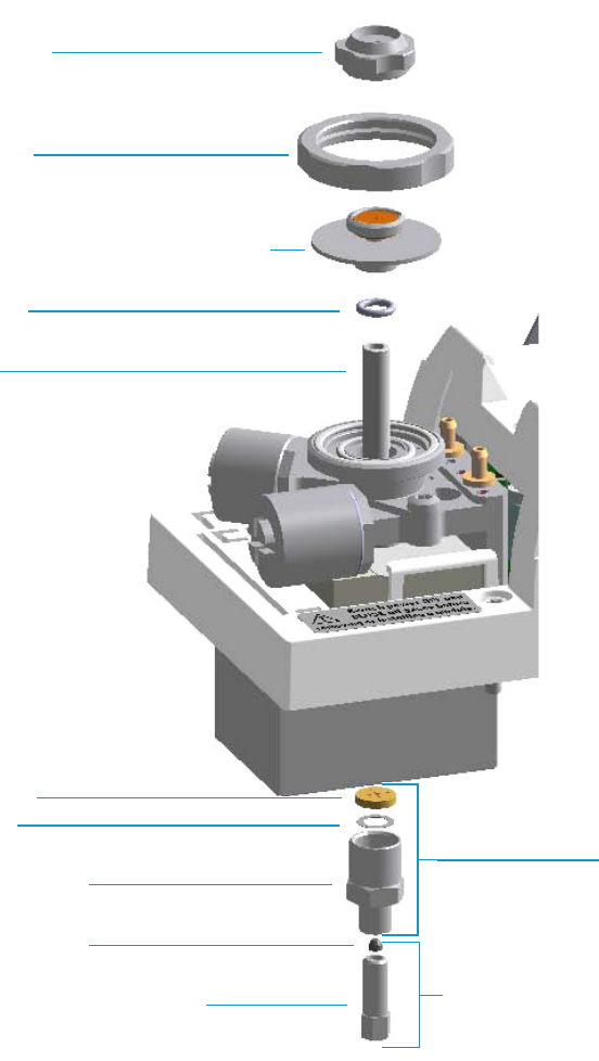
6 Injectors Advanced Maintenance
Cleaning the SSL Injector Body
Thermo Scientific TRACE 1300 and TRACE 1310 Hardware Manual 235
Figure 219. SSL Injector Components
9. Remove the body head o-rings. See Figure 220.
a. Using tweezers, remove both the internal and external body head o-rings.
b. Place and keep all the removed components on a clean surface.
10. Remove the injector body. See Figure 220.
a. Using a T20 Torxhead screwdriver, undo the two injector body fixing screws, and
extract the injector body from its housing.
Septum Cap
Ring Nut
Septum Holder/Liner Cap with Septum
Liner
Liner Seal
Bottom Fittings
Retaining Nut
Washer
Base Seal
Ferrule
Terminal Fitting for Capillary Column
Capillary Column Retaining Nut
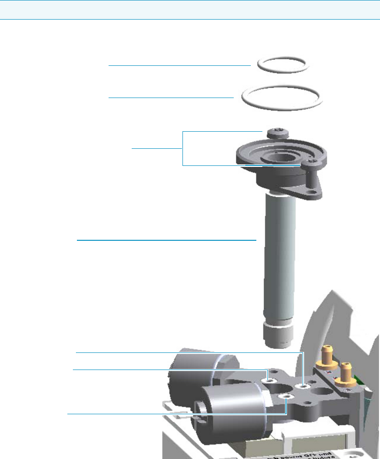
6 Injectors Advanced Maintenance
Cleaning the SSL Injector Body
236 TRACE 1300 and TRACE 1310 Hardware Manual Thermo Scientific
Figure 220. SSL Injector Body Cleaning
11. Clean the injector body.
a. Put the injector body into an ultrasonic cleaner, filled with a methanol/acetone
mixture (1:1).
b. Sonicate the injector body for about half an hour.
c. Using tweezers, remove the injector body from the bath, and dry it with an inert gas.
12. Reinstall the injector body.
a. Reinstall and fix the injector body into its housing by screwing the two fixing screws.
b. Using tweezers, replace both the internal and external body head o-rings.
Note Do not remove the carrier, split and purge lines o-rings.
SSL Injector Body Fixing Screws
SSL Injector Body
Carrier Line O-ring
Split Line O-ring
Purge Line O-ring
Body Head Internal O-ring
Body Head External O-ring

6 Injectors Advanced Maintenance
Cleaning the SSL Injector Body
Thermo Scientific TRACE 1300 and TRACE 1310 Hardware Manual 237
13. Reinstall the bottom parts of the injector.
a. Reinstall the retaining nut with the washer and the base seal.
b. Reinstall the analytical column.
14. Reinstall the liner
a. Using tweezers, place the liner seal over the liner, insert the liner into the injector, and
push it gently towards the bottom of the injector.
15. Reinstall the top parts of the injector.
a. Place the septum holder/liner cap with the septum on the body head of the injector.
Fix them by screwing the ring nut.
b. Screw and tighten the injector cap to finger tight.
16. Close the module flap cover.
17. If present, move the autosampler towards the module to restore the original alignment.
18. Turn the carrier gas on.
19. Set the normal oven and injector working conditions.
CAUTION Do not overtighten the septum cap because you might damage the septum and
affect instrument performance.

6 Injectors Advanced Maintenance
Cleaning the SSLBKF Injector Body
238 TRACE 1300 and TRACE 1310 Hardware Manual Thermo Scientific
Cleaning the SSLBKF Injector Body
Perform this operation when a more efficient cleaning of the injector body is desired or
required, due to contaminants.
To clean the injector body
1. Put the GC in standby condition.
2. Cool the oven and injector to room temperature.
3. Turn the carrier gas off, and wait for the carrier pressure to go to zero.
4. Put the autosampler away if present.
5. Open the module flap cover.
6. Remove the top parts of the injector. See Figure 221.
a. Unscrew the septum cap of the injector.
b. Unscrew the ring nut.
c. Remove the septum holder/liner cap with septum from the injector body head.
7. Remove the liner. See Figure 221.
a. Use tweezers to remove the liner with the liner seal from the injector.
8. Remove the bottom parts of the injector. See Figure 221.
a. Unscrew the capillary column retaining nut, then remove the analytical column with
its ferrule from the bottom of the injector.
b. Unscrew the retaining nut with the washer and the base seal.
Materials needed
Ultrasonic cleaning bath
Methanol/acetone mixture 1:1
GC-grade methanol
1/8-inch -wrench
T20 Torxhead screwdriver
Forceps or tweezers
Note By pressing the Maintenance button, the GC cool down is automatically
carried out.
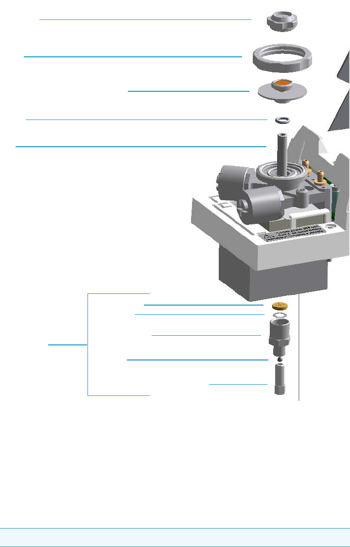
6 Injectors Advanced Maintenance
Cleaning the SSLBKF Injector Body
Thermo Scientific TRACE 1300 and TRACE 1310 Hardware Manual 239
Figure 221. SSLBKF Injector Components
9. Remove the body head o-rings. See Figure 222.
a. Using tweezers, remove both internal and external body head o-rings.
b. Place and keep all the removed components on a clean surface.
10. Remove the injector body. See Figure 222.
a. Using a T20 Torxhead screwdriver, undo the two injector body fixing screws, and
extract the injector body from its housing.
Note Do not remove the carrier, split, and purge lines’ o-rings.
Liner
Liner Seal
Retaining Nut
Washer
Base Seal
Ferrule
Septum Cap
Ring Nut
Septum Holder/Liner Cap with Septum
Capillary Column Retaining Nut
Bottom Fittings
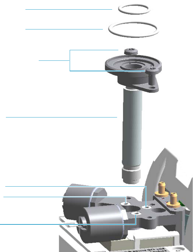
6 Injectors Advanced Maintenance
Cleaning the SSLBKF Injector Body
240 TRACE 1300 and TRACE 1310 Hardware Manual Thermo Scientific
Figure 222. SSLBKF Injector Body Cleaning
11. Clean the injector body.
a. Put the injector body into an ultrasonic cleaner filled with a methanol/acetone
mixture (1:1).
b. Sonicate the injector body for about half an hour.
c. Using tweezers, remove the injector body from the bath, and dry it with an inert gas.
12. Reinstall the injector body.
a. Reinstall and fix the injector body into its housing by screwing the two fixing screws.
b. Using tweezers, replace both the internal and external body head o-rings.
13. Reinstall the bottom parts of the injector.
a. Reinstall the retaining nut with the washer and the base seal.
SSL Injector Body Fixing Screws
SSL Injector Body
Carrier Line O-ring
Split Line O-ring
Purge Line O-ring
Body Head Internal O-ring
Body Head External O-ring

6 Injectors Advanced Maintenance
Cleaning the SSLBKF Injector Body
Thermo Scientific TRACE 1300 and TRACE 1310 Hardware Manual 241
b. Reinstall the analytical column.
14. Reinstall the liner
a. Place the liner seal over the liner, then, Using tweezers, insert the liner into the
injector and push it gently towards the bottom of the injector.
15. Reinstall the top parts of the injector.
a. Place the septum holder/liner cap with the septum on the body head of the injector.
Fix them by screwing the ring nut.
b. Screw and tighten the injector cap to fingertight.
16. Close the module flap cover.
17. If present, move the autosampler towards the module to restore the original alignment.
18. Turn the carrier gas on.
19. Set the normal oven and injector working conditions.
CAUTION Do not overtighten the septum cap because you might damage the septum and
affect instrument performance.

6 Injectors Advanced Maintenance
Cleaning the HeS-S/SL Injector Body
242 TRACE 1300 and TRACE 1310 Hardware Manual Thermo Scientific
Cleaning the HeS-S/SL Injector Body
Over time, contamination of the Instant Connect Helium Saver Injector Module will occur
due to the deposition of cored septum particles or other material not captured by the glass
wool of the injection port liner. In this case, the injector insert should be removed and cleaned
according to the following procedure.
To clean the Instant Connect Helium Saver Injector Module injector body
1. Put the GC in standby condition.
2. Cool the GC oven, injector, transfer line, and ion source.
3. Vent the mass spectrometer and set the inlet flow rate (nitrogen) to Off. Keep the helium
enabled and pressurized as usual.
4. Put the autosampler away if present.
5. Open the module flap covers.
6. Remove the top parts of the injector. See Figure 223.
a. Unscrew the septum cap of the injector.
b. Unscrew the ring nut.
c. Remove the septum holder/liner cap with septum from the injector body head.
7. Remove the liner. See Figure 223.
a. Use tweezers to remove the liner with the liner seal from the injector.
8. Remove the analytical column.
a. Unscrew the capillary column retaining nut, then remove the analytical column with
its ferrule from the bottom of the injector.
Materials needed
Ultrasonic cleaning bath
Methanol/acetone mixture 1:1
GC-grade methanol
Methylene chloride
Hexane
T20 Torxhead screwdriver
Forceps or tweezers
Note By pressing the Maintenance button, the GC cool down is automatically
carried out.
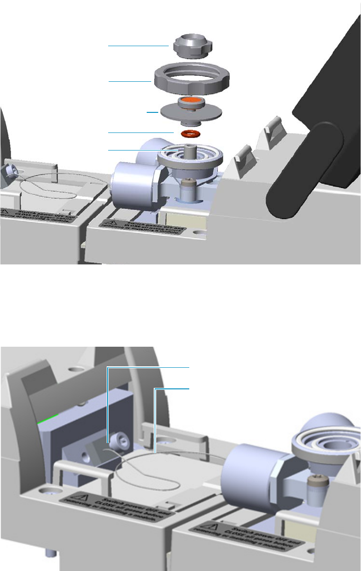
6 Injectors Advanced Maintenance
Cleaning the HeS-S/SL Injector Body
Thermo Scientific TRACE 1300 and TRACE 1310 Hardware Manual 243
Figure 223. Instant Connect Helium Saver Injector Module: Cleaning the Injector Body (1)
9. Disconnect the helium transfer tube See Figure 224.
a. Loosen the captive screw of the helium transfer tube and remove the tube from the
gas delivery block.
Figure 224. Instant Connect Helium Saver Injector Module: Cleaning the Injector Body (2)
10. Remove the body head o-rings. See Figure 225.
a. Using tweezers, remove both the internal and external body head o-rings.
Septum Holder/Liner Cap with Septum
Liner Seal
Ring Nut
Liner
Septum Cap
Helium Transfer Tube
Gas Delivery Block
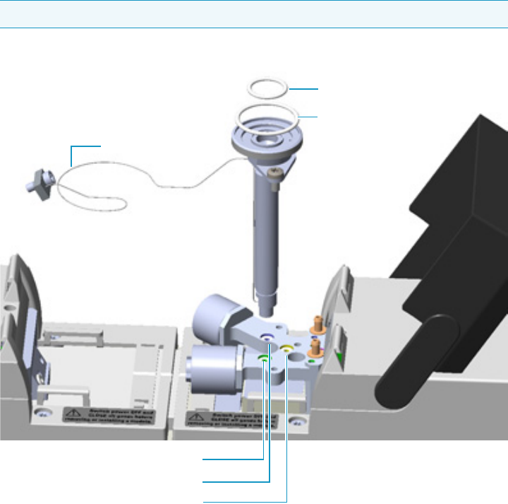
6 Injectors Advanced Maintenance
Cleaning the HeS-S/SL Injector Body
244 TRACE 1300 and TRACE 1310 Hardware Manual Thermo Scientific
b. Place and keep all the removed components on a clean surface.
11. Remove the injector body. See Figure 225.
a. Using a T20 Torxhead screwdriver, undo the two injector body fixing screws, and
extract the injector body from its housing.
Figure 225. Instant Connect Helium Saver Injector Module: Cleaning the Injector Body (3)
12. Clean the injector body.
a. Ultrasonically clean the injector insert using a warm 1% Liquinox™ solution (or
equivalent).
b. Thoroughly rinse the insert then ultrasonically clean in chromatographic grade
methanol or acetone followed by solvents of lower polarity such as methylene
chloride and hexane. Limit ultra-sonication to 5 min in each solvent.
c. Blow dry the insert using high purity gas (do not use compressed house air as it
contains residual oils from the compressor) then assemble in the reverse order of
removal.
Note Do not remove the carrier, split and purge lines o-rings.
Body Head Internal O-ring
Body Head External O-ring
Helium Saver SSL Injector Body
Helium Transfer Tube
Carrier Line O-ring
Split Line O-ring
Purge Line O-ring

6 Injectors Advanced Maintenance
Cleaning the HeS-S/SL Injector Body
Thermo Scientific TRACE 1300 and TRACE 1310 Hardware Manual 245
13. Reinstall the injector body.
a. Reinstall and fix the injector body into its housing by screwing the two fixing screws.
b. Using tweezers, replace both the internal and external body head o-rings.
14. Reconnect the additional helium carrier gas line mating block.
15. Reinstall the liner.
a. Using tweezers, place the liner seal over the liner, insert the liner into the injector, and
push it gently towards the bottom of the injector.
16. Reinstall the analytical column. Refer to the TRACE 1300/1310 GC Hardware Manual.
17. Reinstall the top parts of the injector.
a. Place the septum holder/liner cap with the septum on the body head of the injector.
Fix them by screwing the ring nut.
b. Screw and tighten the injector cap to finger tight.
18. Close the module flap covers.
19. If present, move the autosampler towards the module to restore the original alignment.
20. Wait two or three minutes for helium to purge the inlet.
21. Turn the inlet flow back on and enable the inlet heater.
22. Set the normal injector, detector, and GC working conditions.
Note Do not use abrasives, cleaning wires, or brushes on the inlet insert as these will
damage the passivation treatment layers. Be especially careful not to bend the short
segment of tubing at the base of the insert interior. Nothing should be inserted into
the bore of the insert other than glass liners.
CAUTION Do not overtighten the septum cap because you might damage the septum and
affect instrument performance.
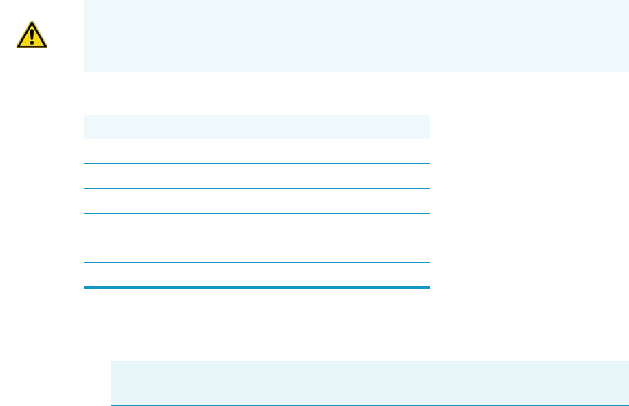
6 Injectors Advanced Maintenance
Cleaning the PTV Injector Head Assembly
246 TRACE 1300 and TRACE 1310 Hardware Manual Thermo Scientific
Cleaning the PTV Injector Head Assembly
Perform this operation when cleaning the injector head assembly is desired or required, due to
contaminants.
To clean the injector head assembly
1. Put the GC in standby condition.
2. Cool the oven, injectors, and detectors to room temperature.
3. Power off the GC.
a. Pull down on the power switch (breaker), located at the back of the instrument, to
the position O.
b. Unplug the power cable from the AC Input connector on the back of the GC, and
from the wall outlet.
4. If external modules are present, unplug the power cable from the AC Input connector of
each external module, and from the wall outlet.
5. Close the gas supplies.
6. Put the autosampler away if present.
7. Remove the top parts of the injector. See Figure 226.
a. Unscrew the septum cap of the injector.
b. Using tweezers, remove the septum from the top of the injector head assembly.
8. Remove the liner. See Figure 226.
a. Using the slotted stubby driver provided, unscrew and remove the liner cap.
WARNING This operation must be carried out by authorized and trained Thermo Fisher
Scientific Service Field Engineers.
Materials needed
Ultrasonic cleaning bath
GC-grade Methanol/acetone mixture 1:1
1/8-inch -wrench
5.5 x 25 mm Slotted Stubby Driver
T10 Torxhead screwdriver
Forceps or tweezers
Note By pressing the Maintenance button, the GC cool down is automatically
carried out.
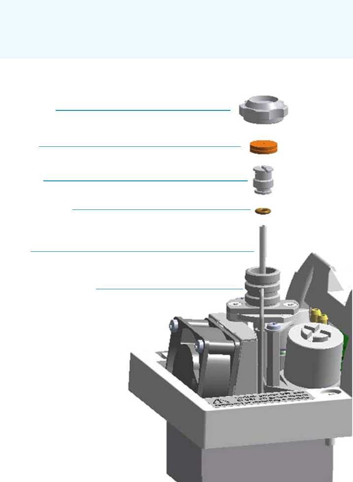
6 Injectors Advanced Maintenance
Cleaning the PTV Injector Head Assembly
Thermo Scientific TRACE 1300 and TRACE 1310 Hardware Manual 247
b. Use tweezers to remove the liner with the liner seal (o-ring) from the injector.
Figure 226. PTV Top Parts and Liner Removal
9. Remove the fan assembly.
The fan is fixed on a support. Do not remove the fan from its support but remove the
assembly proceeding as follows:
a. Using tweezers and a T10 Torxhead screwdriver, unscrew the left fixing screw of the
support, then unscrew the right fixing screw. See Figure 227.
CAUTION Be careful not to break the glass liner when removing it. Glass
splinters might fall into the lower part of the vaporization chamber. If the glass
liner breaks, follow the instructions for “Replacing the PTV Broken Liner” on
page 123.
Septum Cap
Septum
Liner Cap
Liner Seal (O-ring)
Liner
Injector Head Assembly
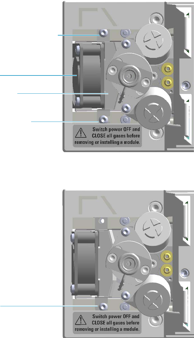
6 Injectors Advanced Maintenance
Cleaning the PTV Injector Head Assembly
248 TRACE 1300 and TRACE 1310 Hardware Manual Thermo Scientific
Figure 227. PTV Module: Fan Assembly
b. Carefully turn the fan assembly slightly to access the slot on the right base of the
support from the right fixing screw. See Figure 228.
Figure 228. PTV Module: Fan Assembly Removal (1)
c. Carefully extract the fan assembly from its seat, and place it sideways to the module.
Be sure to not damage the two wires. See Figure 229.
Unscrew and remove this screw
Fan Support
Loosen this screw
Fan
Slot
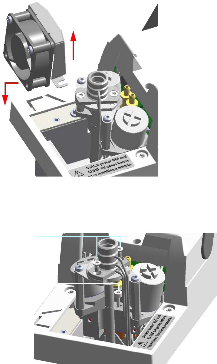
6 Injectors Advanced Maintenance
Cleaning the PTV Injector Head Assembly
Thermo Scientific TRACE 1300 and TRACE 1310 Hardware Manual 249
Figure 229. PTV Module: Fan Assembly Removal (2)
10. Remove the injector head.
a. Using the T10 Torxhead screwdriver, unscrew the two fixing screws, and the captive
screw that respectively fix the top and the bottom of the injector head assembly. See
Figure 230.
Figure 230. PTV Injector Head Assembly
Top Injector
Head Assembly
Fixing Screws
Bottom Injector
Head Assembly
Captive Screw
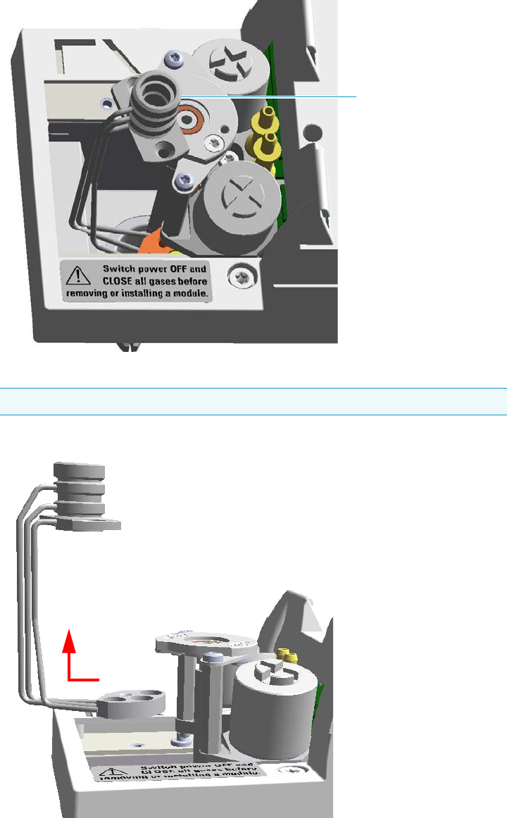
6 Injectors Advanced Maintenance
Cleaning the PTV Injector Head Assembly
250 TRACE 1300 and TRACE 1310 Hardware Manual Thermo Scientific
b. Holding the top of the injector head assembly with your thumb, index, and middle
fingers, turn the assembly clockwise. See Figure 231.
Figure 231. PTV Injector Head Assembly Removal (1)
c. Extract the assembly sideways from its housing. See Figure 232.
Figure 232. PTV Injector Head Assembly Removal (2)
Note Do not remove the carrier, split, and purge lines’ o-rings on the plate.
Injector Head Assembly

6 Injectors Advanced Maintenance
Cleaning the PTV Injector Head Assembly
Thermo Scientific TRACE 1300 and TRACE 1310 Hardware Manual 251
11. Clean the injector head.
a. Put the injector head assembly into an ultrasonic cleaner filled with a
methanol/acetone mixture (1:1).
b. Sonicate the injector head assembly for about half an hour.
c. Using tweezers, remove the injector head assembly from the bath, and dry it with
compressed clean air.
12. Reinstall the injector head.
a. Carefully reinstall the injector head assembly into its housing proceeding in the
reverse order in which it was removed.
b. Screw the two fixing screws and the captive screw fixing the top and the bottom of
the injector head assembly respectively.
13. Remount the fan assembly.
a. Carefully reinsert the fan assembly in its seat into the module.
b. Move the assembly for inserting the slot on the right base of the support slightly
under the head of the right fixing screw, and for aligning the hole on the left base
with the corresponding fixing hole.
c. Using tweezers, reinsert the left fixing screw previously removed.
d. Using a T10 Torxhead screwdriver tighten both the left and right fixing screws.
14. Reinsert the liner.
a. Place the liner seal over the liner.
b. Using tweezers, insert the liner into the injector, and push it gently towards the
bottom of the injector.
c. Reinsert and screw the liner cap using the slotted stubby driver.
15. Reinstall the upper parts of the injector.
a. Place the septum into the injector head assembly.
b. Screw and tighten the septum cap to fingertight.
16. Close the module flap cover.
17. If present, move the autosampler towards the module to restore the original alignment.
CAUTION We suggest replacing the septum with a new one.
CAUTION Do not overtighten the septum cap because you might damage the septum and
affect instrument performance.
6 Injectors Advanced Maintenance
Cleaning the PTV Injector Head Assembly
252 TRACE 1300 and TRACE 1310 Hardware Manual Thermo Scientific
18. Open the gas supplies.
19. If external modules are present, plug the power cable to the AC Input connector of each
external module, and to the wall outlet.
20. Power on the GC.
a. Plug the power cable to the AC Input connector into the back of the GC and to the
wall outlet.
b. Flip up the power switch (breaker) to the position I.
21. Set the normal oven, injectors, and detectors working conditions.

6 Injectors Advanced Maintenance
Cleaning the PTVBKF Injector Head Assembly
Thermo Scientific TRACE 1300 and TRACE 1310 Hardware Manual 253
Cleaning the PTVBKF Injector Head Assembly
Perform this operation when cleaning the injector head assembly is desired or required, due to
contaminants.
To clean the injector head assembly
1. Put the GC in standby condition.
2. Cool the oven, injectors, and detectors to room temperature.
3. Power off the GC.
a. Push down the power switch (breaker), located at the back of the instrument, to the
position O.
b. Unplug the power cable from the AC Input connector into the back of the GC and
from the wall outlet.
4. If external modules are present, unplug the power cable from the AC Input connector of
each external module, and from the wall outlet.
5. Close the gas supplies.
6. Put the autosampler away if present.
7. Open the module flap cover.
8. Remove the top parts of the injector. See Figure 233.
a. Unscrew the septum cap of the injector.
b. Using tweezers, remove the septum from the top of the injector head assembly.
9. Remove the liner. See Figure 233.
WARNING This operation must be carried out by authorized and trained Thermo Fisher
Scientific Field Service Engineers.
Materials needed
Ultrasonic cleaning bath
GC-grade Methanol/acetone mixture 1:1
1/8-inch -wrench
5.5 x 25 mm Slotted Stubby Driver
T10 Torxhead screwdriver
Forceps or tweezers
Note By pressing the Maintenance button, the GC cool down is automatically
carried out.
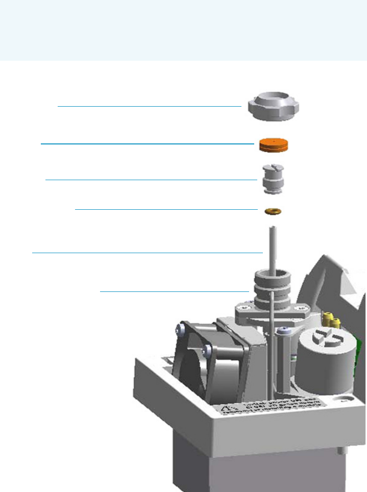
6 Injectors Advanced Maintenance
Cleaning the PTVBKF Injector Head Assembly
254 TRACE 1300 and TRACE 1310 Hardware Manual Thermo Scientific
a. Using the slotted stubby driver provided, unscrew and remove the liner cap.
b. Use tweezers to remove the liner with the liner seal (o-ring) from the injector.
Figure 233. PTVBKF Top Parts and Liner Removal
10. Remove the fan assembly.
The fan is fixed on a support. Do not remove the fan from its support, but remove the
assembly by proceeding as follows:
a. Using tweezers, and a T10 Torxhead screwdriver, unscrew and remove the left fixing
screw of the support, then unscrew and remove the right fixing screw. See Figure 234.
CAUTION Be careful not to break the glass liner when removing it. Glass splinters
might fall into the lower part of the vaporization chamber. If the glass liner
breaks, follow the instructions for “Replacing the PTVBKF Broken Liner” on
page 133.
Septum Cap
Septum
Liner Cap
Liner Seal (O-ring)
Liner
Injector Head Assembly
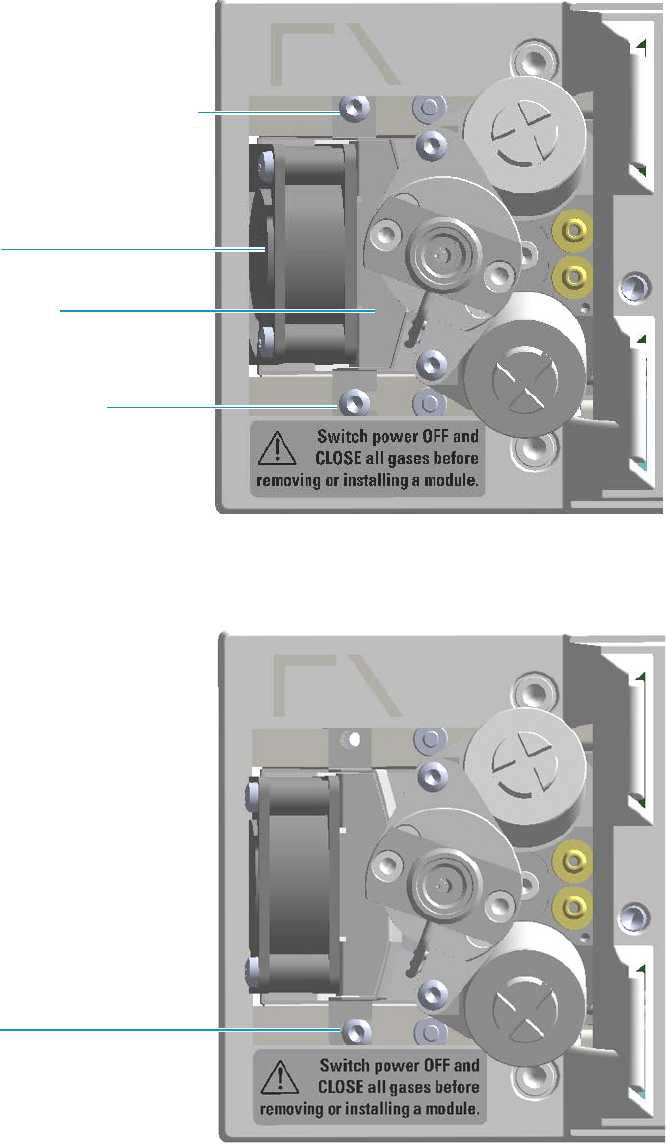
6 Injectors Advanced Maintenance
Cleaning the PTVBKF Injector Head Assembly
Thermo Scientific TRACE 1300 and TRACE 1310 Hardware Manual 255
Figure 234. PTVBKF Module: Fan Assembly
b. Carefully turn the fan assembly slightly to access the slot on the right base of the
support from the right fixing screw. See Figure 235.
Figure 235. PTVBKF Module: Fan Assembly Removal (1)
c. Carefully extract the fan assembly from its seat, and place it sideways to the module.
Be sure to not damage the two wires. See Figure 236.
Unscrew and remove this screw
Fan Support
Loosen this screw
Fan
Slot
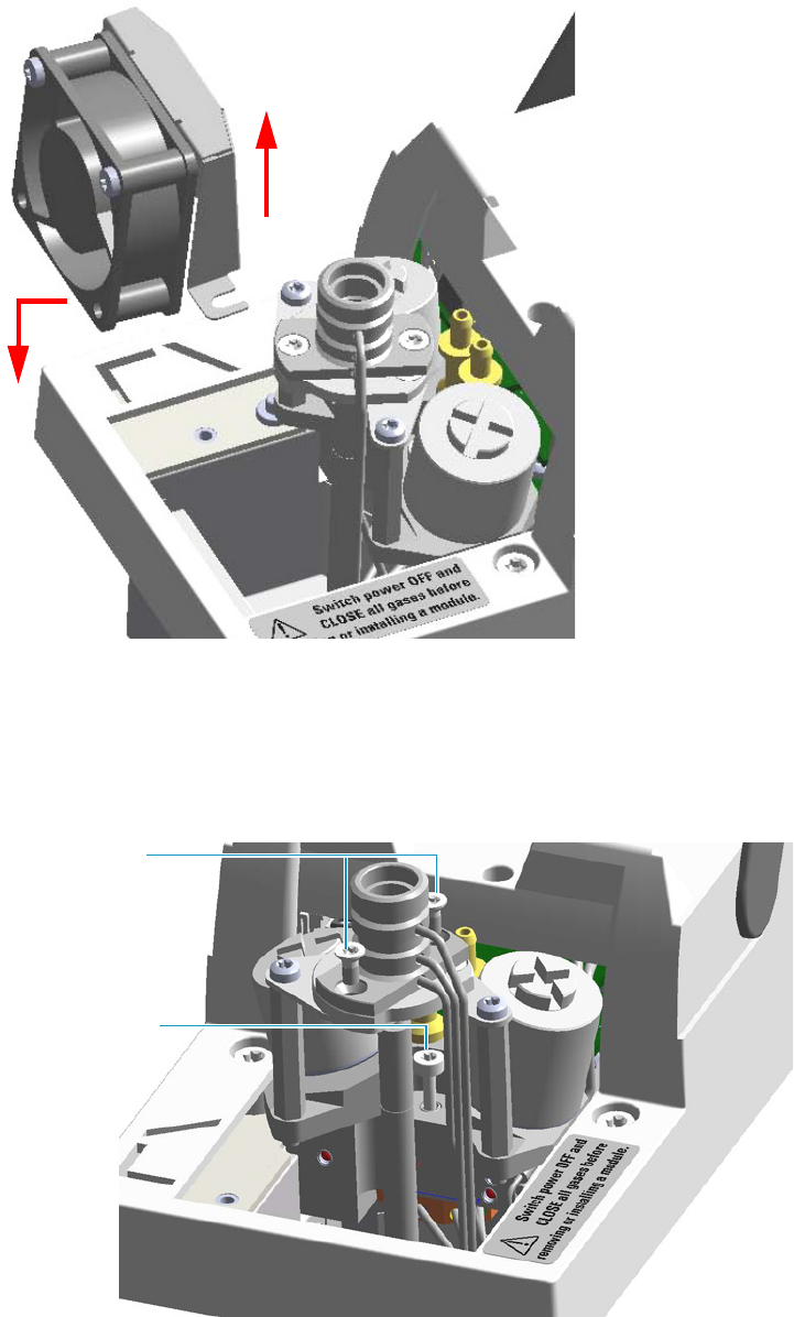
6 Injectors Advanced Maintenance
Cleaning the PTVBKF Injector Head Assembly
256 TRACE 1300 and TRACE 1310 Hardware Manual Thermo Scientific
Figure 236. PTVBKF Module: Fan Assembly Removal (2)
11. Remove and clean the injector head.
a. Using the T10 Torxhead screwdriver, unscrew the two fixing screws, and the captive
screw that respectively fix the top and the bottom of the injector head assembly. See
Figure 237.
Figure 237. PTVBKF Injector Head Assembly
Top Injector
Head Assembly
Fixing Screws
Bottom Injector
Head Assembly
Captive Screw
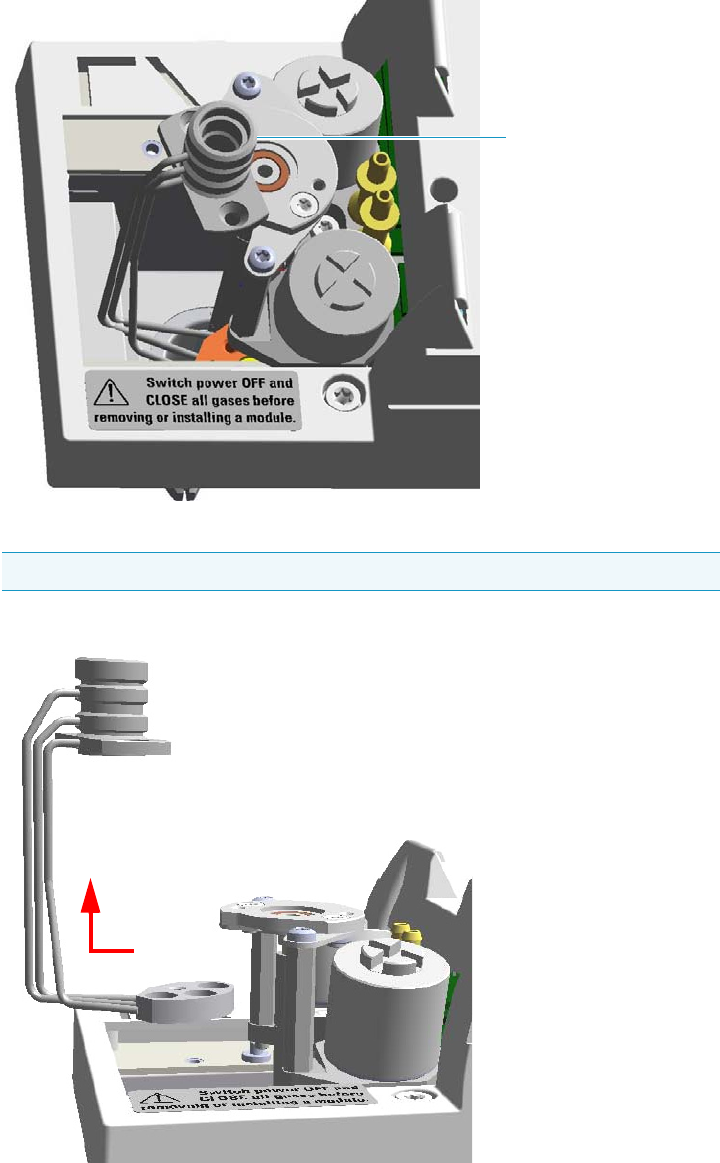
6 Injectors Advanced Maintenance
Cleaning the PTVBKF Injector Head Assembly
Thermo Scientific TRACE 1300 and TRACE 1310 Hardware Manual 257
b. =Holding the top of the injector head assembly with your thumb, index, and middle
fingers, turn the assembly clockwise. See Figure 238.
Figure 238. PTV Injector Head Assembly Removal (1)
c. Extract the assembly sideways from its housing. See Figure 239.
Figure 239. PTVBKF Injector Head Assembly Removal (2)
Note Do not remove the carrier, split, and purge lines’ o-rings on the plate.
Injector Head Assembly

6 Injectors Advanced Maintenance
Cleaning the PTVBKF Injector Head Assembly
258 TRACE 1300 and TRACE 1310 Hardware Manual Thermo Scientific
12. Clean the injector head.
a. Put the injector head assembly into an ultrasonic cleaner filled with a
methanol/acetone mixture (1:1).
b. Sonicate the injector head assembly for about half an hour.
c. Using tweezers, remove the injector head assembly from the bath and dry it with
compressed clean air.
13. Reinstall the injector head.
a. Carefully reinstall the injector head assembly into its housing proceeding in the
reverse order in which it was removed.
b. Screw the two fixing screws and the captive screw fixing the top, and the bottom of
the injector head assembly respectively.
14. Remount the fan assembly.
a. Carefully reinsert the fan assembly in its seat into the module.
b. Move the assembly slightly to position the slot on the right base of the support under
the head of the right fixing screw, and for aligning the hole on the left base with the
corresponding fixing hole.
c. Using tweezers, reinsert the left fixing screw previously removed.
d. Using a T10 Torxhead screwdriver, tighten both the left and right fixing screws.
15. Reinsert the liner.
a. Place the liner seal over the liner.
b. Using tweezers, insert the liner into the injector and push it gently towards the
bottom of the injector.
c. Reinsert and screw the liner cap using the slotted stubby driver.
16. Reinstall the upper parts of the injector.
a. Place the septum into the injector head assembly.
b. Screw and tighten the septum cap to fingertight.
17. Close the module flap cover.
18. If present, move the autosampler towards the module to restore the original alignment.
CAUTION We suggest replacing the septum with a new one.
CAUTION Do not overtighten the septum cap because you might damage the septum and
affect instrument performance.
6 Injectors Advanced Maintenance
Cleaning the PTVBKF Injector Head Assembly
Thermo Scientific TRACE 1300 and TRACE 1310 Hardware Manual 259
19. Open the gas supplies.
20. If external modules are present, plug the power cable to the AC Input connector of each
external module, and to the wall outlet.
21. Power on the GC.
a. Plug the power cable to the AC Input connector into the back of the GC and to the
wall outlet.
b. Flip up the power switch (breaker) to the position I.
22. Set the normal oven, injectors, and detectors working conditions.
6 Injectors Advanced Maintenance
Cleaning the PTVBKF Injector Head Assembly
260 TRACE 1300 and TRACE 1310 Hardware Manual Thermo Scientific

Thermo Scientific TRACE 1300 and TRACE 1310 Hardware Manual 261
7
Detectors Advanced Maintenance
This chapter describes TRACE 1300/TRACE 1310 detector modules that do not require
routine maintenance, but troubleshooting may indicate they need to be cleaned or replaced.
Contents
•Removing/Replacing a Detector Module
•Measuring the FID Gas Flows
•Cleaning or Replacing the FID Jet
•Measuring the NPD Gas Flows
•Measuring the FPD Gas Flows
•Cleaning or Replacing the NPD Jet
•Cleaning or Replacing the FPD Mirror Metal Plug
•Cleaning or Replacing the FPD Filter-side Heat Shields
•Cleaning or Replacing the FPD Flame-side Heat Shields
•Replacing the FPD Photomultiplier Tube
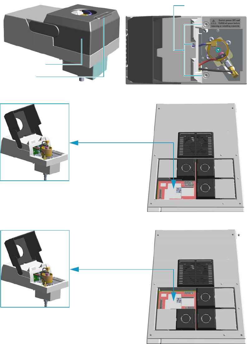
7 Detectors Advanced Maintenance
Removing/Replacing a Detector Module
262 TRACE 1300 and TRACE 1310 Hardware Manual Thermo Scientific
Removing/Replacing a Detector Module
This section provides the instruction for removing/replacing a front/back detector module.
Figure 240. Example of Detector Module
Figure 241. Replacing a Front Detector Module
Figure 242. Replacing a Back Detector Module
Module Flap Cover
Lifting Handle
Captive Fixing Screws
Example of Detector Module
Example of Detector Module
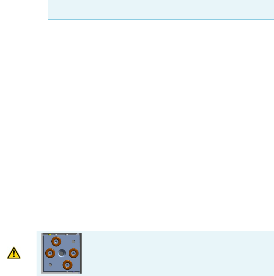
7 Detectors Advanced Maintenance
Removing/Replacing a Detector Module
Thermo Scientific TRACE 1300 and TRACE 1310 Hardware Manual 263
To remove/replace a front/back detector module
1. Put the GC in standby condition.
2. Cool the oven, injectors and detectors to room temperature.
3. Close the gas supplies.
4. Power off the GC.
a. Push down the power switch (breaker), located at the back of the instrument, to the
position O.
b. Unplug the power cable from the AC Input connector on the back of the GC, and
from the wall outlet.
5. If external modules are present, unplug the power cable from the AC Input connector of
each external module, and from the wall outlet.
6. Remove the column from the detector.
a. Open the front door of the GC.
b. Loosen the retaining nut from the detector fitting on the upper interior wall of the
GC oven.
c. Remove the analytical column with its nut and ferrule from the bottom of the
detector.
7. Remove the detector module.
a. Open the module flap cover.
b. Using a T20 Torxhead screwdriver, unscrew the three captive fixing screws.
c. Keeping the module flap cover open, lift up the module from its seat in the injector
housing.
d. Place the module on a clean surface.
8. Replace the detector module.
a. Open the module flap cover.
Note By pressing the Maintenance button, the GC cool down is automatically
carried out.
WARNING Make sure all the four o-rings are placed into their seats on
the gas connection.
Do not install the module if the o-rings are missing.

7 Detectors Advanced Maintenance
Removing/Replacing a Detector Module
264 TRACE 1300 and TRACE 1310 Hardware Manual Thermo Scientific
b. Keeping the module flap cover open, place it in its seat. Be sure to insert the 25-pin
male connector, on the bottom of the module, into the 25-pin female connector on
the injector seat of the injector housing.
c. Use a T20 Torxhead screwdriver to tighten the three captive fixing screws without
overtightening.
.
d. Close the module flap cover.
9. Remove the plug, and reconnect the column end to the detector.
10. Open the gas supplies.
11. Check the gas supply for leaks.
a. Use a handheld electronic leak detector (Thermo Scientific GLD Pro leak detector or
equivalent) to check each fitting for leaks.
b. If you detect a leak, tighten the connection and retest it.
c. Repeat this process until all connections are leak free.
12. If external modules are present, plug the power cable to the AC Input connector of each
external module, and to the wall outlet.
13. Power on the GC.
a. Plug the power cable to the AC Input connector into the back of the GC and to the
wall outlet.
b. Flip up the power switch (breaker) to the position I.
14. Check the module gas connections for leaks.
15. Close the front door of the GC.
CAUTION To maintain the correct alignment the screws must be tightened in turn.
Tighten each screw only a small amount before moving to the next screw. Repeat until all
are secure.

7 Detectors Advanced Maintenance
Measuring the FID Gas Flows
Thermo Scientific TRACE 1300 and TRACE 1310 Hardware Manual 265
Measuring the FID Gas Flows
Use this procedure for manually measuring the FID fuel and make-up gases.
To manually measure the FID flow rates
1. Put the GC in standby condition.
2. Turn the flame off. The fuel gases, hydrogen, and air, are automatically closed.
3. Cool the detector to room temperature.
4. Turn the make-up gas off.
5. Power off the GC.
a. Push down the power switch (breaker), located at the back of the instrument, to the
position O.
b. Unplug the power cable from the AC Input connector into the back of the GC, and
from the wall outlet.
6. If external modules are present, unplug the power cable from the AC Input connector of
each external module, and from the wall outlet
7. Open the module flap cover.
8. Disconnect the signal, glow-plug, and polarizing cables from their contacts on the cell top
cover. See Figure 243 and Figure 244.
Materials needed
Forceps or tweezers
T10 Torxhead screwdriver
Measuring Tool - Flowmeter Adapter
Electronic flowmeter (Thermo Scientific GFM Pro Flowmeter, or equivalent)
Note By pressing the Maintenance button, the GC cool down is automatically
carried out.
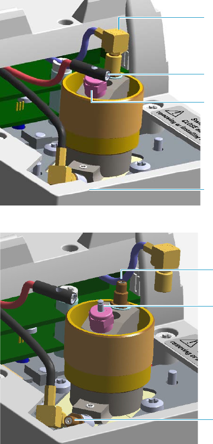
7 Detectors Advanced Maintenance
Measuring the FID Gas Flows
266 TRACE 1300 and TRACE 1310 Hardware Manual Thermo Scientific
Figure 243. FID Cables
Figure 244. FID Cables Disconnection
a. Loosen the glow-plug cable socket set screw using a T10 Torxhead screwdriver.
Carefully pull out the terminal body of the glow-plug cable from the dowel pin on
the glow-plug element.
b. Unscrew and pull out the straight plug crimp connector of the signal cable from the
collecting electrode bulkhead jack.
c. Pull out the quick coupling straight jack connector of the polarizing cable from the
polarizing electrode bulkhead jack.
d. Carefully move the cables in order to have free space for handling the detector.
9. Remove the top parts of the detector. See Figure 245.
Glow-Plug Cable Terminal body
Polarizing Cable Straight Jack Connector
Signal Cable Straight Plug Crimp Connector
Socket Set Screw
Polarizing Electrode Bulkhead Jack
Collecting Electrode Bulkhead Jack
Glow-plug Dowel Pin
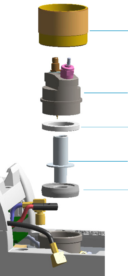
7 Detectors Advanced Maintenance
Measuring the FID Gas Flows
Thermo Scientific TRACE 1300 and TRACE 1310 Hardware Manual 267
Figure 245. FID Top Parts Removal
a. Unscrew and remove the detector cap, paying attention to not rotate the cell top
cover.
b. Remove the cell top cover and put it in a safe place. Do not damage the FID
collecting electrode pin.
10. Remove the electrode. See Figure 245.
a. Using forceps or tweezers, carefully extract the collecting electrode, the insulator ring
and the collector insulator through the top of the detector cell. Place all the parts
removed on a clean surface.
Detector Cap
Cell Top Cover
Collecting Electrode
Insulator Ring
Collector Insulator
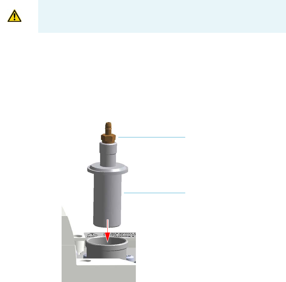
7 Detectors Advanced Maintenance
Measuring the FID Gas Flows
268 TRACE 1300 and TRACE 1310 Hardware Manual Thermo Scientific
b. Loosen the polarizing electrode fixing screw using a T10 Torxhead screwdriver, and
extract the polarizing electrode from its seat.
c. Place the polarizing electrode on a clean surface.
11. Insert the FID gases measuring tool. See Figure 246.
a. Insert the measuring tool into the detector body.
b. Push the measuring tool downwards until it stops.
Figure 246. FID Gases Measuring Tool
c. Screw the detector cap onto the measuring tool. See Figure 247.
WARNING The collector insulator must be stored somewhere it can stay clean.
Measuring Tool
Male Hose Adapter
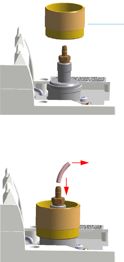
7 Detectors Advanced Maintenance
Measuring the FID Gas Flows
Thermo Scientific TRACE 1300 and TRACE 1310 Hardware Manual 269
Figure 247. FID Gases Measuring Tool Assembling
d. Place the flowmeter tubing over the male hose adapter of the measuring tool to begin
measuring flows. See Figure 248.
Figure 248. Measuring Tool to Flowmeter Connection
12. Power on the GC.
a. Plug the power cable to the AC Input connector into the back of the GC and to the
wall outlet.
b. Flip up the power switch (breaker) to the position I.
13. Measure the gas flow rate.
a. Open the GC user interface.
b. Turn the Hydrogen flow On.
i. Measure the gas flow and verify that the actual flow rate corresponds to the
setpoint value.
Detector Cap
To Flowmeter
7 Detectors Advanced Maintenance
Measuring the FID Gas Flows
270 TRACE 1300 and TRACE 1310 Hardware Manual Thermo Scientific
c. Turn the hydrogen flow Off.
d. Turn the Air supply On.
i. Measure the gas flow and verify that the actual flow rate corresponds to the
setpoint value.
e. Turn the Air flow Off.
f. Turn the Makeup gas flow On.
i. Measure the gas flow and verify that the actual flow rate corresponds to the
setpoint value.
g. Turn the Makeup Off.
14. Power off the GC.
a. Push down the power switch (breaker), located at the back of the instrument, to the
position O.
b. Unplug the power cable from the AC Input connector into the back of the GC, and
from the wall outlet.
15. Unscrew the detector cap, then remove the measuring tool from the detector body.
16. Reinstall the electrodes.
a. Reinsert the polarizing electrode into its seat pushing while screwing it, then screw
the fixing screw.
b. Remount the collector insulator, the collecting electrode, and its insulator ring.
17. Remount the top parts of the detector.
a. Remount the cell top cover.
b. Screw the detector cap paying attention to not rotate the cell top cover.
c. Reconnect the signal, glow-plug, and polarizing cables.
18. Close the module flap cover.
19. If external modules are present, plug the power cable to the AC Input connector of each
external module, and to the wall outlet.
20. Power on the GC.
a. Plug the power cable to the AC Input connector into the back of the GC and to the
wall outlet.
b. Flip up the power switch (breaker) to the position I.
21. Turn the make-up gas on.
22. Set the normal oven and detector working conditions.
23. Ignite the flame. The fuel gases, hydrogen and air, are automatically opened.

7 Detectors Advanced Maintenance
Cleaning or Replacing the FID Jet
Thermo Scientific TRACE 1300 and TRACE 1310 Hardware Manual 271
Cleaning or Replacing the FID Jet
It is good practice to clean the jet semiannually when you are analyzing particularly dirty
compounds such that the flame does not burnt properly. In case of actual damage, the jet
must be replaced.
To clean or replace the FID ceramic jet
1. Put the GC in standby condition.
2. Turn the flame off. The fuel gases, hydrogen, and air, are automatically closed.
3. Cool the detector to room temperature.
4. Turn the make-up gas off.
5. Power off the GC.
a. Push down the power switch (breaker), located at the back of the instrument, to the
position O.
b. Unplug the power cable from the AC Input connector into the back of the GC, and
from the wall outlet.
c. If external modules are present, unplug the power cable from the AC Input connector
of each external module, and from the wall outlet.
6. Open the module flap cover.
7. Disconnect the signal, glow-plug, and polarizing cables from their contacts on the cell top
cover. See Figure 249 and Figure 250.
Materials needed
GC-grade methanol
Distilled water
Screwdriver?
Forceps or tweezers
T10 Torxhead screwdriver
Elbowed box wrench, 8-mm
Ceramic jet (if necessary)
Note By pressing the Maintenance button, the GC cool down is automatically
carried out.
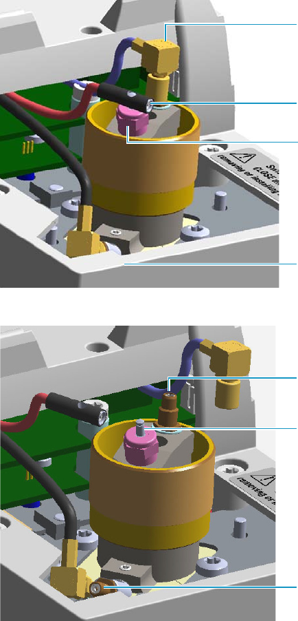
7 Detectors Advanced Maintenance
Cleaning or Replacing the FID Jet
272 TRACE 1300 and TRACE 1310 Hardware Manual Thermo Scientific
Figure 249. FID Cables
Figure 250. FID Cables Disconnection
a. Loosen the glow-plug cable socket set screw using a T10 Torxhead screwdriver.
Carefully pull out the terminal body of the glow-plug cable from the dowel pin on
the glow-plug element.
b. Unscrew and pull out the coaxial straight plug crimp connector of the signal cable
from the collecting electrode bulkhead jack.
c. Pull out the quick coupling coaxial straight jack connector of the polarizing cable
from the polarizing electrode bulkhead jack.
d. Carefully move the cables in order to have free space for handling the detector.
8. Remove the top parts of the detector. See Figure 251.
Glow-Plug Cable Terminal body
Polarizing Cable Straight Jack Connector
Signal Cable Straight Plug Crimp
Connector
Socket Set Screw
Polarizing Electrode Bulkhead Jack
Collecting Electrode Bulkhead Jack
Glow-plug Dowel Pin
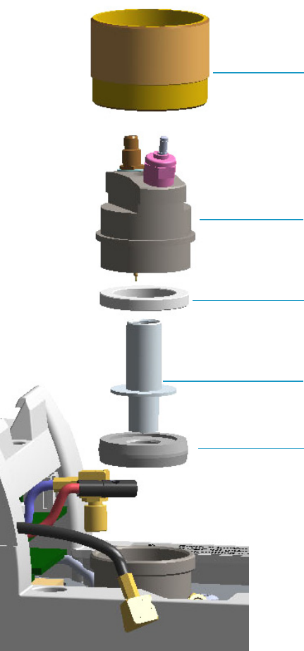
7 Detectors Advanced Maintenance
Cleaning or Replacing the FID Jet
Thermo Scientific TRACE 1300 and TRACE 1310 Hardware Manual 273
Figure 251. FID Top Parts Removal
a. Unscrew and remove the detector cap paying attention to not rotate the cell top
cover.
b. Remove the cell top cover and put it in a safe place. Do not damage the FID
collecting electrode pin.
9. Remove the electrode. See Figure 251.
a. Using forceps or tweezers, carefully extract the collecting electrode, the insulator ring,
and the collector insulator through the top of the detector cell. Place all the parts
removed on a clean surface.
Detector Cap
Cell Top Cover
Collecting Electrode
Insulator Ring
Collector Insulator
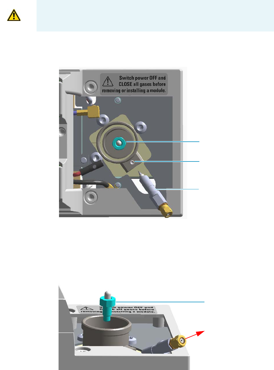
7 Detectors Advanced Maintenance
Cleaning or Replacing the FID Jet
274 TRACE 1300 and TRACE 1310 Hardware Manual Thermo Scientific
b. Loosen the polarizing electrode fixing screw using a T10 Torxhead screwdriver, and
extract the polarizing electrode from its seat. See Figure 252.
Figure 252. FID Jet (2)
c. Place the polarizing electrode on a clean surface.
10. Remove, clean, and reinstall the jet.
a. Use the elbowed box wrench for unscrewing and extracting the jet through the
detector body. See Figure 253.
Figure 253. FID Jet (2)
WARNING The collector insulator must be stored somewhere it can stay clean.
Jet
Polarizing Electrode
Fixing Screw
Polarizing Electrode
Jet

7 Detectors Advanced Maintenance
Cleaning or Replacing the FID Jet
Thermo Scientific TRACE 1300 and TRACE 1310 Hardware Manual 275
b. Place the jet in the ultrasonic cleaner, filled with liquid detergent.
c. Sonicate the jet for about five minutes.
d. Handling the jet with forceps or tweezers. Rinse the jet using distilled water, then
methanol.
e. Place the jet on a paper towel, and let the jet air dry.
f. Using the proper tool, reinsert and screw the cleaned (or a new) jet into its seat in the
detector body.
11. Reinstall the electrodes.
a. Reinsert the polarizing electrode into its seat pushing while screwing it, then screw
the fixing screw.
b. Remount the collector insulator, the collecting electrode, and its insulator ring.
12. Remount the top parts of the detector.
a. Remount the cell top cover.
b. Screw the detector cap paying attention to not rotate the cell top cover.
c. Reconnect signal, glow-plug, and polarizing cables.
13. Close the module flap cover.
14. If external modules are present, plug the power cable to the AC Input connector of each
external module, and to the wall outlet.
15. Power on the GC.
a. Plug the power cable to the AC Input connector into the back of the GC and to the
wall outlet.
b. Flip up the power switch (breaker) to the position I.
16. Turn the make-up gas on.
17. Set the normal detector working conditions.
18. Ignite the flame. The fuel gases, hydrogen. and air, are automatically opened.
Note If after the cleaning physical condition of the jet does not permit its reuse,
replace the jet with a new one.

7 Detectors Advanced Maintenance
Measuring the NPD Gas Flows
276 TRACE 1300 and TRACE 1310 Hardware Manual Thermo Scientific
Measuring the NPD Gas Flows
Use this procedure for manually measuring the NPD fuel and make-up gases.
To manually measure the NPD flow rates
1. Put the GC in standby condition.
2. Switch off the thermionic source. Hydrogen and air are automatically closed.
3. Cool the detector to room temperature.
4. Turn the make-up gas off.
5. Power off the GC.
a. Push down the power switch (breaker), located at the back of the instrument, to the
position O.
b. Unplug the power cable from the AC Input connector into the back of the GC and
from the wall outlet.
6. Unplug the power cable from the AC input connector of the NPD Thermionic Source
Power Module and from the wall outlet.
If other external modules are present, unplug the power cable from the AC Input
connector of each module, and from the wall outlet.
7. Unplug the signal cable from the detector module. See Figure 254.
Materials needed
Forceps or tweezers
T6 Torxhead key
T10 Torxhead screwdriver
6 mm wrench
Measuring Tool Flowmeter Adapter
Electronic flowmeter (Thermo Scientific GFM Pro Flowmeter, or equivalent)
Note By pressing the Maintenance button, the GC cool down is automatically
carried out.
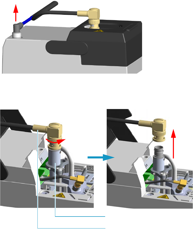
7 Detectors Advanced Maintenance
Measuring the NPD Gas Flows
Thermo Scientific TRACE 1300 and TRACE 1310 Hardware Manual 277
Figure 254. NPD Signal Cable Removal
8. Open the module flap cover.
9. Remove the thermionic source assembly cable. See Figure 255.
Figure 255. NPD Thermionic Source Cable Removal
a. Twist the ring to disconnect the thermionic source assembly cable.
b. Push and twist the lock so that the button slides up in the groove, then pull the cable
ends apart.
10. Unscrew and pull out the straight jack connector of the collecting electrode cable from
the collecting electrode bulkhead jack. See Figure 256.
Thermionic Source Assembly Cable
Thermionic Source Assembly
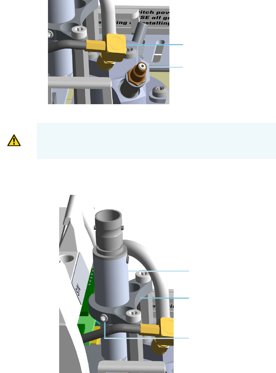
7 Detectors Advanced Maintenance
Measuring the NPD Gas Flows
278 TRACE 1300 and TRACE 1310 Hardware Manual Thermo Scientific
Figure 256. NPD Collecting Electrode Cable Removal
11. Remove the thermionic source
a. Using a T6 Torxhead key, loosen the dowel which fix the thermionic source
connector to the thermionic source support. See Figure 257.
Figure 257. NPD Thermionic Source Removal (1)
Collecting Electrode Cable
Collecting Electrode Straight Jack
Connector
CAUTION The thermionic source is delicate. Be careful not to break or crack the source.
When performing maintenance on the NPD, avoid touching the source with your fingers,
and prevent it from coming in contact with other surfaces.
Wear clean, lint-free gloves to prevent contamination of parts with dirt and skin oils.
Thermionic Source Connector
Dowel
Thermionic Source Support
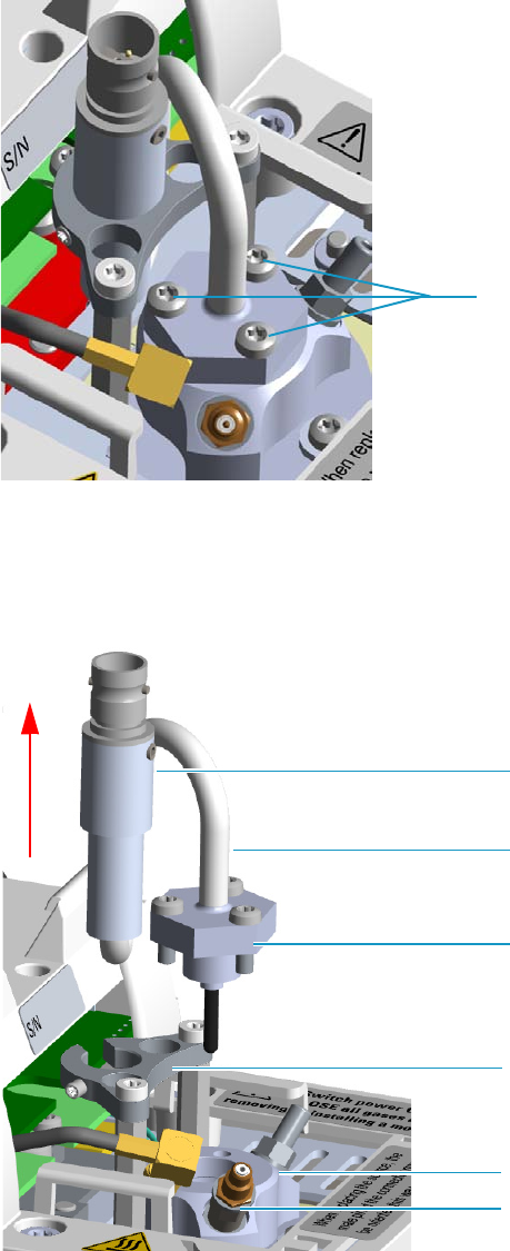
7 Detectors Advanced Maintenance
Measuring the NPD Gas Flows
Thermo Scientific TRACE 1300 and TRACE 1310 Hardware Manual 279
b. Using the T10 Torxhead screwdriver, remove the three T10 Torx screws from the
thermionic source assembly. See Figure 258.
Figure 258. NPD Thermionic Source Removal (2)
c. Gently lift up the thermionic source connector guiding the flexible cable from the
thermionic source support, then remove the thermionic source assemble from the
NPD body. Avoid bumping the bead on the sides of the collector. See Figure 259.
Figure 259. NPD Thermionic Source Removal (3)
T10 Torx Screw
Thermionic Source Connector
Thermionic Source Support
Thermionic Source Assemble
Thermionic Source Flexible Cable
NPD Body
Collecting Electrode Pin
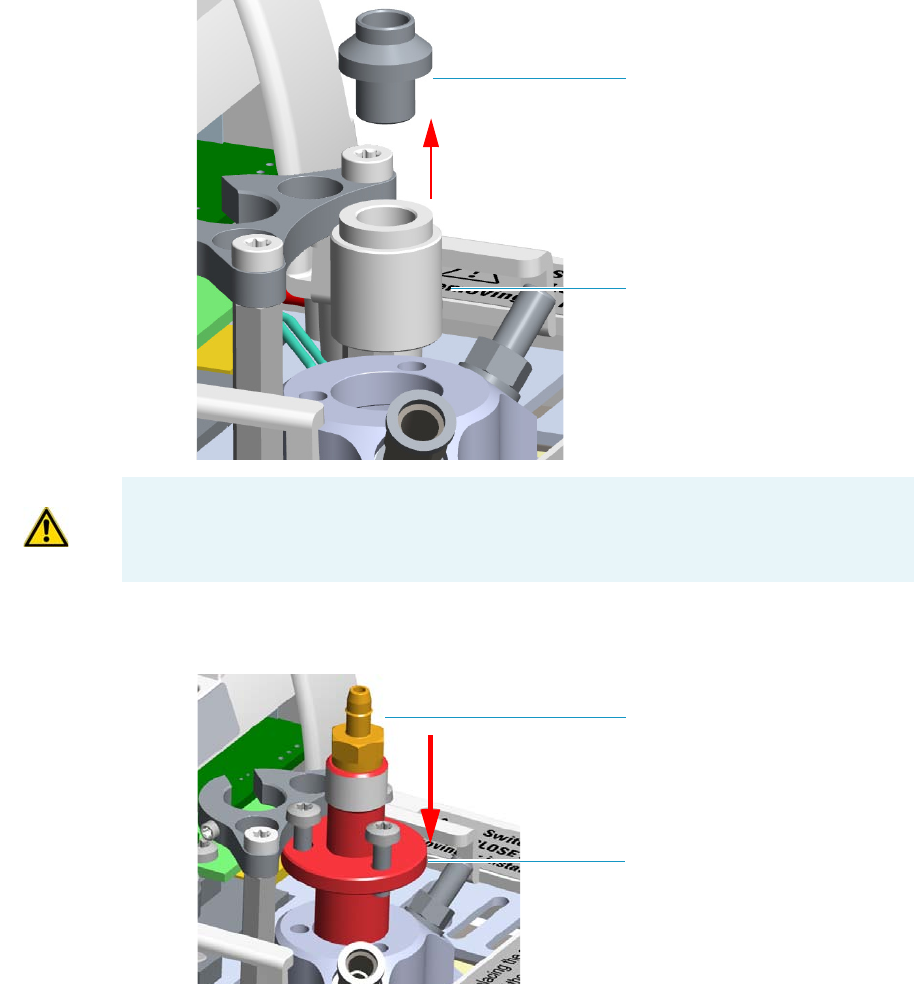
7 Detectors Advanced Maintenance
Measuring the NPD Gas Flows
280 TRACE 1300 and TRACE 1310 Hardware Manual Thermo Scientific
12. Remove the collecting electrode and the insulator. See Figure 260.
a. Using a 6-mm wrench, unscrew and remove the collecting electrode pin from its seat
on the detector body.
b. Using forceps or tweezers, extract the collecting electrode through the top of the
detector body.
c. Using forceps or tweezers, extract the insulator through the top of the detector body.
Place the insulator on a clean surface.
Figure 260. NPD Insulator and Collecting Electrode Removal
13. Insert the NPD gases measuring tool. See Figure 261.
Figure 261. NPD Gases Measuring Tool (1)
Collector Electrode
Insulator
WARNING The collector insulator must be stored somewhere it can stay clean.
Measuring Tool
Male Hose Adapter
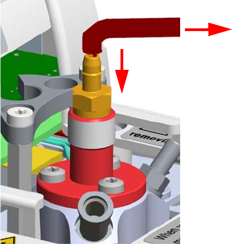
7 Detectors Advanced Maintenance
Measuring the NPD Gas Flows
Thermo Scientific TRACE 1300 and TRACE 1310 Hardware Manual 281
a. Insert the flowmeter adapter measuring tool into the detector body.
b. Push the flowmeter adapter measuring tool downwards until it stops.
c. Rotate the measuring tool to align the fixing holes, then insert the three screws used
to fix the thermionic source.
d. Fix the flowmeter adapter measuring tool to the detector body using a T10 Torxhead
screwdriver.
e. Place the flowmeter tubing over the male hose adapter of the measuring tool to begin
measuring flows.See Figure 262.
Figure 262. NPD Gases Measuring Tool (2)
14. Measure the gas flow rate.
a. Open the GC user interface.
b. Turn the Hydrogen flow On.
i. Measure the gas flow and verify that the actual flow rate corresponds to the
setpoint value.
c. Turn the hydrogen flow Off.
d. Turn the Air supply On.
i. Measure the gas flow and verify that the actual flow rate corresponds to the
setpoint value.
e. Turn the Air flow Off.
f. Turn the Makeup gas flow On.
i. Measure the gas flow and verify that the actual flow rate corresponds to the
setpoint value.
g. Turn the Makeup Off.
15. Remove the flowmeter adapter measuring tool from the detector body proceeding in the
reverse order in which it was installed.
To Flowmeter
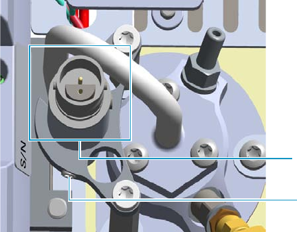
7 Detectors Advanced Maintenance
Measuring the NPD Gas Flows
282 TRACE 1300 and TRACE 1310 Hardware Manual Thermo Scientific
a. Using forceps or tweezers, reinstall the insulator into the detector body.
16. Reinstall the insulator and the collecting electrode.
a. Using forceps or tweezers, reinstall the insulator into the detector body.
b. Place the collecting electrode in its housing.
c. Using a 6-mm wrench, screw the collecting electrode pin into its seat on the detector
body.
d. Screw the straight plug crimp connector of the collecting electrode cable to the
collecting electrode bulkhead jack.
17. Reinstall the thermionic source.
a. Remove the protective cap covering the new thermionic source.
b. Mount and guide the new source assembly on the NPD body proceeding in the
reverse order in which it was removed. Be careful not to bump the bead on the sides
of the body and collecting electrode.
c. Rotate and align the thermionic source connector, then tighten the dowel to fix the
connector to the support using the T6 Torxhead key. See Figure 263.
Figure 263. Reinstall Thermionic Source (1)
18. Reconnect and screw the straight jack connector of the collecting electrode cable to the
collecting electrode bulkhead jack. See Figure 264.
Dowel
Correct Alignment
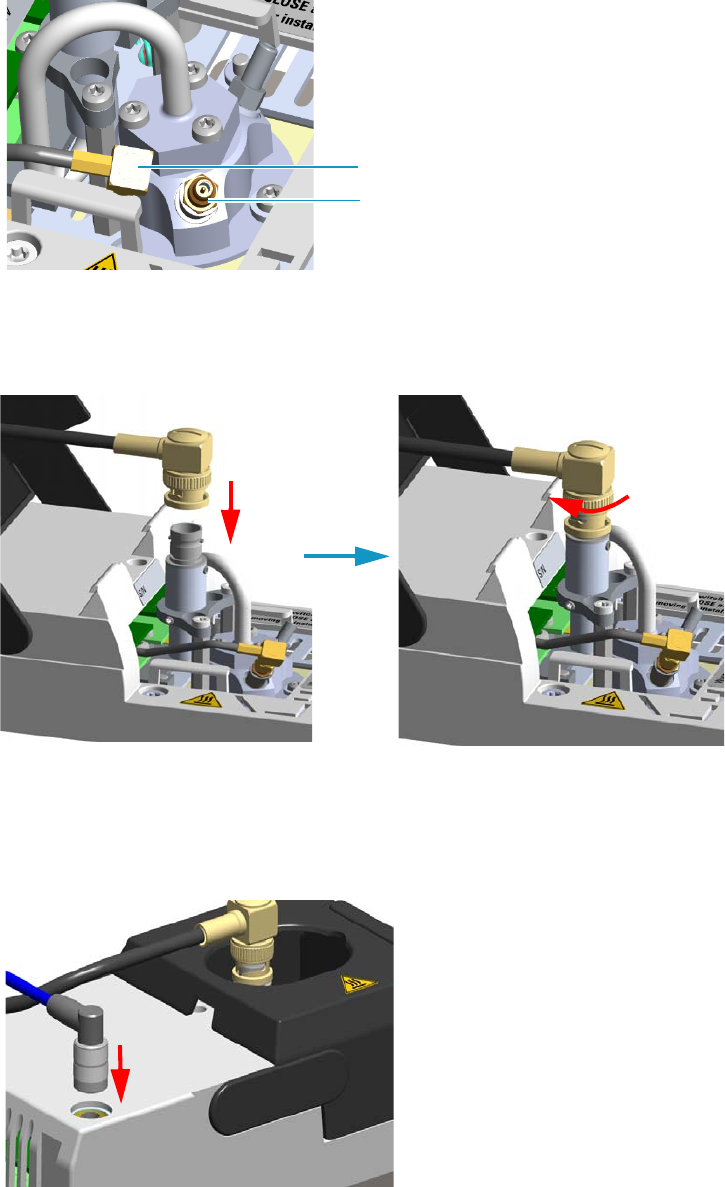
7 Detectors Advanced Maintenance
Measuring the NPD Gas Flows
Thermo Scientific TRACE 1300 and TRACE 1310 Hardware Manual 283
Figure 264. Reinstall Thermionic Source (2)
19. Reconnect the source assembly cable to the NPD cable and twist the ring to lock the
connection. See Figure 265.
Figure 265. Reinstall Thermionic Source (3)
20. Close the module flap cover.
21. Plug in the signal cable into its contact on the detector module. See Figure 266.
Figure 266. Plug NPD Signal Cable
Collecting Electrode Cable
Collecting Electrode Straight Jack Connector
7 Detectors Advanced Maintenance
Measuring the NPD Gas Flows
284 TRACE 1300 and TRACE 1310 Hardware Manual Thermo Scientific
22. Plug the power cable to the AC input connector of the NPD Thermionic Source Power
Module and to the wall outlet. The LED marked On blinks green.
If other external modules are present, plug the power cable to the AC Input connector of
each module, and to the wall outlet.
23. Power on the GC.
a. Plug the power cable to the AC Input connector into the back of the GC and to the
wall outlet.
b. Flip up the power switch (breaker) to the position I.
24. Turn the make-up gas on.
25. Heat the detector the working temperature.
26. Switch on the thermionic source. Hydrogen and air are automatically opened.
The LED marked On of the NPD Thermionic Source Power Module becomes solid
green.

7 Detectors Advanced Maintenance
Cleaning or Replacing the NPD Jet
Thermo Scientific TRACE 1300 and TRACE 1310 Hardware Manual 285
Cleaning or Replacing the NPD Jet
You should cleaning the jet semiannually when you analyze particularly dirty compounds that
the flame does not burnt properly. In case of breakage or cracking, the jet must be replaced.
To clean or replace the NPD jet
1. Put the GC in standby condition.
2. Switch off the thermionic source. Hydrogen and air are automatically closed.
3. Cool the detector to room temperature.
4. Turn the make-up gas off.
5. Power off the GC.
a. Push down the power switch (breaker), located at the back of the instrument, to the
position O.
b. Unplug the power cable from the AC Input connector into the back of the GC and
from the wall outlet.
6. Unplug the power cable from the AC input connector of the NPD Thermionic Source
Power Module and from the wall outlet.
If other external modules are present, unplug the power cable from the AC Input
connector of each module, and from the wall outlet.
7. If present, move the autosampler away from the module.
8. Unplug the signal cable from the detector module. See Figure 267.
Materials needed
Ultrasonic cleaner
Liquid detergent
GC-grade methanol
Distilled water
Forceps or tweezers
T6 Torxhead key
T10 Torxhead screwdriver
6 mm wrench
Elbowed box wrench, 8-mm
Jet (if necessary)
Note By pressing the Maintenance button, the GC cool down is automatically
carried out.
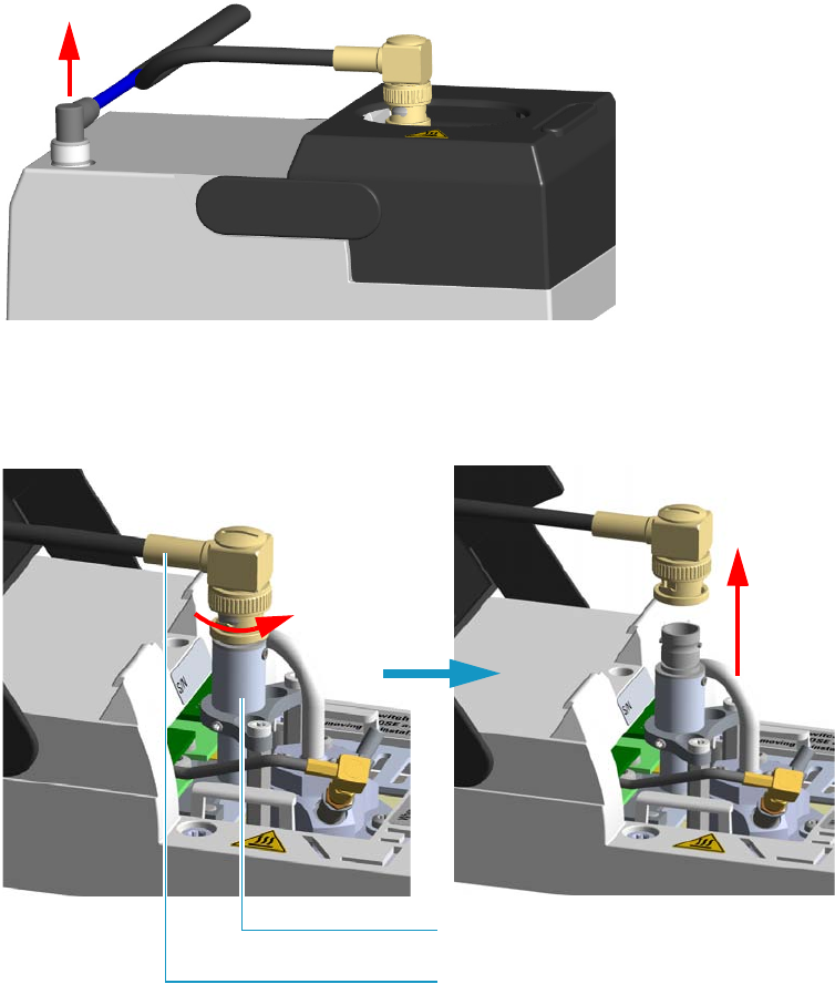
7 Detectors Advanced Maintenance
Cleaning or Replacing the NPD Jet
286 TRACE 1300 and TRACE 1310 Hardware Manual Thermo Scientific
Figure 267. NPD Signal Cable Removal
9. Open the module flap cover.
10. Remove the thermionic source assembly cable. See Figure 268.
Figure 268. NPD Thermionic Source Cable Removal
a. Twist the ring to disconnect the thermionic source assembly cable.
b. Push and twist the lock so that the button slides up in the groove, then pull the cable
ends apart.
11. Unscrew and pull out the straight jack connector of the collecting electrode cable from
the collecting electrode bulkhead jack. See Figure 269.
Thermionic Source Assembly Cable
Thermionic Source Assembly
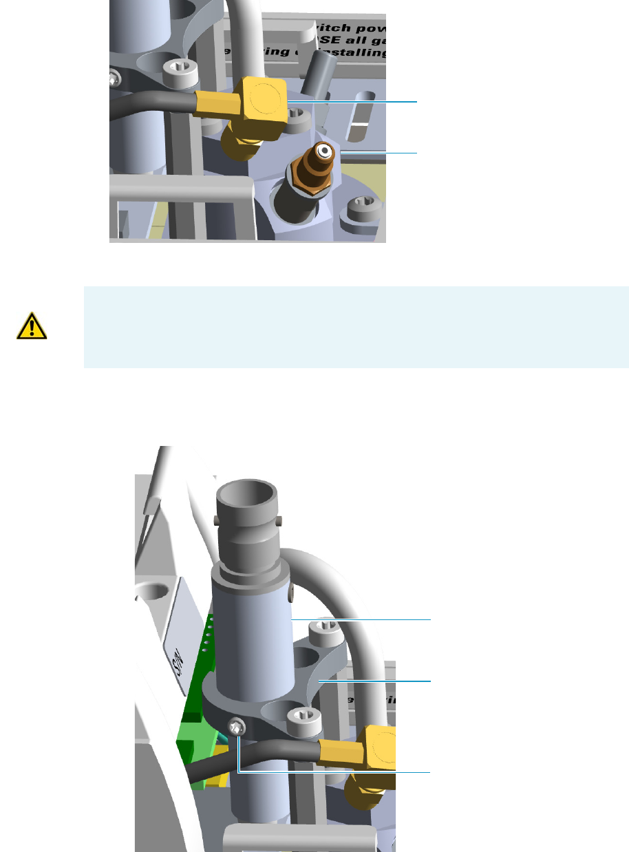
7 Detectors Advanced Maintenance
Cleaning or Replacing the NPD Jet
Thermo Scientific TRACE 1300 and TRACE 1310 Hardware Manual 287
Figure 269. NPD Collecting Electrode Cable Removal
12. Remove the thermionic source
a. Using a T6 Torxhead key, loosen the dowel which fixes the thermionic source
connector to the thermionic source support. See Figure 270.
Figure 270. NPD Thermionic Source Removal (1)
Collecting Electrode Cable
Collecting Electrode Straight Jack
Connector
CAUTION The thermionic source is delicate. Be careful not to break or crack the source.
When performing maintenance on the NPD, avoid touching the source with your fingers,
and prevent it from coming in contact with other surfaces.
Wear clean, lint-free gloves to prevent contamination of parts with dirt and skin oils.
Thermionic Source Connector
Dowel
Thermionic Source Support
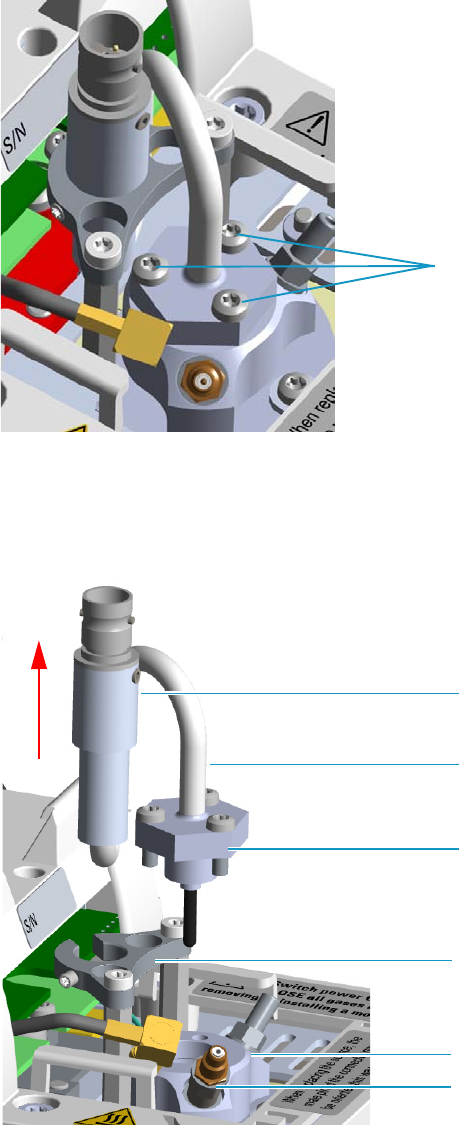
7 Detectors Advanced Maintenance
Cleaning or Replacing the NPD Jet
288 TRACE 1300 and TRACE 1310 Hardware Manual Thermo Scientific
b. Using the T10 Torxhead screwdriver, remove the three T10 Torx screws from the
thermionic source assembly. See Figure 271.
Figure 271. NPD Thermionic Source Removal (2)
c. Gently lift up the thermionic source connector guiding the flexible cable from the
thermionic source support, then remove the thermionic source assembly from the
NPD body. Avoid bumping the bead on the sides of the collector. See Figure 272.
Figure 272. NPD Thermionic Source Removal (3)
T10 Torx Screw
Thermionic Source Connector
Thermionic Source Support
Thermionic Source Assemble
Thermionic Source Flexible Cable
NPD Body
Collecting Electrode Pin

7 Detectors Advanced Maintenance
Cleaning or Replacing the NPD Jet
Thermo Scientific TRACE 1300 and TRACE 1310 Hardware Manual 289
13. Remove the collecting electrode. See Figure 273.
a. Using a 6-mm wrench, unscrew and remove the collecting electrode pin from its seat
on the detector body.
b. Using forceps or tweezers, extract the collecting electrode through the top of the
detector body.
Figure 273. NPD Collecting Electrode Removal
14. Remove and clean the jet. See Figure 274.
a. Using forceps or tweezers, extract the insulator through the top of the detector body.
Place the insulator on a clean surface.
b. Use the elbowed box wrench for unscrewing and extracting the jet through the
detector body.
Figure 274. Jet Removal
Collector Electrode
WARNING The collector insulator must be stored somewhere it can stay clean.
Insulator
Jet
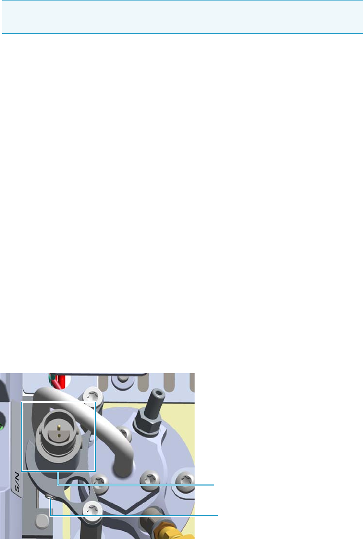
7 Detectors Advanced Maintenance
Cleaning or Replacing the NPD Jet
290 TRACE 1300 and TRACE 1310 Hardware Manual Thermo Scientific
c. Place the jet in the ultrasonic cleaner, filled with liquid detergent.
d. Sonicate the jet for about five minutes.
15. Reinsert the jet
a. Using the proper tool, reinsert the cleaned (or a new) jet, into the detector body and
screw it in its seat.
b. Using forceps or tweezers, reinstall the insulator into the detector body.
16. Reinstall the collecting electrode.
a. Place the cleaned (or a new) collecting electrode in its housing.
b. Using a 6-mm wrench, screw the collecting electrode pin into its seat on the detector
body.
c. Screw the straight plug crimp connector of the collecting electrode cable to the
collecting electrode bulkhead jack.
17. Reinstall the thermionic source.
a. Remove the protective cap covering the new thermionic source.
b. Mount and guide the new source assembly on the NPD body proceeding in the
reverse order in which it was removed. Be careful not to bump the bead on the sides
of the body and collecting electrode.
c. Rotate and align the thermionic source connector, then tighten the dowel to fix the
connector to the support using the T6 Torxhead key. See Figure 275.
Figure 275. Reinstall Thermionic Source (1)
18. Reconnect and screw the straight jack connector of the collecting electrode cable to the
collecting electrode bulkhead jack. See Figure 276.
Note If after cleaning the physical condition of the jet does not permit its reuse,
replace the jet with a new one.
Dowel
Correct Alignment
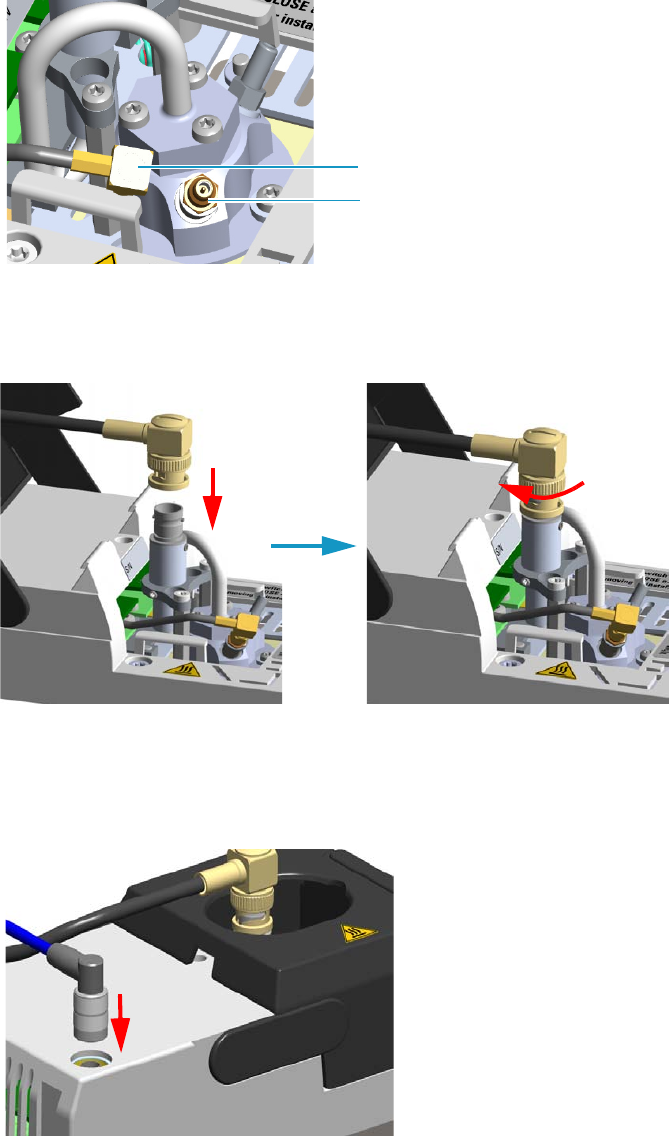
7 Detectors Advanced Maintenance
Cleaning or Replacing the NPD Jet
Thermo Scientific TRACE 1300 and TRACE 1310 Hardware Manual 291
Figure 276. Reinstall Thermionic Source (2)
19. Reconnect the source assemble cable to the NPD cable and twist the ring to lock the
connection. See Figure 277.
Figure 277. Reinstall Thermionic Source (3)
20. Close the module flap cover.
21. Plug in the signal cable into its contact on the detector module. See Figure 278.
Figure 278. Plug NPD Signal Cable
22. If present, move the autosampler towards the module to restore the original alignment.
Collecting Electrode Cable
Collecting Electrode Straight Jack Connector
7 Detectors Advanced Maintenance
Cleaning or Replacing the NPD Jet
292 TRACE 1300 and TRACE 1310 Hardware Manual Thermo Scientific
23. Plug the power cable to the AC input connector of the NPD Thermionic Source Power
Module and to the wall outlet. The LED marked On blinks green.
If other external modules are present, plug the power cable to the AC Input connector of
each module, and to the wall outlet.
24. Power on the GC.
a. Plug the power cable to the AC Input connector into the back of the GC and to the
wall outlet.
b. Flip up the power switch (breaker) to the position I.
25. Turn the make-up gas on.
26. Heat the detector the working temperature.
27. Switch on the thermionic source. Hydrogen and air are automatically opened. The LED
marked On becomes solid green.
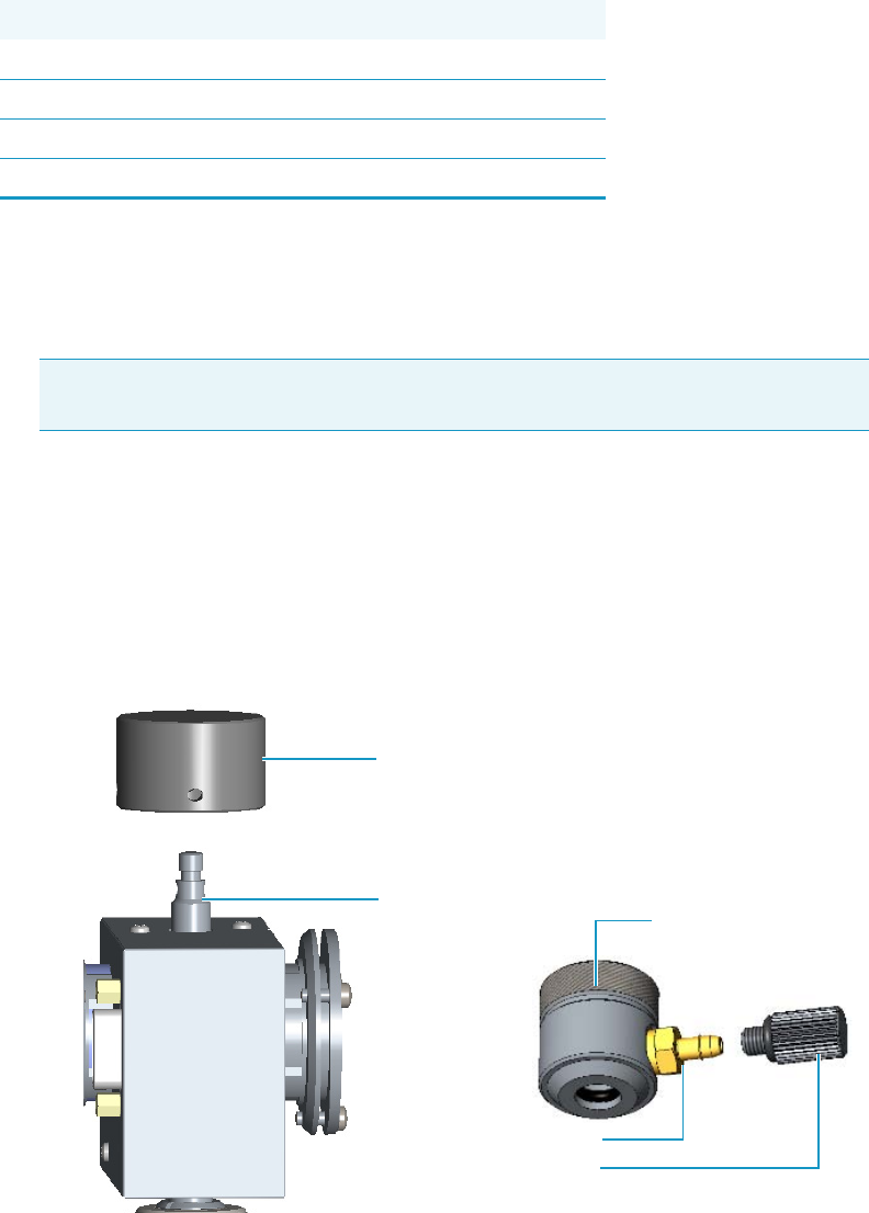
7 Detectors Advanced Maintenance
Measuring the FPD Gas Flows
Thermo Scientific TRACE 1300 and TRACE 1310 Hardware Manual 293
Measuring the FPD Gas Flows
Use this procedure for manually measuring the FPD fuel gases.
To manually measure the FPD flow rates
1. Put the GC in standby condition.
2. Turn the flame off. The fuel gases, hydrogen, and air, are automatically closed.
3. Cool the detector to room temperature.
4. Remove the column end from the bottom of the detector, then plug the bottom of the
detector using the blind cap.
5. Insert the FPD gases measuring tool. See Figure 279.
a. Remove the chimney cap.
b. Place the measuring tool on the chimney.
Figure 279. FPD Gases Measuring Tool
Materials needed
Forceps or tweezers
T10 Torxhead screwdriver
Measuring Tool Flowmeter Adapter
Electronic flowmeter (Thermo Scientific GFM Pro Flowmeter, or equivalent)
Note By pressing the Maintenance button, the GC cool down is automatically
carried out.
Plug
Measuring Tool
Male Hose Adapter
Chimney Cap
Chimney

7 Detectors Advanced Maintenance
Measuring the FPD Gas Flows
294 TRACE 1300 and TRACE 1310 Hardware Manual Thermo Scientific
6. Place the flowmeter tubing over the male hose adapter of the measuring tool to begin
measuring flows.
7. Measure the gas flow rate.
a. Open the GC user interface.
b. Turn the Hydrogen flow On.
i. Measure the gas flow and verify that the actual flow rate corresponds to the
setpoint value.
c. Turn the hydrogen flow Off.
d. Turn the Air supply On.
i. Measure the gas flow and verify that the actual flow rate corresponds to the
setpoint value.
e. Turn the Air flow Off.
8. Remove the flowmeter tubing from the male hose adapter of the measuring tool.
9. Remove the measuring tool from the chimney.
10. Replace the chimney cap over the chimney.
11. Remove the blind cap from the bottom of the detector.
12. Reconnect the column end into the bottom of the detector.
13. Ignite the flame. The fuel gases, hydrogen and air, are automatically opened.
Note For measuring the flows use the male hose adapter. The plug must be used
instead the male hole adapter when a leak test is required.

7 Detectors Advanced Maintenance
Cleaning or Replacing the FPD Mirror Metal Plug
Thermo Scientific TRACE 1300 and TRACE 1310 Hardware Manual 295
Cleaning or Replacing the FPD Mirror Metal Plug
Before cleaning or replacing the FPD mirror metal plug, read the following precautions:
To clean or replace the FPD mirror metal plug
1. Put the GC in standby condition.
2. Switch off the flame. Hydrogen and air are automatically closed.
3. Cool the detector to room temperature.
4. Power off the GC.
a. Push down the power switch (breaker), located at the back of the instrument, to the
position O.
b. Unplug the power cable from the AC Input connector into the back of the GC and
from the wall outlet.
5. If other external modules are present, unplug the power cable from the AC Input
connector of each module, and from the wall outlet.
6. Remove the FPD detector from the base.
a. Disconnect the signal, excitation voltage, and ignition/heating cables from the
detector. See Figure 280.
WARNING Carry out all the operations at low temperature to avoid burns. Therefore,
before beginning maintenance, cool the detector to room temperature.
CAUTION When handling organic solvents you must take precautions to avoid health
hazards.
Materials needed
FPD fixing tools
Paper towels
Methylene chloride or GC-grade methanol
1-mm Allen wrench
Note By pressing the Maintenance button, the GC cool down is automatically
carried out.
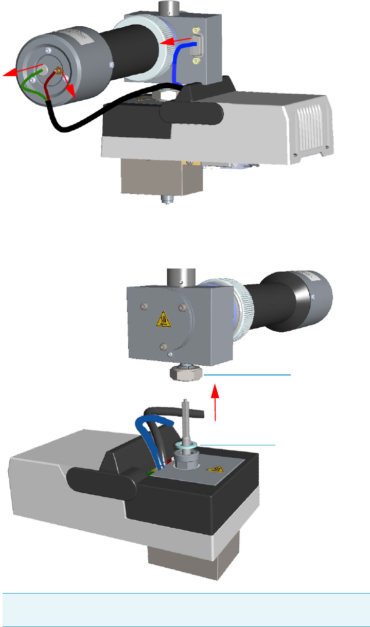
7 Detectors Advanced Maintenance
Cleaning or Replacing the FPD Mirror Metal Plug
296 TRACE 1300 and TRACE 1310 Hardware Manual Thermo Scientific
Figure 280. FPD Cables Disconnection
b. Using the tool provided with the system, loosen the fixing nut on the base of the
detector and remove it. See Figure 281.
Figure 281. FPD Detector Removal
Note Do not lose the aluminium ring inserted between the detector head and
the base body.
FPD Fixing Nut
Aluminium Ring
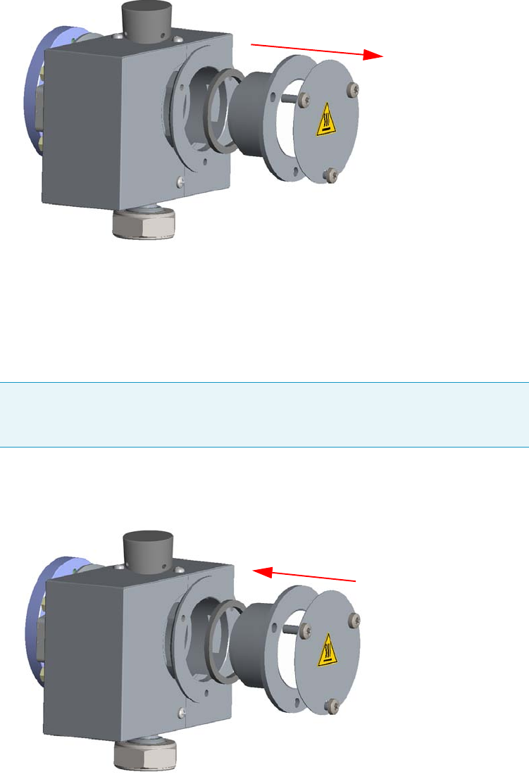
7 Detectors Advanced Maintenance
Cleaning or Replacing the FPD Mirror Metal Plug
Thermo Scientific TRACE 1300 and TRACE 1310 Hardware Manual 297
7. Remove the mirror plug.
a. Loosen the Allen screws on the mirror plug and remove it. See Figure 282.
Figure 282. FPD Mirror Plug Removal
8. Clean the mirror surface of the plug.
a. Using a clean paper towel, clean the mirror surface of the plug. If necessary, use a
solvent as methylene chloride or methanol to remove deposits, and a metal polishing
paste to restore it to the previous reflectivity.
9. Remount the mirror plug.
a. Insert the cleaned or a new mirror plug in the detector body and fix it with the
relevant Allen screws. See Figure 283.
Figure 283. FPD Mirror Plug Remounting
10. Reinstall the FPD detector on the base.
Note Before reinserting the mirror plug, inspect the graphite seal inside the plug’s
housing. If the seal is damaged and could not ensure tightness, replace it with a new
one.
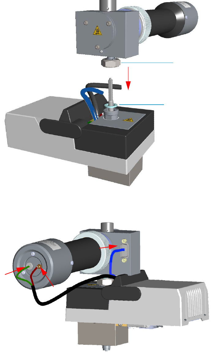
7 Detectors Advanced Maintenance
Cleaning or Replacing the FPD Mirror Metal Plug
298 TRACE 1300 and TRACE 1310 Hardware Manual Thermo Scientific
a. Place the detector on its base body, ensuring that the aluminium ring has been
inserted in the correct position, then tighten the fixing nut. See Figure 284.
Figure 284. FPD Detector Reinstallation
b. Reconnect the signal, excitation voltage and ignition/heating cables to the detector.
See Figure 285.
Figure 285. FPD Cables Connection
FPD Fixing Nut
Aluminium Ring
7 Detectors Advanced Maintenance
Cleaning or Replacing the FPD Mirror Metal Plug
Thermo Scientific TRACE 1300 and TRACE 1310 Hardware Manual 299
11. If other external modules are present, plug the power cable to the AC Input connector of
each module, and to the wall outlet.
12. Power on the GC.
a. Plug the power cable to the AC Input connector into the back of the GC and to the
wall outlet.
b. Flip up the power switch (breaker) to the position I.
13. Set the normal working conditions.

7 Detectors Advanced Maintenance
Cleaning or Replacing the FPD Filter-side Heat Shields
300 TRACE 1300 and TRACE 1310 Hardware Manual Thermo Scientific
Cleaning or Replacing the FPD Filter-side Heat Shields
Before cleaning or replacing the FPD filter-side heat shield, read the following precautions:
To clean or replace the FPD filter-side heat shield
1. Put the GC in standby condition.
2. Switch off the flame. Hydrogen and air are automatically closed.
3. Cool the detector to room temperature.
4. Power off the GC.
a. Push down the power switch (breaker), located at the back of the instrument, to the
position O.
b. Unplug the power cable from the AC Input connector into the back of the GC and
from the wall outlet
5. If other external modules are present, unplug the power cable from the AC Input
connector of each module, and from the wall outlet.
6. Remove the FPD detector from the base.
a. Disconnect the signal, excitation voltage, and ignition/heating cables from the
detector. See Figure 286.
WARNING Carry out all the operations at low temperature to avoid burns. Therefore,
before beginning maintenance, cool the detector to room temperature.
CAUTION When handling organic solvents you must take precautions to avoid health
hazards.
Materials needed
FPD fixing tools
Paper towels
FPD maintenance kit
Methylene chloride or GC-grade methanol
1-mm Allen wrench
Screwdriver
Note By pressing the Maintenance button, the GC cool down is automatically
carried out.
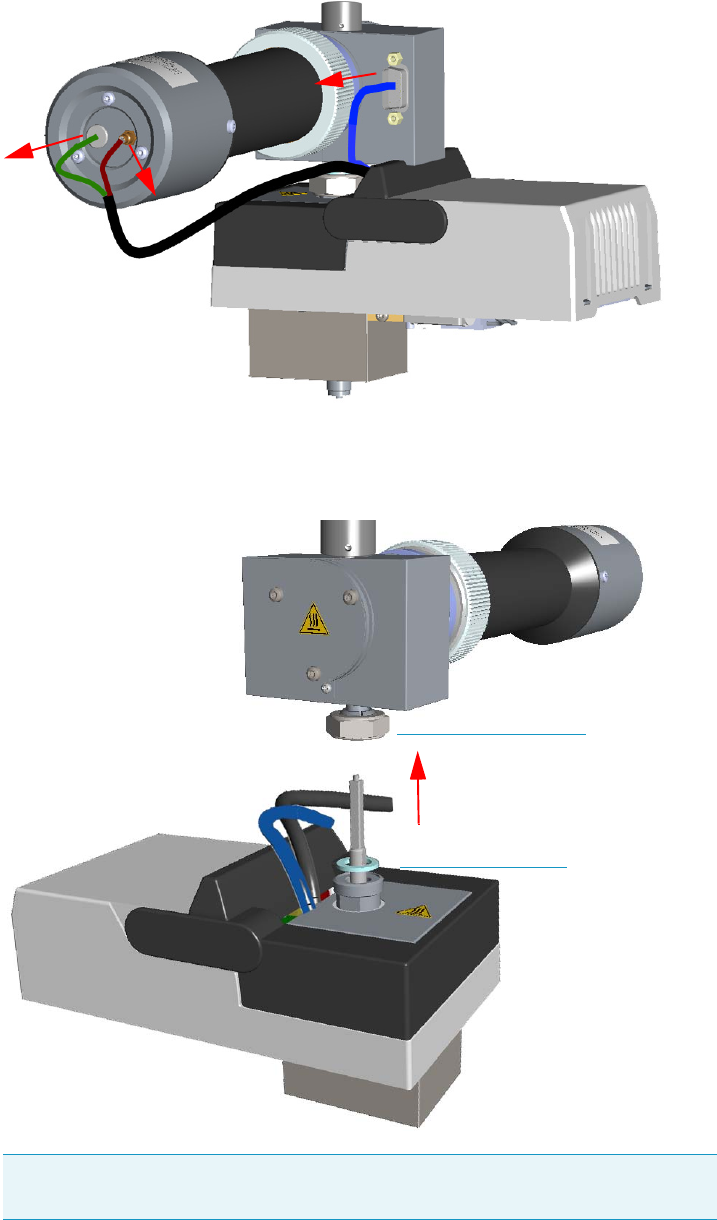
7 Detectors Advanced Maintenance
Cleaning or Replacing the FPD Filter-side Heat Shields
Thermo Scientific TRACE 1300 and TRACE 1310 Hardware Manual 301
Figure 286. FPD Cables Disconnection
b. Using the tool provided with the system, loosen the fixing nut on the base of the
detector and remove it. See Figure 287.
Figure 287. FPD Detector Removal
Note Do not lose the aluminium ring inserted between the detector head and
the base body.
FPD Fixing Nut
Aluminium Ring
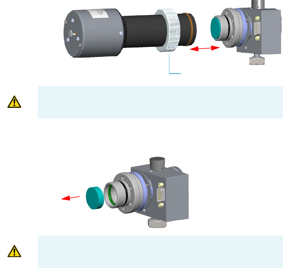
7 Detectors Advanced Maintenance
Cleaning or Replacing the FPD Filter-side Heat Shields
302 TRACE 1300 and TRACE 1310 Hardware Manual Thermo Scientific
7. Remove the photomultiplier assembly and the filter.
a. Loosen the knurled nut that fixes the photomultiplier assembly and remove it from
the detector body. See Figure 288.
Figure 288. Photomultiplier Assembly Removal
b. Remove the interferential filter from its housing, handling it very gently. Keep it
using a clean paper towel. See Figure 289.
Figure 289. Filter Removal
Knurled Nut
CAUTION The photomultiplier tube could damage if exposed to ambient light with the
excitation voltage On. Make sure the power supply has been switched off before
disconnecting the tube from the detector body.
CAUTION Filters are fragile. Pay attention not to let the filter fall down and damage.
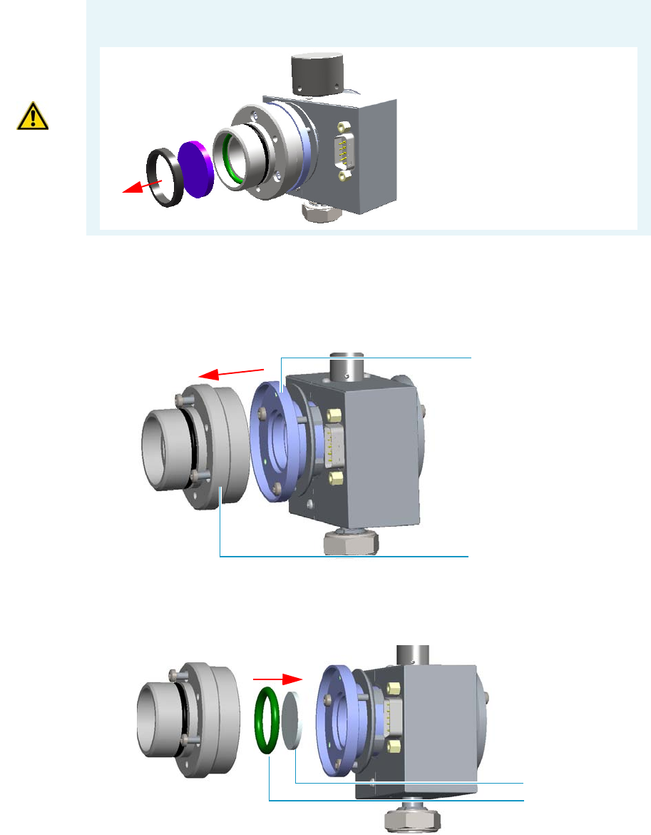
7 Detectors Advanced Maintenance
Cleaning or Replacing the FPD Filter-side Heat Shields
Thermo Scientific TRACE 1300 and TRACE 1310 Hardware Manual 303
8. Remove the filter-side heat shield.
a. Loosen the three Allen screws that fix the filter support to the flange of the detector
body and remove it. See Figure 290.
Figure 290. Filter-side Heat Shield Removal (1)
b. Turn down slowly the detector body and let the filter-side heat shield come out from
the flange. Pay attention not to lose the o-ring inserted in the filter support.
Figure 291. Filter-side Heat Shield Removal (2)
9. Insert a new filter-side heat shield.
CAUTION If the filter installed is equipped with the spacer (see the kits PN 19050785 and
PN 19050786), first remove the spacer, and then the filter.
Interferential Filter
Spacer
Flange
Filter Support
Filter-Side Heat Shield
Viton® O-Ring
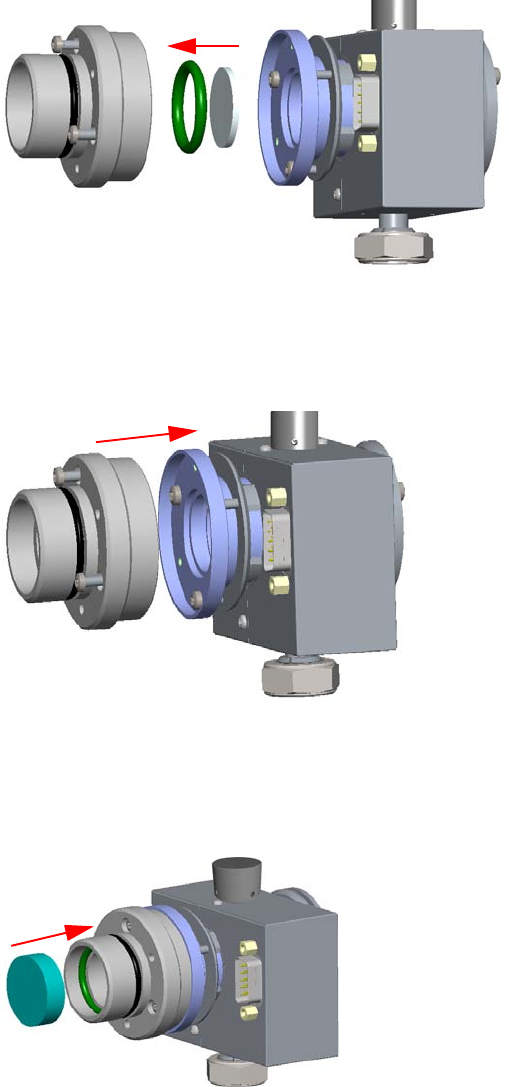
7 Detectors Advanced Maintenance
Cleaning or Replacing the FPD Filter-side Heat Shields
304 TRACE 1300 and TRACE 1310 Hardware Manual Thermo Scientific
a. Insert a new filter-side heat shield into its housing inside the filter support.
See Figure 292.
Figure 292. Filter-side Heat Shield Replacement (1)
b. Insert the filter support into the flange and fix it tightening the three Allen screws.
Check the o-ring that fixes the heat shield is in place before tightening the screws.
See Figure 293.
Figure 293. Filter-side Heat Shield Replacement (2)
10. Remount the filter and the photomultiplier assembly.
a. Reinsert the filter into the support. The mirror face must be oriented towards the
flame. See Figure 294.
Figure 294. Filter Remounting
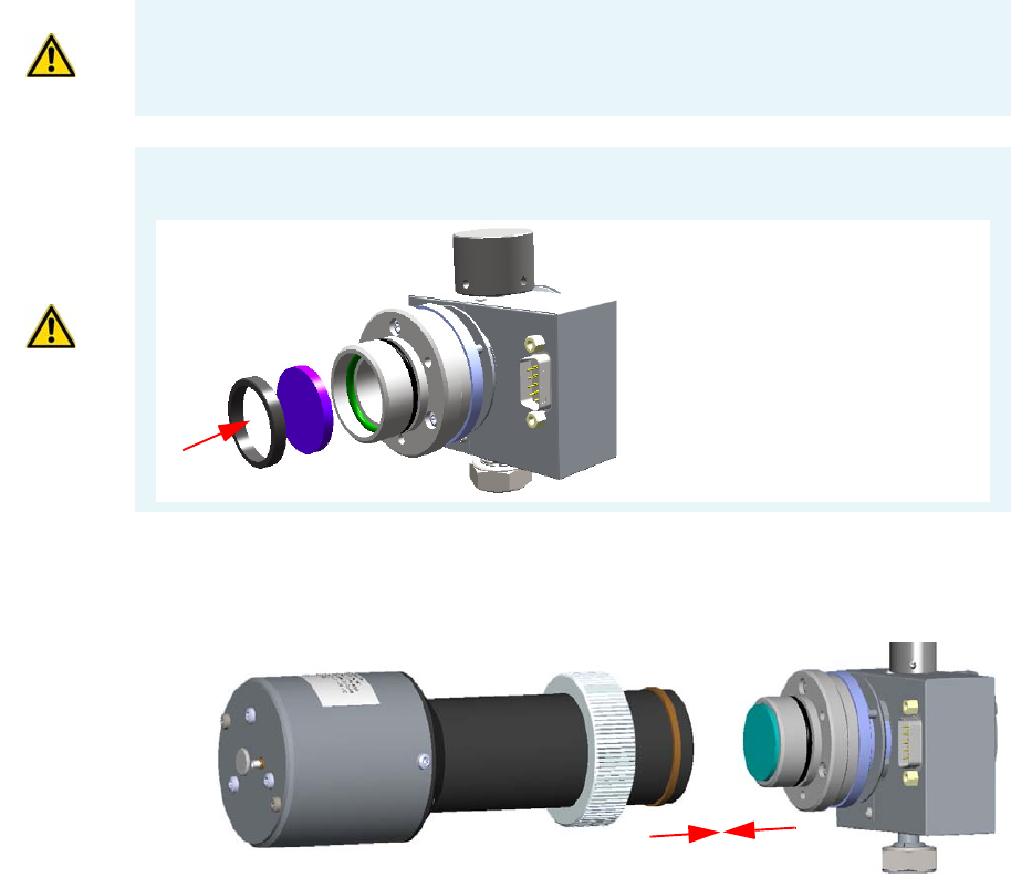
7 Detectors Advanced Maintenance
Cleaning or Replacing the FPD Filter-side Heat Shields
Thermo Scientific TRACE 1300 and TRACE 1310 Hardware Manual 305
b. Reassembly the photomultiplier assembly and the detector body, then fix them
together tightening the knurled nut. See Figure 295.
Figure 295. Photomultiplier Assembly Remounting
11. Reinstall the FPD detector on the base.
a. Place the detector on its base body, ensuring that the aluminium ring has been
inserted in the correct position, then tighten the fixing nut. See Figure 296.
CAUTION Avoid touching the filter with your fingers. If you see fingertips on the filter,
clean it using a clean paper towel and, if needed, GC-grade methanol before remounting.
CAUTION If the filter installed is equipped with the spacer (see the kits PN 19050785 and
PN 19050786), first insert the filter, and then the spacer.
Interferential Filter
Spacer
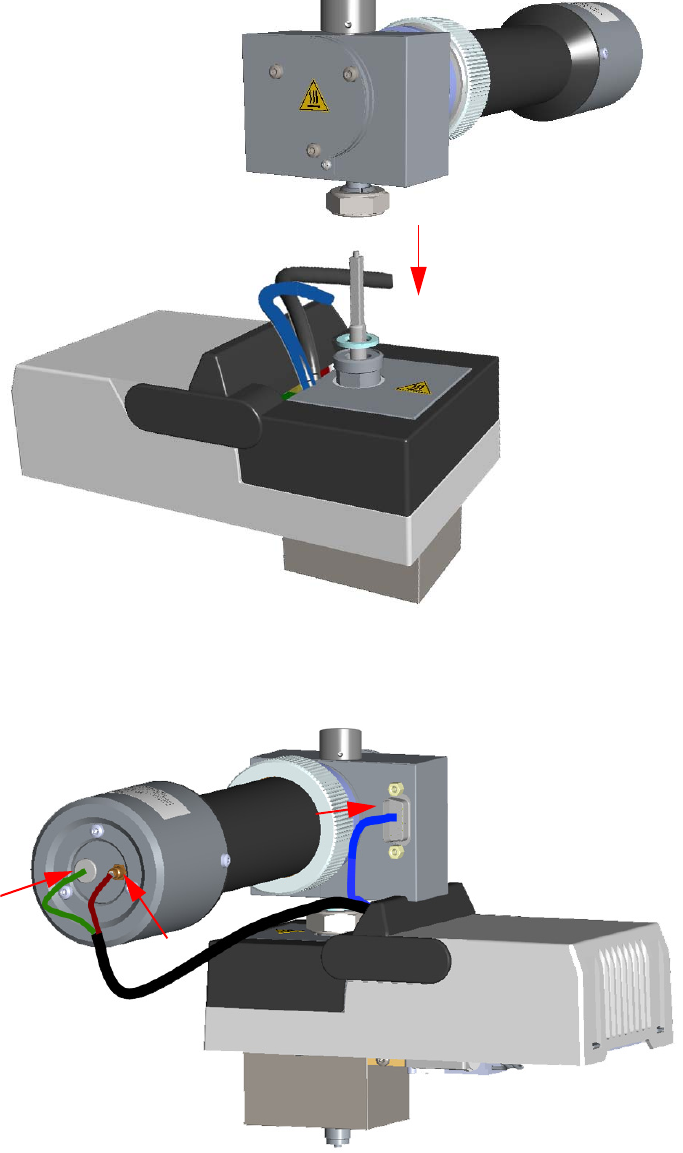
7 Detectors Advanced Maintenance
Cleaning or Replacing the FPD Filter-side Heat Shields
306 TRACE 1300 and TRACE 1310 Hardware Manual Thermo Scientific
Figure 296. FPD Detector Reinstallation
b. Reconnect the signal, excitation voltage and ignition/heating cables to the detector.
See Figure 297.
Figure 297. FPD Cables Connection
12. If other external modules are present, plug the power cable to the AC Input connector of
each module, and to the wall outlet.
7 Detectors Advanced Maintenance
Cleaning or Replacing the FPD Filter-side Heat Shields
Thermo Scientific TRACE 1300 and TRACE 1310 Hardware Manual 307
13. Power on the GC.
a. Plug the power cable to the AC Input connector into the back of the GC and to the
wall outlet.
b. Flip up the power switch (breaker) to the position I.
14. Set the normal working conditions.
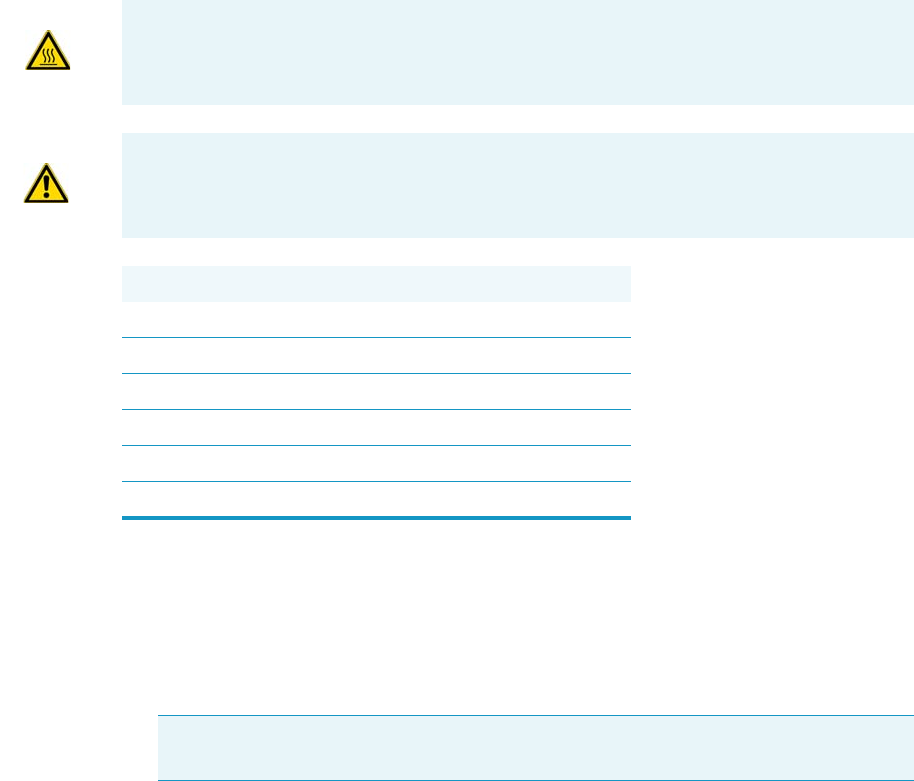
7 Detectors Advanced Maintenance
Cleaning or Replacing the FPD Flame-side Heat Shields
308 TRACE 1300 and TRACE 1310 Hardware Manual Thermo Scientific
Cleaning or Replacing the FPD Flame-side Heat Shields
Before cleaning or replacing the FPD flame-side heat shield, read the following precautions:
To clean or replace the FPD flame-side heat shield
1. Put the GC in standby condition.
2. Switch off the flame. Hydrogen and air are automatically closed.
3. Cool the detector to room temperature.
4. Power off the GC.
a. Push down the power switch (breaker), located at the back of the instrument, to the
position O.
b. Unplug the power cable from the AC Input connector into the back of the GC and
from the wall outlet.
5. If other external modules are present, unplug the power cable from the AC Input
connector of each module, and from the wall outlet.
6. Remove the FPD detector from the base.
a. Disconnect the signal, excitation voltage, and ignition/heating cables from the
detector. See Figure 298.
WARNING Carry out all the operations at low temperature to avoid burns. Therefore,
before beginning maintenance, cool the detector to room temperature.
CAUTION When handling organic solvents you must take precautions to avoid health
hazards.
Materials needed
FPD fixing tools
Paper towels
FPD maintenance kit
Methylene chloride or GC-grade methanol
1-mm Allen wrench
Screwdriver
Note By pressing the Maintenance button, the GC cool down is automatically
carried out.
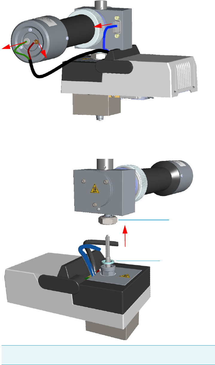
7 Detectors Advanced Maintenance
Cleaning or Replacing the FPD Flame-side Heat Shields
Thermo Scientific TRACE 1300 and TRACE 1310 Hardware Manual 309
Figure 298. FPD Cable Disconnection
b. Using the tool provided with the system, loosen the fixing nut on the base of the
detector and remove it. See Figure 299.
Figure 299. FPD Detector Removal
Note Do not lose the aluminium ring inserted between the detector head and
the base body.
FPD Fixing Nut
Aluminium Ring
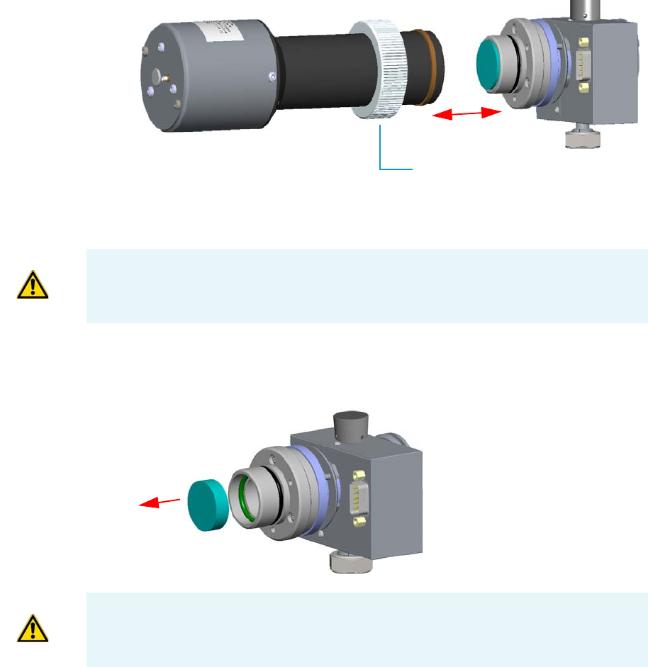
7 Detectors Advanced Maintenance
Cleaning or Replacing the FPD Flame-side Heat Shields
310 TRACE 1300 and TRACE 1310 Hardware Manual Thermo Scientific
7. Remove the photomultiplier assembly and the filter. See Figure 300.
Figure 300. Photomultiplier Assembly Removal
a. Loosen the knurled nut that fixes the photomultiplier assembly and remove it from
the detector body.
b. Remove the interferential filter from its housing, handling it very gently. Keep it
using a clean paper towel. See Figure 301.
Figure 301. Filter Removal
Knurled Nut
CAUTION The photomultiplier tube could damage if exposed to ambient light with the
excitation voltage On. Make sure the power supply has been switched off before
disconnecting the tube from the detector body.
CAUTION Filters are fragile. Pay attention not to let the filter fall down and damage.
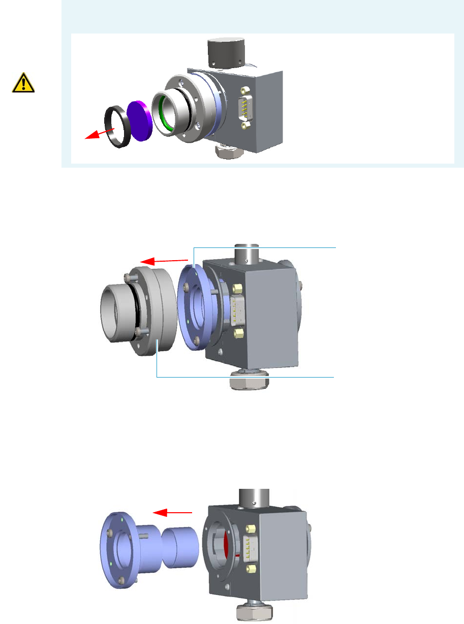
7 Detectors Advanced Maintenance
Cleaning or Replacing the FPD Flame-side Heat Shields
Thermo Scientific TRACE 1300 and TRACE 1310 Hardware Manual 311
8. Remove the filter support.
a. Loosen the three Allen screws that fix the filter support to the flange of the detector
body and remove it. See Figure 302.
Figure 302. Filter Support Removal
9. Remove the filter-side heat shield.
a. Loosen the three Allen screws that fix the flange to the detector body and remove it
with the spacer that should remain inserted in the flange. Now you could access the
flame-side heat shield, and the relevant graphite seal. See Figure 303.
Figure 303. Filter-side Heat Shield Removal (1)
CAUTION If the filter installed is equipped with the spacer (see the kits PN 19050785 and
PN 19050786), first remove the spacer, and then the filter.
Interferential Filter
Spacer
Flange
Filter Support
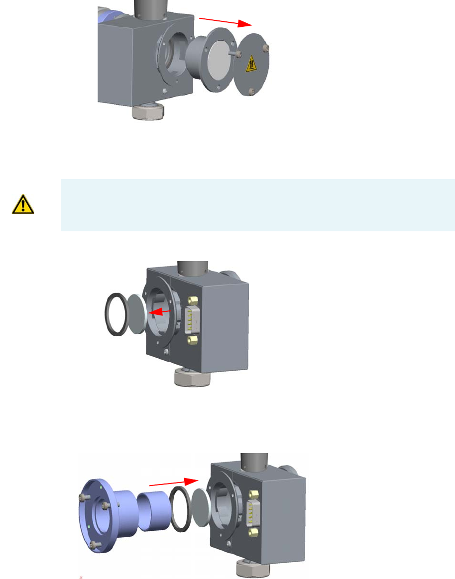
7 Detectors Advanced Maintenance
Cleaning or Replacing the FPD Flame-side Heat Shields
312 TRACE 1300 and TRACE 1310 Hardware Manual Thermo Scientific
b. Loosen the Allen screws that fix the mirror plug and remove it. See Figure 304.
Figure 304. Mirror Plug Removal
c. Insert the handle of a screwdriver or other un-sharpened tool in the combustion
chamber and push the flame-side heat shield and its graphite seal out from its
housing. Act gently to avoid breaking of the heat shield. See Figure 305.
Figure 305. Filter-side Heat Shield Removal (2)
d. Remove with care traces of graphite due to the breaking of the seal.
10. Insert a new filter-side heat shield. See Figure 306.
Figure 306. Filter-side Heat Shield Replacement (1)
CAUTION While pushing out the heat shield, pay attention not to damage the ignition
coil.
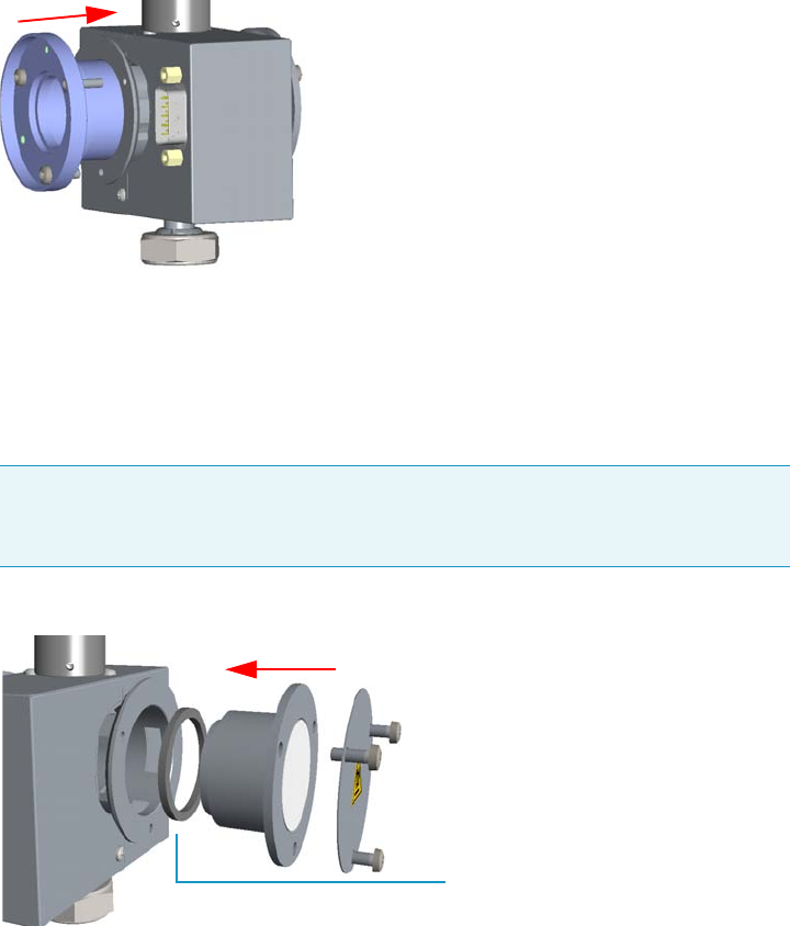
7 Detectors Advanced Maintenance
Cleaning or Replacing the FPD Flame-side Heat Shields
Thermo Scientific TRACE 1300 and TRACE 1310 Hardware Manual 313
a. Insert a new heat shield into its housing inside the detector body.
b. Insert the spacer into the flange, letting it stand out for about 5 mm.
c. Insert a new graphite seal on the spacer, pushing it slowly until it touches the flange.
d. Insert the flange into the detector body and fix it tightening the three Allen screws.
See Figure 307.
Figure 307. Filter-side Heat Shield Replacement
nt (2)
e. Using a clean paper towel, clean the mirror surface of the plug. If necessary, use a
solvent as methylene chloride or methanol to remove deposits and a metal polishing
paste to restore it to the previous reflectivity.
f. Insert the mirror plug in the detector body and fix it with the relevant Allen screws.
See Figure 308.
Figure 308. Mirror Plug Reinstallation
g. Insert the filter support into the flange and fix it tightening the three Allen screws.
Check the O-ring that fixes the heat shield is in place before tightening the screws.
See Figure 309.
Note Before reinserting the plug, inspect the graphite seal inside the plug’s
housing. If the seal is damaged and could not ensure tightness, remove it and
replace with a new one.
Graphite Seal
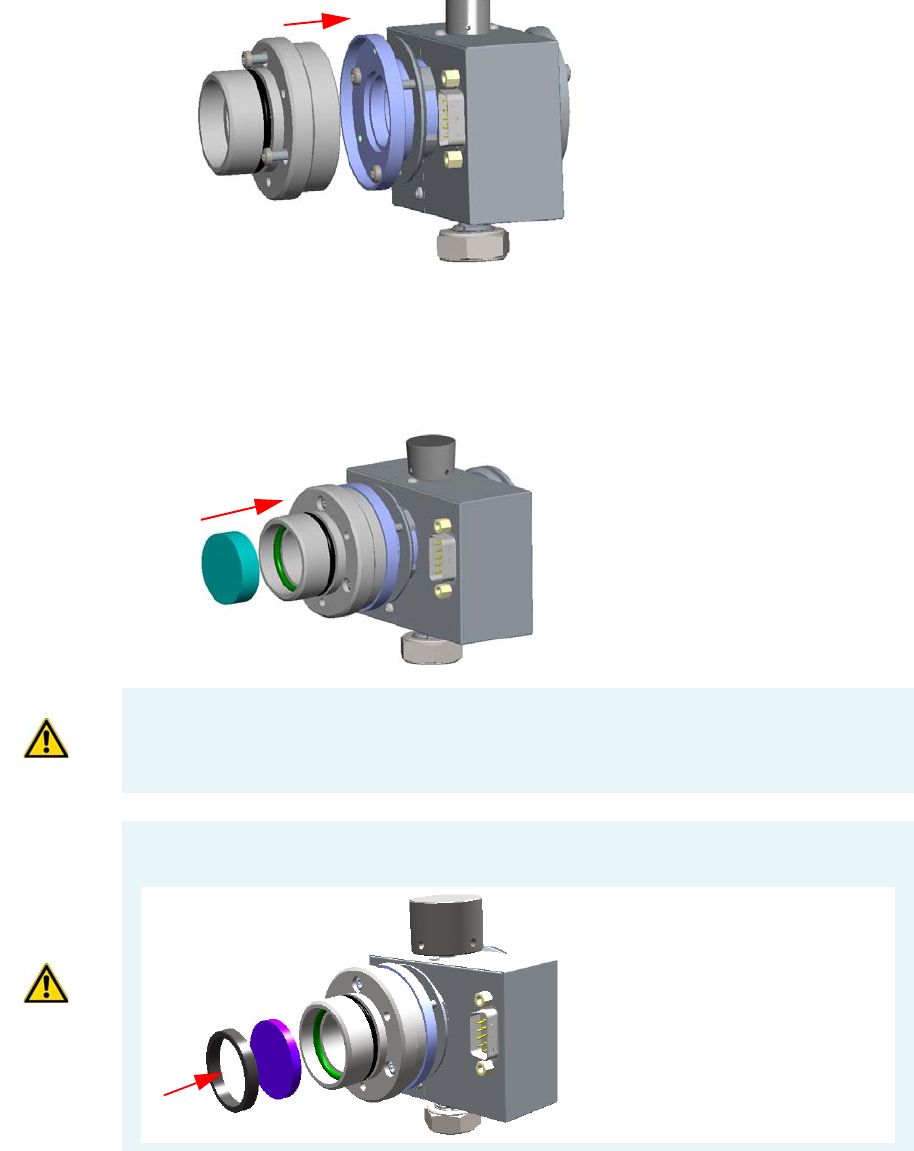
7 Detectors Advanced Maintenance
Cleaning or Replacing the FPD Flame-side Heat Shields
314 TRACE 1300 and TRACE 1310 Hardware Manual Thermo Scientific
Figure 309. Filter Support Reinstallation
11. Reassembly the filter and the photomultiplier assembly.
a. Reinsert the filter into the support. The mirror face must be oriented towards the
flame. See Figure 310.
Figure 310. Filter Remounting
b. Reassembly the photomultiplier assembly and the detector body, then fix them
together tightening the knurled nut. See Figure 311.
CAUTION Avoid touching the filter with your fingers. If you see fingertips on the filter,
clean it using a clean paper towel and, if needed, GC-grade methanol before remounting.
CAUTION If the filter installed is equipped with the spacer (see the kits PN 19050785 and
PN 19050786), first insert the filter, and then the spacer.
Interferential Filter
Spacer
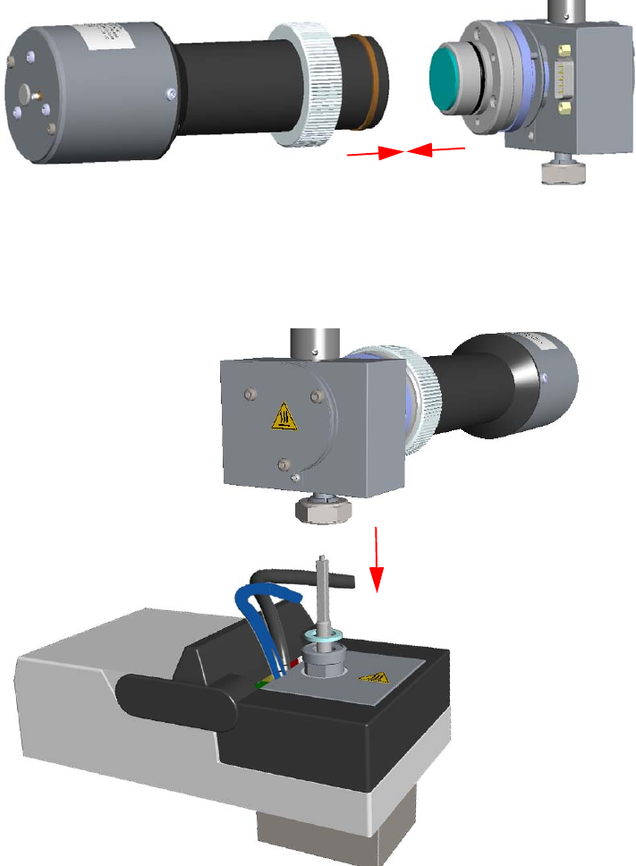
7 Detectors Advanced Maintenance
Cleaning or Replacing the FPD Flame-side Heat Shields
Thermo Scientific TRACE 1300 and TRACE 1310 Hardware Manual 315
Figure 311. Photomultiplier Assembly Remounting
12. Reinstall the FPD detector on the base.
a. Place the detector on its base body, ensuring that the aluminium ring has been
inserted in the correct position, then tighten the fixing nut. See Figure 312.
Figure 312. FPD Detector Reinstallation
b. Reconnect the signal, excitation voltage and ignition/heating cables to the detector.
See Figure 313.
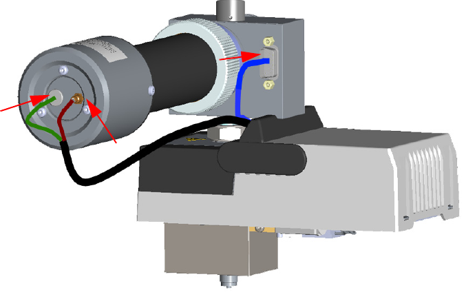
7 Detectors Advanced Maintenance
Cleaning or Replacing the FPD Flame-side Heat Shields
316 TRACE 1300 and TRACE 1310 Hardware Manual Thermo Scientific
Figure 313. FPD Cables Connection
13. If other external modules are present, plug the power cable to the AC Input connector of
each module, and to the wall outlet.
14. Power on the GC.
a. Plug the power cable to the AC Input connector into the back of the GC and to the
wall outlet.
b. Flip up the power switch (breaker) to the position I.
15. Set the normal working conditions.
7 Detectors Advanced Maintenance
Replacing the FPD Photomultiplier Tube
Thermo Scientific TRACE 1300 and TRACE 1310 Hardware Manual 317
Replacing the FPD Photomultiplier Tube
Before replacing the FPD photomultiplier tube, read the following precautions:
To replace the photomultiplier tube
1. Put the GC in standby condition.
2. Switch off the flame. Hydrogen and air are automatically closed.
3. Cool the detector to room temperature.
4. Power off the GC.
a. Push down the power switch (breaker), located at the back of the instrument, to the
position O.
b. Unplug the power cable from the AC Input connector into the back of the GC and
from the wall outlet.
5. If other external modules are present, unplug the power cable from the AC Input
connector of each module, and from the wall outlet.
6. Remove the FPD detector from the base.
a. Disconnect the signal, excitation voltage, and ignition/heating cables from the
detector. See Figure 314.
WARNING Carry out all the operations at low temperature to avoid burns. Therefore,
before beginning maintenance, cool the detector to room temperature.
CAUTION The photomultiplier tube must be replaced only when defective.
Wear clean, lint- and powder-free gloves when you handle the photomultiplier tube.
Materials needed
FPD fixing tools
FPD Photomultiplier Tube
1-mm Allen wrench
Cross head screwdriver
Gloves
Note By pressing the Maintenance button, the GC cool down is automatically
carried out.
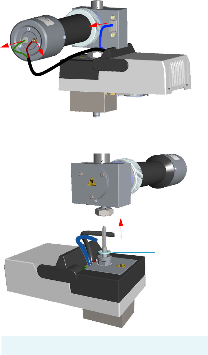
7 Detectors Advanced Maintenance
Replacing the FPD Photomultiplier Tube
318 TRACE 1300 and TRACE 1310 Hardware Manual Thermo Scientific
Figure 314. FPD Cable Disconnection
b. Using the tool provided with the system, loosen the fixing nut on the base of the
detector and remove it. See Figure 315.
Figure 315. FPD Detector Removal
Note Do not lose the aluminium ring inserted between the detector head and
the base body.
FPD Fixing Nut
Aluminium Ring
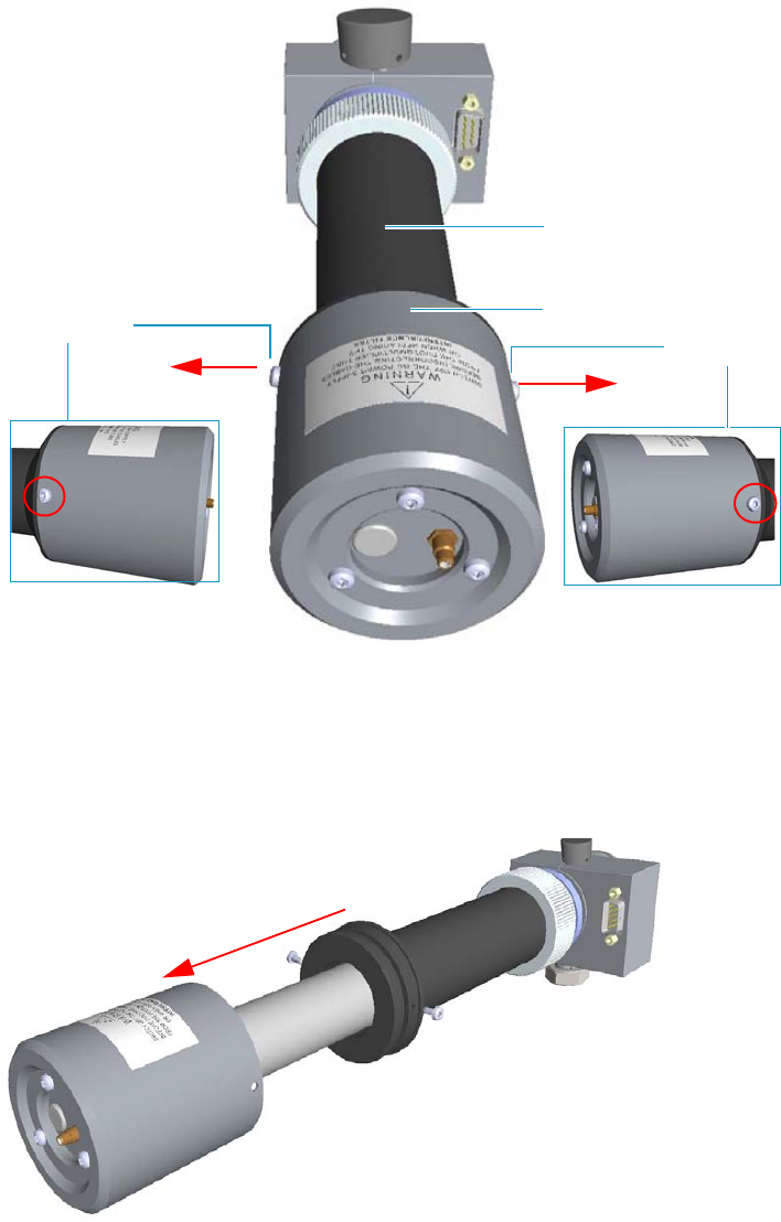
7 Detectors Advanced Maintenance
Replacing the FPD Photomultiplier Tube
Thermo Scientific TRACE 1300 and TRACE 1310 Hardware Manual 319
7. Dismount the photomultiplier tube assembly.
a. Using a crosshead screwdriver unscrew the two fixing screws that fix the
photomultiplier tube housing to the photomultiplier tube holder. See Figure 316.
Figure 316. Photomultiplier Tube Housing Removal (1)
b. Remove the photomultiplier tube housing from the photomultiplier tube holder.
Holding the photomultiplier tube holder with one hand, use the other hand to pull
out the photomultiplier tube housing from the holder. During the extraction meets
some resistance due to the presence of an o-ring inside the holder. See Figure 317.
Figure 317. Photomultiplier Tube Housing Removal (2)
Photomultiplier Tube Holder
Fixing Screw
Fixing Screw Photomultiplier Tube Housing
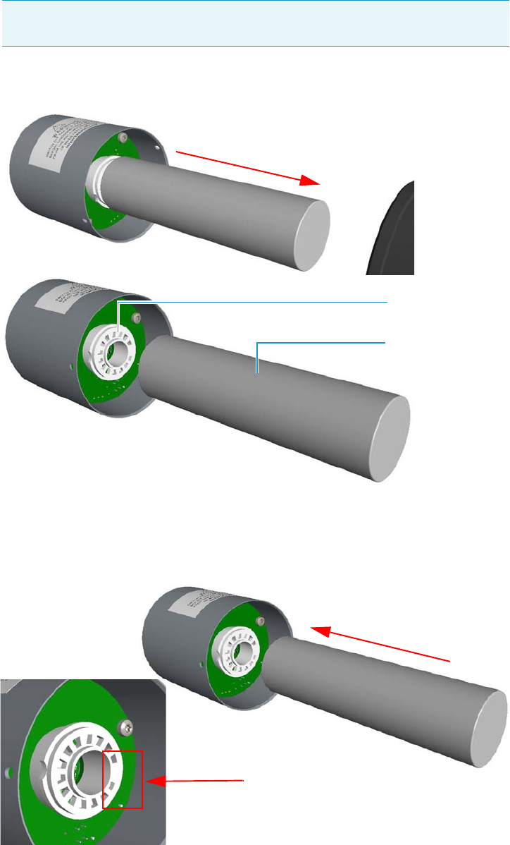
7 Detectors Advanced Maintenance
Replacing the FPD Photomultiplier Tube
320 TRACE 1300 and TRACE 1310 Hardware Manual Thermo Scientific
8. Replace the defective photomultiplier tube.
a. Carefully extract the photomultiplier tube from its connector. See Figure 318.
Figure 318. Photomultiplier Tube Replacement (1)
b. Replace the photomultiplier tube with a new one. Make sure to correctly insert the
pins of the photomultiplier tube into the connector referring to the polarized
position. See Figure 319.
Figure 319. Connector Polarized Position
Note Wear clean, lint- and powder-free gloves when you handle the
photomultiplier tube.
Photomultiplier Tube
Connector
Polarized Position
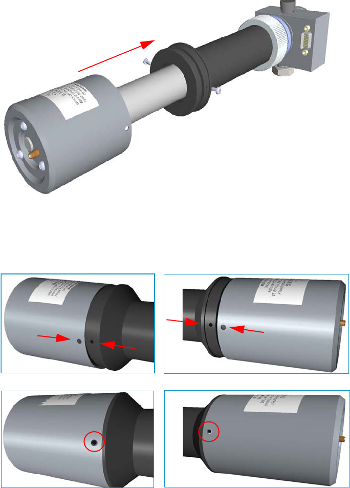
7 Detectors Advanced Maintenance
Replacing the FPD Photomultiplier Tube
Thermo Scientific TRACE 1300 and TRACE 1310 Hardware Manual 321
9. Remount the photomultiplier tube assemble.
a. Reinsert the photomultiplier tube housing into the photomultiplier tube holder.
Holding the photomultiplier tube holder with one hand, use the other hand to
reinsert the photomultiplier tube housing into the holder. During the insertion meets
some resistance due to the presence of an o-ring inside the holder.
See Figure 320.
Figure 320. Photomultiplier Tube Housing Reinstallation (1)
b. Fix the photomultiplier tube housing to the photomultiplier tube holder.
Carefully rotate the photomultiplier tube housing up to matching its fixing holes to
the fixing holes on the photomultiplier tube holder. See Figure 321.
Figure 321. Photomultiplier Tube Housing Reinstallation (2)
c. Insert the two fixing screws into the corresponding fixing holes, then tighten the
screws using a crosshead screwdriver.
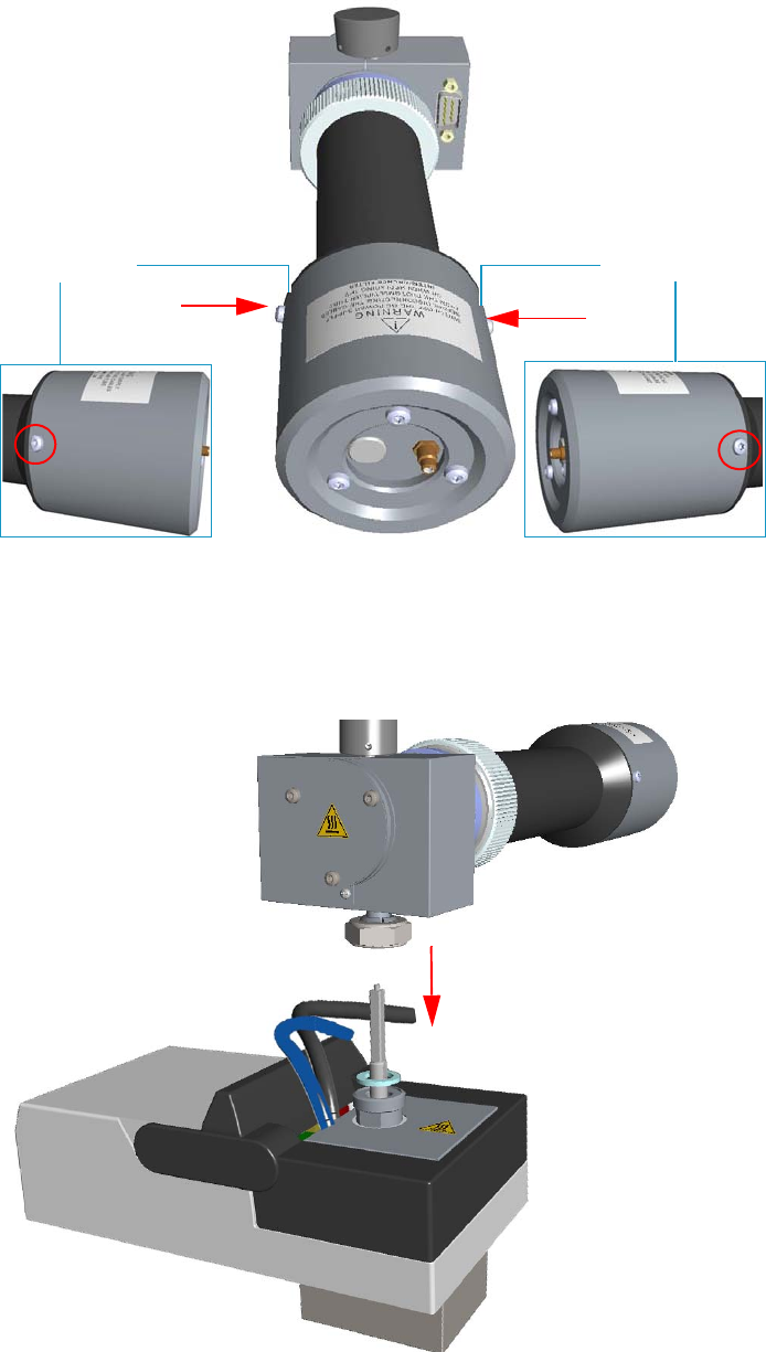
7 Detectors Advanced Maintenance
Replacing the FPD Photomultiplier Tube
322 TRACE 1300 and TRACE 1310 Hardware Manual Thermo Scientific
Figure 322. Photomultiplier Tube Housing Reinstallation (3)
10. Reinstall the FPD detector on the base.
a. Place the detector on its base body, ensuring that the aluminium ring has been
inserted in the correct position, then tighten the fixing nut. See Figure 323.
Figure 323. FPD Detector Reinstallation
Fixing ScrewFixing Screw
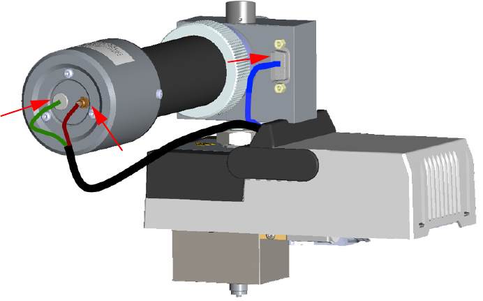
7 Detectors Advanced Maintenance
Replacing the FPD Photomultiplier Tube
Thermo Scientific TRACE 1300 and TRACE 1310 Hardware Manual 323
b. Reconnect the signal, excitation voltage and ignition/heating cables to the detector.
See Figure 324.
Figure 324. FPD Cables Connection
11. If other external modules are present, plug the power cable to the AC Input connector of
each module, and to the wall outlet.
12. Power on the GC.
a. Plug the power cable to the AC Input connector into the back of the GC and to the
wall outlet.
b. Flip up the power switch (breaker) to the position I.
13. Set the normal working conditions.
7 Detectors Advanced Maintenance
Replacing the FPD Photomultiplier Tube
324 TRACE 1300 and TRACE 1310 Hardware Manual Thermo Scientific

Thermo Scientific TRACE 1300 and TRACE 1310 Hardware Manual 325
8
Installing Optional Kits
This chapter describes how to install the optional kits available for the TRACE 1300/TRACE
1310. See the TRACE 1300 and TRACE 1310 Spare Parts Guide for information about
ordering the upgrade kits in this chapter.
Contents
•Installing the Oven Exhaust Kit
•Installing the Merlin Microseal High Pressure Valve Kit
•Installing the Purge & Trap Adapter Kit on the SSL/SSLBKF Injector
•Installing the Packed Column Adapters
•Installing the HS Adapter Kit on the SSL/SSLBKF Injector
•Installing the Large Volume Splitless Kit
•Installing the Manual On/Off Valve for Single Gas Line
•Connecting a SSL/PTV Backflush System
•Connecting a SSL/PTV Backflush System for High Temperature
•Connecting a GSV Backflush System
•Installing the NoVent Microfluidics
•Installing a FTIR Make-up Module
•Installing the Hot Injection Adapter Kit on the SSL/SSLBKF Injector
•Performing the Dual FPD Detector Configuration
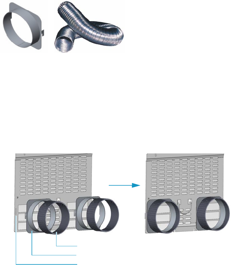
8 Installing Optional Kits
Installing the Oven Exhaust Kit
326 TRACE 1300 and TRACE 1310 Hardware Manual Thermo Scientific
Installing the Oven Exhaust Kit
The oven vents at the back of the GC discharge hot air up to 450 °C (842 °F) during cooling.
Installing the optional Oven Exhaust Kit (PN 19050760), the hot air from the oven vents can
be carried away to a fume hood or other exhausting devices.
The kit includes two air ducts and two 3-m length extensible aluminium tubes.
See Figure 325.
Figure 325. Air Duct and Extensible Aluminium Tube
To install the oven exhaust kit
1. Put the GC in standby condition.
2. Cool the oven to room temperature.
3. Place each air duct on the oven vent inserting the hooks of the air duct into the relevant
vertical slots provided on the GC back panel.
4. Place an end of each extensible aluminium tube on each air duct.
5. Connect the other end of the extensible aluminium tube to an exhausting device.
6. Set the normal GC working conditions.
Air Duct Extensible Aluminium Tube
Air Duct
Extensible Aluminium Tube
Slot

8 Installing Optional Kits
Installing the Merlin Microseal High Pressure Valve Kit
Thermo Scientific TRACE 1300 and TRACE 1310 Hardware Manual 327
Installing the Merlin Microseal High Pressure Valve Kit
This section provides instructions for installing the Merlin Microseal™ High Pressure Valve kit
(PN 19050735) on the SSL, SSLBKF, HeS-S/SL, PTV, and PTVBKF injectors.
Introduction
The Merlin Microseal™ High Pressure Valve is a long-life replacement for the standard septum
on the SSL, SSLBKF, HeS-S/SL, PTV, and PTVBKF injectors of the TRACE 1300/TRACE
1310. High pressure capability allows operation from 15 to 700 kPa (2 - 100 psi). A top wiper
rib improves resistance to particulate contamination. The valve can be taken apart for
cleaning. High resistance to wear greatly reduces the shedding of valve particles into the
injection port liner. This eliminates a major source of septum bleed and ghost peaks in the
chromatogram. Longer life reduces the chances of valve leaks occurring during extended
automated runs. The low syringe insertion force makes manual injections easier.
The Microseal High Pressure valve requires a 0.63-mm diameter (0.025-in.) blunt tip syringe.
Syringe Compatibility — The Microseal valve should be used only with a blunt-tipped
0.63-mm diameter (0.025-in.; 23 gauge) syringe needle.
• A needle with too small a diameter, such as a 0.43-mm diameter (0.017-in.; 23 gauge)
needle, will not seal properly.
• A needle with too large a diameter will overstretch and damage the O-ring and duckbill
seals.
• A sharp-pointed or sharp-edged syringe needle will slice or pierce the seals.
Temperature and Pressure Limits — The operating temperature of the valve is lower than
the injection port temperature set point. For long term operation (> 6 months) use the
following limits for operating conditions:
• Injection port temperature < 350 °C; Pressure range: 15 - 700 kPa (2 - 100 psi)
Higher temperatures and pressures result in shorter lifetime. High temperature deterioration
can be recognized by leaks caused by stiffening and cracking of the Microseal valve,
particularly around the sealing flange.
Getting Started
Install the Microseal High Pressure Valve on the SSL, SSLBKF, HeS-S/SL, PTV, and
PTVBKF injector following the instructions in the next operating procedures.
•“To install the Merlin Microseal Valve kit on the SSL/SSLBKF and HeS-S/SL injector”
on page 328
•“To install the Merlin Microseal Valve kit on the PTV/PTVBKF injector” on page 329
Note Merlin Microseal™ is a trademark of the Merlin Instrument Company.
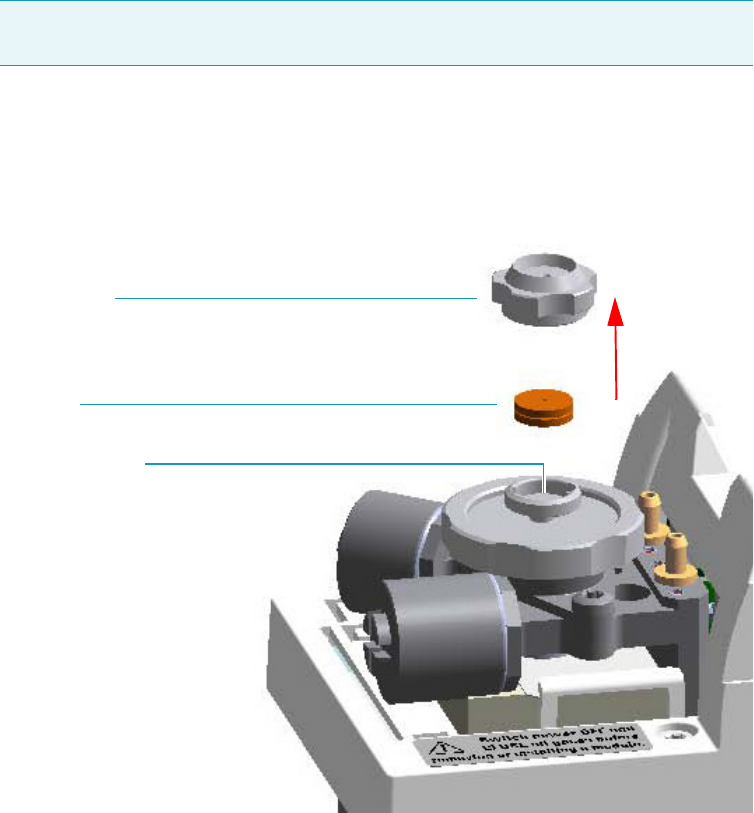
8 Installing Optional Kits
Installing the Merlin Microseal High Pressure Valve Kit
328 TRACE 1300 and TRACE 1310 Hardware Manual Thermo Scientific
To install the Merlin Microseal Valve kit on the SSL/SSLBKF and HeS-S/SL injector
1. Put the GC in standby condition.
2. Cool the oven and injector to room temperature.
3. Turn the carrier gas off, and wait for the carrier pressure to go to zero.
4. Put the autosampler away if present.
5. Open the module flap cover.
6. Remove the septum.
Figure 326. SSL/SSLBKF and HeS-S/SL Injector: Septum Replacement
a. Unscrew and remove the septum cap.
b. Using tweezers, remove the septum from the septum holder.
7. Install the Microseal valve on the injector.
Note By pressing the Maintenance button, the GC cool down is automatically
carried out.
Septum Holder
Septum
Septum Cap
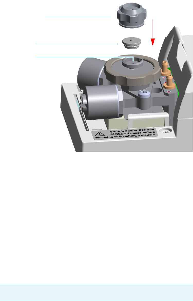
8 Installing Optional Kits
Installing the Merlin Microseal High Pressure Valve Kit
Thermo Scientific TRACE 1300 and TRACE 1310 Hardware Manual 329
Figure 327. SSL/SSLBKF and HeS-S/SL Injector: Microseal Valve Installation
a. Place the Microseal valve in the septum holder.
b. Push down gently to seat the Microseal valve onto the rim of the septum holder.
c. Screw the Microseal valve cap completely. Microseal valve overtightening and sealing
flange stressing is not mechanically allowed.
8. Close the module flap cover.
9. If present, move the autosampler towards the module to restore the original alignment.
10. Turn the carrier gas on.
11. Set the normal injector, detector, and GC working conditions.
To install the Merlin Microseal Valve kit on the PTV/PTVBKF injector
1. Put the GC in standby condition.
2. Cool the oven and injector to room temperature.
3. Turn the carrier gas off, and wait for the carrier pressure to go to zero.
4. Put the autosampler away if present.
Note By pressing the Maintenance button, the GC cool down is automatically
carried out.
Septum Holder
Microseal Valve
Microseal Valve Cap
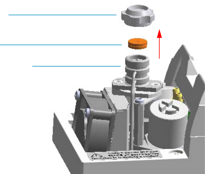
8 Installing Optional Kits
Installing the Merlin Microseal High Pressure Valve Kit
330 TRACE 1300 and TRACE 1310 Hardware Manual Thermo Scientific
5. Open the module flap cover.
6. Remove the septum.
Figure 328. PTV/PTVBKF Injector: Septum Replacement
a. Unscrew the septum cap of the injector.
b. Using tweezers, remove the septum from the injector head assembly.
7. Install the Microseal valve on the injector.
Septum
Septum Cap
Injector Head Assembly
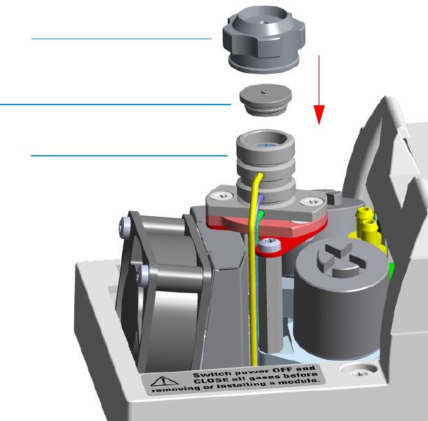
8 Installing Optional Kits
Installing the Merlin Microseal High Pressure Valve Kit
Thermo Scientific TRACE 1300 and TRACE 1310 Hardware Manual 331
Figure 329. PTV/PTVBKF Injector: Microseal Valve Installation
a. Place the Microseal valve in the injector head assembly.
b. Push down gently to seat the Microseal valve onto the rim of the septum holder.
c. Screw the Microseal valve cap completely. Microseal valve overtightening and sealing
flange stressing is not mechanically allowed.
8. Close the module flap cover.
9. If present, move the autosampler towards the module to restore the original alignment.
10. Turn the carrier gas on.
11. Set the normal injector, detector, and GC working conditions.
Microseal Valve
Microseal Valve Cap
Injector Head Assembly
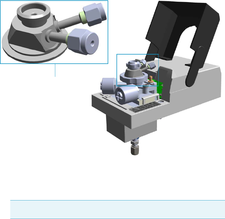
8 Installing Optional Kits
Installing the Purge & Trap Adapter Kit on the SSL/SSLBKF Injector
332 TRACE 1300 and TRACE 1310 Hardware Manual Thermo Scientific
Installing the Purge & Trap Adapter Kit on the SSL/SSLBKF Injector
This section provides the instruction for installing the Purge & Trap Adapter kit
(PN 19050730) on the SSL/SSLBKF injector for the use with a Purge & Trap system.
See Figure 330.
Figure 330. Purge & Trap Adapter
To install the purge & trap adapter
1. Put the GC in standby condition.
2. Cool the oven, injector, and detector to room temperature.
3. Close the gas supplies.
4. Power off the GC.
a. Push down the power switch (breaker), located at the back of the instrument, to the
position O.
b. Unplug the power cable from the AC Input connector into the back of the GC and
from the wall outlet.
5. Remove the column end from the injector.
a. Open the front door of the GC.
Note By pressing the Maintenance button, the GC cool down is automatically
carried out.
Purge and Trap Adapter
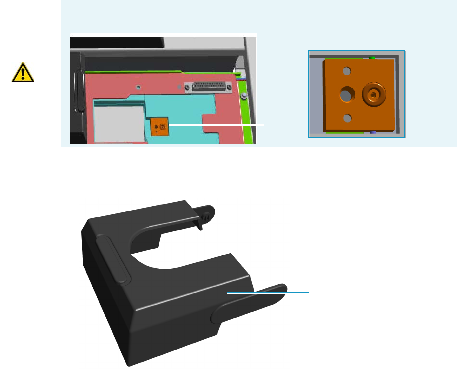
8 Installing Optional Kits
Installing the Purge & Trap Adapter Kit on the SSL/SSLBKF Injector
Thermo Scientific TRACE 1300 and TRACE 1310 Hardware Manual 333
b. Loosen the retaining nut from the injector fitting on the upper interior wall of the
GC oven.
c. Remove the analytical column with its nut and ferrule from the bottom of the
injector.
6. Put the autosampler away if present.
7. Remove the SSL/SSLBKF injector module from its seat.
a. Open the module flap cover.
b. Using a T20 Torxhead screwdriver, unscrew the three captive fixing screws.
c. Throw upward the module from its seat of the injector housing. Place the
SSL/SSLBKF module on a clean surface.
8. Replace the module flap cover with the one’s provided. See Figure 331.
Figure 331. Module Flap Cover for Purge & Trap
9. Reinstall the injector module into the main frame.
a. Open the module flap cover.
WARNING Make sure the o-ring remains into its seat on the gas connection.
Do not install the module if the o-ring is missing.
O-ring
Module Flap Cover

8 Installing Optional Kits
Installing the Purge & Trap Adapter Kit on the SSL/SSLBKF Injector
334 TRACE 1300 and TRACE 1310 Hardware Manual Thermo Scientific
b. Place the injector module in its seat. Be sure to insert the 25-pin male connector, on
the bottom of the module, into the 25-pin female connector on the injector seat of
the injector housing.
c. Use a T20 Torxhead screwdriver to tighten the three captive fixing screws without
overtighten.
10. Remove the top parts of the injector. See Figure 332.
Figure 332. Injector Top Parts Removal
a. Unscrew the septum cap of the injector.
b. Unscrew the ring nut.
c. Remove the septum holder/liner cap with septum from the injector body head.
11. Replace the liner.
a. Use tweezer to remove the current liner with the liner seal (o-ring) from the injector.
b. Holding the HS/SPME liner with tweezers place a new liner seal over the liner.
c. Insert the liner into the injector and push it gently towards the bottom of the injector.
CAUTION To maintain the correct alignment the screws must be tightened in turn.
Tighten each screw only a small amount before moving to the next screw. Repeat until all
are secure.
IMPORTANT We suggest to replace the liner currently installed into the injector with
the HS/SPME liner (PN 453A1335).
CAUTION Be careful not to break the glass liner when removing it. Glass
splinters might fall into the lower part of the vaporization chamber.
Septum Cap
Ring Nut
Septum Holder/Liner Cap with Septum
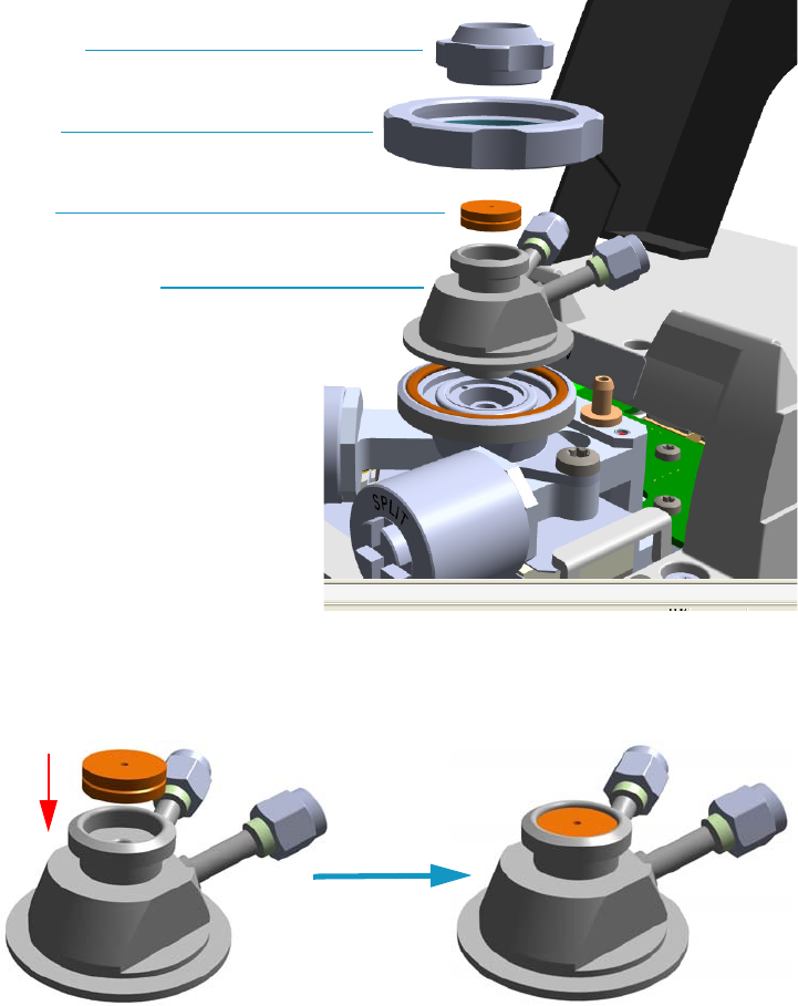
8 Installing Optional Kits
Installing the Purge & Trap Adapter Kit on the SSL/SSLBKF Injector
Thermo Scientific TRACE 1300 and TRACE 1310 Hardware Manual 335
12. Install the purge & trap adapter on the top of the injector. See Figure 333.
Figure 333. Purge & Trap Adapter (1)
a. Avoid touching the septum with your fingers. Insert a new septum into the septum
holder cavity of the purge & trap adapter using tweezers. See Figure 334.
Figure 334. Purge & Trap Adapter (2)
b. Place purge & trap adapter with the septum on the body head of the injector.
See Figure 335.
Septum Cap
Septum
Ring Nut
Purge & Trap Adapter
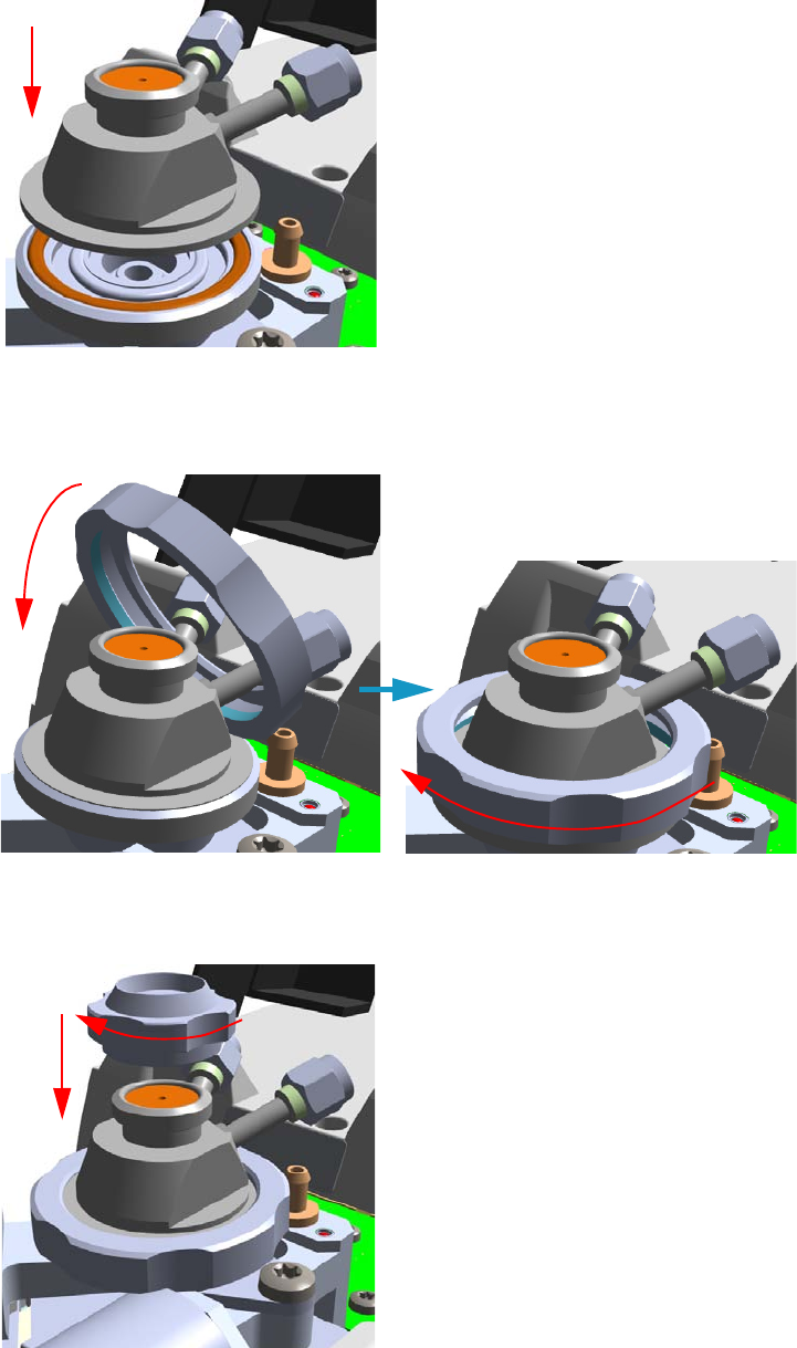
8 Installing Optional Kits
Installing the Purge & Trap Adapter Kit on the SSL/SSLBKF Injector
336 TRACE 1300 and TRACE 1310 Hardware Manual Thermo Scientific
Figure 335. Purge & Trap Adapter (3)
c. Guide the ring nut on the purge & trap adapter with the septum, then fix it screwing
the ring nut. See Figure 336.
Figure 336. Purge & Trap Adapter (4)
d. Screw and tighten the septum cap to finger-tight. See Figure 337.
Figure 337. Purge & Trap Adapter (5)
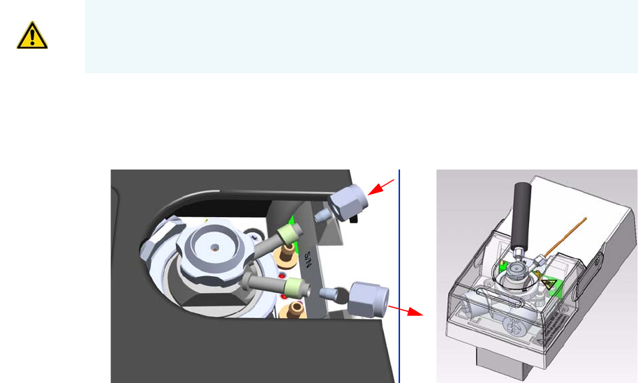
8 Installing Optional Kits
Installing the Purge & Trap Adapter Kit on the SSL/SSLBKF Injector
Thermo Scientific TRACE 1300 and TRACE 1310 Hardware Manual 337
13. Close the module flap cover.
14. Connect the purge & trap adapter to the Purge & Trap system. See Figure 338.
Figure 338. Purge & Trap Adapter (6)
a. Using the nut and ferrule provided, connect the heated transfer line from the Purge
& Trap on the connector IN of the purge & trap adapter.
b. Using the nut and ferrule provided, connect the gas line from the injector module to
the Purge & Trap on the connector OUT of the purge & trap adapter.
15. Reconnect the column end to the injector and verify the connection point.
16. Open the gas supplies.
17. Power on the GC.
a. Plug the power cable to the AC Input connector into the back of the GC and to the
wall outlet.
b. Flip out the power switch (breaker) to the position I.
18. Pressurize the module with the carrier gas.
19. Check for leaks.
a. Use a handheld electronic leak detector (Thermo Scientific GLD Pro leak detector or
equivalent) to check the two fitting for leaks.
b. If you detect a leak, tighten the connection and retest it.
c. Repeat this process until all connections are leak free.
20. Close the front door of the GC.
21. If present, update the autosampler for the new injection position.
CAUTION Do not overtighten the septum cap because you might damage the septum and
affect instrument performance.
IN
OUT
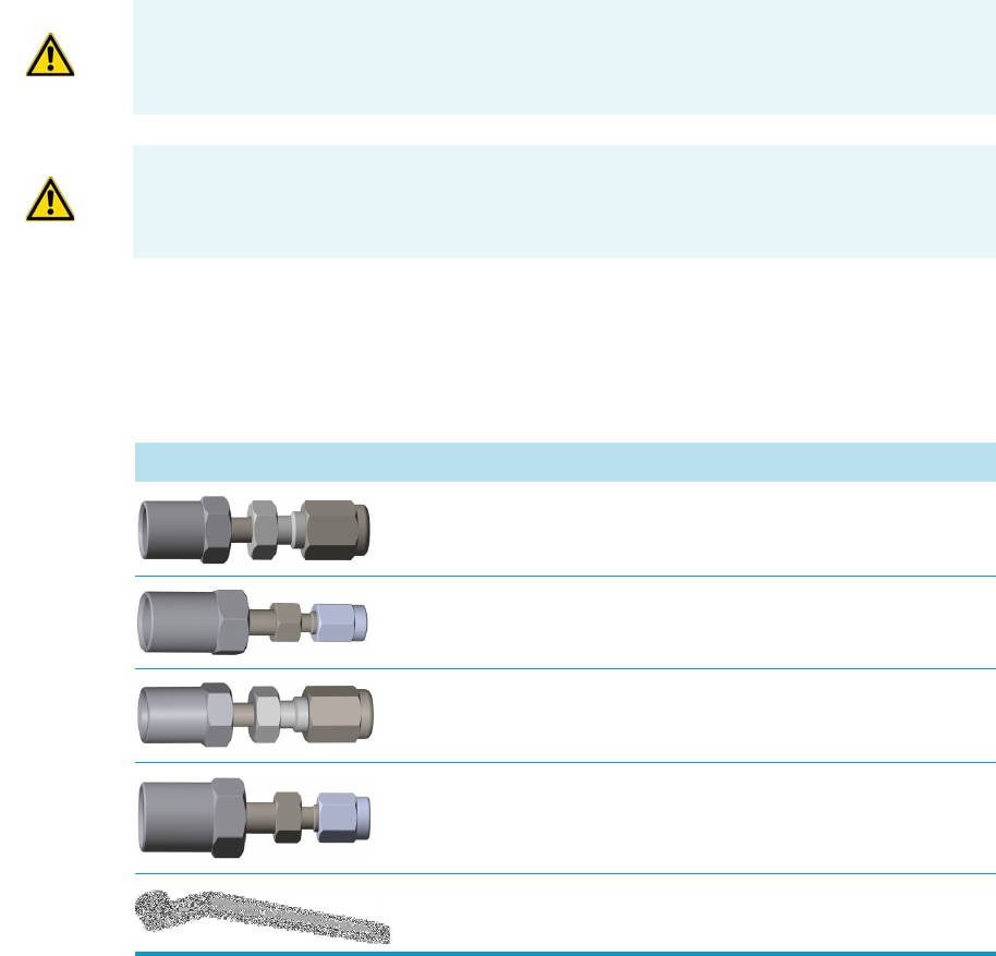
8 Installing Optional Kits
Installing the Packed Column Adapters
338 TRACE 1300 and TRACE 1310 Hardware Manual Thermo Scientific
Installing the Packed Column Adapters
This section provides instructions for installing the adapters for connecting 1/8 or 1/16-in.
OD metal packed columns to the bottom of the SSL injector, FID, NPD, ECD, TCD, and
FPD. For the connection to a PDD detector see the Caution note below.
Introduction
The adapters are provided with the kit PN 19050758. The kit includes the following parts:
Getting Started
Install the column adapters following the instructions in the next operating procedures.
•“To install the packed column adapters” on page 339
•“To connect a new packed column to the injector and detector adapters” on page 341
WARNING Do not try to connect packed columns if the lengths of the column ends
above the end of the ferrule are not compatible with the adapters. In this case we suggest
to connect a new packed column by using the nuts and ferrules provided with the kit.
CAUTION Connecting a packed column to a PDD detector: An adapter to connect the
PDD packed column adapter can be assembled using a piece of tube, the 1/16-in. nut and
gold plated ferrule, and a 1/8-in. to 1/16-in. reducing union in the standard outfit.
Table 14. Packed Column Adapters and 1/2-in. Wrench
Part Description
Adapter for the connection of the 1/8-in. OD packed column
to the SSL injector
Adapter for the connection of the 1/16-in. OD packed
column to the SSL injector
Adapter for the connection of the 1/8-in. OD packed column
to the FID, NPD, ECD, TCD, or FPD detector
Adapter for the connection of the 1/16-in. OD packed
column to the FID, NPD, ECD, or FPD detector
1/2-in. wrench
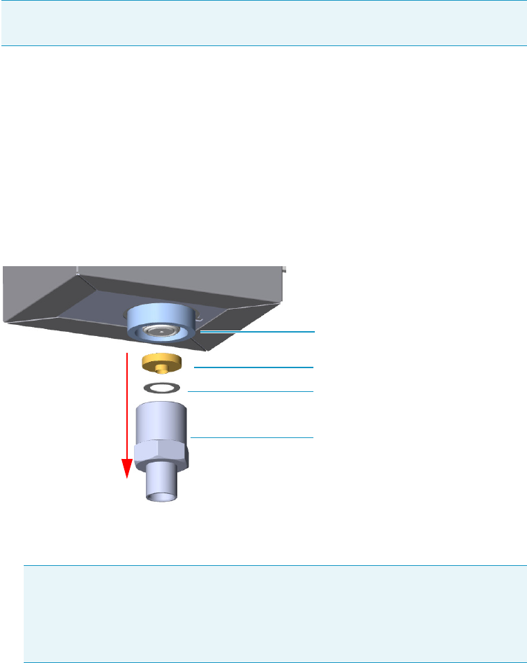
8 Installing Optional Kits
Installing the Packed Column Adapters
Thermo Scientific TRACE 1300 and TRACE 1310 Hardware Manual 339
To install the packed column adapters
1. Put the GC in standby condition.
2. Cool the oven and injector to room temperature.
3. Turn the carrier gas off, and wait for the carrier pressure to go to zero.
4. Remove the analytical column.
a. Open the front door of the GC.
b. Loosen the retaining nut from the injector and detector fitting on the upper interior
wall of the GC oven.
c. Remove the analytical column with its nut and ferrule from the bottom of the
injector and the detector.
5. Remove the bottom parts of the SSL injector. See Figure 339.
Figure 339. SSL Injector Bottom Parts Removal
a. Using the 1/2 wrench provided, unscrew the retaining nut with the base seal and the
washer from the bottom of the injector.
6. Install the adapter on the bottom the injector interposing the washer. See Figure 340.
Note By pressing the Maintenance button, the GC cool down is automatically
carried out.
CAUTION Make sure that the liner does not come out from the bottom of the
injector.
Save the bottom parts of the SSL injector in a safe place because will be reused
when you restore the original configuration for capillary columns.
Base Seal
Washer
Retaining Nut
SSL Injector Bottom
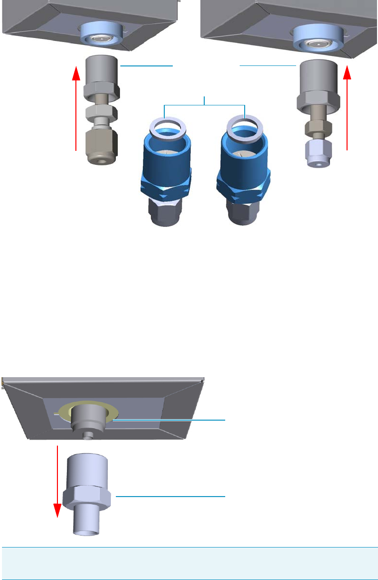
8 Installing Optional Kits
Installing the Packed Column Adapters
340 TRACE 1300 and TRACE 1310 Hardware Manual Thermo Scientific
Figure 340. Adapter Installation on SSL Injector Bottom
a. Finger-tighten the retaining nut of the adapter until it start to grip the bottom of the
injector.
b. Use the 1/2 wrench to firmly tighten the retaining nut of the adapter with the base
seal from the bottom of the injector.
7. Remove the bottom parts of the FID, NPD, ECD, TCD, or FPD detector.
See Figure 341.
Figure 341. Detector Bottom Parts Removal
a. Using the 1/2 wrench provided, unscrew the retaining nut from the bottom of the
detector.
Note Save the bottom parts of the detector in a safe place because will be reused
when you restore the original configuration for capillary columns.
Retaining Nut
Adapter for 1/16-in. OD Packed Column
Adapter for 1/8-in. OD Packed Column
Washer
Detector Bottom
Retaining Nut
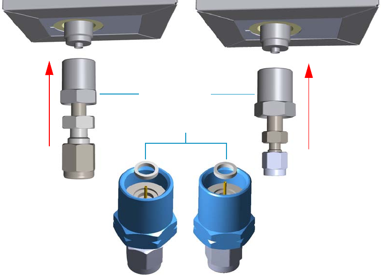
8 Installing Optional Kits
Installing the Packed Column Adapters
Thermo Scientific TRACE 1300 and TRACE 1310 Hardware Manual 341
8. Install the adapter on the bottom the detector interposing the washer. See Figure 342.
Figure 342. Adapter Installation on the Bottom of the Detector
a. Finger-tighten the retaining nut of the adapter until it start to grip the bottom of the
detector.
b. Use the 1/2 wrench to firmly tighten the retaining nut of the adapter with the base
seal from the bottom of the injector.
To connect a new packed column to the injector and detector adapters
Before you begin, verify that the proper adapters are installed on the injector and detector
side.
1. Preparing the metal packed column.
a. Using a 1/4-5/16-in. wrench, remove the column nut and ferrules from the base of
the injector adapter.
b. Using a 1/4-5/16-in. wrench, remove the column nut and ferrules from the base of
the detector adapter.
c. Slide the column nut and the ferrules onto the packed column injector and detector
ends in the order and direction as shown in the Figure 343 and Figure 344.
Adapter for 1/8-in. OD Packed Column Adapter for 1/16-in. OD Packed Column
Retaining Nut
Washer
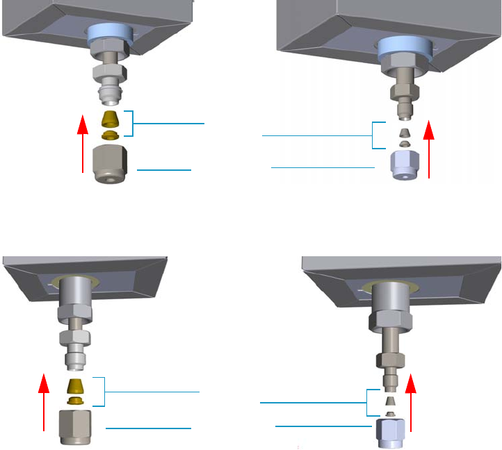
8 Installing Optional Kits
Installing the Packed Column Adapters
342 TRACE 1300 and TRACE 1310 Hardware Manual Thermo Scientific
Figure 343. Column Nut and Ferrules (1)
Figure 344. Column Nut and Ferrules (2)
2. Connect the packed column to the injector.
a. Insert the inlet end of the column as far as possible into bottom of the adapter.
b. Slide the ferrule up to adapter base then finger-tighten the column retaining nut until
it starts to grip the column.
c. Finger-tighten the retaining nut until it starts to grip the column plus a quarter turn.
3. Close the front door of the GC.
4. Turn on the gas supplies and the injector temperature.
5. Setup the GC.
a. Set the oven and injector temperature to 50 °C.
b. Allow the column to purge for few minutes.
6. Condition the column.
The column must be conditioned before inserting it into the detector.
Adapter for 1/8-in. OD Packed Column Adapter for 1/16-in. OD Packed Column
Ferrules
Column Nut
Adapter for 1/8-in. OD Packed Column Adapter for 1/16-in. OD Packed Column
Ferrules
Column Nut
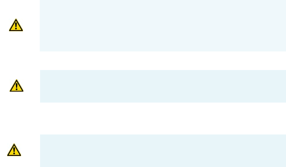
8 Installing Optional Kits
Installing the Packed Column Adapters
Thermo Scientific TRACE 1300 and TRACE 1310 Hardware Manual 343
Column conditioning consists of passing a carrier gas flow through the column heated at
a programmed temperatures as described in the column manufacturer’s instructions.
In case the column does not have any column conditioning instructions, perform the
column conditioning by setting a final temperature up to 10 °C - 20 °C below its
recommended maximum temperature.
a. Run the temperature program that is recommended by the manufacturer.
7. Connect the column to the detector inside the GC.
a. Lower the oven temperature to 30 °C and allow it to cool.
8. Connect the packed column to the detector.
a. Insert the inlet end of the column as far as possible into bottom of the adapter.
b. Slide the ferrule up to adapter base then finger-tighten the column retaining nut until
it starts to grip the column.
c. Use the wrench to tighten the retaining nut. Use no more pressure than is necessary
to obtain a good seal (1/4 to 1/2 turn).
9. End of the column installation.
a. Close the front door of the GC.
CAUTION When performing column conditioning, the column should be connected only
to the injector leaving the column outlet disconnected to avoid the possibility of
contamination of the detector.
Do not use hydrogen as the carrier for conditioning! It could vent into the oven and
present an explosion hazard.
INSTRUMENT DAMAGE: Never exceed the column manufacturer’s maximum operating
temperature.
WARNING-BURN HAZARD: The injector, detector, and oven, may be hot. Allow them to
cool to room temperature before touching them.
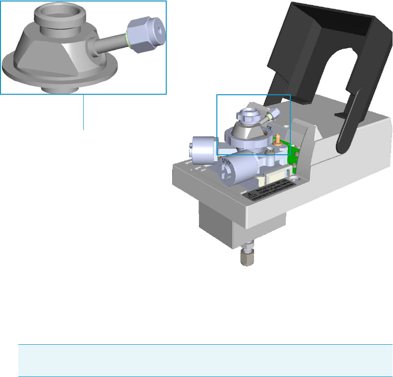
8 Installing Optional Kits
Installing the HS Adapter Kit on the SSL/SSLBKF Injector
344 TRACE 1300 and TRACE 1310 Hardware Manual Thermo Scientific
Installing the HS Adapter Kit on the SSL/SSLBKF Injector
This section provides the instructions for installing the HS Adapter kit PN 19050732, on the
SSL/SSLBKF injector for the use with a TriPlus 300 Headspace sampling system. See
Figure 345.
Figure 345. HS Adapter
To install the HS adapter
1. Put the GC in standby condition.
2. Cool the oven, injector, and detector to room temperature.
3. Close the gas supplies.
4. Power off the GC.
a. Push down the power switch (breaker), located at the back of the instrument, to the
position O.
b. Unplug the power cable from the AC Input connector into the back of the GC and
from the wall outlet.
5. Remove the column end from the injector and the detector.
a. Open the front door of the GC.
Note By pressing the Maintenance button, the GC cool down is automatically car-
ried out.
HS adapter
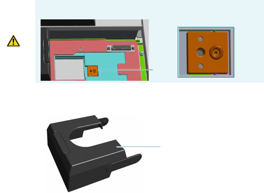
8 Installing Optional Kits
Installing the HS Adapter Kit on the SSL/SSLBKF Injector
Thermo Scientific TRACE 1300 and TRACE 1310 Hardware Manual 345
b. Loosen the retaining nut from the injector fitting on the upper interior wall of the
GC oven.
c. Remove the analytical column with its nut and ferrule from the bottom of the
injector.
6. Remove the SSL/SSLBKF injector module from its seat.
a. Open the module flap cover.
b. Using a T20 Torxhead screwdriver, unscrew the three captive fixing screws.
c. Lift the module from its seat in the injector housing. Place the SSL/SSLBKF module
on a clean surface.
7. Replace the module flap cover with the one’s provided. See Figure 346.
Figure 346. Module Flap Cover for the HS Adapter
8. Reinstall the injector module into the main frame.
a. Open the module flap cover.
b. Place the injector module in its seat. Be sure to insert the 25-pin male connector, on
the bottom of the module, into the 25-pin female connector on the injector seat of
the injector housing.
c. Use a T20 Torxhead screwdriver to tighten the three captive fixing screws without
overtightening.
WARNING Make sure the o-ring remains into its seat on the gas connection.
Do not install the module if the o-ring is missing.
O-ring
Module flap cover
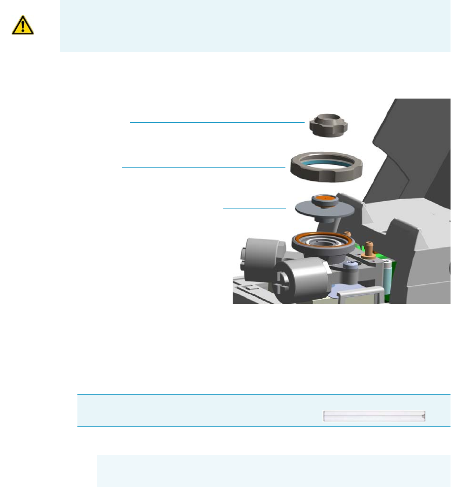
8 Installing Optional Kits
Installing the HS Adapter Kit on the SSL/SSLBKF Injector
346 TRACE 1300 and TRACE 1310 Hardware Manual Thermo Scientific
9. Remove the top parts of the injector. See Figure 347.
Figure 347. Injector Top Parts Removal
a. Unscrew the septum cap of the injector.
b. Unscrew the ring nut.
c. Remove the septum holder/liner cap with septum from the injector body head.
10. Replace the liner.
a. Use tweezers to remove the current liner with the liner seal (o-ring) from the injector.
b. Holding the HS/SPME liner with tweezers, place a new liner seal over the liner.
c. Insert the liner into the injector and push it gently towards the bottom of the injector.
11. Install the HS adapter on the top of the injector. See Figure 348.
CAUTION To maintain the correct alignment the screws must be tightened in turn.
Tighten each screw only a small amount before moving to the next screw. Repeat until all
are secure.
IMPORTANT We suggest replacing the liner currently installed into the injector with
the HS/SPME straight glass empty liner PN 453A1335.
CAUTION Be careful not to break the glass liner when removing it.
Glass splinters might fall into the lower part of the vaporization chamber.
Septum Cap
Ring nut
Septum holder/Liner cap with septum
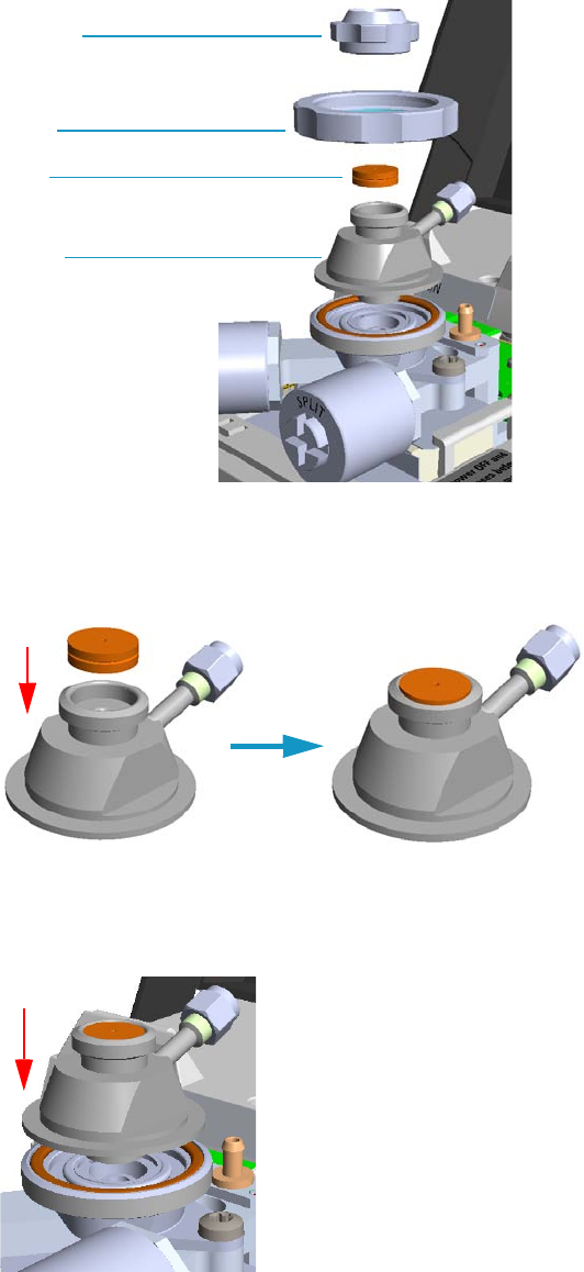
8 Installing Optional Kits
Installing the HS Adapter Kit on the SSL/SSLBKF Injector
Thermo Scientific TRACE 1300 and TRACE 1310 Hardware Manual 347
Figure 348. HS Adapter (1)
a. Avoid touching the septum with your fingers. Insert a new septum into the septum
holder cavity of the HS adapter using tweezers. See Figure 334.
Figure 349. HS Adapter (2)
b. Place the HS adapter with the septum on the body head of the injector.
See Figure 350.
Figure 350. HS Adapter (3)
c. Guide the ring nut on the HS adapter with the septum, then fix it by screwing in the
ring nut. See Figure 351.
Septum cap
Septum
Ring nut
HS adapter
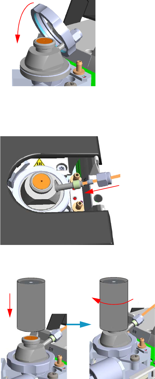
8 Installing Optional Kits
Installing the HS Adapter Kit on the SSL/SSLBKF Injector
348 TRACE 1300 and TRACE 1310 Hardware Manual Thermo Scientific
Figure 351. HS Adapter (4)
12. Close the module flap cover.
13. Connect the carrier gas line coming from the TriPlus 300 Headspace sampling system to
the HS adapter by using the proper nut and ferrule. See Figure 352.
Figure 352. HS Adapter (5)
14. Screw and finger-tighten the septum cap provided. See Figure 353
Figure 353. HS Adapter (6)
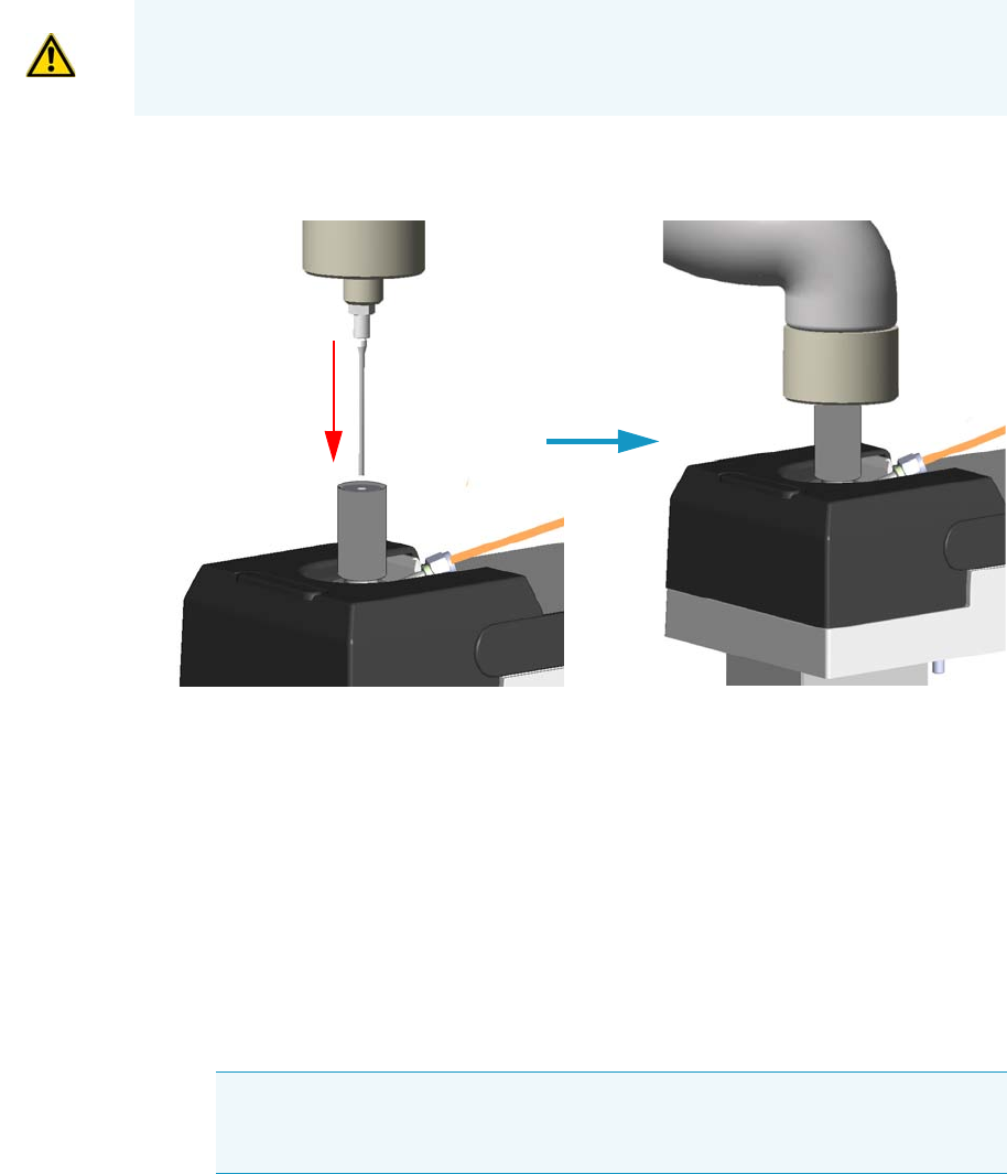
8 Installing Optional Kits
Installing the HS Adapter Kit on the SSL/SSLBKF Injector
Thermo Scientific TRACE 1300 and TRACE 1310 Hardware Manual 349
15. Insert the transfer line needle into the septum cap. See Figure 354.
Figure 354. Transfer Line Connection
16. Cut the piece of column end previously connected to the injector.
a. Use a scoring wafer to score and break the column in order to remove the current
ferrule and the nut.
17. Connect the column to the injector.
a. Wipe about 100 mm (4 in.) of the column with a tissue soaked in methanol.
b. Insert the column through the injector retaining nut and the proper ferrule (open end
up). Wipe the column again with a tissue soaked in methanol.
c. Use a scoring wafer to score and break the column about 1 cm (0.4 in.) from the end.
Use a magnifying glass to check for an even, flat cut. Repeat if necessary.
d. Position the column so that the end of the column extends the proper distance of
30 mm above the end of the ferrule.
e. Insert the notched septum on the column to hold the retaining nut at this position.
Thread the retaining nut into the injector but do not tighten.
CAUTION Do not overtighten the septum cap because you might damage the septum and
affect instrument performance.
Tip Slide a notched septum on the column before the injector retaining nut to
make it easier to measure the proper distance between the nut and the end of the
column.
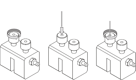
8 Installing Optional Kits
Installing the HS Adapter Kit on the SSL/SSLBKF Injector
350 TRACE 1300 and TRACE 1310 Hardware Manual Thermo Scientific
f. Adjust the column position so that the septum contact the bottom of the retaining
nut.
g. Finger-tighten the retaining nut until it starts to grip the column plus a quarter turn.
h. Remove the notched septum from the column.
18. Open the gas supplies.
19. Power on the GC.
a. Plug the power cable into the AC Input connector on the back of the GC and into
the wall outlet.
b. Flip out the power switch (breaker) to the position I.
20. Setup the GC.
a. Set the oven and injector temperature to 50 °C.
b. Use the column-flowmeter connector to verify that there is flow through the column.
If you do not have a flowmeter, dip the column outlet in a small vial of methanol.
Bubbles indicate there is flow through the column. If there is no flow, check that the
carrier gas is on, the GC inlet is pressurized, and the column is not plugged. If there is
still no flow, consult the section Analytical Troubleshooting in the TRACE
1300/TRACE 1310 User Guide, or contact the Technical Support.
c. Allow the column to purge for few minutes.
21. Perform a column leak check.
a. Carefully push the capillary column end into the column section of the
column-flowmeter connector. See Figure 355.
Figure 355. Using a Flowmeter for Leak Check
b. If your GC is equipped with the touch screen as user interface, select the Leak Check
icon in the Maintenance menu, otherwise perform the Leak Check through the
Chromatography Data System by selecting the proper function.
c. Start the leak check to begin operation. The split and purge valves of the selected
channel are automatically closed and the channel is pressurized with carrier gas to the
leak check setpoint.
A B C
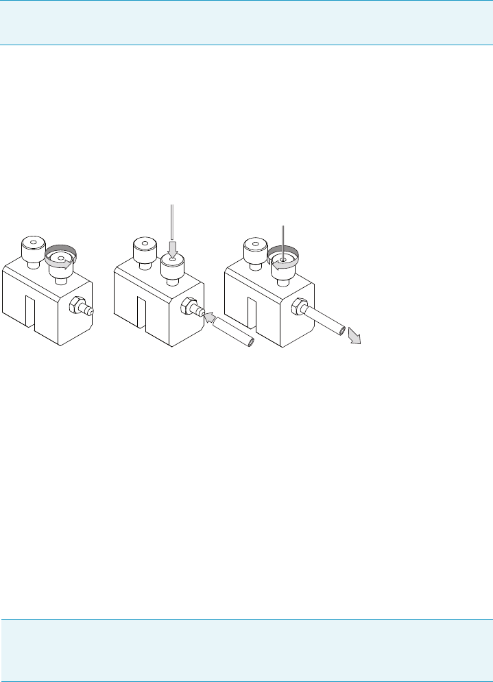
8 Installing Optional Kits
Installing the HS Adapter Kit on the SSL/SSLBKF Injector
Thermo Scientific TRACE 1300 and TRACE 1310 Hardware Manual 351
d. The system monitors the pressure for one minute. If the pressure does not drop more
than the maximum allowed sensitivity value, then the leak check will pass.
If the leak check did not pass, you should use the leak detector to find and fix the
leaks.
e. Repeat the leak check until no leaks are indicated.
22. Calibrate the carrier gas flow (column evaluation).
a. Carefully push the capillary column end into the flow meter section of the column-
flowmeter connector. See Figure 356.
Figure 356. Column Flowmeter Connector
b. Connect the flowmeter to the dedicated fitting on the column-flowmeter connector.
c. If your GC is equipped with the touch screen as user interface, select Back or Front
Column icon in the Configuration menu, otherwise perform the Column
Evaluation through the Chromatography Data System by selecting the proper
function.
d. Select the column and input the physical characteristics of the column.
e. If a pre-/post-column is present, set the length and nominal internal diameter of the
pre-/post-column in the same valid ranges for the column. The following two lines
are added to the menu.
f. According to the physical characteristics of the column, the system calculates and
displays the relevant Column K-factor.
g. Start column evaluation. At the end of the routine, a message will indicate that
evaluation was successful.
Tip Leaks can be caused by not tightening the fitting on the column-flowmeter
connector. We recommend that you check that fitting before looking elsewhere.
Note For the most reproducible results, you should conduct a more detailed
column evaluation. However, the following steps, while recommended, are not
required.
A B C
To flowmeter
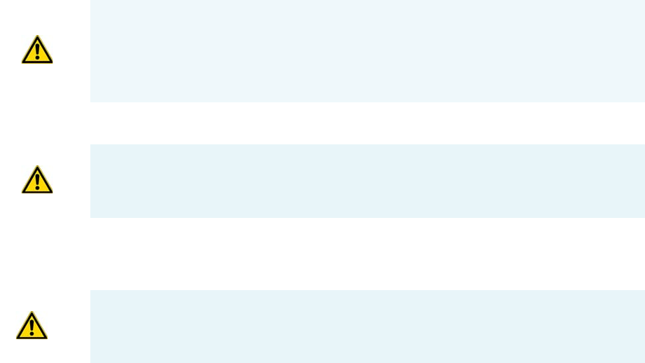
8 Installing Optional Kits
Installing the HS Adapter Kit on the SSL/SSLBKF Injector
352 TRACE 1300 and TRACE 1310 Hardware Manual Thermo Scientific
h. Expect a K-factor of approximately 0.7 – 0.9 for a 15 m, 0.25 mm ID column
(1.3 – 2.0 for a 30 m, 0.25 mm ID column). If the column does not report a K-factor
within this range or within 0.1 units of the previous stored value, check for a leak or
broken column using the leak detector. The K-factor is a measured resistance for the
column. A K-factor that is too low may indicate a leak in the system, while a K-factor
that is too high may indicate a blockage.
23. Disconnect the column-flowmeter.
a. Disconnect the column from the column-flowmeter connector.
b. Remove the clear plastic component, including its fittings, from the oven and set it
aside.
c. Close the GC door.
24. Condition the column.
The column must be conditioned before inserting it into the detector.
Column conditioning consists of passing a carrier gas flow through the column heated at
a programmed temperatures as described in the column manufacturer’s instructions.
In case the column does not have any column conditioning instructions, perform the
column conditioning by setting a final temperature up to 10 °C - 20 °C below its
recommended maximum temperature.
a. Run the temperature program that is recommended by the manufacturer.
25. Connect the column to the detector inside the GC.
a. Lower the oven temperature to 30 °C and allow it to cool.
b. Unwind the column enough to easily connect its ends to the injector and the
detector.
CAUTION When performing column conditioning, the column should be connected only
to the injector leaving the column outlet disconnected to avoid the possibility of
contamination of the detector.
Do not use hydrogen as the carrier for conditioning! It could vent into the oven and
present an explosion hazard.
INSTRUMENT DAMAGE: Never exceed the column manufacturer’s maximum operating
temperature.
WARNING-BURN HAZARD: The injector, detector, oven, and transfer line may be hot.
Allow them to cool to room temperature before touching them.

8 Installing Optional Kits
Installing the HS Adapter Kit on the SSL/SSLBKF Injector
Thermo Scientific TRACE 1300 and TRACE 1310 Hardware Manual 353
c. Wipe about 100 mm (4 in.) of the column with a tissue soaked in methanol.
d. Use a scoring wafer to score and break the column outlet about 2.5cm (1 in.) from
the end. Use a magnifying glass to check for an even, flat cut. Repeat if necessary.
e. Insert the column through the proper detector retaining nut and ferrule (open end
up). Wipe the column again with a tissue soaked in methanol.
f. Position the column so that the end of the column extends the proper distance above
the end of the ferrule as reported in Table 1 5 .
For PDD see the instruction described at the step g on page 353.
i. For FID, NPD, TCD, insert the column into the detector, paying attention to
not force it further. Finger-tighten the retaining nut, then withdraw the column
2-3 mm. Tighten the retaining nut an additional a quarter turn.
ii. For ECD and FPD, insert the notched septum on the column to hold the
retaining nut in this position. Thread the retaining nut into the detector but do
not tighten.
Finger-tighten the retaining nut until it starts to grip the column plus a quarter
turn. Remove the notched septum from the column.
g. For PDD the column must penetrate 136 mm inside the capillary column adapter.
26. End of the column installation.
a. Close the front door of the GC.
Note Wear clean, lint- and powder-free gloves when you handle the column and
injector ferrule.
Tip Slide a notched septum on the column before the detector retaining nut to
make it easier to measure the proper distance between the bottom nut and end of
the column.
Table 15. Column Insertion Depth For FID, NPD, TCD, ECD, FPD, and PDD Detectors
FID NPD TCD ECD FPD PDD
Insert the column as far as goes and withdrawn
about 2mm
23 mm 125 mm 136 mm
Note When inserting the capillary column into the PDD detector it might rarely
happen to feel a slight resistance. In this case, for proper column installation, pull
the column out slightly and adjust the angle before inserting it further.
IMPORTANT To install a packed column, the pre-installed capillary column adapter must
be replaced with the packed columns adapter that enters into the PDD cell for the correct
length.
8 Installing Optional Kits
Installing the Large Volume Splitless Kit
354 TRACE 1300 and TRACE 1310 Hardware Manual Thermo Scientific
Installing the Large Volume Splitless Kit
This section provides instruction for installing the Large Volume Splitless kit (PN 19050725)
on your TRACE 1300/TRACE 1310.
The Large Volume Splitless injector is a setup of the standard splitless injector, where the
introduction of large amount of liquid samples can be performed manually, or with the
TriPlus RSH, TriPlus 100 Liquid Sampler, or AI/AS 1310 autosampler.
Large Volume-Splitless kit includes:
• Two dummy filters
• Two o-rings for dummy filters
• An deactivated connector (press-fit)
• An uncoated precolumn (5 m x 0.32 mm ID)
• A dedicated splitless liner (set of 5)
• LV-SL Assistant software
To install the large volume splitless kit
1. Put the GC in standby condition.
2. Cool the oven and injector to room temperature.
3. Turn the carrier gas off, and wait for the carrier pressure to go to zero.
4. Put the autosampler away if present.
5. Open the module flap cover
6. Replace the filters with the dummy filters.
a. Remove both the filters from their seats by turning them counter-clockwise.
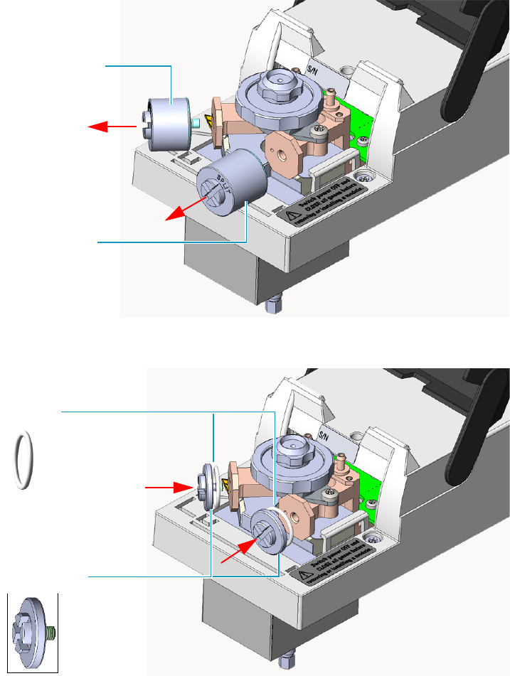
8 Installing Optional Kits
Installing the Large Volume Splitless Kit
Thermo Scientific TRACE 1300 and TRACE 1310 Hardware Manual 355
b. Install the dummy filters in their seats interposing the o-ring, then turn them
clockwise.
7. Replace the current liner installed into the Split/Splitless injector with the dedicated
splitless liner.
8. Close the module flap cover.
9. Install the uncoated precolumn.
a. Open the oven door.
b. Disconnect the analytical column from the bottom of the injector.
Carrier line filter
Split line filter
Dummy filter
O-ring
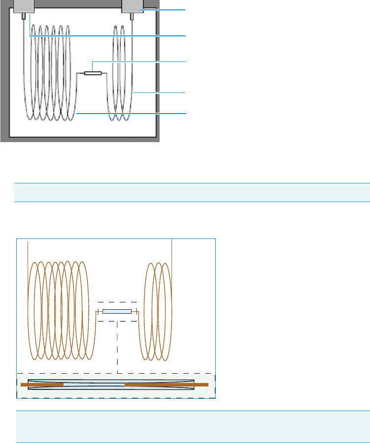
8 Installing Optional Kits
Installing the Large Volume Splitless Kit
356 TRACE 1300 and TRACE 1310 Hardware Manual Thermo Scientific
c. Connect an end of the precolumn to the bottom of the injector by using the proper
nut and ferrule. Position the precolumn so that its end extends a distance of 5 mm
above the end of the ferrule.
10. Couple the precolumn to the analytical capillary column.
a. Properly cut the fused silica column ends pay attention to achieve a clean square cut
by using a ceramic scoring wafer or sapphire scribe.
b. insert the precolumn and analytical column ends into the relevant ports of the
deactivated connector.
11. Close the oven door.
12. If present, move the autosampler towards the module to restore the original alignment.
13. Turn the carrier gas on.
14. Set the injector, detector, and GC working conditions.
CAUTION A poorly cut will produce an insufficient seal.
Note To create a good seal between all the parts, will be necessary to increase the
oven temperature up to 200 °C.
Split/Splitless Injector
Detector
Deactivated connector
Precolumn
Analytical column
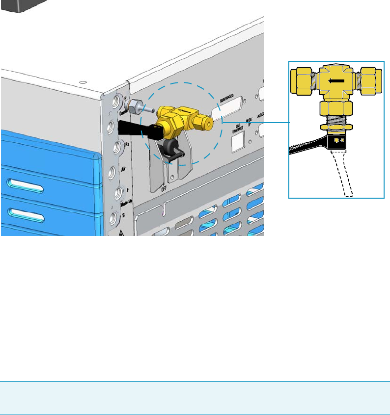
8 Installing Optional Kits
Installing the Manual On/Off Valve for Single Gas Line
Thermo Scientific TRACE 1300 and TRACE 1310 Hardware Manual 357
Installing the Manual On/Off Valve for Single Gas Line
This section provides instructions for installing the manual on/off toggle valve for single gas
line kit (PN 19050756) on a GC gas inlet of your TRACE 1300/TRACE 1310.
See Figure 357.
Figure 357. Manual Toggle Valve Installation
The manual toggle valve is used for manually opening and closing the gas flow coming from
the supply line.
It is particularly useful when for any reason you need to manually interrupt the flow of a gas
into the GC, for example: before the replacement of a module, to save the consumption of a
gas when its flow is unnecessary, and so on.
The kit can be installed only on a single gas line, then if you need managing more gas lines, up
to six kits can be installed accordingly.
To install the manual on/off valve kit
1. Put the GC in standby condition.
2. Cool the oven, injectors and detectors to room temperature.
3. Turn the carrier gas off, and wait for the carrier pressure to go to zero.
4. On the back of the GC disconnect the gas supply tube and the gas inlet fitting with its
o-ring from the GC gas inlet where the manual on/off valve must be installed.
Note This procedure describes the installation of a manual on/off valve on a single gas
line. In the example the installation of the valve on the Front Carrier gas line is considered.
CLOSE
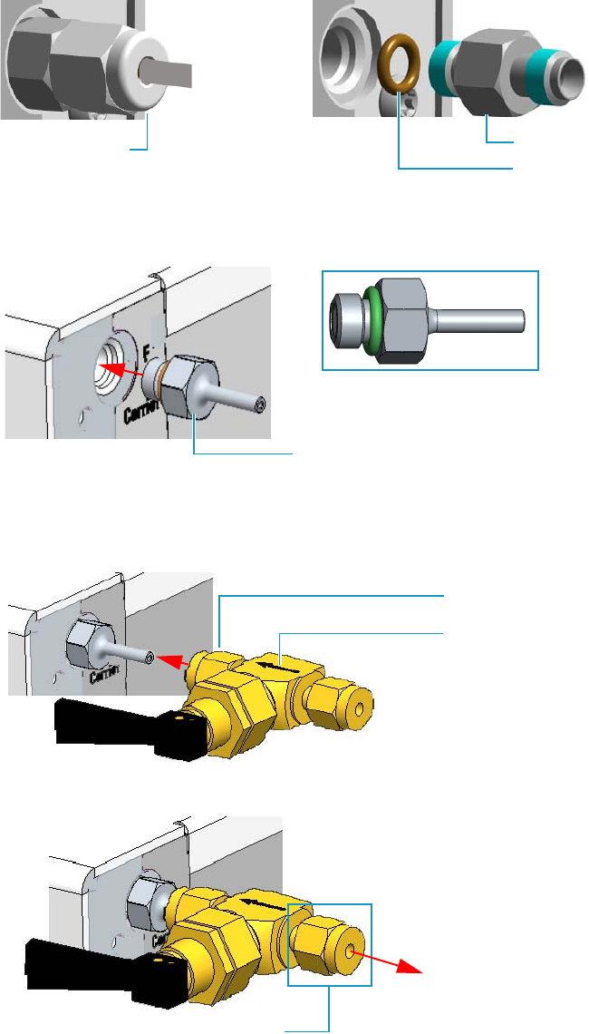
8 Installing Optional Kits
Installing the Manual On/Off Valve for Single Gas Line
358 TRACE 1300 and TRACE 1310 Hardware Manual Thermo Scientific
Use a 7/16-in. wrench for unscrewing the fittings.
5. Screw the gas inlet fitting 1/8-in. provided into the gas inlet port interposing the o-ring.
Use a 7/16-in. wrench for tightening the fitting.
6. Using the nut and ferrules provided, connect the valve outlet to the gas inlet fitting
1/8-in. Make sure that the arrow marked on the valve body indicating the direction of the
flow is turned forward the GC gas inlet. Use a 7/16-in. wrench for tightening the fittings.
7. Remove the nut and the ferrules provided from the valve inlet.
8. Connect the gas supply tube previously disconnected (see the step 4). Use a 7/16-in.
wrench for tightening the fittings.
Gas supply tube Gas inlet fitting
O-ring
Gas inlet fitting 1/8-in.
Gas flow direction
Nut and ferrules
Remove nut and ferrules
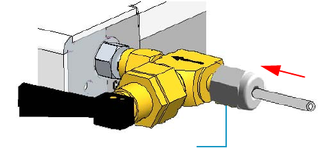
8 Installing Optional Kits
Installing the Manual On/Off Valve for Single Gas Line
Thermo Scientific TRACE 1300 and TRACE 1310 Hardware Manual 359
9. Turn the carrier gas on.
10. Open or close the flow of the supply gas turning the black handle of the valve up or down
respectively.
11. Set the injectors, detectors, and GC working conditions.
Gas supply tube
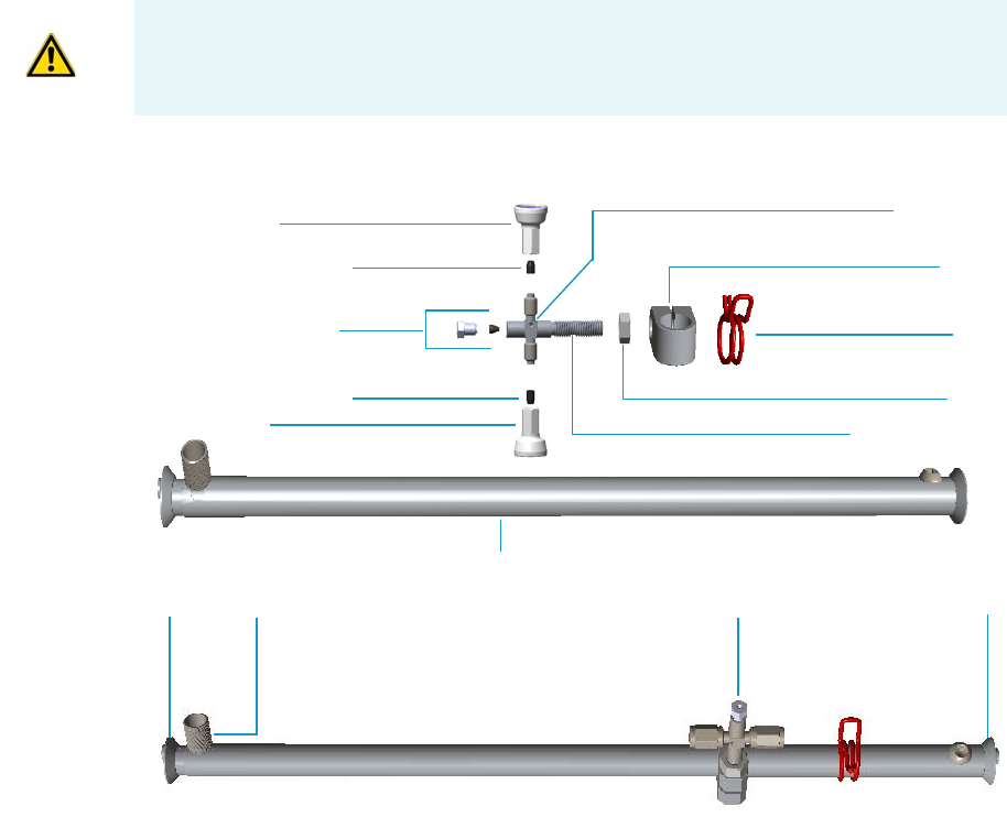
8 Installing Optional Kits
Connecting a SSL/PTV Backflush System
360 TRACE 1300 and TRACE 1310 Hardware Manual Thermo Scientific
Connecting a SSL/PTV Backflush System
This section provides instructions for connecting your SSLBKF/PTVBKF injector modules
with precolumn and analytical capillary column into the oven. Refer to the chapters SSLBKF
Injector Module and PTVBKF Injector Module in the TRACE 1300/TRACE 1310 User
Guide. This system operates up to 300 °C.
The operation consists of the following operating procedures:
•“To assemble the Tee connector on the mounting bracket” on page 360
•“To install the mounting bracket” on page 367
•“To connect backflush line, precolumn, and capillary column” on page 369
•“To install of a second backflush system” on page 373
To assemble the Tee connector on the mounting bracket
1. Remove the nut and the top end of the mounting bracket. This nut secures the two
sections of the mounting bracket. See Figure 358.
CAUTION Before starting make sure the SSLBKF/PTVBKF injector module is correctly
installed into its seat.
Bottom
Tee Connector Assembly
Nut
Top
Mounting Bracket
Retaining Nut
Retaining Nut
Graphite/Vespel Ferrule
Graphite/Vespel Ferrule
Backflush Line Fittings
Nut
Clip
Clamp
Tee Connector
Threaded Shaft
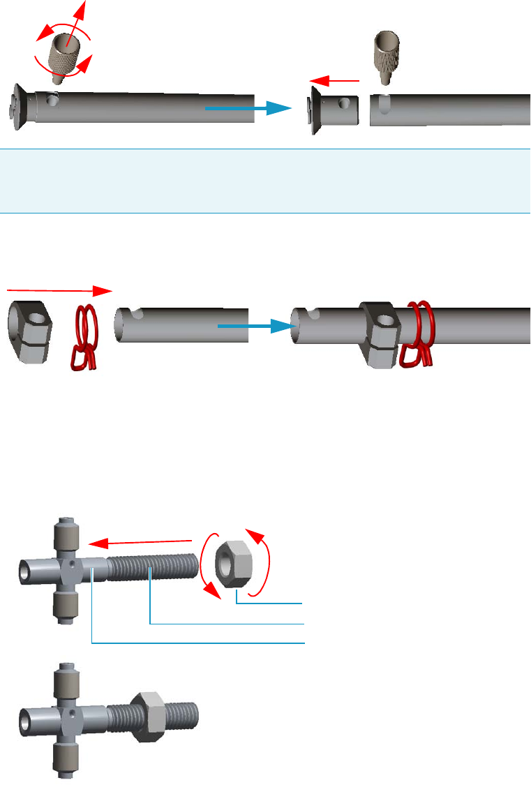
8 Installing Optional Kits
Connecting a SSL/PTV Backflush System
Thermo Scientific TRACE 1300 and TRACE 1310 Hardware Manual 361
Figure 358. Assembling Tee Connector and Mounting Bracket (1)
2. Slide the clip and the clamp on the body of the mounting bracket. See Figure 359.
Figure 359. Assembling Tee Connector and Mounting Bracket (2)
3. Screw the part of threaded shaft of the Tee connector with the smaller diameter into the
Tee connector, then screw the nut on the threaded shaft. Use a 2.5 mm key to tighten the
shaft. See Figure 360.
Figure 360. Assembling Tee Connector and Mounting Bracket (3)
4. Screw the Tee connector into clamp. Turn the threaded shaft until it protrudes the clamp,
then turn the nut until it grip the clamp. See Figure 361.
Note Wait reinstalling the top end of the mounting bracket and the nut. These parts
will be reinstalled during the installation of the mounting bracket into the GC oven.
See “To install the mounting bracket” on page 367.
Nut
Top End
Clamp Clip
Threaded Shaft
Nut
Tee Connector
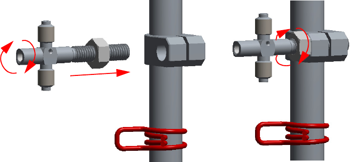
8 Installing Optional Kits
Connecting a SSL/PTV Backflush System
362 TRACE 1300 and TRACE 1310 Hardware Manual Thermo Scientific
Figure 361. Assembling Tee Connector and Mounting Bracket (4)
5. Move the Tee connector support on the lower part of the mounting bracket, then
finger-tighten the nut up to grip the clamp without overtightening. This allow to adjust
the position of the Tee connector during the installation of backflush line, precolumn,
and capillary column.
6. At this point mount the mounting bracket into the oven of the GC. See “To install the
mounting bracket” on page 367.
To install the mounting bracket into the GC oven
Install the mounting bracket near the front of the GC oven on the right-hand side. This will
keep the mounting bracket out of the way of the column.
Proceed as follows:
1. Make sure that the nut at the top end of the mounting bracket are removed. See
Figure 358 on page 361.
2. Line up the bottom of the mounting bracket into two holes on the bottom side of the GC
oven.
3. Hold the mounting bracket directly upright, and twist the top end of it so that it is
securely attached to the GC oven holes.
4. Let out the top of the mounting bracket until it is long enough to be secured into two
holes on the bottom of the GC oven.
5. Replace the nut.
6. Tighten the nut until the mounting bracket is securely attached to the top and bottom of
the GC oven.
Figure 362 shows the result of the operation.
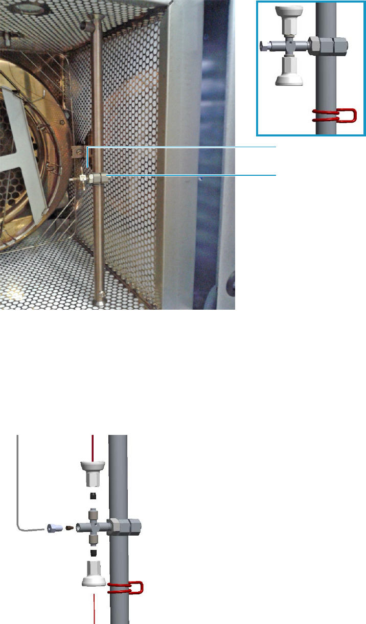
8 Installing Optional Kits
Connecting a SSL/PTV Backflush System
Thermo Scientific TRACE 1300 and TRACE 1310 Hardware Manual 363
Figure 362. Mounting Bracket Installed in the GC
7. At this point connect backflush line, precolumn, and capillary column to the Tee
connector. See “To connect backflush line, precolumn, and capillary column” on
page 369.
To connect backflush line, precolumn, and capillary column
The result of this operation is schematically shown in Figure 368.
Figure 363. Connecting Backflush Line, Precolumn, and Capillary Column
Tee Connector
Clamp
Backflush Line
Capillary Column
Precolumn

8 Installing Optional Kits
Connecting a SSL/PTV Backflush System
364 TRACE 1300 and TRACE 1310 Hardware Manual Thermo Scientific
1. Connect the backflush line metal tube coming from the bottom of the SSLBKF injector
module or PTVBKF injector module to the Tee connector.
a. Slide the retaining nut and the ferrule onto the end of the backflush line.
b. Insert the backflush line into the Tee connector.
c. Finger-tighten the retaining nut until it starts to grip the backflush line.
d. Use the 5 mm wrench to tighten the retaining nut. Use enough pressure necessary to
obtain a good seal without overtighten.
2. Connect the precolumn to the Tee connector.
a. Place the precolumn on the column support.
b. Slide the retaining nut and the 0.8 mm Vespel/graphite ferrule onto the precolumn
with the flat end facing towards the Tee connector. Be careful to avoid damaging the
graphite ferrule when inserting the precolumn. Always use a new ferrule of the
correct diameter.
c. Cut 1 cm from the precolumn end.
d. Insert the precolumn into the Tee connector in the side with the dot that it must be
normally be turned towards the ceiling of the GC oven.
e. Finger-tighten the precolumn retaining nut until it starts to grip the precolumn.
f. Use the 1/4-in. wrench to tighten the retaining nut. Use enough pressure necessary to
obtain a good seal without overtighten.
3. Connect the precolumn to the injector base.
a. Slide the retaining nut and the graphite ferrule onto the fused silica precolumn (0.53
mm ID; 2 m length) with the bevelled end facing towards the injector.
b. Cut 1 cm from the precolumn.
c. Insert the precolumn into the injector and slide the ferrule up to the injector
base.Insert the precolumn about 3 cm into the bottom of the injector.
Note Could be necessary to adjust the position of the Tee connector when installing
backflush line, precolumn, and column to stress as minimal as possible.
Tip The backflush line must be bent as required by the position of the Tee connector
on the mounting bracket.
Note Always use original Thermo Fisher Scientific precolumns.
The use of precolumns not meeting the specifications of our products does not ensure
a good operation of the instrument and may even compromise the analytical results.
Thermo Fisher Scientific precolumn (2 m; 10 m) are mounted on the appropriate
rack and identified with a relevant label fixed on the rack.
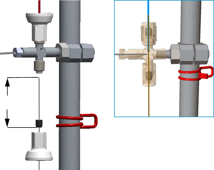
8 Installing Optional Kits
Connecting a SSL/PTV Backflush System
Thermo Scientific TRACE 1300 and TRACE 1310 Hardware Manual 365
d. Finger-tighten the precolumn retaining nut until it starts to grip the precolumn.
e. Use the 6 mm wrench to tighten the retaining nut. Use enough pressure necessary to
obtain a good seal without overtighten.
4. Connect the capillary column to the Tee connector and to the precolumn.
See Figure 369.
Figure 364. Precolumn and Capillary Column Connection
a. Place the column on the column support.
b. Slide the proper retaining nut and Vespel/graphite ferrule onto the column with the
flat end facing towards the Tee connector. Be careful to avoid damaging the ferrule
when inserting the column.
c. Cut 1 cm from the column end.
d. Use typewriter correction fluid or a felt-tipped pen to mark the position of the ferrule
bottom 35 mm from the end of the column.
e. Carefully insert the column into the precolumn up to reach the marked position.
The capillary column end must protrudes the Tee connector; if not, repeat the
operations.
f. Finger-tighten the column retaining nut until it starts to grip the column.
g. Use the 1/4-in. wrench to tighten the retaining nut. Use enough pressure necessary to
obtain a good seal.
Precolumn
Backflush Line
Capillary Column
35 mm
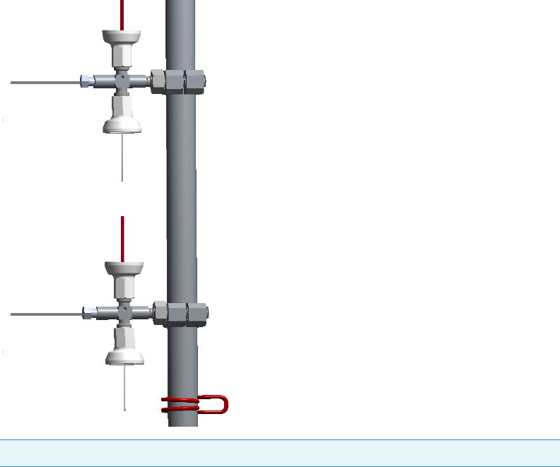
8 Installing Optional Kits
Connecting a SSL/PTV Backflush System
366 TRACE 1300 and TRACE 1310 Hardware Manual Thermo Scientific
5. Connect the analytical column to the detector base.
a. Slide the retaining nut and the graphite ferrule onto the capillary column with the
bevelled end facing the detector base.
Be careful to avoid damaging the graphite ferrule when inserting the column.
b. Cut 2–3 cm from the column end.
c. Insert the column into the detector base body and slide the ferrule up to the detector
base.
d. Finger-tighten the column retaining nut until it starts to grip the column.
e. Push the column through the detector base according to the detector in use.
f. Use the 6 mm wrench to tighten the retaining nut. Use enough pressure necessary to
obtain a good seal without overtighten.
To install of a second backflush system
If a second SSL/PTV Backflush system is installed, you can connect both the systems by using
two Tee connectors mounted on the same mounting bracket as schematically shown in
Figure 370.
Figure 365. Schematically Connection of a Second Backflush System
Tip Turn the Tee connector as required to allow the installation of the two precolumns.
Backflush Line
Capillary Column
Backflush Line
Capillary Column
Precolumn
Precolumn
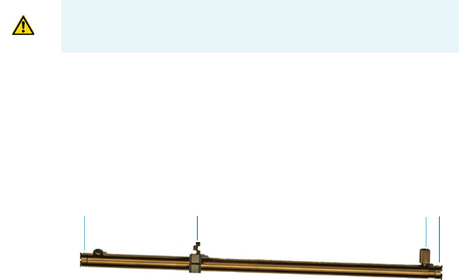
8 Installing Optional Kits
Connecting a SSL/PTV Backflush System for High Temperature
Thermo Scientific TRACE 1300 and TRACE 1310 Hardware Manual 367
Connecting a SSL/PTV Backflush System for High Temperature
This section provides instructions for connecting your SSLBKF/PTVBKF injector modules
with precolumn and analytical capillary column into the oven for application at high
temperature. For the purpose, the kit PN 19050254 is required. Refer to the chapters
SSLBKF Injector Module and PTVBKF Injector Module in the TRACE 1300/TRACE 1310
User Guide. This system operates at a temperature more than 300 °C.
The operation consists of the following operating procedures:
•“To install the mounting bracket” on page 367
•“To connect backflush line, precolumn, and capillary column” on page 369
•“To install of a second backflush system” on page 373
To install the mounting bracket
Install the mounting bracket near the front of the GC oven on the right-hand side. This will
keep the mounting bracket out of the way of the column.
Proceed as follows:
1. Remove the nut at the top end of the mounting bracket. This nut secures the two sections
of the mounting bracket. See Figure 366.
Figure 366. Mounting Bracket Parts
2.Push the top of the mounting bracket down.
3. Line up the bottom of the mounting bracket into two holes on the bottom side of the GC
oven.
4. Hold the mounting bracket directly upright, and twist the top end of it so that it is
securely attached to the GC oven holes.
5. Let out the top of the mounting bracket until it is long enough to be secured into two
holes on the bottom of the GC oven.
6. Replace the nut.
CAUTION Before starting make sure the SSLBKF/PTVBKF injector module is correctly
installed into its seat.
Bottom Tee Connector Nut Top
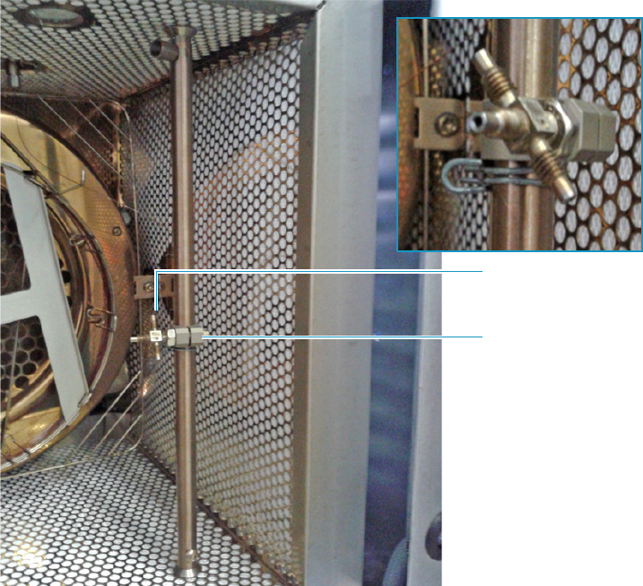
8 Installing Optional Kits
Connecting a SSL/PTV Backflush System for High Temperature
368 TRACE 1300 and TRACE 1310 Hardware Manual Thermo Scientific
7. Tighten the nut until the mounting bracket is securely attached to the top and bottom of
the GC oven.
Figure 367. Mounting Bracket Installed in the GC
Tee Connector
Clamp
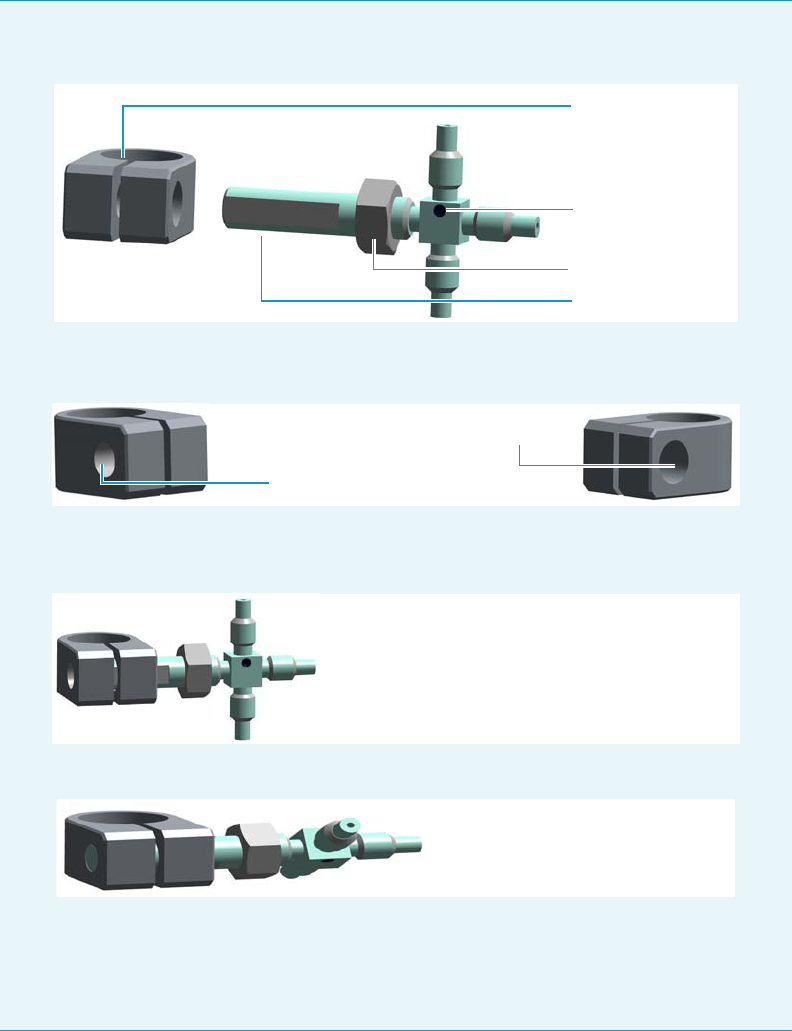
8 Installing Optional Kits
Connecting a SSL/PTV Backflush System for High Temperature
Thermo Scientific TRACE 1300 and TRACE 1310 Hardware Manual 369
To connect backflush line, precolumn, and capillary column
The result of this operation is schematically shown in Figure 368.
Note If the Tee connector should not be assembled into its clamp, proceed as follows:
1. Completely screw the nut on the threaded shaft of the Tee connector.
−
Note that the clamp has two holes: the smaller one is threaded while the bigger other
is not threaded.
−
2. Pay attention to insert the threaded shaft of the Tee connector into the clamp through
the bigger hole not threaded up to grip the threaded hole.
3. Turn the Tee connector until the threaded shaft begins to protrude the clamp.
−
4. Move the Tee connector support on the lower part of the mounting bracket, then
finger-tighten the nut up to grip the clamp without overtightening. This allow to
adjust the position of the Tee connector during the installation of backflush line,
precolumn, and capillary column.
Retaining Nut
Clamp
Tee Connector
Threaded Shaft
Threaded Hole
Not Threaded Hole
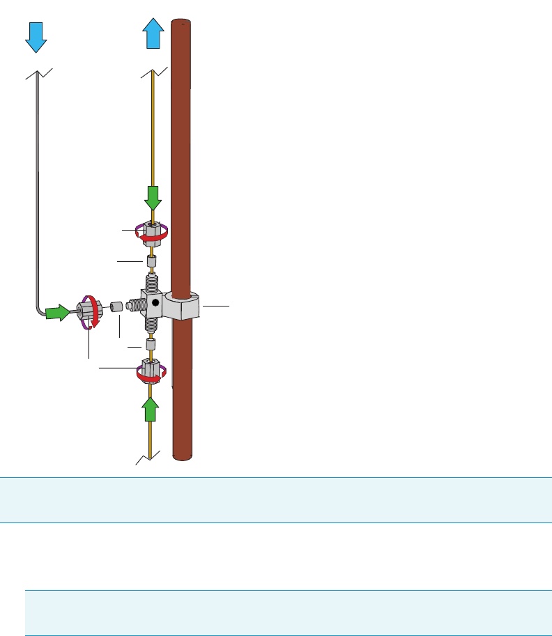
8 Installing Optional Kits
Connecting a SSL/PTV Backflush System for High Temperature
370 TRACE 1300 and TRACE 1310 Hardware Manual Thermo Scientific
Figure 368. Connecting Backflush Line, Precolumn, and Capillary Column
1. Connect the backflush line metal tube coming from the bottom of the SSLBKF injector
module or PTVBKF injector module to the Tee connector.
a. Slide the retaining nut and the 1.0 mm graphite ferrule onto the end of the backflush
line with the bevelled end facing towards the Tee connector. Be careful to avoid
damaging the graphite ferrule when inserting the tube.
b. Shortly activate the backflush with carrier open to eliminate possible graphite pieces
before connecting the Tee connector.
c. Insert the backflush line into the Tee connector.
d. Finger-tighten the retaining nut until it starts to grip the backflush line.
Note Could be necessary to adjust the position of the Tee connector when installing
backflush line, precolumn, and column to stress as minimal as possible.
Tip The backflush line must be bent as required by the position of the Tee connector
on the mounting bracket.
Pre-column
1
2
3
Injector
Backflush Line
2
3
Capillary
Column
1 = Tee Connector Mounted on the Tee holder
2 = Graphite Ferrule 0.8 mm OD
3 = Retaining Nut

8 Installing Optional Kits
Connecting a SSL/PTV Backflush System for High Temperature
Thermo Scientific TRACE 1300 and TRACE 1310 Hardware Manual 371
e. Use the 6 mm wrench to tighten the retaining nut. Use enough pressure necessary to
obtain a good seal without overtighten.
2. Connect the precolumn to the Tee connector.
a. Place the precolumn on the column support.
b. Slide the retaining nut and the 0.8 mm graphite ferrule onto the precolumn with the
bevelled end facing towards the Tee connector. Be careful to avoid damaging the
graphite ferrule when inserting the precolumn. Always use a new ferrule of the
correct diameter.
c. Cut 1 cm from the precolumn end.
d. Insert the precolumn into the Tee connector in the side with the dot that it must be
normally be turned towards the ceiling of the GC oven.
e. Finger-tighten the precolumn retaining nut until it starts to grip the precolumn.
f. Use the 6 mm wrench to tighten the retaining nut. Use enough pressure necessary to
obtain a good seal without overtighten.
3. Connect the precolumn to the injector base.
a. Slide the retaining nut and the graphite ferrule onto the fused silica precolumn (0.53
mm ID; 2 m length) with the bevelled end facing towards the injector.
b. Cut 1 cm from the precolumn.
c. Insert the precolumn into the injector and slide the ferrule up to the injector
base.Insert the precolumn about 3 cm into the bottom of the injector.
d. Finger-tighten the precolumn retaining nut until it starts to grip the precolumn.
e. Use the 6 mm wrench to tighten the retaining nut. Use enough pressure necessary to
obtain a good seal without overtighten.
4. Connect the capillary column to the Tee connector and to the precolumn.
See Figure 369.
Note Always use original Thermo Fisher Scientific precolumns.
The use of precolumns not meeting the specifications of our products does not ensure
a good operation of the instrument and may even compromise the analytical results.
Thermo Fisher Scientific precolumn (2 m; 10 m) are mounted on the appropriate
rack and identified with a relevant label fixed on the rack.
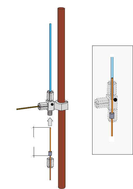
8 Installing Optional Kits
Connecting a SSL/PTV Backflush System for High Temperature
372 TRACE 1300 and TRACE 1310 Hardware Manual Thermo Scientific
Figure 369. Precolumn and Capillary Column Connection
a. Place the column on the column support.
b. Slide the proper retaining nut and graphite ferrule onto the column with the bevelled
end facing towards the Tee connector. Be careful to avoid damaging the graphite
ferrule when inserting the column.
c. Cut 1 cm from the column end.
d. Use typewriter correction fluid or a felt-tipped pen to mark the position of the ferrule
bottom 35 mm from the end of the column.
e. Carefully insert the column into the precolumn up to reach the marked position. The
capillary column end must protrudes the Tee connector; if not, repeat the operations.
f. Finger-tighten the column retaining nut until it starts to grip the column.
g. Use the 6 mm wrench to tighten the retaining nut. Use enough pressure necessary to
obtain a good seal.
5. Connect the analytical column to the detector base.
a. Slide the retaining nit and the graphite ferrule onto the capillary column with the
bevelled end facing the detector base.
Be careful to avoid damaging the graphite ferrule when inserting the column.
Capillary
Column
Pre-column
35 mm Capillary
Column
Pre-column
Backflush Line
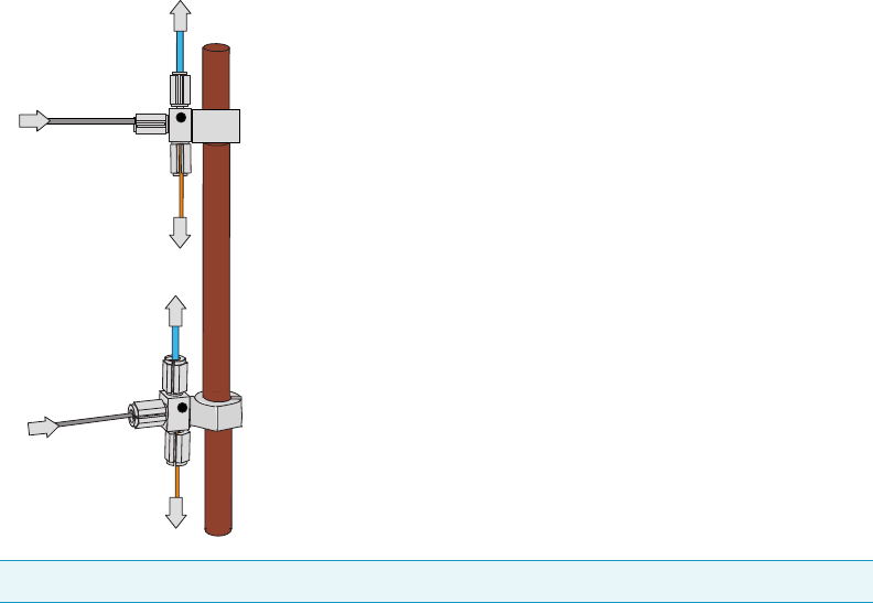
8 Installing Optional Kits
Connecting a GSV Backflush System
Thermo Scientific TRACE 1300 and TRACE 1310 Hardware Manual 373
b. Cut 2–3 cm from the column end.
c. Insert the column into the detector base body and slide the ferrule up to the detector
base.
d. Finger-tighten the column retaining nut until it starts to grip the column.
e. Push the column through the detector base according to the detector in use.
f. Use the 6 mm wrench to tighten the retaining nut. Use enough pressure necessary to
obtain a good seal without overtighten.
To install of a second backflush system
If a second SSL/PTV Backflush system is installed, you can connect both the systems by using
two Tee connectors mounted on the same mounting bracket as schematically shown in
Figure 370.
Figure 370. Schematically Connection of a Second Backflush System
Connecting a GSV Backflush System
This sections provides instructions for connecting your Gas Sampling Valve module with
precolumn and analytical capillary column into the oven of the TRACE 1300/1310 GC.
Refer to the chapters Gas Sampling Valve (GSV) Module in the TRACE 1300/TRACE 1310
User Guide.
The Gas Sampling Valve backflush system is provided with the kit PN 19050764.
Tip Turn the Tee connector as required to allow the installation of the two precolumns.
Capillary Column
to Back Detector
Precolumn
to Back Injector
Capillary Column
to Front Detector
Precolumn
to Front Injector
BackFlush Line
Backflush Line
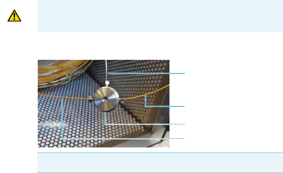
8 Installing Optional Kits
Connecting a GSV Backflush System
374 TRACE 1300 and TRACE 1310 Hardware Manual Thermo Scientific
To connect backflush line, precolumn, and analytical capillary column
The result of this operation is schematically shown in the example of Figure 371.
Figure 371. Connecting GSV Backflush Line, Precolumn, and Analytical Capillary Column
When the GSV module is inserted into its position on the upper deck of the GC, the
backflush line metal tubing protrudes into the GC oven.
1. Open the front door of the GC.
2. Remove nut and ferrule from the metal tubing of the GSV nodule.
3. Connect the backflush line metal tubing coming from the bottom of the Gas Sampling
Valve module to the three-way connector.
a. Slide the 1/32-in. nut and the Vespel/Graphite ferrule PN 29003428 onto the end of
the backflush line with the bevelled end facing towards the three-way connector.
b. Insert the backflush line into the central position of the three-way connector.
c. Slide the retaining nut onto the backflush line through its side cut.
d. Use the 5 mm wrench to tighten the retaining nut. Use enough pressure necessary to
obtain a good seal without overtighten.
4. Connect the precolumn to the Tee connector.
a. Place the precolumn on the column support.
b. Slide the 1/32-in. nut and the proper Vespel/Graphite ferrule onto the precolumn
with the bevelled end facing towards the three-way connector. Always use a new
ferrule of the correct diameter.
c. Cut 1 cm from the precolumn end.
CAUTION Before starting make sure the Gas Sampling Valve (GSV) module is correctly
installed into its seat.
Note Could be necessary to adjust the position of the three-way connector when installing
backflush line, precolumn, and capillary column to stress as minimal as possible.
GSV Backflush Line Metal Tubing
Precolumn
Analytical Capillary Column
Three-way Connector
8 Installing Optional Kits
Connecting a GSV Backflush System
Thermo Scientific TRACE 1300 and TRACE 1310 Hardware Manual 375
d. Insert the precolumn in one of the two external positions of the three-way connector.
e. Finger-tighten the precolumn retaining nut until it starts to grip the precolumn.
f. Use the 5 mm wrench to tighten the retaining nut. Use enough pressure necessary to
obtain a good seal without overtighten.
5. Connect the precolumn to the injector base.
a. Slide the M6 nut and the graphite ferrule onto the fused silica precolumn with the
bevelled end facing towards the injector.
b. Cut 1 cm from the precolumn.
c. Insert the precolumn into the injector and slide the ferrule up to the injector base.
Insert the precolumn till it reaches the mechanical stop, than drawn it back of 1 mm.
d. Finger-tighten the precolumn retaining nut until it starts to grip the precolumn.
e. Use the 1/4-in. wrench to tighten the retaining nut. Use enough pressure necessary to
obtain a good seal without overtighten.
6. Connect the capillary column to the three-way connector.
a. Place the capillary column on the column support.
b. Slide the 1/32-in. nut and the proper Vespel/Graphite ferrule onto the capillary
column with the bevelled end facing towards the three-way connector.
c. Cut 1 cm from the end of the capillary column.
d. Insert the end of the capillary column in the free position of the three-way connector.
e. Finger-tighten the column retaining nut until it starts to grip the column.
f. Use the 5 mm wrench to tighten the retaining nut. Use enough pressure necessary to
obtain a good seal.
7. Connect the capillary column to the detector base.
a. Slide the nut and the graphite ferrule onto the capillary column with the bevelled end
facing the detector base.
b. Be careful to avoid damaging the graphite ferrule when inserting the capillary
column.
c. Cut 2–3 cm from the end of the capillary column.
d. Insert the capillary column into the detector base body and slide the ferrule up to the
detector base.
e. Finger-tighten the capillary column retaining nut until it starts to grip the column.
f. Push the capillary column through the detector base according to the detector in use.
g. Use the 1/4-in. wrench to tighten the retaining nut.
h. Use enough pressure necessary to obtain a good seal without overtighten.
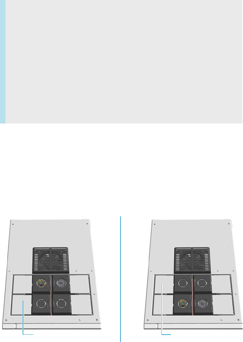
8 Installing Optional Kits
Installing the NoVent Microfluidics
376 TRACE 1300 and TRACE 1310 Hardware Manual Thermo Scientific
Installing the NoVent Microfluidics
This section provides instructions for installing the NoVent™ Microfluidics on your TRACE
1300 or TRACE 1310 GC, and your ISQ or TSQ 8000 Series mass spectrometer.
Connecting the NoVent Microfludics Module to the TRACE 1300/1310
According to the configuration of your TRACE 1300 or TRACE 1310 GC, a dummy
module is present in the free site where the detector module is not installed.
If no dummy module is present, and no vacant module position is present on either the
TRACE 1300 or TRACE 1310 GC or on the optional gas valve oven (if you have one), you
must take one of the existing and installed modules off in order to install the NoVent
Microfluidics.
Figure 372. Location of Detector Modules on your TRACE 1300/TRACE 1310 GC
Contents
•“Connecting the NoVent Microfludics Module to the TRACE 1300/1310” on
page 376
•“Installing the Mounting Bracket” on page 379
•“Preparing the NoVent Microfluidics Restrictor Tubing” on page 381
•“Attaching the Ferrule and Nut to the GC Column” on page 384
•“Attaching the New Tubing to the Transfer Line” on page 385
•“Connecting the Capillaries to the Microfluidics Splitter” on page 390
•“Configuring the Post-Column” on page 391
•“Using the Module” on page 394
Dummy Back Detector Module
Dummy Front Detector Module
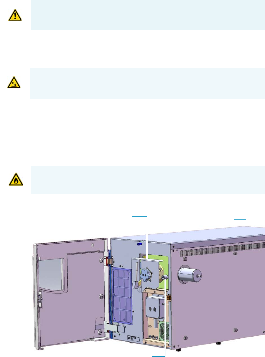
8 Installing Optional Kits
Installing the NoVent Microfluidics
Thermo Scientific TRACE 1300 and TRACE 1310 Hardware Manual 377
To connect the NoVent Microfluidics module to the TRACE 1300/1310 GC
1. Cool the oven, injector or injectors, transfer line, ion source, and any installed GC
detectors to room temperature and shut down the GC.
2. Push down on the power switch to power off the GC.
3. Shut down the TSQ 8000 Series or ISQ Series mass spectrometer using the software. See
your mass spectrometer's user guide for more information. The heaters and the
turbo-molecular pump power off.
4. If you are using hydrogen as a carrier gas, unscrew the hydrogen safety screw on the front
door of the mass spectrometer.
Figure 373. Finding the Vent Valve on the Mass Spectrometer
ATTENTION Where a dummy module is installed, the gas connection is blocked by a
plug.
WARNING - BURN HAZARD: The injectors, detectors, oven, and transfer line may be hot.
Allow them to cool to room temperature before touching them.
WARNING - FIRE HAZARD: If you are using hydrogen, do NOT reach over the top of the
instrument to power it off. Instead, reach around the right side or go to the back of the
instrument and flip down the power switch.
Vacuum Interlock Shield Power Switch
Vent Valve Knob
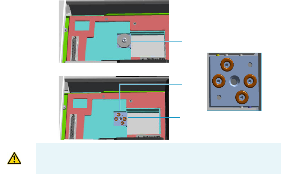
8 Installing Optional Kits
Installing the NoVent Microfluidics
378 TRACE 1300 and TRACE 1310 Hardware Manual Thermo Scientific
5. Open the front door of the mass spectrometer.
6. Look behind the right side of the vacuum interlock shield and twist the vent valve knob
one and a half times in a counter-clockwise direction to open the vent valve.
7. Wait five minutes for the mass spectrometer to vent.
8. Open the front door of the GC and loosen the transfer line nut. Then pull the column
back (into the oven) about 5 cm to ensure the column is no longer in the ion source.
9. Close all GC gas supplies. Shut the carrier gas supply off at its source, such as the tank.
10. Remove the dummy module from the position where the NoVent Microfluidics will be
installed. The most convenient location for accessing the tubing connections is the front
position.
a. Open the module flap cover.
b. Using a T20 Torxhead screwdriver, unscrew and remove the two captive fixing
screws.
c. Keeping the dummy module flap cover open, lift up the module from its seat in the
detector housing. Place the dummy module on a clean surface.
d. Remove the gas plug by unscrewing its fixing screw using a T20 Torxhead
screwdriver.
Figure 374. Removing the Detector Gas Plug
Gas Connections Without Gas Block Plug
Gas Block Plug on Detector Seat
O-rings
WARNING Make sure all four o-rings are correctly seated on the gas connection. Do not
install the module if the o-rings are missing.
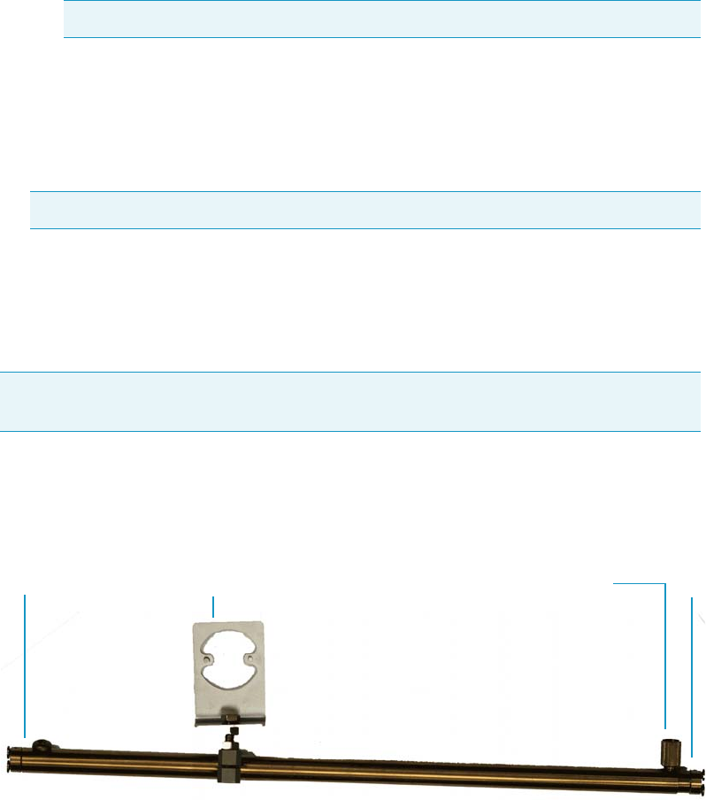
8 Installing Optional Kits
Installing the NoVent Microfluidics
Thermo Scientific TRACE 1300 and TRACE 1310 Hardware Manual 379
11. Install the No-Vent module.
a. Open the module flap cover.
b. Keeping the module flap cover open, place the module in its seat. Be sure to insert the
25-pin male connector, on the bottom of the module, into the 25-pin female
connector on the detector seat of the detector housing.
c. Use a T20 screwdriver to tighten the three captive fixing screws without
overtightening.
d. Close the module flap cover.
12. Power on the GC.
13. Switch the module on so that the LED light glows green and start the carrier gas flowing
to purge the line.
Installing the Mounting Bracket
Install the mounting bracket near the front of the GC oven on the right-hand side. This will
keep the mounting bracket out of the way of the column.
To install the mounting bracket
1. Remove the nut at the top end of the mounting bracket. This nut secures the two sections
of the mounting bracket. See Figure 375.
Figure 375. Mounting Bracket Parts
2. Push the top of the mounting bracket down.
3. Line up the bottom of the mounting bracket into two holes on the bottom side of the GC
oven.
Note Tighten the center screw first and then secure the side screws.
Note This module requires a constant carrier gas pressure of 60 psig (410 kPa).
Note If you already have a mounting bracket installed in your GC with either the SSL
backflush or PTV backflush system, skip this step.
Top
Bottom Nut
Holder
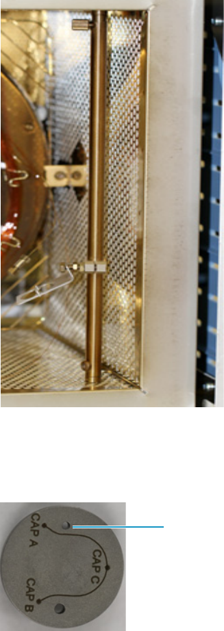
8 Installing Optional Kits
Installing the NoVent Microfluidics
380 TRACE 1300 and TRACE 1310 Hardware Manual Thermo Scientific
4. Hold the mounting bracket directly upright, and twist the top end of it so that it is
securely attached to the GC oven holes.
5. Let out the top of the mounting bracket until it is long enough to be secured into two
holes on the bottom of the GC oven.
6. Loosely replace the nut, then rotate the top and bottom in opposite directions.
7. Tighten the nut until the mounting bracket is securely attached to the top and bottom of
the GC oven.
Figure 376. Mounting Bracket Installed in the GC
8. Attach the Thermo Scientific™ microfluidics splitter to the mounting bracket.
The microfluidics splitter snaps into place. The small hole should be positioned at the
top. See Figure 377 for the correct orientation.
Figure 377. Correct Orientation for the Microfluidics Splitter
Small Hole
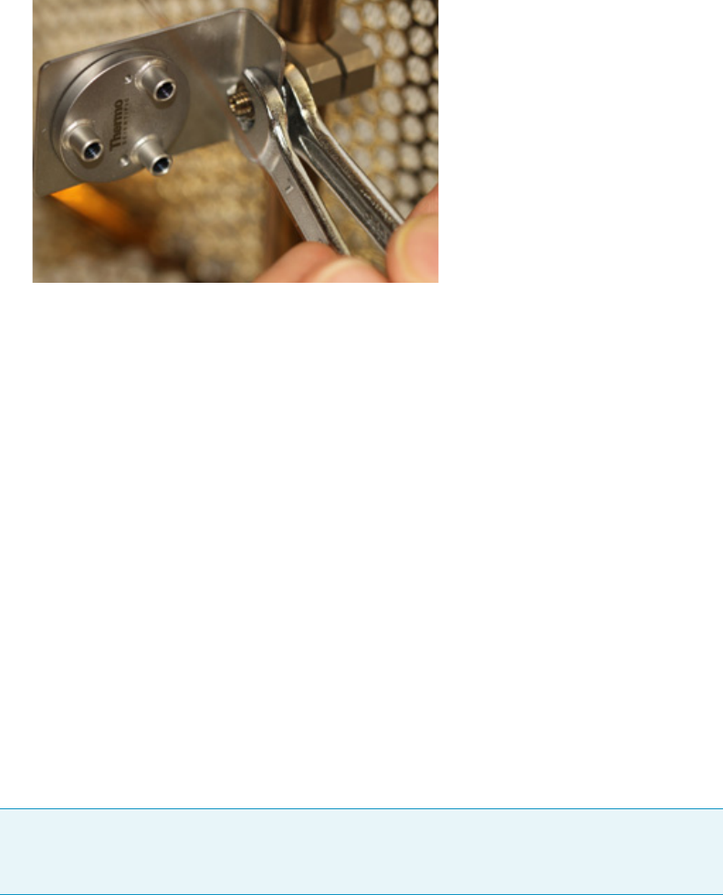
8 Installing Optional Kits
Installing the NoVent Microfluidics
Thermo Scientific TRACE 1300 and TRACE 1310 Hardware Manual 381
9. Position the holder for the microfluidics splitter upright and use two 7 mm wrenches to
secure it. See Figure 378.
Figure 378. Securing the Holder for the Microfluidics Splitter
Preparing the NoVent Microfluidics Restrictor Tubing
If you are using helium as a carrier gas, use the 30 cm length of 75 μm fused silica tubing in
your kit (two are supplied) to connect the NoVent Microfludics module to the splitter.
If you are using hydrogen as a carrier gas, use the 80 cm length of 75 μm fused silica tubing in
your kit (one is supplied) to connect the NoVent Microfludics module to the splitter.
This tubing acts as a flow restrictor to limit the helium flow from the NoVent microfluidics
module.You must swage a SilTite™ ferrule to this tubing.
You will need the following materials to connect the tubing to new ferrule and nut. They are
all included in the complete kit.
• SilTite FingerTite™ pre-swage tool—to pre-swage the SilTite FingerTite ferrule to the GC
module
• SilFlow™ pre-swage tool and SilFlow FingerTite tool—to pre-swage the SilFlow ferrule to
the microfluidics splitter
• SilFlow nut—to connect the tubing to the microfluidics splitter
• SilTite ferrule (1)
• SilFlow ferrules (3)
1. Use a scoring wafer to cut the end off the tubing.
2. Use the SilTite FingerTite pre-swage tool in your kit to pre-swage the SilTite ferrule to
your tubing. See Figure 379. The tubing should extend just past the tool when
pre-swaging the ferrule. After the ferrule is swaged, remove the tool and confirm the
ferrule does not slide on the tubing.
Note If you are using a 0.25 mm id column, use a 0.4 mm SilFlow ferrule and a 0.4 mm
SilFlow FingerTite jig. If you are using a 0.32 mm id column, use a 0.5 mm SilFlow
ferrule and a 0.5 mm SilFlow FingerTite jig.
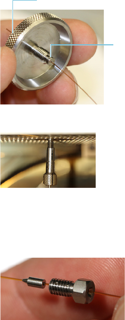
8 Installing Optional Kits
Installing the NoVent Microfluidics
382 TRACE 1300 and TRACE 1310 Hardware Manual Thermo Scientific
Then cut the tubing to about 2 mm past the tip of the ferrule. See Figure 379.
Figure 379. Pre-swaging the Ferrule to the 30 cm Fused Silica Tubing
3. Insert the ferrule and the tubing into the NoVent microfluidics module. See Figure 380.
Figure 380. Securing the 30 cm Fused Silica Restrictor to the No-Vent Microfluidics Module
4. Add the FingerTite screw to the module and tighten.
5. Now you must prepare the other end of the tubing to connect to the microfluidics 3-port
splitter. It is much easier to attach the ferrule to the tubing while it is outside the GC.
You will connect it to the splitter later.
6. Position a SilFlow nut and SilFlow ferrule onto the tubing as shown in Figure 381.
Figure 381. Positioning the SilFlow Nut and SilFlow Ferrule Correctly on the Tubing
7. Use a scoring wafer to cut the tubing after inserting it through the ferrule. See Figure 382.
Then use the SilFlow pre-swage tool to secure the ferrule into position. When done
properly, the tubing will extend slightly past the tip of the ferrule.
SilTite FingerTite Pre-swage Tool
Ferrule
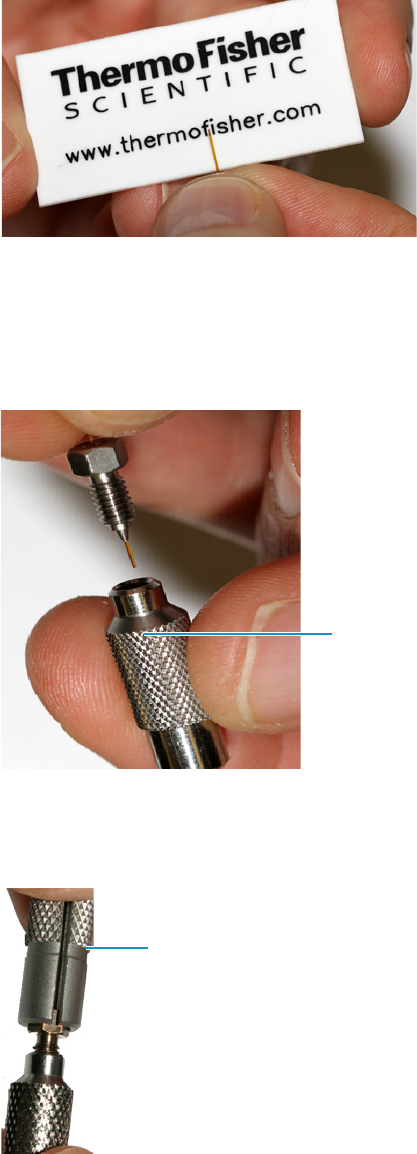
8 Installing Optional Kits
Installing the NoVent Microfluidics
Thermo Scientific TRACE 1300 and TRACE 1310 Hardware Manual 383
It is important to use the SilFlow pre-swage tool in order to prevent crushing the tip of
the fused silica. See Figure 382.
Figure 382. Cutting the Tubing with the Scoring Wafer
8. Place the column and ferrule into SilFlow pre-swage tool until the tubing reaches the
bottom of the tool. When done properly, the tubing will extend slightly past the tip of the
ferrule. It is important to use the pre-swage tool in order to prevent crushing the tip of the
fused silica. See Figure 383.
Figure 383. Inserting the Column and Ferrule into the SilFlow Pre-Swage Tool
9. Use the SilFlow FingerTite tool to swage the ferrule to the tubing. Be sure to keep the tip
of the fused silica bottomed out in the pre-swage tool. See Figure 384.
Figure 384. Swaging the Ferrule Using the SilFlow FingerTite Tool
SilFlow
Pre-Swage Tool
SilFlow
FingerTite
Pre-Swage Tool
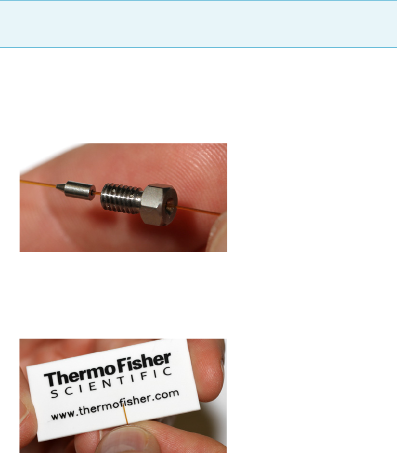
8 Installing Optional Kits
Installing the NoVent Microfluidics
384 TRACE 1300 and TRACE 1310 Hardware Manual Thermo Scientific
10.Remove the jig, and lay the tubing carefully on the bottom of the GC until you are ready
to connect it to the microfluidics splitter.
Attaching the Ferrule and Nut to the GC Column
You will need the following materials to connect the column to new ferrule and nut. They are
all included in the complete kit.
• SilFlow FingerTite tool
• SilFlow pre-swage tool
•SilFlow nut
• SilFlow ferrules
To add the new ferrule and nut to the column
1.Attach the ferrule to the column while it is outside the GC. You will connect it to the
module later.
2. Position the SilFlow nut and SilFlow ferrule onto the column as shown in Figure 385.
Figure 385. Positioning the Nut and Ferrule Correctly on the Column
3. Use a scoring wafer to cut the column after inserting it through the ferrule. Then use the
appropriate pre-swage tool to secure the ferrule into position. When done properly, the
tubing will extend slightly past the tip of the ferrule. It is important to use the pre-swage
tool in order to prevent crushing the tip of the fused silica. See Figure 386.
Figure 386. Cutting the Column with the Scoring Wafer
Note If you are using a 0.25 mm id column, use a 0.4 mm SilFlow ferrule and a 0.4 mm
SilFlow pre-swage tool. If you are using a 0.32 mm id column, use a 0.5 mm SilFlow
ferrule and a 0.5 mm SilFlow pre-swage tool.
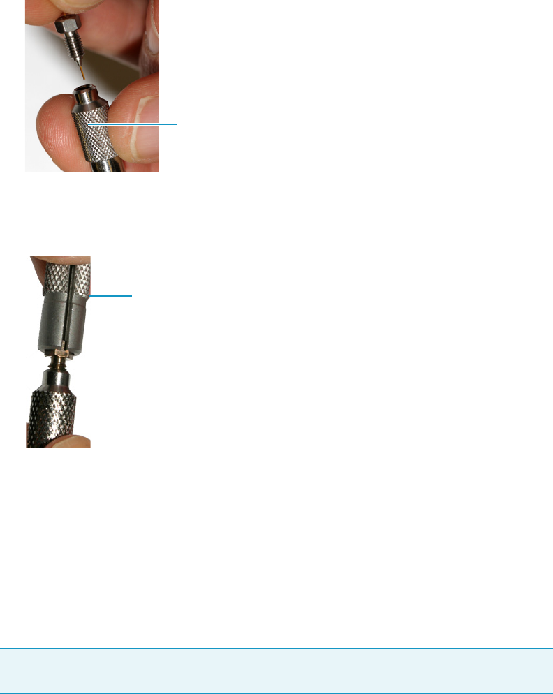
8 Installing Optional Kits
Installing the NoVent Microfluidics
Thermo Scientific TRACE 1300 and TRACE 1310 Hardware Manual 385
4. Place the column and ferrule into the SilFlow pre-swage tool until the column reaches the
bottom of the jig. See Figure 387.
Figure 387. Inserting the Column and Ferrule into the SilFlow Pre-Swage Tool
5. Use the FingerTite tool to swage the ferrule to the column. Be sure to keep the tip of the
fused silica bottomed out in the pre-swage tool. See Figure 388.
Figure 388. Swaging the Ferrule Using the SilFlow FingerTite Tool
6. Remove the pre-swage tool, and lay the column carefully on the bottom of the GC until
you are ready to connect it to the microfluidics splitter.
Attaching the New Tubing to the Transfer Line
Your kit comes with a 0.6 m and 1.2 m deactivated segments of fused silica tubing having an
internal diameter of 0.17 mm. This tubing has fused ends. You must cut these ends off the
tubing and attach a SilFlow ferrule before connecting it. Use this tubing to connect the
microfluidics splitter to the transfer line.
When connecting the column to the transfer line, you may use either the regular transfer line
nut or the spring loaded transfer line nut with the graphite Vespel® ferrule.
To connect the column using the regular transfer line nut
1. Lower the oven temperature and allow it to cool.
SilFlow
Pre-Swage Tool
SilFlow FingerTite Tool
Note Use the 60 cm tubing if you are using helium as a carrier gas. Use the 120 cm length
of tubing if you are using hydrogen as a carrier gas.
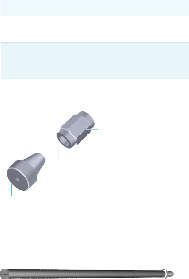
8 Installing Optional Kits
Installing the NoVent Microfluidics
386 TRACE 1300 and TRACE 1310 Hardware Manual Thermo Scientific
2. Confirm that the MS is vented and remove the current transfer line nut and ferrule.
3. Unwind about one turn of the column from the column outlet end.
4. Wipe approximately 300 mm (12 in.) of the column with a tissue soaked in methanol.
5. Choose an appropriate ferrule for the outer diameter of your column.
6. Insert the column through the transfer line nut and ferrule, entering through the tapered
end of the ferrule. Wipe the column again with a tissue soaked in methanol.
Figure 389. Transfer Line Nut and SilTite Ferrule Orientation
7. Insert the column into the column measuring tool (see Figure 390), which is in the ISQ
Toolkit, so that it is even with the lines at the end of the column. Figure 391 indicates
proper positioning of the column in the tool for accurate measuring.
8. Use a scoring wafer to score and break the column. Use a magnifying glass to check for an
even, flat cut. Repeat if necessary.
9. Use a 5/16 in. wrench to hold the column measuring tool steady.
Figure 390. Column Measuring Tool
Note Wear clean, lint- and powder-free gloves when you handle the column and
transfer line ferrule.
Note If the maximum oven temperature in your method is ≥ 290 °C (554 °F),
Thermo Fisher Scientific recommends using a spring loaded transfer line nut with a
graphite Vespel® ferrule or a SilTite™ nut and ferrule. By cycling the oven at and above
this temperature, expansion and contraction of the graphite Vespel® material can
cause leaks in the transfer line.
Transfer Line Nut
SilTite Ferrule
Flat on the Transfer Line Nut
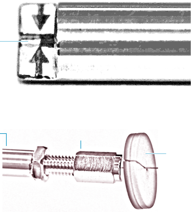
8 Installing Optional Kits
Installing the NoVent Microfluidics
Thermo Scientific TRACE 1300 and TRACE 1310 Hardware Manual 387
10. While holding the column measuring tool steady, tighten the transfer line nut with a
1/4 in. wrench until the column just stops moving in the ferrule.
11. Turn the transfer line nut 1 flat backward so the column is able to move in the ferrule
with slight resistance.
12. Line up the outlet of the column with the arrows on the end of the column measuring
tool.
Figure 391. Lining Up the Column in the Column Measuring Tool
13. Place a septum with a notch cut into it behind the transfer line nut. The septum marks
the place on the column where it should exit the nut.
Figure 392. Positioning the Septum
14. Pull the column back from the transfer line nut. Do not move the septum from its
position on the column.
Column Outlet
Transfer Line
Nut
Septum
Column
Measuring Tool
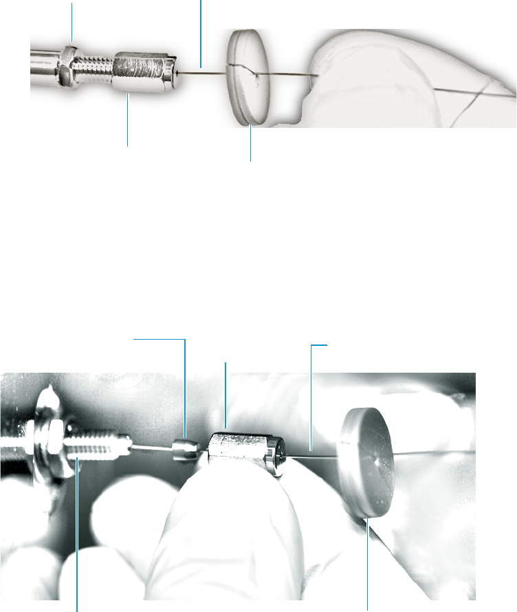
8 Installing Optional Kits
Installing the NoVent Microfluidics
388 TRACE 1300 and TRACE 1310 Hardware Manual Thermo Scientific
Figure 393. Pulling the Column Back from the Transfer Line Nut
15. Loosen the transfer line nut from the column measuring tool.
16. Remove the column, transfer line nut and ferrule from the column measuring tool,
making sure not to move the septum from its location on the column.
17. Insert the column into the transfer line.
Figure 394. Inserting the Column into the Transfer Line
18. Tighten the transfer line nut until it is just secure enough so that you cannot move it.
19. Loosen the nut by turning it exactly 1 flat backward.
20. Position the column in the transfer line. Use the septum as a guide to measure the correct
length you should insert the column. Be careful not to change the location of the septum
on the column.
Transfer Line
Nut Septum
Column
Measuring Tool Column
Transfer Line
Column
Transfer Line
Nut
Ferrule
Septum
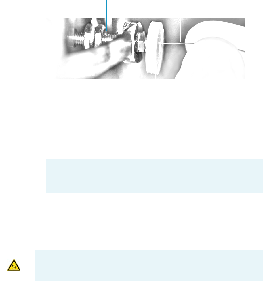
8 Installing Optional Kits
Installing the NoVent Microfluidics
Thermo Scientific TRACE 1300 and TRACE 1310 Hardware Manual 389
Figure 395. Positioning the Column in the Transfer Line
21. Tighten the nut 1 flat forward—back to where it is secure enough in the transfer line that
you cannot move it.
22. Tighten the nut 1 additional quarter turn.
23. Remove the cut septum.
24. Close the front door of the GC.
25. Condition the graphite Vespel ferrule:
a. Raise the oven temperature to the maximum temperature you will operate the GC
column.
b. Wait 10 minutes.
c. Lower the oven temperature to 40 °C (104 °F) and allow it to cool before continuing.
d. Retighten the transfer line nut.
26. Restore working conditions.
a. Raise the oven temperature to the initial temperature that you will use.
b. Turn on vacuum compensation on the GC.
c. Twist the vent valve clockwise to close the valve. Be sure not to pin. the o-ring.
Note If you are using a SilTite ferrule, follow the instructions that come with SilTite
ferrules. If you are using a graphite Vespel ferrule, they require conditioning to ensure
a leak-tight seal. See the ISQ Spare Parts Guide for information about ordering these
ferrules.
Transfer Line Column
Septum
WARNING BRUN HAZARD The oven may be hot. Allow it to cool to room temperature
before opening it. The injector will still be hot, so do not touch it.
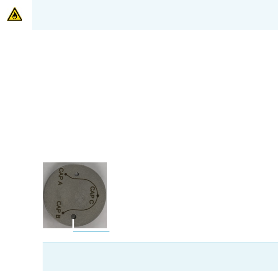
d. If you are using hydrogen as a carrier gas, replace the front panel screw.
e. Replace all remaining hydrogen safety screws if you are using hydrogen.
27. Power on the mass spectrometer.
28. Once the instrument is pumped down and able to scan, click Air & Water / Tune on the
Dashboard view air water spectra and look for evidence of leaks with a large m/z 28 signal.
If you observe a leak, stop scanning and gently tighten the nut in small increments until
no leaks appear when scanning.
Connecting the Capillaries to the Microfluidics Splitter
You can attach now attach all the capillaries to the microfluidics splitter.
To connect the capillaries to the microfluidics splitter
1. Place the ferrule connected to the original GC column into capillary B location on the
microfluidics splitter. See Figure 396. This corresponds to the bottom of the three holes
on a correctly installed splitter.
Figure 396. Correct Orientation for the Microfluidics Splitter
2. Use the FingerTite tool to secure the nut you previously attached to the column to top of
the three holes on the microfluidics splitter.
3. Orient the capillary connected to the transfer line and the one attached to the no-vent
module as shown in Figure 397.
WARNING - FIRE HAZARD: If you are using hydrogen, do NOT reach over the top of the
instrument to power it on. Instead, reach around the side or go to the back of the
instrument and flip up the power switch.
Tip If a ferrule gets stuck in the microfluidics splitter, use a thumbtack or similar
pointed tool for removal. Insert the point of the tool between the ferrule and threads
and press so that the ferrule is forced off center. This will dislodge the ferrule.
GC Column
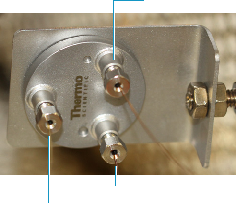
8 Installing Optional Kits
Installing the NoVent Microfluidics
Thermo Scientific TRACE 1300 and TRACE 1310 Hardware Manual 391
Figure 397. Correct Orientation of Columns to Microfluidics Splitter
4. Close the GC door.
5. Close the vent valve knob.
6. Power on the mass spectrometer.
7. Ensure the switch is set to Off on the NoVent microfluidics module.
8. Let the mass spectrometer pump down for a minimum of one hour and then check the
air-water spectrum for gross leaks. Assuming the convection gauge and ion gauge (if
present) indicate appropriate pressures, small leaks can be located by spraying with Freon,
argon, or another suitable gas near the tubing connections.
Configuring the Post-Column
After installing the NoVent microfluidics, you must enter the post-column length and ID
before running samples. This section contains instructions for configuring your post-column
settings on both a TRACE 1310 and a TRACE 1300.
To enter post-column settings on a TRACE 1310
1. On the home page of the TRACE 1310 touchscreen, click the Configuration icon.
Capillary Restrictor to No-Vent Module
GC Column
Capillary Restrictor to Transfer Line
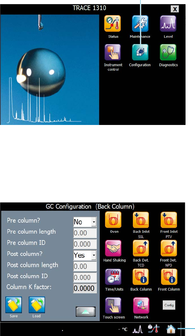
8 Installing Optional Kits
Installing the NoVent Microfluidics
392 TRACE 1300 and TRACE 1310 Hardware Manual Thermo Scientific
Figure 398. Locating the Configuration Icon on the TRACE 1310 Touchscreen
2. The default GC Configuration (Oven) screen opens. Click the Back Column or Front
Column button, corresponding to where you installed the No-vent microfluidics.
3. The GC Configuration (Front or Back Column) screen opens. Click the down arrow to
access the post column settings.
4. Select Yes from the Post Column? menu. Enter the post column length and ID in the
boxes below.
Figure 399. Configuring the Post Column Settings
Configuration Icon
Home Icon
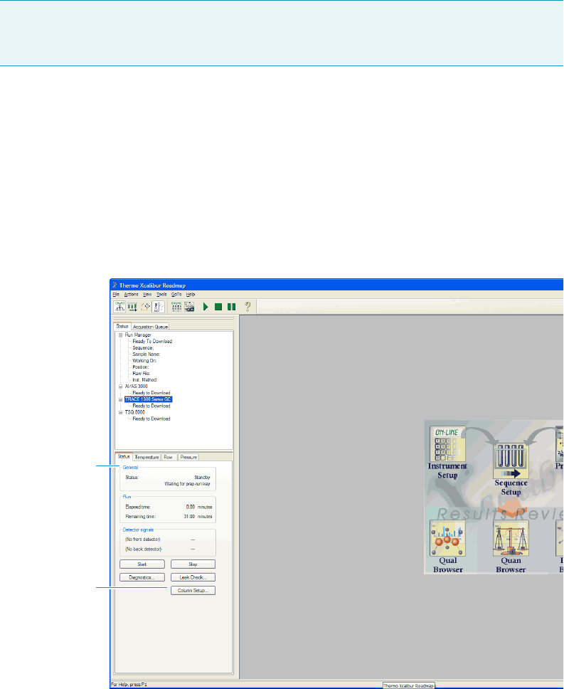
8 Installing Optional Kits
Installing the NoVent Microfluidics
Thermo Scientific TRACE 1300 and TRACE 1310 Hardware Manual 393
5. Click the home icon when you are finished.
To enter the post-column settings on a TRACE 1300
1. Open Xcalibur by clicking the icon on your desktop
2. The Xcalibur Roadmap opens. Select TRACE 1300 Series GC from the list of
instruments.
3. Click Column Setup in the Status pane.
Figure 400. Xcalibur Roadmap
4. The Column Setup window opens. Check the Using Post-Column checkbox and enter
the post-column length and ID.
IMPORTANT For hydrogen, the Post Column Length is 1.2 m. For helium, the Post
Column Length is 0.6 m. The Post Column ID is 0.17 mm for both hydrogen and
helium.
Status Pane
Column
Setup
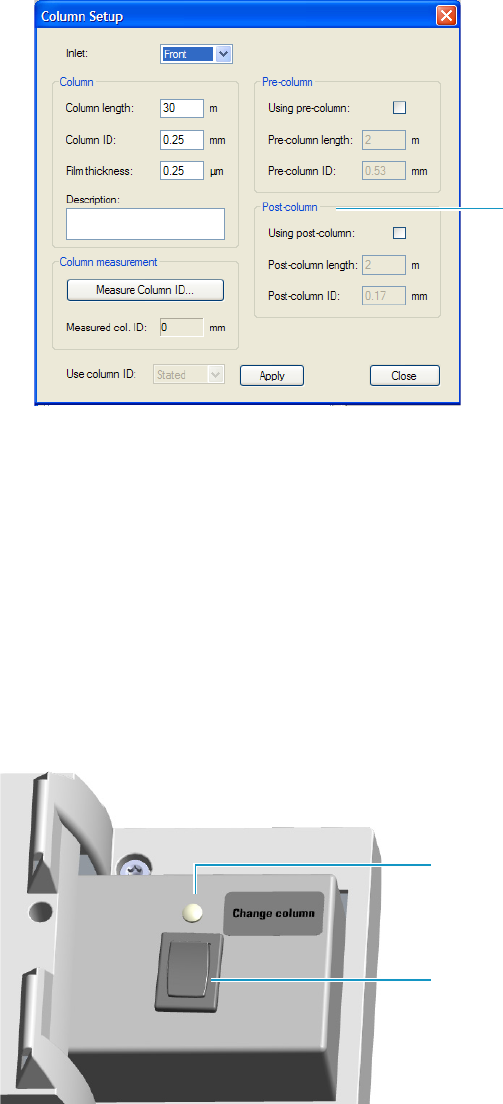
8 Installing Optional Kits
Installing the NoVent Microfluidics
394 TRACE 1300 and TRACE 1310 Hardware Manual Thermo Scientific
Figure 401. Column Setup Options
5. Click Apply.
6. Click Close.
Using the Module
The GC does not recognize the presence of the NoVent microfluidics, so it is invisible to the
system. The module receives only the voltages for supplying the solenoid valve and the
On/Off light from the GC.
The normal condition of the module is Off. If the switch is in the Off position, the Status
LED is off. See Figure 402.
Figure 402. Module in Off Condition
Before replacing the column or performing maintenance on an injector module, flip the
switch to the On position. Ensure the mass spectrometer is in standby mode and the filament
is off. The status LED lights up as solid green indicating that the solenoid valve is activated.
The carrier gas flows into the mass spectrometer to avoid breaking vacuum. See Figure 403.
Post-column Settings
Status LED Off
Switch on Off Position
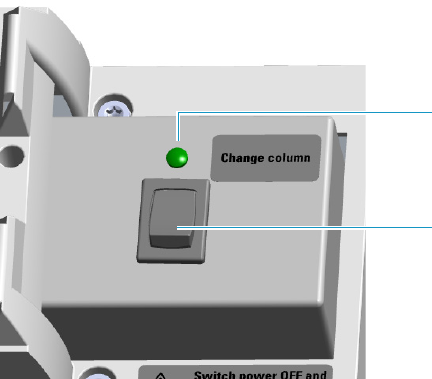
8 Installing Optional Kits
Installing the NoVent Microfluidics
Thermo Scientific TRACE 1300 and TRACE 1310 Hardware Manual 395
Figure 403. Module in On Condition
When you have completed your tasks, flip the switch to the Off position. The status LED
turns Off indicating the solenoid valve is deactivated.
Status LED On
Switch on On Position
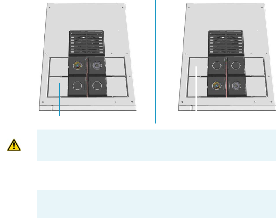
8 Installing Optional Kits
Installing a FTIR Make-up Module
396 TRACE 1300 and TRACE 1310 Hardware Manual Thermo Scientific
Installing a FTIR Make-up Module
This section provides instructions for installing the FTIR Make-up module on your
TRACE 1300/1310 for the connection with the Thermo Scientific Nicolet iS50 FT-IR
Spectrometer. According to the configuration of your TRACE 1300/TRACE 1310, a dummy
module is present into the free site where the detector module is not installed.
See Figure 404.
Figure 404. Add a Front/Back Detector Module
The FTIR Make-up module must be installed into the detectors housing, and supplied
through the line of the front/back carrier gas.
The module is equipped with an ON/OFF needle valve for the regulation of the gas flow.
• Open the needle valve manually turning the knob counter-clockwise.
• Close the needle valve manually turning the knob clockwise.
Perform the regulation of the gas flow using a little flat head screwdriver.
• Increase the gas flow turning the flow regulation screw counter-clockwise.
• Decrease the gas flow turning the flow regulation screw clockwise.
Dummy Back Detector Module
Dummy Front Detector Module
ATTENTION Where a dummy module is installed, the gas connection is blocked by a
plug.
IMPORTANT If the front/back carrier gas is not already used by an injector module, you
must install the front/back carrier gas inlet, and connect the carrier gas line as described in
the section “Making the Gas Supply Plumbing Connections” on page 7.
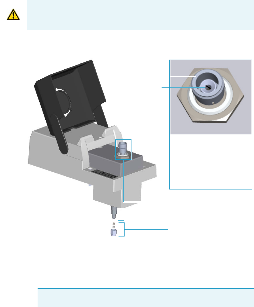
8 Installing Optional Kits
Installing a FTIR Make-up Module
Thermo Scientific TRACE 1300 and TRACE 1310 Hardware Manual 397
The standard operating value is in the range 0.2- 0.3 mL/min. Refer to the Nicolet iS50 FT-IR
Spectrometer Manual for details.
The components of the FTIR module are shown in Figure 405.
Figure 405. FTIR Make-up Module
To add a FTIR Make-up module
1. Put the GC in standby condition.
2. Cool the oven, injector, and detector to room temperature.
3. Close the gas supplies.
4. Power off the GC.
ATTENTION The flow of the carrier gas depends on the inlet pressure. Set the carrier gas
flow according to the working pressure.
Note By pressing the Maintenance button, the GC cool down is automatically
carried out.
Bottom Fitting
Nut and Ferrules
Flow Regulation Screw
Open/Close Knob
Needle Valve VICI-CNV1A10S1
ON/OFF Knob:
Turn clockwise for closing
Turn counter-clockwise for opening
Flow Regulation Screw:
Turn clockwise for decreasing
Turn counter-clockwise for increasing
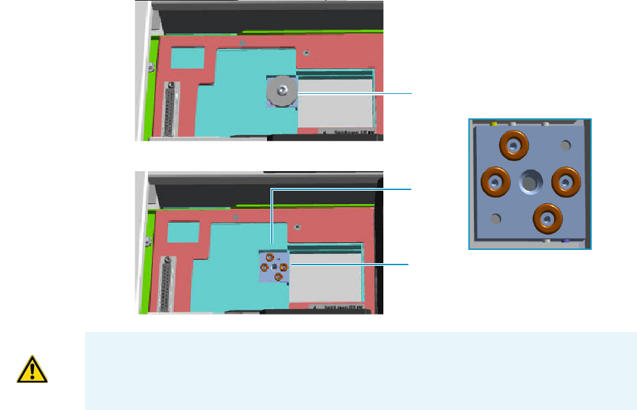
8 Installing Optional Kits
Installing a FTIR Make-up Module
398 TRACE 1300 and TRACE 1310 Hardware Manual Thermo Scientific
a. Push down the power switch (breaker), located at the back of the instrument, to the
position O.
b. Unplug the power cable from the AC Input connector into the back of the GC and
from the wall outlet.
5. If external modules are present, unplug the power cable from the AC Input connector of
each external module, and from the wall outlet.
6. Remove the dummy module from the position where the FTIR module will be installed.
a. Open the module flap cover.
b. Using a T20 Torxhead screwdriver, unscrew and remove the two captive fixing
screws.
c. Keeping the dummy module flap cover open, lift up the module from its seat in the
detector housing. Place the dummy module on a clean surface.
d. Remove the gas block plug from the gas connections by unscrewing its fixing screw
using a T20 Torxhead screwdriver. See Figure 406.
Figure 406. Detector Gas Block Plug
7. Open the front door of the GC.
8. Plug the FTIR Make-up module into the main frame.
a. Open the module flap cover.
Gas Connections Without Gas Block Plug
Gas Block Plug on Detector Seat
O-rings
WARNING Make sure all the four o-rings are placed into their seats on the gas
connection. See Figure 406.
Do not install the module if the o-rings are missing.

8 Installing Optional Kits
Installing a FTIR Make-up Module
Thermo Scientific TRACE 1300 and TRACE 1310 Hardware Manual 399
b. Keeping the module flap cover open, place the module in its seat.
c. Use a T20 Torxhead screwdriver to tighten the three captive fixing screws without
overtightening.
.
d. Close the module flap cover.
9. Connect the 1/16-in tubing provided.
a. Connect an end of the 1/16-in tubing to the bottom fitting of the module using the
Swagelock® nut and ferrules provided.
b. Connect the other end of the tubing to the transfer line of the FT-IR spectrometer.
Refer to the Nicolet iS50 FT-IR Spectrometer Manual for details.
10. Open the gas supplies.
11. If external modules are present, plug the power cable to the AC Input connector of each
external module, and to the wall outlet.
12. Power on the GC.
a. Plug the power cable to the AC Input connector into the back of the GC and to the
wall outlet.
b. Flip up the power switch (breaker) to the position I.
13. Close the front door of the GC.
ATTENTION To maintain the correct alignment the screws must be tightened in turn.
Tighten each screw only a small amount before moving to the next screw. Repeat until all
are secure.
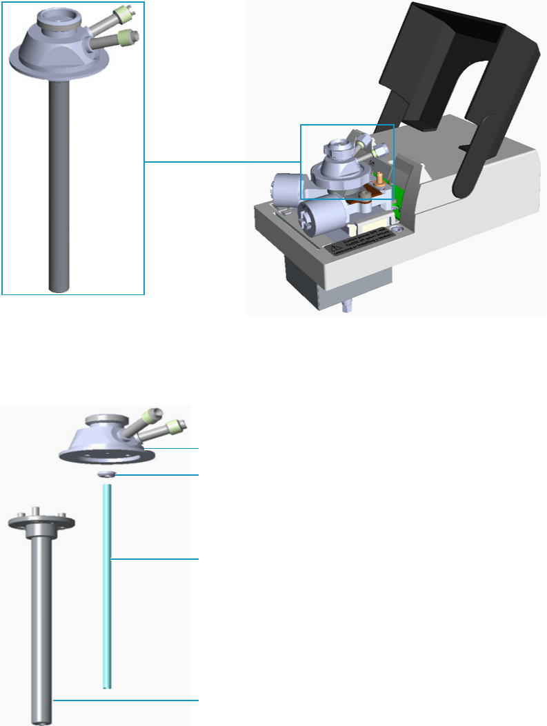
8 Installing Optional Kits
Installing the Hot Injection Adapter Kit on the SSL/SSLBKF Injector
400 TRACE 1300 and TRACE 1310 Hardware Manual Thermo Scientific
Installing the Hot Injection Adapter Kit on the SSL/SSLBKF Injector
This section provides the instruction for installing the Hot Injection Adapter kit
(PN 19050733) on the SSL/SSLBKF injector for the use with an external device for gas
sampling. See Figure 330.
Figure 407. Hot Injection Adapter
The Hot Injection Adapter consists of the following parts: head, short PTV liner, liner seal,
and stem. See Figure 408.
Figure 408. Hot Injector Adapter Assembly
Hot Injection Adapter
Head
Stem
Liner Seal
Short PTV Liner
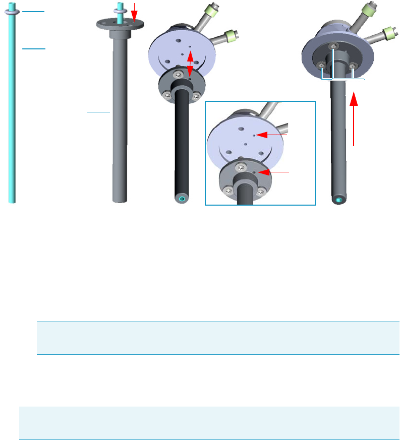
8 Installing Optional Kits
Installing the Hot Injection Adapter Kit on the SSL/SSLBKF Injector
Thermo Scientific TRACE 1300 and TRACE 1310 Hardware Manual 401
To install the hot injection adapter on the injector
1. Assemble the hot injection adapter if not already done. See Figure 409.
Figure 409. Adapter Assembly
a. Place the liner seal on the liner.
b. Insert the liner into the stem.
c. Couple the head and the stem paying attention to properly align the corresponding
holes doing match the polarizing guides on the head and on the flange of the stem.
d. Fix the stem to the head screwing the three fixing screws using a T8 Torxhead
screwdriver.
2. Put the GC in standby condition.
3. Cool the oven, injector, and detector to room temperature.
4. Close the gas supplies.
5. Power off the GC.
a. Push down the power switch (breaker), located at the back of the instrument, to the
position O.
b. Unplug the power cable from the AC Input connector into the back of the GC and
from the wall outlet.
6. Remove the column end from the injector.
Note The stem conducts heat from the body of the SSL/SSLBKF injector to the
head of the adapter allowing a hot injection.
Note By pressing the Maintenance button, the GC cool down is automatically
carried out.
Liner Seal
Liner
Stem
Fixing
Screws
Guides
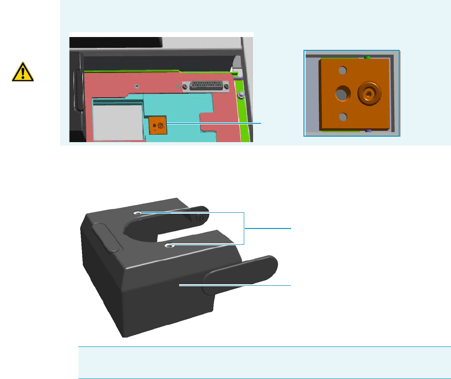
8 Installing Optional Kits
Installing the Hot Injection Adapter Kit on the SSL/SSLBKF Injector
402 TRACE 1300 and TRACE 1310 Hardware Manual Thermo Scientific
a. Open the front door of the GC.
b. Loosen the retaining nut from the injector fitting on the upper interior wall of the
GC oven.
c. Remove the analytical column with its nut and ferrule from the bottom of the
injector.
7. Put the autosampler away if present.
8. Remove the SSL/SSLBKF injector module from its seat.
a. Open the module flap cover.
b. Using a T20 Torxhead screwdriver, unscrew the three captive fixing screws.
c. Throw upward the module from its seat of the injector housing. Place the
SSL/SSLBKF module on a clean surface.
9. Replace the module flap cover with the one provided. See Figure 331.
Figure 410. Module Flap Cover for Hot Injection
10. Reinstall the injector module into the main frame.
a. Open the module flap cover.
WARNING Make sure the o-ring remains into its seat on the gas connection.
Do not install the module if the o-ring is missing.
O-ring
Note The fixing holes present on the top of the module flap cover can be used for
making more stable a sampling device that requires to be seat directly on the injector.
Module Flap Cover
Fixing Holes
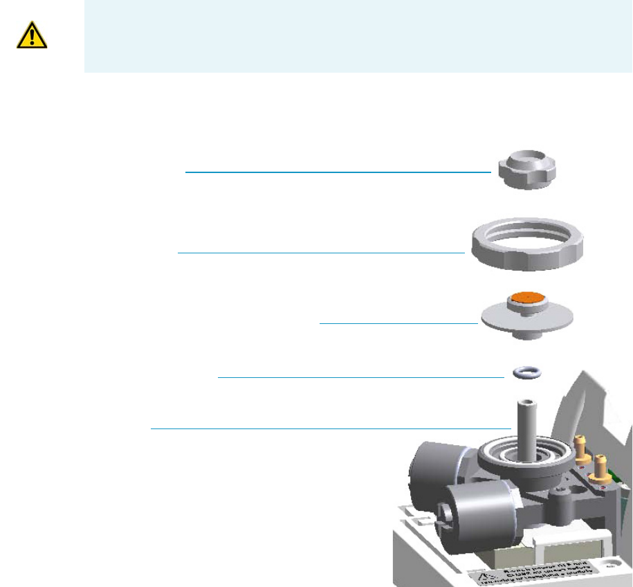
8 Installing Optional Kits
Installing the Hot Injection Adapter Kit on the SSL/SSLBKF Injector
Thermo Scientific TRACE 1300 and TRACE 1310 Hardware Manual 403
b. Place the injector module in its seat. Be sure to insert the 25-pin male connector, on
the bottom of the module, into the 25-pin female connector on the injector seat of
the injector housing.
c. Use a T20 Torxhead screwdriver to tighten the three captive fixing screws without
overtighten.
11. Remove the top parts of the injector. See Figure 332.
Figure 411. Injector Top Parts Removal
a. Unscrew the septum cap of the injector.
b. Unscrew the ring nut.
c. Remove the septum holder/liner cap with septum from the injector body head.
12. Remove the liner and its seal.
a. Use tweezer to remove the current liner with the liner seal (o-ring) from the injector.
13. Remove the injector body. See Figure 412.
CAUTION To maintain the correct alignment the screws must be tightened in turn.
Tighten each screw only a small amount before moving to the next screw. Repeat until all
are secure.
Septum Cap
Ring Nut
Septum Holder/Liner Cap with Septum
Liner Seal (O-ring)
Liner
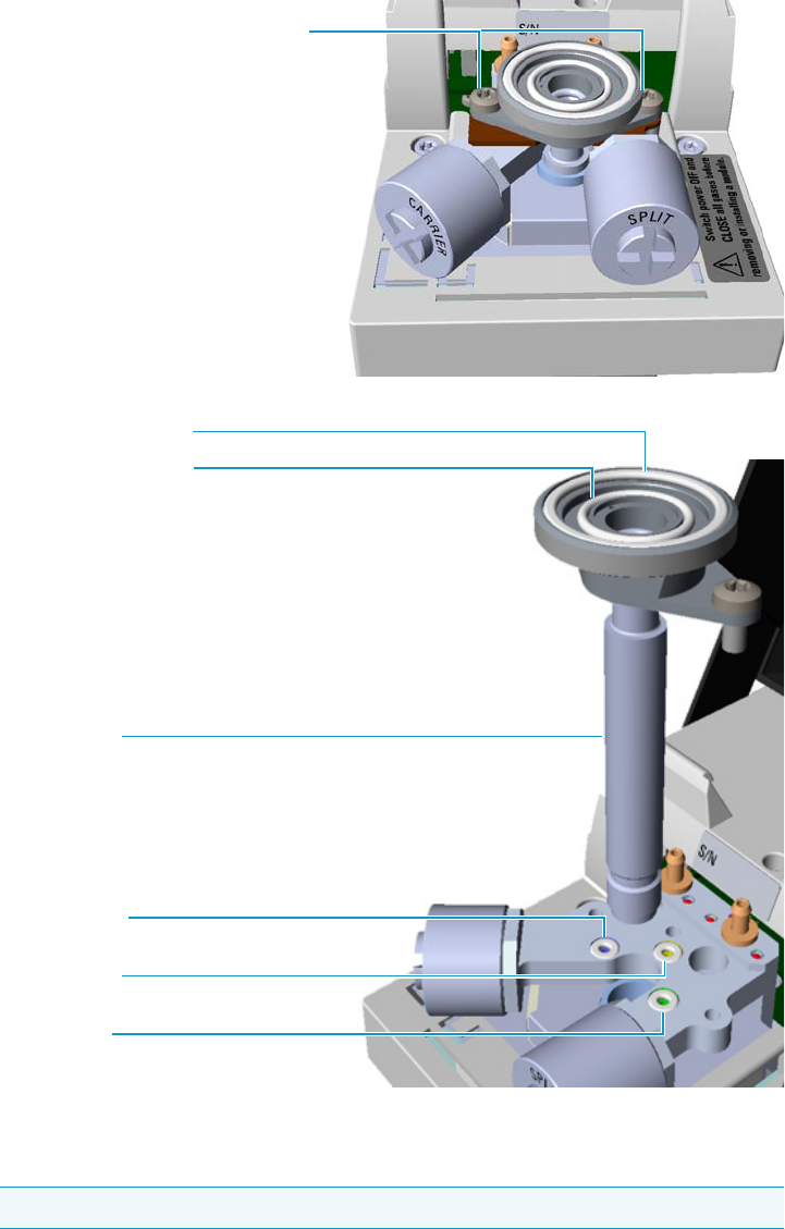
8 Installing Optional Kits
Installing the Hot Injection Adapter Kit on the SSL/SSLBKF Injector
404 TRACE 1300 and TRACE 1310 Hardware Manual Thermo Scientific
Figure 412. SSL Injector Body Removal
a. Using a T20 Torxhead screwdriver, undo the two injector body fixing screws, and
extract the injector body from its housing.
14. Install the spacer plate. See Figure 413.
Note Do not remove the carrier, split, and purge lines o-rings.
Split Line O-ring
Carrier Line O-ring
Purge Line O-ring
SSL Injector Body
SSL/SSLBKF Injector Body Fixing Screws
Internal Body Head O-ring
External Body Head O-ring
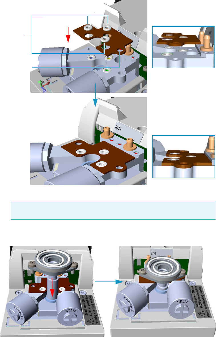
8 Installing Optional Kits
Installing the Hot Injection Adapter Kit on the SSL/SSLBKF Injector
Thermo Scientific TRACE 1300 and TRACE 1310 Hardware Manual 405
Figure 413. Spacer Plate
a. Place the spacer plate and its three o-ring on the injector base.
15. Reinstall the injector body. See Figure 414.
Figure 414. Injector Body Reinstallation
a. Reinstall and fix the injector body into its housing by screwing the two fixing screws.
Note The three o-ring of the spacer plate do not replace the carrier, purge, and
split lines o-rings but are put on them, then six o-rings are present on the base.
O-rings
Spacer Plate
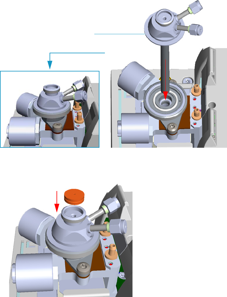
8 Installing Optional Kits
Installing the Hot Injection Adapter Kit on the SSL/SSLBKF Injector
406 TRACE 1300 and TRACE 1310 Hardware Manual Thermo Scientific
b. If required, replace both the internal and external body head o-rings using tweezers.
16. Install the hot injection adapter on the top of the injector. See Figure 333.
Figure 415. Hot Injection Adapter (1)
a. Avoid touching the septum with your fingers. Insert a new septum into the septum
holder cavity of the hot injection adapter using tweezers. See Figure 334.
Figure 416. Hot Injection Adapter (2)
b. Guide the ring nut on the hot injection adapter with the septum, then fix it screwing
the ring nut. See Figure 336.
Hot Injection Adapter
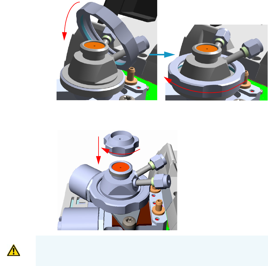
8 Installing Optional Kits
Installing the Hot Injection Adapter Kit on the SSL/SSLBKF Injector
Thermo Scientific TRACE 1300 and TRACE 1310 Hardware Manual 407
Figure 417. Hot Injection Adapter (3)
c. Screw and tighten the septum cap to finger-tight. See Figure 418.
Figure 418. Hot Injection Adapter (4)
17. Close the module flap cover.
18. Connect the hot injection adapter to the device for the sampling of gas. See the example
in Figure 419.
CAUTION Do not overtighten the septum cap because you might damage the septum and
affect instrument performance.
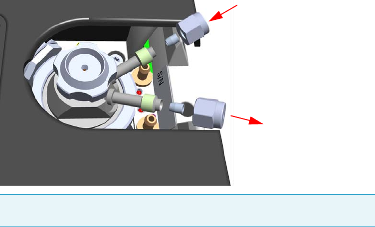
8 Installing Optional Kits
Installing the Hot Injection Adapter Kit on the SSL/SSLBKF Injector
408 TRACE 1300 and TRACE 1310 Hardware Manual Thermo Scientific
Figure 419. Hot Injection Adapter (5)
19. Reconnect the column end to the injector and verify the connection point.
20. Open the gas supplies.
21. Power on the GC.
a. Plug the power cable to the AC Input connector into the back of the GC and to the
wall outlet.
b. Flip out the power switch (breaker) to the position I.
22. Pressurize the module with the carrier gas.
23. Check for leaks.
a. Use a handheld electronic leak detector (Thermo Scientific GLD Pro leak detector or
equivalent) to check the two fitting for leaks.
b. If you detect a leak, tighten the connection and retest it.
c. Repeat this process until all connections are leak free.
24. Close the front door of the GC.
25. If present, update the autosampler for the new injection position.
Note If only a port of the adapter is connected to the device for the sampling of gas,
close the other one with the blind nut provided.
IN
OUT
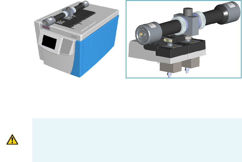
8 Installing Optional Kits
Performing the Dual FPD Detector Configuration
Thermo Scientific TRACE 1300 and TRACE 1310 Hardware Manual 409
Performing the Dual FPD Detector Configuration
This section provides the instructions for performing the Dual FPD configuration by
connecting a second photomultiplier tube with a different interferential filter on the same
detector control module. See Figure 420.
Figure 420. Dual FPD Configuration
To perform the Dual FPD configuration you need the following devices:
• Two Flame Photometric Detector modules
• A Dual FPD upgrade kit PN 19050783
The operation consists of the following steps:
• Remotion of the front and back FPD Detectors from the relevant detector control
module.
• Disassembling the photomultiplier tube from a FPD detector.
• Assembling the second photomultiplier tube on the other FPD detector to obtain the
Dual FPD configuration.
• Remotion of the jet from the front detector control module.
• Installation of the PT100 simulator, provided with the kit, on the detector base of the
front detector control module.
IMPORTANT The Dual FPD must be installed onto the FPD control module placed into
the back site of the detectors housing.
The FPD control module placed into the front site of the detector housing must be
equipped with the PT100 simulator, provided with the kit, instead of the FPD detector,
and will supply the second photomultiplier of the configuration.
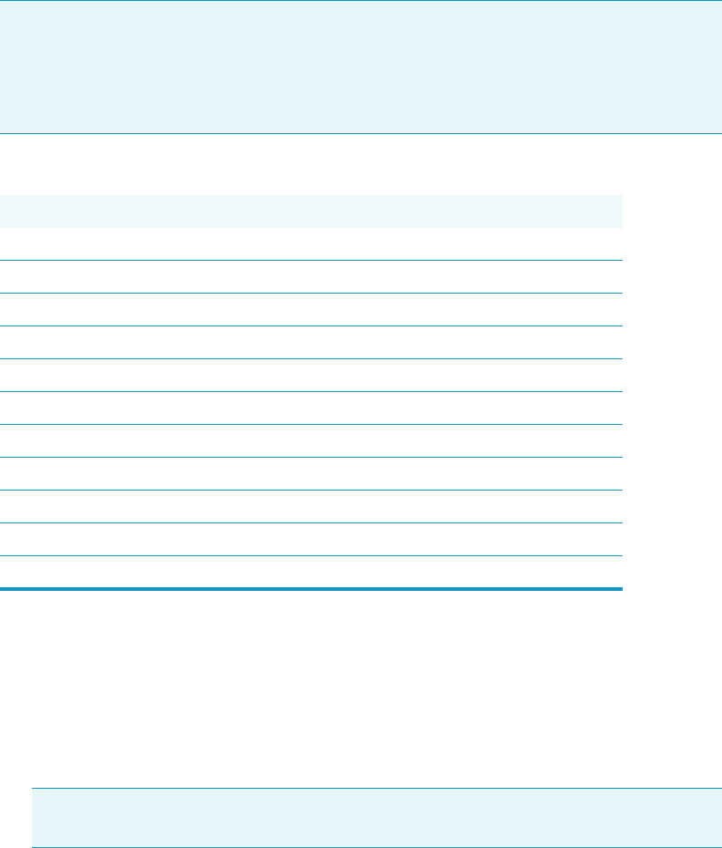
8 Installing Optional Kits
Performing the Dual FPD Detector Configuration
410 TRACE 1300 and TRACE 1310 Hardware Manual Thermo Scientific
To assembly the Dual FPD configuration
Initial operations
1. Put the GC in standby condition.
2. Switch off the flame. Hydrogen and air are automatically closed.
3. Cool the detector to room temperature.
4. Power off the GC.
a. Push down the power switch (breaker), located at the back of the instrument, to the
position O.
b. Unplug the power cable from the AC Input connector into the back of the GC and
from the wall outlet.
5. If other external modules are present, unplug the power cable from the AC Input
connector of each module, and from the wall outlet.
6. Remove the FPD detectors from the base of the respective detector control module.
Note For writing convention, we consider the disassembling of the photomultiplier tube
from the FPD detector installed on the front detector control module, and the assembling
of the Dual FPD configuration on the FPD detector installed on the back detector
control module. We name them secondary FPD detector and primary FPD detector
respectively.
Materials needed
Dual FPD Upgrade Kit PN 19050783
Gloves
FPD fixing tools
Appropriate interferential filter (394 nm for Sulphur; 526 nm for Phosphorous; 610 nm for Tin
Methylene chloride or GC-grade methanol
Screwdriver
T6 Torxhead key
T10 Torxhead screwdriver
1-mm Allen wrench
5 mm wrench
5/16-in tube wrench
Note By pressing the Maintenance button, the GC cool down is automatically
carried out.
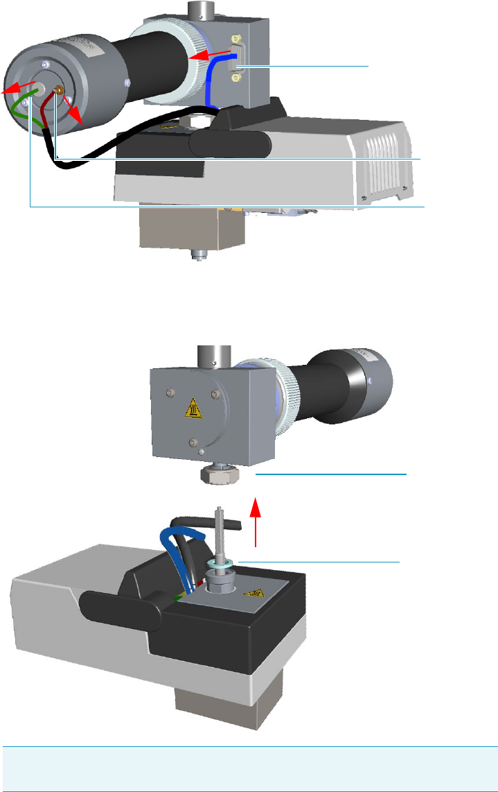
8 Installing Optional Kits
Performing the Dual FPD Detector Configuration
Thermo Scientific TRACE 1300 and TRACE 1310 Hardware Manual 411
a. Disconnect the signal, excitation voltage, and ignition/heating cables from the
detector. See Figure 421.
Figure 421. FPD Cable Disconnection
b. Using the tool provided with the system, loosen the fixing nut on the base of the
detector and remove it. See Figure 422.
Figure 422. FPD Detector Removal
Note Do not lose the aluminium ring inserted between the detector head and
the base body.
Signal Cable
Excitation
Voltage
Cable
Ignition/Heating Cable
FPD Fixing Nut
Aluminium Ring
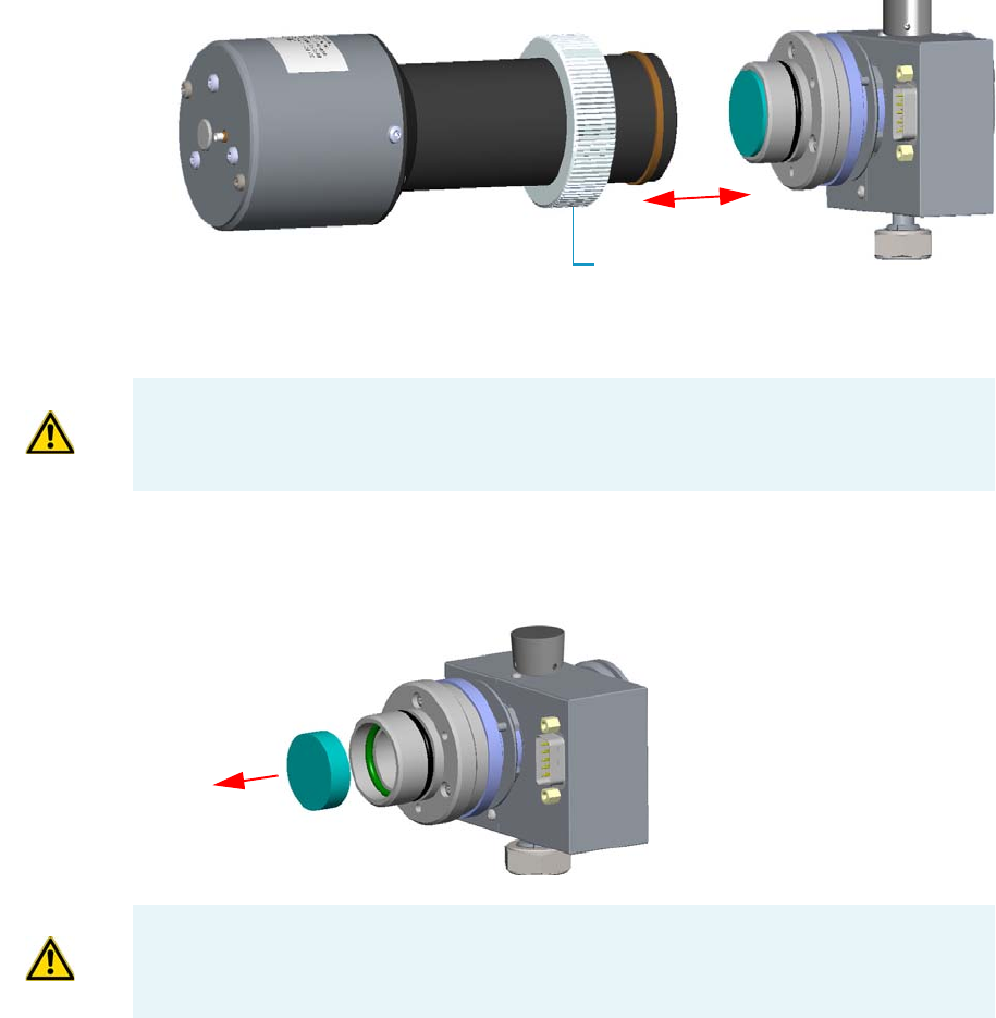
8 Installing Optional Kits
Performing the Dual FPD Detector Configuration
412 TRACE 1300 and TRACE 1310 Hardware Manual Thermo Scientific
c. Place both the FPD detectors on a clean and free workbench.
Disassembling the secondary FPD detector
7. Remove the photomultiplier tube assembly and the filter from the cell of the secondary
FPD detector. See Figure 423.
Figure 423. Photomultiplier Assembly Removal
a. Loosen the knurled nut that fixes the photomultiplier assembly and remove it from
the detector body.
b. Remove the interferential filter from its housing, handling it very gently. Keep it
using a clean paper towel. See Figure 424.
Figure 424. Filter Removal
Knurled Nut
CAUTION The photomultiplier tube could damage if exposed to ambient light with the
excitation voltage On. Make sure the power supply has been switched off before
disconnecting the tube from the detector body.
CAUTION Filters are fragile. Pay attention not to let the filter fall down and damage.
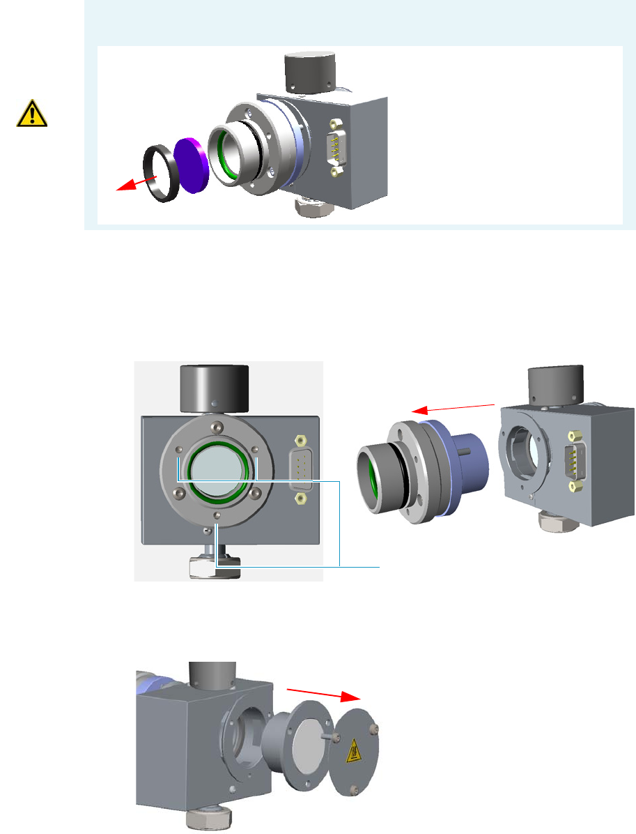
8 Installing Optional Kits
Performing the Dual FPD Detector Configuration
Thermo Scientific TRACE 1300 and TRACE 1310 Hardware Manual 413
8. Remove the filter a support and the flange assembly from the cell of the secondary FPD
detector.
a. Loosen the three smaller Allen screws that fix the flange to the detector body and
remove it with the spacer that should remain inserted in the flange See Figure 425.
Figure 425. Filter Support and Flange Assembly Removal
b. Now you could access the flame-side heat shield, and the relevant graphite seal.
Loosen the Allen screws that fix the mirror plug and remove it. See Figure 426.
Figure 426. Mirror Plug Removal
CAUTION If the filter installed is equipped with the spacer (see the kits PN 19050785 and
PN 19050786), first remove the spacer, and then the filter.
Interferential Filter
Spacer
Fixing Screws
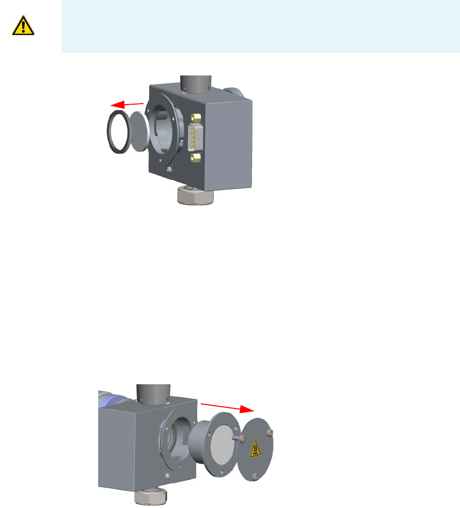
8 Installing Optional Kits
Performing the Dual FPD Detector Configuration
414 TRACE 1300 and TRACE 1310 Hardware Manual Thermo Scientific
c. Insert the handle of a screwdriver or other un-sharpened tool in the combustion
chamber and push the flame-side heat shield and its graphite seal out from its
housing. Act gently to avoid breaking of the heat shield. See Figure 427.
Figure 427. Filter-side Heat Shield Removal
d. Remove with care traces of graphite due to the breaking of the seal.
e. Reinstall the mirror plug.
Assembling the primary FPD detector in Dual FPD configuration
Perform the Dual FPD configuration on the primary FPD detector using the components
removed from the secondary FPD detector.
9. Remove the mirror plug from the cell of the primary FPD detector.
a. Loosen the Allen screws that fix the mirror plug and remove it. See Figure 428.
Figure 428. Mirror Plug Removal
10. Insert the filter support and the flange assembly into the primary FPD detector.
a. Insert the heat shield into its housing inside the detector body.
b. Insert the spacer into the flange, letting it stand out for about 5 mm.
CAUTION While pushing out the heat shield, pay attention not to damage the ignition
coil.
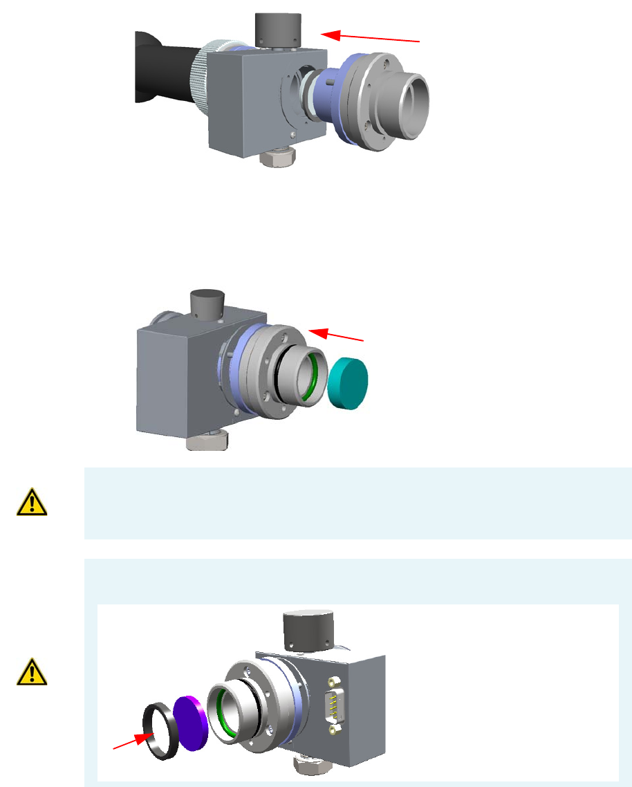
8 Installing Optional Kits
Performing the Dual FPD Detector Configuration
Thermo Scientific TRACE 1300 and TRACE 1310 Hardware Manual 415
c. Insert the graphite seal on the spacer, pushing it slowly until it touches the flange.
d. Fix the assembly tightening the three Allen screws. See Figure 429.
Figure 429. Filter Support and Flange Assembly Installation
11. Place the appropriate filter and the photomultiplier tube assembly.
a. Reinsert the filter into the support. The mirror face must be oriented towards the
flame. See Figure 430.
Figure 430. Filter Remounting
CAUTION Avoid touching the filter with your fingers. If you see fingertips on the filter,
clean it using a clean paper towel and, if needed, GC-grade methanol before remounting.
CAUTION If the filter installed is equipped with the spacer (see the kits PN 19050785 and
PN 19050786), first insert the filter, and then the spacer.
Interferential Filter
Spacer
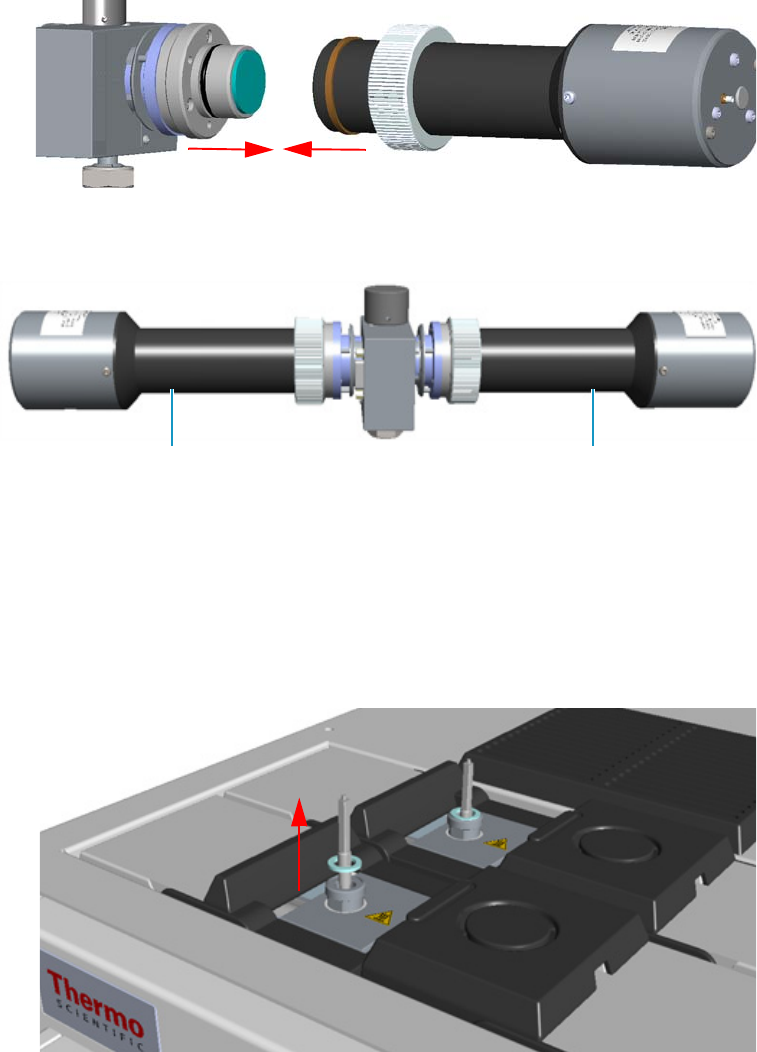
8 Installing Optional Kits
Performing the Dual FPD Detector Configuration
416 TRACE 1300 and TRACE 1310 Hardware Manual Thermo Scientific
b. Mount the photomultiplier tube assembly then fix it tightening the knurled nut.
See Figure 431.
Figure 431. Photomultiplier Tube Assembly Mounting
The result of the operation is shown in Figure 432.
Figure 432. Result of the Dual FPD Configuration
Installing of the Dual FPD and electrical connections
12. Remove the jet of the front detector control module.
a. Using the 5 mm wrench provided with the GC, loosen the jet and remove it from the
detector base body. See Figure 433.
Figure 433. FPD Jet Removal
Primary Photomultiplier Tube Secondary Photomultiplier Tube
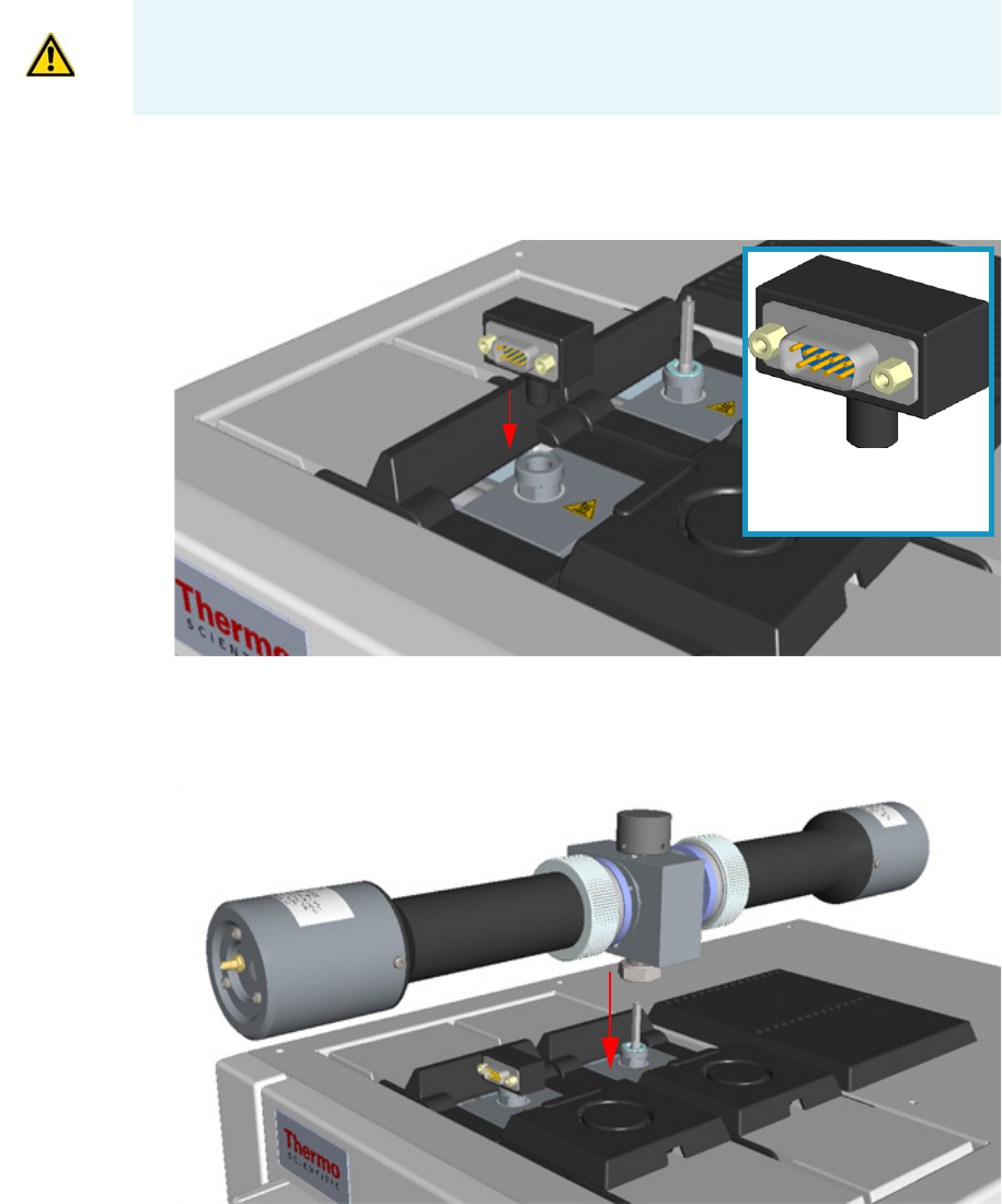
8 Installing Optional Kits
Performing the Dual FPD Detector Configuration
Thermo Scientific TRACE 1300 and TRACE 1310 Hardware Manual 417
13. Install the PT 100 simulator, provided with kit PN 19050783, on the detector base of the
front detector control module. See Figure 434.
Figure 434. PT100 Simulator Installation
14. Install the Dual FPD on the detector base of the detector control module placed into the
back site of the detector housing. See Figure 435.
Figure 435. Dual FPD Installation
a. Place the detector on its base body, ensuring that the aluminium ring has been
inserted in the correct position, then tighten the fixing nut.
15. Connect the cables to the FPD detectors.
IMPORTANT Save the jet and the aluminium ring in a safe place because will be reused
when you restore the original configuration of the FPD modules.
PT100 Simulator provided
with the kit PN 19050783
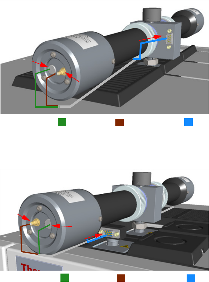
8 Installing Optional Kits
Performing the Dual FPD Detector Configuration
418 TRACE 1300 and TRACE 1310 Hardware Manual Thermo Scientific
a. Connect the signal, excitation voltage and ignition/heating cables coming from the
control module installed into the back site to the primary FPD detector.
See Figure 436.
Figure 436. Primary FPD Detector Cables Connection
b. Connect the signal, excitation voltage and ignition/heating cables coming from the
control module installed into the front site to the secondary FPD detector.
See Figure 436.
Figure 437. Secondary FPD Detector Cables Connection
Restart the GC and set the working parameters
16. If other external modules are present, plug the power cable to the AC Input connector of
each module, and to the wall outlet.
Excitation Voltage Cable Signal Cable Ignition Heating Cable
Excitation Voltage Cable Signal Cable Ignition Heating Cable
8 Installing Optional Kits
Performing the Dual FPD Detector Configuration
Thermo Scientific TRACE 1300 and TRACE 1310 Hardware Manual 419
17. Power on the GC.
a. Plug the power cable to the AC Input connector into the back of the GC and to the
wall outlet.
b. Flip up the power switch (breaker) to the position I.
Set the working parameters
18. Set the parameters for the primary FPD detector (back).
a. Set the flow of the gases, the temperatures, the ignition threshold, and the PMT
voltage for the primary photomultiplier tube according to the working analytical
conditions.
19. Set the parameters for the secondary FPD detector (front).
a. Set the flow of the gases and the temperatures to Off.
b. Set the PMT voltage for the secondary photomultiplier tube.
20. Turn on the Flame On parameter of the primary FPD detector.

Thermo Scientific TRACE 1300 and TRACE 1310 Hardware Manual 421
9
Adding Modules
This chapter describes how to install any added injector, detector, external, module that is
available for the TRACE 1300/TRACE 1310. See the TRACE 1300 and TRACE 1310 Spare
Parts Guide for information about ordering the equipment in this chapter.
Contents
•Adding a SSL, SSLBKF, PTV, or PTVBKF Injector Module
•Adding a GSV Injector Module
•Adding a FID, TCD/TCD In-Series, ECD, or FPD Detector Module
•Adding a NPD Detector Module
•Adding an Aux Temperature/Cryo Module
•Adding a Helium Saver Injector Module
•Adding a PDD Module
•Adding a Generic Detector Interface
•Adding an Analog Output Interface
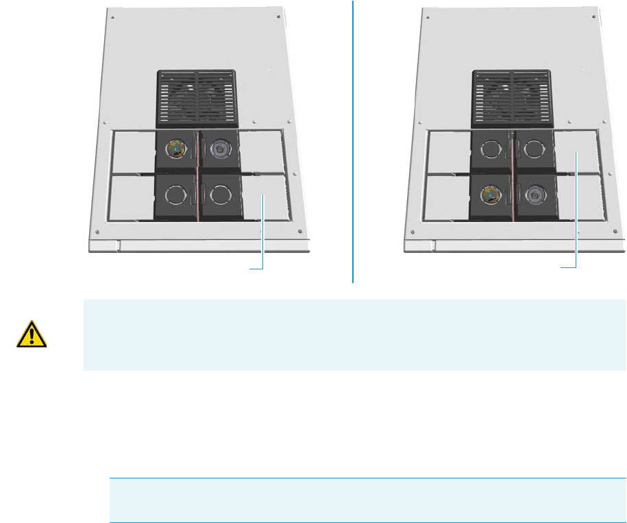
9 Adding Modules
Adding a SSL, SSLBKF, PTV, or PTVBKF Injector Module
422 TRACE 1300 and TRACE 1310 Hardware Manual Thermo Scientific
Adding a SSL, SSLBKF, PTV, or PTVBKF Injector Module
This section provides instructions for adding a front/back SSL, SSLBKF, PTV, or PTVBKF
injector module. According to the configuration of your TRACE 1300/TRACE 1310, a
dummy module is present into the free site where the injector module is not installed.
See Figure 438.
Figure 438. Add a New Front/Back Injector Module
To add an SSL, SSLBKF, PTV, or PTVBKF injector module
1. Put the GC in standby condition.
2. Cool the oven, injector, and detector to room temperature.
3. Close the gas supplies.
4. Power off the GC.
a. Push down the power switch (breaker), located at the back of the instrument, to the
position O.
b. Unplug the power cable from the AC Input connector into the back of the GC and
from the wall outlet.
5. If external modules are present, unplug the power cable from the AC Input connector of
each external module, and from the wall outlet.
Dummy Front Injector Module Dummy Back Injector Module
ATTENTION Where a dummy module is installed, the gas connection is blocked by a
plug.
Note By pressing the Maintenance button, the GC cool down is automatically
carried out.

9 Adding Modules
Adding a SSL, SSLBKF, PTV, or PTVBKF Injector Module
Thermo Scientific TRACE 1300 and TRACE 1310 Hardware Manual 423
6. Put the autosampler away if present.
7. Remove the dummy module from the position where the injector module will be
installed.
a. Open the module flap cover.
b. Using a T20 Torxhead screwdriver, unscrew the three captive fixing screws.
c. Keeping the dummy module flap cover open, lift up the module from its seat into the
injector housing. Place the dummy module on a clean surface.
d. Remove the gas block plug from the gas connections by unscrewing its fixing screw
using a T20 Torxhead screwdriver. See Figure 439.
Figure 439. Injector Gas Block Plug
8. Open the front door of the GC.
9. Plug the injector module into the main frame.
a. Open the module flap cover.
b. Keeping the module flap cover open, place the module in its seat. Be sure to insert the
25-pin male connector, on the bottom of the module, into the 25-pin female
connector on the injector seat of the injector housing.
Gas Connection Without Gas Block Plug
Gas Block Plug on Injector Seat
O-ring
WARNING Make sure the o-ring is placed into its seat on the gas connection.
See Figure 439. Do not install the module if the o-ring is missing.

9 Adding Modules
Adding a SSL, SSLBKF, PTV, or PTVBKF Injector Module
424 TRACE 1300 and TRACE 1310 Hardware Manual Thermo Scientific
c. Use a T20 Torxhead screwdriver to tighten the three captive fixing screws without
overtightening.
d. Close the module flap cover.
e. Keep the plug connected to the bottom.
10. Open the gas supplies.
11. Check the gas supply for leaks.
a. Use a handheld electronic leak detector (Thermo Scientific GLD Pro leak detector or
equivalent) to check each fitting for leaks.
b. If you detect a leak, tighten the connection and retest it.
c. Repeat this process until all connections are leak free.
12. If external modules are present, plug the power cable to the AC Input connector of each
external module, and to the wall outlet.
13. Power on the GC.
a. Plug the power cable to the AC Input connector into the back of the GC and to the
wall outlet.
b. Flip up the power switch (breaker) to the position I.
14. Pressurize the module with the carrier gas.
15. Check the module gas connections for leaks.
16. Remove the plug from the bottom.
17. Connect the analytical column end to the injector and verify the connection point.
a. Position the column so that the end of the column extends the proper distance above
the end of the ferrule as reported in Table 1 6 .
18. Close the front door of the GC.
ATTENTION To maintain the correct alignment the screws must be tightened in turn.
Tighten each screw only a small amount before moving to the next screw. Repeat until all
are secure.
Table 16. Column Insertion Depth For SSL, SSLBKF, PTV, and PTVBKF Injectors
SSL SSLBKF PTV PTVBKF
5 mm (splitless) 5 mm (splitless) 30 mm 30 mm
10 mm (split) 10 mm (split) As far as possible into
the bottom when the
PTV is used as an
On-Column injector.
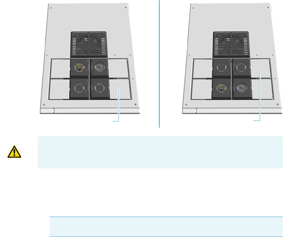
9 Adding Modules
Adding a GSV Injector Module
Thermo Scientific TRACE 1300 and TRACE 1310 Hardware Manual 425
19. If present, move the autosampler towards the module to restore the original alignment.
Adding a GSV Injector Module
This section provides instructions for adding a front/back Gas Sampling Valve injector
module. According to the configuration of your TRACE 1300/TRACE 1310, a dummy
module is present into the free site where the injector module is not installed.
See Figure 440.
Figure 440. Add a New Front/Back GSV Injector Module
To connect the gas sampling valve module to the TRACE 1300/1310 GC
1. Put the GC in standby condition.
2. Cool the oven, injector, and detector to room temperature.
3. Close the gas supplies.
4. Power off the GC.
a. Push down the power switch (breaker), located at the back of the instrument, to the
position O.
Dummy Front Injector Module Dummy Back Injector Module
ATTENTION Where a dummy module is installed, the gas connection is blocked by a
plug.
Note By pressing the Maintenance button, the GC cool down is automatically
carried out.
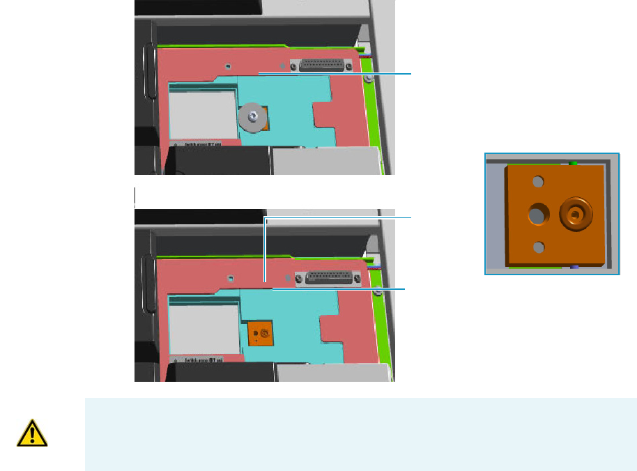
9 Adding Modules
Adding a GSV Injector Module
426 TRACE 1300 and TRACE 1310 Hardware Manual Thermo Scientific
b. Unplug the power cable from the AC Input connector into the back of the GC and
from the wall outlet.
5. If external modules are present, unplug the power cable from the AC Input connector of
each external module, and from the wall outlet.
6. Put the autosampler away if present.
7. Remove the dummy module from the position where the injector module will be
installed.
a. Open the module flap cover.
b. Using a T20 Torxhead screwdriver, unscrew the three captive fixing screws.
c. Keeping the dummy module flap cover open, lift up the module from its seat into the
injector housing. Place the dummy module on a clean surface.
d. Remove the gas block plug from the gas connections by unscrewing its fixing screw
using a T20 Torxhead screwdriver. See Figure 441.
Figure 441. Injector Gas Block Plug
8. Open the front door of the GC.
9. Plug the Gas Sampling Valve module into the main frame.
Gas Connection Without Gas Block Plug
Gas Block Plug on Injector Seat
O-ring
WARNING Make sure the o-ring is placed into its seat on the gas connection.
See Figure 439. Do not install the module if the o-ring is missing.
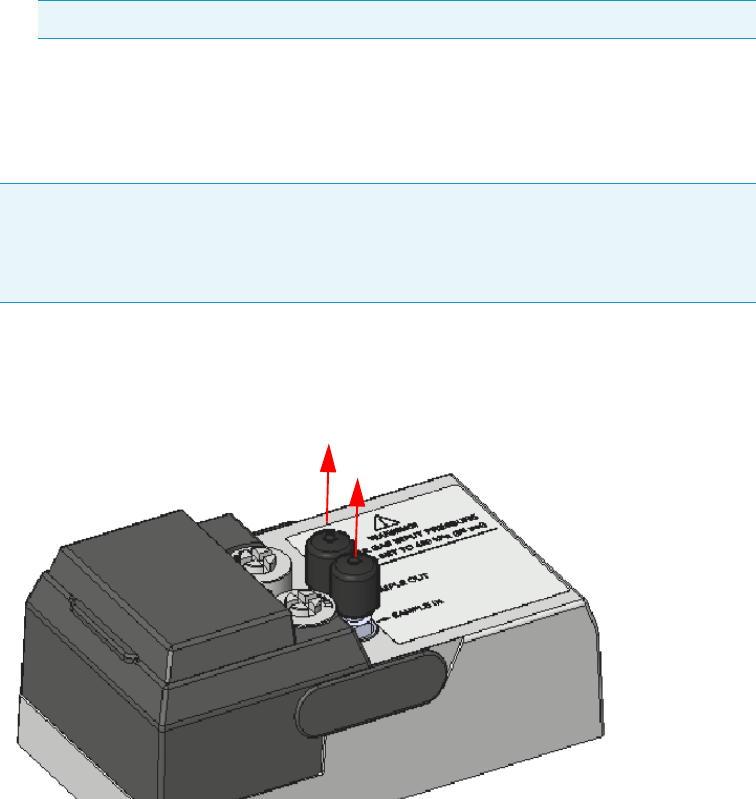
9 Adding Modules
Adding a GSV Injector Module
Thermo Scientific TRACE 1300 and TRACE 1310 Hardware Manual 427
a. Open the module flap cover.
b. Keeping the module flap cover open, place the module in its seat. Be sure to insert the
25-pin male connector, on the bottom of the module, into the 25-pin female
connector on the detector seat of the detector housing.
c. Use a T20 screwdriver to tighten the three captive fixing screws without
overtightening.
d. Close the module flap cover.
10. Connect the analytical column end insert it as far as goes and withdrawn about 2 -3 mm.
See the section “Installing the Column the First Time” on page 57.
11. Close the front door of the GC.
12. Remove the protective caps from the Sample In and Sample Out fittings. See Figure 442.
Figure 442. Protective Caps
13. Connect the Sample In and Sample Out lines.
a. By using the proper 1/8-in. tubing, nut and ferrule, connect the inlet sample line to
the Sample IN port on the GSV module. See Figure 443.
Note Tighten the center screw first and then secure the side screws.
Note If you need the backflush, connect the backflush system into the GC oven
following the instructions provided in the section Connecting the GSV
Backflush System in Chapter 8 of the TRACE 1300/TRACE 1310 Hardware
Manual.
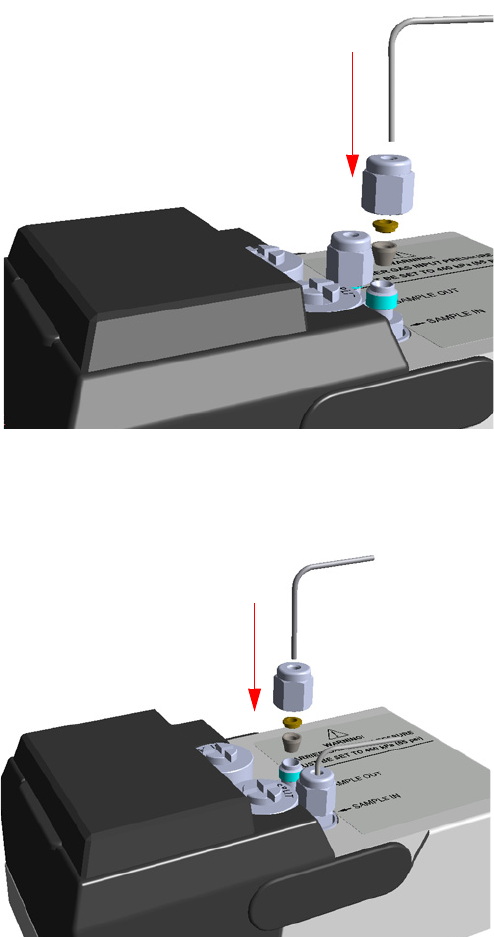
9 Adding Modules
Adding a GSV Injector Module
428 TRACE 1300 and TRACE 1310 Hardware Manual Thermo Scientific
Figure 443. Sample In Line Connection
b. By using the proper 1/8-in. tubing, nut and ferrule, connect the Sample OUT port
on the GSV module to an exhaust system. See Figure 444.
Figure 444. Sample Out Line Connection
14. If external modules are present, plug the power cable to the AC Input connector of each
external module, and to the wall outlet.
15. Power on the GC.
a. Plug the power cable to the AC Input connector into the back of the GC and to the
wall outlet.
b. Flip up the power switch (breaker) to the position I.
16. Open the module flap cover.
IN
OUT
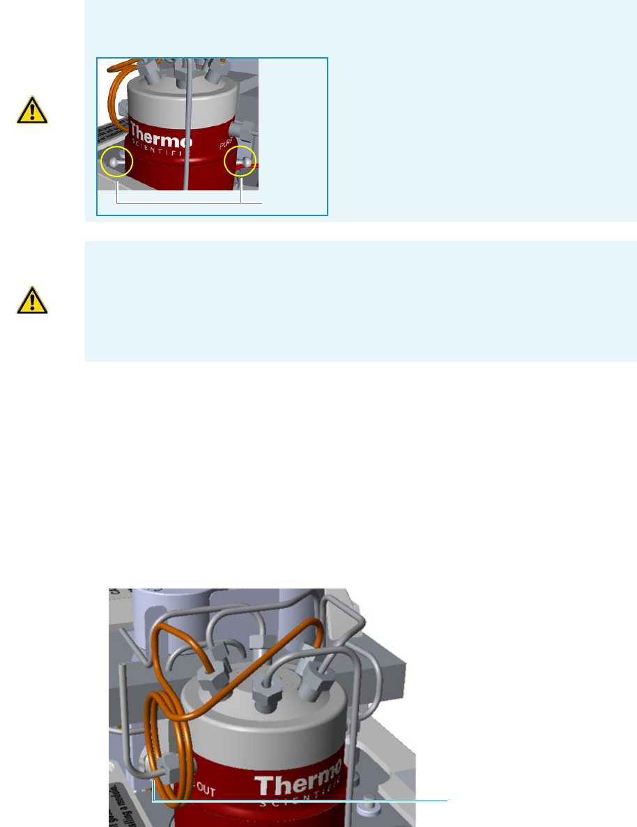
9 Adding Modules
Adding a GSV Injector Module
Thermo Scientific TRACE 1300 and TRACE 1310 Hardware Manual 429
17. Remove the relief pins from the valve body.
a. Open the gas supplies.
b. Adjust the gas pressure to 450 kPa (65 psig; 4.5 bar), actuate the valve and remove the
pins.
You may need to increase the pressure a little to ease hand removal of the pins.
Remember, make sure to properly readjust the actuating operating pressure after
removing the pins, if you had to change it. Keeps these pins in a safe place.
18. For critical applications, where air diffusion must be the lowest possible, we suggest to
replace the purge vent tubing with the longer one provided. See Figure 445.
Figure 445. Purge Vent Tubing
IMPORTANT The valve is delivered with relief pins. These pins MUST BE removed from
the valve body before working with the valve.
Relief Pins
WARNING DO NOT SET THE CARRIER GAS INPUT PRESSURE HIGHER
THAN 450 kPa (65 psig; 4.5 bar), OTHERWISE THE VALVE MAY BE DAMAGED.
WARNING DO NOT USE HYDROGEN AS CARRIER GAS. The module is not
compatible with Hydrogen carrier gas. The same gas used as carrier gas is used to purge
and to actuate the valve and must be an inert gas.
Purge Vent Tubing
9 Adding Modules
Adding a GSV Injector Module
430 TRACE 1300 and TRACE 1310 Hardware Manual Thermo Scientific
a. Remove the purge valve tubing from the Purge Out port on the valve body.
b. Connect to the 24-in. long tubing from the Purge port on the valve body by using
the proper nut and ferrule.
19. Close the module flap cover.
20. If present, move the autosampler towards the to restore the original alignment.
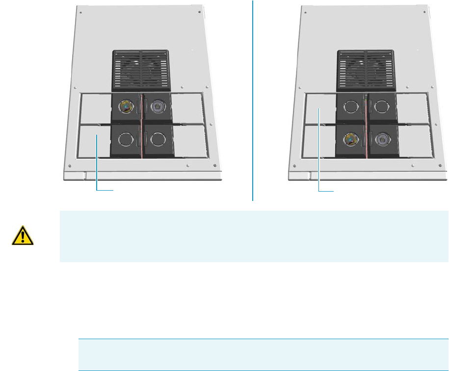
9 Adding Modules
Adding a FID, TCD/TCD In-Series, ECD, or FPD Detector Module
Thermo Scientific TRACE 1300 and TRACE 1310 Hardware Manual 431
Adding a FID, TCD/TCD In-Series, ECD, or FPD Detector Module
This section provides instructions for adding a front/back FID, TCD/TCD In-Series, ECD,
or FPD detector module. According to the configuration of your TRACE 1300/TRACE
1310, a dummy module is present into the free site where the detector module is not installed.
See Figure 446.
Figure 446. Add a Front/Back Detector Module
To add a new FID, TCD/TCD In-Series, ECD, or FPD detector module
1. Put the GC in standby condition.
2. Cool the oven, injector, and detector to room temperature.
3. Close the gas supplies.
4. Power off the GC.
a. Push down the power switch (breaker), located at the back of the instrument, to the
position O.
b. Unplug the power cable from the AC Input connector into the back of the GC and
from the wall outlet.
5. If external modules are present, unplug the power cable from the AC Input connector of
each external module, and from the wall outlet.
Dummy Back Detector Module
Dummy Front Detector Module
ATTENTION Where a dummy module is installed, the gas connection is blocked by a
plug.
Note By pressing the Maintenance button, the GC cool down is automatically
carried out.
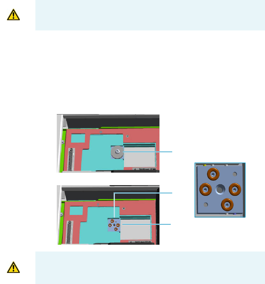
9 Adding Modules
Adding a FID, TCD/TCD In-Series, ECD, or FPD Detector Module
432 TRACE 1300 and TRACE 1310 Hardware Manual Thermo Scientific
6. Remove the dummy module from the position where the detector module will be
installed.
a. Open the module flap cover.
b. Using a T20 Torxhead screwdriver, unscrew and remove the two captive fixing
screws.
c. Keeping the dummy module flap cover open, lift up the module from its seat in the
injector/detector housing. Place the dummy module on a clean surface.
d. Remove the gas block plug from the gas connections by unscrewing its fixing screw
using a T20 Torxhead screwdriver. See Figure 447.
Figure 447. Detector Gas Block Plug
7. Open the front door of the GC.
8. Plug the detector module into the main frame.
a. Open the module flap cover.
ATTENTION The FPD detector must be installed in the back site of the detector housing.
For details about the installation of the FPD detector module, see the section “Installing
the FPD Detector” on page 176.
Gas Connections Without Gas Block Plug
Gas Block Plug on Detector Seat
O-rings
WARNING Make sure all the four o-rings are placed into their seats on the gas
connection. See Figure 447.
Do not install the module if the o-rings are missing.
9 Adding Modules
Adding a FID, TCD/TCD In-Series, ECD, or FPD Detector Module
Thermo Scientific TRACE 1300 and TRACE 1310 Hardware Manual 433
b. Keeping the module flap cover open, place the module in its seat. Be sure to insert the
25-pin male connector, on the bottom of the module, into the 25-pin female
connector on the detector seat of the detector housing.
c. Use a T20 Torxhead screwdriver to tighten the three captive fixing screws without
overtightening.
.
d. Close the module flap cover.
9. Remove the plug and connect the analytical column end to the detector.
a. Position the column so that the end of the column extends the proper distance above
the end of the ferrule as reported in Table 1 7 .
10. Open the gas supplies.
11. Check the gas supply for leaks.
a. Use a handheld electronic leak detector (Thermo Scientific GLD Pro leak detector or
equivalent) to check each fitting for leaks.
b. If you detect a leak, tighten the connection and retest it.
ATTENTION To maintain the correct alignment the screws must be tightened in turn.
Tighten each screw only a small amount before moving to the next screw. Repeat until all
are secure.
Table 17. Column Insertion Depth For FID, NPD, TCD, ECD, and FPD Detectors
FID NPD TCD ECD FPD
Insert the column as far as goes and withdrawn about
2 -3 mm
23 mm 125 mm
Note If you are installing an In-Series Connection TCD module (TCD module
modified for the connection in-series with a second detector or with a
methanizer), you must connect the vent line metal tubing, that protrudes into
the GC oven, to a FIDsecond detector proceeding as follows:
• Being careful not to create too narrow angles, bend the vent line metal
tubing until its end reaches the bottom of the second detector.
• Making sure that the end of the vent line metal tube is perfectly straight, insert it
like as an analytical column through the proper detector retaining nut and
ferrule.
ATTENTION If you are connecting the In-Series Connection TCD module to a
FID, NPD, or FPD, position the vent line metal tubing so that the end of the
tubing extends the proper distance above the end of the ferrule as reported in
Table 17.
If you are connecting the In-Series Connection TCD module to an ECD, the
insertion depth of vent line metal tubing must be 21 mm.
9 Adding Modules
Adding a FID, TCD/TCD In-Series, ECD, or FPD Detector Module
434 TRACE 1300 and TRACE 1310 Hardware Manual Thermo Scientific
c. Repeat this process until all connections are leak free.
12. If external modules are present, plug the power cable to the AC Input connector of each
external module, and to the wall outlet.
13. Power on the GC.
a. Plug the power cable to the AC Input connector into the back of the GC and to the
wall outlet.
b. Flip up the power switch (breaker) to the position I.
14. Check the module gas connections for leaks.
15. Close the front door of the GC.
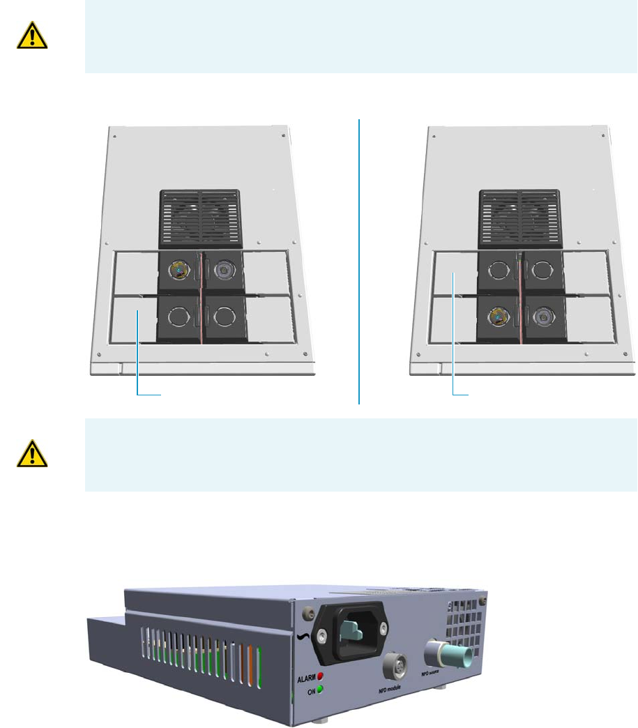
9 Adding Modules
Adding a NPD Detector Module
Thermo Scientific TRACE 1300 and TRACE 1310 Hardware Manual 435
Adding a NPD Detector Module
This section provides instructions for adding a front/back NPD detector module. According
to the configuration of your TRACE 1300/TRACE 1310, a dummy module is present into
the free site where the detector module is not installed. See Figure 448.
Figure 448. Add a Front/Back NPD Module
The NPD detector module addition also requires the installation of the NPD Thermionic
Source Power Module. See Figure 449.
Figure 449. NPD Thermionic Source Power Module
The module includes the following connections. See Figure 450.
ATTENTION This operation must be carried out by authorized and trained Thermo Fisher
Scientific Service Field Engineers.
Dummy Back Detector ModuleDummy Front Detector Module
ATTENTION Where a dummy module is installed, the gas connection is blocked by a
plug.
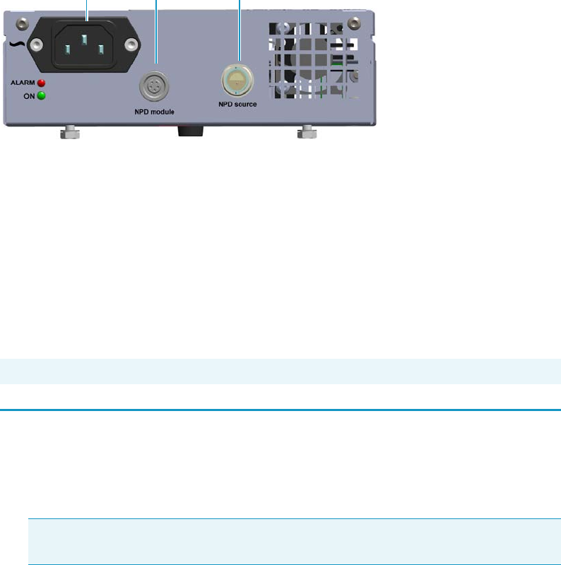
9 Adding Modules
Adding a NPD Detector Module
436 TRACE 1300 and TRACE 1310 Hardware Manual Thermo Scientific
Figure 450. NPD Thermionic Source Power Module Connections
1. AC input connector.
The module has a power rating of 120/230 Vac; 50/60 Hz; 65VA.
2. A 5-pin connector marked NPD Module (2) for the connection of the signal cable
coming from the NPD detector module.
3. A 2-pin connector marked NPD Source (3) for the connection of the thermionic source
assembly cable coming from the NPD detector module.
One protecting fuse is present inside the module. See Table 18.
To add a new NPD detector module
1. Put the GC in standby condition.
2. Cool the oven, injector, and detector to room temperature.
3. Close the gas supplies.
4. Power off the GC.
a. Push down the power switch (breaker), located at the back of the instrument, to the
position O.
b. Unplug the power cable from the AC Input connector into the back of the GC and
from the wall outlet.
5. If external modules are present, unplug the power cable from the AC Input connector of
each external module, and from the wall outlet.
6. Remove the dummy module from the position where the detector module must be
installed.
a. Open the module flap cover.
Table 18. Aux Temperature/Cryo Module Protecting Fuses
Fuse Typ e Protections
F1 F4A 250V; (5 x 20 mm) Circuit for the generation of the current for the thermionic source
Note By pressing the Maintenance button, the GC cool down is automatically
carried out.
23
1
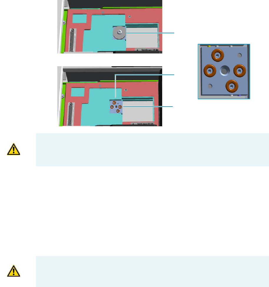
9 Adding Modules
Adding a NPD Detector Module
Thermo Scientific TRACE 1300 and TRACE 1310 Hardware Manual 437
b. Using a T20 Torxhead screwdriver, unscrew and remove the two captive fixing
screws.
c. Keeping the dummy module flap cover open, lift up the module from its seat in the
injector/detector housing. Place the dummy module on a clean surface.
d. Remove the gas block plug from the gas connections by unscrewing its fixing screw
using a T20 Torxhead screwdriver. See Figure 451.
Figure 451. Detector Gas Block Plug
7. Open the front door of the GC.
8. Plug the detector module into the main frame.
a. Open the module flap cover.
b. Keeping the module flap cover open, place the detector module in its seat. Be sure to
insert the 25-pin male connector on the bottom of the module into the 25-pin
female connector on the detector seat of the detector housing.
c. Use a T20 Torxhead screwdriver to tighten the three captive fixing screws without
overtightening.
d. Close the module flap cover.
Gas Connections Without Gas Block Plug
Gas Block Plug on Detector Seat
O-rings
WARNING Make sure all the four o-rings are placed into their seats on the gas
connection. See Figure 451.
Do not install the module if the o-rings are missing.
ATTENTION To maintain the correct alignment the screws must be tightened in turn.
Tighten each screw only a small amount before moving to the next screw. Repeat until all
are secure.
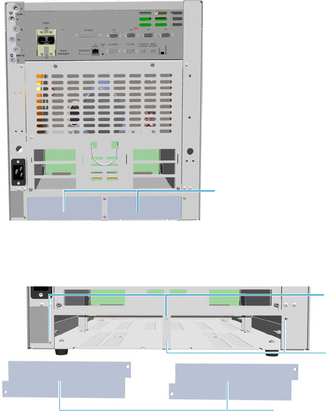
9 Adding Modules
Adding a NPD Detector Module
438 TRACE 1300 and TRACE 1310 Hardware Manual Thermo Scientific
9. Install the NPD Thermionic Source Power Module.
The module should be installed into an external module housing provided on the back
of the GC. See Figure 452.
Figure 452. External Modules Housing
10. Remove the cover of the external modules housing where installing the module. See
Figure 453.
Figure 453. Housing Cover Removal
a. Using a T20 Torxhead screwdriver, unscrew and remove the left or right housing
cover screws.
b. Remove the covers from the housing.
11. Install the module into the housing.
a. Loosen the two hexagonal screws under the module. See Figure 454.
External Modules Housing
Left/Right Housing Covers
Left Cover
Screws
Right Cover
Screws
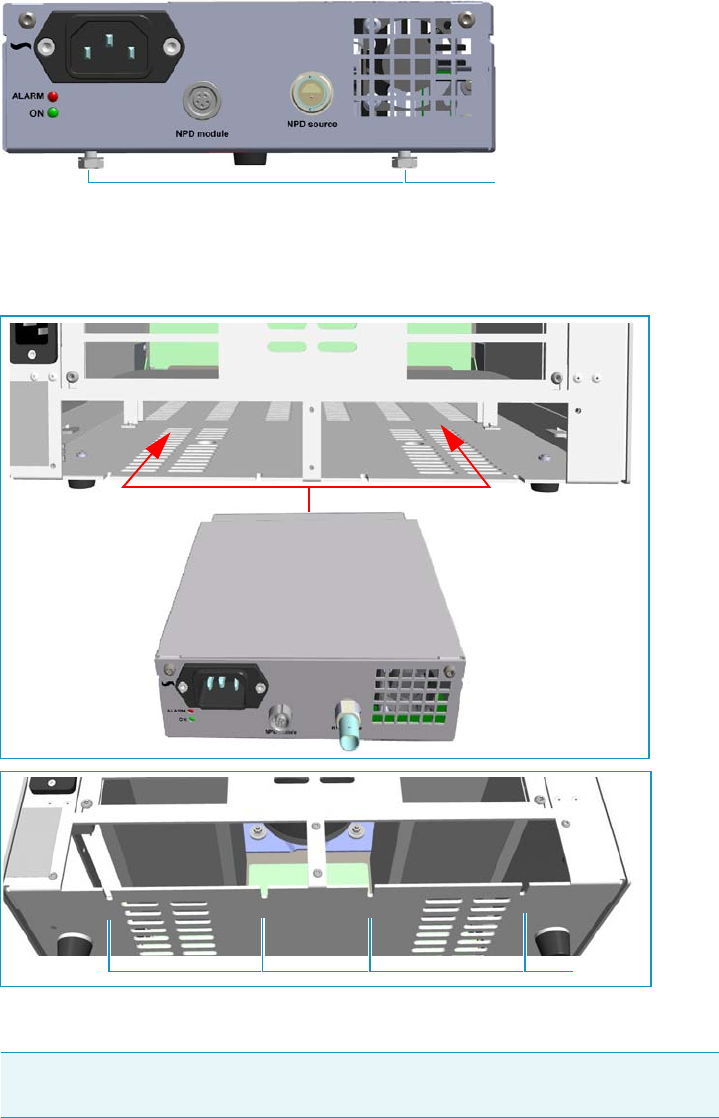
9 Adding Modules
Adding a NPD Detector Module
Thermo Scientific TRACE 1300 and TRACE 1310 Hardware Manual 439
Figure 454. Module Installation (1)
b. Place the module into the left or right housing until the hexagonal screws couple the
slots on the floor of the GC. See Figure 455.
Figure 455. Module Installation (2)
c. Fingertighten the hexagonal screws slightly, or using a 10-mm wrench.
The result of the installation is shown in Figure 456.
Note Always keep the hexagonal screws in their place. This allows you an easier
removal of the auxiliary module when necessary.
Hexagonal Screws
Slots
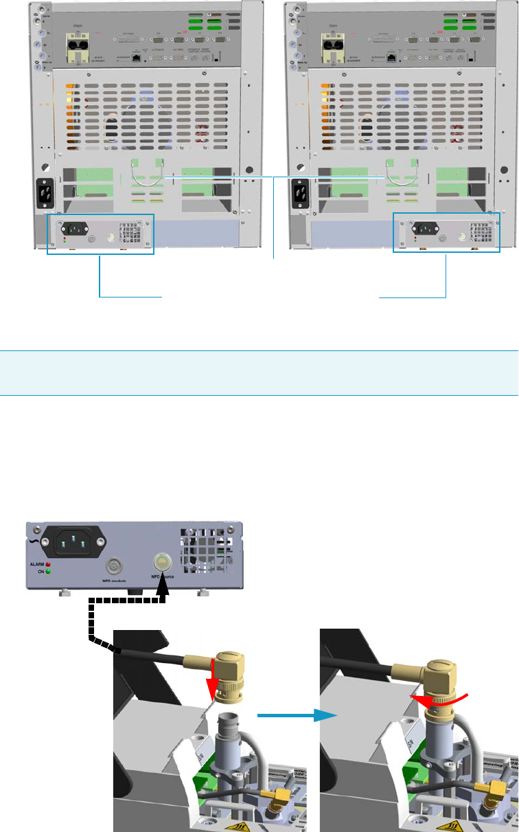
9 Adding Modules
Adding a NPD Detector Module
440 TRACE 1300 and TRACE 1310 Hardware Manual Thermo Scientific
Figure 456. NPD Thermionic Source Power Module Installed into the GC
12. Connect the NPD Thermionic Source Power Module.
a. Open the module flap cover.
b. Using the cable provided, connect the source assembly connector on the NPD
Thermionic Source Power Module to the thermionic source and twist the ring to lock
the connection. See Figure 457.
Figure 457. Thermionic Source Assembly Cable Connection
Tip To avoid the contact with the hot air from the vents, it is suggested to gather the
electrical cables into cables holder.
NPD Thermionic Source Power Module
Cables Holder
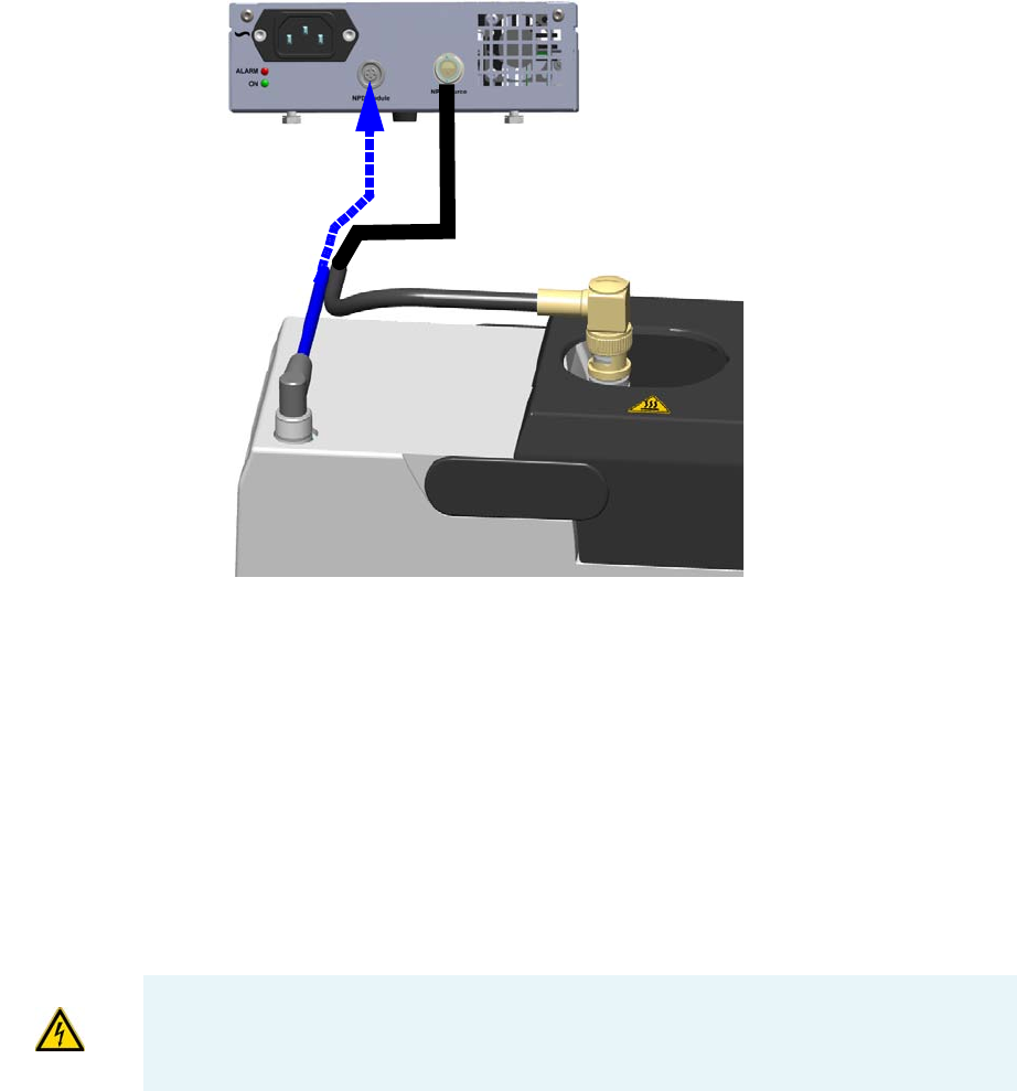
9 Adding Modules
Adding a NPD Detector Module
Thermo Scientific TRACE 1300 and TRACE 1310 Hardware Manual 441
c. Using the cable provided, connect the signal connector on the NPD Thermionic
Source Power Module to the connector on the detector module. See Figure 458.
Figure 458. Signal Cable Connection
13. Remove the plug and connect the column end to the detector.
14. Open the gas supplies.
15. Check the gas supply for leaks.
a. Use a handheld electronic leak detector (Thermo Scientific GLD Pro leak detector or
equivalent) to check each fitting for leaks.
b. If you detect a leak, tighten the connection and retest it.
c. Repeat this process until all connections are leak free.
16. Plug the power cable to the AC input connector of the NPD Thermionic Source Power
Module, and to the wall outlet. The LED marked On blinks green.
If other external modules are present, plug the power cable to the AC Input connector of
each module, and to the wall outlet.
17. Power on the GC.
IMPORTANT The NPD Thermionic Source Power Module must be powered at the same
line voltage of the main GC system.
9 Adding Modules
Adding a NPD Detector Module
442 TRACE 1300 and TRACE 1310 Hardware Manual Thermo Scientific
a. Plug the power cable to the AC Input connector into the back of the GC and to the
wall outlet.
b. Flip up the power switch (breaker) to the position I.
18. Check the module gas connections for leaks.
19. Close the front door of the GC.
20. Set the make-up gas on.
21. Switch on the thermionic source. Hydrogen and air are automatically opened.
The LED marked On of the NPD Thermionic Source Power Module becomes solid
green.
22. With all gases on, heat the detector to 150 °C and hold for about 15 minutes, then
increase the temperature to 250 °C and hold for 15 minutes.
23. Increase the temperature to operating value (300 °C to 320 °C recommended). Allow 15
minutes for equilibration.
24. Check the NPD leakage current. If > 2.0 pA, verify the installation.
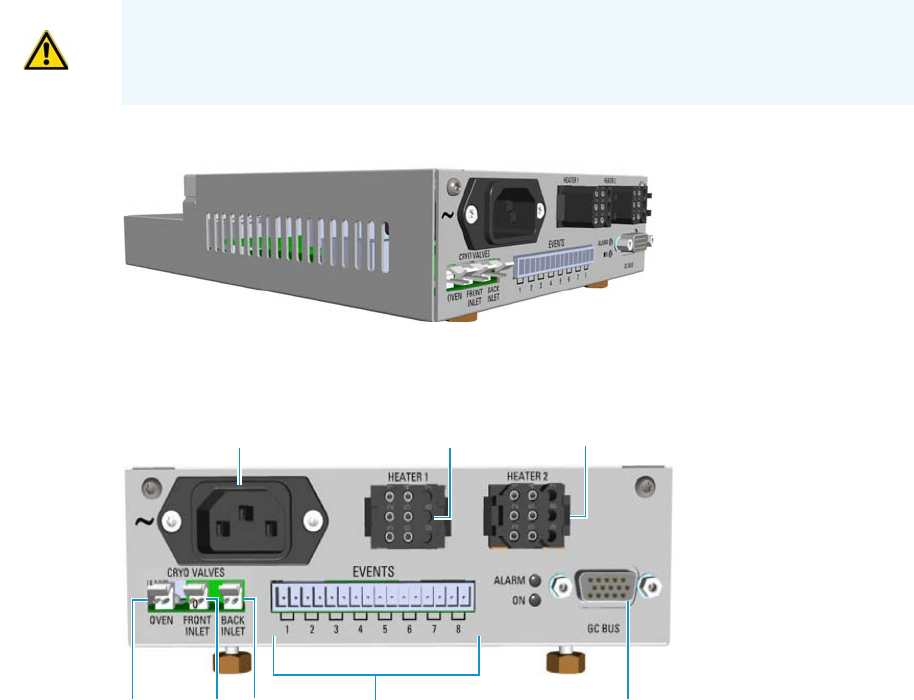
9 Adding Modules
Adding an Aux Temperature/Cryo Module
Thermo Scientific TRACE 1300 and TRACE 1310 Hardware Manual 443
Adding an Aux Temperature/Cryo Module
This section provides instructions for updating your TRACE 1300/TRACE 1310 with the
Aux Temperature/Cryo module. See Figure 459.
Figure 459. Aux Temperature/Cryo Module
The module includes the following connections. See Figure 460.
Figure 460. Aux Temperature/Cryo Module Connections
1. AC input connector.
The module has a power rating of 120/230 Vac; 50/60 Hz; 355 VA.
2. A 6-pin connector marked Heater 1 for the connection of the transfer line of a mass
spectrometer.
3. A 6-pin connector marked Heater 2 for the connection of the transfer line of a second
mass spectrometer.
4. 15-pin female connectors marked Bus for the communication with the GC.
5. A 16-pin connector marked Events for the connection of eight external solenoid valves
(24 V, 2 W max). The valves can be programmed individually during the running of the
instrument.
WARNING This operation must be carried out by authorized and trained Thermo Fisher
Scientific Service Field Engineers.
8765
23
1
4
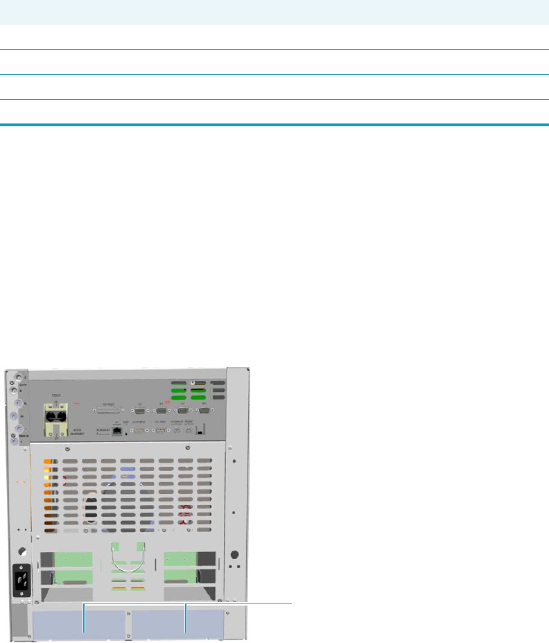
9 Adding Modules
Adding an Aux Temperature/Cryo Module
444 TRACE 1300 and TRACE 1310 Hardware Manual Thermo Scientific
6. A 2-pin connector marked Back Inlet for the connection of the solenoid valves for the
back PTV/PTVBKF cryogenic system.
7. A 2-pin connector marked Front Inlet for the connection of the solenoid valves for the
front PTV/PTVBKF cryogenic system.
8. A 2-pin connector marked Oven for the connection of the solenoid valves for the Oven
cryogenic system.
Four protecting fuses are present inside the module. See Ta ble 19 .
The module features the following:
• The valve control of the Oven cryo option.
• The valve control of the front/back PTV cryo option.
• Up two heater controls for the DSQ II, ITQ, or TSQ Quantum transfer line.
• Sixty-three timed events to automatically drive up to eight external on/off solenoid valves.
The module should be installed into a free external module housing provided on the back of
the GC. See Figure 461.
Figure 461. External Modules Housing
Table 19. Aux Temperature/Cryo Module Protecting Fuses
Fuse Type Protections
F1 F2A 250V; (5 x 20 mm) Heater 1
F2 F2A 250V; (5 x 20 mm) Heater 2
F3 T2A 250V; (5 x 20 mm) 24 V
F4 F1.6A 250V; (5 x 20 mm) 24 V solenoid valves
External Modules Housing
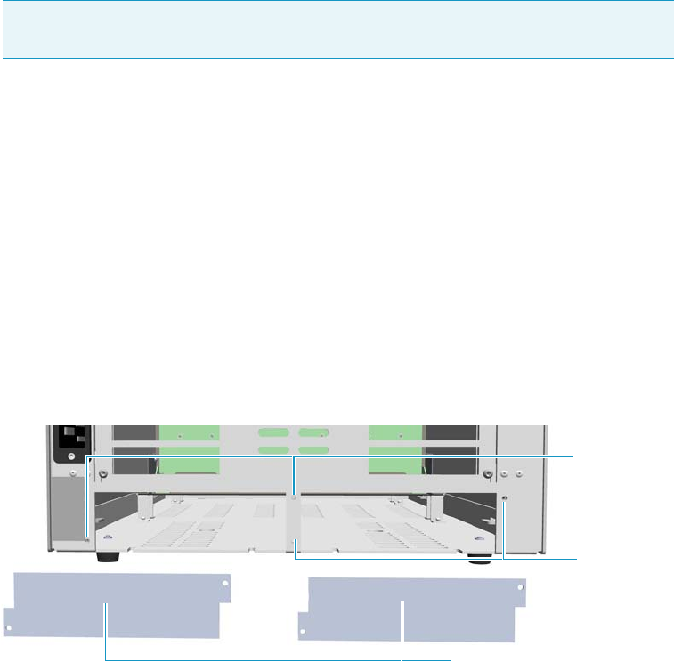
9 Adding Modules
Adding an Aux Temperature/Cryo Module
Thermo Scientific TRACE 1300 and TRACE 1310 Hardware Manual 445
To add an Aux Temperature/Cryo Module
1. Put the GC in standby condition.
2. Cool the oven, injectors, and detectors to room temperature.
3. Close the gas supplies.
4. Power off the GC.
a. Push down the power switch (breaker), located at the back of the instrument, to the
position O.
b. Unplug the power cable from the AC Input connector into the back of the GC and
from the wall outlet.
5. If external modules are present, unplug the power cable from the AC Input connector of
each external module, and from the wall outlet.
6. Remove the cover of the external modules housing where installing the module.
See Figure 462.
Figure 462. Housing Cover Removal
a. Using a T20 Torxhead screwdriver, unscrew and remove the left or right housing
cover screws.
b. Remove the covers from the housing.
7. Install the module into the housing
a. Loosen the two hexagonal screws under the module. See Figure 463.
Note By pressing the Maintenance button, the GC cool down is automatically
carried out.
Left/Right Housing Covers
Left Cover
Screws
Right Cover
Screws
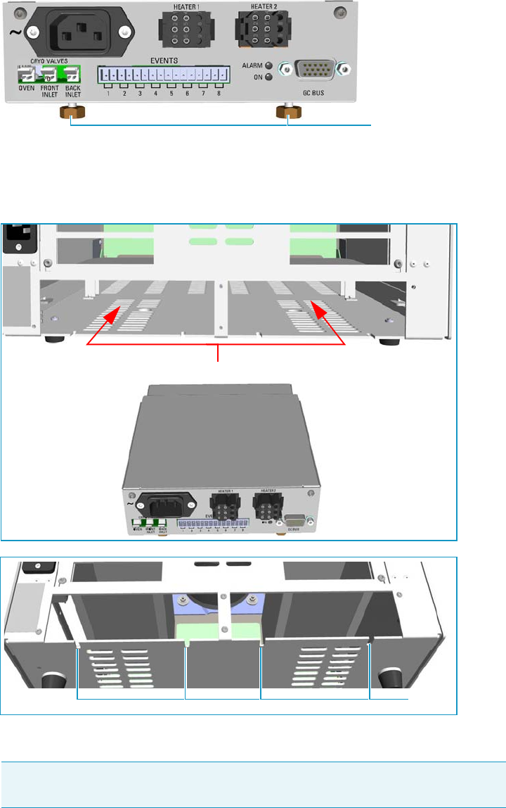
9 Adding Modules
Adding an Aux Temperature/Cryo Module
446 TRACE 1300 and TRACE 1310 Hardware Manual Thermo Scientific
Figure 463. Module Installation (1)
b. Place the module into the left or right housing until the hexagonal screws couple the
slots on the floor of the GC. See Figure 464.
Figure 464. Module Installation (2)
c. Finger-tighten the hexagonal screws slightly, or using a 10-mm wrench.
The result of the installation is shown in Figure 465.
Note Always keep the hexagonal screws in their place. This allows you an easier
removal of the auxiliary module when necessary.
Hexagonal Screws
Slots
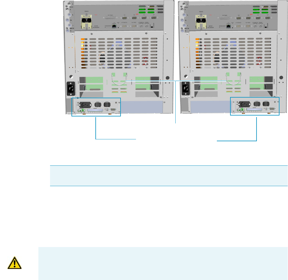
9 Adding Modules
Adding an Aux Temperature/Cryo Module
Thermo Scientific TRACE 1300 and TRACE 1310 Hardware Manual 447
Figure 465. Aux Temperature/Cryo Module Installed into the GC
8. Connect the Aux Temperature/Cryo module.
a. Using the cable provided, connect the 15-pin female connector marked GC Bus on
the module to a Bus interface on the back of the GC.
– If a DSQ II, ITQ, or TSQ Quantum mass spectrometer is coupled with the GC,
connect the heater cable coming from the transfer line to the connector marked
Heater 1 or Heater 2.
– If the cryo option for the Oven is present, connect the 2-pin connector marked
Cryo Valves - Oven to the cryo solenoid valve using the cable provided.
– If the cryo option for the front/back PTV/PTVBKF injector is present, connect
the 2-pin connector marked Cryo Valves - Front Inlet or Cryo Valves-Back
Inlet to the cryo solenoid valve using the cable provided.
– If the on/off activation of external solenoid valves (up to eight) is required,
connect a 2-pin connector marked Event 1÷8 to each external solenoid valve.
– Plug the power cable to the AC Input connector on the front of the module and
to the wall outlet. The LED marked On lights after the GC is powered on.
Tip To avoid the contact with the hot air from the vents, it is suggested to gather the
electrical cables into cables holder.
Aux Temperature/Cryo Module
Cables Holder
ATTENTION An extension cable transfer line is needed when connecting an ITQ mass
spectrometer to the Aux Temperature/Cryo module.
9 Adding Modules
Adding a Helium Saver Injector Module
448 TRACE 1300 and TRACE 1310 Hardware Manual Thermo Scientific
9. Open the gas supplies.
10. If other external modules are present, plug the power cable to the AC Input connector of
each external module, and to the wall outlet.
11. Power on the GC.
a. Plug the power cable to the AC Input connector into the back of the GC and to the
wall outlet.
b. Flip up the power switch (breaker), located at the back of the instrument, to the
position I.
12. Configure and enable the system installed through the user interface of your GC, or
through the CDS in use. Refer to the TRACE 1300 and TRACE 1310 User Guide.
Adding a Helium Saver Injector Module
The Instant Connect Helium Saver Injector Module (HeS-S/SL) is designed as a “double
wide” module that fits into the space provided by one detector module and one injector
module on the upper deck of your TRACE 1300/TRACE 1310 GC.
Installing the Module
The module may be placed in either the Front or Back position on the upper deck.
• If the module is located in the Front position, plumb the helium supply to the Front
Make Up gas connection on the back panel of the GC.
• If the module is located in the Back position, plumb the helium to the Back Make Up gas
connection on the back panel of the GC.
Plumb the nitrogen gas to the corresponding Front or Back Carrier gas connections.
IMPORTANT The Auxiliary Temperature/Cryo module must be powered at the same
power supply voltage required for the GC.
IMPORTANT Although nitrogen will not be the actual carrier gas for the analytical
separation, it will be the carrier gas during the injection, and it is necessary to plumb the
nitrogen to the carrier gas input.
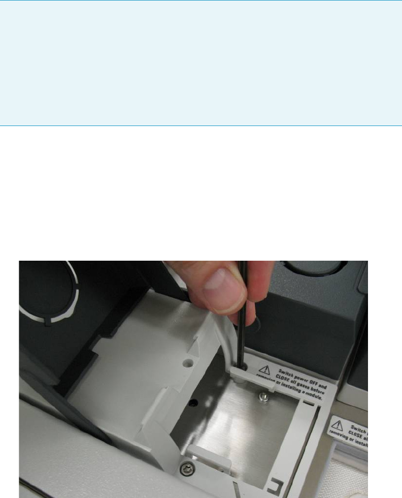
9 Adding Modules
Adding a Helium Saver Injector Module
Thermo Scientific TRACE 1300 and TRACE 1310 Hardware Manual 449
To install the Instant Connect Helium Saver Injector Module
1. Cool the GC and MS heated zones and then shut off all carrier and detector gases on the
local GC user interface as well as at the source cylinder.
2. Remove the detector and injector “dummy modules” from the locations where the
Helium Saver S/SL module will be installed by loosening the two captive T20 screws on
each module. See Figure 466.
Figure 466. Removing the Dummy Modules
3. Remove the blanking washers from the detector and injector pneumatic network.
See Figure 467.
Note For optimal results, use a high capacity oxygen trap on the nitrogen supply, and a
heated zirconium alloy gettering trap on the helium supply. These traps can be purchased
together as Thermo Scientific part number 1R120577-0001.
Alternatively, you may opt to provide own helium purification. Due to the low flow rate
of helium employed, conventional chemical traps (non-heated traps) may actually
contaminate the gas supply. Heated zirconium-based traps specifically designed for helium
are ideal. These traps can also remove nitrogen, which is difficult to eliminate from
conventional traps.
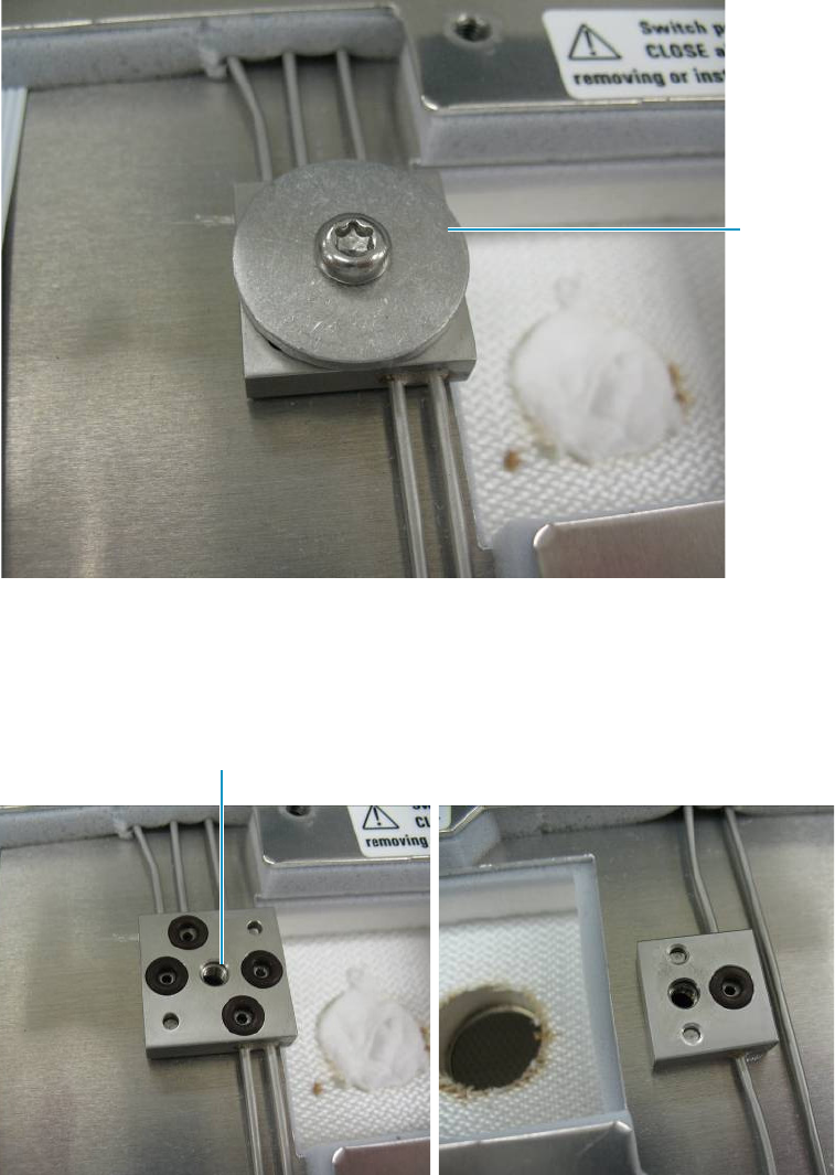
9 Adding Modules
Adding a Helium Saver Injector Module
450 TRACE 1300 and TRACE 1310 Hardware Manual Thermo Scientific
Figure 467. Removing the Blanking Washers
4. Ensure there is an o-ring present in the o-ring seat of each position on the pneumatic
network block. See Figure 468.
Figure 468. Confirming Presence of O-rings
5. Plumb a cylinder of high purity helium 99.999% to the appropriate make-up gas
connection on the back of the GC using the adapter provided. See Figure 469.
The Thermo Scientific gas purification kit part number 1R120577-0001 contains a
heated gettering trap which can be used directly with this fitting.
Blanking
Washer
Make-up Gas Port
Delivering Helium
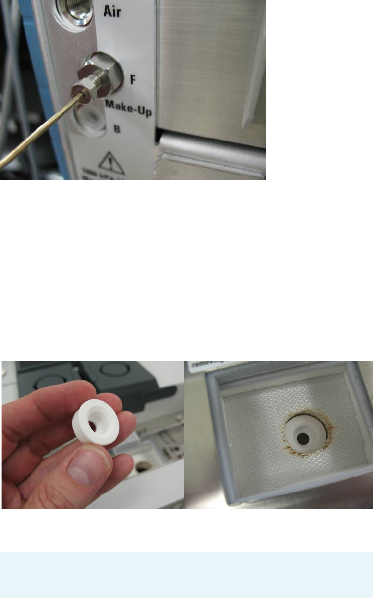
9 Adding Modules
Adding a Helium Saver Injector Module
Thermo Scientific TRACE 1300 and TRACE 1310 Hardware Manual 451
Figure 469. Plumbing the Helium Cylinder
Alternatively, a customer supplied gettering trap can be used along with the provided
1/16 in. stainless steel tubing. Set the regulator pressure such that helium purges the
make-up line of the pneumatic network for 15 min at a flow of 20–100 mL/min.
The flow can be measured directly from the detector block at the left most port as shown
in Figure 468 on page 450. This will purge the gas line as well as eliminate air from the
gettering material of an in-line heated helium purifier. Do this before applying power to
the purifier. Ensure the hose leading to the flowmeter is clean and dust free before holding
it against the o-ring seat.
6. Carefully insert the Instant Connect Helium Saver Injector Module into position on the
GC top deck after first inserting the ceramic insulator shown in Figure 470.
Figure 470. Positioning the Instant Connect Helium Saver Injector Module
Also, be sure to remove the column nut from the injector if it has not already been
removed. This prevents damage to the ceramic insulator when the module is inserted.
Note It may be helpful to insert the left side of the module just prior to the right side
in order to clear the space properly. The module fits snugly into position but should
not require undue force to clear the sheet metal opening.
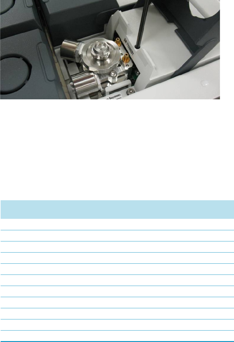
9 Adding Modules
Adding a Helium Saver Injector Module
452 TRACE 1300 and TRACE 1310 Hardware Manual Thermo Scientific
7. Secure the T20 screws near the center line of the module leading to the injector and
detector pneumatic network prior to tightening the captive screws which hold the
module. See Figure 471.
Figure 471. Securing the Instant Connect Helium Saver Injector Module in Place
It will be necessary to push down on the right side of the module near the back edge to
ensure engagement of the 25 pin D-sub electrical connector. Wiggle the module as
necessary to engage the pins and then secure the screws.
8. At this point, the regulator that delivers the helium can be set to the appropriate pressure:
typically 110 psig (760 kPa; 7.6 bar) will suffice for 0.25 mm i.d. columns of 30 m
length.
Dial the pressure up slowly while tapping the pressure gauge in order to set the
appropriate pressure. Table 20 serves as a guide for setting the correct helium regulator
pressure.
Table 20. Determining Correct Helium Regulator Pressure for Column Type (Sheet 1 of 2)
Column Length Column i.d. Desired Flow *Required helium regulator
pressure psig (kPa; bar) **
5 m/10 m 0.10 mm 0.4 mL/min 110 psig (760 kPa; 7.6 bar)
0.5 mL/min 120 psig (830 kPa; 8.3 bar)
0.6 mL/min 130 psig (900 kPa; 9 bar)
10 m/20 m 0.18 mm 0.8 mL/min 100 psig (690 kPa; 6.9 bar)
1.0 mL/min 110 psig (760 kPa; 7.6 bar)
1.2 mL/min 120 psig (830 kPa; 8.3 bar)
1.5 mL/min 130 psig (900 kPa; 9 bar)
2.0 mL/min 140 psig (970 kPa; 9.7 bar)
15 m 0.25 mm 1.0 mL/min 100 psig (690 kPa; 6.9 bar)
1.2 mL/min 110 psig (760 kPa; 7.6 bar)
1.7 mL/min 120 psig (830 kPa; 8.3 bar)

9 Adding Modules
Adding a Helium Saver Injector Module
Thermo Scientific TRACE 1300 and TRACE 1310 Hardware Manual 453
2.2 mL/min 130 psig (900 kPa; 9 bar)
2.7 mL/min 140 psig (970 kPa; 9.7 bar)
30 m 0.25 mm 1.0 mL/min 100 psig (690 kPa; 6.9 bar)
1.2 mL/min 110 psig (760 kPa; 7.6 bar)
1.7 mL/min 120 psig (830 kPa; 8.3 bar)
2.2 mL/min 130 psig (900 kPa; 9 bar)
2.7 mL/min 140 psig (970 kPa; 9.7 bar)
3.2 mL/min 150 psig (1030 kPa; 10.3 bar)
60 m 0.25 mm 1.0 mL/min 120 psig (830 kPa; 8.3 bar)
1.2 mL/min 130 psig (900 kPa; 9 bar)
1.7 mL/min 140 psig (970 kPa; 9.7 bar)
2.2 mL/min 150 psig (1030 kPa; 10.3 bar)
100 m 0.25 mm 1.0 mL/min 130 psig (900 kPa; 9 bar)
1.2 mL/min 140 psig (970 kPa; 9.7 bar)
1.7 mL/min 150 psig (1030 kPa; 10.3 bar)
30 m 0.32 mm 1.5 mL/min 100 psig (690 kPa; 6.9 bar)
2.0 mL/min 110 psig (760 kPa; 7.6 bar)
2.5 mL/min 120 psig (830 kPa; 8.3 bar)
3.0 mL/min 130 psig (900 kPa; 9 bar)
3.5 mL/min 140 psig (970 kPa; 9.7 bar)
60 m 0.32 mm 1.5 mL/min 110 psig (760 kPa; 7.6 bar)
2.0 mL/min 120 psig (830 kPa; 8.3 bar)
2.5 mL/min 130 psig (900 kPa; 9 bar)
3.0 mL/min 140 psig (970 kPa; 9.7 bar)
3.5 mL/min 150 psig (1030 kPa; 10.3 bar)
100 m 0.32 mm 1.5 mL/min 130 psig (900 kPa; 9 bar)
2.0 mL/min 140 psig (970 kPa; 9.7 bar)
2.5 mL/min 150 psig (1030 kPa; 10.3 bar)
*For flow rates not specifically listed, round up in pressure to the next highest value. For example, if
1.5 mL/min is desired using a 0.25 mm ID column of 15 m length, use a helium regulator pressure of
110 psig (760 kPa; 7.6 bar).
** Minimum pressure required to avoid nitrogen back diffusion into the helium carrier gas. Higher pressure
will result in a slightly higher (than minimum) consumption of helium, but will not result in adverse
analytical performance.
Table 20. Determining Correct Helium Regulator Pressure for Column Type (Sheet 2 of 2)
Column Length Column i.d. Desired Flow *Required helium regulator
pressure psig (kPa; bar) **
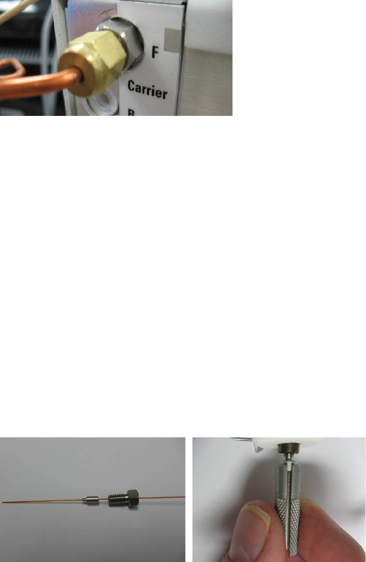
9 Adding Modules
Adding a Helium Saver Injector Module
454 TRACE 1300 and TRACE 1310 Hardware Manual Thermo Scientific
9. Plumb a nitrogen supply to the appropriate Carrier input at the back of the GC as shown
in Figure 472.
Figure 472. Plumbing the Nitrogen Supply to the GC
10. The Thermo Scientific gas purification kit contains a high capacity oxygen trap that
should be placed in the nitrogen line. Be sure to purge the regulator and gas line before
attaching the oxygen filter.
11. Keep nitrogen flowing through the trap while attaching the filter to the back of the GC in
order to prevent oxygen from entering the trap.
12. Adjust the pressure regulator to supply a pressure sufficient for the analytical method in
use. In general, 75 psig (517 kPa; 5.17 bar) is more than sufficient for most applications.
Very small bore capillaries may require higher pressures.
Installing the Column
The Instant Connect Helium Saver Injector Module is designed to be used with Silflow™
metallic ferrules. This allows for very accurate trimming of the column following compression
of the ferrule onto the column. It is important that only 5 mm of column protrudes past the
tip of the ferrule for proper operation. The inlet has been designed to work optimally with
0.25 mm i.d. columns, although larger (up to 0.32 mm i.d.) or narrower i.d.’s can be used
successfully.
To install the column
1. Insert the column through the SilFlow™ nut and ferrule as shown in Figure 473.
Figure 473. Installing the Column Nut and Ferrule
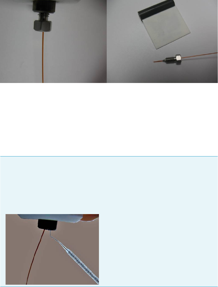
9 Adding Modules
Adding a Helium Saver Injector Module
Thermo Scientific TRACE 1300 and TRACE 1310 Hardware Manual 455
2. Allow a few centimeters of column to extend past the tip of the ferrule and insert it into
the base of the inlet. It will be necessary to gently poke around in order to find the small
bore cone that serves as a column guide and ferrule seat.
3. Use the knurled tool to tighten the nut by finger force only, until the ferrule grabs the
column, and the column no longer slides in the bore of the ferrule.
The column connection should appear as shown in Figure 474.
Figure 474. Installing the Column in the Injector
The column should be fully captured by the ferrule without the ability to slide it up or
down.
4. At this point, remove the nut and ferrule assembly and confirm the column will not slide
in the ferrule (See first Tip on page 455). Trim the column such that only 5 mm extends
past the tip of the ferrule.
5. Carefully reinstall the column and again tighten the ferrule. The column is now installed
in the injector.
Tip An indispensable tool for removal of the column from the inlet is a dental pick or
thumbtack. When the SilFlow ferrule engages the inlet on tightening, it is slightly
deformed at the tip in order for the sealing to occur. This causes the ferrule to become
“stuck,” which is a normal occurrence. The ferrule can easily be removed by inserting
the pointed tip of the dental pick gently along the side of the ferrule and pressing
vertically to cause the ferrule to be displaced to the side. Gently pulling on the
column at the same time will dislodge the ferrule.
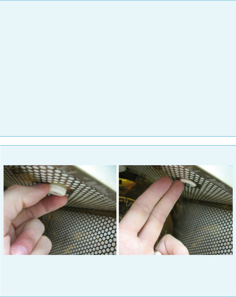
9 Adding Modules
Adding a Helium Saver Injector Module
456 TRACE 1300 and TRACE 1310 Hardware Manual Thermo Scientific
Checking for Leaks
A hand held helium leak detector may be used to check for helium leaks around the inlet and
column connection. With the helium conservation enabled, approximately 4 mL/min of
helium will enter the injection port.
For maximum sensitivity of the leak detector, set the split flow to Off during leak check.
This results only in column and septum purge flows.
Note The standard outfit kit for the Instant Connect Helium Saver Injector Module is
equipped with SilFlow ferrules having internal diameters of 0.50, 0.40, and 0.35 mm.
If you are using a 0.32 mm id column, use the 0.50 mm i.d. ferrules supplied.
If you are using a 0.25 mm id column or smaller, use the 0.35 mm id ferrule if the column
will pass through it.
This will allow easy finger tightening of the ferrule using the hand tool without undue
torque. In other words, use the smallest ferrule that will fit your columns.
The ideal situation is when the column passes through the hole with slight pressure.
The replacement Thermo part numbers are as follows:
• 0.50 mm ferrule 10ea. 29063467 (for 0.32 columns)
• 0.40 mm ferrule 10ea. 29063466 (for 0.25 columns and smaller on the high end of
the o.d. tolerance)
• 0.35 mm ferrule 10ea. 29063465 (for 0.25 columns and smaller on the low end of
the o.d. tolerance).
Tip When installing the column, nut and ferrule, lift up slightly on the ceramic insulator
surrounding the base of the injector insert as shown in figure.
This will expose the end of the insert and make it easier to locate the column in the central
hole.
After the final trimming and installation of the column, make sure to pull the insulator
back to its lowest position.
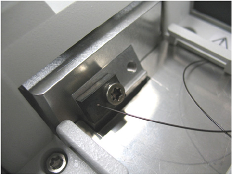
9 Adding Modules
Adding a Helium Saver Injector Module
Thermo Scientific TRACE 1300 and TRACE 1310 Hardware Manual 457
The composition of the gas mixture in the inlet will be mostly helium and allow good
sensitivity. For bulk nitrogen leak detection, the GC column exit can be plugged, and the
automated pressure drop leak detection of the GC used for determining the pressure drop.
The helium delivery block should be parked in the rear “blocked” position of Figure 475 if
leak checking is done based on pressure drop. The block must be replaced in the front
position to resume operation.
Figure 475. Removing the Helium Tube from the Gas Delivery Block
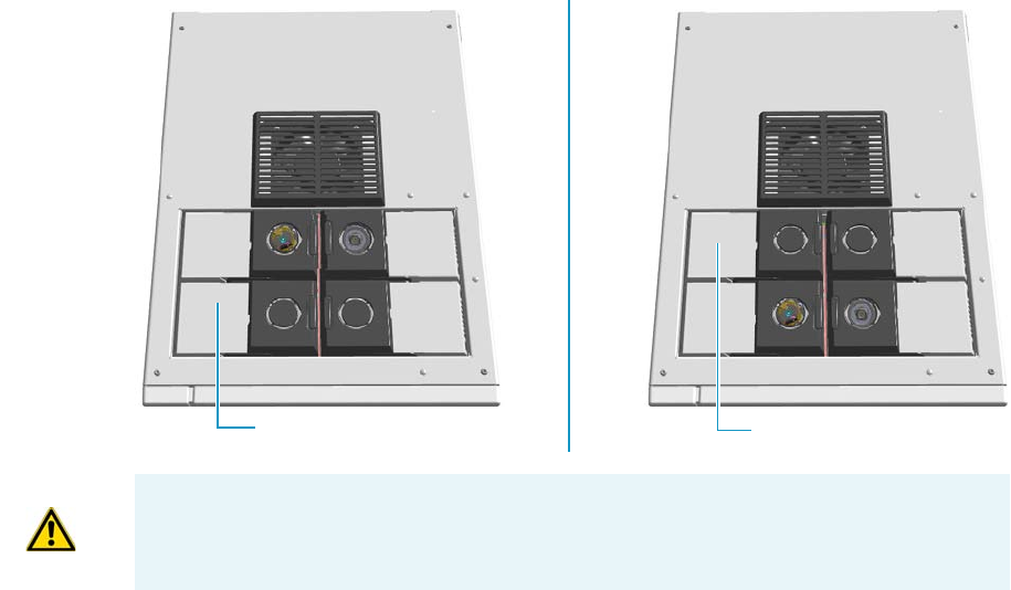
9 Adding Modules
Adding a PDD Module
458 TRACE 1300 and TRACE 1310 Hardware Manual Thermo Scientific
Adding a PDD Module
This section provides instructions for adding a front/back PDD detector module. According
to the configuration of your TRACE 1300/TRACE 1310, a dummy module is present into
the free site where the detector module is not installed. See Figure 476.
Figure 476. Add a Front/Back Detector Module
Getting Started
To properly installing and connecting the PDD module see sequentially the following
sections:
•“Installing a PDD Module” on page 459
•“Plumbing the Gas Lines” on page 463
•“Installing and Purging the Gas Regulator” on page 464
•“Installing and Purging the Helium Purifier” on page 464
•“Connecting the Discharge Gas Supply” on page 465
•“Connecting the High Voltage and Pulses Cables” on page 465
•“Installing the Capillary Column” on page 470
•“Installing the Packed Column” on page 470
•“Testing for Leaks” on page 470
•“Performing Initial Power Up” on page 471
Dummy Back Detector Module
Dummy Front Detector Module
ATTENTION Where a dummy module is installed, the gas connection is blocked by a
plug.
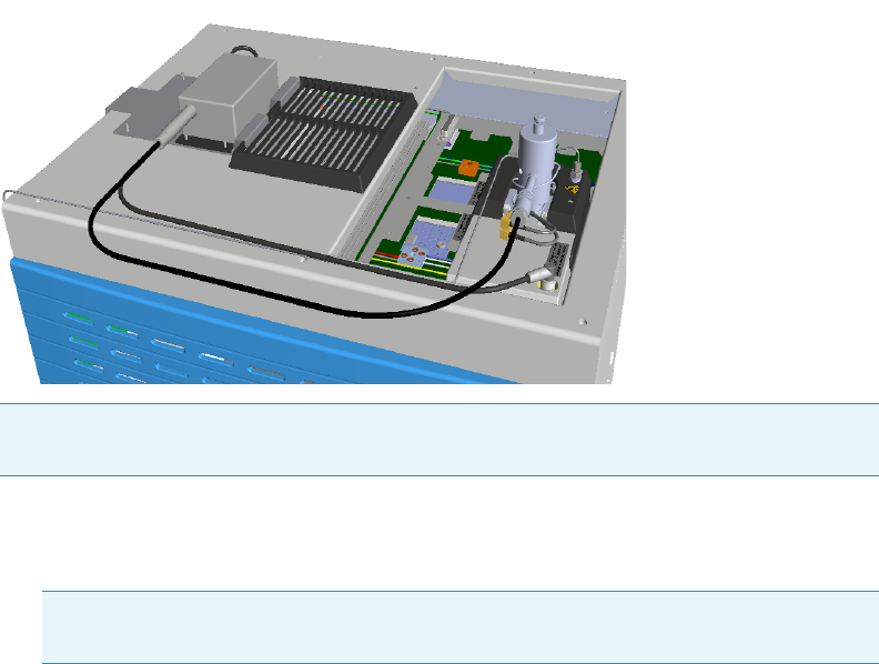
9 Adding Modules
Adding a PDD Module
Thermo Scientific TRACE 1300 and TRACE 1310 Hardware Manual 459
Installing a PDD Module
To install a PDD detector module
The result of the operation is shown in Figure 477.
Figure 477. Result of the PDD Installation
1. Put the GC in standby condition.
2. Cool the oven, injector, and detector to room temperature.
3. Close the gas supplies.
4. Power off the GC.
a. Push down the power switch (breaker), located at the back of the instrument, to the
position O.
b. Unplug the power cable from the AC Input connector into the back of the GC and
from the wall outlet.
5. If external modules are present, unplug the power cable from the AC Input connector of
each external module, and from the wall outlet.
6. Remove the dummy module from the position where the detector module will be
installed.
a. Open the module flap cover.
b. Using a T20 Torxhead screwdriver, unscrew and remove the two captive fixing
screws.
Note The installation of a single PDD detector is considered. The injector modules are
deliberately missing for convenience.
Note By pressing the Maintenance button, the GC cool down is automatically
carried out.
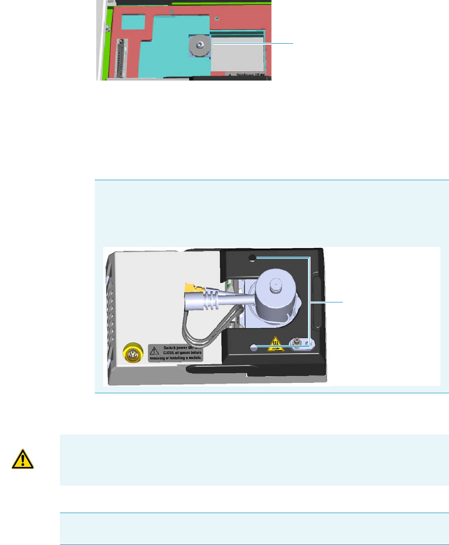
9 Adding Modules
Adding a PDD Module
460 TRACE 1300 and TRACE 1310 Hardware Manual Thermo Scientific
c. Keeping the dummy module flap cover open, lift up the module from its seat in the
injector/detector housing. Place the dummy module on a clean surface.
d. Keep the gas block plug of the gas connections installed. See Figure 447.
Figure 478. Detector Gas Block Plug
7. Open the front door of the GC.
8. Plug and fix the detector module into the main frame.
a. Place the module in its seat. Be sure to insert the 25-pin male connector, on the
bottom of the module, into the 25-pin female connector on the detector seat of the
detector housing.
b. Insert a T20 Torxhead screwdriver into the holes provided on the module flap cover
and tighten the captive fixing screws without overtightening.
.
9. Mount the support bracket of the pulse generator. See Figure 480.
Note Because the module flap cover of the PDD detector cannot be opened, two
holes are provided on the module flap cover for accessing the captive fixing
screws. See Figure 479.
Figure 479. Holes on the Module Flap Cover
Gas Block Plug on Detector Seat
Holes
ATTENTION To maintain the correct alignment the screws must be tightened in turn.
Tighten each screw only a small amount before moving to the next screw. Repeat until all
are secure.
Note The support bracket can hold two pulse generators for supplying two PDD
detectors on the GC.
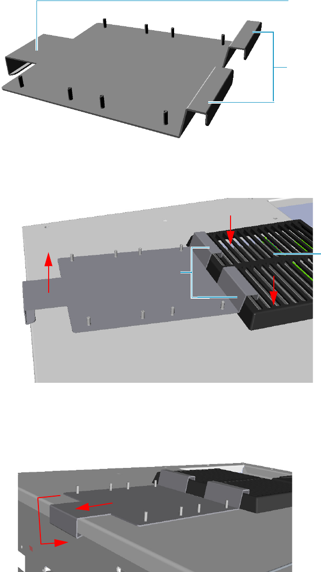
9 Adding Modules
Adding a PDD Module
Thermo Scientific TRACE 1300 and TRACE 1310 Hardware Manual 461
Figure 480. Support Bracket
a. Insert the upper clamps of the support bracket into the last slots of the cooling fan
grid. See Figure 481.
Figure 481. Support Bracket Installation (1)
b. Lift the bottom part of the support bracket and push it back until the lower lamp
hooks the rear of the GC top cover. See Figure 482.
Figure 482. Support Bracket Installation (1)
Lower Clamp
Upper Clamps
Cooling Fan
Grid
Upper Clamps
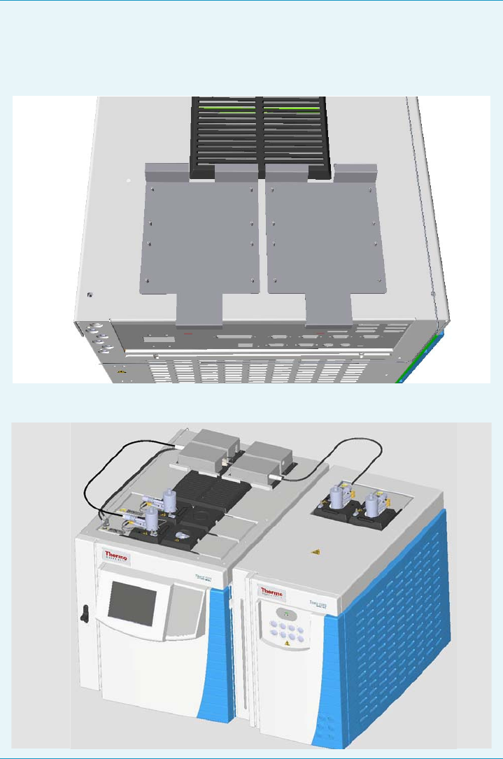
9 Adding Modules
Adding a PDD Module
462 TRACE 1300 and TRACE 1310 Hardware Manual Thermo Scientific
10. Place the pulse generator on the support bracket.
a. Place the pulse generator on a convenient position of the support bracket by aligning
the four holes on the base of the generator with the corresponding four rivets on the
support bracket as shown in the example of Figure 485.
Note Two support brackets can be installed for supplying a maximum of four
PDD detectors, two installed on the GC and two installed on the TRACE 1310
Auxiliary Oven. See the example of Figure 483 and Figure 484.
Figure 483. Installation of two Support Bracket
Figure 484. Installation of Four PDD Detectors
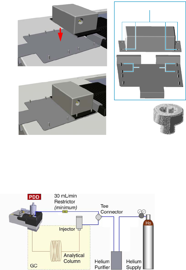
9 Adding Modules
Adding a PDD Module
Thermo Scientific TRACE 1300 and TRACE 1310 Hardware Manual 463
Figure 485. Pulse Generator Installation
b. Fix the pulse generator using the four barrel nuts provided. Tighten the nuts using a
T30 Torxhead screwdriver.
Plumbing the Gas Lines
Figure 486 shows the diagram of the gas lines connections of the detector system.
Figure 486. Gas Line Connections
Before connecting the gas lines verify that:
Base Holes
Pulse
Generator
Rivets
Barrel Nut

9 Adding Modules
Adding a PDD Module
464 TRACE 1300 and TRACE 1310 Hardware Manual Thermo Scientific
• The pressure regulators are commercial ultra-pure grade regulators with stainless steel
diaphragms. Regulators with diaphragms made of neoprene or others elastomers should
never be used.
• The connecting tubes are thoroughly cleaned and baked before use.
• The gas regulator and the helium purifier must be properly purged. See the following
sections for further details: “Installing and Purging the Gas Regulator” on page 464,
“Installing and Purging the Helium Purifier” on page 464, and “Connecting the
Discharge Gas Supply” on page 465.
Installing and Purging the Gas Regulator
To install and purge the gas regulator
1. Install the pressure regulator on the cylinder.
2. Making sure the regulator is closed, open the cylinder allowing the regulator to pressurize.
3. Close the cylinder and check the regulator for pressure leaks. Observe the needle of the
regulator output pressure gauge for 15 minutes.
4. Open the regulator allowing the pressure to relief.
5. Repeat five times from step 2.
Installing and Purging the Helium Purifier
To install and purge the helium purifier
Before starting, make sure the helium purifier outlet tube is capped.
1. Connect the helium cylinder pressure regulator to the inlet port of the helium purifier by
using the appropriate connecting tube and fittings.
2. Turn the output pressure regulating knob clockwise until the gauge registers 345 kPa
(50 psig).
3. Wait five minutes for equilibrium, then turn the regulating knob all the way
counterclockwise.
WARNING Never use leak detecting fluids on any part of the system.
WARNING To avoid injury, before starting make sure to strictly respect all the
Regulations concerning the manual handling of gas cylinders under pressure.
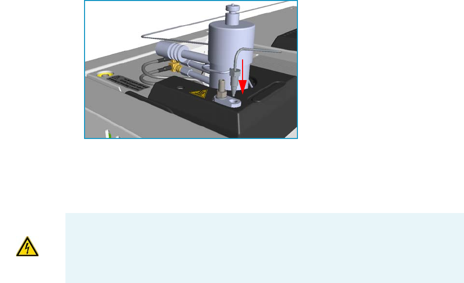
9 Adding Modules
Adding a PDD Module
Thermo Scientific TRACE 1300 and TRACE 1310 Hardware Manual 465
4. Observe the needle of the output pressure gauge for 15 minutes. There will be a slight
initial drop. If it does not move after that, consider all the connections are tight.
5. If necessary, use an electronic leak detector to locate any leaks. If a leak detector is not
available, tighten all the fitting and repressurize the system for another test.
6. Uncap the outlet tube of the helium purifier and purge the system for 15 to 30 minutes at
60 - 80 mL/min to eliminate air from the purifier getting material.
Connecting the Discharge Gas Supply
To connect the discharge gas supply
1. Connect the helium purifier outlet port to a port of the Tee connector provided by using
the 1/16-in. o.d. connecting tube provided.
2. Connect the second port of the Tee connector to the carrier gas inlet port, located on the
rear panel of the GC, by using a sufficient piece of the stainless steel connecting tube
provided and the appropriate fitting.
3. Connect the last port of the Tee connector to the inlet of the discharge gas restrictor.
4. Connect the outlet tube of the restrictor to a flow measuring device and adjust the helium
pressure to obtain a flow of about 30 mL/min.
5. After setting the flow rate, connect the outlet of the restrictor to the discharge gas inlet on
the PDD module. See Figure 487.
Figure 487. Gas Supply Connections
Connecting the High Voltage and Pulses Cables
To connect the cables from the pulse generator to the PDD module
WARNING Never the high voltage discharge cable must be disconnected when the pulse
generator is turned on. Dangerous high voltage is present: 3700 V Peak; 170 mA Peak.
To avoid accidental disconnection of the high voltage discharge cable (mainly) and the
pulses cable from the pulse generator, the safety covers must be installed. See Figure 488.
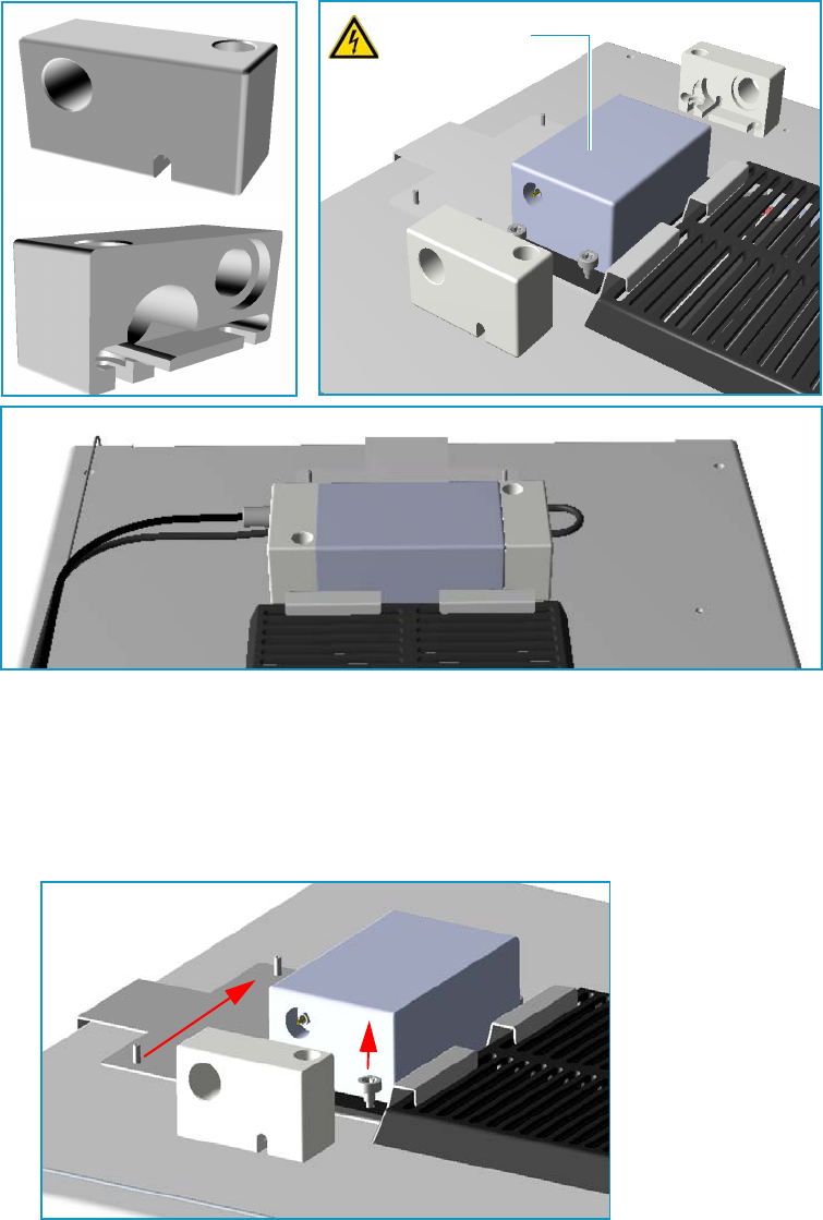
9 Adding Modules
Adding a PDD Module
466 TRACE 1300 and TRACE 1310 Hardware Manual Thermo Scientific
Figure 488. Pulse Generator Safety Covers
1. Connect the high voltage discharge cable.
a. On the high voltage side, loosen the right nut that fix the pulse generator to the
bracket. Do not loosen the left nut, keep it tightened. Place the safety cover until the
nuts couple the slots on the bottom of the safety cover. See Figure 489.
Figure 489. High Voltage Discharge Cable Connection (1)
b. Tighten the right nut using a T30 torxhead screwdriver. See Figure 490.
Pulse Generator Safety Cover
Safety Cover
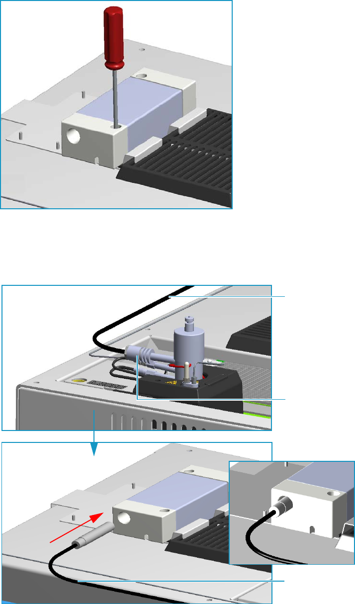
9 Adding Modules
Adding a PDD Module
Thermo Scientific TRACE 1300 and TRACE 1310 Hardware Manual 467
Figure 490. High Voltage Discharge Cable Connection (2)
c. Insert the connector of the high voltage discharge cable, coming from the high
voltage discharge electrode on the PDD module, into the connection provided in the
pulse generator passing through the hole on the safety cover. See Figure 491.
Figure 491. High Voltage Discharge Cable Connection (3)
High Voltage
Discharge Cable
High Voltage
Discharge Cable
High Voltage
Discharge
Electrode
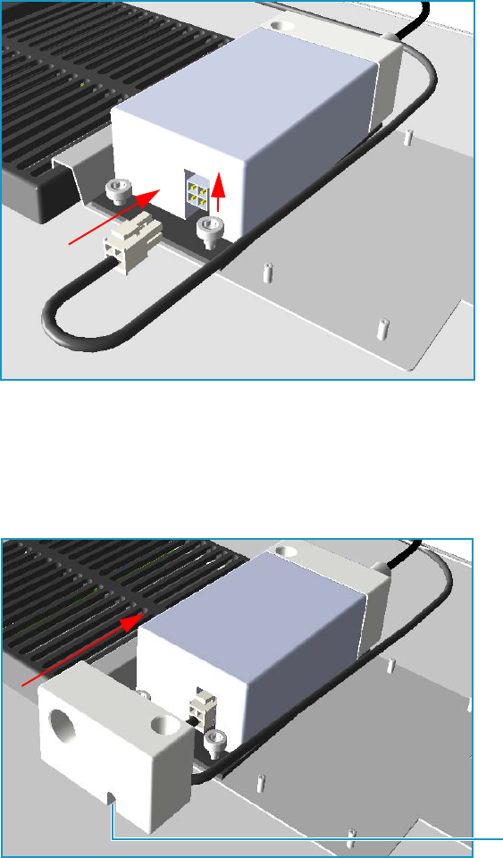
9 Adding Modules
Adding a PDD Module
468 TRACE 1300 and TRACE 1310 Hardware Manual Thermo Scientific
2. Connect the pulses cable.
a. Plug the 4-pin pulses cable connect into the 4-pin connector on the pulse generator
See Figure 492.
Figure 492. Pulses Cable Connection (1)
b. On the pulse generator control side, loosen the right nut that fix the pulse generator
to the bracket. Do not loosen the left nut, keep it tightened. Place the safety cover
until the nuts couple the slots on the bottom of the safety cover payning attention to
guide the cable into the slot located on the bottom of the safety cover. See Figure 493.
Figure 493. Pulses Cable Connection (2)
c. Tighten the right nut using a T30 torxhead screwdriver. See Figure 494.
Slot
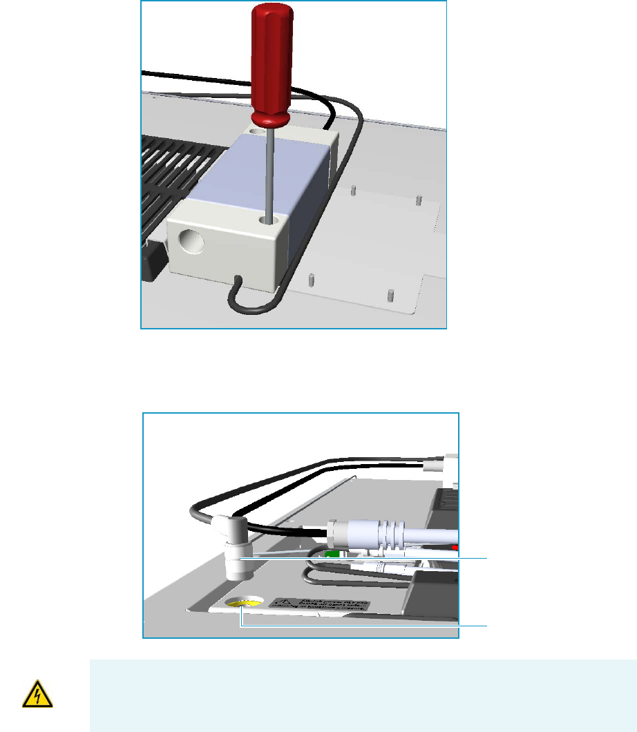
9 Adding Modules
Adding a PDD Module
Thermo Scientific TRACE 1300 and TRACE 1310 Hardware Manual 469
Figure 494. Pulses Cable Connection (3)
d. Connect the cable between the pulse generator and the pulse generator control on the
PDD module. See Figure 495.
Figure 495. Pulses Cable Connection (4)
Pulses Generator Control
Connector
WARNING If for any reasons it is necessary to disconnect the cables from the pulse
generator, the safety covers must be removed proceeding in the reverse order in which they
was installed. Before starting, make sure that the GC is powered Off.
9 Adding Modules
Adding a PDD Module
470 TRACE 1300 and TRACE 1310 Hardware Manual Thermo Scientific
Installing the Capillary Column
For PDD, the column must penetrate 136 mm inside the pre-installed capillary column
adapter.
To install the capillary column
1. Make a mark on the column 136 mm from the end.
2. Remove the knurled nut column inlet at the bottom of the detector. Slide the nut overt
the end of the column, followed by the appropriate column ferrule.
3. Seat the ferrule in the detail of the column adapter and begin sliding the column through
the capillary column adapter and into the column inlet.
4. Get the nut started on the threads and tighten it until you feel it contact the ferrule, then
back off half a turn.
5. Slide the column into the column inlet until the mark is flush with the surface of the
knurled nut, and secure the column in the adapter by tightening the knurled nut finger
tight only.
Installing the Packed Column
To install the packed column
1. Remove the pre-installed capillary column adapter.
2. Replace pre-installed capillary column adapter with the packed columns adapter that
penetrates into the PDD cell for the correct length.
3. Connect the packed column to the packed column adapter.
Testing for Leaks
It is critical for the system to be leak-tight. Leak test is strongly recommended before
operating with PDD.
To test for leaks
1. Open the discharge gas supply.
2. Cap the tube and pressurize the entire system with helium to 138 kPa (20 psi).
3. If the system does not hold pressure, check all the fittings with an electronic helium leak
detector. DO NOT use leak detecting liquids.
4. Tighten fittings as required.

9 Adding Modules
Adding a PDD Module
Thermo Scientific TRACE 1300 and TRACE 1310 Hardware Manual 471
Performing Initial Power Up
To perform the initial power up
1. If external modules are present, plug the power cable to the AC Input connector of each
external module, and to the wall outlet.
2. Power on the GC.
a. Plug the power cable to the AC Input connector into the back of the GC and to the
wall outlet.
b. Flip up the power switch (breaker) to the position I.
3. Close the front door of the GC.
4. Set the detector temperature to 100 °C and allow time for the detector to reach the set
temperature, and for the helium purifier to reach the optimum working condition.
5. Turn on the pulse generator.
6. Check the standing/background current. Optimum range is 600 - 2000 pA at 100°C.
Lower current indicates a clean, leak-free system.
7. The recommended detector temperature is 20 °C above the column temperature, with a
minimum of 100 °C. Set the detector to the operating temperature required for the
intended analysis. When the detector has reached the set temperature, read and record the
standing current.
8. Start carrier flow, then read the standing current.The difference between this reading and
the one previous is the ionization of the combined impurities in and eluting with the
carrier gas. The smaller the difference, the better the quality of the gas exiting the column.
9. Set the column oven to the temperature required for the intended analysis. When the
oven reaches the set temperature, read the standing current. The difference with the
previous reading is the ionization of the column bleed. The smaller the difference, the
better the column is conditioned.
From this point, the standing current should be observed and logged after any system
change. In addition, logging the standing current (with and without the column) on a
regular basis is an effective monitor of system integrity (leak tightness and cleanliness).
We also recommend tracking the internal standard (quantity on column/area count) for
sensitivity continuity.
WARNING During normal operation, the detector produce ultraviolet energy (UVA,
UVB), some of which may be emitted. Do not watch the arc without eye protection.
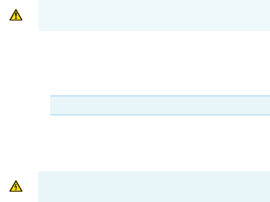
9 Adding Modules
Adding a Generic Detector Interface
472 TRACE 1300 and TRACE 1310 Hardware Manual Thermo Scientific
Adding a Generic Detector Interface
This section provides instructions for installing the detector and control modules of the
Generic Detector Interface on your TRACE 1300/1310 GC or TRACE 1310 Auxiliary
Oven.
Preliminary Operations
Before starting, the following preliminary operation must be carried out.
1. Put the GC in standby condition.
2. Cool the oven, injectors and detectors to room temperature.
3. Power off the GC.
a. Push down the power switch (breaker), located at the back of the instrument, to the
position O.
b. Unplug the power cable from the AC Input connector into the back of the GC and
from the wall outlet.
4. If external modules are present, unplug the power cable from the AC Input connector of
each external module, and from the wall outlet.
Getting Started
For properly installing the Generic Detector Interface see the following sections:
•“Removing the GC Back Cover” on page 473
•“Assembling the GDI Electrical Interface” on page 474
•“Replacing the Encapsulated Flow Restrictors” on page 476
•“Installing and Connecting the GDI Electrical Interface” on page 477
•“Connecting a GDI Interface to the TRACE 1310 Auxiliary Oven” on page 481
WARNING This operation must be carried out by authorized and trained Thermo Fisher
Scientific Service Field Engineers.
Note By pressing the Maintenance button, the GC cool down is automatically
carried out.
CAUTION If the GC is coupled to a TRACE 1310 Auxiliary Oven, unplug the power
cable from the AC Input connector into the back of the TRACE 1310 Auxiliary Oven
and from the wall outlet.

9 Adding Modules
Adding a Generic Detector Interface
Thermo Scientific TRACE 1300 and TRACE 1310 Hardware Manual 473
•“Installing a GDI Mechanical Module” on page 482
•“Connecting the Detector Gas Tubings to the Manifolds” on page 484
•“Connecting Heater and Signal Cables” on page 488
•“Restarting the GC” on page 489
•“Performing the Third-party Detector Start-up and Optimization” on page 489
•“Configuring and Setting GDI Detector” on page 490
Removing the GC Back Cover
Remove the back cover for accessing the compartment on the back of the GC.
To remove the back cover
1. Remove the cover.
a. Using a T20 Torxhead screwdriver, unscrew the four screws that secure the back cover
to the GC. See Figure 496.
Figure 496. Back Cover Removal
b. Lift the cover off using the cover handle. Be aware that the ground wire is attached to
the back cover.
Note Pay attention to the positioning of the ground wire plug, so it can be
reconnected in the same way it was removed.
Back Cover Fixing Screws
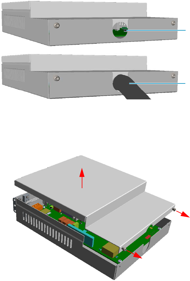
9 Adding Modules
Adding a Generic Detector Interface
474 TRACE 1300 and TRACE 1310 Hardware Manual Thermo Scientific
Assembling the GDI Electrical Interface
If not already done, you must connect the detector cable and its cable grommet into the GDI
electrical interface. See Figure 497.
Figure 497. GDI Electrical Interface Back View
To assemble the GDI electrical interface
1. Unscrew the fixing screws of the GDI electrical interface using a T10 torxhead
screwdriver, and remove the top cover. See Figure 498.
Figure 498. Assemble GDI Electrical Interface (1)
2. On the board inside the control module look for the 26-pin male connector marked J4.
See Figure 499.
Detector Cable
Duct for Detector Cable
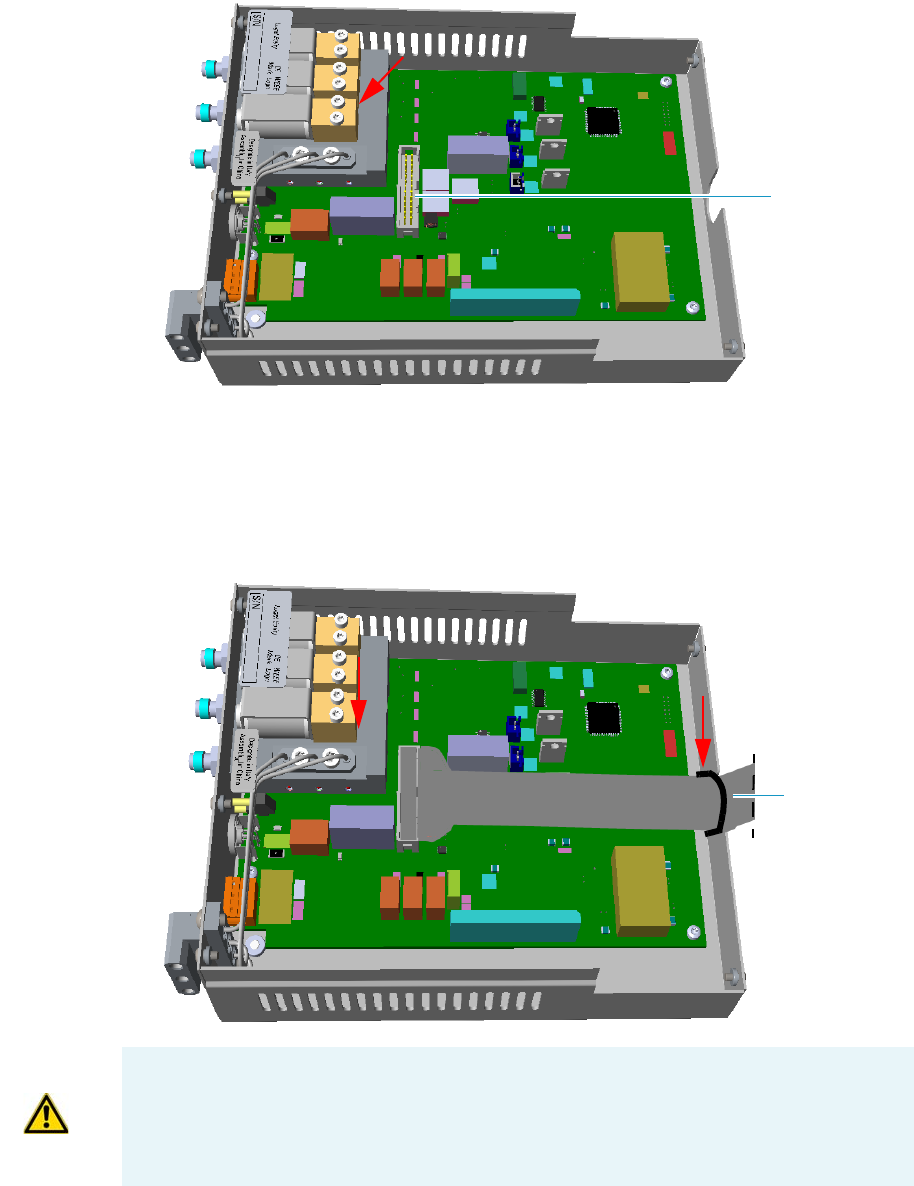
9 Adding Modules
Adding a Generic Detector Interface
Thermo Scientific TRACE 1300 and TRACE 1310 Hardware Manual 475
Figure 499. Assemble GDI Electrical Interface (2)
3. Connect the 26-pin female connector of the detector cable to the 26-pin male connector
marked J4 on the board.
4. Guide the detector cable and its cable grommet out of the control module through the
duct. See Figure 500.
Figure 500. Assemble GDI Electrical Interface (3)
5. Remount and fix the top cover by using the fixing screws.
Connector J4
J4
Detector Cable
F1
F2
ATTENTION Two protecting fuses F1 and F2 are present on the electronic board of the
GDI electrical interface for the protection of the 24 Vdc and 48 Vac respectively:
•F1 = T300mA 250V; (5 x 20 mm)
•F2 = T2A 250V; (5 x 20 mm)
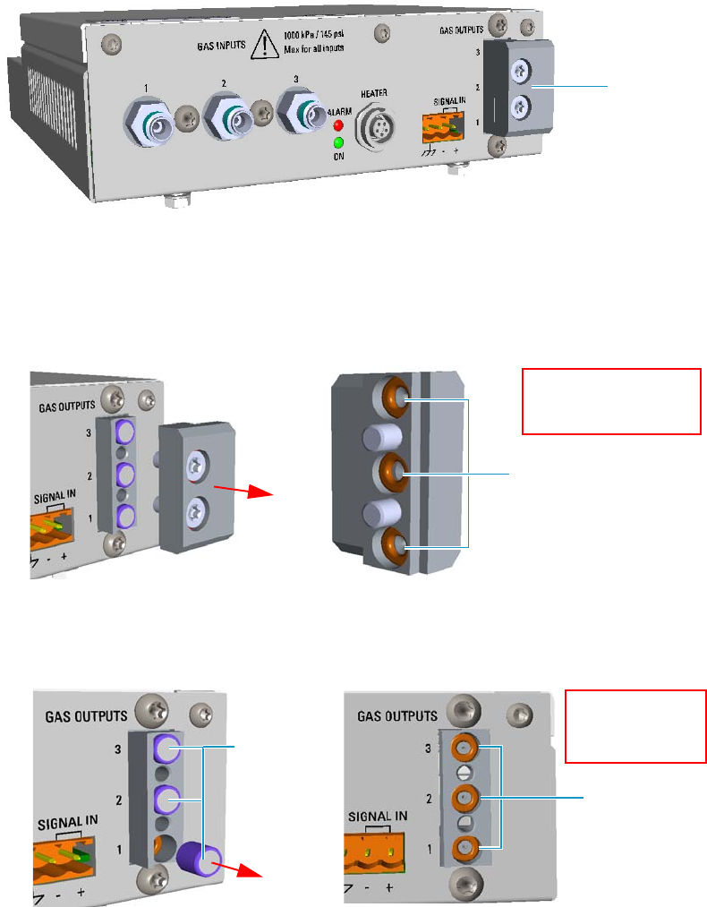
9 Adding Modules
Adding a Generic Detector Interface
476 TRACE 1300 and TRACE 1310 Hardware Manual Thermo Scientific
Replacing the Encapsulated Flow Restrictors
This section provides instruction for replacing the 1/4-in. OD x 1/4-in. length encapsulated
flow restrictors. The flow restrictors are located inside the manifold marked Gas Outputs on
the GDI electrical interface. See Figure 501.
Figure 501. Gas Outputs Manifold
To replace an encapsulated flow restrictor
1. Remove the Gas Outputs manifold from the GDI electrical interface by unscrewing its
fixing screws using a T20 Torxhead screwdriver. See Figure 502.
Figure 502. Gas Outputs Manifold
2. Remove the encapsulated flow restrictor of interest from its seat using tweezers.
See Figure 503.
Figure 503. Flow Restrictor Replacement
Gas Outputs
Manifold
Manifold O-Rings
Pay attention to not lose
the o-ring placed into the
manifold
Internal O-Rings
Pay attention to not
lose the internal
o-ring
Encapsulated
Flow
Restrictors
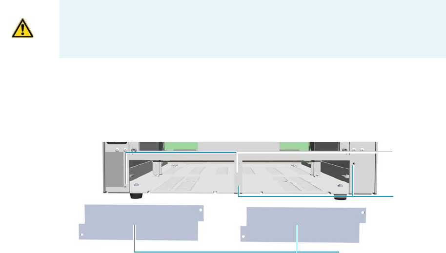
9 Adding Modules
Adding a Generic Detector Interface
Thermo Scientific TRACE 1300 and TRACE 1310 Hardware Manual 477
3. Replace the encapsulated flow restrictor with the ones required by the third-party
detector, then reinstall the manifold proceeding in the reverse order in which it was
removed.
4. Calibrate the new full scale of the flow restrictor.
a. In the GDI Configuration page, set gas type to the real gas in use and full scale to
100 mL/min whatever restrictor is installed.
See the section “Configuring and Setting GDI Detector” on page 490, and refer to
Chapter 2 and Chapter 4 of the TRACE 1300/TRACE 1310 User Guide.
b. Set relevant channel flow rate in the Method/Instrument Control page to the full
scale value (100 mL/min). Make sure the gas input pressure is at least 60 psig
(414 kPa), and verify that the actual flow displayed by the GC reaches 100 mL/min
as set.
See the section “Configuring and Setting GDI Detector” on page 490, and refer to
Chapter 2 and Chapter 4 of the TRACE 1300/TRACE 1310 User Guide.
c. Check the real flow rate with an external flowmeter.
d. Use the real reading of the flowmeter as the new full scale, and set it in the GDI
Configuration page.
Installing and Connecting the GDI Electrical Interface
This section provides the instruction for installing and connecting the GDI electrical
interface.
To install and connect the GDI electrical interface
1. Remove the cover of the external modules housing where installing the module.
See Figure 504.
Figure 504. Housing Cover Removal
CAUTION It is mandatory that the GDI electrical interface must be placed into an
housing on the back of the GC. If both the housings are already occupied by other
external modules, one of these must be removed and placed beside the GC, and in the
most comfortable position for the user to have free access to the connections.
Left/Right Housing Covers
Left Cover
Screws
Right Cover
Screws
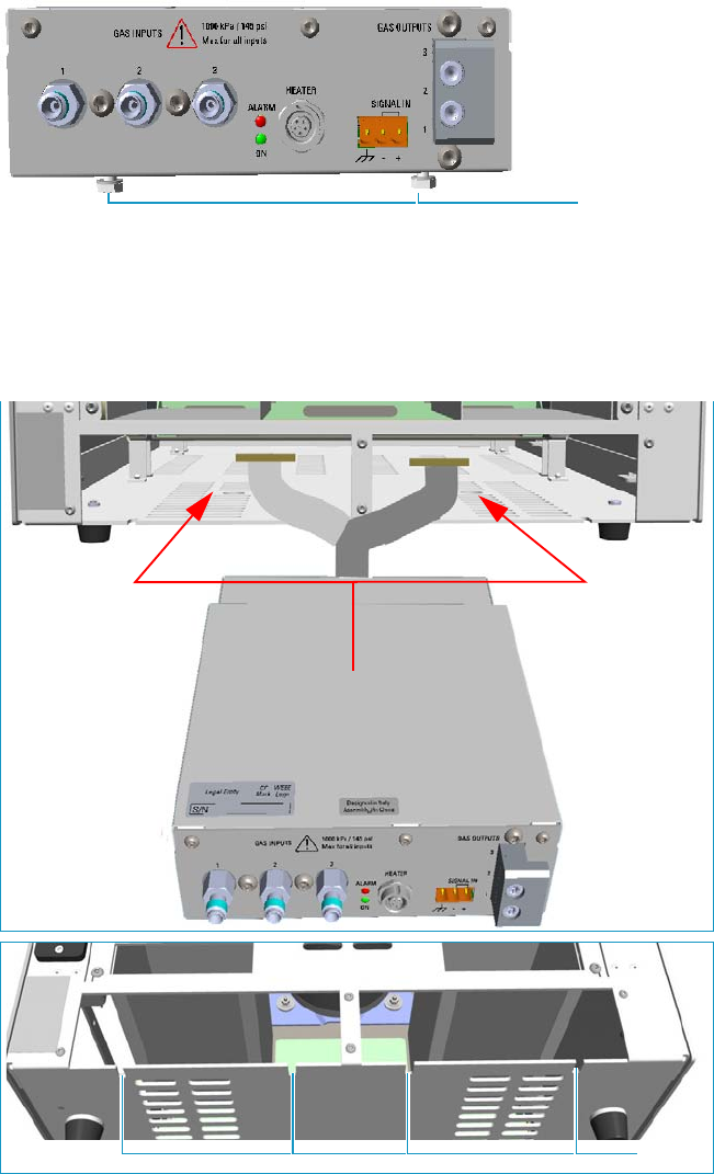
9 Adding Modules
Adding a Generic Detector Interface
478 TRACE 1300 and TRACE 1310 Hardware Manual Thermo Scientific
a. Using a T20 Torxhead screwdriver, unscrew and remove the left or right housing
cover screws, then remove the cover from the housing.
2. Install the GDI electrical interface into the housing
a. Loosen the two hexagonal screws under the module. See Figure 505.
Figure 505. GDI Module Installation (1)
b. Carefully place the GDI electrical interface into the left or right housing. Guide the
detector cable into the electronic compartment of the GC, next push the module
until the hexagonal screws couple with the slots on the floor of the GC.
See Figure 506.
Figure 506. GDI Module Installation (2)
Hexagonal Screws
Slots
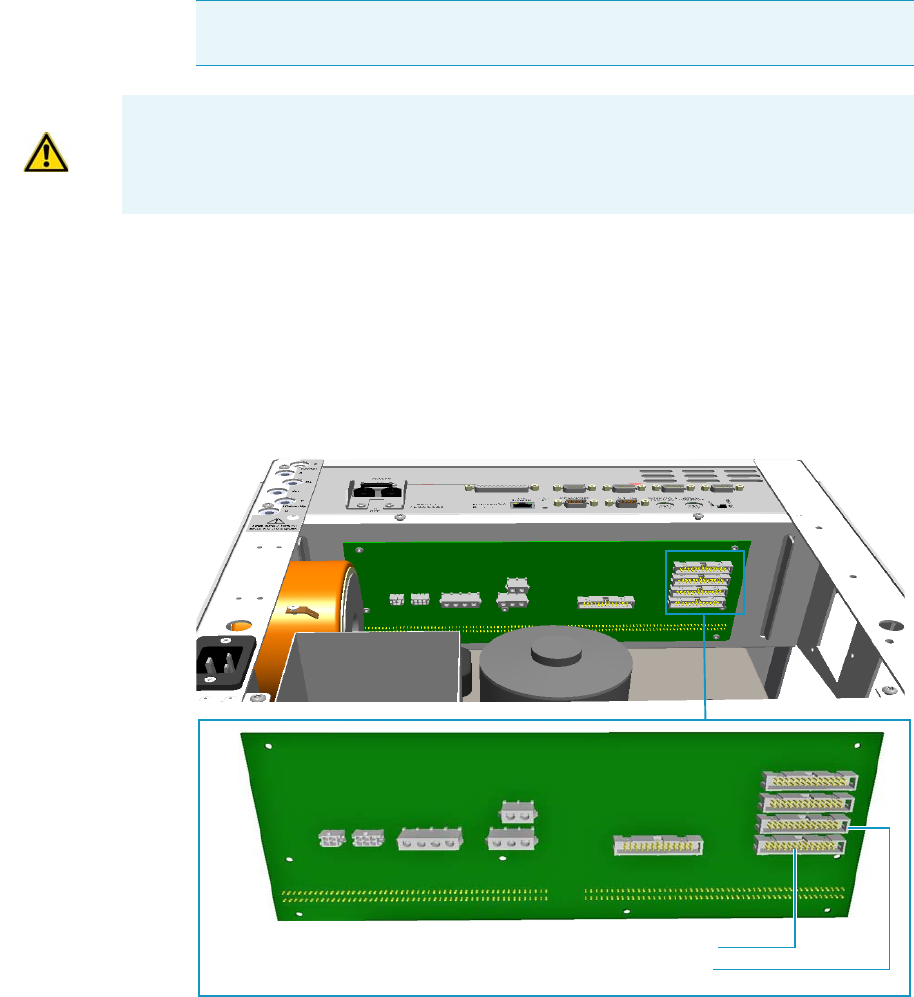
9 Adding Modules
Adding a Generic Detector Interface
Thermo Scientific TRACE 1300 and TRACE 1310 Hardware Manual 479
c. Finger-tighten the hexagonal screws slightly, or use a 10-mm wrench.
3. Connect the 26-pin connector of the detector cable coming from the GDI electrical
interface to the backplane board in the electronic compartment.
a. On the backplane board disconnect the flat cable from the connector marked J13
DET.FRONT if the GDI mechanical module is installed in the Front site, or from
the connector marked J5 DET.REAR if the GDI mechanical module is installed in
the Back site. See Figure 507.
Figure 507. GC Backplane Board Layout
b. Connect the detector cable to the connector J13 DET.FRONT, or J5 DET.BACK
accordingly.
Note Always keep the hexagonal screws in their place. This allows you an easier
removal of the GDI electrical interface when necessary.
ATTENTION If an GDI mechanical module will be installed on the TRACE
1300/TRACE 1310 GC, continue the procedure from the step 3. If an GDI mechanical
module will be installed on the TRACE 1310 Auxiliary Oven, jump to the section
“Connecting a GDI Interface to the TRACE 1310 Auxiliary Oven” on page 481.
J13 DET.FRONT Connector
J5 DET.REAR Connector
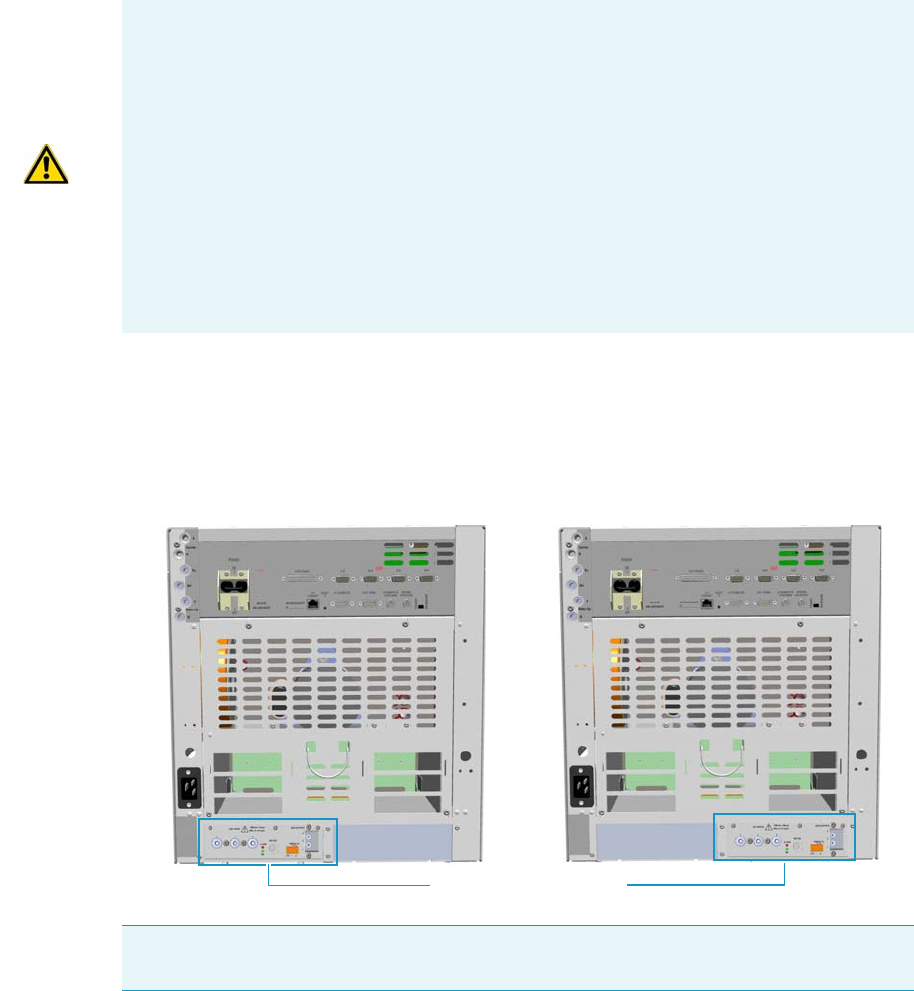
9 Adding Modules
Adding a Generic Detector Interface
480 TRACE 1300 and TRACE 1310 Hardware Manual Thermo Scientific
4. Reconnect the ground wire to the back cover terminal.
5. Replace the back cover of the GC proceeding in the reverse order in which it was
removed.
The result of the installation is shown in Figure 508.
Figure 508. GDI Electrical Interface Installed into the GC
ATTENTION TRACE 13100/1310 coupled with a TRACE 1310 Auxiliary Oven
If you are installing the GDI mechanical module in the Front or Back site of a TRACE
1300/1310 GC coupled with a TRACE 1310 Auxiliary Oven, the detector cable of the
GDI electrical interface must be connected as follows:
•Mechanical module installed in the Front site: On the backplane board disconnect
the flat cable from the connector marked J13 DET.FRONT. Connect the detector
cable to the connector J13 DET.FRONT.
•Mechanical module installed in the Back site: Do NOT DISCONNECT the flat
cable from connector marked J5 DET.REAR. Connect the detector cable directly to
the additional connector on the flat cable.
Note Continue the procedure of installation following the instruction reported in the
section “Installing a GDI Mechanical Module” on page 482.
GDI electrical interface
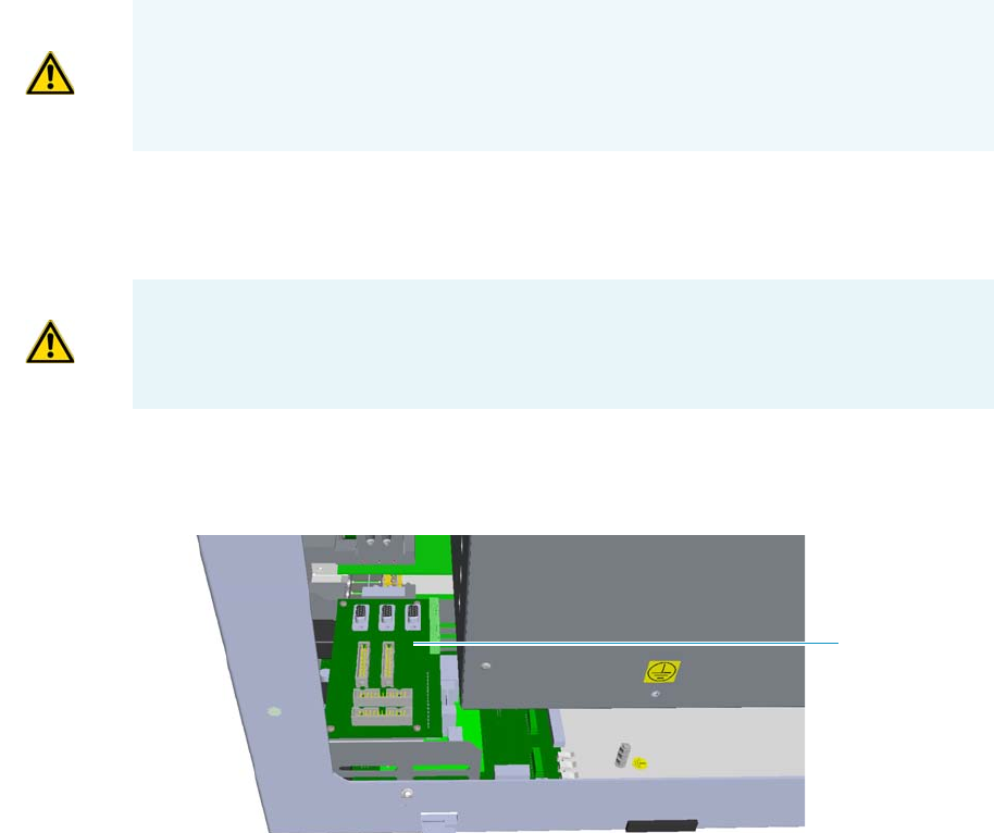
9 Adding Modules
Adding a Generic Detector Interface
Thermo Scientific TRACE 1300 and TRACE 1310 Hardware Manual 481
Connecting a GDI Interface to the TRACE 1310 Auxiliary Oven
The GDI mechanical module can be installed as auxiliary detector into the position Aux L or
Aux R of the auxiliary detector assembly.
The detector cable of the GDI electrical interface, installed into an external module housing
on the back of the GC, must be connected to the VOBP-HRM board located into the
electronic compartment of the TRACE 1310 Auxiliary Oven. See the following procedure.
To connect the GDI electrical interface to the TRACE 1310 auxiliary oven
1. Carefully decouple the TRACE 1310 Auxiliary Oven from the GC for creating enough
operating space for guiding the detector cable from the GDI electrical interface through
the GC into the electronic compartment of the TRACE 1310 Auxiliary Oven.
2. In the electronic compartment look for the VOBP-HRM board. It is located over the
power section of the TRACE 1310 Auxiliary Oven. See Figure 509.
Figure 509. TRACE 1310 Auxiliary Oven: VOBP-HRM Board
3. Connect the 26-pin connector of the detector cable coming from the GDI electrical
interface to the VOBP-HRM board in the electronic compartment.
a. On the board VOBP-HRM disconnect the flat cable from the connector marked J29
AUX DET LEFT if the GDI mechanical module is installed in the Left site, or from
the connector marked J13 AUX DET RIGHT if the GDI mechanical module is
installed in the Right site. See Figure 510.
WARNING This operation must be carried out by authorized and trained Thermo Fisher
Scientific Service Field Engineers.
Before starting make sure that the TRACE 1300/1310 GC and the TRACE 1310
Auxiliary Oven are powered off and the power cables disconnected.
WARNING Before proceeding this operation make sure to disconnect properly the inner
tube. Refer to the section Coupling the TRACE 1310 Auxiliary Oven to the GC on the
TRACE 1310 Auxiliary Oven Instruction Manual, and operating in the reverse order in
which it was mounted.
VOBP-HRM
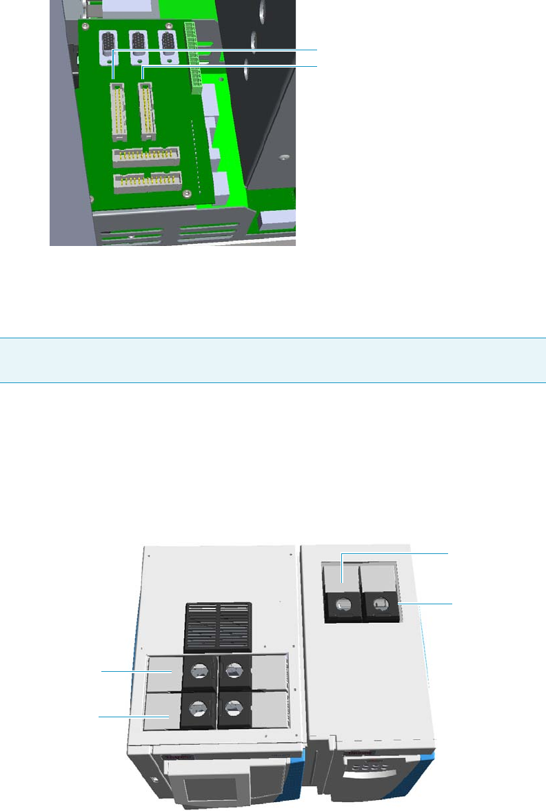
9 Adding Modules
Adding a Generic Detector Interface
482 TRACE 1300 and TRACE 1310 Hardware Manual Thermo Scientific
Figure 510. VOBO-HRM Board Layout
b. Connect the detector cable to the connector J29 AUX DET LEFT, or J13 AUX
DET RIGHT accordingly.
4. Re-couple the TRACE 1310 Auxiliary Oven to the GC.
Installing a GDI Mechanical Module
This section provides instructions for adding a Front/Back/Aux L/Aux R GDI mechanical
module. According to the configuration of your TRACE 1300/TRACE 1310 GC, a dummy
module is present into the free site where a detector module is not installed. See Figure 446.
Figure 511. Add a Front/Back/Aux L/Aux R Detector Module
Note Continue the procedure of installation following the instruction reported in the
section “Installing a GDI Mechanical Module” on page 482.
J29J29 J13
AUX DET RIGHT
AUX DET LEFT
Dummy Front
Detector Module
Dummy Back
Detector Module
Dummy AUX L
Detector Module
Dummy AUX R
Detector Module
TRACE 1300/TRACE 1310 GC TRACE 1310 Auxiliary Oven
detector
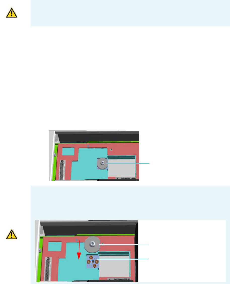
9 Adding Modules
Adding a Generic Detector Interface
Thermo Scientific TRACE 1300 and TRACE 1310 Hardware Manual 483
To install a GDI mechanical module
1. Remove the dummy module from the position where the detector module will be
installed.
a. Open the module flap cover.
b. Using a T20 Torxhead screwdriver, unscrew and remove the two captive fixing
screws.
c. Keeping the dummy module flap cover open, lift up the module from its seat in the
injector/detector housing. Place the dummy module on a clean surface.
d. DO NOT REMOVE the gas block plug from the gas connections. See Figure 512.
The gas supply is done through the GDI electrical interface.
Figure 512. Detector Gas Block Plug (1)
2. Plug the GDI mechanical module into the main frame.
a. Open the module flap cover.
ATTENTION Where a dummy module is installed, the gas connection is blocked by a
plug.
Gas Block Plug on Detector Seat
CAUTION In the case you are removing a real detector module instead of a dummy
module, you must place and fix the gas block plug on the gas connections using a T20
Torx h ead s c rewd r i ver. Se e Figure 513.
Figure 513. Detector Gas Block Plug (2)
Gas Connections
Without Gas Block Plug
Gas Block Plug
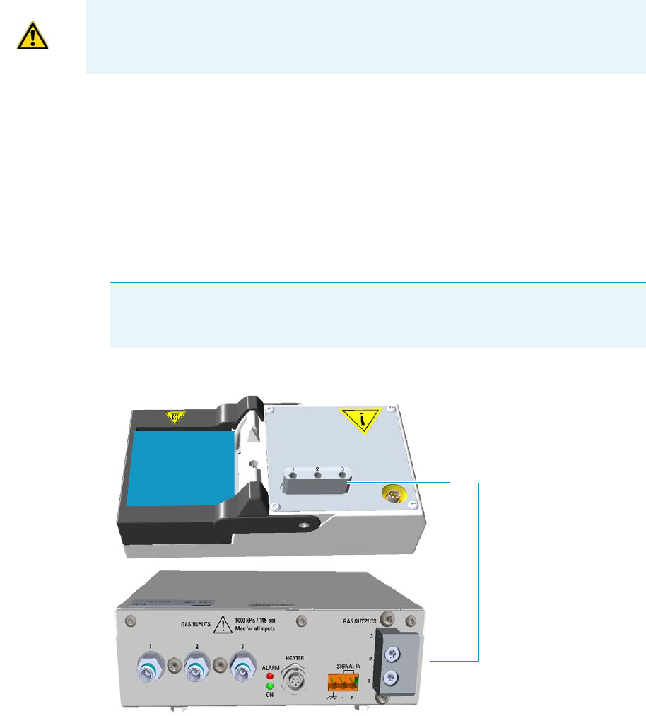
9 Adding Modules
Adding a Generic Detector Interface
484 TRACE 1300 and TRACE 1310 Hardware Manual Thermo Scientific
b. Keeping the module flap cover open, place the module in its seat. Note that the
25-pin female connector on the detector seat of the detector housing is not used.
c. Use a T20 Torxhead screwdriver to tighten the three captive fixing screws without
overtightening.
.
d. Close the module flap cover.
Connecting the Detector Gas Tubings to the Manifolds
This sections provides instruction for connecting the detector gas tubings to the
manifolds of the GDI mechanical module and GDI electrical interface.
To connect the gas tubing block to the manifolds
Figure 514 shows manifolds of the GDI mechanical module and GDI electrical interface.
Figure 514. Detector Gas Tubings Manifolds (1)
1. Take one, two, or three segments of the 1/16-in.stainless steel tubings (provided)
according to the detector gases required and long enough to properly connect both the
detector gas tubings manifolds.
ATTENTION To maintain the correct alignment the screws must be tightened in turn.
Tighten each screw only a small amount before moving to the next screw. Repeat until all
are secure.
Note Figure 514, Figure 515, Figure 516, Figure 517, and Figure 522 do not show
the third-party detector for graphic convenience. Suppose that it is installed in the
detector module GDI.
Detector Gas Tubings
Manifolds
Third-party
Detector
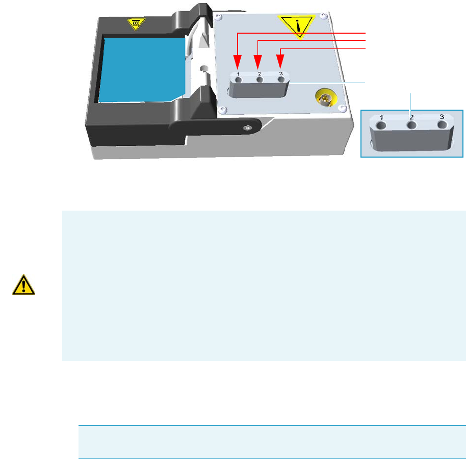
9 Adding Modules
Adding a Generic Detector Interface
Thermo Scientific TRACE 1300 and TRACE 1310 Hardware Manual 485
2. Connect the detector gas tubings to the manifold of the GDI mechanical module.
See Figure 515.
Figure 515. Detector Gas Tubings Connections
a. Connect the detector gas tubings to the numbered inlet ports using the appropriate
Swagelok® 1/16-in. nut and ferrules. Use a 1/4-in. wrench to tighten the fittings.
b. Repeat step a until all the required detector gas tubings are connected to the GDI
mechanical module.
c. Bend and run the detector gas tubings along the top cover.
Third-party
Detector
Detector Gases
Tubings
Detector Gases
Tubings Manifold
ATTENTION The inlet ports of the manifold on the GDI mechanical module are
numbered 1, 2, and 3 respectively. Pay attention to the correct order when you connect
each detector gas tubing to the corresponding outlet ports marked Gas 1, Gas 2, and
Gas 3 on the GDI electrical interface.
Connect the detector gas tubings for the third-party detector as follows:
•Outlet port Gas 1 to inlet port 1
•Outlet port Gas 2 to inlet port 2
•Outlet port Gas 3 = Air (Wall) to inlet port 3
Note The bending of the detector gas tubings shown in Figure 516 and Figure 517 is
indicative.
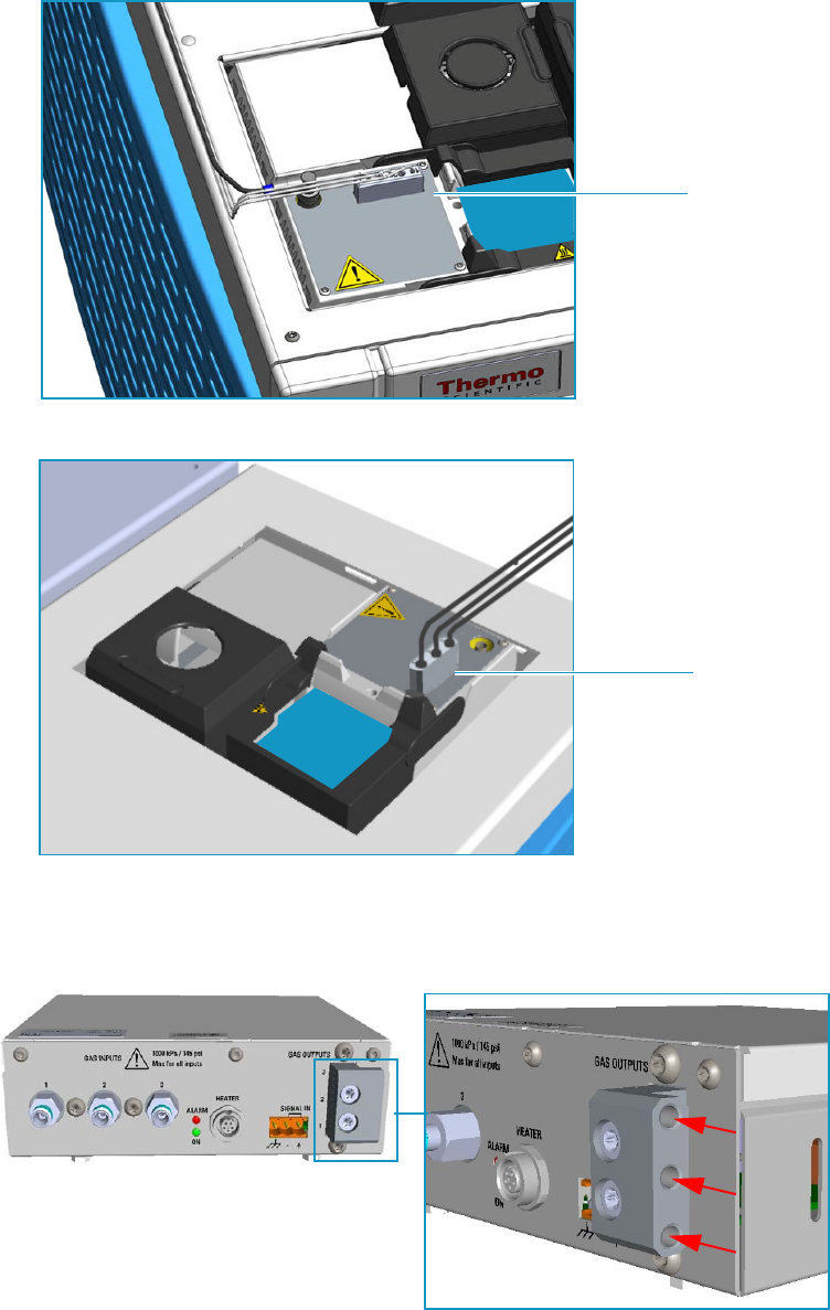
9 Adding Modules
Adding a Generic Detector Interface
486 TRACE 1300 and TRACE 1310 Hardware Manual Thermo Scientific
Figure 516. Bending of the Detector Gas Tubings on the TRACE 1300/1310 GC
Figure 517. Bending of the Detector Gas Tubings on the TRACE 1310 Auxiliary Oven
3. Connect the relevant detector gas tubings to the manifold of the GDI electrical interface.
See Figure 518.
Figure 518. Detector Gas Tubings Connection to the GDI Electrical Interface - External View (1)
a. Guide the detector gas tubings up to reach the GDI electrical interface.
Gas Tubings
Third-party
Detector
Gas Tubings
Third-party
Detector
Gas 3
Gas 2
Gas 1
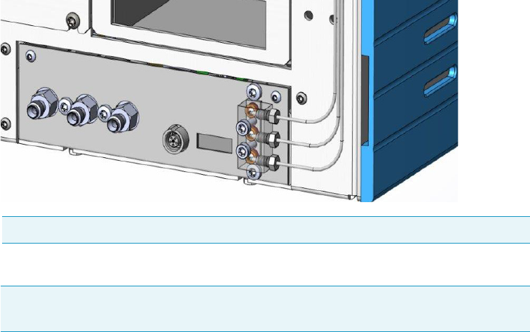
9 Adding Modules
Adding a Generic Detector Interface
Thermo Scientific TRACE 1300 and TRACE 1310 Hardware Manual 487
b. Bend and run the detector gas tubing along the back panel of the GC (or TRACE
1310 Auxiliary Oven) until its end reaches the corresponding numbered gas outlet
port on the GDI electrical interface.
c. Connect the detector gas tubing to the corresponding numbered outlet port using the
appropriate Swagelok® 1/16-in. nut and ferrules. Use a 1/4-in. wrench to tighten the
fittings.
d. Repeat step b and step c until all the required detector gas tubings are connected to
the GDI electrical interface.
The result of the operation is shown in Figure 519.
Figure 519. Detector Gas Tubings Connection to the GDI Electrical Interface - External View (2)
4. Connect the supply gas to the GDI electrical interface.
a. Connect the gas line to the corresponding inlet port using the appropriate nut and
ferrules. Use a 7/16-in. wrench for tightening the fittings.
b. Repeat step a until all the gas lines are connected to the corresponding inlet port on
the GDI electrical interface. See Figure 520.
Note The bending of the gas tubing is indicative.
Note Use the 1/8-in. Swagelok fittings provided on the gas inlet ports to connect the
gas lines.
Gas 1
Gas 2
Gas 3
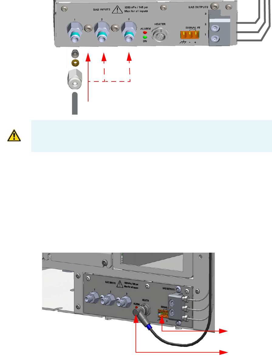
9 Adding Modules
Adding a Generic Detector Interface
488 TRACE 1300 and TRACE 1310 Hardware Manual Thermo Scientific
Figure 520. Gas Lines Connection to the GDI Electrical Interface
Connecting Heater and Signal Cables
If required by the third-party detector, connect the heater cable, the signal cable, or both.
To connect the heater and signal cables
1. Using the cable provided connect the 5-pin connector marked Heater on the GDI
electrical interface to the detector connector on the GDI mechanical module.
See Figure 521 and Figure 522.
Figure 521. Heater and Signal Connectors
Gas 3
Gas 2
Gas 1
Gas 3Gas 2
Gas 1
IMPORTANT The maximum nominal inlet pressure for all the inputs is 1000 kPa
(145 psig). The working inlet pressure range is from 400 kPa (58 psig) to 1000 kPa (
145 psig).
From Third-party
Detector
To Heater
Connector
on Detector
Module
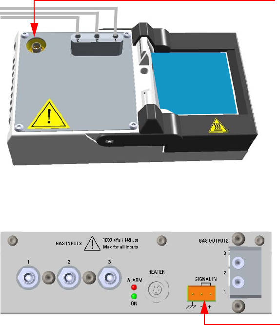
9 Adding Modules
Adding a Generic Detector Interface
Thermo Scientific TRACE 1300 and TRACE 1310 Hardware Manual 489
Figure 522. Heater Cable Connection
2. Connect the signals cable from the third-party detector to the connector marked Signal
IN on the GDI electrical interface. See Figure 523.
Figure 523. Signal Connection
Restarting the GC
To restart the GC
1. Open the gas supplies.
2. If external modules are present, plug the power cable to the AC Input connector of each
external module, and to the wall outlet.
3. Power on the GC.
a. Plug the power cable to the AC Input connector into the back of the GC and to the
wall outlet.
b. Flip up the power switch (breaker), located at the back of the instrument, to the
position I.
Performing the Third-party Detector Start-up and Optimization
Refer to the third-party detector manual.
Heater Cable From GDI
Electrical Interface
Third-party
Detector
Signal Cable from
Third-party Detector
9 Adding Modules
Adding a Generic Detector Interface
490 TRACE 1300 and TRACE 1310 Hardware Manual Thermo Scientific
Configuring and Setting GDI Detector
Configure and enable the GDI mechanical module through the user interface of your GC, or
through the CDS in use. Refer to the TRACE 1300 and TRACE 1310 User Guide.
See the following sequences:
•“Configure and set GDI Detector through the touch screen” on page 490
•“Configure and set GDI Detector through the chromatography data system (CDS)” on
page 490
Configure and set GDI Detector through the touch screen
1. In the main menu select the Configuration icon, the Configuration menu appears.
Select the Front/Back/Aux L/Aux R GDI detector icon to open the relevant sub-menu.
2. In the main menu select the Instrument control icon. The Instrument Control menu
appears. In the Instrument Control menu, select the Front/Back/Aux L/Aux R GDI
detector icon to open the relevant sub-menu.
3. Set the parameters values as required, then return to main menu.
Configure and set GDI Detector through the chromatography data system (CDS)
1. In the Configuration window select the Detectors tab.
2. Select the Detector Type: choose GDI.
3. Click GDI Config...; the GDI Configuration page is visualized.
4. Select the Gas Type used for the detector gases Gas 1, Gas 2, and Gas 3.
Choose one: Air, Hydrogen, Nitrogen, Helium, Argon, or Argon/Methane. Nitrogen is
the default gas.
5. Set the Full-scale flow of the restriction installed for each detector gas. Set a value in the
range 1-1000 mL/min. Default value is 50 mL/min.
6. Select the Max. detector temperature in the range from 0 °C to 450 °C.
The default temperature is 400 °C.
7. Select the ADC full-scale voltage. Choose one: 1 V, 5 V, or 10 V. The default value is 1V.
8. Open the GDI Method Page and set the required parameters.
Note For details refer to Chapter 2 in the TRACE 1300/REACE 1310 User Guide.
Note For details refer to Chapter 4 in the TRACE 1300/REACE 1310 User Guide.
Note If the heater is installed but the actual Temperature read back is 0 °C, check the
integrity of the heater and the temperature probe.
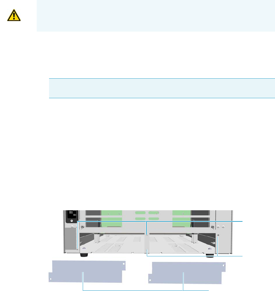
9 Adding Modules
Adding an Analog Output Interface
Thermo Scientific TRACE 1300 and TRACE 1310 Hardware Manual 491
Adding an Analog Output Interface
This section provides instructions for installing the Analog Output Interface (AOI) on your
TRACE 1300/1310 GC.
To install an analog output interface
1. Put the GC in standby condition.
2. Cool the oven, injectors and detectors to room temperature.
3. Power off the GC.
a. Push down the power switch (breaker), located at the back of the instrument, to the
position O.
b. Unplug the power cable from the AC Input connector into the back of the GC and
from the wall outlet.
4. If external modules are present, unplug the power cable from the AC Input connector of
each external module, and from the wall outlet.
1. Remove the cover of the external modules housing where installing the Analog Output
Interface module. See Figure 524.
Figure 524. Housing Cover Removal
a. Using a T20 Torxhead screwdriver, unscrew and remove the left or right housing
cover screws, then remove the cover from the housing.
2. Install the Analog Output Interface into the housing.
a. Loosen the two hexagonal screws under the module. See Figure 525.
WARNING This operation must be carried out by authorized and trained Thermo Fisher
Scientific Service Field Engineers.
Note By pressing the Maintenance button, the GC cool down is automatically
carried out.
Left/Right Housing Covers
Left Cover
Screws
Right Cover
Screws
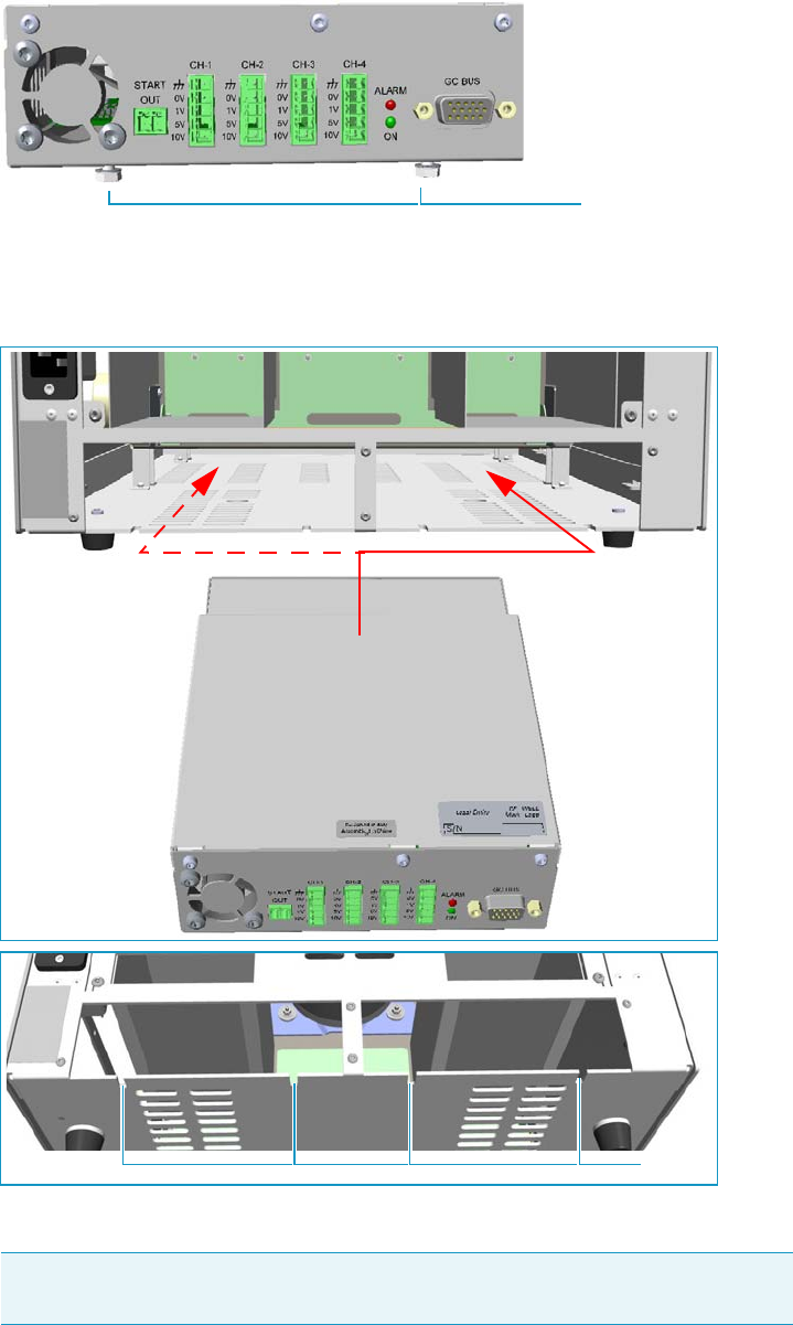
Figure 525. AOI Installation (1)
b. Carefully place the Analog Output Interface into the left or right housing until the
hexagonal screws couple with the slots on the floor of the GC. See Figure 526.
Figure 526. AOI Installation (2)
c. Finger-tighten the hexagonal screws slightly, or use a 10-mm wrench.
Note Always keep the hexagonal screws in their place. This allows you an easier
removal of the auxiliary module when necessary.
Hexagonal Screws
Slots
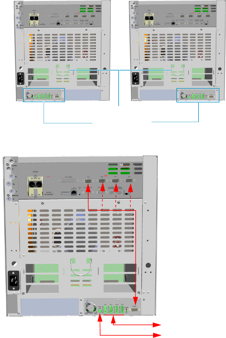
9 Adding Modules
Adding an Analog Output Interface
Thermo Scientific TRACE 1300 and TRACE 1310 Hardware Manual 493
The result of the installation is shown in Figure 508.
Figure 527. Analog Output Interface Module Installed into the GC
3. Connect the analog output interface module. See Figure 528.
Figure 528. AOI Connections
AOI Control Module
Cables Holder
Device
Data System Analog
Acquisition Box
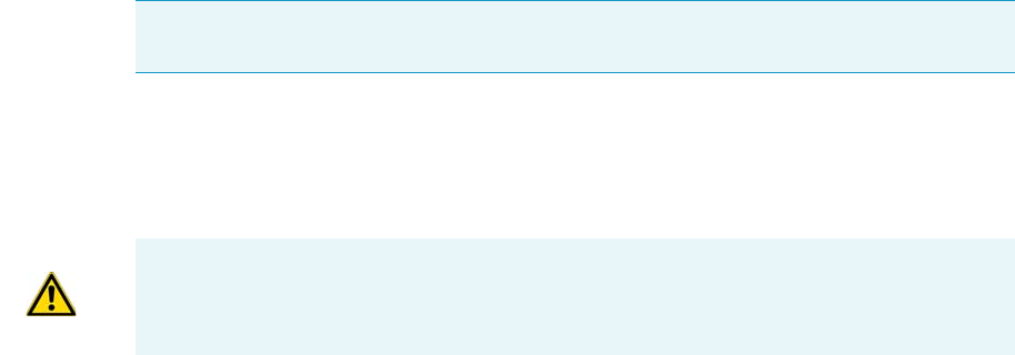
9 Adding Modules
Adding an Analog Output Interface
494 TRACE 1300 and TRACE 1310 Hardware Manual Thermo Scientific
a. Using the cable provided, connect the 15-pin female connector marked GC Bus on
the module to a Bus interface on the back of the GC.
b. Connect up to four channels CH-1, CH-2, CH-3, CH-4 to your device selecting the
full scale of each analogue signal from 1 V to 10 V according to your needs.
c. Connect the Start OUT contact closure to Start IN TTL line of the Data system
analog acquisition box.
4. Open the gas supplies.
5. If other external modules are present, plug the power cable to the AC Input connector of
each external module, and to the wall outlet.
6. Power on the GC.
a. Plug the power cable to the AC Input connector into the back of the GC and to the
wall outlet.
b. Flip up the power switch (breaker), located at the back of the instrument, to the
position I.
7. Configure and enable the system installed through the touch screen of your GC. Refer to
the TRACE 1300 and TRACE 1310 User Guide.
Tip To avoid the contact with the hot air from the vents, it is suggested to gather the
electrical cables into cables holder.
IMPORTANT Only connect the Ground wire to the GND contact of the AOI module or
of the your device. Do not connect the Ground cable to both the devices.

Thermo Scientific TRACE 1300 and TRACE 1310 Hardware Manual 495
10
Adding Systems
This chapter describes how to install any added system that is available for the TRACE
1300/TRACE 1310. See the TRACE 1300 and TRACE 1310 Spare Parts Guide for
information about ordering the equipment in this chapter.
Contents
•Adding the Oven Cryo System
•Adding the PTV and PTVBKF Cryo System
•Adding an Auxiliary Gas System
•Adding the Hydrogen Sensor
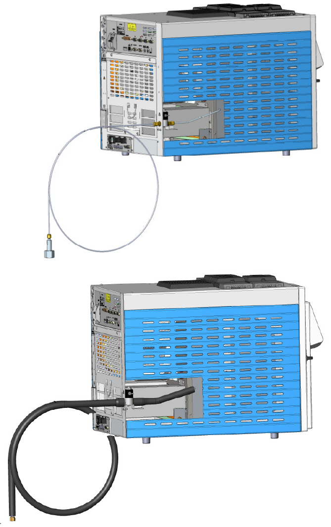
10 Adding Systems
Adding the Oven Cryo System
496 TRACE 1300 and TRACE 1310 Hardware Manual Thermo Scientific
Adding the Oven Cryo System
This section provides instructions for installing and configuring the Oven Cryo system on
your TRACE 1300/TRACE 1310 using the dedicated kit. See Figure 529.
Figure 529. Oven Cryo System for Carbon Dioxide and Liquid Nitrogen
Oven Cryo System for Carbon Dioxide
Oven Cryo System for Liquid Nitrogen
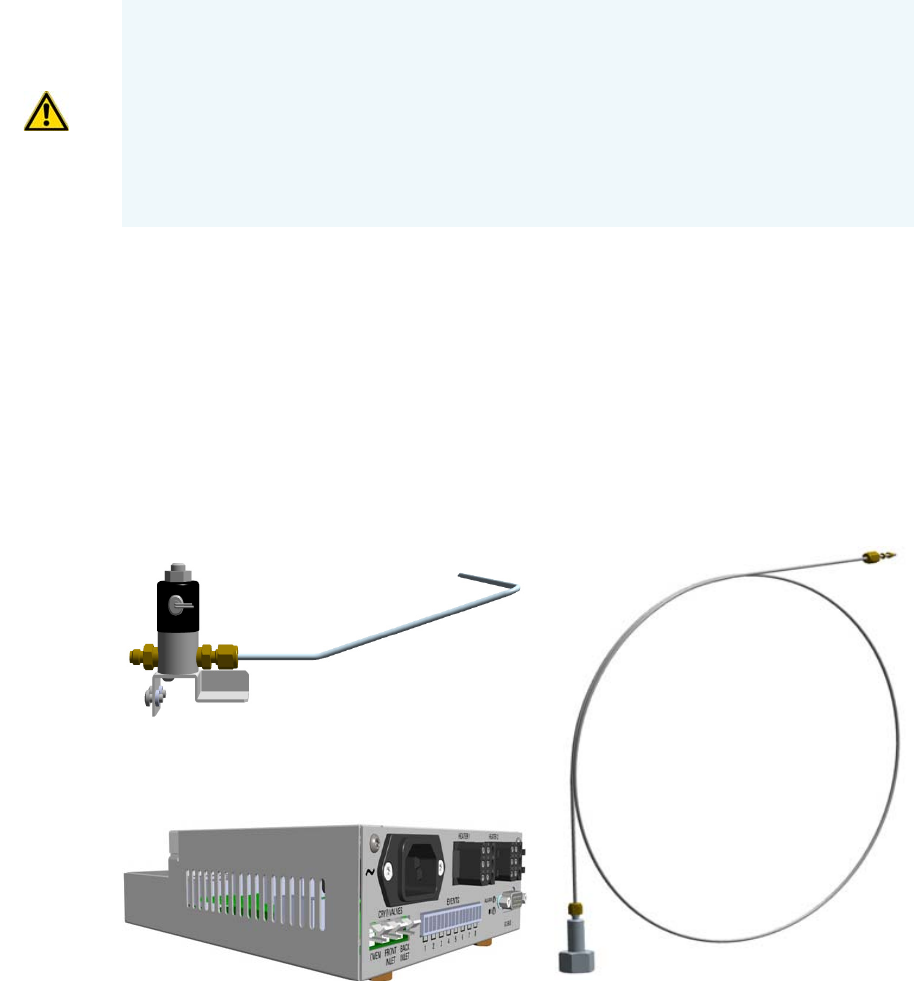
10 Adding Systems
Adding the Oven Cryo System
Thermo Scientific TRACE 1300 and TRACE 1310 Hardware Manual 497
Oven Cryo System Overview
Two Oven Cryo Upgrade Kits are available:
• Oven Cryo with Liquid Nitrogen (LN2) as coolant.
• Oven Cryo with Carbon Dioxide (CO2) as coolant.
Each upgrade kit contains all the material required to install the Oven Cryo system on your
GC. See Figure 530 and Figure 531.
Figure 530. Oven Cryo Kit for Carbon Dioxide
WARNING This operation must be carried out by authorized and trained Thermo Fisher
Scientific Service Field Engineers.
The cryo system requires the use of liquid nitrogen or carbon dioxide as coolant. Before
using liquid nitrogen or carbon dioxide, read the indications of hazards, and the
instructions reported in the Safety sheet supplied by the manufacturer with reference to
the CAS number (Chemical Abstract Service). See also “Liquid Nitrogen Safety
Precautions” on page xxix and “Carbon Dioxide Safety Precautions” on page xxx.
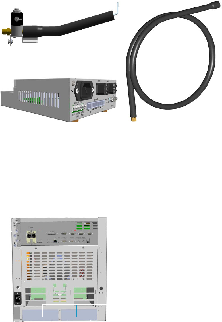
10 Adding Systems
Adding the Oven Cryo System
498 TRACE 1300 and TRACE 1310 Hardware Manual Thermo Scientific
Figure 531. Oven Cryo Kit for Liquid Nitrogen
Each upgrade kit contains all the material required to install the Oven Cryo system on your
GC:
• Dedicated solenoid valve mounted on a support bracket.
• Tube for the coolant into the oven.
• Coolant tank tube with connection fittings.
• Aux Temperature/Cryo Module that should be installed into a free external module
housing provided on the back of the GC. See Figure 532.
Figure 532. External Modules Housing
External Modules Housing
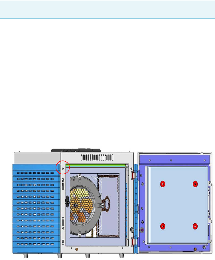
10 Adding Systems
Adding the Oven Cryo System
Thermo Scientific TRACE 1300 and TRACE 1310 Hardware Manual 499
Installing the Oven Cryo System
To install the Oven Cryo System
1. Put the GC in standby condition.
2. Cool the oven, injectors, and detectors to room temperature.
3. Close the gas supplies.
4. Power off the GC.
a. Push down the power switch (breaker), located at the back of the instrument, in the
position O.
b. Unplug the power cable from the AC Input connector into the back of the GC and
from the wall outlet.
5. If external modules are present, unplug the power cable from the AC Input connector of
each external module, and from the wall outlet.
6. Remove the Left Side panel.
a. Open the front door of the GC. Using a T20 Torxhead screwdriver, unscrew the left
side panel screw from the interior front panel. See Figure 533.
Figure 533. Left Side Panel Fixing Screw
b. Slide the panel towards the back of the instrument up to the stop.
c. Remove the panel by pulling it outwards. Be aware that the ground wire is attached
to the panel. See Figure 534.
Note By pressing the Maintenance button, the GC cool down is automatically
carried out.
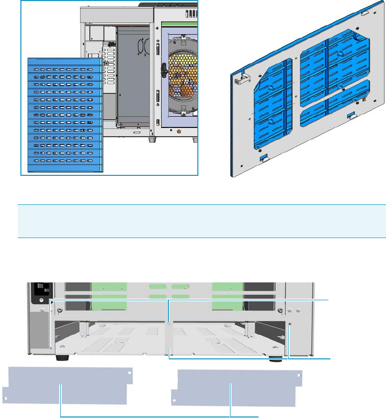
10 Adding Systems
Adding the Oven Cryo System
500 TRACE 1300 and TRACE 1310 Hardware Manual Thermo Scientific
Figure 534. Left Panel Removal
d. Unplug the ground wire from the panel.
7. Install the Aux Temperature/Cryo Module. See Figure 535
Figure 535. Housing Cover Removal
a. Remove the cover of the external modules housing where installing the module.
b. Using a T20 Torxhead screwdriver, unscrew and remove the left or right housing
cover screws.
c. Remove the covers from the housing.
8. Install the module into the housing
a. Loosen the two hexagonal screws under the module. See Figure 536.
Note Pay attention to the positioning of the ground wire plug, so it can be
reconnected in the same way it was removed.
Left/Right Housing Covers
Left Cover
Screws
Right Cover
Screws
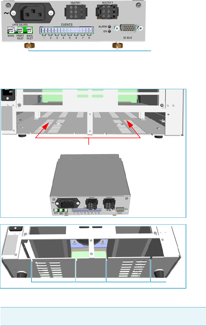
10 Adding Systems
Adding the Oven Cryo System
Thermo Scientific TRACE 1300 and TRACE 1310 Hardware Manual 501
Figure 536. Module Installation (1)
b. Place the module into the left or right housing until the hexagonal screws couple the
slots on the floor of the GC. See Figure 537.
Figure 537. Module Installation (2)
c. Finger-tighten the hexagonal screws slightly, or use a 10-mm wrench.
The result of the installation is shown in Figure 538.
Note Always keep the hexagonal screws in their place. This allows you an easier
removal of the auxiliary module when necessary.
Hexagonal Screws
Slots
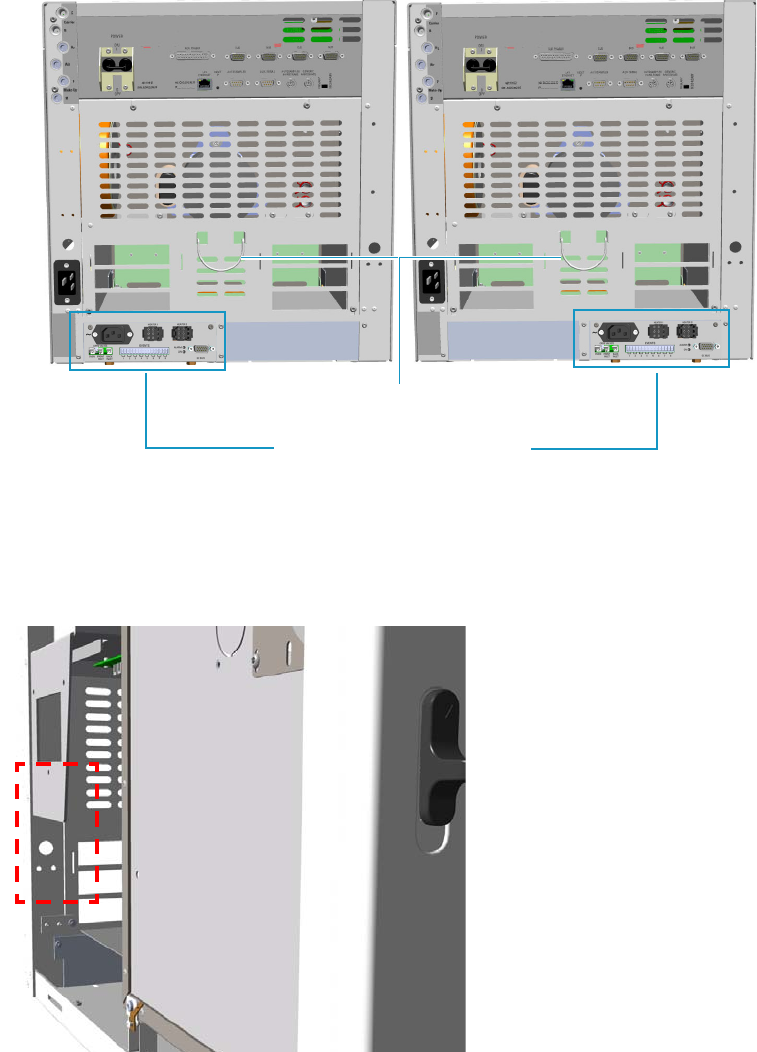
10 Adding Systems
Adding the Oven Cryo System
502 TRACE 1300 and TRACE 1310 Hardware Manual Thermo Scientific
Figure 538. Aux Temperature/Cryo Module Installed into the GC
9. Install the solenoid valve.
The solenoid valve must be installed in the proper seat on the back of the GC. See
Figure 539.
Figure 539. Solenoid Valve Assembly Seat
a. With care, take the solenoid valve assembly and remove the two screws from the
brackets using a T15 Torxhead screwdriver. These screws are used to fix the bracket
on the GC.
If not already done, connect the coolant tube to the solenoid valve using the proper
nut and ferrule. Use a 7/16-in. wrench for tightening the fittings. See Figure 540.
Aux Temperature/Cryo Module
Cables Holder
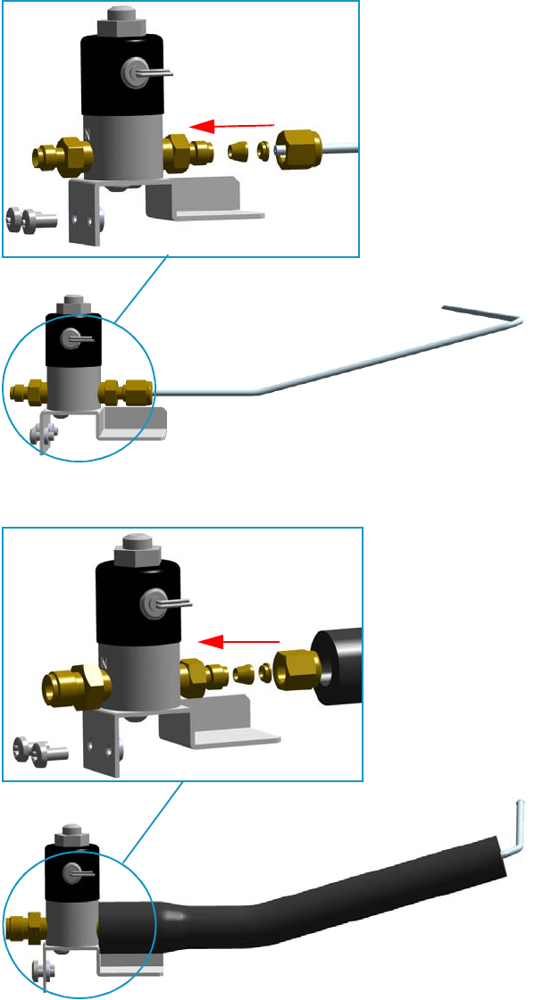
10 Adding Systems
Adding the Oven Cryo System
Thermo Scientific TRACE 1300 and TRACE 1310 Hardware Manual 503
Figure 540. Solenoid Valve Assembly
b. Guide the solenoid valve assembly into its seat on the back of the GC, and the tube
for the coolant into the oven through the holes provided. See Figure 541 and
Figure 542.
Solenoid Valve Assemble
for Carbon Dioxide
Solenoid Valve Assemble
for Liquid Nitrogen
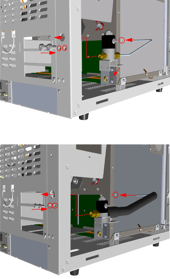
10 Adding Systems
Adding the Oven Cryo System
504 TRACE 1300 and TRACE 1310 Hardware Manual Thermo Scientific
Figure 541. Installation of the Solenoid Valve Assembly for Carbon Dioxide
Figure 542. Installation of Solenoid Valve Assembly for Liquid Nitrogen
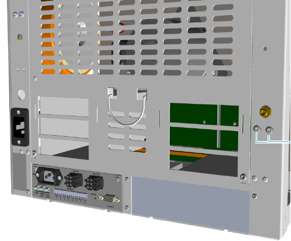
10 Adding Systems
Adding the Oven Cryo System
Thermo Scientific TRACE 1300 and TRACE 1310 Hardware Manual 505
c. Fix the solenoid valve assembly to the back of the GC using the two fixing screws
previously removed. See Figure 543.
Figure 543. Solenoid Valve Assemble Fixing
10. Connect the cryogenic tank tube to the solenoid valve assembly.
a. Connect the proper end of the cryo supply tube to the 1/8-in. NPT connection of
the solenoid valve using the proper nut and ferrule. Use a 7/16-in. wrench for
tightening the fittings. See Figure 544 and Figure 545.
Solenoid Valve
Assembly
Fixing Screws
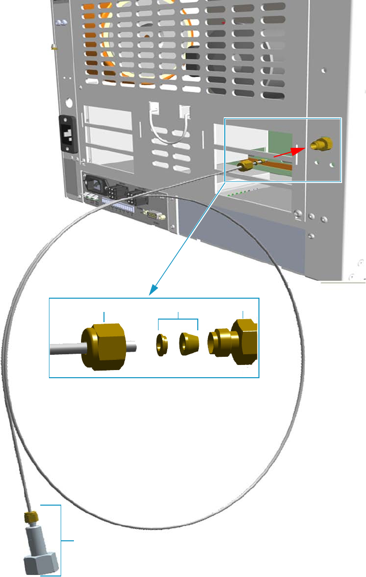
10 Adding Systems
Adding the Oven Cryo System
506 TRACE 1300 and TRACE 1310 Hardware Manual Thermo Scientific
Figure 544. Oven Cryo Supply Tube for Carbon Dioxide Connection
Fittings for the connection to the Liquid Carbon Dioxide Tank
Ferrule 1/8-in. NPT
Nut
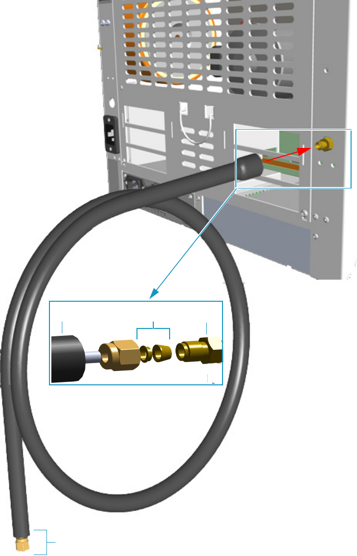
10 Adding Systems
Adding the Oven Cryo System
Thermo Scientific TRACE 1300 and TRACE 1310 Hardware Manual 507
Figure 545. Oven Cryo Supply Tube for Liquid Nitrogen Connection
b. Connect the other end to the coolant container using the appropriate nuts and
ferrules.
Ferrule 1/8-in. NPT
Nut
Fittings for the connection to the Liquid Nitrogen Tank
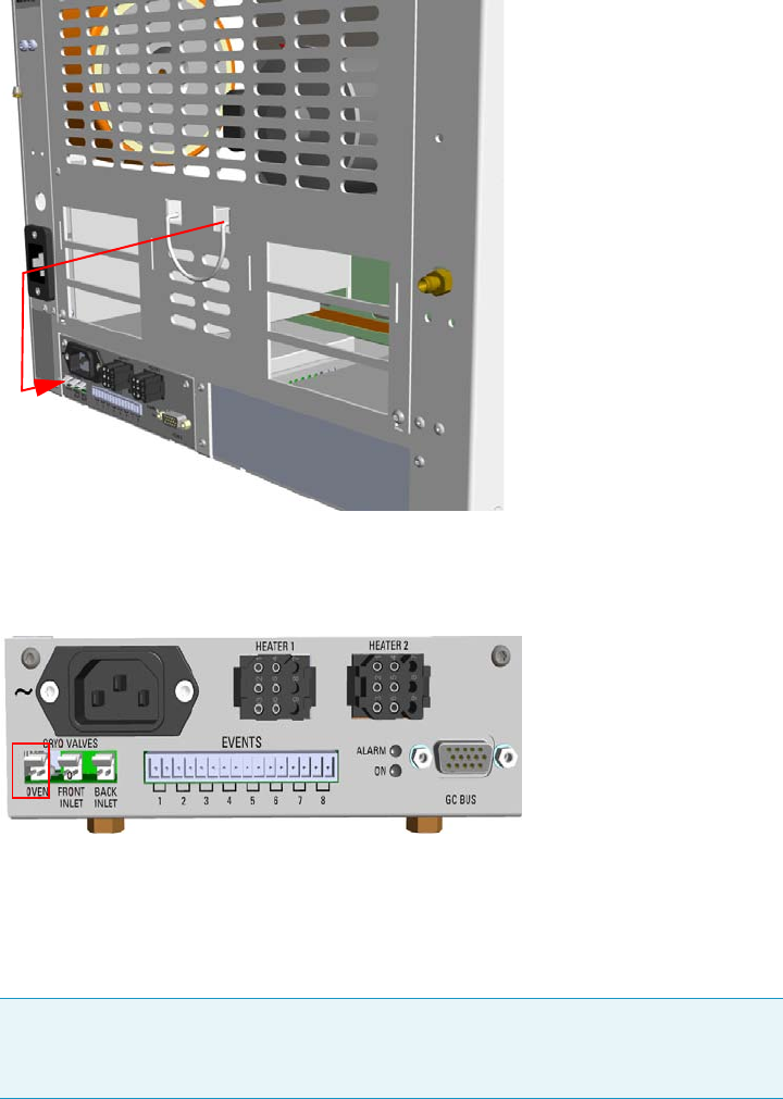
10 Adding Systems
Adding the Oven Cryo System
508 TRACE 1300 and TRACE 1310 Hardware Manual Thermo Scientific
11. Connect the cryo valve to the Aux Temperature/Cryo Module.
a. Connect the cable provided to the solenoid valve connector, and guide the cable
through the slot in the centre of the back panel. See Figure 546.
Figure 546. Solenoid Valve Cable Connection
b. Connect the cryo solenoid valve to the 2-pin connector marked Cryo Valves - Oven
using the cable provided. See Figure 547.
Figure 547. Cryo Valves: Oven
c. Using the cable provided, connect the 15-pin female connector marked GC Bus on
the module to a Bus interface on the back of the GC.
d. Plug the power cable to the AC Input connector on the front of the module and to
the wall outlet. The LED marked On lights after the GC is powered on.
e. Using the cable provided, connect the 15-pin female connector marked GC Bus on
the module to a Bus interface on the back of the GC.
Note For further details regarding the installation of the Aux Temperature/Cryo
module, see the section “Adding an Aux Temperature/Cryo Module” on
page 443.
10 Adding Systems
Adding the Oven Cryo System
Thermo Scientific TRACE 1300 and TRACE 1310 Hardware Manual 509
12. Mount the left side panel proceeding in the reverse order in which the left side panel was
removed.
13. Open the gas supplies.
14. If other external modules are present, plug the power cable to the AC Input connector of
each external module, and to the wall outlet.
15. Power on the GC.
a. Plug the power cable to the AC Input connector into the back of the GC and to the
wall outlet.
b. Flip up the power switch (breaker), located at the back of the instrument, to the
position I.
16. Configure and enable the cryogenic system through the user interface of your GC, or
through the CDS in use. Refer to the TRACE 1300 and TRACE 1310 User Guide.
a. Configuration and enabling through the touch screen.
i. In the main menu select the Configuration icon. The Configuration menu
appears.
ii. In the Configuration menu, select the Oven icon to open the relevant submenu.
iii. Set the Cryogenic parameters.
–Cryogenic Type — Enable or disable the cryogenic system when it is
installed and configured with Carbon Dioxide or Liquid Nitrogen as a
coolant. Select between LN2, CO2, or none.
–Cryo timeout — Enter the time at which the cryo system will be disabled.
Enter a value from 0–30 min.
–Cryo Threshold — Specify the temperature at which the cryo system begins
to supply the coolant. Enter a value from 40-200 °C.
iv. Return to main menu.
b. Configuration and enabling through the Chromatography Data System.
i. In the Configuration window select the Auxiliary tab.
ii. Select the Auxiliary control module check box to enable the setting for the
auxiliary control of the module option installed on your GC.
iii. Select the Oven cryogenics check box.
iv. Select the Cryo type used by your cryogenic option. Choose one: Liquid
Nitrogen or Carbon Dioxide.
v. Open the Oven page. Select the Cryogenics enable check box to enable the
cryogenic system.
vi. In Cryo threshold text box specify the temperature at which the cryo system
begins to supply the coolant. Enter a value from 40-200 °C.
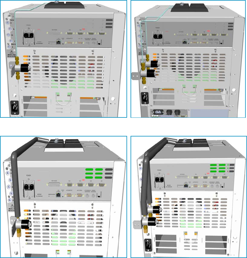
10 Adding Systems
Adding the PTV and PTVBKF Cryo System
510 TRACE 1300 and TRACE 1310 Hardware Manual Thermo Scientific
17. Set the normal detector, injector, and GC working conditions.
Adding the PTV and PTVBKF Cryo System
This section provides instructions for installing and configuring the PTV and PTVBKF Cryo
system on your TRACE 1300/TRACE 1310 using the dedicated kit. See Figure 548 and
Figure 549.
Figure 548. PTV and PTVBKF Single and Double Cryo System for Carbon Dioxide
Figure 549. PTV and PTVBKF Single and Double Cryo System for Liquid Nitrogen
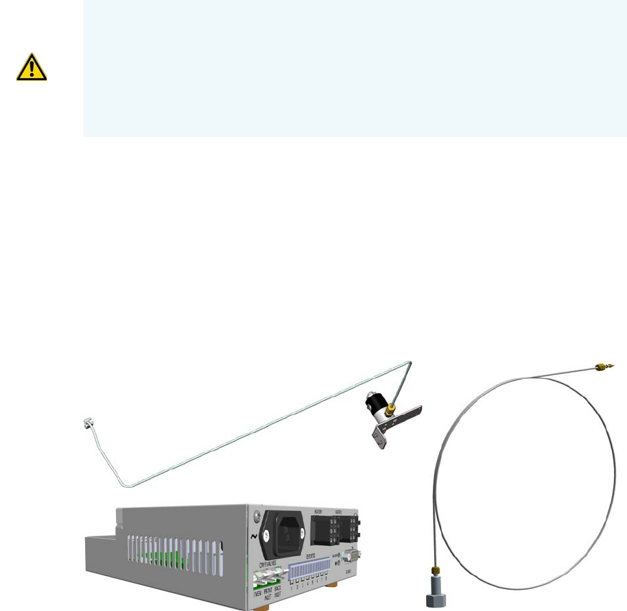
10 Adding Systems
Adding the PTV and PTVBKF Cryo System
Thermo Scientific TRACE 1300 and TRACE 1310 Hardware Manual 511
PTV/PTVBKF Cryo System Overview
Two PTV/PTVBKF Cryo Upgrade Kits are available:
• PTV/PTVBKF Cryo with Liquid Nitrogen (LN2) as coolant.
• PTV/PTVBKF Cryo with Carbon Dioxide (CO2) as coolant.
Each upgrade kit contains all the material required to install the PTV/PTVBKF Cryo system
on your GC. See Figure 550 and Figure 551.
Figure 550. PTV/PTVBKF Cryo Kit for Carbon Dioxide
WARNING This operation must be carried out by authorized and trained Thermo Fisher
Scientific Service Field Engineers.
The cryo system requires the use of liquid nitrogen or carbon dioxide as coolant. Before
using liquid nitrogen or carbon dioxide, read the hazard indications and the instructions
reported in the Safety sheet supplied by the manufacturer with reference to the CAS
number (Chemical Abstract Service). See also “Liquid Nitrogen Safety Precautions” on
page xxix and “Carbon Dioxide Safety Precautions” on page xxx.
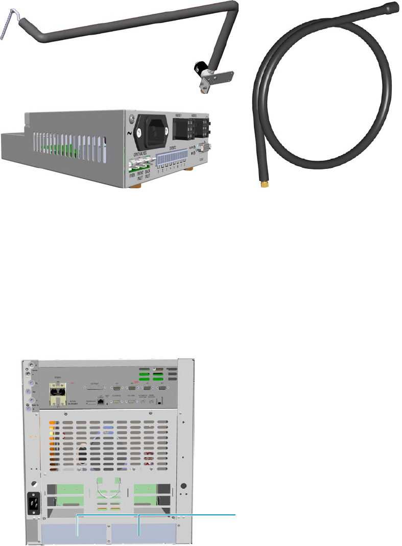
10 Adding Systems
Adding the PTV and PTVBKF Cryo System
512 TRACE 1300 and TRACE 1310 Hardware Manual Thermo Scientific
Figure 551. PTV/PTVBKF Cryo Kit for Liquid Nitrogen
Each upgrade kit contains all the material required to install the PTV/PTVBKF Cryo system
on your GC:
• Dedicated solenoid valve mounted on a support bracket.
• Tube for the coolant into the PTV/PTVBKF injector module.
• Coolant tank tube with connection fittings.
• Aux Temperature/Cryo Module that should be installed into a free external module
housing provided on the back of the GC. See Figure 552.
Figure 552. External Modules Housing
External Modules Housing
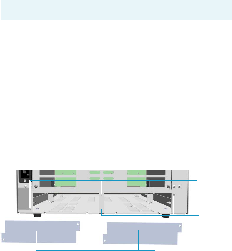
10 Adding Systems
Adding the PTV and PTVBKF Cryo System
Thermo Scientific TRACE 1300 and TRACE 1310 Hardware Manual 513
Installing the PTV/PTVBKF Cryo System
To install the PTV/PTVBKF Cryo System
1. Put the GC in standby condition.
2. Cool the oven, injectors and detectors to room temperature.
3. Close the gas supplies.
4. Power off the GC.
a. Push down the power switch (breaker), located at the back of the instrument, to the
position O.
b. Unplug the power cable from the AC Input connector into the back of the GC and
from the wall outlet.
5. If external modules are present, unplug the power cable from the AC Input connector of
each external module, and from the wall outlet.
6. Put the autosampler away if present.
7. Install the Aux Temperature/Cryo Module.
a. Remove the cover of the external modules housing where installing the module. See
Figure 553.
Figure 553. Housing Cover Removal
b. Using a T20 Torxhead screwdriver, unscrew and remove the left or right housing
cover screws.
c. Move and drive the cover out from the housing.
8. Install the module into the housing
a. Loosen the two hexagonal screws under the module. See Figure 554.
Note By pressing the Maintenance button, the GC cool down is automatically
carried out.
Left/Right Housing Covers
Left Cover
Screws
Right Cover
Screws
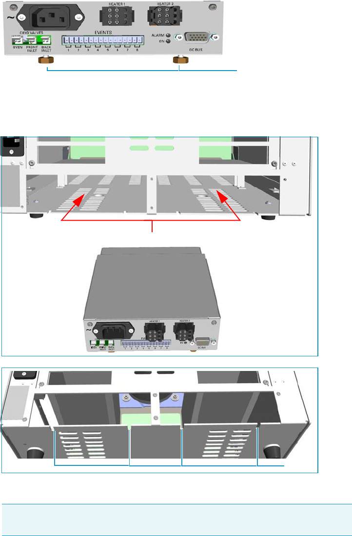
10 Adding Systems
Adding the PTV and PTVBKF Cryo System
514 TRACE 1300 and TRACE 1310 Hardware Manual Thermo Scientific
Figure 554. Module Installation (1)
b. Place the module into the left or right housing until the hexagonal screws couple with
the slots on the floor of the GC. See Figure 555.
Figure 555. Module Installation (2)
c. Finger-tighten the hexagonal screws slightly or use a 10-mm wrench.
The result of the installation is shown in Figure 556.
Note Always keep the hexagonal screws in their place. This allows you an easier
removal of the auxiliary module when necessary.
Hexagonal Screws
Slots
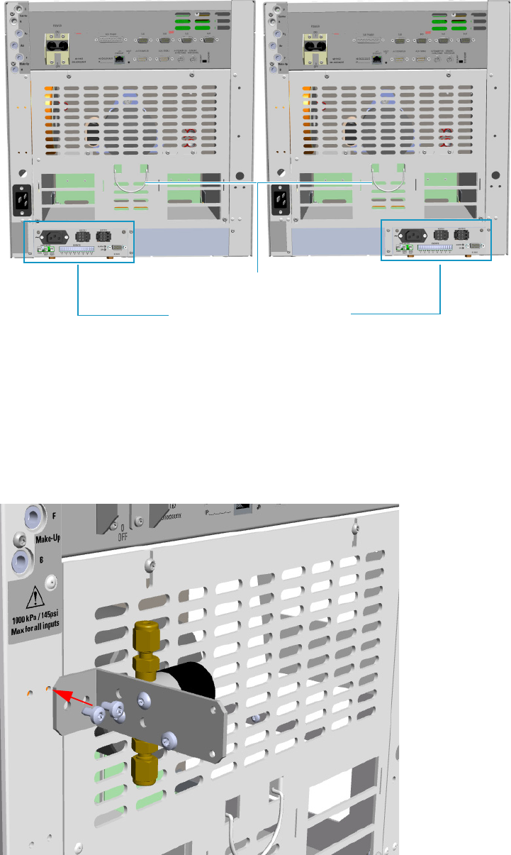
10 Adding Systems
Adding the PTV and PTVBKF Cryo System
Thermo Scientific TRACE 1300 and TRACE 1310 Hardware Manual 515
Figure 556. Aux Temperature/Cryo Module Installed into the GC
9. Install the proper solenoid valve assembly.
The solenoid valve must be installed in the proper seat on the back of the GC.
• In case of a single cryo kit, mount the solenoid assembly as shown in Figure 557.
• In case of double cryo kit, mount the two solenoid valves assembly as shown in
Figure 558.
Figure 557. Single Solenoid Valve Assemble Installation
Aux Temperature/Cryo Module
Cables Holder
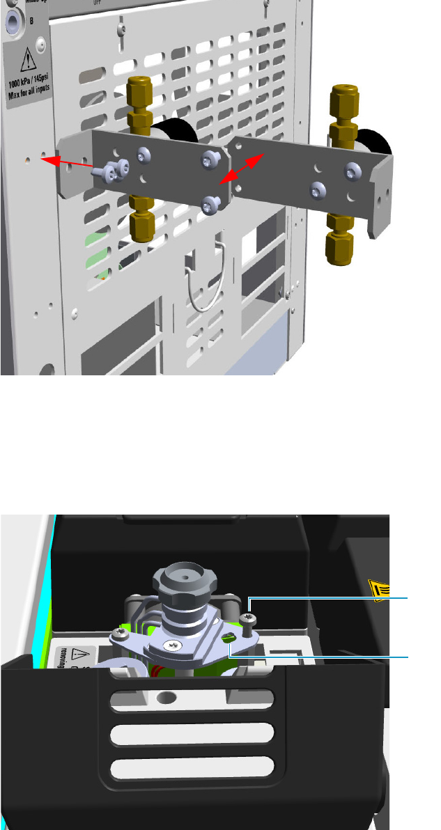
10 Adding Systems
Adding the PTV and PTVBKF Cryo System
516 TRACE 1300 and TRACE 1310 Hardware Manual Thermo Scientific
Figure 558. Double Solenoid Valve Assemble Installation
10. Insert the coolant tube into the PTV/PTVBKF injector module.
a. Open the module flap cover.
b. On the top of the injector, undo and remove the screw closed to the coolant tube
insertion hole. See Figure 559.
Figure 559. Coolant Tube Insertion Hole
Insertion Hole
Screw
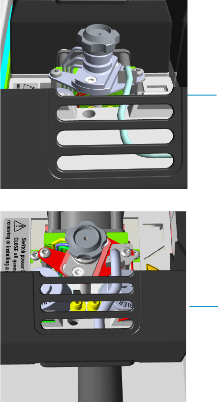
10 Adding Systems
Adding the PTV and PTVBKF Cryo System
Thermo Scientific TRACE 1300 and TRACE 1310 Hardware Manual 517
c. Insert the coolant tube into the insertion hole, and fix it using the screw previously
removed. See Figure 560.
Figure 560. Installation of the Coolant Tubes for Carbon Dioxide and Liquid Nitrogen
d. Guide the coolant tube along the GC top cover up to reach the solenoid valve
assemble on the back of the GC. Bend the tube if necessary.
11. Connect the coolant tube to the solenoid valve assemble.
a. Connect the coolant tube to the solenoid valve assembly using the proper nut and
ferrule. Use a 7/16-in. wrench for tightening the fittings. See Figure 561.
Coolant Tube for Carbon Dioxide
Coolant Tube for Liquid Nitrogen
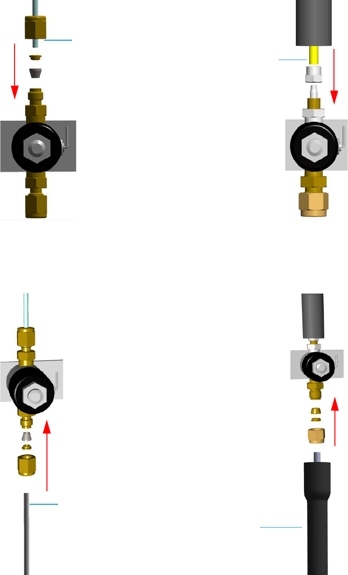
10 Adding Systems
Adding the PTV and PTVBKF Cryo System
518 TRACE 1300 and TRACE 1310 Hardware Manual Thermo Scientific
Figure 561. Coolant Tube Connection to the Solenoid Valve
b. Connect the proper end of the cryo supply tube to the solenoid valve using the
proper nut and ferrule. Use a 7/16-in. wrench for tightening the fittings.
See Figure 562.
Figure 562. Cryo Supply Tube Connection to the Solenoid Valve
Coolant Tube for Carbon Dioxide
Coolant Tube for Liquid Nitrogen
Cryo Supply Tube for Carbon Dioxide
Cryo Supply Tube for Liquid Nitrogen
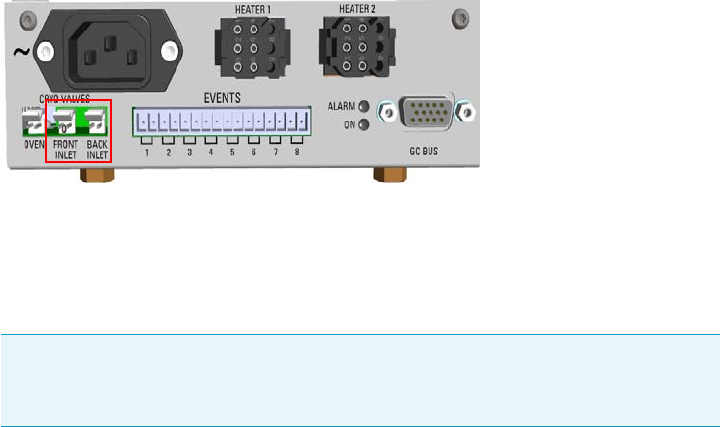
10 Adding Systems
Adding the PTV and PTVBKF Cryo System
Thermo Scientific TRACE 1300 and TRACE 1310 Hardware Manual 519
c. Connect the other end of the cryo supply tube to the coolant container using the
appropriate nuts and ferrules. Use a 7/16-in. wrench for tightening the fittings.
12. Connect the cryo valve to the Aux Temperature/Cryo Module.
a. Connect the cryo solenoid valve to the 2-pin connector marked Cryo Valves - Front
Inlet or Cryo Valves-Back Inlet using the cable provided. See Figure 563.
Figure 563. Cryo Valves: Oven
b. Using the cable provided, connect the 15-pin female connector marked GC Bus on
the module to a Bus interface on the back of the GC.
c. Plug the power cable to the AC Input connector on the front of the module and to
the wall outlet. The LED marked On lights after the GC is powered on.
d. Using the cable provided, connect the 15-pin female connector marked GC Bus on
the module to a Bus interface on the back of the GC.
13. Mount the left side panel proceeding in reverse order which the left side panel was
removed.
14. Open the gas supplies.
15. If other external modules are present, plug the power cable to the AC Input connector of
each external module, and to the wall outlet.
16. Power on the GC.
a. Plug the power cable to the AC Input connector on the back of the GC, and to the
wall outlet.
b. Flip up the power switch (breaker), located at the back of the instrument, to the
position I.
17. Configure and enable the cryogenic system through the user interface of your GC, or
through the CDS in use. Refer to the TRACE 1300 and TRACE 1310 User Guide.
a. Configuration and enabling through the touch screen.
i. In the main menu select the Configuration icon, the Configuration menu
appears.
Note For further details regarding the installation of the Aux Temperature/Cryo
module, see the section “Adding an Aux Temperature/Cryo Module” on
page 443.
10 Adding Systems
Adding the PTV and PTVBKF Cryo System
520 TRACE 1300 and TRACE 1310 Hardware Manual Thermo Scientific
ii. In the Configuration menu, select the Front/Back PTV or PTVBKF icon to
open the relevant submenu.
iii. Set the Cryogenic parameters.
–Cryogenic Type — Enable or disable the cryogenic system when it is
installed and configured with Carbon Dioxide or Liquid Nitrogen as a
coolant. Select between LN2, CO2, none.
–Cryo timeout — Enter the time at which the cryo system will be disabled.
Enter a value from 0–30 min.
–Cryo Threshold — Specify the temperature at which the cryo system begins
to supply the coolant. Enter a value from 40-200 °C.
–Cryo Cool at — Specify the temperature at which the cryogenic system
begins to supply the coolant. Enter a value from 40-200 °C.
iv. Return to main menu.
b. Configuration and enabling through the Chromatography Data System.
i. In the Configuration window select the Auxiliary tab.
ii. Select the Auxiliary control module check box to enable the setting for the
auxiliary control of module and option installed on your GC.
iii. Select the Front inlet cryogenics or/and Back inlet cryogenics check box.
iv. Select the Cryo type used by your cryogenic option. Choose one: Liquid
Nitrogen or Carbon Dioxide.
v. Open the PTV/PTVBKF page. Select the Cryogenics enable check box to
enable the cryogenic system.
vi. In Cool during combo box, select when you want the cooling to be done.
Choose between Prep-Run or Post -Run.
vii. In Cryo threshold text box specify the temperature at which the cryo system
begins to supply the coolant. Enter a value in the range 40-200 °C.
viii. In Cryo timeout text box enter the time at which the cryo system will be
disabled. Enter a value in the range 0–30 min.
18. If present, move the autosampler towards the module to restore the original alignment.
19. Set the normal detector, injector, and GC working conditions.
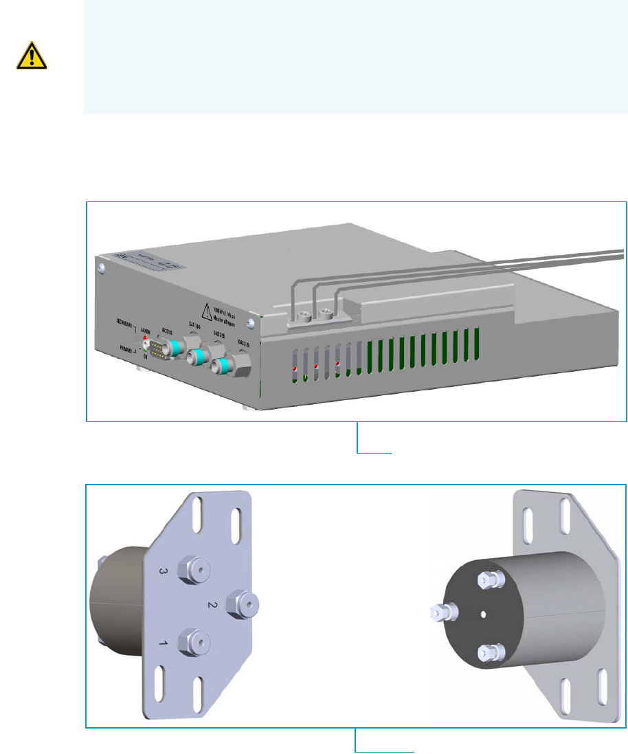
10 Adding Systems
Adding an Auxiliary Gas System
Thermo Scientific TRACE 1300 and TRACE 1310 Hardware Manual 521
Adding an Auxiliary Gas System
This section provides instructions for updating your TRACE 1300/TRACE 1310 with the
Auxiliary Gas System.
The auxiliary gas system comprises the auxiliary gas module and the auxiliary gas interface.
See Figure 564.
Figure 564. Auxiliary Gas Module and Interface
WARNING This operation must be carried out by authorized and trained Thermo Fisher
Scientific Service Field Engineers.
The Auxiliary Gas Module is shipped with a protecting plate screwed on the manifold.
Remove this plate before installing the module. See Installing and Connecting the
Auxiliary Gas Module on page 534 for details.
Auxiliary Gas Module with Gas Tubing Block
Auxiliary Gas Interface
Back View
Front View
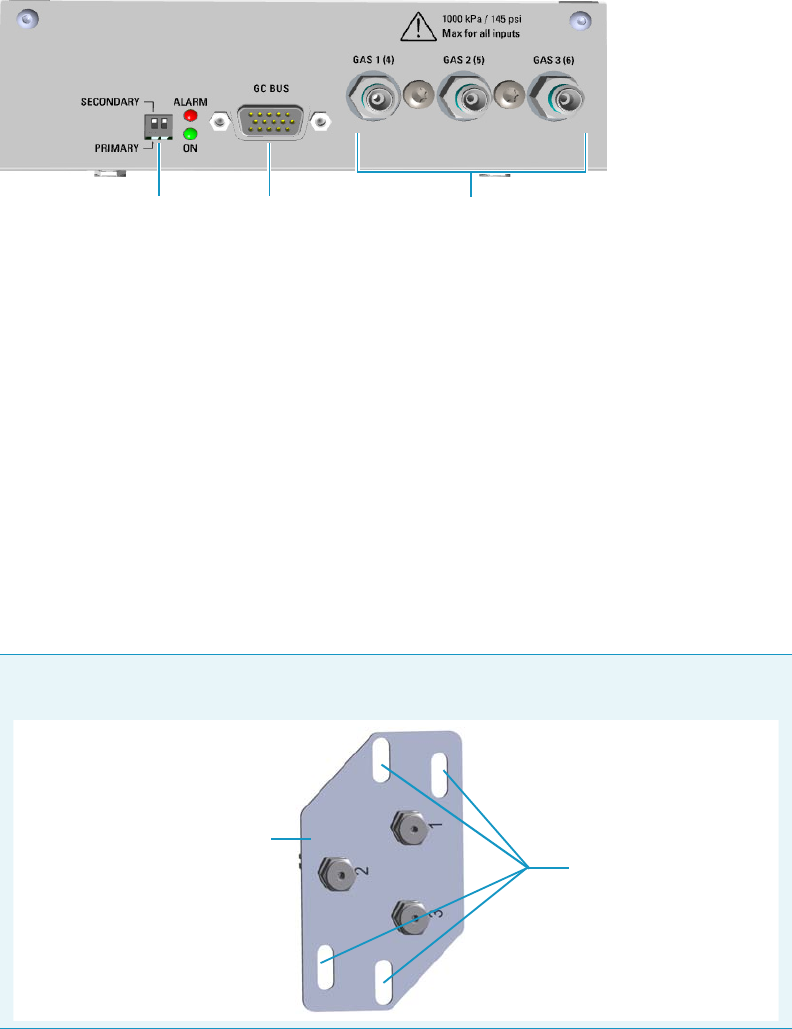
10 Adding Systems
Adding an Auxiliary Gas System
522 TRACE 1300 and TRACE 1310 Hardware Manual Thermo Scientific
Auxiliary Gas Module Overview
The auxiliary gas module includes the following connections. See Figure 565
Figure 565. Auxiliary Gas Module Connections
1. Switch marked Primary/Secondary used to set two Auxiliary Gas modules
simultaneously present, one as Primary, and the other as Secondary. The primary module
controls the aux pressures from 1 to 3, while the secondary module controls the aux
pressures from 4 to 6. See also the point 3.
2. 15-pin female connectors marked Bus for the communication with the GC.
3. Three inlets ports marked Gas 1 (4), Gas 2 (5), and Gas 3 (6) for the connection up to
three auxiliary carrier gases. If two modules are present, up to six auxiliary carrier gases
can be connected. See also the point 1.
Auxiliary Gas Interface Overview
The auxiliary gas interface is installed and fixed on the left or right wall of the GC oven,
through the ducts provided, for the coupling with a mass spectrometer. See Figure 566.
123
Note The Auxiliary Gas Interface is fixed on the exterior wall of the GC oven through the
slots provided on the collar duct. Align the slots to the fixing holes accordingly.
Collar Duct
Slots
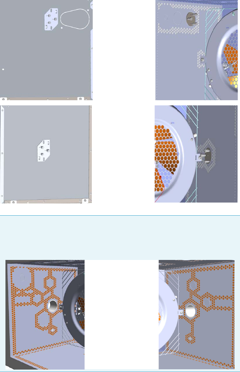
10 Adding Systems
Adding an Auxiliary Gas System
Thermo Scientific TRACE 1300 and TRACE 1310 Hardware Manual 523
Figure 566. Auxiliary Gas Interface Installed in the Oven
Note If your GC is equipped with the oven for the coupling with a Thermo Scientific
high resolution mass spectrometers (HRMS), the Auxiliary Gas Interface is installed
through the ducts provided on the left and right walls of the oven as well as the GC
equipped with the standard oven. See “Installing the Auxiliary Gas Interface on the Oven
for HRMS” on page 532.
Auxiliary Gas Interface
installed on the Left
Auxiliary Gas Interface
installed on the Right
Left Wall Right Wall
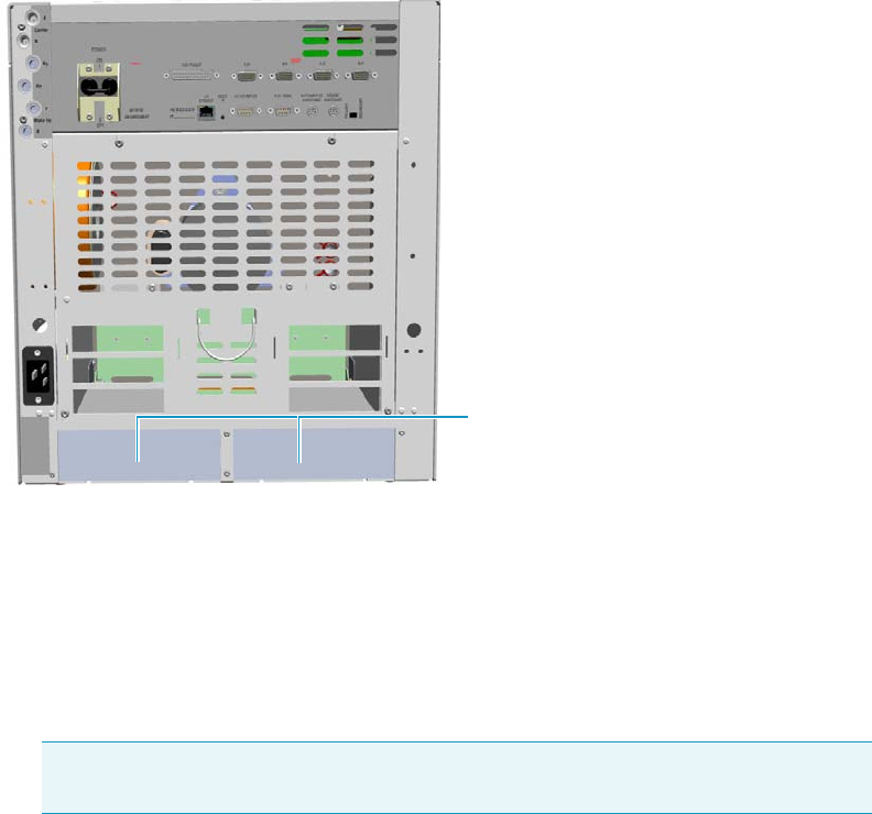
10 Adding Systems
Adding an Auxiliary Gas System
524 TRACE 1300 and TRACE 1310 Hardware Manual Thermo Scientific
The module should be installed into a free external module housing provided on the back of
the GC. See Figure 567.
Figure 567. External Modules Housing
Preliminary Operations
Before starting, the following preliminary operation must be carried out.
1. Put the GC in standby condition.
2. Cool the oven, injectors, and detectors to room temperature.
3. Close the gas supplies.
4. Power off the GC.
a. Push down the power switch (breaker), located at the back of the instrument, to the
position O.
b. Unplug the power cable from the AC Input connector on the back of the GC, and
from the wall outlet.
5. If external modules are present, unplug the power cable from the AC Input connector of
each external module, and from the wall outlet.
External Modules Housing
Note By pressing the Maintenance button, the GC cool down is automatically
carried out.
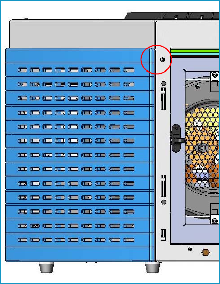
10 Adding Systems
Adding an Auxiliary Gas System
Thermo Scientific TRACE 1300 and TRACE 1310 Hardware Manual 525
Getting Started
To install and connect the Auxiliary Gas Interface and the Auxiliary Gas Module, see the
following sections:
•“Installing the Auxiliary Gas Interface on the Left Wall of the Oven” on page 525
•“Installing the Auxiliary Gas Interface on the Right Wall of the Oven” on page 528
•“Installing the Auxiliary Gas Interface on the Oven for HRMS” on page 532
•“Installing and Connecting the Auxiliary Gas Module” on page 534
Installing the Auxiliary Gas Interface on the Left Wall of the Oven
To install the auxiliary gas interface on the left wall of the oven
1. Make sure that the preliminary operations have been carried out. See “Preliminary
Operations” on page 524.
2. Remove the left side panel.
a. Open the front door of the GC.
b. Using a T20 Torxhead screwdriver, unscrew the left side panel screw from the interior
front panel. See Figure 568. Save the screw because it will be reused later.
Figure 568. Left Side Panel Fixing Screw

10 Adding Systems
Adding an Auxiliary Gas System
526 TRACE 1300 and TRACE 1310 Hardware Manual Thermo Scientific
c. Slide the panel towards the back of the instrument up to the stop.
d. Remove the panel pulling it outward being aware that the ground wire is attached to
the panel. See Figure 569.
e. Unplug the ground wire from the panel.
Figure 569. Left Side Panel Removal
3. Prepare the duct for the installation of the auxiliary gas interface.
a. Remove the partial cut shaped plate from the exterior wall of the oven box for
accessing the insulating material. See Figure 570.
Figure 570. Perform the Duct for the Auxiliary Gas Interface (1)
Partial Cut Shaped Plate
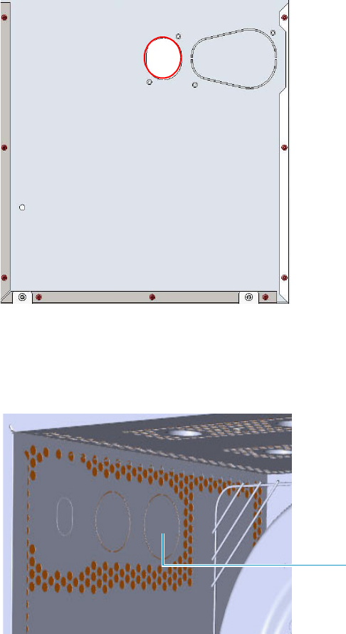
10 Adding Systems
Adding an Auxiliary Gas System
Thermo Scientific TRACE 1300 and TRACE 1310 Hardware Manual 527
b. Using a knife or similar tool, gently cut the insulating material following the border.
See Figure 571.
Figure 571. Perform the Duct for the Auxiliary Gas Interface (2)
c. Save the removed insulating material in a safe place because it can be reused.
d. On the left side wall in the interior of the oven, remove the partial cut plate from the
corresponding duct. See Figure 572.
Figure 572. Perform the Duct for the Auxiliary Gas Interface (3)
e. Insert the auxiliary gas interface into the duct. Fix the interface on the exterior wall of
the oven box using the fixing screws provided. See Figure 573.
Partial Cut Plate
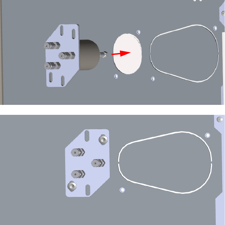
10 Adding Systems
Adding an Auxiliary Gas System
528 TRACE 1300 and TRACE 1310 Hardware Manual Thermo Scientific
Figure 573. Perform the Duct for the Auxiliary Gas Interface (4)
4. Jump to the section “Installing and Connecting the Auxiliary Gas Module” on page 534.
Installing the Auxiliary Gas Interface on the Right Wall of the Oven
To install the auxiliary gas interface on the right wall of the oven
1. Make sure that the preliminary operations have been carried out. See “Preliminary
Operations” on page 524.
2. Remove the right side panel.
a. Open the front door of the GC.
b. Using a T20 Torxhead screwdriver, unscrew the left side panel screw from the interior
front panel. See Figure 574. Save the screw because it will be reused later.
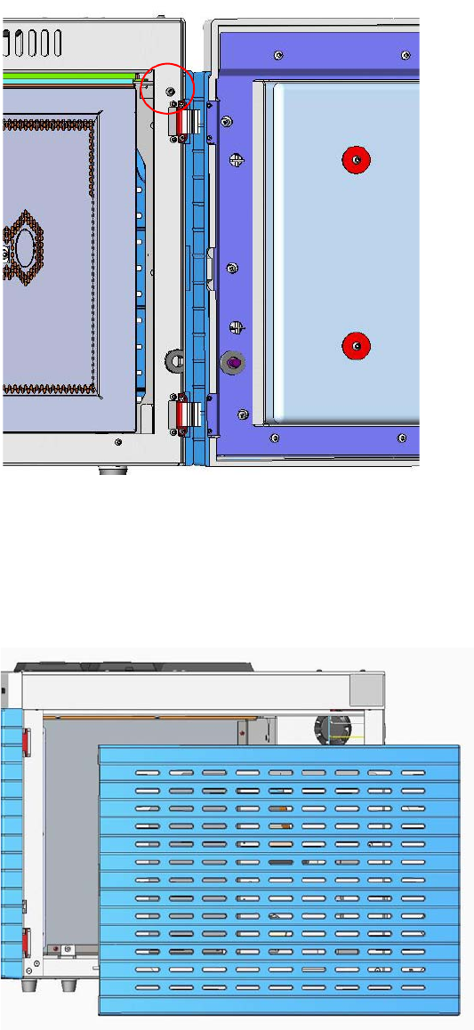
10 Adding Systems
Adding an Auxiliary Gas System
Thermo Scientific TRACE 1300 and TRACE 1310 Hardware Manual 529
Figure 574. Right Side Panel Fixing Screw
c. Slide the panel towards the back of the instrument up to the stop.
d. Remove the panel pulling it outward. Be aware that the ground wire is attached to the
panel. See Figure 575.
e. Unplug the ground wire from the panel.
Figure 575. Right Side Panel Removal
3. Prepare the duct for the installation of the auxiliary gas interface.
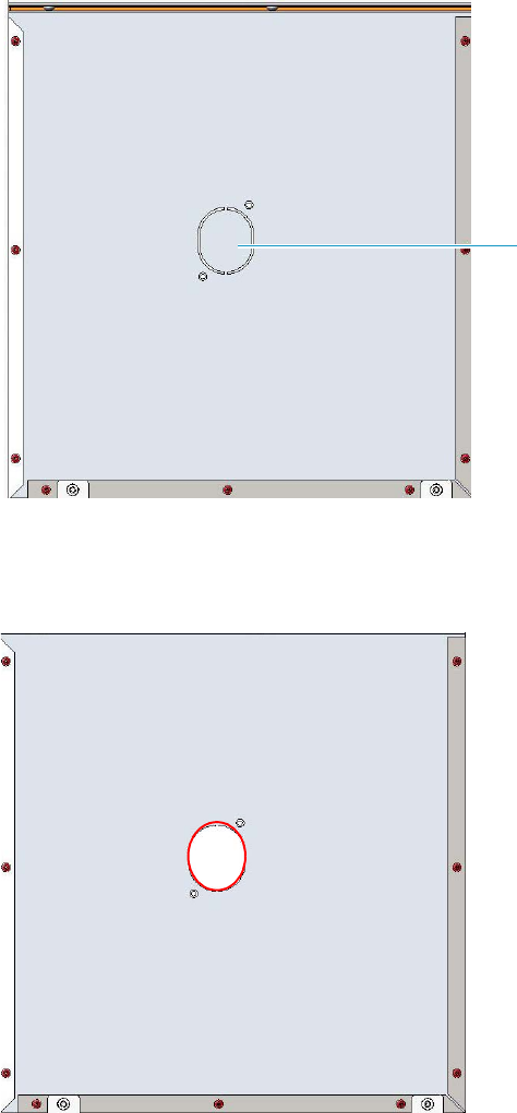
10 Adding Systems
Adding an Auxiliary Gas System
530 TRACE 1300 and TRACE 1310 Hardware Manual Thermo Scientific
a. Remove the partial cut shaped plate from the exterior wall of the oven box for
accessing the insulating material. See Figure 576.
Figure 576. Perform the Duct for the Auxiliary Gas Interface (1)
b. Using a knife or similar tool, gently cut the insulating material following the border.
See Figure 577.
Figure 577. Perform the Duct for the Auxiliary Gas Interface (2)
c. Save the removed insulating material in a safe place because it can be reused.
d. On the left side wall in the interior of the oven, remove the partial cut plate from the
corresponding duct. See Figure 578.
Partial Cut Shaped Plate
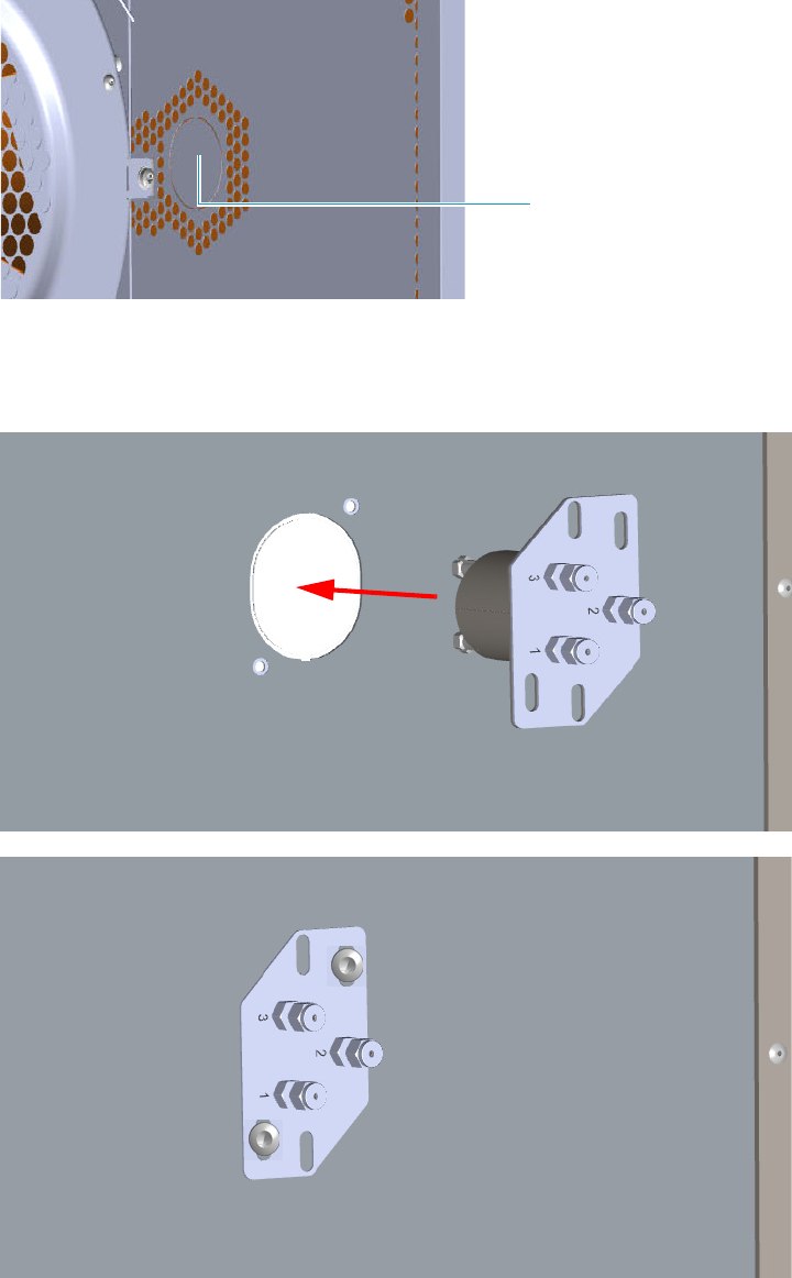
10 Adding Systems
Adding an Auxiliary Gas System
Thermo Scientific TRACE 1300 and TRACE 1310 Hardware Manual 531
Figure 578. Perform the Duct for the Auxiliary Gas Interface (3)
e. Insert the auxiliary gas interface into the duct. Fix the interface on the exterior wall of
the oven box using the fixing screws provided. See Figure 579.
Figure 579. Perform the Duct for the Auxiliary Gas Interface (4)
4. Jump to the section “Installing and Connecting the Auxiliary Gas Module” on page 534.
Partial Cut Plate
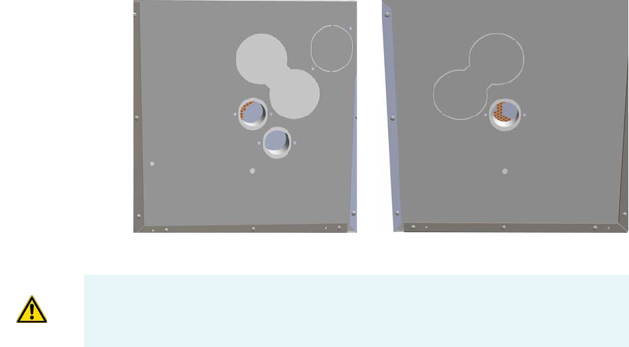
10 Adding Systems
Adding an Auxiliary Gas System
532 TRACE 1300 and TRACE 1310 Hardware Manual Thermo Scientific
Installing the Auxiliary Gas Interface on the Oven for HRMS
To make the duct into the oven for HRMS
1. Remove the left/right side panel.
a. Open the front door of the GC.
b. Use a T20 Torxhead screwdriver to loosen the left/right side panel screw from the
interior front panel. Save the screw because it will be reused later.
c. Slide the panel towards the back of the instrument up to the stop.
d. Remove the panel pulling it outward being aware that the ground wire is attached to
the panel.
2. Prepare the duct for the installation of the auxiliary gas interface.
a. On the left/right exterior wall of the oven box, remove the partial cut plate of the
duct of interest.
b. Remove the pre-shaped plug of insulating material from the duct provided. See
Figure 580.
Figure 580. Left/Right Exterior Oven Wall Box View
c. On the interior of the oven box, remove the partial cut plate from the corresponding
duct. See Figure 581.
Right Oven Wall
Left Oven Wall
IMPORTANT Save the pre-shaped plug of insulating material in a safe place because it
could be reused.
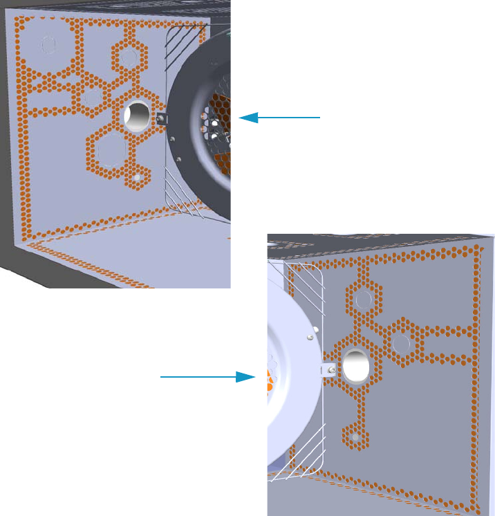
10 Adding Systems
Adding an Auxiliary Gas System
Thermo Scientific TRACE 1300 and TRACE 1310 Hardware Manual 533
Figure 581. Left/Right Interior Oven Wall Box View
3. Insert the auxiliary gas interface into the duct. Fix the interface on the exterior wall of the
oven box using the fixing screws provided.
4. Jump to the section “Installing and Connecting the Auxiliary Gas Module” on page 534.
Left Oven Wall
Right Oven Wall
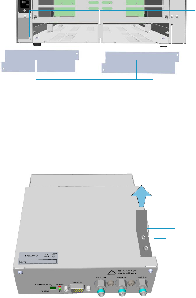
10 Adding Systems
Adding an Auxiliary Gas System
534 TRACE 1300 and TRACE 1310 Hardware Manual Thermo Scientific
Installing and Connecting the Auxiliary Gas Module
To install and connect the Auxiliary Gas Module
1. Remove the cover of the external modules housing where installing the module. See
Figure 582.
Figure 582. Housing Cover Removal
a. Using a T20 Torxhead screwdriver, unscrew and remove the left or right housing
cover screws.
b. Remove the cover from the housing.
2. Remove the manifold protecting plate
a. Using a T20 Torxhead screwdriver, unscrew the two fixing screws, and remove the
protecting plate from the manifold. Save the protecting plate and the fixing screws.
Figure 583. Manifold Protecting Plate
3. Install the module into the housing
Left/Right Housing Covers
Left Cover
Screws
Right Cover
Screws
Protecting Plate
Fixing Screws
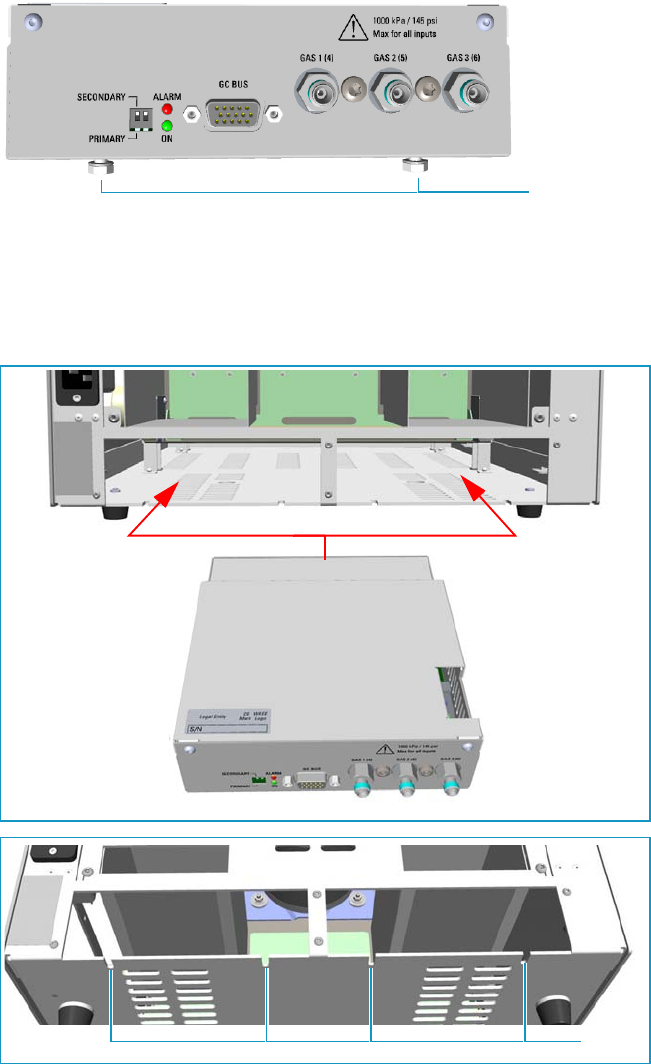
10 Adding Systems
Adding an Auxiliary Gas System
Thermo Scientific TRACE 1300 and TRACE 1310 Hardware Manual 535
a. Loosen the two hexagonal screws under the module. See Figure 584.
Figure 584. Module Installation (1)
b. Carefully place the module into the left or right housing.
c. Push the module until the hexagonal screws couple with the slots on the floor of the
GC. See Figure 585.
Figure 585. Module Installation (2)
d. Finger-tighten the hexagonal screws slightly, or use a 10-mm wrench.
Hexagonal Screws
Slots
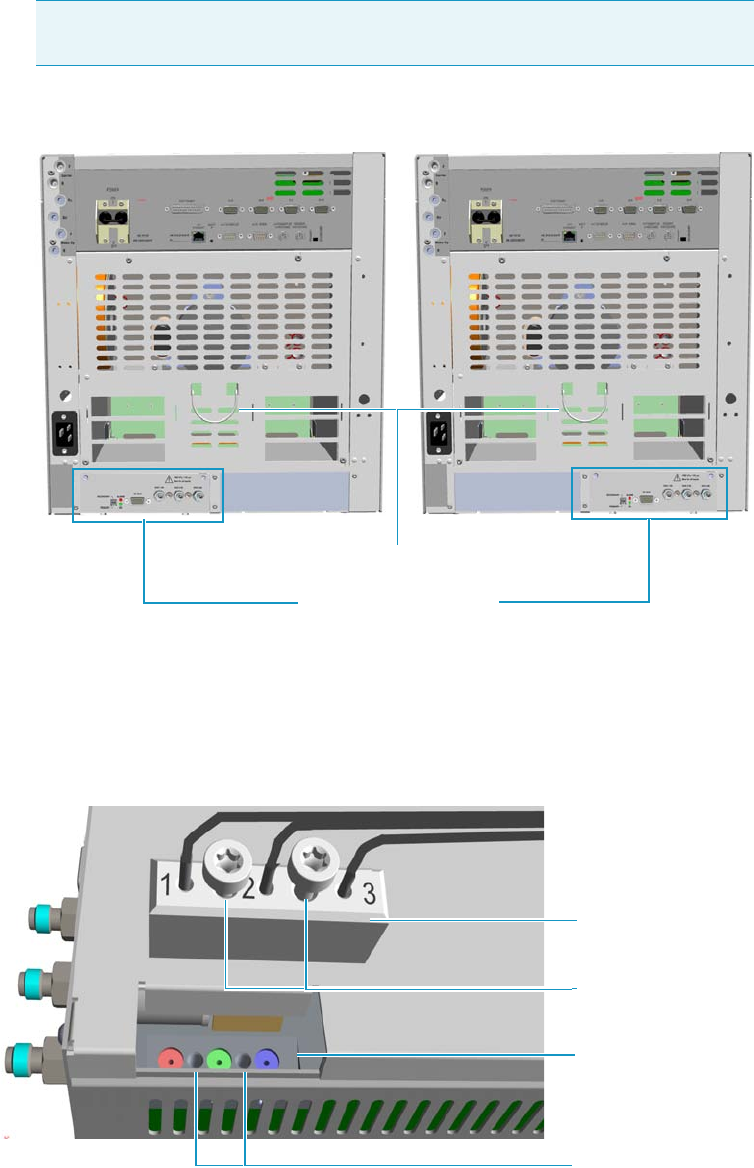
10 Adding Systems
Adding an Auxiliary Gas System
536 TRACE 1300 and TRACE 1310 Hardware Manual Thermo Scientific
The result of the installation is shown in Figure 586.
Figure 586. Auxiliary Gas Module Installed into the GC
4. Connect the gas tubing block to the manifold.
Figure 587 shows the gas tubing block and the manifold located into the auxiliary gas
module.
Figure 587. Gas Tubing Block and Manifold
Note Always keep the hexagonal screws in their place. This allows you an easier
removal of the auxiliary module when necessary.
Auxiliary Gas Module
Cables Holder
Gas Tubing Block
Manifold
Fixing Screws
Fixing Holes
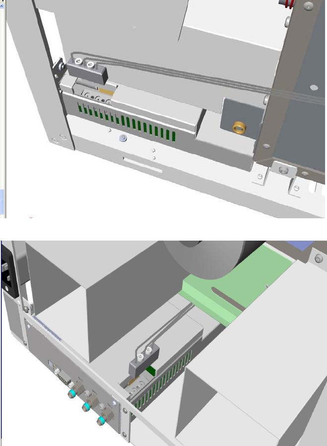
10 Adding Systems
Adding an Auxiliary Gas System
Thermo Scientific TRACE 1300 and TRACE 1310 Hardware Manual 537
a. Carefully guide the gas tubing block on the manifold located into the auxiliary gas
module. See Figure 588 if the module is installed on the right, or Figure 589 if the
module is installed on the left.
Figure 588. Installation on the Right Side
Figure 589. Installation on the Left Side
b. Align the fixing screws of the gas tubing block with the corresponding holes on the
manifold.
c. Use the T20 Torxhead screwdriver to tighten the two fixing screws without
overtightening.
5. Connect the gas tubes of interest to the Auxiliary Gas Interface.
a. Guide the three gas tubes up to reach the Auxiliary Gas interface.
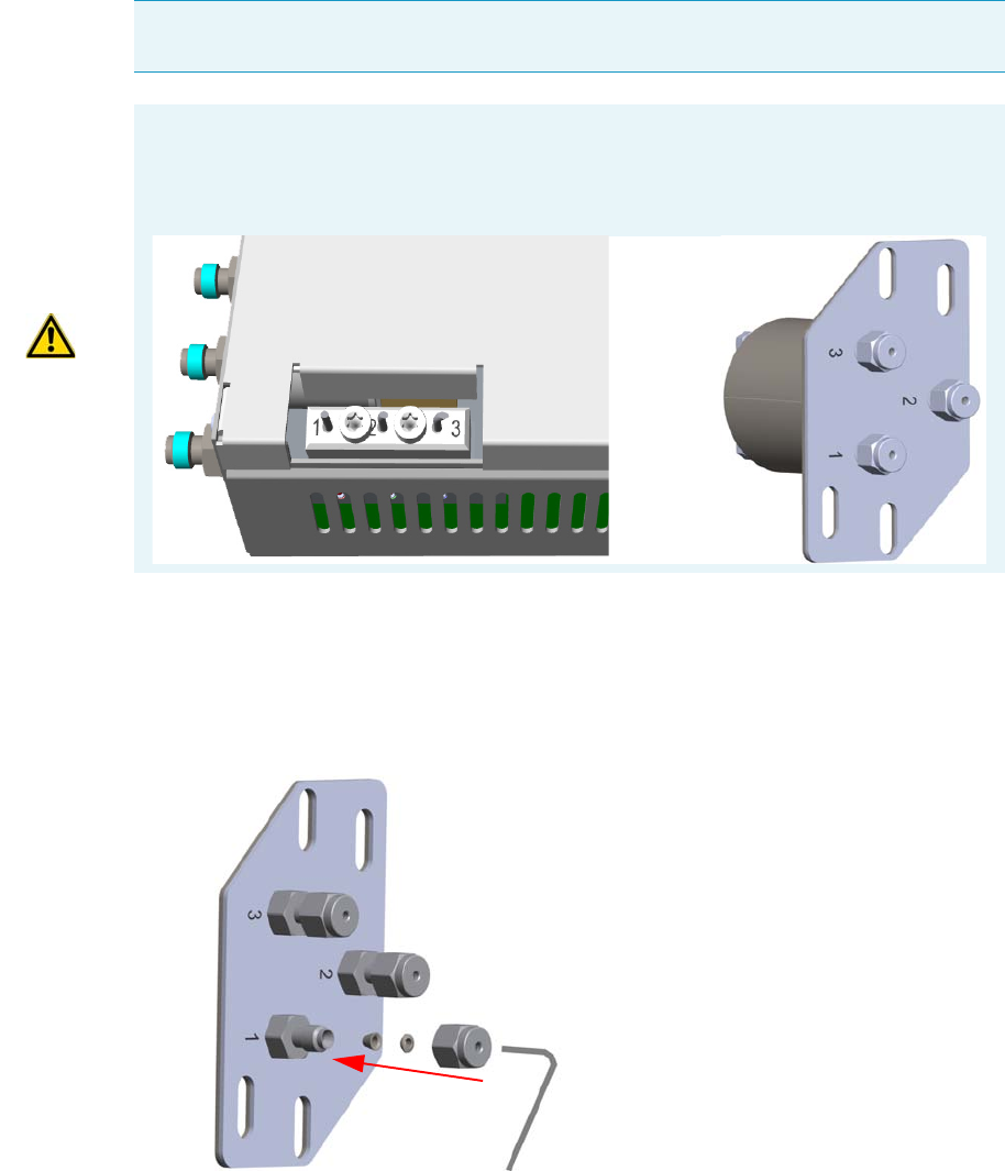
10 Adding Systems
Adding an Auxiliary Gas System
538 TRACE 1300 and TRACE 1310 Hardware Manual Thermo Scientific
b. Bend the gas tube until its end reaches the corresponding numbered inlet port of the
auxiliary interface.
c. Connect the gas tube to the corresponding numbered inlet port using the appropriate
nut and ferrules. Use a 7/16-in. wrench to tighten the fittings. See Figure 590.
Figure 590. Gas Tubes Connection to the Auxiliary Gas Interface - External View(
d. Repeat step b and step c until all the gas tubes of interest are connected to the
auxiliary gas interface.
e. In the GC oven, carry out the connections of the components of interest to the
corresponding inlet ports of the auxiliary gas interface using the appropriate nut and
ferrules.
Note The length of the tubes allows them to reach the Auxiliary Gas Interface whether
they are installed on the same side or on the opposite side of the Auxiliary Gas Module.
ATTENTION The three gas tubes, coming from the gas tubing block, are numbered 1, 2,
and 3 respectively. Pay attention to the correct order when you connect each tube to the
corresponding inlet on the auxiliary gas interface. The end of each tube is provided with a
label indicating the type of gas.
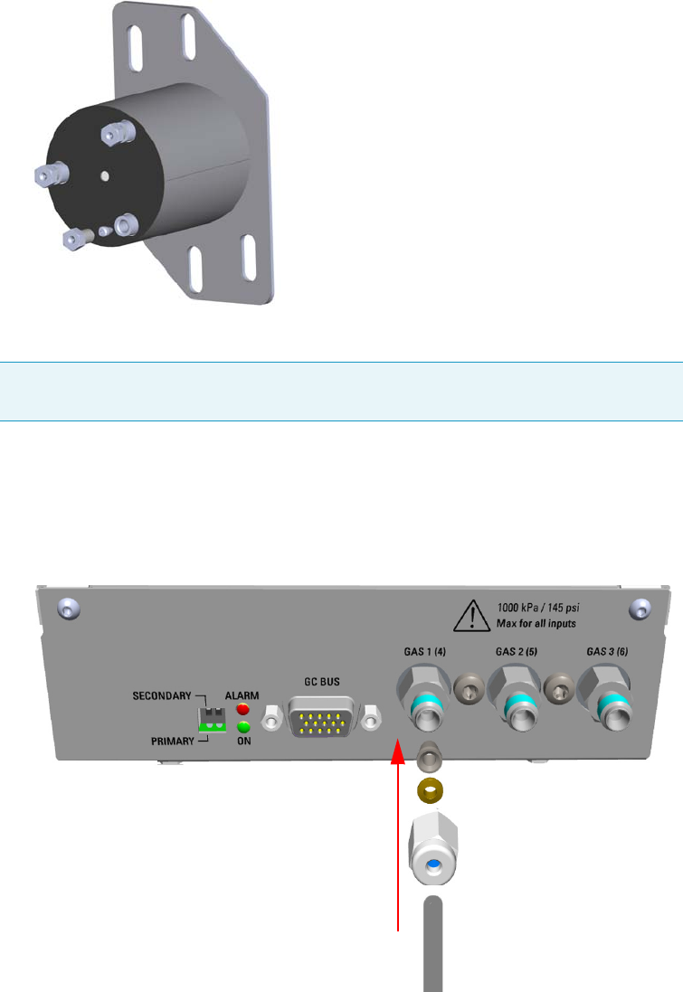
10 Adding Systems
Adding an Auxiliary Gas System
Thermo Scientific TRACE 1300 and TRACE 1310 Hardware Manual 539
f. Repeat step e until all the components are connected to the auxiliary gas interface.
See Figure 591.
Figure 591. Gas Tubes Connection to the Auxiliary Gas Interface - Internal View(
6. Connect the Supply Gas to the Auxiliary Gas Module.
a. Connect the gas line to the corresponding inlet port of interest using the appropriate
nut and ferrules. Use a 7/16-in. wrench for tightening the fittings.
b. Repeat step a until all the gas lines of interest are connected to the corresponding
inlet port on the auxiliary gas module. See Figure 592.
Figure 592. Gas Line Connection to the Auxiliary Gas Interface
Note Use the 1/8-in. Swagelok fittings provided on the gas inlet ports to connect the
gas lines.
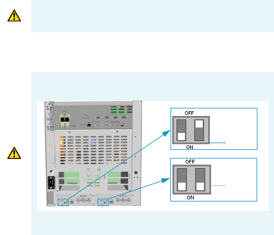
10 Adding Systems
Adding an Auxiliary Gas System
540 TRACE 1300 and TRACE 1310 Hardware Manual Thermo Scientific
7. Connect the Auxiliary Gas Module electrically.
a. Using the cable provided, connect the 15-pin female connector marked GC Bus on
the module to a Bus interface on the back of the GC.
8. Replace the left/right side panel.
a. Plug the ground wire previously removed into the left/right panel.
b. Place the left/right panel and attach the screw holding it in place.
9. Open the gas supplies.
10. If external modules are present, plug the power cable to the AC Input connector of each
external module, and to the wall outlet.
11. Power on the GC.
a. Plug the power cable to the AC Input connector into the back of the GC and to the
wall outlet.
b. Flip up the power switch (breaker), located at the back of the instrument, to the
position I.
IMPORTANT The maximum nominal inlet pressure for all the inputs is 1000 kPa
(145 psig). The working inlet pressure range is from 400 kPa (58 psig) to 1000 kPa
(145 psig).
IMPORTANT If two Auxiliary Gas modules are simultaneously present, one must be set as
Primary and the other as Secondary by mean of dedicated switch on the back panel.
See the example below.
The primary module controls the aux pressures from 1 to 3, while the secondary module
controls the aux pressures from 4 to 6.
Secondary
Primary
10 Adding Systems
Adding an Auxiliary Gas System
Thermo Scientific TRACE 1300 and TRACE 1310 Hardware Manual 541
12. Configure and enable the Auxiliary Gas system through the user interface of your GC, or
through the CDS in use. Refer to the TRACE 1300 and TRACE 1310 User Guide.
a. Configuration and enabling through the touch screen.
i. In the main menu select the Instrument control icon. The Instrument Control
menu appears.
ii. In the Instrument Control menu, select the Auxiliary icon to open the relevant
submenu.
iii. Set the Aux Gas Pressure values as required, then return to main menu.
b. Configuration and enabling through the Chromatography Data System.
i. In the Configuration window select the Auxiliary tab.
ii. Select the check box Auxiliary Carrier Module 1/2 according to the auxiliary
carrier module installed on your GC.
iii. Select the Auxiliary Pressure check box to enable up to six auxiliary Pressures,
and the adjacent field.
iv. According the inlet ports connected to the Auxiliary Gas Interface, select the
corresponding check box and set the pressure in the adjacent field.
13. Set the normal detector, injector, and GC working conditions.
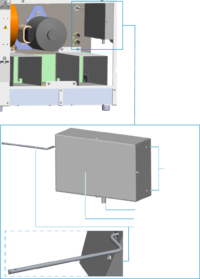
10 Adding Systems
Adding the Hydrogen Sensor
542 TRACE 1300 and TRACE 1310 Hardware Manual Thermo Scientific
Adding the Hydrogen Sensor
This section provides instructions for updating your TRACE 1300/TRACE 1310 with the
hydrogen sensor. See Figure 593.
Figure 593. Hydrogen Sensor
Fixing Screw
Sensor Cable
Sensor Body
Sensor Tube

10 Adding Systems
Adding the Hydrogen Sensor
Thermo Scientific TRACE 1300 and TRACE 1310 Hardware Manual 543
To add the hydrogen sensor
1. Put the GC in standby condition.
2. Cool the oven, injectors and detectors to room temperature.
3. Close the gas supplies.
4. Power off the GC.
a. Push down the power switch (breaker), located at the back of the instrument, to the
position O.
b. Unplug the power cable from the AC Input connector into the back of the GC and
from the wall outlet.
5. If external modules are present, unplug the power cable from the AC Input connector of
each external module, and from the wall outlet.
6. Remove the left side panel.
a. Open the front door of the GC.
b. Using a T20 Torxhead screwdriver, unscrew the left side panel screw from the interior
front panel. Save the screw because it will be reused later.
c. Slide the panel towards the back of the instrument up to the stop.
d. Remove the panel by pulling it outward. Be aware that the ground wire is attached to
the panel.
e. Unplug the ground wire from the panel.
7. Remove the back cover.
a. Use a T20 Torxhead screwdriver to remove the four screws that secure the back cover
to the GC.
b. Lift the cover off using the cover handle. Be aware that the ground wire is attached to
the back panel.
8. Perforate the duct for the installation of the sensor into the oven.
a. Looking the interior of the GC from the back side, locate the duck provided on the
back wall of the oven. See Figure 594.
WARNING This operation must be carried out by authorized and trained Thermo Fisher
Scientific Service Field Engineers.
IMPORTANT The hydrogen sensor requires a GC firmware version 1.03 or later.
Note Pay attention to the positioning of the ground wire plug, so it can be reconnected in
the same way it was removed.
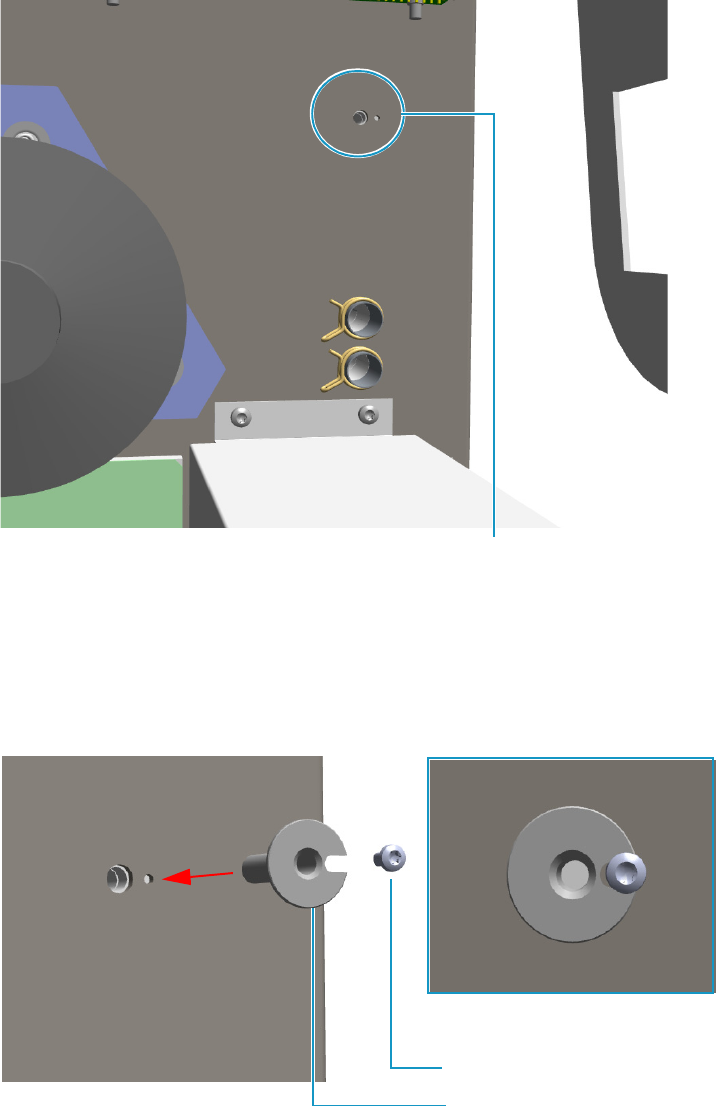
10 Adding Systems
Adding the Hydrogen Sensor
544 TRACE 1300 and TRACE 1310 Hardware Manual Thermo Scientific
Figure 594. Duck for Hydrogen Sensor
b. Using a tool (for example a punch), perforate the insulating material until the tool
protrudes into the oven. Make sure the duct is free of insulating material.
c. Insert the sensor tube adapter into the duct and fix the adapter using the screw
provided. See Figure 595.
Figure 595. Sensor Tube Adapter Installation (1)
9. Open the front door.
a. Look into oven the duct for the hydrogen sensor previously done. See Figure 596.
Duct for Hydrogen Sensor
Sensor Tube Adapter
Sensor Tube Adapter Fixing Screw
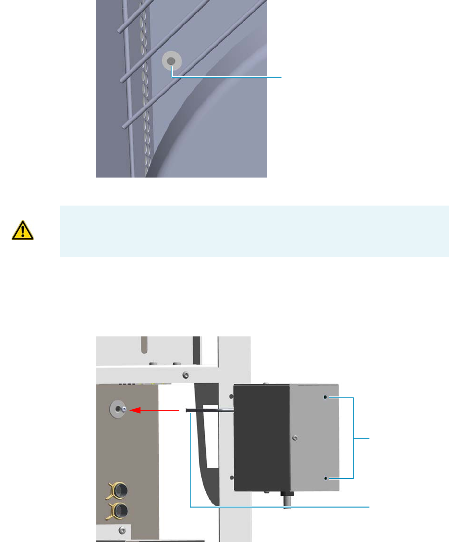
10 Adding Systems
Adding the Hydrogen Sensor
Thermo Scientific TRACE 1300 and TRACE 1310 Hardware Manual 545
Figure 596. View of the Sensor Tube Duct Into the Oven
b. Check the duct is free of insulating material; if not, remove it.
10. Install the hydrogen sensor.
a. Move and guide the sensor tube into the duct for the hydrogen sensor. See
Figure 597.
Figure 597. Hydrogen Sensor Installation (1)
b. Place the hydrogen sensor into the back of the GC aligning the fixing holes to the
corresponding holes on the GC chassis. See Figure 598.
Sensor Tube Duct
IMPORTANT The duct must be free of the insulating material. If not, it could obstruct
the tube sensor.
Fixing Holes
Sensor Tube
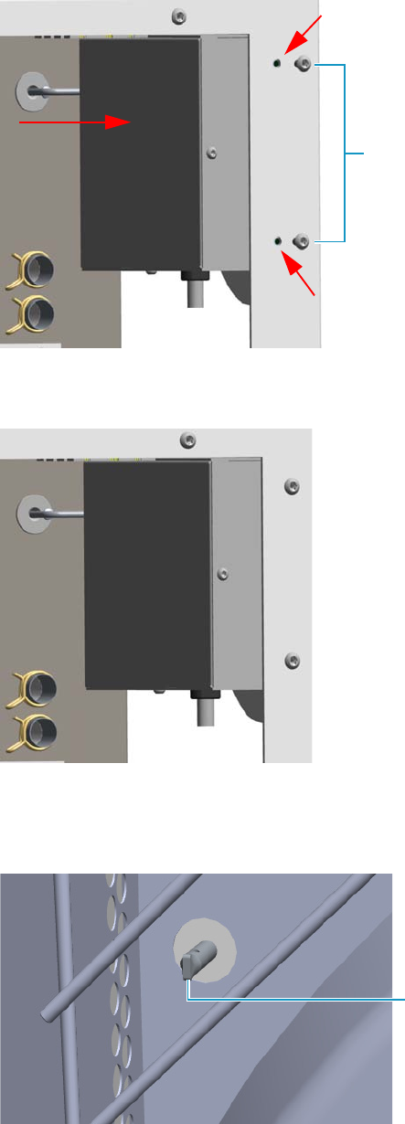
10 Adding Systems
Adding the Hydrogen Sensor
546 TRACE 1300 and TRACE 1310 Hardware Manual Thermo Scientific
Figure 598. Hydrogen Sensor Installation (2)
c. Fix the hydrogen sensor using the two fixing screws. See Figure 599.
Figure 599. Hydrogen Sensor Installation (3)
d. Look into oven the hydrogen sensor tube that protrudes into the oven. See
Figure 600.
Figure 600. Sensor Tube Protruding Into the Oven
Fixing Screws
Sensor Tube
10 Adding Systems
Adding the Hydrogen Sensor
Thermo Scientific TRACE 1300 and TRACE 1310 Hardware Manual 547
11. Connect the sensor cable to the 10-pin connector marked J8 Hydrogen Sensor of the
Backplane board.
12. Close the oven door.
13. Reinstall the back cover.
a. Reconnect the ground wire to the back cover terminal.
b. Replace the cover proceeding in the reverse order in which it was removed.
14. Reinstall the left side panel.
a. Plug the ground wire to the panel.
b. Reinstall the panel proceeding in the reverse order in which it was removed.
15. If external modules are present, plug the power cable to the AC Input connector of each
external module, and to the wall outlet.
16. Power on the GC.
a. Plug the power cable to the AC Input connector into the back of the GC and to the
wall outlet.
b. Flip up the power switch (breaker), located at the back of the instrument, to the
position I.
17. Set the normal injector, detector and GC working conditions.

Thermo Scientific TRACE 1300 and TRACE 1310 Hardware Manual 549
11
Upgrade Equipment
This chapter describes how to upgrade the TRACE 1300/TRACE 1310. See the TRACE
1300 and TRACE 1310 Spare Parts Guide for information about ordering the equipment in
this chapter.
Contents
•Upgrading a TRACE 1300 to a TRACE 1310
•Upgrading a Stand Alone TRACE 1300/TRACE 1310 to MS Version
•Updating HMI Software From USB Stick

11 Upgrade Equipment
Upgrading a TRACE 1300 to a TRACE 1310
550 TRACE 1300 and TRACE 1310 Hardware Manual Thermo Scientific
Upgrading a TRACE 1300 to a TRACE 1310
This section provides the instruction to upgrade a TRACE 1300 to a TRACE 1310 GC.
.
To upgrade a TRACE 1300 to a TRACE 1310 GC
1. Put the GC in standby condition.
2. Cool the oven, injectors and detectors to room temperature.
3. Close the gas supplies.
4. Power off the GC.
a. Push down the power switch (breaker), located at the back of the instrument, to the
position O.
b. Unplug the power cable from the AC Input connector into the back of the GC and
from the wall outlet.
5. If external modules are present, plug the power cable to the AC Input connector of each
external module, and to the wall outlet.
6. Remove the door cover of the TRACE 1300.
a. Open the front door and look for the fixing screws that secure the cover and the
handle to the door. See Figure 601.
WARNING This operation must be carried out by authorized and trained Thermo Fisher
Scientific Service Field Engineers.
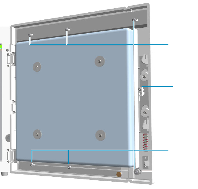
11 Upgrade Equipment
Upgrading a TRACE 1300 to a TRACE 1310
Thermo Scientific TRACE 1300 and TRACE 1310 Hardware Manual 551
Figure 601. Front Door Back View
b. Use a T20 Torxhead screwdriver to remove the screw that secure the handle to the
front door.
c. Pull the door handle out from the front door. See Figure 602.
Save the handle because it must be re-used.
Upper Fixing Screws
Lower Fixing Screws
Door Handle Fixing
Screw
Spacer

11 Upgrade Equipment
Upgrading a TRACE 1300 to a TRACE 1310
552 TRACE 1300 and TRACE 1310 Hardware Manual Thermo Scientific
Figure 602. Door Handle Removal
d. Use a T20 Torxhead screwdriver to remove the three upper and the three lower screws
that secure the cover to the front door. See Figure 603.
Note The lower screw on the lower right corner is screwed into a spacer.
Door Handle
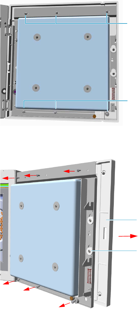
11 Upgrade Equipment
Upgrading a TRACE 1300 to a TRACE 1310
Thermo Scientific TRACE 1300 and TRACE 1310 Hardware Manual 553
Figure 603. Door Cover Fixing Screws Removal
e. Carefully pull the door cover off (see Figure 604), paying attention to the cables that
connect the status panel to the internal section of the door.
Figure 604. Front Door Removal
Lower Fixing Screws
Upper Fixing Screws
Door Cover
Front Door
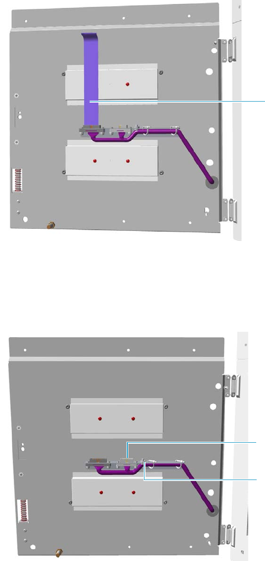
11 Upgrade Equipment
Upgrading a TRACE 1300 to a TRACE 1310
554 TRACE 1300 and TRACE 1310 Hardware Manual Thermo Scientific
f. Disconnect the flat cables from the connector located on the front of the door. See
Figure 605.
Figure 605. Cable Removal
7. Install the door cover of the TRACE 1310.
a. The door cover of the TRACE 1310 includes the touch screen and the cables for its
connection. Figure 606 shows the connection points on the internal section of the
door where the touch screen and ground cables must be connected.
Figure 606. Cables Connections Points
Flat Cables
Touch Screen Connection
Point
Ground Connection
Point
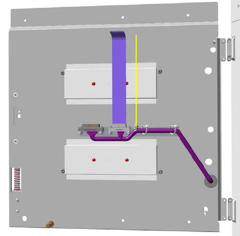
11 Upgrade Equipment
Upgrading a TRACE 1300 to a TRACE 1310
Thermo Scientific TRACE 1300 and TRACE 1310 Hardware Manual 555
b. Connect the touch screen and ground cables to the proper connection points located
on the front of the door. See Figure 607.
Figure 607. Cables Connections
8. Mount the TRACE 1310 cover door proceeding in the reverse order in which the
TRACE 1300 cover door was removed.
9. Remount the door handle.
10. Open the gas supplies.
11. If external modules are present, plug the power cable to the AC Input connector of each
external module, and to the wall outlet.
12. Power on the GC.
a. Plug the power cable to the AC Input connector into the back of the GC and to the
wall outlet.
b. Flip up the power switch (breaker), located at the back of the instrument, to the
position I.
13. Configure the system.
14. Set the normal detector, injector, and GC working conditions.
11 Upgrade Equipment
Upgrading a Stand Alone TRACE 1300/TRACE 1310 to MS Version
556 TRACE 1300 and TRACE 1310 Hardware Manual Thermo Scientific
Upgrading a Stand Alone TRACE 1300/TRACE 1310 to MS Version
This section provides the instructions for updating your TRACE 1300/TRACE 1310 stand
alone version to a MS version. According to Thermo Scientific you need a dedicated upgrade
kit to couple the GC with an ISQ Series, TSQ 8000 Series, DSQ II, ITQ, or TSQ Quantum
mass spectrometer.
Preliminary Operations
Before starting, the following preliminary operation must be carried out.
1. Put the GC in standby condition.
2. Cool the oven, injectors and detectors to room temperature.
3. Close the gas supplies.
4. Power off the GC.
a. Push down the power switch (breaker), located at the back of the instrument, to the
position O.
b. Unplug the power cable from the AC Input connector into the back of the GC and
from the wall outlet.
5. If external modules are present, unplug the power cable from the AC Input connector of
each external module, and from the wall outlet.
Getting Started
Depending on your mass spectrometer, see the following sections:
•Coupling with the ISQ Series / TSQ 8000 Series Mass Spectrometer
•Coupling with the DSQ II Mass Spectrometer
•Coupling with the ITQ Mass Spectrometer
•Coupling with the TSQ Quantum Mass Spectrometer
WARNING This operation must be carried out by authorized and trained Thermo Fisher
Scientific Service Field Engineers.
IMPORTANT The temperature control for the DSQ II, ITQ and TSQ Quantum transfer
line is carried out through the Aux Temperature/Cryo Module. See the section “Adding
an Aux Temperature/Cryo Module” on page 443 for details.
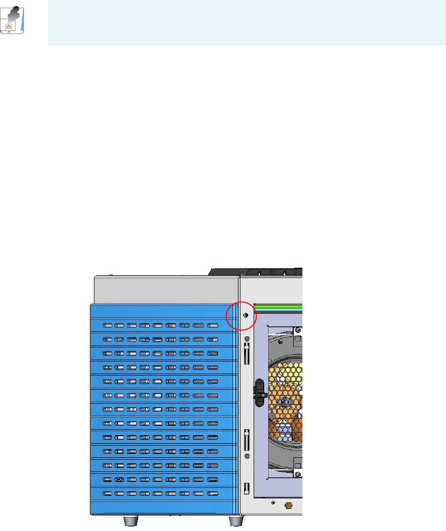
11 Upgrade Equipment
Upgrading a Stand Alone TRACE 1300/TRACE 1310 to MS Version
Thermo Scientific TRACE 1300 and TRACE 1310 Hardware Manual 557
Coupling with the ISQ Series / TSQ 8000 Series Mass Spectrometer
To update the GC for the coupling with the ISQ Series /TSQ 8000 Series mass
spectrometer
1. Make sure that the preliminary operations have been carried out. See “Preliminary
Operations” on page 556.
2. Remove the left side panel.
a. Open the front door of the GC.
b. Use a T20 Torxhead screwdriver to screw the left side panel screw from the interior
front panel. See Figure 608. Save the screw because it will be reused later.
Figure 608. Left Side Panel Fixing Screw
c. Slide the panel towards the back of the instrument up to the stop.
d. Remove the panel pulling it outward being aware that the ground wire is attached to
the panel. See Figure 609.
e. Unplug the ground wire from the panel.
CAUTION - INSTRUMENT DAMAGE: Condition the column before connecting it to the
transfer line. The material released from the column (column bleed) during conditioning
may contaminate the detector.
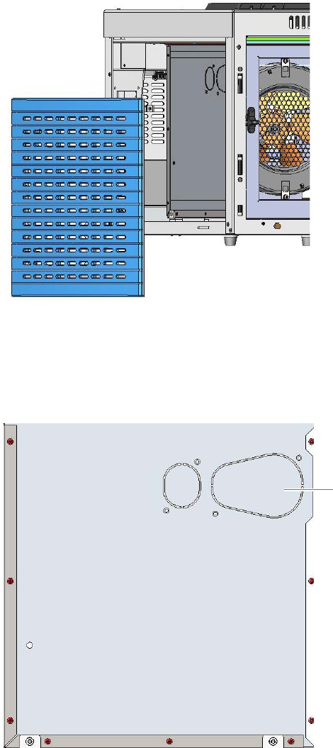
11 Upgrade Equipment
Upgrading a Stand Alone TRACE 1300/TRACE 1310 to MS Version
558 TRACE 1300 and TRACE 1310 Hardware Manual Thermo Scientific
Figure 609. Left Side Panel Removal
3. Prepare the duct for the transfer line inner tube.
a. Remove the partial cut shaped plate from the exterior wall of the oven box to access
the insulating material. See Figure 610.
Figure 610. Perform the Duct for ISQ Series / TSQ 8000 Series (1)
b. Draw up the duct aligning the slot to the fixing holes on the exterior oven wall and
push the duct against the insulating material up to obtain a trace. See Figure 611.
Partial Cut Shaped Plate
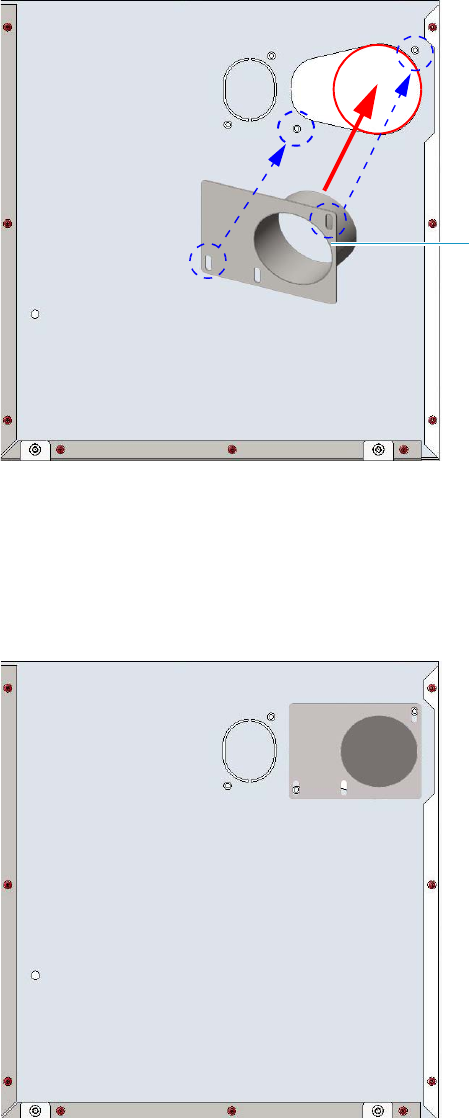
11 Upgrade Equipment
Upgrading a Stand Alone TRACE 1300/TRACE 1310 to MS Version
Thermo Scientific TRACE 1300 and TRACE 1310 Hardware Manual 559
Figure 611. Perform the Duct for ISQ Series / TSQ 8000 Series (2)
c. Using a knife or similar tool, gently cut the insulating material following the track.
d. Save the removed insulating material in a safe place because it can be reused.
e. Place the duct and fix it on the exterior wall of the oven box using the fixing screws
provided. See Figure 612.
Figure 612. Perform the Duct for ISQ Series / TSQ 8000 Series (3)
f. On the left side wall in the interior of the oven, remove the partial cut plate from the
corresponding duct. See Figure 613.
Duct for ISQ Series /TSQ 8000
Series
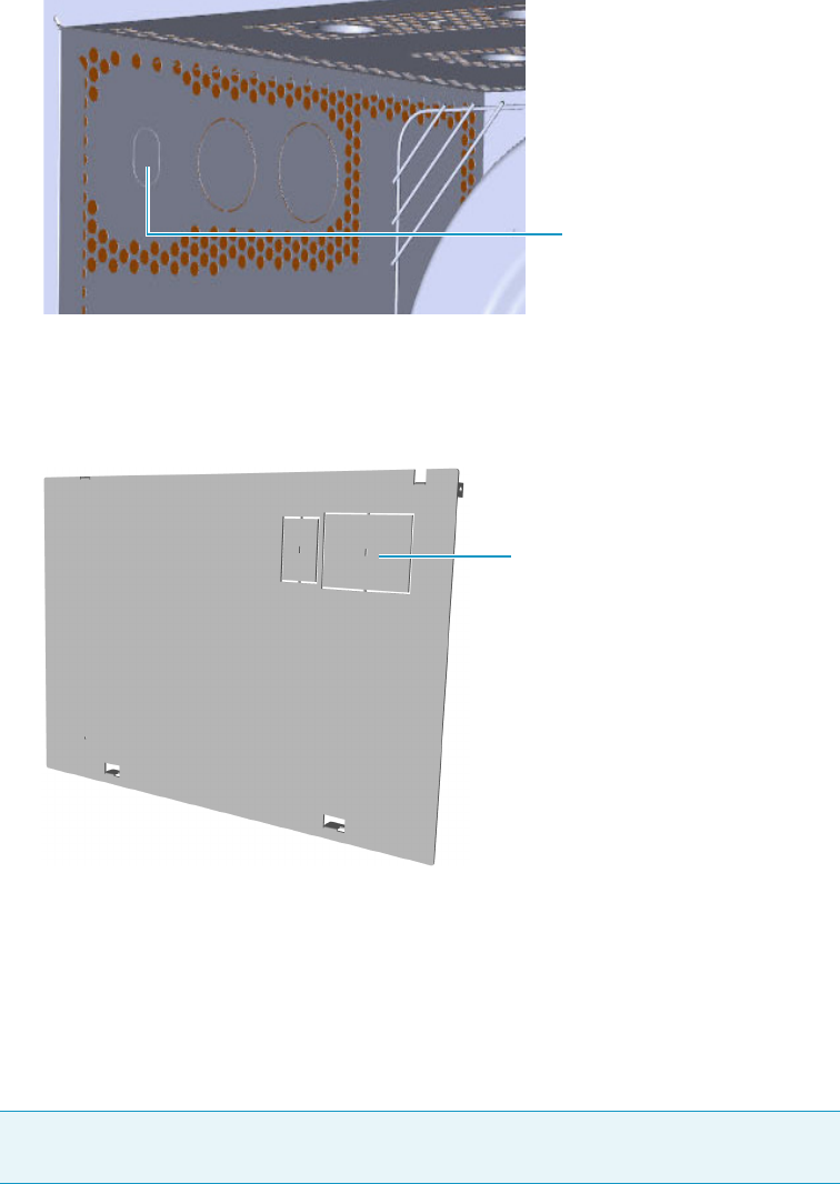
11 Upgrade Equipment
Upgrading a Stand Alone TRACE 1300/TRACE 1310 to MS Version
560 TRACE 1300 and TRACE 1310 Hardware Manual Thermo Scientific
Figure 613. Perform the Duct for ISQ Series / TSQ 8000 Series (4)
4. Replace the left side panel with the left panel for MS provided.
a. Remove the partial cut plate on the GC left panel for MS. See Figure 614.
Figure 614. Left Panel for MS
b. Plug the ground wire previously removed to the left panel for MS provided.
c. Place the left panel for MS and attach the screw holding it in place.
5. Introduce the ISQ Series / TSQ 8000 Series transfer line inner tube into the oven
through the duct provided.
6. Attach the transfer line to the GC column using the proper nut and ferrule.
7. Close the front door of the GC.
8. If external modules are present, plug the power cable to the AC Input connector of each
external module, and to the wall outlet.
9. Power on the GC.
Note The column must be conditioned before installing into the transfer line. See
“Installing the Column the First Time” on page 57
Duct for ISQ Series and
TS 8000 Series Partial Cut Plate
Duct for ISQ Series and
TS 8000 Series Partial Cut Plate
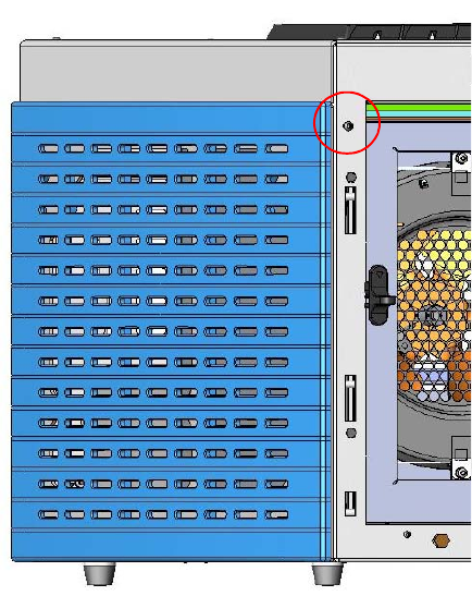
11 Upgrade Equipment
Upgrading a Stand Alone TRACE 1300/TRACE 1310 to MS Version
Thermo Scientific TRACE 1300 and TRACE 1310 Hardware Manual 561
a. Plug the power cable to the AC Input connector into the back of the GC and to the
wall outlet.
b. Flip up the power switch (breaker), located at the back of the instrument, to the
position I.
10. Tune the ISQ Series / TSQ 8000 Series and set its working conditions. Set the GC
working conditions accordingly.
For details please refer to the TRACE 1300 and TRACE 1310 User Guide, and to the ISQ
or TSQ 8000 Series User and Hardware manuals.
Coupling with the DSQ II Mass Spectrometer
To update the GC for the coupling with the DSQ II mass spectrometer
1. Make sure that the preliminary operations have been carried out. See “Preliminary
Operations” on page 556.
2. Remove the left side panel.
a. Open the front door of the GC.
b. Use a T20 Torxhead screwdriver to screw the left side panel screw from the interior
front panel. See Figure 615. Save the screw because it will be reused later.
Figure 615. Left Side Panel Fixing Screw
c. Slide the panel towards the back of the instrument up to the stop.

11 Upgrade Equipment
Upgrading a Stand Alone TRACE 1300/TRACE 1310 to MS Version
562 TRACE 1300 and TRACE 1310 Hardware Manual Thermo Scientific
d. Remove the panel pulling it outward being aware that the ground wire is attached to
the panel. See Figure 616.
e. Unplug the ground wire from the panel.
Figure 616. Left Side Panel Removal
3. Prepare the duct for the transfer line inner tube.
a. Remove the partial cut shaped plate from the stirrer wall of the oven box to access the
insulating material. See Figure 617.
Figure 617. Perform the Duct for DSQ II (1)
Partial Cut Shaped Plate
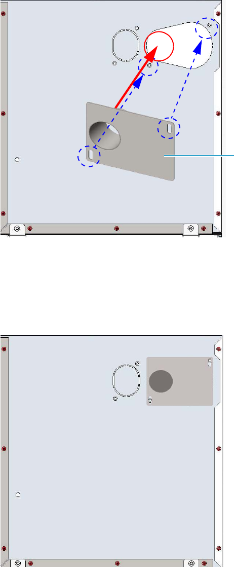
11 Upgrade Equipment
Upgrading a Stand Alone TRACE 1300/TRACE 1310 to MS Version
Thermo Scientific TRACE 1300 and TRACE 1310 Hardware Manual 563
b. Draw up the duct aligning the slot to the fixing holes on the exterior oven wall and
push the duct against the insulating material up to obtain a track. See Figure 618.
Figure 618. Perform the Duct for DSQ II (2)
c. Using a knife or similar tool, gently cut the insulating material following the track.
d. Save the removed insulating material in a safe place because it can be reused.
e. Place the duct and fix it on the exterior wall of the oven box using the fixing screws
provided. See Figure 619.
Figure 619. Perform the Duct for DSQ II (3)
Duct for DSQ II
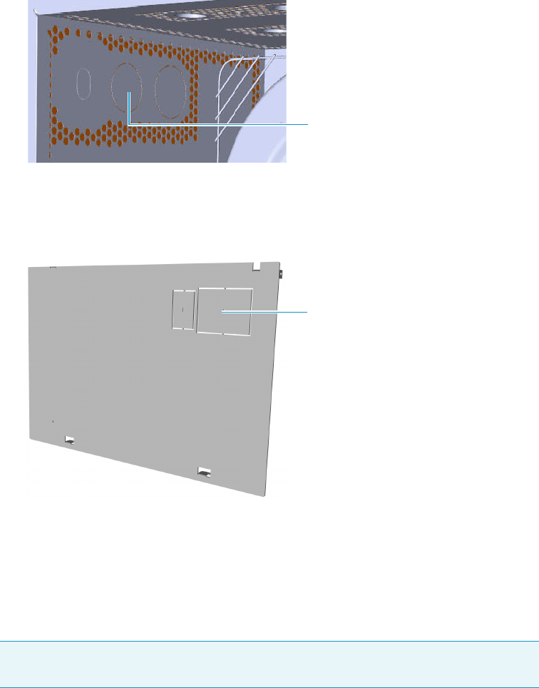
11 Upgrade Equipment
Upgrading a Stand Alone TRACE 1300/TRACE 1310 to MS Version
564 TRACE 1300 and TRACE 1310 Hardware Manual Thermo Scientific
f. On the left side wall in the interior of the oven, remove the partial cut plate from the
corresponding duct. See Figure 620.
Figure 620. Perform the Duct for DSQ II (4)
4. Replace the left side panel with the left panel for MS provided.
a. Remove the partial cut plate on the GC left panel for MS. See Figure 621.
Figure 621. Left Panel for MS
b. Plug the ground wire previously removed to the left panel for MS provided.
c. Place the left panel for MS and attach the screw holding it in place.
5. Introduce the DSQ II transfer line inner tube into the oven through the duct provided.
6. Attach the transfer line to the GC column using the proper nut and ferrule.
7. Place the Aux Temperature/Cryo module into the housing on the back of the GC.
See the section “Adding an Aux Temperature/Cryo Module” on page 443 for details.
Note The column must be conditioned before installing into the transfer line. See
“Installing the Column the First Time” on page 57.
Duct for DSQ II Partial Cut Plate
Duct for DSQ II Partial Cut Plate
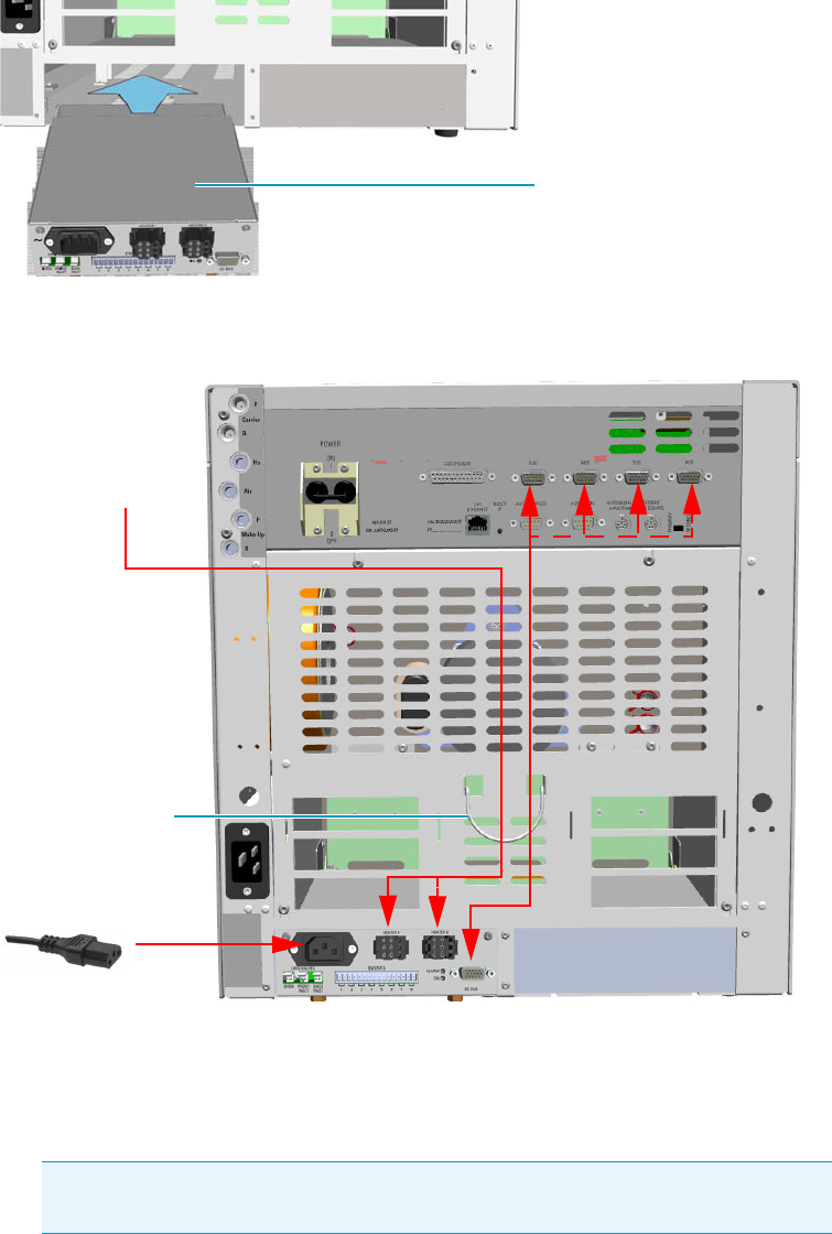
11 Upgrade Equipment
Upgrading a Stand Alone TRACE 1300/TRACE 1310 to MS Version
Thermo Scientific TRACE 1300 and TRACE 1310 Hardware Manual 565
8. Make the electrical connections. See Figure 622.
Figure 622. Electrical Connections
a. Connect the heater cable coming from the transfer line to the connector marked
Heater 1 or Heater 2 on the front of the module
b. Using the cable provided, connect the 15-pin female connector marked GC Bus on
the module to a Bus interface on the back of the GC.
c. Plug the power cable to the AC Input connector on the front of the module and to
the wall outlet. The LED marked On lights.
9. Close the front door of the GC.
Tip To avoid the contact with the hot air from the vents, it is suggested to gather
the electrical cables into the cables holder.
Aux Temperature/Cryo Module
Transfer Line
Cables Holder
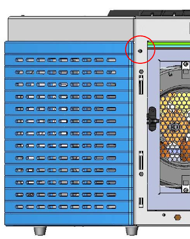
11 Upgrade Equipment
Upgrading a Stand Alone TRACE 1300/TRACE 1310 to MS Version
566 TRACE 1300 and TRACE 1310 Hardware Manual Thermo Scientific
10. If other external modules are present, plug the power cable to the AC Input connector of
each external module, and to the wall outlet.
11. Power on the GC.
a. Plug the power cable to the AC Input connector into the back of the GC and to the
wall outlet.
b. Flip up the power switch (breaker), located at the back of the instrument, to the
position I.
12. Tune the DSQ II and set its working conditions. Set the GC working conditions
accordingly. For details please refer to the TRACE 1300 and TRACE 1310 User Guide and
to the DSQ II User and Hardware manuals.
Coupling with the ITQ Mass Spectrometer
To update the GC for the coupling with the ITQ mass spectrometer
1. Make sure that the preliminary operations have been carried out. See “Preliminary
Operations” on page 556.
2. Remove the left side panel.
a. Open the front door of the GC.
b. Using a T20 Torxhead screwdriver, unscrew the left side panel screw from the interior
front panel. See Figure 623. Save the screw because it will be reused later.
Figure 623. Left Side Panel Fixing Screw
c. Slide the panel towards the back of the instrument up to the stop.
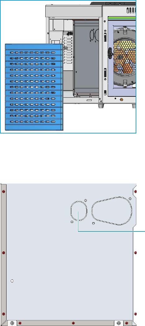
11 Upgrade Equipment
Upgrading a Stand Alone TRACE 1300/TRACE 1310 to MS Version
Thermo Scientific TRACE 1300 and TRACE 1310 Hardware Manual 567
d. Remove the panel pulling it outward being aware that the ground wire is attached to
the panel. See Figure 624.
e. Unplug the ground wire from the panel.
Figure 624. Left Side Panel Removal
3. Prepare the duct for the transfer line inner tube.
a. Remove the partial cut shaped plate from the exterior wall of the oven box to access
the insulating material. See Figure 625.
Figure 625. Perform the Duct for ITQ (1)
Partial Cut Shaped Plate
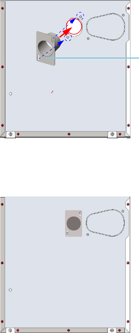
11 Upgrade Equipment
Upgrading a Stand Alone TRACE 1300/TRACE 1310 to MS Version
568 TRACE 1300 and TRACE 1310 Hardware Manual Thermo Scientific
b. Draw up the duct aligning the slot to the fixing holes on the exterior oven wall and
push the duct against the insulating material up to obtain a track. See Figure 626.
Figure 626. Perform the Duct for ITQ (2)
c. Using a knife or similar tool, gently cut the insulating material following the track.
d. Save the removed insulating material in a safe place because it can be reused.
e. Place the duct and fix it on the exterior wall of the oven box using the fixing screws
provided. See Figure 627.
Figure 627. Perform the Duct for ITQ (3)
Duct for ITQ
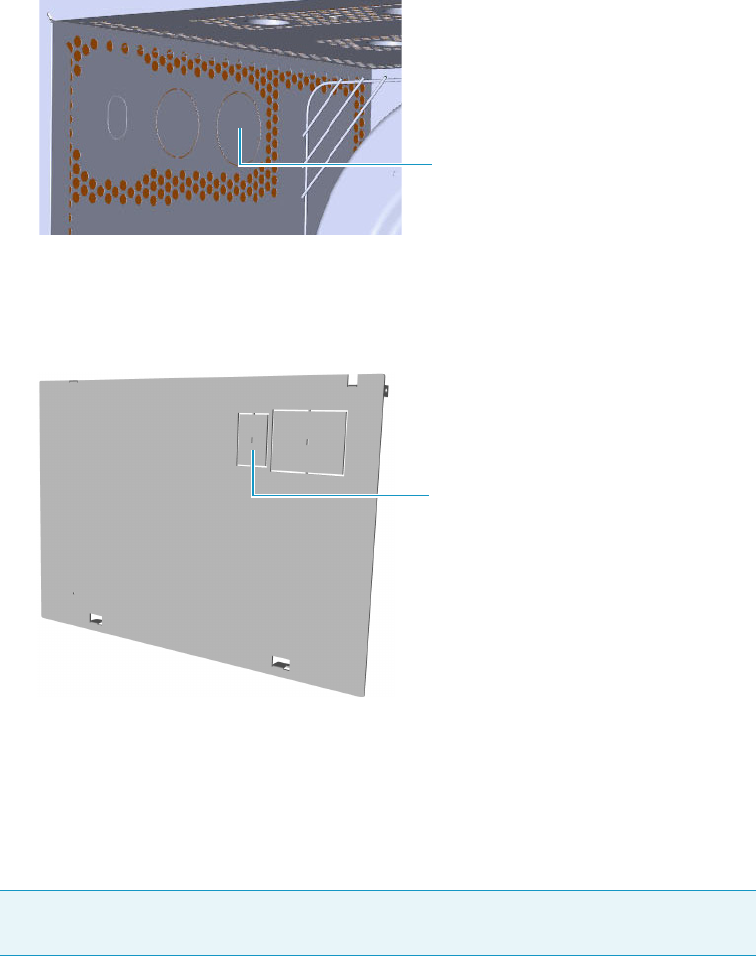
11 Upgrade Equipment
Upgrading a Stand Alone TRACE 1300/TRACE 1310 to MS Version
Thermo Scientific TRACE 1300 and TRACE 1310 Hardware Manual 569
f. On the left side wall in the interior of the oven, remove the partial cut plate from the
corresponding duct. See Figure 628.
Figure 628. Perform the Duct for ITQ (4)
4. Replace the left side panel with the left panel for MS provided.
a. Remove the partial cut plate on the GC left panel for MS. See Figure 629.
Figure 629. Left Panel for MS
b. Plug the ground wire previously removed to the left panel provided for MS.
c. Place the left panel for MS and attach the screw holding it in place.
5. Introduce the ITQ transfer line inner tube into the oven through the duct provided.
6. Attach the transfer line to the GC column using the proper nut and ferrule.
7. Place the Aux Temperature/Cryo module into the housing on the back of the GC.
See the section “Adding an Aux Temperature/Cryo Module” on page 443 for details.
Note The column must be conditioned before installing into the transfer line. See
“Installing the Column the First Time” on page 57.
Duct for ITQ Partial Cut Plate
Duct for ITQ Partial Cut Plate
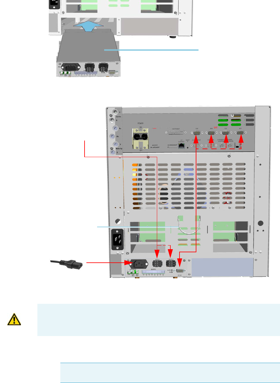
11 Upgrade Equipment
Upgrading a Stand Alone TRACE 1300/TRACE 1310 to MS Version
570 TRACE 1300 and TRACE 1310 Hardware Manual Thermo Scientific
8. Making the electrical connections. See Figure 630.
Figure 630. Electrical Connections
a. Connect the heater cable coming from the transfer line to the connector marked
Heater 1 or Heater 2 on the front of the module.
b. Using the cable provided, connect the 15-pin female connector marked GC Bus on
the module to a Bus interface on the back of the GC.
Aux Temperature/Cryo Module
Transfer Line
Cables Holder
ATTENTION An extension cable transfer line is needed when connecting an ITQ mass
spectrometer to the Aux Temperature/Cryo module.
Tip To avoid the contact with the hot air from the vents, it is suggested to gather
the electrical cables into the cables holder.
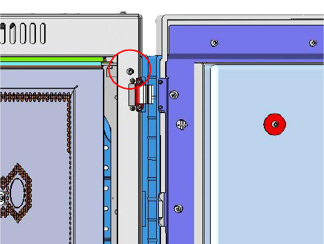
11 Upgrade Equipment
Upgrading a Stand Alone TRACE 1300/TRACE 1310 to MS Version
Thermo Scientific TRACE 1300 and TRACE 1310 Hardware Manual 571
c. Plug the power cable to the AC Input connector on the front of the module and to
the wall outlet. The LED marked On lights.
9. Close the front door of the GC.
10. If other external modules are present, plug the power cable to the AC Input connector of
each external module, and to the wall outlet.
11. Power on the GC.
a. Plug the power cable to the AC Input connector into the back of the GC and to the
wall outlet.
b. Flip up the power switch (breaker), located at the back of the instrument, to the
position I.
12. Tune the ITQ and set its working conditions. Set the GC working conditions
accordingly.
For details please refer to the TRACE 1300 and TRACE 1310 User Guide and to the ITQ
User and Hardware manuals.
Coupling with the TSQ Quantum Mass Spectrometer
To configure the GC for the coupling with the TSQ Quantum mass spectrometer
1. Make sure that the preliminary operations have been carried out. See “Preliminary
Operations” on page 556.
2. Remove the right side panel.
a. Open the front door of the GC.
b. Using a T20 Torxhead screwdriver, unscrew the left side panel screw from the interior
front panel. See Figure 631. Save the screw because it will be reused later.
Figure 631. Right Side Panel Fixing Screw
c. Slide the panel towards the back of the instrument up to the stop.
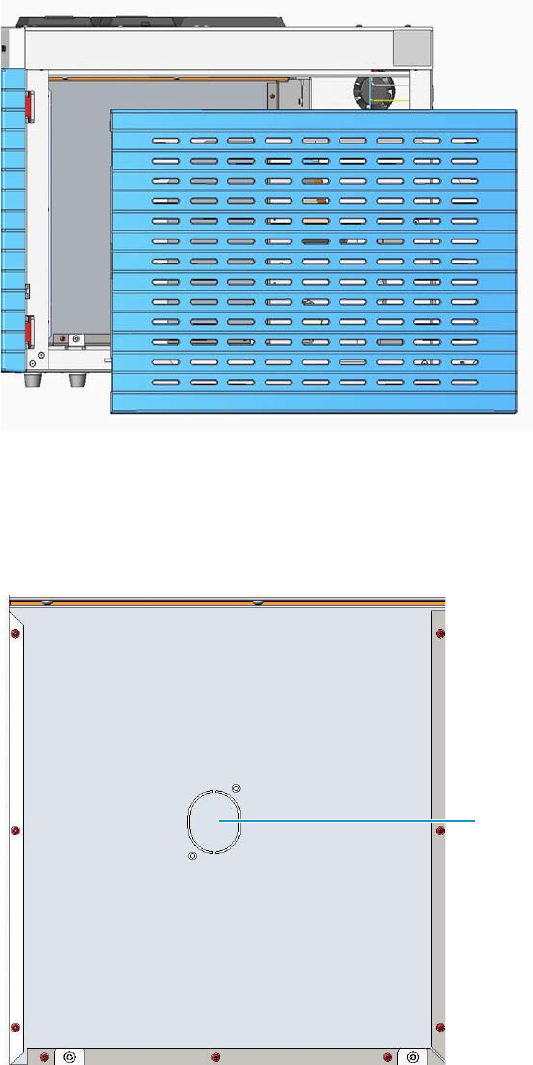
11 Upgrade Equipment
Upgrading a Stand Alone TRACE 1300/TRACE 1310 to MS Version
572 TRACE 1300 and TRACE 1310 Hardware Manual Thermo Scientific
d. Remove the panel pulling it outward being aware that the ground wire is attached to
the panel. See Figure 632.
e. Unplug the ground wire from the panel.
Figure 632. Right Side Panel Removal
3. Prepare the duct for the transfer line inner tube.
a. Remove the partial cut shaped plate from the exterior wall of the oven box to access
the insulating material. See Figure 633.
Figure 633. Perform the Duct for TSQ Quantum (1)
Partial Cut Shaped Plate
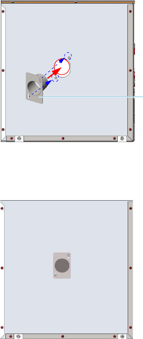
11 Upgrade Equipment
Upgrading a Stand Alone TRACE 1300/TRACE 1310 to MS Version
Thermo Scientific TRACE 1300 and TRACE 1310 Hardware Manual 573
b. Draw up the duct aligning the slot to the fixing holes on the exterior oven wall and
push the duct against the insulating material up to obtain a track. See Figure 634.
Figure 634. Perform the Duct for TSQ Quantum (2)
c. Using a knife or similar tool, gently cut the insulating material following the track.
d. Save the removed insulating material in a safe place because it can be reused.
e. Place the duct and fix it on the exterior wall of the oven box using the fixing screws
provided. See Figure 635.
Figure 635. Perform the Duct for TSQ Quantum (3)
Duct for TSQ Quantum
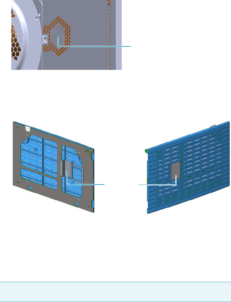
11 Upgrade Equipment
Upgrading a Stand Alone TRACE 1300/TRACE 1310 to MS Version
574 TRACE 1300 and TRACE 1310 Hardware Manual Thermo Scientific
f. On the right side wall in the interior of the oven, remove the partial cut plate from
the corresponding duct. See Figure 636.
Figure 636. Perform the Duct for TSQ Quantum (4)
4. Replace the right side panel with the right panel provided for MS.
a. Using a T20 Torxhead screwdriver, unscrew the duct plate screws from the right
panel for MS. See Figure 637.
Figure 637. Right Panel for MS
b. Plug the ground wire previously removed to the left panel of MS provided.
c. Place the right panel for MS and attach the screw holding it in place.
5. Introduce the TSQ Quantum transfer line inner tube into the oven through the duct
provided.
6. Attach the transfer line to the GC column using the proper nut and ferrule.
7. Place the Aux Temperature/Cryo module into the housing on the back of the GC.
See the section “Adding an Aux Temperature/Cryo Module” on page 443 for details.
Note The column must be conditioned before installing into the transfer line.
See “Installing the Column the First Time” on page 57.
Duct for TSQ Quantum Partial Cut Plate
Duct Plate
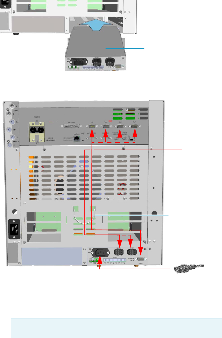
11 Upgrade Equipment
Upgrading a Stand Alone TRACE 1300/TRACE 1310 to MS Version
Thermo Scientific TRACE 1300 and TRACE 1310 Hardware Manual 575
8. Making the electrical connections. See Figure 638.
Figure 638. Electrical Connections
a. Connect the heater cable coming from the transfer line to the connector marked
Heater 1 or Heater 2 on the front of the module
b. Using the cable provided, connect the 15-pin female connector marked GC Bus on
the module to a Bus interface on the back of the GC.
c. Plug the power cable to the AC Input connector on the front of the module and to
the wall outlet. The LED marked On lights up.
Tip To avoid the contact with the hot air from the vents, it is suggested to gather
the electrical cables into the cables holder.
Aux Temperature/Cryo Module
Transfer Line
Cables Holder
11 Upgrade Equipment
Upgrading a Stand Alone TRACE 1300/TRACE 1310 to MS Version
576 TRACE 1300 and TRACE 1310 Hardware Manual Thermo Scientific
9. Close the front door of the GC.
10. Open the gas supplies.
11. If other external modules are present, plug the power cable to the AC Input connector of
each external module, and to the wall outlet.
12. Power on the GC.
a. Plug the power cable to the AC Input connector into the back of the GC and to the
wall outlet.
b. Flip up the power switch (breaker), located at the back of the instrument, to the
position I.
13. Configure and enable the cryogenic system through the user interface of your GC, or
through the CDS in use. Refer to the TRACE 1300 and TRACE 1310 User Guide.
a. Configuration and enabling through the touch screen.
i. In the main menu select the Instrument control icon, the Instrument Control
menu appears.
ii. In the Instrument Control menu, select the Auxiliary icon to open the relevant
submenu.
iii. Set the Aux Temp 1/2 values as required, then return to main menu.
b. Configuration and enabling through the Chromatography Data System.
i. In the Configuration window select the Auxiliary tab.
ii. Select the Auxiliary control module check box to enable the setting for the
auxiliary control of module and option installed on your GC.
iii. In the Heater 1/Heater 2 combo box specify the present heater control.
iv. Open the Auxiliary setup page.
v. Select Heater 1 and/or Heater 2 check box to enable the relevant heater control.
In the adjacent field set the required temperature.
14. Set the normal detector, injector and GC working conditions.
15. Tune the TSQ Quantum and set its working conditions. Set the GC working conditions
accordingly.
For details please refer to the TRACE 1300 and TRACE 1310 User Guide and to the TSQ
Quantum User and Hardware manuals.
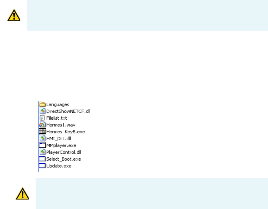
11 Upgrade Equipment
Updating HMI Software From USB Stick
Thermo Scientific TRACE 1300 and TRACE 1310 Hardware Manual 577
Updating HMI Software From USB Stick
This section provides the instruction for updating the HMI software of the TRACE 1310
touch screen through an USB stick.
To update the HMI Software
1. Copy on your PC the HMI SW XX.XX.XX.ZIP folder of the last HMI software version
received from the Thermo Fisher Scientific GC-GC/MS Custom Support.
2. Unzip the folder for extracting the files contained therein. Figure 639 shows an example
of the files contained into the unzipped folder.
Figure 639. Example of the files content into the HMI software folder
3. Copy all the files in the root of the USB stick.
4. Insert the USB stick into the USB port positioned below the touch screen.
On the touch screen main menu, press the Configuration icon to open the
Configuration menu.
5. Press the Tou c h s c re e n icon to open the relevant menu. See Figure 640.
ATTENTION The upgrade must be performed by authorized and trained Thermo Fisher
Scientific technical personnel.
ATTENTION The Hermes_KeyB.exe file and the Languages folder are the fundamental
components always present in the list. The other files shown in the list might change from a
software version and the next.
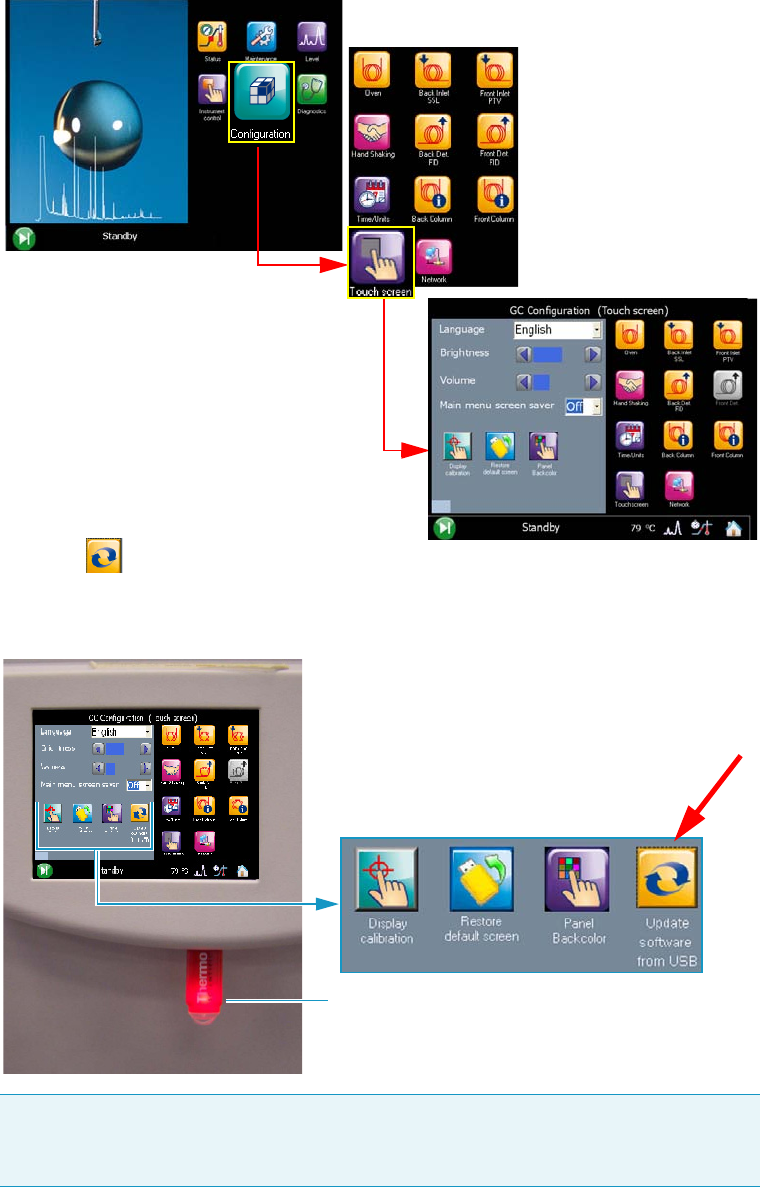
11 Upgrade Equipment
Updating HMI Software From USB Stick
578 TRACE 1300 and TRACE 1310 Hardware Manual Thermo Scientific
Figure 640. Touch Screen Main Menu: Configuration
6. The icon Update software from USB appears in the configuration page.
See Figure 641.
Figure 641. USB stick positioned into the USB port below the touch screen
Note It can take a few moments for USB stick to be recognized by the TRACE 1310.
If you do not see the icon Update software from USB in the menu, then return to the
Home screen, and re-enter the Tou c h s c re en portion of the Configuration menu.
USB Stick
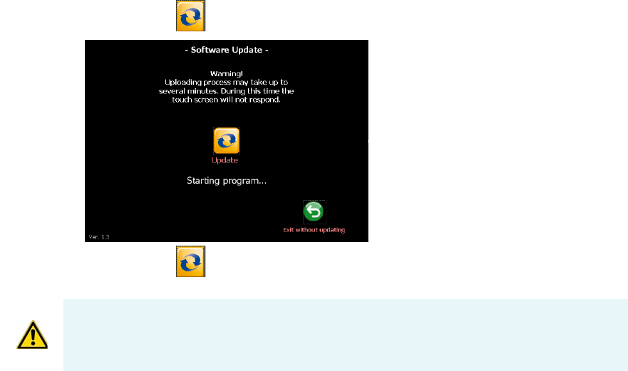
11 Upgrade Equipment
Updating HMI Software From USB Stick
Thermo Scientific TRACE 1300 and TRACE 1310 Hardware Manual 579
7. Press the icon , the following page is visualized:
8. Press the icon Update to start the updating process.
9.At the end of the updating process, the program restarts.
10. Only now remove the USB stick from the USB port.
WARNING DO NOT REMOVE THE USB STICK DURING THE UPDATING PROCESS,
THIS COULD DAMAGE THE INSTRUMENT.

Thermo Scientific TRACE 1300 and TRACE 1310 Hardware Manual 581
12
Troubleshooting
In this chapter, we describe the symptoms of and remedy for each known issue with the
TRACE 1300/TRACE 1310 gas chromatograph. All of these issues are related to hardware,
but your instrument or software will alert you to them. For issues that you discover while
reviewing your data, see the Analytical Troubleshooting section of the TRACE 1300 and
TRACE 1310 User Guide.
Contents
•Investigating Power Supply Issues
•Investigating Communication Issues
•Investigating Sensitivity Issues
•Error Messages
•Contacting Technical Support

12 Troubleshooting
Investigating Power Supply Issues
582 TRACE 1300 and TRACE 1310 Hardware Manual Thermo Scientific
Investigating Power Supply Issues
Verify the correct power supply to the instrument.
TRACE 1300/TRACE 1310 will not power-on
Investigating Communication Issues
Verify the instruments is communicating with the computer.
Software is not communicating with the TRACE 1300/TRACE 1310
TRACE 1300/TRACE 1310 does not start or is not ready
Cannot download methods to the TRACE 1300/TRACE 1310
Possible Remedies
Make sure the TRACE 1300/TRACE 1310 power cable is properly connected to the instrument and to the correct 220/120 V main power
line outlet.
Verify that the electrical outlet is functioning properly.
Power supply system is faulty. Contact your local Thermo Fisher Scientific customer support organization.
Possible Remedies
Make sure the LAN cable is properly connected to the GC.
Confirm the TCP/IP configuration on the computer matches the GC.
Restart the GC.
Possible Remedies
Verify the GC methods and configuration.
Make sure the electrical connections have been properly carried out.
Confirm the GC handshaking parameters are set properly.
Possible Remedies
Verify that your instruments are properly configured.

12 Troubleshooting
Investigating Sensitivity Issues
Thermo Scientific TRACE 1300 and TRACE 1310 Hardware Manual 583
Sample data are not acquired
GC is not communicating with the PC
Autosampler is not communicating with the PC
Investigating Sensitivity Issues
Sensitivity issues are usually the result of an air leak, dirty components, or contamination.
Sometimes sensitivity issues can be caused by simple problems such as the carrier gas tank
running out or a sample not being injected into the GC.
If the problem is more complex, then check for air leaks or dirty components. You can prevent
these problems by properly cleaning and maintaining your GC system.
It is normal to see a decrease in sensitivity in the first few injections on a clean system. Before
troubleshooting for sensitivity issues, look for simple solutions, such as fixing a clogged
autosampler syringe or raising the level of your sample.
Poor sensitivity or sudden loss in sensitivity
Possible Remedies
Make sure the autosampler methods and configuration include starting up and injecting a sample.
You should also make sure the sample has been injected.
Make sure the cables between autosampler and GC are properly connected.
Add more disk space to the computer if necessary.
Possible Remedies
Make sure the GC is powered on.
Make sure the GC is properly configured.
Possible Remedies
Make sure the autosampler is powered on.
Make sure the autosampler is properly configured.
Make sure the cable between the autosampler and PC is properly connected.
Possible Remedies
Check the system for leaks and address them.
Clean or replace the GC injection port liner to remove possible contamination, trim the injector end of the column, or replace the septum.
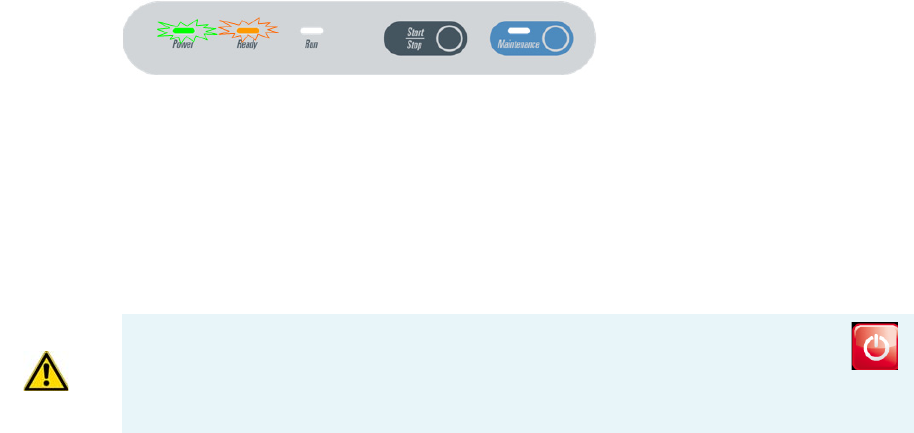
12 Troubleshooting
Error Messages
584 TRACE 1300 and TRACE 1310 Hardware Manual Thermo Scientific
Error Messages
Error messages are visualized in case of GC malfunctioning. See the following sections:
•TRACE 1300 Error Messages
•TRACE 1310 Error Messages
TRACE 1300 Error Messages
TRACE 1300 instrument malfunction, due to a component failure or to abnormal operating
condition is identified by the blinking of both Power and Ready lights located on the
TRACE 1300 Status Panel. See Figure 642.
Figure 642. TRACE 1300: Alarm Identification
A typical sound (beep) is heard. Power and temperatures are automatically cut off.
To reset an alarm, the GC must be powered off, and then powered on.
TRACE 1310 Error Messages
TRACE 1310 instrument malfunctioning, due to a component failure or to abnormal
operating condition, is identified by an error messages displayed before or during the runs.
•FID Front/Back/Left/Right
– Unconnected
– Temperature over limit
– Opened PT100
–Shorted PT100
– Thermal safety: Not Heating or Auto Heating
– Reset detected
• ECD Front/Back/Left/Right
– Unconnected
–PLD error
– Temperature over limit
IMPORTANT When an alarm is displayed in the message bar, try to solve the
problem, then go to the Diagnostics menu and press the Reset button to reboot
the system. If the problem persists, contact the Technical Support; see “Contacting
Tech n i cal Suppor t” on page 589.
12 Troubleshooting
Error Messages
Thermo Scientific TRACE 1300 and TRACE 1310 Hardware Manual 585
– Opened PT100
–Shorted PT100
– Thermal safety: Not Heating or Auto Heating
– Reset detected
• NPD Front/Back/Left/Right
– Unconnected
– Bead Current Over or Under range
– Temperature over limit
– Opened PT100
–Shorted PT100
– Thermal safety: Not Heating or Auto Heating
– Reset detected
–High Voltage shorted
• TCD Front/Back/Left/Right
– Unconnected
– Temperature over limit
– Opened PT100
–Shorted PT100
– Thermal safety: Not Heating or Auto Heating
– Reset detected
• FPD Front/Back/Left/Right
– Unconnected
– Temperature over limit
– Opened PT100
–Shorted PT100
– Thermal safety: Not Heating or Auto Heating
– Reset detected
– Opened Cell PT100
–Shorted Cell PT100
• PDD Front/Back/Left/Right
– Unconnected
– Temperature over limit
12 Troubleshooting
Error Messages
586 TRACE 1300 and TRACE 1310 Hardware Manual Thermo Scientific
– Opened PT100
–Shorted PT100
– Reset detected
•GDI Front/Back/Left/Right
– Unconnected
– Temperature over limit
– Opened PT100
–Shorted PT100
– Reset detected
• SSL-SSLBKF Front/back
– Unconnected
– Temperature over limit
– Opened PT100
–Shorted PT100
– Thermal safety: Not Heating or Auto Heating
– Reset detected
– Loss of Carrier
• PTV-PTVBKF Front/Back
– Unconnected
– Temperature over limit
– Opened Temperature Sensor
– Shorted Temperature Sensor
– Thermal safety: Not Heating or Auto Heating
– Reset detected
– Loss of Carrier
• AUX Temperature EXT-V Sub Ambient
– Unconnected
– X-Line B over limit
– X-Line B Opened PT100
–X-Line B Shorted PT100
–X-Line A over limit
– X-Line A Opened PT100
12 Troubleshooting
Error Messages
Thermo Scientific TRACE 1300 and TRACE 1310 Hardware Manual 587
– X-Line A Shorted PT100
– Thermal safety: Not Heating or Auto Heating
•Valve Oven
– Unconnected
– Heater B over limit
– Heater B Opened PT100
– Heater B Shorted PT100
– Heater A over limit
– Heater A Opened PT100
– Heater A Shorted PT100
– Thermal safety: Not Heating or Auto Heating Heater A or B
• AUX Carrier Primary
– Unconnected
– Channel 1 Loss of Carrier
– Channel 2 Loss of Carrier
– Channel 3 Loss of Carrier
• AUX Carrier Secondary
– Unconnected
– Channel 1 Loss of Carrier
– Channel 2 Loss of Carrier
– Channel 3 Loss of Carrier
•Oven
– Unconnected
– Temperature over limit
– Opened PT100
–Shorted PT100
– Thermal safety: Oven Auto Heating
– Hydrogen Sensor Alarm
– Hydrogen Sensor Fault
– Reset detected
– Thermal safety: Oven Not Heating
– Max Temperature reached
12 Troubleshooting
Error Messages
588 TRACE 1300 and TRACE 1310 Hardware Manual Thermo Scientific
•Main CPU
– Master Safety detected
–Main I2C Bus fault
– Detector I2C Bus fault
– EMI RAM Memory fault
– Main CPU Overheating
– Manifold Temperature Overheating
– 48Vac missing
– +24Vcc missing
– +15Vcc missing
– -15Vcc missing
–AC Mains out of range
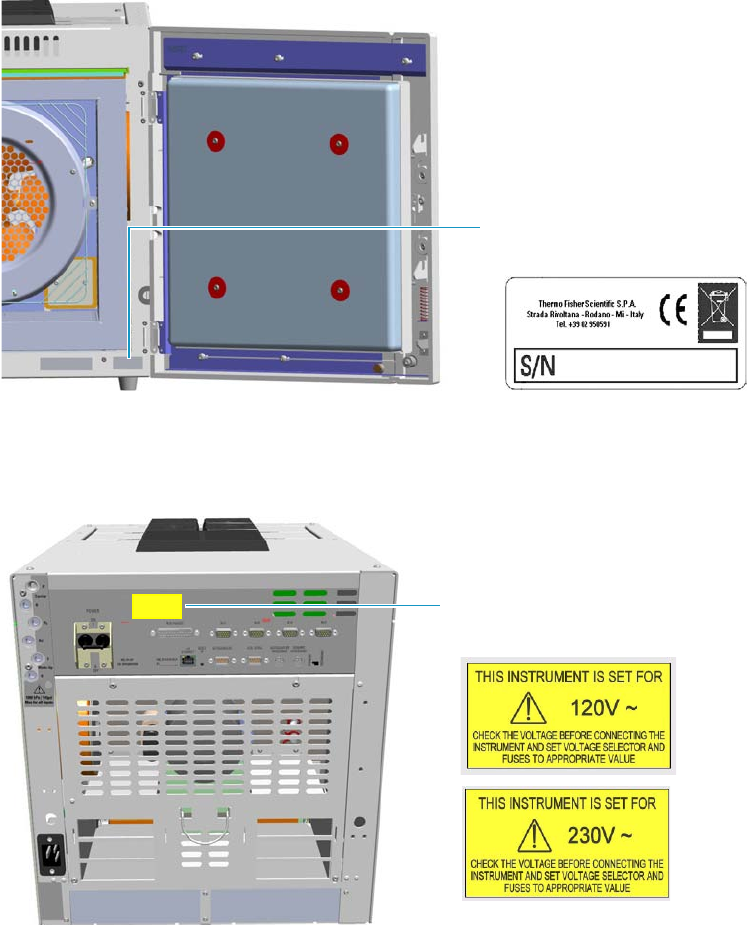
12 Troubleshooting
Contacting Technical Support
Thermo Scientific TRACE 1300 and TRACE 1310 Hardware Manual 589
Contacting Technical Support
If the information in this section does not help solve your problem, you should contact
Technical Support. Be sure to reference the model, serial number, and power supply of your
instrument when contacting them.
•Serial Number — You can find the serial number of the GC by opening the front door,
and reading the serial number label on the right lower corner. See Figure 643.
Figure 643. Identify Your Instrument: Serial Number
•Power supply your GC is set — The 120 Vac or 230 Vac power supply is indicated on
the yellow label on the electronic module. See Figure 644.
Figure 644. Identify Your Instrument: Power Supply Data
For contacting your local Thermo Fisher Scientific office or affiliate GC-GC/MS Customer
Support, see the section “Contacting Us” on page xix.
TRACE 1300/TRACE 1310 Serial
Number Label
Power Supply 120 Vac or
230 Vac Alert Label

Thermo Scientific TRACE 1300 and TRACE 1310 Hardware Manual 591
G
Glossary
This section lists and defines terms used in this manual.
It also includes acronyms, metric prefixes, and symbols.
A
A ampere
ac alternating current
ADC analog-to-digital converter
AOI Analog Output Interface
B
b bit
B byte (8 b)
baud rate data transmission speed in events per
second
C
C Carbon
°C Celsius
CDS Chromatography Data System
CIP Carriage and Insurance Paid To
cm centimeter
CPU central processing unit (of a computer)
<Ctrl> control key of the keyboard
D
d depth
DAC digital-to-analog converter
dc direct current
DS data system
E
ECD Electron Capture Detector
EMC electromagnetic compatibility
ESD electrostatic discharge
F
f femto
ºF Fahrenheit
FID Flame Ionization Detector
FOB Free on board
FSE Field Service Engineer
FPD Flame Photometric Detector
A B C D E F G H I JK L M N O P QR S T V V W X Y Z
Glossary: ft
592 TRACE 1300 and TRACE 1310 Hardware Manual Thermo Scientific
ft foot
FT-IR fourier transform infrared spectroscopy/fourier
transform infrared spectrometer
G
g gram
GC gas chromatography- gas chromatograph
GDI Generic Detector Interface
GND electrical ground
GSV Gas Sampling Valve
H
h height
h hour
H Hydrogen
harmonic distortion A high-frequency disturbance
that appears as distortion of the fundamental sine
wave
He Helium
HeS-S/SL Instant Connect Helium Saver Injector
HV high voltage
Hz hertz (cycles per second)
I
ID inside diameter
IEC International Electrotechnical Commission
Impulse See transient
in. inch
I/O input/output
K
k kilo (103 or 1024)
K Kelvin
kg kilogram
kPa kilopascal
L
l length
L liter
LAN Local Area Network
lb pound
LED light-emitting diode
M
m meter (or milli [10-3])
M mega (106)
μ micro (10-6)
MBq megabecquerel
Ci millicurie
min minute
mL or ml milliliter
mm millimeter
MS mass spectrometry-mass spectrometer
m/z mass-to- charge ratio
N
n nano (10-9)
N Nitrogen
negative polarity The inverse of a detector signal
polarity.
Glossary: nm
Thermo Scientific TRACE 1300 and TRACE 1310 Hardware Manual 593
nm nanometer
NPD Nitrogen Phosphorous Detector
O
OD outside diameter
Ω ohm
P
p pico (10-12)
Pa pascal
PCB printed circuit board
PDD Pulsed Discharge Detector
PN part number
psi pounds per square inch
PTV Programmable Temperature Vaporizing Injector
PTVBKF Programmable Temperature Vaporizing
Injector with backflush
R
RAM random access memory
<Return> <Return> key on the keyboard
RF radio frequency
ROM read-only memory
RS-232 industry standard for serial communication
S
s second
sag See surge
slow average A gradual long-term change in average
RMS voltage level, with typical duration greater than
2 s.
SOP Standard Operating Procedures
SSL split/splitless injector
SSLBKF split/splitless injector with Backflush
source current The current needed to ignite a
source, such as a detector lamp.
surge A sudden change in average RMS voltage level,
with typical duration between 50 μs and 2 s.
T
TCD Thermal Conductivity Detector
transient A brief voltage surge of up to several
thousand volts, with a duration of less than 50 μs.
V
V volt
Vac volts, alternating current
Vdc volts, direct current
VGA Video Graphics Array
W
w width
W Watt
When a unit of measure has a quotient (e.g. Celsius
degrees per minute or grams per liter) this can be written
as negative exponent instead of the denominator:
For example:
°C min-1 instead of °C/min
g L-1 instead of g/L
