Aux Oven 31715011 TRACE 1310 Auxiliary Manual
2016-05-17
: Pdf 31715011 Trace 1310 Auxiliary Oven Manual 31715011 TRACE 1310 Auxiliary Oven Manual TRACE 1300 TRACE 1310 GC AS Manuals User ation
Open the PDF directly: View PDF ![]() .
.
Page Count: 158 [warning: Documents this large are best viewed by clicking the View PDF Link!]
- Contents
- Preface
- Site Preparation
- TRACE 1310 Auxiliary Oven Overview
- Components Installation
- Installing the Valves
- Installing Valves and Fittings into the Main Oven
- Installing Valves and Fittings in the Unheated Compartment
- Plumbing Valves and System
- Configuring the Valves
- Installing the Auxiliary Gas Modules
- Installing the Auxiliary Detectors Assembly
- Installing the Secondary Oven Assembly
- Installing the Methanizer Assembly
- Installing a Heated Sample Transfer Line
- Wiring the TRACE 1310 Auxiliary Oven to the GC
- Coupling the TRACE 1310 Auxiliary Oven to the GC
- Operation
- Maintenance & Troubleshooting
- Ordering Parts

Thermo Scientific
TRACE 1310 Auxiliary
Oven
Instruction Manual
Additional Section of the TRACE 1300/1310 Gas
Chromatographs Hardware Manual & User Guide
PN 31715011 Revision D January 2016
Home
© 2016 Thermo Fisher Scientific Inc. All rights reserved.
TRACE 1300 and TRACE 1310 are trademarks of Thermo Fisher Scientific; VICI ® is a registered mark of the
Valco Instrument Co. Inc., and VICI AG International; AFP™ is a trademark of the Analytical Flow Product,
Division of Mecanique Analitique Inc. All other trademarks are the property of Thermo Fisher Scientific and
its subsidiaries.
Published by Thermo Fisher Scientific S.p.A., Strada Rivoltana 20090 Rodano-Milan, Italy
Tel: +39 02 95059303; Fax: +39 02 95059388
Thermo Fisher Scientific Inc. provides this document to its customers with a product purchase to use in the
product operation. This document is copyright protected and any reproduction of the whole or any part of this
document is strictly prohibited, except with the written authorization of Thermo Fisher Scientific Inc.
The contents of this document are subject to change without notice. All technical information in this
document is for reference purposes only. System configurations and specifications in this document supersede
all previous information received by the purchaser.
Thermo Fisher Scientific Inc. makes no representations that this document is complete, accurate or error-
free and assumes no responsibility and will not be liable for any errors, omissions, damage or loss that might
result from any use of this document, even if the information in the document is followed properly.
This document is not part of any sales contract between Thermo Fisher Scientific Inc. and a purchaser. This
document shall in no way govern or modify any Terms and Conditions of Sale, which Terms and Conditions of
Sale shall govern all conflicting information between the two documents.
Release history: First Edition, released October 2013 “Original Instructions”
Second Edition, released January 2014; Third Edition, released March 2015; Fourth Edition, released
January 2016
For Research Use Only. Not for use in diagnostic procedures.
fold
fold
Reader’s Survey
TRACE 1310 Auxiliary Oven Instruction Manual, PN 31715011, Revision D
If not, please comment below. Attach additional sheets if necessary.
__________________________________________________________ __________________________________________________________________
__________________________________________________________ __________________________________________________________________
__________________________________________________________ __________________________________________________________________
__________________________________________________________ __________________________________________________________________
__________________________________________________________ __________________________________________________________________
__________________________________________________________ __________________________________________________________________
__________________________________________________________ __________________________________________________________________
__________________________________________________________ __________________________________________________________________
__________________________________________________________ __________________________________________________________________
Customer Registration Card
Register now…and receive all the privileges associated with being a Thermo Fisher Scientific product user including customer
support, application reports, and technical reports.
Name __________________________________________________Title__________________________________________________________________
Company __________________________________________________ __________________________________________________________________
Address ___________________________________________________ __________________________________________________________________
City/State _________________________________________Postal Code__________________________________________________________________
Country ___________________________________________________ __________________________________________________________________
Telephone_______________________________________________ Ext. __________________________________________________________________
Serial Number __________________________________ Date purchased __________________________________________________________________
Fold and mail or e-mail to:
Strongly
Agree Agree Neutral Disagree Strongly
Disagree
The manual is well organized. 12345
The manual is clearly written. 12345
The manual contains all the information I need. 12345
The instructions are easy to follow. 12345
The instructions are complete. 12345
The technical information is easy to understand. 12345
Examples of operation are clear and useful. 12345
The figures are helpful. 12345
I was able to operate the system using this manual. 12345
MY ORGANIZATION IS: (Check only one) MY PRIMARY APPLICATION IS: (Check only one)
❏Commercial (for profit) lab ❏Analytical
❏Government lab ❏Biomedical
❏Hospital/Clinic ❏Clinical/Toxicology
❏Industrial lab ❏Energy
❏Research Institute ❏Environmental
❏University/College ❏Food/Agricultural
❏Veterinary ❏Forensic/Toxicology
❏Other______________________ ❏Pharmaceutical
❏Research/Education
MY PRIMARY JOB FUNCTION IS: (Check only one)❏Other______________________
❏Administration
❏Lab management
❏Operator
❏Other______________________
Editor, Technical Publications
Thermo Fisher Scientific S.p.A.
Strada Rivoltana km 4
20090 Rodano (MI)
Italy
Editor, Technical Publications
Thermo Fisher Scientific SID GC-GC/MS
2215 Grand Avenue Parkway
Austin TX 78728-3812
Unites States of America
Declaration
Manufacturer: Thermo Fisher Scientific
Thermo Fisher Scientific is the manufacturer of the instrument described in this manual and, as such, is responsible
for the instrument safety, reliability and performance only if:
•installation
•re-calibration
•changes and repairs
have been carried out by authorized personnel and if:
• the local installation complies with local law regulations
• the instrument is used according to the instructions provided and if its operation is only entrusted to qualified
trained personnel
Thermo Fisher Scientific is not liable for any damages derived from the non-compliance with the aforementioned
recommendations.
Thermo Fisher Scientific S.p.A.
Strada Rivoltana, 20090 Rodano - Milan - Italy — Tel: +39 02 950591 - Fax: +39 02 9505276
Regulatory Compliance
Thermo Fisher Scientific performs complete testing and evaluation of its products to ensure full compliance with
applicable domestic and international regulations.
When the system is delivered to you, it meets all pertinent electromagnetic compatibility (EMC) and safety
standards.
Safety
This device complies with the following safety standards according to Machinery Directive 2006/42/EC and Low
Voltage Directive 2006/95/EC.
• International Electrotechnical Commission (IEC): 61010-1:2001 (Second edition) -61010-2-010:2003
(Second edition)-61010-2-081:2001 (First edition)+ A1:(2003)
• National differences: CAN/CSA C22.2 No. 61010-1 (2nd Edition)-UL 61010-1 (2nd Edition)
• EuroNorm (EN): 61010-1:2001 (2nd Edition) – 61010-2-010:2004 (2nd Edition) - 61010-2-081:2002 (1st
Edition)
Electromagnetic Compatibility
This device complies with the following regulations on Electromagnetic Compatibility (EMC) and Radio
Frequency Interference (RFI) according to directive 2004/108/EC:
• CISPR 11/EN 55011: Group 1 Class A
• IEC/EN 61326-1:2012
IMPORTANT: Class A equipment is intended for use in an industrial environment. In others
environments there may be potential difficulties in ensuring electromagnetic compatibility, due
to the conducted as well as radiated disturbances.
FCC Compliance Statement
Notice on Lifting and Handling of
Thermo Scientific Instruments
For your safety, and in compliance with international regulations, the physical handling of this Thermo Fisher
Scientific instrument requires a team effort to lift and/or move the instrument. This instrument is too heavy and/
or bulky for one person alone to handle safely.
Notice on the Proper Use of
Thermo Scientific Instruments
In compliance with international regulations: Use of this instrument in a manner not specified by Thermo Fisher
Scientific could impair any protection provided by the instrument.
Notice on the Susceptibility
to Electromagnetic Transmissions
Do not use radio frequency transmitters, such as mobile phones, in close proximity to the instrument.
THIS DEVICE COMPLIES WITH PART 15 OF THE FCC RULES. OPERATION IS SUBJECT TO
THE FOLLOWING TWO CONDITIONS: (1) THIS DEVICE MAY NOT CAUSE HARMFUL
INTERFERENCE, AND (2) THIS DEVICE MUST ACCEPT ANY INTERFERENCE RECEIVED,
INCLUDING INTERFERENCE THAT MAY CAUSE UNDESIRED OPERATION.
CAUTION Read and understand the various precautionary notes, signs, and symbols contained
inside this manual pertaining to the safe use and operation of this product before using the device.
WEEE Compliance
This product is required to comply with the European Union’s Waste Electrical & Electronic Equipment (WEEE) Directive
2012/19/EU. It is marked with the following symbol:
Thermo Fisher Scientific has contracted with one or more recycling or disposal companies in each European Union (EU)
Member State, and these companies should dispose of or recycle this product. See www.thermoscientific.com/rohsweee for
further information on Thermo Fisher Scientific’s compliance with these Directives and the recyclers in your country.
WEEE Konformität
Dieses Produkt muss die EU Waste Electrical & Electronic Equipment (WEEE) Richtlinie 2012/19/EU erfüllen. Das Produkt
ist durch folgendes Symbol gekennzeichnet:
Thermo Fisher Scientific hat Vereinbarungen mit Verwertungs-/Entsorgungsfirmen in allen EU-Mitgliedsstaaten getroffen,
damit dieses Produkt durch diese Firmen wiederverwertet oder entsorgt werden kann. Mehr Information über die Einhaltung
dieser Anweisungen durch Thermo Fisher Scientific, über die Verwerter, und weitere Hinweise, die nützlich sind, um die
Produkte zu identifizieren, die unter diese RoHS Anweisung fallen, finden sie unter www.thermoscientific.com/rohsweee.
Conformité DEEE
Ce produit doit être conforme à la directive européenne (2012/19/EU) des Déchets d'Equipements Electriques et
Electroniques (DEEE). Il est marqué par le symbole suivant:
Thermo Fisher Scientific s'est associé avec une ou plusieurs compagnies de recyclage dans chaque état membre de l’union
européenne et ce produit devrait être collecté ou recyclé par celles-ci. Davantage d'informations sur la conformité de Thermo
Fisher Scientific à ces directives, les recycleurs dans votre pays et les informations sur les produits Thermo Fisher Scientific qui
peuvent aider la détection des substances sujettes à la directive RoHS sont disponibles sur www.thermoscientific.com/rohsweee.
Conformità RAEE
Questo prodotto è marcato con il seguente simbolo in conformità alla direttiva europea 2012/19/EU (RAEE) sui rifiuti di
apparecchiature elettriche ed elettroniche:
Thermo Fisher Scientific si è accordata con una o più società di riciclaggio in ciascun Stato Membro della Unione Europea
(EU), e queste società dovranno smaltire o riciclare questo prodotto. Per maggiori informazioni vedere il sito
www.thermoscientific.com/rohsweee.
Conformidad RAEE
Este producto es marcado con el siguiente símbolo en conformidad a la Directiva 2012/19/EU de la Unión Europea sobre los
residuos de aparatos eléctricos y electrónicos:
Thermo Fisher Scientific ha contratado una o más empresas de reciclo para tratar residuos en cada Estado Miembro de la
Unión Europea, y estas empresas deberían reciclar o eliminar este producto. Referirse a www.thermoscientific.com/rohsweee
para una mayor información sobre la conformidad de Thermo Fisher Scientific con estas Directivas y para las empresas de
reciclaje en su país.
IMPORTANT
The symbol indicates the product must not be disposed of with the normal household wastes. Correct disposal of
this product prevents any potentially negative impact on the environmental and human health that could arise
from any inappropriate handling of the product itself.
WEEE rules, while laid down at European level, are put into national law at national level. When exporting to
Europe, it is essential to comply with national law in each relevant country. The EU law simply serves as a template
for national laws, which may differ considerably.
Each EU Member State has own regulations regarding the application of these directives. Please refer to the
regulations in force in your country.

Thermo Scientific TRACE 1310 Auxiliary Oven Instruction Manual ix
C
Preface . . . . . . . . . . . . . . . . . . . . . . . . . . . . . . . . . . . . . . . . . . . . . . . . . . . . . . . . . . . . .xiii
About Your System. . . . . . . . . . . . . . . . . . . . . . . . . . . . . . . . . . . . . . . . . . . . . .xiv
Power Rating . . . . . . . . . . . . . . . . . . . . . . . . . . . . . . . . . . . . . . . . . . . . . . . . . .xiv
Contacting Us . . . . . . . . . . . . . . . . . . . . . . . . . . . . . . . . . . . . . . . . . . . . . . . . . xv
Related Documentation . . . . . . . . . . . . . . . . . . . . . . . . . . . . . . . . . . . . . . . . . . xv
Safety Alerts and Important Information . . . . . . . . . . . . . . . . . . . . . . . . . . . . . xv
Safety Symbols and Signal Words . . . . . . . . . . . . . . . . . . . . . . . . . . . . . . . . .xvi
Instrument Markings and Symbols . . . . . . . . . . . . . . . . . . . . . . . . . . . . . . . . .xviii
Hydrogen Safety Precautions . . . . . . . . . . . . . . . . . . . . . . . . . . . . . . . . . . . . . .xix
Using Hydrogen with TRACE 1300/TRACE 1310 . . . . . . . . . . . . . . . . . . . xx
Hydrogen Connection Guidelines . . . . . . . . . . . . . . . . . . . . . . . . . . . . . . . . .xxi
Purchasing Hydrogen . . . . . . . . . . . . . . . . . . . . . . . . . . . . . . . . . . . . . . . . . xxii
Properly Storing Hydrogen . . . . . . . . . . . . . . . . . . . . . . . . . . . . . . . . . . . . .xxiii
Hydrogen Safety Codes, Standards and References . . . . . . . . . . . . . . . . . . .xxiii
Hazardous Substances Precautions . . . . . . . . . . . . . . . . . . . . . . . . . . . . . . . . . xxv
Venting Toxic Gases . . . . . . . . . . . . . . . . . . . . . . . . . . . . . . . . . . . . . . . . . . xxv
Chapter 1 Site Preparation. . . . . . . . . . . . . . . . . . . . . . . . . . . . . . . . . . . . . . . . . . . . . . . . . . . . . . . .1
Introduction . . . . . . . . . . . . . . . . . . . . . . . . . . . . . . . . . . . . . . . . . . . . . . . . . . . . 2
Entrance Requirements . . . . . . . . . . . . . . . . . . . . . . . . . . . . . . . . . . . . . . . . . . . . 2
Workbench & Space Requirements. . . . . . . . . . . . . . . . . . . . . . . . . . . . . . . . . . . 3
Lighting Requirements . . . . . . . . . . . . . . . . . . . . . . . . . . . . . . . . . . . . . . . . . . . . 4
Power Requirements . . . . . . . . . . . . . . . . . . . . . . . . . . . . . . . . . . . . . . . . . . . . . . 4
LAN Network Requirements. . . . . . . . . . . . . . . . . . . . . . . . . . . . . . . . . . . . . . . . 6
Environment Requirements. . . . . . . . . . . . . . . . . . . . . . . . . . . . . . . . . . . . . . . . . 6
Gas Equipment Requirements. . . . . . . . . . . . . . . . . . . . . . . . . . . . . . . . . . . . . . . 7
Receiving Instruments . . . . . . . . . . . . . . . . . . . . . . . . . . . . . . . . . . . . . . . . . . . . . 8
What Happens Next? . . . . . . . . . . . . . . . . . . . . . . . . . . . . . . . . . . . . . . . . . . . . . 8
Chapter 2 TRACE 1310 Auxiliary Oven Overview. . . . . . . . . . . . . . . . . . . . . . . . . . . . . . . . . . . . .9
Front View . . . . . . . . . . . . . . . . . . . . . . . . . . . . . . . . . . . . . . . . . . . . . . . . . . . . 10
Top View . . . . . . . . . . . . . . . . . . . . . . . . . . . . . . . . . . . . . . . . . . . . . . . . . . . . . 11
Back View . . . . . . . . . . . . . . . . . . . . . . . . . . . . . . . . . . . . . . . . . . . . . . . . . . . . . 13
Right View . . . . . . . . . . . . . . . . . . . . . . . . . . . . . . . . . . . . . . . . . . . . . . . . . . . . 14
Left View. . . . . . . . . . . . . . . . . . . . . . . . . . . . . . . . . . . . . . . . . . . . . . . . . . . . . . 15
Contents
Contents
x TRACE 1310 Auxiliary Oven Instruction Manual Thermo Scientific
Internal View. . . . . . . . . . . . . . . . . . . . . . . . . . . . . . . . . . . . . . . . . . . . . . . . . . . 16
The Heated Compartment . . . . . . . . . . . . . . . . . . . . . . . . . . . . . . . . . . . . . . 17
The Unheated Compartment . . . . . . . . . . . . . . . . . . . . . . . . . . . . . . . . . . . . 18
Main Oven . . . . . . . . . . . . . . . . . . . . . . . . . . . . . . . . . . . . . . . . . . . . . . . . . . . . 24
Label Location on the Instrument . . . . . . . . . . . . . . . . . . . . . . . . . . . . . . . . . . . 28
Tools Needed . . . . . . . . . . . . . . . . . . . . . . . . . . . . . . . . . . . . . . . . . . . . . . . . . . 31
Chapter 3 Components Installation . . . . . . . . . . . . . . . . . . . . . . . . . . . . . . . . . . . . . . . . . . . . . . .33
Installing the Valves. . . . . . . . . . . . . . . . . . . . . . . . . . . . . . . . . . . . . . . . . . . . . . 34
Installing Valves and Fittings into the Main Oven. . . . . . . . . . . . . . . . . . . . . . . 34
Installing the Needle Valves and the Sample Inlet Fittings into the
Main Oven. . . . . . . . . . . . . . . . . . . . . . . . . . . . . . . . . . . . . . . . . . . . . . . . . 34
Bulkhead Connectors for High Temperature. . . . . . . . . . . . . . . . . . . . . . . . . 38
Installing the Rotary Valves into the Main Oven . . . . . . . . . . . . . . . . . . . . . . 40
Installing the Diaphragm Valves in The Main Oven . . . . . . . . . . . . . . . . . . . 46
Installing Valves and Fittings in the Unheated Compartment . . . . . . . . . . . . . . 49
Installing the Needle Valves and the Sample Inlet Fittings into the
Unheated Compartment . . . . . . . . . . . . . . . . . . . . . . . . . . . . . . . . . . . . . . 49
Installing an Unheated Rotary Valve into the Unheated Compartment. . . . . 55
Installing an Unheated Diaphragm Valve into the Unheated
Compartment . . . . . . . . . . . . . . . . . . . . . . . . . . . . . . . . . . . . . . . . . . . . . . 59
Installing an Unheated Valve for Liquid Sample into the Unheated
Compartment . . . . . . . . . . . . . . . . . . . . . . . . . . . . . . . . . . . . . . . . . . . . . . 63
Plumbing Valves and System. . . . . . . . . . . . . . . . . . . . . . . . . . . . . . . . . . . . . . . 70
Configuring the Valves . . . . . . . . . . . . . . . . . . . . . . . . . . . . . . . . . . . . . . . . . . . 70
Gas Sampling Valves . . . . . . . . . . . . . . . . . . . . . . . . . . . . . . . . . . . . . . . . . . . 70
Switching Valves . . . . . . . . . . . . . . . . . . . . . . . . . . . . . . . . . . . . . . . . . . . . . . 70
Testing the Valves . . . . . . . . . . . . . . . . . . . . . . . . . . . . . . . . . . . . . . . . . . . . . 70
Installing the Auxiliary Gas Modules . . . . . . . . . . . . . . . . . . . . . . . . . . . . . . . . . 71
Special Use of the Auxiliary Gas Module for Controlling the Split
Flow. . . . . . . . . . . . . . . . . . . . . . . . . . . . . . . . . . . . . . . . . . . . . . . . . . . . . . 75
Installing the Auxiliary Detectors Assembly. . . . . . . . . . . . . . . . . . . . . . . . . . . . 80
Installing the Secondary Oven Assembly . . . . . . . . . . . . . . . . . . . . . . . . . . . . . . 84
Installing the Methanizer Assembly . . . . . . . . . . . . . . . . . . . . . . . . . . . . . . . . . . 87
Methanizer Pneumatic Circuit. . . . . . . . . . . . . . . . . . . . . . . . . . . . . . . . . . . . 91
Installing a Heated Sample Transfer Line . . . . . . . . . . . . . . . . . . . . . . . . . . . . . 94
Wiring the TRACE 1310 Auxiliary Oven to the GC. . . . . . . . . . . . . . . . . . . . . 95
Coupling the TRACE 1310 Auxiliary Oven to the GC. . . . . . . . . . . . . . . . . . 104
Chapter 4 Operation . . . . . . . . . . . . . . . . . . . . . . . . . . . . . . . . . . . . . . . . . . . . . . . . . . . . . . . . . . .107
Operating Through the GC Touch Screen . . . . . . . . . . . . . . . . . . . . . . . . . . . 108
Operating Through the CDS . . . . . . . . . . . . . . . . . . . . . . . . . . . . . . . . . . . . . 113
Chapter 5 Maintenance & Troubleshooting . . . . . . . . . . . . . . . . . . . . . . . . . . . . . . . . . . . . . . .117
Read Me First . . . . . . . . . . . . . . . . . . . . . . . . . . . . . . . . . . . . . . . . . . . . . . . . . 118
Contents
Thermo Scientific TRACE 1310 Auxiliary Oven Instruction Manual xi
Maintenance Supplies and Tools . . . . . . . . . . . . . . . . . . . . . . . . . . . . . . . . . . . 118
Cleaning Stainless Steel Components . . . . . . . . . . . . . . . . . . . . . . . . . . . . . 119
Powering On the TRACE 1310 Auxiliary Oven . . . . . . . . . . . . . . . . . . . . . . . 120
Shutting Down the TRACE 1310 Auxiliary Oven . . . . . . . . . . . . . . . . . . . . . 121
Cleaning the Instrument Externally. . . . . . . . . . . . . . . . . . . . . . . . . . . . . . . . . 121
Replacing the Column into the Secondary Oven. . . . . . . . . . . . . . . . . . . . . . . 123
Maintaining the Methanizer . . . . . . . . . . . . . . . . . . . . . . . . . . . . . . . . . . . . . . 125
Performing a Leak Test . . . . . . . . . . . . . . . . . . . . . . . . . . . . . . . . . . . . . . . . 127
Catalyst Activation . . . . . . . . . . . . . . . . . . . . . . . . . . . . . . . . . . . . . . . . . . . . . 127
Troubleshooting . . . . . . . . . . . . . . . . . . . . . . . . . . . . . . . . . . . . . . . . . . . . . . . 128
Leak Testing . . . . . . . . . . . . . . . . . . . . . . . . . . . . . . . . . . . . . . . . . . . . . . . . 128
Valve Switching. . . . . . . . . . . . . . . . . . . . . . . . . . . . . . . . . . . . . . . . . . . . . . 129
Valve Plumbing. . . . . . . . . . . . . . . . . . . . . . . . . . . . . . . . . . . . . . . . . . . . . . 129
Methanizer Analytical Troubleshooting. . . . . . . . . . . . . . . . . . . . . . . . . . . . 129
Chapter 6 Ordering Parts . . . . . . . . . . . . . . . . . . . . . . . . . . . . . . . . . . . . . . . . . . . . . . . . . . . . . . .131

Thermo Scientific TRACE 1310 Auxiliary Oven Instruction Manual xiii
P
Preface
This manual is an additional section of the TRACE 1300/1310 gas chromatographs
Hardware Manual (PN 31715002) and User Guide (P/N 31715003).
This manual contains information for installing and using the TRACE 1310 Auxiliary Oven.
This manual is organized as follows:
•Chapter 1, “Site Preparation,” describes how to prepare your site before the Thermo
Scientific Field Service Engineer arrives to install the TRACE 1300/TRACE 1310 GC +
TRACE 1310 Auxiliary Oven.
•Chapter 2, “TRACE 1310 Auxiliary Oven Overview,” provides a detailed overview of the
TRACE 1310 Auxiliary Oven configurations.
•Chapter 3, “Components Installation,” provides instructions for installing and
configuring the optional components such as valves, auxiliary gas modules, auxiliary
detectors, secondary oven, methanizer, and others, in the TRACE 1310 Auxiliary Oven.
The instructions for wiring and coupling the TRACE 1310 Auxiliary Oven to the
TRACE 1300/TRACE 1310 GC are also detailed.
•Chapter 4, “Operation,” provides brief instruction for configuring and operating with the
TRACE 1310 Auxiliary Oven through the GC touch screen and the chromatography
data system.
•Chapter 5, “Maintenance & Troubleshooting,” provides instructions for performing a
maintenance on the TRACE 1310 Auxiliary Oven and to remedy any potential analytical
problems.
•Chapter 6, “Ordering Parts,” contains part numbers for all the kits or spare parts available
for your TRACE 1310 Auxiliary Oven.
Preface
About Your System
xiv TRACE 1310 Auxiliary Oven Instruction Manual Thermo Scientific
About Your System
Thermo Scientific systems provide high-caliber gas chromatography (GC) instrumentation.
GC represents a powerful analytical separation technique. Complex mixtures of individual
compounds can be injected into the GC, either manually or by using an autosampler, and
then separated the eluate for presentation to the detector. The detector generates signals of the
GC eluate and its components. These signals are then processed by a Thermo Scientific
Chromatography Data System for qualitative identification, as well as accurate and precise
quantification of the individual compounds present in the sample.
Power Rating
TRACE 1310 Auxiliary Oven
• 120/230 Vac, 50/60 Hz, 650VA
Detailed instrument specifications are in the Product Specifications or Product Brochure.
IMPORTANT Thermo Scientific systems are designed to optimize the separation and
detection capabilities of GC by providing high performance analytical capabilities for
both research and routine applications. More information on the use of this system can be
found in related documentation sources and by using the provided contact information.
WARNING Thermo Scientific systems operate safely and reliably under carefully
controlled environmental conditions. Using the equipment in a manner not specified by
the manufacturer might impair the protections provided by the equipment. If you
maintain a system outside the specifications listed in this guide, failures of many types,
including personal injury or death, might occur. The repair of instrument failures caused
by operation in a manner not specified by the manufacturer is specifically excluded from
the Standard Warranty and service contract coverage.
WARNING Operation of this system requires the use of chemical substances with
different hazard specifications. Before using any chemicals, please read the hazard
indications and information reported in the Safety Sheet supplied by the manufacturer
referring to the relevant CAS (Chemical Abstract Service) number.
WARNING The TRACE 1310 Auxiliary Oven must be powered at the same line voltage
of the main GC system.

Preface
Contacting Us
Thermo Scientific TRACE 1310 Auxiliary Oven Instruction Manual xv
Contacting Us
Thermo Fisher Scientific provides comprehensive technical assistance worldwide and is
dedicated to the quality of our customer relationships and services.
Use http://www.thermoscientific.com address for products information.
Use http://www.gc-gcms-customersupport.com/WebPage/Share/Default.aspx address to
contact your local Thermo Fisher Scientific office or affiliate GC-GC/MS Customer Support.
Related Documentation
In addition to this manual, Thermo Scientific provides the following documents for the
TRACE 1300 and TRACE 1310.
TRACE 1300 and TRACE 1310 Document Set, PN 31715000
• TRACE 1300 and TRACE 1310 Preinstallation Requirements Guide, PN 31715001
•TRACE 1300 and TRACE 1310 Hardware Manual, PN 31715002
• TRACE 1300 and TRACE 1310 User Guide, PN 31715003
•TRACE 1300 and TRACE 1310 Spare Parts Guide, PN 31715004
To suggest ways we can improve the documentation, follow this link to complete our Reader’s
Survey.
Safety Alerts and Important Information
Make sure you follow the precautionary notices presented in this guide. Safety and other
special notices appear in boxes and include the following:
WARNING Highlights hazards to humans or the environment. This is the general
warning safety symbol and safety alert word to prevent actions that could cause personal
injury. Each WARNING safety alert is preceded with this safety symbol and another
appropriate safety symbol (see “Safety Symbols and Signal Words” on page xvi) Then it is
followed with an appropriate safety precautionary message. When you see a safety alert on
your instrument or in the publications, please carefully follow the safety instructions
before proceeding.
Preface
Safety Alerts and Important Information
xvi TRACE 1310 Auxiliary Oven Instruction Manual Thermo Scientific
Safety Symbols and Signal Words
All safety symbols are followed by WARNING or CAUTION, which indicates the degree of risk
of personal injury and/or instrument damage. Cautions and warnings are followed by a
descriptor, such as BURN HAZARD. A WARNING is intended to prevent improper actions that
could cause personal injury. A CAUTION is intended to prevent improper actions that might
cause personal injury and/or instrument damage. You find the following safety symbols on
your instrument and/or in this guide:
CAUTION Highlights actions that might cause personal injury or instrument damage. We
use it to highlight information necessary to prevent personal injury or damage to software,
loss of data, invalid test results, or to information that is critical for optimal system
performance. A CAUTION safety alert is always preceded with an appropriate safety symbol
(see “Safety Symbols and Signal Words” on page xvi). It is followed with an appropriate
safety precautionary message. When you see a safety alert on your instrument or in the
publications, please carefully follow the safety instructions before proceeding.
IMPORTANT Highlights information necessary to prevent damage to software, loss of
data, or invalid test results, or it might contain information that is critical for optimal
performance of the system.
Note Emphasizes important information about a task.
Tip Provides information that can make a task easier.
Symbol Descriptor
BIOHAZARD: Indicates that a biohazard will, could, or might occur.
BURN HAZARD: Alerts you to the presence of a hot surface that could or might
cause burn injuries.
ELECTRICAL SHOCK HAZARD: Indicates that an electrical shock could or
might occur.
FIRE HAZARD: Indicates a risk of fire or flammability could or might occur.
EXPLOSION HAZARD. Indicates an explosion hazard. This symbol indicates
this risk could or might cause physical injury.
FLAMMABLE GAS HAZARD. Alerts you to gases that are compressed,
liquefied or dissolved under pressure and can ignite on contact with an
ignition source. This symbol indicates this risk could or might cause physical
injury.
GLOVES REQUIRED: Indicates that you must wear gloves when performing a
task or physical injury could or might occur.
Preface
Safety Alerts and Important Information
Thermo Scientific TRACE 1310 Auxiliary Oven Instruction Manual xvii
CLOTHING REQUIRED. Indicates that you should wear a work clothing when
performing a task or else physical injury could or might occur.
BOOTS REQUIRED. Indicates that you must wear boots when performing a
task or else physical injury could or might occur.
MATERIAL AND EYE HAZARD. Indicates you must wear eye protection when
performing a task.
HAND AND CHEMICAL HAZARD: Indicates that chemical damage or physical
injury could or might occur.
HARMFUL. Indicates that the presence of harmful material will, could, or
might occur.
INSTRUMENT DAMAGE: Indicates that damage to the instrument or
component might occur. This damage might not be covered under the
standard warranty.
LIFTING HAZARD. Indicates that a physical injury could or might occur if two
or more people do not lift an object.
MATERIAL AND EYE HAZARD: Indicates that eye damage could or might
occur.
READ MANUAL: Alerts you to carefully read your instrument’s
documentation to ensure your safety and the instrument’s operational ability.
Failing to carefully read the documentation could or might put you at risk for a
physical injury.
TOXIC SUBSTANCES HAZARD: Indicates that exposure to a toxic substance
could occur and that exposure could or might cause personal injury or death.
LASER HAZARD. Indicates that exposure to a laser beam will, could, or might
cause personal injury.
RADIOACTIVE HAZARD. Indicates that the presence of radioactive material
could or might occur.
For the prevention of personal injury, this general warning symbol precedes
the WARNING safety alert word and meets the ISO 3864-2 standard. In the
vocabulary of ANSI Z535 signs, this symbol indicates a possible personal
injury hazard exists if the instrument is improperly used or if unsafe actions
occur. This symbol and another appropriate safety symbol alerts you to an
imminent or potential hazard that could cause personal injury.
Preface
Instrument Markings and Symbols
xviii TRACE 1310 Auxiliary Oven Instruction Manual Thermo Scientific
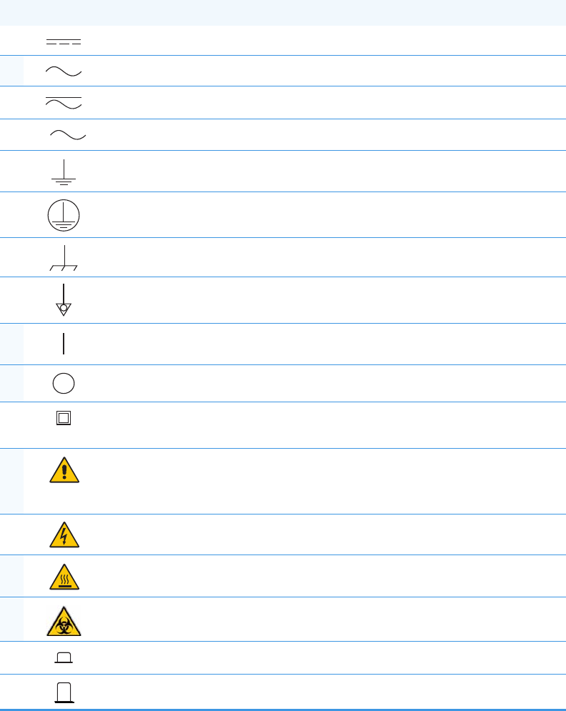
Instrument Markings and Symbols
The following table explains the symbols used on Thermo Fisher Scientific instruments. Only
a few of them are used on the TRACE 1310 Auxiliary Oven. Those that are used are
designated by an asterisk.
Table 1. Instrument Marking and Symbols (Sheet 1 of 2)
Symbol Description
Direct current
*Alternating current
Both direct and alternating current
Three-phase alternating current
Earth (ground) terminal
Protective conductor terminal
Frame or chassis terminal
Equipotentiality
*On (supply)
*Off (supply)
Equipment protected throughout by DOUBLE INSULATION or
REINFORCED INSULATION (Equivalent to Class II of IEC 536)
*Instruction manual symbol affixed to product. Indicates that the user must
refer to the manual for specific WARNING or CAUTION information to
avoid personal injury or damage to the product.
Caution, risk of electric shock
*Caution, hot surface
*Caution, biohazard
In-position of a bistable push control
Out-position of a bistable push control
3
Preface
Hydrogen Safety Precautions
Thermo Scientific TRACE 1310 Auxiliary Oven Instruction Manual xix
Hydrogen Safety Precautions
Hydrogen is a colorless, odorless, highly flammable gas with the molecular formula H2 and an
atomic weight of 1.00794, making it the lightest element. Hydrogen gas presents a hazard as
it is combustible over a wide range of concentrations; at ambient temperature and pressure,
this ranges from about 4% to 74.2% by volume.
Hydrogen has a flash point of - 423 °F (- 253 °C) and an auto-ignition temperature of
1,040 °F (560 °C). It has a very low ignition energy and the highest burning velocity of any
gas. If hydrogen is allowed to expand rapidly from high pressure, it can self-ignite. Hydrogen
burns with a flame that can be invisible in bright light.
Before you begin using hydrogen, you should conduct a risk assessment based on the quantity
of hydrogen to be used and the conditions of your laboratory. You should ask yourself:
“What hydrogen hazards associated with this project are most likely to occur?”
“What hydrogen hazards associated with this project have the potential to result in the
worst consequences?”
• Try to reduce or eliminate the higher risks by using the proper ventilation to remove
hydrogen gas before an ignitable concentration can accumulate. You should also consider
purging the hydrogen to further reduce hazards and ensure anyone who will be working
with hydrogen has basic hydrogen safety training.
• As with laboratory safety in general, be sure to wear safety glasses, laboratory coats, gloves,
etc. Typically there are no specific requirements for gaseous hydrogen, other than eye
protection when working with a compressed gas. If working with liquid (cryogenic)
hydrogen, insulated gloves and protective shoes should be worn in addition to eye
protection.
• You should post “No Smoking” and “No Open Flames” signs to identify hydrogen
sources and cylinders. Maintain, inspect and leak-test all hydrogen sources regularly.
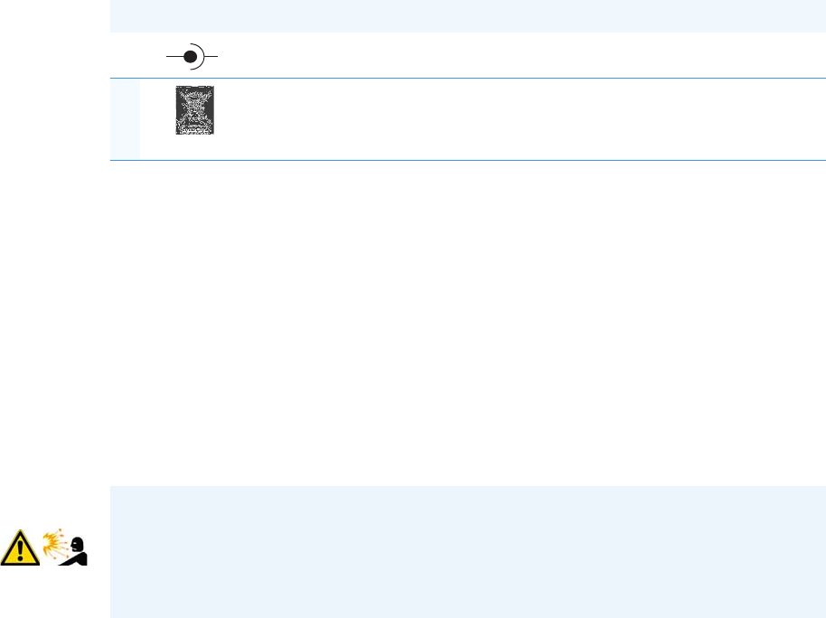
Jack socket
*Symbol in compliance to the Directive 2012/19/EU on Waste Electrical
and Electronic Equipment (WEEE) placed on the European market after
August, 13, 2005.
Table 1. Instrument Marking and Symbols (Sheet 2 of 2)
Symbol Description
+-
WARNING - EXPLOSION HAZARD The use of hydrogen as a carrier gas is dangerous.
Hydrogen is potentially explosive and must be used with extreme care. Any use of
hydrogen gas must be reviewed by appropriate health and safety staff and all installations
of hydrogen systems must be performed to applicable codes and standards. Thermo Fisher
Scientific assumes no liability for the improper use of hydrogen as a carrier gas.

Preface
Hydrogen Safety Precautions
xx TRACE 1310 Auxiliary Oven Instruction Manual Thermo Scientific
• All hydrogen shutoff valves should be clearly marked and permanent hydrogen piping
should be labeled as such at the supply or discharge point and at regular intervals along its
length. Where hydrogen gas piping passes through a wall, the piping should be labeled on
both sides of the wall.
• There should also be contingency plans in place should an incident occur.
• The site emergency response team, as well as the local fire department, should know the
location of all hydrogen storage tanks.
Using Hydrogen with TRACE 1300/TRACE 1310
The use of hydrogen as a carrier gas or as fuel gas for certain flame detectors requires the
operator’s strict attention and compliance with special precautions due to the hazards
involved.
Hydrogen is a dangerous gas, particularly in an enclosed area when it reaches a concentration
corresponding to its lower explosion level (4% in volume). An explosion hazard could develop
in the oven when hydrogen is used as a carrier gas if oven elements are not perfectly connected
to each other, or if the connection materials are worn out, broken, or otherwise faulty.
Use the following safety precautions when using hydrogen:
• Ensure that all hydrogen cylinders comply with the safety requirements for proper use
and storage. Hydrogen cylinders and delivery systems must comply with local regulations.
• Make sure the gas supply is turned completely off when connecting hydrogen lines.
• Perform a leak test to ensure that the hydrogen lines are leak-tight before using the
instrument. Repeat this test to eliminate all leaks.
• Ensure your TRACE 1300/TRACE 1310 has a Thermo Fisher Scientific hydrogen sensor
installed. A hydrogen sensor continuously monitors the hydrogen level in the oven.
WARNING - EXPLOSION HAZARD Hydrogen is a dangerous gas that, when mixed with
air, might create an explosive mixture. The use of hydrogen as a carrier gas requires the
operator’s extreme caution. Special precautions must be taken because of the risk of
explosion. The gas chromatograph must be equipped with a hydrogen sensor if you use
hydrogen as a carrier gas.
Never use hydrogen as carrier gas in your TRACE 1300/TRACE 1310 system unless your
oven has a hydrogen sensor installed. Thermo Fisher Scientific FSEs are not authorized to
install or repair any instrument using hydrogen as a carrier gas unless the instrument is
equipped with the appropriate sensor.
If your oven does not have a hydrogen sensor already installed, contact your Thermo
Fisher Scientific sales representative. To comply with instrument safety requirements, a
Thermo Fisher Scientific FSE or authorized service personnel should install the sensor
into your TRACE 1300/TRACE 1310.
Preface
Hydrogen Safety Precautions
Thermo Scientific TRACE 1310 Auxiliary Oven Instruction Manual xxi
Hydrogen Connection Guidelines
Use the following guidelines to safely connect hydrogen to your system:
•Piping—Hydrogen must be delivered to equipment using appropriate piping and be
done in such a way as to pose essentially no hazard to end-users. Piping systems for the
delivery of hydrogen should be designed and installed by a person qualified by specific
training and experience with hydrogen piping systems.
Stainless steel is usually recommended because it is a safe, cost-effective material. Piping
of black iron or copper must not be used, as the pipe can become brittle with age.
Elastomeric/plastic tubing of various plastics and polymers should not be used, unless the
tubing is approved for use with hydrogen. If elastomeric/plastic tubing is used for
hydrogen gas delivery, the tubing should be tested for hydrogen permeability to minimize
leakage.
The hydrogen piping system must be flexible enough to endure routine thermal
expansion and contraction. The system should also include considerations for the most
severe condition of temperature and pressure expected during service. Piping and
supports must be able to withstand static loading introduced by such things as ice and
snow; and dynamic loading from high wind and earthquake.
Caution should be used if burying hydrogen piping. Proper controls should be used to
protect against damage and corrosion, and also to prevent Hydrogen from entering a
building if there is any leakage.
•Fittings—All fittings must be of the proper type approved or designed for use with
hydrogen gas. Use as few fittings as possible to minimize the potential for leaks. After
installation, ensure that leak testing is carried out prior to system use, and on a regular
basis.
There must be no PTFE tape or other things like plumber's putty used to enhance a seal, as
this actually is a detriment to a good seal. Ideally the best installation would use stainless
steel tubing with appropriate gas-tight fittings.
Welding is usually preferred for joints in hydrogen piping systems since welding provides
a better connection and reduces the potential for leaks compared to mechanical fittings.
Soft solder joints are not permitted for hydrogen systems (due to the low melting point of
soft solder and its potential for brittle failure at cryogenic temperatures). Brazed joints are
permitted, but such joints should be protected against the possibility of external fire.
Tubing connections should be clamped to barbed or press-fit type connections. Hose
clamps or jubilee clamps must not be used.
•Valves— All valves must be suitable for hydrogen service and for the specific operating
conditions. Valves, including regulators, must not be used for hydrogen, unless they are
designed and identified for such a use. Ball valves are often chosen because of their
superior leak tightness through the valve seat. Pneumatic operators are usually chosen for
remotely operated valves so that potential ignition sources (electricity) are remote from
the valve.
Preface
Hydrogen Safety Precautions
xxii TRACE 1310 Auxiliary Oven Instruction Manual Thermo Scientific
Manual shutoff valves should be provided near each point of use, within immediate reach.
If a hydrogen cylinder or hydrogen generation system is located within immediate reach,
a separate point-of-use shutoff valve is usually not necessary.
Line regulators that have their source away from the point of use should have a manual
shutoff valve near the point of use.
An emergency gas shutoff device in an accessible location outside the use area should be
provided in addition to the manual point-of-use valve in each educational and
instructional laboratory space that has a piped gas supply system.
If necessary, the piping system should have uninterruptible pressure relief. The pressure
relief system should be designed to provide a discharge rate sufficient to avoid further
pressure increase and should vent to a safe location outside or to a ventilation system
exhaust.
Purchasing Hydrogen
Use the following guidelines when purchasing hydrogen:
• Hydrogen Generator—Because it minimizes the amount of hydrogen present and reduces
the degree of hazard, a hydrogen generator (also called an electrolyzer) is the safest way to
purchase hydrogen in the quantity used in gas chromatography/mass spectroscopy
systems.
However, to minimize the degree of hazard, operate the hydrogen generator only in a
non-explosive environment because hydrogen buildup can be ignitable. Thus, your
ventilation system for the room or lab hood where the hydrogen generator operates must
maintain an air exchange rate at least two orders of magnitude greater than the maximum
hydrogen production rate of the hydrogen generator. Follow the manufacturers'
directions about proper use and maintenance of the regulator.
To prevent the possibility of releasing hydrogen, set the hydrogen generator to shut down
if:
−There is a loss of flow to the ventilation system
−A hydrogen detector alarms at 25% of the lower flammable limit of hydrogen in air.
Vent the oxygen exhausted by the electrolyzer to the outside as well.
• Hydrogen Cylinder—Hydrogen can be delivered in standard laboratory gas bottles or
cylinders. These cylinders have a limited amount of hydrogen in them and are a safe way
to transport and store hydrogen. Always secure, compressed hydrogen gas cylinders, like
all compressed gas cylinders, in an upright position, ideally with a non-combustible chain
or cable. If the cylinder falls over, the valve can fall off, causing the pressurized cylinder to
take off like a rocket, leading to the release of hydrogen and possibly an explosion, severe
injury, or death. Never crack a hydrogen cylinder valve to remove dust or dirt from
fittings prior to attaching a regulator, as there is a risk of self-ignition.
Preface
Hydrogen Safety Precautions
Thermo Scientific TRACE 1310 Auxiliary Oven Instruction Manual xxiii
Properly Storing Hydrogen
Storing and handling compressed hydrogen gas and cryogenic liquid hydrogen present
potential health and safety hazards. Using proper storage and handling techniques is essential
to maintaining a safe work environment.
Use the following guidelines when storing hydrogen:
• Store spare hydrogen gas cylinders outside and away from doors, windows, building air
intake vents, structures, and vehicle routes. This precaution applies when the hydrogen is
or is not in use. Indoor storage of spare hydrogen cylinders has special requirements,
which are beyond the scope of this document. Documentation for each vessel should
include a description of the vessel, a list of available drawings or other documents, the
most recent inspection results, and the responsible person's name.
• Prevent spare cylinders from toppling by wrapping them with chains. The chains should
also be protected against corrosion and excessive heat.
• Separate spare hydrogen cylinders from oxidizing gases (such as oxygen) with a 5 ft.
(1.5 m) tall fire barrier with a half-hour fire rating or place the cylinders at least 20 ft.
(6 m) apart.
• When moving hydrogen cylinders:
−Remove the regulator and replace the cylinder valve cap before moving.
−Move cylinders on cylinder carts or with other appropriate transport devices.
−Never roll or drop a cylinder and never lift a cylinder by its protective cap.
• Bulk hydrogen systems include either gaseous or liquid hydrogen in fixed installations; in
some gas systems a semi-permanent trailer (tube trailer) can be used. Storage vessels for
compressed hydrogen gas or liquid hydrogen should be designed, constructed, tested, and
maintained in accordance with applicable codes and standards. Bulk hydrogen systems
represent a level of complexity again which is beyond the scope of this document;
however some general guidelines are provided.
• The bulk hydrogen storage system should not be located beneath electric power lines,
close to other flammable gases/liquids, or close to public areas. It should be readily
accessible to authorized personnel and delivery equipment, but protected from physical
damage or tampering.
• As liquid hydrogen systems also have a cryogenic hazard, additional safety considerations
for the use of cryogenic liquids might be necessary.
Hydrogen Safety Codes, Standards and References
The following list of safety codes, standards, and references is in no way an exhaustive list. In
fact, there may be federal, state, or local codes that apply to your specific location. Check with
all appropriate agencies with jurisdiction before installing or using a hydrogen system.
Preface
Hydrogen Safety Precautions
xxiv TRACE 1310 Auxiliary Oven Instruction Manual Thermo Scientific
• Air Products Safetygram #4 Gaseous Hydrogen
• ANSI/AIAA standard for hydrogen safety guidelines is AIAA G-095-2004, Guide to
Safety of Hydrogen and Hydrogen Systems
• ASME B31.1, Power Piping Code
• ASME B31.3, Process Piping Code
• ASME B31.8, Gas Transmission and Distribution Systems
• BCGA Code Of Practice CP4 Industrial Gas Cylinder Manifolds and Gas Distribution
Pipework
• BCGA Code Of Practice CP33 The Bulk Storage of Gaseous Hydrogen at Users'
Premises
• CGA G-5, Hydrogen
• CGA G-5.4, Standard for Hydrogen Piping Systems at Consumer Locations
• CGA G-5.5, Hydrogen Vent Systems
• CGA G-5.6, Hydrogen Pipeline Systems
• CGA G-5.8, High Pressure Hydrogen Piping Systems at Consumer Locations.
• FM Global Property Loss Prevention Data Sheets 7-50: Compressed Gases in Cylinders
• FM Global Property Loss Prevention Data Sheets 7-91: Hydrogen
• IGC Doc 121/04/E, Hydrogen Transportation Pipelines System Design Features
•NASA
• NSS 1740.16 Safety Standard For Hydrogen And Hydrogen Systems Guidelines for
Hydrogen System Design, Materials Selection, Operations, Storage, and Transportation
• NFPA 52, Vehicular Fuel Systems Code
• NFPA 55, Standard for the Storage, Use, and Handling of Compressed Gases and
Cryogenic Fluids in Portable and Stationary Containers, Cylinders, and Tanks, 2005
Edition
• NFPA 68, Standard on Explosion Protection by Deflagration Venting
• NFPA 70, National Electrical Code
• NFPA 497, Recommended Practice for the Classification of Flammable Liquids, Gases,
or Vapors and of Hazardous (Classified) Locations for Electrical Installations in Chemical
Process Areas
• NFPA 13, Standard for the Installation of Sprinkler Systems
• NFPA 45, Standard on Fire Protection for Laboratories Using Chemicals

Preface
Hazardous Substances Precautions
Thermo Scientific TRACE 1310 Auxiliary Oven Instruction Manual xxv
• NFPA 55, Standard for the Storage, Use, and Handling of Compressed Gases and
Cryogenic Fluids in Portable and Stationary Containers, Cylinders, and Tanks
• NFPA 68, 2007 Standard on Explosion Protection by Deflagration Venting
• NFPA 69, Standard on Explosion Prevention Systems
• NFPA 91, Standard for Exhaust Systems for Air Conveying of Vapors
• NFPA 255, Standard Method of Test of Surface Burning Characteristics of Building
Materials
• OSHA 29CFR1910.103 1910.103 Hydrogen
Hazardous Substances Precautions
Venting Toxic Gases
When analyzing toxic compounds be aware that during the normal operation of the GC some
of the sample may be vented outside the instrument through the inlet and detector exits;
therefore the exhaust gases must be vented to a fume hood. Consult local Environmental and
Safety Regulations for instructions in exhausting fumes from your system.
WARNING Before using hazardous substances (toxic, harmful, etc.), please read the
hazard indications and information reported in the applicable Material Safety Data Sheet.
Use Personal protection according to the safety requirements.

Thermo Scientific TRACE 1310 Auxiliary Oven Instruction Manual 1
1
Site Preparation
This chapter describes how to prepare your site before the Thermo Scientific Field Service
Engineer arrives to install the TRACE 1300/TRACE 1310 GC + TRACE 1310 Auxiliary
Oven.
Contents
•Introduction
•Workbench & Space Requirements
•Lighting Requirements
•Power Requirements
•LAN Network Requirements
•Environment Requirements
•Gas Equipment Requirements
•Receiving Instruments
•What Happens Next?
Note In addition to the information in this chapter, you must also obey the building and
safety rules and regulations for construction that apply in your area.
CAUTION For more details about the preparation of the site, refer to the
TRACE 1300/TRACE 1310 Preinstallation Requirements Guide P/N 31715001, Revision C.
1 Site Preparation
Introduction
2 TRACE 1310 Auxiliary Oven Instruction Manual Thermo Scientific
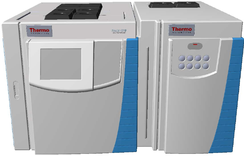
Introduction
The TRACE 1310 Auxiliary Oven is a factory configured temperature controlled enclosure
attached to the right side of the TRACE 1300/1310 GC. See Figure 1.
Figure 1. TRACE 1300/1310 GC and TRACE 1310 Auxiliary Oven
On-site installation is related to the gas plumbing defined by the application or accompanying
diagram.
Entrance Requirements
Use the following guidelines to make sure the entrance to your site will allow delivery of the
TRACE 1300/1310 GC and TRACE 1310 Auxiliary Oven.
1. Ensure the width of your delivery door opening is at least 81 cm (32 in.).
2. Make sure you have enough room to move boxes around corners, into elevators, or
through doorways. The table below contains the dimensions and weight of shipping
boxes, so that you can make accommodations.

1 Site Preparation
Workbench & Space Requirements
Thermo Scientific TRACE 1310 Auxiliary Oven Instruction Manual 3
Workbench & Space Requirements
Use the following guidelines to make sure you have enough space for the TRACE 1300/1310
GC and TRACE 1310 Auxiliary Oven. See Table 2.
1. Ensure you have adequate workbench space for the system. Use the information in the
table below to configure the workbench. Be sure to leave at least 30 cm (12 in.), of extra
space around the instrument for operators to work besides it and in front of it. Keep in
mind that the TRACE 1300/TRACE 1310 GC oven vents to the rear. Any material
exposed to the oven exhaust must be able to withstand repeated exposure to temperatures
of up to 450 °C (842 °F).
2. Supply a 1-in. i.d. hose to a fume hood or other suitable exhaust port. Consult local
Environmental and Safety Regulations for instructions in exhausting fumes from your
system.
Table 1. Shipping Box Dimensions and Weight
Box Contents Depth Width Height Mass
cm in. cm in. cm in. kg lbs
TRACE 1310 Auxiliary Oven with pallet 78.4 30.9 52.4 20.6 74.4 29.3 65 143
TRACE 1300/1310 GC + TRACE 1310
Auxiliary Oven with pallet
92.4 36.6 83.4 32.8 74.4 29.3 150 330
Accessories These modules, such as the computer, monitor, and optional instruments are
shipped in their own boxes. They could be smaller or bigger and weigh less or
more than the TRACE 1310 Auxiliary Oven box.
Table 2. Workbench and Space Requirement
Instrument Depth Width Height Mass
cm in. cm in. cm in. kg lbs
TRACE 1300 GC + TRACE 1310
Auxiliary Oven
60 24 74.5 29 45 18 952-3 2092-3
TRACE 1310 GC + TRACE 1310
Auxiliary Oven
67126 74.5 29 45 18 952-3 2092-3
Computer3, 4 48 19 20 8 43 17 12 27
Monitor31674618 32 13 4 8
Keyboard32394618 5 2 1 2
1 The touch screen protrudes 7 cm from the front of the TRACE 1310 GC.
2 The mass of the GC is intended without injector/detector modules. The mass of each injector/detector module is 0.8 kg (1.77 lbs).
3 The Auxiliary Oven width is 30 cm (12-in.) while its height and depth are the same of the GC. The mass of the Auxiliary Oven is intended with all the
options installed.
1 Site Preparation
Lighting Requirements
4 TRACE 1310 Auxiliary Oven Instruction Manual Thermo Scientific
Allow at least 30 cm (12 in.) of clearance behind the instrument. This space allows for venting
of the hot exhaust, clearance of the gas lines, electrical connections, access to power switch,
and horizontal movement of the TriPlus RSH/TriPlus “Y” axis arm.
3. Make sure you have at least 92 cm (3 ft.) of clearance above the system. This space allows
room for optional accessories (such as autosamplers) and proper heat dissipation.
Make sure your workbench can support the instrument. Keep in mind, additional
instruments add to the total weight.
Ensure that your work area is stable and free of vibration from nearby equipment. It is a
sensitive instrument.
Lighting Requirements
Use the following guidelines to check the lighting of your site:
1. Ensure that your work area is properly lit. You may need an overhead lamp to light your
work area.
2. You may need a small, high-intensity lamp when you clean the instrument.
Power Requirements
Use the following guidelines to ensure your site is equipped with enough power to support the
system.
1. Test the power source quality in your laboratory to offset line voltage problems.
Improving power source quality is a complex task best handled by a company or
consultant specializing in that field. Contact your regional Thermo Scientific Customer
Service office for assistance in locating a power consultant. Having a poor quality power
source degrades the system performance. Here are some examples of poor power source
quality:
• Harmonic Distortion is a high-frequency disturbance that appears as distortion of the
fundamental sine wave. Total harmonic distortion should be less than 6%.
• Sags are constant low line voltage, which cause the system to function erratically or
not at all.
• Slow changes are gradual, long-term changes in average root mean square (RMS)
voltage level, with typical durations greater than 2 s.
• Surges are constant high line voltage, which cause overheating and component
failure. Sags and surges are slow changes in average root mean square (RMS) voltage
level, with typical durations between 50 ms and 2 s.
1 Site Preparation
Power Requirements
Thermo Scientific TRACE 1310 Auxiliary Oven Instruction Manual 5
• Transients, even of a few microseconds duration cause electronic devices to fail or to
degrade and significantly shorten their lives. Transients (or impulses) are brief voltage
excursions of up to several thousand volts with durations less than 50 ms.
2. If your laboratory's power source does not meet the previous requirement, you need to get
a UPS (Uninterruptible Power Supply) or power line conditioner. UPS system must
produce high-quality distortion-free power within our specifications.
A power line conditioner is more suitable for conditions in which a laboratory’s power has
sags, harmonic distortion, surges and transients. In this situation, a power line
conditioner will maintain a smooth and steady power source to the instrument so that
your data will be unaffected by a power surge.
3. Use Ta b l e 3 to determine how many circuits and wall outlets you need and for a list of
maximum current and power consumption. Keep in mind:
a. Power must be single phase.
b. Wall outlets must have earth-ground hard-wired to the main panel.
c. Included power cords are at least 2 m (9 ft.) long.
d. Look at your Customer Sales Order to determine if the instrument is 120 Vac or
230 Vac, because it cannot be re-configured once your field service engineer arrives.
e. Contact your local Customer Service office to discuss power cord sets concerns.
4. Make sure you have at least three (3) separate circuits. They should be within 2 m (6 ft.)
of the instrument.
For example, use one circuit for the TRACE 1300/TRACE 1310 GC, one circuit for the
TRACE 1310 Auxiliary Oven, one circuit for the mass spectrometer, and one circuit for
the data system and any options. But, do not connect the TRACE 1300/TRACE 1310
GC and mass spectrometer to the same circuit. The extra outlets are for additional
options.
5. Make sure that the instruments you plug in do not exceed the maximum circuits and
current rating.
Table 3. System Power Requirements
Equipment Max. Current (A)
at 120 Vac
Max. Current (A)
at 230 Vac Max. Power (VA)
TRACE 1300 GC 16 10 2000
TRACE 1310 GC 16 10 2000
TRACE 1310
Auxiliary Oven
6 3 650
Note The 230 Vac power cord terminates to bare wires. Inform your local Customer
Service office as to your plug type so they can bring the proper power cord or plug.

1 Site Preparation
LAN Network Requirements
6 TRACE 1310 Auxiliary Oven Instruction Manual Thermo Scientific
LAN Network Requirements
The connection between the TRACE 1300/TRACE 1310 GC and the Thermo Scientific
data system must be carried out via Local Area Network (LAN).
Your lab must be provided with one or more RJ-45 wall outlet. To connect your system to
your site’s LAN network, you must have a shielded twisted pair network cable provided.
In the case a LAN is missing, the instrument could be connected directly to the LAN inlet on
the PC by using the red cable.
Environment Requirements
The classification of the instrument includes the following Environmental Conditions.
• Indoor use only.
• Altitude up to 2000 meters.
• Temperature from 15 to 35 °C.
• Maximum relative humidity between 40% and 80%.
• Voltage variations not exceeding percentage of the nominal value.
• Transients according to installation categories II.
• Degree of pollution according to IEC 664 (3.7.3) 2.
•Protection degree IP00
The TRACE 1300/TRACE 1310 GC + TRACE 1310 Auxiliary Oven operates in an
environment where normally only non-conductive pollution occurs, but in which temporary
conductivity due to condensation must be expected. This is a Pollution Degree 2
environment, as specified in International Standard EN 61010-1: 1993 and subsequent
amendments.
Use the following guidelines to ensure your site has the proper environmental conditions for
the system:
1. Ensure that your room temperature is 5-40 °C (41-104 °F). The analytical performance is
only confirmed for temperatures between 15-35 °C (59-95 °F). For best performance, the
operating temperature should be constant. Use the table below to calculate the amount of
heat your system will generate and ensure your air-conditioning system can handle that
amount of heat.
Note We are not responsible for connecting to or establishing communication with your
site LAN network. The FSE will test the system’s ability to communicate on a mini-hub or
LAN switch only (preferable).
1 Site Preparation
Gas Equipment Requirements
Thermo Scientific TRACE 1310 Auxiliary Oven Instruction Manual 7
2. Ensure that the relative humidity in your laboratory is between 40 and 80%, with no
condensation. A temperature and humidity monitor in your laboratory helps ensure that
the climate is within these specifications.
3. Ensure that the air in your site is free of excess particulate matter.
For reference, the air should contain fewer than 100,000 particles (larger than 5 μm) per
cubic meter. If the concentration is larger than this amount, dust can accumulate on
electronic components. This accumulation reduces their ability to cool off properly and
could cause them to overheat. If your environment is particularly dusty, we recommend
that you purchase the optional dust filter for your system.
4. Ensure that your site is free of electrostatic discharge (ESD), which may damage the
electronic components of your system. Ensure your static has been discharged before
touching internal components of the instrument. ESD can damage sensitive components,
resulting in premature failures.
Take the following precaution to prevent electrostatic discharge:
• Use a static-dissipating floor covering (such as tile or conductive linoleum) in the
room housing your instrument.
• Use laboratory chairs covered with natural fibers or other static-dissipating material.
• Wear laboratory coats and clothing made from natural fibers or other
static-dissipating material.
• Do not place polystyrene (foam) cups or packing materials on the instrument.
Gas Equipment Requirements
Use the following guidelines to make sure you have the gas supplies for your system ready far
in advance of installation. You will need a supply of ultra-high purity GC gases.
Table 4. Maximum Heat Output
Instrument Heat Output
(in Btu hr-1)
Heat Output
(in W)
Standard
Equipment
TRACE 1300/TRACE 1310 GC [120 Vac] 6830 2000
TRACE 1300/TRACE 1310 GC [230 Vac] 6830 2000
TRACE 1310 Auxiliary Oven [120/230 Vac] 2220 650
Computer11365 400
Monitor185 25
1 Power requirements vary by manufacturer.
1 Site Preparation
Receiving Instruments
8 TRACE 1310 Auxiliary Oven Instruction Manual Thermo Scientific
Receiving Instruments
When you receive the TRACE 1300/TRACE 1310 GC + TRACE 1310 Auxiliary Oven
system:
1. Inspect the boxes for damage when the instrument arrives. Our instruments are shipped
by electronic equipment carriers who specialize in the handling of delicate equipment.
Occasionally, however, equipment is inadvertently damaged in transit. If you notice
evidence of external damage, do not refuse shipment. Instead, call Customer Service.
2. Once you have finished inspecting your shipment, move the cartons to a protected
location, preferably the installation site. Leave the boxes as complete as possible and do
not unpack or open the boxes without our Field Service Engineer (FSE) present. Doing
otherwise may void your warranty or order.
3. Complete the Installation Request Form located at the front of this guide and forwards it
to Customer Support.
What Happens Next?
After the Installation Request Form is received, Customer Support will contact you to
schedule the installation of your system. It is important to confirm that all the requirements
on the form are met BEFORE the Field Service Engineer arrives.
The Field Service Engineer will install the system and confirm that all performance tests pass.

Thermo Scientific TRACE 1310 Auxiliary Oven Instruction Manual 9
2
TRACE 1310 Auxiliary Oven Overview
This chapter provides a detailed overview of the TRACE 1310 Auxiliary Oven configurations.
Contents
•Front View
•Top V i ew
•Back View
•Right View
•Left View
•Internal View
•Main Oven
•Label Location on the Instrument
•Tools Needed
2 TRACE 1310 Auxiliary Oven Overview
Front View
10 TRACE 1310 Auxiliary Oven Instruction Manual Thermo Scientific
Front View
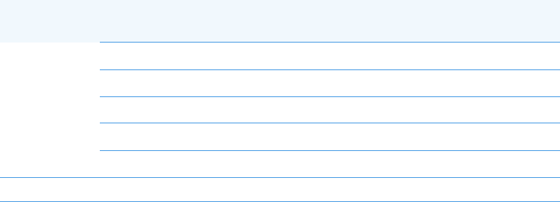
Figure 2 shows the components located on the front panel.
Figure 2. TRACE 1310 Auxiliary Oven Front View
The components are:
•The power LED with a small inlay located on the front is the user interface.
– When the LED lights Green the TRACE 1310 Auxiliary Oven is powered On
•Eight seats marked 1, 2, 3, 4 and 5, 6, 7, 8 for the installation of up to eight heated
needle valves, or up to eight sample inlet fittings. See Figure 3.
Figure 3. Needle Valve and Sample Inlet Fitting with Extension
Power LED (Green = On)
Seats for Sample Inlet or Needle
Valves marked 1, 2, 3, 4
Seats for Sample Inlet or Needle
Valves marked 5, 6, 7, 8
Needle Valve Sample Inlet Fitting with Extension

2 TRACE 1310 Auxiliary Oven Overview
Top View
Thermo Scientific TRACE 1310 Auxiliary Oven Instruction Manual 11
Top View
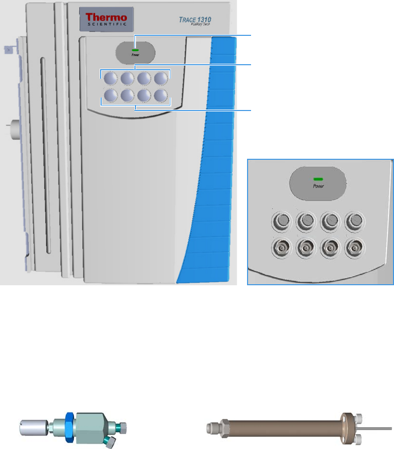
Figure 4 shows the components located on the top of the TRACE 1310 Auxiliary Oven.
Figure 4. TRACE 1310 Auxiliary Oven Top View
Auxiliary Detectors Housing Cover
Auxiliary Oven L-shape Cover
Auxiliary Detectors Housing
2 TRACE 1310 Auxiliary Oven Overview
Top View
12 TRACE 1310 Auxiliary Oven Instruction Manual Thermo Scientific
The components are:
•The Auxiliary detectors housing where up to two of the same detectors modules used in
the main GC can be optionally installed obtaining a configuration with a maximum of
four detectors: two installed into the GC and two into the Auxiliary Oven.
The detectors housing is accessible removing the L-shape cover of the Auxiliary Oven.
The detectors installed into the TRACE 1310 Auxiliary Oven are identified as Aux L and
Aux R.
The example in Figure 5 shows both the left and right auxiliary detectors installed into
the proper housing.
Figure 5. Auxiliary Left and Right Detectors
If the TRACE 1310 Auxiliary Oven is configured with a single detector module, a
dummy module is inserted instead of the missing detector module.
Each position has its own electrical and gas connections.
When the detector module is correctly installed and fixed into its own site, the fitting for
the column connection protrudes into the interior of the main oven through the top wall.
See “Main Oven” on page 24.
IMPORTANT Before installing the auxiliary detector modules, the black cover of the
detector housing must be removed unscrewing the four fixing screws from the
L-shape cover.
Note When a dummy module is installed, its gas connection is closed by a plug.
Auxiliary Left and Right Detectors
2 TRACE 1310 Auxiliary Oven Overview
Back View
Thermo Scientific TRACE 1310 Auxiliary Oven Instruction Manual 13
Back View
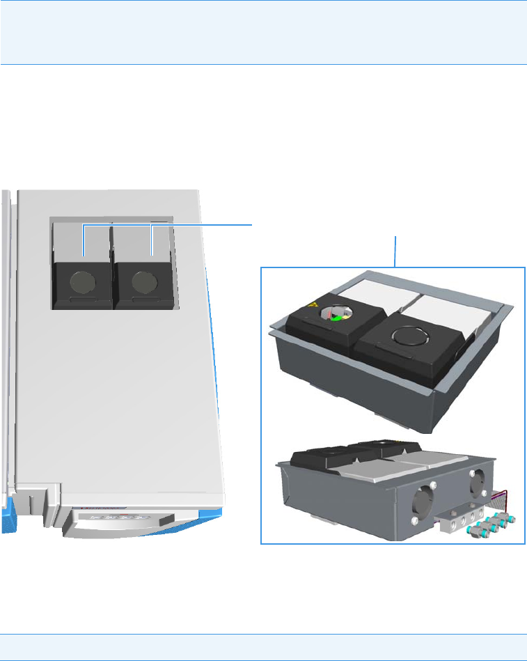
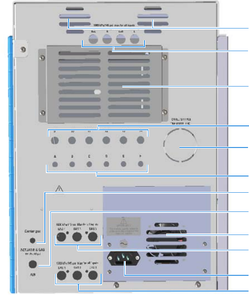
Figure 6 shows the components located on the back of the TRACE 1310 Auxiliary Oven.
Figure 6. TRACE 1310 Auxiliary Oven Back View
The components are:
• Four inlet ports for carrier gas and auxiliary detector gases marked H2 R+L, Make-Up R,
Air L+R, and Make-Up L.
• Up to two fans for the cooling of the auxiliary detectors.
• Six seats marked 9, 10, 11, 12, 13, and 14 for the installation of unheated needle valves.
• Six seats marked A, B, C, D, E and F for the installation of sample inlet/outlet fittings.
• A duct for the connection of a heated sample transfer line.
•An ACTUATING GAS inlet port for the carrier flow connection marked Carrier Gas for
the actuation of the AFP™ diaphragm valves. The inlet pressure is 450 kPa; 65 psi.
•An ACTUATING GAS inlet port for the actuating flow connection marked AIR for the
actuation of the VICI ® rotary valves, VICI ® valves for liquid sample (ASFVO), or both.
The inlet pressure is 450 kPa; 65 psi.
Inlet Ports for Carrier and Detector
gases
Housing for the optional Secondary
Oven or Methanizer
Duct for Heated Sample
Transfer Line
Seats for Needle Valves
Gas Inlet Port for Diaphragm Valves
Auxiliary Gas System Gas Inlet Ports
Marked 4,5,6
AC Input Connector
Seat for Sample Inlet/Output Fitting
Auxiliary Gas System Gas Inlet Ports
Marked 1,2,3
,
Cooling Fan
Cooling fans for Auxiliary Detectors
Air Inlet Port for Rotary Valves
2 TRACE 1310 Auxiliary Oven Overview
Right View
14 TRACE 1310 Auxiliary Oven Instruction Manual Thermo Scientific
•An optional secondary column oven or an optional methanizer installed instead of the
optional secondary column oven.
• Up to six pressure channels by using up to two Auxiliary Gas system. The three lower
inlet ports are marked Gas 1, GAS 2, GAS 3, while the three upper inlet ports are marked
Gas 4, GAS 5, GAS 6.
• A fan for the cooling of the TRACE 1310 Auxiliary Oven.
• AC input connector marked for the connection of the TRACE 1310 Auxiliary Oven to
the mains through the power cable.
The power rating is: 120/230 Vac, 50/60 Hz, 650 VA.
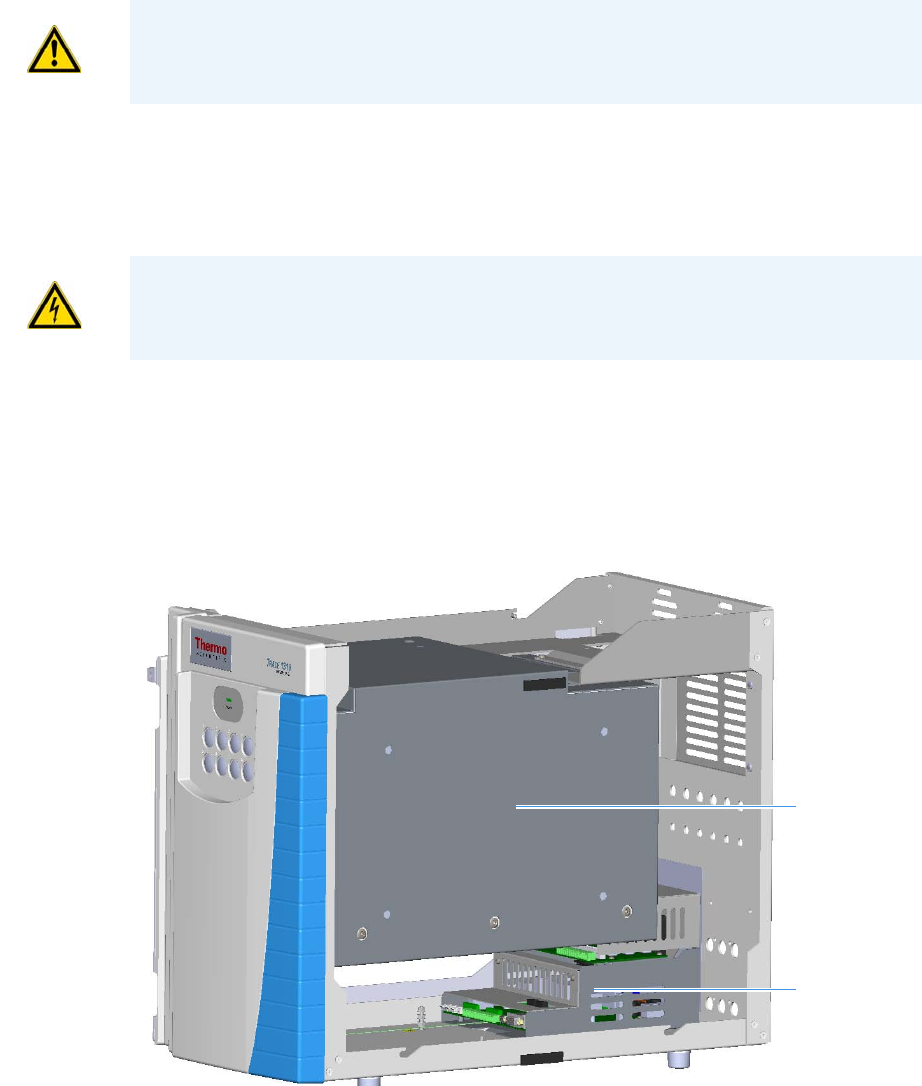
Right View
Figure 7 shows the components located on the right side of the module when the L-shape
cover is removed. For details see ““Internal View” on page 16”.
Figure 7. TRACE 1310 Auxiliary Oven Right View
CAUTION A maximum of two Auxiliary Gas modules can be housed either in the GC or
in the Auxiliary Oven.
WARNING The TRACE 1310 Auxiliary Oven must be powered at the same line voltage
of the main GC system.
Power Section
Main Oven
2 TRACE 1310 Auxiliary Oven Overview
Left View
Thermo Scientific TRACE 1310 Auxiliary Oven Instruction Manual 15
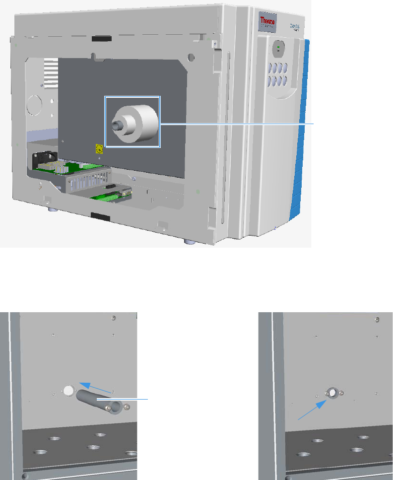
Left View
The left side of the TRACE 1310 Auxiliary Oven is factory hooked and fixed to the right side
of the GC.
This part of the module includes the inner tube that protrudes into the GC oven for
pneumatic connections between the two units.
Figure 8 shows the left side of the module before the assembling.
Figure 8. TRACE 1310 Auxiliary Oven Left View
The inner tube to the GC oven is inserted and fixed into the passing hole provided in the wall
of the main oven as shown in Figure 9.
Figure 9. Inner Tube to the GC Oven
Inner Tube and
Disks of Insulating
Material
Inner Tube to the GC oven
2 TRACE 1310 Auxiliary Oven Overview
Internal View
16 TRACE 1310 Auxiliary Oven Instruction Manual Thermo Scientific
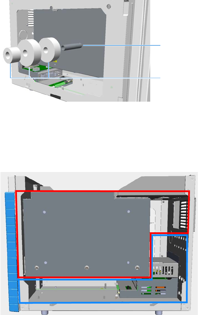
The biggest insulating material disks are placed on the inner tube that protrudes from the wall
of the main oven as shown in Figure 10. The smallest disk will be placed on the inner tube
from the interior of the GC oven. See also “Coupling the TRACE 1310 Auxiliary Oven to the
GC” on page 104.
Figure 10. Placing Insulating Disks
Internal View
This section describes the components located inside the TRACE 1310 Auxiliary Oven in the
maximum configuration. The interior of the Auxiliary Oven is divided into two
compartments: heated and unheated. See Figure 11.
Figure 11. TRACE 1310 Auxiliary Oven Compartments
Inner Tube to the GC oven
Disks of Insulating Material
Unheated Compartment
Heated Compartment
2 TRACE 1310 Auxiliary Oven Overview
Internal View
Thermo Scientific TRACE 1310 Auxiliary Oven Instruction Manual 17
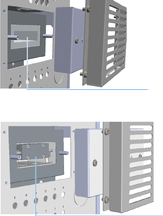
The Heated Compartment
The heated compartment includes:
•The main oven. The working temperature is up to 250 °C if configured as Valve Oven, or
up to 300 °C if configured as HT Valve Oven. See “Main Oven” on page 24 and
Chapter 4, “Operation,” for details.
• An optional secondary oven is accessible from the back removing its cover. See Figure 12.
This option is required to keep the analytical column at lower temperature for
applications using HT valves. The working temperature is up to 250 °C.
Figure 12. Optional Secondary Oven
•An optional methanizer installed instead of the optional secondary column oven.
See Figure 13. The working temperature is up to 400 °C
Figure 13. Methanizer
•Analytical Columns can be installed according to the application.
Secondary Oven
Methanizer
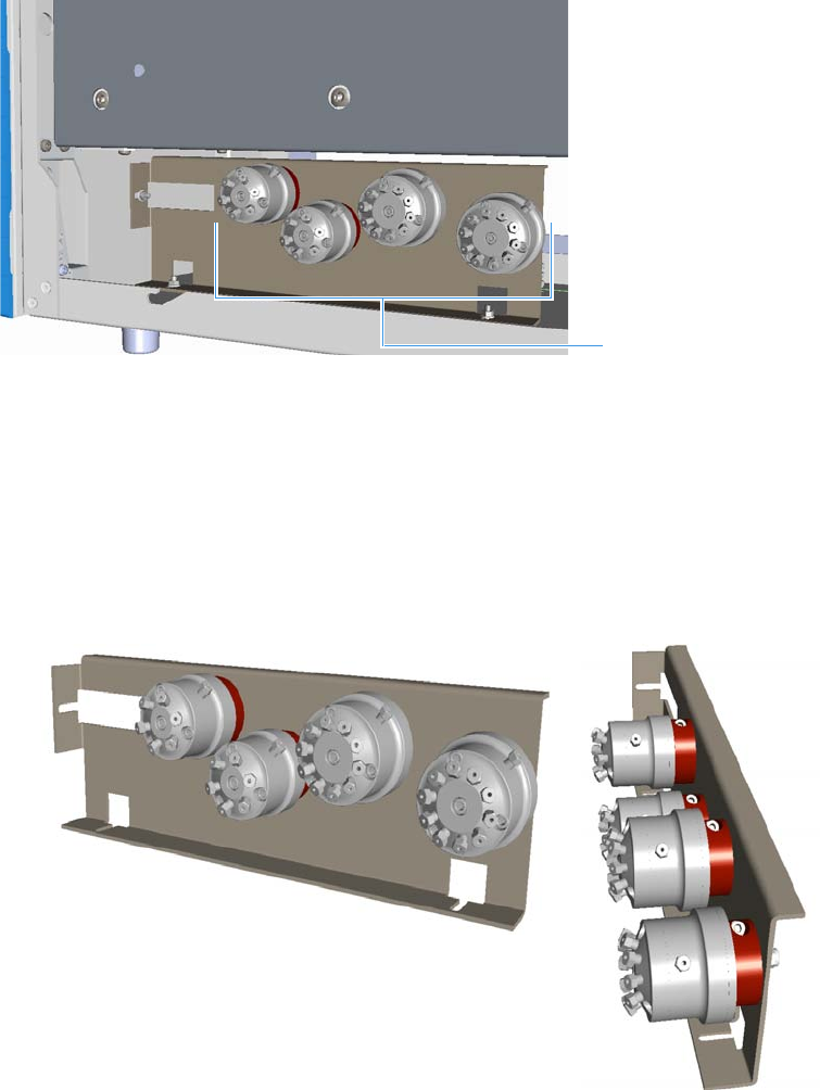
2 TRACE 1310 Auxiliary Oven Overview
Internal View
18 TRACE 1310 Auxiliary Oven Instruction Manual Thermo Scientific
The Unheated Compartment
The unheated compartment includes:
• Up to four unheated 6-port and/or 10-port valves mounted on the proper bracket.
See the example in Figure 14.
Figure 14. Unheated Valves
You can install the unheated valves in the following configurations:
– Up to four diaphragm valves. See the example in Figure 15 on page 18.
– Up to four rotary valves. See the example in Figure 16 on page 19.
– Up to two valves for liquid samples (each valves requires the proper rotary valve for
the actuation, and the proper solenoid manifold). See the example in Figure 17 on
page 19.
Figure 15. Unheated Membrane Valves
Unheated Valves
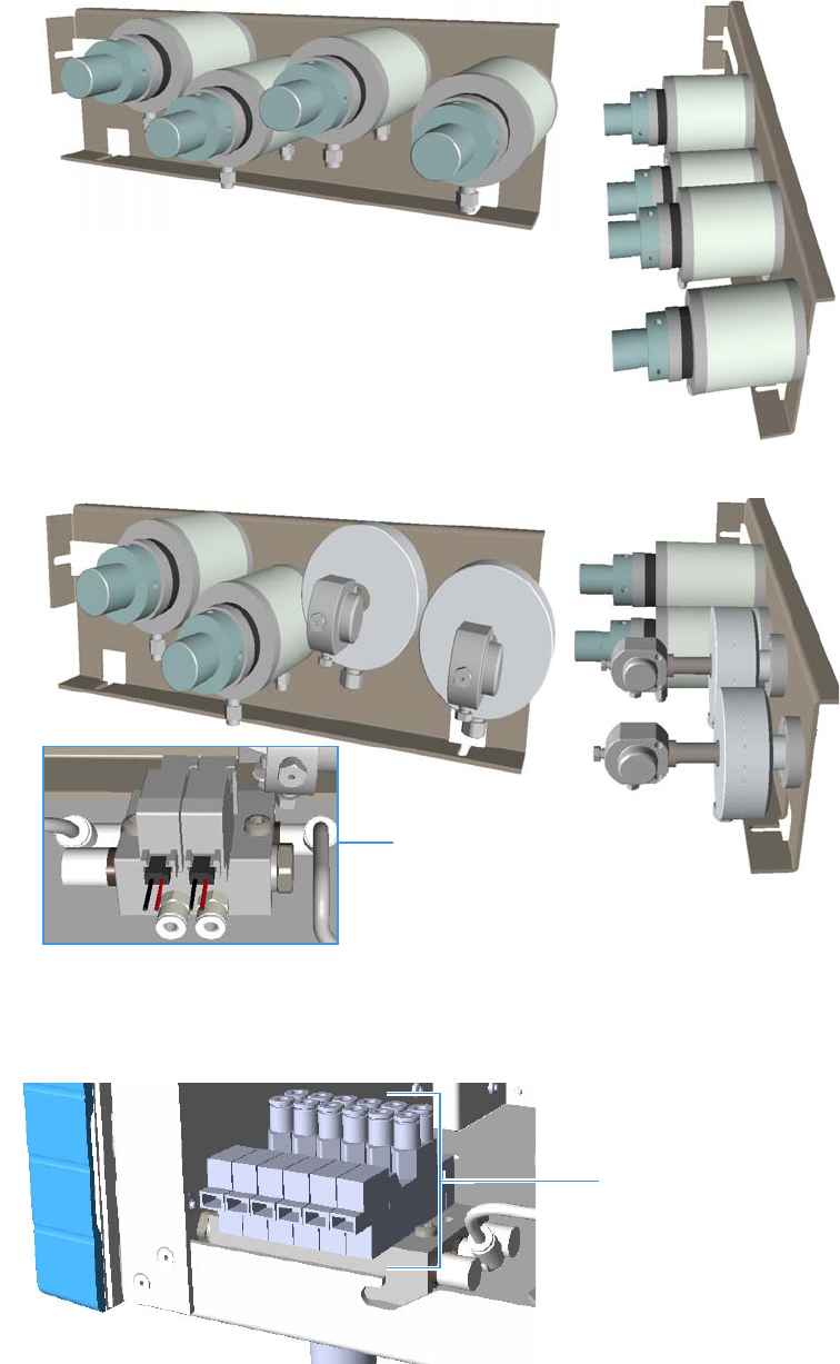
2 TRACE 1310 Auxiliary Oven Overview
Internal View
Thermo Scientific TRACE 1310 Auxiliary Oven Instruction Manual 19
Figure 16. Unheated Rotary Valves
Figure 17. Unheated Valves for Liquid Sample
• A Solenoid manifold placed on the front floor for the pneumatic and electrical
connections of up to six rotary valves. See Figure 18.
Figure 18. Solenoid Manifold for Rotary Valves
Solenoid Manifold
Solenoid Manifold
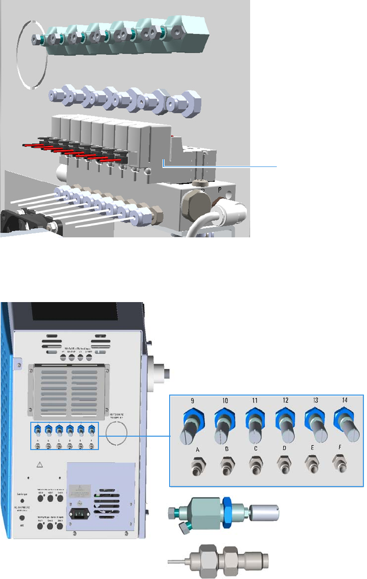
2 TRACE 1310 Auxiliary Oven Overview
Internal View
20 TRACE 1310 Auxiliary Oven Instruction Manual Thermo Scientific
• A Solenoid manifold for the pneumatic and electrical connections of up to eight
diaphragm valves. See Figure 19.
Figure 19. Back Solenoid Manifold for Diaphragm Valves
•Up to six unheated needle valves, and up to six sample inlet fittings mounted on the
back of the instrument. See Figure 20
Figure 20. Unheated Needle Valve and Sample Inlet Fitting
Solenoid Manifold
Sample Inlet Fitting
Needle Valve
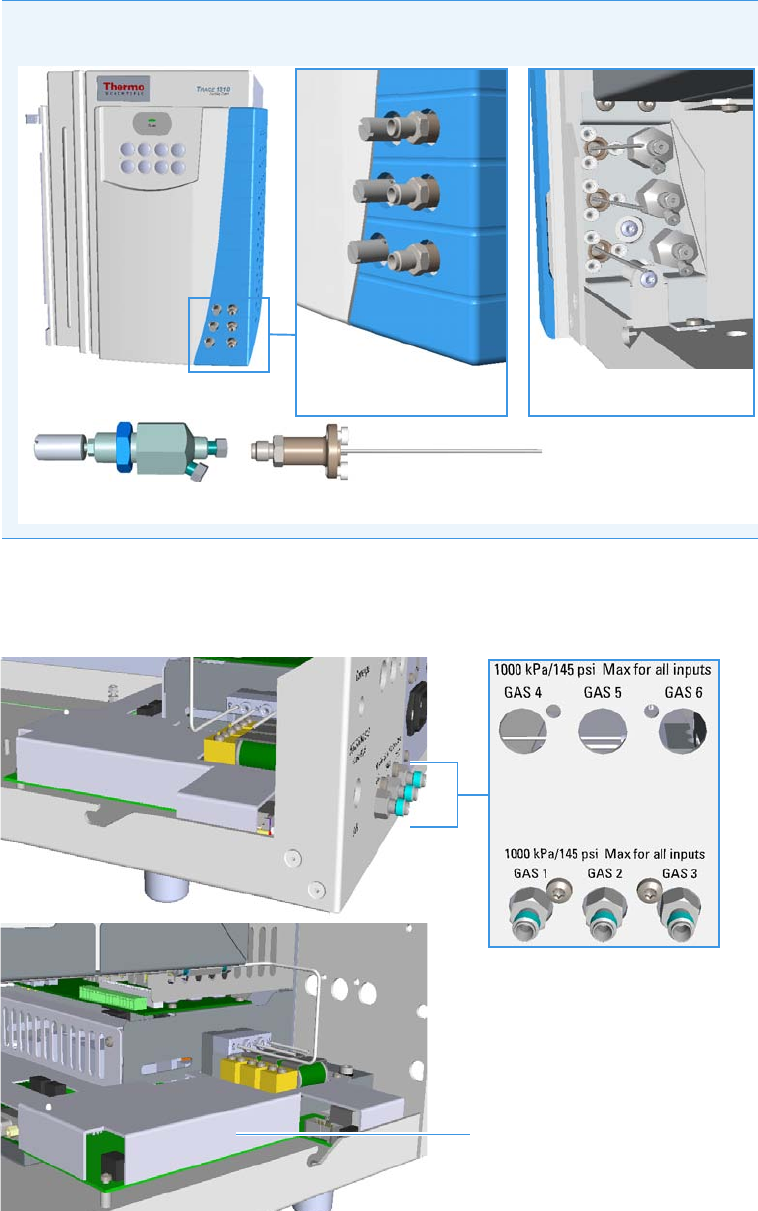
2 TRACE 1310 Auxiliary Oven Overview
Internal View
Thermo Scientific TRACE 1310 Auxiliary Oven Instruction Manual 21
• Up to six optional pressure channels by using up to two Auxiliary Gas modules. See
Figure 21 and Figure 22.
Figure 21. Primary Auxiliary Gas Module
Note Optionally it is possible mounting up to three unheated needle valves and
sample inlet fittings on the front of the instrument if required.
Sample Inlet Fitting with Extension
Needle Valve
Internal View
External View
Primary Auxiliary Gas Module
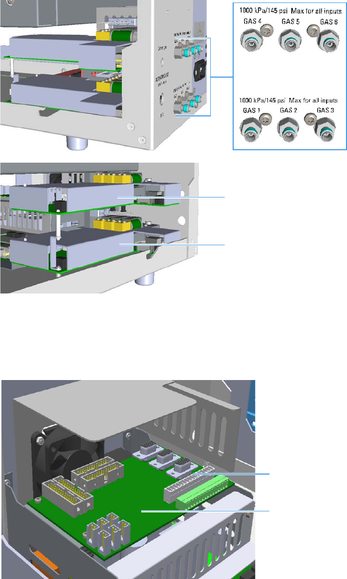
2 TRACE 1310 Auxiliary Oven Overview
Internal View
22 TRACE 1310 Auxiliary Oven Instruction Manual Thermo Scientific
Figure 22. Primary and Secondary Auxiliary Gas Modules
•Eight valve time events available on the VOBP-HRM board located over the power
section of the TRACE 1310 Auxiliary Oven. See Figure 23.
The events can be up to 16 if an Aux Temperature/Cryo module is also installed in the
GC.
Figure 23. External Event Connector
•Power section. See Figure 24.
Primary Auxiliary Gas Module
Secondary Auxiliary Gas Module
VOBP-HRM Board
Events Connector
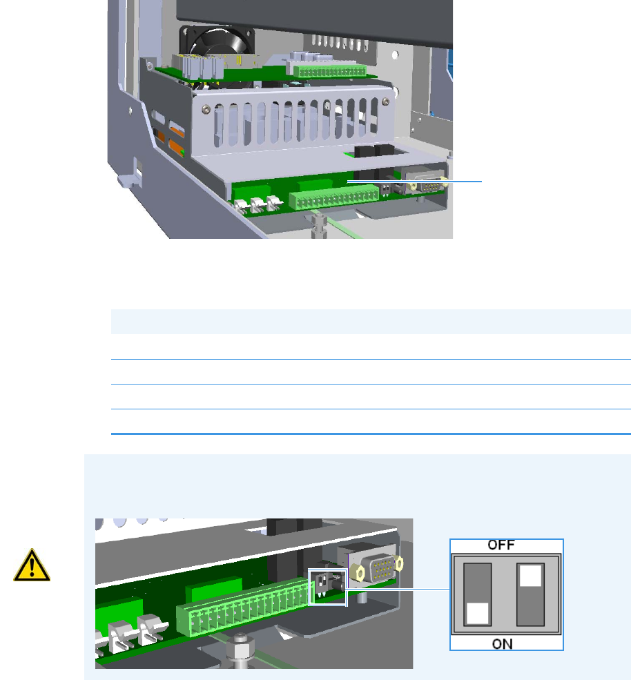
2 TRACE 1310 Auxiliary Oven Overview
Internal View
Thermo Scientific TRACE 1310 Auxiliary Oven Instruction Manual 23
This section consist of the Aux Temp VO/Power Supply board.
See Figure 24.
Figure 24. Power Section
Four protecting fuses are present on the Aux Temp VO/Power Supply board. See Table 5.
Table 5. Protecting Fuses
Fuse Type Protections
F1 F5A 250V; (5 x 20 mm) Heater 1
F2 F2A 250V; (5 x 20 mm) Heater 2
F3 T2A 250V; (5 x 20 mm) 24 V
F4 F1.6A 250V; (5 x 20 mm) 24 V solenoid valves
Aux Temp VO/Power
Supply Board
CAUTION The Aux Temp VO/Power Supply board must be properly configured so that
the GC system recognizes the presence of the TRACE 1310 Auxiliary Oven. For that
purpose verify that the configuration switches on the board are set as follows:
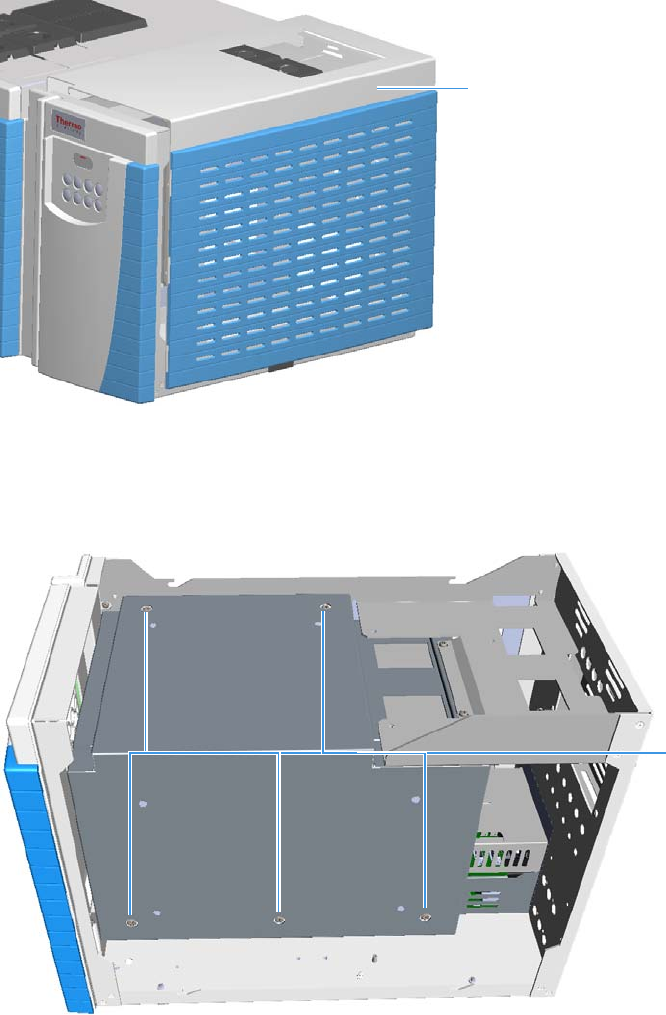
2 TRACE 1310 Auxiliary Oven Overview
Main Oven
24 TRACE 1310 Auxiliary Oven Instruction Manual Thermo Scientific
Main Oven
The main oven is accessible removing the L-shape cover that covers the top and the right side
of the TRACE 1310 Auxiliary Oven. See Figure 25.
Figure 25. TRACE 1310 Auxiliary Oven L-shape Cover
To access the interior of the main oven remove the L-shape cover that covers the top and the
right side of the heated main oven by unscrewing the five fixing screws (two on the top and
three on the right side. See Figure 26.
Figure 26. Main Oven Fixing Screws
Figure 27 shows the interior of the main oven, the valve mounting holes for the installation of
the valves, and the holes for the passage of the tubes.
L-Shape Cover
Main Oven
Fixing Screws

2 TRACE 1310 Auxiliary Oven Overview
Main Oven
Thermo Scientific TRACE 1310 Auxiliary Oven Instruction Manual 25
Figure 27. Main Oven Holes Layout (1)
Figure 28 shows the holes through which the fitting for the column connection of each
auxiliary detector protrudes into the interior of the main oven, the passing hole to the GC
oven, and the passing holes to the optional secondary oven or methanizer.
Figure 28. Main Oven Holes Layout (2)
Main Oven
Interior
Heated
Valves Fixing
Holes
Passing Holes
for Tubing
Passing Hole
To GC Oven
Heated Needle
Valves and
Sample Inlet
Fixing Holes
Passing hole to
GC Oven
Passing hole to
Secondary Oven
or Methanizer
Passing hole for
the fittings of the
Auxiliary
Detectors
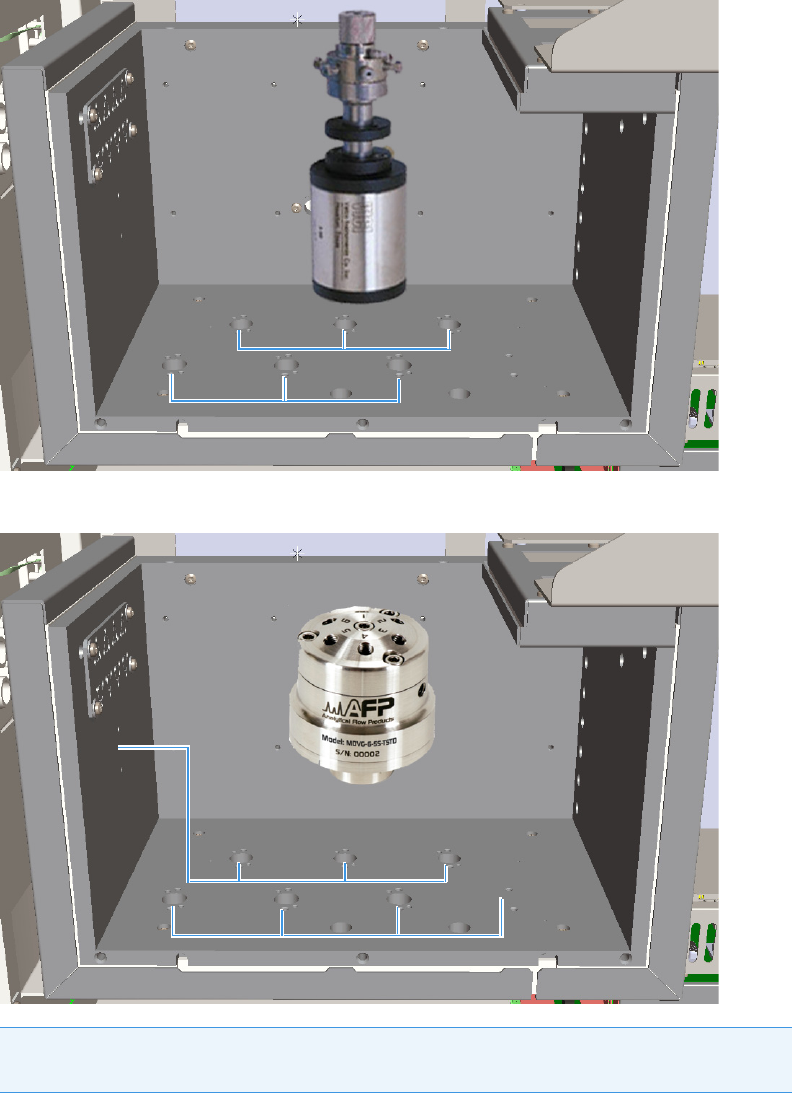
2 TRACE 1310 Auxiliary Oven Overview
Main Oven
26 TRACE 1310 Auxiliary Oven Instruction Manual Thermo Scientific
The main oven can contain up to eight sampling diaphragm valves (AFP™) or up to six
rotary valves (VICI®), up to eight heated needle valves and up to eight heated sample inlet
fittings accessible from the front side for sample transfer directly into the heated zone.
See the example in Figure 29, Figure 30, and Figure 31.
Figure 29. Rotary Valves
Figure 30. Diaphragm Valves
Note For convenience Figure 29 and Figure 30 show 6-port rotary and diaphragm valves.
Rotary and diaphragm valves with ten ports are also available.
Rotary Valves
Diaphragm Valves

2 TRACE 1310 Auxiliary Oven Overview
Main Oven
Thermo Scientific TRACE 1310 Auxiliary Oven Instruction Manual 27
Figure 31. Heated Needle Valves and Sample Inlet Fittings
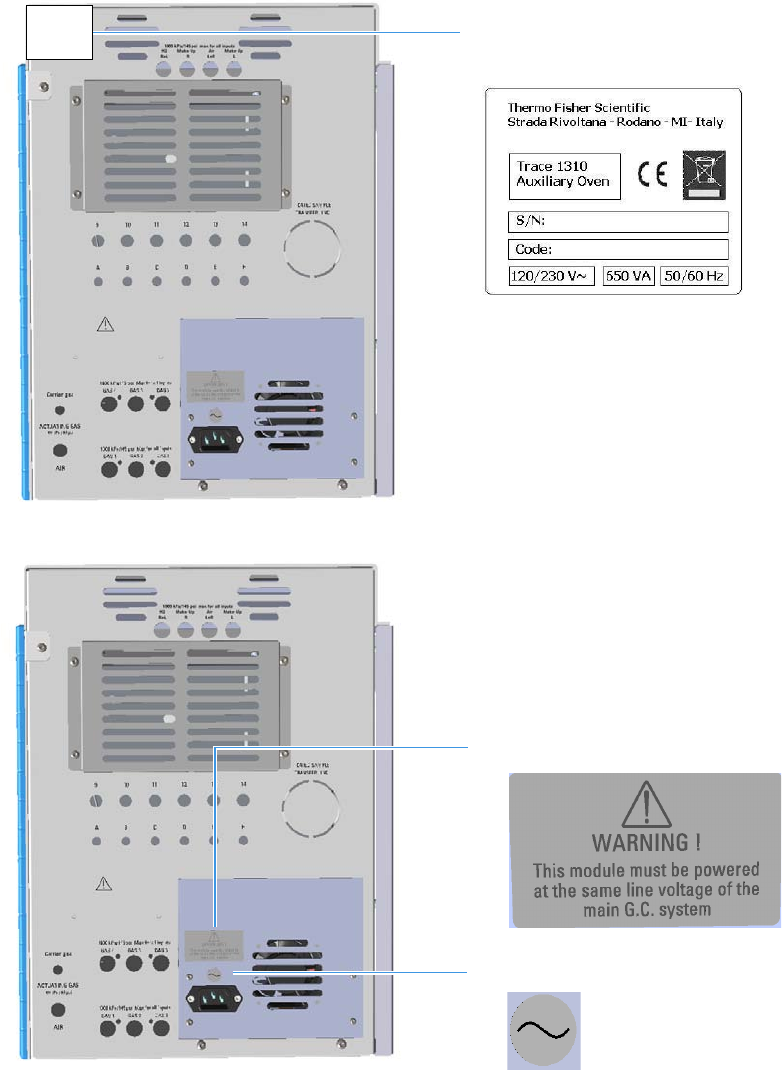
2 TRACE 1310 Auxiliary Oven Overview
Label Location on the Instrument
28 TRACE 1310 Auxiliary Oven Instruction Manual Thermo Scientific
Label Location on the Instrument
The following illustrations show the location of the labels attached on the TRACE 1310
Auxiliary Oven.
Figure 32. TRACE 1310 Auxiliary Oven: Serial Number Label
Figure 33. Power Supply: Alert Label
TRACE 1310 Auxiliary Oven Serial
Number and Electrical Data Labels
Alert Label
Alternating Current Label

2 TRACE 1310 Auxiliary Oven Overview
Label Location on the Instrument
Thermo Scientific TRACE 1310 Auxiliary Oven Instruction Manual 29
Figure 34. Detector Auxiliary Modules: Hot Surface and Alert Labels
Figure 35. Secondary Oven and Methanizer: Hot Surface and Ground Labels
HOT Surface Label
Alert Label
Serial Number Label
HOT Surface Label
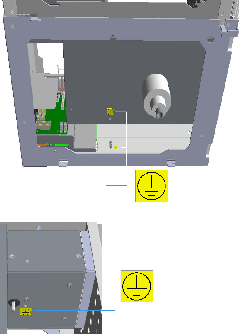
2 TRACE 1310 Auxiliary Oven Overview
Label Location on the Instrument
30 TRACE 1310 Auxiliary Oven Instruction Manual Thermo Scientific
Figure 36. TRACE 1310 Auxiliary Oven Protective Conductor Terminal Label
Figure 37. Secondary Oven and Methanizer: Protective Conductor Terminal Labels
Protective Conductor Terminal Label
Protective Conductor Terminal Label

2 TRACE 1310 Auxiliary Oven Overview
Tools Needed
Thermo Scientific TRACE 1310 Auxiliary Oven Instruction Manual 31
Figure 38. Auxiliary Detector Housing
Tools Needed
The tools needed for installing the components into the TRACE 1310 Auxiliary Oven are
listed in Tab l e 6 .
Detector Gases Connection Label
Table 6. Tools Required (Sheet 1 of 2)
Tool Interested Components
T30 Torxhead screwdriver Main oven cover fixing screws
T25 Torxhead screwdriver M5 screws of the Auxiliary Gas module (for example:
the screw that plug the split inlet).
T20 Torxhead screwdriver All the accessible M4 screws
T20 Torxhead L-shape wrench All the inaccessible M4 screws (for example: to fix the
solenoid valve manifold on the roof.
T10 Torxhead L-shape wrench Auxiliary Gas board
T8 Torxhead L-shape wrench Mixer (Tee fitting) installation on the Methanizer
assemble
1/4- 5/16-in. open-end wrench Valve head nuts
5/8-in. open-end wrench Valco® needle valves
7/16-in. open-end wrench Fittings crossing and 1/8-in. nuts
1/2-in. open-end wrench Fitting nut on the rear panel
7-mm combo open-end wrench Unheated valves and valves for liquid samples
(ASFVO) on the plate
8-mm combo open-end wrench Unheated membrane valves on the plate, and
M5/10-32 fittings
3/8-in. Allen wrench Actuator of the rotary valve

2 TRACE 1310 Auxiliary Oven Overview
Tools Needed
32 TRACE 1310 Auxiliary Oven Instruction Manual Thermo Scientific
3/16-in. Allen wrench Dowel of the clamp ring for both the cdiaphragm
valve, and valve for liquid sample
5/32-in. Allen wrench Clamp ring of the diaphragm valve
9/64-in. Allen wrench Clamp ring of the valve for liquid sample
Table 6. Tools Required (Sheet 2 of 2)
Tool Interested Components

Thermo Scientific TRACE 1310 Auxiliary Oven Instruction Manual 33
3
Components Installation
This chapter provides instructions for installing and configuring the optional components
such as valves, auxiliary gas modules, auxiliary detectors, secondary oven, methanizer, and
others, in the TRACE 1310 Auxiliary Oven, and the instructions for wiring and coupling the
TRACE 1310 Auxiliary Oven to the TRACE 1300/TRACE 1310 GC.
Contents
•Installing the Valves
•Installing Valves and Fittings into the Main Oven
•Installing Valves and Fittings in the Unheated Compartment
•Plumbing Valves and System
•Configuring the Valves
•Installing the Auxiliary Gas Modules
•Installing the Auxiliary Detectors Assembly
•Installing the Secondary Oven Assembly
•Installing the Methanizer Assembly
•Installing a Heated Sample Transfer Line
•Wiring the TRACE 1310 Auxiliary Oven to the GC
•Coupling the TRACE 1310 Auxiliary Oven to the GC
CAUTION These operations must be carried out by authorized and trained Thermo
Fisher Scientific Service Field Engineers.

3 Components Installation
Installing the Valves
34 TRACE 1310 Auxiliary Oven Instruction Manual Thermo Scientific
Installing the Valves
This section provides instruction for installing and configuring the valves in the TRACE 1310
Auxiliary Oven.
I
The heated section of the TRACE 1310 Auxiliary Oven accepts standard VICI® gas actuated
valves with 3-inch standoff. The unheated section will accommodate VICI® gas actuated
valves without standoff.
Related topics:
•“Installing Valves and Fittings into the Main Oven” on page 34
•“Installing Valves and Fittings in the Unheated Compartment” on page 49
•“Installing an Unheated Valve for Liquid Sample into the Unheated Compartment” on
page 63
Installing Valves and Fittings into the Main Oven
This section provides the instruction to install valves and sample inlet fittings into the main
oven.
Related topics:
•“Installing the Needle Valves and the Sample Inlet Fittings into the Main Oven” on
page 34
•“Installing the Rotary Valves into the Main Oven” on page 40
•“Installing the Diaphragm Valves in The Main Oven” on page 46
Installing the Needle Valves and the Sample Inlet Fittings into the Main Oven
To install a needle valve and the sample inlet fitting into the main oven
Note Before starting, cool the TRACE 1310 Auxiliary Oven to 50 °C or cooler.
Do not turn the GC off.
CAUTION Be careful not to mix actuators with valves that have different numbers of
ports, as the actuator movement for each valve can be different.
Note The following example considers the installation of a needle valve into the seat 1
and the sample inlet fittings into the seat 5.
Note The sample inlet fittings (PN 19071014) are capable of permitting the introduction
of the sample up to a temperature of 100 °C. If you need to heat the sample inlet at higher
temperature than 100 °C before entering the main oven, the kit PN 19071022 is
required. See “Bulkhead Connectors for High Temperature” on page 38.
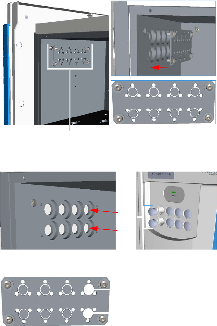
3 Components Installation
Installing Valves and Fittings into the Main Oven
Thermo Scientific TRACE 1310 Auxiliary Oven Instruction Manual 35
1. Remove the plate with the eight pre-cut seats from the wall of the main oven.
a. Using a cross-head screwdriver unscrew the four fixing screws of the plate.
b. Remove the plate. See the example in Figure 39.
Figure 39. Needle Valve and Sample Inlet Fitting Installation (1)
c. Using a pencil or other tool, push into the corresponding holes 1 and 5 for removing
the relevant caps. See the example in Figure 40.
Figure 40. Needle Valve and Sample Inlet Fitting Installation (2)
d. Using a cutter remove the pre-cut seats 1 and 5 from the plate. See Figure 41.
Figure 41. Needle Valve and Sample Inlet Fitting Installation (3)
Plate with Eight Pre-cut Seats
Caps
Pre-cut Seat 1
Pre-cut Seat 5
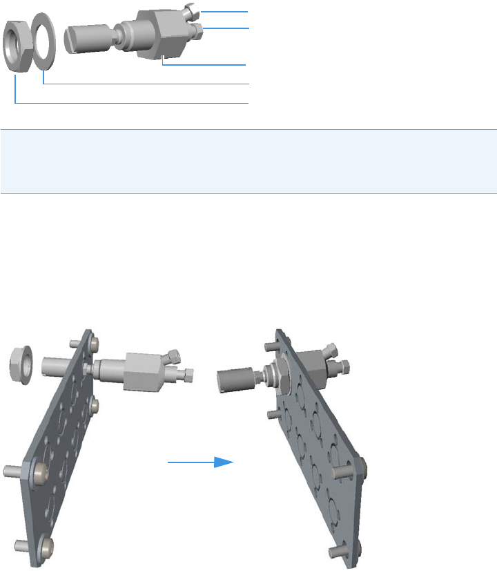
3 Components Installation
Installing Valves and Fittings into the Main Oven
36 TRACE 1310 Auxiliary Oven Instruction Manual Thermo Scientific
2. Mounting the needle valve on the plate.
a. Remove the retaining nut and the washer from the needle valve body. See Figure 42.
Figure 42. Needle Valve and Sample Inlet Fitting Installation (4)
b. Insert the needle valve body into the seat 1 of the plate.
c. Thread the retaining nut on the needle valve body interposing the washer.
d. Use your fingers to tighten the retaining nut until it starts to grip the plate. Tighten
the retaining nut a quarter turn using the proper wrench. See Figure 43.
Figure 43. Needle Valve and Sample Inlet Fitting Installation (5)
3. Mounting the sample inlet fitting on the plate.
a. Prepare the sample inlet fitting with the proper extension and fixing screws.
See Figure 44.
Note Before mounting the needle valve on the plate, we suggest removing the
nuts and ferrules from the inlet and outlet ports for facilitating the connection of
the inlet and outlet tubing to the needle valve.
Needle Valve Body
Washer
Retaining Nut
Inlet
Outlet
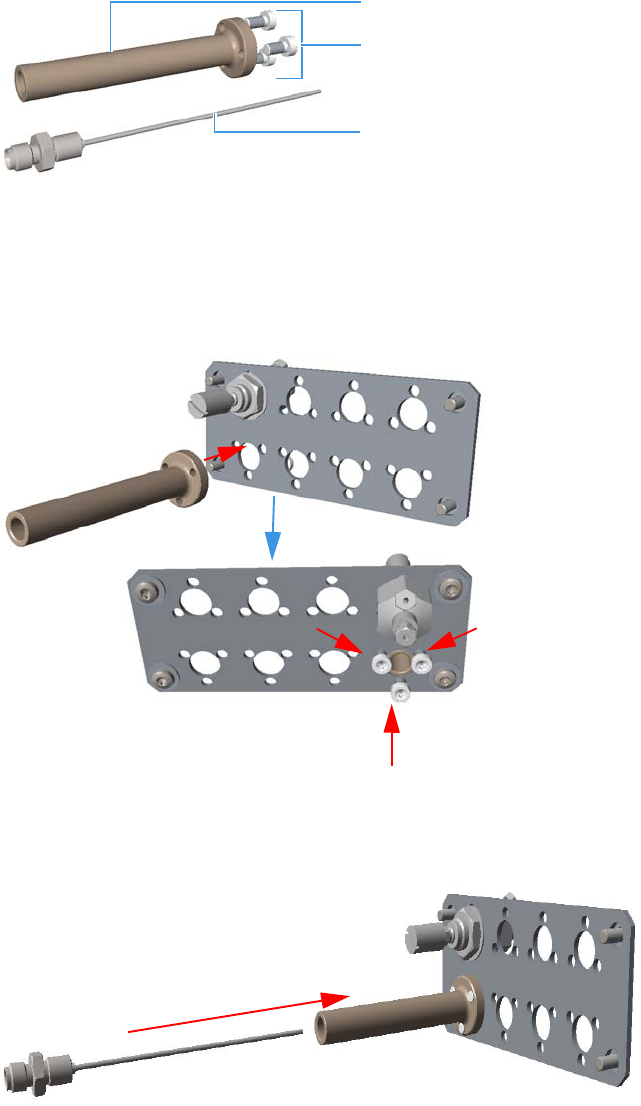
3 Components Installation
Installing Valves and Fittings into the Main Oven
Thermo Scientific TRACE 1310 Auxiliary Oven Instruction Manual 37
Figure 44. Needle Valve and Sample Inlet Fitting Installation (6)
b. Mount the extension on the seat 5 of the plate by matching its fixing holes to the
fixing holes on the plate.
c. Insert the three fixing screws into the corresponding fixing holes, then tighten the
screws using the proper Torxhead key or screwdriver. See Figure 43.
Figure 45. Needle Valve and Sample Inlet Fitting Installation (7)
d. Carefully insert and screw the sample inlet fitting into the extension. See Figure 47
and Figure 47.
Figure 46. Needle Valve and Sample Inlet Fitting Installation (8)
Extension
Fixing Screws
Sample Inlet Fitting
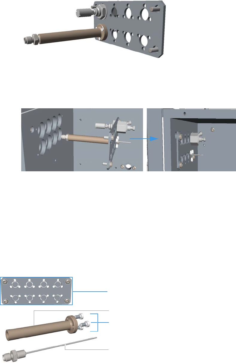
3 Components Installation
Installing Valves and Fittings into the Main Oven
38 TRACE 1310 Auxiliary Oven Instruction Manual Thermo Scientific
Figure 47. Needle Valve and Sample Inlet Fitting Installation (9)
4. Reinstall the plate on the wall of the main oven.
a. Using a cross-head screwdriver screw the four fixing screws of the plate.
See Figure 48.
Figure 48. Needle Valve and Sample Inlet Fitting Installation (10)
Bulkhead Connectors for High Temperature
The bulkhead connectors for high temperature (PN 19071022) allows to heat the sample
inlet at high temperature (up to 200 °C) before entering into the main oven.
For installing the sample inlet fittings for high temperature, follow the same procedure
previously described for installing the standard sample inlet fittings. See “To install a needle
valve and the sample inlet fitting into the main oven” on page 34.
To compare the parts to replace see Figure 49 and Figure 50.
Figure 49. Standard Sample Inlet Fitting
Extension
Fixing Screws
Sample Inlet Fitting
Plate
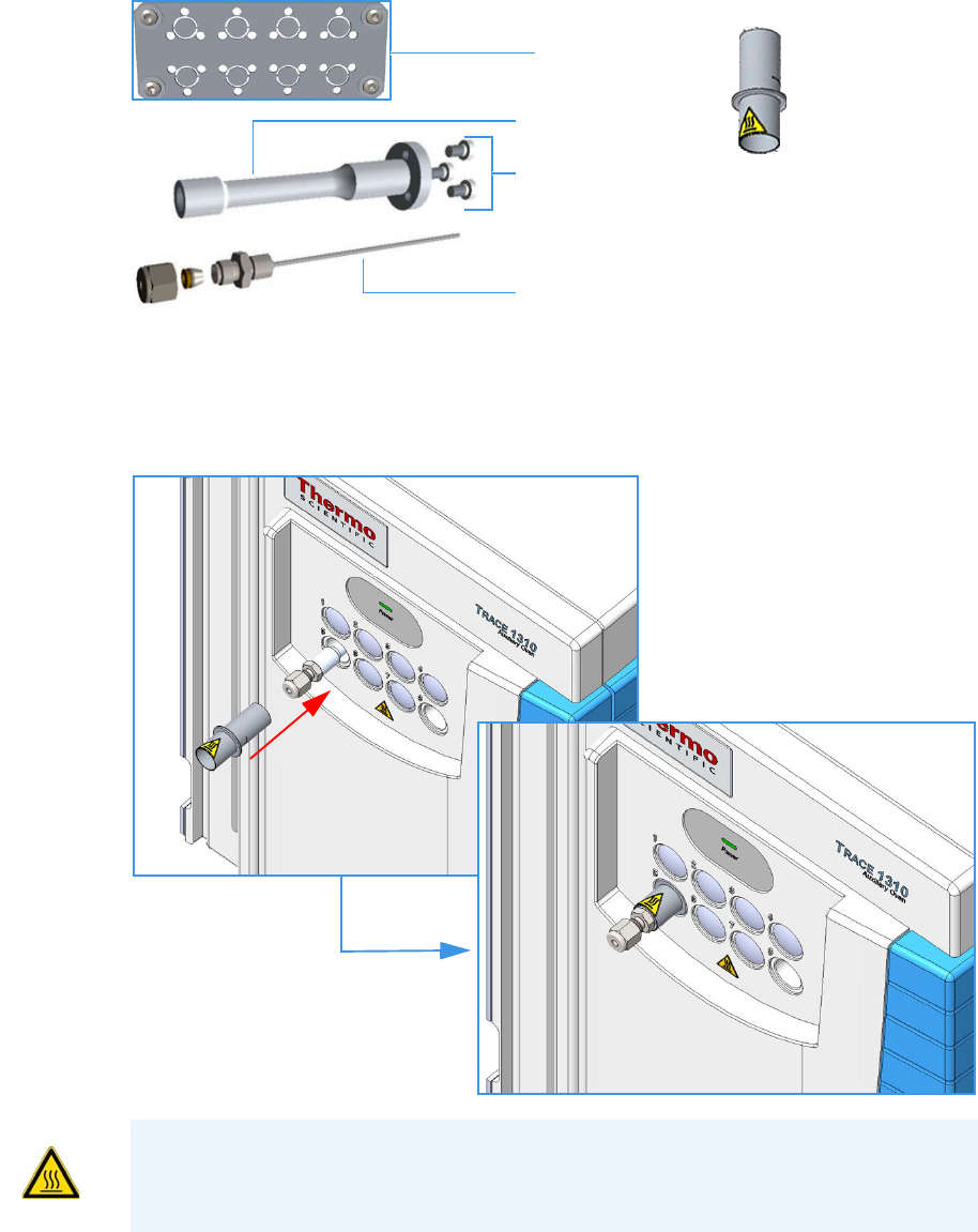
3 Components Installation
Installing Valves and Fittings into the Main Oven
Thermo Scientific TRACE 1310 Auxiliary Oven Instruction Manual 39
Figure 50. Sample Inlet Fitting for High Temperature
At the end of the installation of the sample inlet fittings for high temperature, place the
protection sleeve on the connector that protrudes the front of the TRACE 1310 Auxiliary
Oven. See Figure 51.
Figure 51. Protection sleeve
Extension
Fixing Screws
Sample Inlet Fitting
Plate
Protection Sleeve
WARNING-BURN HAZARD During the runs the protective sleeve may be hot. Do not
touch it to avoid burns. Allow it to cool to room temperature before touching it.
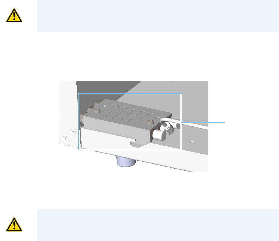
3 Components Installation
Installing Valves and Fittings into the Main Oven
40 TRACE 1310 Auxiliary Oven Instruction Manual Thermo Scientific
Installing the Rotary Valves into the Main Oven
To install a rotary valve into the main oven
Installing valves consists of the following steps:
• Installing the solenoid valves
• Disassembling the rotary valve and actuator
• Installing the rotary valve and standoff
• Connecting gas lines from the solenoid to the actuator
• Installing the actuator to the valve standoff
1. Installing the solenoid valves.
a. Install the solenoid manifold on the floor of the unheated compartment.
See the example of Figure 52.
Figure 52. Rotary Valve Installation (1)
b. Remove the rectangular-shaped cap from the manifold using the phillips screwdriver.
c. Secure the solenoid valve to the under plate using the two screws supplied with the
valve. See Figure 53.
CAUTION Turn the actuator gas off before you start these procedures.
Solenoid Manifold
CAUTION Tighten the screws evenly, taking care that the solenoid gasket rests on all
surfaces to prevent leaks.
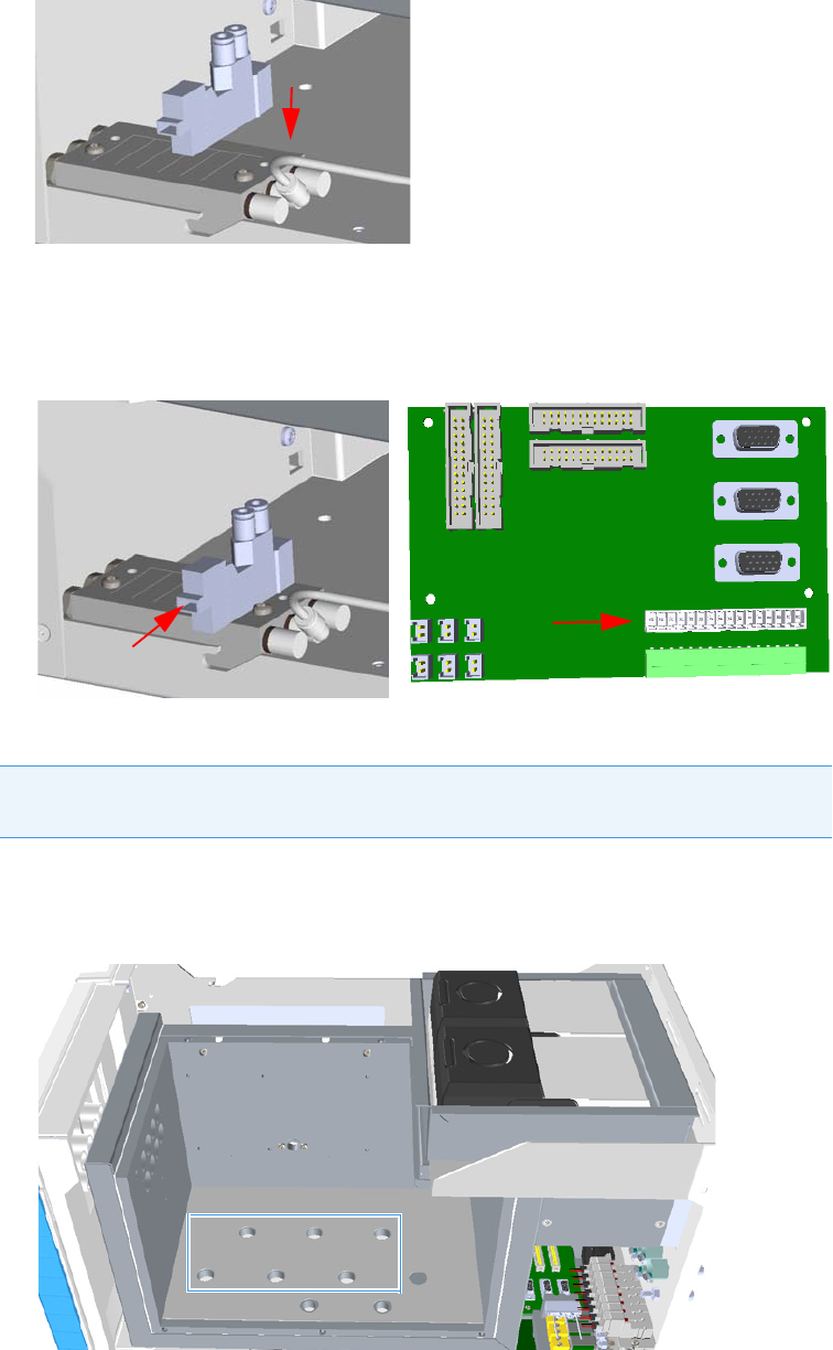
3 Components Installation
Installing Valves and Fittings into the Main Oven
Thermo Scientific TRACE 1310 Auxiliary Oven Instruction Manual 41
Figure 53. Rotary Valve Installation (2)
d. Connect the cable from the solenoid valve to the proper timed event output jack of
the Events connector marked J24 on the VOBP-HRM board located over the power
section. See Figure 54.
Figure 54. Rotary Valve Installation (3)
2. Disassemble the rotary valve and actuator.
a. Remove any insulation found in the valve mounting hole. The valve mounting hole is
located in the floor of the main oven. See Figure 55.
Figure 55. Main Oven Holes Layout (1)
Note Valves are usually installed starting from the mounting hole closest to the back
of the TRACE 1310 Auxiliary Oven.
Events Connector J24
Valves Mounting Holes
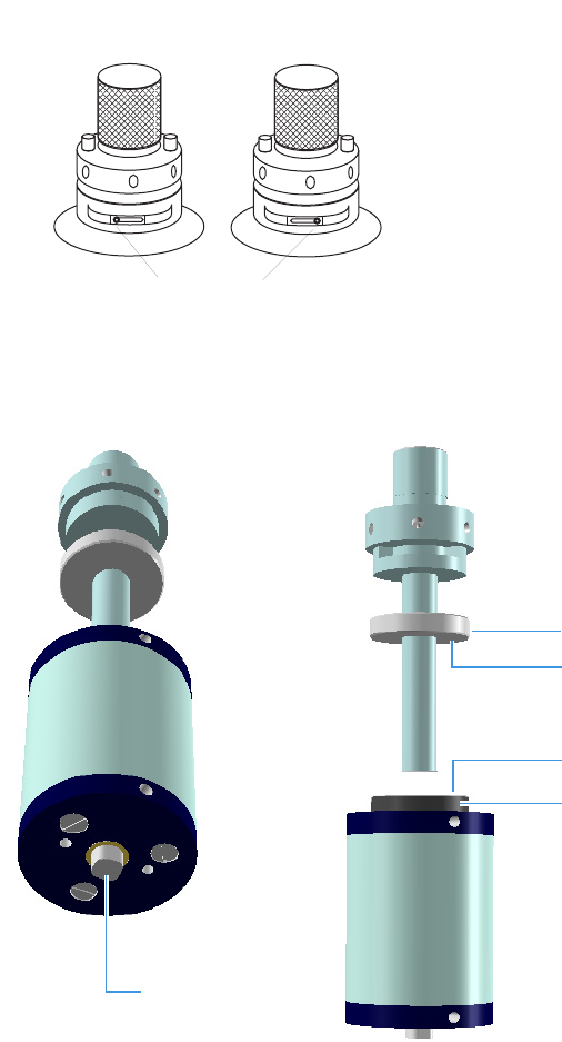
3 Components Installation
Installing Valves and Fittings into the Main Oven
42 TRACE 1310 Auxiliary Oven Instruction Manual Thermo Scientific
b. Inspect the valve and actuator making sure the valve is in the counter clock wise
(CCW) position. The CCW position is when the mechanical stop is in the position
noted in Figure 56.
Figure 56. Mechanical Stop Positions for both CW and CCW
If the valve is not in the CCW position, locate the square nut on the opposite end of
the actuator. See Figure 57.
Figure 57. Valve Separation
c. Using a 5/16” or 8 mm wrench, rotate the nut to the CCW position.
d. Once the valve is in the CCW position, separate the actuator from the valve and
standoff by loosening the Allen screw in collar B. See Figure 57.
Mechanical stop
Clockwise (CW) Position Counterclockwise (CCW) Position
Square Nut
Collar A
Allen Screw
Collar B
Allen Screw
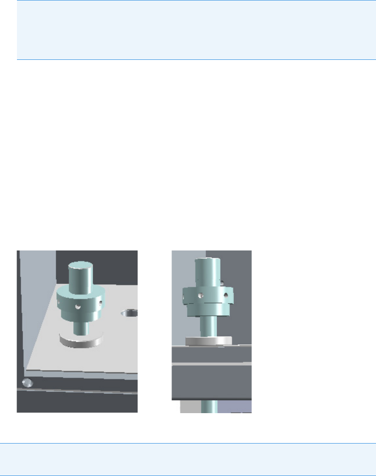
3 Components Installation
Installing Valves and Fittings into the Main Oven
Thermo Scientific TRACE 1310 Auxiliary Oven Instruction Manual 43
e. Remove the collar A attached to the valve standoff by loosening the screw that
secures the collar to the valve standoff. This collar mounts to the heater block of the
TRACE 1310 Auxiliary Oven. See Figure 57.
3. Installing the rotary valve and standoff.
a. Locate the desired valve position in the main oven and place the collar A over the
hole in the main oven. See Figure 58.
b. Secure the collar using two M 4 x10 mm screws. Be sure the 7/64” set screw in the
collar is accessible from the outer edge of the TRACE 1310 Auxiliary Oven.
c. Grip the valve standoff by the standoff only, and slide it through the collar allowing it
to extend into the lower valve compartment.
Figure 58. Valve Installation
4. Connecting gas lines from the solenoid valve manifold to the actuator.
CAUTION Be careful to pull the actuator away from the valve standoff by
gripping the standoff but without rotating the actuator or the valve.
Note Handle the valve and standoff with care so the two pieces do not separate.
Note Gas lines are much easier to connect to the actuator if the connection is made
before the actuator is assembled to the valve.
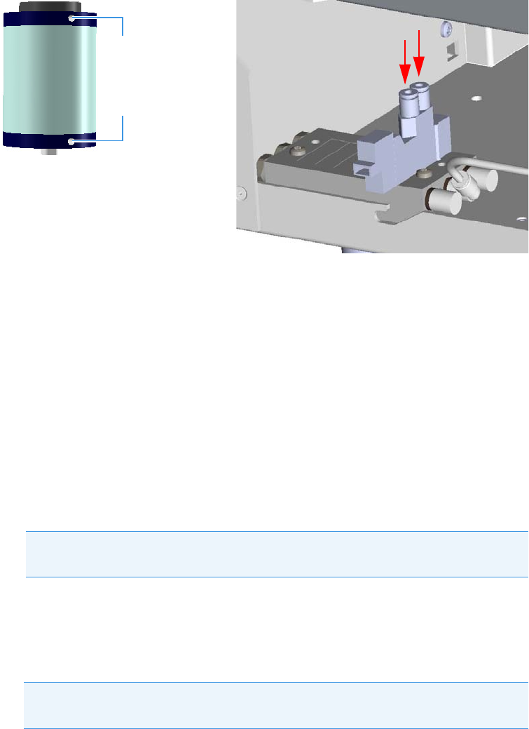
3 Components Installation
Installing Valves and Fittings into the Main Oven
44 TRACE 1310 Auxiliary Oven Instruction Manual Thermo Scientific
Figure 59. Actuator and Solenoid Valves Manifold Edges
With reference to Figure 59 proceed as follows:
a. Locate the nylon tubing supplied in the kit and cut it into two equal 12-in. pieces.
b. Push one of the tube pieces into the lower fitting on the actuator assembly, making
sure it passes through the ferrule in the actuator fitting. Tighten the nut and ferrule
using a 3/8-in. open end wrench. Use a backup 3/8-in. open end wrench on the
mating piece that is screwed into the actuator.
c. Place the other end of the tubing into the valve solenoid fitting located on the outside
edge of the solenoid manifold by pushing the tubing firmly into the fitting. It should
automatically seal in place.
d. Turn the actuator gas supply on. This line should now be pressurized.
e. Verify there are no major leaks in the fittings.
f. Take the other piece of nylon tubing and place it in the upper fitting on the actuator.
Be sure the tube passes through the ferrule in the fitting. Tighten the fitting using the
3/8-inch open end backup wrench.
g. Connect the opposite end to the solenoid fitting.
5. Installing the actuator to the valve standoff.
a. Carefully fit the actuator into the valve standoff being sure not to rotate the valve.
See Figure 60.
Note Applying pressure to this side of the actuator will ensure that the actuator
stays in the CCW position.
Note The tubing can be released from the solenoid by pushing down on the
solenoid fitting and pulling out on the tubing at the same time.
Actuator upper fitting
Actuator lower fitting
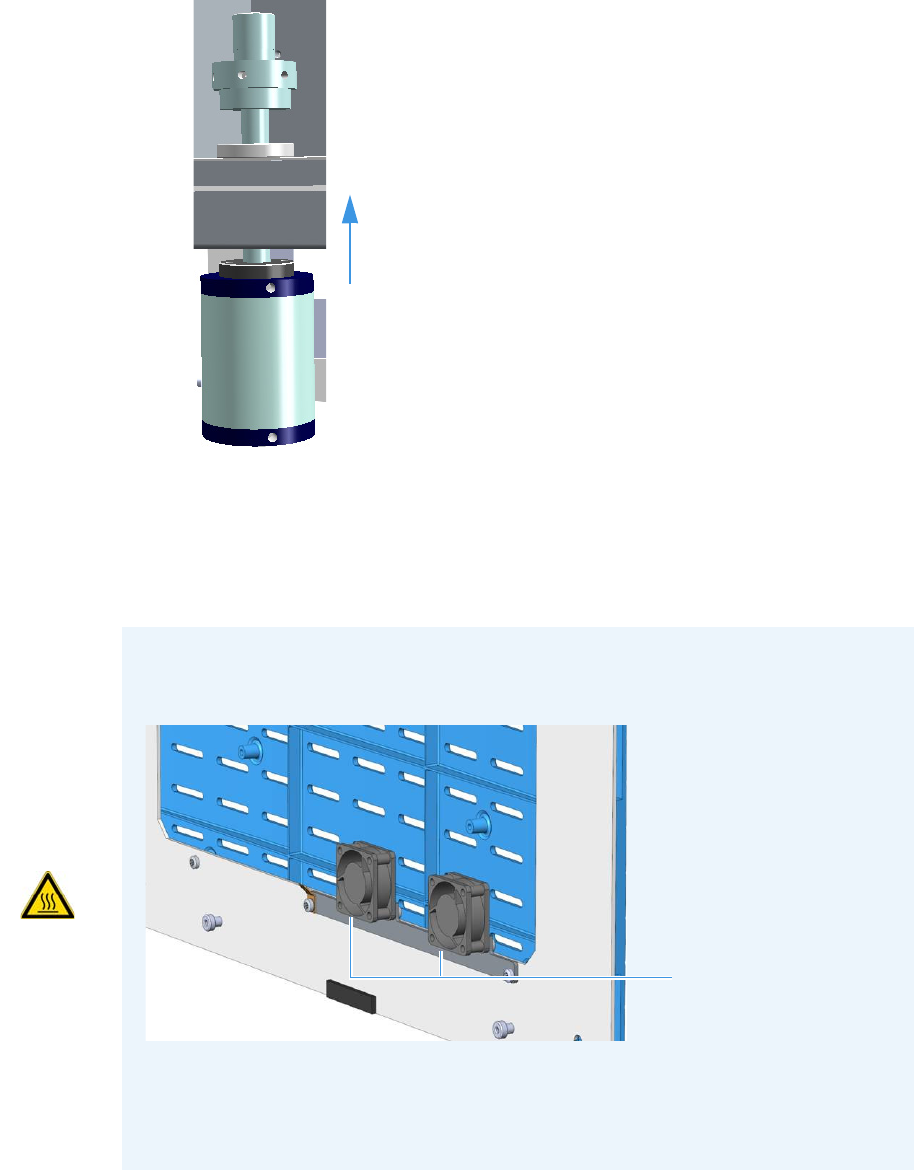
3 Components Installation
Installing Valves and Fittings into the Main Oven
Thermo Scientific TRACE 1310 Auxiliary Oven Instruction Manual 45
Figure 60. Actuator Installation (1)
b. Once the two square fittings on the actuator and valve are coupled, tighten the collar
on the valve. Be sure this fitting is very tight so the actuator will not rotate on the
valve standoff.
c. Slide the valve and actuator assembly up or down to the desired location and tighten
the upper collar to hold the valve and actuator in place.
IMPORTANT The installation of the Valve Actuator Cooling Kit (PN 19071023) is
recommended to preserve maximum actuators lifetime when TRACE 1310 Auxiliary
Oven is used at high temperature, between 150 °C and 270 °C.
For temperature above 270 °C High temperature actuators are recommended and the
cooling fans must not be used.
For further details refer to the Valve Actuator Cooling Kit Installation Note.
Cooling Fans
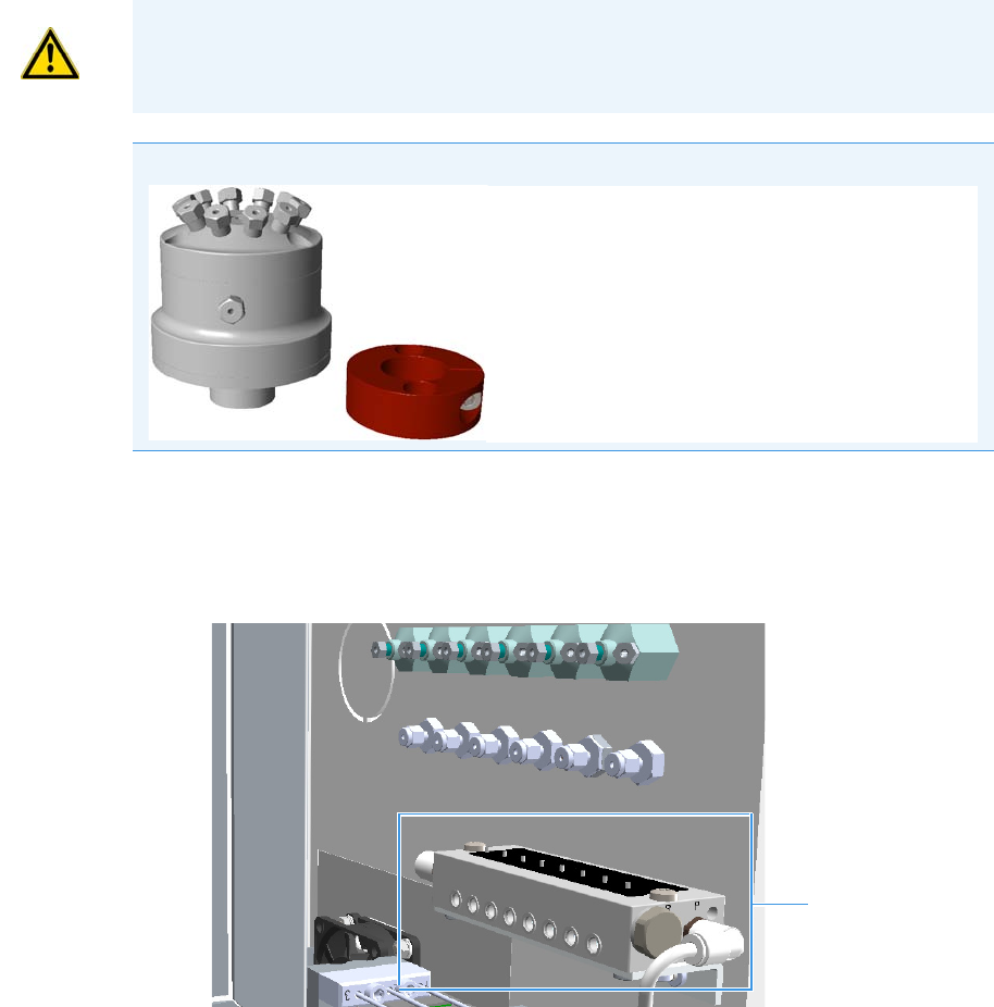
3 Components Installation
Installing Valves and Fittings into the Main Oven
46 TRACE 1310 Auxiliary Oven Instruction Manual Thermo Scientific
Installing the Diaphragm Valves in The Main Oven
To install a diaphragm valve in the main oven
Installing valves consists of the following steps:
• Installing the solenoid valve
• Installing the diaphragm valve
• Connecting the gas line
1. Installing the solenoid valve.
a. Install the solenoid manifold on the rear wall of the valve compartment.
See the example of Figure 61.
Figure 61. Diaphragm Valve Installation (1)
CAUTION Turn the actuator gas off before you start these procedures.
Note The installation of the diaphragm valve requires the use of the fixing clamp ring.
Diaphragm Valve
Clamp Ring
Fixing Dowel
Solenoid Manifold
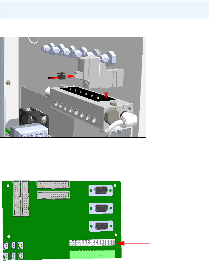
3 Components Installation
Installing Valves and Fittings into the Main Oven
Thermo Scientific TRACE 1310 Auxiliary Oven Instruction Manual 47
b. Remove the rectangular shaped cap from the manifold using the #0 phillips
screwdriver.
c. Secure the solenoid valve to the under plate using the two screws supplied with the
valve. See Figure 62.
Figure 62. Diaphragm Valve Installation (2)
d. Connect the cable from the solenoid valve to the proper timed event output jack of
the Events connector marked J24 on the VOBP-HRM board located over the power
section. See Figure 63.
Figure 63. Diaphragm Valve Installation (3)
2. Installing the valve.
a. Remove any insulation found in the valve mounting hole. The valve mounting hole is
located in the floor of the main oven. See Figure 64.
CAUTION Tighten screws evenly, taking care that the solenoid gasket rests on all
surfaces to prevent leaks.
Events Connector J24
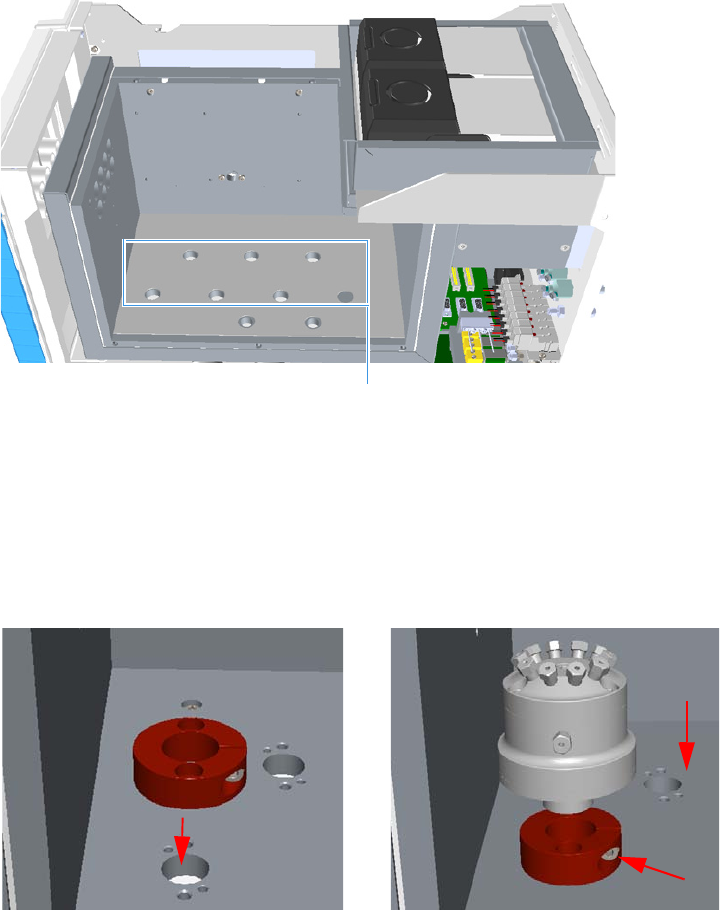
3 Components Installation
Installing Valves and Fittings into the Main Oven
48 TRACE 1310 Auxiliary Oven Instruction Manual Thermo Scientific
Figure 64. Main Oven Holes Layout (1)
b. Locate the desired valve position in the main oven and place the clamp ring over the
hole in the main oven, then secure the clamp ring with the two screws provided.
c. Loosen the dowel on the clamp ring, then insert the valve into the clamp ring.
d. Secure the valve tightening the dowel. See Figure 65.
Figure 65. Installing Diaphragm Valve
3. Connecting the gas line.
a. By using the proper nuts and ferrules, connect the gas line from the solenoid valve
manifold to the diaphragm valve. See Figure 66.
Valves Mounting Holes
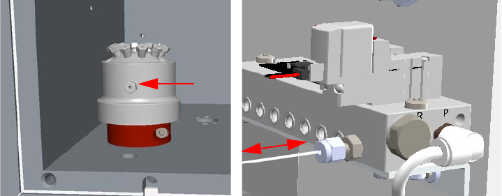
3 Components Installation
Installing Valves and Fittings in the Unheated Compartment
Thermo Scientific TRACE 1310 Auxiliary Oven Instruction Manual 49
Figure 66. Gas Connection
4. Testing the valve.
a. Configure the valve and rotate it clockwise and counter-clockwise.
b. Ensure that the valve moves freely in both directions.
c. Inspect the valve stop when the valve is in both positions to ensure that the stop is at
the movement limit on each side.
Installing Valves and Fittings in the Unheated Compartment
This section provides the instructions to install valves and sample inlet fittings in the unheated
compartment.
Related topics:
•“Installing the Needle Valves and the Sample Inlet Fittings into the Unheated
Compartment” on page 49
•“Installing an Unheated Rotary Valve into the Unheated Compartment” on page 55
•“Installing an Unheated Diaphragm Valve into the Unheated Compartment” on page 59
•“Installing an Unheated Valve for Liquid Sample into the Unheated Compartment” on
page 63
Installing the Needle Valves and the Sample Inlet Fittings into the Unheated
Compartment
This section provides the instructions to install a needle valve and a sample inlet fitting on the
back or on the front panel of the TRACE 1310 Auxiliary Oven.
Related Topics:
•“To install a needle valve and the sample inlet fitting into the back unheated
compartment” on page 50
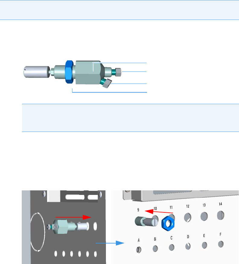
3 Components Installation
Installing Valves and Fittings in the Unheated Compartment
50 TRACE 1310 Auxiliary Oven Instruction Manual Thermo Scientific
•“To install a needle valve and the sample inlet fitting into the front unheated
compartment” on page 51
To install a needle valve and the sample inlet fitting into the back unheated
compartment
1. Mounting the needle valve on the back panel.
a. Remove the retaining nut from the needle valve body. See Figure 67.
Figure 67. Needle Valve and Sample Inlet Fitting Installation (1)
b. Insert the needle valve body into the seat 9 of the back panel.
c. Thread the retaining nut on the needle valve.
d. Use your fingers to tighten the retaining nut until it starts to grip the back panel.
Tighten the retaining nut a quarter turn using a proper wrench. See Figure 68.
Figure 68. Needle Valve and Sample Inlet Fitting Installation (2)
2. Mounting the sample inlet fitting on the back panel.
a. Remove the retaining nut from the fitting body. See Figure 69.
Note The following example considers the installation of a needle valve into the seat 9
and the sample inlet fittings into the seat A.
Note Before mounting the needle valve on the plate, we suggest removing the
nuts and ferrules from the inlet and outlet ports for facilitating the connection of
the inlet and outlet tubing to the needle valve.
Needle Valve Body
Retaining Nut
Inlet
Outlet
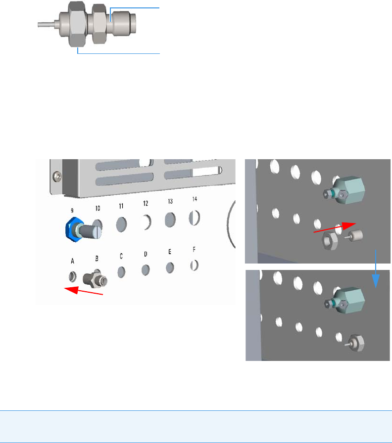
3 Components Installation
Installing Valves and Fittings in the Unheated Compartment
Thermo Scientific TRACE 1310 Auxiliary Oven Instruction Manual 51
Figure 69. Needle Valve and Sample Inlet Fitting Installation (3)
b. Insert the sample inlet fitting into the seat A of the back panel.
c. Thread the retaining nut.
d. Use your fingers to tighten the retaining nut until it starts to grip the panel. Tighten
the retaining nut a quarter turn using a proper wrench. See Figure 70.
Figure 70. Needle Valve and Sample Inlet Fitting Installation (2)
To install a needle valve and the sample inlet fitting into the front unheated
compartment
1. Remove the plate with the six seats from the frontal wall on the left lower corner of the
unheated compartment.
a. Using a cross-head screwdriver unscrew the four fixing screws of the plate.
b. Remove the plate. See the example in Figure 71.
Note This is an optional procedure for mounting up to three unheated needle valves and
sample inlet fittings on the front of the instrument.
Fitting Body
Retaining Nut
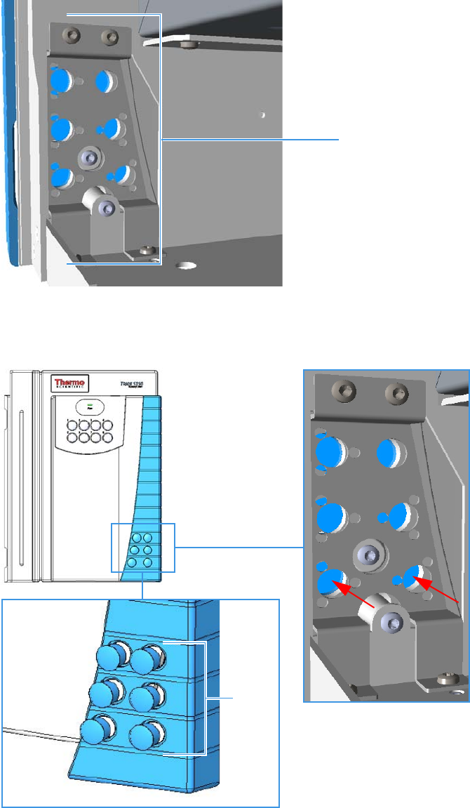
3 Components Installation
Installing Valves and Fittings in the Unheated Compartment
52 TRACE 1310 Auxiliary Oven Instruction Manual Thermo Scientific
Figure 71. Needle Valve and Sample Inlet Fitting Installation (1)
c. Using a pencil or other tool, push into the corresponding holes the for removing the
relevant caps. See the example in Figure 72.
Figure 72. Needle Valve and Sample Inlet Fitting Installation (2)
2. Mounting the needle valve on the plate.
Plate with Six Seats
Caps
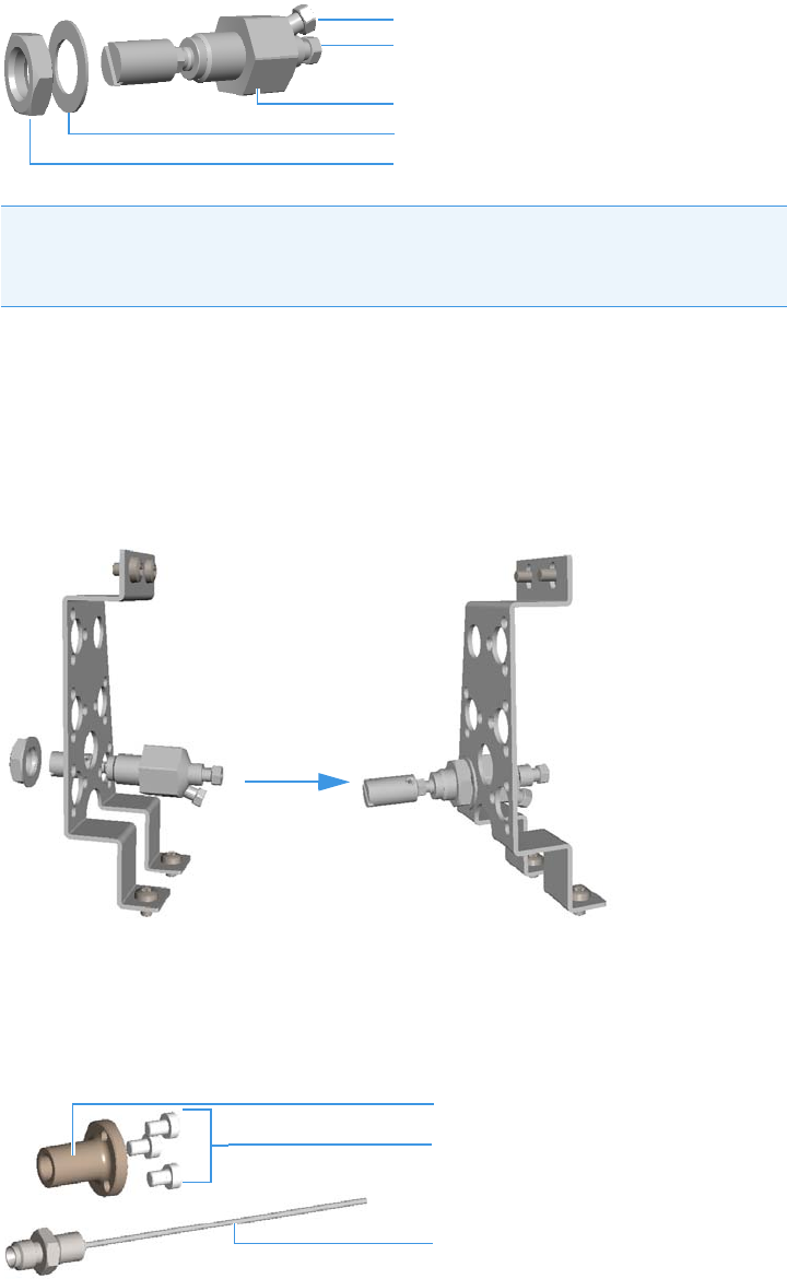
3 Components Installation
Installing Valves and Fittings in the Unheated Compartment
Thermo Scientific TRACE 1310 Auxiliary Oven Instruction Manual 53
a. Remove the retaining nut and the washer from the needle valve body. See Figure 73.
Figure 73. Needle Valve and Sample Inlet Fitting Installation (3)
b. Insert the needle valve body into the desired seat of the plate.
c. Thread the retaining nut on the needle valve body interposing the washer.
d. Use your fingers to tighten the retaining nut until it starts to grip the plate. Tighten
the retaining nut a quarter turn using the proper wrench. See the example in
Figure 74.
Figure 74. Needle Valve and Sample Inlet Fitting Installation (4)
3. Mounting the sample inlet fitting on the plate.
a. Prepare the sample inlet fitting with the proper extension and fixing screws.
See Figure 75.
Figure 75. Needle Valve and Sample Inlet Fitting Installation (5)
Note Before mounting the needle valve on the plate, we suggest removing the
nuts and ferrules from the inlet and outlet ports for facilitating the connection of
the inlet and outlet tubing to the needle valve.
Needle Valve Body
Washer
Retaining Nut
Inlet
Outlet
Extension
Fixing Screws
Sample Inlet Fitting

3 Components Installation
Installing Valves and Fittings in the Unheated Compartment
54 TRACE 1310 Auxiliary Oven Instruction Manual Thermo Scientific
b. Mount the extension on the desired seat of the plate by matching its fixing holes to
the fixing holes on the plate.
c. Insert the three fixing screws into the corresponding fixing holes, then tighten the
screws using the proper Torxhead key or screwdriver. See Figure 76.
Figure 76. Needle Valve and Sample Inlet Fitting Installation (6(
d. Carefully insert and screw the sample inlet fitting into the extension. See Figure 47.
Figure 77. Needle Valve and Sample Inlet Fitting Installation (7)
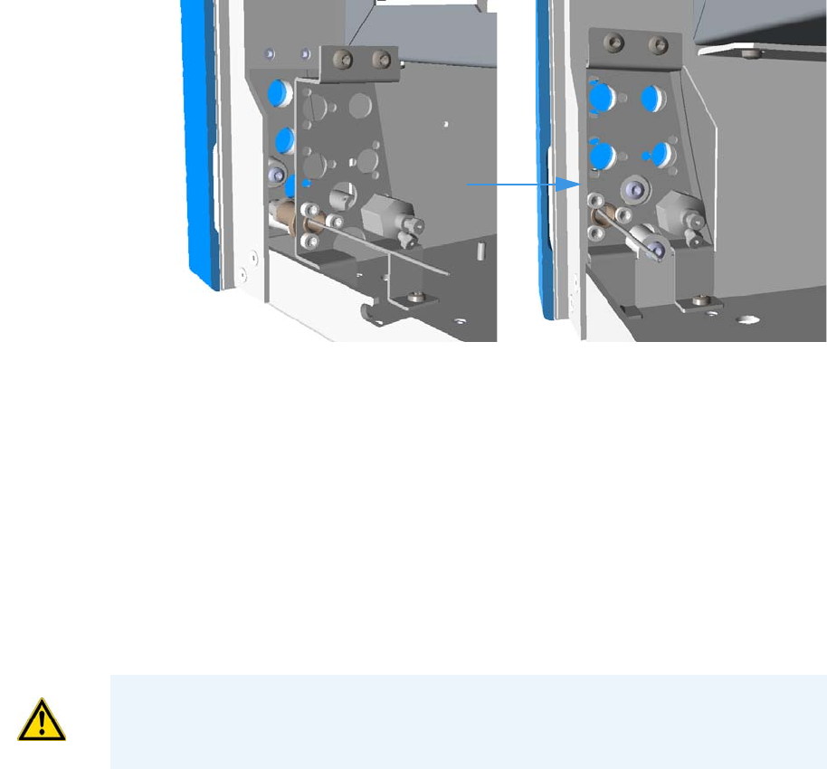
3 Components Installation
Installing Valves and Fittings in the Unheated Compartment
Thermo Scientific TRACE 1310 Auxiliary Oven Instruction Manual 55
4. Reinstall the plate on the frontal wall of the unheated compartment.
a. Using a cross-head screwdriver screw the four fixing screws of the plate.
See Figure 78.
Figure 78. Needle Valve and Sample Inlet Fitting Installation (8)
Installing an Unheated Rotary Valve into the Unheated Compartment
To install a rotary valve in the unheated compartment
Installing valves in the unheated compartment consists of the following steps:
• Installing the valve on the mounting bracket
• Installing the assemble into the unheated compartment under the main oven
• Installing the solenoid valve
• Connecting gas line
1. Install the valve on the mounting bracket
The unheated valve assembly will require the mounting bracket, included as part of the
assembly.
a. Choose the mounting holes in the bracket that will allow the actuator and the valve
to be oriented in a favorable direction.
b. Fix the valve to the bracket by using the two fixing screws. See Figure 79.
CAUTION Turn the actuator gas off before you start these procedures.
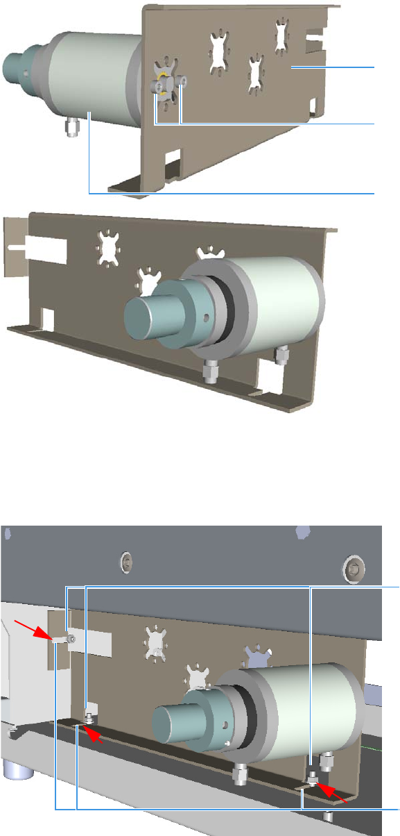
3 Components Installation
Installing Valves and Fittings in the Unheated Compartment
56 TRACE 1310 Auxiliary Oven Instruction Manual Thermo Scientific
Figure 79. Unheated Rotary Valve Installation (1)
2. Install the assembly into the unheated compartment under the main oven.
a. Install the bracket into the unheated compartment pay attentions to meet the fixing
slots on the bracket to the three studs located as shown in Figure 80.
Figure 80. Unheated Rotary Valve Installation (2)
Valve
Mounting Bracket
Fixing Screws
Studs
Slots
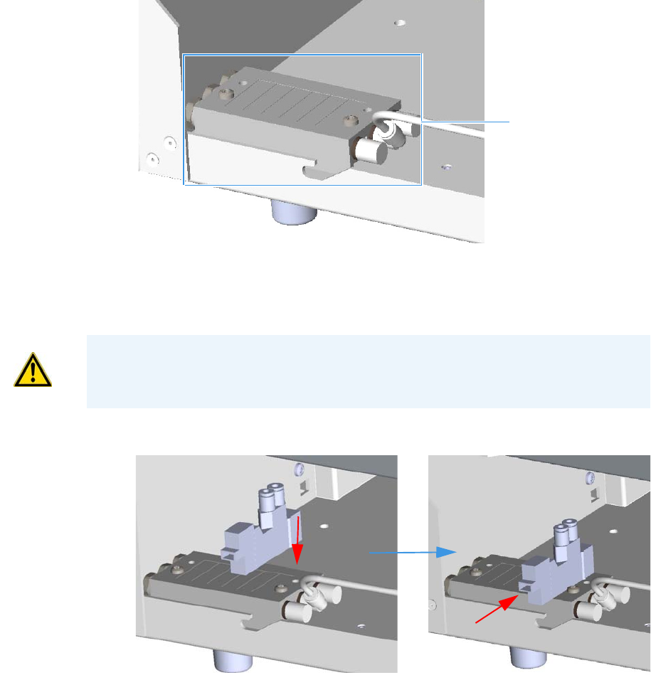
3 Components Installation
Installing Valves and Fittings in the Unheated Compartment
Thermo Scientific TRACE 1310 Auxiliary Oven Instruction Manual 57
b. Push the bracket against the studs, then secure the assembly tightening the studs.
3. Install the solenoid valves.
a. Install the solenoid manifold on the floor of the unheated compartment.
See the example of Figure 81.
Figure 81. Unheated Rotary Valve Installation (3)
b. Remove the rectangular shaped cap from the manifold using the Phillips screwdriver.
c. Secure the solenoid valve to the under plate using the two screws supplied with the
valve. See Figure 82.
Figure 82. Unheated Rotary Valve Installation (4)
d. Connect the cable from the solenoid valve to the proper timed event output jack of
the Events connector marked J24 on the VOBP-HRM board located over the power
section. See Figure 83.
Solenoid Manifold
CAUTION Tighten screws evenly, taking care that the solenoid gasket rests on all surfaces
to prevent leaks.
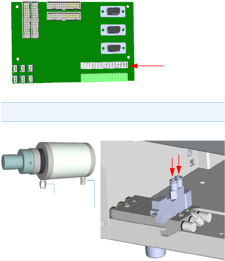
3 Components Installation
Installing Valves and Fittings in the Unheated Compartment
58 TRACE 1310 Auxiliary Oven Instruction Manual Thermo Scientific
Figure 83. Unheated Rotary Valve Installation (5)
4. Connect gas lines from the solenoid valve manifold or the actuator.
Figure 84. Unheated Rotary Valve Installation (4)
With reference to Figure 84 proceed as follows:
a. Locate the nylon tubing supplied in the TRACE 1310 Auxiliary Oven kit and cut it
into two equal 12-in. pieces.
b. Push one of the tube pieces into the lower fitting on the actuator assembly, making
sure it passes through the ferrule in the actuator fitting. Tighten the nut and ferrule
using a 3/8-in. open end wrench. Use a backup 3/8-in. open end wrench on the
mating piece that is screwed into the actuator.
c. Place the other end of the tubing into the valve solenoid fitting located on the outside
edge of the solenoid manifold by pushing the tubing firmly into the fitting. It should
automatically seal in place.
Note Gas lines are much easier to connect to the actuator if the connection is made
before the actuator is assembled to the valve.
Events Connector J24
Actuator upper fitting
Actuator lower fitting

3 Components Installation
Installing Valves and Fittings in the Unheated Compartment
Thermo Scientific TRACE 1310 Auxiliary Oven Instruction Manual 59
d. Turn the actuator gas supply on. This line should now be pressurized.
e. Verify there are no major leaks in the fittings.
f. Take the other piece of nylon tubing and place it in the upper fitting on the actuator.
Be sure the tube passes through the ferrule in the fitting. Tighten the fitting using the
3/8-inch open end backup wrench.
g. Connect the opposite end to the solenoid fitting
Installing an Unheated Diaphragm Valve into the Unheated Compartment
To install a diaphragm valve in the unheated compartment
Installing valves in the unheated compartment consists of the following steps:
• Installing the valve on the mounting bracket
• Installing the assemble into the unheated compartment under the main oven
• Installing the solenoid valve
• Connecting gas line
Proceed as follows:
1. Installing the valve on the mounting bracket.
The unheated valve assembly will require the mounting bracket, included as part of the
assembly.
a. Choose the mounting holes in the bracket that will allow the valve to be oriented in a
favorable direction.
Note Applying pressure to this side of the actuator will ensure that the actuator
stays in the CCW position.
Note The tubing can be released from the solenoid by pushing down on the
solenoid fitting and pulling out on the tubing at the same time.
Note The installation of the diaphragm valve requires the use of the fixing clamp
ring.
Clamp Ring
Fixing Dowel
Diaphragm Valve
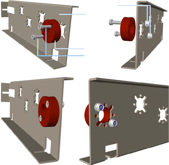
3 Components Installation
Installing Valves and Fittings in the Unheated Compartment
60 TRACE 1310 Auxiliary Oven Instruction Manual Thermo Scientific
b. Place the clamp ring over the hole on the bracket, then secure the clamp ring using
the two screws and nuts provided. Take loose one of the two nuts allowing the dowel
to tighten the clamp ring. See Figure 85.
Figure 85. Unheated Diaphragm Valve Installation (1)
c. Loosen the dowel on the clamp ring, then insert the valve into the clamp ring.
d. Secure the valve tightening the dowel. See Figure 86.
Mounting
Clamp Ring
Fixing Screws
Nuts
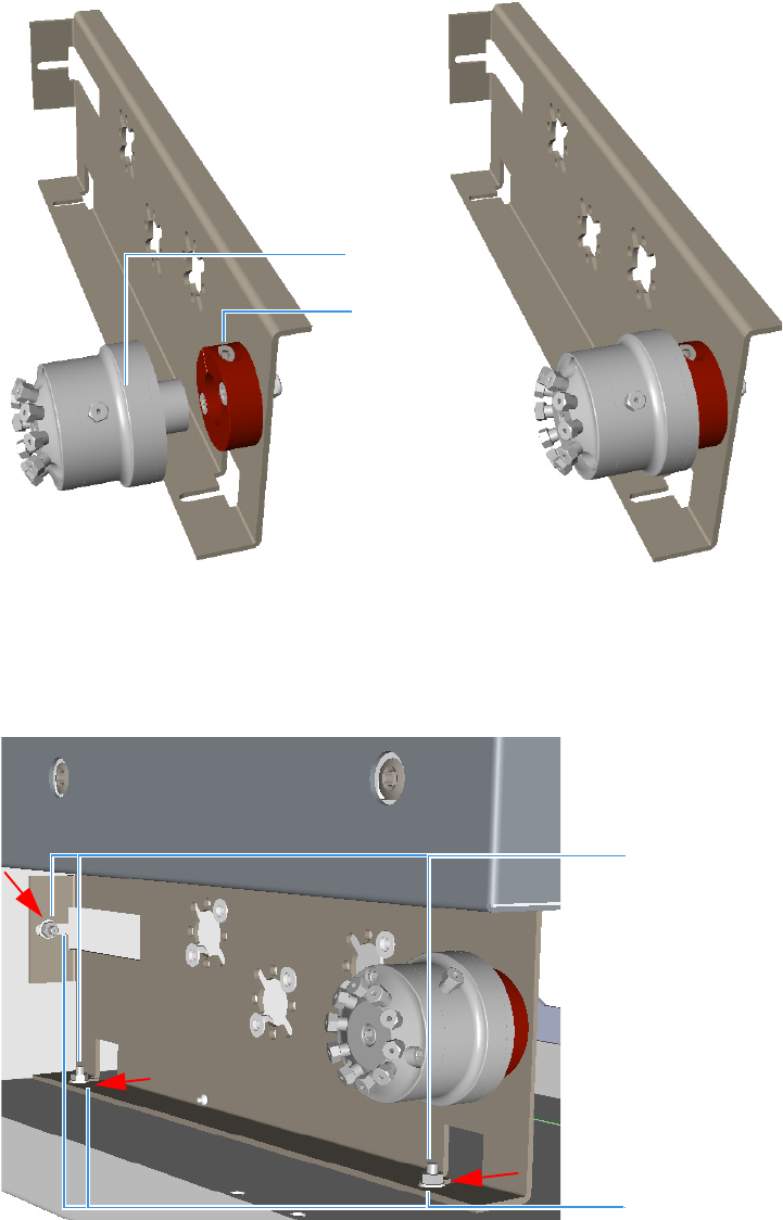
3 Components Installation
Installing Valves and Fittings in the Unheated Compartment
Thermo Scientific TRACE 1310 Auxiliary Oven Instruction Manual 61
Figure 86. Unheated Diaphragm Valve Installation (2)
2. Install the assembly into the unheated compartment under the main oven.
a. Install the bracket into the unheated compartment, paying attentions to meet the
fixing slots on the bracket to the three studs located as shown in Figure 87.
Figure 87. Unheated Diaphragm Valve Installation (2)
#
b. Push the bracket against the studs, then secure the assembly by tightening the studs.
3. Install the solenoid valve.
Valve
Dowel
Studs
Slots
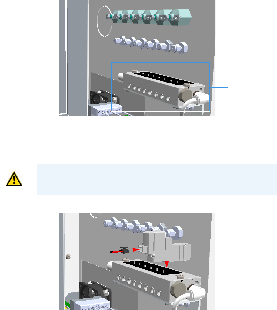
3 Components Installation
Installing Valves and Fittings in the Unheated Compartment
62 TRACE 1310 Auxiliary Oven Instruction Manual Thermo Scientific
a. Install the solenoid manifold on the rear wall of the valve compartment.
See the example of Figure 88.
Figure 88. Unheated Diaphragm Valve Installation (3)
b. Remove the rectangular-shaped cap from the manifold using the #0 phillips
screwdriver.
c. Secure the solenoid valve to the under plate using the two screws supplied with the
valve. See Figure 89.
Figure 89. Unheated Diaphragm Valve Installation (4)
d. Connect the cable from the solenoid valve to the proper timed event output jack of
the Events connector marked J24 on the VOBP-HRM board located over the power
section. See Figure 90.
Solenoid Manifold
CAUTION Tighten screws evenly, taking care that the solenoid gasket rests on all surfaces
to prevent leaks.
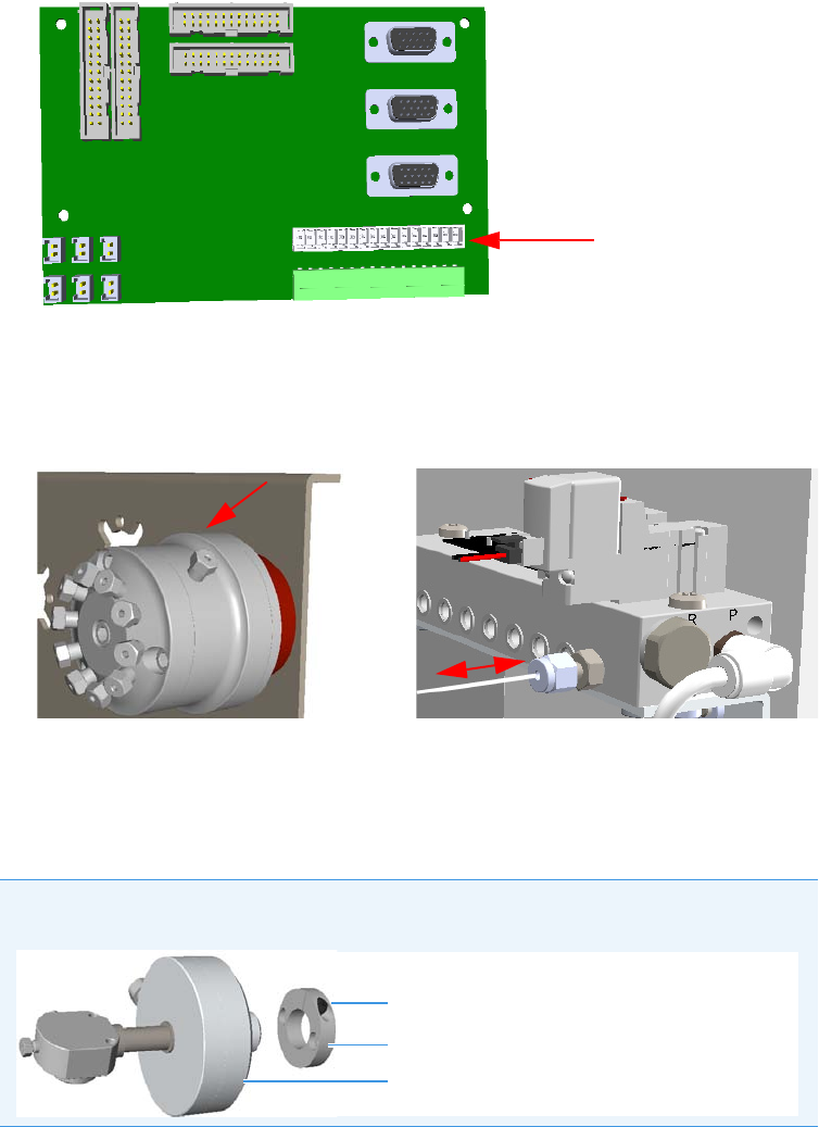
3 Components Installation
Installing Valves and Fittings in the Unheated Compartment
Thermo Scientific TRACE 1310 Auxiliary Oven Instruction Manual 63
Figure 90. Unheated Diaphragm Valve Installation (5)
4. Connecting the gas line.
a. By using the proper nuts and ferrules connect the gas line from the solenoid valve
manifold to the diaphragm valve. See Figure 91.
Figure 91. Unheated Diaphragm Valve Installation (6)
Installing an Unheated Valve for Liquid Sample into the Unheated Compartment
To install a valve for liquid samples in the unheated compartment
Installing valves in the unheated compartment consists of the following steps:
• Installing the rotary valve on the mounting bracket
• Installing the valve for liquid samples on the mounting bracket
• Installing the assemble into the unheated compartment under the main oven
Events Connector J24
Note The installation of the valve for liquid samples requires the use of the fixing
clamp ring and the proper rotary valve for the actuation.
Fixing Dowel
Clamp Ring
Valve for Liquid Sample
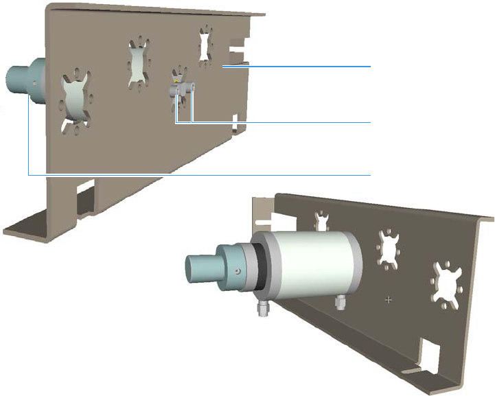
3 Components Installation
Installing Valves and Fittings in the Unheated Compartment
64 TRACE 1310 Auxiliary Oven Instruction Manual Thermo Scientific
• Installing the solenoid valve manifolds
• Connecting gas lines from the solenoid valve manifold to the actuator of the rotary valve
• Connecting gas lines from the solenoid manifold to the valve for liquid sample).
Proceed as follows:
1. Installing the rotary valve on the mounting bracket.
The unheated valve assembly will require the mounting bracket, included as part of the
assembly.
a. Choose the mounting holes in the bracket that will allow the actuator and the valve
to be oriented in a favorable direction.
b. Fix the valve to the bracket by using the two fixing screws. See Figure 92.
Figure 92. Unheated Valve for Liquid Samples Valve Installation (1)
2. Install the valve for liquid samples on the mounting bracket.
a. Choose the mounting holes in the bracket that will allow the valve to be oriented in a
favorable direction.
b. Place the clamp ring over the hole on the bracket, then secure the clamp ring using
the two screws and nuts provided. Loosen one of the two nuts allowing the dowel to
tighten the clamp ring. See Figure 93.
Rotary Valve
Mounting Bracket
Fixing Screws
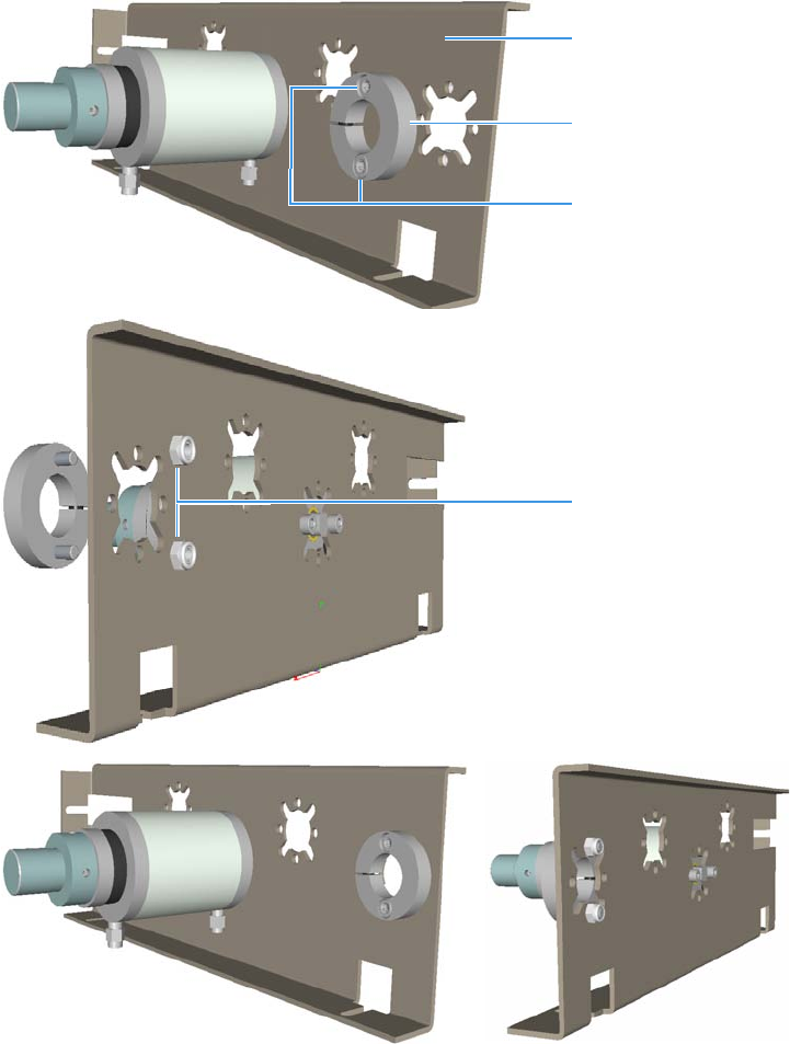
3 Components Installation
Installing Valves and Fittings in the Unheated Compartment
Thermo Scientific TRACE 1310 Auxiliary Oven Instruction Manual 65
Figure 93. Unheated Valve for Liquid Samples Valve Installation (2)
c. Loosen the dowel on the clamp ring, then insert the valve into the clamp ring.
d. Secure the valve tightening the dowel. See Figure 94.
Mounting Bracket
Clamp Ring
Fixing Screws
Nuts
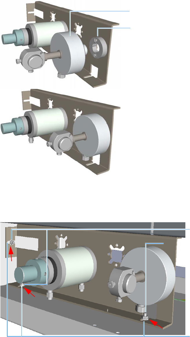
3 Components Installation
Installing Valves and Fittings in the Unheated Compartment
66 TRACE 1310 Auxiliary Oven Instruction Manual Thermo Scientific
Figure 94. Unheated Valve for Liquid Samples Valve Installation (3)
3. Install the assembly into the unheated compartment under the main oven.
a. Install the bracket into the unheated compartment, paying attentions to meet the
fixing slots on the bracket to the three studs located as shown in Figure 95.
Figure 95. Unheated Valve for Liquid Samples Valve Installation (4)
b. Push the bracket against the studs, then secure the assembly by tightening the studs.
Valve
Dowel
Studs
Slots
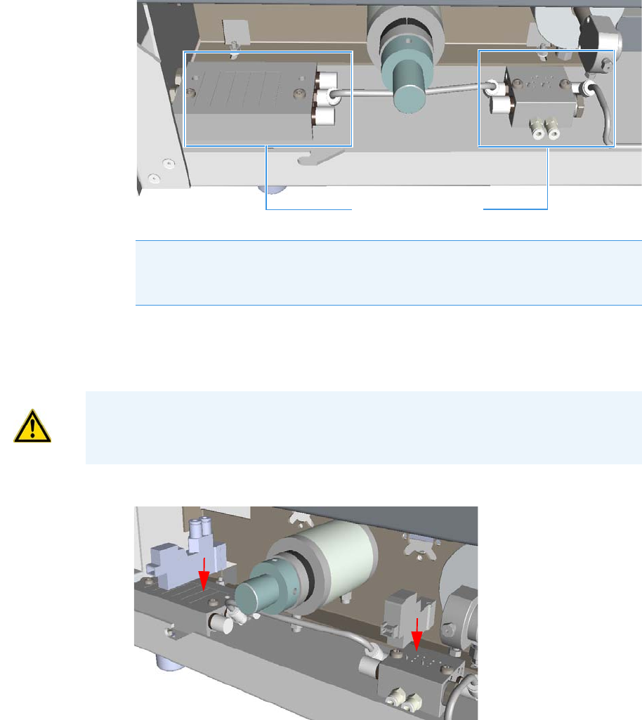
3 Components Installation
Installing Valves and Fittings in the Unheated Compartment
Thermo Scientific TRACE 1310 Auxiliary Oven Instruction Manual 67
4. Installing the solenoid valves.
a. Install the solenoid manifold for the actuation of the valves on the floor of the
unheated compartment. See the example of Figure 96.
Figure 96. Unheated Valve for Liquid Samples Valve Installation (5)
b. Remove the rectangular-shaped cap from the manifold using the phillips screwdriver.
c. Secure the solenoid valve to the under plate using the two screws supplied with the
valve See Figure d.
Figure 97. Unheated Valve for Liquid Samples Valve Installation (6)
d. Connect the cables from the solenoid valves to the proper timed event output jack of
the Events connector marked J24 on the VOBP-HRM board located over the power
section. See Figure 98.
Note The solenoid manifold for the liquid sample valve could have two solenoid
valves already mounted. See Figure 17 on page 19. Use the solenoid valve of
interest.
Solenoid Manifolds
CAUTION Tighten screws evenly, taking care that the solenoid gasket rests on all surfaces
to prevent leaks.
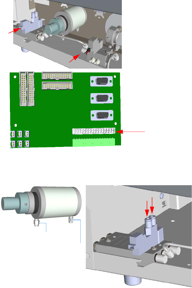
3 Components Installation
Installing Valves and Fittings in the Unheated Compartment
68 TRACE 1310 Auxiliary Oven Instruction Manual Thermo Scientific
Figure 98. Unheated Valve for Liquid Samples Valve Installation (7)
5. Connecting gas lines from the solenoid valve manifold to the actuator of the rotary valve.
With reference to Figure 99 proceed as follows:
Figure 99. Unheated Valve for Liquid Samples Valve Installation (8)
a. Locate the 4 mm nylon tubing supplied in the TRACE 1310 Auxiliary Oven kit and
cut it into two equal 12-in. pieces.
Events Connector J24
Actuator Upper Fitting
Actuator Lower Fitting
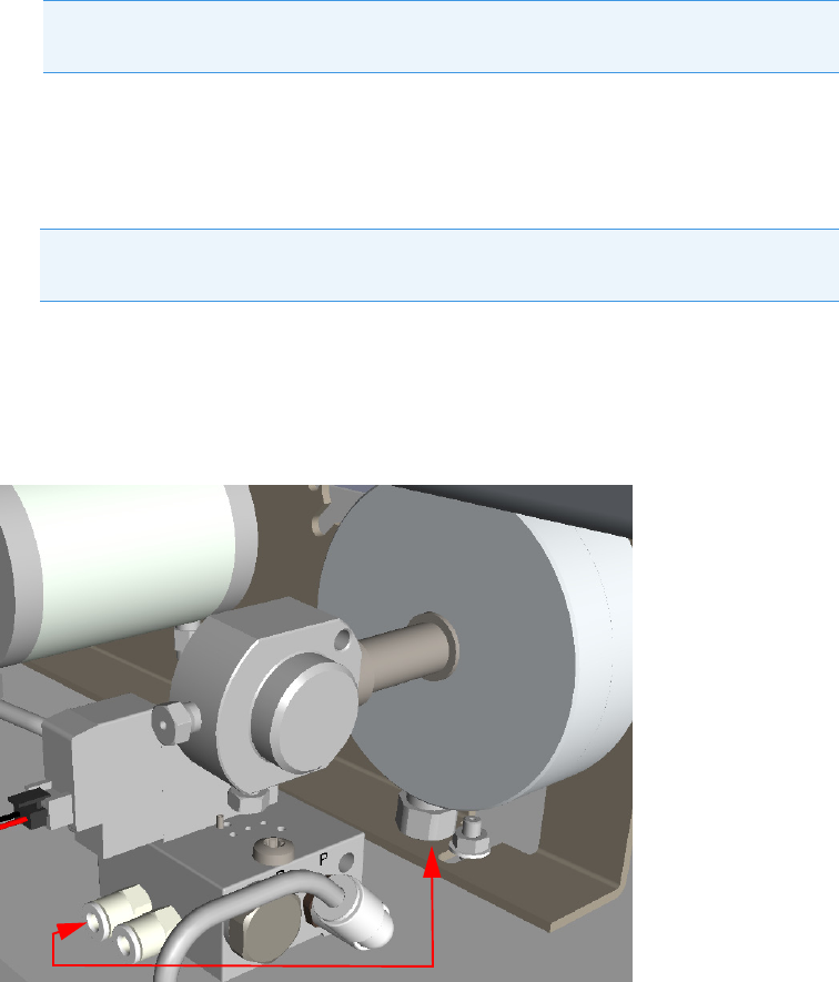
3 Components Installation
Installing Valves and Fittings in the Unheated Compartment
Thermo Scientific TRACE 1310 Auxiliary Oven Instruction Manual 69
b. Push one of the tube pieces into the lower fitting on the actuator assembly, making
sure it passes through the ferrule in the actuator fitting. Tighten the nut and ferrule
using a 3/8-in. open end wrench. Use a backup 3/8-in. open end wrench on the
mating piece that is screwed into the actuator.
c. Place the other end of the tubing into the valve solenoid fitting located on the outside
edge of the solenoid manifold by pushing the tubing firmly into the fitting. It should
automatically seal in place.
d. Turn the actuator gas supply on. This line should now be pressurized.
e. Verify there are no major leaks in the fittings.
f. Take the other piece of nylon tubing and place it in the upper fitting on the actuator.
Be sure the tube passes through the ferrule in the fitting. Tighten the fitting using the
3/8-in. open end backup wrench.
g. Connect the opposite end to the solenoid fitting.
6. Connect gas lines from the solenoid valve manifold to the valve for liquid sample bu
using a piece of 1/8-in. tubing.
With reference to Figure 100 proceed as follows:
Figure 100. Unheated Valve for Liquid Samples Valve Installation (9)
a. Connect the proper outlet port of the actuator gas (air) to the inlet port of the
actuator gas of the valve.
Note Applying pressure to this side of the actuator will ensure that the rotary
actuator stays in the CCW position.
Note The tubing can be released from the solenoid by pushing down on the
solenoid fitting and pulling out on the tubing at the same time.
3 Components Installation
Plumbing Valves and System
70 TRACE 1310 Auxiliary Oven Instruction Manual Thermo Scientific
Plumbing Valves and System
Carry out the valve and system plumbing according to the appropriate plumbing diagram for
your system setup.
Configuring the Valves
The valves in the TRACE 1310 Auxiliary Oven are gas-actuated. The valves are controlled by
solenoid valves that are turned on and off by timed events. Each solenoid valve uses one timed
event. Once a valve occupies a timed event, this timed event is removed from the list of
external events that can be added to a run table. You can configure a valve to be a gas sampling
valve or a switching valve.
Gas Sampling Valves
Gas sampling valves have two positions: Load and Inject.
Switching Valves
Switching valves have two positions: On and Off. Switching valves are plumbed so that the
counter-clockwise position is Off and the clockwise position is On.
Testing the Valves
To test the valves
1. Configure the valve and rotate it clockwise and counter-clockwise.
2. Ensure that the valve moves freely in both directions.
3. Inspect the valve stop when the valve is in both positions to ensure that the stop is at the
movement limit on each side.
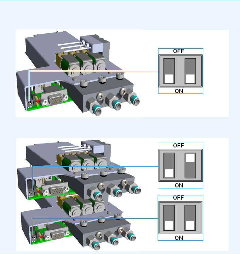
3 Components Installation
Installing the Auxiliary Gas Modules
Thermo Scientific TRACE 1310 Auxiliary Oven Instruction Manual 71
Installing the Auxiliary Gas Modules
This section provides instruction for installing a single and a double auxiliary gas module into
the TRACE 1310 Auxiliary Oven.
To install a single auxiliary gas module
1. Place the auxiliary gas module on the floor of the unheated compartment. Guide and
push the module towards the back until the three gas inlet fittings protrude from the back
panel through the three lower holes. See Figure 101.
CAUTION Before installing an auxiliary gas module make sure that the configuration switches are
properly set:
• Single auxiliary gas module (Gas 1, Gas 2, and Gas 3): set the module as “primary”:
• Double auxiliary gas module (Gas 1, Gas 2, Gas 3, Gas 4, Gas 5, and Gas 6): set the second
module as “secondary”:
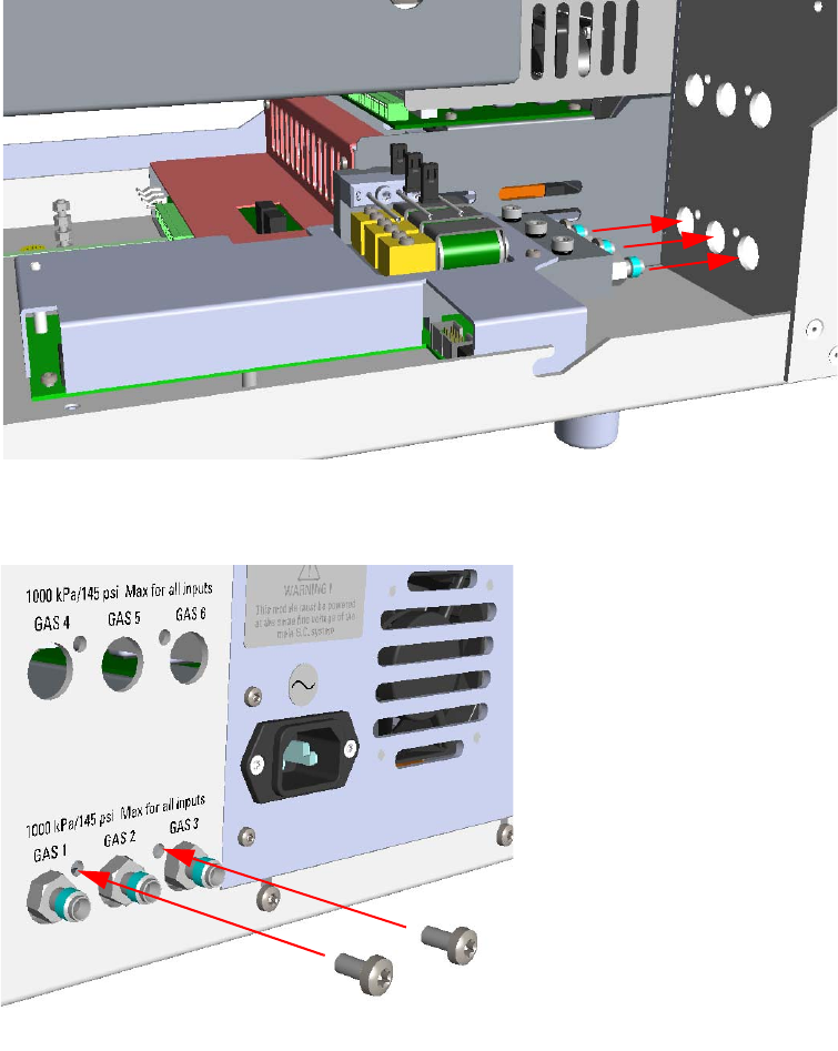
3 Components Installation
Installing the Auxiliary Gas Modules
72 TRACE 1310 Auxiliary Oven Instruction Manual Thermo Scientific
Figure 101. Auxiliary Gas Module Installation (1)
2. Fix the module to the back panel by using the two fixing screws provided. See Figure 102.
Figure 102. Auxiliary Gas Module Installation (2)
3. Fix the module to the floor of the unheated compartment. See Figure 103.
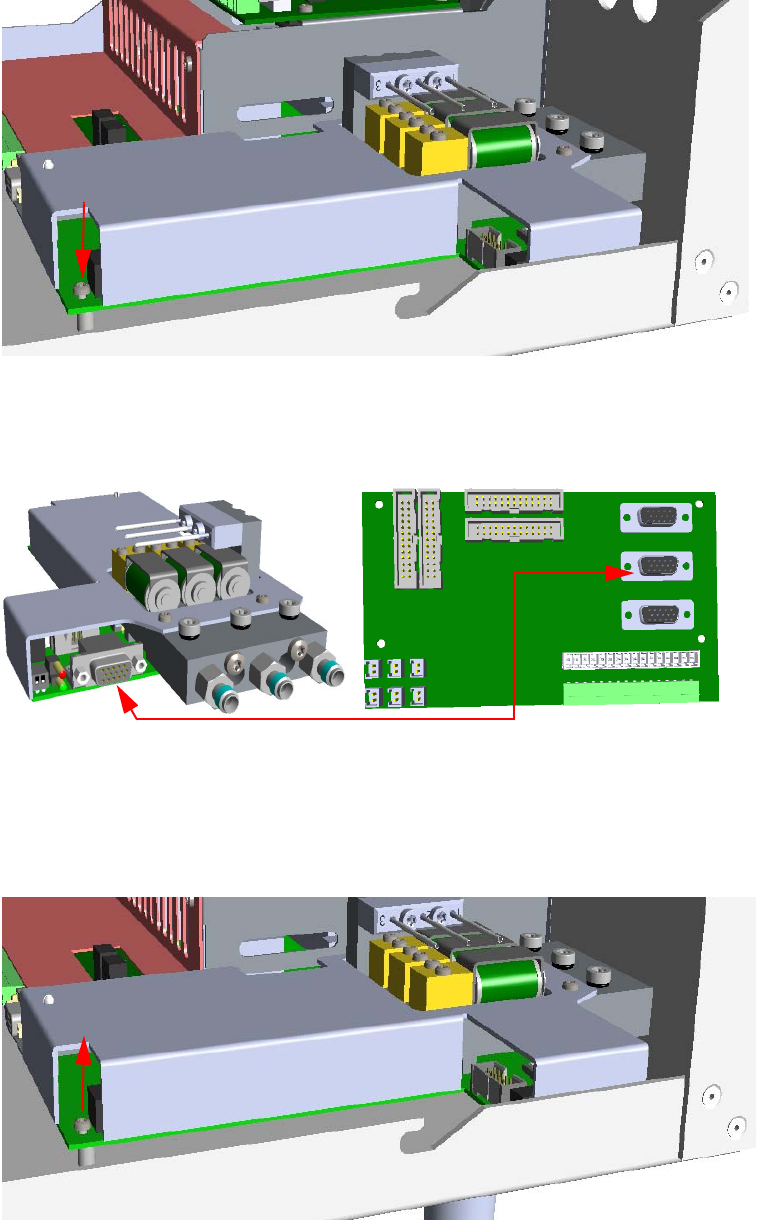
3 Components Installation
Installing the Auxiliary Gas Modules
Thermo Scientific TRACE 1310 Auxiliary Oven Instruction Manual 73
Figure 103. Auxiliary Gas Module Installation (3)
4. Using the cable provided connect the 15-pin female BUS connector on the module to the
connector marked J23 on the VOBP-HRM board. See Figure 104.
Figure 104. Auxiliary Gas Module Installation (4)
To install the second auxiliary gas module
1. Undo the screw that fixes the primary module to the floor of the unheated compartment.
See Figure 105.
Figure 105. Second Auxiliary Gas Module Installation (1)
J23
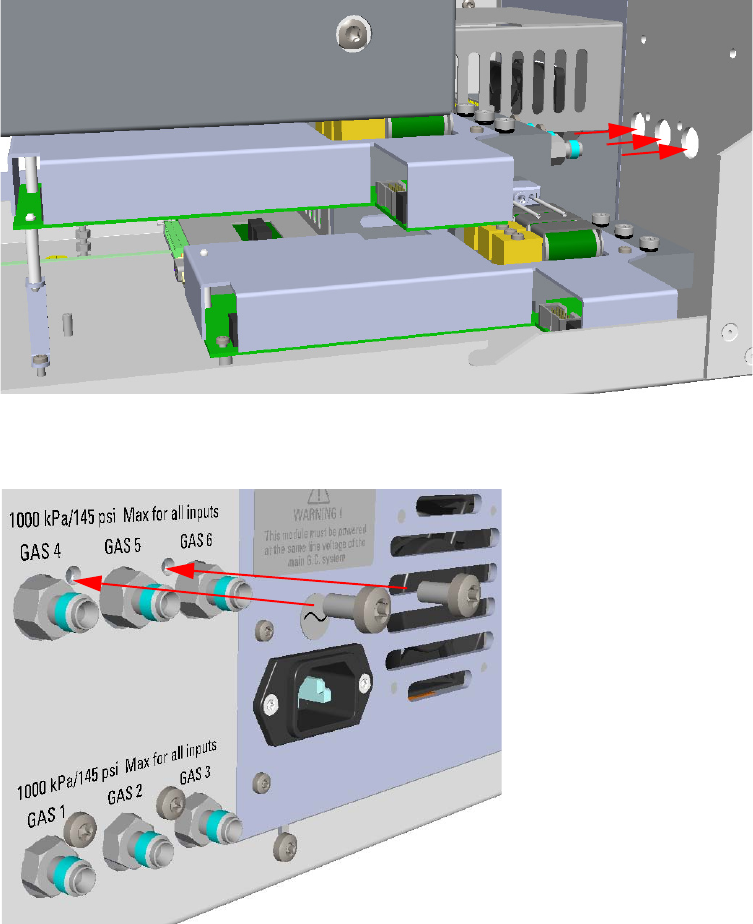
3 Components Installation
Installing the Auxiliary Gas Modules
74 TRACE 1310 Auxiliary Oven Instruction Manual Thermo Scientific
2. Place the second auxiliary gas module over the primary module. Guide and push the
second module towards the back until the three gas inlet fittings protrude from the back
panel through the three upper holes. See Figure 106.
Figure 106. Second Auxiliary Gas Module Installation (2)
3. Fix the module to the back panel by using the two fixing screws provided. See Figure 107.
Figure 107. Second Auxiliary Gas Module Installation (3)
4. Fix the second module to the floor of the unheated compartment. See Figure 108.
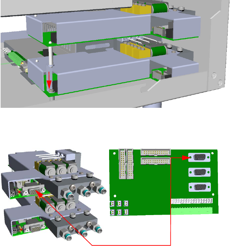
3 Components Installation
Installing the Auxiliary Gas Modules
Thermo Scientific TRACE 1310 Auxiliary Oven Instruction Manual 75
Figure 108. Second Auxiliary Gas Module Installation (4)
5. Using the cable provided connect the 15-pin female BUS connector on the module to the
connector marked J27 on the VOBP-HRM board. See Figure 109.
Figure 109. Second Auxiliary Gas Module Installation (5)
Special Use of the Auxiliary Gas Module for Controlling the Split Flow
The auxiliary carrier module provides three pressure channel controls, but each channel can
be also used as flow controller by adding a flow restrictor.
A particular case is using one of the channels for controlling split flow from a splitter. See the
pneumatic circuit in Figure 110 on page 76.
This application requires the installation of the kit P/N 19071018.
J27

3 Components Installation
Installing the Auxiliary Gas Modules
76 TRACE 1310 Auxiliary Oven Instruction Manual Thermo Scientific
Figure 110. Pneumatic Circuit
To install the split fitting option
This operating sequence provides instruction for installing the split option kit P/N 19071018
into the TRACE 1310 Auxiliary Oven.
1. Power off the GC and the TRACE 1310 Auxiliary Oven.
2. Remove the L-shape cover of the Auxiliary Oven.
3. Remove the L-shape cover of the main oven to access its interior.
4. Modify the gas inlet port of the channel for controlling split flow by plugging the gas inlet
fitting with the provided 1/8-in.cap.
5. Replacing the M5 cap with a M5 gas inlet fittings. See the example in Figure 111.
To DETECTOR
SPLITTER
FLOW
RESTRICTOR
1 m; 0.5 mm i.d.
AUXILIARY OVEN (Main Oven)
SPLIT
AUXILIARY GAS
COLUMN
IN
VENT CHARCOAL TRAP
4
6
5
1
2
3
4
5
6
Sample
Loop
Sampling
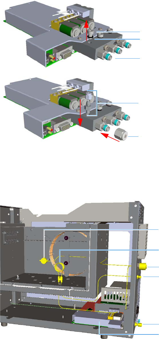
3 Components Installation
Installing the Auxiliary Gas Modules
Thermo Scientific TRACE 1310 Auxiliary Oven Instruction Manual 77
Figure 111. Channel Modification
6. You can position the splitter and flow restrictor at your convenience inside the TRACE
1310 Auxiliary Oven according to the pneumatic circuit in Figure 110.
Figure 112, Figure 113, and Figure 114 shown an example of installation of the kit in
three views. The components of the kit are highlighted in yellow.
Figure 112. Example of Kit Installation - First View
Gas Inlet Fitting
M5 Cap
O-Ring
1/8-in. Cap
M5 Gas Inlet Fittings
1/8-in. Cap
Splitter
(See the note on page 79)
Flow Restrictor
(See the note on page 79)
Charcoal Trap
Vent
Auxiliary Gas Module
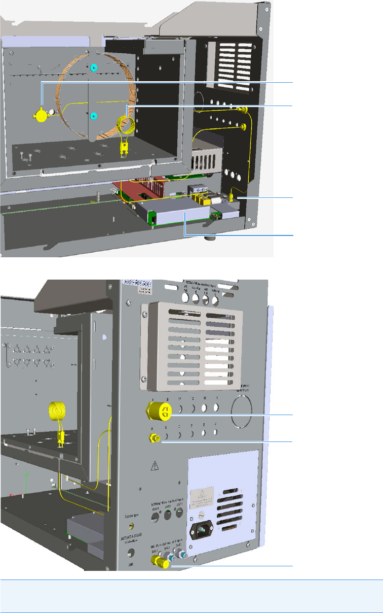
3 Components Installation
Installing the Auxiliary Gas Modules
78 TRACE 1310 Auxiliary Oven Instruction Manual Thermo Scientific
Figure 113. Example of Kit Installation - Second View
Figure 114. Example of Kit Installation - Third View
Note It is important that the flow restrictor is installed inside the aux oven and kept
at regulated temperature. This will guarantee the flow stability.
M5 Gas Inlet Fittings
Auxiliary Gas Module
Splitter
Flow Restrictor
1/8-in. Cap
Charcoal Trap
Vent

3 Components Installation
Installing the Auxiliary Gas Modules
Thermo Scientific TRACE 1310 Auxiliary Oven Instruction Manual 79
Note Installation of the splitter:
The previous figures shown an example of installation of the splitter into the main
oven. You can place the splitter in a position that you feel more convenient based on
the system configuration. If you want to install the splitter on a wall of the main oven
as shown in the figures, proceed as follows:
Screw the dowel provided into the central hole of the splitter using a T8 Torxhead
wrench. Stop the screwing of the dowel when it starts to grip the mixer; the dowel
must protrude few millimeters from the central hole of the splitter, do not overtighten.
Screw the splitter into a hole provided on the wall of the main oven
Connect the splitter to the pneumatic circuit according to the scheme on page 76.
Splitter
Dowel
Charcoal Trap
Analytical Column
From the port 6 of the Sampling Valve
CAUTION To install the capillary column to the splitter, replace the steel ferrule inside the
splitter with the appropriate Vespel® ferrule provided with the kit.
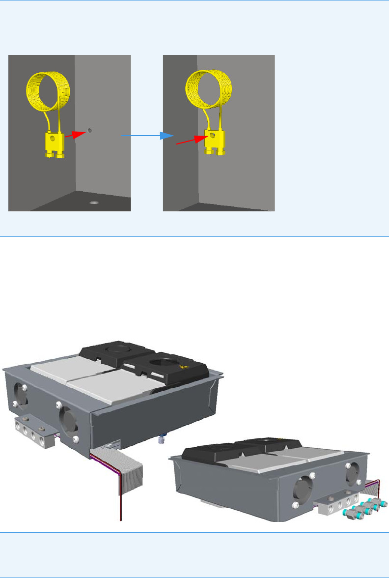
3 Components Installation
Installing the Auxiliary Detectors Assembly
80 TRACE 1310 Auxiliary Oven Instruction Manual Thermo Scientific
Installing the Auxiliary Detectors Assembly
This section provides instructions for installing the auxiliary detectors assemble into the
detector housing. See Figure 115.
Figure 115. Auxiliary Detectors Assembly
Note Installation of the flow restrictor:
The previous figures shown an example of installation of the flow restrictor into the main
oven. The flow restrictor can be secured to the holes available.
Connect the flow restrictor to the pneumatic circuit according to the scheme on page 76.
Note Figure 115 to Figure 119 show both the left and right auxiliary detectors installed
into the assembly. If only a auxiliary detector is required, the assembly will be shipped
with a detector seat empty.
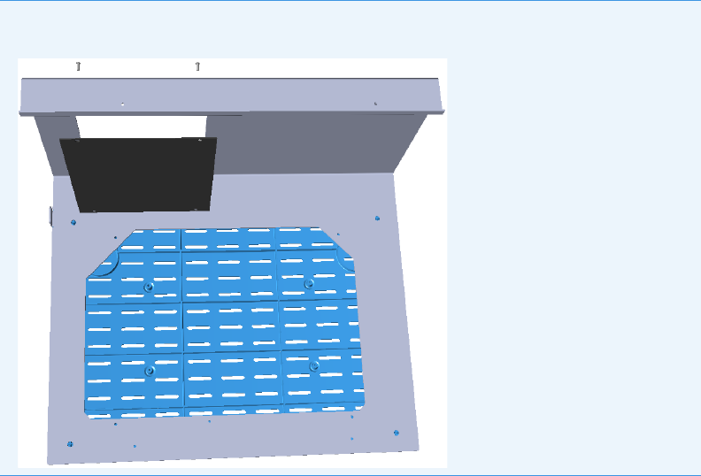
3 Components Installation
Installing the Auxiliary Detectors Assembly
Thermo Scientific TRACE 1310 Auxiliary Oven Instruction Manual 81
To install the auxiliary detectors
1. Insert the auxiliary detector assembly into the auxiliary detector housing making sure to
properly guide the flat cables and the fan cables into the slot provided on the chassis up to
reach the VOBP-HRM board. See Figure 116.
Note Before starting make sure to remove the detector housing cover from the Auxiliary
Oven L-shape Cover.
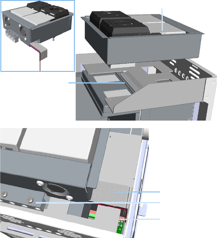
3 Components Installation
Installing the Auxiliary Detectors Assembly
82 TRACE 1310 Auxiliary Oven Instruction Manual Thermo Scientific
Figure 116. Auxiliary Detectors Installation (1)
2. From the back panel of the TRACE 1310 Auxiliary Oven, connect the gas inlet fittings
into the gas inlet ports for carrier and detector gases on the gases manifold. See
Figure 117.
Fan and Flat Cables
Slot
Gases Manifold
Auxiliary Detectors Housing
Auxiliary Detectors Assemble
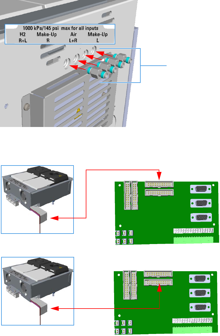
3 Components Installation
Installing the Auxiliary Detectors Assembly
Thermo Scientific TRACE 1310 Auxiliary Oven Instruction Manual 83
Figure 117. Auxiliary Detectors Installation (2)
3. On the VOBP-HRM board connect the flat cable of the left and right detectors
respectively to the connectors marked J29 and J13. See Figure 118.
Figure 118. Auxiliary Detectors Installation (3)
4. On the VOBP-HRM board connect the cables of the left and right fans to the connector
marked J30. See Figure 119.
Gas Inlet Fittings
J29
J13
LEFT
RIGHT
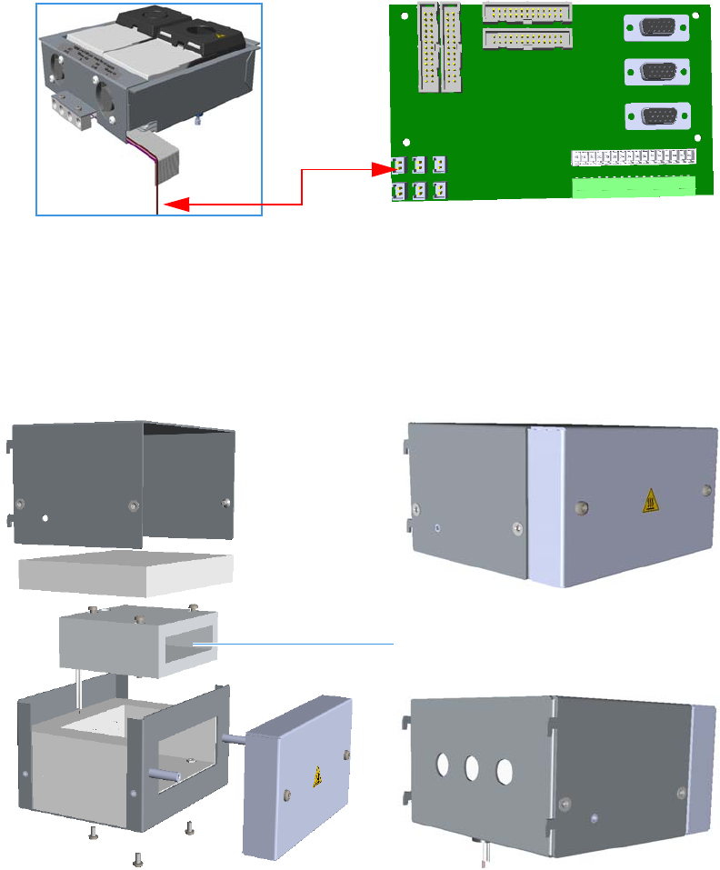
3 Components Installation
Installing the Secondary Oven Assembly
84 TRACE 1310 Auxiliary Oven Instruction Manual Thermo Scientific
Figure 119. Auxiliary Detectors Installation (4)
Installing the Secondary Oven Assembly
This section provides instruction for installing the secondary oven assembly into the TRACE
1310 Auxiliary Oven.The secondary oven is pre-mounted into a metal box. See Figure 120.
Figure 120. Secondary Oven Assemble
To install the secondary oven assembly
1. Remove the protective grid from the back panel unscrewing the four fixing screws.
See Figure 121.
J30
Secondary Oven
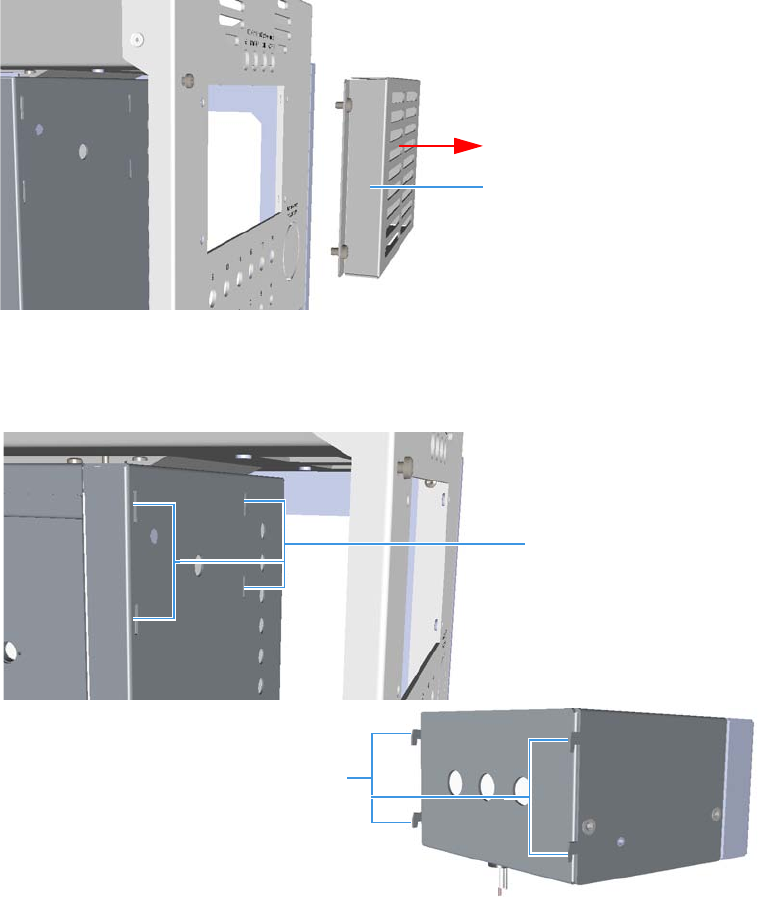
3 Components Installation
Installing the Secondary Oven Assembly
Thermo Scientific TRACE 1310 Auxiliary Oven Instruction Manual 85
Figure 121. Secondary Oven Installation (1)
2. Look for the four slots on the back wall of the main oven, and for the four hook on the
back of the secondary oven assembly. See Figure 122.
Figure 122. Secondary Oven Installation (2)
3. Insert and push the secondary oven assembly into the back of the instrument until the
four hooks enter into the relevant slot, then hook the assembly pushing it downwards.
See Figure 123.
Protective Grid
Slots
Hooks
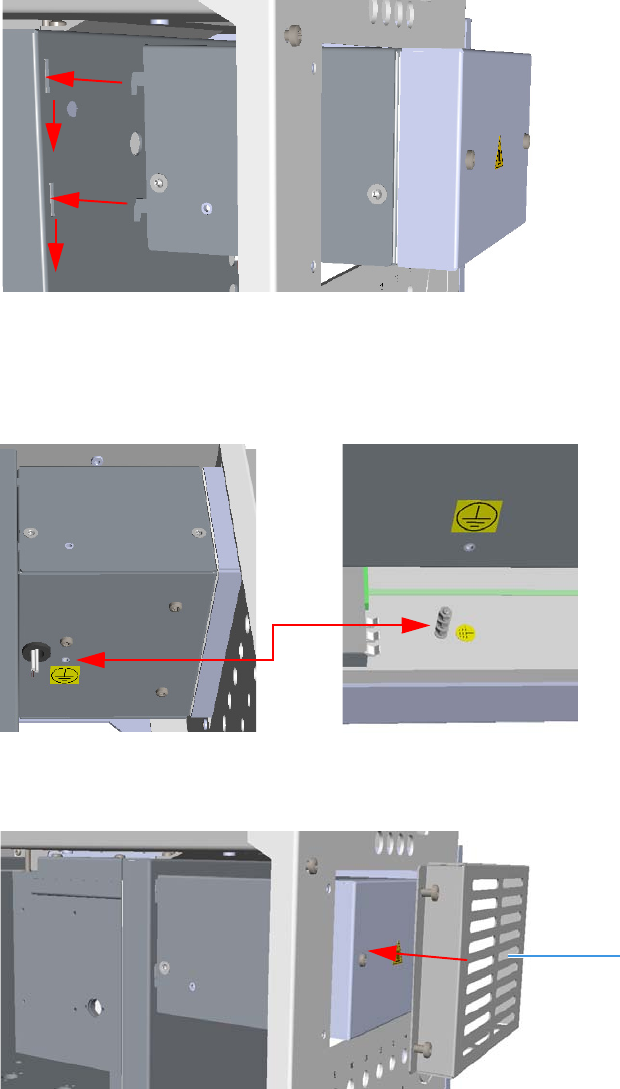
3 Components Installation
Installing the Secondary Oven Assembly
86 TRACE 1310 Auxiliary Oven Instruction Manual Thermo Scientific
Figure 123. Secondary Oven Installation (3)
4. Connect the ground wire on the bottom of the assembly using the proper fixing screw,
then connect the other end of the wire to the common ground point on the chassis of the
instrument. See Figure 124.
Figure 124. Secondary Oven Installation (4)
5. Remount and fix the protective grid. See Figure 125.
Figure 125. Secondary Oven Installation (5)
6. Connect the cables of the heater element and of the RTD Pt100 probe respectively to the
connectors marked J3 and J9 on the Aux Temp VO/Power Supply board.
See Figure 126.
Protective Grid

3 Components Installation
Installing the Methanizer Assembly
Thermo Scientific TRACE 1310 Auxiliary Oven Instruction Manual 87
Figure 126. Secondary Oven Installation (6)
Installing the Methanizer Assembly
This section provides instruction for installing the methanizer assembly PN 19071008 into
the TRACE 1310 Auxiliary Oven.
The methanizer is pre-mounted into a metal box. See Figure 127.
Figure 127. Methanizer Assembly
To install the methanizer assembly
1. Remove the protective grid from the back panel by unscrewing the four fixing screws.
See Figure 128.
J9
Heater Element
RTD Pt100 Probe
J3
Methanizer
OUT IN
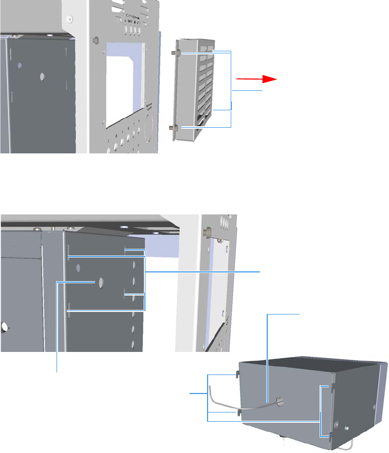
3 Components Installation
Installing the Methanizer Assembly
88 TRACE 1310 Auxiliary Oven Instruction Manual Thermo Scientific
Figure 128. Methanizer (1)
2. Look for the four slots and for the hole on the back wall of the main oven, and for the
four hooks on the back of the methanizer assembly. See Figure 129.
Figure 129. Methanizer Installation (2)
3. Insert the methanizer assembly into the back of the instrument, paying attention to guide
the OUT tubing into the passing hole provided on the back wall of the main oven
4. Push the assembly until the four hooks enter into the relevant slot, then hook the
assembly pushing it downwards. See Figure 130.
Protective Grid
Protective Grid
Fixing Screws
Slots
Hooks
Passing Hole
OUT Tubing
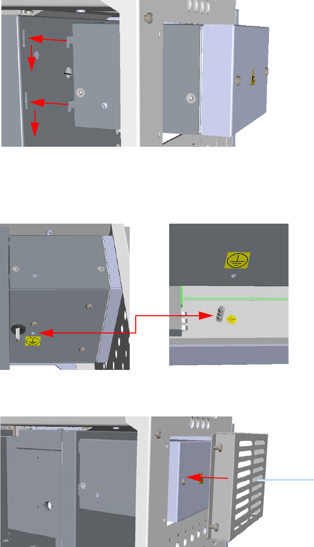
3 Components Installation
Installing the Methanizer Assembly
Thermo Scientific TRACE 1310 Auxiliary Oven Instruction Manual 89
Figure 130. Secondary Oven Installation (3)
5. Connect the ground wire on the bottom of the assembly using the proper fixing screw,
then connect the other end of the wire to the common ground point on the chassis of the
instrument. See Figure 131.
Figure 131. Methanizer Installation (4)
6. Remount and fix the protective grid. See Figure 132.
Figure 132. Methanizer Installation (5)
7. Connect the cables of the heater element and of the RTD Pt100 probe respectively to the
connectors marked J3 and J9 on the Aux Temp VO/Power Supply board.
See Figure 133.
Protective Grid
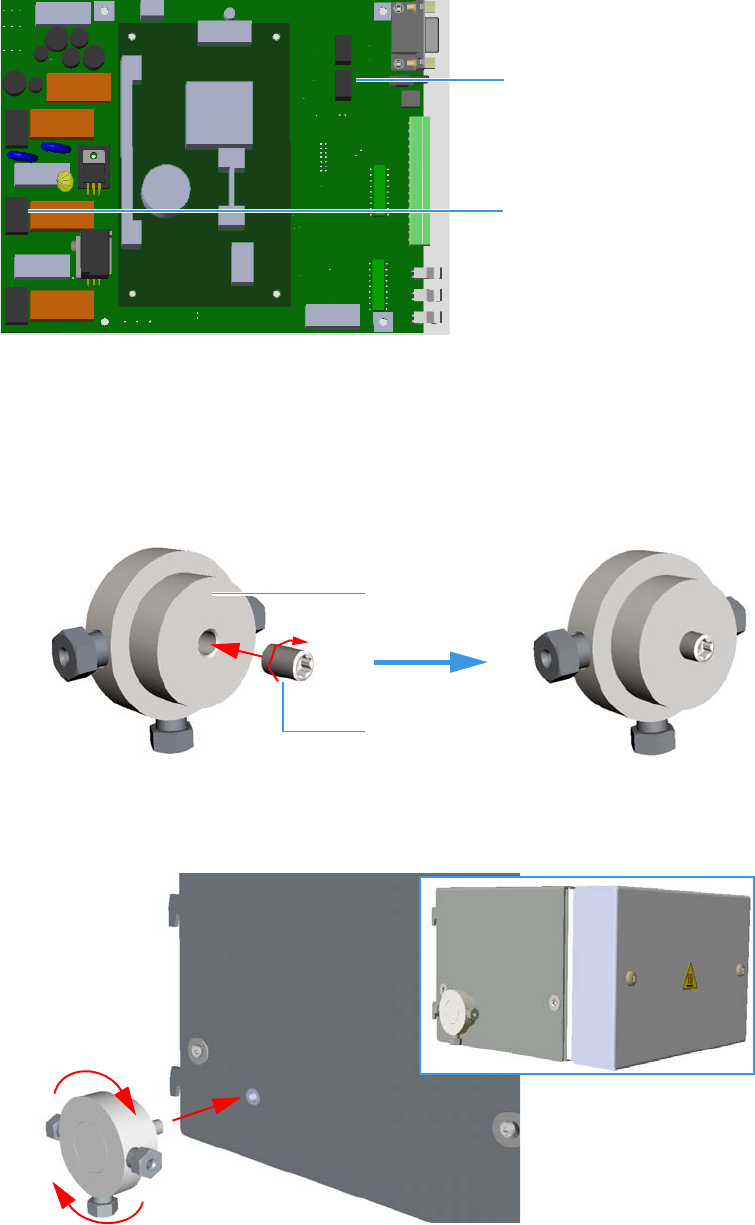
3 Components Installation
Installing the Methanizer Assembly
90 TRACE 1310 Auxiliary Oven Instruction Manual Thermo Scientific
Figure 133. Methanizer Installation (6)
8. Fix the mixer on the left wall of the methanizer assembly.
a. If not already done, screw the dowel provided into the central hole of the mixer using
a T8 Torxhead wrench. Stop the screwing of the dowel when it starts to grip the
mixer; the dowel must protrude few millimeters from the central hole of the mixer,
do not overtighten. See Figure 134.
Figure 134. Mount the Mixer (1)
b. Screw the mixer into the hole provided on the left wall of the methanizer assembly.
See Figure 135.
Figure 135. Mount the Mixer (2)
J9
Heater Element
RTD Pt100 Probe
J3
Mixer
Dowel

3 Components Installation
Installing the Methanizer Assembly
Thermo Scientific TRACE 1310 Auxiliary Oven Instruction Manual 91
Methanizer Pneumatic Circuit
The methanizer device is used to determine low concentrations of carbon monoxide (CO)
and carbon dioxide (CO2) obtained by converting these gases into methane, making them
pass on a catalytic bed kept at a temperature of 350 °C.
Determination of the total quantity of methane developed is carried out using the Flame
Ionization Detector (FID).
The methanizer consists of an aluminium block that includes a metal tube filled with a
nickel-base catalyst kept in place by a quartz wool.
The block is heated to the reaction temperature.
The catalyst must be swept by a constant flow of hydrogen.
The hydrogen flow passing through the catalyst allows the reduction of carbon monoxide and
carbon dioxide into methane according to the following reaction.
The methanizer device pneumatic circuit is schematically represented in Figure 136.
CO2H+ 2350°CCat⁄CO H2O+
CO H+2350°CCat⁄CH4H2O+
WARNING Hydrogen is a dangerous gas that when mixed with air may generate an
explosive mixture.
The use of hydrogen requires the operator’s strict attention and compliance with special
precautions due to the hazard involved.
Leak test carefully all connections before operating the instrument.
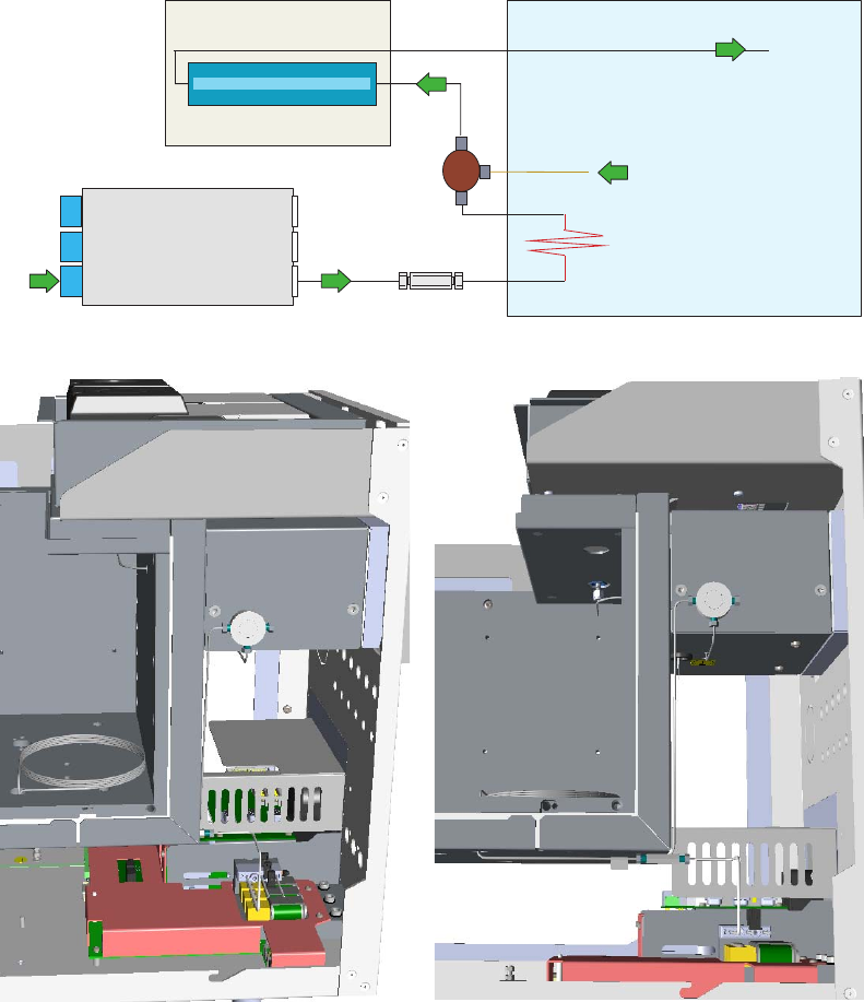
3 Components Installation
Installing the Methanizer Assembly
92 TRACE 1310 Auxiliary Oven Instruction Manual Thermo Scientific
Figure 136. Methanizer Pneumatic Circuit (2)
Mixer
FID
Auxiliary Gas
Restrictor
Union
Mixer
AUXILIARY GAS
SAMPLE from ANALYTICAL
COLUMN or TCD
FLOW RESTRICTOR
1.6 m, 0.25 mm i.d.
AUXILIARY OVEN
H2
MIXER
To FID
METHANIZER
UNION
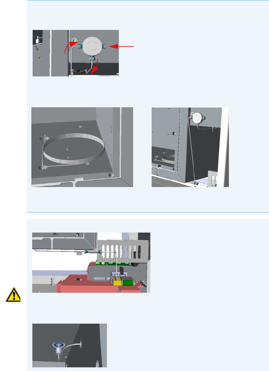
3 Components Installation
Installing the Methanizer Assembly
Thermo Scientific TRACE 1310 Auxiliary Oven Instruction Manual 93
Note The mixer has the purpose of mixing the hydrogen with the sample. Figure 136
shows the mixer anchored to the methanizer assembly. This is the best positioning to
facilitate the connection of the fittings.
The restrictor is placed on the line of the hydrogen. When installing it, try to minimize
the length of the tubing out the main oven. A metal label indicates the column ID value
that must be set in the Auxiliary Column page.
The hydrogen comes from a line of the Auxiliary Gas module connected to the restrictor
through an union.
Analytical Column or TCD
WARNING No fitting where hydrogen flows may be installed into the main oven.
The outlet of the methanizer is connected to the FID detector (installed on the TRACE
1310 Auxiliary Oven or on the GC), using the adapter for packed column. Figure 136
shows a FID installed on the TRACE 1310 Auxiliary Oven.

3 Components Installation
Installing a Heated Sample Transfer Line
94 TRACE 1310 Auxiliary Oven Instruction Manual Thermo Scientific
Installing a Heated Sample Transfer Line
This section provides the instructions for installing a heated sample transfer line into the main
oven.
To install a heated sample transfer line
1. Remove the partial cut shaped plate marked Heated Sample Transfer Line from the back
panel of the instrument. Carefully insert the transfer line and its insulator tube into the
duct carried out. See Figure 137.
Figure 137. Installing a Heated Sample Transfer Line (1)
2. Push the transfer line and its insulator tube into the rear of the instrument up to reach the
main oven. See Figure 138.
Figure 138. Installing a Heated Sample Transfer Line (2)
Partial Cut Shaped Plate
Transfer Line with Insulating Tube
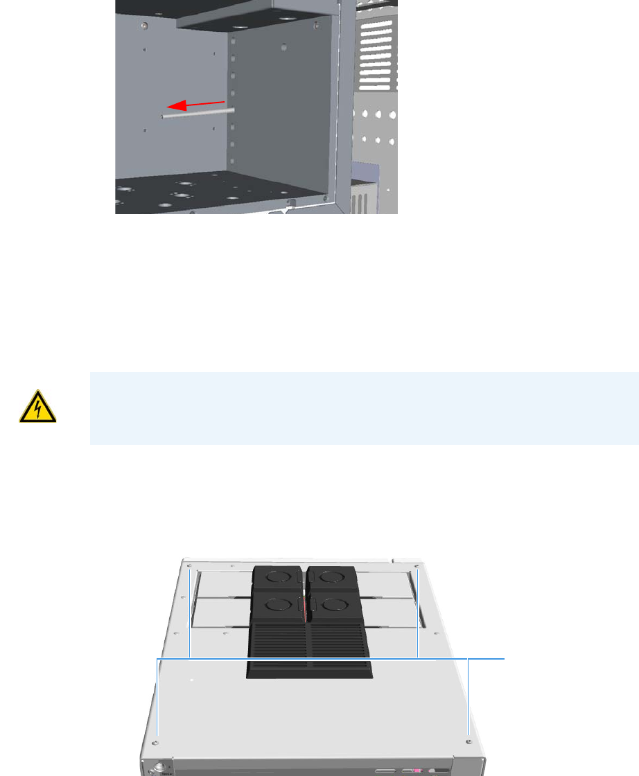
3 Components Installation
Wiring the TRACE 1310 Auxiliary Oven to the GC
Thermo Scientific TRACE 1310 Auxiliary Oven Instruction Manual 95
3. Guide the transfer line into the main oven through a convenient hole on the wall of the
main oven. See Figure 139.
Figure 139. Installing a Heated Sample Transfer Line (3)
Wiring the TRACE 1310 Auxiliary Oven to the GC
This section provides the instructions for wiring the TRACE 1310 Auxiliary Oven with the
GC.
To wire the Valve Oven to the GC
1. Remove the top cover of the GC.
a. Using a T20 Torxhead screwdriver, unscrew the four screws that held it in place.
See Figure 140 and Figure 141.
Figure 140. Top Cover Removal (1)
b. Lift the top panel up and off the GC.
CAUTION Before starting ensure that the GC is powered off and the power cable is
unplugged from the AC Input connector into the back of the GC and from the wall
outlet.
Top Cover Screws
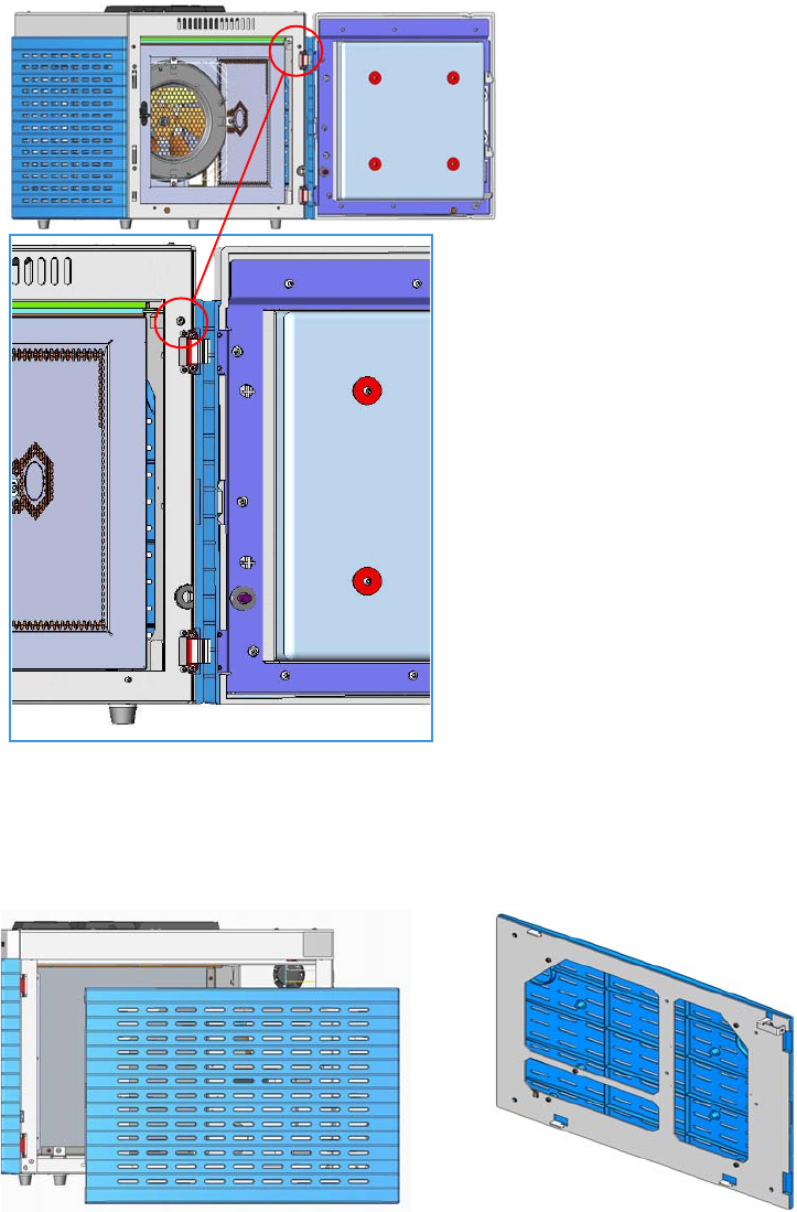
2. Remove the right panel of the GC.
a. Open the front door of the GC. Using a T20 Torxhead screwdriver, unscrew the
right side panel screw from the interior front panel. See Figure 141.
Figure 141. Right Panel Fixing Screw
b. Slide the panel towards the back of the instrument up to the stop. Remove the panel
by pulling it outwards being aware that the ground wire is attached to the panel. See
Figure 142.
Figure 142. Right Panel Removal
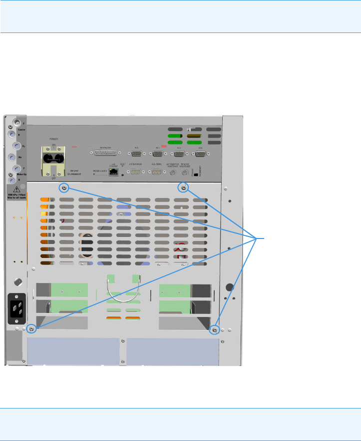
3 Components Installation
Wiring the TRACE 1310 Auxiliary Oven to the GC
Thermo Scientific TRACE 1310 Auxiliary Oven Instruction Manual 97
c. Unplug the ground wire from the panel.
3. Remove the back cover of the GC.
a. Using a T20 Torxhead screwdriver, unscrew the four fixing screws that secure the
back cover to the GC. See Figure 143.
Figure 143. Back Cover Removal
b. Lift the cover off using the cover handle. Be aware that the ground wire is attached to
the back cover.
4. Remove the Electronic Module from the GC.
a. Using the two handles on the top cover of the electronic module, pull out the module
from its housing. See Figure 144.
Note Pay attention to the positioning of the ground wire plug, so it can be
reconnected in the same way it was removed.
Note Pay attention to the positioning of the ground wire plug, so it can be
reconnected in the same way it was removed.
Back Cover Fixing Screws
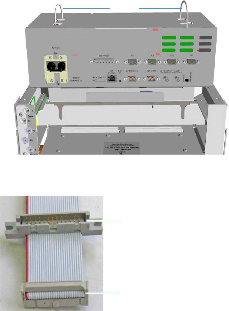
Figure 144. Electronic Module Extraction
5. Guide the TRACE 1310 Auxiliary Oven flat cables with additional connector into the
back compartment of the GC. See Figure 145.
Figure 145. Auxiliary Oven Flat Cable
a. Guide the flat cables into the back compartment of the GC through the free area
between the oven and the housing of the electronic module. See Figure 146.
Handles
Electronic Module Housing
Additional Connector
End Connector
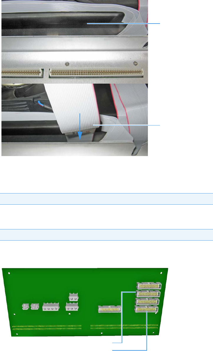
3 Components Installation
Wiring the TRACE 1310 Auxiliary Oven to the GC
Thermo Scientific TRACE 1310 Auxiliary Oven Instruction Manual 99
Figure 146. Placing TRACE 1310 Auxiliary Oven Flat Cables
6. Disconnect the detector rear and injector rear flat cables.
a. Disconnect the flat cable from the connector J5 marked DET.REAR on the
backplane board of the GC.
b. Disconnect the flat cable from the connector J21 marked INJ.REAR on the
backplane board of the GC.
See the example in Figure 147.
Figure 147. GC Backplane Board Layout
IMPORTANT Label this cable as DET to avoid a wrong connection.
IMPORTANT Label this cable as INJ to avoid a wrong connection.
Flat Cable
Free Area
J21 INJ.REAR Connector
J5 DET.REAR Connector
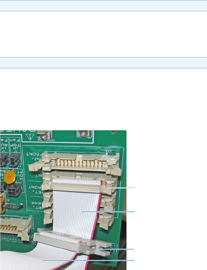
7. Connect the TRACE 1310 Auxiliary Oven flat cables provided instead of the detector
rear and injector rear flat cables.
a. Connect the end connector of the first flat cable to the connector J5 marked
DET.REAR on the backplane board of the GC.
Connect the detector rear flat cable connector, previously disconnected from the
connector J5, to the additional connector on the first flat cable.
b. Connect the end connector of the second flat cable to the connector J5 marked
DET.REAR on the backplane board of the GC.
Connect the injector rear flat cable connector, previously disconnected from the
connector J21, to the additional connector on the second flat cable.
The example in Figure 148 shows the INJ flat cable connected to the connector J21
INJ.REAR on the backplane board, and the connection of the injection rear flat cable
to the additional connector.
Figure 148. TRACE 1310 Auxiliary Oven Flat Cable Connections
8. Guide the other ends of the INJ and DET Auxiliary Oven flat cables out the GC.
a. Carefully, bend and place the flat cables along the wall the oven, then fix the cables
properly. See Figure 149.
IMPORTANT Label this cable as DET to avoid a wrong connection.
IMPORTANT Label this cable as DET to avoid wrong connection.
INJ Flat Cable
Injection Rear Flat Cable
Additional Connector
Connector J5 INJ REAR
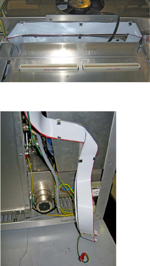
3 Components Installation
Wiring the TRACE 1310 Auxiliary Oven to the GC
Thermo Scientific TRACE 1310 Auxiliary Oven Instruction Manual 101
Figure 149. Fixing INJ and DET TRACE 1310 Auxiliary Oven Flat Cables (1)
b. Carefully guide the INJ and DET flat cables out the GC. See Figure 150.
Figure 150. Fixing INJ and DET Auxiliary Oven Flat Cables (2)
9. Guide and connect the INJ and DET Auxiliary Oven flat cables into the TRACE 1310
Auxiliary Oven.
a. On the left back corner of the TRACE 1310 Auxiliary Oven locate the two free
connectors on the board mounted over the power section. See Figure 151.
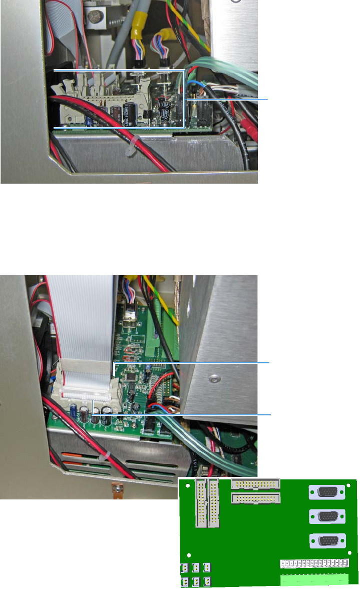
Figure 151. TRACE 1310 Auxiliary Oven Connectors (1)
b. Connect the INJ flat cable to the internal connector marked J21 on the
VOBP-HRM board.
c. Connect the DET flat cable to the external connector on the marked J5 on the
VOBP-HRM board. See the example in Figure 152.
Figure 152. TRACE 1310 Auxiliary Oven Connectors (2)
Free Connectors
DET Connector
INJ Connector
J21
J5
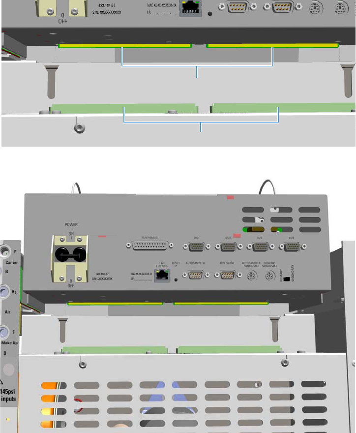
3 Components Installation
Wiring the TRACE 1310 Auxiliary Oven to the GC
Thermo Scientific TRACE 1310 Auxiliary Oven Instruction Manual 103
10. Reinstall the Electronic Module.
a. Guide the electronic module into its housing.
b. Push down the module. Be sure to plug the terminal contacts of the mother board
into the two slots of the backplane board. See Figure 153 and Figure 154.
Figure 153. Electronic Module Re-installation (1)
Figure 154. Electronic Module Re-installation (2)
11. Replace the back and top covers of the GC.
a. Reconnect the ground wire to the back cover terminal.
b. Replace the back and top cover proceeding in the reverse order in which it was
removed.
Mother Board Connectors
Backplane Board Connectors
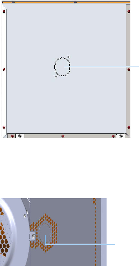
3 Components Installation
Coupling the TRACE 1310 Auxiliary Oven to the GC
104 TRACE 1310 Auxiliary Oven Instruction Manual Thermo Scientific
Coupling the TRACE 1310 Auxiliary Oven to the GC
To couple the TRACE 1310 Auxiliary Oven to the GC
This section provides the instructions for coupling the TRACE 1310 Auxiliary Oven with the
GC.
1. Prepare the duct for the insertion of the TRACE 1310 Auxiliary Oven inner tube into the
GC oven.
a. Remove the partial cut shaped plate from the exterior right wall of the GC oven box
to access the insulating material. See Figure 155.
Figure 155. Perform the Duct (1)
b. Using a knife or similar tool, gently cut the insulating material following the track.
c. Save the removed insulating material in a safe place because it could be reused.
d. On the right side wall in the interior of the oven, remove the partial cut plate from
the corresponding duct. See Figure 156.
Figure 156. Perform the Duct (2)
Partial Cut Shaped Plate
Partial Cut Plate
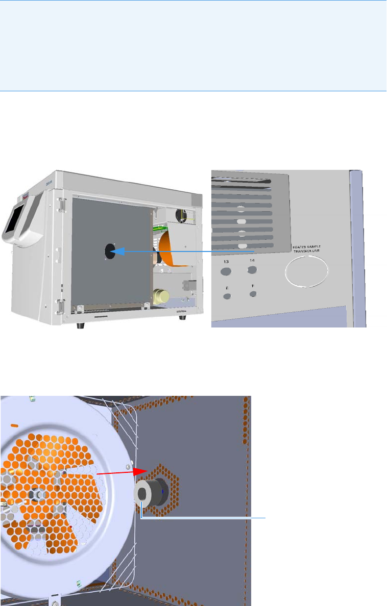
3 Components Installation
Coupling the TRACE 1310 Auxiliary Oven to the GC
Thermo Scientific TRACE 1310 Auxiliary Oven Instruction Manual 105
2. Insert inner tube into the GC oven.
3. Carefully couple the TRACE 1310 Auxiliary Oven as a right panel ensuring that the
inner tube assembly penetrates into the right wall of the GC through the duct previously
prepared. See Figure 157.
Figure 157. Coupling Valve Oven Module and GC (1)
a.
4. From the interior of the GC oven, place the smallest insulating disk on the inner tube,
then push the insulating disk into the duct. See Figure 158.
Figure 158. Coupling Valve Oven Module and GC (2)
CAUTION Before proceeding, ensure that:
• The inner tube to the GC oven has been inserted into the passing hole provided
in the wall of the main oven but not completely fixed. See Figure 9 on page 15.
• The biggest disks of insulating material are placed on the inner tube protruding
from the wall of the main oven. See Figure 10 on page 16.
Smallest Insulating Disk
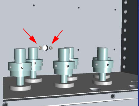
3 Components Installation
Coupling the TRACE 1310 Auxiliary Oven to the GC
106 TRACE 1310 Auxiliary Oven Instruction Manual Thermo Scientific
5. Into the main oven fix completely the inner tube to the GC oven tightening the two
fixing screws. See the example in Figure 159.
Figure 159. Coupling Valve Oven Module and GC (3)

Thermo Scientific TRACE 1310 Auxiliary Oven Instruction Manual 107
4
Operation
This chapter provides brief instructions for configuring and operating with the TRACE 1310
Auxiliary Oven through the GC touch screen and the chromatography data system.
Contents
•Operating Through the GC Touch Screen
•Operating Through the CDS
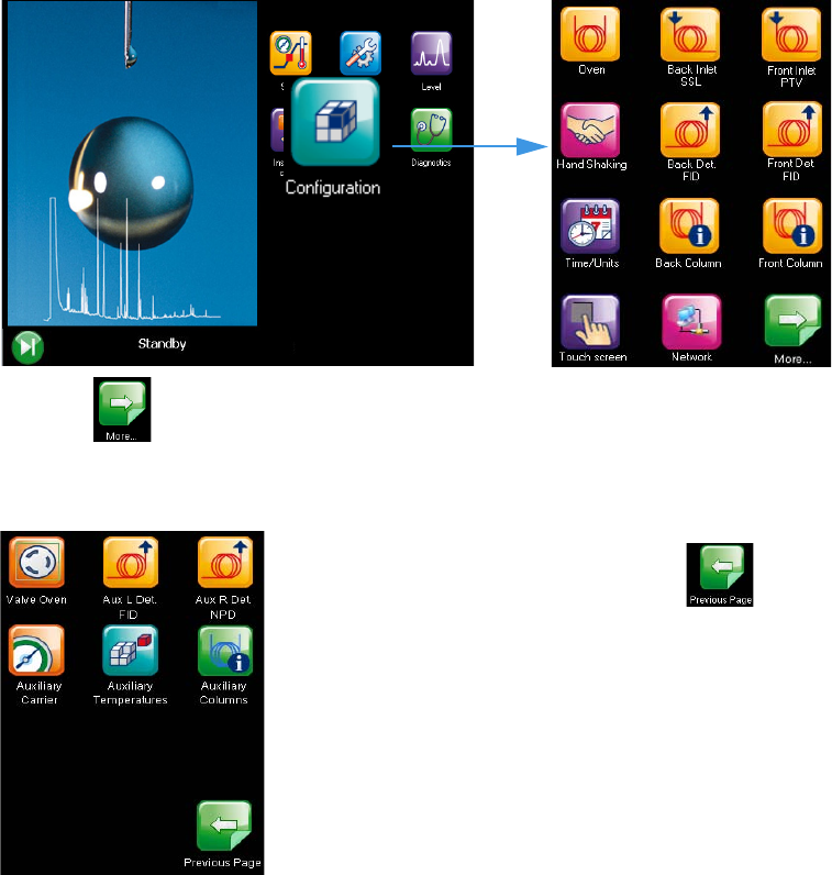
4 Operation
Operating Through the GC Touch Screen
108 TRACE 1310 Auxiliary Oven Instruction Manual Thermo Scientific
Operating Through the GC Touch Screen
This section contains instructions to configure your Valve Oven and to edit the parameters
through the touch screen of the GC. For more details refer the TRACE 1300/TRACE 1310
User Guide.
See the related operating sequences:
•To configure the TRACE 1310 Auxiliary Oven through the GC touch screen
•To edit TRACE 1310 Auxiliary Oven parameters through the GC touch screen
To configure the TRACE 1310 Auxiliary Oven through the GC touch screen
1. Press the Configuration icon on the touch screen main menu to configure the TRACE
1310. See Figure 160.
Figure 160. Touch Screen Main Menu: Configuration
The icon appears to access the second page of the Configuration menu when
additional modules are installed. See Figure 161.
Figure 161. Configuration Menu
To return the previous page press the icon
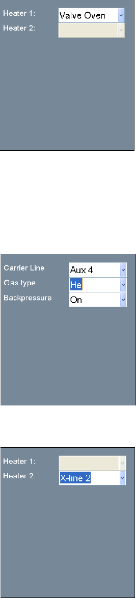
4 Operation
Operating Through the GC Touch Screen
Thermo Scientific TRACE 1310 Auxiliary Oven Instruction Manual 109
2. Press the Valve Oven icon to configures the heating zones of the TRACE 1310 Auxiliary
Oven.
3. Press the Aux L Det/Aux R Det for configuring the auxiliary detector module installed
into the left/right position on the TRACE 1310 Auxiliary Oven. The configuration menu
is the same as the detector modules installed in front and back position on the GC.
4. Press the Auxiliary Carrier icon for setting the parameters for the auxiliary gas modules.
This menu includes both the Auxiliary Gas modules. One of them will be mounted inside
the TRACE 1310 Auxiliary Oven, and the other into the GC.
5. Press the Auxiliary Temperature icon for configuring the heater zones of the Auxiliary
Temperature module.
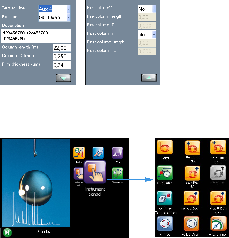
4 Operation
Operating Through the GC Touch Screen
110 TRACE 1310 Auxiliary Oven Instruction Manual Thermo Scientific
6. Press the Auxiliary Column for detailing the auxiliary column if in use.
To edit TRACE 1310 Auxiliary Oven parameters through the GC touch screen
1. Press the Instrument Control icon on the touch screen main menu for programming the
parameters in the analytical method. See Figure 162.
Figure 162. Touch Screen Main Menu: Instrument Control
2. Press the Aux L Det/Aux R Det icon for programming the detector modules if installed
into the left/right position on the TRACE 1310 Auxiliary Oven. The configuration menu
is the same of the detector modules installed in front and back position on the GC.
3. Press the Auxiliary Temperature icon for defining the temperature parameters for the
external auxiliary temperature modules set in the configuration.
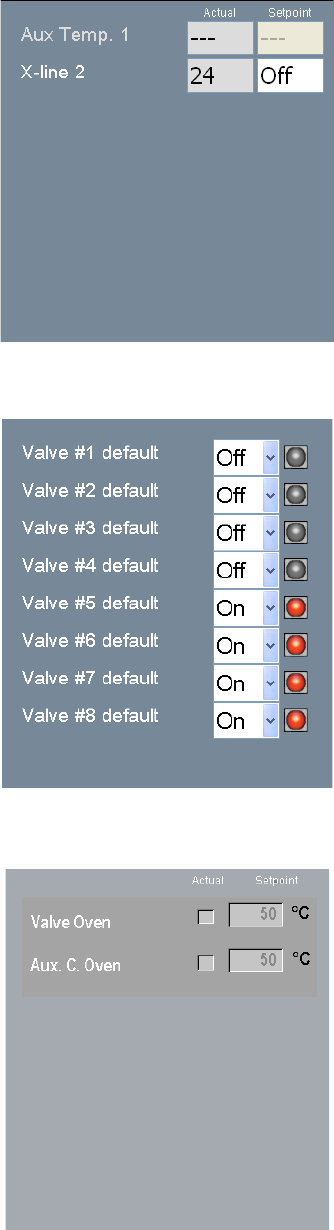
4 Operation
Operating Through the GC Touch Screen
Thermo Scientific TRACE 1310 Auxiliary Oven Instruction Manual 111
4. Press the Valves icon for setting On or Off the external valves connected to the Aux
Temperature Module.
5.
6. Press the Valve Oven for setting the auxiliary temperatures of the TRACE 1310 Auxiliary
Oven.
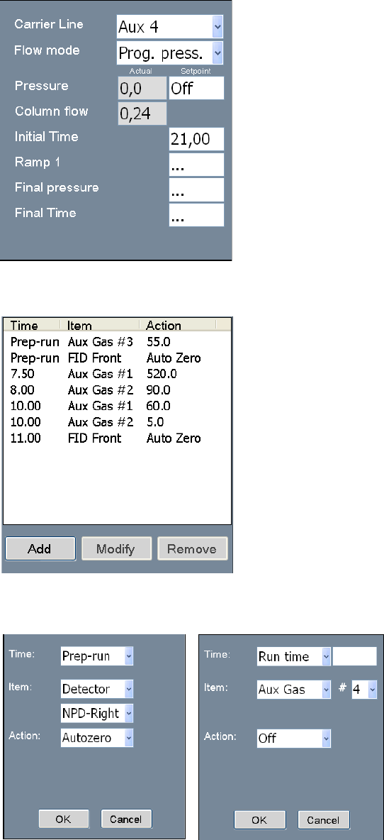
4 Operation
Operating Through the GC Touch Screen
112 TRACE 1310 Auxiliary Oven Instruction Manual Thermo Scientific
7. Press the Aux Carrier for setting the auxiliary carrier lines selected.
8. Press the Run Table for setting detectors, valves, and external events to occur at the
Prep-run or during a run.
Events displayed on the Run Table page are from selections made in the Run-Time Event
screen. The Add button opens the Run-Time Event screen.
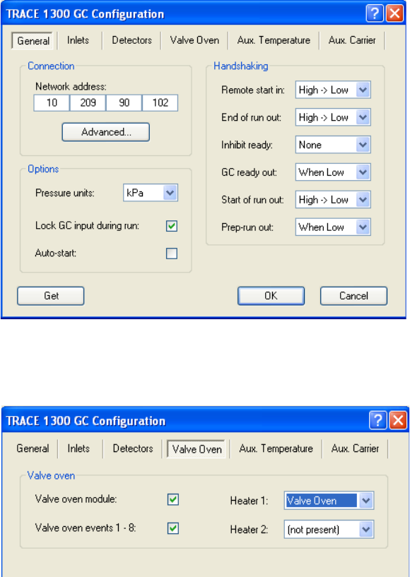
4 Operation
Operating Through the CDS
Thermo Scientific TRACE 1310 Auxiliary Oven Instruction Manual 113
Operating Through the CDS
This section contains instruction to configure your Valve Oven and to edit the parameters
through Xcalibur, Chrom-Card, ChromQuest, or Chromeleon Chromatography Data
System. For more details refer the relevant Manuals and Help Files.
See the related operating sequences:
•To configure the TRACE 1310 Auxiliary Oven through the CDS
•To edit TRACE 1310 Auxiliary Oven parameters through the CDS
To configure the TRACE 1310 Auxiliary Oven through the CDS
1. Run your Chromatography Data System, then open the TRACE 1300 Configuration
window. See the example of Figure 163.
Figure 163. Example of Configuration Window
2. Select the Valve Oven tab for configuring your TRACE 1310 Auxiliary Oven. See the
example of Figure 164.
Figure 164. Configuration Window: Valve Oven Tab
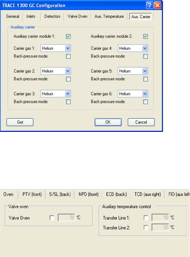
4 Operation
Operating Through the CDS
114 TRACE 1310 Auxiliary Oven Instruction Manual Thermo Scientific
3. Select the Auxiliary Carrier tab to configure and use an Auxiliary Carrier interface. See
the example of Figure 165.
Figure 165. Configuration Window: Auxiliary Carrier Tab
To edit TRACE 1310 Auxiliary Oven parameters through the CDS
1. Select the Auxiliary Temperature page for defining the temperature parameters of the
external auxiliary temperature modules selected in the Instrument Configuration. See the
example Figure 166.
Figure 166. Auxiliary Temperature Page
• Select the Valve Oven options accordingly: Valve Oven, HT Valve Oven, Aux
Column Oven, Aux Heater 3, Aux Heater 4, or Methanizer.
2. Select the Auxiliary Carrier page for defining the carrier gas parameters of the auxiliary
Carrier Gas modules. Up to six auxiliary carrier lines from Carrier 1 to Carrier 6 can be
selected. See the example of Figure 167.
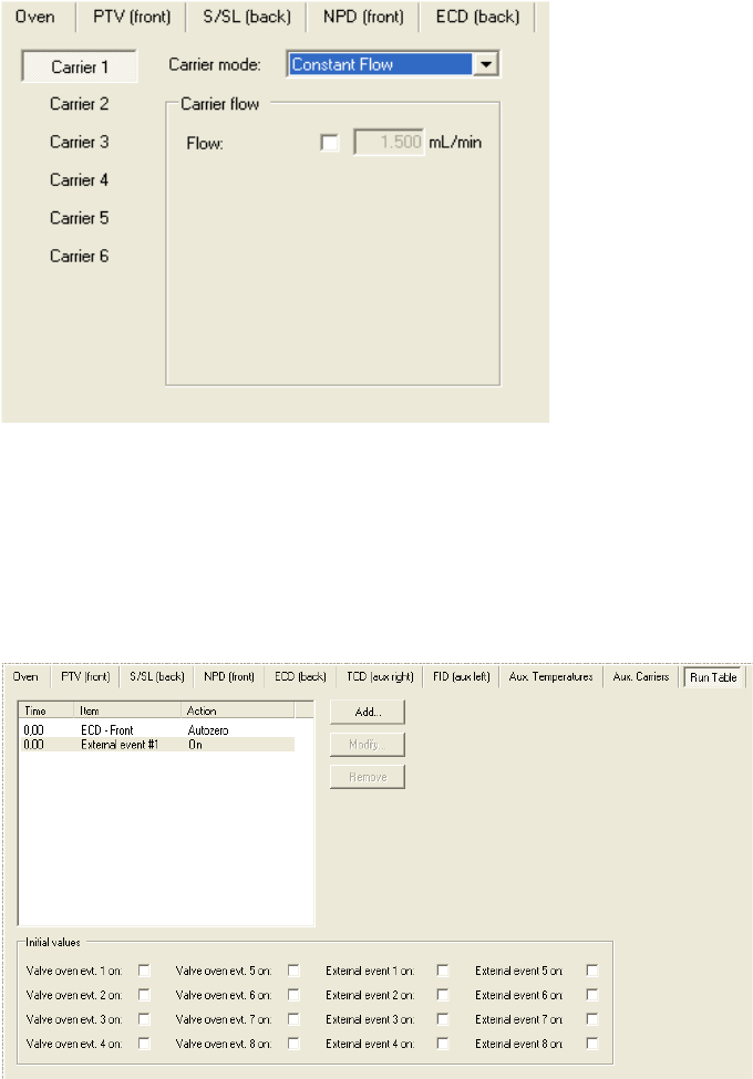
4 Operation
Operating Through the CDS
Thermo Scientific TRACE 1310 Auxiliary Oven Instruction Manual 115
Figure 167. Auxiliary Carrier Page
• For each carrier gas line define the auxiliary carrier gas control mode to use: Constant
Flow, Constant Pressure, Programmed Flow, and Programmed Pressure. Each mode
activates or deactivates the dedicated parameters.
3. Select the Run Table page for setting up detector, valve, and external events to occur at
the Prep-run or during a run. See the example of Figure 168.
Figure 168. Run Table Page
• The events displayed on the Run Table page are from selections made in the Run-Time
Event screen.

Thermo Scientific TRACE 1310 Auxiliary Oven Instruction Manual 117
5
Maintenance & Troubleshooting
This chapter provides instructions for performing a maintenance on the TRACE 1310
Auxiliary Oven and to remedy any potential analytical problems.
Contents
•Read Me First
•Maintenance Supplies and Tools
•Powering On the TRACE 1310 Auxiliary Oven
•Shutting Down the TRACE 1310 Auxiliary Oven
•Cleaning the Instrument Externally
•Replacing the Column into the Secondary Oven
•Maintaining the Methanizer
•Troubleshooting

5 Maintenance & Troubleshooting
Read Me First
118 TRACE 1310 Auxiliary Oven Instruction Manual Thermo Scientific
Read Me First
The instrument will be generally serviced by Thermo Fisher Scientific authorized technical
personnel for all the warranty period or, after the warranty expires, possibly according to a
Programmed Service Contract. For more information contact your local Thermo Fisher
Scientific office.
There are only a few TRACE 1310 Auxiliary Oven components that require routine
maintenance, depending on the quantity and types of samples you are running. A frequently
used instrument will, of course, require more maintenance than an instrument that is rarely
used.
•External Cleaning — The GC needs to be cleaned when it gets dirty. See the section
“Cleaning the Instrument Externally” on page 121.
•Column — You may need to replace the column installed into the secondary oven when
your performance degrades and troubleshooting indicates that the column needs
maintenance. That may mean that end of the column needs to be trimmed or the column
needs to be replaced. See “Replacing the Column into the Secondary Oven” on page 123.
•Detector modules — You may need to install, replace or maintain an auxiliary detector
module. Refer to the TRACE 1310/TRACE 1310 Hardware Manual.
•Methanizer — The methanizer does not usually require maintenance. However, the
replacement of the metal tube containing the nickel-base catalyst is required when the
catalyst results exhausted. See “Maintaining the Methanizer” on page 125.
•Valves — Perform the maintenance of the valves referring to the relevant manual.
Maintenance Supplies and Tools
To perform routine maintenance on the TRACE 1310 Auxiliary Oven, you will need the
following supplies and tools.
• Wrench, open-end, 1/4-in. and 5/16-in., 1/8-in.
•Wrench, 3/8-in.
• Allen wrench, 3/16-in., 5/32-in., 9/64 in.
WARNING If, for technical reasons, it is necessary to work on parts of the machine that
may involve hazardous operations (moving parts, components under voltage, and so on).
Thermo Fisher Scientific authorized Technical Support must be called. This situation can
be identified because the access to these moving parts is possible only using a particular
tool, and because the concerned removable protective covers have a warning symbol that
draws the operator’s attention to the specific warnings included in the documentation
accompanying the instrument. In case the work must be carried out by the operator, and
the latter must prove to be adequately trained to perform the specific maintenance
operation.
5 Maintenance & Troubleshooting
Maintenance Supplies and Tools
Thermo Scientific TRACE 1310 Auxiliary Oven Instruction Manual 119
• Flathead screwdriver
• Crosshead screwdriver
• T30 Torxhead screwdriver
• T25 Torxhead screwdriver
• T20 Torxhead screwdriver
• T8 Torxhead screwdriver
• Electronic flowmeter (Thermo Scientific GFM Pro Flowmeter, or equivalent)
• Electronic leak detector (Thermo Scientific GLD Pro, or equivalent)
• Tweezers (or thin needle-nose pliers) or forceps
• Gloves, heat-resistant (for handling hot parts)
Cleaning Stainless Steel Components
To clean stainless steel components, you will need:
• Acetone, reagent grade (or other suitable polar solvent)
• Applicators, cotton-tipped
•De-ionized water
• Detergent (Alconox, Micro, or equivalent)
• Gas, clean and dry (N2 or He)
• Gloves, clean, lint- and powder-free, latex or nitrile
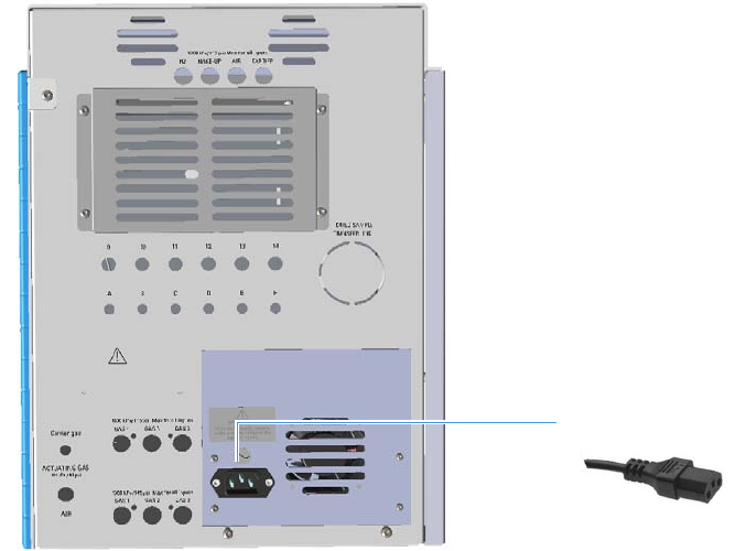
5 Maintenance & Troubleshooting
Powering On the TRACE 1310 Auxiliary Oven
120 TRACE 1310 Auxiliary Oven Instruction Manual Thermo Scientific
Powering On the TRACE 1310 Auxiliary Oven
To power on the TRACE 1310 Auxiliary Oven
1. )Verify that all the connections have been properly done.
2. Open the supply gases.
3. Plug the power cable to the AC Input connector (Main socket) on the TRACE 1310
Auxiliary Oven, and to the wall outlet. See Figure 169.
Figure 169. TRACE 1310 Auxiliary Oven Power On
4. If auxiliary detectors are installed, be sure the carrier gas flowing through the column and
the detector gases flowing through the detector.
5. Power on the GC.
a. If external modules are present, plug the power cable to the AC Input connector of
each module, and to the wall outlet.
b. Flip up the power switch, located on the back side of the GC, to the On (up) position
marked I.
AC Input Connector

5 Maintenance & Troubleshooting
Shutting Down the TRACE 1310 Auxiliary Oven
Thermo Scientific TRACE 1310 Auxiliary Oven Instruction Manual 121
Shutting Down the TRACE 1310 Auxiliary Oven
To shut down the GC and the TRACE 1310 Auxiliary Oven
1. Cool down the GC.
2. If you do not plan to replace the column or perform maintenance on the GC, you do not
have to lower the injector temperature.
3. Turn off the carrier gas supply at the tank.
4. Push down the power switch (breaker), located at the back of the instrument, to the
position O (down).
5. If external modules are present, unplug the power cable from the AC Input connector of
each module, and from the wall outlet.
6. If present, power-off the autosampler by switching off the main power switch, or by
unplugging the power cable from the AC input connector, and from the wall outlet.
7. Power-off all the remaining instruments.
Cleaning the Instrument Externally
Normal usage of the TRACE 1310 Auxiliary Oven can cause the exterior to get dirty.
To clean the instrument externally
1. Place the GC in stand-by condition.
2. Press the Maintenance button to cool down the GC, or switch off the heated zones
manually.
3. Power off the GC and the TRACE 1310 Auxiliary Oven.
a. Push down the power switch (breaker), located at the back of the instrument, to the
position O.
b. Unplug the power cable from the AC Input connector on the back of the GC, and
from the wall outlet.
Note By pressing the Maintenance button, the GC cool down is automatically
carried out.
WARNING It is your responsibility to avoid that dangerous liquids, materials or both,
seeping inside the GC during operation and maintenance.
Solvent must not be used. Do not spray on electrical parts.
5 Maintenance & Troubleshooting
Cleaning the Instrument Externally
122 TRACE 1310 Auxiliary Oven Instruction Manual Thermo Scientific
c. If external modules are present, unplug the power cable from the AC Input connector
of each module, and from the wall outlet.
4. Unplug the power cable from the AC Input connector on the back of the TRACE 1310
Auxiliary Oven, and from the wall outlet.
5. Externally clean the instrument with a soap and water solution, or with a household
non-abrasive product.
• Pay special attention when cleaning the back side of the instrument. Do not spray,
but clean using a cloth imbued with the same substance.
• Carefully avoid seeping of the products used inside the instrument, particularly when
cleaning the grid of the back panel.
• If you just suspect that a substance used for cleaning or a product submitted to
analysis has penetrated inside the instrument, immediately shut down the
instrument, and call an authorized customer support engineer for proper actions.
The service engineer must be fully informed on the nature of the concerned
substance.
In the event that a hazardous material is spilled on or in the instrument, clean the
spill according to the procedures reported in the Material Data Sheet for that
substance.
6. Dry with a clean cloth.
7. If external modules are present, plug the power cable to the AC Input connector of each
module, and to the wall outlet.
8. Power on the GC and the TRACE 1310 Auxiliary Oven.
a. Plug the power cable to the AC Input connector into the back of the GC and to the
wall outlet.
b. Flip up the power switch (breaker) to the position I.
c. Set the normal injector, detector and GC working conditions.
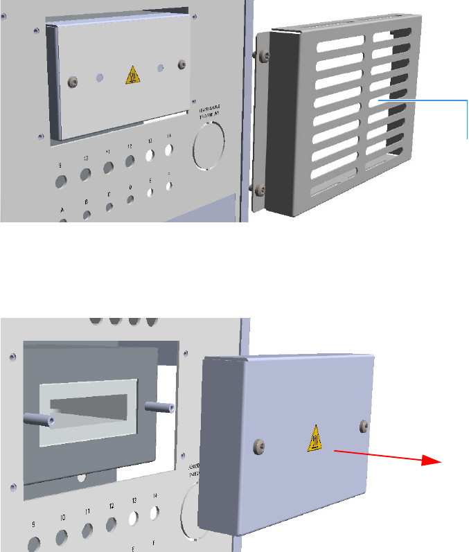
5 Maintenance & Troubleshooting
Replacing the Column into the Secondary Oven
Thermo Scientific TRACE 1310 Auxiliary Oven Instruction Manual 123
Replacing the Column into the Secondary Oven
This section provides instructions for replacing the column installed into the secondary oven.
To replace the column
1. Power off the GC and the TRACE 1310 Auxiliary Oven. See “Shutting Down the
TRACE 1310 Auxiliary Oven” on page 121.
2. Remove the L-shape cover of the Auxiliary Oven.
3. Remove the L-shape cover of the main oven to access its interior.
4. Remove the protective grid from the back panel of the instrument by unscrewing the four
fixing screws. See Figure 174.
Figure 170. Column Replacement (1)
5. Disconnect the ends of column from the components at which the column is connected.
6. Remove the front panel of the secondary oven assembly. See Figure 171.
Figure 171. Column Replacement (2)
7. Carefully remove the column and its end from the secondary oven. See Figure 172.
Protective Grid
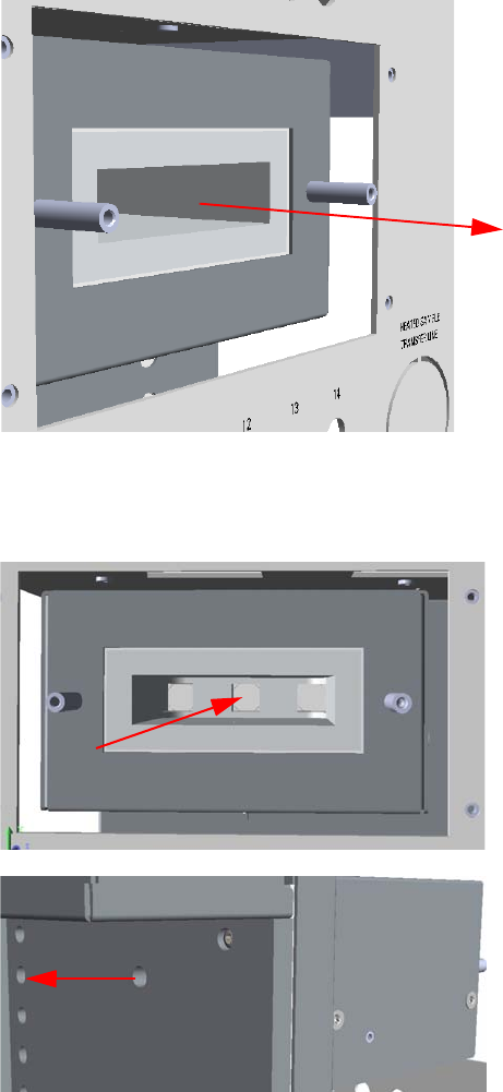
Figure 172. Column Replacement (3)
8. Replace the column with a new one guiding its end into the main oven through the
proper hole. See Figure 173.
Figure 173. Column Replacement (4)
9. Reinstall the front panel of the secondary oven assembly in the reverse order in which it
was removed.
10. Connect the ends of the new column to the components at which the column was
connected in the reverse order in which it was removed.
11. Restart the GC and the TRACE 1310 Auxiliary Oven.
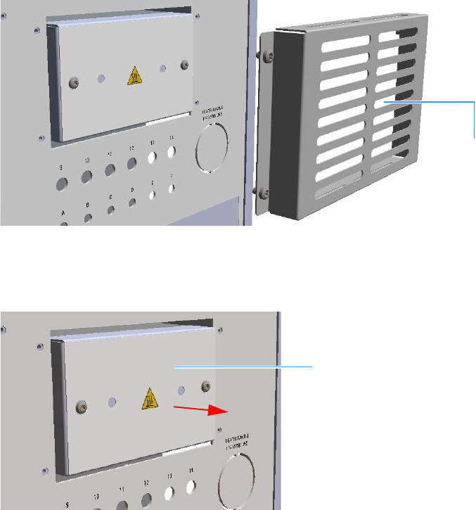
5 Maintenance & Troubleshooting
Maintaining the Methanizer
Thermo Scientific TRACE 1310 Auxiliary Oven Instruction Manual 125
Maintaining the Methanizer
This section provides instructions for replacing the methanizer when the when the catalyst
results exhausted.
To replace the methanizer metal tube containing the catalyst
1. Power off the GC and the TRACE 1310 Auxiliary Oven. See “Shutting Down the
TRACE 1310 Auxiliary Oven” on page 121.
2. Remove the protective grid from the back panel of the instrument undoing the four fixing
screws. See Figure 174.
Figure 174. Methanizer Maintenance (1)
3. Remove the front panel and cover of the methanizer assembly undoing the relevant fixing
screws. See Figure 175.
Figure 175. Methanizer Maintenance (2)
4. Open the heating block of the methanizer by removing the four fixing screws to access the
methanizer metal tube containing the catalysts. See Figure 176.
Protective Grid
Methanizer Assembly Front Panel and Cover
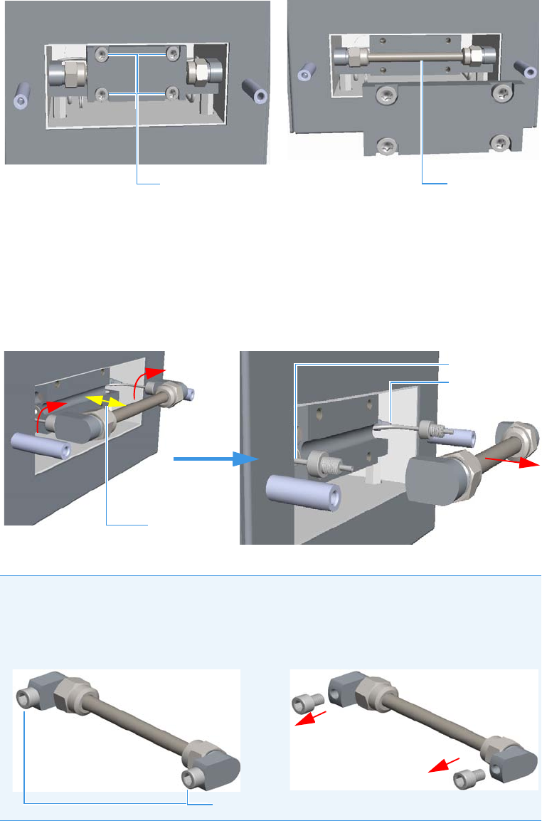
5 Maintenance & Troubleshooting
Maintaining the Methanizer
126 TRACE 1310 Auxiliary Oven Instruction Manual Thermo Scientific
Figure 176. Methanizer Maintenance (3)
5. Carefully extract the methanizer until it protrudes about 2-3 cm from the box, as
permitted by the length of the inlet and outlet tubings connected to it.
Do not force the extraction of the methanizer more than the suggested distance.
6. Using a 1/4 in. wrench, disconnect the fittings of the inlet and outlet tubings from the
methanizer, then remove it. See Figure 177.
Figure 177. Methanizer Maintenance (4)
7. Replace the methanizer with a new one.
a. Connect the inlet and outlet tubings to the connecting ports of the methanizer
without overtightening the fittings.
Note The connecting ports of the new methanizer are protected by two
finger-tightened plugs. Remove the plugs manually before connecting the inlet and
outlet tubings to the methanizer. See Figure 178.
Figure 178. Metal Tube Protective Plugs
Methanizer
Heating Block Fixing Screws
Outlet Tubing
Inlet Tubing
2-3 cm
Protective Plugs
5 Maintenance & Troubleshooting
Catalyst Activation
Thermo Scientific TRACE 1310 Auxiliary Oven Instruction Manual 127
8. Before reinserting the methanizer into the heating block, perform a leak test. See
“Performing a Leak Test” on page 127.
9. At the end of the leak test, carefully reinsert the methanizer into the heating block and
close it by using the four fixing screws.
10. Reinstall the front panel and the cover of the methanizer assembly.
11. Reinstall and fix the protective grid.
12. Restart the GC and the TRACE 1310 Auxiliary Oven.
13. Activate the catalyst. See “Catalyst Activation” on page 127.
Performing a Leak Test
To perform a leak test
1. Turn on the hydrogen flow.
2. Check the metal tube connections with a handheld electronic leak detector to find
possible leaks.
Catalyst Activation
To activate the catalyst
Before starting this procedure do the following:
• Turn off the flame of the FID.
• Set the required carrier gas flow rate (helium or nitrogen).
• Set the injector temperature to 100 °C.
• Set the column oven temperature to 40 °C.
• Set the detector temperature to 250 °C.
Note Because the methanizer is not polarized, it is indifferent to which ports you
connect the inlet and outlet tubings.
IMPORTANT Perform the activation of the catalyst when the methanizer is installed the
first time, and when the methanizer temperature, the flow of hydrogen, or both remain off
for a period of time.

5 Maintenance & Troubleshooting
Troubleshooting
128 TRACE 1310 Auxiliary Oven Instruction Manual Thermo Scientific
To activate the catalyst proceed as follows:
1. Set the hydrogen flow to 30 mL/min.
2. Increase the methanizer temperature (Aux 1 Zone) to 150 °C.
3. Maintain the methanizer at this temperature for about one hour.
4. Increase the methanizer temperature to 380 °C.
5. Let hydrogen flow through the catalyst for approximately two hours to ensure the
complete reduction.
6. At the end of the activation the catalyst can be repeatedly used without further treatment.
Troubleshooting
This section helps you to find and correct potential problems when using the TRACE 1310
Auxiliary Oven.
The most common problem associated with valves and plumbing are leaks, valves not
switching properly, and valves not plumbed correctly.
Leak Testing
Leak testing requires studying plumbing diagrams and system configurations.
Identify all gas sources leading into the flow path to be leak tested. Determine if the gas
sources are either a common source or if they are at the same bottle pressure.
Be sure all components in the sample path will withstand the pressure being applied to the
system.
Be sure all possible gas outlets are blocked. This will require knowing how to identify the
various flow paths throughout the valve system to be sure vents are blocked or bypassed.
Refer to the TRACE 1300/1310 manuals, for leak test suggestions and the necessary hardware
required to pressure check a plumbing system.
In case of problems, see Ta b le 7 for the possible causes and remedies.
CAUTION During the catalyst activation, hydrogen is discharged to the atmosphere.
Therefore the user must take all necessary precautions concerning the use of gases involved
danger of explosion or fire, as provided by the Safety Regulations applicable in the country
where the instrument is used.
Note Leak should be detected using an electronic leak detector (Thermo Scientific GLD
Pro, or equivalent).

5 Maintenance & Troubleshooting
Troubleshooting
Thermo Scientific TRACE 1310 Auxiliary Oven Instruction Manual 129
Valve Switching
VICI® valves contain a rotor that is turned by the actuator. This rotor channels the gas
between the various ports of the valve. If the rotor is not being switched properly, a flow path
may be partially or fully blocked, or leaks may occur between valve ports.
Each valve contains a mechanical stop that should reach an extreme when the valve is rotated
in the clockwise or counterclockwise direction.
Close inspection of the valve will indicate if the valve is being switched to its limits.
Actuator pressure should be 420 kPa (60psig) to 630 kPa (90 psig).
In case of problems, see Ta b le 8 for the possible causes and remedies.
Valve Plumbing
Verify the valve and system plumbing conforms to the appropriate plumbing diagram for your
system setup. Trace the plumbing from port to port to insure all connections are made
properly.
Methanizer Analytical Troubleshooting
Tab l e 9 lists the most common anomalies with the relevant diagnosis and remedy when the
methanizer device is used.
Table 7. Leak Testing for Valves
Symptom Possible Cause Possible Remedy
Valve leaking between ports. Defective rotor. Replace rotor or valve.
Valve leaking around rotor. Valve rotor not seating properly.
Rotor defective.
Tighten rotor.
Replace rotor.
Leaking out valve ports Ferrule not seating. Replace ferrule.
Table 8. Causes and Remedies for Improper Valve Switching
Possible Cause Possible Remedy
Low actuator line pressure. Increase line pressure.
Solenoid not actuating. Verify timed event is set correctly.
Check voltage at solenoid valve.
Replace defective solenoid valve.
Actuator leaking. Replace actuator.
Valve event not set correctly. Check valve event configuration and event in the run
table.

5 Maintenance & Troubleshooting
Troubleshooting
130 TRACE 1310 Auxiliary Oven Instruction Manual Thermo Scientific
Table 9. Methanizer Analytical Troubleshooting
Symptom Diagnosis Remedy
No peaks at all. Column broken or disconnected. Check the column and
connections.
Defective electrometer or
amplifier.
Replace the electrometer or the
amplifier.
FID flame is out. Light the flame.
Poor or missing electrical
connections.
Check the cables connections.
CO or CO2 peaks not present in the
chromatogram.
Methanizer temperature not
correct.
Set the correct temperature.
Catalyst exhausted. Replace the metal tube containing
the catalysts.

Thermo Scientific TRACE 1310 Auxiliary Oven Instruction Manual 131
6
Ordering Parts
This chapter contains part numbers for all the kits or spare parts available for your TRACE
1310 Auxiliary Oven.
Use Table 10 to order new kits or spare parts for your TRACE 1310 Auxiliary Oven.
Table 10. Ordering information for new kits and spare parts (Sheet 1 of 2)
Description Part number
Kits
TRACE 1310 Auxiliary Oven - Detector Seat 19071006
TRACE 1310 Auxiliary Oven - Column Oven 19071007
TRACE 1310 Auxiliary Oven - Methanizer 19071008
TRACE 1310 Auxiliary Oven - Manifold Kit for Valco® Rotary Valves 19071009
TRACE 1310 Auxiliary Oven - Manifold Kit for Membrane Valves 19071010
TRACE 1310 Auxiliary Oven - for Valco® Rotary Valves 19071011
TRACE 1310 Auxiliary Oven - Solenoid Valve for Membrane Valves 19071012
TRACE 1310 Auxiliary Oven - Solenoid Valve for On/Off LPG Valves 19071013
TRACE 1310 Auxiliary Oven - Bulkhead Connector for Sample In/Out
Heated Zone
19071014
TRACE 1310 Auxiliary Oven - Bulkhead Connector for Sample In/Out
Unheated Zone
19071015
TRACE 1310 Auxiliary Oven - Capillary Column Retaining Kit 19071017
TRACE 1310 Auxiliary Oven - Split Fitting for Auxiliary Gas 19071018
TRACE 1310 Auxiliary Oven - Bulkhead Connector for Sample In/Out
at High Temperature
19071022
TRACE 1310 Auxiliary Oven - LPG Installation Kit 19071100
TRACE 1310 Auxiliary Oven - Kit for Installing one Valco® Rotary
Valves
19071200
TRACE 1310 Auxiliary Oven - Kit for Installing one Membrane Valves 19071300

6 Ordering Parts
132 TRACE 1310 Auxiliary Oven Instruction Manual Thermo Scientific
Spare Parts
TRACE 1310 Auxiliary Oven - Methanizer Tube 27609925
TRACE 1310 Auxiliary Oven - PT100 550 mm VO TRC1300 23043772
TRACE 1310 Auxiliary Oven - PT100 300 mm VO TRC1300 23043723
TRACE 1310 Auxiliary Oven - Heater VO TRC1300 23043725
TRACE 1310 Auxiliary Oven - Heater Column Oven TRC1300 23043726
TRACE 1310 Auxiliary Oven - Fan 60 mm VO TRC1300 23043728
TRACE 1310 Auxiliary Oven - Fan 40 mm VO TRC1300 23043729
TRACE 1310 Auxiliary Oven - Aux Gas Board VO TR1300 29903501
TRACE 1310 Auxiliary Oven - Proportional Valve VO TR1300 40516160
TRACE 1310 Auxiliary Oven - Aux Tube Assy VO TR1300 25904060
TRACE 1310 Auxiliary Oven - VOBP-HRM Board VO TR1300 23661128
TRACE 1310 Auxiliary Oven - Aux Temp Board VO TR1300 23661060
TRACE 1310 Auxiliary Oven - LED Plate VO TR1300 23043730
TRACE 1310 Auxiliary Oven - 3-way Solenoid Valve VO TR1300 40517105
TRACE 1310 Auxiliary Oven - 5-way Solenoid Valve VO TR1300 40519029
TRACE 1310 Auxiliary Oven - Needle Valve 1/16-in. 40527097
TRACE 1310 Auxiliary Oven - Bulkhead fitting 5/16-20 35008441
Table 10. Ordering information for new kits and spare parts (Sheet 2 of 2)
Description Part number
