AIAS 1310 31716000 AI AS User Guide
2016-05-17
: Pdf 31716000 Ai 1310 As 1310 User Guide 31716000 AI 1310_AS 1310 User Guide AI-AS 1310 GC AS Manuals User ation
Open the PDF directly: View PDF ![]() .
.
Page Count: 114 [warning: Documents this large are best viewed by clicking the View PDF Link!]
- Preface
- Contents
- Introduction
- Sampling Unit
- Installation
- Who Performs the Installation
- Electrical Requirements
- How to Lift and Carry the Sampling Unit
- Sampling System Support
- Installing the Sampling System Support on the TRACE 1300/1310 GC
- Installing the Sampling System Support on the TRACE GC Ultra
- Installing the Sampling System Support on the FOCUS GC
- Installation of the AI 1310/AS 1310 on the GC
- AI 1310/AS 1310 Control
- Maintenance
- Glossary
- Index

Thermo Scientific
AI 1310 / AS 1310
Autosamplers
User Guide
31716000 Third Edition December 2015
© 2015 Thermo Fisher Scientific Inc. All rights reserved.
AI 1310, AS 1310, TRACE 1300, TRACE 1310, TRACE GC Ultra, FOCUS GC, Xcalibur, Chromeleon,
Chrom-Card and ChromQuest are trademarks of Thermo Fisher Scientific. EzChrom is a trademark of Agilent
Technologies. All other trademarks are the property of Thermo Fisher Scientific and its subsidiaries.
Published by Thermo Fisher Scientific S.p.A., Strada Rivoltana 20090 Rodano-Milan, Italy
Tel: +39 02 95059303; Fax: +39 02 95059388
Thermo Fisher Scientific Inc. provides this document to its customers with a product purchase to use in the
product operation. This document is copyright protected and any reproduction of the whole or any part of this
document is strictly prohibited, except with the written authorization of Thermo Fisher Scientific Inc.
The contents of this document are subject to change without notice. All technical information in this
document is for reference purposes only. System configurations and specifications in this document supersede
all previous information received by the purchaser.
This document is not part of any sales contract between Thermo Fisher Scientific Inc. and a purchaser. This
document shall in no way govern or modify any Terms and Conditions of Sale, which Terms and Conditions of
Sale shall govern all conflicting information between the two documents.
Release history: First edition, released March 2012 “Original Instructions”
Second Edition, released August 2013; Third Edition December 2015
For Research Use Only. Not for use in diagnostic procedures.

fold
fold
Reader’s Survey
AI 1310 / AS 1310 User Guide, PN 31716000, Third Edition
If not, please comment below. Attach additional sheets if necessary.
__________________________________________________________ __________________________________________________________________
__________________________________________________________ __________________________________________________________________
__________________________________________________________ __________________________________________________________________
__________________________________________________________ __________________________________________________________________
__________________________________________________________ __________________________________________________________________
__________________________________________________________ __________________________________________________________________
__________________________________________________________ __________________________________________________________________
__________________________________________________________ __________________________________________________________________
__________________________________________________________ __________________________________________________________________
Customer Registration Card
Register now…and receive all the privileges associated with being a Thermo Fisher Scientific product user including customer
support, application reports, and technical reports.
Name __________________________________________________Title__________________________________________________________________
Company __________________________________________________ __________________________________________________________________
Address ___________________________________________________ __________________________________________________________________
City/State _________________________________________Postal Code__________________________________________________________________
Country ___________________________________________________ __________________________________________________________________
Telephone_______________________________________________ Ext. __________________________________________________________________
Serial Number __________________________________ Date purchased __________________________________________________________________
Fold and mail or e-mail to:
Strongly
Agree Agree Neutral Disagree Strongly
Disagree
The manual is well organized. 1 2 3 4 5
The manual is clearly written. 1 2 3 4 5
The manual contains all the information I need. 1 2 3 4 5
The instructions are easy to follow. 1 2 3 4 5
The instructions are complete. 1 2 3 4 5
The technical information is easy to understand. 1 2 3 4 5
Examples of operation are clear and useful. 1 2 3 4 5
The figures are helpful. 1 2 3 4 5
I was able to operate the system using this manual. 1 2 3 4 5
MY ORGANIZATION IS: (Check only one) MY PRIMARY APPLICATION IS: (Check only one)
❏Commercial (for profit) lab ❏Analytical
❏Government lab ❏Biomedical
❏Hospital/Clinic ❏Clinical/Toxicology
❏Industrial lab ❏Energy
❏Research Institute ❏Environmental
❏University/College ❏Food/Agricultural
❏Veterinary ❏Forensic/Toxicology
❏Other______________________ ❏Pharmaceutical
❏Research/Education
MY PRIMARY JOB FUNCTION IS: (Check only one) ❏Other______________________
❏Administration
❏Lab management
❏Operator
❏Other______________________
Editor, Technical Publications
Thermo Fisher Scientific S.p.A.
Strada Rivoltana km 4
20090 Rodano (MI)
Italy
Editor, Technical Publications
Thermo Fisher Scientific CMD GC-GC/MS
2215 Grand Avenue Parkway
Austin TX 78728-3812
Unites States of America

Declaration
Manufacturer: Thermo Fisher Scientific
Thermo Fisher Scientific is the manufacturer of the instrument described in this manual and, as such, is responsible
for the instrument safety, reliability and performance only if:
•installation
•re-calibration
•changes and repairs
have been carried out by authorized personnel and if:
• the local installation complies with local law regulations
• the instrument is used according to the instructions provided and if its operation is only entrusted to qualified
trained personnel
Thermo Fisher Scientific is not liable for any damages derived from the non-compliance with the aforementioned
recommendations.
Thermo Fisher Scientific S.p.A.
Strada Rivoltana, 20090 Rodano - Milan - Italy — Tel: +39 02 950591 - Fax: +39 02 9505276
Regulatory Compliance
Thermo Fisher Scientific performs complete testing and evaluation of its products to ensure full compliance with
applicable domestic and international regulations.
When the system is delivered to you, it meets all pertinent electromagnetic compatibility (EMC) and safety
standards.
Safety
This device complies with EN 61010-1:2001, EN 61010-2:2002 according to Low Voltage Directive 2006/95/EC.
Electromagnetic Compatibility
This device complies with EN 61326-1:2006 according to directive 2004/108/EC.
FCC Compliance Statement
THIS DEVICE COMPLIES WITH PART 15 OF THE FCC RULES. OPERATION IS SUBJECT TO
THE FOLLOWING TWO CONDITIONS: (1) THIS DEVICE MAY NOT CAUSE HARMFUL
INTERFERENCE, AND (2) THIS DEVICE MUST ACCEPT ANY INTERFERENCE RECEIVED,
INCLUDING INTERFERENCE THAT MAY CAUSE UNDESIRED OPERATION.

Notice on Lifting and Handling of
Thermo Scientific Instruments
For your safety, and in compliance with international regulations, the physical handling of this Thermo Fisher
Scientific instrument requires a team effort to lift and/or move the instrument. This instrument is too heavy and/
or bulky for one person alone to handle safely.
Notice on the Proper Use of
Thermo Scientific Instruments
In compliance with international regulations: Use of this instrument in a manner not specified by Thermo Fisher
Scientific could impair any protection provided by the instrument.
Notice on the Susceptibility
to Electromagnetic Transmissions
Do not use radio frequency transmitters, such as mobile phones, in close proximity to the instrument.
CAUTION Read and understand the various precautionary notes, signs, and symbols contained
inside this manual pertaining to the safe use and operation of this product before using the device.
WEEE Compliance
This product is required to comply with the European Union’s Waste Electrical & Electronic Equipment (WEEE) Directive
2012/19/EU. It is marked with the following symbol:
Thermo Fisher Scientific has contracted with one or more recycling or disposal companies in each European Union (EU)
Member State, and these companies should dispose of or recycle this product. See www.thermoscientific.com/rohsweee for
further information on Thermo Fisher Scientific’s compliance with these Directives and the recyclers in your country.
WEEE Konformität
Dieses Produkt muss die EU Waste Electrical & Electronic Equipment (WEEE) Richtlinie 2012/19/EU erfüllen. Das Produkt
ist durch folgendes Symbol gekennzeichnet:
Thermo Fisher Scientific hat Vereinbarungen mit Verwertungs-/Entsorgungsfirmen in allen EU-Mitgliedsstaaten getroffen,
damit dieses Produkt durch diese Firmen wiederverwertet oder entsorgt werden kann. Mehr Information über die Einhaltung
dieser Anweisungen durch Thermo Fisher Scientific, über die Verwerter, und weitere Hinweise, die nützlich sind, um die
Produkte zu identifizieren, die unter diese RoHS Anweisung fallen, finden sie unter www.thermoscientific.com/rohsweee.
Conformité DEEE
Ce produit doit être conforme à la directive européenne (2012/19/EU) des Déchets d'Equipements Electriques et
Electroniques (DEEE). Il est marqué par le symbole suivant:
Thermo Fisher Scientific s'est associé avec une ou plusieurs compagnies de recyclage dans chaque état membre de l’union
européenne et ce produit devrait être collecté ou recyclé par celles-ci. Davantage d'informations sur la conformité de Thermo
Fisher Scientific à ces directives, les recycleurs dans votre pays et les informations sur les produits Thermo Fisher Scientific qui
peuvent aider la détection des substances sujettes à la directive RoHS sont disponibles sur www.thermoscientific.com/rohsweee.

Conformità RAEE
Questo prodotto è marcato con il seguente simbolo in conformità alla direttiva europea 2012/19/EU (RAEE) sui rifiuti di
apparecchiature elettriche ed elettroniche:
Thermo Fisher Scientific si è accordata con una o più società di riciclaggio in ciascun Stato Membro della Unione Europea
(EU), e queste società dovranno smaltire o riciclare questo prodotto. Per maggiori informazioni vedere il sito
www.thermoscientific.com/rohsweee.
Conformidad RAEE
Este producto es marcado con el siguiente símbolo en conformidad a la Directiva 2012/19/EU de la Unión Europea sobre los
residuos de aparatos eléctricos y electrónicos:
Thermo Fisher Scientific ha contratado una o más empresas de reciclo para tratar residuos en cada Estado Miembro de la
Unión Europea, y estas empresas deberían reciclar o eliminar este producto. Referirse a www.thermoscientific.com/rohsweee
para una mayor información sobre la conformidad de Thermo Fisher Scientific con estas Directivas y para las empresas de
reciclaje en su país.

Thermo Scientific AI 1310/AS 1310 Sampling System - User Guide ix
P
Preface
This manual contains descriptions of the features and components of the AI 1310/AS 1310
sampling systems. Inside, you will find all of the information necessary for routine operation
of your sampling system. This includes operating procedures, sample injection techniques,
and diagrams and descriptions of the major components.
This manual is organized as follows:
•Chapter 1, “Introduction,” provides a basic overview of the features and options of the AI
1310/AS 1310 System. It also describes the available instrument configurations.
•Chapter 2, “Sampling Unit,” provides a description of the components of the sampling
unit of the AI 1310/AS 1310 System.
•Chapter 3, “Installation,” contains the instructions for the installation of the
AI 1310/AS 1310 on the TRACE 1300, TRACE 1310, TRACE GC Ultra and FOCUS
GC gas chromatographs, the syringe and the electrical connections with the different
units of the gas chromatographic system.
•Chapter 4, “AI 1310/AS 1310 Control,” provides the information for controlling the
AI 1310/AS 1310 through the Chromatography Data System, the TRACE GC Ultra, or
the FOCUS GC. The chapter contains also the working procedures with different
injectors.
•Chapter 5, “Maintenance,” provides guidelines for the maintenance of the AI 1310/AS
1310.
•Glossary contains definitions of terms used in this manual. This also includes
abbreviations, acronyms, metric prefixes, and symbols.
•Index contains an alphabetical list of key terms and topics in this guide, including cross
references and the corresponding page numbers.

Preface
About Your System
xAI 1310/AS 1310 Sampling System - User Guide Thermo Scientific
About Your System
Environmental Conditions
•Internal use
• Up to 2000 meters altitude
• Temperature 18 to 30 °C
• Maximum relative humidity between 30% and 85%
• Voltage variations must not exceed the nominal voltage by ± 10%
• Transient overloads in compliance with installation categories II
• Pollution degree according to IEC 664 (3.7.3) 2
• Protection degree IP00
WARNING Thermo Fisher Scientific systems operate safely and reliably under carefully
controlled environmental conditions. If the equipment is used in a manner not specified
by the manufacturer, the protections provided by the equipment may be impaired. If you
maintain a system outside the specifications listed in this guide, failures of many types,
including personal injury or death, may occur. The repair of instrument failures caused by
operation in a manner not specified by the manufacturer is specifically excluded from the
Standard Warranty and service contract coverage.
WARNING When, for technical reasons, it is necessary to work on instrument parts
which may involve an hazard (moving parts, components under voltage, etc.) the
authorized Technical Service must be contacted. This type of situations can be identified
because access to these parts is possible only by using a tool. The removable protective
covers bear a warning symbol suggesting to refer to the documentation accompanying the
instrument. Should an operator perform a maintenance operation, he/she must have
received proper training to carry out that specific action.
WARNING Before using dangerous substances (toxic, harmful, and so forth), read the
hazard indications and information reported in the Safety Sheet supplied by the
manufacturer referring to the relevant CAS (Chemical Abstract Service) number.
The AI 1310/AS 1310 sampling system requires the use of several chemical products,
which are present in vials and syringes, having different hazard characteristics. Before
using these substances or replacing the syringe, please read the hazard indications and
information reported in the Safety Sheet supplied by the manufacturer referring to the
relevant CAS (Chemical Abstract Service) number.

Preface
Rating
Thermo Scientific AI 1310/AS 1310 Sampling System - User Guide xi
Rating
AI 1310/AS 1310 Autosampler
• 24 Vdc through a portable external power supply, level VI efficiency
−input 90-264 Vac; 47-63 Hz — output 24 Vdc; 70 W minimum
Contacting Us
Thermo Fisher Scientific provides comprehensive technical assistance worldwide and is
dedicated to the quality of our customer relationships and services.
Use http://www.thermoscientific.com address for products information.address for products
information.
Use http://www.gc-gcms-customersupport.com/WebPage/Share/Default.aspx address to
contact your local Thermo Fisher Scientific office or affiliate GC-GC/MS Customer Support.
Safety Alerts and Important Information
Make sure you follow the precautionary notices presented in this guide. Safety and other
special notices appear in boxes and include the following:
WARNING This is the general warning safety symbol and safety alert word to prevent
actions that could cause personal injury. It highlights hazards to humans or the
environment. Each WARNING safety alert is preceded with this safety symbol and another
appropriate safety symbol (see “Safety Alerts and Important Information” on page xi)
Then it is followed with an appropriate safety precautionary message. When you see a
safety alert on your instrument or in the publications, please carefully follow the safety
instructions before proceeding.
CAUTION This is the safety alert word to prevent actions that may cause personal injury or
instrument damage. We use it to highlight information necessary to prevent personal
injury or damage to software, loss of data, or invalid test results; or might contain
information that is critical for optimal system performance. A CAUTION safety alert is
always preceded with an appropriate safety symbol (see “Safety Alerts and Important
Information” on page xi) Then it is followed with an appropriate safety precautionary
message. When you see a safety alert on your instrument or in the publications, please
carefully follow the safety instructions before proceeding.
IMPORTANT Highlights information necessary to prevent damage to software, loss of
data, or invalid test results; or might contain information that is critical for optimal
performance of the system.
Preface
Safety Alerts and Important Information
xii AI 1310/AS 1310 Sampling System - User Guide Thermo Scientific
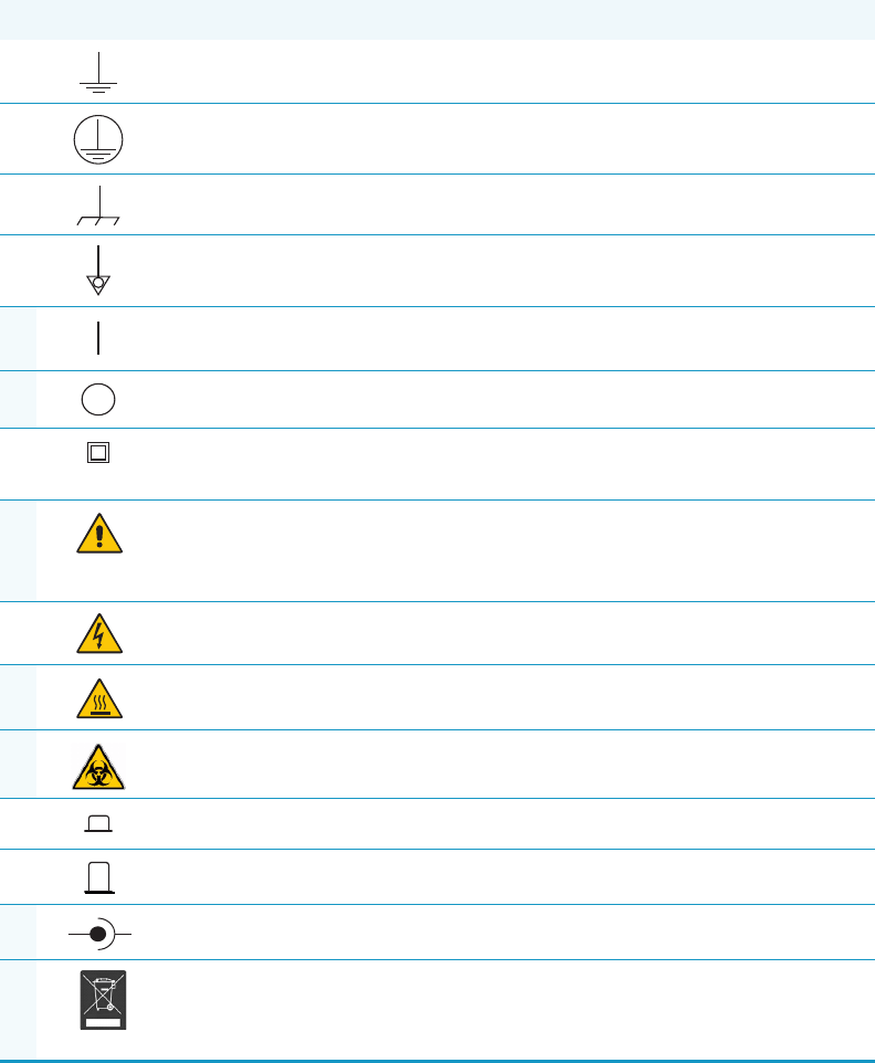
Safety Symbols and Signal Words
All safety symbols are followed by WARNING or CAUTION, which indicates the degree of risk
for personal injury and/or instrument damage. Cautions and warnings are following by a
descriptor, such as BURN HAZARD. A WARNING is intended to prevent improper actions that
could cause personal injury. Whereas, a CAUTION in intended to prevent improper actions
that may cause personal injury and/or instrument damage. The following safety symbols may
be found on your instrument and/or in this guide:
Note Emphasizes important information about a task.
Tip Helpful information that can make a task easier.
Symbol Descriptor
BIOHAZARD: Indicates that a biohazard will, could, or might occur.
BURN HAZARD: Alerts you to the presence of a hot surface that could or might
cause burn injuries.
ELECTRICAL SHOCK HAZARD: Indicates that an electrical shock could or
might occur.
FIRE HAZARD: Indicates a risk of fire or flammability could or might occur.
EXPLOSION HAZARD. Indicates an explosion hazard. This symbol indicates
this risk could or might cause physical injury.
FLAMMABLE GAS HAZARD. Alerts you to gases that are compressed,
liquefied or dissolved under pressure and can ignite on contact with an
ignition source. This symbol indicates this risk could or might cause physical
injury.
GLOVES REQUIRED: Indicates that you must wear gloves when performing a
task or physical injury could or might occur.
CLOTHING REQUIRED. Indicates that you should wear a work clothing when
performing a task or else physical injury could or might occur.
BOOTS REQUIRED. Indicates that you must wear boots when performing a
task or else physical injury could or might occur.
MATERIAL AND EYE HAZARD. Indicates you must wear eye protection when
performing a task.
HAND AND CHEMICAL HAZARD: Indicates that chemical damage or physical
injury could or might occur.
Preface
Instrument Markings and Symbols
Thermo Scientific AI 1310/AS 1310 Sampling System - User Guide xiii
Instrument Markings and Symbols
Table 1 explains the symbols used on Thermo Fisher Scientific instruments. Only a few of
them are used on the AI 1310/AS 1310. See the asterisk.
HARMFUL. Indicates that the presence of harmful material will, could, or
might occur.
INSTRUMENT DAMAGE: Indicates that damage to the instrument or
component might occur. This damage might not be covered under the
standard warranty.
LIFTING HAZARD. Indicates that a physical injury could or might occur if two
or more people do not lift an object.
MATERIAL AND EYE HAZARD: Indicates that eye damage could or might
occur.
READ MANUAL: Alerts you to carefully read your instrument’s
documentation to ensure your safety and the instrument’s operational ability.
Failing to carefully read the documentation could or might put you at risk for a
physical injury.
TOXIC SUBSTANCES HAZARD: Indicates that exposure to a toxic substance
could occur and that exposure could or might cause personal injury or death.
LASER HAZARD. Indicates that exposure to a laser beam will, could, or might
cause personal injury.
RADIOACTIVE HAZARD. Indicates that the presence of radioactive material
could or might occur.
For the prevention of personal injury, this general warning symbol precedes
the WARNING safety alert word and meets the ISO 3864-2 standard. In the
vocabulary of ANSI Z535 signs, this symbol indicates a possible personal
injury hazard exists if the instrument is improperly used or if unsafe actions
occur. This symbol and another appropriate safety symbol alerts you to an
imminent or potential hazard that could cause personal injury.
Table 1. Instrument Marking and Symbols (Sheet 1 of 2)
Symbol Description
Direct Current
*Alternating Current
Both direct and alternating current
Three-phase alternating current
3
Preface
Safety Information and Warnings
xiv AI 1310/AS 1310 Sampling System - User Guide Thermo Scientific
Safety Information and Warnings
This safety guide raises awareness of potential safety issues and general points for
consideration for Thermo Fisher Scientific representatives during installation, and repair of
the AI 1310 /AS 1310 sampling system., or parts of it (following the life cycle principle), as
well as for the end user AI 1310 /AS 1310 sampling system in the lab during the learning
phase, and in routine work.
Earth (ground) terminal
Protective conductor terminal
Frame or chassis terminal
Equipotentiality
*On (Supply)
*Off (Supply)
Equipment protected throughout by DOUBLE INSULATION or
REINFORCED INSULATION (Equivalent to Class II of IEC 536)
*Instruction manual symbol affixed to product. Indicates that the user must
refer to the manual for specific WARNING or CAUTION information to
avoid personal injury or damage to the product.
Caution, risk of electric shock
*Caution, hot surface
*Caution, biohazard
In-position of a bistable push control
Out-position of a bistable push control
*Jack socket
*Symbol in compliance to the Directive 2012/19/EU on Waste Electrical
and Electronic Equipment (WEEE) placed on the European market after
August, 13, 2005.
Table 1. Instrument Marking and Symbols (Sheet 2 of 2)
Symbol Description
+-

Preface
Safety Information and Warnings
Thermo Scientific AI 1310/AS 1310 Sampling System - User Guide xv
General Considerations
• Before a unit is put to use, consult the current User Guide and related documents under
all circumstances.
• Changes or modifications to this unit not expressly approved by the party responsible for
compliance, could void your’s authority to operate the equipment.
• Be aware that if the equipment is used in a manner not specified by the manufacturer, the
protective and safety features of the equipment might be impaired.
• The repair of instrument failures caused by operation in a manner not specified by the
manufacturer is expressly excluded from the standard warranty and service contract
coverage.
• When, for technical reasons, it is necessary to work on instrument parts which may
involve an hazard (moving parts, components under voltage, etc.) the authorized
Technical Service must be contacted. This type of situations can be identified because
access to these parts is possible only by using a tool. The removable protective covers bear
a warning symbol suggesting to refer to the documentation accompanying the
instrument. Should an operator perform a maintenance operation, he/she must have
received proper training to carry out that specific action.
• Before using dangerous substances (toxic, harmful, and so forth), read the hazard
indications and information reported in the Safety Sheet supplied by the manufacturer
referring to the relevant CAS (Chemical Abstract Service) number.
The AI 1310/AS 1310 sampling system requires the use of several chemical products,
which are present in vials and syringes, having different hazard characteristics. Before
using these substances or replacing the syringe, please read the hazard indications and
information reported in the Safety Sheet supplied by the manufacturer referring to the
relevant CAS (Chemical Abstract Service) number.
Electrical Hazards
Every analytical instrument has specific hazards. Be sure to read and comply with the
following pre-cautions. They ensure the safe and long-term use of your AI 1310 /AS 1310
Autosamplers.
The installation over-voltage category is Level II. The Level II category pertains to equipment
receiving its electrical power from the local level, such as an electrical wall outlet.
Connect the AI 1310/AS 1310 sampling system only to instruments complying with IEC
61010 safety regulations.
IMPORTANT Read this section first before operating the AI 1310 /AS 1310 Autosamplers.
Preface
Safety Information and Warnings
xvi AI 1310/AS 1310 Sampling System - User Guide Thermo Scientific
The power line and the connections between the AI 1310/AS 1310 sampling system and
other instruments, used in the configuration setup of the total analytical system, must
maintain good electrical grounding. Poor grounding represents a danger for the operator, and
might seriously affect the performance of the instrument.
Do not connect the AI 1310/AS 1310 sampling system to power lines that supply devices of a
heavy duty nature, such as motors, refrigerators and other devices that can generate electrical
disturbances.
Pay attention not to leave any cable connecting the AI 1310/AS 1310 sampling system and
the chromatographic system, or the power cord close to heated zone, such as the injector or
detector heating blocks, or the GC hot air vents.
Always replace any cable showing signs of damage with another one provided by the
manufacturer. Safety regulations must be respected.
Do not change the external or internal grounding connections. Tampering with or
disconnecting these connections could endanger you and damage the AI 1310/AS 1310
sampling system.
The instrument is properly grounded in accordance with these regulations when shipped.
To ensure safe operation, you do not must make any changes to the electrical connections or
the instrument's chassis.
Do not turn the instrument on if you suspect that it has incurred any type of electrical
damage. Instead, disconnect the power cord and contact a Thermo Fisher Scientific
representative for a product evaluation. Do not attempt to use the instrument until it has been
evaluated. Electrical damage might have occurred if the AI 1310/AS 1310 sampling system
shows visible signs of damage, exposure to any liquids or has been transported under severe
stress.
Damage can also result if the instrument is stored for prolonged periods under unfavorable
conditions: for example, subjected to heat, moisture, and so on. Ensure that the power
supply/controller unit is always placed in a clean and dry position. Avoid any liquid spills in
the vicinity.
Before attempting any type of maintenance work, always disconnect the power cords from the
power supply if optional devices are installed. Capacitors inside the instrument might still be
charged also if the instrument is turned off.
To avoid damaging electrical parts, do not disconnect an electrical assembly while power is
applied to the AI 1310/AS 1310 sampling system. After the power is turned off, wait
approximately 30 seconds before you disconnect an assembly.
The instrument includes a number of integrated circuits. These circuits might be damaged if
exposed to excessive line voltage fluctuations, power surges or electrostatic charges, or both.
Never try to repair or replace any components of the instrument without the assistance of a
Thermo Fisher Scientific representative. There are no operator-serviceable or replaceable parts
inside the power supply or in the AI 1310/AS 1310 sampling system. If a power supply is not
functioning, contact a Thermo Fisher Scientific representative.
Preface
Safety Information and Warnings
Thermo Scientific AI 1310/AS 1310 Sampling System - User Guide xvii
Other Hazards
To avoid injury and possible infection through contamination during AI 1310/AS 1310
sampling system operation, keep your hands away from the syringe.
Danger of crushing to fingers and hands. To avoid injury keep your hands away from moving
parts during operation. Turn off the power to the AI 1310/AS 1310 sampling system if you
must reach inside a mechanically powered system with moving parts.
To avoid injury, observe safe laboratory practice when handling solvents, or operating the AI
1310/AS 1310 sampling system. Know the physical and chemical properties of the solvents
you use. See the MSDS (Material Safety Data Sheets) from the manufacturer of the solvents
being used.
When using the AI 1310/AS 1310 sampling system, follow the generally accepted procedures
for quality control and method development.
Do not operate on the instrument components that form part of the work area of the
AI 1310/AS 1310 sampling system when it is in motion.
Do not use vials without a sealing cap without a plate seal. Vapor phase from organic solvents
can be hazardous and flammable. Acidic vapor phase can cause corrosion to critical
mechanical parts.
Do not reuse the vials. During the process of washing the vial, micro-cracks can form which
will weaken the glass wall and increase the chances of the vial breaking.
Working with Toxic or other Harmful Compounds
Before using dangerous substances (toxic, harmful, and so on) read the hazard indications and
information reported in the Material Safety Data Sheet (MSDS) supplied by the
manufacturer, referring to the relevant CAS (Chemical Abstract Service) number. AI 1310/AS
1310 sampling system requires the use of several chemical products with different hazard
characteristics, which are present in vials and syringes. Before using these substances or
replacing the syringe, please read the hazard indications and information reported in the
MSDS supplied by the manufacturer referring to the relevant CAS number.
WARNING Before using hazardous substances (toxic, harmful, and so on), please read the
hazard indications and information reported in the applicable Material Safety Data Sheet
(MSDS). Use personal protective equipment according to the safety requirements.

Preface
Safety Information and Warnings
xviii AI 1310/AS 1310 Sampling System - User Guide Thermo Scientific
When preparing the samples, please refer to local regulations for the ventilation conditions of
the work room.
All waste materials must be collected and eliminated in compliance with the local regulations
and directives in the country where the instrument is used.
Maintenance
Any external cleaning or maintenance must be performed with the AI 1310/AS 1310
sampling system turned off and the power cord disconnected. Avoid using solvents and
spraying on electrical parts. For the removal of potentially dangerous substances (toxic,
harmful, and so on) read the hazard indications and information reported in the MSDS
(Material Safety Data Sheet) supplied by the manufacturer referring to the relevant CAS
(Chemical Abstract Service) number. Use proper protective gloves.
When working with hazardous materials such as radioactive, biologically hazardous material,
and so on, it is important to train all operators how to respond in case of spills or
contamination.
Depending on the class of hazardous material, the appropriate measures have to be taken
immediately. Therefore, the chemicals or solvents needed for decontamination have to be on
hand.
Any parts of the equipment which can potentially be contaminated, such as the sample vial
rack, syringe tool, wash module, and so on, must be cleaned regularly. The waste solvent from
cleaning and any hardware which requires to be disposed of has to be properly eliminated
with all the necessary precautions, abiding by national and international regulations.
When preparing for decontamination, ensure that the solvent or chemical to be used will not
damage or react with the surface, dye (color) of the instrument, table or other nearby objects.
If in doubt, please contact your Thermo Fisher Scientific representative to verify the
compatibility of the type or composition of solvents with the AI 1310/AS 1310 sampling
system.
It is your responsibility to handle hazardous chemicals or biological compounds, including
(but not limited to) bacterial or viral samples and the associated wastes, safely and in
accordance with international and local regulations.
Disposal
Do not dispose of this equipment or parts thereof unsorted in municipal waste.
Follow local municipal waste regulations for proper disposal provisions to reduce
the environmental impact of waste electrical and electronic equipment (WEEE).
European Union customers: Call your local customer service representative responsible for the
AI 1310/AS 1310 sampling system for complimentary equipment pick-up and recycling.

Preface
Hazardous Substances Precautions
Thermo Scientific AI 1310/AS 1310 Sampling System - User Guide xix
Hazardous Substances Precautions
WARNING The customer has to ensure that the AI 1310/AS 1310 sampling system has
not been contaminated by any hazardous chemical or biological compounds including
(but not limited to) bacteria or viruses.
Any part which had direct contact with the analytical sample must be identified and must
undergo an appropriate decontamination procedure prior to shipping for disposal.
Potentially dangerous components are: syringes and vials. Any critical parts sent for
disposal must be handled according to national laws for hazardous compounds.
The customer and the service engineer are fully responsible for enforcing these
requirements. Thermo Fisher Scientific will hold the representative, customer responsible,
or both, if these regulations are not observed.
WARNING Before using hazardous substances (toxic, harmful, and so on), read the
hazard indications and information reported in the applicable Material Safety Data Sheet
(MSDS.) Use Personal protection according to the safety requirements.

Thermo Scientific AI 1310/AS 1310 Sampling System - User Guide xxi
C
Preface . . . . . . . . . . . . . . . . . . . . . . . . . . . . . . . . . . . . . . . . . . . . . . . . . . . . . . . . . . . . . . ix
About Your System. . . . . . . . . . . . . . . . . . . . . . . . . . . . . . . . . . . . . . . . . . . . . . . x
Environmental Conditions . . . . . . . . . . . . . . . . . . . . . . . . . . . . . . . . . . . . . . . . . x
Rating. . . . . . . . . . . . . . . . . . . . . . . . . . . . . . . . . . . . . . . . . . . . . . . . . . . . . . . . .xi
Contacting Us . . . . . . . . . . . . . . . . . . . . . . . . . . . . . . . . . . . . . . . . . . . . . . . . . .xi
Safety Alerts and Important Information . . . . . . . . . . . . . . . . . . . . . . . . . . . . . .xi
Safety Symbols and Signal Words . . . . . . . . . . . . . . . . . . . . . . . . . . . . . . . . . xii
Instrument Markings and Symbols . . . . . . . . . . . . . . . . . . . . . . . . . . . . . . . . . .xiii
Safety Information and Warnings . . . . . . . . . . . . . . . . . . . . . . . . . . . . . . . . . . .xiv
General Considerations . . . . . . . . . . . . . . . . . . . . . . . . . . . . . . . . . . . . . . . . . xv
Electrical Hazards . . . . . . . . . . . . . . . . . . . . . . . . . . . . . . . . . . . . . . . . . . . . . xv
Other Hazards. . . . . . . . . . . . . . . . . . . . . . . . . . . . . . . . . . . . . . . . . . . . . . . xvii
Working with Toxic or other Harmful Compounds . . . . . . . . . . . . . . . . . . xvii
Maintenance . . . . . . . . . . . . . . . . . . . . . . . . . . . . . . . . . . . . . . . . . . . . . . . .xviii
Disposal. . . . . . . . . . . . . . . . . . . . . . . . . . . . . . . . . . . . . . . . . . . . . . . . . . . .xviii
Hazardous Substances Precautions . . . . . . . . . . . . . . . . . . . . . . . . . . . . . . . . . .xix
Chapter 1 Introduction . . . . . . . . . . . . . . . . . . . . . . . . . . . . . . . . . . . . . . . . . . . . . . . . . . . . . . . . . . .1
The AI 1310/AS 1310 Sampling System . . . . . . . . . . . . . . . . . . . . . . . . . . . . . . . 2
Sampling Unit. . . . . . . . . . . . . . . . . . . . . . . . . . . . . . . . . . . . . . . . . . . . . . . . . 4
Configurations of the 1310 Series Autosampler. . . . . . . . . . . . . . . . . . . . . . . . . . 5
AI 1310 Configuration . . . . . . . . . . . . . . . . . . . . . . . . . . . . . . . . . . . . . . . . . . 5
AS 1310 Configuration . . . . . . . . . . . . . . . . . . . . . . . . . . . . . . . . . . . . . . . . . . 6
Gemini Configuration. . . . . . . . . . . . . . . . . . . . . . . . . . . . . . . . . . . . . . . . . . . 6
Installation . . . . . . . . . . . . . . . . . . . . . . . . . . . . . . . . . . . . . . . . . . . . . . . . . . . 7
Technical Specifications . . . . . . . . . . . . . . . . . . . . . . . . . . . . . . . . . . . . . . . . . . . 8
Chapter 2 Sampling Unit. . . . . . . . . . . . . . . . . . . . . . . . . . . . . . . . . . . . . . . . . . . . . . . . . . . . . . . . .11
Base. . . . . . . . . . . . . . . . . . . . . . . . . . . . . . . . . . . . . . . . . . . . . . . . . . . . . . . . . . 12
Turret . . . . . . . . . . . . . . . . . . . . . . . . . . . . . . . . . . . . . . . . . . . . . . . . . . . . . . . . 13
Injection Assembly . . . . . . . . . . . . . . . . . . . . . . . . . . . . . . . . . . . . . . . . . . . . . . 14
Vial Capture Device . . . . . . . . . . . . . . . . . . . . . . . . . . . . . . . . . . . . . . . . . . . 15
Syringe . . . . . . . . . . . . . . . . . . . . . . . . . . . . . . . . . . . . . . . . . . . . . . . . . . . . . 15
Turret Movements . . . . . . . . . . . . . . . . . . . . . . . . . . . . . . . . . . . . . . . . . . . . 16
Washing and Waste Tray . . . . . . . . . . . . . . . . . . . . . . . . . . . . . . . . . . . . . . . . . 17
Contents
Contents
xxii AI 1310/AS 1310 Sampling System - User Guide Thermo Scientific
Back of the Sampling Unit . . . . . . . . . . . . . . . . . . . . . . . . . . . . . . . . . . . . . . . . 17
Sample Trays. . . . . . . . . . . . . . . . . . . . . . . . . . . . . . . . . . . . . . . . . . . . . . . . . . . 18
8-Position Sample Tray . . . . . . . . . . . . . . . . . . . . . . . . . . . . . . . . . . . . . . . . . 18
105-Position Sample Tray Assembly . . . . . . . . . . . . . . . . . . . . . . . . . . . . . . . 19
155-Position Sample Tray Assembly . . . . . . . . . . . . . . . . . . . . . . . . . . . . . . . 19
Vials . . . . . . . . . . . . . . . . . . . . . . . . . . . . . . . . . . . . . . . . . . . . . . . . . . . . . . . 20
Centering Plate . . . . . . . . . . . . . . . . . . . . . . . . . . . . . . . . . . . . . . . . . . . . . . . . . 20
Centering Plate for TRACE 1300/TRACE 1310 . . . . . . . . . . . . . . . . . . . . . 20
Centering Plate for TRACE GC Ultra and FOCUS GC. . . . . . . . . . . . . . . . 22
Status LED . . . . . . . . . . . . . . . . . . . . . . . . . . . . . . . . . . . . . . . . . . . . . . . . . . . . 22
Chapter 3 Installation . . . . . . . . . . . . . . . . . . . . . . . . . . . . . . . . . . . . . . . . . . . . . . . . . . . . . . . . . . .25
Who Performs the Installation. . . . . . . . . . . . . . . . . . . . . . . . . . . . . . . . . . . . . . 26
Electrical Requirements . . . . . . . . . . . . . . . . . . . . . . . . . . . . . . . . . . . . . . . . . . . 26
How to Lift and Carry the Sampling Unit. . . . . . . . . . . . . . . . . . . . . . . . . . . . . 26
Sampling System Support . . . . . . . . . . . . . . . . . . . . . . . . . . . . . . . . . . . . . . . . . 27
Sampling System Support for TRACE 1300/TRACE 1310 . . . . . . . . . . . . . 27
Sampling System Support for TRACE GC Ultra. . . . . . . . . . . . . . . . . . . . . . 30
Sampling System Support for FOCUS GC . . . . . . . . . . . . . . . . . . . . . . . . . . 32
References for the Installation . . . . . . . . . . . . . . . . . . . . . . . . . . . . . . . . . . . . 32
Installing the Sampling System Support on the TRACE 1300/1310 GC . . . . . 33
Assembling of the Sampling System Support on the Front Injector
Module . . . . . . . . . . . . . . . . . . . . . . . . . . . . . . . . . . . . . . . . . . . . . . . . . . . 34
Assembling of the Sampling System Support on the Back Injector
Module . . . . . . . . . . . . . . . . . . . . . . . . . . . . . . . . . . . . . . . . . . . . . . . . . . . 36
Assembling of the Sampling System Support for the Gemini
Configuration . . . . . . . . . . . . . . . . . . . . . . . . . . . . . . . . . . . . . . . . . . . . . . 38
Assembling of the Sampling System Support When a TSQ Quantum
is Coupled with the GC . . . . . . . . . . . . . . . . . . . . . . . . . . . . . . . . . . . . . . . 40
Installing the Sampling System Support on the TRACE GC Ultra . . . . . . . . . . 42
Installing the Spacer Inside the GC . . . . . . . . . . . . . . . . . . . . . . . . . . . . . . . . 42
Assembling of the Sampling System Support on the GC Right Side . . . . . . . 43
Assembling of the Sampling System Support on the GC Left Side. . . . . . . . . 44
Installing the Sampling System Support on the FOCUS GC. . . . . . . . . . . . . . . 44
Assembling of the Sampling System Support on the GC right side . . . . . . . . 45
Assembling of the Sampling System Support on FOCUS GC MS
Version. . . . . . . . . . . . . . . . . . . . . . . . . . . . . . . . . . . . . . . . . . . . . . . . . . . . 45
Space Saving Installation . . . . . . . . . . . . . . . . . . . . . . . . . . . . . . . . . . . . . . . . 46
Installation of the AI 1310/AS 1310 on the GC . . . . . . . . . . . . . . . . . . . . . . . . 48
Installation of the Sampling Unit . . . . . . . . . . . . . . . . . . . . . . . . . . . . . . . . . 48
Installation of the Syringe . . . . . . . . . . . . . . . . . . . . . . . . . . . . . . . . . . . . . . . 51
Electrical Connections. . . . . . . . . . . . . . . . . . . . . . . . . . . . . . . . . . . . . . . . . . 52
Instrument Start-up. . . . . . . . . . . . . . . . . . . . . . . . . . . . . . . . . . . . . . . . . . . . 56
Contents
Thermo Scientific AI 1310/AS 1310 Sampling System - User Guide xxiii
Chapter 4 AI 1310/AS 1310 Control . . . . . . . . . . . . . . . . . . . . . . . . . . . . . . . . . . . . . . . . . . . . . . . .57
Control Through the Chromatography Data System. . . . . . . . . . . . . . . . . . . . . 58
User Interface . . . . . . . . . . . . . . . . . . . . . . . . . . . . . . . . . . . . . . . . . . . . . . . . 58
Chromeleon CDS User Interface. . . . . . . . . . . . . . . . . . . . . . . . . . . . . . . . . . 59
Xcalibur, Chrom-Card, and ChomQuest CDS User Interface. . . . . . . . . . . . 61
Messages . . . . . . . . . . . . . . . . . . . . . . . . . . . . . . . . . . . . . . . . . . . . . . . . . . . . 63
Control Through the TRACE GC Ultra . . . . . . . . . . . . . . . . . . . . . . . . . . . . . . 63
Configuring the AI 1310/AS 1310 . . . . . . . . . . . . . . . . . . . . . . . . . . . . . . . . 64
AI 1310/AS 1310 Menu . . . . . . . . . . . . . . . . . . . . . . . . . . . . . . . . . . . . . . . . 64
Extended Control Menu . . . . . . . . . . . . . . . . . . . . . . . . . . . . . . . . . . . . . . . . 65
When No Vial Abort Menu . . . . . . . . . . . . . . . . . . . . . . . . . . . . . . . . . . . . . 66
Control Through the FOCUS GC . . . . . . . . . . . . . . . . . . . . . . . . . . . . . . . . . . 66
Configuring the AI 1310/AS 1310 . . . . . . . . . . . . . . . . . . . . . . . . . . . . . . . . 67
AI 1310/AS 1310 Menu . . . . . . . . . . . . . . . . . . . . . . . . . . . . . . . . . . . . . . . . 67
Sequence of Samples with the AS 1310 . . . . . . . . . . . . . . . . . . . . . . . . . . . . . 69
Guidelines for Programming with Different Injectors . . . . . . . . . . . . . . . . . . . . 69
SSL Inlet (TRACE 1300/1310 GC) . . . . . . . . . . . . . . . . . . . . . . . . . . . . . . . 70
SSL Inlet (TRACE GC Ultra/FOCUS GC) . . . . . . . . . . . . . . . . . . . . . . . . . 71
SSL Inlet with a Merlin Microseal™ (TRACE GC Ultra Only) . . . . . . . . . . . 74
PTV Inlet (TRACE 1300/1310 GCTRACE GC Ultra) . . . . . . . . . . . . . . . . 75
PTV Inlet with a Merlin Microseal™ (TRACE 1300/1310 GC,
TRACE GC Ultra). . . . . . . . . . . . . . . . . . . . . . . . . . . . . . . . . . . . . . . . . . . 76
PKD and PPKD Inlets (TRACE GC Ultra, FOCUS GC) . . . . . . . . . . . . . . 76
Chapter 5 Maintenance . . . . . . . . . . . . . . . . . . . . . . . . . . . . . . . . . . . . . . . . . . . . . . . . . . . . . . . . .77
Current Maintenance . . . . . . . . . . . . . . . . . . . . . . . . . . . . . . . . . . . . . . . . . . . . 78
Emptying of the Waste Container . . . . . . . . . . . . . . . . . . . . . . . . . . . . . . . . . . . 78
Cleaning of the Sample Tray Accessory . . . . . . . . . . . . . . . . . . . . . . . . . . . . . . . 78
Cleaning the Instrument Externally. . . . . . . . . . . . . . . . . . . . . . . . . . . . . . . . . . 78
Replacing the Syringe . . . . . . . . . . . . . . . . . . . . . . . . . . . . . . . . . . . . . . . . . . . . 79
Cleaning the Syringe . . . . . . . . . . . . . . . . . . . . . . . . . . . . . . . . . . . . . . . . . . . . . 80
Automated Cleaning . . . . . . . . . . . . . . . . . . . . . . . . . . . . . . . . . . . . . . . . . . . 80
Manual Cleaning. . . . . . . . . . . . . . . . . . . . . . . . . . . . . . . . . . . . . . . . . . . . . . 81
Preparing a New Syringe . . . . . . . . . . . . . . . . . . . . . . . . . . . . . . . . . . . . . . . . . . 81
Moving Away the Sampling Unit from the Injector Module . . . . . . . . . . . . . . . 82
Glossary . . . . . . . . . . . . . . . . . . . . . . . . . . . . . . . . . . . . . . . . . . . . . . . . . . . . . . . . . . . . .83
Index . . . . . . . . . . . . . . . . . . . . . . . . . . . . . . . . . . . . . . . . . . . . . . . . . . . . . . . . . . . . . . . .87

Thermo Scientific AI 1310/AS 1310 Sampling System - User Guide 1
1
Introduction
This chapter provides a basic overview of the features and options of the AI 1310/AS 1310.
The available instrument configurations are also described.
Contents
•The AI 1310/AS 1310 Sampling System
•Configurations of the 1310 Series Autosampler
•Technical Specifications
1 Introduction
The AI 1310/AS 1310 Sampling System
2AI 1310/AS 1310 Sampling System - User Guide Thermo Scientific
The AI 1310/AS 1310 Sampling System
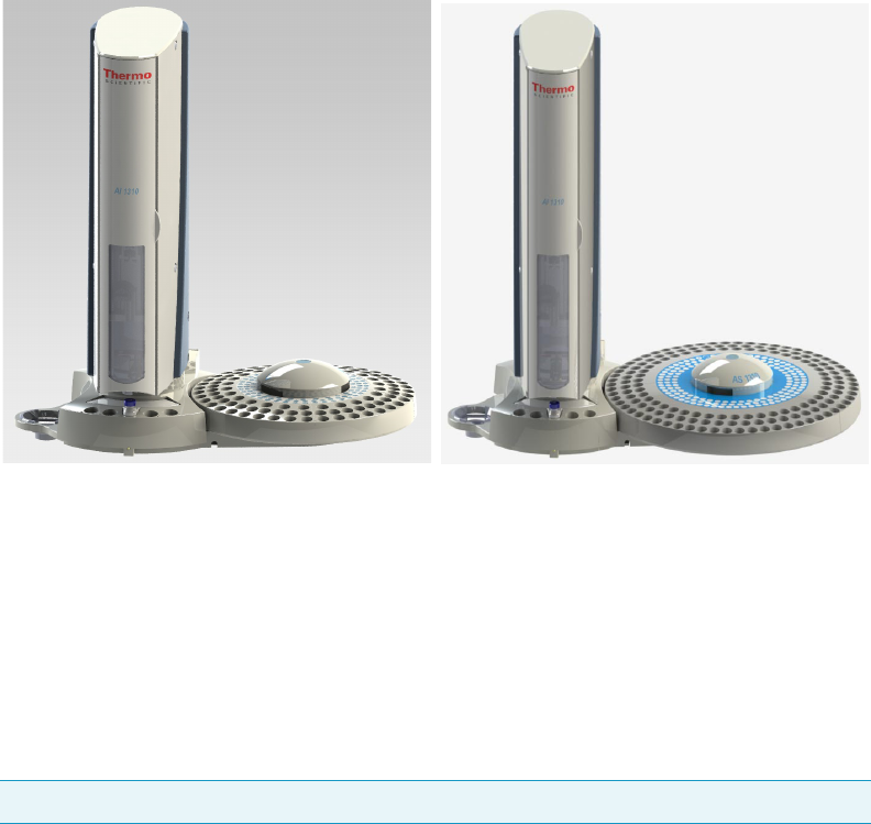
The 1300 Series Autosampler, available as AI 1310 or AS 1310, consists of the following
parts, as respectively shown in Figure 1 and Figure 2.
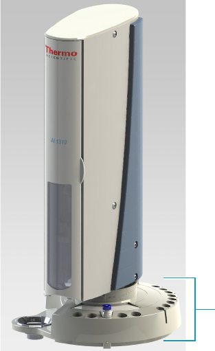
Figure 1. AI 1310 Sampling System
Turret
Base
Safety Door
Injection Unit
Centering Plate
Washing and Waste Tray
8-position Sample Tray

1 Introduction
The AI 1310/AS 1310 Sampling System
Thermo Scientific AI 1310/AS 1310 Sampling System - User Guide 3
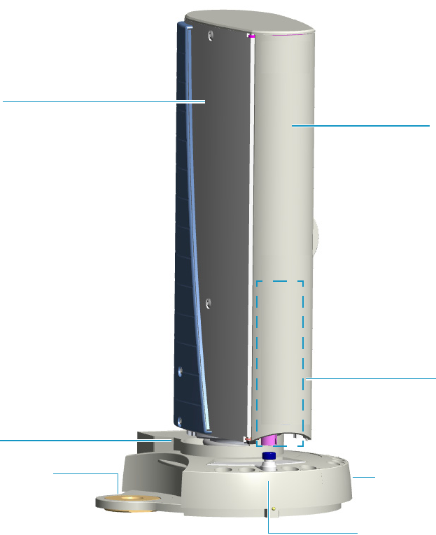
Figure 2. AS 1310 Sampling System
Turret
Safety Door
Injection Unit
Centering Plate
Washing and Waste Tray
Base
105-position Sample Tray or
155-position Sample Tray
AS 1310 with 105-position Sample Tray
AS 1310 with 155-position Sample Tray
1 Introduction
The AI 1310/AS 1310 Sampling System
4AI 1310/AS 1310 Sampling System - User Guide Thermo Scientific
Sampling Unit
The sampling unit consists of the following major components:
Base — This is the structure bearing the sampling unit components.
Tu r re t — Consists of a vertical moving structure that accommodates the injection unit and
accomplishes the necessary movements to carry out the three main operating steps: sample
drawing, injection, syringe washing. The turret is provided with a safety door allowing access
to the syringe.
Injection Assembly — Housed inside the rotating turret, it consists of a moving support
(sliding plate) on which the syringe is installed.
Washing and Waste Tray — Accommodate up to four 4 mL vials of solvents to wash the
syringe, and a 50 mL plastic container to collect the washing solvents after their use.
Centering Plate — Consists of a plate provided with circular guides to center the sampling
unit on the injector nut.
Sample Tray — Contains the seats for the sample vials. Each position is numbered to make
the sample identification easy. The following options are available:
•Sample tray for AI 1310 consisting of an 8-position fixed support.
•Sample holding assembly for AS 1310 consisting of a 105-position turnable mobile
tray mounted on a dedicated support plate.
•Sample holding assembly for AS 1310 consisting of a 155-position turnable mobile
tray mounted on a dedicated support plate.
Sampler Support — Constitutes the supporting base allowing to install the sampler on the
gas chromatograph.
User Interface — The functions of the AI 1310/AS 1310 can be controlled through:
• a data processing system for PC with dedicated software.
• the keypad of the TRACE GC Ultra.
For further information, please refer to:
•“Configurations of the 1310 Series Autosampler” on page 5
•Chapter 2, “Sampling Unit,” on page 11
•Chapter 4, “AI 1310/AS 1310 Control,” on page 57
1 Introduction
Configurations of the 1310 Series Autosampler
Thermo Scientific AI 1310/AS 1310 Sampling System - User Guide 5
Configurations of the 1310 Series Autosampler
The AI 1310/AS 1310 can be installed on the TRACE 1300/TRACE 1310, TRACE GC
Ultra, or FOCUS GC gas chromatographs for sample introduction into the following
injectors:
• TRACE 1300/TRACE 1310: SSL, SSLBKF, PTV, and PTVBKF injectors
• TRACE GC Ultra: SSL, PTV, PKD, and PPKD injectors
• FOCUS GC: SSL injector
The sampler is available in the following options:
•AI 1310 Configuration
•AS 1310 Configuration
•Gemini Configuration
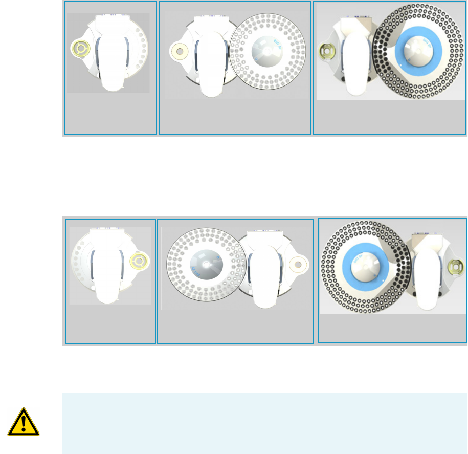
AI 1310 Configuration
In this configuration the 8-position sample tray is used. See Figure 3.
Figure 3. AI 1310 Configuration
As a function of the right or left installation configuration, the support will be introduced into
the relevant side housing on the base of the sampling unit. On the opposite side housing, the
proper centering plate will be positioned.
8-position Sample Tray
1 Introduction
Configurations of the 1310 Series Autosampler
6AI 1310/AS 1310 Sampling System - User Guide Thermo Scientific
AS 1310 Configuration
In this configuration the 105-position or 155-position sample tray is used, mounted on the
hub provided on the own dedicated support plate. See Figure 4.
Figure 4. AS 1310 Configuration
The support plates of the tray and the sampler are electrically connected to each other by the
proper connecting cable.
As a function of the right or left installation configuration, the support will be introduced into
the relevant housing on the base of the sampling unit.
Gemini Configuration
Consists of the installation of two AI 1310/AS 1310 on the same GC.
• With the TRACE 1300/TRACE 1310 — the autosamplers are installed on the right side,
one on the Front injector module, and the other on the Back injector module.
• With the TRACE GC Ultra — one sampler is installed on the left side of the GC, and
the other is installed on the right side.
Each sampler operates simultaneously on its own relevant injector. In this configuration, both
sampler are ready to inject the sample simultaneously according to the programmed analytical
method that could be the same for both or different. See “Gemini Configuration” on page 53.
105-position Sample Tray 155-position Sample Tray
Note Gemini configuration is not possible with the FOCUS GC.
1 Introduction
Configurations of the 1310 Series Autosampler
Thermo Scientific AI 1310/AS 1310 Sampling System - User Guide 7
Installation
The AI 1310/AS 1310 can be installed on the right or left side of the GC according to the
following indications:
Right Configuration
The right configuration is the default configuration for all the TRACE 1300/TRACE 1310,
TRACE GC Ultra, and FOCUS GC units. See Figure 5.
Figure 5. Right Configuration
Left Configuration
The left configuration is only possible with the TRACE GC Ultra. See Figure 6.
Figure 6. Left Configuration
The installation of the AI 1310/AS 1310 requires a dedicated metal support on the base of the
sampler support.
AS 1310 with 155-position Sample Tray
AS 1310 with 105-position Sample Tray
AI 1310 (8-position
Sample Tray)
AS 1310 with 155-position Sample Tray
AS 1310 with 155-position Sample Tray
AI 1310 (8-position
Sample Tray)
WARNING If an existing AI 1310 will be upgraded to AS 1310, it is very important to
power off the AI 1310 before to install the 105 or 155-position sample tray and plug-in its
electrical cable. This recommendation will prevent a possible driver failure on AI 1310’s
electronic board.

1 Introduction
Technical Specifications
8AI 1310/AS 1310 Sampling System - User Guide Thermo Scientific
Gemini Configuration
Two AI 1310/AS 1310 are installed on the same TRACE 1300, TRACE 1310, or TRACE
GC Ultra by using their own dedicated supports. Refer to “Sampling System Support” on
page 27.
Technical Specifications
Technical specification of the AI 1310/AS 1310 are listed in Table 1.
Table 1. Technical Specifications (Sheet 1 of 2)
Sample tray capacity • 8 vials in the AI 1310 configuration
• 105 vials in the AS 1310 configuration
• 155 vials in the AS 1310 configuration
Vials capacity 0.3 and 2 mL (standard) with all 8-, 105-, and 155-position
trays
Flushing solvents 4 vials of 4 mL
Waste container capacity 50 mL
Types of syringes • 10 μL syringe (standard)10 μL syringe for Merlin
Microseal Valve (optional)
•5 μL syringe (optional)
•0.5 μL syringe for Nano-volumes injections (optional)
Volumes programming (μl) • 0 to 5 μL (10 μL syringe) with increments of 0.1 μL
• 0 to 2.5 μL (5 μL syringe) with increments of 0.1 μL
• 0 to 0.5 μL (0.5 μL syringe) with increments of 0.01 μL
Programmability Remote
External interface Serial line RS 232
Power supply rating 24 Vdc through a portable external power supply, level VI
efficiency
Electrical characteristics of the supply
• input 90-264 Vac; 47-63 Hz
• output 24 Vdc; 70 W minimum

1 Introduction
Technical Specifications
Thermo Scientific AI 1310/AS 1310 Sampling System - User Guide 9
Dimensions
(height x width x length)
Sampling unit:
• AI Configuration: approx. 280 x 230 x 400 mm
(D x W x H)
• AS Configuration with 105-position sample tray:
approx. 280 x 410 x 400 mm (D x W x H)
• AS Configuration with 155-position sample tray:
approx. 290 x 470 x 400 mm (D x W x H)
Mass • AI Configuration: approx. 6 kg
• AS Configuration with 105-position sample tray:
approx. 6 kg
• AS Configuration with 155-position sample tray:
approx. 7 kg
Table 1. Technical Specifications (Sheet 2 of 2)

Thermo Scientific AI 1310/AS 1310 Sampling System - User Guide 11
2
Sampling Unit
This chapter provides a description of the components of the sampling unit of the
AI 1310/AS 1310 system.
Contents
•Base
•Turret
•Injection Assembly
•Washing and Waste Tray
•Back of the Sampling Unit
•Sample Trays
•Centering Plate
•Status LED
2 Sampling Unit
Base
12 AI 1310/AS 1310 Sampling System - User Guide Thermo Scientific
Base
The base is the supporting structure of the instrument on which the sampling unit
components and accessories as sample tray, and centering plate, are positioned. The base
consists of four sections: front, back, left, and right. See Figure 7.
Figure 7. The Sections of the Base
•Front Section — Includes the housings for solvents vials and waste container.
On the lower front part there is a LED indicating the instrument status. For details, see
the section “Status LED” on page 22.
•Right and Left Side Sections — Accommodates the, 8-position, 105-position, or
155-position sample tray, and the centering plate for the injector.
The position of these accessories depends on the installation configuration of the sampler.
See the section “Configurations of the 1310 Series Autosampler” on page 5.
•Back Section — Includes the connections of the instrument to the mains, the gas
chromatograph, the data system and the sample tray (only for AS 1310), and the
connection for the Gemini configuration.
Front Section
Back Section Left Side Section
Right Side Section
2 Sampling Unit
Turret
Thermo Scientific AI 1310/AS 1310 Sampling System - User Guide 13
Turret
The turret consists of a moving structure pivoted on a hub. The rotating movements are
carried out by a motor located on the base. An optical sensor determines the turret travel ends.
The front side is provided with a safety door for accessing to the injection assembly.
The door opening immediately cuts off the power supply to the sampling system.
Figure 8. The Turret
Safety Door
2 Sampling Unit
Injection Assembly
14 AI 1310/AS 1310 Sampling System - User Guide Thermo Scientific
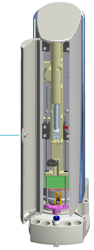
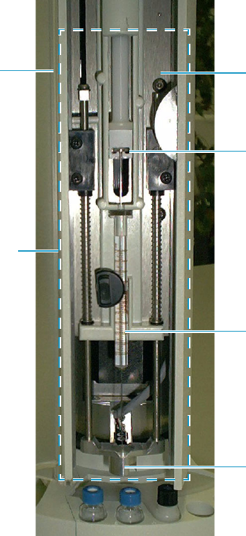
Injection Assembly
The injection assembly consists of a sliding plate which supports and guides the vertical
movements of the injection device constituted by the syringe plunger control, the vial
capture device, and the syringe. See Figure 9.
Figure 9. Injection Assembly
The vertical movements of the injection device are controlled by motors housed in the turret.
The travel ends of the movable parts are defined by a series of sensors.
Inside the turret there are also two electronic boards: one for the motors control and one for
the instrument functions control, respectively.
5
Safety Door
Injection Device
Sliding Plate
Syringe Plunger Control
Syringe
Vial Capture Device
2 Sampling Unit
Injection Assembly
Thermo Scientific AI 1310/AS 1310 Sampling System - User Guide 15
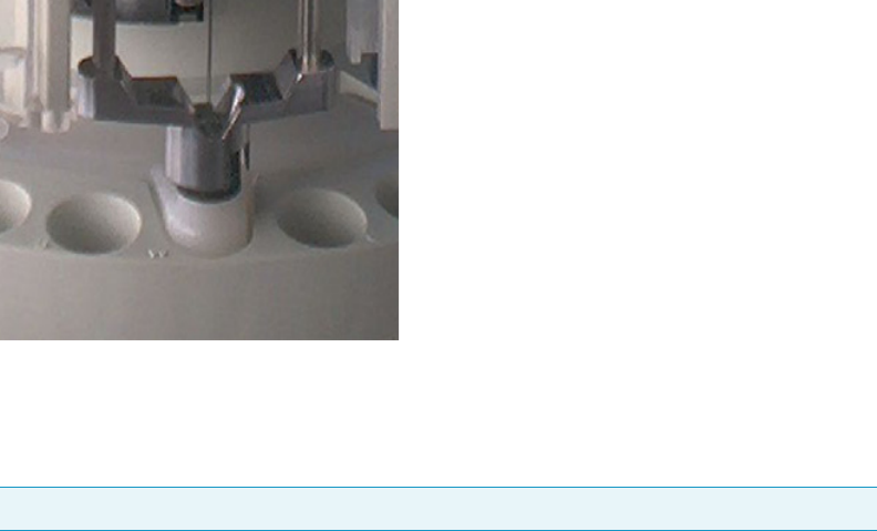
Vial Capture Device
The vial capture device is the lower part of the injection device. See Figure 10.
The functions of this device are:
• to guide the syringe needle
• to acknowledge the vial presence
• to acknowledge the injector presence
Figure 10. Vial Capture Device
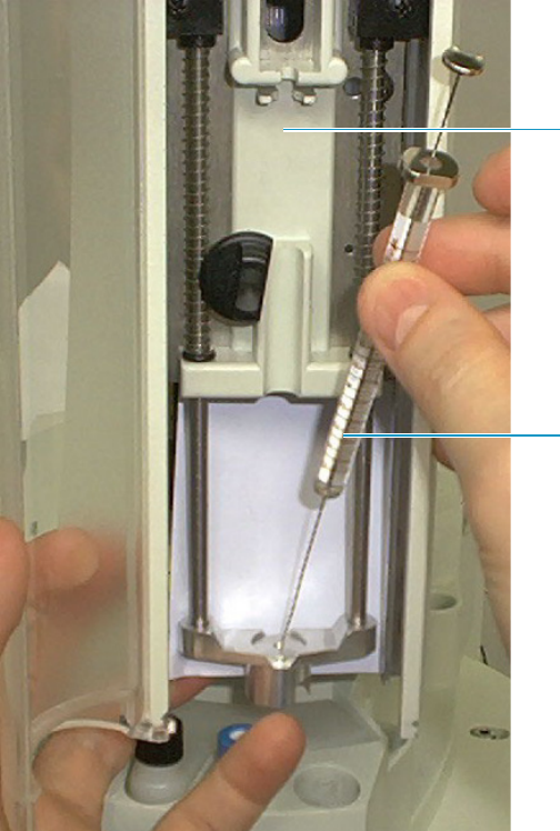
Syringe
The standard syringe has 10 μL capacity with 50 mm needle length.
A thorough washing of the syringe can be done thanks to the possibility of using up to four
solvents. See Washing and Waste Tray.
To install or replace the syringe, please see the Chapter 3, “Installation,” and the Chapter 5,
“Maintenance.”
Figure 11 shows the syringe housing.
Note 5 and 0.5 μL syringes are optionally available.
2 Sampling Unit
Injection Assembly
16 AI 1310/AS 1310 Sampling System - User Guide Thermo Scientific
Figure 11. Syringe Housing
Turret Movements
The sequence of the turret movements allows the sampler to perform the following functions:
•Sample drawing — The turret positions itself on the selected vial, housed in the sample
tray, to allow the syringe to draw the sample it contains.
•Sample injection — The turret positions itself on the injector to perform the sample
injection.
•Syringe washing — The turret positions itself on the solvents vials for the syringe
washing. The solvent is automatically withdrawn and discharged into the waste container.
Syringe Housing
Syringe
2 Sampling Unit
Washing and Waste Tray
Thermo Scientific AI 1310/AS 1310 Sampling System - User Guide 17
Washing and Waste Tray
The washing and waste tray can contain up to four 4 mL vials and a 50 mL plastic container.
See Figure 12.
Figure 12. Washing and Waste Tray
The vials contain the solvent (or the solvents) necessary for the syringe washing, which can
take place both before and after the injection. The washing solvent is then collected in the
waste container.
The four vials containing solvents for the syringe washing are introduced into the appropriate
seats A, B and C, D, respectively on the left and on the right of the WASTE container.
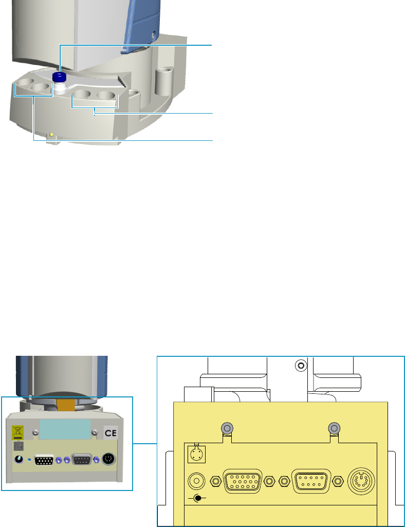
Back of the Sampling Unit
The back side of the sampling unit includes the following components. See Figure 13:
Figure 13. Back of the Sampling Unit
Waste Container
Vials Position for Solvent
C and D
Vials Position for Solvent
A and B
24 Vdc
-+
TRAY
TWIN
SYNC RS 232 GC
2 Sampling Unit
Sample Trays
18 AI 1310/AS 1310 Sampling System - User Guide Thermo Scientific
•Jack marked 24 Vdc for the instrument power supply through the external portable
feeder.
• 15-pin female connector (double density) marked TRAY for the communication between
the sampling unit and the motor actuating the hub positioned on the supporting plate of
the 105-position or 155-position sample tray.
• 9-pin female connector marked RS232 for the communication between the sampler and
the GC (connector marked AUTOSAMPLER) through a proper cable.
• 6-pin female connector marked GC for connecting the sampler to the GC (connector
marked SAMPLER SIGNAL) through the proper cable.
• 4-pin male connector marked TWIN SYNC for the synchronism between two
AI 1310/AS 1310 installed in Gemini configuration through the proper cable.
Sample Trays
The AI 1310/AS 1310 can accept three types of sample trays which are accommodated in one
of the two side housings on the base. The type of sample tray accessory installed on the
instrument (8, 105, or 155 positions) is automatically acknowledged by the sampler when
powered on determining the instrument configuration.
• AI 1310 uses the 8-position sample tray
• AS 1310 uses the 105-position or the 155-position sample tray
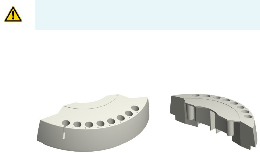
8-Position Sample Tray
The 8-position tray, see Figure 14, consists of a fixed arc-shaped support and can contain up
to 8 vials numbered 1 to 8. The slot present on the tray determines the position 1 and allows
to inspect the level of the liquid contained in the vial.
Figure 14. 8-position Sample Tray
CAUTION The 105-position and the 155-position sample tray require the use of the own
dedicated supporting plate.
2 Sampling Unit
Sample Trays
Thermo Scientific AI 1310/AS 1310 Sampling System - User Guide 19
105-Position Sample Tray Assembly
The assembly consists of a dedicated supporting plate provided with a hub and a 105-position
removable sample tray. See Figure 15.
The rotation of the tray is accomplished by a motor, located under the supporting plate,
which actuates the hub thanks to suitable commands coming from the sampling unit via an
interfacing cable.
An optical sensor defines the rotation travel end and the vial position.
Figure 15. Supporting Plate and 105-Position Sample Tray
The tray can contain up to 105 vials numbered 01 to 105 arranged on three circular rows.
•Vials 01 to 40 are placed into the external row.
•Vials 41 to 80 are placed into the middle row.
•Vials 81 to 105 are placed into the internal row.
155-Position Sample Tray Assembly
The assembly consists of a dedicated supporting plate provided with a hub and a 155-position
removable sample tray. See Figure 16.
The rotation of the tray is accomplished by a motor, located under the supporting plate,
which actuates the hub thanks to suitable commands coming from the sampling unit via an
interfacing cable.
An optical sensor defines the rotation travel end and the vial position.
105-position Sample Tray
Supporting Plate for 105-position Sample Tray
Hub
2 Sampling Unit
Centering Plate
20 AI 1310/AS 1310 Sampling System - User Guide Thermo Scientific
Figure 16. Supporting Plate and 155-Position Sample Tray
The tray can contain up to 155 vials numbered 01 to 155 arranged on three circular rows.
•Vials 01 to 60 are placed into the external row.
•Vials 61 to 110 are placed into the middle row.
•Vials 111 to 155 are placed into the internal row.
Vials
Vials of 0.3 and 2 mL capacity can be used.
The 0.3 mL vial is exactly the same as the 2 mL vial, provided inside with a 0.3 mL calibrated
insert.
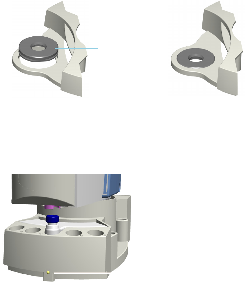
Centering Plate
The centering plate consists of a plate provided with circular guides to center the sampling
unit on the injector nut.
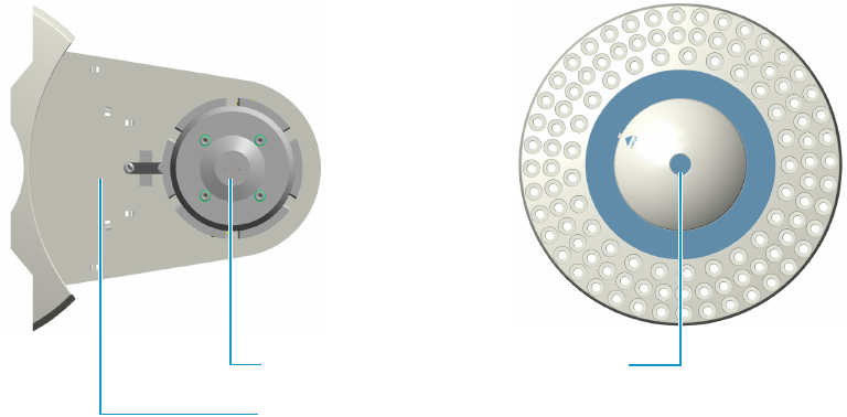
Centering Plate for TRACE 1300/TRACE 1310
The centering plate is provided with two circular guides to center the sampling unit on the
SSL, SSLBKF, PTV and PTVBKF injector nuts.
155-position Sample Tray
Supporting Plate for 155-position Sample Tray
Hub
CAUTION Vials must be accurately closed using appropriate septa and ring nuts.
Septa must be those recommended by Thermo Fisher Scientific. The use of septa with
different characteristics might damage or bend the syringe needle.
During the vials preparation, it is recommended to comply with applicable safety
regulations, specially as far as the conditions of the workplace ventilation are concerned.
2 Sampling Unit
Centering Plate
Thermo Scientific AI 1310/AS 1310 Sampling System - User Guide 21
• To center the sampling unit on the SSL or SSLBKF injector nut, use the circular guide for
SSL only. See Figure 17.
• To center the sampling unit on the PTV or PTVBKF injector nut, use the circular guide
for PTV only. See Figure 18.
Figure 17. Circular Guide for SSL and SSLBKF
Figure 18. Circular Guide for PTV and PTVBKF
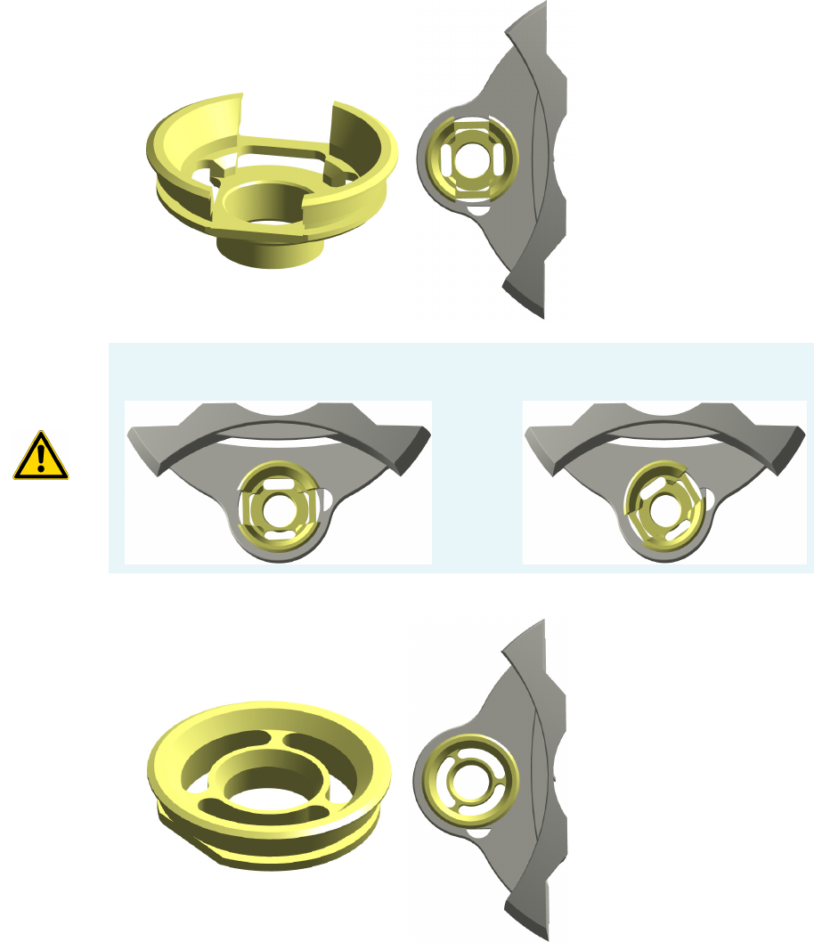
CAUTION The circular guide for SSL and SSLBKF placed in the centering plate must be
aligned as shown below:
CORRECT WRONG
2 Sampling Unit
Status LED
22 AI 1310/AS 1310 Sampling System - User Guide Thermo Scientific
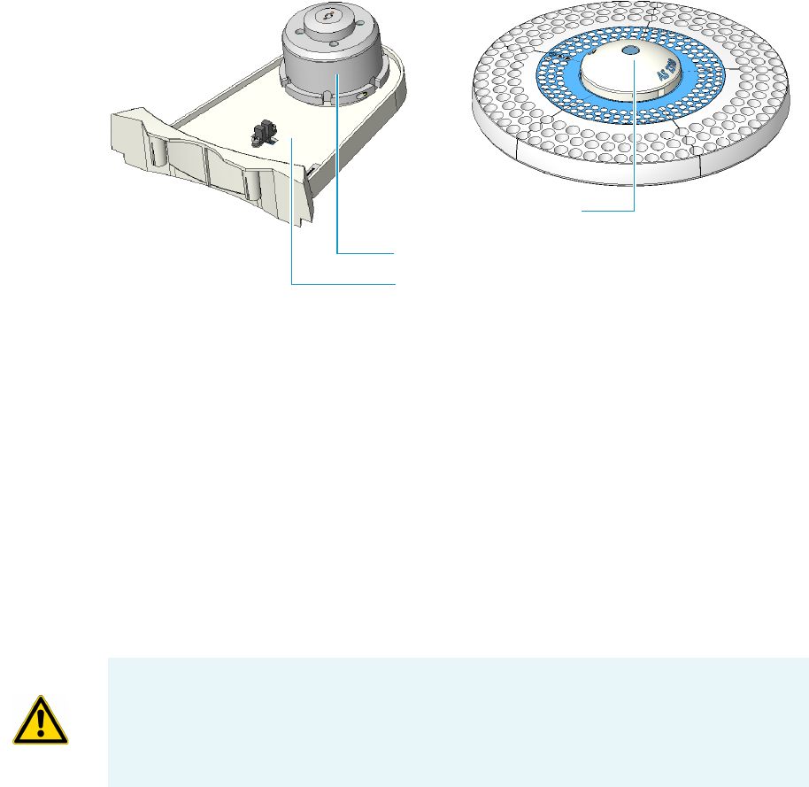
Centering Plate for TRACE GC Ultra and FOCUS GC
Two types of centering plates are available with the GC according to the injector mounted.
• A standard centering plate to center the sampling unit on the SSL, PKD and PPKD
injector nut. This centering plate is used also with the FOCUS GC.
• A centering plate to center the sampling unit on the PTV injector nut. It is recognized by
a circular slot present on the circular guide. This centering plate is not used with the
FOCUS GC.
Figure 19. Centering Plate for TRACE GC Ultra and FOCUS GC
Status LED
The status LED, located on the front side of the sampling unit, see Figure 20, provides the
operator with indications on the instrument operating conditions showing a continuous or
intermittent light. See Table 2 for details.
Figure 20. The Status LED
Circular Guide
Status LED

2 Sampling Unit
Status LED
Thermo Scientific AI 1310/AS 1310 Sampling System - User Guide 23
Buzzer
Two beep monotone; 0.5 seconds ON, 0.5 seconds OFF, 0.5 seconds ON indicates that the
start signal is received.
Five consecutive beep, 1 second with interval of 0.5 seconds OFF in case of error condition.
Table 2. Status LED Conditions
Condition LED
St-by Lit with continuous green light
Position zeroing, sample
preparation, washing,
injection
Intermittent green light; 0.5 seconds ON, 0.5 seconds OFF
Run (waiting GC Ready) Intermittent green-orange lights; 0.5 seconds green, 0.5 seconds
orange
Firmware upload Intermittent orange light; 0.5 seconds ON, 0.5 seconds OFF
Error Lit with continuous orange light

Thermo Scientific AI 1310/AS 1310 Sampling System - User Guide 25
3
Installation
This chapter contains the instructions for the installation of the AI 1310/AS 1310 on the
TRACE 1300/TRACE 1310, TRACE GC Ultra, and FOCUS GC gas chromatographs, the
syringe, and the electrical connections with the different units of the gas chromatographic
system.
Contents
•Who Performs the Installation
•Electrical Requirements
•How to Lift and Carry the Sampling Unit
•Sampling System Support
•Installing the Sampling System Support on the TRACE 1300/1310 GC
•Installing the Sampling System Support on the TRACE GC Ultra
•Installing the Sampling System Support on the FOCUS GC
•Installation of the AI 1310/AS 1310 on the GC
3 Installation
Who Performs the Installation
26 AI 1310/AS 1310 Sampling System - User Guide Thermo Scientific
Who Performs the Installation
The AI 1310/AS 1310 is installed by authorized Thermo Fisher Scientific field service
engineers (FSE), who will check its correct operation. For more details, please contact
Thermo Fisher Scientific local representatives. Should the instrument not be installed by
Thermo Fisher Scientific personnel, please strictly adhere to the following instructions.
Electrical Requirements
The instrument must be electrically supplied as indicated in the “Technical Specifications” on
page 8.
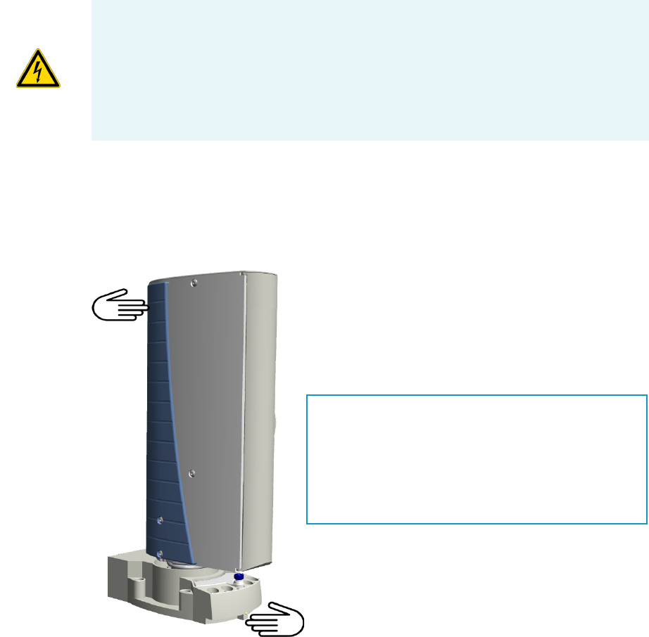
How to Lift and Carry the Sampling Unit
The AI 1310/AS 1310 must be lifted and carried by hand. See Figure 21.
Figure 21. How to lift and carry the Sampling Unit
CAUTION The power line and the connections between the instruments must maintain
good electrical grounding. Poor grounding represents a danger for the operator and may
seriously affect the instrument performance.
Do not connect the AI 1310/AS 1310 to lines feeding devices of a heavy duty nature, such
as motors, UV lamps, refrigerators and other devices that can generate disturbances.
Pay attention not to leave any cable connecting the sampling unit and the
chromatographic system or the power cord close to the GC hot air vents.
ATTENTION:
Before moving the sampling unit, make sure that the 105- or
155-position sample tray is not installed on the sampling
system.
If yes, remove the sampler tray and its supporting plate from the
unit. Reinstall the sampler tray only after the sampling unit has
been properly installed on the GC.

3 Installation
Sampling System Support
Thermo Scientific AI 1310/AS 1310 Sampling System - User Guide 27
Sampling System Support
The AI 1310/AS 1310 is installed on the GC using the appropriate support provided.
According to your GC, see the following sections:
•“Sampling System Support for TRACE 1300/TRACE 1310” on page 27
•“Sampling System Support for TRACE GC Ultra” on page 30
•“Sampling System Support for FOCUS GC” on page 32
Sampling System Support for TRACE 1300/TRACE 1310
The AI 1310/AS 1310 can be installed only on the right side of the GC on the front or back
injector module or on both when in Gemini configuration by using the proper sampling
system support.
The sampling unit support consists of a bottom and a top plates.
1. The bottom plate can be L-shape (see both front/back installation) or double (see
Gemini installation). The plate is provided with a series of holes for the corresponding
fixing screws and must be fixed on the GC.
2. The movable top plate is mounted over the bottom plate and it is provided with a guide
pivot for the accommodation and centering of the sampling unit. The movable top plate
can slides over the bottom plate through a sliding slot and a retainer.
This allows moving away the injection device of the sampling unit from the injector
module when the latter will require maintenance.
To use the proper sampling system support on the TRACE 1300/TRACE 1310 see the
following sections:
•“Support for the Installation on the Front/Back Injector Module” on page 28
•“Support for the Installation in Gemini Configuration” on page 29
•“Support for the Installation When a TSQ Quantum Mass Spectrometer is Coupled with
the GC” on page 29
Note The FOCUS GC MS Version, may accept the AI 1310/AS 1310 also on the left
side. Please refer to “Assembling of the Sampling System Support on FOCUS GC MS
Version” on page 45.
To reduce the FOCUS GC working area, the AS 1310 may be installed as described in
“Space Saving Installation” on page 46.
Note After the installation of the sampling unit on the proper sampling system
support, it is possible locking its plates if desired.
3 Installation
Sampling System Support
28 AI 1310/AS 1310 Sampling System - User Guide Thermo Scientific
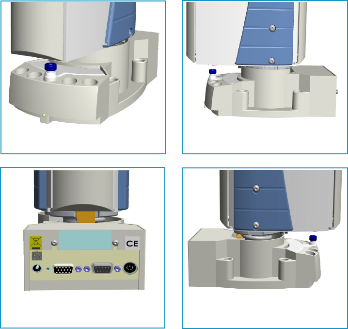
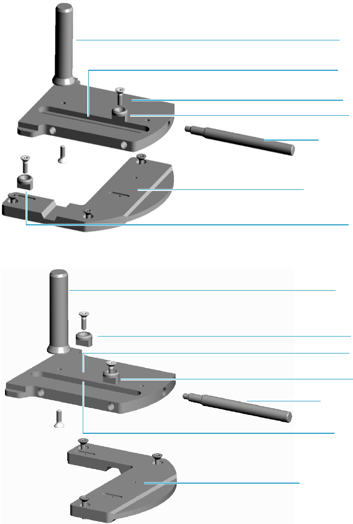
Support for the Installation on the Front/Back Injector Module
The same sampling unit support is used. The L-shape bottom plate must be oriented
accordingly before fixing it on the GC. See Figure 22 and Figure 23.
Figure 22. Support Oriented for the Installation on the Front Injector Module
Figure 23. Support Oriented for the Installation on the Back Injector Module
Guide Pivot
Retainer
Sliding Slot
L-shape Bottom Plate
(Oriented on Front)
Retainer
Top Plate
Support Pin
(Only for AS 1310)
Sliding Slot
L-shape Bottom Plate
(Oriented on Back)
Retainer
Retainer
Support Pin
(Only for AS 1310)
Top Plate
Guide Pivot
3 Installation
Sampling System Support
Thermo Scientific AI 1310/AS 1310 Sampling System - User Guide 29
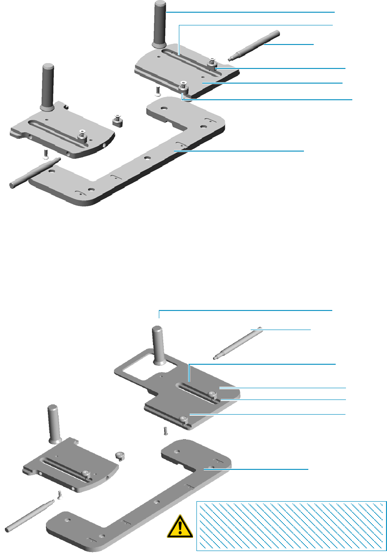
Support for the Installation in Gemini Configuration
This configuration uses a dedicated double bottom plate and two top plates. See Figure 24.
Figure 24. Support for the Installation in Gemini Configuration
Support for the Installation When a TSQ Quantum Mass Spectrometer is Coupled
with the GC
This configuration uses a dedicated double bottom plate and two top plates. See Figure 25.
Figure 25. Support for the Installation when a TSQ Quantum is Coupled with the GC
Double Bottom Plate
Retainer
Sliding Slot
Guide Pivot
Top Plate
Support Pin
(Only for AS 1310)
Retainer
Double Bottom Plate
Retainer
Sliding Slot
Guide Pivot
Top Plate
Support Pin
(Only for AS 1310)
Retainer
Top Plate Back not for
155-position Sample Tray
CAUTION: The AS 1310 equipped with the
155-position sample tray can ONLY be mounted on
the front injector module. The back top plate is not
provided with the 155-position sample tray.
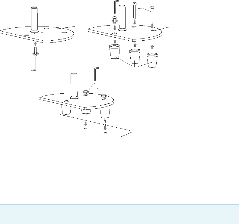
3 Installation
Sampling System Support
30 AI 1310/AS 1310 Sampling System - User Guide Thermo Scientific
Sampling System Support for TRACE GC Ultra
The support for the installation of the AI 1310/AS 1310 on right or left side of the TRACE
GC Ultra consists of a semi-circular plate resting on three spacers non adjustable in height; see
Figure 26. The top surface of the plate is provided with two slots for corresponding fixing
screws. In the middle the guide pivot allows the accommodation and centering of the
sampling unit.
Figure 26. Support for the Installation of the AI 1310/AS 1310 on the TRACE GC Ultra
The AI 1310/AS 1310 is installed on the right or left side of the TRACE GC Ultra.
Installation on the Right Side
When installing the AI 1310/AS 1310 on the TRACE GC Ultra right side, the support is
directly mounted on the GC top panel previous installation of the spacer inside the GC. See
Figure 26.
Installation on the Left Side
When installing the AI 1310/AS 1310 on the TRACE GC Ultra left side, before to mount
the sampling system support, the support bracket must be placed and fixed on the GC top
cover. See Figure 27.
Note For details about the installation of the spacer, see the section “Installing the Spacer
Inside the GC” on page 42 for details.
1
2
3
5
4
1 = Semi-circular Plate
2 = Guide Pivot
3 = Spacers
4 = Slots
5 = Fixing Screws
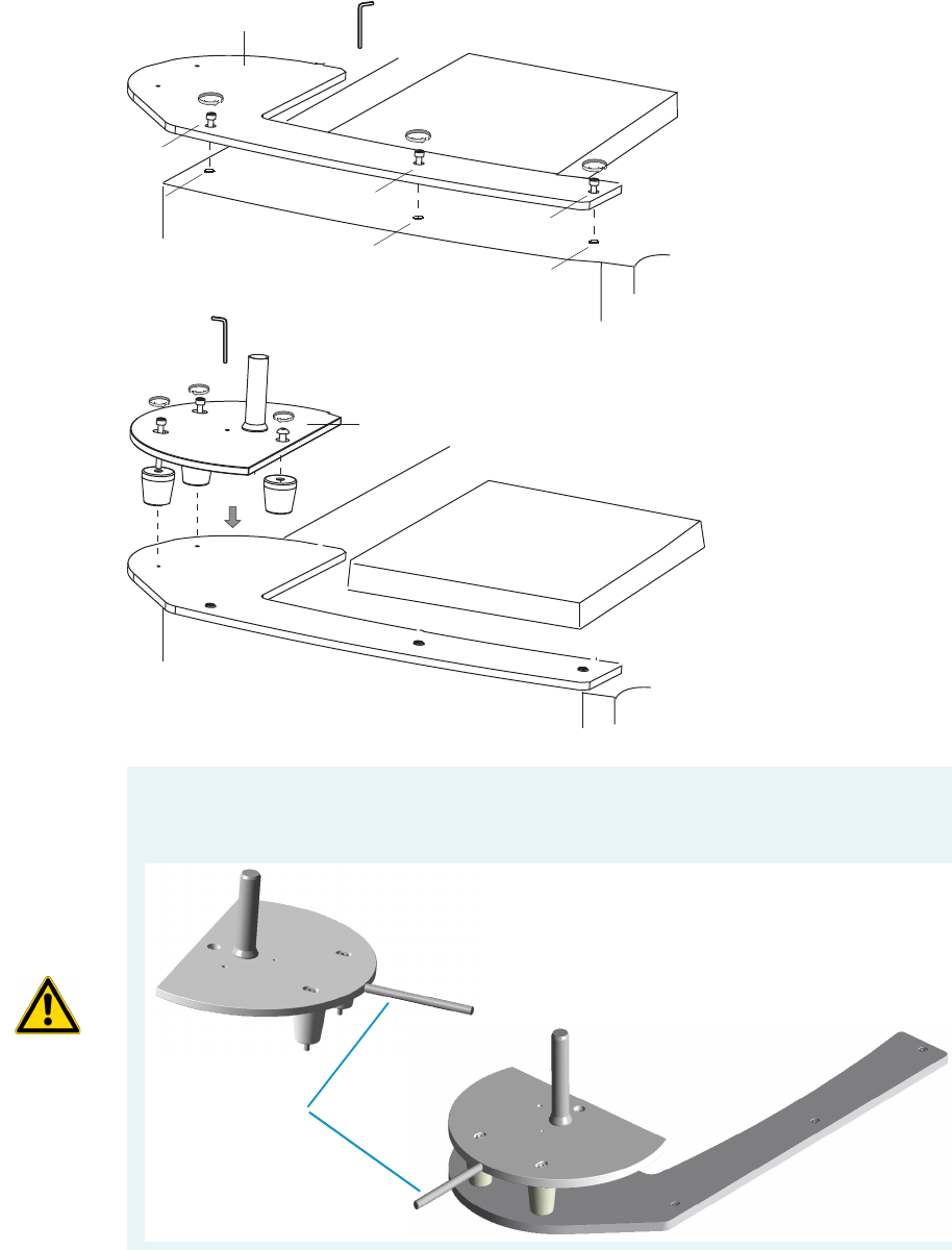
3 Installation
Sampling System Support
Thermo Scientific AI 1310/AS 1310 Sampling System - User Guide 31
Figure 27. Bracket for the Installation of the AI 1310/AS 1310 Support
1
3
3
3
2
22
4
1 = Support Bracket
2 = Holes on the TRACE GC Ultra Top Cover
3 = Fixing Screws
4 = Sampling Unit Support
CAUTION If you are installing the sampling system support for the installation of an
AS1310 equipped with the 155-position sample tray, make sure that the support pin is
screwed into the dedicated hole on the sampling system support. See the images below:
Support Pin
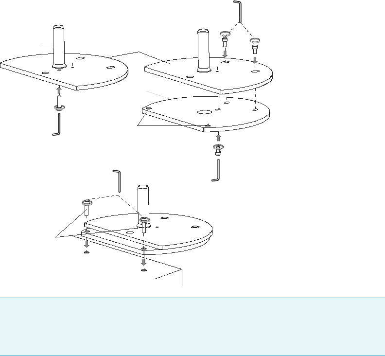
3 Installation
Sampling System Support
32 AI 1310/AS 1310 Sampling System - User Guide Thermo Scientific
Sampling System Support for FOCUS GC
The support for the installation of the AI 1310/AS 1310 on the right side of the FOCUS GC,
consists of two semi-circular plates. See Figure 28. The top surface of the upper plate is
provided with two slots for corresponding fixing screws. In the middle the guide pivot allows
the accommodation and centering of the sampling unit.
Figure 28. Support for the Installation of the AI 1310/AS 1310 on the FOCUS GC
References for the Installation
For the installation of the AI 1310/AS 1310, see the following sections:
•“Installing the Sampling System Support on the TRACE 1300/1310 GC” on page 33
•“Installing the Sampling System Support on the TRACE GC Ultra” on page 42
•“Installing the Sampling System Support on the FOCUS GC” on page 44
•“Installation of the AI 1310/AS 1310 on the GC” on page 48
Note The FOCUS GC MS Version, may accept the AI 1310/AS 1310 also on the left
side. See the section “Assembling of the Sampling System Support on FOCUS GC MS
Version” on page 45. To reduce the FOCUS GC working area, the AS 1310 may be
installed as described in the section “Space Saving Installation” on page 46.
1
2
3
4
5
1 = Upper Semi-circular Plate
2 = Lower Semi-circular Plate
3 = Guide Pivot
4 = Slots
5 = Fixing Screws
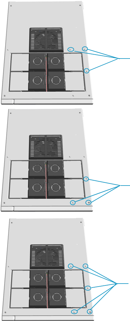
3 Installation
Installing the Sampling System Support on the TRACE 1300/1310 GC
Thermo Scientific AI 1310/AS 1310 Sampling System - User Guide 33
Installing the Sampling System Support on the TRACE 1300/1310 GC
To install the sampling system support on the TRACE 1300/TRACE 1310, please refer to the
instructions reported below. Figure shows the installation holes on the top of the GC.
Figure 29. Sampler Unit Support Installation Holes
Installation Holes for the AI 1310/AS 1310
on the Front Injector Module.
See Assembling of the Sampling System
Support on the Back Injector Module
Installation Holes for the AI 1310/AS 1310
on the Back Injector Module.
See Assembling of the Sampling System
Support on the Front Injector Module
Installation Holes for Two AI 1310/AS 1310 in
Gemini Configuration.
See Assembling of the Sampling System
Support for the Gemini Configuration
Installation Holes for One or Two
AI 1310/AS 1310 when a TSQ Quantum Mass
Spectrometer is Coupled with the GC
See Assembling of the Sampling System
Support When a TSQ Quantum is Coupled
with the GC
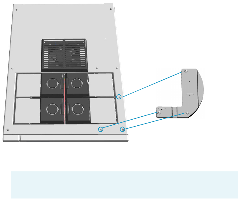
3 Installation
Installing the Sampling System Support on the TRACE 1300/1310 GC
34 AI 1310/AS 1310 Sampling System - User Guide Thermo Scientific
Assembling of the Sampling System Support on the Front Injector Module
The following is the description of how to mount the sampling system support on the front
injector module of the TRACE 1300/TRACE 1310. See Figure 30 and Figure 31.
Figure 30. Assembling on the Front Injector Module (1)
1. Remove from the GC top cover the three plastic caps covering the corresponding fixing
holes. See A, B, and C.
2. Orient the L-shape bottom plate to align the three installation holes to the corresponding
fixing holes located on the GC top.
3. Insert the provided fixing screws into the holes present on the L-shape bottom plate.
Note In comparison with the installation on the back injector module, the
installation on the front injector module requires to upturn the L-shape bottom plate
before fixing it on the GC.
AB
C
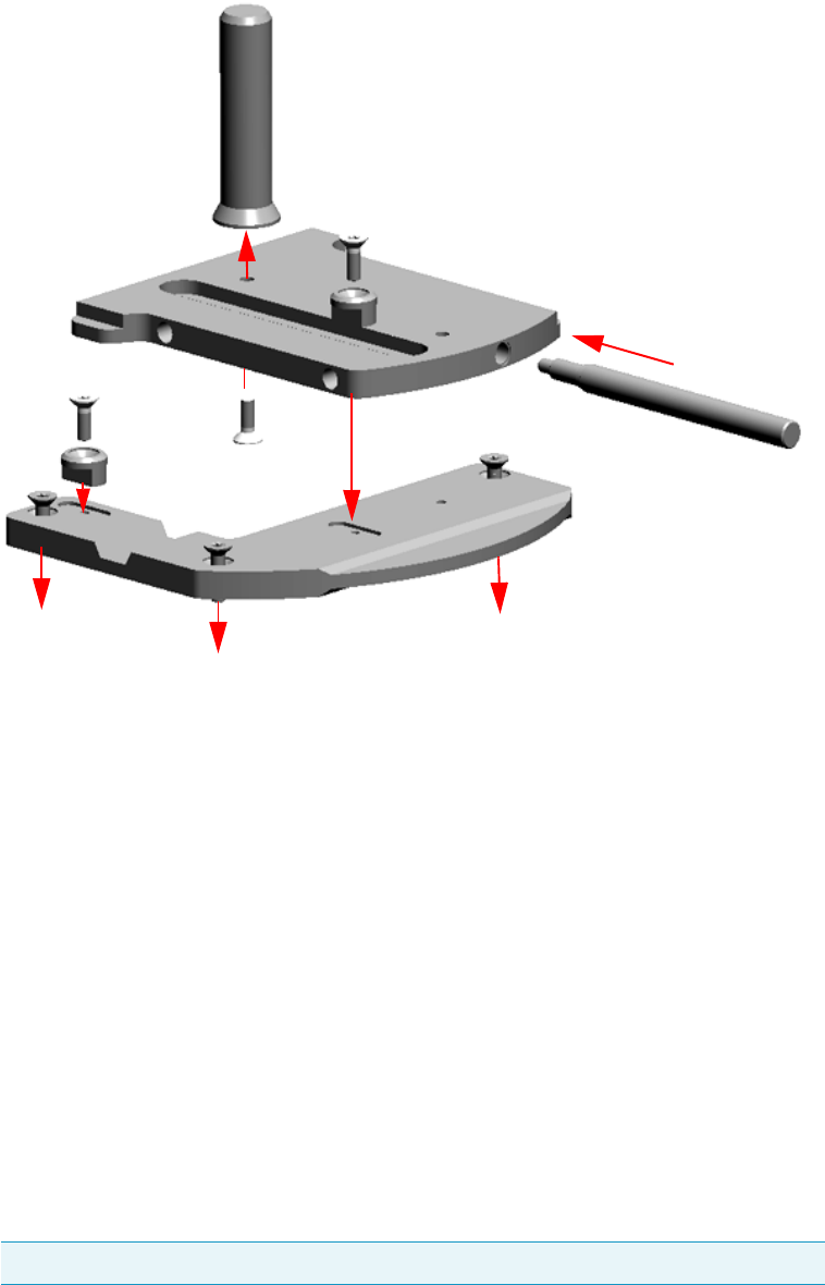
3 Installation
Installing the Sampling System Support on the TRACE 1300/1310 GC
Thermo Scientific AI 1310/AS 1310 Sampling System - User Guide 35
Figure 31. Assembling on the Front Injector Module (2)
4. Place the L-shape bottom plate on the GC top and guide the three fixing screws into the
corresponding fixing holes. See A’, B’, and C’. Tighten the three fixing screws.
5. If not already done, mount and fix the guide pivot on the top plate by using the proper
fixing screw.
6. Place the top plate over the L-shape bottom plate.
7. Guide the retainer and its fixing screw into the sliding slot present on the top plate.
8. Align the retainer fixing screw into the corresponding fixing hole located on the L-shape
bottom plate.
9. Tighten the retaining fixing screw.
10. Clamp the two plates guiding the second retainer and its fixing screw into the hole
provided on the L-shape bottom plate.
11. If you must install an AS 1310, screw the support pin into the dedicated hole on the top
plate.
Note The support pin is NOT required if you must install an AI 1310.
A’ C’
B’
Guide Pivot
Retainer
Top Plate
Support Pin
L-shape Bottom Plate
Retainer
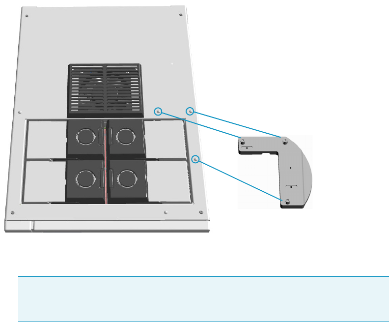
3 Installation
Installing the Sampling System Support on the TRACE 1300/1310 GC
36 AI 1310/AS 1310 Sampling System - User Guide Thermo Scientific
Assembling of the Sampling System Support on the Back Injector Module
The following is the description of how to mount the sampling system support on the back
injector module of the TRACE 1300/TRACE 1310. See Figure 32 and Figure 33.
Figure 32. Assembling on the Back Injector Module (1)
1. Remove from the GC top cover the three plastic caps covering the corresponding fixing
holes. See A, B, and C.
2. Orient the L-shape bottom plate to align the three installation holes to the corresponding
fixing holes located on the GC top.
3. Insert the provided fixing screws into the holes present on the L-shape bottom plate.
Note In comparison with the installation on the front injector module, the
installation on the back injector module requires to upturn the L-shape bottom plate
before fixing it on the GC.
AB
C
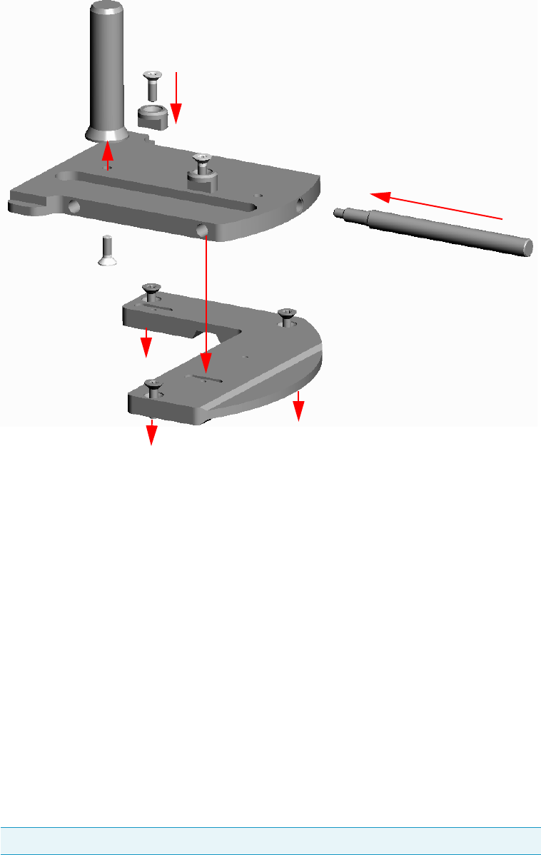
3 Installation
Installing the Sampling System Support on the TRACE 1300/1310 GC
Thermo Scientific AI 1310/AS 1310 Sampling System - User Guide 37
Figure 33. Assembling on the Back Injector Module (2)
4. Place the L-shape bottom plate on the GC top and guide the three fixing screws into the
corresponding fixing holes. See A’, B’, and C’. Tighten the three fixing screws.
5. If not already done, mount and fix the guide pivot on the top plate by using the proper
fixing screw.
6. Place the top plate over the L-shape bottom plate.
7. Guide the retainer and its fixing screw into the sliding slot present on the top plate.
8. Align the retainer fixing screw into the corresponding fixing hole located on the L-shape
bottom plate.
9. Tighten the retaining fixing screw.
10. Clamp the two plates guiding the second retainer and its fixing screw into the hole
provided on the L-shape bottom plate.
11. If you must install an AS 1310, screw the support pin into the dedicated hole of the top
plate.
Note The support pin is NOT required if you must install an AI 1310.
Guide Pivot
Retainer
Retainer
Support Pin
L-shape Bottom Plate
C’
A’
B’
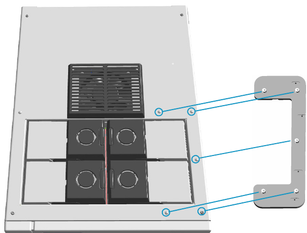
3 Installation
Installing the Sampling System Support on the TRACE 1300/1310 GC
38 AI 1310/AS 1310 Sampling System - User Guide Thermo Scientific
Assembling of the Sampling System Support for the Gemini Configuration
The following is the description of how to mount the sampling system support on the
TRACE 1300/TRACE 1310 for the installation of two AI 1310/AS 1310 sampling systems
in Gemini configuration. See Figure 34 and Figure 35.
Figure 34. Assembling In Gemini Configuration (1)
1. Remove from the GC top cover the five plastic caps covering the corresponding fixing
holes. See A, B, C, D, and E.
2. Insert the provided fixing screws into the five holes present on the double bottom plate.
C
B
E
D
A
Double Bottom Plate

3 Installation
Installing the Sampling System Support on the TRACE 1300/1310 GC
Thermo Scientific AI 1310/AS 1310 Sampling System - User Guide 39
Figure 35. Assembling In Gemini Configuration (2)
3. Guide the five fixing screws into the corresponding fixing holes located on the GC top.
See A’, B’, C’, D’, and E’. Tighten the five fixing screws.
4. If not already done, mount and fix the guide pivot on each top plate by using the proper
fixing screw.
5. Place the two top plates over the double bottom plate.
6. Guide each retainer and its fixing screw into the sliding slot present on each top plate.
7. Align each retainer fixing screw into the corresponding fixing hole located on the double
bottom plate.
8. Tighten each retainer fixing screw to block the corresponding upper plate to the double
bottom plate.
9. Clamp the corresponding plates guiding the second retainer and its fixing screw into the
hole provided on each L-shape bottom plate.
10. If you must install an AS 1310, screw the support pin into the dedicated hole of each top
plate.
Note The support pin is NOT required if you must install an AI 1310.
Guide Pivot
Double Bottom Plate
C’
A’
B’
E’
D’
Retainer
Top Plate Front
Top Plate Back
Retainer
Retainer
Retainer
Support Pin
Support Pin
Guide Pivot
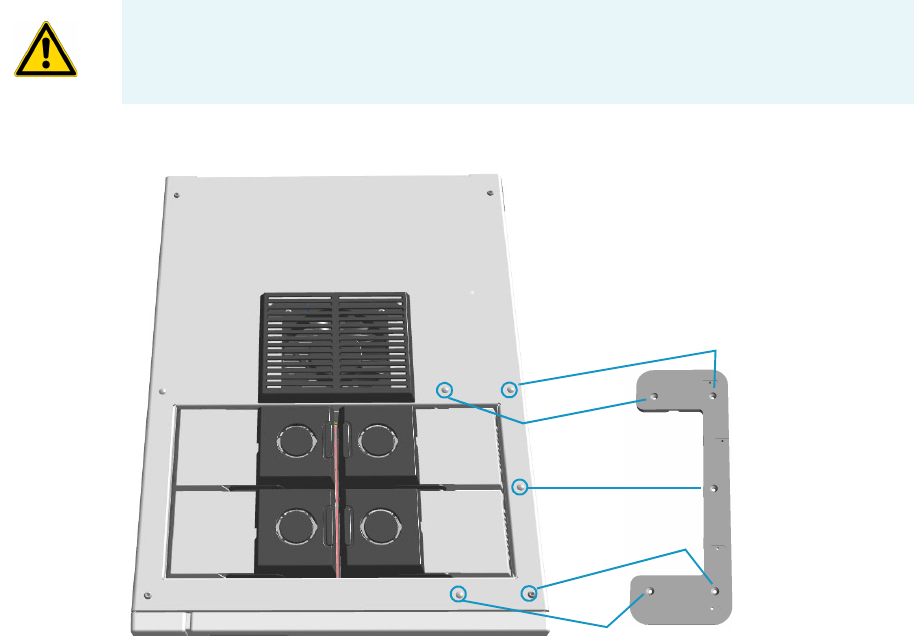
3 Installation
Installing the Sampling System Support on the TRACE 1300/1310 GC
40 AI 1310/AS 1310 Sampling System - User Guide Thermo Scientific
Assembling of the Sampling System Support When a TSQ Quantum is Coupled with
the GC
The following is the description of how to mount the sampling system support on the
TRACE 1300/TRACE 1310 for the installation of one or two AI 1310/AS 1310 sampling
systems when a TSQ Quantum mass spectrometer is coupled with the GC. See Figure 36 and
Figure 37.
Figure 36. Assembling (1)
1. Remove from the GC top cover the five plastic caps covering the corresponding fixing
holes. See A, B, C, D, and E.
2. Insert the provided fixing screws into the five holes present on the double bottom plate.
CAUTION The AS 1310 equipped with the 155-position sample tray can ONLY be
mounted on the front injector module. The back top plate is not provided with the
155-position sample tray.
A
C
B
E
D
Double Bottom Plate
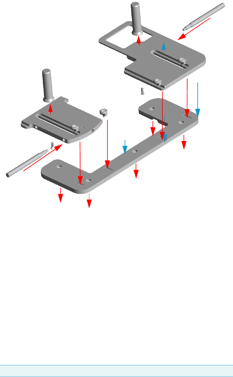
3 Installation
Installing the Sampling System Support on the TRACE 1300/1310 GC
Thermo Scientific AI 1310/AS 1310 Sampling System - User Guide 41
Figure 37. Assembling (2)
3. Guide the five fixing screws into the corresponding fixing holes located on the GC top.
See A’, B’, C’, D’, and E’. Tighten the five fixing screws.
4. If not already done, mount and fix the guide pivot on each top plate by using the proper
fixing screw.
5. Place the two top plates over the double bottom plate. Guide each retainer and its fixing
screw into the sliding slot present on each top plate.
6. Align each retainer fixing screw into the corresponding fixing hole located on the double
bottom plate.
7. Tighten each retainer fixing screw to block the corresponding upper plate to the double
bottom plate.
8. Clamp the corresponding plates guiding the second retainer and its fixing screw into the
hole provided on each L-shape bottom plate.
9. Screw the support pin into the dedicated hole of each top plate.
Note The support pin is NOT required if you must install an AI 1310.
Retainer
Top Plate Front
Support Pin
Double Bottom Plate
Guide Pivot
Guide Pivot
A’ D’
B’
E’
C’
Support Pin
Retainer
Retainer
Top Plate Back not for
155-position Sample Tray
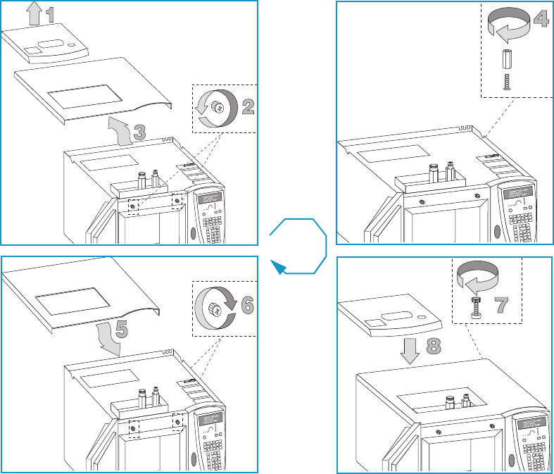
3 Installation
Installing the Sampling System Support on the TRACE GC Ultra
42 AI 1310/AS 1310 Sampling System - User Guide Thermo Scientific
Installing the Sampling System Support on the TRACE GC Ultra
To install the support on the TRACE GC Ultra, please refer to the instructions reported
below. Before installing the sampling system support, the spacer should be installed inside the
GC, then assembly the sampling system support on the GC according to the required
configuration.
•See “Installing the Spacer Inside the GC” on page 42
•See “Assembling of the Sampling System Support on the GC Right Side” on page 43
•See “Assembling of the Sampling System Support on the GC Left Side” on page 44
Installing the Spacer Inside the GC
To installing the spacer should be installed inside the GC proceed as described below. See
Figure 38.
Figure 38. Installation of the Spacer Inside the GC
1. Remove the cover and the collar of the injector and detector compartment.
2. Open the column oven door. Loosen the two knobs located in the upper parts.
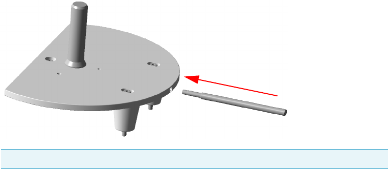
3 Installation
Installing the Sampling System Support on the TRACE GC Ultra
Thermo Scientific AI 1310/AS 1310 Sampling System - User Guide 43
3. Push the cover backwards and remove it.
4. Screw the spacer on the threaded pin.
5. Put the GC cover back in the original position.
6. Tighten the two knobs. Close the column oven door.
7. Mount the spacer fixing Allen screw.
8. Reinstall the cover and the collar of the injector and detector compartment.
Assemble the sampling system support on the GC according to the required configuration.
Assembling of the Sampling System Support on the GC Right Side
The following is the description of how to mount the sampling system support in the default
configuration, i.e. on the right side of the TRACE GC Ultra.
1. Remove from the GC top cover the two plastic caps covering the corresponding fixing
holes.
2. Insert into each slot present on the support the provided fixing screw.
3. Insert each screw into the relevant spacer paying attention to keep its largest surface
turned towards the support base.
4. Holding the spacers in position with your hands, rest the support on the GC top cover,
with their flat side towards the inside.
5. Guide the two fixing screws located on the external spacers into the corresponding fixing
holes.
6. Loosely tighten the screws.
7. If you must install an AS 1310 equipped with the 155-position sampler tray, screw the
support pin into the dedicated hole on the sampling system support.
Note The support pin is NOT required if you must install an AI 1310.
Support Pin
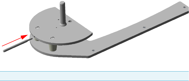
3 Installation
Installing the Sampling System Support on the FOCUS GC
44 AI 1310/AS 1310 Sampling System - User Guide Thermo Scientific
Assembling of the Sampling System Support on the GC Left Side
The following is the description of how to mount the sampling system support on the left
side of the TRACE GC Ultra.
1. Remove from the GC top cover the four plastic caps covering the corresponding fixing
holes.
2. Mount the support bracket on the TRACE GC Ultra and fix by using fixing screws
provided.
3. Insert into each slot present on the support the provided fixing screw.
4. Insert each screw into the relevant spacer paying attention to keep its largest surface
turned towards the support base.
5. Holding the spacers in position with your hands, rest the support on the bracket, with
their flat side towards the inside.
6. Guide the two fixing screws located on the external spacers into the corresponding fixing
holes located on the bracket.
7. Loosely tighten the screws.
8. If you must install an AS 1310 equipped with the 155-position sampler tray, screw the
support pin into the dedicated hole on the sampling system support.
Installing the Sampling System Support on the FOCUS GC
To install the support on the FOCUS GC, please refer to the instructions reported below.
•See “Assembling of the Sampling System Support on the GC right side” on page 45
•See “Assembling of the Sampling System Support on FOCUS GC MS Version” on
page 45
•See “Space Saving Installation” on page 46
Note The support pin is NOT required if you must install an AI 1310.
Support Pin
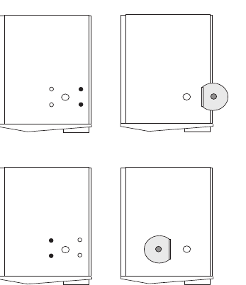
3 Installation
Installing the Sampling System Support on the FOCUS GC
Thermo Scientific AI 1310/AS 1310 Sampling System - User Guide 45
Assembling of the Sampling System Support on the GC right side
The following is the description of how to mount the sampling system support in the default
configuration, i.e. on the right side of the FOCUS GC.
1. Remove from the GC upper cover the two plastic caps covering the corresponding fixing
holes.
2. Insert into each slot present on the support the provided fixing screw.
3. Guide the two fixing screws into the corresponding fixing holes located on the GC upper
panel.
4. Loosely tighten the screws.
Assembling of the Sampling System Support on FOCUS GC MS Version
The installation on the GC left side, instead the conventional installation on the GC right
side, may be carried out to reduce the working area of your FOCUS GC MS Version. Refer to
the Figure 39.
Figure 39. Sampling System Support on the FOCUS GC MS Version (1)
Proceed as follows:
1. Remove from the GC upper cover the two internal plastic caps covering the
corresponding fixing holes. See Figure 40.
A
1
2
1
B
1
4
3
A = Conventional Installation
B = Left Side Installation
1 = Right Side Fixing Hole
2 = Support Positioning
3 = Left Side Fixing Holes
4 = Support Positioning
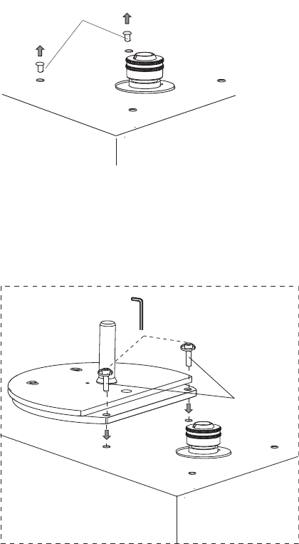
3 Installation
Installing the Sampling System Support on the FOCUS GC
46 AI 1310/AS 1310 Sampling System - User Guide Thermo Scientific
Figure 40. Sampling System Support on the FOCUS GC MS Version (2)
2. Insert the provided fixing screw into each slot present on the support.
3. Guide the two fixing screws into the corresponding fixing holes located on the GC upper
panel. See Figure 41.
Figure 41. Sampling System Support on the FOCUS GC MS Version (3)
4. Loosely tighten the screws.
Space Saving Installation
This type of installation is suggested to reduce the working area of your FOCUS GC
equipped with the AS 1310. This is applicable for example when two or more FOCUS GC
units are to be placed on the same workbench. See Figure 42.
1
1 = Internal Plastic Caps
1
1 = Fixing Screws
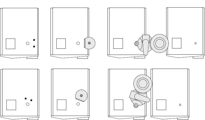
3 Installation
Installing the Sampling System Support on the FOCUS GC
Thermo Scientific AI 1310/AS 1310 Sampling System - User Guide 47
Figure 42. Two or More FOCUS Placed on the Same Workbench
Proceed as follows:
1. Remove from the GC upper cover the two plastic caps covering the corresponding fixing
holes.
2. Insert into each slot present on the support the provided fixing screw.
3. Guide the two fixing screws into the corresponding fixing holes located on the GC upper
panel.
4. Loosely tighten the screws.
A
B
1
2
3
2
1
1
3
4
4
A = Conventional Installation
B = Space Saving Installation
1 = Fixing Screws
2 = Sampling System Support
3 = AS 1310
4 = Second FOCUS GC
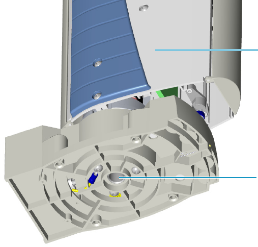
3 Installation
Installation of the AI 1310/AS 1310 on the GC
48 AI 1310/AS 1310 Sampling System - User Guide Thermo Scientific
Installation of the AI 1310/AS 1310 on the GC
To install the AI 1310/AS 1310 on the TRACE 1300/TRACE 1310, TRACE GC Ultra, and
FOCUS GC gas chromatographs, please refer to the instructions reported below:
The procedure includes the following steps:
•“Installation of the Sampling Unit” on page 48
•“Installation of the Syringe” on page 51
•“Electrical Connections” on page 52
•“Instrument Start-up” on page 56
Installation of the Sampling Unit
Proceed as follows:
1. Lift the sampling unit, see Figure 21 on page 26, and insert it into the guide pivot located
on the sampling system support. Introduce the guide pivot into the hole provided on the
bottom of the base. See Figure 43.
Figure 43. Installation of the Sampling Unit
2. Insert the proper centering plate for TRACE GC Ultra or TRACE 1300/TRACE 1310
into its seat of the sampling unit base paying attention that the guide hole, present on the
arm of the centering plate, correctly fits the injector nut. See Figure 44.
Sampling Unit
Hole for the introduction of the
Guide Pivot
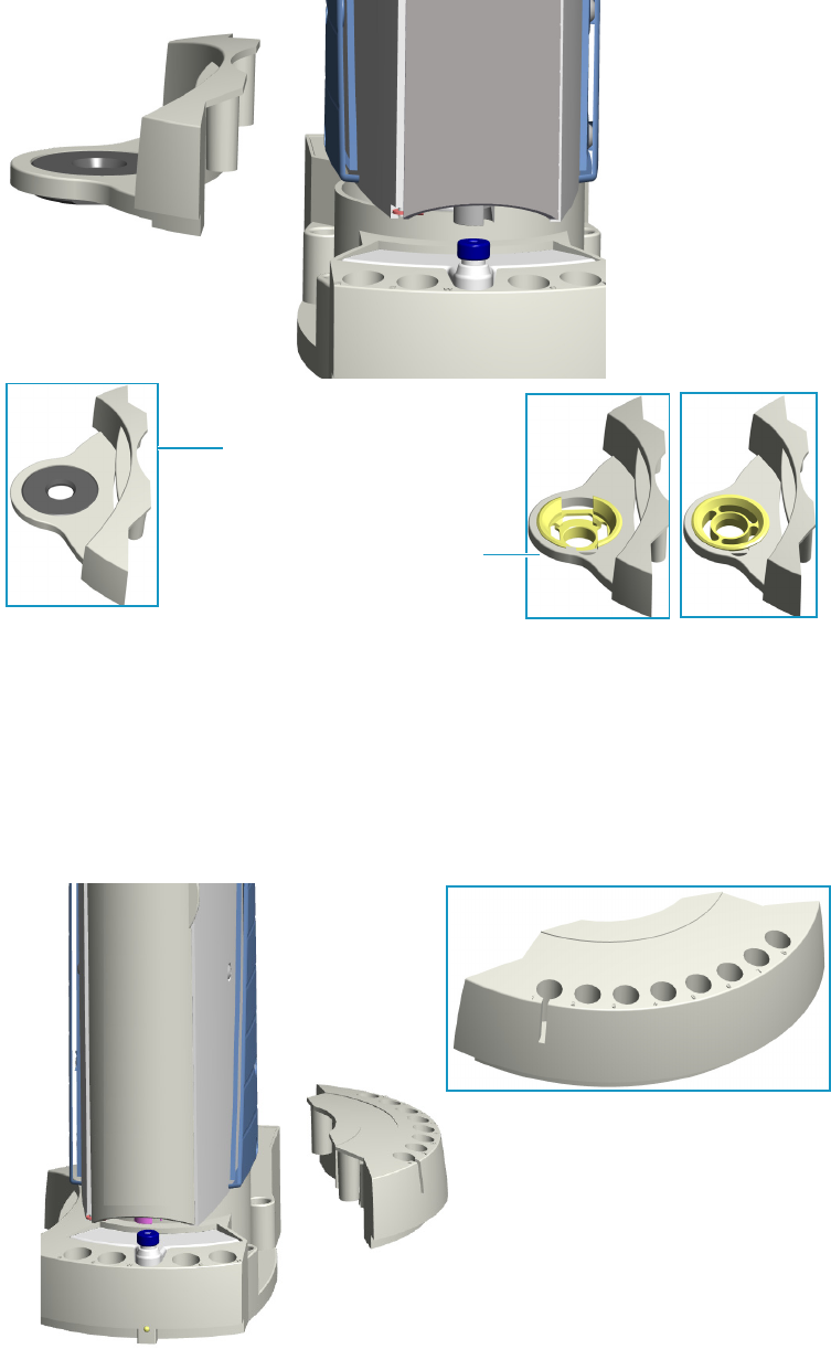
3 Installation
Installation of the AI 1310/AS 1310 on the GC
Thermo Scientific AI 1310/AS 1310 Sampling System - User Guide 49
Figure 44. Centering Plates
3. Check the correct alignment of the sampling system support, then fix it by tightening the
proper fixing screws.
4. Insert the sample tray into the sampling unit base.
•AI 1310 — Insert the 8-position sample tray into the appropriate housing of the
sampling unit base. See Figure 45.
Figure 45. 8-position Sample Tray
Centering Plate for
TRACE GC Ultra
Centering Plate for
TRACE 1300/1310
SSL PTV
8-position Sample Tray
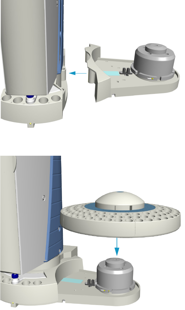
3 Installation
Installation of the AI 1310/AS 1310 on the GC
50 AI 1310/AS 1310 Sampling System - User Guide Thermo Scientific
•AS 1310 — According to the AS 1310 with the 105 or 155-position sample tray,
insert the dedicated support plate into its appropriate housing of the sampling unit
base. Place the sample tray on the hub located on the support. The system will
automatically recognize the sample tray at the instrument power on. See Figure 46.
Figure 46. 105/155-position Sample Tray
Hub
Support Plate for 105-position or 155-position Sample Tray
105-position or 155-position Sample Tray
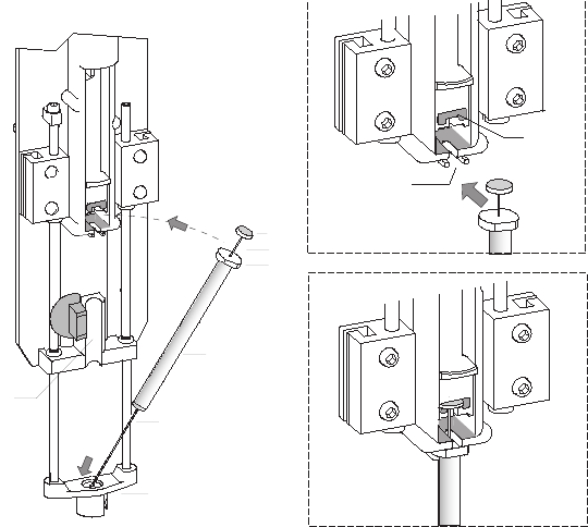
3 Installation
Installation of the AI 1310/AS 1310 on the GC
Thermo Scientific AI 1310/AS 1310 Sampling System - User Guide 51
Installation of the Syringe
To install the syringe follow the instructions reported below.
The installation of the syringe is a simple operation. However, it must be performed with
caution to avoid damages to the syringe needle and ensure an optimal performance of the
injection device.
The standard syringe has 10 μL capacity with 50 mm needle length. 5 and 0.5 μL optional
syringes are optionally available.
1. Open the safety door of the turret.
2. Insert the syringe needle into the vial capture device. See Figure 47.
Figure 47. Syringe Installation (1)
3. Accommodate the syringe body into its seat paying attention to insert simultaneously the
flange and head of the syringe plunger into their relevant guides.
4. Lock the syringe by turning clockwise the lock knob by approximately 180°. See
Figure 48.
5. Close the safety door of the rotating turret.
1
2
3
4
5
6
7
8
9
1 = Syringe Needle
2 = Syringe Body
3 = Flange
4 = Plunger
5 = Plunger Head
6 = Vial Capture Device
7 = Syringe Body Seat
8 = Flange Guide
9 = Plunger Head Guide
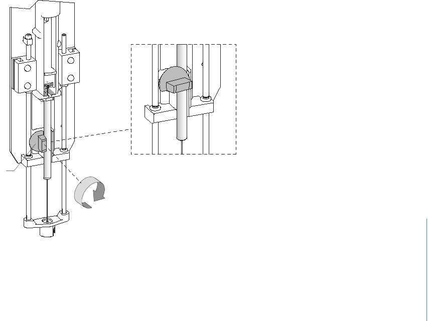
3 Installation
Installation of the AI 1310/AS 1310 on the GC
52 AI 1310/AS 1310 Sampling System - User Guide Thermo Scientific
Figure 48. Syringe Installation (2)
Electrical Connections
The instrument must be powered as indicated in “Technical Specifications” on page 8. Before
performing electrical connections, ensure that the requirements reported in paragraph
“Electrical Requirements” on page 26 have been fulfilled.
This section provides the instruction to connect the AI 1310/AS 1310, in standard o Gemini
configuration, to a TRACE 1300/TRACE 1310, TRACE GC Ultra, or FOCUS GC.
Refer to:
•“Standard Configuration” on page 52
•“Gemini Configuration” on page 53
Standard Configuration
Proceed as follows:
1. By using the cable provided, connect the 6-pin female connector marked GC located on
the sampling unit back side and the connector, located on the back panel of the GC,
marked:
•AUTOSAMPLER HANDSHAKE in the case of TRACE 1300/TRACE 1310.
•SAMPLER SIGNAL in case of TRACE GC Ultra and FOCUS GC.
1
3 Installation
Installation of the AI 1310/AS 1310 on the GC
Thermo Scientific AI 1310/AS 1310 Sampling System - User Guide 53
2. By using the cable provided, connect the 9-pin female connector marked RS232 located
on the sampling unit back side to 9-pin connector marked AUTOSAMPLER located on
the GC back panel.
3. In case of AS 1310, connect the 15-pin female connector of the cable coming from the
support plate of the 105-position sample tray to the connector marked TRAY located on
the sampling unit back side.
Gemini Configuration
This section provides instructions for connecting two AI 1310/AS 1310 in Gemini
Configuration.
In Gemini configuration, the AI 1310/AS 1310 autosamplers can work in three operating
mode:
•High Throughput Mode — Processes large batches of samples with the same analytical
conditions and double the system productivity.
Typically the same type of column and detector are used on both channels; the samples
are injected in the two channels and analyses acquired simultaneously with the same GC
method. The vial sequence is not necessarily the same. Each injection will contain the
data from one data channel.
•Single Mode — Only one AI 1310/AS 1310 autosampler is working.
•Confirmation Mode — Typically, two columns with different stationary phases are
installed in parallel, use the same or a different detector. The same samples are placed in
the same positions on the two sample carousels. The same vial sequence and the same GC
method are requested for the two autosamplers. The samples are injected in the two
channels and analyses acquired simultaneously. In this case the data acquired by each
channel is saved in the same data file.
If Chrom-Card CDS is used, the data acquired by each channel is saved in a proper single
file.
Figure 49 and Figure 50 on page 54 shows two possible cables connection (HWSetup 1 and
HWSetup 2) of two AI 1310/AS 1310 in Gemini configuration. See also “To perform the
HWSetup 1 of two AI/AS 1310 in Gemini Configuration” on page 55 and “To perform the
HWSetup 2 of two AI/AS 1310 in Gemini Configuration” on page 56.
Table 3 on page 55 shows which hardware setup must be carried out according to the Thermo
Scientific Chromatography Data Systems (CDS) in use and to the operating modes.
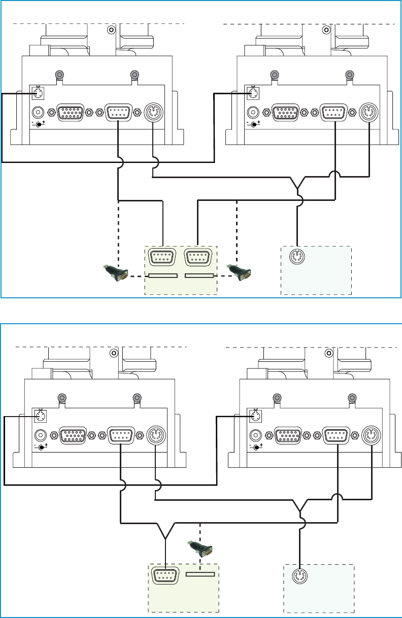
3 Installation
Installation of the AI 1310/AS 1310 on the GC
54 AI 1310/AS 1310 Sampling System - User Guide Thermo Scientific
Figure 49. Gemini Configuration Cables Connections - HWSetup 1
Figure 50. Gemini Configuration Cables Connections - HWSetup 2
24 Vdc
-+
TR AY
TWIN
SYN C RS 232 GC 24 Vdc
-+
TR AY
TWIN
SYN C RS 2 3 2 GC
AI/AS 1310 (a) AI/AS 1310 (b)
GC
PC
SA M PLER SI GNA L
COM 1
USB
COM 2
USB
USB RS232
Adapter
USB RS232
Adapter
Adapter
Adapter
24 Vdc
-+
TR AY
TWIN
SYN C RS 232 GC 24 Vdc
-+
TR AY
TWIN
SYN C RS 2 3 2 GC
GC
PC
SA M PLER SI GNA L
COM 1
AI/AS 1310 (a)
USB Port
AI/AS 1310 (b)
USB RS232 Adapter
U

3 Installation
Installation of the AI 1310/AS 1310 on the GC
Thermo Scientific AI 1310/AS 1310 Sampling System - User Guide 55
To perform the HWSetup 1 of two AI/AS 1310 in Gemini Configuration
1. Using the cable provided (PN 23043672), connect the 4-pin male connector marked
TWIN SYNC, on the back of the sampling unit of the sampler “a”, to the 4-pin male
connector marked TWIN SYNC on the back of the sampling unit of the sampler “b”.
2. Using the Gemini Y shape cable provided (PN 23043623), connect:
a. the 6-pin main connector labelled GC to the connector marked AUTOSAMPLER
HANDSHAKE on the back of the GC.
b. the first branch of the cable, labelled AI/AS 1, to the 6-pin female connector marked
GC on the back of the sampling unit of the sampler “a”.
c. the second branch of the cable, labelled AI/AS 2, to the 6-pin female connector
marked GC on the back of the sampling unit of the sampler “b”.
3. Using the RS232 cable (PN 23043453) provided in the standard outfit of each AI/AS
1310, connect:
a. the 9-pin connector marked RS232 of the first sampler to a PC serial port (e.g. COM
1), or to an USB port, interposing an USB-RS232 adapter not provided.
b. the 9-pin connector marked RS232 of the second sampler to a second PC serial port
(e.g. COM 2), or to an second USB port, interposing a second USB-RS232 adapter
not provided.
4. Connect the power cable to the AC Input connector (Mains socket) on the autosampler
and to the wall outlet.
Table 3. Hardware Setup Comparison Table
Chromatography Data System
(CDS)
High Throughput
Mode
Single
Mode1
1The unplugging of the power cord from the unused AI 1310/AS 1310 autosampler could be required
Confirmation
Mode
Chromeleon 7.2 HWSetup 1
See Figure 49
HWSetup 1
See Figure 49
HWSetup 2
See Figure 50
Xcalibur
Fundation 3.1; GC driver 3.X
NA2
2Not Applicable
HWSetup 21
See Figure 50
HWSetup 2
See Figure 50
Tra c e Fin d e r 3 . 2 N A 2HWSetup 21
See Figure 50
HWSetup 2
See Figure 50
Chrom-Card 2.12 Alternative
See Figure 50
HWSetup 21
See Figure 50
HWSetup 2
See Figure 50
ChromQuest 5; SP2015 R2 HWSetup 1
See Figure 49
HWSetup 1
See Figure 49
HWSetup 1
See Figure 49
EzChrom 3.22; SP2015 R2 HWSetup 1
See Figure 49
HWSetup 1
See Figure 49
HWSetup 1
See Figure 49

3 Installation
Installation of the AI 1310/AS 1310 on the GC
56 AI 1310/AS 1310 Sampling System - User Guide Thermo Scientific
To perform the HWSetup 2 of two AI/AS 1310 in Gemini Configuration
1. By using the cable provided, connect the 4-pin male connector marked TWIN SYNC, on
the back of the sampling unit of the sampler “a”, to the 4-pin male connector marked
TWIN SYNC on the back of the sampling unit of the sampler “b”.
2. By using the Y shape cable provided, connect:
a. the 6-pin female connector marked GC located on the sampling unit back side and
the connector, located on the back panel of the GC, marked:
–AUTOSAMPLER HANDSHAKE in the case of TRACE 1300/TRACE 1310.
–SAMPLER SIGNAL in case of TRACE GC Ultra and FOCUS GC.
b. the first branch of the cable, labelled AI/AS 1 to the 6-pin female connector marked
GC on the back of the sampling unit of the sampler “a”.
c. the second branch of the cable, labelled AI/AS 2 to the 6-pin female connector
marked GC on the back of the sampling unit of the sampler “b”.
3. By using the Y shape cable provided, connect:
a. the 9-pin main connector to a PC serial port (e.g. COM 1) or to an USB port,
interposing an USB-RS232 adapter not provided.
b. the first branch of the cable, labelled Primary AI/AS to the 9-pin female connector
marked RS232 on the back of the sampling unit of the sampler “a”.
c. the second branch of the cable, labelled Secondary AI/AS to the 6-pin female
connector marked RS232 on the back of the sampling unit of the sampler “b”.
Instrument Start-up
1. Plug in the Vdc power cable of the external portable power supply into the jack marked
24 Vdc located on the sampling unit back side.
2. Connect the power cord of the external power supply to the mains outlet.
The AI 1310/AS 1310 will automatically run the self-testing routine during which the
following automatic checks and settings are carried out:
• alignment between AI 1310/AS 1310 and the GC injector
• acknowledgment of the installed sample tray
• calculation of the syringe zero
Note The self-test routine is automatically carried out every time that the safety door of
the turret is closed.

Thermo Scientific AI 1310/AS 1310 Sampling System - User Guide 57
4
AI 1310/AS 1310 Control
This chapter provides the information for controlling the AI 1310/AS 1310 through the
Chromatography Data System, or the TRACE GC Ultra, or the FOCUS GC. The chapter
contains also the working procedures with different injectors.
Contents
•Control Through the Chromatography Data System
•Control Through the TRACE GC Ultra
•Control Through the FOCUS GC
•Guidelines for Programming with Different Injectors
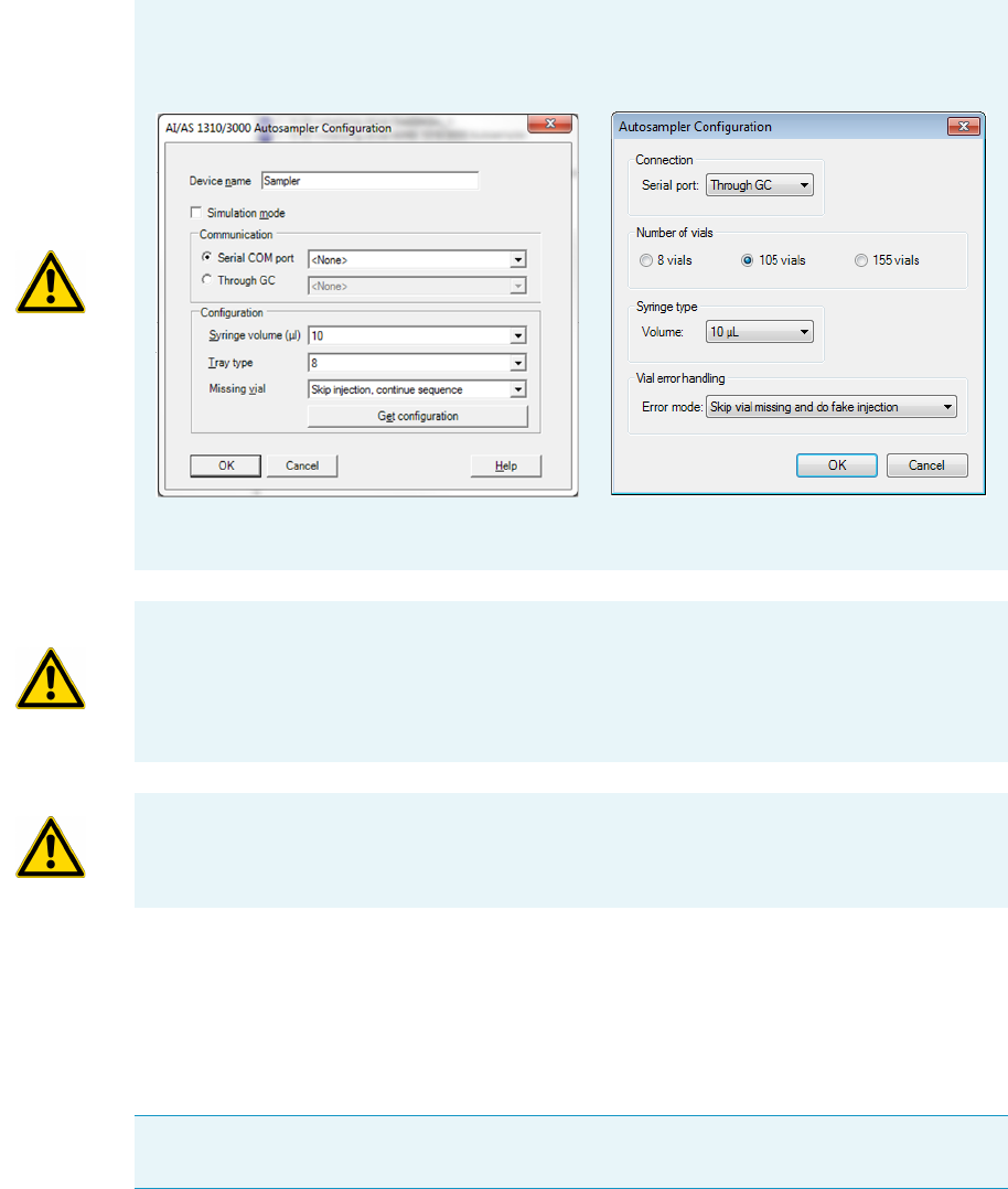
4 AI 1310/AS 1310 Control
Control Through the Chromatography Data System
58 AI 1310/AS 1310 Sampling System - User Guide Thermo Scientific
Control Through the Chromatography Data System
The AI 1310/AS 1310 is controlled through a Thermo Fisher Scientific Chromatography
Data System (CDS) installed in the PC and interfaced with the instrument via serial line
RS 232. This section describes how to program the instrument operating parameters.
User Interface
In the user interface, see Figure 51 and Figure 52, the sampler parameters can be set, whereas
the sequence of samples to be analyzed and acquired is managed by the data system as a
function of the type of sample tray installed.
IMPORTANT Before creating a sampler method, in the AI 1310/AS 1310 Configuration
page of the Chromatography Data System in use you must configure the communication
connection (Through GC or COM), the correct syringe capacity, and the tray in use.
CAUTION Configuring the AI 1310/AS 1310 through the GC may slow down the
communication performance, since a large amount of data is sent to TRACE 1300/1310
GC, and then the GC sends to AI 1310/AS 1310.
The Through GC communication configuration is reliable but significantly slower than
connecting AI 1310/AS 1310 directly on a COM port or through LAN.
IMPORTANT In the Autosampler Configuration page of the data system in use, select the
function Error mode/Missing vial to Stop on vial missing.
Note The user interface is visualized previous the selection in the configuration page of
the data system in use referring to the relevant manual.
Chromeleon CDS Xcalibur, Chrom-Card, ChromQuest CDS
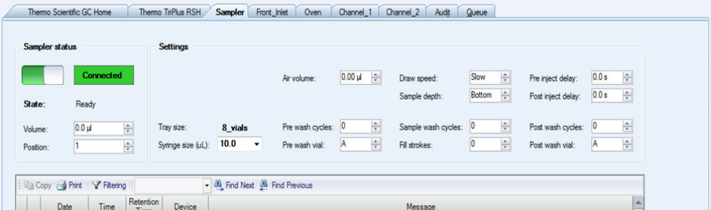
4 AI 1310/AS 1310 Control
Control Through the Chromatography Data System
Thermo Scientific AI 1310/AS 1310 Sampling System - User Guide 59
When in Gemini configuration each sampler is controlled by its own dedicated user interface,
then two AI/AS method pages will be visualized. The parameters set in each page will be sent
to its relevant sampler.
Related Topics
•“Chromeleon CDS User Interface” on page 59
•“Xcalibur, Chrom-Card, and ChomQuest CDS User Interface” on page 61
Chromeleon CDS User Interface
This page is shown in Figure 51.
Figure 51. AI 1310/AS 1310 Autosampler Chromeleon CDS User Interface
Edit the autosampler method using the following parameters:
Air Volume — Specifies the volume of air drawn after pulling the syringe needle out of the
vial. This reduces evaporation from the syringe needle. The total of Air Volume plus Volume
must not exceed the syringe volume. The range is 0.0-3.0 μL.
Draw Speed — Determines how fast the sample is draw. The options are:
•Slow in case of high viscous samples.
•Fast in case of viscous or low viscous samples.
Fill Strokes — Determines how often the syringe plunger is moved up and down before the
sample is actually drawn. This eliminates bubbles and thus, enhances reproducibility.
The range is 0-15.
Inject Wait Time — Sets the time between the injection command and the response from the
autosampler. The range is 0-10.000.000 seconds.
Pre Inject Delay Time — Determines for how long the syringe remains in the injector before
the injection. The range is 0-63 seconds.

4 AI 1310/AS 1310 Control
Control Through the Chromatography Data System
60 AI 1310/AS 1310 Sampling System - User Guide Thermo Scientific
Post Inject Delay Time — Determines for how long the syringe remains in the injector after
the injection. The range is 0-63 seconds.
Pre Wash — Specifies the number of pre-injection cleaning cycles. The range is 0-15.
Post Wash — Specifies the number of post-injection cleaning cycles. The range is 0-15.
Pre Wash Vial — Specifies which vials are used for washing the syringe before the injection
with the solvents. The options are: A, B, C, D, A+B and C+D.
Post Wash Vial — Specifies which vials are used for washing the syringe after the injection
with the solvents. The options are: A, B, C, D, A+B and C+D.
Position — Specifies the vial position in the tray.
Sample Depth — Specifies how deep the needle descends into the vial when drawing the
sample for injection. The options are: Bottom or Half.
Sample Wash — Determines the number of cleaning cycles with sample before injection. The
range is 0-15.
State — Indicates the status of the autosampler (ready-only).
•On = the injection has been performed.
•Off = the injection has not yet been performed.
Syringe Volume — Specifies the total capacity of the syringe: 0.5 μL, 5 μL, or 10 μL. See also
the Configuration page.
Tr a y Ty p e — Specifies the tray type: 8, 105, or 155 vials. See also the Configuration page.
Volume — Specifies the injection volume.
Commands
The following commands are available:
Connect — Connects the autosampler to the data system.
Disconnect — Disconnects the autosampler from the data system.
Clean — (obsolete AI/AS 1310 drivers only) Cleans the syringe in combination with the
washing parameters.
Note You can also use the Post Inject Delay Time and Pre Inject Delay Time Properties to
specify the needle depth during the injection. The following settings are available.
•Standard: Post Inject Delay Time or Pre Inject Delay Time > 0
•Minimum: Post Inject Delay Time and Pre Inject Delay Time = 0
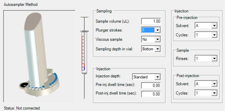
4 AI 1310/AS 1310 Control
Control Through the Chromatography Data System
Thermo Scientific AI 1310/AS 1310 Sampling System - User Guide 61
Inject — Injects the sample. The maximum injection volume must not exceed 505 of the
syringe capacity.
Recalculate — Performs the start procedure gain, allowing the autosampler to recalibrate the
internal positions, such as injector, wash vial, and tray. This command is required when a new
tray was installed.
Stop Inject — Aborts a running injection.
Wash — Starts washing the needle.
Xcalibur, Chrom-Card, and ChomQuest CDS User Interface
This page is shown in Figure 52.
Figure 52. AI 1310/AS 1310 Autosampler Xcalibur, Chrom-Card, ChromQuest CDS User Interface
Edit the autosampler method using the following parameters:
Sample Volume — Enter a value for the injection volume. The range depends on the size of
syringe selected in the Instrument Configuration.
• For a 5 μL syringe the range is 0.0-2.5 μL.
• For a 10 μL syringe the range is 0.0-5.0 μL.
Plunger Strokes — Select the number of strokes of the syringe plunger used to eliminate any
air bubbles from the sample. The range is 1-15.
Viscous Sample — Calculates automatically the speed the sample is pulled-up (withdrawn)
from the vial to the syringe.
•Set No for no viscous or low viscous sample.
•Set Yes for high viscous sample.
4 AI 1310/AS 1310 Control
Control Through the Chromatography Data System
62 AI 1310/AS 1310 Sampling System - User Guide Thermo Scientific
Sampling Depth — Choose the position of the needle in the vial from which the aliquot is
drawn. The options are Bottom (default value), or Center.
•When Bottom is set the syringe needle penetrates up to the bottom of the vial.
•When Center is set, the syringe needle penetrates up to the half of the vial.
Injection Depth — Determines the penetration depth of the syringe needle into the vial. The
options are Standard or Minimum (cold needle technique for TRACE 1300/1310 GC and
TRACE GC Ultra). If the pre and post -injection dwell times are set to zero, the sampler
defaults to the Minimum setting.
•When Standard is set (default value), the syringe needle penetrates into the injector
up the maximum depth limit.
•When Minimum is set, the syringe needle penetrates into the injector up to go
beyond the septum only.
Pre-injection Dwell Time — The time in seconds the syringe needle is held in the inlet before
the injection of sample. When you specify a delay of more than a few seconds, the needle
preheats, which makes a Hot Needle Injection. Enter a value in the range 0-63 seconds.
Post-injection Dwell Time — The time in seconds the syringe needle is held in the after the
injection of sample. A delay of more than a few seconds will heat the needle with the possible
effect of driving those heavier analytes that have condensed in the needle out. A solvent flush
technique may work better. Enter a value in the range 0-63 seconds.
Pre-Injection — Choose a solvent from the drop-down list. The options are: A, B, C, D, A+B
and C+D. These settings correspond to the vials in the Washing and Waste tray.
Cycles — This is the number of times that the syringe is rinsed with the sample prior to
injection. Select a value in the range 1-15.
Rinse— This is the number of times that the syringe is washed with the sample prior to
injection. Select a value in the range 1-15.
Solvent — Choose a solvent from the drop-down list. The options are: A, B, C, D, A+B and
C+D. These settings correspond to the vials in the Washing and Waste tray.
Cycles — Select the number of times the solvent is cycled through the syringe. The range is
1-15.
Commands
The following commands are available:
Get Method from Sampler — Transfer the AI 1310/AS 1310 current method to the GC.
Send Method to Sampler — Transfers the method from the computer to the a AI 1310/AS
1310 and makes the method active.

4 AI 1310/AS 1310 Control
Control Through the TRACE GC Ultra
Thermo Scientific AI 1310/AS 1310 Sampling System - User Guide 63
Start Clean Cycle — Start a washing cycle.
Inject Single Sample — Start the injection of a single sample.
Force Auto-injector to Stand-by — Interrupts any current operation and forces the
AI 1310/AS 1310 to stand-by condition.
Messages
This section lists the status and error messages that the computer may display according to the
status of the AI 1310/AS 1310.
Status Messages
The status messages are listed below:
• Opening Connection
• No connection (Check the serial line connections)
• The AI 1310/AS 1310 is in stand-by
• AI 1310/AS 1310 is checking positions
• AI 1310/AS 1310 ready to inject sample in vial n but waiting GC Ready
• AI 1310/AS 1310 is preparing the sample in vial n.
• AI 1310/AS 1310 has injected the sample in vial n.
• The AI 1310/AS 1310 front door is open (all operations are paused)
Error Messages
The error messages are listed below:
• AI 1310/AS 1310 error, solvent not found
• AI 1310/AS 1310 position error, cannot find the initial zero positions
Control Through the TRACE GC Ultra
This paragraph describes how to program and control the AI 1310/AS 1310 through the
TRACE GC Ultra keypad.
ATTENTION The TRACE GC Ultra does not control the AS 1310 with the 155-position
sample tray.
4 AI 1310/AS 1310 Control
Control Through the TRACE GC Ultra
64 AI 1310/AS 1310 Sampling System - User Guide Thermo Scientific
Groups of samples can be automatically analyzed under different analytical conditions by
programming a sequence of samples. The sequence includes a set of information for a group of
samples and their position on the sample tray. The sequence also specifies the method to be
used to run each group of samples.
Configuring the AI 1310/AS 1310
When the GC is switched on, the presence of the sampler and its configuration is
automatically acknowledged.
The type of configuration is displayed by pressing Config and selecting Autosampler.
The following non editable message is displayed according to the AI 1310/AS 1310 installed:
for the AS 1310, or
for the AI 1310.
AI 1310/AS 1310 Menu
To set the parameters of the AI 1310/AS 1310 method, press Autosampler key to open the
relevant menu described in Table 4.
Note It is not possible to control the 0.5 μL syringe through the GC keypad but only
through the data system.
Note In an analytical method all the AI 1310/AS 1310 functions can be programmed.
To develop an analytical method and activate a sample sequence, refer to the TRACE GC
Ultra Operating Manual.
CONFIG AUTOSAMPLER
Sample tray 105
CONFIG AUTOSAMPLER
Sample tray 8
Note Should the AI 1310/AS 1310 not be installed or correctly connected, the TRACE
GC Ultra will display the message NO AUTOSAMPLER INSTALLED.
Table 4. Control Through the TRACE GC Ultra: Autosampler Menu (Sheet 1 of 2)
Menu Range Comment
AUTOSAMPLER This line displays the menu title.
Sample volume 0–5 μL with increments
of 0.1 μL
This parameter allows to set the sample quantity to
be injected.

4 AI 1310/AS 1310 Control
Control Through the TRACE GC Ultra
Thermo Scientific AI 1310/AS 1310 Sampling System - User Guide 65
Extended Control Menu
In this menu it is possible to set how long the syringe needle must remain inside the injector
without injecting. This allows to avoid discriminations caused by evaporation of the sample
contained in the syringe needle. In this way the sample is completely drawn into the syringe
and the needle left inside the injector and heated for a few seconds before injecting.
See Table 5 for details.
Sample rinses 0–15 This parameter allows to set the number of syringe
pre-washings with the sample.
Plunger strokes 0–15 This parameter allows to set the number of plunger
strokes to eliminate air bubbles forming during the
sample withdrawal.
Pre wash solvent A, B, C, D
A+B
C+D
This parameter allows to select the vial, or
combination of two vials, containing the washing
solvent.
Press Mode/Type to select the solvent vial to be
used.
Pre wash cycles 0–15 This parameter allows to set the number of syringe
pre-washings with the selected solvent.
Post wash solvent A, B, C, D
A+B
C+D
This parameter allows to select the vial, or
combination of two vials, with the washing solvent.
Press Mode/Type to select the vial with the
solvent to be used.
Post wash cycles 0–15 This parameter specifies the number of syringe
post-washings with the solvent selected.
Extended control See “Extended Control
Menu” on page 65
This parameter allows to set optional injection
parameters.
Press Mode/Type to enter the sub-menu.
When no vial abort See “When No Vial Abort
Menu” on page 66
This line shows the menu title.
Table 4. Control Through the TRACE GC Ultra: Autosampler Menu (Sheet 2 of 2)
Menu Range Comment
Table 5. Control Through the TRACE GC Ultra: Extended Control Menu (Sheet 1 of 2)
Menu Range Comments
EXTENDED CONTROL This line shows the menu title.
Viscous sample Yes, No This parameter defines the speed at which the sample is
drawn from the vial as a function of the sample viscosity.
Select No (default value) if the sample has low viscosity.
Select Yes if the sample has high viscosity.

4 AI 1310/AS 1310 Control
Control Through the FOCUS GC
66 AI 1310/AS 1310 Sampling System - User Guide Thermo Scientific
When No Vial Abort Menu
See Table 6 for details.
Control Through the FOCUS GC
This paragraph describes how to program and control the AI 1310/AS 1310 through the
FOCUS GC keypad.
The AS 1310 can automatically analyze groups of samples under different analytical
conditions when a sequence of samples is programmed.
Sampl. depth Bottom, Center
selectable in the
sub-menu
This parameter determines the penetration depth of the
syringe needle into the vial.
Press Mode/Type or Enter to enter the sub-menu.
Selecting Bottom (default value) the needle goes down to
the vial bottom.
Selecting Center the needle goes down to half vial.
Inj. Depth Standard,
Minimum
selectable in the
sub-menu
This parameter determines the penetration depth of the
syringe needle into the injector.
Press Mode/Type or Enter to enter the sub-menu.
Selecting Standard (default value) the needle goes down to
the maximum depth allowed.
Selecting Minimum the needle enters the injector and stops
immediately beyond the septum (Cold Needle Technique).
Table 5. Control Through the TRACE GC Ultra: Extended Control Menu (Sheet 2 of 2)
Menu Range Comments
Table 6. Control Through the TRACE GC Ultra: When No Vial Abort Menu
Menu Comments
ON MISSING AS VIAL This line shows the menu title.
Skip to next If this function is selected, the AI 1310/AS 1310 skips a missing vial
and goes to the next one. The sample sequence and the sample table
are not affected.
Abort sequence If this function is selected, the sequence is aborted after a missing vial.
CAUTION The FOCUS GC does not control the AS 1310 with the 155-position sample
tray.
4 AI 1310/AS 1310 Control
Control Through the FOCUS GC
Thermo Scientific AI 1310/AS 1310 Sampling System - User Guide 67
The sequence includes a set of information for the group of samples and their position on the
sample tray. The sequence also specifies the method to be used to process each group of
samples. See the section “Sequence of Samples with the AS 1310” on page 69.
Configuring the AI 1310/AS 1310
When the GC is switched on, the presence and type of sampling system installed is
automatically acknowledged.
To configure the AI 1310/AS 1310:
1. In Main Menu move the cursor until Others is displayed, then press Enter.
2. Scroll to select Configuration, then press Enter.
3. Scroll to Autosampler, then press Enter.
The following message will be displayed according to the AI 1310/AS 1310 installed:
for the AS 1310, or
for the AI 1310.
The parameter Syringe volume can be modified according to the syringe volume, whereas the
parameter Sample tray is not editable.
AI 1310/AS 1310 Menu
To set the parameters of the AI 1310/AS 1310 method, In Main Menu move the cursor until
Autosampler is displayed, then press Enter to open the menu. See Table 7 for details.
CONFIG AUTOSAMPLER
Syringe Volume
Sample tray
10
105
CONFIG AUTOSAMPLER
Syringe Volume
Sample tray
10
8
Table 7. Control Through the FOCUS GC: Autosampler Menu (Sheet 1 of 2)
Menu Range Comment
AUTOSAMPLER This line displays the menu title.
Sample volume 0–5 μL, 0-2.5 μL
with increments of 0.1 μL
This parameter allows to set the sample quantity to
be injected.
Sample rinses 0–15 This parameter allows to set the number of syringe
pre-washings with the sample.

4 AI 1310/AS 1310 Control
Control Through the FOCUS GC
68 AI 1310/AS 1310 Sampling System - User Guide Thermo Scientific
Plunger strokes 0–15 This parameter allows to set the number of plunger
strokes to eliminate air bubbles forming during the
sample withdrawal.
Pre wash solvent A, B, C, D,
A+B,
C+D
This parameter allows to select the vial, or
combination of two vials, containing the washing
solvent.
Pre wash cycles 0–15 This parameter allows to set the number of syringe
pre-washings with the selected solvent.
Post wash solvent A, B, C, D
A+B
C+D
This parameter allows to select the vial, or
combination of two vials, with the washing solvent.
Post wash cycles 0–15 This parameter specifies the number of syringe
post-washings with the solvent selected.
Viscous sample Yes, No This parameter sets the sample drawing speed from
the vial as a function of the sample viscosity.
Select No (default value) if the sample has low
viscosity.
Select Yes when the sample has high viscosity.
Sample depth Bottom, Center,
selectable in the
sub-menu
This parameters sets the penetration depth of the
syringe needle into the vial.
If Bottom (default value) is selected, the needle
goes down to the vial bottom.
If Center is selected, the needle goes down to half
vial.
Inj. depth Standard, Minimum,
selectable in the
sub-menu
This parameter defines the penetration depth of the
syringe needle into the injector.
If Standard (default value) is selected, the needle
goes down to the maximum allowed depth.
If Minimum is selected, the needle enters the
injector and stops immediately beyond the septum
(Cold Needle Technique).
Pre dwell time 0–63 sec This parameter specifies how long the syringe
needle must remain in the injector before injection
(Hot Needle Technique).
Post dwell time 0–63 sec This parameter specifies how long the syringe
needle must remain inside the injector after
injection.
Table 7. Control Through the FOCUS GC: Autosampler Menu (Sheet 2 of 2)
Menu Range Comment

4 AI 1310/AS 1310 Control
Guidelines for Programming with Different Injectors
Thermo Scientific AI 1310/AS 1310 Sampling System - User Guide 69
Sequence of Samples with the AS 1310
To set the parameters to run a sequence of samples with the AS 1310, in Main Menu move
the cursor until Sequence is displayed, then press Enter to open the menu. See Table 8 for
details.
Guidelines for Programming with Different Injectors
To get the best results from your AI 1310/AS 1310, follow these guidelines when
programming the sampler method according to the injector in use:
•“SSL Inlet (TRACE 1300/1310 GC)” on page 70
•“SSL Inlet (TRACE GC Ultra/FOCUS GC)” on page 71
•“SSL Inlet with a Merlin Microseal™ (TRACE GC Ultra Only)” on page 74
•PTV Inlet (TRACE 1300/1310 GCTRACE GC Ultra)
•PTV Inlet with a Merlin Microseal™ (TRACE 1300/1310 GC, TRACE GC Ultra)
•PKD and PPKD Inlets (TRACE GC Ultra, FOCUS GC)
Table 8. Control Through the FOCUS GC: Sequence Menu with AS 1310
Menu Range Comments
SEQUENCE This line shows the menu title.
First sample 1 to 105 Indicates the first sample of the sequence.
Last sample 1 to 105 Indicates the last sample of the sequence.
Injection/vial 1 to 99 Indicates how many times the same sample
has to be run.
When no vial See Table 9.
Start sequence Indicates the sequence start.
Stop Sequence Indicates the sequence end.
Table 9. Control Through the TRACE GC Ultra: When No Vial Abort Menu
Menu Comments
ON MISSING AS VIAL This line shows the menu title.
Skip to next If this function is selected, the AI 1310/AS 1310 skips a missing vial
and goes to the next one. The sample sequence and the sample table
are not affected.
Abort sequence If this function is selected, the sequence is aborted after a missing vial.

4 AI 1310/AS 1310 Control
Guidelines for Programming with Different Injectors
70 AI 1310/AS 1310 Sampling System - User Guide Thermo Scientific
SSL Inlet (TRACE 1300/1310 GC)
The AI 1310 /AS 1310 injects into the SSL inlet using the liquid band technique.
The needle penetrates for almost its whole length without pre- and post-dwell time in order to
avoid any possible heating, still injecting deep into the liner.
The liquid band technique requires the use of packing material into the liner in order to stop
the sample before its vaporization and its transfer towards the column.
Table 10 reports a summary of injection parameters and conditions for the SSL techniques.
For your reference the type of liner and the column insertion inside the inlet are also reported.
Nano-Volumes Injections in TRACE 1300/1310 GC SSL Inlet
To create a nano-volumes method
1. Enter the AI/AS 1310 method page provided by your Data System.
2. Adjust all the autosampler parameters.
3. Save the method.
Remarks on the Nano-Volume Method:
• The desired volume must be set in microliter units (1 μL = 103 nL).
Table 10. Summary of Injection Parameters and Conditions
Mode Technique Column Insertion Liner Type AI 1310/AS 1310 Injection Parameters
Split Cold Needle 10 mm SSL Split Straight Liner,
Deactivated, 4 mm ID x 6.3 mm
OD x 78.5 mm Length, Quartz
Wool
PN 453A2265
Injection depth = Standard
Pre and Post Inject Delay Time = 0.1 s
(Chromeleon CDS)
Pre and Post Injection Dwell Time = 0 s
(Xcalibur, Chrom-Card, ChromQuest CDS)
Splitless Cold Needle 5 mm SSL Splitless Liner, Single
Taper, Deactivated, 4 mm ID x
6.3 mm OD x 78.5 mm Length,
Quartz Wool
PN 453A1925
Injection depth = Standard
Pre and Post Inject Delay Time = 0.1 s
(Chromeleon CDS)
Pre and Post Injection Dwell Time = 0 s
(Xcalibur, Chrom-Card, ChromQuest CDS)
SSL Nano-Volumes1Cold Needle 10 mm in Split
5 mm in Splitless
Depends if split or splitless
injection
Injection depth = Standard
Pre and Post Inject Delay Time = 0.1 s
(Chromeleon CDS)
Pre and Post Injection Dwell Time = 0 s
(Xcalibur, Chrom-Card, ChromQuest CDS)
1Only with 0.5μL syringe.
4 AI 1310/AS 1310 Control
Guidelines for Programming with Different Injectors
Thermo Scientific AI 1310/AS 1310 Sampling System - User Guide 71
• The Data System will let you choose any volume between 0.010 μL (10 nL) and
0.5 μL in steps of 0.010 μL.
• A default air volume of 0.3 μL is automatically added to the sampler volume in order
to optimize the syringe plunger movements. This value can not be edited by the user.
• Select Draw Speed to Slow (Chromeleon CDS only).
• Always set the Viscous parameter to Yes when using the 0.5 μL syringe (Xcalibur,
Chrom-Card, and ChromQuest CDS only).
• Always set one or more wash with the sample.
• Select a low number of plunger strokes. One or two strokes are sufficient to eliminate
residual air. The liquid is entirely housed inside the needle and is not visible through
the 0.5 μL syringe glass barrel.
• If you do not program solvent washes in the method, always perform a maintenance
cleaning cycle at the end of your sequence of analyses.
SSL Inlet (TRACE GC Ultra/FOCUS GC)
The AI 1310/AS 1310 can inject in a hot SSL inlet using two distinct needle insertion modes:
“Standard” and “Minimum”.
•In Standard mode the needle penetrates for almost its whole length and a dwell time is
programmed to provide needle heating.
•In the Minimum mode the needle penetrates for a minimum depth and for the minimum
time allowing to minimize contact of the needle with the hot inlet.
These two needle insertion modes are conceived to optimize respectively the “Hot Needle”
and the “Cold Needle” injection techniques.
•Cold needle technique — (Minimum depth mode) prevents boil-out from the needle
and lets the sample to enter the injector nearly entirely in liquid phase. This injection
technique requires the use of packed liner to stop the liquid run.
•Hot needle technique — (Standard depth mode) requires a minimum pre-dwell time to
heat the needle (usually 3-5 seconds) to achieve a complete expulsion of the sample from
the needle in form of a spray. This technique permits the use of empty liners.
Table 11 reports a summary of injection parameters and conditions for the two SSL
techniques. For your reference the type of liner and the column insertion inside the inlet are
also reported.

4 AI 1310/AS 1310 Control
Guidelines for Programming with Different Injectors
72 AI 1310/AS 1310 Sampling System - User Guide Thermo Scientific
Table 11. Summary of Injection Parameters and Conditions
Mode Technique Column
Insertion Liner Type Packing of
Liner AI 1310/AS 1310 Injection Parameters
Split Hot Needle 40 mm Tubular Liner
(3 or 5 mm ID)
Not required Injection depth = Standard
Pre Inject Delay Time = 3-5 s
Post Inject Delay Time = 0 s
(Chromeleon CDS)
Pre Injection Dwell Time = 3-5 s
Post Injection Dwell Time = 0
(Xcalibur, ChromCard, ChomQuest CDS)
Split Cold Needle 40 mm Tubular Liner
(3 or 5 mm ID)
Packing material
at half height
Injection depth = Minimum
Pre and Post Inject Delay Time = 0 s
(Chromeleon CDS)
Pre and Post Injection Dwell Time are
automatically inhibited
(Xcalibur, ChromCard, ChomQuest CDS)
Splitless Hot Needle 64 mm Tapered Liner
(3 or 5 mm ID)
Not Required Injection depth = Standard
Pre Inject Delay Time = 3-5 s
Post Inject Delay Time = 0 s
(Chromeleon CDS)
Pre Injection Dwell Time = 3-5 s
Post Injection Dweel Time = 0
(Xcalibur, ChromCard, ChomQuest CDS)
Splitless Cold Needle 50 mm Tapered Liner
(3 or 5 mm ID)
Packing material
at bottom
Injection depth = Minimum
Pre and Post Inject Delay Time = 0 s
(Chromeleon CDS)
Pre and Post Injection Dwell Time are
automatically inhibited
(Xcalibur, ChromCard, ChomQuest CDS)
SSL Nano-Volumes1Cold Needle 40 mm Double Tapered Liner No Injection depth = Minimum
Pre and Post Inject Delay Time = 0 s
(Chromeleon CDS)
Pre and Post Injection Dwell Time are
automatically inhibited
(Xcalibur, ChromCard, ChomQuest CDS)
1Only with 0.5μL syringe.

4 AI 1310/AS 1310 Control
Guidelines for Programming with Different Injectors
Thermo Scientific AI 1310/AS 1310 Sampling System - User Guide 73
Nano-Volumes Injections in TRACE GC Ultra/FOCUS GC SSL Inlets
Injections of sample volumes below 0.1-0.2 μL in SSL inlets is very attractive when the
dilution with a solvent is not desired and/or the main component easily overloads the capillary
column even at high split ratios. Examples of such applications are analyses of essential oils or
petroleum fractions.
The reduction of the injection volume to the sub microliter range using a standard sampler,
like the AI 1310/AS 1310 unit, is achievable by exploiting the low capacity syringe (0.5 μL)
and the tapered liner. High accuracy and repeatability injecting nano-volumes are achievable
by exploiting the “Cold Needle” injection mode.
For injection volumes higher than 0.2-0.3 μL use a 5 (or 10) μL syringe and a standard split
or splitless liner (possibly packed with glass wool whenever you inject in “Cold Needle”
mode). In summary, use the following guideline to choose the best syringe capacity for your
injections with the AI 1310/AS 1310 sampler. See Table 12 for details.
To create a nano-volumes method
1. Enter the AI/AS 1310 method page provided by your Data System.
2. Adjust all the autosampler parameters.
3. Save the method.
Remarks on the Nano-Volume Method:
• The desired volume must be set in microliter units (1 μL = 103 nL).
• The Data System will let you choose any volume between 0.010 μL (10 nL) and
0.5 μL in steps of 0.010 μL.
• A default air volume of 0.3 μL is automatically added to the sampler volume in order
to optimize the syringe plunger movements. This value can not be edited by the user.
• The best repeatability and recovery results are obtained injecting in fast “Cold Needle”
mode (i.e. “minimum” injection depth with no Pre and Post Inject Delay/Pre and
Post Injection Dwell Time).
• Select Draw Speed to Slow (Chromeleon CDS only).
• Always set the Viscous parameter to Yes when using the 0.5 μL syringe (Xcalibur,
Chrom-Card, and ChromQuest CDS only).
Table 12. Syringe Guideline for AI 1310/AS 1310 Autosampler
Injection Volume Range Suggested Syringe1
1See your TRACE GC Ultra and FOCUS GC Spare Part Catalog for items part number.
AI 1310/AS 1310 Injection Parameters
0.5 – 5.0 μL 10 μL Standard – general purpose
0.2 – 1.0 μL5 μL---
0.01 – 0.3 μL0.5 μL Plunger-in-needle
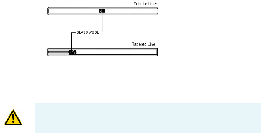
4 AI 1310/AS 1310 Control
Guidelines for Programming with Different Injectors
74 AI 1310/AS 1310 Sampling System - User Guide Thermo Scientific
• Always set one or more wash with the sample.
• Select a low number of plunger strokes. One or two strokes are sufficient to eliminate
residual air. The liquid is entirely housed inside the needle and is not visible through
the 0.5 μL syringe glass barrel.
• If you do not program solvent washes in the method, always perform a maintenance
cleaning cycle at the end of your sequence of analyses.
Packing a SSL Liner
To pack a SSL liner
1. On your TRACE GC Ultra or FOCUS GC keypad, enter the Oven menu and switch off
the oven temperature. This will avoid heating of the analytical column when carrier is off.
2. Enter the Injector menu and switch off the inlet temperature.
3. Enter Carrier Menu and switch off the carrier supply.
4. Remove the centering plate of the AI 1310/AS 1310 (if installed).
5. Wait till the injector has reached room temperature and by means of the outfit tool
unscrew the septum cap, then remove it together with the septum holder and its plate.
6. Unscrew the liner holder and remove it. Use tweezers to gently extract the liner from the
injector.
7. Insert a little plug of packing material (i.e. deactivated glass wool) filling the liner cavity
about 5 mm in length. Push the plug till it reaches the position. See Figure 53.
Figure 53. Packing a SSL Liner
8. Insert the liner in its location, then correctly close the injector and restore the GC
parameters.
SSL Inlet with a Merlin Microseal™ (TRACE GC Ultra Only)
ATTENTION For TRACE 1300/TRACE 1310 GC equipped with the Merlin Microseal,
no modification of the method compared to the standard septum is required.

4 AI 1310/AS 1310 Control
Guidelines for Programming with Different Injectors
Thermo Scientific AI 1310/AS 1310 Sampling System - User Guide 75
This septum-less device offers an effective solution to get rid of traditional rubber septa side
effects (impurities released by excessive warming of septa). Since the temperature around the
microseal is lower than the rest of the injector, the most suitable injections technique is the
cold needle injection. That means no dwell time to warm up the needle. The adapter for
Merlin Microseal™ also behaves as a spacer between the needle entrance and the liner, so
standard injection depth must be used to fulfill correctly the injection.
See “Packing a SSL Liner” on page 74 for instruction.
PTV Inlet (TRACE 1300/1310 GCTRACE GC Ultra)
Since PTV is cold during sample introduction the syringe needle will not be heated whenever
standard or minimum depth is selected or dwell times are set. However standard injection
mode is advisable since the sample evaporation is faster in the deeper part of the liner.
Optional 1-2 seconds of dwell times will guarantee stable flow condition after the needle
introduction. See Table 13 .
Table 13. PTV Inlet
Note In order to guarantee long-life performance of the Merlin Microseal™ it is
recommended to use syringes with 0.63 mm needle diameter and truncated cone shape on
tip. Refer to the TRACE GC Ultra or FOCUS GC Spare Part Catalog for part numbers.
Mode Technique Column
Insertion Liner Type Packing of Liner AI 1310/AS 1310 Injection Parameters
Split Cold Needle 40 mm Tubular Liner
(3 or 5 mm ID)
Packing material at
half height
Injection depth = Standard
Pre and Post Inject Delay Time = 0.1 s
(Chromeleon CDS)
Pre and Post Injection Dwell Time = 0 s
(Xcalibur, Chrom-Card, ChromQuest CDS)
Splitless 50 mm Packing material at
bottom
Injection depth = Standard
Pre and Post Inject Delay Time = 0.1 s
(Chromeleon CDS)
Pre and Post Injection Dwell Time = 0 s
(Xcalibur, Chrom-Card, ChromQuest CDS)
Injector Column Insertion AI 1310/AS 1310 Injection Parameters
Programmed Temperature
Vaporizing Injector (PTV)
30 mm Injection depth = Standard
Pre and Post Inject Delay Time = 1-2 s
(Chromeleon CDS)
Pre and Post Injection Dwell Time = 1-2 s
(Xcalibur, Chrom-Card, ChromQuest CDS)

4 AI 1310/AS 1310 Control
Guidelines for Programming with Different Injectors
76 AI 1310/AS 1310 Sampling System - User Guide Thermo Scientific
PTV Inlet with a Merlin Microseal™ (TRACE 1300/1310 GC, TRACE GC Ultra)
The above PTV conditions apply also when the Merlin Microseal™ is used.
PKD and PPKD Inlets (TRACE GC Ultra, FOCUS GC)
For injection into packed column the standard insertion depth with 3-5 seconds of
pre-injection delay time is suggested. See Table 14.
Note In order to guarantee long-life performance of the Merlin Microseal™ it is
recommended to use syringes with 0.63 mm needle diameter and truncated cone shape on
tip. Please refer to the spare part catalog for part number.
Table 14. PKD and PPKD Inlets
Injector AI 1310/AS 1310 Injection Parameters
Packed Injector (PKD) (TRACE GC Ultra)
Purged Packed Injector (PPKD) (TRACE GC Ultra, FOCUS GC)
Injection depth = Standard
Pre Inject Delay Time = 3-5 s
Post Inject Delay Time = 0 s
(Chromeleon CDS)
Pre Injection Dwell Time = 3-5 s
Post Injection Dwell Time = 0 s
(Xcalibur, Chrom-Card, ChromQuest CDS)

Thermo Scientific AI 1310/AS 1310 Sampling System - User Guide 77
5
Maintenance
This chapter provides guidelines for the maintenance of the AI 1310/AS 1310.
Contents
•Current Maintenance
•Emptying of the Waste Container
•Cleaning of the Sample Tray Accessory
•Cleaning the Instrument Externally
•Replacing the Syringe
•Cleaning the Syringe
•Preparing a New Syringe
•Moving Away the Sampling Unit from the Injector Module
5 Maintenance
Current Maintenance
78 AI 1310/AS 1310 Sampling System - User Guide Thermo Scientific
Current Maintenance
The AI 1310/AS 1310 does not generally require maintenance, except emptying of the waste
container when full, cleaning of the sample tray and replacement of the syringe. For any other
operation, contact Thermo Fisher Scientific Technical Service.
Emptying of the Waste Container
To empty the waste container
1. If necessary, move the turret to have free access to the washing and waste tray.
2. Take out the container.
3. Remove the cap and empty the container.
4. Put on the cap again and reposition the container into its seat.
Cleaning of the Sample Tray Accessory
The sample tray must be periodically cleaned. Use a water and soap solution or a household
non abrasive product. Dry using a clean cloth.
Cleaning the Instrument Externally
Normal usage of the AI 1310/AS 1310 can cause the exterior to get dirty.
To clean the instrument externally
1. Power off the AI 1310/AS 1310.
2. Externally clean the instrument with a soap and water solution, or with a household
non-abrasive product.
WARNING Before starting, if hazardous substances (toxic, harmful, and so forth) are
used, read the hazard indications and information reported in the applicable Material
Safety Data Sheet (MSDS.) Use Personal protection according to the safety requirements.
WARNING It is your responsibility to avoid that dangerous liquids and/or materials
seeping inside the AI 1310/AS 1310 during operation and maintenance.
Solvent should not be used. Do not spray on electrical parts.

5 Maintenance
Replacing the Syringe
Thermo Scientific AI 1310/AS 1310 Sampling System - User Guide 79
• Pay special attention when cleaning the back side of the instrument. Do not spray,
but clean using a cloth imbued with the same substance.
• Carefully avoid seeping of the products used inside the instrument, particularly when
cleaning the grid of the back panel.
• If you just suspect that a substance used for cleaning or a product submitted to
analysis has penetrated inside the instrument, immediately shut down the instrument
and call an authorized customer support engineer for proper actions. The service
engineer must be fully informed on the nature of the concerned substance. In the
event that a hazardous material is spilled on or in the instrument, clean the spill
according to the procedures reported in the Material Data Sheet for that substance.
3. Dry with a clean cloth.
4. Power on the AI 1310/AS 1310.
Replacing the Syringe
The replacement of the syringe is a simple operation. However, it must be performed with
caution to avoid damages to the syringe needle and ensure an optimal performance of the
injection device. The standard syringe has 10 μL capacity with 50 mm needle length.
5 and 0.5 μL syringes are optionally available.
To replace the syringe
This operation is possible with the instrument either On or Off.
1. Open the safety door of the turret.
2. Turn the syringe locking knob by 180° counterclockwise.
3. Gently take out the syringe plunger head and flange from their relevant guides, then
remove the syringe body from its seat.
4. Completely take out the syringe, paying attention while removing the needle from the
vial capture device.
5. Take a new syringe.
6. Insert the syringe needle into the vial capture device.
7. Accommodate the syringe body into its seat, paying attention to simultaneously
introduce the syringe plunger flange and head into their relevant guides.
8. Lock the syringe by turning the lock wheel by 180° clockwise.
Note 5 and 0.5 μL syringes are optionally available.
Note If the instrument is On, the power supply is immediately cut off.

5 Maintenance
Cleaning the Syringe
80 AI 1310/AS 1310 Sampling System - User Guide Thermo Scientific
9. Close the safety door of the rotating turret.
Cleaning the Syringe
To get the best performance from the syringe installed in the sampler and increase the syringe
lifetime here are some useful tips in order or cleaning impact.
To clean the syringe
1. If the sample is not viscous, program in the sampler method one or more rinse with
sample to maintain the lubrication of the plunger.
2. Program in the sampler method one or more post-injection wash cycle with solvent.
3. If the sample is viscous, program in the sampler method wash cycles of extra solvents (e.g.
A+B, where A is used to clean and B to rinse). The first solvent should have a higher
cleaning power than the second solvent. The latter should be chemically similar to the
sample scheduled for injection.
4. Perform an automated maintenance cycle every 100 injections (see “Automated Cleaning”
on page 80).
5. Perform a manual maintenance routine every 1000 injections (see “Manual Cleaning” on
page 81).
Automated Cleaning
The syringe maintenance cycle is always advisable after the injection of pure samples, of
undiluted mixes, of liquids containing solids in suspension or, at any rate, after long sequence
of analyses.
To perform an automated cleaning cycle
1. Fill a 4 mL vial with fresh solvent with high cleaning power (acetone is recommended)
and place it in the D position of the washing tray of the AI 1310/AS 1310.
2. From your PC, enter the Data System and then access the AI 1310/AS 1310 method
page. Select the following parameters:
• Pre-injection Solvent: D
• Pre-injection Cycles: 15
3. Enter the File menu and click Send Method to Sampler.
Note If the instrument is On, when the door is closed the instrument automatically runs
the syringe zero routine.
If the instrument is Off, the operation is performed when it is switched on during the
self-test routine.

5 Maintenance
Preparing a New Syringe
Thermo Scientific AI 1310/AS 1310 Sampling System - User Guide 81
4. Enter the Command menu and click Start Clean Cycle.
5. If necessary, repeat the step 4 of this sequence.
Manual Cleaning
To perform a manual cleaning cycle
1. Remove the syringe as described in the operating sequence “Replacing the Syringe” on
page 79.
2. Completely take out the syringe plunger and clean it gently using a soft cloth or a paper
tissue wetted with high cleaning power solvent (acetone is recommended).
3. Reintroduce the syringe plunger and gently move it repeatedly along its whole travel
drawing an organic solvent (e.g. hexane).
4. Reinstall the syringe as described in the operating sequence “Replacing the Syringe” on
page 79.
Preparing a New Syringe
This operating procedure is always advisable before using a new syringe with low capacity
(like a 5 or 0.5 μL) or a new 10 μL syringe with Teflon tip plunger. The following procedure
will allow to obtain the proper lubrication of the plunger.
To prepare a new syringe
1. Fill a 4 mL vial with fresh solvent (hexane is recommended) and place it in the D position
of the washing tray of the AI 1310/AS 1310.
2. From your PC, enter the Data System and then access the AI 1310/AS 1310 method
page. Select the following parameters:
• Pre-injection Solvent: D
• Pre-injection Cycles: 15
3. Enter the File menu and click Send Method to Sampler.
4. Enter the Command menu and click Start Clean Cycle.
CAUTION This operating sequence is not applicable to the 0.5 μL syringe.

5 Maintenance
Moving Away the Sampling Unit from the Injector Module
82 AI 1310/AS 1310 Sampling System - User Guide Thermo Scientific
Moving Away the Sampling Unit from the Injector Module
When the maintenance of the injector module is required, it is necessary to move away the
sampling system from the injector module.
Front/Back Configuration
1. Power off the AI 1310/AS 1310.
2. Remove the centering plate from the injector nut and the sample tray from the sampling
unit base.
3. Carefully push the sampling unit outwards up to reach the end run of the top plate.
4. When the maintenance of the injector module has been performed, restore the position of
the sampling unit on the injector module.
5. Reinsert the centering plate into its seat of the sampling unit base paying attention that
the guide hole, present on the arm of the centering plate, correctly fits the injector nut.
Gemini Configuration
1. Power off the AI 1310/AS 1310.
2. Remove the centering plate from the injector nut and from its seat on the sampling unit
base.
3. Remove the sample tray from the sampling unit base.
4. Carefully push the sampling unit outwards up to reach the end run of the top plate.
5. When the maintenance of the injector module has been performed, restore the position of
the sampling unit on the injector module.
6. Reinsert the centering plate into its seat of the sampling unit base paying attention that
the guide hole, present on the arm of the centering plate, correctly fits the injector nut.
7. Reinsert the sample tray into its seat of the sampling unit base.
Note It is not necessary to remove the sampling unit from the pivot guide.
Note It is not necessary to remove the sampling unit from the pivot guide.

Thermo Scientific AI 1310/AS 1310 Sampling System - User Guide 83
G
Glossary
This section lists and defines terms used in
this guide. It also includes acronyms,
metric prefixes, symbols and abbreviations
A
A ampere
ac alternating current
ADC analog-to-digital converter
B
b bit
B byte (8 b)
baud rate data transmission speed in
events per second
C
C Carbon
°C Celsius
CIP Carriage and Insurance Paid To
cm centimeter
CPU central processing unit (of a
computer)
<Ctrl> control key of the keyboard
D
d depth
DAC digital-to-analog converter
dc direct current
DS data system
E
EMC electromagnetic compatibility
ESD electrostatic discharge
F
ºF Fahrenheit
FOB Free on board
FSE Field Service Engineer
ft foot
G
g gram
A B C D E F G H I JK L M N O P QR S T V V W X Y Z
Glossary:
84 AI 1310/AS 1310 Sampling System - User Guide Thermo Scientific
GC gas chromatography- gas
chromatograph
GND electrical ground
H
h height
h hour
harmonic distortion A high-frequency
disturbance that appears as distortion
of the fundamental sine wave
HV high voltage
Hz hertz (cycles per second)
I
ID inside diameter
Impulse See transient
IEC International Electrotechnical
Commission
in. inch
I/O input/output
K
k kilo (103 or 1024)
K Kelvin
kg kilogram
kPa kilopascal
L
l length
L liter
LAN Local Area Network
lb pound
LED light-emitting diode
M
m meter (or milli [10-3])
M mega (106)
μ micro (10-6)
min minute
mL milliliter
mm millimeter
N
n nano (10-9)
nm nanometer
O
OD outside diameter
P
p pico (10-12)
Pa pascal
PCB printed circuit board
PKD Packed Column Injector
PN part number
PPKD Purged Packed Injector
psi pounds per square inch
PTV Programmable Temperature
Vaporizing Injector
R
RAM random access memory
<Return> <Return> key on the
keyboard
Glossary:
Thermo Scientific AI 1310/AS 1310 Sampling System - User Guide 85
RF radio frequency
ROM read-only memory
RS-232 industry standard for serial
communication
S
s second
sag See surge
slow average A gradual long-term
change in average RMS voltage level,
with typical duration greater than 2 s.
source current The current needed to
ignite a source, such as a detector
lamp.
SSL split/splitless injector
surge A sudden change in average RMS
voltage level, with typical duration
between 50 μs and 2 s.
T
transient A brief voltage surge of up to
several thousand volts, with a duration
of less than 50 μs.
V
V volt
V ac volts, alternating current
V dc volts, direct current
VGA Video Graphics Array
W
w width
W Wat t
When a unit of measure has a quotient
(e.g. Celsius degrees per minute or grams
per liter) this can be written as negative
exponent instead of the denominator:
For example:
°C min-1 instead of °C/min
g L-1 instead of g/L

Thermo Scientific AI 1310/AS 1310 Sampling System - User Guide 87
I
Index
A
AI 1310 2
AS 1310 3
Assembling 35
Assembling of the Sampling System Support for the Gemini
Configuration 39
Assembling of the Sampling System Support on the Back
Injector Module 37
Assembling of the Sampling System Support on the Front
Injector Module 35
Assembling of the Sampling System Support on the GC Left
Side 45
Assembling of the Sampling System Support on the GC
Right Side 44
Assembling of the Sampling System Support on the GC right
side 46
Assembling of the Syringe 52
Autosampler
Control 57
B
Base 12
C
Centering 22
Centering Plate 21
for TRACE GC Ultra 22
for TRACE 1300/TRACE 1310 23
for FOCUS GC 22
Cleaning
Instrument 76
Sample Tray 76
Syringe 78
Command Menu 62
Configuration
AI 1310 5
AS 1310 6
Gemini 6
Left 7
Right 7
Configuration throught the TRACE GC Ultra 64
Extended Control Menu 65
Menu 64
When No Vial Abort Menu 66
Configurations 5
Contacting Us xi
Control from PC 58
Control Through the FOCUS GC 67
Control Through the TRACE GC Ultra 63
D
Dimensions 9
E
Edit Menu 62
Electrical Connections 53, 53
Gemini Configuration 54
Standard Configuration 53
Electrical Requirements 26
electromagnetic compatibility v
Emptying of the Waste Container 76
Environmental Conditions x
Error Messages 63
Extended control 65
Extended Control Menu 65
External interface 8
F
feedback iii
First sample 70
Flushing solvents 8
FOCUS GC
AI 1310/AS 1310 Menu 68
88 AI 1310/AS 1310 Sampling System - User Guide Thermo Scientific
Index:
Assembling of the Sampling System Support on the
GC right side 46
Configuring the AI 1310/AS 1310 67
Sequence of Samples with the AS 1310 69
Space Saving Installation 47
FOCUS GC MS Version
Installation on the Left Side 46
G
Gemini Configuration 5, 6, 8
H
Help Menu 62
How to Configure the Autosampler 67
How to Install the AI 1310 on the GC 49
I
Important Information xi
Inj. depth 69
Injection Assembly 14
Injection/vial 70
Installation 7
Electrical Connections 53
Gemini Configuration 8
Left Configuration 7
Right Configuration 7
Sampling Unit 49
Syringe 52
Who performs the.... 26
Installation on the GC 49
Installing the Spacer Inside the GC 43
Instrument Externally
Cleaning 76
Instrument Markings xiii
Instrument Symbols xiii
Introduction 1
L
Last sample 70
Left Configuration 7
M
Mass 9
Menu
Extended Control 65
Menu Command
Force Autoinjector to Stand-by 62
Inject Single Sample 62
Start Clean Cycle 62
Menu Edit
View Audit Trail 62
Menus 61
Description 61
Messages 63
N
Nano-Volumes Injections in SSL Inlets 72
P
Packing a SSL Liner 72
Parameters
Injection 60
Sampling 59
Washes 60
PKD Inlet 74
Plunger strokes 65, 68
Post dweel time 69
Post wash cycles 65, 69
Post wash solvent 65, 68
Power supply rating 8
PPKD Inlet 74
Pre dweel time 69
Pre wash cycles 65, 68
Pre wash solvent 65, 68
Programmability 8
Programming with Different Injectors 70
Nano-Volumes Injections in SSL Inlets 72
Packing a SSL Liner 72
PKD Inlet 74
PPKD Inlet 74
PTV Inlet 74
PTV Inlet with a Merlin Microseal™ 74
SSL Inlet with a Merlin Microseal™ 73
SSL Inlet 71
PTV Inlet 74
PTV Inlet with a Merlin Microseal™ 74
R
Rating xi
Reader Survey iii
Registration Card iii
Replacement of the Syringe 77
Right configuration 7
S
SSL Inlet with a Merlin Microseal™ 73
Safety Alerts xi
Safety Door 13, 13
Thermo Scientific AI 1310/AS 1310 Sampling System - User Guide 89
Index: T
Safety Symbols xii
Sample Depth 69
Sample Rinses 64, 68
Sample Tray
105-Position 19
105-Position Assemble 19
155-position 19
8-Position 18
Cleaning 76
Sample Tray Accessory
Cleaning 76
Sample Tray Capacity 8
Sample Trays 18
Sample Volume 64, 68
Sampling System 2
Sampling Unit 4
Base 4
Centering Plate 4
Injection Assembly 4
Sample Tray 4
Sampler Support 4
Washing Tray 4
Support 27
for TRACE 1300/TRACE 1310 33
Installation on the TRACE GC Ultra 43, 46
Installation on the TRACE 1300/TRACE 1310 34
User Interface 4
Sampling System Support for FOCUS GC 32
Sampling System Support for TRACE 1300/TRACE 1310
27
Sampling System Support for FOCUS GC 32
Sampling Unit
Back side 17
Base 12
Centering Plate 21
Dimensions 9
How to Lift and Carry 26
Injection Assembly
Syringe 15
Injector Assembly
Vial Capture Device 15
Moving Away from the Injector Module 80
Moving away from the Injector Module 80
Sample Trays 18
Status LED 23
Turret 13
Vial Capture Device 15
Washing Tray 17
Waste Tray 17
Sequence of Samples with the AS 1310 Autosampler 69
Signal Words xii
SSL Inlet 71
Start sequence 70
Start-up 56
Status LED 23
Buzzer 23
Condition 23
Stop Sequence 70
Support for the Installation on the Front/Back Injector
Module 28
Syringe 15
Cleaning 78
Installation 52
Preparation 79
Replacement 77
Replacing 77
Syringes
Type of.. 8
T
Technical 8
Technical Specifications 8
TRACE GC
Extended Control
Menu 65
Turret 13
Movements of.. 16
U
User Interface 58
V
Vial Capture Device 15
Vials 20
Vials Capacity 8
View Audit Trail 62
Viscous Sample 69
Volumes Programming 8
W
Washing Tray 17
Waste container capacity 8
When no vial 70
