Product Selection Guide 36847 Catalog 1
2014-11-11
: Pdf 36847-Catalog 1 36847-Catalog_1 012750 Batch12 unilog
Open the PDF directly: View PDF ![]() .
.
Page Count: 121 [warning: Documents this large are best viewed by clicking the View PDF Link!]


M o t o r t r o n i c s P r o d u c t S e l e c t i o n G u i d e P a g e 1
TABLE OF CONTENTS INDEX
Page
VMX COMPACT SOFT STARTER SERIES ................................................................................................................... 3
VMX Series Module Only .................................................................................................................................................. 4
VMX Series Enclosed ....................................................................................................................................................... 5
VMX Series Dimensions and Weights - Module ............................................................................................................... 6
VMX Series Dimensions and Weights - Enclosed ............................................................................................................ 7
VMX CONFIGURED SOFT STARTER SERIES ............................................................................................................. 8
VMX-S Configured Series ................................................................................................................................................. 9
VMX-H Configured Series ............................................................................................................................................... 10
VMX CONFIGURED SOFT STARTER with DEADFRONT SERIES ........................................................................... 11
VMX-S Configured w/ Deadfront ..................................................................................................................................... 12
VMX-H Configured w/ Deadfront..................................................................................................................................... 13
VMX Configured Dimensions and Weights ..................................................................................................................... 14
VMX Configured Outline Dimensions ............................................................................................................................. 15
VMX Accessories and Spare Parts ................................................................................................................................. 16
VMX Configured Series Options ..................................................................................................................................... 17
DXT DIGITAL SOFT STARTER SERIES ...................................................................................................................... 18
DXT Series Module Only ................................................................................................................................................. 19
DXT Series Dimensions .................................................................................................................................................. 20
COMMUNICATIONS SOFTWARE & MODULES ......................................................................................................... 21
RX MOTOR PROTECTION SERIES ............................................................................................................................. 22
RX Series and Options .................................................................................................................................................... 23
Current Transformers for the RX Series ......................................................................................................................... 24
RX Current Transformers Dimensions ............................................................................................................................ 25
RX - 5 Dimensions.................................................................................................................. ....................................... 26
RX - KP12-KIT-2 Dimensions................................................................................................. ........................................ 27
ZCT Dimensions..................................................................................................................... ........................................ 28
TE-RTD12 MOTOR RTD MONITOR SERIES ............................................................................................................... 29
TE-RTD12 Model and Dimensions ................................................................................................................................. 30
CURRENT TRANSFORMERS .............................................................................................................................. 31 - 37
MVC PLUS SERIES MEDIUM VOLTAGE STARTERS ................................................................................................ 38
MVC Plus Series Model Ratings ............................................................................................................................. 39 - 40
MVC DOL – Full Voltage Starters ................................................................................................................................... 41
MVC Plus Series Options ........................................................................................................................................ 42 - 43
MVC Plus Series Spare Parts ................................................................................................................................. 44 - 48
MVF MEDIUM VOLTAGE CONTACTOR SERIES ....................................................................................................... 49
7.2kV Medium Voltage Contactors Specification ............................................................................................................ 50
7.2kV Medium Voltage Contactors Structure .................................................................................................................. 51
LOW & MEDIUM VOLTAGE TRANSFORMERS .......................................................................................................... 52
Low Voltage Indoor Potential Transformers .............................................................................................................. 53-56
Medium Voltage Indoor Potential Transformers ....................................................................................................... 57-67
Medium Voltage Control Power Transformers ................................................................................................................ 68
NOTE: PRICES ARE IN US$ AND ARE SUBJECT TO CHANGE WITHOUT NOTICE

M o t o r t r o n i c s P r o d u c t S e l e c t i o n G u i d e P a g e 2
TABLE OF CONTENTS (Continued) INDEX
Page
ABC ELECTRIC BRAKE SERIES ............................................................................................................................... 69
ABC Series Model Ratings ............................................................................................................................................ 70
ABC Series Outline Dimensions ............................................................................................................................ 71 – 75
MWH MOTOR WINDING HEATER SERIES ............................................................................................................... 76
MWH Series Model Ratings .......................................................................................................................................... 77
MWH Series Dimensions ....................................................................................................................................... 78 – 79
XLD DIGITAL SOFT STARTER SERIES .................................................................................................................... 80
XLD Series Model Ratings ............................................................................................................................................ 81
BXLD DIGITAL SOFT STARTER SERIES ................................................................................................................. 82
BXLD Series Model Ratings .......................................................................................................................................... 83
XLD/BXLD Series Circuit Boards and Accessories ....................................................................................................... 84
ME2 OEM AC DRIVE SERIES ..................................................................................................................................... 85
ME2 Series Model Ratings ............................................................................................................................................ 86
ME2 Series Specification ............................................................................................................................................... 87
ME2 Series Models and Dimensions ............................................................................................................................ 88
VCM V/Hz or OPEN LOOP VECTOR AC DRIVE SERIES ......................................................................................... 89
VCM Series Specification .............................................................................................................................................. 90
VCM Series Models and Dimensions ............................................................................................................................ 91
VCM Series Standalone Drive ....................................................................................................................................... 92
VCM Series Options ...................................................................................................................................................... 93
MT AC DRIVE SERIES ................................................................................................................................................ 94
MT Series Specification ........................................................................................................................................... 95-98
MT Series Open-Chassis Models .......................................................................................................................... 99-100
MT Series Dimensions and Weights ........................................................................................................................... 101
MT Series Options ....................................................................................................................................................... 102
MT Series Enclosure Kit Options ................................................................................................................................ 103
TECHNICAL ASSISTANCE AND SERVICE RATES .............................................................................................. 104
FREQUENTLY ASKED QUESTIONS ............................................................................................................... 105-117
TERMS and CONDITIONS ........................................................................................................................................ 118
NOTE: PRICES ARE IN US$ AND ARE SUBJECT TO CHANGE WITHOUT NOTICE
M o t o r t r o n i c s P r o d u c t S e l e c t i o n G u i d e P a g e 3
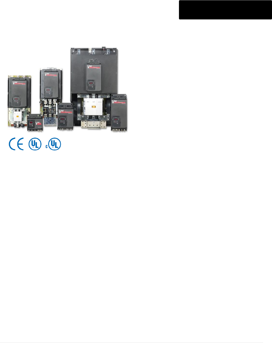
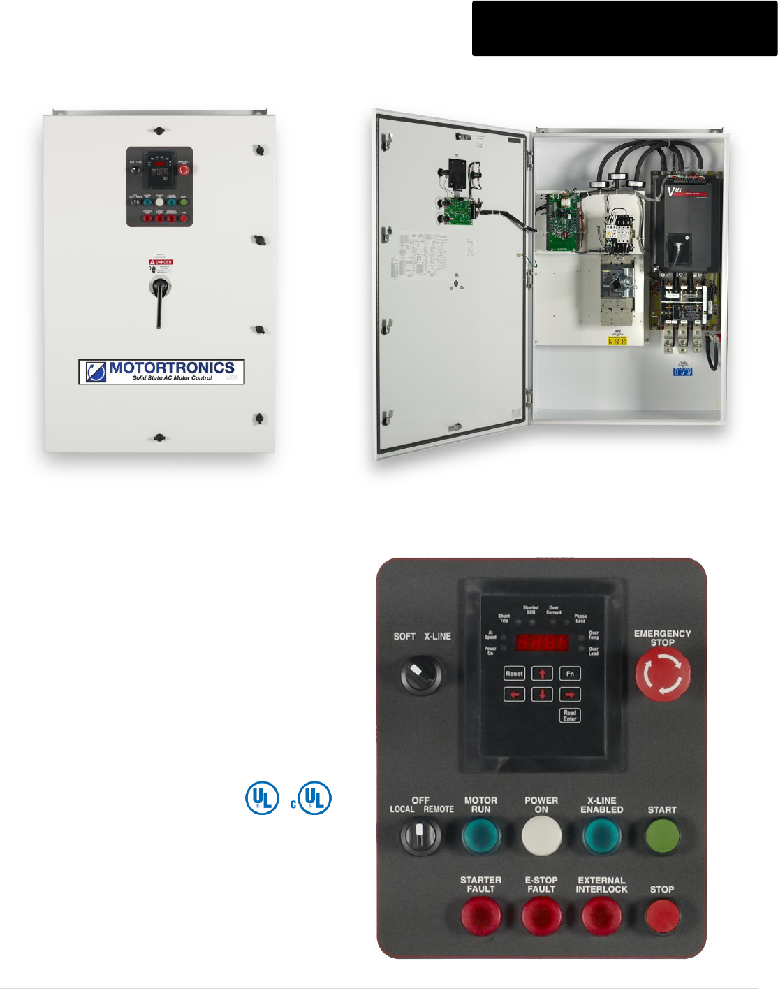
VMX SERIES COMPACT SOFT STARTER
208 - 575V, 9 - 1250 Amps, 5 - 1200 HP VMX Series
Flexibility of Control
Multiple ramp profiles, Pump-Flex™ Decel, process control timers
and advanced motor protection make the VMX Series soft starter
adaptable to a wide variety of AC motor applications... no need for
add-on modules or costly auxiliary devices.
Compact packaging has become critical in more and more
electrical installations. The VMX Series meets this need without
compromising features and ratings. By using a highly engineered
packaging design and the latest generation microprocessor, all the
control and protection features you need are in the VMX Series.
Narrow and shallow dimensions are perfect for integrating the VMX
Series into motor control centers (MCCs), pump control panels,
and retrofit starter enclosures.
Integral Bypass Contactors are standard on all sizes and provide
maximum efficiency of panel space while maintaining the
Motortronics reputation for being able to soft start most any load.
The VMX Series is the only fully integrated, compact, world-class
design offering uncompromised power and control capabilities.
Multiple Ramp Types to Start any Load
Closed Loop Current Ramp or Voltage Ramp, with or without
Current Limit
Built-in Decel Control, Dual Ramp, Kick Start and Jog Modes
Unit Overload Capacity (% FLA)
500% - 60 Seconds
Start & Run Protection
Two programmable overload trip curves allow for the thermal capacity
required to start the load while providing motor overload protection
needed during the run time.
Start: Programmable for Class 5 - 30
Run: Programmable for Class 5 - 30, enabled when starter
detects motor is "At-Speed"
Reset:Manual or automatic, selectable via programming. Remote
reset available.
Real-Time Thermal Modeling
Continuously calculates motor operating temperature even when
the motor is not running.
Retentive Thermal Memory
Remembers the thermal condition of the motor even in the event of a
power brown-out or black-out when power is restored.
Extrapolates motor temperature using a real-time clock.
Dynamic Reset Capacity
Overload will not reset until thermal capacity in the motor is sufficient for
a successful restart. Starter learns and retains this information from
previous starts.
Control
120V AC (customer supplied), 240V (opt)
24V DC dry contact inputs, no external DC power supply required
Motor Temperature
PTC thermistor input can also be used for E-stop or external overload relay.
Equipment Ground Fault
Residual current method with adjustable trip delay.
RS485 Modbus Communications
Full control and/or status monitoring over network or direct to a PC.
Phase Current Imbalance/Loss Protection
Trip level: 5 - 30% current imbalance between any two phases with trip delay
Phase Loss
Trips on phase current or voltage loss
Phase Rotation
Phase rotation trip can be set to A-B-C, A-C-B or disabled.
Electronic Shear Pin Protection
Trip level: 100 - 300% of motor FLA with trip delay
Load Loss (Under Current) Trip Protection
Trip level: 10 - 90% of motor FLA with trip delay
Motor Duty Cycle Protection
Back-spin/coast-down, starts-per-hour or minimum time between
starts lockouts. Restart delay after a power failure.
Short Circuit
Trips at 10x unit current rating during run. Checks for shorted load
prior to each start.
Shorted SCR
Locks out on any single shorted SCR (defeatable) or can provide shunt trip
function if multiple SCRs short or bypass contactor is welded closed.
Metering
Monitors phase current, ground current and motor thermal capacity.
M o t o r t r o n i c s P r o d u c t S e l e c t i o n G u i d e P a g e 4
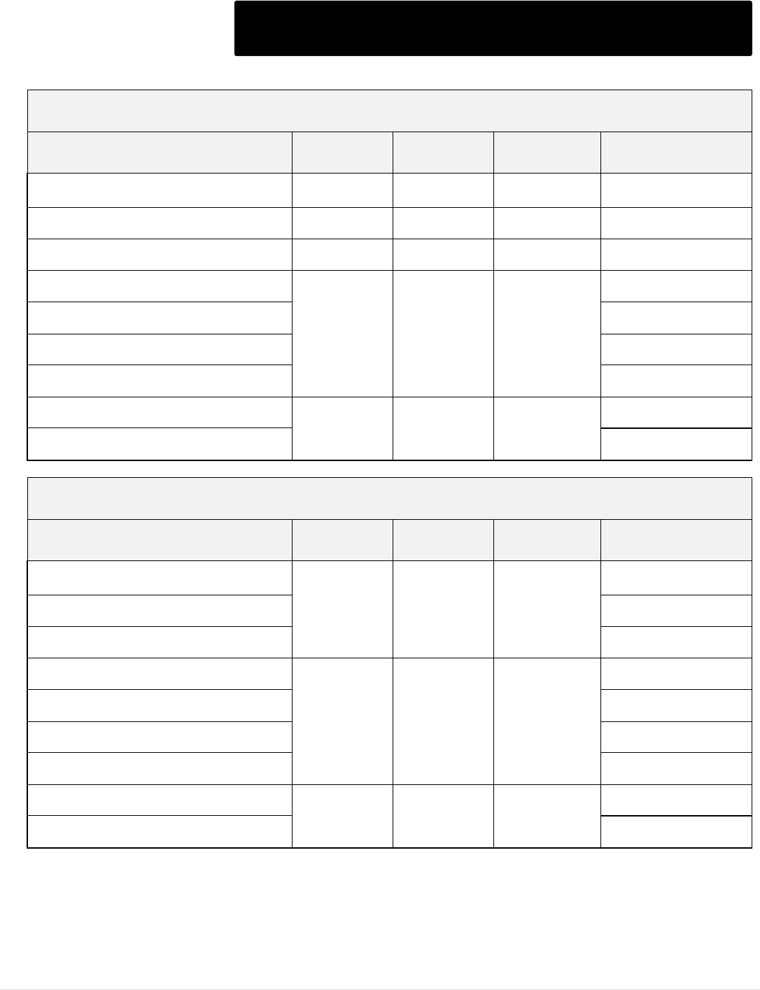
VMX Series (Module)
Model
Number
Amps
208V / HP
240V / HP
480V / HP
575V / HP
List Price $
Shunt
Bypass
Start
Bypass
Shunt
Bypass
Start
Bypass
Shunt
Bypass
Start
Bypass
Shunt
Bypass
Start
Bypass
Module
Only
VMX-18-BP
9 - 18
5
3
5
5
10
10
15
10
1,532
VMX-28-BP
14-28
7.5
7.5
7.5
7.5
20
15
25
20
1,532
VMX-39-BP
19-39
10
10
10
10
25
25
30
30
1,610
VMX-48-BP
24-48
15
10
15
15
30
30
40
30
1,610
VMX-62-BP
31-62
20
15
20
20
40
40
50
50
1,627
VMX-78-BP
39-78
25
20
25
25
60
50
60
60
1,694
VMX-92-BP
46-92
30
25
30
30
60
60
75
75
2,010
VMX-112-BP
56-112
30
30
40
30
75
75
100
75
2,214
VMX-150-BP
75-150
40
40
50
50
100
100
150
-
2,915
VMX-160-BP
80-160
50
40
60
50
125
100
150
-
3,116
VMX-210-BP
105-210
60
50
75
60
150
150
200
150
4,498
VMX-275-BP
138-275
75
60
100
75
200
150
200
150
5,342
VMX-361-BP
181-361
125
75
125
125
300
250
350
300
5,763
VMX-450-BP
225-450
150
125
150
150
350
300
450
300
6,466
VMX-550-BP
275-550
200
150
200
200
450
400
500
500
8,164
VMX-600-BP
300-600
200
200
250
200
500
500
600
600
8,312
VMX-862-BP
431-862
250
250
300
300
600
500
700
600
11,818
VMX-900-BP
450-900
300
250
350
300
700
600
900
600
13,054
VMX-1006-BP
503-1006
350
300
400
400
800
800
1000
900
19,790
VMX-1250-BP
625-1250
450
350
500
450
1000
900
1200
1000
22,244
NOTES:
1 – Size the Soft Starter based on the actual motor nameplate FLA.
2 – The above data is based on the NEC Table 430-150, full load current for 3 phase motors.
3 – All VMX units rated 500% current 60 sec; Start bypass ratings allow for use of 1.15 service factor motors.
4 – Control power is required for all units.
5 – Lug Kits see page 16.
M o t o r t r o n i c s P r o d u c t S e l e c t i o n G u i d e P a g e 5
VMX - __ - BP - _ VMX Series (Enclosed)
Max Amps. Enclosure
N: N1 / N1A
E: N12 (Includes Control Power Transformer)
Max.
Amps
208V / HP
240V / HP
480V / HP
575V / HP
List Price $
Shunt
Bypass
Start
Bypass
Shunt
Bypass
Start
Bypass
Shunt
Bypass
Start
Bypass
Shunt
Bypass
Start
Bypass
N1/ N1A
(Gasketed)
NEMA 4/12
18
5
3
5
5
10
10
15
10
1,745
2,411
28
7.5
7.5
7.5
7.5
20
15
25
20
1,745
2,411
39
10
10
10
10
25
25
30
30
1,822
2,487
48
15
10
15
15
30
30
40
30
1,822
2,487
62
20
15
20
20
40
40
50
50
1,981
2,503
78
25
20
25
25
60
50
60
60
2,048
2,569
92
30
25
30
30
60
60
75
75
2,357
2,879
112
30
30
40
30
75
75
100
75
2,559
3,080
150
40
40
50
50
100
100
150
-
3,342
3,820
160
50
40
60
50
125
100
150
-
3,540
4,018
210
60
50
75
60
150
150
200
150
5,239
5,622
275
75
60
100
75
200
150
200
150
6,108
6,450
361
125
75
125
125
300
250
350
300
6,543
6,866
450
150
125
150
150
350
300
450
300
7,362
7,744
550
200
150
200
200
450
400
500
500
9,114
9,411
600
200
200
250
200
500
500
600
600
9,265
9,556
862
250
250
300
300
600
500
700
600
16,473
CF
900
300
250
350
300
700
600
900
600
16,966
CF
1100
350
300
400
400
800
800
1000
900
23,580
CF
1250
450
350
500
450
1000
900
1200
1000
25,989
CF
NOTES:
1 – Size the Soft Starter based on the actual motor nameplate FLA.
2 – The above data is based on the NEC Table 430-150, full load current for 3 phase motors.
3 – All VMX units rated 500% current 60 sec; Start bypass ratings allow for use of 1.15 service factor motors.
4 – Enclosed units include line + load lugs.
5 – 500HP rating with 1.0 SF.
6 – VMX18 - 160 are N1, VMX210 - 1250 are N1A Gasketed
M o t o r t r o n i c s P r o d u c t S e l e c t i o n G u i d e P a g e 6
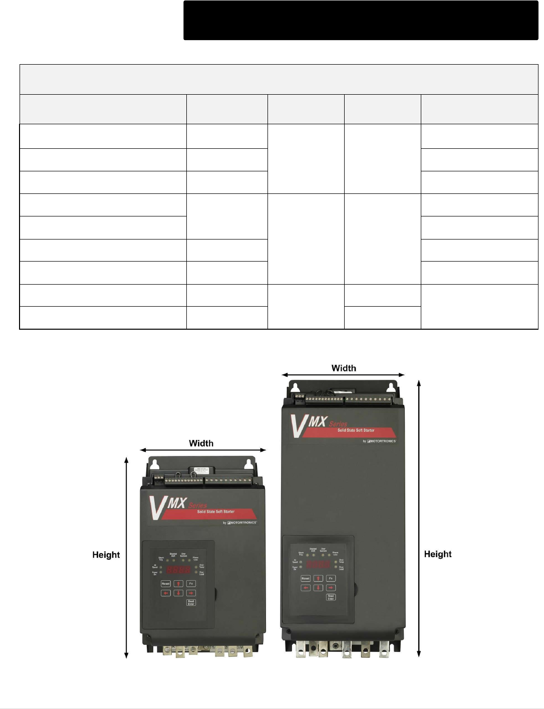
VMX Series Module Dimensions and Weights
PANEL - Dimensions and Shipping Weights
Model Number
H
inches (mm)
W
Inches (mm)
D
inches (mm)
Shipping Weight
Approx. lbs. (kg)
VMX-18-BP thru VMX-48-BP
8.85 (225)
8 (203)
6.65 (169)
13 (6)
VMX-62-BP thru VMX-112-BP
14 (355.6)
23 (10)
VMX-150-BP thru VMX-160-BP
19 (482.6)
33 (15)
VMX-210-BP
28.1 (713.7)
12.5 (317.5)
9.1 (231)
130 (59)
VMX-275-BP
140 (64)
VMX-361-BP thru VMX-450-BP
29.3 (744.2)
145 (66)
VMX-550-BP thru VMX-600-BP
29.5 (749.3)
165 (75)
VMX-862-BP thru VMX-900-BP
44.25 (1124)
25.5 (647.7)
11.86 (301.3)
Contact Factory
VMX-1006-BP thru VMX-1250-BP
50.77 (1289.6)
13.28 (337.3)
NOTE: Dimensions and Weights are subject to change.
M o t o r t r o n i c s P r o d u c t S e l e c t i o n G u i d e P a g e 7
VMX Series Enclosed Dimensions and Weights
N1 / N1A Gasketed - Dimensions and Shipping Weights
Model Number
H
inches (mm)
W
Inches (mm)
D
inches (mm)
Shipping Weight
Approx. lbs. (kg)
VMX-18-BP-N thru VMX-48-BP-N
15 (381)
10 (254)
8 (203.2)
22 (10)
VMX-62-BP-N thru VMX-112-BP-N
20 (508)
10 (254)
8 (203.2)
35 (15.9)
VMX-150-BP-N thru VMX-160-BP-N
28 (711)
10 (254)
8 (203.2)
49 (22.25)
VMX-210-BP-N
48 (1219.2)
33 (838.2)
16 (406.4)
308 (140)
VMX-275-BP-N
318 (144)
VMX-361-BP-N thru VMX-450-BP-N
323 (147)
VMX-550-BP-N thru VMX-600-BP-N
343 (156)
VMX-862-BP-N thru VMX-900-BP-N
92 (2336.8)
36 (914.4)
30 (76.2)
Contact Factory
VMX-1006-BP-N thru VMX-1250-BP-N
Contact Factory
NEMA 4/12 - Dimensions and Shipping Weights
Model Number
H
inches (mm)
W
Inches (mm)
D
inches (mm)
Shipping Weight
Approx. lbs. (kg)
VMX-18-BP-E thru VMX-48-BP-E
37 (939.8)
15 (381)
12 (304.8)
81 (37)
VMX-62-BP-E thru VMX-112-BP-E
91 (41)
VMX-150-BP-E thru VMX-160-BP-E
101 (46)
VMX-210-BP-E
48 (1219.2)
33 (838.2)
16 (406.4)
318 (144)
VMX-275-BP-E
328 (149)
VMX-361-BP-E thru VMX-450-BP-E
338 (153)
VMX-550-BP-E thru VMX-600-BP-E
358 (162)
VMX-862-BP-E thru VMX-900-BP-E
92 (2336.8)
36 (914.4)
30 (76.2)
Contact Factory
VMX-1006-BP-E thru VMX-1250-BP-E
Contact Factory
NOTE: Dimensions and Weights are subject to change.
M o t o r t r o n i c s P r o d u c t S e l e c t i o n G u i d e P a g e 8
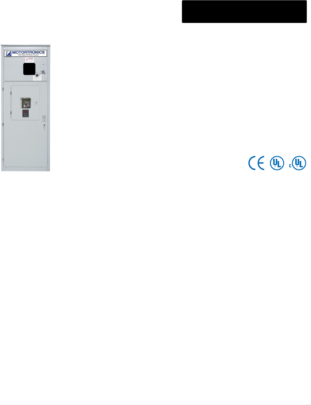
VMX SERIES CONFIGURED SOFT STARTER
208 – 575V, 18 – 1080 Amps, 5 – 1000 HP VMX Configured
The VMX Configured Soft Starter is designed for Heavy Duty Loads and includes the
advanced features of the VMX Chassis Soft Starter in a N4/12 Combination Package. The
Smart Door Customer Interface Panel allows for Superior Functionality and Diagnostics.
VMX-S & VMX-H Include:
N12/4 Enclosure
VMX Softstarter with built-in Bypass
Circuit Breaker Disconnect (55A- & up)
Fusible Switch Disconnect (18A-48A)
Advanced Motor Protection
Control Power Transformer
Interface Board for easy control connections
Smart Door Customer Interface including:
Door Mounted Digital Keypad
Emergency Stop Pushbutton
Local-Off-Remote Selector Switch
Start /Stop Pushbuttons
Motor Run Pilot Light
Power On Pilot Light
Starter Fault Pilot Light
E-Stop Fault Pilot Light
External Interlock Pilot Light
VMX-H also includes:
Start Rated Bypass Contactor
External Motor Overload for Across the Line mode
Soft Start – X-Line mode Selector Switch
X-Line Enabled Pilot Light
M o t o r t r o n i c s P r o d u c t S e l e c t i o n G u i d e P a g e 9
VMX - S - __ - __ - _ VMX-S Series
Max Amps. Line Voltage
1 = 208V, 2 = 240V
4 = 480V, 5 = 575V
Disconnect
FS: 18A-48A (Fused Switch)
CB: 62A-862A (Circuit Breaker)
Max
Amps
Fused Switch/
Circuit Breaker
208V / HP
240V / HP
480V / HP
List Price $
575V / HP
List Price $
18
30A FS
5
5
10
4,285
15
4,714
28
60A FS
7.5
7.5
15-20
4,285
20-25
4,714
39
60A FS
10
10
25
4,362
30
4,798
48
60A FS
15
15
30
4,391
40
4,830
62
100A CB
20
20
40
4,406
50-60
4,847
78
100A CB
25
25
50
5,160
75
5,676
92
150A CB
30
30
60
5,760
75
6,336
112
150A CB
30
40
75
6,360
100
6,996
150
225A CB
40
50
100
7,080
125
7,789
160
225A CB
50
60
125
7,680
150
8,448
210
400A CB
60
75
150
8,640
200
9,504
275
400A CB
75
100
200
10,140
250
11,154
305
400A CB
100
125
250
10,920
300
12,012
361
600A CB
125
125
300
11,640
350
12,804
450
600A CB
150
150
350
11,976
400
13,174
480
600A CB
150
200
400
15,000
500
16,500
550
800A CB
200
200
450
19,080
500
20,988
600
800A CB
200
250
500
22,020
600
24,222
862
1200A CB
250
300
600
24,300
700
26,730
Consult factory for larger models.
NOTES:
1 – Size the Soft Starter based on the actual motor nameplate FLA.
2 – The above data is based on the NEC Table 430-150, full load current for 3 phase motors.
3 – The units listed are rated for 500% overload capacity for 60 sec., 1.0 SF.
4 – Enclosed units include line + load lugs.

M o t o r t r o n i c s P r o d u c t S e l e c t i o n G u i d e P a g e 10
VMX - H - __ - __ - _ VMX-H Series
Max Amps. Line Voltage
1 = 208V, 2 = 240V
4 = 480V, 5 = 575V
Disconnect
FS: 21A-45A (Fused Switch)
CB: 55A-960A (Circuit Breaker)
Max
Amps
Fused Switch/
Circuit Breaker
208V / HP
240V / HP
480V / HP
List Price $
575V / HP
List Price $
21
30A FS
7.5
7.5
15
4,320
10-15
4,752
27
60A FS
10
10
25
4,440
20
4,884
40
60A FS
10
15
30
4,500
25
4,950
45
60A FS
15
20
40
4,800
30
5,279
55
100A CB
20
25
50
5,100
40
5,610
68
100A CB
25
30
60
5,279
50
5,807
80
150A CB
30
30
75
5,721
50
6,293
96
150A CB
30
30
75
6,361
60
6,997
125
225A CB
40
60
100
6,756
75
7,432
156
225A CB
60
75
150
7,920
100
8,712
220
400A CB
60
125
150
9,795
150
10,774
248
400A CB
100
150
250
10,464
200
11,511
312
400A CB
125
150
300
11,976
250
13,174
400
600A CB
125
200
300
13,036
300
14,339
480
600A CB
150
200
400
17,940
500
19,734
600
800A CB
200
200
500
22,200
600
24,421
690
1200A CB
250
300
500
23,700
600
26,069
800
1200A CB
-
300
600
24,900
600
27,391
960
1200A /
1600A CB
300
400
800
34,680
900
38,148
Consult factory for larger models.
NOTES:
1 – Size the Soft Starter based on the actual motor nameplate FLA.
2 – The above data is based on the NEC Table 430-150, full load current for 3 phase motors.
3 – The units listed are rated for 500% overload capacity for 60 sec., 1.15 SF.
4 – Enclosed units include line + load lugs.
5 – 500HP rating with 1.0 SF.
M o t o r t r o n i c s P r o d u c t S e l e c t i o n G u i d e P a g e 11
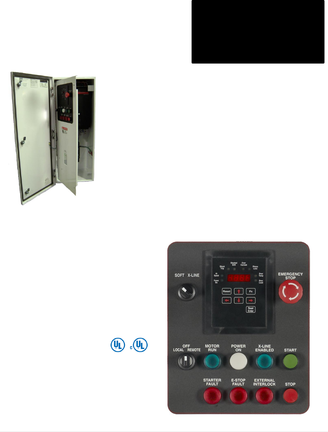
VMX Series
Configured
with Deadfront
VMX SERIES COMPACT SOFT STARTER
208V – 575V, 9 – 1250 Amps, 5 – 1200 HP
VMX Configured with Deadfront
VMX-S & VMX-H Include:
N12/4 Enclosure
VMX Softstarter with built-in Bypass
Circuit Breaker Disconnect (55A- & up)
Fusible Switch Disconnect (18A-48A)
Advanced Motor Protection
Control Power Transformer
Interface Board for easy control connections
Smart Door Customer Interface including:
Door Mounted Digital Keypad
Emergency Stop Pushbutton
Local-Off-Remote Selector Switch
Start /Stop Pushbuttons
Motor Run Pilot Light
Power On Pilot Light
Starter Fault Pilot Light
E-Stop Fault Pilot Light
External Interlock Pilot Light
VMX-H also includes:
Start Rated Bypass Contactor
External Motor Overload for Across the Line mode
Soft Start – X-Line mode Selector Switch
X-Line Enabled Pilot Light
The VMX Configured Soft Starter is designed for Heavy Duty Loads and includes the
advanced features of the VMX Chassis Soft Starter in a N4/12 Combination Package. The
Smart Door Customer Interface Panel allows for Superior Functionality and Diagnostics.
M o t o r t r o n i c s P r o d u c t S e l e c t i o n G u i d e P a g e 12
VMX - S - __ - __ - _ D VMX-S Series
Max Amps. Line Voltage
1 = 208V, 2 = 240V
4 = 480V, 5 = 575V
Disconnect
FS: 18A-48A (Fused Switch)
CB: 62A-600A (Circuit Breaker)
Deadfront
Max
Amps
Fused Switch/
Circuit Breaker
208V / HP
240V / HP
480V / HP
List Price $
575V / HP
List Price $
18
30A FS
5
5
10
4,885
15
5,373
28
60A FS
7.5
7.5
15-20
4,885
20-25
5,373
39
60A FS
10
10
25
4,962
30
5,458
48
60A FS
15
15
30
4,991
40
5,490
62
100A CB
20
20
40
5,007
50-60
5,508
78
100A CB
25
25
50
5,760
75
6,336
92
150A CB
30
30
60
6,360
75
6,996
112
150A CB
30
40
75
6,960
100
7,655
150
225A CB
40
50
100
7,680
125
8,448
160
225A CB
50
60
125
8,280
150
9,108
210
400A CB
60
75
150
9,360
200
10,296
275
400A CB
75
100
200
10,860
250
11,947
305
400A CB
100
125
250
11,640
300
12,804
361
600A CB
125
125
300
12,360
350
13,595
450
600A CB
150
150
350
12,696
400
13,966
480
600A CB
150
200
400
15,720
500
17,293
550
800A CB
200
200
450
19,800
500
21,780
600
800A CB
200
250
500
22,740
600
25,015
Consult factory for larger models.
NOTES:
1 – Size the Soft Starter based on the actual motor nameplate FLA.
2 – The above data is based on the NEC Table 430-150, full load current for 3 phase motors.
3 – The units listed are rated for 500% overload capacity for 60 sec., 1.0 SF.
4 – Enclosed units include line + load lugs.

M o t o r t r o n i c s P r o d u c t S e l e c t i o n G u i d e P a g e 13
VMX - H - __ - __ - _ D VMX-H Series
Max Amps. Line Voltage
1 = 208V, 2 = 240V
4 = 480V, 5 = 575V
Disconnect
FS: 21A-45A (Fused Switch)
CB: 55A-600A (Circuit Breaker)
Deadfront
Max
Amps
Fused Switch/
Circuit Breaker
208V / HP
240V / HP
480V / HP
List Price $
575V / HP
List Price $
21
30A FS
7.5
7.5
15
4,920
10-15
5,413
27
60A FS
10
10
25
5,040
20
5,544
40
60A FS
10
15
30
5,100
25
5,610
45
60A FS
15
20
40
5,400
30
5,940
55
100A CB
20
25
50
5,700
40
6,270
68
100A CB
25
30
60
5,878
50
6,466
80
150A CB
30
30
75
6,320
50
6,952
96
150A CB
30
30
75
6,962
60
7,658
125
225A CB
40
60
100
7,356
75
8,091
156
225A CB
60
75
150
8,520
100
9,372
220
400A CB
60
125
150
10,515
150
11,566
248
400A CB
100
150
250
11,184
200
12,303
312
400A CB
125
150
300
12,696
250
13,966
400
600A CB
125
200
300
13,756
300
15,132
480
600A CB
150
200
400
18,660
500
20,526
600
800A CB
150
200
500
22,920
600
25,212
Consult factory for larger models.
NOTES:
1 – Size the Soft Starter based on the actual motor nameplate FLA.
2 – The above data is based on the NEC Table 430-150, full load current for 3 phase motors.
3 – The units listed are rated for 500% overload capacity for 60 sec., 1.15 SF.
4 – Enclosed units include line + load lugs.
5 – 500HP rating with 1.0 SF.
M o t o r t r o n i c s P r o d u c t S e l e c t i o n G u i d e P a g e 14
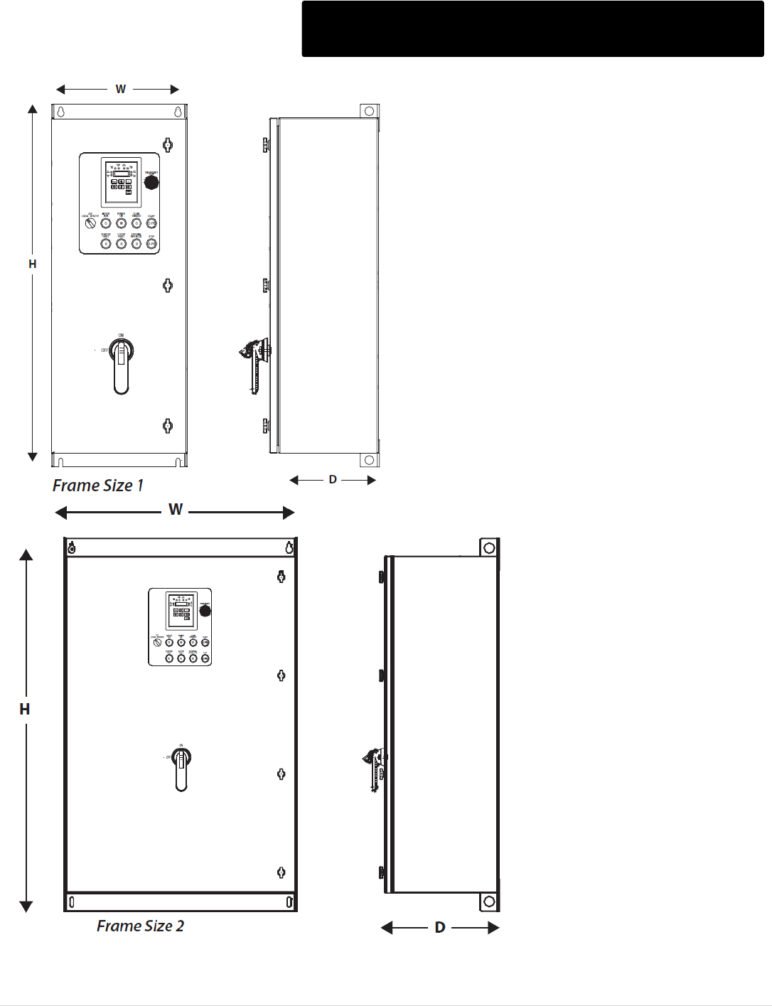
VMX Configured Dimensions and Weights
Frame Size
NEMA 4/12 Enclosure
Dimensions in inches (mm)
H x W x D
1
Wall Mount
37 x 15 x 12 (934 x 381 x 305)
2
Wall Mount
48 x 33 x 16 (1219 x 838 x 406)
3
Floor Standing
92 x 36 x 30 (2337 x 914 x 762)
NOTE: Dimensions and weights subject to change.
VMX-S Model
VMX-H Model
Size
Shipping Weight
lbs (kg)
VMX-S-18-FS
-
1
116 (53)
VMX-S-28-FS
VMX-H-21-FS
1
VMX-S-39-FS
VMX-H-27-FS
1
VMX-S-48-FS
VMX-H-40-FS
1
VMX-S-62-CB
VMX-H-45-FS
1
120 (55)
VMX-S-78-CB
VMX-H-55-CB
1
VMX-S-92-CB
VMX-H-68-CB
1
VMX-S-112-CB
VMX-H-80-CB
1
VMX-S-150-CB
VMX-H-96-CB
1
125 (57)
VMX-S-160-CB
VMX-H-125-CB
1
VMX-S-210-CB
VMX-H-156-CB
2
350 (159)
VMX-S-275-CB
VMX-H-220-CB
2
VMX-S-305-CB
VMX-H-248-CB
2
VMX-S-361-CB
VMX-H-312-CB
2
VMX-S-450-CB
VMX-H-400-CB
2
VMX-S-480-CB
-
2
VMX-S-550-CB
VMX-H-480-CB
2
VMX-S-600-CB
VMX-H-600-CB
2
VMX-S-862-CB
VMX-H-690-CB
3
Consult Factory
VMX-S-900-CB
VMX-H-800-CB
3
VMX-S-1006-CB
VMX-H-960-CB
3
VMX-S-1250-CB
VMX-H-1080-CB
3
M o t o r t r o n i c s P r o d u c t S e l e c t i o n G u i d e P a g e 15
VMX Configured Outline Dimensions

M o t o r t r o n i c s P r o d u c t S e l e c t i o n G u i d e P a g e 16
VMX Series Accessories & Spare Parts
** Includes lugs for all 6 termination points (Line + Load)
* Specify unit amperage rating.
* Models rated 160A and below are not designed for field replacement of the integral contactor.
Optional Lug Kits **
Model Number
Wire Size
Model
List Price $
71-0228
# 14 to # 4 (1 per phase)
VMX-18 to VMX-48
33
71-0229
# 14 to 1/0 (1 per phase)
VMX-62 to VMX-112
55
71-0230
# 14 to 3/0 (1 per phase)
VMX-150 to VMX-160
110
71-0231
# 6 to 250 MCM (2 per phase)
VMX-210 to VMX-361
165
71-0232
# 6 to 500 MCM (2 per phase)
VMX-450 to VMX-600
220
71-0251
# 6 to 600 MCM (3 per phase)
VMX-862 to VMX-900
605
71-0252
# 6 to 600 MCM (4 per phase)
VMX-1006 to VMX-1250
660
Printed Circuit Boards & Accessories
Item
Model Number
Description
Model
List Price $
Keypad / CPU
Assembly
VMX-KP-CPU-XXXX*
VMX Keypad/CPU/I/O board
assembly (specify amperage
when ordering)
VMX-18 to VMX-48
618
VMX-KP-CPU-XXXX*
VMX-62 to VMX-112
642
VMX-KP-CPU-XXXX*
VMX-150 to VMX-160
650
VMX-KP-CPU-XXXX*
VMX-210 & above
650
Main Power
Board
VMX1000-PWR
Main Power PC Board
VMX-18 to VMX-48
336
VMX1001-PWR
VMX-62 to VMX-112
350
VMX1002-PWR
VMX-150 to VMX-160
370
VMX1003-PWR
VMX-210 to VMX-1250
410
Cable assembly with connectors on each end for remote mounting
Remote Display
Kit
VMX-KP12-KIT2-1
NEMA 12 Kit with 1m Cable
VMX-18 to VMX-48
140
VMX-KP12-KIT2-2
NEMA 12 Kit with 2m Cable
160
VMX-KP12-KIT2-3
NEMA 12 Kit with 3m Cable
170
VMX-KP12-KIT-1
NEMA 12 Kit with 1m Cable
VMX-62 and Above
150
VMX-KP12-KIT-2
NEMA 12 Kit with 2m Cable
175
VMX-KP12-KIT-3
NEMA 12 Kit with 3m Cable
180
Replacement Contactors*
Model Number
Model
List Price $
34-GMC-220
VMX-210-BP to VMX-275-BP
983
34-GMC-400
VMX-361-BP to VMX-440-BP
1,426
34-600-600-VC
VMX-550-BP to VMX-600-BP
3,575
34-GMC-800
VMX-718-BP to VMX-900-BP
3,960
34-AF1350
VMX-1006-BP to VMX-1250-BP
Contact Factory

M o t o r t r o n i c s P r o d u c t S e l e c t i o n G u i d e P a g e 17
VMX Configured Series Options
NOTE: VMX-62 thru VMX-160 are provided with terminating bus tabs as standard.
Model Number
Description
List Price $
Option AA
Dual ramp option, includes 2-position switch
132
Option B
Jog option, includes run/jog Switch
165
Option H
Enclosure heater with thermostat
550
Option SA
Surge Suppressor
550
Option OL
Additional overload relay for backup in X-line mode
330
Option RX
RX Series motor protection/metering relay
715
Option X-LINE
Soft – Off – X-Line Switch
165
Option SHIELD
Bolt on Sun Shield
385
M o t o r t r o n i c s P r o d u c t S e l e c t i o n G u i d e P a g e 18
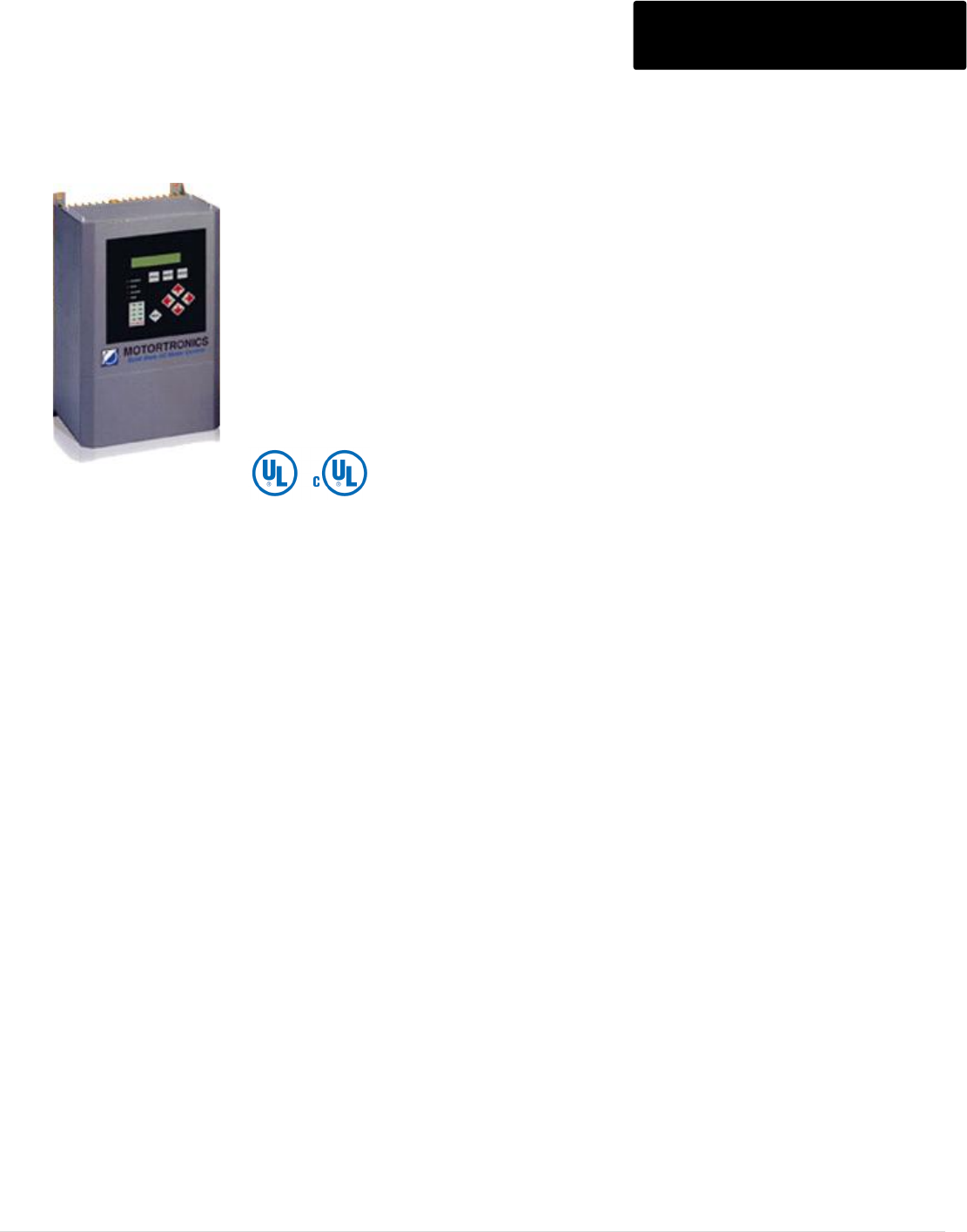
DXT SERIES ADVANCED DIGITAL SOFT STARTER
208 - 575V, 39 - 1250 Amps, 10 - 1125 HP DXT Series
“Medium Voltage features in a low voltage starter"
• Advanced Soft Starter Features
• Thermal Model Motor Protection
• True Motor Power Monitoring
• Voltage, Current and Power Metering
• Flexible Control Features
The DXT Series is a high-end digitally programmable solid
state reduced voltage soft starter. This heavy duty starter
provides reduced voltage, stepless soft starting of 3-phase AC
induction motors, protecting mechanical components from
excessive torque stress and electrical systems from the effects
of high motor inrush currents. The DXT Series includes
advanced motor and load protection features just like those
found in expensive motor protection relays. These include
retentive thermal memory, dynamic reset capacity, true thermal
modeling, separate trip curves for start and run
protection, overload alarm, etc. But in the case of the DXT
Series, these features are built in as standard features,
providing a cost effective and reliable motor starting and
protection scheme for your critical motor applications.
The DXT Series features an easy to use interface operator for
programming and status indication. It includes a large tactile
feedback keypad, LED status indicators and a 2 line x 20
character backlit display using plain English text readout. In
addition to programming the standard parameters such as
starting torque, ramp time, current limit, dual ramp and decel
control, other features like programmable overload trip curves
(NEMA/UL Classes 5 - 30), starts-per-hour, time between starts
and coast down/back spin lockout protection can also be
programmed for your specific application
needs.
The power of the DXT Series is in the CPU, a
microprocessor based protection and control
system for the motor and starter assembly. The
CPU uses Phase Angle Firing of the SCRs to
apply a reduced voltage to the motor, and then
slowly and gently increases torque through
control of the voltage and current until the motor
accelerates to full speed. This starting method
lowers the starting current of the motor, reducing
electrical stresses on the power system and
motor. It also reduces peak starting torque
stresses on both the motor and load mechanical
components, promoting longer service life and
less downtime.
M o t o r t r o n i c s P r o d u c t S e l e c t i o n G u i d e P a g e 19
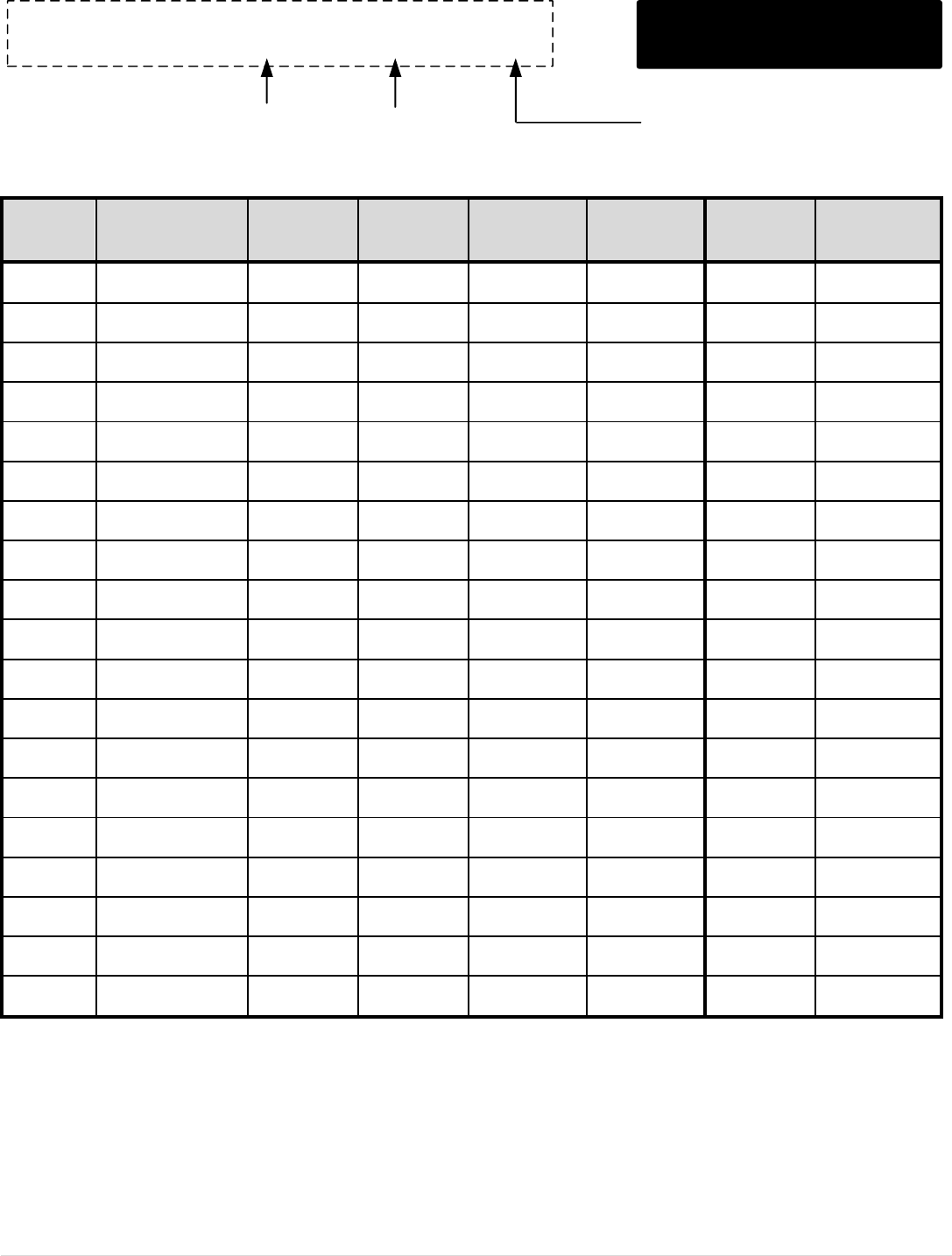
DXT Series (Module)
Model
Max Amps
208V / HP
230V / HP
460V / HP
575V / HP
List Price $
DXT-39
39
10
-
25
30
3,313
DXT-48
48
10
15
30
40
3,423
DXT-62
62
15
20
40
50
3,632
DXT-78
78
20
25
50
60
3,864
DXT-92
92
25
30
60
75
4,349
DXT-120
120
30
40
75
100
4,712
DXT-150
150
40
50
100
125
4,767
DXT-180
180
50
60
125
150
5,450
DXT-220
220
60
75
150
200
5,803
DXT-288
288
75
100
200
250
6,244
DXT-360
360
100
125
250
300
7,032
DXT-414
414
125
150
300
350
7,049
DXT-476
476
-
-
350
400
7,623
DXT-550
550
150
200
400
500
7,986
DXT-718
718
200
250
500
600
9,397
DXT-862
862
250
300
600
700
12,143
DXT-1006
1006
300
350
700
800
14,081
DXT-1150
1150
350
400
800
900
19,320
DXT-1200
1200
400
450
900
1000
21,955
DXT-1250
1250
450
500
1000
1125
24,954
DXT-39 thru DXT-120 includes a Shunt Rated Bypass.
NOTES:
1. Units require an external 120 VAC control circuit. (Specify 240 VAC if required)
2. The units listed are rated for 500% capacity for 60 sec., 1.15 SF

M o t o r t r o n i c s P r o d u c t S e l e c t i o n G u i d e P a g e 20
DXT Series Dimensions
Enclosure
Model Number
Overall Dimensions
(Inches)
Mounting Dimensions
( Inches)
A
B
C
D
E
F
PANEL
DXT-39 to DXT-120
16.5
10
10
15.9
9
0.28
DXT-150 to DXT-180
20
20.1
12
18.5
17.5
0.44
DXT-220 to DXT-288
27
20.1
11.2
25.5
17.5
0.44
DXT-360 to DXT-550
29.5
20.1
11.5
25.5
17.5
0.44
DXT-718 to DXT-1006
45
33
12.8
43.3
31.3
0.44
DXT-1150 to DXT-1250
33
33
15.2
31.2
31.2
0.44
M o t o r t r o n i c s P r o d u c t S e l e c t i o n G u i d e P a g e 21
Communications Software & Modules
MLINK - Monitoring / Programming Software
Series
Description
List Price $
VMX
Low Voltage Starters
Free
DXT
Low Voltage Starters
Free
MVC
Medium Voltage Starters
Free
RX
Motor Protection Relay
Free
TE-RTD12
Motor RTD Module
Free
VCM
Variable Frequency Drive
Free
MT
Variable Frequency Drive
Free
Download from www.motortronics.com
Series
Description
List Price $
64-VS1
Communication Module for Soft Starters, AC Drives and Motor Protection
Relays gives users web-based access to their system using a standard
internet web-browser. Standard built-in features include data-logging,
alarm handling, monitoring and control. The VS1-MT can be configured in
just a matter of minutes and is compatible with any 3rd party device that
supports MODBUS RTU over RS232/RS485 or MODBUS/TCP over
Ethernet. Can also be used as a communication gateway for connection to
PLC systems and simultaneously monitor/log soft starters and AC drives
via your standard web-browser.
This module can also be used as an Ethernet MODBUS/TCP to MODBUS
RTU Communication gateway for connection to PLC systems and soft
starters and AC Drives.
1,600
64-VS2
Ethernet Modbus TCP Communication Module for MVC Plus, DXT, VMX,
RX and TE-RTD12 products.
1,400
64-MLINK-01K
Software Kit includes USB to RS485 Converter and MLINK software for
programming, monitoring and startup of the MVC Plus.
500
64-AB7007
Ethernet/IP Communication Module for MVC Plus, DXT, VMX, RX and
TE-RTD12 products.
3,500
64-GWY-500-B
Profibus DP Communication Module for MVC Plus, DXT, VMX, RX and
TE-RTD12 products.
3,500
M o t o r t r o n i c s P r o d u c t S e l e c t i o n G u i d e P a g e 22
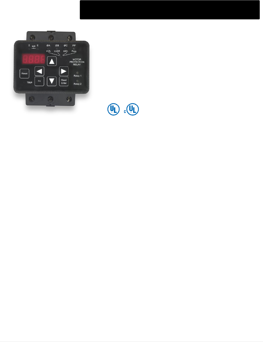
RX Series Motor Protection
“The prescription for a healthy motor"
• “Thermal Model” Motor Protection
• True Motor Power Monitoring
• Voltage, Current and Power Metering
• Flexible Control Features
• Priced Right
Protect your 3 phase motors from:
-Line power problems: Single Phasing
Phase Reversal, Voltage Imbalance
-Thermal Overload (i²t), Class 5 - 30
-Equipment Ground Fault
-Current Imbalance
-Jammed Load / Locked Rotor
-Broken shaft / belt / loss of prime
-Over / Under Voltage
-Low / High Power Factor
-Short Cycling, Too Many Starts per Hour
-Back-Spin Restart Lockout
-Excessive Run Time
-Acceleration / Incomplete Sequence
-Over / Under Frequency from a Generator
Advanced Technology for Maximum Motor and System Protection
The RX Series uses Thermal Modeling software normally found only in
the most sophisticated Motor Protection Relays. This software keeps
track of power related issues occurring in the motor circuit that contribute
to causing a thermal overload. If there is a power loss, a unique
combination of non-volatile memory and a real-time clock ensure that this
protection is in effect when power is restored. Should an overload occur,
the RX Series is intelligent enough to make sure that it can only be reset
when the motor is sufficiently cooled down and is ready to start again
successfully. Voltage input features allow true Motor Load Monitoring, not
just current, along with Power Factor, kVA and monitoring.
Built-in Flexible Control Features Provide Cost and Space Savings
A 24Hr/ / 7Day Real Time Clock allows for additional features that can
eliminate the need for other discrete devices. Duty cycle can be controlled
by using the Starts/Hour and Minimum Time Between Starts features,
plus a Coast-Down / Backspin timer can prevent restarting while a motor
is spinning backwards.
Simple Batch Time processes of up to 7 events can be programmed for
daily, multi-day or weekly operations without the need for an external time
clock. A Restart Delay timer allows staggered restarting of multiple units
as well.
Add Metering and Communications to New or Existing Starters
Metering for Three Phase Currents, Voltages, kW, kVA, kVAR, Power
Factor, Frequency, kWH, Elapsed Run Time, Run Cycle Count, Lock-Out
Time, Reset Time and Remaining Thermal Capacity are all included, and
can be both read on the display and communicated via the built-in RS-
485 Modbus RTU communication.
M o t o r t r o n i c s P r o d u c t S e l e c t i o n G u i d e P a g e 23
RX Series Motor Protection and Options
RX MOTOR PROTECTION SERIES
Model Number
Description
List Price $
RX-5
5A, CT fed relay
550
RX-KP12-KIT-2
NEMA 4/12 Remote keypad kit includes 2 meter DB9
Serial Cable, Gasket and instructions
75
ZCT
Zero Sequence Relay
1,300
TE-RTD12
Relay device adds advanced RTD and Current
monitoring capability.
1,500
M o t o r t r o n i c s P r o d u c t S e l e c t i o n G u i d e P a g e 24
Current Transformers for the RX Series
11 - 2 RL - 500
Ratio
500 = 50:5 / 750 = 75:5
101 = 100:5 / 151 = 150:5
201 = 200:5 / 251 = 250:5
301 = 300:5 / 401 = 400:5
501 = 500:5 / 601 = 600:5
751 = 750:5 / 801 = 800:5
102 = 1000:5 / 122 = 1200:5
152 = 1500:5 / 162 = 1600:5
202 = 2000:5
Windows Size
2 = 1.05 Inch
56 = 2.06 Inch
8 = 3.25 Inch
Style
RL = Round with Leads
SFT = Sq w/ Terminals and Feet
SHT = Sq with Terminals
NOTE: Prices listed above are for a single CT. A quantity of 3 is required for the RX Relay.
Current Transformers
Model Number
Current Ratio
Window (Inches)
List Price $ (Per CT)
2RL
50:5 thru 300:5
1.05
24
2SFT
50:5 thru 400:5
1.05
26
56RL
50:5 thru 500:5
2.06
31
56RL
600:5 thru 1200:5
2.06
39
56SFT
50:5 thru 1200:5
2.06
31
8RL
200:5 thru 1000:5
3.25
62
8RL
1200:5 thru 1500:5
3.25
70
8RL
1600:5 thru 2000:5
3.25
92
8SHT
200:5 thru 1000:5
3.25
65
8SHT
1200:5 thru 1500:5
3.25
89
8SHT
1600:5 thru 2000:5
3.25
93
M o t o r t r o n i c s P r o d u c t S e l e c t i o n G u i d e P a g e 25
RX Current Transformers Dimensions
M o t o r t r o n i c s P r o d u c t S e l e c t i o n G u i d e P a g e 26
RX - 5 Dimensions
M o t o r t r o n i c s P r o d u c t S e l e c t i o n G u i d e P a g e 27
RX - KP12 – KIT – 2 Dimensions
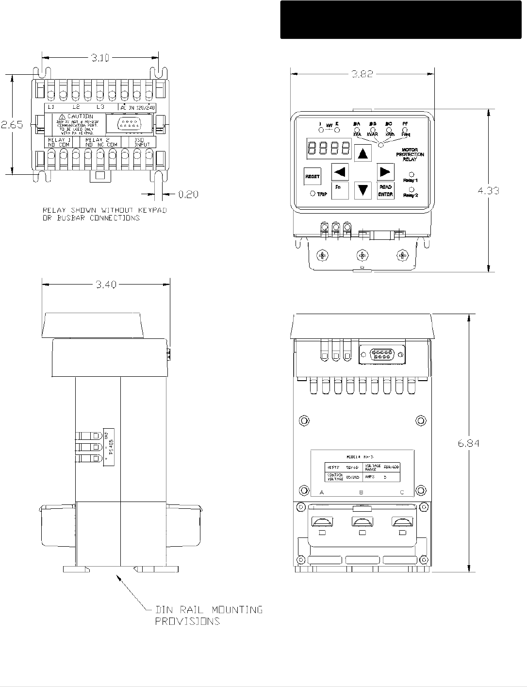
M o t o r t r o n i c s P r o d u c t S e l e c t i o n G u i d e P a g e 28
ZCT Options Dimensions
M o t o r t r o n i c s P r o d u c t S e l e c t i o n G u i d e P a g e 29
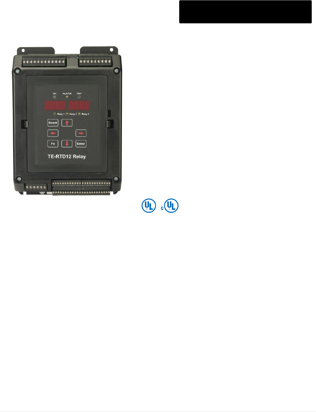
TE-RTD12 Motor RTD Monitor Series TE-RTD12 Series
The TE-RTD12 Relay device adds advanced RTD and Current
monitoring capability to your new or existing motor system. The
TE-RTD12 Relay device offers 12 built-in RTD inputs, 3
programmable output relays (5A), 2 isolated analog inputs (4-
20mA), 3 isolated digital inputs,1 isolated analog output (4-
20mA) and differential current feedback monitoring.
A built-in RS485 (2 wire) communication port allows for use
with a master device (PLC / SCADA / Operator Interface) for
the purpose of programming and monitoring.
Programmable relay outputs are provided that can be set to a
system function or for use as a global Alarm or Trip based on
temperature readout. Temperature readout and programming
can be entered in degrees Celsius or Fahrenheit.
A built-in event recorder stores fault information of current and
past events with date and time-stamp. The TE-RTD12 Relay
device can be mounted on a back panel using the mounting
bracket or DIN-Rail mount.
Control Voltage: 110 - 240Vac Nominal 50/60Hz
Inputs: 12 RTD inputs (Pt100, Ni100, Ni120, Cu10), 3 CT inputs for differential CT’s
2 isolated 4-20mA analog inputs, 3 isolated Digital Inputs
Outputs: 3 programmable form C Relays with 5A contact rating,
One isolated 4-20mA analog output
Keypad: Two 4-digit displays, one for the RTD name (St1, St2, …) and one for the temperature.
1 green ‘OK’ LED, 1 yellow ‘ALARM’ LED, 1 red ‘TRIP’ LED and 3 Relay LED’s.
7 pushbuttons: 4 arrows, 1 ‘Function’, 1 ‘Enter’ and a ‘Reset’ button
Differential CT’s:Primary 5-2000A, Secondary 1A or 5A, Alarm and Trip Levels OFF, 5% to 90 % of CT value
Resolution/Accuracy: Analog Inputs better than 1%, Analog Outputs better than 0.5%
Communication Port: 2 Wire RS-485, MODBUS RTU
I/O Terminals: Removable terminal blocks
Temperature: Operating 32ºF – 122ºF / 0ºC to 50ºC, Storage -4ºF – 176ºF / -20ºC to 80ºC
Humidity: 10% to 90% (non-condensing)
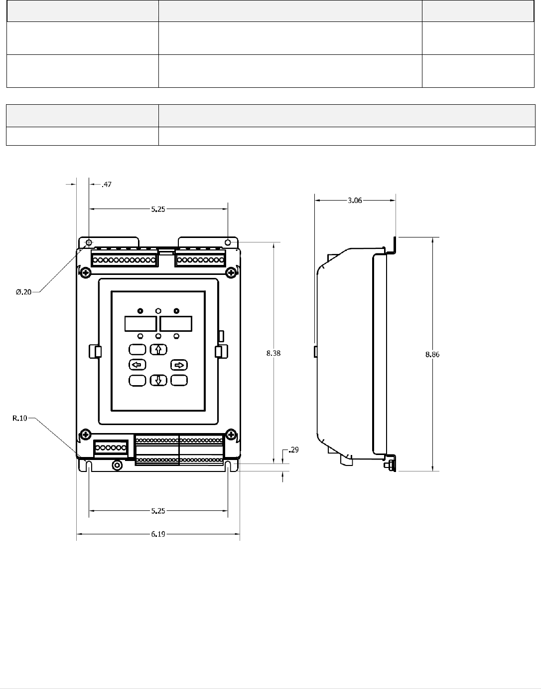
M o t o r t r o n i c s P r o d u c t S e l e c t i o n G u i d e P a g e 30
Model Number
Dimensions (Inches) - H x W x D
TE-RTD12
8.86 x 6.19 x 3.06
Mounting: Use the designated mounting holes to mount the TE-RTD12 in the designated area of your system.
Model Number
Description
List Price $
TE-RTD12
Relay device adds advanced RTD and Current
monitoring capability.
1,500
TE-RTD12-KP12-PTB-KIT
Remote keypad kit
300
M o t o r t r o n i c s P r o d u c t S e l e c t i o n G u i d e P a g e 31
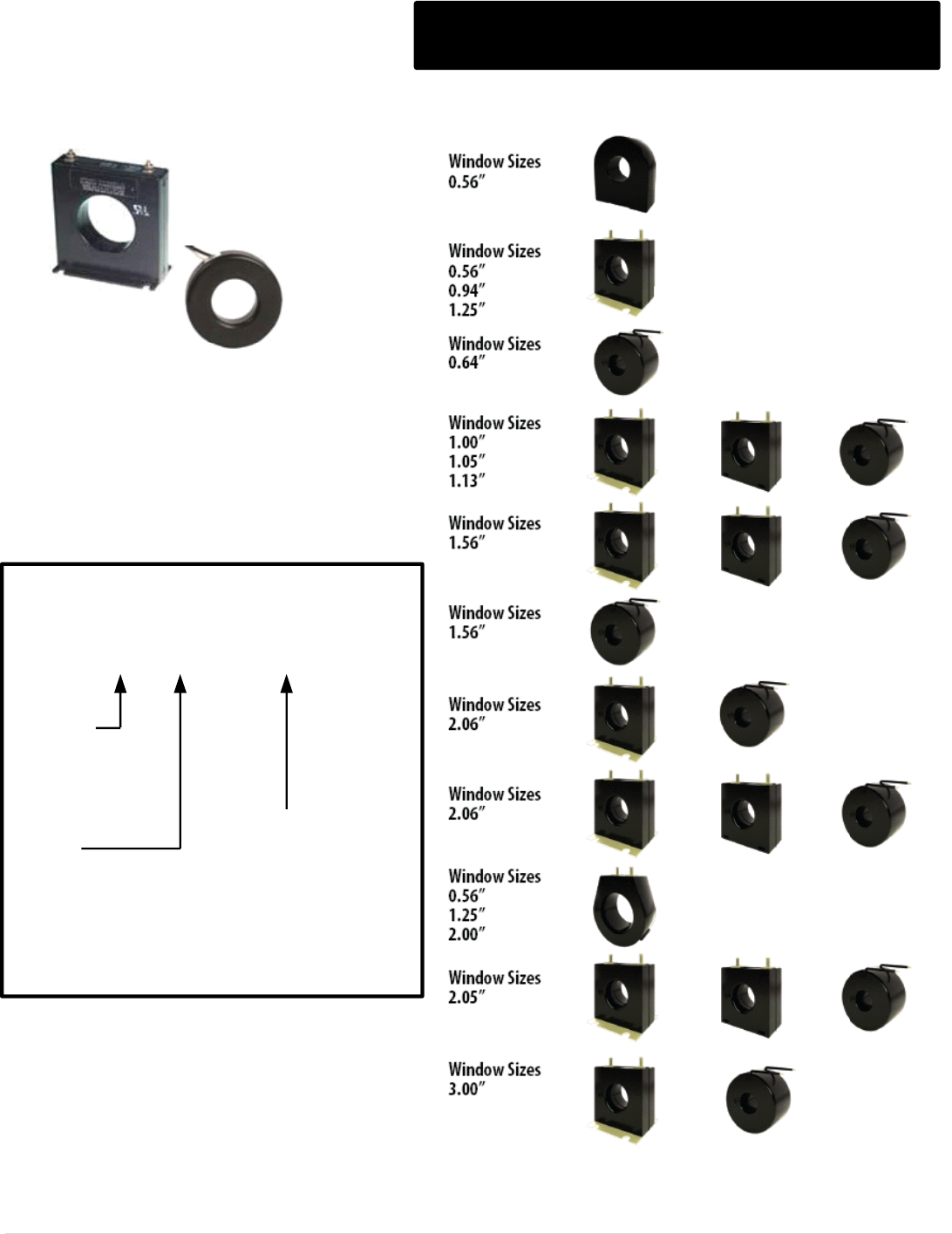
Current Transformers
Frequency: 50 - 400 Hz
Insulation Level: 600 Volts, 10 kV BIL full wave
Application: With Ammeters, wattmeters, cross
current compensation, energy management systems,
instrumentation, relay and Metering.
600V ANSI and Non-ANSI Rated CTs
CT Images shown for illustration purposes only.
2 SFT 2 SHT 2 RL
5 SFT
5 DRL
56 SFT
1A 1B
14, 15, 16 SFT
13
6 SFT 6 SHT 6 RL
63A SFT 63B RT 63C RT
5 SHT 5 RL
56 RL
7 SFT 7 SHT 7 RL
76 SFT
11 - 2 RL - 500
Model
Number
Style
RL = Round with Leads
SFT = Sq w/ Terminals and Feet
SHT = Sq with Terminals
Model Number Configuration
Ratio
500 = 50:5 / 750 = 75:5
101 = 100:5 / 151 = 150:5
201 = 200:5 / 251 = 250:5
301 = 300:5 / 401 = 400:5
501 = 500:5 / 601 = 600:5
751 = 750:5 / 801 = 800:5
102 = 1000:5 / 122 = 1200:5
152 = 1500:5 / 162 = 1600:5
202 = 2000:5

M o t o r t r o n i c s P r o d u c t S e l e c t i o n G u i d e P a g e 32
Current Transformers
Visit www.motortronics.com for Specification Sheets
Model Number
Current Ratio
Window (Inches)
List Price $
13
500 TURNS
0.56
46
13
1000 TURNS
0.56
56
13
2000 TURNS
0.56
60
10SFT
50:5 THRU 300:5
0.94
64
2DARL
50:5 THRU 300:5
1
70
14
50:5 THRU 100:5
0.50
44
15SFT
50:5 THRU 200:5
0.94
56
1A
50:5 THRU 250:5
0.64
44
1B
50:5 THRU 250:5
0.64
48
2DRL
50:5 THRU 600:5
1
64
2RL
50:5 THRU 300:5
1.05
48
2RL
400:5 THRU 500:5
1.05
48
2SFT
50:5 THRU 400:5
1.13
52
2SHT
50:5 THRU 300:5
1.13
72
5RL
50:5 THRU 500:5
1.56
60
5RL
600:5 THRU 1200:5
1.56
74
5RL
1300:5 THRU 2400:5
1.56
74
5SFT
50:5 THRU 500:5
1.56
64
5SFT
600:5 THRU 1200:5
1.56
78
5SHT
50:5 THRU 500:5
1.56
64
5SHT
600:5 THRU 1200:5
1.56
78
5DRL
50:5 THRU 500:5
1.56
70
5DRL
600:5 THRU 1200:5
1.56
86
56
50:5 THRU 500:5
2.06
62
56
600:5 THRU 1200:5
2.06
78
56RL
50:5 THRU 500:5
2.06
62
56RL
600:5 THRU 1200:5
2.06
78
56RL
1400:5 THRU 3200:5
2.06
78
56SFT
50:5 THRU 500:5
2.06
62
56SFT
600:5 THRU 1200:5
2.06
62
6RL
100:5 THRU 600:5
2.06
68

M o t o r t r o n i c s P r o d u c t S e l e c t i o n G u i d e P a g e 33
Current Transformers
Visit www.motortronics.com for Specification Sheets
Model Number
Current Ratio
Window
(Inches)
List Price $
6RL
750:5 THRU 1500:5
2.06
86
6SFT
100:5 THRU 600:5
2.06
70
6SFT
700:5 THRU 1500:5
2.06
88
6SHT
100:5 THRU 600:5
2.06
70
6SHT
750:5 THRU 1500:5
2.06
88
7RL
100:5 THRU 800:5
2.50
70
7RL
1000:5 THRU 1600:5
2.50
94
7SFT
100:5 THRU 800:5
2.50
72
7SFT
1000:5 THRU 1600:5
2.50
104
7SHT
100:5 THRU 800:5
2.50
72
7SHT
1000:5 THRU 1600:5
2.50
104
76RL
200:5 THRU 800:5
3
72
76RL
1000:5 THRU 1800:5
3
104
76RL
2000:5
3
124
76SFT
200:5 THRU 800:5
3
72
76SFT
1000:5 THRU 1800:5
3
104
76SFT
2000:5
3
124
76SHT
100:5 THRU 300:5
3
144
76SHT
400:5 THRU 800:5
3
178
5ARL
50:5 THRU 500:5
1.56
68
5ARL
600:5 THRU 1200:5
1.56
84
5ASFT
50:5 THRU 500:5
1.56
110
5ASHT
600:5 THRU 1200:5
1.56
86
5ASFT
50:5 THRU 500:5
1.56
72
5RBT
50:5 THRU 500:5
1.56
68
5RBT
600:5 THRU 1200:5
1.56
84
5DARL
50:5 THRU 600:5
1.56
80
5DARL
750:5 THRU 1000:5
1.56
100
6ARL,6ASHT, 6ASFT
100:5 THRU 600:5
2.06
76
6ARL,6ASHT, 6ASFT
750:5 THRU 1500:5
2.06
106

M o t o r t r o n i c s P r o d u c t S e l e c t i o n G u i d e P a g e 34
Current Transformers
Visit www.motortronics.com for Specification Sheets
Model Number
Current Ratio
Window
(Inches)
List Price $
7ARL
50:5 THRU 600:5
2.50
80
7ARL
750:5 THRU 1600:5
2.50
114
7ASFT
50:5 THRU 600:5
2.50
80
7ASFT
750:5 THRU 1600:5
2.50
114
7ASHT
50:5 THRU 600:5
2.50
80
7ASHT
750:5 THRU 1600:5
2.50
114
8RL
200:5 THRU 1000:5
3.25
124
8RL
1200:5 THRU 1500:5
3.25
140
8RL
1600:5 THRU 2500:5
3.25
184
8RL
3000:5
3.25
220
8RL
3200:5 THRU 4000:5
3.25
260
8SHT
200:5 THRU 1000:5
3.25
180
8SHT
1200:5 THRU 1500:5
3.25
194
8SHT
1600:5 THRU 2500:5
3.25
202
8SHT
3000:5
3.25
228
8SHT
3200:5 THRU 4000:5
3.25
272
19RL
300:5 THRU 600:5
4.25
120
19RL
750:5 THRU 1200:5
4.25
126
19RL
1500:5 THRU 2000:5
4.25
138
19RL
2500:5 THRU 3000:5
4.25
148
19SHT
300:5 THRU 600:5
4.25
120
19SHT
750:5 THRU 1200:5
4.25
126
19SHT
1500:5 THRU 2000:5
4.25
138
19SHT
2500:5 THRU 3000:5
4.25
148
64
50:5 THRU 500:5
1.56
78
65
50:5 THRU 600:5
2
92
65
750:5 THRU 1500:5
2
110
66
50:5 thru 800:5
2.50
104
100
200:5 thru 600:5
4
156
100
800:5
4
170
100
1000:5 thru 1200:5
4
212

M o t o r t r o n i c s P r o d u c t S e l e c t i o n G u i d e P a g e 35
Current Transformers
Visit www.motortronics.com for Specification Sheets
Model Number
Current Ratio
Window
(Inches)
List Price $
100
1500:5 THRU 2000:5
4
246
100
2500:5 THRU 3000:5
4
296
120
200:5 THRU 600:5
5.75
184
120
800:5
5.75
198
120
1000:5 THRU 1200:5
5.75
234
120
1500:5 THRU 2000:5
5.75
252
120
2500:5 THRU 3000:5
5.75
268
120
3500:5 THRU 4000:5
5.75
314
125
600:5 THRU 1200:5
6.31
196
125
1500:5 THRU 2000:5
6.31
214
125
2500:5 THRU 3000:5
6.31
228
125
3500:5 THRU 5000:5
6.31
266
126
400:5 THRU 1200:5
8.25
292
126
1500:5 THRU 2000:5
8.25
320
126
2500:5 THRU 3000:5
8.25
338
126
3200:5 THRU 4000:5
8.25
380
126
5000:5
8.25
400
135
50:5 THRU 750:5
5.75
378
135
800:5 THRU 1500:5
5.75
388
135
1600:5 THRU 2000:5
5.75
406
135
2500:5 THRU 3000:5
5.75
428
135
3200:5 THRU 4000:5
5.75
492
135
5000:5
5.75
512
140
50:5 THRU 600:5
8.13
400
140
800:5
8.13
412

M o t o r t r o n i c s P r o d u c t S e l e c t i o n G u i d e P a g e 36
Current Transformers
Visit www.motortronics.com for Specification Sheets
Model Number
Current Ratio
Window
(Inches)
List Price $
140
1000:5 THRU 1200:5
8.13
426
140
1500:5 THRU 2000:5
8.13
440
140
2500:5 THRU 3000:5
8.13
496
140
4000:5
8.13
530
140
5000:5
8.13
620
140
6000:5
8.13
738
170
200:5 THRU 600:5
4.25
120
170
750:5 THRU 800:5
4.25
134
170
1000:5 THRU 1200:5
4.25
162
170
1500:5 THRU 2000:5
4.25
200
170
2500:5 THRU 3000:5
4.25
234
170
3500:5 THRU 4000:5
4.25
264
170RL
750:5 THRU 800:5
4.25
134
180SHT
75:5 THRU 600:5
4.25
100
180SHT
750:5 THRU 800:5
4.25
114
180SHT
1000:5 THRU 1200:5
4.25
142
180SHT
1500:5 THRU 2000:5
4.25
178
180SHT
2500:5 THRU 3000:5
4.25
214
180SHT
3500:5 THRU 4000:5
4.25
242
191
100:5 THRU 400:5
1.25
138
192
100:5 THRU 500:5
1.75
128
194
100:5 THRU 800:5
2.50
104
194
1000:5 THRU 1200:5
2.50
138
194
1500:5 THRU 1600:5
2.50
154
195
200:5 THRU 800:5
3.06
116

M o t o r t r o n i c s P r o d u c t S e l e c t i o n G u i d e P a g e 37
Current Transformers
Visit www.motortronics.com for Specification Sheets
Model Number
Current Ratio
Window
(Inches)
List Price $
195
1000:5 THRU 1200:5
3.06
160
195
1500:5 THRU 2000:5
3.06
178
300
50:5 THRU 1000:5
3.75
194
300
1200:5 THRU 2000:5
3.75
224
197
400:5 THRU 800:5
3.12
116
197
1000:5 THRU 1200:5
3.12
160
197
1500:5 THRU 2000:5
3.12
178
780
50:5 THRU 600:5
6.50
456
780
750:5 THRU 1500:5
6.50
490
780
1600:5 THRU 3000:5
6.50
516
780
3200:5 THRU 4000:5
6.50
544
781
600:5MR
6.50
616
781
1200:5MR
6.50
676
781
2000:5MR
6.50
684
781
3000:5MR
6.50
690
781
4000:5MR
6.50
704
785
50:5 THRU 600:5
6.50
846
785
750:5 THRU 1500:5
6.50
908
785
1600:5 THRU 2500:5
6.50
938
785
3000:5 THRU 4000:5
6.50
990
786
600:5MR
6.50
1006
786
1200:5MR
6.50
1068
786
2000:5MR
6.50
1098
786
3000:5MR
6.50
1140
M o t o r t r o n i c s P r o d u c t S e l e c t i o n G u i d e P a g e 38
MVC Series Medium Voltage Starters MVC Plus Series
Soft start & protect any AC motor
Motor and starter protection is taken to a new level by combining a high-end motor protection relay with a
heavy duty solid state starter. Flexible control features and selectable ramping profiles to match any
application... no need to compromise performance. High level circuit isolation via fiber optics (standard on
all units) for safety and power quality immunity. Sealed NEMA 12 enclosures are standard equipment, not
an expensive option.
The MVC Plus Series starter is designed to start AC motors in any fixed speed application. It provides
maximum protection with "True Thermal Modeling," while allowing smooth, stepless control of acceleration
and deceleration. The MVC Plus Series guarantees power control and protection for your most important
assets.
Heavy-duty attitude highest rated power devices for maximum current carrying capacity. Rated at 500% for
60 seconds, the MVC Plus Series starter will never be the limiting factor in your application. Powerful
sustained gate pulse insures reliable SCR firing without reactors (unlike "wimpy" pulse train designs that
require a reactor to prevent SCR and motor damage) .
Features
Advanced motor protection relay and ramp features programmable via the keypad or a laptop computer.
Fiber optically isolated low voltage compartment with up to 110kV BIL rating for safety and reliability.
Built-in 120V control power transformer; voltage and current metering.
Load-break / fault-make rated disconnect switch with door safety interlocking.
Visible grounding bar for safe operation.
Coordinated motor fuses with blown fuse indicators.
Line isolation vacuum contactor.
Fully rated bypass contactor for increased thermal capacity and optional across-the-line starting.
Heavy duty SCR stack assemblies with ring transformer isolation for reliable SCR gate firing.
RTD Option accepts up to 12 RTD inputs.
Zero sequence ground fault protection option.
Top entry, bottom exit with room for stress cones.
Removable entry plates for easy connections.
NEMA 12 gasketed enclosure (NEMA 3R optional).
Advanced Protection
True Thermal Modeling monitors the motor for excessive thermal conditions due to starting, running and even ambient conditions.
Retentive Thermal Memory for continuous overload protection even after a complete power loss.
MVC Plus remembers the last thermal condition of the motor, observes the off time via a real-time clock and adjusts the thermal
model accordingly.
Non-Volatile Memory stores the thermal memory without the need for batteries.
True Time Thermal Tracking adjusts the thermal model for different cooling rates based on motor temperature, running state or
power loss.
Dynamic Reset Response Reset is only allowed after the motor has sufficient thermal capacity for a successful restart.
Thermal Model Biasing adjusts for heating effects of phase current imbalance or optional RTD inputs.
Flexible Setup Choose the level of overload protection.
Programmable Trip Classes selectable from NEMA/UL Classes 5 - 30.
Dual Mode Protection separate trip curves for start and run modes (example: Class 20 for start, Class 10 for run).
Warning Levels can be programmed and assigned to one of six built-in output relays.
Custom Trip Curve programmable based on the motor manufacturer’s data
Remote or Automatic Overload Reset can be activated for unattended operations.
M o t o r t r o n i c s P r o d u c t S e l e c t i o n G u i d e P a g e 39
MVC Plus Series Model Ratings
MVC Plus Series Model Ratings
(Motor FLA x Service Factor = Max Amps)
COMPLETE STARTER
CLASS E-2 CONTROLLER
Model Number
Nominal
Voltage
Max
Amps
Nominal
HP
Nominal
kW
Approx.
Dimensions:
H x W x D (in)
List Price $
MVC4-23100-E-SWG
2300
100
350
261
92.5 x 36 x 30
35,000
MVC4-23200-E-SWG
200
700
522
37,000
MVC4-23400-E-SWG
400
1,400
1044
38,500
MVC4-23600-E-SWG
630
2,200
1,300
92.5 x72 x 30
65,000
MVC4-23800-E-SWG
800
2,800
1,600
70,000
MVC4-33100-E-SWG
3300
100
500
373
92.5 x 36 x 30
38,500
MVC4-33200-E-SWG
200
1,000
746
45,000
MVC4-33400-E-SWG
400
2,000
1,492
48,000
MVC4-33600-E-SWG
630
3,150
2,350
95 x 84 x 44
77,000
MVC4-33800-E-SWG
800
4,000
2,984
84,000
MVC4-41100-E-SWG
4160
100
600
448
92.5 x 36 x 30
43,000
MVC4-41200-E-SWG
200
1,250
933
47,600
MVC4-41400-E-SWG
400
2,500
1,865
52,600
MVC4-41600-E-SWG
630
4,000
2,984
95 x 84 x 44
103,000
MVC4-41800-E-SWG
800
5,000
3,730
120,500
MVC4-411000-E-SWG
1,000
6,350
4,737
95 x 84 x 80
250,000
MVC4-66100-E-SWG
6600
100
1,000
746
92.5 x 42 x 30
45,500
MVC4-66200-E-SWG
200
2,000
1,492
55,000
MVC4-66400-E-SWG
400
4,000
2,984
60,400
MVC4-66600-E-SWG
630
6,350
4,737
92.5 x 117 x 30
117,400
MVC4-66800-E-SWG
800
8,000
5,968
150,400
MVC4-661000-E-SWG
1,000
10,000
7,460
95 x 84 x 80
275,000
MVC4-69100-E-SWG
6.9kV
100
1,000
746
92 x 72 x 30
50,540
MVC4-69200-E-SWG
200
2,100
1,567
61,500
MVC4-69400-E-SWG
400
4,200
3,133
67,500
MVC4-69600-E-SWG
630
6,650
4,961
92.5 x 117 x 30
130,800
MVC4-69800-E-SWG
800
8,000
5,968
195,000
MVC4-691000-E-SWG
1,000
10,500
7,833
95 x 84 x 80
290,000
M o t o r t r o n i c s P r o d u c t S e l e c t i o n G u i d e P a g e 40
MVC Plus Series Model Cont.
MVC Plus Series Model Ratings
(Motor FLA x Service Factor = Max Amps)
COMPLETE STARTER
CLASS E-2 CONTROLLER
Model Number
Nominal
Voltage
Max
Amps
Nominal
HP
Nominal
kW
Approx.
Dimensions:
H x W x D (in)
List Price $
MVC4-72100-E-SWG
7.2KV
100
1,100
821
92 x 72 x 30
52,600
MVC4-72200-E-SWG
200
2,200
1,641
64,740
MVC4-72400-E-SWG
400
4,400
3,282
70,500
MVC4-72600-E-SWG
630
7,000
5,222
92.5 x 117 x 30
137,950
MVC4-72800-E-SWG
800
8,800
6,565
205,000
MVC4-721000-E-SWG
1000
11,000
8,206
95 x 84 x 80
304,600
MVC4-110100-E-SWG
11kV
100
1,700
1,268
95 x 126 x 44
230,000
MVC4-110200-E-SWG
200
3,400
2,536
245,200
MVC4-110400-E-SWG
400
6,700
4,998
264,900
MVC4-110600-E-SWG
630
10,600
7,908
345,700
MVC4-110800-E-SWG
800
13,500
10,071
95 x 120 x 80
450,600
MVC4-1101000-E-SWG
1000
16,500
12,309
480,000
MVC4-138100-E-SWG
13.8kV
100
2,100
1,567
95 x 126 x 44
264,900
MVC4-138200-E-SWG
200
4,200
3,133
287,300
MVC4-138320-E-SWG
320
6,750
5,035
314,400
MVC4-138400-E-SWG
400
8,500
6,341
324,700
MVC4-138600-E-SWG
600
12,500
9,325
95 x 120 x 80
500,800
MVC4-138800-E-SWG
800
17,000
12,682
650,900
MVC4-1381000-E-SWG
1,000
21,000
15,666
700,600
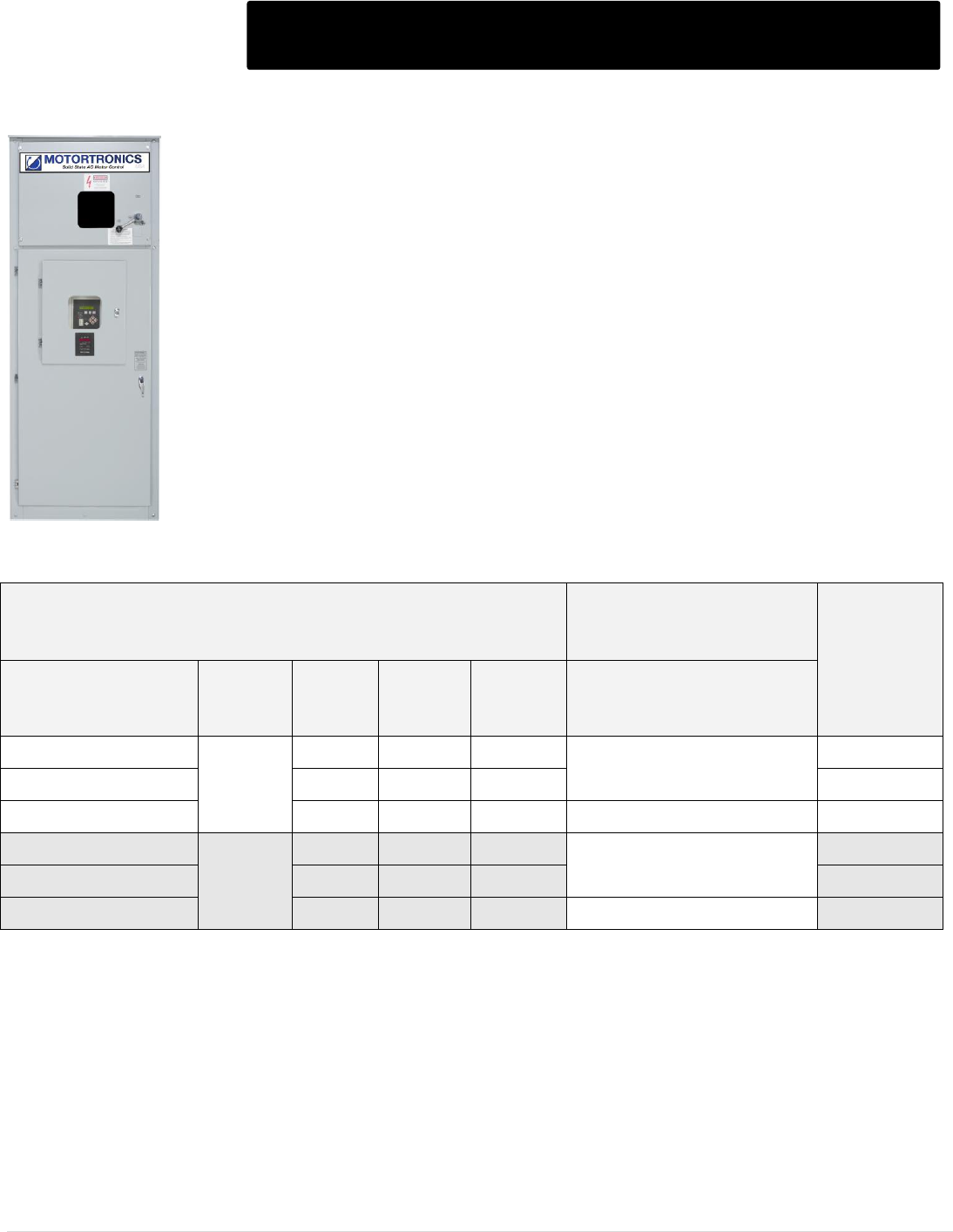
M o t o r t r o n i c s P r o d u c t S e l e c t i o n G u i d e P a g e 41
MVC DOL - Full Voltage Starters
MVC Plus Series Model Ratings
(Motor FLA x Service Factor = Max Amps)
DOL STARTER
List Price $
Model Number(2)
Nominal
Voltage
Max
Amps
Nominal
HP
Nominal
kW
Dimensions:
H x W x D (in)
MVC4-23200-E-DOL
2300
200
700
526
92 x 36 x 30
16,500
MVC4-23400-E-DOL
400
1,400
1052
17,500
MVC4-23600-E-DOL
630
2,200
1657
92.5 x 72 x 30
34,200
MVC4-41200-E-DOL
4160
200
1,250
952
92 x 36 x 30
16,500
MVC4-41400-E-DOL
400
2,500
1900
17,500
MVC4-41600-E-DOL
630
4,000
3000
92.5 x 72 x 30
34,200
The MVC DOL series full voltage starters combine the protection and monitoring capabilities of our
MVC4 series soft starters with the economics of a full voltage starter.
Each MVC DOL starter includes:
All protection and monitoring features and functions of the MVC4 Series Soft Starter
Isolated load break rated disconnect switch
Interlocked door to prevent access unless main power is “OFF”
Current limiting fuses
7.2kV rated main vacuum contactor
3-Phase PT/CPT for voltage metering and control power
Current transformers sized for your application
An isolated low voltage section
The RX -5 Multifunction Motor Protection Relay
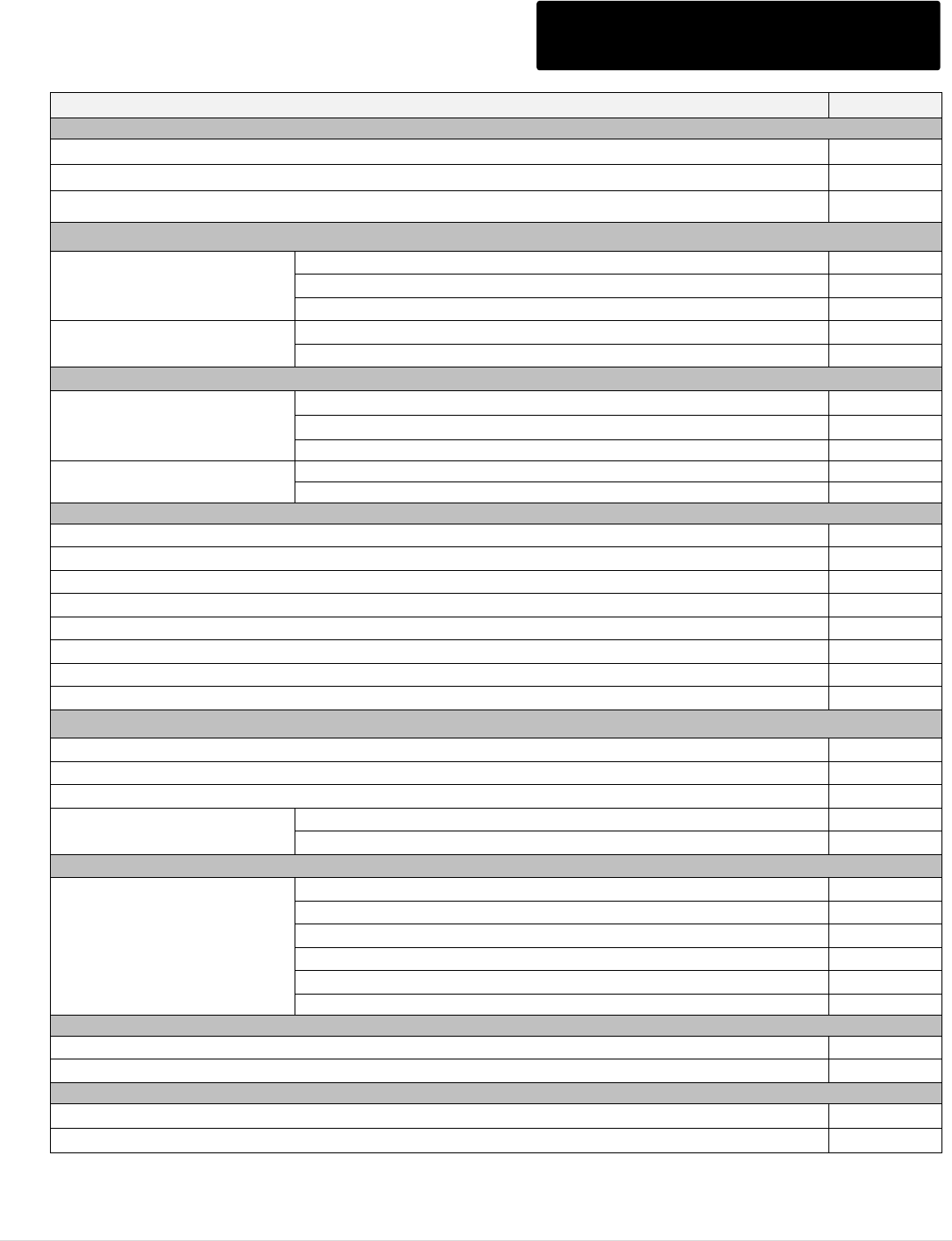
M o t o r t r o n i c s P r o d u c t S e l e c t i o n G u i d e P a g e 42
MVC Plus Series Options
MVC Series Accessory Pricing
List Price $
Options
GF Option adder for units up to 600 Amps
1,320
GF Option adder for units 800 Amps and above
1,560
Emergency OL Relay Option (for use with across line start mode)
1,200
Add Contactors (Multi-motor, inline on soft start only, etc.)
2300 - 4160V
200A
4,000
400A
7,200
600A
9,600
6600 / 6900V
400A
8,400
600A
12,200
Reversing Contactors
2300 / 3300 / 4160V
200A
11,000
400A
11,400
600A
12,600
6600 / 6900V
400A
12,400
600A
16,400
Bus Bars & Bus Slice Kits
800A bus bars
990
800A Bus splice kits
462
1200A bus bars
1,980
1200A bus splice kits
660
1600A bus bars
2,640
1600A Bus splice kits
990
2000A bus bars
4,290
2000A bus splice kits
1,650
Incoming Sections
18" empty pull section
2,760
24" empty pull section
3,120
PFC switch section
C/F
Extra sections w/ LV comp
36" Wide
4,800
60" wide
7,200
Switch only sections w/ LV comp (up to 5kV class)
Note: fuses supplied
separately
(C/F for pricing)
24" wide w/ 400A switch
10,334
30" wide w/ 400A switch
11,290
36" wide w/ 400A switch
11,486
36" wide w/ 600A switch
18,140
36" wide w/ 800A switch
19,300
36" wide w/ 1200A switch
21,050
Space heater w/ Thermostat (per enclosure)
400W
800
600W
1,200
Synchronous Controller (C/F for brush type & other ratings)
Brushless (125VDC, 15A or less)
24,500
Brush Type
C/F

M o t o r t r o n i c s P r o d u c t S e l e c t i o n G u i d e P a g e 43
MVC Plus Series Options Cont.
MVC Series Accessory Pricing Cont.
List Price $
Pushbuttons and Pilot Lights (C/F for custom control scheme)
Pushbuttons (run, stop, jog, reset, etc..)
160
Mushroom head stop PB
210
Illuminated PB (specify color & function)
320
Pilot light
230
Push to test light
300
Selector Switches (C/F for custom control scheme)
H-O-A or Local-Off-Remote switch (3 position)
320
Dual Ramp Switch (2 position)
280
RTD Options: Standard Unit Options
Option RTD (board & hardware only)
1500
Option RTD-Wire (same as above but wired to terminal block)
1900
RTD OEM Kit Options
Option RTD-KIT, includes: DSS1000-RTD remote RTD TCB and all plug connectors (no wire)
1,825
70-RTDWIRE (12) 6' cables for above
325
Communications Bridges (Modbus is standard)
Profibus DP
3,500
DeviceNet
3,500
Ethernet / IP
3,500
Miscellaneous
Conformal Coating of PC boards
1,000
1kVA CPT (100-400A soft start only model)
1,600
Lightning Arrestor (6kV station class with fusing in 36" wide enclosure)
7,000
Power factor correction capacitor
C/F
3rd Party Meters and Motor Protection Relays
C/F
Miscellaneous Services:
Certifications (Cost per model rating, contact factory for quote on other certifications)
DNV (Det Norske Veritas)
10,000
ABS (American Bureau of Shipping)
3,600
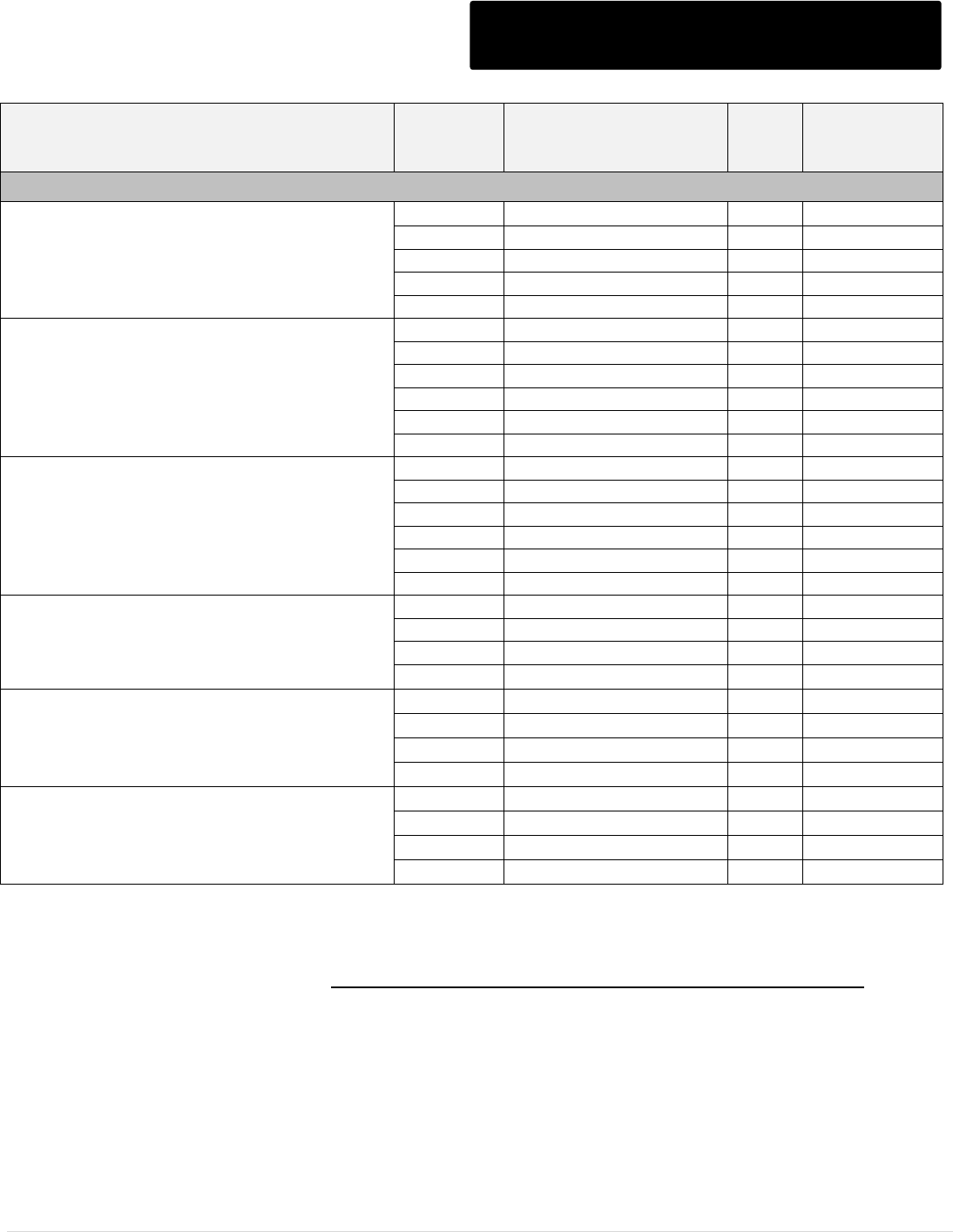
M o t o r t r o n i c s P r o d u c t S e l e c t i o n G u i d e P a g e 44
MVC Plus Series Spare Parts
NOTES:
1 - These items are recommended as spare parts
2 – For aftermarket replacement parts, always verify correct part numbers with factory prior to ordering
Description / Rating
Range
Model Number
Qty
per
Unit
List Price $
ea.
SCR/Heatsink assembly with boards (One phase assembly) see Note 1
2300V
100A
MVC3-STK23100P
3
3,288
200A
MVC3-STK23200P
3
3,616
400A
MVC3-STK23400P
3
4,060
500A
MVC3-STK23500P
3
5,250
600A
MVC3-STK23600P
3
6,560
3300V
100A
MVC3-STK33100P
3
4,936
200A
MVC3-STK33200P
3
5,922
400A
MVC3-STK33400P
3
6,642
500A
MVC3-STK33500P
3
10,500
600A
MVC3-STK33600P
3
13,126
800A
MVC3-STK33800P
3
C/F
4160V
100A
MVC3-STK41100P
3
4,936
200A
MVC3-STK41200P
3
5,922
400A
MVC3-STK41400P
3
6,642
500A
MVC3-STK41500P
3
10,500
600A
MVC3-STK41600P
3
13,126
800A
MVC3-STK41800P
3
C/F
6000/6600 V
100A
MVC3-STK66200P
3
8,374
200A
MVC3-STK66200P
3
8,976
400A
MVC3-STK66400P
3
9,136
600A
MVC3-STK66600P
3
12,324
6900/7200 V
100A
MVC3-STK72100P
3
8,814
200A
MVC3-STK72200P
3
9,450
400A
MVC3-STK72400P
3
9,615
600A
MVC3-STK72600P
3
12,975
13.8kV
125A
MVC3-STK-130125
3
39,030
200A
MVC3-STK-130200
3
42,932
300A
MVC3-STK-130300
3
46,836
600A
MVC3-STK-130600
3
51,276
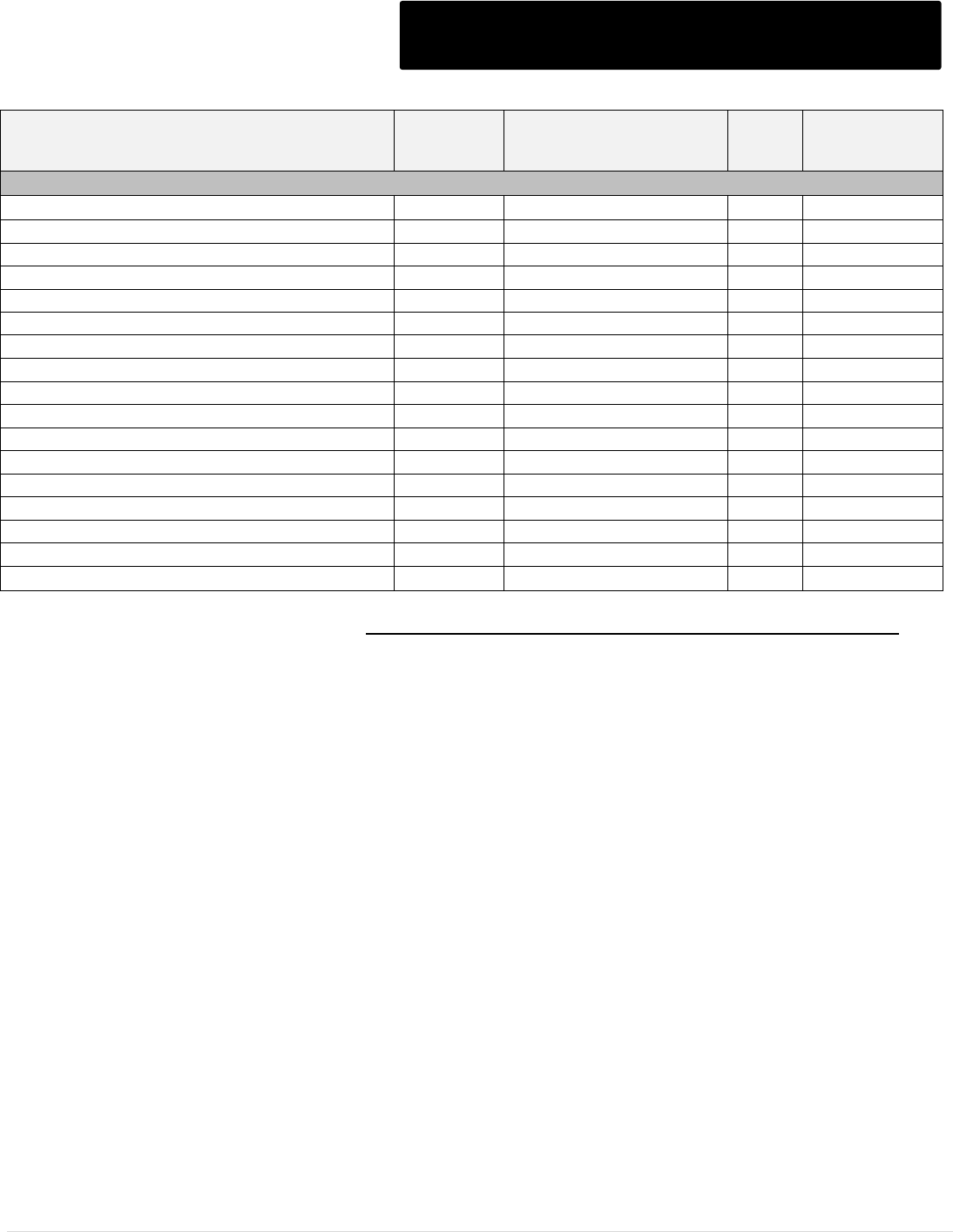
M o t o r t r o n i c s P r o d u c t S e l e c t i o n G u i d e P a g e 45
MVC Plus Series Spare Parts Cont.
NOTE: For aftermarket replacement parts, always verify correct part numbers with factory prior to ordering
Description / Rating
Range
Model Number
Qty
per
Unit
List Price $
ea.
SCR(s) and Heatsink assembly
2300V (one set of 2)
100A
25-0100-6500-23
3
2,000
2300V (one set of 2)
200A
25-0200-6500-23
3
C/F
2300V (one set of 2)
400A
25-0400-6500-23
3
2,700
2300V (one set of 2)
500A
25-0500-6500-23
3
3,000
2300V (one set of 2)
600A
25-0600-3500-23
3
3,500
3300/4160V (one set of 4)
100A
25-0100-6500-41
3
3,194
3300/4160V (one set of 4)
200A
25-0200-6500-41
3
3,514
3300/4160V (one set of 4)
400A
25-0400-6500-41
3
3,500
3300/4160V (one set of 4)
500A
25-0500-6500-41
3
6,990
3300/4160V (one set of 4)
600A
25-0600-3500-41
3
7,200
6600/7200V (two sets of 4 and one set of 2)
100A
25-0100-6500-72
3
7,600
6600/7200V (two sets of 4 and one set of 2)
200A
25-0200-6500-72
3
8,050
6600/7200V (two sets of 4 and one set of 2)
400A
25-0400-6500-72
3
8,450
6600/7200V (three sets of 4)
500A
25-0500-3500-72
3
C/F
6600/7200V (three sets of 4)
600A
25-0600-3500-72
3
C/F
13.8kV (three sets of 4)
300A
25-0300-6500-38
3
C/F
13.8kV (three sets of 4)
600A
25-0600-6500-38
3
C/F
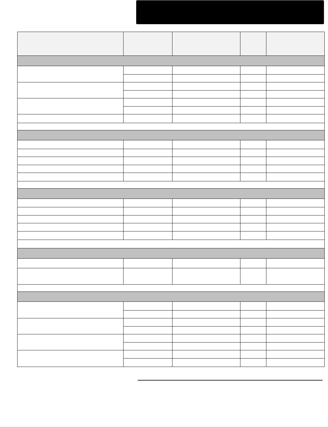
M o t o r t r o n i c s P r o d u c t S e l e c t i o n G u i d e P a g e 46
MVC Plus Series Spare Parts Cont.
Description / Rating
Range
Model Number
Qty
per
Unit
List Price $
ea.
Gate Drive Transformer (Ring transformer)
2300V
≤ 400A
10-0090
3
430
≥ 500A
10-0090
6
430
3300 / 4160V
≤ 400A
10-0090
6
430
≥ 500A
10-0090
12
430
6600 / 7200V
≤ 400A
10-0090
9
430
≥ 500A
10-0090
12
430
13.8kV
≤ 600A
10-0090A
18
430
Potential Transformers
2300V
All
10-0068
1
1,272
3300V
All
10-0072-50
1
1,300
4160V
All
10-0067
1
1,272
6600 / 7200V
All
10-0084
1
1,760
13.8kV
All
10-0103
2
C/F
Control Power Transformers
2300V
All
10-0080
1
960
3300V
All
10-0081
1
1,300
4160V
All
10-0083
1
1,376
6600 / 7200V
All
10-0084
1
1,760
13.8kV
All
10-0104
1
C/F
CT Boards
-
100 - 400A
MVC3-Temp/CT-PS
3
360
-
600, 800A &
13.8kV
MVC3-3CT
1
660
Gate Drive Boards
2300V
≤ 400A
MVC3-GDF
3
647
≥ 500A
MVC3-GDFP
6
750
3300 / 4160V
≤ 400A
MVC3-GDF
6
647
≥ 500A
MVC3-GDFP
12
750
6600 / 7200V
≤ 400A
MVC3-GDF
15
647
≥ 500A
MVC3-GDFP
18
750
13.8kV
≤ 300A
MVC3-GDF
18
647
≥ 600A
MVC3-GDFP
18
750
NOTE: For aftermarket replacement parts, always verify correct part numbers with factory prior to ordering
M o t o r t r o n i c s P r o d u c t S e l e c t i o n G u i d e P a g e 47
MVC Plus Series Spare Parts Cont.
Description / Rating
Range
Model Number
Qty per
Unit
List Price $
ea.
MOV Boards
2300V
≤ 400A
MVC3-MOV
3
428
≥ 500A
MVC3-MOV
6
428
3300 / 4160V
≤ 400A
MVC3-MOV
6
428
≥ 500A
MVC3-MOV
12
428
6600 / 7200V
≤ 400A
MVC3-MOV
15
428
≥ 500A
MVC3-MOV
18
428
dv/dt Boards
2300V
≤ 400A
MVC3-DVDT
3
540
≥ 500A
MVC3-DVDT-5-200
6
540
3300 / 4160V
≤ 400A
MVC3-DVDT
6
540
≥ 500A
MVC3-DVDT-5-200
12
540
6600 / 7200V
≤ 400A
MVC3-DVDT
15
540
≥ 500A
MVC3-DVDT-5-200
18
540
13.8kV
≤ 300A
MVC3-DVDT-150
18
540
≥ 600A
MVC3-DVDT-5-200
36
540
Main board, CPU board &
digital controller assembly with
lexan cover & harness
All ratings
MVC3-MB/CPU-KIT
(Note 1)
1
4,400
Main board & CPU board
(stacked) w/ jumper connector
All ratings
MVC3-MB/CPU-MTR
1
3,400
Digital controller with lexan
cover & harness
All ratings
DSS1000-COM-KIT
1
1,130
Control board
All ratings
MVC3-TCB
1
570
RTD board
All ratings
DSS1000-RTD
1
1,500
NOTES:
1 - These items are recommended as spare parts
2 – For aftermarket replacement parts, always verify correct part numbers with factory prior to ordering
M o t o r t r o n i c s P r o d u c t S e l e c t i o n G u i d e P a g e 48
MVC Plus Series Spare Parts Cont.
Description / Rating
Range
Model Number
Qty per
Unit
List Price $
ea.
Medium Voltage Fuses (Note 1)
2300V
FLA dependent
(check unit for actual fuse
rating used)
52-9R-2400
3
642
52-12R-2400
3
700
52-18R-2400
3
1,140
3300 / 4160V
52-9R-4800
3
510
52-12R-4800
3
594
52-18R-4800
3
948
6600 / 7200V
52-9R-7200
3
852
52-12R-7200
3
900
52-18R-7200
3
1,476
Contactors (Contact factory for pricing on export models)
2300V-7200V
200A Vacuum
34-200-3-7200
2
5,326
400A Vacuum
34-400-3-7200
2
7,790
600A Vacuum
34-600-3-7200
2
10,992
NOTES:
1 - These items are recommended as spare parts
2 – For aftermarket replacement parts, always verify correct part numbers with factory prior to ordering
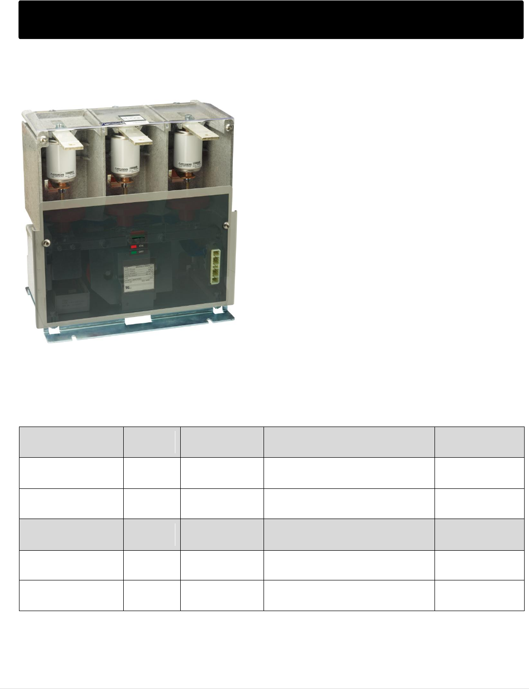
M o t o r t r o n i c s P r o d u c t S e l e c t i o n G u i d e P a g e 49
MVF Series - Medium Voltage Contactors
MVF Series Medium Voltage Contactors
Motortronics MVF Series 7.2kV Class, ‘Non-Latching’
and ‘Latching’ Series of medium voltage three-phase
vacuum contactors can be used in power systems
with a rated voltage up to 7.2 kV and can be used for
continuous AC operating currents of up to 400
amperes. Control voltage for the contactor is AC/DC
100~125V or AC/DC 200~230V*, including an
auxiliary relay with 3 NO and 2NC contacts.
Non-Latching - uses constant-on electromagnetic
coils to close, and hold closed the vacuum bottle
contacts. When the power to the electromagnetic coil
is removed, the vacuum chamber contacts spring
open (termed as; electrically held contacts or non-
latching contacts).
Latching - uses separate coils and mechanisms to
both close and open the vacuum bottle contacts
(termed as; mechanically held or latching, contacts).
*For 200 – 230V control, contact factory for price and availability.
Non-Latching
Model Number
Rated
Voltage
Rated Current
(Amps)
Configuration
List Price $
34-72-4-C-X-0-3-0-12
7.2kV
400A
Fixed Mount, Dbl Terminal w/o
counter, non-fused, 120VAC control.
3,058
34-72-4-C-B-F1-0-12
7.2kV
400A
Draw-out, Compartment Style, non-
fused, 120VAC control.
4,850
Latching Model
Number
Rated
Voltage
Rated Current
(Amps)
Configuration
List Price $
34-72-4-L-X-0-3-0-12
7.2kV
400A
Fixed Mount, Dbl Terminal w/o
counter, non-fused, 120v control.
3,058
34-72-4-L-B-F1-0-12
7.2kV
400A
Draw-out, Compartment Style,
non-fused, 120v control.
4,850
M o t o r t r o n i c s P r o d u c t S e l e c t i o n G u i d e P a g e 50
MVF Series - 7.2kV MV Contactors Specifications
Specification
Fixed type without fuse
Draw-out type without fuse
Type
Continuously
energized
34-72-4-C-X-0-3-0-12
34-72-4-C-B-F1-0-12
Latched
34-72-4-L-X-0-3-0-12
34-72-4-L-B-F1-0-12
Rated insulation voltage (kV)
7.2 kV
Rated operation voltage (kV)
6.6 kV
Rated frequency (Hz)
50/60 Hz
Rated current (A)
400 A
Impulse withstand voltage (kV) (BIL)
60 kV
Power frequency withstand voltage (kV/min)
20 kV/min
Control dielectric strength (kV/min)
2 kV/min
Making and breaking capability (kA)
4 kA
Breaking Capacity
E1
4 (50 MVA@7.2 kV)
(kA, O-3min-CO-3min-CO)
E2
50 @7.2 kV
Peak current (kA)
1 sec
6.3 kA
30 sec
3 kA
Mechanical Endurance
Continuously energized
1,000,000 operations
Latched
300,000 operations
Control voltage(V)
AC/DC 100~125 V
Auxiliary contact
3 Normally Open and 2 Normally Closed Contacts
Applicable load capacity
Motor (kW)
3000 kW
Transformer (kVA)
4000 kVA
Condenser (KVAR)
2000 KVAR
Weight (kg / lbs.)
19 kg / 42 lbs.
35 kg / 77 lbs.
Operating Time and Current
Closing
Current (A)
Holding
Current (A)
Opening
Current (A)
Closing
Time(ms)
Opening
Time(ms)
Continuously Energized Type
3
0.5
-
Max. 100
Max. 40
Latched Type
3
-
4
Max. 100
Max. 25
Control Voltage
Closing
85~110 % of rated voltage
Opening
75~110 % of rated voltage
Rated Current of Auxiliary Contact
Voltage
110 VAC
220 VAC
Rated Current
5 A
2 A
Operation condition
Altitude
Less than 1,000 A.S.L
Relative humidity
Below 85 %
Ambient temperature
-5C ~ +40C
Switching frequency
Not faster than 20 operations / 1 minute
Required mounting direction
Horizontal or Vertical
Additional Ratings
Drop-out control voltage
AC/DC 25 V
Chopping current
1 A
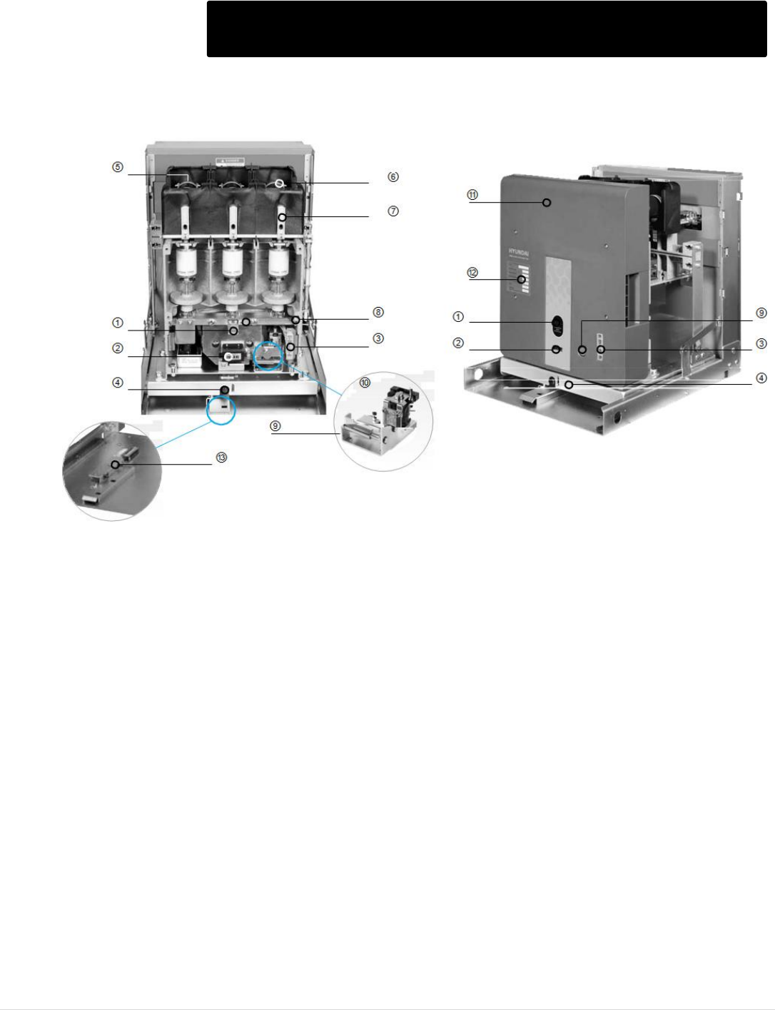
M o t o r t r o n i c s P r o d u c t S e l e c t i o n G u i d e P a g e 51
MVF Series - 7.2kV MV Contactors Structure
① ON/OFF indicator, ON means closed condition, OFF means open condition.
② Counter The counter shows how many times the contactor has operated since it was produced.
③ Control plug. The control source is supplied through the control Jack.
④ Draw-out button
⑤ Fuse. Fuses prevent the magnification of the short-circuit current.
⑥ Fuse holder
⑦ Fuse melting detector. The fuse melting detector can show electrically whether the fuse has blown or not.
⑧ Manual checking hole. A manual checking hole is used to close the contactor manually.
⑨ Emergency trip button. Only the latched types have the trip button which is used in emergencies.
⑩ Latch device
⑪ Front cover
⑫ Name plate
⑬ Position switch. Indicates electrically whether the contactor is in the TEST or CONNECTION position.
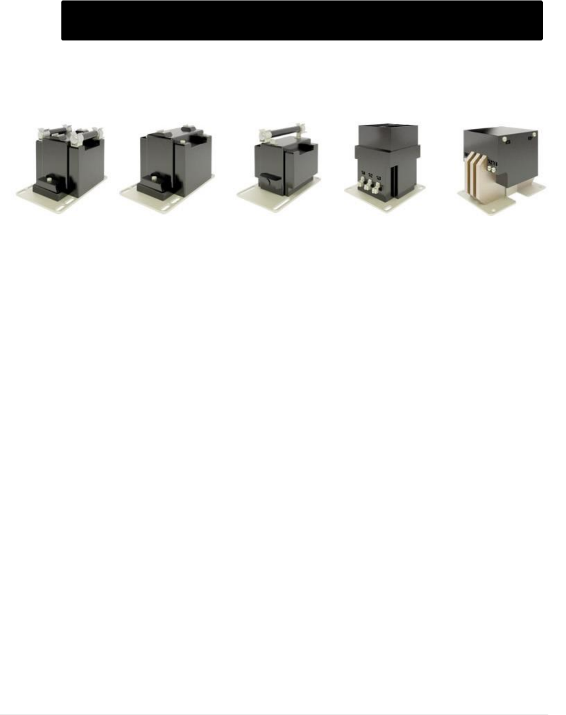
M o t o r t r o n i c s P r o d u c t S e l e c t i o n G u i d e P a g e 52
Low & Medium Voltage Transformers
VT Images shown for illustration purposes only.
INDOOR POTENTIAL TRANSFORMERS
Primary Voltage Range: 69V – 15.5kV
Secondary Voltage: 110/220V or 120/240V
CONTROL POWER TRANSFORMERS
Primary Voltage Range: 2.4 – 6.9kV
Secondary Voltage: 110/220V or 120/240V
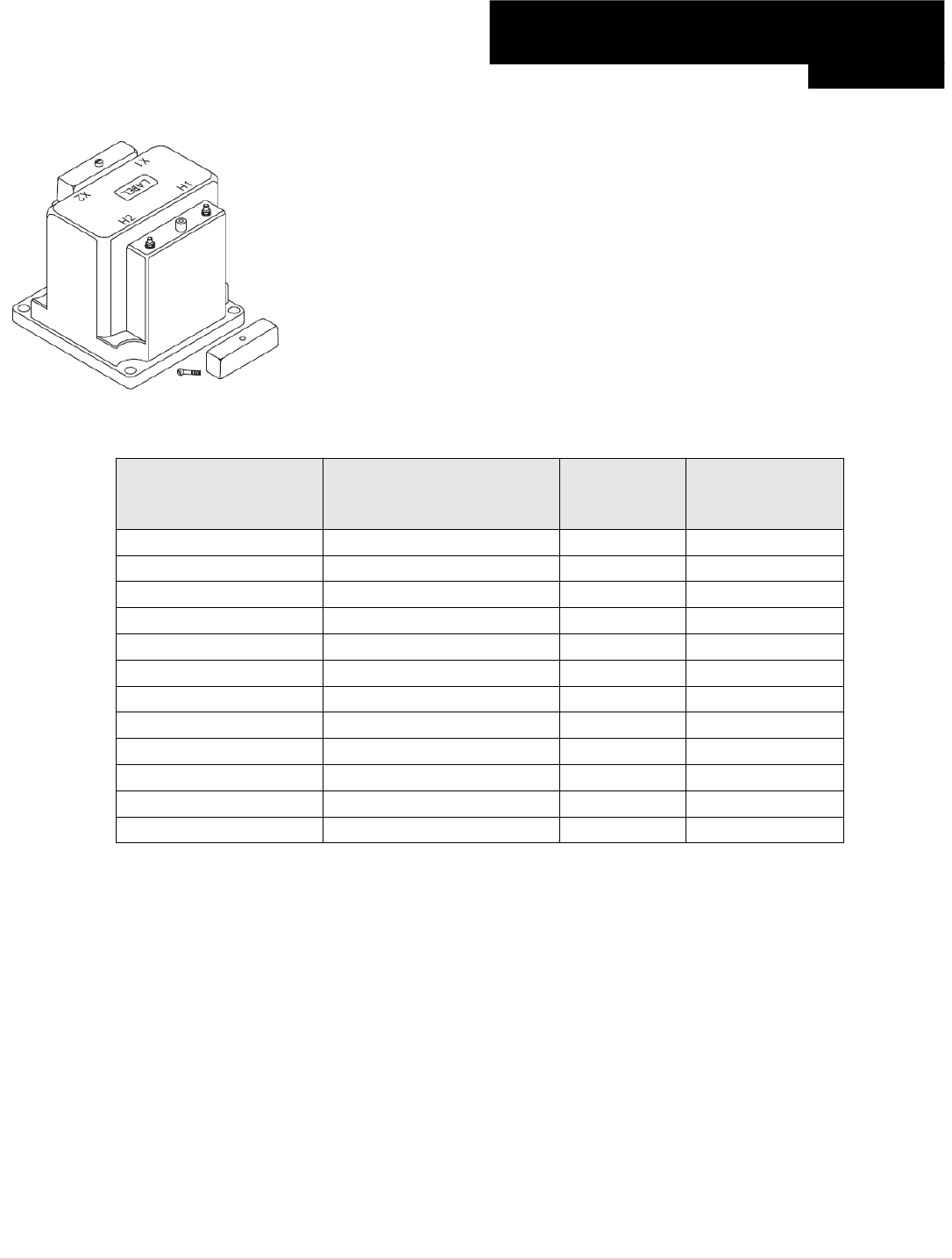
M o t o r t r o n i c s P r o d u c t S e l e c t i o n G u i d e P a g e 53
Primary Voltage 69 – 600V
Visit www.motortronics.com for Specification Sheets Low Voltage
Indoor Potential Transformer
Frequency: 60 Hz
Insulation Level: 600V, 10 kV BIL full wave
Accuracy Class: 0.6 W 1.2 x 60 Hz
Weight: Approximately 7.75 lbs.
Thermal Rating:
150 VA at 30ºC amb. / 100 VA at 55ºC amb.
Standard Secondary Voltage: 120 Volts
Model Number
Rated Primary Voltage
Ratio
List Price $
460-069
69
0.58:1
180
460-120
120
1:1
180
460-208
208
1.73:1
180
460-240
240
2:1
180
460-277
277
2.31:1
180
460-288
288
2.4:1
180
460-300
300
2.5:1
180
460-346
346
2.88:1
189
460-480
480
4:1
189
460-600
600
5:1
189
460i-415
415 (50Hz)
3.46:1
210
460i-690
690 (50Hz)
6.27:1
240
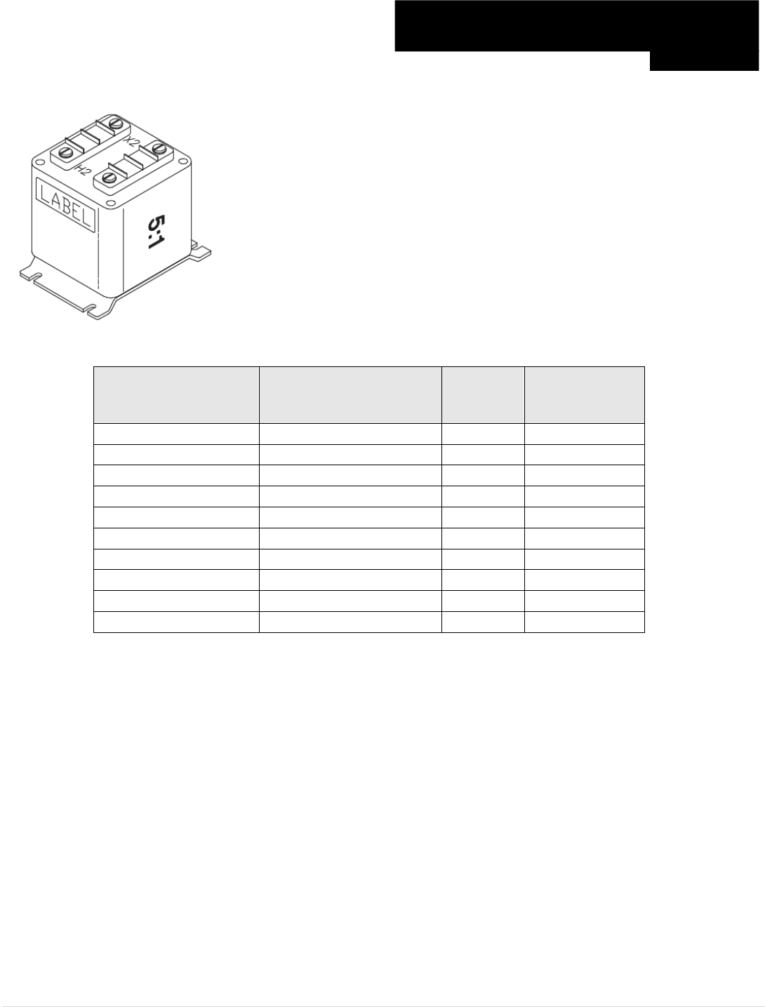
M o t o r t r o n i c s P r o d u c t S e l e c t i o n G u i d e P a g e 54
Primary Voltage 69 – 600V
Visit www.motortronics.com for Specification Sheets Low Voltage
Indoor Potential Transformer
Frequency: 60 Hz
Insulation Level: 600V, 10 kV BIL full wave
Accuracy Class: + 1% at all burdens up to 5VA at 1.0 and 0.95 P.F.
Weight: Approximately 2.5 lbs.
Thermal Rating:
40 VA at 30ºC amb. / 27 VA at 55ºC amb.
Standard Secondary Voltage: 120 Volts
Model Number
Rated Primary Voltage
Ratio
List Price $
467-069
69
0.58:1
175
467-120
120
1:1
175
467-208
208
1.73:1
175
467-240
240
2:1
175
467-277
277
2.31:1
175
467-288
288
2.4:1
175
467-300
300
2.5:1
175
467-346
346
2.88:1
175
467-480
480
4:1
175
467-600
600
5:1
175
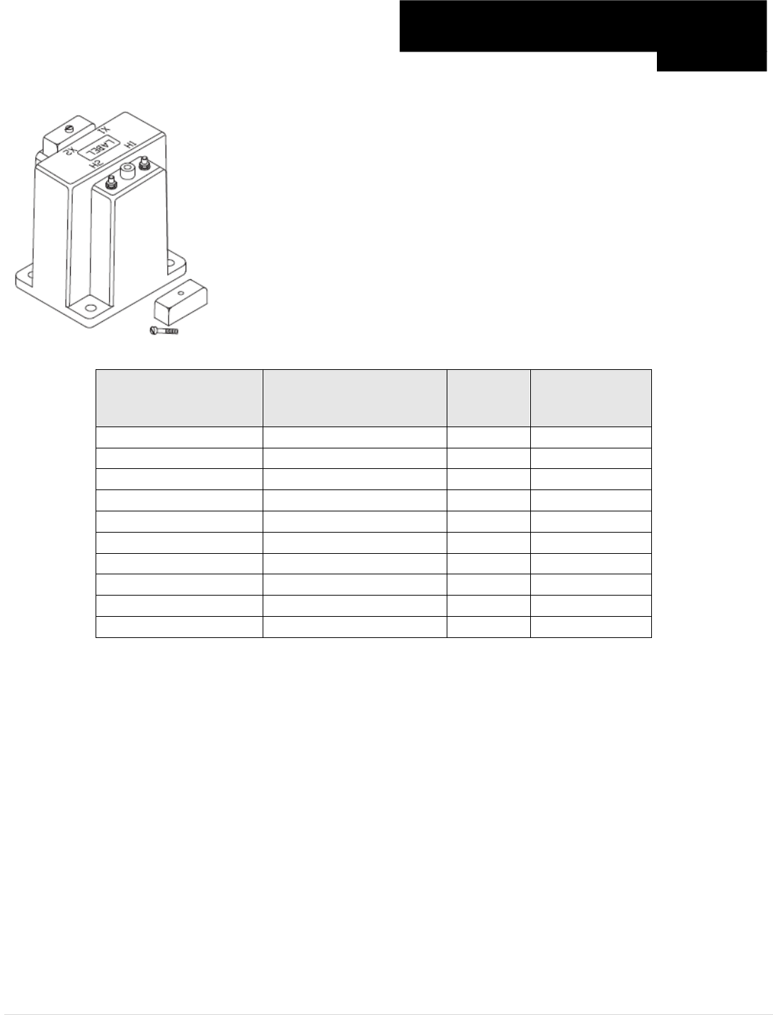
M o t o r t r o n i c s P r o d u c t S e l e c t i o n G u i d e P a g e 55
Primary Voltage 69 – 600V
Visit www.motortronics.com for Specification Sheets Low Voltage
Indoor Potential Transformer
Frequency: 60 Hz
Insulation Level: 600V, 10 kV BIL full wave
Accuracy Class: + 0.6% at all burdens up to 7.5VA and + 1.5% with 20VA burden.
Weight: Approximately 4 lbs.
Thermal Rating:
75 VA at 30ºC amb. / 50 VA at 55ºC amb.
Standard Secondary Voltage: 120 Volts
Model Number
Rated Primary Voltage
Ratio
List Price $
468-069
69
0.58:1
134
468-120
120
1:1
134
468-208
208
1.73:1
134
468-240
240
2:1
134
468-277
277
2.31:1
134
468-288
288
2.4:1
134
468-300
300
2.5:1
134
468-346
346
2.88:1
134
468-480
480
4:1
134
468-600
600
5:1
134
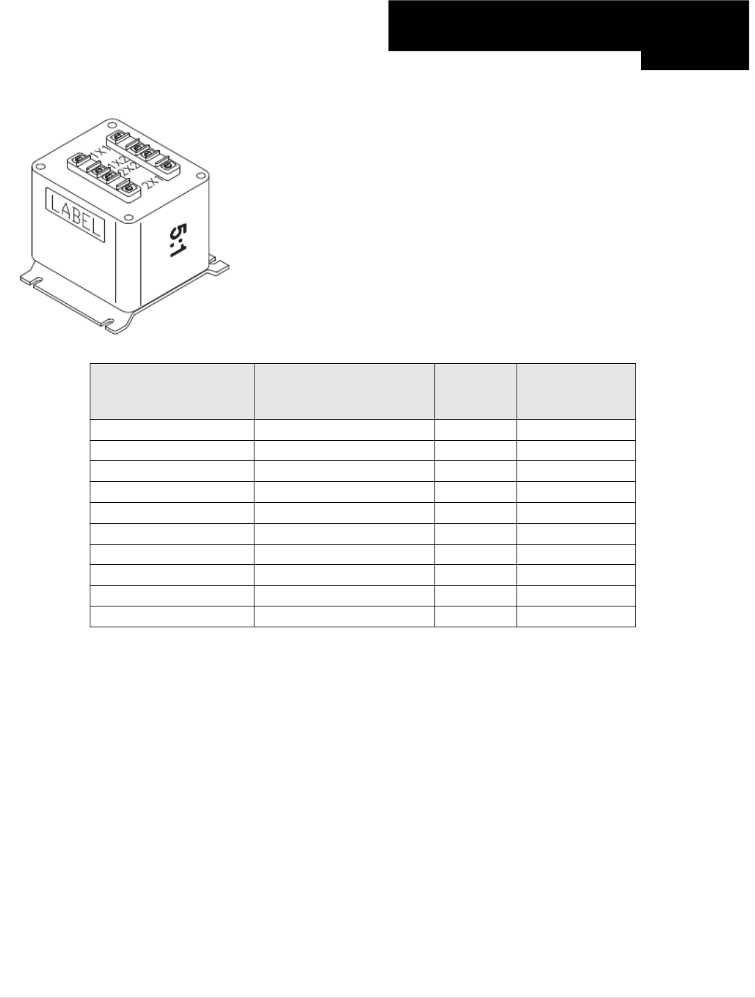
M o t o r t r o n i c s P r o d u c t S e l e c t i o n G u i d e P a g e 56
Primary Voltage 69 – 600V
Visit www.motortronics.com for Specification Sheets Low Voltage
Indoor Potential Transformer
Frequency: 60 Hz
Insulation Level: 600V, 10 kV BIL full wave
Accuracy Class: + 1% at all burdens up to 5 VA at 1.0 and 0.95 P.F.
Weight: Approximately 4.5 lbs.
Thermal Rating:
40 VA at 30ºC amb. / 27 VA at 55ºC amb.
Standard Secondary Voltage: 120 Volts
Model Number
Rated Primary Voltage
(Three Phase Input)
Ratio
List Price $
2VT469-069
69
0.58:1
258
2VT469-120
120
1:1
258
2VT469-208
208
1.73:1
258
2VT469-240
240
2:1
258
2VT469-277
277
2.31:1
258
2VT469-288
288
2.4:1
258
2VT469-300
300
2.5:1
258
2VT469-346
346
2.88:1
275
2VT469-480
480
4:1
275
2VT469-600
600
5:1
275
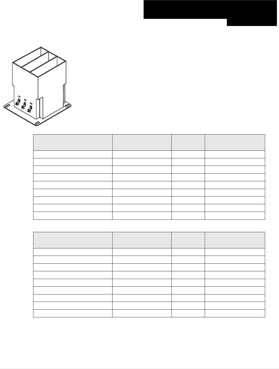
M o t o r t r o n i c s P r o d u c t S e l e c t i o n G u i d e P a g e 57
Primary Voltage 840 – 6.6kV
Visit www.motortronics.com for Specification Sheets Medium Voltage
Indoor Potential Transformer
Frequency: 60 Hz
Accuracy Class: 0.3 WX, 0.6M, 1.2Y at 100% rated voltage with 120V based
ANSI burden
Weight: Approximately 38 lbs.
Thermal Rating:
700 VA total, 350 VA per phase at 30ºC amb.
450 VA total, 225 VA per phase at 55ºC amb.
Standard Secondary Voltage: 120 Volts
Maximum System Voltage: 5.6 kV, 60 kV BIL full wave
Model Number
Three Fuse Clips Only
Rated Primary
Voltage
Ratio
List Price $
3PT3-60-841CCC
840
7:1
1,126
3PT3-60-122CCC
1200
10:1
1,126
3PT3-60-242CCC
2400
20:1
1,126
3PT3-60-332CCC
3300
30:1
1,126
3PT3-60-422CCC
4200
35:1
1,126
3PT3-60-482CCC
4800
40:1
1,218
3PT3-60-552CCC
5500
50:1
1,218
3PT3-60-602CCC
6000
54:1
1,218
3PT3-60-662CCC
6600
55:1
1,218
Model Number
Three Fuses
Rated Primary
Voltage
Ratio
List Price $
3PT3-60-841FFF
840
7:1
1,238
3PT3-60-122FFF
1200
10:1
1,238
3PT3-60-242FFF
2400
20:1
1,238
3PT3-60-332FFF
3300
30:1
1,210
3PT3-60-422FFF
4200
35:1
1,210
3PT3-60-482FFF
4800
40:1
1,302
3PT3-60-552FFF
5500
50:1
1,302
3PT3-60-602FFF
6000
54:1
1,302
3PT3-60-662FFF
6600
55:1
1,302
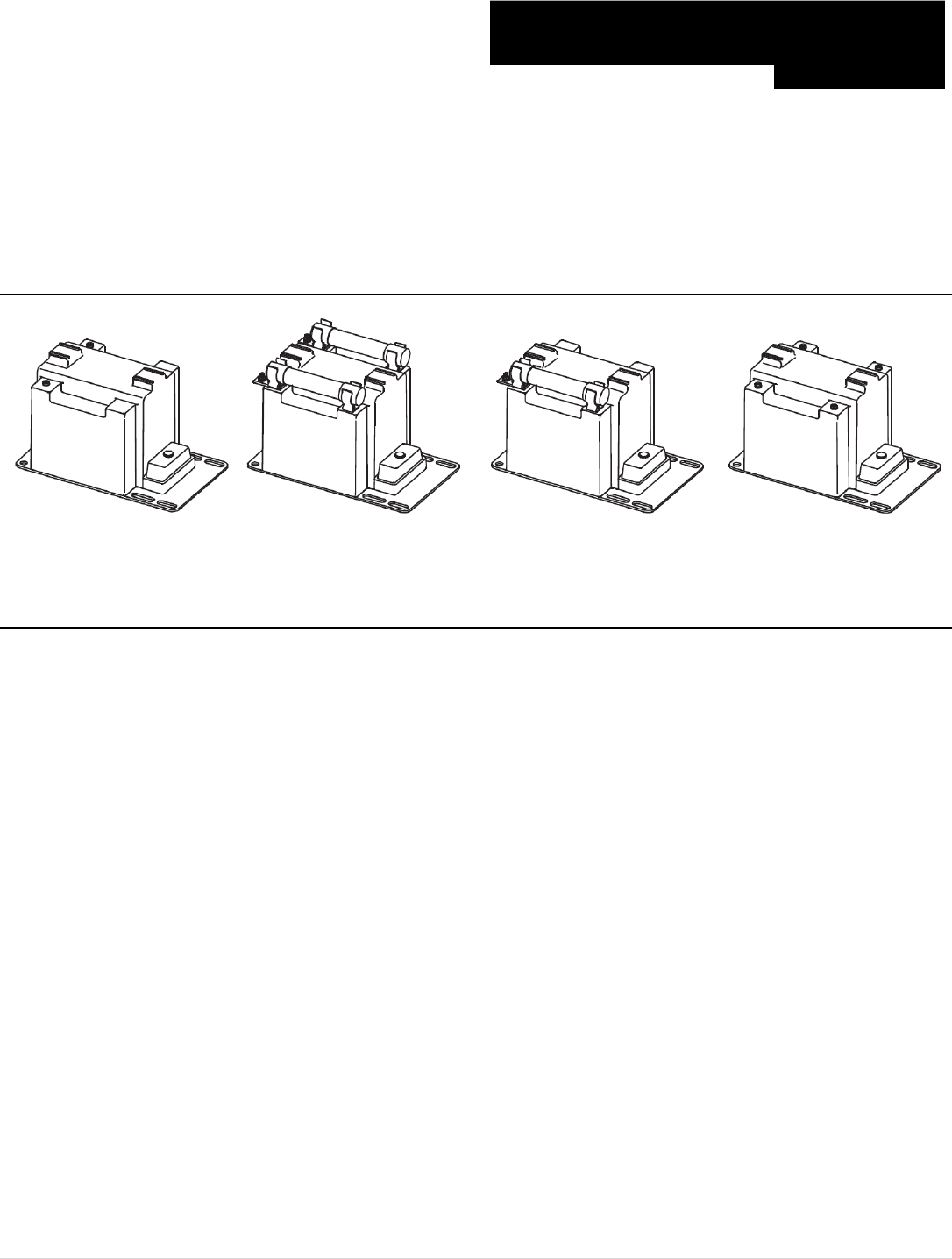
M o t o r t r o n i c s P r o d u c t S e l e c t i o n G u i d e P a g e 58
PTG3-1-60 & PTG3-2-60
PTW3-1-60 & PTW3-2-60
Visit www.motortronics.com for Specification Sheets Medium Voltage
Indoor Potential Transformer
Frequency: 60 Hz
Accuracy Class: 0.3 WXMY, 0.6M, 1.2Z at 100% rated voltage with 120V based ANSI burden. 0.3 WX,
0.6M, 1.2 Y at 58% rated voltage with 69.3 V based ANSI burden
Weight: Approximately 34 lbs., unfused.
Thermal Rating: 750 VA at 30ºC amb. / 500 VA at 55ºC amb.
Standard Secondary Voltage: 120 Volts
Maximum System Voltage: 5.6 kV, 60 kV BIL full wave
Unfused
Two Bushings
(one bushing not shown)
Two Fuses
Two Bushings
One Fuse
One Bushing
Switchgear Style
Two Bushings
(one bushing not shown)

M o t o r t r o n i c s P r o d u c t S e l e c t i o n G u i d e P a g e 59
Primary Voltage 2.4 – 6.9kV
Secondary Voltage 120V
Visit www.motortronics.com for Specification Sheets Medium Voltage
Indoor Potential Transformer
Model Number
Unfused – One Bushing
Rated Primary
Voltage
Ratio
Secondary
Voltage
List Price $
PTG3-1-60-242
2400
20:1
120
902
PTG3-1-60-332
3300
30:1
110 (50Hz)
902
PTG3-1-60-422
4200
35:1
120
902
PTG3-1-60-482
4800
40:1
120
902
PTG3-1-60-502
5000
41.66
120
1,020
PTG3-1-60-552
5500
45.83
120
1,020
PTG3-1-60-602
6000
50.00
120
1,020
PTG3-1-60-662
6600
55.00
120
1,020
PTG3-1-60-692
6900
57.50
120
1,052
Model Number
Single Fuse – One Bushing
Rated Primary
Voltage
Ratio
Secondary
Voltage
List Price $
PTG3-1-60-242F
2400
20:1
120
990
PTG3-1-60-332F
3300
30:1
110 (50Hz)
990
PTG3-1-60-422F
4200
35:1
120
990
PTG3-1-60-482F
4800
40:1
120
1,014
PTG3-1-60-502F
5000
41.66
120
1,065
PTG3-1-60-552F
5500
45.83
120
1,065
PTG3-1-60-602F
6000
50.00
120
1,065
PTG3-1-60-662F
6600
55.00
120
1,133
PTG3-1-60-692F
6900
57.50
120
1,167
Model Number
Single Fuse Clip Only – One Bushing
Rated Primary
Voltage
Ratio
Secondary
Voltage
List Price $
PTG3-1-60-242CS
2400
20:1
120
947
PTG3-1-60-332CS
3300
30:1
110 (50Hz)
947
PTG3-1-60-422CS
4200
35:1
120
947
PTG3-1-60-482CS
4800
40:1
120
947
PTG3-1-60-502CS
5000
41.66
120
1,014
PTG3-1-60-552CS
5500
45.83
120
1,014
PTG3-1-60-602CS
6000
50.00
120
1,042
PTG3-1-60-662CS
6600
55.00
120
1,065
PTG3-1-60-692CS
6900
57.50
120
1,097

M o t o r t r o n i c s P r o d u c t S e l e c t i o n G u i d e P a g e 60
Primary Voltage 2.4 – 6.9kV
Secondary Voltage 120V
Visit www.motortronics.com for Specification Sheets Medium Voltage
Indoor Potential Transformer
Model Number
Unfused – Two Bushing
Rated Primary
Voltage
Ratio
Secondary
Voltage
List Price $
PTG3-2-60-242
2400
20:1
120
902
PTG3-2-60-332
3300
30:1
110 (50Hz)
902
PTG3-2-60-422
4200
35:1
120
902
PTG3-2-60-482
4800
40:1
120
902
PTG3-2-60-502
5000
41.66
120
1,020
PTG3-2-60-552
5500
45.83
120
1,020
PTG3-2-60-602
6000
50.00
120
1,020
PTG3-2-60-662
6600
55.00
120
1,020
PTG3-2-60-692
6900
57.50
120
1,052
Model Number
Two Fuses – Two Bushing
Rated Primary
Voltage
Ratio
Secondary
Voltage
List Price $
PTG3-2-60-242FF
2400
20:1
120
990
PTG3-2-60-332FF
3300
30:1
110 (50Hz)
990
PTG3-2-60-422FF
4200
35:1
120
990
PTG3-2-60-482FF
4800
40:1
120
1,014
PTG3-2-60-450FF
5000
41.66
120
1,065
PTG3-2-60-455FF
5500
45.83
120
1,065
PTG3-2-60-460FF
6000
50.00
120
1,065
PTG3-2-60-466FF
6600
55.00
120
1,133
PTG3-2-60-469FF
6900
57.50
120
1,167
Model Number
Two Fuse Clips Only – Two Bushing
Rated Primary
Voltage
Ratio
Secondary
Voltage
List Price $
PTG3-2-60-242CCS
2400
20:1
120
947
PTG3-2-60-332CCS
3300
30:1
110 (50Hz)
947
PTG3-2-60-422CCS
4200
35:1
120
947
PTG3-2-60-482CCS
4800
40:1
120
947
PTG3-2-60-502CCS
5000
41.66
120
1,014
PTG3-2-60-552CCS
5500
45.83
120
1,014
PTG3-2-60-602CCS
6000
50.00
120
1,042
PTG3-2-60-662CCS
6600
55.00
120
1,065
PTG3-2-60-692CCS
6900
57.50
120
1,097

M o t o r t r o n i c s P r o d u c t S e l e c t i o n G u i d e P a g e 61
Primary Voltage 2.4 – 6.9kV
Secondary Voltage 120V
Visit www.motortronics.com for Specification Sheets Medium Voltage
Indoor Potential Transformer
Model Number
Single Fuse Clips Only – One Bushing
Rated Primary
Voltage
Ratio
Secondary
Voltage
List Price $
PTW3-1-60-242CS
2400
20:1
120
992
PTW3-1-60-332CS
3300
30:1
110 (50Hz)
992
PTW3-1-60-422CS
4200
35:1
120
992
PTW3-1-60-482CS
4800
40:1
120
992
PTW3-1-60-502CS
5000
41.66
120
1,059
PTW3-1-60-552CS
5500
45.83
120
1,059
PTW3-1-60-602CS
6000
50.00
120
1,059
PTW3-1-60-662CS
6600
55.00
120
1,110
PTW3-1-60-692CS
6900
57.50
120
1,142
Model Number
Unfused – One Bushing
Rated Primary
Voltage
Ratio
Secondary
Voltage
List Price $
PTW3-1-60-242
2400
20:1
120
947
PTW3-1-60-332
3300
30:1
110 (50Hz)
947
PTW3-1-60-422
4200
35:1
120
947
PTW3-1-60-482
4800
40:1
120
947
PTW3-1-60-502
5000
41.66
120
1,065
PTW3-1-60-552
5500
45.83
120
1,065
PTW3-1-60-602
6000
50.00
120
1,065
PTW3-1-60-662
6600
55.00
120
1,065
PTW3-1-60-692
6900
57.50
120
1,097
Model Number
Single Fuse – One Bushing
Rated Primary
Voltage
Ratio
Secondary
Voltage
List Price $
PTW3-1-60-242F
2400
20:1
120
1,035
PTW3-1-60-332F
3300
30:1
110 (50Hz)
1,035
PTW3-1-60-422F
4200
35:1
120
1,035
PTW3-1-60-482F
4800
40:1
120
1,059
PTW3-1-60-502F
5000
41.66
120
1,110
PTW3-1-60-552F
5500
45.83
120
1,110
PTW3-1-60-602F
6000
50.00
120
1,110
PTW3-1-60-662F
6600
55.00
120
1,178
PTW3-1-60-692F
6900
57.50
120
1,212

M o t o r t r o n i c s P r o d u c t S e l e c t i o n G u i d e P a g e 62
Primary Voltage 2.4 – 6.9kV
Secondary Voltage 120V
Visit www.motortronics.com for Specification Sheets Medium Voltage
Indoor Potential Transformer
Model Number
Unfused – Two Bushing
Rated Primary
Voltage
Ratio
Secondary
Voltage
List Price $
PTW3-2-60-242
2400
20:1
120
947
PTW3-2-60-332
3300
30:1
110 (50Hz)
947
PTW3-2-60-422
4200
35:1
120
947
PTW3-2-60-482
4800
40:1
120
947
PTW3-2-60-502
5000
41.66
120
1,065
PTW3-2-60-552
5500
45.83
120
1,065
PTW3-2-60-602
6000
50.00
120
1,065
PTW3-2-60-662
6600
55.00
120
1,065
PTW3-2-60-692
6900
57.50
120
1,097
Model Number
Two Fuses – Two Bushing
Rated Primary
Voltage
Ratio
Secondary
Voltage
List Price $
PTW3-2-60-242FF
2400
20:1
120
1,035
PTW3-2-60-332FF
3300
30:1
110 (50Hz)
1,035
PTW3-2-60-422FF
4200
35:1
120
1,035
PTW3-2-60-482FF
4800
40:1
120
1,059
PTW3-2-60-502FF
5000
41.66
120
1,059
PTW3-2-60-552FF
5500
45.83
120
1,059
PTW3-2-60-602FF
6000
50.00
120
1,059
PTW3-2-60-662FF
6600
55.00
120
1,178
PTW3-2-60-692FF
6900
57.50
120
1,212
Model Number
Two Fuse Clips Only – Two Bushing
Rated Primary
Voltage
Ratio
Secondary
Voltage
List Price $
PTW3-2-60-242CCS
2400
20:1
120
992
PTW3-2-60-332CCS
3300
30:1
110 (50Hz)
992
PTW3-2-60-442CCS
4200
35:1
120
992
PTW3-2-60-482CCS
4800
40:1
120
992
PTW3-2-60-450CCS
5000
41.66
120
1,110
PTW3-2-60-455CCS
5500
45.83
120
1,110
PTW3-2-60-460CCS
6000
50.00
120
1,110
PTW3-2-60-466CCS
6600
55.00
120
1,110
PTW3-2-60-469CCS
6900
57.50
120
1,142
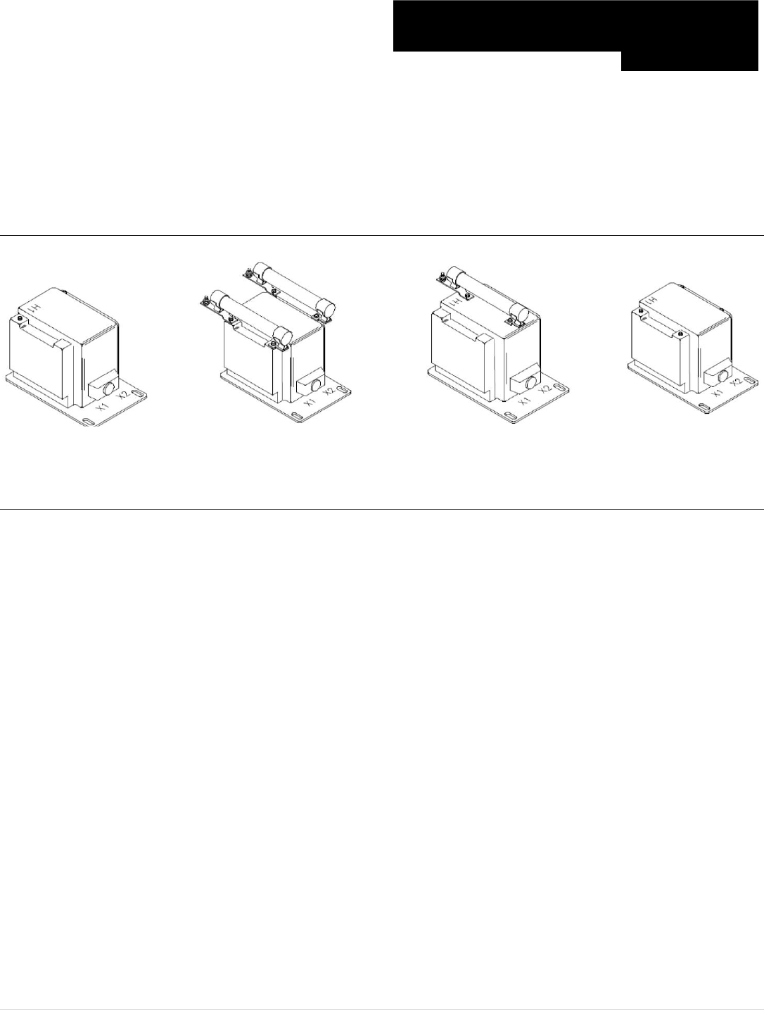
M o t o r t r o n i c s P r o d u c t S e l e c t i o n G u i d e P a g e 63
PTG5-1-60 & PTG5-2-60
PTW5-1-60 & PTW5-2-60
Visit www.motortronics.com for Specification Sheets Medium Voltage
Indoor Potential Transformer
Frequency: 60 Hz
Accuracy Class: 0.3 WXMYZ, 1.2ZZ at 100% rated voltage with 120V based ANSI burden. 0.3 WXMY, 1.2 Z at 58%
rated voltage with 69.3 V based ANSI burden
Weight: Approximately 85 lbs., unfused.
Thermal Rating: 1500 VA at 30ºC amb. / 1000 VA at 55ºC amb.
Standard Secondary Voltage: 120 Volts
Maximum System Voltage: 15.5 kV, 1100 kV BIL full wave
Unfused
Two Bushings
(one bushing not shown)
Two Fuses
Two Bushings
One Fuse
One Bushing
Switchgear Style
Two Bushings
(one bushing not shown)

M o t o r t r o n i c s P r o d u c t S e l e c t i o n G u i d e P a g e 64
Primary Voltage 7.2 – 14.4kV
Secondary Voltage 120V
Visit www.motortronics.com for Specification Sheets Medium Voltage
Indoor Potential Transformer
Model Number
Unfused – One Bushing
Rated Primary
Voltage
Ratio
Secondary
Voltage
List Price $
PTG5-1-110-722
7200
60:1
120
1,521
PTG5-1-110-842
8400
70:1
120
1,521
PTG5-1-110-113
11000
100:1
110 (50Hz)
1,521
PTG5-1-110-123
12000
100:1
120
1,521
PTG5-1-110-1322
13200
110:1
120
1,521
PTG5-1-110-1382
13800
115:1
120
1,521
PTG5-1-110-1442
14400
120:1
120
1,521
Model Number
Single Fuse – One Bushing
Rated Primary
Voltage
Ratio
Secondary
Voltage
List Price $
PTG5-1-110-722F
7200
60:1
120
1,660
PTG5-1-110-842F
8400
70:1
120
1,660
PTG5-1-110-113F
11000
100:1
110 (50Hz)
1,660
PTG5-1-110-123F
12000
100:1
120
1,660
PTG5-1-110-1322F
13200
110:1
120
1,660
PTG5-1-110-1382F
13800
115:1
120
1,660
PTG5-1-110-1442F
14400
120:1
120
1,660
Model Number
Single Fuse Clip Only – One Bushing
Rated Primary
Voltage
Ratio
Secondary
Voltage
List Price $
PTG5-1-110-242C
2400
60:1
120
1,580
PTG5-1-110-332C
3300
70:1
110 (50Hz)
1,580
PTG5-1-110-442C
4200
100:1
120
1,580
PTG5-1-110-482C
4800
100:1
120
1,580
PTG5-1-110-502C
5000
110:1
120
1,580
PTG5-1-110-552C
5500
115:1
120
1,580
PTG5-1-110-602C
6000
120:1
120
1,580

M o t o r t r o n i c s P r o d u c t S e l e c t i o n G u i d e P a g e 65
Primary Voltage 7.2 – 14.4kV
Secondary Voltage 120V
Visit www.motortronics.com for Specification Sheets Medium Voltage
Indoor Potential Transformer
Model Number
Two Fuse Clips Only – Two Bushings
Rated Primary
Voltage
Ratio
Secondary
Voltage
List Price $
PTG5-2-110-242CC
2400
60:1
120
1,620
PTG5-2-110-332CC
3300
70:1
110 (50Hz)
1,620
PTG5-2-110-442CC
4200
100:1
120
1,620
PTG5-2-110-482CC
4800
100:1
120
1,620
PTG5-2-110-502CC
5000
110:1
120
1,620
PTG5-2-110-552CC
5500
115:1
120
1,620
PTG5-2-110-602CC
6000
120:1
120
1,620
Model Number
Unfused – Two Bushings
Rated Primary
Voltage
Ratio
Secondary
Voltage
List Price $
PTG5-2-110-722
7200
60:1
120
1,561
PTG5-2-110-842
8400
70:1
120
1,561
PTG5-2-110-113
11000
100:1
110 (50Hz)
1,561
PTG5-2-110-123
12000
100:1
120
1,561
PTG5-2-110-1322
13200
110:1
120
1,561
PTG5-2-110-1382
13800
115:1
120
1,561
PTG5-2-110-1442
14400
120:1
120
1,561
Model Number
Two Fuses – Two Bushings
Rated Primary
Voltage
Ratio
Secondary
Voltage
List Price $
PTG5-2-110-722FF
7200
60:1
120
1,700
PTG5-2-110-842FF
8400
70:1
120
1,700
PTG5-2-110-113FF
11000
100:1
110 (50Hz)
1,700
PTG5-2-110-123FF
12000
100:1
120
1,700
PTG5-2-110-1322FF
13200
110:1
120
1,700
PTG5-2-110-1382FF
13800
115:1
120
1,700
PTG5-2-110-1442FF
14400
120:1
120
1,700

M o t o r t r o n i c s P r o d u c t S e l e c t i o n G u i d e P a g e 66
Primary Voltage 7.2 – 14.4kV
Secondary Voltage 120V
Visit www.motortronics.com for Specification Sheets Medium Voltage
Indoor Potential Transformer
Model Number
Single Fuse Clip Only – One Bushing
Rated Primary
Voltage
Ratio
Secondary
Voltage
List Price $
PTW5-1-110-722C
2400
60:1
120
1,620
PTW5-1-110-842C
3300
70:1
110 (50Hz)
1,620
PTW5-1-110-113C
4200
100:1
120
1,620
PTW5-1-110-123C
4800
100:1
120
1,620
PTW5-1-110-1322C
5000
110:1
120
1,620
PTW5-1-110-1382C
5500
115:1
120
1,620
PTW5-1-110-1442C
6000
120:1
120
1,620
Model Number
Unfused – One Bushing
Rated Primary
Voltage
Ratio
Secondary
Voltage
List Price $
PTW5-1-110-722
7200
60:1
120
1,561
PTW5-1-110-842
8400
70:1
120
1,561
PTW5-1-110-113
11000
100:1
110 (50Hz)
1,561
PTW5-1-110-123
12000
100:1
120
1,561
PTW5-1-110-1322
13200
110:1
120
1,561
PTW5-1-110-1382
13800
115:1
120
1,561
PTW5-1-110-1442
14400
120:1
120
1,561
Model Number
Single Fuse – One Bushing
Rated Primary
Voltage
Ratio
Secondary
Voltage
List Price $
PTW5-1-110-722F
7200
60:1
120
1,700
PTW5-1-110-842F
8400
70:1
120
1,700
PTW5-1-110-113F
11000
100:1
110 (50Hz)
1,700
PTW5-1-110-123F
12000
100:1
120
1,700
PTW5-1-110-1322F
13200
110:1
120
1,700
PTW5-1-110-1382F
13800
115:1
120
1,700
PTW5-1-110-1442F
14400
120:1
120
1,700
M o t o r t r o n i c s P r o d u c t S e l e c t i o n G u i d e P a g e 67
Primary Voltage 7.2 – 14.4kV
Secondary Voltage 120V
Visit www.motortronics.com for Specification Sheets Medium Voltage
Indoor Potential Transformer
Model Number
Unfused – Two Bushings
Rated Primary
Voltage
Ratio
Secondary
Voltage
List Price $
PTW5-2-110-722
7200
60:1
120
1,561
PTW5-2-110-842
8400
70:1
120
1,561
PTW5-2-110-113
11000
100:1
110 (50Hz)
1,561
PTW5-2-110-123
12000
100:1
120
1,561
PTW5-2-110-1322
13200
110:1
120
1,561
PTW5-2-110-1382
13800
115:1
120
1,561
PTW5-2-110-1442
14400
120:1
120
1,561
Model Number
Two Fuses – Two Bushings
Rated Primary
Voltage
Ratio
Secondary
Voltage
List Price $
PTW5-2-110-722FF
7200
60:1
120
1,700
PTW5-2-110-842FF
8400
70:1
120
1,700
PTW5-2-110-113FF
11000
100:1
110 (50Hz)
1,700
PTW5-2-110-123FF
12000
100:1
120
1,700
PTW5-2-110-1322FF
13200
110:1
120
1,700
PTW5-2-110-1382FF
13800
115:1
120
1,700
PTW5-2-110-1442FF
14400
120:1
120
1,700
Model Number
Two Fuse Clips Only – Two Bushings
Rated Primary
Voltage
Ratio
Secondary
Voltage
List Price $
PTW5-2-110-722CC
2400
60:1
120
1,620
PTW5-2-110-842CC
3300
70:1
110 (50Hz)
1,620
PTW5-2-110-113CC
4200
100:1
120
1,620
PTW5-2-110-123CC
4800
100:1
120
1,620
PTW5-2-110-1322CC
5000
110:1
120
1,620
PTW5-2-110-1382CC
5500
115:1
120
1,620
PTW5-2-110-1442CC
6000
120:1
120
1,620
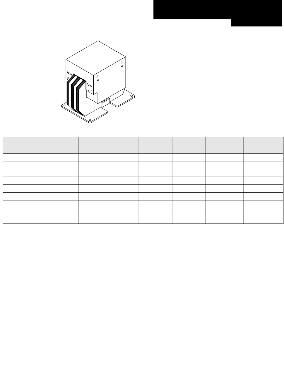
M o t o r t r o n i c s P r o d u c t S e l e c t i o n G u i d e P a g e 68
Primary Voltage 2.4 – 6.9kV
Secondary Voltage 110/220V, 120/240V
Visit www.motortronics.com for Specification Sheets Medium Voltage
Control Power Transformer
* Secondary Voltage
"-5" Model 110/220
* Secondary Voltage
"-6" Model 120/240
Frequency: 50/60 Hz
Insulation Level: 6.9kV, 60 kV BIL full wave
Weight: Approximately 57 lbs.
Thermal Rating:
2.0 kVA at 30ºC amb.
Standard Secondary Voltage: 110/120 Volts
Model Number
Three Fuses
Rated Primary
Voltage
Ratio
110V “-5”
Ratio
120V “-6”
Rated
VA
List Price $
CPT3-60-2-2400-*
2400
21.81
20.00
750
834
CPT3-60-2-3300-*
3300
30.00
27.50
750
834
CPT3-60-2-4160-*
4160
37.61
34.66
750
834
CPT3-60-2-4800-*
4800
43.63
40.00
750
954
CPT3-60-2-5000-*
5000
45.45
41.66
750
954
CPT3-60-2-5500-*
5500
50.00
45.83
750
954
CPT3-30-2-6000-*
6000
54.54
50.00
750
954
CPT3-60-2-6600-*
6600
60.00
55.00
750
954
CPT3-60-2-6900-*
6900
62.72
57.50
750
954
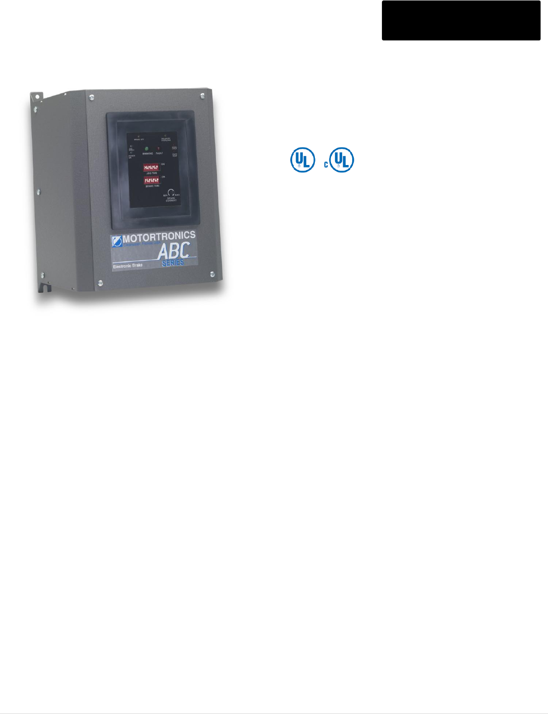
M o t o r t r o n i c s P r o d u c t S e l e c t i o n G u i d e P a g e 69
ABC Series Electric Brakes ABC Series
Operator Adjustments
Brake Time and Jog Time = 7 position binary dipswitch
Brake Current = potentiometer
Adjustment Ranges
Brake Jog Times = 0 - 127 seconds in 1 second increments
Brake Current = Up to 100% unit rating
Inputs
Starter Monitor = Dry input for auxiliary contact from motor starter.
Jumper selectable for N.O. or N.C. contact.
Brake Disable = Dry input for N.O. contact to disable braking before
or during operation. Can be wired to the starter thermal overload
N.O. auxiliary contact to prevent braking of overloaded motor.
Motor Power Sensor (T3) = voltage input used for sensing motor
power presence in sequencing/status circuit and for zero speed
sensing during braking.
Outputs
Starter Coil Interlock Two sets of FORM "C" relay contacts for use
in interlocking the starter coil and/or other devices to prevent energizing
while the braking power is applied.
Mechanical Brake Release N.O. relay contact for use in controlling
electro-mechanical brake as a holding brake. When the ABC is
"disabled," this circuit controls the mechanical brake normally as if it
were the only brake in the system.
Aux Contact Ratings
5 amps, 250VAC max
LED Status Indicators
Large LEDs: Braking = green; Fault = red
Small LEDs: Power On, Jog/Armed, Brake Off, Disabled, Over
Temp, and Wiring Error
Operating Design Temperature
0 - 50ᄎC (32-122ᄎF) open
0 - 40ᄎC (32 - 104ᄎ) enclosed
Ambient Conditions
0 - 95% relative humidity
0 - 3300ft (1000M) elevation
Approvals UL, cUL Listed
Voltage Rating
Selected voltage ratings + 10%
Selectable for 50/60Hz + 2 Hz
Current Ratings
10 - 1000A in 10 sizes:
10, 24, 50, 100, 200, 300, 400, 550, 800, 1000A
Output Capacity
25% duty cycle at 100% unit rating (model dependant above 200
Amps)
Power Circuit
Full wave bridge, 4 SCRs, designed for use without isolation contactors
Transient Protection
RC snubber dv/dt circuit on each SCR device
Fusing
Approved for use with existing motor starter fusing when unit is
sized for motor FLA. Consult NEC for any other fusing requirements.
Control Circuit
Self-powered directly from line terminals. No separate control voltage
required.
Control Method
Microprocessor unit controls sequencing. I/O monitoring and status
annunciation. Braking current is adjustable via true RMS regulated
control using phase angle firing of SCRs.
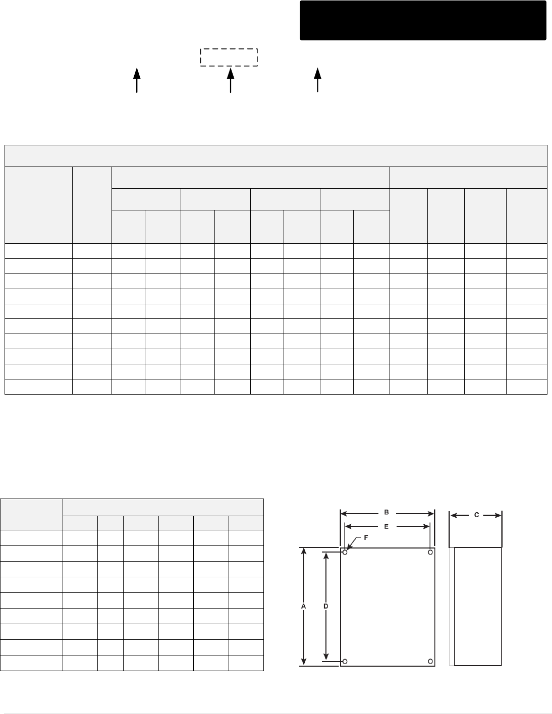
M o t o r t r o n i c s P r o d u c t S e l e c t i o n G u i d e P a g e 70
ABC Series Model Ratings
ABC - 200 - - E
Voltage
240 = 208 – 240V, 400 = 380 – 415V
480 = 440 – 480V, 600 = 575 – 600V
Enclosure
P = Panel Mount
E = NEMA 4/12 Sealed
Max. Brake Amps
10 – 1000 A.
ABC SERIES
Model
Number*
Max
Amps
Typical Horsepower Usage
List Price $
208 V
240V
480V
600V
Panel
Dim
Ref.
#
NEMA
4/12
Dim
Ref.
#
Std.
Duty
Extra
Duty
Std.
Duty
Extra
Duty
Std.
Duty
Extra
Duty
Std.
Duty
Extra
Duty
ABC-10
10
5
5
10
5
15
10
25
10
1,331
2
1,697
7
ABC-24
24
10
5
15
7.5
20
15
30
20
1,398
2
1,782
7
ABC-50
50
15
7.5
20
10
40
25
50
30
1,464
2
1,867
7
ABC -100
100
30
20
40
25
75
50
100
60
1,783
2
2,264
7
ABC-200
200
75
40
75
50
150
100
200
125
2,529
3
3,021
8
ABC-300
300
100
60
125
75
250
150
300
200
3,581
4
4,272
9
ABC-400
400
150
75
150
100
350
200
400
250
4,312
4
5,031
9
ABC-550
550
250
125
200
150
500
300
600
350
5,178
5
5,870
10
ABC -800
800
350
200
350
200
700
450
900
500
7,853
5
8,533
10
ABC-1000
1000
400
250
400
300
900
500
1000
600
9,610
5
10,516
10
* Specify voltage and enclosure type when ordering.
NOTES:
1. Never exceed the Full Load Amp rating of the motor without checking the motor manufacturer's data with regards
to appropriateness of the application and duty cycle.
2. If duty cycle is not known, Motortronics recommends using the Extra Duty Brake since braking current can be
adjusted down to meet the actual load requirements.
Dim
Ref. #
Dimensions (Inches)
A
B
C
D
E
F
2
10.5
7.9
7.2
10
6.8
0.21
3
16.5
10
10
15.9
9
0.28
4
16
16
10
15
15
0.5
5
21
26
10.4
20
25
0.5
6
16
12
9
14.5
10.5
0.5
7
20
16
9
18.5
14.5
0.5
8
24
20
16
22.5
18.5
0.5
9
36
24
16
34.5
22.5
0.5
10
36
30
16
34.5
28.5
0.5
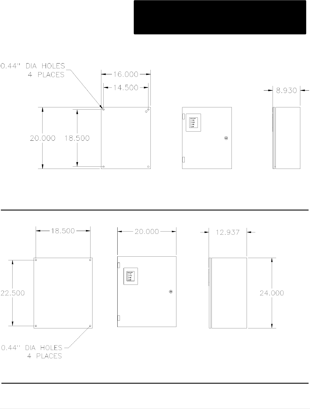
M o t o r t r o n i c s P r o d u c t S e l e c t i o n G u i d e P a g e 71
ABC Series Outline Dimensions
N12 & 4
N4/12 Outline: ABC-10/24/50/100-E
N4/12 Outline: ABC-200-E
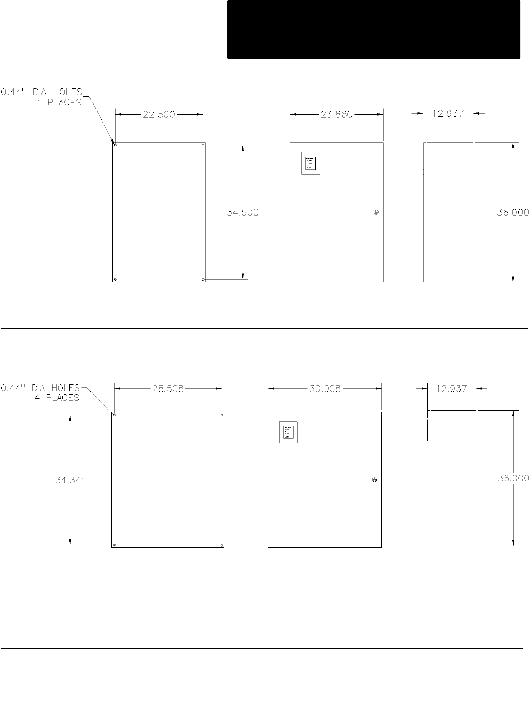
M o t o r t r o n i c s P r o d u c t S e l e c t i o n G u i d e P a g e 72
ABC Series Outline Dimensions
N12 & 4
Cont.
N4/12 Outline: ABC-300/400-E
N4/12 Outline: ABC-550/800-E
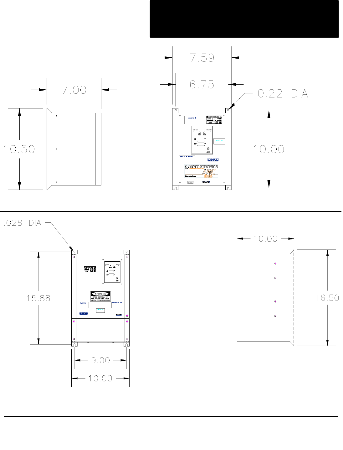
M o t o r t r o n i c s P r o d u c t S e l e c t i o n G u i d e P a g e 73
ABC Series Outline Dimensions
Panel Outline
Panels Outline: ABC-10/24/50/100
Panels Outline: ABC-200
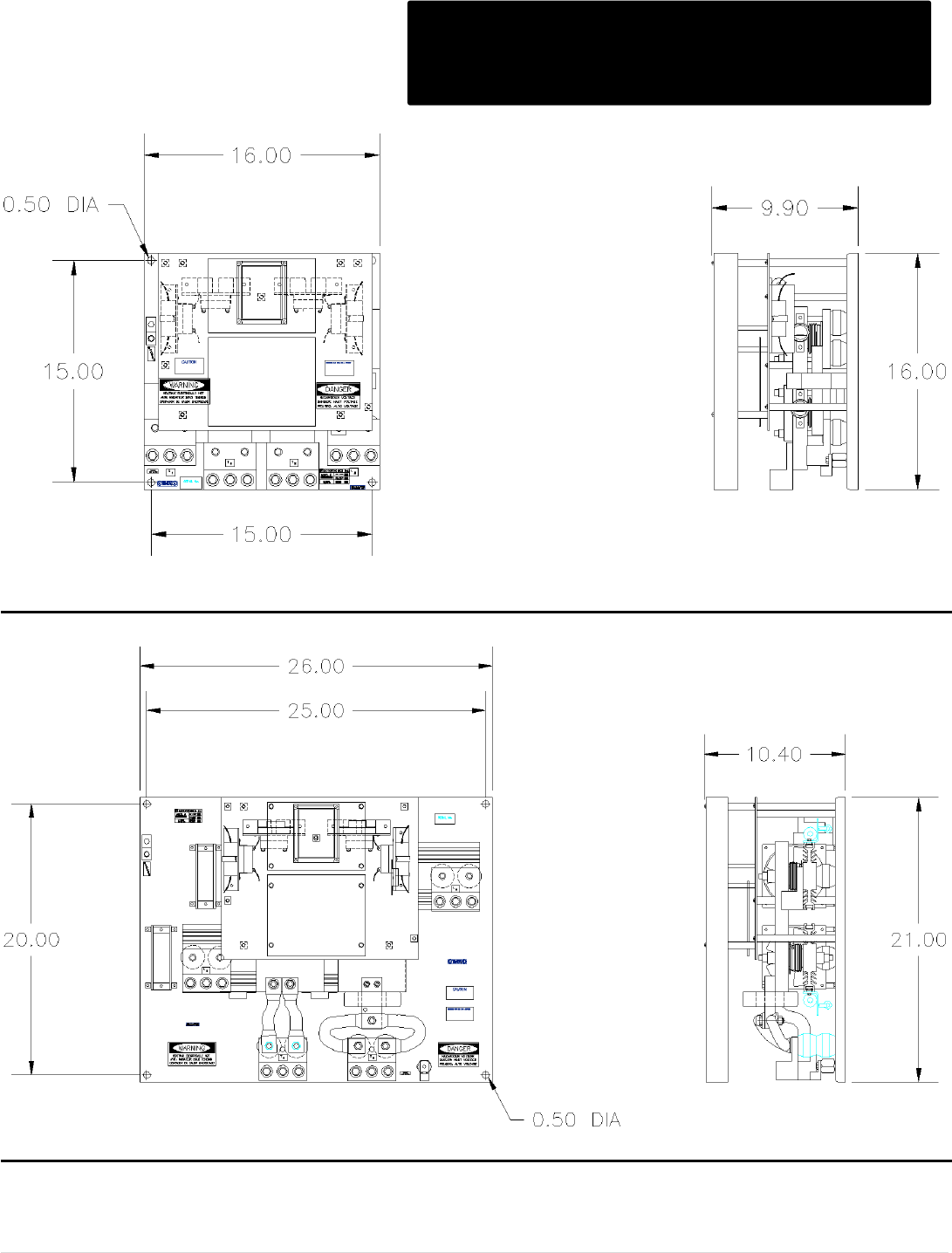
M o t o r t r o n i c s P r o d u c t S e l e c t i o n G u i d e P a g e 74
ABC Series Outline Dimensions
Panel Outline
Cont.
Panels Outline: ABC-300/400
Panels Outline: ABC-550/800
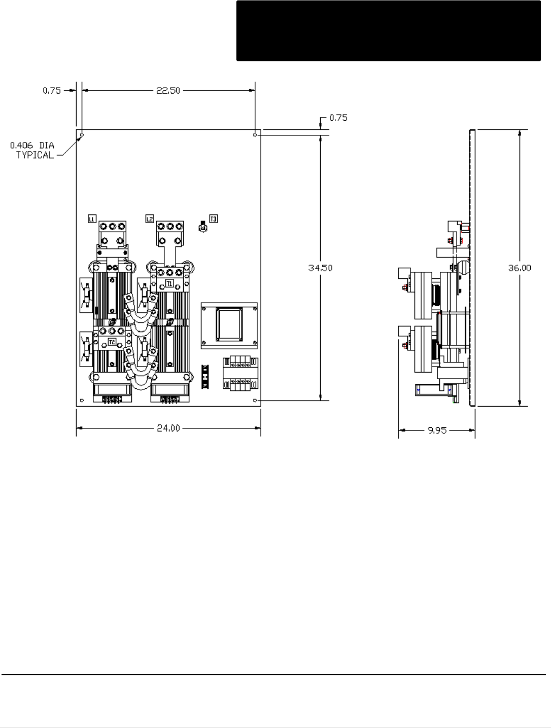
M o t o r t r o n i c s P r o d u c t S e l e c t i o n G u i d e P a g e 75
ABC Series Outline Dimensions
Panel Outline
Cont.
Panels Outline: ABC-1000
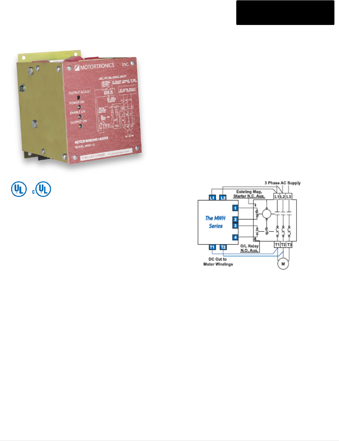
M o t o r t r o n i c s P r o d u c t S e l e c t i o n G u i d e P a g e 76
MWH Series Motor Winding Heaters MWH Series
The MWH Series keeps motors warm & moisture-
Free during extended shut down times
• Use On Any AC Motor
• Simple to Wire/Easy Retrofit
• Cost-Effective Alternative to
Strip Heaters
• Protects Motors from Problems Due to Condensation
Build-up
• Reliable, Maintenance-Free Operation
Protect Your Motors
Even the best motor winding insulation materials
become water permeable with repeated exposure to
temperature extremes and moisture. If the ambient
temperature is below the “dew point” when a motor is
turned off, condensation will form inside the motor as it
cools down. When the motor is re-energized, the
moisture heats up and permeates the windings,
eventually shorting and damaging the motor. Airborne
corrosive elements like salt and chemicals can also
combine with condensation and erode the rotor and
bearings, leading to premature motor failure.
The MWH Series provides a cost effective solution to
these problems by preventing condensation build-up in
motors. By applying a low level current to the motor
windings during extended shut down periods, the MWH
Series keeps AC motors warm and moisture-free.
Fully Automatic Operation
Designed for fully automatic operation, the MWH Series
turns on when the motor starter has turned off. A built-in
one minute timer ensures that the motor magnetic field
has collapsed before it injects DC power into the
windings. When the motor is restarted, the MWH
Series instantly turns off. No operator interface is
required... The MWH Series is in control.
Built-in Overload Sensing
The MWH Series had an optional shutdown input that
can be connected to the N.O. auxiliary contact on the
motor starter’s thermal overload relay. This will disable
the motor winding heater control, preventing any
additional heating in the motor and allowing
for a faster motor cool down period. The MWH Series
then goes back on-line after the overload relay is reset.
Ideal Alternative to Strip Heaters
Eliminate the cost and hassle of installing strip heaters
into your motors. Simply wire up the MWH Series to
generate heat throughout the motor stator windings. The
heat is dissipated evenly without the “hot spots” caused
by strip heaters. Conduction of heat to the rotor, bearings
and shaft is also more effective which means maximized
protection for the whole motor.
M o t o r t r o n i c s P r o d u c t S e l e c t i o n G u i d e P a g e 77
MWH Series Model Ratings
MWH - 10 - P -
Voltage
Blank = 208/240/480V, 380 = 380V
415 = 415V, 575 = 575/600V
Enclosure
P = Panel (Open Chassis)
N = NEMA 1
Amps
Model Number
Max. Amp.
Rating
Motor
Horsepower / Voltage
List Price $
208V
240V
480V
MWH-10-P-*
10
3-40
5-50
10-100
750
MWH-25-P-*
25
50-100
60-125
125-250
906
MWH-50-P-*
50
125-200
150-250
300-500
1,392
MWH-80-P-*
80
250-300
300-400
600-800
1,804
NOTES:
1 - Specify voltage at end of model number.
2 - Contact factory for pricing of unit in NEMA 1 enclosure.
NOTE: Contact factory for pricing of unit in NEMA 1 enclosure.
MWH Series Dimensions (Inches)
Model Number
OPEN PANEL
NEMA 1
H
W
D
H
W
D
MWH-10
6.2
4.5
6
11
7
7
MWH-25
8
6
6
11
7
7
MWH-50
10
8
7.9
15
10
8
MWH-80
10
8
9.3
20
10
10
NOTE: Dimensions are subject to change without notice. (Contact factory for exact dimensions.)
Model Number
Max. Amp.
Rating
Motor
Horsepower / Voltage
List Price $
575V
MWH-10-P-*
10
15-125
750
MWH-25-P-*
25
150-300
906
MWH-50-P-*
50
350-600
1,392
MWH-80-P-*
80
700-900
1,804
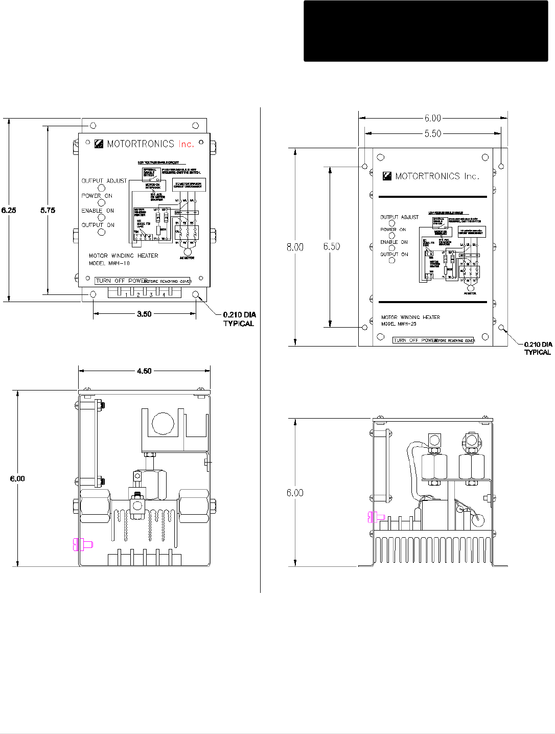
M o t o r t r o n i c s P r o d u c t S e l e c t i o n G u i d e P a g e 78
MWH Series Dimensions
MWH-10 & MWH-25
MWH-10 MWH-25
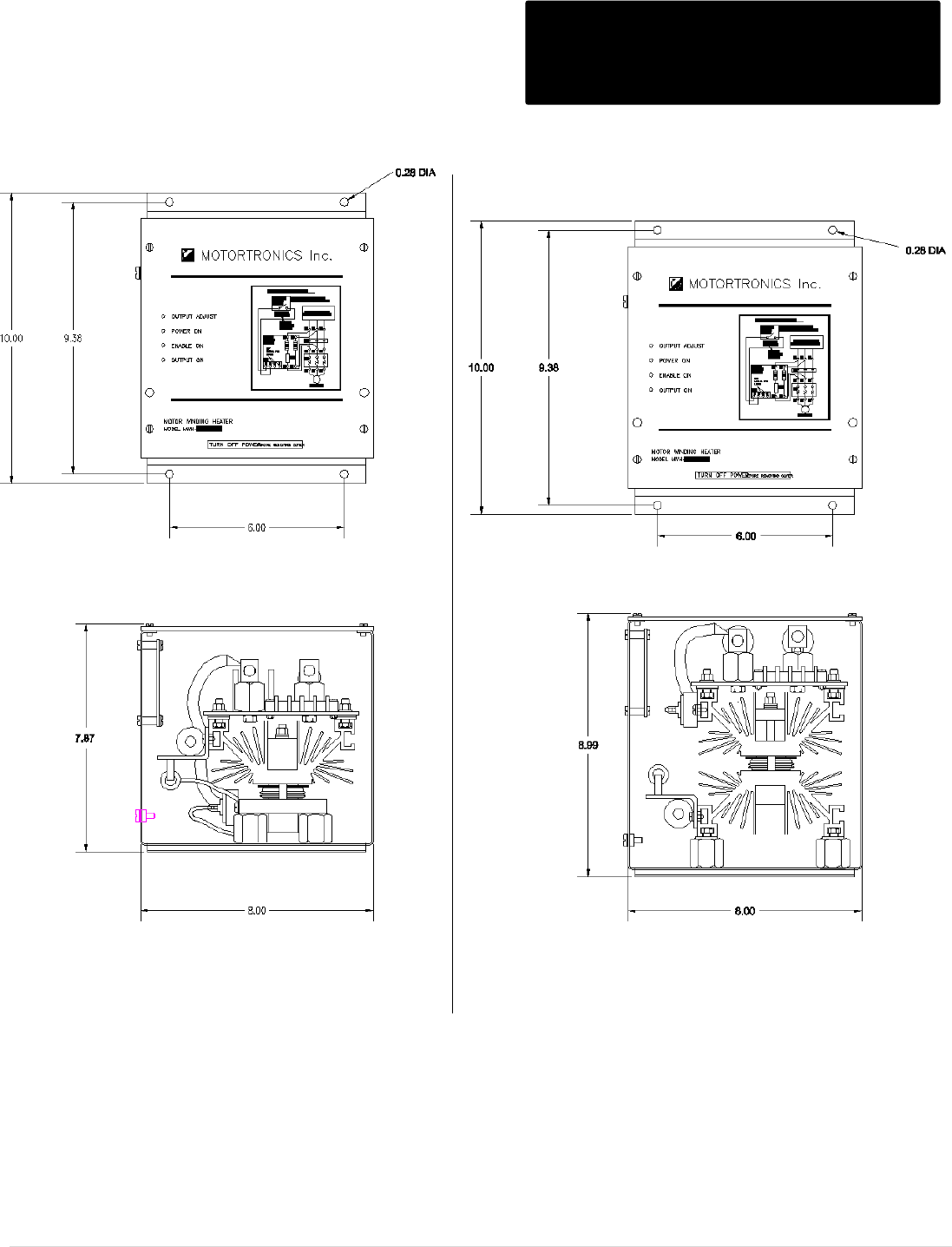
M o t o r t r o n i c s P r o d u c t S e l e c t i o n G u i d e P a g e 79
MWH Series Dimensions
MWH-50 & MWH-80
MWH-50 MWH-80
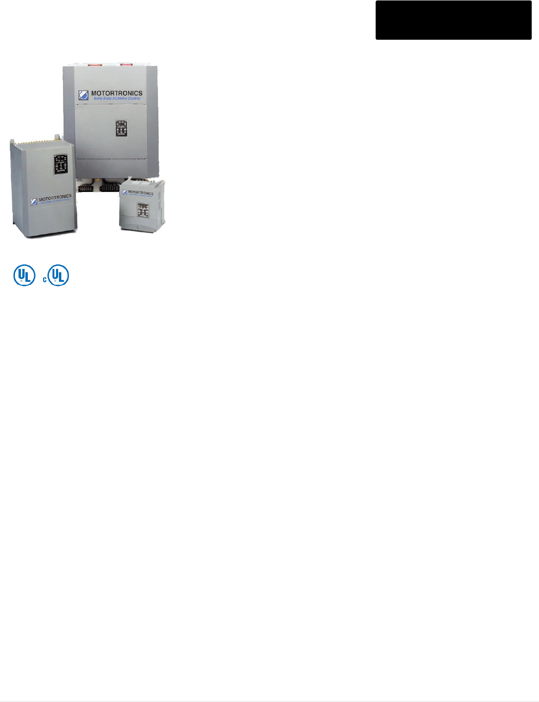
M o t o r t r o n i c s P r o d u c t S e l e c t i o n G u i d e P a g e 80
XLD Series Digital Soft Starters XLD Series
Acceleration Adjustments
Ramp types Voltage ramp or current ramp
Starting torque 0 - 100% of line voltage or
0 - 600% of FLA
Ramp time 1 to 120 seconds
Current limit 200 - 600%
Dual Ramp Settings*
Four (4) programmable ramp options
Deceleration Adjustments
Begin decel level 0 - 100% of line voltage
Stop level 0 to 1% less than begin decel
Decel time 0 - 60 seconds
Operation during overload Ramp down or
coast-to-stop
Jog Settings*
Jog at set current 100 - 500% of FLA
Jog at set voltage 0 - 100% of line voltage
Voltage jog max time 0 - 20 seconds
Kick Start Settings
Kick start 0 - 100% of line voltage
Kick start time 0.1 - 2 seconds
Programmable Output Relays
Three (3) relays can be individually
programmed for change of
state indication for any one of 18 conditions.
Type / Rating FORM C (SPDT),
rated 5 amps, 240VAC max (1200VA)
Two programmable overload trip curves allow for the thermal capacity required to start
the load while providing motor overload protection needed during the run time.
Start: Programmable for Class 5 – 30
Run: Programmable for Class 5 - 30, enabled when starter detects motor is "At-Speed"
Reset: Manual or automatic, selectable via programming
The XLD Series recognizes motor cool-down rates are a function of the run time and
that sometimes a motor will cool faster if allowed to run.
Real-Time Thermal Modeling Continuously calculates motor
operating temperature even when
your motor isn’t running. Knows
when your motor is cool enough
for a successful restart.
Retentive Thermal Memory Remembers the thermal condition
of the motor even in the event of
a power brown-out or black-out.
Extrapolates motor temperature
using a real-time clock.
Dynamic Reset Capacity Overload will not reset until
thermal capacity in the motor is
sufficient for a successful restart.
Starter learns and retains this
information from previous starts.
Phase Current Imbalance/Loss Protection
Imbalance trip level - 5 - 30% current between any two
phases
Imbalance trip delay- 0 - 20 seconds
Phase loss - Trips on any phase current loss
Electronic Shear Pin Protection
Shear pin trip level - 50 - 300% of motor FLA
Shear pin trip delay - 0 - 20 seconds
Load Loss Trip Protection
Under current trip level - 10 - 90% of motor FLA
Under current trip delay - 0 - 20 seconds
Coast Down (Back Spin) Lockout Timer
Coast down time - 0 - 60 minutes
Starts-per-Hour Lockout Timer
Starts-per-hour - 1 - 10 successful starts per hour
Time between starts - 0 - 60 min. between start attempts
Phase Rotation Phase sequence insensitive
Shorted Load During start, injects voltage for 0.25
second and will trip if it sees a 9x
unit current surge
Short Circuit Trips in 12.5 ms at 10x unit current
rating during run
* separate external control inputs
M o t o r t r o n i c s P r o d u c t S e l e c t i o n G u i d e P a g e 81
XLD Series Model Ratings
XLD - 288 - - N -
Voltage
Blank = 208 – 480V
600 = 208 – 600V
Enclosure
P = Panel Mount, N = NEMA 1
E = NEMA 12, N4 = NEMA 4/4X
Max. Amps
39 – 1250 A. Control Power
Blank = 120 VAC
240 = 240 VAC
NOTES:
1. Units require an external 120 VAC control circuit. Specify 240 VAC if required.
2. Motor FLA plus service factor must not exceed unit max amp rating.
3. NEMA1 units rated 150A and above, and all NEMA 12 units, have the keypad operator mounted internally. See
Accessories Page for Remote Keypad Display Kit if required.
Prices subject to change without notice - Consult factory for pricing on modifications.
MODEL
NUMBER
MAX
AMPS
HP
kW
List Price $
208V
240V
480V
600V
230V
400V
PANEL
NEMA 1
NEMA 4/4X
NEMA 12***
XLD-39
39
10
25
30
11
19
2,015
2,417
3,068
2,861
XLD-48
48
10
15
30
40
22
2,278
2,734
3,298
2,879
XLD-62
62
15
20
40
50
15
30
2,354
2,824
3,905
2,955
XLD-78
78
20
25
50
60
22
37
2,942
3,531
4,336
3,311
XLD-92
92
25
30
60
75
-
45
3,843
3,843
C/F
4,393
XLD-120
120
30
40
75
100
30
55
4,071
4,410
4,620
XLD-150
150
40
50
100
125
45
75
5,078
5,857
6,465
XLD-180
180
50
60
125
150
55
90
5,120
6,144
6,879
XLD-220
220
60
75
150
200
-
110
6,031
6,518
7,418
XLD-288
288
75
100
200
250
75
132
6,133
7,225
7,913
XLD-360
360
100
125
250
300
110
160
7,300
8,335
9,296
XLD-414
414
125
150
300
350
-
200
7,314
8,690
11,243
XLD-476
476
-
-
350
400
132
250
9,108
10,199
13,376
XLD-550
550
150
200
-
500
160
-
9,246
13,410
14,490
XLD-718
718
200
250
500
600
200
315
13,469
16,415
20,540
XLD-862
862
250
300
600
700
-
400
14,738
18,822
21,757
XLD-1006
1006
300
350
700
800
-
550
20,134
23,307
29,485
XLD-1150
1150
350
400
800
900
-
637
23,902
27,196
43,514
XLD-1200
1200
400
450
900
1000
-
665
27,593
30,987
55,686
XLD-1250
1250
450
500
1000
1125
-
700
31,740
36,426
67,856
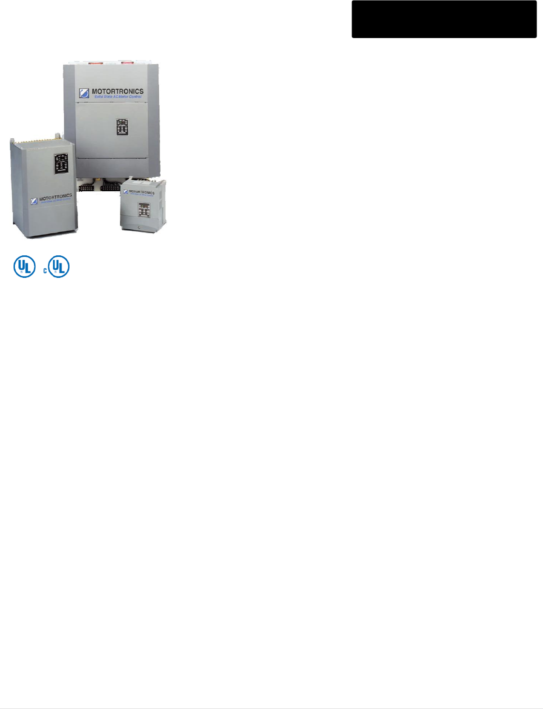
M o t o r t r o n i c s P r o d u c t S e l e c t i o n G u i d e P a g e 82
XLD SERIES DIGITAL SOFT STARTER
WITH CIRCUIT BREAKER BXLD Series
Acceleration Adjustments
Ramp types Voltage ramp or current ramp
Starting torque 0 - 100% of line voltage or
0 - 600% of FLA
Ramp time 1 to 120 seconds
Current limit 200 - 600%
Dual Ramp Settings*
Four (4) programmable ramp options
Deceleration Adjustments
Begin decel level 0 - 100% of line voltage
Stop level 0 to 1% less than begin decel
Decel time 0 - 60 seconds
Operation during overload Ramp down or
coast-to-stop
Jog Settings*
Jog at set current 100 - 500% of FLA
Jog at set voltage 0 - 100% of line voltage
Voltage jog max time 0 - 20 seconds
Kick Start Settings
Kick start 0 - 100% of line voltage
Kick start time 0.1 - 2 seconds
Programmable Output Relays
Three (3) relays can be individually
programmed for change of
state indication for any one of 18 conditions.
Type / Rating FORM C (SPDT),
rated 5 amps, 240VAC max (1200VA)
Two programmable overload trip curves allow for the thermal capacity required to start
the load while providing motor overload protection needed during the run time.
Start: Programmable for Class 5 – 30
Run: Programmable for Class 5 - 30, enabled when starter detects motor is "At-Speed"
Reset: Manual or automatic, selectable via programming
The XLD Series recognizes motor cool-down rates are a function of the run time and
that sometimes a motor will cool faster if allowed to run.
Real-Time Thermal Modeling Continuously calculates motor
operating temperature even when
your motor isn’t running. Knows
when your motor is cool enough
for a successful restart.
Retentive Thermal Memory Remembers the thermal condition
of the motor even in the event of
a power brown-out or black-out.
Extrapolates motor temperature
using a real-time clock.
Dynamic Reset Capacity Overload will not reset until
thermal capacity in the motor is
sufficient for a successful restart.
Starter learns and retains this
information from previous starts.
Phase Current Imbalance/Loss Protection
Imbalance trip level - 5 - 30% current between any two
phases
Imbalance trip delay- 0 - 20 seconds
Phase loss - Trips on any phase current loss
Electronic Shear Pin Protection
Shear pin trip level - 50 - 300% of motor FLA
Shear pin trip delay - 0 - 20 seconds
Load Loss Trip Protection
Under current trip level - 10 - 90% of motor FLA
Under current trip delay - 0 - 20 seconds
Coast Down (Back Spin) Lockout Timer
Coast down time - 0 - 60 minutes
Starts-per-Hour Lockout Timer
Starts-per-hour - 1 - 10 successful starts per hour
Time between starts - 0 - 60 min. between start attempts
Phase Rotation Phase sequence insensitive
Shorted Load During start, injects voltage for 0.25
second and will trip if it sees a 9x
unit current surge
Short Circuit Trips in 12.5 ms at 10x unit current
rating during run
* separate external control inputs
M o t o r t r o n i c s P r o d u c t S e l e c t i o n G u i d e P a g e 83
BXLD Series Model Ratings
BXLD - 288 - - N -
Voltage
Blank = 208 – 480V
600 = 208 – 600V
Enclosure
N = NEMA 1
E = NEMA 12
Max. Amps
39 – 1250 A. Control Power
Blank = 120 VAC
240 = 240 VAC
Model
Number
Max.
Amps.
HP
kW
Circuit Breaker
List Price $
208V
240V
480V
600V
230V
400V
Frame
Size
Trip
Rating
NEMA1
NEMA 12
Inc. Bypass
BXLD-39
39
10
25
30
11
19
80
50
5,116
5,363
BXLD-48
48
10
15
30
40
22
100
60
5,174
5,578
BXLD-62
62
15
20
40
50
15
30
150
100
5,955
6,129
BXLD-78
78
20
25
50
60
22
37
150
100
6,302
6,592
BXLD-92
92
25
30
60
75
45
150
100
6,534
7,593
BXLD-120
120
30
40
75
100
30
55
150
150
7,607
8,114
BXLD-150
150
40
50
100
125
45
75
250
250
8,791
9,246
BXLD-180
180
50
60
125
150
55
90
250
250
8,832
9,798
BXLD-220
220
60
75
150
200
110
250
250
10,946
12,649
BXLD-288
288
75
100
200
250
75
132
400
400
11,178
13,455
BXLD-360
360
100
125
250
300
110
160
400
400
12,507
15,125
BXLD-414
414
125
150
300
350
200
800
600
13,799
17,751
BXLD-476
476
350
400
132
250
800
600
15,001
21,804
BXLD-550
550
150
200
500
160
800
600
15,808
21,887
BXLD-718
718
200
250
500
600
200
315
800
800
18,898
28,635
BXLD-862
862
250
300
600
700
400
1200
1000
27,255
30,581
BXLD-1006
1006
300
350
700
800
1200
1200
28,635
39,882
BXLD-1150
1150
350
400
800
900
1200
1200
39,882
Contact
Factory
BXLD-1200
1200
400
450
900
1000
1600
1600
45,540
BXLD-1250
1250
450
500
1000
1125
1600
1600
46,459
NOTES:
1. Units require an external 120 VAC control circuit. Specify 240 VAC if required.
2. Motor FLA plus service factor must not exceed unit max amp rating.
3. NEMA1 units rated 150A and above, and all NEMA 12 units, have the keypad operator mounted internally. See
Accessories Page for Remote Keypad Display Kit if required.
Prices subject to change without notice - Consult factory for pricing on modifications.
M o t o r t r o n i c s P r o d u c t S e l e c t i o n G u i d e P a g e 84
XLD/BXLD Series Circuit Boards & Accessories
Printed Circuit Board and Accessories
Part
Model Number
Description
Series
List Price $
CONTROL BOARDS
XLD1000-120
CPU and Power Board Assembly (120VAC Control)
XLD
1,725
XLD1000-240
CPU and Power Board Assembly (240VAC Control)
XLD
1,725
XLD-Keypad
Replacement Digital Keypad Operator
XLD
150
XLB1000-120
PC Board for units rated ≥ 39A (120 VAC control)
XLC/XLS
1,121
XLB1000-240
PC Board for units rated ≥ 39A (240 VAC control)
XLC/XLS
1,121
Cable Assembly with connectors on both ends for remote mounting XLD Series
Digital Operator (Operator not included).
REMOTE DISPLAY KITS
XLD-KPN1-KIT-1
NEMA 1 Kit with 1 Meter Cable
XLD
147
XLD-KPN1-KIT-2
NEMA 1 Kit with 2 Meter Cable
XLD
164
XLD-KPN1-KIT-3
NEMA 1 Kit with 3 Meter Cable
XLD
181
XLD-KP12-KIT-1
NEMA 12 Kit with 1 Meter Cable
XLD
242
XLD-KP12-KIT-2
NEMA 12 Kit with 2 Meter Cable
XLD
276
XLD-KPD12-KIT-3
NEMA 12 Kit with 3 Meter Cable
XLD
293
COMM
KITS
XLD-RS485-KIT-1
RS485 Communications Kit with 1 Meter Cable
XLD
397
XLD-RS235-KIT-1
RS232 Communications Kit with 1 Meter Cable
XLD
397
NOTE: Contact Factory for DXT Spare Parts.
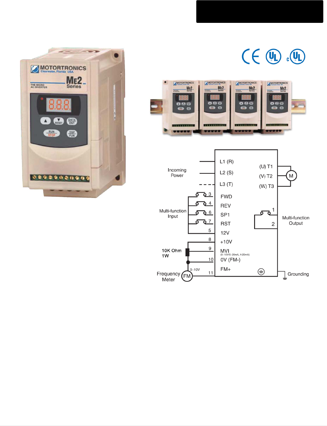
M o t o r t r o n i c s P r o d u c t S e l e c t i o n G u i d e P a g e 85
ME2 SERIES MICRO OEM AC DRIVE
110 – 460V, 0.25 – 3HP (CT) ME2 AC Drive
Compact Size but with the Features you need
• 150% overload capacity for one minute
• Fully rated and fully protected
• 1-200 Hz frequency range
Easy to Install
• Takes up less panel space than other drives in its class
• Single or three phase input (3 phase output) standard
• Optional DIN rail adapter (1HP and below)
Easy to Program / Easy to Operate
• Built-in ‘finger’sized” keypad operator
• Operate directly via the keypad or remotely via a PLC, analog inputs or a 10k potentiometer.
World-wide Credentials
• CE, UL and cUL approvals
• Built-in EMI filter (up to 1HP), no external inductor needed to meet CE requirements.
Application Flexibility
• Use as replacement for DC drives. Allows you to use a standard AC motor instead of ‘maintenance prone” brush-type DC motors.
• Ideal for high duty cycle, reversing applications as a cost effective alternative to mechanical reversing starters

M o t o r t r o n i c s P r o d u c t S e l e c t i o n G u i d e P a g e 86
ME2 AC Drive
ME2 SERIES MICRO OEM AC DRIVE
Specifications Continued
Model Ratings
Model
Input Voltage
Output
Voltage
Motor Rating
Rated Current
(Amps)
Rated Capacity
(kVA)
HP
kW
ME2-1P2-M
Single phase
110 - 120V
Three phase
200 - 230V
¼
0.2
1.4
0.53
ME2-1P5-M
½
0.4
2.3
0.88
ME2-101-M
1
0.75
4.2
1.6
ME2-2P2-M
Single phase
200 - 240V
¼
0.2
1.4
0.53
ME2-2P5-M
½
0.4
2.3
0.88
ME2-201-M
1
0.75
4.2
1.6
ME2-202-M
Single or Three phase
200 - 240V
2
1.5
7.5
2.9
ME2-203-M
3
2.2
10.5
4
ME2-401-M
Three phase
380 - 460V
Three phase
380 - 460V
1
0.75
2.3
1.7
ME2-402-M
2
1.5
3.8
2.9
ME2-403-M
3
2.2
5.2
4
Frequency Control
Frequency Control Range
1 - 200Hz
Frequency Resolution
Digital: 0.1 Hz (0-99.9 Hz), 1 Hz (100 - 200 Hz)
Analog: 1 Hz (60 Hz)
Frequency Setting Signal
Digital Keypad; 0 - 10VDC, 0-20mA, 10k Potentiometer
Frequency Limit
Frequency upper/lower limit
Carrier Frequency
4 ~ 16 kHz
Control Characteristics
Accel/Decel Time
0.1 - 999 seconds
V/f Pattern
6 Patterns
Torque Control
Manual torque boost (adjustable)
Braking Torque
Approximately 20%
Multifunction Inputs
2 inputs; emergency stop, pre-set speed, reset, run enable
Multifunction Outputs
1 (N.O.) relay for fault, run, up to speed indicator
Other Built-in Functions
Upper/lower frequency limit, ramp down or coast to stop, auto reset,
DC injection brake, electronic motor protection

M o t o r t r o n i c s P r o d u c t S e l e c t i o n G u i d e P a g e 87
ME2 AC Drive
ME2 SERIES MICRO OEM AC DRIVE
Specifications Continued
Protective Functions
Instantaneous Overcurrent
200% of rated current
Overload
150% for 1 minute
Over-voltage
ME2-1XX and ME2-2XX: DC-bus voltage >410VDC
ME2-4XX: DC-bus voltage >800VDC
Under-voltage
ME2-1XX and ME2-2XX: DC-bus voltage <200VDC
ME2-4XX: DC-bus voltage <400VDC
Momentary Power Loss
0-2 seconds (can be restarted via speed search)
Stall prevention
During accel/decel/constant speed
Output short circuit
Provided by electronic circuit
Ground fault
Provided by electronic circuit during start-up and run
Other protection
Heatsink fin overtemp, current limit
Other
Control Method
Sinusoidal wave PWM control (PNP type 12 - 24 VDC)
Digital Display
Indicates frequency, parameter selection, fault record
Ambient temperature
- 10 to + 50° C (14° to 122° F)
Humidity
≤ 95% relative, non-condensing
Vibration
Under 1G
EMC
Class A filter standard in all 200 volt units rated 1/4 - 1 HP;
Optional Class B for all other units
Enclosure
Panel Mount / IP20
Approvals
UL, cUL, CE
Mounting
Direct or optional DIN rail mount (for drives rated 1 HP and below)
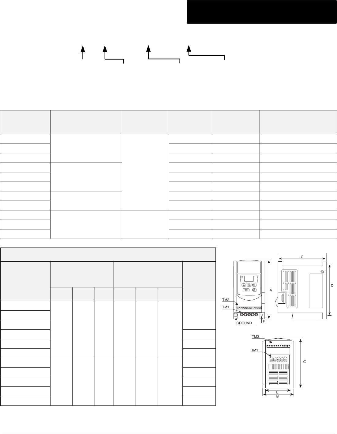
M o t o r t r o n i c s P r o d u c t S e l e c t i o n G u i d e P a g e 88
ME2 AC Drive
ME2 - 2 P2 - M - DIN
Horsepower
P2 = 0.25 HP
P5 = 0.50 HP
01 = 1HP
02 = 2HP
03 = 3HP
Enclosure
IP20/Chassis
Input Voltage
1 = 110V
2 = 220V
4 = 460V
Optional
DIN = Din Rail Adapter
(1HP and below)
Model Number
Input Voltage
Output
Voltage
HP
(CT)
kW
(CT)
List Price $
ME2-1P2-M
Single phase
110 - 120V
Three phase
200 - 230V
¼
0.2
227
ME2-1P5-M
½
0.4
243
ME2-101-M
1
0.75
260
ME2-2P2-M
Single phase
200 - 240V
¼
0.2
217
ME2-2P5-M
½
0.4
233
ME2-201-M
1
0.75
243
ME2-202-M
Single or Three phase
200 - 240V
2
1.5
393
ME2-203-M
3
2.2
483
ME2-401-M
Three phase
380 - 460V
Three phase
380 - 460V
1
0.75
417
ME2-402-M
2
1.5
467
ME2-403-M
3
2.2
567
ME2 Series Dimensions
Model Number
Overall
Dimensions
(Inches)
Mounting
Dimensions
(Inches)
Shipping
Weights
(lbs)
A
B
C
D
E
F
ME2-1P2-M
5.2
2.8
4.65
4.6
2.4
0.18
1.5
ME2-1P5-M
ME2-101-M
ME2-2P2-M
1.6
ME2-2P5-M
1.7
ME2-201-M
1.8
ME2-202-M
5.63
4.65
6.78
5.02
4.26
0.18
3.6
ME2-203-M
3.8
ME2-401-M
3.5
ME2-402-M
3.5
ME2-403-M
3.6
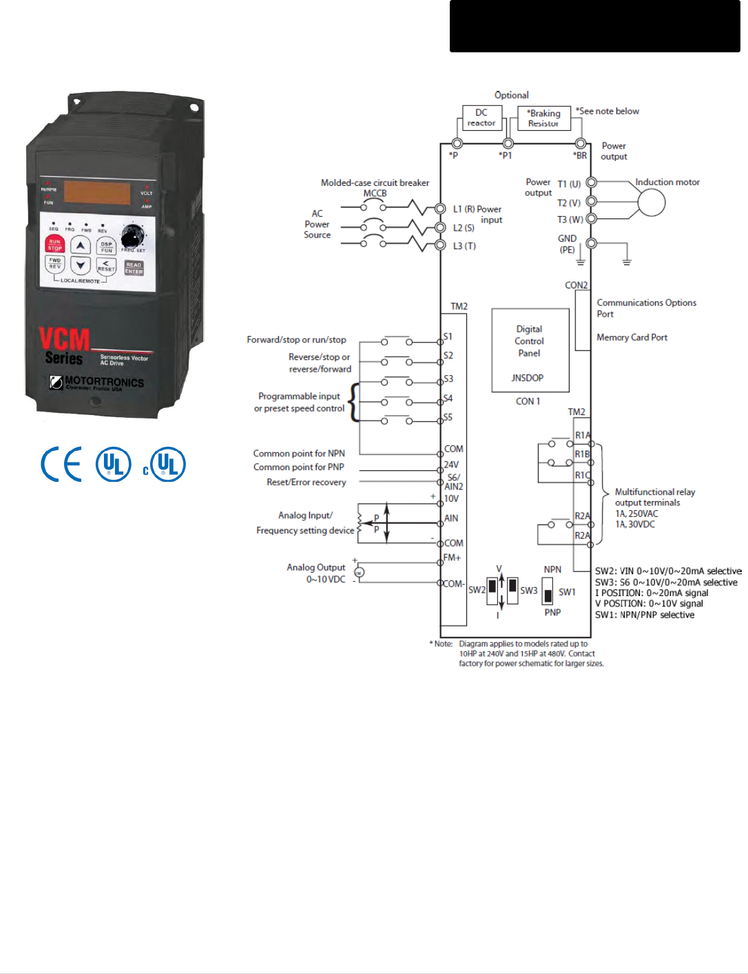
M o t o r t r o n i c s P r o d u c t S e l e c t i o n G u i d e P a g e 89
VCM SERIES V/Hz or OL Vector AC DRIVE
200 – 460V, 0.25 – 75HP (CT) VCM AC Drive
Easy to Use
• Built-in speed potentiometer
• Quick start guide for installation & setup
• Windows based programming software option
Sensorless Vector or V/Hz Control
• Maintain frequency accuracy to 0.01 Hz
• 150% starting torque, up to 200% running torque
• Autotuning for sensorless vector control
Built-in Electronic Overload Relay
• Program to match the exact motor FLA
Wide Frequency Output Range
• 0.1 - 400Hz with 18 selectable V/f patterns,
one programmable custom curve
Adjustable Carrier Frequency
• Up to 16kHz for low noise applications
Heavy Duty Power Design
• 150% overload for 1 minute
• Maximizes power delivery, yet compact in size
PID Function
• 8 PID modes
• Feedback loss detection
• Sleep function
• Engineering unit display
Flexible Speed Command Choices
• Local via keypad or built-in potentiometer
• Remote via 4-20mA, 0-10Vdc, 0-5Vdc 10k ohm potentiometer or floating point (up-down) signal
7 Preset Speeds for Complete Process Control
• Selectable via digital inputs
Programmable I/O Maximizes System Design
• 6 digital inputs, 2 relay outputs
• 2 analog inputs, 1 analog output
• Analog inputs can be reconfigured for additional digital inputs

M o t o r t r o n i c s P r o d u c t S e l e c t i o n G u i d e P a g e 90
VCM SERIES V/Hz or OL Vector AC DRIVE
Specifications VCM AC Drive
Control Mode
Sensorless Vector Control with Auto-tuning, or V/Hz control of three phase AC motors
Carrier Frequency
2 - 16 KHz
Frequency Control
Range
0.1 - 400 Hz
Speed Control
Range
1:50 (Vector mode)
Speed Control
Precision
+ 0.5%
Frequency
Resolution
Digital: 0.01 Hz (Note 1); Analog: 0.06Hz/60 Hz (10bits)
Frequency Setting
Signal
Local: Built-in potentiometer or Up/Down keys on Operator Interface Remote: Analog Input or
multifunction contacts on terminal block (TM2)
ACCEL/DECEL
Time
2 separately programmable ACCEL/DECEL times 0.1 - 3600 seconds with two S-curves
Programmable DECEL or free run to stop
Starting Torque
150%/ 1Hz (Vector mode)
Braking Torque
Standard braking torque = 20%, 10% duty cycle (>20HP requires braking module option)
100% braking torque available with addition of optional braking resistors
V/f Pattern
18 patterns, one curve programmable
Frequency limit
function
Upper/lower frequency limits, programmable skip frequencies and vibration control
Instantaneous
Overcurrent
Approximately 200% of unit rated current
Overload Capacity
of Drive
150% for 1 minute
Motor Overload
Protection
Programmable electronic thermal overload relay
Overvoltage
200V Class: DC bus exceeds 410V
400V Class: DC bus exceeds 820V
Undervoltage
200V Class: DC bus voltage drop < 190V
400V Class: DC bus voltage drop < 380V
Momentary Power
Loss
Programmable 0~2 seconds: unit can be restarted via speed search
DC Bus Protection
Motor coast to stop at blown fuse
Heat Sink Fin
Overheat
Protected by thermistor/thermostat
Ground Fault
Protection
Standard on all units
Stall Prevention
Stall prevention for Acceleration/Deceleration while running
M o t o r t r o n i c s P r o d u c t S e l e c t i o n G u i d e P a g e 91
Single Phase
Operation/Sizing
Three phase drives up to frame size 3 may be operated from single phase power at 56% of
original capacity (Example: 15HP drive will operate 7.5HP motor).
Digital Inputs
Dry contacts through internal power supply: NPN/PNP toggle
Multifunction Input Selection: 30 functions
Digital Relay
Outputs
(1) FORM C, (1) FORM A, 16 functions, 250 VAC 1A, 30 VDC 1A maximum
Built-in Functions
Momentary power loss restart, speed search, overload detection, 8 preset speeds, accel/decel
(2 stages), S-curves, 3-wire control, PID control, auto/manual torque boost, slip compensation,
frequency upper/lower limit, auto energy savings, and auto reset
Analog Inputs
AIN1
AIN2
0-20ma, 0-10 VDC, or external 10K ohm potentiometer Programmable offset and gain,
positive or negative bias and slope
S6 multifunction input can be reconfigured to be 0 - 20mA or 0 -10 VDC analog input
with offset/gain
Analog Output
(0-10 VDC)
Motor speed, voltage and current, DC bus voltage, PID feedback (all with gain calibration)
Display function
Four digit LED (or 2x16 LCD optional) and status indicator; display frequency/ speed/line
speed/DC voltage/output voltage/current/rotation direction/ Inverter parameter/trouble
log/program version
Communications
Control via RS232 or RS485 Modbus RTU One-to-one or One-to-many (RS485 Only) control
Baud rate/Stop bit/Parity/ bit setting
Standard Enclosure
NEMA 1 (IP20), Chassis (HP dependent)
Location and
Altitude
Indoor (protected from gas and dust) 3,300 feet (without derating). Use in an enclosure with
filtered forced ventilation, or if standalone, in a clean pollution- free environment
Ambient
Temperature
Enclosed: -10ºC to 40ºC (14ºF to 104ºF) Chassis: -10ºC to 50ºC (14ºF to 122ºF)
Storage
Temperature
-10ºC to 50ºC (14ºF to 122ºF)
Humidity
0-95% non-condensing
Vibration
1.0 G
EMC
EN_61800-3
LVD
EN_50178
Approvals
UL listed and Canadian UL (cUL) listed, CE Approved
M o t o r t r o n i c s P r o d u c t S e l e c t i o n G u i d e P a g e 92
VCM AC Drive
VCM - 2 30 - - N
Horsepower
See Selection Chart Input Phase
1 = Single Phase
Blank = Three Phase
Voltage Class
2 = 200 – 240V
4 = 380 – 460V
Enclosure
P = Protected Chassis
N = NEMA 1 (IP20)
Input
Voltage
Model Number
Rated
Output
Current
HP
(CT)
kW
(CT)
Frame
Size
Dimensions (Inches)
List
Price $
H
W
D
Single
Phase
200-240V
VCM-2P5-1-P
3.1
0.5
0.4
1
6.42
3.55
5.79
380
VCM-201-1-P
4.5
1
0.75
440
VCM-202-1-P
7.5
2
1.5
2
7.37
5.04
5.83
560
VCM-203-1-P
10.5
3
2.2
740
Three
Phase
200-240V
VCM-2P5-P
3.1
0.5
0.4
1
6.42
3.55
5.79
375
VCM-201-P
4.5
1
0.75
400
VCM-202-P
7.5
2
1.5
470
VCM-203-P
10.5
3
2.2
2
7.37
5.04
5.83
640
VCM-205-P
17.5
5
3.7
720
VCM-207-P
26
7.5
5.5
3
10.24
7.33
7.68
1,040
VCM-210-P
35
10
7.5
1,170
VCM-215-N
48
15
11
4
14.18
10.44
9.77
2,060
VCM-220-N
64
20
15
2,080
VCM-225-N
80
25
18.5
2,820
VCM-230-N
96
30
22
6
25.73
12.14
12.17
4,320
VCM-240-N
130
40
30
4,840
Three
Phase
380-480V
VCM-401-P
2.3
1
0.75
1
6.42
3.55
5.79
460
VCM-402-P
3.8
2
1.5
500
VCM-403-P
5.2
3
2.2
2
7.37
5.04
5.83
670
VCM-405-P
8.8
5
3.7
740
VCM-407-P
13
7.5
5.5
3
10.24
7.33
7.68
1,040
VCM-410-P
17.5
10
7.5
1,140
VCM-415-P
25
15
11
1,300
VCM-420-N
32
20
15
4
14.18
10.44
9.77
1,930
VCM-425-N
40
25
18
2,570
VCM-430-N
48
30
22
2,820
VCM-440-N
64
40
30
5
21.79
10.6
11.98
4,310
VCM-450-N
80
50
37
4,700
VCM-460-N
96
60
45
6
25.73
12.14
12.17
5,340
VCM-475-N
128
75
55
5,960
M o t o r t r o n i c s P r o d u c t S e l e c t i o n G u i d e P a g e 93
VCM SERIES V/Hz or OL Vector AC DRIVE
Options VCM AC Drive
Model Number
Option Description
Option Information
List
Price $
VCM-N1-KIT1
NEMA 1 Kit
Frame 1
18
VCM-N1-KIT2
NEMA 1 Kit
Frame 2
22
VCM-N1-KIT3
NEMA 1 Kit
Frame 3
24
VCM-KEYPD-LCD
Optional LCD Keypad
Replaces LED Keypad
54
VCMW30P5
Keypad Extension Cable
0.5 meters
60
VCMW3001
Keypad Extension Cable
1 meters
65
VCMW3002
Keypad Extension Cable
2 meters
70
VCMW3003
Keypad Extension Cable
3 meters
75
VCMW3005
Keypad Extension Cable
5 meters
80
VCM-232-KIT
Communications Option
RS232
30
VCM-485-KIT
Communications Option
RS485
34
VCM-MP
Communications Option
Memory Pack
15
Braking Resistors
Input Voltage
Model Number
Braking Resistor Model Number
List
Price $
Three Phase
200-240V
VCM-2P5-P
JNBRN2-201
32
VCM-201-P
JNBRN2-201
32
VCM-202-P
JNBRN2-202
38
VCM-203-P
JNBRN2-203
55
VCM-205-P
JNBRN2-205
78
VCM-207-P
JNBRN2-207
140
VCM-210-P
JNBRN2-210
165
Three Phase
380-480V
VCM-401-P
JNBRN2-401
34
VCM-402-P
JNBRN2-402
40
VCM-403-P
JNBRN2-403
60
VCM-405-P
JNBRN2-405
85
VCM-407-P
JNBRN2-407
140
VCM-410-P
JNBRN2-410
165
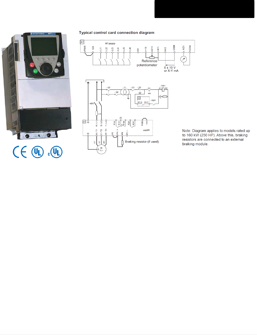
M o t o r t r o n i c s P r o d u c t S e l e c t i o n G u i d e P a g e 94
MT SERIES V/Hz, OLV, CLV AC DRIVE
200 – 480V, 0.5 – 700HP (CT) MT AC Drive
High Performance Vector Drive
• Sensorless vector with autotuning, closed loop vector or simple V/Hz control
• Intuitive programming & monitoring
• Easy to read multi-line LCD display
• Best in-class torque performance & speed regulation
• Built-in application macros
Remarkable Torque Capability
• Up to 220% over torque capability for 2 seconds (170% for up to 60
seconds)
Maximum Response Time and Stability
• Dual-processor design with a dedicated microprocessor for motor control
algorithm means response times in 2 microseconds(not milliseconds).
• Closed loop performance even in the open loop vector mode (160% full load
torque down to 0.5Hz)
• On the fly switching from speed control mode to torque control mode via
logic input
Superior Braking Capability
• Built-in braking transistor in all MT units rated up to 250HP.
• 30% braking torque (on average) without the need for an external dynamic
braking resistor.
Longer Motor-to-Drive Lead Lengths
Unique ‘Sinus Filter’ output function in software limits motor overvoltage to two
times the DC bus voltage. Eliminates the need for external filtering and
extends the maximum allowable motor-to-drive lead length (up to 500 feet).
Cool Drive Operation
Performs in 50 degrees C (and even higher) ambient operating temperatures
at 115% load WITHOUT derating.
Intuitive Multi-line Keypad
Easy to ready multi-line graphic keypad (8 lines of 24 characters)
with English display or programmable for one of five other
languages.
Simple navigation wheel for ‘surfing’ through the menus, to set your
parameters or adjust the motor speed.
For remote mount or door mount requirements use the quick
disconnect tabs for tool-less removal of the NEMA12 rated LCD
keypad. Then mount the keypad wherever you want using a
standard CAT5 communications cables and off-the-shelf
connectors to either of the two built in RJ45 connection points (as
far as 300 feet away from the drive).
Adaptable Chassis Design
MT Series drives are designed as a ‘protected’ chassis with a
NEMA1 kit available as an option for all sizes. The power section
on all sizes is a NEMA12 separate compartment that allows the
power section to be mounted outside of an enclosure using a
simple flange kit.
Standard Features…
• Custom ramps • Accepts up to 50% line voltage drop
• 150 programmable functions • Fast stop / freewheel to stop
• 16 preset speeds • Frequency, current, thermal state, high
• Summing reference speed attained reference
• +/- speed • Catch on-the-fly
• Jog • Defeatable faults stored in EEPROM
• Reference switching • Reverse operation inhibit
• Ramp switching • DC braking
• 2 or 3 wire control • PID control
• Integrated Modbus? & CANopen Port
M o t o r t r o n i c s P r o d u c t S e l e c t i o n G u i d e P a g e 95
MT SERIES V/Hz, OLV, CLV AC DRIVE
Specifications MT AC Drive
Control Characteristics
Control Mode
Sensorless vector, closed loop vector or V/Hz control of AC induction
motors
Carrier Frequency
Adjustable during operation from 1…8, 2.5…8 or from 1…16 based on
rating
200V Drives:
1…16 kHz up to 60HP / 45kW (CT)
1…8 kHz up to 75HP / 60kW to 100HP / 75kW (CT)
400V Drives:
1…16 kHz up to 100HP / 75kW (CT)
2.5…8 kHz up to 125HP / 90kW to 700HP / 500kW (CT)
Note: Above 2.5 or 4 kHz, depending on the rating, the drive decreases
the switching frequency itself in the event of excessive temperature rise.
For continuous operation above the nominal switching frequency, derate
the nominal drive current.
Output Frequency Range
< 50HP / 37 kW (CT) = 0 - 1000 Hz
> 50HP / 37 kW (CT) = 0 - 500 Hz
Speed Control Range
1: 1000 in closed loop mode with incremental encoder feedback
1: 100 in open-loop mode without encoder feedback
Speed Control Accuracy
+ 0.01% of nominal speed, in closed-loop mode with encoder feedback
+10% of nominal slip, without encoder feedback
Frequency Resolution
Digital: 0.1 Hz; Analog: 50 Hz/2048 (11 bit converter)
Frequency Setting Signal
Graphical display, analog inputs or multi-function logic inputs
Accel/Decel Time
Ramp profiles:
• Linear, can be adjusted separately from 0.01 to 9999 seconds
• S, U, or customized
Automatic adjustment of decel ramp time if braking capacity exceeded
Torque Overload
170% of the nominal motor torque (typical value at + 10%) for 60 seconds
220% of the nominal motor torque (typical value at + 10%) for 2 seconds
Braking Torque
30% of the rated motor torque without braking resistor (typical value). Up
to 150% with braking resistor (installed as an option)
V/f Pattern for V/Hz control
2 or 5 points
Frequency limit function
Upper/lower freq. limits, programmable skip freq. & vibration control

M o t o r t r o n i c s P r o d u c t S e l e c t i o n G u i d e P a g e 96
MT SERIES V/Hz, OLV, CLV AC DRIVE
Specifications Continued MT AC Drive
Protection Functions
Current Overload
150% of the nominal drive current for 60 seconds (typical value)
165% of the nominal drive current for 2 seconds (typical value)
Motor Overload Protection
Thermal protection integrated in drive via continuous I²T calculation
The motor thermal state is saved when the drive is powered down
Function can be modified via operator dialog terminals, depending on the type
of motor (force air-cooled or non-ventilated)
Protection against motor phase loss, PTC inputs
Input voltage range
200V range: 200V -15%; 240V +10%
400V range: 380V -15%; 480V +10%
DC Bus Protection
DC Bus overvoltage
Heat Sink Fin Overheat
Protected by thermistor/thermostat
Power Stage Protection
Calculated IGBT Temperature
Ground Fault Protection
Standard on all units
Stall Prevention
Stall prevention for Acceleration/Deceleration while running
Operation Conditions
Digital
Inputs
LI1 - LI5
5 programmable logic inputs, 24VDC, compatible with Level 1 PLC
Impedance: 3.5 Ω
Maximum voltage: 30VDC
Max. sampling time: 2ms + 0.5ms
Multiple assignment allows configuration several functions via one input
LI6
1 logic input, switch-configurable as logic input or as input for PTC probes
Logic input, characteristics identical to inputs LI1 - LI5
Input for a maximum of 6 PTC probes mounted in series:
Positive logic
(Source)
State 0 if < 5VDC or logic input not wired, state 1 if > 11VDC
Negative logic
(Sink)
State 0 if >16VDC or logic input not wired, state 1 if < 10 VDC
Other inputs
See option cards
Digital
Relay
Outputs
R1A, R1B, R1C
1 relay logic output, one NC contact and one NO contact with common point
Minimum switching capacity 3 mA for 24VDC
Maximum switching capacity
• Resistive load (cos Ω = 1): 5A for 250VAC or 30VDC
• Inductive load (cos Ω = 0.4 and L/R = 7ms): 2A for 250VAC or 30VDC
Max response time: 7ms + 0.5ms
Electrical service life: 100,000 operations
R2A, R2B
1 relay logic output, one "N/O" contact
Minimum switching capacity 3 mA for 24VDC
Maximum switching capacity
• Resistive load (cos Ω = 1): 5 A for 250VAC or 30VDC
• Inductive load (cos (SYM) = 0.4 and L/R = 7ms): 2A for 250VAC or 30VDC
Max response time: 7ms + 0.5ms
Electrical service life: 100,000 operations
Other outputs
See option cards

M o t o r t r o n i c s P r o d u c t S e l e c t i o n G u i d e P a g e 97
MT SERIES V/Hz, OLV, CLV AC DRIVE
Specifications Continued MT AC Drive
Operation Conditions
Built-in Functions
Torque regulation, torque/speed regulation switching, torque limitation,
current limitation, reference switching, operations on the reference, S and
customized ramps, ramp switching, Jog, preset speeds, PID regulation,
auto/manual, preset PID references, brake sequence, high speed hoisting,
brake contact feedback processing, weight measurement processing, limit
switch management, load balancing, multi-motors, multi-configurations,
motor fluxing, + speed / - speed with single or 2-stage pushbuttons, reference
saving, automatic DC injection, configuration of type of stop (freewheel, fast
stop, DC injection, etc), configurable undervoltage management, line
contactor control, downstream contactor control, downstream contactors
integrity check, fault reset, fault inhibition, automatic restart, multi-
parameters, auto-tuning and more.
Analog Inputs
AI1-
/AI1+
1 bipolar differential analog input + 10VDC (max safe voltage 24VDC)
Max. sampling time: 2 ms + 0.5 ms
Resolution 11 bits + 1 sign bit
Accuracy + 0.6% for a temperature variation of 60° C
Linearity + 0.15% of the maximum value
AI2
1 software-configurable voltage or current analog input:
• Voltage analog input 0 - 10 V impedance 30kΩ ( max. safe voltage 24VDC)
• Current analog input X - Y mA by programming X and Y from 0 to 20 mA,
with impedance 242Ω Max. sampling time: 2 ms + 0.5 ms
Resolution 11 bits
Accuracy + 0.6% for a temperature variation of 60° C
Linearity + 0.15% of the maximum value
Analog Output
AO1
1 software-configurable voltage or current analog input:
• Voltage analog input 0 - 10 V impedance 30kΩ ( max. safe voltage 24VDC)
• Current analog input X - Y mA by programming X and Y from 0 to 20 mA,
with impedance 242Ω Max. sampling time: 2 ms + 0.5 ms
Resolution 11 bits
Accuracy + 0.6% for a temperature variation of 60° C
Linearity + 0.15% of the maximum value
Display function
24 character, 8 line display; 6 languages available including English,
Chinese, French, Spanish, German, Italian; storage of 4 configurations for
upload from keypad to MT drives and remote mount option.
Communications
Modbus and CANopen communication protocols as standard via 2 RJ45
connector ports; optional deviceNet, Ethernet TCP/IP, Profibus DP, Interbus-
S, Modbus Plus

M o t o r t r o n i c s P r o d u c t S e l e c t i o n G u i d e P a g e 98
MT SERIES V/Hz, OLV, CLV AC DRIVE
Specifications Continued MT AC Drive
Environmental Conditions
and
Approvals
Standard Enclosure
IP20 Protected Chassis, IP00 on large drives (optional NEMA1 Kit available
for all frame sizes)
Altitude
Up to 3,300 feet (derating required at higher altitudes)
Ambient Temperature
-10° C to 50°C (14°F to 122°F)
Operation up to 60°C with derating or use of ventilation control kit
Storage Temperature
-25°C to 70°C (-13°F to 115°F)
Humidity
5 - 95% non-condensing, conforming to IEC 60068-2-3
Vibration
< 75 kW
1.5mm peak to peak, 3-13Hz, 1gn from 13-200 Hz (IEC/EN 60068 2-6)
>90kW
1.5mm peak to peak, 3-10Hz, 0.06gn from 10-200Hz (IEC/EN 60068 2-6)
Shock resistance
< 75 kW
15gn for 11ms (IEC/EN 60068-2-27)
>90kW
7gn for 11 ms (IEC/EN 60068-2-27)
EMC
Emissions: IEC/EN 61800-3, environments 1 & 2, categories C1, C2, C3
Immunity: IEC/EN 61000-4-2, -3, -4, -5, -6, and-11
LVD
EN 50178 and IEC 529
Approvals
UL, CE, CSA, NOM 117, C-Tick
M o t o r t r o n i c s P r o d u c t S e l e c t i o n G u i d e P a g e 99
MT AC Drive
MT - 2 30 - P
Horsepower
See Selection Chart
Voltage Class
2 = 200 – 240V
4 = 380 – 460V
Enclosure
P = Protected Chassis
(Optional NEMA1 kit and NEMA 4/12 flange kit available)
N = NEMA 1 Drive Package
18P = 18 Pulse Drive Package
Input Voltage
Model Number
Rated Output
Current
HP
(CT)
kW
(CT)
List
Price $
200-240V
MT-2P5-P
3
0.5
0.37
1,198
MT-201-P
4.8
1
0.75
1,260
MT-202-P
8
2
1.5
1,360
MT-203-P
11
3
2.2
1,560
MT-205-P
17.5
5
4
2,160
MT-207-P
27.5
7.5
5.5
2,684
MT-210-P
33
10
7.5
3,300
MT-215-P
54
15
11
4,120
MT-220-P
66
20
15
4,852
MT-225-P
75
25
18.5
5,600
MT-230-P
88
30
22
7,208
MT-240-P
120
40
30
7,744
380-480V
MT-401-P
2.3
1
0.75
1,395
MT-402-P
4.1
2
1.5
1,395
MT-403-P
5.8
3
2.2
1,395
MT-405-P
10.5
5
4
1,707
MT-407-P
14.3
7.5
5.5
2,019
MT-410-P
17.6
10
7.5
2,337
MT-415-P
27.7
15
11
2,766
MT-420-P
33
20
15
3,447
MT-425-P
41
25
18.5
4,140
MT-430-P
48
30
22
4,740
MT-440-P
66
40
30
5,550
MT-450-P
79
50
37
6,510
MT-460-P
94
60
45
8,190
MT-475-P
116
75
55
9,075
Cont.
M o t o r t r o n i c s P r o d u c t S e l e c t i o n G u i d e P a g e 100
MT AC Drive
MT - 2 30 - P
Horsepower
See Selection Chart
Voltage Class
2 = 200 – 240V
4 = 380 – 460V
Enclosure
P = Protected Chassis
(Optional NEMA1 kit and NEMA 4/12 flange kit available)
N = NEMA 1 Drive Package
18P = 18 Pulse Drive Package
380-480V
MT-4100-P
160
100
75
9,600
MT-4125-P
179
125
90
12,675
MT-4150-P
215
150
110
17,580
MT-4200-P
259
200
132
18,507
MT-4250-P
314
250
160
21,828
MT-4300-P
387
300
200
24,465
MT-4400-P
481
400
250
26,661
MT-4450-P
550
450
280
31,530
MT-4500-P
616
500
310
41,124
MT-4600-P
759
600
400
59,445
MT-4700-P
941
700
500
82,245
M o t o r t r o n i c s P r o d u c t S e l e c t i o n G u i d e P a g e 101
MT SERIES V/Hz, OLV, CLV AC DRIVE
Weights and Dimensions MT AC Drive
Input
Voltage
Model Number
Frame
Size
Dimensions (Inches)
Shipping
Weight
(Lbs)
H
W
D
200-240V
MT-2P5-P
2
9.06
5.12
6.89
6.61
MT-201-P
MT-202-P
MT-203-P
3
10.24
6.1
7.36
8.82
MT-205-P
MT-207-P
4
11.61
6.89
7.36
12.13
MT-210-P
5A
11.61
8.27
8.39
15.43
MT-215-P
5B
15.75
9.06
8.39
19.84
MT-220-P
MT-225-P
6
16.54
9.45
9.29
66.14
MT-230-P
MT-240-P
7B
21.65
12.6
10.47
81.57
MT-401-P
2
9.06
5.12
6.89
6.61
MT-402-P
MT-403-P
MT-405-P
3
10.24
6.1
7.36
8.82
380-480V
MT-407-P
4
11.61
6.89
6.34
12.31
MT-410-P
MT-415-P
5A
11.61
8.27
8.39
15.43
MT-420-P
5B
15.75
9.06
8.39
19.84
MT-425-P
MT-430-P
6
16.54
9.45
9.29
66.14
MT-440-P
7A
21.65
9.45
10.47
81.57
MT-450-P
MT-460-P
8
24.80
12.6
11.42
100
MT-475-P
MT-4100-P
MT-4125-P
9B
26.77
12.2
15.43
176
MT-4150-P
10A
30.79
13.78
15.43
207
MT-4200-P
11A
46.85
13.39
15.43
300
MT-4250-P
12A
46.85
17.32
15.43
402
MT-4300-P
13
37.4
23.43
15.43
455
MT-4400-P
MT-4450-P
MT-4500-P
14A
54.72
35.04
15.43
704
MT-4600-P
726
MT-4700-P
15A
54.72
44.09
15.43
957
NOTE: Dimensions are subject to change. See manual for mounting dimensions

M o t o r t r o n i c s P r o d u c t S e l e c t i o n G u i d e P a g e 102
MT SERIES V/Hz, OLV, CLV AC DRIVE
Options MT AC Drive
Model Number
Option Description
Option Information
List
Price $
MT-VW3A1101
LCD graphic spare keypad. Supplied as standard
411
Remote Mount Extension Cables
MT-VW3A1104R10
Cable for remote mounting LCD graphic keypad
with RJ45 connector included on each end.
1 meter / 3.28 ft
40
MT-VW3A1104R30
3 meter / 9.84ft
47
MT-VW3A1104R50
5 meter / 16.4ft
53
MT-VW3A1104R100
10 meter / 32.8ft
69
Door Mounting Kits and Accessories
MT-VW3A1102
IP54 / NEMA12 mounting kit incl. bezel & hardware
104
MT-VW3A1103
IP65 / NEMA 4 mounting kit door used above
63
MT-VW3A1105
RJ45 female-female adaptor to connect keypad
42
Contact factory
USB to RS485 converter or RS232 to RS485 converter for PC connection
C/F
I/O Option Cards
MT-VW3A3202
Extended I/O option board
400
MT-VW3A3101
115V input adaptor (adapts 7 logic inputs, user supplied 115VAC signals)
205
Communication Option Cards
MT-VW3A3307
Profibus Option Board
500
MT-VW3A3309
DeviceNet Option Board
351
MT-VW3A3302
Modbus Plus Option Board
325
MT-VW3A3310
Ethernet MB TCP/IP Option Board
417
Encoder for Closed Loop Vector Control
MT-VW3A3401
300kHz max frequency, 5,000 pulses/
rev. maximum A, A -, B, B -
RS422 output, 5VDC
173
MT-VW3A3403
Open collector output, 12VDC
164
MT-VW3A3403
Open collector output, 15VDC
162
MT-VW3A3405
Push-pull outputs, 12VDC
185
MT-VW3A3406
Push-pull outputs, 15VDC
185
MT-VW3A3407
Push-pull outputs, 25VDC
185

M o t o r t r o n i c s P r o d u c t S e l e c t i o n G u i d e P a g e 103
MT SERIES V/Hz, OLV, CLV AC DRIVE
NEMA 1 Conduit Kit, NEMA 4/12 Mounting Kits MT AC Drive
Description
Model Number
List
Price $
NEMA 1 conduit kit Frames 2-13 (Includes metal box with conduit knockouts)
Frame 2 (MT-2P5, -201, -202, -401, -402, -403)
MT-VW3A9201
150
Frame 3 (MT-203, -205, -405)
MT-VW3A9202
150
Frame 4 (MT-207, -407, -410)
MT-VW3A9203
160
Frame 5A (MT-210, -415)
MT-VW3A9204
165
Frame 5B (MT-215, -220, -420, -425)
MT-VW3A9205
170
Frame 6 (MT-225, -230, - 430)
MT-VW3A9206
170
Frame 7A (MT-440, -450)
MT-VW3A9207
175
Frame 7B (MT-240)
MT-VW3A92017
195
Frame 8 (MT-460, -475, -4100)
MT-VW3A9208
200
Frame 9B (MT-4125)
MT-VW3A9209
1,056
Frame 10A (MT-4150)
MT-VW3A9210
1,268
Frame 11A (MT-4200)
MT-VW3A9211
1,136
Frame 12A (MT-4250)
MT-VW3A9212
1,280
Frame 13 (MT-4300, -4400)
MT-VW3A9213
1,384
NEMA 4/12 flange mount kit for mounting the heatsink outside a customer supplied enclosure.
Frame 2 (MT-2P5, -201, -202, -401, -402, -403)
MT-VW3A9501
388
Frame 3 (MT-203, -205, -405)
MT-VW3A9502
420
Frame 4 (MT-207, -407, -410)
MT-VW3A9503
466
Frame 5A (MT-210, -415)
MT-VW3A9504
500
Frame 5B (MT-215, -220, -420, -425)
MT-VW3A9505
573
Frame 6 (MT-225, -230, - 430)
MT-VW3A9506
590
Frame 7A (MT-440, -450)
MT-VW3A9507
630
Frame 7B (MT-240)
MT-VW3A9508
630
Frame 8 (MT-460, -475, -4100)
MT-VW3A9509
650
Frame 9B (MT-4125)
MT-VW3A9510
750
Frame 10A (MT-4150)
MT-VW3A9511
775
Frame 11A (MT-4200)
MT-VW3A9512
915
Frame 12A (MT-4250)
MT-VW3A9513
915
Frame 13 (MT-4300, -4400)
MT-VW3A9514
915
M o t o r t r o n i c s P r o d u c t S e l e c t i o n G u i d e P a g e 104
On Site Assistance and Service Rates
NOTE:
- Rates are subject to change consult factory for current rates and scheduling.
- Prices are for service within the continental USA.
Technical Assistance and Service Rates
Activity
Field Engineer
Daily
Definition
Hourly Rate
$200 / Hour
$1500 / Day
8 Hours / Day, Monday –
Friday
7:00am – 6:00pm
Overtime - Standard
$250 / Hour
Weekdays hours prior to
7:00 am or beyond 6:00pm;
All Saturday time. Total
time not to exceed 8
hours/day
Overtime - Premium
$400 / Hour
All Sunday and holiday
work; all time in excess of 8
hours/Saturday
Travel and Living Expense
At Cost
Standby
Invoiced at appropriate activity rate
Travel Time
Invoiced at 50% of appropriate activity rate
Auto Travel
$0.55 / Mile
$0.55 / Mile
Rate covers round trip use
of company or personal car
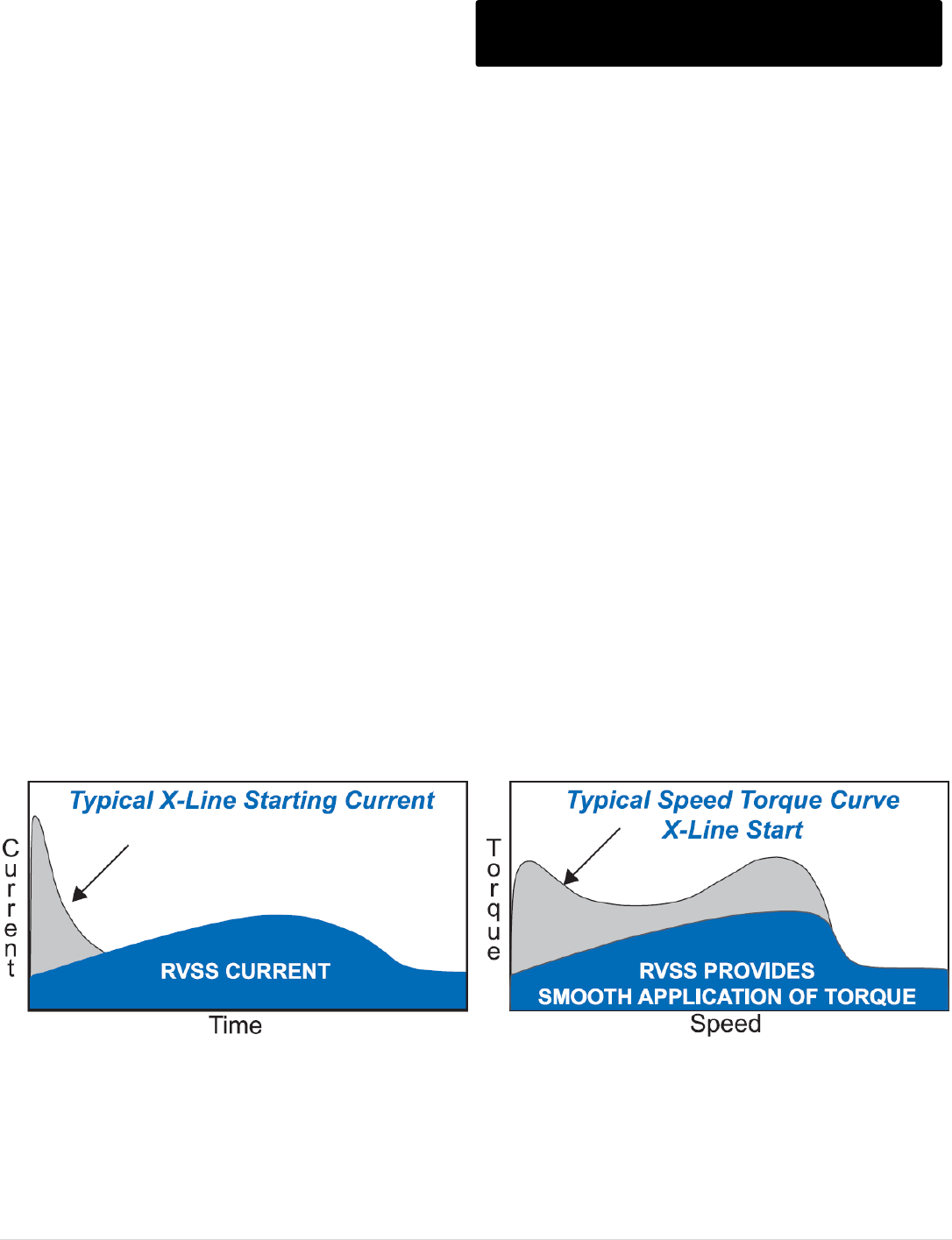
M o t o r t r o n i c s P r o d u c t S e l e c t i o n G u i d e P a g e 105
Frequently Asked Questions
Topic: Why use a RVSS Soft Starter?
Question: I have new equipment to install. Why should I consider using a Reduced Voltage Solid State Soft Starter?
Answer:
All equipment that utilizes electric motors requires a “starter” to control and protect the motor. The starter can be anything
from a cheap Across-the-Line (X-Line) clapper style relay to the much more sophisticated RVSS soft starter. A RVSS soft
starter is the product to choose for system reliability, maximum motor protection and the lowest long term cost of
operation.
As the horsepower goes up, Power Utility or generator sizing requirements may limit your starter options to “Reduced
Voltage” (RV) starting in order to keep the Starting Inrush Current under control. Most utilities require Reduced Voltage
starting on motors over a certain horsepower rating, some as low as 15HP!
Various types of Reduced Voltage starters for AC motors will reduce the negative effects of Inrush Current on the power
source (including voltage dips or generator stalling). Older technologies like electro-mechanical Reduced Voltage (RV)
starters are just one approach to solving this problem. Although they have been around for years, they are now being
replaced by the newer solid state technology available in RVSS starters. In most cases, RVSS starters cost LESS than
the older electro-mechanical RV starters and provide more benefits. This FAQ section offers comparisons on RVSS
starting to the different types of electro-mechanical RV starting methods.
In addition to being less expensive, RVSS offers additional benefits. Most importantly, RVSS starters prevent mechanical
shock and damage to all of your power train components by providing smooth stepless acceleration of
the motor. Reduced repair costs for the motor and machinery is an immediate benefit. The increased reliability of the work
they are doing increases the net value.
Being solid state, RVSS starters give you longer performance with virtually no maintenance. There are no contacts to burn
out, and no armatures to break from repeated slamming on and off. In many cases, replacement contact points for an
electro-mechanical RV starter can be more expensive than replacing the existing starter with an RVSS.
Motortronics RVSS starters offer built in premium motor protection features. Reduced Voltage Solid State Starters are the
optimum value in motor starting technology today.

M o t o r t r o n i c s P r o d u c t S e l e c t i o n G u i d e P a g e 106
Frequently Asked Questions (Cont.)
Topic: RVSS vs X-Line
Question: My Across-the-Line starter has worked fine for years. Why should I change to a RVSS starter?
Answer:
The primary benefit of using RVSS starters is to reduce mechanical stress from excess starting torque. A good analogy to
starting an AC motor across the-line is to imagine having an expensive sports car. If you rev the engine up to the “red line”
RPMs and then pop the clutch, what will happen? After smoking the tires the car will start moving but at what cost to your
drive train? The engine, clutch, transmission...even the body and frame will be affected!
X-Line starting of an AC motor is virtually the same. All of the excess torque from that jerking start is absorbed by the
mechanical components in your equipment. Although they will continue to work, damage is being done every time you
start the motor and you will eventually pay the price.
If your motor runs continuously and shuts down only for routine maintenance, there may still be a valid reason to use an
RVSS. As power distribution grids become more stressed, energy saving becomes more important. Shutting your motor
off more regularly will provide important energy savings (The BEST energy saver is the OFF button). However, this means
you will have to restart your loads more often than the original mechanical design may have allowed for. More frequent
restarts (after load shedding or power losses) will accelerate equipment damage, jeopardizing your machinery and/or
operation. The benefits of restarting softly may take longer to recognize in these applications, but that is only because the
cost of eventual downtime is difficult to predict.
Keep in mind that with torque reduction being a prime benefit, applications which require all the available torque all of the
time may not be good applications for an RVSS. Some examples of these types of applications might include hoists, lifts,
positive displacement pumps and even some types of compressors that must start under full load. If however, the high
torque is only required on occasional starts (such as a loaded restart after a power failure) there is still a place for Soft
Starting. By using the Dual Ramp feature, normal starts can be as soft as possible and high torque starts can be selected
using the second ramp when necessary.
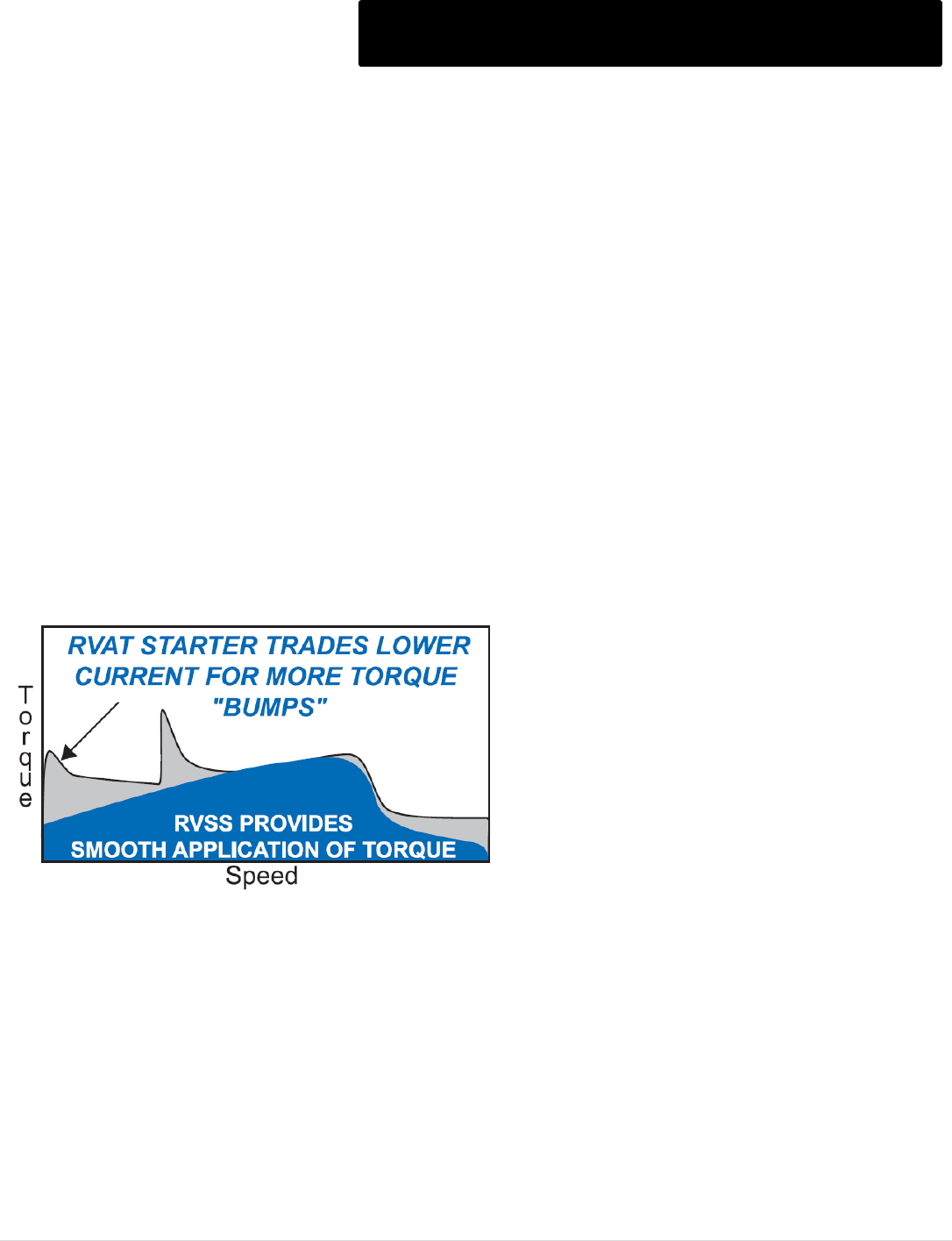
M o t o r t r o n i c s P r o d u c t S e l e c t i o n G u i d e P a g e 107
Frequently Asked Questions (Cont.)
Topic: RVSS vs RVAT
Question: How do RVSS starters compare to Reduced Voltage Auto-Transformer (RVAT) starters?
Answer:
RVSS starters are smaller, more reliable and much more flexible than Reduced Voltage Autotransformer (RVAT) starters,
and are LESS EXPENSIVE! RVAT starters require a 2-step starting process, trading the benefit of the initial starting
current reduction for two consecutive bumps of high torque. This creates mechanical stress in the system which can lead
to equipment damage, product breakage and costly downtime. An RVSS minimizes the mechanical stress by providing a
smooth, gentle ramp for the motor and the load over a selected ramp time. This cannot be done using RVAT starting. An
RVSS starter has no moving parts to wear out or contacts to burn. Even if a Bypass Contactor is added (as with NEMA12
enclosed models), special controls in the Motortronics’ RVSS will prevent any contact deterioration. In contrast, RVAT
starters have 9 sets of contacts that need frequent replacement, along with 3 coils and a timer which means an increased
likelihood of failure.
RVAT starters also have a severely limited duty cycle making them unsuitable for many applications. If a motor/load
needs to be in the Reduced Voltage mode for longer than 15 seconds or if the motor is started too often, thermal devices
in the RVAT starter transformer will trip. A Motortronics RVSS starter will match or exceed the duty cycle rating of the
motor it controls, so duty cycle limits are dictated by the motor being used, not the starter. An RVSS can also be used in
applications where extended ramping times are required (to as much as a 120 second ramp time!).
Another important difference between the two types of starters is flexibility. A Motortronics RVSS can be used to Soft Stop
a motor but an RVAT starter cannot. “Soft Stopping” is the opposite of braking. This feature makes the motor and load
take LONGER to stop than if it was turned off (See Pump Applications FAQ on page 147).
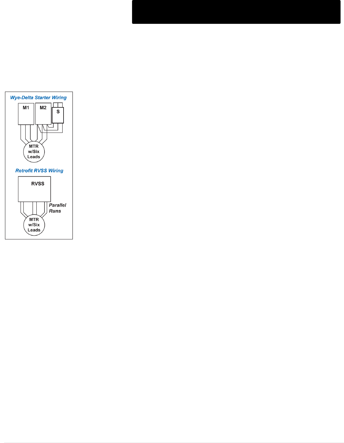
M o t o r t r o n i c s P r o d u c t S e l e c t i o n G u i d e P a g e 108
Frequently Asked Questions (Cont.)
Topic: RVSS vs Wye-Delta
Question: Can I use a Motortronics RVSS to replace a Wye-Delta starter?
Answer
Wye Delta starting (referred to as Star-Delta in Europe) utilizes six leads going to the motor. This starts in two steps. But
unlike RVAT starting, the voltage to the motor is never actually reduced. Instead, the winding
pattern of the motor is switched around externally by means of contactors and shorting bars.
This requires a special motor that has the ends of each winding brought out to the terminal box
(meaning that dual voltage motors will have 12 leads that must be connected). In the Start
stage, the motor windings are connected in a Wye (Star) pattern to a common center point for
each of the three phases. This reduces the output capacity of the motor’s rated torque to 33%.
This means the current is reduced to 33% as well. After the load starts moving (assuming that
33% is enough torque), the motor windings are switched to the Delta pattern to provide full
torque and full current.
Again, this is a two-step starting process. When the starter transitions from Start to Run, a
significant torque “bump” is created, often at Locked Rotor levels. A special version of starter,
known as a “Closed Transition” starter will overcome this problem by utilizing a 4th contactor in
the circuit that switches in a resistor bank during transition (which increases the complexity
and makes it more expensive). In this case, a RVSS starter is a much more attractive
alternative to Wye Delta starting.
Since the 33% torque value is fixed, many users select RVSS as an alternative for greater
flexibility in available torque. If you are retrofitting an existing starter and have all 6 wires
brought out from the motor, simply connect them in the Delta pattern to the RVSS starter. If
you are choosing RVSS over Wye-Delta in a new installation, you only need to run three
conductors from the motor to the starter. This also means you can use a motor from readily
available stock.
There are other significant problems that can occur with Wye Delta starting including severe voltage spikes and field
misconnection. These problems are virtually eliminated if you use RVSS starters.
Topic: RVSS vs PW
Question: I have a Part Winding starter on my pump right now, can I replace it with a Solid State Starter?
Answer:
Part Winding (PW) starting requires a special motor that has it’s windings split into two sections, each brought out to the
terminal box. The electromechanical starter has separate contactors and a timer to bring the motor on-line in two steps.
This is the least expensive STARTER, but requires a special motor, which means higher cost and less flexibility in finding
a replacement if the motor fails. Pumping is the most common application for PW starting. Like the RVAT it cannot provide
Decel, an essential feature in pumping applications. The Decel feature is ONLY available with RVSS starters (see the
FAQ entitled “Pumping Applications”). In some cases, the higher initial torque of a PW starter may cause surges and
equipment damage on start-up. Using an RVSS provides flexibility of adjustment for just the right amount of torque. For
retrofit applications where a PW motor is being used, simply connect all leads for each phase to the RVSS terminals.
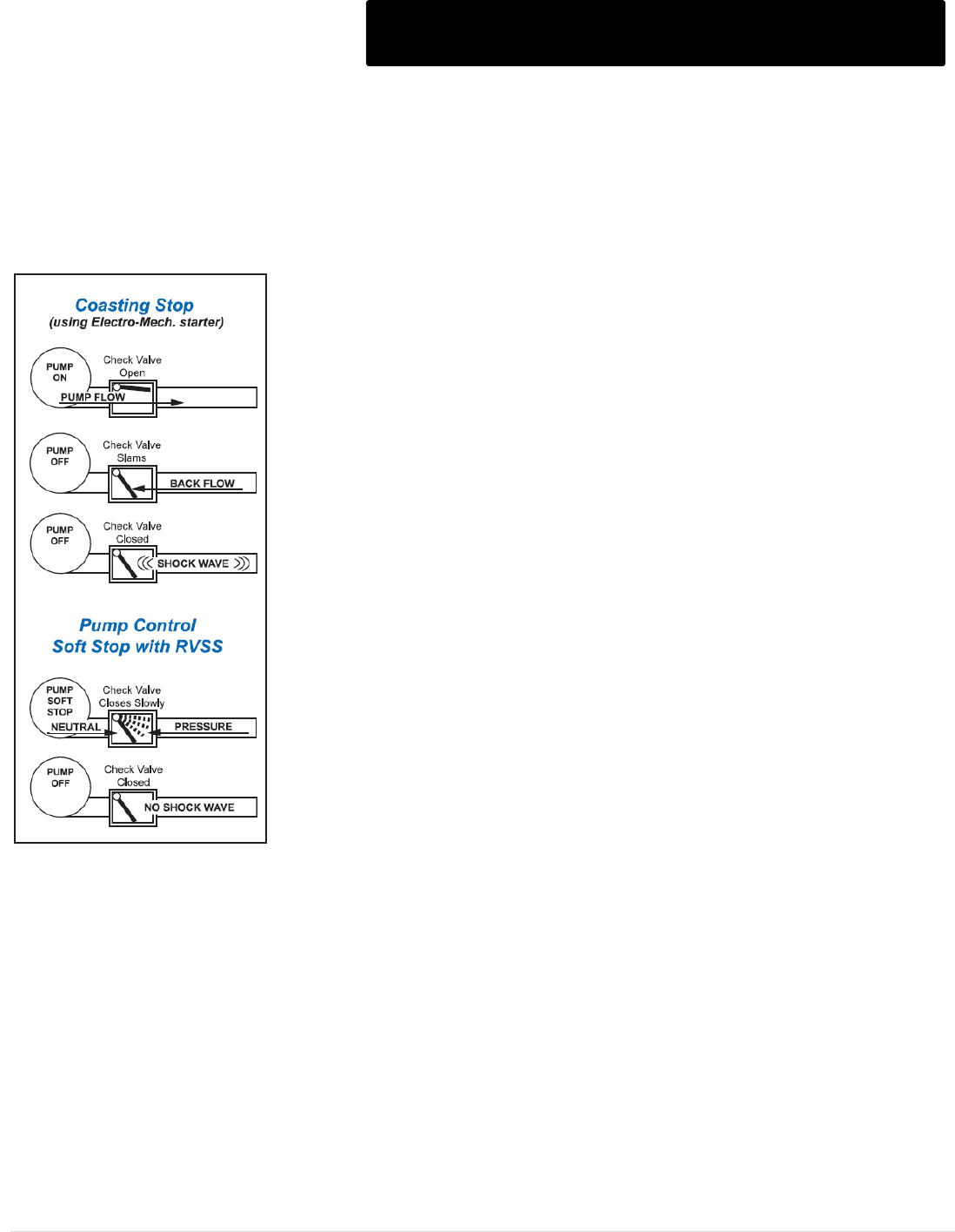
M o t o r t r o n i c s P r o d u c t S e l e c t i o n G u i d e P a g e 109
Frequently Asked Questions (Cont.)
Topic: Pumping Applications
Question: What makes RVSS starters so ideal for use in Pumping Applications?
Answer:
A unique feature available only on RVSS starters is the ability to provide controlled deceleration (Decel) of the motor over
a period that is LONGER than the coast-to-stop time. This Decel feature prevents the load from coming to an abrupt stop
and causing equipment damage or other load problems. The prime use of this feature
is in preventing surges and shock waves (water hammer) in centrifugal pump
systems.
Water Hammer is the result of the kinetic energy of the moving water being trapped
abruptly by a check valve. Since water does not compress, the energy has nowhere
to go and becomes a “shock wave” traveling up and down the piping system
searching for an outlet. The outlet for that energy will be the pipes, seals, hangers,
flanges, concrete walls, mounting bases and a host of other mechanical equipment in
the entire pump and piping system. By extending the ramp-down time, the energy of
the moving liquid is dissipated gradually with the reduced pressure from the pump.
Then, when the check valve closes, there is little or no energy left in the liquid to be
trapped, preventing the shock wave.
Another benefit of using Motortronics RVSS starters on pumps is their ability to
provide controlled acceleration using current limit on turbine pump systems. Rapid
acceleration can cause upthrust of the pump shaft and surging of the water when it
reaches the top of the pipe. Using Current Limit, the RVSS can reduce the pump
motor torque to provide just enough lift to get the water to the top, without excess
surging or upthrust. Since the pump may require very little initial torque to start, the
Motortronics RVSS can ramp gently into that current limit setting, providing the
maximum benefit. Electromechanical RV starters and other RVSS starters are less
able to control these situations.
Reduced Voltage starting is required on many pump applications just as a means of
reducing Inrush Current. By choosing Motortronics RVSS starters, all of the other
benefits of solid state starting are provided as well. Reduced mechanical shock, no
maintenance and advanced motor protection make RVSS technology the starter of
choice for Pump motors.

M o t o r t r o n i c s P r o d u c t S e l e c t i o n G u i d e P a g e 110
Frequently Asked Questions (Cont.)
Topic: Peak Demand
Question: Can soft starters save me money on the peak demand charges from my utility?
Answer
Demand charge savings are possible in many applications, but may come in a different form than what you might expect.
To determine possible savings, it is first necessary to determine how your utility registers demand charges for your billing
cycle. If they use any of the “ratcheting instantaneous demand” meters to measure usage, savings may come as a direct
result of using the Soft Starter Current Limit feature to reduce starting current peaks.
For example, if your utility charges you extra whenever you turn on a large motor, you may be paying for instantaneous
peaks. In a majority of installations however, the demand charges are calculated using a thermal device that takes a
certain amount of time to “warm up” and register the demand. The time it takes the thermal action to register an increase
is called the “demand window”, and is typically 15 to 30 minutes long.
This means that any single event shorter than the demand window will have little effect on the overall demand registration.
The best way to avoid demand charges in this case is to use the #1 rated energy saving device in the world; the “OFF”
button! By using soft starters, you can restart your machines when necessary without causing the associated mechanical
damage or voltage drop problems experienced with across-the-line starting. This allows you to shed loads whenever
possible, saving on both total energy consumption and demand charges.
Topic: Generator Power
Question: I have had several problems trying to power Soft Starter from an emergency diesel generator. Are
Motortronics soft starters suitable for that application?
Answer
Motortronics soft starter products are especially well suited for operating behind portable or stationary emergency
generators. Motortronics soft starters were designed from the outset to provide high precision gate firing in all power
environments. By using an exclusive “Auto-Synchronizing” firing circuit, Motortronics starters maintain firing circuit integrity
regardless of drifting or unstable power. A common problem encountered by users of other soft starters is that the
fluctuations in power frequency and output waveform can cause the firing circuit of the soft starter to “lock-up” and shut
down.
The reasons are complicated and involve the roots of their power sensing circuitry, but it is very real and happens all too
frequently. Another problem comes from the generator voltage regulating circuit. The small amount of electrical “noise”
created by firing the SCRs causes some older voltage regulators to allow the voltage to drift up and down as the soft
starter is trying to start the motor. If the soft starter is having trouble tracking that voltage swing, it may stall the motor.
Because of Motortronics’ unique “Auto-Synchronizing” firing circuit, the soft starter does not have these problems. As
such, Motortronics soft starter products are preferred among many customers who regularly use portable power systems
and demand reliability.
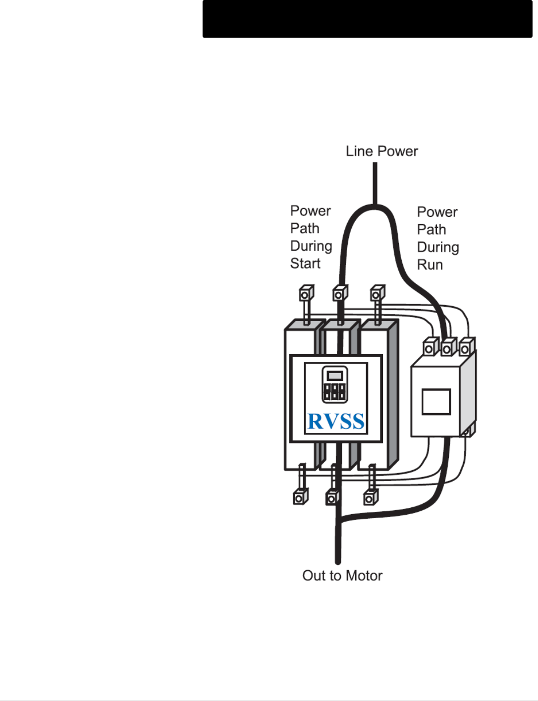
M o t o r t r o n i c s P r o d u c t S e l e c t i o n G u i d e P a g e 111
Frequently Asked Questions (Cont.)
Topic: Bypass Contactors
Question: What is the benefit of having a soft starter with an integral bypass contactor?
Answer
Bypass Contactors are mainly used to shunt the motor
power around the SCRs after the soft starter is finished
ramping the motor to full speed. SCRs give off a small
amount of heat as they conduct current. A conservative rule
of thumb is that each SCR rejects 1.5 watts of heat for each
ampere passing through it per phase, or 4.5 watts per
running load amp. On a 10HP, 460V motor at 14 FLA, this
amounts to only 63 watts (4.5W x 14 FLA). On a 200 HP
460V motor, the total comes to 1080 watts (4.5W x 240
FLA), a large amount of heat to dissipate.
If your application is in a dry and clean environment that
allows you to use a NEMA type 1 (ventilated) enclosure, a
Bypass Contactor is not necessary in the soft starter.
Ventilation and /or fans will take the heat out of the box and
into the surrounding air. However, if your application
requires a sealed (i.e. NEMA 12, 3R or 4) enclosure, the
heat will build up inside the enclosure leading to the point of
failure of the soft starter. To prevent this, Bypass
Contactors are used to “shunt” the power around the SCRs
when they are no longer needed in the circuit. With
Motortronics XLD/DXT Series, all units 92A (100HP @
460V) and larger in sealed enclosures automatically include
a shunt rated bypass contactor in the price. In addition, all
combination starters (prefix "B" or "D") provided with a built-
in circuit breaker or disconnect also includes a shunt
bypass contactor in the price. VMX Series soft starters
include an internal shunt bypass contactor on all ratings.
Another valid reason to use Bypass contactors even in
NEMA 1 applications is when there are several soft starters
in a small room. The heat rejected into the room from each
starter must be dealt with using building ventilation or air
conditioning, adding expense. Example: A control trailer at
a rock quarry with four NEMA 1 starters rated at 200HP will
be receiving over 4300W of heat into the inside air.
Ventilation would introduce a lot of dust, so air conditioning
would be required. Adding Bypass Contactors may be less
expensive than the additional BTU’s of air conditioning
required in cooling the ambient air in the trailer.
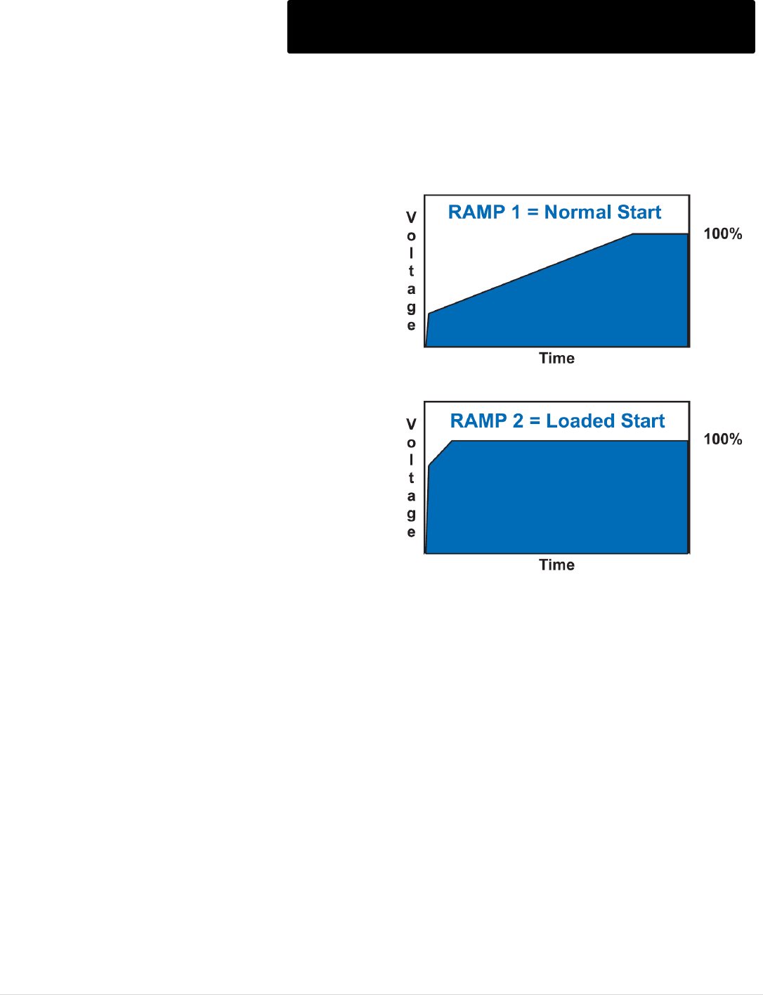
M o t o r t r o n i c s P r o d u c t S e l e c t i o n G u i d e P a g e 112
Frequently Asked Questions (Cont.)
Topic: Line Start Rated Bypass Contactor
Question: Can I start the motor using the Bypass Contactor if the solid state starter should trip or fail?
Answer
Standard duty Motortronics soft starters with built-in bypass
contactors use a Shunt Rated contactor. Motortronics’
design includes a “Silver Saver” circuit that always uses the
SCR devices to both start and stop the motor. The
contactor only needs to handle the running current. Shunt
ratings are based on this lower running current level and
are sized specifically for the intended motor. This usually
means that the Shunt Bypass Contactor cannot be used
for repeated Across-the-Line (X-Line) starting of that motor.
Before continuing on your quest for a contactor rated for X-
Line starting duty, ask yourself these important questions;
Am I requesting this just to be able to apply Locked Rotor
Torque on occasional starts?
All Motortronics starters are capable of delivering at least of
350% current for up to 30 seconds. The VMX, XLD and
DXT Series are capable of delivering 500% current for up to
60 seconds (which is usually more than the motor can
take). By using the Dual Ramp feature, this high level of
starting torque can be made available with the flick of a
switch. Since you are still using the solid state devices,
there will be no flash or contact burn. If you need even
slightly less than locked rotor torque, the Motortronics unit
can be adjusted to give you the exact starting torque you
need but with the least amount of mechanical stress.
Will my electrical system even allow me to start X-Line?
In many cases, soft starter starting is being used because the transformer or generator cannot deliver sufficient power to
start the motor X-Line. A soft starter with a contactor rated to do so might be a waste of money since it will not be able to
start the load anyway.
Do I want to be able to start the motor with the Bypass Contactor if the soft starter fails?
This is the most common reason for requesting a Line Rated Bypass. Keep in mind that the soft starter will be MORE
reliable than an X-Line starter. There is a valid need for an X-Line rated bypass contactor only when the application
itself poses significant risk of physical or electrical damage to the soft starter, i.e. in areas where lightning strikes or
flooding are common. If you have addressed these issues and you still feel you need X-Line starting capability, we
recommend the VMX Series "Heavy Duty" model.
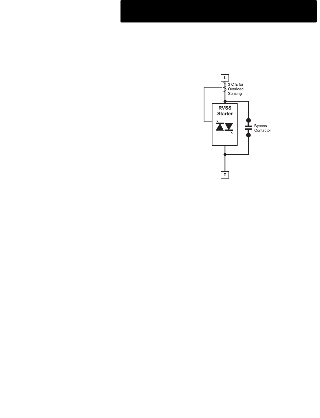
M o t o r t r o n i c s P r o d u c t S e l e c t i o n G u i d e P a g e 113
Frequently Asked Questions (Cont.)
Topic: Overload Protection
Question: How is the motor protected from Overload when running in bypass?
Answer
In order to provide running overload protection for the motor while in the
Bypass mode, Motortronics soft starters maintain a current path that
always has the Solid State Overload Protection in the circuit.
Power to feed the Bypass contactor is taken from downstream of the
current sensors, so no matter how it gets to the motor, it is always
monitored. Care must be taken if building your own Bypass system to
ensure that this current path is maintained. Motortronics can provide
recommended wiring diagrams to help you in that case.
Topic: Electronic Overload
Question: I have had problems with electronic overloads loosing track of my motor after a power failure. Will this be a
problem with the Motortronics soft starters?
Answer
Electronic overload protection has been around for some time now, and has proved to be superior to bi-metallic and
eutectic overload relays in repeatability and accuracy. One design problem unfortunately goes unnoticed with some
manufacturers. The electro-mechanical overload relays inherently retained the thermal condition of the motor, even if
power was removed. When power was restored and the motor restarted, the protective elements were still at the same
temperature state as the motor. If the motor was close to overloading before power failed, as is often the case when a
blackout is preceded by a “brown out”, the bi-metallic overload relay “remembers” and trips quicker if the overload
persists.
Microprocessor based electronics must have electricity to operate, and when the power fails, memory can be lost as well.
Several “electronic overloads” have been found to have no provisions to maintain thermal information. This holds true for
some manufacturers of digital soft starters as well. Motortronics has gone to great lengths to develop and implement a
Retentive Thermal Memory system that virtually duplicates the action of an electro-mechanical thermal overload. A Real
Time Clock keeps track of the elapsed time when power fails. When power is restored, the microprocessor reads the off-
time of the motor from the RTC and adjusts the Thermal Register to provide real Overload Protection that matches the
motor. This protection scheme also involves having non-volatile memory, another feature that sets Motortronics apart. The
bottom line is that you can count on Motortronics’ Solid State Overload to provide reliable, accurate motor overload
protection even in the event of the loss of power.
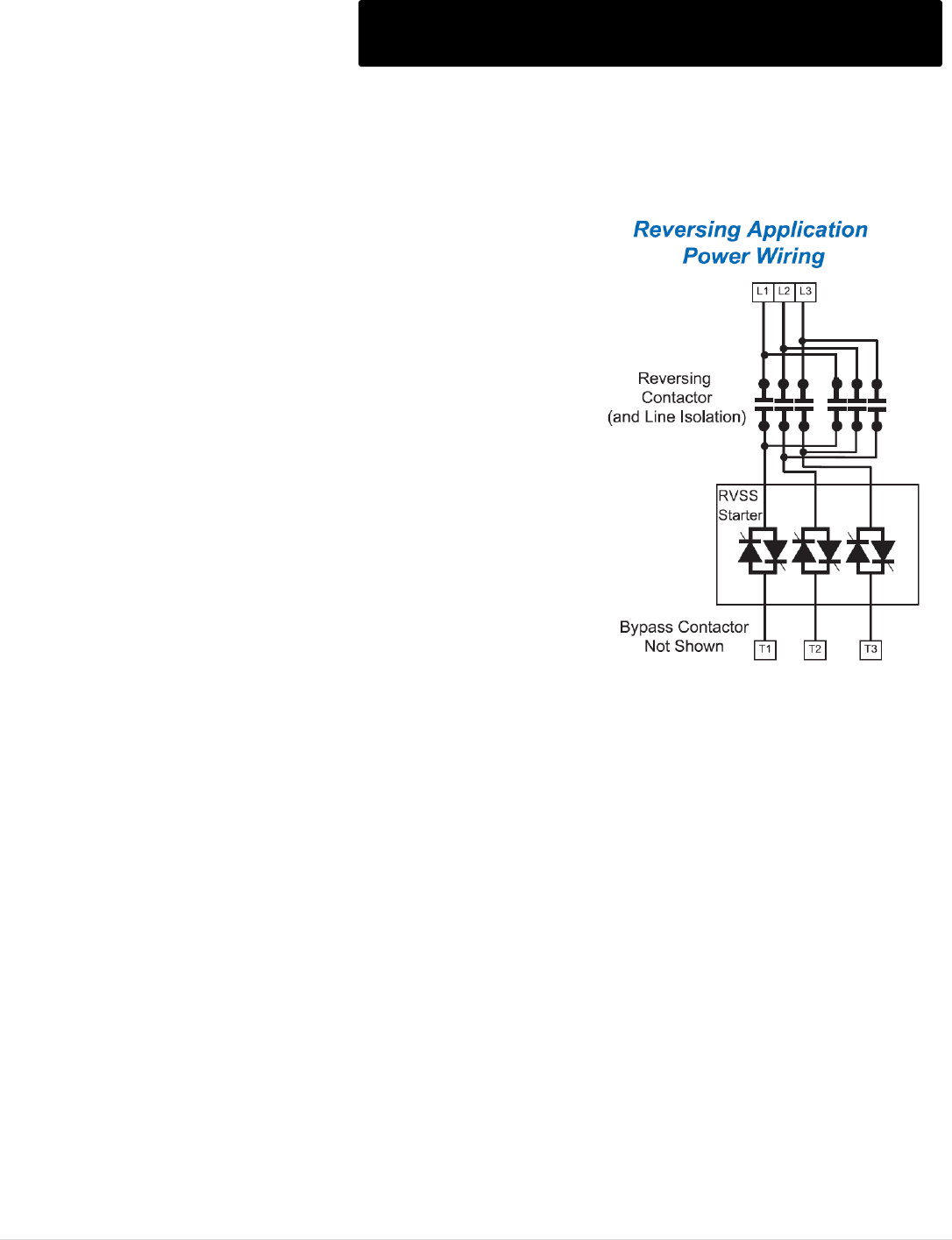
M o t o r t r o n i c s P r o d u c t S e l e c t i o n G u i d e P a g e 114
Frequently Asked Questions (Cont.)
Topic: Reversing Starters
Question: My application requires a Reversing Starter. How can I do that with a Motortronics Soft Starter?
Answer
Reversing can easily be accomplished with any Motortronics soft starter by
adding a reversing contactor to the circuit. Some Motortronics products are
not phase-rotation sensitive so the reversing contactor can be either
upstream or downstream from the soft starter.
Placing it upstream provides the additional benefits of having isolation as
described below. This also allows for simple retrofits where a FVR (Full
Voltage Reversing) starter is already in place. Just add the Motortronics
soft starter downstream, and control it with auxiliary contacts of the FVR
starter. The VMX Series must be programmed to disable phase sensitivity
if a reversing contactor is used upstream.
Topic: Isolation Contactors
Question: Do I need a contactor upstream from a Solid State Starter?
Answer
If severe transient voltage spikes and frequent lightning strikes are not problems in your area, the added cost of Isolation
Contactors may not be warranted. All Motortronics low voltage soft starter products are designed for use without the need
for Line Isolation Contactors. Isolation Contactors however, are a good protective measure to consider using when spikes
and / or lightning are a common occurrence. While the motor is running, these spikes and surges are passed through with
little harm. When the motor is off (but the SCRs are still connected), the SCRs are exposed to these spikes and surges,
causing gradual damage that can lead to eventual failure. If the spikes or surges are severe, immediate failure of multiple
SCR devices is possible.
The “air-gap” provided by an Isolation Contactor is excellent low-cost insurance. Another application is when there are
Power Factor Correction Capacitors (PFCs) in the circuit. The Isolation Contactor can then serve two purposes and is
therefore more cost effective. See the following FAQ entitled “PFC Capacitors” for more details. Some brands of Soft Start
controller designs require in-line contactors for basic operation. Others have no transient protection at all. Those other
manufacturers may state that Isolation Contactors are always REQUIRED, but that may be applicable only to their brand.

M o t o r t r o n i c s P r o d u c t S e l e c t i o n G u i d e P a g e 115
Frequently Asked Questions (Cont.)
Topic: 2-Speed Motors
Question: Can a soft starter used in a 2-speed motor application?
Answer
Two speed motor applications are not a problem for Motortronics soft starters, but they do require some thought and
investigation. There are several ways to do this depending on the answer to these three questions:
1. What Type of 2-speed motor is it, i.e. two speed, two winding or two speed single winding etc.?
2. How does the machine or process operate, i.e. always start in Low and switch to High, or is it possible to start the
motor in either speed?
3. Is it a new application or retrofit to an existing starter? It is often easier to add an soft starter to an existing 2-
speed starter and leave the rest of the control system intact. Contact Motortronics with this information for further
assistance.
Topic: Over Sizing
Question: When should I consider over-sizing or derating a Motortronics Soft Starter?
Answer
Motortronics soft starters are all built as Heavy Duty products. As such, we can tell you that “If your motor can start the
load, Motortronics’ soft starter can start the motor”. Motortronics soft starters are capable of providing 500% of their rated
current for at least 60 seconds. That is the heaviest duty rating available on the market! This rating means that you should
never have to oversize (or derate) these series on any standard or even mill-duty motor application.
In addition, these starters are designed to meet or exceed the duty cycle capabilities of the motor it is intended to serve.
For example, in an application where a 10HP motor is capable of being started 10 times per hour, the Motortronics soft
starters are capable of at least 10 starts per hour as well. The benefit to users is that with Motortronics, your motor will be
the only device limiting your duty cycle. If your motor is oversized to handle a higher duty cycle, just size the Motortronics
unit to match the motor nameplate.
M o t o r t r o n i c s P r o d u c t S e l e c t i o n G u i d e P a g e 116
Frequently Asked Questions (Cont.)
Topic: Altitude Derating
Question: Do I need to derate my soft starter in high altitude applications?
Answer
Because of the limited cooling capacity of thinner air, careful consideration should be given to applying a soft starter in
high altitudes. If the unit will be used in a NEMA 1 ventilated enclosure, some degree of de-rating may be necessary if the
altitude is significantly above 3300 ft. (1000 meters). A very conservative de-rate formula is 1% for each 330 ft. elevation
above 3300 ft.
Example, at a 6000 ft. elevation, this de-rate would be 6000 – 3300 = 2700, divided by 330 = 8.18% de-rate. Keep in
mind, however, that Motortronics starters are sized for maximum current, and in most cases provide significantly more
capacity than what the typical motor at a selected HP requires.
Example, a 200HP 460V motor with a FLA of 240A and a 1.15 service factor may draw 276 FLA at worst case. The
standard Motortronics with the 8.18% de-rate it can still provide 282 amps which is more than that motor requires. Units
with bypass contactors utilize the SCRs for such a short period of time (during ramp-up) that they rarely need derating.
But you must be sure the current never exceeds the maximum rating of the contactor. When in doubt, give all pertinent
altitude information and motor rating data to Motortronics Tech Support for proper unit sizing and selection.
At 10,000 ft., the current de-rate factor becomes 20% and may require derating of the starter. Again, keep in mind that
the motor FLA may be derated as well, so make sure you are working with all of the correct information. Another
consideration at elevations over 10,000 feet is the voltage rating of all electrical devices. The dielectric insulating
properties of the air are decreased, requiring a possible voltage derate at extreme altitudes. Contact Motortronics for
additional help in this situation.
Topic: Temperature
Question: Can I use a Motortronics soft starter in high ambient temperature applications?
Answer
Motortronics starters also provide some of the highest ambient
temperature ratings available. Every soft starter chassis model is designed
for a 50° C (122° F) ambient and is factory tested at 60° C (140° F). Units
with factory supplied enclosures are designed based on a 40° C (104° F)
maximum ambient operating temperature. Derating is possible within these
limits using the formula of 1% per degree above 50° C (40° C for
enclosed), to an absolute maximum of 60° C.
If your application is outdoors, de-rating is rarely necessary providing the
enclosure is protected from direct sun exposure. Radiant heat loading from
any source including the sun can quickly exceed even a derated unit’s
maximum temperature rating. Protect soft starters from all sources of
radiant heat and direct contact with any extremely hot objects such as
ovens or steam pipes.

M o t o r t r o n i c s P r o d u c t S e l e c t i o n G u i d e P a g e 117
Frequently Asked Questions (Cont.)
Topic: Variable Frequency Drive Bypass
Question: Can I use a soft starter as the emergency bypass for my Variable Frequency Drive?
Answer
While Variable Frequency Drives (VFDs) can vary the output speed or torque of the motor, they also provide almost all of
the features offered by soft starters. Users often get their first exposure to the benefits of Soft Stopping a pump to reduce
water hammer because it was a feature of their VFD.
When the VFD fails and the user must run the pump on bypass, they quickly notice that their Soft Stop (Decel Control)
feature is lost with an electro-mechanical bypass starter. Many users are discovering the benefits of using a soft starter as
the emergency bypass of a VFD. In addition to the Soft Stop, they also help in applications where available power is
limited, especially when the application is powered from a back-up generator.
Motortronics Soft starters are ideal for this situation as well. The only consideration to keep in mind is that the soft starter
and VFD must be isolated from each other when operating the motor. Two contactors, one being fed from the VFD output
and one fed from the soft starter output, tie together to feed either output to the motor, but never both. If not, damage to
both the VFD and the soft starter would result.
Contact us for additional help.

M o t o r t r o n i c s P r o d u c t S e l e c t i o n G u i d e P a g e 118
Terms and Conditions
1. General: All orders for products or services of Phasetronics (hereinafter “Company”) are subject to these conditions of sale. No modifications
of, or additions to, these terms will be recognized by the Company unless specifically agreed to in writing by an authorized Company officer.
Failure of Company to object to any provision in conflict with any part of this instrument contained in any prior or subsequent order to
communication from a buyer hereinafter referred to as “the Purchaser” shall be construed as a waiver of these conditions nor an acceptance
of any such provision.
2. Prices: Prices are subject to change without notice. Published prices shown in Company’s catalogs and price bulletins provide a price and
catalog number guide for the selection and application of a specific product. All prices are subject to confirmation by authorized Company
personnel. In the event of a net price change, the price of products on order but unshipped will be adjusted to the price in effect at the time of
shipment. Downward adjustment of prices shall only apply to unshipped portions of outstanding orders. Written quotations must be for specific
quantities, catalog number, price and delivery date(s). In lieu of catalog number, complete specifications must be included in the quotation.
Unless noted otherwise on the written quotation, all quotes are conditioned upon acceptance by Purchaser within thirty (30) days from date
issued and shall be considered as offers by Company to sell during such thirty (30) day period unless sooner terminated by notice. Products to
be furnished or services rendered hereunder will be produced or performed in compliance with all applicable requirements of Sections 6, 7 and
12 of the Fair Labor Standards Act of 1938, as amended on the date hereof, and of all valid and applicable regulations and orders of the
Administrator of the Wage and Hour Division issued under Section 14 thereof, as written on the date of acceptance of the Purchaser’s order.
3. Patents: Company will hold Purchaser harmless against any liability for infringement of any apparatus claim of any United States patent,
issued at the date of the contract, and arising out of the sale or use in the form supplied by Company of equipment designed and/or
manufactured by Company. Company will assume no liability with respect to equipment specified by either Company or Purchaser, but not
designed and/or manufactured by Company. Purchaser will hold Company harmless against any liability for infringement of any apparatus
claim of any United States patent, issued at the date of the contract or order, and involving equipment furnished by Company, in accordance
with drawings and/or specifications furnished by Purchaser. The party assuming liability, as stated above, shall be notified immediately of any
assertion of infringement, and shall have the absolute control of the defense thereto, including the right to settle, defend against legal action,
or make changes in the equipment to avoid infringement.
4. Weights and Dimensions: Catalog weights and dimensions are carefully calculated estimates but are not guaranteed.
5. Taxes: Published or quoted prices do not include sales, excise, use or similar taxes. Applicable taxes must be paid by the Purchaser.
6. Minimum Billing: Orders amounting to less than $100.00 net will be billed at $100.00.
7. Orders: All orders must be bona fide commitments showing definite prices, mutually agreed upon delivery dates, stipulated quantities and
complete item descriptions.
8. Acceptance: No order or commitment is binding upon the Company until accepted at a point of shipment by an authorized Company official.
9. Penalties and Delays: No penalty clause of any kind will be effective unless approved in writing by an authorized Company officer. The
Company will not be liable for any damages caused by delays beyond Company’s reasonable control including, without limitation, fire, strike,
act of the Purchaser, restrictions by civil or military authority, act of God, transportation failures or inability to obtain labor, materials or
manufacturing facilities. In the event of any such delay, the date of delivery shall be extended for a period equal to the time lost by reason of
the delay.
10. Cancellation: Cancellation of any item on an order to the Company will be accepted only on the following basis: Any items which upon receipt
of a written notice of cancellation are within thirty (30) calendar days of completion, as determined by the Company’s best estimate at the time
of receipt of cancellation notice, will be completed and paid for by Purchaser in full under the regular terms and conditions of billing. All items
which are not within thirty (30) days of completion when cancellation is requested may be canceled or altered by the Purchaser only upon
payment of reasonable charges based upon expenses already incurred and commitments made by Company. Company reserves the right to
manufacture ahead of the shipping schedule whenever it is deemed necessary and such advance manufacture shall not void Purchaser’s
responsibility for payment of cancellation or alteration charges.
11. Delivery: Prices are f.o.b. Company plant or point of shipment, with freight collect or, when instructed by the customer, freight may be prepaid
and added to the invoice.
12. Damage and Loss: Company’s products are packed in specifically designated cartons to protect the products from damage during shipment.
Upon delivery to the carrier and his receipt for the products, all responsibility for delivery intact and undamaged to the destination rests with
the carrier and not with the Company.
All shipments should be inspected upon receipt at the destination for visible or concealed damage. Claims for loss or damage should be filed
with the carrier immediately. A concealed damage claim against the carrier is required when damage is not externally visible. Company will
assist insofar as is practical in securing satisfactory adjustment of claims, however, all claims for loss and damage must be made by the
Purchaser to the carrier.

M o t o r t r o n i c s P r o d u c t S e l e c t i o n G u i d e P a g e 119
13. Terms of Payment and Reservations of Title: Standard Terms to Purchasers determined by the Company to have satisfactory credit are as
follows: One percent 10 days, net 30 days. All quoted prices and payments shall be in U.S. dollars. Phasetronics accepts Visa or MasterCard.
Company reserves the right to require full or partial payment in advance of shipment where in the Company’s opinion, exercised in its sole
discretion; the financial condition of the Purchaser does not justify continuance of production or shipment on the terms of payment specified.
Title to all products purchased from Company shall remain in the Company until Company receives payment in full for the products from the
Purchaser at which time title shall pass to the Purchaser. Purchaser agrees, upon request of Company, to promptly execute and return to
Company any documentation necessary to perfect Company’s security interest in the products. Company agrees that upon receipt of payment
in full for the products, it shall cause any existing perfected security interest in the products to be discharged.
Payment Schedules
Orders less than $100,000: On orders having price of less than $100,000 the standard terms of payment are cash in full within 30 days from
the date of each invoice.
Orders for $100,000 or more: On orders having a price of $100,000 or more, the standard method of payment will be PROGRESSIVE
DEPOSITS.
Progressive Deposits are deposits of fixed amounts or percentages at stated monthly intervals during the production period.
If, in the judgment of the Company, the financial conditions of the Purchaser at any time does not justify continuance of production or shipment
on the terms of payment originally specified, the Company may require full or partial payment in advance, and, in the event of bankruptcy or
insolvency of the Purchaser or if Purchaser fails to pay Company any sum when due, then upon seven (7) calendar days written notice, the
Company may cancel any order then outstanding and Purchaser shall be responsible for compensating the Company for expenses incurred in
the performance of the order which have theretofore not been paid.
Each shipment shall be considered a separate and independent transaction and payment, therefore, shall be made accordingly. If work
covered by the purchase order is delayed by the Purchaser, upon demand by Company, payments shall be made on the purchase price
based upon percentage of completion. Products held for the Purchaser shall be at the risk and expense of the Purchaser unless otherwise
agreed upon in writing. The Company reserves the right to ship to its order and make collections by sight draft, C.O.D., or any other terms
approved in writing by the Company’s Credit Department.
14. Late Payment and Past Due Accounts: A finance charge of 1.5% per month (Annual Percentage of 18%) will be charged on any portion of the
unpaid balance over 30 days old. All accounts which have unpaid balances for over 90 days may be turned over for collection or legal action
and Purchaser shall be required to pay collection fees or the costs, including reasonable attorneys fees, incurred by the Company in the trial
court and on appeal for any such collection action.
15. Responsibility: Company is not responsible for the misuse or misapplication of its products, intentional or otherwise. Improper application,
installation, failure to provide safety devices or protective measures, or operation above a product’s rated capacity, and failure to properly
maintain or service products are all beyond the control and responsibility of the Company. Under no circumstances shall Company be liable or
loss of profits, indirect, incidental, special, consequential, or other similar damages arising out of the misuse, misapplication, or failure to
maintain Company’s products.
16. Return of Products: Under No Circumstances are Products to be returned to Company Without First Obtaining Company’s Permission and a
Returned Material Authorization Number (RMA). Unless authority has been granted for return and an RMA issued, shipment will be refused.
Products built to a Purchaser’s specifications cannot be returned for credit under any condition. Products which are authorized for return must
be properly packed to protect against physical damage during shipment and must be shipped prepaid. Transportation charges are Purchaser’s
responsibility for all returned products. Credit will be allowed on authorized returned products on the following basis: Only unused products
which Company is currently selling and which have been sold to the Purchaser within one year of the return date will be considered. Products
ordinarily carried in stock will be accepted for return subject to a minimum service charge of $100.00 or 30% if the billing invoice is more than
$330.00 net. All products must be returned in perfect condition. Any cost incurred by Company to place returned products in perfect condition
will be charge to the Purchaser. Products built-to-order are not subject to return regardless of condition. No credit memo will be issued where
any amount less than $100.00 is involved except to correct errors made by Company. If return is authorized by Company due to a recognized
fault of Company, full credit will be allowed for the returned products including all transportation charges.
17. Warranty: Company warrants its products to be free from defects in material and/or workmanship for a period of one year from the date of
installation, to a maximum of eighteen months from the date of shipment as indicated by the unit’s date code. The Company reserves the right
to repair or replace any malfunctioning units under warranty at Company’s sole option. All warranty repairs must be performed at the
Company’s factory or on site by factory authorized service firms or personnel approved by the Company. Company shall not be responsible
for misuse or failure to maintain its products. See Section 15 - Responsibility, above. Except as Specifically Provided Herein, There Are No
other Warranties, Express or Implied, Including, But Not Limited To, Any Implied Warranties of Merchantability or Fitness for a Particular
Purpose. Solid state controls have different operating characteristics from those of electromechanical equipment. Because of these
differences and the wide variety of applications for solid state controls, each application designer must verify that the solid state equipment is
acceptable for his particular application. In no event will company be responsible or liable for indirect or consequential damages resulting from
the use or application of its products. The diagrams and illustrations, if any, found in documents and/or manuals accompanying Company’s
products are included solely for illustrative purposes. Because of the number of different applications of Company’s products, Company
cannot be responsible or liable for actual use based on the examples or diagrams.
18. Governing Law: Interpretation and enforcement of any rights and obligations between Company and Purchaser arising out of the sale of the
Company products shall be governed by the laws of the State of Florida and any action brought to enforce those rights and/or obligations shall
be brought in the court of competent jurisdiction located in Pinellas County, Florida.

M o t o r t r o n i c s P r o d u c t S e l e c t i o n G u i d e P a g e 120
For the latest product information
visit www.motortronics.com
Phasetronics Inc. dba Motortronics
1600 Sunshine Drive
Clearwater, Florida 33765
USA
Tel: 727.573.1819 or 888.767.7792
Fax: 727.573.1803 or 800.548.4104
E-Mail: sales@motortronics.com
Revision 102712-1.20
