Ii BZ 50 08406r3 WEB Installation Directions
2014-07-05
: Pdf 378995-Installationsheet 378995-InstallationSheet 754182 Batch5 unilog
Open the PDF directly: View PDF ![]() .
.
Page Count: 4
WARRANTY INFORMATION
Watt Stopper/Legrand warranties its products to be free of defects
in materials and workmanship for a period of fi ve (5) years. There
are no obligations or liabilities on the part of Watt Stopper/Legrand
for consequential damages arising out of, or in connection with, the
use or performance of this product or other indirect damages with
respect to loss of property, revenue or profi t, or cost of removal,
installation or reinstallation.
Installation Instructions
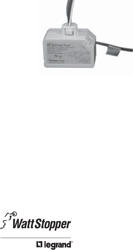
BZ-50
Power Pack
SPECIFICATIONS
Voltages ............................................ 120/230/277VAC,50/60Hz
Load Requirments
Ballast ............................................... 20amp @120/277VAC
Incandescent ............................................ 20amp @120VAC
Motor ...................................................... 1HP @120/240VAC
Output .......................225mA @24VDC (with relay connected)
Low Voltage Input, Control ON ................................. 12-24VDC
Operating Temperature ........................32°-104°F (0-40°C)
Santa Clara, CA 95050
Call 800.879.8585 for Technical Support
DESCRIPTION
The BZ-50 power pack is the foundation for any low voltage lighting control
system. The BZ-50 supplies low voltage power to occupancy sensors and other
control devices, switching line voltage in response to signals from control devices.
The BZ-50 power pack is attached to existing junction boxes or mounted into
fi xture wiring trays.
Low voltage wiring should use at least 22-gauge wire, high voltage connections
should use at least 14-gauge. Always check local building codes. After initial
wiring is complete, check wiring diagram to verify power pack is wired correctly.
Improper wiring can cause damage to power pack, lighting system, and
occupancy sensor.
INSTALLATION
WARNING
TURN POWER OFF AT CIRCUIT
BREAKER BEFORE INSTALLING
POWER PACKS.
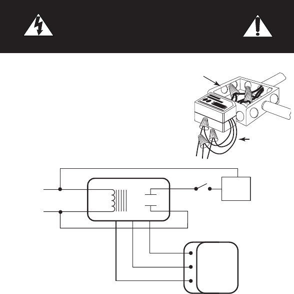
WIRING
Low Voltage
Class 2
High
Voltage
Control Output
Common
+24VDC
Red
White
Neut. BZ-50
Red
Black
Blue
Switch
(optional)
Lighting
Load
Black
Any 3-Wire
24VDC
Sensor
Line Red
1. Make sure power has been turned off
at the circuit breaker.
2. Connect wires as shown in Fig.1 or
Fig. 2.
Fig. 1: Single load control
Installation Notes
1. Power packs should be installed in accordance with state, local and national
electrical codes and requirements.
2. Power packs are designed to attach to existing or new electrical enclosures
with 1/2 inch knockouts.
3. Most applications require UL listed, 18-22 AWG, 3-conductor, Class 2 cable for
low voltage wiring. For plenum return ceilings, use UL listed plenum-approved
cables.
4. The BZ-50 is a Class 2 Ouput Power Supply, suitable for parallel
interconnection of up to 10 units maximum. This powerpack is UL Listed for
Interconnection of Power Sources in accordance with the National Electric
Code.
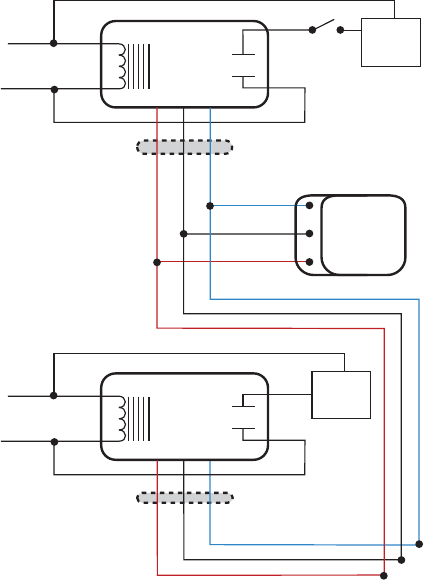
+24VDC
Common
Red
White
Neut. BZ-50
(A)
Blue
Black
Red
Lighting
Load (A)
Black
Any 3-Wire
24VDC
Sensor
Line Red
Control
Class 2
Low Voltage Wires
Red
White
Neut. BZ-50
(B)
Blue
Black
Red
Lighting
Load (B)
Black
Line Red
Class 2
Low Voltage Wires
Switch
(optional)
www.wattstopper.com
Fig. 2: Parallel interconnect
for multiple load
control from a single
sensor

2800 De La Cruz Boulevard, Santa Clara, CA 95050
Technical Support: 800.879.8585 • www.wattstopper.com
08406r3 08/2008
Please
Recycle
OPERATION
Low Voltage Input (Blue Wire):
The blue wire carries the +12-24VDC maintained input Control ON signal to the
BZ-50. Applying 12-24VDC to this input closes the BZ-50 load relay. Removing the
voltage returns the relay to its normal state. This input is intended for sensor or
control device input.
Over Current Protection:
The BZ-50 contains built-in short circuit and thermal protection circuitry that
shuts down the +24VDC output (red wire to sensors) to prevent permanent
damage to the power pack. Removing the excess load from the output restores
the BZ-50 to proper operation. The excess load can be connected to another
power pack.
LED Indicator:
The LED indicates the following conditions on the BZ-50:
• LED OFF: no power to the BZ-50, or the +24VDC output is shorted.
• LED ON, blinks once every 5 seconds: the relay is closed (load ON).
• LED ON continuously: the relay is open (load OFF).
• LED blinking continuously: current output limit is exceeded (too many
sensors are connected to the power pack); +24VDC output shut down.
Load Range
Catalog
No.
Description Input
Voltage
Ballast
(A)
Incan.
(A)
Motor
(hp)
Output
BZ-50 Power Pack 120/230/
277VAC,
50/60Hz
20 20 1 24VDC,
225mA
w/relay
connected
BZ-150 Power Pack,
Hold ON/OFF,
Manual ON
120/230/
277VAC,
50/60Hz
20 20 1 24VDC,
225mA
w/relay
connected
ORDERING INFORMATION
