41819 Catalog
2014-07-05
: Pdf 41819-Catalog 41819-Catalog 785901 Batch5 unilog
Open the PDF directly: View PDF ![]() .
.
Page Count: 156 [warning: Documents this large are best viewed by clicking the View PDF Link!]
Catalogue
2013
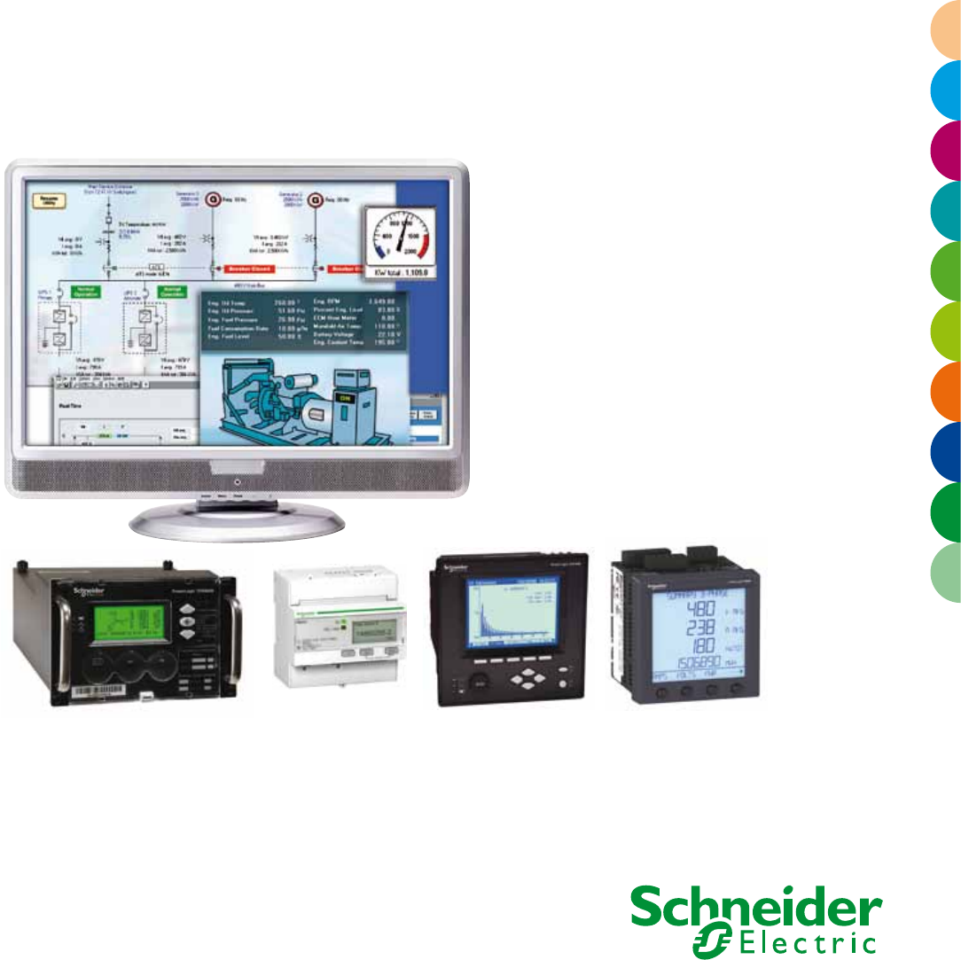
PowerLogic System
Energy management, revenue metering and power quality monitoring
Electrical network management

PowerLogic technology forms one part of your total energy
management solution from Schneider Electric. As the global
energy management specialist, we offer end-to-end power,
building and process management solutions that help you
optimise energy use and costs, improve performance,
enhance comfort and safety, and deliver uninterrupted service
while taking responsible care of our planet.
Our expert services can help you audit your energy use and
build your energy action plan. From power factor correction
systems, harmonic ltering and variable speed drives to HVAC
and lighting controls, we offer a complete range of energy
efcient technologies.
Schneider Electric believes every business can increase
productivity while consuming less and achieving energy
savings of 10% to 30%.
Saving energy reduces costs and pollution, but you need the
tools to uncover all opportunities, avoid risks, track progress
against goals, and verify success. Schneider Electric
provides these tools via the world’s most advanced energy
intelligence technology: PowerLogic.
The PowerLogic range of meters and software help manage
all energy assets, every second of the day. A PowerLogic
system enables all stakeholders, from CEO to facility and
engineering managers, to respond quickly to potential
problems and manage energy in nancial and environmental
terms.
PowerLogic technology delivers the key performance
indicators and analytics that you need to strategically balance
emissions, efciency, reliability and cost.
PowerLogic System is…
2013
General contents
Gain energy insight and control with PowerLogic™
Market segments
Panorama of the PowerLogic range
General information on power-monitoring software
Index of catalogue numbers
4
6
8
13
14
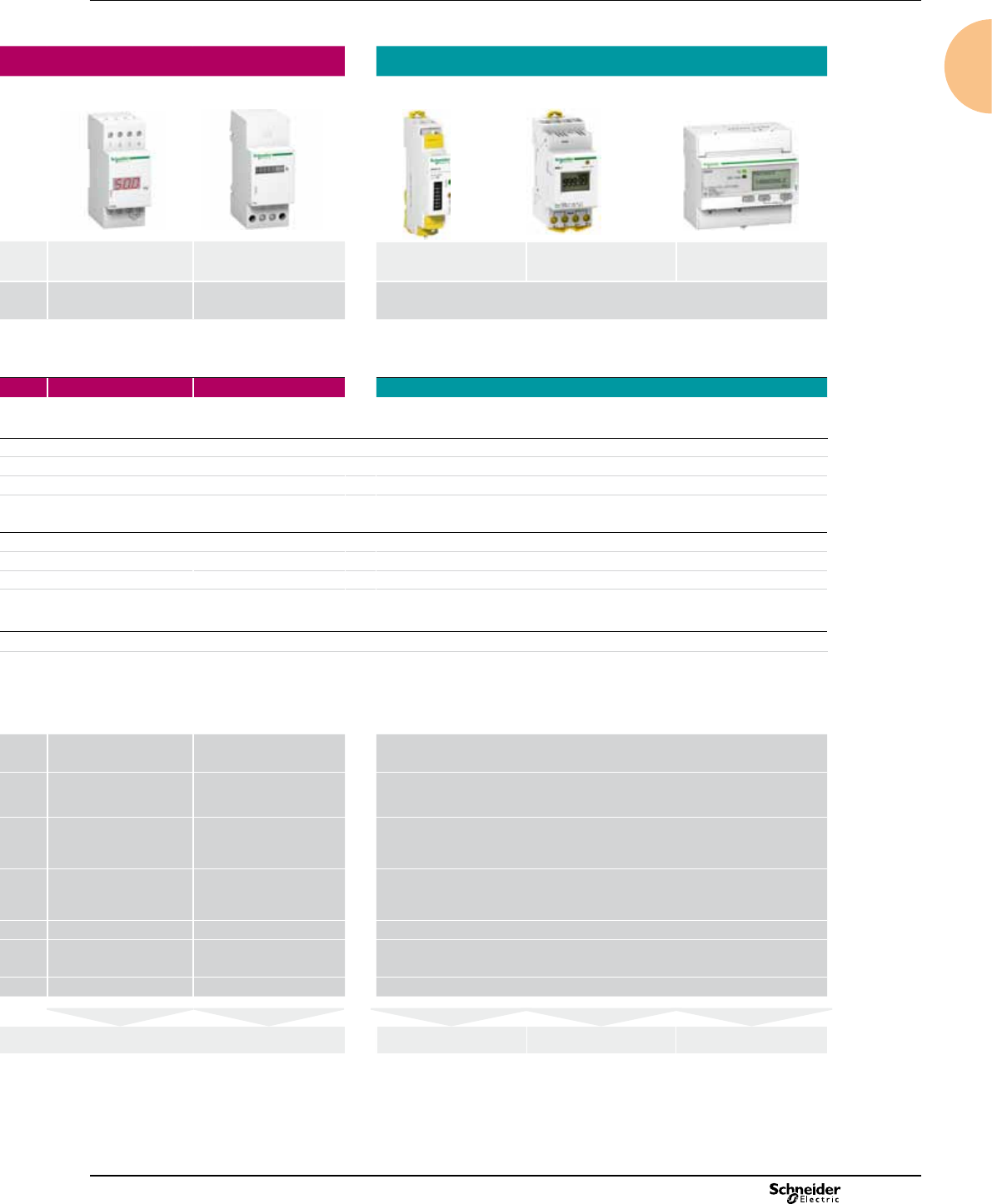
Current transformers 17
Basic panel meters 21
iAMP iVLT iFRE AMP/VLT iCH/iCI
Basic energy meters 31
iEM2000 iEM3000 iME1
Power-monitoring units specification guide 38
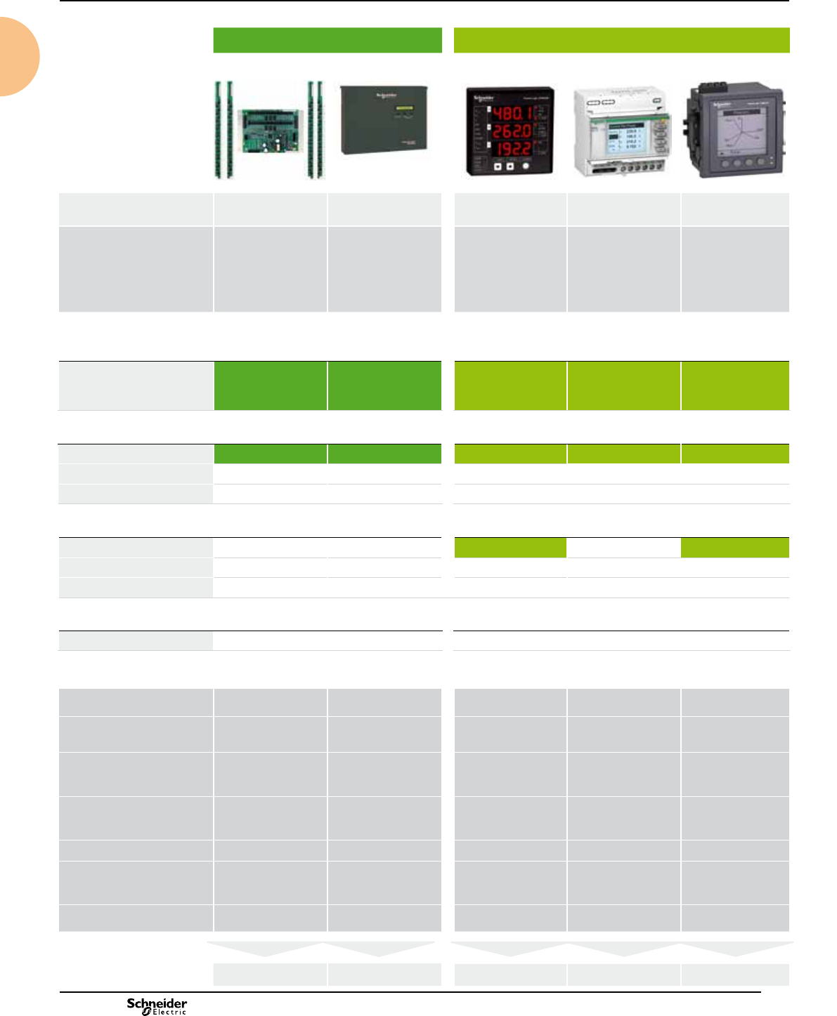
Multi-circuit metering 42
BCPM EM4800
Basic multi-function metering 53
iON6200 PM3000 PM5000
Intermediate metering 78
PM800 ION7330/7350
Advanced metering 94
ION7550/ION7650 CM4000T
Advanced utility metering 108
ION8650 ION8800
Communications 123
Energy Server Com'X 200 EGX100/300 ION7550 RTU
Monitoring software 137
StruxureWare Power Monitoring Expert StruxureWare PowerSCADA Expert
2013
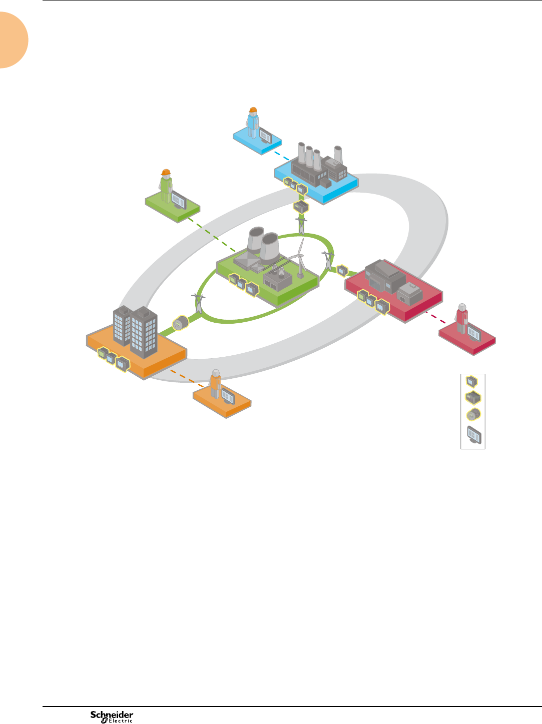
Gain energy insight and control with PowerLogic™
PowerLogic energy and power management systems
Energy insight = energy control
PowerLogic solutions help energy consumers and suppliers world-wide make the most of their energy. They enable businesses to improve their
competitiveness by giving them a complete understanding their organisation's unique energy landscape. PowerLogic technology also provides
hands-on tools to improve energy efciency, reduce operating costs, enhance productivity, and increase power system reliability. Comprising
metering, communication hardware and advanced analysis software, a PowerLogic solution acts like a layer of intelligence across all of your
energy assets. It monitors key energy points and inputs 24 hours a day, then processes and delivers that data as timely and relevant information to
everyone that needs it.
Industry
Critical
infrastructure
Utilities
Buildings
Utility
Intelligent energy
and power quality
meters
PowerLogic
software
The PowerLogic advantage
PowerLogic solutions are the world’s largest and most advanced range of energy management products.
Thousands of organisations world-wide choose PowerLogic systems because of key advantages:
bA fast, quantiable return on investment through both a low total cost of ownership and
rich functionality that returns multiple nancial benets
bA comprehensive portfolio of modular, scalable components that enable
affordable system expansion as needs dictate and budgets allow
bEnd-to-end interoperability offering seamless integration with business, accounting, BAS and SCADA applications
bA complete range of compatible, complementary, single-sourced Schneider Electric power and automation solutions
bSupport for numerous global metering accuracy and power quality monitoring standards.
• generating stations
• transmission substations
• distribution substations
• tenants
• service entrance
• HVAC
• processes
• onsite generation
• power distribution
• servers
• branch circuits
• UPS
4
2013
Cutting-edge technology to increase protability
PowerLogic technology converts the complex dynamics governing the relationship between power generation and distribution on the utility
side, and energy consumption, cost and reliability on the consumer side, into timely, easily understood information. Businesses can use this
powerful to improve tactical actions and strategic decision making.
From a single facility to an entire enterprise, PowerLogic meters monitor key distribution points 24 hours a day. Whether from generators,
substations, service entrances, mains, feeders, loads or 3rd party equipment and systems, PowerLogic technology tracks, records and reports
all real-time conditions and historical performance data. Intuative web-based interfaces give stakeholders access to this data as well as
advanced analytics, alarm annunciation and control capabilities. It supports comprehensive energy management programs by tracking
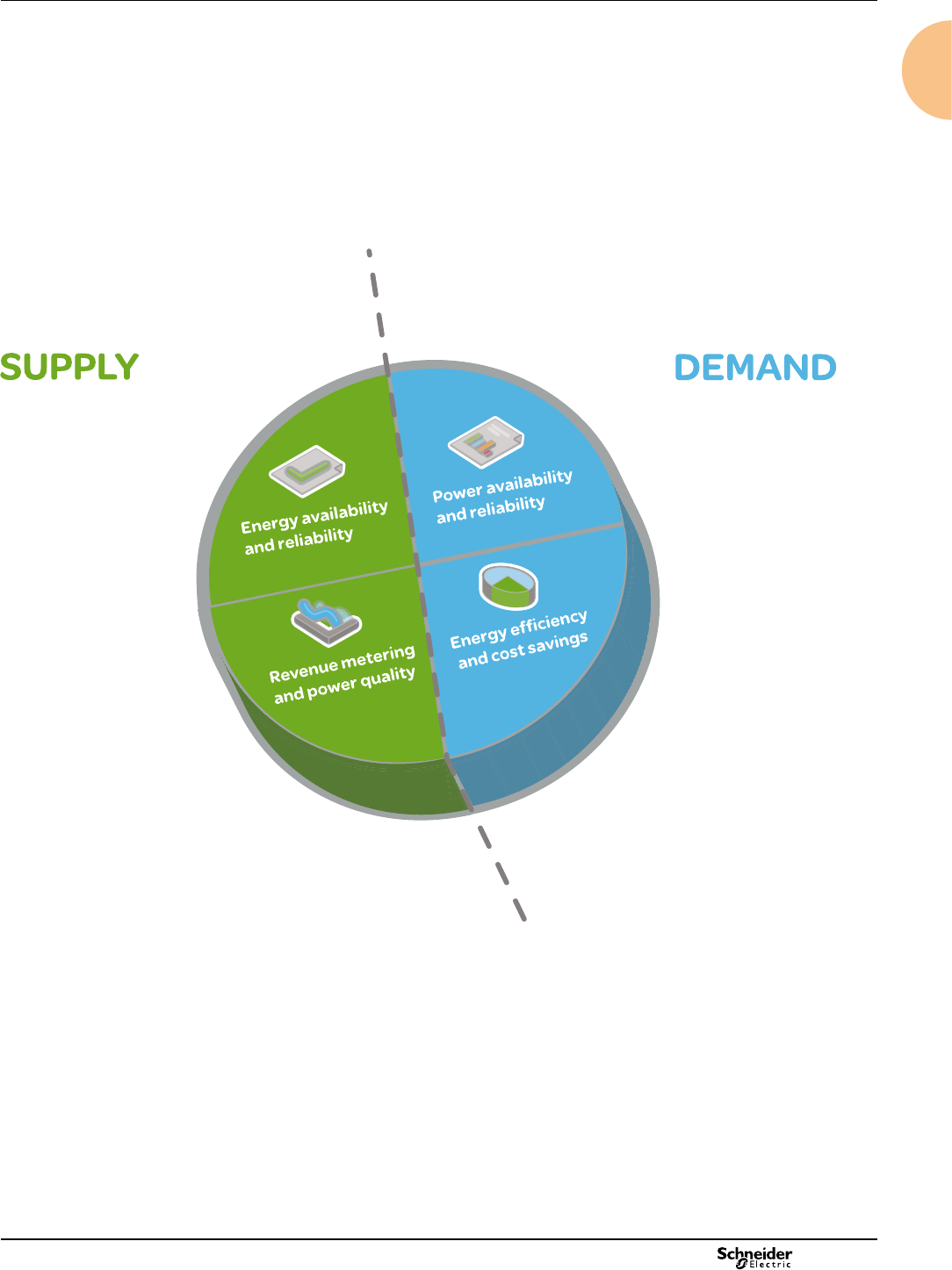
performance and empowering you to make effective decisions.
Power availability
and reliability
bValidate that power quality
complies with the energy contract
bVerify the reliable operation of
power and mitigation equipment
bImprove response to power-
related problems
bLeverage existing infrastructure
capacity and avoid over-building
bSupport proactive maintenance
to prolong asset life
Energy efciency
and cost savings
bMeasure efciency, reveal
opportunities and verify
savings
bManage green house gas
emissions
bAllocate energy costs to
departments or processes
bReduce peak demand and
power factor penalties
bEnable participation in load
curtailment programs
(e.g. demand response)
bStrengthen rate negotiation
with energy suppliers
bIdentify billing discrepancies
bSub-bill tenants for energy
costs
Energy availability
and reliability
bImprove T&D network
reliability
bEnhance substation
automation
bMaximise the use of your
existing infrastructure
Revenue metering
and power quality
bMaximise metering accuracy
at all interchange points
bVerify compliance with new
power quality standards
bAnalyse and isolate the source
of power quality problems
Gain energy insight and control with PowerLogic™
(cont.)
Applications
5

2013
Industry
From nance to engineering, PowerLogic technology gives industry professionals
the energy intelligence and control they need to support strategic decisions and
establish best energy practices. It will help you reduce operational costs and meet
new emissions standards without compromising production schedules or product
quality. Key points are monitored throughout your power distribution, building and
backup systems. Enterprise-level software helps you maximise the use of your
existing energy assets, increase energy efciency and avoid demand or power
factor penalties. Use it to uncover hidden power problems that can shorten
equipment life or cause costly downtime.
Market segments
Buildings
Building managers through operations staff can cut energy and maintenance costs
without effecting the comfort or productivity of their tenants, employees, students,
patients or customers. A PowerLogic system will track all utilities and equipment
conditions, and enterprise-level software will help you analyse and improve electrical
reliability. You can forecast energy requirements, optimise multi-site contracts and
accurately allocate or sub-bill costs. Key performance indicators help you nd and
sustain energy savings, reduce emissions and meet “green” building standards in
order to increase asset value and attract or retain tenants.
• cost allocation
• procurement optimisation
• power factor correction
• measurement and
verication
• infrastructure optimisation
• power quality analysis
• tenant sub-billing
• cost allocation
• energy efciency /
benchmarking
• procurement optimisation
• power availability
• demand response / load
curtailment
6
2013
Critical infrastructure
PowerLogic technology helps keep your systems operating continuously and
securely with an economical supply of energy. Whether you manage data,
communication, transportation or environmental services, minimising the risk of
power-related downtime and keeping costs under control is a priority. A
PowerLogic solution monitors all power and cooling systems and accurately tracks
their energy consumption. Enterprise-level software delivers insightful diagnostics
and metrics to help verify the reliability of your backup systems and maximise the
use of existing capacity to defer new capital investments. You can also reveal
energy inefciencies and strengthen energy procurement across multiple sites.
Utilities
Today’s energy market is more complex than ever before. Whether you generate,
transmit or distribute electricity, more stakeholders need shared access to timely,
accurate energy data from more exchange points and you need to maintain power
availability and reduce price volatility in the face of rising demand and transmission
congestion. A PowerLogic energy information system helps you meet all of these
challenges by:
bMetering all key interchange points with the highest possible accuracy
bImproving the quality of power delivered to your customers
bEssuring the reliability and efciency of your network and equipment.
From advanced energy and power quality metering systems to enterprise-level
analytic software, PowerLogic solutions deliver business-critical information that
conventional metering, SCADA and billing systems cannot. It gives you the energy
intelligence and control needed to track performance, stay informed of critical
conditions and empower you to make strategic decisions. It will help you increase
reliability, maximise the use of resources and improve service.
• infrastructure optimisation
• power quality analysis compliance
• alarming and event notication
• energy efciency
• cost allocation
• procurement
optimisation
• revenue metering
• power availability and reliability
Market segments (cont.)
7
2013
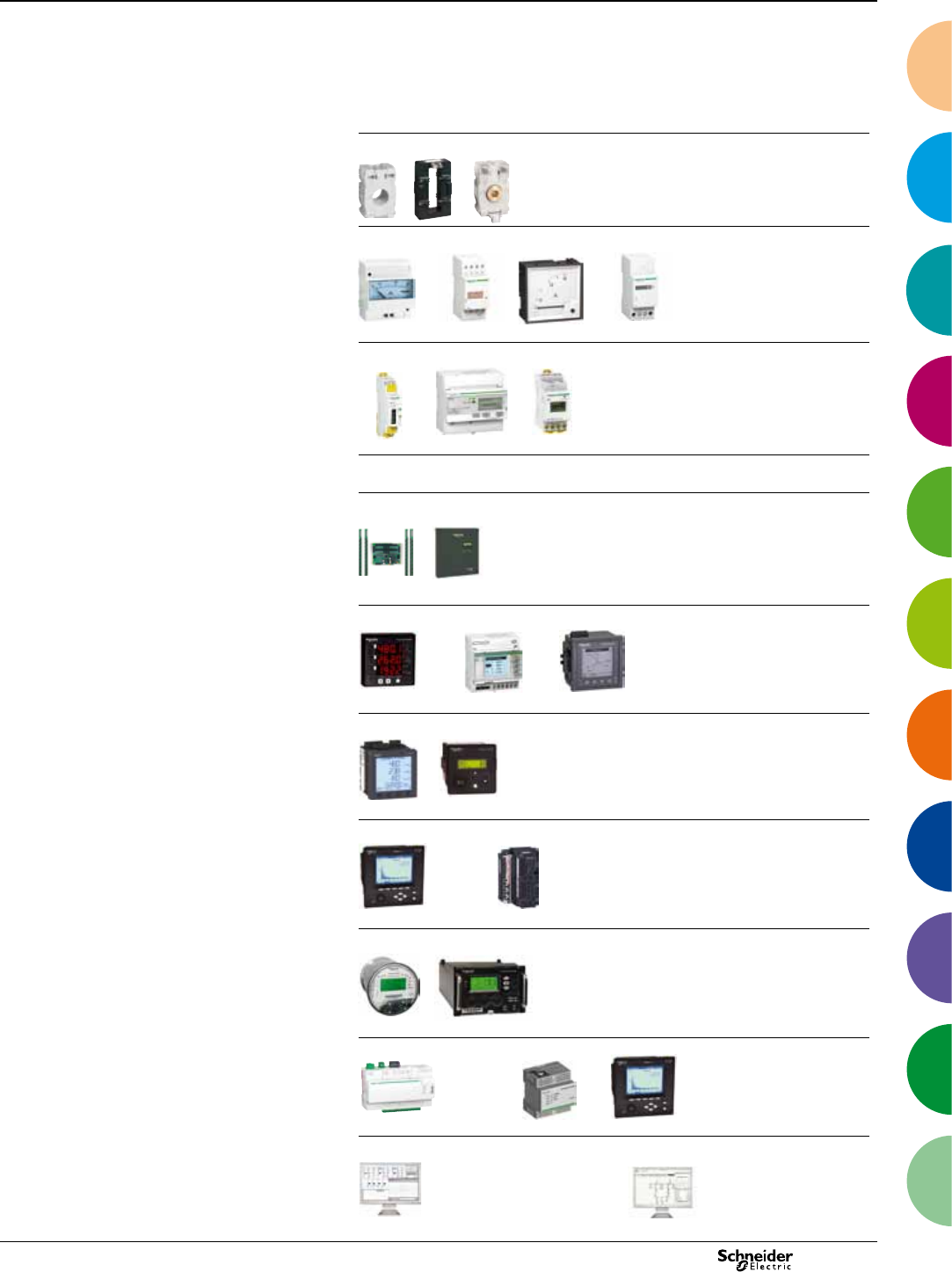
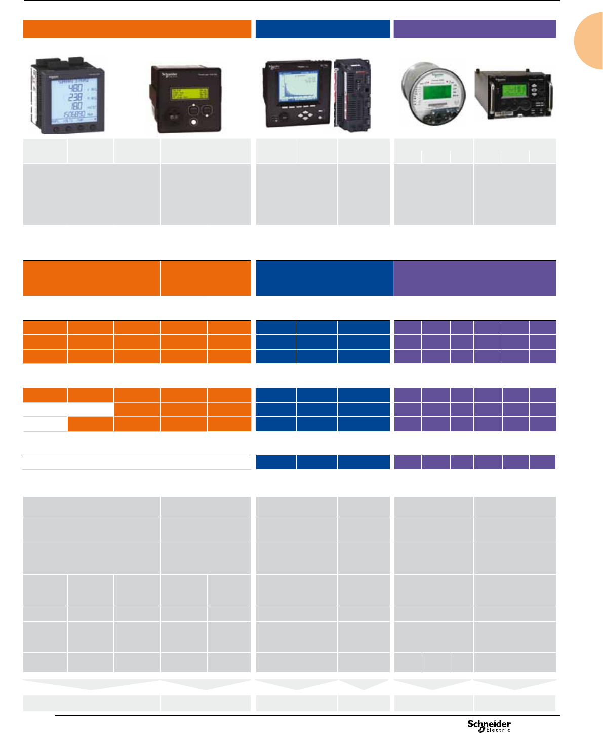
Panorama of the PowerLogic
range
Product selection guide
Current transformers Basic panel meters Basic energy meters
CT Name iAMP / iVLT AMP / VLT iFRE iCH / iCI iEM2000 Series iME1 iEM3000 Series
current transformer Function ammeter, voltmeter frequency meter hour counter
pulse counter
kilowatt-hour meters
Installation
b�insulated cable,
diameter 21 to 35 mm,
through transformer
b�busbar through transformer
b�cable connections
Applications
Panel instrumentation
Panel instrumentation I / U I / U Fhours /pulses E
Energy efciency and cost
Sub billing and cost allocation
Demand and load management
Billing analysis
Power availability and reliability
Compliance monitoring
Sag/swell, transient
Harmonics
Revenue metering
Revenue meter
Characteristics Characteristics
b�transformation ratio:
40/5 A to 6000/5 A
b�accuracy: class 0.5 to 3
b�maximum rated
operational voltage: 720 V AC
b�tropicalised
Measurement accuracy class 1.5 ± 0.5 % ± 1 digit class 1.5 ± 0.5 % ± 1 digit class 1
Installation
DIN rail
4 x 18 mm modules
DIN rail
2 x 18 mm modules
ush mounted
72 x 72 mm
96 x 96 mm
DIN rail
2 x 18 mm modules
CI, CH: DIN rail
2 x 18 mm modules
CH: ush mount
DIN rail
1.2 or 4 x 18 mm modules
Voltage measurement VLT:
500 V AC direct
or external VT
VLT:
600 V AC direct
or external VT
VLT:
500 V AC direct
or external VT
400 V AC direct 400 V AC direct
Current measurement AMP:
30 A direct
or external CT
AMP:
10 A direct
or external CT
AMP:
external CT
40 to 63 A direct
or external CT
Communication ports
Inputs / Outputs
Memory capacity
page 17 page 21 page 22 page 23 page 22 page 27 page 31 page 31 page 34
8
2013
Panorama of the PowerLogic
range (cont.)
Product selection guide
Current transformers Basic panel meters Basic energy meters
CT Name iAMP / iVLT AMP / VLT iFRE iCH / iCI iEM2000 Series iME1 iEM3000 Series
current transformer Function ammeter, voltmeter frequency meter hour counter
pulse counter
kilowatt-hour meters
Installation
b�insulated cable,
diameter 21 to 35 mm,
through transformer
b�busbar through transformer
b�cable connections
Applications
Panel instrumentation
Panel instrumentation I / U I / U Fhours /pulses E
Energy efciency and cost
Sub billing and cost allocation
Demand and load management
Billing analysis
Power availability and reliability
Compliance monitoring
Sag/swell, transient
Harmonics
Revenue metering
Revenue meter
Characteristics Characteristics
b�transformation ratio:
40/5 A to 6000/5 A
b�accuracy: class 0.5 to 3
b�maximum rated
operational voltage: 720 V AC
b�tropicalised
Measurement accuracy class 1.5 ± 0.5 % ± 1 digit class 1.5 ± 0.5 % ± 1 digit class 1
Installation
DIN rail
4 x 18 mm modules
DIN rail
2 x 18 mm modules
ush mounted
72 x 72 mm
96 x 96 mm
DIN rail
2 x 18 mm modules
CI, CH: DIN rail
2 x 18 mm modules
CH: ush mount
DIN rail
1.2 or 4 x 18 mm modules
Voltage measurement VLT:
500 V AC direct
or external VT
VLT:
600 V AC direct
or external VT
VLT:
500 V AC direct
or external VT
400 V AC direct 400 V AC direct
Current measurement AMP:
30 A direct
or external CT
AMP:
10 A direct
or external CT
AMP:
external CT
40 to 63 A direct
or external CT
Communication ports
Inputs / Outputs
Memory capacity
page 17 page 21 page 22 page 23 page 22 page 27 page 31 page 31 page 34
9
2013
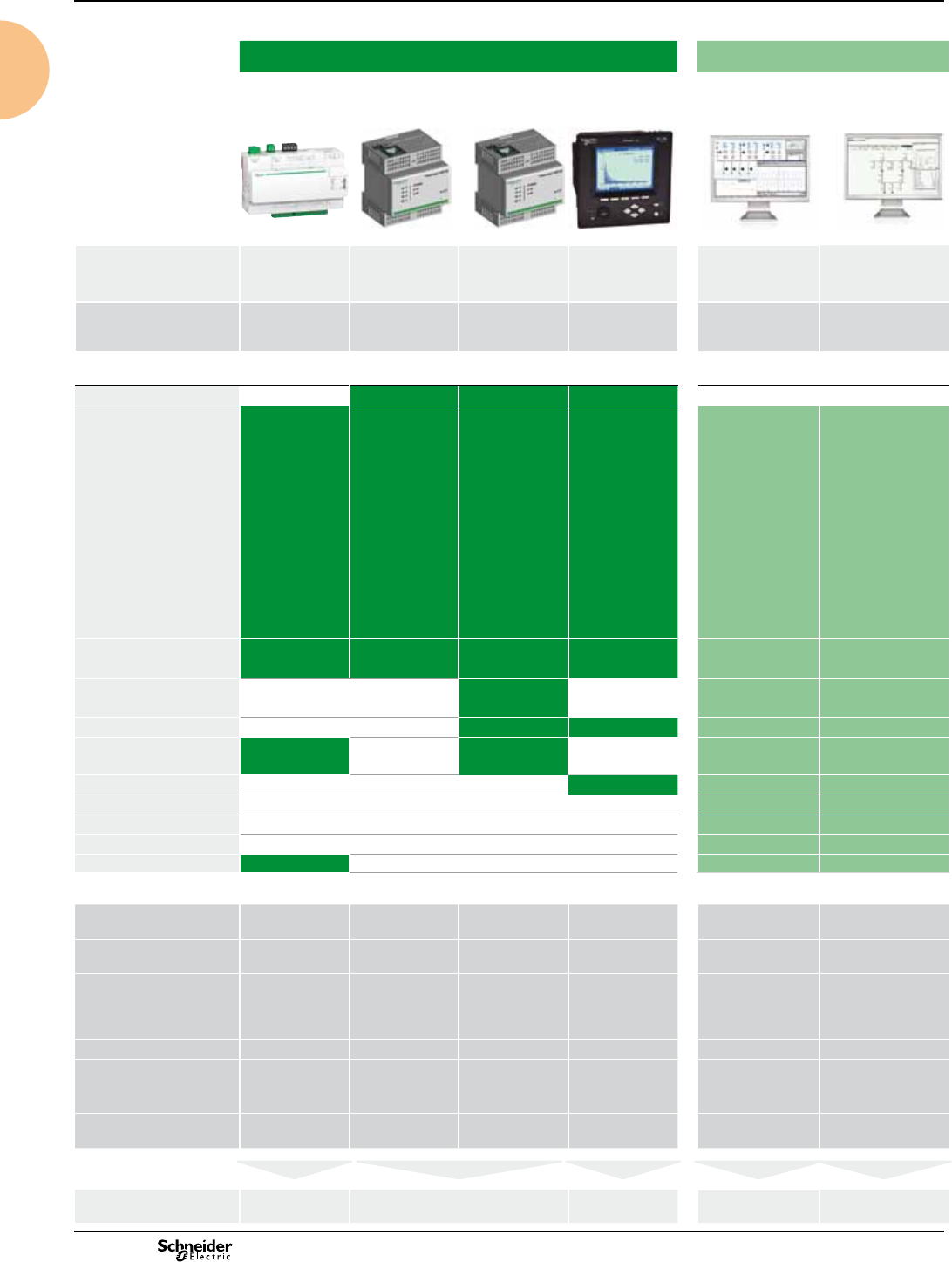
Multi-circuit metering Basic multi-function metering Intermediate metering Advanced metering Advanced utility metering
Name BCPM EM4800 ION6200 PM3000 Series PM5100/PM5300/
PM5500
PM810 PM820/
PM850
PM870 ION7330/7350
ION7550 ION7650
CM4000T ION8650 ION8800
A B C A B C
Function branch circuit monitor
IEC 61036 Class 1
multi-circuit energy
meter
Class 0.5 ANSI C12.1,
C12.20
Class 0.5S IEC
62053-22
metering & sub-metering
Class 0.5S
IEC 60687
metering & sub-metering
Class 0.5S IEC 62053-22
Class 1 IEC 62053-21
Class 2IEC 62053-23
metering & sub-metering
Class 0.5S
IEC 62053-22
Class 0.2S (PM55xx)
IEC 62053-22
Class 1/2 IEC 62053-24
energy and basic PQ power meter
IEC 61557-12
PMD/SD/K70/0.5
PMD/SS/K70/0.5
ANSI 12.20 Class 0.2S real energy
energy and basic PQ power
meter
IEC 61557-12
PMD/SD/K70/0.5
PMD/SS/K70/0.5
ANSI 12.20 Class 0.2S real
energy
energy and power quality
meter
IEC 62052-11
IEC 62053-22/23
Class 0.2S
IEC 61000-4-30 Class A
energy and
power quality
meter
IEC 62053-22
ANSI 12.20
Class 0.2S real
energy
energy and power
quality meter
IEC 62052-11
IEC 62053-22/23
Class 0.2S
IEC 61000-4-30 Class A
energy and power quality
meter
IEC 62052-11
IEC 62053-22/23
Class 0.2S
IEC 61000-4-30
Applications
Panel instrumentation
Panel instrumentation I, U, F, P, Q, S, PF, E
(Power demand and
current demand)
I, U, F, P, Q, S, PF, E
(Power demand and
current demand)
I, U, F, P, Q, S, PF, E
(Power demand and
current demand)
I, U, F, P, Q, S, PF, E
(Power demand and
current demand)
I, U, F, P, Q, S, PF, E
(Power demand and
current demand)
I, U, F, P, Q, S, PF, E, THD, Min/Max,
harm, alarm, I/O (I, U unbalance,
demand, clock/cal (PM810 w/
PM810LOG))
I, U, F, P, Q, S, PF, E, THD,
harm, alarm, I/O
(Power demand and
current demand)
I, U, F, P, Q, S, PF, E (demand, minimum
and maximum values)
I, U, F, P, Q, S, PF, E (demand, minimum and
maximum values)
Energy efciency and cost
Sub billing and cost allocation
Demand and load management
Billing analysis
Power availability & reliability
Harmonics w/PM810LOG
Dip/swell, transient dip/swell
Compliance monitoring PM850 only
Revenue metering
Revenue metering
Characteristics
Measurement accuracy
(active energy)
class 1 (mains active
energy)
Class 0.5S Class 0.5 Class 0.5 Class 0.2S (PM55xx)
Class 0.5S
ANSI 62053-22 Class 0.5S
ANSI 12.20 Class 0.2S
Class 0.5S Class 0.2S Class 0.2S Class 0.2S Class 0.2S
Installation
Installed in panel or
enclosure
Installed in panel or
enclosure
Flush mount
106.7 mm x 106.7 mm
DIN rail Flush mount
96 mm x 96 mm
Flush & DIN rail mount
96 mm x 96 mm
Flush & DIN rail mount
96 mm x 96 mm
TRAN 60 x 100 x 164.5 mm
DIN 192
standard cutout
(186 x 186 mm)
ANSI socket mount 9S,
35S, 36S, 39S and 76S;
FT21 switchboard case
DIN 43862 rack
Voltage measurement 90 – 277 V Line to
Neutral voltage Inputs
80 - 480 V AC L-L without
PTs, Up to 999 kV with
external PTs
60 - 400 V AC L-N
50V to 330V AC (Ph-N)
80V to 570V AC (Ph-Ph)
up to 1MV AC (ext VT)
20 V L-N / 35 V L-L to
277 V L-N /480 V L-L
/600 V L-L (PM55xx)
600 V AC L-L / 347 V AC L-N
50-347 VAC L-N 3P (87-600 L-L)
50-300 VAC L-N 1P (100-600 L-L)
57-347V L-N AC or
100-600V L-L AC
0 to 600 V AC
0 to 1200 kV
AC (ext. VT)
57-277V L-N AC
(9S, 36S);
120-480 V L-L AC (35S)
57-288V L-N AC or
99-500V L-L AC
Current measurement CT strips for branch
circuits and external CTs
for mains
Split- or solid-core CTs external CT external CT external CT external CT external CT external CT external CT external CT external CT external CT external CT external CT
Communication ports 1 for main 2 1 1 2 3 3 3 3 3 5 3 5 5
Inputs / Outputs 2 2 4 I/O
6 I/O (PM55xx)
18 I/O 18 I/O 18 I/O 8 I/O 8 I/O up to 32 I/O up to 25 I/O up to 22 I/O up to 16 I/O
Memory capacity 256 kb
1.1 MB (PM55xx)
80 kbytes with
PM810 LOG
80 / 800 kbytes 800 kbytes 300 kbytes
300 kbytes up to 10 MB up to 32 MB 10 MB 4 MB 2 MB up to 10 MB
page 42 page 50 page 53 page 60 page 71 page 78 page 92 page 98 page 105 page 112 page 120
Panorama of the PowerLogic
range (cont.)
Product selection guide
10
2013
Multi-circuit metering Basic multi-function metering Intermediate metering Advanced metering Advanced utility metering
Name BCPM EM4800 ION6200 PM3000 Series PM5100/PM5300/
PM5500
PM810 PM820/
PM850
PM870 ION7330/7350
ION7550 ION7650
CM4000T ION8650 ION8800
A B C A B C
Function branch circuit monitor
IEC 61036 Class 1
multi-circuit energy
meter
Class 0.5 ANSI C12.1,
C12.20
Class 0.5S IEC
62053-22
metering & sub-metering
Class 0.5S
IEC 60687
metering & sub-metering
Class 0.5S IEC 62053-22
Class 1 IEC 62053-21
Class 2IEC 62053-23
metering & sub-metering
Class 0.5S
IEC 62053-22
Class 0.2S (PM55xx)
IEC 62053-22
Class 1/2 IEC 62053-24
energy and basic PQ power meter
IEC 61557-12
PMD/SD/K70/0.5
PMD/SS/K70/0.5
ANSI 12.20 Class 0.2S real energy
energy and basic PQ power
meter
IEC 61557-12
PMD/SD/K70/0.5
PMD/SS/K70/0.5
ANSI 12.20 Class 0.2S real
energy
energy and power quality
meter
IEC 62052-11
IEC 62053-22/23
Class 0.2S
IEC 61000-4-30 Class A
energy and
power quality
meter
IEC 62053-22
ANSI 12.20
Class 0.2S real
energy
energy and power
quality meter
IEC 62052-11
IEC 62053-22/23
Class 0.2S
IEC 61000-4-30 Class A
energy and power quality
meter
IEC 62052-11
IEC 62053-22/23
Class 0.2S
IEC 61000-4-30
Applications
Panel instrumentation
Panel instrumentation I, U, F, P, Q, S, PF, E
(Power demand and
current demand)
I, U, F, P, Q, S, PF, E
(Power demand and
current demand)
I, U, F, P, Q, S, PF, E
(Power demand and
current demand)
I, U, F, P, Q, S, PF, E
(Power demand and
current demand)
I, U, F, P, Q, S, PF, E
(Power demand and
current demand)
I, U, F, P, Q, S, PF, E, THD, Min/Max,
harm, alarm, I/O (I, U unbalance,
demand, clock/cal (PM810 w/
PM810LOG))
I, U, F, P, Q, S, PF, E, THD,
harm, alarm, I/O
(Power demand and
current demand)
I, U, F, P, Q, S, PF, E (demand, minimum
and maximum values)
I, U, F, P, Q, S, PF, E (demand, minimum and
maximum values)
Energy efciency and cost
Sub billing and cost allocation
Demand and load management
Billing analysis
Power availability & reliability
Harmonics w/PM810LOG
Dip/swell, transient dip/swell
Compliance monitoring PM850 only
Revenue metering
Revenue metering
Characteristics
Measurement accuracy
(active energy)
class 1 (mains active
energy)
Class 0.5S Class 0.5 Class 0.5 Class 0.2S (PM55xx)
Class 0.5S
ANSI 62053-22 Class 0.5S
ANSI 12.20 Class 0.2S
Class 0.5S Class 0.2S Class 0.2S Class 0.2S Class 0.2S
Installation
Installed in panel or
enclosure
Installed in panel or
enclosure
Flush mount
106.7 mm x 106.7 mm
DIN rail Flush mount
96 mm x 96 mm
Flush & DIN rail mount
96 mm x 96 mm
Flush & DIN rail mount
96 mm x 96 mm
TRAN 60 x 100 x 164.5 mm
DIN 192
standard cutout
(186 x 186 mm)
ANSI socket mount 9S,
35S, 36S, 39S and 76S;
FT21 switchboard case
DIN 43862 rack
Voltage measurement 90 – 277 V Line to
Neutral voltage Inputs
80 - 480 V AC L-L without
PTs, Up to 999 kV with
external PTs
60 - 400 V AC L-N
50V to 330V AC (Ph-N)
80V to 570V AC (Ph-Ph)
up to 1MV AC (ext VT)
20 V L-N / 35 V L-L to
277 V L-N /480 V L-L
/600 V L-L (PM55xx)
600 V AC L-L / 347 V AC L-N
50-347 VAC L-N 3P (87-600 L-L)
50-300 VAC L-N 1P (100-600 L-L)
57-347V L-N AC or
100-600V L-L AC
0 to 600 V AC
0 to 1200 kV
AC (ext. VT)
57-277V L-N AC
(9S, 36S);
120-480 V L-L AC (35S)
57-288V L-N AC or
99-500V L-L AC
Current measurement CT strips for branch
circuits and external CTs
for mains
Split- or solid-core CTs external CT external CT external CT external CT external CT external CT external CT external CT external CT external CT external CT external CT
Communication ports 1 for main 2 1 1 2 3 3 3 3 3 5 3 5 5
Inputs / Outputs 2 2 4 I/O
6 I/O (PM55xx)
18 I/O 18 I/O 18 I/O 8 I/O 8 I/O up to 32 I/O up to 25 I/O up to 22 I/O up to 16 I/O
Memory capacity 256 kb
1.1 MB (PM55xx)
80 kbytes with
PM810 LOG
80 / 800 kbytes 800 kbytes 300 kbytes
300 kbytes up to 10 MB up to 32 MB 10 MB 4 MB 2 MB up to 10 MB
page 42 page 50 page 53 page 60 page 71 page 78 page 86 page 94 page 101 page 108 page 116
Panorama of the PowerLogic
range (cont.)
Product selection guide
11
2013
12
Panorama of the PowerLogic
range (cont.)
Product selection guide
Communications Monitoring Software
Name Com'X 200 EGX100 EGX300 ION7550 RTU StruxureWare
Power Monitoring
Expert
StruxureWare
PowerSCADA
Expert
Function Ethernet GPRS
data logger
Ethernet gateway Integrated
gateway-server
Ethernet
gateway-server +
onboard I/O
Power management Network protection
and control
Features
RS485 / Ethernet gateway
Devices supported
EM3000 Series,
iEM3000 Series,
PM800 Series,
ION6200,
ION7300,
Acti 9 Smartlink
Masterpact,
PM5000 Series,
Compact NSX,
iEM1,
iEM2000,
iEM3000,
PM3000 Series
PM800 Series,
CM4000 Series,
Sepam Series
Acti 9 Smartlink,
BCPM Series,
CM Series
PM800 Series,
CM4000 Series,
DM6000, DM6300,
iEM3000 Series,
ION6200, ION8600,
ION8800,
ION7550/7650,
PM1000, PM200,
PM300, PM5350,
PM700,
PM800,Sepam
Series,
Compact NSX,
Vigilohm IM20/
IM20-H
ION8800,
ION7550/7650,
ION6200,
Modbus devices
ION8800,
ION8650,
ION7550/7650,
ION7550RTU,
ION6200,
PM800 Series,
EM1200,
EM5600,
CM4000 Series,
BCPM,
Sepam Series,
Compact NSX,
Vigilohm IM20,
Modicon Mementum M1
- TR8,
Twido Modular PLC
Sepam Series 40
PM800 Series
BCPM/BCM42
CM4000 Series
Web server with
standard HTML pages
(Conguration only) (Conguration only)
Web server with
custom HTML pages
Real time data
Historical data
Export to Internet
database server
Automatic notication
Alarm and event logs
Waveform display
Custom animated graphics
Manual/automatic reports
Characteristics
Ethernet ports
Modbus TCP/IP protocol
210/100 Base
TX port
10/100 Base
TX port
10/100 Base
TX port
RS485 (2-wire / 4-wire) ports
Modbus protocol
1111
Number of devices
connected directly
32 modbus
devices
6 pulse meters (or
dry contacts) – 2
32 64 64
RS232 conguration ports 111
Miscellaneous Connectivity: WiFi,
GPRS,or Ethernet
Serial line to
Ethernet
connectivity
Entry-level Energy
Management in a
box
modem port
I/O (24 I/30 O max)
Installation DIN rail DIN rail DIN rail DIN 192 cutout
(186 x 186 mm)
page 125 page 127 page 129 page 139 page 145
2013 13
General information on
power-monitoring software
Product selection guide
Software, a tool serving site operation.
A site can be compared to a living organism.
The power system manager has no control over the
changes that affect this organism, but must ensure that
it continues to receive the energy it requires.
Similar to a doctor, the power system manager must
carry out preventive measures and diagnose and
remedy any problems that occur. The goal is to
maintain the site in a healthy state, without generating
any secondary effects.
Software enables managers to diagnose the causes of
most problems encountered on electrical systems.
More and more devices are capable of communicating.
The number of available measurements is also on the rise, creating the need for a
tool to successfully manage all the information.
The main purpose of software is to simplify complex sites so that they can be
managed by humans:
bmake the site and its operation intelligible
bmake the power system tangible and visible.
The role of software
All measurements at a single location
All measured values may be accessed via a PC.
Organisation and use of measurements
Before they may be used, certain measurements must be organised, processed or
integrated in special tools.
Device setup
Simple devices may be set up on their front panels.
For devices with advanced functions, local setup is often difcult and even
impossible for some functions.
Software greatly facilitates device setup.
Automatic tasks
Software can execute tasks automatically, triggered by:
b�a date
b�an event
b�an alarm.
These tasks may concern devices (reset, start of a particular function) or system
users (transmission of an e-mail, etc.).
Manual commands
Power-monitoring software can also be used to control devices (e.g. open or close a
circuit breaker).
Certain control/monitoring functions (automatic action on electrical-distribution
system) are carried out by PLCs integrated in the PowerLogic System architecture.
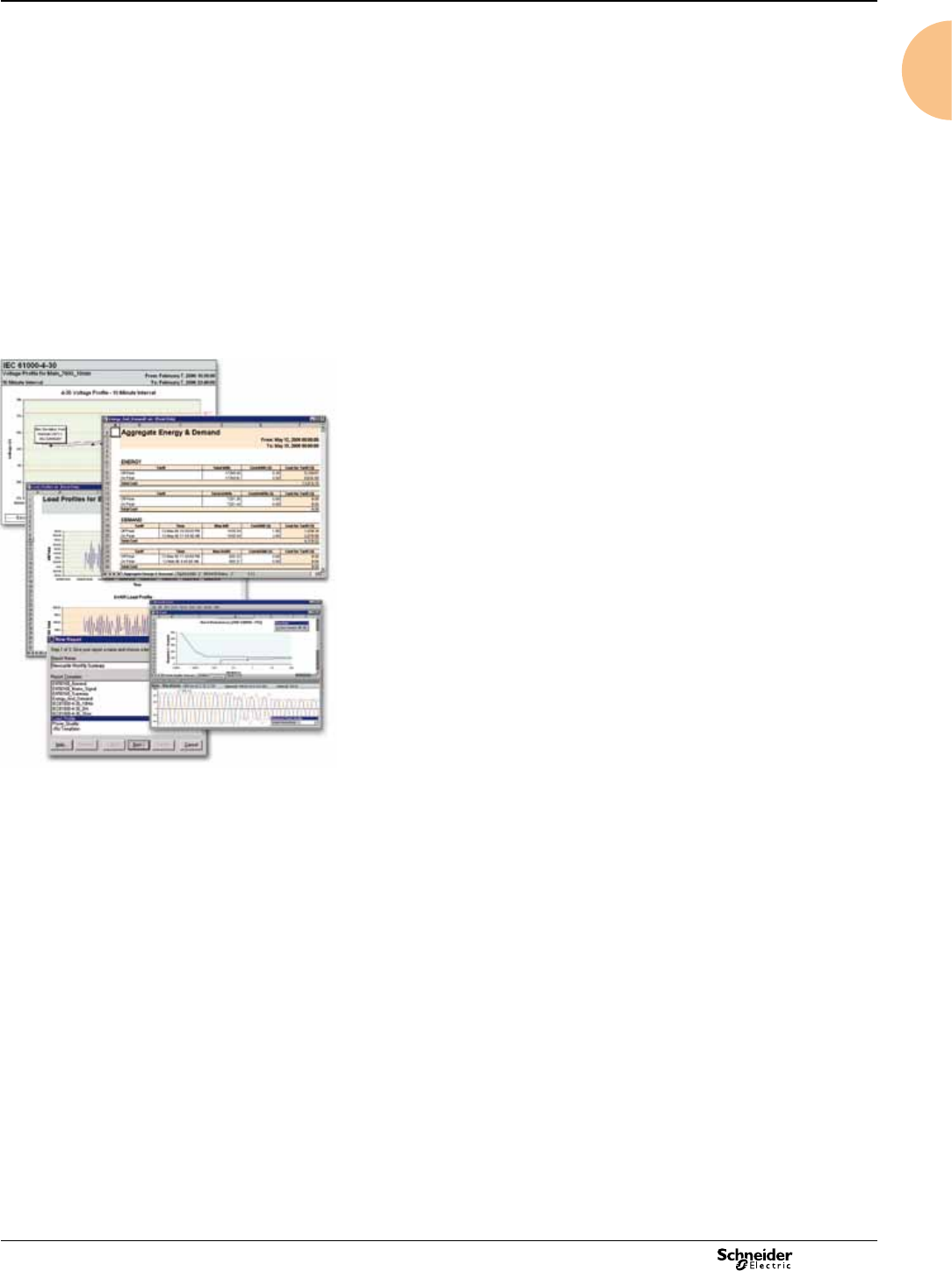
Access via the Web
Information must be adapted to user needs and then made available to them.
Software can handle the adaptation by preparing custom reports.
These reports can then be accessed by any PC on the site using a standard
Web browser.
Software and architecture
Software must be capable of meeting a large number of needs:
b�single-user or multi-user operation
b�data organisation according to user proles
b�adaptation to different site topologies
b�data exchange with other systems, etc.
This set of constraints means that a single product is not sufcient; a range of
software products is required.
PE86194

2013
14
Index of catalogue numbers
Cat. no. Description Page
15100
15125 CMV voltmeter selector switch, DIN rail 25
15126 CMA ammeter selector, DIN rail 25
15200
15201 iVLT digital voltmeter, DIN rail 22
15202 iAMP direct reading digital ammeter, DIN rail 22
15208 iFRE digital frequency meter, DIN rail 22
15209 iAMP multi-rating digital ammeter, DIN rail 22
15400
15440 iCH hour counter, DIN rail (230 V AC) 27
15443 iCI impulse counter, DIN rail 28
15600
15607 CH hour counter, 48 x 48 (24 V AC) 27
15608 CH hour counter, 48 x 48 (230 V AC) 27
15609 CH hour counter, 48 x 48 (12 to 36 V DC) 27
16000
16003 AMP analogue ammeter, 72 x 72, for motor feeders
(delivered without dial)
23
16004 AMP analogue ammeter, 72 x 72, for standard
feeders (delivered without dial)
23
16005 VLT analogue voltmeter, 72 x 72 23
16006 Dial, 0-30-90 A, for AMP 16003 23
16007 Dial, 0-75-225 A, for AMP 16003 23
16008 Dial, 0-200-600 A, for AMP 16003 23
16009 Dial, 0-50 A, for AMP 16004 23
16010 Dial, 0-100 A, for AMP 16004 23
16011 Dial, 0-200 A, for AMP 16004 23
16012 Dial, 0-400 A, for AMP 16004 23
16013 Dial, 0-600 A, for AMP 16004 23
16014 Dial, 0-1000 A, for AMP 16004 23
16015 Dial, 0-1250 A, for AMP 16004 23
16016 Dial, 0-1500 A, for AMP 16004 23
16017 CMA ammeter selector switch, 48 x 48 25
16018 CMV voltmeter selector switch, 48 x 48 25
16019 Dial, 0-2000 A, for AMP 16004 25
16029
iAMP analogue ammeter for direct connection, DIN
rail
26
16030 iAMP analogue ammeter for connection to TC
(delivered without dial), DIN rail
26
16031 Dial, 0-5 A, for iAMP 16030 26
16032 Dial, 0-50 A, for iAMP 16030 26
16033 Dial, 0-75 A, for iAMP 16030 26
16034 Dial, 0-100 A, for iAMP 16030 26
16035 Dial, 0-150 A, for iAMP 16030 26
16036 Dial, 0-200 A, for iAMP 16030 26
16037 Dial, 0-250 A, for iAMP 16030 26
16038 Dial, 0-300 A, for iAMP 16030 26
16039 Dial, 0-400 A, for iAMP 16030 26
16040 Dial, 0-500 A, for iAMP 16030 26
16041 Dial, 0-600 A, for iAMP 16030 26
16042 Dial, 0-800 A, for iAMP 16030 26
16043 Dial, 0-1000 A, for iAMP 16030 26
16044 Dial, 0-1500 A, for iAMP 16030 26
16045 Dial, 0-2000 A, for iAMP 16030 26
16060 iVLT analogue voltmeter (0-300 V), DIN rail 26
16061 iVLT analogue voltmeter (0-500 V), DIN rail 26
16073 AMP analogue ammeter, 96 x 96, for motor feeder
(delivered without dial)
24
16074 AMP analogue ammeter, 96 x 96, for standard feeder
(delivered without dial)
24
16075 VLT analogue voltmeter, 96 x 96 24
16076 Dial, 0-30-90 A, for AMP 16073 24
16077 Dial, 0-75-225 A, for AMP 16073 24
16078 Dial, 0-200-600 A, for AMP 16073 24
16079 Dial, 0-50 A, for AMP 16074 24
16080 Dial, 0-100 A, for AMP 16074 24
16081 Dial, 0-200 A, for AMP 16074 24
16082 Dial, 0-400 A, for AMP 16074 24
16083 Dial, 0-600 A, for AMP 16074 24
Cat. no. Description Page
16084 Dial, 0-1000 A, for AMP 16074 24
16085 Dial, 0-1250 A, for AMP 16074 24
16086 Dial, 0-1500 A, for AMP 16074 24
16087 Dial, 0-2000 A, for AMP 16074 24
16088 Dial, 0-2500 A, for AMP 16074 24
16089 Dial, 0-3000 A, for AMP 16074 24
16090 Dial, 0-4000 A, for AMP 16074 24
16091 Dial, 0-5000 A, for AMP 16074 24
16092 Dial, 0-6000 A, for AMP 16074 24
16400
16451 TC 50/5 tropicalised transformer for cables 18
16452 TC 75/5 tropicalised transformer for cables 18
16453 TC 100/5 tropicalised transformer for cables 18
16454 TC 125/5 tropicalised transformer for cables 18
16455 TC 150/5 tropicalised transformer for cables 18
16456 TC 200/5 tropicalised transformer for cables 18
16459 TC 150/5 tropicalised transfo. for cables and busbars 18
16460 TC 200/5 tropicalised transfo. for cables and busbars 18
16461 TC 250/5 tropicalised transfo. for cables and busbars 18
16462 TC 300/5 tropicalised transformer for cables 18
16463 TC 400/5 tropicalised transfo. for cables and busbars 18
16464 TC 500/5 tropicalised transfo. for cables and busbars 18
16465 TC 600/5 tropicalised transfo. for cables and busbars 18
16468 TC 250/5 tropicalised transfo. for cables and busbars 18
16469 TC 300/5 tropicalised transfo. for cables and busbars 18
16470 TC 400/5 tropicalised transfo. for cables and busbars 18
16471 TC 500/5 tropicalised transfo. for cables and busbars 18
16473 TC 500/5 tropicalised transformer for busbars 18
16474 TC 600/5 tropicalised transformer for busbars 18
16476 TC 200/5 tropicalised transformer for busbars 18
16477 TC 250/5 tropicalised transformer for busbars 18
16478 TC 300/5 tropicalised transformer for busbars 18
16479 TC 400/5 tropicalised transformer for busbars 18
16480 TC 500/5 tropicalised transformer for busbars 18
16481 TC 600/5 tropicalised transformer for busbars 18
16482 TC 800/5 tropicalised transformer for busbars 18
16483 TC 1000/5 tropicalised transformer for busbars 18
16500
16500 TC 40/5 tropicalised transformer for cables 18
16534 TC 1250/5 tropicalised transformer for busbars 18
16535 TC 1500/5 tropicalised transformer for busbars 18
16537 TC 1250/5 tropicalised transformer for busbars 18
16538 TC 1500/5 tropicalised transformer for busbars 18
16540 TC 1250/5 tropicalised transformer for busbars 18
16541 TC 1500/5 tropicalised transformer for busbars 18
16542 TC 2000/5 tropicalised transformer for busbars 18
16543 TC 2500/5 tropicalised transformer for busbars 18
16544 TC 3000/5 tropicalised transformer for busbars 18
16545 TC 2500/5 tropicalised transformer for busbars 18
16546 TC 3000/5 tropicalised transformer for busbars 18
16547 TC 4000/5 tropicalised transformer for busbars 18
16548 TC 5000/5 tropicalised transformer for busbars 18
16549 TC 6000/5 tropicalised transformer for busbars 18
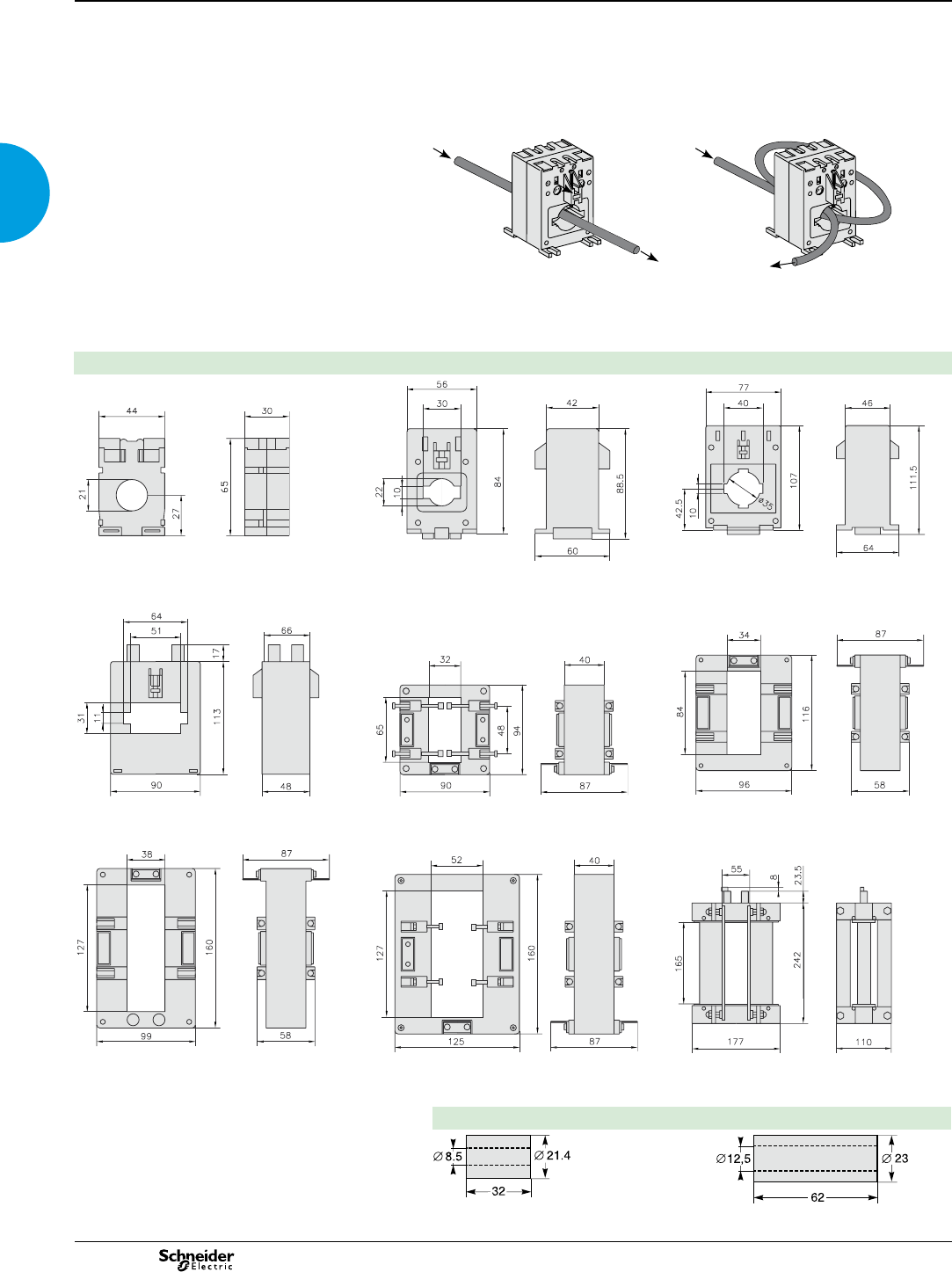
16550 Cylinder Ø 8.5 mm for TC transformer 18
16551 Cylinder Ø 12.5 mm for TC transformer 18
16552 Lead-sealable cover for TC transformer 18
16553 Lead-sealable cover for TC transformer 18
A
A9M17065 ME1 digital kilowatt-hour meter 31
A9M17066 iME1z digital kilowatt-hour meter 31
A9M17067 iME1zr digital kilowatt-hour meter 31
A9MEM2000T iME2000T single-phase kilowatt-hour meter 31
A9MEM2000 iME2000 single-phase kilowatt-hour meter 31
A9MEM2010 iME2010 single-phase kilowatt-hour meter 31
A9MEM3100 iEM3100 basic energy meter 37
A9MEM3110 iEM3110 energy meter with pulse output 37
A9MEM3115 iEM3115 multi-tariff energy meter 37

2013 15
Index of catalogue numbers
(cont.)
Cat. no. Description Page
CM4MA Circuit monitor CM4000T 101
CNV100 Circuit monitor CM4000T 101
E
EBX200 Com'X 200 Ethernet data logger 125
EBXA-USB-WIFI
Com'X 200 WiFi USB stick 125
EBXA-GPRS-SIM
Com'X 200 GPRS modem with SIM card 125
EBXA-GPRS Com'X 200 GPRS modem without SIM card 125
EBXA-ANT-5M Com'X 200 External GPRS antenna 125
EGX100MG EGX100 Ethernet gateway 127
EGX300 EGX300 Ethernet server 127
I
IE7PRIMARY StruxureWare Power Monitoring Primary server
(DVD, includes all available languages)
147
IE7DLS Individual Device Licence for High-End Devices.
Compatible with all device types.
147
IE7DLM Individual Device Licence for Mid-Range Devices.
Compatible with Mid- and Entry-range devices.
147
IE7DLE Individual Device Licence for Entry-Range
Devices. Compatible with Entry range devices.
147
IE7ENGCLIENT Engineering Client Licence (DVD) - Access to
Management Console, Vista, Designer, Reporter
and Web applications; one licence per user.
147
IE7WEBCLIENT
Web Client Licence - Access to Diagrams, Tables,
Alarms, Reports, Dashboard; one licence per user.
147
IE7UNLCLIENT Unlimited Licence for unlimited number of users
(Engineering or Web applications); mandatory for
public displays or Internet hosting.
147
IE7OPCSERVER
OPC DA Server for StruxureWare Power Monitoring 147
IE7SECONDARY
Secondary Server for StruxureWare Power Monitoring
Upgrades from earlier versions
147
IE7PRIMARYUPG
StruxureWare Power Monitoring UPGRADE
software (DVD, includes all available languages)
147
IE7DLSUPG Upgrade DL-S device licence 147
IE7DLMUPG Upgrade DL-M device licence 147
IE7DLEUPG Upgrade DL-E device licence 147
IE7ENGCLIENTUPG
Engineering Client Upgrade Licence - Access to
Management Console, Vista, Designer, Reporterand
Web applications; one licence per user.
147
IE7WEBCLIENTUPG
Web Client Upgrade Licence - Diagrams, Tables,
Alarms, Reports; one licence per user
147
IE7UNLCLIENTUPG
Unlimited Client Upgrade Licence for unlimited
number of users (Engineering or Web applications);
mandatory for public displays or internet hosting.
147
IE7SECONDARYUPG
Secondary Server Upgrade for StruxureWare
Power Monitoring Technical Documentation
147
L
LVCT00102S
100 A 46
LVCT00202S
200 A 46
LVCT00302S
300 A 46
LVCT00403S
400 A 46
LVCT00603S
600 A 46
LVCT00803S
800 A 46
LVCT00804S
800 A 46
LVCT01004S
1000 A 46
LVCT01204S
1200 A 46
LVCT01604S
1600 A 46
LVCT02004S
2000 A 46
LVCT02404S
2400 A 46
M
M7550 ION7550 energy and power quality meter 98,
129
M6200T1A0B0A0A0R
ION6200 energy meter 53
M6200T1A0B0A0A0P
ION6200 energy meter 53
M6200R1A0B0A0B0R
ION6200 energy meter 53
M6200M0A0B0A0B0R
ION6200 energy meter 53
M6200M0A0B0A0A0R
ION6200 energy meter 53
M6200A0A0B0Z0A0P
ION6200 energy meter 53
M6200A0A0B0Z0A0N
ION6200 energy meter 53
M6200A0A0B0A0B0R
ION6200 energy meter 53
M6200A0A0B0A0A0R
ION6200 energy meter 53
M6200A0A0B0A0A0P
ION6200 energy meter 53
Cat. no. Description Page
A9MEM3135 iEM3135 advanced multi-tariff energy meter &
electrical parameter plus M-Bus comm port
37
A9MEM3150 iEM3150 energy meter & electrical parameter
plus Modbus RS485 comm port
37
A9MEM3155 iEM3155 advanced multi-tariff energy meter & electrical
parameter plus Modbus RS485 comm port
37
A9MEM3165 iEM3165 advanced multi-tariff energy meter & electrical
parameter plus Modbus, BACnet MS/ TP comm port
37
A9MEM3175 iEM3175 advanced multi-tariff energy meter & electrical
parameter plus LON TP/FT-10 comm port
37
A9MEM3200 iEM3200 basic energy meter 37
A9MEM3210 iEM3210 energy meter with pulse output 37
A9MEM3215 iEM3215 multi-tariff energy meter 37
A9MEM3235 iEM3235 advanced multi-tariff energy meter &
electrical parameter plus M-Bus comm port
37
A9MEM3250 iEM3250 energy meter & electrical parameter plus
RS485 comm port
37
A9MEM3255 iEM3255 advanced multi-tarrif energy meter &
electrical parameter plus RS485 comm port
37
A9MEM3265 iEM3265 advanced multi-tariff energy meter & electrical
parameter plus Modbus, BACnet MS/ TP comm port
37
A9MEM3275 iEM3275 advanced multi-tariff energy meter & electrical
parameter plus LON TP/FT-10 comm port
37
B
BCPMA042S 42 circuit BCPM 3/4" CT spacing - Advanced 45
BCPMA084S 84 circuit BCPM 3/4" CT spacing - Advanced 45
BCPMA142S 44 circuit BCPM 1" CT spacing - Advanced 45
BCPMA184S 84 circuit BCPM 1" CT spacing - Advanced 45
BCPMB042S 42 circuit BCPM 3/4" CT spacing - Intermediate 45
BCPMB084S 84 circuit BCPM 3/4" CT spacing - Intermediate 45
BCPMB142S 42 circuit BCPM 3/4" CT spacing - Intermediate 45
BCPMB184S 84 circuit BCPM 1" CT spacing - Intermediate 45
BCPMC042S 42 circuit BCPM 3/4" CT spacing - Basic 45
BCPMC084S 84 circuit BCPM 3/4" CT spacing - Basic 45
BCPMC142S 42 circuit BCPM 1" CT spacing - Basic 45
BCPMC184S 84 circuit BCPM 1" CT spacing - Basic 45
BCPMCOVERS Circuit board cover BCPM 45
BCPMSCA30S 30 split-core CTs, Advanced BCPM 45
BCPMSCA42S 42 split-core CTs, Advanced BCPM 45
BCPMSCA60S 60 split-core CTs, Advanced BCPM 45
BCPMSCA84S 84 split-core CTs, Advanced BCPM 45
BCPMSCADPBS
Adapter bord, for split core BCPM 45
BCPMSCB30S 30 split-core CTs, Intermediate BCPM 45
BCPMSCB42S 42 split-core CTs, Intermediate BCPM 45
BCPMSCB60S 60 split-core CTs, Intermediate BCPM 45
BCPMSCB84S 84 split-core CTs, Intermediate BCPM 45
BCPMSCC30S 30 split-core CTs, Basic BCPM 45
BCPMSCC42S 42 split-core CTs, Basic BCPM 45
BCPMSCC60S 60 split-core CTs, Basic BCPM 45
BCPMSCC84S 84 split-core CTs, Basic BCPM 45
BCPMSCCT0 Split core CTs, BCPM 50 A 45
BCPMSCCT0R20
Split core CTs, BCPM 50 A 45
BCPMSCCT1 Split core CTs, BCPM 100 A 45
BCPMSCCT1R20
Split core CTs, BCPM 100 A 45
BCPMSCCT3 Split core CTs, BCPM 200 A 45
BCPMSCCT3R20
Split core CTs, BCPM 200 A 45
C
CAB4 PM/CM <-> display connection cable (1.25 m) 85
CAB12 PM/CM <-> display connection cable (3.65 m) 85
CAB30 PM/CM <-> display connection cable (9.14 m) 85
CBL008 Fiat Ribbon cable for BCPM 49
CBL016
Fiat Ribbon cable for BCPM 49
CBL017 Fiat Ribbon cable for BCPM 49
CBL018 Fiat Ribbon cable for BCPM 49
CBL019 Fiat Ribbon cable for BCPM 49
CBL020
Fiat Ribbon cable for BCPM 49
CBL021 Fiat Ribbon cable for BCPM 49
CBL022 Round Ribbon cable for BCPM 49
CBL023 Round Ribbon cable for BCPM 49
CBL024 Round Ribbon cable for BCPM 49
CD-TECHDOC Latest version of technical documentation for
StruxureWare Power Monitoring
143

2013
16
Index of catalogue numbers
Cat. no. Description Page
M620DR1 ION6200 energy meter 57
M620DN1 ION6200 energy meter 57
M7330 ION7330 energy and power quality meter 95
M7350 ION7350 energy and power quality meter 95
M7550 ION7550 energy and power quality meter 98
M7650 ION7650 energy and power quality meter 98
M8650A ION8650A energy and power quality meter 112
M8650B ION8650B energy and power quality meter 112
M8650C ION8650C energy and power quality meter 112
M8800A ION8800A energy and power quality meter 120
M8800B ION8800B energy and power quality meter 120
M8800C ION8800C energy and power quality meter 120
METSEEM480525
PowerLogic E4800 multi-circuit energy meter 50
METSEEM483325
PowerLogic E4800 multi-circuit energy meter 50
METSEEM488025
PowerLogic E4800 multi-circuit energy meter 50
METSEEM480516
PowerLogic E4800 multi-circuit energy meter 50
METSEEM483316
PowerLogic E4800 multi-circuit energy meter 50
METSEEM488016
PowerLogic E4800 multi-circuit energy meter 50
METSEEM480526
PowerLogic E4800 multi-circuit energy meter 50
METSEEM483326
PowerLogic E4800 multi-circuit energy meter 50
METSEEM488026
PowerLogic E4800 multi-circuit energy meter 50
METSEPM3200 PM3200 basic power meter 60
METSEPM3210 PM3210 power meter with pulse output 60
METSEPM3250 PM3250 power meter with RS485 port 60
METSEPM3255 PM3255 power meter with 2 DI, 2 DO, RS485 port 60
METSEPM5100 PM5100 power meter 71
METSEPM5110 PM5110 power meter 71
METSEPM5111 PM5111 power meter 71
METSEPM5310 PM5310 power meter 71
METSEPM5320 PM5320 power meter 71
METSEPM5330 PM5330 power meter 71
METSEPM5331 PM5331 power meter 71
METSEPM5340 PM5340 power meter 71
METSEPM5341 PM5341 power meter 71
METSEPM5560 PM5560 power meter 71
METSEPM5561 PM5561 power meter 71
METSEPM5563 PM5563 power meter 71
O
OPTICAL-PROBE
Optical communication interface 113
P
PLS101110-11
PowerSCADA Expert 75-150 Server Lic. pt expansions 153
PLS101111
PowerSCADA Expert 150 Server licences 153
PLS101111-12
PowerSCADA Expert 150-500 Server Lic. pt expansions 153
PLS101112
PowerSCADA Expert 500 Server licences 153
PLS101112-13
PowerSCADA Expert 500-1500 Server Lic. pt expansions 153
PLS101113
PowerSCADA Expert 1500 Server licences 153
PLS101113-14
PowerSCADA Expert 1500-5000 Server Lic. pt expansions 153
PLS101114
PowerSCADA Expert 5000 Server licences 153
PLS101114-15
PowerSCADA Expert 5000-15000 Server Lic. pt
expansions
153
PLS101115
PowerSCADA Expert 15000 Server licences 153
PLS101115-99
PowerSCADA Expert 15000-unlimtd. Server Lic. pt
expansions
153
PLS101199
PowerSCADA Expert unlimited Server licences 153
PLS102010
PowerSCADA Expert 75 Control Client licences 153
PLS102010-11
PowerSCADA Expert 75-150 Control Lic. pt expansions 153
PLS102011-12
PowerSCADA Expert 150-500 Control Lic. pt expansions 153
PLS102012
PowerSCADA Expert 500 Control Client licences 153
PLS102012-13
PowerSCADA Expert 500-1500 Control Lic. pt expansions 153
PLS102013
PowerSCADA Expert 1500 Control Client licences 153
PLS102013-14
PowerSCADA Expert 1500-5000 Control Lic. pt
expansions
153
PLS102014
PowerSCADA Expert 5000 Control Client licences 153
PLS102014-15
PowerSCADA Expert 5000-15000 Control Lic. pt
expansions
153
PLS102015
PowerSCADA Expert 15000 Control Client licences 153
PLS102015-99
PowerSCADA Expert unlimited Control Lic. pt expansions 153
PLS102088
PowerSCADA Expert Redundant (CC oating
licence)
153
Cat. no. Description Page
PLS102099
PowerSCADA Expert unlimited Control Client
licences
153
PLS102210
PowerSCADA Expert 75 Web Control licences 153
PLS102210-11
75 - 150 Serveur licence point expansion 153
PLS102211
PowerSCADA Expert 150 Web Control licences 153
PLS10211-12
150 - 500 Serveur licence point expansion 153
PLS102212
PowerSCADA Expert 500 Web Control licences 153
PLS102212-13
500 - 1500 Serveur licence point expansion 153
PLS102213
PowerSCADA Expert 1500 Web Control licences 153
PLS102213-14
1500 - 5000 Serveur licence point expansion 153
PLS102214
PowerSCADA Expert 5000 Web Control licences 153
PLS102214-15
5000 - 15000 Serveur licence point expansion 153
PLS102215
PowerSCADA Expert 15000 Web Control licences 153
PLS102215-99
15000 unlimited Serveur licence point expansion 153
PLS102288
PowerSCADA Expert Redundant (WC oating
licence)
153
PLS102299
PowerSCADA Expert unlimited Web Control licences 153
PLS103088
PowerSCADA Expert Redundant (VOC
oatingLicence)
153
PLS103099
PowerSCADA Expert View Only Client Licence 153
PLS103288
PowerSCADA Expert Redundant WVOC (oating
licence)
153
PLS103299
PowerSCADA Expert Web View Only Client Licence 153
PLS109101
Gold 1 year support, renewal 153
PLS109102
Silver 1 year support, rst year, compulsory 153
PLS109103
Gold 1 year support, rst year 153
PLS109122
Silver 1 year support, renewal 153
PLS109139
Subscription 1 year support renewal 153
PLS109401
Reprogramming free - Authorisation code 153
PLS109911
PowerSCADA Expert additional Parallel key 153
PLS109912
PowerSCADA Expert box with DVD and Parallel key 153
PLS109921
PowerSCADA Expert additional USB key 153
PLS109922
PowerSCADA Expert box with DVD and USB key 153
PM810LOG Optional logging module for on-board data recording
for PM810
83
PM810MG PM810 Power Meter with integrated display 83
PM810RDMG Meter and remote display kit 83
PM810UMG PM810 Power Meter without display 83
PM820MG PM820 Power Meter with integrated display 83
PM820RDMG Meter and remote display kit 83
PM820UMG PM820 Power Meter without display 83
PM850MG PM850 Power Meter with integrated display 83
PM850RDMG Meter and remote display kit 83
PM850UMG PM850 Power Meter without display 83
PM870MG PM870 Power Meter with integrated display 83
PM870RDMG Meter and remote display kit 83
PM870UMG PM870 Power Meter without display 83
PM8ECC PM8ECC module for PM Series 800 83
PM8M22 PM8M22 module for PM Series 800 83
PM8M26 PM8M26 module for PM Series 800 83
PM8M2222 PM8M2222 module for PM Series 800 83
PM8RDA Remote display and adapter alone
PM8RDMG Remote display and adapter with a 3.55 m cable 83
R
RJ11EXT RJ11 Extender kit to mount RJ11 jack in panel door 85
2013 17 17
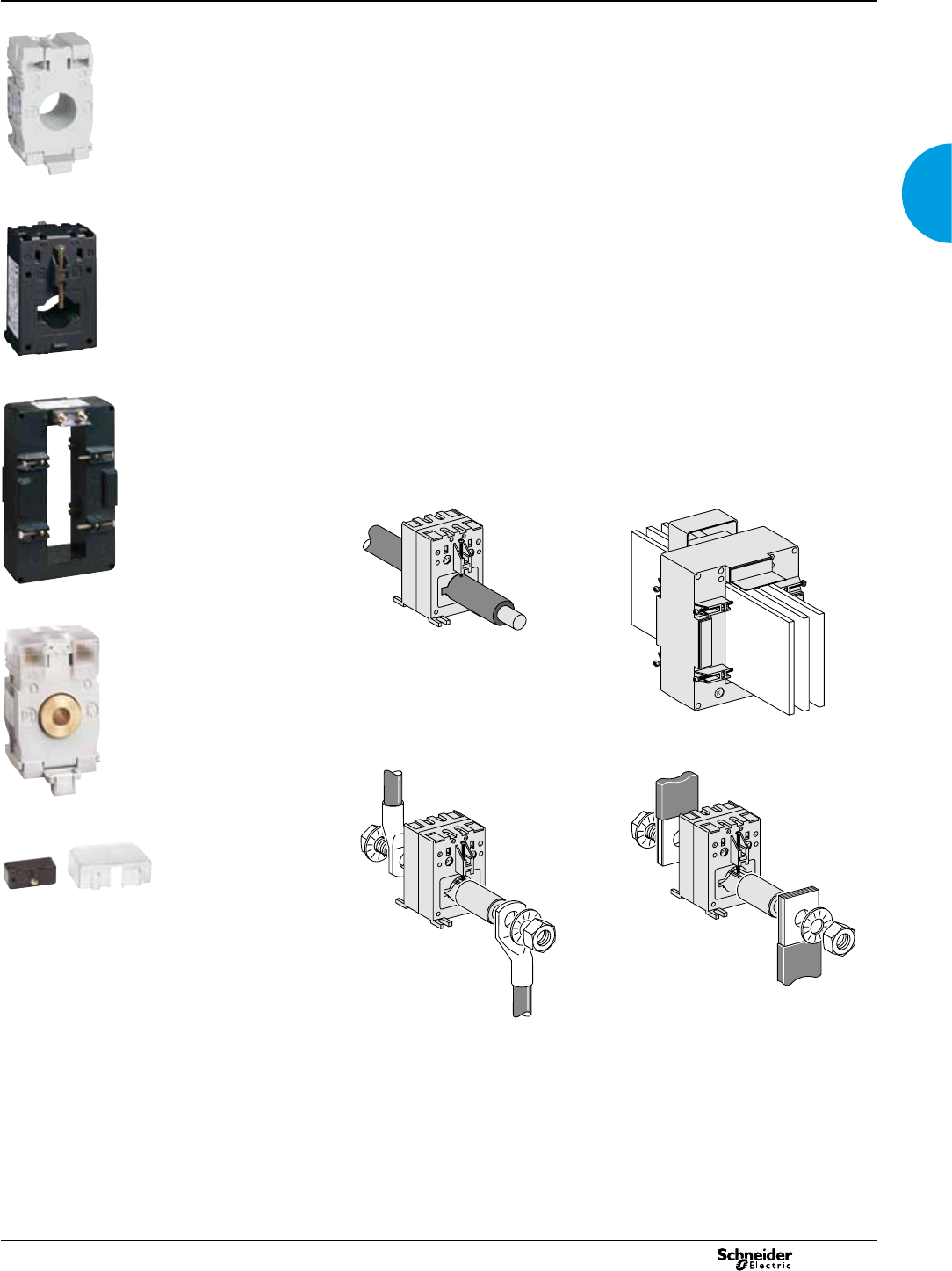
CT current transformers
Current transformers
Function
The Ip/5A ratio current transformers deliver at the secondary a current of 0 to 5 A that
is proportional to the current measured at the primary. They are available in two
major families:
b cable current transformers
b bar current transformers.
This allows them to be used in combination with measurement instruments:
ammeters, kilowatt-hour meters, measurement units, control relays, etc.
Common technical data
b Secondary current: 5 A
b Max. voltage rating Ue: 720 V
b Frequency: 50/60 Hz
b Safety factor (sf):
v 40 to 4000 A: sf y 5
v 5000 to 6000 A: sf y 10.
b Degree of protection: IP20
b Operating temperature: tropicalised range, -25°C to +60°C, relative
humidity > 95 %
b Compliance with standards: IEC 60044-1 and VDE 0414
b Secondary connection (as per model):
v by terminals for lug
v by tunnel terminals
v by screws.
Connection
DB114266
DB114269
CT with let-through primary.
DB114267
DB114268
CT with primary connection by screw and nut.
Use of cylinder 16550 or 16551.
The three references 16482, 16483 and 16534 have a double connection output at the
secondary: twice S1 and twice S2. The terminals are in parallel, as there is only one secondary
winding.
The unused secondary outputs must not be connected.
056853NMD-2
16453.
056854NMD-2
16462.
056852NMD-2
16542.
PB100316
16453 + 16550.
056855MD-2
Sealable cover.
CT current transformers (cont.)
Current transformers
Catalogue numbers
Rating Power (VA) Insulated cable: Dimension Weight (g) Cat. no.
Ip/5 A Accuracy class: maximum
diameter (1)
(mm)
maximum
cross-section (1)
(mm2)
opening for
bars
Tropicalised CT Cylinder (2) Sealable cover
0.5 1 3
40 A - - 1 21 120 - 200 16500 16550 (3) built-in
50 A - 1.25 1.5 21 120 - 200 16451 16550 built-in
75 A - 1.5 2.5 21 120 - 200 16452 16550 built-in
100 A 2 2.5 3.5 21 120 - 200 16453 16550 built-in
125 A 2.5 3.5 4 21 120 - 200 16454 16550 built-in
150 A 3 4 5 21 120 - 200 16455 16550 built-in
1.5 5.5 6.5 22 150 30 x 10 270 16459 16551 (4) 16552
200 A 4 5.5 6 21 120 - 200 16456 16550 built-in
4 7 8.5 22 150 30 x 10 270 16460 16551 16552
- 2 5 - - 65 x 32 600 16476 - built-in
250 A 6911 22 150 30 x 10 270 16461 16551 16552
2.5 5 8 35 240 40 x 10 430 16468 - 16553
146- - 65 x 32 600 16477 - built-in
300 A 7.5 11 13.5 22 150 30 x 10 270 16462 16551 16552
4 8 12 35 240 40 x 10 430 16469 - 16553
1.5 6 7 - - 65 x 32 600 16478 - built-in
400 A 10.5 15 18 22 150 30 x 10 270 16463 16551 16552
8 12 15 35 240 40 x 10 430 16470 - 16553
4 8 10 - - 65 x 32 600 16479 - built-in
500 A 12 18 22 22 150 30 x 10 270 16464 16551 16552
10 12 15 35 240 40 x 10 430 16471 - 16553
246- - 64 x 11
51 x 31
500 16473 - built-in
8 10 12 - - 65 x 32 600 16480 - built-in
600 A 14.5 21.5 26 22 150 30 x 10 270 16465 16551 16552
468- - 64 x 11
51 x 31
500 16474 - built-in
8 12 15 - - 65 x 32 600 16481 - built-in
800 A 12 15 20 - - 65 x 32 600 16482 - built-in
1000 A 15 20 25 - - 65 x 32 600 16483 - built-in
1250 A 15 20 25 - - 65 x 32 600 16534 - built-in
12 15 20 - - 84 x 34 700 16537 - built-in
8 12 - - - 127 x 38 1500 16540 - built-in
1500 A 20 25 30 - - 65 x 32 600 16535 - built-in
15 20 25 - - 84 x 34 700 16538 - built-in
10 15 - - - 127 x 38 1000 16541 - built-in
2000 A 15 20 - - - 127 x 38 1000 16542 - built-in
2500 A 20 25 - - - 127 x 38 1000 16543 - built-in
30 50 60 - - 127 x 52 1300 16545 - built-in
3000 A 25 30 - - - 127 x 38 1000 16544 - built-in
40 60 60 - - 127 x 52 1300 16546 - built-in
4000 A 50 60 60 - - 127 x 52 1300 16547 - built-in
5000 A 60 120 - - - 165 x 55 5000 16548 - built-in
6000 A 70 120 - - - 165 x 55 5000 16549 - built-in
(1) Cable(s) that can be routed through the CT
(2) For CT with primary connection by screw and nut.
(3) Cylinder with inner dia. 8.5 mm, L = 32 mm
(4) Cylinder with inner dia. 12.5 mm, L = 62 mm
Fastening mode
CT cat. no. Adapter for
DIN rail
Mounting
plate
Insulated locking screw
16451...16456 bb-
16459...16471 bbb
16473 and 16474 -bb
16476...16483 --b
16500 bb-
16534...16549 --b
2013
18

CT current transformers (cont.)
Current transformers
Choosing a current transformer
Choice of a CT depends on 2 criteria:
b the Ip/5 A ratio
b the installation type.
The Ip/5 A ratio
We recommend that you choose the ratio immediately higher than the maximum
measured current (In).
Example: In = 1103 A; ratio chosen = 1250/5.
For small ratings from 40/5 to 75/5 and for an application with digital devices, we
recommend that you choose a higher rating, for example 100/5.
This is because small ratings are less accurate and the 40 A measurement, for
example, will be more accurate with a 100/5 CT than with a 40/5 CT.
The installation type
Choice of a CT model depends on the installation type:
b insulated cables
b mounting on bars.
Important precaution
Never open the secondary circuit of a current transformer when the primary circuit is
energised.
Prior to working on the secondary circuit, the secondary terminals of the current
transformer must be short-circuited.
Determining the accuracy class of a CT
The accuracy class depends on the apparent power (VA) of the transformer and on
consumption of the complete measurement system.
The latter allows for consumption of all the devices and the connecting cables.
For a given accuracy class, consumption of the measurement system must not
exceed apparent power (VA) of the CT transformer.
Copper cable cross-section (mm2)Power in VA per doubled meter at 20°C
11
1.5 0.685
2.5 0.41
40.254
60.169
10 0.0975
16 0.062
For each temperature variation per 10°C bracket, the power drawn up by the cables increases by
4 %.
Schneider Electric device Consumption of the current input in VA
Ammeter 72 x 72 / 96 x 96 1.1
Analogue ammeter 1.1
Digital ammeter 0.3
PM800, CM4000 0.15
Example: consumption of a measurement system at 20°C
PM800 0.15 VA
4 meters of 2.5 mm2 doubled wires +1.64 VA
i.e. a measurement system consumption =1.79 VA
Based on the result, the CT accuracy class is determined (see previous page):
b class 3 for a 75/5 ratio CT
b class 0.5 for a 100/5 ratio CT
2013 19
2013
20
Specic case of the motor starter
To measure motor starter current, you must choose a CT with primary current
Ip = Id/2 (Id = motor starting current).
Practical advice
Use a current transformer to measure a nominal current of 50 A.
DB109834
DB109835
50/5 A CT: Imax = 50 A 100/5 A CT, 2 cable openings: Imax = 50 A
To divide by 2 the nominal current of a transformer, you only need to pass the current
to be measured twice through this transformer.
CT current transformers (cont.)
Current transformers
Dimensions
DB109814
DB109815
DB109816
Cat. no. 16500, 16451 to 16456 Cat. no. 16459 to 16465 Cat. no. 16468 to 16471
DB109817
DB109818
DB109819
Cat. no. 16473 and 16474 Cat. no. 16534 to 16535, 16476 to 16483 Cat. no. 16537 and 16538
DB109820
DB109821
DB114270
Cat. no. 16540 to 16544 Cat. no. 16545 to 16547 Cat. no. 16548 and 16549
Cylinders
DB109823
DB109824
Cat. no. 16550 Cat. no. 16551
2013 21
DIN rail analogue ammeters and
voltmeters0
Basic panel meters
Function
iAMP
Ammeters measure the current owing through an electric circuit in amps.
iVLT
Voltmeters measure the potential (voltage) difference of an electric circuit in volts.
Common technical data
Accuracy: class 1.5.
b Complies with standards IEC 60051-1, IEC 61010-1 and IEC 61000-4.
b Ferromagnetic device.
b Pseudo-linear scale over 90°.
b Ammeters (except catalogue number 16029):
v connection on CT, ratio In/5, to be ordered separately
v interchangeable dials.
b Temperature:
v operating temperature: -25°C to +55°C.
v reference temperature: 23°C.
b Inuence of temperature on accuracy: ±0.03 % /°C.
b Utilisation frequency: 50/60 Hz.
b Consumption:
v AMP: 1.1 VA
v VLT catalogue number 15060: 2.5 VA
v VLT catalogue number 16061: 3.5 VA.
b Permanent overload:
v AMP: 1.2 In
v VLT: 1.2 Un.
b Maximum overload for 5 s:
v AMP: 10 In
v VLT: 2 Un.
b Connection: tunnel terminals for 1.5 to 6 mm2 rigid cables.
Catalogue numbers
Type Scale Connection
with CT
Width in mod.
of 9 mm
Cat. no.
iAMP with direct connection
0-30 A no 8 16029
iAMP with connection on CT
Basic device
(delivered without dial)
X/5 8 16030
Dial 0-5 A 16031
0-50 A 50/5 16032
0-75 A 75/5 16033
0-100 A 100/5 16034
0-150 A 150/5 16035
0-200 A 200/5 16036
0-250 A 250/5 16037
0-300 A 300/5 16038
0-400 A 400/5 16039
0-500 A 500/5 16040
0-600 A 600/5 16041
0-800 A 800/5 16042
0-1000 A 1000/5 16043
0-1500 A 1500/5 16044
0-2000 A 2000/5 16045
iVLT
0-300 V 816060
0-500 V 816061
DB119006
iAMP.
DB119005
iVLT.
21 21
2013
22
DIN rail digital ammeters,
voltmeter and frequency meter
Basic panel meters
Function
iAMP
Ammeters measure in amps the current owing through an electric circuit.
iVLT
Voltmeters measure in volts the potential (voltage) difference of an electric circuit.
iFRE
The frequency meter measures in hertz the frequency of an electric circuit from 20 to
600 V AC.
Common technical data
Supply voltage: 230 V.
Operating frequency: 50/60 Hz.
Display by red LED: 3 digits, h = 8 mm.
Accuracy at full-scale: 0.5 % ±1 digit.
Consumption: max. 5 VA or rated 2.5 VA.
Degree of protection:
v IP40 on front face
v IP20 at terminal level.
Connection: tunnel terminals for 2.5 mm2 cables.
Specic data
10 A direct reading ammeter
Minimum value measured: 4 % of rating.
Measurement input consumption: 1 VA.
Multi-rating ammeter
Ratings:
v in direct reading: 5 A
v by CT (not supplied) congurable on the front face of the ammeter: 10, 15, 20, 25,
40, 50, 60, 100, 150, 200, 250, 400, 500, 600, 800, 1000, 1500, 2000, 2500, 4000,
5000 A.
Minimum value measured: 4 % of rating.
Measurement input consumption: 0.55 VA.
Voltmeter
Direct measurement: 0...600 V.
Input impedance: 2 MW.
Minimum value measured: 4 % of rating.
Frequency meter
Minimum value measured: 20 Hz.
Maximum value measured: 100 Hz.
Full-scale display: 99.9 Hz.
Compliance with standards
Safety: IEC/EN 61010-1.
EMC electromagnetic compatibility: IEC/EN 65081-1 and IEC/EN 65082-2.
Catalogue numbers
Type Scale Connection
with CT
Width in mod.
of 9 mm
Cat. no.
Direct reading iAMP
0-10 A No 4 15202
Multi-rating iAMP
0-5000 A As per rating 415209
iVLT
0-600 V 415201
iFRE
20-100 Hz 415208
059623N-40_c
iAMP.
059624N-40_c
iVLT.
059625N-40_c
iFRE.
2013 23
Function
The 72 x 72 measurement devices are designed for ush-mounted installation on
doors, wicket doors and front plates of enclosures and cubicles.
AMP
The ammeters measure in amps the current owing through an electrical circuit.
VLT
The voltmeter measure in volts the potential difference (voltage) of an electrical
circuit.
Common technical data
b Accuracy: class 1.5.
b Compliance with standard IEC 60051-1, IEC 61010-1 and IEC 61000-4.
b Ferromagnetic device.
b Scale length: 62 mm over 90°.
b Mounting in enclosure or in cubicle.
b Degree of protection: IP52.
b Maximum operating position: 30° / vertical.
b Temperature:
v operation: -25°C to +50°C
v reference: 23°C.
b Inuence of temperature on accuracy: ±0.003 % /°C.
b Utilisation frequency: 50/60 Hz.
AMP specic technical data
b Needs a In/5 CT to be ordered separately.
b Interchangeable dials to be ordered separately.
b Consumption: 1.1 VA.
b Permanent overload: 1.2 In.
b Maximum overload for 5 s: 10 In.
VLT specic technical data
b Consumption: 3 VA.
b Permanent overload: 1.2 Un.
b Maximum overload for 5 s: 2 Un.
Catalogue numbers
Type Scale Connection
on CT
Cat. no.
AMP for standard feeder
Basic device (delivered without dial) X/5 16004
1.3 In dial 0-50 A 50/5 16009
0-100 A 100/5 16010
0-200 A 200/5 16011
0-400 A 400/5 16012
0-600 A 600/5 16013
0-1000 A 1000/5 16014
0-1250 A 1250/5 16015
0-1500 A 1500/5 16016
0-2000 A 2000/5 16019
AMP for motor feeder
Basic device (delivered without dial) X/5 16003
3 In dial 0-30-90 A 30/5 16006
0-75-225 A 75/5 16007
0-200-600 A 200/5 16008
VLT
0-500 V 16005
PB101118-30_c
AMP for standard feeder.
PB101119-30_c
AMP for motor feeder.
PB101116-30_c
VLT.
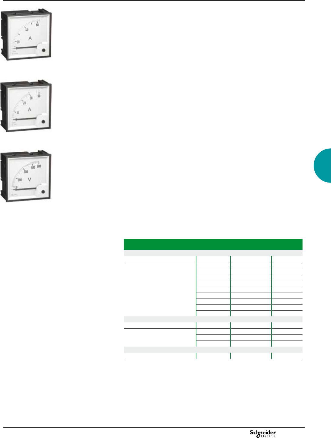
Basic panel meters 72 x 72 analogue ammeters and
voltmeter
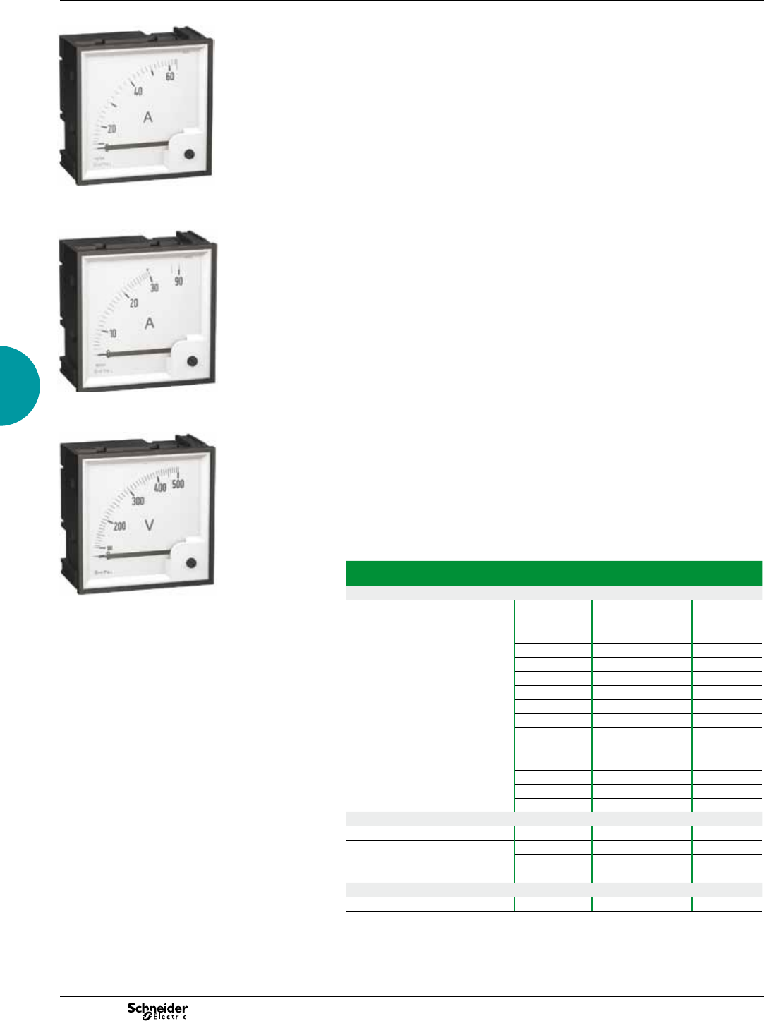
2013
24
Function
The 96 x 96 measurement devices are designed for ush-mounted installation on
doors, wicket doors and front plates of enclosures and cubicles.
AMP
The ammeters measure in amps the current owing through an electrical circuit.
VLT
The voltmeter measure in volts the potential difference (voltage) of an electrical
circuit.
Common technical data
b Accuracy: class 1.5.
b Compliance with standard IEC 60051-1, IEC 61010-1 and IEC 61000-4.
b Ferromagnetic device.
b Scale length: 80 mm over 90°.
b Mounting in enclosure or in cubicle.
b Degree of protection: IP52.
b Maximum operating position: 30° / vertical.
b Temperature:
v operation: -25°C to +50°C
v reference: 23°C.
b Inuence of temperature on accuracy: ±0.003 % /°C.
b Utilisation frequency: 50/60 Hz.
AMP specic technical data
b Needs a In/5 CT to be ordered separately.
b Interchangeable dials to be ordered separately.
b Consumption: 1.1 VA.
b Permanent overload: 1.2 In.
b Maximum overload for 5 s: 10 In.
VLT specic technical data
b Consumption: 3 VA.
b Permanent overload: 1.2 Un.
b Maximum overload for 5 s: 2 Un.
Catalogue numbers
Type Scale Connection
on CT
Cat. no.
AMP for standard feeder
Basic device (delivered without dial) X/5 16074
1.3 In dial 0-50 A 50/5 16079
0-100 A 100/5 16080
0-200 A 200/5 16081
0-400 A 400/5 16082
0-600 A 600/5 16083
0-1000 A 1000/5 16084
0-1250 A 1250/5 16085
0-1500 A 1500/5 16086
0-2000 A 2000/5 16087
0-2500 A 2500/5 16088
0-3000 A 3000/5 16089
0-4000 A 4000/5 16090
0-5000 A 5000/5 16091
0-6000 A 6000/5 16092
AMP for motor feeder
Basic device (delivered without dial) X/5 16073
3 In dial 0-30-90 A 30/5 16076
0-75-225 A 75/5 16077
0-200-600 A 200/5 16078
VLT
0-500 V 16075
PB101118-40_c
AMP for standard feeder.
PB101119-40_c
AMP for motor feeder.
PB101116-40_c
VLT.
Basic panel meters 96 x 96 analogue ammeters and
voltmeter
2013 25
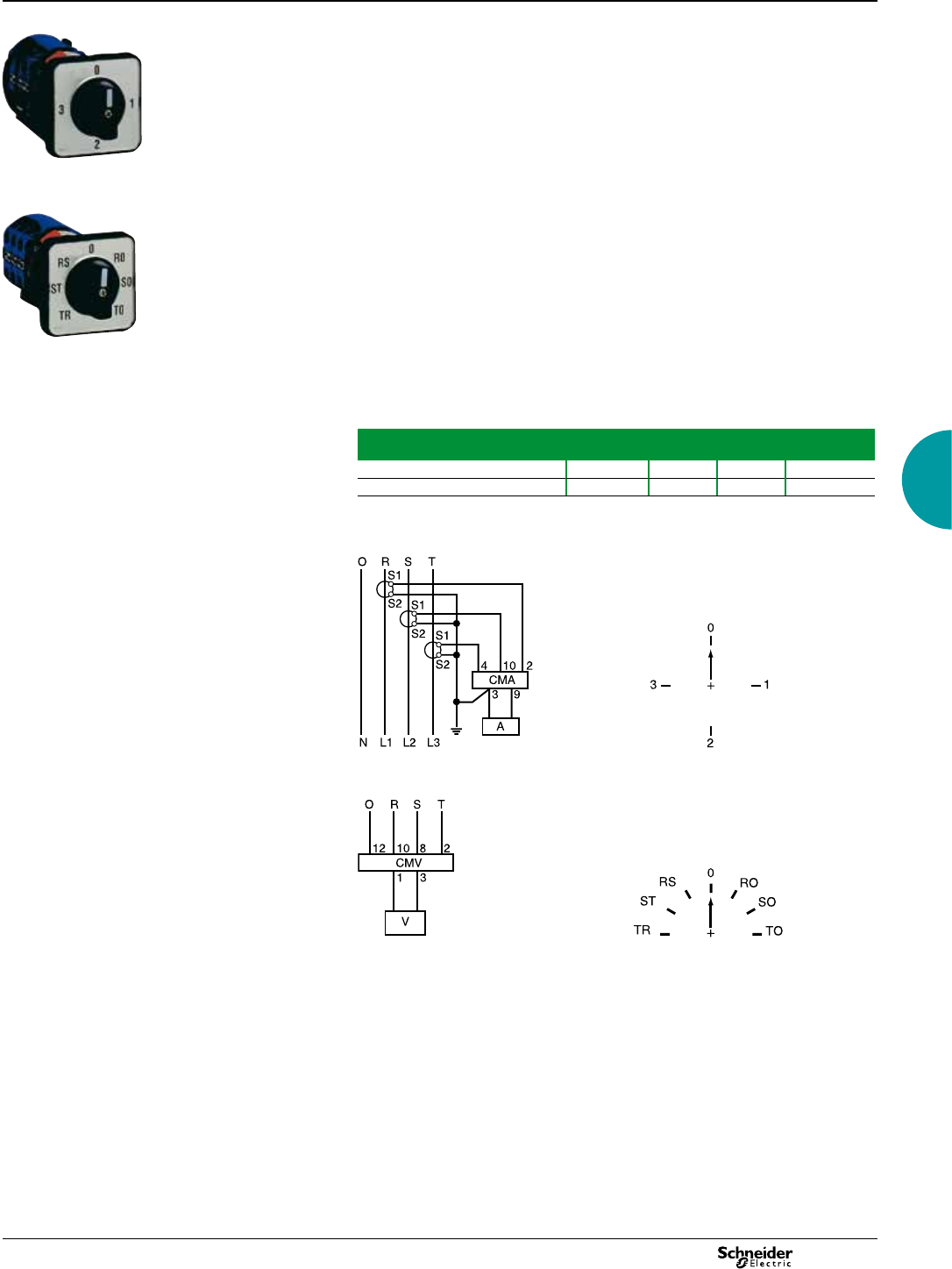
Basic panel meters
Function
The 48 x 48 selector switches are designed for ush-mounted installation on doors,
wicket doors and front plates of enclosures and cubicles.
CMA
The ammeter selector switch uses a single ammeter (by means of current
transformers) for successive measurement of the currents of a three-phase circuit.
CMV
The voltmeter selector switch uses a single voltmeter for successive measurement
of the voltages (phase-to-phase and phase-to-neutral) of a three-phase circuit.
Common technical data
b Durability:
v electrical: 100 000 operations
v mechanical: 2 000 000 operations.
b AgNi contact.
b Operating temperature: -25°C to +50°C.
b Compliance with standards IEC/EN 60947-3.
b Degree of protection:
v IP65 on front face
v IP20 at terminal level.
Catalogue numbers
Type Rating
(A)
Voltage
(V)
Number of
positions
Cat. no.
CMA 20 4 16017
CMV 500 7 16018
Connection
DB117274
CMA.
DB114275
CMV.
Reading 3 phase-to-earth voltages + 3 phase-to-phase voltages.
Note: when connecting do not remove the pre-cabling.
050740-25_c
CMA.
050741-25_c
CMV.
48 x 48 CMA and CMV
selector switches0
2013
26
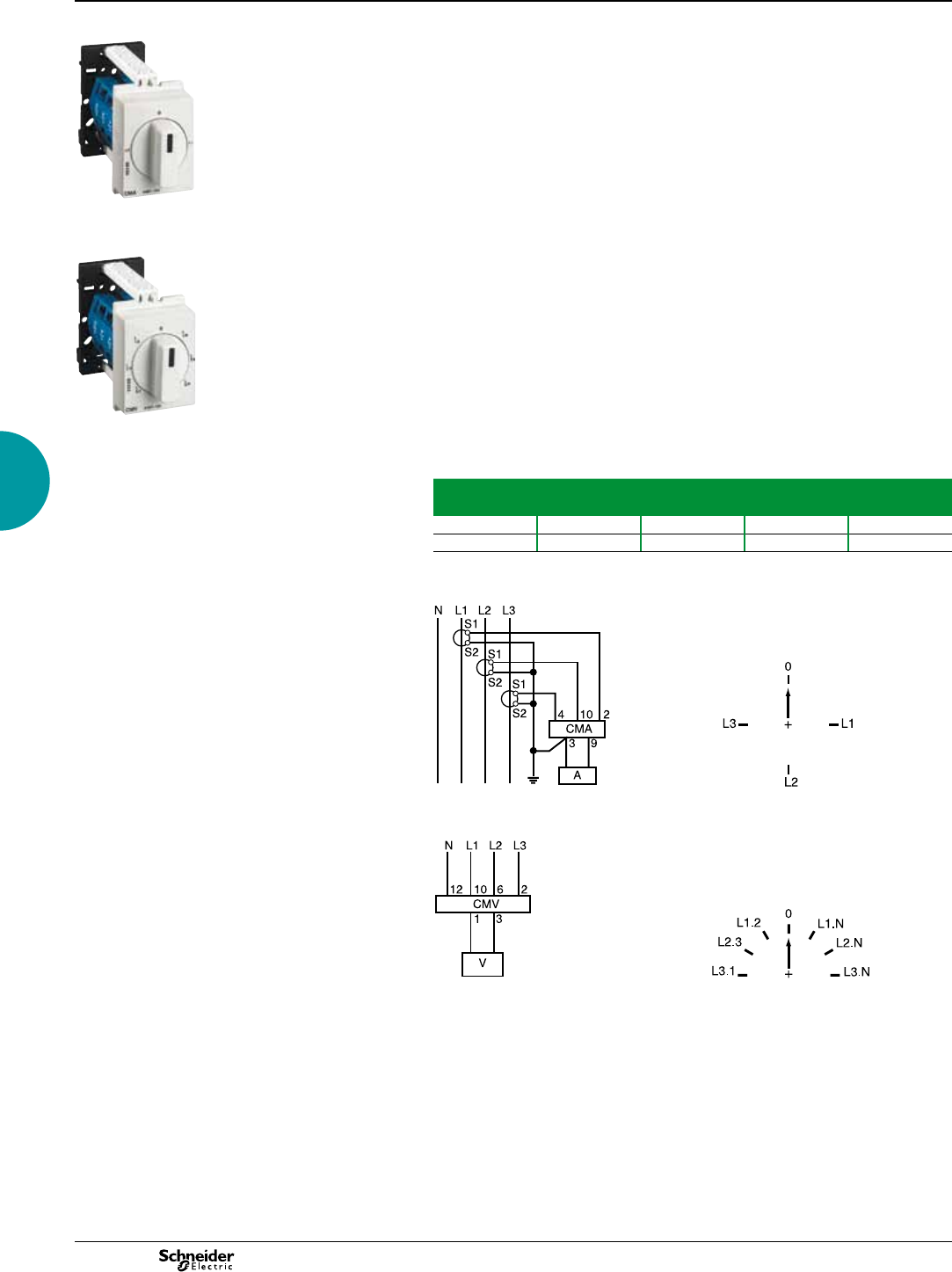
DIN rail iCMA and iCMV selector
switches0
Basic panel meters
Function
iCMA
This 4-position ammeter selector switch uses a single ammeter (using current
transformers) for successive measurement of the currents of a three-phase circuit.
iCMV
This 7-position voltmeter selector switch uses a single voltmeter for successive
measurement of voltages (phase-to-phase and phase-to-neutral) of a three-phase
circuit.
Common technical data
b Rotary handle.
b Maximum operating voltage: 440 V, 50/60 Hz.
b Nominal thermal current: 10 A.
b Operating temperature: -20°C to +55°C.
b Storage temperature: -25°C to +80°C.
b Mechanical durability (AC21A-3 x 440 V): 2 000 000 operations.
b Degree of protection:
v IP66 on front face
v IP20 at terminal level.
b Electrical durability: 1 000 000 operations.
b Connection: jumper terminals with captive screws, for cables up to 1.5 mm2.
b Complies with standards: IEC/EN 60947-3.
Catalogue numbers
Type Rating
(A)
Voltage
(V AC)
Width in
mod. of 9 mm
Cat. no.
iCMA 10 415 4 15126
iCMV 10 415 4 15125
Connection
DB114272
iCMA.
DB114273
iCMV.
059197_c
iCMA.
059198_c
iCMV.
2013 27
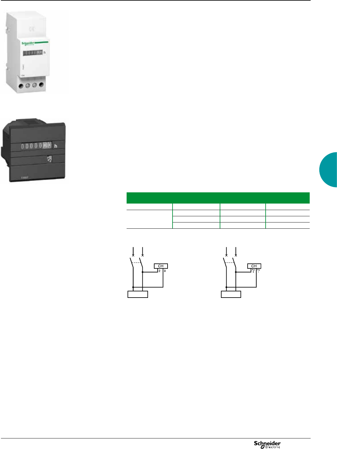
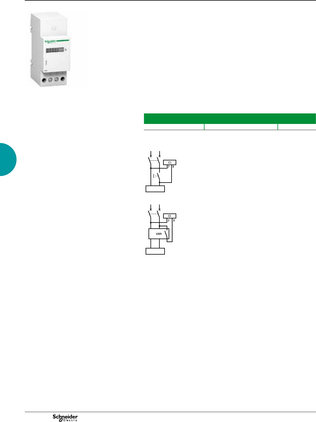
iCH hour counters
Function
Electromechanical counter that counts the operating hours of a machine or piece of
electrical equipment. Giving a precise indication of operating time, the counter is
used to decide when to carry out preventive maintenance.
Common technical data
b Electromechanical display.
b Maximum display: 99999.99 hours.
b Display accuracy: 0.01 %.
b Without reset.
b Storage temperature: -25°C to +85°C.
b Connection: tunnel terminals for 2.5 mm2 cable.
Specic technical data
iCH "DIN"
b Consumption: 0.15 VA.
b Operating temperature: -10°C to +70°C.
b Mounting on DIN rail.
CH "48 x 48"
b Consumption:
v 15607: 0.25 VA
v 15608: 0.15 VA
v 15609: 0.02 VA to 12 V and 0.3 VA to 36 V.
b Operating temperature: -20°C to + 70°C.
b Degree of protection: IP65 on front face.
b Mounting on front face of monitoring switchboards.
Catalogue numbers
Type Voltage
(V)
Width in mod.
of 9 mm
Cat. no.
iCH "DIN" 230 V AC ± 10 %/50 Hz 415440
CH "48 x 48" 24 V AC ± 10 %/50 Hz 15607
230 V AC ± 10 %/50 Hz 15608
12 to 36 V DC 15609
Connection
DB114262
DB114263
iCH "DIN". CH "48 x 48".
DB119002
iCH "DIN".
DB119003
CH "48 x 48".
load load
Basic panel meters
2013
28
iCI impulse counter
Function
Electromechanical counter designed to count impulses emitted by: kilowatt hour
meters, temperature overrun detectors, people meters, speed meters, etc.
Common technical data
b Supply and metering voltage: 230 V AC ± 10 %, 50/60 Hz.
b Consumption: 0.15 VA.
b Maximum display: 9 999 999 impulses.
b Without reset.
b Metering data:
v minimum impulse time: 50 ms
v minimum time between 2 impulses: 50 ms.
b Storage temperature: -25°C to +85°C.
b Operating temperature: -10°C to +70°C.
b Connection: tunnel terminals for 2.5 mm2 cable.
Catalogue number
Type Width in mod.
of 9 mm
Cat. no.
iCI 415443
Connection
DB114271
DB119004
load
load
Basic panel meters
2013 29
Analogue ammeters and voltmeters
DB103473
Digital ammeters, voltmeter and frequency meter
DB103474 converti
iCMA and iCMV selector switches
DB103475 converti
72 x 72 analogue ammeters and voltmeter
DB103476
96 x 96 analogue ammeters and voltmeter
DB103481
Protection cover
Capot de protection
Terminal
M4
Protection cover
Capot de protection
Terminal
M4
Dimensions
Ammeters, voltmeters, selector switches,
impulse counter, hour counters
Basic panel meters
2013
30
Dimensions (cont.)
Ammeters, voltmeters, selector switches,
impulse counter, hour counters
Basic panel meters
48 x 48 CMA and CMV selector switches
DB103477
iCI impulse counter and iCH hour counter
DB103479 converti
48 x 48 CH hour counters
DB109825 converti
3.2 (or 4.8)
24.1 (or 33)
22.3 (or 30.5)
(with adapter)
2013 31
Kilowatt-hour meters
Basic energy meters
Function
Digital kilowatt-hour meters designed for sub-metering of active energy (rms)
consumed by a single-phase or three-phase electric circuit with or without distributed
neutral.
iEM2000T
40 A single-phase kilowatt-hour meter without display, with remote transfer of
metering impulses (static output).
iEM2000
40 A single-phase kilowatt-hour meter.
iEM2010
40 A single-phase kilowatt-hour meter with remote transfer of metering impulses
(static output).
iME1
Single-phase kilowatt-hour meter.
iME1z
Single-phase kilowatt-hour meter with partial meter.
iME1zr
Single-phase kilowatt-hour meter with partial meter and remote transfer of metering
impulses (relay output).
Catalogue numbers
Type Rating
(A)
Voltage
(V AC)
Tolerance
(V AC)
Width in
mod. of
9 mm
Cat. no.
Single-phase circuit (1L + N)
iEM2000 40 230 ±20 2A9MEM2000
iEM2010 40 230 ±20 2A9MEM2010
iEM2000T 40 230 ±20 2A9MEM2000T
iME1 63 230 ±20 4A9M17065
iME1z 63 230 ±20 4A9M17066
iME1zr 63 230 ±20 4A9M17067
Main technical data
iEM2000T iEM2000/iEM2010 iME
Accuracy class 1 1 1
Frequency 48/62 Hz 48/62 Hz 48/62 Hz
Consumption <10VA <10VA 2.5 VA
Operating temp -10°C to +55°C -10°C to +55°C -25°C to +55°C
Connection by
tunnel terminals
Top terminals: 4 mm2Top terminals: 4 mm2Top terminals: 6 mm2
Bottom terminals:
10 mm2
Bottom terminals:
10 mm2
Bottom terminals:
16 mm2
Compliance
with standard
IEC 61557-12 :
- PMD/DD/K55/1
IEC 61557-12 :
- PMD/DD/K55/1
IEC 61557-12 :
- PMD/DD/K55/1
IEC 62053-21
(accuracy)
IEC 62053-21
(accuracy)
IEC 62053-21 (accuracy)
Sealable screw
shield
Yes Yes Yes
MID Compliance No Yes No
PB110836
iEM2000T
PB108400
PB108401
iEM2000 iEM2010
iME1_IMAGE.eps
iME1zr.

2013
32
DB115816
iEM2010
DB118760_i
iME1zr.
DB118815
Circuit-breaker
Contactor
Circuit-breaker
Contactor
Load Load
Kilowatt-hour meter
Kilowatt-hour meter
Example: meter on a load switching
Description
iEM2000, iEM2010, iEM2000T
1 Remote transfer pulse output (iEM2000T, iEM2010).
2 Green power-on indicator light.
3 Yellow metering indicator light (ashing).
4 Display unit (iEM2000, iEM2010).
5 Seal.
6 Allow the comb busbar to pass.
iME1, iME1z, iME1zr
1 Pulse output for remote transfer (iME1zr).
2 Flashing meter indicator.
3 Total or partial meter display (iME1z, iME1zr).
4 Wiring error indicator.
5 Push-button: total or partial meter display, reset partial meter (ME1z, ME1zr).
6 Sealing connection.
Installation
b The front panel of the product is IP40 and its housing is IP20.
b Its installation must be appropriate to the operating conditions.
b The protection must not be less than IP65 for outdoor use.
Use with a contactor
A measurement instrument is normally continually supplied.
For a non-continuous supply (load switching), we recommend that you place the
breaking device downstream from the measurement instrument to limit disturbances
on the module inputs.
These disturbances, particularly on inductive loads, may result in early ageing of the
device.
You must also place the measurement instrument at a distance from the breaking
device to limit the risk of disturbance.
Kilowatt-hour meters (cont.)
Basic energy meters
2013 33
Kilowatt-hour meters (cont.)
Basic energy meters
Specic technical data
iEM2000, iEM2010, iEM2000T, iME1, iME1z and iME1zr specic technical data
iEM2000 iEM2010 iEM2000T iME1 iME1z iME1zr
Direct measurement Up to 40 A Up to 63 A
Metering and activity indicator light
(yellow)
3,200 ashes per kWh 1,000 ashes per kWh
Wiring error indicator Yes
Total meter (max. capacity) on one
phase
999 999.9 kWh 999.99 MWh
Total meter display In kWh with 7 signicant digits (not for iEM2000T) In kWh or MWh with 5 signicant digits. No decimal point in
kWh; 2 digits after the decimal point in MWh
Partial meter (max. capacity) on one
phase with RESET
- - 99.99 MWh
Partial meter display - - In kWh or MWh with 4 signicant digits. No
decimal point in kWh; 2 digits after the decimal
point in MWh
Remote transfer -By static output:
- ELV insulation voltage: 4 kV, 50 Hz
- 20 mA/35 V DC max.
- 100 impulses of 120 ms per kWh
--By NO impulse contact:
- ELV insulation voltage: 4 kV, 50 Hz
- 18 mA/24 V DC, 100 mA/230 V AC
- 1 impulse of 200 ms (contact
closing) per kWh
Connection
Single-phase circuit
DB118858
DB118858
to impulse meter
(iME1zr)
iEM2010 iME1 / iME1z / iME1zr.
Caution
b Do not earth the CT secondary (S2). b You must comply with the routing direction of power cables in the current
transformer primary. Cables enter in "P1" and leave in "P2" to the loads.
DB114265
DB114264
1
2013
34
Acti 9 iEM3000 Series Energy Meters
Functions and characteristics
Basic energy meters
PB108410
bThe Acti 9 iEM3000 Energy Meter Series offers a cost-attractive, competitive range of
DIN rail-mounted energy meters ideal for sub-billing and cost allocation applications.
Combined with communication systems, like Smart Link, the Acti 9 iEM3000 Series
makes it easy to integrate electrical distribution measurements into customer’s facility
management systems. It’s the right energy meter at the right price for the right job.
Two versions are available: 63A direct measure (iEM3100 models) and current
transformers associated meter (iEM3200 models). For each range, eight versions
are available to satisfy basic to advanced applications:
b iEM3100/iEM3200: kWh meter with partial counter
b iEM3110/iEM3210: kWh meter with partial counter and pulse output. MID certied.
b iEM3115/iEM3215: multi-tariff meter controlled by digital input or internal clock, MID
certied.
b iEM3135/iEM3235: energy meter, four quadrant, multi-tariffs with partial counter
and current, voltage, power measurement. M-Bus communication, digital I/O and MID
certied.
b iEM3150/iEM3250: kWh meter with partial counter and current, voltage, power
measurement. Modbus communication.
b iEM3155/iEM3255: energy meter, four quadrant, multi-tariffs with partial counter
and current, voltage, power measurement. Modbus communication, digital I/O, MID
certied.
b iEM3165/iEM3265: energy meter, four quadrant, multi-tariffs with partial counter
and current, voltage, power measurement. BACnet communication, digital I/O and
MID certied.
b iEM3175/iEM3275: energy meter, four quadrant, multi-tariffs with partial counter
and current, voltage, power measurement. LON communication, digital input and
MID certied.
Innovative design makes the meters smart and simple:
b Easy to install for panel builders
b Easy to commission for contractors and installers
b Easy to operate for end users
Applications
Cost management applications
b�Bill verication
b�Sub-billing, including WAGES view (four user-dened tariffs)
b�Cost allocation, including WAGES view
Network management applications
b�Basic electrical parameters like current, voltage and power
b Onboard overload alarm to avoid circuit overload and trip
b Easy integration with PLC systems by input/output interface
Market segments
b�Buildings & Industry
b�Data centres and networks
b�Infrastructure (airports, road tunnels, telecom)
Characteristics
b�Self-powered meters
b�Chain measurement (meters + CTs) accuracy class 1
b�Compliance with IEC 61557-12, IEC 62053-21/22, IEC 62053-23, EN50470-3
b Compact, 5 module width
b Graphical display for easy viewing
b�Onboard Modbus, LON, M-Bus or BACnet communication
b�Easy wiring (without CTs) Acti 9 iEM3100 models
b�Double xation on DIN rail (horizontal or vertical)
b�Anti-tamper security features ensure the integrity of your data
b�MID compliant (selected models) providing certied accuracy and data security
Acti 9 iEM3100 energy meter
PB108432
Acti 9 iEM3255 energy meter
Front of meter parts
1 Conguration mode
2 Values and parameters
3 Unit
4 Cancellation
5 Conrmation
6 Selection
7 Date and time
8 Tariff currently used (iEM3235,
iEM3255, iEM3265, iEM3275)
9 Functions/Measurements
2013 35
Function guide
iEM3100
iEM3110
iEM3115
iEM3135
iEM3150
iEM3155
iEM3165
iEM3175
iEM3200
iEM3210
iEM3215
iEM3235
iEM3250
iEM3255
iEM3265
iEM3275
Direct measurement (up to 63 A) bbbbbbbb
Measurement inputs through CTs (1 A, 5A) bbb bbbbb
Measurement inputs through VTs bbbbb
Active energy measurements class (total & partial kWh) bbbbbbbbbbbbbbbb
Four Quadrant Energy measurements b b b b b b b b
Electrical measurements (I, V, P, etc.) bbbbb bbbbb
Multi-tariff (internal clock) 44 444 44 444
Multi-tariff (external control) 42 222 42 222
Measurement display (number of lines) bbbbbbbbbbbbbbbb
Digital inputs Programmable (Tariff control or WAGES input) 1 1 1 1 1 1 1 1
Tariff control only 2 2
Digital ouputs Programmable (kWh pulse or kW alarm) 1 1 1 1 1 1
kWh pulse only 1 1
kW overload alarm b b b b b b b b
M-Bus b b
Modbus b b b b
BACnet b b
LON b b
MID (legal metrology certication) bbb bbb bbb bbb
Width (18 mm module in DIN Rail mounting) 5555555555555555
PB108410
Connectivity advantages
Programmable digital input External tariff control signal (4 tariffs)
Remote Reset partial counter
External status, e.g. breaker status
Collect WAGES pulses
Programmable digital output kWh overload alarm (iEM3135, iEM3155, iEM3165
iEM3235, iEM3255, iEM3265)
kWh pulses
Graphic LCD display Scroll energies
Current, voltage, power, frequency, power factor
Communication Serial communication options are available with M-Bus,
Modbus, BACnet or LON protocols
Standards
IEC standards IEC 61557-12, IEC 61036, IEC 61010, IEC 62053-21/22
Class 1 and Class 0.5S, IEC 62053-23
MID EN 50470-1/3
Acti 9 iEM3100 models direct connected (63 A)
Multi-tariff capability
The Acti 9 iEM3000 Series allows arrangement of kWh consumption in four different
registers. This can be controlled by:
b Digital Inputs. Signal can be provided by PLC or utilities
b Internal clock programmable by HMI
b Through communication
This function allows users to:
b Make tenant metering for dual source applications to differentiate backup source or
utility source
b Understand well the consumption during working time and non working time, and
between working days and weekends
b Follow up feeders consumption in line with utility tariff rates
Acti 9 iEM3200 models (1 A / 5 A CT connected)
PB108424
Acti 9 iEM3000 Series Energy Meters
Functions and characteristics
Basic energy meters
2013
36
Acti 9 iEM3000 Series Energy Meters
Functions and characteristics
Basic energy meters
Specication guide iEM3100 Models
iEM3100 iEM3110 iEM3115 iEM3135 iEM3150 iEM3155 iEM3165 iEM3175
Current (max.) Direct connected 63 A
Meter constant LED 500/kWh
Pulse output Up to
1000p/kWh
Up to
1000p/kWh
Up to
1000p/kWh
Multi-tariff 4 tariffs 4 tariffs 4 tariffs
Communication M-bus Modbus Modbus BACnet LON
DI/DO 0/1 2/0 1/1 1/1 1/1 1/0
MID (EN50470-3) bbb bbb
Network 1P+N, 3P, 3P+N
Accuracy class Class 1 (IEC 62053-21 and IEC61557-12) Class B (EN50470-3)
Wiring capacity 16 mm²
Display max. LCD 99999999.9kWh
Voltage (L-L) 3 x 100/173 Vac to 3 x 277/480 Vac (50/60 Hz)
IP protection IP40 front panel and IP20 casing
Temperature -25°C to 55°C (K55)
Product size 10 steps of 9mm
Overvoltage and
measurement
Category III, Degree of pollution 2
kWh bbbbbbbb
kVARh b b b b
Active power bbbbb
Reactive power b b b b
Currents and voltages bbbbb
Overload alarm b b b b
Hour counter b b b b
Specication guide iEM3200 Models
iEM3200 iEM3210 iEM3215 iEM3235 iEM3250 iEM3255 iEM3265 iEM3275
1 A / 5 A CTs (max current) 6 A
Meter constant LED 5000/kWh
Pulse output frequency Up to
500p/kWh
Up to
500p/kWh
Up to 500p/kWh
Multi-tariff 4 tariffs 4 tariffs 4 tariffs
Communication M-bus Modbus Modbus BACnet LON
DI/DO 0/1 2/0 1/1 1/1 1/1 1/0
MID (EN50470-3) bbb bbb
Network 1P+N, 3P, 3P+N
support CTs
1P+N, 3P, 3P+N
support CTs & VTs
Accuracy class Class 0.5S (IEC 62053-22 and IEC61557-12) Class C (EN50470-3)(1)
Wiring capacity 6 mm² for currents and 4 mm² for voltages
Display max. LCD 99999999.9kWh or 99999999.9MWh
Voltage (L-L) 3 x 100/173 Vac to 3 x 277/480 Vac (50/60 Hz)
IP protection IP40 front panel and IP20 casing
Temperature -25°C to 55°C (K55)
Product size 10 steps of 9mm
Overvoltage & measurement Category III, Degree of pollution 2
kWh bbbbbbbb
kVARh b b b b
Active power bbbbb
Reactive power b b b b
Currents and voltages bbbbb
Overload alarm b b b b
Hour counter b b b b
(1) For 1 A CTs Class 1 (IEC6253-21 and IEC61557-12 Class B (EN50470-3)
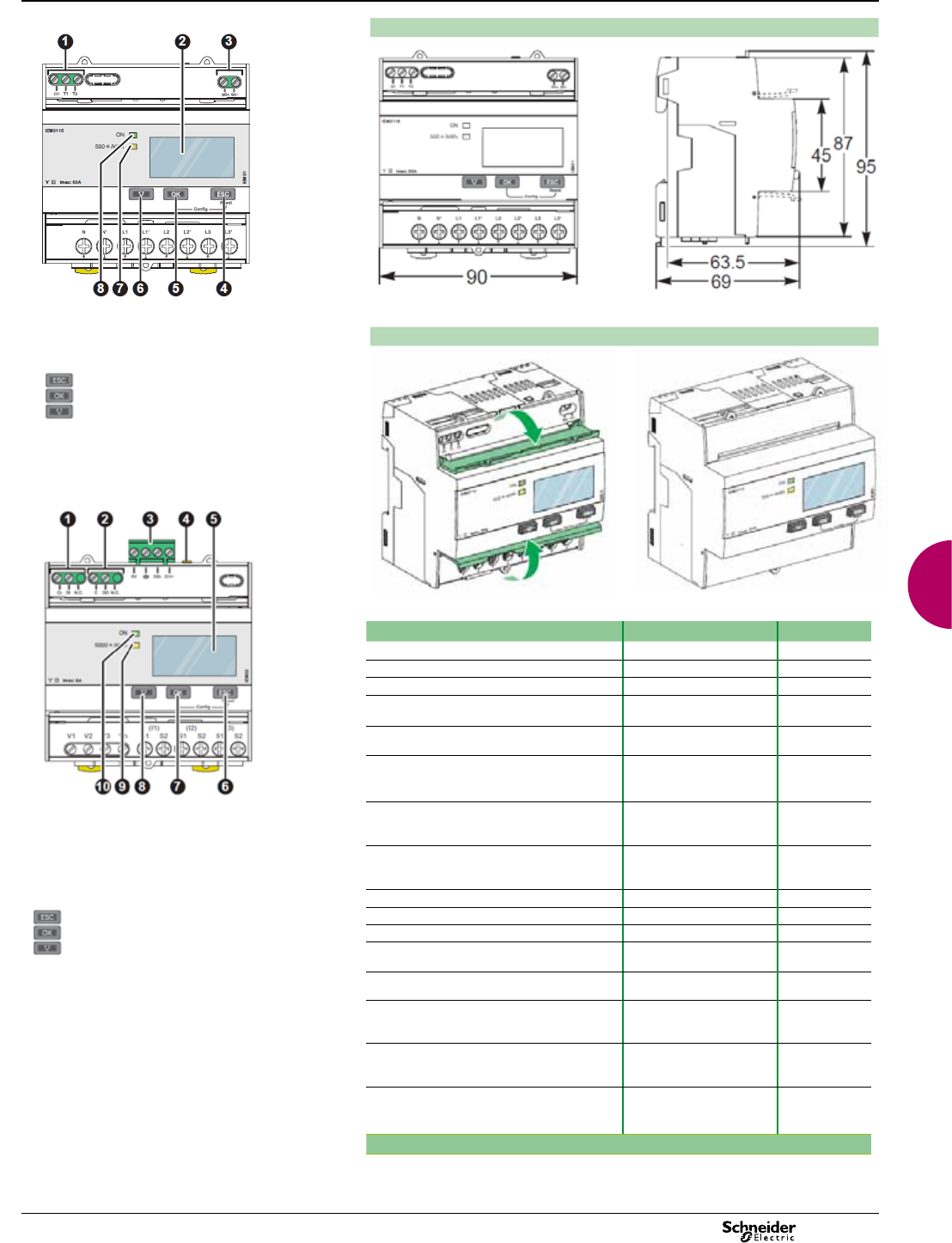
2013 37
iEM3000 series dimensions
PB105302
PB105303
Acti 9 iEM3000 Series front aps open and closed
PB105305
PB105306
iEM3x50 and iEM3x55 Comm./terminal parts
1. Digital input for tariff control (iEM3155 / iEM3255)
2. Digital output (iEM3155/iEM3255)
3. Communication port
4. Yellow indicator for communication diagnosis
5. Display for measurement and conguration
6. Cancellation
7. Conrmtion
8. Selection
9 Flashing yellow meter indicator to check accuracy
10 Green indicator: on/off, error
Note: For further information please see the Installation Guide
and User Guide documents for these products.
Acti 9 iEM3000 Series parts
1. Digital inputs for tariff control (iEM3115 / iEM3215)
2. Display for measurement and conguration
3. Pulse out for remote transfer (iEM3110 / iEM3210)
4. Cancellation
5. Conrmation
6. Selection
7. Flashing yellow meter indicator to check accuracy
8. Green indicator: on/off, error
Meter model and description Current measurement Part no.
iEM3100 basic energy meter Direct connected 63 A A9MEM3100
iEM3110 energy meter with pulse output Direct connected 63 A A9MEM3110
iEM3115 multi-tariff energy meter Direct connected 63 A A9MEM3115
iEM3135 advanced multi-tariff energy meter &
electrical parameter plus M-Bus comm port
Direct connected 63 A A9MEM3135
iEM3150 energy meter & electrical parameter
plus Modbus RS485 comm port
Direct connected 63 A A9MEM3150
iEM3155 advanced multi-tariff energy meter &
electrical parameter plus Modbus RS485 comm
port
Direct connected 63 A A9MEM3155
iEM3165 advanced multi-tariff energy meter &
electrical parameter plus BACnet MS/TP comm
port
Direct connected 63 A A9MEM3165
iEM3175 advanced multi-tariff energy meter &
electrical parameter plus LON TP/FT-10 comm
port
Direct connected 63 A A9MEM3175
iEM3200 basic energy meter Transformer connected 5 A A9MEM3200
iEM3210 energy meter with pulse output Transformer connected 5 A A9MEM3210
iEM3215 multi-tariff energy meter Transformer connected 5 A A9MEM3215
iEM3235 advanced multi-tariff energy meter &
electrical parameter plus M-Bus comm port
Transformer connected 5 A A9MEM3235
iEM3250 energy meter & electrical parameter
plus Modbus RS485 comm port
Transformer connected 5 A A9MEM3250
iEM3255 advanced multi-tariff energy meter &
electrical parameter plus Modbus RS485 comm
port
Transformer connected 5 A A9MEM3255
iEM3265 advanced multi-tariff energy meter &
electrical parameter plus BACnet MS/TP comm
port
Transformer connected 5 A A9MEM3265
iEM3275 advanced multi-tariff energy meter &
electrical parameter plus LON TP/FT-10 comm
port
Transformer connected 5 A A9MEM3275
PB105313
PB1053241
Acti 9 iEM3000 Series Energy Meters
Functions and characteristics
Basic energy meters
2013
Product selection according
to measurement functions
(1) Measurement sensors included.
(2) Available with Micrologic E associated to Compact NS630b...3200, Masterpact NT, Masterpact NW.
(3) Active power or reactive power or apparent power.
Power-monitoring units
specification guide
Multi-circuit Metering Basic multi-function Metering Intermediate Metering Advanced Metering Advanced Utility Metering
BCPM EM4800 ION6200
PM3200/PM3210/
PM3250/PM3255
PM5100/PM5300/
PM5500
PM810/PM820/
PM850/PM870
ION7330/7350 ION 7550 ION 7650 CM4000T ION8650 ION8800
A B C A B C
General selection criteria
Installation Inside panel On DIN rail Flush mount Flush mount Flush mount Flush or DIN rail
mount
Flush mount DIN 192 standard
cutout–186x186 mm
Backplate mount ANSI socket, mount 9S, 35S, 36S;
FT21switchboard case
DIN 43862 rack
Use on LV distribution systems b b b b b b b b b b b
Use on LV and HV distribution systems
- - - - b b b b b b b
Current / voltage accuracy 1 % 0.5 % 0.5 % 1 % 0.5 % current
0.2 % voltage
0.5 % reading 0.1 % reading 0.07 % 0.1 % reading 0.1 % reading
Power / active energy accuracy 1 % 1 % Class 1 IEC 62053-21
Class 1 IEC 61557-12
Class 1
IEC 62053-21
Class 2
IEC 62053-23
Class 0.5 S
IEC 62053-22
For PM55xx:
Class 0.2 S
IEC 62053-22
For PM51/53xx:
Class 0.5 S
IEC 62053-22
Class 0.5S IEC
62053-22
Class 0.2S ANSI
12.20
0.5 % 0.20 % 0.20 % 0.20 % 0.20 %
Instantaneous rms values
Current b Phases b b b b b b b b b b b
b Neutral b b b b b b b b b b b
b Extended
Measurement
range
- - - - - - - b b - -
3 - Phase Voltage b b bb b b b b b b b
Voltage per phase b b bbb b b b b b b
Frequency b b bb b b b b b b b
Total power b Active b b bbb b b b b b b
b Reactive -bbbb b b b b b b
b Apparent -bbb b b b b b b b
Power per phase b Active b b bbb b b b b b b
b Reactive -bbbb b b b b b b
b Apparent - - bbb b b b b b b
Power factor b Total b b bbb b b b b b b
b Per phase b-bbb b b b b b b
Energy values
Active energy b b bbbIn/Out b b b b b
Reactive energy -bbbbIn/Out b b b b b
Apparent energy - - bb b b b b b b b
User-set accumulation mode - - - - - b b b b b b
Demand values
Current - Present and maximum values b-bbb b b b b b b
Total active power - Present and
maximum values
b b (3) bb b b b b b b b
Total reactive power - Present and
maximum values
-b (3) bb b b b b b b b
Total apparent power - Present and
maximum values
-b (3) bb b b b b b b b
Total predicted demand - kW, kVAR, kVA - - - - - b b b b b b
Synchronisation of calculation window - - - - - b b b b b b
User-set calculation mode - - - 1 parameter b b b b b b b
Other measurements
Hour counter -bbiEM31552and
iEM3255
b b - - - - -
38
38
2013
Product selection according
to measurement functions
(cont.)
Multi-circuit Metering Basic multi-function Metering Intermediate Metering Advanced Metering Advanced Utility Metering
BCPM EM4800 ION6200
PM3200/PM3210/
PM3250/PM3255
PM5100/PM5300/
PM5500
PM810/PM820/
PM850/PM870
ION7330/7350 ION 7550 ION 7650 CM4000T ION8650 ION8800
A B C A B C
General selection criteria
Installation Inside panel On DIN rail Flush mount Flush mount Flush mount Flush or DIN rail
mount
Flush mount DIN 192 standard
cutout–186x186 mm
Backplate mount ANSI socket, mount 9S, 35S, 36S;
FT21switchboard case
DIN 43862 rack
Use on LV distribution systems b b b b b b b b b b b
Use on LV and HV distribution systems
- - - - b b b b b b b
Current / voltage accuracy 1 % 0.5 % 0.5 % 1 % 0.5 % current
0.2 % voltage
0.5 % reading 0.1 % reading 0.07 % 0.1 % reading 0.1 % reading
Power / active energy accuracy 1 % 1 % Class 1 IEC 62053-21
Class 1 IEC 61557-12
Class 1
IEC 62053-21
Class 2
IEC 62053-23
Class 0.5 S
IEC 62053-22
For PM55xx:
Class 0.2 S
IEC 62053-22
For PM51/53xx:
Class 0.5 S
IEC 62053-22
Class 0.5S IEC
62053-22
Class 0.2S ANSI
12.20
0.5 % 0.20 % 0.20 % 0.20 % 0.20 %
Instantaneous rms values
Current b Phases b b b b b b b b b b b
b Neutral b b b b b b b b b b b
b Extended
Measurement
range
- - - - - - - b b - -
3 - Phase Voltage b b bb b b b b b b b
Voltage per phase b b bbb b b b b b b
Frequency b b bb b b b b b b b
Total power b Active b b bbb b b b b b b
b Reactive -bbbb b b b b b b
b Apparent -bbb b b b b b b b
Power per phase b Active b b bbb b b b b b b
b Reactive -bbbb b b b b b b
b Apparent - - bbb b b b b b b
Power factor b Total b b bbb b b b b b b
b Per phase b-bbb b b b b b b
Energy values
Active energy b b bbbIn/Out b b b b b
Reactive energy -bbbbIn/Out b b b b b
Apparent energy - - bb b b b b b b b
User-set accumulation mode - - - - - b b b b b b
Demand values
Current - Present and maximum values b-bbb b b b b b b
Total active power - Present and
maximum values
b b (3) bb b b b b b b b
Total reactive power - Present and
maximum values
-b (3) bb b b b b b b b
Total apparent power - Present and
maximum values
-b (3) bb b b b b b b b
Total predicted demand - kW, kVAR, kVA - - - - - b b b b b b
Synchronisation of calculation window - - - - - b b b b b b
User-set calculation mode - - - 1 parameter b b b b b b b
Other measurements
Hour counter -bbiEM31552and
iEM3255
b b - - - - -
Power-monitoring units
specification guide
39
39
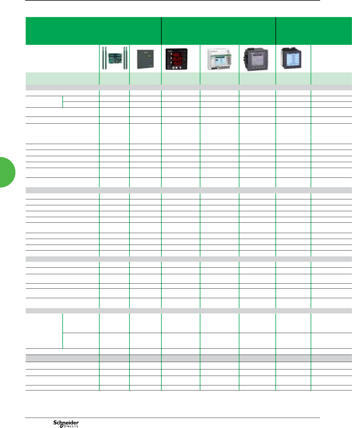
2013
Product selection according
to measurement functions
(cont.)
(4) Maximum only.
(5) Self-powered.
(6) The ION8600 and ION8800 do trending with software but not from the meter's front panel.
(1) With PM810LOG
(2) Congurable.
(3) Except for interharmonics, signalling voltage, icker and transients.meter's
front panel.
Power-monitoring units
specification guide
Multi-circuit Metering Basic multi-function Metering Intermediate Metering Advanced Metering Advanced Utility Metering
BCPM EM4800 ION6200
PM3200/PM3210/
PM3250/PM3255
PM5100/PM5300/
PM5500
PM810/PM820/
PM850/PM870
ION7330/7350 ION 7550 ION 7650 CM4000T ION8650 ION8800
A B C A B C
Power quality measurement
Interharmonics - - - - - - - - b- - b
Total harmonic
distortion
Voltage - - b b b b b b b b b
Current b b b b b b b
Individual harmonic content
(current & voltage)
- - - - b31 (1) b b b b b
Waveform capture - - 0.5 % 1 % -0.5 % reading -b0.07 % b-b
Detection of voltage sags and swells - - Class 1 IEC 62053-21
Class 1 IEC 61557-12
-b - 0.5 % b0.20 % b b
Programmable (logic and mathematical
functions)
- - b-b-b b b b b
Detection & capture of transients - - - b b -b-20 µs b78 µs -20 µs -
Flicker - - - - - - - - b b b -b-
EN 50160 compliance checking - - - b b -b-b b b -b-
IEC 61000-4-30 compliance - - - bb-b-b b - - b-
True rms measurement
Maximum harmonic number
- 15 - b b 63 b63 b63 63
Sampling rate
Points per cycle
- - b32 b128 b256 1024 b256 1024
Data recording
Min/Max of instantaneous values - - bbb b b b b b b
Data logging - - bbb2 (1) b b b b b
Event logging - - bb b b b b b b b
Trend curves - - - - - - bb- - (6) -
Alarms b- - - - b bb-b b
Alarm notication via email - - - - - Optional with
PM8ECC Card
bb-b b
Sequence of Events Recording - - - - - - bb-b b (7
Date and time stamping - - - - - b (1) bb-b b
GPS time synchronisation - - - - - b (1) bb-b b
Storage capacity - - - - 256 kB / 1.1 MB 80 kB (1) 300 kB Up to 10 MB -10 MB 4 MB 2 MB Up to 10 MB
Display, sensors, inputs/outputs
Front-panel display -bbbb b b b b b b
Built-in current and voltage sensors - - bb b -b-b- -
Digital or analogue inputs
(max. number)
- 2 bb2/4 13 digit. / 4
analogue
4 20 b11 3
Pulse outputs -1 (PM9P) 2b1 1 4 1 b2 1
Digital or analogue outputs (max. number
including pulse outputs)
- - 2 - 2 5 digit. / 4
analogue
4 12 b14 13
Direct voltage connections
without external VT
277 V L-N
480 V L-L
277 V L-N
480 V L-L
400 V L-N
690 V L-L
-277 V L-N
400 V L-L
347 V L-N
600 V L-L
347 V L-N
600 V L-L
347 V L-N
600 V L-L
b277 V L-N (9S, 36S)
480 V L-L (35S)
288 V L-N
500 V L-L
Power supply
AC/DC version AC 90 - 277 V 100 - 240 V 20 V L-N / 35 V L-L
to 277 V L-N /480 V
L-L
115 to 415 ±10 %
V AC, 15 VA
45-67 Hz or
350-450 Hz
115 to 415 ±10 %
V AC, 15 VA
45-67 Hz or
350-450 Hz
95 - 240 VAC (+ 10%),
(47 - 440 Hz)
85 to 240 V -
120 to 227 V, 120 to 480 V (35S) /
57 to 70 V / 65 to 120 V / 160 to 277 V
85 to 240 V (+/- 10 %)
47-63 Hz
DC - 110 - 300 V 100 - 300 V 125-250V DC
±20%
125 to 250 ±20 %
V DC, 10W
120 - 310 VDC (+ 10%)
0.2 A worst case loading
(12 W) at 100 VAC at 25°C
110 to 300 V -
80 to 160 V / 200 to 350 V
110 to 270 V (+/- 10 %)
DC version -- - ---- - - - -
Communication
RS 485 port b-Option b b 2- wire (on board) 1/2 b-bOption
Infra-red port -- - - - -bb-b b
RS 232 port -- - - - With remote
display
-b-bOption
Modbus (M) M M M M M M M M - M M
40
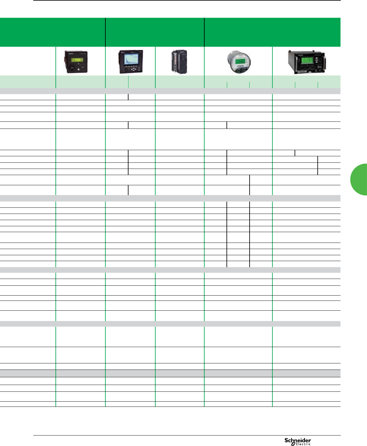
2013
Multi-circuit Metering Basic multi-function Metering Intermediate Metering Advanced Metering Advanced Utility Metering
BCPM EM4800 ION6200
PM3200/PM3210/
PM3250/PM3255
PM5100/PM5300/
PM5500
PM810/PM820/
PM850/PM870
ION7330/7350 ION 7550 ION 7650 CM4000T ION8650 ION8800
A B C A B C
Power quality measurement
Interharmonics - - - - - - - - b- - b
Total harmonic
distortion
Voltage - - b b b b b b b b b
Current b b b b b b b
Individual harmonic content
(current & voltage)
- - - - b31 (1) b b b b b
Waveform capture - - 0.5 % 1 % -0.5 % reading -b0.07 % b-b
Detection of voltage sags and swells - - Class 1 IEC 62053-21
Class 1 IEC 61557-12
-b - 0.5 % b0.20 % b b
Programmable (logic and mathematical
functions)
- - b-b-b b b b b
Detection & capture of transients - - - b b -b-20 µs b78 µs -20 µs -
Flicker - - - - - - - - b b b -b-
EN 50160 compliance checking - - - b b -b-b b b -b-
IEC 61000-4-30 compliance - - - bb-b-b b - - b-
True rms measurement
Maximum harmonic number
- 15 - b b 63 b63 b63 63
Sampling rate
Points per cycle
- - b32 b128 b256 1024 b256 1024
Data recording
Min/Max of instantaneous values - - bbb b b b b b b
Data logging - - bbb2 (1) b b b b b
Event logging - - bb b b b b b b b
Trend curves - - - - - - bb- - (6) -
Alarms b- - - - b bb-b b
Alarm notication via email - - - - - Optional with
PM8ECC Card
bb-b b
Sequence of Events Recording - - - - - - bb-b b (7
Date and time stamping - - - - - b (1) bb-b b
GPS time synchronisation - - - - - b (1) bb-b b
Storage capacity - - - - 256 kB / 1.1 MB 80 kB (1) 300 kB Up to 10 MB -10 MB 4 MB 2 MB Up to 10 MB
Display, sensors, inputs/outputs
Front-panel display -bbbb b b b b b b
Built-in current and voltage sensors - - bb b -b-b- -
Digital or analogue inputs
(max. number)
- 2 bb2/4 13 digit. / 4
analogue
4 20 b11 3
Pulse outputs -1 (PM9P) 2b1 1 4 1 b2 1
Digital or analogue outputs (max. number
including pulse outputs)
- - 2 - 2 5 digit. / 4
analogue
4 12 b14 13
Direct voltage connections
without external VT
277 V L-N
480 V L-L
277 V L-N
480 V L-L
400 V L-N
690 V L-L
-277 V L-N
400 V L-L
347 V L-N
600 V L-L
347 V L-N
600 V L-L
347 V L-N
600 V L-L
b277 V L-N (9S, 36S)
480 V L-L (35S)
288 V L-N
500 V L-L
Power supply
AC/DC version AC 90 - 277 V 100 - 240 V 20 V L-N / 35 V L-L
to 277 V L-N /480 V
L-L
115 to 415 ±10 %
V AC, 15 VA
45-67 Hz or
350-450 Hz
115 to 415 ±10 %
V AC, 15 VA
45-67 Hz or
350-450 Hz
95 - 240 VAC (+ 10%),
(47 - 440 Hz)
85 to 240 V -
120 to 227 V, 120 to 480 V (35S) /
57 to 70 V / 65 to 120 V / 160 to 277 V
85 to 240 V (+/- 10 %)
47-63 Hz
DC - 110 - 300 V 100 - 300 V 125-250V DC
±20%
125 to 250 ±20 %
V DC, 10W
120 - 310 VDC (+ 10%)
0.2 A worst case loading
(12 W) at 100 VAC at 25°C
110 to 300 V -
80 to 160 V / 200 to 350 V
110 to 270 V (+/- 10 %)
DC version -- - ---- - - - -
Communication
RS 485 port b-Option b b 2- wire (on board) 1/2 b-bOption
Infra-red port -- - - - -bb-b b
RS 232 port -- - - - With remote
display
-b-bOption
Modbus (M) M M M M M M M M - M M
Product selection according
to measurement functions
(cont.)
Power-monitoring units
specification guide
41
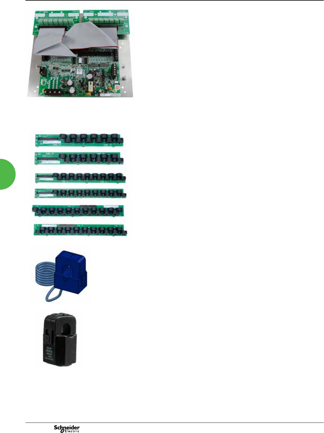
2013
PowerLogic BCPM
Functions and characteristics
PE86166
PowerLogicTM BCPM board
The ideal solution for data centre managers, engineers and operational executives
who are responsible for delivering power to critical applications. In corporate and
hosted data centre facilities, this technology helps you plan and optimise the critical
power infrastructure to meet the demands of continuous availability.
The PowerLogic BCPM is a highly accurate, full-featured metering product designed
for the unique, multi-circuit and minimal space requirements of a high performance
power distribution unit (PDU) or remote power panel (RPP).
The BCPM monitors up to 84 branch circuits with a single device and also monitors
the incoming power mains to provide information on a complete PDU. Full alarming
capabilities ensure that potential issues are dealt with before they become problems.
Unlike products designed for specic hardware, the exible BCPM will t any PDU or
RPP design and supports both new and retrot installations. It has exceptional
dynamic range and accuracy, and optional feature sets to meet the energy
challenges of mission critical data centres.
Applications
Data Centre load monitoring and alarming
Comprehensive monitoring of lighting control panels
Maximise uptime and avoid outages.
Optimise existing infrastructure.
Effectively plan future infrastructure needs.
Improve power distribution efciency.
Track usage and allocate energy costs.
Enable accurate sub-billing.
Main characteristics
Monitor up to 84 branch circuits with a single BCPM.
Ideal for installation in both new PDUs and retrot projects
New installations: BCPM with solid core CTs monitors up to 84 branch circuits
using 2 or 4 CT strips. Solid core CTs are rated to 100 A CTs and are mounted on
strips to simplify installation. CT strips are available with 12, 15 or 21 CTs per strip on
18 mm spacings. 21 CT strips with 3/4” or 1” spacings are also available.
Retrot projects: BCPMSC with split core CTs is ideal for retrots. Any number of
split core CTs, up to 84 maximum, can be installed with a single BCPM. Three sizes
of CT are supported (50 A, 100 A, and 200 A) and all three CT sizes can be used on a
single BCPM. Adapter boards with terminals for split-core CTs can be mounted using
DIN-rail, Snaptrack or on a common mounting plate with the main board (42 ch Y63
models only).
IEC Class 1 metering accuracy
Accurately monitor very low current levels, down to a quarter-Amp.
Easily differentiate between the ow of low current and a trip where no current ows.
Designed to t any PDU or RPP design
Lowers your total installation costs as well as the cost per meter point by supporting
both new and retrot installations.
Modbus RTU protocol
Integrates easily into existing networks using Modbus communications. Optional
Ethernet interfaces:
Optional Ethernet interfaces
Add Modbus TCP support with a Modbus gateway (EGX) or BACnet IP (and MS/TP)
with the E8950*.
Compatible with PowerLogic power monitoring software
Easily turn the large amount of data collected by the devices into useful decision-
making information.
Flexible Conguration capability
Set the ordering and orientation of CT strips, assign individual CT size and phases,
support for 1, 2, and 3-pole breakers.
Multi-circuit metering
PowerLogicTM BCPM split core 12, 18, and 21 CTs strips
PE86281
PowerLogicTM BCPM split core CT
4242
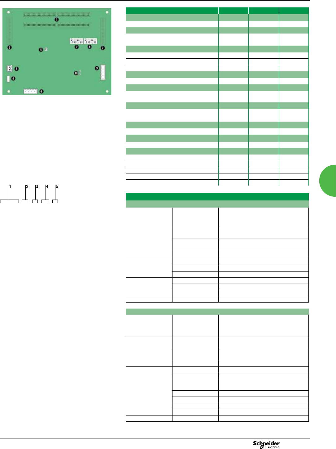
2013
PowerLogic BCPM
Functions and characteristics (cont.)
PowerLogic BCPM
1 50-pin ribbon cable connectors (data acquisition board).
2 Auxiliary inputs.
3 Control (mains) power connection.
4 Control power fuse.
5 Alive LED.
6 Voltage taps.
7 Communications address DIP switches.
8 Communications settings DIP switch.
9 RS-485 2 connection.
10 RS-485 LEDs.
Selection guide BCPMA BCPMB BCPMC
General
Use on LV systems b b b
Power and energy measurements
Mains b b -
Branch circuits b- -
Instantaneous rms values
Current, voltage, frequency b b -
Active power Total and per phase bb (mains only) -
Power factor Total and per phase bb (mains only) -
Energy values
Active energy bb (mains only) -
Demand values
Total active power Present and max.
values
bb (mains only) -
Power quality measurements
Detection of over-voltage/under-voltage b b -
Sampling rate Points per cycle 2560 Hz 2560 Hz 2560 Hz
Alarming
Alarms b b b
Power supply
AC version 90-277 V ac 90-277 V ac 90-277 V ac
Communication
RS 485 port 1 1 1
Modbus protocol b b b
Modbus RTU (Ethernet) optional, add EGX b b b
BACnet IP (Ethernet) optional, add E8950 b b b
BACnet MS/TP (RS 485) optional, add E8950 b b b
BCPM part numbers
Item Code Description
1 Model BCPM BCPM with solid core CTs. Highly accurate
meter that monitors branch circuits and the
incoming power mains and includes full
alarming capabilities
Example BCPM with solid core CTs part number. 2Feature set AAdvanced - Monitors power & energy per
circuit & mains
1 Model.
2 Feature set.
3 CT spacing (solid-core models only)
4 Number of circuits.
5 Brand.
BIntermediate - Monitors current per circuit,
power and energy per mains
CBasic - Monitors current only per circuit & mains
3CT spacing 019 mm CT spacing
126 mm CT spacing
218 mm CT spacing
4Number of circuits 84 84 circuits, (4) 21CT strips
72 72 circuits, (4) 18CT strips (18 mm spacing only)
42 42 circuits, (2) 21CT strips
5 Brand S Schneider Electric
BCPM with split core CTs
Model BCPMSC BCPM with split core CTs. Highly accurate
meter that monitors branch circuits and the
incoming power mains and includes full
alarming capabilities
2Feature set AAdvanced - Monitors power and energy per
circuit and mains
BIntermediate - Monitors current per circuit,
power and energy per mains
CBasic - Monitors current only per circuit and mains
4Number of circuits 142 circuits (no CTs, order separately)
284 circuits (no CTs, order separately)
Y63 42 circuits with main and adapter boards on
single mounting plate
30 30 split core CTs (50 A)
42 42 split core CTs (50 A)
60 60 split core CTs (50 A)
84 84 split core CTs (50 A)
5 Brand S Schneider Electric
Multi-circuit metering
BCPM A0
84 S
The PowerLogic BCPM uses .333 VAC output split-core
CTs for the auxiliary inputs. These CTs are ordered
separately from the BCPM.
PE86168
43 43

2013
PowerLogic BCPM
Functions and characteristics (cont.)
Multi-circuit metering
PowerLogic BCPM specications
Electrical characteristics
Type of measurement
Accuracy Power/energy IEC 62053-21 Class 1, ANSI C12.1-2008
Voltage ±0.5% of reading 90-277V line-to-neutral
Solid Core CT:
50A Split-Core CT:
100A Split-Core CT:
200A Split-Core CT:
±0.5%
±1%
±0.5%
±1%
Data update rate 1.8 seconds
Input-voltage
characteristics
Measured voltage 150 – 480 V ac L-L (1) 90
– 277 V ac L-N (1)
Measurement range 150 – 480 V ac L-L (1) 90
– 277 V ac L-N (1)
Power supply AC 90 – 277 V ac (50/60 Hz)
Mechanical characteristics
Weight 1.5 kg
Dimensions Circuit board 288 x 146 mm
Environmental conditions
Operating temperature 0 to 60ºC
Storage temperature -40ºC to 70ºC
Installation category CAT III
Safety
Europe IEC 61010
U.S. and Canada UL 508 Open type device
Communication
RS 485 Baud rate: DIP-switch selectable 9600, 19200,
38400
DIP-switch selectable 2-wire or 4-wire RS-485
Protocol Modbus RTU. Modbus TCP can be added with
optional gateway (EGX). BACnet MS/TP and
BACnet IP available with optional gateway
(E8950) (2)
Firmware characteristics
Detection of over-voltage/under-voltage User-dened alarm thresholds for over-voltage
and under-voltage detection
Alarms Four alarm levels: high-high, high, low and
low-low (users dene the setpoints for each).
Each alarm has a latching status to alert the
operator that an alarm has previously occurred.
High and Low alarms have instantaneous status
to let the operator know if the alarm state is still
occurring.
Firmware update Update via the RS-485 port
(1) Feature sets ‘A’ and ‘B’ only.
(2) E8950 supports the BCPMAxx42,BCPMBxxx, BCPMCxxxx, BCPMSCBxx, and
BCPMSCCxx - (BCPMAx84 and BCPMSCAxx models are not supported).
1/3 V low-voltage CT (LVCT) specications
Electrical characteristics
Accuracy 1% from 10% to 100% of rated current
Frequency range 50/60 Hz
Leads 18 AWG, 600 V ac, UL 1015 twisted pair, 1.8m
standard length
Max. voltage L-N sensed conductor 600 V ac
Environmental conditions
Operating temperature -15ºC to 60ºC
Storage temperature -40ºC to 70ºC
Humidity range 0 to 95% non-condensing
4444

2013
PowerLogic BCPM
Functions and characteristics (cont.)
Multi-circuit metering
BCPM part numbers for solid and split core CTs (contd.)
Part number Description
BCPMA084S BCPM Advanced feature set, 84 solid core 100 A CTs, 19 mm CT spacing
BCPMA184S BCPM Advanced feature set, 84 solid core 100 A CTs, 26 mm CT spacing
BCPMA042S BCPM Advanced feature set, 42 solid core 100 A CTs, 19 mm CT spacing
BCPMA142S BCPM Advanced feature set, 42 solid core 100 A CTs, 26 mm CT spacing
BCPMA224S BCPM Advanced feature set, 24 solid core 100 A CTs (2 strips), 18 mm CT spacing
BCPMA236S BCPM Advanced feature set, 36 solid core 100 A CTs (2 strips), 18 mm CT spacing
BCPMA242S BCPM Advanced feature set, 42 solid core 100 A CTs (2 strips), 18 mm CT spacing
BCPMA248S BCPM Advanced feature set, 48 solid core 100 A CTs (4 strips), 18 mm CT spacing
BCPMA272S BCPM Advanced feature set, 72 solid core 100 A CTs (4 strips), 18 mm CT spacing
BCPMA284S BCPM Advanced feature set, 84 solid core 100 A CTs (4 strips), 18 mm CT spacing
BCPMB084S BCPM Intermediate feature set, 84 solid core 100 A CTs, 19 mm CT spacing
BCPMB184S BCPM Intermediate feature set, 84 solid core 100 A CTs, 26 mm CT spacing
BCPMB042S BCPM Intermediate feature set, 42 solid core 100 A CTs, 19 mm CT spacing
BCPMB142S BCPM Intermediate feature set, 42 solid core 100 A CTs, 26 mm CT spacing
BCPMB224S BCPM Intermediate feature set, 24 solid core 100 A CTs (2 strips), 18 mm CT spacing
BCPMB236S BCPM Intermediate feature set, 36 solid core 100 A CTs (2 strips), 18 mm CT spacing
BCPMB242S BCPM Intermediate feature set, 42 solid core 100 A CTs (2 strips), 18 mm CT spacing
BCPMB248S BCPM Intermediate feature set, 48 solid core 100 A CTs (4 strips), 18 mm CT spacing
BCPMB272S BCPM Intermediate feature set, 72 solid core 100 A CTs (4 strips), 18 mm CT spacing
BCPMB284S BCPM Intermediate feature set, 84 solid core 100 A CTs (4 strips), 18 mm CT spacing
BCPMC084S BCPM Basic feature set, 84 solid core 100 A CTs, 19 mm CT spacing
BCPMC184S BCPM Basic feature set, 84 solid core 100 A CTs, 26 mm CT spacing
BCPMC042S BCPM Basic feature set, 42 solid core 100 A CTs, 19 mm CT spacing
BCPMC142S BCPM Basic feature set, 42 solid core 100 A CTs, 26 mm CT spacing
BCPMC224S BCPM Basic feature set, 24 solid core 100 A CTs (2 strips), 18 mm CT spacing
BCPMC236S BCPM Basic feature set, 36 solid core 100 A CTs (2 strips), 18 mm CT spacing
BCPMC242S BCPM Basic feature set, 42 solid core 100 A CTs (2 strips), 18 mm CT spacing
BCPMC248S BCPM Basic feature set, 48 solid core 100 A CTs (4 strips), 18 mm CT spacing
BCPMC272S BCPM Basic feature set, 72 solid core 100 A CTs (4 strips), 18 mm CT spacing
BCPMC284S BCPM Basic feature set, 84 solid core 100 A CTs (4 strips), 18 mm CT spacing
BCPM with split core
BCPMSCA1S BCPM feature set A, 42 circuit split core CT power and energy meter, CTs sold
separately
BCPMSCA2S BCPM feature set A, 84 circuit split core CT power and energy meter, CTs sold
separately
BCPMSCA30S BCPM feature set A, 30 circuit split core CT power and energy meter, CTs rated to 50 A
BCPMSCA42S BCPM feature set A, 42 circuit split core CT power and energy meter, CTs rated to 50 A
BCPMSCA60S BCPM feature set A, 60 circuit split core CT power and energy meter, CTs rated to 50 A
BCPMSCAY63S BCPM feature set A, 42 circuit split core power and energy meter - all boards on
backplate, 50A CTs
BCPMSCA84S BCPM feature set A, 84 circuit split core CT power and energy meter, CTs rated to 50 A
BCPMSCB1S BCPM feature set B, 42 circuit split core CT branch current, mains power meter, no CTs
BCPMSCB2S BCPM feature set B, 84 circuit split core CT branch current, mains power meter, no CTs
BCPMSCB30S BCPM feature set B, 30 circuit split core CT branch current, mains power meter, 50 A CTs
BCPMSCB42S BCPM feature set B, 42 circuit split core CT branch current, mains power meter, 50 A CTs
BCPMSCB60S BCPM feature set B, 60 circuit split core CT branch current, mains power meter, 50 A CTs
BCPMSCBY63S BCPM feature set B, 42 circuit split core CT branch current, mains - all boards on backplate,
50 A CTs
BCPMSCB84S BCPM feature set B, 84 circuit split core CT branch current, mains power meter, 50 A CTs
BCPMSCC1S BCPM feature set C, 42 circuit split core CT current meter, CTs sold separately
BCPMSCC2S BCPM feature set C, 84 circuit split core CT current meter, CTs sold separately
BCPMSCC30S BCPM feature set C, 30 circuit split core CT current meter, CTs rated to 50 A
BCPMSCC42S BCPM feature set C, 42 circuit split core CT current meter, CTs rated to 50 A
BCPMSCC60S BCPM feature set C, 60 circuit split core CT current meter, CTs rated to 50 A
BCPMSCCY63S BCPM feature set C, 42 circuit split core CT current meter , all boards on backplate,
50A CTs 50 A
BCPMSCC84S BCPM feature set C, 84 circuit split core CT current meter, CTs rated to 50 A
PE86284
cbl022.jpg
Flat ribbon cable
Round ribbon cable
Cabling and connection
Round ribbon cable is recommended for use
when
the BCPM printed circuit board will be mounted
outside of the PDU that is being monitored.
Round ribbon cable is the prefered choice when
the ribbon cable will be threaded through
conduit.
Flat ribbon cable is recommended for projects
where the BCPM printed circuit board will be
installed inside of the PDU that is being
monitored.
Flat ribbon cable is more exible than round
ribbon cable and is the preferred choice if the
ribbon cable will not be threaded through conduit.
45 45
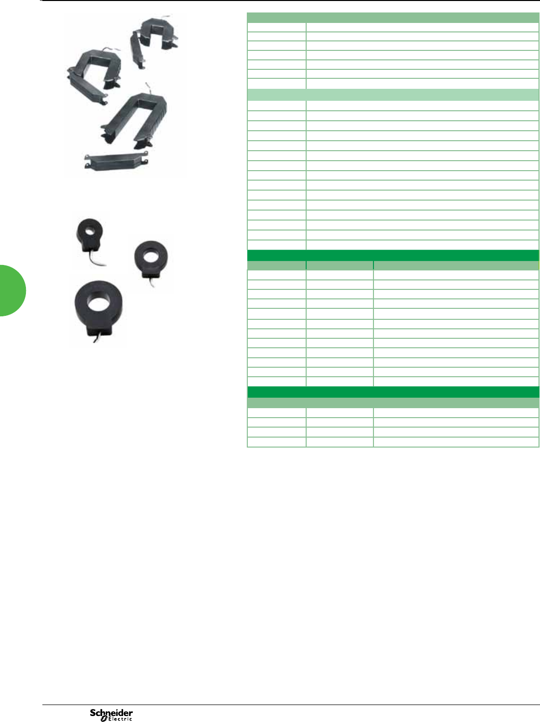
2013
PowerLogic BCPM
Functions and characteristics (cont.)
Multi-circuit metering
BCPM split core accessories
BCPMSCADPBS BCPM adapter boards, quantity 2, for split core BCPM
BCPMSCCT0 BCPM 50 A split core CTs, Quantity 6, 1.8 m lead lengths
BCPMSCCT0R20 BCPM 50 A split core CTs, quantity 6, 6 m lead lengths
BCPMSCCT1 BCPM 100 A split core CTs, Quantity 6, 1.8 m lead lengths
BCPMSCCT1R20 BCPM 100 A split core CTs, Quantity 6, 6 m lead lengths
BCPMSCCT3 BCPM 200 A split core CTs, Quantity 1, 1.8 m lead lengths
BCPMSCCT3R20 BCPM 200 A split core CTs, Quantity 1, 6 m lead lengths
Additional accessories for use with BCPM products
BCPMCOVERS BCPM circuit board cover
BCPMREPAIR CT repair kit for solid core BCPM (includes one CT)
H6803R-0100 Additional 108 split core CT for use with solid core repair kit
E8950 Modbus to BACnet protocol converter
CBL008 Flat Ribbon cable (quantity 1) for BCPM, length = 0.45 m
CBL016 Flat Ribbon cable (quantity 1) for BCPM, length = 1.2 m
CBL017 Flat Ribbon cable (quantity 1) for BCPM, length = 1.5 m
CBL018 Flat Ribbon cable (quantity 1) for BCPM, length = 1.8 m
CBL019 Flat Ribbon cable (quantity 1) for BCPM, length = 2.4 m
CBL020 Flat Ribbon cable (quantity 1) for BCPM, length = 3.0 m
CBL021 Flat Ribbon cable (quantity 1) for BCPM, length = 6.1 m
CBL022 Round Ribbon cable (quantity 1) for BCPM, length = 1.2 m
CBL023 Round Ribbon cable (quantity 1) for BCPM, length = 3 m
CBL024 Round Ribbon cable (quantity 1) for BCPM, length = 6.1 m
CBL033 Round Ribbon cable (quantity 1) for BCPM, length = 2.4 m
1/3 V low-voltage CT part numbers
Part number Amperage rating Inside dimensions
LVCT00102S 100 A 31 mm x 100 mm
LVCT00202S 200 A 31 mm x 100 mm
LVCT00302S 300 A 31 mm x 100 mm
LVCT00403S 400 A 62 mm x 132 mm
LVCT00603S 600 A 62 mm x 132 mm
LVCT00803S 800 A 62 mm x 132 mm
LVCT00804S 800 A 62 mm x 201 mm
LVCT01004S 1000 A 62 mm x 201 mm
LVCT01204S 1200 A 62 mm x 201 mm
LVCT01604S 1600 A 62 mm x 201 mm
LVCT02004S 2000 A 62 mm x 201 mm
LVCT02404S 2400 A 62 mm x 201 mm
Solid core CT part numbers
Part number Amperage rating Inside dimensions
E682A051V3 50A 10 mm
E682A101V3 100A 10 mm
E682C201V3 200A 25 mm
E682D401V3 400A 33 mm
PE86183
E682large
PowerLogicTM BCPM split core CTs
PowerLogicTM BCPM solid core CTs (small, medium, large)
E682small
E682medium
The PowerLogicTM BCPM uses .333 VAC output
split-core CTs for the auxiliary inputs. These
CTs are ordered separately from the BCPM.
4646
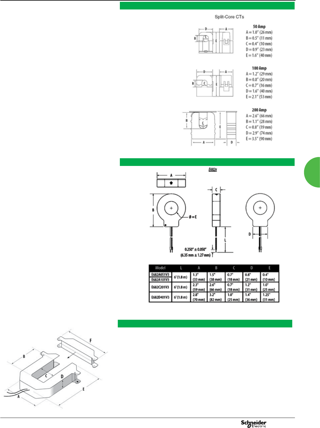
2013
PowerLogic BCPM 0
Dimensions and connection
Multi-circuit metering
PowerLogic BCPM dimensions
Small form factor
100/200/300 Amp
A = 96 mm
B = 30 mm
C = 31 mm
D = 30 mm
E = 100 mm
F = 121 mm
Large form factor
800/1000/1200/
1600/2000/2400 Amp
A = 125 mm
B = 139 mm
C = 62 mm
D = 30 mm
E = 201 mm
F = 151 mm
Medium form factor
400/600/800 Amp
A = 125 mm
B = 73 mm
C = 62 mm
D = 30 mm
E = 132 mm
F = 151 mm
PE86183
1/3 V low-voltage CT form factor
Solid core CT dimensions
47 47
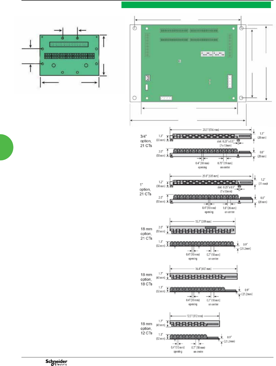
2013
Multi-circuit metering PowerLogic BCPM 0
Dimensions and connection
211 mm
146 mm
122 mm
184 mm
228 mm
PowerLogic BCPM dimensions
PE86183
1.0”
(26 mm)
1.0”
(26 mm)
2.75”
(70 mm)
4.6”
(117 mm)
PE86286
PowerLogic BCPM adapter board (one board
per 21 split core branch CTs)
4848
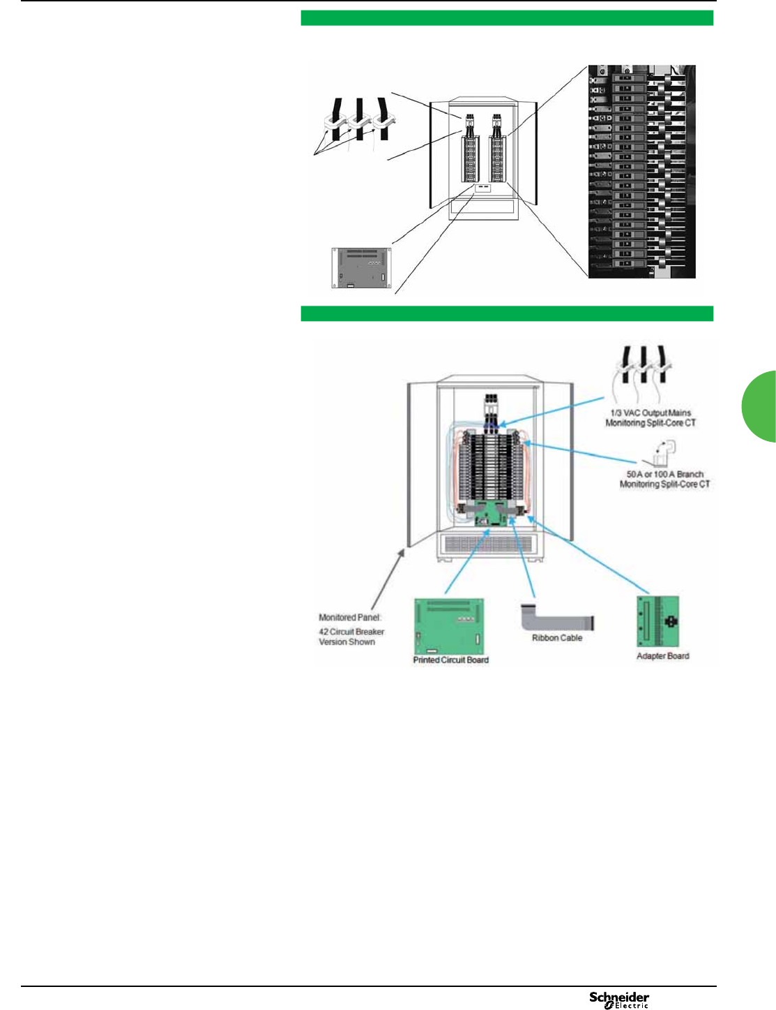
2013
Multi-circuit metering
PowerLogic BCPM with solid core CT strips installation details
PE86171
PowerLogic BCPM with split core CTs installation details
PE86287
Mains monitoring
(CTs ordered separately)
BCPM PCB
Transducers (1/3 Vac)
Circuit monitoring
4 CT strips monitor 84 circuits
PowerLogic BCPM 0
Dimensions and connection
49 49
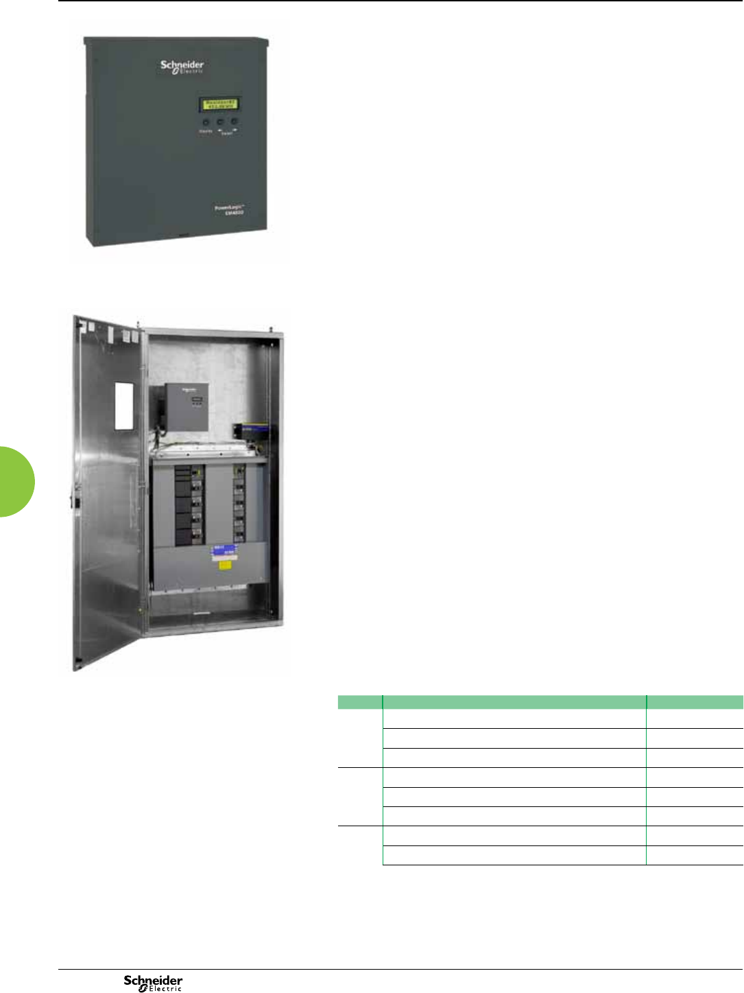
EM4800 series
Functions and characteristics
Multi-circuit energy meters
PE86326 PE86325
EM4800 series multi-circuit energy meter
front (above), installed in panel (below)
The compact PowerLogic EM4800 series multi-circuit energy meter from Schneider
Electric enables reliable metering of individual tenants with a low installation
cost-per-point by combining revenue-accurate electricity sub-metering with
advanced communications technology.
The EM4800 is ideal for multi-tenant or departmental metering applications within
ofce towers, condominiums, apartment buildings, shopping centres and other
multi-user environments.
The PowerLogic EM4800 series meters monitor up to 24 tenants with a single
device. Multiple meters can be combined to support an unlimited number of suites.
Three meter models offer a choice of CT secondary ratings and installation options:
PowerLogic EM4805: 5 A, split- or solid-core CTs
PowerLogic EM4833: 0.333 V, split- or solid-core CTs
PowerLogic EM4880: 80 mA, solid-core CTs
Applications
Multi-tenant metering.
Energy management.
Energy cost allocation.
Utility bill verication.
Main characteristics
Compact, maintenance-free design
Requires no oor space.
Hi-density, exible connection
From single-pole to single- or three-phase metering -- supports up to 24 circuits.
Select the connection type using an intuitive conguration tool.
Direct connection
For 100 - 300 V ac L-N electrical distribution systems:
120/240 V, 120/208 V, 230/240 V, 220/380 V, 240/415 V, 277/480 V
Multiple CT types
Support a variety of needs in both new and retrot installations.
1/3 V output CT option does not require shorting blocks, making it the ideal choice for
retrot installations.
No rewiring required
Use existing wiring to connect to existing panels.
Integrated communications
Onboard Ethernet and modem allows for easy integration into existing
communications networks.
Part numbers
Model Description Part number
EM4805 24 x 5 A inputs, 230/240 V control power, 50 Hz METSEEM480525
24 x 5 A inputs, 120 V control power, 60 Hz METSEEM480516
24 x 5 A inputs, 230/240 V control power, 60 Hz METSEEM480526
EM4833 24 x 333 mV inputs, 230/240 V control power, 50 Hz METSEEM483325
24 x 333 mV inputs, 120 V control power, 60 Hz METSEEM483316
24 x 333 mV inputs, 230/240 V control power, 60 Hz METSEEM483326
EM4880 24 x 80 mA inputs, 120 V control power, 60 Hz METSEEM488016
24 x 80 mA inputs, 230/240 V control power, 60 Hz METSEEM488026
2013
50
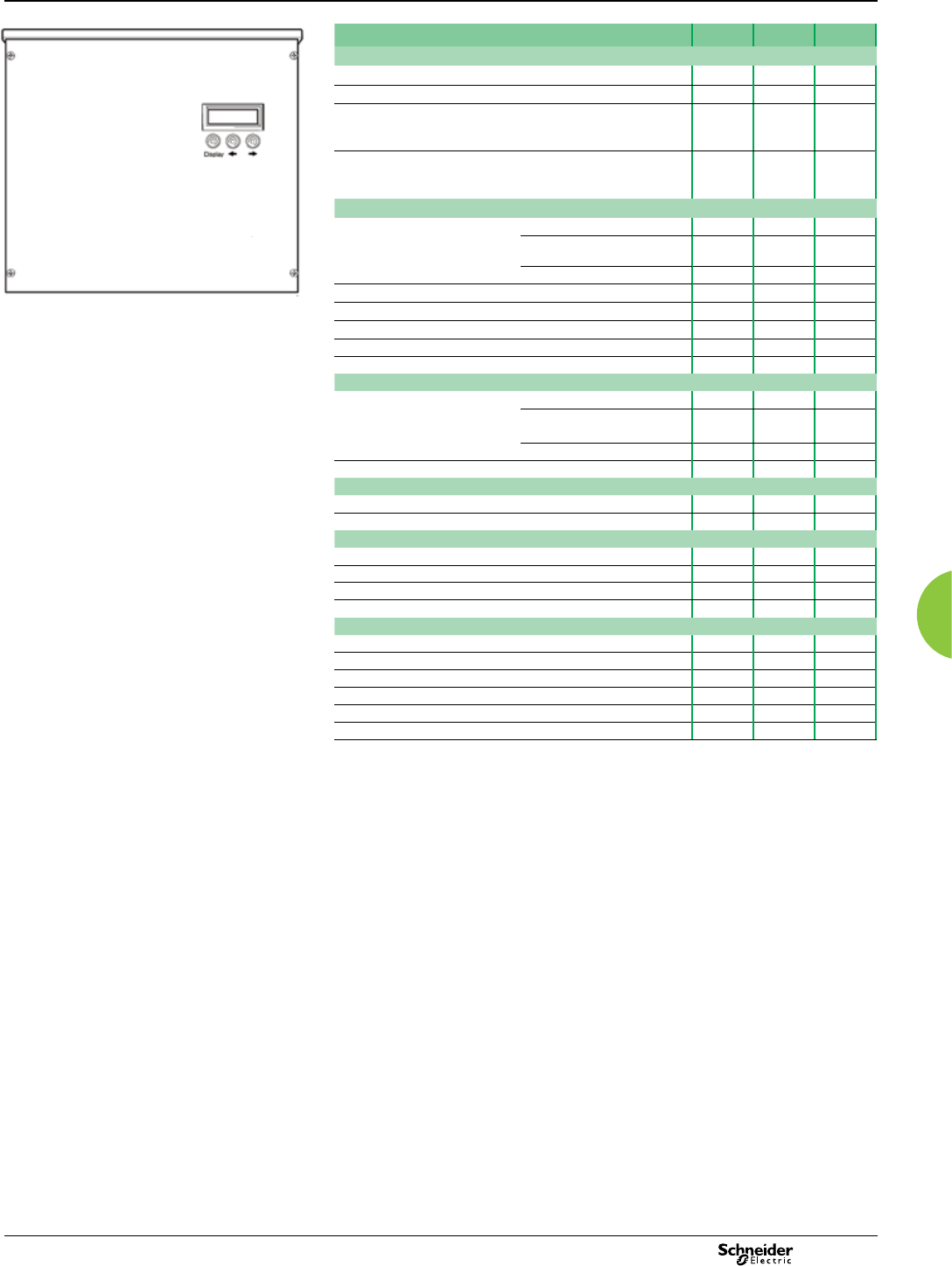
EM4800 series
Functions and characteristics (cont.)
PE86327A
PowerLogic EM4800 series digital panel meter.
Selection guide EM4805 EM4833 EM4880
General
Use on LV systems b b b
Accuracy +/- 0.5% b b b
Accuracy compliance ANSI C12.1 and C12.20 Class
0.5;
IEC 62053-22, Class 0.5S
b b b
Maximum circuits:
single-pole / single phase /
three-phase
24 / 12 / 8 b b b
Instantaneous rms values
Energy real, kWh received/delivered b b b
reactive, kvarh received/
delivered
b b b
apparent, VAh b b b
Voltage b b b
Pulse counts b b b
Voltage and current V rms, I rms per phase b b b
Power real, reactive, apparent b b b
Power factor b b b
Measurements available for data logging
Energy real, kWh received/delivered b b b
reactive, kvarh received/
delivered
b b b
apparent, VAh b b b
Voltage b b b
Display
Backlit LCD display 2 lines of 16 characters b b b
Optional remote modular display available b b b
Communication
Ethernet port b b b
V.90 modem port b b b
Pulse inputs 2b b b
Protocols: Modbus TCP/IP, HTTP, BACnet/IP, FTP, and SNTP b b b
Installation options
5 A CTs b
0.333 V CTs b
80 mA CTs b
Split core CT b b
Solid core CT b b b
Remore modular display b b b
Multi-circuit energy meters
2013 51

EM4800 series
Functions and characteristics (cont.)
Multi-circuit energy meters
Electrical characteristics
Input-voltage
characteristics
Inputs V1, V2, V3, Vn
Measured voltage 80 - 480 V AC L-L without PTs
Up to 999 kV with external PTs
Frequency range 50/60 Hz
Mechanical characteristics
Weight EM4805 approx. 5.4 kg
EM4833 / EM4880 approx. 4.0 kg
Dimensions EM4805 33.5 cm x 44 cm x 5.5 cm
(13.125 in x 17 in x 2.125 in)
EM4833 / EM4880 33.5 cm x 30.5 cm x 5.5 cm
(13.125 in x 12 in x 2.125 in)
Environmental conditions
Operating temperature -40°C to +70°C
Storage temperature -40°C to +70°C
Humidity rating 0% to 90 % RH non-condensing
Enclosure Type 1 (indoor or enclosed outdoor use)
Altitude 3000 m
Pollution degree 2
Safety and standards
UL Certied to IEC/EA/CSA 61010-1
CSA-C22.2 No 61010-1-04
FCC Part 15 Class B
ICES-003 EN55022, IEC 6100-4-5
ANSI/TIA968-A: 2002
Communication
Ports Ethernet
V.90 modem
Pulse inputs 2
Protocols: Modbus TCP/IP, HTTP, BACnet/IP,
FTP, and SNTP
Display characteristics
Integrated backlit LCD display 2 ines, 16 digits per line display;
R / L arrow buttons select metering point;
Display button cycles through measurements
per point.
2013
52
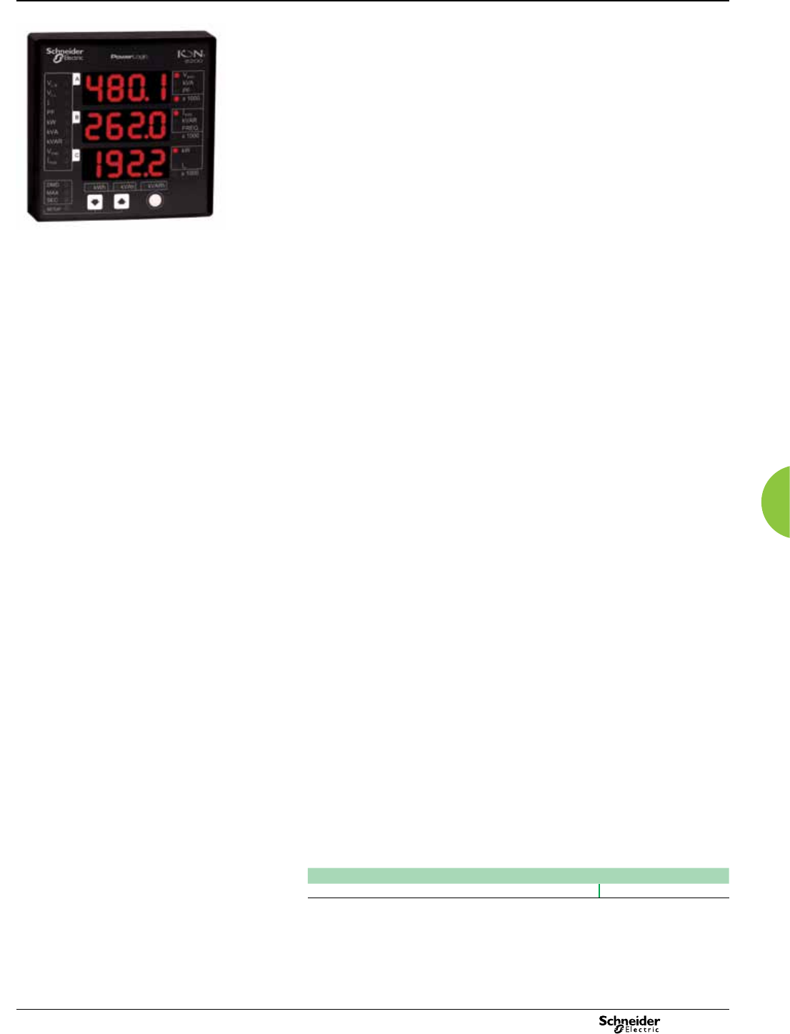
Basic multi-function metering
PE86127
The PowerLogic ION6200 meter offers outstanding quality, versatility, and
functionality in a low-cost, ultra-compact unit. The meter is simple to use and offers a
big, bright LED display for superior readability in poor lighting conditions.
Complete with four-quadrant power, demand, energy, power factor, and frequency
measurements, this versatile unit is easy to wire and mount. It offers an excellent
upgrade path that lets you start with a low-cost base model and add enhanced
functionality over the long term.
The ION6200 meter lets you upgrade functionality in the eld by activating the base
unit. Rather than carry a large inventory of pre-congured meters, genset and
electrical equipment manufacturers, panel shops, EMS manufacturers and energy
service providers can each adapt meter functionality to specic applications as
required.
Applications
Class 0.5S metering and sub-metering
Replace multiple analogueue meters
Basic metering
Cost allocation
Substation monitoring
Main characteristics
High visibility front panel display
The ION6200 displays all basic power parameters on a bright LED display with
twelve 19 mm high digits.
Megawatt option
The Megawatt option displays all power and energy values in millions (e.g.
megawatts) and volts in thousands (kilovolts), using a different front panel faceplate
than the standard meter, with labels for kV, MW, MVA, Mvar, MWh, MVAh and Mvarh.
Complete communications
Optional RS 485 port with standard Modbus RTU and ION compatible protocol; data
rates from 1,200 bps to 19,200 bps.
Modularity
The ION6200’s modular construction allows for simple retrot, allowing you to save
money by making a low initial investment that can be upgraded to meet future needs.
Easy to use
Fast setup via display or software; free conguration software; and a bright, easy to
read LED display make the ION6200 easy to use.
Accuracy certication
This meter offers IEC 60687 Class 0.5S accuracy for use as a tariff meter.
Revenue metering option
Provides power and energy measurements that are certied for revenue metering
and protection against unauthorized alteration of these measured quantities.
Flexible architecture
Patented ION® technology provides a modular, exible architecture that offers
extensive user programmability. It uniquely addresses complex monitoring and
control applications, and adapts to changing needs, avoiding obsolescence.
Multiple installation options
Supports Direct 4-wire Wye, 3-wire Wye, 3-wire Delta, Direct Delta and
single phase congurations
PowerLogic ION6200.
Part numbers
PowerLogic ION6200 meters
PowerLogic ION6200 M6200
See page 56 for part number descriptions and options.
ION6200
Functions and characteristics
2013 53
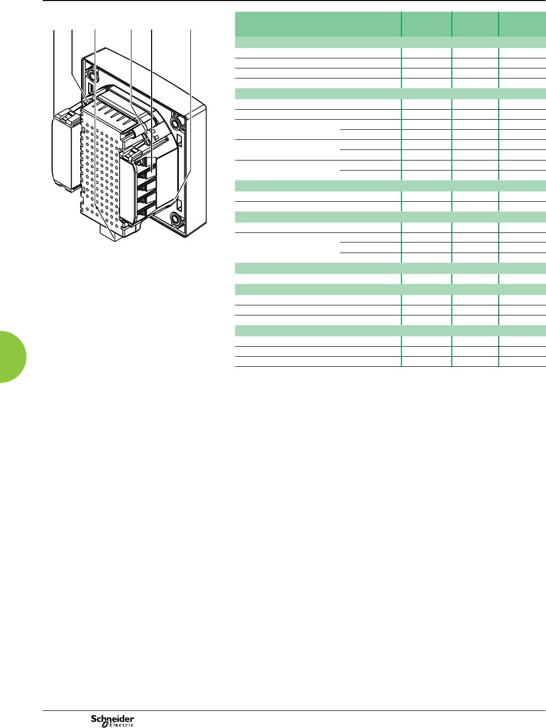
Basic multi-function metering
PE86079
1 Current inputs
2 COM1 port
3 Power supply
4 D2: Form A digital out
5 Voltage inputs
6 D1: Form A digital out
Selection guide ION6200
Standard
ION6200
EP #1*
ION6200
EP #2*
General (N) (P) (R)
Use on LV and HV systems b b b
Current and voltage accuracy(1) 0.3% 0.3% 0.3%
Energy and power accuracy 0.5% 0.5% 0.5%
Number of samples per cycle 64 64 64
Instantaneous RMS values
Current and voltage(2) b b b
Frequency - b b
Active power Total - b b
per phase - - b
Reactive and apparent power Total - - b
per phase - - b
Power factor Total - b b
per phase - - b
Energy values
Active energy(3) -b b
Reactive, apparent energy(3) - - b
Demand values
Current Present and max. -b b
Active power Present - - b
Max. - b b
Reactive and apparent power Present and max. - - b
Power quality measurements
Harmonic distortion(2) Current, voltage - - b
Display and I/O
LED display b b b
Pulse output b b b
Direct voltage connection (V ac) 400/690 400/690 400/690
Communication
RS-485 port b b b
ION compatibility b b b
Modbus RTU protocol b b b
(*) EP = ’Enhanced package.’
(1) For L-N only. L-L = 0.5% reading accuracy.
(2) Some values not available when Volts Mode is set to Delta or Delta Direct.
(3) Additional energy values available on Standard and EP#1 models through pulse output.
13456
2
ION6200
Functions and characteristics (cont.)
2013
54
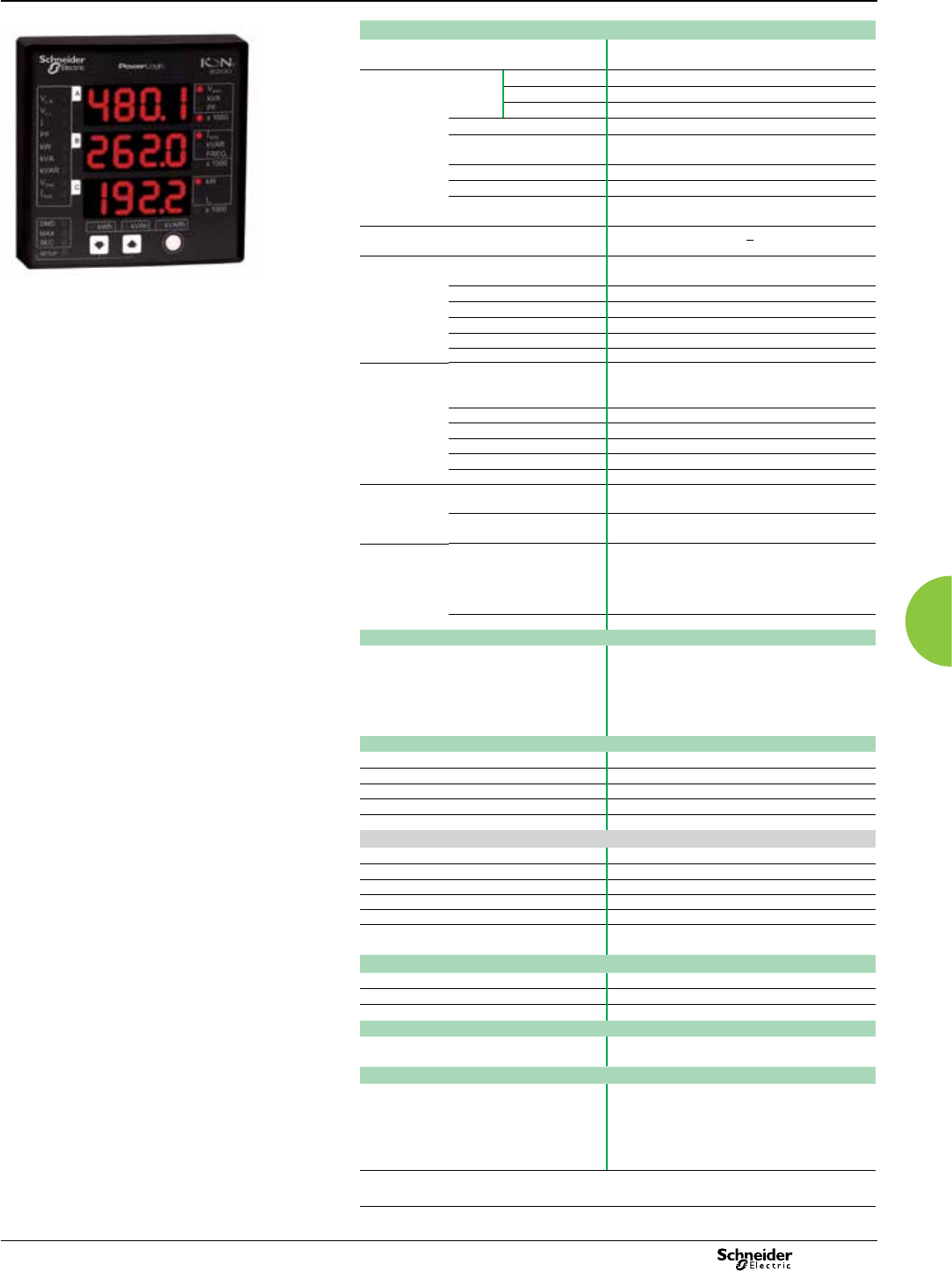
Basic multi-function metering
PE86127
PowerLogic ION6200.
Electrical characteristics
Type of measurement True rms electrical parameters
Up to 64 samples/cycle
Measurement
accuracy
Current ≥ 5% of full scale: 0.3% reading
< 5% of full scale 0.3% reading + 0.05% full scale
I4 derivation 0.6% reading + 0.05% full scale
Voltage L-N 0.3% reading, L-L 0.5% reading
Power IEC 60687 Class 0.5
ANSI 12.20 Class 0.5
Frequency 0.1% reading
Power factor 1.0% reading
Energy IEC 60687 Class 0.5
ANSI 12.20 Class 0.5
Harmonic distortion Total harmonic distortion + 1.0%
Input-voltage
characteristics
Measured voltage(1) 60-400 LN (103.5-690 LL) V ac RMS (3 phase)
60-400 LN V ac (single phase)
Measurement range 60-400 LN V ac
Impedance 2 MW /phase
Inputs V1, V2, V3, Vref
Overload 1500 V ac RMS continuous
Dielectric withstand >3250 V ac RMS; 60 Hz for 1 minute
Input-current
characteristics
Rated Inputs(1) 5 A nominal /10 A full scale RMS (+20%
overrange with full accuracy, 300 V RMS to
ground)
Permissible overload 120 A RMS for 1 second, non-recurring
Starting current 0.005 A RMS
Burden 0.05 VA (typical) @ 5 A RMS
Inputs I1, I2, I3
Dielectric withstand 3000 V RMS for 1 minute
Power supply AC Standard: 100-240 V ac, 50-60 Hz
480 V: 480 V ac +/- 5%, 60 Hz
DC Standard: 110-300 V dc
Low Voltage DC: 20-60 V dc
Input/outputs Digital outputs 2 optically isolated digital outputs for KY pulsing
or control
Max forward current: 150 mA
Max voltage: 200 V
Max current: 150 mA
RS-485 port Optically isolated
Mechanical characteristics
Weight 0.68 kg (shipping)
IP degree of protection (IEC 60529) Meter with display: front IP 65, back IP 30;
Transducer unit (no integrated display): IP 30
Remote display unit: front IP 65; back IP 30
Dimensions Basic unit installed depth: 106.7x106.7x40.6 mm
Remote display: 106.7x106.7x22.9 mm
Environmental conditions
Operating temperature -20°C to 70°C ambient air
Storage temperature -40°C to 85°C
Humidity rating 5% to 95% non-condensing
Pollution degree 2
Installation category III (Distribution)
Electromagnetic compatibility
Electrostatic discharge IEC 61000-4-2 (EN61000-4-2/IEC801-2)
Immunity to radiated elds IEC 61000-4-3 (EN61000-4-3/IEC801-3)
Immunity to fast transients IEC 61000-4-4 (EN61000-4-4/IEC801-4)
Surge immunity IEC 61000-4-5 (EN61000-4-5/IEC801-5)
Conducted immunity IEC 61000-4-6 (EN61000-4-6/IEC801-6)
Electromagnetic compatibility for industrial
environments
IEC 61000-6-2
Safety
cUL compliant to CSA C22.2 No. 1010-1
IEC1010-1 (EN61010-1)
UL 3111-1
Communications
RS 485 port Up to 19 200 bps, Modbus RTU, ION compatible
protocol
Display characteristics
Bright LED display 19 mm high digits
Displays all basic power parameters
Easy setup for common conguration
parameters
Password protection on setup parameters
Password protection for demand reset
(1) The meter inputs can be used with PTs that have secondaries rated between 50 V ac and
347 V ac +25%. Use CTs that are compliant with the electrical safety code in your region.
ION6200
Functions and characteristics (cont.)
2013 55
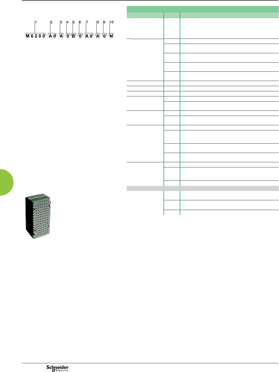
Basic multi-function metering
Part Numbers
Item Code Description
PE86080
1 Model M6200 ION6200 Meter Kit: ION6200 Meter base, Options Card and
Power Supply
Example product part number.
1 Model.
2 Form factor.
3 Current inputs.
4 Voltage inputs.
5 Power supply.
6 System frequency.
7 Communications.
8 Onboard inputs/outputs.
9 Security.
10 Measurement package.
2Form Factor A0 Integrated display model
R1 Transducer model with DIN rail mount, Remote Display and
14-ft cable (RJ11, 6 conductor, 26 gauge)
R2 Transducer model with DIN rail mount, Remote Display and
6-ft cable (RJ11, 6 conductor, 26 gauge)
R3 Transducer model DIN rail mount, Remote Display and 30-ft
cable (RJ11, 6 conductor, 26 gauge)
T1 Transducer model with DIN rail mount (requires Comms or
pulse outputs)
3Current Inputs A10 Amp current inputs (12 Amp max)
4Voltage Inputs 0Autoranging (57-400 V ac L-N / 99-690 V ac L-L)
6System Frequency 0Calibrated for use with 50 Hz or 60 Hz systems
7Communications Z0 No communications
A0 Single RS-485 port (supports Modbus RTU protocol and
ION-compatible PML protocol)
8 I/O A No I/O
BThis option activates the two Form A digital outputs for kWh,
kvarh energy pulsing
9 Security 0 No hardware lock (setup is password protected)
2RMANSI: Revenue Meter approved for use in the United
States (ANSI C12.16 approved; meets ANSI C12.20 class 0.5
accuracy at 23°C; 10A current inputs only)
3RMICAN: Measurement Canada approved revenue meter for
use in Canada (10A current inputs only)
4**RMICAN-SEAL: Factory-sealed and Measurement Canada
approved revenue meter
10 Measurement
package
NStandard Measurements (Volts/Amps per phase and avg)
PEnhanced Package #1 (Standard Measurements plus
Energy/Power total, Frequency, Power Factor total, Neutral
Current
REnhanced Package #2 (all measurements)
Power supply
PE86081
Power supply P620PB Standard plug-in power supply (100-240 V ac / 50-60 Hz or
110-300 V dc)
P620PC Low voltage DC plug-in power supply (20-60 V dc)
P620PD 480V power supply (480 VAC, 60 Hz)
ION6200
Functions and characteristics (cont.)
2013
56
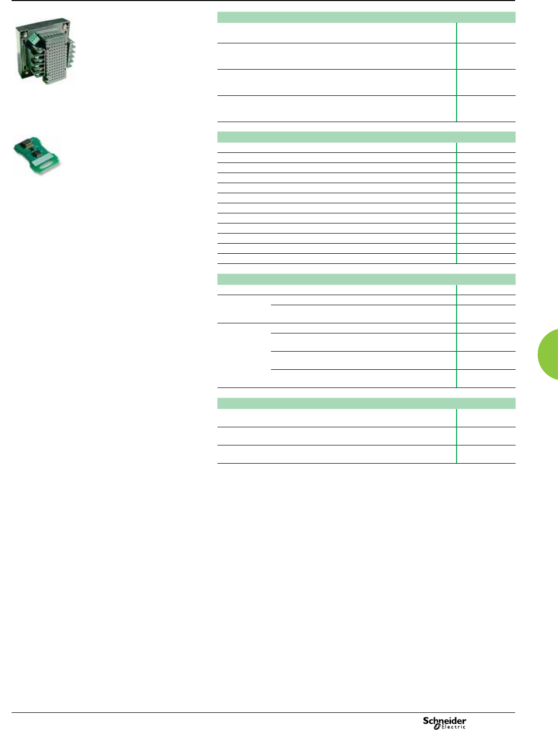
Basic multi-function metering
PE86082
MegaWatt options
MegaWatt option on meter base with integrated display. Not available for
RMICAN or RMICAN-sealed meters
M0
MegaWatt option on Transducer model with DIN rail mount, Remote Display
and 14-ft cable (RJ11, 6 conductor, 26 gauge). Not available with Security
options RMICAN or RMICAN-SEAL.
N1
MegaWatt option on Transducer model with DIN rail mount, Remote Display
and 6-ft cable (RJ11, 6 conductor, 26 gauge). Not available with Security
options RMICAN or RMICAN-SEAL.
N2
MegaWatt option on Transducer model with DIN rail mount, Remote Display
and 30-ft cable (RJ11, 6 conductor, 26 gauge). Not available with Security
options RMICAN or RMICAN-SEAL.
N3
PE86083
Options card
1Standard Measurements Z0A0N
2Enhanced Package #1 Z0A0P
3Enhanced Package #2 Z0A0R
4Standard Measurements, two pulse outputs Z0B0N
5Enhanced Package #1, two pulse outputs Z0B0P
6Enhanced Package #2, two pulse outputs Z0B0R
7Standard Measurements, RS-485 A0A0N
8Enhanced Package #1, RS-485 A0A0P
9Enhanced Package #2, RS-485 A0A0R
10 Standard Measurements, two pulse outputs, RS-485 A0B0N
11 Enhanced Package #1, two pulse outputs, RS-485 A0B0P
12 Enhanced Package #2, two pulse outputs, RS-485 A0B0R
Remote modular display (RMD)
Model M620D
Display Type Standard Display R
MegaWatt option - for use with Transducer meter base with
MegaWatt option
N
Cable Length No Cable 0
14-ft cable for connecting Remote Display Unit to the
ION6200 Transducer meter base
1
6-ft cable for connecting Remote Display Unit to the
ION6200 Transducer meter base
2
30-ft cable for connecting Remote Display Unit to the
ION6200 Transducer meter base
3
Cables for remote modular display
14-ft cable for connecting Remote Display Unit to the ION6200 transducer
meter base.
P620C1
6-ft cable for connecting Remote Display Unit to the ION6200 transducer
meter base.
P620C2
30-ft cable for connecting Remote Display Unit to the ION6200 transducer
meter base.
P620C3
ION6200
Functions and characteristics (cont.)
2013 57
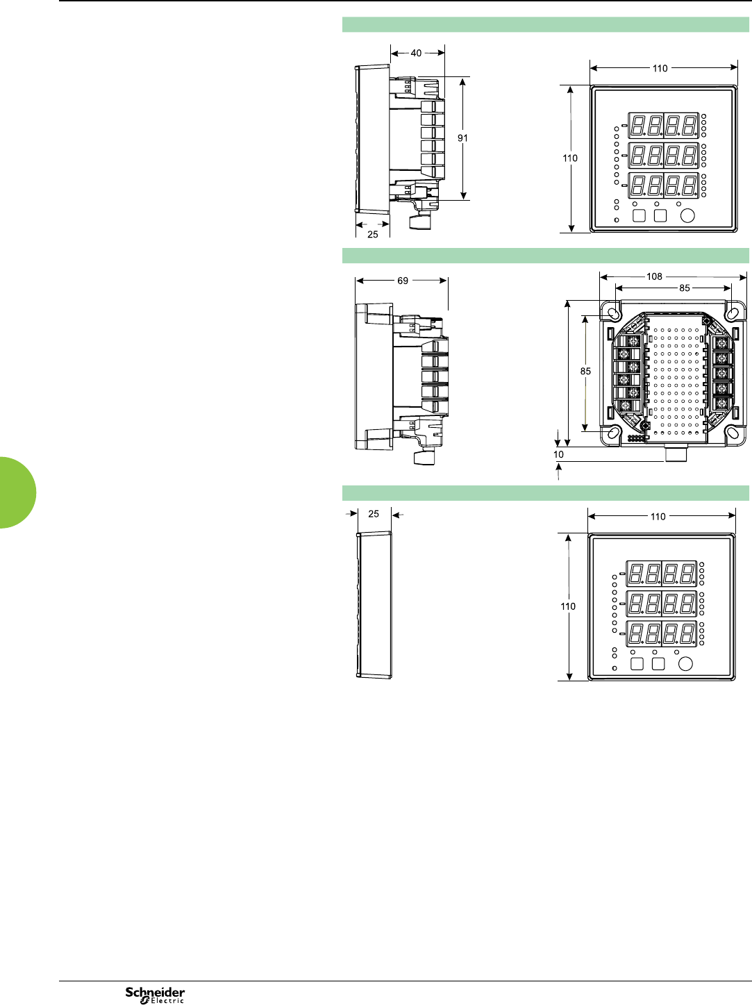
ION6200
Dimensions and connections
ION6200 integrated model dimensions
PE86084
PE86085
ION6200 TRAN model dimensions
PE86086
PE86087
ION6200 RMD dimensions
PE86088
PE86085
Basic multi-function metering
2013
58
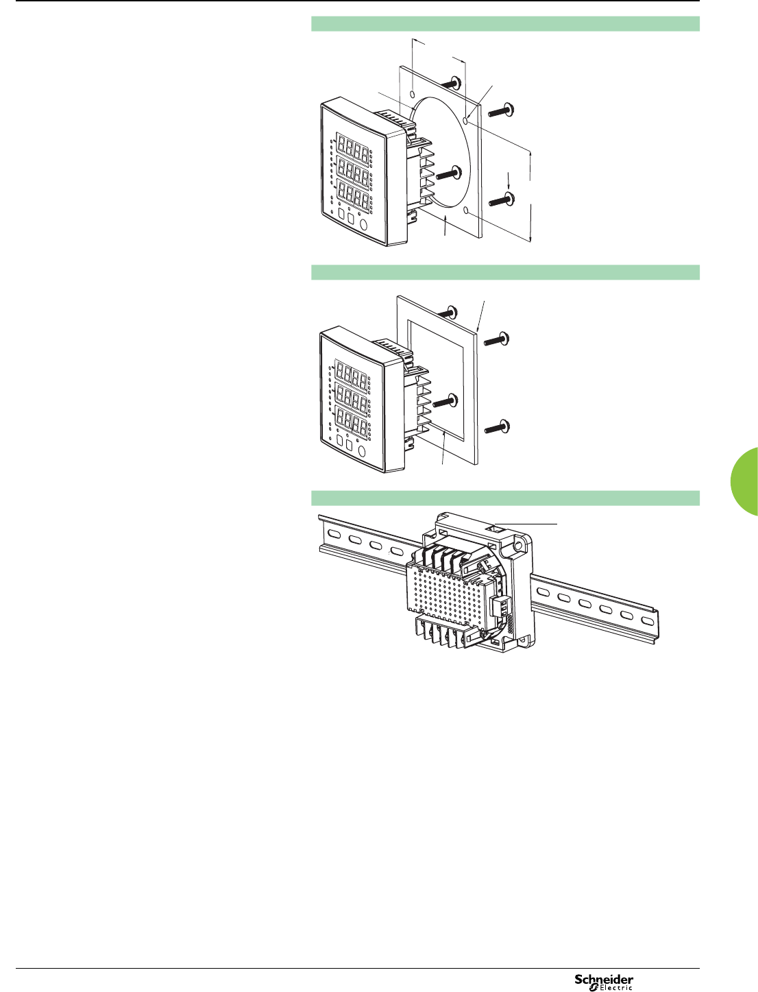
ION6200
Dimensions and connections (cont.)
Mounting integrated model - ANSI 4” (4 1/2” Switchboard)
PE86089
Mounting integrated model - DIN 96
PE86090
Mounting the TRAN model
PE86091
85.7 mm
4.67 mm
diameter
screw &
washer
85.7 mm
mounting
surface
101.6 mm
diameter
screws t in corners;
holes not required
92 mm x 92 mm
RMD port faces up
Basic multi-function metering
2013 59
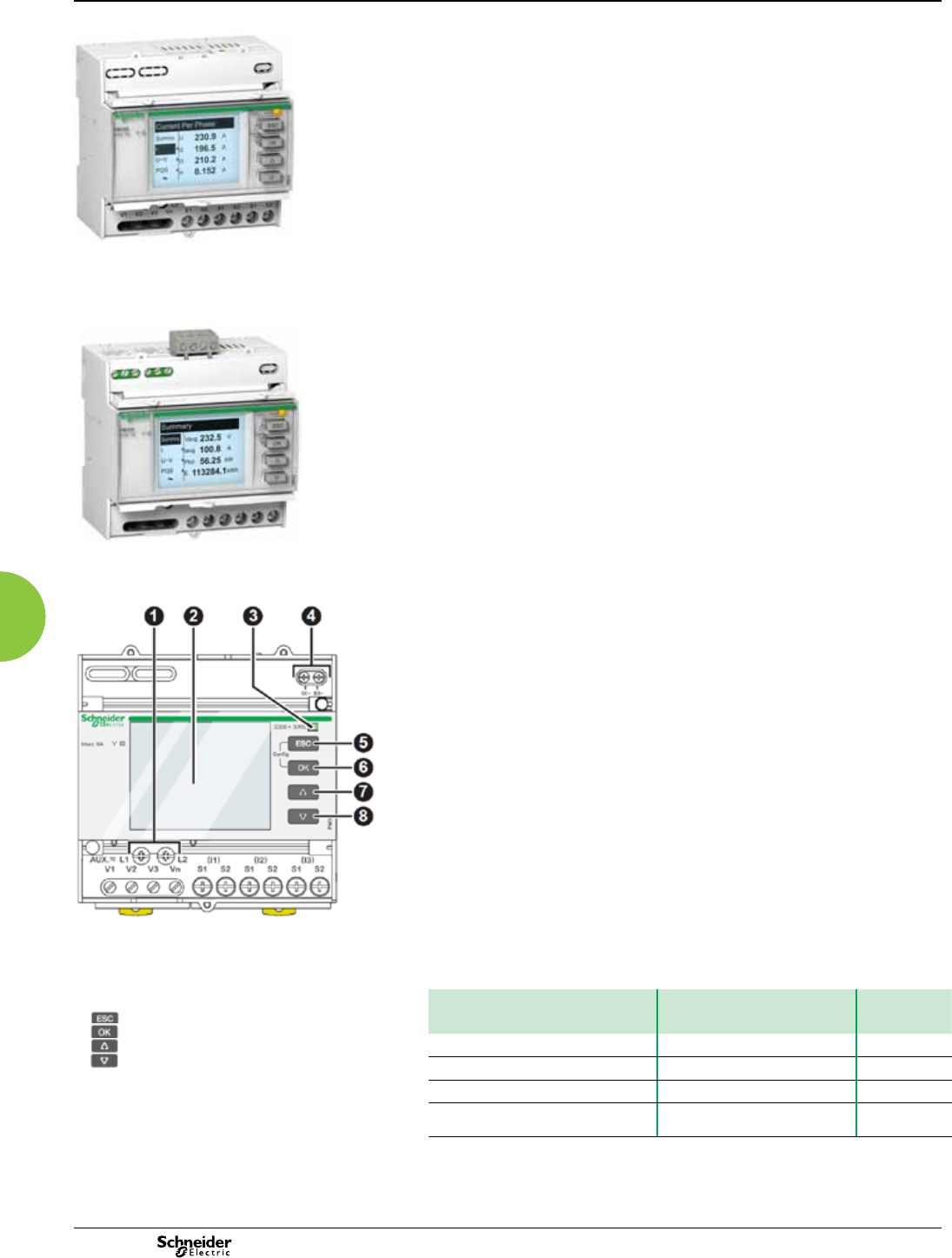
Power Meter Series PM3200
Functions and characteristics
Basic multi-function metering
PB108433
This PowerLogic Power meter offers basic to advanced measurement capabilities.
With compact size and DIN rail mounting, the PM3200 allows mains and feeders
monitoring in small electrical cabinets. Combined with current transformers and
voltage transformers, these meters can monitor 2-, 3- and 4-wire systems. The
graphic display has intuitive navigation to easily access important parameters.
Four versions are available offering basic to advanced applications:
b PM3200
v Electrical parameters I, In, U, V, PQS, E, PF, Hz
v Power/current demand
v Min/max.
b PM3210
v Electrical parameters I, In, U, V, PQS, E, PF, Hz, THD
v Power/current demand, peak demand
v Min/max.
v 5 timestamped alarms
v kWh pulse output
b PM3250
v Electrical parameters I, In, U, V, PQS, E, PF, Hz, THD
v Power/current demand, peak demand
v Min/max.
v 5 timestamped alarms
v LED to indicate communications
v RS485 port for Modbus communication
b PM3255
v Electrical parameters I, In, U, V, PQS, E, PF, Hz, THD
v Power/current demand and peak demand
v Min/max. and 15 timestamped alarms
v LED to indicate communications
v Up to 4 tariffs management
v 2 digital inputs, 2 digital outputs
v Memory for load prole (demand 10mn to 60mn)
v RS485 port for Modbus communication
b Innovative design makes the meters smart and simple:
b Easy to install for panel builders
b Easy to commission for contractors and installers
b Easy to operate for end users
Applications
Cost management applications
b�Bill checking
b Sub-billing, including WAGES view
b Cost allocation, including WAGES view
Network management applications
b Panel instrumentation
b Up to 15 onboard timestamped alarms to monitor events
b Easy integration with PLC system by input/output interface
Market segments
b Buildings
b Industry
b Data centres and networks
b Infrastructure (airports, road tunnels, telecom)
Part numbers
Power Meter Series PM3200
PB108435
Power Meter Series PM3255
Meter model and description Performance Part no.
PM3200 basic power meter Basic power meter METSEPM3200
PM3210 power meter with pulse output Power, current, THD, peak demand METSEPM3210
PM3250 power meter with RS485 port Power, current, THD, peak demand METSEPM3250
PM3255 power meter plus 2 digital inputs,
2 digital outputs with RS485 port
Power, current, THD, peak demand,
memory for load prole
METSEPM3255
Front of meter parts
1 Control power
2 Display with white backlit
3 Flashing yellow meter indicator (to check accuracy)
4 Pulse output for remote transfer (PM3210)
5 Cancellation
6 Conrmation
7 Up
8 Down
2013
60
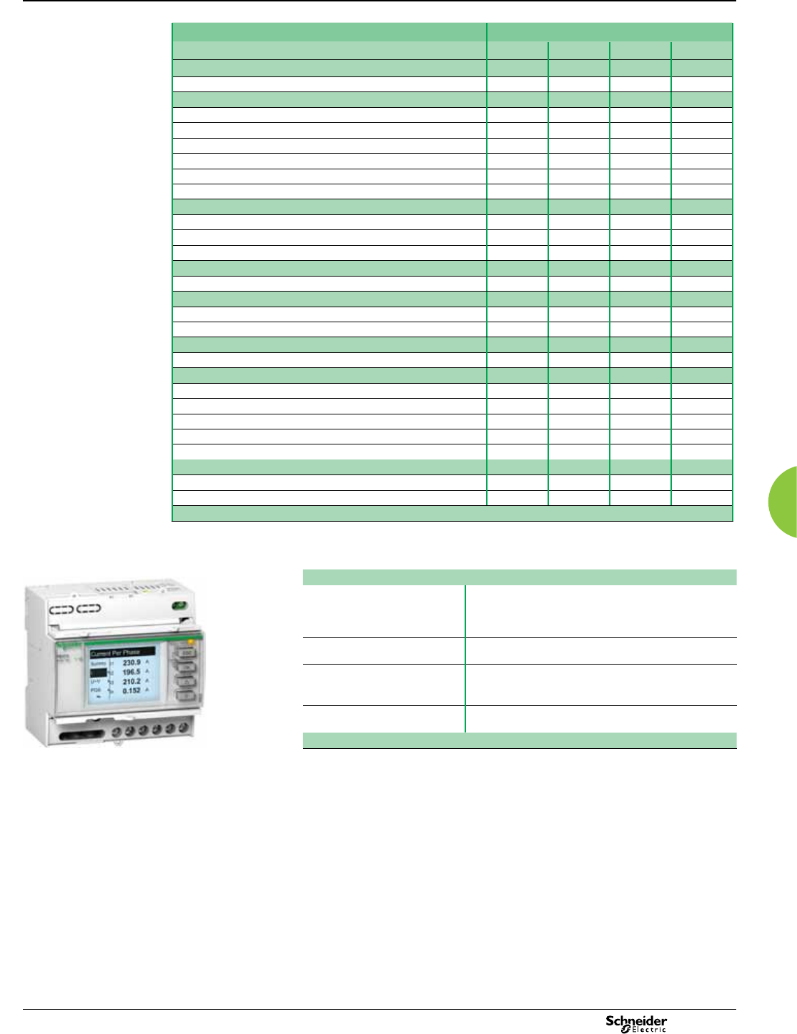
Basic multi-function metering Power Meter Series PM3200
Functions and characteristics (cont.)
PB108434
Connectivity advantages
Programmable digital input External tariff control signal (4 tariffs)
Remote Reset partial counter
External status like breaker status
Collect WAGES pulses
Programmable digital output Alarm (PM3255)
kWh pulses
Graphic LCD display Backlit graphic display allows smart navigation in relevant
information and in multi languages
Communication Modbus RS485 with screw terminals allows connection to a
daisy chain
Power Meter Series PM3210
Function guide PM3200 Range
PM3200 PM3210 PM3250 PM3255
Performance standard
IEC61557-12 PMD/Sx/K55/0.5 bbbb
General
Use on LV and HV systems bbbb
Number of samples per cycle 32 32 32 32
CT input 1A/5A bbbb
VT input bbbb
Multi-tariff 4 4 4 4
Multi-lingual backlit display bbbb
Instantaneous rms values
Current, voltage Per phase and average bbbb
Active, reactive, apparent power Total and per phase bbbb
Power factor Total and per phase bbbb
Energy values
Active, reactive and apparent energy; import and export bbbb
Demand value
Current, power (active, reactive, apparent) demand; present bbbb
Current, power (active, reactive, apparent) demand; peak bbb
Power quality measurements
THD Current and voltage bbb
Data recording
Min/max of the instantaneous values bbbb
Power demand logs b
Energy consumption log (day, week, month) b
Alarms with time stamping 5 5 15
Digital inputs/digital outputs 0/1 2/2
Communication
RS-485 port b b
Modbus protocol b b
2013 61

Power Meter Series PM3200
Functions and characteristics (cont.)
Basic multi-function metering
Specications PM3200 Range
Type of measurement True rms up to the 15th harmonic on three-phase (3P,3P+N) and single-phase
AC systems. 32 samples per cycle
Measurement accuracy
Current with x/5A CTs 0.3% from 0.5A to 6A
Current with x/1A CTs 0.5% from 0.1A to 1.2A
Voltage 0.3% from 50V to 330V (Ph-N), from 80V to 570V (Ph-Ph)
Power factor ±0.005 from 0.5A to 6A with x/5A CTs; from 0.1A to 1.2A with x/1A CTs and from
0.5L to 0.8C
Active/Apparent Power with x/5A CTs Class 0.5
Active/Apparent Power with x/1A CTs Class 1
Reactive power Class 2
Frequency 0.05% from 45 to 65Hz
Active energy with x/5A CTs IEC62053-22 Class 0.5s
Active energy with x/1A CTs IEC62053-21 Class 1
Reactive energy IEC62053-23 Class 2
Data update rate
Update rate 1s
Input-voltage characteristics
Measured voltage 50V to 330V AC (direct / VT secondary Ph-N)
80V to 570V AC (direct / VT secondary Ph-Ph)
up to 1MV AC (with external VT)
Frequency range 45Hz to 65Hz
Input-current characteristics
CT primary Adjustable from 1A to 32767A
CT secondary 1A or 5A
Measurement input range with x/5A CTs 0.05A to 6A
Measurement input range with x/1A CTs 0.02A to 1.2A
Permissible overload 10A continuous, 20A for 10s/hour
Control Power
AC 100/173 to 277/480V AC (+/-20%), 3W/5VA; 45Hz to 65Hz
DC 100 to 300V DC, 3W
Input
Digital inputs (PM3255) 11 to 40V DC, 24V DC nominal, <=4mA maximum burden, 3.5kVrms insulation
Output
Digital output (PM3210) Optocoupler, polarity sensitive, 5 to 30V, 15mA max, 3.5kVrms insulation
Digital outputs (PM3255) Solid state relay, polarity insensitive, 5 to 40V, 50mA max, 50Ω max,
3.5kVrms insulation
2013
62
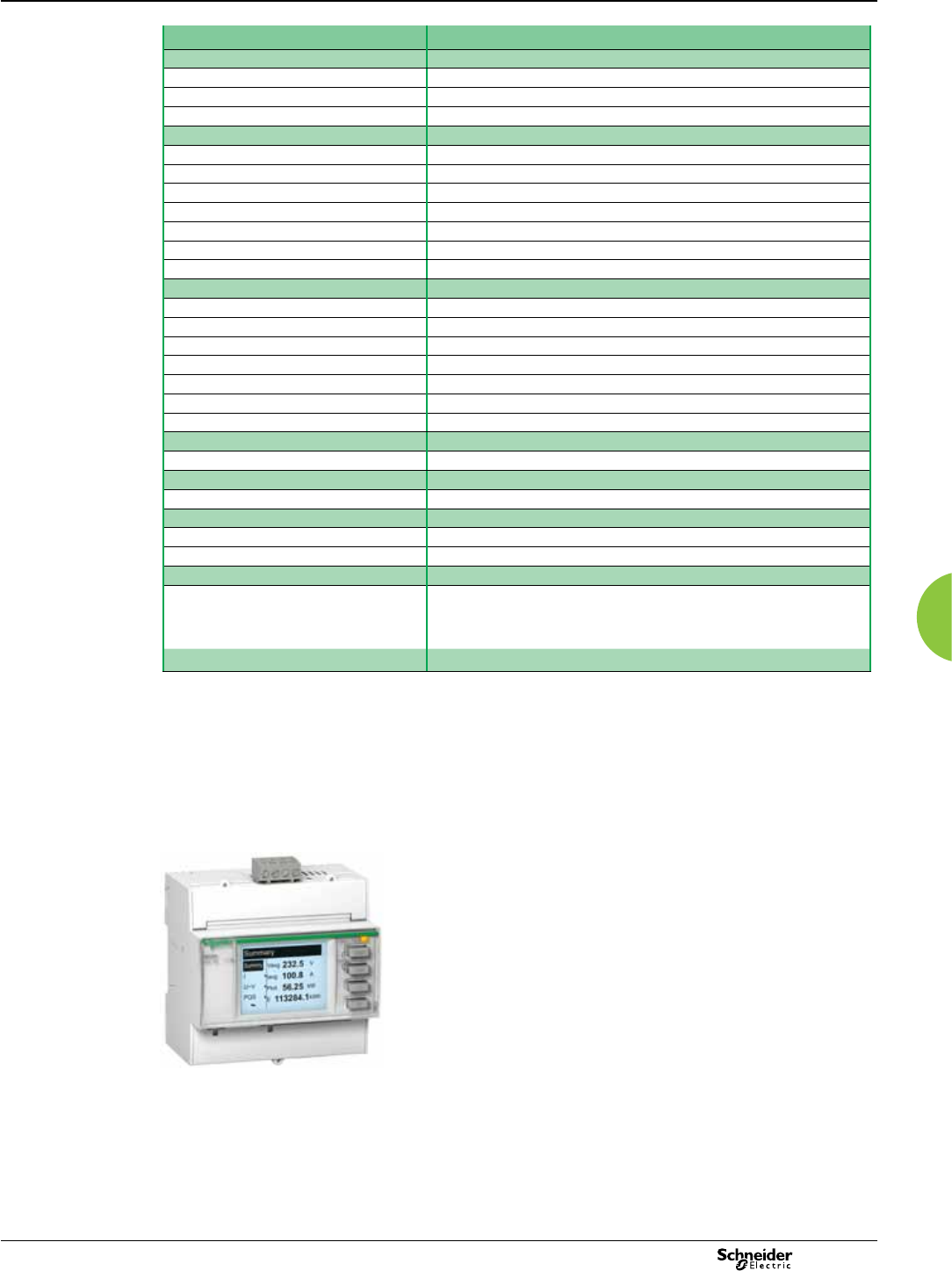
Basic multi-function metering Power Meter Series PM3200
Functions and characteristics (cont.)
Specications (continued) PM3200 Range
Mechanical characteristics
Weight 0.26kg
IP degree of protection (IEC60529) IP40 front panel, IP20 meter body
Dimension 90 x 95 x 70mm
Environmental conditions
Operating temperature -25 ºC to +55 ºC
Storage temperature -40 ºC to +85 ºC
Humidity rating 5 to 95% RH at 50ºC (non-condensing)
Pullution degree 2
Metering category III, for distribution systems up to 277/480VAC
Dielectric withstand As per IEC61010-1, Doubled insulated front panel display
Altitude 3000m max
Electromagnetic compatibility
Electrostatic discharge Level IV (IEC61000-4-2)
Immunity to radiated elds Level III (IEC61000-4-3)
Immunity to fast transients Level IV (IEC61000-4-4)
Immunity to surge Level IV (IEC61000-4-5)
Conducted immunity Level III (IEC61000-4-6)
Immunity to power frequency magnetic elds 0.5mT (IEC61000-4-8)
Conducted and radiated emissions Class B (EN55022)
Safety
CE as per IEC61010-1 (1)
Communication
RS485 port Half duplex, from 9600 up to 38400 bauds, Modbus RTU (double insulation)
Display characteristics
Dimensions (VA) 43mm x 34.6mm
Display resolution 128 x 96 dots
Standard compliance
IEC61557-12, EN61557-12
IEC61010-1, UL61010-1
IEC62052-11, IEC62053-21, IEC62053-22, IEC62053-23
EN50470-1, EN50470-3
(1) Protected throughout by double insulation
Multi-tariff capability
The PM3200 range allows arrangement of kWh
consumption in four different registers. This can be
controlled by:
b Digital Inputs. Signal can be provided by PLC or utilities
b Internal clock programmable by HMI
b Through communication
This function allows users to:
b Make tenant metering for dual source applications to
differentiate backup source or utility source
b Understand well the consumption during working time
and non working time, and between working days and
weekends
b Follow up feeders consumption in line with utility tariff
rates
Power Meter Series PM3250
2013 63
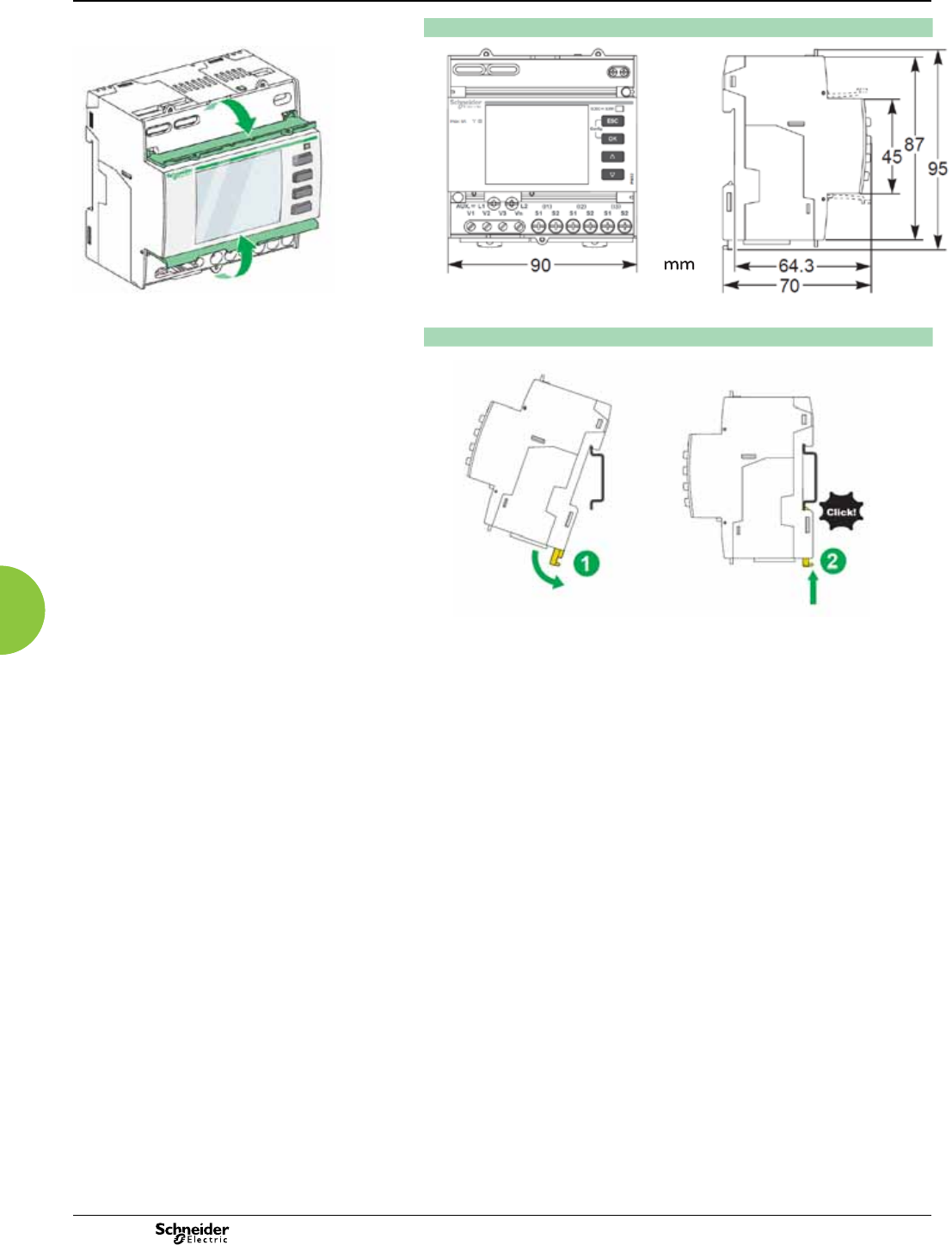
Power Meter Series PM3200
Dimensions and connection
Basic multi-function metering
PM3200 series dimensions
PB105302
PM3200 top and lower aps PM3200 series easy installation
PB105446
2013
64
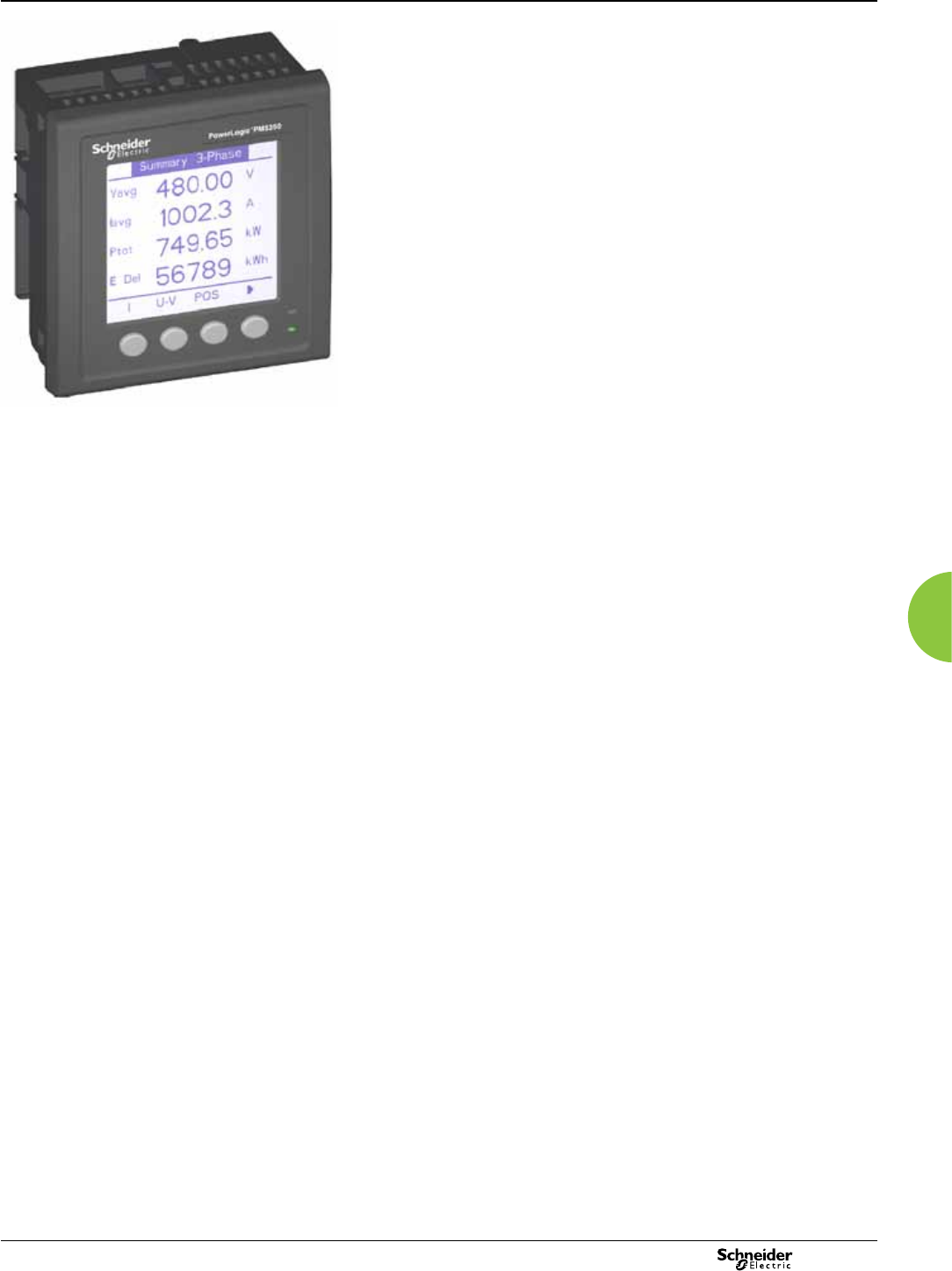
65
2013
Basic multi-funtional metering PM5350
Functions and characteristics
PE86278
PowerLogic PM5350.
The PowerLogic PM5350 power meter offers all the measurement capabilities
required to monitor an electrical installation in a single 96 x 96 mm unit extending only
44 mm behind the mounting surface.
With its large display, all three phases and neutral can be monitored simultaneously.
The bright, anti-glare display features large characters and powerful backlighting
for easy reading even in extreme lighting conditions and viewing angles. The meter
menus are understood by all, with the availability of two languages (English/Chinese)
included standard in the PM5350.
Its compact size and high performance make the PowerLogic PM5350 suitable for
many applications.
Applications
Panel instrumentation.
Cost allocation or energy management.
Electrical installation remote monitoring.
Alarming with under/over, digital status, control power failure, meter reset,
self diagnostic issue.
Circuit Breaker monitoring and control with relay outputs and whetted digital inputs.
Main characteristics
Easy to install
Mounts using two clips, no tools required. Ultra compact meter with 44mm depth
connectable up to 480 VL-L without voltage transformers for installations compliant
with category III, as per IEC 61010-1. See specication table for UL voltage limits.
Easy to operate
Intuitive navigation with self-guided, language selectable menus, six lines, four
concurrent values. Two LEDs on the meter face help the user conrm normal
operation (heartbeat/communications indicator LED: green and other LED orange,
customizable either for alarms or energy pulse outputs).
Easy circuit breaker monitoring and control
The PM5350 provides two relay outputs (high performance) with capability to
command most of the circuit breaker coils directly. In addition, monitored switches
can be wired directly to the meter without external power supply.
System status at a glance
Bright, anti-glare, backlit display plus two LEDs; orange for energy pulse or alarm
and green for heartbeat/communications indication.
IEC 62053-22 class 0.5S accuracy for active energy
Accurate energy measurement for cost allocation.
Power Quality analysis
The PM5350 offers THD and TDD measurements as standard. Total Demand
Distortion is based on a point of common coupling (PCC), which is a common point
that each user receives power from the power source. The TDD compares the
contribution of harmonics versus the maximum demand load.
Load management
Peak demands with time stamping are provided. Predicted demand values can be
used in basic load shedding applications.
Alarming with time stamping
Over 30 alarm conditions, such as under/over conditions, digital input changes, and
phase unbalance inform you of events. A time-stamped log maintains a record of the
last 40 alarm events.
Load timer
Load timer setpoint adjustable to monitor and advise maintenance requirements.
Performance Standard Meets IEC 61557-12 PMD/S/K70/0.5.
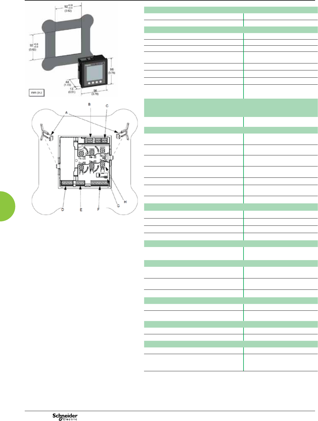
66 2013
Basic multi-funtional metering PM5350
Functions and characteristics (cont.)
PE86323
General
Use on LV and MV systems b
Basic metering with THD and min/max readings b
Instantaneous rms values
Current Total, Phases and neutral b
Voltage Total, Ph-Ph and Ph-N b
Frequency b
Real, reactive, and
apparent power
Total and per phase Signed
True Power Factor Total and per phase Signed, Four Quadrant
Displacement PF Total and per phase Signed, Four Quadrant
Unbalanced I, VL-N, VL-L b
PE86324
Energy values Stored in
non-volatile
memory
Accumulated Active, Reactive and Apparent Energy Received/Delivered;
Net and absolute;
b
Demand values
Current average Present, Last, Predicted,
Peak, & Peak Date Time
b
Active power Present, Last, Predicted,
Peak, & Peak Date Time
b
Reactive power Present, Last, Predicted,
Peak, & Peak Date Time
b
Apparent power Present, Last, Predicted,
Peak, & Peak Date Time
b
Peak demand with timestamping D/T for current & powers b b
Demand calculation Sliding, xed and rolling block,
thermal
b b
Synchronization of the measurement window b b
Other measurements
I/O timer b b
Operating timer b b
Active load timer b b
Alarm counters b b
Power quality measurements
THD, thd (Total Harmonic Distortion) I,VLN, VLL
TDD, thd (Total Demand Distortion) b
Data recording
Min/max of instantaneous values, plus phase
identication
b b
Alarms with 1s timestamping Standard 29; Unary 4;
Digital 4
Alarms stored in non-volatile memory 40 events b
Inputs/Outputs
Digital inputs 4 (DI1, DI2, DI3, DI4)
Digital outputs 2 relay outputs (DO1,
DO2)
Display
White backlit LCD display, 6 lines, 4 concurrent values b
IEC or IEEE visualization mode b
Communication
Modbus RTU, Modbus ASCII, Jbus Protocol b
Firmware update via RS485 serial port
(DLF3000 via the Schneider Electric website:
www.schneider-electric.com)
b
PM5350 meter parts
A Retainer clips.
B Control power supply connector.
C Voltage inputs.
D Digital outputs.
E Rs485 port (COM1).
F Digital outputs.
G Optical revenue switch.
H Current inputs.
67
2013
Basic multi-funtional metering PM5350
Functions and characteristics (cont.)
Electrical characteristics
PE86292
Type of measurement True rms up to the 15th harmonic on three-phase
(3P, 3P + N)
32 samples per cycle, zero blind
Measurement
accuracy
Current, Phase (1)±0.30%
Voltage, L-N (1)±0.30%
Power Factor (1)±0.005
Power, Phase IEC 61557-12 Class 0.5; For 5 A nominal CT (for 1
A nominal CT when I > 0.15A)
±0.5% from 0.25 A to 9.0 A at COS φ = 1
±0.6% from 0.50 A to 9.0 A at COS φ = 0.5 (ind or cap)
Frequency (1)±0.05%
Real Energy IEC 62053-22 Class 0.5S; IEC 61557-12 Class 0.5;
For 5 A nominal CT (for 1 A nominal CT when I > 0.15A)
±0.5% from 0.25 A to 9.0 A at COS φ = 1
±0.6% from 0.50 A to 9.0 A at COS φ = 0.5 (ind or cap)
IEC 61557-12 Class 0.5
Reactive Energy IEC 62053-23 Class 3, IEC 61557-12 Class 2
For 5 A nominal CT (for 1 A nominal CT when I > 0.15A)
±2.0% from 0.25 A to 9.0 A at SIN φ = 1
±2.5% from 0.50 A to 9.0 A at SIN φ = 0.5 (ind or cap)
Data update rate 1 second nominal (50/60 cycles)
Input-voltage VT primary 1.0 MV AC max, starting voltage depends on VT ratio.
U nom 277 V L-N
Measured voltage with
overrange & Crest Factor
IEC: 20 to 690 V AC L-L; 20 to 400 V AC L-N
UL: 20 to 300 V AC L-L
Permanent overload 700 Vac L-L, 404 Vac L-N
Impedance 10 M W
Front screen view of PM5350. Frequency range 45 to 70 Hz
Input-current CT ratings Primary Adjustable 1 A to 32767 A
Secondary 1A, 5 A nominal
Measured voltage with
overrange & Crest Factor
5 mA to 9 A
Withstand Continuous 20 A,10 sec/hr 50 A,1 sec/hr 500 A
Impedance < 0.3 mW
Frequency range 45 to 70 Hz
Burden < 0.024 VA at 9 A
AC control
power
Operating range 85 - 265 V AC
Burden 4.1 VA / 1.5 W typical, 6.7 VA / 2.7 W max at 120 V AC
6.3 VA / 2.0 W typical, 8.6 VA / 2.9 W max at 230 V AC
9.6 VA / 3.5 W maximum at 265 V AC
Frequency 45 to 65 Hz
Ride-through time 100 mS typical at 120 V AC and maximum burden
400 mS typical at 230 V AC and maximum burden
DC control
power
Operating range 100 to 300 V DC
Burden 1.4 W typical, 2.6 W maximum at 125 V DC
1.8 W typical, 2.7 W maximum at 250 V DC
3.2 W maximum at 300 V DC
Ride-through time 50 mS typical at 125 V DC and maximum burden
Real time clock Ride-through time 30 seconds
Digital output Number/Type 2 - Mechanical Relays
Output frequency 0.5 Hz maximum (1 second ON / 1 second OFF -
minimum times)
Switching Current 250 V AC at 2.0 Amps, 200 k cycles, resistive
250 V AC at 8.0 Amps, 25 k cycles, resistive
250 V AC at 2.0 Amps, 100 k cycles, COSΦ=0.4
250 V AC at 6.0 Amps, 25 k cycles, COSΦ=0.4
30 V DC at 2.0 Amps, 75 k cycles, resistive
30 V DC at 5.0 Amps, 12.5 k cycles, resistive
Isolation 2.5 kVrms
Status Digital
Inputs
Voltage ratings ON 18.5 to 36 V DC, OFF 0 to 4 V DC
Input Resistance 110 k W
Maximum Frequency 2 Hz (T ON min = T OFF min = 250 ms)
Response Time 10 ms
Isolation 2.5 kVrms
Whetting output Nominal voltage 24 V DC
Allowable load 4 mA
Isolation 2.5 kVrms
(1) Measurements taken from 45 Hz to 65 Hz, 0.5 A to 9 A, 57 V to 347 V & 0.5 ind to 0.5 cap
power factor with a sinusoidal wave.

68 2013
Basic multi-funtional metering PM5350
Functions and characteristics (cont.)
Mechanical characteristics
Weight 250 g
IP degree of protection (IEC 60529) IP51 front display, IP30 meter body
Dimensions W x H x D 96 x 96 x 44 mm (depth of meter from housing
mounting ange)
96 x 96 x 13 mm (protrusion of meter from housing ange)
Mounting position Vertical
Panel thickness 6.35 mm maximum
Environmental characteristics
Operating
temperature
Meter -25 °C to 70 °C
Display -20 °C to +70 °C
(Display functions to -25°C with reduced performance)
Storage temp. Meter + display -40 °C to +85 °C
Humidity rating 5 to 95 % RH at 50 °C (non-condensing)
Pollution degree 2
Altitude 3000 m max.
Electromagnetic compatibility
Electrostatic discharge IEC 61000-4-2(2)
Immunity to radiated elds IEC 61000-4-3(2)
Immunity to fast transients IEC 61000-4-4(2)
Immunity to impulse waves IEC 61000-4-5(2)
Conducted immunity IEC 61000-4-6(2)
Immunity to magnetic elds IEC 61000-4-8(2)
Immunity to voltage dips IEC 61000-4-11(2)
Radiated emissions FCC part 15 class A, EN 55011 Class A
Conducted emissions FCC part 15 class A, EN 55011 Class A
Harmonics IEC 61000-3-2(2)
Flicker emissions IEC 61000-3-3(2)
Safety
Europe e, as per IEC 61010-1
U.S. and Canada cULus as per UL61010-1, IEC 61010-1 (2nd Edition)
Measurement category (Voltage and current
inputs)
Per IEC 61010-1:
CAT III, 277 V L-N / 480 V L-L (1) nominal;
CAT II 400 V L-N / 690 V L-L (1) nominal
Per UL 61010-1 and CSA C22.2 No. 61010-1:
CAT III, 300 V L-L
Overvoltage Category (Control power) CAT III
Dielectric As per IEC 61010-1
Double insulated front panel display
Protective Class II
Communication
RS 485 port 2-Wire, 9600,19200 or 38400 baud, Parity - Even,
Odd, None, 1 stop bit if parity Odd or Even, 2 stop bits if
None; Modbus RTU, Modbus ASCII (7 or 8 bit), JBUS
Firmware and language le update Update via comunication port using DLF3000 software
Isolation 2.5 kVrms, double insulated
Human machine interface
Display type Monochrome Graphics LCD
Resolution 128 x 128
Backlight White LED
Viewable area (W x H) 67 x 62.5 mm
Keypad 4-button
Indicator Heartbeat / Comm activity Green LED
Energy pulse output / Active alarm indication (congurable)
Type Optical, amber LED
Wavelength 590 to 635 nm
Maximum pulse rate 2.5 kHz
(1) V L-L is limited to 700 V AC
(2) As per IEC 61557-12
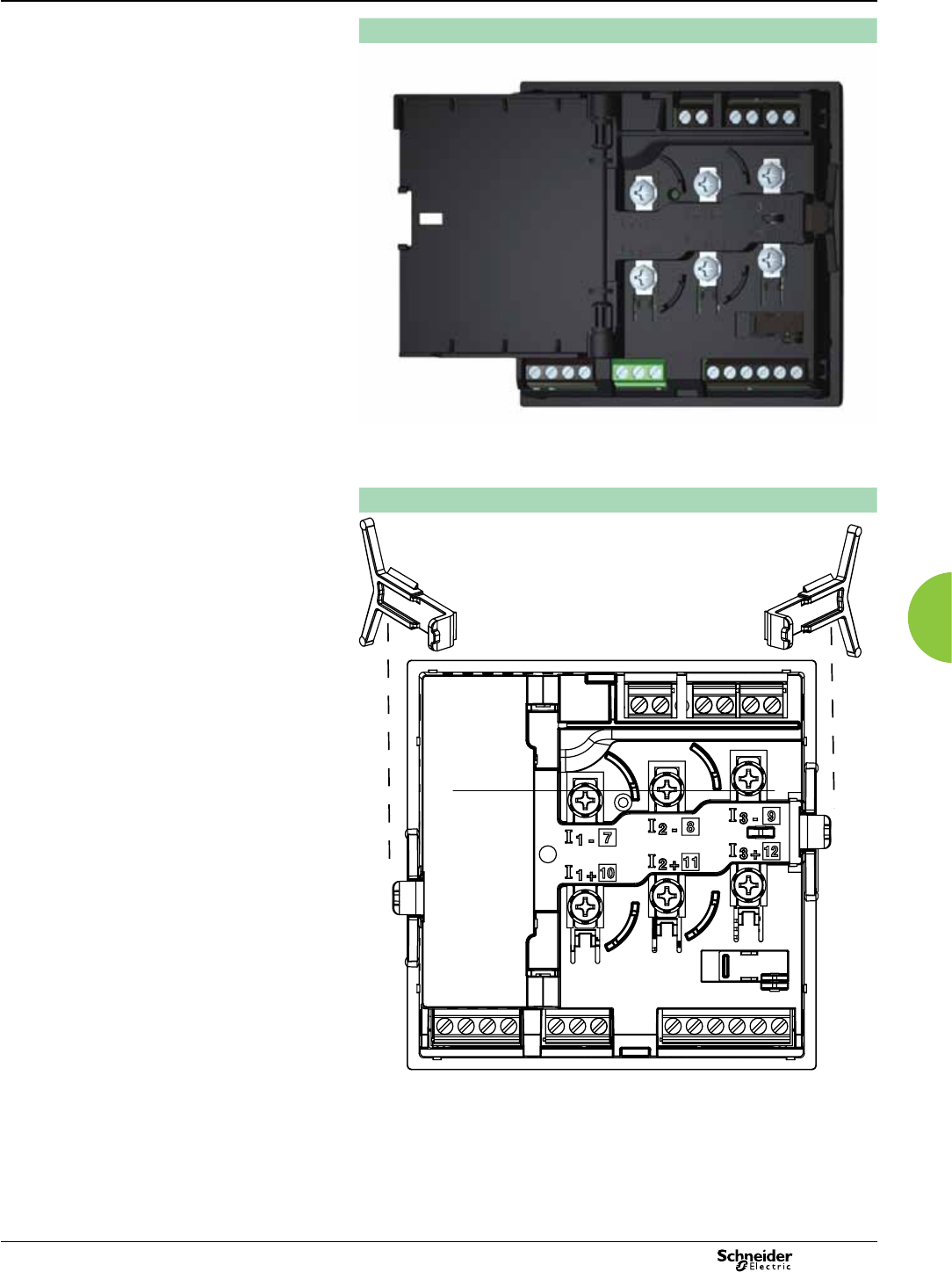
69
2013
Basic multi-funtional metering PM5350 Power Meter
Dimensions and connection
Rear of meter - open
PE86279
Rear view retainers - installation
PE86274
For detailed installation instructions see the product's Installation guide.
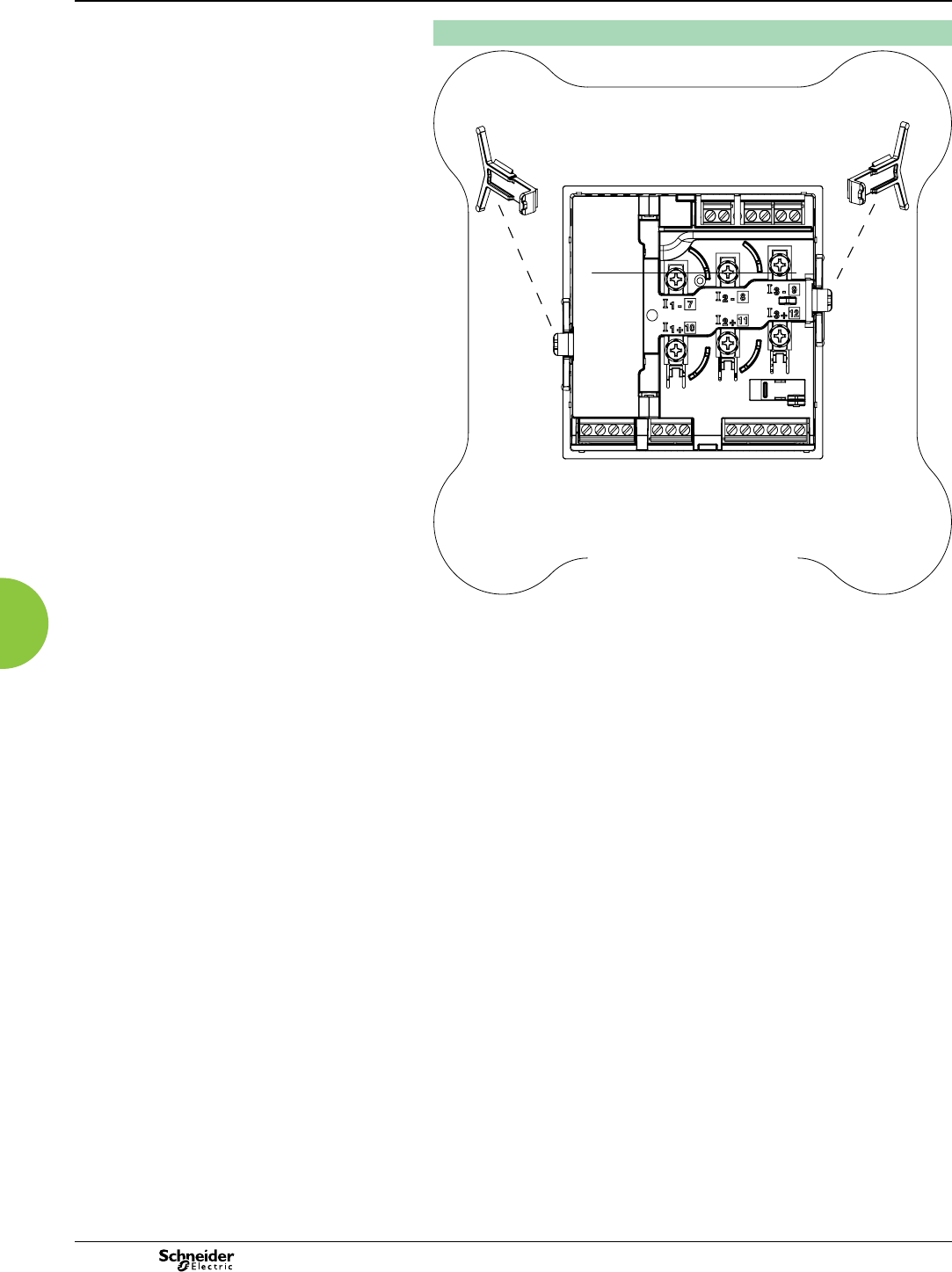
70 2013
Basic multi-funtional metering PM5350 Power Meter
Dimensions and connection (cont.)
Rear view retainers - users
PE86275
For detailed installation instructions see the product's Installation guide.
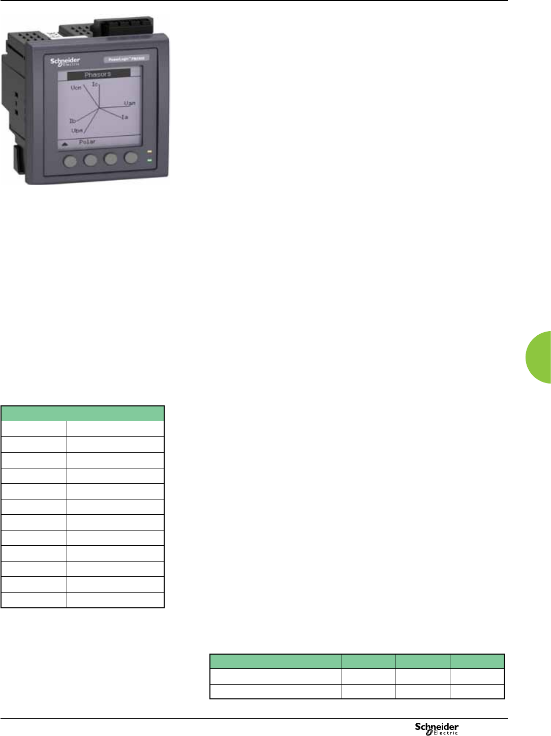
71
2013
Basic multi-function metering PM5000 Series
Functions and characteristics
PB111776
PowerLogic™ PM5000 Series meter
Commercial reference numbers
PM5100 METSEPM5100
PM5110 METSEPM5110
PM5111 METSEPM5111
PM5310 METSEPM5310
PM5320 METSEPM5320
PM5330 METSEPM5330
PM5331 METSEPM5331
PM5340 METSEPM5340
PM5341 METSEPM5341
PM5560 METSEPM5560
PM5561 METSEPM5561
PM5563 METSEPM5563
PowerLogic™ PM5100, PM5300 and PM5500 series
The PowerLogic™ PM5000 power meter is the ideal t for cost management
applications. It provides the measurement capabilities needed to allocate energy usage,
perform tenant metering and sub-billing, pin-point energy savings, optimize equipment
efciency and utilization, and perform a high level assessment of the power quality of the
electrical network.
In a single 96 x 96 mm unit, with a graphical display, all three phases, neutral and
ground can be monitored simultaneously.
The bright, anti-glare display features large characters and powerful backlighting
for easy reading even in extreme lighting conditions and viewing angles.
Easy to understand menus, text in 8 selectable languages, icons and graphics create
a friendly environment to learn about your electrical network.
Highly accurate devices with global billing certications.
Applications
Cost management: Cost saving opportunities becomes clear once you understand
how and when your facility uses electricity. These meters are ideal for:
b Sub billing / tenant metering: allows a landlord, property management rm,
condominium association, homeowners association, or other multi-tenant property to
bill tenants for individual measured utility (electricity) usage. MID approved meters for
billing applications across Europe.
b Cost allocation: allocate energy costs between different departments (HVAC,
indoor and outdoor lighting, refrigeration, etc), different parts of an industrial process
or different cost centres. Cost allocation systems can help you save money by making
changes to your operation, better maintaining your equipment, taking advantage of
pricing uctuations, and managing your demand.
Network management: Improving reliability of the electrical network is key for
success in any business. Monitoring values such as voltage levels, harmonic
distortion and voltage unbalance will help you to ensure proper operation and
maintenance of your electrical network and equipment. PowerLogic™ PM5000 series
meters are the perfect tool for:
b Basic Power Quality monitoring: power quality phenomena can cause
undesirable effects such as heating in transformers, capacitors, motors, generators
and misoperation of electronic equipment and protection devices.
b Min/ Max monitoring (with timestamp): understanding when electrical
parameters, such as voltage, current and power demand, reach maximum and
minimum values will give you the insight to correctly maintain your electrical network
and assure equipment will not be damaged.
b Alarming: alarms help you to be aware of any abnormal behavior on the electrical
network in the moment it happens.
b WAGES monitoring: take advantage of the input metering on PM5000 meters to
integrate measurements from 3rd party devices such as water, air, gas, electricity or
steam, meters.
Main characteristics
Easy to install
Mounts using two clips, in standard cut out for DIN 96 x 96mm, no tools required.
Compact meter with 72mm (77mm for PM5500) depth connectable up to 690 VL-L
without voltage transformers for installations compliant with category III.
Easy to operate
Intuitive navigation with self-guided, language selectable menus, six lines, four
concurrent values. Two LEDs on the meter face help the user conrm normal
operation with a green LED - heartbeat/communications indicator, and the amber LED
- customizable either for alarms or energy pulse outputs.
Easy circuit breaker monitoring and control
The PM5300 provides two relay outputs (high performance Form A type) with
capability to command most of the circuit breaker coils directly. For Digital Inputs,
monitored switches can be wired directly to the meter without external power supply.
PM5500 series have 4 status inputs (digital) and 2 digital output (solid state) to use for
WAGES monitoring, control and alarm annunciation.
Accurate energy measurement for precise cost allocation:
PM5100 PM5300 PM5500
IEC 62053-22 (Active Energy) Class 0.5S Class 0.5S Class 0.2S
IEC 62053-24 (Reactive Energy) Class 2 Class 2 Class 1
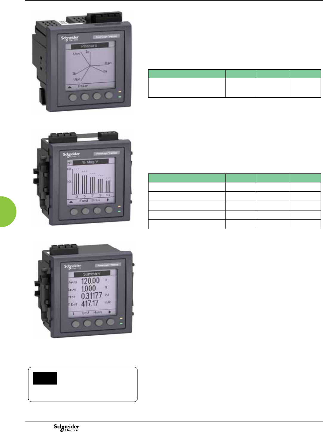
72 2013
Direct metering of neutral current
The PM5500 has a fourth CT for measuring neutral current. In demanding IT
applications, where loads are non-linear (i.e. switching power supplies on computers/
servers), measuring neutral current is essential to avoid overload and resulting
outage. In addition, the PM5500 provides a calculated ground current value, not
available in meters with 3 CTs.
Power Quality analysis
The PM5000 offers Total Harmonic Distortion (THD/thd), Total Demand
Distortion (TDD) measurements and individual harmonics (odd) magnitudes and
angles for voltage and current:
These types of power quality parameters help to identify the source of harmonics
that can harm transformers, capacitors, generators, motors and electronic
equipment.
Load management
Peak demands with time stamping are provided. Predicted demand values can be
used in combination with alarms for basic load shedding applications.
Alarming with time stamping
A different combination of set point driven alarms and digital alarms with 1s time
stamping are available in the PM5000 family:
Alarms can be visualized as Active (the ones that have picked up and did not drop out
yet) or Historical (the ones that happened in the past).
Alarms can be programmed and combined to trigger digital outputs and mechanical
relays (PM5300).
The PM5000 series keeps an alarm log with the active and historical alarms with date
and time stamping.
Load timer
A load timer can be set to count load running hours based on a minimum current
withdraw, adjustable to monitor and advise maintenance requirements on the load.
High Performance and accuracy
IEC 61557-12 Performance measuring and monitoring devices (PMD)
Denes the performance expectation based on classes. It denes the allowable
error in the class for real and reactive power and energy, frequency, current, voltage,
power factor, voltage unbalance, voltage and current harmonics (odds), voltage
THD, current THD, as well as ratings for temperature, relative humidity, altitude, start-
up current and safety. It makes compliant meters readings comparable - they will
measure the same values when connected to the same load.
Meets IEC 61557-12 PMD/S/K70/0.5 for PM5100 and PM5300
Meets IEC 61557-12 PMD/S/K70/0.2 for PM5500
Legal billing compliance
MID compliance is compulsory for billing applications across Europe.
In addition to billing applications, for facility managers responsible for energy cost
MID means same level of quality as a billing meter.
MID ready compliance, EN50470-1/3 – Class C
Basic multi-function metering PM5000 Series
Functions and characteristics (cont.)
Certied according to MID
Directive, Annex "B" + Annex "D" for
legal metrology relevant to active
electrical energy meters (see Annex MI-003 of
MID). Can be used for scal (legal) metrology.
MID
PM5100 PM5300 PM5500
Individual Harmonics magnitudes
up to 15th
magnitudes
up to 31st
magnitudes
& angles
up to 63rd
PM5100 PM5300 PM5500
Set point driven alarms 29 29 29
Unary 4 4 4
Digital 2 2 4
Boolean / Logic – – 10
Custom defined – – 5
PowerLogic™ PM5500 meter
PowerLogic™ PM5300 meter
PowerLogic™ PM5100 meter

73
2013
Basic multi-function metering PM5000 Series
Functions and characteristics (cont.)
General PM5100 PM5300 PM5500
Use on LV and MV systems b
Basic metering with THD and min/max readings b
Instantaneous rms values
Current per phase, neutral and ground
(PM5500)
b
Voltage Total, per phase L-L and L-N b
Frequency b
Real, reactive, and
apparent power
Total and per phase Signed, Four Quadrant
True Power Factor Total and per phase Signed, Four Quadrant
Displacement PF Total and per phase Signed, Four Quadrant
% Unbalanced I, VL-N, VL-L b
Direct monitoring of neutral current b
Energy values*
Accumulated Active, Reactive and Apparent Energy Received/Delivered; Net and absolute; Time Counters
Demand values*
Current average Present, Last, Predicted, Peak, and Peak Date Time
Active power Present, Last, Predicted, Peak, and Peak Date Time
Reactive power Present, Last, Predicted, Peak, and Peak Date Time
Apparent power Present, Last, Predicted, Peak, and Peak Date Time
Peak demand with time stamping D/T for current and powers b
Demand calculation Sliding, xed and rolling block,
thermal methods
b
Synchronization of the measurement window to input,
communication command or internal clock
b
Settable Demand intervals b
Demand calculation for Pulse input (WAGES) b
Other measurements*
I/O timer b
Operating timer b
Load timer b
Alarm counters and alarm logs b
Power quality measurements
THD, thd (Total Harmonic Distortion) I, VLN, VLL per phase I,VLN, VLL
TDD (Total Demand Distortion) b
Individual harmonics (odds) 15th 31st 63rd
Neutral Current metering with ground current calculation b
Data recording
Min/max of instantaneous values, plus phase identication* b
Alarms with 1s timestamping* b
Data logging 2 xed parameters kWh and
kVAh with congurable interval
and duration (e.g. 2 parameters
for 60 days at 15 minutes
interval)
Up to 14 selectable parameters
with congurable interval and
duration (e.g. 6 parameters for 90
days at 15 minutes interval)
Memory capacity 256 kB 1.1 MB
Min/max log b b b
Maintenance, alarm and event logs b b
Customizable data logs b
Inputs/Outputs/Relays
Digital inputs 2 (SI1, SI2) 4 (SI1, SI2, SI3, SI4) with WAGES
support
Digital outputs 1 (kWh only) 2 (configurable)
Form A Relay outputs 2
Timestamp resolution in seconds 1
Whetting voltage b
*Stored in non-volatile memory

74 2013
Basic multi-function metering PM5000 Series
Functions and characteristics (cont.)
Electrical characteristics* PM5100 PM5300 PM5500
Type of measurement: True rms on three-phase
(3P, 3P + N), zero blind
64 samples per cycle 128 samples per cycle
Measurement
accuracy
IEC 61557-12 PMD/S/K70/0.5 PMD/[SD|SS]/K70/0.2
IEC 62053-22 Active Energy Class 0.5S Class 0.2S
IEC 62053-24 Reactive Energy Class 2S Class 1S
Active Energy ±0.5% ±0.2%
Reactive Energy ±2% ±1%
Active Power Class 0.5 as per IEC 61557-12 Class 0.2 as per IEC 61557-12
Apparent Power Class 0.5 as per IEC 61557-12
Current, Phase Class 0.5 as per IEC 61557-12 ±0.15%
Voltage, L-N Class 0.5 as per IEC 61557-12 ±0.1%
Frequency ±0.05%
MID Directive EN50470-1, EN50470-3 Annex B and Annex D (Optional model references) Class C
Input-voltage
(up to 1.0
MV AC max,
with voltage
transformer)
Nominal Measured Voltage range 20 V L-N / 35 V L-L to 400 V L-N /690 V L-L
absolute range 35 V L-L to 760 V L-L
20 V L-N / 20 V L-L to 400 V L-N
/690 V L-L
absolute range 20 V L-L to 828 V L-L
Impedance 5 M W
F nom 50 or 60 Hz ±5% 50 or 60 Hz ±10%
Input-current
(congurable
for 1 or 5 A
secondary
CTs)
I nom 5 A
Measured Amps with over range and
Crest Factor
5 mA to 8.5 A Starting current: 5m A
Operating range: 50 mA to 10 A
Withstand Continuous 20 A,10 sec/hr 50 A
Impedance < 0.3 mW
F nom 50 or 60 Hz ±5% 50 or 60 Hz ±10%
Burden < 0.024 VA at 10 A
AC control
power
Operating range 100- 415 V AC L-L ±10%
CAT III 300V class per IEC 61010
100-480 V AC ±10%
CAT III 600V class per IEC 61010
Burden <5 W,11 VA at 415V L-L <5W/16.0 VA at 480 V AC
Frequency 45 to 65 Hz
Ride-through time 80 mS typical at 120V AC and maximum burden.
100 mS typical at 230 V AC and maximum burden
100 mS typical at 415 V AC and maximum burden
35 ms typical at 120 V L-N and
maximum burden
129 ms typical at 230 V L-N and
maximum burden
DC control
power
Operating range 125-250 V DC ±20%
Burden <4 W at 250 V DC typical 3.1W at 125 V DC, max. 5W
Ride-through time 50 mS typical at 125 V DC and maximum burden
Outputs Mechanical Max output frequency 0.5 Hz maximum (1 second ON /
1 second OFF - minimum times)
Switching current 250 V AC at 8.0 Amps, 25 k
cycles, resistive
30 V DC at 2.0 Amps, 75 k cycles,
resistive 30 V DC at 5.0 Amps,
12.5 k cycles, resistive
Isolation 2.5 kV rms
Digital
outputs
122
Max load voltage 40 V DC (AC not available) 30 V AC / 60 V DC
Max load current 20 mA 125 mA
On Resistance 50 W max 8 W
Meter constant from 1 to 9,999,999 pulses per kWh
Pulse width for Digital
Output
50% duty cycle
Pulse frequency for Digital
Output
25 Hz max.
Leakage current 0.03 micro Amps 1 micro Amps
Isolation 5 kV rms 2.5 kV rms
Optical outputs
Pulse width (LED) 200 ms
Pulse frequency 50 Hz. max. 2.5 kHz. max
Meter constant from 1 to 9,999,999 pulses per k_h

75
2013
Basic multi-function metering PM5000 Series
Functions and characteristics (cont.)
*Electrical Characteristics still under verication at time of printing of the catalogue, may be subject to change.
Electrical characteristics* (cont'd) PM5100 PM5300 PM5500
Status Inputs ON Voltage 18.5 to 38 V DC 30 V AC / 60 V DC max
OFF Voltage 0 to 4 V DC
Input Resistance 110 k Ω 100 k Ω
Maximum Frequency 2 Hz (T ON min = T OFF min =
250 ms)
25 Hz (T ON min = T OFF min =
20 ms)
Response Time 20 ms 10 ms
Opto Isolation 5 kV rms 2.5 kV rms
Whetting output 24 V DC/ 8mA max
Input Burden 2 mA @ 24 V AC/DC
Mechanical characteristics
Weight 380 g 430 g 450 g
IP degree of protection (IEC 60529) IP52 front display, IP30 meter body
Dimensions W x H x D [protrusion from cabinet] 96 x 96 x 72mm (77mm for PM5500) (depth of meter from housing mounting flange) [13mm]
Mounting position Vertical
Panel thickness 6 mm maximum
Environmental characteristics
Operating
temperature
Meter -25 °C to 70 °C
Display (Display functions to -25º with
reduced performance)
-25 °C to +70 °C
Storage temp. -40 °C to +85 °C
Humidity range 5 to 95 % RH at 50 °C (non-condensing)
Polution degree 2
Altitude 2000 m CAT III / 3000 m CAT II 3000 m max. CAT III
Electromagnetic compatibility
Harmonic current emissions IEC 61000-3-2
Flicker emissions IEC 61000-3-3
Electrostatic discharge IEC 61000-4-2
Immunity to radiated elds IEC 61000-4-3
Immunity to fast transients IEC 61000-4-4
Immunity to surge IEC 61000-4-5
Conducted immunity 150kHz to 80MHz IEC 61000-4-6
Immunity to magnetic elds IEC 61000-4-8
Immunity to voltage dips IEC 61000-4-11
Radiated emissions FCC part 15, EN 55022 Class B
Conducted emissions FCC part 15, EN 55022 Class B

76 2013
Basic multi-function metering PM5000 Series
Functions and characteristics (cont.)
Safety PM5100 PM5300 PM5500
Europe CE, as per IEC 61010-1 Ed. 3 and IEC 62052-11
U.S. and Canada cULus as per UL61010-1 (3rd Edition)
Measurement category (Voltage and Current inputs) CAT III up to 277 V L-N / 480 V L-L ; CAT II up to 400 V L-N / 690 V L-L CAT III up to 400 V L-N / 690
V L-L
Dielectric As per IEC/UL 61010-1 Ed. 3
Protective Class II, Double insulated for user accessible parts
Communication
RS 485 port Modbus RTU, Modbus ASCII
(7 or 8 bit), JBUS
2-Wire, 9600,19200 or 38400 baud, Parity - Even, Odd, None, 1 stop bit if parity Odd or Even, 2 stop bits if
None; (Optional in PM51x and PM53x)
Ethernet port: 10/100 Mbps; Modbus TCP/IP 1 Optional 2 (for daisy chain only, one IP
address)
Firmware and language le update Meter rmware update via the communication ports
Isolation 2.5 kVrms, double insulated
Human machine interface
Display type Monochrome Graphics LCD
Resolution 128 x 128
Backlight White LED
Viewable area (W x H) 67 x 62.5 mm
Keypad 4-button
Indicator Heartbeat / Comm activity Green LED
Energy pulse
output / Active
alarm indication
(configurable)
Optical, amber LED
Wavelength 590 to 635 nm
Maximum pulse rate 2.5 kHz
PM5100 PM5300 PM5500
PE86288
Features and Options PM5100 PM5110 PM5310 PM5320 PM5330 PM5340 PM5560 PM5563
Installation
Fast installation, panel mount with integrated
display
b b b b b b b –
Fast installation, DIN rail mountable – – – – – – – b
Accuracy Display
Display CI 0.5 CI 0.5 CI 0.5 CI 0.5 CI 0.5 CI 0.5 CI 0.2 CI 0.2
Backlit LCD, multilingual, bar graphs, 6 lines,
4 concurrent values
b b b b b b b b
Power and energy metering
3-phase voltage, current, power, demand,
energy, frequency, power factor
b b b b b b b b
Multi-tariff – – 4 4 4 4 8 8
Power quality analysis
THD, thd, TDD b b b b b b b b
Harmonics, individual (odd) up to 15th 15th 31st 31st 31st 31st 63rd 63rd
I/Os and relays
I/Os 1DO 1DO 2DI/2DO 2DI/2DO 2DI/2DO 2DI/2DO 4DI/2DO 4DI/2DO
Relays 0 0 0 0 220 0
Alarms and control
Alarms 33 33 35 35 35 35 52 52
Set point response time, seconds 1 1 1 1 1 1 1 1
Single and multi-condition alarms – – b b b b b b
Boolean alarm logic – – – – – – b b
Communications
Serial ports with modbus protocol –1 1 – 1 – 1 1
Ethernet port with Modbus TCP protocol – – – 1 – 1 2** 2**
MID ready compliance,
EN50470-1/3, Annex B and Annex D
Class C
PM5111 PM5331 PM5341 PM5561
** 2 Ethernet ports for daisy chain, one IP address.
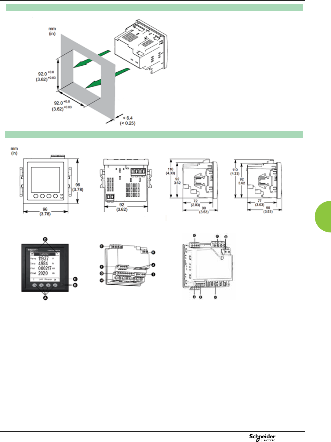
77
2013
Basic multi-function metering PM5000 Series
Dimensions and connection
PM5000 meter parts
A Menu selection buttons
B LED indicators
C Navigation or menu selections
D Maintenance and alarm
notication area
PM5000 Series meter flush mounting
PM5000 Series meter dimensions
PB111276
PB111279
PB111278
PB111277
Please see the Installation Guide for accurate and complete information on the installation of this product.
PM5100 / PM5300 meter parts
E Relay output (PM5300 only)
F Voltage inputs
G Control power
H Current inputs
I Status inputs/digital outputs
J Communications port:
Ethernet (PM5300 only) or
RS-485)
PM5100 / PM5300 PM5500
PM5500 meter parts
E Voltage inputs
F RS-485 comms
G Digital inputs
H Current inputs
I Digital outputs
J Ethernet ports
K Control power
PM5500
PM5100 PM5300 PM5500
PE86288
Features and Options PM5100 PM5110 PM5310 PM5320 PM5330 PM5340 PM5560 PM5563
Installation
Fast installation, panel mount with integrated
display
b b b b b b b –
Fast installation, DIN rail mountable – – – – – – – b
Accuracy Display
Display CI 0.5 CI 0.5 CI 0.5 CI 0.5 CI 0.5 CI 0.5 CI 0.2 CI 0.2
Backlit LCD, multilingual, bar graphs, 6 lines,
4 concurrent values
b b b b b b b b
Power and energy metering
3-phase voltage, current, power, demand,
energy, frequency, power factor
b b b b b b b b
Multi-tariff – – 4 4 4 4 8 8
Power quality analysis
THD, thd, TDD b b b b b b b b
Harmonics, individual (odd) up to 15th 15th 31st 31st 31st 31st 63rd 63rd
I/Os and relays
I/Os 1DO 1DO 2DI/2DO 2DI/2DO 2DI/2DO 2DI/2DO 4DI/2DO 4DI/2DO
Relays 0 0 0 0 220 0
Alarms and control
Alarms 33 33 35 35 35 35 52 52
Set point response time, seconds 1 1 1 1 1 1 1 1
Single and multi-condition alarms – – b b b b b b
Boolean alarm logic – – – – – – b b
Communications
Serial ports with modbus protocol –1 1 – 1 – 1 1
Ethernet port with Modbus TCP protocol – – – 1 – 1 2** 2**
MID ready compliance,
EN50470-1/3, Annex B and Annex D
Class C
PM5111 PM5331 PM5341 PM5561
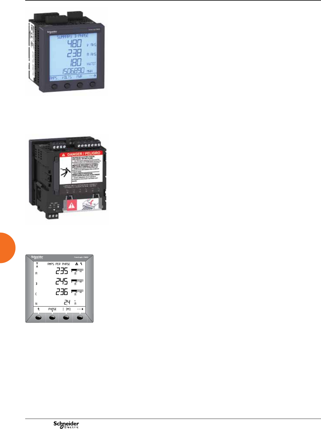
2013
Front view of PowerLogic PM800 series meter with
integrated display.
The PowerLogic PM800 series meters offers many high-performance capabilities
needed to meter and monitor an electrical installation in a compact 96 x 96 mm unit.
All models include an easy-to-read display that presents measurements for all three
phases and neutral at the same time, an RS-485 Modbus communication port, one
digital input, one KY-type digital output, total harmonic distortion (THD) metering,
and alarming on critical conditions. Four models offer an incremental choice of
custom logging and power quality analysis capabilities. Expand any model with
eld-installable option modules that offer a choice of additional digital inputs and
outputs, analogue inputs and outputs, and Ethernet port.
Applications
b Panel instrumentation
b Sub-billing, cost allocation and energy management
b Remote monitoring of an electrical installation
b Power quality analysis
b Utility bill verication, utility contract optimization and load preservation.
Characteristics
Easy to install
Mounts using two clips, with no tools required. Direct connect the voltage inputs, with
no need for potential transformers (PTs) up to 600 VAC.
Easy to operate
Intuitive navigation with self-guided, language-selectable menus.
System status at a glance
Large, anti-glare display with back-light provides summary screens with multiple
values. Bar charts graphically represent system loading and I/O.
Custom alarming with time stamping
Over 50 alarm conditions, including over or under conditions, digital input changes,
phase unbalance and more. The models PM850 and PM870 offer boolean logic that
can be used to combine up to four alarms.
Power quality analysis
The PM800 series offers an incremental range of features for troubleshooting and
preventing power quality related problems. All models offer THD metering. The
PM810 with PM810LOG option and PM820 offer individual current and voltage
harmonics readings. The PM850 and PM870 offer waveform capture (PM870 is
congurable) and power quality compliance evaluation to the international EN50160
-ITI(CBEMA)/SEMI F-47 standards. The PM870 offers voltage and current
disturbance (sag/swell) detection.
Extensive on-board memory
All models offer billing (energy and demand), maintenance, alarm and customizable
data logs, all stored in non-volatile memory (PM810 requires PM810LOG option).
ANSI 12.20 Class 0.2S and IEC 62053-22 Class 0.5S accuracy for active energy
Accurate energy measurement for sub-billing and cost allocation.
IEC61557-12 performance standard
Meets PMD/SD/K70/0.5 and PMD/SS/K70/0.5 requirements for combined
Performance Measuring and monitoring Devices (PMD).
Trend curves and short-term forecasting
The models PM850 and PM870 offer trend logging and forecasting of energy and
demand readings to help compare load characteristics and manage energy costs.
Expandable I/O capabilities
Use the on-board or optional digital inputs for pulse counting, status/position
monitoring, demand synchronisation or control (gating) of the conditional energy
metering. Use the on-board or optional digital outputs for equipment control or
interfacing, controllable by internal alarms or externally through digital input status.
Use the optional analogue inputs and outputs for equipment monitoring or
interfacing.
Metering of other utilities (WAGES)
All models offer ve channels for demand metering of water, air, gas, electricity or
steam utilities (WAGES) through the pulse counting capabilities of the digital inputs.
Pulses from multiple inputs can be summed through a single channel.
Modular and upgradeable
All models offer easy-to-install option modules (memory, I/O and communications)
and downloadable rmware for enhanced meter capabilities.
Remote display
The optional remote display can be mounted as far as 10 m from the metering unit.
The adapter includes an additional 2- or 4-wire RS-485/RS-232 communication port.
PE86134PB101823-50
Rear view of PowerLogic PM800 series meter.
PowerLogic PM800 series meter display
screen showing bar graphs.
PE86229
PM800 series
Functions and characteristics
Intermediate metering
78
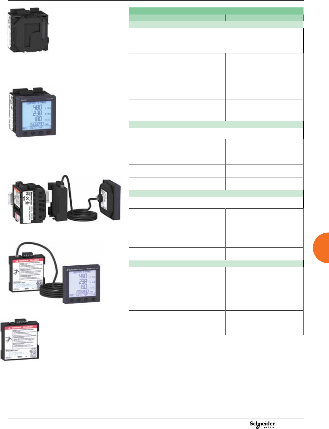
2013
Part Numbers
Description
Meter without display
Use the base meter unit without display to comply with voltage limitations for local regulations
when door mounting is not possible, or when meter voltage exceeds regulations, or when local
display is not required. When the meter is used without a display, conguration of the
communications port is limited to the default (address 1, 9600 baud, parity even). Requires
software to read data.
PM810 meter unit only, no display,
basic instrumentation, THD, alarming, 80 kB logging
(with PM810LOG)
PM810UMG
PM820 meter unit only, no display,
basic instrumentation, THD, alarming, 80 kB logging
PM820UMG
PM850 meter unit only, no display,
basic instrumentation, THD, alarming, 800 kB
logging, waveform capture
PM850UMG
PM870 meter unit only, no display,
basic instrumentation, THD, alarming, 800 kB
logging, congurable waveform capture and
disturbance detection.
PM870UMG
Meter with integrated display
Use the meter with integrated display for panel mounting when door space is available and when
voltage usage is within the local regulation limits.
PM810 meter with integrated display, PM810MG
PM820 meter with integrated display PM820MG
PM850 meter with integrated display PM850MG
PM870 meter with integrated display PM870MG
Meter with remote display
Conveniently packaged kit consist of a base meter (810, 820, 850 or 870) with a remote display,
remote display adapter, and remote display cable 3 m (9.ft 10 inches).
PM810 meter with remote display PM810RDMG
PM820 meter with remote display PM820RDMG
PM850 meter with remote display PM850RDMG
PM870 meter with remote display PM870RDMG
Parts and accessories
Remote display adapter with remote display and
a 3 m (9 ft 10 inch) cable
Use this combination of remote display, adapter, and
3 m cable to equip a base meter unit for use with a
remote display. In addition, the display can be carried
from meter to meter, enabling you to purchase one
display for multiple meters. Each base unit meter
must be equipped with a remote display adapter
(PM8RDA).
PM8RDMG
Remote display adapter alone
When added to the front of the base unit (PM8xxU),
the adapter brings two additional communication
ports: one for the remote display and one 4-wire/2-
wire RS 485/RS 232.
PM8RDA
Part number list continued on next page.
PowerLogic PM800 series meter without display.
PowerLogic PM800 series meter with remote display.
Remote display adapter with display and cable.
Remote display adaptor alone.
PB101819 -32
PE86135 PB101822 -68 PE86134 PB101814 -36
PowerLogic PM800 series meter with integrated display.
PM800 series
Functions and characteristics (cont.)
Intermediate metering
79
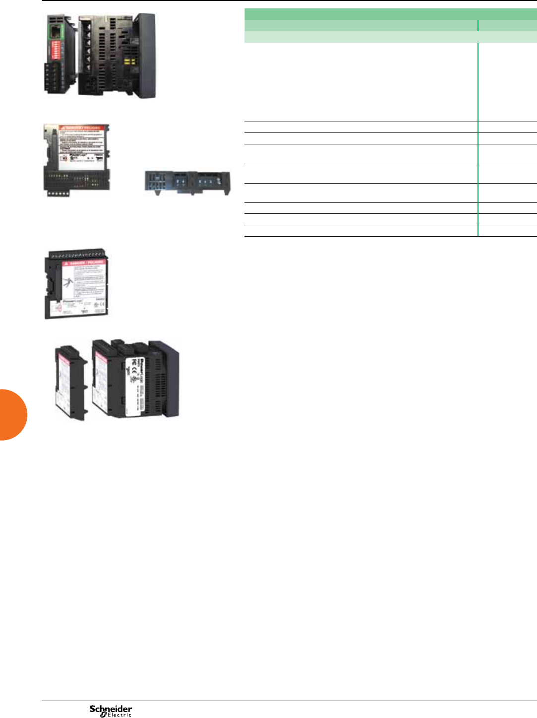
2013
PowerLogic PM870 with ECC module (bottom view
showing connectors and conguration switches).
ECC module (front view)
DB119012 DB119011
ECC module (side view
showing LED indicators).
DB119013
PowerLogic PM8M26 module.
PowerLogic PM800 with PM8M22 and
PM8M26 modules.
PB101824 -50 PB1018216 -34
Part Numbers - continued
Description
Optional modules
Ethernet communication module provides a 10/100BaseTx UTP port,
an RS-485 Modbus serial master port, Ethernet-to-serial line gateway
functionality, and an embedded web server that is fully compliant with
Transparent Ready - Level 1 (TRe1) systems.
The PM8ECC supports a private host PM8ECC MIB. Use of this MIB allows
the reading of Basic Metering Data, Conguration and Status of I/Os and
Conguration and Status of Alarms, plus SNMP Trap generation in response
to any PM8 on-board alarms.
PM8ECC
2 relay outputs, 2 digital inputs PM8M22
2 relay outputs, 6 digital inputs PM8M26
2 relay outputs, 2 digital inputs, 2 analogue outputs,
2 analogue inputs
PM8M2222
PM810 optional logging module for on-board data recording, uses a
non-volatile, battery-backed internal clock
PM810LOG
RJ11 Extender kit to mount RJ11 jack in panel door
(for use with PM800, CM3000, and CM4000 series meters)
RJ11EXT
Cable for remote display adapter 1.25 m (4 ft) CAB4
Cable for remote display adapter 3 m (9 ft 10 inch) CAB12
Cable for remote display adapter 9.14 m (30 ft) CAB30
Intermediate metering PM800 series
Functions and characteristics (cont.)
80
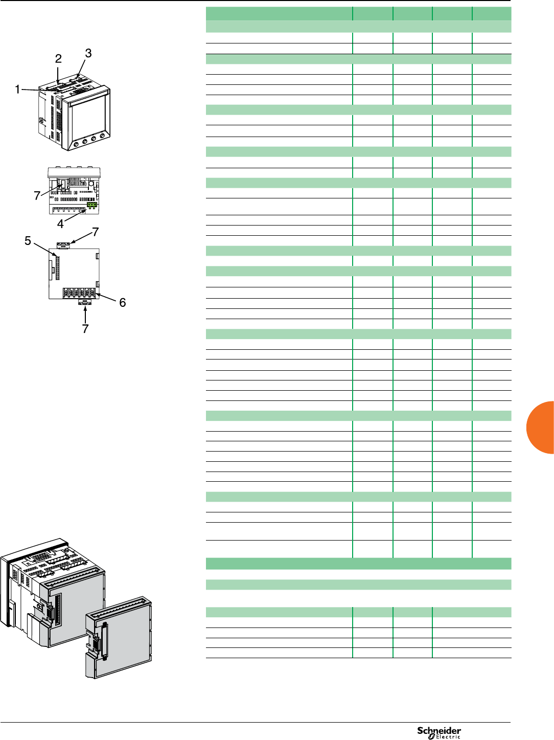
2013
Selection guide PM810 PM820 PM850 PM870
Performance standard
ANSI 12.20 Class 0.2S b b b b
IEC 61557-12 PMD/SD/K70/0.5 and PMD/SS/K70/0.5 b b b b
General
Use on LV and HV systems b b b b
Current and voltage accuracy 0.5 %/0.2% 0.5 %/0.2% 0.5 %/0.2% 0.2 %/0.2%
Active energy accuracy (5% to 200% of load) 0.2 % 0.2 % 0.2% 0.2%
Number of samples per cycle 128 128 128 128
Instantaneous rms values
Current, voltage, frequency b b b b
Active, reactive,apparent power Total & per phase b b b b
Power factor Total & per phase b b b b
Energy values
Active, reactive, apparent energy b b b b
Congurable accumulation mode b b b b
Demand values
Current Present & max. b b b b
Active, reactive, apparent
power
Present & max. b b b b
Predicted active, reactive, apparent power b b b b
Synchronisation of the measurement window b b b b
Demand calculation modeBlock, sliding, thermal b b b b
Other measurements
Hour counter b b b b
Power quality measurements
Harmonic distortion Current & voltage b b b b
Individual harmonics Current & voltage 31 (1) 31 63 63
Waveform capture - - bb (2)
EN50160 - ITI(CBEMA)/SEMI F-47 b (4) b
Sag and swell detection - - - b
Data recording
Min/max of instantaneous values b b b b
Data logs 2 (1) 2 4 4
Event logs -b b b
Trending / forecasting - - b b
GPS synchronisation b (1) b b b
Alarms b b b b
Time stamping b (1) b b b
Display and I/O
White backlit LCD display b b b b
Multilingual b b b b
Digital input (standard/optional) 1/12 1/12 1/12 1/12
Digital output (standard/optional) 1 KY/4 RY 1 KY/4 RY 1 KY/4 RY 1 KY/4 RY
Analogue inputs (standard/optional) 0/4 0/4 0/4 0/4
Analogue outputs (standard/optional) 0/4 0/4 0/4 0/4
Input metering capability (number of channels) 5 5 5 5
Communication
RS 485 port 2-wire 2-wire 2-wire 2-wire
Modbus protocol b b b b
RS 232/RS 485, 2- or 4-wire Modbus RTU/
ASCII (with addition of PM8RDA module)
b b b b
Ethernet 10/100Base Tx UTP port and RS485
Modbus serial master port with PM8ECC
b b b b
Option modules selection guide
The PM800 can be tted with 2 optional modules, unless otherwise indicated (3)
PM8ECC module
10/100BaseTx UTP port, RS-485 Modbus serial master port, Ethernet to serial line gateway,
embedded web server
Input/Output modules PM8M22 PM8M26* PM8M2222
Relay outputs 2 2 2
Digital inputs 2 6 2
Analogue outputs 4-20 mA 2
Analogue inputs 0-5 Vdc or 4-20 mA 2
* Includes a 24 Vdc Power Supply that can be used to power the digital inputs
(1) With PM810LOG, battery-backed internal clock and 80 kB memory. (2) Congurable. (3) Series 800
Power Meters supports up to two option modules. When PM8M2222 & PM8ECC are mounted together
with control power>370 V AC temperature rating must be reduced to -25°C to 50°C. Same applies when
using two PM8M2222. (4) PM850 does not include sag or swell detection.
PowerLogic PM800 series connectors.
1. Control power.
2. Voltage inputs.
3. Digital input/output.
4. RS 485 port.
5. Option module connector.
6. Current inputs.
7. Mounting clips.
DB109269
PowerLogic PM800 series meter with I/O module.
Intermediate metering PM800 series
Functions and characteristics (cont.)
81

2013
Electrical characteristics
Type of measurement 63rd harmonic, 128 samples per cycle
Measurement accuracy standard IEC 61557-12 compliant
Current 0.5% from 0.5 A to 10 A
Voltage 0.2% 10 V - 277 V
Power Factor +/- 0.002 from 0.500 leading to 0.500 lagging
Active Power 0.2%
Frequency +/- 0.01 Hz at 45 to 67 Hz
+/- 0.01 Hz at 350 to 450 Hz
Active Energy IEC 62053-22 Class 0.5S and
ANSI C12.20 Class 0.2S
Reactive Energy IEC 62053-23 Class 2
Data update 1 s
Input-voltage
characteristics
Measured voltage 0 to 600 V AC (direct L-L)
0 to 347 V AC (direct L-N)
up to 3.2 MV AC (with external VT)
Metering over-range 1.5 Un
Impedance 5 MW
Frequency measurement range 45 to 67 Hz and 350 to 450 Hz
Input-current
characteristics
CT ratings Primary Adjustable from 5 A to 32767 A
Secondary 1 A or 5 A
Measurement input range 5 mA to 10 A AC
Permissible overload 15 A continuous
50 A for 10 seconds per hour
500 A for 1 second per hour
Impedance < 0.1 W
Load < 0.15 VA
Control Power AC 115 to 415 ±10 % V AC, 15 VA with options at
45 to 67 Hz or 350 to 450 Hz
DC 125 to 250 ±20 % V DC, 10 W with options
Ride-through time 45 ms at 120 V AC or 125 V DC
Inputs/Outputs (2)
Standard
(meter unit)
1 digital KY pulse output 6 to 220 V AC ± 10% or 3 to 250 V DC ± 10%,
100 mA max. at 25 °C, 1350 V rms isolation
1 digital input 24 to 125 V AC/DC ±10 %, < 5 mA maximum
burden, 1350 Vrms isolation
PM8M22
option
2 relay outputs (1) 6 to 240 V AC or 6 to 30 V DC
2 A rms, 5 A max. for 10 seconds per hour
2 digital inputs 19 to 30 V DC, 5 mA max. at 24 V DC
PM8M26
option
2 relay outputs (1) 6 to 240 V AC, 6 to 30 V DC
2 A rms, 5 A max. for 10 seconds per hour
6 digital inputs 20 to 150 V AC/DC, 2 mA max.
24 V internal supply 20 - 34 V DC, 10 mA max. (feeds 6 digital inputs)
PM8M2222
option
2 relay outputs (1) 6 to 240 V AC, 6 to 30 V DC
2 A rms, 5 A max. for 10 seconds per hour
2 digital inputs 20 to 150 V AC/DC, 2 mA max.
2 analogue outputs 4 to 20 mA dc into 600 ohms maximum
2 analogue inputs Adjustable from 0 to 5 V DC or 4-20 mA
Switching
frequency
(digital I/O)
Standard Input/output 25 Hz, 50 % duty cycle (20 ms ON/OFF)
PM8M22 Input/output 1 Hz, 50 % duty cycle (500 ms ON/OFF)
PM8M26 and
PM8M2222
Input 25 Hz, 50 % duty cycle (20 ms ON/OFF)
Output 1 Hz, 50 % duty cycle (500 ms ON/OFF)
Mechanical characteristics
Weight (meter with integrated display) 0.6 kg
IP degree of protection (IEC 60529) IP52 integrated display. Type 12 compliant
remote display (with gasket). IP30 meter body
Dimensions Without options 96 x 96 x 70 mm (mounting surface)
With 1 option 96 x 96 x 90 mm (mounting surface)
Environmental conditions
Operating
temperature
Meter -25 °C to +70 °C (2)
Display -10 °C to +50 °C
Storage temp. Meter + display -40 °C to +85 °C
Humidity rating 5 to 95 % RH at 40 °C (non-condensing)
Pollution degree 2
Installation category III, for distribution systems up to 347 V L-N /
600 V AC L-L
Dielectric withstand As per EN 61010, UL508
Altitude 3000 m max.
(1) Mechanical endurance: 15 million operations, Electrical endurance:25000 commutations at
2 A / 250 V AC (2) Series 800 Power Meters supports up to two option modules. When
PM82222 & PM8ECC are mounted together with control power >370 V AC temperature rating
must be reduced to -25°C to 50°C. Same is true when using two PM8M2222.
Intermediate metering PM800 series
Functions and characteristics (cont.)
82

2013
Electromagnetic compatibility
Electrostatic discharge Level III (IEC 61000-4-2)
Immunity to radiated elds Level III (IEC 61000-4-3)
Immunity to fast transients Level III (IEC 61000-4-4)
Immunity to impulse waves Level III (IEC 61000-4-5)
Conducted immunity Level III (IEC 61000-4-6)
Immunity to magnetic elds Level III (IEC 61000-4-8)
Immunity to voltage dips Level III (IEC 61000-4-11)
Conducted and radiated
emissions
e industrial environment/FCC part 15 class A EN 55011
Harmonics emissions IEC 61000-3-2
Flicker emissions IEC 61000-3-3
Surge immunity IEC 61000-4-12
Surge withstand capability (SWC) ANSI C37.90.1.2002
Safety
Europe e, as per IEC 61010-1 i (1)
U.S. and Canada cULus (UL508 and CAN/CSA C22.2 No. 14-M95, Industrial
Control Equipment)
Onboard communications
RS 485 port 2-wire, up to 38400 baud, Modbus
Model-dependent characteristics
Data Logs PM810 with PM810LOG, PM820, PM850 and PM870:
- 1 billing log
- 1 customisable log
PM850 and PM870 only: 2 additional custom logs
Min./max. Worst min. and max. with phase indication for Voltages,
Currents, Voltage unbalance, and THD. Min. and max. values
for power factor (True and Displacement), power (P, Q, S) and
frequency
One event log Time stamping to 1 second
Trend curves
(PM850 and PM870 only)
Four trend curves: 1 minute, 1 hour, 1 day and 1 month. Min./
max./avg. values recorded for eight parameters:
- every second for one minute for the 1-minute curve
- every minute for one hour for the 1-hour curve
- every hour for one day for the 1-day curve
- every day for one month for the 1-month curve
Hour counter Load running time in days, hours and minutes
Energy per shift Up to three user-dened intervals per day
Available for all models (the PM810 requires the PM810LOG
module)
Forecasting
(PM850 and PM870 only)
Forecasting of the values for the trended parameters for the
next four hours and next four days
PM850 waveform capture Triggered manually or by alarm, 3-cycle, 128 samples/cycle on
6 user congurable channels
PM870 enhanced waveform
capture
From 185 cycles on 1 channel at 16 samples per cycle up to
3 cycles on 6 channels at 128 samples per cycle
Alarms Adjustable pickup and dropout setpoints and time delays,
numerous activation levels possible for a given type of alarm
Historical and active alarm screens with time stamping
Response time: 1 second
Boolean combination of four alarms is possible using
the operators NAND, AND, OR, NOR and XOR on PM850 and
PM870
Digital alarms: status change of digital inputs
Memory available for logging
and waveform capture (2)
80 kbytes in PM810 with PM810LOG and PM820
800 kbytes in PM850 and PM870
Firmware update (all models) Update via the communication ports
File download available free from www.powerlogic.com
Bar graphs (all models) Graphical representation of system performance
Display characteristics
Languages English, French, Spanish, German, Russian, Turkish and
Portuguese.
Display screen Back-lit white LCD (6 lines total, 4 concurrent values)
Dimensions Display screen viewable area 73 x 69 mm
Integrated display Overall 96 x 96 mm
Depth meter + display 69.4 mm + 17.8 mm
Remote display Overall 96 x 96 x 40 mm
Weight Meter with remote display adapter 0.81 kg
Remote display 0.23 kg
Intermediate metering PM800 series
Functions and characteristics (cont.)
83
2013
Intermediate metering Power Meter Series 800
Dimensions and connection
Power meter with integrated display
Dimensions
DB111765
DB111766
DB111767
Front-panel mounting (meter with integrated display)
DB111768
Spacing between units
DB111769
DB111770
84
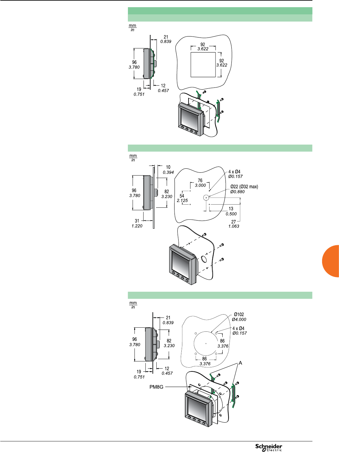
2013
Intermediate metering Power Meter Series 800
Dimensions and connection (cont.)
Remote display door mounting
Flush mounting
DB111792
Surface mount
DB111793
Mounting in a Ø102 cutout (replace analogue device: ammeter, voltmeter, etc.)
DB111794
85
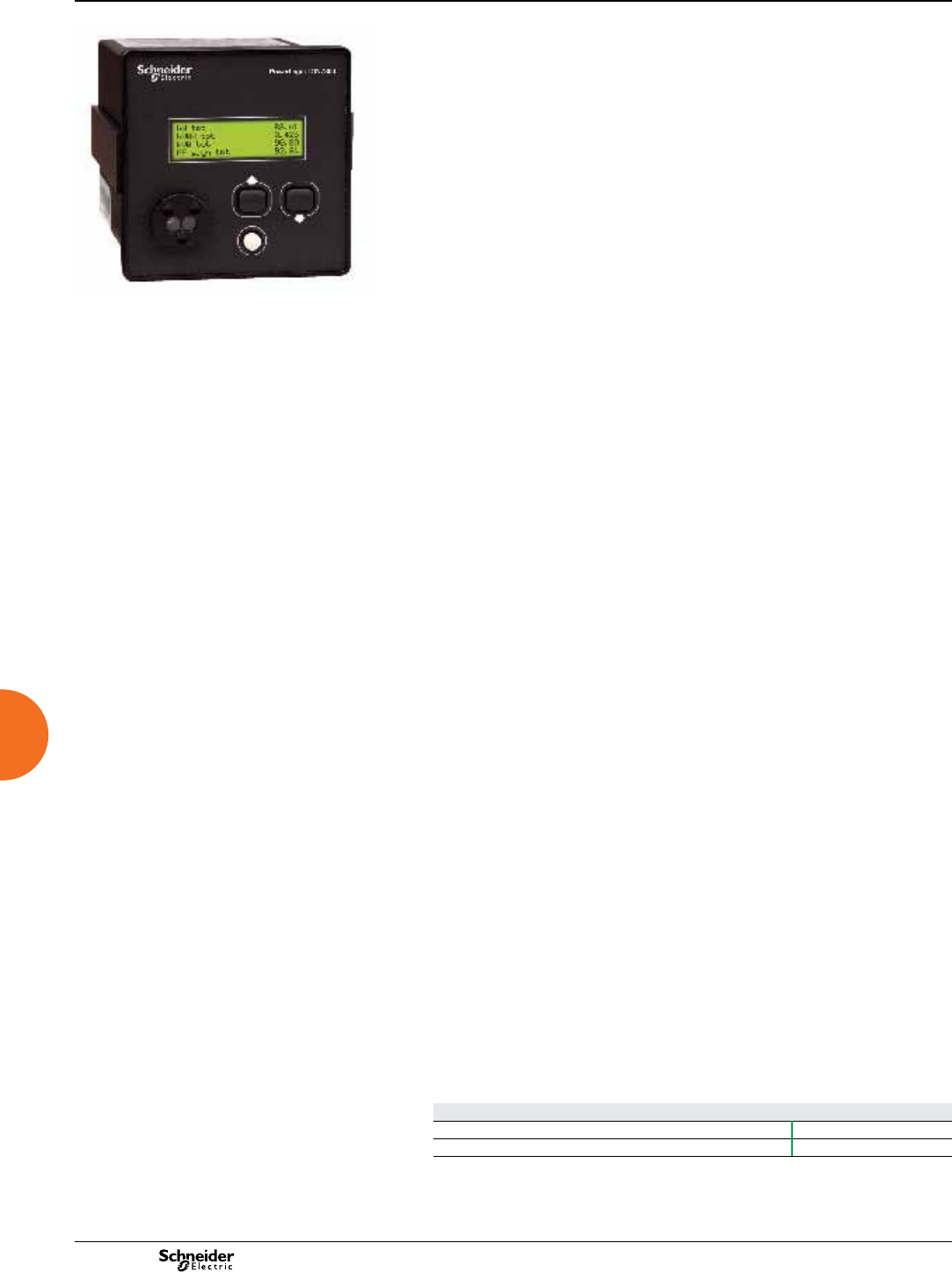
2013
ION7300 Series
Functions and characteristics
Intermediate metering
PE86151a
PowerLogic™ ION 7300 Series meter.
Used in enterprise energy management applications such as feeder monitoring and
sub-metering, ION7300 Series meters offer unmatched value, functionality, and
ease of use. ION7300 Series meters interface to PowerLogic StrxureWare software
or other automation systems to give all users fast information sharing and analysis.
ION7300 Series meters are an ideal replacement for analogue meters, with a
multitude of power and energy measurements, analogue and digital I/O,
communication ports, and industry-standard protocols. The ION7330 meter has
on-board data storage, emails of logged data, and an optional modem. The ION7350
meter is further augmented by more sophisticated power quality analysis, alarms and
a call-back-on-alarm feature.
Applications
Power monitoring and control operations.
Power quality analysis.
Cost allocation and billing.
Demand and power factor control.
Load studies and circuit optimisation.
Equipment monitoring and control.
Preventive maintenance.
Main characteristics
Accurate metering
Ensure metering accuracy with compliance to IEC 60687 class 0,5S standard.
Multiple communications options: Ethernet - Serial - Modem
Gateway functionality simplies communications architecture and reduces leased
line or connection costs. Concurrent, independent ports communicate with a variety
of protocols such as ION, DNP 3.0, Modbus RTU, and Modbus TCP.
Easy to read display
An easy-to-read front panel with a back-lit LCD screen supports local data display
and basic setup.
Set automatic alarms
Use congurable event priorities, logical operators, and setpoints to dene alarm
conditions and set alarms.
Integrate with software
Easily integrate ION7300 Series meters with an energy management or SCADA
system to provide remote display at a PC workstation, as well as remote
conguration and manual control capabilities.
Notication of alarms via email
Alarm notications sent via email to any workstation, cell phone, pager, or PDA.
Server for custom HTML pages
An on-board Web server combined with an Ethernet port offers quick and easy
access to real-time energy and basic power quality information without special
software.
Monitor dips and swells (ION7350)
Detect dips and swells on any voltage channel.
Interoperability expands existing networks
The ION7330/ION7350 concurrently communicates via multiple protocols, allowing
you to extend an existing Modbus, DNP, or Enterprise network.
Memory
Non-volatile memory (300kB) ensures that valuable information can be preserved
between intervals.
Part numbers
ION7300 series
ION7330 M7330
ION7350 M7350
Refer to the part number section for further explanations.
86
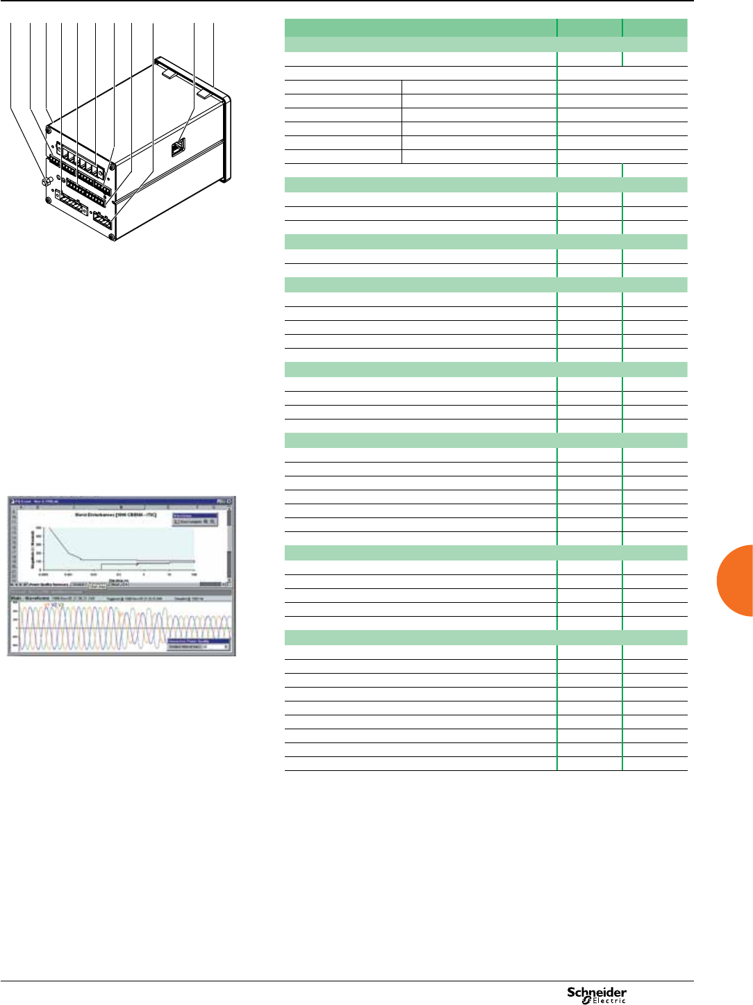
2013
ION7300 Series
Functions and characteristics (cont.)
Intermediate metering
PE86057
PowerLogic ION7330/ION7350
Selection guide ION7330 ION7350
General
Use on LV and HV systems b b
Current and voltage accuracy 0.25% + 0.05 % full scale
Power accuracy Real (kW) 0.5% reading
Apparent (kVA) 0.5% + 0.1%
Reactive (kvar) 1.5% reading
Energy accuracy Real (kWh) 0.5% reading
Apparent (kVAh) 1.0% reading
Reactive (kvarh) 1.5% reading
Number of samples per cycle 32 64
Instantaneous rms values
Current, voltage, frequency b b
Active, reactive, apparent power Total and per phase b b
Power factor Total and per phase b b
Energy values
Active, reactive, apparent energy b b
Settable accumulation modes b b
Demand values
Current Present and max. b b
Active, reactive, apparent power Present and max. b b
Predicted active, reactive, apparent power b b
1 Chassis Ground
2 Analogue Inputs
3 Internal Modem Port
4 Voltage Inputs
5 Digital Outputs
6 Current Inputs
7 Digital Inputs
8 RS-485 Bus
9 Power Supply
10 Ethernet Port
11 IR Port
Synchronisation of the measurement window b b
Setting of calculation mode Block, sliding b b
Power quality measurements
Harmonic distortion Current, voltage b b
Individual harmonics 15th 31st
Waveform capture -b
Detection of voltage dips and swells -b
Data recording
Min/max of instantaneous values b b
Historical logs max. # of channels 32 96
Waveform logs max. # of channels - 48
Trending / forecasting -b
Alarms b b
Time stamp resolution (s) 0.001 0.001
300 Kbyte memory b b
Display and I/O
Display b b
Wiring self-test b b
Analogue inputs / analogue outputs 4/4 4/4
Digital status inputs/counter 4 4
Digital relay outputs 4 4
Communication
RS-485 port 2 2
Disturbance waveform capture and power quality report. Modbus protocol b b
Ethernet (Modbus/TCP/IP protocols) 1 1
Ethernet gateway (EtherGate) b b
Internal modem 1 1
Modem gateway (ModemGate) b b
Infrared optical port 1 1
DNP 3.0 via serial, modem, IR ports b b
HTML page web server (WebMeter) b b
12345 678910 11
87
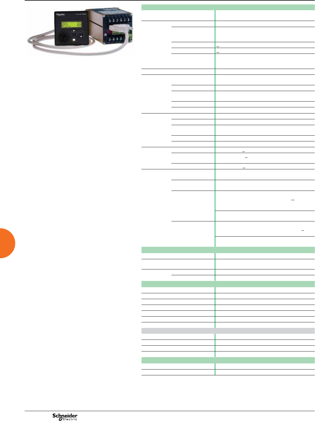
2013
ION7300 Series
Functions and characteristics (cont.)
Intermediate metering
PowerLogic ION7300 Series remote terminal display.
Electrical characteristics
PE86236
Type of measurement True rms up to the 15th harmonic (31st for ION7350)
32 samples/cycle (64 for ION7350)
Measurement
accuracy
Current and voltage 0.25% + 0.05%
Power Real: 0.5% reading
Apparent: 0.5% + 0.1%
Reactive (>5% FS): 1.5% reading
Frequency + 0.01 Hz
Power factor (at Unity PF) + 1.5% reading
Energy(1) kWh: 0.5% reading
kVAh: 1.0% reading
kvarh: 1.5% reading
Data update rate 1 second
Input-voltage
characteristics
Measured voltage 50 - 347 VAC L-N 3-phase (87-600 L-L)
50 - 300 VAC L-N single phase (100 - 600 L-L)
Metering over-range 25%
Overload withstand 1500 VAC continuous
3250 VAC for 1 second non-recurring
Impedance >2 M Ohms/phase (phase - Vref)
Frequency range 40 - 70 Hz
Input-current
characteristics
CT ratings 5 A nominal / 10 A full scale
Measurement range 20 mA - 10 A rms (+20%, 300 V rms to ground)
Overload withstand 20 A continuous
500 A for 1 second non-recurring
Burden Worst case (at 10 A): 0.0625 VA
Impedance > 2 M Ohms/phase (phase-Vref)
Power supply AC 95 - 240 VAC (+ 10%), (47 - 440 Hz)
DC 120 - 310 VDC (+ 10%)
0.2 A worst case loading (12 W) at 100 VAC at 25°C
P24 option 20 to 60 VDC (+ 10%)
Input/outputs 4 Digital status inputs
(7330/7350)
Self-excited (internal 30 VDC supply); Min pulse width:
25 msec; Max 40 transitions/sec
4 digital outputs Form A Solid State; Max forward current: 80 mA
Max voltage: 30 V
4 optional analogue
inputs
0-20 mA (scalable to 4-20 mA) option
Input impedence: 24.3 Ohms; Accuracy: < + 0.3% of
full-scale; Update rate: 1 second; Max common mode
voltage: 30 V; Sample rate: 16 samples/second
0-1 mA option same as above except:
Input impedence: 475 Ohms
4 optional analogue
outputs
0-20 mA (scalable to 4-20 mA) option
Max load drive capability: 500 Ohms; Accuracy: +
0.3% of full-scale; Max common mode voltage: 30 V
0-1 mA option same as above except:
Max load drive capability: 10 kOhms
Mechanical characteristics
Weight 1.8 kg
IP degree of protection Integrated display: front IP 50; back IP 40
Transducer unit (no display): IP 40
Dimensions Standard model 96 x 96 x 162.2 mm
TRAN model 60 x 100 x 164.5 mm
Environmental conditions
Operating temperature -20 to +60° C ambient air
Storage temperature -30 to +85°C
Humidity rating 5% to 95% non-condensing
Altitude Less than 2000 m above sea level
Installation category III, for distribution systems
Pollution degree 2
Dielectric withstand As per IEC 61010, UL3111
Electromagnetic compatibility
Electrostatic discharge EN 60687:1993
Immunity to electromagnetic HF elds EN 60687:1993
Immunity to fast transients IEC 61000-4-4
Conducted and radiated emissions EN 55014-1:1993
Safety
Europe IEC 1010-1
USA and Canada UL 3111 and CSA C22.2 No. 1010-1
(1) Accuracy complies with IEC 687 class 0.5S and ANSI 12.20 class 0.5 at 25ºC.
88
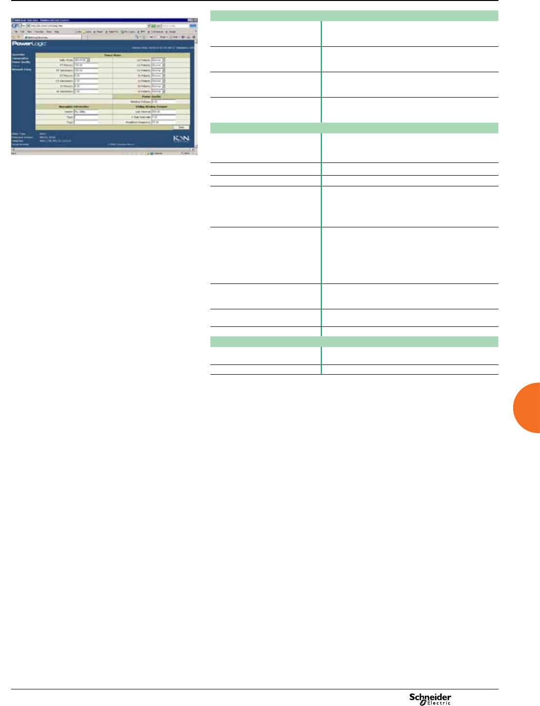
2013
Intermediate metering
PE86004
Communication
RS-485 ports Optically isolated
Up to 19,200 bauds
Protocols: ION, DNP 3.0, Modbus RTU, GPS
Ethernet port (Modbus TCP
protocol)
Up to 10 Mbps
With EtherGate
Optional 10Base-T
Infrared optical port Front panel ANSI Type 2
Up to 19,200 bauds
Protocols: ION, Modbus RTU, DNP 3.0
Internal modem From 300 to 33,600 bauds
ModemGate
Call-back feature(1)
Firmware characteristics
Data logs Scheduled or event driven
7330: Maximum of 2 data logs, 32 parameters
7350: Maximum of 6 data logs, 96 parameters
Example WebMeter page showing realtime values. Harmonic distortion Individual and total up to the 15th harmonic (31st for 7350)
Sag/swell detection (1) Detects dips and swells on any voltage channel
Instantaneous True rms, per phase, and total for:
- Voltage and current
- Active (kW), reactive (kvar), and apparent (kVA) power
- Power factor and frequency
- Voltage and current unbalance
Min/max logging Perform on any parameter, over any time interval
Min and max values for all basic power parameters:
- Voltage per phase
- Current per phase
- Active (kW), reactive (kvar), apparent (kVA) power
- Power factor & frequency
- Rolling block demand for kW, kvar, kVA
Waveform captures Simultaneous capture of events on all channels. up to 48
cycles each, 64 samples/cycle. Maximum of 6,900 cycles
for contiguous waveform capture
Alarms Single- and multi-condition alarms, call-out on alarms,
dene alarms conditions with congurable event priorities
Memory 300 kB standard
Display characteristics
Integrated display 4-parameter to single parameter large character displays,
back-lit LCD with adjustible contrast
Languages English
(1) Available on ION7350 only.
ION7300 Series
Functions and characteristics (cont.)
89
2013
Intermediate metering
Part numbers
Item Code Description
PE86059
Example and explanation of product part number.
1 Model M7350 ION7350: Advanced power meter with basic sag/swell
detection, waveform recording, harmonics (up to the 31st),
high-speed data logging and automatic modem dial-out,
multi-port communications, 4 digital inputs and 4 digital
outputs.
M7330 ION7330: Advanced power meter with over 200 high-
accuracy, 3-phase measurements, data logging, multiport
communications, 4 digital inputs and 4 outputs
2Form factor A0 Integrated display, with front optical port
R0 Transducer with RMD (remote display), with front optical port.
DOES NOT support Analogue Input and/or Analogue Output
options. Not available with Security options RMICAN or
RMICAN-SEAL.
R1 Same as R0, but with DIN rail mounts on the transducer. DOES
NOT support Analogue Input and/or Analogue Output options.
T0 Transducer (no display). Note you cannot use an RMD on this
meter if you order the Analogue Input and/or Analogue Output
options. Not available with Security options RMICAN or
RMICAN-SEAL.
T1 Transducer (no display) with DIN rail mount. Note you cannot
use an RMD on this meter if you order the Analogue Input and/
or Analogue Output options. Not available with Security
options RMICAN or RMICAN-SEAL.
3Current inputs B5 Amp nominal, 10 Amp full scale current input
4Voltage inputs 0Autoranging (50 to 347 VAC +25%)
5Power supply BP240 power supply (95-240 VAC/47-4f40 Hz/120-310 VDC)
CP24 power supply (20 to 65 VDC)
6System frequency 0Autoranging (50 and 60 Hz)
7 Communications Z0 No communications.
A0 Two RS-485 ports
C1 One RS-485 EtherGate port, one RS-485 ModemGate port,
10Base-T Ethernet (RJ45), 33.6k universal internal modem.
DOES NOT support Analogue Input and/or Analogue Output
options.
M1 One 33.6k universal internal modem (RJ11) port, one RS-485
port, one RS-485 ModemGate port.
E0 One RS-485 port, one 10Base-T Ethernet (RJ45)
8 Inputs/Outputs A No analogue inputs/outputs. You must choose this option if
ordering Display-only or RMD remote display options (Form
Factor types “D” or “R”), or Ethernet option (Communications
options “E0”).
MFour 0 to 1 mA analogue inputs & four 0 to 1 mA analogue
outputs. NOT AVAILABLE with RMD or Ethernet options
NFour 0 to 20 mA analogue inputs & four 0 to 20 mA analogue
outputs. NOT AVAILABLE with RMD or Ethernet options
9 Security 0 Password protected, no hardware lock
2Password protected with hardware lock enabled
3(ION7330 model only) RMICAN Measurement Canada
approved
4(ION7330 model only) RMICAN-SEAL Measurement Canada
approved, factory sealed(1)
6Password protected with security lock enabled, terminal cover
and UK OFGEM labels
10 Special order ANone
BPre-set to MODBUS (available for Form Factor T0, T1, T2 and
T3 only). Not available with Security options RMICAN or
RMICAN-SEAL.
CTropicalisation treatment applied
DTropicalisation treatment applied and pre-set to MODBUS
(available for Form Factor T0, T1, T2 and T3 only). Not
available with Security options RMICAN or RMICAN-SEAL.
(1)A completed ION7300 series RMICAN-SEAL checklist must accompany each RMICAN-
SEAL meter order.
ION7300 Series
Functions and characteristics (cont.)
90
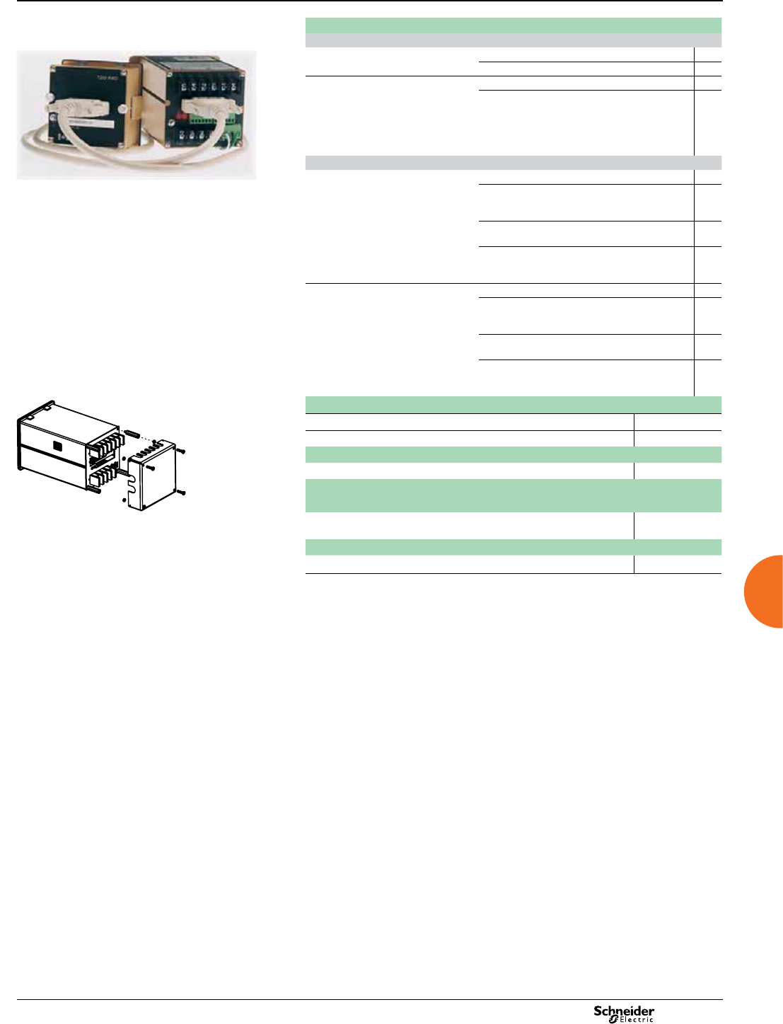
2013
Intermediate metering ION7300 Series
Functions and characteristics (cont.)
Part numbers (cont’d)
Transducer unit
ION7330 TRAN No display T0
With DIN rail mount T1
ION7350 TRAN No display T0
With DIN rail mount T1
Communications
ION7330 Two RS-485 ports A0
One RS-485 EtherGate port, one RS-485
ModemGate port, 10Base-T Ethernet (RJ45),
33.6k universal internal modem1
C1
One 10Base-T Ethernet (RJ45) port, one
RS-485 port, one RS485 EtherGate port1
E0
One 33.6k universal internal modem (RJ11)
port, one RS-485 port, one RS-485 ModemGate
port
M1
ION7350 Two RS-485 ports A0
One RS-485 EtherGate port, one RS-485
ModemGate port, 10Base-T Ethernet (RJ45),
33.6k universal internal modem (RJ11)1
C1
One 10Base-T Ethernet (RJ45) port, one
RS-485 port, one RS-485 EtherGate port1
E0
One 33.6k universal internal modem (RJ11)
port, one RS-485 port, one RS-485 ModemGate
port
M1
Remote modular display
Remote Modular Display with 6 foot DB25 cable RMD-7330
Remote Modular Display with 6 foot DB25 cable RMD-7350
Terminal strip cover
Terminal strip cover TERMCVR-73XX
DB9 optical probe
Terminal strip cover. Optical probe (DB-9) for use with ION7300 Series meters OPTICAL-
PROBE
Water resistant gasket
Water resistant gasket GSKT
(1) Does NOT support Analogue Input and/or Analogue Output options.
91
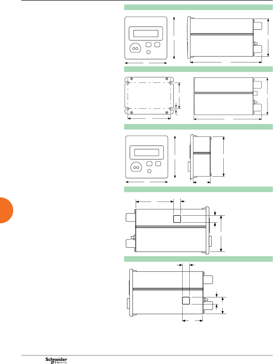
2013
ION7300 Series 0
Dimensions and connection
Intermediate metering
ION7300 Series dimensions
PE86063
PE86064
ION7300 Series TRAN dimensions
PE86065
PE86066
ION7300 Series RMD dimensions
PE86063
PE86067
Ethernet port location (if equipped)
PE86068
Internal modem port location (if equipped)
PE86069
96
96
162
86
100
6
60
164
86
96
96
37
86
14
17
73
57
13
14
31
34
92
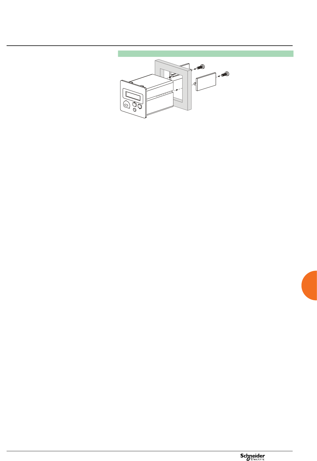
2013
Intermediate metering ION7300 Series 0
Dimensions and connection (cont.)
Front panel mounting
PE86070
93

2013
94
Used at key distribution points and sensitive loads, PowerLogic™ ION7550 and
ION7650 meters offer unmatched functionality including advanced power quality
analysis coupled with revenue accuracy, multiple communications options, web
compatibility, and control capabilities. Customise metering or analysis functions at your
work station, without hard wiring. Just link drag-and-drop icons or select default
settings. Integrate the meters with StruxureWare Power Monitoring software or share
data with SCADA systems via multiple communication channels and protocols.
Applications
Reduce energy costs.
Increase equipment utilisation.
Comply with environmental and regulatory requirements.
Improve power quality and reliability.
Improve customer satisfaction and retention.
Monitor and control equipment.
Integrated utility metering.
Allocate or sub-bill energy costs to departments, processes or tenants.
Main characteristics
Anticipate, diagnose and verify to increase efciency
Reveal energy inefciencies or waste and optimise equipment operation to increase
efciency. Isolate reliability risks, diagnose power-related equipment issues and
verify reliable operation.
Summarise power quality, set targets, measure and verify results
Consolidate all the power quality characteristics into a single trendable index.
Benchmark power quality and reliability and compare against standards, or compare
facilities or processes.
Easy to use, multilingual, IEC/IEEE congureable display
Bright LCD display with adjustable contrast. Screen-based menu system to
congure meter settings including IEC or IEEE notations. Multilingual support for
English, French, Spanish and Russian. 12/24 hour clock support in multiple formats.
Modbus Master functionality
Read information from downstream Modbus devices and view it via the front panel or
store in memory until you upload to the system level.
IEC 61850 protocol
Increase interoperability and decrease engineering time using standard protocol.
Gateway functionality
Access through the meter’s Ethernet port (EtherGate) or telephone network
(ModemGate) to Modbus communicating devices connected to meter serial ports.
Detect and capture transients as short as 20µs at 50Hz (17µs at 60 Hz)
Identify problems due to short disturbances, e.g. switching of capacitors, etc.
Power quality compliance monitoring
Monitor compliance with international quality-of-supply standards (IEC 61000-4-30
class A ed. 2(1), EN50160(1), IEC 61000-4-7(1), IEC 61000-4-15(1), IEEE 519, IEEE 1159,
and CBEMA/ITIC). Evaluate icker based on IEC 61000-4-15(1) and IEEE 1453(1).
Detect waveshape changes
Detection of phase switching phenomena (for example during the transfer of a
high-speed static switch) not detected by classical threshold-based alarms.
Record ultra-fast electrical parameters every 100 ms or every cycle
Preventive maintenance: acquisition of a motor startup curve, etc.
Trend curves and short-term forecasting
Rapid trending and forecasting of upcoming values for better decision making.
Disturbance direction detection
Determine disturbance location and direction relative to the meter. Results captured
in the event log, along with a timestamp and certainty level.
Alarm setpoint learning
The meter analyses the circuit and recommends alarm setpoints to minimise
nuisance or missed alarms.
Notify alarms via email
High-priority alarms sent directly to the user’s PC. Instant notication of power quality
events by email.(1) ION7650 only
Part numbers
ION7550 / ION7650
ION7550 M7550
ION7650 M7650
SE remote display M765RD
SE remote display w/power supply M765RDPS
ION7550 / ION7650
Functions and characteristics
Advanced metering
(1) ION7650 only
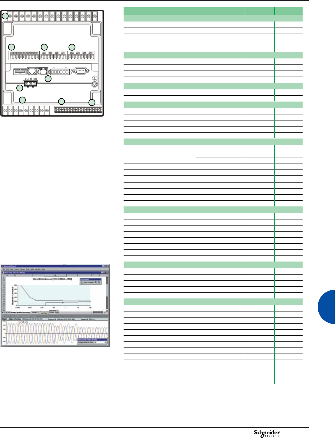
2013 95
PE86288
PowerLogic™ ION7550 / ION7650 rear view.
1 Current/voltage inputs
2 Digital inputs
3 Analogue inputs
4 Analogue outputs
5 Communications card
6 Power supply
7 Form C digital outputs
8 Digital inputs
9 Form A digital outputs
Selection guide ION7550 ION7650
General
Use on LV and HV systems b b
Current accuracy (1A to 5A) 0.1 % reading 0.1 % reading
Voltage accuracy (57V to 288V) 0.1 % reading 0.1 % reading
Energy accuracy 0.2 % 0.2 %
Nbr of samples/cycle or sample frequency 256 1024
Instantaneous rms values
Current, voltage, frequency b b
Active, reactive, apparent power Total and per phase b b
Power factor Total and per phase b b
Current measurement range (autoranging) 0.01 - 20A 0.01 - 20A
Energy values
Active, reactive, apparent energy b b
Settable accumulation modes b b
Demand values
Current Present and max. values b b
Active, reactive, apparent power Present and max. values b b
Predicted active, reactive, apparent power b b
Synchronisation of the measurement window b b
Setting of calculation mode Block, sliding b b
Power quality measurements
Harmonic distortion Current and voltage b b
Individual harmonics Via front panel 63 63
Via ION Enterprise 127 511
Waveform capture b b
Detection of voltage swells and sags b b
Detection and capture of transients -20 µs(1)
Flicker -b
Fast acquisition of 100 ms or 20 ms data b b
EN50160 compliance checking -b
Programmable (logic and math functions) b b
Data recording
Min/max of instantaneous values b b
Data logs b b
Event logs b b
Trending/forecasting b b
SER (Sequence of event recording) b b
Time stamping b b
GPS synchronisation (1 ms) b b
Memory (in Mbytes) 10 10
Display and I/O
PE86002
Front panel display b b
Wiring self-test b b
Pulse output 1 1
Digital or analogue inputs(max) 20 20
Digital or analogue outputs (max, including pulse output) 12 12
Communication
RS 485 port 1 1
RS 485 / RS 232 port 1 1
Optical port 1 1
Modbus protocol b b
IEC 61850 protocol b b
Ethernet port (Modbus/TCP/IP protocol, IEC 61850 (2))1 1
Ethernet gateway (EtherGate) 1 1
Alarms (optional automatic alarm setting b b
Disturbance waveform capture and power quality report Alarm notication via email b b
HTML web page server (WebMeter) b b
Internal modem 1 1
Modem gateway (ModemGate) b b
DNP 3.0 through serial, modem, and I/R ports b b
(1) For 50 Hz line frequency; 17µs for 60 Hz line frequency.
ION7550 / ION7650
Functions and characteristics (cont.)
Advanced metering
1
1
234
6
78
5
9
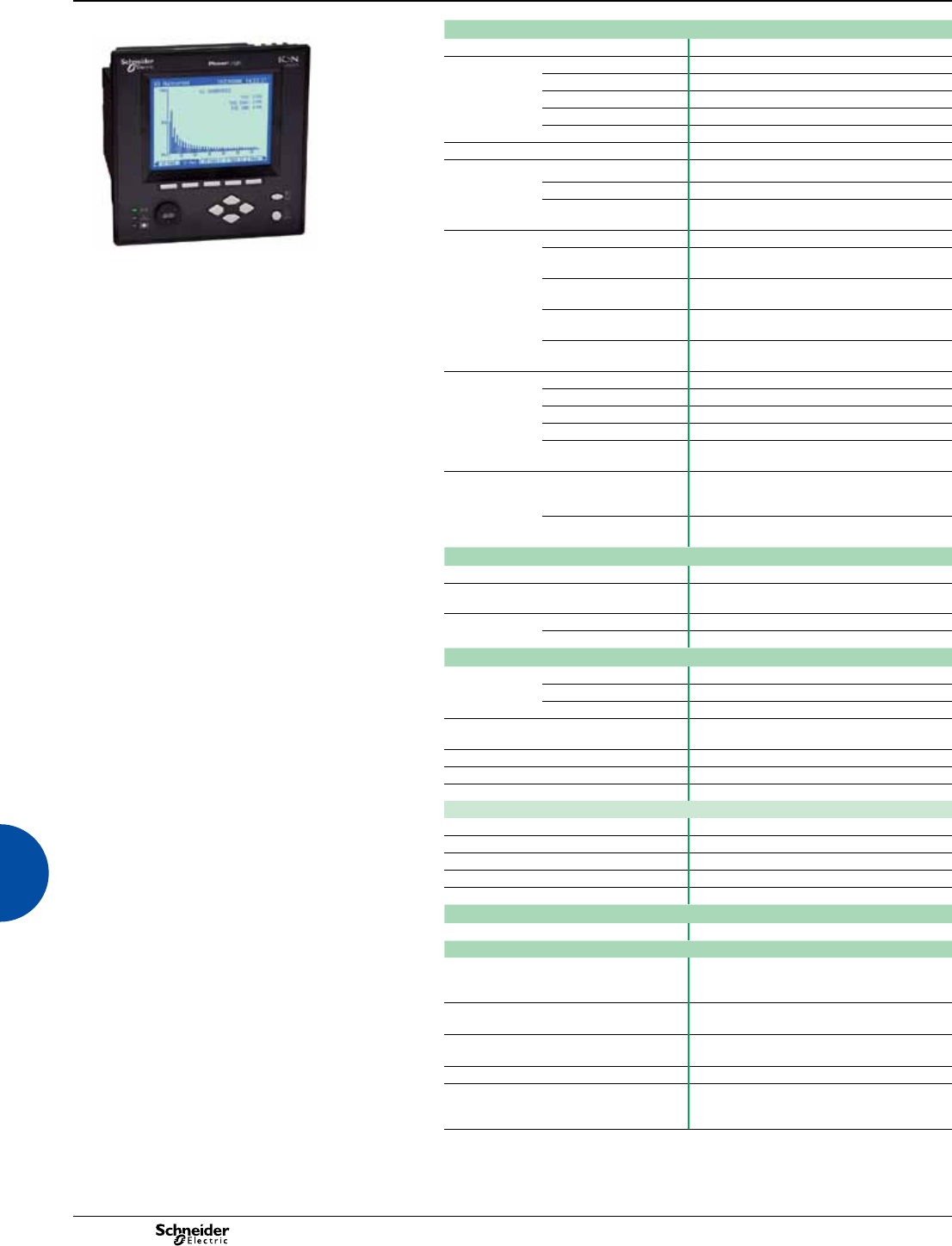
2013
96
PowerLogic ION7650
Electrical characteristics
PE86126
Type of measurement True rms to 1024 samples per cycle (ION7650)
Measurement
accuracy
Current and voltage ±0.01% of reading + ±0.025% of full scale
Power ±0.075% of reading + ±0.025% of full scale
Frequency ±0.005Hz
Power factor ±0.002 from 0.5 leading to 0.5 lagging
Energy: IEC62053-22 0,2S, 1A and 5A
Data update rate 1/2 cycle or 1 second
Input-voltage
characteristics
Measurement range Autoranging 57V through 347V LN / 600V LL
Impedance 5 MW/phase (phase - Vref)
Frequency measurement
range
42 to 69Hz
Input-current
characteristics
Rated nominal current 1A, 2A, 5A, 10A
Measurement range 0.005 - 20 A autoranging (standard range)
0.001 - 10 A autoranging (optional range)
Permissible overload 500 A rms for 1 s, non-recurring (5A)
50 A rms for 1s, non-recurring (1A)
Impedance 0.002 W per phase (5A)
0.015 W per phase (1A)
Burden 0.05 VA per phase (5 A)
0.015 VA per phase (1 A)
Power supply AC 85-240 V AC ±10% (47-63 Hz)
DC 110-300 V DC ±10%
DC low voltage (optional) 20-60 V DC ±10%
Ride-through time 100 ms (6 cycles at 60 Hz) min.
Burden Standard: typical 20 VA, max 45 VA
Low voltage DC: typical 15 VA, max 20 VA
Input/outputs(1) Standard 8 digital inputs (120 V DC)
3 relay outputs (250 V AC / 30 V DC)
4 digital outputs (solid state)
Optional 8 additional digital inputs
4 analogue outputs, and/or 4 analogue inputs
Mechanical characteristics
Weight 1.9 kg
IP degree of protection (IEC 60529) Integrated display, front: IP 50; back: IP 30
Transducer unit (no display): IP 30
Dimensions Standard model 192 x 192 x 159 mm
TRAN model 235.5 x 216.3 x 133.1 mm
Environmental conditions
Operating
temperature
Standard power supply -20 to +70 ºC
Low voltage DC supply -20 to +50 ºC
Display operating range -20 to +60 ºC
Storage
temperature
Display, TRAN -40 to +85 ºC
Humidity rating 5 to 95% non-condensing
Installation category III (2000m above sea level)
Dielectric withstand As per EN 61010-1, IEC 62051-22A(2)
Electromagnetic compatibility
Electrostatic discharge IEC 61000-4-2
Immunity to radiated elds IEC 61000-4-3
Immunity to fast transients IEC 61000-4-4
Immunity to surges IEC 61000-4-5
Conducted and radiated emissions CISPR 22
Safety
Europe IEC 61010-1
Communication
RS 232/485 port (1) Up to 115,200 bauds (57,600 bauds for RS 485),
ION, DNP 3.0, Modbus, GPS, EtherGate,
ModemGate, Modbus Master
RS 485 port (1) Up to 57,600 bauds, ION, DNP 3.0, Modbus,
GPS, EtherGate, ModemGate, Modbus Master
Infrared port(1) ANSI type 2, up to 19,200 bauds, ION, Modbus,
DNP 3.0
Ethernet port 10Base-T/100Base-TX, RJ45 connector, 100 m link
Fibre-optic Ethernet link 100 Base FX, SC duplex connector, 1300 nm,
FO multimode with gradient index 62.5/125 µm
or 50/125 µm, 2000 m link
(1) Consult the ION7550 / ION7650 installation guide for complete specications.
(2) IEC 62051-22B with serial ports only.
ION7550 / ION7650
Functions and characteristics (cont.)
Advanced metering
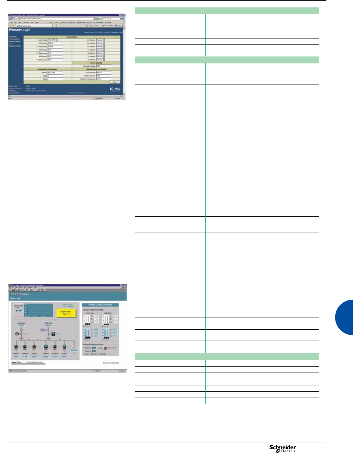
2013 97
PE86004
Communication (cont.)
Protocol ION, Modbus, TCP/IP, DNP 3.0, Telnet, IEC 61850(2)
EtherGate Communicates directly with up to 62 slave devices via
available serial ports
ModemGate Communicates directly with up to 31 slave devices
Ethernet port 10Base-T/100Base-TX, RJ45 connector, 100 m link
WebMeter 5 customisable pages, new page creation capabilities,
HTML/XML compatible
Firmware characteristics
High-speed data recording Down to 5ms interval burst recording, stores detailed
characteristics of disturbances or outages. Trigger
recording by a user-dened setpoint, or from external
equipment.
Harmonic distortion Up to 63rd harmonic (511th for ION7650 via ION Enterprise
software) for all voltage and current inputs
Sag/swell detection Analyse severity/potential impact of sags and swells:
- magnitude and duration data suitable for plotting on
voltage tolerance curves
- per phase triggers for waveform recording, control
Disturbance direction detection Determine the location of a disturbance more quickly and
accurately by determining the direction of the disturbance
relative to the meter. Analysis results are captured in the
event log, along with a timestamp and condence level
indicating level of certainty.
Instantaneous High accuracy (1s) or high-speed (1/2 cycle)
measurements, including true rms per phase / total for:
- voltage and current
- active power (kW) and reactive power (kvar)
- apparent power (kVA)
- power factor and frequency
- voltage and current unbalance
- phase reversal
Load proling Channel assignments (800 channels via 50 data
recorders) congurable for any measurable parameter,
including historical trend recording of energy, demand,
voltage, current, power quality, or any measured
parameter. Trigger recorders based on time interval,
calendar schedule, alarm/event condition, or manually.
Trend curves Access historical data at the front panel. Display, trend
and continuously update historical data with date and
timestamps for up to four parameters simultaneously.
Waveform captures Simultaneous capture of all voltage and current channels
- sub-cycle disturbance capture
- maximum cycles is 214,000 (16 samples/cycle x 96
cycles, 10Mbytes memory)
- 256 samples/cycle (ION7550)
- 512 samples/cycle standard, 1024 samples/cycle
optional (ION7650)
COMTRADE waveform format available direct from the
meter (Ethernet port option only)
PE86005
Alarms Threshold alarms:
- adjustable pickup and dropout setpoints and time
delays, numerous activation levels possible for a given
type of alarm
- user-dened priority levels
- boolean combination of alarms is possible using the
operators NAND, OR, NOR and XOR
Advanced security Up to 16 users with unique access rights. Perform resets,
time syncs, or meter congurations on user privileges
Transformer correction Correct for phase / magnitude inaccuracies in current
transformers (CTs), potential transformers (PTs)
Memory 5 to 10 Mbytes (specied at time of order)
Firmware update Update via the communication ports
Display characteristics
Integrated display Back lit LCD, congurable screens
Languages English, French, Spanish, Russian
Example showing instantaneous values and alarm. Notations IEC, IEEE
(1) All the communication ports may be used simultaneously.
(2) Only available with 5MB memory meters.
ION7550 / ION7650
Functions and characteristics (cont.)
Advanced metering
2013
98
ION7550 / ION7650
Functions and characteristics (cont.)
Advanced metering
Part numbers
Example ION7650 product part number.
Item Code Description
PE86020
1 Model M7650 Advanced meter with wide-range voltage inputs (57-347V
line-neutral or 100-600V line-line), transient detection, data and
waveform recording, IEC 61000-4-30 Class A & EN50160.
Supports ION, IEC 61850 (only for meters with 5MB memory and
Ethernet comm card) Modbus-RTU, and DNP 3.0.
M7550 Advanced meter with wide-range voltage inputs (57-347V
line-neutral or 100-600V line-line), sag/swell detection, data and
waveform recording. Supports ION, IEC 61850 (only for meters
with 5MB memory and Ethernet comm card) Modbus-RTU, and
DNP 3.0.
2Form Factor A0 Integrated display with front optical port, 5 MB logging memory,
and 512 samples/cycle resolution (ION7650) or 256 samples/
cycle (ION7550).
A1 ION7650 only. Integrated display with front optical port, 5 MB
logging memory, and 1024 samples/cycle resolution.
1 Model.
2 Form factor.
3 Current Inputs.
4 Voltage Inputs.
5 Power supply.
6 System frequency.
7 Communications.
8 Inputs/outputs.
9 Security.
10 Special order.
B0 Integrated display with front optical port, 10 MB logging memory,
and 512 samples/cycle resolution (ION7650) or 256 samples/
cycle (ION7550).
B1 ION7650 only. Integrated display with front optical port, 10 MB
logging memory, and 1024 samples/cycle resolution.
T0 Transducer (no display) version, with 5 MB logging memory, and
512 samples/cycle resolution (ION7650) or 256 samples/cycle
(ION7550).
T1 ION7650 only. Transducer (no display) version, with 5 MB logging
memory, and 1024 samples/cycle resolution.
U0 Transducer (no display) version, with 10 MB logging memory, and
512 samples/cycle resolution (ION7650) or 256 samples/cycle
(ION7550).
U1 ION7650 only. Transducer (no display) version, with 10 MB
logging memory, and 1024 samples/cycle resolution.
3Current Inputs C5 Amp nominal, 20 Amp full scale current input
E1 Amp nominal, 10 Amp full scale current input
F Current Probe Inputs (for 0-1 VAC current probes; sold separately)
G Current Probe Inputs with three Universal Technic 10A clamp on
CTs; meets IEC 1036 accuracy
4Voltage Inputs 057 to 347 VAC line-to-neutral / 100 to 600 VAC line-to-line
5Power Supply BStandard power supply (85-240 VAC, ±10%/47-63 Hz / 110-300
VDC, ±10%)
CLow voltage DC power supply (20-60 VDC)
6 System
Frequency
5Calibrated for 50 Hz systems
6Calibrated for 60 Hz systems
7 Communications A0 Standard communications (1 RS-232/RS-485 port, 1 RS-485 port).
Integrated display models include 1 ANSI Type 2 optical port.
C1 Standard communications plus 10Base-T/100Base-TX Ethernet
(RJ45), 56k universal internal modem (RJ11). Ethernet and
modem gateway functions each use a serial communications port.
D7 Standard communications plus 10Base-T/100Base-TX Ethernet
(RJ45) and 100BaseFX Ethernet Fiber, 56k universal internal
modem (RJ11). Ethernet/modem gateway uses serial port.
E0 Standard communications plus 10Base-T/100Base-TX (RJ45).
Ethernet gateway function uses a serial communications port.
F1 Standard communications plus 10Base-T/100Base-TX Ethernet
(RJ45) and 100Base-FX (SC male Fiber Optic connection).
Ethernet gateway function uses a serial port.
M1 Standard communications plus 56k universal internal modem
(RJ11). Modem gateway function uses a serial port.
8 I/O AStandard I/O (8 digital ins, 3 Form C relays, 4 Form A solid-state out)
E Standard I/O plus Expansion I/O card (8 additional digital inputs &
four 0 to 20 mA analogue inputs)
KStandard I/O plus Expansion I/O card (8 additional digital inputs &
four 0 to 20 mA analogue outputs)
NStandard I/O plus Expansion I/O card (8 additional digital inputs &
four 0 to 20 mA analogue inputs and four 0 to 20 mA outputs)
PStandard I/O plus Expansion I/O card (8 additional digital inputs &
four 0 to 1 analogue inputs and four -1 to 1 mA analogue outputs)
9 Security 0 Password protected, no hardware lock
1Password protected, hardware lockable (enabled/disabled via
jumper on comm card)
6Password protected with security lock enabled, terminal cover and
UK OFGEM labels
M
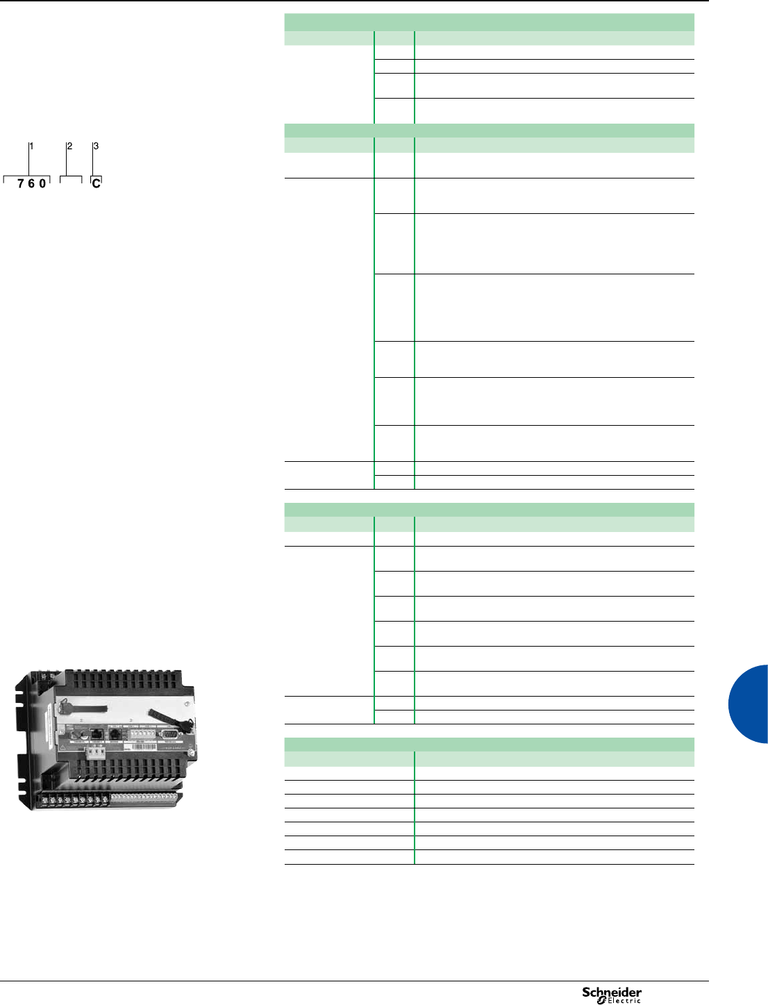
2013 99
ION7650 / ION7550
Functions and characteristics (cont.)
Part numbers (cont’d)
Item Code Description
10 Other options A None
CTropicalisation treatment applied
E ION7650 only. EN50160 compliance monitoring,
IEC61000-4-30 Class A measurements
F ION7650 only. EN50160 compliance monitoring, with
tropicalisation treatment, IEC61000-4-30 Class A measurements
Communications Card (1)
PE86021
Example order code. Use this group of codes when ordering
the PowerLogic™ ION7550/7650 communications or I/O
cards.
Item Code Description
1 Comm card P765C ION7550 / ION7650 communication card for eld retrot
installations
2Type A0 Standard communications (1 RS-232/RS-485 port, 1 RS-485
port). Front optical port support for meters with integrated
display.
C1 Standard communications plus 10Base-T/100Base-TX Ethernet
(RJ45), 56k universal internal modem (RJ11; the modem port is
shared with the front optical port). Ethernet and modem gateway
functions each use a serial communications port. IEC 61850
protocol (depending on rmware version).
1 Communications or I/O card.
2 Type
3 Special order.
D7 Standard communications plus 10Base-T/100Base-TX Ethernet,
100BaseFX Ethernet Fiber, 56k universal internal modem (RJ11;
the modem port is shared with the front optical port).
Ethernet and modem gateway functions each use a serial
communications port.IEC 61850 protocol (depending on
rmware version).
E0 Standard communications plus 10Base-T/100Base-TX Ethernet.
Ethernet gateway function uses a serial communications port.
IEC 61850 protocol (depending on rmware version).
F1 Standard communications plus 10Base-T/100Base-TX Ethernet,
100BaseFX Ethernet Fiber (SC male Fiber Optic connection).
Ethernet gateway function uses a serial communications port.
IEC 61850 protocol (depending on rmware version).
M1 Standard communications plus 56k universal internal modem
(RJ11; the modem port is shared with the front optical port).
Modem gateway function uses a serial communications port.
3Special order A None
CTropicalization treatment applied
Input/Output expansion card
Item Code Description
I/O card P760A Expansion I/O for eld retrot installations.
Type DExpansion I/O card with eight digital inputs, four 0 to 1 mA
analogue inputs
E Expansion I/O card with eight digital inputs, four 0 to 20 mA
analogue inputs
HExpansion I/O card with eight digital inputs, four -1 to 1 mA
analogue outputs
KExpansion I/O card with eight digital inputs, four 0 to 20 mA
analogue outputs
NExpansion I/O card with eight digital inputs, four 0 to 20 mA
analogue inputs & four 0 to 20 mA outputs
PExpansion I/O card with eight digital inputs, four 0 to 1 analogue
inputs and four -1 to 1 mA analogue outputs
Special Order A None
PE86019
CTropicalization treatment applied
ION7550 / ION7650 related items
Code Description
ADPT-37XX-7500 Adapter plate to t meter into a 3710 or 3720 ACM panel cutout
TERMCVR-7500 Terminal strip cover for the ION7550 or ION7650
M1UB10A1V-10A 10 A / 1 VAC Universal Technic Clamp On Current Probe
P32UEP813-1000A 1000 A / 1 VAC Universal Technic Clamp On Current Probe
P32UEP815-3000A 3000 A / 1 VAC Universal Technic Clamp On Current Probe
SCT0750-005-5A 5 A / 0.333 VAC Magnelabs Split Core Current Probe
SCT1250-300-300A 300 A / 0.333 VAC Magnelabs Split Core Current Probe
PowerLogic™ ION7550 TRAN
(1) Firmware version 350 or higher required.
P
C 1
Advanced metering
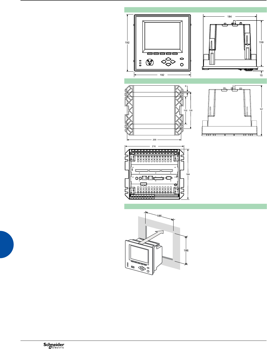
2013
100
ION7550 / ION7650
Dimensions and connection
ION7550/ION7650 dimensions
PE86022
PE86023
ION7550 / ION7650 TRAN dimensions
PE86024
PE86025
PE86026
Front-panel mounting
ION7550 and ION7650 meter can have integrated or remote
display. The meter with integrated display is designed to t DIN
standard 192 cutout (186 mm by 186 mm) . The remote display
is intalled through a circular cutout (22.5 mm diameter) at the
panel door and it has a front and a back module that is
connected to the meter mounted in a DIN rail at the back.
PE86027
Advanced metering
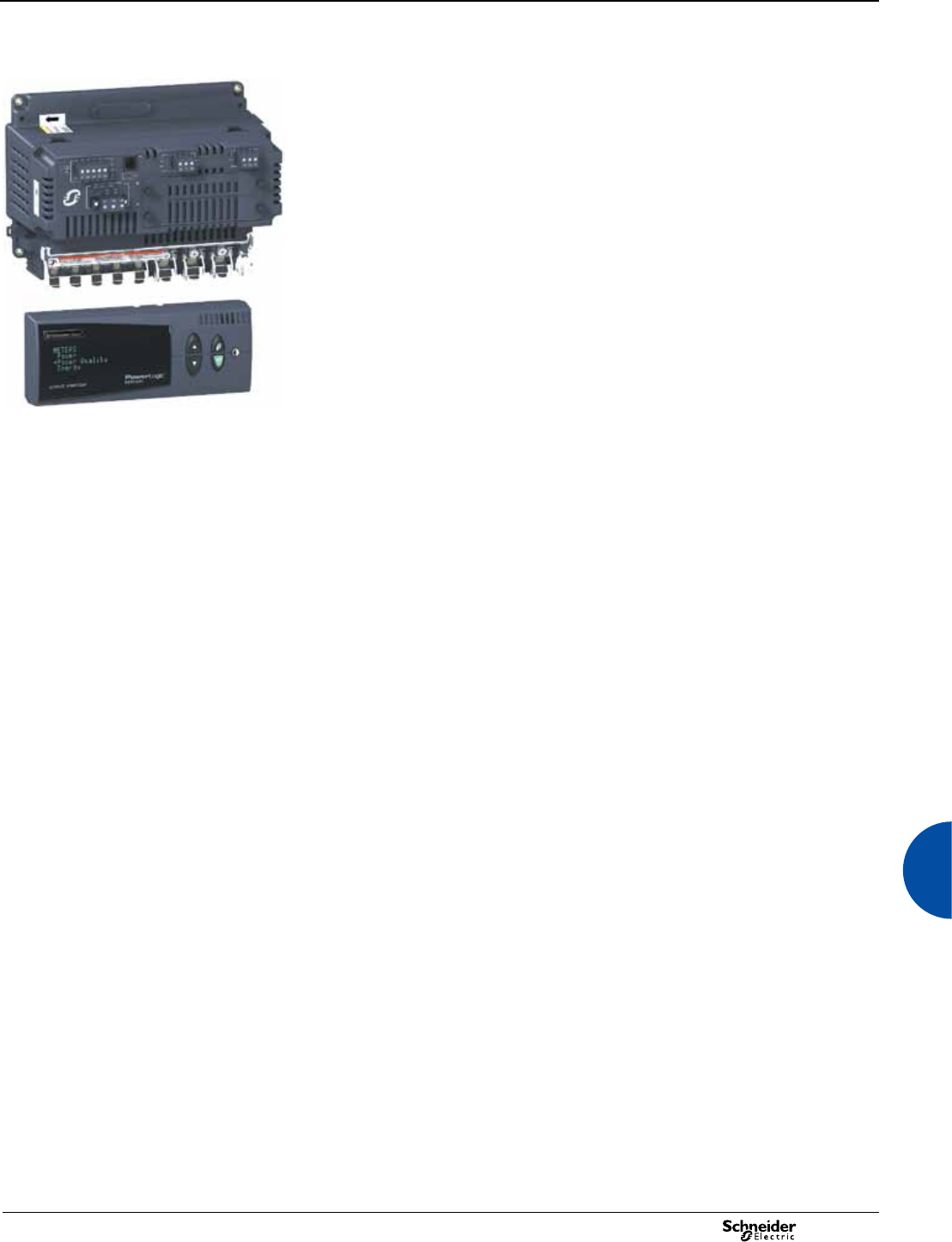
2013 101
Advanced metering
The PowerLogic Circuit Monitor Series 4000 offers high-performance digital
instrumentation, data acquisition and control capabilities. The products can integrate
easily in power monitoring and control systems due to their optional Ethernet
connections and embedded web server. They are Transparent Ready.
These devices are designed for applications where power quality and availability are
critical factors. They are generally used at service entrances and interconnection
points or on circuits feeding sensitive equipment. Due to their very wide range of
features, including transient detection (CM4000T only), it is possible to rapidly solve
problems related to poor power quality. EN 50160 compliance checking capability
makes these products ideal to meet new needs related to market deregulation.
The Circuit Monitor Series 4000 is available in two versions:
bCM4250, with detection of voltage sags, swells and other power quality indices
bCM4000T, with detection of voltage sags and swells together with transient
detection and icker measurements.
Applications
Panel instrumentation.
Sub-billing / cost allocation.
Remote monitoring of an electrical installation.
Extensive power-quality monitoring.
Contract and load curve optimisation.
EN 50160 electrical supply compliance checking.
Metering of other utilities.
Main characteristics
Disturbance direction detection
Indication of whether the source of a specic power quality event is upstream or
downstream from the meter.
Power quality summary
Consolidation of all the power quality characteristics into a single trendable index.
Adaptive waveform capture
Capture of long-duration events.
Shift energy summary
Indication of energy usage per shift up to three shifts a day.
Detection and capture of voltage sags and swells
Fast identication of problems causing production shutdown.
Detection and capture of short transients less than 1 µs
(optional, CM4000T only)
Identication of problems due to short disturbances, e.g. switching of capacitors, etc.
Flicker evaluation based on IEC 61000-4-15 and IEEE 1453 (CM4000T only)
Measurement of rapid voltage variations.
Electrical quality checking in compliance with EN 50160
Fast standardised check on the quality of the electricity supplied.
Detection of major waveform changes
Detection of phase switching phenomena (for example during the transfer of a
high-speed static switch) not detected by classical threshold-based alarms.
Ultra-fast recording of electrical parameters every 100 ms or every cycle
Preventive maintenance: acquisition of a motor startup curve, etc.
Trend curves and short-term forecasting
Rapid trending and forecasting of upcoming values for better decision making.
Automatic alarm setting
Alarm setpoint learning feature for optimum threshold settings.
Up to 32 Mbytes of memory (16 Mbytes standard)
For archiving of data and waveforms.
Ethernet 10/100 Mbits/s card and server for HTML pages
(with optional Ethernet card)
Rapid data transfers over an intranet or the internet, simply using a web browser.
Alarm notication via email
High-priority alarms sent directly to the user’s PC.
Instant notication of power quality events by email.
Up to 25 inputs/outputs to monitor the electrical installation
(with optional I/O cards)
Status of circuit breakers, as well as metering of other commodities, e.g. gas, water, etc.
IEC 62053-22 and ANSI C12.20 Class 0.2S for energy
Verication of consumption and load curves.
PE86140
CM4000 + vacuum uorescent display (VFD).
Circuit Monitor Series 4000
Functions and characteristics
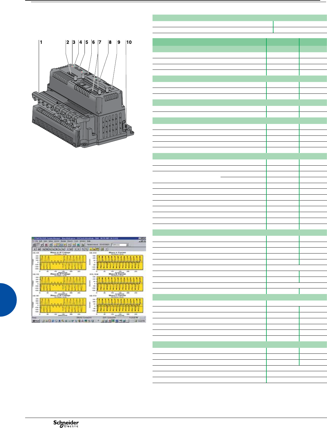
2013
102
Advanced metering
Part numbers
Circuit Monitor Series 4000
Circuit Monitor CM4250 CM4250
Circuit Monitor CM4000T CM4000T
DB108168
CM4000 series.
1 Current/voltage module.
2 Control power-supply connector.
3 Maintenance LED indicator.
4 Power LED indicator.
5 RS 485 port with transmit and receive LED indicators.
6 Display communication port.
7 Slots for optional cards.
8 RS 232 port with transmit and receive LED indicators.
9 KYZ pulse output.
10 Sealable access door.
Selection guide CM4250 CM4000T
General
Use on LV and HV systems b b
Current and voltage accuracy 0.07 % 0.07 %
Energy and power accuracy 0.2 % 0.2 %
Nbr of samples/cycle or sample frequency 512 5 MHz
Instantaneous rms values
Current, voltage, frequency b b
Active, reactive, apparent power Total and per phase b b
Power factor Total and per phase b b
Energy values
Active, reactive, apparent energy b b
Settable accumulation modes b b
Demand values
Current Present and max. values b b
Active, reactive, apparent power Present and max. values b b
Predicted active, reactive, apparent power b b
Synchronisation of the measurement window b b
Setting of calculation mode Block, sliding b b
Power quality measurements
Interharmonics b-
Harmonic distortion Current and voltage b b
Individual harmonics Via monitor 63 63
Via SMS 255 255
Waveform capture b b
Detection of voltage swells and sags b b
Adaptive waveform capture (up to 64 s) b b
Detection and capture of transients (< 1 µs) -b
Flicker -b
Fast acquisition of 100 ms or cycle by cycle data b b
EN 50160 compliance checking (1) b b
Programmable (logic and math functions) b b
Data recording
E87306
Min/max of instantaneous values b b
Data logs b b
Event logs b b
Trending/forecasting b b
Alarms (optional automatic alarm setting) b b
Alarm notication via email ECC21 option
SER (Sequence of Event Recording) b b
Time stamping b b
GPS synchronisation (1 ms) IOC44 option
Memory expandable up to 32 Mbytes 32 Mbytes
Display and I/O
Display CMDLC or CMDVF option
Multilingual: English, French, Spanish, German, Italian, Polish b b
Wiring self-test b b
Pulse output b b
Disturbance waveform capture: detection of a voltage sag. Maximum number of I/Os 25 25
Input metering capability (number of channels) 10 10
Direct voltage connection 690 V 600 V
Communication
RS 485 port 2/4 wires 2/4 wires
RS 232 port b b
Modbus protocol b b
Ethernet card (Modbus/TCP/IP protocol) ECC21 option
HTML-page web server ECC21 option
Ethernet gateway for third-party products ECC21 option
(1) Except for interharmonics, signalling voltages, icker and transients.
Circuit Monitor Series 4000
Functions and characteristics (cont.)
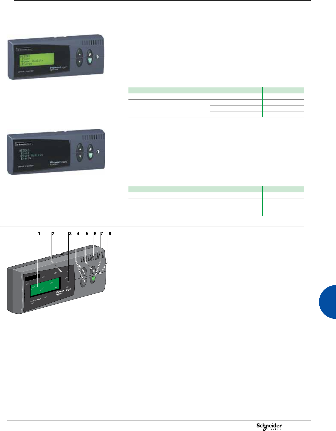
2013 103
Advanced metering
The Circuit Monitor has two optional display units, an LCD display and a vacuum
uorescent display (VFD). They may be used for local circuit-monitor setup and
operation.
PE86143
CMDLC display
Back-lit LCD display with four lines and 20 characters per line. The display unit has
four navigation buttons, a contrast button and a red alarm LED.
It connects to the Circuit Monitor via a CAB12 cable, 4.2 metres long, supplied with
the display.
Part numbers
LCD display supplied with the CAB12 cable CMDLC
Connection cables:
Circuit Monitor <-> display
1.25 m (4 ft) CAB4
3.65 m (12 ft) CAB12
9.14 m (30 ft) CAB30
PE86142
CMDVF display
Vacuum uorescent display (VFD) with four lines and 20 characters per line.
The display unit has four navigation buttons, a contrast button, a red alarm LED.
The display comes with a cable for connection to the Circuit Monitor (CAB12 cable,
4.2 m long).
Part numbers
VFD supplied with the CAB12 cable CMDVF
Connection cables:
Circuit Monitor <-> display
1.25 m (4 ft) CAB4
3.65 m (12 ft) CAB12
9.14 m (30 ft) CAB30
E87288
1 Display screen.
2 Alarm LED.
3 Arrow buttons.
4 Menu button.
5 Proximity sensor (VFD display only).
6 Enter button.
7 Contrast button.
Display.
Circuit Monitor Series 4000
Functions and characteristics (cont.)
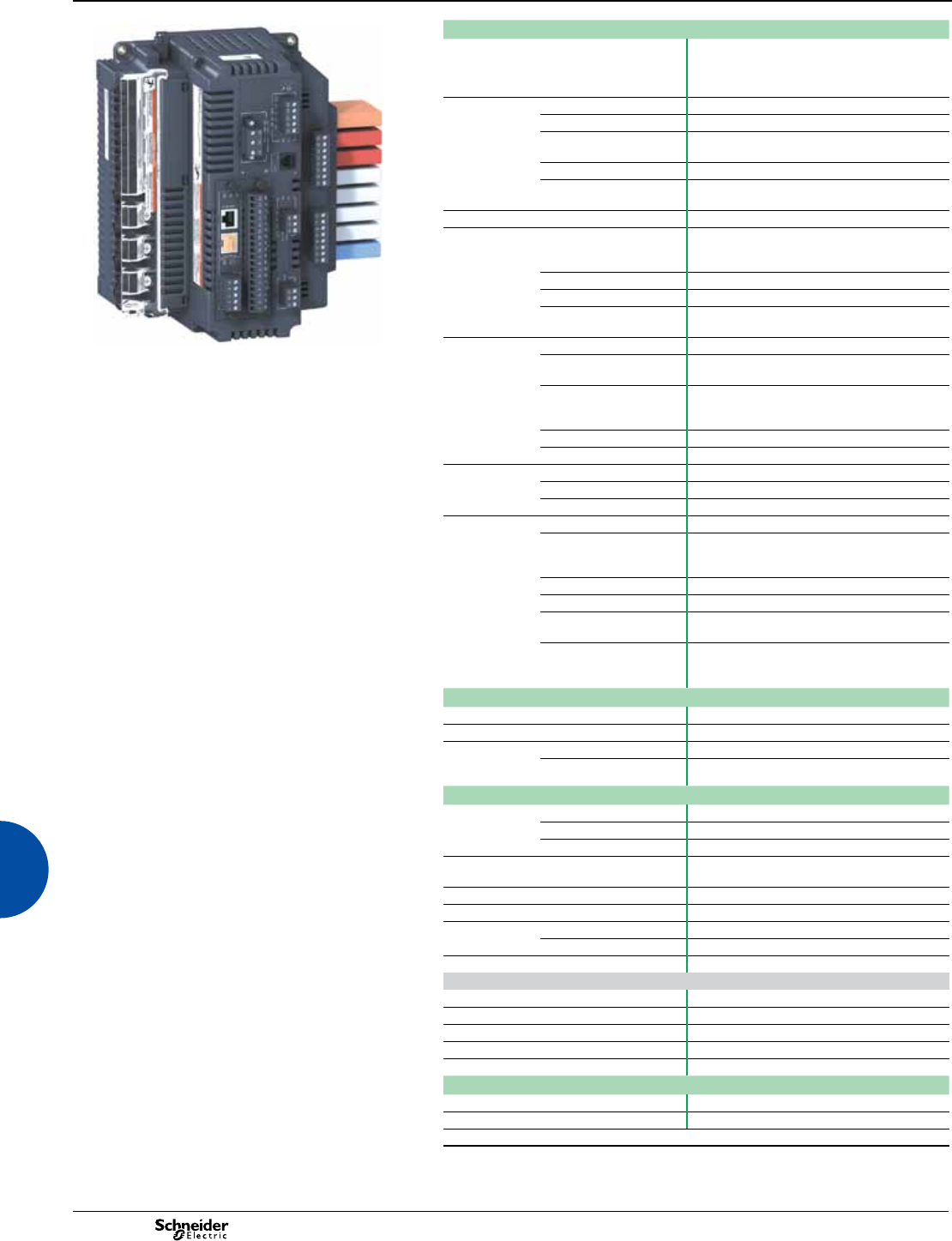
2013
104
Advanced metering
PE86141
CM4000 + options: ECC21, IOC44 and IOX2411.
Electrical characteristics
Type of measurement True rms up to the 255th harmonic
On three-phase AC system (3P, 3P + N)
Up to 512 samples per cycle
Up to 5 MHz for transient events (CM4000T only)
Measurement
accuracy
Current and voltage ±0.04 % of reading + ±0.025 % of full scale
Power ±0.075 % of reading + ±0.025 % of full scale
Frequency ±0.01 Hz from 45 to 67 Hz
±0.1 Hz from 350 to 450 Hz
Power factor ±0.002 from 0.5 leading to 0.5 lagging
Energy:
CM4250/CM4000T
IEC 62053-22 and ANSI C12.20 Class 0.2S
Data update rate 1 s in normal mode
Input-voltage
characteristics
Measured voltage 0 to 600 V AC on CM4000T (direct)
0 to 690 V AC on CM4250 (direct)
0 to 1200 kV AC (with external VT)
Measurement range 0 to 1.5 Un
Impedance > 2 MW
Frequency measurement
range
45 to 67 Hz and 350 to 450 Hz
Input-current
characteristics
CT ratings Adjustable from 5 A to 30 000 A
Measurement range
CM4250/CM4000T
5 mA to 10 A
Permissible overload 15 A continuous
50 A for 10 seconds per hour
500 A for 1 second per hour
Impedance < 0.1 W
Load < 0.15 VA
Power supply AC 100 to 275 V AC (±10 %), 50 VA
DC 125 to 250 V DC (±20 %), 30 W
Ride-through time 100 ms at 120 V DC
Input/outputs Pulse output Static output (240 V AC max, 96 mA max)
IOC44 card (optional) 4 digital inputs (20-138 V AC/DC),
3 relay outputs (5 A to 240 V AC)
1 static output (96 mA max to 240 V AC)
IOX extender (optional) Slots for 8 I/Os
IOX08 (optional) 8 digital inputs 120 V AC
IOX0404 (optional) (1) 4 dig. inputs 120 V AC, 4 analogue outputs 4-20
mA
IOX2411 (optional) (1) 2 dig. outputs 120 V AC, 4 dig. inputs 32 V DC,
1 analogue input 0-5 V, 1 analogue output 4-20
mA
Mechanical characteristics
Weight 1.9 kg
IP degree of protection (IEC 60529) IP52
Dimensions
CM4250/
CM4000T
Without IOX accessory 235.5 x 165.6 x 133.1 mm
With IOX accessory 235.5 x 216.3 x 133.1 mm
Environmental conditions
Operating
temperature
Circuit Monitor -25 °C to +70 °C
CMDLC display -20 °C to +60 °C
CMDVF display -20 °C to +70 °C
Storage
temperature
CM + displays -40 °C to +85 °C
Humidity rating 5 to 95 % RH at 40 °C
Pollution degree 2
Installation
category
CVM42 IV
CVMT II
Dielectric withstand As per EN 61010, UL508, CSA C22.2-2-4-M1987
Electromagnetic compatibility
Electrostatic discharge Level 3 (IEC 61000-4-2)
Immunity to radiated elds Level 3 (IEC 61000-4-3)
Immunity to fast transients Level 3 (IEC 61000-4-4)
Immunity to impulse waves Level 4 (IEC 61000-4-5)
Conducted and radiated emissions e industrial envir./FCC part 15 class A
Safety
Europe e, as per CEI 61010
USA and Canada UL508 and CSA C22.2-2-4-M1987
(1) Operating limits: 0° C to +60 °C. Storage limits: -25 °C to +85 °C.
Circuit Monitor Series 4000
Functions and characteristics (cont.)
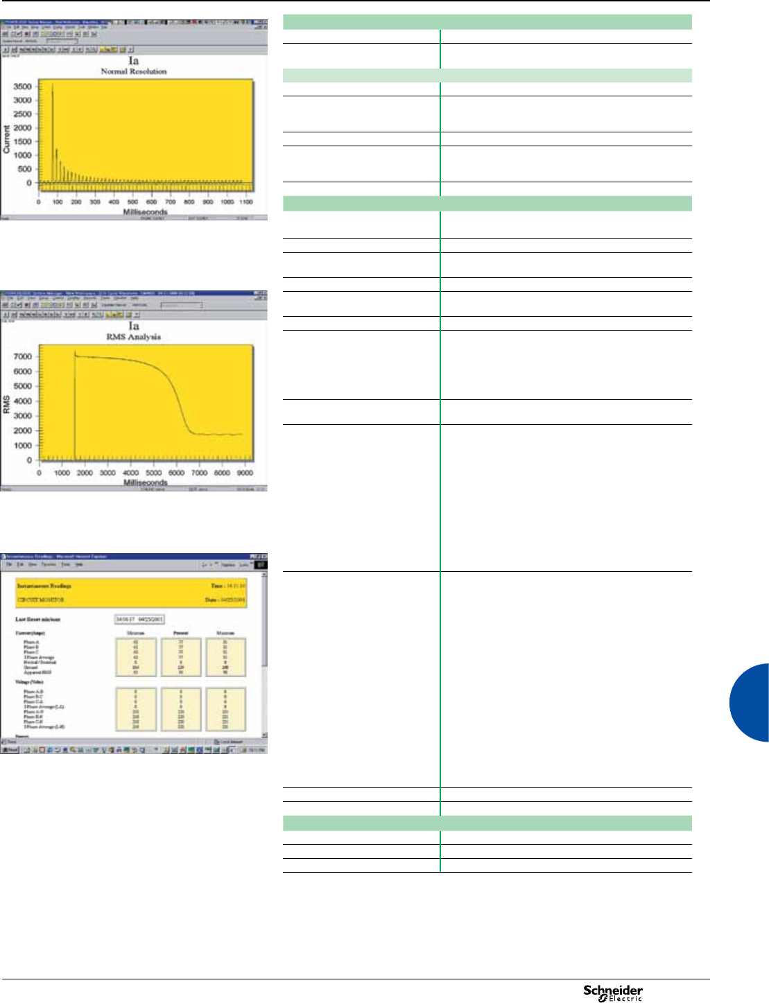
2013 105
Advanced metering
E87307
Communication
RS 485 port (1) 2/4 wires, up to 38400 bauds, Modbus
RS 232 port (1) Up to 38400 bauds, Modbus, direct connection to a PC
or modem
Ethernet ECC21 card with HTML server (optional) (1)
Copper Ethernet link 10/100 BaseTX, RJ45 connector, 100 m link
Fiber-optic Ethernet link 100 Base FX, LC duplex connector, 1300 nm, FO
multimode with gradient index 62.5/125 µm or 50/125 µm,
2000 m link
Protocol Modbus/TCP/IP
Gateway function for products
connected to the ECC21
Master Modbus port, 31 daisy-chained slaves,
63 with repeater, 2/4 wires, 1200 to 38400 bauds,
also compatible with the PowerLogic protocol
HTML server 1 standard page, 5 customisable pages
Firmware characteristics
Adaptive waveform capture: transformer inrush current. 14 data logs Up to 96 different parameters, factory-set logs ready
to use
One 100 ms data log Parameters recorded every 100 ms for events
One 20 ms (50 Hz) or 16 ms (60 Hz)
data log
Parameters recorded every 20 ms or 16 ms for events
E87308
One min/max log -
One min/max/avg. log Min/max/avg. values recorded for 23 parameters at
regular intervals from 1 to 1440 minutes
One event log Time stamping to 1 ms, synchro. 1 ms by GPS
Trend curves Four trend curves: 1 minute, 1 hour, 1 day and 1 month.
Min./max./avg. values recorded for eight parameters:
- every second for one minute for the 1-minute curve
- every minute for one hour for the 1-hour curve
- every hour for one day for the 1-day curve
- every day for one month for the 1-month curve
Forecasting Forecasting of the values for the eight parameters
for the next four hours and next four days
Waveform captures Standard: manual launch, 1 cycle, 512 samples, 255th
harmonic
Disturbance: manual launch or by alarm, adjustable from
512 samples/cycle over 28 cycles to 16 samples/cycle
over 915 cycles, response time less than 0.5 cycle,
number of cycles before alarm settable from 2 to 10
Adaptive: manual launch or by alarm, adjustable from
512 samples/cycle over 8 seconds to 16 samples/cycle
over 264 seconds, capture takes place during a set
duration or as long as an alarm is active (to save memory),
number of cycles before alarm settable from 2 to 10
Transient: voltage sampling at 5 MHz (83 333 samples/
cycle) over 2 ms to capture transient peaks < 1 µs
Adaptive waveform capture: motor start, rms value.
E87309
Alarms Threshold alarms:
- adjustable pickup and dropout setpoints and time delays,
numerous activation levels possible for a given type of
alarm
- 4 priority levels
- 4 response times: standard 1 s, fast 100 ms,
disturbance < 1/2 cycle, transient < 1µs
- boolean combination of four alarms is possible using the
operators NAND, OR, NOR and XOR
Automatic alarm setting: after a learning phase, the alarm
thresholds are set automatically. The alarms will trip in the
event of drift with respect to reference values determined
during the learning period.
Digital alarms: logic input transitions
Waveform alarms: alarm tripping by a special algorithm
when the current or voltage waveform is distorted beyond
an adjustable level. Makes it possible to detect
disturbances that cannot be detected by classical
threshold alarms (e.g. phase switching).
Example CM4250 HTML page showing instantaneous values.
Memory 8 Mbytes standard, expandable up to 32 Mbytes
Firmware update Update via the communication ports
Display characteristics
CMDLC (optional) Back lit LCD
CMDVF (optional) Vacuum uorescent display (VFD) with IR port
Languages English, French, Spanish, German, Italian, Polish
(1) All the communication ports may be used simultaneously.
Circuit Monitor Series 4000
Functions and characteristics (cont.)
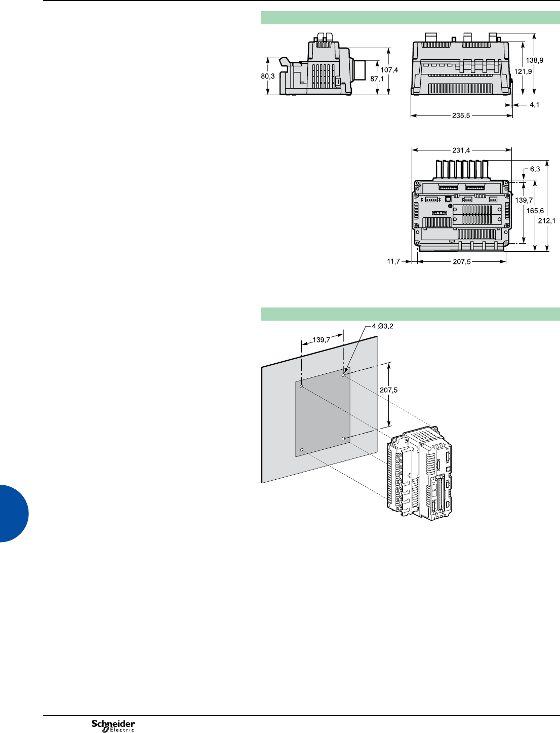
2013
106
CM4250 / CM4000T dimensions
E94393
E94394
E94392
Mounting on a backplate
DB108169
Advanced metering Circuit Monitor Series 4000
Dimensions and connection
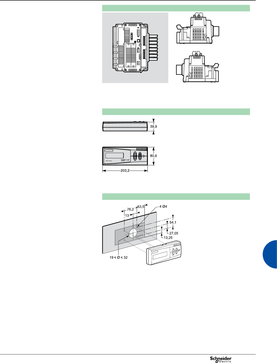
2013 107
Advanced metering Circuit Monitor Series 4000
Dimensions and connection
Mounting possibilities
DB108007
DB108005DB108006
Vertical mounting. Horizontal mounting.
CMDLC/CMDVF dimensions
E87286E87285
Mounting on a backplate
E94377
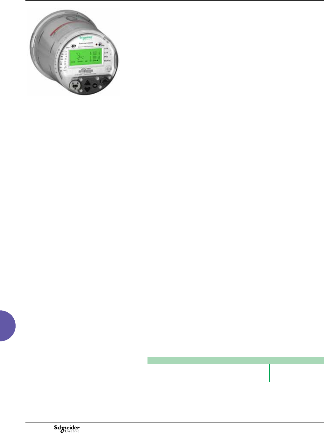
2013
108
ION8650
Functions and characteristics
Advanced utility metering
PB107500
PowerLogic ION8650 socket meter
Used to monitor electric energy provider networks, service entrances and
substations, PowerLogic ION8650 meters are ideal for independent power
producers and cogeneration applications that need to accurately measure energy
bi-directionally in both generation and stand-by modes. These meters give utilities
the tools to manage complex energy supply contracts that include commitments to
power quality. Integrate them with our StruxureWare Power Monitoring (ION
Enterprise™) operations software or other energy management and SCADA
systems through multiple communication channels and protocols, including Itron
MV-90, Modbus, DNP, IEC 61850.
Applications
Revenue metering.
Co-generation and IPP monitoring.
Compliance monitoring.
Power quality analysis.
Demand and power factor control.
Load curtailment.
Equipment monitoring and control.
Energy pulsing and totalisation.
Instrument transformer correction.
Main characteristics
ANSI Class 0.2 and IEC 62053-22/23 Class 0,2S metering
For interconnection points on medium, high, and ultra-high voltage networks; twice
as accurate as current IEC and ANSI Class 0.2 standards over all conditions and
including single wide range current measurement.
Power quality compliance monitoring
Monitor compliance with international quality-of-supply standards (IEC 61000-4-30
Class A/S, EN50160, IEC 61000-4-7, IEC 61000-4-15, IEEE 1159, IEEE 519).
Digital fault recording
Simultaneous capture of voltage and current channels for sub-cycle disturbance.
Complete communications
Multi-port, multi-protocol ports including serial, infrared, modem and ethernet.
Simultaneously supports multiple industry standard protocols including: Itron MV-90,
Modbus, Modbus Master, DNP 3.0 and IEC 61850.
Multiple tariffs and time-of-use
Apply tariffs, seasonal rate schedules to measure energy and demand values for
time periods with specic billing requirements.
Multiple setpoints for alarm and functions
Use up to 65 setpoints for single/multi-condition alarms and I/O functions with
response times down to 1/2 cycle.
Multiple setpoints for alarm and functions
Use up to 65 setpoints.
Instrument transformer correction
Save money and improve accuracy by correcting for less accurate transformers.
Alarm notication via email
High-priority alarms, data logs sent directly to the user’s PC. Instant notication of
power quality events by email.
Part numbers
ION8650 meters
ION8650A M8650A
ION8650B M8650B
ION8650C M8650C
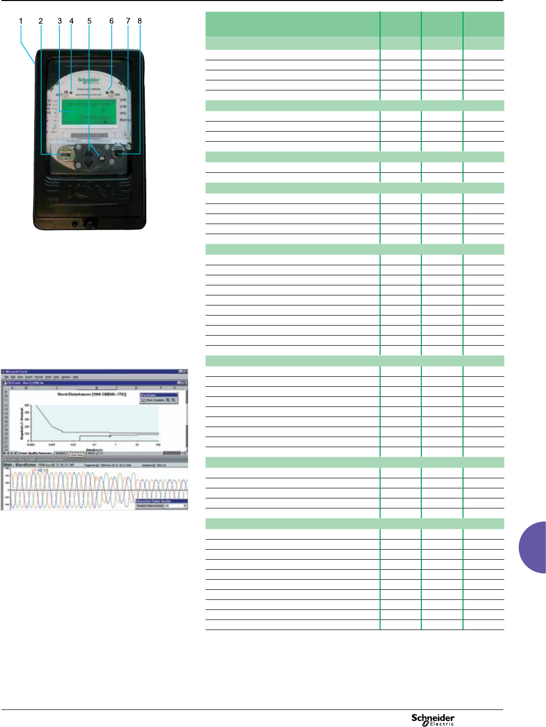
2013 109
ION8650
Functions and characteristics (cont.)
Advanced utility metering
PE86302-95
PowerLogic ION8650 socket meter.
1 Terminals
2 Optical port
3 Main display status bar
4 Watt LED
5 Navigation, ALT/Enter buttons
6 VAR LED
7 Nameplate label
8 Demand reset switch
Selection guide ION8650
A
ION8650
B
ION8650
C
General
Use on LV, MV and HV systems bbb
Current accuracy 0.1 % 0.1 % 0.1 %
Voltage accuracy 0.1 % 0.1 % 0.1 %
Power accuracy 0.1 % 0.1 % 0.1 %
Samples/cycle 1024 1024 1024
Instantaneous values
Current, voltage, frequency bbb
Active, reactive, apparent power Total & per phase bbb
Power factor Total & per phase bbb
Current measurement range 0 - 20A 0 - 20A 0 - 20A
Energy values
Active, reactive, apparent energy bbb
Settable accumulation modes bbb
Demand values
Current Present & max. values bbb
Active, reactive, apparent power Present & max. values bbb
Predicted active, reactive, apparent power bbb
Synchronisation of the measurement window bbb
Demand modes: Block (sliding), thermal (exponential) bbb
Power quality measurements
Harmonic distortion Current & voltage bbb
Individual harmonics Via front panel 63 63 31
Waveform / transient capture b / b- / b- / -
Harmonics: magnitude, phase, and interharmonics 50 40 -
Detection of voltage sags and swells bbb
IEC 61000-4-30 class A /S AS-
IEC 61000-4-15 (Flicker) bb-
High speed data recording (down to 10 ms) bb-
EN50160 compliance reporting bb-
Programmable (logic and math functions) bbb
Data recording
PE86002
Disturbance waveform capture and power quality report
Onboard Memory (in Mbytes) 128 64 32
Revenue logs bbb
Event logs bbb
Historical logs bbb
Harmonics logs bbb
Sag/swell logs bbb
Transient logs b- -
Time stamping to 1 ms bbb
GPS synchronisation (IRIG-B standard) bbb
Display and I/O
Front panel display bbb
Wiring self-test (requires PowerLogic ION Setup) bbb
Pulse output (front panel LED) 222
Digital or analogue inputs(1) (max) 11 11 11
Digital or analogue outputs(1) (max, including pulse output) 16 16 16
Communication
Infrared port 111
RS 485 / RS 232 port 111(3)
RS 485 port 111(3)
Ethernet port (Modbus/TCP/IP protocol) with gateway 111(3)
Internal modem with gateway (ModemGate) 111(3)
HTML web page server bbb
IRIG-B port (unmodulated IRIG B00x time format) 111
Modbus TCP Master / Slave (Ethernet port) b / b b / b- / b
Modbus RTU Master / Slave (Serial ports) b / b b / b- / b
DNP 3.0 through serial, modem, and I/R ports bbb
(1) With optional I/O Expander.
(2) For 9S, and 36S only. For 35S system up to 480V line-to-line.
(3) C model limited to IR + 2 other ports at one time. Ports can be enabled/disabled by user.
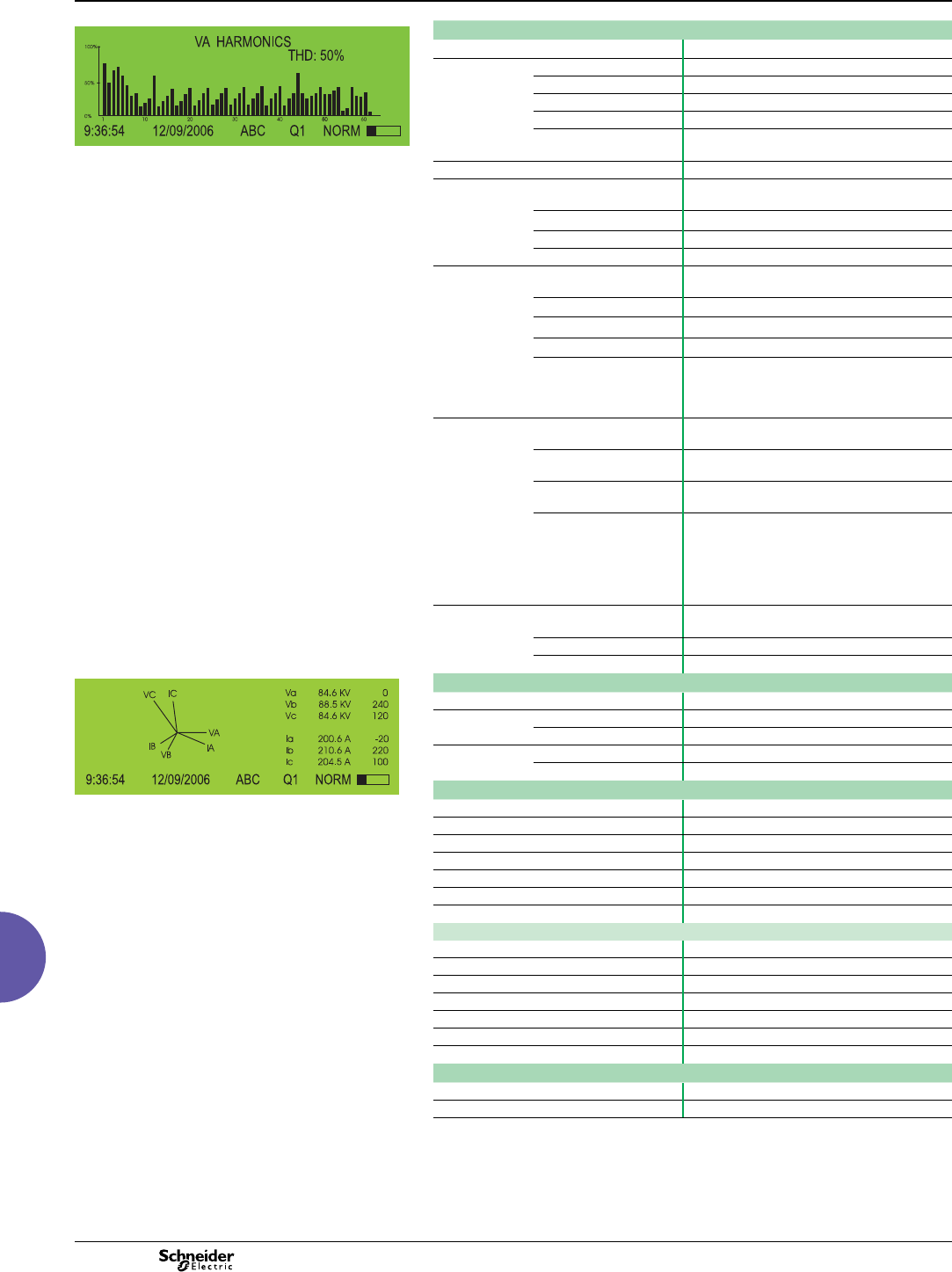
2013
110
ION8650
Functions and characteristics (cont.)
Advanced utility metering
PE86041
PowerLogic ION8650 front panel harmonic display.
Electrical characteristics
Type of measurement True rms 1024 samples per cycle
Measurement
accuracy
Current and voltage 0.1 % Reading
Power 0.1%
Frequency ±0.001 Hz
Power factor 0.1%
Energy 0.1%, twice as accurate as ANSI Class 0.2 and
IEC 62053-22/23 (0,2S)
Data update rate 0.5 cycle or 1 second (depending on value)
Input-voltage
characteristics (1)
Nominal voltage 57V to 277VLN rms
100V to 480VLL rms (35S)
Maximum voltage 347 VLN rms, 600 VLL rms (9S)
Impedance 5 MW /phase (phase-Vref/Ground)
Inputs V1, V2, V3, VREF
Input-current
characteristics
Rated nominal/current
class
1A, 2 A, 5 A and/or 10 A (Class 1/2/10/20)
Accuracy range 0.01 - 20 A (standard range)
Measurement range 0.001 - 24 A
Permissible overload 500A rms for 1 second, non-recurring
Burden per phase Socket: Typical: 3 W, 8 VA/phase, 3-phase
operation; Maximum: 4 W, 11 VA/phase,
3-phase operation
Switchboard: 0.05VA at 1A (0.05 Ω max)
Power supply Standard power supply,
blade powered
120-277 VLN RMS (-15%/+20%) 47-63 Hz or
120-480 VLL RMS (-15%/+20%) 47-63 Hz (35S)
Auxiliary powered low
voltage
AC: 65-120 (+/- 15%) VLN RMS, 47-63 Hz
DC: 80-160 (+/- 20%) VDC
Auxiliary powered high
voltage
AC: 160-277 (+/- 20%) VLN RMS, 47-63 Hz
DC: 200-300 (+/- 20%) VDC
Ride-through time,
(Standard power supply)
Socket: min guaranteed: 6 cycles at nominal
frequency (minimun 50 Hz), at 120 V L-N rms
(208 V L-L rms) 3-phase operation
Switchboard: min guaranteed: `6 cycles at
nominal frequency (minimun 50 Hz), at 120 V
L-N rms (208 V L-L rms) 3-phase operation
Input/outputs Digital outputs (Form C) 4 Solid state relays (130 V AC/ 200 V DC)
50 mA AC/DC
Digital outputs (Form A) 4 Solid state relays (via optional I/O Expander)
Digital inputs 4 Solid state inputs (via optional I/O Expander)
PE86042
ION8650 front panel phasor display and table.
Mechanical characteristics
Weight 7.0 kg
IP degree of
protection
Socket Front IP65, back IP51
Switchboard Front IP50, back IP30
Dimensions Socket 178 x 237 mm
Switchboard 285 x 228 x 163 mm
Environmental conditions
Operating temperature -40°C to +85°C
Display operating range -20°C to +60°C
Storage temperature -40°C to +85°C
Humidity rating 5 to 95 % RH non-condensing
Pollution degree 2
Installation category Cat III
Dielectric withstand 2.5kV
Electromagnetic compatibility
Electrostatic discharge IEC 61000-4-2
Immunity to radiated elds IEC 61000-4-3
Immunity to fast transients IEC 61000-4-4
Immunity to surge IEC 61000-4-5
Immunity conducted IEC61000-4-6
Damped oscillatory waves immunity IEC61000-4-12
Conducted and radiated emissions CISPR 22 (class B)
Safety
Europe As per IEC62052-11
North America As per ANSI C12.1
(1)Specications are limited by the operating range of the power supply if a non-aux power supply is used.
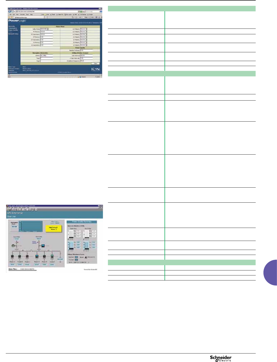
2013 111
ION8650
Functions and characteristics (cont.)
Advanced utility metering
PE86004-C
Example embedded webserver page (WebMeter) showing
realtime values.
Communication
RS 232 / RS 485 port (COM1) User-selectable RS 232 or RS 485.
300 - 115,200 bauds (RS485 limited to 57,600 bps);
protocols: ION, Modbus/RTU/Mastering, DNP 3.0,
GPSTRUETIME/DATUM.
Internal modem port (COM2) 300-57,600 bps
ANSI 12.18 Type II optical port
(COM3)
Up to 19200 bps
RS 485 port (COM4) Up to 57,600 bauds, Modbus, direct connection to a PC
or modem
Ethernet port 10/100 BaseT, RJ45 connector, protocols:
DNP, ION, Modbus/TCP/Mastering, IEC 61850
EtherGate Up to 31 slave devices via serial ports
ModemGate Up to 31 slave devices
Firmware characteristics
High-speed data recording Up to 1/2-cycle interval burst recording, stores detailed
characteristics of disturbances or outages. Trigger
recording by a user-dened setpoint, or from external
equipment.
Harmonic distortion Up to 63rd harmonic for all voltage and current inputs
Dip/swell detection Analyse severity/potential impact of sags and swells:
- magnitude and duration data suitable for plotting on
voltage tolerance curves
- per phase triggers for waveform recording or control
operations
Instantaneous High accuracy measurements with 1s or 1/2 cycle update
rate for:
- voltage and current
- active power (kW) and reactive power (kVAR)
- apparent power (kVA)
- power factor and frequency
- voltage and current unbalance
- phase reversal
Load proling Channel assignments are user congurable:
- 800 channels via 50 data recorders (feature set A),
- 720 channels via 45 data recorders (feature set B),
- 64 channels via 4 data recorders (feature set C).
Congure for historical trend recording of energy,
demand, voltage, current, power quality, other measured
parameter. Recorders can trigger on time interval basis,
calendar schedule, alarm/event condition, manually.
Waveform captures Simultaneous capture of all voltage and current channels
- sub-cycle disturbance capture (16 to 1024 samples/
cycle)
PE86005-C
Alarms Threshold alarms:
- adjustable pickup and dropout setpoints and time
delays, numerous activation levels possible for a given
type of alarm
- user-dened priority levels
- boolean combination of alarms
Advanced security Up to 16 users with unique access rights. Perform resets,
time syncs, or meter congurations based on user
priviledges.
Transformer correction Correct for phase / magnitude inaccuracies in current
transformers (CTs), potential transformers (PTs)
Memory 128 Mbytes (A), 64 Mbytes (B), 32 Mbytes (C)
Firmware update Update via the communication ports
Display characteristics
Type FSTN transreective LCD
Backlight LED
Languages English
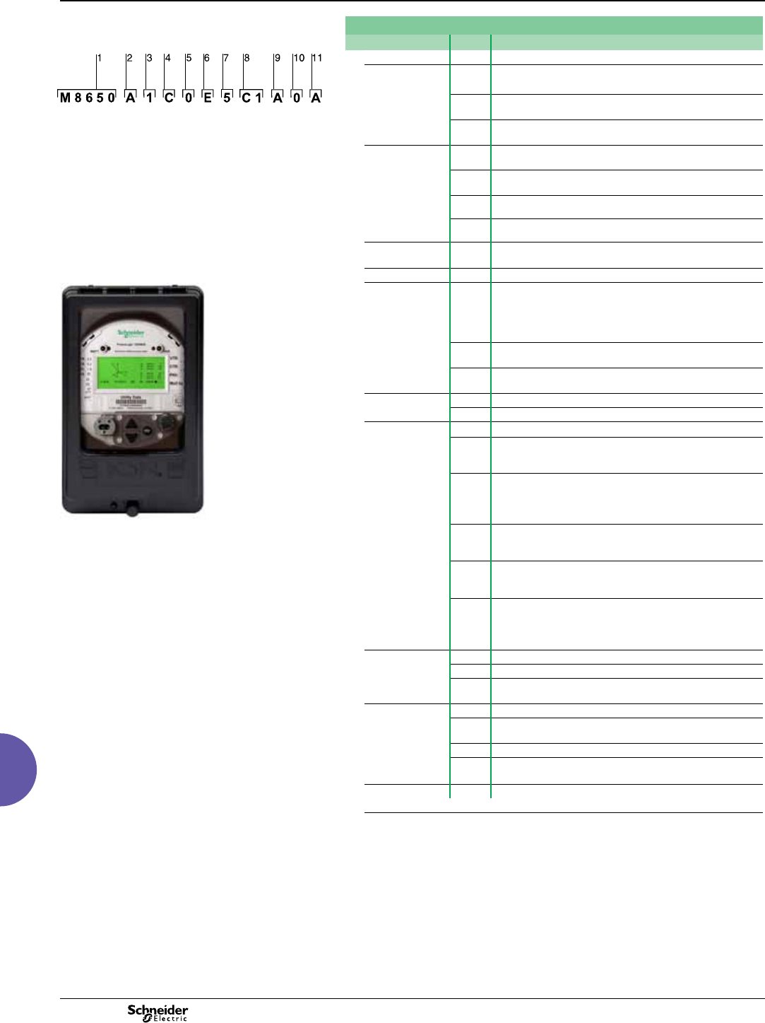
2013
112
ION8650
Functions and characteristics (cont.)
Advanced utility metering
Part Numbers
Item Code Description
PE86043-C
Example product part number.
1 Model M8650 Schneider Electric energy and power quality meter.
2Feature Set A128MB Memory Class A power quality analysis, waveforms and
transient capture with 1024 samples/cycle.
B64MB memory, energy meter Class S EN50160 power quality
monitoring.
1 Model.
2 Feature set.
3 Form factor.
4 Current Inputs.
5 Voltage inputs.
6 Power supply.
7 System frequency.
8 Communications.
9 Input/output options.
10 Security.
11 Special order options.
C32MB memory, basic tariff/energy metering (4 data recorders,
64 channels).
3Form Factor (1) 0Form 9S/29S/36S Base, 57-277 VLN (autoranging)
3-Element, 4-Wire / 2 1/2-Element, 4-Wire
1Form 35S Base - 120-480 VLL (autoranging) 2-Element,
3-Wire
4Form 9/29/35/36S FT21 Switchboard (meter + case) with break
out panel
7Form 9/29/35/36S FT21 Switchboard (meter + case) with break
out cable
4Current Inputs C1, 2 or 5 Amp nominal, 20 Amp full scale (24 Amp fault
capture, start at 0.001 A)
5Voltage Inputs 0Standard (see Form Factor above)
PB107507
6Power Supply EForm 9/29/35/36S, (socket) and Form 9, 36 (FT21
switchboard): 120-277 VAC. Form 35S (socket) and Form 35
(FT21 switchboard): 120-480 VAC. Powered from the meter’s
voltage connections.
HAuxiliary Power Pigtail: 65-120 VAC or 80-160 VDC
(power from external source)
JAuxiliary Power Pigtail: 160-277 VAC or 200-300 VDC
(power from external source)
7System Frequency 5Calibrated for 50 Hz systems.
6Calibrated for 60 Hz systems.
8 Communications A 0 Infrared optical port, RS 232/RS 485 port, RS 485 port
C 1 Infrared optical port. RS 232/485 port (note this port is not
available with feature set C), Ethernet (10BaseT), 56k
universal internal modem (RJ11),
PowerLogic ION8650 meter with switchboard case
C 7 Infrared optical port, Ethernet (10 BaseT), RS 232/485 port,
RS 485 port (note: in addition to infrared optical port, Feature
Set C can use any two ports (congurable)), 56k universal
internal modem (RJ11)
E 0 Infrared optical port, RS 485 port (note this port is not
available with feature set C) Ethernet (10BaseT), RS 232/485
port,
E 1 Infrared optical port, Ethernet (10 BaseT), RS 232/485 port,
RS 485 port (note: in addition to infrared optical port, Feature
Set C can use any two ports (congurable))
M 1 Infrared optical port, RS 232/485 port, RS 485 port (note: in
addition to infrared optical port, Feature Set C can use any
two ports (congurable)), 56k universal internal modem
(RJ11).
9Onboard I/O A None.
B4 Form C digital outputs, 3 Form A digital inputs.
C4 Form C digital outputs, 1 Form A digital output, 1 digital
input.
10 Security 0 Password protected, no security lock
1Password protected with security lock enabled (requires
removal of outer cover to congure billing parameters)
3RMICAN (Measurement Canada approved)
4RMICAN-SEAL (Measurement Canada approved, and factory
sealed)**
11 Special Order A None
(1)Specications are limited by the operating range of the power supply if a non-aux power supply is used.
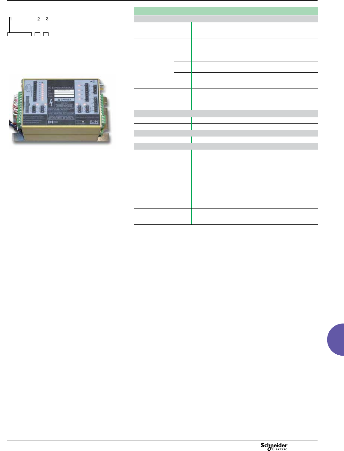
2013 113
ION8650
Functions and characteristics (cont.)
Advanced utility metering
Part numbers (cont.)
PE86044
I/O Expander
Digital/Analogue I/O P850E Schneider Electric I/O Expander for ION8600 meters: Inputs and
Outputs for energy pulsing, control, energy counting, status
monitoring, and analogue interface to SCADA.
Example order code. Use this group of codes when ordering
the I/O Expander.
I/O option AExternal I/O box with 8 digital inputs and 8 digital outputs
(4 Form A, 4 Form C)
1 Digital / Analogue I/O.
2 I/O option.
3 Cable option.
BExternal I/O box with 8 digital inputs and 4 digital outputs
(4 Form C) and 4 analogue outputs (0 to 20mA)
CExternal I/O box with 8 digital inputs and 4 digital outputs
(4 Form C) and 4 analogue outputs (-1mA to 1mA)
PE86131
DExternal I/O box with 8 digital inputs and 4 digital outputs
(4 Form C) and 4 analogue outputs (two -1 to 1 mA, and two 0 to
20 mA outputs)
Cable option 0No cable - cables for the I/O box are no ordered as a separate
part number. Refer to part numbers: CBL-8X00IOE5FT,
CBL-8X00IOE15FT and CBL-8XX0-BOP-IOBOX under
Connector cables, below.
A-base adapters
A-BASE-ADAPTER-9 Form 9S to Form 9A adapter
A-BASE-ADAPTER-35 Form 35S to Form 35A adapter
Optical communication interface
OPTICAL-PROBE Optical communication interface
Connector cables
CBL-8X00BRKOUT 5’ extension cable, mates with 24-pin male Molex connector from
the meter to the 24-pin Molex connector on the I/O expander box
(not for use with breakout panel E8, F8 & G8 form factors)
CBL-8X00IOE5FT 15’ extension cable, mates with 24-pin male Molex connector
from the meter to the 24-pin Molex connector on the I/O
expander box (not for use with breakout panel E8, F8 & G8 form
factors)
CBL-8X00IOE15FT 15’ extension cable, mates with 24-pin male Molex connector
from the meter to the 24-pin female Molex connector on the I/O
Expander box (not for use with breakout panel E8, F8 & G8 form
factors)
CBL-8XX0-BOP-IOBOX 6’ connector cable, 24-pin male to 14-pin male Molex connector
for connecting an ION8000Series meter with breakout panel to
an I/O Expander Box
A2
P 8 5 0 E
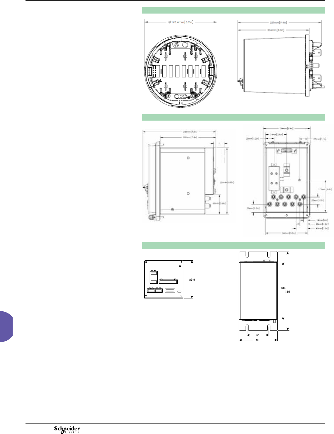
2013
114
ION8650
Dimensions and connections
ION8650 socket dimensions
PE86303
PE86304
ION8650 switchboard dimensions
PE86305
PE86306
I/O Expander dimensions
PE86307
PE86308
Advanced utility metering
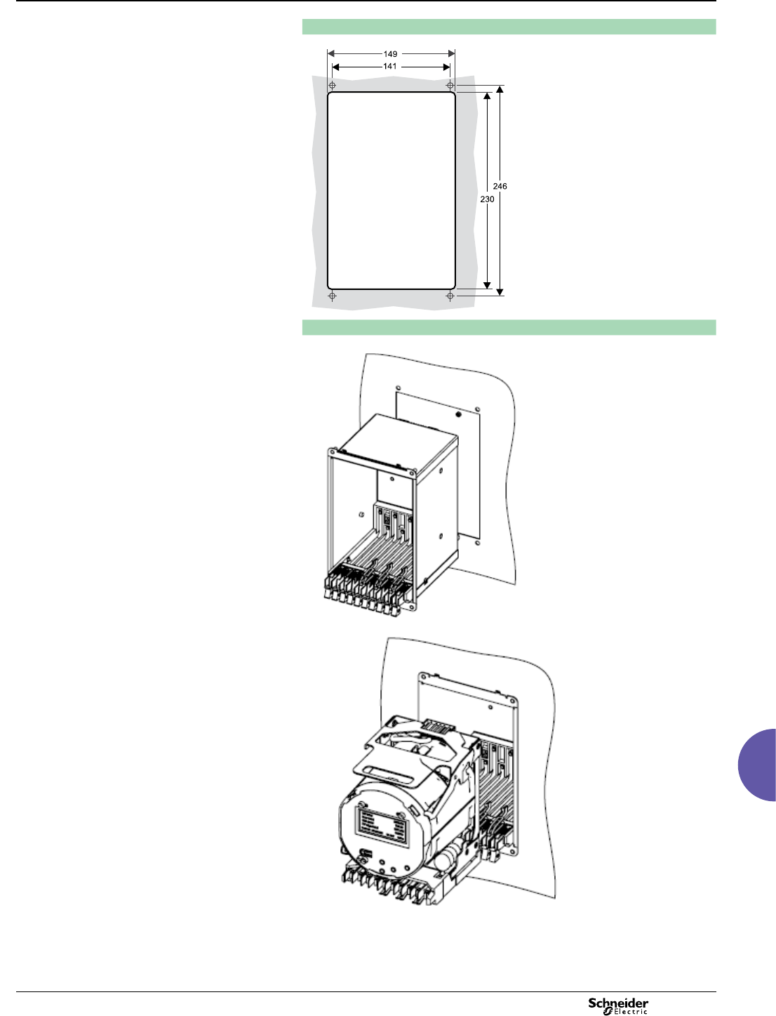
2013 115
Advanced utility metering ION8650
Dimensions and connections (cont.)
ION8650 suggested switchboard mounting dimensions
PE86052
ION8650 switchboard mounting
PE86309
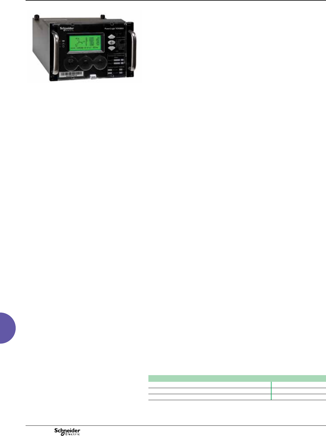
2013
116
ION8800
Functions and characteristics
Advanced utility metering
PE86176
Providing high accuracy and a wide range of features for transmission and
distribution metering, the PowerLogic ION8800 advanced revenue and power quality
meter has the exibility to change along with your needs. The meter provides the
tools necessary to:
b manage energy procurement and supply contracts
b perform network capacity planning and stability analysis’
b monitor power quality compliance, supply agreements, and regulatory
requirements.
Integrate the PowerLogic ION8800 meter with your existing wholesale settlement
system, use StruxureWare Power Monitoring (PowerLogic ION Enterprise™)
software, or share operations data with SCADA systems through multiple
communication channels and protocols.
Applications
Transmission and distribution metering.
Settlements, customer billing, cost allocation.
Extensive power quality monitoring and analysis.
Contract optimisation and compliance verication.
Main characteristics
IEC 19-inch rack mount design to DIN 43862 standard
Use Essailec connectors with common measurement and energy pulsing pin-out to
easily retrot into existing systems.
Accurate metering
Interconnection points on medium, high, and ultra-high voltage networks are in
compliance with IEC 62053-22/23 Class 0,2S.
Power quality compliance monitoring
Monitor compliance with international quality-of-supply standards (IEC 61000-4-30
Class A/S, EN50160, IEC 61000-4-7, IEC 61000-4-15, IEEE 1159, IEEE 519).
Power quality summary
Consolidate power quality characteristics into easily viewable reports indices.
Digital fault recording
Capture voltage and current channels simultaneously for sub-cycle disturbances.
Complete communications
Use the IEC1107 optical port or the optional communications module that supports
concurrent Ethernet, serial, and modem communications.
Multiple tariffs and time-of-use
Apply tariffs and seasonal rate schedules to measure energy and demand values for
time periods with specic billing requirements.
Alarms and I/O functions
Use up to 65 setpoints for single/multi-condition alarms and I/O functions with
response times down to 1/2 cycle.
Alarm notication via email
High-priority alarms, data logs sent directly to the user’s PC. Instant notication of
power quality events by email.
Software integration
Easily integrate the meter with StruxureWare Power Monitoring (ION Enterprise) or
other utility software; MV-90, Pacis and third-party SCADA packages.
Transformer/line loss compensation
Compensate for system losses in real time directly in the meter.
Instrument transformer correction
Save money and improve accuracy by correcting for less accurate transformers.
PowerLogic™ ION8800 meter
Part numbers(1)
PowerLogic ION8800 meters
PowerLogic ION8800A M8800A
PowerLogic ION8800B M8800B
PowerLogic ION8800C M8800C
(1)Representative part numbers only. See page 120 for complete part number descriptions.
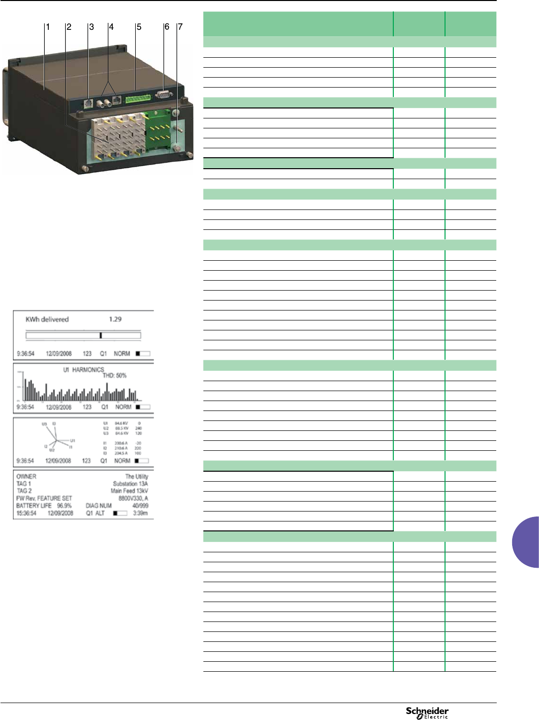
2013 117
ION8800
Functions and characteristics (cont.)
Advanced utility metering
PE86001
PowerLogic ION8800 meter
1 Optional communications module.
2 Essailec connectors.
3 Internal modem.
4 Optional Ethernet communications.
5 Selectable RS 485 serial port.
6 Selectable RS 232 or RS 485 serial port.
7 Ground terminal.
Selection guide ION8800A
ION8800B
ION8800C
General
Use on LV, MV and HV systems b b
Current accuracy 0.1 % 0.1 %
Voltage accuracy 0.1 % 0.1 %
Power accuracy 0.2 % 0.2 %
Samples/cycle 1024 1024
Instantaneous rms values
Current, voltage, frequency (Class 0,2S) b b
Active, reactive, apparent power Total and per phase b b
Power factor Total and per phase b b
Current measurement range 0.001 - 10A 0.001 - 10A
Current measurement range 0.001 - 10A 0.001 - 10A
Energy values
Active, reactive, apparent energy b b
Settable accumulation modes b b
Demand values
Current b b
Active, reactive, apparent b b
Predicted active, reactive, apparent b b
Demand modes (block, sliding, thermal, predicted) b b
Power quality measurements
Detection of voltage dips (sags) and swells 10 ms 10 ms
Symmetrical components: zero, positive, negative b-
Transient detection, microseconds (50 Hz) 20 (1) 20 (1)
Harmonics: individual, even, odd, total up to 63rd 63rd
Harmonics: magnitude, phase and inter-harmonics 50th 40th
EN 50160 compliance b
IEC 61000-4-30 class A b
IEC 61000-4-30 class S b (2)
IEC 61000-4-15 (Flicker) b-
PE86235
Congurable for IEEE 519 - 1992, IEEE1159-1995 b(1) -
Programmable (logic and math functions) b b
Data recording
Min/max logging for any parameter b b
Historical logs Maximum # of records 800(1) 640(2) 32
Waveform logs Maximum # of records 96 (1) -
Timestamp resolution in seconds 0.001 0.001
Setpoints, minimum response time ½ cycle ½ cycle
Number of setpoints 65 65
GPS time synchronisation (IRIG-B) b b
Could add transient logs. COMTRADE fault records. b b
User congurable log memory 10 Mbytes 10 Mbytes
Display and I/O
Front panel display b b
Active/reactive energy pulser, LED and IEC 1107 style port b b
Digital pulse outputs, optional Solid state Form A 8 8
Digital pulse outputs Solid state Form C 4 4
Alarm relay output Form C 1 1
Digital inputs (optional) 3 3
Display screen examples: KWh disk simulator, voltage
harmonics histogram, phasor diagram, and name plate1.
Communications
RS 232/485 port 1 1
RS 485 port 1 1
Ethernet port 1 1
IEC 1107 optical port 1 1
Internal modem 1 1
3-port DNP 3.0 through serial, modem, Ethernet and I/R ports b b
Modbus RTU master / slave (serial, modem and I/R ports) b / b- / b
Modbus TCP master / slave (via Ethernet port) b / b- / b
Data transfer between Ethernet and RS 485 (EtherGate) b b
Data transfer between internal modem, RS 485 (ModemGate) b b
Alarms, single or multi-condition b b
Alarm notication & logged data via email b b
Embedded web server (WebMeter) b b
(1) ION8800A only.
(2) ION8800B only.
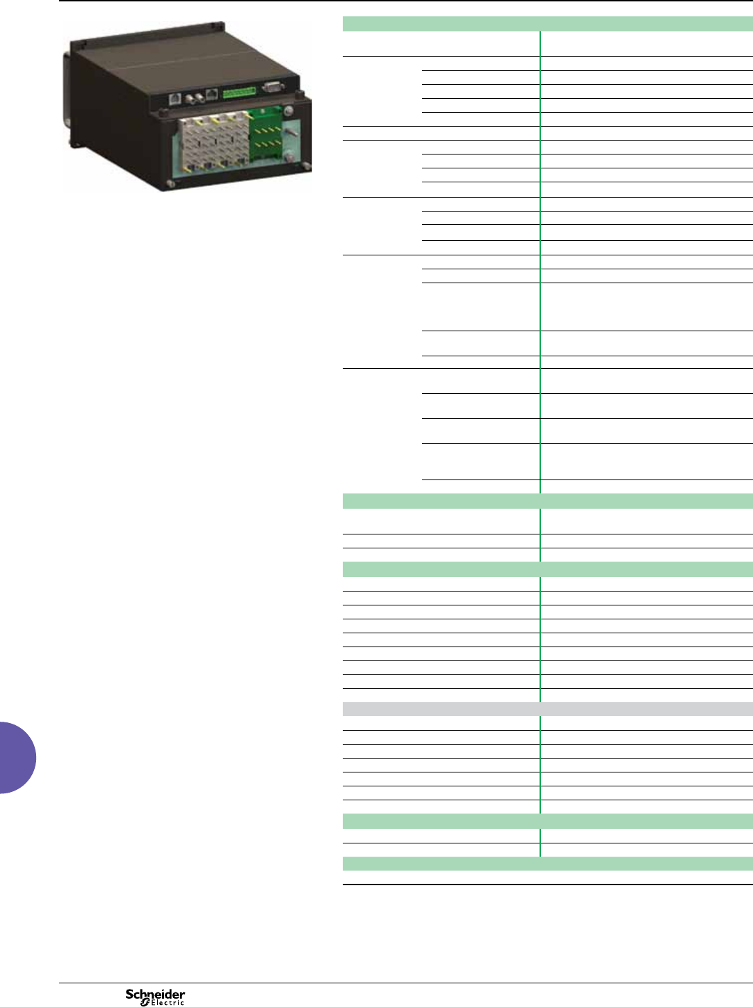
2013
118
ION8800
Functions and characteristics (cont.)
Advanced utility metering
PE86003
PowerLogic ION8800 with optional communications module.
Electrical characteristics
Type of measurement True rms
1024 samples per cycle
Measurement
accuracy
Current and voltage 0.1 %
Power 0.2 %
Frequency ±0.005 Hz
Power factor 0.1%
Energy IEC 62053-22/23 Class 0.2 S
Data update rate ½ cycle or 1 second
Input-voltage
characteristics
Inputs U1, U2, U3, Uref
Measurement range 57-288 LN VAC rms (99-500 LL VAC rms)
Dielectic withstand 3320 VAC rms
Impedance 5 MW /phase (phase-Uref/Ground)
Input-current
characteristics
Rated nominals 5 A, 1 A, 2 A
Permissible overload 200A rms for 0.5s, non-recurring (IEC 62053-22)
Impedance 10 mW /phase
Burden 0.01 VA per phase (1A), 0.25 VA per phase (5 A)
Power supply AC 85 - 240 VAC (+/- 10%), 47-63 Hz
DC 110 - 270 VDC (+/- 10%)
Burden Typical (without comm module): 13 VA, 8 W
Typical (with comm module): 19 VA, 12 W
Max (without comm module): 24 VA, 10 W
Max (with comm module): 32 VA, 14 W
Ride-through time Typical: 0.5 s to 5 s depending on conguration
Min: 120 ms (6 cycles @ 50 Hz)
Dielectric withstand 2000 VAC
Input/outputs Mechanical alarm relay 1 Form C digital output (250 V AC / 125 V DC,
1 A AC / 0.1 A DC max)
Digital outputs (Form C) 4 Solid state relay outputs (210 V AC / 250 V DC)
100 mA AC/DC
Digital outputs (Form A) 8 Solid state relay outputs (210 V AC / 250 V DC)
100 mA AC/DC
Digital inputs 3 Solid state digital inputs (low-voltage inputs 15
to 75 V AC/DC; high-voltage inputs 75 to 280 V
AC/DC; 3 mA max.)
Pulse rate 20 Hz maximum
Mechanical characteristics
Weight 6.0 kg
(6.5 kg with optional communications module)
IP degree of protection (IEC 60529) IP51
Dimensions 202.1 x 261.51 x 132.2 mm
Environmental conditions
Mounting location Indoor
Maximum altitude 2000 m above sea level
Limit range of operation -25°C to +70°C
Specied operating temperature -10°C to +45°C (as per 62052-11)
Display operating range -10°C to +60°C
Storage temperature -25°C to +70°C
Humidity rating 5 to 95 % RH non-condensing
Pollution degree 2
Installation category Power supply (II) Metering inputs (III)
Electromagnetic compatibility
Electrostatic discharge IEC 61000-4-2
Immunity to radiated elds IEC 61000-4-3
Immunity to fast transients IEC 61000-4-4
Immunity to surge waves IEC 61000-4-5
Conducted immunity IEC 61000-4-6
Damped oscillatory waves immunity IEC 61000-4-12
Conducted and radiated emissions CISPR 22 (class B)
Safety
Europe As per IEC 62052-11
International As per IEC 60950
Utility approval
EGR, GOST, ESKOM, NMI
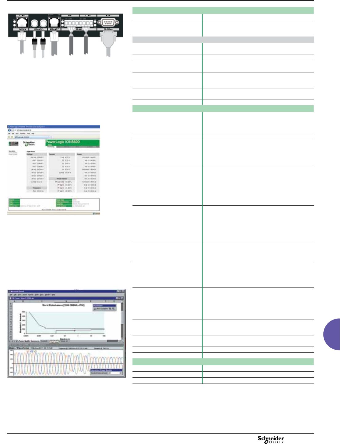
2013 119
ION8800
Functions and characteristics (cont.)
Advanced utility metering
PE86234
Communication
IEC 1107 optical port 2/4 wires, up to 19200 bauds
RS 485 port Up to 57600 bauds, direct connection to a PC or modem,
protocols: ION, Modbus RTU, Modbus Master, DNP 3.0,
GPSTRUETIME/DATUM, DLMS
Communications module (optional)
RS 232/485 port 300 - 115,200 bauds (RS 485 limited to 57,600 bauds);
protocols: same as RS 485 port
Internal modem port 300 bauds - 56000 bauds, RJ11 connector
Ports on the optional communications module. Ethernet port 10 BaseT, RJ45 connector, 100 m link; protocols: DNP
TCP, ION, Modbus TCP, Modbus Master, IEC 61850
Fiber-optic Ethernet link 10 Base FL, ST connector, 1300 nm, FO multimode with
gradient index 62.5/125 µm or 50/125 µm, 2000 m link;
protocols: same as Ethernet port
EtherGate Communicates directly with up to 62 slave devices via
available serial ports
ModemGate Communicates directly with up to 31 slave devices
Firmware characteristics
PE86233
High-speed data recording Up to ½-cycle interval burst recording, stores detailed
characteristics of disturbances or outages
Trigger recording by a user-dened setpoint, or from
external equipment.
Harmonic distortion Up to 63rd harmonic for all voltage and current inputs
Dip/swell detection Analyse severity/potential impact of sags and swells:
- magnitude and duration data suitable for plotting on
voltage tolerance curves
- per phase triggers for waveform recording or control
operations
Instantaneous High accuracy measurements with 1s or 1/2 cycle update
rate for:
- voltage and current
- active power (kW) and reactive power (kvar)
- apparent power (kVA)
- power factor and frequency
- voltage and current unbalance
- phase reversal
Example embedded webserver page (WebMeter) showing
realtime values.
Load proling Channel assignments (800 channels via 50 data
recorders) are congurable for any measureable
parameter, including historical trend recording of
energy, demand, voltage, current, power quality, or any
measured parameter
Trigger recorders based on time interval, calendar
schedule, alarm/event condition, or manually.
Modbus Master Master up to 32 slave devices per serial channel and store
their data at programmable intervals. Use this data to
aggregate and sum energy values and perform complex
totalization.
Waveform captures Simultaneous capture of all voltage and current channels
- sub-cycle disturbance capture
- maximum cycles is 214,000
(16 samples/cycle x 96 cycles, 10 Mbytes memory)
- 1024 samples/cycle
PE86002
Alarms Threshold alarms:
- adjustable pickup and dropout setpoints and time
delays, numerous activation levels possible for a given
type of alarm
- user-dened priority levels
- boolean combination of alarms possible
Advanced security Up to 16 users with unique access rights. Perform resets,
time syncs, or meter congurations based on user
priviledges.
Transformer correction Correct for phase / magnitude inaccuracies in current
transformers (CTs), potential transformers (PTs)
Memory 5 -10 Mbytes (specied at time of order)
Firmware update Update via the communication ports
Display characteristics
Type FSTN transreective LCD
Backlight LED
Sample power quality report. Languages English
2013
120
ION8800
Functions and characteristics (cont.)
Advanced utility metering
Part Numbers
Item Code Description
PE86006
1 Model M8800 ION8800 IEC/DIN 43862 19” rack mount energy and power
quality meter.
Example product part number.
1 Model.
2 Feature set.
3 Memory / form factor.
4 Current Inputs.
5 Voltage inputs.
6 Power supply.
7 System frequency.
8 Communications.
9 Onboard inputs/outputs.
10 Security.
11 Special order.
2Feature Set AClass A power quality analysis, waveforms and transient capture
with 1024 samples/cycle.
BEnergy meter Class S EN50160 power quality monitoring.
CBasic tariff/energy revenue meter with sag/swell monitoring.
3 Memory/Form
Factor
110 MB logging memory, Essailec connectors.
25 MB logging memory, Essailec connectors, with IEC61850
protocol
4Current Inputs C(I1-I3): Congured for 5 A nominal, 10 A full scale, 14 A fault
capture, 0.001 A starting current.
E(I1-I3): Congured for 1 A nominal, 10 A full scale, 14 A fault
capture, 0.001 A starting current.
5Voltage Inputs 0(V1-V3): Autoranging (57-288 VAC L-N or 99-500 VAC L-L)
6Power Supply BSingle phase power supply: 85-240 VAC ±10% (47-63 Hz) or
110-270 VDC.
7 System
Frequency
5Calibrated for 50 Hz systems.
6Calibrated for 60 Hz systems.
8 Communications
module (eld
serviceable)
Z0 No communications module - meter includes Base Onboard I/O
and comms (see below for details).
A0 Standard communications: 1 RS 232/RS 485 port, 1 RS 485
port (COM2) (1).
C1 Standard communications plus 10Base-T Ethernet (RJ45), 56 k
universal internal modem (RJ11).
D1 Standard communications plus 10Base-T Ethernet (RJ45) /
10Base-FL Ethernet Fiber, 56 k universal internal modem
(RJ11).
E0 Standard communications plus 10Base-T Ethernet (RJ45).
F0 Standard communications plus 10Base-T Ethernet (RJ45) /
10Base-FL (ST male Fiber Optic connection).
M1 Standard communications plus 56k universal internal modem
(RJ11).
9Onboard I/O and
communications
(not eld
serviceable, part
of base unit)
ABase option AND 8 Form A digital outputs (2), 1 RS-485 (COM2)
port (1).
BBase Option AND 8 Form A digital outputs (2), 3 digital inputs
(20-56 VDC/AC).
CBase Option AND 8 Form A digital outputs (2), 3 digital inputs
(80-280 VDC/AC).
DBase Option AND 1 IRIG-B time sync port (2), 1 RS-485 port
(COM2), 3 digital inputs (20-56 V DC/AC) (1).
EBase Option AND 1 IRIG-B time sync port (2), 1 RS-485 port
(COM2), 3 digital inputs (80-280 V DC/AC) (1).
10 Security 0 Password protected, no security lock.
1Password protected with security lock enabled.
11 Special Order A None.
CTropicalisation treatment applied.
Related products
RACK-8800-RAW IEC/DIN 34862 19” Rack with female mating voltage/current
and I/O blocks unassembled.
IEC-OPTICAL-PROBE Optional IEC 1107 compliant Optical Probe for use with
ION8800 meters.
BATT-REPLACE-8XXX Replacement batteries for the ION8600 or ION8800,
quantity 10.
ION-SETUP Free conguration software for the ION8800. Ships on a CD.
(1) Channel COM2 is available on the port at the back of the meter OR on the Comm Module
(if installed). You must select which connectors your communications wiring is connected to
during meter setup.
(2) All Onboard I/O and Comms (Base Option) options include: 4 Form C solid-state digital
outputs, 1 Form C mechanical relay output, one IEC 1107 optical communications port,
two IEC 1107 style optical pulsing ports.
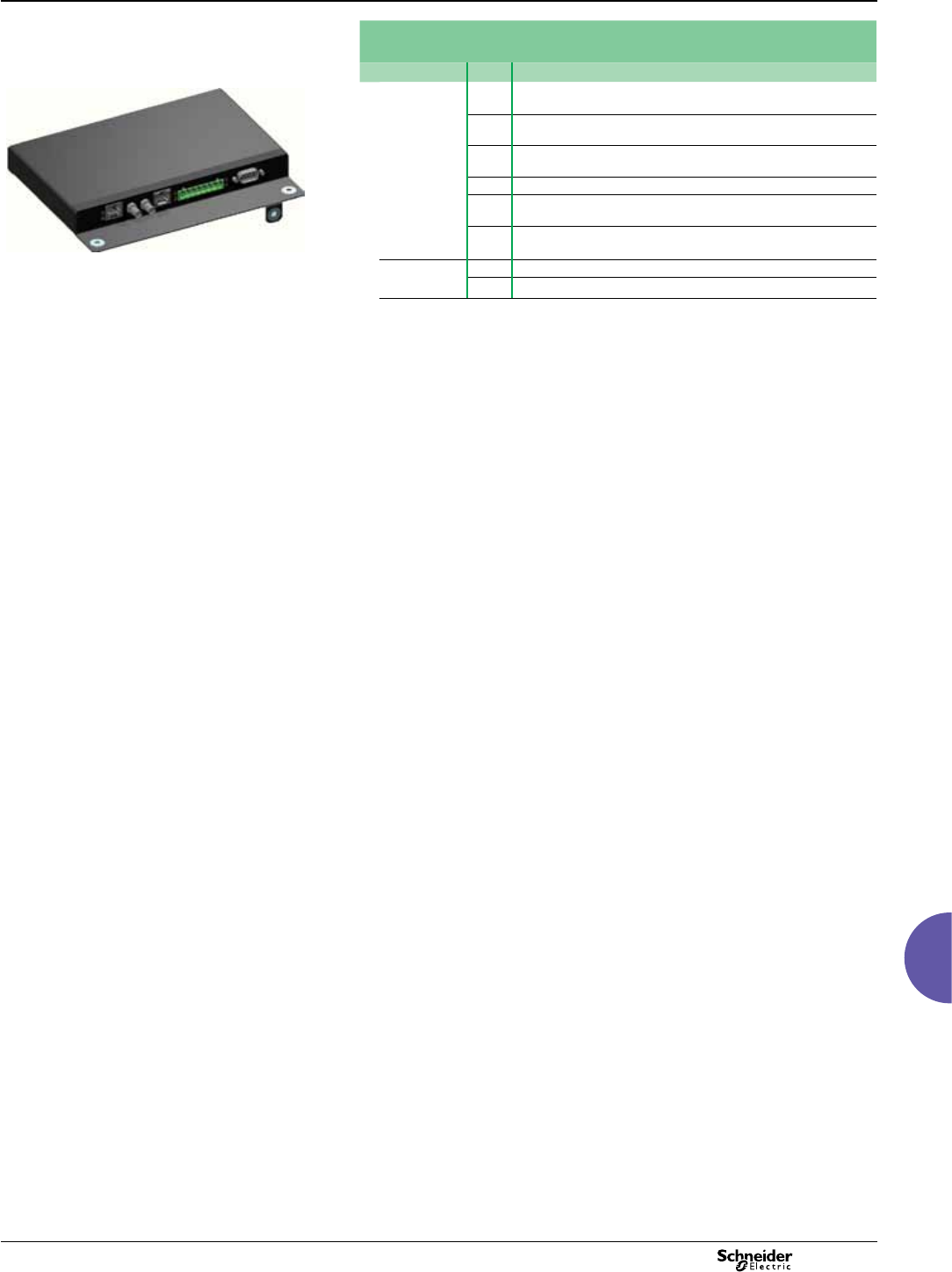
2013 121
ION8800
Functions and characteristics (cont.)
Advanced utility metering
Part Numbers (cont.)
ION8800 communications module for eld retrot installations
Item Code Description
P880C
A0 Standard communications: 1 RS-232/RS-485 port, 1 RS-485 port
(COM2) (1).
PE86007
C1 Standard communications plus 10Base-T Ethernet (RJ45), 56k
universal internal modem (RJ11).
D1 Standard communications plus 10Base-T Ethernet (RJ45) /
10Base-FL Ethernet Fiber, 56k universal internal modem (RJ11).
E0 Standard communications plus 10Base-T Ethernet (RJ45).
F0 Standard communications plus 10Base-T Ethernet (RJ45) /
10Base-FL Ethernet Fiber (ST male Fiber optic connection).
M1 Standard communications plus 56k universal internal modem
(RJ11).
Special Order A None.
Optional ION8800 communications module. CTropicalisation treatment applied.
(1) Channel COM2 is available on the port at the back of the meter OR on the Comm Module
(if installed). You must select which connectors your communications wiring is connected to
during meter setup.
Note: The part number above should conform to the following format: P880C A0 A.
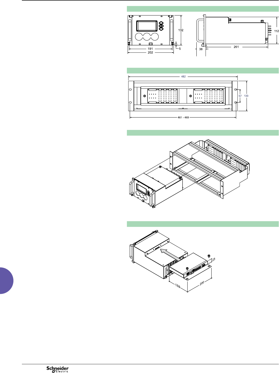
2013
122
ION8800
Dimensions and connections
ION8800 dimensions
PE86008
PE86009
ION8800 Essailec rack dimensions
PE86010
Rack mounting the ION8800
PE86011
ION8800 communication module dimensions
PE86012
Advanced utility metering
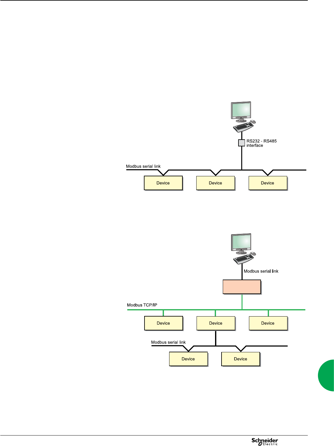
123
2013
Communication interfaces
and associated services0
Switchboard-data acquisition and monitoring
make it possible to anticipate events. In this way,
they reduce customer costs in terms of
operation, maintenance and investment.
Serial link
With communication technology, it is no longer necessary to be physically present at
the site to access information. Data is transmitted by networks.
In all architectures, the communication interface serves as the link between
the installation devices and the PC running the operating software. It provides
the physical link and protocol adaptation. Adaptation is required because the
communication systems used by the PC (Modbus via RS232 and/or Ethernet) are
generally not those used by the installation devices (e.g. the Modbus protocol via
RS485).
Dedicated application software prepares the information for analysis under the best
possible conditions.
DB111316
Modbus communication architecture.
In addition, an EGX100 in serial port slave mode allows a serial Modbus master
device to access information from other devices across a Modbus TCP/IP network.
DB111317
EGX100
serial slave mode
Modbus master device
Modbus communication across Ethernet network
Communications
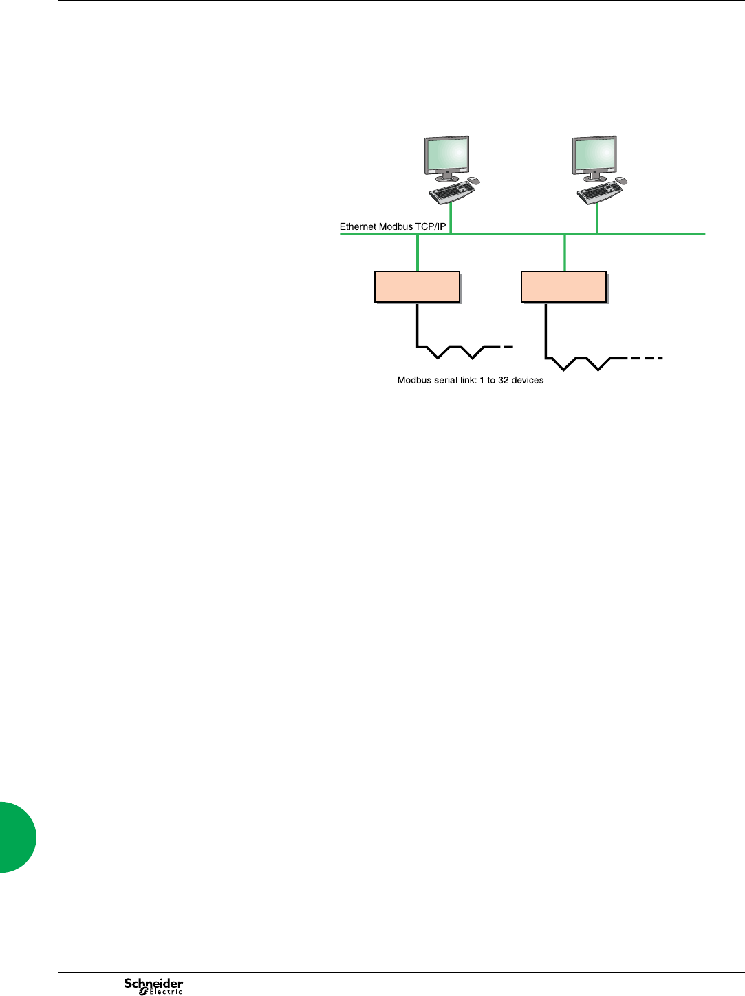
124 2013
Communication interfaces
and associated services (cont.)
Ethernet link
Using modern Web technologies, the operator can access information from
monitoring and protection devices using any PC connected to the network, with all
the required security.
The Ethernet EGX100 gateway or the EGX300 integrated gateway-servers provide
connectivity between Modbus RS485 and Ethernet Modbus TCP/IP.
DB111313a
Ethernet communication architecture.
The services available with these technologies considerably simplify the creation,
maintenance and operation of these supervision systems.
The application software is now standardised: the web interface into the system does
not require custom web pages to be created. It is personalised by simply identifying
the components in your installation and can be used as easily as any internet
application.
The first step in this approach is the EGX300 integrated gateway-server with HTML
pages. Power management software (StuxureWare Power Monitoring Expert and
StruxureWare PowerSCADA Expert), running on a PC, provide broader coverage for
more specific needs.
EGX100 EGX300
Communications
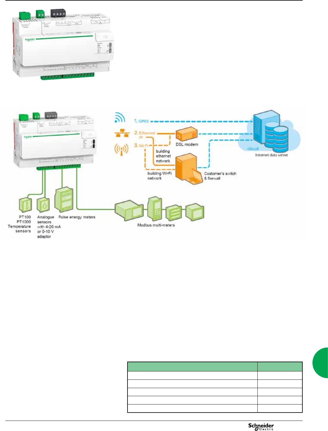
125
2013
Communications Energy Server Com'X 200
Functions and characteristics
PB112041
Energy Server Com'X 200
Ethernet GPRS data logger function
The Energy Server Com'X 200 collects and stores WAGES consumptions (Water,
Air, Gas, Electricity, Steam) and environmental parameters such as temperatures,
humidity, and CO2 levels in a building. Data is periodically transmitted as a report to
an Internet database server.
Data processing and display
Once received by the server, the data is ready to be processed and displayed as web
pages through web services provided by Schneider Electric, such as StruxureWare
Energy Operation and StruxureWare Energy On Line.
b Energy Operation
b Energy Online
or by any private energy management platform.
Architecture
Access to the web: choice of 3 media
Features
b From a simple metering installation with 1 device to large metering systems,
Com'X 200 collects data from any Modbus TCP or serial devices, from any pulse
meters, actuators and analogue sensors
b Automatic discovery of connected Modbus devices
b Connectivity to the cloud through Ethernet, Wi-Fi and GPRS
b 2 Ethernet ports to separate upstream cloud connection from eld devices network
b Protocols: HTTP, HTTPS, FTP, SMTP with Proxy management
b Data export: Native connection to Schneider Electric Service platforms (Energy
Operation, Energy Online)– CSV le export for other database servers
b Setup through convenient built-in web pages
b Compliant with electrical switchboard environment (Temperature , electro
magnetic compatibility)
b Storage of data in case of communication failure
b Local backup of the conguration parameters
When associated with SE Services:
b Remotely managed (rmware upgrade, conguration backup, troubleshooting,
parameters setting
b GPRS contract management with SIM card provided
Part Numbers
Energy Server Com'X 200
Com'X 200 Ethernet data logger EBX200
Wi-Fi USB stick EBXA-USB-WiFi
GPRS modem with SIM card EBXA-GPRS-SIM
GPRS modem without SIM card EBXA-GPRS
External GPRS antenna EBXA-ANT-5M
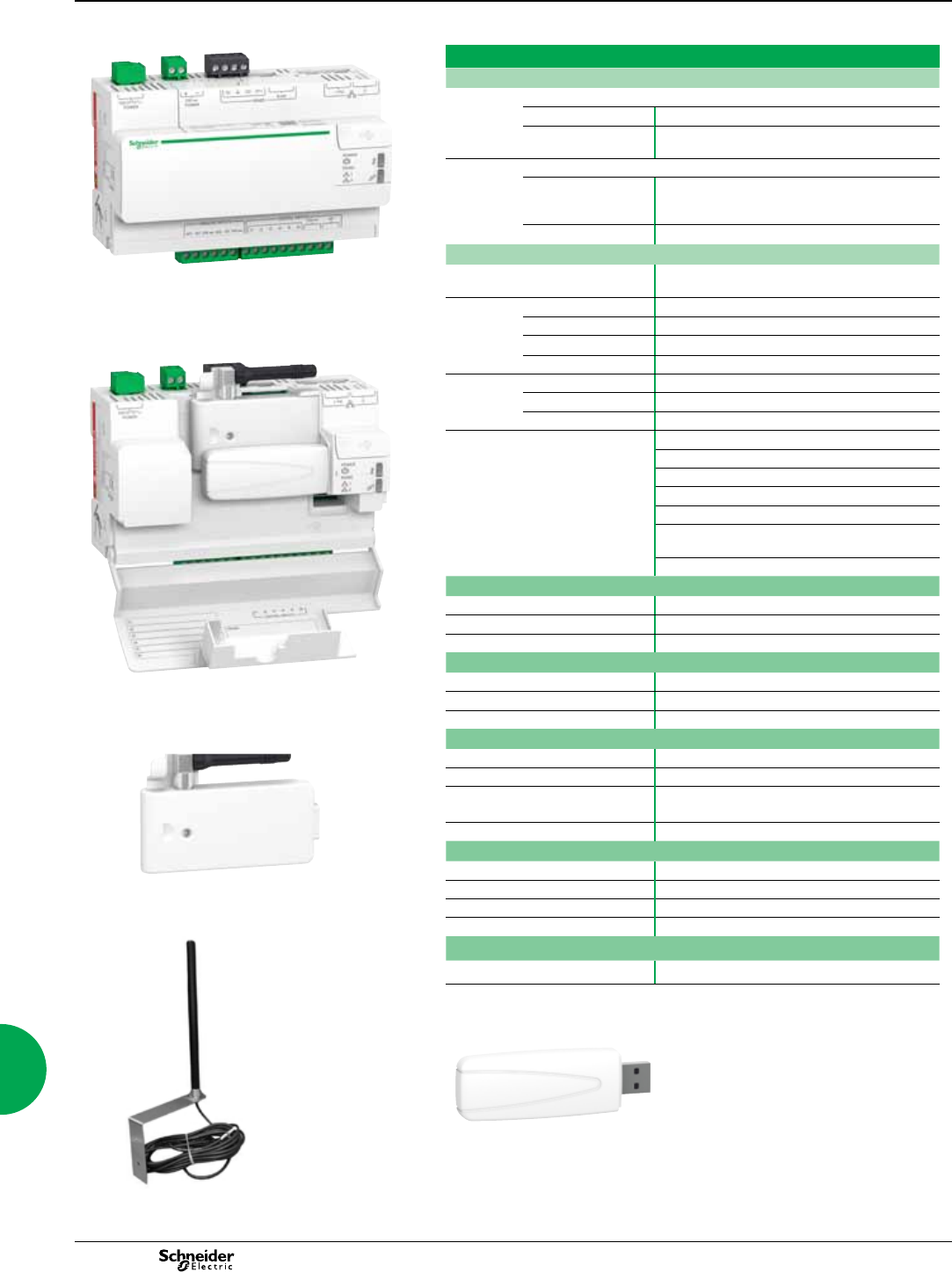
126 2013
Communications Energy Server Com'X 200
Functions and characteristics (cont.)
PB112050
PB112042
Ethernet GPRS data logger
PB112041
Energy Server Com'X 200
Characteristics
Inputs
6 Digital inputs
Max impulse frequency 25 Hz (min duration 20ms) IEC 62053-31 Class A
Power Supply Provided by Com'X 200: 12 V DC – 60 mA
External: from 10 to 30 V DC
2 Analogue inputs
Sensor
compatibility
PT100 – PT1000 2-wires probes (accuracy 1%)
Sensors with 4 -20 mA or 0-10 V output (accuracy
0.5%)
Power supply Provided by Com'X 200: 24 V DC - 50 mA per input
Communication
Meter Network 1 RS485 Modbus serial port, RJ45 connector, for 32
Modbus components maximum
Conguration / Data transfer 2 Ethernet ports RJ45 10/100 Base, DPWS ready
Ethernet 1 PoE class 3 (802.3af), DHCP client
Ethernet 2 DHCP client or server
Energy Server Com'X 200 with the front face in Open position,
GPRS modem and Wi-Fi USB stick are connected.
Protocols IPv4, IPv6 – HTTP, HTTPS, Modbus TCP/IP
USB Ports 2
For memory stick USB port on front face
For Wi-Fi stick USB port 2 behind cover
LED indicators 11
Power/ Boot status
GPRS modem status and signal level
Modbus communication
Ethernet communication
Wi-Fi communication mode (Access point /
Infrastructure) and status
Digital inputs status and pulse reception
Power Supply
AC 100-277 V (+/- 15%)(50-60Hz)
DC 24 V (+/- 10%)
Max power 26 W max
Mechanical
IP Front face IP40, terminals IP20
Dimensions (HxWxD) 91 x 144 x 65.8 mm
Weight 450 g
Environment
GPRS modem (antenna in folded position)
Operating temperature -25 to +70°C (-13 to +158°F)
Storage temperature -40 to +85°C (-40 to +185°F)
Humidity 5 to 95% relative humidity (without condensation) at
+55ºC
Pollution Class III
Safety standards / regulation
International (CB scheme) IEC 60950
USA UL508/UL60950
Canada cUL (complies with CSA C22.2, no. 60950)
Europe EN 60950
Quality Brands
CE, UL
External GPRS antenna
Wi-Fi USB stick
PB112044
440800021
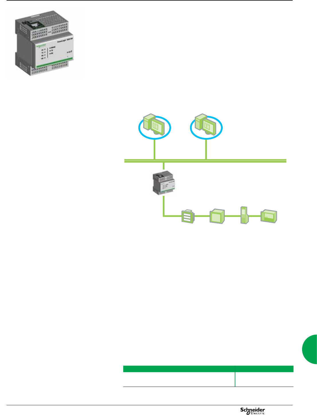
127
2013
PowerLogic EGX100
Ethernet gateway
Function
The EGX100 serves as an Ethernet gateway for PowerLogic system devices and
for any other communicating devices utilising the Modbus protocol. The EGX100
gateway offers complete access to status and measurement information provided by
the connected devices via PowerLogic software installed on a PC.
PowerLogic software compatibility
PowerLogic software is recommeded as a user interface because they provide access
to all status and measurement information. They also prepare summary reports. The
EGX100 is compatible with:
StruxureWare Power Monitoring Expert software
StruxureWare PowerSCADA Expert.
Architecture
Setup
Setup via an Ethernet network
Once connected to an Ethernet network, the EGX100 gateway can be accessed by a
standard internet browser via its IP address to:
specify the IP address, subnet mask and gateway address of the EGX gateway
configure the serial port parameters (baud rate, parity, protocol, mode, physical
interface and timeout value)
create user accounts
create or update the list of the connected products with their Modbus or PowerLogic
communication parameters
configure IP filtering to control access to serial devices
access Ethernet and serial port diagnostic data
update the firmware
specify the user language.
Setup via a serial connection
Serial setup is carried out using a PC connected to the EGX100 via an RS232 link.
This setup:
b specifies the IP address, subnet mask and gateway address of the EGX gateway
specifies the language used for the setup session.
Part numbers
Powerlogic EGX100 Schneider Electric
EGX100 EGX100MG
PowerLogic EGX100
PE86138
PowerLogic
software
Ethernet Modbus TCP/IP
EGX100 gateway
Modbus RS485 serial link
ION6200 PM800 Micrologic Sepam
Communications
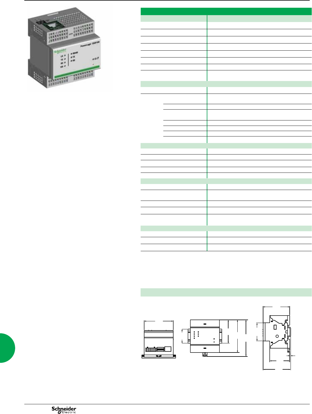
128 2013
Characteristics
EGX100
PE86138
Weight 170 g
Dimensions (HxWxD) 80.8 x 72 x 65.8 mm
Mounting Din rail
Power-over-Ethernet (PoE) Class 3
Power supply 24 V DC if not using PoE
Maximum burden 4 W
Operating temperature -25 to 70ºC
Humidity rating 5 to 95 % relative humidity (without condensation) at
+55ºC
Regulatory/standards compliance for electromagenetic interference
Emissions (radiated and conducted) EN55022/EN55011/FCC class A
PowerLogic EGX100 Immunity for industrial environments:
electrostatic discharge EN 61000-6-2
radiated RF EN 61000-4-2
electrical fast
transients
EN 61000-4-3
surge EN 61000-4-4
conducted RF EN 61000-4-5
power frequency EN 61000-4-6
magnetic field EN 61000-4-8
Regulatory/standards compliance for safety
International (CB scheme) IEC 60950
USA UL508/UL60950
Canada cUL (complies with CSA C22.2, no. 60950)
Europe EN 60950
Australia/New Zealand AS/NZS25 60950
Serial ports
Number of ports 1
Types of ports RS232 or RS485 (2-wire or 4-wire), depending on
settings
Protocol Modbus RTU/ASCII, PowerLogic (SY/MAX), Jbus
Maximum baud rate 38400 or 57600 baud depending on settings
Maximum number of connected
devices
32 (directly)
247 (indirectly)
Ethernet port
Number of ports 1
Type of port 10/100 Base TX (802.3af) port
Protocol HTTP, Modbus TCP/IP, FTP, SNMP (MIB II)
Installation
Din rail mounting
PowerLogic EGX100
Ethernet gateway (cont’d)
72
57.9 80.8 90.7
35
45.2
65.8
2.5
49.5
68.3
Communications

129
2013
Communications ION7550 RTU
Functions and characteristics
PE86117
PowerLogic ION 7550 RTU.
The PowerLogic ION7550 RTU (remote terminal unit) is an intelligent web-enabled
device ideal for combined utilities metering of water, air, gas, electricity and steam
(WAGES). When combined with PowerLogic software, the ION7550 RTU offers a
seamless, end-to-end WAGES metering solution. Featuring a large, high-visibility
display and overall versatility of the PowerLogic system, the ION7550 RTU provides
extensive analogue and digital I/O choices and is a cost-effective dedicated WAGES
solution when compared to a traditional meter. The device automatically collects,
scales and logs readings from a large number of connected meters or transducers
and delivers information to one or more head-end systems through a unique
combination of integrated Ethernet, modem or serial gateways. As part of a complete
enterprise energy management solution, the ION7550 RTU can be integrated with
PowerLogic ION Enterprise software, or other SCADA, information and automation
systems.
Applications
WAGES metering.
Data concentration through multi-port, multi-protocol communications.
Equipment status monitoring and control.
Programmable setpoints for out-of-limit triggers or alarm conditions.
Integrated utility metering with advanced programmable math functions.
Main characteristics
Increase efciency
Reduce waste and optimise equipment operation to increase efciency.
Easy to operate
Screen-based menu system to congure meter settings. Bright LCD display with
adjustable contrast.
Integrate with software
Easily integrated with PowerLogic or other energy management enterprises,
including SCADA systems.
Transducer and equipment condition monitoring
Versatile communications, extensive I/O points, clock synchronization, event
logging and sequence of events recording capabilities for transducer and equipment
condition and status monitoring at utility substations.
Set automatic alarms
Alarm setpoint learning feature for optimum threshold settings.
Up to 10 Mbytes of memory
For archiving of data and waveforms.
Notify alarms via email
High-priority alarms sent directly to the user’s PC. Instant notication of power quality
events by email.
Modbus Master functionality
Aggregate and store data from downstream Modbus devices using serial or Ethernet
connections.
Part numbers
ION7550 RTU
ION7550 M7550
See page 133 for order code explanations.
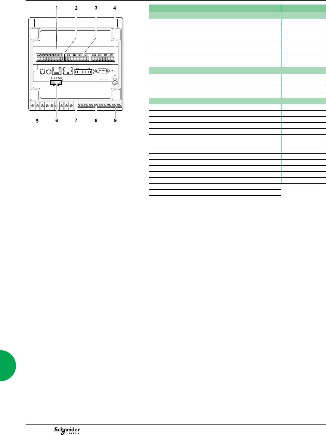
130 2013
Communications ION7550 RTU
Functions and characteristics (cont.)
PE86124
PowerLogic® ION7550 RTU.
Selection guide ION7550 RTU
Data recording
Min/max of instantaneous values
Data logs
Event logs
Trending
SER (Sequence of event recording)
Time stamping
GPS synchronisation (1 ms)
Memory (in Mbytes) 10
Display and I/O
Front panel display
Pulse output 1
Digital or analogue inputs(max) 24
Digital or analogue outputs (max, including pulse output) 30
Communication
RS 485 port 1
RS 485 / RS 232 port 1
Optical port 1
Modbus TCP Master / Slave (Ethernet port)
Modbus RTU Master / Slave (Serial port)
Ethernet port (Modbus/TCP/IP protocol) 1
1 I/O expansion card.
2 Digital inputs.
3 Analogue inputs.
4 Analogue outputs.
5 Communications card.
6 Power supply.
7 Form C digital outputs.
8 Digital inputs.
9 Form A digital outputs.
Ethernet gateway (EtherGate) 1
Alarms (optional automatic alarm setting b
Alarm notication via email (Meterm@il)
HTML web page server (WebMeter)
Internal modem 1
Modem gateway (ModemGate)
DNP 3.0 through serial, modem, and I/R ports
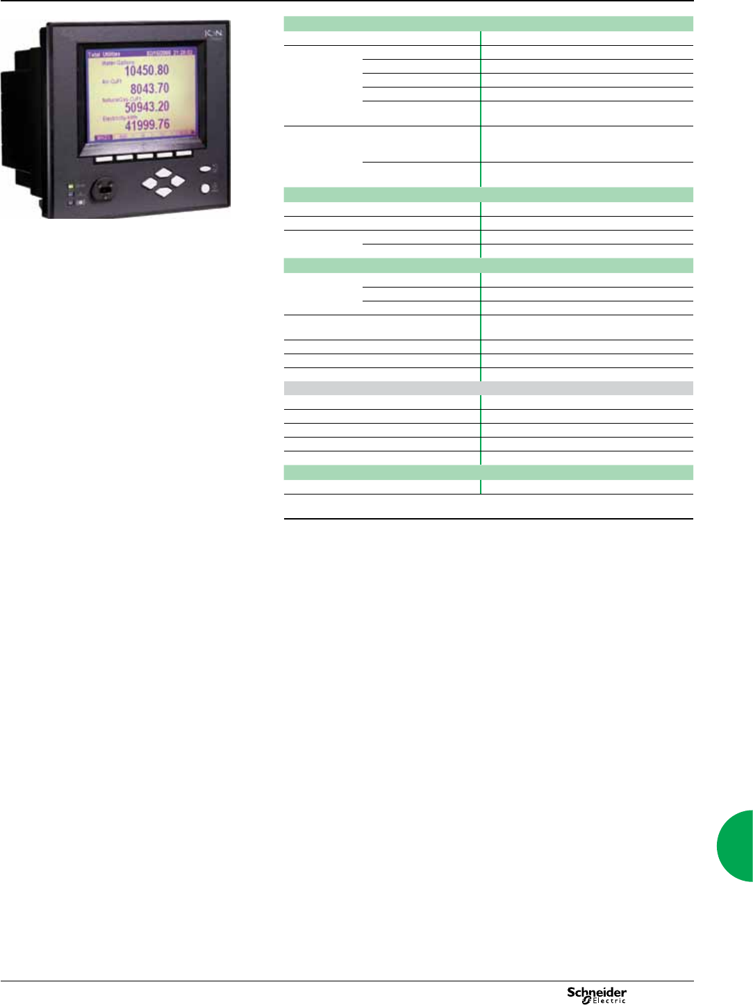
131
2013
Communications ION7550 RTU
Functions and characteristics (cont.)
PE86117
Electrical characteristics
Data update rate 1/2 cycle or 1 second
Power supply AC 85-240 V AC ±10% (47-63 Hz)
DC 110-300 V DC ±10%
DC low voltage (optional) 20-60 V DC ±10%
Ride-through time 100 ms (6 cycles at 60 Hz) min. at 120 V DC
Burden Standard: typical 15 VA, max 35 VA
Low voltage DC: typical 12 VA, max 18 VA
Input/outputs(1) Standard 8 digital inputs (120 V DC)
3 relay outputs (250 V AC / 30 V DC)
4 digital outputs (solid state)
Optional 8 additional digital inputs
4 analogue outputs, and/or 4 analogue inputs
Mechanical characteristics
Weight 1.9 kg
IP degree of protection (IEC 60529) IP52
PowerLogic ION7550 RTU. Dimensions Standard model 192 x 192 x 159 mm
TRAN model 235.5 x 216.3 x 133.1 mm
Environmental conditions
Operating
temperature
Standard power supply -20 to +70ºC
Low voltage DC supply -20 to +50ºC
Display operating range -20 to +70ºC
Storage
temperature
Display, TRAN -40 to +85ºC
Humidity rating 5 to 95% non-condensing
Installation category III (2000m above sea level)
Dielectric withstand As per EN 61010-1, IEC 62051-22A(2)
Electromagnetic compatibility
Electrostatic discharge IEC 61000-4-2
Immunity to radiated elds IEC 61000-4-3
Immunity to fast transients IEC 61000-4-4
Immunity to surges IEC 61000-4-5
Conducted and radiated emissions CISPR 22
Safety
Europe IEC 61010-1
(1) Consult the ION7550 / ION7650 installation guide for complete specications.
(2) IEC 62051-22B with serial ports only.

132 2013
Communications ION7550 RTU
Functions and characteristics (cont.)
Communication
RS 232/485 port (1) Up to 115,200 bauds (57,600 bauds for RS 485), ION,
DNP 3.0, Modbus, GPS, EtherGate, ModemGate,
Modbus Master
RS 485 port (1) Up to 115,200 bauds, ION, DNP 3.0, Modbus, GPS,
EtherGate, ModemGate, Modbus Master
Infrared port(1) ANSI type 2, up to 19,200 bauds, ION, Modbus, DNP 3.0
Ethernet port 10BaseT, 100BaseTX. RJ45 connector, 10/100 m link
Fibre-optic Ethernet link 100Base FX, SC duplex connector, 1300 nm, FO
multimode with gradient index 62.5/125 µm or 50/125
µm, 2000 m link
Protocol ION, Modbus, Modbus Master, TCP/IP, DNP 3.0, Telnet
EtherGate Communicates directly with up to 62 slave devices via
available serial ports
ModemGate Communicates directly with up to 31 slave devices
WebMeter 5 customisable pages, new page creation capabilities,
HTML/XML compatible
Firmware characteristics
High-speed data recording Down to 5ms interval burst recording, stores detailed
characteristics of disturbances or outages. Trigger
recording by a user-dened setpoint, or from external
equipment.
Load proling Channel assignments (800 channels via 50 data
recorders) are congurable for any measurable
parameter. Trigger recorders based on
time interval, calendar schedule, alarm/event condition,
or manually.
Trend curves Access historical data at the front panel. Display, trend
and continuously update historical data with date and
timestamps for up to four parameters simultaneously.
Alarms Threshold alarms:
adjustable pickup and dropout setpoints and time delays,
numerous activation levels possible for a given type of
alarm
user-dened priority levels
boolean combination of alarms is possible using the
operators NAND, OR, NOR and XOR
Advanced security Up to 16 users with unique access rights. Perform
resets, time syncs, or meter congurations based on
user privileges
Memory 5 to 10 Mbytes (specied at time of order)
Firmware update Update via the communication ports
Display characteristics
Integrated display Back lit LCD, congurable screens
Languages English
(1) All the communication ports may be used simultaneously.
133
2013
Communications ION7550 RTU
Functions and characteristics (cont.)
Part numbers
PE86118
5N 9
M
4
Item Code Description
1 Model 7550 ION7550 device
2Form Factor A0 Integrated display with front optical port, 5 MB logging memory,
and 512 samples/cycle resolution.
Sample ION7550 RTU part number. B0 Integrated display with front optical port, 10 MB logging memory,
and 512 samples/cycle resolution.
T0 Transducer (no display) version, with 5 MB logging memory.
U0 Transducer (no display) version, with 10 MB logging memory.
3RTU option N9 RTU option
4Power Supply BStandard power supply (85-240 VAC, ±10%/47-63 Hz / 110-330
VDC, ±10%)
CLow voltage DC power supply (20-60 VDC)
5Internal use 9This eld for internal use only
6 Communications A0 Standard communications (1 RS-232/RS-485 port, 1 RS-485
port). Integrated display models also include 1 ANSI Type 2
optical communications port.
C1 Standard communications plus 10BASE-T/100BASE-TX
Ethernet (RJ-45), 56k universal internal modem (RJ-11).
Ethernet, modem gateway functions each use a serial port.
D7 Standard comms plus 10BASE-T/100BASE-TX Ethernet (RJ-
45) and 100BASE-FX Ethernet Fiber, 56k universal internal
modem (RJ-11). Ethernet and modem gateway functions each
use a serial communications port.
E0 Standard communications plus 10BASE-T/100BASE-TX
Ethernet (RJ-45). Ethernet gateway function uses serial port.
F1 Standard communications plus 10BASE-T/100BASE-TX
Ethernet (RJ-45) and 100BASE-FX (SC ber optic connection).
Ethernet gateway uses a serial port.
M1 Standard communications plus 56k universal internal modem
(RJ-11). Modem gateway uses serial communications port.
7I/O AStandard I/O (8 digital inputs, 3 Form C relays, 4 Form A solid-
state outputs)
DStandard I/O plus Expansion I/O card (8 additional digital inputs
& four 0 to 1 mA analogue inputs)
EStandard I/O plus Expansion I/O card (8 additional digital inputs
& four 0 to 20 mA analogue inputs)
HStandard I/O plus Expansion I/O card (8 additional digital inputs
& four -1 to 1 mA analogue outputs)
KStandard I/O plus Expansion I/O card (8 additional digital inputs
& four 0 to 20 mA analogue outputs)
NStandard I/O plus Expansion I/O card (8 additional digital inputs
& four 0 to 20 mA analogue inputs and four 0 to 20 mA outputs)
PStandard I/O plus Expansion I/O card (8 additional digital inputs
& four 0 to 1 analogue inputs and four -1 to 1 mA analogue
8 Security 0 Password protected, no hardware lock
9Special Order A None
CTropicalisation treatment applied
134 2013
Communications ION7550 RTU
Functions and characteristics (cont.)
Communications Card
PE86021
P
C 1
Example order code. Use this group of codes when ordering the
PowerLogic ION7550 RTU communication or I/O card.
Item Code Description
1 Comm card P765C ION7550 RTU communication card for eld retrot installations
2 Type A0 Standard communications (1 RS-232/RS-485 port, 1 RS-485
port). Front optical port support for meters with integrated
display.
C1 Standard communications plus 10BASE-T/100BASE-TX
Ethernet (RJ-45), 56k universal internal modem (RJ-11; the
modem port is shared with the front optical port). Ethernet and
modem gateway functions each use a serial communications
port.
1 Communications or I/O card.
2 Type.
3 Special order.
D7 Standard communications plus 10BASE-T/100BASE-TX
Ethernet, 100BASE-FX Ethernet Fiber, 56k universal internal
modem (RJ-11; the modem port is shared with the front optical
port). Ethernet and modem gateway functions each use a serial
communications port.
E0 Standard communications plus 10BASE-T/100BASE-
TX Ethernet. Ethernet gateway function uses a serial
communications port.
F1 Standard communications plus 10BASE-T/100BASE-
TX Ethernet, 100BASE-FX Ethernet Fiber (SC ber optic
connection). Ethernet gateway function uses a serial
communications port.
M1 Standard communications plus 56k universal internal modem
(RJ-11; the modem port is shared with the front optical port).
Modem gateway function uses a serial communications port.
3Special order A None
CTropicalization treatment applied

135
2013
Communications ION7550 RTU
Functions and characteristics (cont.)
Part numbers (cont’d)
Input/Output expansion card
Item Code Description
I/O card P760A Expansion I/O for eld retrot installations.
Type D Expansion I/O card with eight digital inputs, four 0 to 1 mA
analogue inputs
EExpansion I/O card with eight digital inputs, four 0 to 20 mA
analogue inputs
HExpansion I/O card with eight digital inputs, four -1 to 1 mA
analogue outputs
KExpansion I/O card with eight digital inputs, four 0 to 20 mA
analogue outputs
NExpansion I/O card with eight digital inputs, four 0 to 20 mA
analogue inputs & four 0 to 20 mA outputs
PExpansion I/O card with eight digital inputs, four 0 to 1 analogue
inputs and four -1 to 1 mA analogue outputs
Special Order A None
CTropicalization treatment applied
OpenDAC rack, controllers, power supply
70LRCK16-48 OpenDAC rack. Holds up to 8 OpenLine modules to provide up
to 16 I/O points. Requires communications controller
72-MOD-4000 OpenDAC OpenDAC RS-485 serial module. Communications
controller for use in a Modbus RTU network. Supports up to 2
70LRCK16-48 OpenDAC racks
72-ETH-T000 OpenDAC Ethernet network module for use on an Modbus/TCP
Ethernet network. Supports up to 2 OpenDAC racks
PS-240-15W 85-264VAC/110-370VDC 15 Watt power supply. Required for
applying power to the racks and controllers
OpenLine digital I/O modules
70L-IAC digital input, 120VAC
70L-IACA digital input, 220VAC
70L-IDC digital input, 3-32VDC
70L-IDCB digital input, fast switching
70L-IDCNP digital input, 15-32VAC/10-32VDC
70L-IDC5S dry contact closure-sensing DC input
70L-ISW input test module
70L-OAC digital output, 120VAC
70L-OACL digital output, 120VAC inductive loads
70L-OACA digital output, 220VAC
70L-OACAL digital output, 220VAC inductive loads
70L-ODC digital output, 3-60VDC fast
70L-ODCA digital output, 4-200 VDC
70L-ODCB digital output, fast switching
70L-ODC5R digital output, dry contact
OpenLine analogue I/O modules
73L-II020 analogue input, current, 0-20mA
73L-II420 analogue input, current, 4-20mA
73L-ITCJ analogue input, temperature, J-type TC
73L-ITCK analogue input, temperature, K-type TC
73L-ITCT analogue input, temperature, T-type TC
73L-ITR100 analogue input, temperature, RTD
73L-ITR3100 analogue input, temperature, 3wire RTD
73L-ITR4100 analogue input, temperature, 4wire RTD
73L-IV1 analogue input, voltage, 0-1VDC
73L-IV10 analogue input, voltage, 0-10VDC
73L-IV10B analogue input, voltage, -10 to 10VDC
73L-IV100M analogue input, voltage, 0-100VDC
73L-IV5 analogue input, voltage, 0-5VDC
73L-IV5B analogue input, voltage, -5 to 5VDC
73L-IV50M analogue input, voltage, 0-50mV
73L-OI020 analogue output, current, 0-20mA
73L-OI420 analogue output, current, 4-20mA
73L-OV10 analogue output, voltage, 0-10VDC
73L-OV10B analogue output, voltage, -10 to 10VDC
73L-OV5 analogue output, voltage, 0-5VDC
73L-OV5B analogue output, voltage, -5 to 5VDC
136 2013
Communications ION7550 RTU
Dimensions and connection
ION7550 RTU dimensions
PE86022
PE86023
Front-panel mounting
PE86027
Power supply
PE86123
Note: the current and voltage terminal strip (I52, I51, I42, I41, I32, I31, I22,
I21, I12, I11, V4, V3, V2, V1, Vref) is not present on the RTU.
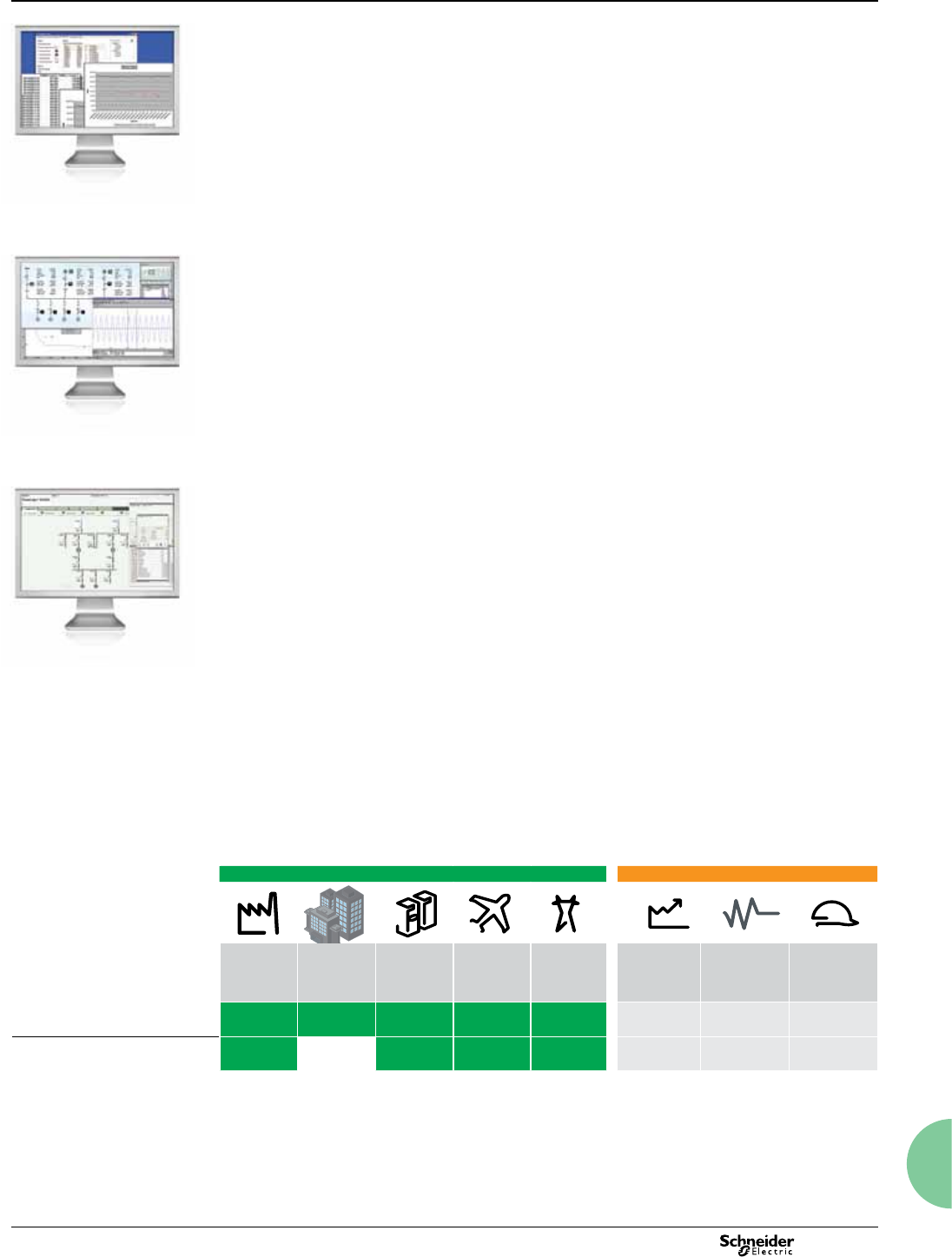
137
2013
Software introduction and
comparison
Environment Application category
Software Industry Buildings Data
centres
Infra-
structure
Electric
utilities
Energy
efficiency
& cost
Power
availability
& reliability
Network
protection
& control
StruxureWare
Power Monitoring Expert
bbb bbbb b
StruxureWare PowerSCADA
Expert
bb bbbb
The number of square bullets indicates the relative strength of feature set for the noted application category.
PE86230
A choice of powerful, effective solutions
StruxureWare software offerings give you desktop access to your entire electrical
network. They convert energy-related data into timely, actionable information and
give you the control to act on your decisions. The depth of different offerings makes it
easy to match a product to your goals, your business and your budget.
v StruxureWare Power Monitoring Expert software is a complete power
management solution that helps you maximise energy efciency, cut energy-related
costs and avoid power-quality related equipment failures and downtime.
v StruxureWare PowerSCADA Expert software is a power monitoring and control
solution with high reliability and performance for helping reduce the risk of power
outages and increase network-wide efciency.
Extensive reach and flexibility
StruxureWare software forms an important part of your overall energy efciency and
reliability solutions from Schneider Electric. A PowerLogic system can grow with your
business, giving you the level of energy intelligence and control you need to reduce
energy consumption and costs, minimise environmental impacts, and assure power
availability, uptime and safety.
Each product collects energy-related data from a variety of sources, including
PowerLogic or third-party meters and sensors. Some products offer integration with
other Schneider Electric or third-party automation systems, and other energy-
relevant information feeds.
Choosing your solution
This section provides a brief overview of the types of environments and applications
each software offer is best suited for. See the following product sections for more
detail on specic product features and compatibilities. Your Schneider Electric
representative can help you design the best solution by choosing the best product
and associated services for your needs.
StruxureWare software
PE86202
StruxureWare Power Monitoring
Expert software
PE86231
StruxureWare PowerSCADA
Expert monitoring and control software
Monitoring software
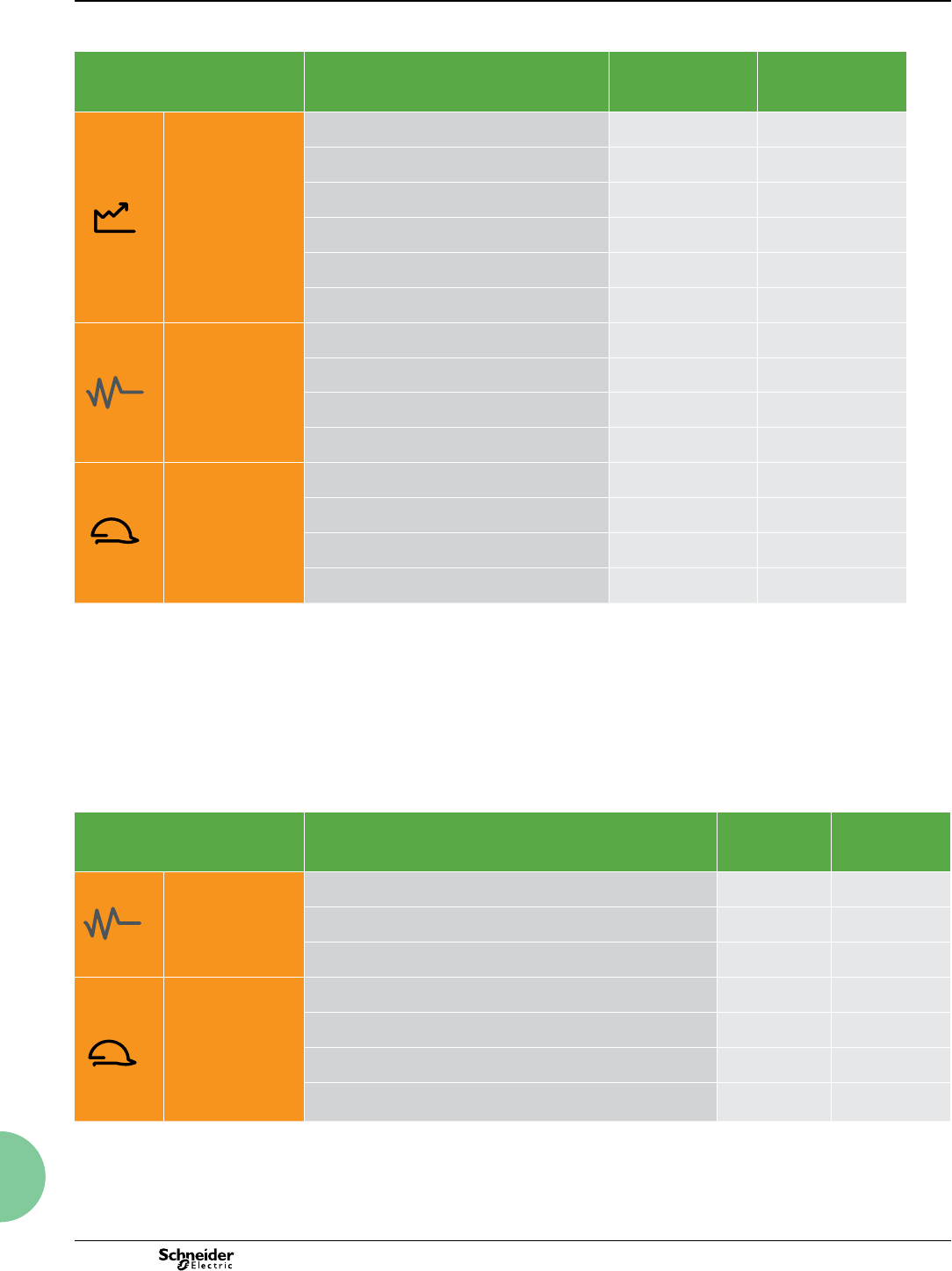
138 2013
Software introduction and
comparison
Applications for industry, buildings, data centres and infrastructure
Category Application StruxureWare
Power Monitoring
Expert
StruxureWare
PowerSCADA
Expert
Energy efficiency
& cost
Energy usage analysis bb b
Cost allocation
b
Procurement optimisation
b
Peak demand reduction
bbb bb
Demand response and curtailment
bbb bb
Power factor correction
bbb
Power availability
& reliability
Electrical distribution (ED) asset optimisation
bbb b
Power quality analysis and compliance
bbb b
ED commissioning, monitoring, and troubleshooting
bbbb bbb
ED alarming and events
bbb bbb
Network protection
& control
ED automation and control
bb bbbb
Load management and shedding
b b
Redundancy
bbbb
High reliability and time performance
bbbb
The number of square bullets indicates the relative strength of feature set for the noted application.
Applications for electric utilities
Category Application StruxureWare
Power Monitoring
Expert
StruxureWare
PowerSCADA
Expert
Power availability
& reliability
Power quality analysis and compliance
bbb
Electrical distribution (ED) commissioning, monitoring and
troubleshooting
b bbbb
ED alarming and events
bb bbb
Network protection
& control
ED automation and control
b bbbb
Load management and shedding
b bb
Redundancy
bbbb
High reliability and time performance
bbbb
The number of square bullets indicates the relative strength of feature set for the noted application.
Monitoring software
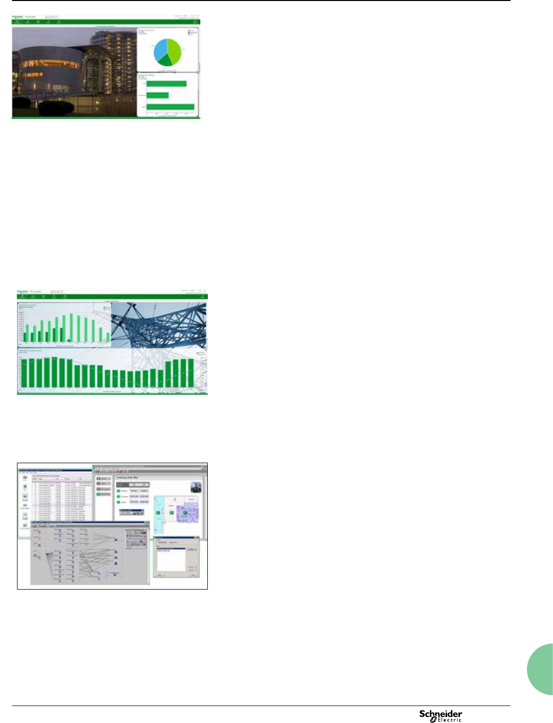
139
2013
Monitoring software
StruxureWare Power Monitoring 7
(PowerLogic ION Enterprise™)
Functions and characteristics
EB100263
StruxureWare Power Monitoring is an operations-level supervisory software that
provides a complete power management solution for industry, large commercial and
institutional buildings, data centres, healthcare facilities, and utilities. Engineering and
management personnel can cut energy-related costs, avoid downtime, and optimise
equipment operations by using the information provided by StruxureWare Power
Monitoring software.
StruxureWare Power Monitoring also enables tracking of real-time power conditions,
analysis of power quality and reliability, and quick response to alarms to avoid critical
situations. The software forms a layer of energy intelligence across your facility,
campus or service area, acting as a unified interface to all electrical and piped utilities.
Typical applications
StruxureWare Power Monitoring software has many applications:
b Monitor the facility electrical network and verify reliable operation
b Improve response to power-related events and restore operations quickly
b Analyze and isolate the source of power quality problems
b Analyze energy use to identify waste and reduce cost
b Estimate utility bills to verify accuracy and identify errors
b Allocate energy costs to departments to drive accountability and awareness
b Reduce peak demand surcharges and power factor penalties
b Idenfity excess capacity in existing infrastructure and avoid over-building
b Support proactive maintenance to prolong asset life.
For electric utilities:
b Improve T&D network reliability
b Enhance substation automation
b Maximise the use of existing infrastructure
b Verify compliance with new power quality standards
b Analyse and isolate the source of power quality problems
b Help customers manage reliability using operational and power quality data.
Scalable, flexible architecture
Functional components
Provides operators with a rich environment to view and navigate real-time displays of
measurements and status indicators; perform power quality and reliability analysis;
historical trending; alarms; and manual control.
Web Clients
b Reports - generate or edit historical reporst for energy cost, consumption, and
power quality (requires Microsoft SQL Server Standard Edition)
b Access power monitoring system from anywhere on your network using a web
browser. Day-to-day functionality including system status, alarm response, or viewing
dashboards. Web client provides authenticated access to common functions:
b Diagrams – navigate network displays to check system status and analyze trends
b Tables – quickly compare multiple devices in your network in real-time
b Reports – generate or edit historical reports for energy cost, consumption, and power
quality
b Alarms – quickly identify alarm states in your system and investigate root causes
b Dashboards – share information from your power monitoring system with any occupant.
Engineering Workstations
Client software to allow engineers and power users access to administrative and
configuration functions of the software, and real-time display, control, and historical
analysis functions. The Engineering Workstation includes:
b Management Console – use this component to configure your StruxureWare Power
Monitoring network, including communication paths, devices and logical groups
b Vista – build and edit custom graphical displays to represent your facility. One-line
diagrams, campus maps, equipment plan views and mimic diagrams can be created
using Vista graphical objects and imported graphic les
b Designer – use this interface to program ION devices and create system
applications with ION Technology and Virtual ION Processors
b Reporter - generate or edit historical reporst for energy cost, consumption, and
power quality.
StruxureWare Power Monitoring dashboard (sample)
EB100264
Dashboard - Energy Summary
Engineering Client Applications
EB100283
140 2013
Scalable, flexible architecture (cont.)
Data acquisition and management
b Device Support Library
b Virtual ION Processor
b Site server
b SQL ODBC-compliant databases
b SQL Server 2008 R2. Log device data, system data and events with accurate
meter synchronisation (+/- 16 ms or +/-1 ms using GPS) for precise event
timestamping, power quality analysis and revenue billing. This data is accessible
using industry-standard database tools and you can add distributed databases
and servers for load balancing
b OPC DA Client (included) OPC DA Server (optional).
Functions
StruxureWare Power Monitoring offers a wide range of functions:
b Data acquisition and integration
b Real-time monitoring
b Trend analysis
b Power quality analysis
b Alarms and events
b Reporting
b Dashboards
b Manual and automated control
b Patented ION® technology.
Data acquisition and integration
Integrate WAGES (water, air, gas, electricity, steam) metering. Native, out-of-the-
box support for dozens of devices (See Supported Devices section for details).
Enables access to real-time and timestamped historical meter data, control of on-
board relays and digital outputs, and server time synchronization. Communicate
over Internet, Ethernet, wireless. Interface with third-party meters, transducers,
PLCs, RTUs and power distribution or mitigation equipment through Modbus or
OPC. Add and configure direct communications with remote devices over Modbus
RTU or Modbus TCP protocols using easy-to-use device templates.
Scalable platform enables remote device and user client addition as needs grow
while maintaining original investment. Integrate other energy management or
automation systems (e.g. SCADA, BAC, DCS, ERP) through ODBC, XML, OPC,
email, FTP, CSV and PQDIF compliance; integrate with web services through
XML.
Real-time monitoring
b View the status of your electrical network from any workstation
b See numeric values, status indicators, gauges, and trends, all with intuitive
graphical navigation
b Extend comprehensive out-of-the-box displays and create custom graphical
diagrams to represent your facility; one-line diagrams, campus maps, equipment
plan views and mimic diagrams can be created using embedded graphical
objects and imported graphic les
b Quickly compare multiple devices in your network in real-time in a tabular
display
b Choose from a library of pre-built tables, or create your own. Save your
favorites for quick access later.
StruxureWare Power Monitoring 7
(PowerLogic ION Enterprise™)
Functions and characteristics
Equipment Status example - Diagrams
One Line example - Diagrams
PB86097
EB100266EB100265
Monitoring software
141
2013
StruxureWare Power Monitoring 7
(PowerLogic ION Enterprise™)
Functions and characteristics
Trend analysis
b Trend any parameter to reveal demand peaks and track system-wide energy
costs.
b Graph any combination of measured parameters
b Plot time-series or scatter charts
b Perform calculations, obtain statistics, and display historical data
b Identify dangerous trends and redistribute loads
b Optimise network capacity and avoid over-building
b View operating parameters and determine when maintenance is required
b Avoid peak demand surcharges and power factor penalties.
Power quality analysis
b StruxureWare Power Monitoring software allows continuous, wide-area
monitoring and data capture for power quality and reliability conditions.
b Power quality events automatically detected by PQ-capable metering devices are
uploded to the system automatically. Analyze waveforms to determine source and
cause of issue
b Determine if power quality events are upstream or downstream (requires
PowerLogic meter with Disturbance Direction Detection feature)
b IEC 61000-4-30 and EN50160 compliance reporting veries power quality
performance to international standards and allows you to quickly review power
quality indices as numeric charts or graphic proles (requires PowerLogic meters
that support compliance monitoring)
b Display harmonic histograms, odd/even harmonics, THD, K-factor, crest factor,
phasor diagrams, and symmetrical components
b Plot waveforms of up to many seconds in duration, with overlays that correlate
phase-to-phase relationships between voltages, currents, and cascading failures
b Plot sags, swells, short duration transients and other disturbance events on
industry-standard voltage tolerance curves, including ITIC (CBEMA) and SEMI
b For any event, you can display a list of associated time-stamped incidents, then
click on any incident to see more detailed information.
Alarms and events
StruxureWare Power Monitoring software allows you to receive alerts to outages or
impending problems that could lead to equipment stress, failures, or downtime.
b Quickly lter on active or unacknowledged alarms
b Acknowledge alarms from anywhere in your facility
b Trigger on complex conditions
b Log all relevant data sequence of events for diagnosis
b Flag & avert potential problems
b Alert key personnel 24/7
b Optimise maintenance scheduling.
Dashboards
b Create engaging dashboard displays of your power monitoring system information
and easily share information with anyone in your facility
b Make power monitoring information visible and engaging
b Promote education and drive behaviour
b Display as an interactive kiosk, on a corporate intranet, or as a slideshow on a
large wall-mounted display
b Replace hard to maintain home-grown portals and dashboards
b Chart or trend any quantity in your power monitoring database
b Simple conversions into other units (e.g. dollars, emissions, normalizations, etc.)
b Compare multiple time-ranges
b Show impact of temperature, occupancy, or production values on energy usage
b Add eye-catching backgrounds to enhance presentation value
b User authentication for conguration, and both authenticated and unauthenticated
modes available for display.
EB100268EB100269EB100270
The Diagrams web application allows users to easily view
create trend plots and analyze historical data.
The Diagrams web application allows users to view and
analyze waveforms captured by devices.
Monitoring software
142 2013
StruxureWare Power Monitoring 7
(PowerLogic ION Enterprise™)
Functions and characteristics
Reporting
b The powerful, intuitive reporting options let users see critical information exactly
how, where, and when they need it
b Reports can be generated manually and saved as Excel, HTML and other formats
or scheduled to automatically distribute to a printer or via email
b There are two different report engines that may be used (Reporter and web-based
Reports). See the table below to compare their features.
Feature Set SPM7
Reporter
SPM7
Web Reporter
Energy Cost Management
Energy and Demand n n
Load Profile n n
Multi-Device Energy Usage -n
Energy Usage by Shift -n
Single Device Energy Usage -n
Network Management
Power Quality n n
EN50160 Compliance n n
IEC-61000-4-30 10 Mins n n
IEC-61000-4-30 2 Hours n n
IEC-61000-4-30 3 Secs n n
100ms Report -n
Alarm History -n
Generic Reports
Generic data query n-
Tabular Report -n
Trend Report -n
Feature Set
Excel 2003 support n n
Excel 2007 support n n
Excel 2010 support n n
Export to Excel n n
Export to PDF -n
Export to HTML n n
Export to XML -n
Email n n
Print n n
Run on a Schedule n n
Run on Alarm -n
Accessible via Web Browser -n
Report Configuration Save n n
Report Edit n n
Custom Reports n n
Data Validation n-
TOU n n
User Administration -n
Translatable Reports n n
EB100280 EB100279
The Reports web application provides many different
report templates to allow users to easily display and deliver
the information they need .
Power Quality Summary Report example - Reports
Monitoring software
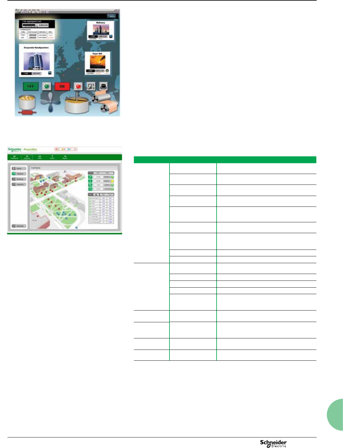
143
2013
PE86125
Manual and automated control
b Perform fast, manual control operations by clicking on-screen trigger buttons, and
operate remote breakers, relays, and other power distribution and mitigation
equipment
b Perform manual or setpoint-triggered functions
b Coordinate control of multiple loads, generators, relays, etc.
b Support energy-saving applications
b Manage distributed energy assets
b Automate substations & reduce service time.
b Interoperability
b Integrate all energy management and automation systems (SCADA, BAC, DCS,
ERP, etc.)
b Share data with third-party SCADA, automation, and accounting systems
b Comply with ODBC, OPC, and PQDIF standards
Patented ION technology
StruxureWare Power Monitoring software and a variety of PowerLogic ION metering
products feature the unique ION architecture. This modular, flexible architecture
offers extensive customisation of functionality using a simple .building block.
approach. The technology uniquely addresses advanced monitoring and control
applications and adapts to changing needs, avoiding obsolescence.
EB100281
Software is available in English, French, Spanish, German, and Chinese. Other
languages may be available - contact your Schneider Electric representative.
Part numbers*
New systems &
add-ons
IE7PRIMARY StruxureWare Power Monitoring Primary server
(DVD, includes all available languages)
IE7DLS(1) Individual Device Licence for High-End Devices.
Compatible with all device types.
IE7DLM(1))Individual Device Licence for Mid-Range Devices.
Compatible with Mid- and Entry-range devices.
IE7DLE (1) Individual Device Licence for Entry-Range
Devices. Compatible with Entry range devices
IE7ENGCLIENT(2) Engineering Client Licence (DVD) - Access to
Management Console, Vista, Designer, Reporter
and Web applications; one licence per user.
IE7WEBCLIENT(2) Web Client Licence - Access to Diagrams, Tables,
Alarms, Reports, Dashboard; one licence per user
IE7UNLCLIENT(3) Unlimited Licence for unlimited number of users
(Engineering or Web applications); mandatory for
public displays or Internet hosting.
IE7OPCSERVER OPC DA Server for StruxureWare Power Monitoring
IE7SECONDARY Secondary Server for StruxureWare Power Monitoring
Upgrades from
earlier versions
IE7PRIMARYUPG(4) StruxureWare Power Monitoring UPGRADE
software (DVD, includes all available languages)
IE7DLSUPG(1) Upgrade DL-S device licence
IE7DLMUPG(1) Upgrade DL-M device licence
IE7DLEUPG(1) Upgrade DL-E device licence
IE7ENGCLIENTUPG(2) Engineering Client Upgrade Licence - Access to
Management Console, Vista, Designer, Reporter
and Web applications; one licence per user.
IE7WEBCLIENTUPG(2) Web Client Upgrade Licence - Diagrams, Tables,
Alarms, Reports; one licence per user
IE7UNLCLIENTUPG(3) Unlimited Client Upgrade Licence for unlimited
number of users (Engineering or Web applications);
mandatory for public displays or internet hosting.
IE7SECONDARYUPG Secondary Server Upgrade for StruxureWare
Power Monitoring
Technical
documentation
CD-TECHDOC Latest version of technical documentation for
StruxureWare Power Monitoring
(1) An appropriate device licence (DL-S, DL-M, DL-E) is required for each device added to your system in Management
Console. A minimum order value may apply.
(2) Each user of the system must have an appropriate Client Licence. An Engineering Client Licence permits access to
Management Console, Vista, Designer, Reporter and the Web applications. This includes remote access through Terminal
Services or other methods. A Web Client licence only permits access to web applications - Dashboards, Diagrams, Tables,
Alarms, Reports. Contact your sales representative for more information.
(3) An Unlimited Client Licence provides access to all software applications (including Management Console, Vista,
Designer, Reporter, Dashboards, Diagrams, Tables, Alarms, Reports) for an unlimited number of users. This type of
Client License is required when accounting for individual users is not possible (applications available in public areas,
internet hosting, etc). Engineering Client or Web Client Licenses are not required when an Unlimited Client License is in
place. Please note that performance limitations of your installation may affect the practical number of concurrent users.
(4) Upgrade part numbers apply to PowerLogic ION Enterprise 5.6 and later, and PowerLogic SMS v4.x. Technical
upgrades from earlier versions may be possible - contact your sales representative for more information.
* Please consult a Schneider Electric sales representative for full pricing and part numbers information.
StruxureWare Power Monitoring 7
(PowerLogic ION Enterprise™)
Functions and characteristics
Custom graphics screen example - Diagrams
Campus map example - Diagrams
Monitoring software
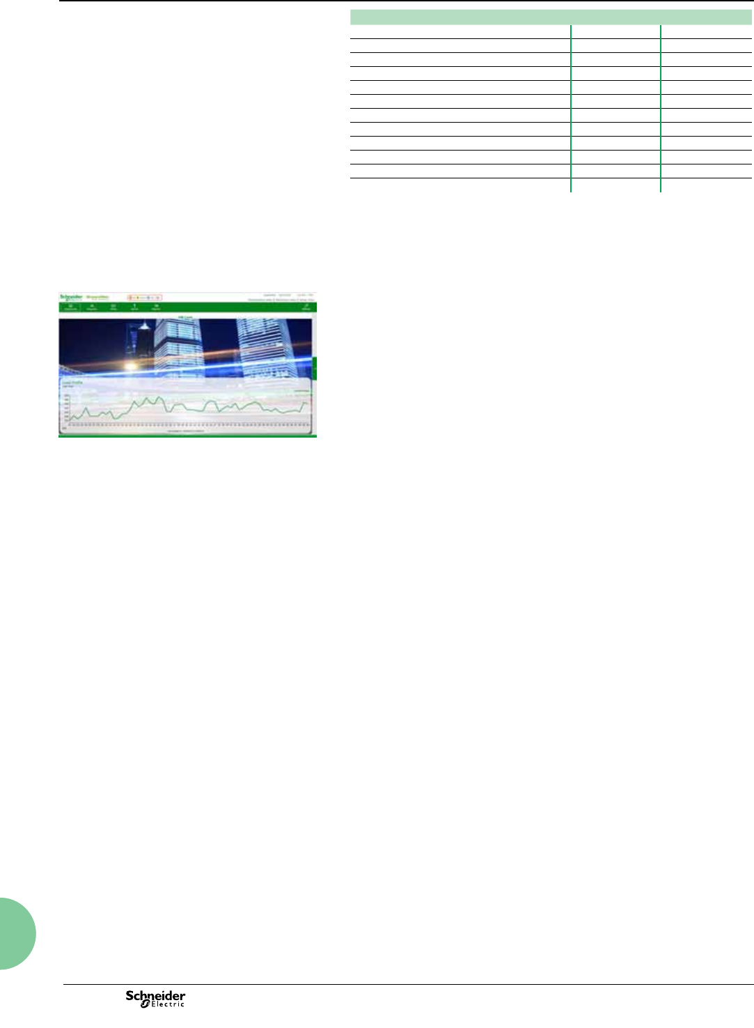
144 2013
Monitoring software
StruxureWare Power Monitoring 7
(PowerLogic ION Enterprise™)
Functions and characteristics
Features Included Optional
Dashboards b-
Diagrams b-
Tables b-
Alarms b-
Reports* b-
Modbus Device Importer b-
Designer b-
EGX300 Log File Importer b-
SQL Server 2008 R2 Express Edition b-
SQL Server 2008 R2 Standard Edition -b
OPC client b-
OPC server -b
Minimum system requirements
Please consult your local Schneider Electric representative for complete system
requirements and commissioning information for StruxureWare Power Monitoring.
*Note: There are two different report engines that may be used: Reporter and web-based
Reports. The Reporter application is always available as an Engineering Client tool. The web-based Reports
feature is only available when the system has been installed using SQL Server Standard Edition.
PowerLogic circuit monitors:
b CM2000 Series (CM2050, CM2150, CM2250, CM2350, CM2450)
b CM3000 Series (CM3250, CM3350)
b CM4000 Series (CM4150, CM4250, CM4000T).
PowerLogic branch circuit power meters:
b BCPM (A, B, C models).
Circuit breaker trip units
b Micrologic A, E, P and H devices
b Micrologic Compact NSX Type A and Type E.
Protective relays
b Sepam Series 10, 20, 40, 48, 80.
Insulation monitors
b Vigilohm IM20.
Power Measurement power and energy meters:
b ION8000 Series (ION8300, ION8400, ION8500, ION8600, )
b ION7000 Series (ION7500, ION7600, ION7700)
b ION7500RTU
b ION7300 Series (ION7300, ION7330, ION7350)
b ACM3000 Series (ACM3300 , ACM3710, ACM3720).
PLCs for WAGES applications
b Modicon Momentum M1 - TR (A8, D10, D16)
b Twido Modular PLC (D12,D28, D44).
Communications Interfaces
b Acti9 Smartlink.
“Limited Edition” (LE) drivers available for download from website
b Modbus-compatible devices
b Other devices through OPC.
EB100282
Supported devices
PowerLogic power and energy meters:
b ION8800 Series
b ION8650 Series
b ION7650/7550
b ION7550RTU
b ION6200
b PM5350
b PM3000 Series (PM3250, PM3255)
b PM1200
b PM800 Series (PM810, PM820,
PM850, PM870)
b PM700 Series (PM710, PM750)
b PM600 Series (PM600, PM620,
PM650)
b PM210
b PM9C
b DM6200
b DM6300
b EM1200
b EM5600
b iEM3000 Series (iEM3150,
iEM3155, iEM3250, iEM3255)
b EM1200 Series
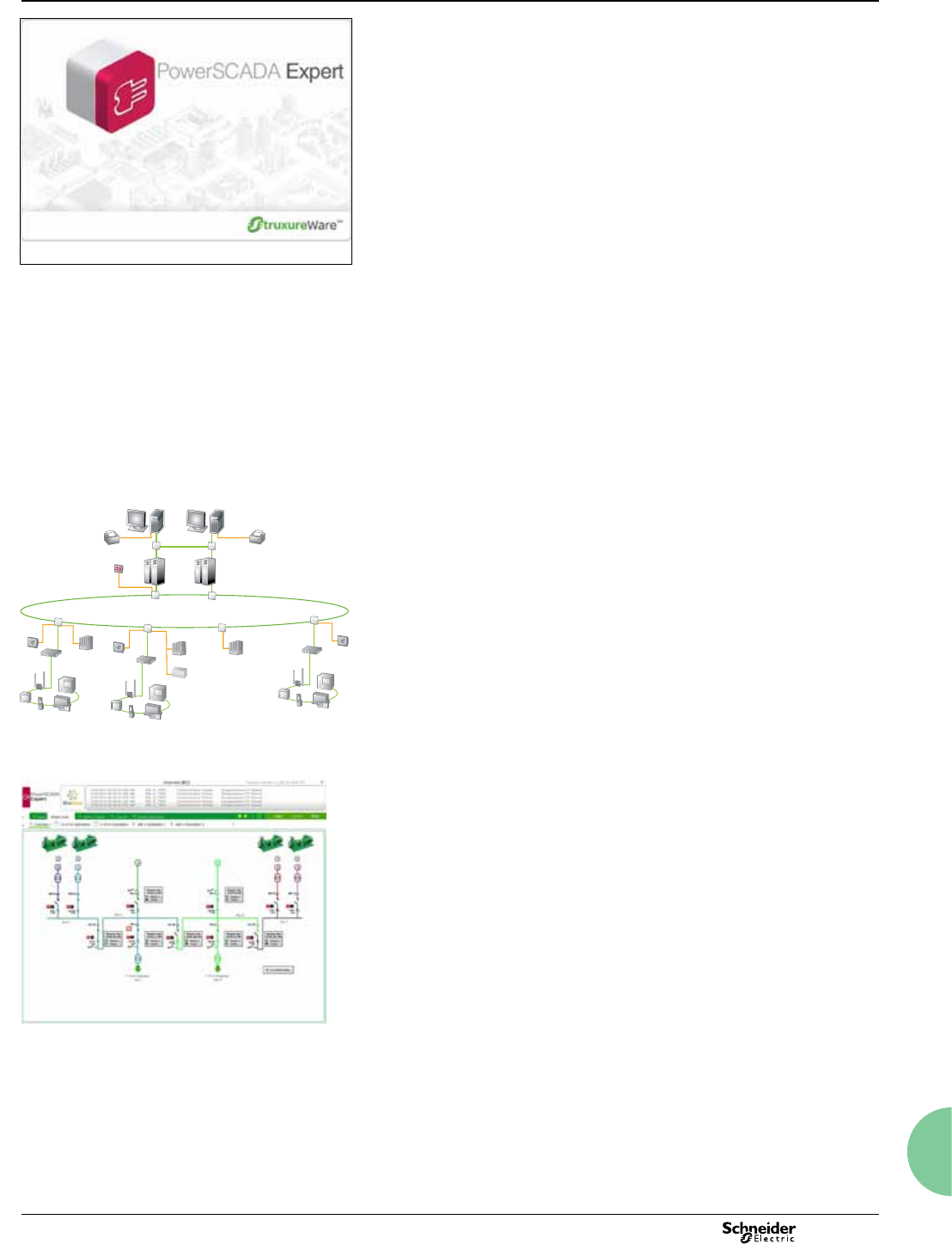
145
2013
StruxureWare PowerSCADA Expert
Functions and characteristics
Monitoring software
PBS100001
StruxureWare PowerSCADA Expert (previously known as PowerLogic SCADA) is a
reliable, flexible and high performance monitoring and control solution designed to
reduce outages and increase power efficiency. It is built to handle user requirements
from the smallest to the most demanding enterprises, while still providing high time
performance and reliability. Easy-to-use configuration tools and powerful features
enable faster development and deployment of any size of application.
Object-based, standard graphics and symbols provide operators with an interactive
and user-friendly interface. Intuitive commands and controls increase efficiency
of operators to interact with the system interface. StruxureWare PowerSCADA
Expert controls your system with high reliability, performance and data integrity
through the use of advanced architectures, such as hot/warm redundant I/O device
configurations, self-healing ring communications, and primary and standby server
configurations. Comprehensive user-based security is integrated into all interface
elements, ensuring a secure control system.
Typical applications
StruxureWare PowerSCADA Expert software has the following applications:
bNetwork protection and control
bOperate distribution network safely and reliably
bImprove continuity of electrical service
bEquipment monitoring and control
bEnergy availability and reliability
bVerify the reliable operation of equipment
bSupport proactive maintenance to prolong asset life.
System architecture
Human machine interface (HMI)
StruxureWare PowerSCADA Expert offers secure, operator-dedicated, multi-user
data and control access through a local server interface, full control client and also
through web clients.
Main components
bSCADA software
vDrivers, libraries and communication tools.
vUse these components to congure your SCADA network, including
communication paths, devices and logical groups.
bCommunication hardware
vIncludes gateways, PLCs, RTUs, switches, etc.
vRedundant, self-healing ring, double-ring technology
bDesign reference guide
vDesign of architectures to achieve time performance & reliability
bSchneider Services
vPro-active assistance to facility maintenance team for sensitive electrical
distribution maintenance operations.
Data acquisition and management
vRedundant I/O server
vHot/warm standby: data acquisition is never interrupted even if one server fails.
vDistributed, multiple server architecture
vI/O servers, with corresponding conguration tools
vIEC61850 compliant databases
vDesigned for interoperable exchange of data for distributed substation automation
systems and third-party devices.
vSupports data import/export with compliant devices and systems.
StruxureWare PowerSCADA Expert.
PE86178
ECS Engineer workstation
EGX 400
PLC
PLC Islanding
PLC
Clock
EGX 400
Remote I/O
rack
EGX 400
Master clock
Ethernet optical ring
Optical converter
Optical converter
Compatible devices
Compatible devices
Compatible devices
Optical converters
ECS Operator workstation
Redundant ECS server
Functional components of StruxureWare PowerSCADA Expert.
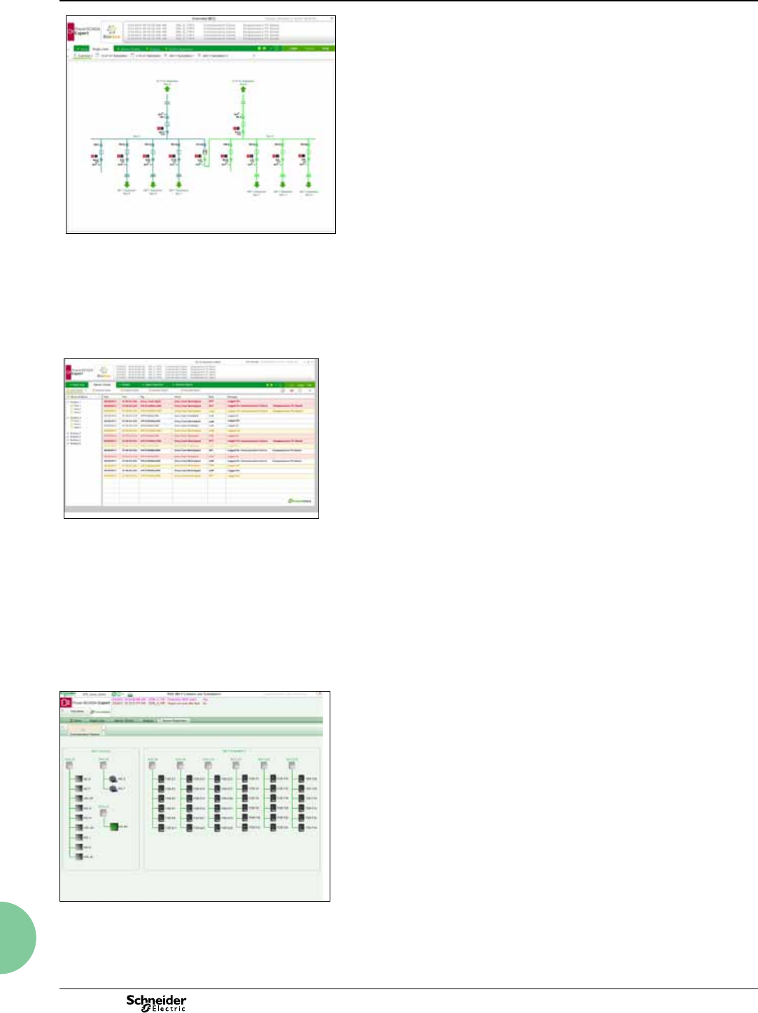
146 2013
StruxureWare PowerSCADA Expert
Functions and Characteristics (cont.)
Monitoring software
PB100005
Monitor the whole communications network. Connect to
switches, IEDs, RTUs, control and monitoring devices.
Extract values for dynamic power and energy readings.
Functions
StruxureWare PowerSCADA Expert offers a wide range of functions:
bData acquisition and integration.
bAlarms and events with 1ms timestamp support.
bElectrical distribution control.
bReal-time monitoring.
bAnalysis.
Data acquisition and integration
Integrate electrical distribution devices with PLCs, RTUs, Controllers and other
intelligent energy devices. Native, out-of-the-box support for all SEPAM Series 20,
40, 80, and SEPAM 2000 (S36), Micrologic 5.0P and 6.0P, Micrologic A, Micrologic
A FW v2, Micrologic H, PowerLogic CM4000 series, PM800 series, PM710, PM750,
ION7650 and BCPM/BCM42. Enables access to meter data, control of protection
relays and digital outputs and remote configuration. Interface with PLCs, RTUs and
power distribution equipment. Quickly add and configure devices with easy-to-use
Profile Wizard and Profile Editor. Scalable platform enables remote devices and
user clients to be added as needs grow while maintaining your original investment.
Integrate with other energy management or automation systems through Modbus
TCP/IP.
PB100004
View all alarm conditions at a glance.
Alarms and events
StruxureWare PowerSCADA Expert software allows you to receive alerts to outages
or impending problems that could lead to equipment stress, failures, or downtime.
Configure alarms to trigger on events, power thresholds, or equipment conditions.
The software logs complete information on an event, including related coincident
conditions, all with accurate 1ms timestamping.
bEasily discriminate between alarm criticality levels.
bHigh speed alarm response. Capture and log every single alarm or event.
bOrganise, lter and print by any alarm property. Congure specic alarm
occurrences to change symbol color or ash an icon on a page.
bView the ve most recent alarms from every page, providing detailed information
in easy-to-understand formats.
bEvent log for all PC-based and on-board eld events, alarms.
bEasily congure to annunciate based on alarm type.
Standards supported
bIEC61850
bDNP3
PBS100006
Electrical distribution control
Perform fast, manual control operations by clicking on-screen trigger buttons, and
operate remote breakers, protection relays, and other power distribution equipment.
System Supervision displays such as this let the user see the
real-time status of all devices and provide detailed information
for best decision making.
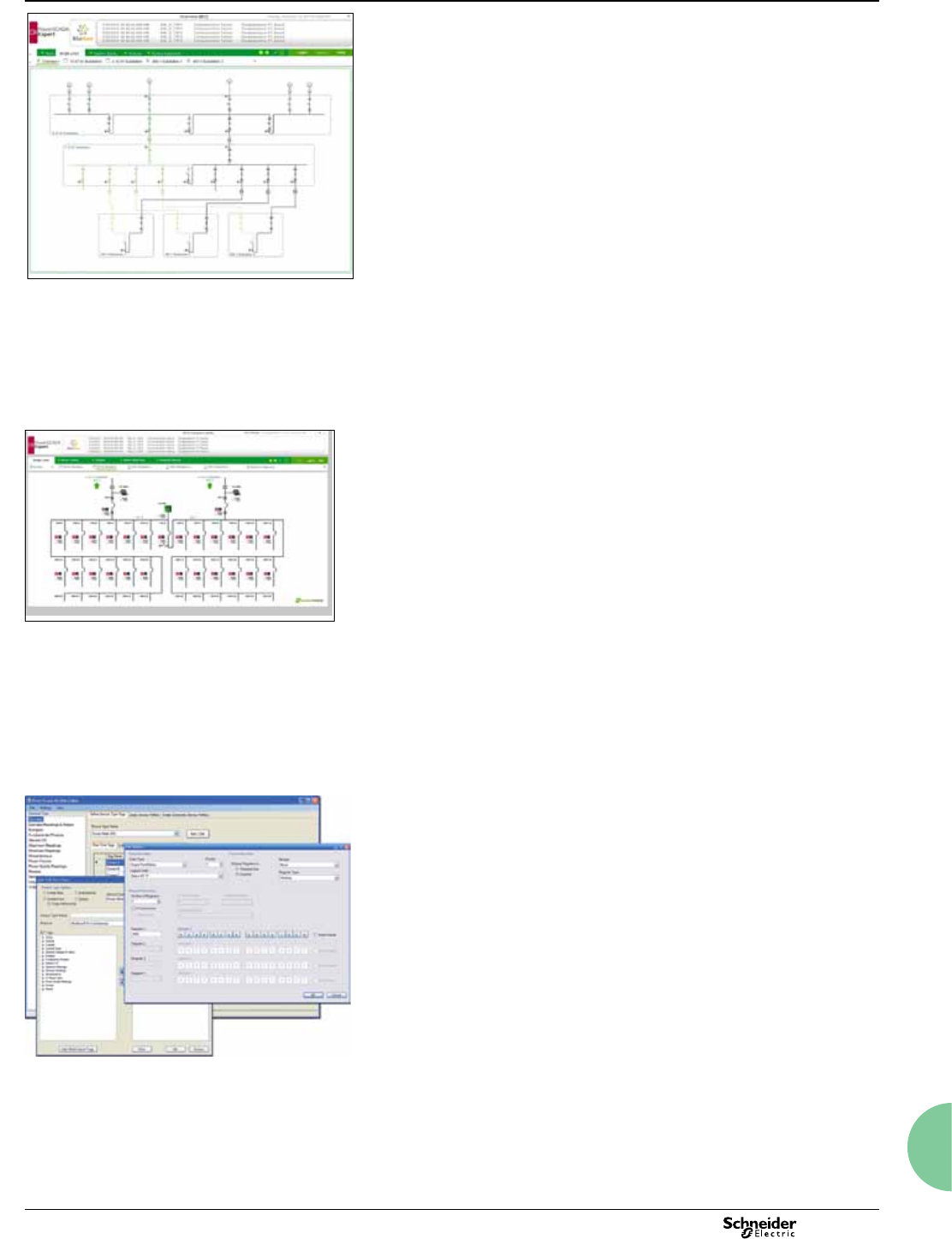
147
2013
StruxureWare PowerSCADA Expert
Functions and Characteristics (cont.)
Monitoring software
PBS100002
Desktop access to power system information from any
department, building or of relevant, realtime data.
Real-time monitoring
View all distribution points across your network. Secure display of real-time power
and energy measurements, historical trends and data logs, alarm conditions,
equipment status (on/off, temperature, pressure, etc.), control triggers, and
analysis tools.
bSingle line diagrams with real-time monitoring and control of devices, objects
and distribution points. Point-and-click navigation reveals deeper layers of detail.
bIEC- and ANSI-standard symbols and templates that are fully animated and
interactive, to blend control and display functionality.
bDynamic colouring is easily congured using the default set or user-dened
colours and voltage levels.
bTrue color, easy-to-use human machine interface (HMI) that provides operators
with intuitive and consistent screens.
PBS100003
Analysis
Trend and analyse on any measured parameter, allowing operators to recognise
patterns that may lead to disturbances. Display millisecond-accurate historical
alarms and trends to help determine the sequence of events or root cause
analysis. Unite trend and alarm data for sophisticated disturbance views and
analysis. User-defined colour coding and overlays clearly highlight data series,
time ranges, thresholds and limits. View waveforms via ActiveX tool (waveforms
from the ION8650 are captured via IEC61850 only). Record, save or export trends
to archives.
Optimise equipment use by maximising capacity or balancing
loads. Reveal critical trends, expensive processes or energy
waste.
PE86189
Use the Profile Editor and Profile Wizard to design and configure
your network. Customise device profiles specific to your project.
Configuration tools
StruxureWare PowerSCADA Expert is supplied with a package of configuration
tools designed to make set up uniquely easy and quick.
bDesigned to help make project set up and network conguration fast and easy.
bProle Editor provides standard device types and their associated proles
and allows engineers to easily customise the proles of the devices specic to
the project. New export/import capability allows easier sharing of proles.
v Standardized tags per device prole (congurable), XML le.
vCreates, adds, edits device types, tags and proles.
bProle Wizard provides a standard interface for quick SCADA data base
generation:
vInstantiation of devices, on a per object basis.
vCreates tags, trends, alarms and events when devices are added to system.
vBatch editing supported by automation interface.
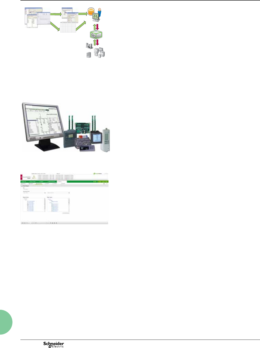
148 2013
StruxureWare PowerSCADA Expert
Functions and Characteristics (cont.)
Monitoring software
PE86190
PowerLogic SCADA
PLCs Compatible devices
Device Profile Editor
Add/configure
single device
Add/configure
multiple devices
Device Wizard
Generators
Database
Drivers
Automation interface
(Spreadsheet)
PowerLogic SCADA files and data flow configuration steps.
Minimum system requirements
Please consult your local Schneider Electric representative for complete system
requirements and commissioning information for StruxureWare PowerSCADA
Expert. The following are minimum support requirements with factory default
settings.
bRuns on standard PCs or servers, and supports the following operating systems:
vWindows 2003 Server (32-bit)
vWindows XP Professional (32-bit)
vWindows Vista Business
vWindows XP SP3 (32-bit)
vWindows 2003 Server SP2 (32-bit)
vWindows Vista SP2 (32- and 64-bit)
vWindows Server 2008 SP2 (32- and 64-bit)
vWindows 7 (32- and 64-bit)
PE86191
Supported devices and protocols
PowerLogic electrical network protection:
bSepam series 20, 40, 80, SEPAM 2000 (S36)
PowerLogic power and energy meters:
bPM800 series
bPM710, PM750
bCM4000 series
bION 7650
Circuit breaker control units
bMicrologic 5.0P
bMicrologic 6.0P
bMicrologic A, and Micrologic A FW v2
bMicrologic H
Branch circuit monitors
bBCPM
bBCM42
Native device protocol support
bIEC 61850 Edition 1 (New)
bDNP3
bModBus TCP/IP
bRS-485
bSNMP
Optional support
bIEC 80750-5-104
bBCM42
Data access (Other protocols support)
bOPC DA Version 1 & 2 Client Server
bODBC
Other:
bAny PLC or other device via Modbus protocol
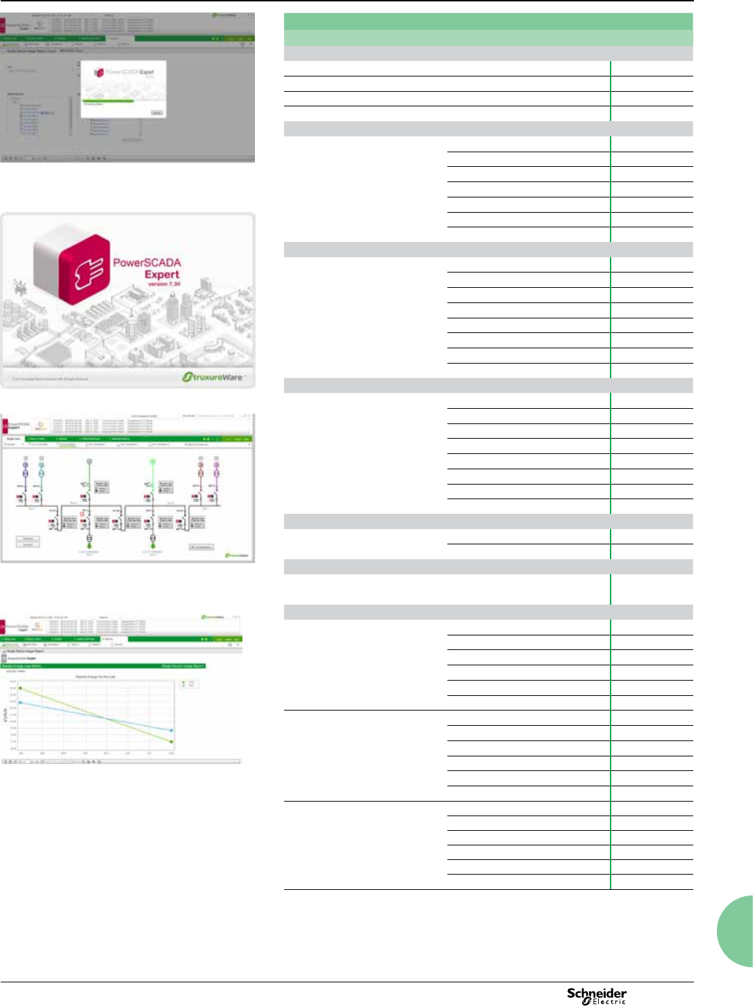
149
2013
StruxureWare PowerSCADA Expert
Functions and Characteristics (cont.)
Monitoring software
Part Numbers
Description
StruxureWare PowerSCADA Expert Software and one (1) key in a box
PowerLogic SCADA box with DVD and USB key PLS109922
PowerLogic SCADA box with DVD and Parallel key PLS109912
PowerLogic SCADA additional USB key PLS109921
PowerLogic SCADA additional Parallel key PLS109911
Server Licences (includes server Control Client)
Server Licence
75 PLS101110
150 PLS101111
500 PLS101112
1500 PLS101113
5000 PLS101114
15000 PLS101115
Unlimited PLS101199
Control Client Licences
Control Client Licence
75 PLS102010
150 PLS102011
500 PLS102012
1500 PLS102013
5000 PLS102014
15000 PLS102015
Unlimited PLS102099
Redundant (floating licence) PLS102088
Web Control Client Licences
Web Control Client Licence
75 PLS102210
150 PLS102211
500 PLS102212
1500 PLS102213
5000 PLS102214
15000 PLS102215
Unlimited PLS102299
Redundant (floating licence) PLS102288
View Only Client Licences
View Only Client Licence Independent of points PLS103099
Redundant (floating licence) PLS103088
Web View Only Client Licences
Web View only Client Licence Independent of points PLS103299
Redundant (floating licence) PLS103288
Point Expansions
Server licence point expansion
75 - 150 PLS101110-11
150 - 500 PLS101111-12
500 - 1500 PLS101112-13
1500 - 5000 PLS101113-14
5000 - 15000 PLS101114-15
15000 - unlimited PLS101115-99
Control licence point expansion
75 - 150 PLS102010-11
150 - 500 PLS102011-12
500 - 1500 PLS102012-13
1500 - 5000 PLS102013-14
5000 - 15000 PLS102014-15
15000 - unlimited PLS102015-99
Web control licence point expansion
75 - 150 PLS102210-11
150 - 500 PLS102211-12
500 - 1500 PLS102212-13
1500 - 5000 PLS102213-14
5000 - 15000 PLS102214-15
15000 - unlimited PLS102215-99

150 2013
StruxureWare PowerSCADA Expert
Functions and Characteristics (cont.)
Monitoring software
Part Numbers
Description
Key Reprogramming
Reprogramming fee - Authorisation Code1PLS109401
Tech Support2
Silver 1 year support, first year, compulsory PLS109102
Silver 1 year support, renewal PLS109122
Gold 1 year support, first year PLS109103
Gold 1 year support, renewal PLS109101
Service Levels
Level Service Description
Silver
No access to a new version;
Tech support business hours;
Hot Fix
Gold
12 months access to a new version;
Tech support business hours;
Hot Fix
1: Reprogramming fee is required for any key modifications: addition of a new licence or point
expansion
2: First year Tech Support is not included in licence. First year Tech Support is compulsory.
Subscription level is not available for 1st year, minimum level is Silver or above. Support
reinstatement applies 3 year backwards maximum.

151
2013

152 2013

153
2013

154 2013

155
2013

Schneider Electric Industries SAS
35, rue Joseph Monier
CS 30323
F - 92506 Rueil-Malmaison Cedex
RCS Nanterre 954 503 439
Capital social 896 313 776 €
http://www.schneider-electric.com
Printed on ecological paper
05-2013
As standards, specications and designs change from time to time, please ask for conrmation
of the information given in this publication.
ART837220 © 2013 - Schneider Electric - All rights reserved
Layout: Schneider Electric
Photos: Schneider Electric
Printing:
PLSED309005EN
