PA02100001E
2014-09-08
: Pdf 474971-Attachment 474971-Attachment 786676 Batch5 unilog
Open the PDF directly: View PDF ![]() .
.
Page Count: 4
Arc Flash and PPE
Arc fl ash hazard reduction
Safety is crucial and standards
like NFPA 70E (Standard
for Electrical Safety in the
Workplace) have emerged,
making it unacceptable for
engineers to accept existing or
to design new unit substations
without considering the impact
of arc flash hazards and second-
ary bus protection. Eaton’s MSB
delivers an elegantly simple
design approach. MSB offers
primary transformer protection
and secondary bus protection in
one 15 kV class primary metal-
enclosed assembly.
Eaton’s MSB (metal-enclosed switch and breaker
combination) is an integrated assembly using reliable,
cost-effective load interrupter switches in series with
VCP-TR vacuum circuit breakers. MSB combines the reliable
visible disconnect of a load-break switch with the superior
protection capabilities of a fixed-mounted vacuum
circuit breaker.
MSB can be used as the primary protection for a
single-ended substation (eliminating the need for a
secondary main breaker), or it can be used as the
primary main device and integrated into a lineup of
fused MVS switchgear.
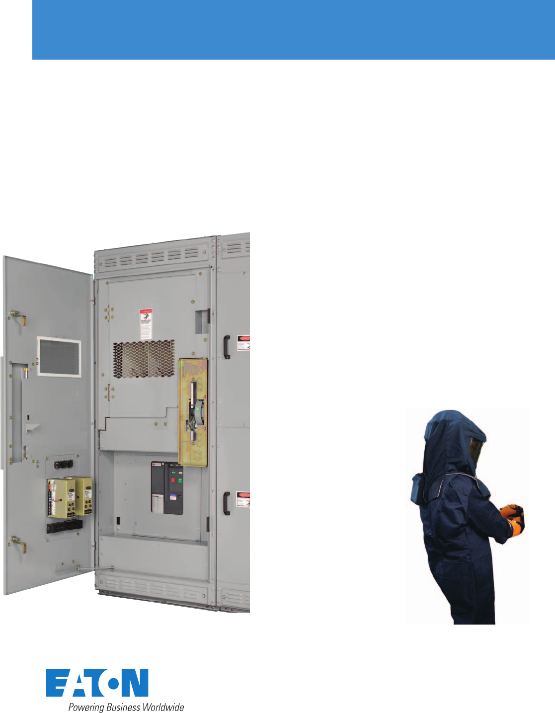
Reduce the arc fl ash hazard in
your substation with Eaton’s MSB,
featuring the Arcflash Reduction
Maintenance System
MSB–enhanced substation
primary and load interrupter
switchgear
Vents
DANGER
HIGH
VOLTAGE
NAMEPLATE
Vent Vent
ØC
ØB
ØA
N
MAIN
METERING
FDR
800A
FDR
800A
FDR
800A
FDR
800A
CPT VT
CT
1500 kVA
5.75% Z
2000A
100E
Unit substation dilemma
For the past 30 to 40 years,
engineers have designed
secondary unit substations
based on application of a 15 kV
metal-enclosed fused load-break
switch, close coupled to a trans-
former primary, then in turn
connected to low voltage
switchgear at the transformer
secondary.
National Electrical Code (NEC)
requirements for this class
of equipment contained two
statements that resulted in quite
a few unit substations being
installed with very high levels
of available arcing energy
unprotected on the secondary
bus of the transformers.
Those two statements were:
1. Note 2 of NEC Article 450.3
Equipment—Transformers
describes the “six discon-
nect rule.” This article
states, “Where secondary
overcurrent protection is
required, the secondary
overcurrent device shall
be permitted to consist of
not more than six circuit
breakers or six sets of fuses
grouped in one location.”
2. NEC Article 240.21(C)2
Overcurrent Protection
describes transformer sec-
ondary conductors not over
10 ft (3m) long such that the
ampacity of the secondary
conductors is not less than
the combined calculated
loads on the circuits supplied
by the secondary conductors.
These two articles in the Code
resulted in thousands of unit
substations being installed
using a fused load-break
switch as the secondary
bus protection!
The emergence of new electri-
cal safe workplace standards
such as the NFPA 70E–2009 has
challenged users to take another
look at their substations based
on the incident energy or arc
flash hazard should a secondary
bus fault occur. This could hap-
pen while doing energized work
such as racking a secondary
feeder circuit breaker on or off
of an energized bus.
NFPA 70E arc flash hazard
calculations conducted at one
industrial site yielded arc flash
energies in excess of 700
calories/centimeter2 at the
secondary bus as shown in
the substation diagram below.
Because personal protective
equipment (PPE) available at
the site was only rated up to
Category 4, 40 calories/
centimeter2, there was no safe
condition in which an operator
could insert or remove a feeder
circuit breaker from an energized
bus in order to perform lockout/
tagout safety procedures.
Potential arc flash hazard for
secondary switchgear bus
without MSB
Bus fault at 480V switchgear
• 10 kA secondary arcing fault
• At 13.8 kV = 348A primary fault
• 100E fuse clearing time = 160 seconds
Fault at 480V switchgear bus
• NFPA 70E results
• 31.8 kA symmetrical fault current
• 1167-inch arc flash boundary
• 702.4 cal/cm at 18 inches
• Unapproachable NFPA 70E–2009:
Category 4 is highest category
at 40 cal/cm
MSB is the solution to the
arc fl ash hazard dilemma
Reduce arc flash hazard in your
substation with Eaton’s MSB.
Solving this electrical safety
hazard involved replacement
of the existing metal-enclosed
fused load-break switch with an
Eaton metal-enclosed medium
voltage switch over vacuum
circuit breaker (MSB) assembly.
MSB is perfect for retrofit in
existing substations where arc
flash safety is an issue. And, the
MSB is perfect for application in
new substations.
With MSB, sensors can be
installed on the secondary bus
that are connected into the
primary vacuum circuit breaker.
MSB can effectively provide
primary substation transformer
protection as well as secondary
switchgear bus protection using
one device.
The VCP-T main circuit breaker
can be equipped with multiple
user preferred methods for arc
energy reduction, drastically
reducing the arc flash energy on
the secondary bus for any unit
substation.
Two available methods for
reducing incident arcing
energy are:
• Arcflash Reduction
Maintenance System mode
• (ZSI) Zone selective interlock-
ing; see diagram on page 3 for
ZSI example
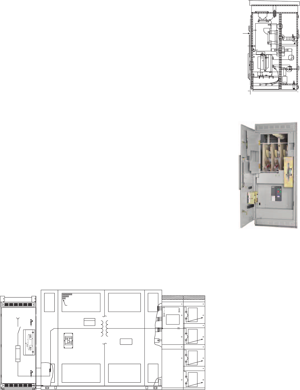
105.45
(2678.4)
52.25
(1327.1)
55.25
(1403.4)
0
0
Barrier
MSB Side View
MSB Front View
Typical unit substation with fused switch primary and no secondary main breaker
2EATON CORPORATION MSB–enhanced substation primary and load interrupter switchgear
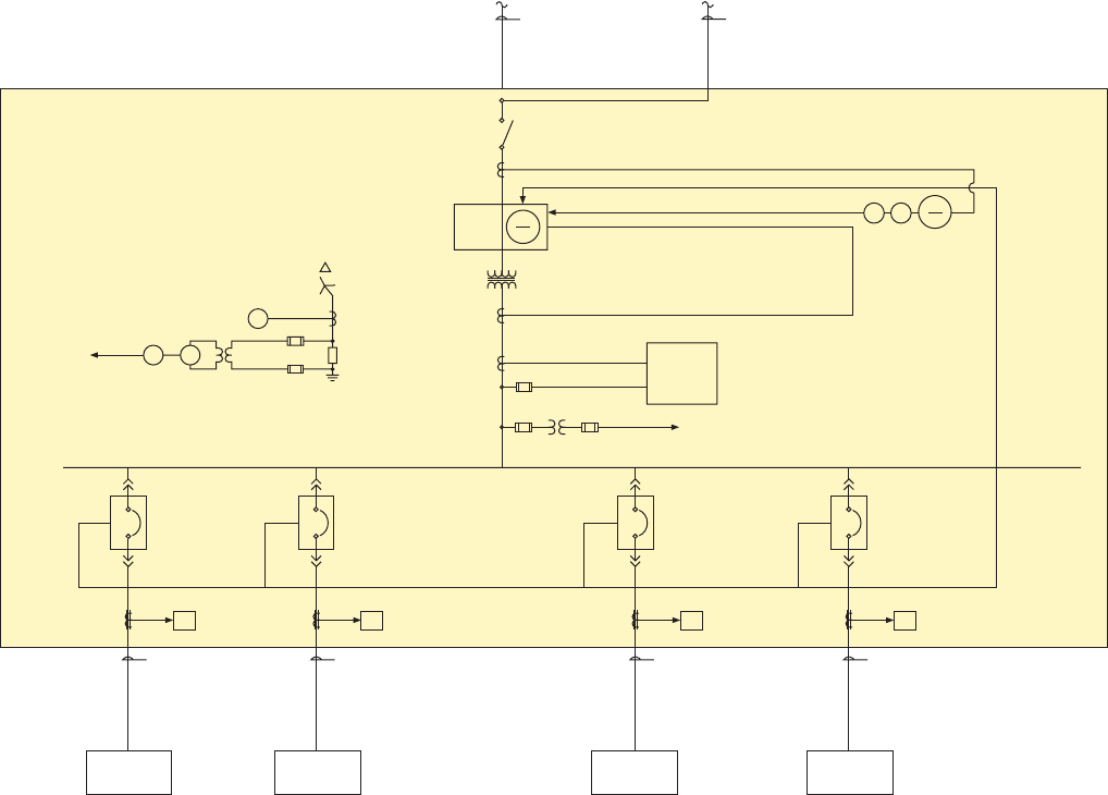
Diagram of substation using MSB with ZSI employed between the primary main breaker and the secondary feeder breakers
ST
59
Gȍ
AM
GSCT GSCT GSCT GSCT
2A
ZSI
LV MCC
DES-XXX
LV MCC
DES-XXX
LV MCC
DES-XXX
LV MCC
DES-XXX
AM
2B
4-3/C, #500 kcmil
600V, TC, XHHW-2,
with Ground
Cable Tray
100 Feet
4-3/C, #500 kcmil
600V, TC, XHHW-2,
with Ground
Cable Tray
100 Feet
4-3/C, #500 kcmil
600V, TC, XHHW-2,
with Ground
Cable Tray
100 Feet
4-3/C, #500 kcmil
600V, TC, XHHW-2,
with Ground
Cable Tray
100 Feet
AM
2C
AM
2D
ZSI
3-100:5 CT
From
15 kV Switchgear
To
Substation
Note: 50/51 Integral Trip Includes Arms DT-3000 or
EDR-3000
3-3150:1 Current Sensors
3-3200:5 CT
1-3/C, #4/0 AWG
15 kV, EPR, MV-105,
133%, Tape Shield
Cable Tray
Eaton MSB
Fused Load-Breaker
Switch with VCP-TR
Vacuum Breaker 50
51
600A, 15 kV, 40 kA, Asymmetrical Interrupting
2000/3000 kVA-12,470-480Y/277V
AA/FA (Cast Coil)
Z = 5.77%
50
51
86
Power
Metering
CPT
5 kVA
To
Transformer Fans
480V, 3200A Cu. Bus, 3-Phase, 3-Wire, 60 Hz, Isc. = 100 kA
High Resistance Grounding
Alarm 86
G
AM
0–5A
FU1.0A
FU1.0A
(1) VT
(2.5:1)
10:10
250
LV Substation
Substation One-Line
Preferred Primary Protection
1-3/C, #4/0 AWG
15 kV, EPR, MV-105,
133%, Tape Shield
Cable Tray
MV
VCB
L,S,I
600AF
800AT
LV
PCB
L,S,I
800AF
800AT
ZSI
LV
PCB
L,S,I
800AF
800AT
ZSI
LV
PCB
L,S,I
800AF
800AT
ZSI
LV
PCB
L,S,I
800AF
800AT
Product offering
• Rated maximum voltage:
4.76 to 15 kV
• Rated voltage withstand (BIL):
4.76 kV Class—60 kV peak;
15 kV Class—95 kV peak
• Assembly main bus
continuous current: 1200A
• Non-fused and fused switch:
refer to type MVS load
interrupter switchgear
• Fuse types: current limiting
(CLE), expulsion (RBA)
• Breaker types: VCP-TR, VCP-
TRL vacuum breakers, fixed
Available confi gurations
• Main with feeders
• Maintenance tie breaker
with feeders
• Main-main with feeders
• Main-main automatic transfer
• Maintenance tie breaker
automatic transfer
• Main service disconnect
• Switching and protection of
transformers, feeder circuits
and capacitor banks
• Capacitor switching
Unique features
• Combination load-break
switch and medium voltage
vacuum circuit breaker
• Door-mounted DT-3000 50/51
overcurrent protection with
integral current transformers
• Integral 50/51 trip unit in
a VCP-T primary vacuum
breaker with special design
current sensors mounted at
the secondary bus. Special arc
flash reduction maintenance
setting to lower incident
energy while racking
secondary feeder breakers
• Capability for ZSI connection
across all Eaton trip units at
both primary and secondary
• Special design R-C snubber
network to ensure substation
transformer is protected from
switching transients
• Arcflash Reduction
Maintenance System mode
available to temporarily
reduce the clearing time for
the VCP-T breaker during
downstream maintenance
Standards
• IEEE C37.20.3
• IEEE C37.04
• IEEE C37.06
• IEEE C37.09
• CSA C22.2
Reduced arc flash hazard with MSB
Bus fault at 480V switchgear
• 10 kA secondary arcing fault
• At 13.8 kV = 348A primary fault
• 100E fuse clearing time = 160 seconds
• Using MSB with integral trip unit
with ZSI or in Arcflash Reduction
Maintenance System mode
clears fault in three cycles or less
(arcing energy down to Category 2
per NFPA 70E)
3
EATON CORPORATION MSB–enhanced substation primary and load interrupter switchgear
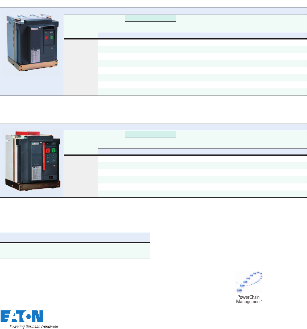
Available vacuum breaker ratings
VCP-TR Breaker Ratings for Use with MSB (ANSI C37.04 UL-Recognized Component)
Identification Rated Values
Circuit
Breaker
Type
Rated
Maximum
Voltage (V)
Insulation Level
Continuous
Current
Short
Circuit
Breaking
Current
Short
Circuit
Making
Current
Mechanical
Endurance
C-O Approx.
Weight
Power
Frequency Impulse
Withstand
kV rms kV rms kV Peak Amperes kA rms kA Peak Operations Lbs
50 VCP-TR16 4.76 19 60 600, 1200 16 42 10,000 157, 159
50 VCP-TR20 4.76 19 60 600, 1200 20 52 — 163, 165
150 VCP-TR25 4.76 19 60 600, 1200 25 65 10,000 169, 171
150 VCP-TR16 15 36 95 600, 1200 16 42 10,000 159, 161
50 VCP-TR20 15 19 95 600, 1200 20 52 10,000 165, 167
150 VCP-TR25 15 36 95 600, 1200 25 65 10,000 171, 173
50 VCP-TR20 4.76 19 60 600, 1200 40 104 10,000 334, 334
150 VCP-TR25 15 36 95 600, 1200 40 104 10,000 338, 338
Independent shunt trips are available for use with traditional protective relaying schemes.
Also two-second short time current rating.
VCP-TLR Breaker Ratings for Use with MSB (ANSI C37.04 and C37.09 UL-Recognized Components)
Identification Rated Values
Circuit
Breaker
Type
Rated
Maximum
Voltage (V)
Insulation Level
Continuous
Current
Short
Circuit
Breaking
Current
Short
Circuit
Making
Current
Mechanical
Endurance
C-O Approx.
Weight
Power
Frequency Impulse
Withstand
kV rms kV rms kV Peak Amperes kA rms kA Peak Operations Lbs
50 VCP-TR16 4.76 19 60 600, 1200 16 42 100,000 153, 155
50 VCP-TR20 4.76 19 60 600, 1200 20 52 — 159, 161
150 VCP-TR25 4.76 19 60 600, 1200 25 65 100,000 166, 168
150 VCP-TR16 15 36 95 600, 1200 16 42 100,000 156, 157
50 VCP-TR20 15 36 95 600, 1200 20 52 100,000 161, 163
150 VCP-TR25 15 36 95 600, 1200 25 65 100,000 168, 170
Independent shunt trips are available for use with traditional protective relaying schemes.
Also two-second short time current rating.
Operating mechanism up to 100,000 operations, vacuum interrupter 30,000.
Optional VCP-TRL Breakers with Capacitors Switching Capabilities
Circuit Breaker
Type Single
Bank Back-to-
Back Cable
Charging
Optional “C” type versions
available in rating shown
in above rating table
250A
and
1000A
250A
and
630A
25A
Enhanced circuit breaker
protection
With the addition of VCP-TR/
VCP-TRL vacuum circuit
breakers, MSB is able to provide
enhanced system capabilities
as follows:
• VCP-TRL breakers use a linear
actuator mechanism that is
capable of enduring 100,000
operations
• High interrupting capacity suit-
able for use with ground fault
equipment and differential
relay schemes
• Adjustable overcurrent
protection
• Three-phase tripping,
eliminating single phasing
• Eaton’s integrally mounted
self-powered 520MCV,
1150V trip units and FP-5000
protective relay offer
Arcflash Reduction
Maintenance System
Eaton Corporation
Electrical Sector
1111 Superior Ave.
Cleveland, OH 44114
United States
877-ETN-CARE (877-386-2273)
Eaton.com
© 2010 Eaton Corporation
All Rights Reserved
Printed in USA
Publication No. PA02100001E / Z9564
February 2010
PowerChain Management is a registered
trademark of Eaton Corporation.
All other trademarks are property of their
respective owners.
