Arkansas_3 2011_ 476547 Catalog 1
2014-07-05
: Pdf 476547-Catalog 1 476547-Catalog_1 784572 Batch5 unilog
Open the PDF directly: View PDF ![]() .
.
Page Count: 36
Meter Mounting Equipment
Arkansas, W. Tennessee,
N. Mississippi Market

2
2
MILBANK OVERVIEW
MILBANK OVERVIEW
Milbank: Quality Metering Products for 80+Years
ilbank Manufacturing
Company was estab-
lished in 1927 by
Charles A. Milbank. Originally,
the company manufactured high
voltage switches; however, by
1941 Milbank devoted itself pri-
marily to the manufacture of
sheet metal enclosures and relat-
ed equipment for the electrical
generation and distribution indus-
try. Today we are an industry
leader in the manufacture of elec-
trical meter sockets. Through a
national network of manufactur-
er’s representatives we provide
wholesale electrical distributors
with quality electrical products
for the utility, contractor, industri-
al and OEM markets.
As the meter standards have
changed, Milbank has been suc-
cessful in adapting its product
line to these changes. Our full
scale engineering department
designs products to meet cus-
tomer specifications and satisfy
all utility requirements.
Milbank’s employee base of over
1,000 workers, along with our
five manufacturing facilities com-
prising almost 550,000 square
feet give us the flexibility to
schedule, produce, and ship
orders quickly. Currently,
Milbank manufactures over
10,000 different catalog items,
and this list continues to grow.
Our unique product offering
includes: Residential &
Commercial Meter Sockets;
Residential & Commercial Meter
Pedestals; RV/MH Power Outlets,
Service Pedestals, and
Transformers; Commercial &
Industrial Electrical Enclosures;
Circuit Breakers; Disconnects &
Safety Switches; Safety Sockets;
Utility & Residential Secondary
Pedestals; Hubs, and related
accessories. If you don’t find a
unit in this catalog to service your
needs, send us your specifications
and we will be happy to work
with you.
Our success has come from a
loyal customer base that can rely
on us to build quality products at
a fair price in a timely manner.
Our willingness and ability to
design and produce new products
to meet our customer demands is
an important factor to remain
competitive in today’s electrical
market.
Milbank has been serving the
electric utility & wholesale distri-
bution industries for more than
80 years with innovative, qual-
ity engineered products. So
remember us for all of your meter
mounting and related require-
ments, and we will be happy to
serve you as we have in the
past–with dependable service and
quality products!
We take great pride in being
one of the few family-owned
businesses left in our industry.
We are a third generation run
business and truly believe that...
FAMILY MAKES A
DIFFERENCE!
M
Charles A. Milbank
1879-1966 Bill Martin
1916-1998
Robert F. Waldrop
1922-2002 Robert F. Waldrop, II
Chairman
Katrina Waldrop Henke
Vice Chairman

3
TABLE OF CONTENTS
TABLE OF CONTENTS
CATALOG NUMBER LOGIC . . . . . . . . . . . . . . . . . . . . . . . . . . . . . . . . . . . . . . . . . . . . . . . . . . . . . . . . . . . . . . . . . . . . . . . . . . . 4
DISCONNECTS (30-200 AMP)
30 & 60 AMP FUSIBLE/NON-FUSIBLE AC DISCONNECTS . . . . . . . . . . . . . . . . . . . . . . . . . . . . . . . . . . . . . . . . . . . . . . 5
AC DISCONNECT WITH GFCI PROTECTION / SPA BOX . . . . . . . . . . . . . . . . . . . . . . . . . . . . . . . . . . . . . . . . . . . . . . . . 6
SINGLE POSITION
125 & 200 AMP–4 TERMINAL–RINGLESS–600 VAC . . . . . . . . . . . . . . . . . . . . . . . . . . . . . . . . . . . . . . . . . . . . . . . . . . . . 7
200 AMP–5 & 7 TERMINAL–HEAVY DUTY LEVER BYPASS–RINGLESS–600 VAC . . . . . . . . . . . . . . . . . . . . . . . . . . . 8
320 AMP–4 & 5 TERMINAL–HEAVY DUTY LEVER BYPASS–RINGLESS–600 VAC . . . . . . . . . . . . . . . . . . . . . . . . . . . 9
320 AMP–7 TERMINAL–HEAVY DUTY LEVER BYPASS–RINGLESS–600 VAC . . . . . . . . . . . . . . . . . . . . . . . . . . . . . 10
METER MAINS
100 & 200 AMP–4 TERMINAL–RINGLESS METER MAIN . . . . . . . . . . . . . . . . . . . . . . . . . . . . . . . . . . . . . . . . . . . . . . . 11
200 AMP–4 TERMINAL–METER MAIN W/BREAKERS–RINGLESS . . . . . . . . . . . . . . . . . . . . . . . . . . . . . . . . . . . . . . . 12
200 AMP–7 TERMINAL–METER MAIN–RINGLESS . . . . . . . . . . . . . . . . . . . . . . . . . . . . . . . . . . . . . . . . . . . . . . . . . . . . 13
320 AMP–4 TERMINAL–RINGLESS–METER MAIN WITH SIDE WIREWAY . . . . . . . . . . . . . . . . . . . . . . . . . . . . . . . . . 14
400 AMP–320 CONTINUOUS–METER MAIN COMBINATION W/LOAD CENTER . . . . . . . . . . . . . . . . . . . . . . . . . . . . 15
MULTIPLE POSITION
100 & 200 AMP/POSITION–4 TERMINAL–HORIZONAL GANGS–RINGLESS . . . . . . . . . . . . . . . . . . . . . . . . . . . . . . . 16
125 & 200 AMP/POSITION–4 TERMINAL–CONDOMINIUM METERING BANKS . . . . . . . . . . . . . . . . . . . . . . . . . . 17-18
CONDOMINIUM METERING BANKS . . . . . . . . . . . . . . . . . . . . . . . . . . . . . . . . . . . . . . . . . . . . . . . . . . . . . . . . . . . . . 19-20
POWER OUTLETS & METERED PEDESTALS
100 AMP–4 TERMINAL–SERVICE POWER OUTLET . . . . . . . . . . . . . . . . . . . . . . . . . . . . . . . . . . . . . . . . . . . . . . . . 21-22
200 AMP–METERED PEDESTALS–RINGLESS . . . . . . . . . . . . . . . . . . . . . . . . . . . . . . . . . . . . . . . . . . . . . . . . . . . . . . . 23
MISCELLANEOUS
CT ENCLOSURES . . . . . . . . . . . . . . . . . . . . . . . . . . . . . . . . . . . . . . . . . . . . . . . . . . . . . . . . . . . . . . . . . . . . . . . . . . . . . . 24
COMMERCIAL METER PEDESTALS OVERVIEW, APPLICATIONS & ACCESSORIES . . . . . . . . . . . . . . . . . . . . . 25-26
UQFP PLUG-IN SERIES CIRCUIT BREAKERS . . . . . . . . . . . . . . . . . . . . . . . . . . . . . . . . . . . . . . . . . . . . . . . . . . . . . . . 27
ACCESSORIES . . . . . . . . . . . . . . . . . . . . . . . . . . . . . . . . . . . . . . . . . . . . . . . . . . . . . . . . . . . . . . . . . . . . . . . . . . . . . . 28-29
NEMA & UL RATINGS . . . . . . . . . . . . . . . . . . . . . . . . . . . . . . . . . . . . . . . . . . . . . . . . . . . . . . . . . . . . . . . . . . . . . . . . . . . 30
CONDUIT & AMPACITY INFORMATION . . . . . . . . . . . . . . . . . . . . . . . . . . . . . . . . . . . . . . . . . . . . . . . . . . . . . . . . . . . . . 32
ENERGIZATION OF ELECTRICAL EQUIPMENT . . . . . . . . . . . . . . . . . . . . . . . . . . . . . . . . . . . . . . . . . . . . . . . . . . . . . . 33
MATERIALS AND FINISHES . . . . . . . . . . . . . . . . . . . . . . . . . . . . . . . . . . . . . . . . . . . . . . . . . . . . . . . . . . . . . . . . . . . . . . 34
ADDITIONAL MILBANK PRODUCTS . . . . . . . . . . . . . . . . . . . . . . . . . . . . . . . . . . . . . . . . . . . . . . . . . . . . . . . . . . . . . . . 35
CATALOG INDEX . . . . . . . . . . . . . . . . . . . . . . . . . . . . . . . . . . . . . . . . . . . . . . . . . . . . . . . . . . . . . . . . . . . . . . . . . . . . . . . . . . . 31
3
4
4
CATALOG NUMBER LOGIC
CATALOG NUMBER LOGIC
5
Utility requirements for this equipment may vary. Always consult the serving utility for their requirements before ordering or
installing equipment in this catalog.
5
30 & 60 AMP–FUSIBLE / NON-FUSIBLE–AIR CONDITIONER DISCONNECTS
30 & 60 AMP–FUSIBLE / NON-FUSIBLE–AIR CONDITIONER DISCONNECTS
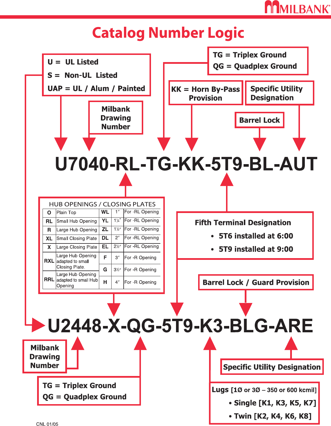
Milbankʼs air conditioner disconnect has a removable hinged cover which makes wiring a breeze.
Our compact design meets all wire bending space requirements in the NEC and, also, complies
with article 440-14 in the NEC. To insure the safest conditions, we designed our disconnect pullers
to be removable or they may be reinstalled in the off position. Another safety feature is the padlock
provision on the front cover. As with all Milbank products, our enclosure is constructed of G90U
galvanized steel and finished with an attractive, light gray, baked powder coating. Our state of the
art finish combines epoxy and polyester hybrid resins into a hybrid powder coating which is then
electrostatically applied. This offers a durable, nonfading finish.
TECHNICAL INFORMATION
TYPEAMP CATALOG
NUMBER
MAX
H.P.
WT.
@
#
30 FUSIBLE U3832 32.5
60 FUSIBLE U3860 10 3.3
LINE & LOAD
WIRE RANGE
GROUND
WIRE RANGE DIMENSIONS WIRE RATING
CU AL CU/AL
#14-#3
AWG #14-#3
AWG #14-3 AWG
#14-#3
AWG #14-#3
AWG #14-3 AWG
D" W" H" CU °CAL °C
2-1/8 5760°/75°60°
3 5 9-1/4 60°/75°60°/75°
60
NON FUSIBLE
U3802 10 3.25 #14-#2
AWG #12-#2
AWG #14-4 AWG 2-1/2 57-1/2 60°/75°60°/75°
60
NON AUTO
U3812 10 3.3 #14-#2
AWG #12-#2
AWG #14-4 AWG 2-1/2 57-1/2 60°/75°60°/75°
PROFILE
✓ UL Listed as Enclosed Pullout Switch
✓ 1∅, 240 VAC
✓ Type 3R Rainproof
✓ One-inch concentric knockouts
U3832
U3802
6
6
AC DISCONNECT / SPA BOX
AC DISCONNECT / SPA BOX
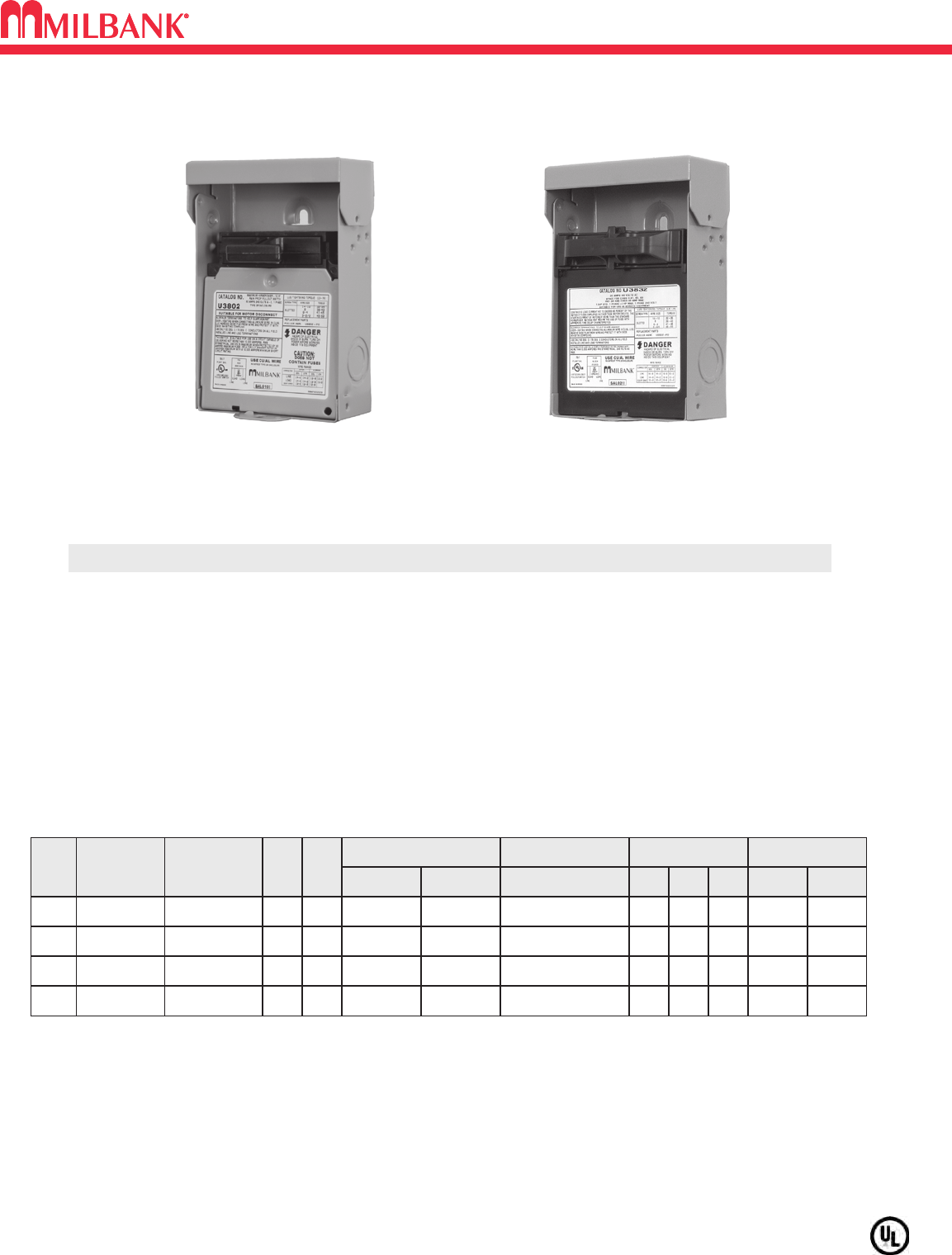
• Meets NEC #210.63 Requirements*
• UL Listed as Power Outlet
• Type 3R Enclosure
• In-Use Cover**
• Duplex Ground Connector
• 1” Concentric Knockouts
AC DISCONNECT
•1
∅
, 240 Volt
• 60 amp, Non-Fused
GFCI RECEPTACLE
• 20 amp
• Reset/Test Button
• Weather Resistant/Tamper Resistant
• Meets NEC #406.8 Requirements*
Combination AC Disconnect / 20 Amp GFCI Receptacle–Together in 1 Box
To ensure the safest conditions, Milbank disconnect pullers are designed to be reversible so they may be reinstalled in the OFF position.
All units are designed with a padlock provision on the cover for security.
**Note: U3822-20GWR cover rated as
IN-USE COVER
(Cover may be closed with cords plugged into receptacle).
Units supplied with WRTR receptacle.
*Reprinted with permission from NFPA 70-2002, National Electrical Code®, Copyright 2001, National Fire Protection Association, Quincy, MA 02269. This reprinted material is not the complete
and official position of the NFPA on the referenced subject, which is represented only by the standard in its entirety. National Electrical Code®and NEC®are registered trademarks of the
National Fire Protection Association, Quincy, MA.
* NEC®#210.63 Heating,
Air-Conditioning and
Refrigeration Equipment
Outlet.
...The receptacle shall be
located on the same level
and within 7.5 m (25 ft.) of
the heating, air-conditioning
and refrigeration equipment.
* NEC®#210.68 Ground-
Fault Circuit – Interruptor
protection for personnel.
* NEC®#406.8 receptacles
in damp or wet locations.
U4881-O-50GB
AMP TYPE CATALOG
NUMBER
WT.
@
#
–
BREAKER
PROVISION
U4881-O 7
LINE & LOAD CONNECTOR
WIRE RANGE
GROUND CONNECTOR
WIRE RANGE DIMENSIONS
CU AL CU/AL
#14-1/0 #14-1/0 #14-1/0
D″W″H″
3 3
⁄
471
⁄
281
⁄
2
50
60
BREAKER
BREAKER
U4881-O-50GB
U4881-O-60GB
8
8
#14-1/0
#14-1/0
#14-1/0
#14-1/0
#14-1/0
#14-1/0
3 3
⁄
4
3 3
⁄
4
71
⁄
2
71
⁄
2
81
⁄
2
81
⁄
2
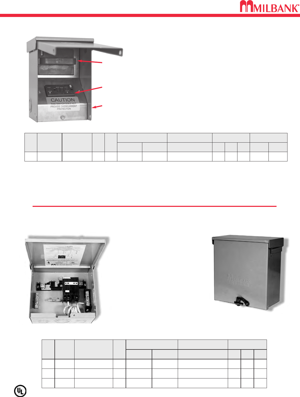
•
240 Volt ground fault protection
•
UL listed, Type 3R rainproof
•
Milbank reliability
•
Easy installation
•
2 pole, 50 amp GFCI breaker protection
•
Compact size:
8-1/2” H x 7-1/2” W x 3-3/4” D
•
3 or 4 wire installation
•
1
∅
, 120 / 240 VAC
•
Standard package of 12
•
2 extra one-pole breaker spaces
•
100 amp overall rating
Sub Panel Breaker Enclosure
•
Use as a 100 amp, 4 circuit sub pane enclosure
• U4881-O has provision for (2) 2-pole or
(4) 1-pole small frame breakers
Hot Tub Disconnect or Sub Panel Breaker Enclosure–Type 3R
Spa Box with GFCI Protection
U3822-20GWR
60 amp,
Non-Fused
AC Disconnect
Duplex 20 amp
GFCI Receptacle
WR-TR
Type 3R Enclosure
with In-Use Cover
AMP TYPE CATALOG
NUMBER
MAX
H.P.
WT.
@
#
60
NONFUSIBLE
U3822-20GWR
10 6
LINE & LOAD CONNECTOR
WIRE RANGE
GROUND CONNECTOR
WIRE RANGE DIMENSIONS WIRE RATING
CU AL CU/AL
#14-#2
AWG #12-#2
AWG #14-4 AWG
D″W″H″CU °CAL °C
4.8 5.25 7.4 60°/75°60°/75°
7
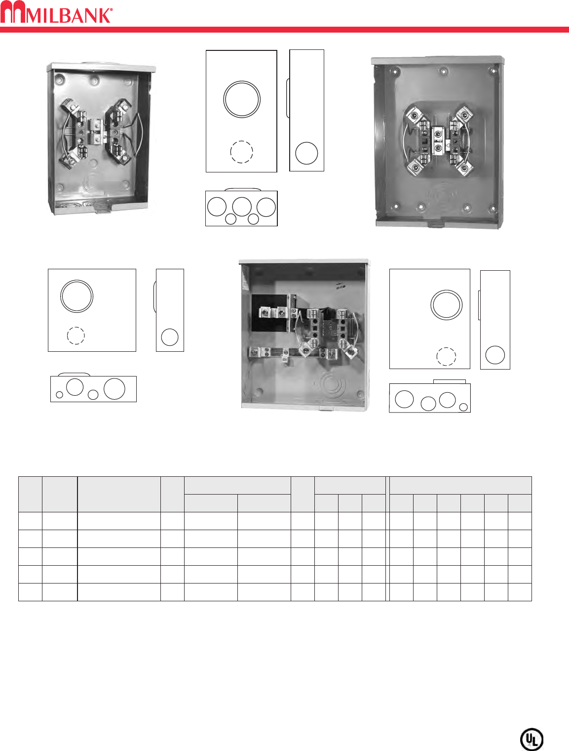
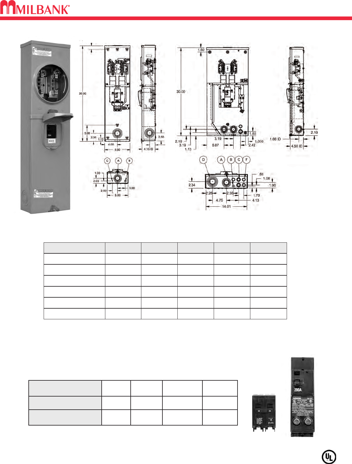
125 & 200 AMP–4 TERMINAL–RINGLESS–600 VAC
125 & 200 AMP–4 TERMINAL–RINGLESS–600 VAC
Utility requirements for this equipment may vary. Always consult the serving utility for their requirements before ordering or
installing equipment in this catalog.
HUBS: For proper hub selection see the hub suffix chart on the accessory page.
FIFTH TERMINAL: For field mounted fifth terminal, order catalog number K5T to fit into square opening at the 9 oʼclock
position of the new style block (#6-350 kcmil.) Order catalog number 5T8K2 to fit into round opening at the 9 oʼclock
position of the old style block (#2-350 kcmil.) Order catalog number 5T8K2 for U8435. For the U7040 & U1980-O, order
catalog number K5T.
CONNECTORS: Extruded aluminum connectors are tin plated. Units are supplied with triplex neutral.
AMP
125
SERVICE
CATALOG
NUMBER HUB
OH/UG U8435-RL-TG H.O.
CONNECTORS
CU/AL
LINE LOAD
BY-
PASS
NONE
DIMENSIONS CONCENTRIC K.O.ʼS
123456
11
⁄
211
⁄
2211
⁄
4–1
⁄
4
D″W″H″
35
⁄
16 8111
⁄
2
#6-2/0 #6-2/0
200 OH/UG U7040-RL-TG H.O. NONE 21
⁄
221
⁄
221
⁄
221
⁄
21
⁄
4,1
⁄
2
1
⁄
4
41
⁄
811 151
⁄
2
#6-350 kcmil #6-350 kcmil
200 OH U7021-RL-TG H.O. NONE 21
⁄
221
⁄
221
⁄
2–1
⁄
41
⁄
4,1
⁄
2
41
⁄
88151
⁄
2
#6-350 kcmil #6-350 kcmil
125 & 200 AMP–4 TERMINAL–RINGLESS
200 UG NONE 21
⁄
221
⁄
221
⁄
2311
⁄
21
⁄
4,1
⁄
2
41
⁄
213 151
⁄
4
#6-350 kcmil #6-350 kcmilU4413-O
200 UG NONE 21
⁄
221
⁄
2311
⁄
221
⁄
21
⁄
4,1
⁄
2
41
⁄
213 151
⁄
4
#6-350 kcmil #6-350 kcmilU1980-O
BLANK
BLANK
U8435-RL-TG
U7040-RL-TG
1
5
5
3
4
6
2
4
U1980-O
2
4
3
1
6
5
1980
8435
7040
7021
12
34
5
6
4413
7
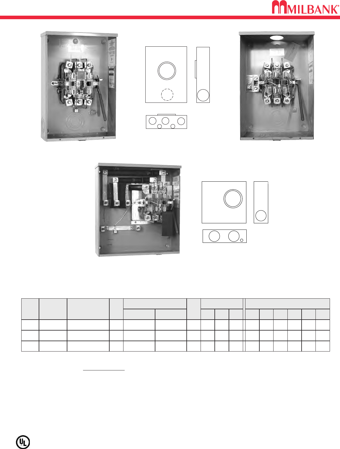
200 AMP–5 & 7 TERMINAL–HEAVY DUTY LEVER BYPASS–RINGLESS–600 VAC
8
200 AMP–5 & 7 TERMINAL–HEAVY DUTY LEVER BYPASS–RINGLESS–600 VAC
8
Utility requirements for this equipment may vary. Always consult the serving utility for their requirements before ordering or
installing equipment in this catalog.
12
56
3
44
U4581-RL-QG
U4184-X
U4701-RL-QG
TERM
5
SERVICE CATALOG
NUMBER
HUB
OH/UG U4581-RL-QG
H.O.
CONNECTORS
CU/AL
LINE LOAD
BY-
PASS
LEVER
DIMENSIONS CONCENTRIC K.O.ʼS
12345
321
⁄
23 3 1
⁄
4
D″W″H″
47
⁄
813 19
#6-350 kcmil #6-350 kcmil
7
OH/UG U4701-RL-QG
H.O.
LEVER
321
⁄
23 3 1
⁄
4
6
1
⁄
4,1
⁄
2
7
OH/UG U4184-X
C.P.
LEVER
4 4 1
⁄
4,1
⁄
2– –
618 191
⁄
4
#6-350 kcmil #6-350 kcmil
–
1
⁄
4,1
⁄
2
47
⁄
813 19
#6-350 kcmil #6-350 kcmil
200 AMP–5 & 7 TERMINAL–RINGLESS–600 VAC
CONNECTORS: Extruded aluminum connectors are tin plated.
The U4581 has a manual center disconnect on the neutral / center phase.
LEVER BYPASS: Lever supplies clamping action and operates bypass device.
BONDING LINK: U4581-RL-QG is factory bonded. Can be field isolated.
4581
4701
2
11
3
4184
1
5
5
3
4
6
2
4
9
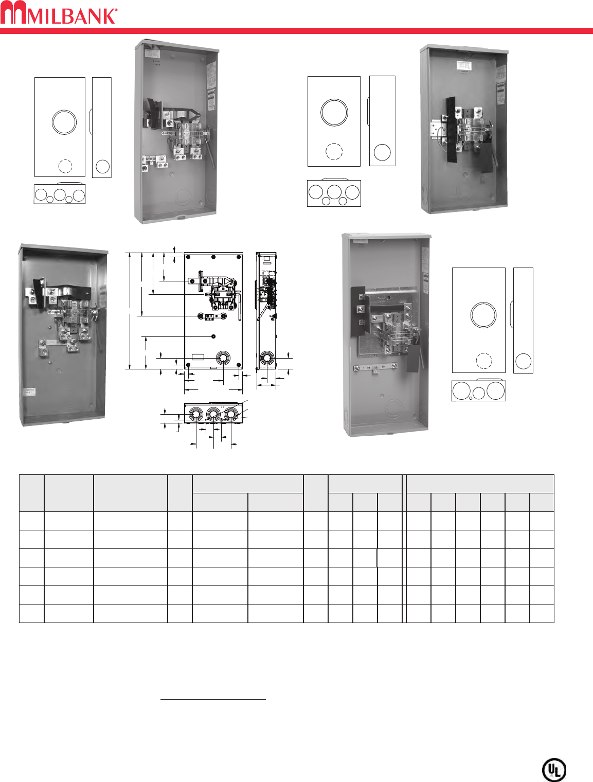
320 AMP–4 & 5 TERMINAL–HEAVY DUTY LEVER BYPASS–RINGLESS–600 VAC
320 AMP–4 & 5 TERMINAL–HEAVY DUTY LEVER BYPASS–RINGLESS–600 VAC
Utility requirements for this equipment may vary. Always consult the serving utility for their requirements before ordering or
installing equipment in this catalog.
5OH/UG U4505-X C.P.
LEVER
33331
⁄
41
⁄
4,1
⁄
2
47
⁄
815 281
⁄
4
3/8″-16
STUD 3/8″-16
STUD
5OH/UG U4419-X C.P.
LEVER
321
⁄
23 3 1
⁄
41
⁄
4,1
⁄
2
47
⁄
815 29
3/8″-16
STUD 3/8″-16
STUD
TERM
SERVICE CATALOG
NUMBER HUB
CONNECTORS
CU/AL
LINE LOAD
BY-
PASS
DIMENSIONS CONCENTRIC K.O.ʼS
123456D″W″H″
4OH/UG U4702-X C.P.
LEVER
33331
⁄
41
⁄
4,1
⁄
2
47
⁄
815 281
⁄
4
3/8″-16
STUD 3/8″-16
STUD
4OH/UG
U5161-X-K3L-K2L
C.P.
LEVER
3(1) 3 1
⁄
4,1
⁄
21
⁄
4– –
47
⁄
815 30
(1) #4-600 or
(2) 1/0-250 (2) #6-350
4UG
U1797-O-K3L-K2L
*C.P.
LEVER
33331
⁄
41
⁄
4,1
⁄
2
47
⁄
815 30
#4-600 or
(2) 1/20-250 TWIN
#6-350
4OH/UG U4905-X C.P.
LEVER
431
⁄
231
⁄
4,1
⁄
2– –
53
⁄
416 383
⁄
4
3/8″-16
STUD 3/8″-16
STUD
HUBS: For proper hub selection see the hub suffix chart on the accessory page.
LEVER BYPASS: Lever supplies clamping action and operates bypass device.
CONNECTORS: Stud type units supplied with 3/8″-16 hex head nuts with Belleville washers. For single lug connector kits,
order as extra K1539 (350 kcmil), K3082 (350 kcmil) or K3441 (600 kcmil). For twin lug connectors order as extra K1350
(350 kcmil) or K3442 (350 kcmil). Separate kits are required for both line and load.
DISCONNECT: The U4419 has a manual center disconnect on the neutral / center phase.
PHASES: The U4505 &U4419 are 1∅3W or 3∅3W, and the U4702 is 1∅3W.
FIFTH TERMINAL: For field installed fifth terminal order catalog no. K3865.
*SIDE WIREWAY
4419
4505
4702
320 AMP CONTINUOUS
400 AMP MAX
2
3
4
11
2
U4505-X
U4905-X
4905
U1797-O-K3L-K2L
30.00
15.00
O.D.
1.13
1.13
2.88
8.44
1.00 1.00
10.00
7.30
10.75
16.31
4.84
I.D.
2.88
2.22
4.50
4.50
2.03
2.00
.75
2.19
1/4
”
1/4
”,
1/2
”
3” (5)
320 AMP–4 & 5 TERMINAL–RINGLESS
1797
U5161-X-K3L-K2L
9
2
1
131
4
2
5161
UG U2120-X C.P.
LEVER
43441
⁄
41
⁄
2,3
⁄
4,1
61
⁄
2173
⁄
4313
⁄
4
3/8″-16
STUD 3/8″-16
STUD
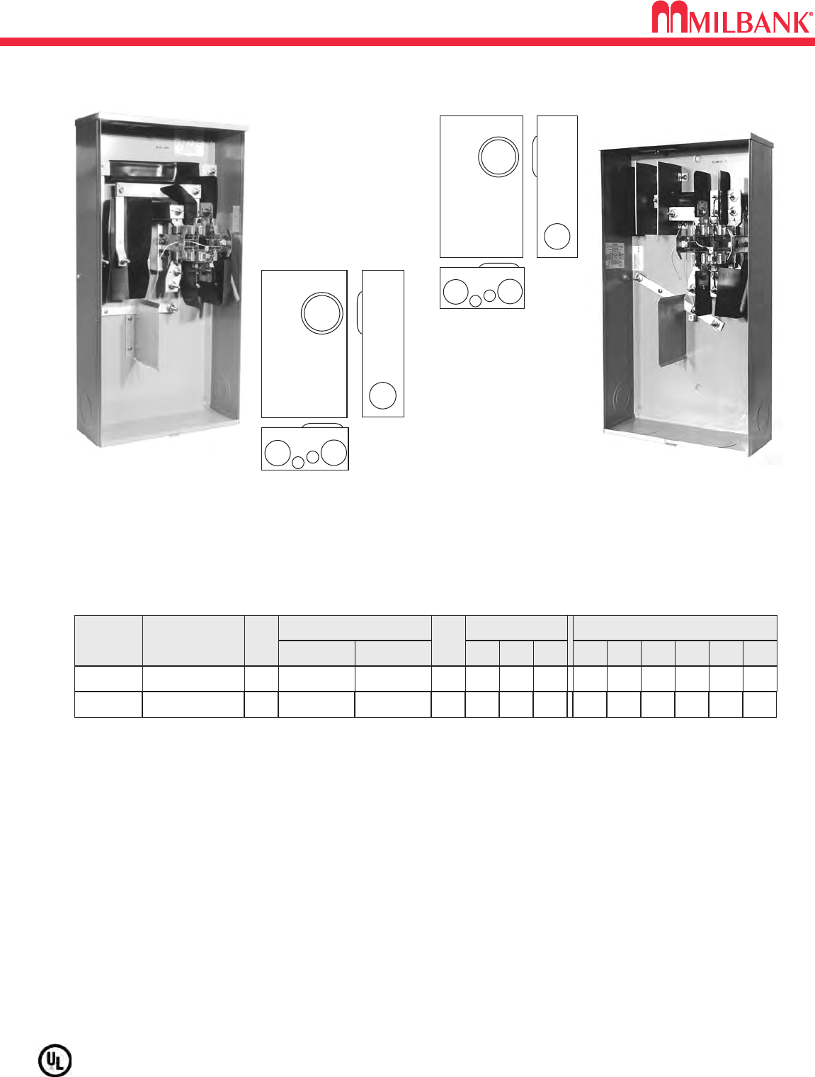
320 AMP–7 TERMINAL–HEAVY DUTY LEVER BYPASS–SIDE WIREWAY–RINGLESS–600 VAC
10
10
Utility requirements for this equipment may vary. Always consult the serving utility for their requirements before ordering or
installing equipment in this catalog.
2
34
5
6
2120
SERVICE CATALOG
NUMBER HUB
CONNECTORS
CU/AL
LINE LOAD
BY-
PASS
DIMENSIONS CONCENTRIC K.O.ʼS
123456D″W″H″
OH/UG U2594-X C.P.
LEVER
–3–4 1
⁄
4 61
⁄
219 341
⁄
8
3/8″-16
STUD 3/8″-16
STUD
320 AMP–7 TERMINAL–SIDE WIREWAY–RINGLESS–3∅4W
HUBS: For proper hub selection see the hub suffix chart on the accessory page.
LEVER BYPASS: Lever supplies clamping action and operates bypass device.
CONNECTORS: Stud type units supplied with 3/8″-16 hex head nuts with Belleville washers. For single lug connector kits,
order as extra: K3082 (350 kcmil) or K3441 (600 kcmil). For twin lug connectors order as extra: K3442 (350 kcmil).
Separate kits are required for both line and load.
U2594-X
2
34
5
6
2594
1⁄2,3⁄4, 1
U2120-X
320 AMP–7 TERMINAL–HEAVY DUTY LEVER BYPASS–SIDE WIREWAY–RINGLESS–600 VAC
Amperage 60 100 150 200
10KAIC Breaker Model Q260 Q2100 QN2150 QN2200
22KAIC Breaker Model Q260H Q2100H QN2150H QN2200H
11
U5842/44 RINGLESS METER MAINS–240V
U5842/44 RINGLESS METER MAINS–240V
U5842
U5842 Configuration U5844 Configuration
Utility requirements for this equipment may vary. Always consult the serving utility for their requirements before ordering or
installing equipment in this catalog.
11
MAIN CIRCUIT BREAKER CHART
AIC RATING: All models are rated 22K AIC when Siemens breakers are used.
HUB: OH/UG units supplied with one (1) closing plate packed inside.
FIFTH TERMINAL: For field installed 208Y/120 network service order K5T. Installs in the 9 oʼclock position.
*2 pole position.
CATALOG NUMBER AMP MAIN TERM SERVICE WT (#)
U5842-RL-100 100 100a 4 OH 26
U5842-RL-200 200 200a 4 OH 26
U5844-PXL 200 2p* 4OH/UG 37
U5844-PXL-100 100 100a 4OH/UG 37
U5844-PXL-150 150 150a 4OH/UG 37
U5844-PXL-200 200 200a 4OH/UG 37
RINGLESS METER MAIN MODELS
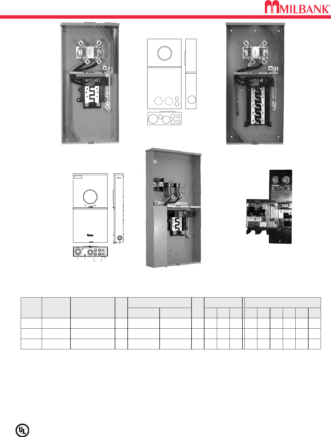
200 AMP–4 TERMINAL–RINGLESS–METER MAIN WITH BREAKERS–240V
12
200 AMP–4 TERMINAL–RINGLESS–METER MAIN WITH BREAKERS/BRKR. PROVISION–240V
12
Utility requirements for this equipment may vary. Always consult the serving utility for their requirements before ordering or
installing equipment in this catalog.
2
3
5
4
5
11
5
6
6
5
6
U5168-XTL-200
5168
5268
AVAIL.
CIRCUITS
SERVICE
CATALOG
NUMBER
HUB
CONNECTORS
LINE LOAD
BY-
PASS
DIMENSIONS
CONCENTRIC K.O.ʼS
1 2 3 4 5 6D″W″H″
HUB: Supplied with (2) closing plates packed inside. Order hubs as a separate item. See accessory page for hub options and
twin hub openings.
INTERIOR: U5168 and U5898 units have 8-circuit interior; U5268 units have 20-circuit interior.
FIFTH TERMINAL: Order K5T and field install for 208Y/120 network systems. Installs in the 9 oʼclock position only for
U5168 and U5268. In U5898, it can be rotated to 6 o'clock position..
BREAKERS: Rated 22K AIC with Milbank QNR2200H main installed.
INTERLOCK KIT: For generator auxiliary circuit breaker interlock, order K5815 for large QN with small frame Q; order K5820 for
large frame QN with large frame QN.
*SUB-FEED LUGS: #6-350 kcmil sub-feed lugs provided on 8-circuit interior. Order K3701 for 20-circuit interior.
8
OH/ UG
U5168-XTL-200
C.P.
NONE 2 2 3 21
⁄
21
⁄
2,3
⁄
4
41
⁄
2141
⁄
832
#6-350 kcmil #6-300 kcmil
Breaker*
1
⁄
2,3
⁄
4, 1
20
OH/ UG
U5268-XTL-200
C.P.
NONE 2 2 3 21
⁄
21
⁄
2,3
⁄
4
41
⁄
2141
⁄
832
#6-350 kcmil Breaker
1
⁄
2,3
⁄
4, 1
8
UG
U5898-O-200
C.P.
NONE 2 3 21
⁄
211
⁄
4,1
⁄
2
41
⁄
217 341
⁄
2
#6-350 kcmil #6-350 kcmil
1
⁄
2,3
⁄
4
200 AMP–4 TERMINAL–METER MAIN–22K AIC–120/240 VOLT–1Ø3W
K5815 – QN w/Q Interlock Kit
(shown installed)
for Standby Power Hookup
1
2345
6
5898
U5898-O-200
U5268-XTL-200
13
200 AMP–7 TERMINAL–METER MAIN–RINGLESS–240V
200 AMP–7 TERMINAL–METER MAIN–RINGLESS–240V
Utility requirements for this equipment may vary. Always consult the serving utility for their requirements before ordering or
installing equipment in this catalog.
13
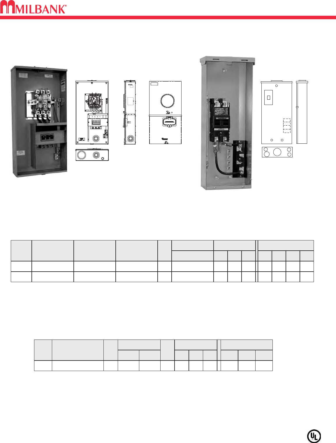
200 AMP MAIN POWER OUTLET–BRANCH PROVISIONS–1∅3W–10K AIC RATING
SERVICE
CATALOG
NUMBER
CONNECTORS
LINE
DIMENSIONS
CONCENTRIC K.O.ʼS
1 2 3 4D" W" H"
OH
USE-22-200-MB
BREAKERS
INSTALLED
UQFB-M-200
ADDITIONAL
CIRCUITS *
4-Branch 1 2 1
⁄
2,3
⁄
41
⁄
2,3
⁄
4
481
⁄
8225
⁄
8
2/0-300 kcmil2"
OH USE-AP-200-MB UQFB-M-200 4-Branch 1 2 1
⁄
2,3
⁄
41
⁄
2,3
⁄
4
5 8 26
#4-2502"
HUB
NOTE: The neutral bus/ground bar is factory installed.
USE-22-200-MB: 200 amp main with provisions for 200 AMP direct wire feeder. 200 amp bolt-on breaker wired in series with
plug-in style bus. Space for four single pole or two 2-pole plug-in, branch circuit breakers. One 2″hub included. Quadplex style
breakers may be used in accordance with the NEC.
12
3
4
4
USE-22-200-MB
USE-22
CATALOG
NUMBER
U5750-RXL-200-BL
HUB
C.P.
CONNECTOR
CU/AL
BY-
PASS
LEVER
DIMENSIONS
CONCENTRIC K.O.ʼS
1
11⁄4-3 3-4 1⁄2-2
2 3D"
53⁄4
W"
173⁄8
H"
34
LINE
#6-350
LOAD
C/B
AMPS
200
200 AMP–7 TERMINAL–METER MAIN–RINGLESS–3∅4W
HUBS: For proper hub selection see the hub suffix chart on the accessory page.
BYPASS: The lever supplies clamping action on the meter spade and also operates the bypass device.
BREAKER: Factory installed 200 amp, 3-pole, 10,000 AIC
U5750-RXL-200-BL
2
1
1
1
3
5750
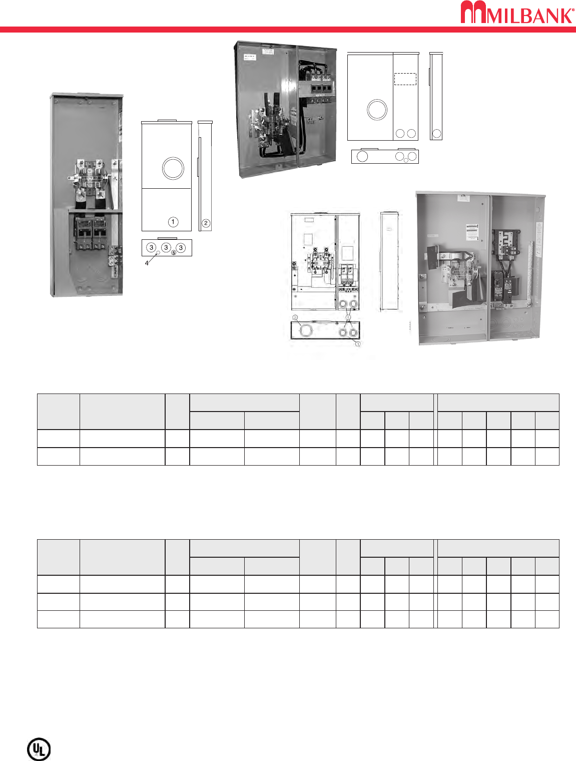
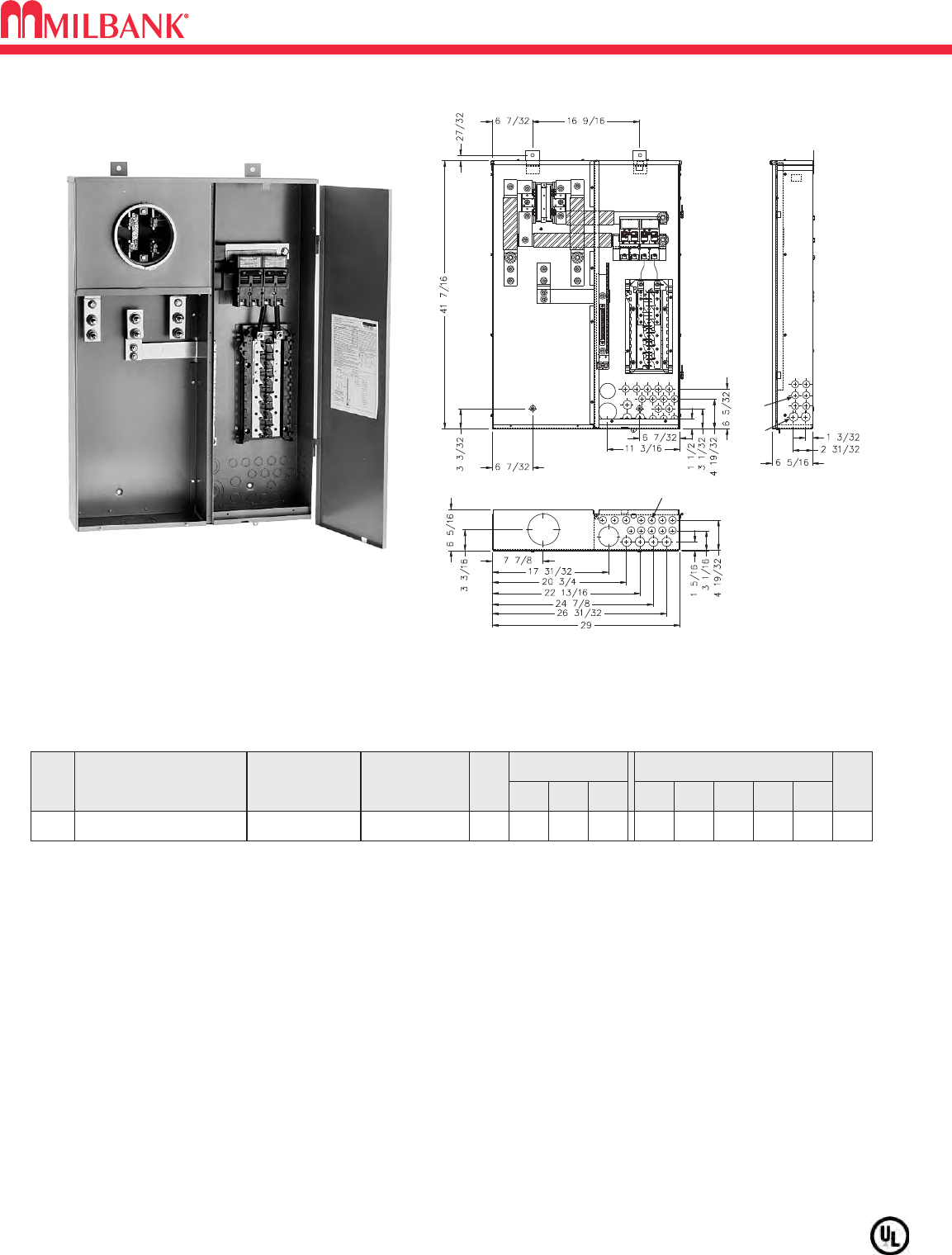
320 AMP–4 TERMINAL–RINGLESS–METER MAIN WITH SIDE WIREWAY–240V
14
320 AMP–4 TERMINAL–RINGLESS–METER MAIN WITH SIDE WIREWAY–240V
14
Utility requirements for this equipment may vary. Always consult the serving utility for their requirements before ordering or
installing equipment in this catalog.
SERVICE
CATALOG
NUMBER HUB
CONNECTORS
CU/AL
LINE LOAD
BY-
PASS
FIFTH
TERM.
KIT
DIMENSIONS CONCENTRIC K.O.ʼS
1 2 3 4 5D″W″H″
OH/UG C.P.
LEVER
3 3 4 3 1
⁄
4,1
⁄
2
53⁄4
25 30
3/8"-16
STUDS #1/0-300
KCMIL K3866
320 AMP METER MAIN WITH BREAKERS–SIDE WIREWAY–1Ø3W–RINGLESS–120/240 VAC
OH/UG C.P.
LEVER
3 3 3 1
⁄
41
⁄
4,1
⁄
2
47⁄8
15 42
#4-600
KCMIL #1/0-300
KCMIL K3866
U5059-X-2/200-K3L
5059
LEVER BYPASS: Lever supplies clamping action and operates bypass device.
CONNECTORS: Sockets are supplied with 3/8” - 16 hex head nuts with Belleville washers. For connector lug kits, order as
extra from chart on accessory page. Lug kit required for line side only.
*BREAKERS: Supplied with (2) bolt-in Milbank UQFBH-200 breakers. Rated at 22K AIC. Supplied with (2) plug-in Milbank
UQFPH-200 breakers.
U4835-X-2/200-BL
SERVICE
CATALOG
NUMBER HUB
CONNECTORS
CU/AL
LINE LOAD
BY-
PASS
FIFTH
TERM.
KIT
DIMENSIONS CONCENTRIC K.O.ʼS
1 2 3 4 5D″W″H″
OH/UG C.P.
LEVER
4
21⁄2
1
⁄
4–– ––
6241⁄2
35STUDS 1/0-300 K3865
OH/UG C.P.
LEVER
4
21⁄2
1
⁄
4–– ––
6291⁄2
35STUDS 1/0-300 K3865
U5892-X-2/200**¿
OH/UG C.P.
LEVER
4
21⁄2
1
⁄
4–– ––
6291⁄2
35STUDS 1/0-300 K3865
U5894-X-2/200-MLK*
¡
U5890-X-2/200
(U4031 AND U4835
PREWIRED WITH
MILBANK LARGE
FRAME BREAKERS)
U4835-X-2/200-BL
3
2
2
11
4 4
5
4835
U5059-X-2/200-K3L
5894
BREAKERS: U5890 installed with Milbank QN2200H breakers. U5894 and U5895 installed with left breaker QN2200H and
right breaker QN2200RH.
¿SUB-FEED LUGS: #6-350 kcmil sub-feed lugs provided on 8-circuit interior. Order K3701 for 20-circuit interior or
–MLK for factory installed.
¡SIDE WIREWAY
*12-circuit load center
**24-circuit load center
U5894-X-2/200-MLK
15
400 AMP–320 AMP CONTINUOUS–METER MAIN COMBINATION WITH LOAD CENTER–240V
Utility requirements for this equipment may vary. Always consult the serving utility for their requirements before ordering or
installing equipment in this catalog.
M400-UG-APS-LC
1
2
3
4
5
24
(32)
(9)
SPLIT MAIN W/ 24/40 CIRCUIT LOAD CENTER– 4 TERMINAL–1∅3W–TYPE 3R–RING TYPE–120/240 VAC
SERV CATALOG
NUMBER
PRIMARY
DISCONNECT
BY-
PASS
CONCENTRIC K.O.ʼS
12345
WT.
#
DIMENSIONS
D" W" H"
SECONDARY
DISCONNECT
UG M400-UG-APS-LC ¿200 Amp / 2 Pole
Circuit Breaker NONE 11
⁄
221
⁄
243
⁄
41110#
65
⁄
16 29 417
⁄
16
200 Amp / 2 Pole
Circuit Breaker
UL LISTING: UL listed Service Entrance Equipment File E42827.
NEUTRAL: Bonded neutral and ground factory Installed.
LINE SIDE CONNECTORS: Two 1/2" studs per phase on 1 3/4" centers.
SHORT CIRCUIT CURRENT WITHSTAND RATING: 10,000 AIC standard
22,000 AIC available. Consult factory.
¿BREAKERS: Two 200 Amp 2-pole main breakers factory installed, and semi-flush flange kit packed inside meter section.
Universal Copper 24 / 40 Circuit interior accepts Challenger, GE, Murrary, Siemens / ITE, and Cutler-Hammer / Westinghouse
universal type plug-in branch circuit breakers.
400 AMP–320 AMP CONTINUOUS–METER MAIN COMBINATION WITH LOAD CENTER–240V
15
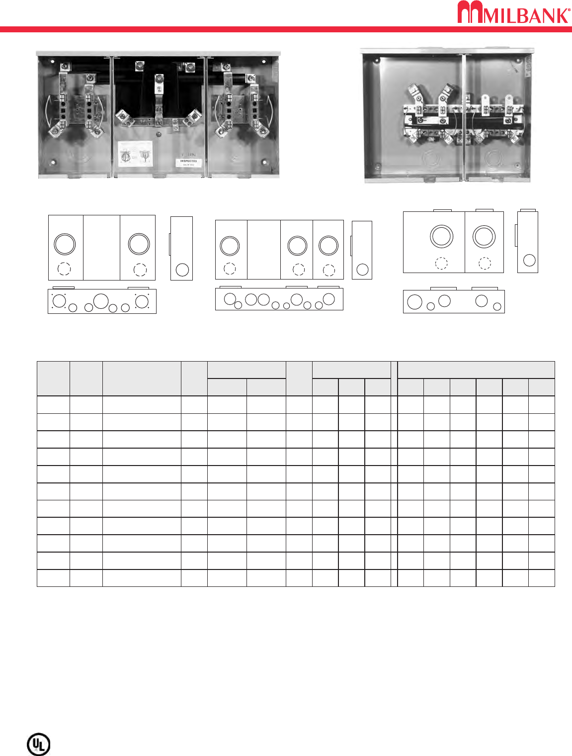
100 & 200 AMP–4 TERMINAL–HORIZONTAL GANGS–RINGLESS–300V
16
100 & 200 AMP–4 TERMINAL–HORIZONTAL GANGS–RINGLESS–300V
16
Utility requirements for this equipment may vary. Always consult the serving utility for their requirements before ordering or
installing equipment in this catalog.
100 & 200 AMP / POSITION–4 TERMINAL–RINGLESS–1∅3W–OH/UG*
NO.
OF
POS.
CATALOG
NUMBER HUB
CONNECTOR
CU/AL
BY-
PASS
DIMENSIONS CONCENTRIC K.O.ʼS
1 2 3 4 5 6D″W″H″LINE LOAD
AMPS
2100 U8212-RL H.O. NONE 2 2 2 21
⁄
2
1
⁄
4,1
⁄
2–
41
⁄
2205
⁄
16 16
#6-350
kcmil #6-2/0
2U1252-REL-K1 21
⁄
2NONE 21
⁄
2321
⁄
2
1
⁄
21
⁄
41
⁄
2,3
⁄
4,1
51
⁄
8261
⁄
214
3/8″-16
STUD
#6-350
kcmil
3U1253-X C.P. NONE 21
⁄
2321
⁄
2
1
⁄
21
⁄
41
⁄
4,1
⁄
2,1
51
⁄
8
3411⁄16
14
3/8″-16
STUD
#6-350
kcmil
4U1254-X C.P. NONE 21
⁄
2321
⁄
2
1
⁄
21
⁄
41
⁄
4,1
⁄
2,1
51
⁄
8427
⁄
816
3/8″-16
STUD
#6-350
kcmil
5U1255-X C.P. NONE 21
⁄
2321
⁄
2
1
⁄
21
⁄
41
⁄
4,1
⁄
2,1
51
⁄
8547
⁄
816
3/8″-16
STUD
#6-350
kcmil
6
200
200
200
200
200 U1256-X C.P. NONE 21
⁄
2321
⁄
2
1
⁄
21
⁄
41
⁄
4,1
⁄
2,1
51
⁄
8631
⁄
16 18
3/8″-16
STUD
#6-350
kcmil
3100 U8213-RL H.O. NONE 2 2 2 21
⁄
2
1
⁄
4,1
⁄
2–
41
⁄
2281
⁄
216
#6-350
kcmil #6-2/0
4100 U8214-RL H.O. NONE 2 2 2 21
⁄
2
1
⁄
4,1
⁄
2–
41
⁄
2
4011⁄16
16
#6-350
kcmil #6-2/0
5100 U8215-RL H.O. NONE 2 2 2 21
⁄
2
1
⁄
4,1
⁄
2–
41
⁄
2487
⁄
816
#6-350
kcmil #6-2/0
6100 U8216-XL C.P. NONE 2 2 2 21
⁄
2
1
⁄
4,1
⁄
2–
41
⁄
2571
⁄
16 16
#6-350
kcmil #6-2/0
111
2
33
56
4 4
111
2
35
6
44
1
33
4
2
1252-3 1254-6
HUB: For proper hub selection refer to the hub suffix chart on the accessory page. For the U1254-6 two hub openings are supplied and
the extra opening is closed with a closing plate as standard. For the U8212 a hub opening is supplied at each end and the extra opening
is closed with a closing plate as standard.
FIFTH TERMINAL: For field mounted fifth terminal for U8212-6, order 5T8K2 (6 oʼclock position). For field mounted fifth terminal for
U4252 & U1252-6, order catalog number K5T (9 oʼclock position).
CONNECTORS: Extruded aluminum connectors are tin plated.
BUSSING: Bussing is 5/16″ x 1″aluminum on the U1252-1253, U4252 and the U8212-6. On the U1254-6 gangs the bussing is 3/8″x 1″
aluminum.
NOTE: See chart on page 32 for gang socket overall ampacities.
U1252-R
3
3
455
2
11
8212-6
U8212-RL (4” side wireway / OH/UG service)
2U4252-RXL-K2 C.P. NONE 21
⁄
2321
⁄
2
1
⁄
21
⁄
41
51
⁄
8261
⁄
214
3/8″-16
STUD
#6-350
kcmil
200
17
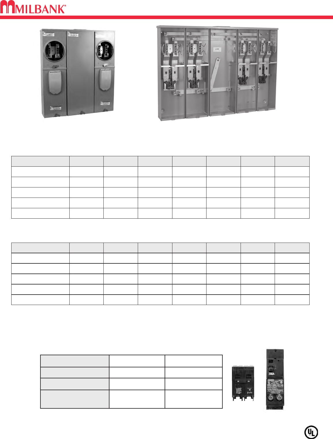
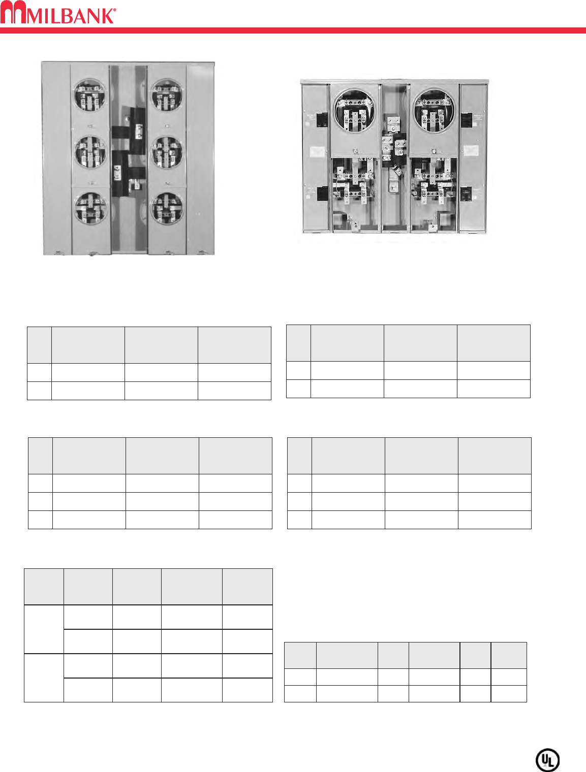
U5882–86 & U5902–06 CONDOMINIUM METERING BANKS
U5882–86 & U5902–06 CONDOMINIUM METERING BANKS
Utility requirements for this equipment may vary. Always consult the serving utility for their requirements before ordering or
installing equipment in this catalog.
17
CIRCUIT BREAKER CHART
Manufacturer 10K Models 22K Models
Siemens QP, QN QPH, QNH
Cutler-Hammer BR, HPQ, QPGF —
Square D Homeline —
G.E. (50 Amp Max.) THQL, THQL-GF —
U5882-X
CATALOG NUMBER AMP POSITIONS TERM SERVICE LINE LOAD WT (#)
U5902-X 100 2 4 OH/UG 1/0-350 #6-350 58
U5903-X 100 3 4 OH/UG 1/0-350 #6-350 88
U5904-X 100 4 4 OH/UG 1/0-350 #6-350 107
U5905-X 100 5 4 OH/UG 1/0-350 #6-350 128
U5906-X 100 6 4 OH/UG 1/0-350 #6-350 146
OPTIONAL: 200 Amp are available with 200 Amp breakers from factory.
AIC RATING: All models are rated 22K AIC.
HUB: Units supplied with one (1) closing plate. Order hubs separately, see accesory page.
FIFTH TERMINAL: For field installed 208Y/120 network service, order K5T. Installs in the 9 oʼclock position.
CONDOMINIUM METERING BANKS
125A / POSITION
CATALOG NUMBER AMP POSITIONS TERM SERVICE LINE LOAD WT (#)
U5882-X 200 2 4 OH/UG 1/0-350 #6-350 58
U5883-X 200 3 4 OH/UG 1/0-350 #6-350 88
U5884-X 200 4 4 OH/UG 1/0-350 #6-350 107
U5885-X 200 5 4 OH/UG 1/0-350 #6-350 128
U5886-X 200 6 4 OH/UG 1/0-350 #6-350 146
200A / POSITION
OPTIONAL: 100 Amp are available with 100 Amp breakers from factory.
U5884-X
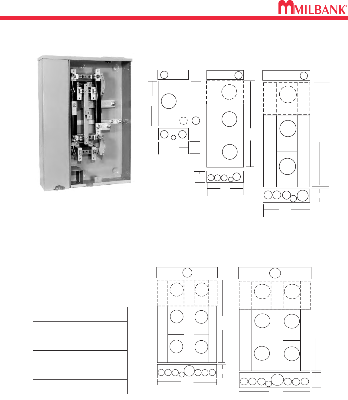
CONDOMINIUM METERING BANKS DIMENSIONAL INFORMATION
18
CONDOMINIUM METERING BANKS DIMENSIONAL INFORMATION
18
30"
26.5"
13
44
522
22
5882
5902
5.125"
34.56"
30"
1
2322 1
5883
5903
5.125"
30"
42.81" 5.125"
5884
5904
1312222
30"
51.06"
5.125"
11
222 22
3
5885
5905
11
222 222
3
30"
59.31"
5.125"
5886
5906
Condominium Metering Banks
Dimensional Information
3
KNOCKOUTS
21
21⁄27⁄81⁄41
345
CONDOMINIUM METERING BANKS
Dimensional Information
30" 30"
30"
30"
30"
5.125"
26.5"
34.56"
42.81" 51.06"
59.31"
5.125" 5.125"
5.125"
5.125"
5882
5902
5883
5903
5884
5904 5885
5905
5886
5906
19
CONDOMINIUM METERING BANKS–240V
CONDOMINIUM METERING BANKS–240V
Utility requirements for this equipment may vary. Always consult the serving utility for their requirements before ordering or
installing equipment in this catalog.
19
CATALOG
NUMBER
NO.
OF
POS.
MAIN BUS
RATING
LINE
CONNECTOR
SIZE
CATALOG
NUMBER
NO.
OF
POS.
MAIN BUS
RATING
LINE
CONNECTOR
SIZE
2
3
U2852-X 200 AMP
U2853-X 200 AMP
*3/8″-16 STUD
*3/8″-16 STUD
2
3
U2862-X 250 AMP
U2863-X 300 AMP
*3/8″-16 STUD
*3/8″-16 STUD
125 AMP/POSITION 200 AMP/POSITION
U2854-X
(Order circuit breakers as extra)
U2866-X
CATALOG
NUMBER
NO.
OF
POS.
4
5
6
MAIN BUS
RATING
LINE
CONNECTOR
SIZE
U2854-X 400 AMP
U2855-X ①400 AMP
U2856-X ①400 AMP
*3/8″-16 STUD
*3/8″-16 STUD
*3/8″-16 STUD
CATALOG
NUMBER
NO.
OF
POS.
4
5
6
MAIN BUS
RATING
LINE
CONNECTOR
SIZE
U2864-X 400 AMP
U2865-X 600 AMP
U2866-X 600 AMP
*3/8″-16 STUD
*3/8″-16 STUD
*3/8″-16 STUD
SIZE SUFFIX
SINGLE
TWIN
K1539-K1
-K3
-K2
-K4
K1540
K1350
K1541
U2852-56
U2862-66
U2854-56
U2864-66
U2854-56
U2863-66
U2864-66
#6-350
kcmil
#4-600
kcmil
#6-350
kcmil
#2-600
kcmil
KIT
NUMBER
COMPATIBLE
WITH
WIRE
RANGE
*CONNECTORS: For line wire connector kits, order separately.
FIFTH TERMINALS: For field mounted fifth terminal order catalog
number K2381. Order one per meter position (9 oʼclock position
only).
BREAKERS: Units have provision for one double pole main per
meter position. Breakers not included. Order as extra Milbank.
①NOT STOCKED
125 AMP/POSITION 200 AMP/POSITION
CONNECTOR KITS *
VERTICAL
RECTANGULAR
PLUG-IN BREAKER COMPATIBILITY CHART
AMPS
CUTLER-HAMMER
(WESTINGHOUSE)
SIEMENS
(ITE)
SIEMENS
MURRAY /
CROUSE-HINDS
G.E.
SQ-D
125-200
HQP / BR / WBJ
–
MD
Q LINE
–
≤ 100
QP / BR / HQP
QP
MP
Q LINE
HOMELINE
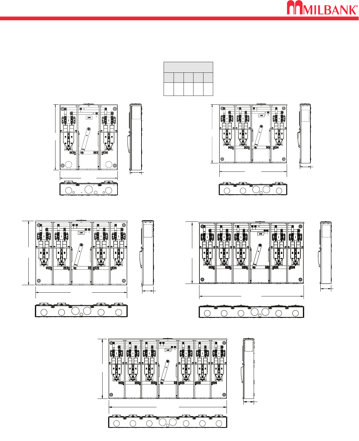
CONDOMINIUM METERING BANKS–240V
20
CONDOMINIUM METERING BANKS–240V
20
AA
C
B
E
E
E
B
CC
DDD
B
EE E C
29" or
41"
5 13/16"
13"
or
18"
21"
25" or
37"
5 13/16"
18"
21"
5 13/16"
C
B
D
A
C
B
D
EE E EEE
AAA A
A
29" or
41"
4 7/8"
36"
37" or
25"
4 7/8"
31"
VERTICAL
RECTANGULAR
125 &200 amp/pos.
(single position)
125 amp/pos.
(2-3 position)
200 amp/pos.
(2-3 position)
125 amp/pos.
(4, 5 & 6 position)
200 amp/pos.
(4, 5 & 6 position)
CONDOMINIUM
METERING BANKS
U2852-X
FIG.
A
B
C
D
E
DIMENSIONS
11
⁄
4″CONCENTRIC K.O.
1
⁄
4,1
⁄
2″CONCENTRIC K.O.
3″CONCENTRIC K.O.
4″HUB OPENING
2″CONCENTRIC K.O.
21
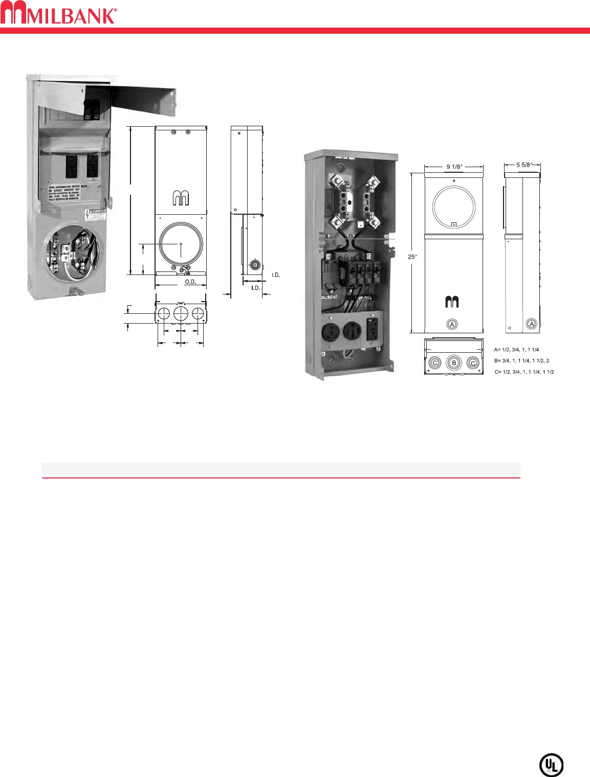
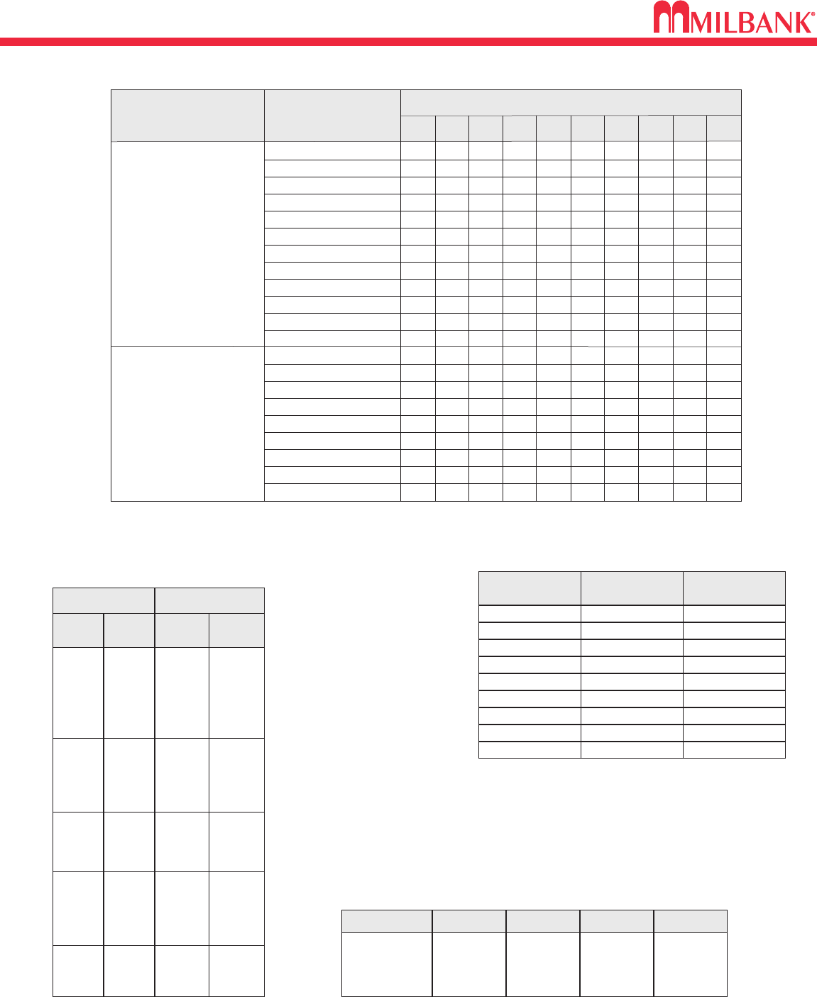
100 AMP–4 TERMINAL–SERVICE POWER OUTLET–240V
Utility requirements for this equipment may vary. Always consult the serving utility for their requirements before ordering or
installing equipment in this catalog.
21
U5100-XL-75
Loop feed not available.
SPECIFICATIONS
●Available in ringless style (U4908 series) or ring type (U4909 series).
●UL Listed 100 Amp, 120/240 Volt – 1∅Underground Service Power Outlet. (U4908-UG and U5101-OH)
● Type 3R welded enclosure for durable outdoor use.
● Hub opening with closure plate. (U5101)
● Wire terminations accept copper or aluminum conductors. (U4908)
Service–Line & Neutral: (1) #6-2/0 Load Ground: (2) 1/0-#14 & (4) #6-#14
Load Neutral: (2) 1/0-#14 & (4) #6-#14 Service Ground: #2-#8
● Wire terminations accept copper or aluminum conductors. Loop feed not available. (U5101)
Line: (1) #6-250 kcmil Ground: (2) 1/0-#14 & (4) #6-#14 Neutral: (2) 1/0-#14 & (4) #6-#14
●Four terminal, ringless meter socket with stainless steel locking hasp.
MILBANK
MILBANK
25 15/16
5 3/8
9”
1 5/8
4
4
33
5 1/4
3 5/16
C
L
U4908-O-11GR 4908
5100
TEMP POWER
100 AMP–4 TERMINAL–SERVICE POWER OUTLET–240V
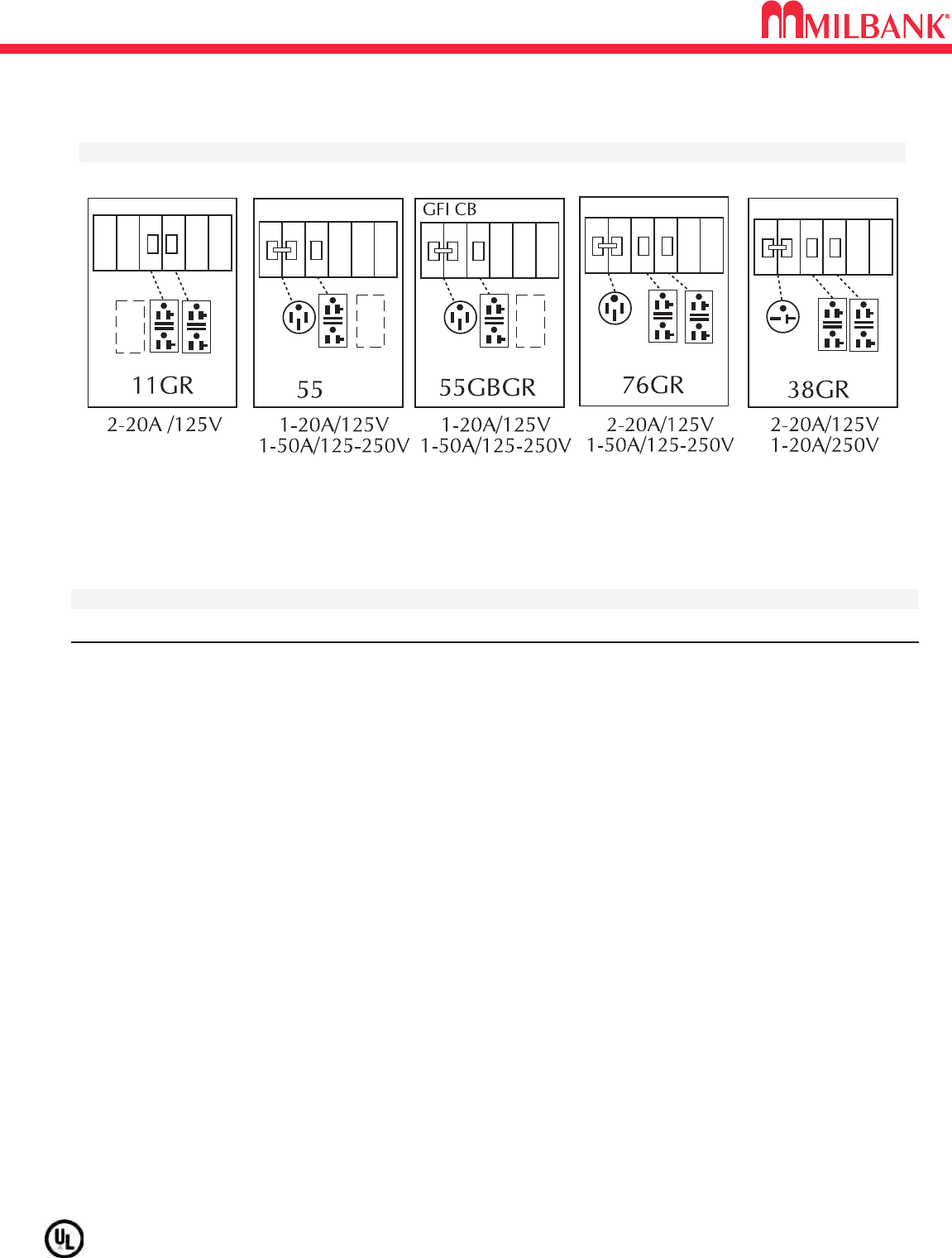
SERIES U4908 & U4909 STANDARD CONFIGURATIONS
22
SERIES U4908 & U4909 STANDARD CONFIGURATIONS
22
Utility requirements for this equipment may vary. Always consult the serving utility for their requirements before ordering or
installing equipment in this catalog.
ORDERING INFORMATION
CATALOG # SOCKET TYPE DESCRIPTION
U4908-O-(*)
Ringless (*) Add suffix from above chart to complete catalog number (ie: U4908-O-11GR)
U5101-XL-(*)
Ringless (*) Add suffix from above chart to complete catalog number (ie: U5101-XL-11GR)
* Cover may not close completely while in use with Twist-Locking devices.
Available without meter and available as ring type.
Other configurations available, consult factory.
U5100 & U5101 STANDARD CONFIGURATIONS
23
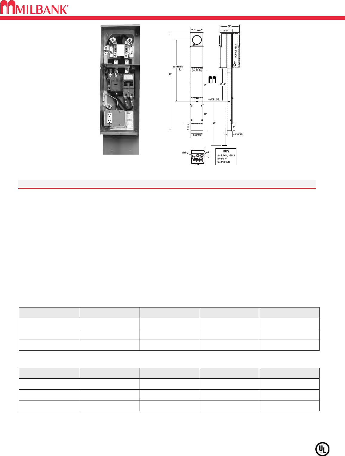
U5136 & U5137–RINGLESS–METERED PEDESTALS
U5136 & U5137–RINGLESS–METERED PEDESTALS
Utility requirements for this equipment may vary. Always consult the serving utility for their requirements before ordering or
installing equipment in this catalog.
23
SPECIFICATIONS
• 200 amp maximum, 120/240 volt, single phase, three wire meter socket
• Ringless meter socket with horn bypass and stainless steel latch
• Short circuit withstand rating 22K AIC.
• Wire terminations accept copper or aluminum conductors
• Line & Neutral: (2) #6-350 kcmil per phase
• Line Ground: (4) #14-1/0
• Load (CB): 2/0 to 300 kcmil per pole
• Load Neutral: (1) #6-350 kcmil
• Load Ground: (2) #14-1/0, (4) #14/6
• Milbank plug-in main circuit breaker. Available in 100, 125, 150 & 200 amp. Type UQFPH-M.
• Four-circuit plated copper interior accepts (2) 2-pole or (4) 1-pole standard plug-in type circuit breakers up
to a total of 125 amps maximum. Acceptable manufacturers: Cutler-Hammer, GE or Siemens
• Factory installed receptacle bridge and receptacle / circuit breakers.
U5136-0-200S-10GR
with series wired main
K5415 Stabilizer Foot sold separately. Pad mount pedestals require K5035 pad mount kit. Order separately.
Pad mount available.
CATALOG NUMBER MAIN BREAKER MAIN CB BRANCH WT (#)
U5136-0-100S UQFPH-M-100 100 4 Circuit 82
U5136-0-200S UQFPH-M-200 200 4 Circuit 82
U5136-0 (parallel wired) provision for
UQFPH-M Series ––– 4 Circuit 80
SINGLE PEDESTAL (DIRECT BURIAL)
CATALOG NUMBER MAIN BREAKER MAIN CB BRANCH WT (#)
U5137-0-100S (2) UQFPH-M-100 100 4 Circuit 115
U5137-0-200S (2) UQFPH-M-200 200 4 Circuit 115
U5137-0 (parallel wired)
provision for
(2) UQFPH-M Series
––– 4 Circuit 111
DOUBLE PEDESTAL (DIRECT BURIAL)
CT ENCLOSURES
24
CT ENCLOSURES
24
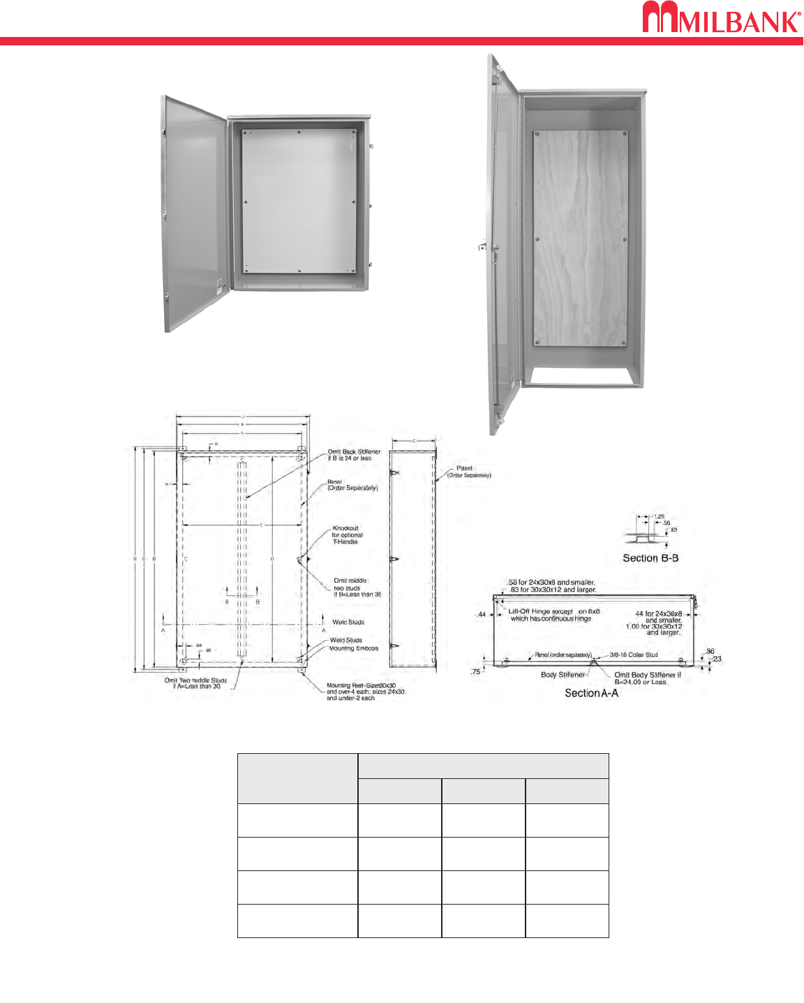
OUTDOOR TRANSFORMER CABINETS–NEMA 3R
CATALOG
NUMBER
DIMENSIONS
D″W″H″
403214-TC3R-SP1
14 40 32
543214-TC3R-SP1
14 54 32
307220-TC3R-WB*
20 30 72
363616-CT3R-WB*
16 36 36
*Wood backboard factory installed.
Bottom panel kit available for 307220-TC3R-WB, order A-3020-BTMKIT.
403214-TC3R-SP1
307220-TC3R-WB
25
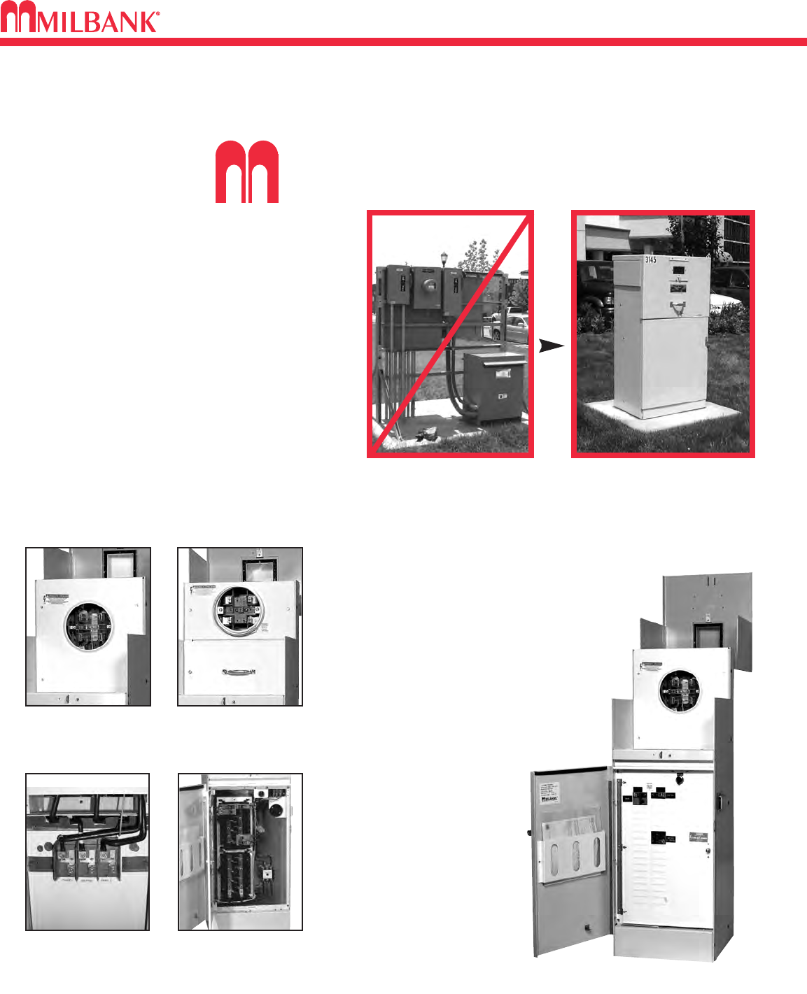
COMMERCIAL METER PEDESTALS OVERVIEW
COMMERCIAL METER PEDESTALS OVERVIEW
25
ilbank Commercial Pedestals are pad-mounted, weatherproof electrical
enclosures consisting of a utility pull section with optional meter socket, and
a customer section containing distribution and control equipment. Milbank
Commercial Pedestals
are an attractive, secure,
easy to install and cost-
effective solution when
underground remote
site power distribution
and control equipment
is required, replacing
unsightly and inefficient
strut and backboard
structures.
Un-Strut
Your
Stuff...
Commercial Pedestals
• Attractive • Easy to install • Secure • Cost effective
STANDARD FEATURES –COMMERCIAL PEDESTALS
• Type 3R rainproof, vandal-resistant cabinet of
polyurethane powder-coated steel (aluminum or
stainless steel also available)
• UL listed as enclosed industrial control equip-
ment (UL508)
• Isolated, lockable & sealable utility metering &
lug landing sections
• Lockable customer section for distribution &
control equipment with internal deadfront
• Print pocket inside customer section door
contains wiring schematics
and installation instructions
• Most load centers are UL
listed for use with various
manufacturers’ circuit
breakers
• All stainless steel external
hardware (screws, bolts,
hinges, handles, hasps and
sealing screws)
• Meets EUSERC 308 and other
utility standards.
Ringless Socket Ring-type Socket
Utility Lug Landing Customer Interior
UL Listed as Industrial Control Equipment (File E113855).
Strut and backboard design Commercial Pedestal
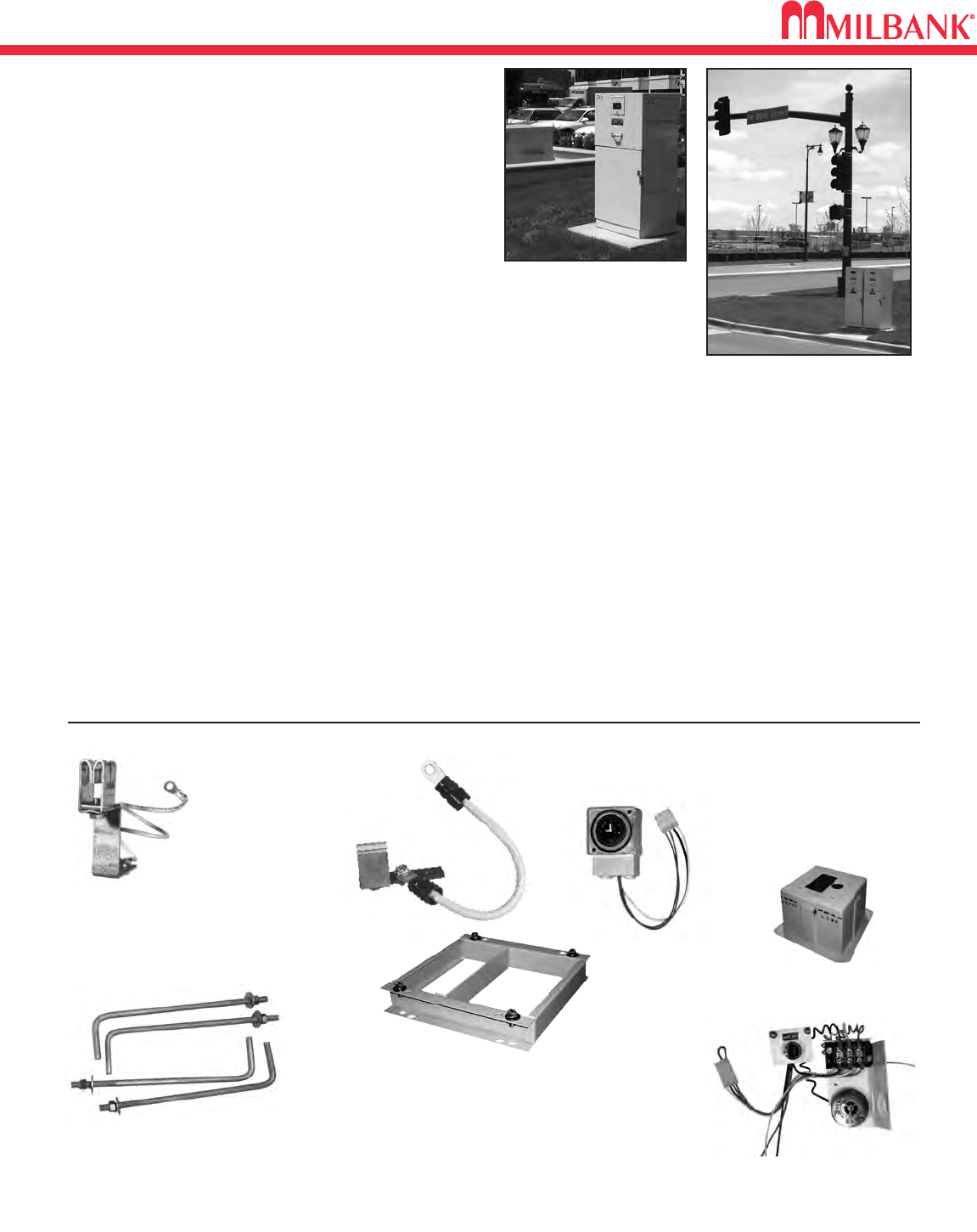
APPLICATIONS & ACCESSORIES
26
APPLICATIONS & ACCESSORIES
26
CP-16PDMNT-CALT
Pedestal mounting base for 16" pedestal
CP-24PDMNT-CALT
Pedestal mounting base for 24" pedestal
(includes mounting hardware)
CP-32PDMNT
Pedestal mounting base for 32" pedestal
(includes mounting hardware)
CP-ABK5/8
Anchor bolt kit (includes four 5/8-
13 x 18" anchor bolts)
CP-PE-HOA-3POS
HOA switch – for field
installation
ACCESSORIES
CP-TC7D 7-day time clock kit
CP-TC24H 24-hour time clock kit
CP-TCWIRE Male four-pin connector and
wiring harness for use with
time clocks other than shown
K3865
Fifth terminal kit for
use with ringless
meter sockets
• Meter sockets – ring type or ringless, to 400 amp (unmetered
and dual-metered pedestals also available)
•Main and branch breakers or T fuses
• Distribution – copper load centers & panel boards
• Clocks / timers / relays
• Photoelectric cells and controls
• Power receptacles – pin & sleeve, twist lock or straight blade
• Contactors – definite purpose, electrical or mechanically
held, IEC and mercury types
• Surge protection & lightning arrestors
• Reserve inlet generator receptacle with interlocked circuit
breakers
• Motor starters, relays
• Push button controls
• Thermostat controls, fans and heating strips
• Power blocks and terminal blocks
• Steel, aluminum and plywood back boards
• Transformers
• Interlock devices for circuit breakers
• Available in steel, aluminum (raw painted or anodized) or
stainless steel construction with powder-coated finish avail-
able in 8 standard colors or special ordered RAL colors.
• Available for applications up to 400 amp, 120V, 208V,
240V, 277V, 480V – 1Ø or 3Ø.
APPLICATIONS
These units are ideal for controlling and metering:
• Traffic signals
• Street lighting
• Irrigation / sprinkler systems
• Cell towers / telephone vaults
• Pump stations
• Temporary power for fairgrounds, swap meets, outdoor
markets, portable offices, holiday lights, etc.
• Outdoor lighting for athletic fields, tennis and basketball courts, parking lots, land-
scaping and subdivision entrances, etc.
AVAILABLE FACTORY-INSTALLED OPTIONS
105J
Fifth terminal
kit for use
with ring-type
meter sockets
CP-16FPAD
Fiberglass pedestal mounting base
for 16" pedestal (direct buried)
27
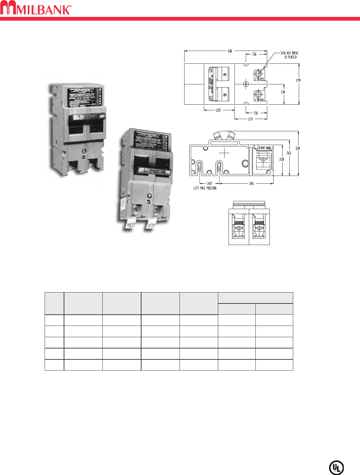
UQFP PLUG-IN SERIES CIRCUIT BREAKERS
UQFP PLUG-IN SERIES CIRCUIT BREAKERS
Utility requirements for this equipment may vary. Always consult the serving utility for their requirements before ordering or
installing equipment in this catalog.
27
#3-#1 #1-1/0
#3-#1 #1-1/0
1/0-300 2/0-300
1/0-300 2/0-300
1/0-300 2/0-300
WIRE RANGE
CU AL
200 AMP FRAME—PLUG-IN—10,000 AIC & 22,000 AIC
TWO-POLE—COMMON TRIP
UL LISTED: For use with 60°C or 75°C wire.
UQFP: For parallel main circuit breaker applications
UQFP-M: For series main circuit breaker applications. Split load tab features allow for feed
through capability.
STANDARD PACKAGING: 5 units per 16 lb. carton.
UQFP
UQFP-M
AMPS
100 UQFP-100
125 UQFP-125
150 UQFP-150
175 UQFP-175
200 UQFP-200
10K AIC
PLUG-IN
UQFPH-100
UQFPH-125
UQFPH-150
UQFPH-175
UQFPH-200
22K AIC
PLUG-IN
UQFP-M-100
UQFP-M-125
UQFP-M-150
UQFP-M-175
UQFP-M-200
10K AIC
PLUG-IN
UQFPH-M-100
UQFPH-M-125
UQFPH-M-150
UQFPH-M-175
UQFPH-M-200
22K AIC
PLUG-IN
ACCESSORIES
28
ACCESSORIES
28
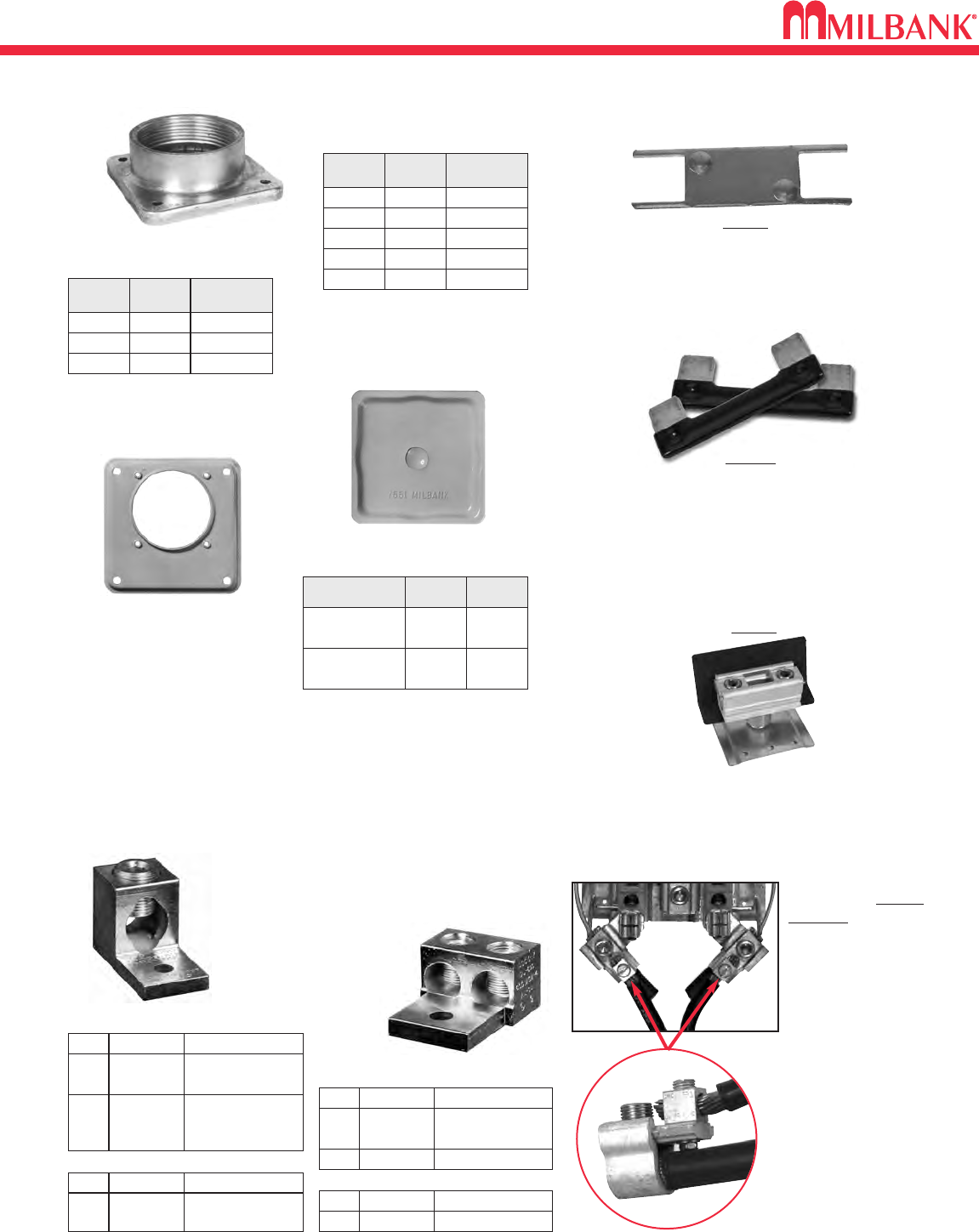
INTERCHANGEABLE UNIT HUBS
HUB ADAPTER PLATE
(Converts 4″opening to 21
⁄
2″)
S8324
1″
WL
SIZESUFFIX MILBANK
NO.
YL
ZL
DL
EL
A7514
11
⁄
4″A7515
11
⁄
2″A7516
2″A7517
21
⁄
2″A7518
3″
F
SUFFIX SIZE MILBANK
NO.
G
H
A8110
31
⁄
2″A8111
4″A8112
SMALL “RL"
OPENING (STANDARD)
LARGE “R”
OPENING (HEAVY DUTY)
REMOVABLE HUB
CLOSING PLATE
DESCRIPTION SUFFIX CAT. #
STANDARD
(for -RL opening)
-XL A7551
LARGE
(for -R opening) -X A9064
For use with 3/8”-16 stud
type units only
SINGLE
TWIN
K1350K2 6-350 kcmil
K1350L
K1541
K2L
K4
6-350 kcmil
Non-rotating
4-600 kcmil
CATALOG #SUFFIX (3 per set) – 1 ∅
K3442K6 6-350 kcmil
K3083K8 4-600 kcmil
CATALOG #SUFFIX (4 per set) – 3 ∅
K3082K5 6-350 kcmil
K3441K7 4-600 kcmil or
(2) 1/0-250 kcmil
CATALOG #SUFFIX (4 per set) – 3 ∅
K1539K1 6-350 kcmil
K1540
K1540L
K3
K3L
4-600 kcmil or
(2) 1/0-250 kcmil
4-600 kcmil or
(2) 1/0-250 kcmil
Non-rotating
CATALOG #SUFFIX (3 per set) – 1 ∅
TAP CONNECTORS (3 per set)
Replaces the line or
load side slide-in nut
assembly on Milbank
200 amp sockets. Allows
for a 100 amp tap loca-
tion in addition to the
#6-350 kcmil load-side
connector. K5022
Includes Safety Barrier
Extensions– for applica-
tions over 300 VAC.
K4977-INT
INTERNAL HEX
K5022-INT
INTERNAL HEX
CONNECTOR KITS
BYPASS LINK
K8180
(Bypass links sold in pairs)
ANTI-INVERSION CLIP
K4802
ISOLATED NEUTRAL KIT
K1047
29
ACCESSORIES
29
ACCESSORIES
FIFTH TERMINALS
100-200 amp
“PLUG-IN” FIFTH TERMINAL
5T8K2
200 amp
FIFTH TERMINAL
K5T
(New style block with square hole)
FOR CONDO
METERING BANKS
(125-200 amp)
K2381
METER CLOSING PLATE
(Ring type / Ringless)
6003 (Gray Plastic)
6116 (Clear Plastic)
METAL CLOSING PLATE
(For Ringless sockets)
CP-21
CLOSING COVERS
(For Ring type sockets)
MCP
HEAVY DUTY JAW
CLAMPING
K3865
(K3866 w/out neutral wire)
SEALING RINGS
SNAP ACTION
MR-2
SCREW TYPE
(Stainless Steel)
MR-4
TRIPLEX GROUND
K1190
(For factory installed triplex
ground add suffix “-TG” to the
catalog number.)
DISCONNECT SLEEVE *
M5-144
(*NOT TO BE USED WITH LEVER
BYPASS SOCKETS)
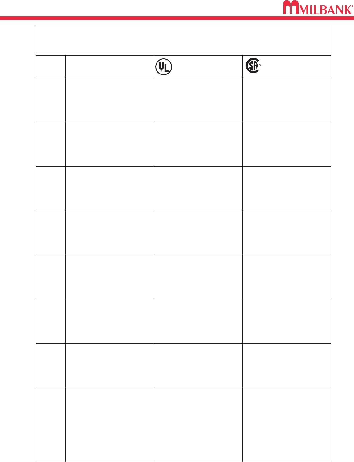
NEMA & UL RATINGS
30
NEMA & UL RATINGS
30
RATING NEMA
TYPE 1
TYPE 3
TYPE
3R
TYPE 4
TYPE
4X
TYPE
12
National Electrical
Manufacturers Association
(NEMA Standard 250)
Underwriters Laboratories Inc.
(UL 50 and UL 508)
Canadian Standards*
CAN/CSA–C22.2
No. 94-M91
Enclosures are intended for indoor
use primarily to provide a degree of
protection against limited amounts
of falling dirt.
(NEMA Standard 7-15-1991)
Indoor use primarily to provide a
degree of protection against limited
amounts of falling dirt.
General purpose enclosure. Protects
against accidental contact with live
parts.
Outdoor use primarily to provide a
degree of protection against rain,
sleet, windblown dust, and damage
from external ice formation.
An Enclosure for either indoor or
outdoor use, constructed so as to
provide a degree of protection
against rain, snow, and windblown
dust; undamaged by the external for-
mation of ice on the enclosure.
An Enclosure for either indoor or outdoor
use, constructed so as to provide a degree
of protection against rain, snow, and
windblown dust, splashing and hose-
directed water; undamaged by the exter-
nal formation of ice on the enclosure.
An Enclosure for either indoor or outdoor
use, constructed so as to provide a degree
of protection against rain, snow, and
windblown dust, splashing and hose-
directed water; undamaged by the exter-
nal formation of ice on the enclosure.
An Enclosure for either indoor or outdoor
use, constructed so as to provide a degree
of protection against rain, snow, and
windblown dust, splashing and hose-
directed water; undamaged by the exter-
nal formation of ice on the enclosure;
resists corrosion.
An Enclosure for either indoor use,
constructed so as to provide a
degree of protection against circulat-
ing dust, lint, fibers, and flyings;
dripping and light splashing of non-
corrosive liquids; not provided with
knockouts.
Outdoor use primarily to provide a
degree of protection against rain,
sleet, and damage from external ice
formation.
Enclosures are intended for outdoor
use primarily to provide a degree of
protection against rain, sleet, wind-
blown dust, and damage from exter-
nal ice formation.
(NEMA Standard 7-15-1991)
Enclosures are intended for outdoor
use primarily to provide a degree of
protection against rain, sleet, and
damage from external ice formation.
(NEMA Standard 7-15-1991)
Enclosures are intended for indoor and out-
door use primarily to provide a degree of
protection against windblown dust and
rain, splashing water, hose-directed water,
and damage from external ice formation.
(NEMA Standard 1-10-1979)
Indoor or outdoor use primarily to
provide a degree of protection against
windblown dust and rain, splashing
water, hose-directed water, and dam-
age from external ice formation.
Indoor or outdoor use primarily to
provide a degree of protection against
corrosion, windblown dust and rain,
splashing water, hose-directed water,
and damage from external ice forma-
tion.
Indoor use primarily to provide a
degree of protection against circulat-
ing dust, falling dirt, and dripping
noncorrosive liquids.
Enclosures are intended for indoor and out-
door use primarily to provide a degree of
protection against corrosion, windblown
dust and rain, splashing water, hose-direct-
ed water, and damage from external ice
formation. (NEMA Standard 1-10-1979)
Enclosures are intended for indoor
use primarily to provide a degree of
protection against circulating dust,
falling dirt, and dripping noncorrosive
liquids.
(NEMA Standard 7-15-1991)
TYPE
13
Indoor use; provides a degree of pro-
tection against circulating dust, lint,
fibers, and flyings; seepage and
spraying of noncorrosive liquids,
including oils and coolants.
Indoor use primarily to provide a
degree of protection against lint, dust,
seepage, external condensation, and
spraying of water, oil, and noncorro-
sive liquids.
Enclosures are intended for indoor
use primarily to provide a degree of
protection against dust, spraying of
water, oil, and noncorrosive coolant.
NEMA and UL
are standard writing organizations commonly recognized in the North American continent. The following ratings are based on
similar application descriptions and expected performance. UL requires enclosure testing by qualified evaluators. The Milbank Test Lab is certi-
fied in the UL Client Test Data Program. They also send site inspectors to check manufacturer adherence to prescribed manufacturing methods
and material specifications. NEMA does not require independent testing, which leaves compliance totally up to the manufacturer.
The definitions on this page are
reproduced with permission from
NEMA. These descriptions are not
intended to be complete representa-
tions of National Electrical
Manufacturers Association stan-
dards.
*Our enclosures are tested to CSA
Standards by Underwriters
Laboratories and bear the CUL
Listing Mark.
The definitions on this page are
reproduced with permission from
CSA. These descriptions are not
intended to be complete representa-
tions of CSA standards.
The preceding definitions were reproduced
with permission from Underwriters
Laboratories Inc. Enclosures for Electrical
Equipment. UL 50, Copywrite 1995.
Underwriters Laboratories Inc. (UL) shall
not be responsible for the use of or
reliance upon a UL Standard by anyone.
UL shall not incur any obligation or liabili-
ty for damages, including consequential
damages, arising out of or connection with
the use, interpretation of or reliance upon
a UL Standard.
DISCLAIMERS

31
INDEX
31
INDEX
6003 . . . . . . . . . . . . . . . . . . . . . . . . . . . . .29
6116 . . . . . . . . . . . . . . . . . . . . . . . . . . . . .29
105J . . . . . . . . . . . . . . . . . . . . . . . . . . . . .26
307220-TC3R-WB . . . . . . . . . . . . . . . . . .24
363616-CT3R-WB . . . . . . . . . . . . . . . . . .24
403214-TC3R-SP1 . . . . . . . . . . . . . . . . .24
543214-TC3R-SP1 . . . . . . . . . . . . . . . . .24
5T8K2 . . . . . . . . . . . . . . . . . . . . . . . . . . .29
A7514 . . . . . . . . . . . . . . . . . . . . . . . . . . .28
A7515 . . . . . . . . . . . . . . . . . . . . . . . . . . .28
A7516 . . . . . . . . . . . . . . . . . . . . . . . . . . .28
A7517 . . . . . . . . . . . . . . . . . . . . . . . . . . .28
A7518 . . . . . . . . . . . . . . . . . . . . . . . . . . .28
A7551 . . . . . . . . . . . . . . . . . . . . . . . . . . .28
A8110 . . . . . . . . . . . . . . . . . . . . . . . . . . .28
A8111 . . . . . . . . . . . . . . . . . . . . . . . . . . .28
A8112 . . . . . . . . . . . . . . . . . . . . . . . . . . .28
A9064 . . . . . . . . . . . . . . . . . . . . . . . . . . .28
CP-16FPAD . . . . . . . . . . . . . . . . . . . . . . .26
CP-16PDMNT-CALT . . . . . . . . . . . . . . . .26
CP-21 . . . . . . . . . . . . . . . . . . . . . . . . . . .29
CP-24PDMNT-CALT . . . . . . . . . . . . . . . .26
CP-32PDMNT . . . . . . . . . . . . . . . . . . . . .26
CP-ABK/8 . . . . . . . . . . . . . . . . . . . . . . . .26
CP-PE-HOA-3POS . . . . . . . . . . . . . . . . .26
CP-TC24H . . . . . . . . . . . . . . . . . . . . . . . .26
CP-TC7D . . . . . . . . . . . . . . . . . . . . . . . . .26
CP-TCWIRE . . . . . . . . . . . . . . . . . . . . . .26
K1047 . . . . . . . . . . . . . . . . . . . . . . . . . . .28
K1190 . . . . . . . . . . . . . . . . . . . . . . . . . . .29
K1350 . . . . . . . . . . . . . . . . . . . . . . . .19, 28
K1350L . . . . . . . . . . . . . . . . . . . . . . . . . .28
K1539 . . . . . . . . . . . . . . . . . . . . . . . .19, 28
K1540 . . . . . . . . . . . . . . . . . . . . . . . .19, 28
K1540L . . . . . . . . . . . . . . . . . . . . . . . . . .28
K1541 . . . . . . . . . . . . . . . . . . . . . . . .19, 28
K2381 . . . . . . . . . . . . . . . . . . . . . . . . . . .29
K3082 . . . . . . . . . . . . . . . . . . . . . . . . . . .28
K3083 . . . . . . . . . . . . . . . . . . . . . . . . . . .28
K3441 . . . . . . . . . . . . . . . . . . . . . . . . . . .28
K3442 . . . . . . . . . . . . . . . . . . . . . . . . . . .28
K3865 . . . . . . . . . . . . . . . . . . . . . . . . . . .26
K3865 . . . . . . . . . . . . . . . . . . . . . . . . . . .29
K3866 . . . . . . . . . . . . . . . . . . . . . . . . . . .29
K4802 . . . . . . . . . . . . . . . . . . . . . . . . . . .28
K4977-INT . . . . . . . . . . . . . . . . . . . . . . . .28
K5022-INT . . . . . . . . . . . . . . . . . . . . . . . .28
K5T . . . . . . . . . . . . . . . . . . . . . . . . . . . . .29
K8180 . . . . . . . . . . . . . . . . . . . . . . . . . . .28
M400-UG-APS-LC . . . . . . . . . . . . . . . . . .15
M5-144 . . . . . . . . . . . . . . . . . . . . . . . . . .29
MCP . . . . . . . . . . . . . . . . . . . . . . . . . . . . .29
MR-2 . . . . . . . . . . . . . . . . . . . . . . . . . . . .29
MR-4 . . . . . . . . . . . . . . . . . . . . . . . . . . . .29
Q2100 . . . . . . . . . . . . . . . . . . . . . . . . . . .11
Q2100H . . . . . . . . . . . . . . . . . . . . . . . . . .11
Q260 . . . . . . . . . . . . . . . . . . . . . . . . . . . .11
Q260H . . . . . . . . . . . . . . . . . . . . . . . . . . .11
QN2150 . . . . . . . . . . . . . . . . . . . . . . . . . .11
QN2150H . . . . . . . . . . . . . . . . . . . . . . . . .11
QN2200 . . . . . . . . . . . . . . . . . . . . . . . . . .11
QN2200H . . . . . . . . . . . . . . . . . . . . . . . . .11
S8324 . . . . . . . . . . . . . . . . . . . . . . . . . . .28
U1252-REL-K1 . . . . . . . . . . . . . . . . . . . .16
U1253-X . . . . . . . . . . . . . . . . . . . . . . . . .16
U1254-X . . . . . . . . . . . . . . . . . . . . . . . . .16
U1255-X . . . . . . . . . . . . . . . . . . . . . . . . .16
U1256-X . . . . . . . . . . . . . . . . . . . . . . . . .16
U1797-O-K3L-K2L . . . . . . . . . . . . . . . . . . .9
U1980-O . . . . . . . . . . . . . . . . . . . . . . . . . .7
U2120-X . . . . . . . . . . . . . . . . . . . . . . . . .10
U2594-X . . . . . . . . . . . . . . . . . . . . . . . . .10
U2852-X . . . . . . . . . . . . . . . . . . . . . . . . .19
U2853-X . . . . . . . . . . . . . . . . . . . . . . . . .19
U2854-X . . . . . . . . . . . . . . . . . . . . . . . . .19
U2855-X . . . . . . . . . . . . . . . . . . . . . . . . .19
U2856-X . . . . . . . . . . . . . . . . . . . . . . . . .19
U2862-X . . . . . . . . . . . . . . . . . . . . . . . . .19
U2863-X . . . . . . . . . . . . . . . . . . . . . . . . .19
U2864-X . . . . . . . . . . . . . . . . . . . . . . . . .19
U2865-X . . . . . . . . . . . . . . . . . . . . . . . . .19
U2866-X . . . . . . . . . . . . . . . . . . . . . . . . .19
U3313-X-2/K3 . . . . . . . . . . . . . . . . . . . . . .9
U3822-20GWR . . . . . . . . . . . . . . . . . . . . .6
U3830 . . . . . . . . . . . . . . . . . . . . . . . . . . . .5
U3860 . . . . . . . . . . . . . . . . . . . . . . . . . . . .5
U4252-RXL-K2 . . . . . . . . . . . . . . . . . . . .16
U4413-O . . . . . . . . . . . . . . . . . . . . . . . . . .7
U4419-X . . . . . . . . . . . . . . . . . . . . . . . . . .9
U4505-X . . . . . . . . . . . . . . . . . . . . . . . . . .9
U4581-RL-QG . . . . . . . . . . . . . . . . . . . . . .8
U4701-RL-QG . . . . . . . . . . . . . . . . . . . . . .8
U4702-X . . . . . . . . . . . . . . . . . . . . . . . . . .9
U4835-X-2/200-BL . . . . . . . . . . . . . . . . . .14
U4881-O . . . . . . . . . . . . . . . . . . . . . . . . . .6
U4881-O-50GB . . . . . . . . . . . . . . . . . . . . .6
U4881-O-60GB . . . . . . . . . . . . . . . . . . . . .6
U4908-O . . . . . . . . . . . . . . . . . . . . . .21, 22
U5059-X-2/200-K3L . . . . . . . . . . . . . . . . .14
U5101-XL . . . . . . . . . . . . . . . . . . . . .21, 22
U5136-O . . . . . . . . . . . . . . . . . . . . . . . . .23
U5136-O-100S . . . . . . . . . . . . . . . . . . . .23
U5136-O-200S . . . . . . . . . . . . . . . . . . . .23
U5137-O . . . . . . . . . . . . . . . . . . . . . . . . .23
U5137-O-100S . . . . . . . . . . . . . . . . . . . .23
U5137-O-200S . . . . . . . . . . . . . . . . . . . .23
U5168-XTL-200 . . . . . . . . . . . . . . . . . . . .12
U5268-XTL-200 . . . . . . . . . . . . . . . . . . . .12
U5750-RXL-200-BL . . . . . . . . . . . . . . . . .13
U5842-RL-100 . . . . . . . . . . . . . . . . . . . . .11
U5842-RL-200 . . . . . . . . . . . . . . . . . . . . .11
U5844-PXL . . . . . . . . . . . . . . . . . . . . . . .11
U5844-PXL-100 . . . . . . . . . . . . . . . . . . . .11
U5844-PXL-150 . . . . . . . . . . . . . . . . . . . .11
U5844-PXL-200 . . . . . . . . . . . . . . . . . . . .11
U5882-X . . . . . . . . . . . . . . . . . . . . . . . . .17
U5883-X . . . . . . . . . . . . . . . . . . . . . . . . .17
U5884-X . . . . . . . . . . . . . . . . . . . . . . . . .17
U5885-X . . . . . . . . . . . . . . . . . . . . . . . . .17
U5886-X . . . . . . . . . . . . . . . . . . . . . . . . .17
U5890-X-2/200 . . . . . . . . . . . . . . . . . . . .14
U5892-X-2/200 . . . . . . . . . . . . . . . . . . . .14
U5894-X-2/200-MLK . . . . . . . . . . . . . . . .14
U5902-X . . . . . . . . . . . . . . . . . . . . . . . . .17
U5903-X . . . . . . . . . . . . . . . . . . . . . . . . .17
U5904-X . . . . . . . . . . . . . . . . . . . . . . . . .17
U5905-X . . . . . . . . . . . . . . . . . . . . . . . . .17
U5906-X . . . . . . . . . . . . . . . . . . . . . . . . .17
U7021-RG-TG . . . . . . . . . . . . . . . . . . . . . .7
U7040-RL-TG . . . . . . . . . . . . . . . . . . . . . .7
U8212-RL . . . . . . . . . . . . . . . . . . . . . . . .16
U8213-RL . . . . . . . . . . . . . . . . . . . . . . . .16
U8214-RL . . . . . . . . . . . . . . . . . . . . . . . .16
U8215-RL . . . . . . . . . . . . . . . . . . . . . . . .16
U8216-RL . . . . . . . . . . . . . . . . . . . . . . . .16
U8435-RL-TG . . . . . . . . . . . . . . . . . . . . . .7
UQFB-M-200 . . . . . . . . . . . . . . . . . . . . . .13
UQFP-100 . . . . . . . . . . . . . . . . . . . . . . . .27
UQFP-125 . . . . . . . . . . . . . . . . . . . . . . . .27
UQFP-150 . . . . . . . . . . . . . . . . . . . . . . . .27
UQFP-175 . . . . . . . . . . . . . . . . . . . . . . . .27
UQFP-200 . . . . . . . . . . . . . . . . . . . . . . . .27
UQFPH-100 . . . . . . . . . . . . . . . . . . . . . . .27
UQFPH-125 . . . . . . . . . . . . . . . . . . . . . . .27
UQFPH-150 . . . . . . . . . . . . . . . . . . . . . . .27
UQFPH-175 . . . . . . . . . . . . . . . . . . . . . . .27
UQFPH-200 . . . . . . . . . . . . . . . . . . . . . . .27
UQFPH-M-100 . . . . . . . . . . . . . . . . . .23, 27
UQFPH-M-125 . . . . . . . . . . . . . . . . . . . . .27
UQFPH-M-150 . . . . . . . . . . . . . . . . . . . . .27
UQFPH-M-175 . . . . . . . . . . . . . . . . . . . . .27
UQFPH-M-200 . . . . . . . . . . . . . . . . . .23, 27
UQFP-M-100 . . . . . . . . . . . . . . . . . . . . . .27
UQFP-M-125 . . . . . . . . . . . . . . . . . . . . . .27
UQFP-M-150 . . . . . . . . . . . . . . . . . . . . . .27
UQFP-M-175 . . . . . . . . . . . . . . . . . . . . . .27
UQFP-M-200 . . . . . . . . . . . . . . . . . . . . . .27
USE-22-200-MB . . . . . . . . . . . . . . . . . . .13
USE-AP-200-M . . . . . . . . . . . . . . . . . . . .13
CATALOG # PAGE # CATALOG # PAGE # CATALOG # PAGE #
CONDUIT AND AMPACITY INFORMATION
32
32
TYPE
THHN,
THWN,
THWN-2
CONDUCTOR
SIZE
(AWG / kcmil)
12
10
8
6
4
3
2
1
1/0
2/0
3/0
4/0
4
2
1/0
2/0
4/0
250
350
500
750
CONDUIT TRADE SIZES (INCHES)
1
⁄
23
⁄
41 11
⁄
411
⁄
22 21
⁄
23 31
⁄
24
9
6
3
2
1
1
1
1
1
0
0
0
1
1
1
0
0
0
0
0
0
16
10
6
4
2
1
1
1
1
1
1
1
2
1
1
1
1
0
0
0
0
26
17
9
7
4
3
3
1
1
1
1
1
4
3
1
1
1
1
1
0
0
46
29
16
12
7
6
5
4
3
2
1
1
7
5
3
2
1
1
1
1
0
62
39
22
16
10
8
7
5
4
3
3
2
10
7
4
3
2
1
1
1
1
102
64
37
27
16
14
11
8
7
6
5
4
16
12
7
6
4
3
2
1
1
146
92
53
38
23
20
17
12
10
8
7
6
24
17
10
9
6
5
3
2
1
225
142
82
59
36
31
26
19
16
13
11
9
37
26
16
13
9
7
6
4
3
301
189
109
79
48
41
34
25
21
18
15
12
49
35
22
18
12
10
7
5
4
387
244
140
101
62
53
44
33
27
23
19
16
63
45
28
23
16
13
10
7
5
XHH,
XHHW,
XHHW-2
u
This table is for concentric stranded conductors only. For cables with compact conductors refer to NEC.
Refer to latest NEC Code or Local Codes for updated requirements.
*CU
A
18
16
14
12
10
8
6
4
3
2
1
1/0
2/0
3/0
4/0
250
300
350
400
500
600
700
750
255
285
310
335
380
420
460
475
–
–
20✝
25✝
35✝
50
65
85
100
115
130
150
175
200
230
B
250
300
350
400
500
600
700
750
–
–
–
12
10
8
6
4
3
2
1
1/0
2/0
3/0
4/0
A
AL or **Cu-Clad AL
205
230
250
270
310
340
375
385
–
–
–
20✝
30✝
40
50
65
75
90
100
120
135
155
180
C
AMBIENT
TEMP.C°
CORRECTION
FACTOR
AMBIENT
TEMP.F°
21 - 25 1.05 70 - 77
26 - 30 1.00 78 - 86
31 - 35 .94 87 - 95
36 - 40 .88 96 - 104
41 - 45 .82 105 - 113
46 - 50 .75 114 - 122
51 - 55 .67 123 - 131
56 - 60 .58 132 - 140
61 - 65 .33 141 - 158
*ALLOWABLE AMPACITIES OF INSULATED COPPER &
** ALUMINUM CONDUCTORS (3W IN CONDUIT) 75°C (167°F)
AMPACITY CORRECTION FACTORS
Overall ampere ratings of U/L listed Milbank multiple position meter sockets are based on 2008 N.E.C.
Handbook Article 220-84 and ANSI / UL-414 (except where restricted by line connector size.) These
requirements provide for a diversity factor / demand factor being utilized in determining the overall (main
bus / lug) rating of a gang socket. All Milbank U/L listed gang sockets meet or exceed these diversity
factor/demand factor requirements. Standard overall ampacity ratings for U/L listed and non U/L listed
gang sockets are as shown in the chart below. Ampere ratings of meter sockets are based on the meter
socket being wired with 75°C insulated wire conductor, sized in accordance with Table 310-16 of the
National Electric Code.
NO. OF METER
POSITIONS 100A / POS.
AMPACITY 125A / POS.
AMPACITY 150A / POS.
AMPACITY 200A / POS.
AMPACITY
2
3
4
5
6
200A
200A
200A
225A
270A
200A
225A
250A
285A
330A
200A
225A
270A
338A
396A
400A
270A
360A
450A
528A
MAXIMUM NUMBER OF CONDUCTORS IN CONDUIT
u
Table from 2008 NEC Code Reference: Rigid Metal Conduit
A = Size: AWG/MCM
*B = Ampere Rating for
Insulation Types:
FEPW, RH, RHW, THW,
THWN, XHHW, USE, 2W.
**C = Ampere Rating for
Insulation Types:
RH, RHW, THW, THWN,
XHHW, USE
(Per NEC table 310-16)
✝Unless otherwise permitted elsewhere in the Code, the overcurrent protection for conductor types marked with an obelisk (✝) shall not
exceed 15 amps for 14 AWG, 20 amps for 12 AWG, and 30 amps for 10 AWG copper: or 15 amps for 12 AWG and 25 amps for 10 AWG
aluminum and copper-clad aluminum after any correction factors for ambient temperature and number of conductors have been applied.
GANG SOCKET OVERALL AMPACITIES
CONDUIT AND AMPACITY INFORMATION
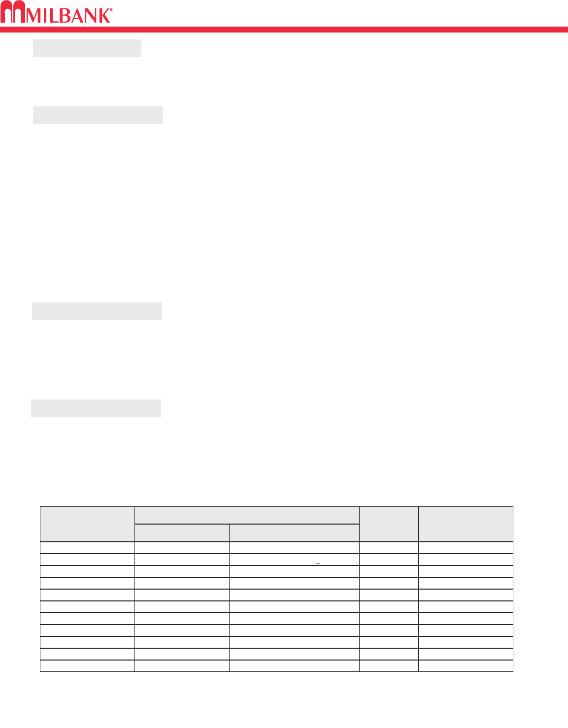
33
ENERGIZATION OF ELECTRICAL EQUIPMENT
ENERGIZATION OF ELECTRICAL EQUIPMENT
33
BEFORE ENERGIZING
IMPORTANT NOTE
WHEN ENERGIZING
AFTER ENERGIZING
A. Give equipment a thorough visual examination to determine that:
1) No shipping or installation damage exists.
2) Proper clearances have been maintained.
3) All connections have been made.
4) Equipment is clean and dry.
B. Make a thorough examination to:
1) Verify tightness of all bolted connections (see table below).
2) Manually operate all circuit breakers, switches, relays, etc.
3) Check rigidity of all mountings, bus bars and components.
4) Use test equipment to check continuity of circuitry and integrity of insulation.
C. All switches and circuit breakers should be in the “off” position.
D. Verify that manual meter bypass (if applicable) is in non-bypass position.
E. Install cover and/or close doors.
F. If installation is not being energized at this time, follow “after-energizing” steps listed below. These
steps will secure the installation in case of accidental energization.
A. Use caution and follow established safety procedures:
1) Wear safety apparel.
2) Use safety equipment.
3) Take action to prevent injury to yourself and others in the event of failure of the installation.
4) Take action to prevent/decrease damage to property in the event of failure of the installation.
5) If you are unsure how to safely energize the installation, get someone who is knowledgeable to do it.
A. Secure the installation:
1) To prevent accidental contact with energized parts, cover all openings with approved filler devices.
2) To prevent unauthorized access, secure all covers and/or doors with approved security devices.
3) Attach/post information to advise others of potential hazards associated with the installation.
NOMINAL
SIZE
10
10
10
12
12
1/4
1/4
5/16
JOINT DESCRIPTION
SCREW NUT
BRASS
STEEL
STEEL
STEEL
STEEL
STEEL
STEEL
STEEL
Brass Nut or Extruded Hole
CU or AL Busbar <1/8″
Steel Nut or EH; CU or AL Busbar >1/8″
Aluminum Extruded Hole
Steel Nut or Extruded Hole
Aluminum Extruded Hole
Steel Nut or EH; CU or AL Busbar
Aluminum Extruded Hole
ALL
ALL
ALL
ALL
ALL
ALL
ALL
HEX
20-25 in. lbs.
25-30 in. lbs
30-35 in. lbs
30-35 in. lbs
40-50 in. lbs.
40-50 in. lbs.
50-60 in. lbs.
60-70 in. lbs.
5/16 STEEL Steel Nut or EH; CU or AL Busbar HEX 100-150 in. lbs.
3/8 STEEL Steel Nut HEX 150-200 in. lbs.
1/2 STEEL Steel Nut HEX 200-250 in. lbs.
HEAD TYPE TORQUE
( INCH LBS. )
*Interior labels typically indicate the required torque for wire connectors and studs, and should be referenced first.
EH: Extruded Hole
CU: Copper
AL: Aluminum
RECOMMENDED TORQUE FOR GENERAL APPLICATIONS*
In addition to national and local electrical codes, many utilities have specific requirements for metering equip-
ment. Always consult the serving utility for their specifications and requirements prior to ordering or installing
Milbank meter mounting equipment.

MATERIALS AND FINISHES
34
MATERIALS AND FINISHES
34
MATERIALS
STEEL SHEET
STEEL QUALITY
ALUMINUM EXTRUSION
ALUMINUM SHEET
COPPER SHEET & BUS
INSULATING MATERIALS
PROCESS
METAL FASTENERS
The meter equipment listed in this catalog is made of galvanized steel (AISI* G90) to afford the
best possible weather proofing. *American Iron and Steel Institute.
Light gray “state of the art” electrostatically applied powder paint offers a durable, non-fading
finish. For further information concerning the chemical analysis of the weather resistant finish,
please contact the factory.
Wire-Terminals: Alloy; 6061-T6, Tin-plated for CU/AL wire.
Bus Bar: Alloy; 6101-o & 6063-O
3000 series aluminum sheet, H14, or 5052 series aluminum sheet, H32. Where applicable thick-
nesses range from .064 – .125
Electrolytic copper with tin plating in most applications.
Zinc-coated with a chromate dip.
• In most units, support bases for current-carrying components are molded from fiberglass rein-
forced high-strength, track resistant, thermoset polyester molding compounds.
• Clear or black safety shields and polarity barriers are molded from high-strength, track resistant,
polycarbonate molding compounds.
• Various sheet insulating materials, as appropriate for the application are utilized in the fabrica-
tion of flat, formed and punched component parts and barriers.
16 gauge, galvanized, sheet: 0.90 oz./ sq.ft. class zinc-coated.
(AISI G90)
14 gauge, galvanized, sheet: 0.90 oz./ sq.ft. class zinc-coated.
FINISH
NEMA RATING
All Milbank meter sockets, CT cans and meter socket / breaker units have a type 3R rating.
RATING
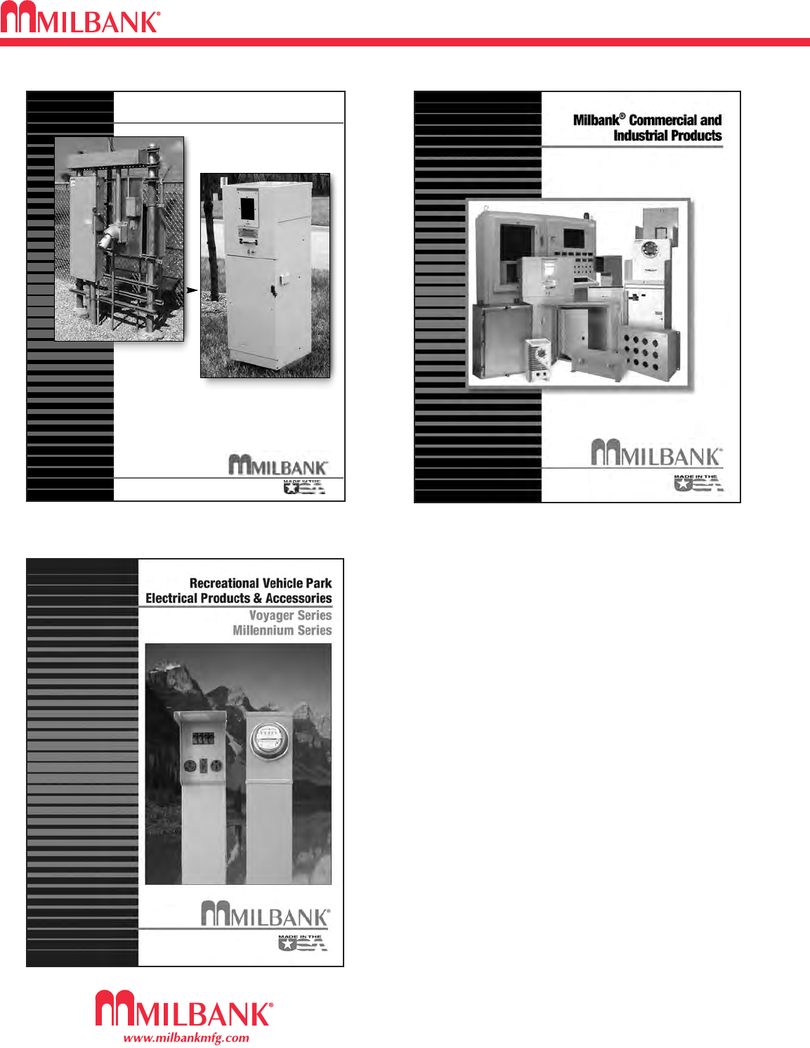
35
ADDITIONAL MILBANK PRODUCTS
35
ADDITIONAL MILBANK PRODUCTS
In addition to your local utility’s meter mounting
equipment, Milbank also manufactures
supporting products, such as...
Air Conditioner Disconnects
Hot Tub Disconnects
RV/Mobile Home Power Outlets
Terminal Boxes
Temporary Power Outlets
Commercial Pedestals
Commercial Enclosures
CT Enclosures
Circuit Breakers
Enclosed Circuit Breakers
Safety Switches
Test Switches
Contact your local distributor or go to
www.milbankmfg.com
to find additional product literature.
Other quality products available from Milbank
Un-
Strut Your
Stuff...
Commercial Pedestals
• Attractive • Easy to install
• Secure • Cost effective
www.milbankmfg.com
816.483.6357 fax
816.483.5314 phone
ComPed 2/09 (7.5K)
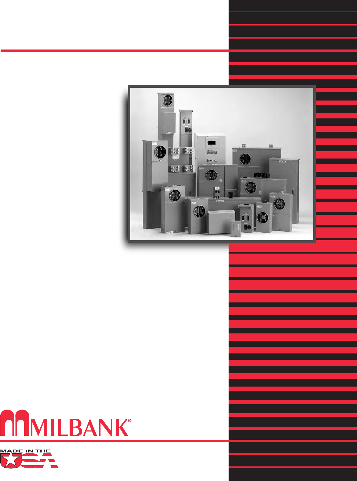
Meter Mounting Equipment & More!
Commercial Electrical Enclosures
Residential & Commercial Metering
Commercial Meter Pedestals
Disconnect Devices
Current Transformer Enclosures
RV/MH Pedestals
Temporary Power Outlets
Circuit Breakers
Distribution Unit Substations
Enclosed Circuit Breakers
Safety Switches
Test Switches
PORTER SALES
6001 Murray Street
Little Rock, AR 72209
Tel: 501-570-8100
Fax: 501-570-8190
ARK/WTN/NMS 3/11 (750)
www.milbankmfg.com
MILBANK MFG. CO.
PO Box 419028
Kansas City, MO 64141-0028
Tel: 816-483-5314 Fax: 816-483-6357
Toll Free: 877-483-5314
www.milbankmfg.com
