482851 Catalog
2014-07-05
: Pdf 482851-Catalog 482851-Catalog 785901 Batch5 unilog
Open the PDF directly: View PDF ![]() .
.
Page Count: 56
Class 1100
QO® and Homeline® Load
Centers and Enclosures
Catalog
1100CT0501
2007
CONTENTS
Description. . . . . . . . . . . . . . . . . . . . . . . . . . . . . . . . . . . . . . . . . . . . . .Page
QO® Circuit Breakers and Load Centers . . . . . . . . . . . . . . . . . . . . . . . . . . . 3
QO®, QOM2 and Q-Frame Enclosed Circuit Breakers . . . . . . . . . . . . . . . 34
Homeline® Circuit Breakers and Load Centers . . . . . . . . . . . . . . . . . . . . . 40

QO® and Homeline® Load Centers and Enclosures
Table of Contents
2
© 2007 Schneider Electric All Rights Reserved 03/2007
TABLE OF CONTENTS
Product Description 3
Features 3
QO® Catalog Number Description 4
General information and Application Data 5
Service 5
Ratings 5
Branch Circuit Breakers 5
Indoor Enclosures (Type 1) 6
Indoor Covers 6
Rainproof Enclosures (Type 3R) 6
Bolt-On Hubs 6
Class CTL 7
Phasing 7
Line Lugs 7
Neutral Assemblies 7
Single Phase, 216 Circuits, 30 125 A, Fixed Mains 8
Single-Phase,1242 Circuits, 100225 A, Convertible Mains 9
Special Purpose 11
Generator Panels 12
Three-Phase, 34 2 Circuits, 6022 5 A, Convertible or Fixed Mains 13
Single-Phase, 12 42 Circuits, 300 400 A, Fixed Mains 15
Accessories 16
Technical Information 19
Grounding Bar Kits 19
Main Lugs and Main Circuit Breakers Ratings 20
Dimensions and Knockouts 26
QO 1-Phase and 3-Phase Label Samples 28 29
Wiring Diagrams 30
NOTE: For information on Replacement Parts with specific part numbers,
go to www.schneider-electric.us, click on Product FAQ’s, enter the device
catalog number, click SEARCH, then look for the information required.
QO® and Homeline® Load Centers and Enclosures
Product Description
3
03/2007 © 2007 Schneider Electric All Rights Reserved
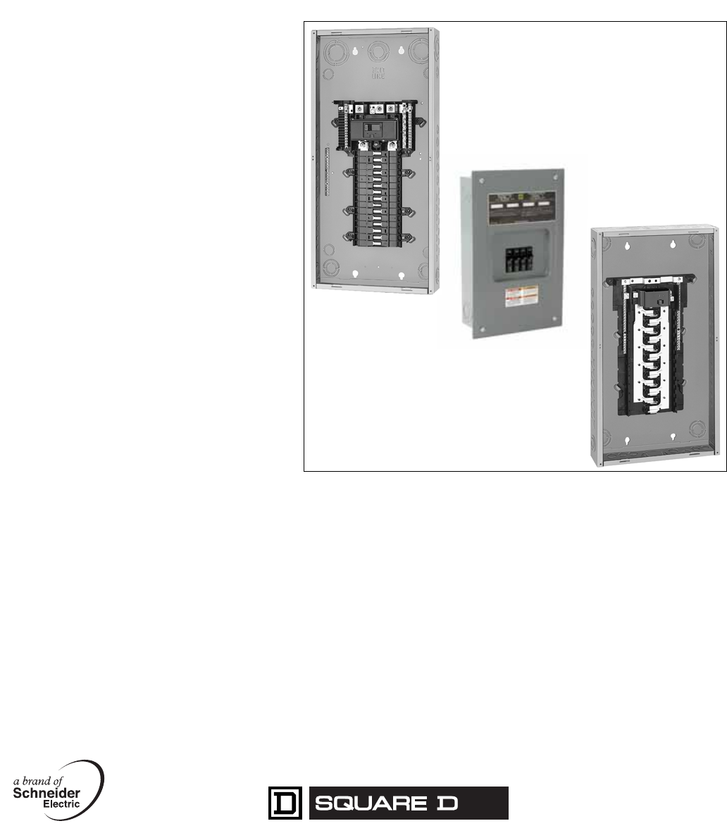
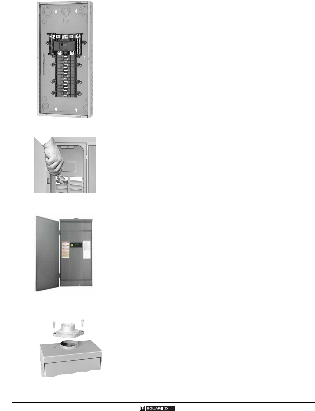
PRODUCT DESCRIPTION
QO® Circuit Breaker Load Centers from Square D® are Underwriters
Laboratories (UL) Listed panelboards. They are designed to meet
residential, commercial, and industrial requirements to protect electrical
systems, equipment, and people.
Features
Single- or three-phase construction
30 400 A main lug or main circuit breaker ratings
24 2 circuit indoor or outdoor versions
Flush or surface mounting
Aluminum bus construction on fixed mains panels
Service entrance equipment capable panels
Straight-in wiring to minimize service cable installation
Convertible mains to meet changing job site requirements
Standard 22/10 k AIR series rating on main circuit breaker panels,
increasing application capability
65 k AIR ratings for main lugs panels for industrial applications
65 k AIR rating with optional main circuit breaker on three-phase panels
for industrial applications
Shielded one-piece plated copper bus construction on convertible mains
panels, an industry exclusive for protection and performance
Single captive screw interior mounting on indoor panels to ease removal
Split branch neutral for clutter-free wiring
Top or bottom feed by rotating convertible mains panels 180 degrees
Top or bottom feed for three-phase convertible panels by removing main
circuit breaker and rotating panel 180 degrees
Combination slot/square drive neutral, ground, and cover screws for
positive drive and improved torque
Three grounding bar mounting locations for ease of wiring
Automatic flush adjustment cover to speed installation
Tangential main service knockouts that eliminate offsets
Equipment grounding bar included with main lug load centers
Covers sold separately
Provisions for door lock on convertible mains panel covers
Two branch circuit breaker twistouts that are factory removed for easier
installation of circuit breakers
Side hinge doors on outdoor convertible main panels
Outdoor panel covers lockable with padlock
Manual and automatic transfer switch capability
QO® Circuit Breaker Load Center
QO® and Homeline® Load Centers and Enclosures
Catalog Number Description
4
© 2007 Schneider Electric All Rights Reserved 03/2007
CATALOG NUMBER DESCRIPTION
QO® Load Centers
Number Segment Character Description QO®1 3040 L 200 G——
Load Center Family QO®UL and NOM Listed
CQO CSA® Certified
Phase 1Blank or 1 = Single
3 = Three
Spaces / Circuits 3040
Mains Type
MMain circuit breaker
MX Main circuit breaker for Automatic Transfer Switch
LMain lugs
UUniversal mains (studs only)
Amperes
Grounding Bar
Blank Purchase separately
GIncluded
NNeutral installed
TFactory-installed
Cover
Blank Purchase cover separately
CCombination flush / surface indoor cover
DF Flush cover with door
DS Surface cover with door
FFlush cover
RRainproof
RB Rainproof for B hub
SSurface cover
Special Construction
CU Copper bussing
FT Feed-thru lugs
GP Generator panel
NM Non-metallic enclosure
RGenerator receptacle
WG Wide gutter riser panel
QO® Circuit Breakers
Number
Segment Character Description QO®115—
Brand QO Full Size
QOT Tandem
Number of Poles
Amperes
Device Name
Blank 10,000 AIR
EPD 30 mA equipment ground fault protection
GFI Ground fault circuit interruption
HID For use on high intensity discharge lighting systems
HM High magnetic trip circuit breakers are recommended for
applications where high initial inrush current may occur
KKey operated
PL Remote control switching capability
SWN Switch neutral common trip
VH 22,000 AIR
AFI Arc fault circuit interruption
CAFI Combination arc fault circuit interruption
QO® and Homeline® Load Centers and Enclosures
General Information and Application Data
5
03/2007 © 2007 Schneider Electric All Rights Reserved
GENERAL INFORMATION AND APPLICATION DATA
Circuit breaker load centers for use on electrical systems are UL Listed
under File E-6294 (panelboards) and meet Federal Specifications
W-P-115c, Type 1, Class 2 for use in government housing. Select from QO,
QOT, QO-PL, QO-GFI (UL Class A ground fault protection), QO-AFI
(arc fault circuit interrupter), QO-CAFI (combination arc fault interrupter), or
QO-EPD (30 mA equipment ground fault protection) branch circuit breakers.
Service
Ratings
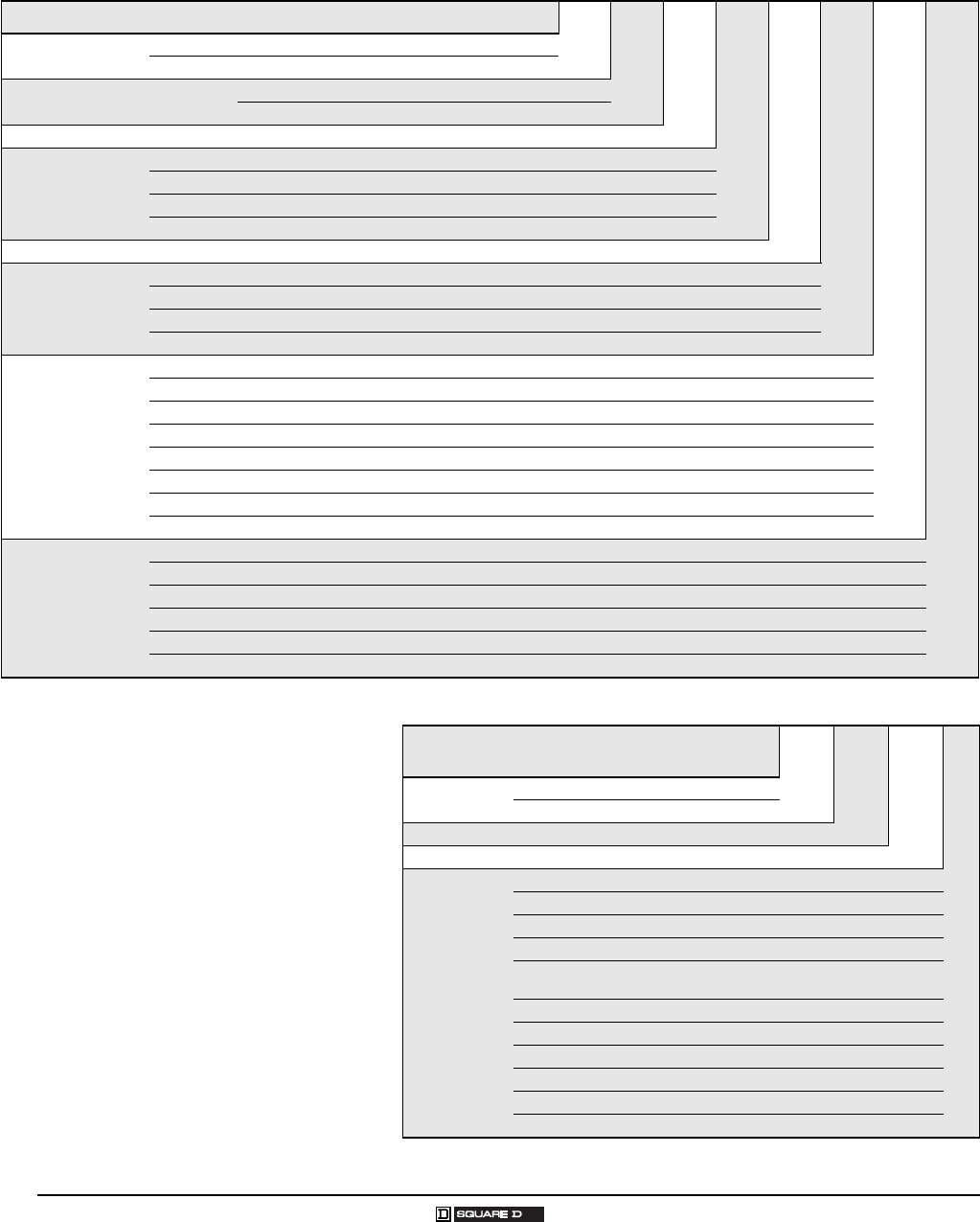
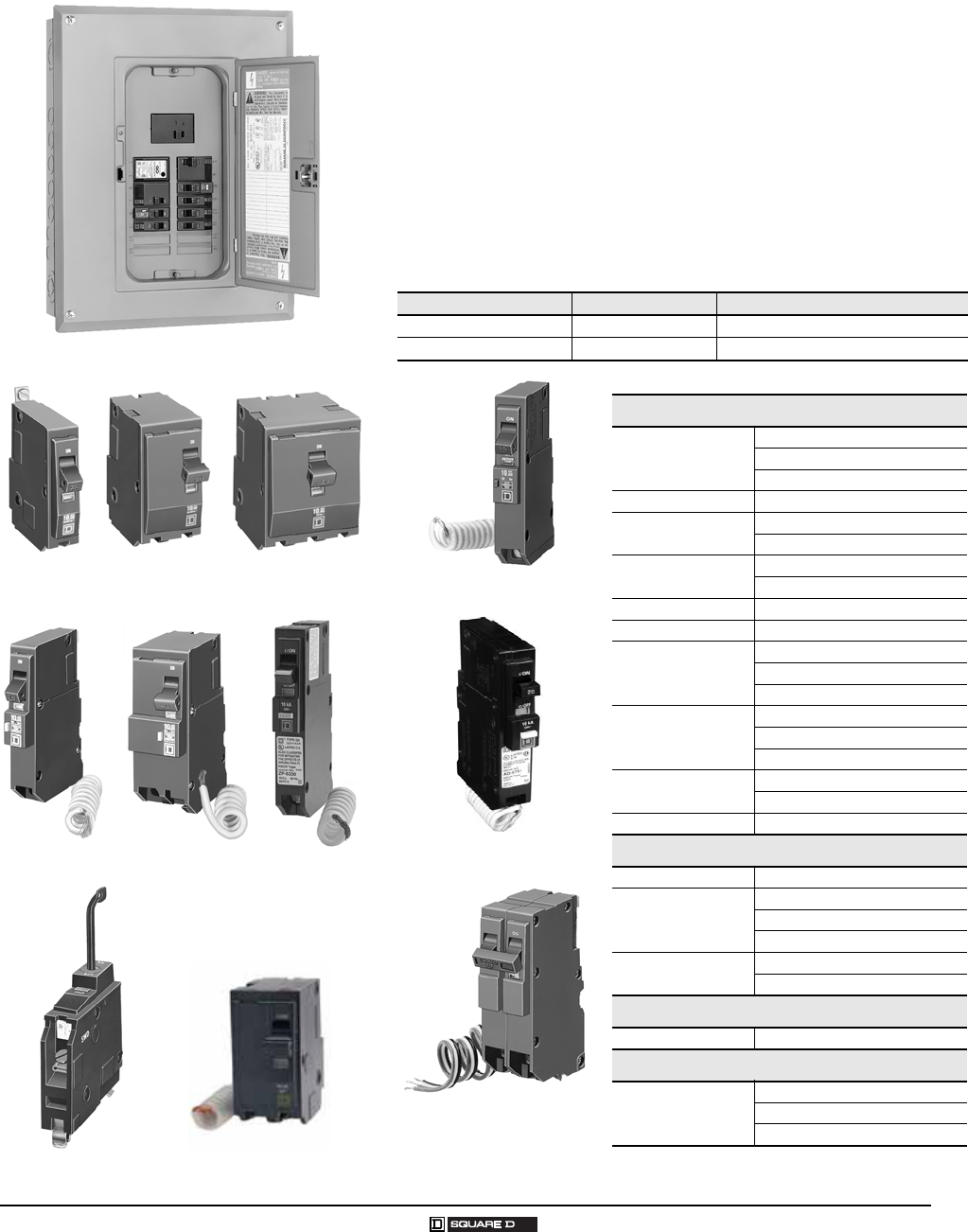
Branch Circuit Breakers
QO® Circuit Breaker Load Center
QO
1-Pole QO
2-Pole QO
3-Pole
QO-GFI
1-Pole QO-GFI
2-Pole
QOK, 1-Pole QO-SWN, 1-Pole
QO-AFI 1-Pole
120 Vac, 1φ2W 240/120 Vac delta, 3φ4W
120/240 Vac, 1φ3W 240 Vac corner grounded delta, 3φ3W
240 Vac delta, 3φ3W 48 Vdc maximum (1φ convertible main
lug 124 2 circuit only)
208Y/120 Vac, 3φ4W
Main Lugs Main Circuit Breaker
Single-Phase 30 400 A 1004 00 A
Three-Phase 60 225 A 1002 25 A
10,000 AIR
QO
1-pole, 1070 A
2-pole, 1012 5 A
3-pole, 1010 0 A
QOT 1-pole, 1520 A
QO-EPD 1-pole, 1530 A
2-pole, 1560 A
QO-GFI 1-pole, 1530 A
2-pole, 1560 A
QO-AFI 1-pole, 1520 A
QO-CAFI 1-pole, 1520 A
QO-HID
1-pole, 1550 A
2-pole, 1550 A
3-pole, 1530 A
QO-PL
QO-PLILC
1-pole, 1020 A, 30 A
2-pole, 1060 A
3-pole, 1560 A
QO-SWN 2-wire, 1050 A
3-wire, 1050 A
QOK 1-pole, 1030 A
22,000 AIR
QO-VHGFI 1-pole, 1530 A
QO-VH
1-pole, 1530 A
2-pole, 1512 5 A
3-pole, 1510 0 A
QOB-VH 2-pole, 150 A 1
1For use with 300 A and 400 A load centers only. Requires PK3CA
mounting kit, ordered separately.
3-pole, 110150 A 1
42,000 AIR
QOH 2-pole, 4012 5 A
65,000 AIR
QH
1-pole, 1530 A
2-pole, 1530 A
3-pole, 1530 A
QO-PL 2-Pole
QO-EPD 1-Pole
QO-CAFI 1-Pole
QO® and Homeline® Load Centers and Enclosures
General Information and Application Data
6
© 2007 Schneider Electric All Rights Reserved 03/2007
Indoor Enclosures (Type 1)
Welded sheet steel with knockouts at top, bottom, back, and sides
Finish: gray baked enamel, electrodeposited over cleaned,
phosphatized steel
Most 100 225 A indoor enclosures are 14.25 in. (362 mm) wide (see
Dimensions and Knockouts on page 26)
300 A and 400 A indoor enclosures are 20 in. (508 mm) wide
Top or bottom feed by rotating enclosure
Indoor Covers
Doors to cover circuit breaker handles, except on 24, 48, 612 , and
816 circuit models
Shutter-type twistouts
Flush and surface covers available, sold separately
Flush covers have automatic flush adjustment
Field-installed door lock provisions available on most covers
QOFP filler plates available for all covers
QOM1FP filler plates available for 1001 25 A convertible load center
covers
QOM2FP filler plates available for 1502 25 A convertible load center
covers
Q2FP filler plates available for 3-phase load center covers
Triple lead cover screws for fast cover installation
Rainproof Enclosures (Type 3R)
Complete enclosure includes interior trim and door
Welded, galvannealed steel
Finish: gray baked enamel, electrodeposited over cleaned,
phosphatized, galvannealed steel
RB devices have provisions for interchangeable bolt-on hub
Top-centered rainproof mounting boss on the back of the enclosure
simplifies installation and saves time
Stainless steel door latch on the enclosure provides secure closure and
maximum durability
Convertible main panels are side-hinge door devices
Allow 1.25 in. (32 mm) on the left side for the door to open
Side-hinged door provides full wiring access without door removal
Bolt-On Hubs
Hubs available from 0.75 in. (19 mm) to 4 in. (102 mm) conduit size
No gasket required with hubs from 0.75 in. (19 mm) to 2.50 in. (64 mm)
when used on RB type load centers
QO130M150
Indoor Cover
QO140M200RB
Bolt-On Hubs
QO® and Homeline® Load Centers and Enclosures
General Information and Application Data
7
03/2007 © 2007 Schneider Electric All Rights Reserved
Class CTL
Class CTL load centers are UL Listed
Circuit breaker mounting rails have slots to accept tandem circuit
breakers, on specified load centers
Meets paragraph 408.35 of the 2005 National Electrical Code® (NEC®)
Phasing
Load centers have distributed phase bussing
Most branch circuit breakers can be mounted in any position
Line Lugs
All lugs suitable for 75 °C copper or aluminum wires (see Main Lugs
and Main Circuit Breaker Ratings on page 20)
Main lugs and main circuit breaker load centers have wire binding screw
torque values on the wiring diagrams and circuit breaker labels
Neutral Assemblies
All lugs suitable for copper or aluminum wire (see Main Lugs and Main
Circuit Breaker Ratings on page 20)
Branch neutral terminals suitable for one #14#4 AWG copper or one
#12#4 AWG aluminum wire
Three #141/0 AWG copper or #14#6 AWG aluminum terminals
provided on 1242 circuits, 100 225 A load centers
Suitable lugs provided on the neutrals for termination of the grounding
conductor
All unused neutral terminals may be used to terminate bare or green
equipment grounding conductors when the load center is used as
service equipment:
one or two #14# 12 AWG copper
one or two #12# 10 AWG aluminum
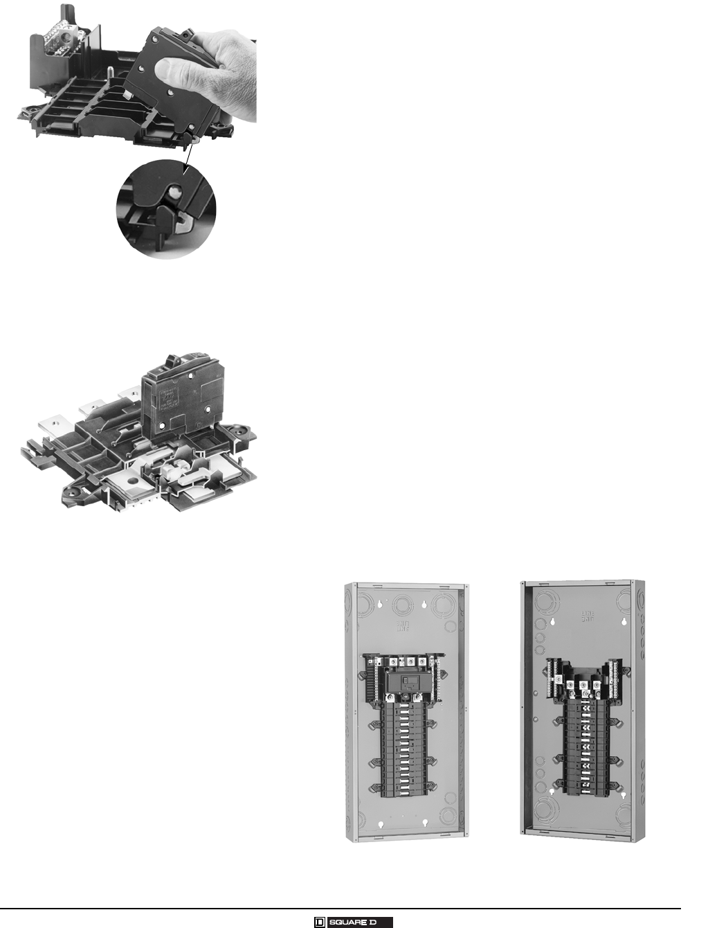
Tandem circuit breaker mounts on rails.
Branch Circuit Breaker
Neutral assemblies accept copper or aluminum wire.
QO® and Homeline® Load Centers and Enclosures
General Information and Application Data
8
© 2007 Schneider Electric All Rights Reserved 03/2007
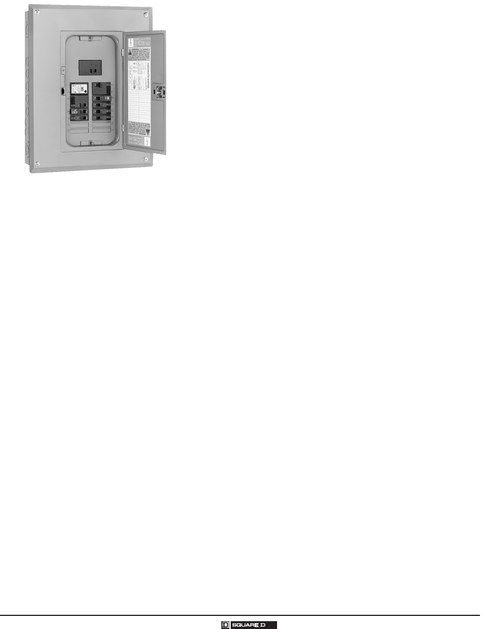
Single Phase, 2–16 Circuits, 30–125 A, Fixed Mains
UL Listed
File E-6294
Suitable for use as service equipment
75 °C wire rating (see Technical Information on page 20)
Federal Specification W-P-115c, Type 1, Class 2
CSA Certified
File LL-89066-21
For other CSA certified load centers, see Supplemental Digest 174.
Short Circuit Current Rating
UL short circuit current rating depends on lowest interrupting rating of
circuit breaker installed (see Technical Information on page 20)
Interior
Tin plated aluminum bus
Tin plated copper bus is an available option on 6 12 and 816 circuit
load centers
Tin plated copper bus is standard on 4 8 circuit load centers
Mains
Factory-installed main lugs
Top mains positioning only
Top or bottom feed
A backfed main circuit breaker can be field-installed in 48 , 6 12 and
816 load centers using the PK2MB retaining kit
Cover
Flush- or surface-mounted cover included with load centers
A cover with a door is an available option on 61 2 and 8 16 circuit load
centers
QO24L70S
QO816L100DS
QO148L125GF
QO® and Homeline® Load Centers and Enclosures
General Information and Application Data
9
03/2007 © 2007 Schneider Electric All Rights Reserved
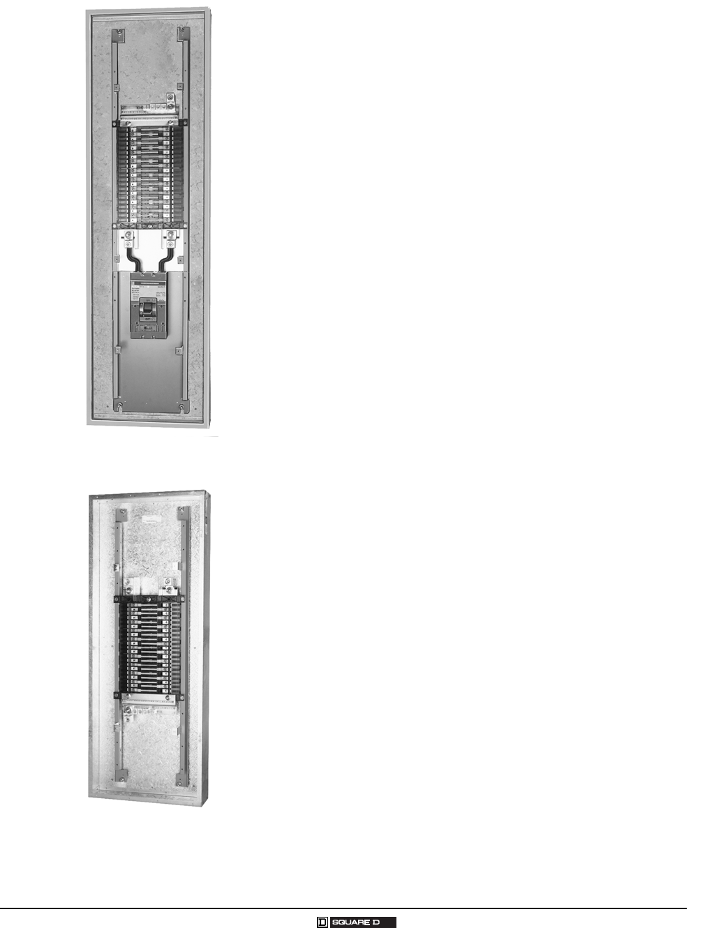
Single-Phase, 12–42 Circuits, 100–225 A, Convertible Mains
UL Listed
File E-6294
Federal Specification W-P-115c, Type 1, Class 2
Suitable for use as service equipment
75 °C wire rating (see Technical Information on page 20)
Short Circuit Current Rating
Main lugs: up to 65,000 AIR (depends on lowest interrupting rating of
branch circuit breakers installed)
Main circuit breaker: 22,000 AIR standard
22,000 AIR main circuit breaker kits (refer to page 10 and Technical
Information on page 20)
Interior
Shielded, one-piece tin plated copper bus
Removable interior with single, captive mounting screw
Split branch neutral with up to 50% more terminations than required
Multiple mounting locations for equipment grounding bar kits: left, right,
and bottom
Main lugs load centers have equipment grounding bar kits included (not
factory-installed)
Mains
Factory-installed main lugs convertible to main circuit breaker
Factory-installed main circuit breaker convertible to main lugs
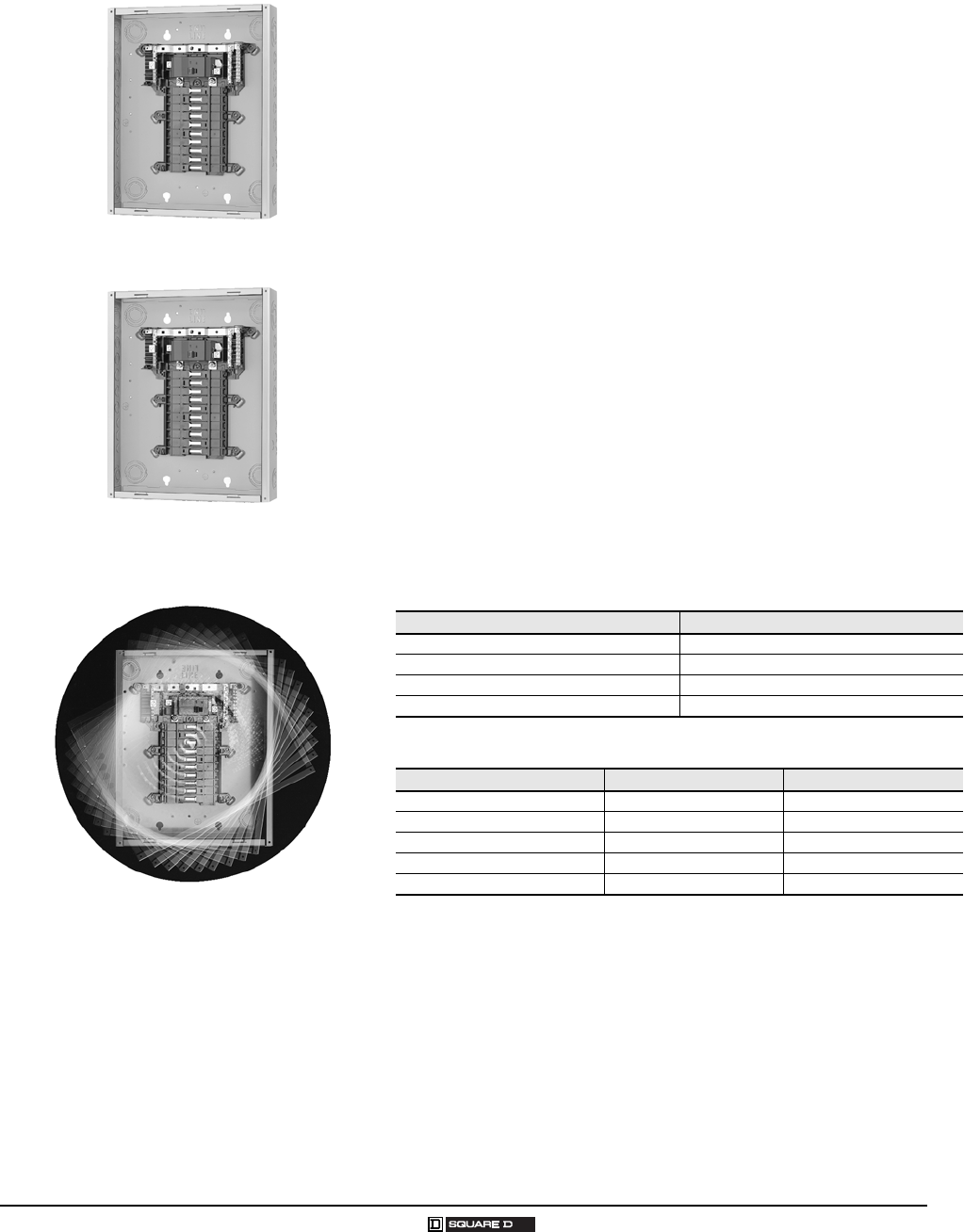
Load Center Amperage Main Circuit Breaker Kit Amperage
125 50 125
150 10015 0
200 10020 0
225 10022 5
Main Circuit Breaker Amperage Main Lug Kit Amperage Load Center Amperage
100 125 100
125 125 125
150 225 150
200 225 200
225 225 225
Main Circuit Breaker
Main Lug
Top or bottom mains positioning. Rotate
entire load center 180 degrees.
QO® and Homeline® Load Centers and Enclosures
General Information and Application Data
10
© 2007 Schneider Electric All Rights Reserved 03/2007
Single-Phase, 12–42 Circuits, 100–225 A, Convertible Mains,
Continued
Covers
Flush and surface covers sold separately
Flush covers have spring-loaded interior trim for automatic flush
adjustment
Positive action, easy-open door latch
Main Lugs Kits
Field-installable in main circuit breaker or main lugs load centers
QOL125 kit for use in 100 125 A load centers
QOL225 kit for use in 150 225 A load centers
Main Circuit Breaker Kits
Field-installable in main lugs or main circuit breaker load centers
502 25 A main circuit breaker kit is 22,000 AIR series rated with 10,000
AIR branch circuit breakers
Field-Installable Main Circuit Breaker (Convertible Main Load Centers Only)
Main Circuit
Breaker Ampere
Rating 1
1Do not exceed the load center mains rating.
Use with
Convertible
Load Center
Mains Rating
22,000 AIR Lug Wire Size 2
AWG/kcmil
Al or Cu
2Wire range listed for QOM circuit breaker kits is the wire range of that circuit breaker. To find
out maximum wire size permitted in a particular load center per UL, see Main Wire Size
AWG/kcmil on page 20.
Lug Torque
lb-in. / N•m
Main Circuit
Breaker
QOM1 Frame Size
50 100 125 A QOM50VH
#12 2/0 50 lb-in.
(6 N•m)
60 100 125 A QOM60VH
70 100 125 A QOM70VH
80 100 125 A QOM80VH
90 100 125 A QOM90VH
100 100 125 A QOM100VH
110 125 A QOM110VH
125 125 A QOM125VH
QOM2 Frame Size 3 4
3Add suffix 1021 for shunt trip.
4Add suffix 8041 for control wire taps.
100 150 225 A QOM2100VH
#430 0 250 lb-in.
(28 N•m)
125 150 225 A QOM2125VH
150 150 225 A QOM2150VH
175 200 225 A QOM2175VH
200 200 225 A QOM2200VH
225 225 A QOM2225VH
QOL125 Kit
QOL225 Kit
Cover
QOM1
Main Frame Size
50–125 A
QOM2
Main Frame Size
100–225 A

QO® and Homeline® Load Centers and Enclosures
General Information and Application Data
11
03/2007 © 2007 Schneider Electric All Rights Reserved
Special Purpose
Recreational Vehicle and Manufactured Housing Load Centers
UL Listed (File E-6294) and CSA Certified (LL89066-14)
Single-phase, 2- and 3-wire
Factory-installed equipment grounding bar
Covers included with load centers
Load Centers with Covers
Combination flush/surface cover included with load centers
Equipment grounding bar included on main lug load centers
Top or bottom feed on incoming service by rotating complete load
center 180 degrees
Convertible main load centers
Non-Metallic Load Center
UL Listed
Suitable for use as service equipment
Side-hinge door device
10,000 AIR rating
Single-phase, 2- and 3-wire
Factory-installed grounding bar
Cover included with load center
Knockouts in bottom endwall, side and back
Main Circuit Breaker with Feed-Thru Lugs
Available rainproof enclosure only
Side hinge door devices
Allow 1.25 in. (32 mm) on the left side for the door to open
125, 150, and 200 A mains rating
125, 150, and 200 A feed-thru lugs
Space for up to 8 single-pole circuit breakers
QO130M150
QO24L60NRNM
QO1816M200FTRB
QO2L30TTS
QO® and Homeline® Load Centers and Enclosures
General Information and Application Data
12
© 2007 Schneider Electric All Rights Reserved 03/2007
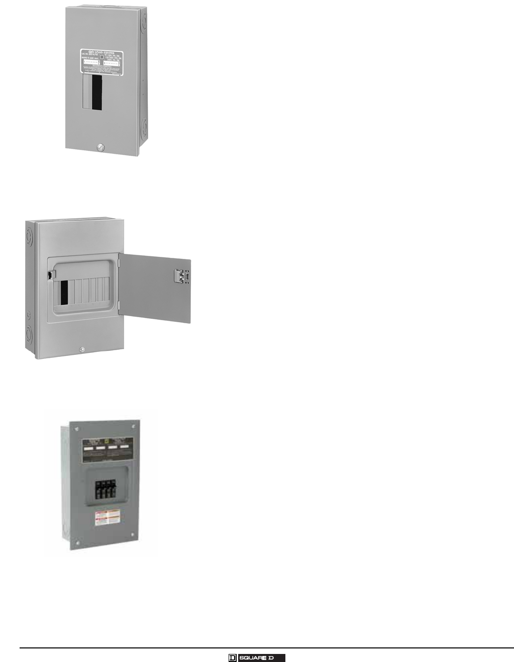
Generator Panels
Generator PanelManu al Transfer
Connects utility and standby power to installed branch circuits
Includes two factory-installed 2-pole main circuit breakers tied together
with a mechanical interlock
30 A and 60 A main circuit breaker versions
Supply up to 8 branch circuits using tandem circuit breakers
Available indoor enclosure only
Cover with door included
Generator PanelAutomatic Transfer
QO® load center platform construction
Automatic transfer from utility to back-up power source
Transfer cycle less than 10 seconds
Indoor and outdoor enclosures
120 / 240 Vac single-phase
150, 200 and 225 A main circuit breaker
42 circuit maximum construction, indoor, 28 circuit maximum outdoor
125 A maximum branch feeder connection to an alternative energy source
Service entrance rated
Manual override capability
Easy removal of interior and transfer switch for rough in wiring
5-year limited warranty
Compatible with standard load center field-installable accessories
Riser Panels
Offset interior provides ample wire gutter space for high rise applications
Factory-installed main lugs (125 A), convertible to main circuit breaker
with standard QOC cover and optional Mono-Flat cover
Factory-installed main lugs (200 A), convertible to main circuit breaker
when used with QOC cover only
Available in 12 to 40 circuits
Indoor only
Optional Mono-Flat® cover available for both 125 A and 200 A panels
(sold separately)
QO48M60DSGP
Wide Gutter
QO® Intelligent Load Center
QO® and Homeline® Load Centers and Enclosures
General Information and Application Data
13
03/2007 © 2007 Schneider Electric All Rights Reserved
Three-Phase, 3–42 Circuits, 60–225 A, Convertible or Fixed Mains
UL Listed
File E-6294
Suitable for use as service equipment
75 °C wire rating (see Technical Information on page 19)
Short Circuit Current Rating
Main lugs: up to 65,000 AIR (depends on lowest interrupting rating of
branch circuit breakers installed)
Main circuit breaker up to 225 A: 22,000 AIR standard; optional up to
65,000 AIR for 100 A to 225 A main circuit breakers
Mains
Factory-installed main lugs or main circuit breaker
Main neutral terminal located next to the phase terminals on 1252 25 A
main circuit breaker devices
Top or bottom feed (see Technical Information on page 24)
Fully convertible from main circuit breaker to main lugs (100 225 A)
100 A maximum back-fed main QO® circuit breaker; requires the use of
retaining kit PK3MB
Cover
Flush- and surface-mount covers sold separately
Flush covers have spring-loaded interior trim for automatic flush
adjustment
Positive action, easy-to-open door latch
Interior
Shielded one-piece plated copper bus on 1002 25 A
Removable interior with single, captive mounting screw on 10022 5 A
(indoor only)
Main lugs load centers have equipment grounding bar kits included
(not factory-installed)
Branch Neutral Termination
Suitable for copper or aluminum wire
Terminals suitable for one #14#4 AWG coppe r or one #12 #4 AWG
aluminum wire
Positioned on both sides of the mains compartment
Slot/square drive wire binding screws
Three (3) #141 /0 AWG copper or #14# 6 AWG aluminum terminations
standard on 124 2 circuits, 10022 5 A load centers
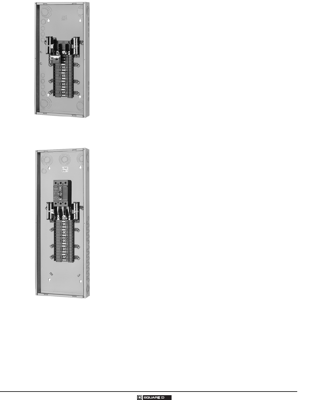
QO330L200G
QO330MQ150
QO® and Homeline® Load Centers and Enclosures
General Information and Application Data
14
© 2007 Schneider Electric All Rights Reserved 03/2007
Three-Phase, 3–42 Circuits, 60–225 A, Convertible or Fixed
Mains (Continued)
Main Lugs Kits
Field-installable in main circuit breaker or main lugs load centers
QOL3125 kit for use in 100125 A load centers
QOL3225 kit for use in 150225 A load centers
Main Circuit Breakers
Field-installable in main circuit breaker load centers
25,000 AIR QDL main circuit breakers series rated with 10,000 AIR QO®
branch circuit breakers
100 225 A main circuit breakers are series rated up to 100,000 AIR (see
table below) with 10,000 AIR branch circuit breakers in 30 circuit or
larger main circuit breaker load centers with optional QJL main circuit
breaker
Back-fed QO-VH (100 A maximum) main circuit breaker may be field
installed in main lugs and main circuit breaker load centers (requires
PK3MB retaining kit)
27 circuit, 100 A main circuit breaker load center includes factory-
installed back-fed QO-VH main circuit breaker
Electrical accessories are not available on QDL, QGL, or QJL circuit
breakers
304 2 circuit, 12522 5 A main circuit breaker load centers include
integral QDL circuit breakers. Optional QGL and QJL circuit breakers
available as shown:
Amperage 25,000 AIR 65,000 AIR 100,000 AIR 1
1When these 3-pole circuit breakers are used as the main circuit breaker of a three-phase
load center, the maximum AIR rating is 65,000 at 240 Vac and 100,000 at 208 Vac.
70 QDL32070 QGL32070 QJL32070
80 QDL32080 QGL32080 QJL32080
90 QDL32090 QGL32090 QJL32090
100 QDL32100 QGL32100 QJL32100
110 QDL32110 QGL32110 QJL32110
125 QDL32125 QGL32125 QJL32125
150 QDL32150 QGL32150 QJL32150
175 QDL32175 QGL32175 QJL32175
200 QDL32200 QGL32200 QJL32200
225 QDL32225 QGL32225 QJL32225
QOL3225
Main Lugs Kit
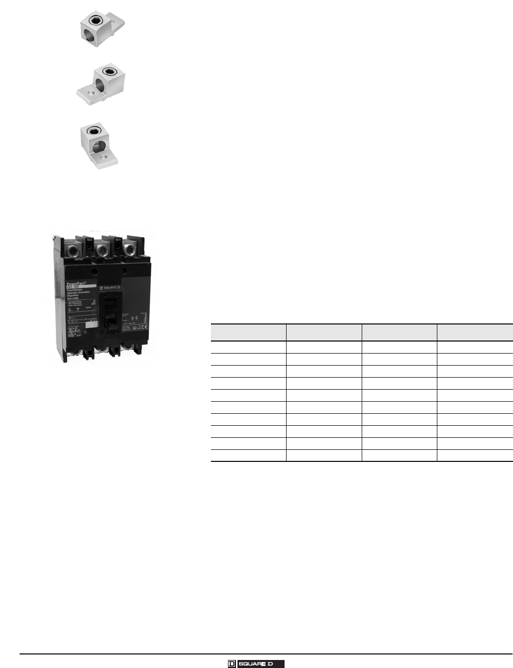
QDL Circuit Breaker
70–225 A
QO® and Homeline® Load Centers and Enclosures
General Information and Application Data
15
03/2007 © 2007 Schneider Electric All Rights Reserved
Single-Phase, 12–42 Circuits, 300–400 A, Fixed Mains
UL Listed
File E-6294
Suitable for use as service equipment
75 °C wire rating (see Technical Information on page 20)
Short Circuit Current Rating
Main lugs: up to 65,000 AIR
Main circuit breaker: 42,000 AIR fully rated (see Technical Information
on page 20)
Mains
Factory-installed main lugs and main circuit breaker
Multiple wire terminals for phases and neutral
Top or bottom mains positioning (see Technical Information on
page 20)
Cover
Flush- and surface-mount covers sold separately
Interior
Available in single-phase construction
Interiors accept QO® and QOB-VH 110 150 A maximum circuit
breakers (QOB-VH circuit breakers require connector kit PK3CA)
Tin plated aluminum bus
Tin plated copper connector fingers
Neutral assemblies positioned opposite the mains compartment
Enclosures
20 in. (508 mm) wide galvanized steel
Embossed 0.25 in. (6 mm) standoffs
End walls, one blank and one with knockouts, are standard; both are
removable and interchangeable
Embossed keyholes centered at both ends and in visual positioning
Multiple grounding bar mounting locations
Wire management braces
QON42MS400 and MH68
QON42LS400 and MH53
16
© 2007 Schneider Electric All Rights Reserved 03/2007
QO® Circuit Breaker Load Centers—Class 1130
General Information and Application Data
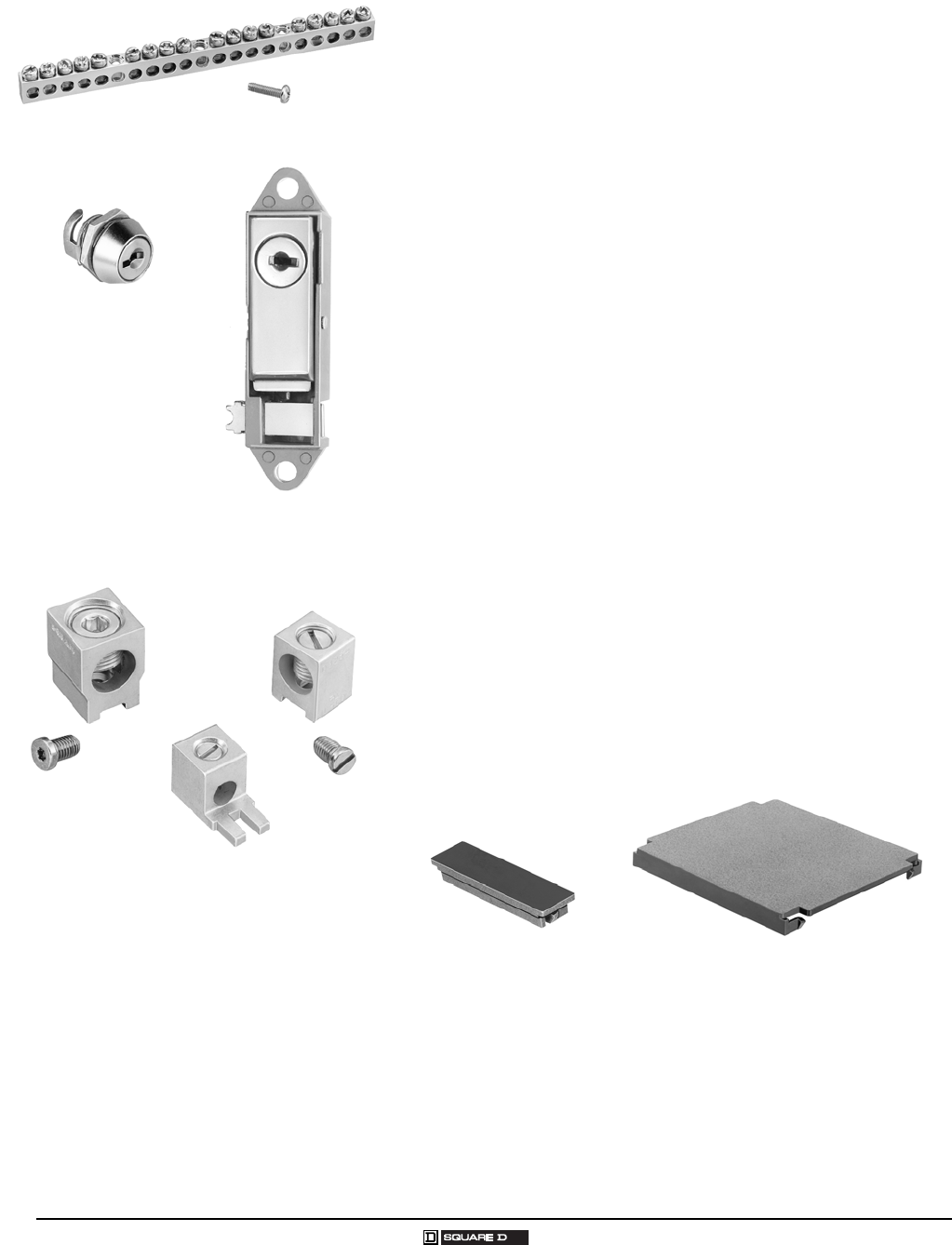
Accessories
Grounding Bar Kits
Field-installable in all load centers
Same wire size as terminals (see page 19)
Suitable for copper or aluminum wire
Available with #1 4/0 lug PK15GTA-L, PK18GTA-L, and PK23GTA-L
(see page 19)
Flush Lock Kits
Available for indoor load centers
Two keys provided with each lock kit
PK6FL for convertible 1242 circuit load centers
PK4FL for 300 and 400 A load centers
Auxiliary Neutral Lugs
UL Listed for copper or aluminum wire
Field-installable on neutral assembly
LK70AN:#12# 2 AWG Al or #14 #4 AWG Cu
LK100AN:#62 /0 AWG (Al/Cu)
LK125AN:#14 2/0 AWG (Al/Cu)
LK150AN:#23 /0 AWG (Al/Cu)
LK225AN:#43 00 kcmil (Al/Cu), use ONLY in Series S, 15022 5 A
QO® or Homeline® load center
Cover Filler Plates
Fast to install, snap-in type
QOFP branch circuit
QOM1FP for 70125 A, single-phase, main circuit breakers
QOM2FP for 15022 5 A, single-phase, main circuit breakers
Q2FP for 125225 A, three-phase, main circuit breakers
PG18GTA Grounding Bar Kit
PK6FL Flush Lock Kit
PK4FL Flush Lock Kit
LK150AN
LK70AN
LK100AN
Auxiliary Neutral Lugs
QOFP Cover Filler Plate Q2FP Cover Filler Plate
QO® and Homeline® Load Centers and Enclosures
General Information and Application Data
17
03/2007 © 2007 Schneider Electric All Rights Reserved
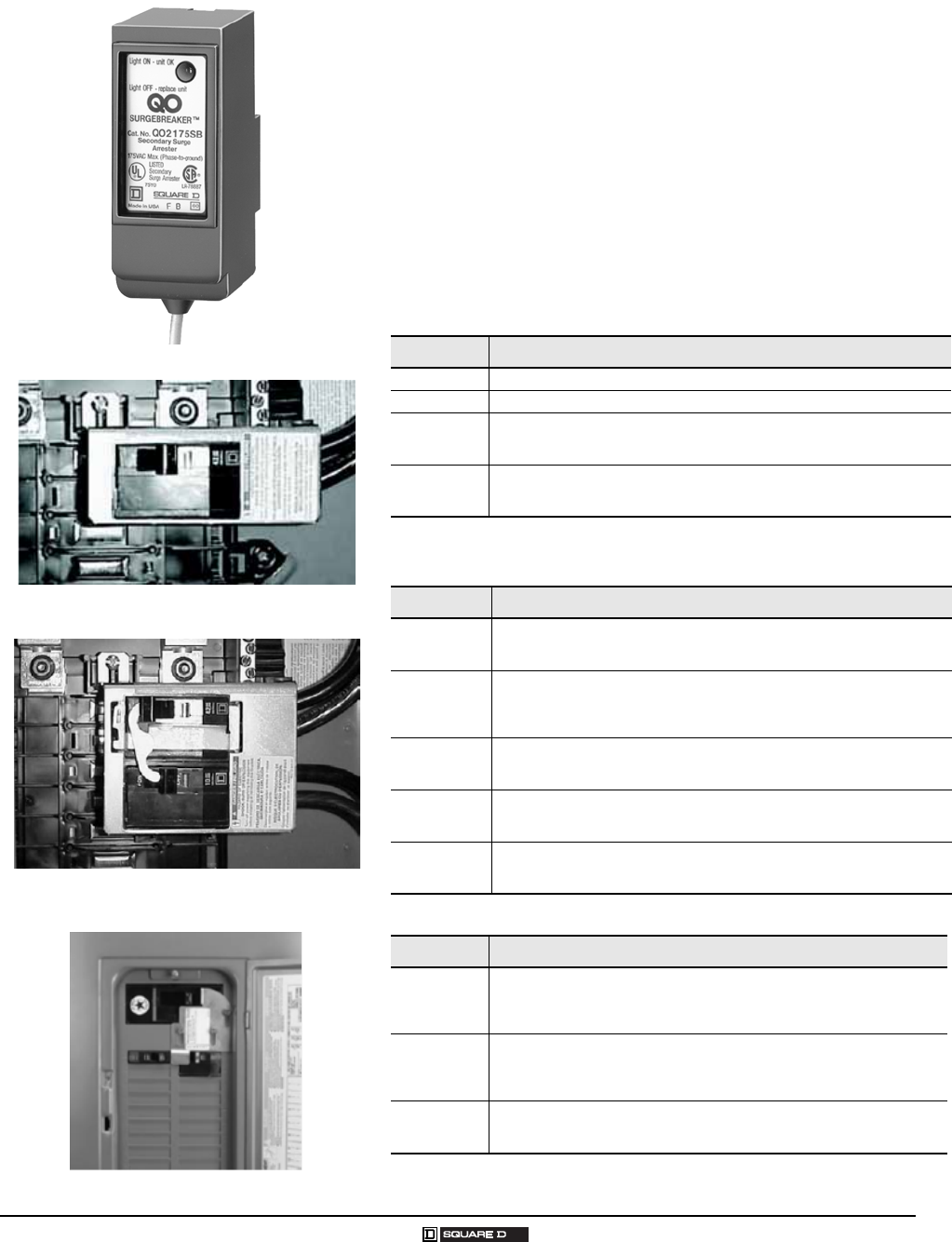
Accessories (Continued)
Surgebreaker® Secondary Surge Arrester
QO2175SB UL Listed secondary surge arrester
Easy plug-on installation for QO® load centers
LED indicates operational status
Plug-on design requires two pole spaces
Designed to protect electrical service and major household appliances,
excluding electronic devices
Back-Fed Main Circuit Breaker Retaining Kits
Back-fed main circuit breaker retaining kits secure 2-pole, 10125 A circuit
breakers to single-phase or three-phase mains interiors when used as
back-fed main circuit breakers. Mounting of retaining kits is based on
top-feed applications.
UL Listed Manual Transfer Equipment Kits
Manual transfer equipment kits secure two 2-pole, 10 125 A circuit breakers.
Generator Circuit Breaker Interlock Kit
Catalog No. Description
PK2MB QO 61 2, 4 8, and 816 loa d centers
PK3MB Three-phase load centers
PK4MB2LA
Mounts on the right side of QO single-phase, 100125 A convertible main load
center, series S01 and S02. Retains one 2-pole QO circuit breaker with or
without electrical accessories.
PK4MB2HA
Mounts on the right side of QO single-phase, 150225 A convertible main load
center, series S01 and S02. Retains one 2-pole QO circuit breaker with or
without electrical accessories.
Catalog No. Description
QO2DTI
For interlocking the handles of two 2-pole or one 2-pole and one 1-pole QO
and Q1 circuit breakers mounted side-by-side so that only one circuit breaker
can be ON at a time.
QO2DTIM
QO2DTI mechanical interlock attachment with retaining kits for securing two
adjacent back-fed circuit breakers in dual power supply applications. Can be
used with two 2-pole or one 2-pole and one 1-pole QO circuit breakers in
QO816L100 load centers.
PK4DTIM4LA
Mounts on the right side of QO single-phase, 100125 A convertible main load
center, series S01 and S02. Retains two 2-pole QO circuit breakers with a
QO2DTI kit included for dual power supply applications.
PK4DTIM4HA
Mounts on the right side of QO single-phase, 150225 A convertible main load
center, series S01 and S02. Retains two 2-pole QO circuit breakers with a
QO2DTI kit included for dual power supply applications.
PK4DTIM4LAL
Mounts on the left side of QO single-phase, 1001 25 A convertible main load
center, series S01 and S02. Retains two 2-pole QO circuit breakers with a
QO2DTI kit included for dual power supply applications.
Catalog No. Description
QOCRBGK1
For use on "G" and "S" Series NEMA Type 1 and "G", "S1" and "S2" Series
NEMA Type 3R load centers. Interlocks a QOM1, 2-pole main circuit breaker
of a load center (100-125 A) with a QO, 2-pole (15-125 A) branch circuit
breaker. Includes a retaining kit.
QOCGK2
For use on G and S Series NEMA Type 1 and G and S1 Series NEMA
Type 3R load centers. Interlocks a QOM2, 2-pole main circuit breaker of a
load center (15022 5 A) with a QO 2-pole (1512 5 A) branch circuit breaker.
Includes a retaining kit.
QORBGK2
For use on S2 Series NEMA Type 3R load centers. Interlocks a QOM2 2-pole
main circuit breaker of a load center (150 225 A) with a QO 2-pole (151 25 A)
branch circuit breaker. Includes a retaining kit.
QO2175SB
Back-fed Main Circuit Breaker
Retaining Kit (PK4MB2LA)
QO Manual Transfer
Equipment Kit (PK4DTIM4HA)
Generator Interlock Kit Installed
18
© 2007 Schneider Electric All Rights Reserved 03/2007
QO® Circuit Breaker Load Centers—Class 1130
General Information and Application Data
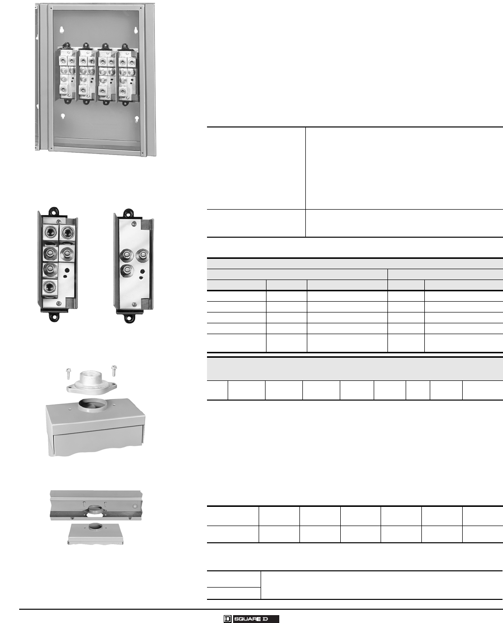
Accessories (Continued)
Auxiliary Gutters and Tap Kits
Field-installable on the left or right side of load centers
Auxiliary gutters are 13.50 in. wide x 26.12 in. height x 3.75 in. deep
Conduit riser sizes: 1-3/4, 2, 2-1/2 or 3 in. (3 in. requires use of B300
bolt-on hubs)
Flush cover included with auxiliary gutter
Tap kits required for each riser wire to be tapped (see below for tap kits)
Wire range on tap kits is #4 AWG to 300 kcmil copper or aluminum
Tap kits include mechanical-type lugs or studs for crimp-type lugs
Crimp-type lugs not included in tap kits (order separately)
Auxiliary Gutter (SDAG26) to Load Center Catalog Number Reference
Tap Kits
Bolt-On Hubs
Equipment with an RB suffix, meaning Rainproof Type 3R construction,
uses the bolt-on hubs listed below. RB devices will accept 0.75 in. (19 mm)
through 2.50 in. (64 mm) bolt-on hubs without the use of reducers. Off-
center conduit thread openings and elongated mounting holes provide quick
and easy adjustment to eliminate costly conduit offsets and bends. Hubs are
suitable for use with conduit having ANSI standard taper pipe thread.
UL Listed Bolt-On Hubs for RB Devices
UL Listed Enclosure Coupling for RB Devices
RB Hub
BC200 Enclosure Coupling
SDAG26
With Tap Kits Installed
Tap Kit with
Mechanical Lugs Tap Kit for
Crimp Lugs
QO® Single-Phase QO112L125G
QO11224L125G
QO112L125GC
QO11224L125GC
QO116L125G
QO11624L125G
QO120L125G
QO12024L125G
QO124L125G
QO120L125GC
QO112M100
QO116M100
QO120M100
QO124M100
QO124M125
QO112M100C
QO11220M100C
QO116M100C
QO120M100C
QO® Three-Phase QO312L125G
QO320L125G
QO324L125G
UL Listed for Use with Auxiliary Gutter SDAG26
Riser Wire Tap Off Wire
Catalog Number Lug Type Wire Size Lug Type Wire Size
SDGT30020 Mechanical (2) #6 AWG3 00 kcmil Mechanical (1) #6 AWG2 /0 AWG
SDGT300300 Mechanical (2) #6 AWG3 00 kcmil Mechanical (1) #6 AWG30 0 kcmil
SDGT300C10C Crimp (2) #4 AWG3 00 kcmil Crimp (1) #8 AWG1 /0 AWG
SDGT300C300C Crimp (2) #4 AWG3 00 kcmil Crimp (1) #4 AWG30 0 kcmil
QOGL20
(grounding lugs) Mechanical (2) #6 AWG 2/0 AWG
Auxiliary Gutter
UL Listed for Use with Standard Load Centers for Riser Applications
SDAG26 Flush No N/A See Tap
Kit No
Conduit Size 0.75 in.
19 mm
1.00 in.
25 mm
1.25 in.
32 mm
1.50 in.
38 mm
2.00 in.
51 mm
2.50 in.
64 mm
Hub Cat. No. B075 B100 B125 B150 B200 B250
NOTE: Closing cap (catalog number B-CAP) is provided factory-installed on each device having the RB suffix.
Cat. No. Designed for connecting wireway or other enclosures to units having RB
bolt-on conduit provisions. Provides a bushed opening equal to 2 inch conduit.
Eliminates the need for conduit nippling.
BC200
QO® and Homeline® Load Centers and Enclosures
Technical Information
19
03/2007 © 2007 Schneider Electric All Rights Reserved
TECHNICAL INFORMATION
Grounding Bar Kits
All PK equipment grounding kits are supplied with mounting screws,
necessary installation instructions, and an Equipment Grounding Terminal
self-adhesive label.
Catalog
Number Total
Qty.
Terminals Approximate
Overall
Length
Distance
Between
Mounting
Holes Mounting
Quantity Each Size
See “Wire Range
Table” below.
III III IV VVI in. mm in. mm
PK0GTA21
1Mounting screw 40205-065-01 (one required).
2 2 1.75 44 One
hole
One
hole Top
PK0GTA62
2Mounting screw 21922-18360 (two required).
6 6 4.61 117 1.69 43 Top
PK3GTA13
3Mounting screw 21594-14220 (two required).
3 3 1.38 35 One
hole
One
hole Top
PK4GTA34 4 1.63 41 One
hole
One
hole Top
PK5GTA4
4Mounting screw 21594-14241 (two required).
5 5 2.25 57 1.25 32 Top
PK7GTA37 7 2.88 73 1.25 32 Top or side
PK9GTA139 9 3.25 83 One
hole
One
hole Top
PK9GTA39 9 3.78 96 3.13 80 Top
PK12GTA312 12 4.70 119 3.13 80 Top
PK15GTA315 15 5.63 143 3.13 80 Top
PK15GTAL5
5Mounting screw 21594-14302 (two required).
16 15 1 8.13 207 3.13 80 Top
PK15GTA66
6Mounting screws 21594-14241(two required) and 21594-17121(two required).
21 15 6 5.88 149 7
73.13 in. (80 mm) on small terminals; 5.25 in. (133 mm) on large terminals.
7Top
PK18GTA318 18 6.56 167 3.13 80 Top
PK18GTAL519 18 1 8.81 224 3.13 80 Top
PK23GTA323 23 8.11 206 3.13 80 Top
PK23GTAL524 23 1 9.44 240 3.13 80 Top
PK27GTA3
8
8PK27GTA includes one main grounding lug that mounts with two terminal screws and requires
three terminals for mounting.
27 or
26
27
26 1 9.36 238 3.13 80 Top
Size Cu (AWG) Al (AWG)
I (1) #14# 4 or (2) #14 or #12 (1) #12#4 or (2) #12 or #10
II (1) #14/ 0 (1) #1 4/0
III (1) #62/ 0 (1) #6 2/0
IV (1) #63/ 0 (1) #6 3/0
V (1) #141 /0 (1) #14 1/0
VI (1) #10 2/0 (1) #62 /0
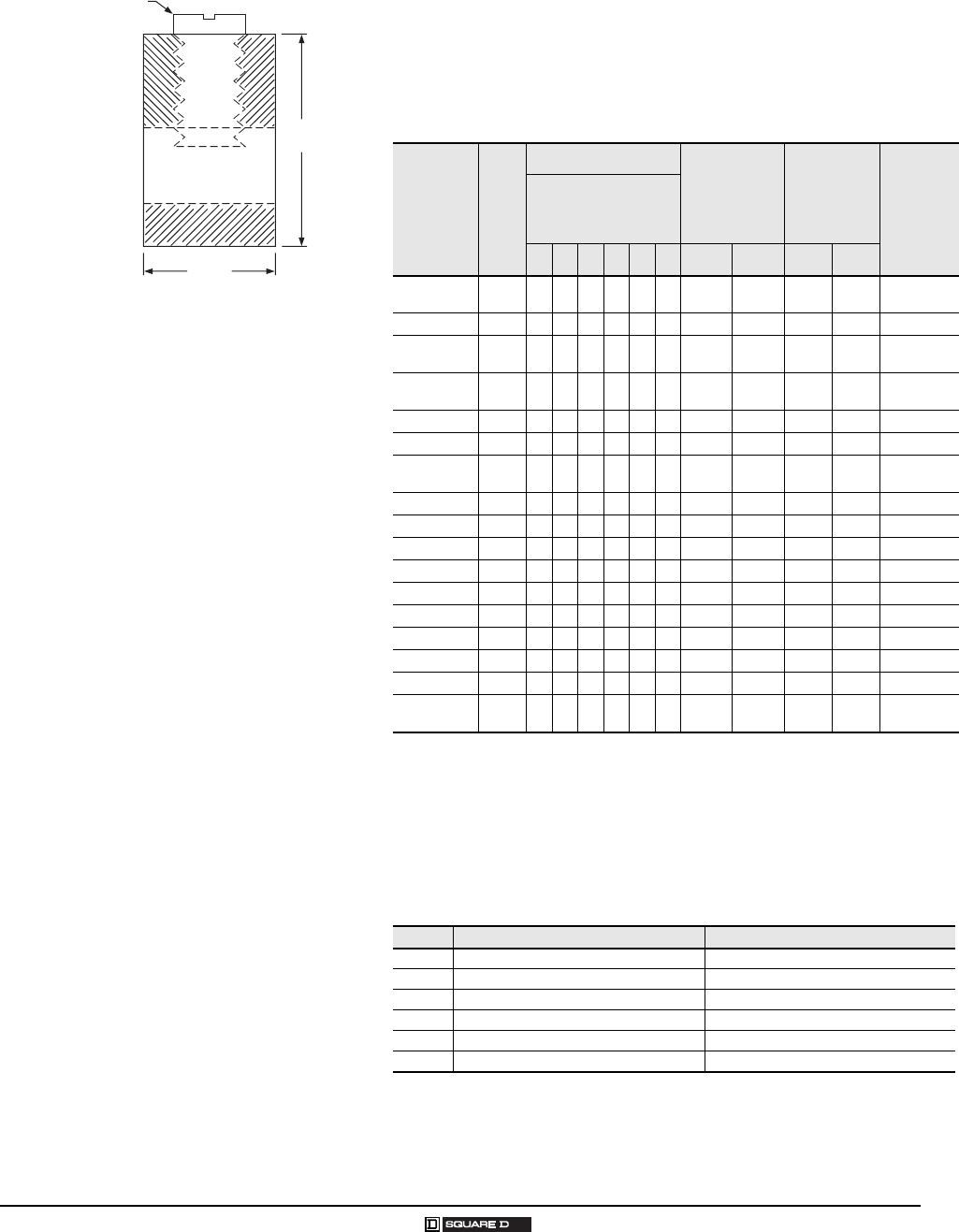
Slot / Robertson screw
Cross Section of Size 1 Ground Bar
0.437
[11]
0.3125
[8]
in.
[mm]
Dimensions:
20
© 2007 Schneider Electric All Rights Reserved 03/2007
QO® Circuit Breaker Load Centers—Class 1130
Technical Information
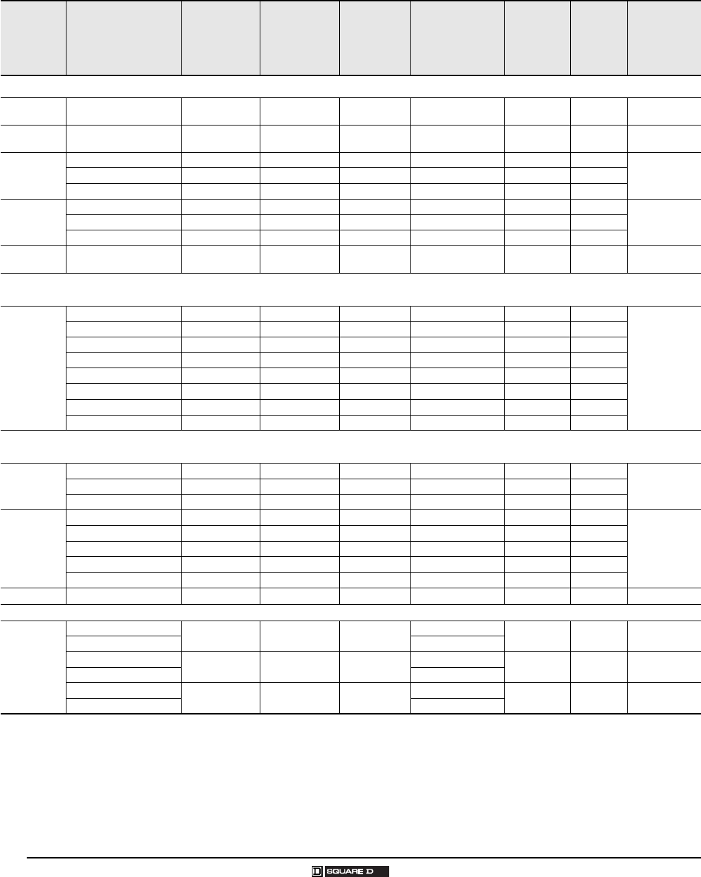
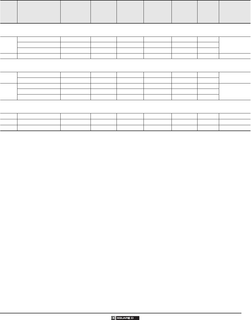
Main Lugs and Main Circuit Breaker Ratings
Single-Phase, Three-Wire, 120/240 Vac; Main Lugs Indoor
Mains
Rating in
Amps
Load Center Catalog
Number
Load Center
Cover Catalog
Number
UL Listed
Service
Equipment
(See notes)
Maximum
UL Short
Circuit
Rating 1
1Short circuit current rating depends on lowest AIR rating of main or branch circuit breaker installed.
M a i n W i r e S i z e
AWG/kcmil
Al/Cu
Enclosure
No.
(Page 26)
Top
or Bottom
Mains
Position
UL Listed for
Corner
Grounded
Delta
Systems
Fixed Mains – Factory-Installed Main Lugs
30 QO2L30S Included No 10,000 A #1210 Al
#1410 Cu 1Top No
70 QO24L70F/S Included B 10,000 A #123 Al
#14 4 Cu 2Top No
100
QO612L100F/S Included B, C 10,000 A #81 4 Top
No
QO612L100DF/S Included B, C 10,000 A #81 4 Top
QO612L100DFCU/SCU Included B, C 10,000 A #81 4 Top
100
QO816L100F/S Included B, C 10,000 A #81 4 Top
No
QO816L100DF/S Included B, C 10,000 A #81 4 Top
QO816L100DFCU/SCU Included B, C 10,000 A #81 4 Top
125 QO148L125GF/S Included B, C 10,000 A #122 /0 Al
#142/ 0 Cu 21 Top No
Convertible Mains – Factory-Installed Main Lugs
QOM1 Main Frame Size – Convertible to Main Circuit Breaker – Copper Bus
125
QO112L125G QOC16UF/S B, C 65,000 A 2 3
2UL Listed for 5000 A rms symmetrical short circuit rating when used in 3-phase, 240 Vac, corner grounded Delta systems, when used as main lugs load center only.
Use 240 Vac circuit breakers only.
322,000 A rms symmetrical maximum when supplied by integral type QOM-VH main circuit breaker from Square D® with 22,000 A rms symmetrical minimum
interrupting rating and when all installed QO® branch circuit breakers have 10,000 A rms symmetrical minimum interrupting rating.
#62/ 0 6 Both
Yes
QO11224L125G QOC16UF/S B, C 65,000 A 2 3#62/ 0 6 Both
QO116L125G QOC24UF/S B, C 65,000 A 2 3#62/ 0 7 Both
QO11624L125G QOC24UF/S B, C 65,000 A 2 3#62/ 0 7 Both
QO120L125G QOC24UF/S B 65,000 A 2 3#62/ 0 7 Both
QO12024L125G QOC24UF/S B 65,000 A 2 3#62/ 0 7 Both
QO124L125G QOC24UF/S B 65,000 A 2 3#62/ 0 7 Both
QO132L125G QOC32UF/S B 65,000 A 2 3#62/ 0 8 Both
Convertible Mains – Factory-Installed Main Lugs
QOM2 Main Frame Size – Convertible to Main Circuit Breaker – Copper Bus
150
QO12030L125G QOC30UF/S B, C 65,000 A 2 3#625 0 9 Both
Yes
QO124L150G QOC30UF/S B, C 65,000 A 2 3#625 0 9 Both
QO130L150G QOC30UF/S B, C 65,000 A 2 3#625 0 9 Both
200
QO112L200G QOC30UF/S B, C 65,000 A 2 3#625 0 9 Both
Yes
QO12436L200TFT QOC40UF/S B, C 65,000 A 2 3#625 0 10 Both
QO130L200G QOC30UF/S B, C 65,000 A 2 3#625 0 9 Both
QO13040L200G QOC30UF/S B, C 65,000 A 2 3#625 0 9 Both
QO140L200G QOC40UF/S B, C 65,000 A 2 3#625 0 10 Both
225 QO142L225G QOC42UF/S B 65,000 A 2 3#630 0 11 Both Yes
Fixed Mains – Factory-Installed Main Lugs
400
QON12LS400 (Interior) MHC50VF/S C 65,000 A 4
4UL Listed for 5000 A rms symmetrical short circuit rating when used on 3-phase, 240 Vac, corner grounded Delta systems. Use 240 Vac circuit breakers only.
B UL Listed as suitable for use as service equipment (neutral bonded at the time of installation) with field-installed service disconnect.
C UL Listed as suitable for use as service equipment (neutral bonded at the time of installation) when not more than six service disconnecting means are provided and
when not used as a lighting and appliance branch circuit panelboard.
(1)1/0 750 15 Both Yes
MH50 (Enclosure) (2)1/0 300
QON30LS400 (Interior) MHC50QVF/S No 65,000 A 4(1)1/0 750 15 Both Yes
MH50 (Enclosure) (2)1/0 300
QON42LS400 (Interior) MHC53QVF/S No 65,000 A 4(1)1/0 750 17 Both Yes
MH53 (Enclosure) (2)1/0 300
QO® and Homeline® Load Centers and Enclosures
Technical Information
21
03/2007 © 2007 Schneider Electric All Rights Reserved
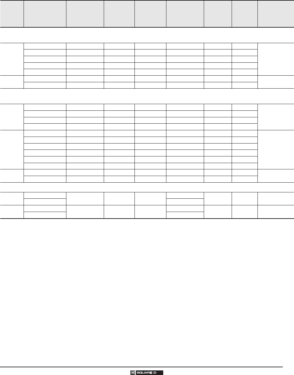
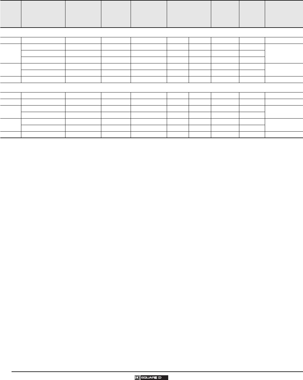
Single-Phase, Three-Wire, 120/240 Vac; Main Circuit Breaker Ind oor
Mains
Rating in
Amps
Load Center
Catalog Number
Load Center
Cover Catalog
Number
UL Listed
Service
Equipment
(See Notes)
Maximum
UL Short
Circuit
Rating 1
1Short circuit current rating depends on lowest AIR rating of main or branch circuit breaker installed.
M a i n W i r e S i z e
AWG/kcmil
Al/Cu
Enclosure
No.
(Page 26)
Top
or Bottom
Mains
Position
UL Listed for
Corner
Grounded
Delta Systems
Convertible Mains – Factory-Installed Main Circuit Breaker
QOM1 Main Frame Size – Convertible to Main Lugs or Lower Amperage Main Circuit Breaker – Copper Bus
100
QO112M100 QOC12UF/S A, B 22,000 A 2
222,000 A rms symmetrical maximum when supplied by integral type QOM-VH main circuit breaker from Square D® with 22,000 A rms symmetrical minimum
interrupting rating and when all installed QO® branch circuit breakers have 10,0000 A rms symmetrical minimum interrupting rating. 65,000 A rms symmetrical
maximum when main lugs kits are installed.
#41 5 Both
No
QO116M100 QOC20U100F/S A, B 22,000 A 2#41 6 Both
QO120M100 QOC20U100F/S A, B 22,000 A 2#41 6 Both
QO124M100 QOC24UF/S A, B 22,000 A 2#41 7 Both
QO132M100 QOC32UF A, B 22,000 A 2#41 8 Both
125 QO124M125 QOC24UF/S A, B 22,000 A 2#4 2/0 7 Both No
QO132M125 QOC32UF A, B 22,000 A 2#4 2/0 8 Both
Convertible Mains – Factory-Installed Main Circuit Breaker
QOM2 Main Frame Size – Convertible to Main Lugs or Lower Amperage Main Circuit Breaker – Copper Bus
150
QO12030M150 QOC30UF/S A, B 22,000 A 2#4 250 9 Both
No
QO124M150 QOC30UF/S A, B 22,000 A 2#4 250 9 Both
QO130M150 QOC30UF/S A, B 22,000 A 2#4 250 9 Both
QO132M150 QOC40UF/S A, B 22,000 A 2#4 250 10 Both
200
QO12040M200 QOC30UF/S A, B 22,000 A 2#4 250 9 Both
No
QO124M200 QOC30UF/S A, B 22,000 A 2#4 250 9 Both
QO130M200 QOC30UF/S A, B 22,000 A 2#4 250 9 Both
QO13040M200 QOC30UF/S A, B 22,000 A 2#4 250 9 Both
QO140M200 QOC40UF/S A, B 22,000 A 2#4 250 10 Both
QO142M200 QOC42UF/S A, B 22,000 A 2#4 250 11 Both
225 QO140M225 QOC42UF/S A, B 22,000 A 2#4 300 11 Both No
QO142M225 QOC42UF/S A, B 22,000 A 2#4 300 11 Both
Fixed Mains – Factory-Installed Main Circuit Breaker
300 QON42MS300 MHC68VF/S A 42,000 A 3
3UL Listed for 5000 A rms symmetrical short circuit current rating when used in 3-phase, 240 Vac, corner grounded Delta systems. Use 240 Vac circuit breakers only.
A UL Listed as suitable for use as service equipment (neutral bonded at the time of installation) with factory-installed service disconnect.
B UL Listed as suitable for use as service equipment (neutral bonded at the time of installation) with field installed main lugs when not more than six disconnecting
means are provided and when not used as a lighting and appliance branch circuit panelboard. See NEC Article for Lighting and Appliance Branch Circuit Panelboard.
(1)#4 500 16 Both Yes
MH68 (Enclosure) (2)#43 /0
400 QON42MS400 MHC68VF/S A 42,000 A 3(1)#4 600 16 Both Yes
MH68 (Enclosure) (2)#4 250
QO® and Homeline® Load Centers and Enclosures
Technical Information
22
© 2007 Schneider Electric All Rights Reserved 03/2007
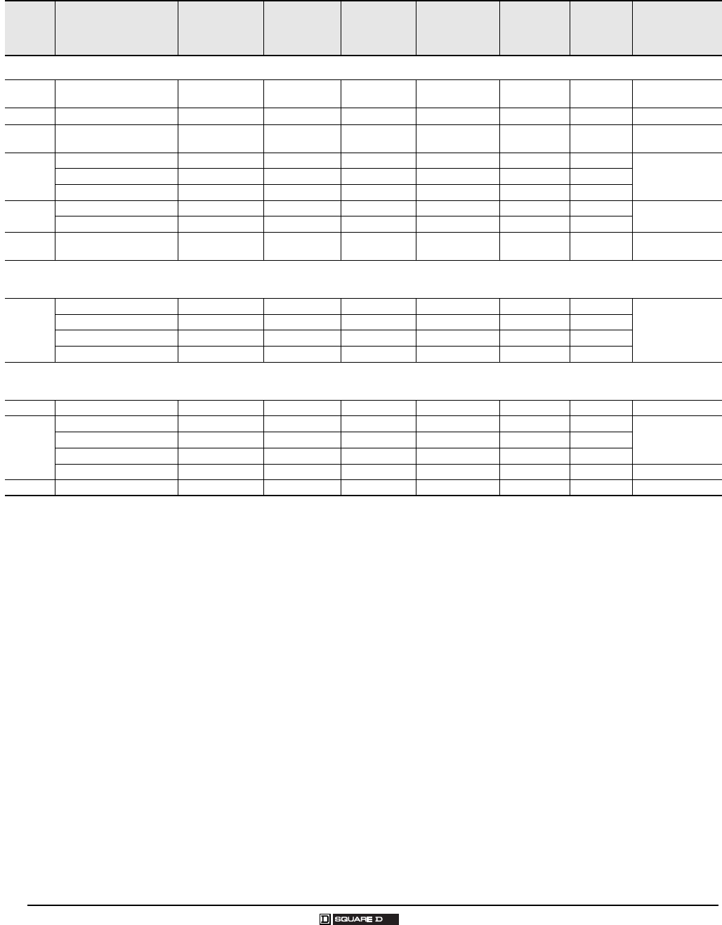
Single-Phase, Three-Wire, 120/240 Vac; Main Lugs Rainproof
Mains
Rating in
Amps
Load Center
Catalog Number
Load Center
Cover Catalog
Number 1
1Convertible mains load center has a side-hinge door. Allow 1.25 in. (32 mm) on the left side for the door to open.
UL Listed
Service
Equipment
(See Notes)
Maximum UL
Short Circuit
Rating 2
2Short circuit current rating depends on lowest AIR rating of main or branch circuit breaker installed.
M a i n W i r e S i z e
AWG/kcmil
Al/Cu
Enclosure
No.
(Page 27)
Top
or Bottom
Mains
Position
UL Listed for
Corner Grounded
Delta Systems
Fixed Mains – Factory-Installed Main Lugs
40 QO2L40RB Included B 10,000 A #12 6
#1410 1R Top No
60 QO24L60NRNM Included B 10,000 A #14 4 1NM Top No
70 QO24L70RB Included B 10,000 A #12 3
#14 4 1R Top No
100
QO612L100RB Included B, C 10,000 A #81 2R Top
No
QO612L100TRB Included B, C 10,000 A #81 2R Top
QO612L100RBCU Included B, C 10,000 A #81 2R Top
100 QO816L100RB Included B, C 10,000 A #81 2R Top No
QO816L100RBCU Included B, C 10,000 A #81 2R Top
125 QO148L125GRB Included B, C 10,000 A #122/ 0
#142/ 0 15R Top No
Convertible Mains – Factory-Installed Main Lugs
QOM1 Main Frame Size – Convertible to Main Circuit Breaker – Copper Bus
125
QO112L125GRB Included B, C 65,000 A 3 4
3UL Listed at 5000 A rms symmetrical short circuit current rating when used in 3-phase, corner grounded, Delta systems, when used as main lugs load center only.
Use 240 Vac circuit breakers only.
422,000 A rms symmetrical maximum when supplied by integral type QOM-VH main circuit breaker from Square D® with 22,000 A rms symmetrical minimum
interrupting rating and when all QO® installed branch circuit breakers have 10,000 A rms symmetrical minimum interrupting rating.
B UL Listed as suitable for use as service equipment (neutral bonded at the time of installation) with field-installed service disconnect.
C UL Listed as suitable for use as service equipment (neutral bonded at the time of installation) when not more than six service disconnecting means are provided and
when not used as a lighting and appliance branch circuit panelboard. See NEC Article for Lighting and Appliance Branch Circuit Panelboard.
#62 /0 3R Top
Yes
QO11224L125GRB Included B, C 65,000 A 3 4#62 /0 3R Top
QO11624L125GRB Included B, C 65,000 A 3 4#62 /0 4R Top
QO124L125GRB Included B, C 65,000 A 3 4#62 /0 4R Top
Convertible Mains – Factory-Installed Main Lugs
QOM2 Main Frame Size – Convertible to Main Circuit Breaker – Copper Bus
150 QO130L150GRB Included B, C 65,000 A 3 4#6 250 6R Top Yes
200
QO112L200GRB Included B, C 65,000 A 3 4#6 250 5R Top
Yes
QO130L200GRB Included B, C 65,000 A 3 4#6 250 6R Top
QO13040L200GRB Included B, C 65,000 A 3 4#6 250 6R Top
QO140L200GRB Included B, C 65,000 A 3 4#6 250 7R Top Yes
225 QO142L225GRB Included B, C 65,000 A 3 4#6 300 8R Top Yes
QO® and Homeline® Load Centers and Enclosures
Technical Information
23
03/2007 © 2007 Schneider Electric All Rights Reserved
Single-Phase, Three-Wire, 120/240 Vac; Main Circuit Breaker Rainproof
Mains
Rating
in
Amps
Load Center
Catalog
Number
Load Center
Cover Catalog
Number 1
1Convertible mains load center has a side-hinge door. Allow 1.25 in. (32 mm) on the left side for the door to open.
UL Listed
Service
Equipment
(See Notes)
Maximum
UL Short
Circuit
Rating 2
2Short circuit current rating depends on lowest AIR rating of main or branch circuit breaker installed.
Main Wire
Si ze
AWG/kcmil
Al/Cu
Enclosure
No.
(Page 27)
Top
or Bottom
Mains
Position
UL Listed for
Corner
Grounded
Delta Systems
Convertible Mains – Factory-Installed Main Circuit Breaker
QOM1 Main Frame Size – Convertible to Main Lugs or Lower Amperage Main Circuit Breaker – Copper Bus
100
QO112M100RB Included A, D 22,000 A 3
322,000 A rms symmetrical maximum when supplied by integral type QOM-VH main circuit breaker from Square D® with 22,000 A rms symmetrical minimum
interrupting rating and when all installed QO® branch circuit breakers have 10,000 A rms symmetrical minimum interrupting rating. 65,000 A rms symmetrical
maximum when main lug kits installed.
#6 2/0 3R Top
No
QO116M100RB Included A, D 22,000 A 3#6 2/0 4R Top
QO120M100RB Included A, D 22,000 A 3#6 2/0 4R Top
125 QO124M125RB Included A, D 22,000 A 3#6 2/0 4R Top No
Convertible Mains – Factory-Installed Main Circuit Breaker
QOM2 Main Frame Size – Convertible to Main Lugs or Lower Amperage Main Circuit Breaker – Copper Bus
150 QO12030M150RB Included A, D 22,000 A 3#4 250 5R Top No
QO130M150RB Included A, D 22,000 A 3#4 250 6R Top
200
QO12040M200RB Included A, D 22,000 A 3#4 250 5R Top
No
QO130M200RB Included A, D 22,000 A 3#4 250 6R Top
QO140M200RB Included A, D 22,000 A 3#4 250 7R Top
Convertible Mains – Factory-Installed Main Circuit Breaker with Feed-Thru Lugs
QOM1/QOM2 Frame Size – Convertible to Main Lugs or Lower Amperage Main Circuit Breaker – Copper Bus
125 QO1612M125FTRB 4
4QO1612M125FTRB provided with QOM1 frame main circuit breaker. QO1816M150/200FTRB provided with QOM2 frame main circuit breaker.
A UL Listed as suitable for use as service equipment (neutral bonded at time of installation) with factory-installed service disconnect.
D UL Listed as suitable for use as service equipment (neutral bonded at the time of installation) with field-installed main lugs when not more than six service
disconnecting means are provided and when not used as a lighting and appliance branch circuit panelboard. See NEC Article for Lighting and Appliance Branch
Circuit Panelboard.
Included A, D 22,000 A 3#4 2/0 3R Top No
150 QO1816M150FTRB 4Included A, D 22,000 A 3#4 250 6R Top No
200 QO1816M200FTRB 4Included A, D 22,000 A 3#4 250 6R Top No
24
© 2007 Schneider Electric All Rights Reserved 03/2007
QO® Circuit Breaker Load Centers—Class 1130
Technical Information
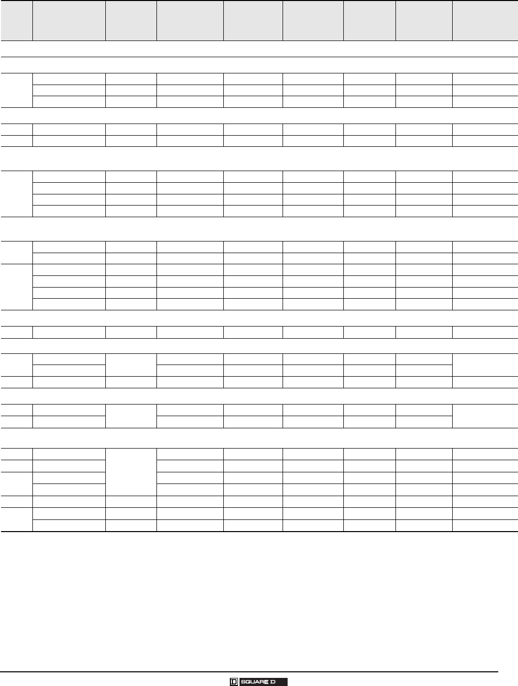
3-Phase, 4-Wire, 208Y/120 Vac; 3-Phase, 4-Wire, 240/120 Vac, Delta;
3-Phase, 3-Wire, 240 Vac, Delta; Main Lugs, Main Circuit Breaker In door
Mains
Rating
in Amps
Load Center
Catalog Number
Load Center
Cover Catalog
Number
UL Listed
Service
Equipment
(See Notes)
Maximum UL
Short Circuit
Rating 1
1Short circuit current rating depends on lowest AIR rating of branch circuit breaker installed.
M a i n W i re S iz e
AWG/kcmil
Al/Cu
Enclosure
No.
(Page 26)
Top or
Bottom
Mains
Position
UL Listed for
Corner
Grounded Delta
Systems
Fixed Mains – Factory-Installed Main Lugs – Copper Bus
60 QO403L60NF/S Included B 22,000 A 1#10-6 13 Top No
125
QO312L125G 2
2Certified to IEC 60439-1 for use on 415Y/240 Vac 3-phase 4-wire, 3,000 SCCR when QODX ... branch circuit breakers are used and 10,000 SCCR when QO...VS
branch circuit breakers are used. CE marked.
QOC16UF/S B, C 65,000 A 1#62 /0 #62/ 0 6 Both
NoQO320L125G 2QOC24UF/S B, C 65,000 A 1#62 /0 #62/ 0 7 Both
QO324L125G 2QOC24UF/S B, C 65,000 A 1#62 /0 #62/ 0 7 Both
200 QO318L200G 2QOC30UF/S B, C 65,000 A 1#6 250 #62 50 9 Both No
QO330L200G 2QOC30UF/S B, C 65,000 A 1#6 250 #62 50 9 Both
225 QO342L225G 2QOC42UF/S B 65,000 A 1#6 300 #63 00 11 Both No
Convertible Mains – Factory-Installed QDL Main Circuit Breaker – Copper Bus
100 QO327M100 3
3Includes factory-installed back-fed QO3100VH main circuit breaker.
QOC30UF/S A, D 22,000 A #42 /0 #42/ 0 9 Both No
125 QO330MQ125 2 4
4Mains positioning from top to bottom feed: first rotate the main circuit breaker 180 degrees, then rotate the complete load center 180 degrees.
QOC342MQF/S A, D 100,000 A 5 6
5100,000 A rms at 208 Vac symmetrical maximum when type QJL main circuit breaker from Square D® with 100,000 A rms minimum interrupting rating is installed
and when all installed QO® and Q1 branch circuit breakers have 10,000 A rms symmetrical minimum interrupting rating.
625,000 A rms symmetrical maximum when supplied by integral type QDL main circuit breaker from Square D® with 25,000 A rms minimum interrupting rating and
when all installed QO® and Q1 branch circuit breakers have 10,000 A rms symmetrical minimum interrupting rating.
A UL Listed as suitable for use as service equipment (neutral bonded at the time of installation) with factory-installed service disconnect.
B UL Listed as suitable for use as service equipment (neutral bonded at the time of installation) with field-installed service disconnect.
C UL Listed as suitable for use as service equipment (neutral bonded at the time of installation) when not more than six service disconnecting means are provided and
when not used as a lighting and appliance branch circuit panelboard. See NEC Section 384-14.
D UL Listed as suitable for use as service equipment (neutral bonded at the time of installation) with field-installed main lugs, when not more than six service
disconnecting means are provided and when not used as a lighting and appliance branch circuit panelboard. See NEC Article for Lighting and Appliance Branch
Circuit Panelboard.
#4 300 #43 00 12 H No
150 QO330MQ150 2 4QOC342MQF/S A, D 100,000 A 5 6#4 300 #43 00 12 H No
QO342MQ150 2 4QOC342MQF/S A, D 100,000 A 5 6#4 300 #43 00 12 H
200 QO330MQ200 2 4QOC342MQF/S A, D 100,000 A 5 6#4 300 #43 00 12 H No
QO342MQ200 2 4QOC342MQF/S A, D 100,000 A 5 6#4 300 #43 00 12 H
225 QO342MQ225 2 4QOC342MQF/S A, D 100,000 A 5 6#4 300 #43 00 12 H No
QO® and Homeline® Load Centers and Enclosures
Technical Information
25
03/2007 © 2007 Schneider Electric All Rights Reserved
Mains
Rating
in
Amps
Load Center
Catalog Number
Load Center
Cover
Catalog
Number
UL Listed Service
Equipment
(See Notes)
Maximum UL
Short
Circuit Rating 1
M a i n W i r e S i z e
AWG/kcmil
Al/Cu
Enclosure
No.
(Pages 26
and 27)
Top or Bottom
Mains Position
UL Listed for
Corner Grounded
Delta Systems
Load Center with Cover – 1-Phase, 3-Wire, 120/240 Vac – UL Listed; Complete QO® Load Center – Box, Interior and Combination Cover (in one package)
Convertible Mains – Factory-Installed Main Lugs; QOM1 Main Frame Size – Convertible to Main Circuit Breaker – Copper Bus
125
QO112L125GC Included B, C 65,000 A 2 3#42 /0 6 Both Yes
QO11224L125GC Included B, C 65,000 A 2 3#42 /0 6 Both Yes
QO120L125GC Included B, C 65,000 A 2 3#42 /0 7 Both Yes
Convertible Mains – Factory-Installed Main Lugs; QOM2 Main Frame Size – Convertible to Main Circuit Breaker – Copper Bus
150 QO130L150TC Included B, C 65,000 A 2 3#42 50 9 Both Yes
200 QO13040L200GC Included B, C 65,000 A 2 3#42 50 9 Both Yes
Convertible Mains – Factory-Installed Main Circuit Breaker – 22,000 RMS Symmetrical Amperes Short Circuit Current Rating
QOM1 Main Frame Size – Convertible to Main Lugs – Copper Bus
100
QO112M100C Included A, D 22,000 A 2#4-1/0 5 Both Yes
QO11220M100C Included A, D 22,000 A 2#4-1/0 5 Both Yes
QO116M100C Included A, D 22,000 A 2#4-1/0 6 Both Yes
QO120M100C Included A, D 22,000 A 2#4-1/0 6 Both Yes
Convertible Mains – Factory-Installed Main Circuit Breaker – 22,000 RMS Sym. Amperes Short Circuit Current Rating
QOM2 Main Frame Size – Convertible to Main Lugs – Copper Bus
150 QO12030M150C Included A, D 22,000 A 2#42 50 9 Both No
QO130M150C Included A, D 22,000 A 2#42 50 9 Both No
200 A
QO12040M200C Included A, D 22,000 A 2#42 50 9 Both No
QO130M200C Included A, D 22,000 A 2#42 50 9 Both No
QO13040M200C Included A, D 22,000 A 2#42 50 9 Both No
QO140M200C Included A, D 22,000 A 2#42 50 10 Both No
Non-Metallic 1-Phase, 3-Wire, 120/240 Vac – Main Lugs Only
60 QO24L60NRNM Included B, C 10,000 A #14 4 1NM Bottom No
Riser , 1-Phase, 3-Wire, 120/240 Vac – Factory-Installed Main Lugs – Offset Interior Wide Gutter QOM1/QOM2 4 Main Frame Size – Convertible to Main Circuit Breaker – Copper Bus 3
125 QO11224L125WG QOC20UFWG B, C 65,000 A 2#42 /0 14 Both Yes
QO12030L125WG B 65,000 A 2#42 /0 14 Both
200 QO13040L200WG QOC30UFW B, C 65,000 A #42 50 23 Both Ye s
Generator Panel, 1-Phase, 3-Wire, 120/240 Vac – Factory-Installed Main Circuit Breakers with Mechanical Interlock
30 QO48M30DSGP Included No 10,000 A #148 4 Bottom No
60 QO48M60DSGP A 10,000 A #8 2 4 Bottom
Generator Panel - Use with Automatic Transfer Switch, 1-Phase, 3-Wire, 120 / 240 Vac, Factory- / Field-Installed Main Circuit Breaker –
22,000 RMS Sym. Amperes Short Circuit Current Rating 5
150 QO13842MX150
QOC38MXUF
A 22,000 A #4-250 12 Both No
200 QO13842MX200 A 22,000 A #4-250 12 Both No
225 QO13842MX225 A 22,000 A #4-250 12 Both No
QO13842UX225 B 22,000 A #4-250 12 Both No
150 QO11428MX150FTRB6Included A 22,000 A #4-250 7R Both No
200 QO11428MX200FTRB6Included A 22,000 A #4-250 7R Both No
QO11428UX200FTRB6Included B 22,000 A #4-250 7R Both No
1Short circuit current rating depends on lowest AIR rating of main or branch circuit breaker installed.
222,000 A rms symmetrical maximum when supplied by integral type QOM-VH main circuit breaker from Square D® with 22,000 A rms symmetrical minimum interrupting rating
and when all installed QO® branch circuit breakers have 10,000 A rms symmetrical minimum interrupting rating.
3UL Listed for 5000 A rms symmetrical short circuit rating when used in 3-phase, 240 Vac, corner grounded Delta systems, when used as main lugs load center only. Use QO-
H 240 Vac circuit breakers only.
4QOM2 Load Center is ONLY convertible to main circuit breaker when used with QOC cover.
5One main circuit breaker is included with panel. Alternate source main circuit breaker (QO 125 A max.) must be ordered separately. Automatic transfer switch and generator kit
for secondary power sources are ordered through a Kohler® authorized dealer or contractor.
6Side-hinge door device allow 1.25 in. (32mm) on the left side for the door to open.
A UL Listed as suitable for use as service equipment (neutral bonded at the time of installation) with factory-installed service disconnect.
B UL Listed as suitable for use as service equipment (neutral bonded at the time of installation) with field-installed service disconnect.
C UL Listed as suitable for use as service equipment (neutral bonded at the time of installation) when not more than six service disconnecting means are provided and when not
used as a lighting and appliance branch circuit panelboard. See NEC Article for Lighting and Appliance Branch Circuit Panelboard.
D UL Listed as suitable for use as service equipment (neutral bonded at the time of installation) with field-installed main lugs and not more than six service disconnecting means
are provided and when not used as a lighting and appliance branch circuit panelboard. See NEC Article for Lighting and Appliance Branch Circuit Panelboard.

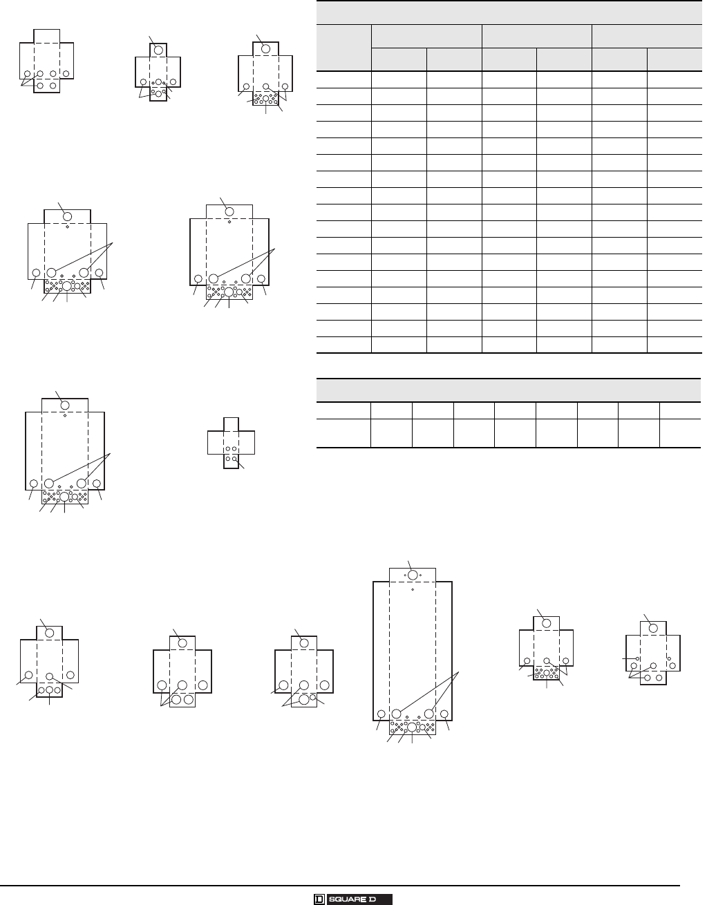
26
© 2007 Schneider Electric All Rights Reserved 03/2007
QO® Circuit Breaker Load Centers—Class 1130
Indoor Dimensions Indoor Dimensions
Box
No.
W H D Box
No.
W H D
in. mm in. mm in. mm in. mm in. mm in. mm
1 3.81 97 6.72 171 3.00 76 13 5.88 149 13.12 333 3.38 86
2 4.81 122 9.30 236 3.19 81 14 14.25 362 20.92 531 3.75 95
3 4.81 122 9.30 236 3.19 81 15 20.00 508 50.00 1270 5.75 146
4 8.88 226 12.57 319 3.80 97 16 20.00 508 68.00 1727 5.75 146
5 14.25 362 14.92 379 3.75 95 17 20.00 508 53.00 1346 5.75 146
6 14.25 362 17.92 455 3.75 95 18 5.88 149 16.12 409 3.38 86
7 14.25 362 20.92 531 3.75 95 19 7.56 192 23.12 587 4.25 108
8 14.25 362 26.04 661 3.75 95 20 9.62 244 26.12 663 4.75 121
9 14.25 362 29.86 758 3.75 95 21 8.88 226 14.80 376 3.80 97
10 14.25 362 33.78 858 3.75 95 22 8.55 217 23.92 608 3.95 100
11 14.25 362 37.98 965 3.75 95 23 14.25 362 29.86 758 3.75 95
12 14.25 362 39.37 1000 3.75 95
Knockouts
Symbol ABC D E F G H I
Conduit
Size 0.50 in.
13 mm
0.75 in.
19 mm
1.00 in.
25 mm
1.25 in.
32 mm
1.50 in.
38 mm
2.00 in.
51 mm
2.50 in.
64 mm
3.00 in.
76 mm
3.50 in.
89 mm
A, B, C, D
A,
B
A
AA, B
C, D, E, F
A
A, B, C, D
A, B
B, C, D, E
C, D, E, F
AA, B
C, D, E, F
B, C, D,E
D, E,
F, G
B, C, D, E
C, D, E, F D, E, F, G
A
A, B
A, B, C
A, B, C, D
B, C
B, C, D, E
C, D, E, F
AA, B
D, E,
F, G
D, E, F, G
C, D, E, F
A, B, C, D
B, C, D, E
B, C, D, E
D, E, F, G
C, D, E,
F, G
C, D, E, F
A, B
D, E, F, G A, B
A
D, E, F,
G, H
A, B, C, D
A
B, C, D, E
A, B
B, C, D, E
A
A, B, C
A
A,
B,
CA
A
A, B,
CA, B, C
A, B, C, D
Box 1 Box 2 Box 3
A
A, B
Box 4 Box 5
A
B, C,
D, E B, C, D, E
B, C, D, E
B, C,
D, E B, C, D, E
B, C, D, E
A
A
A, B
A, B,
C, D
B, C,
D, E
C, D,
E, F, G
C, D,
E, F
B, C,
D, E
A, B
A
B, C, D, E
C, D, E,
F,G C, D, E, F
A
A, B, C, D
A, B
B, C, D, E
A, B
A
B, C, D, E
C, D, E,
F,G
Box 6 Box 7 Box 8 Box 9 Box 10
C, D, E,
F,G
B, C
B, C, D, E
C, D, E,
F,G
D, E,
F, G
C, D, E, F
A, B, C, D,
D, E, F, G
C, D, E, F
B, C, D, E
C, D, E,
F,G AA, B
B, C, D, E
D, E, F, G
D, E, F, G, H, I
AA, B
C, D, E, F
C, D, E, F
A, B, C, D
C, D, E, F
A, B
A
A
A, B
B, C
B, C, D, E
A, B, C, D
D, E, F, G
A
A, B
B, C
D
, E,
F
, G
C, D,
E, F
B, C,
D, E
C, D, E,
F, G A, B
A
B, C, D, E
D, E, F, G
Box 11 Box 12
Box 13 Box 14
Box 15, 16, 17
A, B, C, D C, D, E, F
D, E, F, G
D, E, F, G
C, D, E, F E, F, G, H
A
B, C, D, E
B, C, D, E
A, B AB, C, D, E
B, C, D, E
B, C, D, E
B, C, D, E
A, B
C, D, E, F
C, D, E, F
A, B, C, D
D, E, F, G
A
A, B
B, C
D, E, F, G
C, D, E, F
AA, B
A, B, C D, E, F, G
B, C, D, E
D, E, F, G
Box 23
Box 22Box 21Box 20Box 19Box 18
QO® and Homeline® Load Centers and Enclosures
Outdoor Dimensions and Knockouts
27
03/2007 © 2007 Schneider Electric All Rights Reserved
OUTDOOR DIMENSIONS AND KNOCKOUTS
1
LOAD CENTERS
Outdoor Dimensions
Box No. W H D
in. mm in. mm in. mm
1NM 6.52 166 8.79 223 3.90 99
1R1
1HOME250SPA top endwall has no hub opening.
4.88 124 9.38 238 4.00 102
2R 8.88 226 12.65 321 4.27 108
3R 14.75 375 18.92 481 4.52 115
4R 14.75 375 22.06 560 4.52 115
5R 14.75 375 26.04 661 4.52 115
6R 14.75 375 29.86 758 4.52 115
7R 14.75 375 33.78 858 4.52 115
8R 14.75 375 37.98 965 4.52 115
9R 4.56 116 6.50 165 3.88 99
10R 6.92 176 13.18 335 4.12 105
11R 7.56 192 192 590 4.75 121
12R 9.62 244 26.24 666 5.50 140
13R 6.92 176 16.18 411 4.12 105
14R 14.75 375 39.37 1000 4.52 115
15R 8.88 226 14.80 376 4.27 108
16R 8.55 217 24.75 629 4.16 106
Knockouts
SymbolABCDEFGH
Conduit
Size
0.50 in.
13 mm
0.75 in.
19 mm
1.00 in.
25 mm
1.25 in.
32 mm
1.50 in.
38 mm
2.00 in.
51 mm
2.50 in.
64 mm
3.00 in.
76 mm
Box 1NM Box 1R Box 2R
A, B, C
2.5 in. (64 mm)
Hub Max.
2.5 in. (64 mm)
Hub Max.
A, B, C, D A
A, B B, C, D, EA
B, C, D, E A, B
B, C,
D, E
Box 3R, 4R Box 5R
2.5 in. (64 mm)
Hub Max.
2.5 in. (64 mm)
Hub Max.
C, D, E F, G
C, D,
E, F AA,
B
C, D,
E, F,
G
A, B, C
C, D, E, F
2.5 in. (64 mm)
Hub Max.
2.5 in. (64 mm)
Hub Max. 2.5 in. (64 mm)
Hub Max.
2.5 in. (64 mm)
Hub Max.
2.5 in. (64 mm)
Hub Max.
2.5 in. (64 mm)
Hub Max.
2.5 in. (64 mm)
Hub Max.
C, D, E, F, G
C, D,
E, F
AA, B
C, D,
E, F, G
A, B, C
C, D, E, F
A, B, C
Box 6R, 7R, 8R
Box 9R
C, D,
E, F
C, D, E
F, G
C, D, E F
AA,
BC, D, E F, G
A, B, C
C, D,
E, F
A, B
C, D, E, F, G
B, C, D, E
A
B, C, D, E A, B
B, C, D, E
C, D, E, F
AA, B C, D, E, F, G
A, B, C
C, D, E, F
A, B,
C, D B, C, D, E
B, C, D, E
D, E,
F, G
D, E, F, G
E, F, G, H E, F
Box 10R, 13R Box 11R Box 12R
Box 14R
Box 15R Box 16R
28
© 2007 Schneider Electric All Rights Reserved 03/2007
QO® Circuit Breaker Load Centers—Class 1130
QO Single-Phase Labels
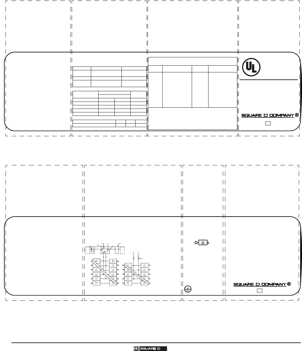
QO SINGLE-PHASE LABELS
The labels below represent typical labels. Information may not be applicable or may change without notice. See the actual label in
the load center for the latest information.
QO Single-Phase Box Label Sample
QO Single-Phase Wiring Diagram Sample
Short circuit ratings.
Short circuit ratings and additional of
replacement circuit breakers.
LISTED
Electric
Cabinet Box
Issue No. V-2813
QO® LOAD CENTER
See Panelboard interior for Catalog No.
Box Cat. No. / Caja No. de Catalogo:
BX18C
Use Cover Cat. No. /
Utilice la Cubierta No. de Catalogo:
QOC16US or/or QOC16UF
Mains 125A max.
Lina principal de 125A maximo.
See main or service disconnect
rating if installed.
240 V ~ Max. 1Ø, 50 / 60 Hz.
24 circuit max. / 24 circuitos maximo.
Type 1 Enclosure
Gabinete Tipo 1
For installation, repairs or alterations,
Call an electrical contractor or electrician.
Panel
Rating
Remote
Main
Integral
Main
Branch (min.)/
Cat. prefix
*65,000 ---- Lugs65,000 / QH
*42,000 ---- Lugs42,000 / QOH
*22,000 ---- Lugs22,000 / OQ.VH
*10,000 ---- Lugs10,000 / OO, QOT & Q1
**5,000 ---- Lugs5,000 / QO...H (2 pole)
100,000 --100-200A,300V T FuseLugs10,000 / QO & QOT
42,0000 QOH Lugs10,000 / QO & QOT
22,000 Q2...H, KD, QO...VH Lugs10,000 / QO & QOT
65,000 KG Lugs10,000 / QO & QOT
22,000 ---- QOM...VH 10,000 / QO, QOT & Q1
** 240 v ~ 3Ph. 3W. Grounded B” phase requires 240 V ~ branch
breakers.
* The rating is equal to the lowest interrupting rating of any circuit breaker
installed. Refer to branch breaker for individual ratings. Additional or
replacement branch circuit breakers, main breaker, or service disconnect
MUST have an interrupting rating equal to or greater than that of the
circuit breaker with the lowest interrupting rating presently installed.
See panelboard interior for breaker types.
LUG TORQUE DATA
See circuit breakers and field installed
units for wire binding screw torque
Branch Neutral and Equipment Ground Bar
Equipment Ground Combinations
Wire Range (AWG/kcmil) Torque (in/lbs.)
Line Neutral
Lug4 - 2/0 CU/AL 50
Main Lug 6 - 2/0 CU/AL 50
Alternate
Main Breaker
See Main
Breaker
See Main
Breaker
Wire Range (AWG) To r que (in./lbs.) Bar with 1
Bar with 2 screw sizesscrew size
1/0 - 3 CU / AL Large 50 Small
4 CU / AL Large 45 Small 35
6 CU / AL Large 45 Small 25 35
8 CU / AL Large 40 Small 10 25
10-14 CU, 10-12 AL Large 35Small 10 20
Two 14 or 12 CU, Two 12 AL 3510 25
Two 10 AL 35 25
SHORT CIRCUIT RATING
RMS Symmetrical Amperes at 120 / 240 V ~ Maximum
Underwriter’s
Laboratories, Inc.®
Number of circuits maximum.
Enclosure catalog number.
Catalog number of covers; flush
or surface.
See panelboard interior for the
catalog number.
Voltage ratings.
Amperage rating. UL Listing.
001021 40265-381-0315
®
Install loose label with Spanish translation
on back of cover.
Adhiera la etiqueta suelta con las traducciones
en espanol en la parte posterior del frente.
Please read information before installing
Por favor lea la informacion antes de instalar.
~
/
Wire range for lug torque data table.
Made in U.S.A. 40265-668-0215
Suitable for use with 75oC
Copper or Aluminum
main conductors. See
branch breakers for
branch wire ratings.
* Suitable for use as service equipment when
service disconnect (main breaker) is installed.
* Suitable for use as service equipment when
not more than six main disconnecting means
are provided and when not used as a lighting
and appliance branch circuit panelboard.
See Article 384-14 of the NEC.
* When used as service equipment, all unused
neutral terminals may be used for terminating
equipment ground wires.
1. Box bonding when required. / Conexion a la caja
cuando fuese necesario.
2. Main breaker type: QOM1 or QOM1A. / Interruptor
automatico principal tipo: QOM1 o QOM1A.
3.Service ground
when required. /
Tierra de acometida
cuando fuese
necesario
4. Main lugs kit no:
QOL125. / No. de
accesorio de las
zapatas
principales:
QOL125.
Tw o single poles. One plug
on space or may use one
single pole. One two pole
requires two spaces.
To r que Note: When main
breaker or main lug
connector mounting nuts
are loosened or removed,
retighten to 75 lbs./in.
torque.
* May plug on two adjacent spaces.
Torque Note: When interior mounting screw is
loosened or removed, retighten to 35 lbs./in.
Load Center Accessories - Kits
PK4MB2LA Back-fed Main Cir. Brkr. Retaining
QO2175SBPlug-0n Surge Arrestor *
SDSA1175 1 Phase Surge Arrestor
QOSAMK SDSA1175 Mounting Bracket
QOL2125 1 Phase Plug-on Subfeed Lugs *
PK9--27GTA(L) Equipment Ground Bar
PKGTAB Equipment Ground Bar Insulator
LK70AN 70A Max. Neutral Lug
LK100AN 125A Max. Neutral Lug
QOL125 Main Lugs
PK6FL Indoor Cover Lock
Equipment Grounding
Terminals
Service Equipment marking.
Use of unused neutral branch terminal for
equipment grounding, service equipment
application only.
Installation of back-fed main circuit breaker and
required kit.
Alternate wiring diagram for main circuit breaker or
main lug.
Load center accessories.
Neutral lug for 1/0 AWG or larger wire.
Type of circuit breakers
from Square D that
may be used in this
panelboard.
Line / Linea
N
N
OO
3
NO
O12
4
LOAD / CARGAS
LOAD / CARGAS
LOAD / CARGAS
Main Breaker diagram Main Lugs diagram
NN
QO® and Homeline® Load Centers and Enclosures
QO Three-Phase Label Samples
29
03/2007 © 2007 Schneider Electric All Rights Reserved
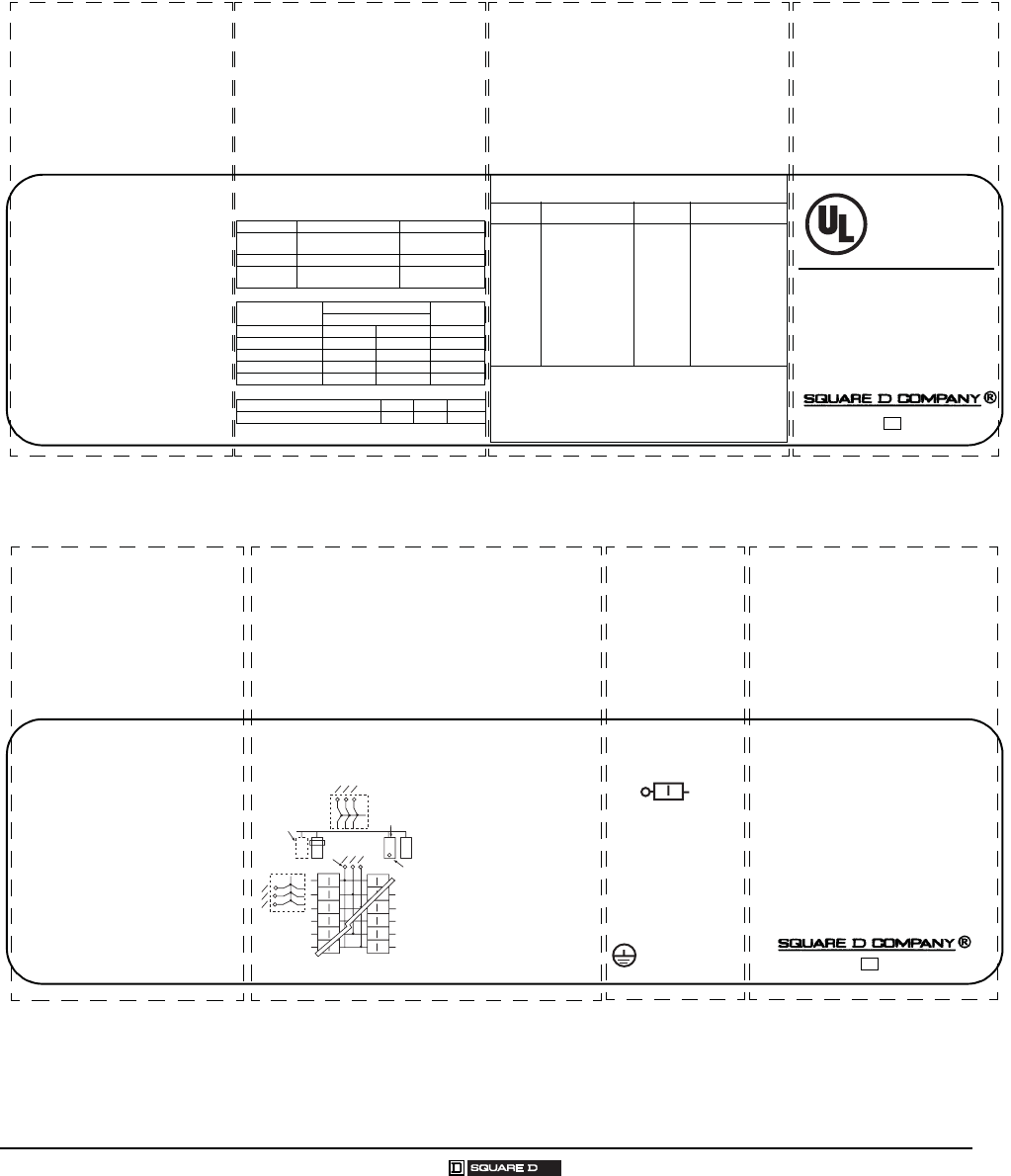
QO THREE-PHASE LABEL SAMPLES
The labels below represent typical labels. Information may not be applicable or may change without notice. See the actual label in
the load center for the latest information.
QO Three-Phase Box Label Sample
QO Three-Phase Wiring Diagram Sample
LISTED
Electric
Cabinet Box
Issue No. V-2813
QO® LOAD CENTER
See Panelboard interior for Catalog No.
Box Cat. No. / Caja No. de Catalogo:
BX338C
Use Cover Cat. No. /
Utilice la Cubierta No. de Catalogo:
QOC42US or/or QOC42UF
Mains 225A / Lina principal de
225A maximo.
See main or service disconnect
rating if installed.
240 V ~ Max. 3Ø, 50 / 60 Hz.
42 circuit max. / 42 circuitos maximo.
Type 1 Enclosure
Gabinete Tipo 1
240V, 3PH, 3W: For this system neutral is not
used and only breakers rated 240V are to be used.
240V, 3PH, 4W: When wired for delta system,
phase “B” must be 208V to neutral. Breaker
poles connected to phase “B” must be rated 240V.
1PH: Single pole breakers can not be connected
to phase B.
Panel
Rating
Remote
Main
Integral
Main
Branch (min.)/
Cat. prefix
*65,000 ---- Lugs65,000 / QH
*42,000 ---- Lugs42,000 / QOH
*22,000 ---- Lugs22,000 / OQ.VH
*10,000 ---- Lugs10,000 / OO&Q1,QO...H
**5,000 ---- Lugs5,000 / QO...H(2 POLE)
100,000 100-200A,300V T FuseLugs10,000 / QO
22,000 KD, QO...VH Lugs10,000 / QO
22,000 Q2...H Lugs10,000 / QO (10A-60A)
65,000 KG Lugs10,000 / QO
65,000 ---- KG 10,000 QO&Q1
22,000 ---- KD 10,000 QO&Q1
22,000 ---- QO...VH 10,000 / QO
** 240 v ~ 3Ph. 3W. Grounded “B” phase requires 240 V ~ branch
breakers.
* The rating is equal to the lowest interrupting rating of any circuit breaker
installed. Refer to branch breaker for individual ratings. Additional or
replacement branch circuit breakers, main breaker, or service disconnect
MUST have an interrupting rating equal to or greater than that of the
circuit breaker with the lowest interrupting rating presently installed.
See panelboard interior for breaker types.
LUG TORQUE DATA
See circuit breakers and field installed
units for wire binding screw torque
Branch Neutral and Equipment Ground Bar
Equipment Ground Combinations
Wire Range (AWG/kcmil) Torque (in/lbs.)
Line Neutral
Lug4 - 300 CU/AL 250
Main Lug4 - 300 CU/AL 250
Alternate
Main Breaker
See Main
Breaker
See Main
Breaker
Wire Range (AWG) To r que (in./lbs.) Bar with 1
Bar with 2 screw sizesscrew size
1/0 - 3 CU / AL Large 50 Small
4 CU / AL Large 45 Small 35
6 CU / AL Large 45 Small 25 35
8 CU / AL Large 40 Small 10 25
10-14 CU, 10-12 AL Large 35Small 10 20
Two 14 or 12 CU, Two 12 AL 3510 25
Tw o 1 0 A L 35 25
SHORT CIRCUIT RATING
RMS Symmetrical Amperes at 120 / 240 V ~ Maximum Underwriter’s
Laboratories, Inc.®
Number of circuits maximum.
Enclosure catalog number.
Catalog number of covers; flush
or surface.
See panelboard interior for the
catalog number.
Voltage ratings.
Amperage rating.
Wire range for lug torque data table.
Short circuit ratings.
Short circuit ratings and additional of
replacement circuit breakers.UL Listing.
001021 40265-381-0315
®
For installation, repairs or alterations,
Call an electrical contractor or electrician.
Install loose label with Spanish translation
on back of cover.
Adhiera la etiqueta sauelat con la traduccion
en Espanol en la parte posterior de la cubierta.
Please read information before installing.
Por favor lea la informacion antes de instalor.
~
/
N
N
2
Load /
Cargas
Load /
Cargas
NN
1
3
4
Line / Linea
OO O
O O O
6.
Line /
Linea
5. Line /
Linea
O
O
O
Made in U.S.A. 40265-545-01
15
Suitable for use with 75oC
Copper or Aluminum
main conductors. See
branch breakers for
branch wire ratings.
* Suitable for use as service equipment when
service disconnect (main breaker) is installed.
* Suitable for use as service equipment when
not more than six main disconnecting means
are provided and when not used as a lighting
and appliance branch circuit panelboard.
See Article 384-14 of the NEC.
* When used as service equipment, all unused
neutral terminals may be used for terminating
equipment ground wires.
1. Box bonding when required. /
Conexion a la caja cuando fuese
necesario.
2. Service ground when required. /
Tierra de acometida cuando fuese
necesario
3.Main lugs kit no: QOL3225. / No.
de accesorio de las zapatas principales:
QOL3225.
4. Lug kit when installed. / Accesorio
de la zapata, cuando se instala.
5. Back fed main circuit breaker
when installed. / Interruptor
automatico principal de alimentacion
posterior, cuando se instala.
6. Integral main circuit breaker when
installed. / Interruptor automatico
integral principal, cuando se instala.
One single pole. One plug
on space. One two pole
requires two plug on
spaces. One three pole
requires three plug on spaces.
To r que Note: When main
breaker or main lug
connector mounting nuts
are loosened or removed,
retighten to 75 lbs./in.
torque.
Equipment Grounding
Terminals
* May plug on two adjacent spaces.
+ May plug on three adjacent spaces.
To r que Note: When interior or main breaker
mounting screws are loosened or removed,
retighten to 35 lbs./in.
Load Center Accessories - Kits
PK3MB Back-fed Main Cir. Brkr. Retaining
SDSA3650 3 Phase Surge Arrestor
QO60SL1 Phase Plug-on Subfeed Lugs *
QO2125SL1 Phase Plug-on Subfeed Lugs *
QO3125SL3 Phase Plug-on Subfeed Lugs +
PK9-27GTA(L) Equipment Ground Bar
PKGTAB Equipment Ground Bar Insulator
LK100AN 125A Max. Neutral Lug
LK150AN 150A Max. Neutral Lug
QOL3225 Main Lugs
PK6FL Indoor Cover Lock
~/
Service Equipment marking.
Use of unused neutral branch
terminal for equipment grounding,
service equipment application only.
Alternate wiring diagram for main circuit breaker or
main lug.
Installation of back-fed main circuit breaker and
required kit.
Load center accessories.
Neutral lug for 1/0 AWG or larger wire.
Type of circuit breakers
from Square D that
may be used in this
panelboard.
/
~
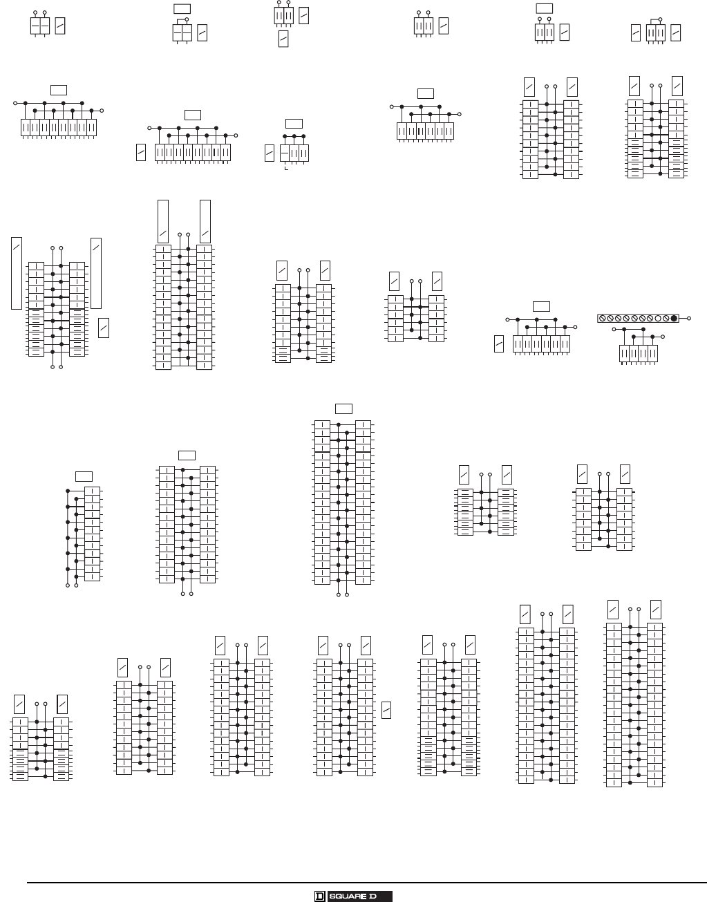
30
© 2007 Schneider Electric All Rights Reserved 03/2007
QO® Circuit Breaker Load Centers—Class 1130
Wiring Diagrams
WIRING DIAGRAMS
QO2L30S
QO2L40RB
S
N
QO2L30TTS
S
N
G/B
QO112L125G
QO112L125GC
QO112L125GRB
QO112L200G
QO112L200GRB
S
N
S
N
S
N
S
N
QO11224L125G
QO11224L125GRB
QO11224L125WG
QO11224L125GC
QO24L70F/S
QO24L70RB
S
N
QO24L50TTS
S
N
G
B
QO35FM30TTF/S
G
B
Line
S/N
QO612L100F/S
QO612L100DF/S
QO612L100DFCU/SCU
QO612L100RB
QO612L100RBCU
S/N
QO148L125GF/S
QO148L125GRB
QO612L100TF/S
QO612L100DTF/S
QO612L100TRB
S/N
G
B
QO816L100F/S
QO816L100DF/S
QO816L100DFCU/SCU
QO816L100RB
QO816L100RBCU
S/N
QO816L100TF/S
QO816L100DTF/S
S/N
G
B
QO116L125G
S
N
S
N
QO11624L125G
QO11624L125GRB
S
N
S
N
S
N
S
N
QO120L125G
QO120L125GC
S
N
S
N
QO12030L150G
S
N
S
N
QO12024L125G
QO12030L125WG
S
N
S
N
QO124L125G
QO124L150G
QO124L125GRB
S
N
S
N
QO130L150G
QO130L200G
QO130L150GRB
QO130L200GRB
S
N
S
N
QO13040L200G
QO13040L200GRB
QO13040L200GC
QO13040L200WG
S
N
S
N
QO142L225G
QO142L225GRB
QON30LS400
S/N
QON42LS400
S/N
S/N
1-Phase, 3-Wire Main Lugs
QO24L70TS
S
N
G/B
QO24L60NRNM
S
N
G
B
S/N
QON12LS400
S
N
S
N
QO12436L200TFT
G
B
QO132L125G
S
N
S
N
S
N
S
N
QO130L150TC
G
B
S
N
S
N
QO140L200G
QO140L200GRB
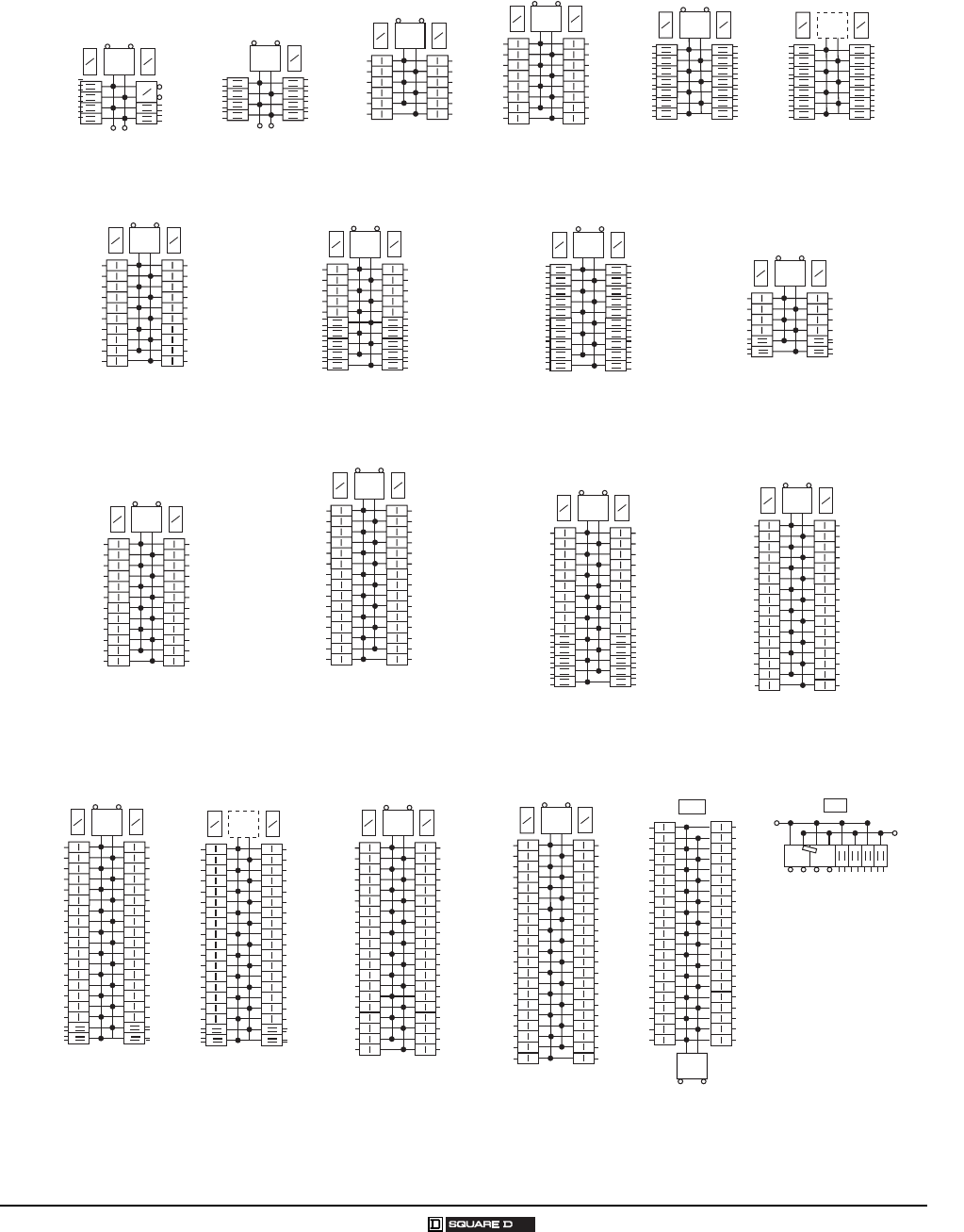
QO® and Homeline® Load Centers and Enclosures
Wiring Diagrams
31
03/2007 © 2007 Schneider Electric All Rights Reserved
MAIN S
N
QO1612M125FTRB
S
F
S
N
MAIN S
N
QO1816M150FTRB
QO1816M200FTRB
MAIN S
N
S
N
QO112M100
QO112M100RB
QO112M100C
MAIN S
N
S
N
QO116M100
QO116M100RB
QO116M100C
MAIN S
N
S
N
QO120M100
QO120M100RB
QO120M100C
MAIN S
N
S
N
QO12030M150
QO12030M150RB
QO12030M150C
MAIN S
N
S
N
QO12040M200
QO12040M200RB
QO12040M200C
MAIN S
N
S
N
QO124M125
QO124M125RB
QO124M150
QO124M200
QO124M100
MAIN S
N
S
N
QO130M150
QO130M200
QO130M150RB
QO130M150C
QO130M200C
QO130M200RB
QON42MS300
QON42MS400
MAIN
S/N
MAIN S
N
S
N
QO140M200
QO140M225
QO140M200RB
QO140M200C
1-Phase, 3-Wire Main Circuit Breakers
MAIN S
N
S
N
QO13040M200
QO13040M200C
MAIN S
N
S
N
QO132M100
QO132M125
QO132M150
QO48M30DSGP
QO48M60DSGP
S/N
Main Main
MAIN S
N
S
N
QO142M200
QO142M225
QO142M225RB
MAIN S
N
S
N
S
N
S
N
QO1428MX150FTRB
QO1428MX200FTRB QO1428UX200FTRB
MAIN S
N
S
N
QO11220M100C
S
N
S
N
QO13842UX225
MAIN S
N
S
N
QO13842MX150
QO13842MX200
QO13842MX225
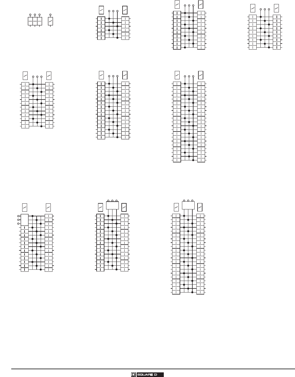
32
© 2007 Schneider Electric All Rights Reserved 03/2007
QO® Circuit Breaker Load Centers—Class 1130
Wiring Diagrams
QO403L60NF/S
QO403L60NRB
S
N
QO312L125G
QO312L125GRB
S
N
S
N
QO324L125G
S
N
S
N
QO320L125G
QO320L125GRB
S
N
S
N
QO342MQ150
QO342MQ200
QO342MQ225
QO342MQ200RB
QO342MQ225RB
S
N
S
N
MAIN
QO342L225G
QO342L225GRB
S
N
S
N
QO327M100
QO327M100RB
S
N
S
N
QO318L200G
QO318L200GRB
S
N
S
N
QO330L200G
QO330L200GRB
S
N
S
N
M
A
I
N
QO330MQ125
QO330MQ150
QO330MQ200
QO330MQ125RB
QO330MQ150RB
QO330MQ200RB
S
N
S
N
MAIN
3-Phase, 4-Wire Main Lugs
3-Phase, 4-Wire Main Circuit Breakers

QO®, QOM2 and Q-Frame Enclosed Circuit Breakers—Class 1131
Table of Contents
33
03/2007 © 2007 Schneider Electric All Rights Reserved
TABLE OF CONTENTS
General Information and Application Data 34
Type 34
Service 34
Ratings 34
Enclosure 34
Type 3R Rainproof 34
Circuit Breakers 35
Knockouts 35
Equipment Grounding Bar 35
Neutral Assemblies 35
Bolt-On Hubs 35
Technical Information 36
Enclosed Molded-Case Circuit Breaker Ratings 36
Dimensions and Knockouts 37
NOTE: For information on Replacement Parts with specific part numbers,
go to www.schneider-electric.us, click on Product FAQ’s, enter the device
catalog number, click SEARCH, then look for the information required.
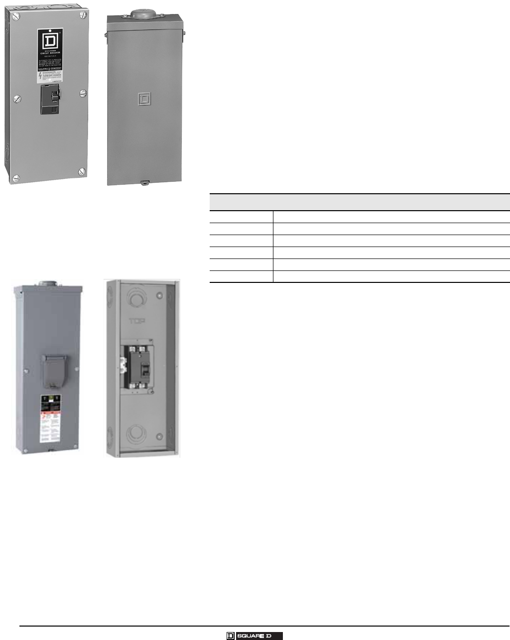
QO®, QOM2 and Q-Frame Enclosed Circuit Breakers—Class 1131
General Information and Application Data
34
© 2007 Schneider Electric All Rights Reserved 03/2007
GENERAL INFORMATION AND APPLICATION DATA
Type
Enclosed molded case circuit breakers are UL® Listed; File E136861, for
enclosures and File E10027 for circuit breakers.
Molded case circuit breakers meet Federal Specifications W-C-375-B.
Enclosed molded case switches are UL Listed under File E59921.
Service
120/240 Vac, 1φ3W
240 Vac, 1φ2W
240 Vac, 1φ3W
240/120 Vac, 3φ4W
208Y/120 Vac, 3φ4W
Ratings
Enclosure
Type 1 indoor general purpose
Welded sheet steel with knockouts at top, bottom, back and sides
Finish: gray baked enamel, electrodeposited over cleaned,
phosphatized steel
Padlock provisions for locking circuit breaker handle in ON (I) or
OFF (O) position
Flush or surface mount covers
Type 3R Rainproof
Welded, galvannealed sheet steel
Finish: gray baked enamel, electrodeposited over cleaned,
phosphatized, galvannealed steel
Provisions to padlock cover closed
RB devices have provisions for interchangeable bolt-on hubs
QO2100BNS
QOM22225NRB
QO2100BNRB
Q22200NS
With Cover Removed
(Order Q-Frame Circuit
Breaker Separately)
Enclosed Molded Case Circuit Breakers
QO 10,000 A
QOM2 22,000 A
QB 10,000 A
QD 25,000 A
QG 65,000 A
QJ 65,000 A @ 240 V or 100,000 A @ 208Y / 120
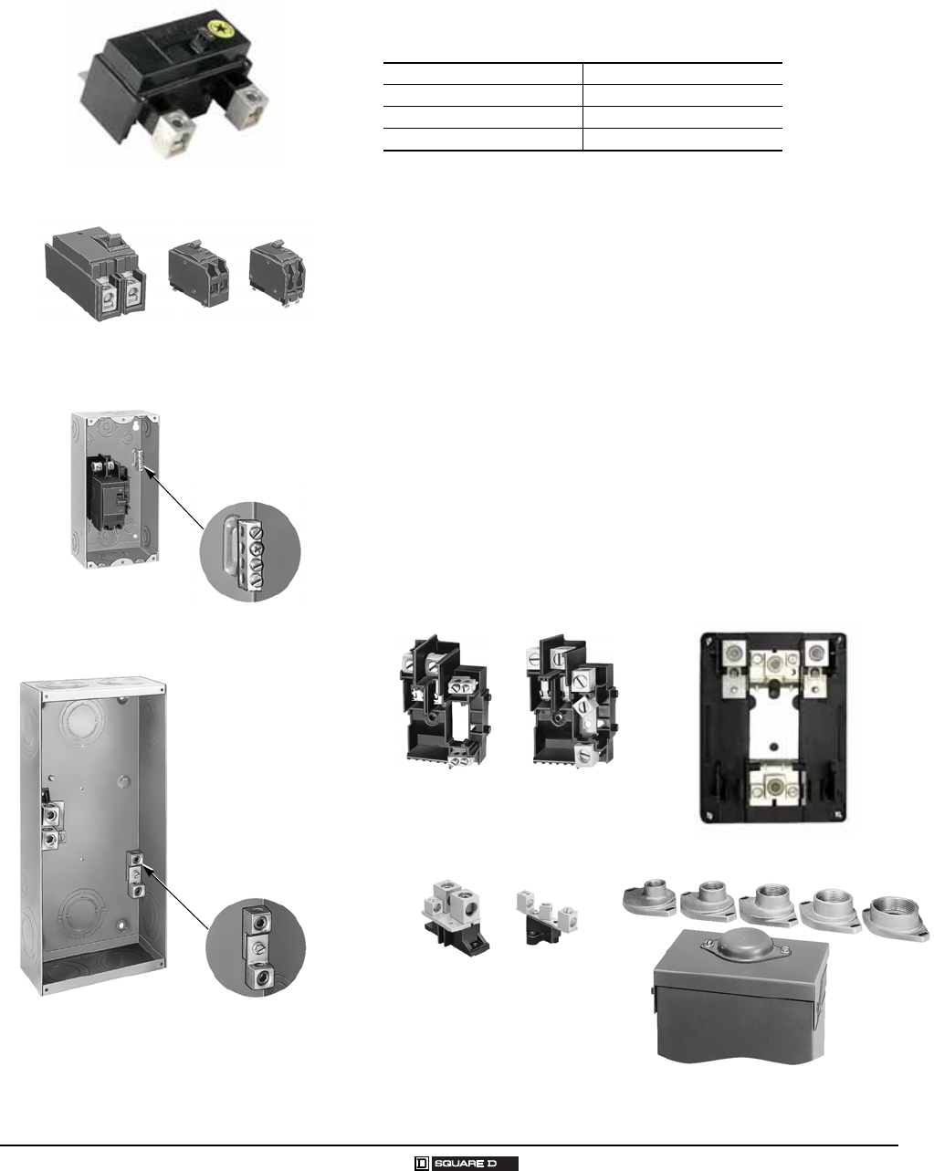
QO®, QOM2 and Q-Frame Enclosed Circuit Breakers—Class 1131
General Information and Application Data
35
03/2007 © 2007 Schneider Electric All Rights Reserved
Circuit Breakers
Visi-Trip® indication (QO® circuit breakers)
Lugs suitable for aluminum or copper wire
(refer to catalog sections listed below:)
Knockouts
Located in back, side and bottom of all devices
Equipment Grounding Bar
Field-installable PKOGTA2
Suitable for #6 AWG 2/0 aluminum or #10 AWG 2/0 AWG copper wire
Neutral Assemblies
Insulated, groundable (except QO2TR)
Suitable for aluminum or copper wire
Grounding terminal provided
Bolt-On Hubs
Hubs available from 0.75 in. (19 mm) to 2.50 in. (64 mm) conduit size
Off-center thread openings keep conduit close to wall
No gasket required with hubs
QOM2200VH
Circuit Breakers
Factory-installed equipment grounding bar.
PKOGTA2 field installed.
QO Class 730
QB, QD, QG and QJ Class 734
QOM2 Class 736
Molded-case switches Class 601
QOM2 Base
QO Base Assemblies
Neutral Assemblies
Hubs
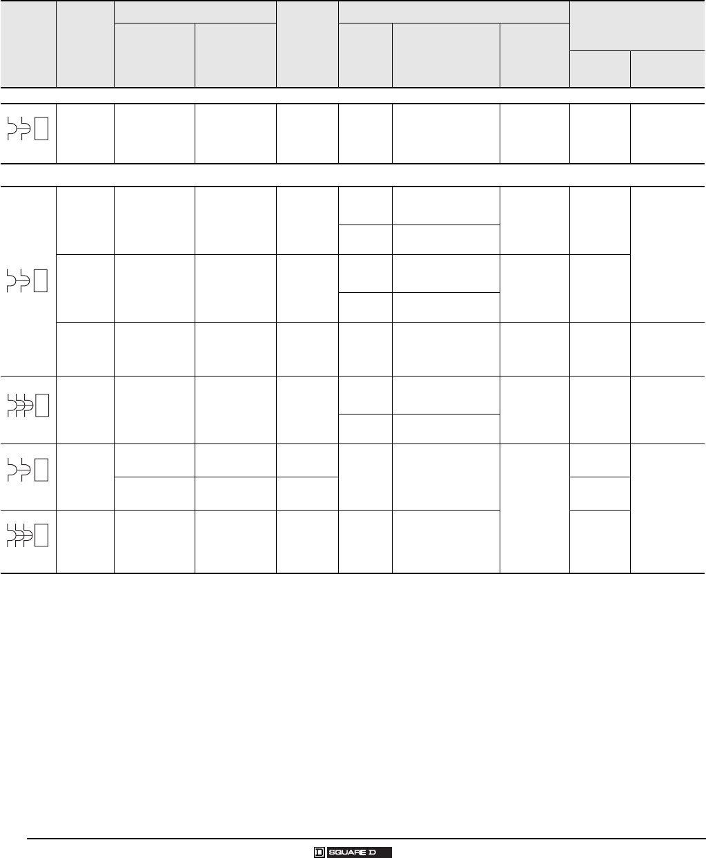
QO®, QOM2 and Q-Frame Enclosed Circuit Breakers—Class 1131
Technical Information
36
© 2007 Schneider Electric All Rights Reserved 03/2007
TECHNICAL INFORMATION
Enclosed Molded-Case Circuit Breaker Ratings
Service Rating in
Amperes
Enclosure
Enclosure
No.
(Page 37)
Circuit Breaker 1
1Order circuit breaker separately.
Neutral Assembly
Terminal Wire Size
AWG/kcmil
Type 1
Catalog
Number
Type 3R
Catalog
Number
Catalog
Number
UL® Listed
Interrupting Rating
in RMS Amps
Symmetrical
Terminal
Lug Wire
Size
AWG/kcmil Neutral
Terminals Grounding
Terminals
Enclosed Circuit Breaker Mounting Base
60 A 2
2Not suitable for service equipment.
QO2TR 3
3Top endwall has no hub opening; back and bottom feed only.
1R QO210 to
QO260 10,000 AIR #144
Al or Cu 4
4Load terminals use #6 maximum.
#14 8
Al or Cu
Enclosed Circuit Breakers
100 A QO2100BNF/S 5
5Enclosures will accept QO circuit breakers with factory-installed accessories.
QO2100BNRB 51, 2R
QO
QO-PL
QO-GFI
10,000 AIR #121 Al
or
#141 Cu
#121 Al
or
#141 Cu
#122 Al
or
#142 Cu
QO-VH 22,000 AIR
125 A QO2125BNF/S 5QO2125BNRB 52, 3R
QO
QO-PL
QO-GFI
10,000 AIR
#122/ 0 Al
#14 2/0 Cu
#12 2/0 Al
#142 /0 Cu
QO-VH 22,000 AIR
100-225 A QOM22225NF/S
6
6Enclosure will accept QOM2 circuit breaker with factory-installed accessories.
QOM22225NRB
66, 6R QOM2-VH 22,000 AIR 4 - #42 50
kcmil Al/Cu
2 - #425 0
kcmil
4 - #142/ 0
Al or Cu
2 - #62 /0 Al
2 - #10 2/0 Cu
100 A QO3100BNF/S 5QO3100BNRB 51, 2R
QO
QO-PL
QO-GFI
10,000 AIR #121 Al
or
#141 Cu
#121 Al
or
#141 Cu
#122 Al
or
#142 Cu
QO-VH 22,000 AIR
100-225 A
Q22200NS 7 8
7Accepts 200 A maximum, 2-pole Q-frame circuit breakers.
8Equipment grounding kit factory-installed.
Q22200NRB 7 83, 4R QBL
QDL
QGL
QJL
10,000 AIR
25,000 AIR
65,000 AIR
100,000 AIR
#4 300
Al or Cu
#42 50
Al or Cu
#121/ 0 Al
or
#14 1/0 Cu
Q23225NF/S 8Q23225NRB 84, 5R #43 00
Al or Cu
100-225 A Q23225NF/S 8Q23225NRB 84, 5R
QBL
QDL
QGL
QJL
10,000 AIR
25,000 AIR
65,000 AIR
100,000 AIR9
9When these 3-pole circuit breakers are mounted in an enclosure, the maximum AIR rating is 65,000 at 240 Vac and 100,000 at 208 Vac.
#43 00
Al or Cu
G
B
240 Vac
S
N
120/240 Vac
S
N
240 Vac
S
N
2-pole
240 Vac Max.
S
N
3-pole
240 Vac
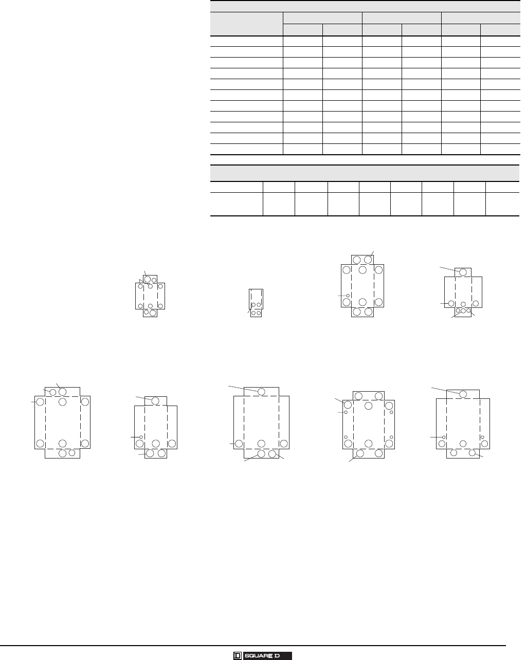
QO®, QOM2 and Q-Frame Enclosed Circuit Breakers—Class 1131
Dimensions and Knockouts
37
03/2007 © 2007 Schneider Electric All Rights Reserved
DIMENSIONS AND KNOCKOUTS
Dimensions
Enclosure No. W H D
in. mm in. mm in. mm
1 5.88 149 13.12 333 3.38 86
2 5.88 149 16.12 409 3.38 86
1R 4.56 116 6.50 165 3.88 99
2R 6.92 176 13.12 333 4.12 105
3R 6.92 176 16.12 409 4.12 105
3 7.56 192 23.12 587 4.25 108
4 9.62 244 26.12 663 4.75 121
4R 7.56 192 23.24 590 4.75 121
5R 9.62 244 26.24 666 5.50 140
6 8.55 217 23.92 608 3.95 100
6R 8.55 217 24.75 629 4.16 106
Knockouts
Symbol ABCDEFGH
Conduit Size 0.50 in.
13 mm
0.75 in.
19 mm
1.00 in.
25 mm
1.25 in.
32 mm
1.50 in.
38 mm
2.00 in.
51 mm
2.50 in.
64 mm
3.00 in.
76 mm
Box 1R
A,B,C
A,B,C,D
Box 1, 2
C,D,E,F
Box 3
A,B
Box 6
C,D,E,F
C,D,E,F
A,B
2-1/2 in.
Hub Max.
Box 5R
E,F,G,H
D,E,F,G
C,D,E,F
A,B
Box 6R
C,D,E,F
2-1/2 in.
Hub Max.
Box 2R, 3R
B,C,D,E
C,D,E,F
A,B,C,D
2-1/2 in.
Hub Max.
Box 4R
D,E,F,G
A,B
2-1/2 in.
Hub Max.
Box 4
E,F,G,H
C,D,E,F
D,E,F,G
Outdoor Dimensions and Knockouts
D, E, F, G

38
© 2007 Schneider Electric All Rights Reserved 03/2007
QO®, QOM2 and Q-Frame Enclosed Circuit Breakers—Class 1131
Dimensions and Knockouts

Homeline® Circuit Breakers and Load Centers—Class 1170
Table of Contents
39
03/2007 © 2007 Schneider Electric All Rights Reserved
TABLE OF CONTENTS
Product Description 40
Features 40
Homeline® Catalog Number Description 41
General Information and Application Data 42
Type 42
Service 42
Ratings 42
UL Listed 42
Class CTL 42
Branch Circuit Breakers 42
Main Circuit Breaker QOM-VH 42
Indoor Enclosures (NEMA Type 1) 43
Indoor Covers 43
Rainproof Enclosures (NEMA Type 3R) 43
Bolt-On Hubs 43
Single-Phase, 2 12 Circuits, 70 125 A, Fixed Mains 44
Single-Phase, 124 2 Circuits, 1002 25 A, Convertible Mains 44
Surgebreaker® Secondary Surge Arrester 46
Accessories 46
Technical Information 48
Grounding Bar Kits 48
Wire Range Table 48
Main Lugs and Main Circuit Breakers Ratings 49
Dimensions and Knockouts 26-28
Homeline® Label Samples 52
Wiring Diagrams 53
INDEX 55
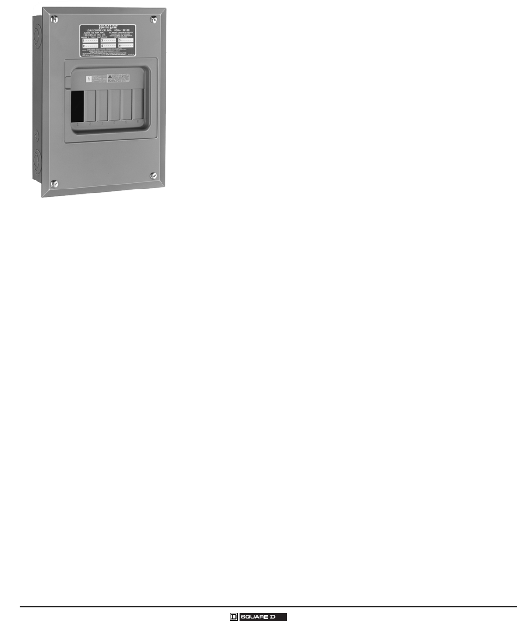
Homeline® Circuit Breakers and Load Centers—Class 1170
Product Description
40
© 2007 Schneider Electric All Rights Reserved 03/2007
PRODUCT DESCRIPTION
Homeline® circuit breaker load centers from Square D® are UL Listed
panelboards. They are designed to meet residential, commercial, and
industrial requirements to protect electrical systems, equipment, and people.
Features
Single-phase construction
302 25 A main lug or main circuit breaker ratings
242 circuit indoor or outdoor versions
Combination cover for flush or surface mounting
Aluminum bus construction on main lug or main circuit breaker panels
Service entrance equipment capable panels
Straight-in wiring to help minimize service cable installation
Convertible mains meet changing job site requirements
Standard 22/10 k AIR series rating on main circuit breaker panels
increases application capability
Single captive screw interior mounting on indoor panels to ease removal
Split branch neutral for clutter-free wiring
Top or bottom feed by rotating convertible mains panels 180 degrees
Combination slot/square drive neutral, ground, and cover screws for
positive drive and improved torque
Three ground bar mounting locations for ease of wiring
Automatic flush adjustment cover speeds installation
Tangential main service knockouts eliminate offsets
Equipment grounding bar included with main lug load centers
Cover supplied with load center
Provisions for door lock on convertible mains panel covers
Two branch circuit breaker twistouts are factory removed for easier
installation of circuit breakers
New side hinge doors on outdoor convertible main panels
Outdoor panel covers are lockable with padlock
Homeline® Circuit Breaker Load Center
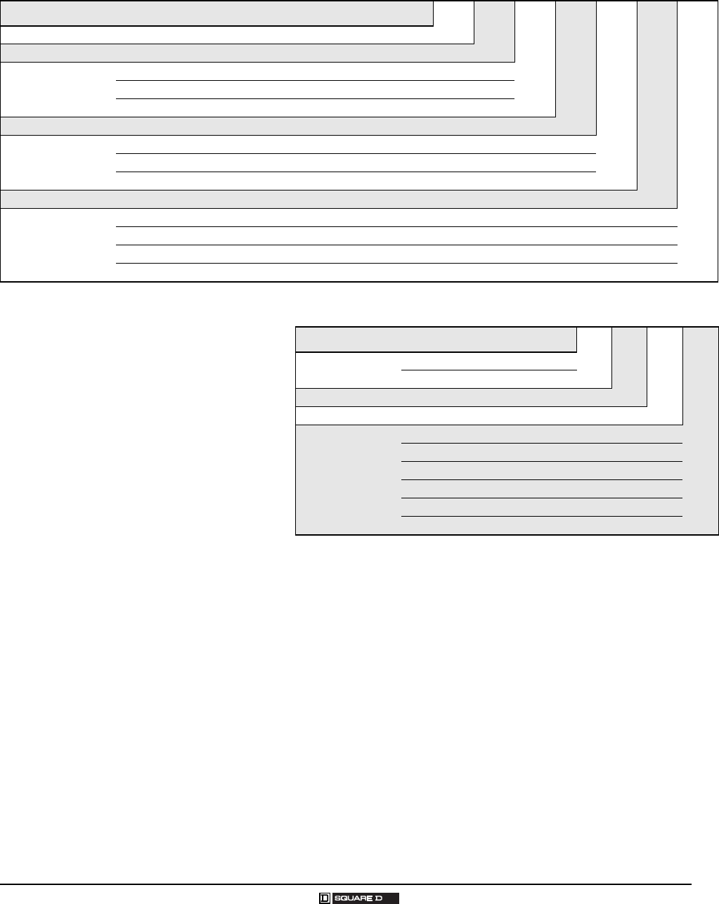
Homeline® Circuit Breakers and Load Centers—Class 1170
Product Description
41
03/2007 © 2007 Schneider Electric All Rights Reserved
Homeline® Load Centers
Number Segment Character Description HOM 3040 L 200 —C
Load Center Family HOM UL Listed
Spaces / Circuits 3040
Mains Type
M Main circuit breaker
L Main lugs
U Universal mains
Amps
Ground Bar
G Factory included
T Factory-installed
Blank Purchase separately
Special Construction FT Feed-thru
Cover
C Combination flush / surface indoor cover
FFlush
RB Rainproof
SSurface
Homeline® Circuit Breakers
Number Segment Character Description HOM 115—
Brand HOM Full Size
HOMT Tandem
Number of Poles
Amps
Device Name
AFI Arc fault circuit interruption
Blank 10,000 AIR
CAFI Combination arc fault circuit interruption
EPD Equipment protection device
GFI Ground fault circuit interruption
HM High magnetic trip
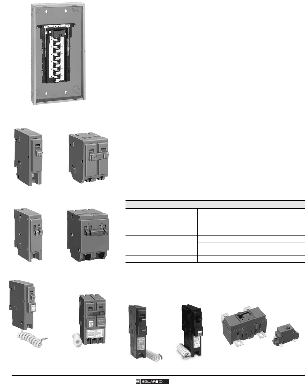
Homeline® Circuit Breakers and Load Centers—Class 1170
General Information and Application Data
42
© 2007 Schneider Electric All Rights Reserved 03/2007
GENERAL INFORMATION AND APPLICATION DATA
Type
Circuit breaker load centers for use on ac systems. They are UL Listed
under file E-6294 (panelboards) and meet Federal Specifications W-P-115b
NEMA Type 1, Class 2.
Service
120 Vac, 1φ2W
120/240 Vac, 1φ3W
Ratings
Main lugs: 702 25 A
Main circuit breaker: 502 25 A
UL Listed
File E-6294 (panelboards)
Suitable for use as service equipment
75 °C wire rating
Class CTL
UL Listed Class CTL load centers
Meets the National Electrical Code® (NEC®) article for Lighting and
Appliance Branch Circuit panelboards.
Branch Circuit Breakers
Main Circuit Breaker Kits
50 225 A main circuit breaker kit is 22,000 AIR series rated with
10,000 AIR branch circuit breakers
Refer to Main Circuit Breaker Kits on page 10 for listing.
HOM24M125C
HOM 1-Pole
1 space required. HOM 2-Pole
2 spaces required.
HOMT 1-Pole Tandem
1 space required. HOMT Quad Circuit Breaker
2 spaces required.
HOM 1-Pole GFI
with ground fault
circuit interrupter;
1 space required.
HOM 2-Pole GFI
with ground fault
circuit interrupter;
2 space required.
10,000 AIR
HOM 1-pole, 155 0 A
2-pole, 151 25 A
HOMT 1-pole, 153 0 A
2-pole, 155 0 A
HOM-GFI 1-pole, 152 0 A
2-pole, 15, 20, 30, 40, 50 A
HOM-AFI 1-pole, 152 0 A
HOM-CAFI 1-pole, 152 0 A
HOM-AFI
1 space required.
QOM2 Frame Size
100–225 A
QOM1 Frame Size
50–125 A
HOM-CAFI
1 space required.
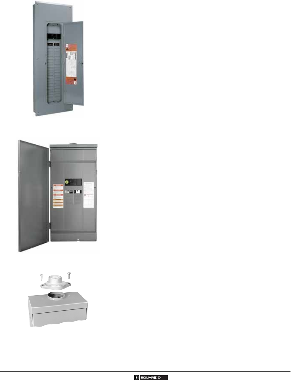
Homeline® Circuit Breakers and Load Centers—Class 1170
General Information and Application Data
43
03/2007 © 2007 Schneider Electric All Rights Reserved
Indoor Enclosures (NEMA Type 1)
Welded sheet steel with knockouts at top, bottom, back and sides
Finish: gray baked enamel electrodeposited over cleaned, phosphatized
steel
Most indoor enclosures are 14.25 in (362 mm) wide
Top or bottom feed by rotating enclosure
Indoor Covers
Doors to cover circuit breaker handles, except on 24 , 48 and 61 2
circuit models
Combination flush and surface cover with latch opening door included
with load centers
Automatic flush adjustment is standard
Triple lead cover screws for fast cover installation
Shutter-type twistouts
HOMFP snap-in style filler plates available for all covers
QOM1FP filler plates available for 10012 5 A convertible load center
covers
QOM2FP filler plates available for 15022 5 A convertible load center
covers
Rainproof Enclosures (NEMA Type 3R)
Complete enclosure includes interior trim and door
Welded galvannealed steel
Finish: gray baked enamel electrodeposited over cleaned,
phosphatized, galvannealed steel
RB devices have provisions for interchangeable bolt-on hub
Top centered rainproof mounting boss on the back of the enclosure
simplifies installation and saves time
Stainless steel door latch on the enclosure provides a secure closure
and maximum durability
Convertible main panels are side-hinge door devices
Side-hinged door provides full wiring access without door removal
Allow 1.25 in (32 mm) on the left side for the door to open
Bolt-On Hubs
Hubs available for 0.75 in (19 mm) to 4 in (102 mm) conduit size (see
page 46)
No gasket required with hubs from 0.75 in (19 mm) to 2.50 in (64 mm)
when used on RB type load centers
HOM40M200C With Cover
New RB Device
Bolt-On Hubs
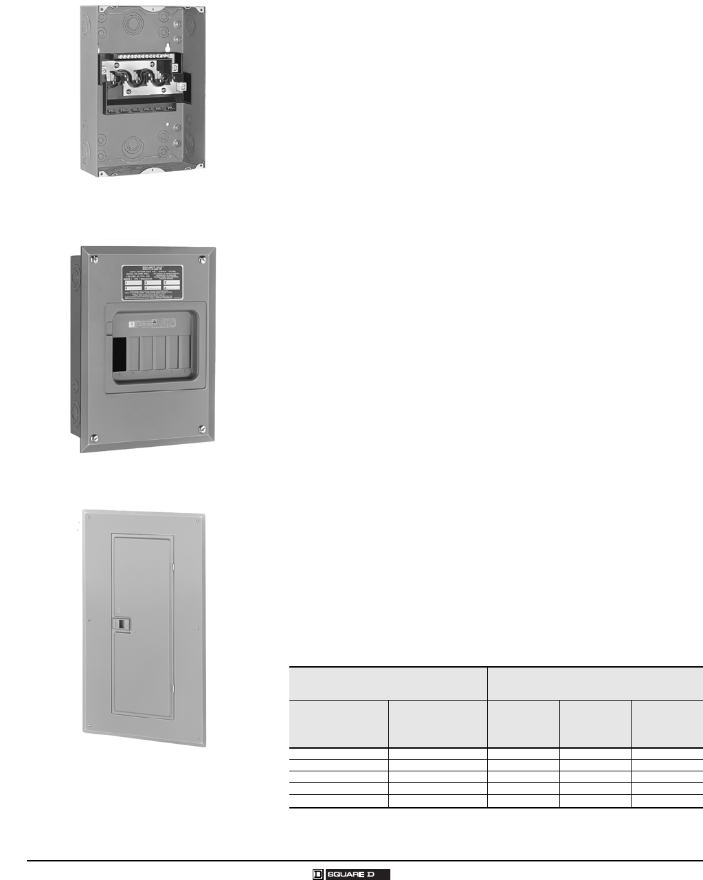
Homeline® Circuit Breakers and Load Centers—Class 1170
General Information and Application Data
44
© 2007 Schneider Electric All Rights Reserved 03/2007
Single-Phase, 2–12 Circuits, 70–125 A, Fixed Mains
UL Listed
File E-6294
Suitable for use as service equipment
75 °C wire rating (see Technical Information on page 49)
Short Circuit Current Rating
Main lugs: up to 10,000 AIR (see Technical Information on page 49)
Interior
Tin plated aluminum bus
Mains
Factory-installed fixed main lugs
Top mains positioning only
Top or bottom feed (see Technical Information on page 49)
A backfed main circuit breaker can be field installed in a 612 load
center using the HOM1RK retaining kit
Cover
Combination flush and surface cover
Single-Phase, 12–42 Circuits, 100–225 A, Convertible Mains
UL Listed
File E-6294
Suitable for use as service equipment
75 °C wire rating (see Technical Information on page 48)
Short Circuit Current Rating
Main lugs: up to 10,000 AIR
Main circuit breaker: 22,000 AIR standard (see Technical Information
on page 48)
Interior
Tin plated aluminum bus
Removable interior with single, captive mounting screw
Split branch neutral with up to 50% more terminations than required
Multiple mounting locations for equipment ground bar kits: left, right, bottom
Mains
HOM612L100F
Flush Cover
Combination Cover with Door
Factory-Installed Main Lugs
Convertible to Main Circuit Breaker Factory-Installed Main Circuit Breaker
Convertible to Main Lugs
Load Center
Amperage
Main Circuit
Breaker Kit
Amperage
Main Circuit
Breaker
Amperage
Main Lug
Kit
Amperage
Load
Center
Amperage
125 50 - 125 100 125 100
150 100 - 150 125 125 125
200 100 - 200 150 225 150
225 100 - 225 200 225 200
225 225 225
Top or bottom mains positioning, by rotating the complete indoor load center 180 degrees.
(see Technical Information on page 48)
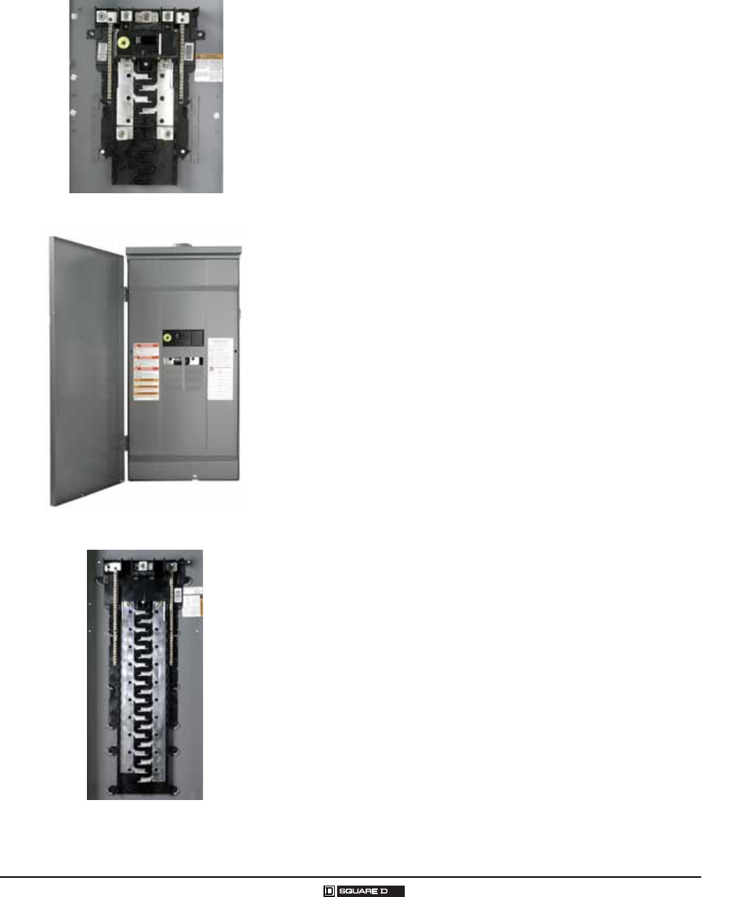
Homeline® Circuit Breakers and Load Centers—Class 1170
General Information and Application Data
45
03/2007 © 2007 Schneider Electric All Rights Reserved
Single-Phase, 12–42 Circuit, 100–225 A, Convertible Mains,
Continued
Cover
Combination flush and surface cover included with load centers
Optional door lock kit for indoor load centers
Positive action, easy open door latch
Main Circuit Breaker with Feed-Thru Lugs
Rainproof only, side hinged
150 and 200 A mains rating
Space for up to 8 single-pole circuit breakers
Factory-installed main circuit breaker
Factory-installed feed-thru lugs
Universal Mains Load Centers, Studs Only
No factory-installed main circuit breaker or main lugs
200 A mains rating
Indicated by a U in the catalog number
Purchase main lug kit or main circuit breaker kit and field install
Combination flush / surface cover included with indoor load center
Factory-installed ground bar kit
Universal Mains Load Center with Feed-Thru Lugs
No factory-installed main circuit breaker or main lugs
200 A mains rating
Feed-thru lugs are factory-installed
Rainproof only, side hinged
Space for up to 8 single-pole circuit breakers
Purchase main lug kit or main circuit breaker kit and field install
Main Circuit Breaker Mobile Home Load Centers
Covers included with load centers
Factory-installed grounding bar, indicated by a T in the catalog number
Top or bottom feed on incoming service by rotating the complete load
center 180 degrees
HOM816M200FTRB
HOM816U200FTRB
HOM3040U200TC
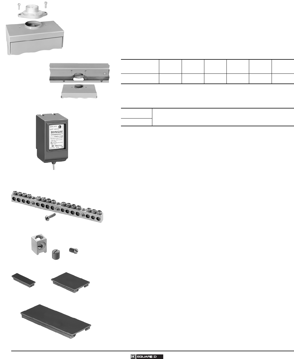
Homeline® Circuit Breakers and Load Centers—Class 1170
General Information and Application Data
46
© 2007 Schneider Electric All Rights Reserved 03/2007
Accessories
Bolt-On Hubs
Equipment with an RB suffix, meaning Rainproof NEMA Type 3R
construction, uses the bolt-on hubs listed below. RB devices will accept
0.75 in (19 mm) through 2.50 in (64 mm) bolt-on hubs without the use of
reducers.
Off-center conduit thread openings and elongated mounting holes provide
quick and easy adjustment to eliminate costly conduit offsets and bends.
Hubs are suitable for use with conduit having ANSI standard taper pipe
thread.
UL Listed Bolt-On Hubs for RB Devices
UL Listed Enclosure Coupling for RB Devices
Surgebreaker® Secondary Surge Arrester
HOM2175SB UL Listed secondary surge arrester
Easy plug-on installation for Homeline® load center
LED indicates operational status
Plug-on design requires two pole spaces
Designed to protect electrical service and major household appliances,
excluding electronic devices
Grounding Bar Kits
Field installable in all load centers
Wire size of terminals (see Technical Information on page 48)
Suitable for copper or aluminum wire
Available with #14/0 AWG lug PK15GTA-L, PK18GTA-L and PK23GTA-L
(see Technical Information on page 48)
Auxiliary Neutral Lugs
UL Listed for copper or aluminum wire
Field installable on neutral assembly
LK70AN: #122 Al or #14 4 Cu AWG
LK100AN: #62/0 Al/Cu AWG
LK125AN: #142/0 Al/Cu AWG
Cover Filler Plates
Fast to install; snap-in type
HOMFP branch circuit
QOM1FP 501 25 A main circuit breaker
QOM2FP 150 225 A main circuit breaker
RB Hub
BC200 Enclosure Coupling
HOM Surgebreaker®
Surge Arrester
2 spaces required.
PK15GTA
LK100AN
HOMFP QOM1FP
QOM2FP
Conduit Size 0.75 in
9 mm
1.00 in
25 mm
1.25 in
32 mm
1.50 in
38 mm
2.00 in
51 mm
2.50 in
64 mm
Hub Cat. No. B075 B100 B125 B150 B200 B250
NOTE: Closing cap (catalog number B-CAP) is provided factory-installed on each device having
the RB suffix.
Cat. No. Designed for connecting wireway or other enclosures to units having RB
bolt-on conduit provisions. Provides a bushed opening equal to 2 in conduit.
Eliminates the need for conduit nippling.
BC200
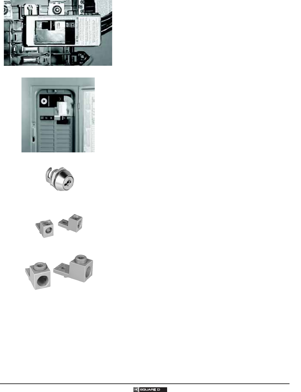
Homeline® Circuit Breakers and Load Centers—Class 1170
General Information and Application Data
47
03/2007 © 2007 Schneider Electric All Rights Reserved
Back-Fed Main Circuit Breaker Retaining Kits
HOM1RK: secures circuit breaker to interior when used as back-fed
main for HOM612L100F/S and RB load centers
HOM4RK2LA: mounts on the right side of HOM 100 125 A convertible
main load centers, series S01 and S02 (retains one 2-pole HOM circuit
breaker)
HOM4RK2HA: mounts on the right side of HOM 1502 25 A convertible
main load centers, series S01 and S02 (retains one 2-pole HOM circuit
breaker)
Generator Circuit Breaker Interlock Kit
HOMCRBGK1: interlocks a QOM1 2-pole main circuit breaker of a load
center (100125 A) with a Homeline® 2-pole (15 125 A) branch circuit
breaker, "S" series NEMA Type 1 and "S1" and "S2" series NEMA type 3R
load centers
HOMCGK2: interlocks a QOM2 2-pole main circuit breaker of a load center
(150225 A) with a Homeline 2-pole (15 125 A) branch circuit breaker, S
series NEMA Type 1 and S01 series NEMA Type 3R load centers
HOMRBGK2: interlocks a QOM2 2-pole main circuit breaker of a load
center (150225 A) with a Homeline 2-pole (15 125 A) branch circuit
breaker, S02 series NEMA Type 3R load centers
Flush Lock Kits
Available for indoor load centers
Two keys provided with each lock kit
PK6FL for single-phase convertible 842 circuit load centers
Main Lugs Kits
Field installable in main circuit breaker or main lugs load centers
125 A kit usable in 100 125 A load centers, QOL125
225 A kit usable in 150 225 A load centers, QOL225
Main Circuit Breaker Kits
Field installable in main lugs or main circuit breaker load centers
50 225 A main circuit breaker kit with 22,000 AIR usable with 10,000
AIR branch circuit breakers (see page 10)
PK6FL
QOL125
QOL225
Back-Fed Main Circuit Breaker Retaining Kit
Cutaway Showing Installed Generator Interlock Kit
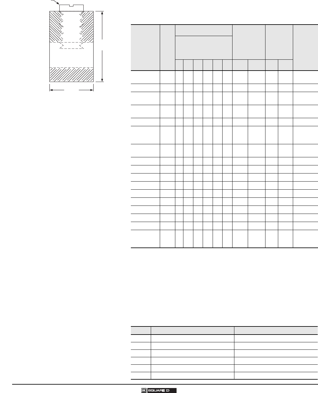
Homeline® Circuit Breakers and Load Centers—Class 1170
Technical Information
48
© 2007 Schneider Electric All Rights Reserved 03/2007
TECHNICAL INFORMATION
Grounding Bar Kits
All PK equipment grounding bar kits are supplied with mounting screws,
necessary installation instructions and an Equipment Grounding Terminal
self-adhesive label.
Wire Range Table
Slot / Robertson screw
Cross Section of Size 1 Ground Bar
0.3125
[8]
0.437
[11]
Dimensions: in
[mm]
Catalog
Number Total
Qty.
Terminals Approximate
Overall
Length
Distance
Between
Mounting
Holes Mounting
Quantity Each Size
See “Wire Range
Table” below.
III III IV VVI in [mm] in [mm]
PK0GTA2 1
1Mounting screw 40205-065-01 (one required).
2 2 1.75 [44] One
hole
One
hole Top
PK0GTA6 2
2Mounting screw 21922-18360 (two required).
6 6 4.61 [117] 1.69 [43] Top
PK3GTA1 3
3Mounting screw 21594-14220 (two required).
3 3 1.38 [35] One
hole
One
hole Top
PK4GTA 34 4 1.63 [41] One
hole
One
hole Top
PK5GTA 4
4Mounting screw 21594-14241 (two required).
5 5 2.25 [57] 1.25 [32] Top
PK7GTA 37 7 2.88 [73] 1.25 [32]
Top
or
Side
PK9GTA1 39 9 3.25 [83] One
hole
One
hole Top
PK9GTA 39 9 3.78 [96] 3.13 [80] Top
PK12GTA 312 12 4.70 [119] 3.13 [80] Top
PK15GTA 315 15 5.63 [143] 3.13 [80] Top
PK15GTAL 5
5Mounting screw 21594-14302 (two required).
16 15 1 8.13 [207] 3.13 [80] Top
PK15GTA6 6
6Mounting screws 21594-14241(two required) and 21594-17121(two required).
21 15 6 5.88 [149] 7
73.13 in. (80 mm) on small terminals; 5.25 in. (133 mm) on large terminals.
7Top
PK18GTA 318 18 6.56 [167] 3.13 [80] Top
PK18GTAL 519 18 1 8.81 [224] 3.13 [80] Top
PK23GTA 323 23 8.11 [206] 3.13 [80] Top
PK23GTAL524 23 1 9.44 [240] 3.13 [80] Top
PK27GTA 3 8
8PK27GTA includes one main grounding lug that mounts with two terminal screws and requires
three terminals for mounting.
27
or
26
27
or
26
1 9.36 [238] 3.13 [80] Top
Size Cu (AWG) Al (AWG)
I (1) #14 #4 or (2) #14 or #12 (1) #12 #4 or (2) #12 or #10
II (1) #14 /0 (1) #14 /0
III (1) #62 /0 (1) #62 /0
IV (1) #63 /0 (1) #63 /0
V (1) #14 1/0 (1) #141 /0
VI (1) #10 2/0 (1) #62 /0
Homeline® Circuit Breakers and Load Centers—Class 1170
Main Lugs and Main Circuit Breakers Ratings
49
03/2007 © 2007 Schneider Electric All Rights Reserved
MAIN LUGS AND MAIN CIRCUIT BREAKERS RATINGS
Single-Phase, Three-Wire, 120/240 Vac Main Lugs Indoor
Mains
Rating
in
Amps
Load Center
Catalog Number
L o a d C e n t e r
C o v e r
Catalog
Number
UL Listed
Se rv ice
Equipment
(See Notes)
Maximum
UL Short
Circuit
Rating 1
M a i n W i r e S i z e
AWG/kcmil
Al/Cu
Enclosure
No.
(Page 27)
Top or
Bottom
Mains
Position
UL Li ste d for
Corner Grounded
Delta Systems
Fixed Mains – Factory-Installed Main Lugs
70 HOM24L70F/S Included B 10,000 A #123
#144 2 Top No
100 HOM612L100F/S Included B, C 10,000 A #81 4 Top No
125 HOM48L125GC Included B, C 10,000 A #42/ 0 21 Top No
Convertible Mains – Factory-Installed Main Lugs
QOM1 Main Frame Size – Convertible to 22,000 AIR Main Circuit Breaker
125
HOM816L125C Included B, C 10,000 A #62/ 0 6 Both
No
HOM816L125TC Included B, C 10,000 A #62/ 0 6 Both
HOM12L125C Included B, C 10,000 A #62/ 0 6 Both
HOM1224L125TC Included B, C 10,000 A #62/ 0 6 Both
HOM1624L125C Included B, C 10,000 A #62/ 0 8 Both
HOM20L125C Included B, C 10,000 A #62/ 0 8 Both
HOM20-24L125TC Included B, C 10,000 A #62/ 0 8 Both
HOM24L125TC Included B, C 10,000 A #62/ 0 8 Both
Convertible Mains – Factory-Installed Main Lugs
QOM2 Main Frame Size – Convertible to 22,000 AIR Main Circuit Breaker
150 HOM30L150C Included B, C 10,000 A #4250 10 Both
No
HOM30L150TC Included B, C 10,000 A #6250 10 Both
200
HOM1632L200TC Included B, C 10,000 A #4250 9 Both
HOM1632L200TCFT 2Included B, C 10,000 A #6250 10 Both
HOM2040L200TC Included B, C 10,000 A #6250 9 Both
HOM30L200C Included B, C 10,000 A #6250 10 Both
HOM30L200TC Included B, C 10,000 A #6250 9 Both
HOM3040L200TC Included B, C 10,000 A #6250 10 Both
HOM40L200C Included B, C 10,000 A #6250 12 Both
HOM40L200TC Included B, C 10,000 A #6250 12 Both
225 HOM42L225C Included B, C 10,000 A #6250 10 Both
1UL short circuit rating with optional QOM-VH main circuit breaker, 22,000 AIR.
2Supplied with feed-thru lugs.
B UL Listed as suitable for use as service equipment (neutral bonded at the time of installation) with field-installed service disconnect.
C UL Listed as suitable for use as service equipment (neutral bonded at the time of installation) when not more than six service disconnecting means are provided and
when not used as a lighting and appliance branch circuit panelboard.
Homeline® Circuit Breakers and Load Centers—Class 1170
Main Lugs and Main Circuit Breakers Ratings
50
© 2007 Schneider Electric All Rights Reserved 03/2007
Single-Phase, Three-Wire, 120/240 Vac Main Circuit Breaker Indoor
Mains
Rating
in
Amps
Load
Center Catalog
Number
Load
C e n t e r C o v e r
Catalog
Number
UL Listed
Se rv ice
Equipment
(See Notes)
Maximum
UL Short
Circuit
Rating 1▲
1UL short circuit rating with optional QOM-VH main circuit breaker, 22,000 AIR.
A UL Listed as suitable for use as service equipment (neutral bonded at the time of installation) with a factory-installed service disconnect.
B UL Listed as suitable for use as service equipment (neutral bonded at the time of installation) with field-installed service disconnect.
C UL Listed as suitable for use as service equipment (neutral bonded at the time of installation) with field-installed main lugs when not more than six disconnecting
means are provided and when not used as lighting and appliance branch circuit panelboard.
M a i n W i r e S i z e
AWG/kcmil
Al/Cu
Enclosure
No.
(Page 27)
Top or
Bottom
Mains
Position
U L L is t ed f or
Corner
Grounded Delta
Systems
Convertible Mains – Factory-Installed Main Circuit Breaker
QOM1 Main Frame Size – Convertible to Main Lugs
100
HOM816M100C Included A, C 22,000 A #61 5 Both
No
HOM816M100TC Included A, C 22,000 A #61 5 Both
HOM12M100C Included A, C 22,000 A #42 /0 6 Both
HOM1224M100TC Included A, C 22,000 A #42 /0 6 Both
HOM20M100C Included A, C 22,000 A #42 /0 8 Both
HOM24M100C Included A, C 22,000 A #42 /0 8 Both
HOM30M100C Included A, C 22,000 A #42 /0 10 Both
125
HOM1224M125C Included A, C 22,000 A #42 /0 6 Both
No
HOM1224M125TC Included A, C 22,000 A #42 /0 6 Both
HOM24M125C Included A, C 22,000 A #42 /0 8 Both
HOM30M125C Included A, C 22,000 A #42 /0 10 Both
Convertible Mains – Factory-Installed Main Circuit Breaker
QOM2 Main Frame Size – Convertible to Main Lugs
150
HOM1632M150TC Included A, C 22,000 A #4 250 9 Both
NoHOM2030M150TC Included A, C 22,000 A #4 250 9 Both
HOM30M150C Included A, C 22,000 A #4 250 10 Both
200
HOM1224M200TC Included A, C 22,000 A #4 250 9 Both
No
HOM1632M200TC Included A, C 22,000 A #4 250 9 Both
HOM2040M200C Included A, C 22,000 A #4 250 9 Both
HOM2040M200TC Included A, C 22,000 A #4 250 9 Both
HOM30M200C Included A, C 22,000 A #4 250 10 Both
HOM3040M200TC Included A, C 22,000 A #4 250 10 Both
HOM40M200C Included A, C 22,000 A #4 250 12 Both
HOM42M200C Included A, C 22,000 A #4 250 12 Both
225 HOM42M225C Included A, C 22,000 A #4 250 12 Both No
Universal Mains – No Factory-Installed Main Circuit Breaker or Main Lugs
QOM2 Main Frame Size – Field-Installed Main Lugs or 22,000 AIR Main Circuit Breaker
200
HOM1632U200TC Included B, C 10,000 A #4 250 9 Both
NoHOM2040U200TC Included B, C 10,000 A #4 250 9 Both
HOM3040U200TC Included B, C 10,000 A #4 250 10 Both
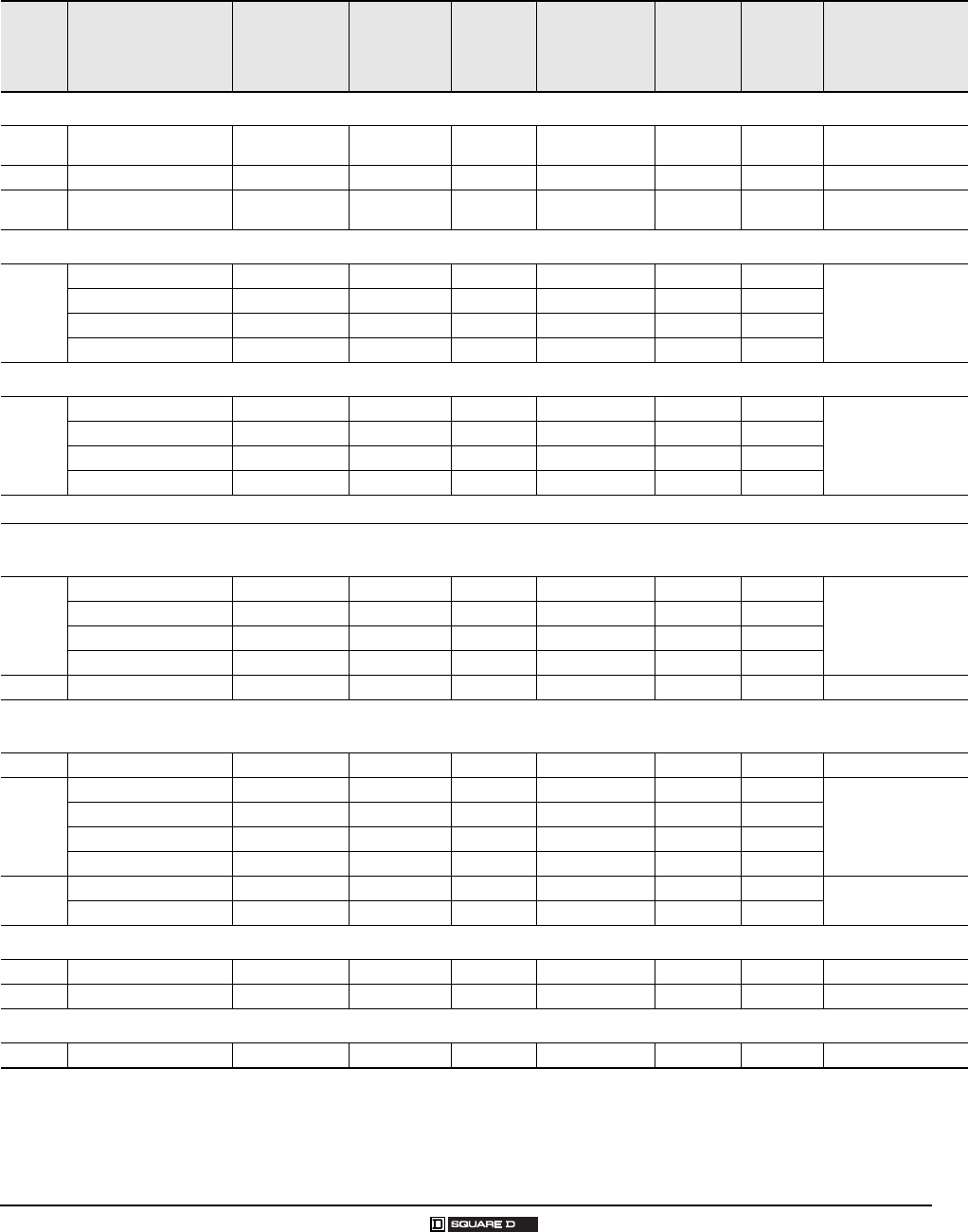
Homeline® Circuit Breakers and Load Centers—Class 1170
Main Lugs and Main Circuit Breakers Ratings
51
03/2007 © 2007 Schneider Electric All Rights Reserved
Single-Phase, Three-Wire, 120/240 Vac Main Lugs Rainproof
Mains
Rating
in
Amps
Load
Center Catalog
Number
Load
C e n t e r C o v e r
Catalog
Number
UL Li ste d
S er v ic e
Equipment
(See Notes)
Maximum
UL Short
Circuit
Rating 1▲
1UL short circuit rating with optional QOM-VH main circuit breaker, 22,000 AIR.
A UL Listed as suitable for use as service equipment (neutral bonded at time of installation) with factory-installed service disconnect.
B UL Listed as suitable for use as service equipment (neutral bonded at time of installation) with field-installed service disconnect.
C UL Listed as suitable for use as service equipment (neutral bonded at the time of installation) with field-installed main lugs when not more than six service
disconnecting means are provided and when not used as a lighting and appliance branch circuit panelboard.
M a i n W i r e S i z e
AWG/kcmil
Al/Cu
Enclosure
No.
(Page 28)
Top or
Bottom
Mains
Position
UL Listed for
Corner Grounded
Delta Systems
Fixed Mains – Factory-Installed Main Lugs
70 HOM24L70RB Included B 10,000 A #123 Al
#144 Cu 1R Top No
100 HOM612L100RB Included B, C 10,000 A #8 1 2R Top No
125 HOM48L125GRB Included B, C 10,000 A #122/ 0 Al
#14 2/0 Cu 16R Top No
Convertible Mains – Factory-Installed Main Lugs – QOM1 Main Frame Size – Convertible to 22,000 AIR Main Circuit Breaker
125
HOM816L125RB Included B, C 10,000 A #62 /0 3R Top
No
HOM12L125RB Included B, C 10,000 A #62 /0 3R Top
HOM1224L125RB Included B, C 10,000 A #62 /0 3R Top
HOM20L125RB Included B, C 10,000 A #62 /0 4R Top
Convertible Mains – Factory-Installed Main Lugs – QOM2 Main Frame Size – Convertible to 22,000 AIR Main Circuit Breaker
200
HOM12L200RB Included B, C 10,000 A #6 250 5R Top
No
HOM2040L200RB Included B, C 10,000 A #6 250 6R Top
HOM30L200RB Included B, C 10,000 A #6 250 7R Top
HOM40L200RB Included B, C 10,000 A #6 250 8R Top
Single-Phase Three Wire 120/240 Vac Main Breaker Rainproof
Convertible Mains – Factory-Installed Main Circuit Breaker
QOM1 Main Frame Size – Convertible to Main Lugs or Lower Amperage Main Circuit Breaker
100
HOM816M100RB Included A, C 22,000 A #42 /0 3R Top
No
HOM12M100RB Included A, C 22,000 A #42 /0 3R Top
HOM20M100RB Included A, C 22,000 A #42 /0 4R Top
HOM24M100RB Included A, C 22,000 A #42 /0 6R Top
125 HOM24M125RB Included A, C 22,000 A #42 /0 6R Top No
Convertible Mains – Factory-Installed Main Circuit Breaker
QOM2 Main Frame Size – Convertible to Main Lugs or Lower Amperage Main Circuit Breaker
150 HOM30M150RB Included A, C 22,000 A #4 250 7R Top No
200
HOM2040M200RB Included A, C 22,000 A #4 250 6R Top
No
HOM30M200RB Included A, C 22,000 A #4 250 7R Top
HOM3040M200RB Included A, C 22,000 A #4 250 7R Top
HOM40M200RB Included A, C 22,000 A #4 250 8R Top
225
HOM1624M225RB Included A, C 22,000 A #4-250 Top No
HOM42M225RB Included A, C 22,000 A #4-250 Top
Factory-Installed Main Circuit Breaker with Feed-Thru Lugs
150 HOM816M150FTRB Included A, C 22,000 A #4 250 6R Top No
200 HOM816M200FTRB Included A, C 22,000 A #4 250 6R Top No
Universal Main Circuit Breaker with Feed-Thru Lugs
200 HOM816U200FTRB Included B 22,000 A #4 250 6R Top No
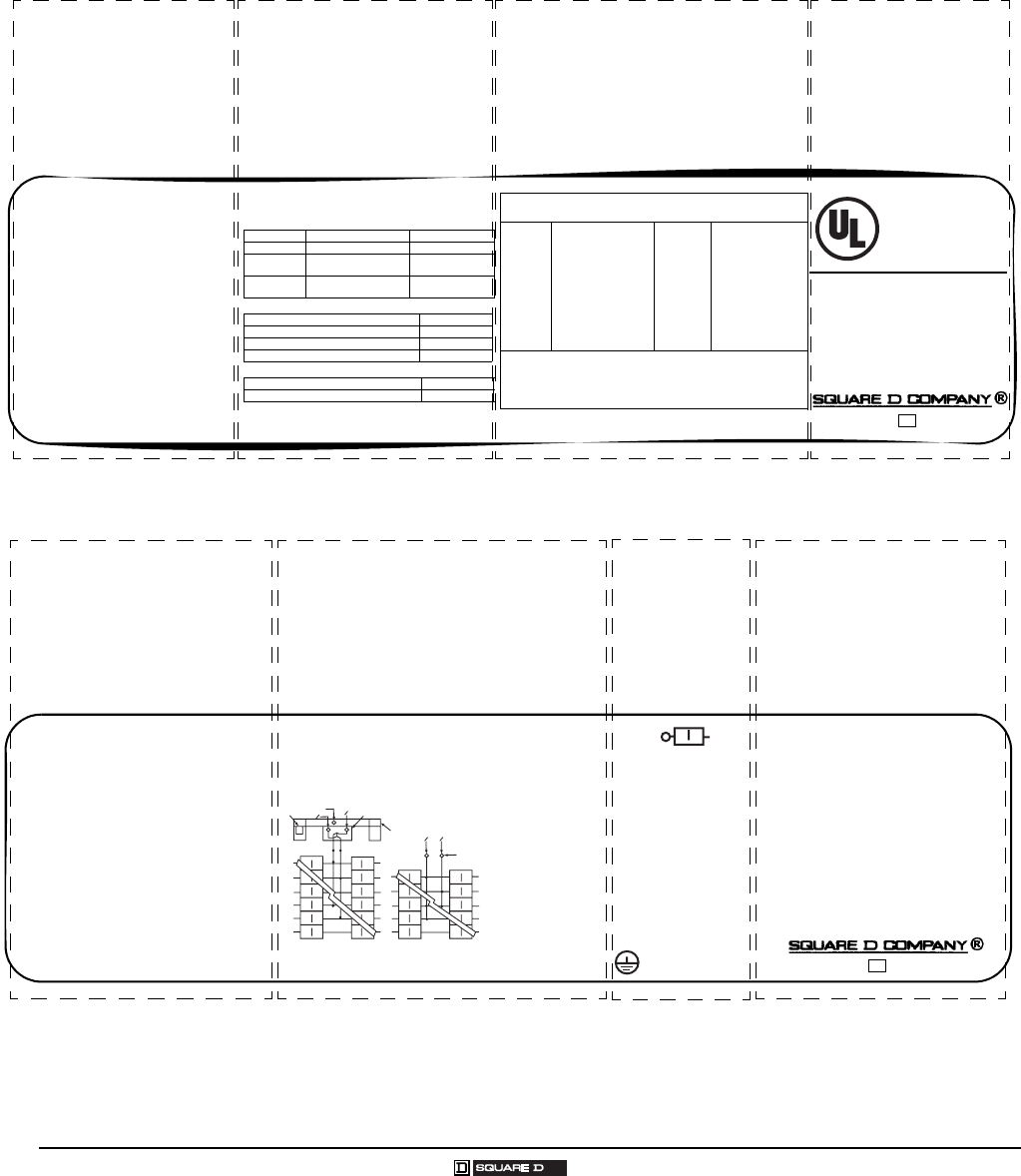
Homeline® Circuit Breakers and Load Centers—Class 1170
Homeline Label Samples
52
© 2007 Schneider Electric All Rights Reserved 03/2007
HOMELINE LABEL SAMPLES
For information on two-tier and three-tier series ratings, see Data Bulletin number 4100DB0301, Square D® Load Center Short
Circuit Current Ratings, located on the Technical Library at www.SquareD.com.
Install loose label with Spanish translation
on back of cover.
Adhiera la etiqueta suelta con las traducciones
en espanol en la parte posterior del frente.
Please read information before installing
Por favor lea la informacion antes de instalar.
~
/
LISTED
Electric
Cabinet Box
Issue No. V-2813
HOM LOAD CENTER
See Panelboard interior for Catalog No.
Box Cat. No. / Caja No. de Catalogo:
BXH34A
Use Cover Cat. No. /
Utilice la Cubierta No. de Catalogo:
HOMC30UC
Mains 200A max. / Lina Principal de.
200A maximo.
See main or service disconnect
rating if installed.
120/240 V ~ Max. 1Ø, 50 / 60 Hz.
30 circuit max. / 30 circuitos maximo.
Type 1 Enclosure
Gabinete Tipo 1
For installation, repairs or alterations,
Call an electrical contractor or electrician.
Panel
Rating
Remote
Main
Integral
Main
Branch (min.)/
Cat. prefix
42,000 QOH Lugs 10,000 / HOM
22,000 QOME..VH Lugs 10,000 / HOM
*10,000 ---- Lugs 10,000 HOM
22,000 ---- QOM2...VH 10,000 HOM
10,000 ---- QOM2 10,000 HOM
* The rating is equal to the lowest interrupting rating of any circuit breaker
installed. Refer to branch breaker for individual ratings. Additional or
replacement branch circuit breakers, main breaker, or service disconnect
MUST have an interrupting rating equal to or greater than that of the
circuit breaker with the lowest interrupting rating presently installed.
See panelboard interior for breaker types.
LUG TORQUE DATA
See circuit breakers and field installed
units for wire binding screw torque
Branch Neutral and Equipment Ground Bar
Equipment Ground Combinations
Wire Range (AWG/kcmil) Torque (in/lbs.)
Main Lug 4 - 250 CU/AL 250
Service
Ground Lug 6 - 2/0 CU/AL 50
Alternate
Main Breaker
See Main
Breaker
See Main
Breaker
Wire Range (AWG) Torque (in./lbs.)
6 CU / AL Large 45
8 CU / AL Large 40
14-10 CU, 12-10 AL Large 35
Two 14 or 12 CU 25
Two 12 or 10 AL 10
SHORT CIRCUIT RATING
RMS Symmetrical Amperes at 120 / 240 V ~ Maximum
Underwriter’s
Laboratories, Inc.®
Number of circuits maximum.
Enclosure catalog number.
Catalog number of covers; flush
or surface.
See panelboard interior for the
catalog number.
Voltage ratings.
Amperage rating. Wire range for lug torque data table.
Short circuit ratings.
Short circuit ratings and additional of replacement
circuit breakers. UL listing.
001021 40265-381-0315
®
Homeline Box Label Sample
Line / Lines
N
NO O
3
NO
O
12
4
LOAD / CARGAS
LOAD / CARGAS
LOAD / CARGAS
Main Breaker diagram Main Lugs diagram
Service Equipment marking.
Use of unused neutral branch terminal for
equipment grounding, service equipment
application only.
Made in U.S.A. 40265-668-0215
1. Box bonding when required. / Conexion a la caja
cuando fuese necesario.
2. Main breaker type: QOM1 or QOM1A. / Interruptor
automatico principal tipo: QOM1 o QOM1A.
3. Service ground
when required. /
Tierra de acometida
cuando fuese
necesario
4. Main lugs kit no:
QOL125. / No. de
accesorio de las
zapatas
principales:
QOL125.
One single pole. One plug
on space. One two pole
requires two plug on
spaces.
Torque Note: When main
breaker or main lug
connector mounting nuts
are loosened or removed,
retighten to 75 lbs./in.
torque.
* May plug on two adjacent spaces.
Torque Note: When interior mounting screw is
loosened or removed, retighten to 35 lbs./in.
Load Center Accessories - Kits
HOM4K2LA Back-fed Main Circuit Brkr. Retaining
HOM2175SB Plug-0n Surge Arrestor *
SDSA1175 1 Phase Surge Arrestor
QOSAMK SDSA1175 Mounting Bracket
HOML2125 1 Phase Plug-on Subfeed Lugs *
PK9--27GTA(L) Equipment Ground Bar
PKGTAB Equipment Ground Bar Insulator
LK70AN 70A Max. Neutral Lug
LK100AN 125A Max. Neutral Lug
QOL125 Main Lugs
PK6FL Indoor Cover Lock
Equipment Grounding
Terminals
Type of circuit breakers
from Square D that
may be used in this
panelboard.
Installation of back-fed main circuit breaker and
required kit.
Alternate wiring diagram for main circuit breaker or
main lug.
Load center accessories.
Neutral lug for 1/0 AWG or larger wire.
Suitable for use with 75oC
Copper or Aluminum
main conductors. See
branch breakers for
branch wire ratings.
* Suitable for use as service equipment when
service disconnect (main breaker) is installed.
* Suitable for use as service equipment when
not more than six main disconnecting means
are provided and when not used as a lighting
and appliance branch circuit panelboard.
See Article 384-14 of the NEC.
* When used as service equipment, all unused
neutral terminals may be used for terminating
equipment ground wires.
Homeline Wiring Diagram Sample
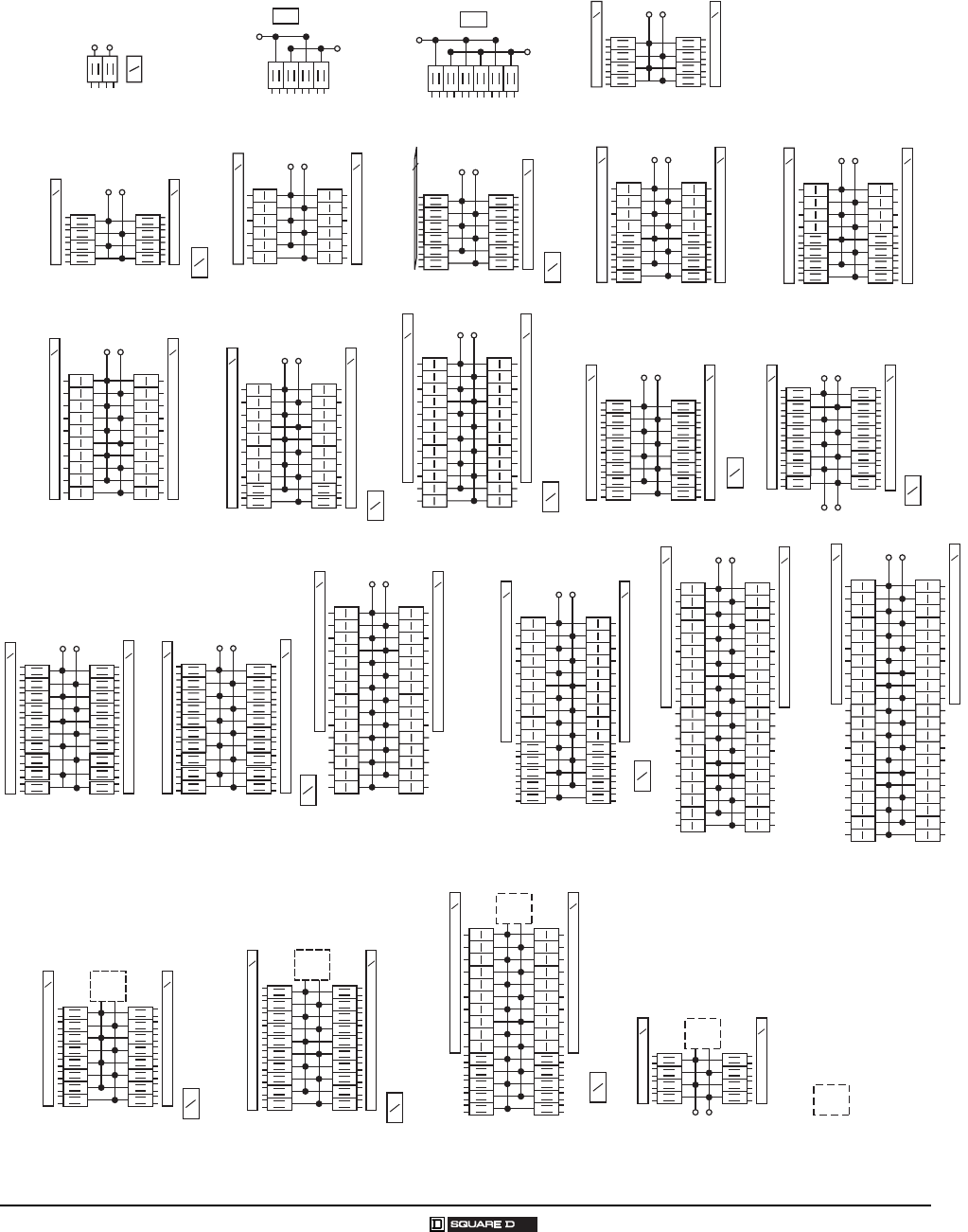
Homeline® Circuit Breakers and Load Centers—Class 1170
Wiring Diagrams
53
03/2007 © 2007 Schneider Electric All Rights Reserved
WIRING DIAGRAMS
1-Phase, 3-Wire Main Lugs
HOM24L70F/S
HOM24L70RB
S
N
HOM612L100F/S
HOM612L100RB
S/N
HOM48L125GC
HOM48L125GRB
S/N
HOM816L125C
HOM816L125RB
HOM816L125TC HOM12L125C
HOM12L125RB
HOM12L200RB
HOM1224L125TC HOM1624L125C
S
N
S
N
S
N
S
N
S
N
S
N
G
B
S
N
S
N
G
B
S
N
S
N
G
B
S
N
S
N
S
N
HOM2024L125TC
S
N
S
N
HOM20L125C
HOM20L125RB
S
N
S
N
HOM1632L200TC
S
N
G
B
G
B
S
N
HOM30L150C
HOM30L200C
HOM30L200RB
HOM30L200TC
S
NS
N
HOM3040L200TC
S
N
G
B
S
N
HOM40L200C
HOM40L200RB
S
N
S
N
HOM42L225C
S
N
HOM246125TC
Universal Mains
HOM1632U200TC
S
N
G
B
S
N
HOM2040U200TC
S
N
G
B
S
N
S
N
HOM3040U200TC
S
N
G
B
S
N
HOM816U200FTRB
S
N
Requires Field Installed Main
S
N
S
N
G
B
HOM1632L200TCFT
S
N
S
N
G
B
HOM2040L200TC
HOM1224L125RB
S
N
S
N
S
N
S
N
HOM2040L200RB
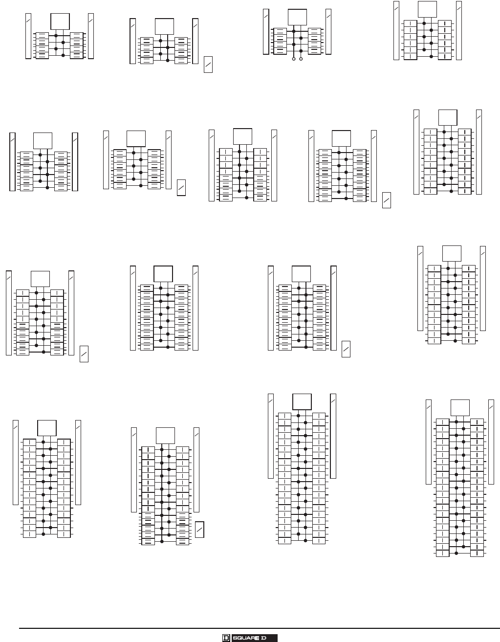
Homeline® Circuit Breakers and Load Centers—Class 1170
Wiring Diagrams
54
© 2007 Schneider Electric All Rights Reserved 03/2007
1-Phase, 3-Wire Main Circuit Breakers
S
N
HOM816M100C
HOM816M100RB
S
N
G
B
MAIN
S
N
HOM816M100TC
S
N
MAIN
S
N
HOM816M150FTRB
HOM816M200FTRB
S
N
MAIN
S
N
HOM12M100C
HOM12M100RB
S
N
MAIN
G
B
S
N
HOM1224M125C
S
N
MAIN
S
N
HOM1224M100TC
HOM1224M125TC
HOM1224M200TC
S
N
MAIN
G
B
S
N
HOM1632M150TC
HOM1632M200TC
S
N
MAIN
S
N
HOM20M100C
HOM20M100RB
S
N
MAIN
S
N
HOM2040M200C
HOM2040M200RB
S
N
MAIN
HOM2040M200TC
S
N
MAIN
G
B
S
N
HOM2030M150TC
G
B
S
N
S
N
MAIN
S
N
HOM24M100C
HOM24M100RB
HOM24M125C
HOM24M125RB
HOM24M200C
S
N
MAIN
MAIN
MAIN
S
N
HOM30M100C
HOM30M125C
HOM30M150C
HOM30M200C
HOM30M150RB
HOM30M200RB
S
NS
N
HOM3040M200TC
HOM3040M200RB
S
N
G
B
MAIN
S
N
HOM40M200C
HOM40M200RB
S
N
MAIN
S
N
HOM42M225C
S
N
S
N
S
N
HOM1624M225RB
HOM42M200C
HOM42M225RB
MAIN

© 2007 Schneider Electric All Rights Reserved 55
1100CT0501 QO® and Homeline® Load Centers and Enclosures
03/2007 Index
INDEX
A
accessories
cover filler plates 16, 46
flush lock kits 16, 47
generator circuit breaker interlock kit 17, 47
grounding bar kits 16, 19, 51
manual transfer equipment kit 17
secondary surge arrester 17, 46
assemblies
base 35
neutral 7, 35
auxiliary
gutters and tap kits 18
neutral lugs 16, 46
B
back-fed circuit breaker retaining kit 17, 47
base assemblies 35
bolt-on hubs 6, 18, 35, 46
branch circuit breakers 5, 42
C
catalog number description 4, 41
circuit breakers
back-fed 17, 47
branch 5, 42
enclosed molded case 36
lugs 10
main 10, 13, 44
ratings 5, 9, 20, 34, 36, 44, 47
with Visi-Trip® 35
class CTL 7, 42
convertible
main circuit breakers, single-phase 9, 47
main lugs, single-phase 10, 20, 47
mains, single-phase 8, 15, 45
mains, three-phase 13, 14
cover filler plates 16, 46
covers
indoor 6, 44
load centers 8, 10, 13, 44
CSA certified 8, 11
D
dimensions and knockouts
indoor 26, 37
outdoor 27, 37
E
enclosures
type 1, indoor 6, 34, 43
type 3R, outdoor 6, 34, 43
F
feed-thru
lugs 11, 45, 53, 51
universal main 45, 47
fixed
main lugs, single-phase 8, 15, 20, 45, 47
main lugs, three-phase 13
mains, single-phase 10, 15, 20, 21, 45,
47, 51
mains, three-phase 14, 24, 29
flush lock kits 16, 47
G
generator panels 12, 25
grounding bar kits 16, 19, 35, 46, 48
H
hubs, bolt-on 6, 18, 35, 46, 46
I
interiors 8, 9, 13, 15, 44
K
kits
auxiliary gutters and taps 18
back-fed main circuit breakers 17, 47
flush lock 16, 47
grounding bar 16, 19, 35, 46, 47
main circuit breakers 10, 45, 47
main lugs 10, 14, 47
manual transfer 17
retaining 17, 47
L
load centers
Homeline® circuit breaker 42
QO® circuit breaker 3
lugs
auxiliary neutral 16, 46
feed-thru 11, 26, 45, 51
line 7
main 7,11,14, 20-26, 44, 45, 47
ratings 5, 9, 20, 44, 46
M
main circuit breakers
features 3, 11,12,16, 45
kits 10, 47
mobile home load centers 45
ratings 5, 9, 35, 36, 45
sizes 12,13,15, 44
mains
back-fed 17, 47
convertible, single-phase 9, 20-24, 28, 49
convertible, three-phase 13
fixed, single-phase 20, 44, 49, 51
fixed, three-phase 24, 29
lug kits 10, 14, 47
lugs 14, 202 8, 44, 46
manual transfer kits 17
N
neutral assemblies 7, 35
R
ratings
circuit breakers 5, 20, 34, 36, 44, 47
enclosed molded case circuit breakers 34,
36
grounding bar 16, 19, 35, 46, 51
main circuit breakers 5, 13, 20, 45, 47
indoor, single-phase 9, 10, 20, 49
indoor, three-phase 24, 28
rainproof, single-phase 11, 18, 46
rainproof, three-phase 24, 25
main lugs 5, 20-28, 44, 45
main lugs and main circuit breakers 5,
202 8, 45, 47
indoor, single-phase 9,10, 20, 49
indoor, three-phase 24, 25
rainproof, single-phase 11,12, 20,
47, 51
rainproof, three-phase 24, 25
recreational vehicle and manufactured
housing 11
short circuit 8, 9,13, 15, 20-25, 44, 47
tap kits 18
RB devices 6, 18, 34, 46
recreational vehicle and manufactured
housing 11
replacement parts - see note below
retaining kits 17, 47
S
service 5, 34, 42
short circuit ratings 9,13,15, 20-25, 44, 49
special purpose 11 12
surge arresters, secondary 17, 46
T
transfer switches, manual and automatic 12
U
UL listed 8 9, 13, 15, 17, 18, 20-26, 36, 42,
46, 49
W
wiring diagrams 3033, 53
NOTE: For information on Replacement
Parts with specific part numbers, go to
www.schneider-electric.us, click on
Product FAQ’s, enter the device catalog
number, click SEARCH, then look for
the information required.

Electrical equipment should be installed, operated, serviced, and maintained only by qualified
personnel. No responsibility is assumed by Schneider Electric for any consequences arising out of
the use of this material.
1100CT0501 © 2007 Schneider Electric All Rights Reserved
Replaces 1100CT9901 dated September 2000.
1601 Mercer Road
Lexington, KY 40511 USA
1-888-SquareD
(1-888-778-2733)
www.us.SquareD.com
03/2007
Schneider Electric USA
QO® and Homeline® Circuit Breaker Load Centers and Enclosures
Catalog
