RTTE TCF Form 501682 CE Report Linktek
2016-04-11
: Pdf 501682 Ce Report Linktek 501682_CE__Report--Linktek CertsReports 501682 ProductFiles
Open the PDF directly: View PDF ![]() .
.
Page Count: 146 [warning: Documents this large are best viewed by clicking the View PDF Link!]

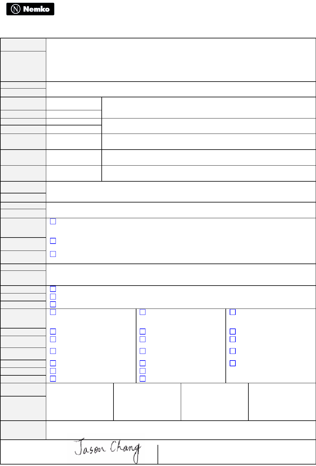
APPLICATION FORM
We hereby order examination by Nemko as specified below. When the order is received, Nemko will provide an Order Confirmation
which, together with the signed Application Form, will constitue a binding agreement between the applicant and NEMKO. The
appropriate conditions are described overleaf.
APPLICANT
Name and address
Cameo Communications, Inc
No. 42, Min Chuan East Road, Section 6, Taipei 114,
Taiwan
Our reference./ contact person: Mr. Jason Chang
Possible other invoice reference:
TRAINING RESEARCH CO., LTD.
Phone: 886-2-2693-5155 ext.32
Fax/E-mail: 886-2-2693-4440 /
jack@trclab.com.tw
MANU-
FACTURER
(if different from
the applicant)
Name and address
Cameo Communications, Inc
6F, NO. 22, Chung Shin Rd., Hsi-Chih, Taipei 221, Taiwan
FACTORY/
PROD. SITE
(if different from
the manufacturer)
Name and address
PRODUCT
CATEGORY 802.11g Wireless PCI Adapter
MARKING ON
THE PRODUCT
Model/type: WLG-1202, WNC-0300, LWS5410P, NWP-0108G, ALL0281A
Data:
Other specification: 802.11g Wireless PCI Adapter
Name/trade mark/logo *) CAMEO, Level One, LG, Etherwan, Allnet GmbH
THE ORDER
COMPRISES
x New order ¨ Repeated examination, please indicate previous Nemko Order No.:
...................................
¨ Complete Nemko product certificate *)
¨ Nordic Certification Service *) for: ¨ Denmark ¨ Finland ¨ Sweden ¨ Iceland *)
¨ Testing for European certification (CCA), relevant countries: *)
¨ Testing for international certification (CB), relevant countries: *)
¨ Statement of conformity with standard for one product sample *)
¨ Test report according to the following standards/specifications:
¨ Attestation of conformity with: ¨ The EMC-Directive ¨ Other relevant Directives *)
x Other: *) Conformity assessment for letter of opinion R&TTE Directive
SUBMITTED/
ENCLOSED
¨ Test sample(s) ¨ Extra components x Declaration of Identity *) x Test report(s)
from others
x Wiring/circuit diagram(s) x Part list x Drawing(s) ¨ Certificate(s) from others
x User’s instruction ¨ Mounting instruction x EMC test report ¨ Self declaration
(conformi
ty
¨ List of applicant(s)/contact(s) in secondary countries for Nordic Certification Service *) with the EMC
Directive)
x Other: See attached TCF
SPECIAL
INFORMATIO
N
Test sample(s)
after examination:: ¨ Collected by applicant 1) ¨ To be discarded by Nemko ¨ Returned at
applicant’
s cost
Completed Questionnaire
on Production surveillance *) ¨ Enclosed ¨ Submitted previously ¨ Will be forwarded
Power of Attorny *) ¨ Enclosed ¨ Submitted previously ¨ Will be
forwarded
Certificate desired in: ¨ English ¨ Norwegian ¨ Other *
Delivery of result: ¨ By mail ¨ Preliminary by fax *) ¨ By courier express service
*
Remarks:
We recognize and accept the technical, commercial and legal conditions described overleaf, as far as these are applicable to the specified
assignment.
The undersigned is authorized to sign on behalf of the applicant.
2005/4/27 Cameo Communications, Inc (Jason Chang / Wireless Comm. R&D Dept. Manager)
Date Binding on the applicant
*) Confer separate Guidance 1) Will be discarded by Nemko if not collected or notice given within 4 weeks after dispatch of the Return
Notice. The same applies if not ticked in any of the boxes for “Test sample(s) after examination”.
APPLICATION FORM - R&TTE APPENDIX
We hereby order Notified Body assessment by Nemko as specified below. When the order is received, Nemko will provide an Order Confirmation, which
together with the signed Application Form, will constitue a binding agreement between the applicant and Nemko.
APPLICANT
Name and address
Cameo Communications, Inc
No. 42, Min Chuan East Road, Section 6, Taipei 114, Taiwan
PRODUCT Category Model/type
802.11g Wireless PCI Adapter WLG-1202, WNC-0300, LWS5410P, NWP-0108G, ALL0281A
RADIO
TECHINCAL Frequency range
Range Harmonized
2412 to 2472 MHz YES
Channels Number Separation
13 5
Output power 802.11b: 93.33mW ; 802.11g: 94.62mW (e.i.r.p.)
Modulation DBPSK / DQPSK / CCK / OFDM
Type of antenna Dipole
TCAM
(if applicable)
Category
USAGE Intended use Operating environment Portability
RESIDENTIAL PORTABLE
THE ORDER
COMPRISES
R&TTE Directive – Module Aa (Annex III) – Radio test suite assessment
(NB issues a radio test suite proposal)
R&TTE Directive – Module Aa+ (Annex IV) – TCF assessment
(NB issues an opinion based on examination of the technical construction file (TCF) presented by the applicant)
R&TTE Directive – Module H (Annex V) – Full quality assessment
(NB verifies the quality system and the requirements for periodic control of test suites)
Remarks:
OTHER
Similar applications have been submitted to other Notified Bodies (must be listed on separate letter)
Nemko is supposed to do assessments of the quality system
Nemko is supposed to do annual production surveillance
SUBMITTED
DOCUMENTS
Safety test report (3.1a)
Technical specifications
User documentation
MPE calculation (3.1a)
Principle diagrams
Service documentation
EMC test report (3.1b)
Block diagrams
ISO 9000 certificates
Radio test report (3.2)
Circuit diagrams
Quality manual
CEPT radio application
Part lists
Methods for periodic control
List of standards
Component lists
Declaration of Conformity
Sample of the product
STANDARDS
APPLIED
Art.3.1a Art.3.1b Art.3.2 Art.3.3
EN60950-1: 2001 EN 301 489-1 V1.4.1
EN 301 489-17 V1.2.1 EN 300 328-2 V1.2.1
REMARKS
This appendix supports the information given in the Nemko application form. The same conditions apply. The undersigned is authorized to sign on behalf of the applicant.
2005/4/27
Date Cameo Communications, Inc
(Jason Chang / Wireless Comm. R&D Dept. Manager)
Binding on the applicant
Nemko's general terms of agreement for testing and certification of equipment

1.1
1.1.1
1.1.2
1.2
1.3
1.4
1.5
1.6
1.7
1.8
1.9
2.
2.1
2.2
2.3
The terms of this agreement govern the relation between the party applying for
testing/evaluation and/or certification of equipment (the Applicant), the party
responsible for design, production and quality assurance of the equipment or
marks the equipment as its (the Manufacturer) and Nemko performing the
services.
If the order is to lead to certification, then part 1., 2. and 3. of these terms shall
apply. The Applicant to be the Manufacturer or a physical or juridical person
appointed by the Manufacturer.
Should the Applicant not be identical with the Manufacturer in such cases,
the order shall be carried out only if the Manufacturer, on a form set by Nemko
(Power of Attorny), declares that he is aware of and agrees that the Applicant
gives Nemko the task of carrying out the certification of the equipment in
question and that he accepts the obligations that these terms impose on the
Manufacturer. (items 1.2, 3.2.1, 3.2.4, 3.2.6, 3.2.7, 3.3, 3.4.2).
If the order is to lead to issuing of a test report or another document only
giving statement concerning the tested sample, part 1., 2. of these terms shall
apply. Nemko is carrying such orders regardless of who the Applicant is, and
shall in this connection solely cooperate with the Applicant concerned.
The general terms are as follows:
The Applicant is obliged to pay Nemko for the performing of the agreed order
in accordance with the at all times current Nemko prices. For certificates this
also includes payment of an annual licence fee for the right to use the
certificate and for the right to use Nemko's name or certification mark. The
Applicant is obliged to pay for for the work performed with the purpose of
issuing a certificate, even if such document cannot be issued, whether being
due to the tested sample, the Manufacturer or the Applicant.
Regarding orders which are to result in issuing of a certificate, Nemko may
permit that the obligation to pay totally or partly is transferred from the
Applicant to the Manufacturer, provided this is satisfactory documented
towards Nemko.
Payment to take place in accordance with invoices and their terms of payment.
Nemko may require payment in advance. I such case the balance will be settled
upon completion of the order. Other terms of delivery will be as described in
connection with confirmation for the individual order.
The Nemko staff is bound to observe professional secrecy, not disclosing any
confidential information received in connection with the order. According to
Norwegian law, the professional secrecy may be set aside in case of lawsuit in
Norwegian Court. Nemko is also obliged to ensure that other co-operating
bodies that might deal with the order, instruct their staff to observe the
equivalent professional secrecy.
Nemko's decision may be appealed to Nemko's Appeal Committee, which
deals with the appeal in accordance with Nemko's appeal procedure. An
appeal in writing must be received by Nemko within 3 weeks from the time the
Applicant has received Nemko's written decision.
Any dispute that might occur regarding these terms, one should primarily try
to resolve by negotiations between the parties. If this fail to succeed, the
dispute should be decided by the ordinary courts, unless the parties agree to
arbitration. Any dispute to be settled in accordance with Norwegian law.
Legal venue is City of Oslo Stipendiary Magistrate's Court.
Nemko's Board has at any time the right to revise the present terms.
Alterations of the terms are only applicable for orders commenced 3 - three -
weeks after Nemko's Board having approved the alterations concerned.
The rights to a certificate devolve on the Manufacturer, provided that the
Applicant does not produce evidence that it is agreed with the Manufacturer
that such rights are to pass to the Applicant.
The rights to a test report or any other document concerning the tested sample
only, devolve on the Applicant.
Nemko has no liability for errors made in connection with the performance of
the order except for errors due to purpose or gross negligence on Nemko's
side. Nor has Nemko any liability for indirect losses, cfr. Norwegian Sale of
Goods Act § 67 (2).
The present terms are binding on the Applicant as from the moment he has
signed the Application form,and when appliable, for the Manufacturer when a
Power of Attorny as mentioned under item 1.1.1 is signed.
These terms are issued in an English and a Norwegian version. In case of
differencies in the wording, the Norwegian version shall apply and the
Norwegian version will supersede the English version.
TESTING/EVALUATION
Nemko carries out testing/evaluation of equipment according to valid
standard or other agreed specification. Nemko reserves the right, in
exceptional cases, to subcontract parts of the testing to an other competent
laboratory.
As a basis for the testing, the Applicant is to submit, free of all costs to
Nemko, test sample(s), installation and user’s instruction, other technical
documentation, extra components etc. to the extent found necessary by Nemko
for the order in question.
Nemko undertakes no responsibility whatsoever for damages that might occur
3.1
3.1.1
3.1.2
3.1.3
3.2
3.2.1
3.2.2
3.2.3
3.2.4
3.2.5
3.2.6
3.2.7
3.3
3.4
3.4.1
3.4.2
3.4.3
3.5
GENERAL
Based on performed testing or other examination, Nemko certifies equipment found
to comply with current standard or other agreed specification, and which
otherwise is considered suitable for its purpose. Nemko also issues
documentation as a basis for certification in other countries in accordance with i.a.
Nordic EMKO agreement, European CCA agreement or international CB
agreement (primary orders). Correspondingly, Nemko issues national certificates,
based on documentation from other certification bodies according to the above
mentioned agreements (secondary orders).
As a basis for the application, the Applicant is to submit the material and
information found necessary by Nemko for issuing and maintainance of such a
certificate. Documentation in accordance with the EMKO-, CCA-, CB agreement or
equivalent, to be a basis for the certification by Nemko, must not exceed 3 years of
age.
Unless otherwise agreed upon, Nemko has the proprietary right to Nemko's own
original documents. These documents are filed by Nemko during their period of
validity, cfr. item 3.4.1.
FURTHER RIGHTS, RESPONSIBILITIES AND OBLIGATIONS
In connection with marketing, sales etc., the Manufacturer and the Applicant have
the right to inform that the products are certified by Nemko. The Manufacturer and
the Applicant are obliged to ensure that Nemko's name or certification mark are
affixed to the certified products in accordance with current instructions, and that
Nemko's name and certification mark are not misused.
Nemko's certificate, test report etc. does not exempt the Applicant, the
Manufacturer nor a third party for liability according to Norwegian or foreign
product liability legislation.
The certificate may be pleaded as documentation only for products that are
manufactured in total conformity with the certified design.
The Manufacturer is obliged to conform to the rules applying for Nemko's
production surveillance. If required by Nemko, representatives from Nemko or from
other bodies acting on Nemko's behalf, are given admittance to the production
sites, in order to ensure that the conditions associated with the certificates issued
by Nemko, are maintained. Nemko is entitled to invoice the Manufacturer for the
costs related to consumption of work hours, travel- and daily allowances, in
accordance with item 1.2.
In cases required by Nemko, the Applicant shall, free of all costs to Nemko,
provide a sample of the certified product for re-examination in order to ensure that
it remains in conformity with the certified design. The Applicant is obliged to pay
for Nemko’s costs in connection with such re-examination.
Nemko to be notified by the Manufacturer with regard to complaints covering the
equipment and possibly affecting the certificate.
The Manufacturer and the Applicant are obliged to conform to Nemko's possible
directions, as a consequence of the above items 3.2.4 - 3.2.6.
CHANGES TO THE PRODUCT
The manufacturer shall notify Nemko in writing of any proposed product
alteration. Nemko is to evaluate whether the certificate may be maintained or
whether the equipment has to be re-certified, if necessary after repeated testing.
DURATION, TERMINATION AND WITHDRAWAL
Rights and obligations according to these terms attaching to an issued certificate,
do no longer apply after expiry period of the certificate, i.e. maximum 10 years,
unless otherwise is stated in the certificate. (Not applicable to Ex-equipment).
If production and/or marketing of certified equipment should terminate, and
obligations according to the present terms should be required terminated, the
Manufacturer or the Applicant must immediately give Nemko a written request to
be released from the obligations. If Nemko agrees to the release, the rights of the
persons or companies concerned according to the certificate simultaneously shall
no longer apply.
Nemko may withdraw the certificate if the Manufacturer or the Applicant do not
fulfil their obligations in accordance with the present terms. Notice of withdrawal
is to be sent in writing, stating the reason for the withdrawal and the appointed
time of conclusion. Withdrawal of a certificate will normally take effect between 1
and 6 months upon Nemko's dispatch of their notice of withdrawal. In case of
fundamental breach, the withdrawal may have immediate effect. If a certificate
should be withdrawn, each and every right in accordance with the certificate and
the present terms shall no longer apply, hereunder the right to use Nemko's name
and certification mark.
TRANSFER OF CERTIFICATE
The certificate may only be transferred when it is documented towards Nemko that
the present and future owner of the certificate agree to that. The product may,
however, be re-certified under a different company name, as long as documentation
is produced showing that the holder of the certificate permits this. Should the
Manufacturer in such cases approve a new Applicant, a new Power of Attorny as
mentiond under item 1.1.1 above must be submitted. Agreements made between the
former Applicant(s) and the Manufacturer is outside the concern of Nemko.

necessary, the Applicant himself is to provide for insurance covering all
submitted material, cfr. item 2.2. Test samples not collected within 4 - four -
weeks from Nemko dispatching a Return Notice will be discarded. The same
applies if none of the boxes of the Application Form for "Test sample(s) after
examination" are ticked off.
3.6 For maintenance of the certificate, hereunder the use of Nemko's name or
certification mark on certified products and in connection with marketing and
sales, an annual fee per each certified type/model shall be paid, according to item
1.2. In case of termination or withdrawal of a certificate, the annual fee will not be
refunded.

R&TTE
Technical Construction File
Product description:
802.11g Wireless PCI Adapter
Applicant:
CAMEO COMMUNICATIONS, INC.
Manufacture:
CAMEO COMMUNICATIONS, INC.
Brand and Type/model number:
Brand Name Model Name
Cameo WLG-1202
Level One WNC-0300
LG LWS5410P
Etherwan NWP-0108-G
Allnet GmbH ALL0281A
Technical Construction file in accordance with R&TTE Annex IV
Under the provisions if Annex IV point 4 of the R&TTE directive 1999/5/EC of the European Parliament
and of the council of 9 March on Radio equipment and Telecommunications Terminal Equipment
(R&TTE directive) and the mutual recognition of their conformity,
We, the undersigned,
Company CAMEO COMMUNICATIONS, INC.
Address, City No. 42, Min Chuan East Road, Section 6, Taipei 114,
Country Taiwan
Phone number 886-2-27908998
Fax number 886-2-27909463
E-mail Jason_Chang@mail.cameo.com.tw
Have established a Technical Construction File as specified below to be presented to the Notified Body
for his opinion and to be kept available to the relevant national authorities of any Member State for
inspection purpose:
Item number Technical Document description
01 Technical File in accordance with R&TTE directive Annex II point 4
02 Declaration of conformity to specific test suites described in R&TTE directive Annex III
For the following product:
Product Description / Supplementary Info
802.11g Wireless PCI Adapter
Manufacturer CAMEO COMMUNICATIONS, INC.
Brand CAMEO, Level One, LG, Etherwan, Allnet GmbH
Type WLG-1202, WNC-0300, LWS5410P, NWP-0108G, ALL0281A
The Technical Construction File as specified above will be kept for a period ending at least 10 years
after the last product has been manufactured at the disposal of the relevant national authorities of any
Member State for inspection purpose,
Draw up in
TAIWAN, R.O.C.
Date 2005/4/27
CAMEO COMMUNICATIONS, INC.
No. 42, Min Chuan East Road, Section 6,
Taipei 114, Taiwan
Signature & company stamp Jason Chang /
Wireless Comm. R&D Dept. Manager
Technical Construction file in accordance with R&TTE Annex II Point 4
Under the provisions if Annex II point 4 of the R&TTE directive 1999/5/EC of the European Parliament
and of the council of 9 March on Radio equipment and Telecommunications Terminal Equipment
(R&TTE directive) and the mutual recognition of their conformity,
We, the undersigned,
Company CAMEO COMMUNICATIONS, INC.
Address, City No. 42, Min Chuan East Road, Section 6, Taipei 114,
Country Taiwan
Phone number 886-2-27908998
Fax number 886-2-27909463
E-mail Jason_Chang@mail.cameo.com.tw
Have established a Technical Construction File as specified below to enable assessment of the product
conformity with the essential requirements of the R&TTE directive:
Item number Technical Document description
01 Block diagram
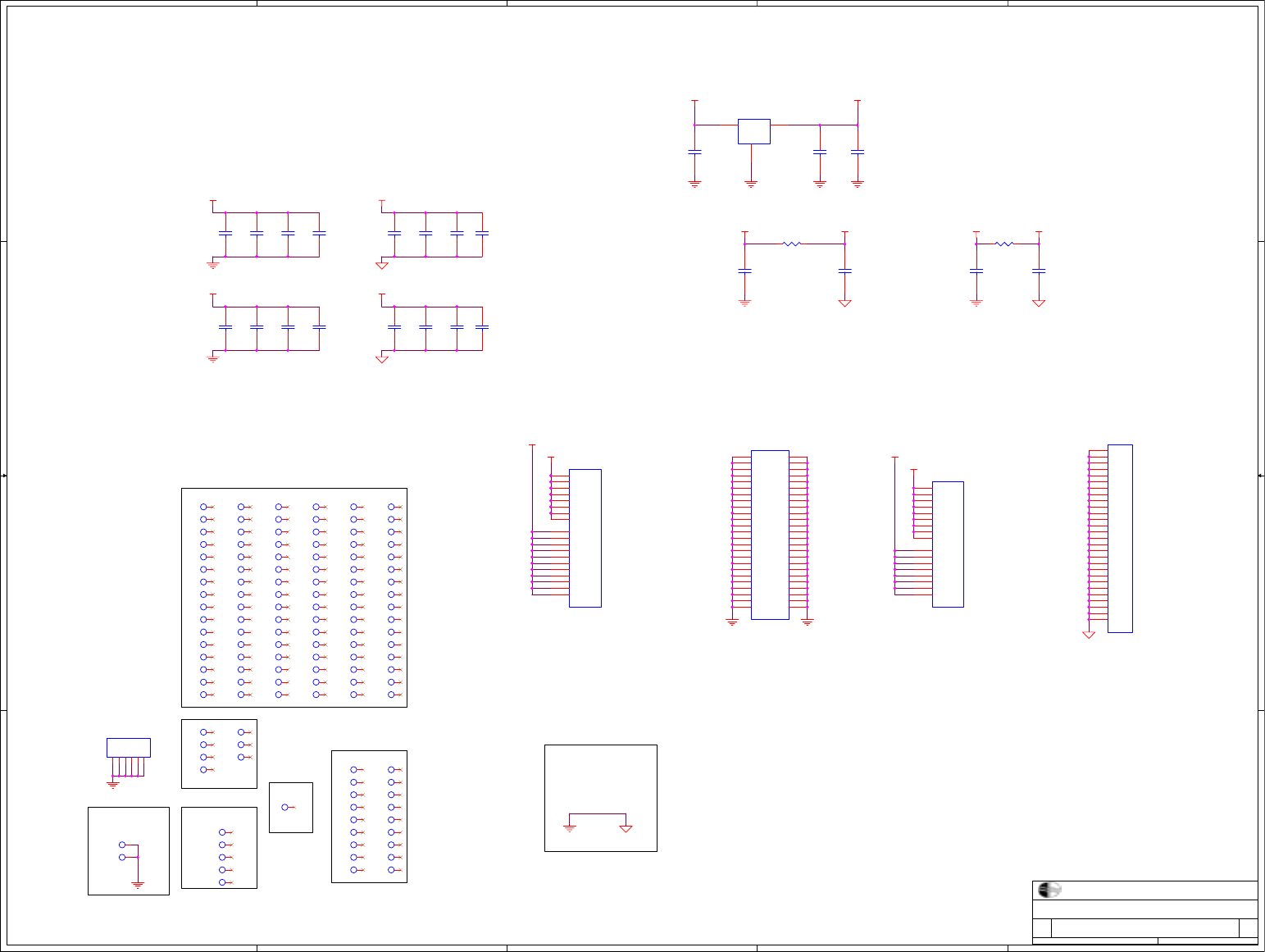
02a Circuit diagram
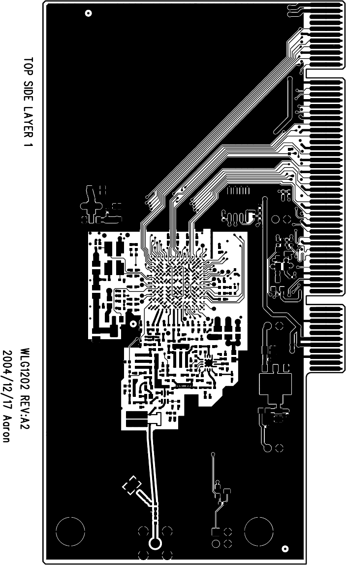
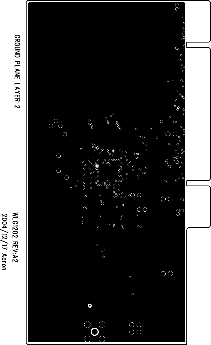
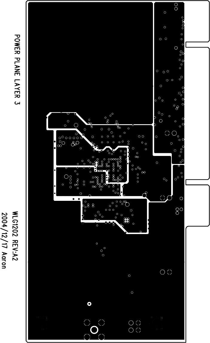
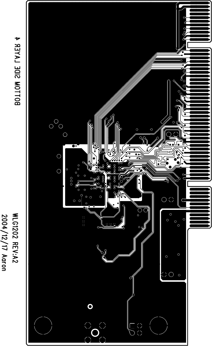
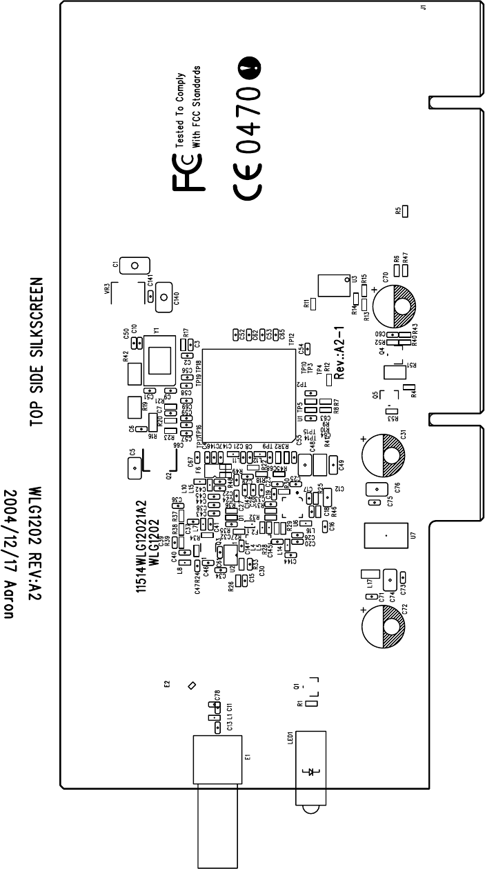
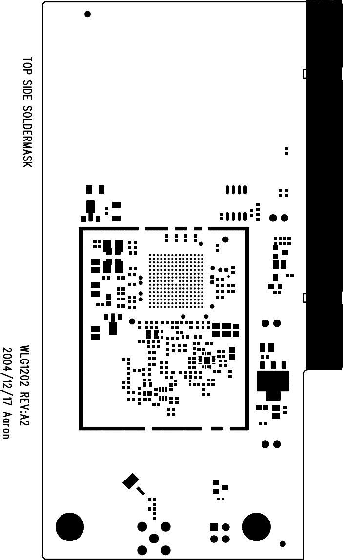
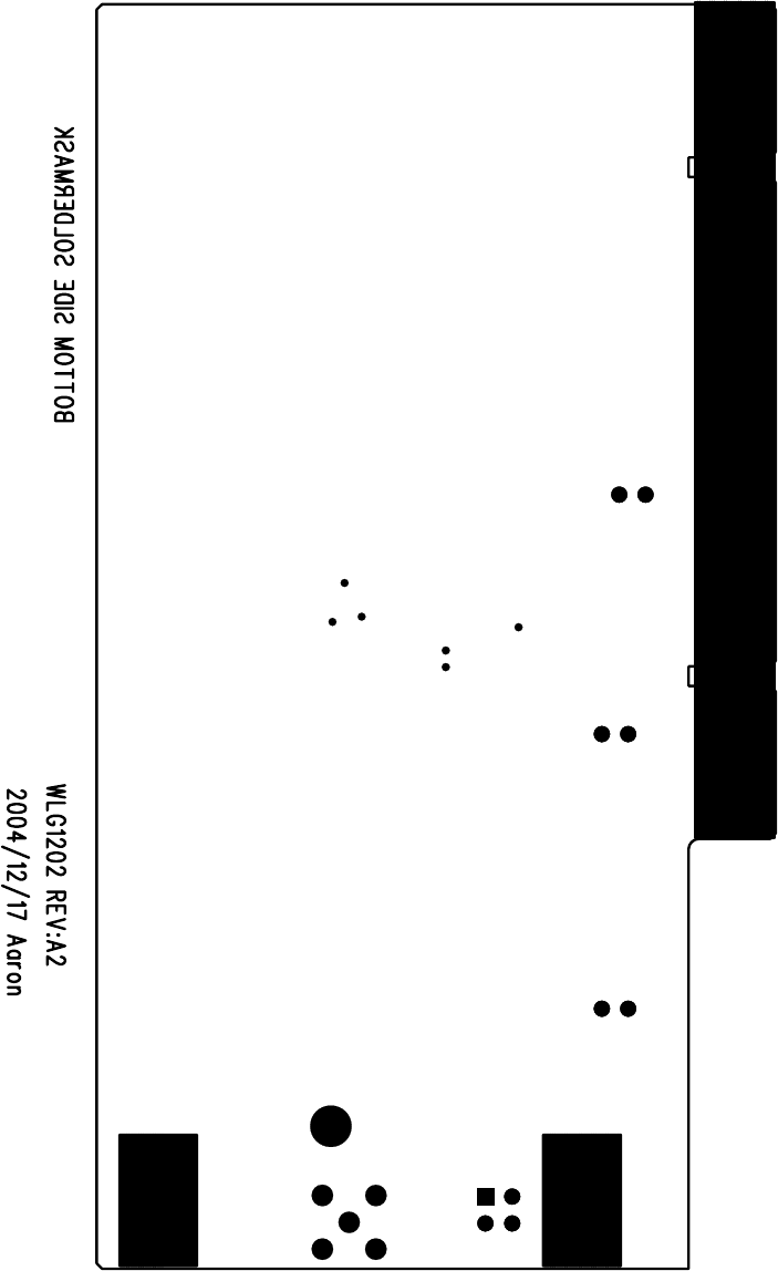
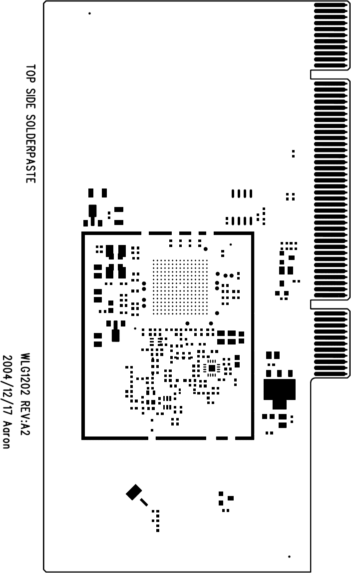
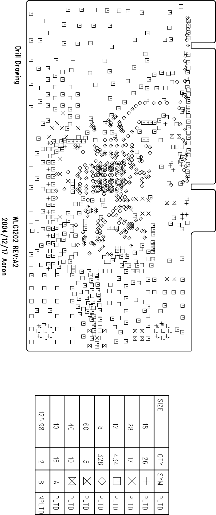
02b PCB layout
02c Part list
02d Exterior photographs
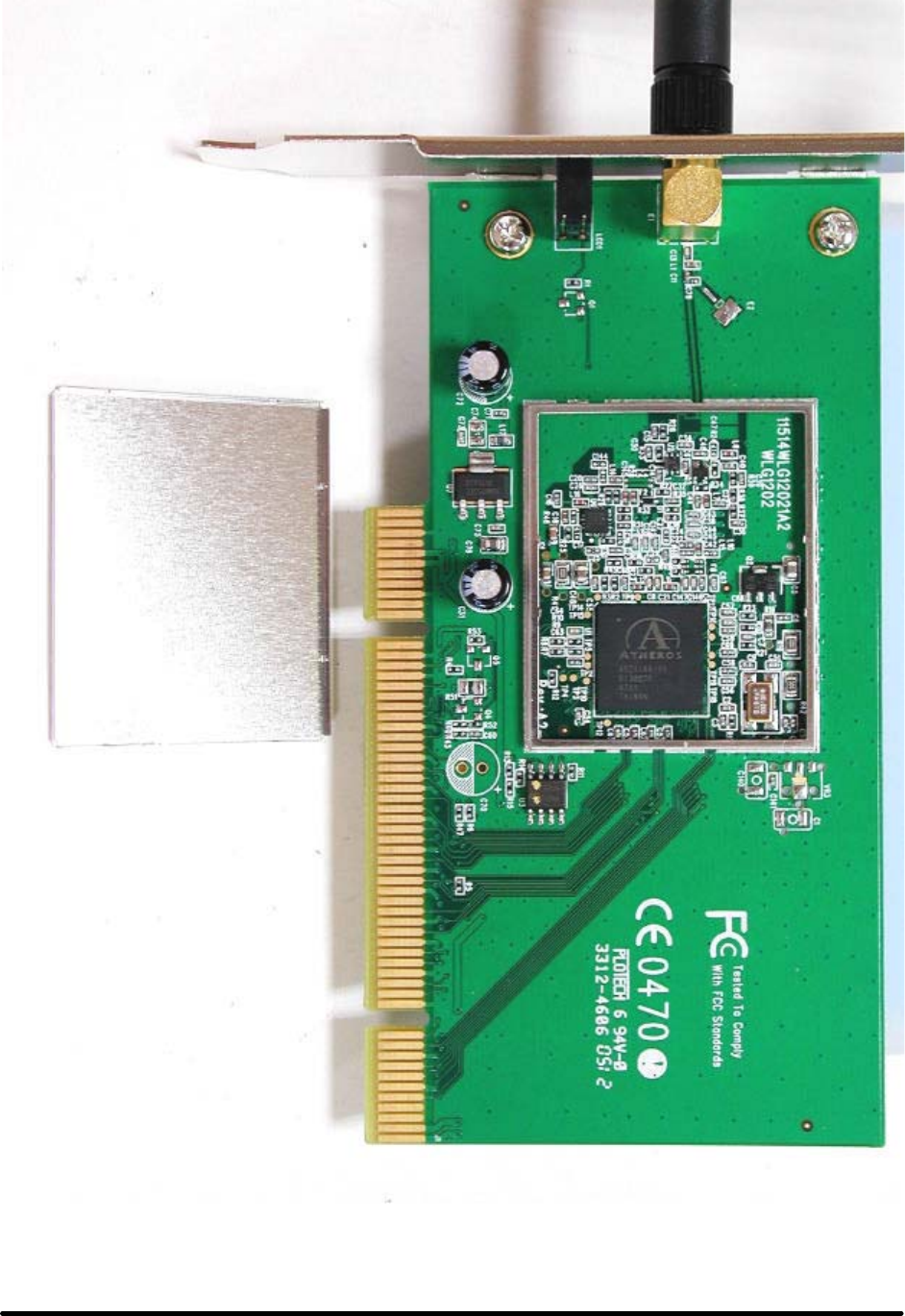
02e Interior photographs
02f Label information
03a Technical description
03b User manual
04 R&TTE standard list
05 RF-EMC-LVD test report and corresponding annexes
06 Copy of the R&TTE Declaration of Conformity (DOC)
07 Product Quality Assurance documents
For the following product:
Product Description / Supplementary Info
802.11g Wireless PCI Adapter
Manufacturer CAMEO COMMUNICATIONS, INC.
Brand CAMEO, Level One, LG, Etherwan, Allnet GmbH
Type WLG-1202, WNC-0300, LWS5410P, NWP-0108G, ALL0281A
The Technical File as specified above will be kept for a period ending at least 10 years after the last
product has been manufactured at the disposal of the relevant national authorities of any Member State
for inspection purpose,
Draw up in
TAIWAN, R.O.C.
Date 2005/4/27
CAMEO COMMUNICATIONS, INC.
No. 42, Min Chuan East Road, Section 6,
Taipei 114, Taiwan
Signature & company stamp Jason Chang /
Wireless Comm. R&D Dept. Manager
Block Diagram
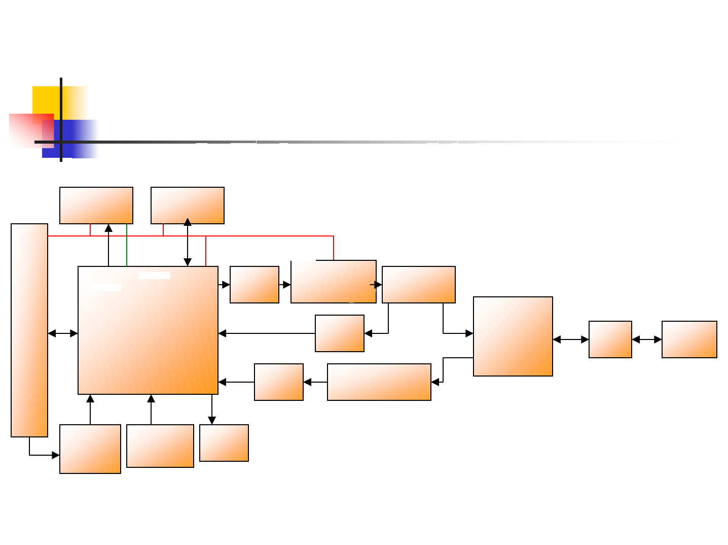
Block Diagram
32K Bit
EEPROM
1.8V
PCI Interface
PNP
AR2414A-00
LED
WAKE
ON
LAN
40MHZ
XTAL
BPF OPB
( Epicom )
PA2409
280mA
BPF
PDET
XLNA
(SGA-8343)
SPDT
(NJG1600
KB2) LPF ANT
(SMA)
3.3v
VREG_OUT 509mW Coupler
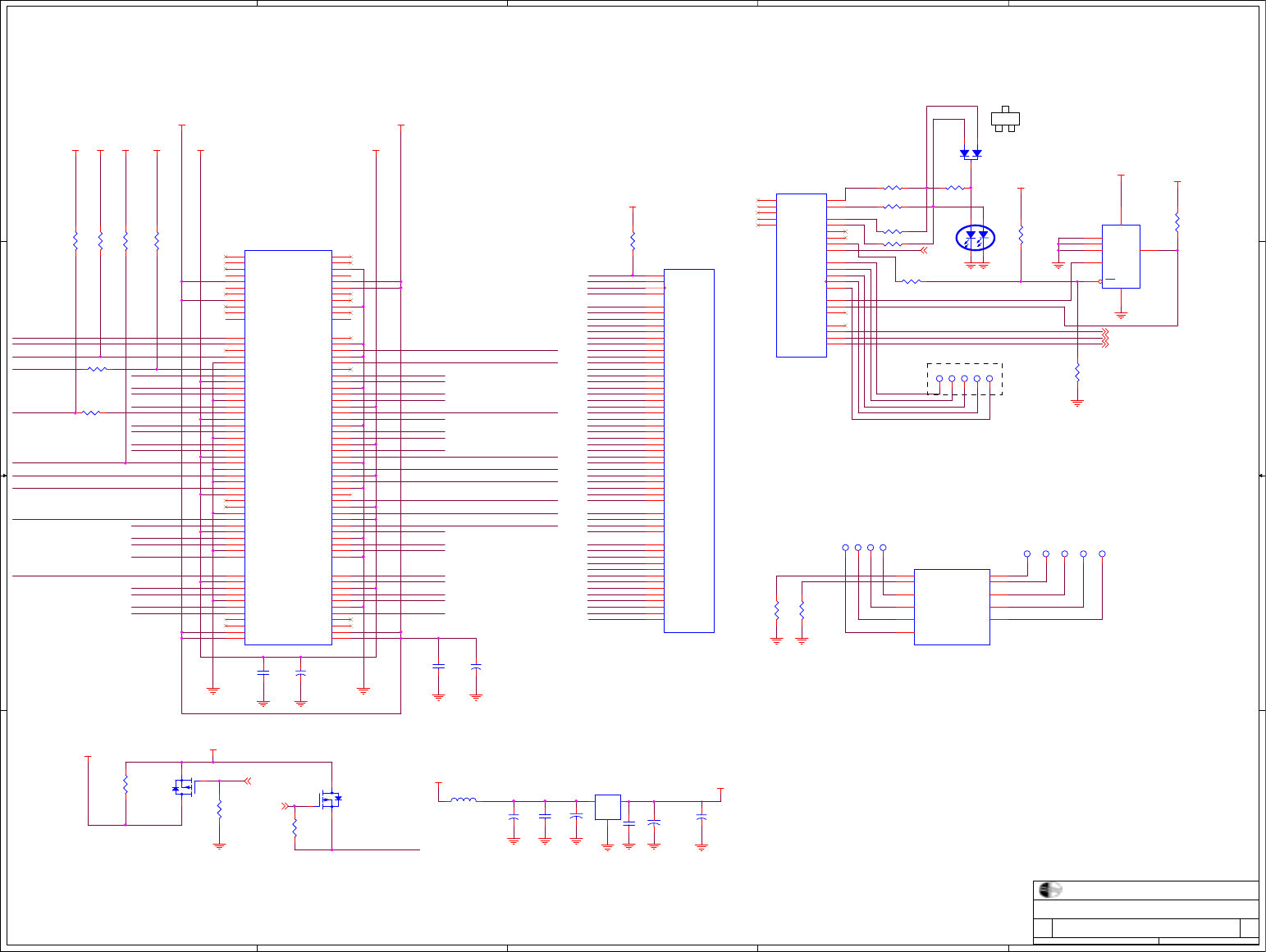
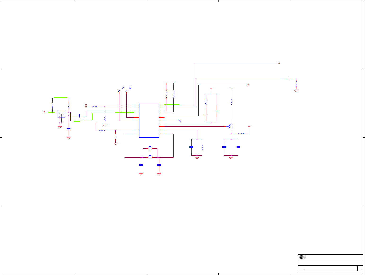
Circuit Diagram
5
5
4
4
3
3
2
2
1
1
D D
C C
B B
A A
PUT TP12 ON TOP LAYER
EEPROM
KEEP CLOSE TOGETHER
WAKE ON LAN
2
3
1
SOT-23
Connector & Digital
A2
WLG-1202 PCI adapter
C
14Friday, January 14, 2005
Product Name
Size Function Description Rev
Date: Sheet of
CAMEO
AD26
AD16
PCI_IRDY_L
AD12
AD0
AD1
PCI_GNT_L
AD6
AD19
AD4
AD25
AD31
AD22
AD18
PCI_CBE1_L
AD3
AD30
PCI_PAR
AD20
AD9
AD24
PCI_SERR_L
PCI_PERR_L
AD17
PCI_REQ_L
AD7
PCI_CLKRUN_L
PCI_TRDY_L
AD13
AD14
AD15
AD29
PCI_CLK
PCI_CBE0_L
AD23
AD8
AD2
AD21
PCI_FRAME_L
AD10
PCI_MODE
PCI_STOP_L
PCI_DEVSEL_L
AD11
AD27
PCI_CBE2_L
PCI_CBE3_L
PCI_INT_L
AD5
AD28
IDSEL
PCI_RST_L
PCI_IRDY_L
AD11
PCI_PERR_L
AD1
AD27
AD29
AD18
PCI_SERR_L
AD25
AD16
AD9
AD20
PCI_DEVSEL_L
PCI_CBE0_L
AD23
AD3
AD7
AD30
AD14 PCI_CBE1_L
AD13
PCI_GNT_L
AD10
AD26
AD24
AD15
PCI_STOP_L
AD12
PCI_CBE2_L
PCI_PAR
PCI_REQ_L
PCI_RST_L
IDSEL
AD5
AD28
AD21
AD17
PCI_TRDY_L
AD22
PCI_CBE3_L
AD6
PCI_FRAME_L
AD8
AD4
AD31
PCI_CLK
AD2
AD0
AD19
3.3V_AUX
3.3V_AUX
PCI_PME_L
LED_0
ANTA
ANTB
ANTC
LED_1
LED_1
PCI_PME_L
ANTA 4
ANTC 4
ANTB 4
GPIO_51
LED_1 1
GPIO_5 1
3.3V
3.3V 3.3V
3.3V
3.3V_CON3.3V_CON3.3V_CON 3.3V_CON3.3V_CON
3.3V
3.3V_CON
3.3V_CON
5V_CON 5V_CON
3.3V
5V_CON
C70
NC,220uF,EC10V
R
R53
Q
Q4
3
1
2
C74
NC,10uF/16V
12
TP12
1
RFDATAIN_3 = U0_CTS_L
RFDATAIN_2 = U0_CLK
RFDATAIN_1 = U0_SIN
RFDATAIN_0 = EPRM_SCK
RFDATAOUT = EPRM_SDA
RFSHIFT = ANTD
RFLOAD = ANTB
RFRST_L = ANTA
U1B
AR2414A-00 EJTAG, GPIO, UART, EPRM, ANT
E2
E1
F2
F1
G2
G1
A3
A2
A1
B1
C1
H3
H2
J2
J1
H1
D1
D2
D3
A4
A5
B4
B5
C4
C5
GPIO_5
GPIO_4
GPIO_3
GPIO_2
GPIO_1
GPIO_0
TDI
TDO
TMS
TRST_L
TCLK
U0_SOUT
U0_RTS_L
U0_CTS_L
U0_CLK
U0_SIN
EPRM_SCK
EPRM_SDA
EPRM_EN_L
ANTD
ANTC
ANTB
ANTA
LED_1
LED_0
R
R10
L17
BLM18HG471
U1A
AR2414A-00 PCI Interface
M1
M3
M2
R1
N2
P3
P1
N4
P4
R5
P5
N6
P6
N7
P7
N8
N12
P11
R12
P12
R13
P13
R14
R15
N15
N14
M14
L14
L15
L13
M15
M13
R3
R7
R11
P15
R10
L1
R4
N1
R8
P8
P9
N9
P10
N10
K1
L2
R6
K14
L3
K3
R9
PCI_AD31
PCI_AD30
PCI_AD29
PCI_AD28
PCI_AD27
PCI_AD26
PCI_AD25
PCI_AD24
PCI_AD23
PCI_AD22
PCI_AD21
PCI_AD20
PCI_AD19
PCI_AD18
PCI_AD17
PCI_AD16
PCI_AD15
PCI_AD14
PCI_AD13
PCI_AD12
PCI_AD11
PCI_AD10
PCI_AD9
PCI_AD8
PCI_AD6
PCI_AD7
PCI_AD5
PCI_AD0
PCI_AD1
PCI_AD2
PCI_AD3
PCI_AD4
PCI_CBE3_L
PCI_CBE2_L
PCI_CBE1_L
PCI_CBE0_L
PCI_PERR_L
PCI_REQ_L
PCI_IDSEL
PCI_PME_L
PCI_FRAME_L
PCI_IRDY_L
PCI_SERR_L
PCI_TRDY_L
PCI_DEVSEL_L
PCI_STOP_L
PCI_INT_L
PCI_GNT_L
PCI_PAR
PCI_MODE
PCI_RST_L
PCI_CLK
PCI_CLKRUN_L
TP14
1
C73
1000pF
NC,0
R40
R
R9
C76
10uF/16V
12
0
R1
R
R15
C60
0.1uF,Y5V
10K
R5
R51
NC
Q
Q5
3
1
2
10K
R11
Q1
NC,1PS301
SOT-23
0
R13
C75
0.01uF
10K
R6
J1
PCI-BUS(universal)
CON\PCIB
A1
A2
A3
A4
A5
A6
A7
A8
A9
A10
A11
A14
A15
A16
A17
A18
A19
A20
A21
A22
A23
A24
A25
A26
A27
A28
A29
A30
A31
A32
A33
A34
A35
A36
A37
A38
A39
A40
A41
A42
A43
A44
A45
A46
A47
A48
A49
A52
A53
A54
A55
A56
A57
A58
A59
A60
A61
A62
B1
B2
B3
B4
B5
B6
B7
B8
B9
B10
B11
B14
B15
B16
B17
B18
B19
B20
B21
B22
B23
B24
B25
B26
B27
B28
B29
B30
B31
B32
B33
B34
B35
B36
B37
B38
B39
B40
B41
B42
B43
B44
B45
B46
B47
B48
B49
B52
B53
B54
B55
B56
B57
B58
B59
B60
B61
B62
#TRST
+12V
TMS
TDI
+5V
#INTA
#INTC
+5V
RESERV
+5Vio
RESERV
RESERV
#RST
+5Vio
#GNT
GND
RESERV
AD30
+3V3
AD28
AD26
GND
AD24
IDSEL
+3V3
AD22
AD20
GND
AD18
AD16
+3V3
#FRAME
GND
#TRDY
GND
#STOP
+3V3
SDONE
#SBO
GND
PAR
AD15
+3V3
AD13
AD11
GND
AD9
#BE0/C
+3V3
AD6
AD4
GND
AD2
AD0
+5Vio
#REQ64
+5V
+5V
-12V
TCK
GND
TD0
+5V
+5V
#INTB
#INTD
#PRSNT1
RESERVED
#PRSNT2
RESERVED
GND
CLK
GND
#REQ
+5V(I/O)
AD31
AD29
GND
AD27
AD25
+3V3
#BE3/C
AD23
GND
AD21
AD19
+3V3
AD17
#BE2/C
GND
#IRDY
+3V3
#DEVSEL
GND
#LOCK
#PERR
+3V3
#SERR
+3V3
#BE1/C
AD14
GND
AD12
AD10
GND
AD8
AD7
+3V3
AD5
AD3
GND
AD1
+5V(I/O)
#ACK64
+5V
+5V
C72
100uF,EC16V
0
R3
C31
100uF,EC16V
10K
R12
TP8
1
C72
NC,220uF,EC10V
10K
R52
U1C
AR2414A-00 Digital Interface
F3
K2A6
B6
C6
K13
K15 E3
R2
B3
P14
TX_FRAME
RX_FRAMEPOR_EN
POR_L
F2D2EN
BT_ACTIVE
PLLBYPASS CLKOBS
RX_CLEAR
SLEEP
RFTEST
TP1
1
C71
0.1uF,Y5V
10K
R4
0
R2
TP7
1
390
R8
TP2
1
M24C32WMN6
U3
2
4
7
3
1
5
8
6
E1
VSS
WC
E2
E0
SDA
VCC
SCL
TP6
1
0
R47
TP3
1
390
R7
TP13
1
TP10
1
TP4
1
TP9
1
GREEN
LED1
12
4 3
10K
R14
NC,10K
R43
TP11
1
TP5
1
U7
RT9161A-33CG
2
1
3
Vin
GND
Vout
5
5
4
4
3
3
2
2
1
1
D D
C C
B B
A A
BIASREF
XTAL
VREG
PUT TP15 ON TOP LAYER
Radio_Interface
A2
WLG-1202 PCI adapter
C
24Friday, January 14, 2005
Product Name
Size Function Description Rev
Date: Sheet of
CAMEO
VREG_COMP
XBIAS
VREG_OUT
XTALO
BIASREF
RFOUT_P
XTALI
P_DET RFOUT_N
P_DET3
RFIN3
XBIAS 3
RFOUT_P 3
OPT3
3.3V_A 3.3V_A
1.8V_A
3.3V_A
1.8V_A 1.8V_A
TP16
1
TP15
1
0.1uF
10V
C6
U1D
AR2414A-00 Radio Interface
A8C8 A9C9
A12
A13 A7
A10
G15
G14
E14
E15
C15
C14
C2
F13
J14
G13
J13
J15
C11
RFOUTNPDETN RFOUTPPDETP
RFINN
RFINP RFOUTN_BIAS
RFOUTP_BIAS
ADC_DAC_IP
ADC_DAC_IN
ADC_DAC_QP
ADC_DAC_QN
ATBP
ATBN
TX2
BIASREF
XTALO
VREG_OUT
VREG_COMP
XTALI
IDDQ
TP17
1
0
R48
TP18
1
R
R23
43K
R17
0
R49
0
R19
Y
XY1
1 3
TP19
1
40.000MHZ
Y1
1 3
C5
10uF
1.5pF
C8
22pF
C9
1
R16
15pF
C10
Q2
2SB1132
12
3
2.2pF
C7
390
R20
0
R18
120pF
C2
6.19K
1%
R21
10pF
C4
R
R45
10pF
C3
L12
3.3nH
2.2pF
C147
47
R22
BALU N
F6
1
2
3
4
5
6
L11
3.3nH
2.2pF
C146
5
5
4
4
3
3
2
2
1
1
D D
C C
B B
A A
S=5
L=180
W10 L120
W=20
W10 L30
W10 L70
ANT 1
INPUT MATCHING
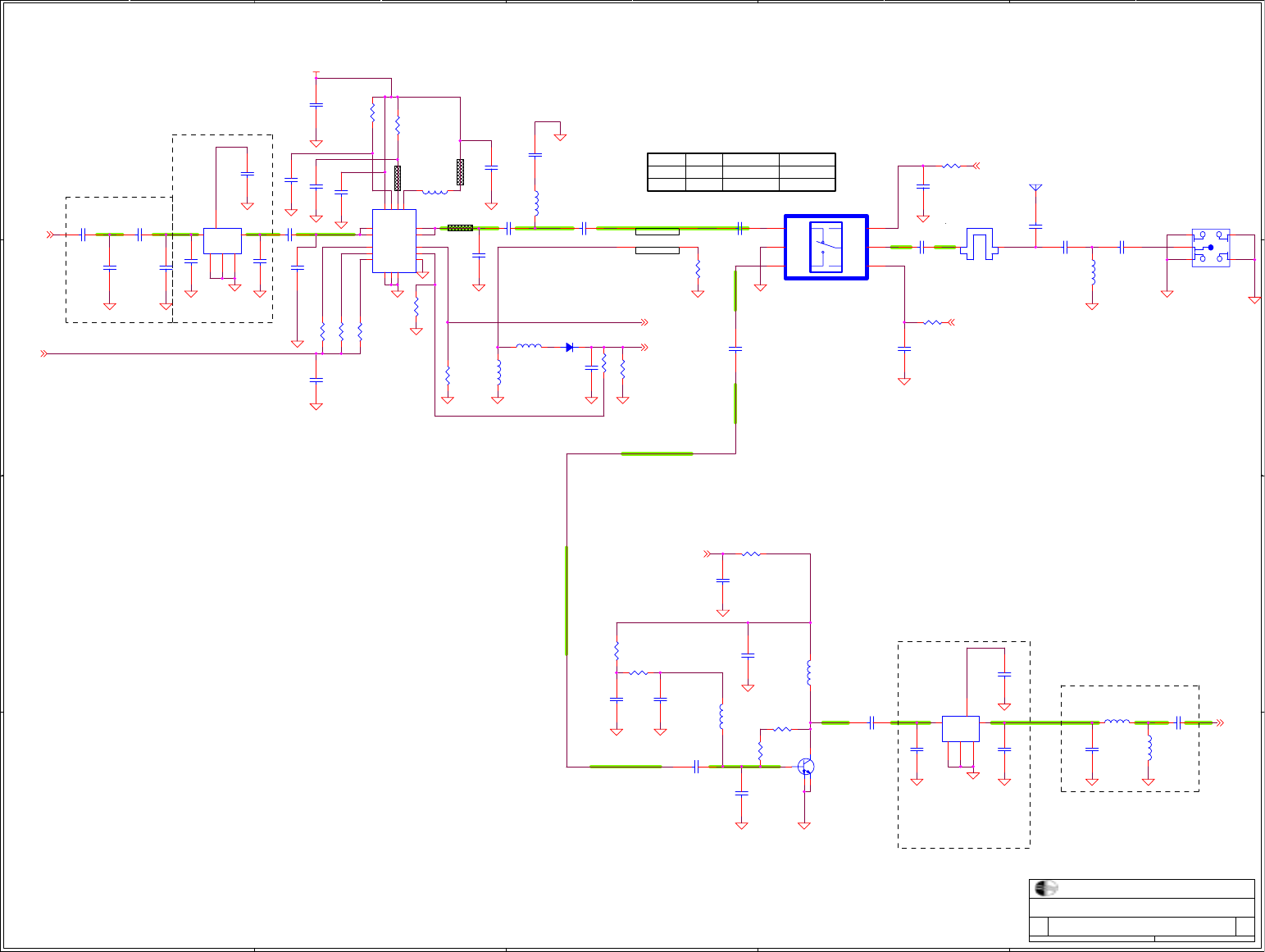
PRINTED TRANSMIT
COMBLINE FILTER
OUTPUT MATCHING
PRINTED RECEIVE
COMBLINE FILTER
50 OHM LINES
IL0 RX ModeVhigh
0 TX Mode
V2 J1-J2
IL
J1-J3V1
Isolation
Isolation
Vhigh
Front_End
A2
WLG-1202 PCI adapter
C
34Friday, January 14, 2005
Product Name
Size Function Description Rev
Date: Sheet of
CAMEO
XBIAS
RFIN 2
ANTC1
XBIAS2 P_DET 2
RFOUT_P2
OPT 2 ANTA 1
ANTB 1
3.3V_A
C25
NC
C11
15pF
R35
NC
L16
10nH
C47
NC
C36
220pF
R31
82.5,1%
R25
0R
R28
100K
L4
3.9nH
C19
NC
C33
47pF
R46
1.5nH
R30
180,1%
F4
12 IO
L14
NC
F2
4-PIN-COUPLER
1
23
4
C39
120pF
C12
1uF
R29
100K
C144
NC
C26
1.5pF
R36
5.1K
C24
NC
L8
18nH
1 2
PA2409
U6
1
2
3
4
5
6
7
8
16
10
11
9
13
12
1415
17
NC
RF IN
RF IN
VB1
VCC
VB2
VB3
REF
VC1
RF OUT
RF OUT
DET
NC
VC3
VC2NC
GND
R33
1K
C42
10pF
C21
1.5pF
R38
15K
C45
NC
C27
3pF(phycom)
C23
10pF
C18
NC
R32
150,1%
C14
10pF
C34
10pF
ANT1
C78
NC
C15
10pF
R24
NC
C142
3pF(phycom)
C13
2.2pF
C30
10pF
C40
10pF
L5
3.9nH
C145
47pF
L1
3.3nH
C29
NC
E1
SMA
ANT\RP-SMA
1
2
3 4
5
E
RF
EE
E
U2
NJG1600KB2
IC6\SC70\0.65
4
5
61
2
3V1
J1
V2J3
GND
J2
C28
3pF(phycom)
C37
10pF
C32
10pF
R26
1K
SGA-8343
Q3
1
32
4
PRINTED BPF
F3
4 5
3
1
26
IN OUT
GND
GND
GND C
C61
10pF
C43
3pF(phycom)
C20
10pF
L7
18nH
1 2
R34
NC
C17
NC
C16
0.1uF
C38
3pF(phycom)
R39
47
L15
1nH
R27
47
R37
56
C22
10pF
PRINTED BPF
F5
45
3
1
26
INOUT
GND
GND
GND C
L10
NC
C44
3pF(phycom)
C46
10pF
C41
10pF
SMS7630-996
D1
21
5
5
4
4
3
3
2
2
1
1
D D
C C
B B
A A
Tie ground
planes
together.
TOOLING
HOLES
BREAKAWAYS
LOGO
PANEL PERFORATIONS
FIDUCIALS
OPTIONAL SHIELD
HOLES TOOLING HOLES
Power&Misc
A2
WLG-1202 PCI adapter
C
44Friday, January 14, 2005
Product Name
Size Function Description Rev
Date: Sheet of
CAMEO
3.3V
1.8V
3.3V_A
1.8V
3.3V
1.8V_A
3.3V_A
1.8V_A
3.3V 3.3V_A 1.8V 1.8V_A
3.3V 1.8V
X578 1
X32 1
X614 1
X505 1
X590 1
X2 1
1000pF
C66
X607 1
X613 1
X580 1
X573 1
X326 1
X594 1
X577 1
1000pF
C67
X33 1
X503 1
X546 1
ZH1 1
X612 1
X537 1
X570 1
X600 1
0.1uF
10V
C52
X619 1
X548 1
0.1uF
10V
C53
X526 1
1000pF
C51
X39 1
X592 1
X335 1
X8 1
X13 1
X547 1
X336 1
X524 1
ZH502 1
X617 1
X563 1
2.2uF
10V
C48
X545 1
FD1 1
X525 1
X518 1
0.1uF
10V
C50
X9 1
X608 1
X603 1
X536 1
X602 1
ZH501 1
X618 1
X558 1
U1E
AR2414A-00 Digital VDD
G3
D7
M9
D8
D5
E4
G4
J3
H4
L4
L12
M8
M5
N5
N11
J4
J12
M11
M7
VDD18
VDD18
VDD18
VDD33
VDD33
VDD33
VDD18
VDD18
VDD33
VDD33
VDD33
VDD33
VDD33
VDD33
VDD33
VDD18
VDD18
VDD33
VDD18
X561 1
FD2 1
X565 1
X339 1
X10 1
X12 1
X342 1
X556 1
C1
NC
X14 1
0.01uF
25V
C54
ZH500 1
X571 1
X575 1
FD3 1
X596 1
X11 1
X609 1
X581 1
X569 1
X588 1
ZH503 1
X622 1
X341 1
X582 1
U1H
AR2414A-00 Analog Ground
A11
A14
A15
B7
B10
B11
B12
B13
B14
C13
D10
D12
D14
E9
E10
E11
F9
F10
F11
F12
F14
G9
G10
G11
H9
H10
H11
H13
AGND
AGND
AGND
AGND
AGND
AGND
AGND
AGND
AGND
AGND
AGND
AGND
AGND
AGND
AGND
AGND
AGND
AGND
AGND
AGND
AGND
AGND
AGND
AGND
AGND
AGND
AGND
AGND
X585 1
U1F
AR2414A-00 Digital Ground
B2
C3
D4
D6
E5
E6
E7
E8
F4
F5
F6
F7
F8
G5
G6
G7
G8
H5
H6
H7
J5
J6
J7
J8
J9 P2
N13
N3
M12
M10
M6
M4
L11
L10
L9
L8
L7
L6
L5
K12
K11
K10
K9
K8
K7
K6
K5
K4
J11
J10
GND
GND
GND
GND
GND
GND
GND
GND
GND
GND
GND
GND
GND
GND
GND
GND
GND
GND
GND
GND
GND
GND
GND
GND
GND GND
GND
GND
GND
GND
GND
GND
GND
GND
GND
GND
GND
GND
GND
GND
GND
GND
GND
GND
GND
GND
GND
GND
GND
GND
FD4 1
X599 1
10pF
C58
X21 1
X620 1
X579 1
X555 1
0.01uF
25V
C65
X598 1
FD502 1
X574 1
X333 1
X572 1
VR
VR3
2 3
1
IN OUT
GND
X601 1
X22 1
X7 1
X587 1
X519 1
0.1uF
10V
C63
1uF
10V
C49
X564 1
U1G
AR2414A-00 Analog VDD
B8
C10
B9
D11
D15
C12
F15
B15
C7
D9
D13
G12
H14
E12
E13
H12
H15
AVDD
AVDD33
AVDD
AVDD33
AVDD33
AVDD33
AVDD
AVDD
AVDD
AVDD
AVDD
AVDD
AVDD
AVDD33
AVDD33
AVDD33
AVDD33
FD501 1
X516 1
X568 1
X562 1X527 1
0.1uF
10V
C141
X583 1
X29 1
X615 1
X576 1
X502 1
0.01uF
25V
C55
0.01uF
25V
C64
X604 1
X517 1
CB51 SHIELD
X99
1
2
3
4
5
6
GND
GND
GND
GND
GND
GND
0
R41
FD500 1
X504 1
X589 1
10pF
C68
X595 1
C
C140
X586 1
X441
PCB_CB
1
10pF
C69
X30 1
X621 1
X330 1
X557 1
0
R42
0.1uF
10V
C62
X605 1
X610 1
X329 1X327 1
1000pF
C56
X560 1
X535 1
X1 1
X28 1
X591 1
10pF
C59
X31 1
X616 1
X584 1
X593 1
X606 1
1000pF
C57
X611 1
X332 1
X338 1
X538 1
X597 1
PCB Layout
Bill of Materials (Part List)

WLG-1202 PCI adapter Bill of material
Item Quantity Reference Part PCB Footprint
Capacitance
1 3 C8,C21,C26 1.5pF CAP-0402
2 4 C7,C13,C146,C147 2.2pF CAP-0402
3 6 C27,C28,C38,C43,C44,C142 3pF+/-0.1P(phycom) CAP-0402
C3,C4,C14,C15,C20,C22,C23
C30,C32,C34,C37,C40,C41,
C42,C46,C58,C59,C61,C68,
C69
5 2 C10,C11 15pF CAP-0402
6 1 C9 22pF CAP-0402
72C33,C145 47pF CAP-0402
8 2 C2,C39 120pF CAP-0402
9 1 C36 220pF CAP-0402
10 6 C51,C56,C57,C66,C67,C73 1000pF CAP-0402
11 5 C54,C55,C64,C65,C75 0.01uF CAP-0402
C6,C16,C50,C52,C53,C60,C62,C63,
C71,C141
13 2 C12,C49 1uF CAP-0603
14 2 C48 2.2uF CAP-0805
15 2 C5,C76 10uF CAP-0805
16 1 L15 1nH IND-0402
17 1 R46 1.5nH IND-0402
18 3 L1,L11,L12 3.3nH IND-0402
19 2 L4,L5 3.9nH IND-0402
20 1 L16 10nH IND-0402
21 2 L7,L8 18nH IND-0402
22 1 L17 BEAD, 60O,500mA RES-0603
R1,R2,R3,R13,R18,R25,R47,R48,
R49
24 3 R19,R41,R42 0RES-0805
25 1 R16 1RES-0603
26 3 R22,R27,R39 47 RES-0402
27 1 R37 56 RES-0402
28 1 R31 82.5,1% RES-0402
29 1 R32 150,1% RES-0402
30 1 R30 180,1% RES-0402
31 3 R7,R8,R20 390 RES-0402
32 2 R26,R33 1K RES-0402
33 1 R36 5.1K RES-0402
34 1 R21 6.19K,1% RES-0402
R4,R5,R6,R11,R12,R14
R52
36 1 R38 15K RES-0402
37 1 R17 43K RES-0402
38 2 R28,R29 100K RES-0402
39 1 D1 SMS7630-996 DIO-SC-70
40 1 Q2 2SB1132 SOT89-MIRRORED
735 10K RES-0402
12 CAP-040210 0.1uF
9 0 RES-040223
204 10pF CAP-0402

41 1 Q3 LNA-2.4GHZ-SGA-8343 SOT-343
42 1 U1 AR2414A-00 Digital VDD BGA-224-15X15
43 1 U2 NJG1600KB2 IC6\SC70\0.65
44 1 U3 SO8 M24C32WMN6
45 1 U6 Epicom PA-2409
46 1 Y1 FY4000041 CRY-SMD4-40MHz
47 1 U7 RT9161A-33CG SOT-223
48 1 PCB 4層, Netgaear, WG311Tv1h3主板, REV.A1
49 1 Shielding Box-Frame, 無色
50 2 螺絲 圓頭 +字 無頸下物 公制牙(粗牙) 鍍鎳
51 1BRACKET, PCI, 上折邊, 鍍鎳, 打字,SMA頭
52 1E1 SMA ANT\RP-SMA
53
1
LED1
LED-GREEN-(2) Holder 90° 3? 5mm
54
2
C31,C72
EC-100uF
55 1Shielding Box-Cover, 無色
56 1分離式天線,2dbi
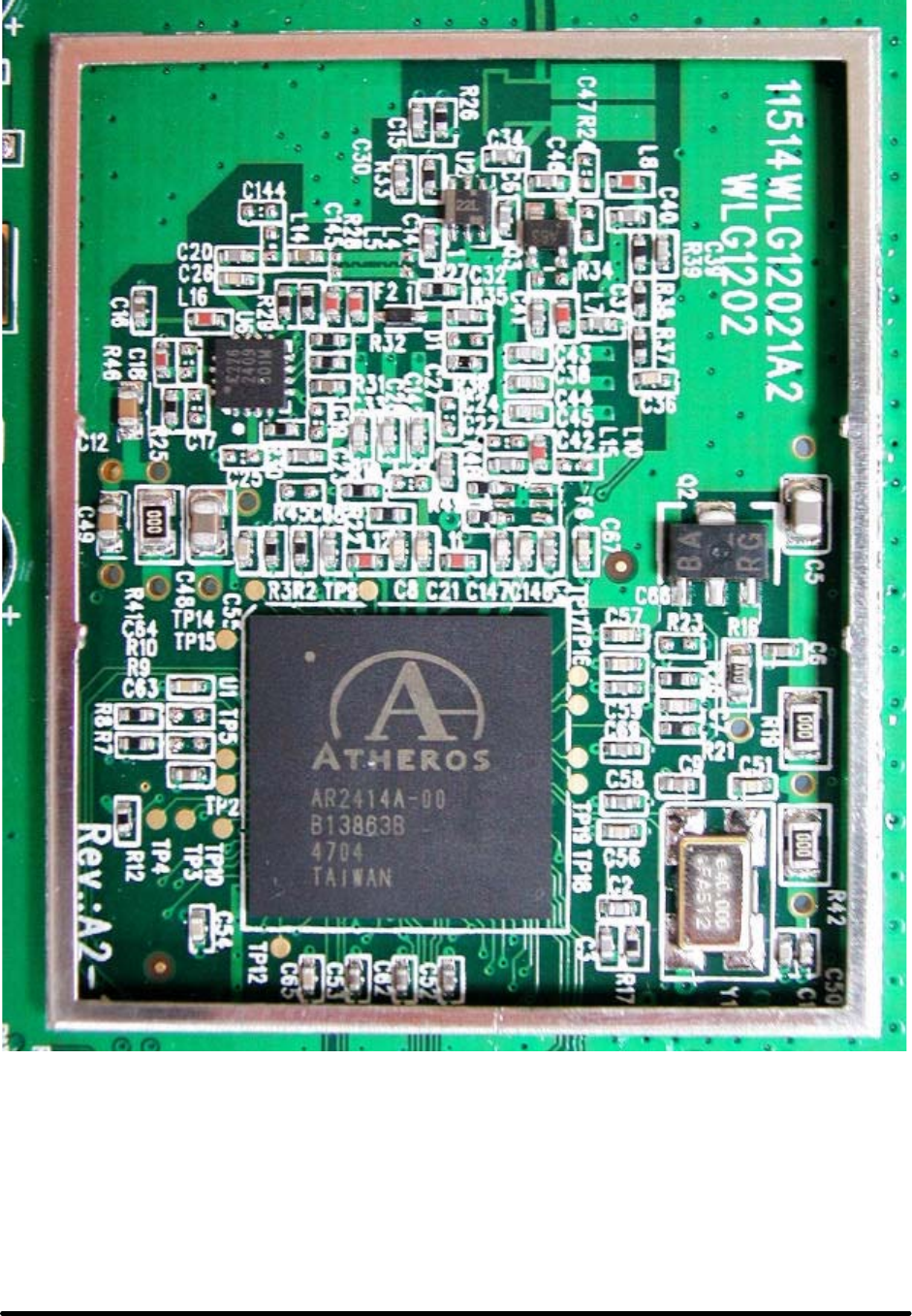
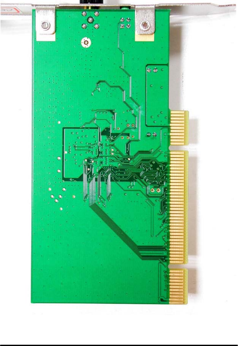
Exterior and Interior Photographs
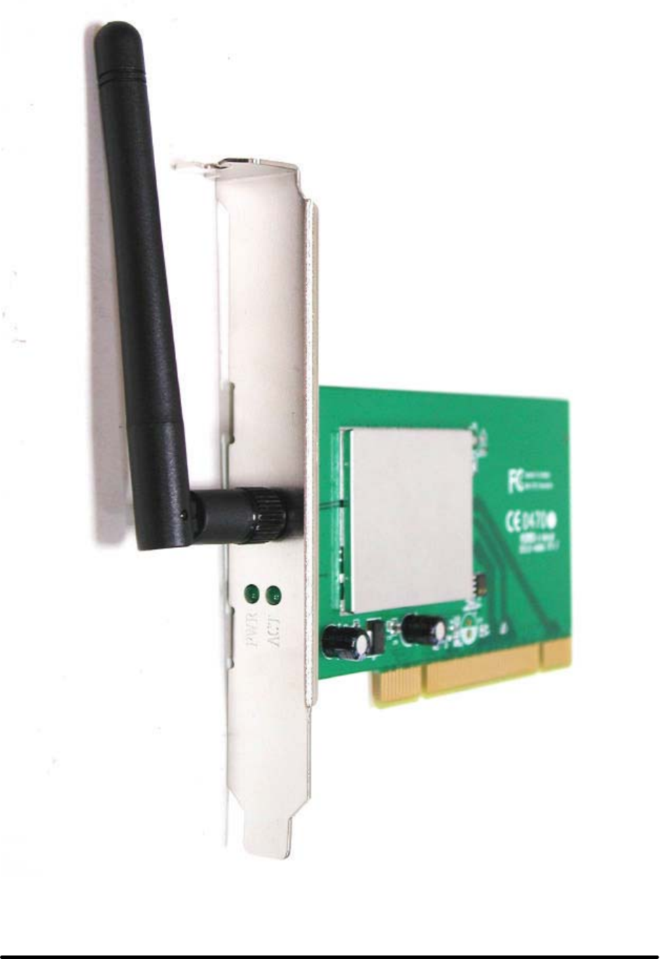
External Photos of 802.11g Wireless PCI Adapter ---------------------------------- 1/4
Applicant: CAMEO COMMUNICATIONS, INC. FCC ID: NHPWLG1202
Training Research Co., Ltd., TEL: 886-2-26935155, Fax: 886-2-26934440
External Photos of 802.11g Wireless PCI Adapter ---------------------------------- 2/4
Applicant: CAMEO COMMUNICATIONS, INC. FCC ID: NHPWLG1202
Training Research Co., Ltd., TEL: 886-2-26935155, Fax: 886-2-26934440
External Photos of 802.11g Wireless PCI Adapter ---------------------------------- 3/4
Applicant: CAMEO COMMUNICATIONS, INC. FCC ID: NHPWLG1202
Training Research Co., Ltd., TEL: 886-2-26935155, Fax: 886-2-26934440
External Photos of 802.11g Wireless PCI Adapter ---------------------------------- 4/4
Applicant: CAMEO COMMUNICATIONS, INC. FCC ID: NHPWLG1202
Training Research Co., Ltd., TEL: 886-2-26935155, Fax: 886-2-26934440
Label Information
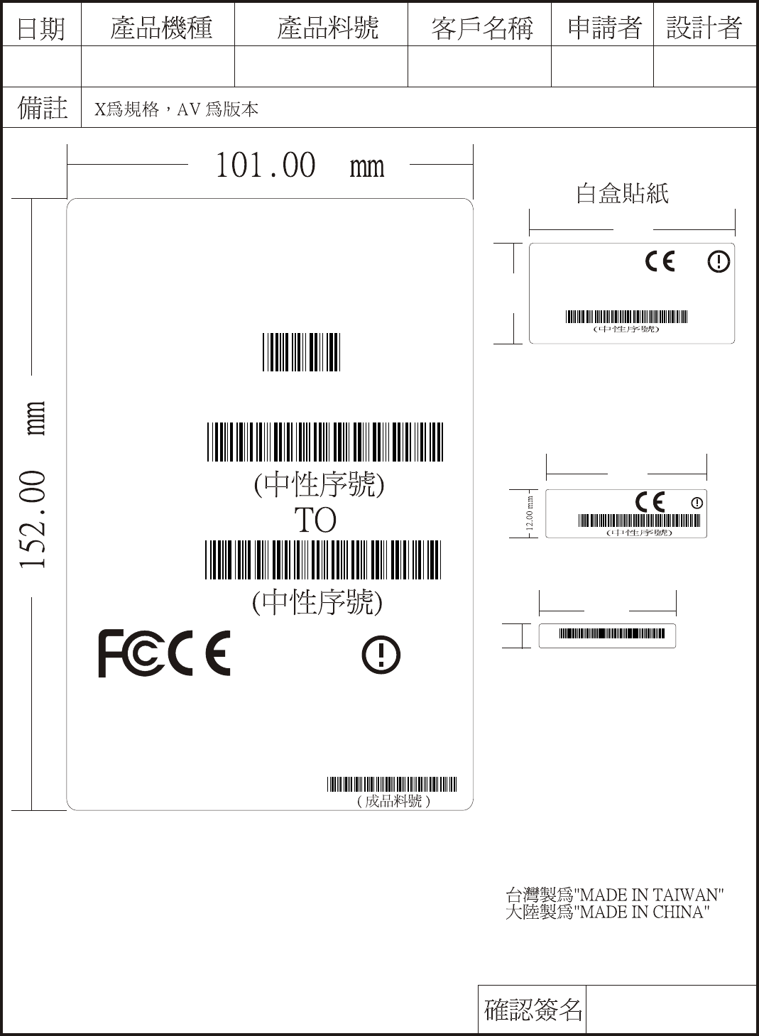
9500WLG12020XAV
WLG-1202/X
Joseph Liu
6.00 mm
34.00 mm
000000000000
MAC:
Grace Chen
MODEL : WLG-1202/X
Q'TY:
S/N:
40 PCS
FROM
CARTON OF NO. /
MADE IN xxxxxx
CAMEO
94.04.12
0470
¾÷Åé¶K¯È
S/N:
WLG-1202/X Rev.AV
FCC ID: NHPWLG1202
25.00 mm
51.00 mm
0470
"See Caution in Manual"
802.11g WLAN
PCI Adapter
Made in XXXXXX
S/N:
WLG-1202/X
FCC ID: NHPWLG1202
40.00 mm
0470
"See Caution in Manual"
Technical Description

TECHNICAL SPECIFICATIONS
General
Radio Technology IEEE 802.11b Direct Sequence Spread Spectrum (DSSS)
IEEE 802.11g Orthogonal Frequency Division Multiplexing
(OFDM)
Interface 32-bit PCI 2.1, 2.2. Bus Master
Data Transfer Rate 1, 2, 5.5, 6, 9, 11, 12, 18, 24, 36, 48, 54Mbps (auto sense)
Receiver Sensitivity 54Mbps: Typical -73dBm @ 10% PER (Packet Error Rate)
11Mbps: Typical -85dBm @ 8% PER (Packet Error Rate)
Transmit Rate 802.11g: 14dBm typically
802.11b: 18dBm typically
Frequency Range 2412 ~ 2484 MHz ISM band (channels 1 ~ 14)
Modulation Schemes DBPSK/DQPSK/CCK/OFDM
Channels 1~11 channels (FCC), 1~13 channels (ETSI), 1~14 channels
(MKK-Japan)
Media Access Protocol CSMA/CA with ACK
Security 64/128-bits WEP Encryption, WPA
Diagnostic LED LNK (Link status), ACT (Activity status)
Antenna 1.8 dBi Dipole Antenna
Physical and Environmental
Driver Support Windows 98se, Windows 2000, Windows ME, Windows XP
Continuous Current
Consumption 250mA typ. for receive mode, 350mA typ. for transmit mode
Temperature Operating: 0° ~ 40° C, Storage: -10° ~ 70° C
Humidity 10% ~ 95% RH, no condensation
Dimensions 133 x 121 x 21.6 mm (without antenna)
Certifications FCC Part 15.247 for US, ETS 300 328 for Europe,
User Manual
IEEE 802.11g
PCI Adapter
User’s Guide

i
Regulatory notes and statements
Wireless LAN, Health and Authorization for use
Radio frequency electromagnetic energy is emitted from Wireless LAN devices.
The energy levels of these emissions however are far much less than the
electromagnetic energy emissions from wireless devices like for example mobile
phones. Wireless LAN devices are safe for use frequency safety standards and
recommendations. The use of Wireless LAN devices may be restricted in some
situations or environments for example:
·On board of airplanes, or
·In an explosive environment, or
·In case the interference risk to other devices or services is perceived or identified
as harmful
In case the policy regarding the use of Wireless LAN devices in specific
organizations or environments (e.g. airports, hospitals, chemical/oil/gas industrial
plants, private buildings etc.) is not clear, please ask for authorization to use these
devices prior to operating the equipment.
Regulatory Information/disclaimers
Installation and use of this Wireless LAN device must be in strict accordance with
the instructions included in the user documentation provided with the product. Any
changes or modifications made to this device that are not expressly approved by the
manufacturer may void the user’s authority to operate the equipment. The
Manufacturer is not responsible for any radio or television interference caused by
unauthorized modification of this device, of the substitution or attachment.
Manufacturer and its authorized resellers or distributors will assume no liability for
any damage or violation of government regulations arising from failing to comply
with these guidelines.
USA-FCC (Federal Communications Commission) statement
This device complies with Part 15 of FCC Rules.
Operation is subject to the following two conditions:
1. This device may not cause interference, and
2. This device must accept any interference, including interference that may cause
undesired operation of this device.
FCC Radio Frequency Exposure statement
This Wireless LAN radio device has been evaluated under FCC Bulletin OET 65
and found compliant to the requirements as set forth in CFR 47 Sections 2.1091,
2.1093, and 15.247 (b) (4) addressing RF Exposure from radio frequency devices.

ii
The radiated output power of this Wireless LAN device is far below the FCC radio
frequency exposure limits. Nevertheless, this device shall be used in such a manner
that the potential for human contact during normal operation is minimized.
When nearby persons has to be kept to ensure RF exposure compliance, in order to
comply with RF exposure limits established in the ANSI C95.1 standards, the
distance between the antennas and the user should not be less than 20 cm.
FCC Interference Statement
This equipment has been tested and found to comply with the limits for a Class B
digital device, pursuant to Part 15 of the FCC Rules. These limits are designed to
provide reasonable protection against harmful interference in a residential
installation.
This equipment generates, uses, and can radiate radio frequency energy. If not
installed and used in accordance with the instructions, it may cause harmful
interference to radio communications.
However, there is no guarantee that interference will not occur in a particular
installation. If this equipment does cause harmful interference to radio or television
reception, which can be determined by turning the equipment off and on, the user is
encouraged to try and correct the interference by one or more of the following
measures:
1. Reorient or relocate the receiving antenna.
2. Increase the distance between the equipment and the receiver.
3. Connect the equipment to an outlet on a circuit different from that to which the
receiver is connected.
4. Consult the dealer or an experienced radio/TV technician for help.
Export restrictions
This product or software contains encryption code that may not be exported or
transferred from the US of Canada without an approved US Department of
Commerce export license.
Safety Information
Your device contains a low power transmitter. When device is transmitted it sends
out radio frequency (RF) signal.
CAUTION: To maintain compliance with FCC’s RF exposure guidelines, this
equipment should be installed and operated with minimum distance 20cm between
the radiator and your body. Use on the supplied antenna. Unauthorized antenna,
modification, or attachments could damage the transmitter and may violate FCC
regulations.

iii
The antenna(s) used for this transmitter must be installed to provide a separation
distance of at least 20 cm from all persons and must not be co-located or operating
in conjunction with any other antenna or transmitter.
CE Mark Warning
This is a Class B product. In a domestic environment, this product may cause radio
interference, in which case the user may be required to take adequate measures.
Protection requirements for health and safety – Article 3.1a
Testing for electric safety according to EN 60950 has been conducted. These are
considered relevant and sufficient.
Protection requirements for electromagnetic compatibility – Article
3.1b
Testing for electromagnetic compatibility according to EN 301 489-1, EN 301 489-
17 and EN 55024 has been conducted. These are considered relevant and sufficient.
Effective use of the radio spectrum – Article 3.2
Testing for radio test suites according to EN 300 328-2 has been conducted. These
are considered relevant and sufficient.
CE in which Countries where the product may be used freely:
Germany, UK, Italy, Spain, Belgium, Netherlands, Portugal, Greece, Ireland,
Denmark, Luxembourg, Austria, Finland, Sweden, Norway and Iceland.
France: except the channel 10 through 13, law prohibits the use of other channels.

iv
TABLE OF CONTENT
Introduction .................................................................................................1
Overview of this User’s Guide..................................................................1
Unpacking and Setup...................................................................................2
Unpacking..................................................................................................2
Setup..........................................................................................................2
Hardware Installation ..................................................................................3
LED Indicator............................................................................................3
Check the installation ................................................................................3
Software Installation....................................................................................4
Windows 98se/ME/2000/XP Utility and Driver Installation ....................4
Wireless Utility Setting.............................................................................5

1
INTRODUCTION
Congratulations on your purchase of this IEEE 802.11g Wireless PCI Adapter.
This manual helps to get familiar with the Wireless PCI Adapter. This manual
contains detailed instructions in operation of this product. Please keep this manual
for future reference.
With a Wireless (IEEE 802.11g) PCI Adapter, a computer or a station can
communicate with another computer in a wireless way. Easy-to-use utilities are
bundled with Wireless PCI Adapter for configuration, monitoring, and diagnosis
purposes.
Wireless PCI Adapter can wirelessly transmit and receive data, minimizing the
need for wired connections, at a speed of up to fifty-four megabit per second. With
Wireless PCI Adapter, you can locate your PC or station wherever you want
without wires and cables.
Wireless PCI Adapter provides users with an access to real-time information
anywhere in their organization. The mobility provides productivity and service,
which are not available under wired networks. The Wireless PCI Adapter
configuration is easy to change from peer-to-peer networks, suitable for a small
number of users, to full infrastructure networks of thousands of users that allow
roaming around a broad area.
Overview of this User’s Guide
Introduction. Describes the Wireless PCI Adapter.
Unpacking and Setup. Helps you get started with the basic installation of the
Wireless PCI Adapter.
Hardware Installation. Describes the LED indicators of the Adapter.
Software Installation. Tells how to setup the driver and the utility setting.
Technical Specifications. Lists the technical (general, physical and environmental)
specifications of the Wireless PCI Adapter.

2
UNPACKING AND SETUP
This chapter provides unpacking and setup information for the Wireless PCI
Adapter.
Unpacking
Open the box of the Wireless PCI Adapter and carefully unpack it. The box should
contain the following items:
u One 802.11g Wireless PCI Adapter
u One Driver & Utility CD-ROM
If any item is found missing or damaged, please contact your local reseller for
replacement.
Setup
The setup of the Wireless PCI Adapter can be performed using the following steps:
u Visually inspect the PCI Adapter and make sure that it is fully plugged in to the
PC’s PCI slot.
u Make sure that there is a well environment that there is no much intrusion to
have a better connection.

3
HARDWARE INSTALLATION
LED Indicator
LNK (Link)
The LNK indicator indicates green when the Wireless PCI Adapter is connected to
a network successfully.
ACT (Activity)
The ACT indicator blinks green continuously whiles the Wireless PCI Adapter is
transmitting data.
Check the installation
1. Shut down the computer, unplugs its power cord, and remove the chassis cover.
2. Insert the contact edge of the Wireless PCI Adapter into the connector of any
available PCI Bus Master Expansion slot. Press the card firmly into the connector
such that the card’s contacts are fully seated in the PCI slot connector.
3. Install the bracket screw and secure the card to the computer chassis.
4. Cover the computer’s chassis.
5. Switch computer power on. The computer will automatically activate the newly
installed driver and utility the Wireless PCI Adapter.
4
SOFTWARE INSTALLATION
This section will lead you to install the driver and utility of the Wireless Cardbus
Adapter.
Windows 98se/ME/2000/XP Utility and Driver Installation
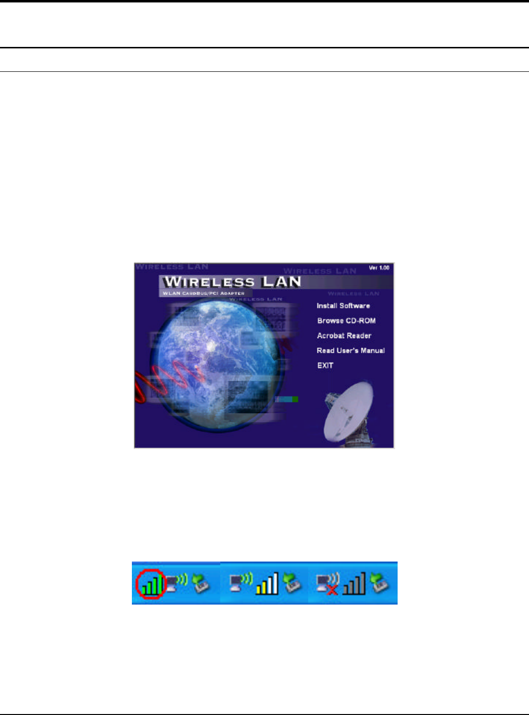
1. Insert the Wireless Cardbus Adapter Driver & Utility CD-ROM into computer’s
CD-ROM Drive and it will automatically run a setup menu and install the driver
and the utility. In some specific setting on Windows system, you may need to
proceed the software manually, go to your Windows Start menu and choose
Run, type “D:\Utility\Setup.exe” in the dialog box (D:\ will depend on where
your CD-ROM drive is located) and click OK.
2. If you need to install the driver manually, refer each Windows OS to the
following CD-Rom directory path: D:\Driver\<Windows OS>\net5211.inf.
Note: (D:\ will depends on where the CD-ROM drive is located and
<Windows OS> will depend on the Windows OS you are using).
3. The Install Shield Wizard screen will appear. Click “Next” to continue.
4. The installation program will help you to setup the Wireless Cardbus utility.
Be noted that the Windows XP have its own Wireless Utility; you can either
use the utility of Windows XP or the provided utility.
5. When the Wireless Cardbus Adapter was installed, you will see the icon on the
Windows task bar.
When the icon in the toolbar represents in full green color then the signal
strength has an excellent performance with the AP, if it represents in yellow
color then the signal strength has a fair performance with the AP, and if the icon
represents no color, then the signal strength has a worst performance with the
wireless station.
5
Wireless Utility Setting
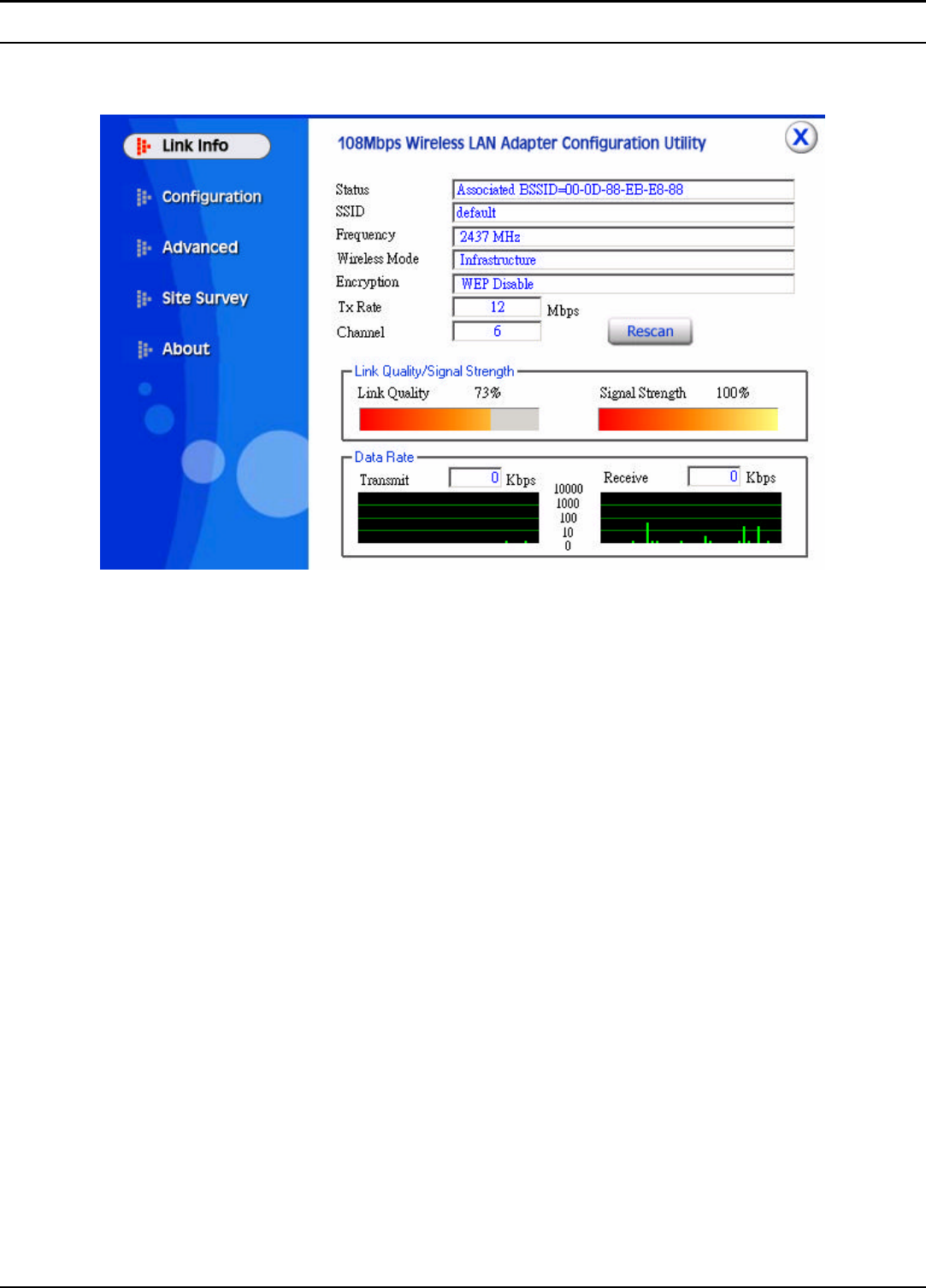
I. Link Information
The default page is as below after launching the Utility program.
Status: Shows the BSSID associated, which can be used to identify the wireless
network.
SSID: Shows current SSID, which must be the same for the wireless client and AP
in order for communication to be established.
Frequency: Shows the current frequency used for wireless network.
Wireless Mode: Shows the current wireless mode used for wireless communication.
Encryption: Shows the current encryption mode used for wireless network.
TxRate: Shows the current data rate used for transmitting.
Channel: Shows the current channel for communication.
Link Quality: Shows the link quality of the 108Mbps wireless LAN PC card with
the Access Point when operating under Infrastructure mode.
Signal Strength: Shows the wireless signal strength of the connection between the
108Mbps wireless LAN PC card with the Access Point.
Data Rate: Shows the statistics of data transfer, and the calculation is based on the
number of packets transmitted and received.
6
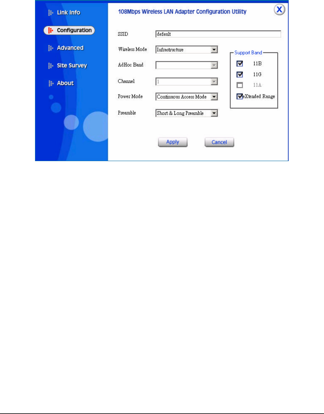
II. Configuration
This is the page where changes the basic settings of the PC card with the minimum
amount of effort to implement a secure wireless network environment.
SSID: Service Set Identifier, which is a unique name shared among all clients and
nodes in a wireless network. The SSID must be identical for each clients and nodes
in the wireless network.
Wireless Mode: There are two types available for selection
?Infrastructure – to establish wireless communication with LAN and other wireless
clients through the use the Access Points.
?Ad-Hoc – to establish point-to-point wireless communication directly with other
wireless client devices such as wireless network PCI Adapter.
AdHoc Band: There are two bands available for selection- 11B and 11G
Channel: The value of channel that AP will operate in. User can select the channel
range of 1 to 11 for North America (FCC) domain and 1 to 13 for European (ETSI)
domain and 1 to 14 for Japanese domain.
Tx Rate: Select the data rate for data transmission.
Power Mode: There are 3 modes to choose.
?Continuous Access Mode (default) – the PC card is constantly operating with full
power and it consumes the most power.
?Maximum Power Save – the PC card consumes the least power and only operates
when there is wireless network activity.
?Power Save – the PC card consumes the moderate level of power.
7
Preamble: Select Long or Short Preamble type. Preamble is a sequence of bits
transmitted at 1Mbps that allows the PHY circuitry to reach steady-state
demodulation and synchronization of bit clock and frame start. Two different
preambles and headers are defined: the mandatory supported Long Preamble and
header, which interoperate with the 1 Mbit/s and 2 Mbit/s DSSS specification (as
described in IEEE Std 802.11), and an optional Short Preamble and header (as
described in IEEE Std 802.11b). At the receiver, the Preamble and header are
processed to aid in demodulation and delivery of the PSDU. The Short Preamble
and header may be used to minimize overhead and, thus, maximize the network
data throughput. However, the Short Preamble is supported only from the IEEE
802.11b (High- Rate) standard and not from the original IEEE 802.11. That means
that stations using Short-Preamble cannot communicate with stations implementing
the original version of the protocol. Click “Apply” for the changes to take effect.
Support Band: There are three functions for users select, including 11B, 11G and
eXtended Range. The default setting is 11B, 11G and eXtended Range enable,
which is interoperable with both 11B and 11G devices, and provide more than
500m connection ability.
Note: user must select one of 11B or 11G at least, otherwise the wireless
connection will not function.
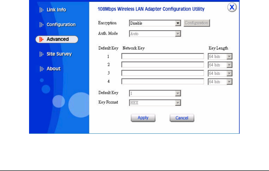
III. Advanced
This is the page to configure Security settings of 108Mbps wireless LAN PC card.
Encryption: 4 options are available: Disable, Enable, WPA and WPA-PSK.
Select Enable or Disable for WEP data encryption feature. If one of the two
8
options is selected, it is required to select the Authentication mode from the next
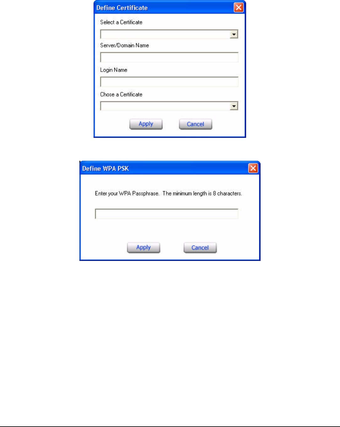
dropping list. If WPA is selected, configuration is enabled. Please click the
“configuration”. The below window is pop up. Then, please select the certificate
that user wants to use and enter the server name and login name
If WPA-PSK is selected, click the configuration button. The popping window is as
the below. Please enter the key.
Auth. Mode: There are three modes available to choose.
??Open Authentication – the sender and receiver do not share secret Key for
communication. Instead, each party generates its own key-pairs and asks the other
party to accept it. The key is regenerated when the connection is established every
time.
??Shared Authentication – the sender and receiver shares the common key for
data communication, and the key is used for extended length of time.
??Auto – depend on the communication to establish, and automatically use the
proper authentication mode.
The following will only be activated to allow for configuration when Encryption is
enabled.
Default Key: select one of the 4 keys to use.
9
Network Key: choose the encryption way, either in HEX or ASCII formats, and
enter the password in the blank space.
Key Length: select 64 or 128 bits as the length of the keys
Key Format: ASCII or HEX
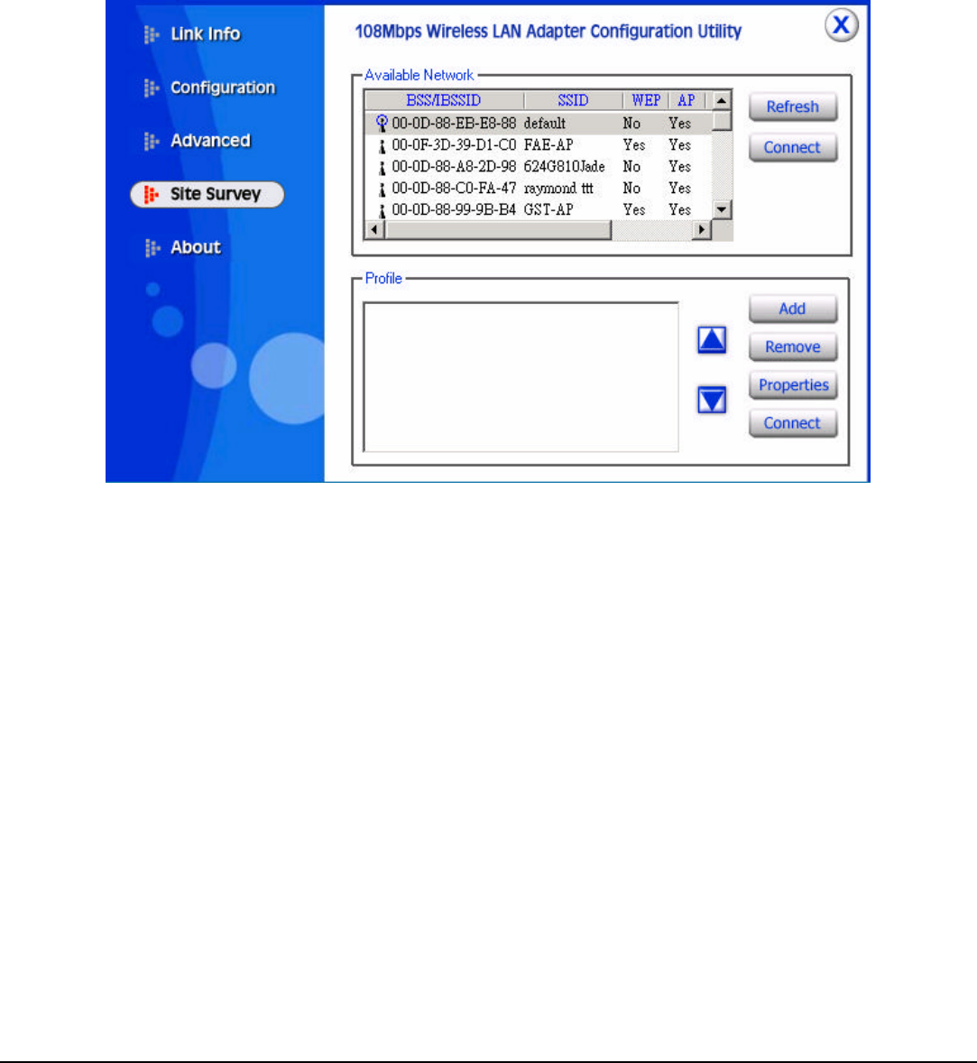
IV. Site Survey
This page allows user to enable the Site Survey function to scan for the available
wireless network (wireless clients and Access Points) and establish wireless
communications with one.
Available Network – displays the wireless networks (wireless clients and Access
Points) that are in signal range.
Select any one of them to establish communications by simply mouse double-click
or click on the “Connect” button.
Click “Refresh” button to start scanning for available network again.
Profile – User can create and manage the created profiles for Home, offices or
public areas. By double-clicking on one of the created profile, the setting will adapt
to the configuration such as SSID, channel, and WEP settings saved by that
particular profile.
Remove: To remove the selected the profile
Properties: To view and change its settings of the profile.
10
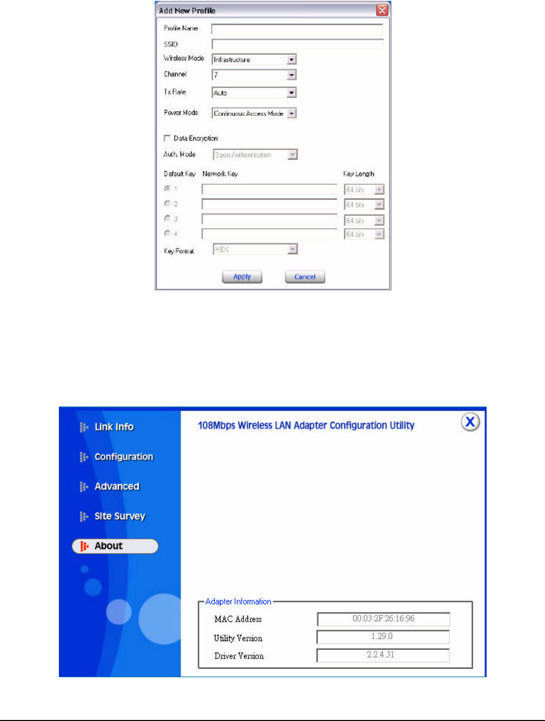
Add: To add a profile. Then, the following screen would appear. User can enter the
necessary information required for accessing Access Points or Wireless Router.
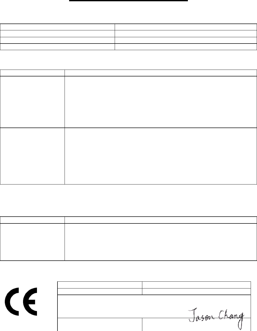
V. About
This page displays some information about the 108Mpbs wireless LAN PC card
utility, which includes the version numbers for Driver, Firmware and Utility. When
there is new version of software available for upgrade, users will be able to identify
by version numbers.
R&TTE Standards List
R&TTE List of Standard
With referring to the article of the directive of R&TTE 1999/5/EC, the following equipment:
Product Description / Supplementary Info
802.11g Wireless PCI Adapter
Manufacturer CAMEO COMMUNICATIONS, INC.
Brand CAMEO, Level One, LG, Etherwan, Allnet GmbH
Type WLG-1202, WNC-0300, LWS5410P, NWP-0108G, ALL0281A
has been tested to and conforms with the following List of R&TTE Harmonized standards:
Standard Issue date
ETSI EN 300 328-2
ETSI RF Specification V1.2.1 Dec. 2001
Electromag
netic compatibility and Radio spectrum Matters (ERM); Wideband
Transmission systems; Data transmission equipment operating in the 2,4GHz
ISM band and using spread spectrum modulation techniques; Harmonized
EN covering essential requirements under article 3.2 of the R&TTE Directive.
Meets R&TTE directive art. 3.2.a on effective use of radio frequency
spectrum so as to avoid harmful interference.
ETSI EN 301 489-1
ETSI EN 301 489-17
ETSI EMC Specification
V1.4.1 Aug. 2002
V1.2.1 Apr. 2002
Electromagnetic compatibility and Radio spectrum Matters(ERM);
Electro Magnetic Compatibility (EMC) standard for radio equipment and
services; Part 1: Common Technical requirements; Part 17: Specific
conditions for Wideband data and HIPERLAN equipment.
Meets R&TTE direc
tive art. 3.1.b of essential requirements on protection with
respect to Electro Magnetic Compatibility.
As such standards referred to tin Article 5 of the directive have not been applied or do not exist, the
following Adopted solutions with descriptions and explanations as listed below, have been applied
in full or in part, to meet the essential requirements of the directive:
Standard Issue date
EN 60950-1
LVD specification 2001
Safety of information technology equipment, including electrical business
equipment.
Meets R&TTE directive art. 3.1.a of essential requirements on protection of
the health and safety of the user.
Draw up in
TAIWAN, R.O.C.
Date 2005/4/27
CAMEO COMMUNICATIONS, INC.
No. 42, Min Chuan East Road, Section 6,
Taipei 114, Taiwan
Signature & company stamp Jason Chang /
Wireless Comm. R&D Dept. Manager
RF & EMC Test Reports and
Corresponding Annexes

Test Report -------------------------------------------------------------------------------- 1/38
Report No.: C51ET050304 (ETSI EN 300 328)
Training Research Co., Ltd., TEL:886-2-26935155, Fax:886-2-26934440
Report No. C51ET050304
Specifications ETSI EN 300 328-1 (V.1.3.1) / December, 2001
ETSI EN 300 328-2 (V.1.2.1) / December, 2001
Applicant CAMEO COMMUNICATIONS, INC.
Applicant No. 42, Min Chuan East Road, Section 6,
address Taipei 114, Taiwan
Items tested 802.11g Wireless PCI Adapter
Model No. W LG-1202, WNC- 0300, LWS5410P, NWP-0108G,
ALL0281A
EUT Condition Engineering sample; Pre-production; Final production
(Sample # N10415)
Results Compliance (As detailed within this report)
Date 12/01/2004 (month / day / year) (Sample received)
12/14/2004 (month / day / year) (Test)
Prepared by Project Engineer
______________________ (Jack Tsai)
Authorized by General Manager
(Frank Tsai)
Issue date December 16, 2004 (month / day / year)
Modifications None
Tested by Training Research Co., Ltd.
Office at No. 255, Nan Yang Street, Shijr City, Taipei Hsien 221, Taiwan
Laboratory at 1F, No. 255, Nan Yang Street, Shijr City, Taipei Hsien 221, Taiwan
Open site at No. 15, Lane 530, Balian Rd., Sec. 1, Shijr City, Taipei Hsien 221, Taiwan
Conditions of issue:
This test report shall not be reproduced except in full, without written approval of
TRC. And the test result contained within this report only relate to the sample submitted
for testing.
Aut. No. ELA 131

Test Report -------------------------------------------------------------------------------- 2/38
Report No.: C51ET050304 (ETSI EN 300 328)
Training Research Co., Ltd., TEL:886-2-26935155, Fax:886-2-26934440
We here by verify that:
The test data, data evaluation, test procedures and equipment configurations shown in this report
were made mainly in accordance with the procedures given in ETSI EN 300328-2 (V.1.2.1) as a
reference. All test were conducted by Training Research Co., Ltd.,255 Nanyang Street, Shijr, Taipei
Hsien 221, Taiwan, R.O.C. Also, we attest to the accuracy of each.
We further submit that the energy emitted by the sample EUT tested as described in the report is
in compliance with the technical requirements set second edition in the European Telecommunication
Standard ETSI EN 300328-2 (V.1.2.1).
Reservation:
The test results herein refer only to the tested sample. Training Research Co., Ltd. is not
responsible for any generalizations or conclusions draw from these test results and concerning further
samples. Any modification of the tested samples is prohibited and leads to the invalidity of this test report.
Test by :
Training Research Co., Ltd.
TEL: 886-2-26935155 FAX: 886-2-26934440
No. 255, Nanyang Street, Shijr, Taipei Hsien 221, Taiwan, R.O.C.

Test Report --------------------------------------------------------------------------------3/38
Report No.: C51ET050304 (ETSI EN 300 328)
Training Research Co., Ltd., TEL:886-2-26935155, Fax:886-2-26934440
Tables of Contents
I. GENERAL..........................................................................................4
1.1 INTRODUCTION........................................................................................................4
1.2 DESCRIPTION OF EUT ..............................................................................................4
1.3 TEST METHOD .........................................................................................................4
1.4 DESCRIPTION OF SUPPORT EQUIPMENT ....................................................................5
1.5 CONFIGURATION OF SYSTEM UNDER TEST...............................................................7
1.6 VERIFY THE FREQUENCY AND CHANNEL ..................................................................8
1.7 TEST PROCEDURE.....................................................................................................8
1.8 LOCATION OF THE TEST SITE ...................................................................................8
1.9 GENERAL TEST CONDITION......................................................................................9
II. SECTION 5.2.1: EFFECTIVE RADIATED POWER....................11
2.1 Test Result of Effective Radiated Power for IEEE 802.11b.....................................11
2.2 Test Result of Effective Radiated Power for IEEE 802.11g.....................................12
2.3 Test Result of Effective Radiated Power for Super 802.11g....................................13
III. SECTION 5.2.2: PEAK POWER DENSITY...................................14
3.1 Test Result of Peak Power Density for IEEE 802.11b.............................................14
3.2 Test Result of Peak Power Density for IEEE 802.11g.............................................14
3.3 Test Result of Peak Power Density for Super 802.11g............................................14
IV. SECTION 5.2.3 : FREQUENCY RANGE.......................................18
4.1 Test Result of Frequency Range for IEEE 802.11b.................................................18
4.2 Test Result of Frequency Range for IEEE 802.11g.................................................20
4.3 Test Result of Frequency Range for Super 802.11g................................................22
V. SECTION 5.2.4: TRANSMITTER SPURIOUS EMISSIONS .......24
5.1 Test Result for IEEE 802.11b.................................................................................24
5.2 Test Result for IEEE 802.11g.................................................................................27
5.3 Test Result for Super 802.11g................................................................................29
VI. SECTION 5.3.2: RECEIVER SPURIOUS EMISSIONS................30
6.1 Test Result for IEEE 802.11b.................................................................................30
6.2 Test Result for IEEE 802.11g.................................................................................33
6.3 Test Result for Super 802.11g................................................................................35
6.4 Test Result for Standby mode.................................................................................36
VII. INSTRUMENT AND ANCILLARIES EQUIPMENT OF LIST....37
Appendix A: Antenna Specification............................................................38

Test Report -------------------------------------------------------------------------------- 4/38
Report No.: C51ET050304 (ETSI EN 300 328)
Training Research Co., Ltd., TEL:886-2-26935155, Fax:886-2-26934440
I. GENERAL
1.1. Introduction
The following measurement report is submitted on behalf of Applicant in support of a wireless
LAN measurement in accordance with ETSI EN 300328-2 (V.1.2.1) (Dec. 2001) of the European
Telecommunication Standard.
1.2. Description of EUT
Product Name : 802.11g Wireless PCI Adapter
Model No. : WLG-1202, WNC-0300, LWS5410P,
NWP-0108G, ALL0281A
Frequency Range : 2.400GHz ~ 2.4835GHz
Operating Frequency : 2.412GHz ~ 2.472GHz
Support Channel : 13 Channels
Modulation Skill : DBPSK, DQPSK, CCK, OFDM
Power Type : Power by PCI of client’ s device
Power Cable : None
Data Cable : None
1.3. Test Method
1. Put the EUT into a personal computer’ s PCI bus and fix it.
2. Using the notebook computer and software provided by the manufacturer to control the
EUT. The test is performed under those specific conditions.
3. Set different channel [ CH1/CH7/CH13/Super 802.11g (only CH7) ] and data rate being
tested, and then making EUT to the following modes:
a) The mode of continuous transmission.
b) The receive mode.
c) The standby mode.

Test Report -------------------------------------------------------------------------------- 5/38
Report No.: C51ET050304 (ETSI EN 300 328)
Training Research Co., Ltd., TEL:886-2-26935155, Fax:886-2-26934440
1.4. Description of Support Equipment
In order to construct the minimum testing, following equipment were used as the support units.
PC : IBM 6840
Model No. : 6840MJV
Serial No. : 96CC 0BT
FCC ID : DoC Approved
ᛀ : 3892I279
Power type : 100 ~ 127/ 200 ~ 240VAC, 4A/2A 50/60 Hz, Switching
Power cord : Non-shielded, 182cm length, Plastic hood, No ferrite core
Monitor : HP 15’ Color Monitor
Model No. : D2827A
Serial No. : KR91161716
FCC ID : C5F7NFCMC1518X
ᛀ : 3872B039
Power type : 110 ~ 240 VAC / 50 ~ 60 Hz, Switching
Power cord : Shielded, 1.83m long, No ferrite core
Data cable : Shielded, 1.46m long, with two ferrite cores
PS/2 Keyboard : HP
Model No. : 5181
Serial No. : BE21700405
FCC ID : DoC Approved
ᛀ : 3892C981
Power type : By PC
Data cable : Shielded, 1.70m length, with ferrite core
PS/2 Mouse : HP
Model No. : M-S34
Serial No. : LZB90714106
FCC ID : DZL211029
ᛀ : 4862A011
Power type : By PC
Power cord : Non-shielded, 1.88m long, No ferrite core

Test Report -------------------------------------------------------------------------------- 6/38
Report No.: C51ET050304 (ETSI EN 300 328)
Training Research Co., Ltd., TEL:886-2-26935155, Fax:886-2-26934440
Notebook : IBM Think Pad X20
Model No. : 2662-11T
Serial No. : FX-1192200/09
FCC ID : N/A, DoC Approved
ᛀ : 3892B565
Adaptor : IBM
Model No. : PA2450U
Serial No. : 02K6654
FCC ID : N/A, DoC Approved
Power type : I/P: 100 ~ 240vac, 50 ~ 60 Hz, 0.5A ~ 1.2A; O/P: 16Vdc, 4.5A
Power cord : Non-shielded, 1.80m length, Plastic, with ferrite core
WLAN Card : Gemtek Technology Co., Ltd.
Model No. : C911003
FCC ID : MXF-C911003
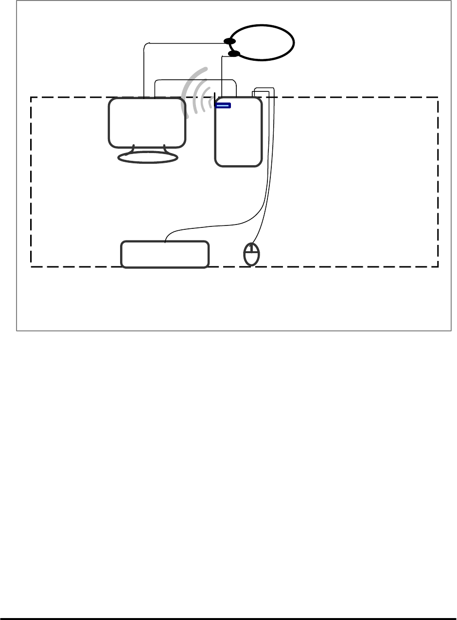
Test Report -------------------------------------------------------------------------------- 7/38
Report No.: C51ET050304 (ETSI EN 300 328)
Training Research Co., Ltd., TEL:886-2-26935155, Fax:886-2-26934440
1.5. Configuration of System Under Test
The tests below are carried with the EUT transmitter set at high power in TDD mode. The
EUT is forced to select of output power level and channel number by PC.
Test-table
EUT
Monitor PC
Power
Source
PS/2
Mouse
PS/2
Keyboard

Test Report -------------------------------------------------------------------------------- 8/38
Report No.: C51ET050304 (ETSI EN 300 328)
Training Research Co., Ltd., TEL:886-2-26935155, Fax:886-2-26934440
1.6. Verify the Frequency and Channel
CH12345678910
0 2412 2417 2422 2427 2432 2437 2442 2447 2452 2457
1 2462 2467 2472 --- --- --- --- --- --- ---
Note:
(1) This is for sure that all frequencies are in 2.4GHz – 2.4835 GHz.
(2) After test, the EUT operating frequencies are in 2.412GHz to 2.472GHz. So all the item as
followed in testing report are need to test these three frequencies:
channel 1, channel 7, and channel 13.
(3) E.T.S.I (2400MHz ~ 2483.5MHz),
FRANCE outdoor use limited to 10mW e.i.r.p. within the band (2454MHz ~ 2483.5MHz)
1.7. Test Procedure
All measurements performed in this report were performed mainly according to the techniques
described in ETSI EN 300328-2 (Dec., 2001) and the pre-setup was written on 1.4 test method, the
detail setup was written on each test item.
1.8. Location of the Test Site
The radiated emissions measurements required by the rules were performed on the
three-meter,Anechoic Chamber (Registration Number: 93906) maintained by Training
Research Co., Ltd. 1F., No. 255 Nanyang Street, Shijr, Taipei Hsien 221, Taiwan, R.O.C. Complete
description and measurement data have been placed on file with the commission. The conducted
power line emissions tests and other test items were performed in a anechoic chamber also located at
Training Research Co., Ltd.
No. 255 Nanyang Street, Shijr, Taipei Hsien 221, Taiwan, R.O.C. Training Research Co.,
Ltd. is listed by the FCC as a facility available to do measurement work for others on a contract
basis.

Test Report -------------------------------------------------------------------------------- 9/38
Report No.: C51ET050304 (ETSI EN 300 328)
Training Research Co., Ltd., TEL:886-2-26935155, Fax:886-2-26934440
1.9. General Test Condition
The test condition shall be as follows: (See Clause 6)
The NORMAL temperature and humidity conditions for tests shall be any convenient
combination of temperature and humidity within the following ranges:
-temperature: +15к to +35к;
-relative humidity: 20% to 75%.
The normal test voltage for equipment to be connected to the main shall be the nominal mains
voltage.
For purpose of this ETS, the normal voltage shall be the declared voltage or any of the declared
voltages for which the equipment was designed.
The frequency of the test power source corresponding to the AC mains shall be between 49Hz
and 51Hz. When radio equipment is intended for operation from the usual, alternator fed lead-acid
battery power source used on vehicles, then the normal test voltage shall be 1.1 times the nominal
voltage of the battery (6V, 12V, etc.)
For operation from other power sources or types of battery (primary or secondary), the
nominal test voltage shall be as declared by the equipment manufacturer. This shall be recorded in the
test report.
For tests at EXTREME temperatures, measurements shall be made in accordance with the
procedures specified in subclause 6.4.3, at the upper and lower temperatures of the range as follows:
temperature: -20к to +55к;
Where the manufacturer’ s declared operating range does not include the range of -20к to
+55к, the equipment shall be tested over the following temperature ranges:
a)0к to +35кfor equipment intended for INDOOR use only, or intended for use in areas
where the temperature is controlled within this range;
b)Over the extremes of the operating temperature range(s) of the declared host equipment(s)
in case of plug-in radio devices.

Test Report -------------------------------------------------------------------------------- 10/38
Report No.: C51ET050304 (ETSI EN 300 328)
Training Research Co., Ltd., TEL:886-2-26935155, Fax:886-2-26934440
The frequency range as in subclause 5.2.3 and the e.i.r.p. Limit in subclause5.2.1 shall not be
exceeded.
Tests at extreme power source voltages specified below are not required when the equipment
under test is designed for operation as part of and powered by another system or piece of equipment.
Where this is the case, the limit values of the host system or host equipment shall apply. The
appropriate limit values shall be declared by the manufacturer and recorded in the test report.
The EXTREME TEST VOLTAGE for equipment to be connected to an AC mains source
shall be the nominal mains voltage ±10%.
When radio equipment is intended for operation from the usual type of alternator fed lead-acid
battery power source used on vehicles, then extreme test voltage shall be 1.3 and 0.9 times the
nominal voltage of the battery (6V, 12V, …etc.).
The lower extreme test voltage for equipment with power source using the following type of
battery, shall be:
-for the Leclanche’ or lithium type battery: 0.85 times the nominal voltage of the battery;
-for the mercury or nickel-cadmium type of battery: 0.9 times the nominal voltage of the
battery.
In both cases, the upper extreme test voltage shall be 1.15 times the nominal voltage of the
battery.
For equipment using other power sources, or capable of being operated from a variety of
power sources (primary or secondary), the extreme test voltages shall be those declared by the
manufacturer; these shall be recorded in the test report. Before measurements are made the
equipment shall have reached thermal balance in the test chamber.

Test Report -------------------------------------------------------------------------------- 11/38
Report No.: C51ET050304 (ETSI EN 300 328)
Training Research Co., Ltd., TEL:886-2-26935155, Fax:886-2-26934440
II. Section 5.2.1: Effective Radiated Power
2.1 Test Result of Effective Radiated Power for IEEE 802.11b
Power level at which the measurement has been performed 93.33 mW
TRANSMITTER PEAK POWER
TEST CONDITION Tx Peak
(dBm)
Tx Ave.
(dBm)
Cable Loss
(dB)
25 {C 10.93 8.82
0{C 12.10 9.75
Channel 1
35 {C 10.52 8.41
5.80
25 {C 11.13 9.07
0{C 12.10 9.92
Channel 7
35 {C 10.41 8.35
5.80
25 {C 10.80 8.74
0{C 11.92 9.58
Channel 13
35 {C 9.98 7.96
5.80
Limit Tx Peak : 23dBm / -7dBW
Tx Ave. : 20dBm / -10dBW
NOTE:
(1) The E.U.T is a stand-alone radio device (see the clause 6.2.2). The powered by the adaptor. So,
the AC power is used as the extreme voltage source. (See clause 6.3.2.1)
(2) The value of table is worst case during test condition, includes different combinations of
transmitter rate antenna polarity and temperature
(3) TX PEAK: Max Peak Power, TX Ave.: Average Peak.
Actually Power = Max Peak Power + Cable Loss,
E.I.R.P. = Actually Power + Antenna Gain
= 17.90 dBm + 1.80dBi
= 19.70 dBm
(4) ETSI (2400MHz ~ 2483.5MHz),
FRANCE outdoor use limited to 10mW e.i.r.p. within the band (2454MHz ~ 2483.5MHz)

Test Report -------------------------------------------------------------------------------- 12/38
Report No.: C51ET050304 (ETSI EN 300 328)
Training Research Co., Ltd., TEL:886-2-26935155, Fax:886-2-26934440
2.2 Test Result of Effective Radiated Power for IEEE 802.11g
Power level at which the measurement has been performed 94.62 mW
TRANSMITTER PEAK POWER
TEST CONDITION Tx Peak
(dBm)
Tx Ave.
(dBm)
Cable Loss
(dB)
25 {C 11.04 1.78
0{C 12.16 2.98
Channel 1
35 {C 10.44 1.01
5.80
25 {C 10.88 1.60
0{C 12.05 2.84
Channel 7
35 {C 10.12 0.73
5.80
25 {C 11.19 1.66
0{C 12.14 2.71
Channel 13
35 {C 10.33 0.63
5.80
Limit Tx Peak : 23dBm / -7dBW
Tx Ave. : 20dBm / -10dBW
NOTE:
(1) TX PEAK: Max Peak Power, TX Ave.: Average Peak.
Actually Power = Max Peak Power + Cable Loss,
E.I.R.P. = Actually Power + Antenna Gain
= 17.96 dBm + 1.80 dBi
= 19.76 dBm

Test Report -------------------------------------------------------------------------------- 13/38
Report No.: C51ET050304 (ETSI EN 300 328)
Training Research Co., Ltd., TEL:886-2-26935155, Fax:886-2-26934440
2.3 Test Result of Effective Radiated Power for Super 802.11g
Power level at which the measurement has been performed 91.62 mW
TRANSMITTER PEAK POWER
TEST CONDITION Tx Peak
(dBm)
Tx Ave.
(dBm)
Cable Loss
(dB)
25 {C 10.66 1.60
0{C 12.02 3.04
Channel 7
35 {C 9.90 0.69
5.80
Limit Tx Peak : 23dBm / -7dBW
Tx Ave. : 20dBm / -10dBW
NOTE:
(1) TX PEAK: Max Peak Power, TX Ave.: Average Peak.
Actually Power = Max Peak Power + Cable Loss,
E.I.R.P. = Actually Power + Antenna Gain
= 17.82 dBm + 1.80 dBi
= 19.62 dBm

Test Report -------------------------------------------------------------------------------- 14/38
Report No.: C51ET050304 (ETSI EN 300 328)
Training Research Co., Ltd., TEL:886-2-26935155, Fax:886-2-26934440
III. Section 5.2.2: Peak Power Density
3.1 Test Result of Peak Power Density for IEEE 802.11b
Channel Frequency
(MHz)
Ppr
(dBm)
CF
(dB)
Ant. Gain
(dB)
Ppq
(dBm)
Limit
(dBm)
Margin
(dB)
CH 01 2412 -2.54 6.60 1.80 5.86 10.00 -4.14
CH 07 2442 -1.79 6.60 1.80 6.61 10.00 -3.39
CH 13 2472 -2.81 6.70 1.80 5.69 10.00 -4.31
3.2 Test Result of Peak Power Density for IEEE 802.11g
Channel Frequency
(MHz)
Ppr
(dBm)
CF
(dB)
Ant. Gain
(dB)
Ppq
(dBm)
Limit
(dBm)
Margin
(dB)
CH 01 2412 0.23 6.60 1.80 8.63 10.00 -1.37
CH 07 2442 -0.23 6.60 1.80 8.17 10.00 -1.83
CH 13 2472 -1.38 6.70 1.80 7.12 10.00 -2.88
3.3 Test Result of Peak Power Density for Super 802.11g
Channel Frequency
(MHz)
Ppr
(dBm)
CF
(dB)
Ant. Gain
(dB)
Ppq
(dBm)
Limit
(dBm)
Margin
(dB)
CH 07 2442 -4.42 6.60 1.80 3.98 10.00 -6.02
NOTE:
(1) For equipment using FHSS modulation, the peak power density shall be limit to
–10dBW(100mW) per 100kHz E.I.R.P.
(2) For equipment using other types modulation, the peak power density shall be limit
–20dBW(10mW) per MHz E.I.R.P.
(3) Ppr: spectrum read power density (using peak search mode), CF: correct factor,
CF: Correct Factor, AG: Antenna Gain
Ppq: actual peak power density in the spread spectrum band. Ppq = Ppr + CF + AG
(4) The value of table is worst case during test condition, includes different combination s of
transmitter rate, antenna polarity and temperature
(5) The data in the above table are summarizing the following attachment spectrum analyzer hard
copy.
(6) ETSI (2400MHz ~ 2483.5MHz),
FRANCE outdoor use limited to 10mW e.i.r.p. within the band (2454MHz ~ 2483.5MHz)
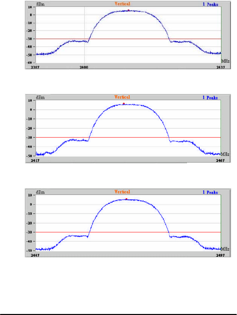
Test Report -------------------------------------------------------------------------------- 15/38
Report No.: C51ET050304 (ETSI EN 300 328)
Training Research Co., Ltd., TEL:886-2-26935155, Fax:886-2-26934440
IEEE 802.11b
CH01
CH07
CH13
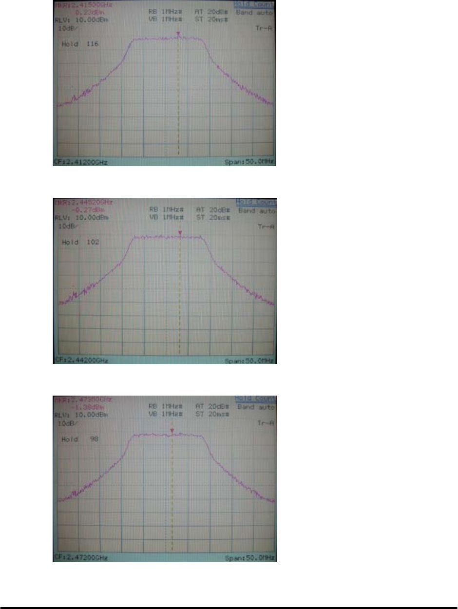
Test Report -------------------------------------------------------------------------------- 16/38
Report No.: C51ET050304 (ETSI EN 300 328)
Training Research Co., Ltd., TEL:886-2-26935155, Fax:886-2-26934440
IEEE 802.11g
CH01
CH07
CH13
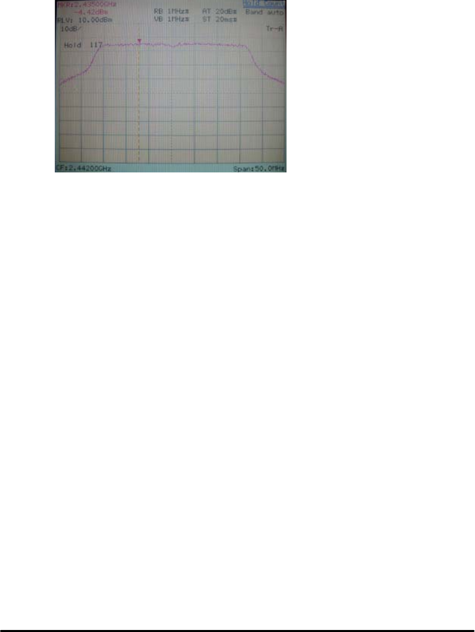
Test Report -------------------------------------------------------------------------------- 17/38
Report No.: C51ET050304 (ETSI EN 300 328)
Training Research Co., Ltd., TEL:886-2-26935155, Fax:886-2-26934440
Super 802.11g
CH07

Test Report -------------------------------------------------------------------------------- 18/38
Report No.: C51ET050304 (ETSI EN 300 328)
Training Research Co., Ltd., TEL:886-2-26935155, Fax:886-2-26934440
IV. Section 5.2.3 : Frequency Range
4.1 Test Result of Frequency Range for IEEE 802.11b
Transmitter Frequency Range – DSSS Equipment
FREQUENCY(MHz)
Lowest Channel Highest Channel
Channel 1 Channel 13
TEST CONDITION
Frequency Rate (Mbps) Frequency Rate (Mbps)
207 V 2402.70 11 2482.10 11
0к
253 V 2402.80 11 2482.10 11
˅ˈк 230 V 2402.30 11 2482.60 11
207 V 2402.30 11 2482.50 11
35к
253 V 2402.30 11 2482.50 11
Measured frequencies
(lowest and highest) FL = 2402.30 MHz FH = 2482.60 MHz
Limit FL > 2400MHz FH < 2483.5MHz
Note:
(1) The E.U.T is a stand-alone radio device (see the clause 6.2.2). This is powered by the main. So,
the AC power is used as the extreme voltage source. (see clause 6.3.2.1).
(2) B: Battery, AC: AC Source, Rate: Transmitter Rate.
(3) The value of table is worst case during test condition, includes different combinations of
transmitter rate, antenna polarity and temperature.
(4) The data in the above table are summarizing the following attachment spectrum analyzer hard
copy.
(5) ETSI (2400MHz ~ 2483.5MHz),
FRANCE outdoor use limited to 10mW e.i.r.p. within the band (2454MHz ~ 2483.5MHz)
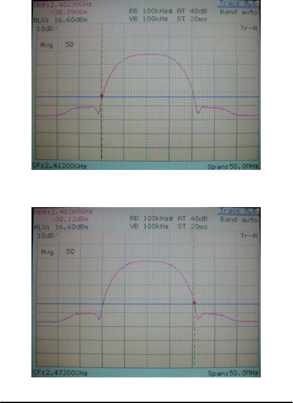
Test Report -------------------------------------------------------------------------------- 19/38
Report No.: C51ET050304 (ETSI EN 300 328)
Training Research Co., Ltd., TEL:886-2-26935155, Fax:886-2-26934440
Channel 1 (The lowest one in the frequency range)
Channel 13 (The greatest one in the frequency range)

Test Report -------------------------------------------------------------------------------- 20/38
Report No.: C51ET050304 (ETSI EN 300 328)
Training Research Co., Ltd., TEL:886-2-26935155, Fax:886-2-26934440
4.2 Test Result of Frequency Range for IEEE 802.11g
Trans mitter Frequency Range – DSSS Equipment
FREQUENCY(MHz)
Lowest Channel Highest Channel
Channel 1 Channel 13
TEST CONDITION
Frequency Rate (Mbps) Frequency Rate (Mbps)
207 V 2403.60 54 2481.20 54
0к
253 V 2403.70 54 2481.20 54
˅ˈк 230 V 2402.80 54 2481.90 54
207 V 2402.80 54 2481.80 54
35к
253 V 2402.90 54 2481.80 54
Measured frequencies
(lowest and highest) FL = 2402.80 MHz FH = 2481.90 MHz
Limit FL > 2400MHz FH < 2483.5MHz
Note:
(1) The E.U.T is a stand-alone radio device (see the clause 6.2.2). This is powered by the main. So,
the AC power is used as the extreme voltage source. (see clause 6.3.2.1).
(2) B: Battery, AC: AC Source, Rate: Transmitter Rate.
(3) The value of table is worst case during test condition, includes different combinations of
transmitter rate, antenna polarity and temperature.
(4) The data in the above table are summarizing the following attachment spectrum analyzer hard
copy.
(5) ETSI (2400MHz ~ 2483.5MHz),
FRANCE outdoor use limited to 10mW e.i.r.p. within the band (2454MHz ~ 2483.5MHz)
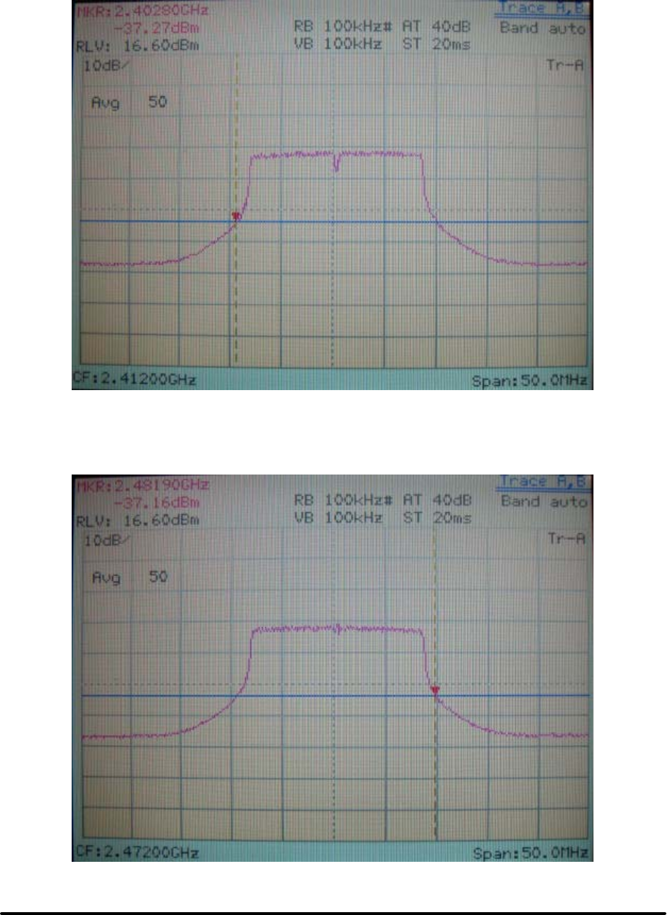
Test Report -------------------------------------------------------------------------------- 21/38
Report No.: C51ET050304 (ETSI EN 300 328)
Training Research Co., Ltd., TEL:886-2-26935155, Fax:886-2-26934440
Channel 1 (The lowest one in the frequency range)
Channel 13 (The greatest one in the frequency range)

Test Report -------------------------------------------------------------------------------- 22/38
Report No.: C51ET050304 (ETSI EN 300 328)
Training Research Co., Ltd., TEL:886-2-26935155, Fax:886-2-26934440
4.3 Test Result of Frequency Range for Super 802.11g
Transmitter Frequency Range – DSSS Equipment
FREQUENCY(MHz)
Lowest Frequency Highest Frequency
Channel 7 Channel 7
TEST CONDITION
Frequency Rate (Mbps) Frequency Rate (Mbps)
207 V 2425.10 108 2459.70 108
0к
253 V 2425.10 108 2459.70 108
˅ˈк 230 V 2424.10 108 2460.30 108
207 V 2424.60 108 2460.20 108
35к
253 V 2424.50 108 2460.20 108
Measured frequencies
(lowest and highest) FL = 2424.10 MHz FH = 2459.70 MHz
Limit FL > 2400MHz FH < 2483.5MHz
Note:
(6) The E.U.T is a stand-alone radio device (see the clause 6.2.2). This is powered by the main. So,
the AC power is used as the extreme voltage source. (see clause 6.3.2.1).
(7) B: Battery, AC: AC Source, Rate: Transmitter Rate.
(8) The value of table is worst case during test condition, includes different combinations of
transmitter rate, antenna polarity and temperature.
(9) The data in the above table are summarizing the following attachment spectrum analyzer hard
copy.
(10) ETSI (2400MHz ~ 2483.5MHz),
FRANCE outdoor use limited to 10mW e.i.r.p. within the band (2454MHz ~ 2483.5MHz)
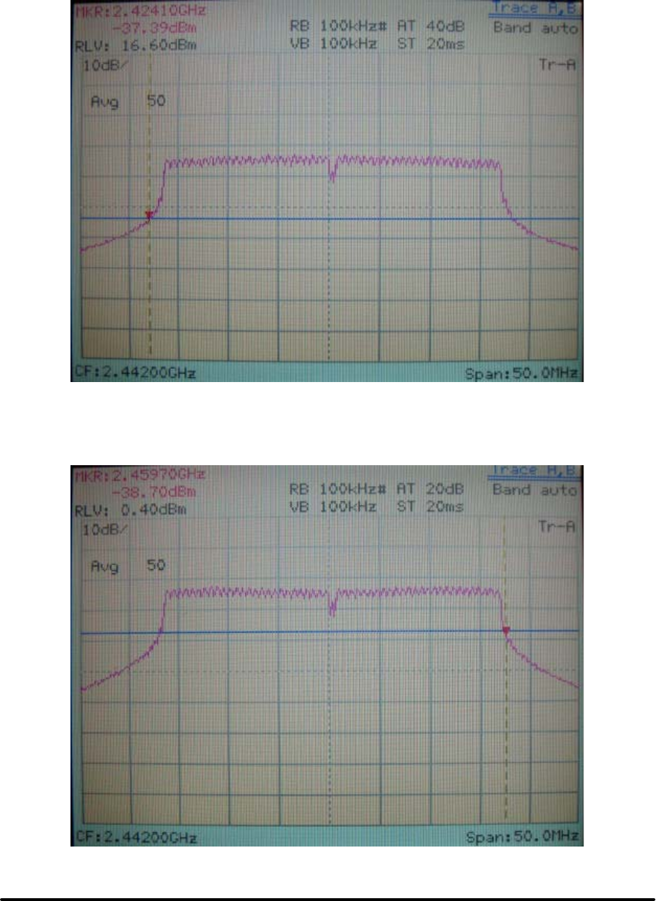
Test Report -------------------------------------------------------------------------------- 23/38
Report No.: C51ET050304 (ETSI EN 300 328)
Training Research Co., Ltd., TEL:886-2-26935155, Fax:886-2-26934440
Channel 1 (The lowest one in the frequency range)
Channel 13 (The greatest one in the frequency range)

Test Report -------------------------------------------------------------------------------- 24/38
Report No.: C51ET050304 (ETSI EN 300 328)
Training Research Co., Ltd., TEL:886-2-26935155, Fax:886-2-26934440
V. Section 5.2.4: Transmitter Spurious Emissions (Radiated)
5.1 Test Result for IEEE 802.11b
Channel 1 (30MHz to 1GHz)
Frequency
(MHz)
A. P.
(H/V)
LEVEL
(dBm)
Limit
(dBm)
Margin
(dB)
Rate
(Mbps)
302.81 H-75.98 -36.00 -39.98 11
436.19 H-67.80 -36.00 -31.80 11
502.87 H-67.46 -36.00 -31.46 11
564.71 H-64.01 -36.00 -28.01 11
598.66 H-63.42 -36.00 -27.42 11
700.51 H-66.12 -36.00 -30.12 11
367.07 V-71.12 -36.00 -35.12 11
437.40 V-71.30 -36.00 -35.30 11
468.92 V-70.49 -36.00 -34.49 11
500.45 V-64.31 -36.00 -28.31 11
564.71 V-66.79 -36.00 -30.79 11
598.66 V-61.24 -36.00 -25.24 11
Note:
(1) A. P. means antenna polarization, horizontal and vertical.
Amplitude means the fundamental emission measured
C F. means Correct Factor, Rate means transmitter rate
Corrected Factor (C. F.) = Cable Loss + Antenna Factor – Amplified Gain
LEVEL = Amplitude + Corrected Factor
(2) The margin is minus that means under limit.
(3) The value of table is the worst case during test condition. This is including different
combinations of transmitter rate antenna polarity and temperature.
(4) ETSI (2400MHz ~ 2483.5MHz),
FRANCE outdoor use limited to 10mW e.i.r.p. within the band (2454MHz ~ 2483.5MHz)

Test Report -------------------------------------------------------------------------------- 25/38
Report No.: C51ET050304 (ETSI EN 300 328)
Training Research Co., Ltd., TEL:886-2-26935155, Fax:886-2-26934440
Channel 13 (30MHz to 1GHz)
Frequency
(MHz)
A. P.
(H/V)
LEVEL
(dBm)
Limit
(dBm)
Margin
(dB)
Rate
(Mbps)
339.19 H-66.11 -36.00 -30.11 11
386.47 H-71.27 -36.00 -35.27 11
436.19 H-67.34 -36.00 -31.34 11
502.87 H-68.16 -36.00 -32.16 11
564.71 H-64.38 -36.00 -28.38 11
598.66 H-63.60 -36.00 -27.60 11
369.50 V-71.31 -36.00 -35.31 11
434.97 V-70.60 -36.00 -34.60 11
468.92 V-70.56 -36.00 -34.56 11
501.66 V-63.92 -36.00 -27.92 11
564.71 V-66.81 -36.00 -30.81 11
598.66 V-60.79 -36.00 -24.79 11

Test Report -------------------------------------------------------------------------------- 26/38
Report No.: C51ET050304 (ETSI EN 300 328)
Training Research Co., Ltd., TEL:886-2-26935155, Fax:886-2-26934440
Channel 1 (1GHz to 12.75GHz)
Frequency
(MHz)
A. P.
(H/V)
LEVEL
(dBm)
Limit
(dBm)
Margin
(dB)
Rate
(Mbps)
2158.33 H -52.58 -30.00 -22.58 11
2637.50 H -55.03 -30.00 -25.03 11
7234.69 H-59.19 -30.00 -29.19 11
9647.40 H-56.41 -30.00 -26.41 11
12060.10 H-57.37 -30.00 -27.37 11
2362.50 V-52.21 -30.00 -22.21 11
2639.58 V-50.36 -30.00 -20.36 11
7234.69 V-60.03 -30.00 -30.03 11
9647.40 V-58.74 -30.00 -28.74 11
12060.10 V-57.04 -30.00 -27.04 11
Channel 13 (1GHz to 12.75GHz)
Frequency
(MHz)
A. P.
(H/V)
LEVEL
(dBm)
Limit
(dBm)
Margin
(dB)
Rate
(Mbps)
2158.33 H-54.42 -30.00 -24.42 11
2637.50 H-55.37 -30.00 -25.37 11
7415.83 H-59.30 -30.00 -29.30 11
9886.35 H-57.01 -30.00 -27.01 11
12360.73 H-57.69 -30.00 -27.69 11
1820.83 V-54.97 -47.00 -7.97 11
2637.50 V-52.20 -30.00 -22.20 11
4945.31 V-63.16 -30.00 -33.16 11
7415.83 V-59.96 -30.00 -29.96 11
9886.35 V-58.01 -30.00 -28.01 11
12360.73 V-58.36 -30.00 -28.36 11

Test Report -------------------------------------------------------------------------------- 27/38
Report No.: C51ET050304 (ETSI EN 300 328)
Training Research Co., Ltd., TEL:886-2-26935155, Fax:886-2-26934440
5.2 Test Result for IEEE 802.11g
Channel 1 (30MHz to 1GHz)
Frequency
(MHz)
A. P.
(H/V)
LEVEL
(dBm)
Limit
(dBm)
Margin
(dB)
Rate
(Mbps)
434.97 H-67.17 -36.00 -31.17 54
500.45 H-69.21 -36.00 -33.21 54
564.71 H-64.64 -36.00 -28.64 54
598.66 H-64.41 -36.00 -28.41 54
698.09 H-66.84 -36.00 -30.84 54
369.50 V-71.04 -36.00 -35.04 54
434.97 V-71.07 -36.00 -35.07 54
468.92 V-70.56 -36.00 -34.56 54
501.66 V-64.43 -36.00 -28.43 54
565.92 V-66.01 -36.00 -30.01 54
597.45 V-60.32 -36.00 -24.32 54
Channel 13 (30MHz to 1GHz)
Freque ncy
(MHz)
A. P.
(H/V)
LEVEL
(dBm)
Limit
(dBm)
Margin
(dB)
Rate
(Mbps)
436.19 H-66.76 -36.00 -30.76 54
501.66 H-69.37 -36.00 -33.37 54
564.71 H-64.82 -36.00 -28.82 54
598.66 H-64.30 -36.00 -28.30 54
699.30 H-66.71 -36.00 -30.71 54
369.50 V-71.36 -36.00 -35.36 54
468.92 V-70.72 -36.00 -34.72 54
501.66 V-64.24 -36.00 -28.24 54
565.92 V-66.39 -36.00 -30.39 54
597.45 V-60.81 -36.00 -24.81 54

Test Report -------------------------------------------------------------------------------- 28/38
Report No.: C51ET050304 (ETSI EN 300 328)
Training Research Co., Ltd., TEL:886-2-26935155, Fax:886-2-26934440
Channel 1 (1GHz to 12.75GHz)
Frequency
(MHz)
A. P.
(H/V)
LEVEL
(dBm)
Limit
(dBm)
Margin
(dB)
Rate
(Mbps)
2158.33 H -52.25 -30.00 -22.25 54
2637.50 H -53.53 -30.00 -23.53 54
7234.69 H-59.69 -30.00 -29.69 54
9647.40 H-58.74 -30.00 -28.74 54
12060.10 H-56.71 -30.00 -26.71 54
2237.50 V -55.76 -30.00 -25.76 54
2639.58 V -49.86 -30.00 -19.86 54
7234.69 V-61.03 -30.00 -31.03 54
9647.40 V-58.91 -30.00 -28.91 54
12060.10 V-57.21 -30.00 -27.21 54
Channel 13 (1GHz to 12.75GHz)
Frequency
(MHz)
A. P.
(H/V)
LEVEL
(dBm)
Limit
(dBm)
Margin
(dB)
Rate
(Mbps)
2158.33 H-52.75 -30.00 -22.75 54
2637.50 H-54.20 -30.00 -24.20 54
4945.31 H-61.66 -30.00 -31.66 54
7415.83 H-59.63 -30.00 -29.63 54
9886.35 H-58.01 -30.00 -28.01 54
12360.73 H-57.86 -30.00 -27.86 54
2358.33 V-53.41 -30.00 -23.41 54
2637.50 V-50.20 -30.00 -20.20 54
7415.83 V-59.80 -30.00 -29.80 54
9886.35 V-57.01 -30.00 -27.01 54
12360.73 V-57.69 -30.00 -27.69 54

Test Report -------------------------------------------------------------------------------- 29/38
Report No.: C51ET050304 (ETSI EN 300 328)
Training Research Co., Ltd., TEL:886-2-26935155, Fax:886-2-26934440
5.3 Test Result for Super 802.11g
Channel 7 (30MHz to 1GHz)
Frequency
(MHz)
A. P.
(H/V)
LEVEL
(dBm)
Limit
(dBm)
Margin
(dB)
Rate
(Mbps)
301.60 H-74.70 -36.00 -38.70 108
434.97 H-68.63 -36.00 -32.63 108
500.45 H-69.49 -36.00 -33.49 108
565.92 H-64.69 -36.00 -28.69 108
598.66 H-64.62 -36.00 -28.62 108
287.05 V-74.68 -36.00 -38.68 108
401.02 V-72.83 -36.00 -36.83 108
434.97 V-70.43 -36.00 -34.43 108
531.98 V-67.20 -36.00 -31.20 108
598.66 V-66.19 -36.00 -30.19 108
700.51 V-66.78 -36.00 -30.78 108
Channel 7 (1GHz to 12.75GHz)
Frequency
(MHz)
A. P.
(H/V)
LEVEL
(dBm)
Limit
(dBm)
Margin
(dB)
Rate
(Mbps)
2237.50 H -54.09 -30.00 -24.09 108
2518.75 H -56.35 -30.00 -26.35 108
7327.19 H-58.62 -30.00 -28.62 108
9766.87 H-57.91 -30.00 -27.91 108
12210.42 H-56.43 -30.00 -26.43 108
1820.83 V -58.31 -30.00 -28.31 108
2518.75 V -52.68 -30.00 -22.68 108
7327.19 V-60.95 -30.00 -30.95 108
9766.87 V-58.41 -30.00 -28.41 108
12210.42 V-55.43 -30.00 -25.43 108

Test Report -------------------------------------------------------------------------------- 30/38
Report No.: C51ET050304 (ETSI EN 300 328)
Training Research Co., Ltd., TEL:886-2-26935155, Fax:886-2-26934440
VI. Section 5.3.2: Receiver Spurious Emissions (Radiated)
6.1 Test Result for IEEE 802.11b
Channel 1 (30MHz to 1GHz)
Frequency
(MHz)
A. P.
(H/V)
LEVEL
(dBm)
Limit
(dBm)
Margin
(dB)
Rate
(Mbps)
403.45 H-71.81 -57.00 -14.81 11
433.76 H-65.07 -57.00 -8.07 11
501.66 H-63.05 -57.00 -6.05 11
564.71 H-63.57 -57.00 -6.57 11
597.45 H-62.20 -57.00 -5.20 11
631.40 H-67.21 -57.00 -10.21 11
302.81 V-72.75 -57.00 -15.75 11
369.50 V-70.81 -57.00 -13.81 11
436.19 V-70.26 -57.00 -13.26 11
502.87 V-63.93 -57.00 -6.93 11
564.71 V-65.71 -57.00 -8.71 11
598.66 V-60.32 -57.00 -3.32 11
Note:
(1) A. P. means antenna polarization, horizontal and vertical.
Amplitude means the fundamental emission measured.
C F. means Correct Factor, Rate means transmitter rate
Corrected Factor (C. F.) = Cable Loss + Antenna Factor – Amplified Gain
LEVEL = Amplitude + Corrected Factor
(2) The value of table is worst case during test condition, includes different combinations of
transmitter rate antenna polarity and temperature
(3) ETSI (2400MHz ~ 2483.5MHz),
FRANCE outdoor use limited to 10mW e.i.r.p. within the band (2454MHz ~ 2483.5MHz)

Test Report -------------------------------------------------------------------------------- 31/38
Report No.: C51ET050304 (ETSI EN 300 328)
Training Research Co., Ltd., TEL:886-2-26935155, Fax:886-2-26934440
Channel 13 (30MHz to 1GHz)
Frequency
(MHz)
A. P.
(H/V)
LEVEL
(dBm)
Limit
(dBm)
Margin
(dB)
Rate
(Mbps)
401.02 H-72.24 -57.00 -15.24 11
434.97 H-64.62 -57.00 -7.62 11
500.45 H-62.50 -57.00 -5.50 11
564.71 H-63.02 -57.00 -6.02 11
598.66 H-62.49 -57.00 -5.49 11
700.51 H-67.21 -57.00 -10.21 11
369.50 V-71.48 -57.00 -14.48 11
436.19 V-70.31 -57.00 -13.31 11
468.92 V-69.45 -57.00 -12.45 11
504.09 V-64.03 -57.00 -7.03 11
564.71 V-66.22 -57.00 -9.22 11
598.66 V-59.74 -57.00 -2.74 11

Test Report -------------------------------------------------------------------------------- 32/38
Report No.: C51ET050304 (ETSI EN 300 328)
Training Research Co., Ltd., TEL:886-2-26935155, Fax:886-2-26934440
Channel 1 (1GHz to 12.75GHz)
Frequency
(MHz)
A. P.
(H/V)
LEVEL
(dBm)
Limit
(dBm)
Margin
(dB)
Rate
(Mbps)
1499.37 H-63.82 -47.00 -16.82 11
3957.08 H-62.36 -47.00 -15.36 11
5670.62 H-60.95 -47.00 -13.95 11
9964.27 H-56.36 -47.00 -9.36 11
2096.67 V-59.48 -47.00 -12.48 11
3942.40 V-62.43 -47.00 -15.43 11
5611.87 V-60.23 -47.00 -13.23 11
9425.73 V-57.28 -47.00 -10.28 11
Channel 13 (1GHz to 12.75GHz)
Frequency
(MHz)
A. P.
(H/V)
LEVEL
(dBm)
Limit
(dBm)
Margin
(dB)
Rate
(Mbps)
1499.37 H-63.15 -47.00 -16.15 11
3315.73 H-63.58 -47.00 -16.58 11
5176.15 H-60.86 -47.00 -13.86 11
9734.17 H-58.32 -47.00 -11.32 11
1499.37 V-59.32 -47.00 -12.32 11
3315.73 V-61.98 -47.00 -14.98 11
5176.15 V-58.62 -47.00 -11.62 11
9734.17 V-56.82 -47.00 -9.82 11

Test Report -------------------------------------------------------------------------------- 33/38
Report No.: C51ET050304 (ETSI EN 300 328)
Training Research Co., Ltd., TEL:886-2-26935155, Fax:886-2-26934440
6.2 Test Result for IEEE 802.11g
Channel 1 (30MHz to 1GHz)
Frequency
(MHz)
A. P.
(H/V)
LEVEL
(dBm)
Limit
(dBm)
Margin
(dB)
Rate
(Mbps)
402.24 H-72.16 -57.00 -15.16 54
434.97 H-63.76 -57.00 -6.76 54
501.66 H-62.79 -57.00 -5.79 54
564.71 H-63.09 -57.00 -6.09 54
598.66 H-62.24 -57.00 -5.24 54
632.61 H-67.30 -57.00 -10.30 54
331.91 V-69.91 -57.00 -12.91 54
434.97 V-70.63 -57.00 -13.63 54
501.66 V-64.39 -57.00 -7.39 54
565.92 V-66.48 -57.00 -9.48 54
598.66 V-60.25 -57.00 -3.25 54
Channel 13 (30MHz to 1GHz)
Frequency
(MHz)
A. P.
(H/V)
LEVEL
(dBm)
Limit
(dBm)
Margin
(dB)
Rate
(Mbps)
437.40 H-63.94 -57.00 -6.94 54
500.45 H-63.00 -57.00 -6.00 54
531.98 H-68.24 -57.00 -11.24 54
565.92 H-63.65 -57.00 -6.65 54
597.45 H-62.47 -57.00 -5.47 54
369.50 V-70.58 -57.00 -13.58 54
436.19 V-70.24 -57.00 -13.24 54
501.66 V-64.08 -57.00 -7.08 54
565.92 V-66.32 -57.00 -9.32 54
598.66 V-60.18 -57.00 -3.18 54

Test Report -------------------------------------------------------------------------------- 34/38
Report No.: C51ET050304 (ETSI EN 300 328)
Training Research Co., Ltd., TEL:886-2-26935155, Fax:886-2-26934440
Channel 1 (1GHz to 12.75GHz)
Frequency
(MHz)
A. P.
(H/V)
LEVEL
(dBm)
Limit
(dBm)
Margin
(dB)
Rate
(Mbps)
1499.37 H-62.82 -47.00 -15.82 11
2096.67 H-65.98 -47.00 -18.98 11
3991.35 H-61.36 -47.00 -14.36 11
9533.44 H-56.36 -47.00 -9.36 11
1499.37 V-57.99 -47.00 -10.99 11
2096.67 V-59.32 -47.00 -12.32 11
5043.96 V-61.49 -47.00 -14.49 11
9753.75 V-56.29 -47.00 -9.29 11
Channel 13 (1GHz to 12.75GHz)
Frequency
(MHz)
A. P.
(H/V)
LEVEL
(dBm)
Limit
(dBm)
Margin
(dB)
Rate
(Mbps)
1499.37 H-65.49 -47.00 -18.49 11
2738.02 H-65.31 -47.00 -18.31 11
5695.10 H-60.58 -47.00 -13.58 11
9504.06 H-56.94 -47.00 -9.94 11
1499.37 V-57.15 -47.00 -10.15 11
2096.67 V-59.32 -47.00 -12.32 11
4941.15 V-60.84 -47.00 -13.84 11
8999.79 V-58.29 -47.00 -11.29 11

Test Report -------------------------------------------------------------------------------- 35/38
Report No.: C51ET050304 (ETSI EN 300 328)
Training Research Co., Ltd., TEL:886-2-26935155, Fax:886-2-26934440
6.3 Test Result for Super 802.11g
Channel 7 (30MHz to 1GHz)
Frequency
(MHz)
A. P.
(H/V)
LEVEL
(dBm)
Limit
(dBm)
Margin
(dB)
Rate
(Mbps)
142.76 H-76.10 -57.00 -19.10 108
301.60 H-77.07 -57.00 -20.07 108
434.97 H-69.16 -57.00 -12.16 108
501.66 H-68.59 -57.00 -11.59 108
565.92 H-64.23 -57.00 -7.23 108
598.66 H-60.33 -57.00 -3.33 108
214.30 V-75.58 -57.00 -18.58 108
313.72 V-70.86 -57.00 -13.86 108
434.97 V-73.98 -57.00 -16.98 108
500.45 V-69.01 -57.00 -12.01 108
598.66 V-63.30 -57.00 -6.30 108
850.86 V-64.52 -57.00 -7.52 108
Channel 7 (1GHz to 12.75GHz)
Frequency
(MHz)
A. P.
(H/V)
LEVEL
(dBm)
Limit
(dBm)
Margin
(dB)
Rate
(Mbps)
1592.40 H-63.86 -47.00 -16.86 108
3203.12 H-63.03 -47.00 -16.03 108
4843.23 H-61.14 -47.00 -14.14 108
9504.06 H-58.44 -47.00 -11.44 108
1499.37 V-57.65 -47.00 -10.65 108
2096.67 V-60.32 -47.00 -13.32 108
4711.04 V-61.41 -47.00 -14.41 108
8285.00 V-58.04 -47.00 -11.04 108

Test Report -------------------------------------------------------------------------------- 36/38
Report No.: C51ET050304 (ETSI EN 300 328)
Training Research Co., Ltd., TEL:886-2-26935155, Fax:886-2-26934440
6.4 Test Result for Standby mode
(30MHz to 12.5GHz)
Frequency
(MHz)
A. P.
(H/V)
LEVEL
(dBm)
Limit
(dBm)
Margin
(dB)
Rate
(Mbps)
168.22 H-77.06 -57.00 -20.06 ---
234.91 H-74.83 -57.00 -17.83 ---
369.50 H-73.91 -57.00 -16.91 ---
402.24 H-72.37 -57.00 -15.37 ---
434.97 H-64.39 -57.00 -7.39 ---
501.66 H-62.96 -57.00 -5.96 ---
564.71 H-63.30 -57.00 -6.30 ---
598.66 H-62.35 -57.00 -5.35 ---
1592.40 H-65.69 -47.00 -18.69 ---
3070.94 H-63.95 -47.00 -16.95 ---
3991.35 H-62.20 -47.00 -15.20 ---
8363.33 H-59.85 -47.00 -12.85 ---
301.60 V-72.14 -57.00 -15.14 ---
328.27 V-66.98 -57.00 -9.98 ---
365.86 V-71.04 -57.00 -14.04 ---
436.19 V-70.21 -57.00 -13.21 ---
502.87 V-64.33 -57.00 -7.33 ---
567.14 V-66.82 -57.00 -9.82 ---
598.66 V-61.22 -57.00 -4.22 ---
1499.37 V-57.99 -47.00 -10.99 ---
2096.67 V-58.82 -47.00 -11.82 ---
3971.77 V-60.29 -47.00 -13.29 ---
8363.33 V-58.18 -47.00 -11.18 ---

Test Report -------------------------------------------------------------------------------- 37/38
Report No.: C51ET050304 (ETSI EN 300 328)
Training Research Co., Ltd., TEL:886-2-26935155, Fax:886-2-26934440
VII. Instrument and Ancillaries Equipment of List
Calibration Date
Instrument Name Model Brand Serial No. Next time
EMI Receiver 8546A HP 3520A00242 08/05/05
RF Filter Section 85460A HP 3448A00217 08/05/05
Small Biconical
Antenna
UBAA9114 &
BBVU9135
SCHWARZECK 127 10/11/05
Pre-amplifier PA1F TRC 1FAC 05/20/05
Auto Switch Box
(?30MHz)
ASB-01 TRC 9904-01 05/20/05
Coaxial Cable
(Double shielded,
15 meter)
A30A30-0058-50FS-15M JYEBAO SMA-01 05/20/05
Coaxial Cable
(1.1 meter)
A30A30-0058-50FS-1M JYEBAO SMA-02 05/20/05
Spectrum Analyzer 8564E HP 3720A00840 08/13/05
Microwave
Preamplifier
84125C HP US36433002 08/13/05
Horn Antenna 3115 EMCO 9104-3668 12/18/04
Standard Guide
Horn Antenna
84125-80008 HP 18-26.5GHz 12/18/04
Standard Guide
Horn Antenna
84125-80001 HP 26.5-40GHz 12/18/04
Horn Antenna 1196E (3115) HP (EMCO) 9704-5178 12/12/04
Pre-amplifier PA2F TRC 2F1GZ 03/20/05
Coaxial Cable
(3 miter)
A30A30-0058-50FST118 JYEBAO MSA-05 03/20/05
Coaxial Cable
(1 meter)
A30A30-0058-50FST118 JYEBAO MSA-04 03/20/05
The level of confidence of 95% , the uncertainty of measurement of radiated emission is +3.05dB / -3.84dB .

Test Report -------------------------------------------------------------------------------- 38/38
Report No.: C51ET050304 (ETSI EN 300 328)
Training Research Co., Ltd., TEL:886-2-26935155, Fax:886-2-26934440
Appendix A
Antenna Specification
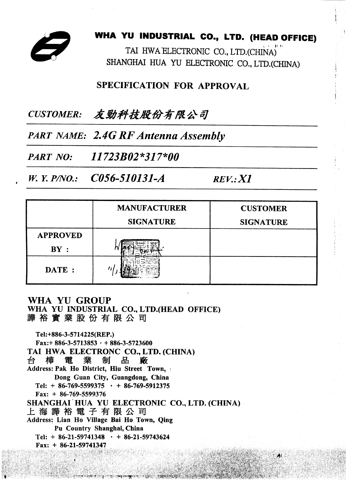
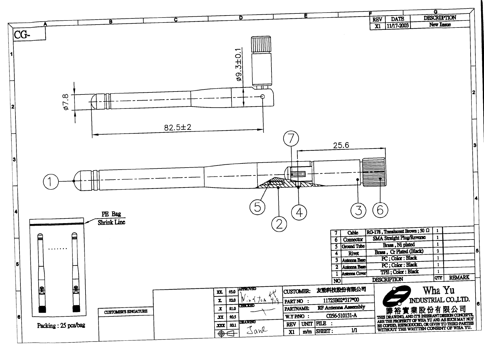
Test Report ------------------------------------------------------------------------------- 1/45
Report No.: C51ET050304 (ETSI EN 301 489)
Training Research Co., Ltd., TEL: 886-2-26935155, Fax: 886-2-26934440
Report No. C51ET050304
Specifications ETSI EN 301 489-1 V1.4.1 (August, 2002)
ETSI EN 301 489-17 V1.2.1 (April, 2002)
Applicant CAMEO COMMUNICATIONS, INC.
Applicant No. 42, Min Chuan East Road, Section 6,
address Taipei 114, Taiwan
Items tested 802.11g Wireless PCI Adapter
Model No. W LG-1202, WNC- 0300, LWS5410P, NWP-0108G,
ALL0281A
EUT Condition Engineering sample; Pre-production; Final production
(Sample # N10415)
Results Compliance (As detailed within this report)
Date 12/01/2004 (month / day / year) (Sample received)
12/14/2004 (month / day / year) (Test)
Prepared by Project Engineer
______________________ (Jack Tsai)
Authorized by General Manager
(Frank Tsai)
Issue date December 16, 2004 (month / day / year)
Modifications None
Tested by Training Research Co., Ltd.
Office at No. 255, Nan Yang Street, Shijr City, Taipei Hsien 221, Taiwan
Laboratory at 1F, No. 255, Nan Yang Street, Shijr City, Taipei Hsien 221, Taiwan
Open site at No. 15, Lane 530, Balian Rd., Sec. 1, Shijr City, Taipei Hsien 221, Taiwan
Conditions of issue:
This test report shall not be reproduced except in full, without written approval of
TRC. And the test result contained within this report only relate to the sample
submitted for testing.
Ϫʳ
Aut. No. ELA 131

Test Report ------------------------------------------------------------------------------- 2/45
Report No.: C51ET050304 (ETSI EN 301 489)
Training Research Co., Ltd., TEL: 886-2-26935155, Fax: 886-2-26934440
Generally Statement:
The results appear in the following order:
Electromagnetic compatibility and radio spectrum matters (ERM); Electro Magnetic
Compatibility (EMC) standard for radio equipment and services;
Part 1: Common Technical requirements
Part 17: Specific conditions for Wideband data and HIPERLAN equipment.
The results exhibits below only apply to particular samples tested and to the specific tests
carried out, as detailed in this Test Report. The issue of this Test Report does not indicate any
measure of Approval, Certification, Supervision, Control or Surveillance by Training Research
Co., Ltd. of any product. No extract, abridgement or abstraction from a Test Report may be
published or used to advertise a product without the written consent of the Director, Training
Research Co., Ltd. who reserves the absolute right to agree or reject all or any of the details of
any item of publicity for which consent may be sought.

Test Report ------------------------------------------------------------------------------- 3/45
Report No.: C51ET050304 (ETSI EN 301 489)
Training Research Co., Ltd., TEL: 886-2-26935155, Fax: 886-2-26934440
Contents
CHAPTER 0 EMISSION AND SUSCEPTIBILITY STANDARDS ........5
EMISSION STANDARDS...............................................................................5
SUSCEPTIBILITY STANDARDS.....................................................................5
CHAPTER 1 INTRODUCTION..............................................................6
DESCRIPTION OF EUT................................................................................6
TEST METHOD ...........................................................................................6
LIST OF SUPPORT EQUIPMENT....................................................................7
CHAPTER 2 EMISSION AND IMMUNITY REQUIREMENTS
OVERVIEW...................................................................10
EMISSION (ETSI EN 301 489-1) ..............................................................10
IMMUNITY (ETSI EN 301 489-1).............................................................11
CHAPTER 3 PERFORMANCE CRITERIA.........................................12
ETSI EN 301 489-17, SUBCLAUSE 6.2 ....................................................12
CHAPTER 4 ELECTROSTATIC DISCHARGES IMMUNITY TEST 18
ESD TEST INFORMATION:........................................................................18
EN 61000-4-2 PHOTO OF TESTSET-UP .............................................20
CHAPTER 5 RADIO FREQUENCY IMMUNITY TEST (RS).............21
RS TEST INFORMATION:...........................................................................21
EN 61000-4-3 PHOTO OF TESTSET-UP .............................................23
CHAPTER 6 ELECTRIC FAST TRANSIENT/
BURST REQUIREMENTS TEST..................................24
EFT TEST INFORMATION: ........................................................................24
EN 61000-4-4 PHOTO OF TESTSET-UP .............................................26
CHAPTER 7 SURGE IMMUNITY TEST.............................................27
SURGE TEST INFORMATION:.....................................................................27
EN 61000-4-5 PHOTO OF TESTSET-UP .............................................29

Test Report ------------------------------------------------------------------------------- 4/45
Report No.: C51ET050304 (ETSI EN 301 489)
Training Research Co., Ltd., TEL: 886-2-26935155, Fax: 886-2-26934440
CHAPTER 8 CONTINUOUS WAVE VOLTAGE IMMUNITY TEST 30
CS TEST INFORMATION:...........................................................................30
TEST INSTRUMENTS: ................................................................................32
EN 61000-4-6 PHOTO OF TESTSET-UP .............................................33
CHAPTER 9 VOLTAGE DIP / INTERRUPTION TEST.....................34
DIP TEST INFORMATION:.........................................................................34
EN 61000-4-11 PHOTO OF TESTSET-UP ...........................................35
CHAPTER 10 HARMONICS TEST........................................................36
CHAPTER 11 VOLTAGE FLUCTUATION AND FLICKER TEST.....37
CHAPTER 12 CONDUCTED EMISSION TEST....................................38
TEST CONDITION AND SETUP ....................................................................38
LIST OF TEST INSTRUMENT ......................................................................39
CONDUCTED TEST PLACEMENT (FRONT VIEW AND SIDE VIEW )...............40
TEST RESULT OF CONDUCTED EMISSIONS FOR MAINS POWER.................41
CHAPTER 13 RADIATED EMISSION TEST........................................42
TEST CONDITION AND SETUP ....................................................................42
LIST OF TEST INSTRUMENT ......................................................................43
RADIATED TEST PLACEMENT (FRONT VIEW AND REAR VIEW ).................44
TEST RESULT OF SPURIOUS RADIATED EMISSIONS FOR 30MHZ TO 1GHZ
[HORIZONTAL].........................................................................................45
TEST RESULT OF SPURIOUS RADIATED EMISSIONS FOR 30MHZ TO 1GHZ
[VERTICAL] .............................................................................................45

Test Report ------------------------------------------------------------------------------- 5/45
Report No.: C51ET050304 (ETSI EN 301 489)
Training Research Co., Ltd., TEL: 886-2-26935155, Fax: 886-2-26934440
Chapter 0 Emission and Susceptibility Standards
Emission Standards
Emission Standard European Standard International Standard
( ) EN 61000-6-3/2001 IEC 61000-6-3/1996
( ) EN 61000-6-4/2001 IEC 61000-6-4/1997
( ) EN 50081-1/1992
( ) EN 50081-1/8.93
( ) EN 55014/4.93 CISPR 14: 1993
( ) EN 55015/12.93 CISPR 15: 1992
( ) EN 55011/91 CISPR 11: 1990
( X ) EN 55022/98 CISPR 22: 1997
( X ) EN 61000-3-2/2000 IEC 61000-3-2: 2000
( X ) EN 61000-3-3/1995
+A1/2001
IEC 61000-3-3: 1994
+A1/2001
Susceptibility Standards
Susceptibility Standard European Standard International Standard
( ) EN 61000-6-1/2001 IEC 61000-6-1/1997
( ) EN 61000-6-2/2001 IEC 61000-6-2/1999
( ) EN 50082-1/1997
( ) EN 50082-2/1994
( ) EN 55024/1998 CISPR 24/1997
( ) EN 55020/2002 CISPR 20/2002
( X ) EN 61000-4-2:1995 IEC 61000-4-2:1995
( X ) EN 61000-4-3:1996 IEC 61000-4-3:1995
( X ) EN 61000-4-4:1995 IEC 61000-4-4:1995
( X ) EN 61000-4-5:1995 IEC 61000-4-5:1995
( X ) EN 61000-4-6:1996 IEC 61000-4-6:1996
( ) EN 61000-4-8:1993 IEC 61000-4-8:1993
( X ) EN 61000-4-11:1994 IEC 61000-4-11:1994
( ) EN 55014-2:1993 CISPR/F (Sec) 159

Test Report ------------------------------------------------------------------------------- 6/45
Report No.: C51ET050304 (ETSI EN 301 489)
Training Research Co., Ltd., TEL: 886-2-26935155, Fax: 886-2-26934440
Chapter 1 Introduction
Description of EUT
Product Name : 802.11g Wireless PCI Adapter
Model Name : W LG-1202, WNC- 0300,
LWS5410P, NWP-0108G,
ALL0281A
Frequency Range : 2.400GHz ~ 2.4835GHz
Operating Frequency : 2.412GHz ~ 2.472GHz
Support Channel : 13 Channels
Modulation Skill : DBPSK, DQPSK, CCK, OFDM
Power Type : Power by PCI of client’ s device
Power Cable : None
Data Cable : None
Test Method
1. Put the EUT into a personal computer’ s PCI bus and fix it.
2. Using the notebook computer and software provided by the manufacturer to control
EUT, the test is performed under the specific conditions.
3. Then making EUT to the following mode.
(a) EMI testing: During test, making EUT to the linking mode with support equipments
(b) EMS testing: same as above

Test Report ------------------------------------------------------------------------------- 7/45
Report No.: C51ET050304 (ETSI EN 301 489)
Training Research Co., Ltd., TEL: 886-2-26935155, Fax: 886-2-26934440
List of Support Equipment
In order to construct the minimum testing, following equipment were used as the support
units.
PC : IBM 6840; HP Pavilion; HP d330 uT
Model No. : 6840MJV; P8574A; d338 uT
Serial No. : 96CC 0C1; TW21920435; SGH41508NP
FCC ID : N/A, DoC
ᛀ : 3892I279; 3902H097, R33001
Power type : 100 ~ 127VAC / 4A, 200 ~ 240VAC/2A, 50 ~ 60Hz, 5A, Switching
Power cord : Non-shielded, 2.33 m length, Plastic hood, No ferrite core
Fax/Modem : Aceex
Model No. : DM-1414
Serial No. : 9010582
FCC ID : IFAXDM1414
Power type : 110 VAC / 50 ~ 60 Hz, Switching
Power Cord : Non-shielded, 1.90m long, Plastic hoods, and no ferrite bead
Data Cable : RS-232ШShielded, 1.30m long, Metal hoods , No bead
RJ-11Cx2ШNon-shielded, 7’ long, Plastic hoods, No bead
Printer : HP
Model No. : C6464A, C2642A
Serial No. : TH16LEB5PK, SG69A196GV
FCC ID : None (DoC Approved), B94C2642X
ᛀ :3892H381, None
Power type : Switching adaptor
Power cord : Non-shielded, 173cm length, No ferrite core
(between adaptor and AC source)
Non-shielded, 180cm length, with ferrite core
(between printer and adaptor)
Data cable : Shielded, 1.70m length, No ferrite core

Test Report ------------------------------------------------------------------------------- 8/45
Report No.: C51ET050304 (ETSI EN 301 489)
Training Research Co., Ltd., TEL: 886-2-26935155, Fax: 886-2-26934440
Monitor : HP 15’ Color Monitor, HP pavilion mx70
Model No. : D2827A, P1283A
Serial No. : KR91379759, TWTBQ00397
FCC ID : C5F7NFCMC1518X
BSMI : 3872B039
Power type : 110 ~ 240 VAC / 50 ~ 60 Hz, Switching
Power cord : Shielded, 1.83m length, No ferrite core
Data cable : Shielded, 1.46m length, with two ferrite cores
USB Gamepad : Rockfire
Model No. : QF-337uv
Serial No. : 10600545, KR91379759
FCC ID : None (CE approval)
BSMI : 3862A574
Power type : By computer
Data Cable : Shielded, 1.81m long, Plastic, with ferrite core
PS/2 Keyboard : HP
Model No. : 5187-0343, SK-2501K
Serial No. : BE21700404, M981216213
FCC ID : DoC Approved, GYUR38SK
BSMI : 3892C981, 3862A621
Power type : By PC
Data cable : Shielded, 1.73m length, Plastic hood, No ferrite core
Mouse : HP
Model No. : M-UR89, M-S34
Serial No. : LZS21750238, LZC84446151
FCC ID : DoC Approved, DZL211029
BSMI : 3892D767, 4862A011
Power type : By PC
Power cord : Shielded, 1.80m length, No ferrite core

Test Report ------------------------------------------------------------------------------- 9/45
Report No.: C51ET050304 (ETSI EN 301 489)
Training Research Co., Ltd., TEL: 886-2-26935155, Fax: 886-2-26934440
Notebook : ASUS
Model No. : M2400E
FCC ID : N/A, DoC Approved
Adaptor : DELTA ELECTRONICS, INC.
Model No. : ADP-65DB REV.B
Serial No. : Q3W0311044403
FCC ID : N/A, CE Approved
BSMI : 3882B596
Power type : I/P: 100 ~ 240vac, 50 ~ 60 Hz, 1.5A ; O/P: 19Vdc, 3.42A
Power cable : Non-shielded, 1.85m length, Plastic hood, No ferrite core
(Between power adaptor and AC power source)
Power cable : Non-Shielded, 1.70m length, with ferrite core
(Between power adaptor and notebook)
WLAN Card : Gemtek Technology Co., Ltd.
Model No. : C911003
FCC ID : MXF-C911003

Test Report ------------------------------------------------------------------------------- 10/45
Report No.: C51ET050304 (ETSI EN 301 489)
Training Research Co., Ltd., TEL: 886-2-26935155, Fax: 886-2-26934440
Chapter 2 Emission and Immunity Requirements Overview
Emission (ETSI EN 301 489-1)
Equipment test requirementPhenomenon Application
Radio and
ancillary
equipment for
fixed use (base
station
equipment)
Radio and
ancillary
equipment for
vehicular use
(mobile
equipment)
Radio and
ancillary
equipment for
portable use
(portable
equipment)
Reference
Subclause in
the present
document
Radiated
emission
Enclosure of
ancillary
equipment
Applicable for
stand alone
testing
Applicable for
stand alone
testing
Applicable for
stand alone
testing
8.2
Conducted
emission
DC power
input/output
port
Applicable Applicable Not applicable 8.3
Conducted
emission
AC mains
input/output
port
Applicable Not applicable Not applicable 8.4
Harmonic
current
emissions
AC mains
input port
Applicable Not applicable Not applicable 8.5
Voltage
fluctuations
and flicker
AC mains
input port
Applicable Not applicable Not applicable 8.6

Test Report ------------------------------------------------------------------------------- 11/45
Report No.: C51ET050304 (ETSI EN 301 489)
Training Research Co., Ltd., TEL: 886-2-26935155, Fax: 886-2-26934440
Immunity (ETSI EN 301 489-1)
Equipment test requirementPhenomenon Application
Radio and
ancillary
equipment for
fixed use (base
station
equipment)
Radio and
ancillary
equipment for
vehicular use
(mobile
equipment)
Radio and
ancillary
equipment for
portable use
(portable
equipment)
Reference
Subclause in
the present
document
RF
electromagnetic
field ( 80MHz to
1GHz)
Enclosure Applicable Applicable Applicable 9.2
Electrostatic
discharge
Enclosure Applicable Applicable Applicable 9.3
Fast transients
common mode
Signal,
telecommunication
and control ports,
DC and AC power
ports
Applicable Not
applicable
Not
applicable
9.4
RF common
mode 0.15 MHz
to 80MHz
Signal,
telecommunication
and control ports,
DC and AC power
ports
Applicable Applicable Not
applicable
9.5
Transients and
surges
DC power input
ports
Not applicable Applicable Not
applicable
9.6
Voltage dips and
interruptions
AC mains power
input ports
Applicable Not
applicable
Not
applicable
9.7
Surges, line to
line and line
ground
AC mains power
input ports,
telecommunication
ports
Applicable Not
applicable
Not
applicable
9.8

Test Report ------------------------------------------------------------------------------- 12/45
Report No.: C51ET050304 (ETSI EN 301 489)
Training Research Co., Ltd., TEL: 886-2-26935155, Fax: 886-2-26934440
Chapter 3 Performance Criteria
ETSI EN 301 489-17, Subclause 6.2
Table 1 Performance criteria
Criteria During test After test
AShall operate as intended
May show degradation of
performance (NOTE 1)
Shall be no loss of function
Shall be no unintentional
transmissions
Shall operate as intended
Shall be no degradation of performance
(NOTE 2)
Shall be no loss of function
Shall be no lo ss of stored data or user
programmable functions
BMay show loss of function (one or
more)
May show degradation of
performance (NOTE 1)
No unintentional transmissions
Function shall be self-recoverable
Shall operate as intended after recovering
Shall be no degradation of performance
(NOTE 2)
Shall be no loss of stored data or user
programmable functions
CMay be loss of function (one or
more)
Functions shall be recoverable by the
operator
Shall operate as intended after recovering
Shall be no degradation of performance
(NOTE 2)

Test Report ------------------------------------------------------------------------------- 13/45
Report No.: C51ET050304 (ETSI EN 301 489)
Training Research Co., Ltd., TEL: 886-2-26935155, Fax: 886-2-26934440
NOTE 1:
Degradation of performance during the test is understood as a degradation to a level not
below a minimum performance level specified by the manufacturer for the use of the apparatus
as intended. In some cases the specified minimum performance level may be replaced by a
permissible degradation of performance.
If the minimum performance level or the permissible performance degradation in not
specified by the manufacturer then either of these may be derived from the product description
and documentation (including leaflets and advertising) and what the user may reasonably expect
form the apparatus if used as intended.
NOTE 2:
No degradation of performance after the test is understood as no degradation below a
minimum performance level specified by the manufacturer for the use of the apparatus as
intended. In some cases the specified minimum performance level may be replaced by a
permissible degradation of performance. After the test no change of actual operating data or user
retrievable data is allowed.
If the minimum performance level or the permissible performance degradation in not
specified by the manufacturer then either of these may be derived from the product description
and documentation (including leaflets and advertising) and what the user may reasonably expect
form the apparatus if used as intended.

Test Report ------------------------------------------------------------------------------- 14/45
Report No.: C51ET050304 (ETSI EN 301 489)
Training Research Co., Ltd., TEL: 886-2-26935155, Fax: 886-2-26934440
ETSI EN 301 489-1
Performance criteria for Continuous phenomena applied Transmitters (CT)
If no further details are given in the relevant part of the present document dealing with the
particular type of radio equipment, the following general performance criteria for continuous
phenomena shall apply.
During and after the test:
The apparatus shall continue to operate as intended. No degradation of performance or loss
of function is allowed below a permissible performance level specified by the manufacturer
when the apparatus is used as intends. In some cases this permissible performance level may
be replaced by a permissible loss of performance.
During the test:
The EUT shall not unintentionally transmit or change its actual operating state and stored
data. If the minimum performance level or the permissible loss is not specified by the
manufacturer, then either of these may be deduced from the product description and
documentation and what the user may reasonably expect form the apparatus if used as
intended.
For ancillary equipment the pass/failure criteria supplied by the manufacturer (see subclause
6.4) shall apply, unless the ancillary equipment is tested in connection with a receiver or
transmitter in which case the corresponding performance criteria above shall apply.
Performance criteria for Transient phenomena applied Transmitters (TT)
If no further details are given in the relevant part of the present document dealing with the
particular type of radio equipment, the following general performance criteria for transient
phenomena shall apply.
After the test:
The apparatus shall continue to operate as intended. No degradation of performance or loss
of function is allowed below a permissible performance level specified by the manufacturer
when the apparatus is used as intends. In some cases this permissible performance level may
be replaced by a permissible loss of performance.
During the test:
The EMC exposure to an electromagnetic phenomenon, a degradation of performance is,
however, allowed. No change of the actual mode of operation (e.g. unintended transmission)
or stored data is allowed.

Test Report ------------------------------------------------------------------------------- 15/45
Report No.: C51ET050304 (ETSI EN 301 489)
Training Research Co., Ltd., TEL: 886-2-26935155, Fax: 886-2-26934440
If the minimum performance level or the permissible loss is not specified by the
manufacturer, Then either of these may be deduced from the product description and
documentation and what the user may reasonably expect form the apparatus if used as
intended.
For ancillary equipment the pass/failure criteria supplied by the manufacturer (see subclause
6.4) shall apply, unless the ancillary equipment is tested in connection with a receiver or
transmitter in which case the corresponding performance criteria above shall apply.
Performance criteria for Continuous phenomena applied Receivers (CR)
If no further details are given in the relevant part of the present document dealing with the
particular type of radio equipment, the following general performance criteria for continuous
phenomena shall apply.
During and after the test:
The apparatus shall continue to operate as intended. No degradation of performance or loss
of function is allowed below a permissible performance level specified by the manufacturer
when the apparatus is used as intends. In some cases this permissible performance level may
be replaced by a permissible loss of performance.
During the test:
The EUT shall not unintentionally transmit or change its actual operating state and stored
data. If the minimum performance level or the permissible loss is not specified by the
manufacturer, then either of these may be deduced from the product description and
documentation and what the user may reasonably expect form the apparatus if used as
intended.
For ancillary equipment the pass/failure criteria supplied by the manufacturer (see subclause
6.4) shall apply, unless the ancillary equipment is tested in connection with a receiver or
transmitter in which case the corresponding performance criteria above shall apply.

Test Report ------------------------------------------------------------------------------- 16/45
Report No.: C51ET050304 (ETSI EN 301 489)
Training Research Co., Ltd., TEL: 886-2-26935155, Fax: 886-2-26934440
Performance criteria for Transient phenomena applied Receivers (TR)
If no further details are given in the relevant part of the present document dealing with the
particular type of radio equipment, the following general performance criteria for transient
phenomena shall apply.
After the test:
The apparatus shall continue to operate as intended. No degradation of performance or loss
of function is allowed below a permissible performance level specified by the manufacturer
when the apparatus is used as intends. In some cases this permissible performance level may
be replaced by a permissible loss of performance.
During the test:
The EMC exposure to an electromagnetic phenomenon, a degradation of performance is,
however, allowed. No change of the actual mode of operation (e.g. unintended transmission)
or stored data is allowed.
If the minimum performance level or the permissible loss is not specified by the
manufacturer, then either of these may be deduced from the product description and
documentation and what the user may reasonably expect form the apparatus if used as
intended.
For ancillary equipment the pass/failure criteria supplied by the manufacturer (see subclause
6.4) shall apply, unless the ancillary equipment is tested in connection with a receiver or
transmitter in which case the corresponding performance criteria above shall apply.

Test Report ------------------------------------------------------------------------------- 17/45
Report No.: C51ET050304 (ETSI EN 301 489)
Training Research Co., Ltd., TEL: 886-2-26935155, Fax: 886-2-26934440
ETSI EN 301 489-17
Performance criteria for Continuous phenomena applied Transmitters (CT)
The performance criteria A shall apply.
Tests shall be repeated with the EUT in standby mode (if applicable) to ensure that
unintentional transmission does not occur. In systems using acknowledgement signals, it is
recognized that an ACKnowledgement (ACK) or Not ACKnowledgement (NACK) transmission
may occur, and steps should be taken to ensure that any transmission resulting from the
application of the test is correctly interpreted.
Performance criteria for Transient phenomena applied Transmitters (TT)
The performance criteria B shall apply, except for voltage dips of 100ms and voltage
interruptions of 5000 ms duration, for which performance criteria C shall apply.
Tests shall be repeated with the EUT in standby mode (if applicable) to ensure that unintentional
transmission does not occur. In system using acknowledgement signals, it is recognized that an
acknowledgement (ACK) or not-acknowledgement (NACK) transmission may occur, and steps
should be taken to ensure that any transmission resulting from the application of the test is
correctly interpreted.
Performance criteria for Continuous phenomena applied Receivers (CR)
The performance criteria A shall apply.
Where the EUT is a transceiver, under no circumstances, shall the transmitter operate
unintentionally during the test. In systems using acknowledgement signals, it is recognized that
an ACK or NACK transmission may occur, and steps should be taken to ensure that any
transmission resulting from the application of test is correctly interpreted.
Performance criteria for Transient phenomena applied Receivers (TR)
The performance criteria B shall apply, except for voltage dips of 100ms and voltage
interruptions of 5000 ms duration, for which performance criteria C shall apply.
Where the EUT is a transceiver, under no circumstances, shall the transmitter operate
unintentionally during the test. In systems using acknowledgement signals, it is recognized that
an ACK or NACK transmission may occur, and steps should be taken to ensure that any
transmission resulting from the application of test is correctly interpreted.
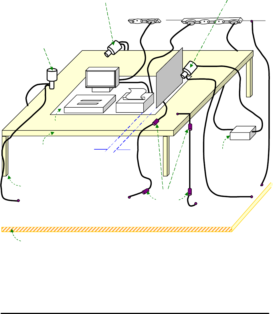
Test Report ------------------------------------------------------------------------------- 18/45
Report No.: C51ET050304 (ETSI EN 301 489)
Training Research Co., Ltd., TEL: 886-2-26935155, Fax: 886-2-26934440
Chapter 4 Electrostatic Discharges Immunity Test
ESD Test information:
Test setup: Shielded room, According to EN 61000-4-2
Test setup for table-top equipment at laboratory tests:
0.1 m
Ground Reference Plane
Wooden table H=0.8m
470kohm
Resistor
Insulation
Power Supply
VP
C
0.5m X 0.5m
H
orizontal coupling place
1.6m X 0.8m
Typical position for
indirect discharge to VCP
Typical position for
indirect discharge
Typical position for
indirect discharge to HCP

Test Report ------------------------------------------------------------------------------- 19/45
Report No.: C51ET050304 (ETSI EN 301 489)
Training Research Co., Ltd., TEL: 886-2-26935155, Fax: 886-2-26934440
Test levels: (Apply Level 2 and Level 3)
1a — Contact discharge 1b — Air discharge
Level Test voltage
(kV)
Level Test voltage
(kV)
12 12
2424
36 3 8
48 415
X Special X Special
NOTE: “X” is an open level. The level has to be specified in the dedicated equipment specification. If
higher voltages than those shown are specified, special test equipment may be needed.
Test Voltage: ( X ) 4KV contact discharge ( X ) 8KV air discharge
Indirect Discharges: ( X ) HCP ( X ) VCP
Polarity: ( X ) Positive ( X ) Negative
Test mode: Refer to Test method of Chapter 1
Test points: Chassis of EUT.
Test instruments:
Name Model Number Serial Number Selected
Best Plus BURST ESD
SURGE TRANSIENTS
Best Plus V6.2 199749-019SC
BEST EMC Test
Instrument
BEST EMC V2.3
(-8, -9)
199918-006SC
KeyTek Instrument
ESD Test system
Series 2000 9204303/9204310
9209226/9301395
X
NoiseKen Electrostatic
Discharge Simulator
ESS-100L(A) 2100C03605
NoiseKen Electrostatic
Discharge Gun
TC-815P 2100C03566
Comment:
Performance Criteria: (According to ETSI EN 301 489-1)
( X ) Enclosure ( )CT ( X )TT ( ) CR ( X )TR
( ) Signal and control ports ( )CT ( )TT ( ) CR ( )TR
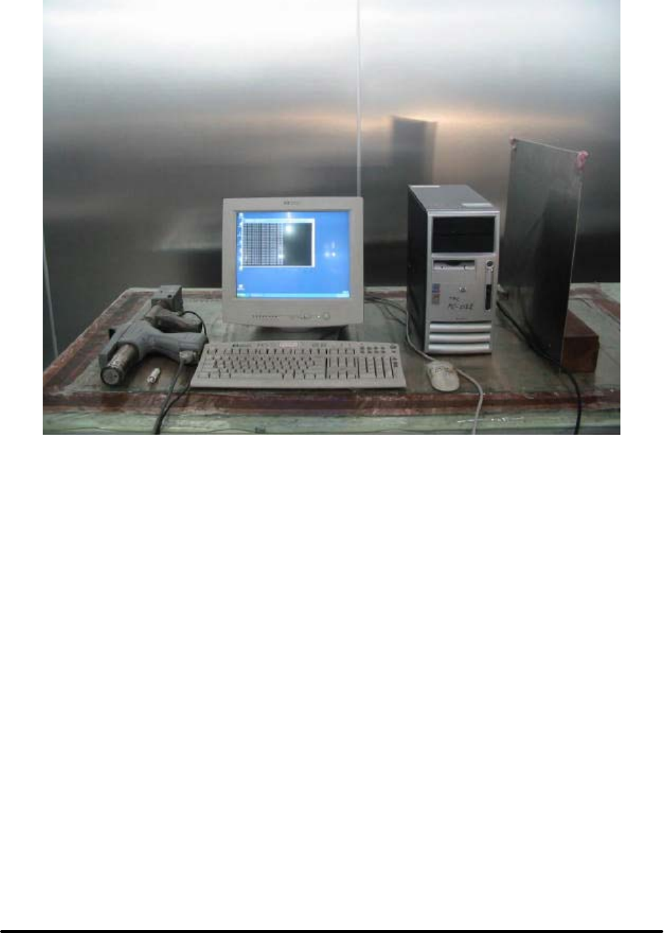
Test Report ------------------------------------------------------------------------------- 20/45
Report No.: C51ET050304 (ETSI EN 301 489)
Training Research Co., Ltd., TEL: 886-2-26935155, Fax: 886-2-26934440
EN 61000-4-2 PHOTO OF TEST SET-UP
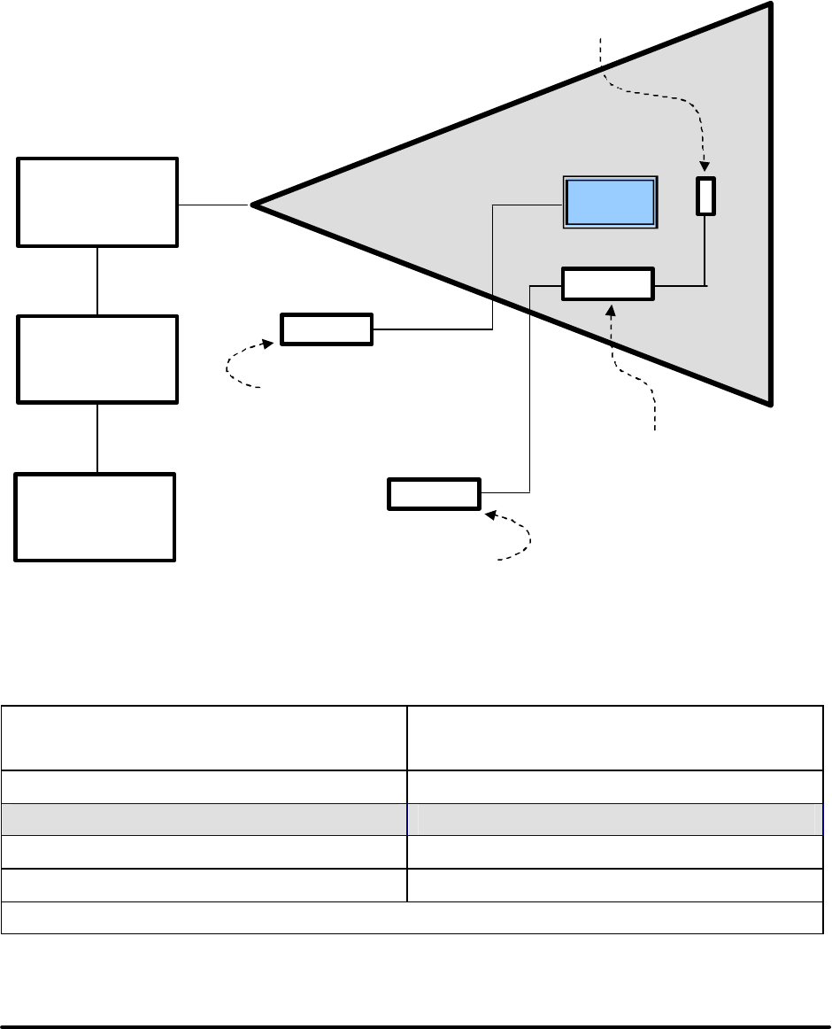
Test Report ------------------------------------------------------------------------------- 21/45
Report No.: C51ET050304 (ETSI EN 301 489)
Training Research Co., Ltd., TEL: 886-2-26935155, Fax: 886-2-26934440
Chapter 5 Radio Frequency Immunity Test (RS)
RS Test information:
Test setup: GTEM cell
Radiated Immunity Test Setup
Test levels: (Apply Level 2)
Level Test Field Strength
(V/m)
11
2 3
310
X Special
NOTE: the “X” is an open test level. This level may be given in the product specification.
High Power
Amplifier
Signal
Generator
Modulation
Generator
EU
T
GTEMI Cell
EUT Performance
Monitor
Model 7110 Data
Processing / Interface Unit
Model 7122 Co mpanion
Metering Unit
Model 7122
Isotropic Probe

Test Report ------------------------------------------------------------------------------- 22/45
Report No.: C51ET050304 (ETSI EN 301 489)
Training Research Co., Ltd., TEL: 886-2-26935155, Fax: 886-2-26934440
Field strength: ( X ) 3V/m at 80 ~ 1000 MHz
( X ) 3V/m at 1400 ~ 2000 MHz
Modulation: ( ) FM %
( X ) 80% AM Modulation with 1KHz
( ) 80% AM Modulation with 400Hz when signal is modulated at 1kHz
( ) 900 KHz²5 KHz with PM 200 Hz and 100% depth
Step size: ( X ) 1% step size
Sweep time: ( X ) 2.5 Second
Test mode: Ref. Test method of Chapter 1
Test instruments:
Name Model Number Serial Number Selected
EMCO GTEM 5317 9411-1123 X
EMCO Probe 7122 9406-1194 X
EMCO METERING UNIT 7122 9406-1194 X
EMCO data interface 7110 9410-1273 X
HP Personal Computer D3178A 3438S00486 X
HP Signal Generator 8657B 2928U00286 X
HP Signal Generator 83711A 3429A00434 X
IFI Wideband Amplifier SMX50 467-0795 X
Min-circuit Amplifier GFL-2500VH N/A X
WG radiation meters EMC-20 BN2244129 X
WG E-filed 2244 / 90.20 Z-0001 X
HP Transmission Test Set 4935A 3115A24046 X
B & K Precision Sound Level Meter Type 2232 1810564 X
Comment:
Performance Criteria: (According to ETSI EN 301 489-1)
( X ) Enclosure ( X )CT ( )TT ( X ) CR ( )TR
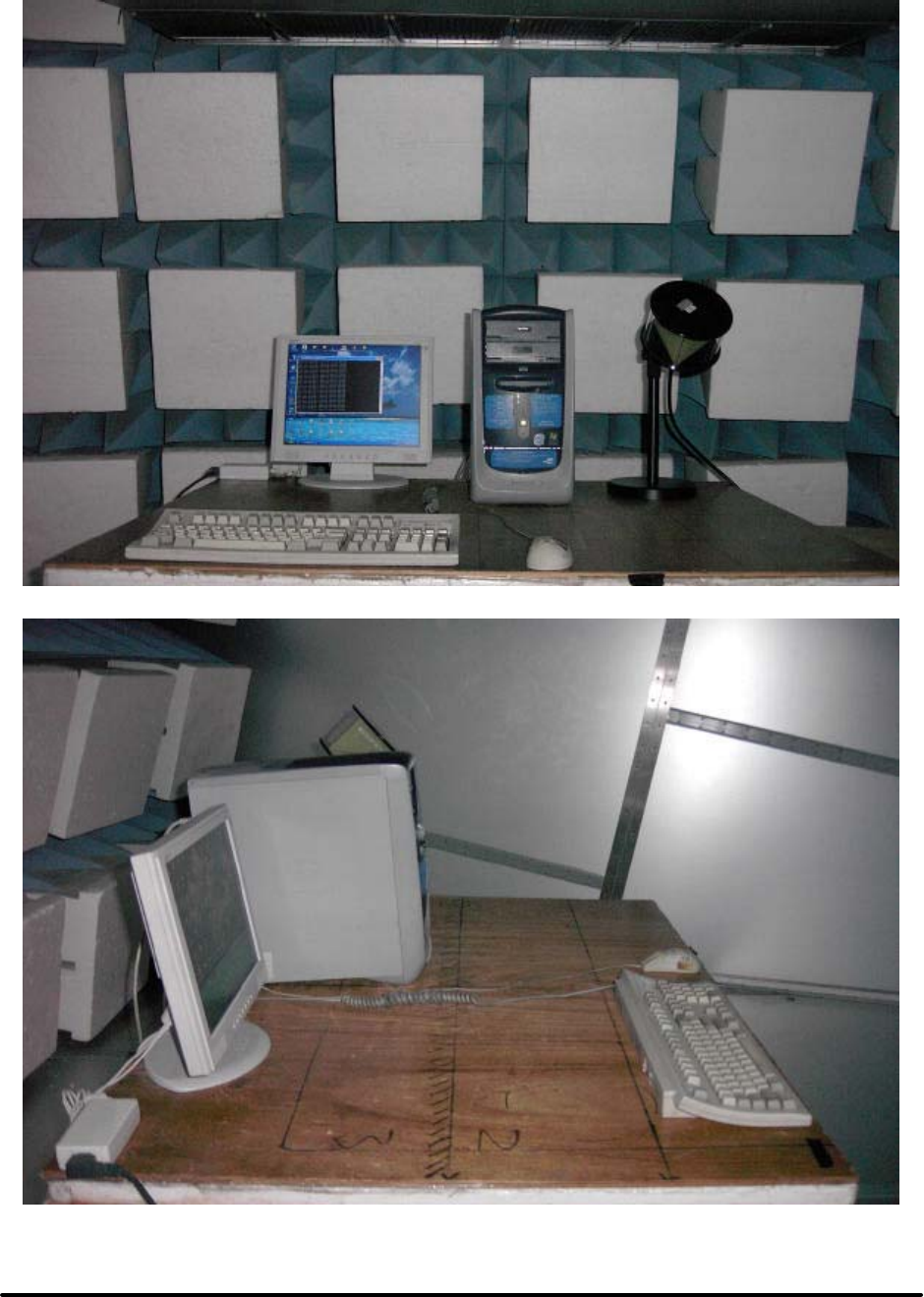
Test Report ------------------------------------------------------------------------------- 23/45
Report No.: C51ET050304 (ETSI EN 301 489)
Training Research Co., Ltd., TEL: 886-2-26935155, Fax: 886-2-26934440
EN 61000-4-3 PHOTO OF TEST SET-UP
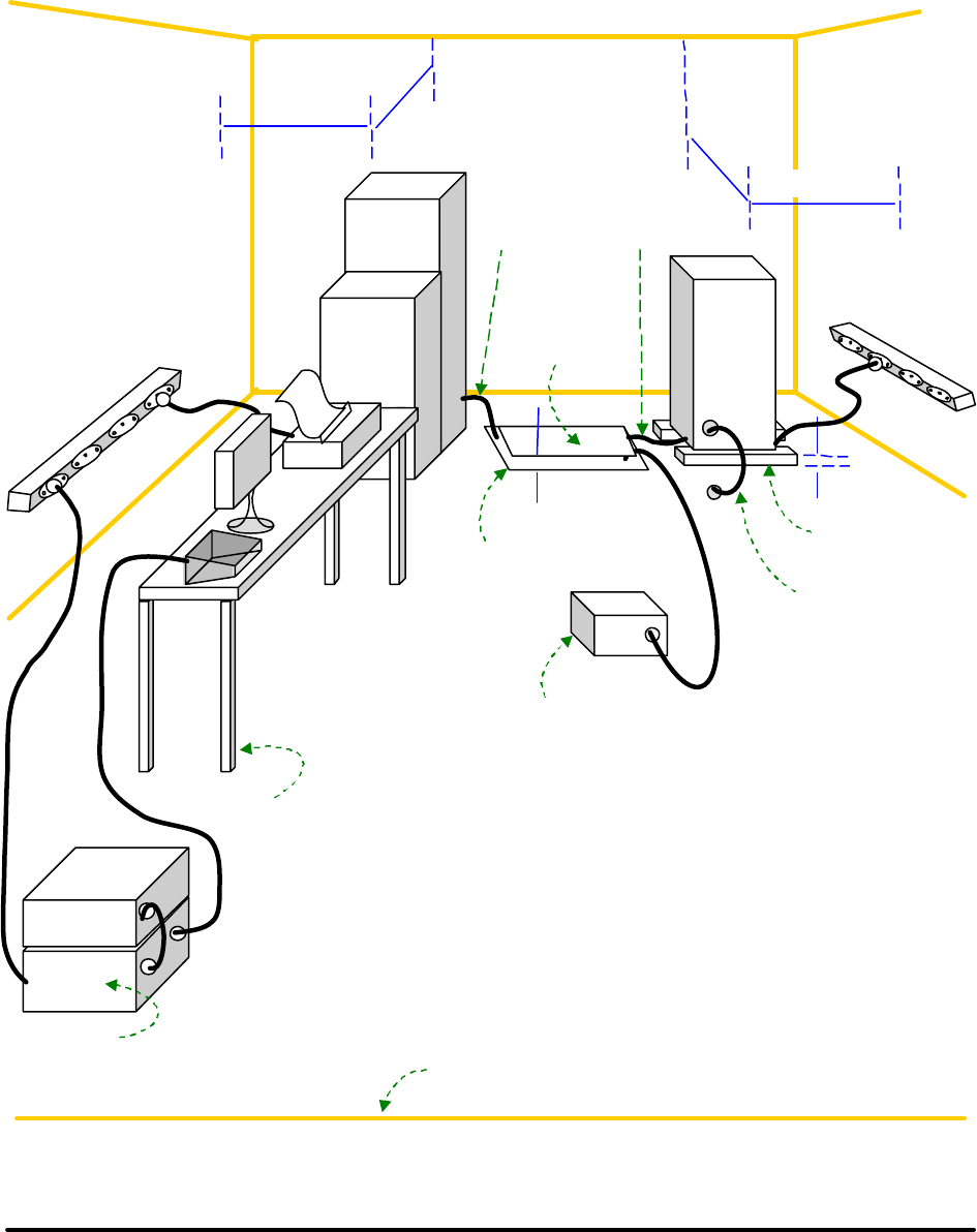
Test Report ------------------------------------------------------------------------------- 24/45
Report No.: C51ET050304 (ETSI EN 301 489)
Training Research Co., Ltd., TEL: 886-2-26935155, Fax: 886-2-26934440
Chapter 6 Electric Fast Transient/Burst Requirements Test
EFT Test information:
General test set-up for laboratory type tests:
> 0.25 m
> 0.25 m
EUT
EUT
AC mains
supply
EUT
EFT/B-
generator
Coupling / decoupling
network (A)
Non-metallic
table
EUT
0.1 m
R
eference
plane
E
FT/B-
generator (B)
0.1 m
AC mains
supply
Capacitive
coupling clamp
Grounding connection
according to the
manufacturer’ s
specification.
Length to be specified
in the test plan.
I
nsulating
support
R
eference
plane
(L)
(L) = length between clamp and EUT to be tested, should
not be more than 1-meter
(A) = location for supply line coupling
(
B
)
= location for si
g
nal lines cou
p
lin
g
(L)
> 0.25 m
> 0.25 m

Test Report ------------------------------------------------------------------------------- 25/45
Report No.: C51ET050304 (ETSI EN 301 489)
Training Research Co., Ltd., TEL: 886-2-26935155, Fax: 886-2-26934440
Test levels: (Apply Level 2)
Open-circuit output test voltage (±10%) and repetition rate of the impulses (±20%)
On power supply port, PE On input/output signal, data and
control ports
Level Voltage peak
kV
Repetition rate
kHz
Voltage peak
kV
Repetition rate
kHz
1 0.5 5 0.25 5
2 1 5 0.5 5
32 5 1 5
4 4 2.5 2 5
X Special Special Special Special
NOTE: the “X” is an open level. The level has to be specified in the dedicated equipment specification
Test setup: According to EN 61000-4-4
Test Voltage: DC Power line ( ) 0.5 KV, 5 KH
AC Power line ( X ) 1 KV, 5 KHz
Signal & Control line ( ) 0.5 KV, 5 KHz; ( ) 1 KV, 5 KHz
Polarity: ( X ) Positive ( X ) Negative
Test Duration: ( X ) 1 minute ( ) 3 minutes
Connected lines: ( ) Power line shielded ( X ) Power line non-shielded
( ) Signal & Control line non-shielded
( ) Signal & Control line shielded
Test mode: Ref. Test method of Chapter 1.
Test instrument:
Name Model Number Serial Number Selected
Best Plus BURST ESD
SURGE TRANSIENTS
Best Plus V6.2 199749-019SC
BEST EMC Test
Instrument
BEST EMC V2.3
(-8, -9)
199918-006SC
KeyTek Instrument
EFT Test system
E412 9505206/505207 X
Comment:
Performance Criteria: (According to ETSI EN 301 489-1)
( ) Signal and control ports ( )CT ( )TT ( ) CR ( )TR
( ) DC power input ports ( )CT ( )TT ( ) CR ( )TR
( X ) AC mains input ports ( )CT ( X )TT ( ) CR ( X )TR
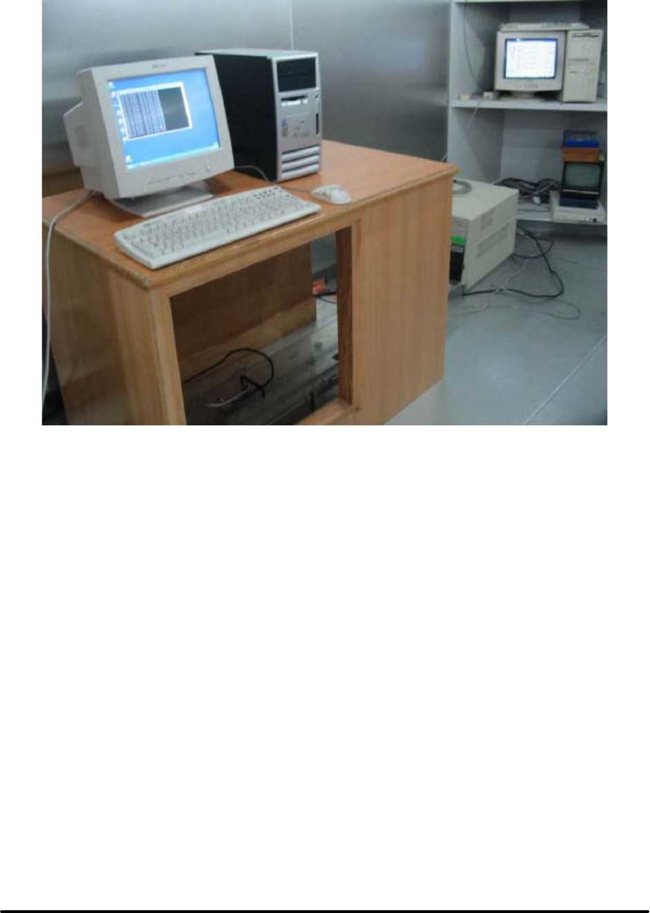
Test Report ------------------------------------------------------------------------------- 26/45
Report No.: C51ET050304 (ETSI EN 301 489)
Training Research Co., Ltd., TEL: 886-2-26935155, Fax: 886-2-26934440
EN 61000-4-4 PHOTO OF TEST SET-UP

Test Report ------------------------------------------------------------------------------- 27/45
Report No.: C51ET050304 (ETSI EN 301 489)
Training Research Co., Ltd., TEL: 886-2-26935155, Fax: 886-2-26934440
Chapter 7 Surge Immunity Test
Surge Test information:
Test setup: According to EN 61000-4-5
Test levels: (Apply Level 2 and Level 3)
Level Test Field Strength
(kV)
1 0.5
2 1.0
3 2.0
4 4.0
X Special
NOTE: the “X” is an open class. This level may be specified in the product specification.
Test Voltage: DC Power line ( ) 0.5 KV
AC Power line ( ) Line – Line: 1KV
( ) Line – Ground: 2KV
( X ) Line – Line: 0.5KV
( X ) Line – Ground: 1KV
Control line ( ) 0.5 KV
Signal ( ) 1 KV, ( ) 0.5KV
Time: ( X ) 1.2/50µs [8/20µs]
Polarity: ( X ) Positive ( X ) Negative
Connected lines: ( ) Power line shielded
( X ) Power line non-shielded
( ) Signal & Control line non-shie lded
( ) Signal & Control line shielded
Test mode: Ref. Test method of Chapter 1.

Test Report ------------------------------------------------------------------------------- 28/45
Report No.: C51ET050304 (ETSI EN 301 489)
Training Research Co., Ltd., TEL: 886-2-26935155, Fax: 886-2-26934440
Test instrument:
Name Model Number Serial Number Selected
Best Plus BURST ESD
SURGE TRANSIENTS
Best Plus V6.2 199749-019SC
BEST EMC Test
Instrument
BEST EMC V2.3
(-8, -9)
199918-006SC
KeyTek Pulsed-EMI
Test System
E103, 501B, E502B,
E503, E505A,
E4552A
0008260 ~0008264,
0008254
X
Comment:
Performance Criteria: (According to ETSI EN 301 489-1)
( X ) AC mains input ports ( )CT ( X )TT ( ) CR ( X )TR
( ) Signal and control ports ( )CT ( )TT ( ) CR ( )TR
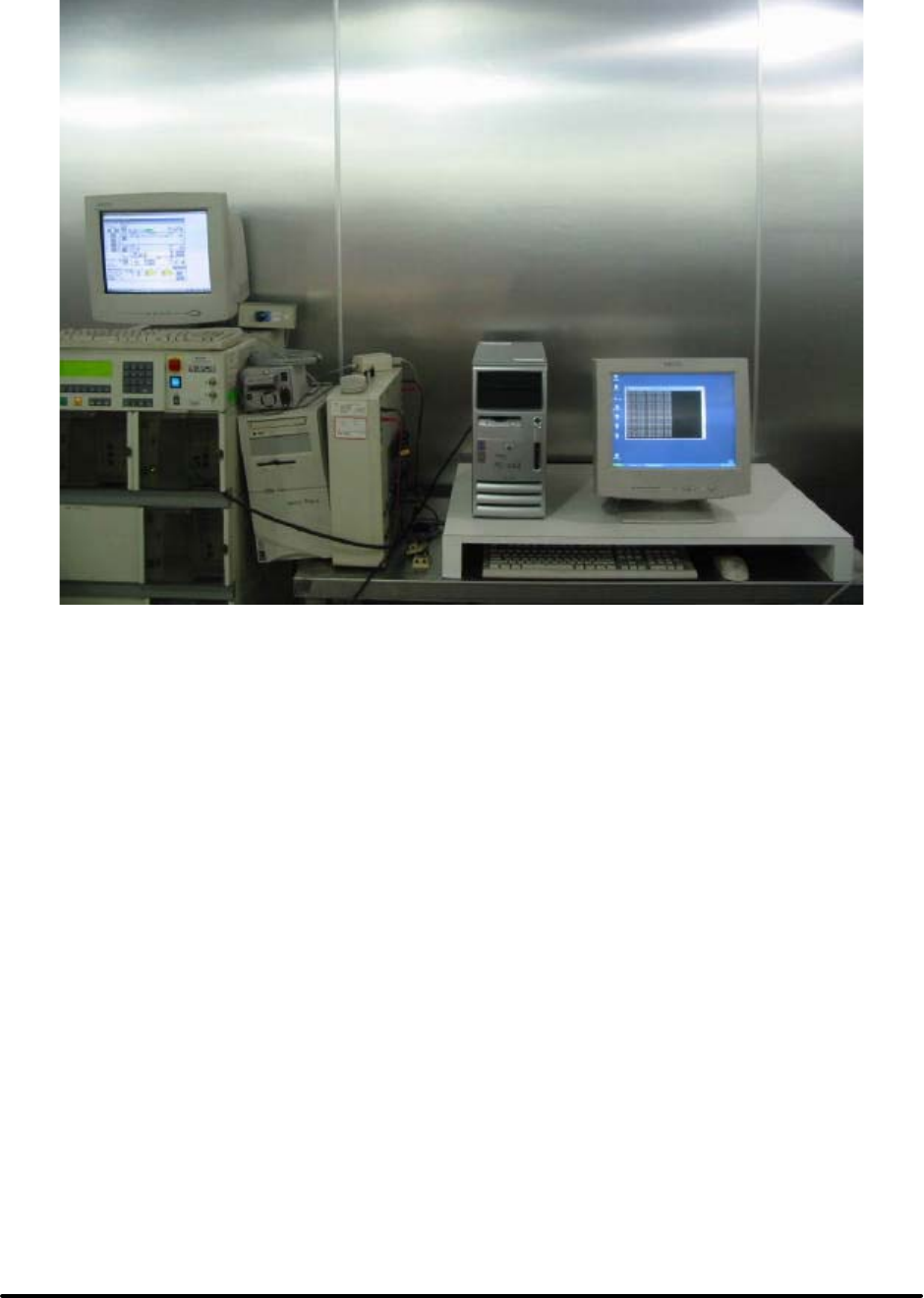
Test Report ------------------------------------------------------------------------------- 29/45
Report No.: C51ET050304 (ETSI EN 301 489)
Training Research Co., Ltd., TEL: 886-2-26935155, Fax: 886-2-26934440
EN 61000-4-5 PHOTO OF TEST SET-UP
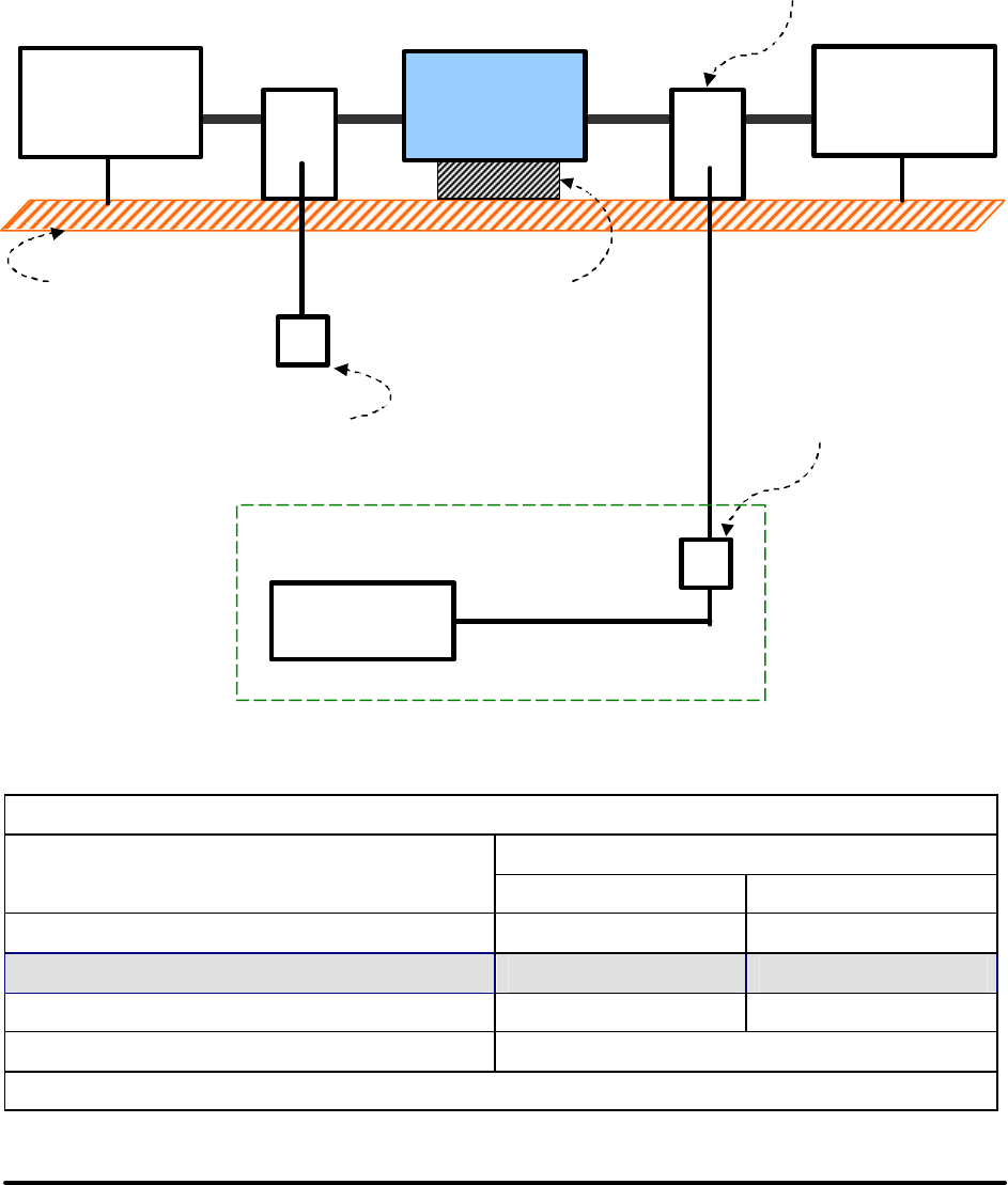
Test Report ------------------------------------------------------------------------------- 30/45
Report No.: C51ET050304 (ETSI EN 301 489)
Training Research Co., Ltd., TEL: 886-2-26935155, Fax: 886-2-26934440
Chapter 8 Continuous Wave Voltage Immunity Test
CS Test information:
Test setup: According to EN 61000-4-6
Immunity test to RF conducted disturbances:
Test levels: (Apply Level 2)
Frequency range 150kHz to 80MHz
Voltage level (e.m.f.)
Level Uo [dB(µv)] Uo [V]
1 120 1
2 130 3
3 140 10
X Special
NOTE: the “X” is an open test level.
CDN
Auxiliary
equipment 1
Equipment
under test CDN
Auxiliary
equipment 1
T
Ground reference plane
0.1 m
support
RF — generator
T2
Test generator
T: Termination 50ohm
T
2
:
Power attenuato
r
(6dB)
CDN: Coupling and
decoupling network

Test Report ------------------------------------------------------------------------------- 31/45
Report No.: C51ET050304 (ETSI EN 301 489)
Training Research Co., Ltd., TEL: 886-2-26935155, Fax: 886-2-26934440
Test Frequency: ( X ) 0.15 ~ 80MHz
Modulation: ( ) FM %
( X ) 80% AM Modulation with 1kHz
( ) 80% AM Modulation with 400Hz when signal is modulated at 1kHz
( ) 900 MHz²5 MHz with PM 200 Hz and 50% duty cycle
Step size: ( ) Performed over the frequency range 150kHz to 80MHz with the
exception of an exclusion band for transmitters, and for receivers and
duplex transceivers
( X ) For receivers and transmitters the stepped frequency increments shall
be 1% frequency increment of the momentary frequency in the
frequency range 150kHz to 80MHz, unless specified otherwise in the
part of EN 301 489 dealing with the particular type of radio equipment
Field strength: ( ) 1Vrms ( X ) 3Vrms ( ) 10Vrms
Connected lines: ( ) Power line shielded
( X ) Power line non-shielded
( ) Signal & Control line non-shielded
( ) Signal & Control line shielded
Test mode: Ref. Test method of Chapter 1

Test Report ------------------------------------------------------------------------------- 32/45
Report No.: C51ET050304 (ETSI EN 301 489)
Training Research Co., Ltd., TEL: 886-2-26935155, Fax: 886-2-26934440
Test instruments:
Name Model Number Serial Number Selected
FRANKONIA EMV–Mess–
System
CIT-10 103A3113 X
FRANKONIA CDN M2+M3 A3011015 X
FRANKONIA CDN T2-801 A3010002
FRANKONIA CDN T4-801 A3015004
FRANKONIA CDN S1-801 A3005002
SCHAFFNER FM-Koppelzange KEMZ 801 17045
SCHAFFNER RF-SYNTHE
SIZERIAMP21FIER
NSG 2070-1 1020
SCHAFFNER CDN M325 13773
SCHAFFNER CDN M216 15604
SCHAFFNER CDN T004 15230
SCHAFFNER CDN S501 15167
SCHAFFNER FM-Koppelzange KEMZ 801 14301
HP Transmission Test Set 4935A 3115A24046
B & K Precision Sound Level Meter Type 2232 1810564
Comment:
Performance Criteria: (According to ETSI EN 301 489-1)
( ) Antenna port ( )CT ( )TT ( ) CR ( )TR
( ) Signal and control ports ( )CT ( )TT ( ) CR ( )TR
( ) DC power input ports ( )CT ( )TT ( ) CR ( )TR
( X ) AC mains input ports ( X )CT ( )TT ( X ) CR ( )TR
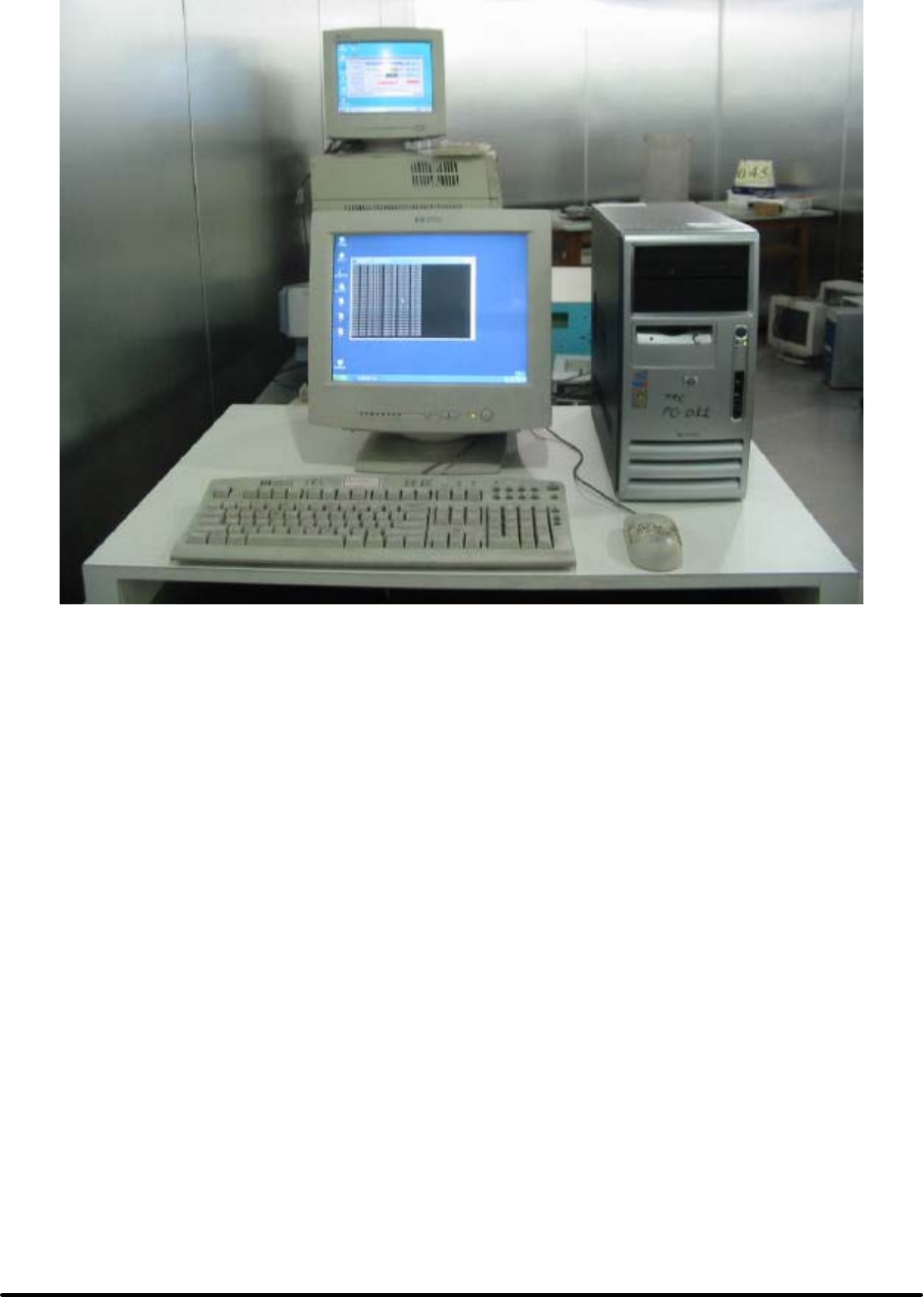
Test Report ------------------------------------------------------------------------------- 33/45
Report No.: C51ET050304 (ETSI EN 301 489)
Training Research Co., Ltd., TEL: 886-2-26935155, Fax: 886-2-26934440
EN 61000-4-6 PHOTO OF TEST SET-UP

Test Report ------------------------------------------------------------------------------- 34/45
Report No.: C51ET050304 (ETSI EN 301 489)
Training Research Co., Ltd., TEL: 886-2-26935155, Fax: 886-2-26934440
Chapter 9 Voltage DIP / Interruption Test
DIP Test information:
Test setup: According to EN 61000-4-11
Voltage dips : ( X ) 30%, 0.01 Second
( X ) 60%, 0.1 Second
Voltage interruptions: ( X ) > 95%, 5 Seconds
Test mode: Ref. Test method of Chapter 1
Test instruments:
Name Model Number Serial Number Selected
Best Plus BURST ESD
SURGE TRANSIENTS
Best Plus V6.2 199749-019SC
BEST EMC Test
Instrument
BEST EMC V2.3
(-8, -9)
199918-006SC
Partner EMS Tester Transienter-1000 PIO X
Comment:
Performance Criteria: (According to ETSI EN 301 489-1)
Dips 30%: ( X ) CT ( ) TT ( X ) CR ( ) TR
Dips 60%: ( ) CT ( ) TT ( ) CR ( ) TR
Interruptions >95%: ( ) CT ( ) TT ( ) CR ( ) TR
No unintentional responses shall occur at the end of the test;
( )Event of loss of function(s) ( )Event of loss of user stored data
Performance Criteria: (According to ETSI EN 301 489-17)
Dips 60%, 100 ms : ( ) A ( ) B ( X ) C
Interruptions >95%, 5 000 ms: ( ) A ( ) B ( X ) C
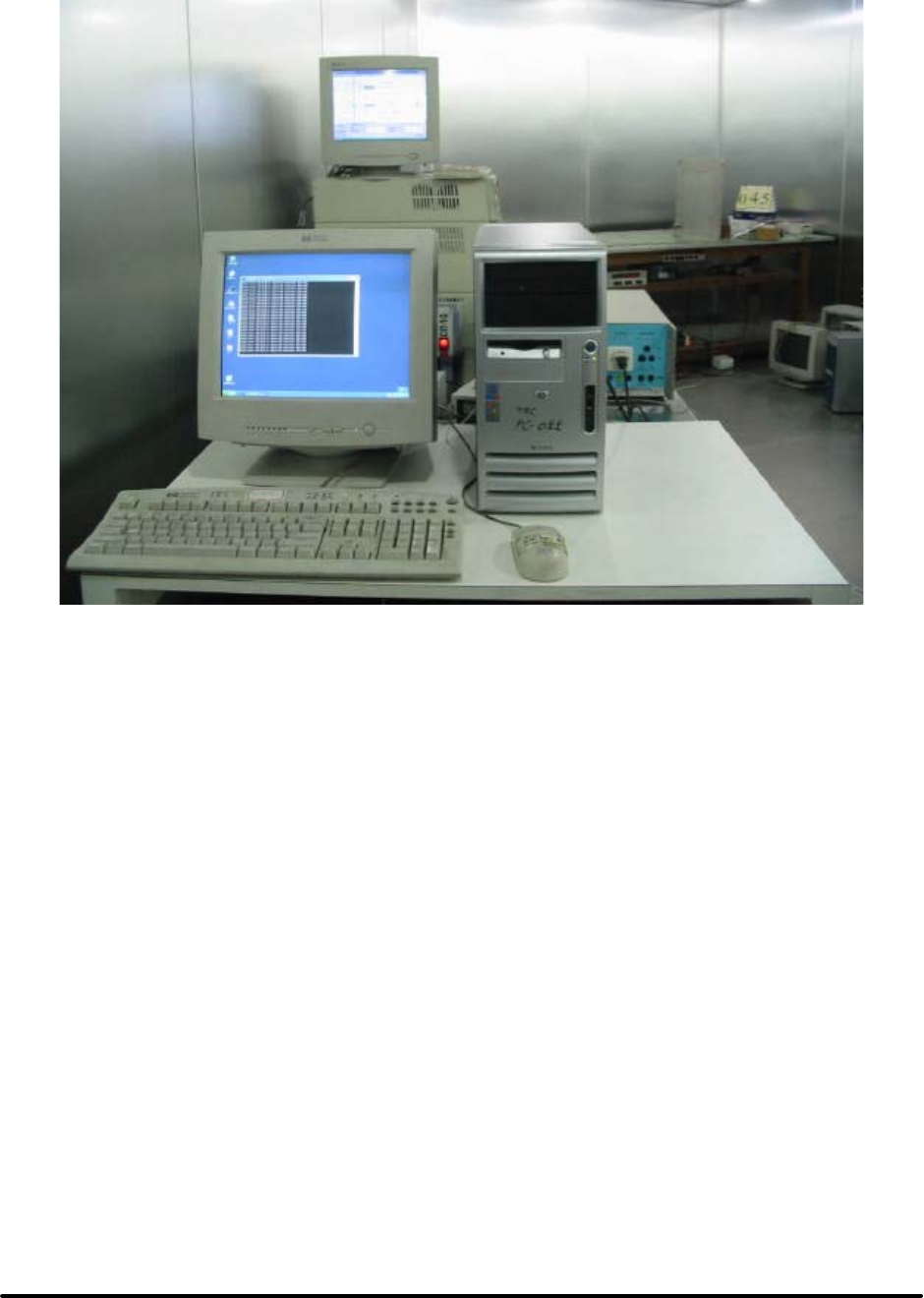
Test Report ------------------------------------------------------------------------------- 35/45
Report No.: C51ET050304 (ETSI EN 301 489)
Training Research Co., Ltd., TEL: 886-2-26935155, Fax: 886-2-26934440
EN 61000-4-11 PHOTO OF TEST SET-UP

Test Report ------------------------------------------------------------------------------- 36/45
Report No.: C51ET050304 (ETSI EN 301 489)
Training Research Co., Ltd., TEL: 886-2-26935155, Fax: 886-2-26934440
Chapter 10 Harmonics Test
Test information:
Test setup: According to EN 61000-3-2
Test item: Quasi – stationary & Fluctuating Current Harmonics Test.
Test mode: Ref. Test method of Chapter 1
Test instrument:
Name Model Number Serial Number Selected
Harmonic/Flicker Test
System
HP 6842A 3531A-00102 X
Test Equipment Settings: Quasi-stationary Current
Harmonics Test
Fluctuating Current
Harmonics Test
Line Voltage 230VAC 230VAC
Line Frequency 50Hz 50Hz
Device Class D D
Test Limit Overrides None None
Total Number of Failures: None None
Total Number of Errors: None None
Test Result: Pass

Test Report ------------------------------------------------------------------------------- 37/45
Report No.: C51ET050304 (ETSI EN 301 489)
Training Research Co., Ltd., TEL: 886-2-26935155, Fax: 886-2-26934440
Chapter 11 Voltage Fluctuation and Flicker Test
Test information:
Test setup: According to EN 61000-3-3
Test mode: Ref. Test method of Chapter 1
Test instrument:
Name Model Number Serial Number Selected
Harmonic/Flicker Test
System
HP 6842A 3531A-00102 X
Test Equipment Settings:
Line Voltage 230VAC
Line Frequency 50Hz
Test Limit Overrides None
Total Number of Failures: Pst: (0), Plt: (0)
Dc: (0), Dmax (0), Dt (0)
Total Number of Errors: None
Test Result: Pass

Test Report ------------------------------------------------------------------------------- 38/45
Report No.: C51ET050304 (ETSI EN 301 489)
Training Research Co., Ltd., TEL: 886-2-26935155, Fax: 886-2-26934440
Chapter 12 Conducted Emission Test
Test condition and setup
All the equipment is placed and setup according to EN 55022.
Mains power:
The EUT is assembled on a wooden table, which is 80 cm high and placed 40 cm from the
back-wall, which is a vertical conducting plane. One LISN is for EUT, the other LISN is for
support equipment. They are all placed on the conductive ground. The EUT’ s LISN connect a
line switch box for selecting L1 or L2, then connect to a preamplifier and spectrum.
The spectrum scans from 150KHz to 30MHz. Conducted emission levels are detected at
maximum peak mode. But if the maximum peak mode failed or over average limit, it will be
measured by average detection mode.
While testing the worst-emission plot printed in the peak detection mode, and there are up
to 6 highest emissions to be recorded. The plot is kept as the original data and not included in the
test report.

Test Report ------------------------------------------------------------------------------- 39/45
Report No.: C51ET050304 (ETSI EN 301 489)
Training Research Co., Ltd., TEL: 886-2-26935155, Fax: 886-2-26934440
List of test Instrument
Calibration Date
Instrument Name Model Brand Serial No. Next time
EMI Receiver 8546A HP 3520A00242 08/05/05
RF Filter Section 85460A HP 3448A00217 08/05/05
LISN
(EUT)
LISN-01 TRC 99-05 10/07/05
LISN
(Support E.)
LISN-01 TRC 9912- 03, 04 11/04/05
Pre-amplifier 15542 ZFL-500 Mini –
Circuits
0 0117 05/20/05
6dB
Attenuator
MCL BW-S6W2 Mini –
Circuits
9915 –
Conducted
05/20/05
10dB
Attenuator
A5542 VAT010 Mini –
Circuits
0215 –
Conducted
05/20/05
Coaxial Cable
(2 meter)
A30A30-0058-50FS-2M Jyebao SMA-08 05/20/05
Coaxial Cable
(1.1 meter)
A30A30-0058-50FS-1M Jyebao SMA-09 05/20/05
Coaxial Cable
(20 meter)
RG-214/U Jyebao NP-01 05/20/05
Coaxial Cable
(20 meter)
RG-214/U Jyebao NP-02 05/20/05
Auto Switch Box
(< 30MHz)
ASB-01 TRC 9904-01 05/20/05
The level of confidence of 95%, the uncertainty of measurement of conducted emission is +2.43dB / -2.53dB.
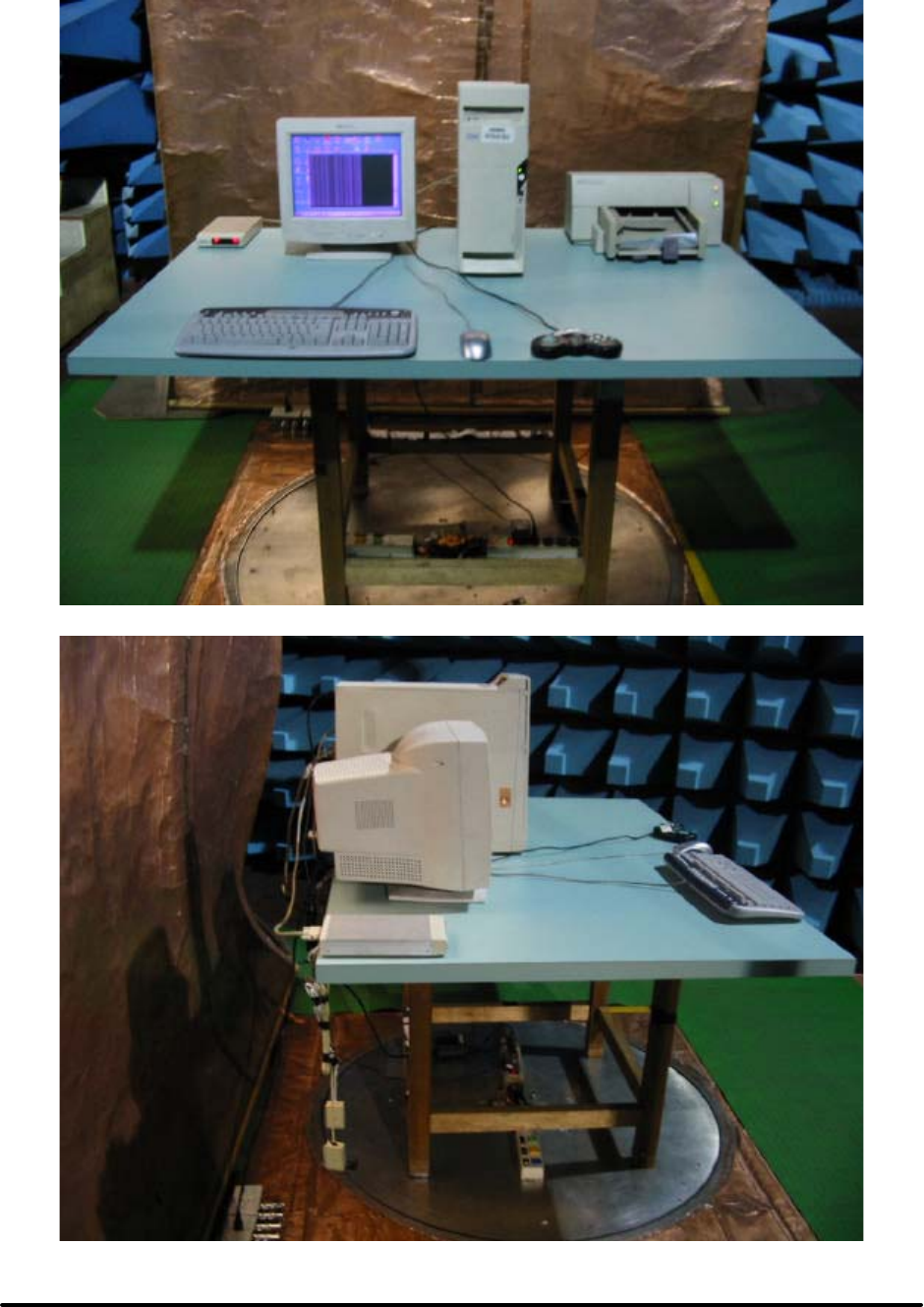
Test Report ------------------------------------------------------------------------------- 40/45
Report No.: C51ET050304 (ETSI EN 301 489)
Training Research Co., Ltd., TEL: 886-2-26935155, Fax: 886-2-26934440
Conducted Test Placement (Front view and Side view)

Test Report ------------------------------------------------------------------------------- 41/45
Report No.: C51ET050304 (ETSI EN 301 489)
Training Research Co., Ltd., TEL: 886-2-26935155, Fax: 886-2-26934440
Test Result of Conducted Emissions for Mains power
Test Conditions: Temperature : 25 °C Humidity : 73 % RH
Power Connected Emissions Class B
Conductor Frequency
(KHz)
Peak
(dB
µ
V)
QP
(dB
µ
V)
Average
(dB
µ
V)
QP-limit
(dB
µ
V)
AVG-limit
(dB
µ
V)
Margin
(dB)
197.000 32.95 --- --- 64.66 54.66 -21.71
331.000 29.21 --- --- 60.83 50.83 -21.62
528.000 29.79 --- --- 56.00 46.00 -16.21
788.000 28.02 --- --- 56.00 46.00 -17.98
Line 1 4406.000 32.88 --- --- 56.00 46.00 -13.12
5940.000 29.86 --- --- 60.00 50.00 -20.14
6000.000 29.09 --- --- 60.00 50.00 -20.91
6140.000 29.49 --- --- 60.00 50.00 -20.51
262.000 30.37 --- --- 62.80 52.80 -22.43
329.000 33.12 --- --- 60.89 50.89 -17.77
533.000 33.19 --- --- 56.00 46.00 -12.81
788.000 31.05 --- --- 56.00 46.00 -14.95
Line 2 4406.000 32.37 --- --- 56.00 46.00 -13.63
4762.000 30.47 --- --- 56.00 46.00 -15.53
6460.000 30.91 --- --- 60.00 50.00 -19.09
6670.000 30.53 --- --- 60.00 50.00 -19.47
Note:
1. The reading amplitudes are all under limit.
2. Testing result = Amplitude reading + Correction factor (Insertion loss of LISN, Cable loss,
Attenuator, Amplifier and so on)

Test Report ------------------------------------------------------------------------------- 42/45
Report No.: C51ET050304 (ETSI EN 301 489)
Training Research Co., Ltd., TEL: 886-2-26935155, Fax: 886-2-26934440
Chapter 13 Radiated Emission Test
Test condition and setup
Pretest: Prior to the final test (OATS test), the EUT is placed in a shielded enclosure,
and scan from 30MHz to 1GHz. This is done to ensure the radiation is exactly emitted from the
EUT.
Final test: Final radiation measurements are made on a 10 – meter, open-field test
site. The EUT is placed on a nonconductive table, which is 0.8m height, the top surface is 1.0 x
1.5 meter. The entire placement is according to EN 55022.
The whole range antenna is used to measure frequency from 30 MHz to 1GHz. The final
test is used the spectrum analyzer (EMI Receiver). Measure more than six top marked
frequencies generated form pretest by computer step by step at each frequency.
The EUT is rotated 360 degrees, and antenna is raised and lowered from 1 to 4 meters to
find the maximum emission levels. The antenna is used with both horizontal and vertical
polarization.
Appropriated preamplifier which is made by TRC is used for improving sensitivity and
precautions is taken to avoid overloading .The spectrum analyzer’ s 6dB bandwidth is set to 120
kHz, and the EUT is measured at quasi-peak (below 1GHz) mode.
If the emission is close to the frequency band of ambient, the tester will recheck the data
and the corrected data will be written in the test data sheet. If the emission is just within the
ambient, the data from shielded room will be taken as the final data.

Test Report ------------------------------------------------------------------------------- 43/45
Report No.: C51ET050304 (ETSI EN 301 489)
Training Research Co., Ltd., TEL: 886-2-26935155, Fax: 886-2-26934440
List of test Instrument
Calibration Date
Instrument Name Model Brand Serial No. Next time
EMI Receiver 8546A HP 3520A00242 08/05/05
RF Filter Section 85460A HP 3448A00217 08/05/05
Small Biconical
Antenna
UBAA9114 &
BBVU9135
SCHWARZECK 127 10/11/05
Pre-amplifier PA1F TRC 1FAC 05/20/05
Auto Switch Box
(>30MHz)
ASB-01 TRC 9904-01 05/20/05
Coaxial Cable
(Double shielded,
15 meter)
A30A30-0058-50FS-15M JYEBAO SMA-08 05/20/05
Coaxial Cable
(1.1 meter)
A30A30-0058-50FS-1M JYEBAO SMA-02 05/20/05
Receiver SCR3102 SCHAFFNER 012 05/13/05
Control Box TWR95-4 TRC C9001-2 N/A
Antenna CBL6141A SCHAFFNER 4206 05/26/05
Pre-amplifier TRC-CB-2 TRC CB-002 05/28/05
Coaxial cable
(20 meter)
RG-214/U JYEBAO Cl-002 05/28/05
Coaxial Cable
(50 cm)
BNC31VB-0316 JYEBAO SMA-02 05/28/05
Coaxial Cable
(1.1 meter)
BNC31VB-0318 JYEBAO SMA-02 05/28/05
Coaxial Cable
(1.1 meter)
BNC31VB-0316 JYEBAO SMA-02 05/28/05
Coaxial Cable
(1.1 meter)
BNC31VB-0316 JYEBAO SMA-02 05/28/05
The level of confidence of 95% , the uncertainty of measurement of radiated emission is +2.85dB / -2.77dB .
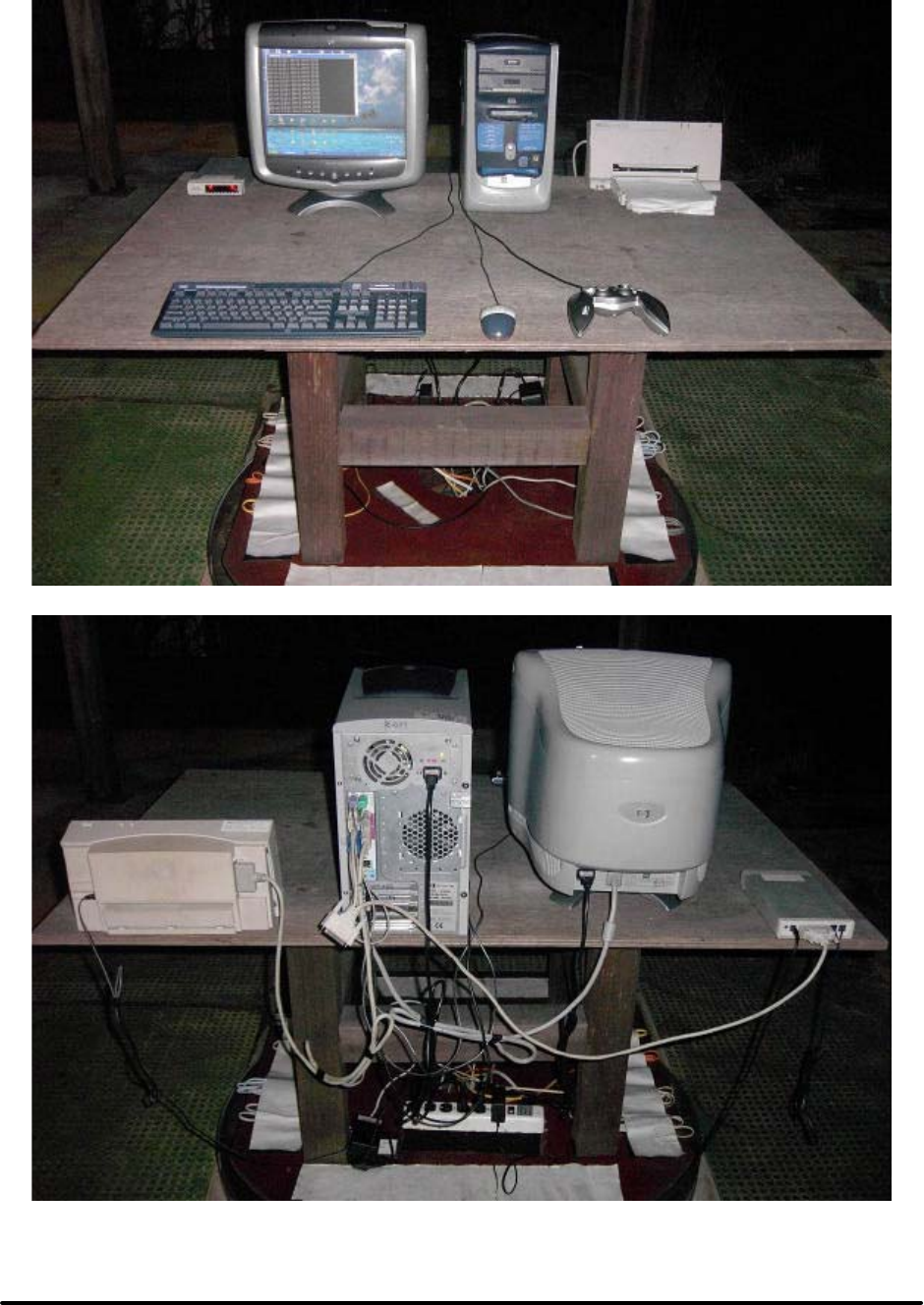
Test Report ------------------------------------------------------------------------------- 44/45
Report No.: C51ET050304 (ETSI EN 301 489)
Training Research Co., Ltd., TEL: 886-2-26935155, Fax: 886-2-26934440
Radiated Test Placement (Front view and Rear view)

Test Report ------------------------------------------------------------------------------- 45/45
Report No.: C51ET050304 (ETSI EN 301 489)
Training Research Co., Ltd., TEL: 886-2-26935155, Fax: 886-2-26934440
Test Result of Spurious Radiated Emissions
Test Conditions:
Testing room : Temperature : 25 ° C Humidity : 73 % RH
Testing site : Temperature : 22 ° C Humidity : 65 % RH
Test Result of Spurious Radiated Emissions for 30MHz to 1GHz [Horizontal]
Frequency Reading
Amplitude
Ant.
Height
Table Correction
Factors
Corrected
Amplitude
Class B
Limit
Margin
MHz dBµV m degree dB/m dBµV/m dBµV/m dB
75.7728 31.57 2.29 270 -10.17 21.40 30.00 -8.60
355.8113 16.48 1.00 156 2.04 18.52 37.00 -18.48
552.0938 12.11 1.88 47 8.17 20.28 37.00 -16.72
753.7826 11.47 1.00 156 14.28 25.75 37.00 -11.25
Test Result of Spurious Radiated Emissions for 30MHz to 1GHz [Vertical]
Frequency Reading
Amplitude
Ant.
Height
Table Correction
Factors
Corrected
Amplitude
Class B
Limit
Margin
MHz dBµV m degree dB/m dBµV/m dBµV/m dB
39.4230 24.17 2.48 308 -0.47 23.70 30.00 -6.30
54.9095 22.98 1.00 43 -6.52 16.46 30.00 -13.54
76.9673 32.50 1.00 30 -10.12 22.38 30.00 -7.62
169.3797 27.12 1.00 359 -5.88 21.24 30.00 -8.76
338.7602 20.98 1.00 9 0.98 21.96 37.00 -15.04
432.0596 17.70 2.47 63 5.24 22.94 37.00 -14.06
Note:
1. Margin = Amplitude – limit, if margin is minus means under limit.
2. Corrected Amplitude = Reading Amplitude + Correction Factors
3. Correction factor = Antenna factor + (Cable Loss – Amplitude gain) + Switching Box Loss
Copy of the R&TTE Declaration of
Conformity (DoC)
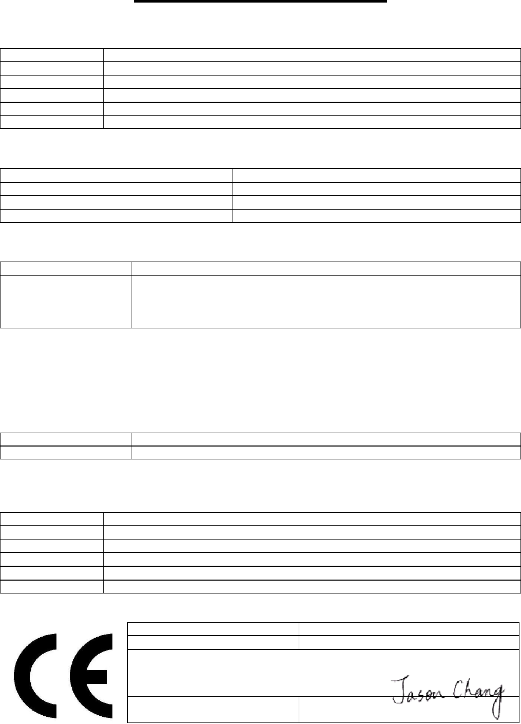
Declaration of Conformity
We, the under signed,
Company CAMEO COMMUNICATIONS, INC.
Address, City No. 42, Min Chuan East Road, Section 6, Taipei 114,
Country Taiwan
Phone number 886-2-27908998
Fax number 886-2-27909463
E-mail Jason_Chang@mail.cameo.com.tw
certify and declare under our sole responsibility that the following equipment:
Product Description / Supplementary Info
802.11g Wireless PCI Adapter
Manufacturer CAMEO COMMUNICATIONS, INC.
Brand CAMEO, Level One, LG, Etherwan, Allnet GmbH
Type WLG-1202, WNC-0300, LWS5410P, NWP-0108G, ALL0281A
is tested to and conforms with the essential radio test suites included in the following standards:
Standard Issue date
ETSI EN 300 328-2
ETSI EN 301 489-1
ETSI EN 301 489-17
EN 60950-1
V1.2.1 Dec. 2001
V1.4.1 Aug. 2002
V1.2.1 Apr. 2002
2001
and therefore complies with the essential requirements and provisions of the R&TTE directive
1999/5/EC of the European Parliament and of the council of 9March 1999 on radio equipment and
Telecommunications Terminal Equipment and the mutual recognition of their conformity and the
requirements of Annex IV (conformity Assessment procedure referred to in article 10(4)).
The following Notified Bodies have been consulted in the Conformity Assessment procedure:
Notified Body number Name and address
0470 Nemko, PO Box 73, Blindern N-0314 Oslo, Norway
The technical documentation as required by the Conformity Assessment procedure is kept at the
following address:
Company CAMEO COMMUNICATIONS, INC.
Address, City No. 42, Min Chuan East Road, Section 6, Taipei 114,
Country Taiwan
Phone number 886-2-27908998
Fax number 886-2-27909463
E-mail Jason_Chang@mail.cameo.com.tw
Draw up in
TAIWAN, R.O.C.
Date 2005/4/27
CAMEO COMMUNICATIONS, INC.
No. 42, Min Chuan East Road, Section 6,
Taipei 114, Taiwan
Signature & company stamp Jason Chang /
Wireless Comm. R&D Dept. Manager
Product Quality
Assurance Documents
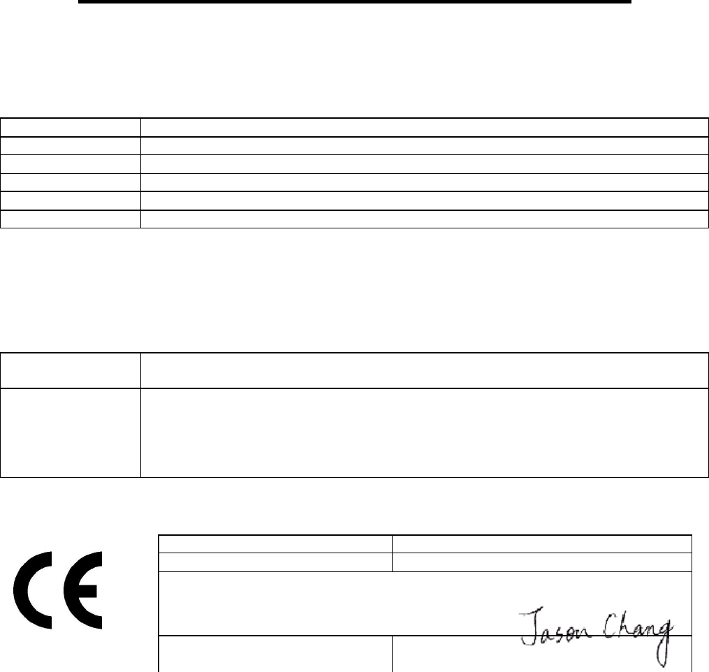
Declaration of Product Quality Assurance
In accordance with the Conformity Assessment procedure referred to in article 10(3) of R&TTE
Directive 1999/5/EC of the European Parliament and the council of 9 march 1999 on the Radio
equipment and Telecommunication Terminal Equipment and their mutual recognition of their conformity
(R&TTE directive) the following manufacture:
Company CAMEO COMMUNICATIONS, INC.
Address, City 6F, NO. 22, Chung Shin Rd., Hsi-Chih,
Country Taipei 221, Taiwan
Phone number 886-2-26499800
Fax number 886-2-26499984
E-mail Jason_Chang@mail.cameo.com.tw
declares under its sole responsibility that it had taken the following measures in order to achieve that
the manufacturing process ensures compliance of the manufactured products with the technical
documentation as established by CAMEO COMMUNICATIONS, INC.. under the requirements of the
R&TTE directive and with the requirements of R&TTE directive that apply to them:
Number Measures taken in order to achieve that the manufacturing process ensures
compliance of the manufactured products
01 Manufacturing of the equipment is subcontracted by CAMEO
COMMUNICATIONS, INC. to CAMEO COMMUNICATIONS, INC. located at 6F,
NO. 22, Chung Shin Rd., Hsi-Chih, Taipei 221, Taiwan. who is ISO 9001 certified
for development, production and distribution of radio products. (See copy of ISO
9001 certification attached)
Draw up in
TAIWAN, R.O.C.
Date 2005/4/27
CAMEO COMMUNICATIONS, INC.
No. 42, Min Chuan East Road, Section 6,
Taipei 114, Taiwan
Signature & company stamp Jason Chang /
Wireless Comm. R&D Dept. Manager