W4_Band_1_E_150dpi 502856 Catalog
2014-07-29
: Pdf 502856-Catalog 502856-Catalog 007436 Batch6 unilog
Open the PDF directly: View PDF ![]() .
.
Page Count: 432 [warning: Documents this large are best viewed by clicking the View PDF Link!]

Volume 1
Rail-Mounted Terminal Blocks
X-COM®-SYSTEM
Terminal Strips
Patchboard Systems
Shield (Screen)
Connecting System
Rail-Mounted
Terminal Block Systems
GENERAL CATALOGUE W4
w
CAGE CLAMP topJob X-COM CC-Matic ProServe
TOPLON
are trademarks of WAGO Kontakttechnik GmbH & Co. KG, D-32423 Minden

1
2
3
4
5
6
7
8
9
10
11
1
2
3
4
5
6
7
8
9
10
11
12
CONTENTS FULL LINE CATALOG W4, VOLUME 3 Volume 3
Interface Modules
Components for
Automation
F U LL LI N E CATALOG W4
VOLUME 3
WAGO*SYSTEM Modular system Series 750
WAGO*SYSTEM Compact system Series 752
WAGO*SYSTEM Modules for severe conditions Series 755
WAGO*SYSTEM Industrial compact PC Series 758
Service and programming software/WAGO TOPLON® software for building automation Series 759
Interface modules
Overvoltage protection
Power supplies
Empty housings
Accessories, shield (screen) connection system
Technical section
PCB terminal blocks
Pluggable PCB connectors
Feedthrough terminal blocks
PCB connectors Pin spacing Cross section
MULTI CONNECTION SYSTEM MICRO
100% protected against mismating 2.5 mm/0.098 in 0.08 mm2- 0.5 mm2/AWG 28 - 20
MULTI CONNECTION SYSTEM MINI
100% protected against mismating 3.5 +3.81 mm/0.138+0.15 in 0.08 mm2- 1.5 mm2/AWG 28 - 14
MULTI CONNECTION SYSTEM MIDI
100% protected against mismating 5 /7.5 mm/0.197+0.295 in 0.08 mm2- 2.5 mm2/AWG 28 - 12
MULTI CONNECTION SYSTEM MIDI 5 /5.08 mm/0.197+0.2 in 0.08 mm2- 2.5 mm2/AWG 28 - 12
Standard design 7.5 /7.62 mm/0.295+0.3 in 0.08 mm2- 2.5 mm2/AWG 28 - 12
X-COM®connectors for PCBs 5 mm/0.197 in 0.08 mm2– 4 mm2/ AWG 28 - 12
WINSTA connectors for PCBs 10 mm/0.394 in 2 x 0.5 mm2– 4 mm2/ AWG 20 - 12
Connectors for special applications
Accessories Marking material
Tools
Technical section Approvals Index of item numbers WAGO companies and representations
Technical information Index of products
CONTENTS FULL LINE CATALOG W4, VOLUME 2 Volume 2
F U LL LI N E CATALOG W4
PCB Terminal Blocks
Feedthrough Terminal Blocks
PCB Connectors
Connectors
for Special Applications
PCB Terminal Blocks
and Connectors
VOLUME 2

1
2
3
4
5
6
7
8
9
10
11
12
13
14
15
1
2
3
4
5
6
7
8
9
10
11
12
13
14
15
TOPJOB®S Through terminal blocks 4terminal blocks
Rail-mounted terminal blocks Ground (earth) conductor terminal blocks
with CAGE CLAMP®S connection
Technical section Approvals Index of products
Technical information
Index of item numbers
CONTENTS
VOLUME 1
Rail-mounted terminal blocks Through terminal blocks
with side-entry Ground (earth) conductor
Function terminal blocks Disconnect terminal blocks Sensor/actuator terminal blocks
Disconnect terminal blocks Diode/LED terminal blocks
for test and measurement Terminal blocks with
Fused disconnect term. blocks surge suppression
FIT CLAMP Through terminal blocks
Rail-mounted terminal blocks Ground (earth) conductor
with IDC connection
Patchboard systems Matrix patchboards Ground (earth) busbar term. bl.
Busbar terminal blocks Terminal blocks for N busbar terminal blocks
matrix patching Lbusbar terminal blocks
Shield (screen) connecting system Shield (screen) clamping saddle
Busbar carrier system
4Technical information
Accessories Marking material
Mounting accessories
Tools
Front-entry Through terminal blocks 4terminal blocks
Rail-mounted terminal blocks Ground (earth) conductor Distribution terminal blocks
Double deck terminal blocks Shield (screen) terminal blocks
Triple deck terminal blocks Term. bl. for electric motor wiring
COMPACT Through terminal blocks 4terminal blocks
Rail-mounted terminal blocks Ground (earth) conductor
Double deck terminal blocks
Triple deck terminal blocks
MINI Through terminal blocks 4terminal blocks
Rail-mounted terminal blocks Ground (earth) conductor
topJob®see Full Line Catalog W4
rail mounted terminal blocks Volume 1 – German version
X-COM®-System Carrier terminal blocks Female plugs
Double deck carrier term. bl. with CAGE CLAMP®connection
Headers with solder pins Male connectors
Strain relief housings with CAGE CLAMP®connection
Modular terminal blocks and Terminal blocks and MICRO push-wire connectors
terminal strips terminal strips for Push-wire connectors
surface mounting Lighting connectors
Terminal strips Compact connectors
Rail-Mounted Terminal Block Systems
❮
30%
0
4Innovations from the Leader of Spring
TOPJOB®S RAIL-MOUNTED TERMINAL BLOCKS
CAGE CLAMP® RAIL-MOUNTED TERMINAL BLOCKS
0
5
Clamp Termination Technology
FUNCTION TERMINAL BLOCKS
FIT CLAMP RAIL-MOUNTED TERMINAL BLOCKS
0
6Innovations from the Leader of Spring
MODULAR TERMINAL BLOCKS/TERMINAL STRIPS
X-COM®-SYSTEM
0
7
Clamp Termination Technology
SHIELD (SCREEN) CONNECTING SYSTEM
PATCHBOARD SYSTEMS

0
8
= front-entry = side-entry
“s“ “f-st“
Standard
TOPJOB®S
FIT CLAMP
Sensor/actuator
Standard
Miniature term. bl.
TOPJOB®S
Compact
Slim Line
Standard
279 2001 290 270 280 264 2002 870 880 281Series
Characteristic
Cross section
(mm2)
max.
min.
Nominal current (ampere)
Overall width (mm)
Test slot (Ø mm)
Comment
2-conductor terminal block
3-conductor terminal block
4-conductor terminal block
2-cond. (earth) term. block
3-cond. (earth) term. block
4-cond. (earth) term. block
Double potential
Double deck
Triple deck
Quadruple deck
Disconnect terminal block
N-disconnect terminal block
Fused disconnect term. block
Diode terminal block
Surge suppression devices
Sensor/actuator
Front-entry
Side-entry
Adjacent jumper
Staggered jumpers
Push-in type jumper bar
Comb type jumper bar
Step-down jumpers
Nominal current for jumpers (A)
WSB Quick marking
WMB Multi marking
Mini WSB
18 18 13.5 18 24 24 24 24 25 32
44.255565.2556
0.08 0.25 0.31 0.34 0.08 0.08 0.08 0.25 0.08 0.08 0.08
1.5 1.5 1 1.5 2.5 2.5 2.5 2.5 4 4 4
2
FIT specifi-
cations
6.6/2.8
2.8
2.8
2.8
2.8
2.8
2.9
2.29
7.56
X
X
X
15
X
4.4
4.4
4.4
X
X
16
X
3.6
3.6
3.6
3.6
3.6
3.6
3.8
3.9
7.64
Vol . 3
X
X
X
18
X
2.14
2.14
2.14
2.14
2.14
2.14
X
X
X
24
X
X
6.6/2.16
2.16
2.16
6.6/2.16
2.16
2.16
2.33
2.36
7.12
7.30
7.58
X
X
X
X
32
X
X
Page
6.6/2.10
2.10
2.10
6.6/2.10
2.10
2.10
2.11
2.30
2.34
7.10
7.57
Vol . 3
7.44
X
X
X
X
24
X
X
8.6
8.6
8.6
8.6
8.6
8.6
X
X
X
24
X
X
1.6
1.6
1.6
1.6
1.6
1.6
X
X
18
X
X
7.39
X
X
X
1.7
1.7
1.7
1.7
1.7
X
X
25
X
X

0
9
TOPJOB®S
Standard
TOPJOB®S
Standard
Standard
TOPJOB®S
Standard
Standard
2004 282 2006 284 2010 283 2016 285 285
-6xx -19x
Series
Characteristic
Cross section
(mm2)
max.
min.
Nominal current (ampere)
Overall width (mm)
Test slot (Ø mm)
Comment
2-conductor terminal block
3-conductor terminal block
4-conductor terminal block
2-cond. (earth) term. block
3-cond. (earth) term. block
4-cond. (earth) term. block
Double potential
Double deck
Triple deck
Quadruple deck
Disconnect terminal block
N-disconnect terminal block
Fused disconnect term. block
Diode terminal block
Surge suppression devices
Sensor/actuator
Front-entry
Side-entry
Adjacent jumper
Staggered jumpers
Push-in type jumper bar
Comb type jumper bar
Step-down jumpers
Nominal current for jumpers (A)
WSB Quick marking
WMB Multi marking
Mini WSB
32 41 41 57 57 76 76 125 232
6.2 8 7. 5 10 10 12 12 16 25
0.5 0.2 0.5 0.2 0.5 0.2 0.5 6 35
4 6 6 10 10 16 16 35 95
1.8
1.8
1.8
1.8
1.8
1.8
X
X
32
X
X
6.7/2.20
2.20
6.7/2.20
2.20
X
X
X
X
70
X
X
2.21
2.21
X
X
X
85
X
X
2.24
2.24
X
X
232
X
Page
1.10
1.10
1.10
1.10
X
X
57
X
X
1.9
1.9
1.9
1.9
X
X
41
X
X
6.7/2.18
2.18
6.7/2.18
2.18
7.26/7.22
7.36
X
X
X
X
41
X
X
1.11
1.11
1.11
1.11
X
X
76
X
X
6.7/2.19
2.19
6.7/2.19
2.19
X
X
X
X
57
X
X
TOPJOB®S
Stranded Wires
Solid Wires
Ferruled Wires

1
1
VOLUME 1
TOPJOB®S Rail-Mounted Terminal Blocks with CAGE CLAMP®S Connection
TOPJOB®S rail-mounted terminal blocks with CAGE CLAMP®S connection
AWG 22 – 14 (0.25 mm2– 1.5 (2.5) mm2) Series 2001 1.6
AWG 22 – 12 (0.25 mm2– 2.5 (4) mm2) Series 2002 1.7
Ferrules and crimping tools 1.13
Modular TOPJOB®S connectors 1.12
Testing accessories 1.12
TOPJOB®S rail-mounted terminal blocks with CAGE CLAMP®S connection
AWG 20 – 10 (0.5 mm2– 4 (6) mm2) Series 2004 1.8
AWG 20 – 8 (0.5 mm2– 6 (10) mm2) Series 2006 1.9
TOPJOB®S rail-mounted terminal blocks with CAGE CLAMP®S connection
AWG 20 – 6 (0.5 mm2– 10 (16) mm2) Series 2010 1.10
AWG 20 – 4 (0.5 mm2– 16 (25) mm2) Series 2016 1.11
1
2
TOPJOB®S Rail-Mounted Terminal Blocks with CAGE CLAMP®S Connection
– Product Summary –
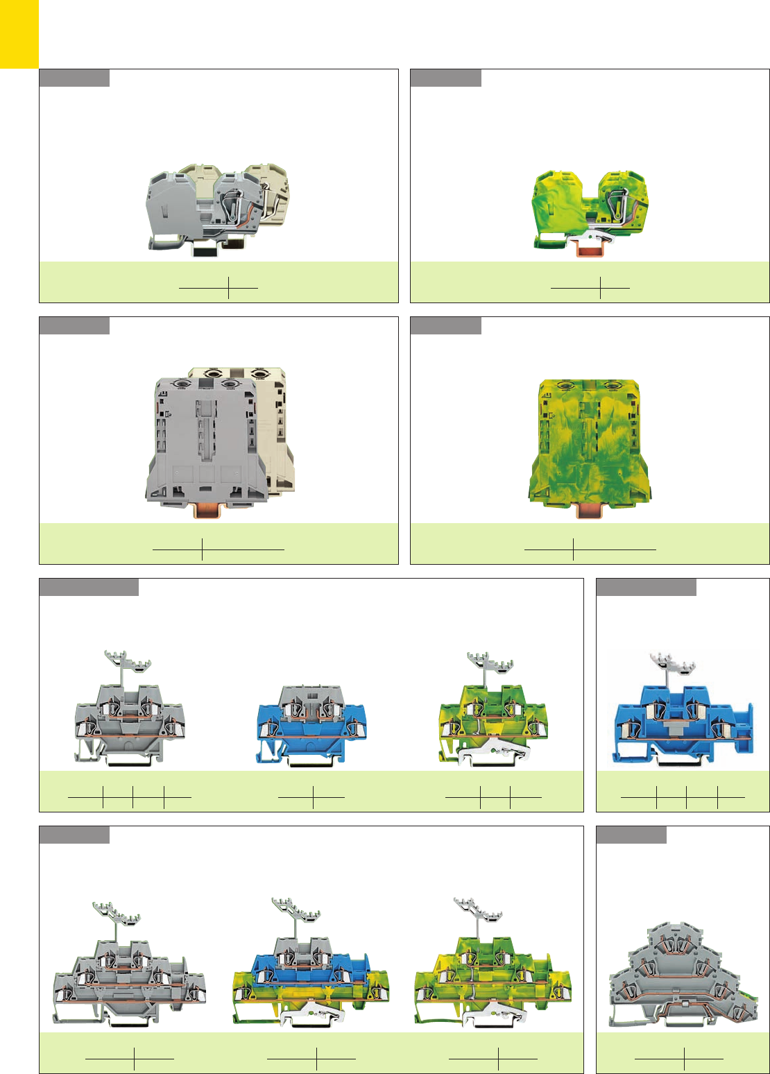
Through terminal blocks
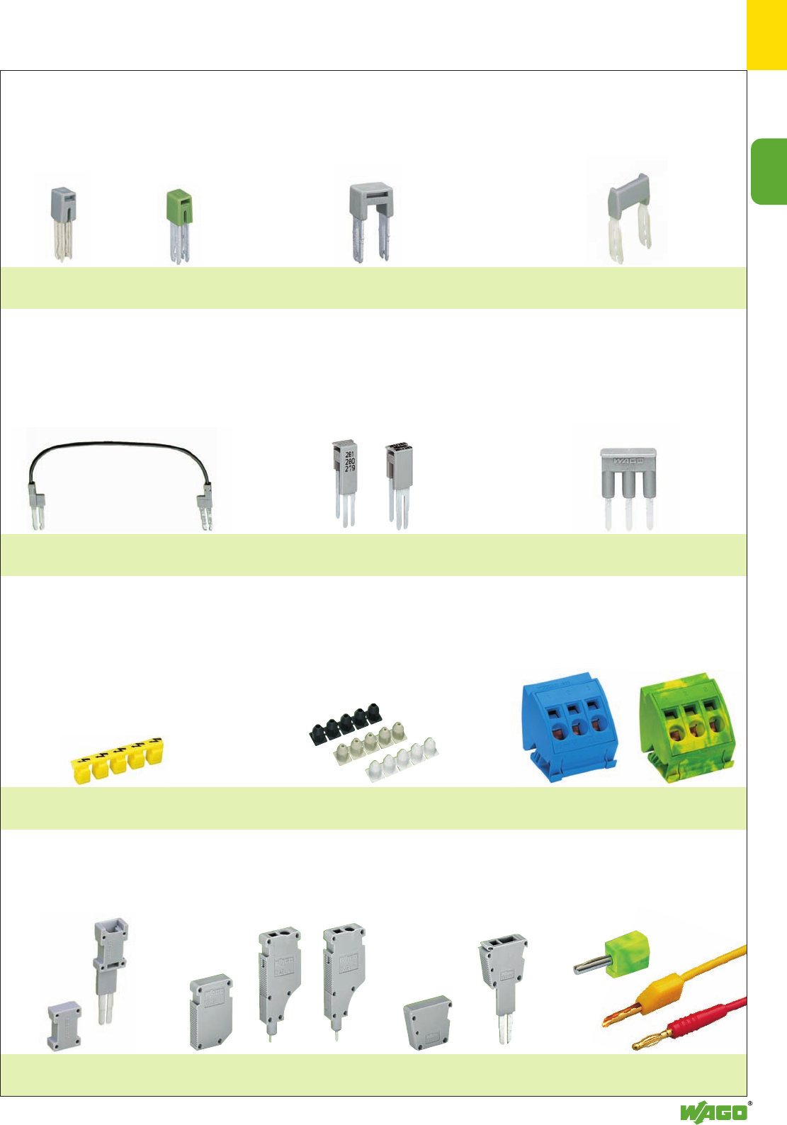
Accessories (selection)
Ex i Through terminal blocks
Ground (earth) conductor terminal blocks
2-conductor terminal blocks 4-conductor terminal blocks
mm2/AWG 0.25 – 1.5 (2.5)/14 0.25 – 2.5 (4)/12 0.5 – 4 (6)/10
Page 1. 6 7 8
2-conductor terminal blocks 4-conductor terminal blocks3-conductor terminal blocks
3-conductor terminal blocks
2-conductor terminal blocks 4-conductor terminal blocks3-conductor terminal blocks
Insulation stops
for Series 2001
Page 1.6
Insulation stops
for Series 2002 and 2004
Page 1.7 and 1.8
Protective warning marker
Page 1.7
Push-in type jumper bars
Page 1.6
Push-in type jumper bars
Page 1.6
Marker strips
for center marking
Page 1.6
Series 2001/2002/2004
Series 2001/2002/2004
Series 2001/2002/2004
mm2/AWG 0.25 – 1.5 (2.5)/14 0.25 – 2.5 (4)/12 0.5 – 4 (6)/10
Page 1. 6 7 8
mm2/AWG 0.25 – 1.5 (2.5)/14 0.25 – 2.5 (4)/12 0.5 – 4 (6)/10
Page 1. 6 7 8
1
1
3
Accessories (selection)
Through terminal blocks
Ex i Through terminal blocks
Ground (earth) conductor terminal blocks
2-conductor terminal blocks 3-conductor terminal blocks
2-conductor terminal blocks 3-conductor terminal blocks
2-conductor terminal blocks 3-conductor terminal blocks
Modular TOPJOB®S connectors
Page 1.6
Test plug adapter
for test plug 4 mm Ø
Page 1.12
Ferrules and
crimping tools
Page 1.13
Testing tap
for max. 2.5 mm2 / AWG 12
Page 1.12
Series 2006/2010/2016
Series 2006/2010/2016
Series 2006/2010/2016
mm2/AWG 0.5 – 6 (10)/8 0.5 – 10 (16)/6 0.5 – 16 (25 “f-st“)/4
Page 1. 9 10 11
mm2/AWG 0.5 – 6 (10)/8 0.5 – 10 (16)/6 0.5 – 16 (25 “f-st“)/4
Page 1. 9 10 11
mm2/AWG 0.5 – 6 (10)/8 0.5 – 10 (16)/6 0.5 – 16 (25 “f-st“)/4
Page 1. 9 10 11
1
4
800 V
U600 V
4550 V
500 V
U300 V
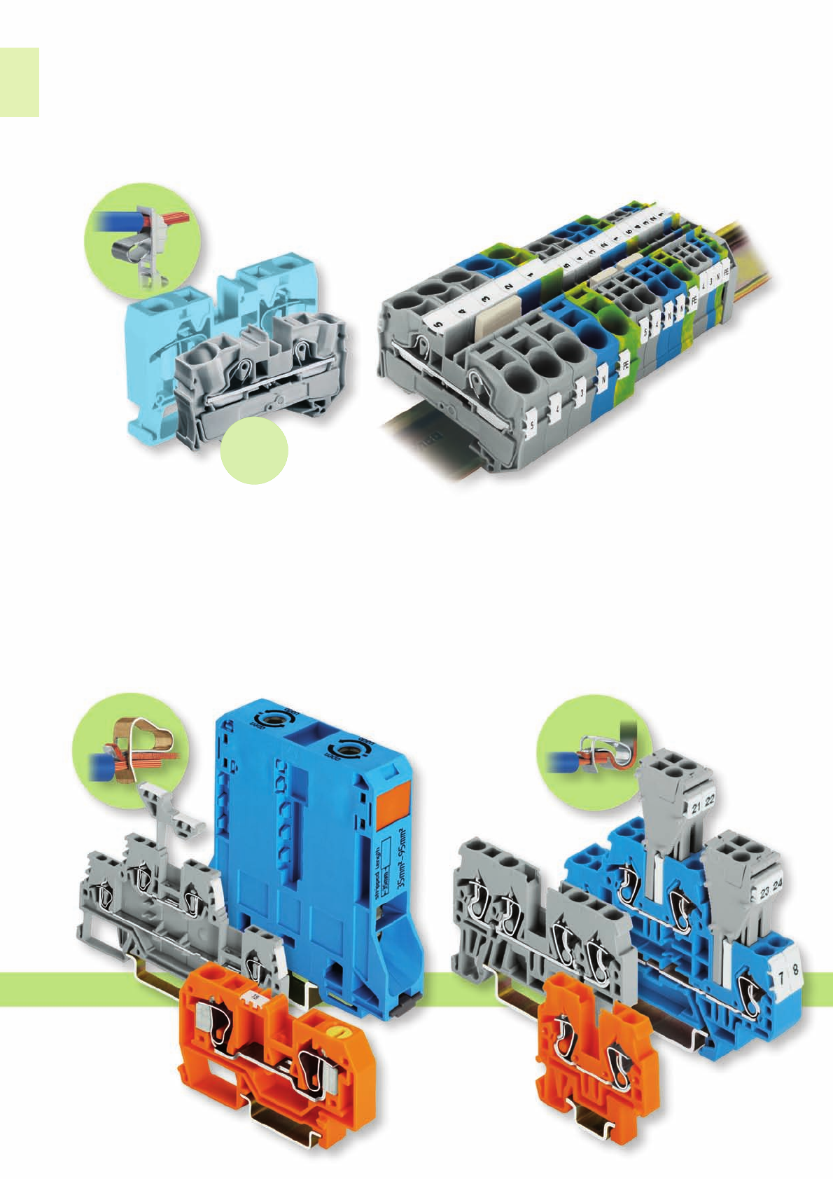
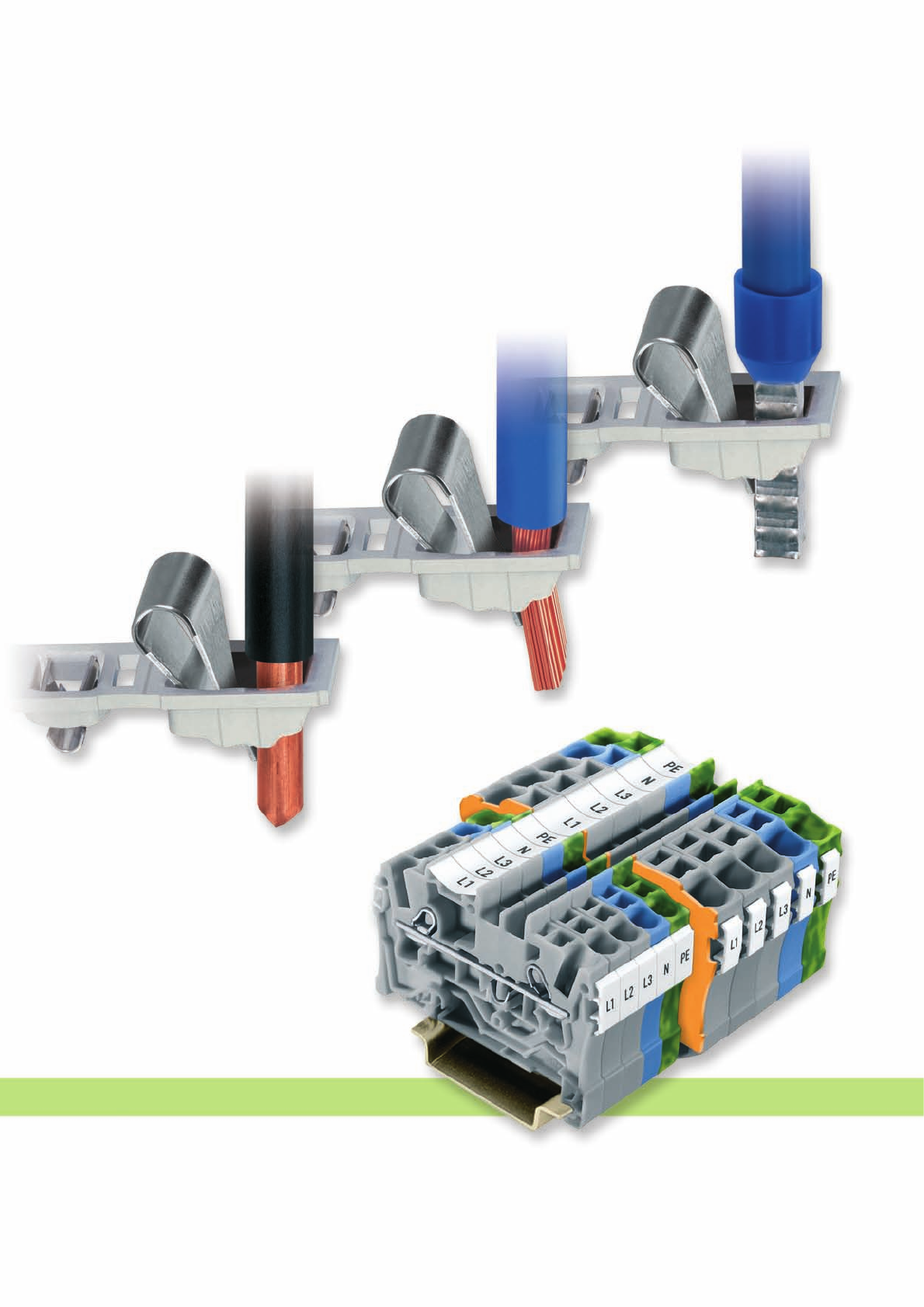
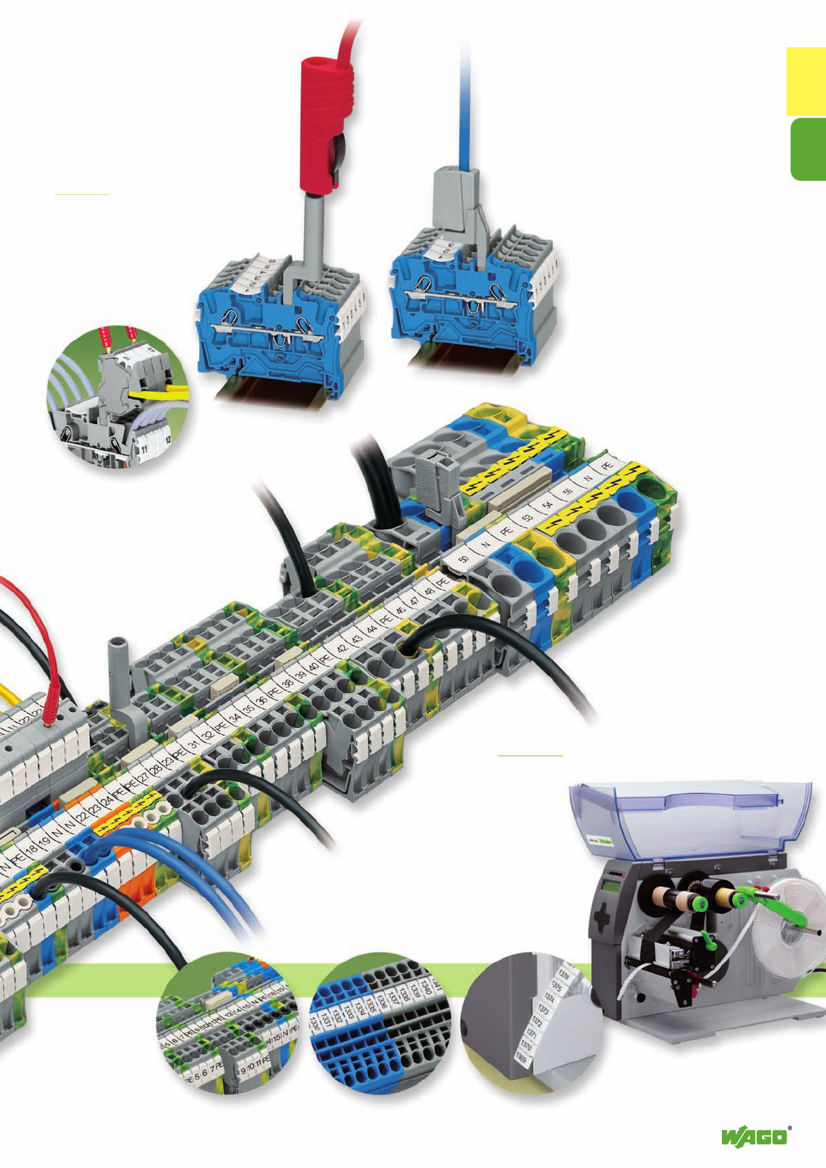
TOPJOB®S with CAGE CLAMP®S
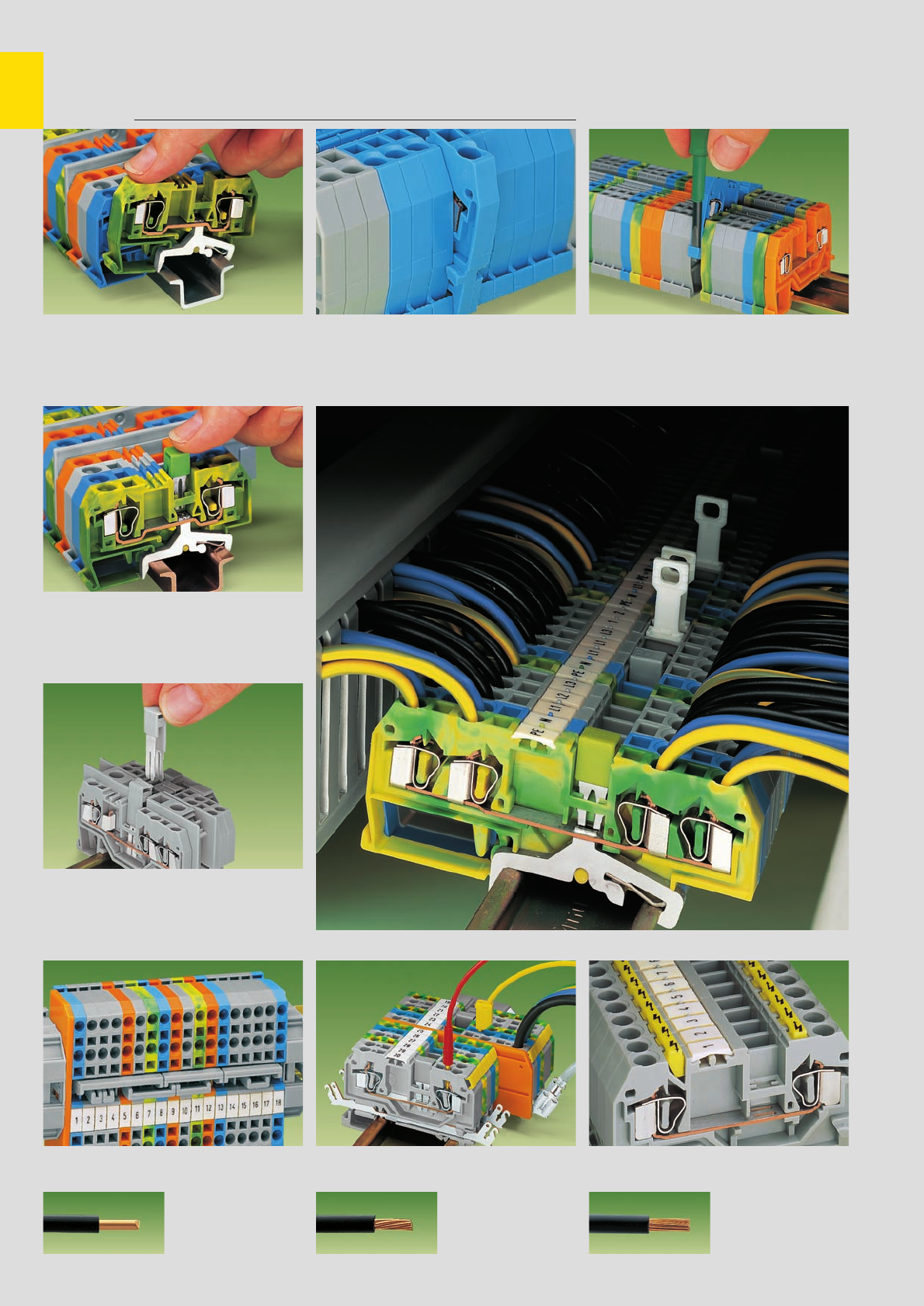
Wire connection
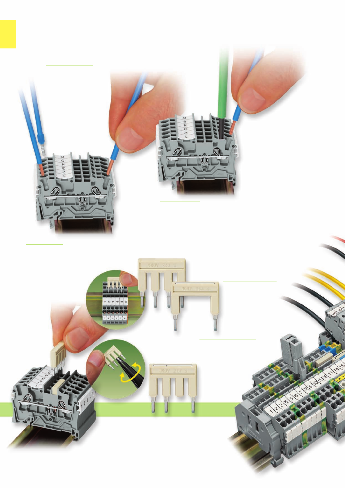
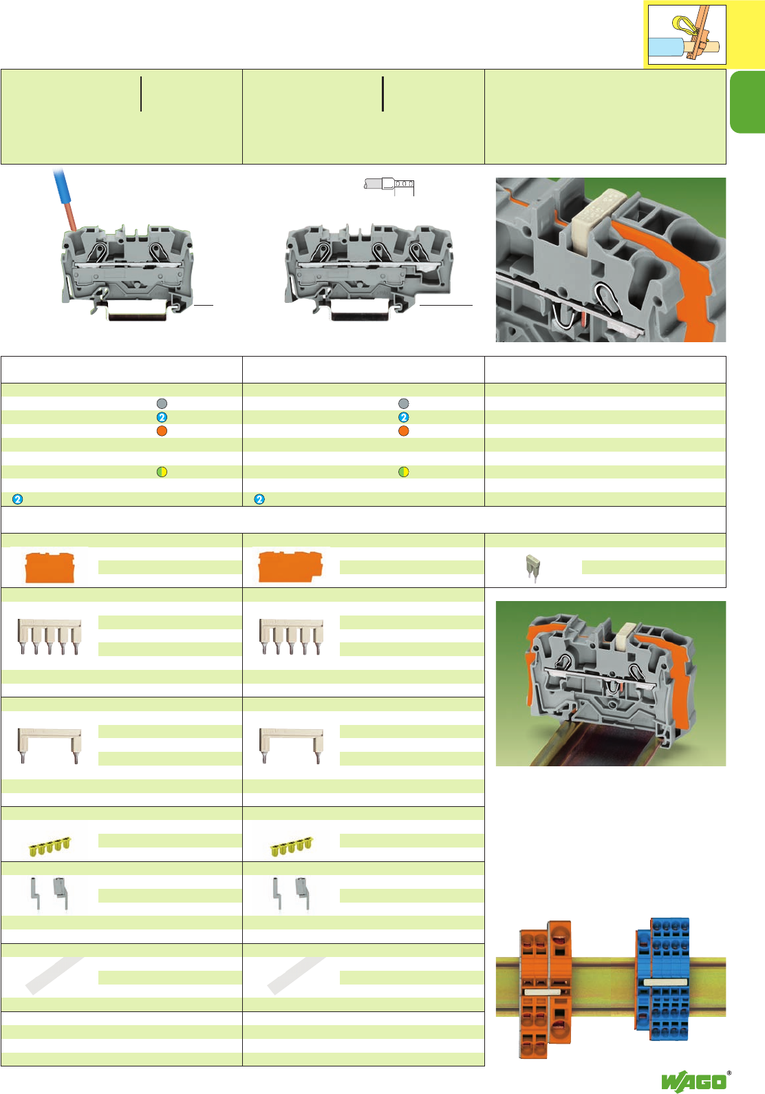
Push-in connection –
Solid wires can be pushed in
directly without tools.
Push-in connection –
Stranded conductors with
ferrules can also be easily
inserted without using any
tools.
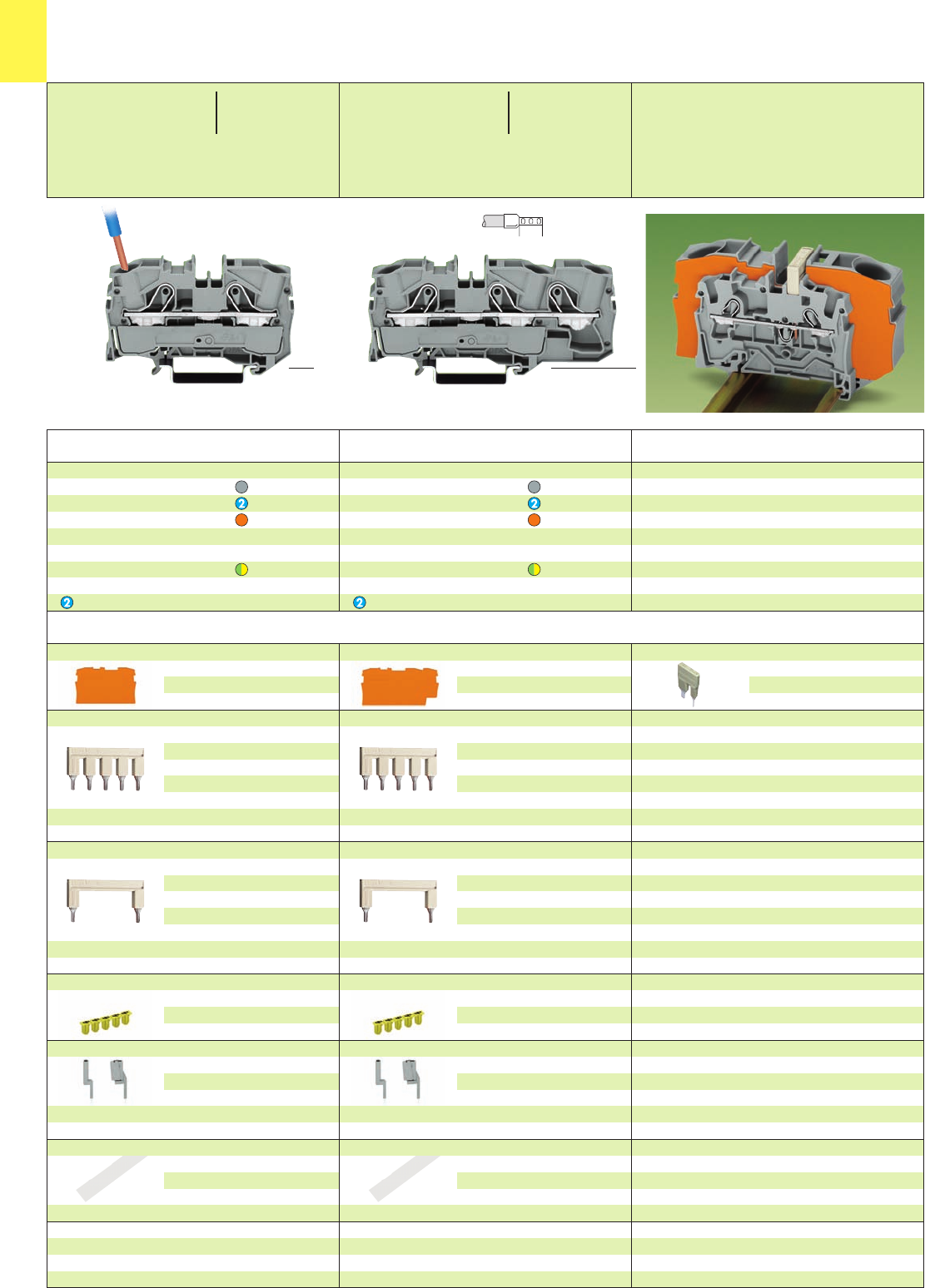
Wire connection
Using a screwdriver – Similar to the
original CAGE CLAMP®, all conductor
types can be terminated via a simple
screwdriver actuation.
Wire removal
The conductor is removed using a standard screwdriver,
like the original CAGE CLAMP®.
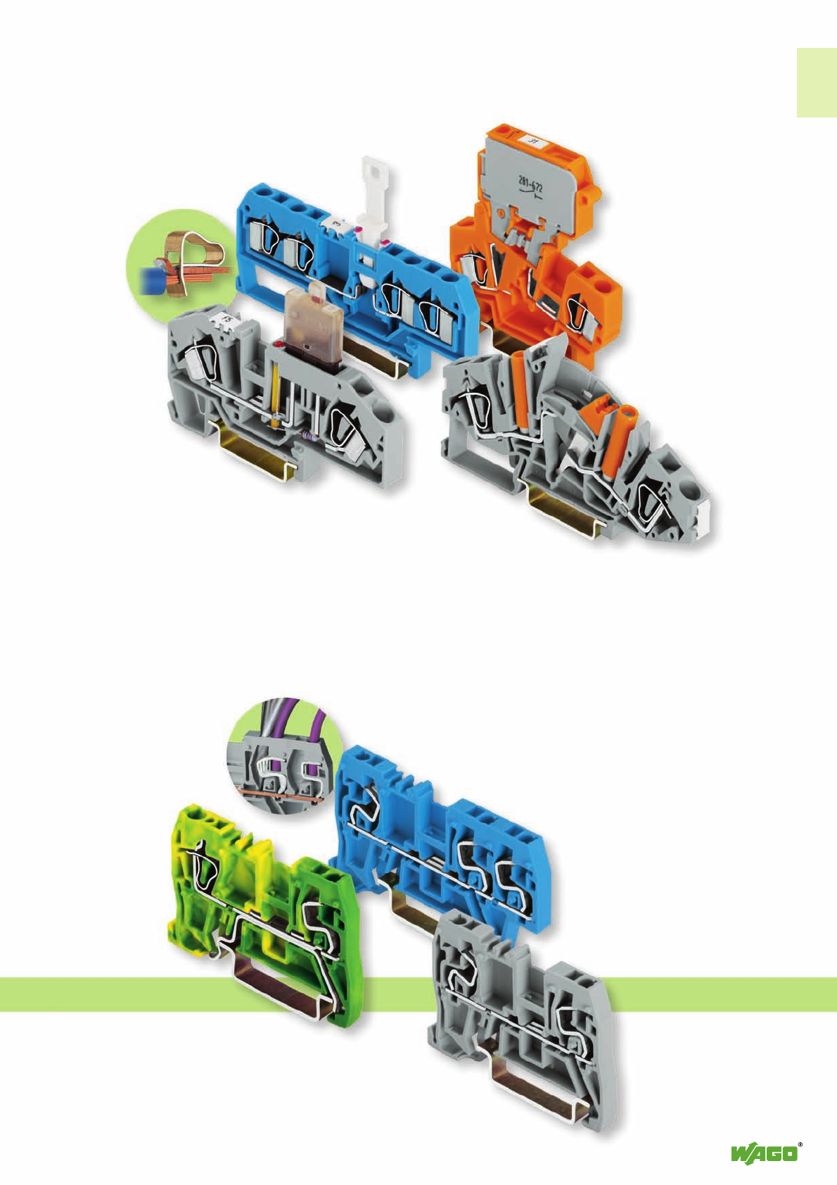
Commoning
The unique “plug and socket“ design of the push-in,
comb style jumper systems allows the full rated
current of the terminal block to be applied.
The dual jumper slots offer more
flexibility. Testing accessories
and jumpers can be used
in parallel.
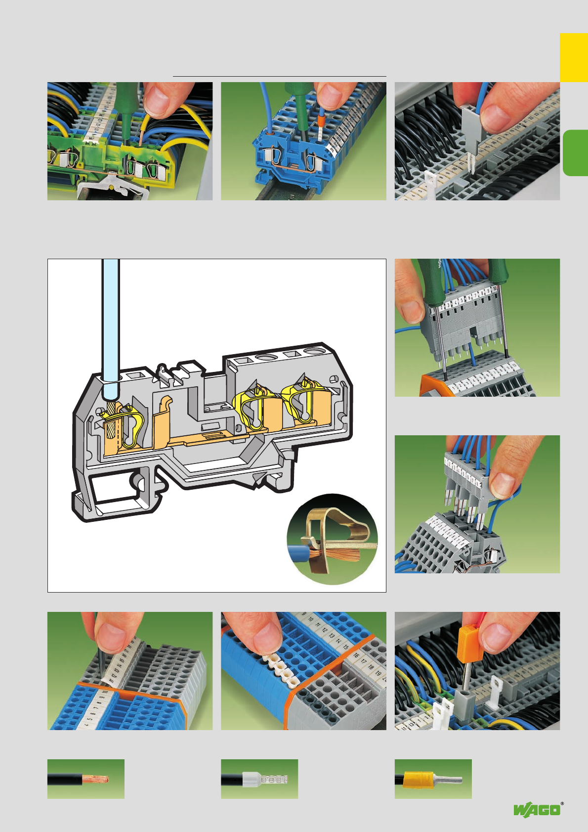
Ready-made push-in type
jumper bars
The rated voltage of the factory
delivered push-in type jumper
bars is 800 V.
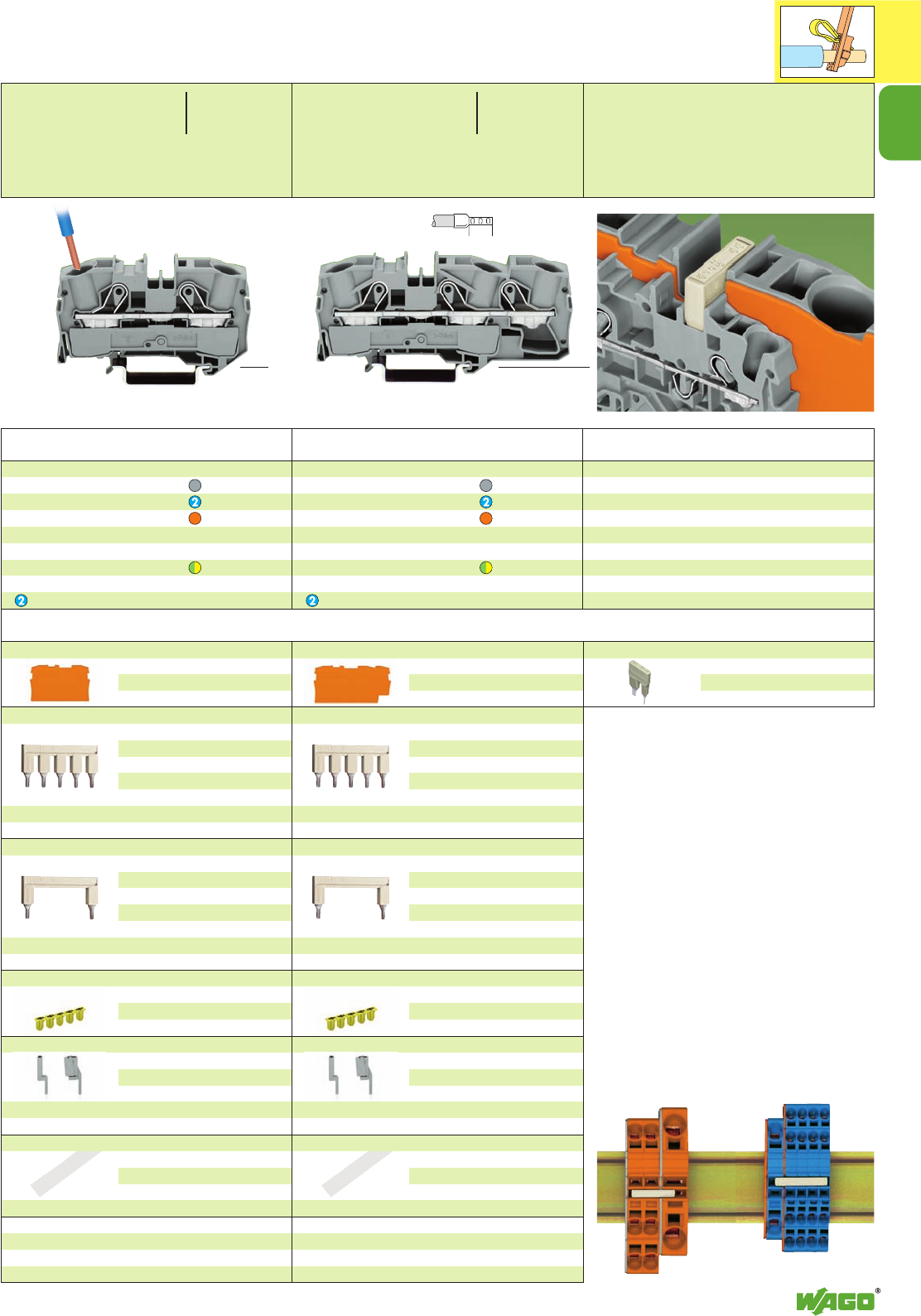
Custom made push-in type
jumper bars
Jumper contacts can be removed
using pliers. Appropriate marking
is possible on the top of the
jumper. The rated voltage
is 500 V. This applies for
Series 2001, 2002
and 2004.
Commoning with step-down jumpers
The spring-loaded jumper system allows commoning of two
adjacent terminal blocks of different size using a standard
jumper. This way, it is possible to jump over a cross
section size. Special step-down jumpers can be
used for even greater leaps.
1
5
1
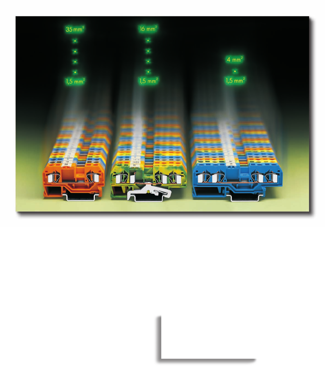
Connection Series 2001/2002 /2004 /2006 /2010 /2016
Rated AWG 16 /AWG 14 / AWG 12 / AWG 10 / AWG 8 / AWG 6
cross section (1.5 mm2/2.5 mm2/4 mm
2/6 mm
2/ 10 mm2/ 16 mm2)
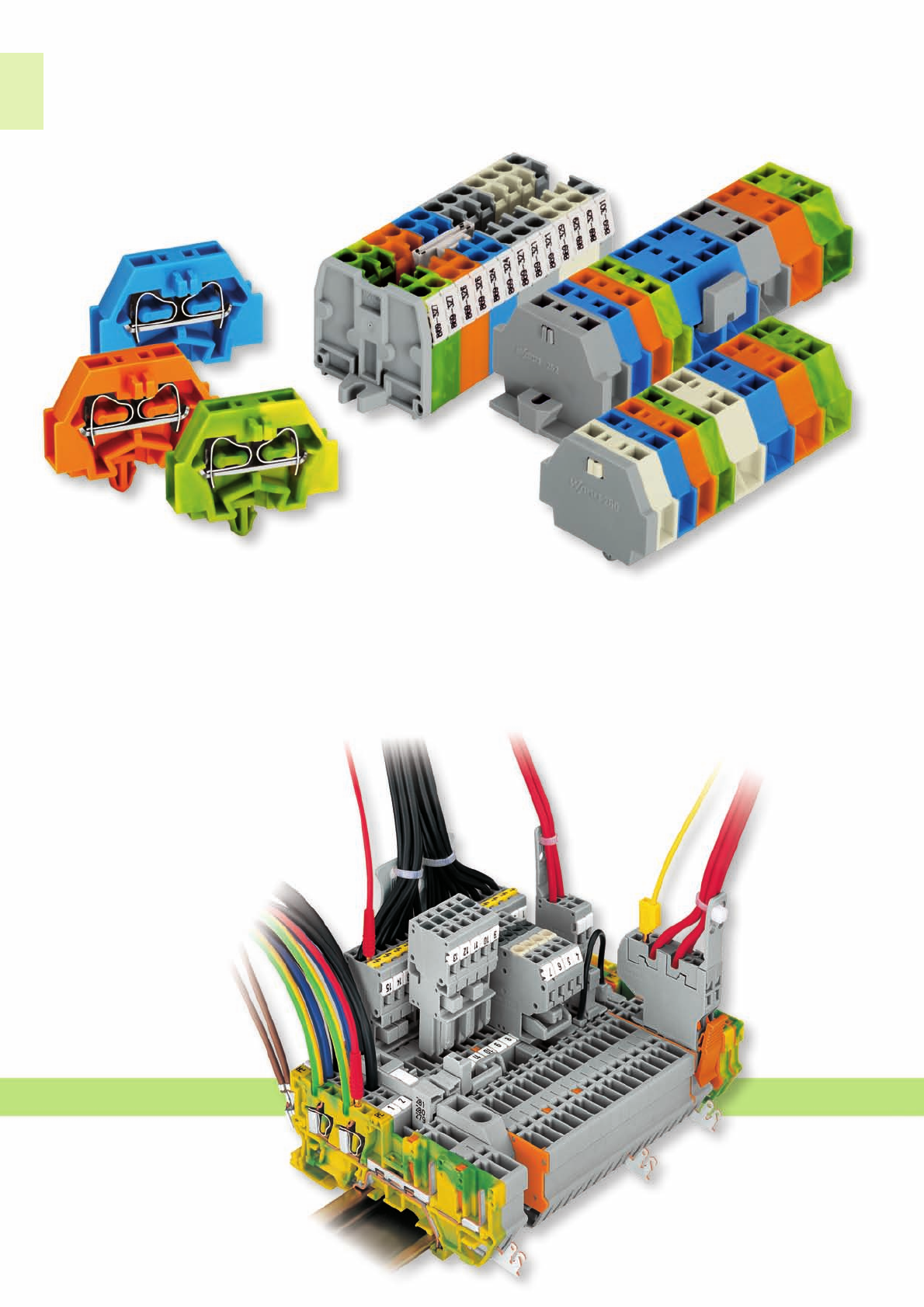
Testing
The spring-loaded jumper system is suited
for testing accessories like testing taps and
test plug adapters as well as modular
TOPJOB®S connectors.
Marking
The TOPJOB®S series offer three marker
receptacles for WMB or miniature WSB cards.
The center receptacle allows the use of a continuous
marker strip. The marker receptacles of terminal
blocks from AWG 14 to 8 (1.5 mm2to 6 mm2)
as well as AWG 6 (10 mm2) and AWG 4 (16 mm2)
are at the same height so that one single marker strip can be
used for different terminal block sizes. Marking is done using
both a thermal transfer printer and WAGO‘s Smart Designer
software. Apart from continuous marker strips, the printer is
also suited for printing WMB markers on roll.
Modular TOPJOB®S connectors
Modular connectors with CAGE CLAMP®S
technology offer an additional connection
option. The connector is equipped with a
2mm/0.079 in Ø or 2.3mm/0.091 in Ø test
socket. Additionally, terminal blocks can be
skipped using spacer modules.
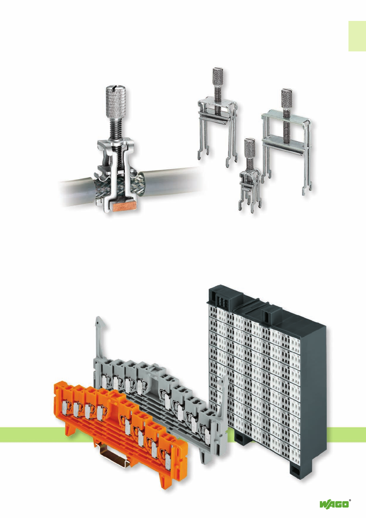
Testing tap
Testing tap suited for series 2001 to
2016. Individual test wires up to
AWG 12 (2.5 mm2) can be connected
without using any tools.
Test plug adapter
Test plug adapter for
4 mm/0.157 in Ø plugs suited
for series 2001 to 2016.
1
6
*U2
*U2 *U2
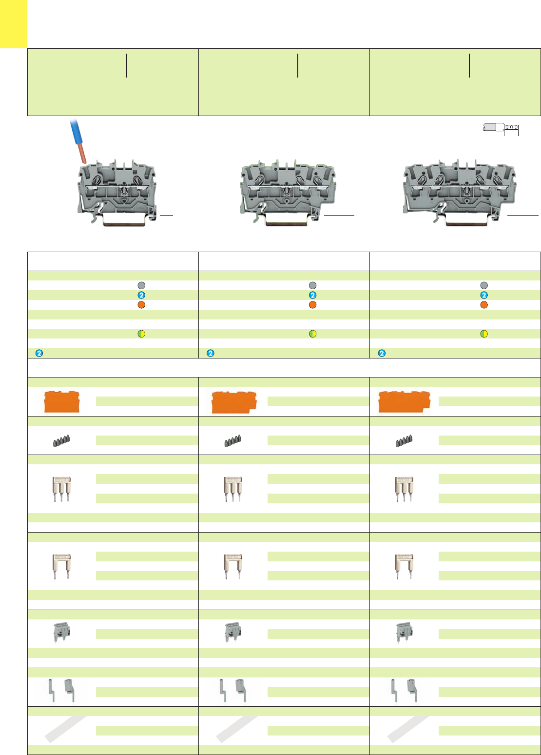
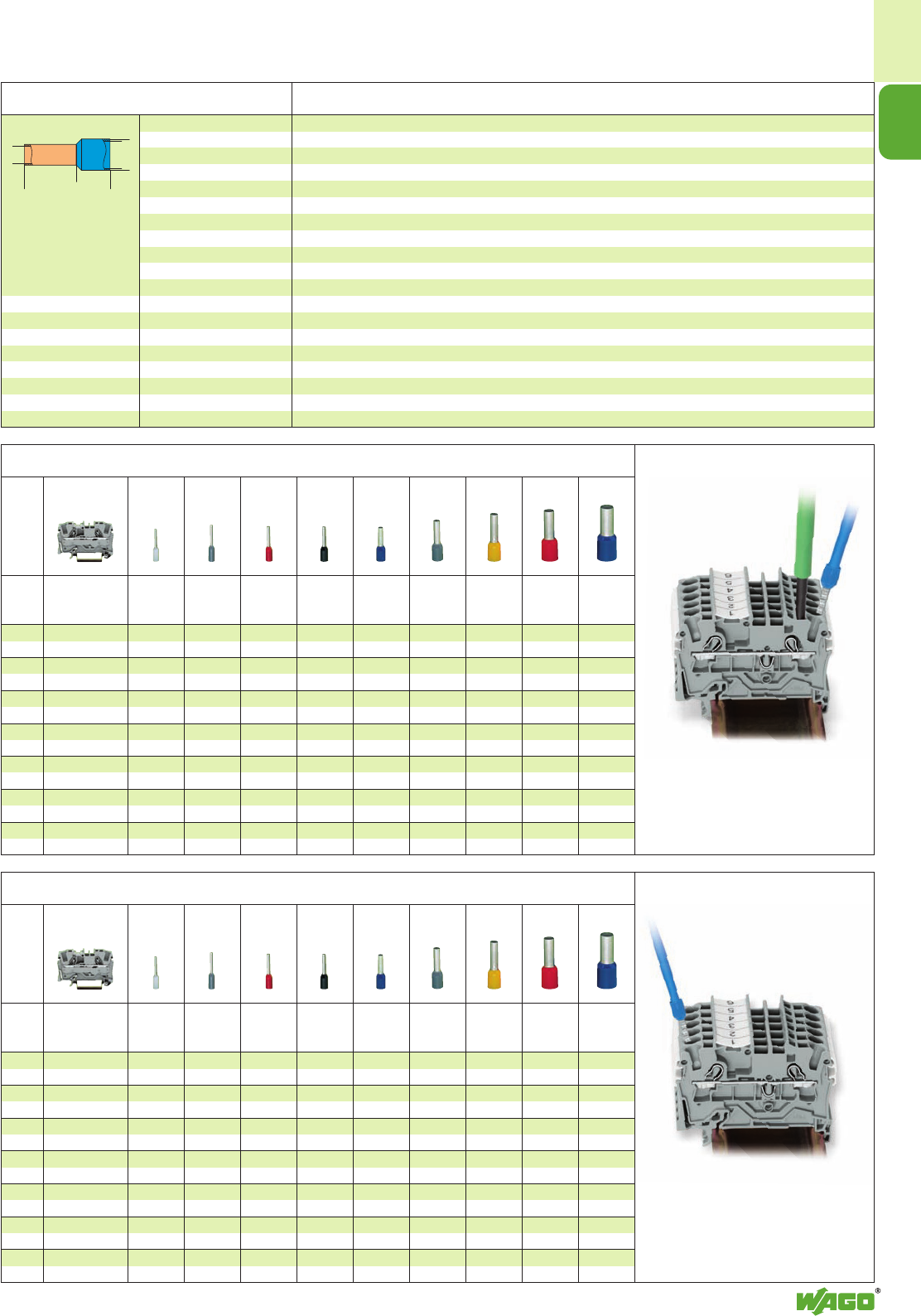
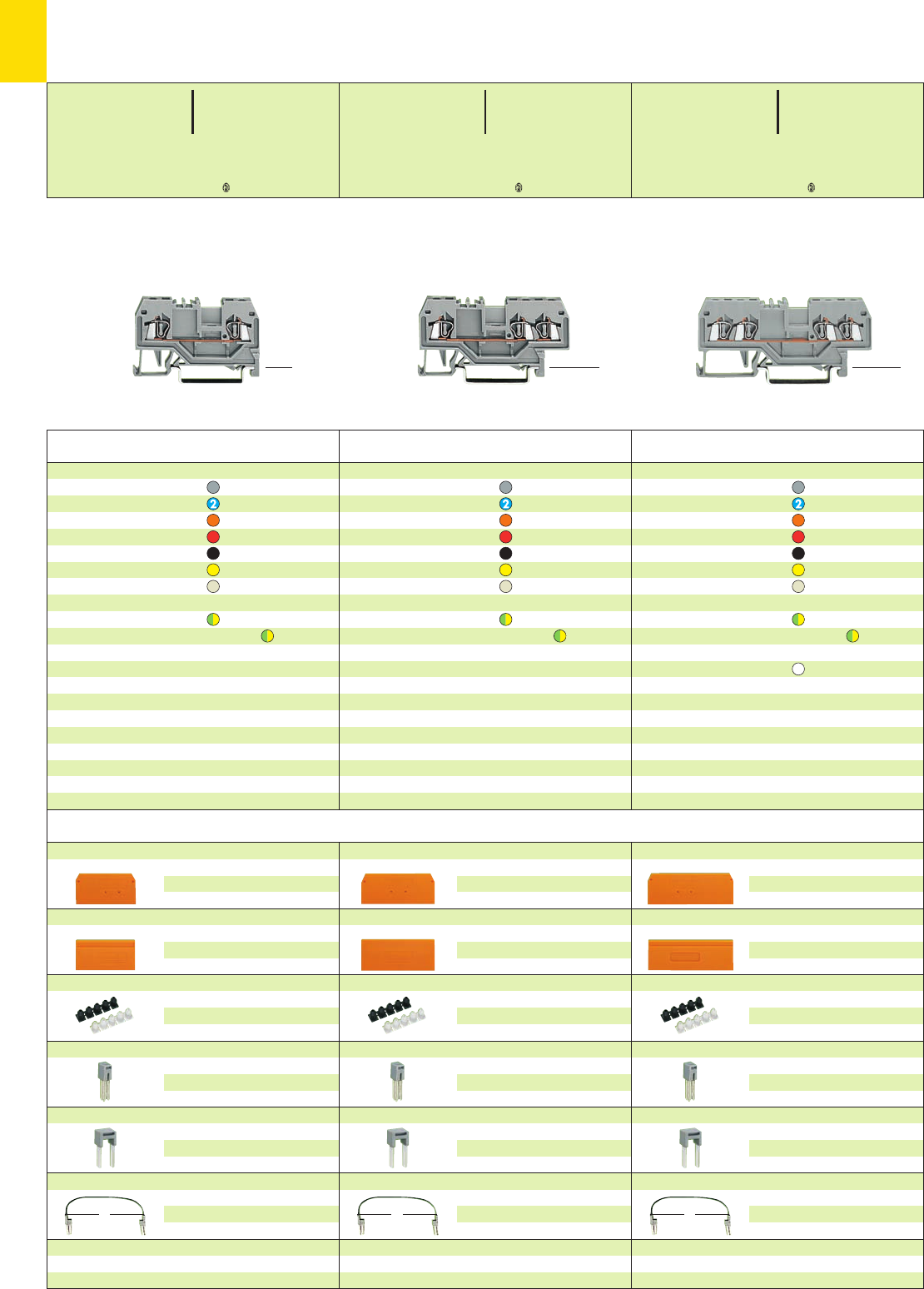
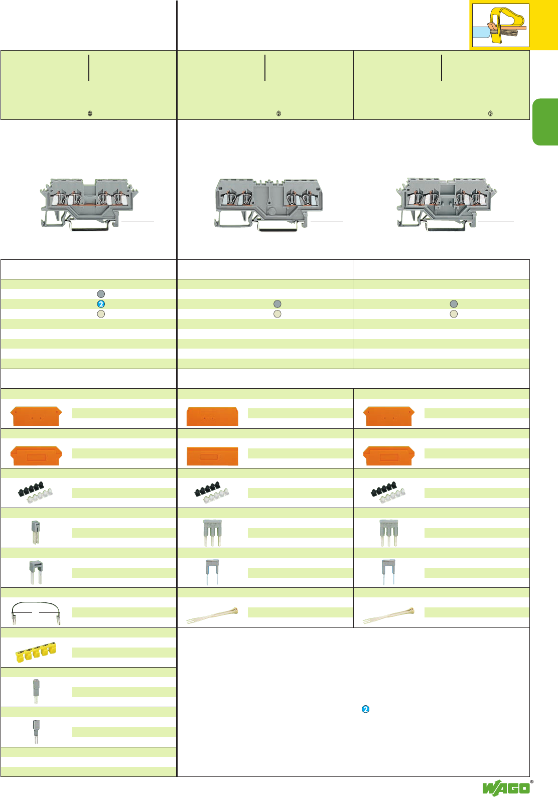
TOPJOB®S
Rail-Mounted Terminal Blocks 1.5 (2.5) mm2/AWG 14
Series 2001
* For further approvals with corresponding ratings see section 15.
Accessories appropriate marker system WMB/Marker strips (see section 14)
Item Pack.-unit
No. pcs
Item Pack.-unit
No. pcs
Item Pack.-unit
No. pcs
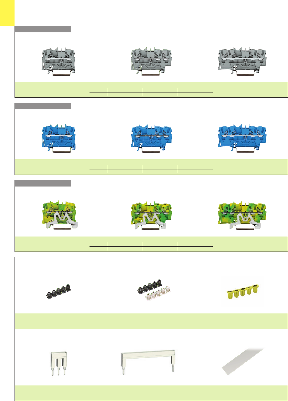
4-conductor through terminal blocks
grey 2001-1401 100
blue 2001-1404 100
orange 2001-1402 100
more colors are being prepared
4-conductor ground (earth) terminal block
green-yellow 2001-1407 100
4Ex e II applications are being prepared
Suitable for Ex i applications
3-conductor through terminal blocks
grey 2001-1301 100
blue 2001-1304 100
orange 2001-1302 100
more colors are being prepared
3-conductor ground (earth) terminal block
green-yellow 2001-1307 100
4Ex e II applications are being prepared
Suitable for Ex i applications
2-conductor through terminal blocks
grey 2001-1201 100
blue 2001-1204 100
orange 2001-1202 100
more colors are being prepared
2-conductor ground (earth) terminal block
green-yellow 2001-1207 100
4Ex e II applications are being prepared
Suitable for Ex i applications
End and intermediate plate, 0.8 mm /0.031 in thick
orange 2002-1492100 (4 x 25)
grey 2002-1491100 (4 x 25)
Insulation stop, 5 pcs/strip 200 strips
dark grey2001-172 0.75-1 mm2
Push-in type jumper bars, light grey, insulated, IN18 A
2-way 2001-402 200 (8 x 25)
3-way 2001-403 200 (8 x 25)
4-way 2001-404 200 (8 x 25)
5-way 2001-405 100 (4 x 25)
::
10-way 2001-410 100 (4 x 25)
Push-in type jumper bars, light grey, insulated, IN18 A
1 - 3 2001-433 200 (8 x 25)
1 - 4 2001-434 200 (8 x 25)
1 - 5 2001-435 100 (4 x 25)
::
1 - 10 2001-440 100 (4 x 25)
Modular TOPJOB®S connector,
for jumper contact slot
1pole 2001-501 100 (4 x 25)
Spacer, modular 2001-549 100 (4 x 25)
see also page 1.12
Test plug adapter, for test plug 4 mm/0.157 in Ø
2009-174 100 (4 x 25)
Testing tap, for max. 2.5 mm2
2009-182 100 (4 x 25)
Marker strip, white, plain
for center marking
11 mm /0.433 in wide
50 m 2009-110 1
on roll 300 m 2009-130 1
End and intermediate plate, 0.8 mm /0.031 in thick
orange 2002-1392100 (4 x 25)
grey 2002-1391100 (4 x 25)
Insulation stop, 5 pcs/strip 200 strips
dark grey2001-172 0.75-1 mm2
Push-in type jumper bars, light grey, insulated, IN18 A
2-way 2001-402 200 (8 x 25)
3-way 2001-403 200 (8 x 25)
4-way 2001-404 200 (8 x 25)
5-way 2001-405 100 (4 x 25)
::
10-way 2001-410 100 (4 x 25)
Push-in type jumper bars, light grey, insulated, IN18 A
1 - 3 2001-433 200 (8 x 25)
1 - 4 2001-434 200 (8 x 25)
1 - 5 2001-435 100 (4 x 25)
::
1 - 10 2001-440 100 (4 x 25)
Modular TOPJOB®S connector,
for jumper contact slot
1pole 2001-501 100 (4 x 25)
Spacer, modular 2001-549 100 (4 x 25)
see also page 1.12
Test plug adapter, for test plug 4 mm/0.157 in Ø
2009-174 100 (4 x 25)
Testing tap, for max. 2.5 mm2
2009-182 100 (4 x 25)
Marker strip, white, plain
for center marking
11 mm /0.433 in wide
50 m 2009-110 1
on roll 300 m 2009-130 1
End and intermediate plate, 0.8 mm /0.031 in thick
orange 2002-1292100 (4 x 25)
grey 2002-1291100 (4 x 25)
Insulation stop, 5 pcs/strip 200 strips
dark grey2001-172 0.75-1 mm2
Push-in type jumper bars, light grey, insulated, IN18 A
2-way 2001-402 200 (8 x 25)
3-way 2001-403 200 (8 x 25)
4-way 2001-404 200 (8 x 25)
5-way 2001-405 100 (4 x 25)
::
10-way 2001-410 100 (4 x 25)
Push-in type jumper bars, light grey, insulated, IN18 A
1 - 3 2001-433 200 (8 x 25)
1 - 4 2001-434 200 (8 x 25)
1 - 5 2001-435 100 (4 x 25)
::
1 - 10 2001-440 100 (4 x 25)
Modular TOPJOB®S connector,
for jumper contact slot
1pole 2001-501 100 (4 x 25)
Spacer, modular 2001-549 100 (4 x 25)
see also page 1.12
Test plug adapter, for test plug 4 mm/0.157 in Ø
2009-174 100 (4 x 25)
Testing tap, for max. 2.5 mm2
2009-182 100 (4 x 25)
Marker strip, white, plain
for center marking
11 mm /0.433 in wide
50 m 2009-110 1
on roll 300 m 2009-130 1
➊ Push-in conductor sizes: AWG 20 – 14 (0.5 mm2– 2.5 mm2) “s“ and AWG 18 – 16 (0.75 mm2– 1.5 mm2) “insulated ferrules, 12 mm“
0.25 –1.5 (2.5) mm2➊AWG 22 – 14
800 V/8 kV/3 600 V, 15 A U
18 A 600 V, 15 A 2
Terminal block width 4.2 mm / 0.165 in
L9 – 11 mm / 0.39 in
0.25 –1.5 (2.5) mm2➊AWG 22 – 14
800 V/8 kV/3 600 V, 15 A U
18 A 600 V, 15 A 2
Terminal block width 4.2 mm / 0.165 in
L9 – 11 mm / 0.39 in
0.25 –1.5 (2.5) mm2➊AWG 22 – 14
800 V/8 kV/3 600 V, 15 A U
18 A 600 V, 15 A 2
Terminal block width 4.2 mm / 0.165 in
L9 – 11 mm / 0.39 in
<_12 _>
<____________ 70 mm /2.76 in ____________><____ 48.5 mm /1.91 in ____> <_______ 59.5 mm /2.34 in ________>
<___ 33 mm/ ___>
1.3 in
<___ 33 mm/ ___>
1.3 in
<___ 33 mm/___>
1.3 in
1
1
7
444
*UY2KCCA {4
*UY2KCCA {4 *UY2KCCA {4
* For further approvals with corresponding ratings see section 15.
Accessories appropriate marker system WMB/Miniature WSB/Marker strips (see section 14)
End and intermediate plate, 0.8 mm /0.031 in thick
orange 2002-1492100 (4 x 25)
grey 2002-1491100 (4 x 25)
Insulation stop, 5 pcs/strip 200 strips
light grey 2002-171 0.25-0.5 mm2
dark grey2002-172 0.75-1 mm2
Push-in type jumper bars, light grey, insulated,
IN25 A, 420 A
2-way 2002-402 200 (8 x 25)
3-way 2002-403 200 (8 x 25)
4-way 2002-404 200 (8 x 25)
5-way 2002-405 100 (4 x 25)
::
10-way 2002-410 100 (4 x 25)
Push-in type jumper bars, light grey, insulated,
IN25 A, 420 A
1 - 3 2002-433 200 (8 x 25)
1 - 4 2002-434 200 (8 x 25)
1 - 5 2002-435 100 (4 x 25)
::
1 - 10 2002-440 100 (4 x 25)
Protective warning marker,
for 5 terminal blocks
yellow 2002-115 100 (4 x 25)
Modular TOPJOB®S connector,
for jumper contact slot
1pole 2002-501 100 (4 x 25)
Spacer, modular 2002-549 100 (4 x 25)
see also page 1.12
Test plug adapter, for test plug 4 mm/0.157 in Ø
2009-174 100 (4 x 25)
Testing tap, for max. 2.5 mm2
2009-182 100 (4 x 25)
End and intermediate plate, 0.8 mm /0.031 in thick
orange 2002-1392100 (4 x 25)
grey 2002-1391100 (4 x 25)
Insulation stop, 5 pcs/strip 200 strips
light grey 2002-171 0.25-0.5 mm2
dark grey2002-172 0.75-1 mm2
Push-in type jumper bars, light grey, insulated,
IN25 A, 420 A
2-way 2002-402 200 (8 x 25)
3-way 2002-403 200 (8 x 25)
4-way 2002-404 200 (8 x 25)
5-way 2002-405 100 (4 x 25)
::
10-way 2002-410 100 (4 x 25)
Push-in type jumper bars, light grey, insulated,
IN25 A, 420 A
1 - 3 2002-433 200 (8 x 25)
1 - 4 2002-434 200 (8 x 25)
1 - 5 2002-435 100 (4 x 25)
::
1 - 10 2002-440 100 (4 x 25)
Protective warning marker,
for 5 terminal blocks
yellow 2002-115 100 (4 x 25)
Modular TOPJOB®S connector,
for jumper contact slot
1pole 2002-501 100 (4 x 25)
Spacer, modular 2002-549 100 (4 x 25)
see also page 1.12
Test plug adapter, for test plug 4 mm/0.157 in Ø
2009-174 100 (4 x 25)
Testing tap, for max. 2.5 mm2
2009-182 100 (4 x 25)
End and intermediate plate, 0.8 mm /0.031 in thick
orange 2002-1292100 (4 x 25)
grey 2002-1291100 (4 x 25)
Insulation stop, 5 pcs/strip 200 strips
light grey 2002-171 0.25-0.5 mm2
dark grey2002-172 0.75-1 mm2
Push-in type jumper bars, light grey, insulated,
IN25 A, 420 A
2-way 2002-402 200 (8 x 25)
3-way 2002-403 200 (8 x 25)
4-way 2002-404 200 (8 x 25)
5-way 2002-405 100 (4 x 25)
::
10-way 2002-410 100 (4 x 25)
Push-in type jumper bars, light grey, insulated,
IN25 A, 420 A
1 - 3 2002-433 200 (8 x 25)
1 - 4 2002-434 200 (8 x 25)
1 - 5 2002-435 100 (4 x 25)
::
1 - 10 2002-440 100 (4 x 25)
Protective warning marker,
for 5 terminal blocks
yellow 2002-115 100 (4 x 25)
Modular TOPJOB®S connector,
for jumper contact slot
1pole 2002-501 100 (4 x 25)
Spacer, modular 2002-549 100 (4 x 25)
see also page 1.12
Test plug adapter, for test plug 4 mm/0.157 in Ø
2009-174 100 (4 x 25)
Testing tap, for max. 2.5 mm2
2009-182 100 (4 x 25)
Item Pack.-unit
No. pcs
Item Pack.-unit
No. pcs
Item Pack.-unit
No. pcs
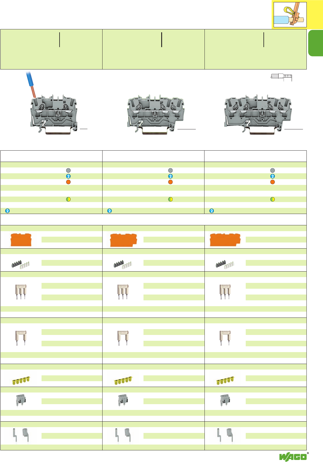
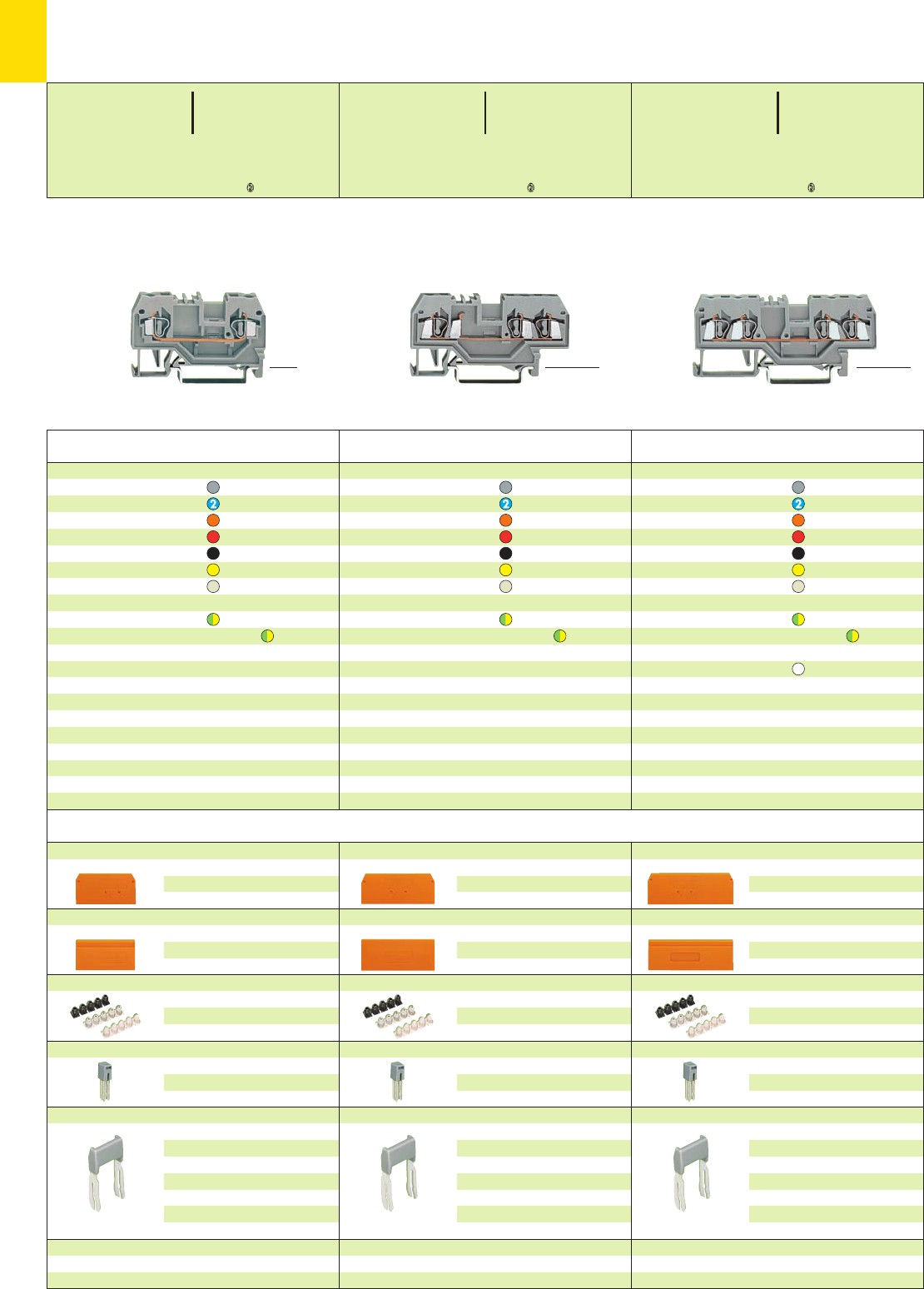
TOPJOB®S
Rail-Mounted Terminal Blocks 2.5 (4) mm2/AWG 12
Series 2002
4-conductor through terminal blocks
grey 42002-1401 100
blue 42002-1404 100
orange 42002-1402 100
more colors are being prepared
4-conductor ground (earth) terminal block
green-yellow 42002-1407 100
4Suitable for Ex e II applications 550 V, 22 A
Suitable for Ex i applications
3-conductor through terminal blocks
grey 42002-1301 100
blue 42002-1304 100
orange 42002-1302 100
more colors are being prepared
3-conductor ground (earth) terminal block
green-yellow 42002-1307 100
4Suitable for Ex e II applications 550 V, 22 A
Suitable for Ex i applications
2-conductor through terminal blocks
grey 42002-1201 100
blue 42002-1204 100
orange 42002-1202 100
more colors are being prepared
2-conductor ground (earth) terminal block
green-yellow 42002-1207 100
4Suitable for Ex e II applications 550 V, 22 A
Suitable for Ex i applications
➊ Push-in conductor sizes: AWG 18 – 12 (0.75 mm2– 4 mm2) “s“ and AWG 18 – 14 (0.75 mm2– 2.5 mm2) “insulated ferrules, 12 mm“
0.25 – 2.5 (4) mm2➊AWG 22 – 12
800 V/8 kV/3 600 V, 20 A U
24 A 600 V, 20 A 2
Terminal block width 5.2 mm / 0.205 in
L10 – 12 mm / 0.43 in
0.25 – 2.5 (4) mm2➊AWG 22 – 12
800 V/8 kV/3 600 V, 20 A U
24 A 600 V, 20 A 2
Terminal block width 5.2 mm / 0.205 in
L10 – 12 mm / 0.43 in
0.25 – 2.5 (4) mm2➊AWG 22 – 12
800 V/8 kV/3 600 V, 20 A U
24 A 600 V, 20 A 2
Terminal block width 5.2 mm / 0.205 in
L10 – 12 mm / 0.43 in
<_12 _>
<____ 48.5 mm /1.91 in ____> <________ 59.5mm /2.34 in _________> <_____________ 70 mm /2.76 in _____________>
<___ 33 mm/ ___>
1.3 in
<___ 33 mm/ ___>
1.3 in
<___ 33 mm/ ___>
1.3 in
1
8
*U2
*U2 *U2
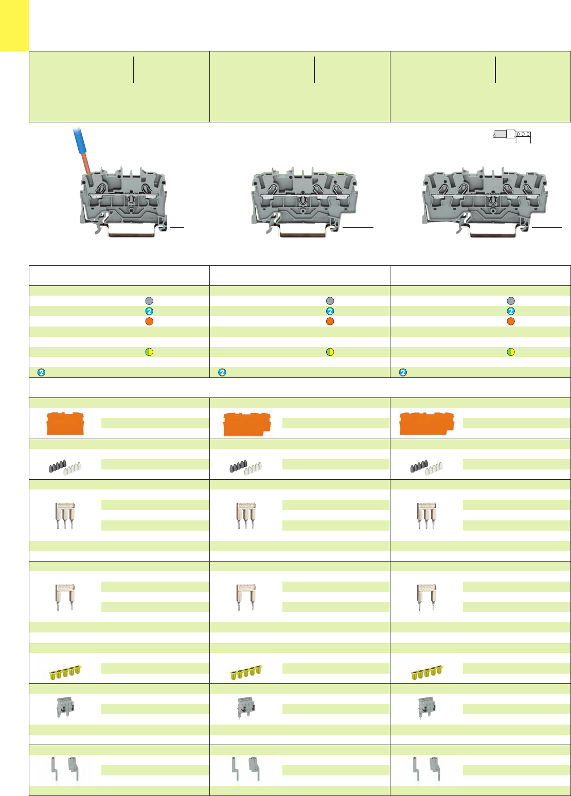
Accessories appropriate marker system WMB/Miniature WSB/Marker strips (see section 14)
End and intermediate plate, 1 mm /0.039 in thick
orange 2004-1492100 (4 x 25)
grey 2004-1491100 (4 x 25)
Insulation stop, 5 pcs/strip 200 strips
light grey 2004-171 0.25-0.5 mm2
dark grey2004-172 0.75-1 mm2
Push-in type jumper bars, light grey, insulated, IN32 A
2-way 2004-402 100 (4 x 25)
3-way 2004-403 100 (4 x 25)
4-way 2004-404 100 (4 x 25)
5-way 2004-405 50 (2 x 25)
::
10-way 2004-410 50 (2 x 25)
Push-in type jumper bars, light grey, insulated, IN32 A
1 - 3 2004-433 100 (4 x 25)
1 - 4 2004-434 100 (4 x 25)
1 - 5 2004-435 50 (2 x 25)
::
1 - 10 2004-440 50 (2 x 25)
Protective warning marker,
for 5 terminal blocks
yellow 2004-115 100 (4 x 25)
Modular TOPJOB®S connector,
for jumper contact slot
1pole 2004-501 100 (4 x 25)
Spacer, modular 2004-549 100 (4 x 25)
see also page 1.12
Test plug adapter, for test plug 4 mm/0.157 in Ø
2009-174 100 (4 x 25)
Testing tap, for max. 2.5 mm2
2009-182 100 (4 x 25)
End and intermediate plate, 1 mm /0.039 in thick
orange 2004-1392100 (4 x 25)
grey 2004-1391100 (4 x 25)
Insulation stop, 5 pcs/strip 200 strips
light grey 2004-171 0.25-0.5 mm2
dark grey2004-172 0.75-1 mm2
Push-in type jumper bars, light grey, insulated, IN32 A
2-way 2004-402 100 (4 x 25)
3-way 2004-403 100 (4 x 25)
4-way 2004-404 100 (4 x 25)
5-way 2004-405 50 (2 x 25)
::
10-way 2004-410 50 (2 x 25)
Push-in type jumper bars, light grey, insulated, IN32 A
1 - 3 2004-433 100 (4 x 25)
1 - 4 2004-434 100 (4 x 25)
1 - 5 2004-435 50 (2 x 25)
::
1 - 10 2004-440 50 (2 x 25)
Protective warning marker,
for 5 terminal blocks
yellow 2004-115 100 (4 x 25)
Modular TOPJOB®S connector,
for jumper contact slot
1pole 2004-501 100 (4 x 25)
Spacer, modular 2004-549 100 (4 x 25)
see also page 1.12
Test plug adapter, for test plug 4 mm/0.157 in Ø
2009-174 100 (4 x 25)
Testing tap, for max. 2.5 mm2
2009-182 100 (4 x 25)
End and intermediate plate, 1 mm /0.039 in thick
orange 2004-1292100 (4 x 25)
grey 2004-1291100 (4 x 25)
Insulation stop, 5 pcs/strip 200 strips
light grey 2004-171 0.25-0.5 mm2
dark grey2004-172 0.75-1 mm2
Push-in type jumper bars, light grey, insulated, IN32 A
2-way 2004-402 100 (4 x 25)
3-way 2004-403 100 (4 x 25)
4-way 2004-404 100 (4 x 25)
5-way 2004-405 50 (2 x 25)
::
10-way 2004-410 50 (2 x 25)
Push-in type jumper bars, light grey, insulated, IN32 A
1 - 3 2004-433 100 (4 x 25)
1 - 4 2004-434 100 (4 x 25)
1 - 5 2004-435 50 (2 x 25)
::
1 - 10 2004-440 50 (2 x 25)
Protective warning marker,
for 5 terminal blocks
yellow 2004-115 100 (4 x 25)
Modular TOPJOB®S connector,
for jumper contact slot
1pole 2004-501 100 (4 x 25)
Spacer, modular 2004-549 100 (4 x 25)
see also page 1.12
Test plug adapter, for test plug 4 mm/0.157 in Ø
2009-174 100 (4 x 25)
Testing tap, for max. 2.5 mm2
2009-182 100 (4 x 25)
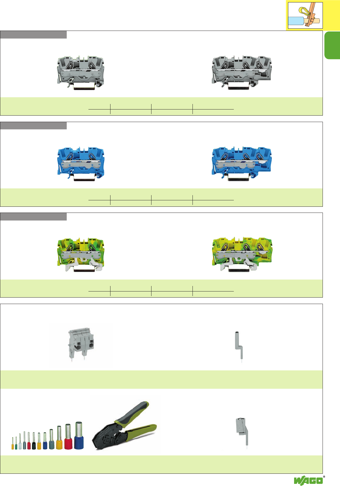
4-conductor through terminal blocks
grey 2004-1401 50
blue 2004-1404 50
orange 2004-1402 50
more colors are being prepared
4-conductor ground (earth) terminal block
green-yellow 2004-1407 50
4Ex e II applications are being prepared
Suitable for Ex i applications
3-conductor through terminal blocks
grey 2004-1301 50
blue 2004-1304 50
orange 2004-1302 50
more colors are being prepared
3-conductor ground (earth) terminal block
green-yellow 2004-1307 50
4Ex e II applications are being prepared
Suitable for Ex i applications
2-conductor through terminal blocks
grey 2004-1201 50
blue 2004-1204 50
orange 2004-1202 50
more colors are being prepared
2-conductor ground (earth) terminal block
green-yellow 2004-1207 50
4Ex e II applications are being prepared
Suitable for Ex i applications
Item Pack.-unit
No. pcs
Item Pack.-unit
No. pcs
Item Pack.-unit
No. pcs
TOPJOB®S
Rail-Mounted Terminal Blocks 4 (6) mm2/AWG 10
Series 2004
* For further approvals with corresponding ratings see section 15.
➊ Push-in conductor sizes: AWG 17 – 10 (1 mm2– 6 mm2) “s“ and AWG 18 – 12 (0.75 mm2– 4 mm2) “insulated ferrules, 12 mm“
0.5 – 4 (6) mm2➊AWG 20 – 10
800 V/8 kV/3 600 V, 30 A U
32 A 600 V, 30 A 2
Terminal block width 6.2 mm / 0.244 in
L11 – 13 mm / 0.47 in
0.5 – 4 (6) mm2➊AWG 20 – 10
800 V/8 kV/3 600 V, 30 A U
32 A 600 V, 30 A 2
Terminal block width 6.2 mm / 0.244 in
L11 – 13 mm / 0.47 in
0.5 – 4 (6) mm2➊AWG 20 – 10
800 V/8 kV/3 600 V, 30 A U
32 A 600 V, 30 A 2
Terminal block width 6.2 mm / 0.244 in
L11 – 13 mm / 0.47 in
<_12 _>
<____ 52.5 mm /2.07 in ____> <________ 65.5 mm /2.58 in ________> <_____________ 79 mm /3.11 in _____________>
<___ 33 mm/ ___>
1.3 in
<___ 33 mm/ ___>
1.3 in
<___ 33 mm/ ___>
1.3 in
1
1
9
*UY2KCCA {
*UY2KCCA {
TOPJOB®S
Rail-Mounted Terminal Blocks 6 (10) mm2/AWG 8
Series 2006
* For further approvals with corresponding ratings see section 15.
Accessories appropriate marker system WMB/Miniature WSB/Marker strips (see section 14)
End and intermediate plate, 1 mm /0.039 in thick
orange 2006-1392100 (4 x 25)
grey 2006-1391100 (4 x 25)
Push-in type jumper bars, light grey, insulated, IN41 A
2-way 2006-402 50 (2 x 25)
3-way 2006-403 50 (2 x 25)
4-way 2006-404 50 (2 x 25)
5-way 2006-405 50 (2 x 25)
Push-in type jumper bars, light grey, insulated, IN41 A
1 - 3 2006-433 50 (2 x 25)
1 - 4 2006-434 50 (2 x 25)
1 - 5 2006-435 50 (2 x 25)
Protective warning marker,
for 5 terminal blocks
yellow 2006-115 100 (4 x 25)
Test plug adapter, for test plug 4 mm/0.157 in Ø
2009-174 100 (4 x 25)
Testing tap, for max. 2.5 mm2
2009-182 100 (4 x 25)
Marker strip, white, plain
for center marking
11 mm /0.433 in wide
50 m 2009-110 1
on roll 300 m 2009-130 1
End and intermediate plate, 1 mm /0.039 in thick
orange 2006-1292100 (4 x 25)
grey 2006-1291100 (4 x 25)
Push-in type jumper bars, light grey, insulated, IN41 A
2-way 2006-402 50 (2 x 25)
3-way 2006-403 50 (2 x 25)
4-way 2006-404 50 (2 x 25)
5-way 2006-405 50 (2 x 25)
Push-in type jumper bars, light grey, insulated, IN41 A
1 - 3 2006-433 50 (2 x 25)
1 - 4 2006-434 50 (2 x 25)
1 - 5 2006-435 50 (2 x 25)
Protective warning marker,
for 5 terminal blocks
yellow 2006-115 100 (4 x 25)
Test plug adapter, for test plug 4 mm/0.157 in Ø
2009-174 100 (4 x 25)
Testing tap, for max. 2.5 mm2
2009-182 100 (4 x 25)
Marker strip, white, plain
for center marking
11 mm /0.433 in wide
50 m 2009-110 1
on roll 300 m 2009-130 1
3-conductor through terminal blocks
grey 2006-1301 25
blue 2006-1304 25
orange 2006-1302 25
3-conductor ground (earth) terminal block
green-yellow 2006-1307 25
4Ex e II applications are being prepared
Suitable for Ex i applications
2-conductor through terminal blocks
grey 2006-1201 50
blue 2006-1204 50
orange 2006-1202 50
2-conductor ground (earth) terminal block
green-yellow 2006-1207 50
4Ex e II applications are being prepared
Suitable for Ex i applications
Item Pack.-unit
No. pcs
Item Pack.-unit
No. pcs
Commoning with push-in type
jumper bars
Commoning over the open side of the
terminal block with end plate allows
jumpering over one cross section size for 6 mm2,
4 mm2and 2.5 mm2.
Commoning over the closed side of the
terminal block with end plate allows
jumpering over two cross section sizes:
e.g. from 6 mm2to 2.5 mm2(see blue terminal
blocks).
Commoning with step-down jumpers
Note:
The total current flowing must not exceed
the rating of the step-down jumper/push-in
type jumper bar.
Step-down jumper, light grey, insulated
32 A
2006-499 50 (2 x 25)
0.5 – 6 (10) mm2➊AWG 20 – 8
800 V/8 kV/3 600 V, 50 A U
41 A 600 V, 50 A 2
Terminal block width 7.5 mm / 0.295 in
L13 – 15 mm / 0.55 in
0.5 – 6 (10) mm2➊AWG 20 – 8
800 V/8 kV/3 600 V, 50 A U
41 A 600 V, 50 A 2
Terminal block width 7.5 mm / 0.295 in
L13 – 15 mm / 0.55 in
Item Pack.-unit
No. pcs
Commoning with step-down jumpers
An end plate must be applied between the two terminal
blocks.
Step-down jumper 2006-499 can be used for
commoning AWG 12/10 (4/6 mm2) terminal blocks with
AWG 12/14/16 (4/2.5/1.5 mm2) terminal blocks.
Step-down jumpers are simply pushed down to full
insertion, in the same way as all other push-in type
jumper bars.
<_12 _>
<_____ 57.5 mm /2.26 in ______> <____________ 73.5 mm /2.89 in ___________>
<___ 33 mm/ ___>
1.3 in
<___ 33 mm/ ___>
1.3 in
➊ Push-in conductor sizes: AWG 16 – 8 (1.5 mm2– 10 mm2) “s“ and
AWG 16 – 10 (1.5 mm2– 6 mm2) “insulated ferrules, 12 mm“
1
10
*U2
*U2
* For further approvals with corresponding ratings see section 15.
TOPJOB®S
Rail-Mounted Terminal Blocks 10 (16) mm2/AWG 6
Series 2010
Accessories appropriate marker system WMB/Miniature WSB/Marker strips (see section 14)
Step-down jumper, light grey, insulated
57 A
2016-499 50 (2 x 25)
End and intermediate plate, 1 mm /0.039 in thick
orange 2010-1392100 (4 x 25)
grey 2010-1391100 (4 x 25)
Push-in type jumper bars, light grey, insulated, IN57 A
2-way 2010-402 50 (2 x 25)
3-way 2010-403 50 (2 x 25)
4-way 2010-404 50 (2 x 25)
5-way 2010-405 50 (2 x 25)
Push-in type jumper bars, light grey, insulated, IN57 A
1 - 3 2010-433 50 (2 x 25)
1 - 4 2010-434 50 (2 x 25)
1 - 5 2010-435 50 (2 x 25)
Protective warning marker,
for 5 terminal blocks
yellow 2010-115 100 (4 x 25)
Test plug adapter, for test plug 4 mm Ø
2009-174 100 (4 x 25)
Testing tap, for max. 2.5 mm2
2009-182 100 (4 x 25)
Marker strip, white, plain
for center marking
11 mm /0.433 in wide
50 m 2009-110 1
on roll 300 m 2009-130 1
End and intermediate plate, 1 mm /0.039 in thick
orange 2010-1292100 (4 x 25)
grey 2010-1291100 (4 x 25)
Push-in type jumper bars, light grey, insulated, IN57 A
2-way 2010-402 50 (2 x 25)
3-way 2010-403 50 (2 x 25)
4-way 2010-404 50 (2 x 25)
5-way 2010-405 50 (2 x 25)
Push-in type jumper bars, light grey, insulated, IN57 A
1 - 3 2010-433 50 (2 x 25)
1 - 4 2010-434 50 (2 x 25)
1 - 5 2010-435 50 (2 x 25)
Protective warning marker,
for 5 terminal blocks
yellow 2010-115 100 (4 x 25)
Test plug adapter, for test plug 4 mm Ø
2009-174 100 (4 x 25)
Testing tap, for max. 2.5 mm2
2009-182 100 (4 x 25)
Marker strip, white, plain
for center marking
11 mm /0.433 in wide
50 m 2009-110 1
on roll 300 m 2009-130 1
Commoning with step-down jumpers
An end plate must be applied between the two terminal
blocks.
Step-down jumper 2016-499 can be used for
commoning AWG 8/6 (10/16 mm2) terminal blocks with
AWG 8/10/12/14 (10/6/4/2.5 mm2) terminal blocks.
Step-down jumpers are simply pushed down to full
insertion, in the same way as all other push-in type
jumper bars.
3-conductor through terminal blocks
grey 2010-1301 25
blue 2010-1304 25
orange 2010-1302 25
3-conductor ground (earth) terminal block
green-yellow 2010-1307 25
4Ex e II applications are being prepared
Suitable for Ex i applications
2-conductor through terminal blocks
grey 2010-1201 25
blue 2010-1204 25
orange 2010-1202 25
2-conductor ground (earth) terminal block
green-yellow 2010-1207 25
4Ex e II applications are being prepared
Suitable for Ex i applications
Item Pack.-unit
No. pcs
Item Pack.-unit
No. pcs
Commoning with step-down jumpers
Note:
The total current flowing must not exceed
the rating of the step-down jumper/push-in
type jumper bar.
➊ Push-in conductor sizes: AWG 14 – 6 (2.5 mm2– 16 mm2) “s“ and
AWG 14 – 8 (2.5 mm2– 10 mm2) “insulated ferrules, 18 mm“
0.5 – 10 (16) mm2➊AWG 20 – 6
800 V/8 kV/3 600 V, 65 A U
57 A 600 V, 65 A 2
Terminal block width 10 mm / 0.394 in
L17 – 19 mm / 0.71 in
0.5 – 10 (16) mm2➊AWG 20 – 6
800 V/8 kV/3 600 V, 65 A U
57 A 600 V, 65 A 2
Terminal block width 10 mm / 0.394 in
L17 – 19 mm / 0.71 in
Item Pack.-unit
No. pcs
<_18 _>
<________ 68 mm /2.68 in _________> <_________________ 89 mm /3.5 in __________________>
<___ 37 mm/ ___>
1.46 in
<___ 37 mm/ ___>
1.46 in
1
1
11
*UY2KCCA {
*UY2KCCA {
* For further approvals with corresponding ratings see section 15.
End and intermediate plate, 1 mm /0.039 in thick
orange 2016-1392100 (4 x 25)
grey 2016-1391100 (4 x 25)
Push-in type jumper bars, light grey, insulated, IN76 A
2-way 2016-402 50 (2 x 25)
3-way 2016-403 50 (2 x 25)
4-way 2016-404 50 (2 x 25)
5-way 2016-405 50 (2 x 25)
Push-in type jumper bars, light grey, insulated, IN76 A
1 - 3 2016-433 50 (2 x 25)
1 - 4 2016-434 50 (2 x 25)
1 - 5 2016-435 50 (2 x 25)
Protective warning marker,
for 5 terminal blocks
yellow 2016-115 100 (4 x 25)
Test plug adapter, for test plug 4 mm Ø
2009-174 100 (4 x 25)
Testing tap, for max. 2.5 mm2
2009-182 100 (4 x 25)
Marker strip, white, plain
for center marking
11 mm /0.433 in wide
50 m 2009-110 1
on roll 300 m 2009-130 1
End and intermediate plate, 1 mm /0.039 in thick
orange 2016-1292100 (4 x 25)
grey 2016-1291100 (4 x 25)
Push-in type jumper bars, light grey, insulated, IN76 A
2-way 2016-402 50 (2 x 25)
3-way 2016-403 50 (2 x 25)
4-way 2016-404 50 (2 x 25)
5-way 2016-405 50 (2 x 25)
Push-in type jumper bars, light grey, insulated, IN76 A
1 - 3 2016-433 50 (2 x 25)
1 - 4 2016-434 50 (2 x 25)
1 - 5 2016-435 50 (2 x 25)
Protective warning marker,
for 5 terminal blocks
yellow 2016-115 100 (4 x 25)
Test plug adapter, for test plug 4 mm Ø
2009-174 100 (4 x 25)
Testing tap, for max. 2.5 mm2
2009-182 100 (4 x 25)
Marker strip, white, plain
for center marking
11 mm /0.433 in wide
50 m 2009-110 1
on roll 300 m 2009-130 1
Commoning with step-down jumpers
An end plate must be applied between the two terminal
blocks.
Step-down jumper 2016-499 can be used for
commoning AWG 8/6 (10/16 mm2) terminal blocks with
AWG 8/10/12/14 (10/6/4/2.5 mm2) terminal blocks.
Step-down jumpers are simply pushed down to full
insertion, in the same way as all other push-in type
jumper bars.
3-conductor through terminal blocks
grey 2016-1301 20
blue 2016-1304 20
orange 2016-1302 20
3-conductor ground (earth) terminal block
green-yellow 2016-1307 20
4Ex e II applications are being prepared
Suitable for Ex i applications
2-conductor through terminal blocks
grey 2016-1201 20
blue 2016-1204 20
orange 2016-1202 20
2-conductor ground (earth) terminal block
green-yellow 2016-1207 20
4Ex e II applications are being prepared
Suitable for Ex i applications
Item Pack.-unit
No. pcs
Item Pack.-unit
No. pcs
TOPJOB®S
Rail-Mounted Terminal Blocks 16 (25 ”f-st”) mm2/AWG 4
Series 2016
Accessories appropriate marker system WMB/Miniature WSB/Marker strips (see section 14)
➊ Push-in conductor sizes: AWG 14 – 6 (2.5 mm2– 16 mm2) “s“ and
AWG 14 – 6 (2.5 mm2– 16 mm2) ”insulated ferrules, 18 mm“
Step-down jumper, light grey, insulated
57 A
2016-499 50 (2 x 25)
Commoning with step-down jumpers
Note:
The total current flowing must not exceed
the rating of the step-down jumper/push-in
type jumper bar.
0.5
– 16 (25
”f-st“
)mm
2
➊
AWG 20 – 4
800 V/8 kV/3 600 V, 85 A U
76 A 600 V, 85 A 2
Terminal block width 12 mm / 0.472 in
L18 – 20 mm / 0.75 in
0.5
– 16 (25
”f-st“
)mm
2
➊
AWG 20 – 4
800 V/8 kV/3 600 V, 85 A U
76 A 600 V, 85 A 2
Terminal block width 12 mm / 0.472 in
L18 – 20 mm / 0.75 in
Item Pack.-unit
No. pcs
Commoning with push-in type
jumper bars
Commoning over the open side of the
terminal block with end plate allows
jumpering over two cross section sizes for 16 mm2
and 10 mm2and one cross section size for 6 mm2,
4 mm2and 2.5 mm2:
e.g. from 16 mm2to 6 mm2(see orange terminal
blocks) or from 10 mm2to 4 mm2.
Commoning over the closed side of the
terminal block with end plate allows
jumpering over two cross section sizes:
e.g. from 16 mm2to 6 mm2or from 6 mm2to
2.5 mm2(see blue terminal blocks).
<_18 _>
<___________ 70 mm /2.76 in _________> <_________________ 92 mm /3.62 in ___________________>
<___ 37 mm/ ___>
1.46 in
<___ 37 mm/ ___>
1.46 in
1
12
Item Pack. unit
No. pcs
Item Pack. unit
No. pcs
Accessories appropriate marker system WMB/Mini-WSB/Marker strips (see section 14)
Application notes
Banana plugs, for sockets 4 mm/0.157 in Ø
see page 2.42
Test plug, 4 mm/0.157 in Ø,
touch proof,
not offered by WAGO
for ex. mfd by Multi Contact Deutschland GmbH
Test plug adapter,
for test plugs 4 mm/0.157 in Ø,
for testing rail-mounted terminal blocks
of series
2001/2002/2004/2006/2010/2016
2009-174 100 (4 x 25)
Testing tap,
for connecting individual test wires of AWG 28 to 14
(0.08 mm2– 2.5 mm2) without tools
2009-182 100 (4 x 25)
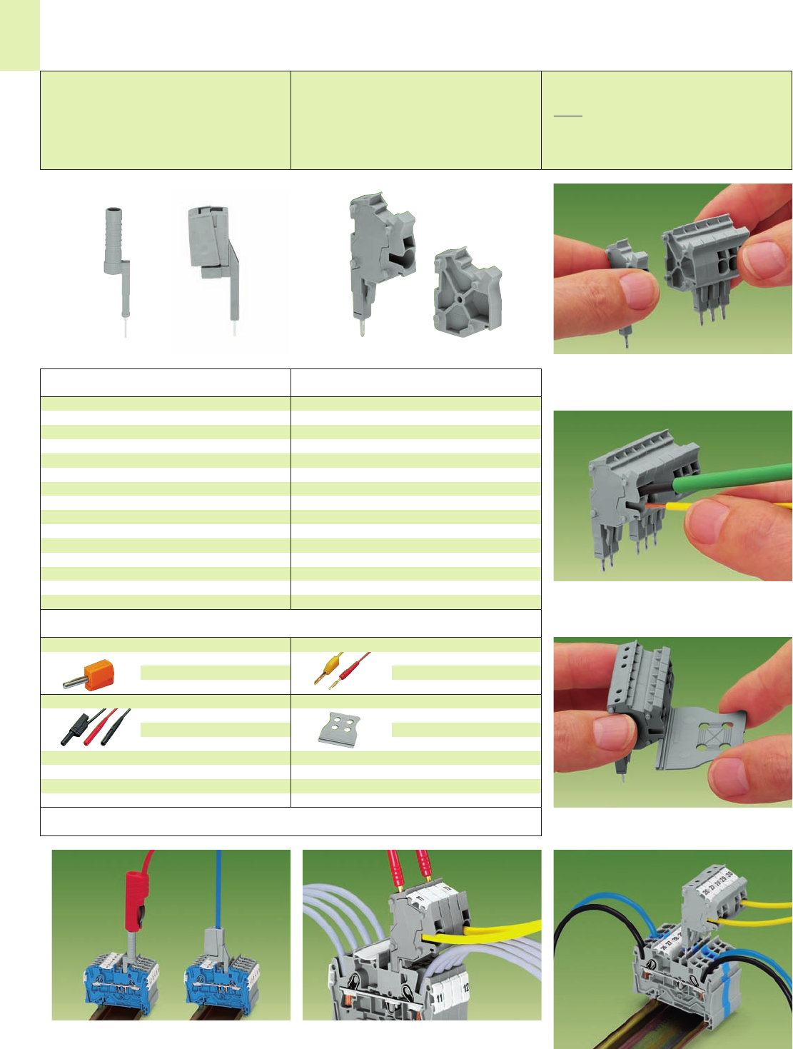
Modular TOPJOB®S connectors
with CAGE CLAMP®S connection, modular, grey,
for series 2001, module width 4.2 mm/0.165 in, 18 A
1 pole 2001-501 100 (4 x 25)
for Series 2002, module width 5.2 mm/0.205 in, 24 A
1 pole 2002-501 100 (4 x 25)
for Series 2004, module width 6.2 mm/0.244 in, 32 A
1 pole 2004-501 100 (4 x 25)
Spacer, modular, grey,
for series 2001, width 4.2 mm/0.165 in
2001-549 100 (4 x 25)
for series 2002, width 5.2 mm/0.205 in
2002-549 100 (4 x 25)
for series 2004, width 6.2 mm/0.244 in
2004-549 100 (4 x 25)
Snapping together of connectors and spacers to assem-
ble a multi-pole connector
The connector has a test socket for 2 mm/0.079 in or
2.3 mm/0.091 in test plugs.
Modular TOPJOB®S Connectors with
CAGE CLAMP®S Connection
Test plug adapter and testing tap
for testing rail-mounted terminal blocks
of series
2001/2002/2004/2006/2010/2016
Modular TOPJOB®S connectors ➊
for rail-mounted terminal blocks of series
2001 AWG 22 – 14 / 0.25 mm2– 1.5 (2.5) mm2
2002 AWG 22 – 12 / 0.25 mm2– 2.5 (4) mm2
2004 AWG 20 – 10 / 0.5 mm2– 4 (6) mm2
Wire connection:
Screwdriver actuation for connection of all conductor
types, i.e. stripped stranded conductors, or push-in
connection of solid or ferruled stranded conductors.
➊Test voltage 500 V/ 6 kV
Test current 18 A/24 A/32 A
Note: Unmated connectors must not be live.
Also, connectors used according to the
regulations must not be connected or
disconnected under load.
Test plug, with cable 500 mm/1’7.7’’
2 mm/0.079 in Ø, red
210-136 50
2.3 mm/0.091 in Ø, yel.
210-137 50
Strain relief plate, grey
snappable onto connector strips
6 mm /0.236 in wide
734-327 100 (4 x 25)
12.5 mm /0.492 in wide
734-328 100 (4 x 25)
25 mm /0.984 in wide
734-329 100 (4 x 25)
35 mm /1.378 in wide
734-326 100 (4 x 25)
Testing TOPJOB®S rail-mounted terminal blocks using a
test plug adapter or testing tap.
Snapping on a strain relief plate
Test Plug Adapter and
Testing Tap
The modular connectors provide an additional connec-
tion option for conductors of the same cross section
range as the terminal blocks being used.
<____ L1 ____>
<_ D1 _>
<__ D __>
<___________ L __________>
D2 <
<
1
1
13
Ferrules for TOPJOB®S Rail-mounted Terminal Blocks and
Crimping Tools
Rated
cross section
in mm2
0.25 – 1.5 (2.5)
0.25 – 2.5 (4)
0.25 – 2.5 (4)
0.5 – 4 (6)
0.5 – 6 (10)
0.5 – 10 (16)
0.5 – 16 (25)
Series
2001
2002
2003
2004
2006
2010
2016
0.5
mm2
216-241
216-241
216-241
––
––
––
––
0.75
mm2
216-242
216-242
216-242
216-262
216-262
––
––
1
mm2
216-243
216-243
216-243
216-263
216-263
––
––
1.5
mm2
216-244
216-244
216-244
216-264
216-264
216-284
216-284
2.5
mm2
––
216-246
216-246
216-266
216-266
216-286
216-286
4
mm2
––
––
––
216-267
216-267
216-287
216-287
6
mm2
––
––
––
––
216-208
216-288
216-288
10
mm2
––
––
––
––
––
216-289
216-289
16
mm2
––
––
––
––
––
––
216-210
TOPJOB®S – overview of directly connectable ferrules
Rated
cross section
in mm2
0.25 – 1.5 (2,5)
0.25 – 2.5 (4)
0.25 – 2.5 (4)
0.5 – 4 (6)
0.5 – 6 (10)
0.5 – 10 (16)
0.5 – 16 (25)
Series
2001
2002
2003
2004
2006
2010
2016
0.5
mm2
––
––
––
––
––
––
––
0.75
mm2
216-242
216-242
216-242
216-262
––
––
––
1
mm2
216-243
216-243
216-243
216-263
––
––
––
1.5
mm2
216-244
216-244
216-244
216-264
216-264
––
––
2.5
mm2
––
216-246
216-246
216-266
216-266
216-286
216-286
4
mm2
––
––
––
216-267
216-267
216-287
216-287
6
mm2
––
––
––
––
216-208
216-288
216-288
10
mm2
––
––
––
216-289
216-289
16
mm2
––
––
––
––
––
––
216-210
TOPJOB®S – overview of ferrules from 0.5 mm2
0.5 22 white 12 16 10 3.1 2.6 1.0 216-241 1000
0.75 20 grey 12 16 10 3.3 2.8 1.2 216-242 1000
0.75 20 grey 14 18 12 3.3 2.8 1.2 216-262 1000
1.0 18 red 12 16 10 3.5 3.0 1.4 216-243 1000
1.0 18 red 14 18 12 3.5 3.0 1.4 216-263 1000
1.5 16 black 12 16 10 4.0 3.5 1.7 216-244 1000
1.5 16 black 14 18 12 4.0 3.5 1.7 216-264 1000
1.5 16 black 20 24 18 4.0 3.5 1.7 216-284 1000
2.5 14 blue 12 17 10 4.7 4.2 2.2 216-246 1000
2.5 14 blue 14 19 12 4.7 4.2 2.2 216-266 1000
2.5 14 blue 20 25 18 4.7 4.2 2.2 216-286 1000
4.0 12 grey 14 20 12 5.4 4.8 2.8 216-267 500
4.0 12 grey 20 26 18 5.4 4.8 2.8 216-287 500
6.0 10 yellow 14 20 12 6.9 6.3 3.5 216-208 500
6.0 10 yellow 20 26 18 6.9 6.3 3.5 216-288 500
10.0 8 red 20 28 18 8.4 7.6 4.5 216-289 500
16.0 6 blue 23 28 18 9.6 8.8 5.8 216-210 500
2001 – 2002
2001 – 2002
2002 – 2006
2001 – 2002
2002 – 2006
2001 – 2002
2002 – 2006
2010 – 2016
2002
2002 – 2006
2010 – 2016
2004 – 2006
2010 – 2016
2006
2010 – 2016
2010 – 2016
2016
Sleeve for
Color Stripped L L1 D D1 D2 Item Pack.-unit
mm2AWG length mm mm No. pcs
Dimensions (in mm)
Insulated ferrules,
electrolytic copper,
electro-tin plated,
acc. to DIN 46228,
part 4/09.90
suitable for
series
Crimping tools see section 14
WAGO front-entry
rail-mounted terminal blocks
of series 279 to 285

2
2
VOLUME 1
Rail-Mounted Terminal Blocks (Front-Entry) and Multilevel Terminal Blocks
Through, ground (earth) conductor and shield (screen) terminal blocks
– angled type
– horizontal type
0.08 mm2to 16 mm2/ AWG 28 – 6 Series 279 – 284 and 880 2.8 – 2.20
Distribution terminal blocks
10 mm2/35 mm2/ AWG 8/2 Series 284 2.25
High current terminal blocks
6 mm2– 35 mm2/ AWG 8 – 2 Series 285 2.21
25 mm2– 95 mm2/ AWG 4 – 0000 Series 285 2.22 – 2.24
Multilevel terminal blocks
– Double deck 1.5 mm2/ AWG 16 Series 279
2.5 mm2/ AWG 12 Series 280
4 mm2/ AWG 12 Series 281 2.29 – 2.33
– Triple deck 2.5 mm2/ AWG 12 Series 280 2.34 – 2.35
– Quadruple deck 4 mm2/ AWG 12 Series 281 2.36
Accessories for rail-mounted terminal blocks
– Banana plugs 2.42
– Busbar terminal blocks 11.20 – 11.21
– Comb type jumper bars 2.44
– Insulations stops 2.43
– Staggered jumpers 2.45
– Step-down jumpers for through terminal blocks 2.26 – 2.27
– Test plug modules 2.38 – 2.41
– Wire jumpers 2.45
2
2
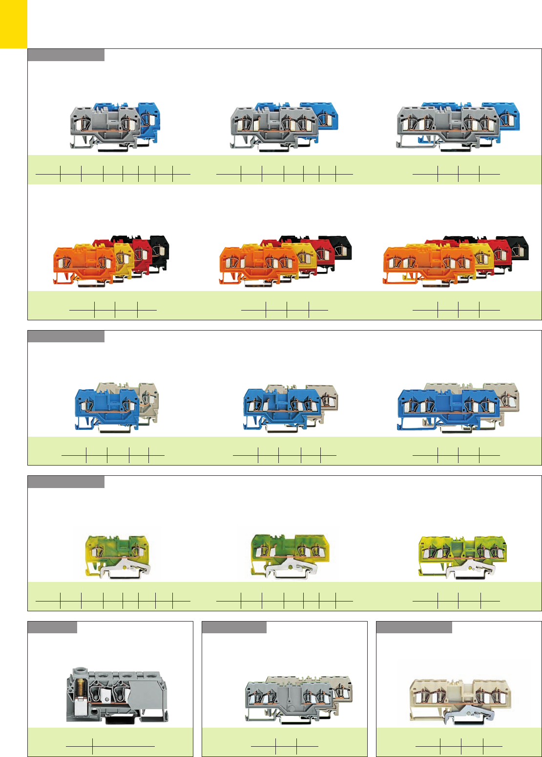
Rail-Mounted Terminal Blocks with CAGE CLAMP®Connection
– Product Summary –
Series 279 – 285
Series 284 Series 279 – 281
Series 279 – 285
Series 279 – 282 Through terminal blocks for hazardous environments Ex i and Ex e II
Ground (earth) conductor terminal blocks
Shield (screen)
terminal blocks
Distribution terminal
blocks
Through terminal blocks
mm
2
/AWG
1.5/16 2.5/12 4/12 6/10 10/8 16/6 35/2
Page 2. 8 10/12 16/17 18 19 20 21
Through terminal blocks
Series 279/280
Double potential
terminal blocks and
Ex e II double
potential terminal
blocks
mm
2
/AWG
35/2 and 3x10/3x8
Page 2. 25
2-conductor terminal blocks 3-conductor terminal blocks 4-conductor terminal blocks
2-conductor terminal blocks 3-conductor terminal blocks 4-conductor terminal blocks
2-conductor terminal blocks 3-conductor terminal blocks 4-conductor terminal blocks
2-conductor terminal blocks 3-conductor terminal blocks 4-conductor terminal blocks
mm
2
/AWG
1.5/16 2.5/12 4/12 6/10 10/8 16/6
Page 2. 8 10 16 18 19 20
mm
2
/AWG
1.5/16 2.5/12 4/12
Page 2. 8 10 -12 16
mm
2
/AWG
1.5/16 2.5/12 4/12
Page 2. 8 10 16
mm
2
/AWG
1.5/16 2.5/12 4/12
Page 2. 8 10 16
mm
2
/AWG
1.5/16 2.5/12 4/12
Page 2. 8 11-12 16
mm
2
/AWG
1.5/16 2.5/12 4/12
Page 2. 8/9 10 -12 16
mm
2
/AWG
1.5/16 2.5/12 4/12 6/10 10/8 16/6
Page 2. 8 10/12 16 18 19 20
mm
2
/AWG
1.5/16 2.5/12 4/12 6/10
Page 2. 8 10/12 16/17 18
mm
2
/AWG
1.5/16 2.5/12 4/12 6/10
Page 2. 8 10 16 18
mm
2
/AWG
1.5/16 2.5/12 4/12 6/10 10/8 16/6 35/2
Page 2. 8 10/12 16/17 18 19 20 21
mm
2
/AWG
1.5/16 2.5/12 4/12
Page 2. 8 10/11 16
mm
2
/AWG
1.5/16 2.5/12
Page 2. 8 10/12
4-conductor terminal blocks
mm
2
/AWG
1.5/16 2.5/12 4/12
Page 2. 8 10/11 16
2
Series 283
Series 280
Series 280/281
Series 280/281
Series 280/281
Series 880
Series 880
Through terminal blocks without/with shield (screen) contact, Slim-Line, 5 mm/0.197 in wide
2-conductor terminal block
mm2/AWG 4/12
Page 2. 14
3-conductor terminal block 4-conductor terminal block 2- to 4-conductor terminal blocks
4 mm2/AWG 12 with ferrules
Page 2.15
Ground (earth) conductor terminal blocks, Slim-Line, 5 mm/0.197 in wide
2- to 4-conductor terminal blocks
4 mm2/AWG 12 with ferrules
Page 2.15
Through terminal blocks
3-conductor terminal blocks 4-conductor terminal block 3- and 4-conductor terminal blocks
Through terminal blocks for hazardous
environments Ex i and Ex e II
Shield (screen) terminal blocks
3- and 4-conductor terminal blocks 3-conductor terminal block
3-conductor terminal blocks
Ground (earth) conductor terminal blocks Ground (earth) conductor terminal blocks
Supply terminal blocks
Supply terminal block 0.2 – 16 mm2/AWG 24 – 6
283-609
Accessories end plate 283-320
mm2/AWG 4/12
Page 2. 14
mm2/AWG 4/12
Page 2. 14
2-conductor terminal block
mm2/AWG 4/12
Page 2. 14
3-conductor terminal block 4-conductor terminal block
mm2/AWG 4/12
Page 2. 14
mm2/AWG 4/12
Page 2. 14
mm
2
/AWG
2.5/12
Page 2. 13
mm
2
/AWG
2.5/12 4/12
Page 2. 12 17
mm
2
/AWG
2.5/12
Page 2. 12 - 13
mm
2
/AWG
2.5/12
Page 2. 12
mm
2
/AWG
2.5/12 4/12
Page 2. 12 17
mm
2
/AWG
2.5/12 4/12
Page 2. 12 17
2
3
2
4
Series 285Series 285
Series 285Series 285
High Current Rail-Mounted Terminal Blocks and
Multilevel Rail-Mounted Terminal Blocks
– Product Summary –
Series 280/281Series 280/281
Series 281Series 280
Through terminal block and
Ex e II through terminal block Ground (earth) conductor
terminal block
mm2/AWG 35/2
Page 2. 21
Ground (earth) conductor
terminal block
Through terminal block and
Ex e II through terminal block
mm2/AWG 25 to 95/4 to 0000
Page 2. 24
Double deck terminal blocks (selection)
Through/through connection Through/carrier connection 4-conductor terminal block
Ex i double deck terminal
blocks
Through/through connection
Triple deck terminal blocks (selection)
Through/through/through connection
mm2/AWG 2.5/12
Page 2. 34 - 35
Ground (earth)/through/through connection 6-conductor ground (earth) terminal block Quadruple deck
Rail-mounted terminal blocks
for wiring of electric motors
mm2/AWG 35/2
Page 2. 21
mm2/AWG 25 to 95/4 to 0000
Page 2. 24
mm
2
/AWG
1.5/16 2.5/12 4/12
Page 2. 29 30 - 32 33
mm
2
/AWG
2.5/12
Page 2. 31
mm
2
/AWG
1.5/16 2.5/12
Page 2. 29 30
mm
2
/AWG
1.5/16 2.5/12 4/12
Page 2. 29 30 33
mm2/AWG 2.5/12
Page 2. 34 - 35
mm2/AWG 2.5/12
Page 2. 34 - 35
mm2/AWG 2.5/12
Page 2. 34 - 35
2
2
5
Accessories for Terminal Blocks
Modular test plugs
Page 2.40
Test plug modules
using cond. wire opening
Page 2.38
Test plug modules
using jumper contact position
Page 2.39 and 2.41
Banana plugs – Page 2.42
Test plugs
Protective warning marker
Page 2.8
Insulation stops
Page 2.43
Wire jumper
Page 2.45
Step-down jumper
Pages 2.26 – 2.27
Comb type jumper bar
Page 2.44
Adjacent jumpers
Page 2.8
Alternate jumper
Page 2.8
Staggered jumper
Page 2.45
Accessories (selection)
Busbar terminal blocks
Pages 11.20 – 11.21
,
2
6
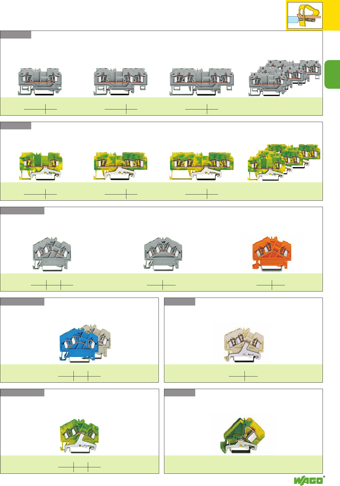
Rail-mounted Terminal Blocks with CAGE CLAMP®. . .
Series 279 to 285 and 880
Assembly
Commoning
Commoning
Removal
Protective warning marker
Commoning
According to EN 60947-7-2 [VDE 0611, part 3]
steel carrier rails may not be used for PEN applications.
CAGE CLAMP®
clamps the following
copper wires: *
solid stranded
fine stranded,
also with tinned
single strands
Quick assembly keys prevent reverse mounting Removal of a terminal block from the assemblyBy snapping a ground (earth) conductor terminal
block onto the carrier rail, a direct electrical
connection is automatically made to the rail.
Commoning of ground (earth) cond. term. blocks
with through term. bl. is possible in one direction
only using adjacent jumpers. In addition to the
required marking of these term. blocks, we also
recommend the use of the yell.-green adj. jumpers.
Commoning of terminal blocks of different sizes –
step down
Application notes see page 2.26
Staggered jumpers for sophisticated wiring jobs.
Application notes see page 2.45
Testing – Series 880
The terminal blocks of series 880 have an
additional test slot for test plugs 2 mm /0.079 in Ø
or 2.3 mm /0.091 in Ø
Protective warning markers inserted into the
operating slots
* For aluminum wire see notes in section 15!
,
2
7
2
. . . Description and Handling
Testing
Testing
Testing
TestingInsulation stopMarking
CAGE CLAMP®connection
Connection of conductors
Test plug modules with CAGE CLAMP®. Testing
using the conductor wire opening, see page 2.38
Test plug modules with CAGE CLAMP®. Testing using
jumper contact position in current bar, see page 2.39
fine-stranded wire –
tip bonded
fine-stranded wire
with crimped ferrule ➊fine-stranded wire
with crimped pin terminal
Marking with WMB multi-marking system or
WSB quick marking system.
For other systems see section 14
Insertion of insulation stop.
Application notes see page 2.43 Testing with banana plug 4 mm /0.157 in Ø,
using test plug adapter 209-170
Connection of conductors
➊ When using conductors with ferrules, it is
necessary to use a terminal block one size
larger than the nominal cross section of the
conductor
Testing with test plug.
Test plug with CAGE CLAMP®
2
8
*U2KfaJq:;{[ 4 *U2KfaJq:;{[ .4 *U2KfaJq:;{[ 4
L L L
Accessories Series 279 Appropriate marking system WMB/WSB/WFB (see section 14)
End and intermediate plate, 2 mm /0.079 in thick
orange 279-328 100 (4 x 25)
grey 279-325 100 (4 x 25)
light grey 279-330 100 (4 x 25)
Separator,oversized, 2 mm /0.079 in thick
orange 279-329 100 (4 x 25)
grey 279-326 100 (4 x 25)
light grey 279-331 100 (4 x 25)
Insulation stop ➌, 5 pcs /strip
white 279-470 200 strips
dark grey 279-471 200 strips
Adjacent jumper, insulated, IN15 A
grey 279-402 200 (8 x 25)
yell.-green 279-422 200 (8x 25)
Alternate jumper, insulated, IN15 A
grey 279-409 100 (4 x 25)
Push-in type wire jumper ➌, insulated, IN9 A
L =
60 mm
249-125 10
L =
110 mm
249-126 10
L =
250 mm
249-127 10
Protective warning marker, comp type jumper bar,
test plug adapter, etc. (see right page)
4-conductor through terminal blocks
grey 279-831 100
blue 279-834 100
orange 279-832 100
red 279-833100
black 279-835 100
yellow 279-836 100
light grey 4279-994 100
4-conductor ground (earth) terminal blocks
green-yellow 279-837 100
green-yellow 4279-837/999-950 100
4-conductor shield (screen) terminal block
white 279-838 100
Other terminal blocks with the same shape
double potential 279-826 page 2.9
diode 279-815/...-... page 7.56
LED 279-809/...-... page 7.60
3-conductor through terminal blocks
grey 279-681 100
blue 279-684 100
orange 279-682 100
red 279-683 100
black 279-685 100
yellow 279-686 100
light grey 4279-993 100
3-conductor ground (earth) terminal blocks
green-yellow 279-687 100
green-yellow 4279-687/999-950 100
Other terminal blocks with the same shape
diode 279-673/...-... page 7.56
LED 279-674/...-... page 7.60
Item Pack. unit
No. pcs
Through/Ground (Earth) Conductor/Shield (Screen) and
4Terminal Blocks 1.5 mm2/ AWG 16,
Series 279
Item Pack. unit
No. pcs Item Pack. unit
No. pcs
* For further approvals with corresponding ratings see section 15.
(32 mm /1.26 in )
<____ 52 mm /2.05 in ____> (32 mm /1.26 in )
<______ 62.5 mm /2.46 in ______> <_ 42.5 mm /1.67 in _>
<_________ 73 mm /2.87 in _________>
End and intermediate plate, 2 mm /0.079 in thick
orange 279-339 100 (4 x 25)
grey 279-308 100 (4 x 25)
light grey 279-341 100 (4 x 25)
Separator,oversized, 2 mm /0.079 in thick
orange 279-340 100 (4 x 25)
grey 279-309 100 (4 x 25)
light grey 279-342 100 (4 x 25)
Insulation stop ➌, 5 pcs /strip
white 279-470 200 strips
dark grey 279-471 200 strips
Adjacent jumper, insulated, IN15 A
grey 279-402 200 (8 x 25)
yell.-green 279-422 200 (8x 25)
Alternate jumper, insulated, IN15 A
grey 279-409 100 (4 x 25)
Push-in type wire jumper ➌, insulated, IN9 A
L =
60 mm
249-125 10
L =
110 mm
249-126 10
L =
250 mm
249-127 10
Protective warning marker, comp type jumper bar,
test plug adapter, etc. (see right page)
End and intermediate plate, 2 mm /0.079 in thick
orange 279-346 100 (4 x 25)
grey 279-344 100 (4 x 25)
light grey 279-348 100 (4 x 25)
Separator,oversized, 2 mm /0.079 in thick
orange 279-347 100 (4 x 25)
grey 279-345 100 (4 x 25)
light grey 279-349 100 (4 x 25)
Insulation stop ➌, 5 pcs /strip
white 279-470 200 strips
dark grey 279-471 200 strips
Adjacent jumper, insulated, IN15 A
grey 279-402 200 (8 x 25)
yell.-green 279-422 200 (8x 25)
Alternate jumper, insulated, IN15 A
grey 279-409 100 (4 x 25)
Push-in type wire jumper ➌, insulated, IN9 A
L =
60 mm
249-125 10
L =
110 mm
249-126 10
L =
250 mm
249-127 10
Protective warning marker, comp type jumper bar,
test plug adapter, etc. (see right page)
2-conductor through terminal blocks
grey 279-901 100
blue 279-904 100
orange 279-902 100
red 279-903 100
black 279-905 100
yellow 279-906 100
light grey 4279-992 100
2-conductor ground (earth) terminal blocks
green-yellow 279-907 100
green-yellow 4279-907/999-950 100
Other terminal blocks with the same shape
diode 279-915/...-... page 7.56
0.08 – 1.5 mm2AWG 28 – 16
800 V/8 kV/3 ➊600 V, 10 A U
18 A 600 V, 10 A 2
Terminal block width 4 mm / 0.157 in
L8 – 9 mm / 0.33 in
0.08 – 1.5 mm2AWG 28 – 16
800 V/8 kV/3 ➊600 V, 10 A U
18 A 600 V, 10 A 2
Terminal block width 4 mm / 0.157 in
L8 – 9 mm / 0.33 in
0.08 – 1.5 mm2AWG 28 – 16
800 V/8 kV/3 ➊600 V, 10 A U
18 A 600 V, 10 A 2
Terminal block width 4 mm / 0.157 in
L8 – 9 mm / 0.33 in
<_ 27 mm /_>
1.06 in
<_ 27 mm /_>
1.06 in
<_ 27 mm /_>
1.06 in
2
0.08 – 4 mm2
AWG 28 – 12
800 V/8 kV/3 ➊
600 V, 20 A U
32 A 600 V, 25 A 2
Terminal block width 6 mm / 0.236 in
*U2fNSDJ|: .4 *U2KfNSDaJ|q:;{[ .4
*U2KfaJq;{[ 4
2
9
L
Double potential terminal blocks, with marker
receptacle on the side of the terminal block
grey 279-626 100
light grey 4279-989 100
Attention! These double potential terminal blocks
cannot be commoned with adjacent jumpers!
Double potential terminal blocks, with double mar-
ker receptacle in the center of the terminal block
grey 279-826 100
light grey 4279-995 100
Attention! These double potential terminal blocks
cannot be commoned with adjacent jumpers!
4-conductor through terminal blocks
grey 279-621 100
blue 279-604 100
light grey 4279-990 100
Other terminal blocks with the same shape
double potential 279-626
diode 279-623/...-... page 7.56
LED 279-624/...-... page 7.60
Item Pack. unit
No. pcs
➊800 V = rated voltage
8 kV = rated surge voltage
3 = pollution degree
(see also section 15)
Suitable for Ex i applications
4Suitable for Ex e II applications
0.2 – 1.5 mm2AWG 24 – 16
550 V, 15 A
(see also section 13)
Ex e/Ex i separator see page 2.13
➌See application notes
on
pages
2.43 – 2.45
End and intermediate plate, 2 mm /0.079 in thick
orange 279-317 100 (4 x 25)
grey 279-316 100 (4 x 25)
light grey 279-318 100 (4 x 25)
Separator,oversized, 2 mm /0.079 in thick
orange 279-327 100 (4 x 25)
grey 279-337 100 (4 x 25)
light grey 279-338 100 (4 x 25)
Insulation stop ➌, 5 pcs /strip
white 279-470 200 strips
dark grey 279-471 200 strips
Adjacent jumper, insulated, IN15 A
grey 279-402 200 (8 x 25)
yell.-green 279-422 200 (8x 25)
Alternate jumper, insulated, IN15 A
grey 279-409 100 (4 x 25)
Push-in type wire jumper ➌, insulated, IN9 A
L =
60 mm
249-125 10
L =
110 mm
249-126 10
L =
250 mm
249-127 10
Protective warning marker, for 5 terminal blocks,
fits into screwdriver slot
yellow 279-415 100 (4 x 25)
Test plug adapter, suitable f. term. bl. 1.5 mm2– 4 mm2,
5 mm /0.197 in wide
280-404 100 (4 x 25)
or. test plug 210-137 (2.3 mm Ø)
Test plug adapter, suitable f. term. bl. 1.5 mm2– 10 mm2,
8 mm /0.315 in wide
209-170 50 (2 x 25)
for test plug 4 mm /0.157 in Ø
Comp type jumper bar (see right column)
Double Potential Terminal Blocks
1.5 mm2/ AWG 16,
Series 279
Item Pack. unit
No. pcs Item Pack. unit
No. pcs
<_ 42.5 mm /1.67 in _>
<_________ 73 mm /2.87 in _________> <________ 68 mm /2.68 in ________><_______ 68 mm /2.68 in _______>
End and intermediate plate, 2 mm /0.079 in thick
orange 279-317 100 (4 x 25)
grey 279-316 100 (4 x 25)
light grey 279-318 100 (4 x 25)
Separator,oversized, 2 mm /0.079 in thick
orange 279-327 100 (4 x 25)
grey 279-337 100 (4 x 25)
light grey 279-338 100 (4 x 25)
Insulation stop ➌, 5 pcs /strip
white 279-470 200 strips
dark grey 279-471 200 strips
Comb type jumper bar ➌, insulated,
IN= INof terminal block
2-way 279-482 200 (8 x 25)
3-way 279-483 200 (8 x 25)
Alternate comb type jumper bar, insulated,
IN= INof terminal block
2-way 279-492 200 (8 x 25)
Operating tool, insulated
2-way 279-432 1
3-way 279-433 1
End and intermediate plate, 2 mm /0.079 in thick
orange 279-346 100 (4 x 25)
grey 279-344 100 (4 x 25)
light grey 279-348 100 (4 x 25)
Separator,oversized, 2 mm /0.079 in thick
orange 279-347 100 (4 x 25)
grey 279-345 100 (4 x 25)
light grey 279-349 100 (4 x 25)
Insulation stop ➌, 5 pcs /strip
white 279-470 200 strips
dark grey 279-471 200 strips
Comb type jumper bar ➌, insulated,
IN= INof terminal block
2-way 279-482 200 (8 x 25)
3-way 279-483 200 (8 x 25)
Alternate comb type jumper bar, insulated,
IN= INof terminal block
2-way 279-492 200 (8 x 25)
Operating tool, insulated
2-way 279-432 1
3-way 279-433 1
Double potential terminal blocks are space
savers. Two independent through terminal blocks
are placed in one insulated housing on one
level. The width of the housing is only
4 mm /0.157 in. Compared to standard through
terminal blocks, the width is only 2 mm /0.079 in
for a total height of only 27 mm/1.063 in from
the upper edge of the carrier rail. Input and out-
put contacts of one circuit are placed on the
same side of the terminal block. Both circuits can
be individually marked according to input and
output.
0.08 – 1.5 mm2AWG 28 – 16
800 V/8 kV/3 ➊600 V, 10 A U
18 A 600 V, 10 A 2
Terminal block width 4 mm / 0.157 in
L8 – 9 mm / 0.33 in
0.08 – 1.5 mm2AWG 28 – 16
800 V/8 kV/3 ➊600 V, 10 A U
18 A 600 V, 10 A 2
Terminal block width 4 mm / 0.157 in
L8 – 9 mm / 0.33 in
0.08 – 1.5 mm2AWG 28 – 16
800 V/8 kV/3 ➊600 V, 10 A U
18 A 600 V, 10 A 2
Terminal block width 4 mm / 0.157 in
L8 – 9 mm / 0.33 in
<_ 27 mm /
_>
1.06 in
<_ 27 mm /_>
1.06 in
<_ 27 mm /_>
1.06 in
2
10
*U2KfDaJq:;{[ 4
*U2KfNDaJq:;{[ .4 *U2KfaJq:;{[ 4
(32 mm /1.26 in )
<_______ 64 mm /2.52 in _______> <_ 42.5 mm/1.67in _>
<__________ 75 mm /2.95 in __________>
Accessories Series 280 Appropriate marking system WMB/WSB/WFB (see section 14)
End and intermediate plate, 2.5 mm/0.098 in thick
orange 280-315 100 (4 x 25)
grey 280-314 100 (4 x 25)
light grey 280-352 100 (4 x 25)
Separator,oversized, 2 mm /0.079 in thick
orange 280-335 100 (4 x 25)
grey 280-334 100 (4 x 25)
light grey 280-353 100 (4 x 25)
Insulation stop ➌, 5 pcs /strip
white 280-470 200 strips
light grey 280-471 200 strips
dark grey 280-472 200 strips
Adjacent jumper, insulated, IN24 A, 420 A
grey 280-402 200 (8 x 25)
yell.-green 280-422 200 (8x 25)
Staggered jumper ➌, insulated, IN24 A, 420 A
width 5 mm /0.197 in
from 1 to 2 780-452 100 (4 x 25)
from 1 to 3 780-453 100 (4 x 25)
from 1 to 4 780-454 100 (4 x 25)
from 1 to 5 780-455 50 (2 x 25)
::
from 1 to 8 780-458 50 (2 x 25)
Protective warning marker, comp type jumper bar,
test plug adapter, etc. (see page 2.13)
End and intermediate plate, 2.5 mm/0.098 in thick
orange 280-326 100 (4 x 25)
grey 280-324 100 (4 x 25)
light grey 280-358 100 (4 x 25)
Separator,oversized, 2 mm /0.079 in thick
orange 280-346 100 (4 x 25)
grey 280-344 100 (4 x 25)
light grey 280-359 100 (4 x 25)
Insulation stop ➌, 5 pcs /strip
white 280-470 200 strips
light grey 280-471 200 strips
dark grey 280-472 200 strips
Adjacent jumper, insulated, IN24 A, 422 A
grey 280-402 200 (8 x 25)
yell.-green 280-422 200 (8x 25)
Staggered jumper ➌, insulated, IN24 A, 422 A
width 5 mm /0.197 in
from 1 to 2 780-452 100 (4 x 25)
from 1 to 3 780-453 100 (4 x 25)
from 1 to 4 780-454 100 (4 x 25)
from 1 to 5 780-455 50 (2 x 25)
::
from 1 to 8 780-458 50 (2 x 25)
Protective warning marker, comp type jumper bar,
test plug adapter, etc. (see page 2.13)
End and intermediate plate, 2.5 mm/0.098 in thick
orange 280-309 100 (4 x 25)
grey 280-308 100 (4 x 25)
light grey 280-356 100 (4 x 25)
Separator,oversized, 2 mm /0.079 in thick
orange 280-311 100 (4 x 25)
grey 280-310 100 (4 x 25)
light grey 280-357 100 (4 x 25)
Insulation stop ➌, 5 pcs /strip
white 280-470 200 strips
light grey 280-471 200 strips
dark grey 280-472 200 strips
Adjacent jumper, insulated, IN24 A, 423 A
grey 280-402 200 (8 x 25)
yell.-green 280-422 200 (8x 25)
Staggered jumper ➌, insulated, IN24 A, 423 A
width 5 mm /0.197 in
from 1 to 2 780-452 100 (4 x 25)
from 1 to 3 780-453 100 (4 x 25)
from 1 to 4 780-454 100 (4 x 25)
from 1 to 5 780-455 50 (2 x 25)
::
from 1 to 8 780-458 50 (2 x 25)
Protective warning marker, comp type jumper bar,
test plug adapter, etc. (see page 2.13)
4-conductor through terminal blocks
grey 280-833 100
blue 280-834 100
orange 280-835 100
red 280-830100
black 280-831 100
yellow 280-832 100
light grey 4280-994 100
4-conductor ground (earth) terminal blocks
green-yellow 280-837 100
green-yellow 4280-837/999-950 100
4-conductor shield (screen) terminal block
white 280-838 100
Other terminal blocks with the same shape
double potential 280-826 page 2.11
disconnect 280-836 page 7.10
disc., test a. meas. 280-829 page 7.10
carrier term. block 280-816 page 7.35
diode 280-815/...-... page 7.57
LED 280-809/...-... page 7.60
spacer 280-835/056-000
3-conductor through terminal blocks
grey 280-681 100
blue 280-684 100
orange 280-650 100
red 280-653 100
black 280-671 100
yellow 280-672 100
light grey 4280-993 100
3-conductor ground (earth) terminal blocks
green-yellow 280-687 100
green-yellow 4280-687/999-950 100
Other terminal blocks with the same shape
disconnect 280-683 page 7.10
carrier term. block 280-610 page 7.35
diode 280-673/...-... page 7.57
spacer 280-650/056-000
2-conductor through terminal blocks
grey 280-901 100
blue 280-904 100
orange 280-902 100
red 280-903 100
black 280-905 100
yellow 280-906 100
light grey 4280-992 100
2-conductor ground (earth) terminal blocks
green-yellow 280-907 100
green-yellow 4280-907/999-950 100
Other terminal blocks with the same shape
disconnect 280-912 page 7.10
carrier term. block 280-916 page 7.35
diode 280-915/...-... page 7.57
spacer 280-902/056-000
Item Pack. unit
No. pcs
Through/Ground (Earth) Conductor/Shield (Screen) and
4Terminal Blocks 2.5 mm2/ AWG 12,
Series 280
(32 mm /1.26 in )
<_____ 53 mm /2.09 in _____>
Item Pack. unit
No. pcs Item- Pack.-unit
No. pcs
* For further approvals with corresponding ratings see section 15.
0.08 – 2.5 mm2AWG 28 – 12
800 V/8 kV/3 ➊600 V, 20 A U
24 A 600 V, 25 A 2
Terminal block width 5 mm / 0.197 in
L8 – 9 mm / 0.33 in
0.08 – 2.5 mm2AWG 28 – 12
800 V/8 kV/3 ➊600 V, 20 A U
24 A 600 V, 25 A 2
Terminal block width 5 mm / 0.197 in
L8 – 9 mm / 0.33 in
0.08 – 2.5 mm2AWG 28 – 12
800 V/8 kV/3 ➊600 V, 20 A U
20 A 600 V, 25 A 2
Terminal block width 5 mm / 0.197 in
L8 – 9 mm / 0.33 in
<_ 28 mm / _>
1.10 in
<_ 28 mm/_>
1.10 in
<_ 28 mm/_>
1.10 in
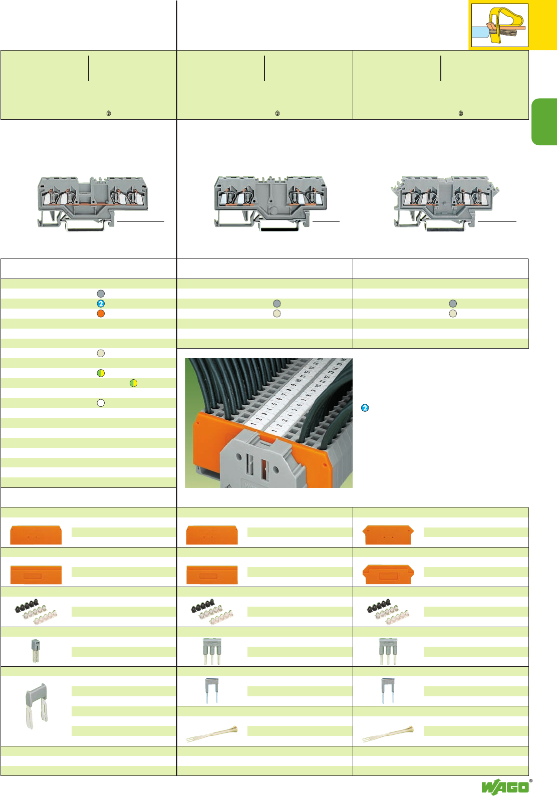
2
0.08 – 4 mm2
AWG 28 – 12
800 V/8 kV/3 ➊
600 V, 20 A U
32 A 600 V, 25 A 2
Terminal block width 6 mm / 0.236 in *U2KfaJ:;{[ 4
*U2KfaJq:;{[ 4 *U2KfDaJ:;{[ 4
2
11
Double potential terminal blocks, with marker
receptacle on the side of the terminal block
grey 280-626 100
light grey 4280-989 100
Attention! These double potential terminal blocks
cannot be commoned with adjacent jumpers!
Double potential terminal blocks, with double mar-
ker receptacle in the center of the terminal block
grey 280-826 100
light grey 4280-995 100
Attention! These double potential terminal blocks
cannot be commoned with adjacent jumpers!
4-conductor through terminal blocks
grey 280-633 100
blue 280-634 100
orange 280-603 100
light grey 4280-999 100
4-conductor ground (earth) terminal blocks
green-yellow 280-677 100
green-yellow 4280-677/999-950 100
4-conductor shield (screen) terminal block
white 280-678 100
Other terminal blocks with the same shape
double potential 280-626 page 2.11
disconnect 280-685 page 7.11
disc., test a. meas. 280-649 page 7.11
carrier term. block 280-686 page 7.35
diode 280-655/...-... page 7.57
LED 280-658/...-... page 7.61
Item Pack. unit
No. pcs
<_ 42.5 mm /1.67 in _>
<___________ 75 mm /2.95 in ___________>
(32 mm/1.26 in )
<__________ 75 mm /2.95 in __________>
End and intermediate plate, 2.5 mm/0.098 in thick
orange 280-315 100 (4 x 25)
grey 280-314 100 (4 x 25)
light grey 280-352 100 (4 x 25)
Separator,oversized, 2 mm /0.079 in thick
orange 280-335 100 (4 x 25)
grey 280-334 100 (4 x 25)
light grey 280-353 100 (4 x 25)
Insulation stop ➌, 5 pcs /strip
white 280-470 200 strips
light grey 280-471 200 strips
dark grey 280-472 200 strips
Adjacent jumper, insulated, IN24 A, 420 A
grey 280-402 200 (8 x 25)
yell.-green 280-422 200 (8x 25)
Staggered jumper ➌, insulated, IN24 A, 420 A
width 5 mm /0.197 in
from 1 to 2 780-452 100 (4 x 25)
from 1 to 3 780-453 100 (4 x 25)
from 1 to 4 780-454 100 (4 x 25)
from 1 to 5 780-455 50 (2 x 25)
::
from 1 to 8 780-458 50 (2 x 25)
Protective warning marker, comp type jumper bar,
test plug adapter, etc. (see page 2.13)
End and intermediate plate, 2.5 mm/0.098 in thick
orange 280-315 100 (4 x 25)
grey 280-314 100 (4 x 25)
light grey 280-352 100 (4 x 25)
Separator,oversized, 2 mm /0.079 in thick
orange 280-335 100 (4 x 25)
grey 280-334 100 (4 x 25)
light grey 280-353 100 (4 x 25)
Insulation stop ➌, 5 pcs /strip
white 280-470 200 strips
light grey 280-471 200 strips
dark grey 280-472 200 strips
Comb type jumper bar ➌, insulated,
IN= INof terminal block
2-way 280-482 200 (8 x 25)
3-way 280-483 200 (8 x 25)
Alternate comb type jumper bar, insulated,
IN= INof terminal block
2-way 280-492 200 (8 x 25)
Operating tool, insulated
2-way 280-432 1
3-way 280-433 1
End and intermediate plate, 2.5 mm/0.098 in thick
orange 280-317 100 (4 x 25)
grey 280-316 100 (4 x 25)
light grey 280-364 100 (4 x 25)
Separator,oversized, 2 mm /0.079 in thick
orange 280-327 100 (4 x 25)
grey 280-337 100 (4 x 25)
light grey 280-365 100 (4 x 25)
Insulation stop ➌, 5 pcs /strip
white 280-470 200 strips
light grey 280-471 200 strips
dark grey 280-472 200 strips
Comb type jumper bar ➌, insulated,
IN= INof terminal block
2-way 280-482 200 (8 x 25)
3-way 280-483 200 (8 x 25)
Alternate comb type jumper bar, insulated,
IN= INof terminal block
2-way 280-492 200 (8 x 25)
Operating tool, insulated
2-way 280-432 1
3-way 280-433 1
Double Potential Terminal Blocks
2.5 mm2/ AWG 12,
Series 280
<__________ 73 mm /2.87 in __________>
Item Pack. unit
No. pcs Item Pack. unit
No. pcs
Terminal block marking directly on the terminal block
either with WSB or WMB markers.
➊800 V = rated voltage
8 kV = rated surge voltage
3 = pollution degree
(see also section 15)
Suitable for Ex i applications
4Suitable for Ex e II applications
0.2 – 2.5 mm2AWG 24 – 12
550 V, 20 A
(see also section 13)
When using staggered jumpers the max. rated
voltage will be reduced to 275 V.
Ex e/Ex i separator see page 2.13
➌See application notes
on
pages
2.38 – 2.45
0.08 – 2.5 mm2AWG 28 – 12
800 V/8 kV/3 ➊600 V, 20 A U
20 A 600 V, 25 A 2
Terminal block width 5 mm / 0.197 in
L8 – 9 mm / 0.33 in
0.08 – 2.5 mm2AWG 28 – 12
800 V/8 kV/3 ➊600 V, 15 A U
24 A 600 V, 15 A 2
Terminal block width 5 mm / 0.197 in
L8 – 9 mm / 0.33 in
0.08 – 2.5 mm2AWG 28 – 12
800 V/8 kV/3 ➊600 V, 15 A U
24 A 600 V, 20 A 2
Terminal block width 5 mm / 0.197 in
L8 – 9 mm / 0.33 in
<_ 28 mm /_>
1.10 in
<_ 28 mm /_>
1.10 in
<_ 28 mm /_>
1.10 in
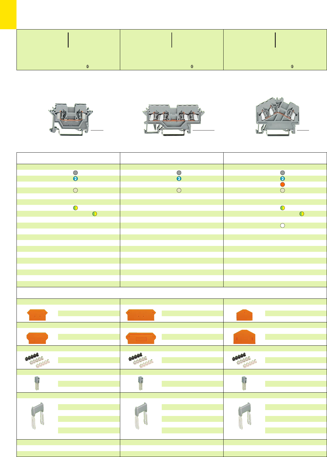
2
12
*U2KfD8aJq:;{[ 4
*U2KfDaHJq:;{[ 4 *U2fNDaHJq:;{[ 4
End and intermediate plate, 2.5 mm/0.098 in thick
orange 280-313 100 (4 x 25)
grey 280-312 100 (4 x 25)
light grey 280-354 100 (4 x 25)
Separator,oversized, 2.5 mm /0.098 in thick
orange 280-318 100 (4 x 25)
grey 280-348 100 (4 x 25)
light grey 280-355 100 (4 x 25)
Insulation stop ➌, 5 pcs /strip
white 280-470 200 strips
light grey 280-471 200 strips
dark grey 280-472 200 strips
Adjacent jumper, insulated, IN24 A, 423 A
grey 280-402 200 (8 x 25)
yell.-green 280-422 200 (8x 25)
Staggered jumper ➌, insulated, IN24 A, 423 A
width 5 mm /0.197 in
from 1 to 2 780-452 100 (4 x 25)
from 1 to 3 780-453 100 (4 x 25)
from 1 to 4 780-454 100 (4 x 25)
from 1 to 5 780-455 50 (2 x 25)
::
from 1 to 8 780-458 50 (2 x 25)
Protective warning marker, comp type jumper bar,
test plug adapter, etc. (see right page)
End and intermediate plate, 2.5 mm/0.098 in thick
orange 280-317 100 (4 x 25)
grey 280-316 100 (4 x 25)
light grey 280-364 100 (4 x 25)
Separator,oversized, 2 mm /0.079 in thick
orange 280-327 100 (4 x 25)
grey 280-337 100 (4 x 25)
light grey 280-365 100 (4 x 25)
Insulation stop ➌, 5 pcs /strip
white 280-470 200 strips
light grey 280-471 200 strips
dark grey 280-472 200 strips
Adjacent jumper, insulated, IN24 A, 422 A
grey 280-402 200 (8 x 25)
yell.-green 280-422 200 (8x 25)
Staggered jumper ➌, insulated, IN24 A, 422 A
width 5 mm /0.197 in
from 1 to 2 780-452 100 (4 x 25)
from 1 to 3 780-453 100 (4 x 25)
from 1 to 4 780-454 100 (4 x 25)
from 1 to 5 780-455 50 (2 x 25)
::
from 1 to 8 780-458 50 (2 x 25)
Protective warning marker, comp type jumper bar,
test plug adapter, etc. (see right page)
End and intermediate plate, 2.5 mm/0.098 in thick
orange 280-331 100 (4 x 25)
grey 280-330 100 (4 x 25)
light grey 280-362 100 (4 x 25)
Separator,oversized, 2 mm /0.079 in thick
orange 280-328 100 (4 x 25)
grey 280-338 100 (4 x 25)
light grey 280-363 100 (4 x 25)
Insulation stop ➌, 5 pcs /strip
white 280-470 200 strips
light grey 280-471 200 strips
dark grey 280-472 200 strips
Adjacent jumper, insulated, IN24 A, 423 A
grey 280-402 200 (8 x 25)
yell.-green 280-422 200 (8x 25)
Staggered jumper ➌, insulated, IN24 A, 423 A
width 5 mm /0.197 in
from 1 to 2 780-452 100 (4 x 25)
from 1 to 3 780-453 100 (4 x 25)
from 1 to 4 780-454 100 (4 x 25)
from 1 to 5 780-455 50 (2 x 25)
::
from 1 to 8 780-458 50 (2 x 25)
Protective warning marker, comp type jumper bar,
test plug adapter, etc. (see right page)
3-conductor through terminal blocks
grey 280-641 100
blue 280-651 100
orange 280-654 100
light grey 4280-998 100
3-conductor ground (earth) terminal blocks
green-yellow 280-637 100
green-yellow 4280-637/999-950 100
3-conductor shield (screen) terminal block
white 280-640 100
Other terminal blocks with the same shape
spacer 280-654/056-000
4-conductor through terminal blocks
grey 280-621 100
blue 280-604 100
light grey 4280-990 100
Other terminal blocks with the same shape
double potential 280-626 page 2.11
disconnect 280-622 page 7.11
disc., test a. meas. 280-627 page 7.11
carrier term. block 280-606 page 7.35
term. bl. f. pl. mod.
280-608 W4, vol. 3
diode 280-623/...-... page 7.57
LED 280-624/...-... page 7.60
2-conductor through terminal blocks
grey 280-601 100
blue 280-602 100
light grey 4280-691 100
2-conductor ground (earth) terminal blocks
green-yellow 280-607 100
green-yellow 4280-607/999-950 100
Other terminal blocks with the same shape
disconnect 280-612 page 7.11
carrier term. block 280-616 page 7.35
term. bl. f. pl. mod.
280-618 W4, vol. 3
diode 280-613/...-... page 7.57
variable transistor 280-615/...-... page 7.58
Item Pack. unit
No. pcs
Item Pack. unit
No. pcs
Item Pack. unit
No. pcs
<___ 50 mm /1.97 in ___> <_________ 73 mm /2.87 in _________> <___ 50.5 mm /1.99 in ___>
Through/Ground (Earth) Conductor/Shield (Screen) and
4Terminal Blocks 2.5 mm2/ AWG 12 ,
Series 280
* For further approvals with corresponding ratings see section 15.
Accessories Series 280 Appropriate marking system WMB/WSB/WFB (see section 14)
0.08 – 2.5 mm2AWG 28 – 12
800 V/8 kV/3 ➊600 V, 20 A U
24 A 600 V, 25 A 2
Terminal block width 5 mm / 0.197 in
L8 – 9 mm / 0.33 in
0.08 – 2.5 mm2AWG 28 – 12
800 V/8 kV/3 ➊600 V, 15 A U
24 A 600 V, 15 A 2
Terminal block width 5 mm / 0.197 in
L8 – 9 mm / 0.33 in
0.08 – 2.5 mm2AWG 28 – 12
800 V/8 kV/3 ➊600 V, 20 A U
24 A 600 V, 25 A 2
Terminal block width 5 mm / 0.197 in
L8 – 9 mm / 0.33 in
<_ 28 mm /_>
1.10 in
<_ 28 mm /_>
1.10 in
<___ 36.5 mm /
___>
1.44 in
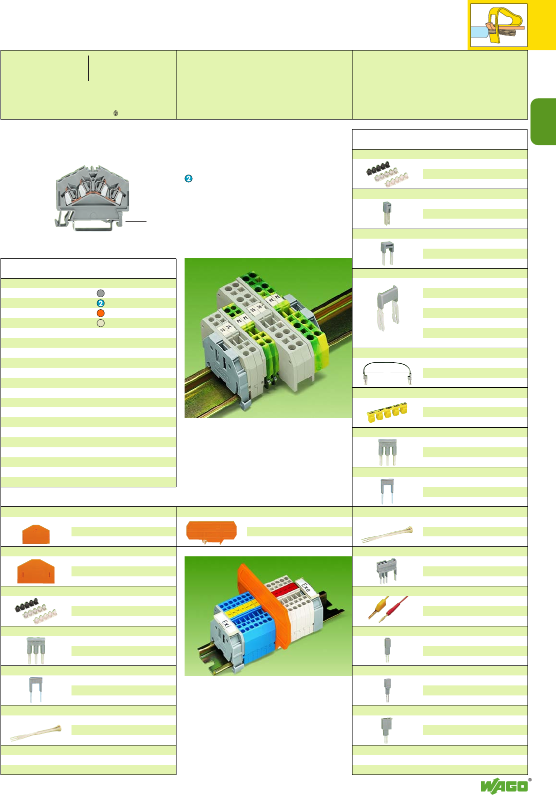
L
2
2
13
*U2KfDaJq:;{[ 4
Accessories Series 280
End and intermediate plate, 2.5 mm/0.098 in thick
orange 280-313 100 (4 x 25)
grey 280-312 100 (4 x 25)
light grey 280-354 100 (4 x 25)
Separator,oversized, 2.5 mm /0.098 in thick
orange 280-318 100 (4 x 25)
grey 280-348 100 (4 x 25)
light grey 280-355 100 (4 x 25)
Insulation stop ➌, 5 pcs /strip
white 280-470 200 strips
light grey 280-471 200 strips
dark grey 280-472 200 strips
Comb type jumper bar ➌, insulated,
IN= INof terminal block
2-way 280-482 200 (8 x 25)
3-way 280-483 200 (8 x 25)
Alternate comb type jumper bar, insulated,
IN= INof terminal block
2-way 280-492 200 (8 x 25)
Operating tool, insulated
2-way 280-432 1
3-way 280-433 1
Test plug module,
testing using conductor entry holes
see page 2.38
4-conductor through terminal blocks
grey 280-646 100
blue 280-656 100
orange 280-946 100
light grey 4280-996 100
Attention! These terminal blocks cannot be
commoned with adjacent jumpers!
Item Pack. unit
No. pcs
➊800 V = rated voltage
8 kV = rated surge voltage
3 = pollution degree
(see also section 15)
Suitable for Ex i applications
4Suitable for Ex e II applications
0.2 – 2.5 mm2AWG 24 – 12
550 V, 20 A
(see also section 13)
When using staggered jumpers the max. rated
voltage will be reduced to 275 V.
➌See application notes
on
pages
2.38 – 2.45
Insulation stop ➌, 5 pcs /strip
white 280-470 200 strips
light grey 280-471 200 strips
dark grey 280-472 200 strips
Adjacent jumper, insulated, IN24 A, 420 A
grey 280-402 200 (8 x 25)
yell.-green 280-422 200 (8x 25)
Alternate jumper, insulated,I
N24 A, 420 A
grey 280-409 100 (4 x 25)
Staggered jumper ➌, insulated, IN24 A, 420 A
width 5 mm /0.197 in
from 1 to 2 780-452 100 (4 x 25)
from 1 to 3 780-453 100 (4 x 25)
from 1 to 4 780-454 100 (4 x 25)
from 1 to 5 780-455 50 (2 x 25)
::
from 1 to 8 780-458 50 (2 x 25)
Push-in type wire jumper ➌, insulated, IN9 A
L =
60 mm
249-125 10
L =
110 mm
249-126 10
L =
250 mm
249-127 10
Protective warning marker, for 5 terminal blocks,
fits into screwdriver slot
yellow 280-415 100 (4 x 25)
Comb type jumper bar ➌, insulated,
IN= INof terminal block
2-way 280-482 200 (8 x 25)
3-way 280-483 200 (8 x 25)
Alternate comb type jumper bar, insulated,
IN= INof terminal block
2-way 280-492 200 (8 x 25)
Operating tool, insulated
2-way 280-432 1
3-way 280-433 1
Test plug module ➌,
testing using jumper contact slots
or conductor entry holes
Test plug,
with
cable 500 mm/1’7.7’’
2 mm Ø, red
210-136 50 (5 x 10)
2.3 mm Ø, yel.
210-137 50 (5 x 10)
Test plug adapter, suitable f. term. bl. 1.5 mm2– 4 mm2,
5 mm /0.197 in wide
280-404 100 (4 x 25)
for test plug 210-137 (2.3 mm Ø)
Test plug adapter, suitable f. term. bl. 1.5 mm2– 10 mm2,
8 mm /0.315 in wide
209-170 50 (2 x 25)
for test plug 4 mm /0.157 in Ø
Test plug, 6 mm/0.236 in wide, with CAGE CLAMP®for
0.08 mm2– 2.5 mm2/AWG 28 –14
IN24 A 281-407 100 (4 x 25)
Banana plugs, 4 mm/0.157 in Ø, color mixed
see page 2.42
<___ 50,5 mm /1.99 in ___>
Item Pack. unit
No. pcs
Separator for Ex e/Ex i applications
According to EN 50020 a minimum distance of
50 mm must be kept between live parts of Ex e
and Ex i circuits. When mounting Ex e and
Ex i rail-mounted terminal blocks together on a
common rail WAGO offers a space saving
solution to the problem by using the Ex e/Ex i
separators.
Suitable for series 279 to 282.
209-190 for 2-conductor terminal blocks.
209-191 for 2-, 3-, 4-conductor terminal blocks.
In order to meet the air and creepage distances
specified for Ex e applications it is necessary to
insert an end or intermediate plate between a
through and a ground (earth) conductor terminal
block.
Ex e/Ex i separator, 3 mm /0.118 in thick, orange
90 mm wide209-190 50 (2 x 25)
120 mm w. 209-191 50 (2 x 25)
<___ 36.5 mm /
___>
1.44 in
0.08 – 2.5 mm2AWG 28 – 12
800 V/8 kV/3 ➊600 V, 20 A U
24 A 600 V, 25 A 2
Terminal block width 5 mm / 0.197 in
L8 – 9 mm / 0.33 in
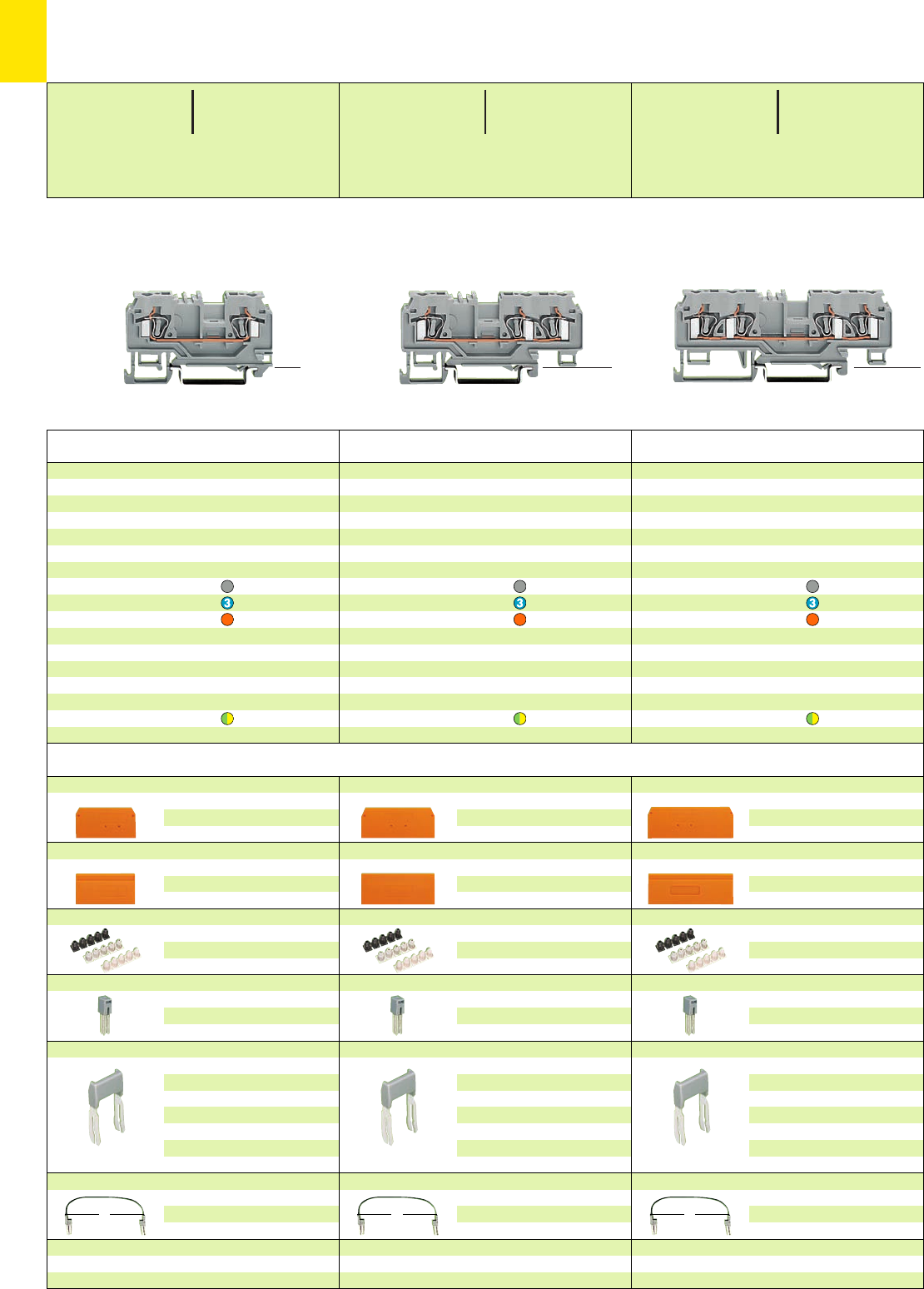
LLL
2
14
*YKf:;{ *YKf:;{ *Y
Accessories Series 880 Appropriate marking system
WMB/WSB oder Mini-WSB
(see section 14)
End and intermediate plate, 2.5 mm/0.098 in thick
orange 880-346 100 (4 x 25)
grey 880-344 100 (4 x 25)
Separator,oversized, 2 mm /0.079 in thick
orange 880-347 100 (4 x 25)
grey 880-345 100 (4 x 25)
Insulation stop ➍, 5 pcs /strip
white 280-470 200 strips
light grey 280-471 200 strips
dark grey 280-472 200 strips
Adjacent jumper, insulated, IN24 A
grey 280-402 200 (8 x 25)
yell.-green 280-422 200 (8x 25)
Staggered jumper ➍, insulated, IN24 A
width 5 mm /0.197 in
from 1 to 2 780-452 100 (4 x 25)
from 1 to 3 780-453 100 (4 x 25)
from 1 to 4 780-454 100 (4 x 25)
from 1 to 5 780-455 50 (2 x 25)
::
from 1 to 8 780-458 50 (2 x 25)
Push-in type wire jumper ➍, insulated, IN9 A
L =
60 mm
249-125 10
L =
110 mm
249-126 10
L =
250 mm
249-127 10
Protective warning marker, comp type jumper bar,
test plug adapter, etc. (see page 2.13)
End and intermediate plate, 2.5 mm/0.098 in thick
orange 880-339 100 (4 x 25)
grey 880-308 100 (4 x 25)
Separator,oversized, 2 mm /0.079 in thick
orange 880-340 100 (4 x 25)
grey 880-309 100 (4 x 25)
Insulation stop ➍, 5 pcs /strip
white 280-470 200 strips
light grey 280-471 200 strips
dark grey 280-472 200 strips
Adjacent jumper, insulated, IN24 A
grey 280-402 200 (8 x 25)
yell.-green 280-422 200 (8x 25)
Staggered jumper ➍, insulated, IN24 A
width 5 mm /0.197 in
from 1 to 2 780-452 100 (4 x 25)
from 1 to 3 780-453 100 (4 x 25)
from 1 to 4 780-454 100 (4 x 25)
from 1 to 5 780-455 50 (2 x 25)
::
from 1 to 8 780-458 50 (2 x 25)
Push-in type wire jumper ➍, insulated, IN9 A
L =
60 mm
249-125 10
L =
110 mm
249-126 10
L =
250 mm
249-127 10
Protective warning marker, comp type jumper bar,
test plug adapter, etc. (see page 2.13)
End and intermediate plate, 2.5 mm/0.098 in thick
orange 880-328 100 (4 x 25)
grey 880-325 100 (4 x 25)
Separator,oversized, 2 mm /0.079 in thick
orange 880-329 100 (4 x 25)
grey 880-326 100 (4 x 25)
Insulation stop ➍, 5 pcs /strip
white 280-470 200 strips
light grey 280-471 200 strips
dark grey 280-472 200 strips
Adjacent jumper, insulated, IN24 A
grey 280-402 200 (8 x 25)
yell.-green 280-422 200 (8x 25)
Staggered jumper ➍, insulated, IN24 A
width 5 mm /0.197 in
from 1 to 2 780-452 100 (4 x 25)
from 1 to 3 780-453 100 (4 x 25)
from 1 to 4 780-454 100 (4 x 25)
from 1 to 5 780-455 50 (2 x 25)
::
from 1 to 8 780-458 50 (2 x 25)
Push-in type wire jumper ➍, insulated, IN9 A
L =
60 mm
249-125 10
L =
110 mm
249-126 10
L =
250 mm
249-127 10
Protective warning marker, comp type jumper bar,
test plug adapter, etc. (see page 2.13)
Through terminal block without/with shield (screen)
contact
and test slot for test plug
Ø 2 mm / 0.079 in and Ø 2.3 mm / 0.091 in,
for DIN 35 rail
4-conductor through terminal blocks without shield
(screen) contact
grey 880-831 100
blue 880-834 100
orange 880-832 100
4-conductor ground (earth) terminal block
green-yellow 880-837 100
Through terminal block without/with shield (screen)
contact
and test slot for test plug
Ø 2 mm / 0.079 in and Ø 2.3 mm / 0.091 in,
for DIN 35 rail
3-conductor through terminal blocks without shield
(screen) contact
grey 880-681 100
blue 880-684 100
orange 880-682 100
3-conductor through terminal blocks with shield
(screen) contact – please contact factory
3-conductor ground (earth) terminal block
green-yellow 880-687 100
Through terminal block without/with shield (screen)
contact
and test slot for test plug
Ø 2 mm / 0.079 in and Ø 2.3 mm / 0.091 in,
for DIN 35 rail
2-conductor through terminal blocks without shield
(screen) contact
grey 880-901 100
blue 880-904 100
orange 880-902 100
2-conductor through terminal blocks with shield
(screen) contact – please contact factory
2-conductor ground (earth) terminal block
green-yellow 880-907 100
Item Pack. unit
No. pcs
Through and Ground (Earth) Conductor Terminal Blocks,
Terminal Block Width 5 mm / 0.197 in, 4 mm2/ AWG 12
Series 880
Item Pack. unit
No. pcs Item Pack. unit
No. pcs
* For further approvals with corresponding ratings see section 15. ** Max. diameter of insulation: 4.4 mm /0.173 in
(_ 35 mm /1.38 in _)
<______ 58,5 mm /2.3 in ______> (_ 35 mm /1.38 in _)
<__________ 73 mm /2.87 in __________> <___ 49 mm /1.93 in ___>
<______________ 87 mm /3.43 in ______________>
➋➋
0.08 – 4 mm2** AWG 28 – 12
800 V/8 kV/3 ➊Y➊
25 A
Terminal block width 5 mm / 0.197 in
L8 – 9 mm / 0.33 in
0.08 – 4 mm2** AWG 28 – 12
800 V/8 kV/3 ➊Y➊
25 A
Terminal block width 5 mm / 0.197 in
L8 – 9 mm / 0.33 in
0.08 – 4 mm2** AWG 28 – 12
800 V/8 kV/3 ➊Y➊
20 A
Terminal block width 5 mm / 0.197 in
L8 – 9 mm / 0.33 in
<_ 29 mm / _>
1.14 in
<_ 29 mm / _>
1.14 in
<_ 29 mm /_>
1.14 in
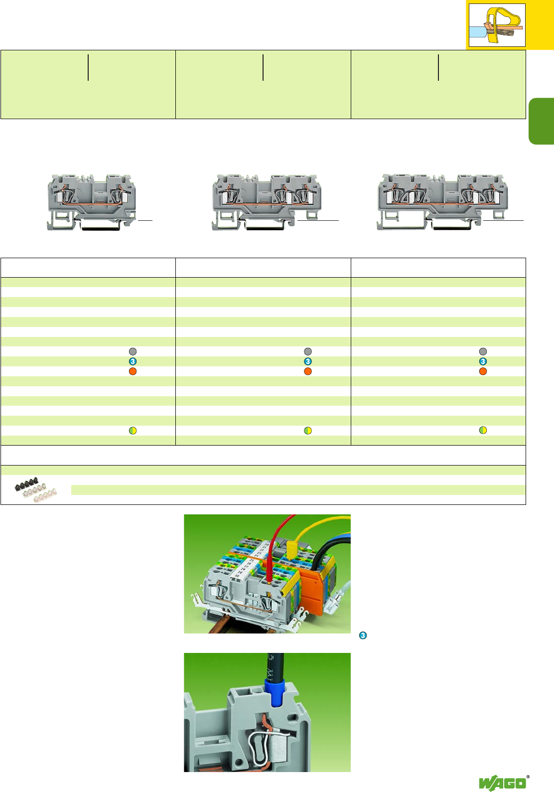
2
15
▲
2
*Y*Y*Y
Through terminal block without/with shield (screen)
contact
and test slot for test plug
Ø 2 mm / 0.079 in and Ø 2.3 mm / 0.091 in,
for DIN 35 rail
4-conductor through terminal blocks without shield
(screen) contact
grey 880-831/999-940 100
blue 880-834/999-940 100
orange 880-832/999-940 100
4-conductor ground (earth) terminal block
green-yellow 880-837/999-940 100
Through terminal block without/with shield (screen)
contact
and test slot for test plug
Ø 2 mm / 0.079 in and Ø 2.3 mm / 0.091 in,
for DIN 35 rail
3-conductor through terminal blocks without shield
(screen) contact
grey 880-681/999-940 100
blue 880-684/999-940 100
orange 880-682/999-940 100
3-conductor through terminal blocks with shield
(screen) contact – please contact factory
3-conductor ground (earth) terminal block
green-yellow 880-687/999-940 100
Through terminal block without/with shield (screen)
contact
and test slot for test plug
Ø 2 mm / 0.079 in and Ø 2.3 mm / 0.091 in,
for DIN 35 rail
2-conductor through terminal blocks without shield
(screen) contact
grey 880-901/999-940 100
blue 880-904/999-940 100
orange 880-902/999-940 100
2-conductor through terminal blocks with shield
(screen) contact – please contact factory
2-conductor ground (earth) terminal block
green-yellow 880-907/999-940 100
Item Pack. unit
No. pcs Item Pack. unit
No. pcs Item Pack. unit
No. pcs
Through and Ground (Earth) Conductor Terminal Blocks f. Special Cables,
Terminal Block Width 5 mm / 0.197 in, 4 mm2/ AWG 12
Series 880 (AWG 12 with ferrule item no. 216-206)
(_ 35 mm /1.38 in _)
<______ 58,5 mm /2.3 in ______> (_ 35 mm /1.38 in _)
<__________ 73 mm /2.87 in __________> <___ 49 mm /1.93 in ___>
<______________ 87 mm /3.43 in ______________>
Features
●2-, 3- or 4-conductor terminal blocks,
5 mm / 0.197 in wide
●Cross section of the conductor up to
4 mm2/AWG 12 (acc. to VDE 0281) or
2.5 mm2/AWG 14
with rubber-insulated conductors having a dia-
meter up to 4.4 mm /0.173 in
●Shield (screen) connection, solder
contact /quick-connect contact 6.3 (2 x 2.8) mm
●Test plug, red, 2 mm /0.079 in Ø
●Test plug, yellow, 2.3 mm /0.091 in Ø
●Marking with WMB/WSB system
●Marking with miniature WSB system
on both sides
●Commoning with standard WAGO jumper
system
Using a cable AWG 12 with ferrule
Item No. 216-206
➊800 V = rated voltage
8 kV = rated surge voltage
3 = pollution degree
Y600 V/20 A
with shield (screen) contact 400 V/6 kV/3
Y300 V/10 A
(see also section 15)
➋Dimensions with shield (screen) contact
2-conductor terminal blocks
(____ 45 mm /1.77 in ____)
<___________ 79 mm /3.11 in ____________>
3-conductor terminal blocks
(____ 45 mm /1.77 in ____)
<______________ 92.5 mm /3.64 in ______________>
Suitable for Ex i applications
➍See application notes on pages 2.38 – 2.45
Accessories (see left page, except insulation stop)
➋➋
Insulation stop, 5 pcs /strip
white 0.08 – 0.2 mm2 ➎/ AWG 28 – 24 769-470 200 strips ➎ 0.2 mm2/AWG 24 “s” (0.14 mm2/AWG 26 “f-str”)
light grey 0.25 – 0.5 mm2/ AWG 22 – 20 769-471 200 strips
dark grey 0.75 – 1 mm2/ AWG 18 769-472 200 strips
<_ 29 mm /_>
1.14 in
0.08 – 4 mm2AWG 28 – 12
800 V/8 kV/3 ➊Y➊
25 A
Terminal block width 5 mm / 0.197 in
L8 – 9 mm / 0.33 in
0.08 – 4 mm2AWG 28 – 12
800 V/8 kV/3 ➊Y➊
25 A
Terminal block width 5 mm / 0.197 in
L8 – 9 mm / 0.33 in
0.08 – 4 mm2AWG 28 – 12
800 V/8 kV/3 ➊Y➊
20 A
Terminal block width 5 mm / 0.197 in
L8 – 9 mm / 0.33 in
<_ 29 mm /_>
1.14 in
<_ 29 mm / _>
1.14 in
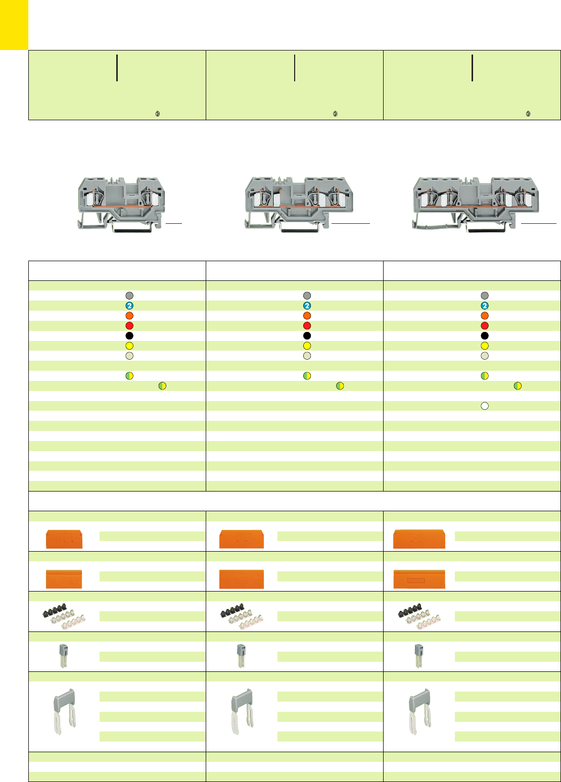
2
16
*U2KfNDaHJq:;{[ .-4 *U2KfNDaHJq:;{[ .4 *UY2KfNDaHJq:;{[ .4
Through/Ground (Earth) Conductor/Shield (Screen) and
4Terminal Blocks 4 mm2/ AWG 12,
Series 281
<_ 36 mm /1.42 in _>
<_____ 59 mm /2.32 in _____> <_ 37 mm /1.46 in _>
<________ 73,5 mm /2.89 in ________> <____50 mm /1.97 in ____>
<____________ 86 mm /3.39 in ____________>
Accessories Series 281 Appropriate marking system WMB/WSB/WFB (see section 14)
End and intermediate plate, 2.5 mm/0.098 in thick
orange 281-329 100 (4 x 25)
grey 281-328 100 (4 x 25)
light grey 281-349 100 (4 x 25)
Separator,oversized, 2 mm /0.079 in thick
orange 281-331 100 (4 x 25)
grey 281-330 100 (4 x 25)
light grey 281-350 100 (4 x 25)
Insulation stop ➌, 5 pcs /strip
white 281-470 200 strips
light grey 281-471 200 strips
dark grey 281-472 200 strips
Adjacent jumper, insulated, IN32 A, 426 A
grey 281-402 200 (8 x 25)
yell.-green 281-422 200 (8x 25)
Staggered jumper ➌, insulated, IN32 A, 426 A
width 6 mm/0.236 in
from 1 to 2 781-452 100 (4 x 25)
from 1 to 3 781-453 100 (4 x 25)
from 1 to 4 781-454 100 (4 x 25)
from 1 to 5 781-455 50 (2 x 25)
from 1 to 6 781-456 50 (2 x 25)
Protective warning marker, comp type jumper bar,
test plug adapter, etc. (see right page)
4-conductor through terminal blocks
grey 281-652 50
blue 281-654 50
orange 281-653 50
red 281-663 50
black 281-664 50
yellow 281-668 50
light grey 4281-994 50
4-conductor ground (earth) terminal blocks
green-yellow 281-657 50
green-yellow 4281-657/999-950 50
4-conductor shield (screen) terminal block
white 281-658 50
Other terminal blocks with the same shape
disconnect 281-659 page 7.12
disc., test a. meas. 281-666 page 7.10
carrier term. block 281-656 page 7.34
diode 281-665/...-... page 7.58
3-conductor through terminal blocks
grey 281-681 50
blue 281-684 50
orange 281-678 50
red 281-679 50
black 281-685 50
yellow 281-686 50
light grey 4281-993 50
3-conductor ground (earth) terminal blocks
green-yellow 281-687 50
green-yellow 4281-687/999-950 50
Other terminal blocks with the same shape
disconnect 281-683 page 7.12
carrier term. block 281-610 page 7.34
diode 281-673/...-... page 7.58
2-conductor through terminal blocks
grey 281-901 50
blue 281-904 50
orange 281-902 50
red 281-903 50
black 281-905 50
yellow 281-906 50
light grey 4281-992 50
2-conductor ground (earth) terminal blocks
green-yellow 281-907 50
green-yellow 4281-907/999-950 50
Other terminal blocks with the same shape
disconnect 281-912 page 7.12
carrier term. block 281-916 page 7.34
diode 281-915/...-... page 7.58
Item Pack. unit
No. pcs Item Pack. unit
No. pcs Item Pack. unit
No. pcs
* For further approvals with corresponding ratings see section 15.
End and intermediate plate, 2.5 mm/0.098 in thick
orange 281-326 100 (4 x 25)
grey 281-324 100 (4 x 25)
light grey 281-355 100 (4 x 25)
Separator,oversized, 2 mm /0.079 in thick
orange 281-346 100 (4 x 25)
grey 281-344 100 (4 x 25)
light grey 281-356 100 (4 x 25)
Insulation stop ➌, 5 pcs /strip
white 281-470 200 strips
light grey 281-471 200 strips
dark grey 281-472 200 strips
Adjacent jumper, insulated, IN32 A, 426 A
grey 281-402 200 (8 x 25)
yell.-green 281-422 200 (8x 25)
Staggered jumper ➌, insulated, IN32 A, 426 A
width 6 mm/0.236 in
from 1 to 2 781-452 100 (4 x 25)
from 1 to 3 781-453 100 (4 x 25)
from 1 to 4 781-454 100 (4 x 25)
from 1 to 5 781-455 50 (2 x 25)
from 1 to 6 781-456 50 (2 x 25)
Protective warning marker, comp type jumper bar,
test plug adapter, etc. (see right page)
End and intermediate plate, 2.5 mm/0.098 in thick
orange 281-335 100 (4 x 25)
grey 281-334 100 (4 x 25)
light grey 281-345 100 (4 x 25)
Separator,oversized, 2 mm /0.079 in thick
orange 281-339 100 (4 x 25)
grey 281-338 100 (4 x 25)
light grey 281-347 100 (4 x 25)
Insulation stop ➌, 5 pcs /strip
white 281-470 200 strips
light grey 281-471 200 strips
dark grey 281-472 200 strips
Adjacent jumper, insulated, IN32 A, 426 A
grey 281-402 200 (8 x 25)
yell.-green 281-422 200 (8x 25)
Staggered jumper ➌, insulated, IN32 A, 426 A
width 6 mm/0.236 in
from 1 to 2 781-452 100 (4 x 25)
from 1 to 3 781-453 100 (4 x 25)
from 1 to 4 781-454 100 (4 x 25)
from 1 to 5 781-455 50 (2 x 25)
from 1 to 6 781-456 50 (2 x 25)
Protective warning marker, comp type jumper bar,
test plug adapter, etc. (see right page)
<__29 mm / __>
1.14 in
<__29 mm /__>
1.14 in
<__29 mm / __>
1.14 in
0.08 – 4 mm2AWG 28 – 12
800 V/8 kV/3 ➊600 V, 20 A U
32 A 600 V, 15 A 2
Terminal block width 6 mm / 0.236 in
L9 – 10 mm / 0.37 in
0.08 – 4 mm2AWG 28 – 12
800 V/8 kV/3 ➊600 V, 20 A U
32 A 600 V, 15 A 2
Terminal block width 6 mm / 0.236 in
L9 – 10 mm / 0.37 in
0.08 – 4 mm2AWG 28 – 12
800 V/8 kV/3 ➊600 V, 20 A U
26 A 600 V, 15 A 2
Terminal block width 6 mm / 0.236 in
L9 – 10 mm / 0.37 in
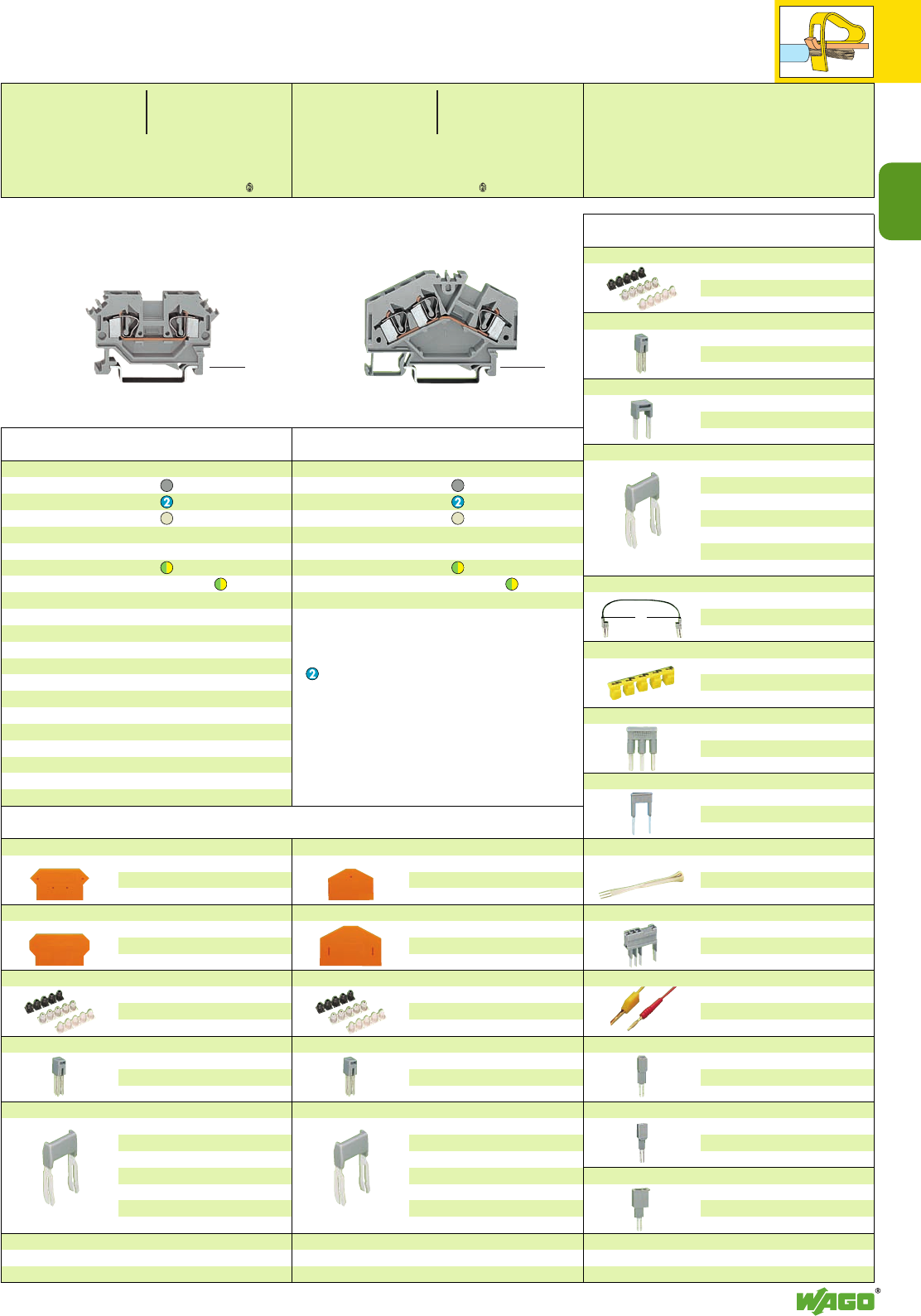
2
2
17
*U2KfDaJq:;{[ .4
*UY2KfND8aHJq:;{[ .-4
L
Accessories Series 281
2-conductor through terminal blocks
grey 281-601 50
blue 281-604 50
light grey 4281-691 50
2-conductor ground (earth) terminal blocks
green-yellow 281-607 50
green-yellow 4281-607/999-950 50
Other terminal blocks with the same shape
diode 281-603/...-... page 7.58
Item Pack. unit
No. pcs
Insulation stop ➌, 5 pcs /strip
white 281-470 200 strips
light grey 281-471 200 strips
dark grey 281-472 200 strips
Adjacent jumper, insulated, IN32 A, 426 A
grey 281-402 200 (8 x 25)
yell.-green 281-422 200 (8x 25)
Alternate jumper, insulated, IN32 A, 426 A
grey 281-409 100 (4 x 25)
Staggered jumper ➌, insulated, IN32 A, 426 A
width 6 mm/0.236 in
from 1 to 2 781-452 100 (4 x 25)
from 1 to 3 781-453 100 (4 x 25)
from 1 to 4 781-454 100 (4 x 25)
from 1 to 5 781-455 50 (2 x 25)
from 1 to 6 781-456 50 (2 x 25)
Push-in type wire jumper ➌, insulated, IN9 A
L =
60 mm
249-125 10
L =
110 mm
249-126 10
L =
250 mm
249-127 10
Protective warning marker, for 5 terminal blocks,
fits into screwdriver slot
yellow 281-415 100 (4 x 25)
Comb type jumper bar ➌, insulated,
IN= INof terminal block
2-way 281-482 100 (4 x 25)
3-way 281-483 100 (4 x 25)
Alternate comb type jumper bar, insulated,
IN= INof terminal block
2-way 281-492 100 (4 x 25)
Operating tool, insulated
2-way 280-432 1
3-way 280-433 1
Test plug module ➌,
testing using jumper contact slots
or conductor entry holes
Test plug,
with
cable 500 mm/1’7.7’’
2 mm Ø, red
210-136 50 (5 x 10)
2.3 mm Ø, yel.
210-137 50 (5 x 10)
Test plug adapter, suitable f. term. bl. 1.5 mm2– 4 mm2,
5 mm /0.197 in wide
280-404 100 (4 x 25)
for test plug 210-137 (2.3 mm Ø)
Test plug adapter, suitable f. term. bl. 1.5 mm2– 10 mm2,
8 mm /0.315 in wide
209-170 50 (2 x 25)
for test plug 4 mm /0.157 in Ø
Test plug, 6 mm/0.236 in wide, with CAGE CLAMP®for
0.08 mm2– 2.5 mm2/AWG 28 –14
IN24 A 281-407 100 (4 x 25)
Banana plugs, 4 mm/0.157 in Ø, color mixed
see page 2.42
Item Pack. unit
No. pcs
3-conductor through terminal blocks
grey 281-631 100
blue 281-651 100
light grey 4281-998 100
3-conductor ground (earth) terminal blocks
green-yellow 281-637 100
green-yellow 4281-637/999-950 100
Item Pack. unit
No. pcs
<______ 61,5 mm /2.42 in ______>
End and intermediate plate, 3 mm/0.118 in thick
orange 281-317 100 (4 x 25)
grey 281-316 100 (4 x 25)
light grey 281-353 100 (4 x 25)
Separator,oversized, 2 mm /0.079 in thick
orange 281-327 100 (4 x 25)
grey 281-337 100 (4 x 25)
light grey 281-354 100 (4 x 25)
Insulation stop ➌, 5 pcs /strip
white 281-470 200 strips
light grey 281-471 200 strips
dark grey 281-472 200 strips
Adjacent jumper, insulated, IN32 A, 426 A
grey 281-402 200 (8 x 25)
yell.-green 281-422 200 (8x 25)
Staggered jumper ➌, insulated, IN32 A, 426 A
width 6 mm/0.236 in
from 1 to 2 781-452 100 (4 x 25)
from 1 to 3 781-453 100 (4 x 25)
from 1 to 4 781-454 100 (4 x 25)
from 1 to 5 781-455 50 (2 x 25)
from 1 to 6 781-456 50 (2 x 25)
Protective warning marker, comp type jumper bar,
test plug adapter, etc. (see righthand side of the
page)
End and intermediate plate, 2.5 mm/0.098 in thick
orange 281-313 100 (4 x 25)
grey 281-312 100 (4 x 25)
light grey 281-357 100 (4 x 25)
Separator,oversized, 2 mm /0.079 in thick
orange 281-318 100 (4 x 25)
grey 281-348 100 (4 x 25)
light grey 281-358 100 (4 x 25)
Insulation stop ➌, 5 pcs /strip
white 281-470 200 strips
light grey 281-471 200 strips
dark grey 281-472 200 strips
Adjacent jumper, insulated, IN32 A, 426 A
grey 281-402 200 (8 x 25)
yell.-green 281-422 200 (8x 25)
Staggered jumper ➌, insulated, IN32 A, 426 A
width 6 mm/0.236 in
from 1 to 2 781-452 100 (4 x 25)
from 1 to 3 781-453 100 (4 x 25)
from 1 to 4 781-454 100 (4 x 25)
from 1 to 5 781-455 50 (2 x 25)
from 1 to 6 781-456 50 (2 x 25)
Protective warning marker, comp type jumper bar,
test plug adapter, etc. (see righthand side of the
page )
<_____ 53 mm /2.09 in _____>
➊800 V = rated voltage
8 kV = rated surge voltage
3 = pollution degree
(see also section 15)
Suitable for Ex i applications
4Suitable for Ex e II applications
0.2 – 4 mm2AWG 24 – 12
550 V, 30 A
(see also section 13)
When using staggered jumpers the max. rated
voltage will be reduced to 275 V.
Ex e/Ex i separator see page 2.13
➌See application notes
on
pages
2.38 – 2.45
Appropriate marking system WMB/WSB/WFB (see section 14)
0.08 – 4 mm2AWG 28 – 12
800 V/8 kV/3 ➊600 V, 20 A U
32 A 600 V, 15 A 2
Terminal block width 6 mm / 0.236 in
L9 – 10 mm / 0.37 in
0.08 – 4 mm2AWG 28 – 12
800 V/8 kV/3 ➊600 V, 20 A U
32 A 600 V, 15 A 2
Terminal block width 6 mm / 0.236 in
L9 – 10 mm / 0.37 in
<__29 mm / __>
1.14 in
<____ 37 mm / ____>
1.46 in
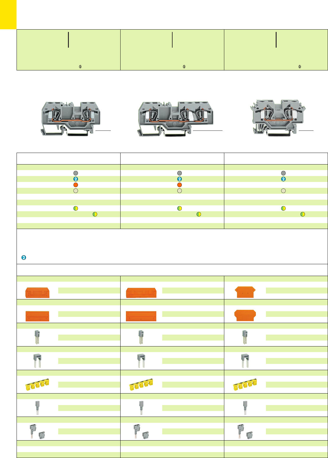
2
18
*U2KfaJq:;{[ 4 *U2KfaJq:;{[ .4 *U2KfD8aHJq:;{[ .-4
Accessories Series 282 Appropriate marking system WMB/WSB/WFB (see section 14)
End and intermediate plate, 2.5 mm/0.098 in thick
orange 282-328 100 (4 x 25)
grey 282-325 100 (4 x 25)
light grey 282-330 100 (4 x 25)
Separator,oversized, 2 mm /0.079 in thick
orange 282-329 100 (4 x 25)
grey 282-326 100 (4 x 25)
light grey 282-331 100 (4 x 25)
Adjacent jumper, insulated,I
N41 A, 435 A
grey 282-402 100 (4 x 25)
yell.-green 282-422 100 (4x 25)
Alternate jumper, insulated,I
N41 A, 435 A
grey 282-409 100 (4 x 25)
Protective warning marker, for 5 terminal blocks,
fits into screwdriver slot
yellow 282-415 100 (4 x 25)
Test plug adapter, suitable f. term. bl. 1.5 mm2– 10 mm2,
8 mm /0.315 in wide
209-170 50 (2 x 25)
for test plug 4 mm /0.157 in Ø
Test plug module and spacer, suitable for term. blocks
0.2 mm2– 6 mm2/AWG 24-10
8 mm /0.315 in wide
see page 2.41
Step down jumper and cover plate
see pages 2.26 – 2.27
2-conductor through terminal blocks
grey 282-601 50
blue 282-604 50
light grey 4282-691 50
2-conductor ground (earth) terminal blocks
green-yellow 282-607 50
green-yellow 4282-607/999-950 50
3-conductor through terminal blocks
grey 282-681 25
blue 282-684 25
orange 282-682 25
light grey 4282-993 25
3-conductor ground (earth) terminal blocks
green-yellow 282-687 25
green-yellow 4282-687/999-950 25
2-conductor through terminal blocks
grey 282-901 50
blue 282-904 50
orange 282-902 50
light grey 4282-992 50
2-conductor ground (earth) terminal blocks
green-yellow 282-907 50
green-yellow 4282-907/999-950 50
Item Pack. unit
No. pcs
Through/Ground (Earth) Conductor and
4Terminal Blocks 6 mm2/ AWG 10,
Series 282
Item Pack. unit
No. pcs Item Pack. unit
No. pcs
* For further approvals with corresponding ratings see section 15.
End and intermediate plate, 2.5 mm/0.098 in thick
orange 282-339 100 (4 x 25)
grey 282-308 100 (4 x 25)
light grey 282-341 100 (4 x 25)
Separator,oversized, 2 mm /0.079 in thick
orange 282-340 100 (4 x 25)
grey 282-309 100 (4 x 25)
light grey 282-342 100 (4 x 25)
Adjacent jumper, insulated,I
N41 A, 435 A
grey 282-402 100 (4 x 25)
yell.-green 282-422 100 (4x 25)
Alternate jumper, insulated,I
N41 A, 435 A
grey 282-409 100 (4 x 25)
Protective warning marker, for 5 terminal blocks,
fits into screwdriver slot
yellow 282-415 100 (4 x 25)
Test plug adapter, suitable f. term. bl. 1.5 mm2– 10 mm2,
8 mm /0.315 in wide
209-170 50 (2 x 25)
for test plug 4 mm /0.157 in Ø
Test plug module and spacer, suitable for term. blocks
0.2 mm2– 6 mm2/AWG 24-10
8 mm /0.315 in wide
see page 2.41
Step down jumper and cover plate
see pages 2.26 – 2.27
End and intermediate plate, 4 mm/0.157 in thick
orange 282-317 100 (4 x 25)
grey 282-316 100 (4 x 25)
light grey 282-318 100 (4 x 25)
Separator,oversized, 2 mm /0.079 in thick
orange 282-327 100 (4 x 25)
grey 282-337 100 (4 x 25)
light grey 282-338 100 (4 x 25)
Adjacent jumper, insulated,I
N41 A, 435 A
grey 282-402 100 (4 x 25)
yell.-green 282-422 100 (4x 25)
Alternate jumper, insulated,I
N41 A, 435 A
grey 282-409 100 (4 x 25)
Protective warning marker, for 5 terminal blocks,
fits into screwdriver slot
yellow 282-415 100 (4 x 25)
Test plug adapter, suitable f. term. bl. 1.5 mm2– 10 mm2,
8 mm /0.315 in wide
209-170 50 (2 x 25)
for test plug 4 mm /0.157 in Ø
Test plug module and spacer, suitable for term. blocks
0.2 mm2– 6 mm2/AWG 24-10
8 mm /0.315 in wide
see page 2.41
Step down jumper and cover plate
see pages 2.26 – 2.27
<__ 45.5 mm /1.79 in __>
<________ 74.5 mm /2.93 in ________> <__ 45.5 mm /1.79 in __>
<______________ 93 mm /3.66 in ______________> <______ 62 mm /2.44 in ______>
➊800 V = rated voltage
8 kV = rated surge voltage
3 = pollution degree
(see also section 15)
Suitable for Ex i applications
4Suitable for Ex e II applications
0.5 – 6 mm2AWG 20 – 10
550 V, 39 A jumper 35 A
(see also section 13)
Ex e/Ex i separator see page 2.13
<___ 31.5 mm /__>
1.24 in
0.2 – 6 mm2AWG 24 – 10
800 V/8 kV/3 ➊600 V, 30 A U
41 A 600 V, 40 A 2
Terminal block width 8 mm / 0.315 in
L12 – 13 mm / 0.49 in
0.2 – 6 mm2AWG 24 – 10
800 V/8 kV/3 ➊600 V, 30 A U
41 A 600 V, 40 A 2
Terminal block width 8 mm / 0.315 in
L12 – 13 mm / 0.49 in
0.2 – 6 mm2AWG 24 – 10
800 V/8 kV/3 ➊600 V, 30 A U
41 A 600 V, 40 A 2
Terminal block width 8 mm / 0.315 in
L12 – 13 mm / 0.49 in
<_ 32.5 mm /_>
1.28 in
<_ 32.5 mm /_>
1.28 in
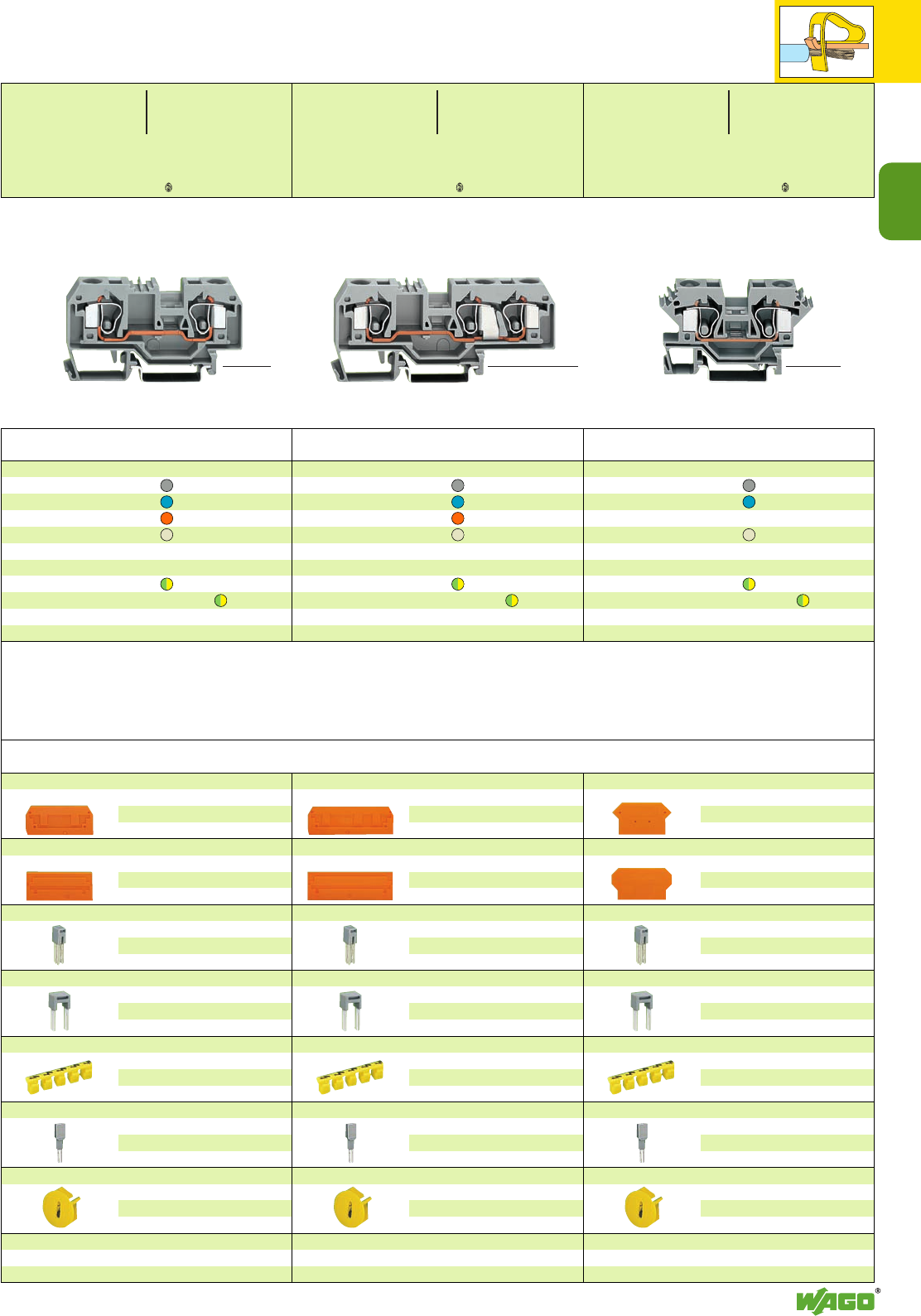
2
2
19
*U2KfaJq:{[ 4 *U2KfaJq:{[ .4 *U2KfDaHJq:;{[ .-4
Accessories Series 284 Appropriate marking system WMB/WSB/WFB (see section 14)
End and intermediate plate, 2.5 mm/0.098 in thick
orange 284-328 100 (4 x 25)
grey 284-325 100 (4 x 25)
light grey 284-330 100 (4 x 25)
Separator,oversized, 2 mm /0.079 in thick
orange 284-329 100 (4 x 25)
grey 284-326 100 (4 x 25)
light grey 284-331 100 (4 x 25)
Adjacent jumper, insulated,I
N57 A, 453 A
grey 284-402 100 (4 x 25)
yell.-green 284-422 100 (4x 25)
Alternate jumper, insulated,I
N57 A, 453 A
grey 284-409 50 (2 x 25)
Protective warning marker, for 5 terminal blocks,
fits into screwdriver slot
yellow 284-415 50 (2 x 25)
Test plug adapter, suitable f. term. bl. 1.5 mm2– 10 mm2,
8 mm /0.315 in wide
209-170 50 (2 x 25)
see also page 2.41
Finger guard cover,
serves as touchproof protection
for unused clamping units
yellow 284-400 100 (4 x 25)
Step down jumper and cover plate
see pages 2.26 – 2.27
2-conductor through terminal blocks
grey 284-601 25
blue 284-604 25
light grey 4284-691 25
2-conductor ground (earth) terminal blocks
green-yellow 284-607 25
green-yellow 4284-607/999-950 25
3-conductor through terminal blocks
grey 284-681 25
blue 284-684 25
orange 284-682 25
light grey 4284-993 25
3-conductor ground (earth) terminal blocks
green-yellow 284-687 25
green-yellow 4284-687/999-950 25
2-conductor through terminal blocks
grey 284-901 25
blue 284-904 25
orange 284-902 25
light grey 4284-992 25
2-conductor ground (earth) terminal blocks
green-yellow 284-907 25
green-yellow 4284-907/999-950 25
Item Pack. unit
No. pcs
Through/Ground (Earth) Conductor and
4Terminal Blocks 10 mm2/ AWG 8,
Series 284
Item Pack. unit
No. pcs Item Pack. unit
No. pcs
* For further approvals with corresponding ratings see section 15.
End and intermediate plate, 2.5 mm/0.098 in thick
orange 284-339 100 (4 x 25)
grey 284-308 100 (4 x 25)
light grey 284-341 100 (4 x 25)
Separator,oversized, 2 mm /0.079 in thick
orange 284-340 100 (4 x 25)
grey 284-309 100 (4 x 25)
light grey 284-342 100 (4 x 25)
Adjacent jumper, insulated,I
N57 A, 453 A
grey 284-402 100 (4 x 25)
yell.-green 284-422 100 (4x 25)
Alternate jumper, insulated,I
N57 A, 453 A
grey 284-409 50 (2 x 25)
Protective warning marker, for 5 terminal blocks,
fits into screwdriver slot
yellow 284-415 50 (2 x 25)
Test plug adapter, suitable f. term. bl. 1.5 mm2– 10 mm2,
8 mm /0.315 in wide
209-170 50 (2 x 25)
see also page 2.41
Finger guard cover,
serves as touchproof protection
for unused clamping units
yellow 284-400 100 (4 x 25)
Step down jumper and cover plate
see pages 2.26 – 2.27
End and intermediate plate, 2.5 mm/0.098 in thick
orange 284-317 100 (4 x 25)
grey 284-316 100 (4 x 25)
light grey 284-318 100 (4 x 25)
Separator,oversized, 2 mm /0.079 in thick
orange 284-327 100 (4 x 25)
grey 284-337 100 (4 x 25)
light grey 284-338 100 (4 x 25)
Adjacent jumper, insulated,I
N57 A, 453 A
grey 284-402 100 (4 x 25)
yell.-green 284-422 100 (4x 25)
Alternate jumper, insulated,I
N57 A, 453 A
grey 284-409 50 (2 x 25)
Protective warning marker, for 5 terminal blocks,
fits into screwdriver slot
yellow 284-415 50 (2 x 25)
Test plug adapter, suitable f. term. bl. 1.5 mm2– 10 mm2,
8 mm /0.315 in wide
209-170 50 (2 x 25)
see also page 2.41
Finger guard cover,
serves as touchproof protection
for unused clamping units
yellow 284-400 100 (4 x 25)
Step down jumper and cover plate
see pages 2.26 – 2.27
<_ 46.5 mm /1.83 in _>
<__________ 78 m m / 3. 0 7 i n __________> <_ 46.5 mm /1.83 in _>
<______________ 97.5 mm /3.84 in ______________> <______ 69 mm /2.72 in _______>
➊800 V = rated voltage
8 kV = rated surge voltage
3 = pollution degree
(see also section 15)
4Suitable for Ex e II applications
0.5 – 10 mm2AWG 20 – 8
550 V, 53 A
(see also section 13)
0.2 – 10 mm2AWG 24 – 8
800 V/8 kV/3 ➊600 V, 50 A U
57 A 600 V, 54 A 2
Terminal block width 10 mm / 0.394 in
L12 – 13 mm / 0.49 in
0.2 – 10 mm2AWG 24 – 8
800 V/8 kV/3 ➊600 V, 50 A U
57 A 600 V, 54 A 2
Terminal block width 10 mm / 0.394 in
L12 – 13 mm / 0.49 in
<__33.5 mm / __>
1.32 in
0.2 – 10 mm2AWG 24 – 8
800 V/8 kV/3 ➊600 V, 50 A U
57 A 600 V, 65 A 2
Terminal block width 10 mm / 0.394 in
L12 – 13 mm / 0.49 in
<___35 mm / ____>
1.38 in
<___ 35 mm / ___>
1.38 in
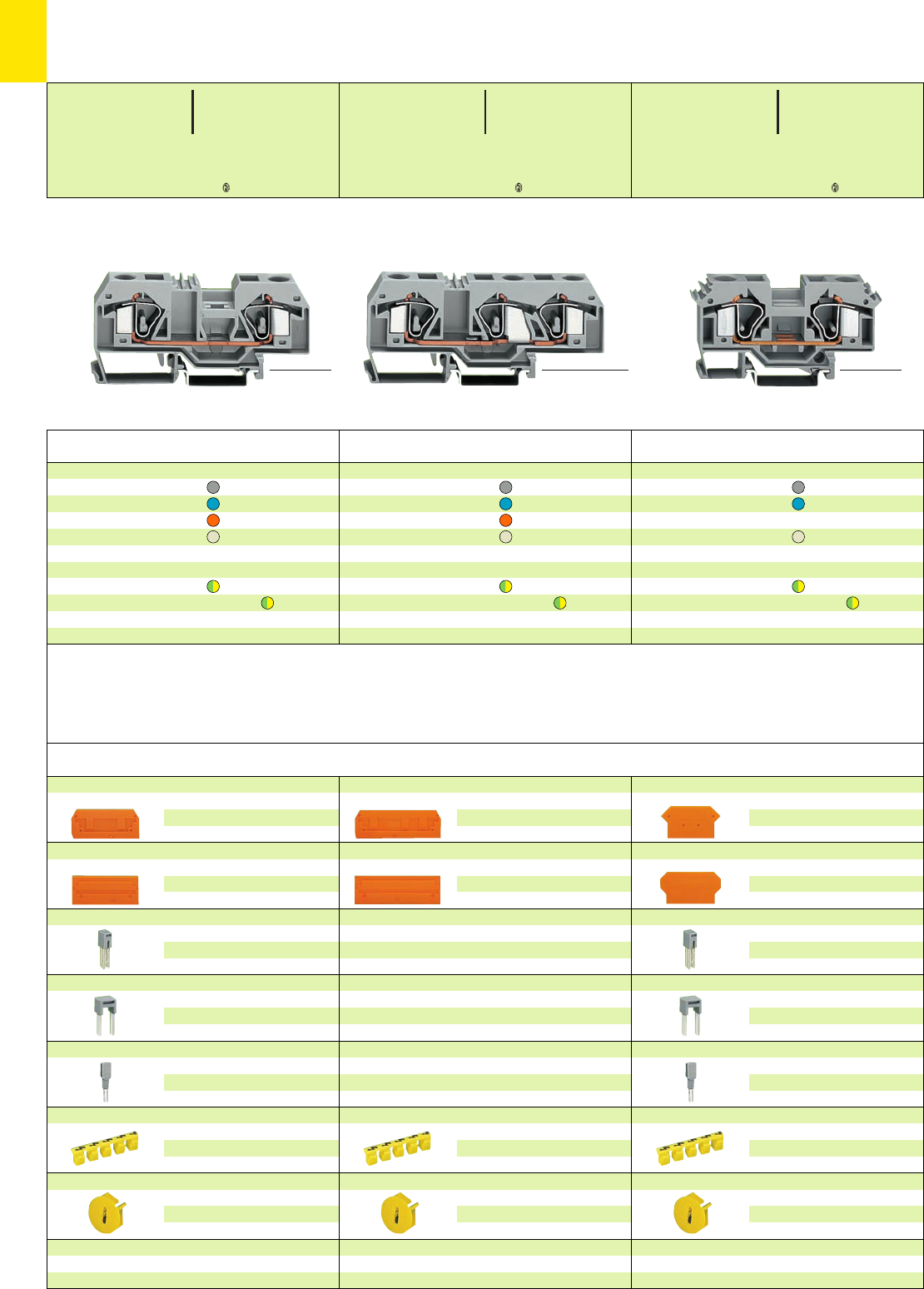
2
20
2
20
*U2KfaJq:;{[ 4 *U2KfD8aJq:;{[ .-4
*U2KfaJq:;{[ .4
Accessories Series 283 Appropriate marking system WMB/WSB/WFB (see section 14)
End and intermediate plate, 2.5 mm/0.098 in thick
orange 283-328 50 (2 x 25)
grey 283-325 50 (2 x 25)
light grey 283-330 50 (2 x 25)
Separator,oversized, 2 mm /0.079 in thick
orange 283-329 50 (2 x 25)
grey 283-326 50 (2 x 25)
light grey 283-331 50 (2 x 25)
Adjacent jumper, insulated, IN70 A, 463 A
grey 283-402 50 (2 x 25)
yell.-green 283-422 50 (2x 25)
Alternate jumper, insulated, IN76 A, 463 A
grey 283-409 50 (2 x 25)
Test plug adapter, suitable f. term. bl. 1.5 mm2– 16 mm2,
11.6 mm/0.457 in wide
283-404 25
for test plug 4 mm /0.157 in Ø
Protective warning marker, for 5 terminal blocks,
fits into screwdriver slot
yellow 283-415 50 (2 x 25)
Finger guard cover,
serves as touchproof protection
for unused clamping units
yellow 283-400 100 (4 x 25)
Step down jumper and cover plate
see pages 2.26 – 2.27
2-conductor through terminal blocks
grey 283-601 25
blue 283-604 25
light grey 4283-691 25
2-conductor ground (earth) terminal blocks
green-yellow 283-607 25
green-yellow 4283-607/999-950 25
3-conductor through terminal blocks
grey 283-671 20
blue 283-674 20
orange 283-672 20
light grey 4283-998 20
3-conductor ground (earth) terminal blocks
green-yellow 283-677 20
green-yellow 4283-677/999-950 20
Attention! These terminal blocks cannot be
commoned with adjacent jumpers!
2-conductor through terminal blocks
grey 283-901 20
blue 283-904 20
orange 283-902 20
light grey 4283-992 20
2-conductor ground (earth) terminal blocks
green-yellow 283-907 20
green-yellow 4283-907/999-950 20
Item Pack. unit
No. pcs
Through/Ground (Earth) Conductor and
4Terminal Blocks 16 mm2/ AWG 6,
Series 283
Item Pack. unit
No. pcs Item Pack. unit
No. pcs
* For further approvals with corresponding ratings see section 15.
End and intermediate plate, 2.5 mm/0.098 in thick
orange 283-352 50 (2 x 25)
grey 283-350 50 (2 x 25)
light grey 283-354 50 (2 x 25)
Separator,oversized, 2 mm /0.079 in thick
orange 283-353 50 (2 x 25)
grey 283-351 50 (2 x 25)
light grey 283-355 50 (2 x 25)
Protective warning marker, for 5 terminal blocks,
fits into screwdriver slot
yellow 283-415 50 (2 x 25)
Finger guard cover,
serves as touchproof protection
for unused clamping units
yellow 283-400 100 (4 x 25)
Attention! These terminal blocks cannot be
commoned with step down jumpers!
End and intermediate plate, 4 mm/0.157 in thick
orange 283-317 50 (2 x 25)
grey 283-316 50 (2 x 25)
light grey 283-318 50 (2 x 25)
Separator,oversized, 2 mm /0.079 in thick
orange 283-327 50 (2 x 25)
grey 283-337 50 (2 x 25)
light grey 283-338 50 (2 x 25)
Adjacent jumper, insulated, IN70 A, 463 A
grey 283-402 50 (2 x 25)
yell.-green 283-422 50 (2x 25)
Alternate jumper, insulated, IN76 A, 463 A
grey 283-409 50 (2 x 25)
Test plug adapter, suitable f. term. bl. 1.5 mm2– 16 mm2,
11.6 mm/0.457 in wide
283-404 25
for test plug 4 mm /0.157 in Ø
Protective warning marker, for 5 terminal blocks,
fits into screwdriver slot
yellow 283-415 50 (2 x 25)
Finger guard cover,
serves as touchproof protection
for unused clamping units
yellow 283-400 100 (4 x 25)
Step down jumper and cover plate
see pages 2.26 – 2.27
<___ 54.5 mm /2.15 in ___>
<_____________ 94.5 mm /3.72 in _____________> <___________ 80 mm /3.15 in ___________>
<___ 54.5 mm /2.15 in ___>
<_______________ 104.5 mm /4.11 in _______________>
0.2 – 16 mm2AWG 24 – 6
800 V/8 kV/3 ➊600 V, 65 A U
76 A 600 V, 70 A 2
Terminal block width 12 mm / 0.472 in
L16 – 17 mm / 0.65 in
0.2 – 16 mm2AWG 24 – 6
800 V/8 kV/3 ➊600 V, 65 A U
76 A 600 V, 70 A 2
Terminal block width 12 mm / 0.472 in
L16 – 17 mm / 0.65 in
0.2 – 16 mm2AWG 24 – 6
800 V/8 kV/3 ➊600 V, 65 A U
76 A 600 V, 70 A 2
Terminal block width 12 mm / 0.472 in
L16 – 17 mm / 0.65 in
<___ 37.5 mm / ___>
1.48 in
<___ 37.5 mm / ___>
1.48 in
<___ 37.5 mm / ___>
1.48 in
➊800 V = rated voltage
8 kV = rated surge voltage
3 = pollution degree
(see also section 15)
4Suitable for Ex e II applications
0.5 – 6 mm2AWG 20 – 6
550 V, 68 A jumper 63 A
(see also section 13)
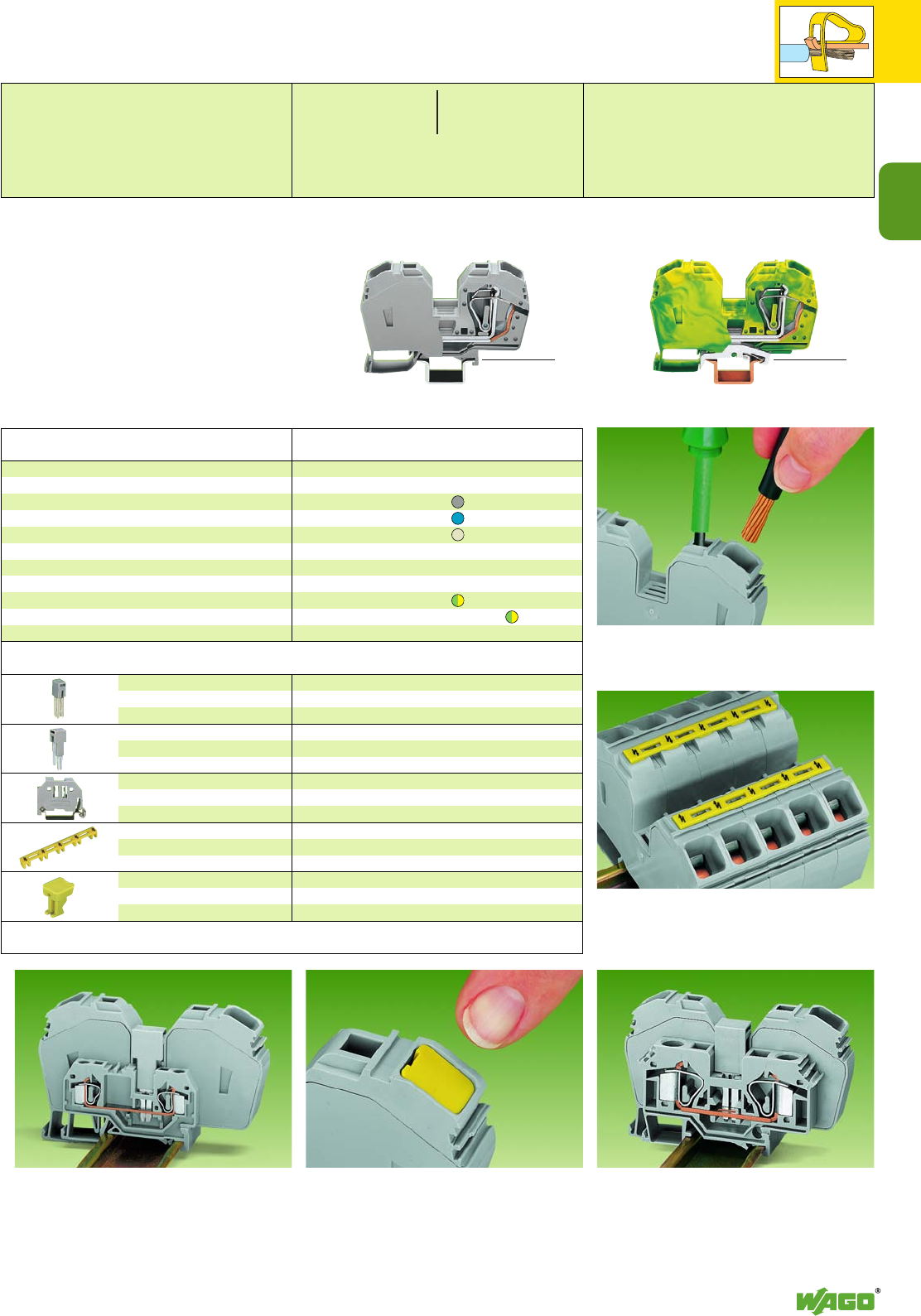
2
2
21
6 – 35 mm2
AWG 8 – 2
1000 V/8 kV/3 ➊
600 V, 115 A
125 A
Terminal block width 16 mm / 0.63 in
*U2f:4
Commoning of a series 285 terminal block (35 mm
2
/AWG 2)
with a series 281 terminal block (4 mm2/AWG 12) using
step-down jumper 283-414
Finger guard cover snapped into unused clamping unit
Application notes
Connection of conductor 35 mm2/AWG 2
Protective warning markers in operating slots
Terminal blocks of series 285 can be commoned
with terminal blocks of series 283:
285-635 and 285-634 with
283-601 and 283-604 resp.
jumper required: 285-435.
Please note that the nominal current of the
adjacent jumper should not exceed 63 A.
➊1000 V = rated voltage
8 kV = rated surge voltage
3 = pollution degree
(see also section 15)
4Suitable for Ex e II applications
6 – 35 mm2AWG 8 – 2
750 V, 85 A
6 – 25 mm2AWG 8 – 4
for ground (earth) terminal blocks
(see also section 13) <_______ 100 mm /3.94 in ________>
IN85 A
grey 285-435 50 (2 x 25)
IN32 A
grey 283-414 50 (2 x 25)
6 mm /0.236 in w.
249-116 100 (4 x 25)
10 mm /0.394 in
w. 249-117 50 (2 x 25)
yellow 285-416 50 (2 x 25)
yellow 285-401 100 (4 x 25)
Adjacent jumper,
insulated
Step-down jumper,
insulated
Screwless end stop
Protective warning marker,
for 5 terminal blocks,
fits into screwdriver slot
Finger guard cover,
serves as touchproof protection
for unused clamping units
Description
Rail-mounted high current terminal blocks,
for DIN 35 rail
2-conductor through terminal blocks
with integrated end plate
grey 285-635 15
blue 285-634 15
light grey 4285-992 15
2-conductor ground (earth) terminal blocks
with integrated end plate
green-yellow 285-637 15
green-yellow 4285-637/999-950 15
not to be used on DIN 35 x 7.5 rail
Item Pack. unit
No. pcs
Accessories Series 285 Appropriate marking system
WMB/WSB or Mini-
WSB (see section 14)
High Current Through/Ground (Earth) Conductor and
4Terminal Blocks 35 mm2/ AWG 2,
Series 285
For terminal blocks
with larger cross sections,
please see Specialty Products
Catalog KSK 1.2
<_______ 100 mm /3.94 in ________>
6 – 35 mm2AWG 10 – 2
1000 V/8 kV/3 ➊600 V, 115 A U
125 A 600 V, 140 A 2
Terminal block width 16 mm / 0.63 in
L23 mm / 0.91 in [16 mm/0.63 in
for 35 mm2“str.”]
<___ 53 mm / ___>
2.09 in
<___ 53 mm / ___>
2.09 in
* For further approvals with corresponding ratings see section 15.
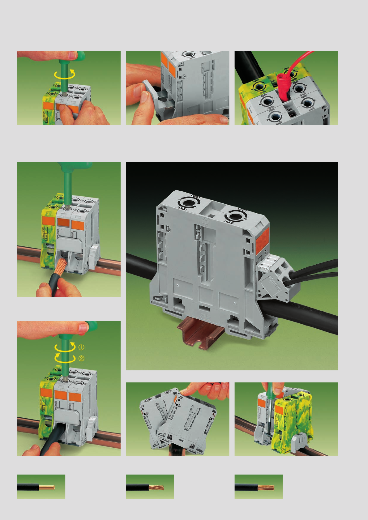
,
2
22
95 mm2/AWG 4/0 Rail-Mounted High Current Terminal Blocks . . .
with POWER CLAMP Connection, Series 285
Counter-clockwise rotation using a hex wrench.
Hold clamp in open position using the latch.
Commoning with adjacent jumper. Insertion of jum-
per above the conductor entry hole, without tools.
Rated cross section is still 95 mm
2
/AWG 0000.
Testing with test plug 4 mm/0.157 in diameter,
protected against accidental contact.
Snapping a terminal block onto the carrier rail.
From the left or from the right. Removing a terminal block from the carrier rail.
To the left or to the right.
Commoning Testing
Wire connection
Wire connection
Assembly Removal
Wire connection
Introduce stripped wire into the clamping unit up to
the stop and hold it in position . . .
. . . A small counter-clockwise rotation releases the
latch ➊. Once the operating tool ➋has been
removed the conductor is safely clamped.
* For aluminum wire see notes in section 15!
The POWER CLAMP
connection clamps the
following copper wires:*
solid stranded
fine-stranded,
also with tinned
single strands
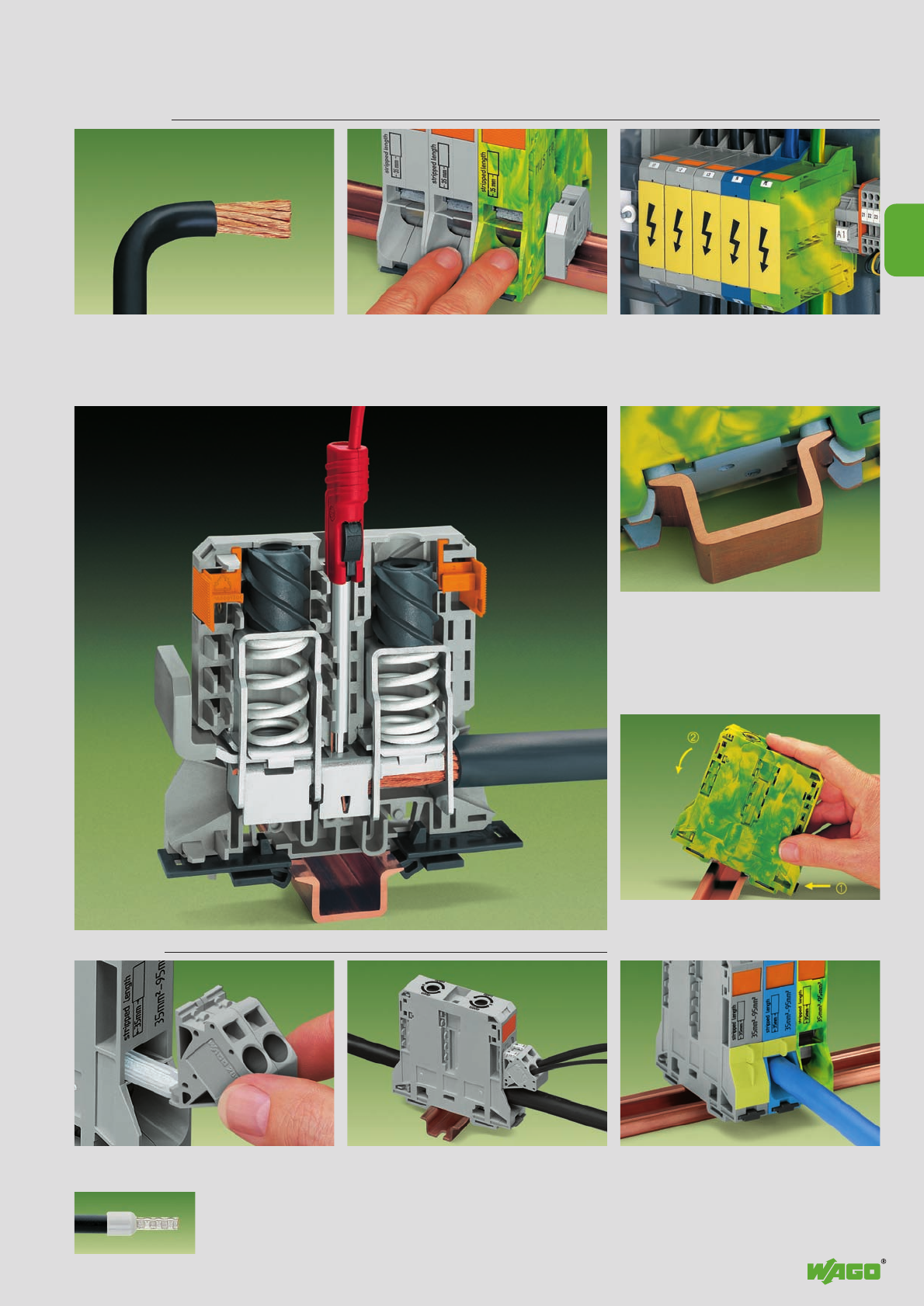
,
2
23
2
✗
. . . Description and Handling
Grounding foot
Ground (earth) conductor terminal
blocks
Touch protection coverVoltage tap
Safety notices
Bend the conductor before stripping!
Wire end has to be straight!
Note: Stripped length 35 mm
Contact pressure is distributed symmetrically on all
defined contact zones.
Short circuit currents of more than 11, 400 A per
second are grounded safely.
Firmly snap ground (earth) conductor terminal
block onto the carrier rail. The grounding foot
makes an automatic contact to the rail.
fine-stranded,
with crimped ferrule
(gas tight)
Reliable and simple tap directly onto the power supply. Insert the unwired tap before opening the
pressure spring. Covers provide touchproof safety by closing un-
used clamping units and jumper contact slots
(detach the cover of the jumper contact slot from
the touch protection cover of the clamping unit)
Attention! Health hazard!
Keep your fingers out of the conductor entry hole! Protective warning marker may indicate:
Attention! Voltage may be present despite main
circuit being switched off!
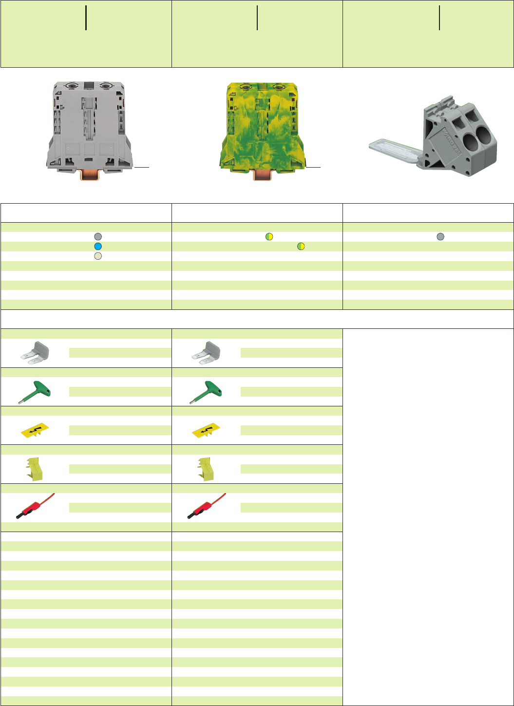
2
24
*U2f:4
*U2f:4
Accessories Appropriate marking system WSB (see section 14)
Voltage tap,
grey 285-407 5
2-conductor ground (earth) terminal blocks
green-yellow 285-197 5
green-yellow 4285-197/999-950 5
To be used exclusively on DIN 35 x 15;
2.3 mm / 0.091 in thick, Cu
2-conductor through terminal blocks
grey 285-195 5
blue 285-194 5
light grey 4285-995 5
To be used exclusively on DIN 35 x 15;
2.3 mm / 0.091 in thick
Item Pack. unit
No. pcs
Item Pack. unit
No. pcs
Item Pack. unit
No. pcs
High Current Through/Ground (Earth) Conductor and
4Terminal Blocks 95 mm2/AWG 4/0, Series 285
Side-entry
Adjacent jumper, insulated,
IN232 A for 1 jumper
IN192 A for 2 to 4 jumpers
grey 285-495 25
Hex wrench with partially insulated shaft
285-172 1
Protective warning marker,
with high voltage symbol, black
yellow 285-170 50 (2 x 25)
Touch protection cover, serves as touchproof protec-
tion for unused clamping units
yellow 285-169 25
Test plug, Ø 4 mm /0.157 in, protected against accidental
contact, not offered by WAGO
e. g
. Fa. Multi-Contact Deutschland GmbH
Postfach 16 06 · 79551 Weil am Rhein
Hegenheimerstraße 19 · 79576 Weil am Rhein
➊1000 V = rated voltage
8 kV = rated surge voltage
3 = pollution degree
(see also section 15)
4Suitable for Ex e II applications
25 – 95 mm2AWG 4 – 4/0
750 V, 195 A
35 – 70 mm2AWG 2 – 00
for ground (earth) terminal blocks
(see also section 13)
<______ 107 mm /4.21 in ______> <______ 107 mm /4.21 in ______>
Appropriate marking system WMB/WSB
Adjacent jumper, insulated,
IN232 A for 1 jumper
IN192 A for 2 to 4 jumpers
grey 285-495 25
Hex wrench with partially insulated shaft
285-172 1
Protective warning marker,
with high voltage symbol, black
yellow 285-170 50 (2 x 25)
Touch protection cover, serves as touchproof protec-
tion for unused clamping units
yellow 285-169 25
Test plug, Ø 4 mm /0.157 in, protected against accidental
contact, not offered by WAGO
e. g
. Fa. Multi-Contact Deutschland GmbH
Postfach 16 06 · 79551 Weil am Rhein
Hegenheimerstraße 19 · 79576 Weil am Rhein
* For further approvals with corresponding ratings see section 15.
25 – 95 mm2AWG 4 – 4/0
Terminal block width 25 mm / 0.98 in
L35 mm / 1.38 in
25 – 95 mm2AWG 4 – 4/0
1000 V/8 kV/3 ➊600 V, 200 A U
232 A 600 V, 210 A 2
Terminal block width 25 mm / 0.98 in
L35 mm / 1.38 in
<____ 101 mm /3.98 in ____>
<____ 101 mm /3.98 in ____>
0.2 –10/16mm
2➋
AWG 24 - 6
1000 V/8 kV/3
57 A
Module width 20 mm / 0.787 in
➋ max. conductor cross section 16 mm2
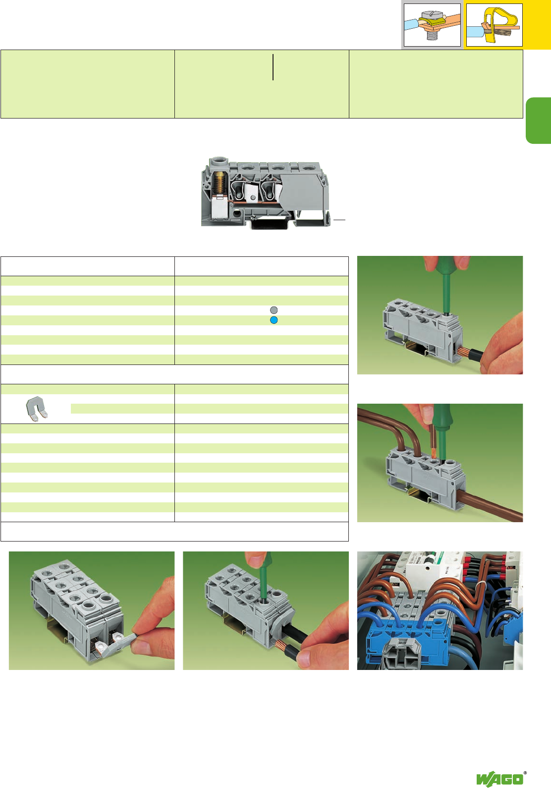
2
25
2
*U2KfCB :;{[
Distribution Terminal Blocks, Series 284
Front-entry/side-entry
Commoning with comb type jumper bar Connecting a 35 mm2/AWG 2 conductor
Connection of conductor 35 mm2/AWG 2
Screw-clamp connection, side-entry
Connection of conductor 10 mm2/AWG 8
CAGE CLAMP®connection, front-entry
Rail-mounted distribution terminal block with
35 mm2/AWG 2 and 3 x 10 mm2/3 x AWG 8
front-entry CAGE CLAMP®connection. To snap
onto DIN 35 carrier rails according to EN 60715.
The terminal block is closed on both sides, an end
or intermediate plate is not necessary.
In case of maximum wiring with
3 x 10 mm2/3 x AWG 8 on the distribution
side the nominal current of 125 A should not
be exceeded.
Distribution terminal block, for DIN 35 rail
Comb type jumper bar, insulated,
2-way
Distribution terminal blocks,
with 3 x CAGE CLAMP®connection ➊10 mm2/AWG 8
and 1 x screw-clamp connection ➋35 mm2/AWG 2
grey 284-621 15
blue 284-624 15
IN125 A ➍
grey 284-412 100 (4 x 25)
Item Pack. unit
No. pcs
Description
Application notes
➊CAGE CLAMP®connection
➋Screw-clamp connection
➌800 V = rated voltage
8 kV = rated surge voltage
3 = pollution degree
(see also section 15)
➍Individual arrangement 125 A
2 jumpers combined in one clamping unit 100 A <______________ 89 mm /3.5 in ______________>
Accessories Appropriate marking system WMB/WSB (see section 14)
* For further approvals with corresponding ratings see section 15.
0.2 – 10 mm2 ➊AWG 24 – 8 ➊
6.0 – 35 mm2 ➋AWG 10 – 2 ➋
800 V/8 kV/3 ➌; 125 A 600 V, 115 A U2
Terminal block width 17.5 mm / 0.689 in
L12 – 14 mm / 0.51 in
<_ 39.5 mm / _>
1.56 in
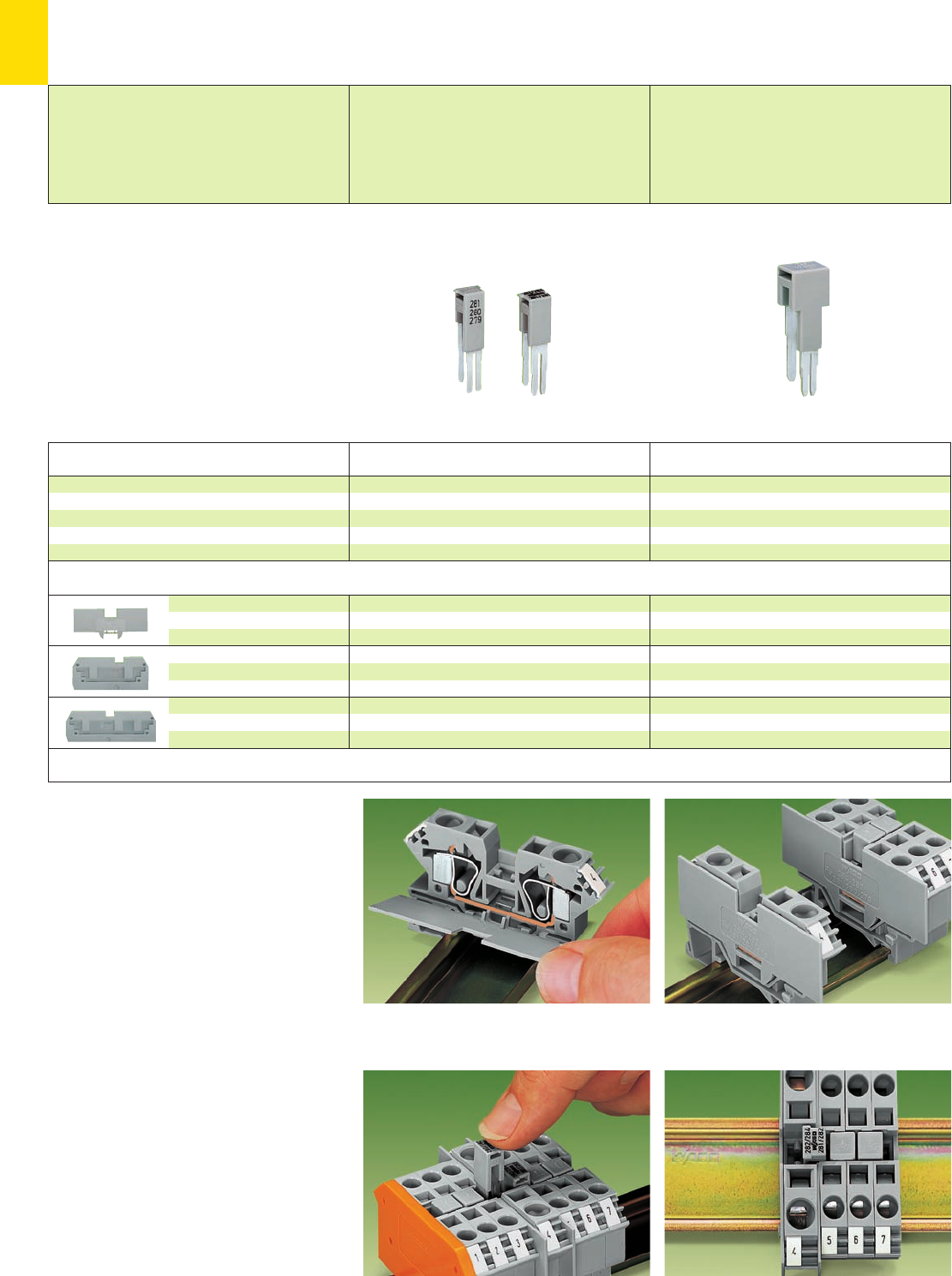
2
26
Cover plate snapped onto open side of terminal block
Larger “supply” blocks may be commoned to blocks for
smaller wires.
Push jumper down FIRMLY until FULLY inserted!
Note: jumpers are marked with suitable terminal block
sizes ensuring they are correctly installed.
Always use a cover plate also on the other side of the
larger terminal block.
Step-down jumpers may be used for commoning
terminal blocks of different sizes, without losing a
conductor clamping point. This can be an advan-
tage on long conductor runs where voltage drop
can be a problem.
A large conductor can be easily connected to
smaller wires at the distribution point.
Step-down jumpers are simply pushed down to
full insertion, in the same way as all other push-in
jumpers. Commoning may be made in either
direction using the special thin end plate to cover
the open side. Further terminal blocks of the
smaller cross section may be commoned using
standard adjacent jumpers. In this case pay
attention that:
1. the total current flowing does not exceed
the rating of the step-down jumper
2. the standard or special thin end plate is
applied to the open side of the larger block.
Application notes
Accessories
1 mm/0.039 in thick
grey 284-334 284-336 ➊284-335 ➋25
orange 284-344 284-346 ➊284-345 ➋25
1 mm/0.039 in thick
series 282 series 284
grey 282-357 284-357 25
orange 282-367 284-367 25
1 mm/0.039 in thick
series 282 series 284
grey 282-358 284-358 25
orange 282-368 284-368 25
1 mm/0.039 in thick, for 2-cond. terminal block 283-601
grey 283-334 25
orange 283-336 25
1 mm/0.039 in thick, for 2-cond. terminal block 283-901
grey 283-357 25
orange 283-367 25
Cover plate,
for 2-, 3- and
4-conductor terminal blocks
Cover plate,
for 2-conductor terminal blocks
282-901 and 284-901
Cover plate,
for 3-conductor terminal blocks
282-681 and 284-681
➊For use with terminal blocks
279-831; 280-833; 281-652 only
➋For use with terminal block 280-633 only
Step-down jumpers cannot be used for commoning
front-entry terminal blocks with side-entry terminal blocks
Description Item Pack. unit
No. pcs Item Pack. unit
No. pcs
Step-down jumper, insulated 10/6 mm2/AWG 8/10 →
4/2.5/1.5 mm2/ AWG 12/14/16
IN15 A, grey 284-414 50 (2 x 25)
10/6 mm2/AWG 8/10 →6/4 mm2/ AWG 10/12
IN30 A, grey 284-413 50 (2 x 25)
16 mm2/AWG 6 →4 mm2/ AWG 12
IN32 A, grey 283-414 50 (2 x 25)
Step-Down Jumpers for
Front-Entry Through Terminal Blocks up to 16 mm2/ AWG 6*
Step-down jumper commoning term. bl.
10/6 mm2/AWG 8/10 →
4/2.5/1.5 mm2/ AWG 12/14/16
800 V/8 kV/3; 15 A or
10/6 mm2/AWG 8/10 →
6/4 mm2/ AWG 10/12
800 V/8 kV/3; 30 A
Step-down jumper
for commoning terminal blocks
16 mm2/AWG 6 →4 mm2/AWG 12
800 V/8 kV/3
32 A
* Through terminal blocks 35 mm2/AWG 2 see page 2.21
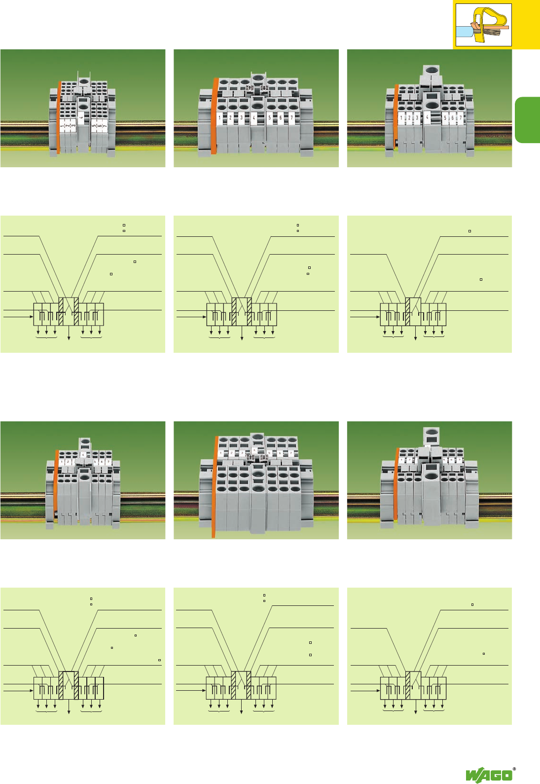
2
2
27
Commoning of front-entry rail-mounted terminal blocks
6 mm2/AWG 10 (series 282) with front-entry rail-moun-
ted terminal blocks 1.5 mm2/AWG 16 (series 279).
Commoning of front-entry rail-mounted terminal blocks
10 mm2/AWG 8 (series 284) with front-entry rail-moun-
ted terminal blocks 6 mm2/AWG 10 (series 282).
Commoning of front-entry rail-mounted terminal blocks
16 mm2/AWG 6 (series 283) with front-entry rail-moun-
ted terminal blocks 4 mm2/AWG 12 (series 281).
Examples of Assembly
Commoning of front-entry rail-mounted terminal blocks
6 mm2/AWG 10 (series 282) with front-entry rail-
mounted terminal blocks 1.5 mm2/AWG 16 (series 279).
Commoning of front-entry rail-mounted terminal blocks
10 mm2/AWG 8 (series 284) with front-entry rail-
mounted terminal blocks 6 mm2/AWG 10 (series 282).
Commoning of front-entry rail-mounted terminal blocks
16 mm2/AWG 6 (series 283) with front-entry rail-
mounted terminal blocks 4 mm2/AWG 12 (series 281).
Term. block 16 76 A: 283-601
Step-down jumper
283-414 (32 A)
Term. block 4 : 281-601;
281-681; 281-901
Adjacent jumper
281-402
Cover plate
283-334
same as right
same
as right
Here open
term. block
side
∑I ≤32 A ∑I ≤32 A
Step-down jumper
284-413 (30 A) Term. block 10 57A: 284-601
or 6 41A: 282-601
Cover plate
284-336➊; 284-334
Term. block 6 : 282-601
or 4 : 281-601;
281-652
➊
;281-681;
281-901
Adjacent jumper
281-402
282-402
same as right
same as right
same
as right
Here open
term. block
side
∑I ≤INAdjacent jumper ∑I ≤INAdjacent jumper∑I ≤INAdjacent jumper ∑I ≤INAdjacent jumper
Step-down jumper
284-414 (15 A) Term. block 10 57A: 284-601
or 6 41A: 282-601
Cover plate 284-334;
284-335➋;284-336➊
Term. block 4 : 281-601;
281-652
➊
;281-681; 281-901
or 2.5 : 280-601; 280-621;
280-633
➋
; 280-681;
280-833
➊
;280-901 or 1.5
:
279-621; 279-681;
279-831
➊
; 279-901
Adjacent jumper
279-402
280-402
281-402
same as right
same as right
same
as right
Here open
term. block
side
Example of assembly “Commoning of front-entry rail-
mounted terminal blocks 10 /6 mm2/AWG 8/10 with
front-entry rail-mounted terminal blocks 4/2.5/1.5 mm2/
AWG 12/14/16 with step-down jumper 284-414.”
Example of assembly “Commoning of front-entry rail-
mounted terminal blocks 10/6 mm2/AWG 8/10 with
front-entry rail-mounted terminal blocks 6/4 mm2/
AWG 10/12 with step-down jumper 284-413.”
Example of assembly “Commoning of front-entry
rail-mounted terminal blocks 16 mm2/AWG 6 with
front-entry rail-mounted terminal blocks 4 mm2/
AWG 12 with step-down jumper 283-414.”
Step-down jumper
284-414 (15 A) Term. block 10 57A: 284-901➍; 284-681➌
or 6 41A: 282-901➍; 282-681➌
Cover plate 284-334
284-335➋;284-336➊
Term. block 4 : 281-601;
281-652
➊
;281-681; 281-901
or 2.5 : 280-601; 280-621;
280-633
➋
; 280-681;
280-833
➊
;280-901 or 1.5 :
279-621; 279-681;
279-831
➊
; 279-901
Adjacent jumper
279-402
280-402
281-402
Step-down
cover plate
282/284-357➍
282-284-358➌
same as right
same
as right
Here open
term. block
side
∑I ≤INAdjacent jumper ∑I ≤INAdjacent jumper
Step-down jumper
284-413 (30 A)
Term. block 10 57A: 284-901➍; 284-681➌
or 6 41A: 282-901➍; 282-681➌
Step-down cover plate
284-336➊;
284-334; 282-357➍;
282-358➌
Term. block 6 : 282-601;
282-681
➌
; 282-901
➍
;
or 4 : 281-601;
281-652
➊
;281-681;
281-901
Adjacent jumper
281-402
282-402
Step-down
cover plate
282/284-357➍
282/284-358➌
same as right
same
as right
Here open
term. block
side
∑I ≤INAdjacent jumper ∑I ≤INAdjacent jumper
Term. block 16 76 A: 283-901
Step-down jumper
283-414 (32 A)
Term. block 4 : 281-601;
281-681; 281-901
Adjacent jumper
281-402
Cover plate
283-357
same as right
same
as right
Here open
term. block
side
∑I ≤32 A ∑I ≤32 A
Example of assembly “Commoning of front-entry rail-
mounted terminal blocks 10/6 mm2/AWG 8/10 with
front-entry rail-mounted terminal blocks 4/2.5/1.5 mm2/
AWG 12/14/16 with step-down jumper 284-414.”
Example of assembly “Commoning of front-entry rail-
mounted terminal blocks 10/6 mm2/AWG 8/10 with
front-entry rail-mounted terminal blocks 6/4 mm2/
AWG 10/12 with step-down jumper 284-413.”
Example of assembly “Commoning of front-entry
rail-mounted terminal blocks 16 mm2/AWG 6 with
front-entry rail-mounted terminal blocks 4 mm2/
AWG 12 with step-down jumper 283-414.”
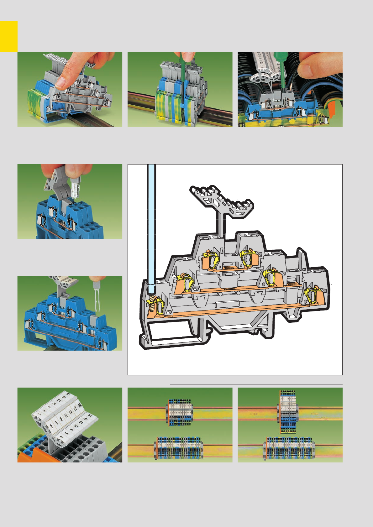
2
28
Double and Triple Deck Terminal Blocks with CAGE CLAMP
®
connection
Description and Handling
Series 279/280 and 281
Assembly of a terminal block on the rail
Commoning
Commoning with adjacent jumpers 280-402.
Push jumper down FIRMLY until FULLY inserted!
Commoning
Combined horizontal and vertikal commoning
fine-stranded wire –
tip bonded
fine-stranded wire
with crimped ferrule ➊fine-stranded wire
with crimped pin terminal
Space saving
Marking with WMB multi-marking system or
WSB quick marking system.
For other systems see section 14
Space saving of 50 % when using double deck
terminal blocks Space saving of 67 % when using triple deck
terminal blocks
Removal of a terminal block from the assembly Connection of wires
Marking
CAGE CLAMP®clamps
the following copper
wires:*
solid stranded
fine-stranded,
also with tinned
single strands
* For aluminum wire see notes in section 15!
➊When using wires with ferrules, it is necessary to use a terminal block one size larger than the nominal cross section of the wire.
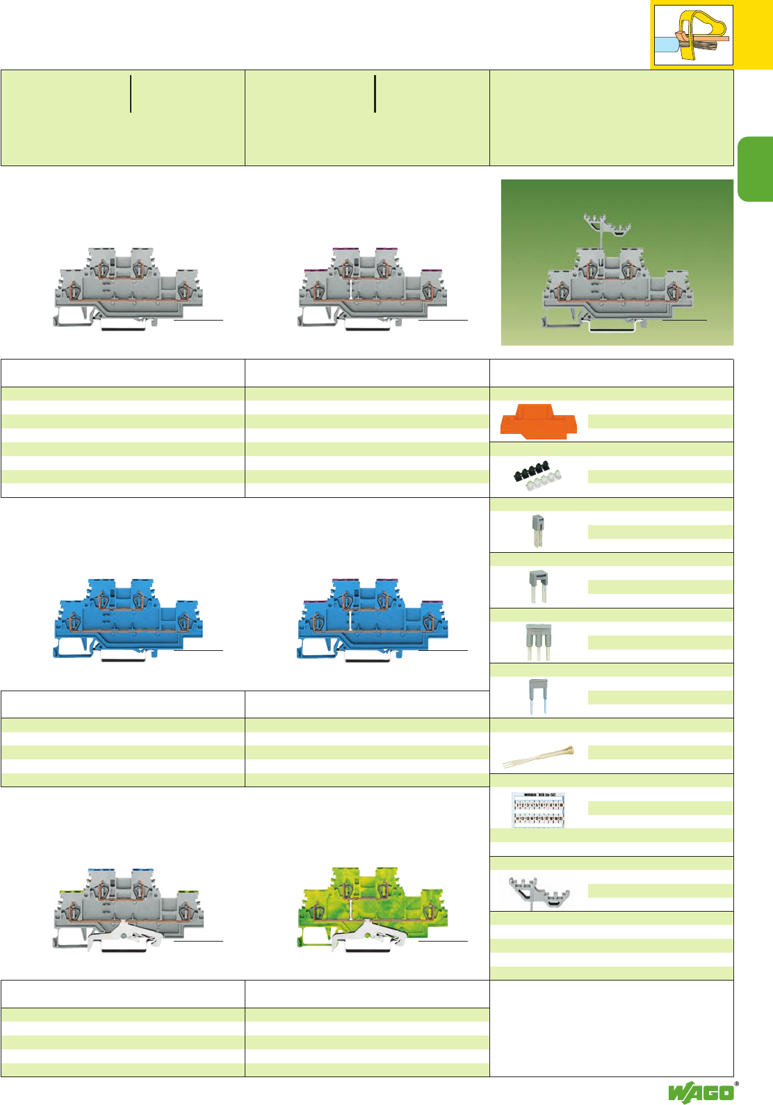
2
29
2
➌
➌
➌
Double deck terminal block,
for DIN 35 rail
4-conductor through terminal block,
internal commoning, housing color grey,
conductor entry position colored in violet
L279-508 50
Double deck terminal block,
for DIN 35 rail
Through/through terminal blocks,
housing color grey
L/L 279-501 50
N/L 279-512 50
L/N 279-513 50
Item Pack. unit
No. pcs
Item Pack. unit
No. pcs
Double Deck Terminal Blocks 1.5 mm2/ AWG 16,
Series 279
End and intermediate plate, 2 mm /0.079 in thick
orange 279-519 100 (4 x 25)
grey 279-518 100 (4 x 25)
Insulation stop ➋, 5 pcs /strip
white 279-470 200 strips
dark grey 279-471 200 strips
Adjacent jumper, insulated, IN15 A
grey 279-402 200 (8 x 25)
yell.-green 279-422 200 (8x 25)
Alternate jumper, insulated, IN15 A
grey 279-409 100 (4 x 25)
Comb type jumper bar ➋, ins., IN= INof terminal block
2-way 279-482 200 (8 x 25)
3-way 279-483 200 (8 x 25)
10-way 279-490 50 (2 x 25)
Alternate comb type jumper bar, insulated,
IN= INof terminal block
2-way 279-492 200 (8 x 25)
Operating tool, insulated
2-way 279-432 1
3-way 279-433 1
10-way 279-440 1
WMB multi-marking system or
WSB quick marking system,
10 strips with 10 markers each
see section 14
WSB double marker carrier
279-529 50 (2 x 25)
Double deck terminal block,
for DIN 35 rail
Through/through terminal block,
housing color blue
N/N 279-504 50
Item Pack. unit
No. pcs
Item Pack. unit
No. pcs
Double deck terminal block,
for DIN 35 rail
4-conductor ground (earth) terminal block,
internal commoning, housing color green-yellow
PE 279-507 50
Double deck terminal block,
for DIN 35 rail
Ground (earth) conductor/through terminal blocks,
housing color grey
PE /N 279-517 50
PE /L 279-527 50
Item Pack. unit
No. pcs
Item Pack. unit
No. pcs
Item Pack. unit
No. pcs
Accessories
Double deck terminal block,
for DIN 35 rail
4-conductor through terminal block,
internal commoning, housing color grey,
conductor entry position colored in violet
N279-509 50
➊500 V = rated voltage
6 kV = rated surge voltage
3 = pollution degree
(see also section 15)
➋See application notes
on
pages
2.43 – 2.44
Suitable for Ex i applications
<___ 58.5 mm /2.30 in ___>
<__________ 85 mm /3.35 in __________>
<__ 39 mm / __>
1.54 in
<__________ 85 mm /3.35 in __________>
<__ 39 mm / __>
1.54 in
<__________ 85 mm /3.35 in __________> <__________ 85 mm /3.35 in __________>
<__________ 85 mm /3.35 in __________> <__________ 85 mm /3.35 in __________>
Height including WSB double marker carrier
0.08 – 1.5 mm2AWG 28 – 16
500 V/6 kV/3 ➊
18 A
Terminal block width 4 mm / 0.157 in
L8 - 9 mm / 0.33 in
0.08 – 1.5 mm2AWG 28 – 16
500 V/6 kV/3 ➊
18 A
Terminal block width 4 mm / 0.157 in
L8 - 9 mm / 0.33 in
<__ 39 mm / __>
1.54 in
<__ 39 mm / __>
1.54 in
<__ 39 mm / __>
1.54 in
<__ 39 mm / __>
1.54 in
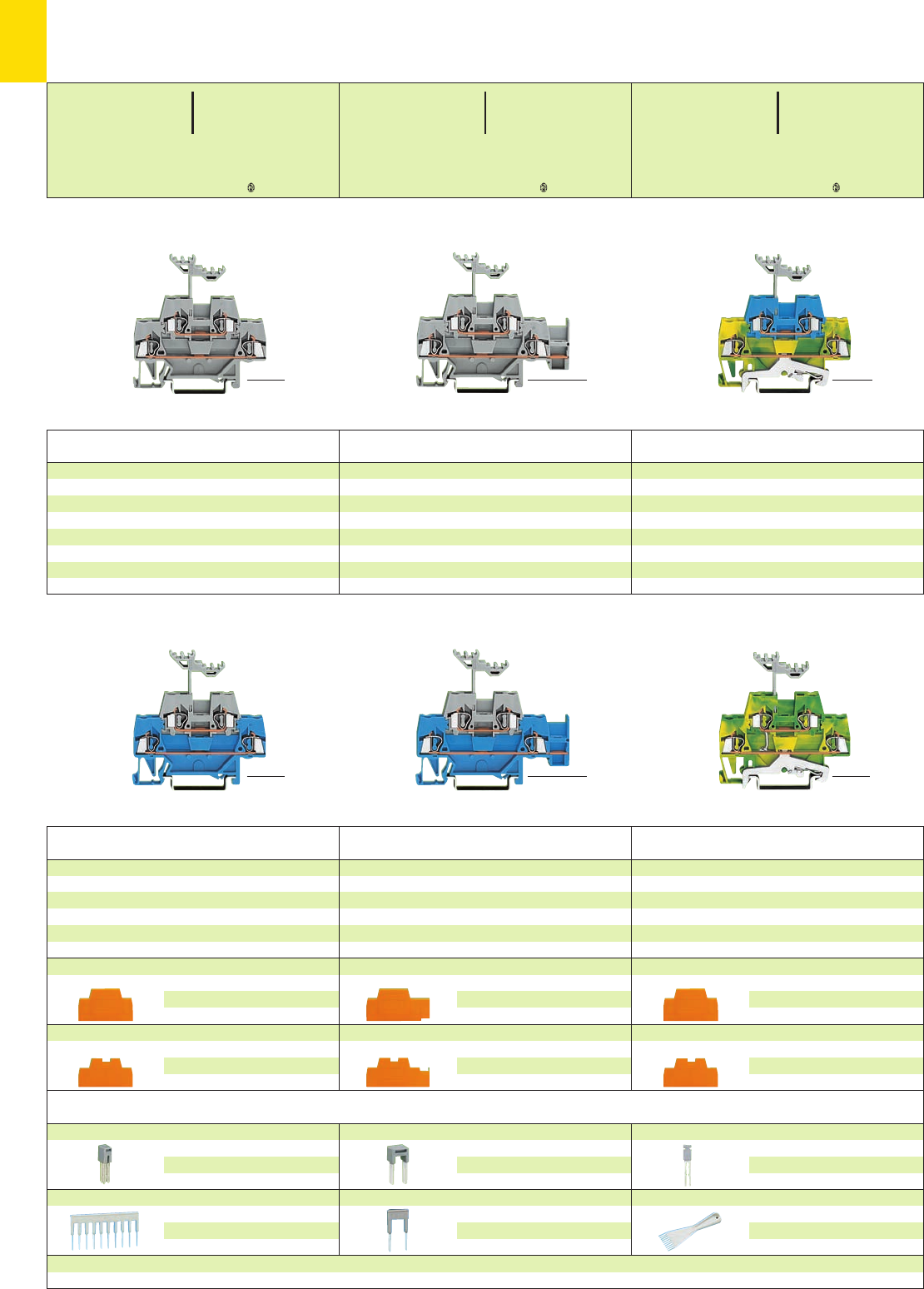
2
30
*U2KfNDaJq:;{[
*U2KfNDaJq:;{[ *U2KfNDaJq:;{[
➋➋
Accessories Series 280, see page 2.13 for a complete overview
End and intermediate plate, 2.5 mm/0.098 in thick
orange 280-341 100 (4 x 25)
grey 280-340 100 (4 x 25)
Intermediate plate, 1.1 mm /0.043 in thick
orange 280-366 100 (4 x 25)
End and intermediate plate, 2.5 mm/0.098 in thick
orange 280-343 100 (4 x 25)
grey 280-342 100 (4 x 25)
Intermediate plate, 1.1 mm /0.043 in thick
orange 280-369 100 (4 x 25)
End and intermediate plate, 2.5 mm/0.098 in thick
orange 280-341 100 (4 x 25)
grey 280-340 100 (4 x 25)
Intermediate plate, 1.1 mm /0.043 in thick
orange 280-366 100 (4 x 25)
Double deck terminal block,
for DIN 35 rail
4-conductor ground (earth) terminal block,
internal commoning
green-yellow 280-517 50
Double deck terminal block,
for DIN 35 rail
Through/through terminal blocks
horizontal jumpering on lower level
blue/grey (shown) 280-524 50
grey/blue (not shown)280-534 50
Double deck terminal block,
for DIN 35 rail
Through/through terminal blocks
blue/grey (shown) 280-523 50
grey/blue (not shown)280-533 50
Item Pack. unit
No. pcs
Item Pack. unit
No. pcs
Item Pack. unit
No. pcs
Double deck terminal block,
for DIN 35 rail
Ground (earth) conductor/through terminal blocks
green-yellow/g r e y 280-527 50
green-yellow/blue 280-537 50
Double deck terminal block,
for DIN 35 rail
Through/through terminal blocks
horizontal jumpering on lower level
grey 280-520 50
blue 280-530 50
Double deck terminal block,
for DIN 35 rail
Through/through terminal blocks
grey 280-519 50
blue 280-529 50
Other terminal blocks with the same shape
diode/LED 280-9xx/...-... page 7.62
Item Pack. unit
No. pcs
Item Pack. unit
No. pcs
Item Pack. unit
No. pcs
Double Deck Terminal Blocks 2.5 mm2/ AWG 12,
Series 280
Appropriate
marking system WMB/WSB (see section 14)
<_____ 64 mm /2.52 in _____> <_______ 74 mm /2.91 in _______>
<_____ 64 mm /2.52 in _____> <_______ 74 mm /2.91 in _______> <____ 64 mm /2.52 in ____>
<____ 64 mm /2.52 in ____>
Adjacent jumper, insulated, IN24 A
grey 280-402 200 (8 x 25)
yell.-green 280-422 200 (8x 25)
Comb type jumper bar ➍, ins., IN= INof terminal block
2-way 280-482 200 (8 x 25)
3-way 280-483 200 (8 x 25)
10-way 280-490 50 (2 x 25)
Alternate jumper, insulated,I
N24 A
grey 280-409 100 (4 x 25)
Alternate comb type jumper bar, insulated,
IN= INof terminal block
2-way 280-492 200 (8 x 25)
Vertical jumper, insulated,I
N24 A
grey 281-421 200 (8 x 25)
Operating tool, insulated
2-way 280-432 1
3-way 280-433 1
10-way 280-440 1
* For further approvals with corresponding ratings see section 15.
0.08 – 2.5 mm2AWG 28 – 12
500 V/6 kV/3 ➊300 V, 15 A U
20 A 300/600 V, 20/5 A 2
Terminal block width 5 mm / 0.197 in
L8 – 9 mm / 0.33 in
0.08 – 2.5 mm2AWG 28 – 12
500 V/6 kV/3 ➊300 V, 15 A U
20 A 300/600 V, 20/5 A 2
Terminal block width 5 mm / 0.197 in
L8 – 9 mm / 0.33 in
0.08 – 2.5 mm2AWG 28 – 12
500 V/6 kV/3 ➊300 V, 15 A U
20 A 300/600 V, 20/5 A 2
Terminal block width 5 mm / 0.197 in
L8 – 9 mm / 0.33 in
<__ 58.5 mm /2.30 in __>
<__ 58.5 mm /2.30 in __>
<__ 58.5 mm /2.30 in __>
<__ 58.5 mm /2.30 in __>
<__ 58.5 mm /2.30 in __> <__ 58.5 mm /2.30 in __>
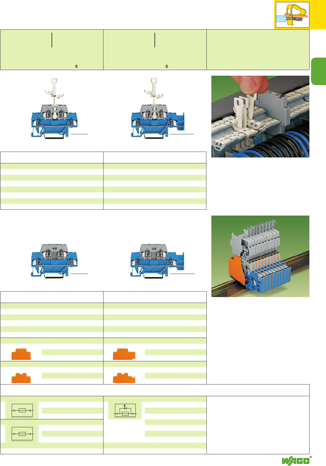
2
2
31
*U2KfNDa:;{[
*U2KfNDaJ|q:;{[
➋
➊400/500 V = rated voltage
6 kV = rated surge voltage
3 = pollution degree
(see also section 15)
Suitable for Ex i applications
➌Electrical ratings are given by the fuse
or nominal voltage of the indicator lamp
respectively
see also pages 7.38 – 7.39
➍See application notes
on
pages
2.43 and 2.44
End and intermediate plate, 2.5 mm/0.098 in thick
orange 280-343 100 (4 x 25)
grey 280-342 100 (4 x 25)
Intermediate plate, 1.1 mm /0.043 in thick
orange 280-369 100 (4 x 25)
End and intermediate plate, 2.5 mm/0.098 in thick
orange 280-341 100 (4 x 25)
grey 280-340 100 (4 x 25)
Intermediate plate, 1.1 mm /0.043 in thick
orange 280-366 100 (4 x 25)
Double deck terminal block,
for DIN 35 rail
Through/carrier terminal blocks for pluggable fuse
modules ➌
horizontal jumpering on lower level
blue/grey (shown) 280-532 50
grey/grey (not shown)280-891 50
Double deck terminal block,
for DIN 35 rail
Through/carrier terminal blocks for pluggable fuse
modules ➌
blue/grey (shown) 280-531 50
grey/grey (not shown)280-514 50
Item Pack. unit
No. pcs
Item Pack. unit
No. pcs
Double deck terminal block,
for DIN 35 rail
Through/disconnect terminal blocks
horizontal jumpering on lower level
grey/grey 280-522 50
blue/grey 280-526 50
Double deck terminal block,
for DIN 35 rail
Through/disconnect terminal blocks
grey/grey 280-521 50
blue/grey 280-525 50
Item Pack. unit
No. pcs
Item Pack. unit
No. pcs
Fuse plug, for miniature metric fuses
5 x 20 mm and 5 x 25 mm
6 mm /0.236 in wide with pull-tab
281-511 50
Fuse plug, same as above, but with hole for LED
(for self-assembly)
6 mm /0.236 in wide with pull-tab
281-512 50
Fuse plug, same as on the left,
with additional indicator lamp,
LED, AC/DC 24 V,
Can be used in either polarity
direction
6 mm /0.236 in wide with pull-tab
281-512/281-501 50
<____ 64 mm /2.52 in ____> <_______ 74 mm /2.91 in _______>
Double deck terminal blocks with fuse plugs
When double deck terminal blocks are used with
a fuse plug (width 6 mm /0.236 in) in the recept-
acle (top) level, the extra width can be compen-
sated for the 280 series (width 5 mm /0.197 in) by
use of an intermediate plate (thickness 1.1 mm /
0.043 in).
This special intermediate plate still allows jumpe-
ring on the lower level when required, by use of
the push-in jumpers.
Pulling of disconnecting tab
The double deck terminal blocks enable two
circuits of different potentials to be contained
in one 2-level terminal block. The lower deck is
wider than the upper, for ease of wiring.
Different circuits can be differentiated by color
coding of either level.
residual current in
case of blown fuse
LED 5 – 20 mA
<____ 64 mm /2.52 in ____> <_______ 74 mm /2.91 in _______>
Accessories Series 280, see page 2.13 Appropriate
marking system WMB/WSB (see section 14)
0.08 – 2.5 mm2AWG 28 – 12
400 V/6 kV/3 ➊ ➌ 300 V, 10 A U➌
6.3 A ➌/10 A 300/600 V, 20/5 A 2
Terminal block width 5 mm / 0.197 in
L8 – 9 mm / 0.33 in
0.08 – 2.5 mm2AWG 28 – 12
400 V/6 kV/3 ➊ ➌ 300 V, 10 A U➌
6.3 A ➌/10 A 300/600 V, 20/5 A 2
Terminal block width 5 mm / 0.197 in
L8 – 9 mm / 0.33 in
<_______ 76 mm /2.99 in ______>
<______ 81.5 mm /3.21 in ______>
<_______ 76 mm /2.99 in ______>
<______ 81.5 mm /3.21 in ______>
(39.5 mm/1.55 in )
<w. fuse plug 85 mm /3.35 in >
(39.5 mm/1.55 in )
<w. fuse plug 85 mm /3.35 in >
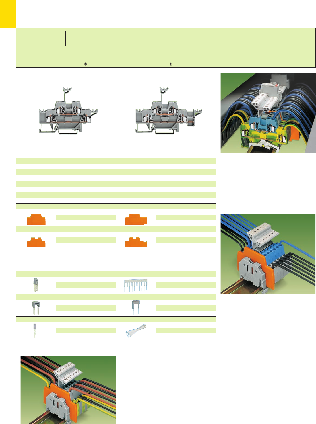
2
32
*U2KNaJq:;{[
*U2KfNaJ|q:;{[
* For further approvals with corresponding ratings see section 15.
Double Deck Terminal Blocks 2.5 mm2/ AWG 12,
Series 280
➊500 V = rated voltage
6 kV = rated surge voltage
3 = pollution degree
(see also section 15)
➋See application notes
on
pages
2.43 and 2.44
End and intermediate plate, 2.5 mm/0.098 in thick
orange 280-343 100 (4 x 25)
grey 280-342 100 (4 x 25)
Intermediate plate, 1.1 mm /0.043 in thick
orange 280-369 100 (4 x 25)
End and intermediate plate, 2.5 mm/0.098 in thick
orange 280-341 100 (4 x 25)
grey 280-340 100 (4 x 25)
Intermediate plate, 1.1 mm /0.043 in thick
orange 280-366 100 (4 x 25)
Double deck terminal block, with additional
marking possibilities on both sides of the
terminal block, for DIN 35 rail
Through/through terminal block
horizontal jumpering on lower level
grey 280-543 50
Double deck terminal block, with additional
marking possibilities on both sides of the
terminal block, for DIN 35 rail
Through/through terminal block
grey 280-513 50
Item Pack. unit
No. pcs
Item Pack. unit
No. pcs
Appropriate marking system WMB/WSB (see section 14)
Example of a mixed assembly with double deck terminal
blocks
Double deck terminal blocks used for the connection of
a three-phase motor
Double deck terminal blocks used as control wire
terminals; for ex. for magnetic valves. Upper deck
commoned.
The flexible marker carrier, which is placed above
the wiring level, can be pushed aside during the
wiring or commoning operation. The marker
carrier has two levels for two different markers
relating to the two decks of the terminal blocks.
The double deck terminal blocks, series 280, are
available with decks of same or different color
according to the function. This is an additional
visual aid during wiring or in case of possible
service and maintenance work.
With a terminal block width of only 5 mm/0.197 in,
an effective width of only 2.5 mm/0.098 in for
terminal blocks of same or different potential can
be realized at a cross sectional area of 0.08 mm2
to 2.5 mm2/AWG 28 – 14 !
Standard insulated push-in jumpers can be used
for commoning. A vertical jumper allows
commoning of upper and lower level, giving a
4-conductor commoned through terminal block in
one housing. Two adjacent terminals may be
commoned together on the same level using a
push-in adjacent jumper.
<_________ 84 mm /3.31 in _________> <___________ 95 mm /3.74 in ___________>
Accessories Series 280, see page 2.13 for a complete overview
Adjacent jumper, insulated, IN24 A
grey 280-402 200 (8 x 25)
Alternate jumper, insulated,I
N24 A
grey 280-409 100 (4 x 25)
Vertical jumper, insulated,I
N24 A
grey 281-421 200 (8 x 25)
Comb type jumper bar
➋
, ins., I
N
= I
N
of terminal block
2-way 280-482 200 (8 x 25)
3-way 280-483 200 (8 x 25)
10-way 280-490 50 (2 x 25)
Alternate comb type jumper bar, insulated,
IN= INof terminal block
2-way 280-492 200 (8 x 25)
Operating tool, insulated
2-way 280-432 1
3-way 280-433 1
10-way 280-440 1
Application notes
0.08 – 2.5 mm2AWG 28 – 12
500 V/6 kV/3 ➊300 V, 15 A U
20 A 300/600V, 20/5 A 2
Terminal block width 5 mm / 0.197 in
L8 – 9 mm / 0.33 in
0.08 – 2.5 mm2AWG 28 – 12
500 V/6 kV/3 ➊300 V, 15 A U
20 A 300/600V, 20/5 A 2
Terminal block width 5 mm / 0.197 in
L8 – 9 mm / 0.33 in
<__ 58.5 mm /2.30 in __>
<__ 58.5 mm /2.30 in __>
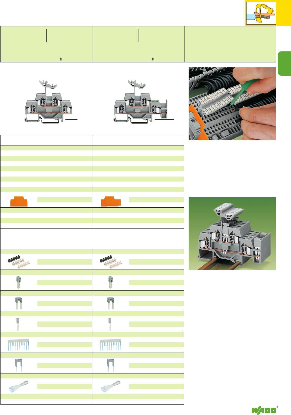
2
33
2
*U2KfDaJq:;{[ .
*U2KfDaJq:;{[ .
➋
➋➋
* For further approvals with corresponding ratings see section 15.
Double Deck Terminal Blocks 4 mm2/ AWG 12,
Series 281
➊500 V = rated voltage
6 kV = rated surge voltage
3 = pollution degree
(see also section 15)
Suitable for Ex i applications
➌See application notes
on
pages
2.43 and 2.44
End and intermediate plate, 2.5 mm/0.098 in thick
orange 281-343 100 (4 x 25)
grey 281-342 100 (4 x 25)
End and intermediate plate, 2.5 mm/0.098 in thick
orange 281-341 100 (4 x 25)
grey 281-340 100 (4 x 25)
Double deck terminal block,
for DIN 35 rail
Through/through terminal blocks
horizontal jumpering on lower level
grey 281-620 50
blue 281-630 50
Double deck terminal block,
for DIN 35 rail
Through/through terminal blocks
grey 281-619 50
blue 281-629 50
Other terminal blocks with the same shape
diode/LED 281-6xx/...-... page 7.62
Item Pack. unit
No. pcs
Item Pack. unit
No. pcs
Accessories Series 281, see page 2.17 for a complete overview
Insulation stop ➌, 5 pcs /strip
white 281-470 200 strips
light grey 281-471 200 strips
dark grey 281-472 200 strips
Adjacent jumper, insulated, IN32 A
grey 281-402 200 (8 x 25)
yell.-green 281-422 200 (8x 25)
Alternate jumper, insulated, IN32 A
grey 281-409 100 (4 x 25)
Vertical jumper, insulated,I
N24 A
grey 281-421 200 (8 x 25)
Comb type jumper bar ➌, ins., IN= INof terminal block
2-way 281-482 100 (4 x 25)
3-way 281-483 100 (4 x 25)
10-way 281-490 50 (2 x 25)
Alternate comb type jumper bar, insulated,
IN= INof terminal block
2-way 281-492 100 (4 x 25)
Operating tool, insulated
2-way 280-432 1
3-way 280-433 1
5-way 281-440 1
<______ 73.5 mm /2.89 in _____> <________ 83.5 mm /3.29 in ________>
Wiring
Commoning of double deck terminal blocks
Appropriate marking system WMB/WSB (see section 14)
0.08 – 4 mm2AWG 28 – 12
500 V/6 kV/3 ➊300 V, 15 A U
26 A 600 V, 15 A 2
Terminal block width 6 mm / 0.236 in
L9 – 10 mm / 0.37 in
0.08 – 4 mm2AWG 28 – 12
500 V/6 kV/3 ➊300 V, 15 A U
26 A 600 V, 15 A 2
Terminal block width 6 mm / 0.236 in
L9 – 10 mm / 0.37 in
<__ 58.5 mm /2.30 in __>
<__ 58.5 mm /2.30 in __>
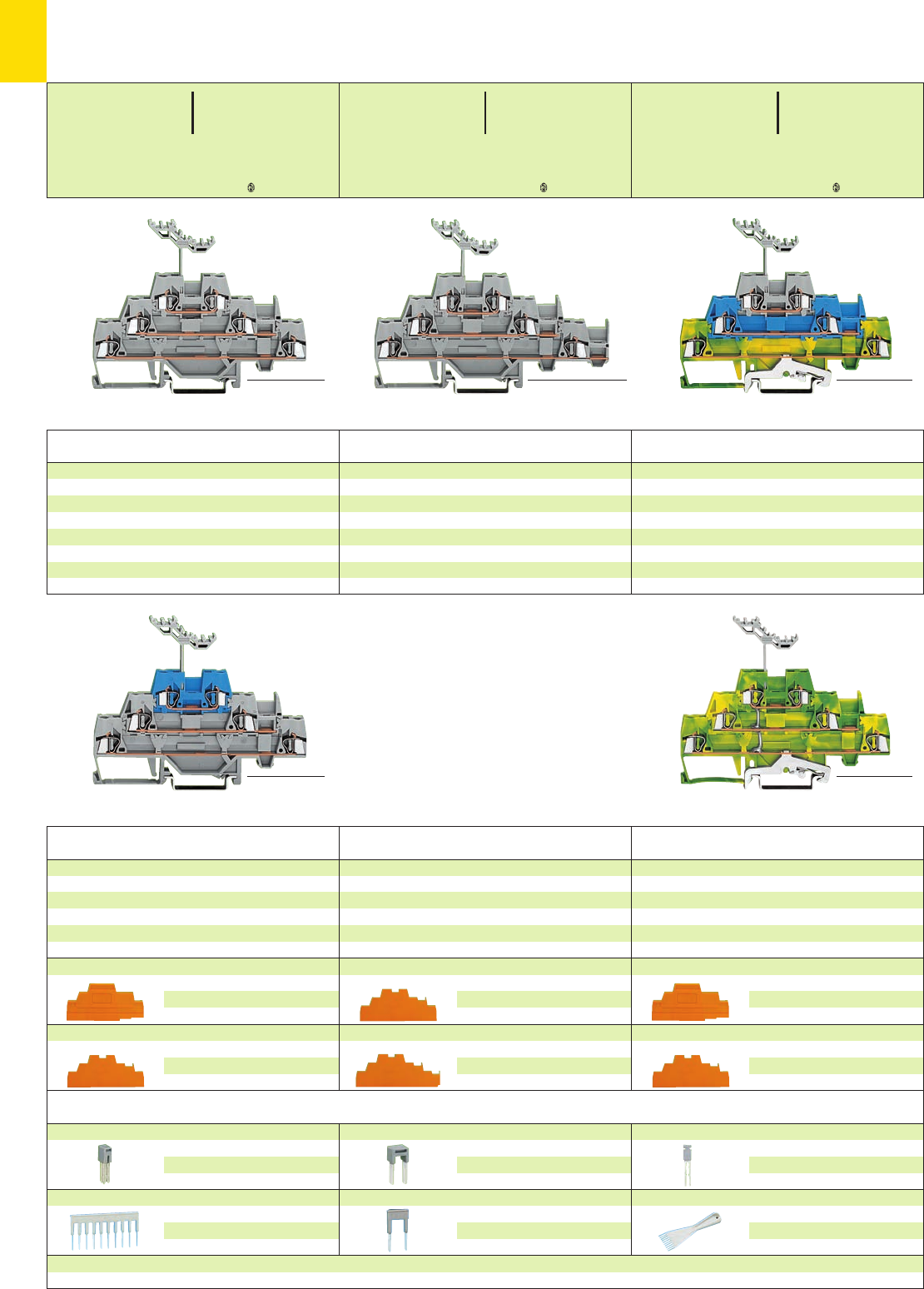
2
34
*U2KfNDaJq:;{[
*U2KfNDaJq:;{[ *U2KfNDaJq:;{[
* For further approvals with corresponding ratings see section 15.
Accessories Series 280, see page 2.13 for a complete overview
End and intermediate plate, 2.5 mm/0.098 in thick
orange 280-304 100 (4 x 25)
grey 280-303 100 (4 x 25)
Intermediate plate, 1.1 mm /0.043 in thick
orange 280-336 100 (4 x 25)
End and intermediate plate, 2.5 mm/0.098 in thick
orange 280-306 100 (4 x 25)
grey 280-305 100 (4 x 25)
Intermediate plate, 1.1 mm /0.043 in thick
orange 280-339 100 (4 x 25)
End and intermediate plate, 2.5 mm/0.098 in thick
orange 280-304 100 (4 x 25)
grey 280-303 100 (4 x 25)
Intermediate plate, 1.1 mm /0.043 in thick
orange 280-336 100 (4 x 25)
Triple deck terminal block, for DIN 35 rail
6-cond. gr. (earth) term. block, internal commoning
green-yellow 280-597 40
Triple deck terminal block, for DIN 35 rail
Through/through/through terminal block
grey/grey/blue 280-552 40
Item Pack. unit
No. pcs
Item Pack. unit
No. pcs
Triple deck terminal block, for DIN 35 rail
Ground (earth)/through/through terminal blocks
green-yel./blue/grey 280-547 40
green-yel./grey/grey 280-557 40
Shield (screen)/through/through terminal blocks
white/grey/grey 280-548 40
white/blue/grey 280-558 40
Triple deck terminal block, for DIN 35 rail
Through/through/through terminal block
horizontal jumpering on lower level
grey 280-550 40
Triple deck terminal block, for DIN 35 rail
Through/through/through terminal blocks
grey 280-549 40
blue 280-551 40
Item Pack. unit
No. pcs
Item Pack. unit
No. pcs
Item Pack. unit
No. pcs
Triple Deck Terminal Blocks 2.5 mm2/ AWG 12,
Series 280
Appropriate
marking system WMB/WSB (see section 14)
Adjacent jumper, insulated, IN24 A
grey 280-402 200 (8 x 25)
yell.-green 280-422 200 (8x 25)
Comb type jumper bar ➌, ins., IN= INof terminal block
2-way 280-482 200 (8 x 25)
3-way 280-483 200 (8 x 25)
10-way 280-490 50 (2 x 25)
Alternate jumper, insulated,I
N24 A
grey 280-409 100 (4 x 25)
Alternate comb type jumper bar, insulated,
IN= INof terminal block
2-way 280-492 200 (8 x 25)
Vertical jumper, insulated,I
N24 A
grey 281-421 200 (8 x 25)
Operating tool, insulated
2-way 280-432 1
3-way 280-433 1
10-way 280-440 1
<_____________ 103 mm /4.05 in _____________> <_______________ 113 mm /4.45 in _______________> <_____________ 103 mm /4.05 in _____________>
<_____________ 103 mm /4.05 in _____________> <_____________ 103 mm /4.05 in _____________>
0.08 – 2.5 mm2AWG 28 – 12
500 V/6 kV/3 ➊300/600 V, 15/5 AU
20 A 300/600 V, 20/5 A 2
Terminal block width 5 mm / 0.197 in
L8 – 9 mm / 0.33 in
0.08 – 2.5 mm2AWG 28 – 12
500 V/6 kV/3 ➊300/600 V, 15/5 AU
20 A 300/600 V, 20/5 A 2
Terminal block width 5 mm / 0.197 in
L8 – 9 mm / 0.33 in
0.08 – 2.5 mm2AWG 28 – 12
500 V/6 kV/3 ➊300/600 V, 15/5 AU
20 A 300/600 V, 20/5 A 2
Terminal block width 5 mm / 0.197 in
L8 – 9 mm / 0.33 in
<______ 76.5 mm /3.01 in ______>
<______ 76.5 mm /3.01 in ______>
<______ 76.5 mm /3.01 in ______>
<______ 76.5 mm /3.01 in ______>
<______ 76.5 mm /3.01 in ______>
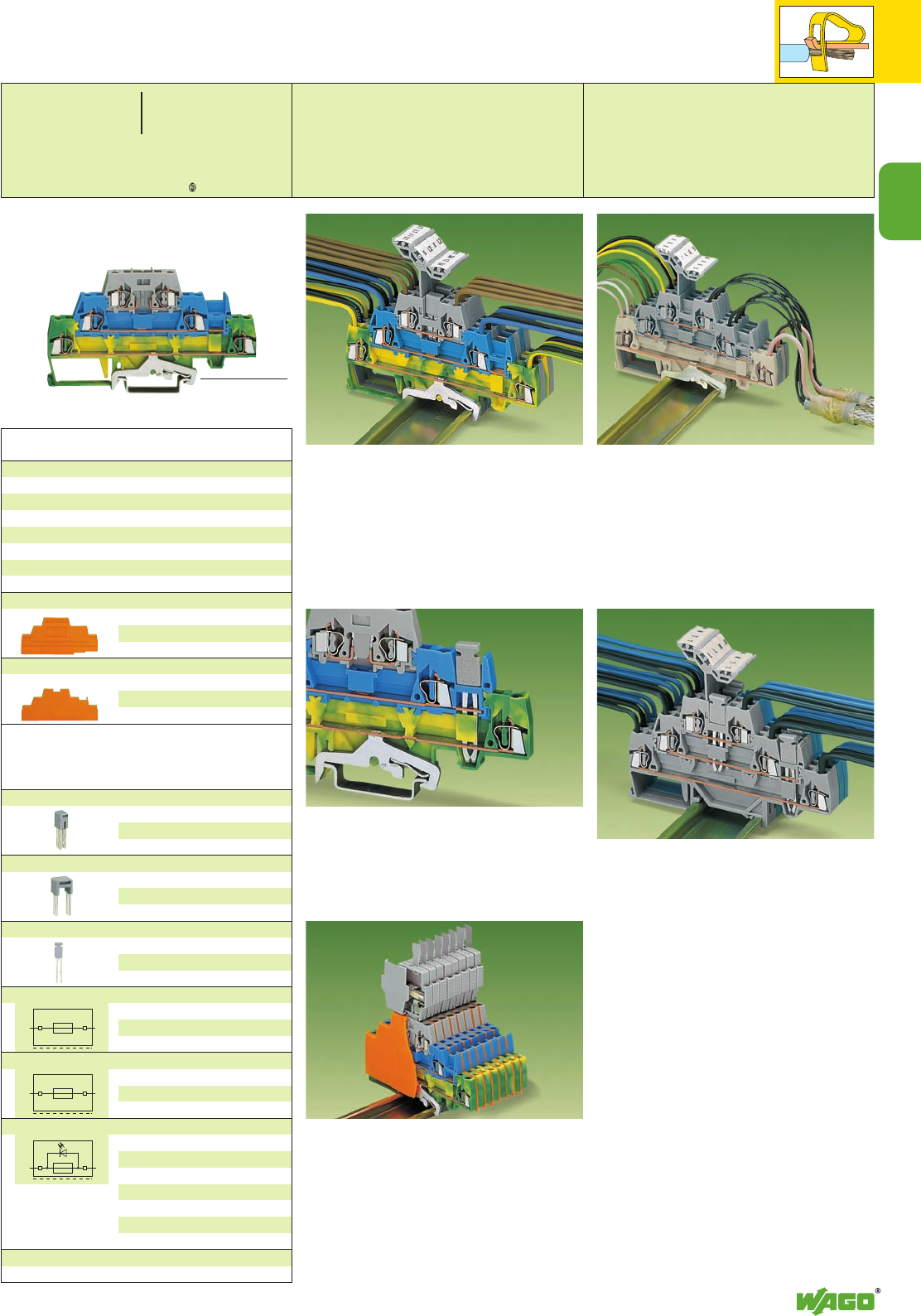
2
35
2
*U2KfNaJq:;{[
Appropriate
marking system WMB/WSB (see section 14)
➊400/500 V = rated voltage
6 kV = rated surge voltage
3 = pollution degree
(see also section 15)
➋Electrical ratings are given by the fuse
or nominal voltage of the indicator lamp
respectively
see also pages 7.38 – 7.39
➌See application notes on
pages
2.43 and 2.44
Accessories Series 280, see page 2.13
End and intermediate plate, 2.5 mm/0.098 in thick
orange 280-304 100 (4 x 25)
grey 280-303 100 (4 x 25)
Intermediate plate, 1.1 mm /0.043 in thick
orange 280-336 100 (4 x 25)
Triple deck terminal block, for DIN 35 rail
Ground (earth) conductor/through/carrier terminal
blocks for pluggable fuse modules
green-yellow/blue/grey
(shown) 280-510 50
grey/grey/grey
(not shown) 280-889 50
Item Pack. unit
No. pcs
Adjacent jumper, insulated, IN24 A
grey 280-402 200 (8 x 25)
yell.-green 280-422 200 (8x 25)
Alternate jumper, insulated,I
N24 A
grey 280-409 100 (4 x 25)
Vertical jumper, insulated,I
N24 A
grey 281-421 200 (8 x 25)
Fuse plug, for miniature metric fuses
5 x 20 mm and 5 x 25 mm
6 mm /0.236 in wide with pull-tab
281-511 50
Fuse plug, same as above, but with hole for LED
(for self-assembly)
6 mm /0.236 in wide with pull-tab
281-512 50
Fuse plug, same as above,
with additional indicator lamp,
LED, AC/DC 24 V,
Can be used in either polarity
direction
6 mm /0.236 in wide with pull-tab
281-512/281-501 50
The ground (earth) conductor or screen (shield)
terminal blocks have a contact foot in the bottom
level, ensuring automatically a direct contact to
the carrier rail.
The flexible marker carrier, which is placed above
the wiring levels, can be pushed aside during the
wiring or commoning operation. The marker
carrier has three levels for three different
markers relating to the three decks of the
terminal blocks.
With a terminal block width of only 5 mm/0.197 in
an effective width of only 1.67 mm/0.066 in for
terminal blocks of same or different potentials
can be realized for wire sizes 0.08 – 2.5 mm2/
AWG 28–14.
Standard insulated push-in jumpers can be used
for commoning. A vertical jumper allows
commoning of upper and lower level, giving a
6-conductor commoned through terminal block in
one housing. Two adjacent terminals may be
commoned together on the same level using a
push-in adjacent jumper.
Grounding (earthing) to carrier rail.
Connection of N-level to ground (earth) level
by vertical jumper
The greater width of the fuse plugs compared to the
terminal blocks has to be compensated by use of an
intermediate plate (280-336)
3-wire power circuit with additional branch
circuit tapping
Shielded (screened) twisted pair cable
Commoning with vertical and adjacent jumpers
The triple deck terminal blocks enable three
circuits of different potentials to be contained in
one 3-level terminal block. The lower decks are
wider than the upper, for ease of wiring.
Different circuits can be differentiated by color
coding of any level.
residual current in
case of blown fuse
LED 5 – 20 mA
<_____________ 103 mm /4.05 in _____________>
<_ 49.5 mm /1.95 in _>
<w. fuse plug 95 mm /3.74 in >
0.08 – 2.5 mm2AWG 28 – 12
400 V/6 kV/3 ➊ ➋ 300/600 V, 15/5 AU
6.3 A ➋ / 20 A 600 V, 20 A 2
Terminal block width 5 mm / 0.197 in
L8 – 9 mm / 0.33 in
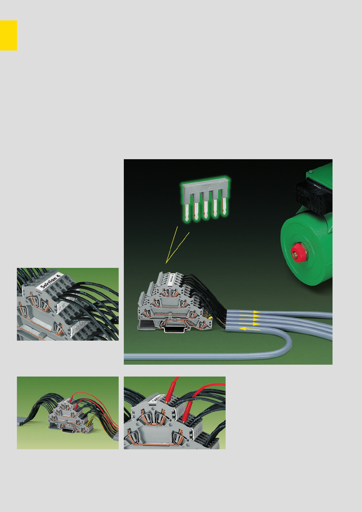
2
36
Rail-Mounted Quadruple Deck Terminal Blocks or
Rail-Mounted
Terminal Blocks for Wiring of Electric Motors, Series 281
Description and Handling
Marking
Marking clamping units with WMB multi-marking
system or WSB quick marking system.
(see section 14)
Group marking with marking strips
Item No. 709-196.
Testing
3 phases and ground (earth) conductor in one
terminal block
Compact design
Testing with test plug 2 mm /0.079 in Ø
In addition to the rail-mounted terminal
blocks for electric motor wiring, new
versions are now available.
–
Terminal block without ground (earth)
contact and with only 2potentials.
Especially for additional functions such
as engine brakes or temperature
probes. Having the same shape, this
type can be put next to the
appropriate terminal block for electric
motor wiring without having to use
separator plates. That makes the rail
assembly clearer and wiring is easier.
Since no clamping unit remains
unwired, wiring errors are avoided.
– Terminal block without ground (earth)
contact and with 3potentials.
Clear and unambiguous assignment
of clamping units is also the main
advantage with this type. When using
devices with protective insulation for
example, there are no open ground
(earth) clamping units that could lead
to confusion.
➊400 V = rated voltage
6 kV = rated surge voltage
3 = pollution degree
(see also section 15)
➋See application notes
on
pages
2.43 and 2.44
fine-stranded wire –
tip bonded
fine-stranded wire
with crimped ferrule**
fine-stranded wire
with crimped pin terminal
CAGE CLAMP®clamps
the following copper
wires:*
solid stranded
fine-stranded,
also with tinned
single strands
* For aluminum wire see notes in section 15!
** When using wires with ferrules, it is necessary to use a terminal block one size larger than the nominal cross section of the wire.
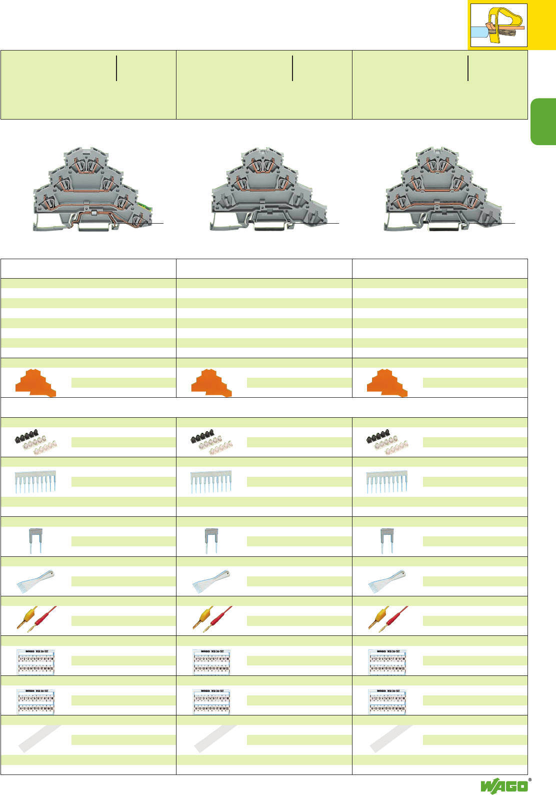
2
37
2
*Y2Kfa:;{[
* For further approvals with corresponding ratings see section 15.
Rail-mounted terminal block for wiring of
electric motors or
rail-mounted quadruple deck terminal block,
for DIN 35 rail
L1 – L 2 – L 3
grey 281-532 50
Rail-mounted terminal block for wiring of
electric motors or
rail-mounted quadruple deck terminal block,
for DIN 35 rail
L1 – L 2
grey 281-531 50
Rail-mounted terminal block for wiring of electric
motors or
rail-mounted quadruple deck terminal block,
for DIN 35 rail
L1 – L 2 – L 3 – PE
grey 281-530 50
Item Pack. unit
No. pcs
Item Pack. unit
No. pcs
Item Pack. unit
No. pcs
Rail-Mounted Quadruple Deck Terminal Blocks or
Rail-Mounted
Terminal Blocks for Wiring of Electric Motors
Series 281
<__ 50 mm /1.97 in __>
<___________ 100 mm /3.94 in ___________> <__ 50 mm /1.97 in __>
<___________ 100 mm /3.94 in ___________>
<__ 50 mm /1.97 in __>
<___________ 100 mm /3.94 in ___________>
End and intermediate plate, 1 mm /0.039 in thick
orange 281-366 100 (4 x 25)
grey 281-365 100 (4 x 25)
End and intermediate plate, 1 mm /0.039 in thick
orange 281-366 100 (4 x 25)
grey 281-365 100 (4 x 25)
Accessories Series 281 Appropriate marking system WMB/WSB (see section 14)
Insulation stop ➋,5 pcs /strip
white 281-470 200 strips
light grey 281-471 200 strips
dark grey 281-472 200 strips
Comb type jumper bar ➋, insulated,
IN= INof terminal block
2-way 281-482 100 (4 x 25)
3-way 281-483 100 (4 x 25)
5-way 281-485 100 (4 x 25)
10-way 281-490 50 (2 x 25)
Alternate comb type jumper bar ➋, insulated,
IN= INof terminal block
2-way 281-492 100 (4 x 25)
Operating tool, insulated
2-way 280-432 1
3-way 280-433 1
5-way 281-440 1
Test plug,
with
cable 500 mm/1’7.7’’
2 mm Ø, red
210-136 50 (5 x 10)
2.3 mm Ø, yel.
210-137 50 (5 x 10)
WMB multi-marking system,
10 strips with 10 markers each,
white with black printing
see section 14
WSB quick marking
system,
10 strips with 10 markers each,
white with black printing
see section 14
Marker strips, transparent, plain, for central marking
– group marking –
1 m /3’33’’ long,
7.5 mm /0.295 in wide
on roll 50 m 709-177 1
on roll 300 m 709-187 1
End and intermediate plate, 1 mm /0.039 in thick
orange 281-366 100 (4 x 25)
grey 281-365 100 (4 x 25)
0.08 – 4 mm2AWG 28 – 12
400 V/6 kV/3 ➊
20 A (2.5 mm2) 25 A (4 mm2)
Terminal block width 6 mm / 0.236 in
L8 – 9 mm / 0.33 in
0.08 – 4 mm2AWG 28 – 12
400 V/6 kV/3 ➊300 V, 20 A
20 A (2.5 mm2) 25 A (4 mm2)
Terminal block width 6 mm / 0.236 in
L8 – 9 mm / 0.33 in
0.08 – 4 mm2AWG 28 – 12
400 V/6 kV/3 ➊
20 A (2.5 mm2) 25 A (4 mm2)
Terminal block width 6 mm / 0.236 in
L8 – 9 mm / 0.33 in
<____ 62.5 mm /2.46 in ___>
<____ 62.5 mm /2.46 in ___>
<____ 62.5 mm /2.46 in ___>
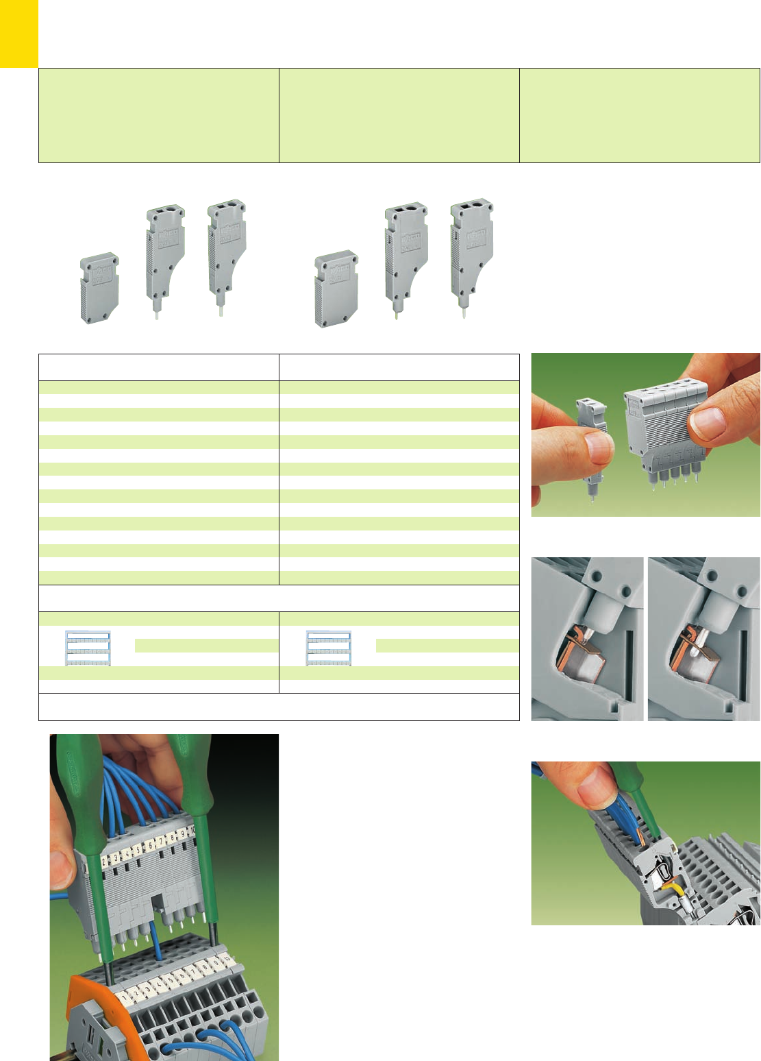
AB
2
38
Item Pack. unit
No. pcs
Item Pack. unit
No. pcs
Accessories
Application notes
Miniature WSB quick marking system or
WMB multi-marking system,
10 strips with 10 markers each,
white with black printing
see section 14
Miniature WSB quick marking system or
WMB multi-marking system,
10 strips with 10 markers each,
white with black printing
see section 14
Test plug module with spring loaded contact pin
with CAGE CLAMP®,
center module, grey, module width 5 mm /0.197 in
249-141 100 (4 x 25)
End module with rigid contact pin
with CAGE CLAMP®,
external module, grey, module width 5 mm /0.197 in
249-142 100 (4 x 25)
Spacer module,
for bridging over wired terminal blocks, grey,
module width 5 mm /0.197 in
249-143 100 (4 x 25)
Test plug module with spring loaded contact pin
with CAGE CLAMP®,
center module, grey, module width 6 mm /0.236 in
249-144 100 (4 x 25)
End module with rigid contact pin
with CAGE CLAMP®,
external module, grey, module width 6 mm /0.236 in
249-145 100 (4 x 25)
Spacer module,
for bridging over wired terminal blocks, grey,
module width 6 mm /0.236 in
249-146 100 (4 x 25)
Snapping together of test plug, end and spacer modules
to assemble a multipole test plug strip (10-pole max.)
A = center module with spring loaded contact pin
B = external module with rigid contact pin
CAGE CLAMP®
0.08 mm2 – 1.5 mm2(AWG 28 – 16),
module width 5 mm /0.197 in
0.08 mm2 – 2.5 mm2(AWG 28 – 14),
module width 6 mm /0.236 in
For simple testing of terminal block assemblies,
the test plug modules with CAGE CLAMP®
(version for testing using the conductor wire
opening) may be used for testing unwired
terminal blocks. For testing, the module is
assembled with spring loaded pins in the center
positions and rigid pin modules at the ends.
The terminal blocks corresponding to the end
position modules are opened using screwdrivers
(as shown), these rigid pins are then held in place
by the CAGE CLAMP®, the intermediate pins are
spring loaded and make contact with the current
bars, for test currents up to 6 amps.
Clamping units which need to remain wired may
be skipped over by assembling a spacer in the
test plug module.
Attention!
Mating direction must be observed (see ill.)
Test Plug Modules with CAGE CLAMP®, for Testing of
Rail-Mounted Terminal Blocks 2.5 mm2/AWG 14 and
4 mm2/AWG 12, Using the Conductor Wire Opening
Test plug for rail-mounted terminal blocks of
series 280
Module width 5 mm / 0.197 in
Test voltage 630 V
Test current 6 A
Test plug for rail-mounted terminal blocks of
series 281
Module width 6 mm / 0.236 in
Test voltage 630 V
Test current 6 A
Note:
These test plugs are not suitable for Ex e
applications
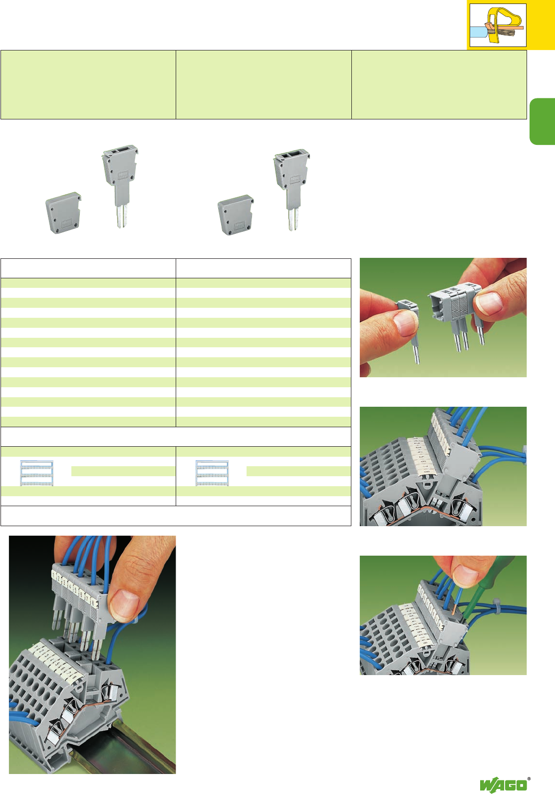
2
39
2
Item Pack. unit
No. pcs
Item Pack. unit
No. pcs
Accessories
Application notes
Miniature WSB quick marking system or
WMB multi-marking system,
10 strips with 10 markers each,
white with black printing
see section 14
Miniature WSB quick marking system or
WMB multi-marking system,
10 strips with 10 markers each,
white with black printing
see section 14
Test plug module with CAGE CLAMP®,
version using jumper contact position in current bar,
grey, module width 5 mm /0.197 in,
suitable for all rail-mounted terminal blocks series 280
with jumper contact slots in the current bar
249-106 100 (4 x 25)
Spacer module,
for bridging over commoned terminal blocks, grey,
module width 5 mm /0.197 in
249-107 100 (4 x 25)
Test plug module with CAGE CLAMP®,
version using jumper contact position in current bar,
grey, module width 6 mm /0.236 in, suitable for all rail-
mounted terminal blocks series 281 with jumper contact
slots in the current bar
249-147 100 (4 x 25)
Spacer module,
for bridging over commoned terminal blocks, grey,
module width 6 mm /0.236 in
249-148 100 (4 x 25) Snapping together of test plug and spacer modules to
assemble multi-pole test plug modules (10-pole max.)
Test plug modules are directly inserted into the jumper
contact slots in the current bar
CAGE CLAMP®
0.08 mm2– 1.5 mm2(AWG 28 – 16),
module width 5 mm /0.197 in
0.08 mm2– 2.5 mm2(AWG 28 – 14),
module width 6 mm /0.236 in
For testing of individual circuits WAGO offers a
single-pole test plug accessory with
CAGE CLAMP®- up to 2.5 mm2/AWG 14 for
direct contact with the current bar of a terminal
block, or 1-pole test plug adapters for test plugs
4 mm dia.
For serial testing on assembled terminal block
assemblies WAGO has developed special multi-
pole (max. 10) modular test plug modules. For
testing completely wired terminal blocks (even
when using horizontal jumpers) the test plug
modules with CAGE CLAMP®(version with testing
using jumper contact position in current bar) are
the ideal solution. For this type of testing, the
structure of the testing plug modules is exactly
adaptable to that of the terminal block assembly.
The test plug modules make direct contact to the
jumper contact slot of the terminal blocks to be
tested.
Test Plug Modules with CAGE CLAMP®, for Testing of
Rail-Mounted Terminal Blocks 2.5 mm2/AWG 14 and
4 mm2/AWG 12, Using Jumper Contact Position in Current Bar
Test plug for rail-mounted terminal blocks of
series 280
Module width 5 mm / 0.197 in
Test voltage 630 V
Test current 10 A
Test plug for rail-mounted terminal blocks of
series 281
Module width 6 mm / 0.236 in
Test voltage 630 V
Test current 10 A
Note:
These test plugs are not suitable for Ex e
applications
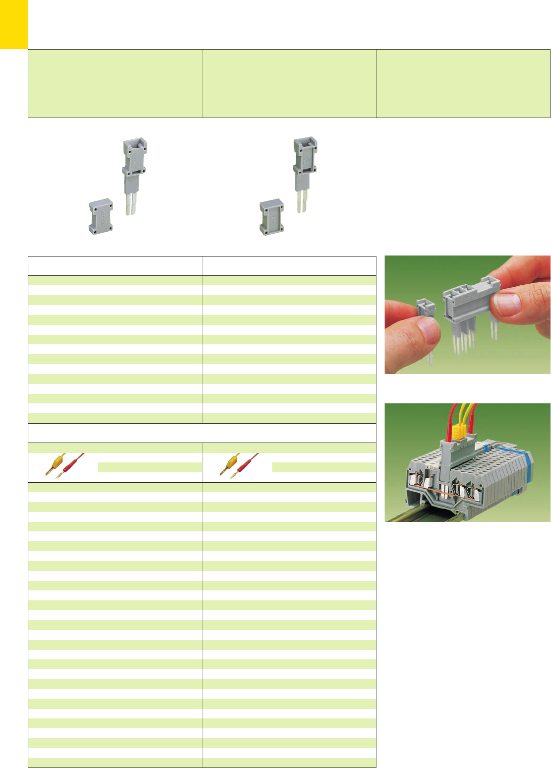
2
40
Modular Test Plugs for Rail-Mounted Terminal Blocks
2.5 mm2/AWG 14 and 4 mm2/AWG 12
Test plug for rail-mounted terminal blocks of
series 280
Module width 5 mm / 0.197 in
Test voltage 400 V
Test current 6 A
Test plug for rail-mounted terminal blocks
of series 281
Module width 6 mm / 0.236 in
Test voltage 400 V
Test current 6 A
Item Pack. unit
No. pcs
Item Pack. unit
No. pcs
Accessories
Test plug,
with
cable 500 mm/1’7.7’’
2 mm Ø, red
210-136 50 (5 x 10)
2.3 mm Ø, yel.
210-137 50 (5 x 10)
Test plug, modular, grey,
module width 5 mm /0.197 in,
suitable for all rail-mounted terminal blocks series 280
with jumper slots in the current bar
280-418 100 (4 x 25)
Spacer, modular, grey,
module width 5 mm /0.197 in,
for bridging over alternate or multiple terminal blocks
280-419 100 (4 x 25)
Test plug, modular, grey,
module width 6 mm /0.236 in,
suitable for all rail-mounted terminal blocks series 281
with jumper slots in the current bar
281-418 100 (4 x 25)
Spacer, modular, grey,
module width 6 mm /0.236 in,
for bridging over alternate or multiple terminal blocks
281-419 100 (4 x 25)
Assembly of modular test plugs and spacers to multipole
test plug strips
The modular test plugs are directly pushed into the
jumper slots of the current bar
Test plug,
with
cable 500 mm/1’7.7’’
2 mm Ø, red
210-136 50 (5 x 10)
2.3 mm Ø, yel.
210-137 50 (5 x 10)
Note:
These test plugs are not suitable for Ex e
applications
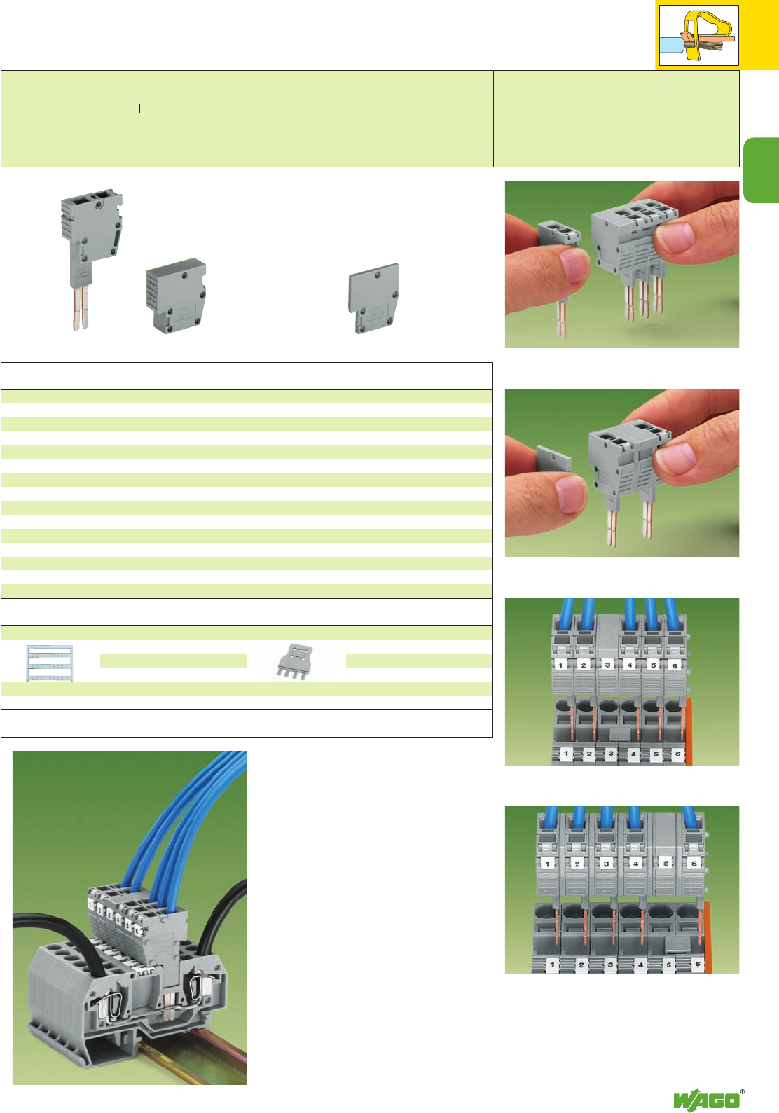
2
41
2
Item Pack. unit
No. pcs
Item Pack. unit
No. pcs
Accessories
Application notes
Miniature WSB quick marking system or
WMB multi-marking system,
10 strips with 10 markers each,
white with black printing
see section 14
Test plug module with CAGE CLAMP®,
version using jumper contact position in current bar,
grey, module width 8 mm/0.315 in, suitable for all rail-
mounted terminal blocks series 282 with jumper slots in
the current bar
709-310 100 (4 x 25)
Spacer module,
for bridging over commoned terminal blocks,
grey, module width 8 mm/0.315 in
709-311 100 (4 x 25)
Spacer plate,
modular, grey, module width 2 mm/0.079 in,
snap on test plug modules 709-310 and spacer module
709-311 for testing of rail-mounted terminal blocks series
284
709-312 100 (4 x 25)
Snapping together of test plug and spacer modules to
assemble a multipole test plug strip for series 282
(max. 10 poles)
Test plug strips are directly inserted into the jumper
contact slots in the current bar (picture shows series 282)
Test plug strip with spacer plates for testing of
rail-mounted terminal blocks series 284
CAGE CLAMP®
0.2 mm2– 6 mm2AWG 24 – 10
For testing of individual circuits WAGO offers as
accessory the single-pole test plugs with
CAGE CLAMP®up to 6 mm2/AWG 10 for direct
contact with the current bar of a terminal block,
or single-pole test plug adapters for test plugs
4 mm dia.
For serial testing on assembled terminal strips
WAGO has developed special multipole (max.
10) modular test plug strips. For testing
completely wired terminal strips (also when using
horizontal jumpers) the test plug modules with
CAGE CLAMP®(version with testing using jumper
contact position in current bar) are the ideal
solution. For this type of testing the structure of
the testing strips is exactly adapted to that of the
terminal strip. The contacting of the test plug
modules is made directly in the jumper contact
position of the terminal blocks to be tested.
Test Plug Modules with CAGE CLAMP®, for Testing of
Rail-Mounted Terminal Blocks 6 mm2/AWG 10 and
10 mm2/AWG 8, Using Jumper Contact Position in Current Bar
Spacer plate for test plug module
for testing rail-mounted terminal blocks
of series 284
Module width 2 mm / 0.079 in
Snapping together of test plug and spacer modules with
spacer plates to assemble a multipole test plug strip for
series 284 (max. 10 poles)
➊ Test voltage 800 V/ 8 kV
Test current 32 A
Note:
These test plugs are not suitable for Ex e
applications
Strain relief plate
6 mm210 mm2
2-way 709-332 709-322
4-way 709-334 709-324
6-way 709-336 709-326
Test plug module ➊for rail-mounted
terminal blocks of series 282
0.2 – 6 mm2AWG 24 – 10
Module width 8 mm / 0.315 in
L12 mm / 0.472 in
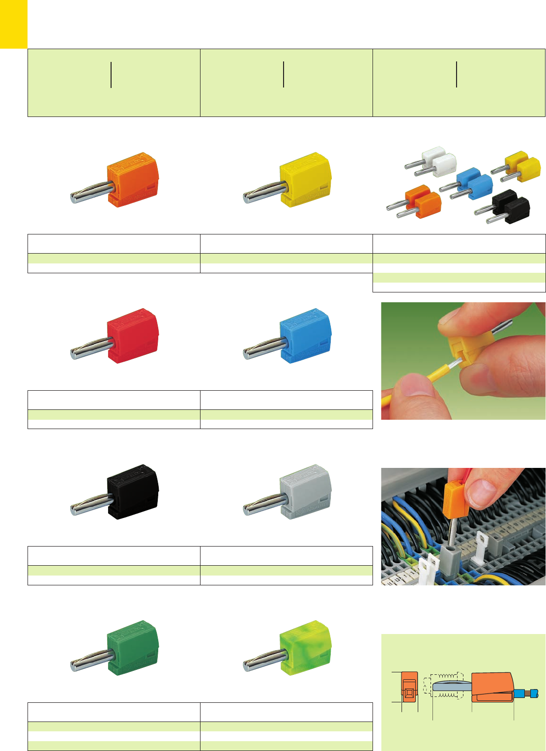
2
42
<___20,5___>
<___________40___________>
(8)
<__15 __>
Color Item Pack. unit
No. pcs Color Item Pack. unit
No. pcs
Banana plug, for sockets Ø 4 mm/0.157 in
red 215-212 50
Banana plug, for sockets Ø 4 mm/0.157 in
blue 215-711 50
Banana plug, for sockets Ø 4 mm/0.157 in
grey 215-811 50
Color Item Pack. unit
No. pcs
Banana plug, for sockets Ø 4 mm/0.157 in
black 215-311 50
Color Item Pack. unit
No. pcs Color Item Pack. unit
No. pcs
Banana plug, for sockets Ø 4 mm/0.157 in
yellow 215-511 50
Banana plug, for sockets Ø 4 mm/0.157 in
orange 215-211 50
Color Item Pack. unit
No. pcs Color Item Pack. unit
No. pcs
Banana plug, for sockets Ø 4 mm/0.157 in
green-yellow 215-911 50
Banana plug, for sockets Ø 4 mm/0.157 in
green 215-411 50
white 215-611 50
Item Pack. unit
No. pcs
Banana plugs, for sockets Ø 4 mm/0.157 in
color mixed 215-111 50
10 each – orange, white, black, blue, yellow
Banana Plugs (Only for Safety Extra-Low Voltage)
Banana plug used as test plug
Picture shows test adapter 209-170
To connect: Press button fully and insert stripped conduc-
tor into square entry hole and release.
Color Item Pack. unit
No. pcs
For sockets Ø 4 mm / 0.157 in
0.08 – 2.5 mm2AWG 28 – 14
42 V
20 A
L9 – 11 mm / 0.39 in
For sockets Ø 4 mm / 0.157 in
0.08 – 2.5 mm2AWG 28 – 14
42 V
20 A
L9 – 11 mm / 0.39 in
For sockets Ø 4 mm / 0.157 in
0.08 – 2.5 mm2AWG 28 – 14
42 V
20 A
L9 – 11 mm / 0.39 in
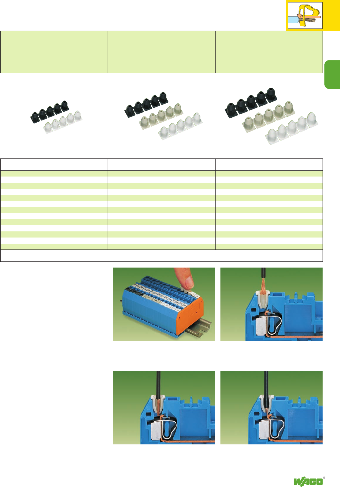
2
43
2
Insulation Stops for Conductors
0.08 mm2– 1.5 mm2/ AWG 28 – 16
Insulation stop,
suitable for all front-entry rail-mounted
terminal blocks of series 279
Terminal block width 4 mm / 0.157 in
L8 – 9 mm / 0.33 in
Insulation stop,
suitable for all front-entry rail-mounted
term. blocks of series 280/870 and 880
Terminal block width 5 mm / 0.197 in
L8 – 9 mm / 0.33 in
Insulation stop,
suitable for all front-entry rail-mounted
terminal blocks of series 281
Terminal block width 6 mm / 0.236 in
L9 – 10 mm / 0.37 in
For the wiring of programmable logic controllers
and microprocessor operated control circuits very
small cross sections of fine-stranded conductors
are frequently used. These small conductors are
so flexible that they deform when pushed against
the conductor stop in the terminal blocks. As a
result, the conductor insulation may be clamped
instead of the copper conductor, resulting in no or
very intermittent contact. This problem exists with
all types of terminal blocks currently offered on
the market. Unnecessary time is spent on fault-
tracing as a consequence.
The insulation stop for rail-mounted terminal
blocks is the answer to solve these problems. It
bundles the cores of fine-stranded conductors
automatically when introduced into the clamping
unit without any splaying and reduces the con-
ductor entry hole to a defined cross sectional
area so that the insulation of these conductors
cannot be introduced into the clamping unit.
The insulation stop is available as dividable 5-
pole strip for rail-mounted terminal blocks of
series 279, 280/870/880 and 281.
With the use of the insulation stop the conductor
stripped lengths related to the respective rail-
mounted terminal block, remain unchanged.
Push insulation stop into the conductor entry holes of
front-entry rail-mounted terminal blocks.
Introduce stripped, untwisted conductor into
insulation stop . . .
. . . the conductor is bundled . . . . . . and the conductor insulation is prevented from being
pushed into the clamping unit by the positive stop.
Item Pack. unit
No. pcs Item Pack. unit
No. pcs
Item Pack. unit
No. pcs
Insulation stop, 5 pcs /strip
white 279-470 200 strips
0.08 – 0.2 mm2➊/AWG 28 – 24
dark grey 279-471 200 strips
0.25 mm2/AWG 22
➊ 0.2 mm2 /AWG 24 solid
0.14 mm2 /AWG 26 fine-stranded
Insulation stop, 5 pcs /strip
white 280-470 200 strips
0.08 – 0.2 mm2➊/AWG 28 – 24
light grey 280-471 200 strips
0.25 – 0.5 mm2 /AWG 22 – 20
dark grey 280-472 200 strips
0.75 – 1 mm2/AWG 18
➊ 0.2 mm2/AWG 24 solid
0.14 mm2/AWG 26 fine-stranded
Insulation stop, 5 pcs /strip
white 281-470 200 strips
0.08 – 0.2 mm2➊/AWG 28 – 24
light grey 281-471 200 strips
0.25 – 0.5 mm2 /AWG 22 – 20
dark grey 281-472 200 strips
0.75 – 1.5 mm2/AWG 18 – 16
➊ 0.2 mm2/AWG 24 solid
0.14 mm2/AWG 26 fine-stranded
Application notes
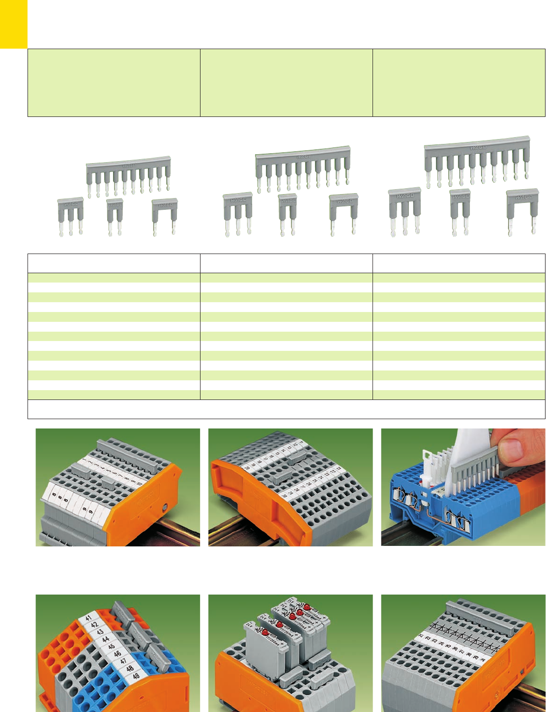
2
44
➊
➊
➋
Applications
Item Pack. unit
No. pcs Item Pack. unit
No. pcs
Item Pack. unit
No. pcs
Comb type jumper bar, insulated
2-way 279-482 200 (8 x 25)
3-way 279-483 200 (8 x 25)
10-way 279-490 50 (2 x 25)
Alternate comb type jumper bar, insulated
2-way 279-492 200 (8 x 25)
Operating tool, insulated
2-way 279-432 1
3-way 279-433 1
10-way 279-440 1
see also section 14
Comb type jumper bar, insulated
2-way 280-482 200 (8 x 25)
3-way 280-483 200 (8 x 25)
10-way 280-490 50 (2 x 25)
Alternate comb type jumper bar, insulated
2-way 280-492 200 (8 x 25)
Operating tool, insulated
2-way 280-432 1
3-way 280-433 1
10-way 280-440 1
see also section 14
Comb type jumper bar, insulated
2-way 281-482 100 (4 x 25)
3-way 281-483 100 (4 x 25)
5-way 281-485 100 (4 x 25)
10-way 281-490 50 (2 x 25)
Alternate comb type jumper bar, insulated
2-way 281-492 100 (4 x 25)
Operating tool, insulated
2-way 280-432 1
3-way 280-433 1
5-way 281-440 1
see also section 14
Double potential terminal blocks
2-way, 3-way and 10-way comb type jumper bars
3-conductor double potential terminal blocks
Alternate comb type jumper bars
Disconnect terminal blocks for test purposes
10-way comb type jumper bar
4-conductor through terminal blocks, angled version
Formation of groups with 3-way comb type jumper bars
Carrier terminal blocks with component plugs
➊Alternate comb type jumper bars
➋3-way comb type jumper bar
Diode terminal blocks
10-way comb type jumper bar
Comb Type Jumper Bars and Alternate Comb Type Jumper Bars
Operating Tools
Comb type jumper bar and
alternate comb type jumper bar
for series 279
IN= INof terminal block
Operating tool
Comb type jumper bar and
alternate comb type jumper bar
for series 280/769/880
IN= INof terminal block
Operating tool
Comb type jumper bar and
alternate comb type jumper bar
for series 281
IN= INof terminal block
Operating tool
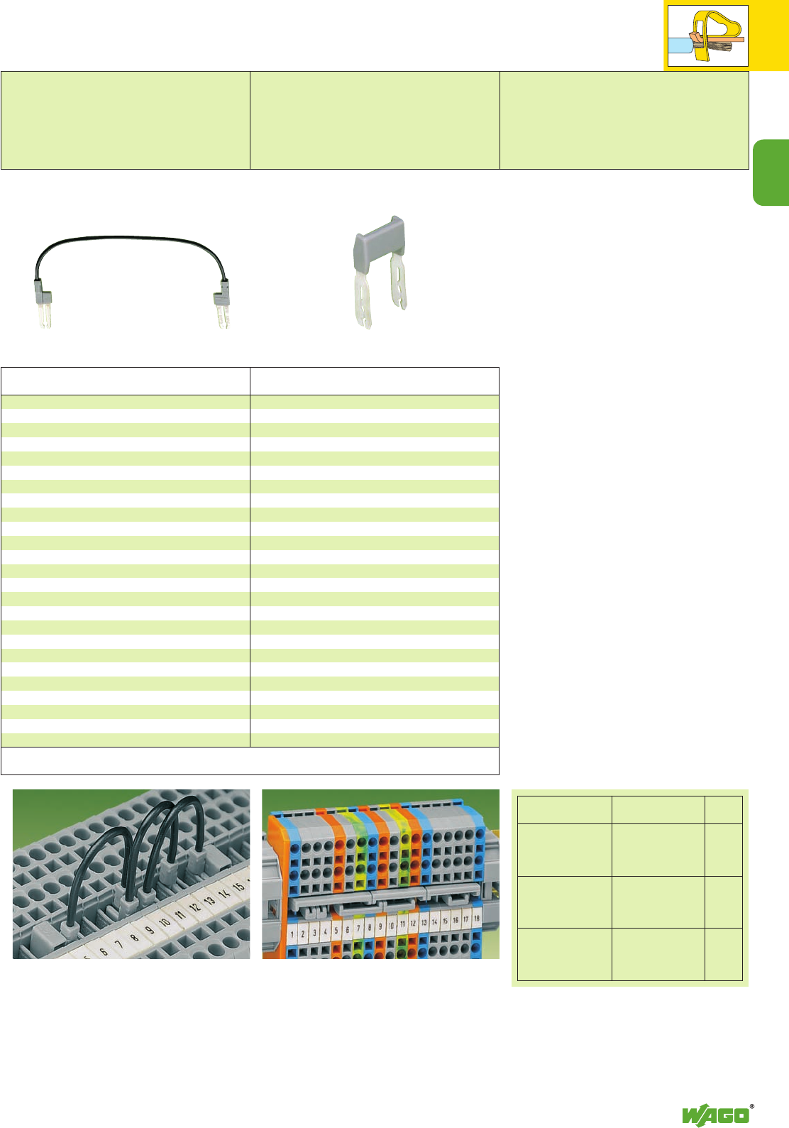
2
45
2
Item Pack. unit
No. pcs
Application notes
Push-in type wire jumpers,
insulated, grey, conductor cross section
0.75 mm2/AWG 18,
suitable for rail-mounted terminal blocks
series 279 (1.5 mm2/AWG 16),
280 (2.5 mm2/AWG 14) and
281/769/880 (4 mm2/AWG 12)
Wire length
60 mm/2.362 in 249-125 10
Wire length
110 mm /4.331 in 249-126 10
Wire length
250 mm/9.843 in 249-127 10
Note:
Push wire jumper down FIRMLY until FULLY inserted!
Staggered jumpers, insulated,
for terminal blocks series 280, 769 and 880
IN24 A, 423 A – 2-conductor terminal blocks
22 A – 3-conductor terminal blocks
20 A – 4-conductor terminal blocks
from 1 to 2 780-452 100 (4 x 25)
from 1 to 3 780-453 100 (4 x 25)
from 1 to 4 780-454 100 (4 x 25)
from 1 to 5 780-455 50 (2 x 25)
from 1 to 6 780-456 50 (2 x 25)
from 1 to 7 780-457 50 (2 x 25)
from 1 to 8 780-458 50 (2 x 25)
for terminal blocks series 281
IN32 A, 426 A
from 1 to 2 781-452 100 (4 x 25)
from 1 to 3 781-453 100 (4 x 25)
from 1 to 4 781-454 100 (4 x 25)
from 1 to 5 781-455 50 (2 x 25)
from 1 to 6 781-456 50 (2 x 25)
Series 280 and 281 will accept two wire jumpers, so it is
possible to bridge several terminal blocks together. Since
series 279 will only accept one wire jumper per terminal
block, the bridging of several terminal blocks is not possi-
ble. Series 280, 769, 281 and 880 permit the introduc-
tion of a wire jumper and a adjacent jumper into the
same block at the same time.
Wire jumpers
When installing machines or control systems, it is
often necessary to make an additional connection
between two terminal blocks that are not directly
adjacent on the rail. In such cases, the new plug-in,
touchproof wire jumper is of great help.
Suitable for rail-mounted terminal blocks
series 279 (1.5 mm2/AWG 16), 280
(2.5 mm2/AWG 14) and 281/769 and 880
(4 mm2/AWG 12), this jumper is available in 3
different wire lengths: 60 mm, 110 mm and
250 mm. This allows up to 60 terminal blocks
between the two blocks being commoned (see
table below).
“n” = number of series 279, 280/769/880 and
281 terminal blocks which can be skipped with a
wire jumper.
Staggered jumper for sophisticated wiring jobs
Item Pack. unit
No. pcs
Push-in Type Wire Jumpers
Staggered Jumpers
Wire jumpers
Nominal voltage: 800 V/8 kV/3
Nominal current: 9 A
Nominal cross section: 0.75 mm2/AWG 18
Conductor lengths: 60/110/250 mm
Staggered jumpers
Nominal voltage: 400 V/6 kV/3
4275 V
Terminal blocks Wire jumpers “n”
Series Item No.
279 249-125 13
1.5 mm2/AWG 16 249-126 25
249-127 60
280 249-125 10
2.5 mm2/AWG 14 249-126 20
769, 880 249-127 48
4 mm2/AWG 12
281 249-125 9
4 mm2/AWG 12 249-126 17
249-127 40
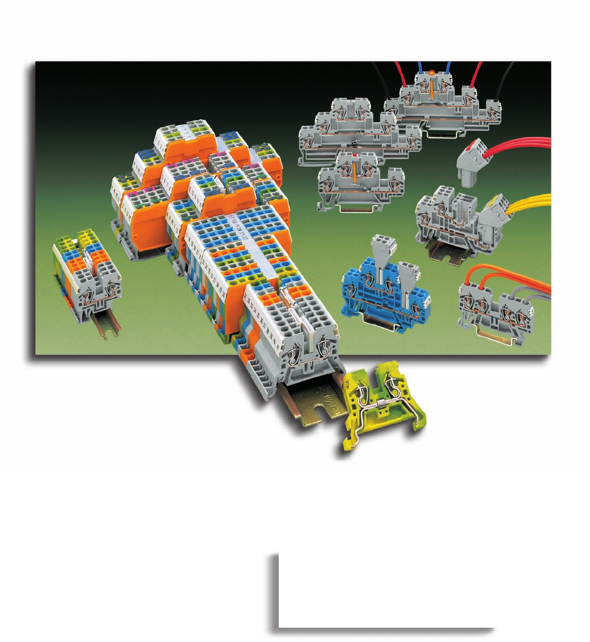
Compact and versatile:
WAGO front-entry rail-mounted terminal
blocks of series 870
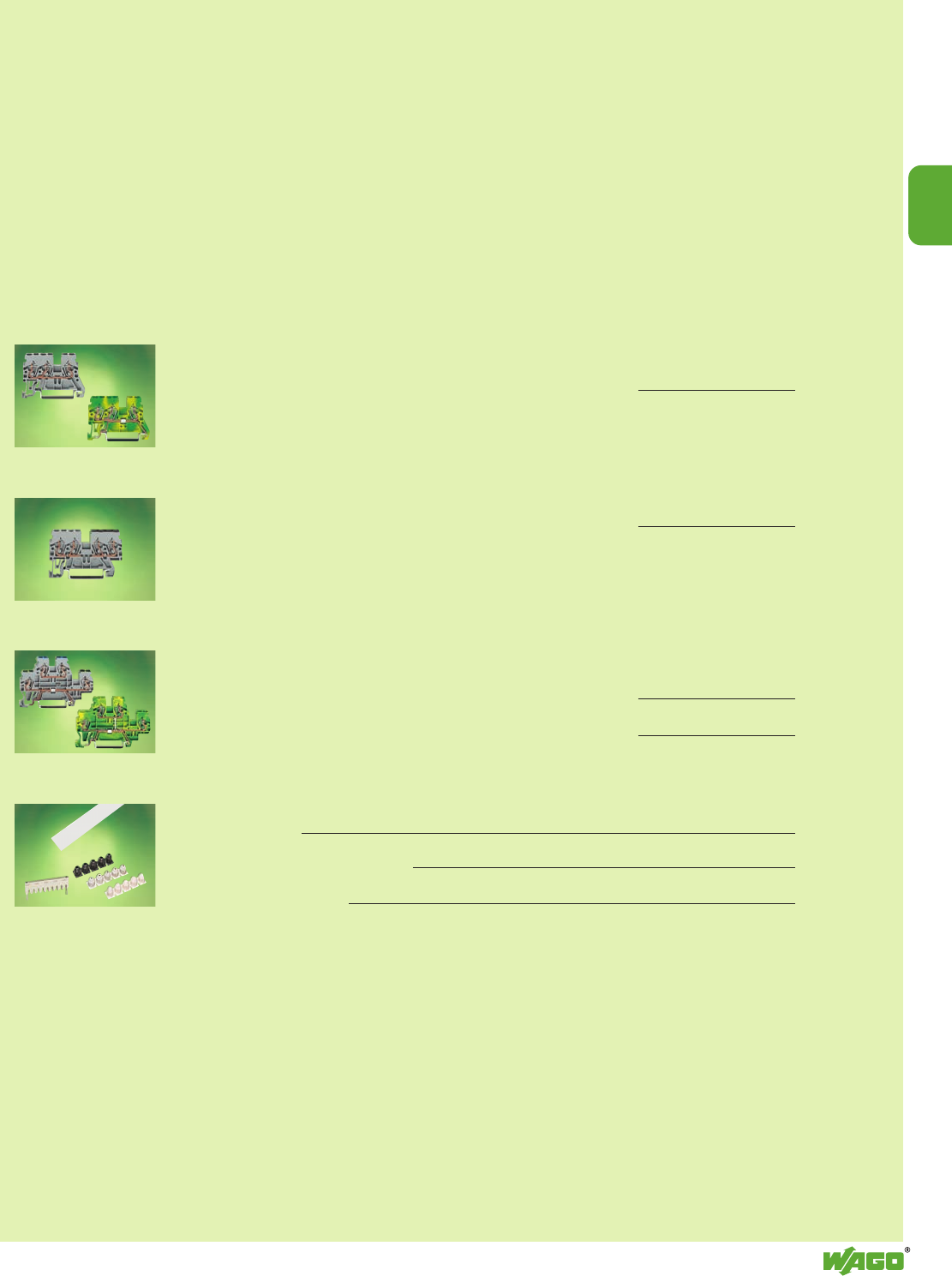
3
3
VOLUME 1
COMPACT Rail-Mounted Terminal Blocks
Through terminal blocks and ground (earth) conductor terminal blocks
– for DIN 35 and DIN 15
0.08 mm2to 2.5 mm2/4 mm2/ AWG 28 – 12 Series 870 3.6 – 3.7
Double potential terminal blocks
0.08 mm2to 2.5 mm2/4 mm2/ AWG 28 – 12 Series 870 3.7
Multilevel terminal blocks
– Double deck
0.08 mm2to 2.5 mm2/4 mm2/ AWG 28 – 12 Series 870 3.8
– Triple deck
0.08 mm2to 2.5 mm2/4 mm2/ AWG 28 – 12 Series 870 3.9
Accessories
– Insulation stops 2.43
– Secondary connection modules 3.11
– Group marker carriers 3.11
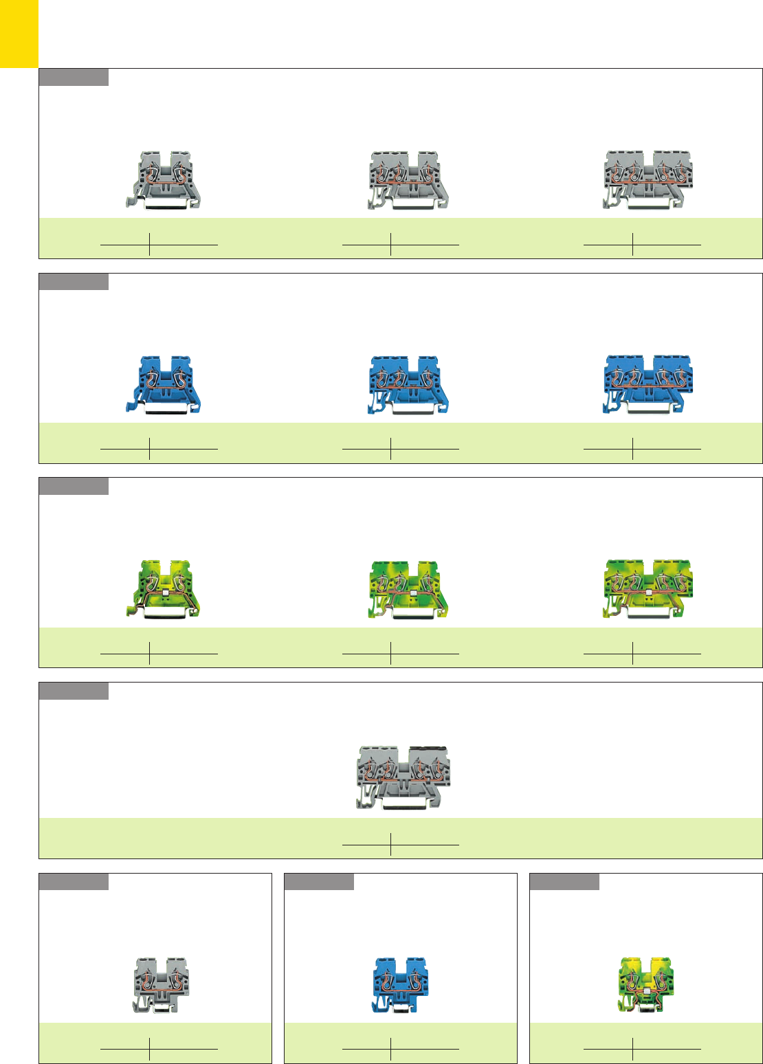
3
2
COMPACT Rail-Mounted Terminal Blocks, Series 870
– Product Summary –
Series 870Series 870Series 870
Series 870
Series 870
Series 870 Through terminal blocks for DIN 35 rail
mm2/AWG 2.5/4/12
Page 3.6
Through terminal blocks
for DIN 15 rail
Ex i
through terminal blocks
for DIN 15 rail
Ground (earth) conduc-
tor terminal blocks for
DIN 35 rail
Series 870
Double potential terminal block
Ex i through terminal blocks for DIN 35 rail
Ground (earth) conductor terminal blocks for DIN 35 rail
Double potential terminal blocks for DIN 35 rail
2-conductor terminal block 3-conductor terminal block 4-conductor terminal block
2-conductor terminal block 3-conductor terminal block 4-conductor terminal block
2-conductor terminal block 3-conductor terminal block 4-conductor terminal block
2-conductor terminal block 2-conductor terminal block 2-conductor terminal block
mm2/AWG 2.5/4/12
Page 3.6
mm2/AWG 2.5/4/12
Page 3.6
mm2/AWG 2.5/4/12
Page 3.6
mm2/AWG 2.5/4/12
Page 3.6
mm2/AWG 2.5/4/12
Page 3.6
mm2/AWG 2.5/4/12
Page 3.6
mm2/AWG 2.5/4/12
Page 3.6
mm2/AWG 2.5/4/12
Page 3.6
mm2/AWG 2.5/4/12
Page 3.7
mm2/AWG 2.5/4/12
Page 3.7
mm2/AWG 2.5/4/12
Page 3.7
mm2/AWG 2.5/4/12
Page 3.7
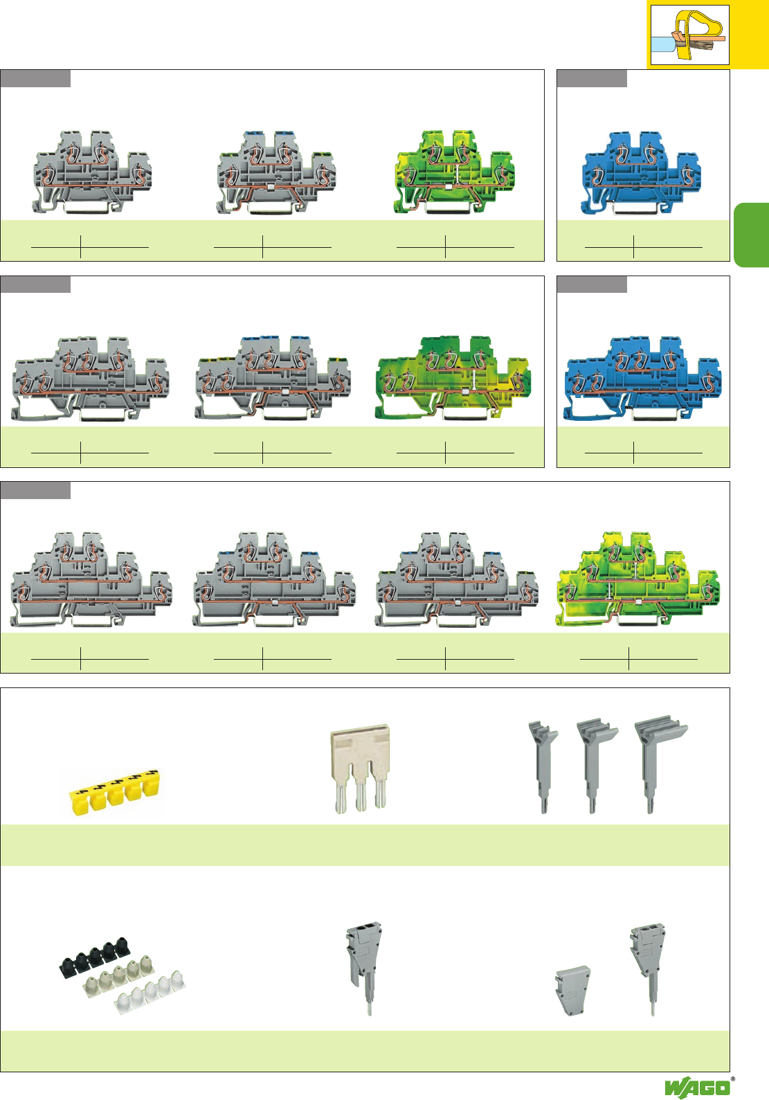
3
3
3
Series 870
Series 870
Series 870
Series 870
Series 870
Accessories (selection)
Protective warning marker
Page 3.4
Push-in type jumper bars
Page 3.6
Group marker carriers
Page 3.11
Insulation stops
Page 2.43
Anti-reverse mating removable
terminal block
Page 3.11
Removable terminal block
Page 3.11
Double deck terminal blocks (selection)
Through/through connection Ground (earth)/through connection 4-conductor terminal block
Ex i
double deck terminal blocks
Through/through connection
3-conductor double deck terminal blocks (selection)
Through/through connection Ground (earth)/through connection 6-conductor terminal block
Ex i 3-conductor double
deck terminal blocks
Through/through connection
Triple deck terminal blocks (selection)
Through/through/through connection Shield (screen)/through/through connection Ground (earth)/through/through connection 6-conductor terminal block
mm2/AWG 2.5/4/12
Page 3.8
mm2/AWG 2.5/4/12
Page 3.8
mm2/AWG 2.5/4/12
Page 3.8
mm2/AWG 2.5/4/12
Page 3.8
mm2/AWG 2.5/4/12
Page 3.8
mm2/AWG 2.5/4/12
Page 3.8
mm2/AWG 2.5/4/12
Page 3.9
mm2/AWG 2.5/4/12
Page 3.8
mm2/AWG 2.5/4/12
Page 3.9
mm2/AWG 2.5/4/12
Page 3.9
mm2/AWG 2.5/4/12
Page 3.9
mm2/AWG 2.5/4/12
Page 3.9
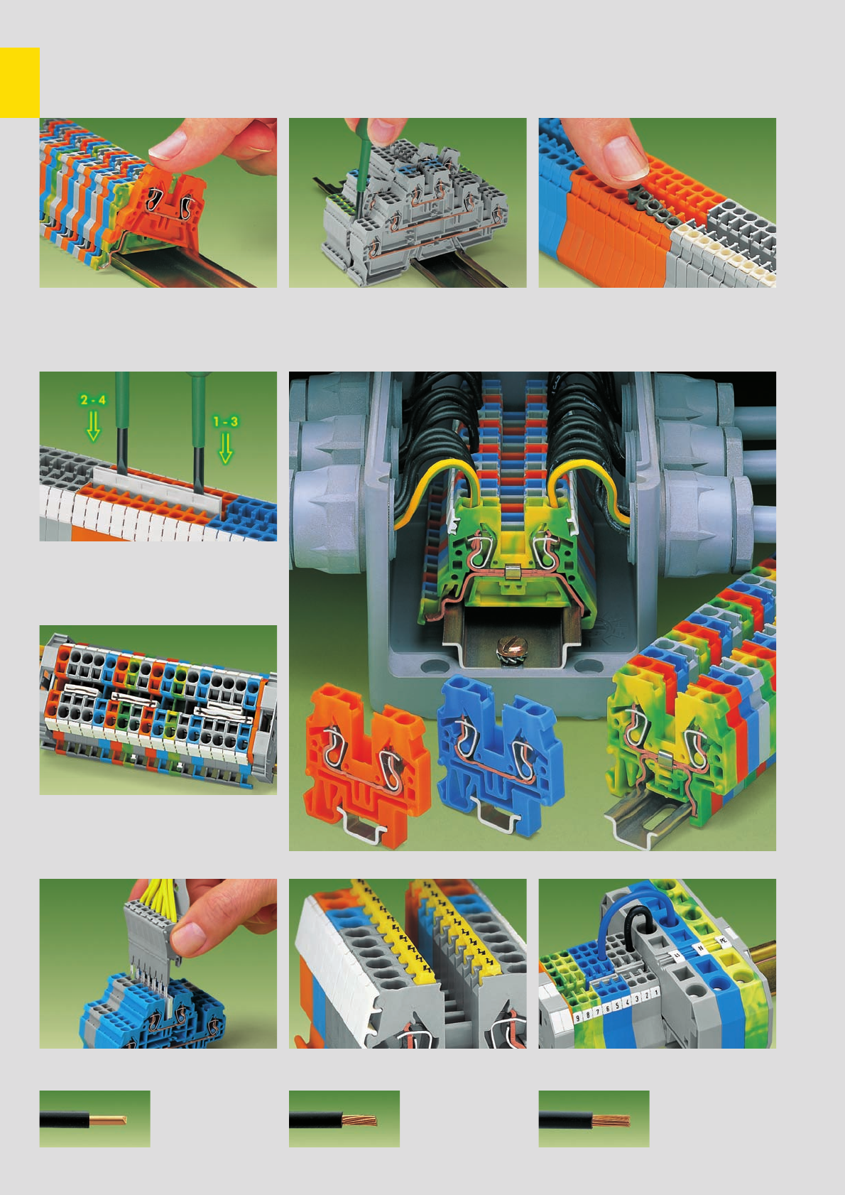
,
3
4Insulation stop
Insertion of insulation stop.
(see page 2.43)
Assembly
Push-in type jumper bar system
Push-in type jumper bar system
Removal
Testing
Removal of a terminal block from the assemblyAssembly of a rail-mounted terminal block on the
DIN 35 rail
Push jumper bars down firmly until fully inserted!
When using multi-pole bars, push alternately on
right and then left side, successively until installed.
Push-in type jumper bars
1 – 3 – 5 – 7.../1 – – 4 – – 7 upon request
2 parallel receptacles for jumpers in one terminal
block.
Testing is possible using a wired strip in the very
same way as test plugs Terminal blocks with larger cross sections can be
commoned to term. bl. with smaller cross sections
COMPACT Rail-Mounted Terminal Blocks with CAGE CLAMP®
for DIN 15 and DIN 35 Rails, Series 870 . . .
Protective warning marker Commoning
Protective warning marker for 5 terminal blocks
yellow – Item No. 280-405
CAGE CLAMP®
clamps the following
copper wires: *
solid stranded
fine stranded,
also with tinned
single strands
* For aluminum wire see notes in section 15!
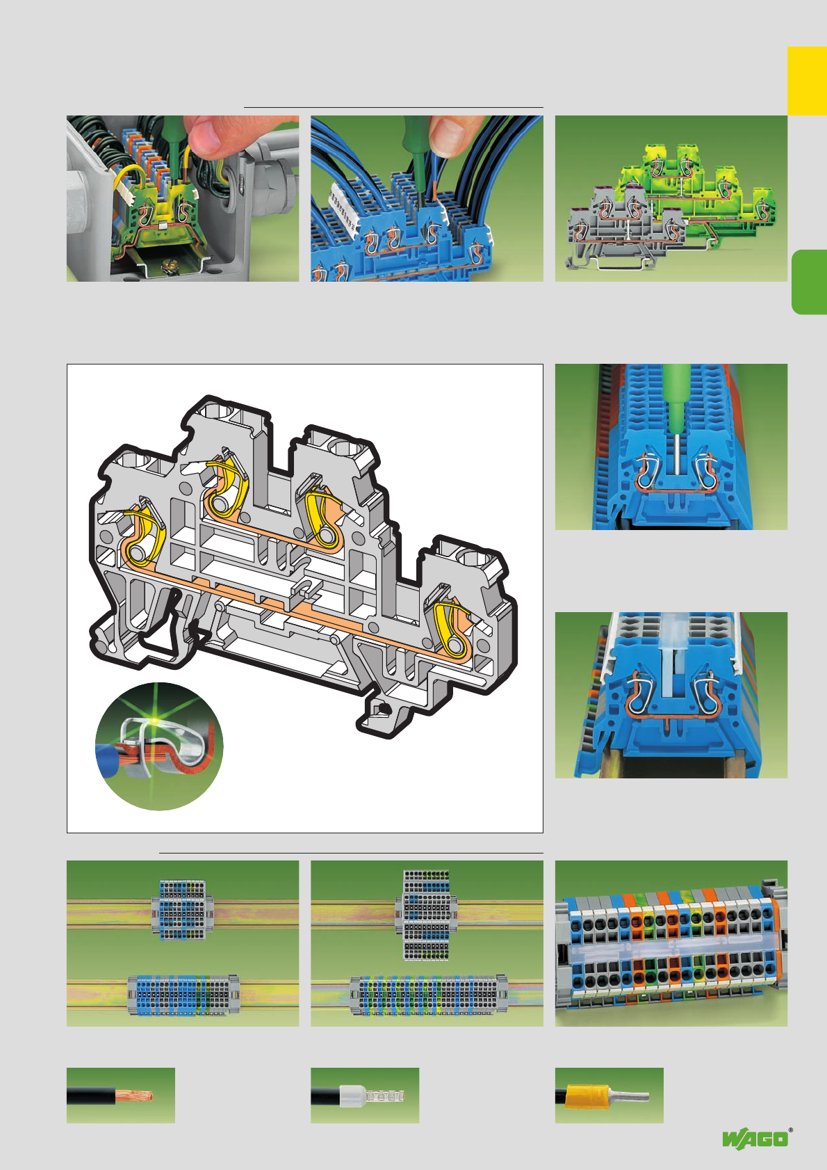
,
3
5
3
. . . Description and Handling
Testing
Marking
Marker strips Space saving
CAGE CLAMP®
connection
Connection of stranded conductors
0.08 mm2to 4 mm2/ AWG 28 –12
Testing with phase testing device,
possible with 1-pole voltage tester too
Marking with WMB multi-marking system or
miniature WSB quick marking system
Space saving of 50 % when using double deck
terminal blocks Space saving of 67 % when using triple deck
terminal blocks Transparent marker strips
(note: jumpers below may be viewed)
Multi-level and multi-connector
terminal blocks
Double and triple deck terminal blocks with
internal commoning acting as 4- and 6-conductor
terminal blocks
fine-stranded wire –
tip bonded
fine-stranded wire
with crimped ferrule
fine-stranded wire
with crimped pin terminal
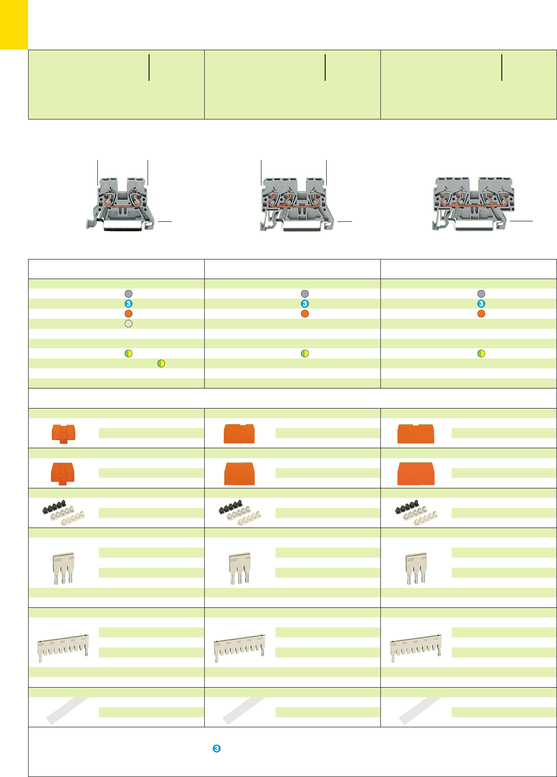
3
6
*YKfaJ:{ *YfJ:{ *Y2J:{
* For further approvals with corresponding ratings see section 15. ** 10 A for push-in type jumper bars with different potentials, placed in parallel
4-conductor through terminal blocks, for DIN 35 rail
grey 870-831 100
blue 870-834 100
orange 870-832 100
4-conductor ground (earth) term. bl., for DIN 35 rail
green-yellow 870-837 100
Attention! These ground (earth) conductor terminal
block cannot be commoned!
3-conductor through terminal blocks, for DIN 35 rail
grey 870-681 100
blue 870-684 100
orange 870-682 100
3-conductor ground (earth) term. bl., for DIN 35 rail
green-yellow 870-687 100
Attention! These ground (earth) conductor terminal
block cannot be commoned!
2-conductor through terminal blocks, for DIN 35 rail
grey 870-901 100
blue 870-904 100
orange 870-902 100
light grey 4870-909 100
2-conductor ground (earth) term. bl., for DIN 35 rail
green-yellow 870-907 100
green-yellow 4870-907/999-950 100
Attention! These ground (earth) conductor terminal
blocks cannot be commoned!
Item Pack. unit
No. pcs
Through/Ground (Earth) Conductor and
Double Potential Terminal Blocks 2.5 mm2/4 mm2/ AWG 12
Series 870
Accessories serie 870 Appropriate marking system WMB/Mini-WSB (see section 14)
End and intermediate plate, 2 mm /0.079 in thick
orange 870-924 100 (4 x 25)
grey 870-923 100 (4 x 25)
Separator,oversized, 2 mm /0.079 in thick
orange 870-929 100 (4 x 25)
grey 870-928 100 (4 x 25)
Insulation stop ➍, 5 pcs /strip
white 280-470 200 strips
light grey 280-471 200 strips
dark grey 280-472 200 strips
Push-in type jumper bars, light grey, insulated,
IN18 A
2-way 870-402 200 (8 x 25)
3-way 870-403 200 (8 x 25)
4-way 870-404 200 (8 x 25)
5-way 870-405 100 (4 x 25)
::
10-way 870-410 100 (4 x 25)
Push-in type jumper bars, light grey, insulated,
IN18 A
from 1 to 3 870-433 200 (8 x 25)
from 1 to 4 870-434 200 (8 x 25)
from 1 to 5 870-435 100 (4 x 25)
::
from 1 to 10
870-440 100 (4 x 25)
Marker strips, transparent, for central marking
1 m /3’33’’ long;
7.5 mm /0.295 in wide
plain 709-196 1
➊Max. diameter of insulation 4.4 mm /0.173 in
➋500 V = rated voltage
6 kV = rated surge voltage
3 = pollution degree
(see also section 15)
4Ex e II application in preperation
Suitable for Ex i applications
➍See application notes on
page
2.43
<_____ 55 mm /2.17 in _____><__44.5 mm /1.75 in __> <_____ 49 mm /1.93 in ___>
Item Pack. unit
No. pcs Item Pack. unit
No. pcs
End and intermediate plate, 1 mm/0.039 in thick
orange 870-934 100 (4 x 25)
grey 870-933 100 (4 x 25)
Separator,oversized, 1 mm/0.039 in thick
orange 870-947 100 (4 x 25)
grey 870-946 100 (4 x 25)
Insulation stop ➍, 5 pcs /strip
white 280-470 200 strips
light grey 280-471 200 strips
dark grey 280-472 200 strips
Push-in type jumper bars, light grey, insulated,
IN18 A
2-way 870-402 200 (8 x 25)
3-way 870-403 200 (8 x 25)
4-way 870-404 200 (8 x 25)
5-way 870-405 100 (4 x 25)
::
10-way 870-410 100 (4 x 25)
Push-in type jumper bars, light grey, insulated,
IN18 A
from 1 to 3 870-433 200 (8 x 25)
from 1 to 4 870-434 200 (8 x 25)
from 1 to 5 870-435 100 (4 x 25)
::
from 1 to 10
870-440 100 (4 x 25)
Marker strips, transparent, for central marking
1 m /3’33’’ long;
7.5 mm /0.295 in wide
plain 709-196 1
End and intermediate plate, 1 mm/0.039 in thick
orange 870-944 100 (4 x 25)
grey 870-943 100 (4 x 25)
Separator,oversized, 1 mm/0.039 in thick
orange 870-949 100 (4 x 25)
grey 870-948 100 (4 x 25)
Insulation stop ➍, 5 pcs /strip
white 280-470 200 strips
light grey 280-471 200 strips
dark grey 280-472 200 strips
Push-in type jumper bars, light grey, insulated,
IN18 A
2-way 870-402 200 (8 x 25)
3-way 870-403 200 (8 x 25)
4-way 870-404 200 (8 x 25)
5-way 870-405 100 (4 x 25)
::
10-way 870-410 100 (4 x 25)
Push-in type jumper bars, light grey, insulated,
IN18 A
from 1 to 3 870-433 200 (8 x 25)
from 1 to 4 870-434 200 (8 x 25)
from 1 to 5 870-435 100 (4 x 25)
::
from 1 to 10
870-440 100 (4 x 25)
Marker strips, transparent, for central marking
1 m /3’33’’ long;
7.5 mm /0.295 in wide
plain 709-196 1
0.08 –2.5 mm2/4 mm2 ➊AWG 28 – 12
500 V/6 kV/3 ➋300/600 V,
24 A 20/5 A**
Terminal block width 5 mm / 0.197 in
L6 – 7 mm / 0.26 in
0.08 –2.5 mm2/4 mm2➊AWG 28 – 12
500 V/6 kV/3 ➋300/600 V,
24 A 20/5 A**
Terminal block width 5 mm / 0.197 in
L6 – 7 mm / 0.26 in
0.08 –2.5 mm2/4 mm2➊AWG 28 – 12
500 V/6 kV/3 ➋300/600 V,
24 A 20/5 A**
Terminal block width 5 mm / 0.197 in
L6 – 7 mm / 0.26 in
<27.5 mm />
1.08 in
<27.5 mm />
1.08 in
<__33.5 mm / __>
1.32 in <____ 44.5 mm /____>
1.75 in
<27.5 mm / >
1.08 in
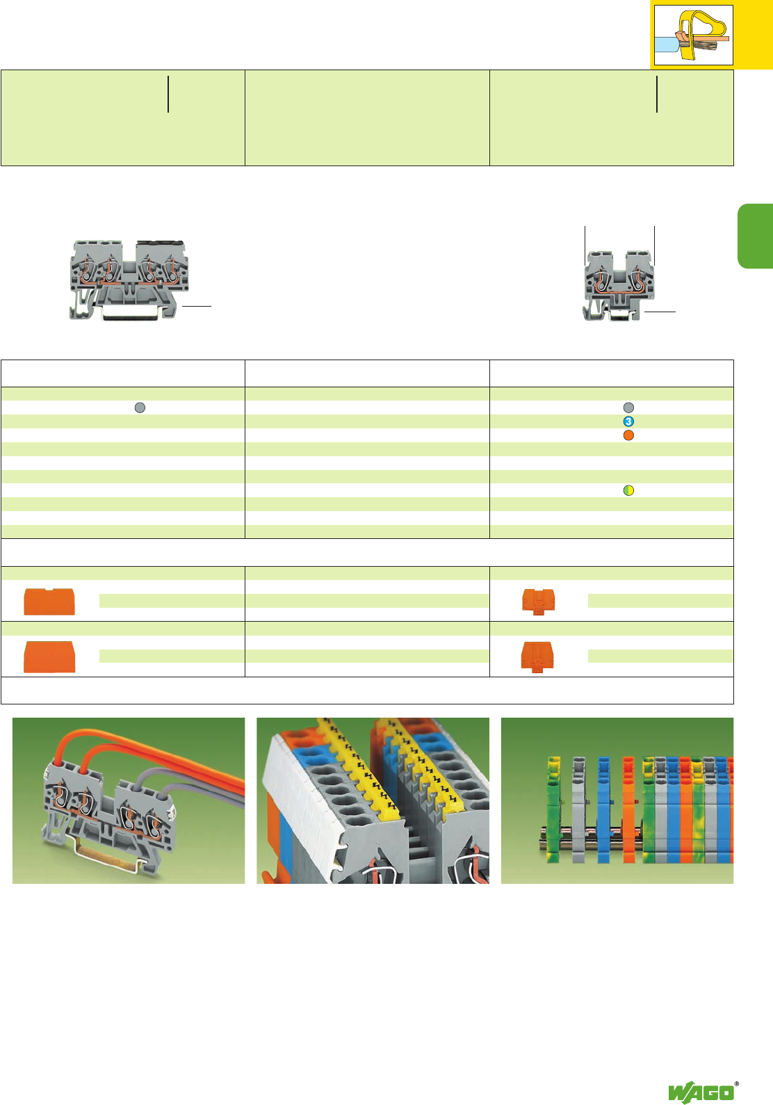
3
7
3
*Y
Double potential terminal block, for DIN 35 rail
grey 870-826 100
Attention!
These double potential terminal block cannot be
commoned!
Item Pack. unit
No. pcs
End and intermediate plate, 1 mm/0.039 in thick
orange 870-944 100 (4 x 25)
grey 870-943 100 (4 x 25)
Separator,oversized, 1 mm/0.039 in thick
orange 870-949 100 (4 x 25)
grey 870-948 100 (4 x 25)
Item Pack. unit
No. pcs
<______ 55 mm /2.17 in ______>
Terminal block marking directly on the terminal block
either with miniature WSB or WMB markers
WAGO front-entry double potential terminal
blocks are space savers. Two independent
through terminal blocks are placed in one insula-
ted housing on one level. The width of the hou-
sing is only 5 mm /0.197 in. Compared to stan-
dard through terminal blocks, the width is only
2.5 mm /0.098 in for a total height of only
27.5 mm /1.08 in from the upper edge of the
carrier rail. Input and output contacts of one cir-
cuit are placed on the same side of the terminal
block. Both circuits can be individually marked
according to input and output.
(34.5 mm /1.36 in )
Assembly
Snap individual terminal blocks onto carrier rail
DIN 15 and engage.
Removal
Open assembly by laterally sliding terminal blocks
with a screwdriver and remove them from the
rail.
2-conductor through terminal blocks, for DIN 15 rail
grey 870-911 100
blue 870-914 100
orange 870-912 100
2-conductor ground (earth) term. bl., for DIN 15 rail
green-yellow 870-917 100
Attention! These ground (earth) conductor terminal
block cannot be commoned!
End and intermediate plate, 2 mm /0.079 in thick
orange 870-924 100 (4 x 25)
grey 870-923 100 (4 x 25)
Separator,oversized, 2 mm /0.079 in thick
orange 870-929 100 (4 x 25)
grey 870-928 100 (4 x 25)
Application notes
Protective warning marker
for 5 terminal blocks
yellow 280-405 100 (4 x 25)
Accessories serie 870 Appropriate marking system WMB/Mini-WSB (see section 14)
<27.5 mm / >
1.08 in
0.08 –2.5 mm2/4 mm2➊AWG 28 – 12
500 V/6 kV/3 ➋300 V, 20 A**
24 A 300 V, 25 A**
Terminal block width 5 mm / 0.197 in
L6 – 7 mm / 0.26 in
<26.5 mm />
1.04 in
0.08 –2.5 mm2/4 mm2➊AWG 28 – 12
500 V/6 kV/3 ➋300/600 V,
24 A 20/5 A**
Terminal block width 5 mm / 0.197 in
L6 – 7 mm / 0.26 in
<__33.5 mm / __>
1.32 in
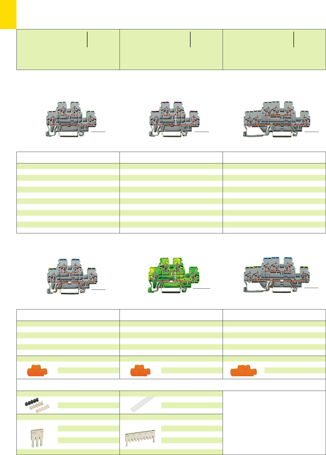
3
8
*YKfaJ:;{[ *YKfaJ:;{[ *YfJ:{
➌
➌
➌
➌
<______ 70 mm /2.76 in ______>
Item Pack. unit
No. pcs
Double deck terminal block,
for DIN 35 rail
Through/through terminal blocks,
housing color grey
L/L 870-501 50
N/L 870-502 50
L/N 870-503 50
housing color blue
N/N 870-504 50
housing color light grey
L/L 4870-961 50
Other terminal blocks with the same shape
diode/LED 870-5xx/...-... page 7.64
<______ 70 mm /2.76 in ______>
Double deck terminal block,
for DIN 35 rail
4-conductor through terminal block,
internal commoning, housing color grey,
conductor entry position colored in violet
L870-508 50
4-conductor through terminal block,
internal commoning, housing color blue,
conductor entry position colored in violet
N870-509 50
<______ 70 mm /2.76 in ______>
<______ 70 mm /2.76 in ______>
Item Pack. unit
No. pcs
3-cond. double deck terminal block,
for DIN 35 rail
Through/through terminal blocks,
housing color grey
L/L 870-531 50
N/L 870-532 50
L/N 870-533 50
housing color blue
N/N 870-534 50
<___________ 91 mm /3.58 in ___________>
<___________ 91 mm /3.58 in ___________>
* For further approvals with corresponding ratings see section 15. ** 10 A for push-in type jumper bars with different potentials, placed in parallel
Item Pack. unit
No. pcs
Double Deck and Triple Deck Terminal Blocks 2.5 mm2/4 mm2/ AWG 12,
Series 870
Accessories serie 870 Appropriate marking system WMB/Mini-WSB (see section 14)
End and intermediate plate, 2 mm /0.079 in thick
orange 870-574 100 (4 x 25)
grey 870-573 100 (4 x 25)
End and intermediate plate, 2 mm /0.079 in thick
orange 870-519 100 (4 x 25)
grey 870-518 100 (4 x 25)
3-cond. double deck terminal block,
for DIN 35 rail
Ground (earth) conductor/through terminal blocks,
housing color grey
PE /N 870-535 50
PE /L 870-536 50
Double deck terminal block,
for DIN 35 rail
4-conductor ground (earth) terminal block,
internal commoning, housing color green-yellow
PE 870-507 50
Double deck terminal block,
for DIN 35 rail
Ground (earth) conductor/through terminal blocks,
housing color grey
PE/N 870-517 50
PE/L 870-527 50
Item Pack. unit
No. pcs
Item Pack. unit
No. pcs
Item Pack. unit
No. pcs
Insulation stop ➍, 5 pcs /strip
white 280-470 200 strips
light grey 280-471 200 strips
dark grey 280-472 200 strips
Push-in type jumper bars, light grey, insulated, IN18 A
2-way 870-402 200 (8 x 25)
3-way 870-403 200 (8 x 25)
4-way 870-404 200 (8 x 25)
5-way 870-405 100 (4 x 25)
::
10-way 870-410 100 (4 x 25)
Marker strips, transparent, for central marking
1 m /3’33’’ long;
7.5 mm /0.295 in wide
plain 709-196 1
Push-in type jumper bars, light grey, insulated,
IN18 A
from 1 to 3 870-433 200 (8 x 25)
from 1 to 4 870-434 200 (8 x 25)
from 1 to 5 870-435 100 (4 x 25)
::
from 1 to 10
870-440 100 (4 x 25)
➊Max. diameter of insulation 4.4 mm /0.173 in
➋500 V = rated voltage
6 kV = rated surge voltage
3 = pollution degree
(see also section 15)
4Ex e II application in preperation
Suitable for Ex i applications
➍See application notes on
page
2.43
End and intermediate plate, 2 mm /0.079 in thick
orange 870-519 100 (4 x 25)
grey 870-518 100 (4 x 25)
<__ 40 mm / __>
1.57 in
0.08 –2.5 mm2/4 mm2➊AWG 28 – 12
500 V/6 kV/3 ➋300/600 V,
24 A 20/5 A**
Terminal block width 5 mm / 0.197 in
L6 – 7 mm / 0.26 in
<__ 40 mm / __>
1.57 in
0.08 –2.5 mm2/4 mm2➊AWG 28 – 12
500 V/6 kV/3 ➋300/600 V,
24 A 20/5 A**
Terminal block width 5 mm / 0.197 in
L6 – 7 mm / 0.26 in
<__ 40 mm / __>
1.57 in
<__ 40 mm / __>
1.57 in
0.08 –2.5 mm2/4 mm2➊AWG 28 – 12
500 V/6 kV/3 ➋300/600 V,
24 A 20/5 A**
Terminal block width 5 mm / 0.197 in
L6 – 7 mm / 0.26 in
<___ 40 mm / ___>
1.57 in <___ 40 mm / ___>
1.57 in
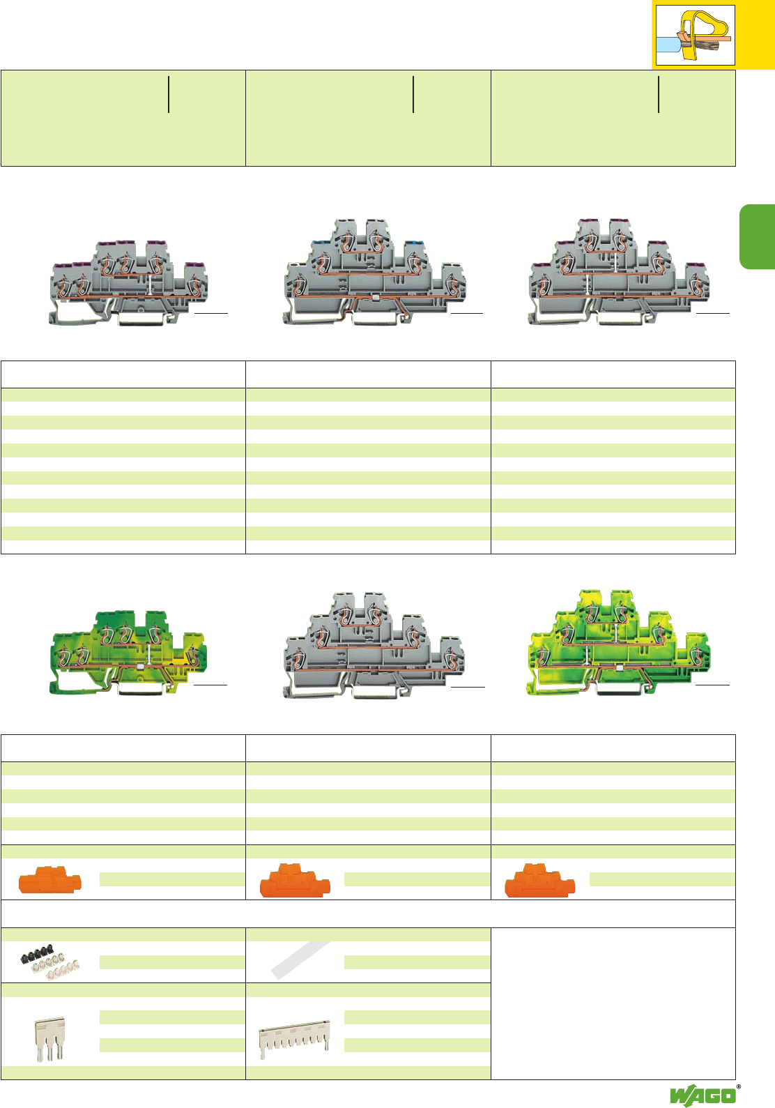
3
9
3
*YKfaJ:;{[
*YfJ:{ *YKfaJ:;{[
➌
➌
Item Pack. unit
No. pcs
Double deck terminal block,
for DIN 35 rail
6-conductor through terminal block,
internal commoning, housing color grey,
conductor entry position colored in violet
L870-538 50
6-conductor through terminal block,
internal commoning, housing color blue,
conductor entry position colored in violet
N870-539 50
<___________ 91 mm /3.58 in ___________> <_____________ 106 mm /4.17 in ______________>
Item Pack. unit
No. pcs
Triple deck terminal block, for DIN 35 rail
Shield (screen)/through/through terminal blocks
,
housing color grey
Shield(scr.)/N /L 870-558 50
Shield(scr.)/L /L 870-559 50
Ground (earth)/through/through terminal blocks
,
housing color grey
PE /N /L 870-567 50
PE /L /L 870-577 50
Other terminal blocks with the same shape
diode/LED 870-5xx/...-... page 7.66
<______________ 106 mm /4.17 in ______________>
Item Pack. unit
No. pcs
Triple deck terminal block, for DIN 35 rail
6-conductor through terminal block,
internal commoning, housing color grey,
conductor entry position colored in violet
L
870-556 50
Triple deck terminal block, for DIN 35 rail
6-conductor ground (earth) terminal block,
internal commoning, housing color green-yellow
PE 870-557 50
Through/through/through terminal blocks
,
housing color grey
L/L/L 870-551 50
L/L/N 870-553 50
housing color light grey
L/L/L 4870-951 50
Double deck terminal block,
for DIN 35 rail
6-conductor ground (earth) terminal block,
internal commoning, housing color green-yellow
PE 870-537 50
Item Pack. unit
No. pcs
Item Pack. unit
No. pcs
Item Pack. unit
No. pcs
<___________ 91 mm /3.58 in ___________> <_____________ 106 mm /4.17 in ______________> <_____________ 106 mm /4.17 in ______________>
Accessories serie 870 Appropriate marking system WMB/Mini-WSB (see section 14)
End and intermediate plate, 2 mm /0.079 in thick
orange 870-569 50 (2 x 25)
grey 870-568 50 (2 x 25)
End and intermediate plate, 2 mm /0.079 in thick
orange 870-569 50 (2 x 25)
grey 870-568 50 (2 x 25)
End and intermediate plate, 2 mm /0.079 in thick
orange 870-574 100 (4 x 25)
grey 870-573 100 (4 x 25)
Insulation stop ➍, 5 pcs /strip
white 280-470 200 strips
light grey 280-471 200 strips
dark grey 280-472 200 strips
Push-in type jumper bars, light grey, insulated, IN18 A
2-way 870-402 200 (8 x 25)
3-way 870-403 200 (8 x 25)
4-way 870-404 200 (8 x 25)
5-way 870-405 100 (4 x 25)
::
10-way 870-410 100 (4 x 25)
Marker strips, transparent, for central marking
1 m /3’33’’ long;
7.5 mm /0.295 in wide
plain 709-196 1
Push-in type jumper bars, light grey, insulated,
IN18 A
from 1 to 3 870-433 200 (8 x 25)
from 1 to 4 870-434 200 (8 x 25)
from 1 to 5 870-435 100 (4 x 25)
::
from 1 to 10
870-440 100 (4 x 25)
➊Max. diameter of insulation 4.4 mm /0.173 in
➋500 V = rated voltage
6 kV = rated surge voltage
3 = pollution degree
(see also section 15)
4Ex e II application in preperation
Suitable for Ex i applications
➍See application notes on
page
2.43
0.08 –2.5 mm2/4 mm2➊AWG 28 – 12
500 V/6 kV/3 ➋300/600 V,
24 A 20/5 A**
Terminal block width 5 mm / 0.197 in
L6 – 7 mm / 0.26 in
<___ 40 mm / ___>
1.57 in
<_ 52.5 mm /2.07 in _>
0.08 –2.5 mm2/4 mm2➊AWG 28 – 12
500 V/6 kV/3 ➋300/600 V,
24 A 20/5 A**
Terminal block width 5 mm / 0.197 in
L6 – 7 mm / 0.26 in
<_ 52.5 mm /2.07 in _>
0.08 –2.5 mm2/4 mm2➊AWG 28 – 12
500 V/6 kV/3 ➋300/600 V,
24 A 20/5 A**
Terminal block width 5 mm / 0.197 in
L6 – 7 mm / 0.26 in
<___ 40 mm / ___>
1.57 in
<_ 52.5 mm /2.07 in _>
<_ 52.5 mm /2.07 in _>
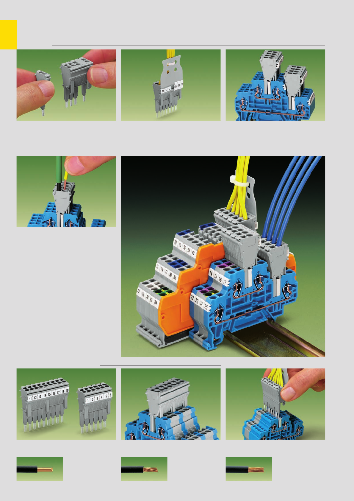
3
10
Snap together individual terminal blocks and spa-
cer modules to create custom removable terminal
block modules (10-pole max.)
Removable terminal block module with
CAGE CLAMP®connection (0.25 mm2– 2.5 mm2 /
AWG 24 – 14), with strain relief plate and marker
position for miniature WSB or WMB marking.
Testing is also possible using a prewired remova-
ble terminal block module just like traditional test
plugs.
CAGE CLAMP® connection
Removable Terminal Block Modules with
CAGE CLAMP
®
, Series 870
Description
Assembly
The removable term. bl. modules can be directly
inserted into the jumper contact slot in the current
bar of the receiving rail-mounted term. block.
Term. blocks can also be commoned utilizing a
comb style jumper parallel to the jumper contact
slot being used by the removable term. bl. module.
These modules are used when additional or remo-
vable connections are required (can be used as a
permanent connection or a test plug). Wiring of the
removable terminal block module is possible
whether or not the module is plugged into the rail-
mounted terminal block assembly.
* For aluminum wire see notes in section 15!
CAGE CLAMP®
clamps the following
copper wires:*
solid stranded
fine-stranded,
also with tinned
single strands
Use anti-reverse mating modules at both ends of the remov. term. bl. module to prevent reverse mating.
Three anti-reverse mating modules are necessary when snapping more than 7 modules together.
Anti-reverse mating modules Testing
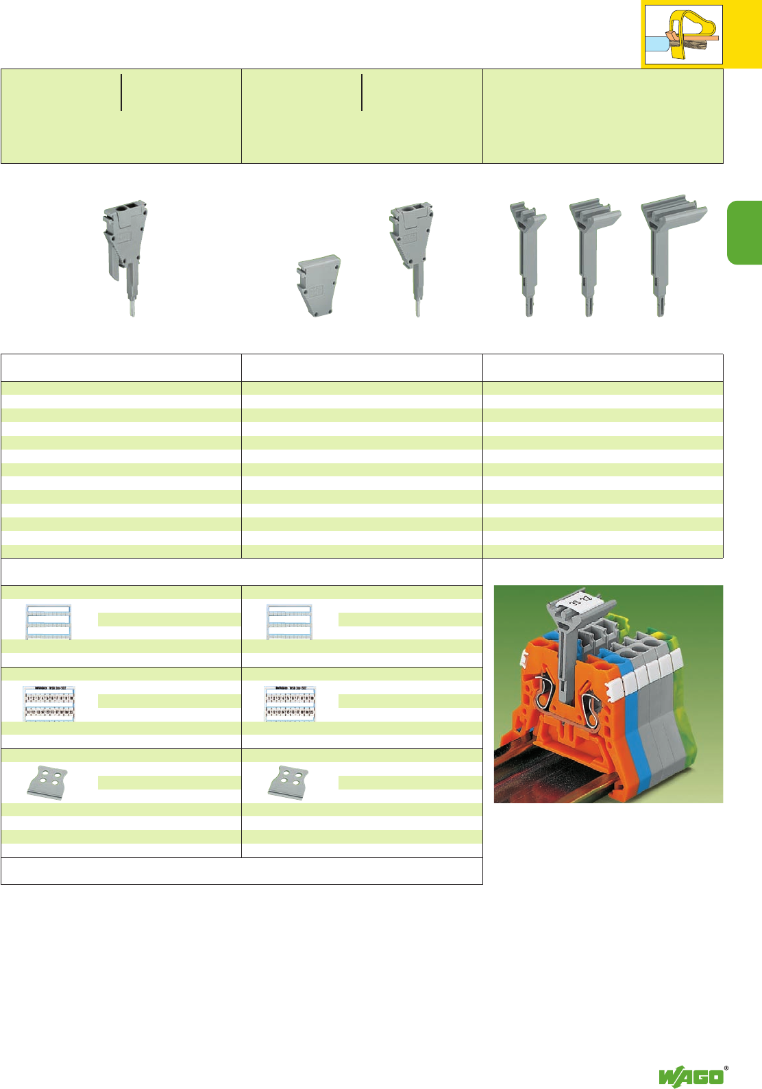
3
11
3
Item Pack. unit
No. pcs
Accessories
Miniature WSB quick marking card,
10 strips with 10 markers each,
white with black printing
see section 14
5 mm /0.197 in wide
248-5.. 5 cards
10 mm /0.394 in wide
264-9.. 5 cards
WMB multi marking system,
10 strips with 10 markers each,
white with black printing
see section 14
5 mm /0.197 in wide
793-5.. 5 cards
Strain relief plate, grey
can be snapped onto secondary
connection module
s
6 mm/0.236 in wide
734-327 100 (4 x25)
12.5 mm/0.492 in wide
734-328 100 (4 x25)
25 mm/0.984 in wide
734-329 100 (4 x25)
35 mm/1.38 in wide
734-326 100 (4 x25)
Anti-reverse mating removable terminal block
with CAGE CLAMP®,
version using jumper contact position in current bar,
grey, module width 5 mm /0.197 in,
suitable for all rail-mounted terminal blocks series 870
with jumper contact slots in current bar
870-425 100 (4 x 25)
For additional-wire connections, as well as serial
testing on terminal block assemblies, WAGO has
developed special multi-pole modular removable
terminal blocks.
The structure of the removable terminal block
module can be specifically adapted to the termi-
nal block assembly using spacer modules if neces-
sary (see left page).
The connection of the modules is made directly in
the jumper contact positions of the terminal
blocks to be tested / tapped, even though a
comb style jumper bar is already being used.
Accessories for Series 870,
Removable Terminal Block Modules and Group Marker Carriers
Item Pack. unit
No. pcs
Removable terminal block with CAGE CLAMP®,
version using jumper contact position in current bar,
grey, module width 5 mm /0.197 in,
suitable for all rail-mounted terminal blocks series 870
with jumper contact slots in the current bar
870-426 100 (4 x 25)
Spacer module,
for bridging over terminal blocks, grey,
module width 5 mm /0.197 in
870-427 100 (4 x 25)
Miniature WSB quick marking card,
10 strips with 10 markers each,
white with black printing
see section 14
5 mm /0.197 in wide
248-5.. 5 cards
10 mm /0.394 in wide
264-9.. 5 cards
WMB multi marking system,
10 strips with 10 markers each,
white with black printing
see section 14
5 mm /0.197 in wide
793-5.. 5 cards
Strain relief plate, grey
can be snapped onto secondary
connection module
s
6 mm/0.236 in wide
734-327 100 (4 x25)
12.5 mm/0.492 in wide
734-328 100 (4 x25)
25 mm/0.984 in wide
734-329 100 (4 x25)
35 mm/1.38 in wide
734-326 100 (4 x25)
0.25 – 2.5 mm2AWG 24 – 14
500 V/6 kV/3
18 A
Module width 5 mm / 0.197 in
L10 mm / 0.38 in
0.25 – 2.5 mm2AWG 24 – 14
500 V/6 kV/3
18 A
Module width 5 mm / 0.197 in
L10 mm / 0.38 in
Group marker carrier,
using jumper contact position in current bar
5 mm/0.197 in wide 870-184 50
10 mm/0.394 in wide 870-183 50
15 mm/0.591 in wide 870-182 50
Attention!
Ground (earth) conductor terminal blocks and
double potential terminal blocks have no jumper
contact slots!
Application notes
In addition to the plastic marker strips, group
marker carriers are now available for the WMB
and WSB marking systems. They can be mounted
in parallel to a comb style jumper bar using the
open jumper contact slot. It is also very useful if
the marker receptacles on the side of the terminal
block are hidden.
The marker carrier is available in 5 mm/0.197 in,
10 mm/0.394 in and 15 mm/0.591 in widths.
Attention!
Marker carriers are not suitable for ground
(earth) conductor terminal blocks and double
potential terminal blocks as they have no jumper
contact slots.
WAGO group marker carriers
for terminal blocks series 869, 870
Module width 5 mm / 0.197 in
Module width 10 mm / 0.394 in
Module width 15 mm / 0.591 in
Item Pack. unit
No. pcs
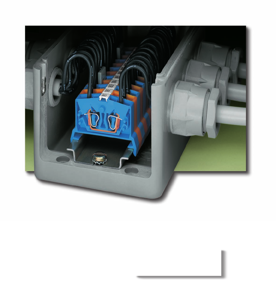
Ideal for confined spaces:
WAGO miniature rail-mounted ter-
minal blocks.

4
4
VOLUME 1
Miniature Rail-Mounted Terminal Blocks
Through terminal blocks and ground (earth) conductor terminal blocks
– for DIN 35 and DIN 15
0.08 mm2to 2.5 mm2/ AWG 28 – 12 Series 264 4.4 – 4.5
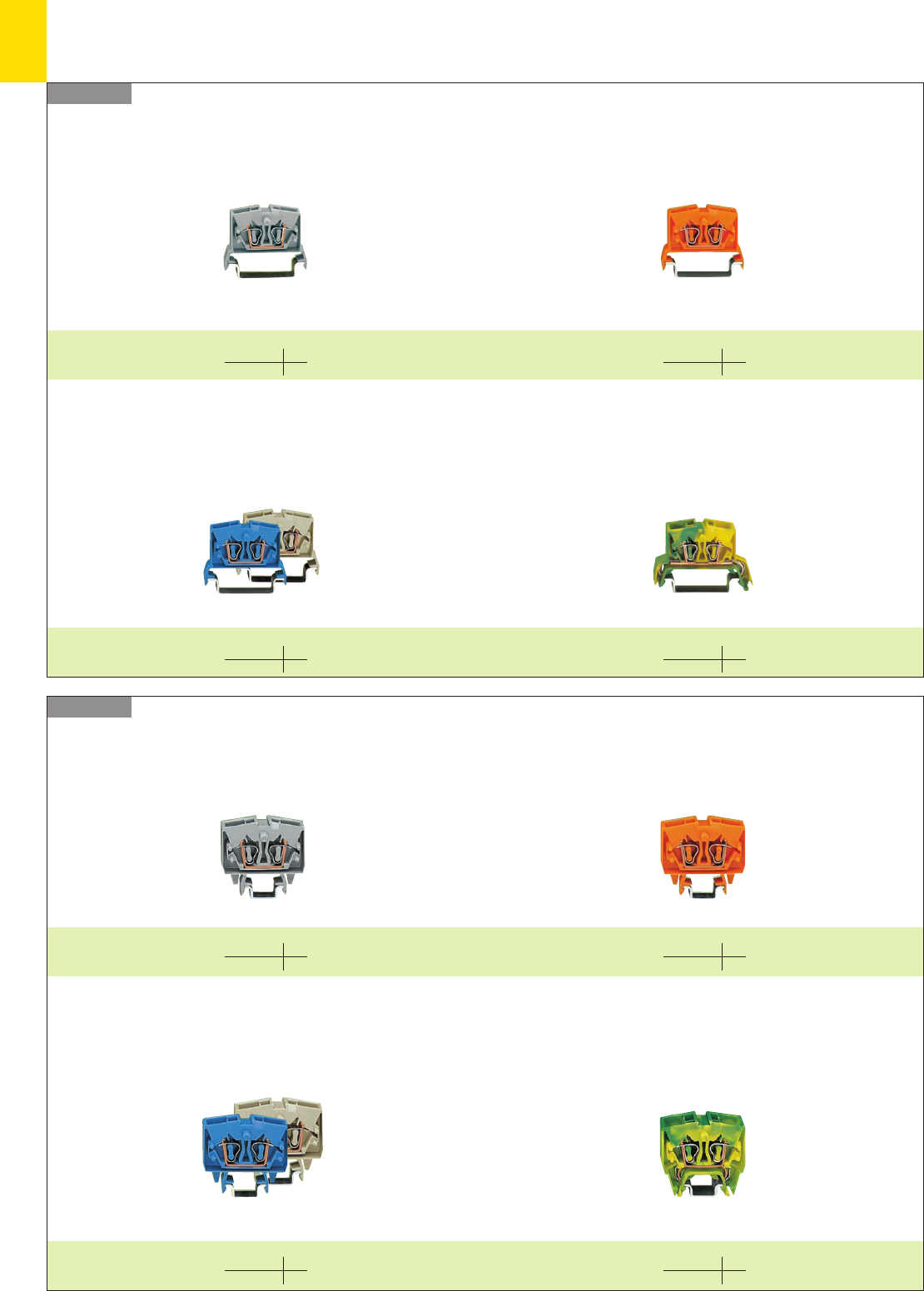
,
4
2
Miniature Rail-Mounted Terminal Blocks, Series 264
– Product Summary –
Series 264 Miniature through terminal blocks for DIN 35 rail
2- and 4-conductor terminal blocks 2- and 4-conductor terminal blocks
Miniature through terminal blocks for DIN 35 rail
for hazardous environments Ex i and Ex e II
2- and 4-conductor terminal blocks 4-conductor terminal block
Miniature ground (earth) conductor terminal blocks
for DIN 35 rail
Series 264 Miniature through terminal blocks for DIN 15 rail
Miniature through terminal blocks for DIN 15 rail
for hazardous environments Ex i and Ex e II Miniature ground (earth) conductor terminal blocks
for DIN 15 rail
2- and 4-conductor terminal blocks 2- and 4-conductor terminal blocks
2- and 4-conductor terminal blocks
mm2/AWG 2.5
Page 4.4
mm2/AWG 2.5
Page 4.4
mm2/AWG 2.5
Page 4.4
mm2/AWG 2.5
Page 4.4
mm2/AWG 2.5
Page 4.5
mm2/AWG 2.5
Page 4.5
mm2/AWG 2.5
Page 4.5
mm2/AWG 2.5
Page 4.5
2- and 4-conductor terminal blocks
4-conductor terminal block
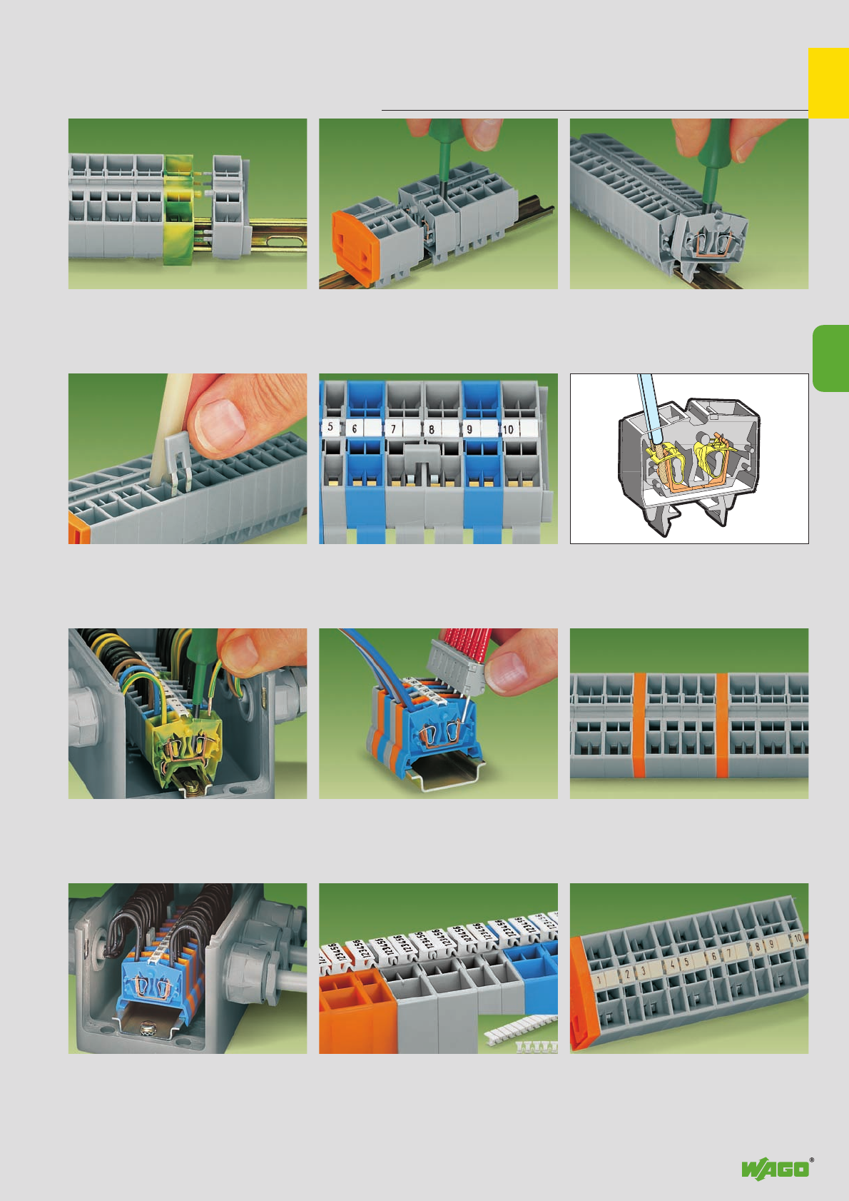
,
4
3
4
. . . and remove from the carrier rail
Commoning
Commoning with comb type jumper bar
Testing
Testing by quick contact to
the CAGE CLAMP®spring (limited to 0.5 A max.)
Easy handling with minimum space in small
enclosures Marking with T marker tag
Miniature Rail-Mounted Terminal Blocks with CAGE CLAMP®
for DIN 15 and DIN 35 Rails, Series 264 – Description and Handling
Assembly Removal
Commoning
Commoning with comb type jumper bar
CAGE CLAMP®connection
Connection of conductors
CAGE CLAMP®
clamps the following
copper wires: *
solid stranded
fine stranded,
also with tinned
single strands
Application T marker tag
Mixing of 2- and 4-conductor terminal blocks.
Marking with miniature WSB quick marking system
Mixing/Marking
Quick assembly keys prevent reverse mounting Separate terminal strip and slide individual
terminal block laterally . . .
* For aluminum wire see notes in section 15!
Indication of groups by use of intermediate plates
Group formation
fine-stranded wire –
tip bonded
fine-stranded wire
with crimped ferrule
fine-stranded wire
with crimped pin terminal
. . . and remove from the carrier rail
Commoning with comb type jumper bar
Testing by quick contact to
the CAGE CLAMP®spring (limited to 0.5 A max.)
Easy handling with minimum space in small
enclosures Marking with T marker tag
Commoning with comb type jumper bar
Connection of conductors
CAGE CLAMP®
clamps the following
copper wires: *
solid stranded
fine stranded,
also with tinned
single strands
Mixing of 2- and 4-conductor terminal blocks.
Marking with miniature WSB quick marking system
Mixing/Marking
Quick assembly keys prevent reverse mounting Separate terminal strip and slide individual
terminal block laterally . . .
* For aluminum wire see notes in section 15!
Indication of groups by use of intermediate plates
Group formation
fine-stranded wire –
tip bonded
fine-stranded wire
with crimped ferrule
fine-stranded wire
with crimped pin terminal
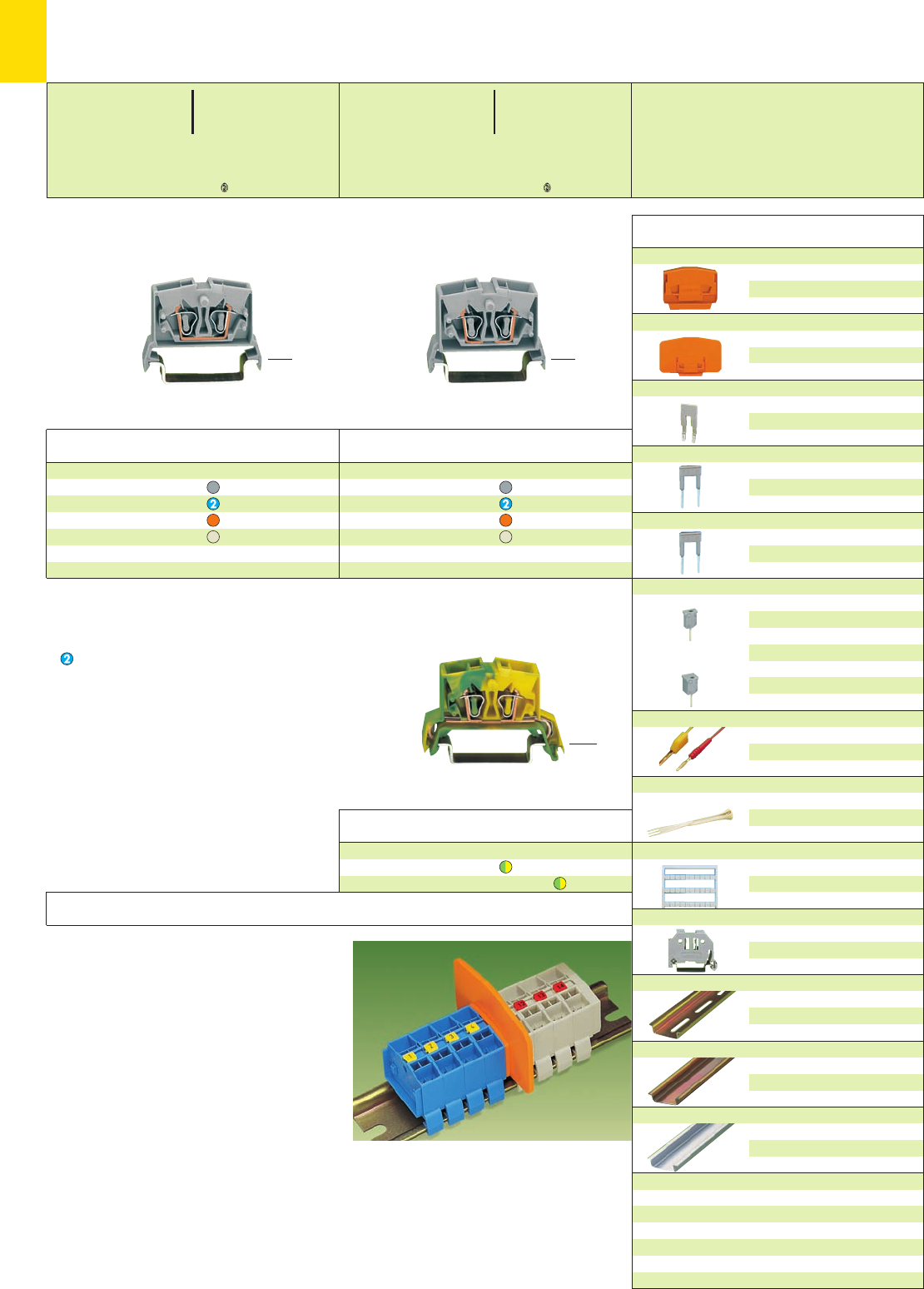
4
4
*UQKfSDaJq:;{[ .4
*U2QsKfDJ:;{ .4
4-conductor ground (earth) term. bl., for DIN 35 rail
green-yellow 264-737 100
green-yellow 4264-737/999-950 100
Item Pack. unit
No. pcs
4-conductor through terminal blocks, for DIN 35 rail
grey 264-731 100
blue 264-734 100
orange 264-736 100
light grey 4264-225 100
2-conductor through terminal blocks, for DIN 35 rail
grey 264-711 100
blue 264-714 100
orange 264-716 100
light grey 4264-125 100
Item Pack. unit
No. pcs
Item Pack. unit
No. pcs
➊800 V = rated voltage
8 kV = rated surge voltage
3 = pollution degree
(see also section 15)
Suitable for Ex i applications
4Suitable for Ex e II applications
0.5 – 2.5 mm2AWG 20 – 12
750 V, 23 A
(see also section 13)
➌Test current in case of touch contacting 0.5 A max.,
6 A if the test pins are firmly connected in the
clamping units.
Max. test voltage 400 V/800 V only in test equip-
ment, respecting relevant air and creepage
distances. In case of touch contacting the max. test
voltage must not exceed 48 V, test pins are not
touchproof.
➍For marking possibilities
see section 14.
Direct printing of assemblies
contact factory.
End and intermediate plate, 4 mm /0.157 in thick
orange 264-369 25
grey 264-368 25
light grey 264-370 25
Separator for Ex e/Ex i applications,
4 mm/0.157 in thick
66 mm/2.598 in wide
orange 264-367 25
Comb type jumper bar,insulated, IN16 A, grey
2-way 264-402 200 (8 x 25)
reduce wire
to 1.5 mm2/AWG 16 max.
Alternate comb type jumper bar, insulated,
IN= INof terminal block
for 2-conductor terminal blocks
2-way 281-492 100 (4 x 25)
Alternate comb type jumper bar, insulated,
IN= INof terminal block
for 4-conductor terminal blocks
2-way 280-492 200 (8 x 25)
Test plug modul, modular, see also page 10.15
test current 0.5 A /6 A ➌
for 2-conductor terminal blocks
6 mm wide
249-136 100 (4 x 25)
test voltage 400 V/48 V ➌
for 4-conductor terminal blocks
10 mm wide
249-139 100 (4 x 25)
test voltage 800 V/48 V ➌
Test plug,
with
cable 500 mm/1’7.7’’
2 mm Ø, red
210-136 50 (5 x 10)
2,3 mm Ø, yel.
210-137 50 (5 x 10)
Operating tool, insulated,
for comp type jumper bar
2-way 280-432 1
Miniature WSB quick marking card,
10 strips with 10 markers each,
white with black printing
see section 14
Screwless end stop, for DIN 35 rail
6 mm wide
249-116 100 (4 x 25)
10 mm wide
249-117 50 (2 x 25)
Carrier rail DIN 35, 35 x 7.5 mm/1.38 x 0.30 in, 1 mm /0.039 in
thick, acc. to DIN EN 60715, steel, zinc
plated a. yellow chromated, 2 m /6’6’’ long
slotted 210-112 10
Carrier rail DIN 35, 35 x 7.5 mm/1.38 x 0.30 in, 1 mm /0.039 in
thick, acc. to DIN EN 60715, steel, zinc
plated a. yellow chromated, 2 m /6’6’’ long
unslotted 210-113 10
Carrier rail DIN 35, 35 x 7.5 mm/1.38 x 0.30 in, 1.5 mm /0.059 in
thick, acc. to DIN EN 60715, aluminum
2 m /6’6’’ long
unslotted 210-196 10
Item Pack. unit
No. pcs
<_____ 46.5 mm /1.83 in _____>
Miniature Through/Ground (Earth) Conductor and
4Terminal Blocks 2.5 mm2/AWG 12 for DIN 35 Rail,
Series 264
<____ 38 mm /1.5 in ____><____ 38 mm /1.5 in ____>
* For further approvals with corresponding ratings see section 15.
Accessories series 264 for DIN 35 rail
Application notes
Separator for Ex e/Ex i applications
for miniature terminal blocks
According to EN 50 020 a minimum distance of
50 mm must be kept between live parts of Ex e
and Exi i circuits. When mounting Ex e and Ex i
rail-mounted terminal blocks together on the
same rail, offers a space saving solution to the
problem by using the new Ex e/Ex separators.
The separators are snapped onto the miniature
rail-mounted terminal blocks and therefore can-
not be removed independently from the carrier
rail.
<_ 24.5 mm / _>
0.96 in
<___ 24.5 mm /___>
0.96 in
0.08 – 2.5 mm2AWG 28 – 12
800 V/8 kV/3 ➊600 V, 20 A U
24 A 600 V, 20 A 2
Terminal block width 6 mm / 0.236 in
L8 – 9 mm / 0.33 in
2 x 0.08 – 2.5 mm22 x AWG 28 –12
800 V/8 kV/3 ➊600 V, 20 A U
24 A 600 V, 20 A 2
Terminal block width 10 mm / 0.394 in
L8 – 9 mm / 0.33 in
<___ 24.5 mm /___>
0.96 in
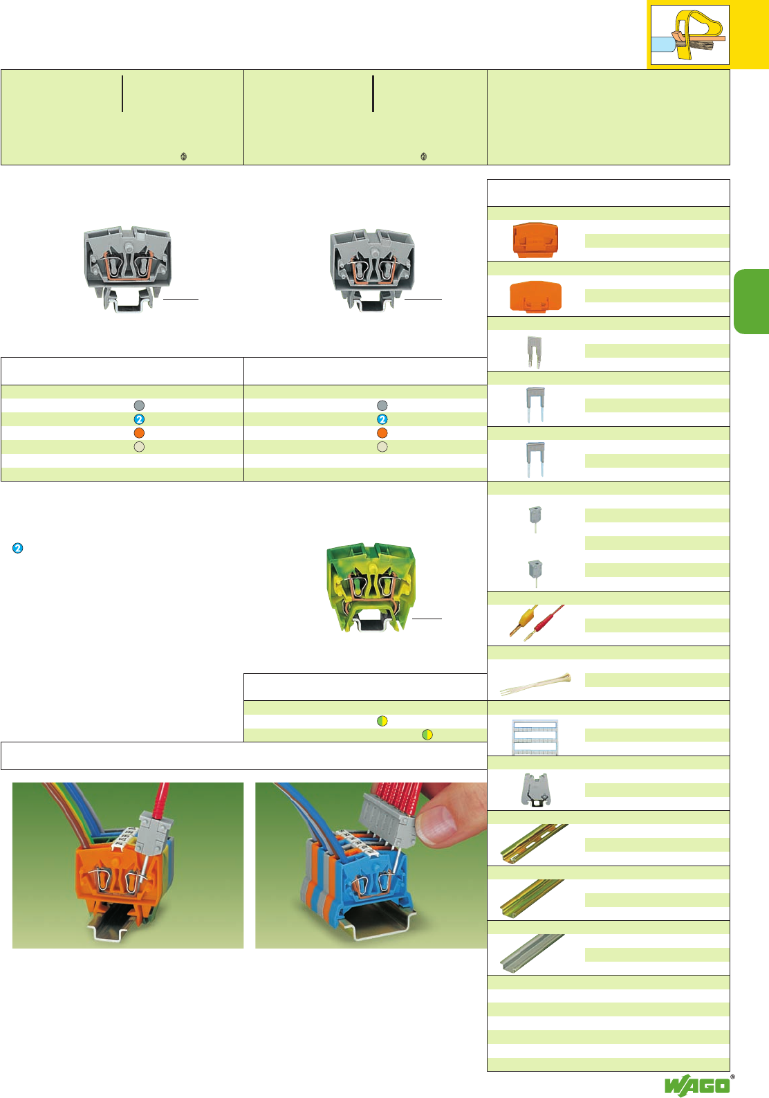
4
5
*UQKfNSDaJq:;{[ .-4 *U2QKfNSDJq:;{[ .4
4
Miniature Through/Ground (Earth) Conductor and
4Terminal Blocks 2.5 mm2/AWG 12 for DIN 15 Rail,
Series 264
4-conductor ground (earth) term. bl., for DIN 15 rail
green-yellow 264-727 100
green-yellow 4264-727/999-950 100
Item Pack. unit
No. pcs
4-conductor through terminal blocks, for DIN 15 rail
grey 264-721 100
blue 264-724 100
orange 264-726 100
light grey 4264-220 100
2-conductor through terminal blocks, for DIN 15 rail
grey 264-701 100
blue 264-704 100
orange 264-706 100
light grey 4264-120 100
Item Pack. unit
No. pcs
Item Pack. unit
No. pcs
End and intermediate plate, 4 mm /0.157 in thick
orange 264-369 25
grey 264-368 25
light grey 264-370 25
Separator for Ex e/Ex i applications,
4 mm/0.157 in thick
66 mm/2.598 in wide
orange 264-367 25
Comb type jumper bar,insulated, IN16 A, grey
2-way 264-402 200 (8 x 25)
reduce wire
to 1.5 mm2/AWG 16 max.
Alternate comb type jumper bar, insulated,
IN= INof terminal block
for 2-conductor terminal blocks
2-way 281-492 100 (4 x 25)
Alternate comb type jumper bar, insulated,
IN= INof terminal block
for 4-conductor terminal blocks
2-way 280-492 200 (8 x 25)
Test plug modul, modular, see also page 10.15
test current 0.5 A /6 A ➌
for 2-conductor terminal blocks
6 mm wide
249-136 100 (4 x 25)
test voltage 400 V/48 V ➌
for 4-conductor terminal blocks
10 mm wide
249-139 100 (4 x 25)
test voltage 800 V/48 V ➌
Test plug,
with
cable 500 mm/1’7.7’’
2 mm Ø, red
210-136 50 (5 x 10)
2,3 mm Ø, yel.
210-137 50 (5 x 10)
Operating tool, insulated,
for comp type jumper bar
2-way 280-432 1
Miniature WSB quick marking card,
10 strips with 10 markers each,
white with black printing
see section 14
Screwless end stop, for DIN 15 rail
6 mm wide 249-101 25
Carrier rail DIN 15, 15 x 5.5 mm/0.59 x 0.217 in, 1 mm /0.039 in
thick, acc. to DIN EN 60715, steel, zinc
plated a. yellow chromated, 2 m /6’6’’ long
slotted 210-111 1
Carrier rail DIN 15, 15 x 5.5 mm/0.59 x 0.217 in, 1 mm /0.039 in
thick, acc. to DIN EN 60715, steel, zinc
plated a. yellow chromated, 2 m /6’6’’ long
unslotted 210-295 1
Carrier rail DIN 15, 15 x 5.5 mm/0.59 x 0.217 in/ 1 mm /0.039 in
thick, acc. to DIN EN 60715, aluminum,
2 m /6’6’’ long
unslotted 210-296 1
Item Pack. unit
No. pcs
* For further approvals with corresponding ratings see section 15.
<__ 32 mm /1.26 in __><__ 32 mm /1.26 in __>
<__ 32 mm /1.26 in __>
Application notes
Accessories series 264 for DIN 15 rail
➊800 V = rated voltage
8 kV = rated surge voltage
3 = pollution degree
(see also section 15)
Suitable for Ex i applications
4Suitable for Ex e II applications
0.5 – 2.5 mm2AWG 20 – 12
750 V, 23 A
(see also section 13)
➌Test current in case of touch contacting 0.5 A max.,
6 A if the test pins are firmly connected in the
clamping units.
Max. test voltage 400 V/800 V only in test equip-
ment, respecting relevant air and creepage
distances. In case of touch contacting the max. test
voltage must not exceed 48 V, test pins are not
touchproof.
➍For marking possibilities
see section 14.
Direct printing of assemblies
contact factory.
Testing with touch contact at the CAGE CLAMP®
connection made of spring steel –
limited to a current of 0.5 A max.
Testing using CAGE CLAMP®connection on the current
bar – max. nominal current 6 A.
The CAGE CLAMP®clamps individual test contacts.
<__ 24.5 mm /__>
0.96 in
<_ 24.5 mm /_>
0.96 in
0.08 – 2.5 mm2AWG 28 – 12
800 V/8 kV/3 ➊600 V, 20 A U
24 A 600 V, 20 A 2
Terminal block width 6 mm / 0.236 in
L8 – 9 mm / 0.33 in
2 x 0.08 – 2.5 mm22 x AWG 28 –12
800 V/8 kV/3 ➊600 V, 20 A U
24 A 600 V, 20 A 2
Terminal block width 10 mm / 0.394 in
L8 – 9 mm / 0.33 in
<__ 24.5 mm / __>
0.96 in

5
5
VOLUME 1
topJob®Rail-Mounted Terminal Blocks
Through terminal blocks
0.08 mm2to 35 mm2/ AWG 28 – 2 Series 780 – 785
Ground (earth) conductor terminal blocks
0.08 mm2to 35 mm2/ AWG 28 – 2 Series 780 – 785
Shield (screen) terminal blocks
0.08 mm2to 2,5 mm2/ AWG 28 – 12 Series 780
see Full Line Catalog W4, Volume 1, Section 5 (German version)
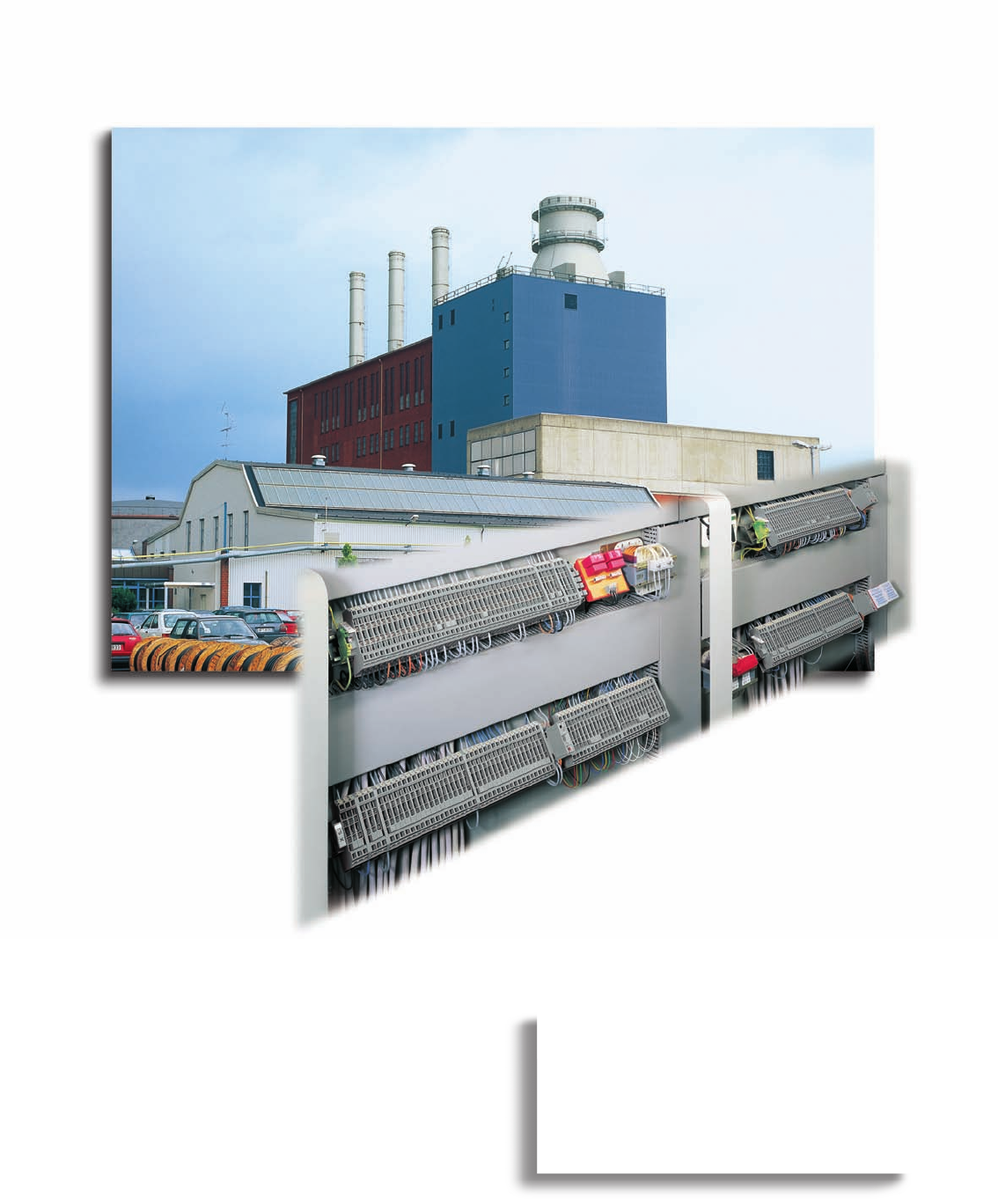
For more than 20 years, the
WAGO rail-mounted side-entry terminal blocks
(as well as WAGO disconnect terminal blocks
for test and measurement) with
CAGE CLAMP®connection technology, have
been providing safe connections.

6
6
VOLUME 1
Rail-Mounted Terminal Blocks (Side-Entry)
Through terminal blocks and ground (earth) conductor terminal blocks
0.08 mm2to 16 mm2/ AWG 28 – 6 Series 279 – 283 6.6 – 6.7
High current terminal blocks
25 mm2– 95 mm2/ AWG 4 – 000 Series 285 2.22 – 2.24
Accessories
– Busbar terminal blocks 11.20 – 11.21
– Comb type jumper bars 2.44
– Insulations stops 2.43
– Wire jumpers 2.45
– Test plug modules 2.38 – 2.41
– Step-down jumpers for through terminal blocks 6.3
– Staggered jumpers 2.45
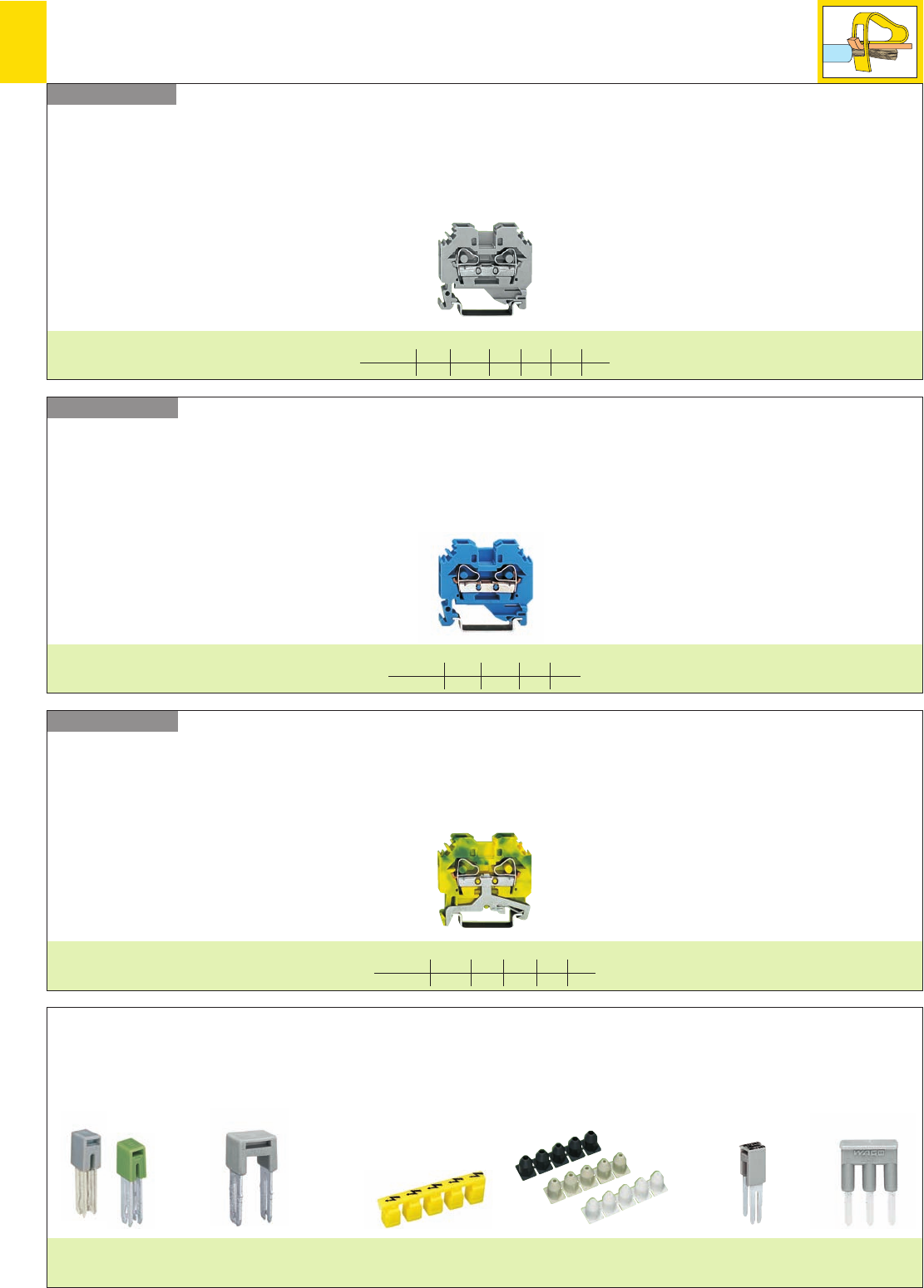
,
6
2
Series 279 – 282
Series 279 – 284
Series 279 – 284
Rail-Mounted Terminal Blocks
– Product Summary –
Through terminal blocks
Ground (earth) conductor terminal blocks
Ex i through terminal blocks
2-conductor terminal blocks
mm2/AWG 1.5/16 2.5/12 4/12 6/10 10/8 16/6
Page 6. 6 6 6 7 7 7
2-conductor terminal blocks
mm2/AWG 1.5/16 2.5/12 4/12 6/10
Page 6. 6 6 6 7
2-conductor terminal blocks
mm2/AWG 2.5/12 4/12 6/10 10/8 16/6
Page 6. 6 6 7 7 7
Adjacent jumpers
Page 6.6
Alternate jumper
Page 6.6
Step-down jumper
Page 6.3
Comb type jumper bar
Page 2.44
Protective warning marker
Page 6.6
Insulation stops
Page 2.43
Accessories (selection)
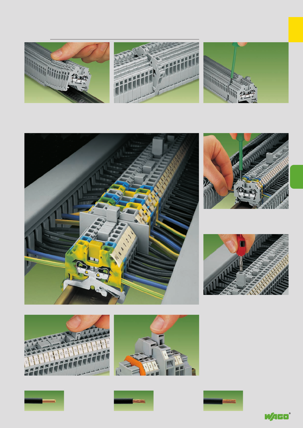
,
6
3
6
Rail-Mounted Terminal Blocks with CAGE CLAMP®Continued ➦
Series 279 to 283
Assembly
Snapping rail-mounted terminal blocks with
side-entry wiring onto the carrier rail
Removal
Removal from the carrier rail
CAGE CLAMP®connection
Connection of wires
Testing
Testing with test plug adapter
CAGE CLAMP®
clamps the following
copper wires: *
solid stranded
fine stranded,
also with tinned
single strands
Commoning
Commoning with adjacent jumpers. Push jumper
down FIRMLY until FULLY inserted! Commoning of side-entry rail-mounted terminal
blocks with step-down jumpers
Commoning with step-down jumpers
Quick assembly keys prevent reverse mounting
* For aluminum wire see notes in section 15!
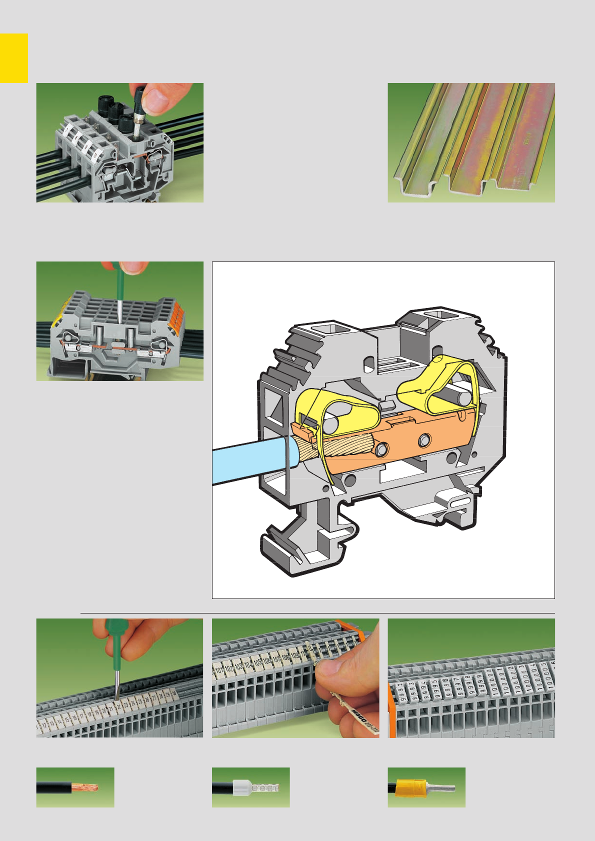
6
4
Rail-Mounted Terminal Blocks with CAGE CLAMP®
Series 279 to 283
Fuse terminal blocks
Suitable for all carrier rails DIN 35Replacing a fuse
Shifting the disconnect slide link
Disconnect terminal blocks
for test purposes
CAGE CLAMP®
clamps the following
copper wires:
fine-stranded wire –
tip bonded
fine-stranded wire
with crimped ferrule ➊fine-stranded wire
with crimped pin terminal
Marking
Marking with WMB Multi marking system or WSB
Quick marking system Marking with marker branches Marking with marker carriers and marker tags
➊When using conductors with ferrules, it is necessary to use a terminal block one size larger than the nominal cross section of the conductor
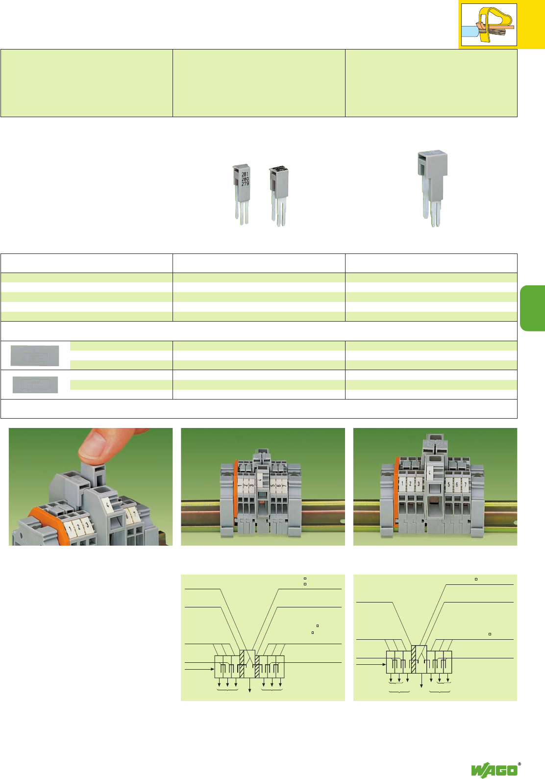
6
6
5
123A11 12 13
Side-entry terminal blocks and front-entry terminal
blocks cannot be commoned with step-down jumpers.
Commoning front-entry terminal blocks with step-down
jumpers see pages 2.26 – 2.27.
Accessories
Commoning of rail-mounted terminal blocks 6 mm2/
AWG 10 (series 282) with rail-mounted terminal blocks
1.5 mm2/AWG 16 (series 279).
Example of assembly “Commoning of side-entry rail-
mounted terminal blocks 10/6 mm2/AWG 8/10 with
side-entry rail-mounted terminal blocks 4/2.5/1.5 mm2/
AWG 12/14/16 with step-down jumper 284-414.”
➊ Commoning of side-entry rail-mounted terminal blocks 10 mm2/AWG 8, item no. 284-101, with 2.5 mm2/
AWG 14, item no. 280-101, or with 1.5 mm2/AWG 16, item no. 279-101, in direction of rear side is not possible
(see example: terminal block A with terminal block 11).
Example of assembly “Commoning of rail-mounted
terminal blocks 16 mm2/AWG 6 with rail-mounted
terminal blocks 4 mm2/AWG 12 with step-down jumper
283-414.”
Step-down jumpers may be used for commoning
terminal blocks ➊of different sizes, without losing
a conductor clamping point. This can be an
advantage on long conductor runs where voltage
drop can be a problem. A large conductor can
be easily connected to smaller wires at the distri-
bution point.
Step-down jumpers are simply pushed down to
full insertion, in the same way as all other push-in
jumpers. Commoning may be made in either
direction using the special thin end plate to cover
the open side. Further terminal blocks of the
smaller cross section may be commoned using
standard adjacent jumpers. In this case pay
attention that:
1. the total current flowing does not exceed
the rating of the step-down jumper
2. the standard or special thin end plate is
applied to the open side of the larger block.
Commoning of rail-mounted terminal blocks 16 mm2/
AWG 6 (series 283) with rail-mounted terminal blocks
4 mm2/AWG 12 (series 281).
Item Pack. unit
No. pcs Item Pack. unit
No. pcs
Application notes
Description
1 mm /0.039 in thick
grey 284-333 100 (4 x 25)
orange 284-343 100 (4 x 25)
1 mm /0.039 in thick
grey 281-333 100 (4 x 25)
orange 281-336 100 (4 x 25)
1 mm /0.039 in thick
grey 283-333 100 (4 x 25)
orange 283-335 100 (4 x 25)
Cover plate
Intermediate plate, for
terminal blocks 4/2.5/1.5 mm2/
AWG 12/14/16 only
Step-down jumper, insulated 10/6 mm2/AWG 8/10 →
4/2.5/1.5 mm2/AWG 12/14/16
IN15 A, grey 284-414 50 (2 x 25)
10/6 mm2/AWG 8/10 →6/4 mm2/ AWG 10/12
IN30 A, grey 284-413 50 (2 x 25)
16 mm2/AWG 6 →4 mm2/AWG 12
IN32 A, grey 283-414 50 (2 x 25)
Step-Down Jumpers
for Through Terminal Blocks, Side-Entry
Step-down jumpers f. commoning term. bl.
10/6 mm2/AWG 8/10 →
4/2.5/1.5 mm2/AWG 12/14/16
800 V/8 kV/3; 15 A or
10/6 mm2/AWG 8/10 →
6/4 mm2/AWG 10/12
800 V/8 kV/3; 30 A
Step-down jumper
for commoning terminal blocks
16 mm2/AWG 6 →4 mm2/AWG 12
800 V/8 kV/3
32 A
Step-down-jumper
284-414 or 284-413 Term. block 10 57A: 284-101
or 6 41A: 282-101
Intermediate plate
281-333
Term. block 4 : 281-101
or 2.5 : 280-101
➊
or 1.5: 279-101
➊
Adjacent jumper
279-402
280-402
281-402
Cover plate
284-333
same as right
same as
right
Here open
term. block
side
∑I ≤INadjac. jumper ∑I ≤INadjac. jumper
Term. block 16 76 A: 283-101
Step-down jumper
283-414
Term. block 4 : 281-101
Adjacent jumper
281-402
Cover plate
283-333
same as right
same as
right
Here open
term. block
side
∑I ≤24 A ∑I ≤24 A
∑I ≤32 A ∑I ≤32 A
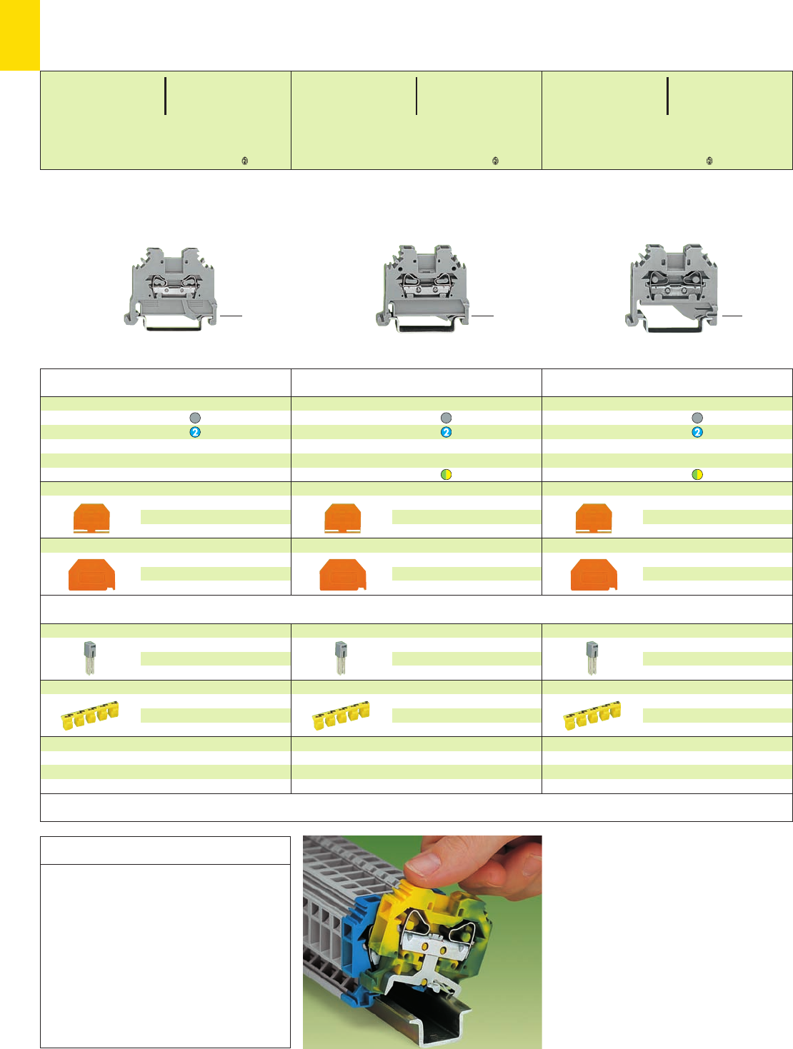
6
6
*U2KfNSD8aJ|q:;{[ . *U2KfND8aJ|9q:;{[ . *U2KND8aJ9q:;{[
End and intermediate plate, 2.5 mm/0.098 in thick
orange 280-302 100 (4 x 25)
grey 280-301 100 (4 x 25)
Separator,oversized, 2 mm /0.079 in thick
orange 280-322 100 (4 x 25)
grey 280-332 100 (4 x 25)
2-conductor through terminal blocks
grey 281-101 100
blue 281-104 100
2-conductor ground (earth) terminal block
green-yellow 281-107 100
2-conductor through terminal blocks
grey 280-101 100
blue 280-104 100
2-conductor ground (earth) terminal block
green-yellow 280-107 100
Item Pack. unit
No. pcs
Through and Ground (Earth) Conductor Terminal Blocks
1.5 mm2to 16 mm2/ AWG 16 – 6,
Series 279 bis 283
* For further approvals with corresponding ratings see section 15.
End and intermediate plate, 2.5 mm/0.098 in thick
orange 280-302 100 (4 x 25)
grey 280-301 100 (4 x 25)
Separator,oversized, 2 mm /0.079 in thick
orange 280-322 100 (4 x 25)
grey 280-332 100 (4 x 25)
End and intermediate plate, 3 mm/0.118 in thick
orange 281-302 100 (4 x 25)
grey 281-301 100 (4 x 25)
Separator,oversized, 2 mm /0.079 in thick
orange 281-322 100 (4 x 25)
grey 281-332 100 (4 x 25)
2-conductor through terminal blocks
grey 279-101 100
blue 279-104 100
<_ 42.5 mm /1.67 in _> <_ 42.5 mm /1.67 in _> <_ 42.5 mm /1.67 in _>
Carrier rail Item- Current ➌acc. to
No. [A]
mm
2
/AWG Cu
DIN 35 x 7.5 (steel)
slotted 210-112 76 16/6
unslotted 210-113 76 16/6
DIN 35 x 15 (steel)
1.5 mm/
0.059 in thick 210-114 125 35/2
2.3 mm/
0.091 in thick 210-118 125 35/2
DIN 35 x 7.5 (Alu)
unslotted 210-196 76 16/6
DIN 35 x 15 (Cu) 2.3 mm/
0.091 in thick 210-198 309 150/6/0
➌ applies to rails of 1m/3’3” length
Ground (earth) conductor terminal blocks snap
onto the rail like through terminals, but
automatically make a direct electrical connection
on the rail.
Sliding on the rail is not then possible.
When mounting on the rail, ensure that
open sides of terminal blocks face in the
same direction.
Visual control is possible, that all screwdriver
removal slots are on the same side.
If it is required to use standard carrier rails as
ground (earth) conductor busbars, please refer to
the maximum current capacities listed above.
Assembly on the carrier rail
Application notes
Adjacent jumper, insulated, IN15 A
grey 279-402 200 (8 x 25)
yell.-green 279-422 200 (8x 25)
Protective warning marker, for 5 terminal blocks,
fits into screwdriver slot
yellow 279-415 100 (4 x 25)
Accessories series 279
see page 2.9
Adjacent jumper, insulated,I
N24 A
grey 280-402 200 (8 x 25)
yell.-green 280-422 200 (8x 25)
Protective warning marker, for 5 terminal blocks,
fits into screwdriver slot
yellow 280-405 100 (4 x 25)
Accessories series 280
see page 2.13
Adjacent jumper, insulated,I
N32 A
grey 281-402 200 (8 x 25)
yell.-green 281-422 200 (8x 25)
Protective warning marker, for 5 terminal blocks,
fits into screwdriver slot
yellow 281-405 100 (4 x 25)
Accessories series 281
see page 2.17
Item Pack. unit
No. pcs
Item Pack. unit
No. pcs
Accessories Appropriate marking system WMB/WSB (see section 14)
0.08 – 1.5 mm2AWG 28 – 16
800 V/8 kV/3 ➊600 V, 10 A U
18 A 600 V, 10 A 2
Terminal block width 4 mm / 0.157 in
L8 – 9 mm / 0.33 in
0.08 – 2.5 mm2AWG 28 – 12
800 V/8 kV/3 ➊600 V, 20 A U
24 A 600 V, 20 A 2
Terminal block width 5 mm / 0.197 in
L8 – 9 mm / 0.33 in
0.08 – 4 mm2AWG 28 – 12
800 V/8 kV/3 ➊600 V, 20 A U
32 A 600 V, 25 A 2
Terminal block width 6 mm / 0.236 in
L9 – 10 mm / 0.37 in
<_ 30.5 mm /_>
1.2 in
<_ 30.5 mm /_>
1.2 in
<_ 32.5 mm /__>
1.28 in
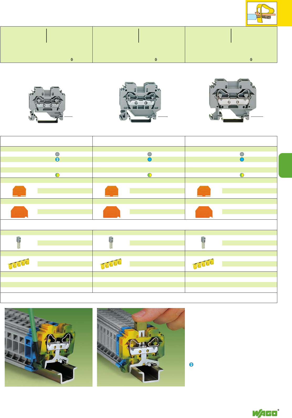
6
6
7
0.08 – 4 mm2
AWG 28 – 12
800 V/8 kV/3 ➊
600 V, 20 A U
32 A 600 V, 25 A 2
Terminal block width 6 mm / 0.236 in
*U2KfND8aJ9q:;{[ . *2KfND8aJ9q:;{[ .
*U2KfDaHJq:;{[ .
2-conductor through terminal blocks
grey 283-101 50
blue 283-104 50
2-conductor ground (earth) terminal block
green-yellow 283-107 50
2-conductor through terminal blocks
grey 284-101 50
blue 284-104 50
2-conductor ground (earth) terminal block
green-yellow 284-107 50
2-conductor through terminal blocks
grey 282-101 50
blue 282-104 50
2-conductor ground (earth) terminal block
green-yellow 282-107 50
Item Pack. unit
No. pcs
➊800 V = rated voltage
8 kV = rated surge voltage
3 = pollution degree
(see also section 15)
Suitable for Ex i applications
End and intermediate plate, 4 mm/0.157 in thick
orange 282-302 100 (4 x 25)
grey 282-301 100 (4 x 25)
Separator,oversized, 2 mm /0.079 in thick
orange 282-322 100 (4 x 25)
grey 282-332 100 (4 x 25)
End and intermediate plate, 4 mm/0.157 in thick
orange 283-302 50 (2 x 25)
grey 283-301 50 (2 x 25)
Separator,oversized, 2 mm /0.079 in thick
orange 283-322 50 (2 x 25)
grey 283-332 50 (2 x 25)
End and intermediate plate, 2.5 mm/0.098 in thick
orange 284-302 100 (4 x 25)
grey 284-301 100 (4 x 25)
Separator,oversized, 2 mm /0.079 in thick
orange 284-322 100 (4 x 25)
grey 284-332 100 (4 x 25)
<__ 46.5 mm /1.83 in __> <____ 52 mm /2.05 in ____> <______ 58 mm /2.28 in ______>
Commoning of ground (earth) conductor terminal
blocks with through terminal blocks is possible in
one direction only using adjacent jumpers. In
addition to the required marking of these termi-
nal blocks we recommend the use of the yellow-
green adjacent jumpers to indicate ground (earth)
connection.
According to EN 60947-7-2 [VDE 0611, part 3]
steel mounting rails may not be used for
ground/earth (PEN) applications.
Push jumper down FIRMLY until FULLY inserted!Removal from the carrier rail
Adjacent jumper, insulated, IN41 A
grey 282-402 100 (4 x 25)
yell.-green 282-422 100 (4x 25)
Protective warning marker, for 5 terminal blocks,
fits into screwdriver slot
yellow 282-405 100 (4 x 25)
Accessories series 282 see page 2.18
Step down jumper see page 6.5
Adjacent jumper, insulated,I
N57 A
grey 284-402 100 (4 x 25)
yell.-green 284-422 100 (4x 25)
Protective warning marker, for 5 terminal blocks,
fits into screwdriver slot
yellow 284-405 50 (2 x 25)
Accessories series 284 see page 2.19
Step down jumper see page 6.5
Adjacent jumper, insulated,I
N70 A
grey 283-402 50 (2 x 25)
yell.-green 283-422 50 (2x 25)
Protective warning marker, for 5 terminal blocks,
fits into screwdriver slot
yellow 283-405 50 (2 x 25)
Accessories series 283 see page 2.20
Step down jumper see page 6.5
Item Pack. unit
No. pcs Item Pack. unit
No. pcs
Appropriate marking system WMB/WSB (see section 14)
0.2 – 6 mm2AWG 24 – 10
800 V/8 kV/3 ➊600 V, 30 A U
41 A 600 V, 40 A 2
Terminal block width 8 mm / 0.315 in
L12 – 13 mm / 0.49 in
0.2 – 10 mm2AWG 24 – 8
800 V/8 kV/3 ➊600 V, 50 A U
57 A 600 V, 65 A 2
Terminal block width 10 mm / 0.394 in
L12 – 13 mm / 0.49 in
0.2 – 16 mm2AWG 24 – 6
800 V/8 kV/3 ➊600 V, 65 A U
76 A 600 V, 90 A 2
Terminal block width 12 mm / 0.472 in
L16 – 17 mm / 0.65 in
<37 mm /1.46 in >
<_ 41.5 mm /1.63 in _>
<_ 45.5 mm /1.79 in _>
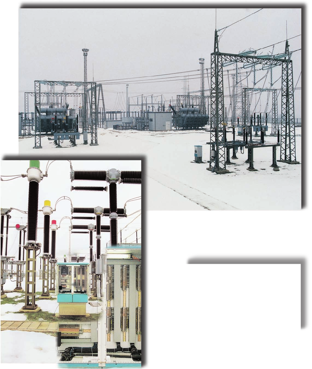
Withstanding heat and cold:
WAGO rail-mounted terminal blocks
up to 35 mm2/AWG 2 !
Disconnect terminal blocks for test and
measurement in current transformer circuits
and disconnect terminal blocks in outdoor
distribution cabinets of a power station
transformer substation.

7
7
VOLUME 1
Function Terminal Blocks
Disconnect terminal blocks for test and measurement
with knife disconnect Series 280 7.8 – 7.9
Disconnect terminal blocks for test and measurement
with disconnecting tab Series 280/281 7.10 – 7.12
Disconnect terminal blocks for test and measurement
of transformer circuits Series 282 7.18 – 7.19
Transverse switching terminal blocks and longitudinal
switching disconnect terminal blocks Series 282 7.20 – 7.21
Ground (earth) conductor
disconnect terminal blocks Series 282 7.23 / 7.27
Fused disconnect terminal blocks
with pivoting holder Series 281 7.28 – 7.33
Fuse plugs
for carrier terminal blocks Series 280/281 7.34 – 7.35
Fuse terminal blocks for
mini-automative blade-type fuses Series 282 7.24 – 7.25
Fuse terminal blocks (side-entry) Series 282 7.36 – 7.37
Technical details fuse terminal blocks and pluggable fuse modules 7.38 – 7.39
Sensor and actuator terminal blocks Series 270 7.41 – 7.43
Sensor and actuator terminal blocks Series 280 7.46 – 7.55
Diode terminal blocks Series 279/280/281 7.56 – 7.58
LED terminal blocks Series 279/280 7.60 – 7.61
Double deck diode and LED terminal blocks Series 280/281 7.62 – 7.63
Double deck diode and LED terminal blocks Series 870 7.64 – 7.65
Pluggable modules -
diodes, LED and neon indicators Series 280 7.68 – 7.71
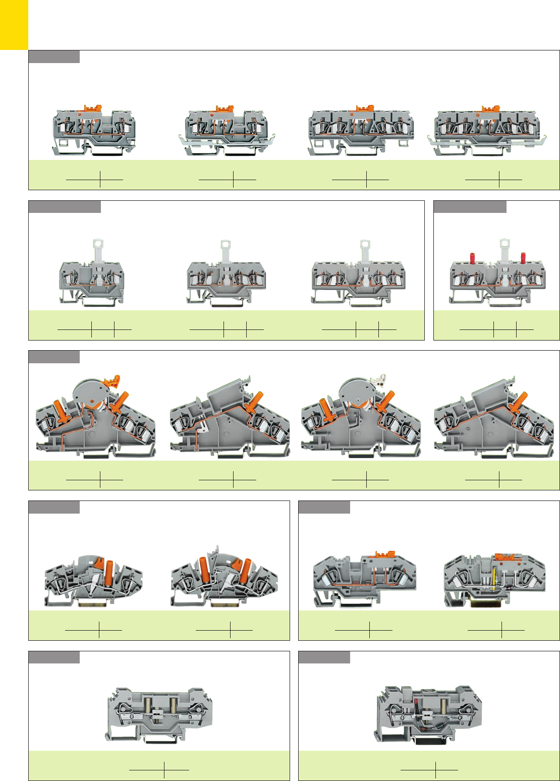
7
2
Series 282
Series 282
Series 280/281
Series 282
Series 282
Series 282
Series 280/281
Series 280
Function Terminal Blocks
Disconnect Terminal Blocks with CAGE CLAMP®Connection
– Product Summary –
Disconnect terminal blocks
Ground (earth) conductor
disconnect terminal blocks
2-conductor terminal blocks
Disconnect terminal blocks for test and measurment, with knife disconnect and integrated test slot
2-conductor terminal block 4-conductor terminal blockwith shield (screen) contact with shield (screen) contact
mm2/AWG 2.5/12
Page 7. 8
Disconnect terminal blocks with disconnect tab
3-conductor terminal blocks
mm2/AWG 2.5/12 4/12
Page 7. 10 - 11 12
2-conductor terminal blocks 4-conductor terminal blocks
Disconnect term. blocks for
test and measurment, with
disconnect
tab
2-conductor terminal blocks
Disconnect terminal blocks for test and measurement, through terminal blocks
for example for current transformator circuits for example for voltage transformator circuits
Transverse switching terminal blocks and
longitudinal switching
disconnect terminal blocks
2-conductor transverse switching 2-cond. longitudinal switching disconnect
Disconnect terminal blocks for test purposes
mm2/AWG 6/10
Page 7. 26 - 27
Ground (earth) conductor
disconnect terminal blocks
Ground (earth) conductor disconnect
mm2/AWG 2.5/12
Page 7. 8
mm2/AWG 2.5/12
Page 7. 9
mm2/AWG 2.5/12
Page 7. 9
mm2/AWG 2.5/12 4/12
Page 7. 10 - 11 12
mm2/AWG 2.5/12 4/12
Page 7. 10 - 11 12
mm2/AWG 2.5/12 4/12
Page 7. 10 - 11 12
mm2/AWG 6/10
Page 7. 18
mm2/AWG 6/10
Page 7. 18
mm2/AWG 6/10
Page 7. 19
mm2/AWG 6/10
Page 7. 19
mm2/AWG 6/10
Page 7. 21
mm2/AWG 6/10
Page 7. 21
mm2/AWG 6/10
Page 7. 22
mm2/AWG 6/10
Page 7. 23
terminal
blocks
terminal
blocks
terminal
blocks
mm2/AWG 6/10
Page 7. 27
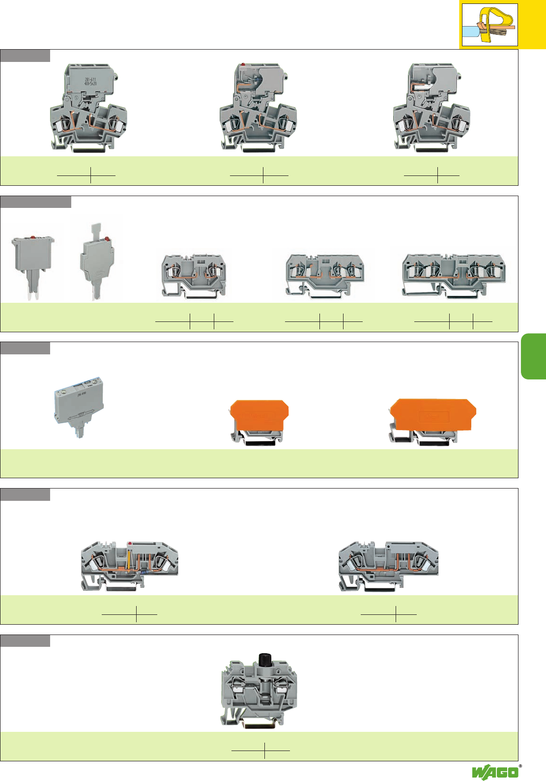
7
3
7
Series 282
Series 282
Series 286
Series 280/281
Series 281
Fuse Terminal Blocks with CAGE CLAMP®Connection
Fuse terminal blocks for mini-automotive blade-type fuses
with blown fuse indication without blown fuse indication
mm2/AWG 6/10
Page 7. 24
Fused disconnect terminal blocks with pivoting holder
without blown fuse indication
mm2/AWG 4/12
Page 7. 30/32
with blown fuse indication Disconnect terminal block
Fuse plugs for carrier terminal blocks
Pages 7.34 and 7.35
2-conductor terminal blocks 3-conductor terminal blocks 4-conductor terminal blocks
mm2/AWG 2.5/14 4/12
Page 7. 35 34
Fuse modules on carrier terminal blocks
see volume 3 “ELECTRONICC”
Carrier terminal block
with 2-conductor terminal blocks
see volume 3 “ELECTRONICC”
Carrier terminal block
with 4-conductor terminal blocks
see volume 3 “ELECTRONICC”
Fuse terminal blocks
mm2/AWG 6/10
Page 7. 36 - 37
mm2/AWG 4/12
Page 7. 30 - 33
mm2/AWG 4/12
Page 7. 31
mm2/AWG 2.5/14 4/12
Page 7. 35 34
mm2/AWG 2.5/14 4/12
Page 7. 35 34
mm2/AWG 6/10
Page 7. 25
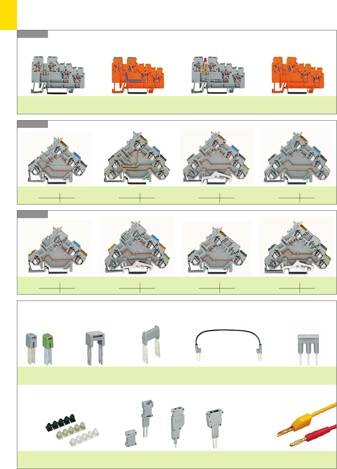
7
4
Series 270
Series 280
Series 280
Sensor/Actuator Terminal Blocks with CAGE CLAMP®Connection
Accessories (selection)
Adjacent jumpers Alternate jumper Staggered jumper
Page 2.45
Wire jumper
Page 2.45
Comb type jumper bar
Page 2.44
Insulation stops
Page 2.43
Modular test plug
Page 2.40
Test plugs
Page 7.8
Test plug module
Page 2.38
Test plug module
Page 2.39
Sensor/actuator terminal blocks
Actuator terminal blocks with/without LED
with ground (earth)/shield (screen) connection
Page 7.43
Sensor supply terminal blocks
with/without LED
Pages 7.41 – 7.42
Actuator supply terminal blocks
Page 7.43
Sensor terminal blocks with/without LED
and/or ground (earth)/shield (screen) connection
Pages 7.41 – 7.42
Sensor terminal blocks
for 3-conductor sensors for fuse plugs f. 3-conductor sensors w. ground (earth) connection for 4-conductor sensors
mm2/AWG 2.5/12
Page 7. 46 – 47
Actuator terminal blocks
e. g. for magnetic valves etc. e.g. for servomotors w. ground (earth) connection e. g. for pressure switches etc. e. g. for thermocouples etc.
mm2/AWG 2.5/12
Page 7. 46
mm2/AWG 2.5/12
Page 7. 48 – 49
mm2/AWG 2.5/12
Page 7. 49 – 50
mm2/AWG 2.5/12
Page 7. 54 - 55
mm2/AWG 2.5/12
Page 7. 54 - 55
mm2/AWG 2.5/12
Page 7. 52
mm2/AWG 2.5/12
Page 7. 52 - 53
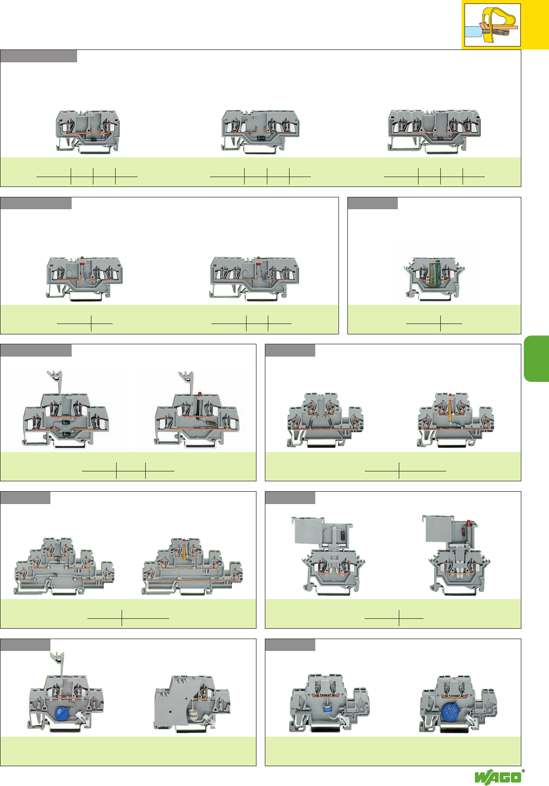
7
7
5
Series 870
Series 870
Series 280
Series 280
Series 870
Series 280/281
Series 279/280
Series 279 – 281
Rail-Mounted Terminal Blocks with Electronic Components
and CAGE CLAMP®Connection
mm2/AWG 1.5/16 2.5/14 4/12
Page 7. 56 57 58
Diode terminal blocks
LED terminal blocks
3-conductor terminal blocks 4-conductor terminal blocks
mm2/AWG 1.5/16
Page 7. 60
mm2/AWG 1.5/16 2.5/14
Page 7. 60 60 - 61
Variable resistor
terminal blocks
Double deck diode
and LED terminal blocks
mm2/AWG 2.5/14 4/12
Page 7. 62 – 63 62 – 63
Double deck diode
and LED terminal blocks
mm2/AWG 2.5/4 “f-st”/12
Page 7. 64 – 65
Triple deck diode
and LED terminal blocks
Terminal blocks with surge suppression
with gas filled surge arrester
see volume 3 “ELECTRONICC”
with varistor
see volume 3 “ELECTRONICC”
Terminal blocks with surge suppression
with varistor
see volume 3 “ELECTRONICC”
with gas filled surge arrester
see volume 3 “ELECTRONICC”
Series 280 Pluggable modules -
diodes, LED and neon indicators
mm2/AWG 2.5/14
Page 7. 68 - 71
2-conductor terminal blocks 3-conductor terminal blocks 4-conductor terminal blocks
mm2/AWG 1.5/16 2.5/14 4/12
Page 7. 56 57 58
mm2/AWG 1.5/16 2.5/14 4/12
Page 7. 56 57 58
mm2/AWG 1.5/16
Page 7. 61
mm2/AWG 2.5/4 “f-st”/12
Page 7. 66 – 67
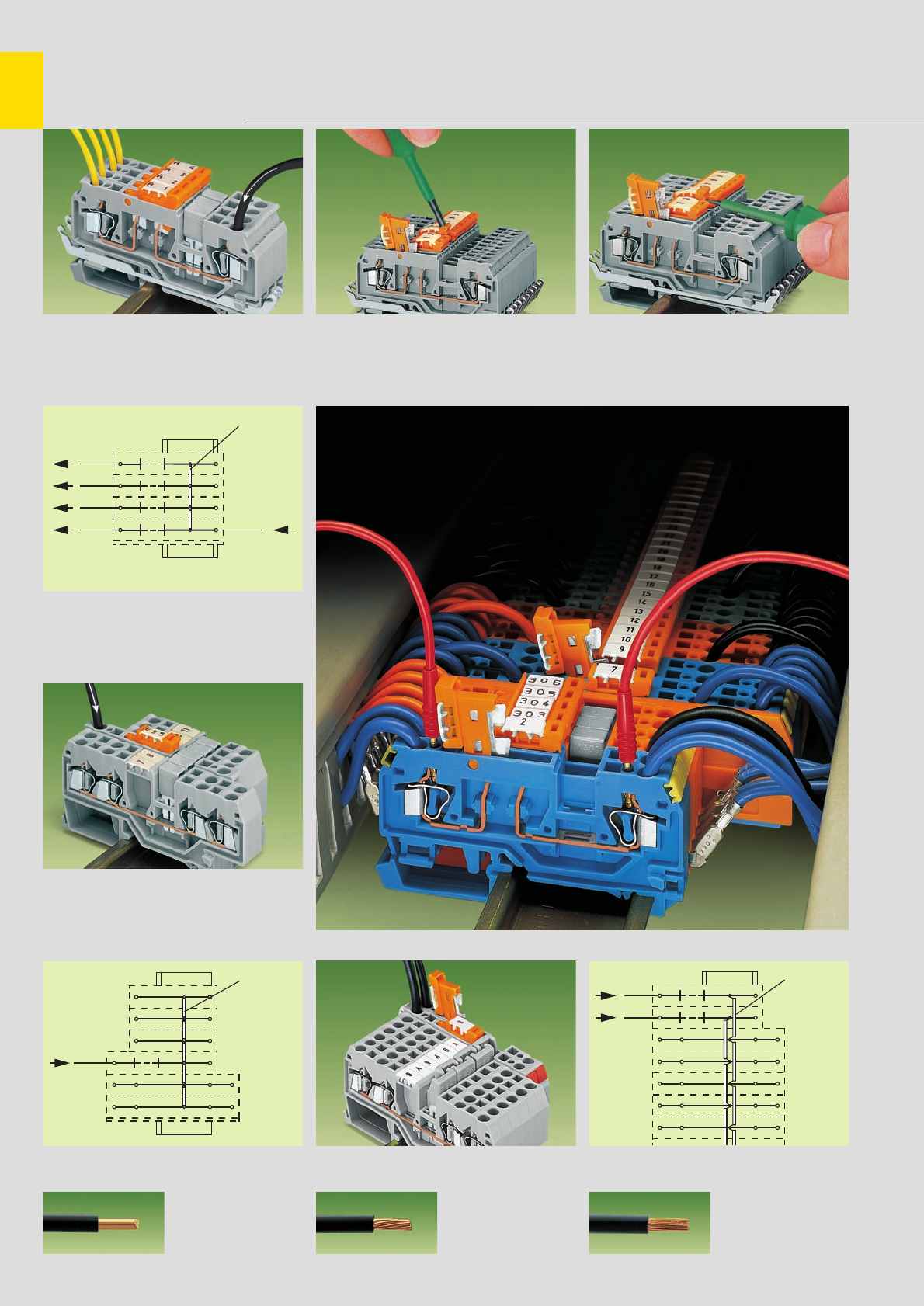
,
7
6
staggered
jumper
adjacent
jumper
adjacent
jumper
Disconnect Terminal Blocks for Test and Measurement with CAGE CLAMP
®
. . .
Series 280 and 281
. . . with knife disconnect
Power distribution using commoning jumpers.
Knife disconnect used to disconnect individual
outputs.
CAGE CLAMP®
clamps the following
copper wires: *
solid stranded
fine stranded,
also with tinned
single strands
Power distribution using knife disconnect in supply
line, disconnection of all outputs.
Staggered jumper for sophisticated wiring jobs. Push jumpers down FIRMLY until FULLY inserted.
Movable knife disconnect clearly
indicates the circuit state . . . . . . by defined, notched positions
“ON” <> “OFF”
* For aluminum wire see notes in section 15!
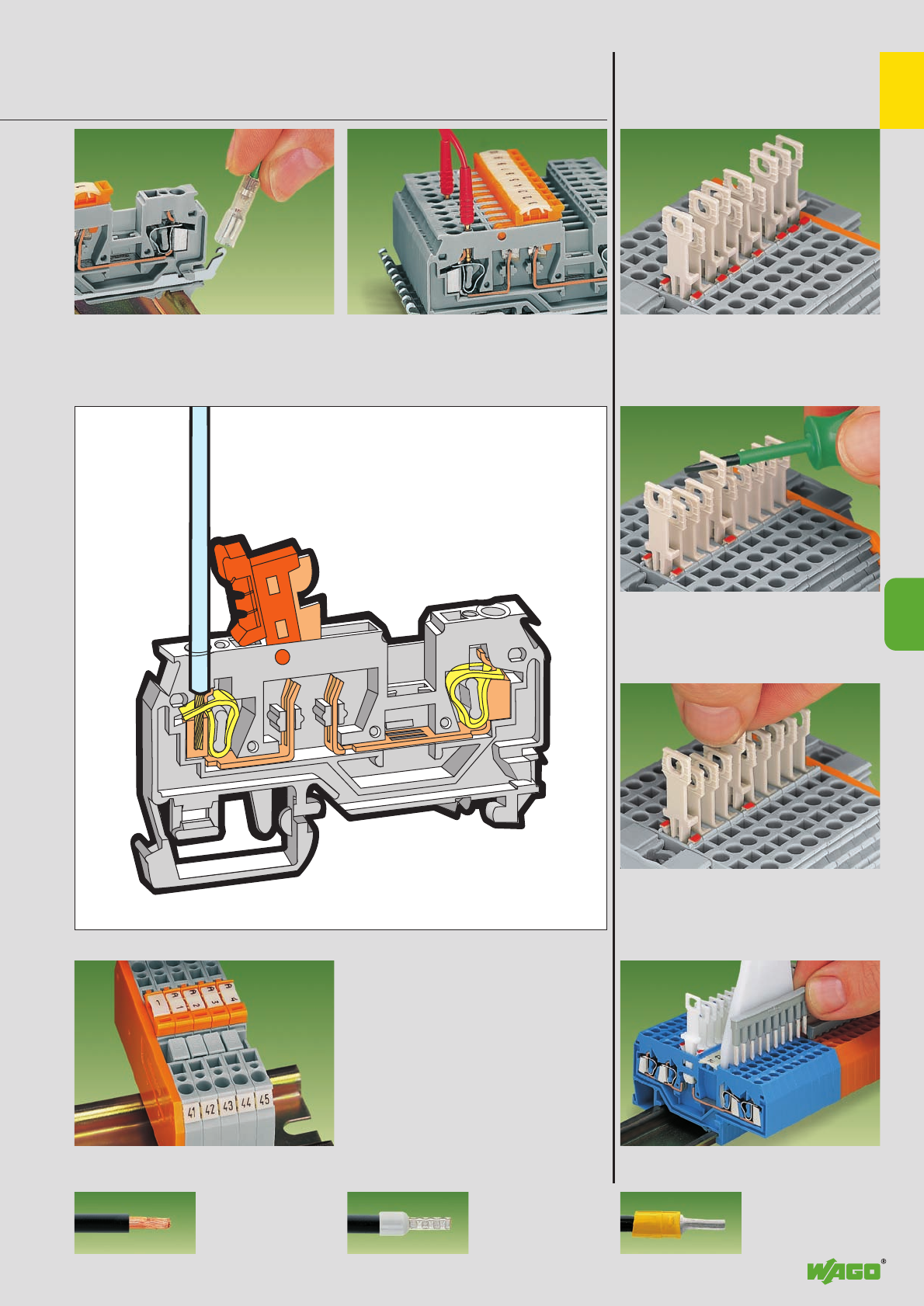
,
7
7
7
Commoning with comb type jumper bars
. . . Description and Handling
. . . with disconnect tab
Shield (screen) contact:
with solder/crimp quick disconnect terminal
(2.8 x 0.8) mm
Pulling the disconnect tab with screwdriver
Pulling the disconnect tab by hand
fine-stranded wire –
tip bonded
fine-stranded wire
with crimped ferrule ➊fine-stranded wire
with crimped pin terminal
Terminal bl. marking: with WSB Quick marking or
WCB Combi marking (center position) and Miniature
WSB (on the sides) – see also section 14 –.
Test slot: for test plug Ø 2 mm/0.079 in or
Ø 2.3 mm/0.091 in – with direct contact to
the current bar
Disconnect terminal block with colored tab to
indicate the switching condition
(red = disconnected)
Disconnect lock see page 7.13
➊When using wires with ferrules, it is necessary to use a terminal block one size larger than the nominal cross section of the wire.
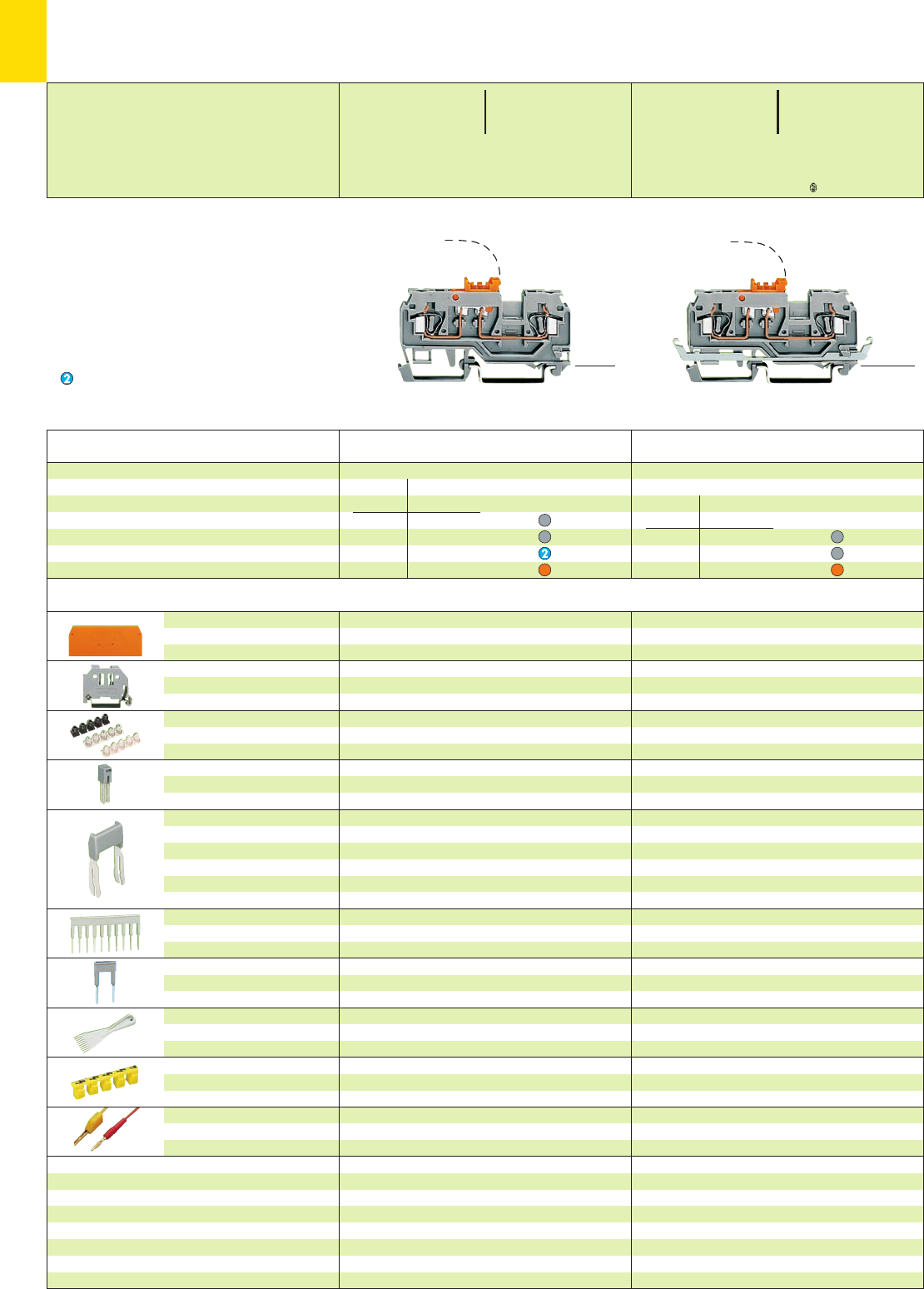
7
8
*U2KfaJq:;{[ *U2KfaJq:;[5
<_________ 69.5 mm /2.74 in __________>
<____________ 82 mm /3.23 in ____________>
<__ 45.5 mm /1.79 in __>
<__ 28.5 mm /__>
1.12 in
End and
intermediate plate
Screwless
end stop
Insulation stop ➌,white
5 pcs/strip light grey
dark grey
Adjacent jumper,
insulated
Staggered jumper ➌,from 1 to 2
insulated, from1 to 3
width 5 mm/0.197 in from1 to 4
from 1 to 5
:
from 1 to 8
Comb type jumper bar ➌,
insulated,
IN= INof terminal block
Alternate comb type
jumper bar ➌,
insulated, IN= INof terminal block
Operating tool,
insulated
Protective warning marker,
for 5 terminal blocks,
fits into screwdriver slot
Test plug, w. cable 500 mm/1’7.7”
2 mm /0.079 in Ø
2.3 mm /0.091 in Ø
2.5 mm /0.098 in thick
orange 280-371 100 (4 x 25)
grey 280-374 100 (4 x 25)
6 mm /0.236 in wide 249-116 100 (4 x 25)
10 mm /0.394 in wide 249-117 50 (2 x 25)
0.08 – 0.2 mm2280-470 200 strips
0.25 – 0.5 mm2280-471 200 strips
0.75 – 1 mm2280-472 200 strips
IN24 A
grey 280-402 200 (8 x 25)
yellow-green 280-422 200 (8 x 25)
IN24 A 780-452 100 (4 x 25)
780-453 100 (4 x 25)
780-454 100 (4 x 25)
780-455 50 (2 x 25)
:
780-458 50 (2 x 25)
2-way 280-482 200 (8 x 25)
3-way 280-483 200 (8 x 25)
10-way 280-490 50 (2 x 25)
2-way 280-492 200 (8 x 25)
2-way 280-432 1
3-way 280-433 1
10-way 280-440 1
yellow 280-415 100 (4 x 25)
red 210-136 50 (5 x 10)
yellow 210-137 50 (5 x 10)
Accessories Appropriate marking system
WMB/WSB or Miniature WSB
(see section 14)
2-cond. disc. term. blocks for test and measurem.
term. block knife
housing disconnect
grey orange 280-870 100
grey grey 280-868 100
blue orange 280-876 100
orange orange 280-879 100
2-conductor disconnect terminal blocks for test
and measurement with shield (screen) connection
term. block knife
housing disconnect
grey orange 280-871 50
grey grey 280-869 50
orange orange 280-880 50
Disconnect terminal block for test and
measurement with knife disconnect,
with test plug Ø 2 mm/0.079 in and
Ø 2.3 mm/0.091 in, for DIN 35 rail
<___ 46 mm /1.81 in ___>
<________ 69.5 mm /2.74 in ________>
Disconnect Terminal Blocks for Test and Measurement
with Knife Disconnect 2.5 mm2/ AWG 12,
Series 280
➊ 400/250 V = rated voltage
6/4 kV = rated surge voltage
3 = pollution degree
(see also section 15)
Suitable for Ex i applications
➌See application notes
on
pages
2.38 – 2.45
Description Item Pack. unit
No. pcs
Item Pack. unit
No. pcs
* For further approvals with corresponding ratings see section 15.
0.08 – 2.5 mm2AWG 28 – 12
400 V/6 kV/3 ➊600 V, 15 A U
16 A 300 V, 15 A 2
Terminal block width 5 mm / 0.197 in
L8 – 9 mm / 0.33 in
0.08 – 2.5 mm2AWG 28 – 12
250 V/4 kV/3 ➊600 V, 15 A U
16 A 300 V, 15 A 2
Terminal block width 5 mm / 0.197 in
L8 – 9 mm / 0.33 in
<__ 28.5 mm /__>
1.12 in
<__ 45.5 mm /1.79 in __>
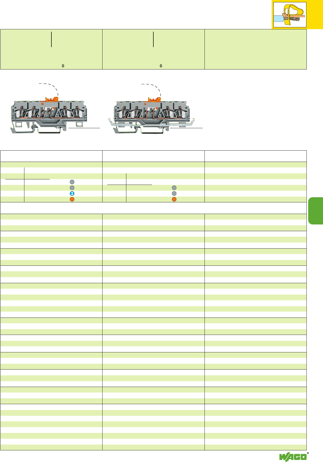
7
7
9
*U2KfaJq:;{[ *U2KfaJ:;{[
4-conductor disconnect terminal blocks for test
and measurement with shield (screen) connection
term. block knife
housing disconnect
grey orange 280-875 50
grey grey 280-882 50
orange orange 280-884 50
4-cond. disc. term. blocks for test and measurem.
term. block knife
housing disconnect
grey orange 280-874 50
grey grey 280-881 50
blue orange 280-885 50
orange orange 280-883 50
2.5 mm /0.098 in thick
orange 280-373 100 (4 x 25)
grey 280-376 100 (4 x 25)
6 mm /0.236 in wide 249-116 100 (4 x 25)
10 mm /0.394 in wide 249-117 50 (2 x 25)
0.08 – 0.2 mm2280-470 200 strips
0.25 – 0.5 mm2280-471 200 strips
0.75 – 1 mm2280-472 200 strips
2-way 280-482 200 (8 x 25)
3-way 280-483 200 (8 x 25)
10-way 280-490 50 (2 x 25)
2-way 280-492 200 (8 x 25)
2-way 280-432 1
3-way 280-433 1
10-way 280-440 1
yellow 280-415 100 (4 x 25)
red 210-136 50 (5 x 10)
yellow 210-137 50 (5 x 10)
Item Pack. unit
No. pcs
Item Pack. unit
No. pcs
<___ 45 mm /1. 77 in ___>
<_______________ 89 mm /3.5 in _______________><______________ 89 mm /3.5 in ______________>
<_________________ 101 mm /3.98 in _________________>
<__ 45.5 mm /1.79 in __>
<__ 28.5 mm /__>
1.12 in
<__ 45.5 mm /1.79 in __>
<__ 28.5 mm /__>
1.12 in
Appropriate marking system
WMB/WSB or Miniature WSB
(see section 14)
0.08 – 2.5 mm2AWG 28 – 12
400 V/6 kV/3 ➊600 V, 15 A U
16 A 300 V, 15 A 2
Terminal block width 5 mm / 0.197 in
L8 – 9 mm / 0.33 in
0.08 – 2.5 mm2AWG 28 – 12
250 V/4 kV/3 ➊600 V, 15 A U
16 A 300 V, 15 A 2
Terminal block width 5 mm / 0.197 in
L8 – 9 mm / 0.33 in
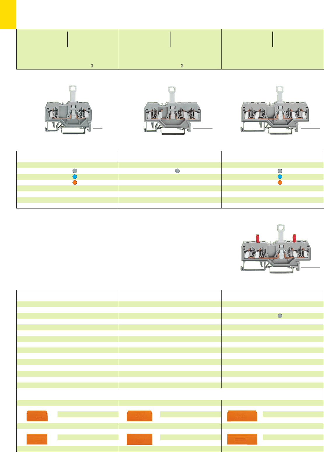
7
10
*U2KfNDaJq:;{[5 *U2KfaJq:;{[ *U2
(32 mm /1.26 in )
<_____ 53 mm /2.09 in _____>
<___ 46.5 mm /1.83 in ___>
<____ 52.5 mm /2.07 in ____>
(32 mm /1.26 in )
<________ 64 mm /2.52 in ________>
<___ 46.5 mm /1.83 in ___>
<____ 52.5 mm /2.07 in ____>
(___ 42.5 mm /1.67 in ___)
<____________ 75 mm /2.95 in ____________>
<___ 46.5 mm /1.83 in ___>
<____ 52.5 mm /2.07 in ____>
* For further approvals with corresponding ratings see section 15.
End and intermediate plate, 2.5 mm/0.098 in thick
orange 280-315 100 (4 x 25)
grey 280-314 100 (4 x 25)
light grey 280-352 100 (4 x 25)
Separator,oversized, 2 mm /0.079 in thick
orange 280-335 100 (4 x 25)
grey 280-334 100 (4 x 25)
light grey 280-353 100 (4 x 25)
End and intermediate plate, 2.5 mm/0.098 in thick
orange 280-326 100 (4 x 25)
grey 280-324 100 (4 x 25)
light grey 280-358 100 (4 x 25)
Separator,oversized, 2 mm /0.079 in thick
orange 280-346 100 (4 x 25)
grey 280-344 100 (4 x 25)
light grey 280-359 100 (4 x 25)
End and intermediate plate, 2.5 mm/0.098 in thick
orange 280-309 100 (4 x 25)
grey 280-308 100 (4 x 25)
light grey 280-356 100 (4 x 25)
Separator,oversized, 2 mm /0.079 in thick
orange 280-311 100 (4 x 25)
grey 280-310 100 (4 x 25)
light grey 280-357 100 (4 x 25)
2-conductor disconnect terminal block for test and
measurement with integrated test sockets
grey 280-829 50
Through terminal block with the same shape
grey 280-833 page 2.10
Through terminal block with the same shape
grey 280-681 page 2.10
Through terminal block with the same shape
grey 280-901 page 2.10
Item Pack. unit
No. pcs
Item Pack. unit
No. pcs
Item Pack. unit
No. pcs
4-conductor disconnect terminal blocks
grey 280-836 50
blue 280-839 50
orange 280-805 50
3-conductor disconnect terminal block
grey 280-683 50
Item Pack. unit
No. pcs
Item Pack. unit
No. pcs
Item Pack. unit
No. pcs
Disconnect Terminal Blocks for Test and Measurement 2.5 mm2/ AWG 12,
Series 280
(___ 42.5 mm /1.67 in ___)
<____________ 75 mm /2.95 in ____________>
<___ 46.5 mm /1.83 in ___>
<____ 52.5 mm /2.07 in ____>
➊400 V = rated voltage
6 kV = rated surge voltage
3 = pollution degree
(see also section 15)
0.08 – 2.5 mm2AWG 28 – 12
400 V/6 kV/3 ➊300 V, 15 A U
10 A 300 V, 15 A 2
Terminal block width 5 mm / 0.197 in
L8 – 9 mm / 0.33 in
0.08 – 2.5 mm2AWG 28 – 12
400 V/6 kV/3 ➊300 V, 15 A U
10 A 600 V, 15 A 2
Terminal block width 5 mm / 0.197 in
L8 – 9 mm / 0.33 in
0.08 – 2.5 mm2AWG 28 – 12
400 V/6 kV/3 ➊300 V, 15 A U
10 A 600 V, 15 A 2
Terminal block width 5 mm / 0.197 in
L8 – 9 mm / 0.33 in
Accessories Series 280 (see page 7.13) Appropriate marking system WMB/WSB/WFB (see section 14)
2-conductor disconnect terminal blocks
grey 280-912 50
blue 280-914 50
orange 280-913 50
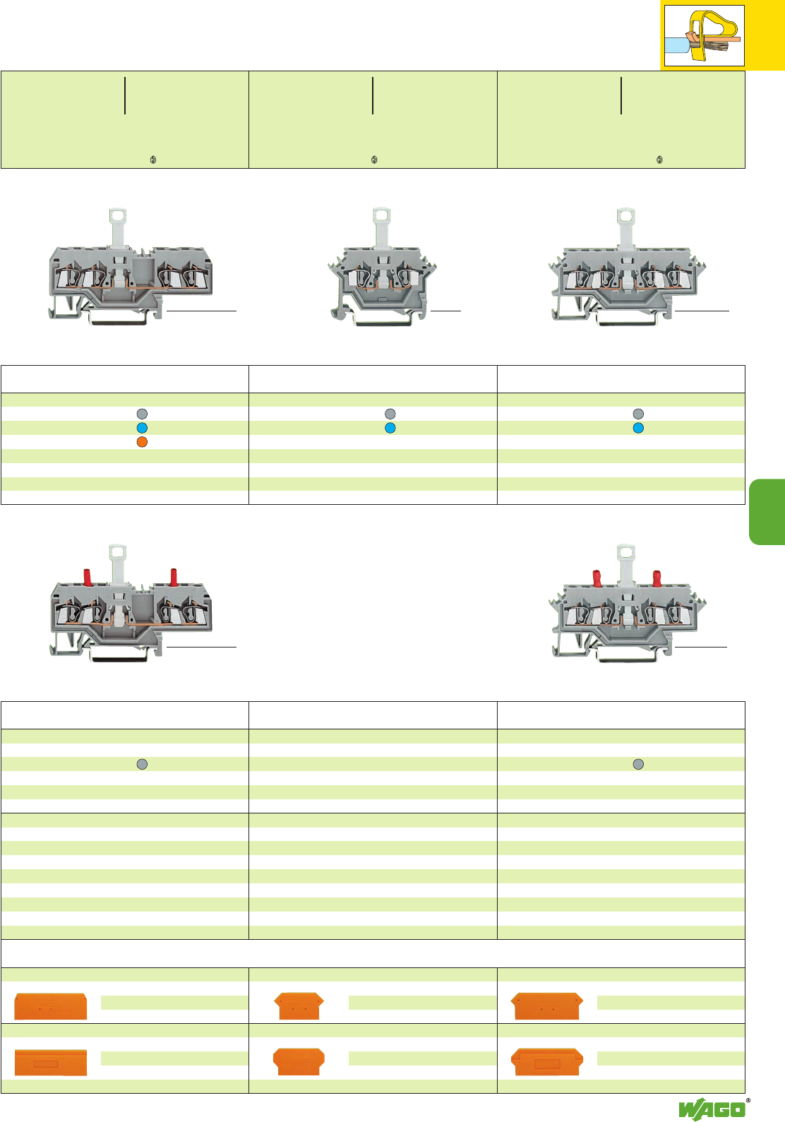
7
7
11
*U2KfaJq:;{[ *U2KaJq:;{[ *U2KfNaJq:;{[
End and intermediate plate, 2.5 mm/0.098 in thick
orange 280-317 100 (4 x 25)
grey 280-316 100 (4 x 25)
light grey 280-364 100 (4 x 25)
Separator,oversized, 2 mm /0.079 in thick
orange 280-327 100 (4 x 25)
grey 280-337 100 (4 x 25)
light grey 280-365 100 (4 x 25)
End and intermediate plate, 2.5 mm/0.098 in thick
orange 280-331 100 (4 x 25)
grey 280-330 100 (4 x 25)
light grey 280-362 100 (4 x 25)
Separator,oversized, 2 mm /0.079 in thick
orange 280-328 100 (4 x 25)
grey 280-338 100 (4 x 25)
light grey 280-363 100 (4 x 25)
End and intermediate plate, 2.5 mm/0.098 in thick
orange 280-315 100 (4 x 25)
grey 280-314 100 (4 x 25)
light grey 280-352 100 (4 x 25)
Separator,oversized, 2 mm /0.079 in thick
orange 280-335 100 (4 x 25)
grey 280-334 100 (4 x 25)
light grey 280-353 100 (4 x 25)
2-conductor disconnect terminal block for test and
measurement with integrated test sockets
grey 280-627 50
Through terminal block with the same shape
grey 280-621 page 2.12
Through terminal block with the same shape
grey 280-601 page 2.12
2-conductor disconnect terminal block for test and
measurement with integrated test sockets
grey 280-649 50
Through terminal block with the same shape
grey 280-633 page 2.11
Item Pack. unit
No. pcs
Item Pack. unit
No. pcs
Item Pack. unit
No. pcs
4-conductor disconnect terminal blocks
grey 280-622 50
blue 280-632 50
2-conductor disconnect terminal blocks
grey 280-612 50
blue 280-614 50
4-conductor disconnect terminal blocks
grey 280-685 50
blue 280-676 50
orange 280-695 50
Item Pack. unit
No. pcs
Item Pack. unit
No. pcs
Item Pack. unit
No. pcs
<32 mm/1.26 in_>
<___________ 75 mm /2.95 in ___________>
<___ 46.5 mm /1.83 in ___>
<____ 52.5 mm /2.07 in ____>
<____ 50 mm /1.97 in ____>
<___ 46.5mm /1.83 in ___>
<____ 52.5 mm /2.07 in ____>
<32 mm/1.26 in_>
<___________ 75 mm /2.95 in ___________>
<__________ 73 mm /2.87 in __________>
<___ 46.5mm /1.83 in ___>
<____ 52.5 mm /2.07 in ____>
<__________ 73 mm /2.87 in __________>
<___ 46.5mm /1.83 in ___>
<____ 52.5 mm /2.07 in ____>
<___ 46.5 mm /1.83 in ___>
<____ 52.5 mm /2.07 in ____>
0.08 – 2.5 mm2AWG 28 – 12
400 V/6 kV/3 ➊300 V, 15 A U
10 A 600 V, 15 A 2
Terminal block width 5 mm / 0.197 in
L8 – 9 mm / 0.33 in
0.08 – 2.5 mm2AWG 28 – 12
400 V/6 kV/3 ➊300 V, 15 A U
10 A 600 V, 15 A 2
Terminal block width 5 mm / 0.197 in
L8 – 9 mm / 0.33 in
0.08 – 2.5 mm2AWG 28 – 12
400 V/6 kV/3 ➊300 V, 15 A U
10 A 600 V, 15 A 2
Terminal block width 5 mm / 0.197 in
L8 – 9 mm / 0.33 in
Appropriate marking system WMB/WSB/WFB (see section 14)
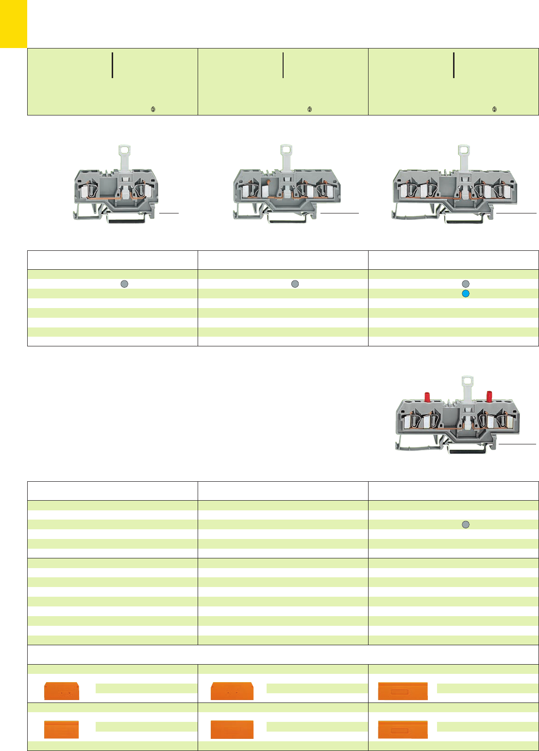
7
12
*U2KfNDaJq:;{[5 *U2KfaJq:;{[5 *U2KfNDaJq:;{[5
* For further approvals with corresponding ratings see section 15.
<36.5 mm /1.44 in >
<______ 59 mm /2.32 in ______>
<___ 47.5mm/1.87in ___>
<____ 53.5 mm /2 .11 in ____>
<___ 47.5 mm /1.87 in ___>
<____ 53.5 mm /2.11 in ____>
<___ 47.5 mm /1.87 in ___>
<____ 53.5 mm /2.11 in ____>
<_ 37 mm /1.46 in _>
<__________ 73.5 mm /2.89 in __________> <_____ 50 mm /1.97 in _____>
<_______________ 86 mm /3.39 in _______________>
<___ 47.5 mm /1.87 in ___>
<____ 53.5 mm /2.11 in ____>
<______ 50 mm /1.97 in ______>
<_______________ 86 mm /3.39 in _______________>
End and intermediate plate, 2.5 mm/0.098 in thick
orange 281-335 100 (4 x 25)
grey 281-334 100 (4 x 25)
light grey 281-345 100 (4 x 25)
Separator,oversized, 2 mm /0.079 in thick
orange 281-339 100 (4 x 25)
grey 281-338 100 (4 x 25)
light grey 281-347 100 (4 x 25)
End and intermediate plate, 2.5 mm/0.098 in thick
orange 281-326 100 (4 x 25)
grey 281-324 100 (4 x 25)
light grey 281-355 100 (4 x 25)
Separator,oversized, 2 mm /0.079 in thick
orange 281-346 100 (4 x 25)
grey 281-344 100 (4 x 25)
light grey 281-356 100 (4 x 25)
End and intermediate plate, 2.5 mm/0.098 in thick
orange 281-329 100 (4 x 25)
grey 281-328 100 (4 x 25)
light grey 281-349 100 (4 x 25)
Separator,oversized, 2 mm /0.079 in thick
orange 281-331 100 (4 x 25)
grey 281-330 100 (4 x 25)
light grey 281-350 100 (4 x 25)
2-conductor disconnect terminal block for test and
measurement with integrated test sockets
grey 281-666 50
Through terminal block with the same shape
grey 281-652 page 2.16
Through terminal block with the same shape
grey 281-681 page 2.16
Through terminal block with the same shape
grey 281-901 page 2.16
Item Pack. unit
No. pcs
Item Pack. unit
No. pcs
Item Pack. unit
No. pcs
4-conductor disconnect terminal blocks
grey 281-659 50
blue 281-660 50
3-conductor disconnect terminal block
grey 281-683 50
Item Pack. unit
No. pcs
Item Pack. unit
No. pcs
Item Pack. unit
No. pcs
Disconnect Terminal Blocks for Test and Measurement 4 mm2/ AWG 12,
Serie 281
➊400 V = rated voltage
6 kV = rated surge voltage
3 = pollution degree
(see also section 15)
0.08 – 4 mm2AWG 28 – 12
400 V/6 kV/3 ➊300 V, 15 A U
10 A 300 V, 15 A 2
Terminal block width 6 mm / 0.236 in
L9 – 10 mm / 0.37 in
0.08 – 4 mm2AWG 28 – 12
400 V/6 kV/3 ➊300 V, 15 A U
10 A 600 V, 15 A 2
Terminal block width 6 mm / 0.236 in
L9 – 10 mm / 0.37 in
0.08 – 4 mm2AWG 28 – 12
400 V/6 kV/3 ➊300 V, 15 A U
10 A 600 V, 15 A 2
Terminal block width 6 mm / 0.236 in
L9 – 10 mm / 0.37 in
2-conductor disconnect terminal block
grey 281-912 50
Accessories Series 281 (see page 7.13) Appropriate marking system WMB/WSB/WFB (see section 14)
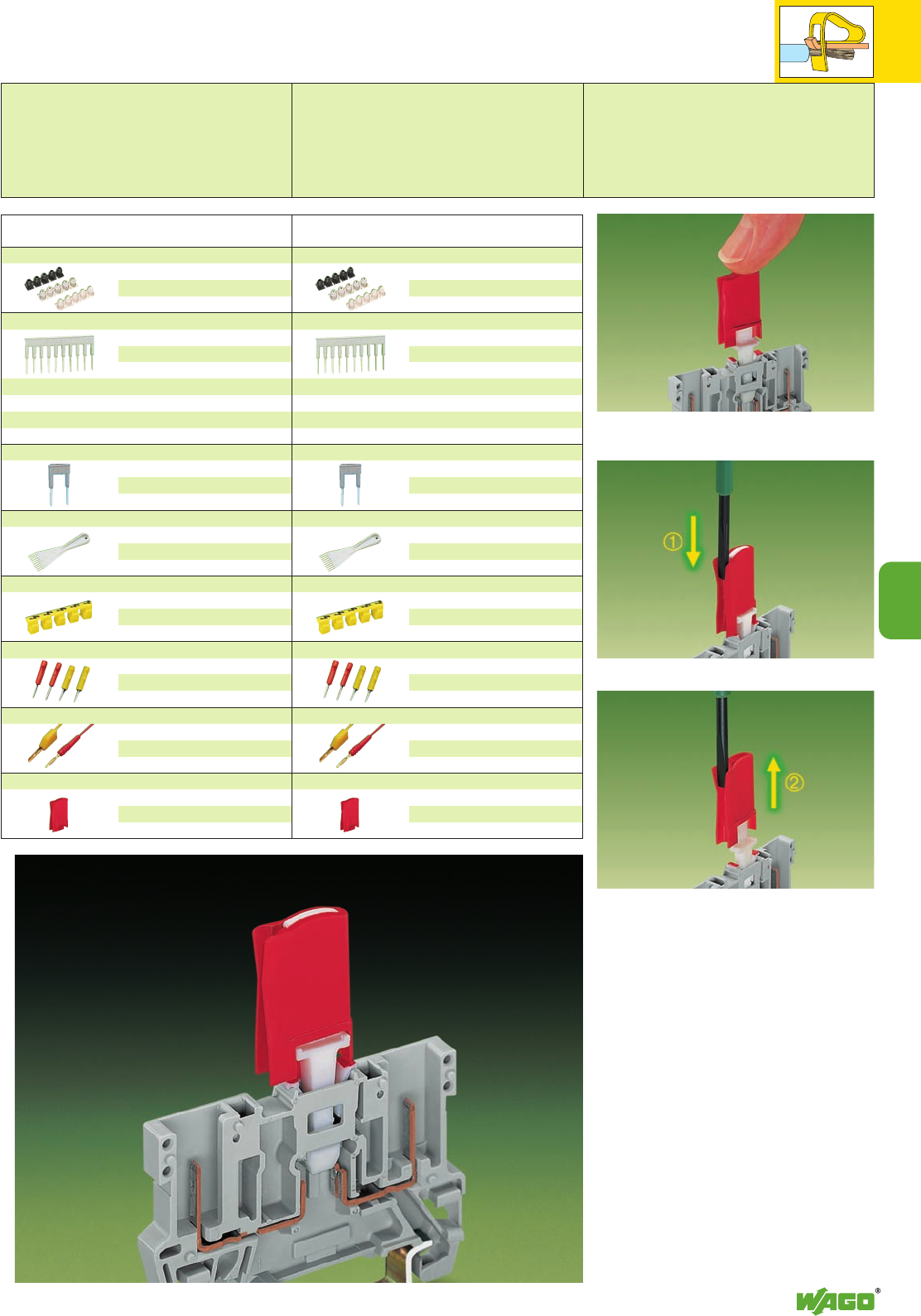
7
7
13
Accessories series 280
see also pages 2.43 and 2.44
Insulation stop, 5 pcs /strip
white 280-470 200 strips
light grey 280-471 200 strips
dark grey 280-472 200 strips
Comb type jumper bar, insulated,
IN= INof terminal block
2-way 280-482 200 (8 x 25)
3-way 280-483 200 (8 x 25)
10-way 280-490 50 (2 x 25)
Alternate comb type jumper bar, insulated,
IN= INof terminal block
2-way 280-492 200 (8 x 25)
Operating tool, insulated
2-way 280-432 1
3-way 280-433 1
10-way 280-440 1
Protective warning marker, for 5 terminal blocks,
fits into screwdriver slot
yellow 280-415 100 (4 x 25)
Test socket, insulated
2 mm Ø, red
209-107 100 (2 x 50)
2.3 mm Ø, yel.
209-108 100 (2 x 50)
Test plug,
with
cable 500 mm/1’7.7’’
2 mm Ø, red
210-136 50 (5 x 10)
2.3 mm Ø, yel.
210-137 50 (5 x 10)
Disconnect lock, for disconnect tab of series
280/281 disconnect terminal
blocks
red 709-170 200 (8 x 25)
Item Pack. unit
No. pcs Item Pack. unit
No. pcs
Accessories series 281
see also pages 2.43 and 2.44
Double safety
The disconnect tab has been designed to provide
maximum operational safety.
As soon as the disconnect tab is in the disconnect
position, it can be further protected against unin-
tentional reconnection by using the disconnect
lock.
Only by means of a conscious act, and the use of
a tool, can the disconnect lock be
removed, and the circuit reconnected.
Features/Benefits:
●Easy handling
●The disconnect lock can be easily installed
●Clear identification with the position of the
disconnect tab
●Increases safety
●Reconnecting the circuit requires a conscious
act
The lock is put on the disconnect tab of the disconnect
terminal block (the picture shows a 2-pin base receptacle
block series 769)
➀
Unlocking of disconnect lock
➁
Removing of disconnect lock
Application notes
Insulation stop, 5 pcs /strip
white 281-470 200 strips
light grey 281-471 200 strips
dark grey 281-472 200 strips
Comb type jumper bar, insulated,
IN= INof terminal block
2-way 281-482 100 (4 x 25)
3-way 281-483 100 (4 x 25)
5-way 281-485 50 (2 x 25)
10-way 281-490 50 (2 x 25)
Alternate comb type jumper bar, insulated,
IN= INof terminal block
2-way 281-492 100 (4 x 25)
Operating tool, insulated
2-way 280-432 1
3-way 280-433 1
5-way 281-440 1
Protective warning marker, for 5 terminal blocks,
fits into screwdriver slot
yellow 281-415 100 (4 x 25)
Test socket, insulated
2 mm Ø, red
209-107 100 (2 x 50)
2.3 mm Ø, yel.
209-108 100 (2 x 50)
Test plug,
with
cable 500 mm/1’7.7’’
2 mm Ø, red
210-136 50 (5 x 10)
2.3 mm Ø, yel.
210-137 50 (5 x 10)
Disconnect lock, for disconnect tab of series
280/281 disconnect terminal
blocks
red 709-170 200 (8 x 25)
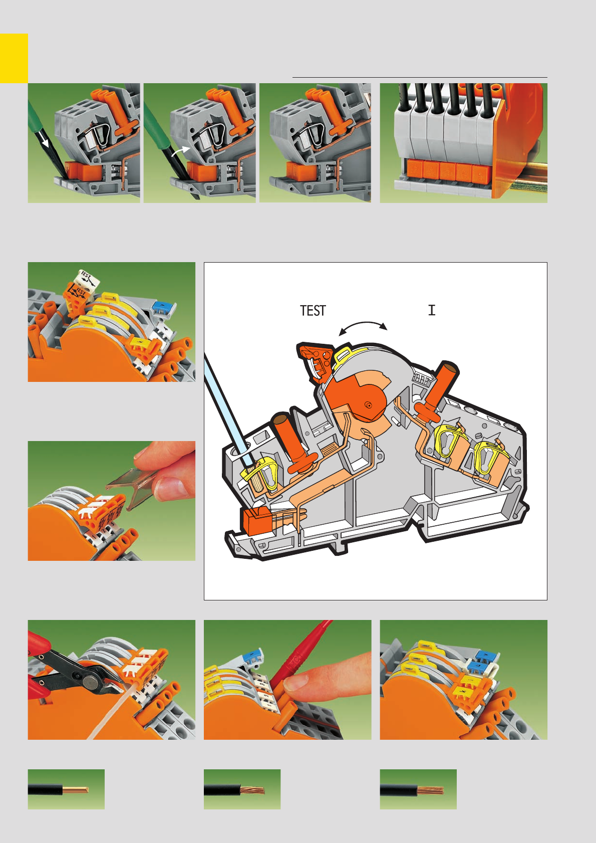
7
14
Disconnect Terminal Blocks for Test and Measurement of Transformer Circuits,
with CAGE CLAMP®, Series 282 . . .
Preparing the shorting path for the current transformer
Positive action
Locking cover for disconnect links
MarkingInterlocking link Touchproof test sockets
CAGE CLAMP®
clamps the following
copper wires: *
solid
Insertion of insulated, touchproof adjacent jumpers into the protected shorting position Terminal strip permanently prepared for current
transformer circuits
Transparent locking cover for 1–4 disconnect links
can be snapped on
a) for mechanical interlocking for multipole
switching
b) for protecting markers
stranded
fine stranded,
also with tinned
single strands
Lock-out has ”snap“ action into two notched
positions preventing accidental operation of the
disconnect link
For touchproof test plugs Ø 4 mm (for example
mfd by Multi-Contact)
Interlocking link for mechanical interlocking of
several links for multipole switching Marking with WMB Multi marking system,
WSB Quick marking system or
WCB Combi marking system.
* For aluminum wire see notes in section 15!
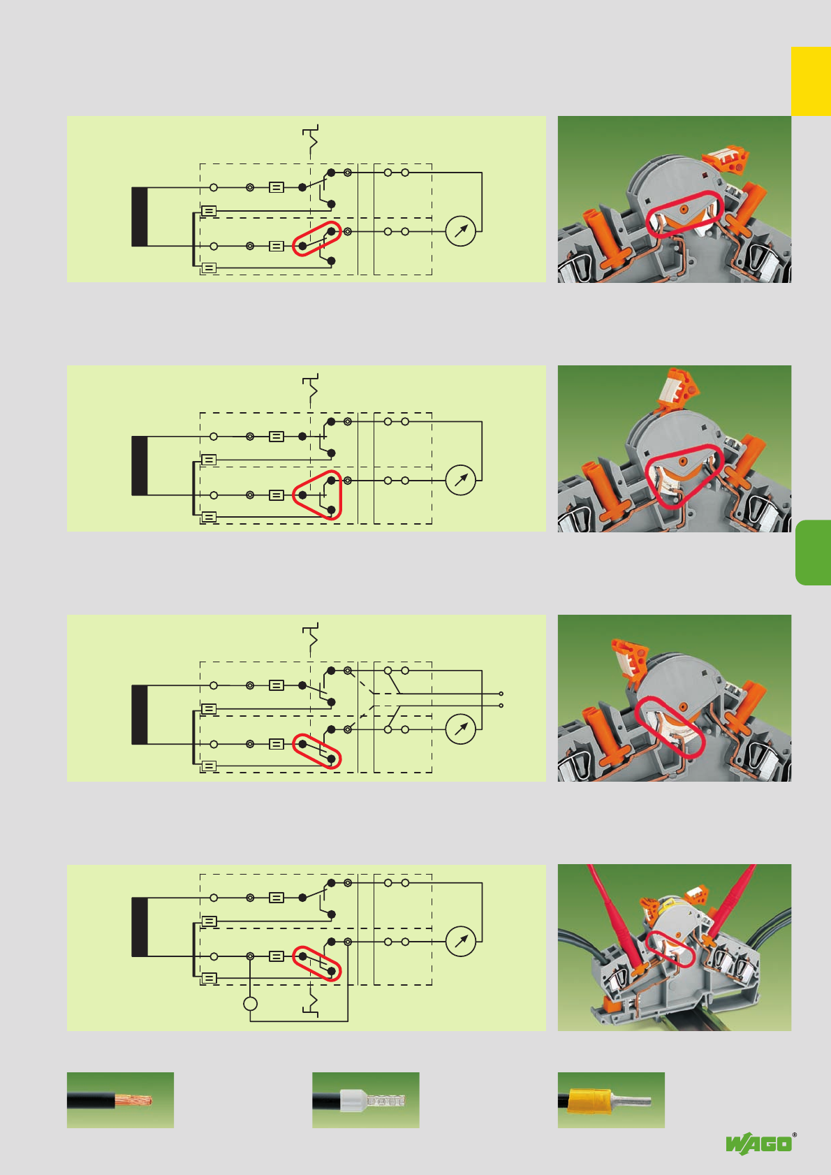
7
P
B
P
12
P
B
A
P
12
P
B
P
12
P
B
P
12
~
7
15
➊ When using wires with ferrules, it is necessary to use a terminal block one size larger than the nominal cross section of the wire.
fine-stranded wire –
tip bonded
fine-stranded wire
with crimped ferrule ➊fine-stranded wire
with crimped pin terminal
T
T
T
T
T
T
T
T
T
T
. . . Description and Handling
Disconnect link in notched position ” “ (terminal blocks 1+2)
Disconnect link in transition from ” “ ➞ ”TEST“ (terminal blocks 1+2)
Disconnect link in notched position ”TEST“ (terminal blocks 1+2)
Disconnect link in notched position ” “ (terminal block 2)
Disconnect link in notched position ”TEST“ (terminal block 1)
In position ” “ the measuring instrument is connected to the transformer secondary
B = shorting jumper, P = test socket
By moving the interlocked disconnect links from ” “ to ”TEST“ the shorting path is activated without
disconnection of the measuring instrument yet.
The measuring instrument is electrically disconnected from the transformer.
In this position, if necessary, an external voltage can be applied via the sockets or the 2nd CAGE CLAMP®
connection for relay testing in transformer protection circuits
Measured value test. Before moving the disconnect link of terminal block 1 into the notched position
”TEST“ the reference current meter must be inserted into the test socket of terminal block 1!
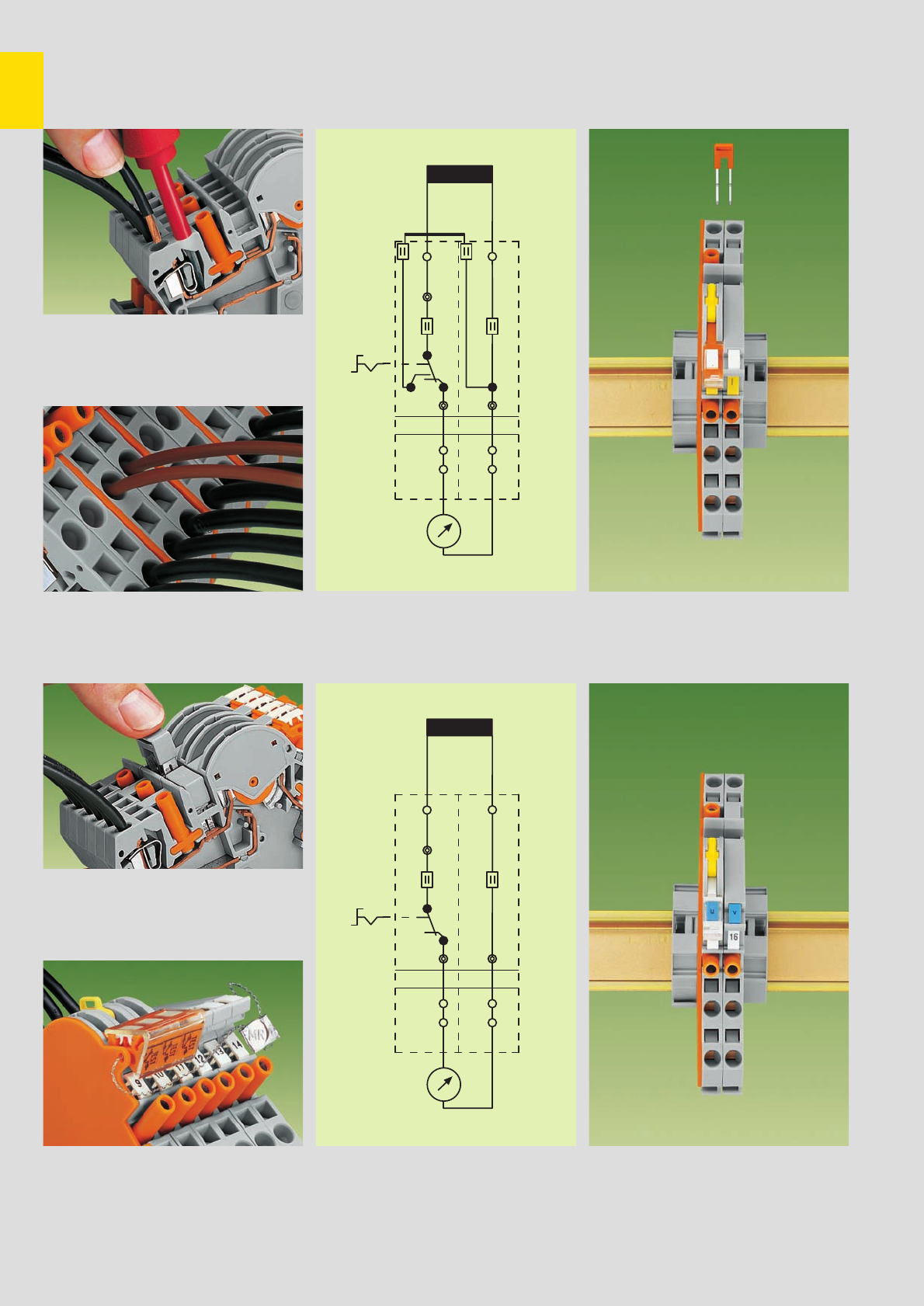
7
16
P
B
P
12
P
P
P
12
P
Examples of Circuit Configuration
(without testing facility
Measuring set for a single-phase current transformer
for measured value test)
CAGE CLAMP®connection
Additional CAGE CLAMP
®
connection
Commoning
Lock-out seal
Measuring set for a single-phase voltage transformer
Connection of conductors with screwdriver
(5.5 x 0.8) mm
Additional CAGE CLAMP®connection on the side
of the measuring instrument
For example: connecting wire commoning chains
or applying an external voltage
Terminal blocks required: 1x disconnect/test terminal block 282-870
1x through terminal block 282-865
1x jumper, orange 282-424
1x end plate, orange 282-386
in addition locking cover, lock-out
Terminal blocks required: 1x disconnect/test terminal block 282-860
1x through terminal block 282-866
1x end plate, orange 282-386
in addition locking cover, lock-out
Additional commoning possibility with adjacent
jumper.
For example: ‘Y‘ ^
=star point
A lock-out seal can be used on the disconnect link
in notched position “ “
T
T
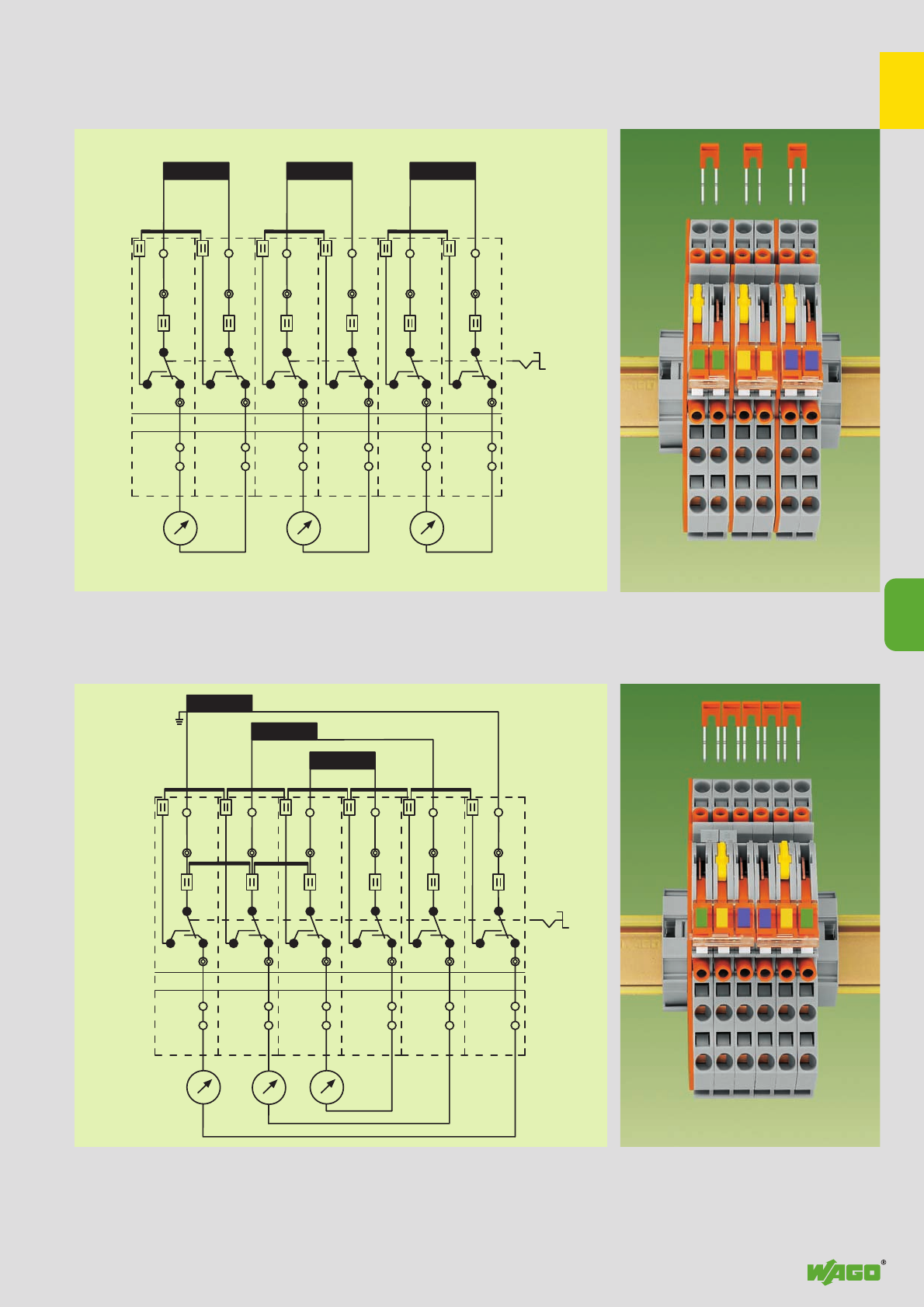
7
P
B
P
12
P
B
P
34
P
B
P
56
k l
k l k l
P
B
P
12
P
B
P
34
P
B
P
56
k l
k l
k l
kP
7
17
Measuring set for a 3-phase current transformer
Measuring set for a 3-phase current transformer with ‘Y‘ point
Pairs of disconnect links are interlocked by means of the locking covers. Terminal blocks required:
After the interlocking has been released testing of the measured value is also possible.
B = shorting jumper, P = test socket
All 6 disconnect links are interlocked by means of the interlocking link. Terminal blocks required:
kP = ‘Y‘ point jumpers
6x disconnect/test terminal block 282-870
3x jumper, orange 282-424
3x end plate, orange 282-386
in addition locking links, locking covers, lock-outs
6x disconnect/test terminal block 282-870
5x through terminal block, orange 282-424
2x jumper, grey 282-402
1x end plate, orange 282-386
in addition locking links, locking covers, lock-outs
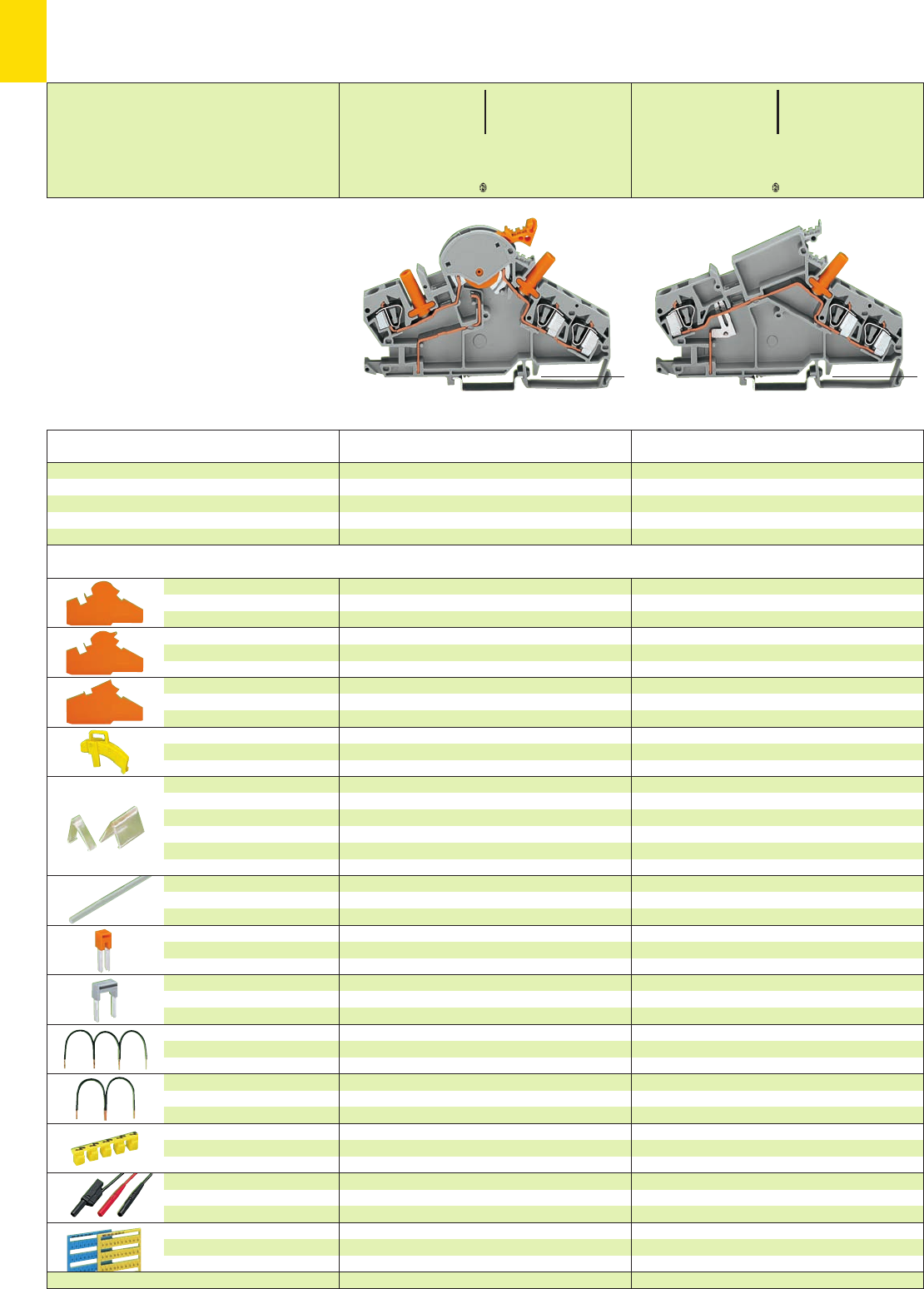
7
18
*UKfa:;{[ *UKfa:;{[
Accessories Appropriate marking system WMB/WSB/WCB (see section 14)
Description
1.5 mm /0.059 in thick
orange 282-386 50 (5 x 10)
grey 282-391 50 (5 x 10)
1.5 mm /0.059 in thick
orange 282-387 50 (5 x 10)
grey 282-392 50 (5 x 10)
yellow 282-384 100 (5 x 20)
transparent
1-pole 282-881 50 (5 x 10)
2-pole 282-882 50 (5 x 10)
3-pole 282-883 20 (2 x 10)
4-pole 282-884 20 (2 x 10)
1 m /3’3’’ long
transparent 210-254 1
IN41 A
grey 282-402 100 (4 x 25)
orange 282-424 100 (4 x 25)
IN41 A
grey 282-409 100 (4 x 25)
spacing
3 x 80 mm /3.15 in 709-110 1
spacing
2 x 90 mm /3.54 in 709-111 1
2 x 150 mm /5.91 in 709-112 1
yellow 282-415 100 (4 x 25)
for ex. mfd by Multi-Contact Deutschland GmbH
not offered by WAGO
yellow
k/l (50 each) 249-553/000-002 1 card
210-412 100
1.5 mm /0.059 in thick
orange 282-385 50 (5 x 10)
grey 282-390 50 (5 x 10)
IN41 A
grey 282-402 100 (4 x 25)
orange 282-424 100 (4 x 25)
IN41 A
grey 282-409 100 (4 x 25)
spacing
3 x 80 mm /3.15 in 709-110 1
spacing
2 x 90 mm /3.54 in 709-111 1
2 x 150 mm /5.91 in 709-112 1
yellow 282-415 100 (4 x 25)
for ex. mfd by Multi-Contact Deutschland GmbH
not offered by WAGO
yellow
k/l (50 each) 249-553/000-002 1 card
210-415 100
End and intermediate plate,
without use of lock-out seal
End and intermediate plate,
for use of lock-out seal
End and
intermediate plate
Lock-out,
for disconnect link
Locking cover,
for mechanical locking
of several links
Interlocking link,
for mechanical locking
of several links
Adjacent jumper,
insulated
Alternate jumper,
insulated
Wire commoning chain,
insulated, black,
4 connections, 24 A, 2.5 mm2
Wire commoning chain,
insulated, black,
3 connections, 24 A, 2.5 mm2
Protective warning marker,
for 5 terminal blocks,
fits into screwdriver slot
Test plug, 4 mm /0.157 in Ø,
touch-proof,
WSB Marker card,
10 strips with 10 markers each,
with printing
Operating sticker
Disconnect/test terminal block
and
Through terminal block, for DIN 35 rail
Disconnect/test terminal block,
example for current transformer circuits
with touch-proof test plug 4 mm /0.157 in Ø,
disconnect link orange
grey 282-870 20
Through terminal block,
example for current transformer circuits
with touch-proof test plug 4 mm /0.157 in Ø,
grey 282-865 20
Item Pack. unit
No. pcs Item Pack. unit
No. pcs
<________________122 mm /4.80 in __________________> <________________122 mm /4.80 in __________________>
Disconnect/Test Terminal Blocks 6 mm2 (AWG 10)/30 A,
Through Terminal Blocks, Series 282
for Example for Current Transformer Circuits
➊500 V = rated voltage
6 kV = rated surge voltage
3 = pollution degree
(see also section 15)
➋max. height when rotating disconnect,
incl. locking cover, is 92 mm /3.62 in.
* For further approvals with corresponding ratings see section 15.
<_______ 74 mm /2.91 in _______>
0.2 – 6 mm2AWG 24 – 10
500 V/6 kV/3 ➊600 V, 30 A U
30 A
Terminal block width 8 mm / 0.315 in
L12 – 13 mm / 0.49 in
0.2 – 6 mm2AWG 24 – 10
500 V/6 kV/3 ➊600 V, 30 A U
30 A
Terminal block width 8 mm / 0.315 in
L12 – 13 mm / 0.49 in
<______ 75 mm /2.95 in ➋______>
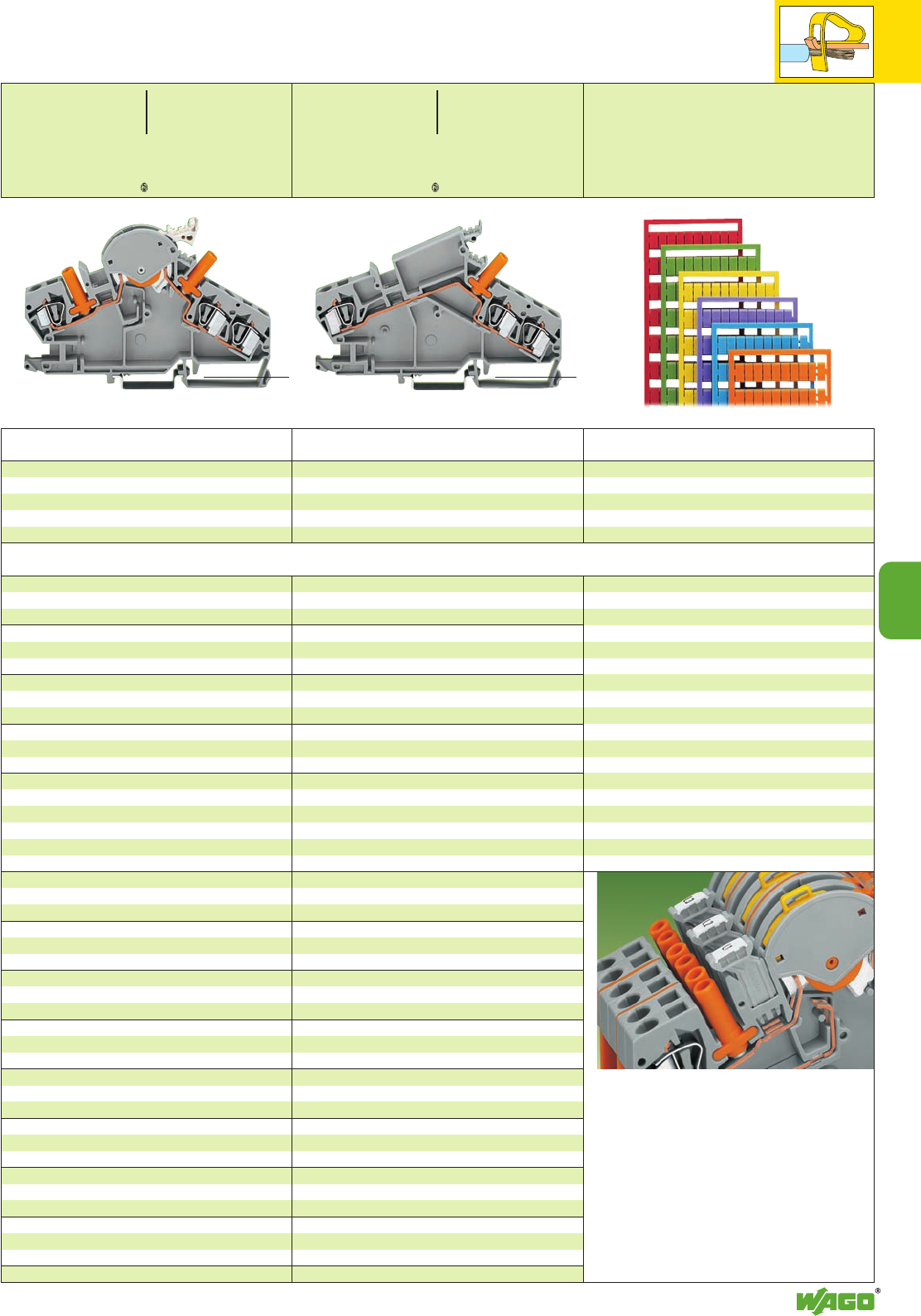
7
7
19
*UKfa:;{[
*UKfa:;{[
Item Pack. unit
No. pcs
Item Pack. unit
No. pcs Color Item
No.
Disconnect/test terminal block,
example for voltage transformer circuits
with touchproof test plug 4 mm /0.157 in Ø,
disconnect link light grey
grey 282-860 20
Colored Marker cards
All markings in section 14 are also available with black
printing on colored marker cards.
Through terminal block,
example for voltage transformer circuits
with touchproof test plug 4 mm /0.157 in Ø,
grey 282-866 20
1.5 mm /0.059 in thick
orange 282-386 50 (5 x 10)
grey 282-391 50 (5 x 10)
1.5 mm /0.059 in thick
orange 282-387 50 (5 x 10)
grey 282-392 50 (5 x 10)
yellow 282-384 100 (5 x 20)
transparent
1-pole 282-881 50 (5 x 10)
2-pole 282-882 50 (5 x 10)
3-pole 282-883 20 (2 x 10)
4-pole 282-884 20 (2 x 10)
1 m /3’3’’ long
transparent 210-254 1
IN41 A
grey 282-402 100 (4 x 25)
IN41 A
grey 282-409 100 (4 x 25)
spacing
3 x 80 mm /3.15 in 709-110 1
spacing
2 x 90 mm /3.54 in 709-111 1
2 x 150 mm /5.91 in 709-112 1
yellow 282-415 100 (4 x 25)
for ex. mfd by Multi-Contact Deutschland GmbH
not offered by WAGO
blue
U/V (50 each) 249-554/000-006 1 card
210-414 100
1.5 mm /0.059 in thick
orange 282-385 50 (5 x 10)
grey 282-390 50 (5 x 10)
IN41 A
grey 282-402 100 (4 x 25)
IN41 A
grey 282-409 100 (4 x 25)
spacing
3 x 80 mm /3.15 in 709-110 1
spacing
2 x 90 mm /3.54 in 709-111 1
2 x 150 mm /5.91 in 709-112 1
yellow 282-415 100 (4 x 25)
for ex. mfd by Multi-Contact Deutschland GmbH
not offered by WAGO
blue
U/V (50 each) 249-554/000-006 1 card
210-413 100
Add. item nos. for colored marker cards
yellow . . . /000-002
red . . . /000-005
blue . . . /000-006
grey . . . /000-007
orange . . . /000-012
green . . . /000-023
violet . . . /000-024
Ordering example
Marking 1 . . . 50 on red card
209-566/000-005
Note:
Please note that colored marker cards are normally on
longer delivery and more expensive than standard
cards.
Group marker carriers
– angled
209-144 Pack.-unit 50
The group marker carriers make it possible to mark
subgroups in confined places.
They can be snapped into the jumper contact positions
of the terminal block housing.
The marking can be done with either the
WAGO WSB Quick marking system,
WAGO WMB Multi marking system or the
WAGO WCB Combi marking system.
<________________122 mm /4.80 in __________________> <________________122 mm /4.80 in __________________>
Colored marker cards
vertical/horizontal marking
for terminal block width > 5 mm/0.197 in
Disconnect/Test Terminal Blocks 6 mm2(AWG10)/30 A,
Through Terminal Blocks, Angled Type; Series 282
for Example for Voltage Transformer Circuits
Appropriate marking system WMB/WSB/WCB (see section 14)
<_______ 74 mm /2.91 in _______>
0.2 – 6 mm2AWG 24 – 10
500 V/6 kV/3 ➊600 V, 30 A U
30 A
Terminal block width 8 mm / 0.315 in
L12 – 13 mm / 0.49 in
0.2 – 6 mm2AWG 24 – 10
500 V/6 kV/3 ➊600 V, 30 A U
30 A
Terminal block width 8 mm / 0.315 in
L12 – 13 mm / 0.49 in
<______ 75 mm /2.95 in ➋______>
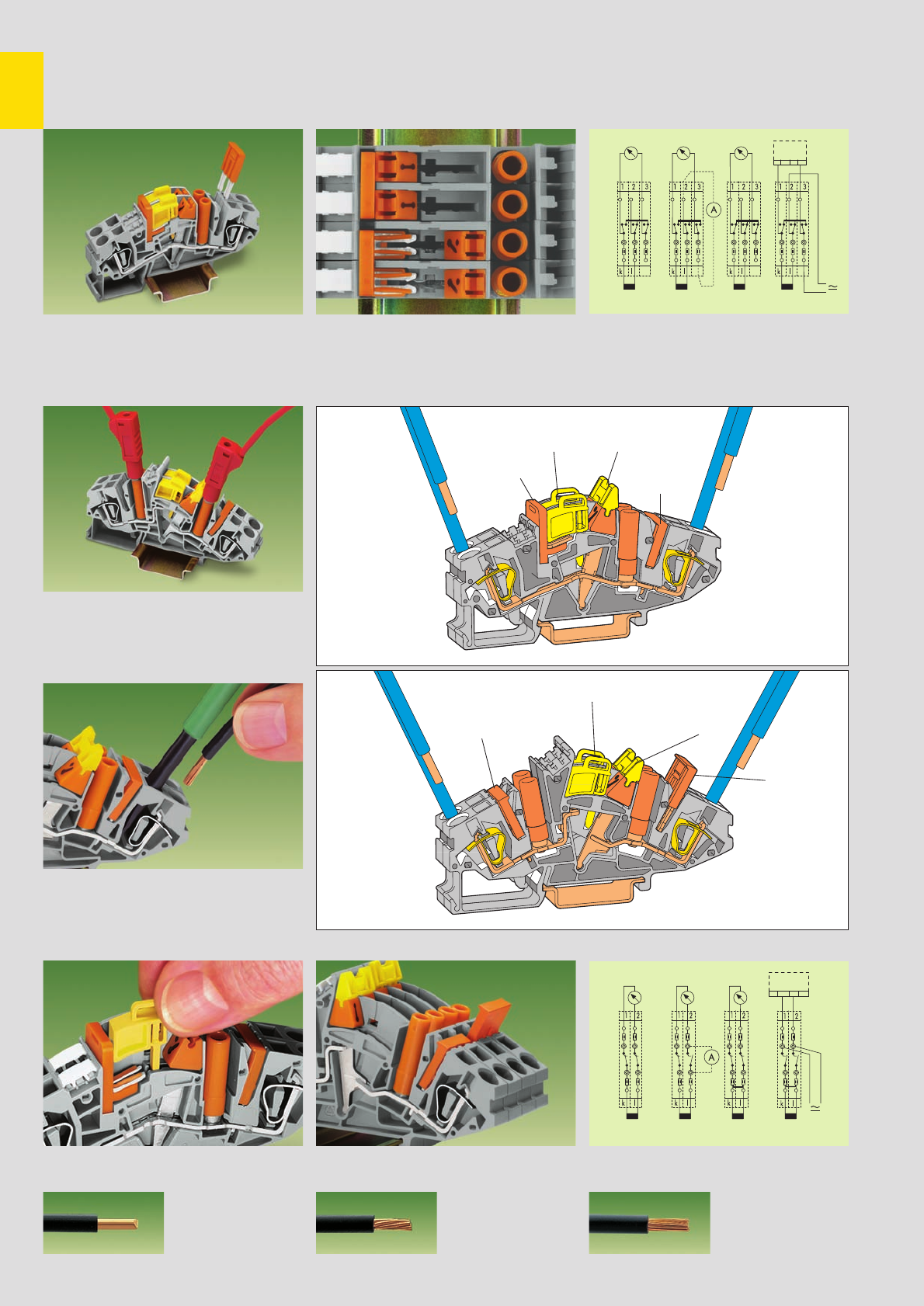
7
20
➊
➋
➊
➋
Transverse switching terminal blocks
➊
Adjacent jumper for commoning of switching
lever
➋
Commoning with orange jumper
closed open
a = Normal operation b = Measured value test
c = Transformer short-circuit d = Relay test
Longitudinal switching disconnect terminal blocks
with jumper
➊
in connected and ➋in disconnect
position
a = Normal operation b = Measured value test
c = Transformer short-circuit d = Relay test
Switch positions Current transformer circuit with
transverse switching term. blocks
Testing
CAGE CLAMP®connection
Commoning
Transverse Switching Terminal Blocks and Longitudinal Switching Disconnect
Terminal Blocks with CAGE CLAMP®, Series 282 – Description
Commoning
Testing with touchproof test plug 4 mm/0.157 in Ø
Connecting wire
* For aluminum wire see notes in section 15!
CAGE CLAMP®
clamps the following
copper wires: *
solid stranded
fine stranded,
also with tinned
single strands
Inserting lock-out device
Switching lock-out
Jumper
in disconnect
position
ab cd
ab cd
Transverse switching
terminal block
Longitudinal switching
disconnect terminal block
Adjacent
jumper for
switching
lever
Lock-out
device
Jumper
Coupling
device
Lock-out device
Jumper
Coupling
device
Current transformer circuit with longitudinal
switching disconnect terminal blocks
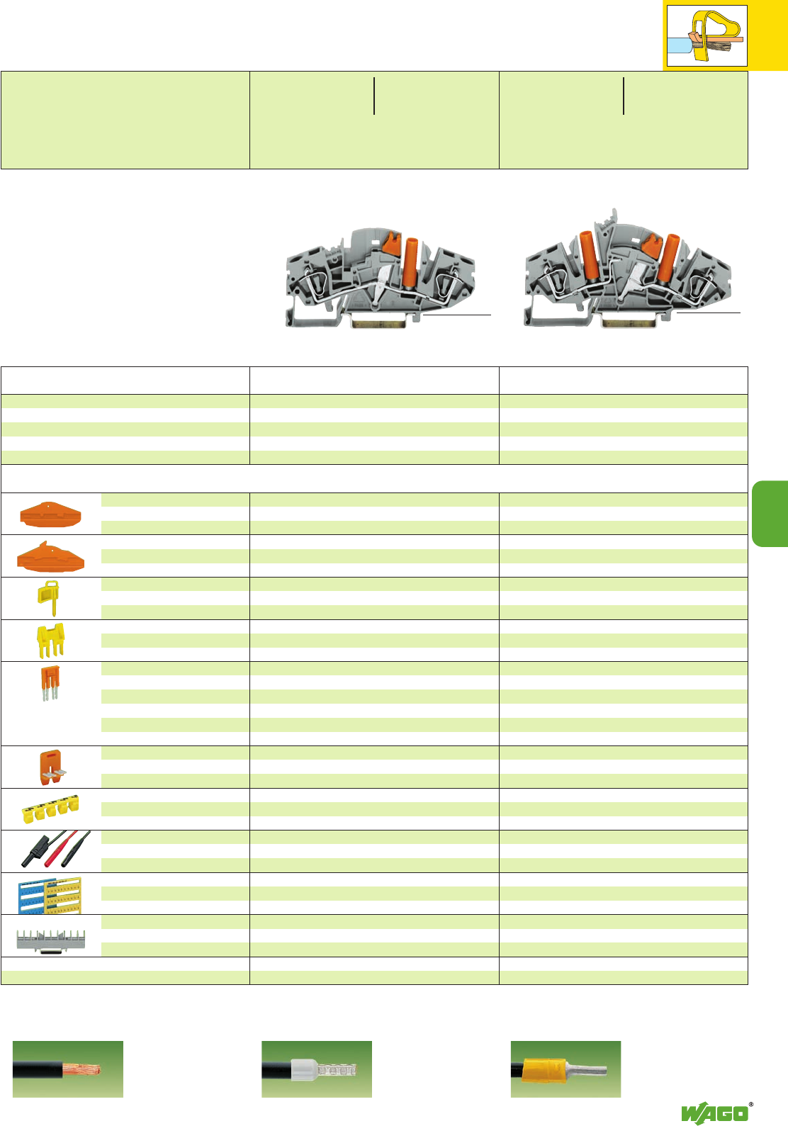
7
*UKf *UKf
7
21
Accessories Appropriate marking system WMB/WSB/WCB/Miniature WSB (see section 14)
Description
1.5 mm/0.059 in thick
orange 282-366 50 (5 x 10)
grey 282-361 50 (5 x 10)
yellow 282-370 100 (4 x 25)
2-way 282-372 50 (5 x 10)
3-way 282-373 50 (5 x 10)
4-way 282-374 50 (5 x 10)
2-way 282-432 50 (5 x 10)
3-way 282-433 50 (5 x 10)
4-way 282-434 50 (5 x 10)
5-way 282-435 50 (5 x 10)
:
10-way 282-440 50 (5 x 10)
2-way 282-442 50 (5 x 10)
3-way 282-443 50 (5 x 10)
4-way 282-444 50 (5 x 10)
yellow 282-415 100 (4 x 25)
for ex. mfd by Multi-Contact Deutschland GmbH
U/V (50 each) 794-554/000-006 1 card
k/l (50 each) 794-553/000-002 1 card
282-369 25
210-424 100
1.5 mm/0.059 in thick
orange 282-365 50 (5 x 10)
grey 282-360 50 (5 x 10)
yellow 282-370 100 (4 x 25)
2-way 282-372 50 (5 x 10)
3-way 282-373 50 (5 x 10)
4-way 282-374 50 (5 x 10)
2-way 282-432 50 (5 x 10)
3-way 282-433 50 (5 x 10)
4-way 282-434 50 (5 x 10)
5-way 282-435 50 (5 x 10)
:
10-way 282-440 50 (5 x 10)
yellow 282-415 100 (4 x 25)
for ex. mfd by Multi-Contact Deutschland GmbH
U/V (50 each) 794-554/000-006 1 card
k/l (50 each) 794-553/000-002 1 card
282-369 25
210-423 100
End and intermediate plate,
for 2-conductor transverse
switching terminal blocks
End and intermediate plate,
for 2-cond. longitudinal switching
disconnect terminal blocks
Lock-out device,
for switching lever
Coupling device, yellow,
to couple
several switching levers
Jumper, orange, IN30 A
insulated
Jumper, special design
for ex. 3-way (1-3-5)
please contact factory
Adjacent jumper for switching
lever, orange, IN30 A, for trans.
switching term. blocks, insulated
Protective warning marker,
for 5 terminal blocks,
fits into screwdriver slot
Test plug, 4 mm/0.157 in Ø,
touch-proof,
not offered by WAGO
WMB Marker card, 10 strips
with 10 markers each, blue
with printing yellow
Collective carrier for jumpers,
see page 14.37
Operating sticker
Transverse switching terminal block
and
longitudinal switching disconnect terminal block,
for DIN 35 rail
2-conductor transverse switching terminal block,
with (orange) touchproof test plug 4 mm/0.157 in Ø
grey 282-811 20
2-conductor longitudinal switching disconnect
terminal block,
with (orange) touchproof test plugs 4 mm/0.157 in Ø
grey 282-821 20
Item Pack. unit
No. pcs Item Pack. unit
No. pcs
<_____________ 89 mm /3.5 in ________________> <________________ 98 mm /3.86 in _________________>
Transverse Switching Terminal Blocks and Longitudinal Switching
Disconnect Terminal Blocks , 6 mm2/ AWG 10, Series 282
for Example for Current Transformer Circuits
➊500 V = rated voltage
6 kV = rated surge voltage
3 = pollution degree
(see also section 15)
➋max. height when rotating disconnect,
incl. coupling device, 45 mm /1.77 in
* For further approvals with corresponding ratings see section 15.
➌When using wires with ferrules, it is necessary to use a terminal block one size larger than the nominal cross section of the wire.
0.2 – 6 mm2AWG 24 – 10
500 V/6 kV/3 ➊600 V, 30 A U
30 A
Terminal block width 8 mm / 0.315 in
L12 – 13 mm / 0.49 in
0.2 – 6 mm2AWG 24 – 10
500 V/6 kV/3 ➊600 V, 30 A U
30 A
Terminal block width 8 mm / 0.315 in
L12 – 13 mm / 0.49 in
<__ 37.5 mm / __>
1.48 in ➋
<_____ 46.5 mm / ______>
1.83 in
fine-stranded wire –
tip bonded
fine-stranded wire
with crimped ferrule ➌fine-stranded wire
with crimped pin terminal
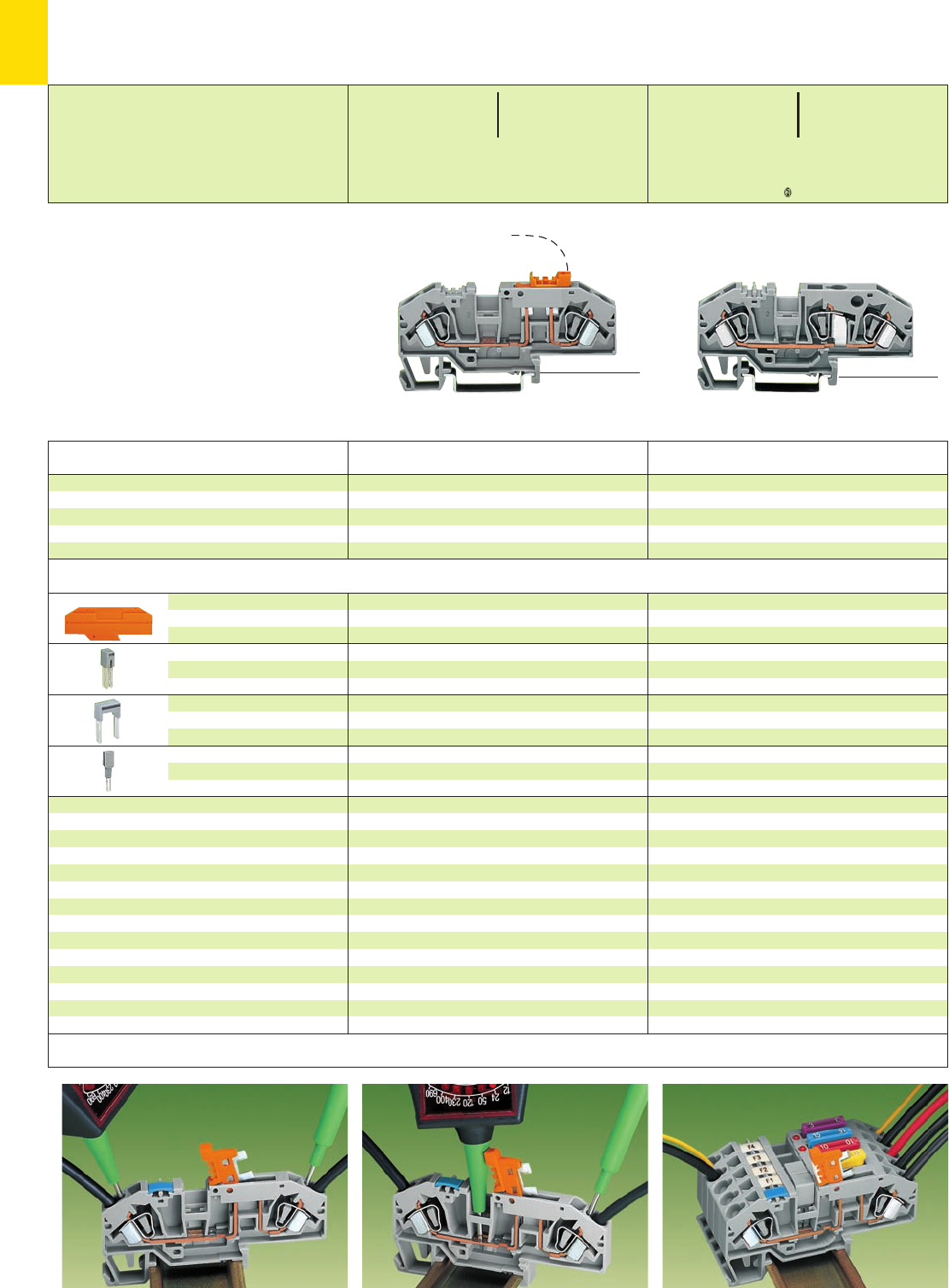
7
22
*U2Kfa:;{[ *U2fa:;{[
Application notes
Testing using the conductor wire opening . . . . . . or the jumper contact position in current bar. Supply via disconnect. All-pole disconnection of the com-
moned fuse terminal blocks.
Accessories Appropriate marking system WMB/WSB (see section 14)
Description
2 mm /0.079 in thick
orange 282-333 100 (4 x 25)
grey 282-334 100 (4 x 25)
IN41 A
grey 282-402 100 (4 x 25)
IN41 A
grey 282-409 100 (4 x 25)
8 mm /0.315 in wide
209-170 50 (2 x 25)
for test plug 4 mm /0.157 in Ø
2 mm /0.079 in thick
orange 282-333 100 (4 x 25)
grey 282-334 100 (4 x 25)
IN41 A
grey 282-402 100 (4 x 25)
IN41 A
grey 282-409 100 (4 x 25)
8 mm /0.315 in wide
209-170 50 (2 x 25)
for test plug 4 mm /0.157 in Ø
End plate
Adjacent jumper
insulated
Alternate jumper,
insulated
Test plug adapter,
suitable for terminal blocks
1.5 mm2– 10 mm2/AWG 16 – 8
Disconnect terminal block,
ground (earth) conductor disconnect terminal block
and
through terminal block, for DIN 35 rail
2-conductor disconnect terminal blocks,
with testing facility,
disconnect link orange
grey 282-697 25
blue 282-695 25
3-conductor through terminal blocks,
with testing facility,
of same shape as disconnect terminal blocks at the left
grey 282-699 25
blue 282-694 25
Item Pack. unit
No. pcs Item Pack. unit
No. pcs
(35.5 mm /1.40 in )
<______________ 85 mm /3.35 in ______________>(35.5 mm /1.40 in )
<_____________ 85 mm /3.35 in _____________>
<_ 37 mm /1.46 in _>
<___ 50.5 mm /1.99 in ___>
<__ 32.5 mm /__>
1.28 in
0.2 – 6 mm2AWG 24 – 10
400 V/6 kV/3 ➊600 V, 30 A U
30 A 300 V, 40 A 2
Terminal block width 8 mm / 0.315 in
L12 – 13 mm / 0.49 in
0.2 – 6 mm2AWG 24 – 10
800 V/8 kV/3 ➊600 V, 30 A U
41 A 600 V, 40 A 2
Terminal block width 8 mm / 0.315 in
L12 – 13 mm / 0.49 in
Disconnect Terminal Blocks 6 mm2(AWG 10)/30 A,
and Through Terminal Blocks of Same Shape,
Series 282
* For further approvals with corresponding ratings see section 15. **AWG 12: THHN, THWN
➊ 400/800 V = rated voltage
6/8 kV = rated surge voltage
3 = pollution degree
(see also section 15)
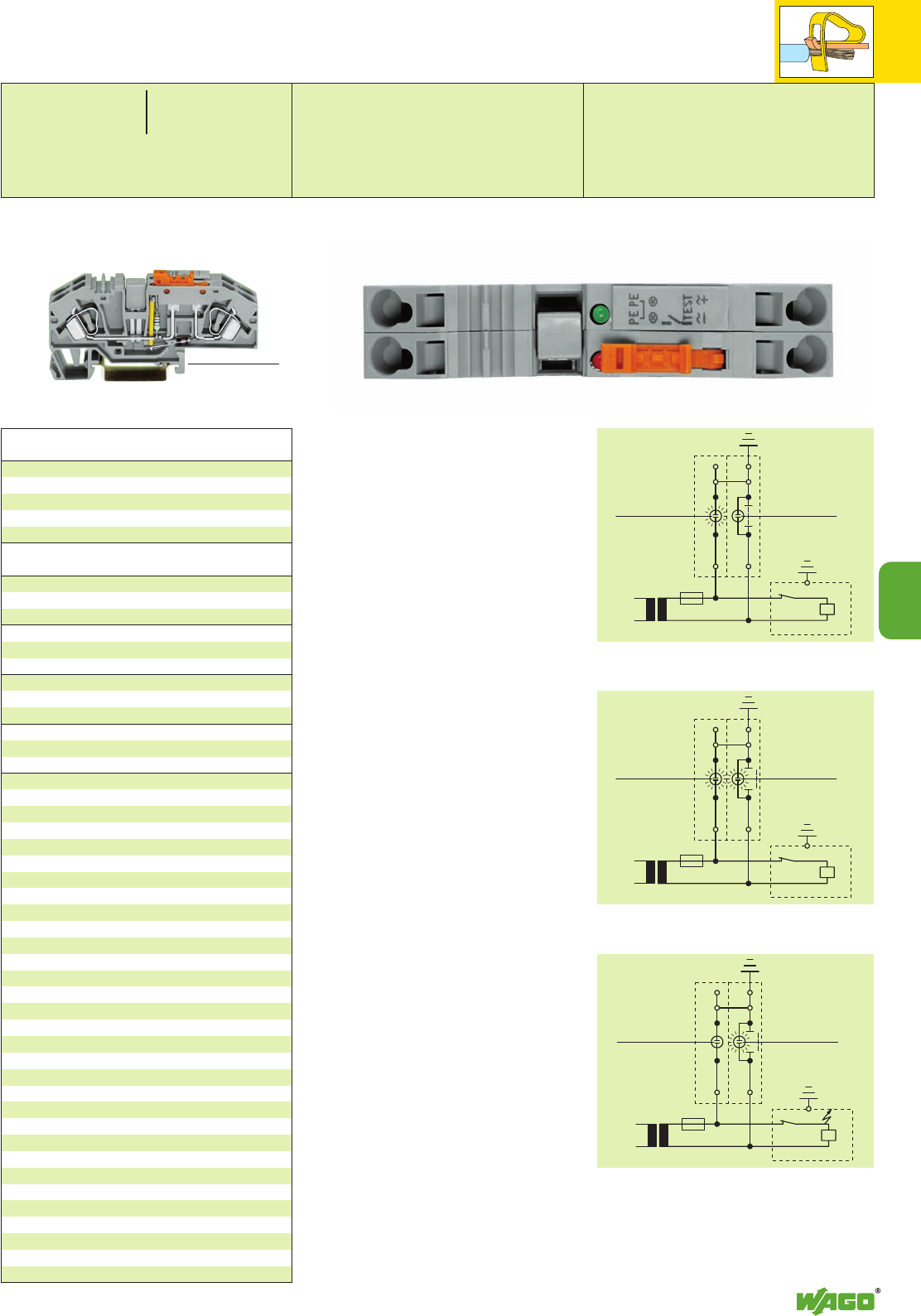
7
7
23
F 1
F 1
F 1
Ground (Earth) Conductor Disconnect
Terminal Blocks 6 mm2(AWG 10)/30 A
Series 282
2 mm /0.079 in thick
orange 282-333 100 (4 x 25)
grey 282-334 100 (4 x 25)
IN41 A
grey 282-402 100 (4 x 25)
IN41 A
grey 282-409 100 (4 x 25)
8 mm /0.315 in wide
209-170 50 (2 x 25)
for test plug 4 mm /0.157 in Ø
Ground (earth) cond. disconnect term. blocks, grey
f. AC/DC 24 V 282-640 12
f. AC/DC 48 V 282-641 12
f. AC/DC 120 V 282-638 12
f. AC/DC 230 V 282-639 12
Item Pack. unit
No. pcs
(35.5 mm /1.40 in )
<_____________ 85 mm /3.35 in _____________>
<__ 32.5 mm /
__>
1.28 in
Appropriate
marking system
WMB/WSB
(see section 14)
0.2 – 6 mm2AWG 24 – 10
400 V/6 kV/3 ➊
30 A
Terminal block width 16 mm / 0.630 in
L12 – 13 mm / 0.49 in
IEC 204-1:1992 “Electrical equipment of indu-
strial machines, part 1: General requirements”
9.4.3.1
Earth faults on control circuits shall not cause
unintentional starting, hazardous movements,
or prevent stopping of the machine.
In order to fulfill this requirement, bonding to
the protective bonding circuit shall be provided
in accordance with 8.2 and the devices shall
be connected as described in 9.1.4. Control
circuits fed from a transformer and not
connected to the protective bonding circuit
shall be provided with an insulation monitoring
device (e. g. residual current device) which
either indicates an earth fault or interrupts the
circuit automatically after an earth fault.
In the case of electronic circuits, the connection
of one side of the control circuit to the protec-
tive bonding circuit in accordance with 9.1.4
can prevent unintentional operation. When this
does not help, or if due to other reasons elec-
tronic circuits cannot be connected to the pro-
tective bonding circuit, other measures shall be
taken to achieve the same level of safety.
Where the control circuit is directly connected
between the phase conductors of the supply or
between a phase conductor and a neutral
conductor which is either not earthed or eart-
hed through a high impedance, multi-pole con-
trol switches which interrupt all live conductors
shall be used for start or stop of those machine
functions which can cause a hazardous conditi-
on or damage to the machine or to the work
in progress, in the event of unintentional star-
ting or failure to stop.
H 2
LED /green lamp
T 1 K 2 K 1
H 1
LED /red lamp
H 2
LED /green lamp
H 1
LED /red lamp
H 2
LED /green lamp
H 1
LED /red lamp
T 1 K 2 K 1
T 1 K 2 K 1
Operating condition
slide link closed, auxiliary circuit grounded (earthed),
green lamp lights.
Test condition – no grounding (earthing)
slide link open, auxiliary circuit not grounded (earthed).
Fault condition – grounding (earthing)
slide link open, auxiliary circuit not grounded (earthed),
red lamp lights.
Ground (earth) conductor disconnect terminal block
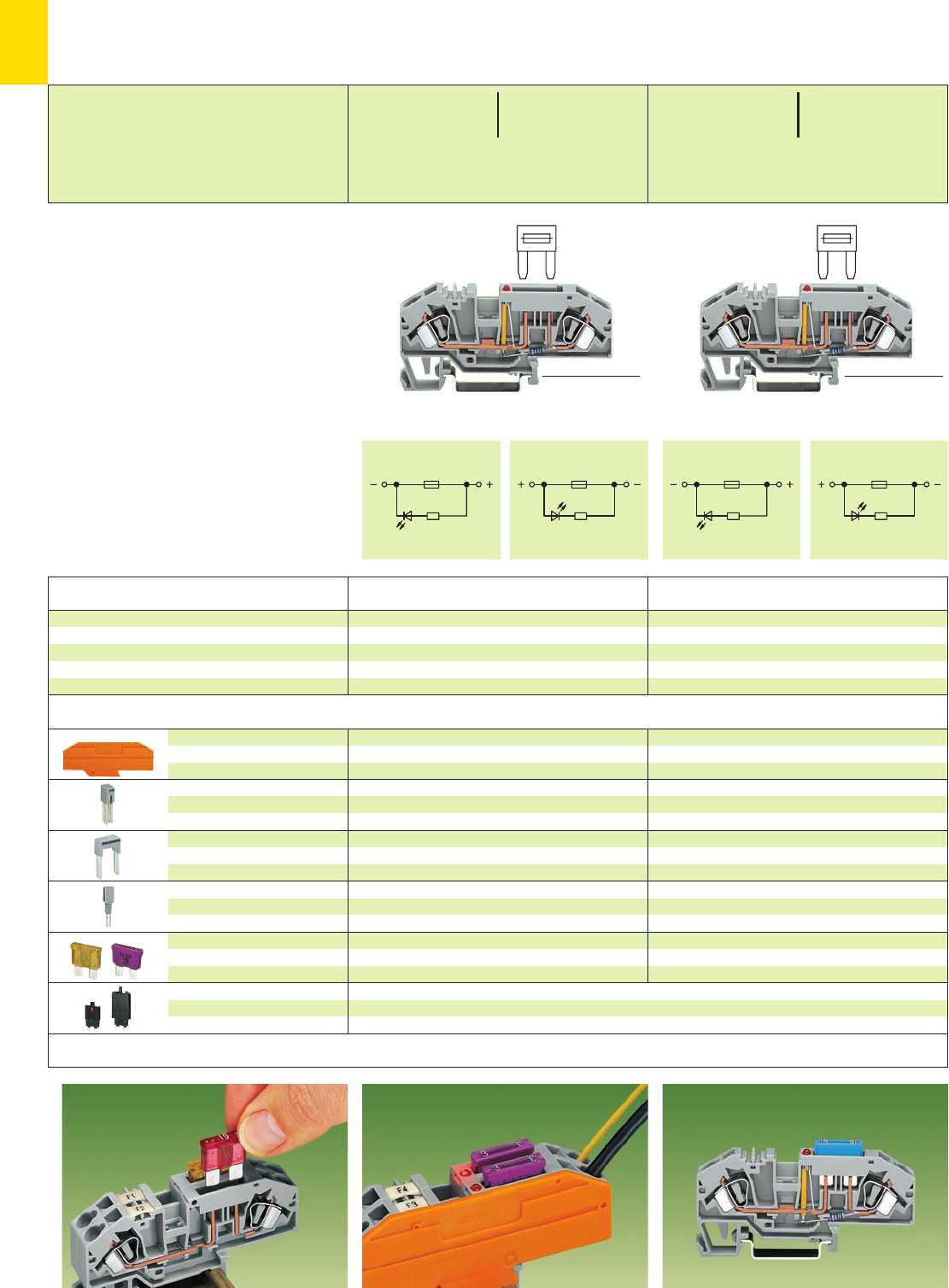
7
24
III III
*U2 *U
Blown fuse indication by LED. 2-conductor fuse terminal block with mini-automotive
blade-type fuse.
Insertion of a fuse.
2 mm /0.079 in thick
orange 282-333 100 (4 x 25)
grey 282-334 100 (4 x 25)
IN41 A
grey 282-402 100 (4 x 25)
IN41 A
grey 282-409 100 (4 x 25)
8 mm /0.315 in wide
209-170 50 (2 x 25)
for test plug 4 mm /0.157 in Ø
not offered by WAGO
Item Pack. unit
No. pcs
2 mm /0.079 in thick
orange 282-333 100 (4 x 25)
grey 282-334 100 (4 x 25)
IN41 A
grey 282-402 100 (4 x 25)
IN41 A
grey 282-409 100 (4 x 25)
8 mm /0.315 in wide
209-170 50 (2 x 25)
for test plug 4 mm /0.157 in Ø
not offered by WAGO
2-cond. fuse term. bl. for mini-automotive fuses,
12 V, with blown fuse indication by LED,
with testing facility
Circuit I, grey 282-698/281-429 25
Circuit II, grey 282-698/281-449 25
2-cond. fuse term. bl. for mini-automotive fuses,
24 V, with blown fuse indication by LED,
with testing facility
Circuit I, grey 282-698/281-413 25
Circuit II, grey 282-698/281-434 25
Item Pack. unit
No. pcs
not offered by WAGO. Recommended excess-current circuit-breakers of ETA
Types 1170-02, 1610-21 or 1610-22,
individual or block arrangement up to 25 A for conductor cross section 4 mm2/AWG 12
(35.5 mm /1.40 in )
<_____________ 85 mm /3.35 in _____________>
(35.5 mm /1.40 in )
<_____________ 85 mm /3.35 in _____________>
(33.5 mm /1.32 in )
<38.5 mm /1.52 in➌>
(33.5 mm /1.32 in )
<38.5 mm /1.52 in➌>
Fuse Terminal Blocks for Mini-Automotive Blade-Type Fuses, 6 mm2/AWG 10
Series 282
Application notes
Accessories Appropriate marking system WMB/WSB (see section 14)
Description
End plate
Adjacent jumper,
insulated
Alternate jumper,
insulated
Test plug adapter,
suitable for terminal blocks
1.5 mm2– 10 mm2/AWG 16 – 8
Blade-type fuse cartridges,
acc. to DIN 72 581-3c/ISO 8820
Excess-current circuit-breaker,
thermal,
mfd by ETA
Terminal block for mini-autom. blade-type fuses,
for DIN 35 rail
➊400 V = rated voltage
6 kV = rated surge voltage
3 = pollution degree
(see also section 15)
➋Electrical data are determined by the fuse.
(Blade-type cartridges, for 42 V and more touch-
proof protection)
Current consumption LED 4.8 mA
➌with inserted fuse
* For further approvals with corresponding ratings see section 15.
0.2 – 6 mm2AWG 24 – 10
400 V/6 kV/3 ➊➋ 12 V, 30 A U
25/30 A ➋ ➍
Terminal block width 8 mm / 0.315 in
L12 – 13 mm / 0.49 in
0.2 – 6 mm2AWG 24 – 10
400 V/6 kV/3 ➊➋ 24 V, 30 A U
25/30 A ➋ ➍
Terminal block width 8 mm / 0.315 in
L12 – 13 mm / 0.49 in
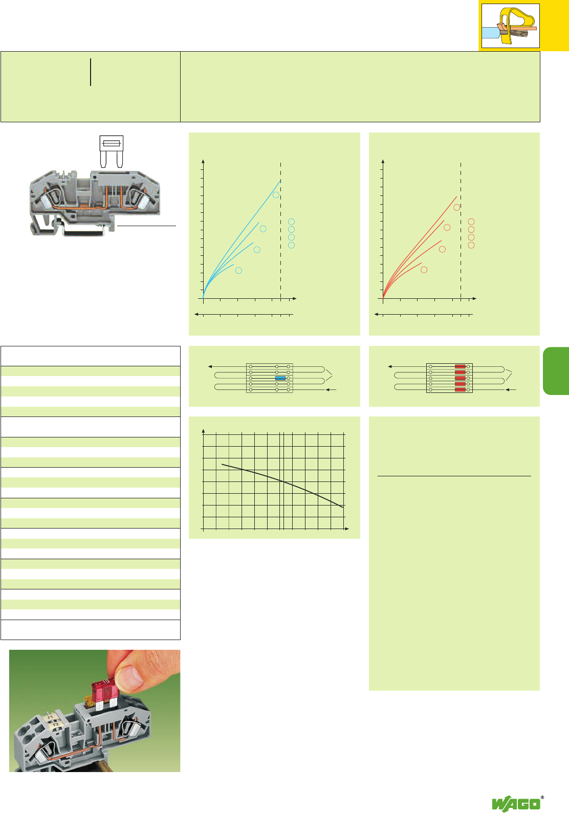
7
-40
-30
-20
-10
0
10
20
30
40
6040200-20
23°C
7
25
*U2
10 20 30 40 5045
75 65 55 45 354085
0
2
4
6
8
10
12
14
16
18
20
22
24
26
28
30
2
3
4
1
1
2
3
4
10 20 30 40 5045
75 65 55 45 354085
0
2
4
6
8
10
12
14
16
18
20
22
24
26
28
30
2
3
4
1
1
2
3
4
➍Higher ambient temperatures (Tamb) are an additional burden on fuse
cartridges.
Therefore, the reduction of the rated current according to the following
diagrams and tables (see factor FT) should be taken into account in such
applications:
(35.5 mm /1.40 in )
<_____________ 85 mm /3.35 in _____________>
(32.5 mm /1.28 in )
<38.5 mm /1.52 in➌>
Current-Carrying Capacity Curves
Appropriate
marking system
WMB/WSB (see section 14)
Insertion of a fuse.
2 mm /0.079 in thick
orange 282-333 100 (4 x 25)
grey 282-334 100 (4 x 25)
IN41 A
grey 282-402 100 (4 x 25)
IN41 A
grey 282-409 100 (4 x 25)
8 mm /0.315 in wide
209-170 50 (2 x 25)
for test plug 4 mm /0.157 in Ø
not offered by WAGO
not offered by WAGO.
Recommended excess-current circuit-breakers of ETA
2-cond. fuse term. bl. for mini-automotive fuses,
without blown-fuse indication,
with testing facility
grey 282-696 25
Item Pack. unit
No. pcs
0.2 – 6 mm2AWG 24 – 10
400 V/6 kV/3 ➊➋ 600 V, 30 A U
25/30 A ➋ ➍ 24 V, 30 A 2
Terminal block width 8 mm / 0.315 in
L12 – 13 mm / 0.49 in
Commo-
ning
It
Ambient temperature °C
Irat – Displacement %
0.877
0.885
0.893
0.901
0.909
0.917
0.926
0.943
0.962
0.980
1.000
1.020
1.042
1.064
1.087
1.111
1.14 9
1.19 0
1.235
1.282
Current-carrying capacity
[A]
Fuse ...A
/ Cross section ...mm
2
Temperature rise
ΔT [K]
Ambient operating
temperature [°C]
In a group
10 A / 2.5 mm2
15 A / 2.5 mm2
20 A / 4 mm2
25 A / 4 mm2
Commo-
ning
It
Information from the mini-automotive
blade-type fuse manufacturers
Derating
Tamb/°C % FT
–25
– 20
–15
–10
–5
0
5
10
15
20
23
30
35
40
45
50
55
60
65
70
14
13
12
11
10
9
8
6
4
2
0
– 2
– 4
– 6
– 8
– 10
– 13
– 16
– 19
– 22
Current-carrying capacity
[A]
Fuse ...A
/ Cross section ...mm
2
Temperature rise
ΔT [K]
Ambient operating
temperature [°C]
Individual arrangement
10 A / 2.5 mm2
15 A / 2.5 mm2
20 A / 2.5 mm2
30 A / 4 mm2
Individual arrangement In a group
The rated currents of the fuse cartridges are
defined differently in international standards.
Due to the different current rating definitions,
the recommended current-carrying permanent
capacity of the fuses is max. 80% of their rated
current according to DIN 72581 part 3 (for an
ambient operating temperature of 23°C).
Selecting the correct fuse cartrigde is important
for product safety within applications as well as
the service life/operational reliability of the fuse
cartrigdes. Fuse cartrigdes can operate perfectly
as protection (break-off point) if they are pro-
perly selected and are used in accordance with
the manufacturers specifications.
In general it is necessary to test fuse cartridges
under normal conditions and operational failures
within your application.
With regard to the product safety, it is in
general necessary to test the fuse in the
appliance under normal conditions and
operational failures.
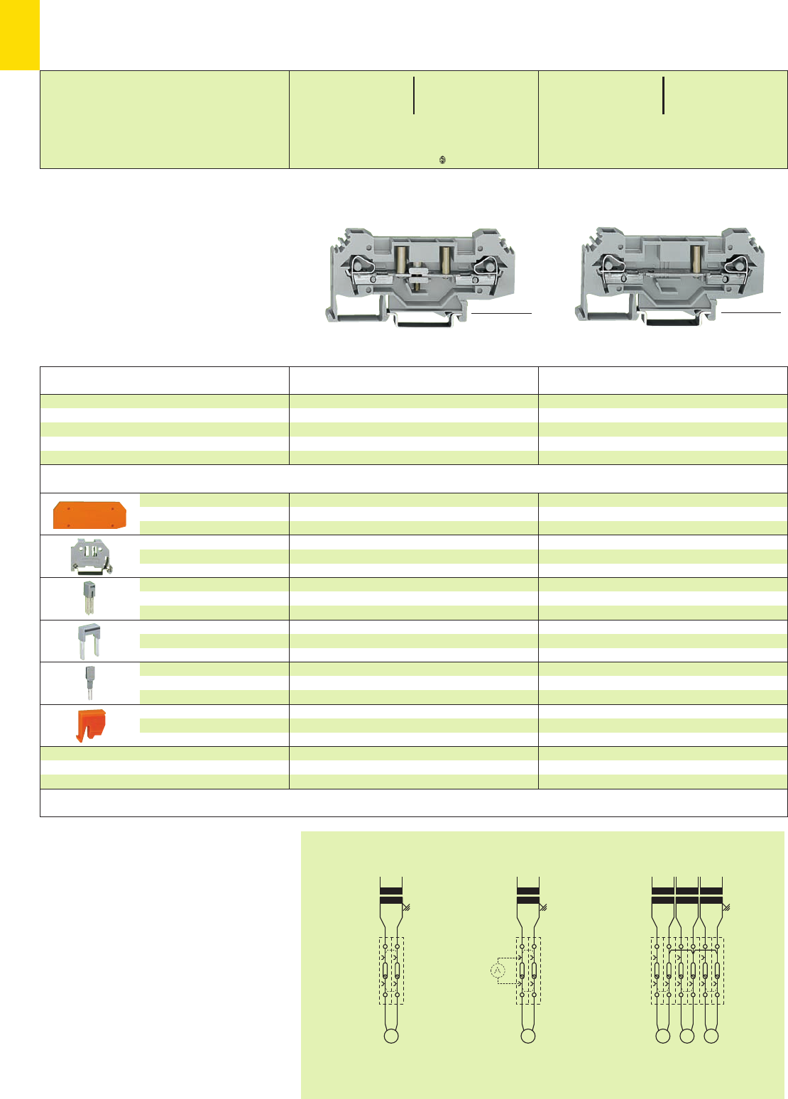
7
26
A A
b)a)
AA
c)
A
l k l k l k
*U2KfNaJ:;{[ . *U2KfNaq:;{[.
<_____________ 87.5 mm/3.44 in _____________><_____________ 87.5 mm/3.44 in _____________>
(_ 37 mm /1.46 in _)
(_ 37 mm /1.46 in _)
* For further approvals with corresponding ratings see section 15.
Item Pack. unit
No. pcs Item Pack. unit
No. pcs
a) Current transformer circuit with current path
separation and commoning possibility.
b) Current transformer circuit with the connection of a
second test unit through test sockets.
c) Transformer test circuit, K-conductors of the
transformers connected.
End and
intermediate plate
Screwless
end stop
Adjacent jumper,
insulated
Alternate jumper,
insulated
Test plug adapter,
suitable for terminal blocks
1.5 mm2– 10 mm2/AWG 16–8
Lock-out, snap-in type,
to prevent reclosing of slide link
4 mm /0.157 in thick
orange 282-315 50 (2 x 25)
grey 282-314 50 (2 x 25)
6 mm /0.236 in wide
249-116 100 (4 x 25)
10 mm /0.394 in wide
249-117 50 (2 x 25)
IN41 A
grey 282-402 100 (4 x 25)
IN41 A
grey 282-409 100 (4 x 25)
8 mm /0.315 in wide
209-170 50 (2 x 25)
for test plug 4 mm /0.157 in Ø
orange 282-137 100 (4 x 25)
4 mm /0.157 in thick
orange 282-315 50 (2 x 25)
grey 282-314 50 (2 x 25)
6 mm /0.236 in wide
249-116 100 (4 x 25)
10 mm /0.394 in wide
249-117 50 (2 x 25)
IN41 A
grey 282-402 100 (4 x 25)
IN41 A
grey 282-409 100 (4 x 25)
8 mm /0.315 in wide
209-170 50 (2 x 25)
for test plug 4 mm /0.157 in Ø
Accessories Appropriate marking system WMB/WSB (see section 14)
Examples of circuit configuration
Description
Disconnect terminal block for test purposes
with test sockets 4 mm /0.157 in Ø
grey 282-131 25
Through terminal block
grey 282-133 25
Disconnect terminal block for test purposes,
for DIN 35 rail
Through terminal block, for DIN 35 rail
➊400 V = rated voltage
6 kV = rated surge voltage
3 = pollution degree
(see also section 15)
Disconnect Terminal Blocks for Test Purposes,
Ground (Earth) Conductor Disconnect Terminal Blocks 6 mm2,
Series 282
0.2 – 6 mm2AWG 24 – 10
400 V/6 kV/3 ➊300 V, 30 A U
41 A 300 V, 40 A 2
Terminal block width 8 mm / 0.315 in
L12 – 13 mm / 0.49 in
0.2 – 6 mm2AWG 24 – 10
400 V/6 kV/3 ➊300 V, 30 A U
41 A 300 V, 40 A 2
Terminal block width 8 mm / 0.315 in
L12 – 13 mm / 0.49 in
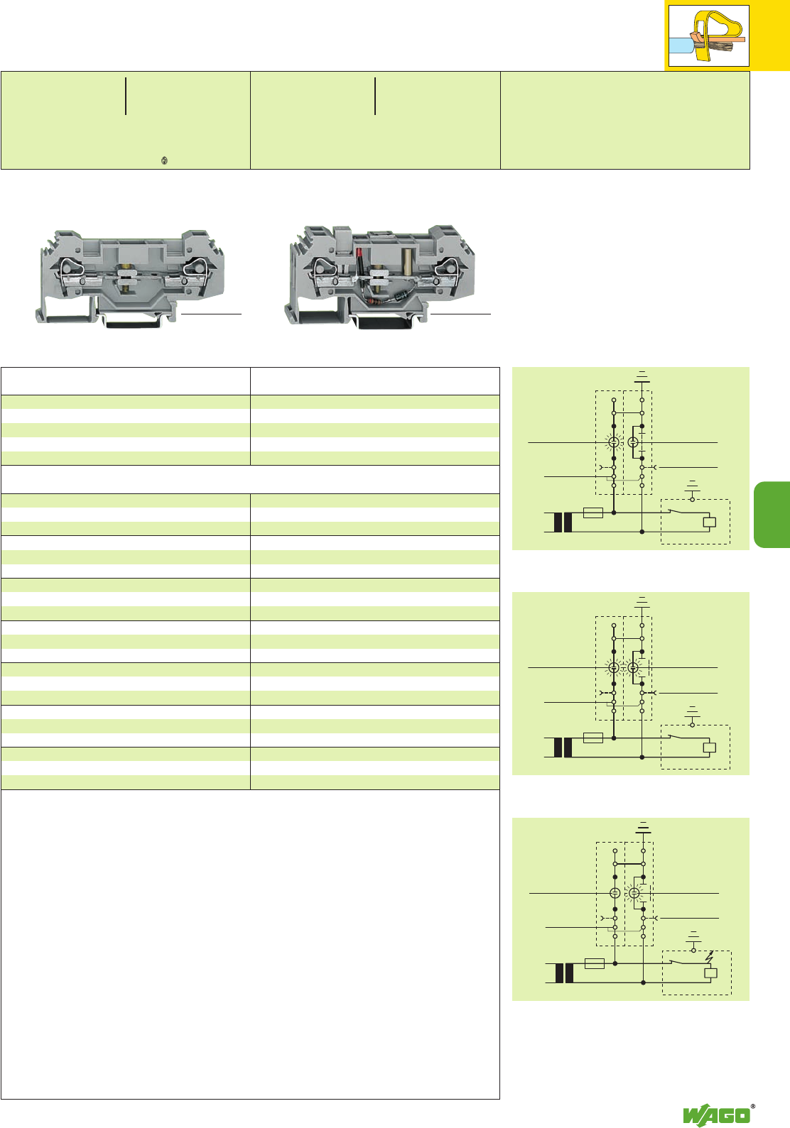
F 1
F 1
F 1
7
7
27
F 1
F 1
F 1
*U2KfNaJq:;{[ . *KfaJq:;{[.
Item Pack. unit
No. pcs
Item Pack. unit
No. pcs
4 mm /0.157 in thick
orange 282-315 50 (2 x 25)
grey 282-314 50 (2 x 25)
6 mm /0.236 in wide
249-116 100 (4 x 25)
10 mm /0.394 in wide
249-117 50 (2 x 25)
IN41 A
grey 282-402 100 (4 x 25)
IN41 A
grey 282-409 100 (4 x 25)
8 mm /0.315 in wide
209-170 50 (2 x 25)
for test plug 4 mm /0.157 in Ø
orange 282-137 100 (4 x 25)
IEC 204-1:1992 “Electrical equipment of indu-
strial machines, part 1: General requirements”
9.4.3.1
Earth faults on control circuits shall not cause
unintentional starting, hazardous movements,
or prevent stopping of the machine.
In order to fulfil this requirement, bonding to
the protective bonding circuit shall be provided
in accordance with 8.2 and the devices shall
be connected as described in 9.1.4. Control
circuits fed from a transformer and not
connected to the protective bonding circuit
shall be provided with an insulation monitoring
device (e. g. residual current device) which
either indicates an earth fault or interrupts the
circuit automatically after an earth fault.
In the case of electronic circuits, the connection
of one side of the control circuit to the protec-
tive bonding circuit in accordance with 9.1.4
can prevent unintentional operation. When this
does not help, or if due to other reasons elec-
tronic circuits cannot be connected to the pro-
tective bonding circuit, other measures shall be
taken to achieve the same level of safety.
Where the control circuit is directly connected
between the phase conductors of the supply or
between a phase conductor and a neutral
conductor which is either not earthed or eart-
hed through a high impedance, multi-pole con-
trol switches which interrupt all live conductors
shall be used for start or stop of those machine
functions which can cause a hazardous conditi-
on or damage to the machine or to the work
in progress, in the event of unintentional star-
ting or failure to stop.
4 mm /0.157 in thick
orange 282-315 50 (2 x 25)
grey 282-314 50 (2 x 25)
6 mm /0.236 in wide
249-116 100 (4 x 25)
10 mm /0.394 in wide
249-117 50 (2 x 25)
IN41 A
grey 282-402 100 (4 x 25)
8 mm /0.315 in wide
209-170 50 (2 x 25)
for test plug 4 mm /0.157 in Ø
orange 282-137 100 (4 x 25)
Ground (earth) cond. disconnect term. blocks, grey
f. AC/DC 24 V 282-140 12
f. AC/DC 48 V 282-141 12
f. AC/DC 120 V 282-138 12
f. AC/DC 230 V 282-139 12
Disconnect terminal block for test purposes
grey 282-135 25
without test sockets
<_____________ 87.5 mm/3.44 in _____________><_____________ 87.5 mm/3.44 in _____________>
(_ 38.5 mm /1.52 in _)
(_ 37 mm /1.46 in _)
Appropriate marking system WMB/WSB (see section 14)
0.2 – 6 mm2AWG 24 – 10
400 V/6 kV/3 ➊300 V, 30 A U
41 A 300 V, 40 A 2
Terminal block width 8 mm / 0.315 in
L12 – 13 mm / 0.49 in
0.2 – 6 mm2AWG 24 – 10
Terminal block width 16 mm / 0.630 in
L12 – 13 mm / 0.49 in
H 2
LED /green lamp
jumper
connection
T 1 K 2 K 1
test socket
riveted
H 1
LED /red lamp
H 2
LED /green lamp
jumper
connection
test socket
riveted
H 1
LED /red lamp
H 2
LED /green lamp
jumper
connection
test socket
riveted
H 1
LED /red lamp
T 1 K 2 K 1
T 1 K 2 K 1
Operating condition
slide link closed, auxiliary circuit grounded (earthed),
green lamp lights.
Test condition – no grounding (earthing)
slide link open, auxiliary circuit not grounded (earthed).
Fault condition – grounding (earthing)
slide link open, auxiliary circuit not grounded (earthed),
red lamp lights.
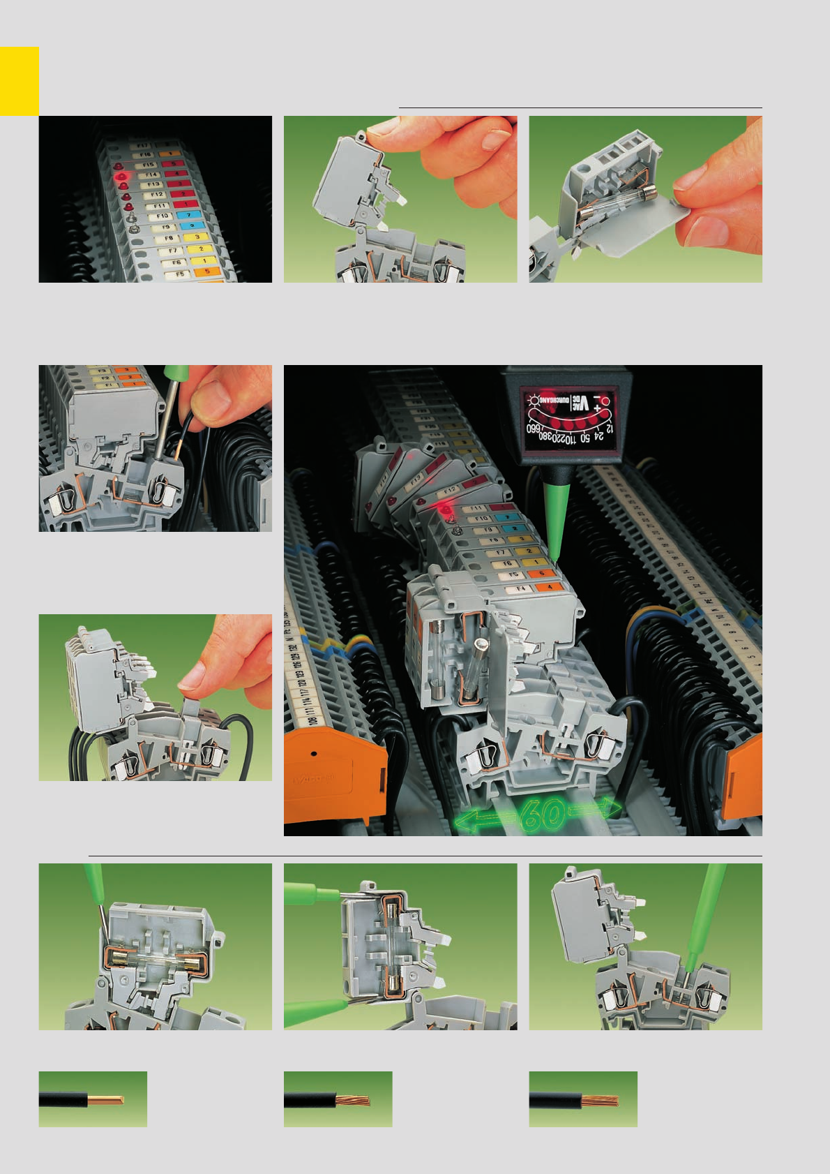
,
7
28
Fused Disconnect Terminal Blocks for Miniature Fuses
with CAGE CLAMP®connection, Series 281 . . .
Blown fuse indication Exchange of fuse
Blown fuse indication by
LED or neon lamp
CAGE CLAMP®connection
Connection of conductors
Front-entry
Commoning
Distribution of current to several fuse protected
circuits by using insulated touchproof jumpers
CAGE CLAMP®
clamps the following
copper wires: *
solid stranded
fine stranded,
also with tinned
single strands
Testing
Voltage test, either at input or output with fuse
holder in closed position (live) Through test with fuse holder in open position
(no voltage) Voltage test at input in the test slot of the
current bar
Before exchanging the fuse, pivot the fuse holder
in the locked open position One end of the fuse is automatically ejected from
the holder when opening the cover . . .
* For aluminum wire see notes in section 15!
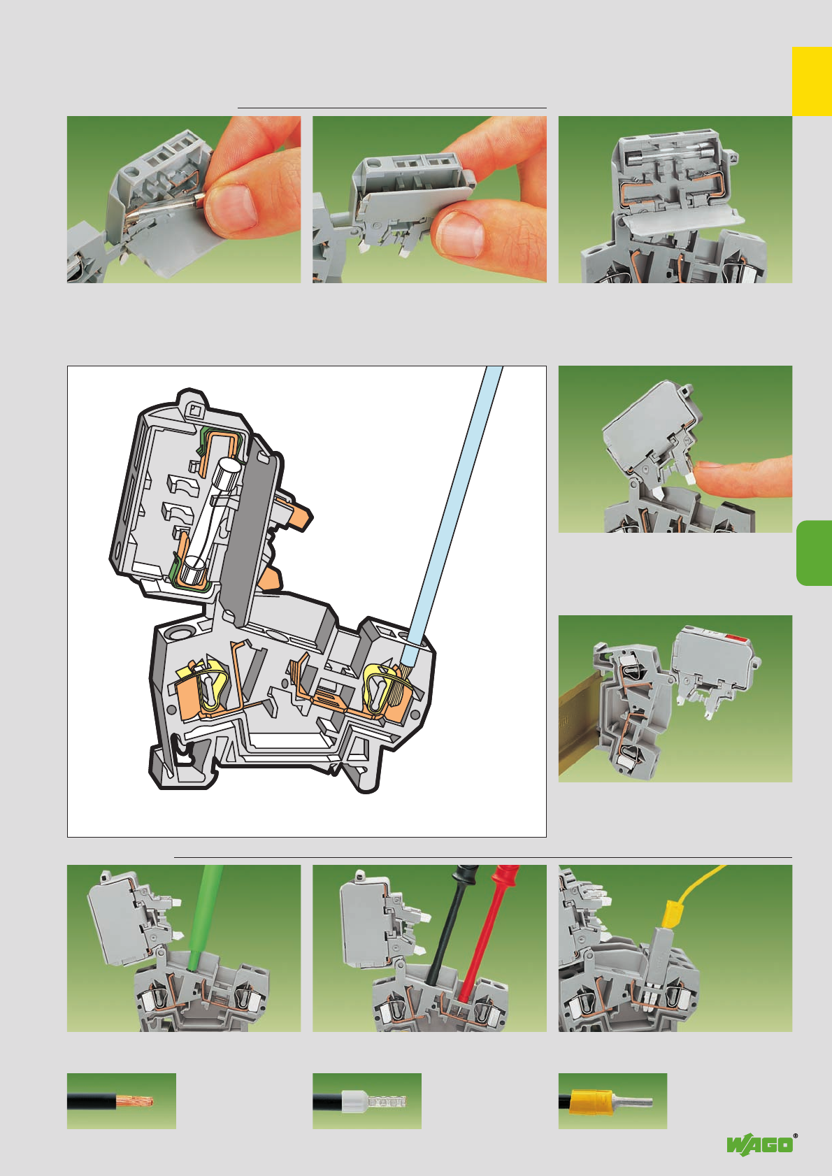
,
7
7
29
. . . Description and Handling
Exchange of fuse (continued) Spare fuse
. . . and can be easily removed by hand.
Insert new fuse . . .
Touchproof protection
“Touchproof” protection in all positions
of the fuse holder
Locked position
Also in vertical assembly of the fused blocks safe
locking of the fuse holder in pivoted open position
fine-stranded wire –
tip bonded
fine-stranded wire
with crimped ferrule ➊fine-stranded wire
with crimped pin terminal
Testing (continued)
Testing of voltage at the output
through separate test slot Current measuring between jumper slot and
separate test slot Voltage testing at input with test plug adapter
280-404 (shown) or test plug 281-407
. . . and snap the cover closed Storage of spare fuse
(fuse holder without blown fuse indication)
➊When using wires with ferrules, it is necessary to use a terminal block one size larger than the nominal cross section of the wire.
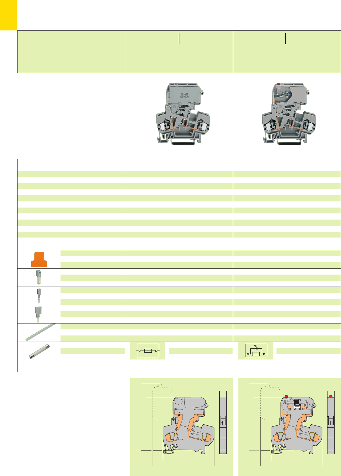
7
30
8
><
<____________ 60 ____________>
<________________ 75, 5 ________________>
<____________ 60 ____________>
<_______________ 73 _______________>
<____________ 60 ____________>
<________________ 75, 5 ________________>
<____________ 60 ____________>
<_______________ 73 _______________>
8
><
*U2KND:; *U2KN
* For further approvals with corresponding ratings see section 15.
Item Pack. unit
No. pcs Item Pack. unit
No. pcs
Dimensions (in mm)
Accessories Appropriate marking system WMB/WSB (see section 14)
Description
Fused disconnect terminal block
with pivotable fuse holder,
for DIN 35 rail,
for miniature metric fuses 5 x 20 mm
5 x 20 mm
5 x 25 mm
5 x 25 mm
5 x 30 mm
5 x 30 mm
without blown fuse indication
grey 281-611 50
orange 281-616 50
grey 281-612 50
grey 281-622 50
2.5 mm /0.098 in thick
orange 281-309 100 (4 x 25)
grey 281-311 100 (4 x 25)
IN32 A
grey 281-402 200 (8 x 25)
5 mm /0.197 in wide
280-404 100 (4 x 25)
for test plug 210-137 (2.3 mm /0.091 in Ø)
IN24 A
281-407 100 (4 x 25)
transparent 210-254 1
contact factory
2.5 mm /0.098 in thick
orange 281-309 100 (4 x 25)
grey 281-311 100 (4 x 25)
IN32 A
grey 281-402 200 (8 x 25)
5 mm /0.197 in wide
280-404 100 (4 x 25)
for test plug 210-137 (2.3 mm /0.091 in Ø)
IN24 A
281-407 100 (4 x 25)
transparent 210-254 1
contact factory
End and
intermediate plate
Adjacent jumper,
insulated
Test plug adapter,
suitable for terminal blocks
1.5 mm2– 4 mm2/AWG 16–12
Test plug, 6 mm /0.236 in wide,
with CAGE CLAMP®for
0.08 mm2– 2.5 mm2/AWG 28-14
Connecting strip, for ganging
several fuse holders,
length 1 m /3’3’’
Miniature metric fuse
with blown fuse indication by LED
grey 15 – 30 V앓➌281-611/281-541 50
grey 30 – 65 V앓➌281-611/281-542 50
grey 15 – 30 V앓➌281-612/281-541 50
grey 30 – 65 V앓➌281-612/281-542 50
grey 15 – 30 V앓➌281-622/281-541 50
grey 30 – 65 V앓➌281-622/281-542 50
<______ 60 mm /2.36 in ______>
<______ 60 mm /2.36 in ______>
<______ 60 mm /2.36 in ______>
<______ 60 mm /2.36 in ______>
Fused Disconnect Terminal Blocks 4 mm2/AWG 12,
for Miniature Metric Fuses 5 x 20 mm, 5 x 25 mm, 5 x 30 mm
Series 281
➊800 V = rated voltage
8 kV = rated surge voltage
3 = pollution degree
(see also section 15)
➋Nominal voltage and current are given
by the LED or fuse
Technical details see pages 7.38 – 7.39
➌Leakage current in case of blown fuse:
LED 6 mA, neon lamp < 0.4 mA
0.08 – 4 mm2AWG 28 – 12
800 V/8 kV/3 ➊➋ 600 V, 10 A ➋U2
10 A max. ➋
Terminal block width 8 mm / 0.315 in
L9 – 10 mm / 0.37 in
0.08 – 4 mm2AWG 28 – 12
800 V/8 kV/3 ➊➋ 30/65 V, 10 A ➋U2
10 A max. ➋
Terminal block width 8 mm / 0.315 in
L9 – 10 mm / 0.37 in
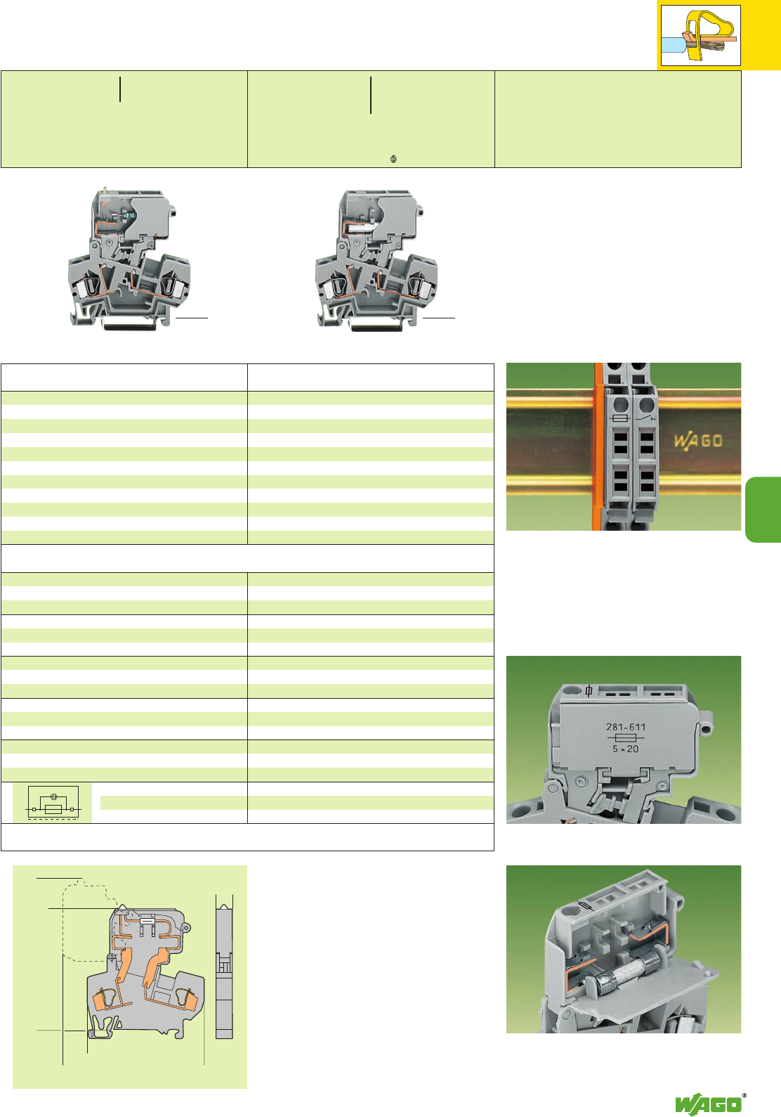
7
7
31
<____________ 60 ____________>
<________________ 75, 5 ________________>
<____________ 60 ____________>
<_______________ 73 _______________>
8
><
*U2N *U2fNDaJ:;{[ Application notes
Item Pack. unit
No. pcs
2.5 mm /0.098 in thick
orange 281-309 100 (4 x 25)
grey 281-311 100 (4 x 25)
IN32 A
grey 281-402 200 (8 x 25)
5 mm /0.197 in wide
280-404 100 (4 x 25)
for test plug 210-137 (2.3 mm /0.091 in Ø)
IN24 A
281-407 100 (4 x 25)
transparent 210-254 1
contact factory
2.5 mm /0.098 in thick
orange 281-309 100 (4 x 25)
grey 281-311 100 (4 x 25)
IN32 A
grey 281-402 200 (8 x 25)
5 mm /0.197 in wide
280-404 100 (4 x 25)
for test plug 210-137 (2.3 mm /0.091 in Ø)
IN24 A
281-407 100 (4 x 25)
transparent 210-254 1
with blown fuse indication by neon lamp
grey 230 V앓➌281-611/281-417 50
grey 120 V앓➌281-611/281-418 50
grey 230 V앓➌281-612/281-417 50
grey 120 V앓➌281-612/281-418 50
grey 230 V앓➌281-622/281-417 50
grey 120 V앓➌281-622/281-418 50
Item Pack. unit
No. pcs
Disconnect terminal blocks with “knife” disconnect
grey 281-624 50
orange 281-672 50
Fused or fused disconnect terminal blocks with a width of
8 mm/0.315 in can be assembled adjacent to each other.
At the end of an assembly, if there is no adjacent fused
or fused disconnect terminal block, an end or inter-
mediate plate must be used.
Fuse holders are printed with correct fuse size and . . .
. . . are fitted with stops on the inside of the cover.
For types 5 x 20 mm, 5 x 25 mm and 1⁄4’’ x 1’’
<______ 60 mm /2.36 in ______>
<______ 60 mm /2.36 in ______>
<______ 60 mm /2.36 in ______>
<______ 60 mm /2.36 in ______>
0.08 – 4 mm2AWG 28 – 12
800 V/8 kV/3 ➊➋ 110/220V,10 A➋U2
10 A max. ➋
Terminal block width 8 mm / 0.315 in
L9 – 10 mm / 0.37 in
0.08 – 4 mm2AWG 28 – 12
800 V/8 kV/3 ➊600 V, 10 A U2
16 A
Terminal block width 8 mm / 0.315 in
L9 – 10 mm / 0.37 in
Appropriate marking system WMB/WSB (see section 14)
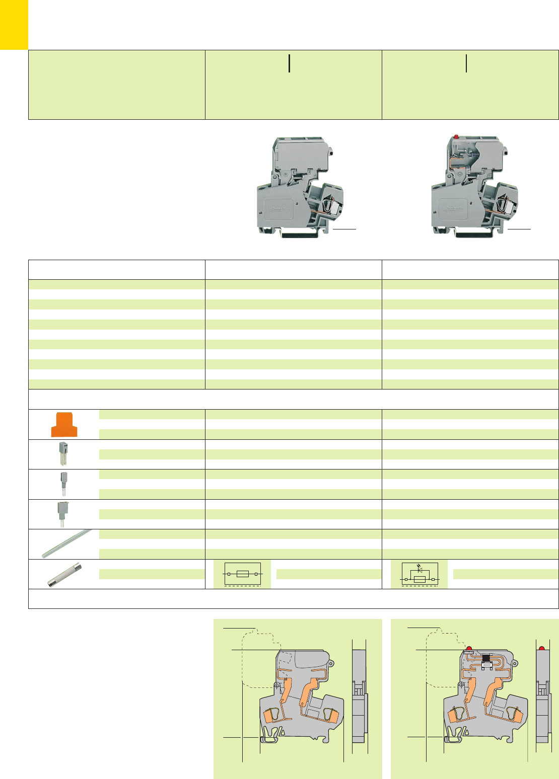
7
32
<____________ 60 ____________>
<________________ 75, 5 ________________>
<____________ 60 ____________>
<_______________ 73 _______________>
9
><
(_10_)
<____________ 60 ____________>
<________________ 75, 5 ________________>
<____________ 60 ____________>
<_______________ 73 _______________>
9
><
(_10_)
*U2KND:; *U2KN
<______ 60 mm /2.36 in ______>
<______ 60 mm /2.36 in ______>
<______ 60 mm /2.36 in ______>
<______ 60 mm /2.36 in ______>
➊800 V = rated voltage
8 kV = rated surge voltage
3 = pollution degree
(see also section 15)
➋Nominal voltage and current are given
by the LED or fuse
Technical details see pages 7.38 – 7.39
➌Leakage current in case of blown fuse:
LED 6 mA, neon lamp < 0.4 mA
Item Pack. unit
No. pcs Item Pack. unit
No. pcs
Dimensions (in mm)
Accessories Appropriate marking system WMB/WSB (see section 14)
Description
* For further approvals with corresponding ratings see section 15.
2.5 mm /0.098 in thick
orange 281-309 100 (4 x 25)
grey 281-311 100 (4 x 25)
IN32 A
grey 281-402 200 (8 x 25)
5 mm /0.197 in wide
280-404 100 (4 x 25)
for test plug 210-137 (2.3 mm /0.091 in Ø)
IN24 A
281-407 100 (4 x 25)
transparent 210-254 1
contact factory
2.5 mm /0.098 in thick
orange 281-309 100 (4 x 25)
grey 281-311 100 (4 x 25)
IN32 A
grey 281-402 200 (8 x 25)
5 mm /0.197 in wide
280-404 100 (4 x 25)
for test plug 210-137 (2.3 mm /0.091 in Ø)
IN24 A
281-407 100 (4 x 25)
transparent 210-254 1
contact factory
End and
intermediate plate
Adjacent jumper,
insulated
Test plug adapter,
suitable for terminal blocks
1.5 mm2– 4 mm2/AWG 16–12
Test plug, 6 mm /0.236 in wide,
with CAGE CLAMP®for
0.08 mm2– 2.5 mm2/AWG 28-14
Connecting strip, for ganging
several fuse holders,
length 1 m /3’3’’
Miniature metric fuse
Fused disconnect terminal block,
with pivotable fuse holder,
for DIN 35 rail, 1⁄4’’ x 1’’
for miniature fuses 1⁄4’’ x 1’’
1⁄4’’ x 11⁄4’’
1⁄4’’ x 11⁄4’’
without blown fuse indication
grey 281-613 50
grey 281-623 50
with blown fuse indication by LED
grey 15 – 30 V앓➌281-613/281-541 50
grey 30 – 65 V앓➌281-613/281-542 50
grey 15 – 30 V앓➌281-623/281-541 50
grey 30 – 65 V앓➌281-623/281-542 50
Fused Disconnect Terminal Blocks 4 mm2/AWG 12,
for Miniature Metric Fuses 1⁄4’’ x 1’’, 1⁄4’’ x 11⁄4’’,
Series 281
0.08 – 4 mm2AWG 28 – 12
800 V/8 kV/3 ➊➋ 600 V, 10 A ➋U2
10 A max. ➋
Terminal block width 10 mm / 0.394 in
L9 – 10 mm / 0.37 in
0.08 – 4 mm2AWG 28 – 12
800 V/8 kV/3 ➊➋ 30/65 V, 10 A ➋U2
10 A max. ➋
Terminal block width 10 mm / 0.394 in
L9 – 10 mm / 0.37 in
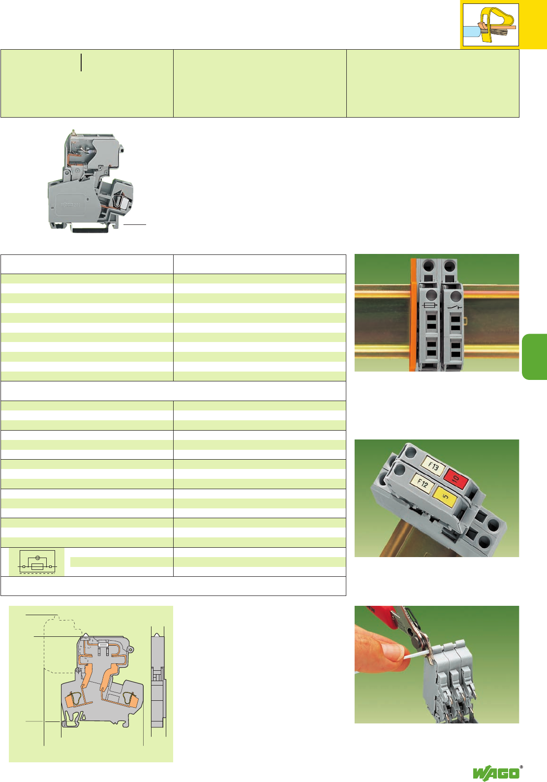
7
7
33
<____________ 60 ____________>
<________________ 75, 5 ________________>
<____________ 60 ____________>
<_______________ 73 _______________>
9
><
(_10_)
*U2KN Application notes
<______ 60 mm /2.36 in ______>
<______ 60 mm /2.36 in ______>
2.5 mm /0.098 in thick
orange 281-309 100 (4 x 25)
grey 281-311 100 (4 x 25)
IN32 A
grey 281-402 200 (8 x 25)
5 mm /0.197 in wide
280-404 100 (4 x 25)
for test plug 210-137 (2.3 mm /0.091 in Ø)
IN24 A
281-407 100 (4 x 25)
transparent 210-254 1
contact factory
with blown fuse indication by neon lamp
grey 230 V앓➌281-613/281-417 50
grey 120 V앓➌281-613/281-418 50
grey 230 V앓➌281-623/281-417 50
grey 120 V앓➌281-623/281-418 50
Item Pack. unit
No. pcs
In case of 10 mm /0.394 in wide fused terminal blocks a
spacer is part of the terminal block and will be supplied
as a standard.
At the end of an assembly or if there is no adjacent
fused terminal block, an end or intermediate plate must
be used.
2 marker receptacles each per fuse holder for individual
WMB Multi marking or WSB Quick marking
(example: 8 mm /0.315 in terminal blocks)
Ganging of several fuse holders with a connecting strip
(example: 8 mm /0.315 in terminal blocks)
Appropriate
marking system
WMB/WSB (see section 14)
0.08 – 4 mm2AWG 28 – 12
800 V/8 kV/3 ➊➋ 110/220 V, 10 A ➋U2
10 A max. ➋
Terminal block width 10 mm / 0.394 in
L9 – 10 mm / 0.37 in
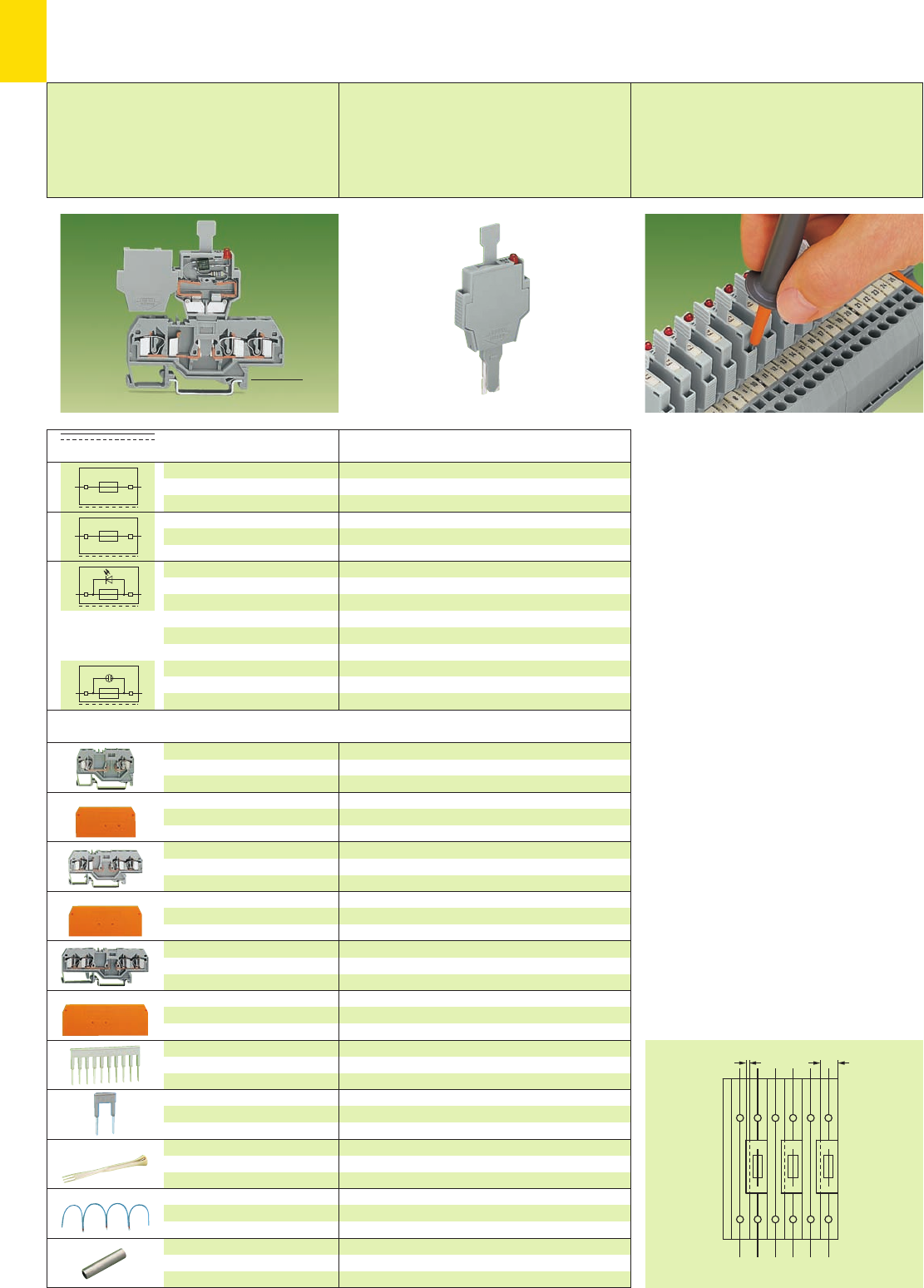
7
34
N L1 N L2 N L3
15
Pluggable fuse modules
on terminal blocks for pluggable modules
Item No. 286-890
see W4, Volume 3
residual current
in case of blown fuse
LED 5 – 20 mA,
Neon lamp < 0.4 mA
The use of pluggable fuse holders with rail moun-
ted terminal blocks for protection of control cir-
cuits offers many advantages to the user since
the function and the wiring are accomplished by
two separate parts:
●no additional cost for assembly and wiring
●no risk of accidental contact with live parts
during disconnection of fuse plug
●in case of exchanging a defective fuse the fuse
plug is completely separated from the carrier
terminal block
●therefore safe exchange of the fuse away from
current carrying parts
●the fuse plug can be taken away by the
serviceman avoiding unintentional reclosing of
the circuit by another person
●quick exchange of a fuse by using a prepared
“stand-by plug.”
Further advantages:
●optional LED indicates blown fuse
●marking facility on the fuse plug for clear co-
ordination to the correct carrier terminal block
(WSB-Quick Marking System 4 mm /0.157 in)
●two touchproof test slots
●high density with only 6 mm /0.236 in width of
terminal block/fuse plug
●instead of a fuse, a shorting link may be used
as a disconnect plug.
When corresponding Neutral-circuit is adjacent to
a fuse plug, a 5 mm /0.197 in. wide space saving
terminal block may be used, as a 6 mm /0.236 in.
fuse plug may overlap the terminal block.
See right page for 5 mm /0.197 in wide carrier
terminal blocks (can be used with end plate, for
example).
➊59 mm /2.32 in
➋73.5 mm /2.89 in
➌86 mm /3.39 in
Item Pack. unit
No. pcs
Description
open side of terminal
Terminal block width 6 mm /0.236 in
grey 281-916 50
2.5 mm /0.098 in thick
orange 281-329 100 (4 x 25)
grey 281-328 100 (4 x 25)
Terminal block width 6 mm /0.236 in
grey 281-610 50
2.5 mm /0.098 in thick
orange 281-326 100 (4 x 25)
grey 281-324 100 (4 x 25)
Terminal block width 6 mm /0.236 in
grey 281-656 50
2.5 mm /0.098 in thick
orange 281-335 100 (4 x 25)
grey 281-334 100 (4 x 25)
2-way 281-482 100 (4 x 25)
3-way 281-483 100 (4 x 25)
5-way 281-485 100 (4 x 25)
2-way 281-492 100 (4 x 25)
2-way 280-432 1
3-way 280-433 1
5-way 281-440 1
Max. commoning distance 120 mm /4.724 in
black 210-103 1
blue 210-123 1
281-503 250 (10 x25)
2-cond. carrier term. block ➊,
0.08 – 4 mm2/AWG 28 – 12
stripped length 9 – 10 mm /0.37 in
End and intermediate plate,
for 2-conductor
carrier terminal block
3-cond. carrier term. block ➋,
0.08 – 4 mm2/AWG 28 – 12
stripped length 9 – 10 mm/0.37in
End and intermediate plate,
for 3-conductor
carrier terminal block
4-cond. carrier term. block ➌,
0.08 – 4 mm2/AWG 28 – 12
stripped length 9 – 10 mm /0.37 in
End and intermediate plate,
for 4-conductor
carrier terminal block
Comb type jumper bar,
insulated, see also page 2.44
IN32 A
Alternate comb type
jumper bar,
insulated, IN32 A
Operating tool,
insulated
Wire commoning chain,
insulated, 50 connections, 8 A
Shorting link, 5 x 20 mm /
0.20 x 0.79 in, 6.3 A, if the fuse
plug is used as disconnect plug
Fuse plug, for
miniature metric fuses 5 x 20 mm
and 5 x 25 mm
Fuse plug, same as above,
with hole for one LED
(for self-assembly)
Fuse plug, same as above, with
additional indicator lamp,
LED, AC/DC 24 V,
can be used in both switching
directions
Neon lamp
AC/DC 120 V
AC/DC 230 V
6 mm /0.236 in wide
with pull-tab
281-511 50
6 mm /0.236 in wide
with pull-tab
281-512 50
6 mm /0.236 in wide
with pull-tab
281-512/281-501 50
6 mm /0.236 in wide
with pull-tab
281-512/281-418 50
281-512/281-417 50
Terminal blocks and accessories
open side of terminal block left
<______ 74.5 mm /2.93 in ______>
<___________ ➊➋➌___________>
Pluggable Fuse Modules for
Replaceable Miniature Fuses 4 mm2/AWG 12,
Series 281
250 V max.*
6.3 max.
Appropriate Plug
WSB
4 mm /0.157 in wide
marking system T. bl.
WMB/WSB
For further approvals with corresponding ratings see section 15.
* Electrical ratings are given by the fuse or nomi-
nal voltage of the indicator lamp respectively.
Technical details see pages 7.38 – 7.39.
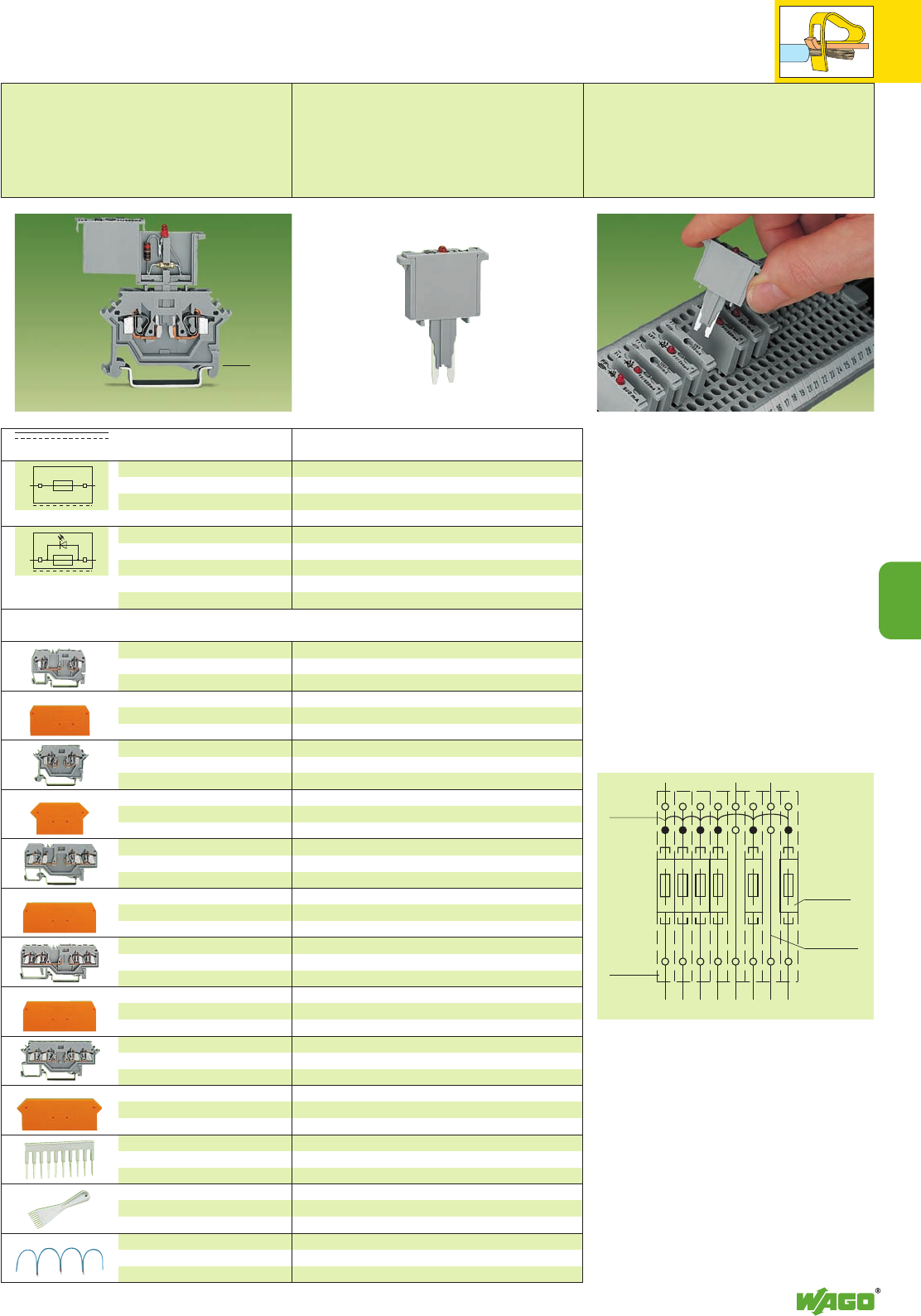
7
7
35
12345678
<____ ➊➋➌➍➎➏ ____>
<_____ 52.5 mm /2.07 in _____>
Item Pack. unit
No. pcs
Pluggable Fuse Modules for
Replaceable Miniature Fuses 2.5 mm2/AWG 14,
Series 280
125 V max.*
5 A*
The use of pluggable fuse holders with rail moun-
ted terminal blocks for protection of control cir-
cuits offers many advantages to the user since
the function and the wiring are accomplished by
two separate parts:
●no additional cost for assembly and wiring
●no risk of accidental contact with live parts
during disconnection
●quick exchange of fuse plug in case of
blown fuse
●the fuse plug can be taken away by the
serviceman avoiding unintentional reclosing of
the circuit by another person
Further advantages
●extremely high density with only 5 mm /0.197 in
width of terminal block/fuse plug
●optional LED indicates blown fuse
Description
open side of terminal
Terminal block width 5 mm /0.197 in
grey 280-916 ➊100
2.5 mm /0.098 in thick
orange 280-309 100 (4 x 25)
grey 280-308 100 (4 x 25)
Terminal block width 5 mm /0.197 in
grey 280-616 ➋100
2.5 mm /0.098 in thick
orange 280-331 100 (4 x 25)
grey 280-330 100 (4 x 25)
Terminal block width 5 mm /0.197 in
grey 280-610 ➌100
2.5 mm /0.098 in thick
orange 280-326 100 (4 x 25)
grey 280-324 100 (4 x 25)
Terminal block width 5 mm /0.197 in
grey 280-816 ➎100
grey 280-686 ➍100
2.5 mm /0.098 in thick
orange 280-315 100 (4 x 25)
grey 280-314 100 (4 x 25)
Terminal block width 5 mm /0.197 in
grey 280-606 ➏100
2.5 mm /0.098 in thick
orange 280-317 100 (4 x 25)
grey 280-316 100 (4 x 25)
2-way 280-482 200
3-way 280-483 200
10-way 280-490 50
2-way 280-432 1
3-way 280-433 1
10-way 280-440 1
Max. commoning distance 120 mm /4.724 in
black 210-103 1
blue 210-123 1
2-cond. carrier term. block,
0.08 – 2.5 mm2/AWG 28 – 14
stripped length 8 – 9 mm /0.33 in
End and intermediate plate,
for 2-conductor carrier terminal
block 280-916
2-cond. carrier term. block,
0.08 – 2.5 mm2/AWG 28 – 14
stripped length 8 – 9 mm /0.33 in
End and intermediate plate,
for 2-conductor carrier terminal
block 280-616
3-cond. carrier term. block,
0.08 – 2.5 mm2/AWG 28 – 14
stripped length 8 – 9 mm /0.33 in
End and intermediate plate,
for 3-conductor carrier terminal
block 280-610
4-cond. carrier term. block,
0.08 – 2.5 mm2/AWG 28 – 14
stripped length 8 – 9 mm /0.33 in
End and intermediate plate,
for 4-conductor
carrier terminal blocks
4-cond. carrier term. block,
0.08 – 2.5 mm2/AWG 28 – 14
stripped length 8 – 9 mm /0.33 in
End and intermediate plate,
for 4-conductor carrier terminal
block 280-606
Comb type jumper bar,
insulated, see also page 2.44
IN24 A
Operating tool,
insulated
Wire commoning chain,
insulated, 50 connections, 8 A
Fuse plug, 5 mm /0.197in wide,
with soldered miniature fuse
Fuse plug, same as above,
with additional indicator lamp,
LED, DC 15 – 30 V
250 mA FF 280-850 100
500 mA FF 280-852 100
1 A FF 280-854 100
2 A FF 280-856 100
250 mA FF 280-850/281-413 100
500 mA FF 280-852/281-413 100
1 A FF 280-854/281-413 100
2 A FF 280-856/281-413 100
Terminal blocks and accessories
Terminal block width
➊53 mm /2.09 in
➋50 mm /1.97 in
➌64 mm /2.52 in
➍Terminal block marking in center position right
75 mm /2.95 in
➎Terminal block marking in center position left
75 mm /2.95 in
➏Terminal block marking on both sides
73 mm /2.87 in
residual current
in case of blown fuse
LED 5 – 20 mA
Appropriate
marking system
WMB/WSB
(see section 14)
For further approvals with corresponding ratings see section 15.
* Electrical ratings are given by the fuse or nomi-
nal voltage of the indicator lamp respectively.
Technical details see pages 7.38 – 7.39.
open side of terminal block right
Wire
commoning
chain
Fuse plug
280-850/
281-413
Through
term. block
280-681
Carrier
term. block
280-610
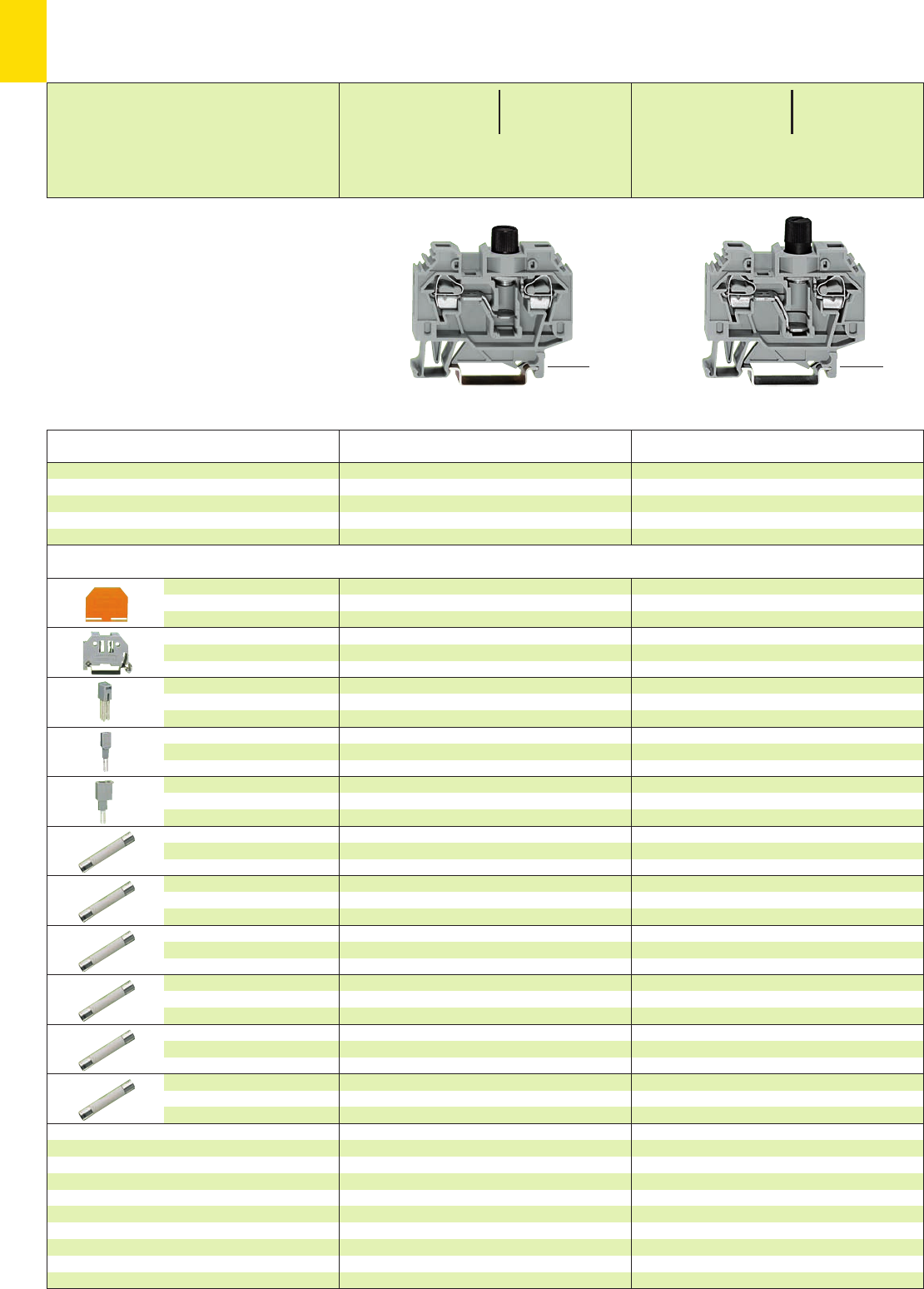
7
36
*U2K. *U2K.
<________ 62 mm /2.44 in ________>
<______ 54.5 mm /2.15 in ______>
<________ 62 mm /2.44 in ________>
<_____ 56.5 mm /2.22 in _____>
Fuse Terminal Blocks 6 mm2/AWG 10,
Series 282
➊500 V = rated voltage
6 kV = rated surge voltage
3 = pollution degree
(see also section 15)
Nominal voltage and current are given
by the LED or fuse
Technical details see pages 7.38 – 7.39
Item Pack. unit
No. pcs Item Pack. unit
No. pcs
Accessories Appropriate marking system WMB/WSB (see section 14)
Description
4 mm /0.157 in thick
orange 282-312 50 (2 x 25)
grey 282-311 50 (2 x 25)
6 mm /0.236 in wide
249-116 100 (4 x 25)
10 mm /0.394 in wide
249-117 50 (2 x 25)
IN41 A
grey 282-402 100 (4 x 25)
8 mm /0.315 in wide
209-170 50 (2 x 25)
for test plug 4 mm /0.157 in Ø
IN24 A
281-407 100 (4 x 25)
282-451 200 (20 x10)
4 mm /0.157 in thick
orange 282-312 50 (2 x 25)
grey 282-311 50 (2 x 25)
6 mm /0.236 in wide
249-116 100 (4 x 25)
10 mm /0.394 in wide
249-117 50 (2 x 25)
IN41 A
grey 282-402 100 (4 x 25)
8 mm /0.315 in wide
209-170 50 (2 x 25)
for test plug 4 mm /0.157 in Ø
IN24 A
281-407 100 (4 x 25)
282-458 200 (20 x10)
282-457 200 (20 x10)
282-454 200 (20 x10)
End and
intermediate plate
Screwless end stop,
for DIN 35 rail
Adjacent jumper,
insulated
Test plug adapter,
suitable for terminal blocks
1.5 mm2– 10 mm2/AWG 16–8
Test plug, 6 mm /0.236 in wide,
with CAGE CLAMP®for
0.08 mm2- 2.5 mm2/AWG 28 -14
Miniature metric fuse,
5 x 20 mm, without indicator,
6.3 A /250 V, medium slow
Miniature metric fuse,
5 x 25 mm, with indicator,
6.3 A /250 V, medium slow
Miniature metric fuse,
5 x 25 mm, with indicator,
10 A /450 V, quick acting
Miniature fuse,
1⁄4“ x 1“, without indicator,
10 A /240 V, acc. to BS 1362
Miniature fuse,
1⁄4“ x 11⁄4“, without indicator,
10 A /250 V, medium slow
Miniature fuse,
1⁄4“ x 11⁄4“, without indicator,
10 A /500 V, very quick acting
Fuse terminal block, for DIN 35 rail,
for cartridges
Fuse terminal block, without indicator
grey, 5 x 20 mm 282-122 40
Fuse terminal blocks, without indicator
grey, 1⁄4“ x 1“ 282-120 40
grey, 1⁄4“ x 11⁄4“282-128 40
* For further approvals with corresponding ratings see section 15.
0.2 – 6 mm2AWG 24 – 10
500 V/6 kV/3 max. ➊600 V, 10 A ➊U
10 A max. ➊250 V, 10 A ➊2
Terminal block width 13 mm / 0.512 in
L12 – 13 mm / 0.49 in
0.2 – 6 mm2AWG 24 – 10
500 V/6 kV/3 max. ➊600 V, 10 A ➊U
10 A max. ➊250 V, 10 A ➊2
Terminal block width 13 mm / 0.512 in
L12 – 13 mm / 0.49 in
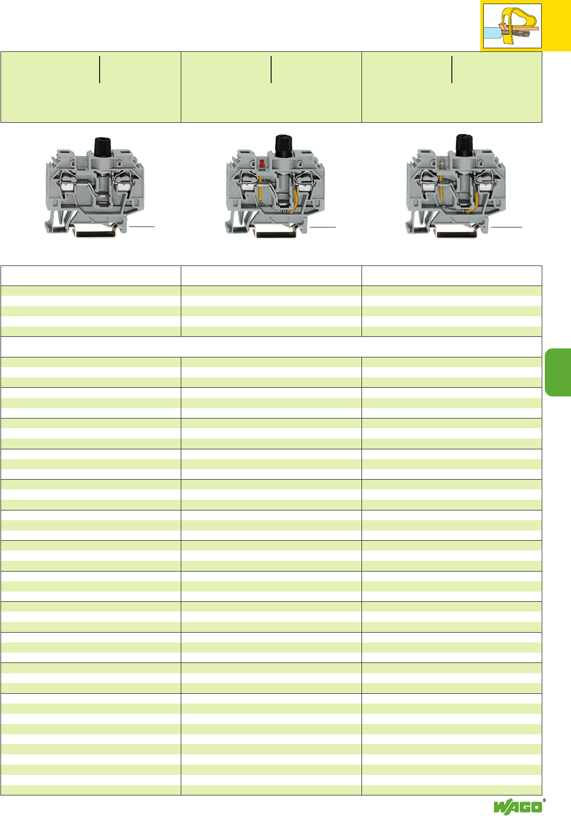
7
7
37
*U2K:. *U2K *U2K.
<________ 62 mm /2.44 in ________>
<_____ 54.5 mm /2.15 in _____>
<________ 62 mm /2.44 in ________>
<_____ 56.5 mm /2.22 in _____>
<________ 62 mm /2.44 in ________>
Item Pack. unit
No. pcs
Item Pack. unit
No. pcs Item Pack. unit
No. pcs
4 mm /0.157 in thick
orange 282-312 50 (2 x 25)
grey 282-311 50 (2 x 25)
6 mm /0.236 in wide
249-116 100 (4 x 25)
10 mm /0.394 in wide
249-117 50 (2 x 25)
IN41 A
grey 282-402 100 (4 x 25)
8 mm /0.315 in wide
209-170 50 (2 x 25)
for test plug 4 mm /0.157 in Ø
IN24 A
281-407 100 (4 x 25)
282-452 200 (20 x10)
282-453 200 (20 x10)
4 mm /0.157 in thick
orange 282-312 50 (2 x 25)
grey 282-311 50 (2 x 25)
6 mm /0.236 in wide
249-116 100 (4 x 25)
10 mm /0.394 in wide
249-117 50 (2 x 25)
IN41 A
grey 282-402 100 (4 x 25)
8 mm /0.315 in wide
209-170 50 (2 x 25)
for test plug 4 mm /0.157 in Ø
IN24 A
281-407 100 (4 x 25)
282-457 200 (20 x10)
282-454 200 (20 x10)
4 mm /0.157 in thick
orange 282-312 50 (2 x 25)
grey 282-311 50 (2 x 25)
6 mm /0.236 in wide
249-116 100 (4 x 25)
10 mm /0.394 in wide
249-117 50 (2 x 25)
IN41 A
grey 282-402 100 (4 x 25)
8 mm /0.315 in wide
209-170 50 (2 x 25)
for test plug 4 mm /0.157 in Ø
IN24 A
281-407 100 (4 x 25)
282-451 200 (20 x10)
282-457 200 (20 x10)
282-454 200 (20 x10)
Fuse terminal block, with indicator
grey, 5 x 25 mm 282-126 40
Fuse terminal blocks,
with neon lamp AC 250 V/DC 220 V
grey, 5 x 20 mm 282-124 ➋40
grey, 1⁄4“ x 11⁄4“282-128/281-417➌40
Fuse terminal blocks,
with neon lamp AC/DC 120 V
grey, 1⁄4“ x 11⁄4“282-128/281-418 40
with LED DC 24 V
grey, 1⁄4“ x 11⁄4“282-128/281-413 40
0.2 – 6 mm2AWG 24 – 10
500 V/6 kV/3 max.➊600 V, 10 A ➊U
10 A max. ➊250 V, 10 A ➊2
Terminal block width 13 mm / 0.512 in
L12 – 13 mm / 0.49 in
0.2 – 6 mm2AWG 24 – 10
120 V 앓24 /110 V, 10 A ➊U
10 A max. ➊24 /110 V, 10 A ➊2
Terminal block width 13 mm / 0.512 in
L12 – 13 mm / 0.49 in
0.2 – 6 mm2AWG 24 – 10
250 V 앓250 V, 10 A ➊U
10 A max. ➊220 V, 10 A ➊2
Terminal block width 13 mm / 0.512 in
L12 – 13 mm / 0.49 in
Appropriate marking system WMB/WSB (see section 14)
<____ 54.5 mm/2.15 in➋
____>

7
38
Terminal blocks for miniature metric fuses tested acc. to IEC or EN 60947-7-3/VDE 0611-6
Notes on the Use of Terminal Blocks for Miniature Metric Fuses
When selecting miniature metric fuses, the maximum power loss listed below
should not be exceeded.
The power loss is determined according to IEC or EN 60947-7-3/VDE 0611-6
at 23°C.
The temperature rise of the terminal blocks must be checked according their
application and mounting.
Higher ambient temperatures represent an additional impact on miniature
metric fuses. Therefore, in such applications the rated current must be reduced
if necessary.
More details from the manufacturer.
Miniature metric fuses 5 x 20
Series Overload Short circuit protection only
Item No. and short circuit protection
Individual arrangement
In a group
Individual arrangement
In a group
Fuse terminal blocks (with screw cap) front-entry (5 x 20 mm)
282-122 2.5 W 2.5 W 4 W 4 W
282-124
Fused disconnect terminal blocks for miniature metric fuses (5 x 20 mm)
281-611
281-616
281-611/281-541 2.5 W 1.6 W 4 W 4 W
281-611/281-542
281-611/281-417
281-611/281-418
Pluggable fuse modules for miniature metric fuses (5 x 20 mm)
281-511
281-512
281-512/281-501 2.5 W 1.6 W 4 W 4 W
281-512/281-418
281-512/281-417
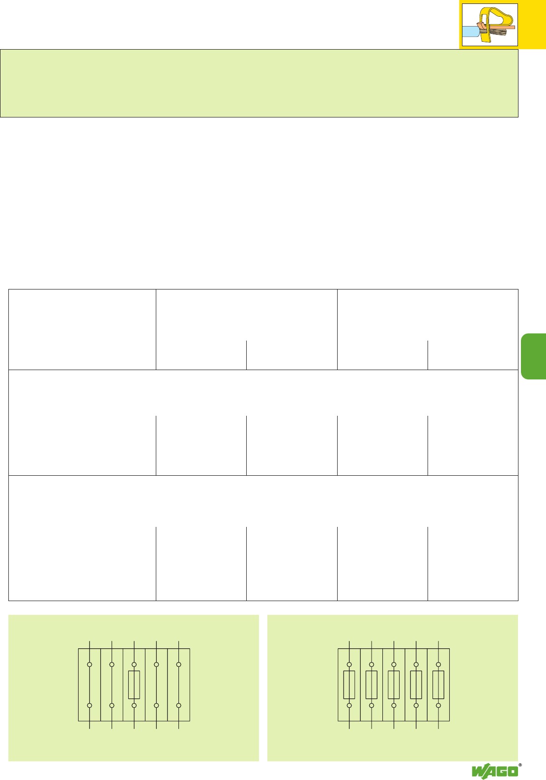
7
7
39
Miniature metric fuses 6.3 x 32
Series Overload Short circuit protection only
Item No. and short circuit protection
Individual arrangement
In a group
Individual arrangement
In a group
Fuse terminal blocks (with screw cap) front-entry (1
/
4’’ x 11
/
4’’ ≈ 6.3 x 32 mm)
282-128
282-128/281-418
282-128/281-413 2.5 W 2.5 W 4 W 4 W
282-128/281-417
Fused disconnect terminal blocks for miniature metric fuses (1
/
4’’ x 11
/
4’’ ≈ 6.3 x 32 mm)
281-623
281-623/281-541
281-623/281-542 2.5 W 1.6 W 4 W 2,5 W
281-623/281-417
281-623/281-418
Fuse terminal block in individual arrangement Fuse terminal blocks in a group
Terminal block assembly including
one fuse terminal block and 4 through terminal blocks
Terminal block assembly including
5 fuse terminal blocks
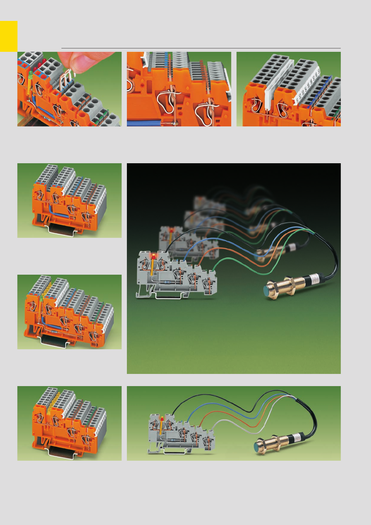
7
40
Sensor Terminal Blocks and Actuator Terminal Blocks with CAGE CLAMP®,
Description and Handling, Series 270
Commoning
Insertion of a jumper
Sensor terminal blocks
Terminal block assembly
Sensor terminal blocks
Sensor LED terminal blocks
Terminal block assembly
Sensor LED terminal blocks
stranded
fine-stranded,
also with tinned
single strands
CAGE CLAMP®clamps
the following copper
wires:*
solid
fine-stranded wire –
tip bonded
fine-stranded wire
with crimped ferrule ➊fine-stranded wire
with crimped pin terminal
Actuator LED terminal blocks
Terminal block assembly
Actuator LED terminal blocks Sensor-LED terminal block
Commoning of signal level voltage using insulated
push-in type jumper bars – series 870,
2- to 9-way, depending on application
Sensor LED terminal blocks cannot be commoned
on the signal level!
* For aluminum wire see notes in section 15!
➊When using wires with ferrules, it is necessary to use a terminal block one size larger than the nominal cross section of the wire.
Commoning of supply voltage using uninsulated
push-in type jumper bars, 2- to 9-way or 17-way
(2 x 8 bits), depending on application
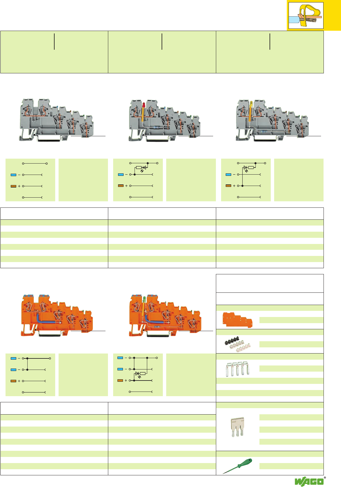
7
41
SSSS
SS
*Kf *Kf *Kf
4-cond. sensor LED terminal block, for DIN 35 rail
for PNP (positive) switching sensors
LED red 270-570/281-434 50
➌Other voltages – contact factory
Power consumption LED: 4.8 mA
4-conductor sensor terminal block, for DIN 35 rail
270-570 50
➊250 V = rated voltage
4 kV = rated surge voltage
3 = pollution degree
(see also section 15)
Item Pack. unit
No. pcs
Item Pack. unit
No. pcs
4-conductor sensor LED supply terminal block,
for DIN 35 rail
LED green 270-574/281-483 10
Item Pack. unit
No. pcs
Item Pack. unit
No. pcs
4-cond. sensor LED terminal block, for DIN 35 rail
for NPN (negative) switching sensors
LED yellow 270-570/281-507 50
➌Other voltages – contact factory
Power consumption LED: 4.8 mA
Item Pack. unit
No. pcs
4-conductor sensor supply terminal block,
for DIN 35 rail
270-574 10
➋Internal commonig 9 A
Sensor Terminal Blocks, for 4-Conductor Sensors and
Sensor LED Terminal Blocks, for 4-Conductor Sensors, Series 270
End and intermediate plate, 1 mm /0.039 in thick
orange 270-322 100 (4 x 25)
grey 270-320 100 (4 x 25)
Insulation stop, 5 pcs/strip see page 2.43
white 280-470 200 strips
light grey 280-471 200 strips
dark grey 280-472 200 strips
Push-in type jumper bars, uninsulated, IN18 A
9-way 270-409 100 (4 x 25)
17-way 270-417 100 (4 x 25)
80-way 270-480 10
Jumpers can be cut using side cutting pliers.
Push-in type jumper bars, light grey, insulated, IN18 A
2-way 870-402 200 (8 x 25)
3-way 870-403 200 (8 x 25)
4-way 870-404 200 (8 x 25)
5-way 870-405 100 (4 x 25)
::
9-way 870-409 100 (4 x 25)
Sensor LED term. bl. cannot be commoned on the signal level!
Screwdriver with partially insulated shaft,
(3.5 x 0.5) mm
210-620 1
Accessories
for 4-conductor terminal blocks
Appropriate
marking system WMB/Mini-WSB
(see section 14)
ground (earth)
shield (screen) ground (earth)
shield (screen)
ground (earth)
shield (screen)
* For further approvals with corresponding ratings see section 15.
(33 mm /1.3 in )
<____________ 83 mm /3.27 in _____________> (33 mm /1.3 in )
<____________ 83 mm /3.27 in _____________> (33 mm /1.3 in )
<____________ 83 mm /3.27 in _____________>
(33 mm /1.3 in )
<____________ 83 mm /3.27 in _____________> (33 mm /1.3 in )
<____________ 83 mm /3.27 in _____________>
ground (earth)
shield (screen)
ground (earth)
shield (screen)
0.08 – 2.5 mm2AWG 28 – 12
DC 24 V ➌
Terminal block width 5 mm / 0.197 in
L6 – 7 mm / 0.26 in
0.08 – 2.5 mm2AWG 28 – 12
250 V/4 kV/3 ➊300 V, 10 A
18 A ➋
Terminal block width 5 mm / 0.197 in
L6 – 7 mm / 0.26 in
0.08 – 2.5 mm2AWG 28 – 12
DC 24 V ➌
Terminal block width 5 mm / 0.197 in
L6 – 7 mm / 0.26 in
<___ 39 mm / ___>
1.54 in
<___ 39 mm / ___>
1.54 in
<___ 39 mm / ___>
1.54 in
<___ 39 mm / ___>
1.54 in
<___ 39 mm / ___>
1.54 in
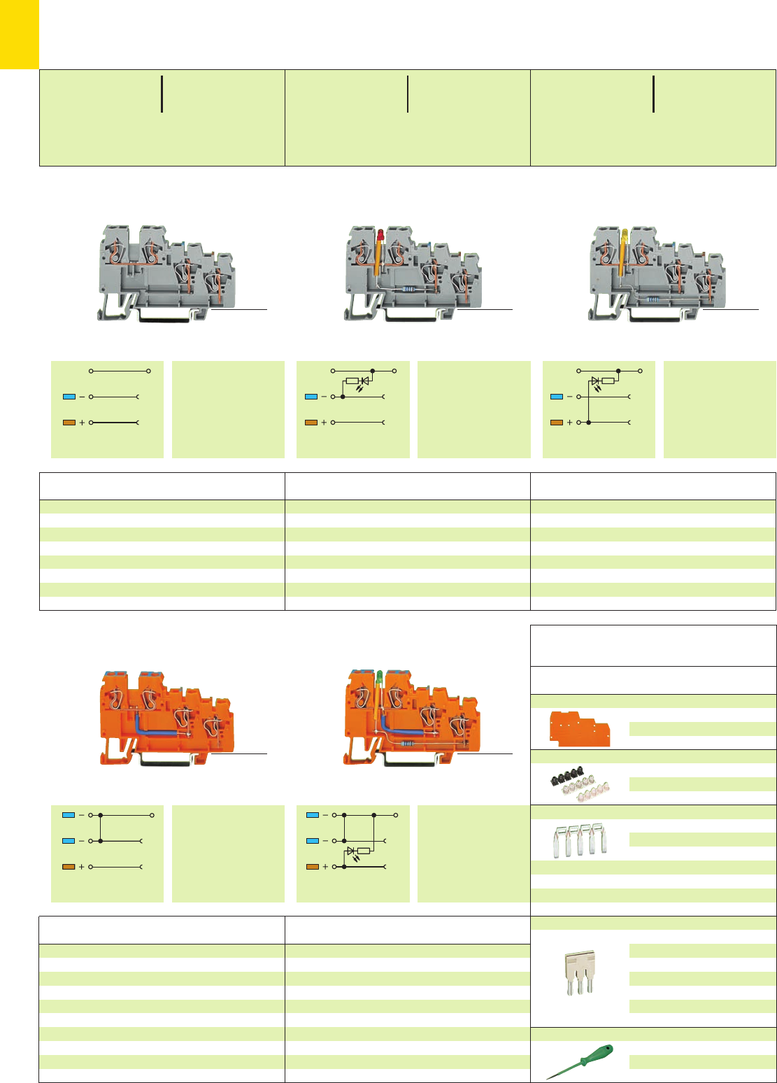
SSSS
SS
7
42
*Kf *Kf *Kf
3-cond. sensor LED terminal block, for DIN 35 rail
for PNP (positive) switching sensors
LED red 270-560/281-434 50
➌Other voltages – contact factory
Power consumption LED: 4.8 mA
3-conductor sensor terminal block, for DIN 35 rail
270-560 50
➊250 V = rated voltage
4 kV = rated surge voltage
3 = pollution degree
(see also section 15)
Item Pack. unit
No. pcs
Item Pack. unit
No. pcs
0.08 – 2.5 mm2AWG 28 – 12
DC 24 V ➌
Terminal block width 5 mm / 0.197 in
L6 – 7 mm / 0.26 in
0.08 – 2.5 mm2AWG 28 – 12
250 V/4 kV/3 ➊300 V, 10 A
18 A ➋
Terminal block width 5 mm / 0.197 in
L6 – 7 mm / 0.26 in
3-conductor sensor LED supply terminal block,
for DIN 35 rail
LED green 270-564/281-483 10
0.08 – 2.5 mm2AWG 28 – 12
DC 24 V ➌
Terminal block width 5 mm / 0.197 in
L6 – 7 mm / 0.26 in
Item Pack. unit
No. pcs
3-cond. sensor LED terminal block, for DIN 35 rail
for NPN (negative) switching sensors
LED yellow 270-560/281-507 50
➌Other voltages – contact factory
Power consumption LED: 4.8 mA
Item Pack. unit
No. pcs
3-conductor sensor supply terminal block,
for DIN 35 rail
270-564 10
➋Internal commonig 9 A
Sensor Terminal Blocks, for 3-Conductor Sensors and
Sensor LED Terminal Blocks, for 3-Conductor Sensors, Series 270
Accessories
for 3-conductor terminal blocks
Appropriate
marking system WMB/Mini-WSB
(see section 14)
* For further approvals with corresponding ratings see section 15.
(33 mm /1.3 in )
<_________ 68 mm /2.68 in _________>
<___ 39 mm / ___>
1.54 in
(33 mm /1.3 in )
<_________ 68 mm /2.68 in _________>
<___ 39 mm / ___>
1.54 in
(33 mm /1.3 in )
<_________ 68 mm /2.68 in _________>
<___ 39 mm / ___>
1.54 in
(33 mm /1.3 in )
<_________ 68 mm /2.68 in _________>
<___ 39 mm / ___>
1.54 in
(33 mm /1.3 in )
<_________ 68 mm /2.68 in _________>
<___ 39 mm / ___>
1.54 in
Item Pack. unit
No. pcs
End and intermediate plate, 1 mm /0.039 in thick
orange 270-321 100 (4 x 25)
grey 270-319 100 (4 x 25)
Insulation stop, 5 pcs/strip see page 2.43
white 280-470 200 strips
light grey 280-471 200 strips
dark grey 280-472 200 strips
Push-in type jumper bars, uninsulated, IN18 A
9-way 270-409 100 (4 x 25)
17-way 270-417 100 (4 x 25)
80-way 270-480 10
Jumpers can be cut using side cutting pliers.
Push-in type jumper bars, light grey, insulated, IN18 A
2-way 870-402 200 (8 x 25)
3-way 870-403 200 (8 x 25)
4-way 870-404 200 (8 x 25)
5-way 870-405 100 (4 x 25)
::
9-way 870-409 100 (4 x 25)
Sensor LED terminal blocks cannot be commoned!
Screwdriver with partially insulated shaft,
(3.5 x 0.5) mm
210-620 1
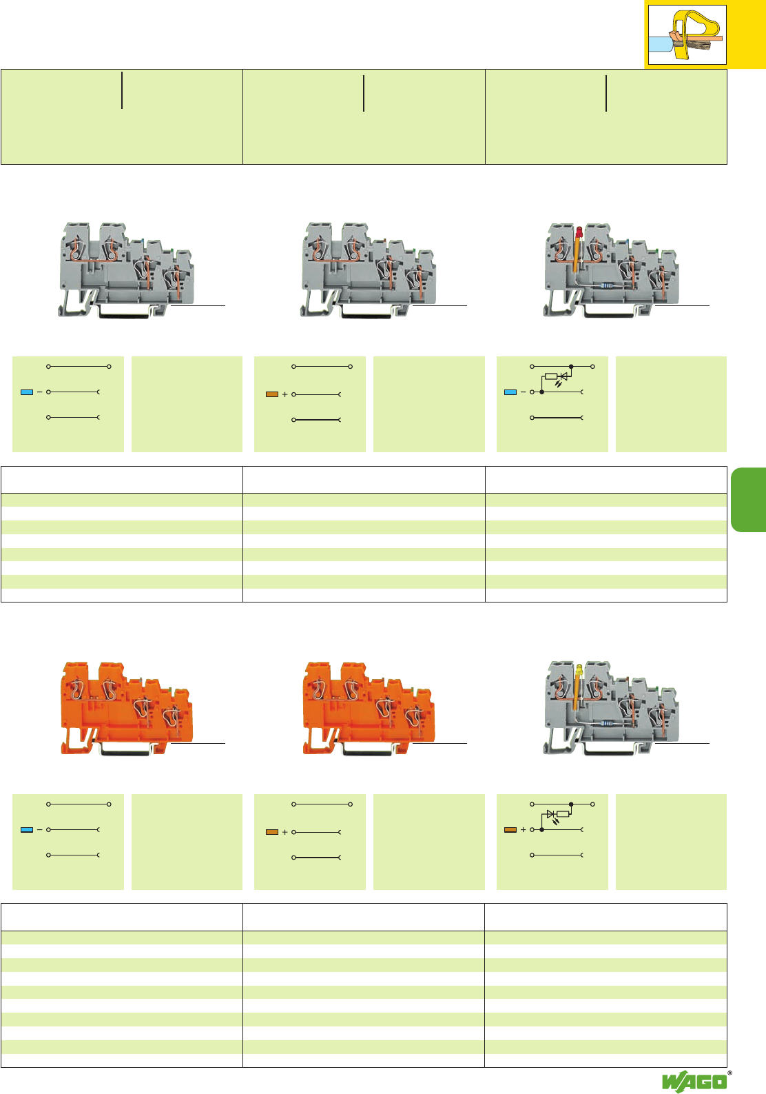
SS
SS
7
7
43
SS
SS
SS SS
*Kf
*Kf *Kf
3-conductor actuator terminal block, for DIN 35 rail
270-585 50
3-conductor actuator terminal block, for DIN 35 rail
270-572 50
➊250 V = rated voltage
4 kV = rated surge voltage
3 = pollution degree
(see also section 15)
Item Pack. unit
No. pcs
Item Pack. unit
No. pcs
0.08 – 2.5 mm2AWG 28 – 12
250 V/4 kV/3 ➊300 V, 10 A
18 A
Terminal block width 5 mm / 0.197 in
L6 – 7 mm / 0.26 in
0.08 – 2.5 mm2AWG 28 – 12
250 V/4 kV/3 ➊300 V, 10 A
18 A
Terminal block width 5 mm / 0.197 in
L6 – 7 mm / 0.26 in
3-conductor actuator supply terminal block,
for DIN 35 rail
270-586 10
Item Pack. unit
No. pcs
0.08 – 2.5 mm2AWG 28 – 12
DC 24 V ➋
Terminal block width 5 mm / 0.197 in
L6 – 7 mm / 0.26 in
Item Pack. unit
No. pcs
3-conductor actuator LED terminal block,for DIN
35 rail, for PNP (positive) switching actuators
LED red 270-572/281-434 50
3-cond. actuator supply term. block,for DIN 35 rail
270-577 10
➋Other voltages – contact factory
Power consumption LED: 4.8 mA
Item Pack. unit
No. pcs
3-conductor actuator supply terminal block,
for DIN 35 rail
270-577 10
3-Conductor Actuator Terminal Blocks and
3-Conductor Actuator LED Terminal Blocks, Series 270
ground (earth)
shield (screen)
3-conductor actuator LED terminal block,for DIN
35 rail, for NPN (negative) switching actuators
LED yellow 270-585/281-507 50
3-cond. actuator supply term. block,for DIN 35 rail
270-586 10
➋Other voltages – contact factory
Power consumption LED: 4.8 mA
Item Pack. unit
No. pcs
ground (earth)
shield (screen) ground (earth)
shield (screen)
ground (earth)
shield (screen) ground (earth)
shield (screen) ground (earth)
shield (screen)
* For further approvals with corresponding ratings see section 15.
(33 mm /1.3 in )
<_________ 68 mm /2.68 in _________>
<___ 39 mm / ___>
1.54 in
(33 mm /1.3 in )
<_________ 68 mm /2.68 in _________>
<___ 39 mm / ___>
1.54 in
(33 mm /1.3 in )
<_________ 68 mm /2.68 in _________>
<___ 39 mm / ___>
1.54 in
(33 mm /1.3 in )
<_________ 68 mm /2.68 in _________>
<___ 39 mm / ___>
1.54 in
(33 mm /1.3 in )
<_________ 68 mm /2.68 in _________>
<___ 39 mm / ___>
1.54 in
(33 mm /1.3 in )
<_________ 68 mm /2.68 in _________>
<___ 39 mm / ___>
1.54 in
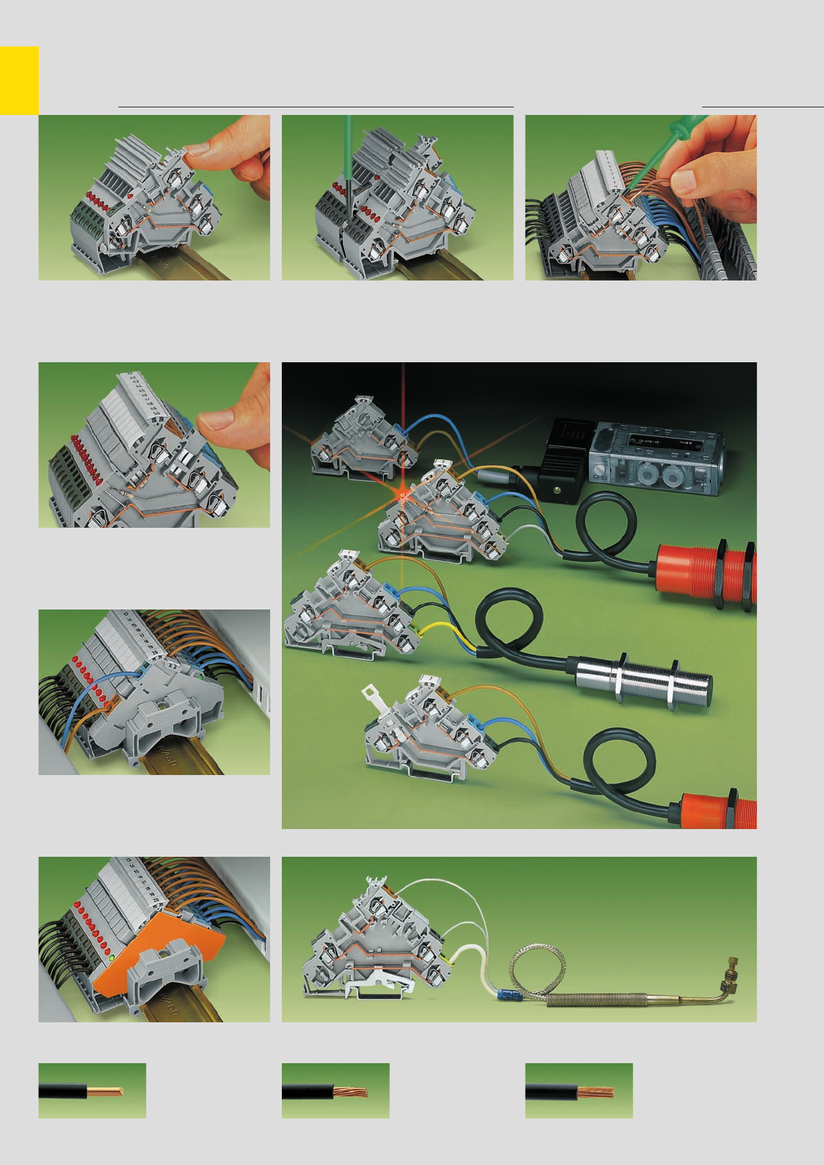
,
7
44
Sensor Terminal Blocks and Actuator Terminal Blocks with CAGE CLAMP®. . .
Series 280
Assembly CAGE CLAMP®connection
Assembly on the carrier rail. Terminal blocks with
ground (earth) connection automatically
establish a direct contact to the rail.
Commoning
Commoning with adjacent jumpers. Push jumper
down FIRMLY until FULLY inserted!
Voltage supply to assembly
Sensor terminal blocks.
Voltage supply from control panel side
CAGE CLAMP®
clamps the following
copper wires: *
solid stranded
fine stranded,
also with tinned
single strands
Voltage supply to assembly
Sensor terminal blocks.
Voltage supply from sensor side Actuator terminal blocks and a thermocouple and shield (screen) connection
Removal from the carrier rail.
Attention - remove jumper contacts first! Connection of conductors with straight screw-
driver 210-120
* For aluminum wire see notes in section 15!
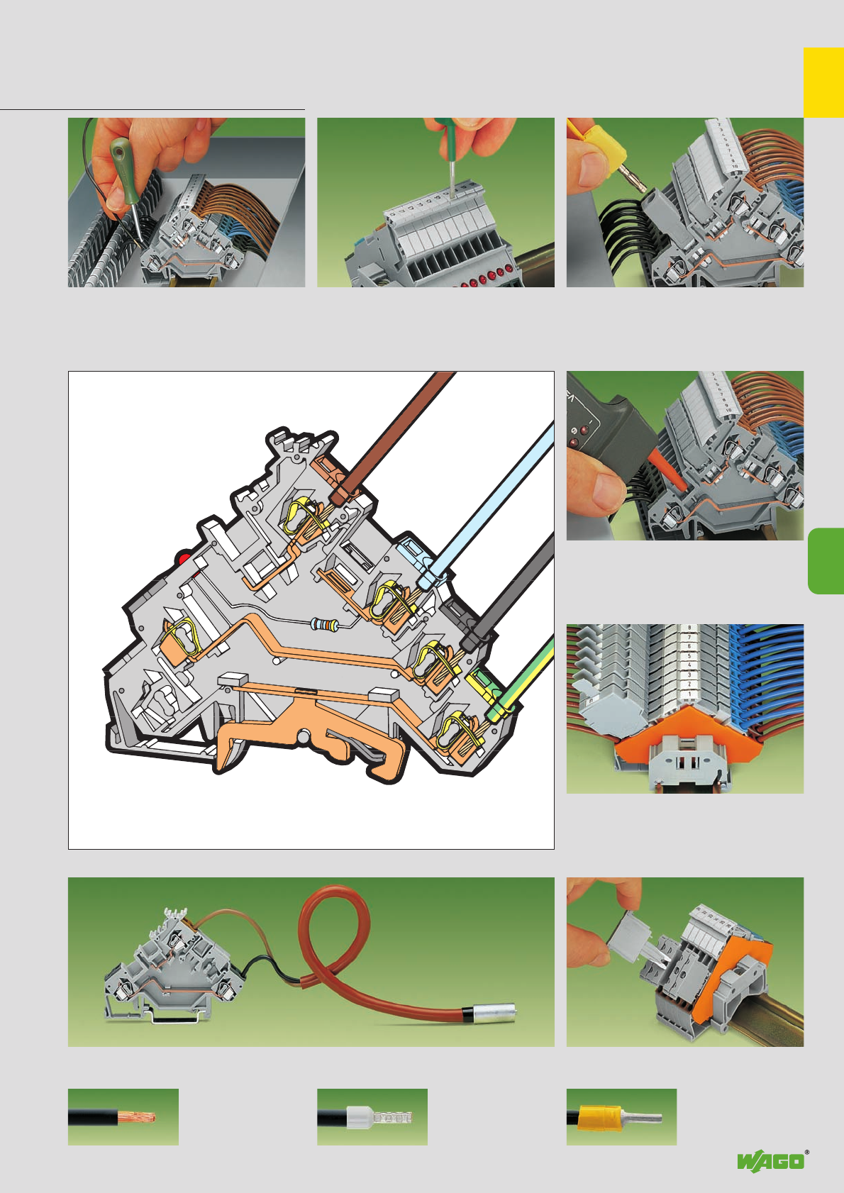
,
7
7
45
. . . Description and Handling
Marking Testing
Connection of conductors with angled screwdriver
210-258
Testing
Testing with voltage tester directly on the current
bar
Fuse plugs
Actuator terminal blocks with fuse plugs 281-511
(requires additional intermediate plates)
fine-stranded wire –
tip bonded
fine-stranded wire
with crimped ferrule ➊fine-stranded wire
with crimped pin terminal
Actuator terminal block with thermocouple
Component plugs
Actuator terminal blocks with component plugs
280-801
Marking with WMB Multi marking system or
WSB Quick marking system.
For other systems see section 14.
Testing with banana plug and adapter 209-170
➊When using wires with ferrules, it is necessary to use a terminal block one size larger than the nominal cross section of the wire.
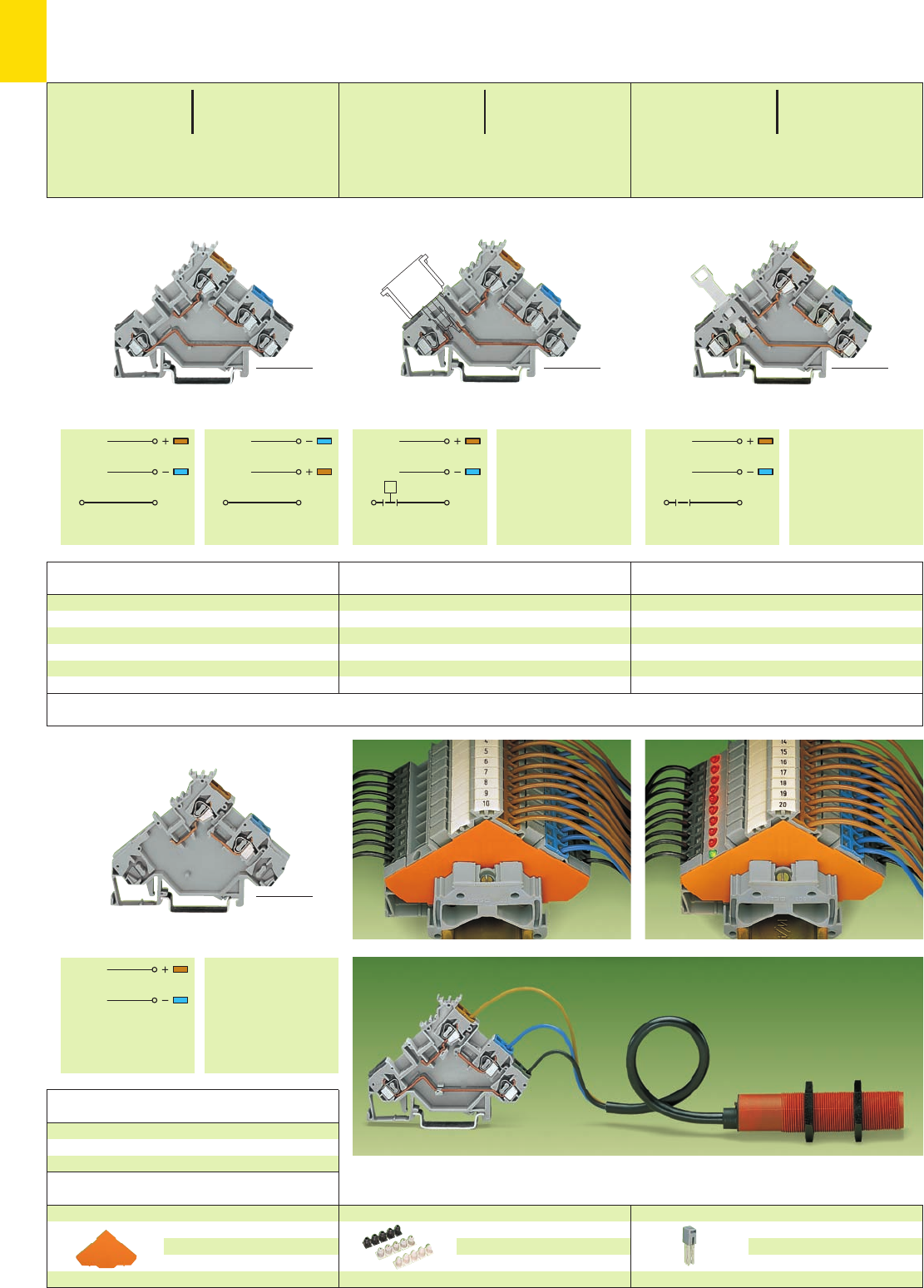
SS SS SS SS
7
46
*U2N; *U2N; *U2N;
III
* For further approvals with corresponding ratings see section 15.
Sensor disconnect terminal block,
for signal interruption
280-563 50
Sensor terminal block,
for component plugs
280-561 50
Empty component plug housing see W4, volume 3
Fuse plug see page 7.35
Sensor terminal blocks
I280-560 50
II 280-553 50
Item Pack. unit
No. pcs
Item Pack. unit
No. pcs
Item Pack. unit
No. pcs
Sensor Terminal Blocks 2.5 mm2/AWG 12, for 3-Conductor Sensors
Series 280
>X<_________ 80 mm /3.15 in __________>
X = 12 mm /0.472 in
<__________ 80 mm /3.15 in __________> <___________ 82 mm /3.23 in ___________>
<___________ 85 mm /3.35 in ___________>
Sensor supply terminal block,
voltage supply from sensor side
280-564 10
Item Pack. unit
No. pcs
Appropriate marking system WMB/WSB (see section 14)
<_________ 80 mm /3.15 in _________>
Sensor terminal block, with 3-conductor sensor
End and intermediate plate, 1 mm/0.039 in thick
for triple deck terminal blocks
orange 280-321 100 (4 x 25)
grey 280-319 100 (4 x 25)
Accessories Series 280
Insulation stop, 5 pcs /strip see page 2.43
white 280-470 200 strips
light grey 280-471 200 strips
dark grey 280-472 200 strips
Adjacent jumper, insulated, IN24 A
grey 280-402 200 (8 x 25)
0.08 – 2.5 mm2AWG 28 – 12
250 V/4 kV/3 ➊➋ 300 V, 6 A U
6 A ➋300 V, 15 A 2
Terminal block width 5 mm / 0.197 in
L8 – 9 mm / 0.33 in
0.08 – 2.5 mm2AWG 28 – 12
400 V/6 kV/3 ➊300 V, 15 A U
20 A 300 V, 15 A 2
Terminal block width 5 mm / 0.197 in
L8 – 9 mm / 0.33 in
0.08 – 2.5 mm2AWG 28 – 12
400 V/6 kV/3 ➊300 V, 10 A U
10 A 300 V, 15 A 2
Terminal block width 5 mm / 0.197 in
L8 – 9 mm / 0.33 in
<___ 55.5 mm /2.19 in ___>
<___ 55.5 mm /2.19 in ___>
<___ 55.5 mm /2.19 in ___>
<___ 55.5 mm /2.19 in ___>
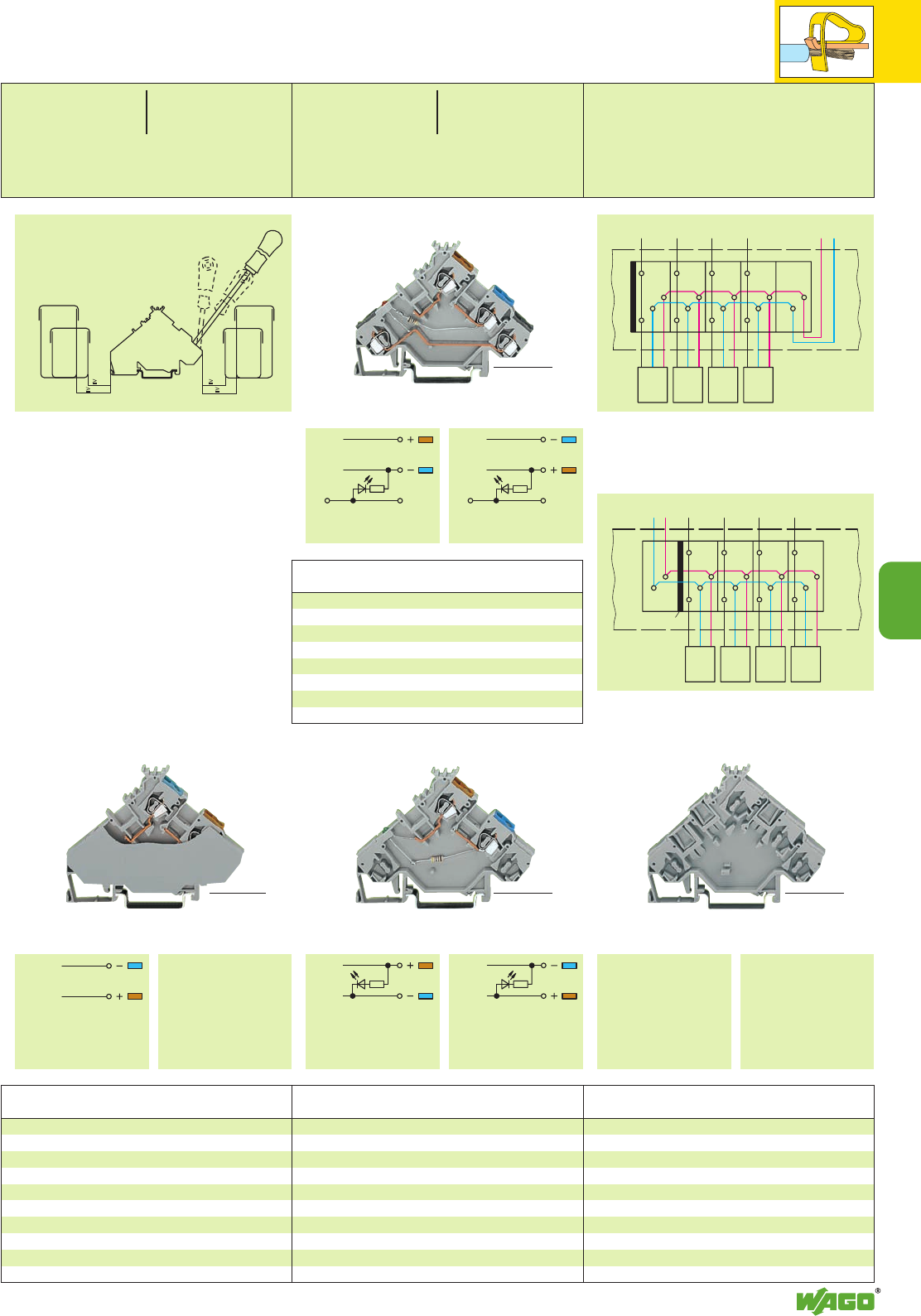
7
7
47
SS SS
III
III
*2N;
*U2N; *U2N
Sensor-LED terminal blocks,
DC 24 V, for PNP (positive) switching sensors
I LED red ➍280-560/281-434 50
DC 24 V, for NPN (negative) switching sensors
II LED red ➍280-561/281-413 50
Item Pack. unit
No. pcs
Spacer, same shape as
3-conductor sensor or actuator
terminal blocks
280-559 50
Spacers allow clear separation of groups of
sensors or actuators, especially if they are supplied
from different voltage sources.
Sensor-LED supply terminal blocks,
voltage supply from sensor side,
DC 24 V, for PNP (positive) switching sensors
I LED green ➍280-564/281-483 10
voltage supply from sensor side,
DC 24 V, for NPN (negative) switching sensors
II LED green ➍280-566/281-496 10
Sensor supply terminal block,
voltage supply from control panel side,
with end plate 280-567 20
Item Pack. unit
No. pcs
Item Pack. unit
No. pcs
Item Pack. unit
No. pcs
<_________ 80 mm /3.15 in _________>
<__________ 80 mm /3.15 in __________>
<__________ 80 mm /3.15 in __________> <_________ 80 mm /3.15 in _________>
➊400/250 V = rated voltage
6/4 kV = rated surge voltage
3 = pollution degree
(see also section 15)
➋Electrical ratings are given by the fuse or
components used in the component plug
(see also page 7.35 and
Full Line Catalog W4, volume 3)
➌Other voltages – contact factory
➍Power consumption LED: 4.8 mA
Spacer
Spacer width 5 mm / 0.197 in
0.08 – 2.5 mm2AWG 28 – 12
DC 24 V ➌24 V, 15 A U
20 A 300 V, 15 A 2
Terminal block width 5 mm / 0.197 in
L8 – 9 mm / 0.33 in
0.08 – 2.5 mm2AWG 28 – 12
400 V/6 kV/3 ➊300 V, 15 A U
20 A 300 V, 15 A 2
Terminal block width
with end plate 6 mm / 0.236 in
L8 – 9 mm / 0.33 in
<___ 55.5 mm /2.19 in ___>
<___ 55.5 mm /2.19 in ___><___ 55.5 mm /2.19 in ___>
<___ 55.5 mm /2.19 in ___>
Min. mounting distance – terminal blocks to cable duct
Screwdriver
210-258
210-257
“60er“
cable duct
“60er“
cable duct
“40er“
cable duct
“40er“
cable duct
20
30 20
30
210-120
Voltage supply from sensor side
to control panel
Sensors
End plate
Voltage supply from control panel side
to control panel
Sensors
Intermediate plate
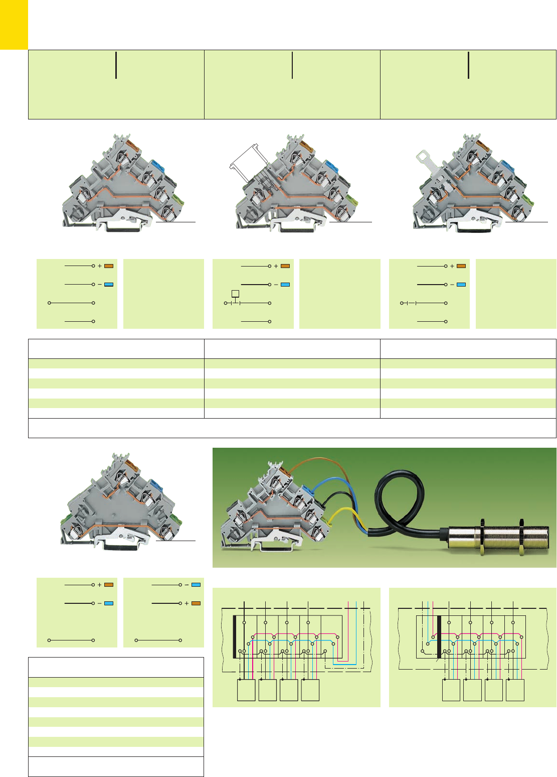
7
48
*U2N; *U2N; *U2N
SS
PE
SS
PE
SS
PE
PE PE PE PE
III
Sensor disconnect terminal block with ground
(earth) connection, plus signal interruption
280-573 50
Sensor terminal block with ground (earth)
connection, for component plugs
280-571 50
Empty component plug housing see W4, volume 3
Fuse plug see page 7.35
Sensor terminal block with ground (earth)
connection
280-570 50
Item Pack. unit
No. pcs
Item Pack. unit
No. pcs
Item Pack. unit
No. pcs
Sensor Terminal Blocks 2.5 mm2/AWG 12,
for 3-Conductor Sensors with Ground (Earth) Connection
Series 280
Sensor supply terminal block with ground (earth)
connection, voltage supply from sensor side
280-574 10
Sensor supply terminal block with ground (earth)
connection, voltage supply from control panel side,
with end plate 280-577 20
Item Pack. unit
No. pcs
>X<___________ 90.5 mm /3.56 in ___________>
X = 7 mm /0.276 in
<___________ 90.5 mm /3.56 in ___________> <___________ 90.5 mm /3.56 in ___________>
<___________ 90.5 mm /3.56 in ___________>
Sensor terminal block, with 3-conductor sensor with ground (earth) connection
➊400/250 V = rated voltage
6/4 kV = rated surge voltage
3 = pollution degree
(see also section 15)
➋Electrical ratings are given by the fuse or components
used in the component plug
(see also page 7.35 and
Full Line Catalog W4, volume 3)
➌Other voltages – contact factory
➍Power consumption LED: 4.8 mA
* For further approvals with corresponding ratings see section 15.
see page 7.51
Accessories Insulation stop and jumper
Appropriate marking system WMB/WSB (see section 14)
0.08 – 2.5 mm2AWG 28 – 12
400 V/6 kV/3 ➊300 V, 10 A U
10 A 300 V, 15 A 2
Terminal block width 5 mm / 0.197 in
L8 – 9 mm / 0.33 in
<_____ 63.5 mm /2.5 in _____>
0.08 – 2.5 mm2AWG 28 – 12
250 V/4 kV/3 ➊➋ 300 V, 6 A U
6 A ➋300 V, 15 A 2
Terminal block width 5 mm / 0.197 in
L8 – 9 mm / 0.33 in
0.08 – 2.5 mm2AWG 28 – 12
400 V/6 kV/3 ➊300 V, 15 A U
20 A 300 V, 15 A 2
Terminal block width 5 mm / 0.197 in
(with end plate 6 mm / 0.236 in)
L8 – 9 mm / 0.33 in
<_____ 63.5 mm /2.5 in _____>
<_____ 63.5 mm /2.5 in _____>
<_____ 63.5 mm /2.5 in _____>
Voltage supply from control panel sideVoltage supply from sensor side
to control panel
Sensors with PE
(ground) connection
Intermediate plate
to control panel
Sensors with PE
(ground) connection
End plate
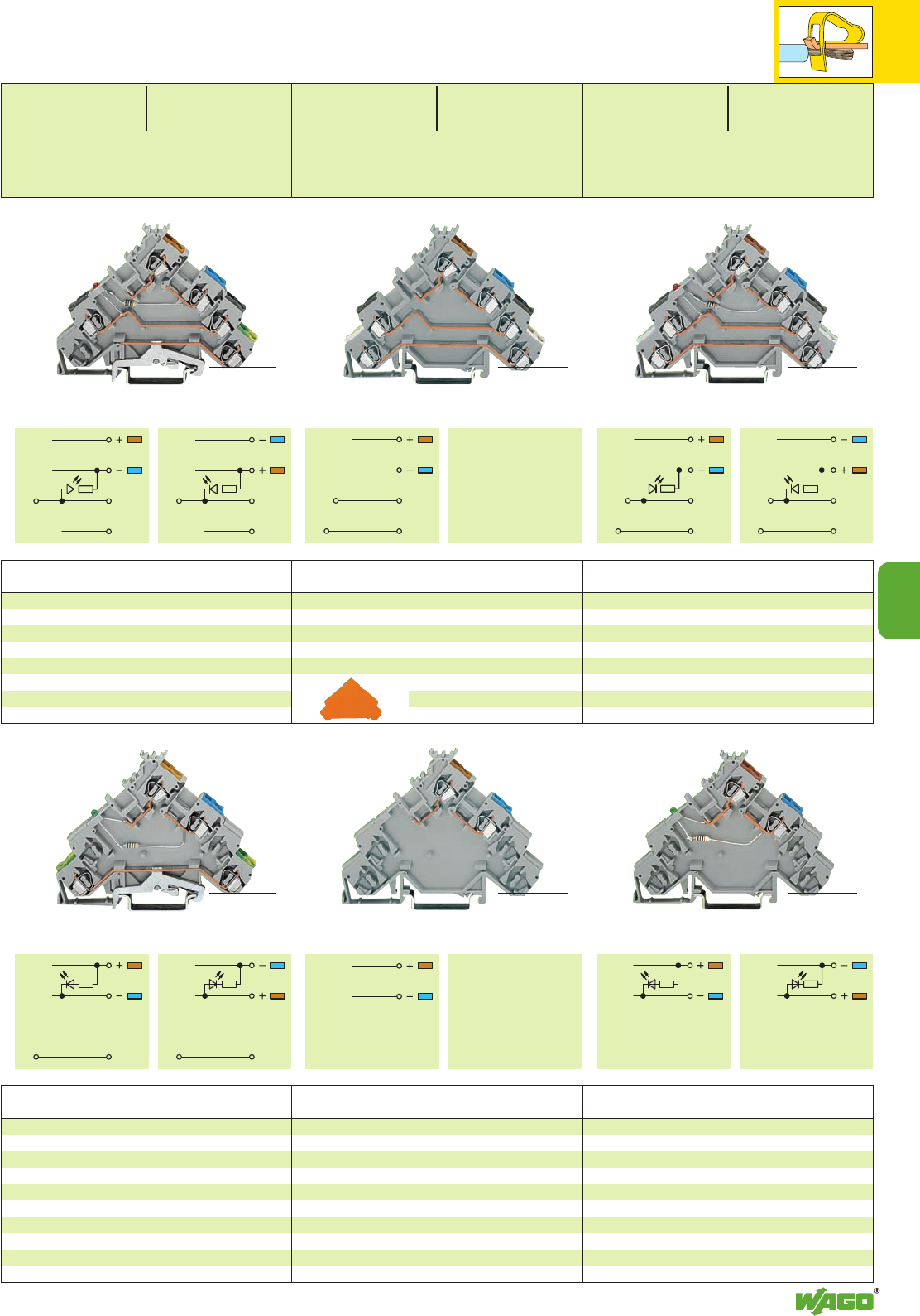
7
7
49
SS
PE
SS
PE
III
PE PE PE PE
III III
S1S1
S2S2
S1S1
S2S2
III
S1
S2
S1
S2
*U2N;
*U2N *U2N
Sensor-LED terminal blocks,
DC 24 V, for PNP (positive) switching sensors
I LED red ➍280-570/281-434 50
DC 24 V, for NPN (negative) switching sensors
II LED red ➍280-571/281-413 50
Sensor terminal block
280-580 50
Item Pack. unit
No. pcs Item Pack. unit
No. pcs
Sensor-LED supply terminal blocks with ground
(earth) connection, voltage supply from sensor side,
DC 24 V, for PNP (positive) switching sensors
I LED green ➍280-574/281-483 10
DC 24 V, for NPN (negative) switching sensors
II LED green ➍280-576/281-496 10
Voltage supply from control panel side,
DC 24 V, for PNP (positive) switching sensors
I LED green ➍
with end plate 280-577/281-496 20
Item Pack. unit
No. pcs
<___________ 90.5 mm /3.56 in ___________>
<___________ 90.5 mm /3.56 in ___________>
<___________ 90.5 mm /3.56 in ___________>
Sensor LED supply terminal blocks,
voltage supply from sensor side,
DC 24 V, for PNP (positive) switching sensors
I LED green ➍280-584/281-483 10
DC 24 V, for NPN (negative) switching sensors
II LED green ➍280-586/281-496 10
Item Pack. unit
No. pcs
<___________ 90.5 mm /3.56 in ___________>
Item Pack. unit
No. pcs
Sensor LED terminal blocks,
DC 24 V, for PNP (positive) switching sensors
I LED red ➍280-580/281-434 50
DC 24 V, for NPN (negative) switching sensors
II LED red ➍280-581/281-413 50
<___________ 90.5 mm /3.56 in ___________>
Item Pack. unit
No. pcs
Sensor supply terminal blocks,
voltage supply from sensor side,
without end plate 280-584 10
voltage supply from control panel side,
with end plate 280-587 20
<___________ 90.5 mm /3.56 in ___________>
End and intermediate plate, 1 mm/0.039 in thick
for quadruple deck terminal blocks
orange 280-323 100 (4 x 25)
grey 280-320 100 (4 x 25)
Sensor Terminal Blocks 2.5 mm2/AWG 12,
for 4-Conductor Sensors
Series 280
0.08 – 2.5 mm2AWG 28 – 12
DC 24 V ➌24 V, 15 A U
20 A 300 V, 15 A 2
Terminal block width 5 mm / 0.197 in
(with end plate 6 mm / 0.236 in)
L8 – 9 mm / 0.33 in
0.08 – 2.5 mm2AWG 28 – 12
400 V/6 kV/3 ➊300 V, 15 A U
20 A 300 V, 15 A 2
Terminal block width 5 mm / 0.197 in
(with end plate 6 mm / 0.236 in)
L8 – 9 mm / 0.33 in
<_____ 63.5 mm /2.5 in _____>
<_____ 63.5 mm /2.5 in _____><_____ 63.5 mm /2.5 in _____>
0.08 – 2.5 mm2AWG 28 – 12
DC 24 V ➌24 V, 15 A U
20 A 300 V, 15 A 2
Terminal block width 5 mm / 0.197 in
L8 – 9 mm / 0.33 in
<_____ 63.5 mm /2.5 in _____>
<_____ 63.5 mm /2.5 in _____> <_____ 63.5 mm /2.5 in _____>
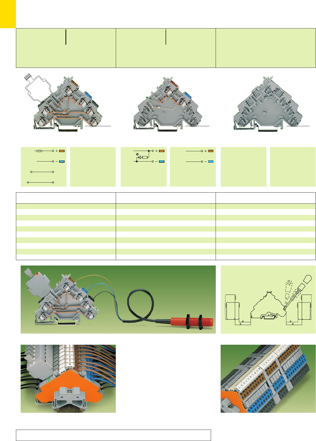
7
50
*U2N; *U2N;
S1
S2
S1
S2
III
*N;
* For further approvals with corresponding ratings see section 15.
see page 7.51
Accessories Insulation stop and jumper
Spacer, same shape as
4-conductor sensor terminal blocks,
3-conductor sensor terminal blocks with
ground (earth) connection or the
corresponding actuator terminal blocks
280-582 50
Sensor-LED supply terminal block,
voltage supply from sensor side, DC 24 V,
for PNP (positive) switching sensors
I LED green ➌280-584/281-483 10
Sensor supply terminal block, (see ill. page 7.49)
voltage supply from sensor side,
II 300 V 280-584 10
Sensor supply terminal block, (see ill. page 7.49)
voltage supply from control panel side,
II with end plate 280-587 20
Sensor terminal blocks, for fuse plugs,
for PNP (positive) switching sensors
without end plate 280-588 50
with end plate
grey 280-588/280-320 50
orange 280-588/280-323 50
Item Pack. unit
No. pcs
Item Pack. unit
No. pcs
Item Pack. unit
No. pcs
Sensor Terminal Blocks 2.5 mm2/AWG 12, for Fuse Plugs
for 3- and 4-Conductor Sensors
Series 280
<___________ 90.5 mm /3.56 in ___________>
Sensor terminal block, with fuse plug, with 3-conductor sensor
➊Electrical ratings are given by the fuse or components
used in the component plug
(see also pages 7.34 and 7.35
Full Line Catalog W4, volume 3)
➋Other voltages – contact factory
➌Power consumption LED: 4.8 mA
0.08 – 2.5 mm2AWG 28 – 12
DC 24 V ➋300/24 V, 15 A U
20 A 300 V, 15 A 2
Terminal block width 5 mm / 0.197 in
(with end plate 6 mm / 0.236 in)
L8 – 9 mm / 0.33 in
0.08 – 2.5 mm2AWG 28 – 12
125 V/5 A ➊250 V; 6,3 A U
300 V, 15 A 2
Terminal block width 5 mm / 0.197 in
(with end plate 6 mm / 0.236 in)
L8 – 9 mm / 0.33 in
<_____ 63.5 mm /2.5 in _____>
>X<___________ 90.5 mm /3.56 in ___________>
X = 15.5 mm /0.61 in Y = 10 mm/0.394 in
<_____ 63.5 mm /2.5 in _____>Y(
<___________ 90.5 mm /3.56 in ___________>
<_____ 63.5 mm /2.5 in _____>
The fuse plug is 1 mm/0.039 in wider than the terminal
block. This means an intermediate plate has to be fitted.
Spacers allow clear separation of groups of
sensors or actuators, especially if they are supplied
from different voltage sources.
Appropriate
marking system WMB/WSB
(see section 14)
Spacer
Spacer width 5 mm / 0.197 in
Min. mounting distance – terminal blocks to cable duct
Screwdriver
210-258
210-257
“60mm“
cable duct
“60mm“
cable duct
“40mm“
cable duct
“40mm“
cable duct
30
40 30
40
210-120
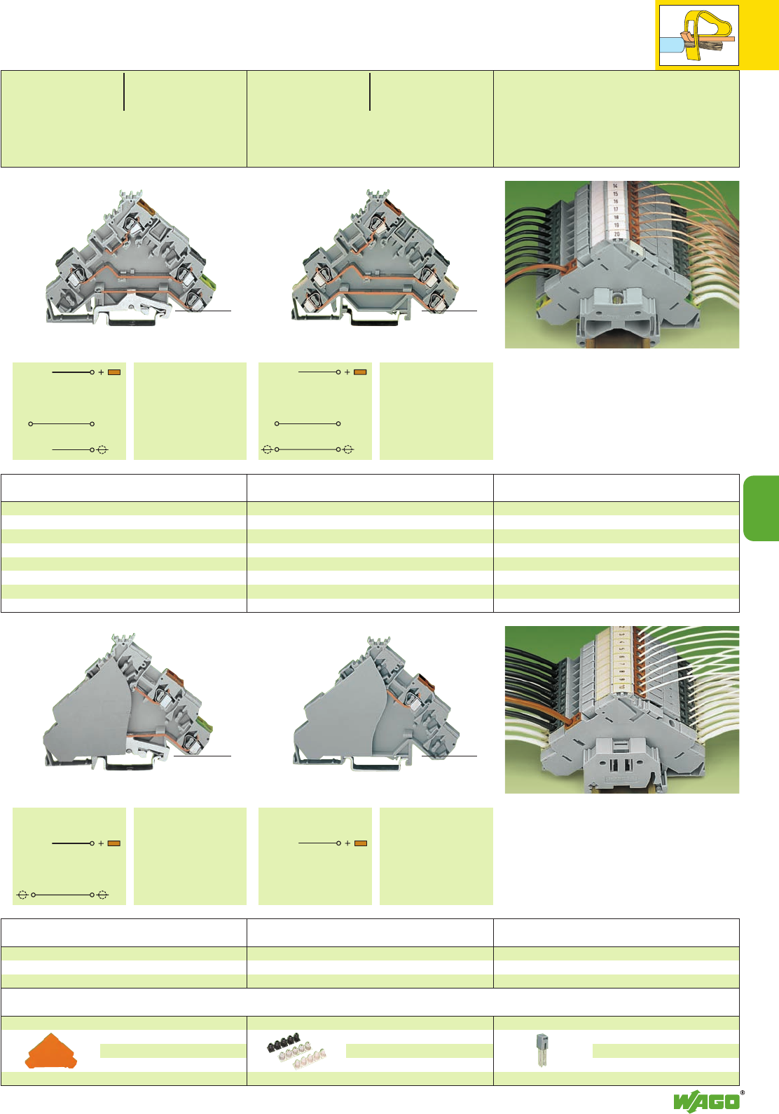
7
7
51
SS SS
*U2N; *U2N;
Actuator terminal block with shield (screen)
conductor through contact
280-583 50
Actuator terminal block with shield (screen)
connection
280-585 50
Item Pack. unit
No. pcs
Item Pack. unit
No. pcs
0.08 – 2.5 mm2AWG 28 – 12
400 V/6 kV/3 ➊300 V, 15 A U
20 A 300 V, 15 A 2
Terminal block width 5 mm / 0.197 in
(with end plate 6 mm / 0.236 in)
L8 – 9 mm / 0.33 in
0.08 – 2.5 mm2AWG 28 – 12
400 V/6 kV/3 ➊300 V, 15 A U
20 A 300 V, 15 A 2
Terminal block width 5 mm / 0.197 in
(with end plate 6 mm / 0.236 in)
L8 – 9 mm / 0.33 in
Item Pack. unit
No. pcs
Item Pack. unit
No. pcs
Actuator Terminal Blocks 2.5 mm2/ AWG 12, for Actuators with Shield
(Screen) Connection and for Actuators with Shield (Screen) Conductor
Through Contact (for Thermocouples etc.) Series 280
<___________ 90.5 mm /3.56 in ___________> <___________ 90.5mm /3.56 in ___________>
<___________ 90.5 mm /3.56 in ___________>
<_____ 63.5 mm /2.5 in _____>
<___________ 90.5 mm /3.56 in ___________>
Green-yellow clamping unit = shield (screen) connection
White clamping unit = shield (screen) conductor through
contact
<_____ 63.5 mm /2.5 in _____>
<_____ 63.5 mm /2.5 in _____>
Actuator supply terminal block with shield (screen)
connection, voltage supply from control panel side,
with end plate 280-586 20
End and intermediate plate, 1 mm/0.039 in thick
for quadruple deck terminal blocks
orange 280-323 100 (4 x 25)
grey 280-320 100 (4 x 25)
Actuator supply terminal block,
voltage supply from control panel side,
with end plate 280-515 20
Insulation stop, 5 pcs /strip see page 2.43
white 280-470 200 strips
light grey 280-471 200 strips
dark grey 280-472 200 strips
Adjacent jumper, insulated, IN24 A
grey 280-402 200 (8 x 25)
<_____ 63.5 mm /2.5 in _____>
Accessories Series 280 Appropriate marking system WMB/WSB (see section 14)
* For further approvals with corresponding ratings see section 15.
➊400 V = rated voltage
6 kV = rated surge voltage
3 = pollution degree
(see also section 15)
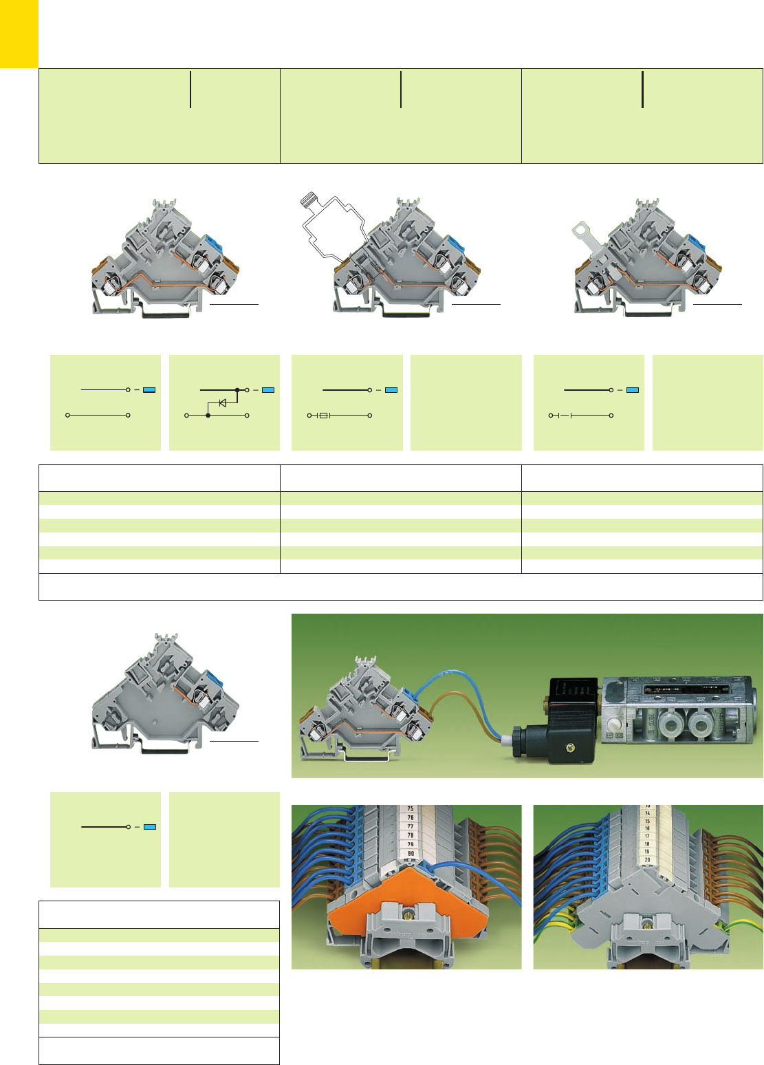
7
52
*U2*U2N; *U2
SS SS
III
SS SS
* For further approvals with corresponding ratings see section 15.
see page 7.53
Accessories Insulation stop and jumper
Actuator disconnect terminal block,
for interruption of line
280-566 50
Actuator terminal blocks, for fuse plugs ➍,
for fuse protection of line voltage,
without end plate 280-565 50
with end plate
grey 280-565/280-319 50
orange 280-565/280-321 50
Actuator terminal block
I280-562 50
Actuator terminal block,
with recovery diode 1 N 4007 ➋
II 280-562/281-411 50
Item Pack. unit
No. pcs
Item Pack. unit
No. pcs
Item Pack. unit
No. pcs
Actuator Terminal Blocks 2.5 mm2/ AWG 12, (for Pressure Switches, Thermocouples etc.)
Series 280
Actuator supply terminal block,
voltage supply from actuator side
280-592 10
Item Pack. unit
No. pcs
Appropriate marking system WMB/WSB (see section 14)
Actuator terminal block, here with a magnetic valve
<_________ 80 mm /3.15 in _________> >X<_________ 80 mm /3.15 in __________>
X = 15.5 mm /0.61 in Y = 10 mm/0.394 in
<__________ 82 mm /3.23 in __________>
<__________ 85 mm /3.35 in __________>
<_________ 80 mm /3.15 in _________>
0.08 – 2.5 mm2AWG 28 – 12
125 V/5 A ➌250 V; 6.3 A U
250 V/6.3 A ➌300 V, 15 A 2
Terminal block width 5 mm / 0.197 in
(with end plate 6 mm / 0.236 in)
L8 – 9 mm / 0.33 in
0.08 – 2.5 mm2AWG 28 – 12
400 V/6 kV/3, 20 A ➊300 V, 15 A U
250 V/4 kV/3, 20 A ➊ ➋ 300 V, 15 A 2
Terminal block width 5 mm / 0.197 in
L8 – 9 mm / 0.33 in
0.08 – 2.5 mm2AWG 28 – 12
400 V/6 kV/3 ➊300 V, 10 A U
10 A 300 V, 15 A 2
Terminal block width 5 mm / 0.197 in
L8 – 9 mm / 0.33 in
<___ 55.5 mm /2.19 in ___>
<___ 55.5 mm /2.19 in ___> Y<
<___ 55.5 mm /2.19 in ___>
<___ 55.5 mm /2.19 in ___>
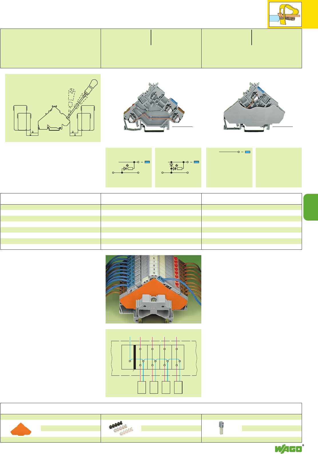
7
7
53
SS SS
III
*U2N *U2N;
Actuator LED terminal block, DC 24 V
I LED red ➏280-562/281-434 50
Actuator LED terminal block, DC 24 V,
with recovery diode 1 N 4007
II LED red ➏280-562/281-420 50
Item Pack. unit
No. pcs
Actuator supply terminal block,
voltage supply from control panel side,
with end plate 280-568 20
Item Pack. unit
No. pcs
➊400/250 V = rated voltage
6/4 kV = rated surge voltage
3 = pollution degree
(see also section 15)
➋with recovery diode
➌Electrical ratings are given by the fuse or components
used in the component plug
(see also pages 7.34 and 7.35 and
Full Line Catalog W4, volume 3)
➍The fuse plug is 1 mm /0.039 in wider than
the terminal block. This means an intermediate
plate has to be fitted.
➎Other voltages – contact factory
➏Power consumption LED: 4.8 mA
<_________ 80 mm /3.15 in _________><__________ 80 mm /3.15 in __________>
ÉVoltage supply from control panel side
End and intermediate plate, 1 mm/0.039 in thick
for triple deck terminal blocks
orange 280-321 100 (4 x 25)
grey 280-319 100 (4 x 25)
Insulation stop, 5 pcs /strip see page 2.43
white 280-470 200 strips
light grey 280-471 200 strips
dark grey 280-472 200 strips
Adjacent jumper, insulated, IN24 A
grey 280-402 200 (8 x 25)
Accessories Series 280 Appropriate marking system WMB/WSB (see section 14)
0.08 – 2.5 mm2AWG 28 – 12
DC 24 V ➎24 V, 15 A U
20 A 300 V, 15 A 2
Terminal block width 5 mm / 0.197 in
L8 – 9 mm / 0.33 in
<___ 55.5 mm /2.19 in ___>
<___ 55.5 mm /2.19 in ___>
0.08 – 2.5 mm2AWG 28 – 12
400 V/6 kV/3 ➊300 V, 15 A U
20 A 300 V, 15 A 2
Terminal block width
with end plate 6 mm / 0.236 in
L8 – 9 mm / 0.33 in
Min. mounting distance – terminal blocks to cable duct
Screwdriver
210-258
210-257
“60mm“
cable duct
“60mm“
cable duct
“40mm“
cable duct
“40mm“
cable duct
20
30 20
30
210-120
To control panel
Magnetic valve
Intermediate plate
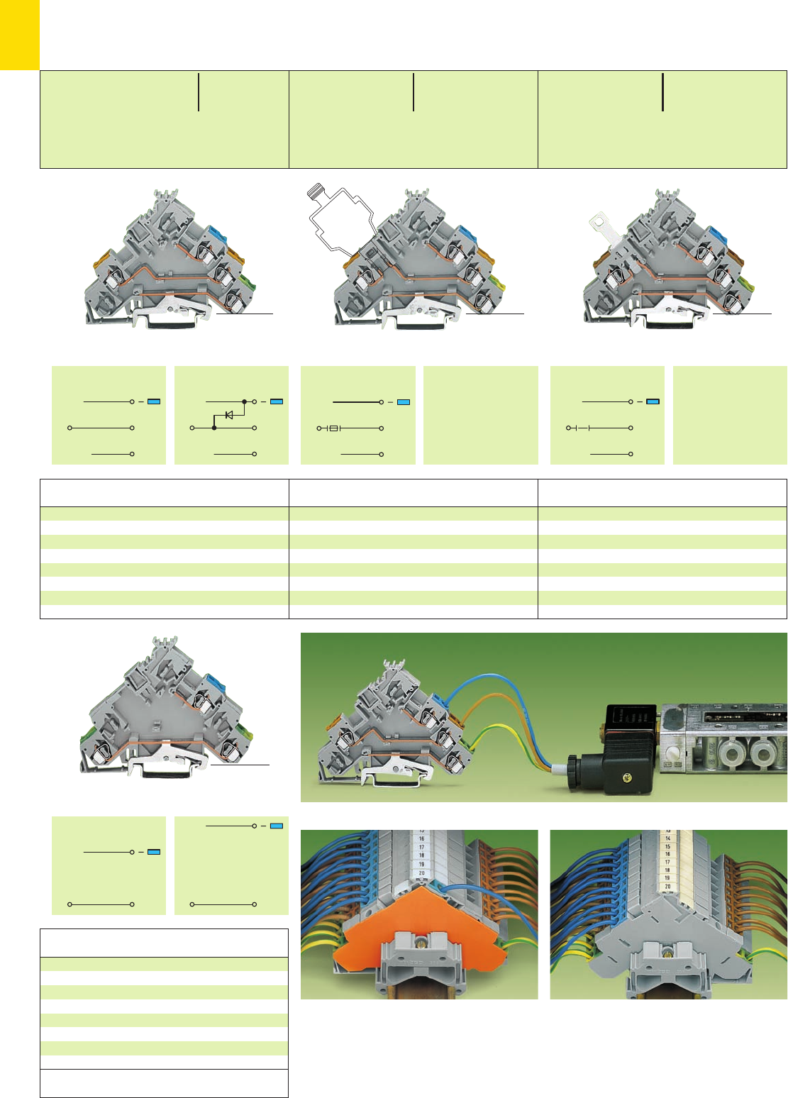
7
54
*U2N; *U2N *U2N;
SS
PE PE
SS
PE
SS
III
PE
SS
PE PE PE PE
III
* For further approvals with corresponding ratings see section 15.
see page 7.55
Accessories Insulation stop and jumper
Actuator disconnect terminal block
with ground (earth) connection,
for interruption of line
280-576 50
Actuator terminal blocks
with ground (earth) connection,
for fuse plugs ➍, for fuse protection of line,
without end plate 280-575 50
with end plate
grey 280-575/280-320 50
orange 280-575/280-323 50
Actuator terminal blocks
with ground (earth) connection,
I280-572 50
and recovery diode 1 N 4007
II 280-572/281-411 50
Item Pack. unit
No. pcs
Item Pack. unit
No. pcs
Item Pack. unit
No. pcs
Actuator Terminal Blocks
with Ground (Earth) Connection 2.5 mm2/ AWG 12, (for Magnetic Valves, Servomotors etc.)
Series 280
Actuator disconnect terminal blocks
with ground (earth) connection,
voltage supply from the actuator side
I280-593 10
voltage supply from the control panel side,
with end plate
II 280-578 20
Item Pack. unit
No. pcs
Actuator terminal block, here with a magnetic valve with ground (earth) connection
<___________ 90.5 mm /3.56 in ___________> > X<___________ 90.5 mm /3.56 in ___________>
X = 15.5 mm /0.61 in Y = 10 mm/0.394 in <___________ 90.5 mm /3.56 in ___________>
<___________ 90.5 mm /3.56 in ___________>
0.08 – 2.5 mm2AWG 28 – 12
400 V/6 kV/3 ➊300 V, 10 A U
10 A 300 V, 15 A 2
Terminal block width 5 mm / 0.197 in
L8 – 9 mm / 0.33 in
0.08 – 2.5 mm2AWG 28 – 12
125 V/5 A ➌250 V; 6.3 A U
250 V/6.3 A ➌300 V, 15 A 2
Terminal block width 5 mm / 0.197 in
(with end plate 6 mm / 0.236 in)
L8 – 9 mm / 0.33 in
0.08 – 2.5 mm2AWG 28 – 12
400 V/6 kV/3, 20 A ➊300 V, 15 A U
250 V/4 kV/3, 20 A ➊ ➋ 300 V, 15 A 2
Terminal block width 5 mm / 0.197 in
(with end plate 6 mm / 0.236 in)
L8 – 9 mm / 0.33 in
<_____ 63.5 mm /2.5 in _____>Y(
<______ 63.5 mm /2.5 in ______>
<_______ 63.5 mm /2.5 in _______><______ 63.5 mm /2.5 in ______>
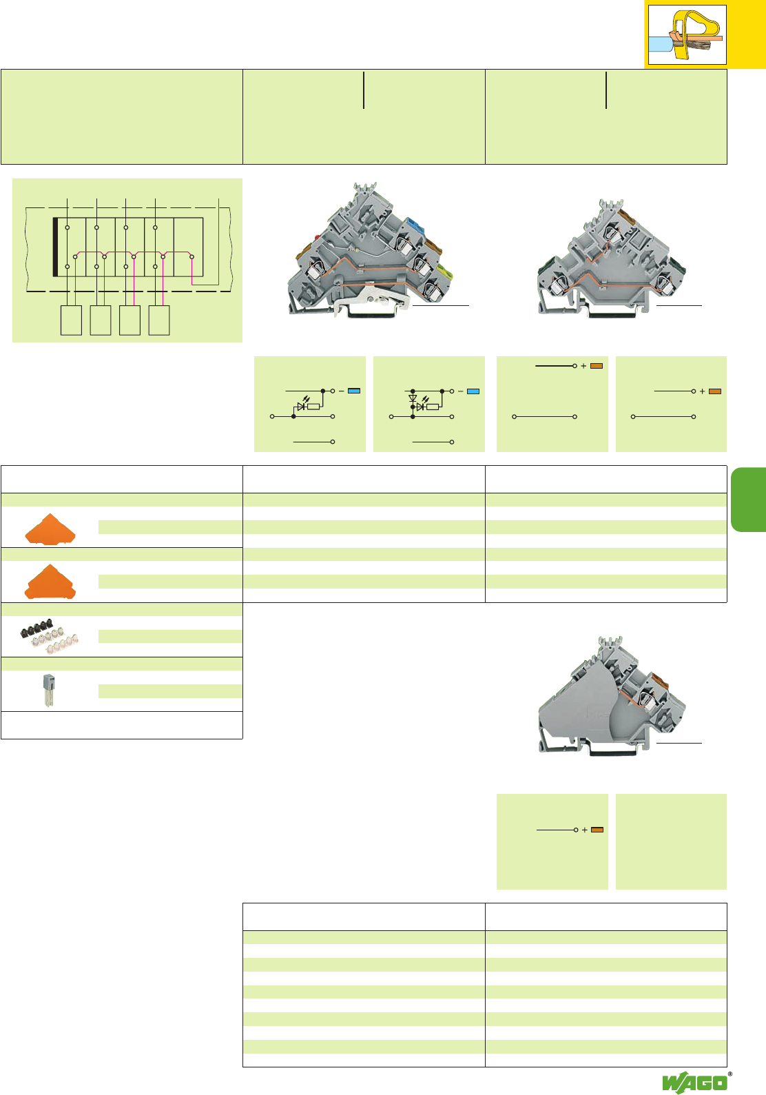
7
7
55
SS SS
III
SS
PE PE
SS
III
*U2N; *U2N;
Actuator LED terminal blocks
with ground (earth) connection, DC 24 V
I LED red ➍280-572/281-434 50
with recovery diode 1 N 4007
II LED red ➍280-572/281-420 50
Item Pack. unit
No. pcs
Actuator supply terminal block, in connection with:
280-555 ➞voltage supply from control panel side
280-554 ➞voltage supply from actuator side
with end plate 280-556 20
Item Pack. unit
No. pcs
Item Pack. unit
No. pcs
Actuator terminal block
I280-555 50
Actuator terminal block, not shown
II 280-554 50
➊400/250 V = rated voltage
6/4 kV = rated surge voltage
3 = pollution degree
(see also section 15)
➋with recovery diode
➌Electrical ratings are given by the fuse or compo-
nents used in the component plug
(see also pages 7.34 and 7.35 and
Full Line Catalog W4, volume 3)
➍The fuse plug is 1 mm /0.039 in wider than
the terminal block. This means an intermediate
plate has to be fitted.
End and intermediate plate, 1 mm/0.039 in thick
for triple deck terminal blocks
orange 280-321 100 (4 x 25)
grey 280-319 100 (4 x 25)
End and intermediate plate, 1 mm/0.039 in thick
for quadruple deck terminal blocks
orange 280-323 100 (4 x 25)
grey 280-320 100 (4 x 25)
Insulation stop, 5 pcs /strip see page 2.43
white 280-470 200 strips
light grey 280-471 200 strips
dark grey 280-472 200 strips
Adjacent jumper, insulated, IN24 A
grey 280-402 200 (8 x 25)
<__________ 90.5 mm /3.56 in __________> <__________ 80 mm /3.15 in __________>
<__________ 80 mm /3.15 in __________>
Item Pack. unit
No. pcs
Appropriate
marking system WMB/WSB
(see section 14)
0.08 – 2.5 mm2AWG 28 – 12
DC 24 V ➌24 V, 15 A U
20 A 300 V, 15 A 2
Terminal block width 5 mm / 0.197 in
L8 – 9 mm / 0.33 in
0.08 – 2.5 mm2AWG 28 – 12
400 V/6 kV/3 ➋300 V, 15 A U
20 A 300 V, 15 A 2
Terminal block width 5 mm / 0.197 in
(with end plate 6 mm / 0.236 in)
L8 – 9 mm / 0.33 in
<______ 63.5 mm /2.5 in ______>
<___ 55.5 mm /2.19 in ___><___ 55.5 mm /2.19 in ___>
Voltage supply from actuator side
To control panel
Thermocouples
End plate
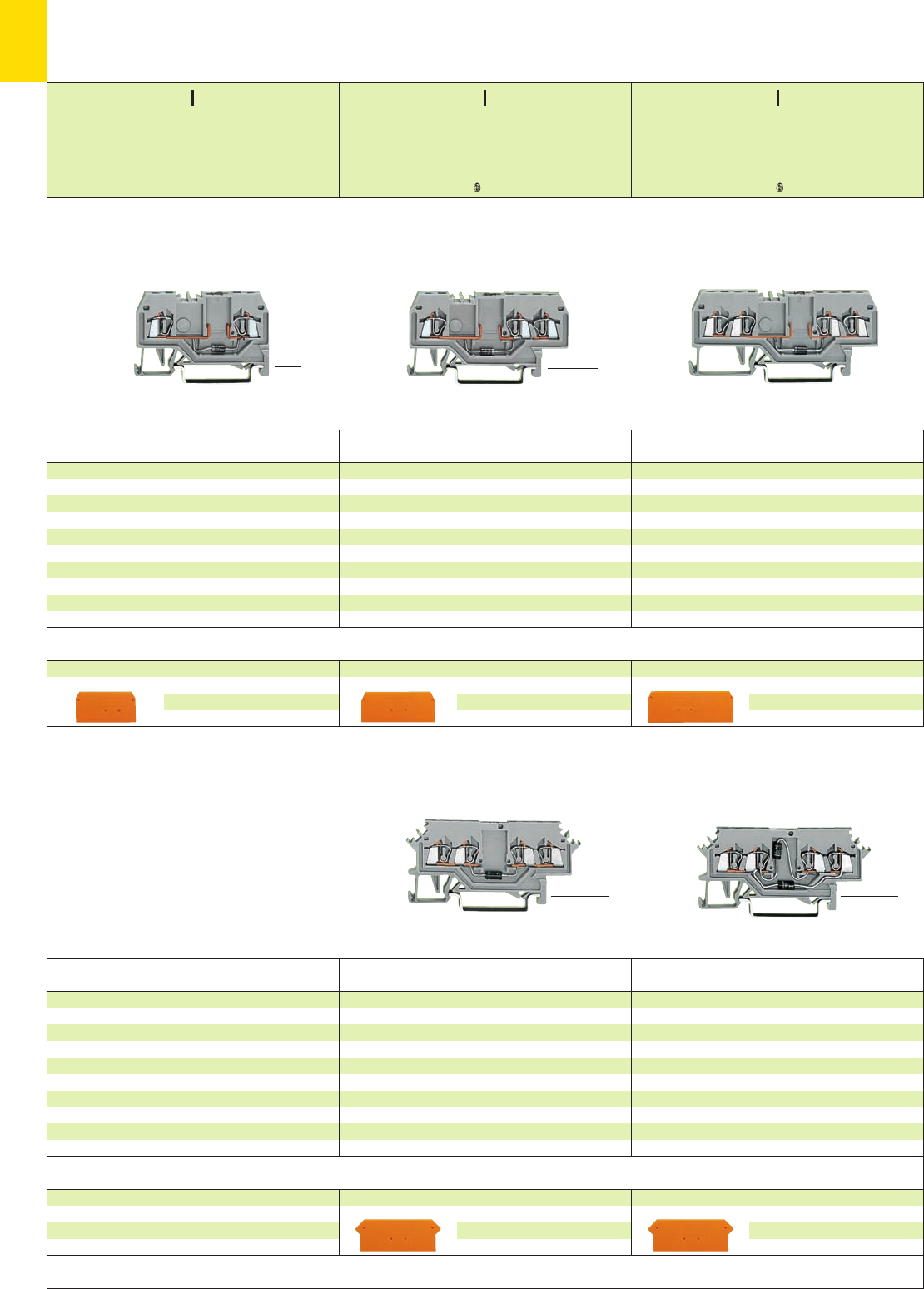
7
56
*KfSbJ|;[ . *KfSbJ|;{[
* For further approvals with corresponding ratings see section 15.
End and intermediate plate, 2 mm /0.079 in thick
orange 279-317100 (4 x 25)
grey 279-316100 (4 x 25)
End and intermediate plate, 2 mm /0.079 in thick
orange 279-317100 (4 x 25)
grey 279-316100 (4 x 25)
4-conductor diode terminal block
with 2 diodes 1 N 4007
grey 279-620/281-408 100
(for lamp test circuits up to 60 V)
Through terminal block with the same shape
grey 279-621 page 2.9
4-conductor diode terminal blocks
with diode 1 N 4007
Circuit I, grey 279-623/281-410 100
Circuit II, grey 279-623/281-411 100
Examples of circuit configuration see page 7.59
Through terminal block with the same shape
grey 279-621 page 2.9
Item Pack. unit
No. pcs
Item Pack. unit
No. pcs
4-conductor diode terminal blocks
with diode 1 N 4007
Circuit I, grey 279-815/281-410 100
Circuit II, grey 279-815/281-411 100
Examples of circuit configuration see page 7.59
Through terminal block with the same shape
grey 279-831 page 2.8
3-conductor diode terminal blocks
with diode 1 N 4007
Circuit I, grey 279-673/281-410 100
Circuit II, grey 279-673/281-411 100
Examples of circuit configuration see page 7.59
Through terminal block with the same shape
grey 279-681 page 2.8
2-conductor diode terminal blocks
with diode 1 N 4007
Circuit I, grey 279-915/281-410 100
Circuit II, grey 279-915/281-411 100
Examples of circuit configuration see page 7.59
Through terminal block with the same shape
grey 279-901 page 2.8
Item Pack. unit
No. pcs
Item Pack. unit
No. pcs
Item Pack. unit
No. pcs
Diode Terminal Blocks 1.5 mm2/ AWG 16,
Series 279
(_ 32 mm /1.26 in _)
<_______ 62.5 mm /2.46 in _______>
(_ 32 mm /1.26 in _)
<_____ 52 mm /2.05 in _____> <__42.5 mm /1.67 in __>
<___________ 73 mm /2.87 in ___________>
End and intermediate plate, 2 mm /0.079 in thick
orange 279-346100 (4 x 25)
grey 279-344100 (4 x 25)
End and intermediate plate, 2 mm /0.079 in thick
orange 279-339100 (4 x 25)
grey 279-308100 (4 x 25)
End and intermediate plate, 2 mm /0.079 in thick
orange 279-328100 (4 x 25)
grey 279-325100 (4 x 25)
Appropriate marking system WMB/WSB (see section 14)
Marker width 4 mm/0.157 in
<_________ 68 mm /2.68 in _________> <_________ 68 mm/2.68 in _________>
Accessories Series 279, see page 7.59
Appropriate marking system WMB/WSB (see section 14)
Marker width 4 mm/0.157 in
<_ 27 mm / __>
1.06 in <_ 27 mm / __>
1.06 in
<_ 27 mm / __>
1.06 in
<_ 27 mm / __>
1.06 in
0.08 – 1.5 mm2AWG 28 – 16
UN250 V; URM 1000 V
1 N 4007 – 0.5 A continuous current
Terminal block width 4 mm / 0.157 in
L8 – 9 mm / 0.33 in
0.08 – 1.5 mm2AWG 28 – 16
UN250 V; URM 1000 V
1 N 4007 – 0.5 A continuous current
Terminal block width 4 mm / 0.157 in
L8 – 9 mm / 0.33 in
0.08 – 1.5 mm2AWG 28 – 16
UN250 V; URM 1000 V
1 N 4007 – 0.5 A continuous current
Terminal block width 4 mm / 0.157 in
L8 – 9 mm / 0.33 in
<_ 27 mm / __>
1.06 in
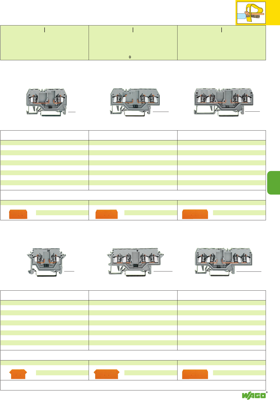
7
7
57
*KfbJ|;{[
*Kq *Kq
End and intermediate plate, 2.5 mm/0.098 in thick
orange 280-315100 (4 x 25)
grey 280-314100 (4 x 25)
End and intermediate plate, 2.5 mm/0.098 in thick
orange 280-317100 (4 x 25)
grey 280-316100 (4 x 25)
4-conductor diode terminal blocks
with diode 1 N 4007
Circuit I, grey 280-655/281-410 100
Circuit II, grey 280-655/281-411 100
Examples of circuit configuration see page 7.59
Through terminal block with the same shape
grey 280-633 page 2.11
4-conductor diode terminal blocks
with diode 1 N 4007
Circuit I, grey 280-623/281-410 100
Circuit II, grey 280-623/281-411 100
Examples of circuit configuration see page 7.59
Through terminal block with the same shape
grey 280-621 page 2.12
Item Pack. unit
No. pcs
Item Pack. unit
No. pcs
4-conductor diode terminal blocks
with diode 1 N 4007
Circuit I, grey 280-815/281-410 100
Circuit II, grey 280-815/281-411 100
Examples of circuit configuration see page 7.59
Through terminal block with the same shape
grey 280-833 page 2.10
3-conductor diode terminal blocks
with diode 1 N 4007
Circuit I, grey 280-673/281-410 100
Circuit II, grey 280-673/281-411 100
Examples of circuit configuration see page 7.59
Through terminal block with the same shape
grey 280-681 page 2.10
2-conductor diode terminal blocks
with diode 1 N 4007
Circuit I, grey 280-915/281-410 100
Circuit II, grey 280-915/281-411 100
Examples of circuit configuration see page 7.59
Through terminal block with the same shape
grey 280-901 page 2.10
Item Pack. unit
No. pcs
Item Pack. unit
No. pcs
Item Pack. unit
No. pcs
Diode Terminal Blocks 2.5 mm2/ AWG 12,
Series 280
End and intermediate plate, 2.5 mm/0.098 in thick
orange 280-315100 (4 x 25)
grey 280-314100 (4 x 25)
End and intermediate plate, 2.5 mm/0.098 in thick
orange 280-326100 (4 x 25)
grey 280-324100 (4 x 25)
End and intermediate plate, 2.5 mm/0.098 in thick
orange 280-309100 (4 x 25)
grey 280-308100 (4 x 25)
Accessories Series 280, see page 7.59
(_ 32 mm /1.26 in _)
<_____ 53 mm /2.09 in _____> (_ 32 mm /1.26 in _)
<________ 64 mm /2.52 in ________> <__ 42.5 mm /1.67 in __>
<___________ 75 mm /2.95 in ____________>
<32 mm/1.26 in >
<___________ 75 mm /2.95 in ___________>
<____ 50 mm /1.97 in ____>
2-conductor diode terminal blocks
with diode 1 N 4007
Circuit I, grey 280-613/281-410 100
Circuit II, grey 280-613/281-411 100
Examples of circuit configuration see page 7.59
Through terminal block with the same shape
grey 280-601 page 2.12
End and intermediate plate, 2.5 mm/0.098 in thick
orange 280-331100 (4 x 25)
grey 280-330100 (4 x 25)
Item Pack. unit
No. pcs
<__________ 73 mm /2.87 in __________>
* For further approvals with corresponding ratings see section 15.
Appropriate marking system WMB/WSB (see section 14)
Marker width 5 mm/0.197 in
Appropriate marking system WMB/WSB (see section 14)
Marker width 5 mm/0.197 in
<_ 28 mm / _>
1.10 in
0.08 – 2.5 mm2AWG 28 – 12
UN250 V; URM 1000 V
1 N 4007 – 0.5 A continuous current
Terminal block width 5 mm / 0.197 in
L8 – 9 mm / 0.33 in
<_ 28 mm / _>
1.10 in
<_ 28 mm / _>
1.10 in
0.08 – 2.5 mm2AWG 28 – 12
UN250 V; URM 1000 V
1 N 4007 – 0.5 A continuous current
Terminal block width 5 mm / 0.197 in
L8 – 9 mm / 0.33 in
0.08 – 2.5 mm2AWG 28 – 12
UN250 V; URM 1000 V
1 N 4007 – 0.5 A continuous current
Terminal block width 5 mm / 0.197 in
L8 – 9 mm / 0.33 in
<_ 28 mm / _>
1.10 in
<_ 28 mm / _>
1.10 in
<_ 28 mm / _>
1.10 in
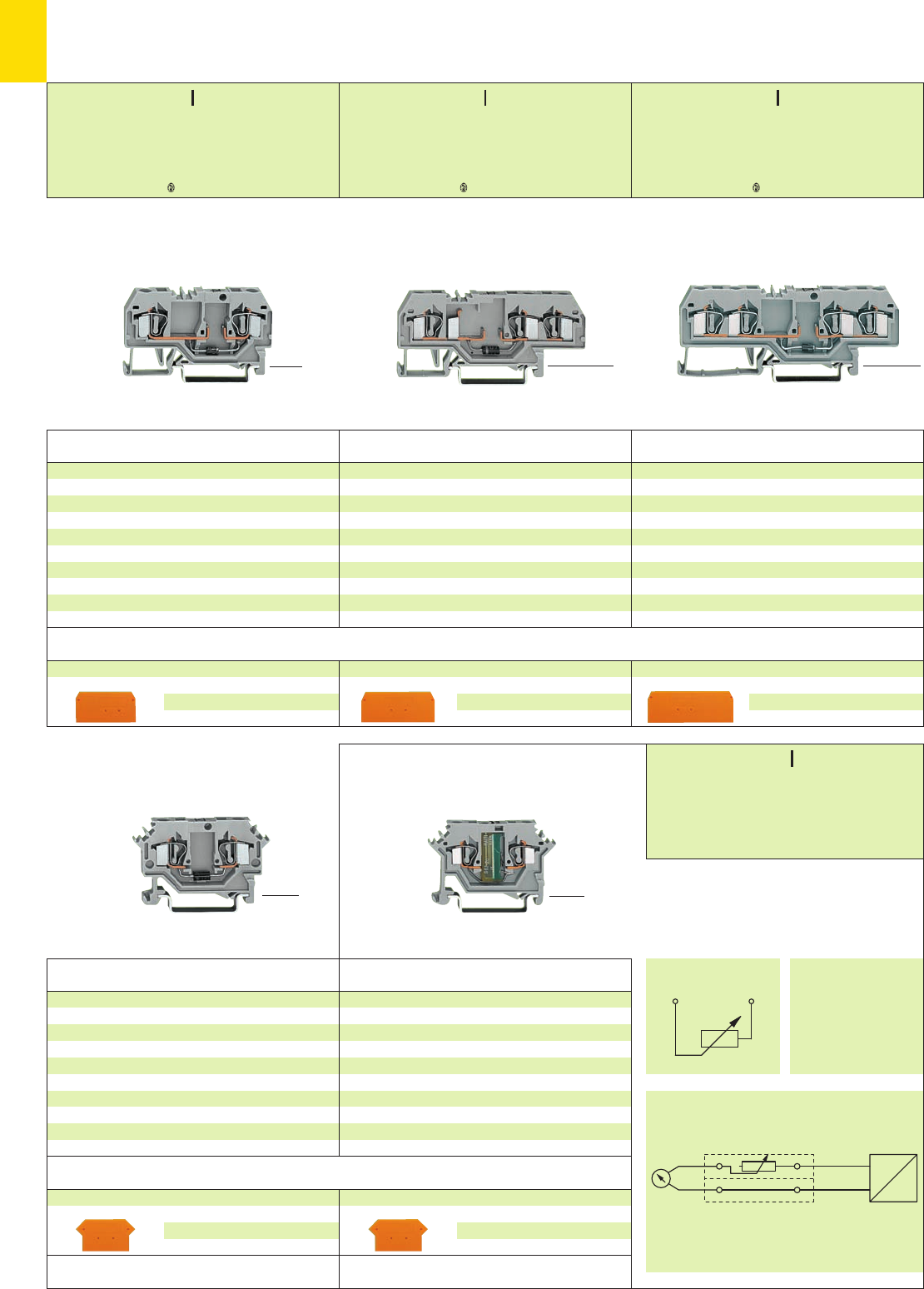
7
58
*KfbJ;{[
*KfbJ;{[ *KfbJ;{[
P1–P2
U
➋
➋
4-conductor diode terminal blocks
with diode 1 N 4007
Circuit I, grey 281-665/281-410 50
Circuit II, grey 281-665/281-411 50
4-conductor diode terminal blocks
with diode 1 N 5408
Circuit I, grey 281-665/281-400 50
Circuit II, grey 281-665/281-401 50
Through terminal block with the same shape
grey 281-652 page 2.16
3-conductor diode terminal blocks
with diode 1 N 4007
Circuit I, grey 281-673/281-410 50
Circuit II, grey 281-673/281-411 50
3-conductor diode terminal blocks
with diode 1 N 5408
Circuit I, grey 281-673/281-400 50
Circuit II, grey 281-673/281-401 50
Through terminal block with the same shape
grey 281-681 page 2.16
2-conductor diode terminal blocks
with diode 1 N 4007
Circuit I, grey 281-915/281-410 50
Circuit II, grey 281-915/281-411 50
2-conductor diode terminal blocks
with diode 1 N 5408
Circuit I, grey 281-915/281-400 50
Circuit II, grey 281-915/281-401 50
Through terminal block with the same shape
grey 281-901 page 2.16
Item Pack. unit
No. pcs
Item Pack. unit
No. pcs
Item Pack. unit
No. pcs
Diode Terminal Blocks 4 mm2/ AWG 12 and
Variable Resistor Terminal Blocks 2.5 mm2/ AWG 12,
Series 281 and Series 280
End and intermediate plate, 2.5 mm/0.098 in thick
orange 281-335100 (4 x 25)
grey 281-334100 (4 x 25)
End and intermediate plate, 2.5 mm/0.098 in thick
orange 281-326100 (4 x 25)
grey 281-324100 (4 x 25)
End and intermediate plate, 2.5 mm/0.098 in thick
orange 281-329100 (4 x 25)
grey 281-328100 (4 x 25)
Accessories Series 281, see page 7.59
2-conductor diode terminal blocks
with diode 1 N 4007
Circuit I, grey 281-603/281-410 100
Circuit II, grey 281-603/281-411 100
2-conductor diode terminal blocks
with diode 1 N 5408
Circuit I, grey 281-603/281-400 100
Circuit II, grey 281-603/281-401 100
Through terminal block with the same shape
grey 281-601 page 1.23
End and intermediate plate, 2.5 mm/0.098 in thick
orange 281-317100 (4 x 25)
grey 281-316100 (4 x 25)
Item Pack. unit
No. pcs
<36 mm /1.42 in >
<______ 59 mm /2.32 in ______> <_____ 50 mm /1.97 in ____>
<______________ 86 mm /3.39 in ______________>
<_ 37mm /1.46 in _>
<__________ 73.5 mm /2.89 in __________>
<_____ 53 mm /2.09 in _____>
* For further approvals with corresponding ratings see section 15.
Appropriate marking system WMB/WSB (see section 14)
Marker width 5 mm/0.197 in
Appropriate marking system WMB/WSB (see section 14)
Marker width 5 mm/0.197 in
Trimming circuit for differential pressure sensor
Item Pack. unit
No. pcs
End and intermediate plate, 2.5 mm/0.098 in thick
orange 280-331100 (4 x 25)
grey 280-330100 (4 x 25)
Variable resistor term. block, w. balancing resistance
0.5 Ω– 20 Ω, 0.75 W ➊
grey 280-615/281-412 100
Variable resistor term. block, w. balancing resistance
0.5 Ω– 20 Ω, 0.75 W ➊
blue 280-645/281-412 100
Variable resistor term. block, w. balancing resistance
20 Ω– 1 kΩ, 0.75 W ➊
grey 280-615/281-428 100
<____ 50 mm /1.97 in ____>
Variable Resistor Terminal Blocks
2.5 mm2/AWG 14,
Series 280
Accessories Series 280, see page 7.59
➊For other resistor values – contact factory
If used with intermediate plate
280-331 also suitable for Ex i-applications
<_ 29 mm / _>
1.14 in
<_ 29 mm / _>
1.14 in <_ 29 mm / _>
1.14 in
<_ 29 mm / _>
1.14 in
0.08 – 4 mm2AWG 28 – 12
UN250 V; URM 1000 V
1 N 4007 – 0.5 A continuous current
1 N 5408 – 1.5 A continuous current
Terminal block width 6 mm / 0.236 in
L9 – 10 mm / 0.37 in
0.08 – 4 mm2AWG 28 – 12
UN250 V; URM 1000 V
1 N 4007 – 0.5 A continuous current
1 N 5408 – 1.5 A continuous current
Terminal block width 6 mm / 0.236 in
L9 – 10 mm / 0.37 in
0.08 – 4 mm2AWG 28 – 12
UN250 V; URM 1000 V
1 N 4007 – 0.5 A continuous current
1 N 5408 – 1.5 A continuous current
Terminal block width 6 mm / 0.236 in
L9 – 10 mm / 0.37 in
<_ 28 mm / _>
1.10 in
0.08 – 2.5 mm2AWG 28 – 14
250 V
Terminal block width 5 mm / 0.197 in
L8 – 9 mm / 0.33 in
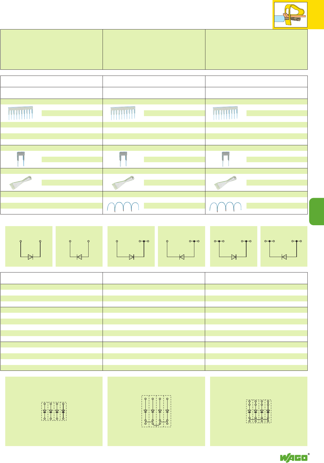
7
7
59
IIIIIIIII
Accessories and Examples of Circuit Configuration
Diode Terminal Blocks, Series 279/280/281
Comb type jumper bar, insulated, see page 2.44
IN= INof terminal block
2-way 279-482200 (8 x 25)
3-way 279-483200 (8 x 25)
10-way 279-490 50 (2 x 25)
Alternate comb type jumper bar, insulated,
IN= INof terminal block
2-way 279-492200 (8 x 25)
Operating tool, insulated
2-way 279-432 1
3-way 279-433 1
10-way 279-440 1
Item Pack. unit
No. pcs Item Pack. unit
No. pcs
Comb type jumper bar, insulated, see page 2.44
IN= INof terminal block
2-way 280-482200 (8 x 25)
3-way 280-483200 (8 x 25)
10-way 280-490 50 (2 x 25)
Alternate comb type jumper bar, insulated,
IN= INof terminal block
2-way 280-492200 (8 x 25)
Operating tool, insulated
2-way 280-432 1
3-way 280-433 1
10-way 280-440 1
Wire commoning chain, insulated, 50 connections, 8 A
black 210-103 1
blue 210-123 1
Comb type jumper bar, insulated, see page 2.44
IN= INof terminal block
2-way 281-482100 (4 x 25)
3-way 281-483100 (4 x 25)
5-way 281-485100 (4 x 25)
10-way 281-490 50 (2 x 25)
Alternate comb type jumper bar, insulated,
IN= INof terminal block
2-way 281-492100 (4 x 25)
Operating tool, insulated
2-way 280-432 1
3-way 280-433 1
5-way 281-440 1
Wire commoning chain, insulated, 50 connections, 8 A
black 210-103 1
blue 210-123 1
Accessories Series 279 Accessories Series 280 Accessories Series 281
2-conductor diode terminal block 3-conductor diode terminal block 4-conductor diode terminal block
Circuit I 279-815/281-410 100
Circuit II 279-815/281-411 100
Circuit I 279-623/281-410 100
Circuit II 279-623/281-411 100
Circuit I 280-815/281-410 100
Circuit II 280-815/281-411 100
Circuit I 280-655/281-410 100
Circuit II 280-655/281-411 100
Circuit I 280-623/281-410 100
Circuit II 280-623/281-411 100
Circuit I 281-665/281-410 50
Circuit II 281-665/281-411 50
Circuit I 281-665/281-400 50
Circuit II 281-665/281-401 50
Circuit I 279-673/281-410 100
Circuit II 279-673/281-411 100
Circuit I 280-673/281-410 100
Circuit II 280-673/281-411 100
Circuit I 281-673/281-410 50
Circuit II 281-673/281-411 50
Circuit I 281-673/281-400 50
Circuit II 281-673/281-401 50
Circuit I 279-915/281-410 100
Circuit II 279-915/281-411 100
Circuit I 280-915/281-410 100
Circuit II 280-915/281-411 100
Circuit I 280-613/281-410 100
Circuit II 280-613/281-411 100
Circuit I 281-915/281-410 50
Circuit II 281-915/281-411 50
Circuit I 281-915/281-400 50
Circuit II 281-915/281-401 50
Item Pack. unit
No. pcs
Item Pack. unit
No. pcs
Item Pack. unit
No. pcs
Open diode gate Polarized diode gate, common cathodePolarized diode gate, common cathode
Item Pack. unit
No. pcs
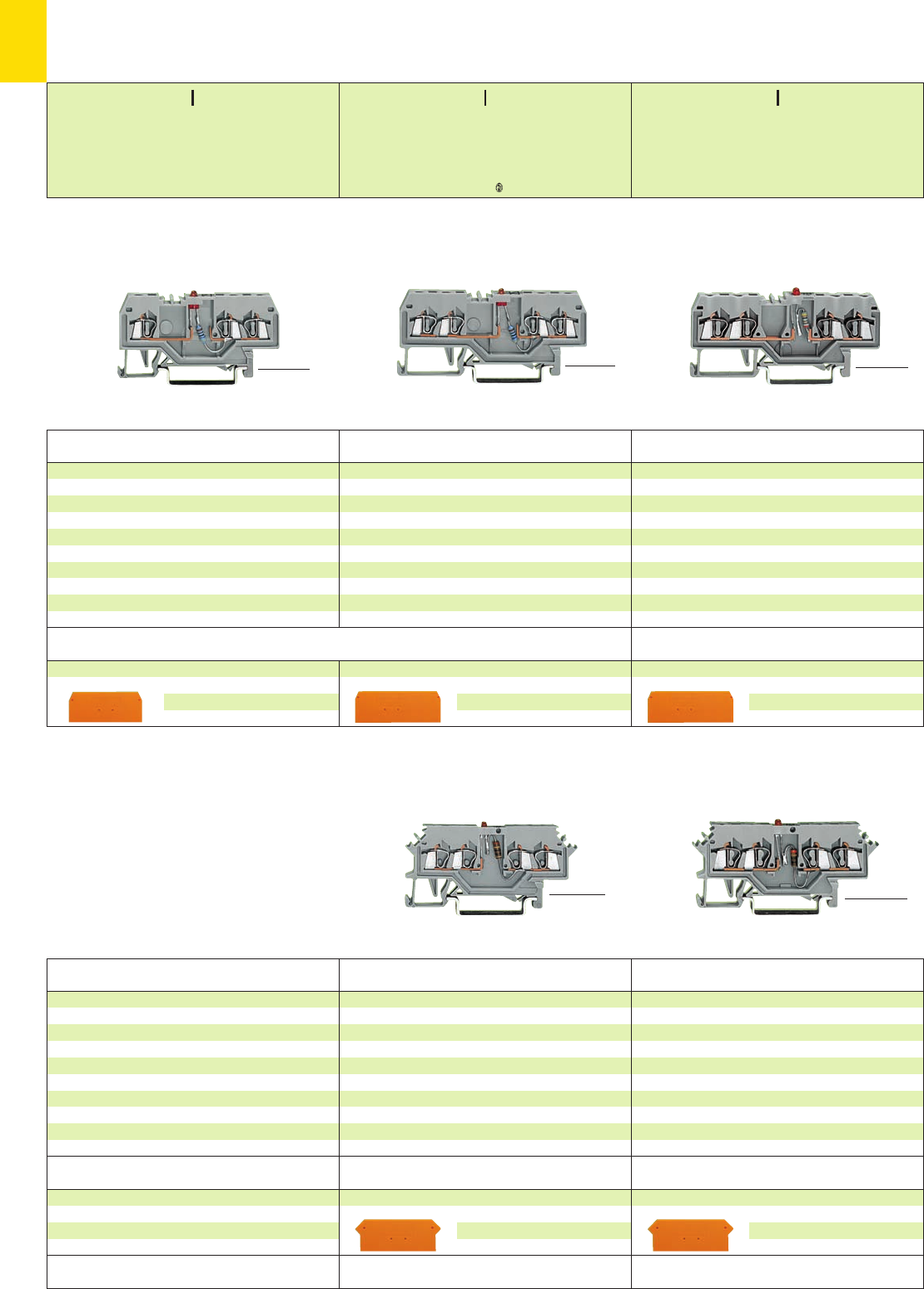
*KfSbJ|q;{[ *U
7
60
End and intermediate plate, 2.5 mm/0.098 in thick
orange 280-317100 (4 x 25)
grey 280-316100 (4 x 25)
End and intermediate plate, 2 mm /0.079 in thick
orange 279-317100 (4 x 25)
grey 279-316100 (4 x 25)
4-conductor LED terminal blocks
with red LED, DC 24 V
Circuit I, grey 280-624/281-434 100
Circuit II, grey 280-624/281-413 100
Examples of circuit configuration see page 7.61
Through terminal block with the same shape
grey 280-621 page 2.12
4-conductor LED terminal blocks
with red LED, DC 24 V
Circuit I, grey 279-624/281-434 100
Circuit II, grey 279-624/281-413 100
Examples of circuit configuration see page 7.61
Through terminal block with the same shape
grey 279-621 page 2.9
Item Pack. unit
No. pcs
Item Pack. unit
No. pcs
4-conductor LED terminal blocks
with red LED, DC 24 V
Circuit I, grey 280-809/281-434 100
Circuit II, grey 280-809/281-413 100
Examples of circuit configuration see page 7.61
Through terminal block with the same shape
grey 280-833 page 2.10
4-conductor LED terminal blocks
with red LED, DC 24 V
Circuit I, grey 279-809/281-434 100
Circuit II, grey 279-809/281-413 100
Examples of circuit configuration see page 7.61
Through terminal block with the same shape
grey 279-831 page 2.8
3-conductor LED terminal blocks
with red LED, DC 24 V
Circuit I, grey 279-674/281-434 100
Circuit II, grey 279-674/281-413 100
Examples of circuit configuration see page 7.61
Through terminal block with the same shape
grey 279-681 page 2.8
Item Pack. unit
No. pcs
Item Pack. unit
No. pcs
Item Pack. unit
No. pcs
LED Terminal Blocks 1.5 mm2/ AWG 16 and 2.5 mm2/ AWG 12,
Series 279 and 280
Appropriate marking system WMB/WSB (see section 14)
Marker width 4 mm/0.157 in
Appropriate marking system WMB/WSB (see section 14)
Marker width 5 mm/0.197 in
End and intermediate plate, 2.5 mm/0.098 in thick
orange 280-315100 (4 x 25)
grey 280-314100 (4 x 25)
End and intermediate plate, 2 mm /0.079 in thick
orange 279-346100 (4 x 25)
grey 279-344100 (4 x 25)
End and intermediate plate, 2 mm /0.079 in thick
orange 279-339100 (4 x 25)
grey 279-308100 (4 x 25)
Appropriate marking system WMB/WSB (see section 14)
Marker width 4 mm/0.157 in
Accessories Series 279, see page 7.61
<32 mm/1.26 in >
<_______ 62.5 mm /2.46 in _______> <___ 42.5 mm /1.67 in ___>
<___________ 73 mm /2.87 in ___________>
<_________ 68 mm /2.68 in _________>
<__ 42.5 mm /1.67 in __>
<___________ 75 mm /2.95 in ____________>
<__________ 73 mm /2.87 in __________>
* For further approvals with corresponding ratings see section 15.
Appropriate marking system WMB/WSB (see section 14)
Marker width 5 mm/0.197 in
0.08 – 1.5 mm2AWG 28 – 16
DC 24 V
IF25 mA max.
Terminal block width 4 mm / 0.157 in
L8 – 9 mm / 0.33 in
0.08 – 1.5 mm2AWG 28 – 16
DC 24 V
IF25 mA max.
Terminal block width 4 mm / 0.157 in
L8 – 9 mm / 0.33 in
0.08 – 2.5 mm2AWG 28 – 12
DC 24 V
IF25 mA max.
Terminal block width 5 mm / 0.197 in
L8 – 9 mm / 0.33 in
<__27 mm / _>
1.06 in
<__27 mm / _>
1.06 in
<__27 mm / _>
1.06 in
<_ 28 mm /_>
1.10 in
<_ 28 mm / _>
1.10 in
Accessories Series 280, see page 7.61
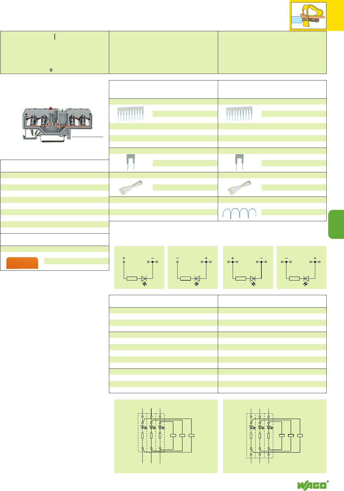
*KfbJq;{[
IIIIII
+ + +
– – –
+ + +
– – –
7
7
61
4-conductor LED terminal blocks
with red LED, DC 24 V
Circuit I, grey 280-658/281-434 100
Circuit II, grey 280-658/281-413 100
Examples of circuit configuration see page 7.61
Through terminal block with the same shape
grey 280-633 page 2.11
Item Pack. unit
No. pcs
End and intermediate plate, 2.5 mm/0.098 in thick
orange 280-315100 (4 x 25)
grey 280-314100 (4 x 25)
Appropriate marking system WMB/WSB (see section 14)
Marker width 5 mm/0.197 in
<32 mm/1.26 in >
<__________ 75 mm /2.95 in __________>
Comb type jumper bar, insulated, see page 2.44
IN= INof terminal block
2-way 279-482200 (8 x 25)
3-way 279-483200 (8 x 25)
10-way 279-490 50 (2 x 25)
Alternate comb type jumper bar, insulated,
IN= INof terminal block
2-way 279-492200 (8 x 25)
Operating tool, insulated
2-way 279-432 1
3-way 279-433 1
10-way 279-440 1
Item Pack. unit
No. pcs Item Pack. unit
No. pcs
Comb type jumper bar, insulated, see page 2.44
IN= INof terminal block
2-way 280-482200 (8 x 25)
3-way 280-483200 (8 x 25)
10-way 280-490 50 (2 x 25)
Alternate comb type jumper bar, insulated,
IN= INof terminal block
2-way 280-492200 (8 x 25)
Operating tool, insulated
2-way 280-432 1
3-way 280-433 1
10-way 280-440 1
Wire commoning chain, insulated, 50 connections, 8 A
black 210-103 1
blue 210-123 1
Accessories Series 279 Accessories Series 280
3-conductor LED terminal block 4-conductor LED terminal block
Circuit I 279-809/281-434 100
Circuit II 279-809/281-413 100
Circuit I 279-624/281-434 100
Circuit II 279-624/281-413 100
Circuit I 280-809/281-434 100
Circuit II 280-809/281-413 100
Circuit I 280-658/281-434 100
Circuit II 280-658/281-413 100
Circuit I 280-624/281-434 100
Circuit II 280-624/281-413 100
Circuit I 279-674/281-434 100
Circuit II 279-674/281-413 100
Item Pack. unit
No. pcs
Item Pack. unit
No. pcs
Voltage indication Voltage indication
0.08 – 2.5 mm2AWG 28 – 14
DC 24 V
IF25 mA max.
Terminal block width 5 mm / 0.197 in
L8 – 9 mm / 0.33 in
<_ 28 mm / _>
1.10 in
Accessories and
Examples of Circuit Configuration
LED Terminal Blocks, Series 279 and 280
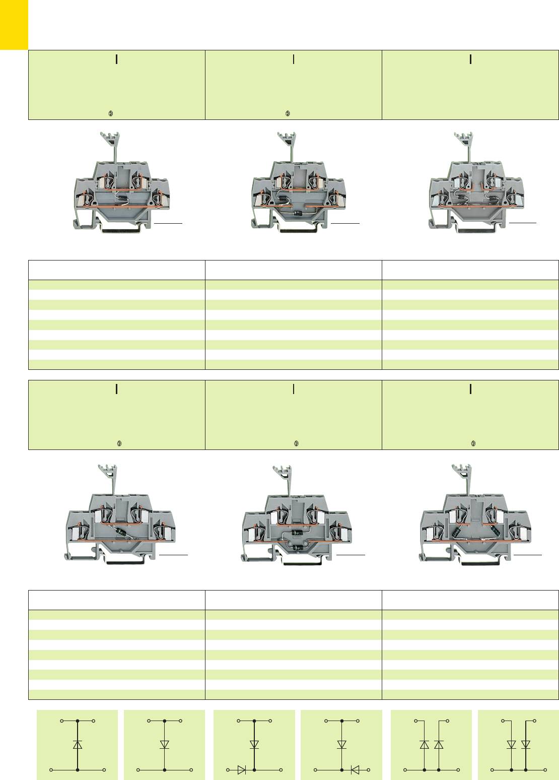
III
*KfbJq;{[*KfbJq;{[
III III
*KfbJq;{[5*KfbJq;{[5*KfbJq;{[5
7
62
Item Pack. unit
No. pcs
Double deck diode terminal blocks
with 2 diodes 1 N 4007
Circuit I, grey 280-942/281-487 50
Circuit II, grey 280-942/281-488 50
Through terminal blocks with the same shape and
accessories
grey 280-519 page 2.30
<_______ 64 mm /2.52 in _______>
Double Deck Diode Terminal Blocks
Double Deck LED Terminal Blocks 2.5 mm2/ AWG 14 and 4 mm2/ AWG 12
Series 280 and 281
Item Pack. unit
No. pcs Item Pack. unit
No. pcs
Double deck diode terminal blocks
with diode 1 N 4007
Circuit I, grey 280-940/281-410 50
Circuit II, grey 280-940/281-411 50
Through terminal blocks with the same shape and
accessories
grey 280-519 page 2.30
Double deck diode terminal blocks
with 2 diodes 1 N 4007
Circuit I, grey 280-941/281-492 50
Circuit II, grey 280-941/281-491 50
Through terminal blocks with the same shape and
accessories
grey 280-519 page 2.30
* For further approvals with corresponding ratings see section 15.
<_______ 64 mm /2.52 in _______> <_______ 64 mm /2.52 in _______>
Item Pack. unit
No. pcs Item Pack. unit
No. pcs
Double deck diode terminal blocks
with diode 1 N 4007
Circuit I, grey 281-633/281-410 50
Circuit II, grey 281-633/281-411 50
Through terminal blocks with the same shape and
accessories
grey 281-619 page 2.33
Double deck diode terminal blocks
with 2 diodes 1 N 4007
Circuit I, grey 281-635/281-492 50
Circuit II, grey 281-635/281-491 50
Through terminal blocks with the same shape and
accessories
grey 281-619 page 2.33
<_________ 73.5 mm /2.89 in _________> <_________ 73.5 mm /2.89 in _________>
Item Pack. unit
No. pcs
Double deck diode terminal blocks
with 2 diodes 1 N 4007
Circuit I, grey 281-636/281-487 50
Circuit II, grey 281-636/281-488 50
Through terminal blocks with the same shape and
accessories
grey 281-619 page 2.33
<_________ 73.5 mm /2.89 in _________>
<_____ 58.5 mm /2.30 in _____>
<_____ 58.5 mm /2.30 in _____>
<_____ 58.5 mm /2.30 in _____>
0.08 – 2.5 mm2AWG 28 – 14
UN250 V; URM 1000 V
1 N 4007 – 0.5 A continuous current
Terminal block width 5 mm / 0.197 in
L8 – 9 mm / 0.33 in
0.08 – 2.5 mm2AWG 28 – 14
UN250 V; URM 1000 V
1 N 4007 – 0.5 A continuous current
Terminal block width 5 mm / 0.197 in
L8 – 9 mm / 0.33 in
0.08 – 2.5 mm2AWG 28 – 14
UN250 V; URM 1000 V
1 N 4007 – 0.5 A continuous current
Terminal block width 5 mm / 0.197 in
L8 – 9 mm / 0.33 in
<_____ 58.5 mm /2.30 in _____>
<_____ 58.5 mm /2.30 in _____>
0.08 – 4 mm2AWG 28 – 12
UN250 V; URM 1000 V
1 N 4007 – 0.5 A continuous current
Terminal block width 6 mm / 0.236 in
L9 – 10 mm / 0.37 in
0.08 – 4 mm2AWG 28 – 12
UN250 V; URM 1000 V
1 N 4007 – 0.5 A continuous current
Terminal block width 6 mm / 0.236 in
L9 – 10 mm / 0.37 in
0.08 – 4 mm2AWG 28 – 12
UN250 V; URM 1000 V
1 N 4007 – 0.5 A continuous current
Terminal block width 6 mm / 0.236 in
L9 – 10 mm / 0.37 in
<_____ 58.5 mm /2.30 in _____>
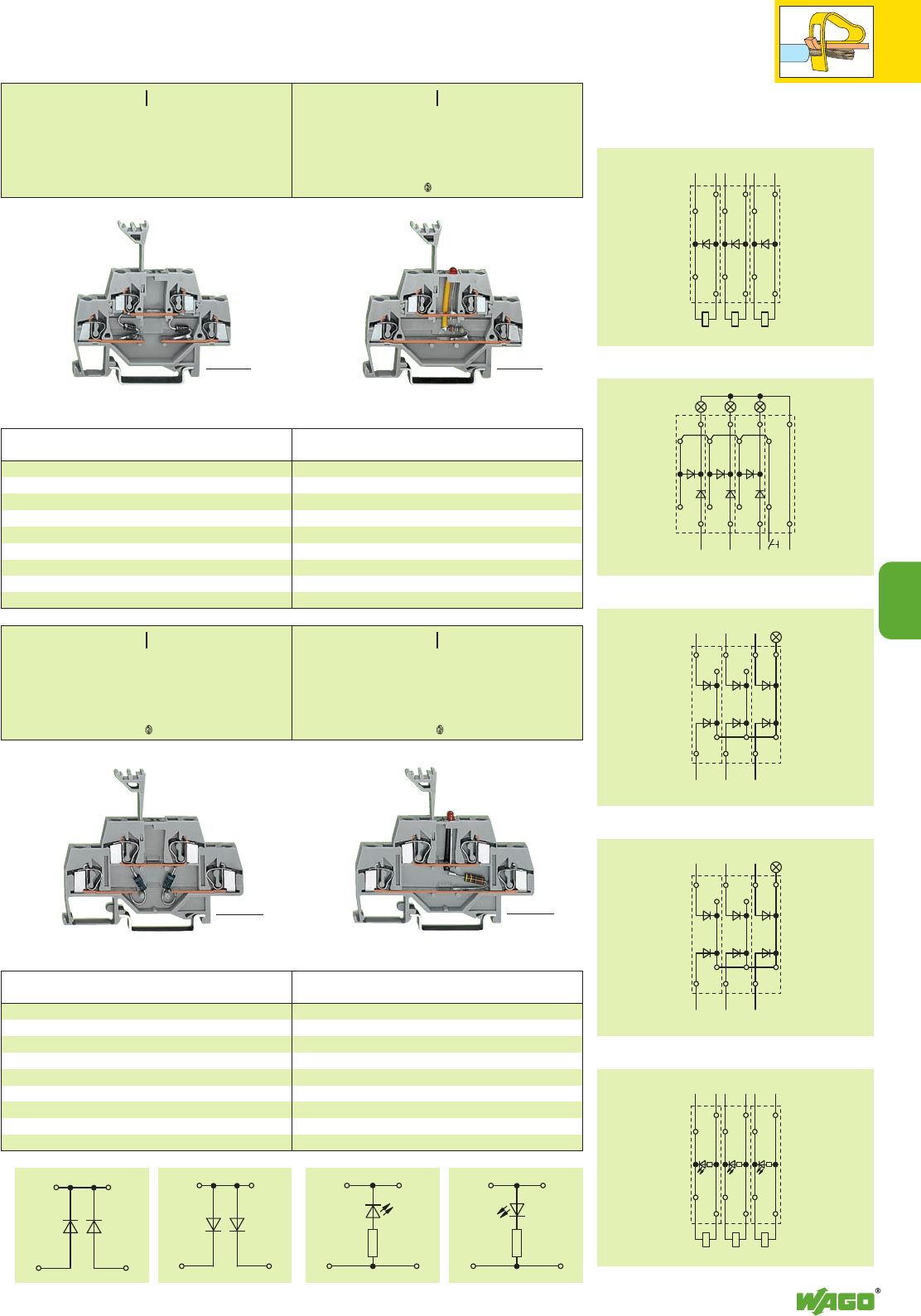
+ + + + –
+ – + – + –
+
–
+
–
–
+
–
+
– + – + – +
+ + +
+ + + –
+ + +
+ + + –
III III
*KfbJq;{[
*KfbJq;{[5 *KfbJq;{[5
7
7
63
Item Pack. unit
No. pcs Item Pack. unit
No. pcs
Double deck diode terminal blocks
with 2 diodes 1 N 4007
Circuit I, grey 280-941/281-489 50
Circuit II, grey 280-941/281-490 50
Through terminal blocks with the same shape and
accessories
grey 280-519 page 2.30
Double deck LED terminal blocks
with red LED, DC 24 V
Circuit I, grey 280-943/281-434 50
Circuit II, grey 280-943/281-413 50
Through terminal blocks with the same shape and
accessories
grey 280-519 page 2.30
Voltage indication
Used as collective fault indication
Used in lamp test circuit
<_______ 64 mm /2.52 in _______> <_______ 64 mm /2.52 in _______>
Examples of circuit configuration
Used in lamp test circuit
Used as recovery diodes
<_________ 73.5 mm /2.89 in _________> <_________ 73.5 mm /2.89 in _________>
Item Pack. unit
No. pcs Item Pack. unit
No. pcs
Double deck LED terminal blocks
with red LED, DC 24 V
Circuit I, grey 281-634/281-434 50
Circuit II, grey 281-634/281-413 50
Through terminal blocks with the same shape and
accessories
grey 281-619 page 2.33
Double deck diode terminal blocks
with 2 diodes 1 N 4007
Circuit I, grey 281-635/281-489 50
Circuit II, grey 281-635/281-490 50
Through terminal blocks with the same shape and
accessories
grey 281-619 page 2.33
<_____ 58.5 mm /2.30 in _____>
<_____ 58.5 mm /2.30 in _____>
0.08 – 2.5 mm2AWG 28 – 14
UN250 V; URM 1000 V
1 N 4007 – 0.5 A continuous current
Terminal block width 5 mm / 0.197 in
L8 – 9 mm / 0.33 in
0.08 – 2.5 mm2AWG 28 – 14
DC 24 V
IF25 mA max.
Terminal block width 5 mm / 0.197 in
L8 – 9 mm / 0.33 in
<_____ 58.5 mm /2.30 in _____>
<_____ 58.5 mm /2.30 in _____>
0.08 – 4 mm2AWG 28 – 12
UN250 V; URM 1000 V
1 N 4007 – 0.5 A continuous current
Terminal block width 6 mm / 0.236 in
L9 – 10 mm / 0.37 in
0.08 – 4 mm2AWG 28 – 12
DC 24 V
IF25 mA max.
Terminal block width 6 mm / 0.236 in
L9 – 10 mm / 0.37 in
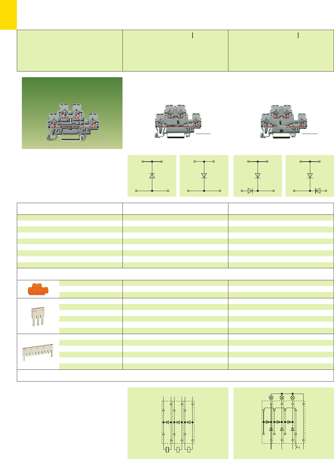
+ + + + –
+ – + – + –
III III
7
64
➊Max. diameter of insulation: 4.4 mm /0.173 in
<___ 70 mm /2.76 in ____> <___ 70 mm /2.76 in ___>
Double Deck Diode Terminal Blocks
Double Deck LED Terminal Blocks 2.5 mm2/4 mm2/ AWG 12
Series 870
Item Pack. unit
No. pcs Item Pack. unit
No. pcs
Accessories Appropriate marking system WMB/Mini-WSB (see section 14)
Exemples of circuit configuration
Description
End and
intermediate plate
Push-in type jumper bars,
light grey, insulated,
IN18 A
Push-in type jumper bars,
light grey, insulated,
IN18 A
Double deck diode terminal block
and
double deck LED terminal block, for DIN 35 rail
Double deck diode terminal blocks
with diode 1 N 4007
Circuit I, grey 870-540/281-410 50
Circuit II, grey 870-540/281-411 50
Double deck diode terminal blocks
with 2 diodes 1 N 4007
Circuit I, grey 870-541/281-492 50
Circuit II, grey 870-541/281-491 50
Used in lamp test circuitUsed as recovery diodes
2 mm /0.079 in thick
grey 870-518 100 (4 x 25)
orange 870-519 100 (4 x 25)
2-way 870-402 200 (8 x 25)
3-way 870-403 200 (8 x 25)
4-way 870-404 200 (8 x 25)
5-way 870-405 100 (4 x 25)
::
10-way 870-410 100 (4 x 25)
from 1 to 3 870-433 200 (8 x 25)
from 1 to 4 870-434 200 (8 x 25)
from 1 to 5 870-435 100 (4 x 25)
::
from 1 to 10 870-440 100 (4 x 25)
Through terminal blocks with the same shape see
page 3.8
<__40 mm / _>
1.57 in
<__40 mm / _>
1.57 in
0.08
–2.5 mm
2
/4 mm
2
“f-st”
➊AWG 28 – 12
UN250 V; URM 1000 V
1 N 4007 – 0.5 A continuous current
Terminal block width 5 mm / 0.197 in
L6 – 7 mm / 0.26 in
0.08
–2.5 mm
2
/4 mm
2
“f-st”
➊AWG 28 – 12
UN250 V; URM 1000 V
1 N 4007 – 0.5 A continuous current
Terminal block width 5 mm / 0.197 in
L6 – 7 mm / 0.26 in
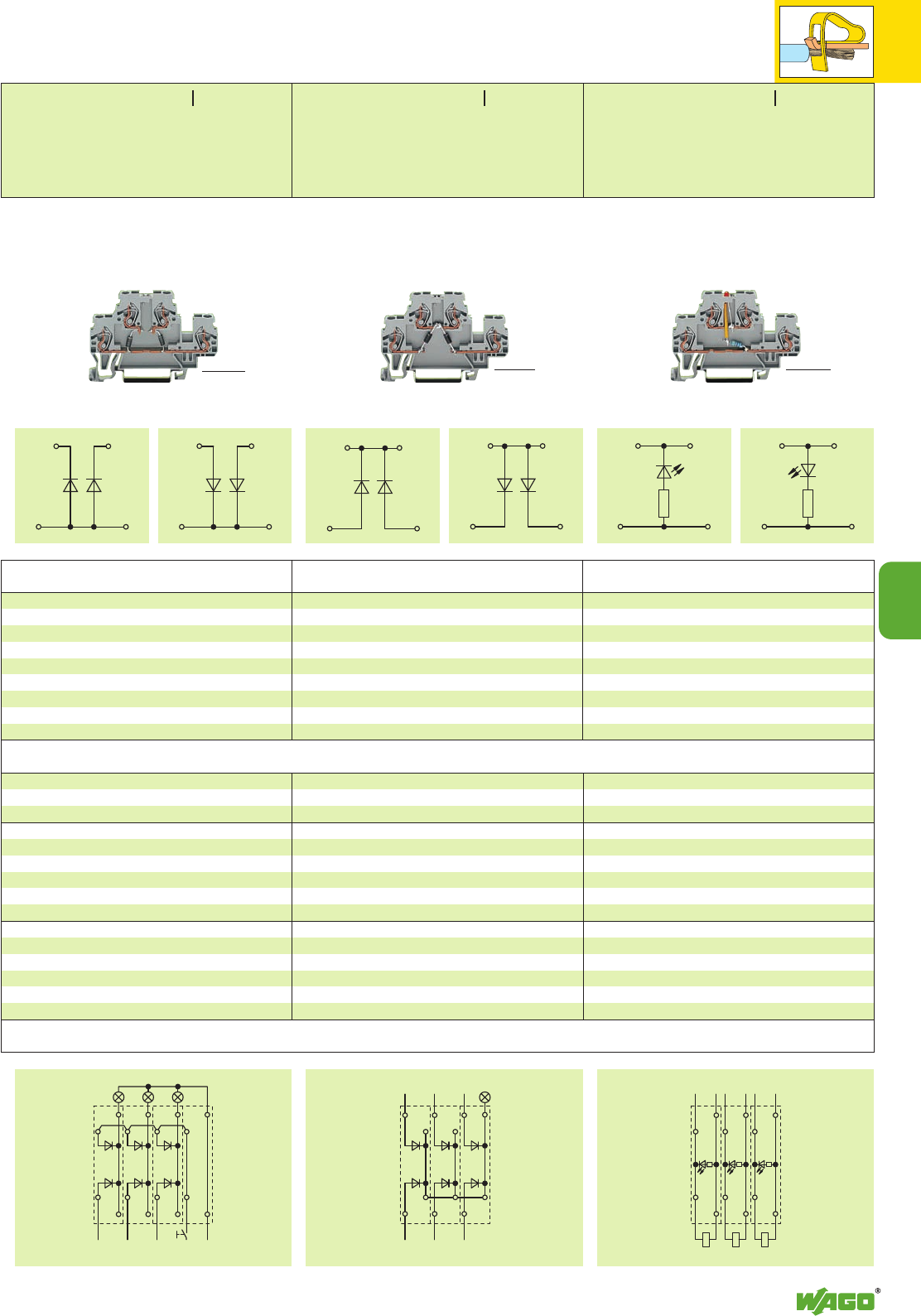
7
65
+
–
+
–
–
+
–
+
– + – + – +
+ + +
+ + + –
+ + + + –
III III III
7
<____ 70 mm /2.76 in ____> <____ 70 mm /2.76 in ____> <____ 70 mm /2.76 in ____>
Item Pack. unit
No. pcs
Item Pack. unit
No. pcs Item Pack. unit
No. pcs
Double deck diode terminal blocks
with 2 diodes 1 N 4007
Circuit I, grey 870-542/281-487 50
Circuit II, grey 870-542/281-488 50
Double deck diode terminal blocks
with 2 diodes 1 N 4007
Circuit I, grey 870-541/281-489 50
Circuit II, grey 870-541/281-490 50
Double deck LED terminal blocks
with red LED, DC 24 V
Circuit I, grey 870-543/281-434 50
Circuit II, grey 870-543/281-413 50
Used for voltage indicationUsed for collective fault indicationUsed in lamp test circuit
2 mm /0.079 in thick
grey 870-518 100 (4 x 25)
orange 870-519 100 (4 x 25)
2-way 870-402 200 (8 x 25)
3-way 870-403 200 (8 x 25)
4-way 870-404 200 (8 x 25)
5-way 870-405 100 (4 x 25)
::
10-way 870-410 100 (4 x 25)
from 1 to 3 870-433 200 (8 x 25)
from 1 to 4 870-434 200 (8 x 25)
from 1 to 5 870-435 100 (4 x 25)
::
from 1 to 10 870-440 100 (4 x 25)
Appropriate marking system WMB/Mini-WSB (see section 14)
<__40 mm / _>
1.57 in
<__40 mm / _>
1.57 in
<__40 mm / _>
1.57 in
0.08
–2.5 mm
2
/4 mm
2
“f-st”
➊AWG 28 – 12
UN250 V; URM 1000 V
1 N 4007 – 0.5 A continuous current
Terminal block width 5 mm / 0.197 in
L6 – 7 mm / 0.26 in
0.08
–2.5 mm
2
/4 mm
2
“f-st”
➊AWG 28 – 12
UN250 V; URM 1000 V
1 N 4007 – 0.5 A continuous current
Terminal block width 5 mm / 0.197 in
L6 – 7 mm / 0.26 in
0.08
–2.5 mm
2
/4 mm
2
“f-st”
➊AWG 28 – 12
DC 24 V
IF25 mA max.
Terminal block width 5 mm / 0.197 in
L6 – 7 mm / 0.26 in
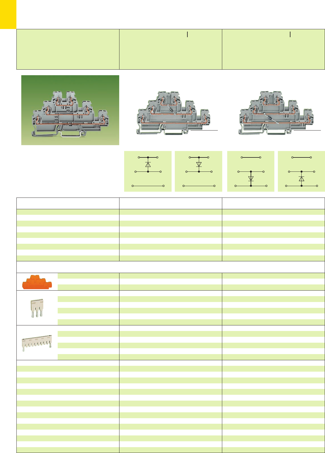
III III
7
66
➊Max. diameter of insulation: 4.4 mm /0.173 in
<____________ 106 mm /4.17 in _____________> <____________ 106 mm/4.17 in _____________>
Triple Deck Diode Terminal Blocks
Triple Deck LED Terminal Blocks 2.5 mm2/4 mm2/ AWG 12
Series 870
Item Pack. unit
No. pcs Item Pack. unit
No. pcs
Accessories Appropriate marking system WMB/Mini-WSB (see section 14)
Description
End and
intermediate plate
Push-in type jumper bars,
light grey, insulated,
IN18 A
Push-in type jumper bars,
light grey, insulated,
IN18 A
Triple deck diode terminal block
and
Triple deck LED terminal block, for DIN 35 rail
Triple deck diode terminal blocks
with diode 1 N 4007
Circuit I, grey 870-590/281-410 50
Circuit II, grey 870-590/281-411 50
Triple deck diode terminal blocks
with diode 1 N 4007
Circuit I, grey 870-590/281-675 50
Circuit II, grey 870-590/281-676 50
2 mm /0.079 in thick
grey 870-568 100 (4 x 25)
orange 870-569 100 (4 x 25)
2-way 870-402 200 (8 x 25)
3-way 870-403 200 (8 x 25)
4-way 870-404 200 (8 x 25)
5-way 870-405 100 (4 x 25)
::
10-way 870-410 100 (4 x 25)
from 1 to 3 870-433 200 (8 x 25)
from 1 to 4 870-434 200 (8 x 25)
from 1 to 5 870-435 100 (4 x 25)
::
from 1 to 10 870-440 100 (4 x 25)
Through terminal blocks with the same shape see
page 3.9
<__52.5 mm / 2.07 in >
<__52.5 mm / 2.07 in >
0.08
–2.5 mm
2
/4 mm
2
“f-st”
➊AWG 28 – 12
UN250 V; URM 1000 V
1 N 4007 – 0.5 A continuous current
Terminal block width 5 mm / 0.197 in
L6 – 7 mm / 0.26 in
0.08
–2.5 mm
2
/4 mm
2
“f-st”
➊AWG 28 – 12
UN250 V; URM 1000 V
1 N 4007 – 0.5 A continuous current
Terminal block width 5 mm / 0.197 in
L6 – 7 mm / 0.26 in
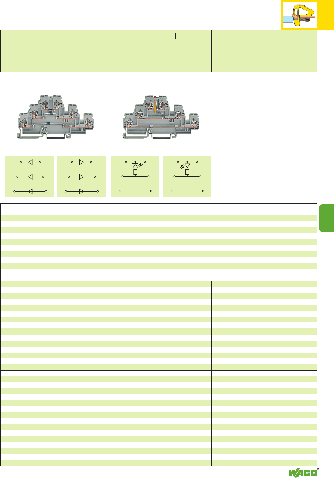
7
67
III III
7
Item Pack. unit
No. pcs
Item Pack. unit
No. pcs
Triple deck diode terminal blocks
with 3 diodes 1 N 4007
Circuit I, grey 870-596/281-673 50
Circuit II, grey 870-596/281-674 50
Triple deck LED terminal blocks
with red LED,DC 24 V
Circuit I, grey 870-593/281-434 50
Circuit II, grey 870-593/281-413 50
2 mm /0.079 in thick
grey 870-568 100 (4 x 25)
orange 870-569 100 (4 x 25)
2-way 870-402 200 (8 x 25)
3-way 870-403 200 (8 x 25)
4-way 870-404 200 (8 x 25)
5-way 870-405 100 (4 x 25)
::
10-way 870-410 100 (4 x 25)
from 1 to 3 870-433 200 (8 x 25)
from 1 to 4 870-434 200 (8 x 25)
from 1 to 5 870-435 100 (4 x 25)
::
from 1 to 10 870-440 100 (4 x 25)
<____________ 106 mm /4.17 in _____________> <____________ 106 mm /4.17 in _____________>
Appropriate marking system WMB/Mini-WSB (see section 14)
<__52.5 mm / 2.07 in >
<__52.5 mm / 2.07 in >
0.08
–2.5 mm
2
/4 mm
2
“f-st”
➊AWG 28 – 12
UN250 V; URM 1000 V
1 N 4007 – 0.5 A continuous current
Terminal block width 5 mm / 0.197 in
L6 – 7 mm / 0.26 in
0.08
–2.5 mm
2
/4 mm
2
“f-st”
➊AWG 28 – 12
DC 24 V
IF25 mA max.
Terminal block width 5 mm / 0.197 in
L6 – 7 mm / 0.26 in
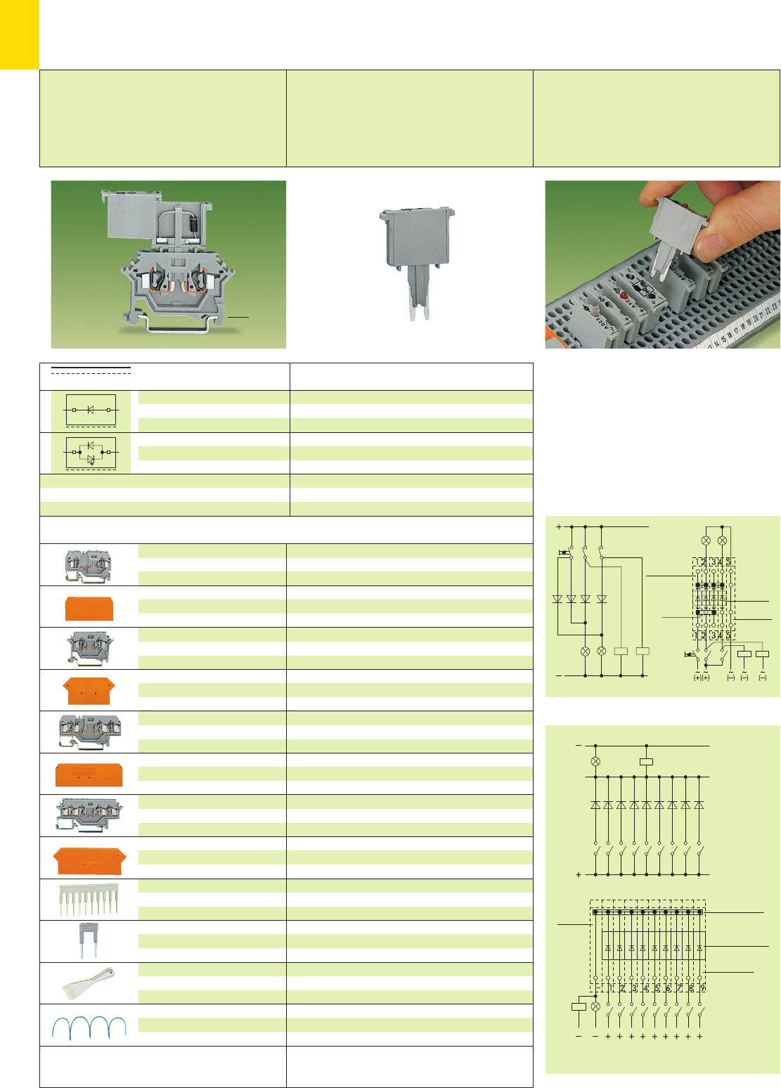
7
68
+–
–
+
Pluggable Modules – Diodes on
Carrier Terminal Blocks 2.5 mm2/ AWG 14,
Series 280
(Marking accessories
see section 14)
Diode module: diode 1 N 4007
VN250 V; VRM 1000 V; 1 A max.
LED IF25 mA
Module width 5 mm / 0.197 in
These diode modules, specially designed for
the individual construction of, for example, lamp
test circuits or collective fault indicating systems,
offer the following advantages to the user:
●Separation into functional and wiring layer
●Polarized direction of switching
●High density with only 5 mm / 0.197 in width
of terminal block and module.
●Quick and easy exchange of modules
Examples of circuit configuration
Description Item Pack. unit
No. pcs
Diode module,
5 mm / 0.197 in wide,
diode 1 N 4007
Diode module, 5 mm / 0.197 in
wide, diode 1 N 4007 as
free-wheeling diode and LED
280-801/281-411 100
DC 24 V 280-801/281-420 100
DC 48 V 280-801/281-421 100
open side of term. block
Carrier terminal blocks for pluggable modules and accessories
2-cond. carrier term. block,
0.08 – 2.5 mm2/AWG 28 – 14
stripped length 8 – 9 mm /0.33 in
End and intermediate plate,
for 2-conductor carrier terminal
block 280-916
2-cond. carrier term. block,
0.08 – 2.5 mm2/AWG 28 – 14
stripped length 8 – 9 mm /0.33 in
End and intermediate plate,
for 2-conductor carrier terminal
block 280-616
3-cond. carrier term. block,
0.08 – 2.5 mm2/AWG 28 – 14
stripped length 8 – 9 mm /0.33 in
End and intermediate plate,
for 3-conductor carrier terminal
block 280-610
4-cond. carrier term. block,
0.08 – 2.5 mm2/AWG 28 – 14
stripped length 8 – 9 mm /0.33 in
End and intermediate plate,
for 4-conductor orange
carrier terminal blocks grey
Comb type jumper bar,
insulated, see page 2.44
IN= INof terminal block
Alternate comb type
jumper bar, insulated,
IN= INof terminal block
Operating tool,
insulated
Wire commoning chain,
insulated,
50 connections, 8 A
Terminal block width 5 mm / 0.197 in
grey 280-916 ➊100
2.5 mm / 0.098 in thick
orange 280-309 100 (4 x 25)
grey 280-308 100 (4 x 25)
Terminal block width 5 mm / 0.197 in
grey 280-616 ➋100
2.5 mm / 0.098 in thick
orange 280-331 100 (4 x 25)
grey 280-330 100 (4 x 25)
Terminal block width 5 mm / 0.197 in
grey 280-610 ➌100
2.5 mm / 0.098 in thick
orange 280-326 100 (4 x 25)
grey 280-324 100 (4 x 25)
Terminal block width 5 mm / 0.197 in
grey
280-606 ➍280-686 ➎100
2.5 mm / 0.098 in thick
280-317 280-315 100 (4 x 25)
280-316 280-314 100 (4 x 25)
2-way 280-482 200 (8 x 25)
3-way 280-483 200 (8 x 25)
10-way 280-490 50 (2 x 25)
2-way 280-492 200 (8 x 25)
2-way 280-432 1
3-way 280-433 1
10-way 280-440 1
Commoning distance max. 120 mm /4.72 in
black 210-103 1
blue 210-123 1
➍Term. block marking on both sides 73 mm / 2.87 in
➎Terminal block marking in center position
75 mm / 2.95 in
Lamp test circuit with blocking diodes
➊53 mm / 2.09 in
➋50 mm / 1.97 in
➌64 mm / 2.52 in Diode gate for collective fault indication
<_____ ➊ ➋ ➌ ➍ ➎ _____>
<____ 52.5 mm /2.07 in ____>
Diode
modules
1–4
280-801/
281-411
Terminal
block 5
280-621
Terminal
blocks 1–4
280-606
V1–V4
Comb type
jumper bars
280-492
Comb type
jumper bars
280-490
Diode modules
280-801/281-411
Terminal
blocks 1–9
280-616
Terminal
block
280-601
open side of terminal block left
open side of terminal block left
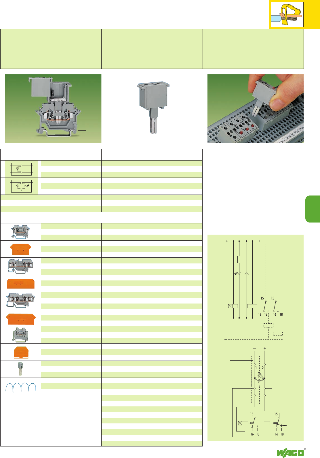
7
69
7
H1
V1
V1H1
A1
A2
A1
A2
K1 K2
K1 K2
K1 K2
R1
–
–
+
+
–
–
+
+
Pluggable Modules – Diodes on
Through Terminal Blocks 2.5 mm2/ AWG 14,
Series 280
Diode module: diode 1 N 4007
VN250 V; VRM 1000 V; 1 A max.
Module width 10 mm / 0.394 in
(Marking accessories
see section 14)
Through terminal blocks for pluggable modules and accessories
These diode modules are simply pushed into the
contact slots of the current bars of two adjacent
through terminal blocks like a push-in jumper.
This offers the following advantages to the user:
●The modules are suitable for all through
terminal blocks of series 280.
●Existing terminal block assemblies can be
refitted with diode modules without any
problem.
Further advantages:
●Separation into functional and wiring layer.
●Modules can be replaced quick by other types
of modules
Example of circuit configuration
Free-wheeling diode and voltage check
Item Pack. unit
No. pcs
Description
Diode module, 10 mm / 0.394 in
wide, diode 1 N 4007 as
free-wheeling diode
Diode module, 10 mm / 0.394 in
wide, diode 1 N 4007 as
free-wheeling diode and LED
280-803/281-411 50
DC 24 V 280-803/281-420 50
DC 48 V 280-803/281-421 50
Terminal block width 5 mm / 0.197 in
grey
280-601 ➊280-901 ➋100
2.5 mm / 0.098 in thick
280-331 280-309 100 (4 x 25)
280-330 280-308 100 (4 x 25)
Terminal block width 5 mm / 0.197 in
grey 280-681 ➌100
2.5 mm / 0.098 in thick
orange 280-326 100 (4 x 25)
grey 280-324 100 (4 x 25)
Terminal block width 5 mm / 0.197 in
grey
280-621 ➍280-833 ➎100
2.5 mm / 0.098 in thick
280-317 280-315 100 (4 x 25)
280-316 280-314 100 (4 x 25)
Terminal block width 5 mm / 0.197 in
grey 280-101 ➏100
2.5 mm / 0.098 in thick
orange 280-302 100 (4 x 25)
grey 280-301 100 (4 x 25)
IN24 A
grey 280-402 200 (8 x 25)
Commoning distance max. 120 mm / 4.72 in
black 210-103 1
blue 210-123 1
Front-entry 2-cond. term. block,
0.08 – 2.5 mm2/AWG 28 – 12
stripped length 8 – 9 mm /0.33 in
End and intermediate plate,
for 2-conductor orange
terminal blocks grey
Front-entry 3-cond. term. block
,
0.08 – 2.5 mm2/AWG 28 – 12
stripped length 8 – 9 mm /0.33 in
End and intermediate plate,
for 3-conductor terminal block
280-681
Front-entry 4-cond. term. block,
0.08 – 2.5 mm2/AWG 28 – 12
stripped length 8 – 9 mm /0.33 in
End and intermediate plate,
for 4-conductor orange
terminal blocks grey
Side-entry terminal block,
0.08 – 2.5 mm2/AWG 28 – 12
stripped length 8 – 9 mm /0.33 in
End and intermediate plate,
for side-entry terminal block
280-101
Adjacent jumper,
insulated
Wire commoning chain,
insulated,
50 connections, 8 A
➊Term. block marking on both sides 50 mm / 1.97 in
➋Terminal block marking in center position
53 mm / 2.09 in
➌Terminal block marking in center position
64 mm / 2.52 in
➍Term. block marking on both sides 73 mm / 2.87 in
➎Terminal block marking in center position
75 mm / 2.95 in
➏Term. bl. marking on both sides 42.5 mm / 1.67 in
<___➊ ➋ ➌ ➍ ➎ ➏ ___>
<____ 52.5 mm /2.07 in ____>
Terminal
blocks 1+2
280-681
Diode
module
280-803/
280-420
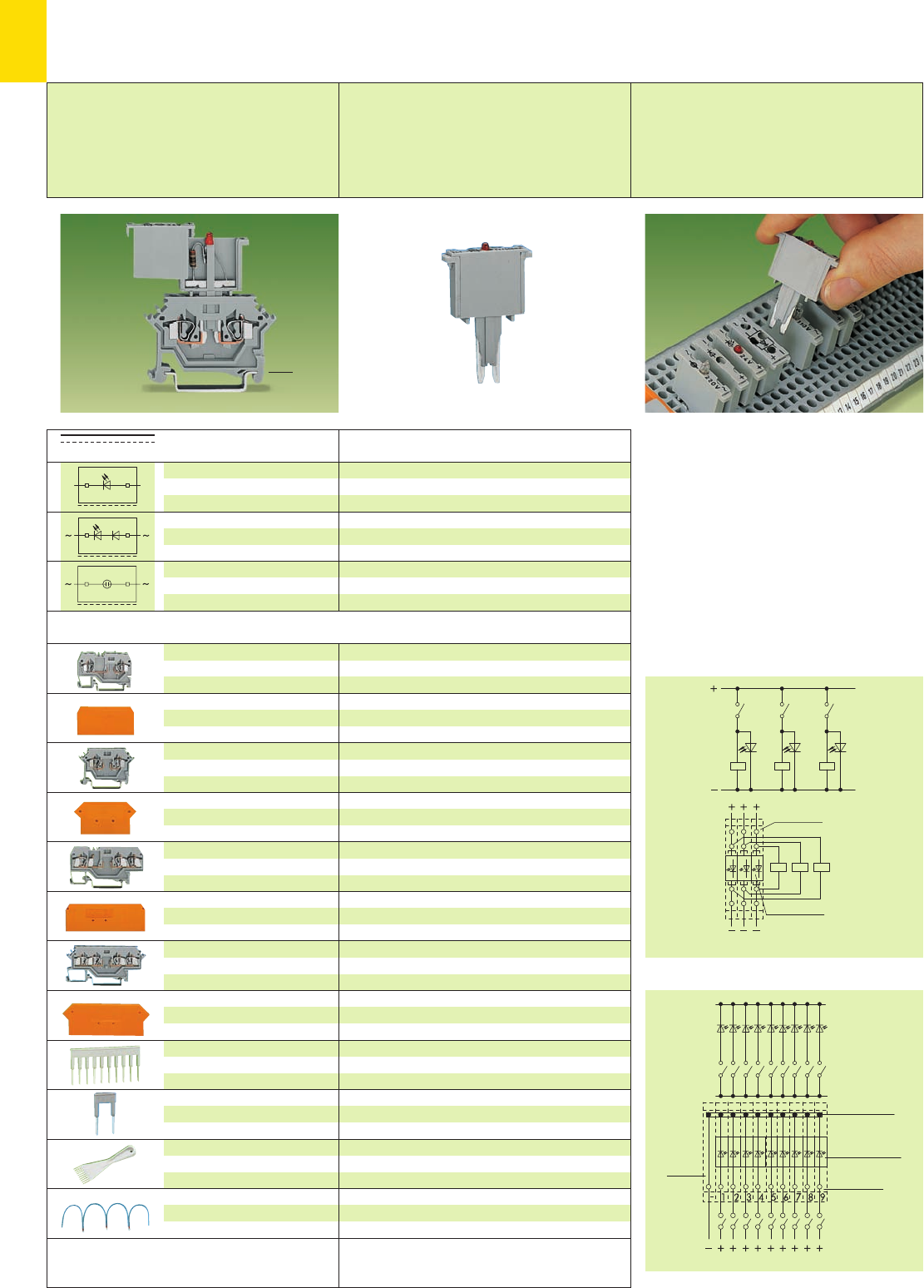
7
70
+
_
+–
Pluggable Modules – LED and Neon Indicators on
Carrier Terminal Blocks 2.5 mm2/ AWG 14,
Series 280
LED module:
IN≤5.6 mA; IF≤25 mA
Neon indicator module:
IN≤0.5 mA
Module width 5 mm / 0.197 in
The monitoring of control and operating current
circuits with LED and neon indicator modules on
rail-mounted terminal blocks offers various
advantages to the user:
●No additional time and material cost
●Separation into functional and wiring layer
●Modules can be replaced quick and easily by
other types of modules.
Futher advantages:
●Polarized direction of switching
●High density with only 5 mm / 0.197 in width
of terminal block/fuse module.
Examples of circuit configuration
Voltage control refers to current circuits
LED gate for collect. fault indication – individual display
Item Pack. unit
No. pcs
Description
2-cond. carrier term. block,
0.08 – 2.5 mm2/AWG 28 – 14
stripped length 8 – 9 mm /0.33 in
End and intermediate plate,
for 2-conductor carrier terminal
block 280-916
2-cond. carrier term. block,
0.08 – 2.5 mm2/AWG 28 – 14
stripped length 8 – 9 mm /0.33 in
End and intermediate plate,
for 2-conductor carrier terminal
block 280-616
3-cond. carrier term. block,
0.08 – 2.5 mm2/AWG 28 – 14
stripped length 8 – 9 mm /0.33 in
End and intermediate plate,
for 3-conductor carrier terminal
block 280-610
4-cond. carrier term. block,
0.08 – 2.5 mm2/AWG 28 – 14
stripped length 8 – 9 mm /0.33 in
End and intermediate plate,
for 4-conductor orange
carrier terminal blocks grey
Comb type jumper bar,
insulated, see page 2.44
IN= INof terminal block
Alternate comb type
jumper bar, insulated,
IN= INof terminal block
Operating tool,
insulated
Wire commoning chain,
insulated,
50 connections, 8 A
DC 24 V 280-801/281-413 100
DC 48 V 280-801/281-414 100
AC/DC 24 V 280-801/281-415 100
AC/DC 48 V 280-801/281-416 100
AC/DC 110 V 280-801/281-418 100
AC/DC 230 V 280-801/281-417 100
Terminal block width 5 mm / 0.197 in
grey 280-916 ➊100
2.5 mm / 0.098 in thick
orange 280-309 100 (4 x 25)
grey 280-308 100 (4 x 25)
Terminal block width 5 mm / 0.197 in
grey 280-616 ➋100
2.5 mm / 0.098 in thick
orange 280-331 100 (4 x 25)
grey 280-330 100 (4 x 25)
Terminal block width 5 mm / 0.197 in
grey 280-610 ➌100
2.5 mm / 0.098 in thick
orange 280-326 100 (4 x 25)
grey 280-324 100 (4 x 25)
Terminal block width 5 mm / 0.197 in
grey
280-606 ➍280-686 ➎100
2.5 mm / 0.098 in thick
280-317 280-315 100 (4 x 25)
280-316 280-314 100 (4 x 25)
2-way 280-482 200 (8 x 25)
3-way 280-483 200 (8 x 25)
10-way 280-490 50 (2 x 25)
2-way 280-492 200 (8 x 25)
2-way 280-432 1
3-way 280-433 1
10-way 280-440 1
Commoning distance max. 120 mm /4.72 in
black 210-103 1
blue 210-123 1
➍Term. block marking on both sides 73 mm / 2.87 in
➎Terminal block marking in center position
75 mm / 2.95 in
LED module,
5 mm / 0.197 in wide,
with red LED
LED module,
5 mm / 0.197 in wide,
with red LED
Neon indicator module,
5 mm / 0.197 in wide
➊53 mm / 2.09 in
➋50 mm / 1.97 in
➌64 mm / 2.52 in
open side of term. block
(Marking accessories
see section 14)
Carrier terminal blocks for pluggable modules and accessories
<____ ➊ ➋ ➌ ➍ ➎ ____>
Carrier
terminal blocks
280-606
LED module
280-801/281-413
open side of terminal block right
Comb type
jumper bars
280-490
LED modules
280-801/281-413
Terminal blocks 1–9
280-616
Terminal
block
280-601
open side of terminal block right
<____52.5 mm /2.07 in ____>
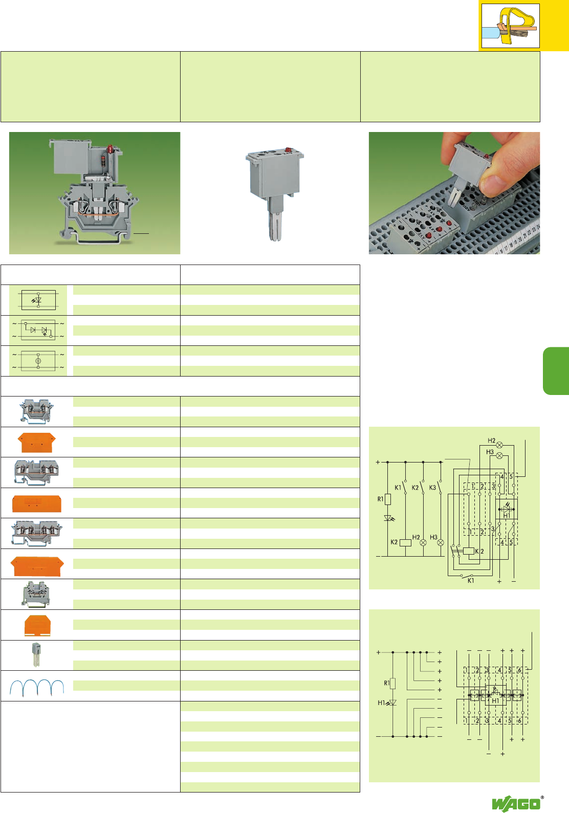
7
71
7
H1
+
+
–
–
Pluggable Modules – LED and Neon Indicators on
Through Terminal Blocks 2.5 mm2/ AWG 14,
Series 280
LED module:
IN≤5.6 mA; IF≤25 mA
Neon indicator module:
IN≤0.5 mA
Module width 10 mm / 0.394 in
Item Pack. unit
No. pcs
These LED and neon indicator modules are simply
pushed into the contact slots of the current bars
of two adjacent through terminal blocks like a
push-in jumper.
This offers the following advantages to the user:
●The modules are suitable for all through
terminal blocks of series 280.
●Existing terminal block assemblies can be
refitted with diode modules without any
problem.
Further advantages:
●Separation into functional and wiring level.
●Modules can be replaced quick by other types
of modules.
Example of circuit configuration
Multiple outputs with illuminated indicator
Control unit
Description
Terminal block width 5 mm / 0.197 in
grey
280-601 ➊280-901 ➋100
2.5 mm / 0.098 in thick
280-331 280-309 100 (4 x 25)
280-330 280-308 100 (4 x 25)
Terminal block width 5 mm / 0.197 in
grey 280-681 ➌100
2.5 mm / 0.098 in thick
orange 280-326 100 (4 x 25)
grey 280-324 100 (4 x 25)
Terminal block width 5 mm / 0.197 in
grey
280-621 ➍280-833 ➎100
2.5 mm / 0.098 in thick
280-317 280-315 100 (4 x 25)
280-316 280-314 100 (4 x 25)
Terminal block width 5 mm / 0.197 in
grey 280-101 ➏100
2.5 mm / 0.098 in thick
orange 280-302 100 (4 x 25)
grey 280-301 100 (4 x 25)
IN24 A
grey 280-402 200 (8 x 25)
Commoning distance max. 120 mm / 4.72 in
black 210-103 1
blue 210-123 1
Front-entry 2-cond. term. block,
0.08 – 2.5 mm2/AWG 28 – 12
stripped length 8 – 9 mm /0.33 in
End and intermediate plate,
for 2-conductor orange
terminal blocks grey
Front-entry 3-cond. term. block
,
0.08 – 2.5 mm2/AWG 28 – 12
stripped length 8 – 9 mm /0.33 in
End and intermediate plate,
for 3-conductor terminal block
280-681
Front-entry 4-cond. term. block,
0.08 – 2.5 mm2/AWG 28 – 12
stripped length 8 – 9 mm /0.33 in
End and intermediate plate,
for 4-conductor orange
terminal blocks grey
Side-entry terminal block,
0.08 – 2.5 mm2/AWG 28 – 12
stripped length 8 – 9 mm /0.33 in
End and intermediate plate,
for side-entry terminal block
280-101
Adjacent jumper,
insulated
Wire commoning chain,
insulated,
50 connections, 8 A
LED module,
10 mm / 0.394 in wide,
with red LED
LED module,
10 mm / 0.394 in wide,
with red LED
Neon indicator module,
10 mm / 0.394 in wide
DC 24 V 280-803/281-413 50
DC 48 V 280-803/281-414 50
AC/DC 24 V 280-803/281-415 50
AC/DC 48 V 280-803/281-416 50
AC/DC 110 V 280-803/281-418 50
AC/DC 230 V 280-803/281-417 50
➊Term. block marking on both sides 50 mm / 1.97 in
➋Terminal block marking in center position
53 mm / 2.09 in
➌Terminal block marking in center position
64 mm / 2.52 in
➍Term. block marking on both sides 73 mm / 2.87 in
➎Terminal block marking in center position
75 mm / 2.95 in
➏Term. bl. marking on both sides 42.5 mm / 1.67 in
(Marking accessories
see section 14)
Carrier terminal blocks for pluggable modules and accessories
<___➊ ➋ ➌ ➍ ➎ ➏ ___>
LED modules
280-803/281-413
Terminal blocks
4+5 280-621
Terminal
blocks 1–3
280-601
outputs outputs
input
Terminal blocks 1–6
280-101
Jumper contact
280-402
LED modules
280-803/281-414
outputs
input 48 V
outputs
<____ 52.5 mm /2.07 in ____>
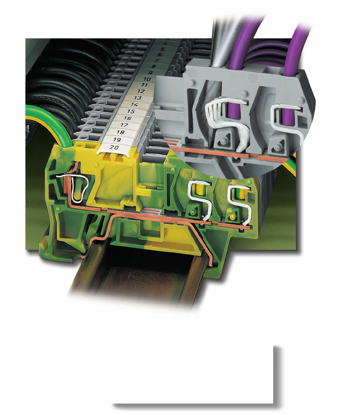
Unique combination of connection technologies:
WAGO rail-mounted terminal blocks with
FIT CLAMP connection for the factory wiring and
CAGE CLAMP®connection for the “field wiring“.

8
8
VOLUME 1
Rail-Mounted Terminal Blocks with IDC-Connection (FIT CLAMP)
Through terminal blocks and ground (earth) conductor terminal blocks
with CAGE CLAMP®/FIT CLAMP connection Series 290 8.7
with FIT CLAMP connection Series 290 8.6
Accessories
– Banana plugs 2.42
– Busbar terminal blocks 11.20 –11.21
– Comb type jumper bars 2.44
– Insulations stops 2.43
– Wire jumpers 2.45
– Test plug modules 2.38 – 2.41
– Staggered jumpers 2.45
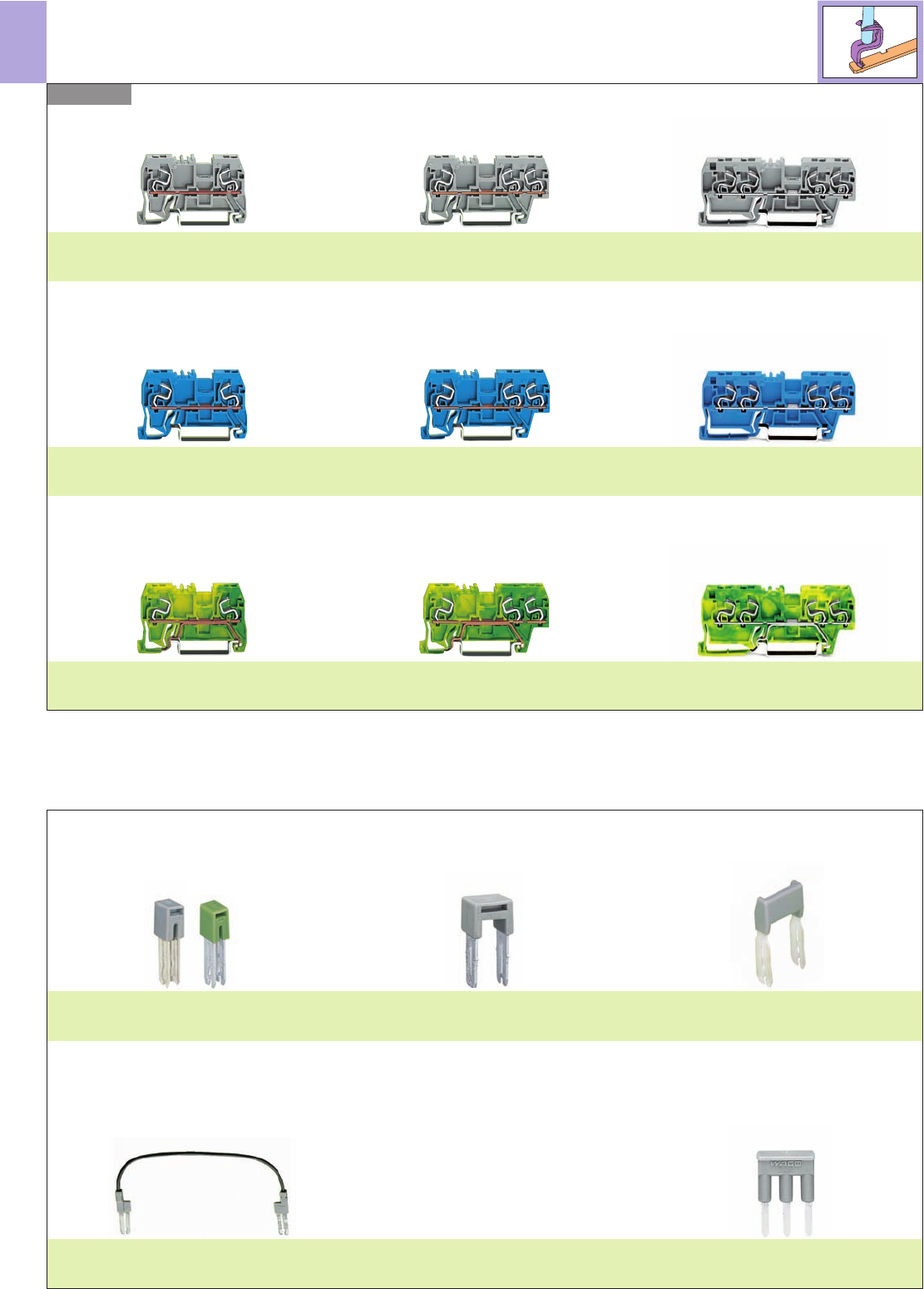
8
2
Rail-Mounted Terminal Blocks with IDC-Connection (FIT CLAMP)
– Product Summary –
Series 290
Adjacent jumpers
Page 8.6
Alternate jumper
Page 2.13
Staggered jumper
Page 2.45
Wire jumper
Page 2.45
Comb type jumper bar
Page 2.44
Through terminal blocks AWG 22 - 18 (0.31 mm2- 1.0 mm2) “s”/ AWG 22 - 16 (0.34 mm2- 1.5 mm2) “f-st”
Ex i Through terminal blocks AWG 22 - 18 (0.31 mm2- 1.0 mm2) “s”/ AWG 22 - 16 (0.34 mm2- 1.5 mm2) “f-st”
2-conductor terminal block
1 x FIT CLAMP/1 x FIT CLAMP
Page 8.6
3-conductor terminal block
1 x FIT CLAMP/2 x FIT CLAMP
Page 8.6
4-conductor terminal block
2 x FIT CLAMP/2 x FIT CLAMP
Page 8.6
2-conductor terminal block
1 x FIT CLAMP/1 x FIT CLAMP
Page 8.6
3-conductor terminal block
1 x FIT CLAMP/2 x FIT CLAMP
Page 8.6
4-conductor terminal block
2 x FIT CLAMP/2 x FIT CLAMP
Page 8.6
Ground (earth) conductor terminal blocks AWG 22 - 18 (0.31 mm2- 1.0 mm2) “s”/ AWG 22 - 16 (0.34 mm2- 1.5 mm2) “f-st”
2-conductor terminal block
1 x FIT CLAMP/1 x FIT CLAMP
Page 8.6
3-conductor terminal block
1 x FIT CLAMP/2 x FIT CLAMP
Page 8.6
4-conductor terminal block
2 x FIT CLAMP/2 x FIT CLAMP
Page 8.6
Accessories (selection)
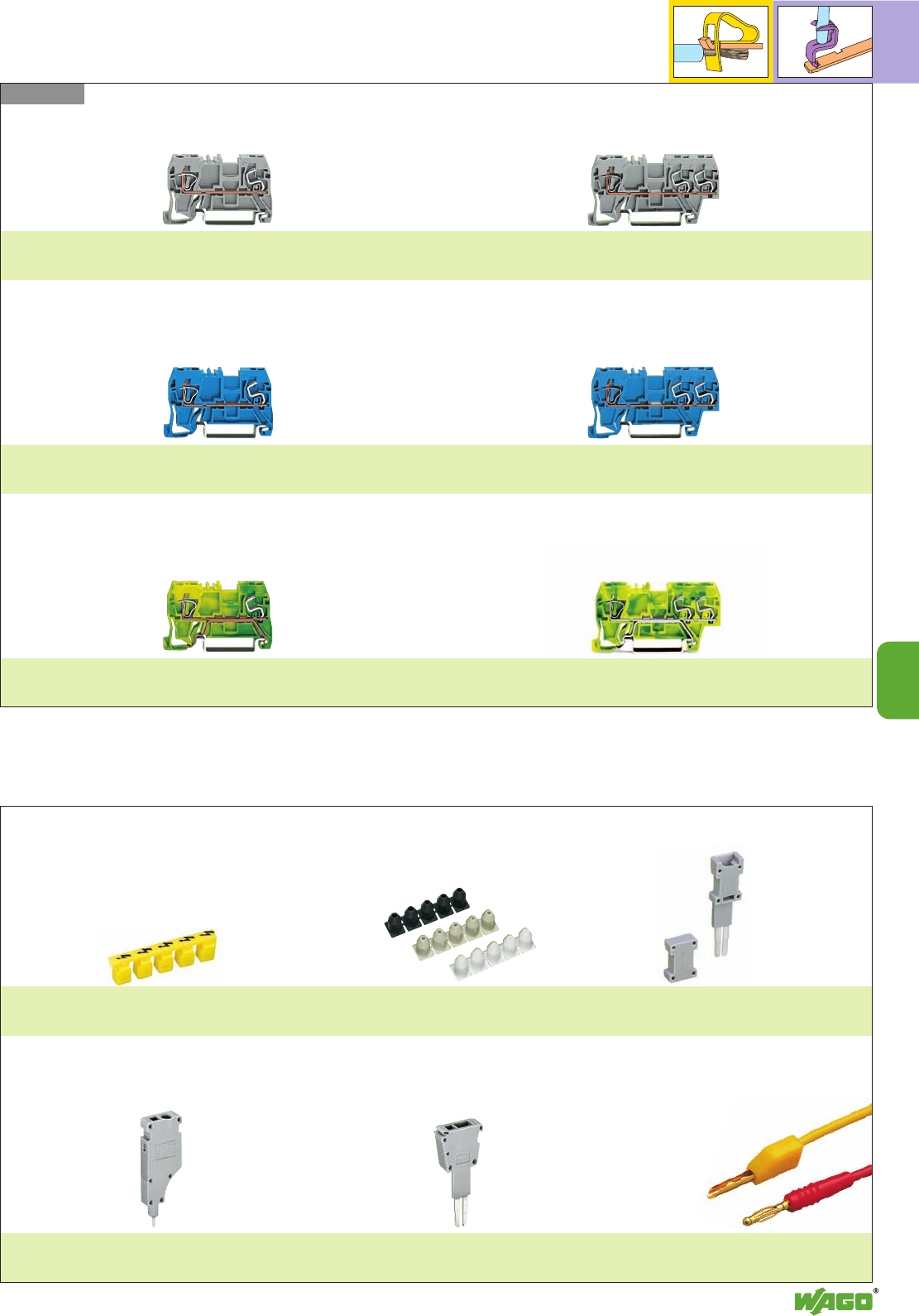
8
3
8
Rail-Mounted Terminal Blocks with
CAGE CLAMP®/IDC-Connection (FIT CLAMP)
Series 290
Ex i Through terminal blocks AWG 22 - 18 (0.31 mm2- 1.0 mm2) “s”/ AWG 22 - 16 (0.34 mm2- 1.5 mm2) “f-st”
2-conductor terminal block
1 x CAGE CLAMP®/1 x FIT CLAMP
Page 8.7
3-conductor terminal block
1 x CAGE CLAMP®/2 x FIT CLAMP
Page 8.7
2-conductor terminal block
1 x CAGE CLAMP®/1 x FIT CLAMP
Page 8.7
3-conductor terminal block
1 x CAGE CLAMP®/2 x FIT CLAMP
Page 8.7
Ground (earth) conductor terminal blocks AWG 22 - 18 (0.31 mm2- 1.0 mm2) “s”/ AWG 22 - 16 (0.34 mm2- 1.5 mm2) “f-st”
2-conductor terminal block
1 x CAGE CLAMP®/1 x FIT CLAMP
Page 8.7
3-conductor terminal block
1 x CAGE CLAMP®/2 x FIT CLAMP
Page 8.7
Protetice warning marker
Page 8.7
Insulation stops
Page 2.43
Test plug
modules
Page 2.40
Test plugs
Page 2.40
Test plug modules
using cond. wire opening
Page 2.38
Test plug modules
using jumper contact position
Page 2.39
Accessories (selection)
Through terminal blocks AWG 22 - 18 (0.31 mm2- 1.0 mm2) “s”/ AWG 22 - 16 (0.34 mm2- 1.5 mm2) “f-st”
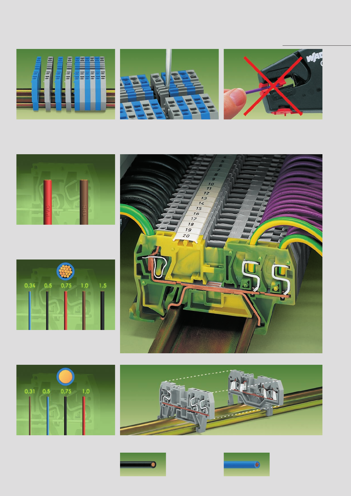
,
8
4
Solid conductors from 0.31 mm2/AWG 22 up to
1.0 mm2/AWG 18 can be used Terminal blocks with FIT CLAMP connection of series 290 have the same dimensions as terminal blocks
with CAGE CLAMP®connection of series 280. They have the same terminal block width: 5 mm/0.197 in!
Rail-Mounted Terminal Blocks with FIT CLAMP Connection,
Series 290 . . .
Mounting FIT CLAMP connection Removal
Snap individual terminal blocks onto carrier rail
and slide to adjacent terminal block
Types of conductors
Conductors of PVC (e. g. H05V) or TPE (e. g. H05Z)
will be safely connected,
other conductors upon request
Types of conductors
Fine-stranded conductors from 0.34 mm2 / AWG 22
up to 1.5 mm2/AWG 16 can be used
Types of conductors Dimension
Unlock assembly with screwdriver – remove termi-
nal block from the rail FIT CLAMP connection without stripping
With FIT CLAMP connection
the following copper wires
can be connected:
solid fine-stranded
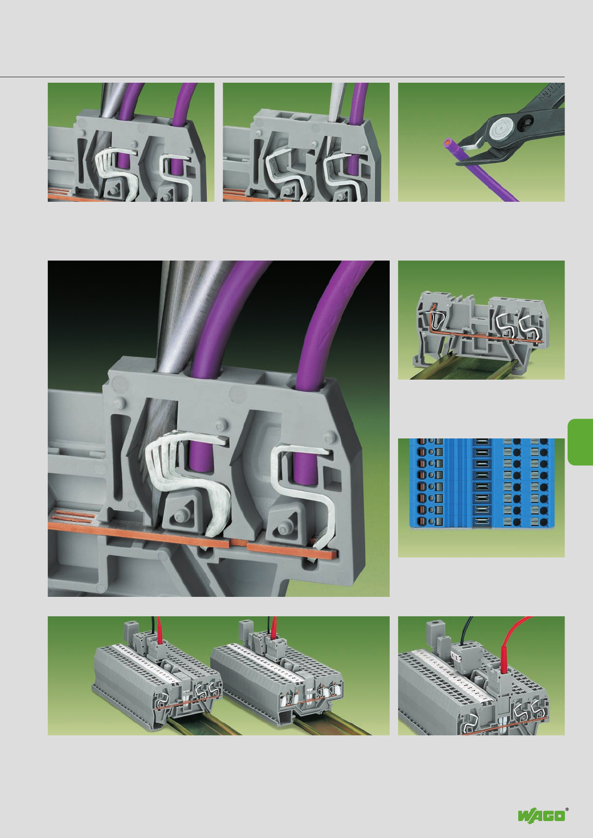
,
8
5
8
external internal
Accessories as for instance jumper contacts and test plug adapters of series 280 can be used Testing with accessories of series 280
. . . Description and Handling
Connecting conductors.
Introduce the conductor into the clamping unit until
it is fully inserted. Then insert a 3.5 mm/0.138 in
screwdriver into the operating slot, aiming the
blade away from the conductor, and slide it until
fully inserted Mixed assembly
Internal = FIT CLAMP connection (factory wiring)
External = CAGE CLAMP®connection
Mixed assembly
Depending on the connection system there are
different conductor entry holes
TestingAccessories
Disconnecting conductors.
Insert the screwdriver into the operating slot,
aiming the blade towards the conductor until it
makes contact with the corner of the FIT CLAMP.
Then press on the FIT contact and pivot the
swrewdriver towards the conductor
If the connected conductor is to be re-used,
the conductor end should be cut square.
To re-connect use only the same type of conductors
with the same cross section
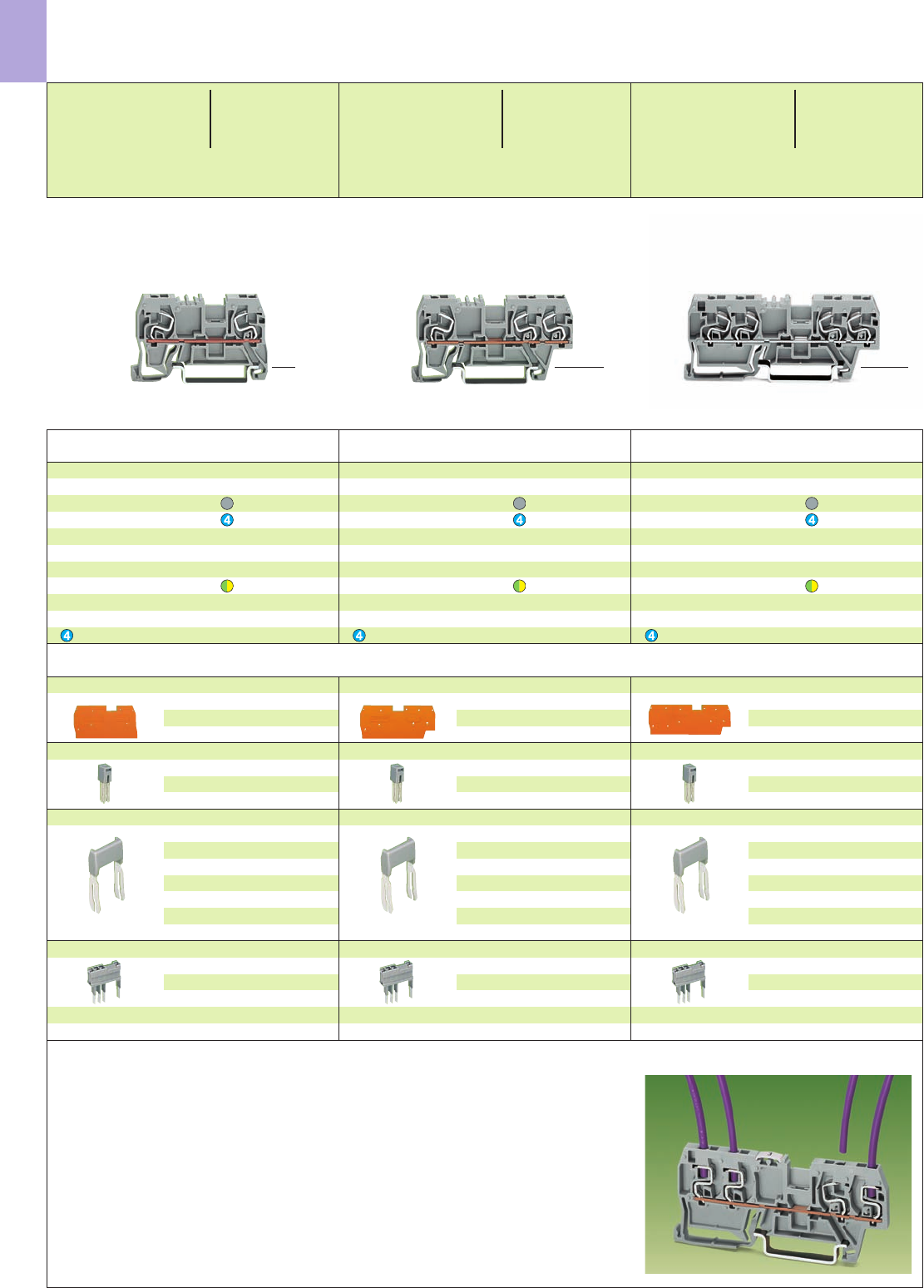
8
6
➊➊ ➊➊➊ ➊➊➊➊
*YKf:{ *YKf:{
Accessories, see also series 280 page 2.13 Appropriate marking system WMB/WSB/WFB (see section 14)
End and intermediate plate, 1.1 mm /0.043 in thick
orange 290-306 100 (4 x 25)
grey 290-305 100 (4 x 25)
Adjacent jumper, insulated, IN24 A
grey 280-402 200 (8 x 25)
yell.-green 280-422 200 (8x 25)
Staggered jumper ➎, insulated, IN24 A
width 5 mm /0.197 in
from 1 to 2 780-452 100 (4 x 25)
from 1 to 3 780-453 100 (4 x 25)
from 1 to 4 780-454 100 (4 x 25)
from 1 to 5 780-455 50 (2 x 25)
::
from 1 to 8 780-458 50 (2 x 25)
All test plug modules and test plugs
for testing using jumper contact
slots or conductor entry holes,
item nos and application notes
see pages 2.39 – 2.40
Item Pack. unit
No. pcs Item Pack. unit
No. pcs Item Pack. unit
No. pcs
Through and Ground (Earth) Conductor Terminal Blocks
with FIT CLAMP Connection,
Series 290
(_ 32 mm/1.26 in _)
<_____ 53 mm /2.09 in _____>
1 FIT CLAMP/ 1 FIT CLAMP
Through terminal blocks
grey 290-961 100
blue 290-964 100
Ground (earth) terminal block
green-yellow 290-967 100
Suitable for Ex i applications
(_ 32 mm/1.26 in _)
<________ 64 mm /2.52 in ________>
1 FIT CLAMP/ 2 FIT CLAMP
Through terminal blocks
grey 290-661 100
blue 290-664 100
Ground (earth) terminal block
green-yellow 290-667 100
Suitable for Ex i applications
<___ 46.5 mm/1.85 in ___>
<____________ 79 mm /3.11 in ____________>
2 FIT CLAMP/ 2 FIT CLAMP
Through terminal blocks
grey 290-861 100
blue 290-864 100
Ground (earth) terminal block
green-yellow 290-867 100
Suitable for Ex i applications
End and intermediate plate, 1.1 mm /0.043 in thick
orange 290-302 100 (4 x 25)
grey 290-301 100 (4 x 25)
Adjacent jumper, insulated, IN24 A
grey 280-402 200 (8 x 25)
yell.-green 280-422 200 (8x 25)
Staggered jumper ➎, insulated, IN24 A
width 5 mm /0.197 in
from 1 to 2 780-452 100 (4 x 25)
from 1 to 3 780-453 100 (4 x 25)
from 1 to 4 780-454 100 (4 x 25)
from 1 to 5 780-455 50 (2 x 25)
::
from 1 to 8 780-458 50 (2 x 25)
All test plug modules and test plugs
for testing using jumper contact
slots or conductor entry holes,
item nos and application notes
see pages 2.39 – 2.40
End and intermediate plate, 1.1 mm /0.043 in thick
orange 290-310 100 (4 x 25)
grey 290-309 100 (4 x 25)
Adjacent jumper, insulated, IN24 A
grey 280-402 200 (8 x 25)
yell.-green 280-422 200 (8x 25)
Staggered jumper ➎, insulated, IN24 A
width 5 mm /0.197 in
from 1 to 2 780-452 100 (4 x 25)
from 1 to 3 780-453 100 (4 x 25)
from 1 to 4 780-454 100 (4 x 25)
from 1 to 5 780-455 50 (2 x 25)
::
from 1 to 8 780-458 50 (2 x 25)
All test plug modules and test plugs
for testing using jumper contact
slots or conductor entry holes,
item nos and application notes
see pages 2.39 – 2.40
➊FIT CLAMP connection only with standard EN
harmonized PVC or PE insulation for factory wiring
➋CAGE CLAMP®connection for external wiring
➌500 V = rated voltage
6 kV = rated surge voltage
3 = pollution degree
(see also section 15)
➎See application notes on pages 2.43 – 2.45
* For further approvals with corresponding ratings see section 15.
<_ 28 mm /_>
1.10 in
<_ 28 mm /
_>
1.10 in
<_ 28 mm /
_>
1.10 in
0.34 –1.5mm2“f-st”➊AWG 22 –16“str.” ➊
0.31–1.0mm2“s” ➊AWG 22 –18“sol.” ➊
500 V/6 kV/3 ➌300 V, 10 A Y
13.5 A ➊
Terminal block width 5 mm / 0.197 in
0.34 –1.5mm2“f-st”➊AWG 22 –16“str.” ➊
0.31–1.0mm2“s” ➊AWG 22 –18“sol.” ➊
500 V/6 kV/3 ➌300 V, 10 A Y
13.5 A ➊
Terminal block width 5 mm / 0.197 in
0.34 –1.5mm2“f-st”➊AWG 22 –16“str.” ➊
0.31–1.0mm2“s” ➊AWG 22 –18“sol.” ➊
500 V/6 kV/3 ➌300 V, 10 A
13.5 A ➊
Terminal block width 5 mm / 0.197 in
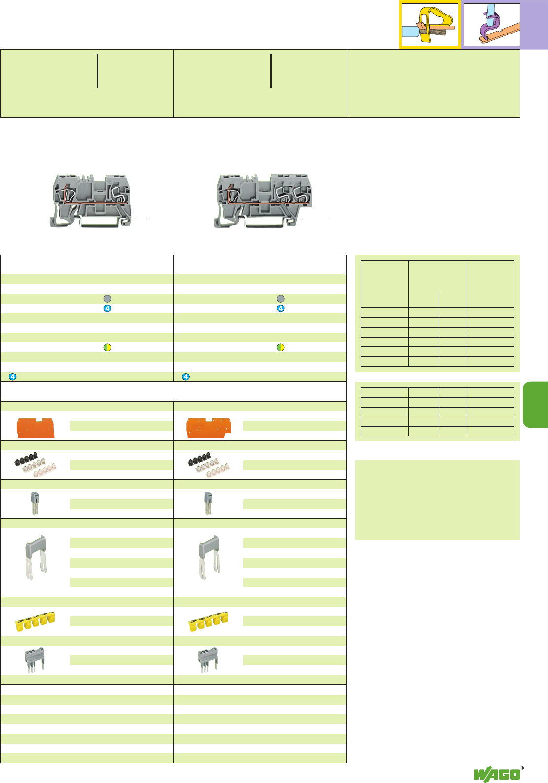
8
7
➊➋ ➋➊➊
8
Application criteria
For the WAGO FIT CLAMP connection
Conductor: PVC insulation
∧DIN/VDE 0281/HD 21.1 S3
TPE insulation
∧DIN/VDE 0282/HD 22.1 S3
Shore hardness A (standard value):
70 – 90
Temperature range for the conductor connection:
10 – 40 °C
In accordance with test specification
DIN EN 60998-2-3, to re-connect use only
the same type of conductors with the same
cross section within the rated cross section
range.
The terminal block profile is similar to that of the
280 series WAGO rail-mounted terminal blocks
with CAGE CLAMP®connection up to
2.5 mm /AWG 12. Accessories for the 280 series,
including the jumpers, can also be used for the
290 series FIT CLAMP.
The FIT CLAMP connection is designed to be
factory-wired but is also approved for field
wiring by UL and CSA. In order to achieve a ter-
minal block width of only 5 mm, there is a small
reduction of the rated current of the respective
wire cross section (see table).
➏max. overall diameter of conductor insulation
0.017 in /43 mm
AWG sol. str. in / mm
22 4.0 A 2.0 A 0.67/1.7 ➏
20 6.0 A 4.0 A 0.75/1.9 ➏
18 9.0 A 6.0 A 0.87/2.2 ➏
16 – 9.0 A 0.98/2.5 ➏
Conductors used:
PVC insulated wires
(e. g. H05V, UL Style 1007/1569.1061)
TPE insulated wires
(e. g. H05Z, UL Style 3199.3265.3266)
AWG wires
stranded ≤26 individual cores
Item Pack. unit
No. pcs Item Pack. unit
No. pcs
Through and Ground (Earth) Conductor Terminal Blocks
with CAGE CLAMP®/ FIT CLAMP Connection,
Series 290
(_ 32 mm/1.26 in _)
<_____ 53 mm /2.09 in _____>
1 CAGE CLAMP®/ 1 FIT CLAMP
Through terminal blocks
grey 290-901 100
blue 290-904 100
Ground (earth) terminal block
green-yellow 290-907 100
Suitable for Ex i applications
(_ 32 mm/1.26 in _)
<________ 64 mm /2.52 in ________>
1 CAGE CLAMP®/ 2 FIT CLAMP
Through terminal blocks
grey 290-681 100
blue 290-684 100
Ground (earth) terminal block
green-yellow 290-687 100
Suitable for Ex i applications
End and intermediate plate, 1.1 mm /0.043 in thick
orange 290-306 100 (4 x 25)
grey 290-305 100 (4 x 25)
Insulation stop ➎, 5 pcs /strip
white 280-470 200 strips
light grey 280-471 200 strips
dark grey 280-472 200 strips
Adjacent jumper, insulated, IN24 A
grey 280-402 200 (8 x 25)
yell.-green 280-422 200 (8x 25)
Staggered jumper ➎, insulated, IN24 A
width 5 mm /0.197 in
from 1 to 2 780-452 100 (4 x 25)
from 1 to 3 780-453 100 (4 x 25)
from 1 to 4 780-454 100 (4 x 25)
from 1 to 5 780-455 50 (2 x 25)
::
from 1 to 8 780-458 50 (2 x 25)
Protective warning marker, for 5 terminal blocks,
fits into screwdriver slot
yellow 280-415 100 (4 x 25)
All test plug modules and test plugs
for testing using jumper contact
slots or conductor entry holes,
item nos and application notes
see pages 2.38 – 2.40
End and intermediate plate, 1.1 mm /0.043 in thick
orange 290-302 100 (4 x 25)
grey 290-301 100 (4 x 25)
Insulation stop ➎, 5 pcs /strip
white 280-470 200 strips
light grey 280-471 200 strips
dark grey 280-472 200 strips
Adjacent jumper, insulated, IN24 A
grey 280-402 200 (8 x 25)
yell.-green 280-422 200 (8x 25)
Staggered jumper ➎, insulated, IN24 A
width 5 mm /0.197 in
from 1 to 2 780-452 100 (4 x 25)
from 1 to 3 780-453 100 (4 x 25)
from 1 to 4 780-454 100 (4 x 25)
from 1 to 5 780-455 50 (2 x 25)
::
from 1 to 8 780-458 50 (2 x 25)
Protective warning marker, for 5 terminal blocks,
fits into screwdriver slot
yellow 280-415 100 (4 x 25)
All test plug modules and test plugs
for testing using jumper contact
slots or conductor entry holes,
item nos and application notes
see pages 2.38 – 2.40
Appropriate marking system WMB/WSB/WFB (see section 14)
<_ 28 mm /_>
1.10 in
<_ 28 mm /_>
1.10 in
0.34 –1.5mm2“f-st”➊AWG 22 –16“str.” ➊
0.31–1.0mm2“s” ➊AWG 22 –18“sol.” ➊
0.08 –2.5mm2➋AWG 28 – 12 ➋
500 V/6 kV/3 ➌300 V, 10 A Y*
13.5 A ➊/24 A ➋
Terminal block width 5 mm / 0.197 in
L8 – 9 mm / 0.33 in ➋
0.34 –1.5mm2“f-st”➊AWG 22 –16“str.” ➊
0.31–1.0mm2“s” ➊AWG 22 –18“sol.” ➊
0.08 –2.5mm2➋AWG 28 – 12 ➋
500 V/6 kV/3 ➌300 V, 10 A Y*
13.5 A ➊/24 A ➋
Terminal block width 5 mm / 0.197 in
L8 – 9 mm / 0.33 in ➋
Nominal Types of Overall dia-
cross section conductors and meter of the con-
reduced rated ductor insulation
currents up to
mm2s f-st mm
0.31 4.0 A – 2.0
0.34 – 2.0 A 2.0
0.5 6.0 A 4.0 A 2.3
0.75 9.0 A 6.0 A 2.5
1.0 13.5 A 9.0 A 2.6
1.5 – 13.5 A 3.0
A special series of rail-mounted terminal blocks
combines FIT CLAMP and CAGE CLAMP®connec-
tions. The CAGE CLAMP®connection is made for
external wiring, the FIT CLAMP connection is made
for factory wiring (note: both CAGE CLAMP®
and
FIT CLAMP are UL, CSA rated for factory
and field wiring).
As conductors do not have to
be stripped, considerable time can be saved.
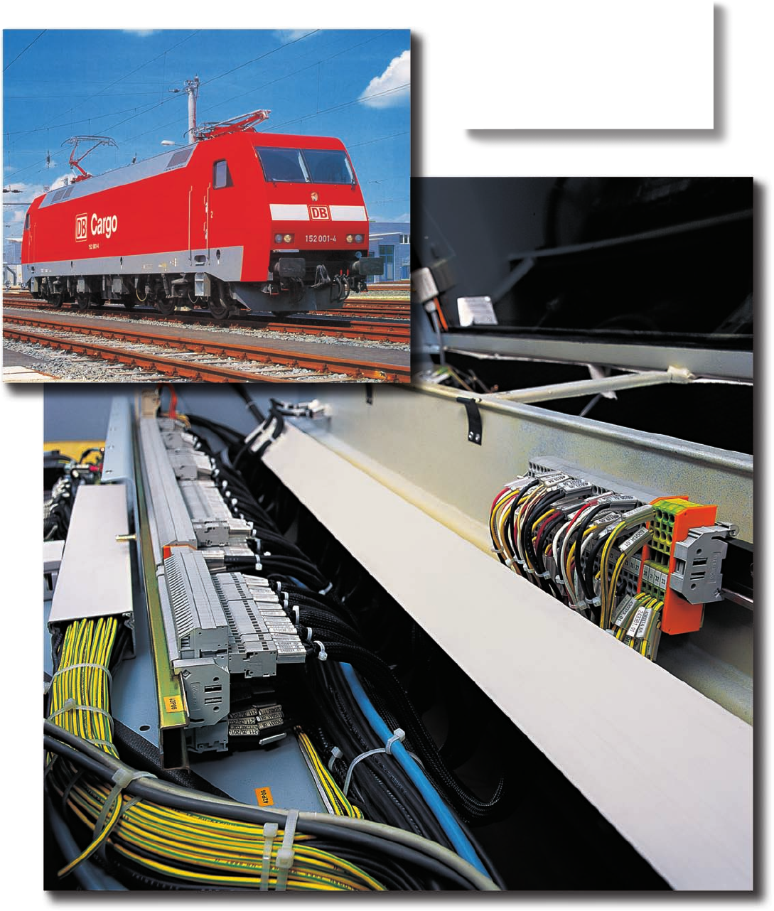
Exposed to constant vibrations:
WAGO rail-mounted terminal blocks
and the WAGO X-COM®-SYSTEM
in an electric locomotive.
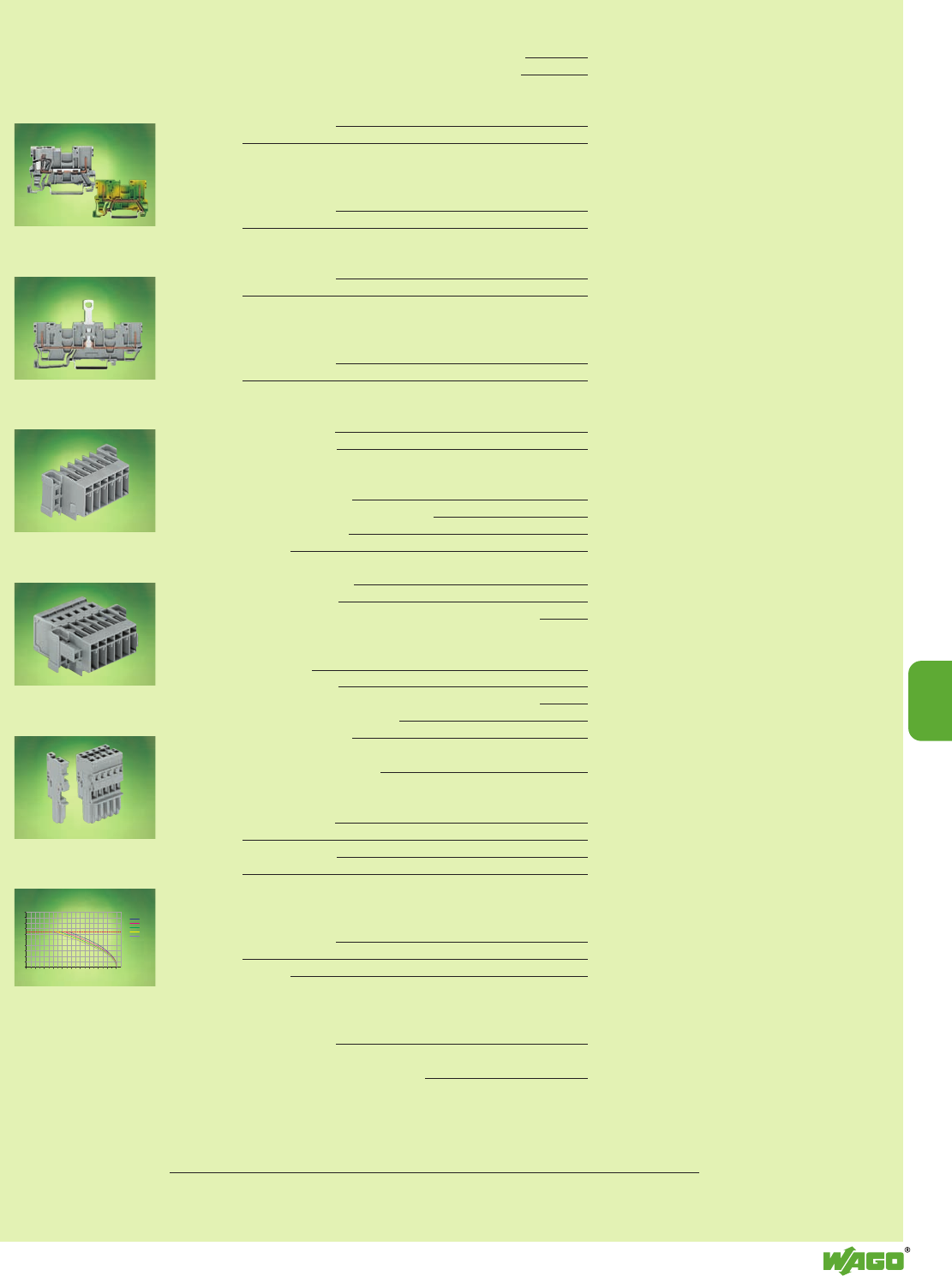
50
45
40
35
30
25
20
15
10
5
0
010 4020 30 50 60 8070 90 100
Prüfstrom (A)
2-polig
4-polig
5-polig
6-polig
15-polig
Umgebungs-
temperatur (°C)
Leiterbemessungsstrom
9
9
VOLUME 1
Current-carrying capacity curves (derating curves)
– Receptacle terminal blocks and female plugs 9.48 – 9.49
– Headers, male connectors and female plugs 9.50 – 9.51
Diode and LED receptacle terminal blocks
– 1-conductor/1-pin 9.24
– 2-pin 9.24
Diode and LED receptacle terminal blocks
with 2 jumper positions
– 1-conductor/1-pin 9.25
– 2-pin 9.25
Disconnect receptacle terminal blocks with/without shield (screen) contact
– 1-conductor/1-pin 9.22
– 2-pin 9.22
Disconnect receptacle terminal blocks with/without shield (screen) contact
with 2 jumper positions
– 1-conductor/1-pin 9.23
– 2-pin 9.23
Double deck terminal blocks
– 1-conductor/1-pin 9.34 – 9.35
– 2-conductor/2-pin 9.34 – 9.35
Female plugs
– 1-conductor, straight 9.44
– 1-conductor, with locking levers 9.44
– 1-conductor, angled 9.46
– 2-conductor 9.45
Headers with solder pins 9.40
– with fixing flanges 9.41
– with fixing flanges for feedthrough application 9.42
Male connectors with CAGE CLAMP®connection
– for flying leads 9.38
– with fixing flanges 9.38
– with fixing flanges for feedthrough application 9.39
– with snap-in mounting feet 9.38
– with snap-in flanges 9.39
Operating tool – Handling – 9.36
Receptacle terminal blocks
– 1-conductor/1-pin 9.12 – 9.13
– 2-pin 9.14 – 9.15
– 2-conductor/2-pin 9.16 – 9.17
– 4-pin 9.18 – 9.19
Receptacle terminal blocks for pluggable modules
with 2 jumper positions
– 1-conductor/1-pin 9.28 / 9.30
– 2-pin 9.28 / 9.30
– 2-conductor 9.32
Receptacle terminal blocks
with 3 jumper positions
– 1-conductor/1-pin 9.20 – 9.21
Snap-on type strain relief housings 9.47
Note other connectors with pin spacings
5.08 mm /0.2 in; 7.5 mm /0.295 in or 7.62 mm /0.3 in
see MULTI CONNECTION SYSTEM Volume 2 – section 4 to 7
X-COM®-SYSTEM
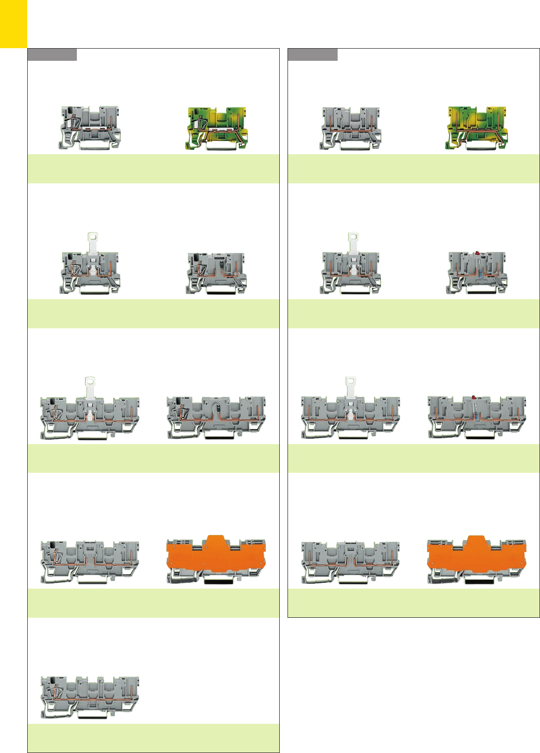
9
2
Series 769Series 769
Product Summary X-COM®-SYSTEM –
. . . Receptacle Terminal Blocks
1-conductor/1-pin . . .
without /with shield (screen) contact
Page 9.12
Ground (earth) terminal block
Page 9.12
1-conductor/1-pin . . .
Disconnect Disconnect shield (screen)
Page 9.22
Diode LED
Page 9.24
Disconnect Disconnect shield (screen)
Page 9.23
Diode LED
Page 9.25
1-conductor/1-pin . . .
. . . with 2 jumper positions
for 5 mm /0.197 in wide plugs
with electronic components
Page 9.28
for plugs with electronic components
10 mm /0.394 in, 15 mm /0.591 in,
20 mm /0.787 in, 25 mm/0.984 in wide
Page
9.30
1-conductor/1-pin . . .
. . . with 2 jumper positions
1-conductor/1-pin . . .
. . . with 3 jumper positions
Page 9.20
2-pin . . .
without /with shield (screen) contact
Page 9.14
Ground (earth) terminal block
Page 9.14
2-pin . . .
Disconnect Disconnect shield (screen)
Page 9.22
Diode LED
Page 9.24
Disconnect Disconnect shield (screen)
Page 9.23
Diode LED
Page 9.25
2-pin . . .
. . . with 2 jumper positions
for 5 mm /0.197 in wide plugs
with electronic components
Page 9.28
for plugs with electronic components
10 mm /0.394 in, 15 mm /0.591 in,
20 mm /0.787 in, 25 mm/0.984 in wide
Page
9.30
2-pin . . .
. . . with 2 jumper positions
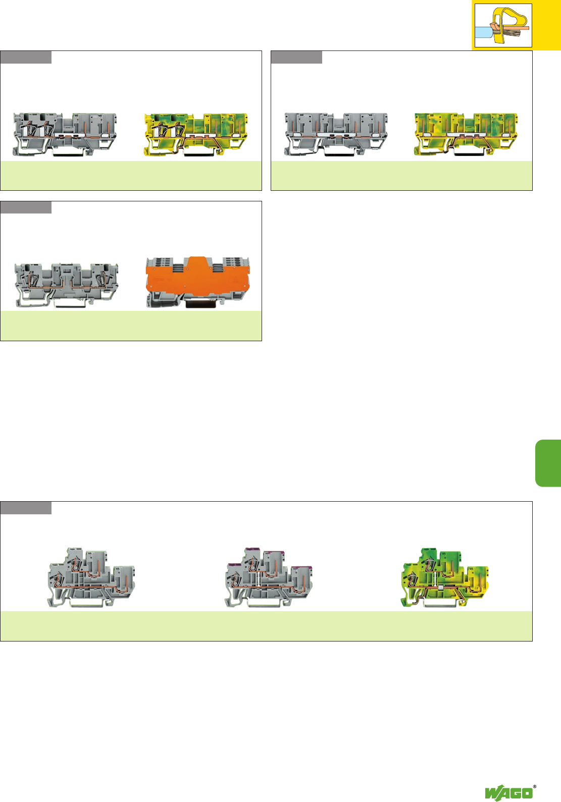
9
9
3
Series 870 1-conductor/1-pin . . .
Page 9.34
internal commoning
Page 9.34
internal commoning
Page 9.35
Series 769Series 769
Series 769 2-conductor . . .
for 5 mm /0.197 in wide plugs
with electronic components
Page 9.32
for plugs with electronic components
10 mm /0.394 in, 15 mm /0.591 in,
20 mm /0.787 in, 25 mm/0.984 in wide
Page
9.32
2-conductor/2-pin . . .
without /with shield (screen) contact
Page 9.16
Ground (earth) terminal block
Page 9.16
4-pin . . .
without /with shield (screen) contact
Page 9.18
Ground (earth) terminal block
Page 9.18
. . . Double Deck Receptacle Terminal Blocks
. . . Receptacle Terminal Blocks
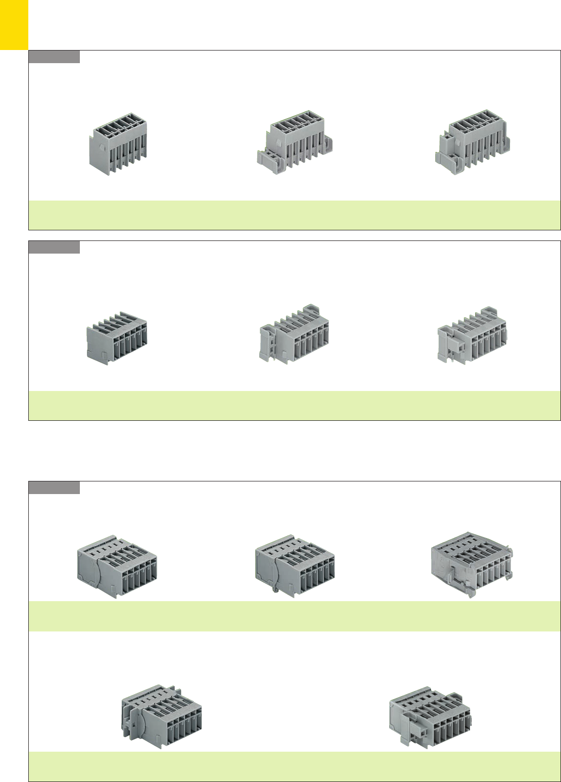
9
4
X-COM®-SYSTEM
. . . Headers and Male Connectors
Series 769
Series 769 Headers with straight solder pins
Page 9.40
with fixing flanges
Page 9.41
with fixing flanges
for feedthrough applications
Page 9.42
Headers with right angle solder pins
Page 9.40
with fixing flanges
Page 9.41
with fixing flanges
for feedthrough applications
Page 9.42
Series 769
. . . Male Connectors with CAGE CLAMP®Connection
Male connectors with CAGE CLAMP®connection
Page 9.38
with snap-in mounting feet
Page 9.38
with fixing flanges
Page 9.38
with fixing flanges
for feedthrough applications
Page 9.39
with snap-in flanges
Page 9.39
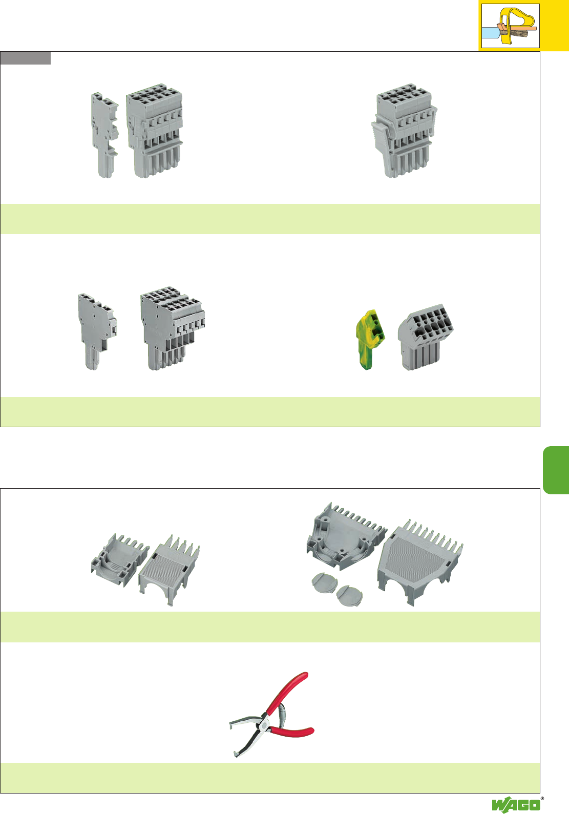
9
9
5
Snap-on type strain relief housings
Page 9.47
Operating tool
Page 9.36
Series 769 Female plugs with CAGE CLAMP®connection
1-conductor
Page 9.44
1-conductor
with lateral locking levers
Page 9.44
2-conductor
Page 9.45
1-conductor
angled
Page 9.46
. . . Female Plugs
. . . Accessories
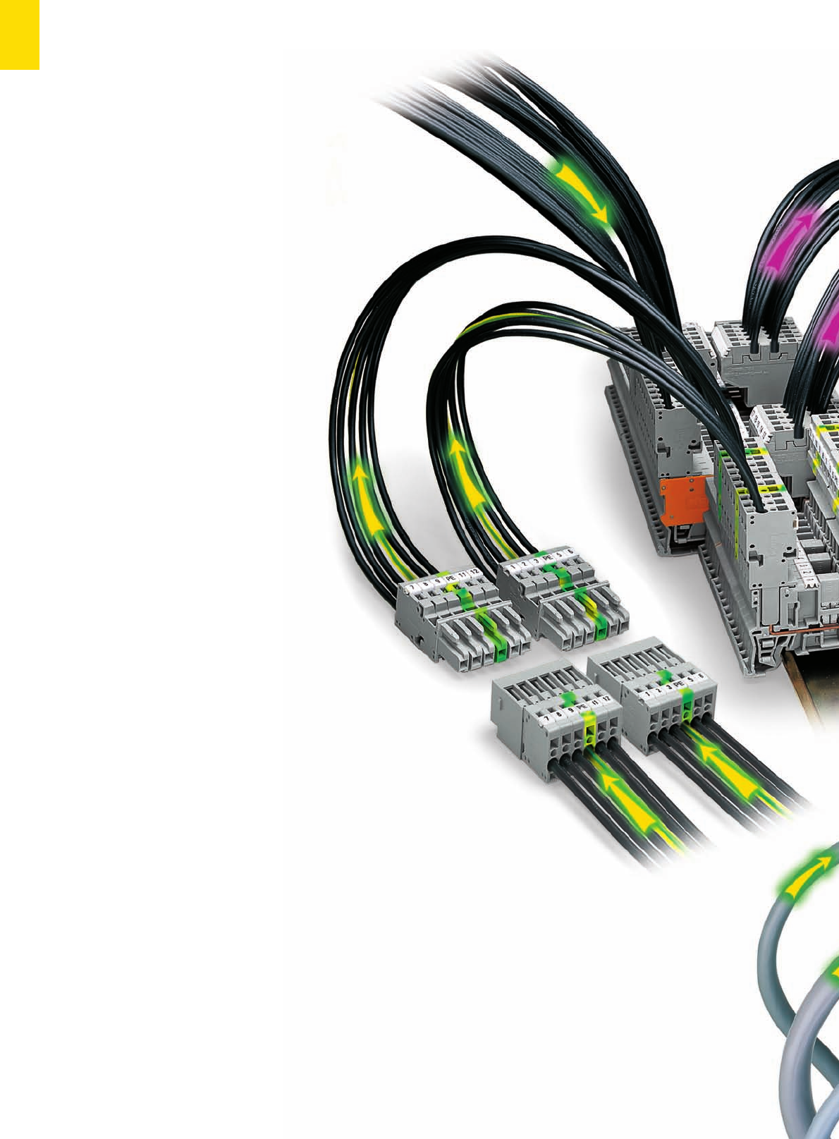
9
6
The WAGO X-COM
®
-SYSTEM
is mostly used in switchgear and
control applications.
lt is designed for a rated current up to
16/32 A at UN500 V and AWG 12 /
4 mm2rated cross section (up to 600 V,
10 A, and 12 AWG UL)
offering an alternative to heavy duty rec-
tangular and circular connectors used in
power wiring applications where electrical
compliance is more important than a high
degree of protection.
Pre-assembly of connector systems offers the
following advantages to the user:
●During manufacturing: Pre-assembled
part or function assemblies can be tested
before assembly.
●During assembly: Pre-assembled plugga-
ble cable harnesses help solve time and
space issues on site. Connector systems
with protection against mismating can be
handled by persons of all skill levels.
●During servicing: Sub-assemblies can be
replaced very quickly and without failu-
res.
The X-COM®-SYSTEM consists of base
receptacle rail-mounted terminal blocks,
male connectors and female plugs with dif-
ferent types of mounting systems as well as
headers with solder pins. Pin spacing is
generally 5 mm/0.197 in.
Protection against mismating and acci-
dental contact
The WAGO X-COM®-SYSTEM is fully pro-
tected against accidental contact - even
when plugs are disconnected. As a
result, considerations on how to plan the
power distribution become easier. Further-
more, the whole system is 100 % protected
against mismating. Coded, without the
lose of any poles, prevents mismating of
male connectors and female plugs having
the same number of poles.
Base receptacle terminal blocks
Base receptacle terminal blocks are availa-
ble as through terminal blocks, double deck
terminal blocks as well as ground (earth)
conductor terminal blocks with automatic
contact to the carrier rail. Base receptacle
terminal blocks with special functions are
available in disconnect, diode and LED ver-
sions. To use all the functions of pluggable
electronic modules which include a wide
range of relays, optocoupler modules and
converters, etc., some base receptacle termi-
nal blocks have an additional plug-in slot.
Depending on the type of terminal block,
the base receptacle terminal blocks are
equipped with one to three jumper positions
for commoning of signals using insulated
plug-in jumpers.
WAGO
X-COM
®
-SYSTEM
COM-bination of Connectors and Rail-Mounted Terminal Blocks
Types of application
Equipment connection with the
WAGO X-COM®-SYSTEM for:
– Frequency converters
– Thyristor actuators
– Soft start motor controllers
– Motors
– Phase filter
– Power sub-assemblies
– Power units
– Uninterruptible Power Supply (UPS)
– Wiring of removable doors on enclo-
sures and cabinets
– Pluggable feedthrough connections
– Flying leads
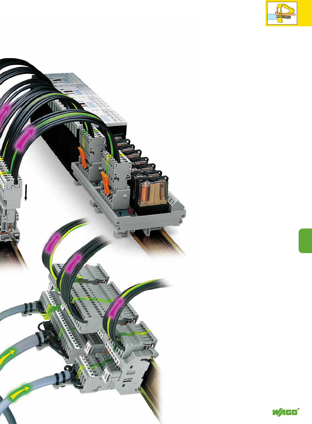
9
7
9
Female plugs
The mating half of the base receptacle
terminal blocks are modular 1- to 15-
pole, 1-conductor and 2-conductor
straight or angled female plugs. Angled
female plugs combined with double
deck terminal blocks offer high
density wiring and a reduced overall
terminal block height. Using the jumper
slot, the distribution of a potential is
made simple - even on the female
plugs. This makes the commoning of
supply lines particularly interesting as
the voltage supply of downstream sub-
assemblies is maintained even after
female plugs have been removed.
1-pole female plugs
Special 1-pole female plugs can carry
the full rated current of the terminal
blocks allowing many different applica-
tions:
●as test adapters,
●as connectors for motor lead tests,
●for all types of patchboard applicati-
ons,
●for the
creation of multi-pole prototy-
pes,
●for phase selection in a three-phase
network without interfering with the
wiring or
●for one-pole voltage supply in com-
mercial vehicles. The grounding of all
electrical components is connected
through the chassis.
Male connectors
Additional male connectors are availa-
ble with mounting feet for surface
mounting, with fixing flanges for feed-
through applications or without moun-
ting elements for flying leads. Strain
relief plates are available as accesso-
ries. Sub-assemblies on printed circuit
boards can be integrated into the
system wiring using headers with solder
pins. As a result, parts can be exchan-
ged quickly without wiring failures.
Protection degree
mated: IP 20
unmated: IP 20
Temperature range
– 35°C to +100°C
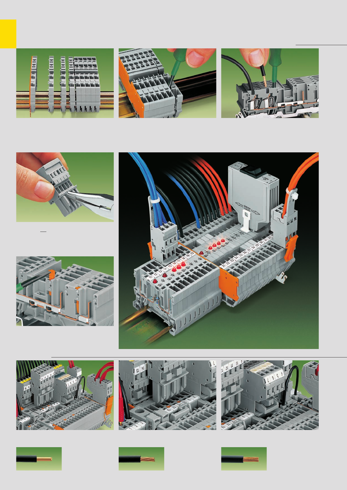
,
9
8
CAGE CLAMP®
connects the following
copper wires: *
solid stranded
fine stranded,
also with tinned
single strands
Commoning with adjacent jumper, or alternatively
with staggered jumper. Push jumper down FIRMLY
until FULLY inserted!
Commoning of receptacle terminal block with
staggered jumper Commoning of 2-conductor female plug with
staggered jumper and commoning of receptacle
terminal block with adjacent jumper
* For aluminum wire see notes in section 15!
X-COM®-SYSTEM Receptacle Terminal Blocks and Female Plugs
Series 769 . . .
Assembly CAGE CLAMP®connection Removal
Snap individual base receptacle terminal blocks
onto carrier rail
Coding
Coding a female plug – removal of coding
finger(s). Do not break off the first and last latch
position coding finger!
Coding
Snap coding pin in proper direction on receptacle
terminal block. Removal of a coding pin from
receptacle terminal block
Commoning
Unlock assembly with screwdriver (3.5 x 0.5) mm
and remove terminal block via release lever Receptacle terminal block: connection/removal of
conductor with screwdriver (3.5 x 0.5) mm
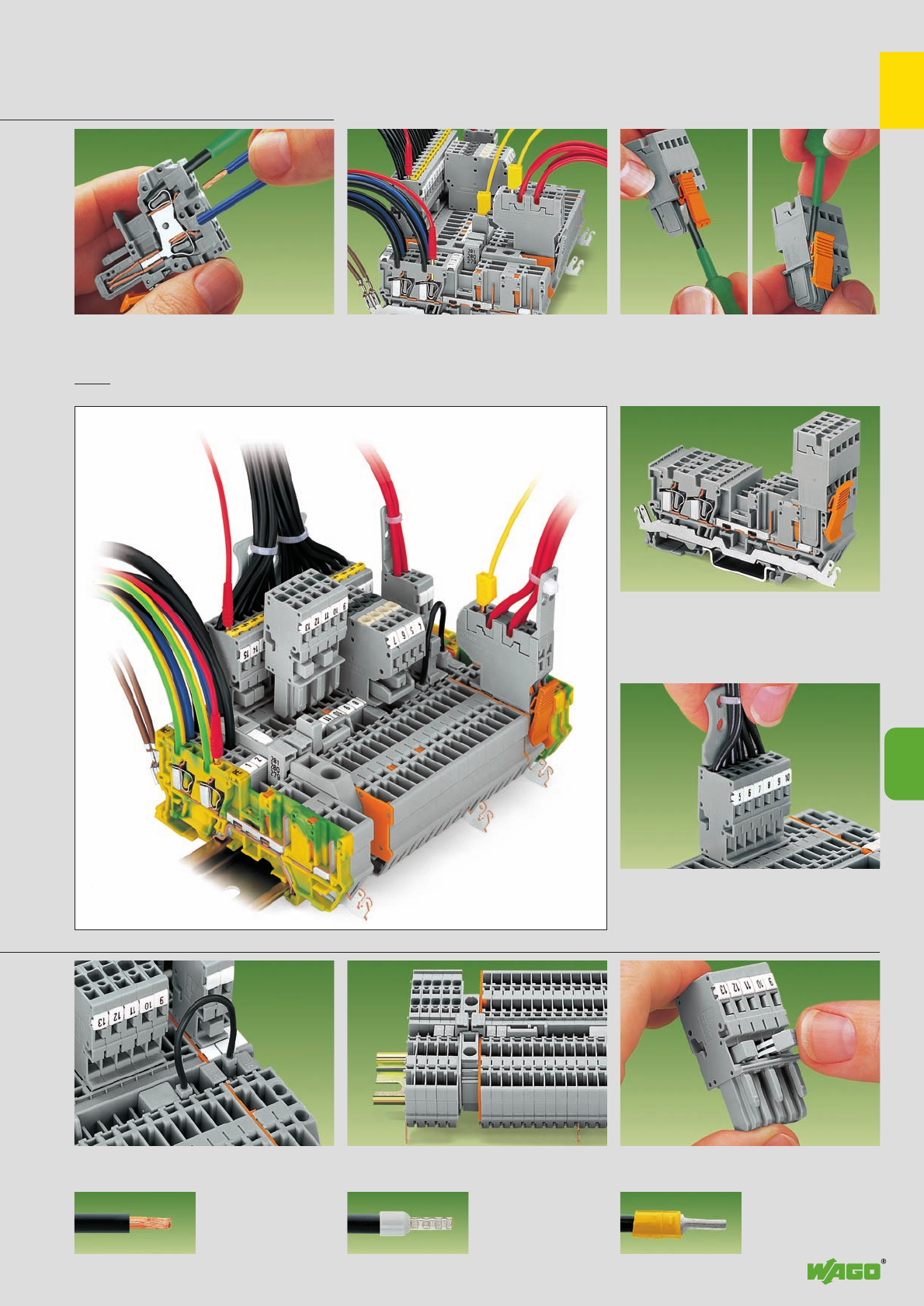
,
9
9
9
fine-stranded wire –
tip bonded
fine-stranded wire
with crimped ferrule ➊fine-stranded wire
with crimped pin terminal
Commoning of receptacle terminal blocks with
push-in type wire, or adjacent jumpers, also over
the intermediate plate
Step-down jumper used for commoning terminal
blocks of different sizes (max. 10 mm2/AWG 8) Commoning of 1-conductor female plugs with
miniature adjacent jumpers
➊When using wires with ferrules, it is necessary to use a terminal block one size larger than the nominal cross section of the wire.
Note: Connectors used according to the regulations should not be connected or
disconnected under load.
. . . Description and Handling
Locking leverTesting
Female plug: connection /removal of conductor.
Operation 90° to wire also possible
Locking lever
Female plug secured with locking lever in external
area of receptacle terminal block
Strain relief
Removal of female plug, wires provided with
strain relief plate
Testing with test plug Ø 2 mm/0.079 in (red)
or Ø 2.3 mm/0.091 in (yellow) Snapping in/removal of locking lever
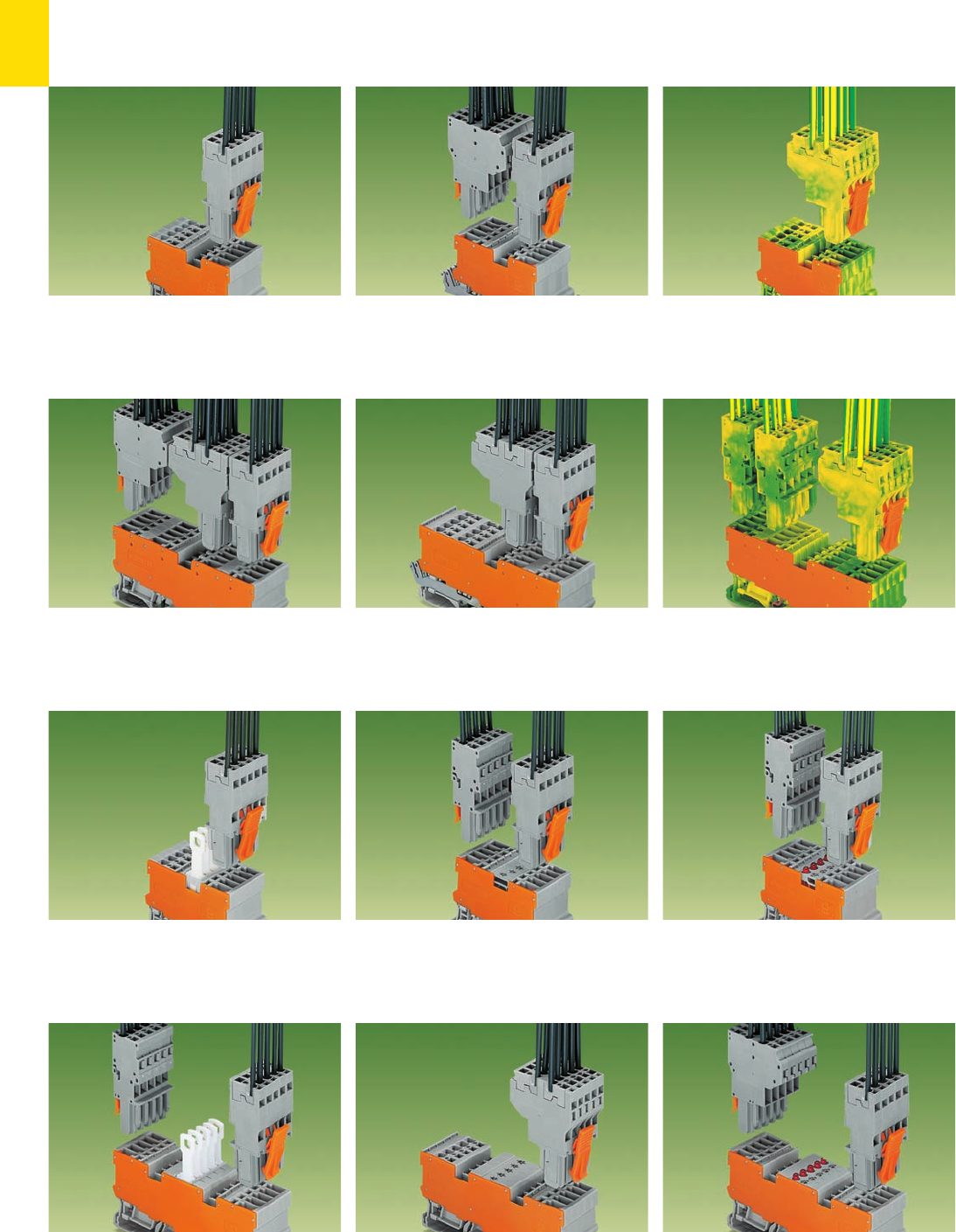
9
10
➁
➀➀➀
➁
➀➀➀
➀➀➀
➁➂
➁
➁➁
➁
➁
➁
➁
➂
➁
➂
➁
➂
➁
➁
➀➀➀
➁➁
➁
➂
X-COM®-SYSTEM, Series 769, Product Summary
Receptacle Terminal Blocks and Female Connectors
➀1-conductor/1-pin ground (earth) receptacle
terminal block
➁2-conductor female plug
➀4-pin ground (earth) receptacle terminal block
➁1-conductor female plugs
➂2-conductor female plug
➀2-pin LED receptable terminal block
➁1-conductor female plugs, straight*
➀2-pin LED receptacle terminal block
with 2 jumper positions
➁2-conductor female plug
➂1-conductor female plug, straight*
➀1-conductor/1-pin receptable terminal block
➁1-conductor female plug, straight*
➀2-pin shield (screen) receptacle terminal block
➁2-conductor female plug
➂1-conductor female plug, straight*
➀4-pin receptacle terminal block
➁2-conductor female plugs
➂1-conductor female plug, straight
➀2-conductor/2- pin shield (screen) receptacle
terminal block
➁2-conductor female plug
➂1-conductor female plug, straight
➀1-conductor/1-pin disconnect receptacle
terminal block
➁1-conductor female plug, straight*
➀2-pin diode receptacle terminal block
➁1-conductor female plugs, straight*
➀2-pin disconnect receptacle terminal block
with 2 jumper positions
➁1-conductor female plugs, straight*
➀1-conductor/1-pin diode receptacle terminal
block with 2 jumper positions
➁2-conductor female plug
* or 1-conductor female plug, angled
* or 1-conductor female plug, angled
* or 1-conductor female plug, angled
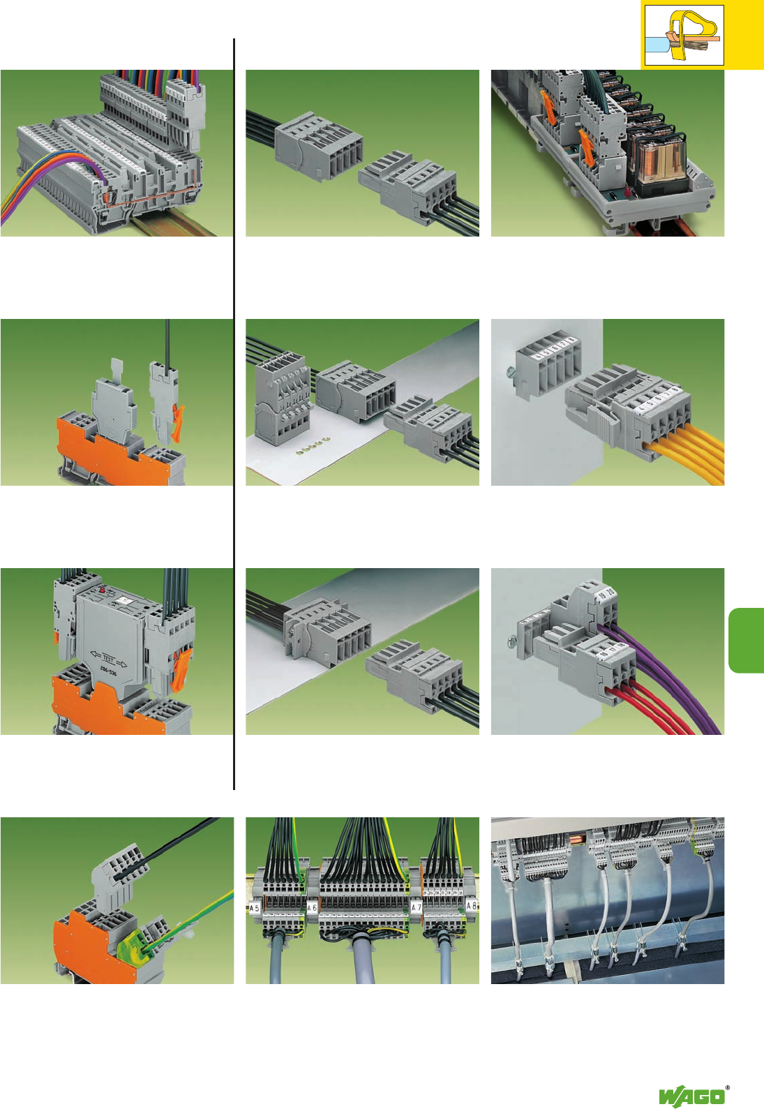
9
11
➀
➁
➀
➁
➀
➁
➀
➁
➀
➁
➂➀
➁
➀
➁
➀
➁
➂
➁
➀
➁
➂
➀
➁
9
Headers and Male Connectors
➀1-conductor/1-pin receptacle terminal block
with 3 jumper positions
➁1-conductor female plug, straight*
➀1-conductor/1-pin receptacle terminal block
with 2 jumper positions
➁1-conductor female plug, straight*
➂Fuse plug, 6 mm/0.236 in wide
(every other terminal block)
➀2-pin terminal block for pluggable modules*
with 2 jumper positions
➁1-conductor female plugs, straight**
➂Relay plug 25 mm/0.9843 in wide
* with separator plate
** or 1-conductor female plug, angled
Introduction of the cables in the switchboard
cabinet.
The cables are introduced in the switchboard
cabinet with the connected female plugs and
are directly plugged in the receptacle terminal
blocks.
➀Male connector with CAGE CLAMP®connec-
tion
➁1-conductor female plug
➀Male connector with CAGE CLAMP®connec-
tion and mounting feet
➁1-conductor female plug
➀Male connector with CAGE CLAMP®connec-
tion and fixing flanges
➁1-conductor female plug
➀Header with straight solder pins
➁1-conductor female plug
➀Header with straight or angled solder pins and
fixing flanges
➁1-conductor female plug straight with locking
levers
➀Header with straight or angled solder pins and
fixing flanges for feedthrough applications
➁1-conductor female plug
➂2-conductor female plug
* or 1-conductor female plug, angled
* or 1-conductor female plug, angled
Example of application: cost-efficient alter-
native to heavy connectors
* or 1-conductor female plug, straight
Cable entry in the base of the switchgear
cabinet, with separate strain relief, movable IP 54
bottom plates sealed with sponge rubber (e. g.
by Rittal)
➀1 conductor/1 pin double deck terminal block
➁1 conductor female plug, angled*
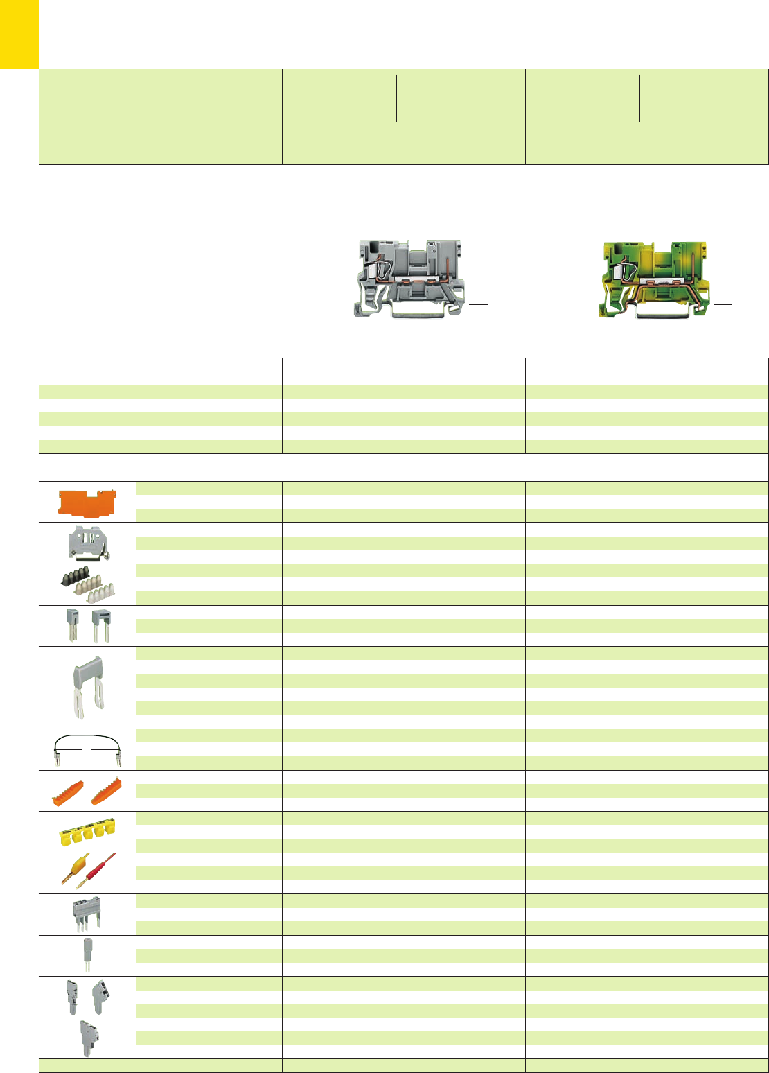
,
9
12
L
*U2fJ{5 *U2fJ{5
Item Pack. unit
No. pcs
* For further approvals with corresponding ratings see section 15. ** Current-carrying capacity curve see page 9.48 and www.wago.com
Description Item Pack. unit
No. pcs
X-COM®-SYSTEM
1-Conductor/1-Pin Receptacle Terminal Blocks
➊500 V = rated voltage
6 kV = rated surge voltage
3 = pollution degree
250 V/4 kV/3 = rated voltage
with shield (screen) contact
(see also section 15)
➋See application notes on pages 2.43 – 2.45
(29.5mm/1.16in)
<____ 52.5 mm /2.07 in ____>
<28.5 mm / >
1.12 in
<28.5 mm / >
1.12 in
(29.5 mm /1.16 i n )
<____ 52.5 mm /2.07 in ____>
1.1 mm /0.043 in thick
grey 769-307 100 (4 x 25)
orange 769-308 100 (4 x 25)
6 mm /0.236 in wide
249-116 100 (4 x 25)
10 mm /0.394 in wide
249-117 50 (2 x 25)
0.08 – 0.2 mm2769-470 200 strips
0.25 – 0.5 mm2769-471 200 strips
0.75 – 1 mm2769-472 200 strips
grey 280-402 200 (8 x 25)
grey 280-409 100 (4 x 25)
IN24 A 780-452 100 (4 x 25)
780-453 100 (4 x 25)
780-454 100 (4 x 25)
780-455 50 (2 x 25)
:
780-458 50 (2 x 25)
L = 60 mm /2.362 in
249-125 10
L = 110 mm /4.331 in
249-126 10
L = 250 mm /9.843 in
249-127 10
orange 769-435 100 (4 x 25)
red 210-136 50 (5 x 10)
yellow 210-137 50 (5 x 10)
Application notes and part numbers
see pages 2.38 – 2.40
5 mm/0.197 in wide
280-404 100 (4 x 25)
or test plug 210-137 (2.3 mm /0.091 in Ø)
see pages 9.44/9.46
see page 9.45
1.1 mm /0.043 in thick
grey 769-307 100 (4 x 25)
orange 769-308 100 (4 x 25)
6 mm /0.236 in wide
249-116 100 (4 x 25)
10 mm /0.394 in wide
249-117 50 (2 x 25)
0.08 – 0.2 mm2769-470 200 strips
0.25 – 0.5 mm2769-471 200 strips
0.75 – 1 mm2769-472 200 strips
grey 280-402 200 (8 x 25)
grey 280-409 100 (4 x 25)
IN24 A 780-452 100 (4 x 25)
780-453 100 (4 x 25)
780-454 100 (4 x 25)
780-455 50 (2 x 25)
:
780-458 50 (2 x 25)
L = 60 mm /2.362 in
249-125 10
L = 110 mm /4.331 in
249-126 10
L = 250 mm /9.843 in
249-127 10
orange 769-435 100 (4 x 25)
yellow 280-415 100 (4 x 25)
red 210-136 50 (5 x 10)
yellow 210-137 50 (5 x 10)
Application notes and part numbers
see pages 2.38 – 2.40
5 mm/0.197 in wide
280-404 100 (4 x 25)
or test plug 210-137 (2.3 mm /0.091 in Ø)
see pages 9.44/9.46
see page 9.45
End and
intermediate plate
Screwless
end stop
Insulation stop ➋,white
5 pcs/strip light grey
dark grey
Adjacent jumper, IN24 A
insulated
Alternate jumper
Staggered jumper
➋,from 1 to 2
insulated, from 1 to 3
width 5 mm/0.197 in from 1 to 4
from 1 to 5
:
from 1 to 8
Push-in type wire jumper ➋,
insulated, 9 A – conductor
cross section 0.75 mm2/AWG 18
Coding pin,
for coding of female plugs
Protective warning marker,
for 5 terminal blocks,
fits into screwdriver slot
Test plug, w. cable 500 mm/1’7.7’’
2 mm /0.079 in Ø
2.3 mm /0.091 in Ø
Test plug module,
for test using jumper position in
current bar or cond. wire opening
Test plug adapter,
see also pages 2.38 – 2.40
1-conductor female plug,
straight or angled
2-conductor female plug
1-conductor/1-pin receptacle terminal block
grey 769-176 100
1-conductor/1-pin receptacle terminal block
with shield (screen) contact, (no picture)
grey 769-231 50
1-conductor/1-pin receptacle terminal block,
suitable for DIN 35 rail acc. to EN 60715
1-conductor/1-pin ground (earth) receptacle
terminal block
green-yellow 769-237 100
0.08 – 4 mm2AWG 28 – 12
Terminal block width 5 mm / 0.197 in
L8 – 9 mm / 0.33 in
0.08 – 4 mm2AWG 28 – 12
500 V/6 kV/3 ➊300/600 V, 10/5 A U
250 V/4 kV/3 ➊300 V, 10 A 2
32 A**
Terminal block width 5 mm / 0.197 in
L8 – 9 mm / 0.33 in
Accessories Appropriate marking system Mini-WSB (see section 14)
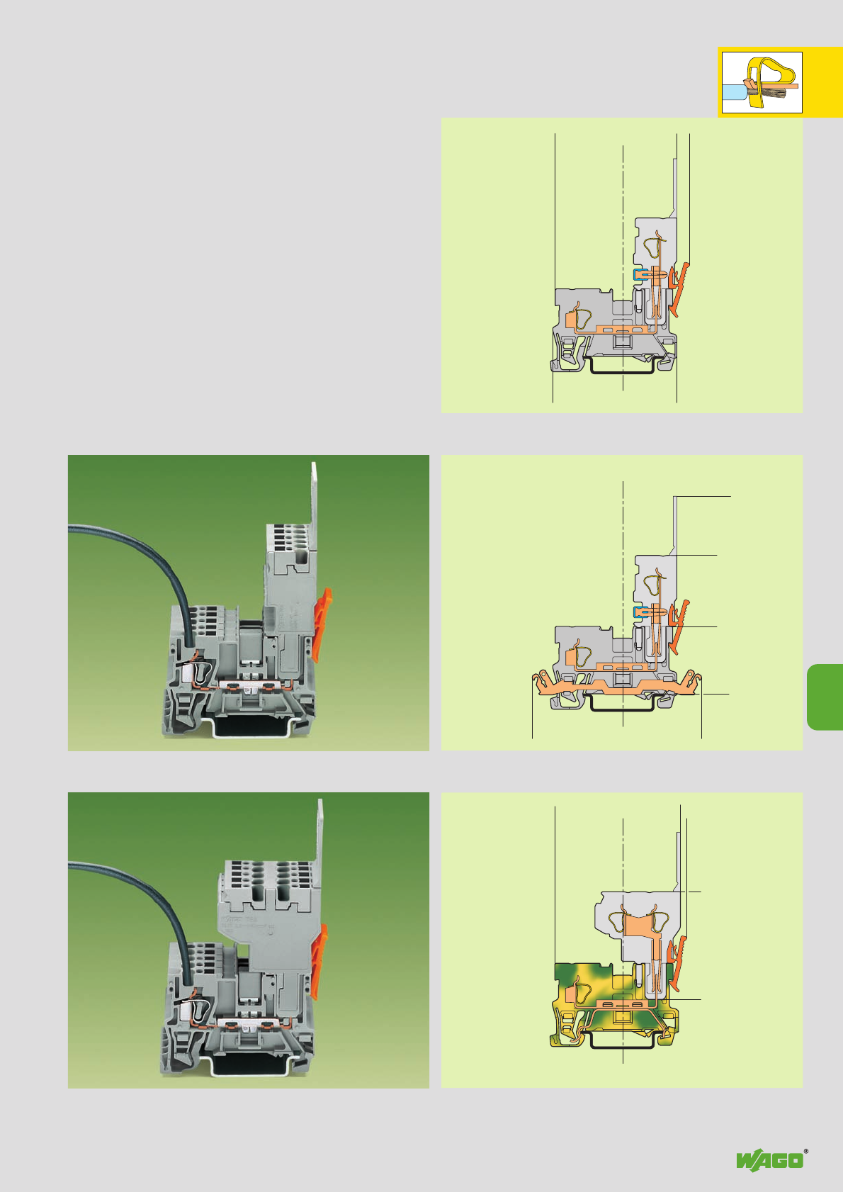
,
9
13
<___________51,4___________>
<____28,5___>
<_____________52,4_________>
<____29,5____>
5,5<
<_________________71,4_________________>
<_______38,3_______>
<______30______>
<____28,5____>
<_____________________83,5 _____________________>
<____________52,8_____________>
<____28,5____> <__> 2,5
<_________45,2_________>
9
Receptacle terminal block with shield (screen) contact
Types of Assembly
1-Conductor/1-Pin Receptacle Terminal Blocks
and 1-/2-Conductor Female Plugs
1-conductor female plug Commoning possibility of receptacle
terminal blocks with jumper contact systems, series 280 and 780,
and testing possibility with test plug adapter 280-4 . .
2-conductor female plug Commoning possibility of receptacle
terminal blocks only with adjacent jumpers and
alternate jumpers, series 280
Ground (earth) receptacle terminal block
Receptacle terminal block
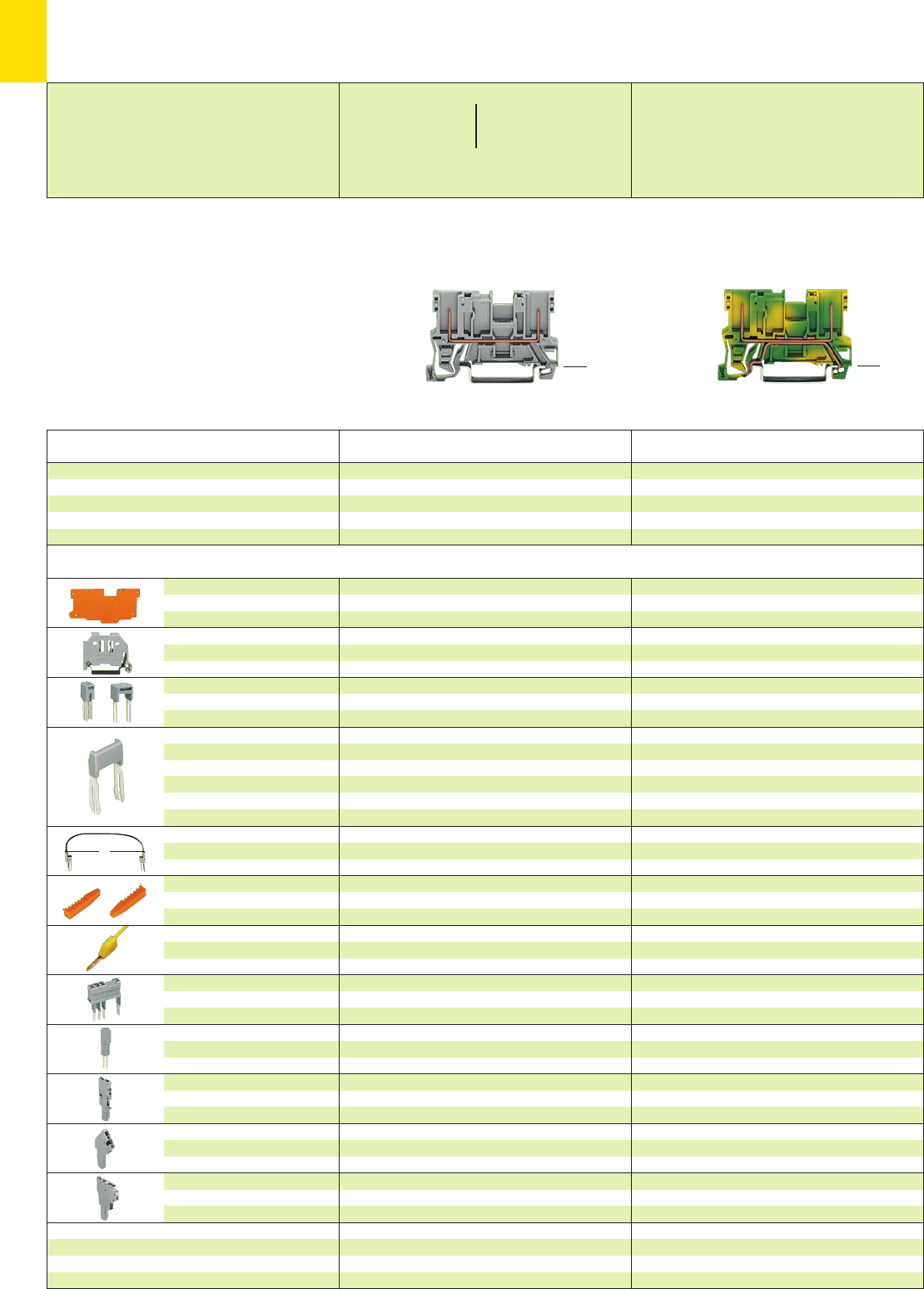
,
9
14
*U2fJ{ *U2fJ{
L
* For further approvals with corresponding ratings see section 15. ** Current-carrying capacity curve see page 9.48 and www.wago.com
Description Item Pack. unit
No. pcs
(29.5mm/1.16in )
<____ 52.5 mm /2.07 in ____>
<28.5 mm / >
1.12 in
➊500 V = rated voltage
6 kV = rated surge voltage
3 = pollution degree
250 V/4 kV/3 = rated voltage
with shield (screen) contact
(see also section 15)
➋See application notes on page 2.45
X-COM®-SYSTEM
2-Pin Receptacle Terminal Blocks
Item Pack. unit
No. pcs
1.1 mm /0.043 in thick
grey 769-305 100 (4 x 25)
orange 769-306 100 (4 x 25)
6 mm /0.236 in wide
249-116 100 (4 x 25)
10 mm /0.394 in wide
249-117 50 (2 x 25)
grey 280-402 200 (8 x 25)
grey 280-409 100 (4 x 25)
IN24 A 780-452 100 (4 x 25)
780-453 100 (4 x 25)
780-454 100 (4 x 25)
780-455 50 (2 x 25)
:
780-458 50 (2 x 25)
L = 60 mm /2.362 in
249-125 10
L = 110 mm /4.331 in
249-126 10
L = 250 mm /9.843 in
249-127 10
orange 769-435 100 (4 x 25)
yellow 210-137 50 (5 x 10)
Application notes and part numbers
see pages 2.39 – 2.40
5 mm /0.197 in wide
280-404 100 (4 x 25)
or test plug 210-137 (2.3 mm /0.091 in Ø)
see page 9.44
see page 9.46
see page 9.45
End and
intermediate plate
Screwless
end stop
Adjacent jumper, IN24 A
insulated
Alternate jumper
Staggered jumper
➋,from 1 to 2
insulated, from 1 to 3
width 5 mm /0.197 in from 1 to 4
from 1 to 5
:
from 1 to 8
Push-in type wire jumper ➋,
insulated, 9 A – conductor
cross section 0.75 mm2/AWG 18
Coding pin,
for coding of female plugs
Test plug,
with cable 500 mm/1’7.7’’
2.3 mm /0.091 in Ø
Test plug module,
for test using jumper position in
current bar or cond. wire opening
Test plug adapter,
see also pages 2.39 – 2.40
1-conductor female plug,
straight
1-conductor female plug,
angled
2-conductor female plug
2-pin receptacle terminal block,
suitable for DIN 35 rail acc. to EN 60715
2-pin receptacle terminal block
grey 769-156 100
2-pin receptacle terminal block
with shield (screen) contact, (no picture)
grey 769-221 50
1.1 mm /0.043 in thick
grey 769-305 100 (4 x 25)
orange 769-306 100 (4 x 25)
6 mm /0.236 in wide
249-116 100 (4 x 25)
10 mm /0.394 in wide
249-117 50 (2 x 25)
grey 280-402 200 (8 x 25)
grey 280-409 100 (4 x 25)
IN24 A 780-452 100 (4 x 25)
780-453 100 (4 x 25)
780-454 100 (4 x 25)
780-455 50 (2 x 25)
:
780-458 50 (2 x 25)
L = 60 mm /2.362 in
249-125 10
L = 110 mm /4.331 in
249-126 10
L = 250 mm /9.843 in
249-127 10
orange 769-435 100 (4 x 25)
yellow 210-137 50 (5 x 10)
Application notes and part numbers
see pages 2.39 – 2.40
5 mm /0.197 in wide
280-404 100 (4 x 25)
or test plug 210-137 (2.3 mm /0.091 in Ø)
see page 9.44
see page 9.46
see page 9.45
2-pin ground (earth) receptacle terminal block
green-yellow 769-227 100
<28.5 mm / >
1.12 in
(29.5 mm /1.16 i n )
<____ 52.5 mm /2.07 in ____>
Accessories Appropriate marking system Mini-WSB (see section 14)
500 V/6 kV/3 ➊300/600 V, 10/5 A U
250 V/4 kV/3 ➊300 V, 10 A 2
32 A**
Terminal block width 5 mm / 0.197 in Terminal block width 5 mm / 0.197 in
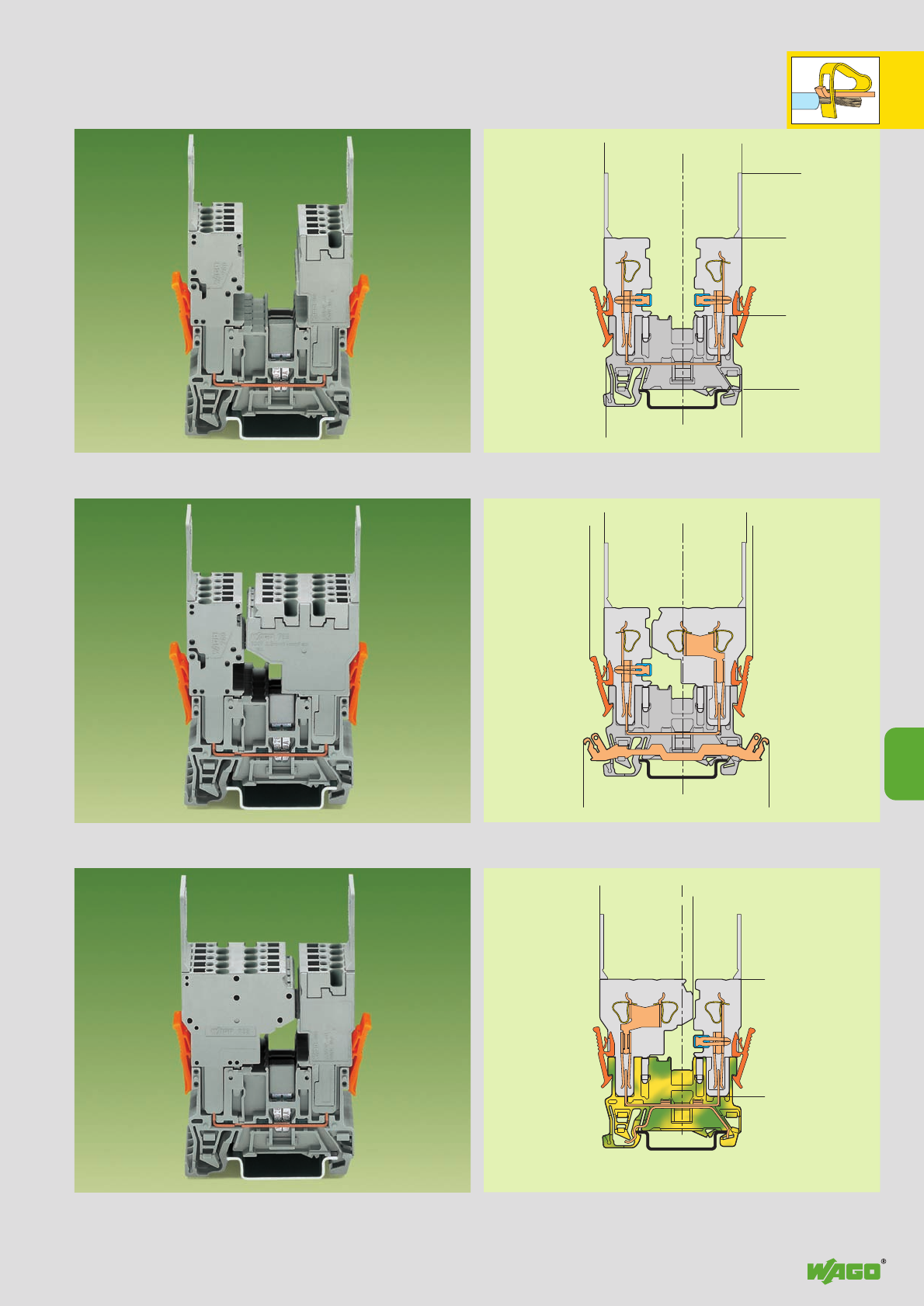
,
9
15
<_____30,2_____>
<____________53,1____________>
<___________52,4___________>
<____29,5_____>
<______30______>
<____28,5____>
<_____________________83,5 _____________________>
<______35,9______>
<_____31,6_____>
<_________45,2_________>
<_____30,2_____>
<____________54,5____________>
<_________________71,4_________________>
<_______38,3_______>
__>
5,5 <__
2,5
9
Types of Assembly
2-Pin Receptacle Terminal Blocks
and 1-/2-Conductor Female Plugs
2 x 1-conductor female plugs Commoning possibility of receptacle
terminal blocks with jumper contact systems, series 280 and 780,
and testing possibility with test plug adapter 280-4 . .
1-conductor female plug left Commoning possibility of receptacle
2-conductor female plug right terminal blocks only with adjacent jumpers
and alternate jumpers, series 280
2-conductor female plug left Commoning possibility of receptacle
1-conductor female plug right terminal blocks with jumper contact systems,
series 280 and 780, and testing possibility with test plug adapter 280-4 . .
Receptacle terminal block
Receptacle terminal block with shield (screen) contact
Ground (earth) receptacle terminal block
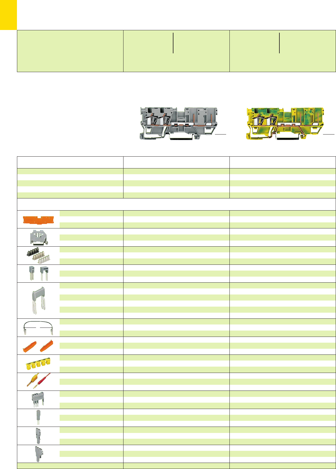
,
9
16
*U2KfJ:{ *U2KfJ{
L
<28.5 mm />
1.12 in
<__ 46 mm /1.81 in __>
<_____________ 87.5mm/3.44in _____________>
Description Item Pack. unit
No. pcs Item Pack. unit
No. pcs
<__ 46 mm /1.81 in __>
<____________ 87.5 mm /3.44 in ____________>
<28.5 mm / >
1.12 in
X-COM®-SYSTEM
2-Conductor/ 2-Pin Receptacle Terminal Blocks
➊500 V = rated voltage
6 kV = rated surge voltage
3 = pollution degree
250 V/4 kV/3 = rated voltage
with shield (screen) contact
(see also section 15)
➋See application notes on pages 2.43 – 2.45
End and
intermediate plate
Screwless
end stop
Insulation stop ➋,white
5 pcs/strip light grey
dark grey
Adjacent jumper, IN24 A
insulated
Alternate jumper
Staggered jumper
➋,from 1 to 2
insulated, from 1 to 3
width 5 mm/0.197 in from 1 to 4
from 1 to 5
:
from 1 to 8
Push-in type wire jumper ➋,
insulated, 9 A – conductor
cross section 0.75 mm2/AWG 18
Coding pin,
for coding of female plugs
Protective warning marker,
for 5 terminal blocks,
fits into screwdriver slot
Test plug, w. cable 500 mm/1’7.7’’
2 mm /0.079 in Ø
2.3 mm /0.091 in Ø
Test plug module,
for test using jumper position in
current bar or cond. wire opening
Test plug adapter,
see also pages 2.38 – 2.40
1-conductor female plug,
straight
2-conductor female plug
1.1 mm /0.043 in thick
grey 769-303 100 (4 x 25)
orange 769-304 100 (4 x 25)
6 mm /0.236 in wide
249-116 100 (4 x 25)
10 mm /0.394 in wide
249-117 50 (2 x 25)
0.08 – 0.2 mm2769-470 200 strips
0.25 – 0.5 mm2769-471 200 strips
0.75 – 1 mm2769-472 200 strips
grey 280-402 200 (8 x 25)
grey 280-409 100 (4 x 25)
IN24 A 780-452 100 (4 x 25)
780-453 100 (4 x 25)
780-454 100 (4 x 25)
780-455 50 (2 x 25)
:
780-458 50 (2 x 25)
L = 60 mm /2.362 in
249-125 10
L = 110 mm /4.331 in
249-126 10
L = 250 mm /9.843 in
249-127 10
orange 769-435 100 (4 x 25)
red 210-136 50 (5 x 10)
yellow 210-137 50 (5 x 10)
Application notes and part numbers
see pages 2.38 – 2.40
5 mm/0.197 in wide
280-404 100 (4 x 25)
or test plug 210-137 (2.3 mm /0.091 in Ø)
see page 9.44
angled – cannot be used
see page 9.45
1.1 mm /0.043 in thick
grey 769-303 100 (4 x 25)
orange 769-304 100 (4 x 25)
6 mm /0.236 in wide
249-116 100 (4 x 25)
10 mm /0.394 in wide
249-117 50 (2 x 25)
0.08 – 0.2 mm2769-470 200 strips
0.25 – 0.5 mm2769-471 200 strips
0.75 – 1 mm2769-472 200 strips
grey 280-402 200 (8 x 25)
grey 280-409 100 (4 x 25)
IN24 A 780-452 100 (4 x 25)
780-453 100 (4 x 25)
780-454 100 (4 x 25)
780-455 50 (2 x 25)
:
780-458 50 (2 x 25)
L = 60 mm /2.362 in
249-125 10
L = 110 mm /4.331 in
249-126 10
L = 250 mm /9.843 in
249-127 10
orange 769-435 100 (4 x 25)
yellow 280-415 100 (4 x 25)
red 210-136 50 (5 x 10)
yellow 210-137 50 (5 x 10)
Application notes and part numbers
see pages 2.38 – 2.40
5 mm/0.197 in wide
280-404 100 (4 x 25)
or test plug 210-137 (2.3 mm /0.091 in Ø)
see page 9.44
angled – cannot be used
see page 9.45
2-conductor/2-pin receptacle terminal block,
suitable for DIN 35 rail acc. to EN 60715
2-conductor/2-pin receptacle terminal block
grey 769-171 50
2-conductor/2-pin r
eceptacle terminal block
with shield (screen) contact, (no picture)
grey 769-211 50
2-conductor/2-pin ground (earth) receptacle
terminal block
green-yellow 769-217 50
Accessories Appropriate marking system Mini-WSB (see section 14)
* For further approvals with corresponding ratings see section 15. ** Current-carrying capacity curve see page 9.49 and www.wago.com
0.08 – 4 mm2AWG 28 – 12
500 V/6 kV/3 ➊300/600 V, 10/5 A U
250 V/4 kV/3 ➊300 V, 10 A 2
32 A**
Terminal block width 5 mm / 0.197 in
L8 – 9 mm / 0.33 in
0.08 – 4 mm2AWG 28 – 12
Terminal block width 5 mm / 0.197 in
L8 – 9 mm / 0.33 in
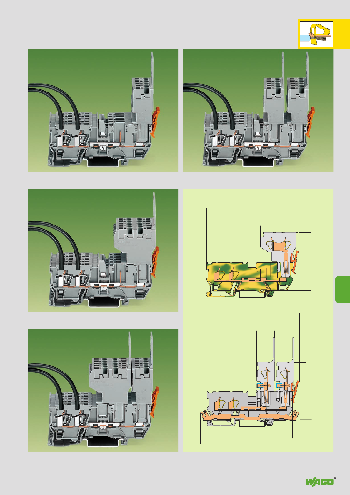
,
9
17
<__________________________94,5__________________________>
<_________________________93_________________________>
<_______________________90,5_______________________>
<__________46__________> <_______36_______>
<_____________58,5_____________>
<_________________________89_________________________>
<__________46__________> <_18,3_><__20__>
<________________________87,5________________________>
<____________________________101 _____________________________>
<_______________________83,5______________________>
<____28,5____><_____ 30 _____>
<____________53____________>
<__________45,2__________>
9
Types of Assembly
2-Conductor/2-Pin Receptacle Terminal Blocks
and 1-/2-Conductor Female Plugs
1-conductor female plug Commoning possibility of receptacle
terminal blocks with jumper contact systems, series 280 and 780,
and testing possibility with test plug adapter 280-4 . .
2-conductor female plug Commoning possibility of receptacle
terminal blocks with jumper contact systems, series 280 and 780,
and testing possibility with test plug adapter 280-4 . .
Ground (earth) receptacle terminal block
1-conductor female plug and Commoning possibility of receptacle
2-conductor female plug terminal blocks only with adjacent jumpers
and alternate jumpers, series 280
Receptacle terminal block with shield (screen) contact
2 x 1-conductor female plugs Commoning possibility of receptacle
terminal blocks with jumper contact systems, series 280 and 780,
and testing possibility with test plug adapter 280-4 . .
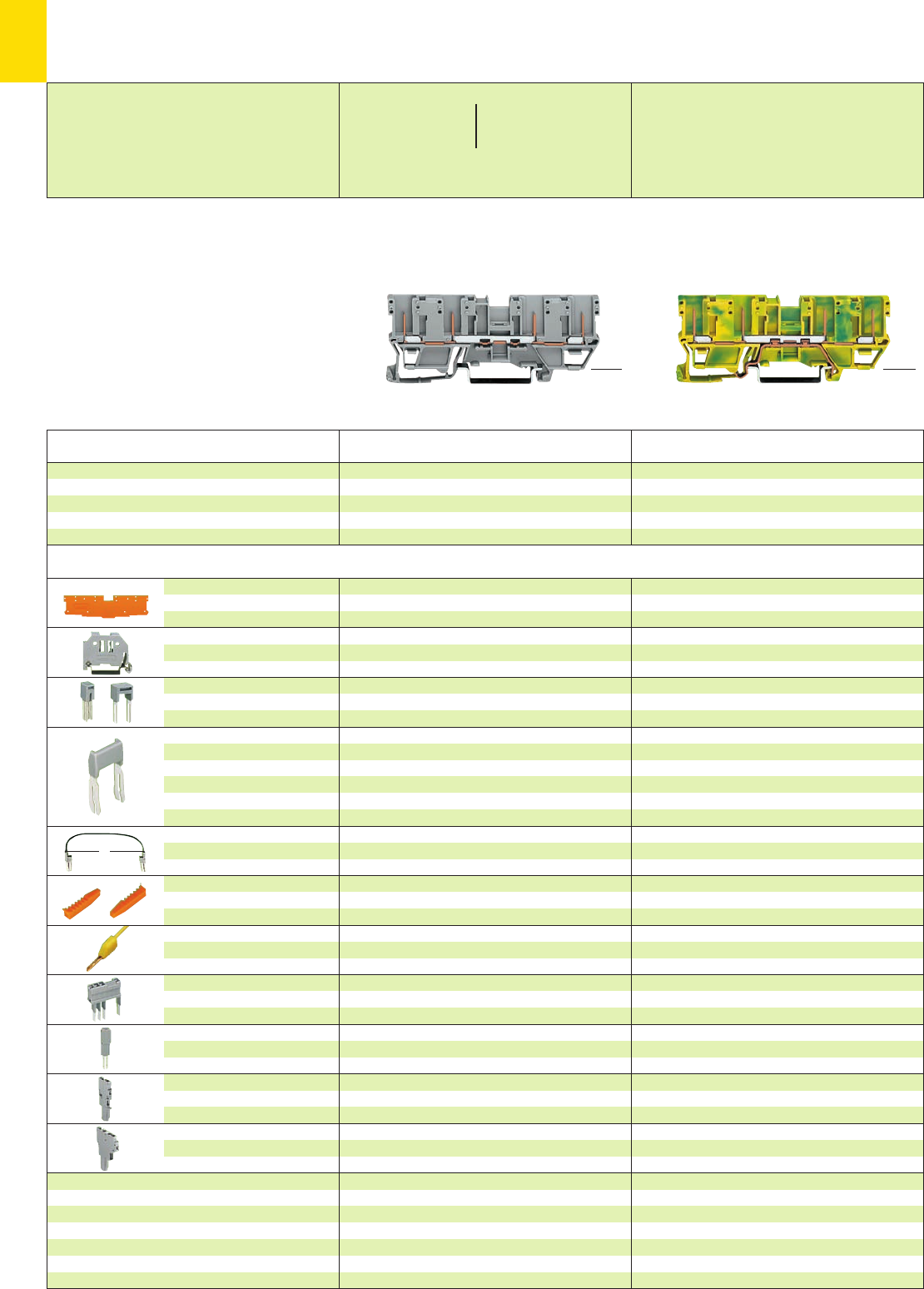
,
9
18
*U2KfJ:{ *U2KfJ:{
L
* For further approvals with corresponding ratings see section 15. ** Current-carrying capacity curve see page 9.49 and www.wago.com
Description
1.1 mm /0.043 in thick
grey 769-301 100 (4 x 25)
orange 769-302 100 (4 x 25)
6 mm /0.236 in wide
249-116 100 (4 x 25)
10 mm /0.394 in wide
249-117 50 (2 x 25)
grey 280-402 200 (8 x 25)
grey 280-409 100 (4 x 25)
IN24 A 780-452 100 (4 x 25)
780-453 100 (4 x 25)
780-454 100 (4 x 25)
780-455 50 (2 x 25)
:
780-458 50 (2 x 25)
L = 60 mm /2.362 in
249-125 10
L = 110 mm /4.331 in
249-126 10
L = 250 mm /9.843 in
249-127 10
orange 769-435 100 (4 x 25)
yellow 210-137 50 (5 x 10)
Application notes and part numbers
see pages 2.39 – 2.40
5 mm /0.197 in wide
280-404 100 (4 x 25)
or test plug 210-137 (2.3 mm /0.091 in Ø)
see page 9.44
angled – cannot be used
see page 9.45
End and
intermediate plate
Screwless
end stop
Adjacent jumper, IN24 A
insulated
Alternate jumper
Staggered jumper
➋,from 1 to 2
insulated, from 1 to 3
width 5 mm /0.197 in from 1 to 4
from 1 to 5
:
from 1 to 8
Push-in type wire jumper ➋,
insulated, 9 A – conductor
cross section 0.75 mm2/AWG 18
Coding pin,
for coding of female plugs
Test plug,
with cable 500 mm/1’7.7’’
2.3 mm /0.091 in Ø
Test plug module,
for test using jumper position in
current bar or cond. wire opening
Test plug adapter,
see also pages 2.39 – 2.40
1-conductor female plug,
straight
2-conductor female plug
4-pin receptacle terminal block,
suitable for DIN 35 rail acc. to EN 60715
Item Pack. unit
No. pcs
4-pin receptacle terminal block
grey 769-151 50
4-pin receptacle terminal block
with shield (screen) contact, (no picture)
grey 769-201 50
Item Pack. unit
No. pcs
4-pin ground (earth) receptacle terminal block
green-yellow 769-207 50
➊500 V = rated voltage
6 kV = rated surge voltage
3 = pollution degree
250 V/4 kV/3 = rated voltage
with shield (screen) contact
(see also section 15)
➋See application notes on page 2.45
X-COM®-SYSTEM
4-Pin Receptacle Terminal Blocks
<28.5 mm />
1.12 in
<__ 46 mm /1.81 in __>
<____________ 87.5mm/3.44in ____________>
<__ 46 mm /1.81 in __>
<____________ 87.5mm/3.44in ____________>
<28.5 mm / >
1.12 in
Accessories Appropriate marking system Mini-WSB (see section 14)
500 V/6 kV/3 ➊300/600 V, 10/5 A U
250 V/4 kV/3 ➊300 V, 10 A 2
32 A**
Terminal block width 5 mm / 0.197 in Terminal block width 5 mm / 0.197 in
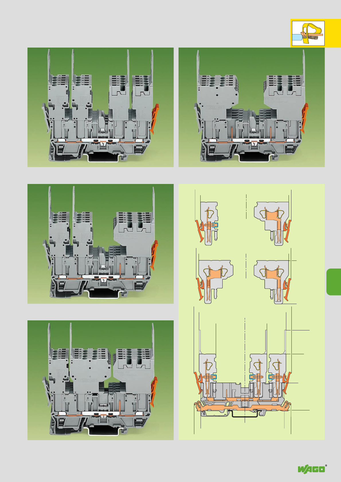
,
9
19
<________________________99 ________________________>
<___________49,5 ___________><_________ 44,5 _________>
<___________________________102 ___________________________>
<________________________91 _____________________>
<__________43 __________>
<_18 __> <___20 ___>
<___________________________101 ___________________________>
<___28,5 _____>
<___________58,5 ____________>
<_____________________83,5 _____________________>
<___________46___________>
<_______________________87,5 ____________________>
<___________________________101________________________>
<_________48 _________><_________44,5 __________>
<__________45,2__________>
9
Types of Assembly
4-Pin Receptacle Terminal Blocks
and 1-/2-Conductor Female Plugs
4 x 1-conductor female plugs Commoning possibility of receptacle
terminal blocks with jumper contact systems, series 280 and 780,
and testing possibility with test plug adapter 280-4 . .
2 x 1-cond. fem. plugs left Commoning possibility of receptacle term.
1 x 2-cond. female plug right blocks w. jumper contact systems, series 280 a. 780,
Also possible the other way round a. testing possibility w. test plug adapter 280-4 . .
1-conductor and 2-conductor female plugs left Commoning possibility of
2-conductor female plug right receptacle terminal blocks only with adjacent
Also possible the other way round jumpers and alternate jumpers, series 280
Receptacle terminal block with shield (screen) contact
2 x 2-conductor female plugs Commoning possibility of receptacle
terminal blocks with jumper contact systems, series 280 and 780,
and testing possibility with test plug adapter 280-4 . .
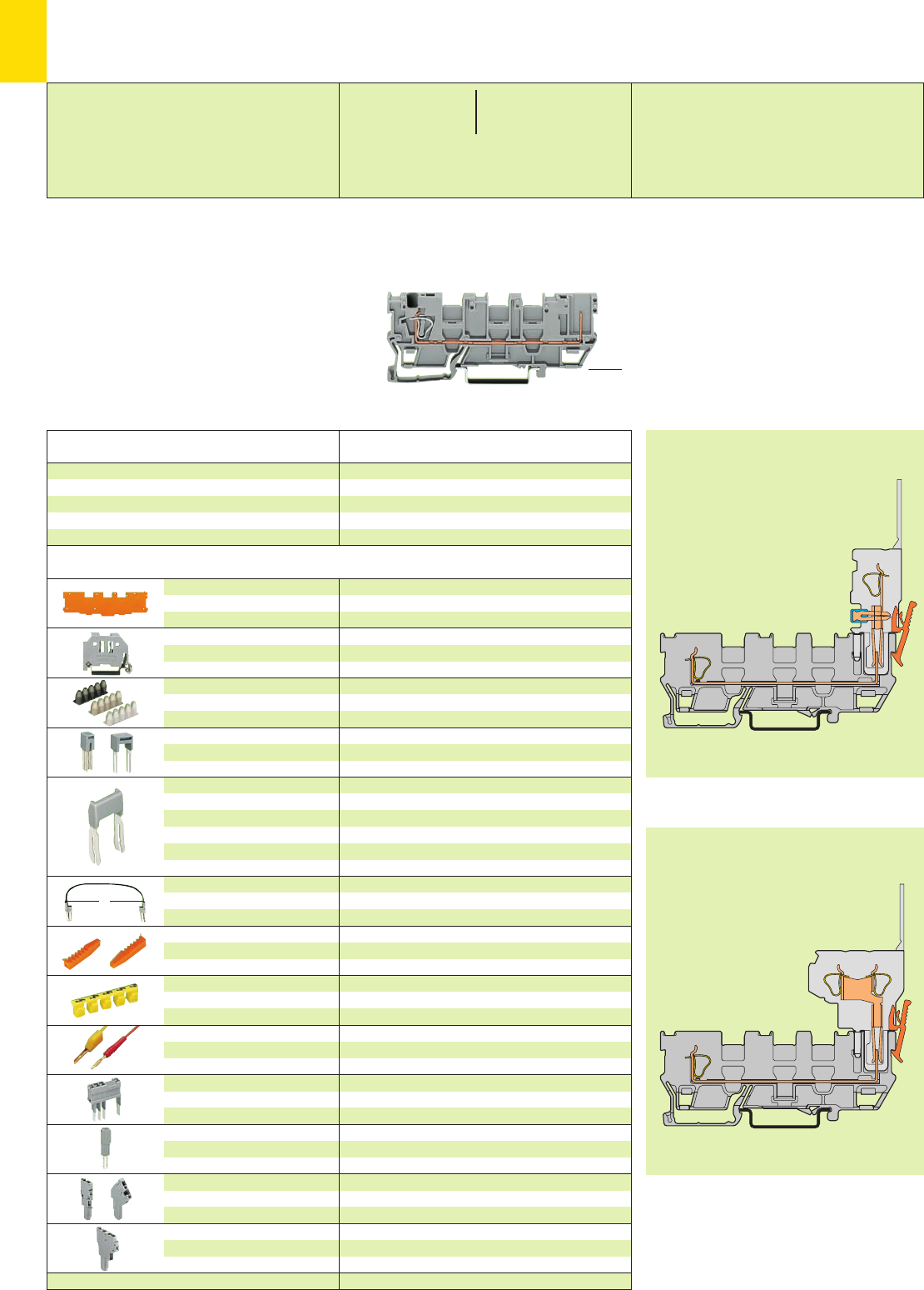
9
20
L
*U2fJ{
Dimensions see page 9.17
Dimensions see page 9.17
* For further approvals with corresponding ratings see section 15. ** Current-carrying capacity curve see www.wago.com
Description Item Pack. unit
No. pcs
<__ 46 mm /1.81 in __>
<____________ 87.5 mm /3.44 in ____________>
<28.5 mm / >
1.12 in
X-COM®-SYSTEM
1-Conductor/1- Pin Receptacle Terminal Blocks with 3 Jumper Positions
Types of assembly
with 1-/2-conductor female plugs
➊500 V = rated voltage
6 kV = rated surge voltage
3 = pollution degree
(see also section 15)
➋See application notes on pages 2.43 – 2.45
End and
intermediate plate
Screwless
end stop
Insulation stop ➋,white
5 pcs/strip light grey
dark grey
Adjacent jumper, IN24 A
insulated
Alternate jumper
Staggered jumper
➋,from 1 to 2
insulated, from 1 to 3
width 5 mm/0.197 in from 1 to 4
from 1 to 5
:
from 1 to 8
Push-in type wire jumper ➋,
insulated, 9 A – conductor
cross section 0.75 mm2/AWG 18
Coding pin,
for coding of female plugs
Protective warning marker,
for 5 terminal blocks,
fits into screwdriver slot
Test plug, w. cable 500 mm/1’7.7’’
2 mm /0.079 in Ø
2.3 mm /0.091 in Ø
Test plug module,
for test using jumper position in
current bar or cond. wire opening
Test plug adapter,
see also pages 2.38 – 2.40
1-conductor female plug,
straight or angled
2-conductor female plug
1.1 mm /0.043 in thick
grey 769-315 100 (4 x 25)
orange 769-316 100 (4 x 25)
6 mm /0.236 in wide
249-116 100 (4 x 25)
10 mm /0.394 in wide
249-117 50 (2 x 25)
0.08 – 0.2 mm2769-470 200 strips
0.25 – 0.5 mm2769-471 200 strips
0.75 – 1 mm2769-472 200 strips
grey 280-402 200 (8 x 25)
grey 280-409 100 (4 x 25)
IN24 A 780-452 100 (4 x 25)
780-453 100 (4 x 25)
780-454 100 (4 x 25)
780-455 50 (2 x 25)
:
780-458 50 (2 x 25)
L = 60 mm /2.362 in
249-125 10
L = 110 mm /4.331 in
249-126 10
L = 250 mm /9.843 in
249-127 10
orange 769-435 100 (4 x 25)
yellow 280-415 100 (4 x 25)
red 210-136 50 (5 x 10)
yellow 210-137 50 (5 x 10)
Application notes and part numbers
see pages 2.38 – 2.40
5 mm/0.197 in wide
280-404 100 (4 x 25)
or test plug 210-137 (2.3 mm /0.091 in Ø)
see pages 9.44/9.46
see page 9.45
1-conductor/1-pin receptacle terminal block
with 3 jumper positions,
suitable for DIN 35 rail acc. to EN 60715
1-conductor/1-pin receptacle terminal block
with 3 jumper positions
grey 769-214 50
Accessories Appropriate marking system Mini-WSB (see section 14)
0.08 – 4 mm2AWG 28 – 12
500 V/6 kV/3 ➊300/600 V,10/5 A U
32 A** 300 V, 10 A 2
Terminal block width 5 mm / 0.197 in
L8 – 9 mm / 0.33 in
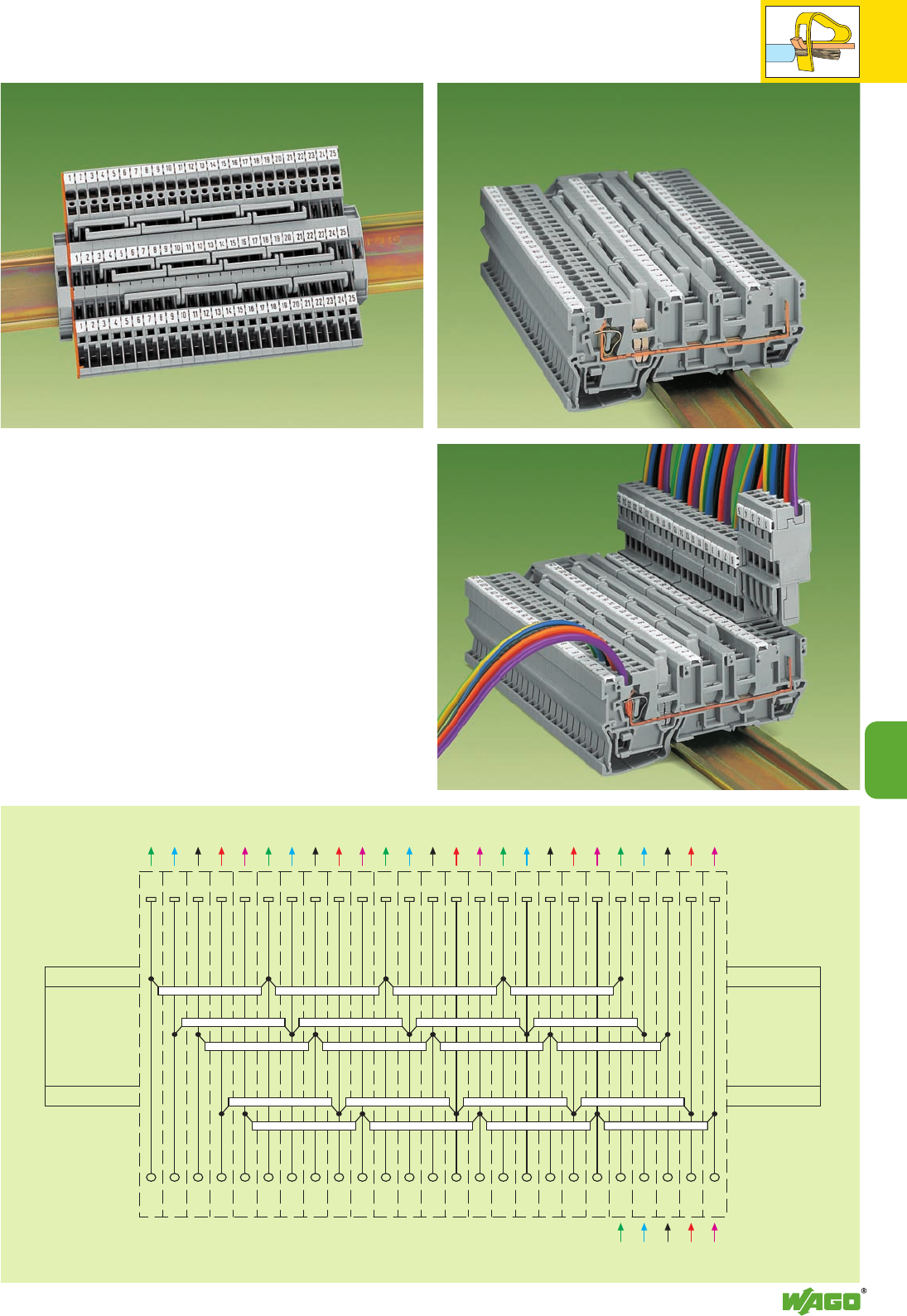
9
21
⎧
⎪
⎪
⎨
⎪
⎪
⎩
⎧
⎪
⎪
⎨
⎪
⎪
⎩
⎧
⎪
⎪
⎨
⎪
⎪
⎩
⎧
⎪
⎪
⎨
⎪
⎪
⎩
⎧
⎪
⎪
⎨
⎪
⎪
⎩
⎧
⎪
⎪
⎨
⎪
⎪
⎩
9
Output 5 Output 4 Output 3 Output 2 Output 1
Input 1
Applications
1-conductor/1-pin receptacle terminal blocks
with 3 jumper positions
The 3 jumper positions allow up to six jumpering possibilities for staggered
jumpers.
The pictures opposite and the wiring scheme demonstrate the supply of a
5-wire input to 5 identical pluggable outputs.
Application examples:
– Muliplication of three-phase circuits L1-L2-L3-N-PE with pluggable out-
puts; for example, use with motors, frequency converters, power units,
etc.
– voltage supplies to multiple locations
± 15 V, 0 V, + 5 V, + 12 V, + 24 V
– Various wire-to-wire interfacing possibilities
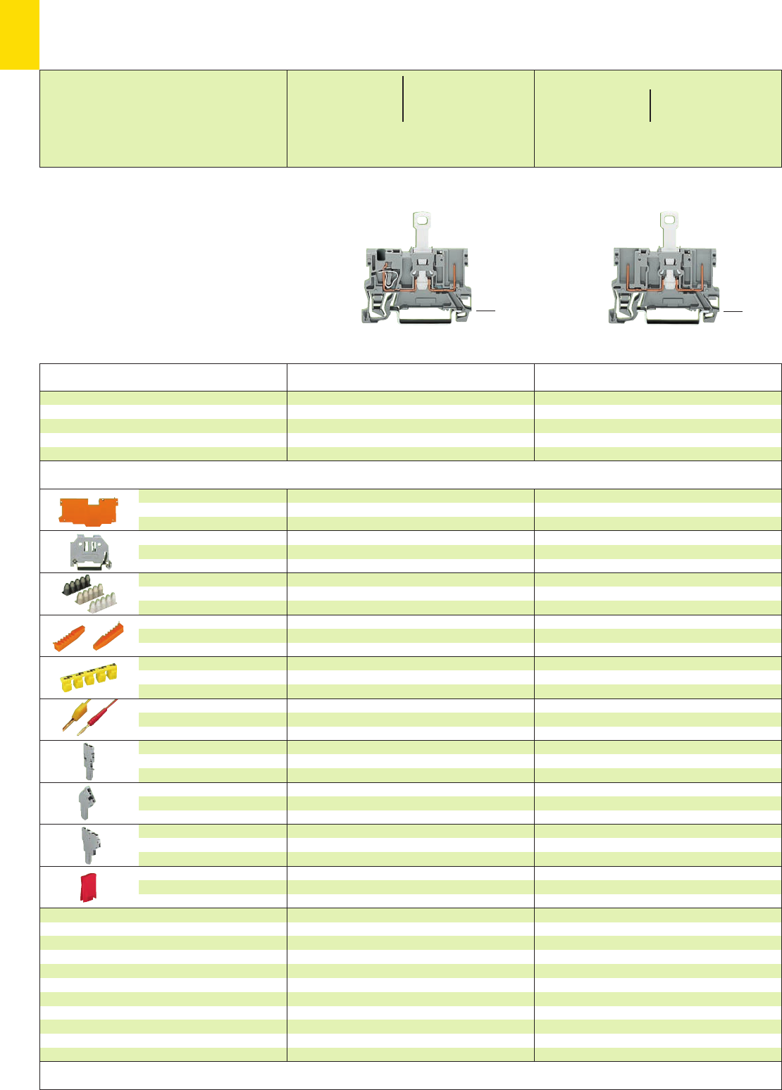
9
22
*U2fJ{ *U2fJ{
1.1 mm /0.043 in thick
grey 769-305 100 (4 x 25)
orange 769-306 100 (4 x 25)
6 mm /0.236 in wide
249-116 100 (4 x 25)
10 mm /0.394 in wide
249-117 50 (2 x 25)
orange 769-435 100 (4 x 25)
yellow 210-137 50 (5 x 10)
see page 9.44
see page 9.46
cannot be used
see also page 7.13
red 709-170 200 (8 x 25)
Item Pack. unit
No. pcs
2-pin disconnect receptacle terminal block
grey 769-222 50
2-pin disconnect receptacle terminal block with
shield (screen) contact (no picture)
grey 769-223 50
Description
1.1 mm /0.043 in thick
grey 769-307 100 (4 x 25)
orange 769-308 100 (4 x 25)
6 mm /0.236 in wide
249-116 100 (4 x 25)
10 mm /0.394 in wide
249-117 50 (2 x 25)
0.08 – 0.2 mm2769-470 200 strips
0.25 – 0.5 mm2769-471 200 strips
0.75 – 1 mm2769-472 200 strips
orange 769-435 100 (4 x 25)
yellow 280-415 100 (4 x 25)
red 210-136 50 (5 x 10)
yellow 210-137 50 (5 x 10)
see page 9.44
see page 9.46
cannot be used
see also page 7.13
red 709-170 200 (8 x 25)
End and
intermediate plate
Screwless
end stop
Insulation stop ➋,white
5 pcs/strip light grey
dark grey
Coding pin,
for coding of female plugs
Protective warning marker,
for 5 terminal blocks,
fits into screwdriver slot
Test plug, w. cable 500 mm/1’7.7’’
2 mm /0.079 in Ø
2.3 mm /0.091 in Ø
1-conductor female plug,
straight
1-conductor female plug,
angled
2-conductor female plug
Disconnect lock,
for disconnecting tab of
disconnect terminal blocks
1-conductor/1-pin and 2-pin disconnet receptacle
terminal block
without/with shield (screen) contact,
suitable for DIN 35 rail acc. to EN 60715
Item Pack. unit
No. pcs
1-cond./1-pin disconnect receptacle term. block
grey 769-232 50
1-conductor/1-pin disconnect receptacle terminal
block with shield (screen) contact (no picture)
grey 769-233 50
X-COM®-SYSTEM
1-Conductor/1-Pin and 2-Pin
Disconnect Receptacle Terminal Blocks
➊400 V = rated voltage
6 kV = rated surge voltage
3 = pollution degree
250 V/4 kV/3 = rated voltage
with shield (screen) contact
(see also section 15)
➋See application notes on page 2.43
(29.5mm/1.16in)
<___ 52.5 mm /2.07 in ___>
<28.5 mm />
1.12 in
(29.5mm/1.16in)
<___ 52.5 mm /2.07 in ___>
<28.5 mm />
1.12 in
Dimensions and types of assembly (see page 9.26)
Accessories Appropriate marking system Mini-WSB (see section 14)
0.08 – 4 mm2AWG 28 – 12
400 V/6 kV/3 ➊300/600 V,10/5AU
250 V/4 kV/3 ➊300 V, 10 A 2
16 A **
Terminal block width 5 mm / 0.197 in
L8 – 9 mm / 0.33 in
400 V/6 kV/3 ➊300/600 V,10/5AU
250 V/4 kV/3 ➊300 V, 10 A 2
16 A **
Terminal block width 5 mm / 0.197 in
* For further approvals with corresponding ratings see section 15. **16 A, temperature limit of 85°C
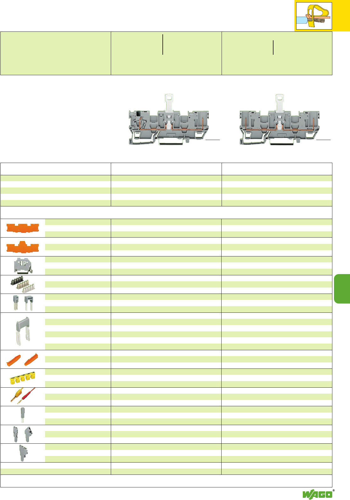
9
23
9
*U2fJ{ *U2fJ{
Description Item Pack. unit
No. pcs Item Pack. unit
No. pcs
<__ 46 mm /1.81 in __>
<____________ 87.5 mm /3.44 in ____________>
1-Conductor/1-Pin and 2-Pin
Disconnect Receptacle Terminal Blocks with 2 Jumper Positions
➊400 V = rated voltage
6 kV = rated surge voltage
3 = pollution degree
250 V/4 kV/3 = rated voltage
with shield (screen) contact
(see also section 15)
➋See application notes on pages 2.43 – 2.45
End and
intermediate plate
Separator plate,
oversized
Screwless
end stop
Insulation stop ➋,white
5 pcs/strip light grey
dark grey
Adjacent jumper, IN24 A
insulated
Alternate jumper
Staggered jumper
➋,from 1 to 2
insulated, from 1 to 3
width 5 mm/0.197 in from 1 to 4
from 1 to 5
:
from 1 to 8
Coding pin,
for coding of female plugs
Protective warning marker,
for 5 terminal blocks,
fits into screwdriver slot
Test plug, w. cable 500 mm/1’7.7’’
2 mm /0.079 in Ø
2.3 mm /0.091 in Ø
Test plug module,
see also pages 2.38 – 2.40
1-conductor female plug,
straight or angled
2-conductor female plug
Disconnect lock,
for disconnec-
ting tab of disconnect term. blocks
1.1 mm /0.043 in thick
grey 769-309 100 (4 x 25)
orange 769-310 100 (4 x 25)
1.1 mm /0.043 in thick
orange 769-313 100 (4 x 25)
6 mm /0.236 in wide
249-116 100 (4 x 25)
10 mm /0.394 in wide
249-117 50 (2 x 25)
grey 280-402 200 (8 x 25)
grey 280-409 100 (4 x 25)
IN24 A 780-452 100 (4 x 25)
780-453 100 (4 x 25)
780-454 100 (4 x 25)
780-455 50 (2 x 25)
:
780-458 50 (2 x 25)
orange 769-435 100 (4 x 25)
yellow 210-137 50 (5 x 10)
5 mm/0.197 in wide
280-404 100 (4 x 25)
or test plug 210-137 (2.3 mm /0.091 in Ø)
see pages 9.44/9.46
see page 9.45
see also page 7.13
red 709-170 200 (8 x 25)
1.1 mm /0.043 in thick
grey 769-311 100 (4 x 25)
orange 769-312 100 (4 x 25)
1.1 mm /0.043 in thick
orange 769-314 100 (4 x 25)
6 mm /0.236 in wide
249-116 100 (4 x 25)
10 mm /0.394 in wide
249-117 50 (2 x 25)
0.08 – 0.2 mm2769-470 200 strips
0.25 – 0.5 mm2769-471 200 strips
0.75 – 1 mm2769-472 200 strips
grey 280-402 200 (8 x 25)
grey 280-409 100 (4 x 25)
IN24 A 780-452 100 (4 x 25)
780-453 100 (4 x 25)
780-454 100 (4 x 25)
780-455 50 (2 x 25)
:
780-458 50 (2 x 25)
orange 769-435 100 (4 x 25)
yellow 280-415 100 (4 x 25)
red 210-136 50 (5 x 10)
yellow 210-137 50 (5 x 10)
5 mm/0.197 in wide
280-404 100 (4 x 25)
or test plug 210-137 (2.3 mm /0.091 in Ø)
see pages 9.44/9.46
see page 9.45
see also page 7.13
red 709-170 200 (8 x 25)
2-pin disconnect receptacle terminal block
grey 769-202 50
2-pin disconnect receptacle terminal block with
shield (screen) contact (no picture)
grey 769-203 50
1-cond./1-pin disconnect receptacle term. block
grey 769-212 50
1-conductor/1-pin disconnect receptacle terminal
block with shield (screen) contact (no picture)
grey 769-213 50
1-conductor/1-pin and 2-pin disconnet receptacle
terminal block
without/with shield (screen) contact,
suitable for DIN 35 rail acc. to EN 60715
<28.5 mm / >
1.12 in
<__ 46 mm /1.81 in __>
<____________ 87.5 mm /3.44 in ____________>
<28.5 mm / >
1.12 in
Dimensions and types of assembly (see page 9.27)
Accessories Appropriate marking system Mini-WSB (see section 14)
0.08 – 4 mm2AWG 28 – 12
400 V/6 kV/3 ➊300/600 V,10/5 AU
250 V/4 kV/3 ➊300 V, 10 A 2
16 A **
Terminal block width 5 mm / 0.197 in
L8 – 9 mm / 0.33 in
400 V/6 kV/3 ➊300/600 V,10/5 AU
250 V/4 kV/3 ➊300 V, 10 A 2
16 A **
Terminal block width 5 mm / 0.197 in
* For further approvals with corresponding ratings see section 15. **16 A, temperature limit of 85°C
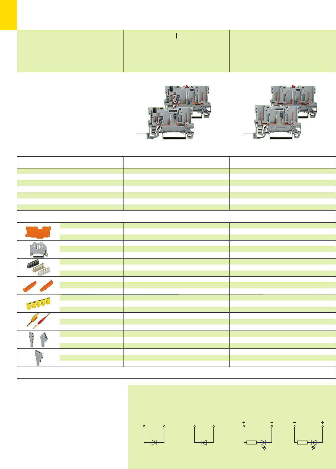
9
24
*U2 *U2
Diode
Anode left
LED
Anode left
LED
Anode right
Diode
Anode right
➊For information on use of insulation stops and wire
range, see page 2.43
1.1 mm /0.043 in thick
grey 769-305 100 (4 x 25)
orange 769-306 100 (4 x 25)
6 mm /0.236 in wide
249-116 100 (4 x 25)
10 mm /0.394 in wide
249-117 50 (2 x 25)
orange 769-435 100 (4 x 25)
yellow 210-137 50 (5 x 10)
see pages 9.44/9.46
cannot be used
Item Pack. unit
No. pcs
2-pin diode receptacle terminal blocks, grey
Anode left 769-228/281-410 100
Anode right 769-228/281-411 100
2-pin LED receptacle terminal blocks, grey
Anode right 769-229/281-413 100
Anode left 769-229/281-434 100
Terminal block width 5 mm / 0.197 in
Description
1.1 mm /0.043 in thick
grey 769-307 100 (4 x 25)
orange 769-308 100 (4 x 25)
6 mm /0.236 in wide
249-116 100 (4 x 25)
10 mm /0.394 in wide
249-117 50 (2 x 25)
0.08 – 0.2 mm2769-470 200 strips
0.25 – 0.5 mm2769-471 200 strips
0.75 – 1 mm2769-472 200 strips
orange 769-435 100 (4 x 25)
yellow 280-415 100 (4 x 25)
red 210-136 50 (5 x 10)
yellow 210-137 50 (5 x 10)
see pages 9.44/9.46
cannot be used
End and
intermediate plate
Screwless
end stop
Insulation stop ➊,white
5 pcs/strip light grey
dark grey
Coding pin,
for coding of female plugs
Protective warning marker,
for 5 terminal blocks,
fits into screwdriver slot
Test plug, w. cable 500 mm/1’7.7’’
2 mm /0.079 in Ø
2.3 mm /0.091 in Ø
1-conductor female plug,
straight or angled
2-conductor female plug
1-conductor/1-pin diode receptacle terminal block,
2-pin diode receptacle terminal block,
1-conductor/1-pin LED receptacle terminal block,
2-pin LED receptacle terminal block
suitable for DIN 35 rail acc. to EN 60715
Item Pack. unit
No. pcs
1-cond./1-pin diode receptacle term. blocks, grey
Anode left 769-238/281-410 100
Anode right 769-238/281-411 100
1-cond./1-pin LED receptacle term. blocks, grey
Anode right 769-239/281-413 100
Anode left 769-239/281-434 100
X-COM®-SYSTEM
1-Conductor/1-Pin and 2-Pin Diode and
LED Receptacle Terminal Blocks
0.08 – 4 mm2AWG 28 – 12
Terminal block width 5 mm / 0.197 in
L8 – 9 mm / 0.33 in
(29.5mm/1.16in)
<____ 52.5 mm /2.07in ____>
<28.5 mm / >
1.12 in
(29.5mm/1.16in)
<____ 52.5 mm /2.07in ____>
<28.5 mm / >
1.12 in
Dimensions and types of assembly (see page 9.26)
Technical data
Diode
UN250 V; URM 1000 V 300/600 V, 10/5 A U
1 N 4007 – 0.5 A constant current 300 V, 10 A 2
LED
DC 24 V 300/600 V, 10/5 A U
IF 25 mA max. 300 V, 10 A 2
Accessories Appropriate marking system Mini-WSB (see section 14)
Connection schemes
* For further approvals with corresponding ratings see section 15.
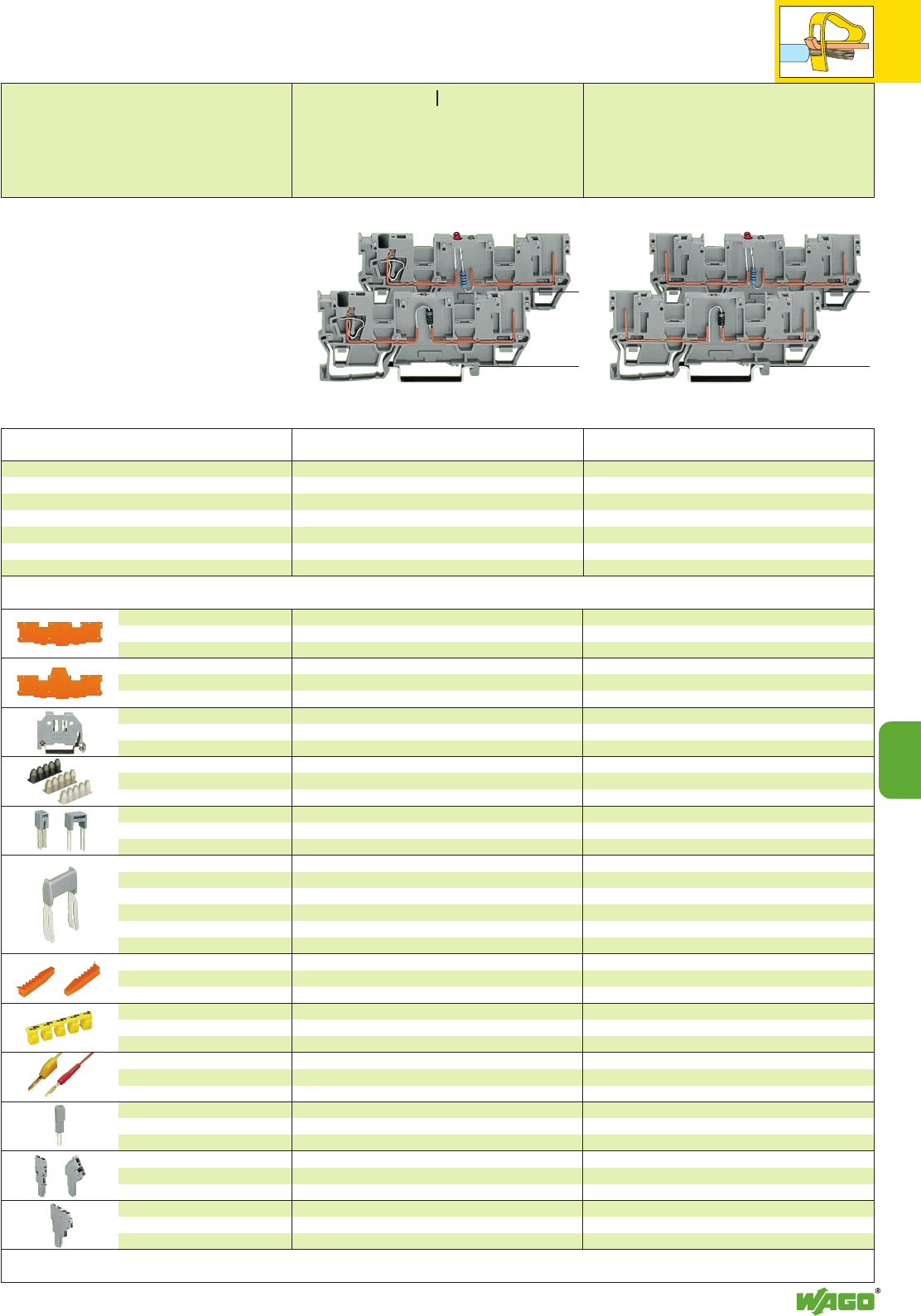
9
25
9
*U2 *U2
➊See application notes on pages 2.43 – 2.45
Description Item Pack. unit
No. pcs Item Pack. unit
No. pcs
<__ 46 mm /1.81 in __>
<____________ 87.5 mm /3.44 in ____________>
1-Conductor/1-Pin and 2-Pin Diode and
LED Receptacle Terminal Blocks with 2 Jumper Positions
0.08 – 4 mm2AWG 28 – 12
Terminal block width 5 mm / 0.197 in
L8 – 9 mm / 0.33 in
Terminal block width 5 mm / 0.197 in
Technical data
Diode
UN250 V; URM 1000 V 300/600 V, 10/5 A U
1 N 4007 – 0.5 A constant current 300 V, 10 A 2
LED
DC 24 V 300/600 V, 10/5 A U
IF 25 mA max. 300 V, 10 A 2
End and
intermediate plate
Separator plate,
oversized
Screwless
end stop
Insulation stop ➋,white
5 pcs/strip light grey
dark grey
Adjacent jumper, IN24 A
insulated
Alternate jumper
Staggered jumper
➋,from 1 to 2
insulated, from 1 to 3
width 5 mm /0.197 in from 1 to 4
from 1 to 5
:
from 1 to 8
Coding pin,
for coding of female plugs
Protective warning marker,
for 5 terminal blocks,
fits into screwdriver slot
Test plug, w. cable 500 mm/1’7.7’’
2 mm /0.079 in Ø
2.3 mm /0.091 in Ø
Test plug adapter,
see pages 2.38 –2.40
1-conductor female plug,
straight or angled
2-conductor female plug
1.1 mm /0.043 in thick
grey 769-309 100 (4 x 25)
orange 769-310 100 (4 x 25)
1.1 mm /0.043 in thick
orange 769-313 100 (4 x 25)
6 mm /0.236 in wide
249-116 100 (4 x 25)
10 mm /0.394 in wide
249-117 50 (2 x 25)
grey 280-402 200 (8 x 25)
grey 280-409 100 (4 x 25)
IN24 A 780-452 100 (4 x 25)
780-453 100 (4 x 25)
780-454 100 (4 x 25)
780-455 50 (2 x 25)
:
780-458 50 (2 x 25)
orange 769-435 100 (4 x 25)
yellow 210-137 50 (5 x 10)
5 mm/0.197 in wide
280-404 100 (4 x 25)
or test plug 210-137 (2.3 mm /0.091 in Ø)
see pages 9.44/9.46
see page 9.45
1.1 mm /0.043 in thick
grey 769-311 100 (4 x 25)
orange 769-312 100 (4 x 25)
1.1 mm /0.043 in thick
orange 769-314 100 (4 x 25)
6 mm /0.236 in wide
249-116 100 (4 x 25)
10 mm /0.394 in wide
249-117 50 (2 x 25)
0.08 – 0.2 mm2769-470 200 strips
0.25 – 0.5 mm2769-471 200 strips
0.75 – 1 mm2769-472 200 strips
grey 280-402 200 (8 x 25)
grey 280-409 100 (4 x 25)
IN24 A 780-452 100 (4 x 25)
780-453 100 (4 x 25)
780-454 100 (4 x 25)
780-455 50 (2 x 25)
:
780-458 50 (2 x 25)
orange 769-435 100 (4 x 25)
yellow 280-415 100 (4 x 25)
red 210-136 50 (5 x 10)
yellow 210-137 50 (5 x 10)
5 mm/0.197 in wide
280-404 100 (4 x 25)
or test plug 210-137 (2.3 mm /0.091 in Ø)
see pages 9.44/9.46
see page 9.45
2-pin diode receptacle terminal blocks, grey
Anode left 769-208/281-410 50
Anode right 769-208/281-411 50
2-pin LED receptacle terminal blocks, grey
Anode right 769-209/281-413 50
Anode left 769-209/281-434 50
1-cond./1-pin diode receptacle term. blocks, grey
Anode left 769-218/281-410 50
Anode right 769-218/281-411 50
1-cond./1-pin LED receptacle term. blocks, grey
Anode right 769-219/281-413 50
Anode left 769-219/281-434 50
1-conductor/1-pin diode receptacle terminal block,
2-pin diode receptacle terminal block,
1-conductor/1-pin LED receptacle terminal block,
2-pin LED receptacle terminal block
suitable for DIN 35 rail acc. to EN 60715
<28.5 mm / >
1.12 in
<28.5 mm / >
1.12 in
<__ 46 mm /1.81 in __>
<____________ 87.5 mm /3.44 in ____________>
Dimensions and types of assembly (see page 9.27)
Accessories Appropriate marking system Mini-WSB (see section 14)
* For further approvals with corresponding ratings see section 15.
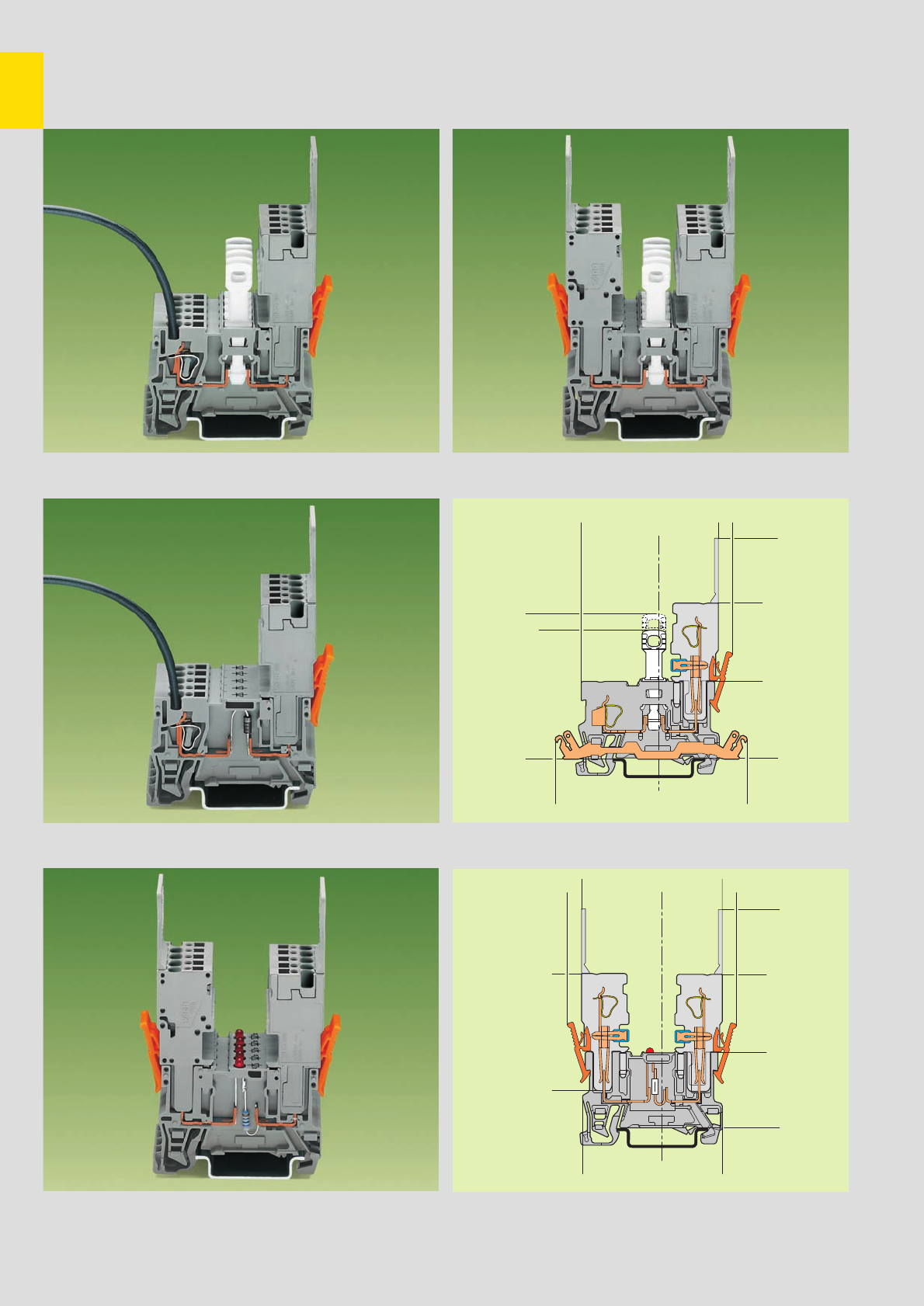
,
9
26
<__
5,5
<_____28,5____>
<__________________71,4__________________>
<________38,3_______>
<______30______>
<____28,5____>
<_____________________83,5 _____________________>
<____________51,4 __________>
<___________48____________>
<______________54_____________>
<__
5,5
__>
5,5 <_____30,2_____>
<____________53,1____________>
<____________52,4___________>
<_____29,5_____>
<______30______>
<____28,5____>
<_____________________83,5 _____________________>
<__________45,2________>
>
➊
➋
Types of Assembly
1-Conductor/1-Pin and 2-Pin Receptable Terminal Blocks
and 1-Conductor Female Plugs
1-conductor female plug The commoning of disconnect receptacle
terminal blocks is not possible
1-conductor female plug The commoning of diode receptacle
terminal blocks is not possible Disconnect receptacle terminal block with shield (screen) contact
➊ Please see also page 9.13 for further dimensions.
2 x 1-conductor female plugs The commoning of LED receptacle
terminal blocks is not possible LED receptacle terminal block
➋ Please see also page 9.15 for further dimensions
2 x 1-conductor female plugs The commoning of disconnect receptacle
terminal blocks is not possible
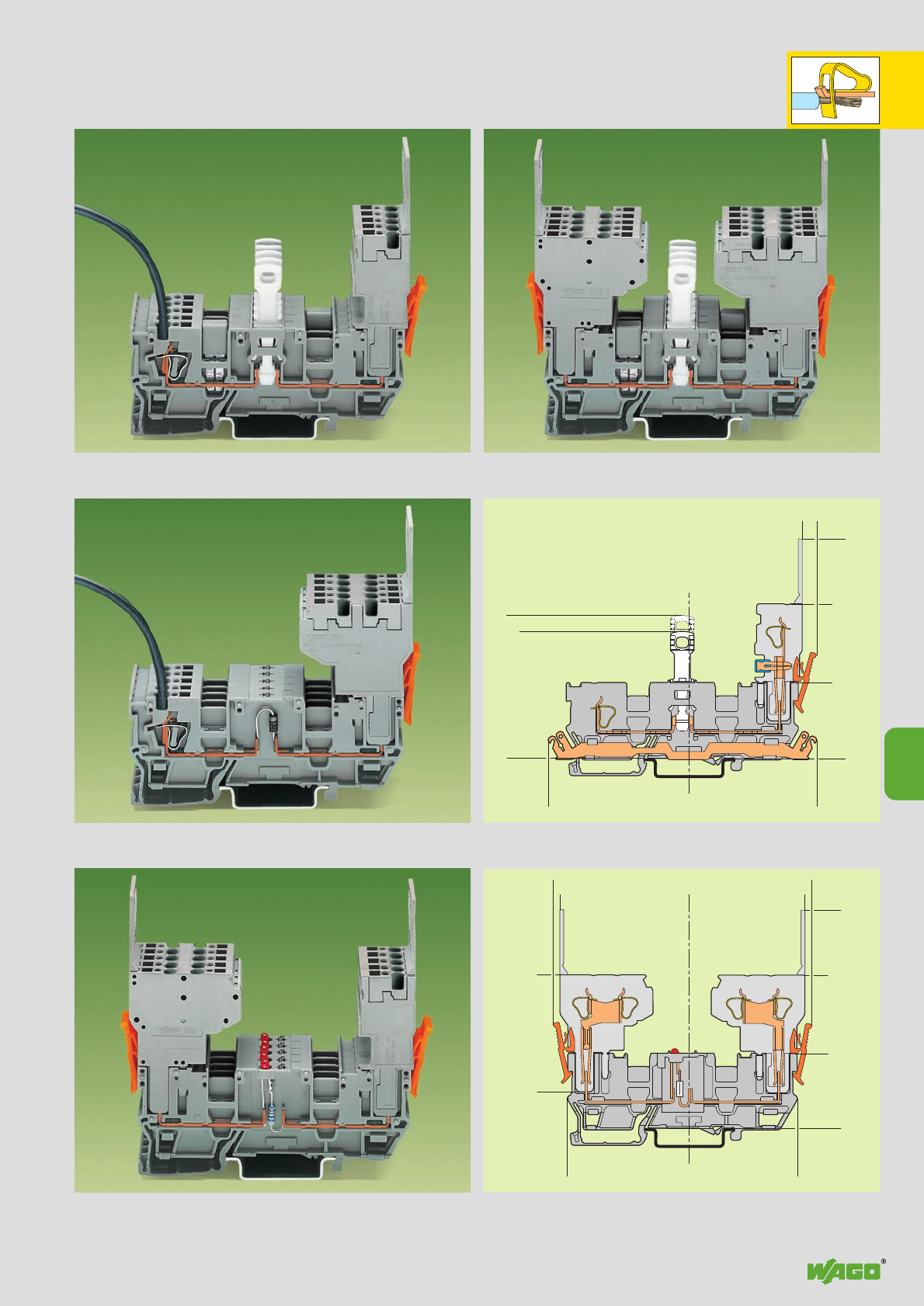
,
9
27
<_____________________83,5____________________>
<__
>5,5
<___________________________101 ___________________________>
<___________48___________>
<_____________54_____________>
<____28,5____>
<_____________53____________>
<_____30_____>
<________________________99 ________________________>
<__________45,2__________>
<_________44,5 __________>
<____________49,5 ____________> <__
__>
2,5 2,5
<__________46__________>
<_______________________87,5_____________________>
<____________________83,5_____________________>
<______30_____>
<____28,5____>
➌
➍
9
Types of Assembly
1-Conductor/1-Pin and 2-Pin Receptacle Terminal Blocks
with 2 Jumper Positions and 1-/2-Conductor Female Plugs
2-conductor female plug Commoning possibility of disconnect receptacle
terminal blocks with jumper contact systems, series 280 and 780,
and testing possibility with test plug adapter 280-4 . .
2-conductor female plug, left Commoning possibility of LED receptacle term.
1-conductor female plug, right bl. w. jumper contact systems, series 280 and 780,
Vice versa possible too and testing possibility w. test plug adapter 280-4 . .
2-conductor female plug, left Commoning possibility of disconnect
2-conductor female plug, right receptacle terminal blocks with jumper
contact systems, series 280 and 780
Disconnect receptacle terminal block with shield (screen) contact
➌ Please see also page 9.17 for further dimensions.
LED receptacle terminal block
➍ Please see also page 9.19 for further dimensions
1-conductor female plug Commoning possibility of disconnect receptacle
terminal block with jumper contact systems, series 280 and 780,
and testing possibility with test plug adapter 280-4 . .
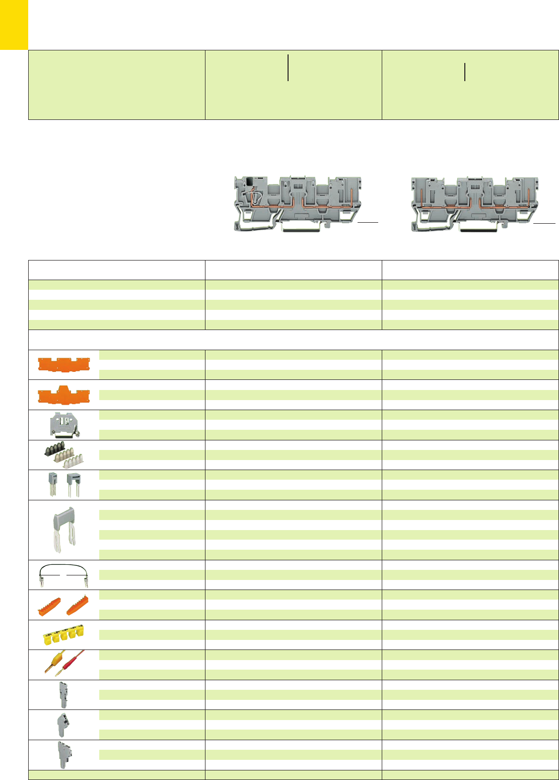
9
28
L
*U2fJ{ *U2fJ{
* For further approvals with corresponding ratings see section 15. **16 A, temperature limit of 85°C
Description Item Pack. unit
No. pcs Item Pack. unit
No. pcs
<__ 46 mm /1.81 in __>
<____________ 87.5 mm /3.44 in ____________>
X-COM®-SYSTEM
Receptacle Terminal Blocks with 2 Jumper Positions Used
for Pluggable Modules, Series 280 and 281
➊400 V = rated voltage
6 kV = rated surge voltage
3 = pollution degree
(see also section 15)
➋See application notes on pages 2.43 – 2.45
End and
intermediate plate
Separator plate,
oversized
Screwless
end stop
Insulation stop ➋,white
5 pcs/strip light grey
dark grey
Adjacent jumper, IN24 A
insulated
Alternate jumper
Staggered jumper
➋,from 1 to 2
insulated, from 1 to 3
width 5 mm /0.197 in from 1 to 4
from 1 to 5
:
from 1 to 8
Push-in type wire jumper ➋,
insulated, 9 A – conductor
cross section 0.75 mm2/AWG 18
Coding pin,
for coding of female plugs
Protective warning marker,
for 5 terminal blocks,
fits into screwdriver slot
Test plug, w. cable 500 mm/1’7.7’’
2 mm /0.079 in Ø
2.3 mm /0.091 in Ø
1-conductor female plug,
straight
1-conductor female plug,
angled
2-conductor female plug
1.1 mm /0.043 in thick
grey 769-309 100 (4 x 25)
orange 769-310 100 (4 x 25)
1.1 mm /0.043 in thick
orange 769-313 100 (4 x 25)
6 mm /0.236 in wide
249-116 100 (4 x 25)
10 mm /0.394 in wide
249-117 50 (2 x 25)
grey 280-402 200 (8 x 25)
grey 280-409 100 (4 x 25)
IN24 A 780-452 100 (4 x 25)
780-453 100 (4 x 25)
780-454 100 (4 x 25)
780-455 50 (2 x 25)
:
780-458 50 (2 x 25)
L = 60 mm /2.362 in
249-125 10
L = 110 mm /4.331 in
249-126 10
L = 250 mm /9.843 in
249-127 10
orange 769-435 100 (4 x 25)
yellow 210-137 50 (5 x 10)
see page 9.44
see page 9.46
cannot be used
1.1 mm /0.043 in thick
grey 769-311 100 (4 x 25)
orange 769-312 100 (4 x 25)
1.1 mm /0.043 in thick
orange 769-314 100 (4 x 25)
6 mm /0.236 in wide
249-116 100 (4 x 25)
10 mm /0.394 in wide
249-117 50 (2 x 25)
0.08 – 0.2 mm2769-470 200 strips
0.25 – 0.5 mm2769-471 200 strips
0.75 – 1 mm2769-472 200 strips
grey 280-402 200 (8 x 25)
grey 280-409 100 (4 x 25)
IN24 A 780-452 100 (4 x 25)
780-453 100 (4 x 25)
780-454 100 (4 x 25)
780-455 50 (2 x 25)
:
780-458 50 (2 x 25)
L = 60 mm /2.362 in
249-125 10
L = 110 mm /4.331 in
249-126 10
L = 250 mm /9.843 in
249-127 10
orange 769-435 100 (4 x 25)
yellow 280-415 100 (4 x 25)
red 210-136 50 (5 x 10)
yellow 210-137 50 (5 x 10)
see page 9.44
see page 9.46
cannot be used
2-pin receptacle terminal block, grey
2 poles 769-161 50
1-conductor/1-pin receptacle terminal block, grey
2 poles 769-181 50
1-conductor/1-pin receptacle terminal block
and
2-pin receptacle terminal block,
suitable for DIN 35 rail acc. to EN 60715
<28.5 mm / >
1.12 in
<__ 46 mm /1.81 in __>
<____________ 87.5 mm /3.44 in ____________>
<28.5 mm / >
1.12 in
Accessories Appropriate marking system Mini-WSB (see section 14)
0.08 – 4 mm2AWG 28 – 12
400 V/6 kV/3 ➊300/600 V, 10/5 A U
16 A** 300 V, 10 A 2
Terminal block width 5 mm / 0.197 in
L8 – 9 mm / 0.33 in
400 V/6 kV/3 ➊300/600 V, 10/5 A U
16 A** 300 V, 10 A 2
Terminal block width 5 mm / 0.197 in
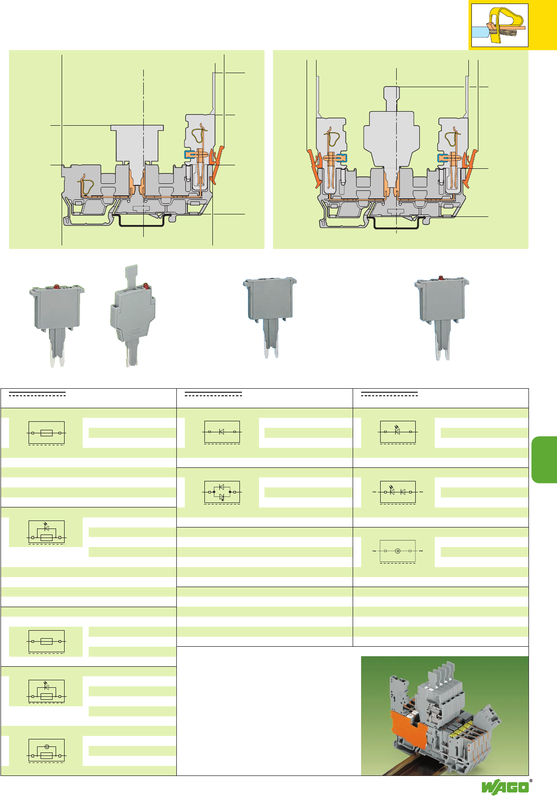
+–
–
+
+–
9
29
<___________46___________><____28,5____>
<________________________91 _____________________>
<__________43 __________>
5,5 5,5
<__
__>
<____22____>
<__________________________94,5__________________________>
<_________________________89_________________________>
<________________________87,5________________________>
<_______________________83,5______________________>
<____28,5____><_____30 _____>
<____________46____________>
9
Item Pack. unit
No. pcs
Item Pack. unit
No. pcs
Item Pack. unit
No. pcs
See also page 9.17 for dimensions See also page 9.19 for dimensions
Diode module, 5 mm /0.197 in wide,
Diode 1N 4007
280-801/281-411 100
Diode module, 5 mm /0.197 in wide,
Diode 1N 4007, as a recovery
diode, LED additionally
DC 24 V 280-801/281-420 100
DC 48 V 280-801/281-421 100
Electrical data are determined by the electronic components.
Types of Assembly with 1-Conductor Female Plugs
and Selection of Pluggable Modules (see also Full Line Catalog W4, Volume 3)
Open side of term. block
Fuse plug, 5 mm /0.197 in wide,
with soldered
miniature fuse
250 mA FF 280-850 100
500 mA FF 280-852 100
1 A FF 280-854 100
2 A FF 280-856 100
Fuse plug, 5 mm /0.197 in wide,
additionally with LED,
DC 15 – 30 V
250 mA FF 280-850/281-413 100
500 mA FF 280-852/281-413 100
1 A FF 280-854/281-413 100
2 A FF 280-856/281-413 100
Fuse plug with pull-tab, 6 mm /0.236 in wide,
for miniature metric fuse 5 x 20 mm and 5 x 25 mm
281-511 50
LED (self assembly)
281-512 50
Fuse plug with pull-tab, 6 mm /0.236 in wide,
additionally with LED
AC/DC 24 V
281-512/281-501 50
Use in both switching
directions
Neon lamps
AC/DC 120 V
281-512/281-418 50
AC/DC 230 V
281-512/281-417 50
Open side of term. block
Residual current in
case of defective fuse
LED 5 – 20 mA
Residual current in case of
defective fuse LED 5 – 20 mA,
neon lamp < 0.4 mA
LED modules, 5 mm /0.197 in wide,
with red LED
DC 24 V 280-801/281-413 100
DC 48 V 280-801/281-414 100
LED modules, 5 mm /0.197 in wide,
with red LED
AC/DC 24 V 280-801/281-415 100
AC/DC 48 V 280-801/281-416 100
Neon lamp modules,
5 mm /0.197 in wide,
AC/DC 120 V 280-801/281-418 100
AC/DC 230 V 280-801/281-417 100
Open side of term. block
Adjacent assembly of receptacle terminal
blocks for fuse plugs requires that the width
of the fuse plugs (6 mm/0.236 in) compared
to that of the terminal blocks (5 mm/0.197 in)
be compensated for by using intermediate
plates (1.1 mm/0.043 in).
The use of intermediate plates requires adja-
cent jumpers from series 280 to be used
when commoning adjacent terminal blocks.
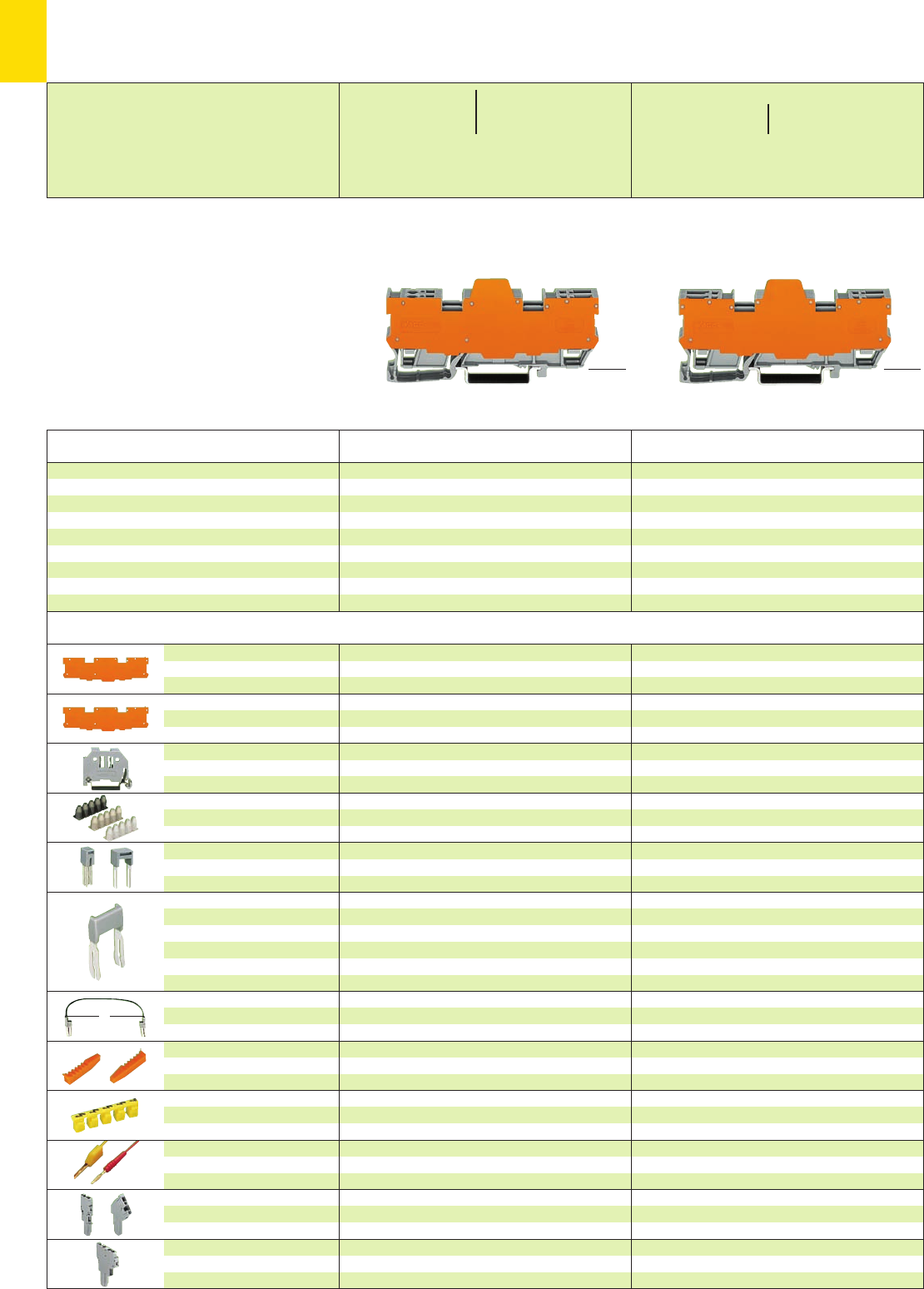
9
30
L
*U2 *U2fJ{
<28.5 mm / >
1.12 in
<28.5 mm />
1.12 in
Description Item Pack. unit
No. pcs Item Pack. unit
No. pcs
<__ 46 mm /1.81 in __>
<____________ 87.5 mm /3.44 in ____________> <__ 46 mm /1.81 in __>
<____________ 87.5 mm /3.44 in ____________>
X-COM®-SYSTEM
Receptacle Terminal Blocks with 2 Jumper Positions
for Pluggable Modules, Series 286 (Relay Modules, Optocoupler Modules etc.)
➊400 V = rated voltage
6 kV = rated surge voltage
3 = pollution degree
(see also section 15)
➋See application notes on pages 2.43 – 2.45
End and
intermediate plate
Separator plate,
oversized
Screwless
end stop
Insulation stop ➋,white
5 pcs/strip light grey
dark grey
Adjacent jumper, IN24 A
insulated
Alternate jumper
Staggered jumper
➋,from 1 to 2
insulated, from 1 to 3
width 5 mm /0.197 in from 1 to 4
from 1 to 5
:
from 1 to 8
Push-in type wire jumper ➋,
insulated, 9 A – conductor
cross section 0.75 mm2/AWG 18
Coding pin,
for coding of female plugs
Protective warning marker,
for 5 terminal blocks,
fits into screwdriver slot
Test plug, w. cable 500 mm/1’7.7’’
2 mm /0.079 in Ø
2.3 mm /0.091 in Ø
1-conductor female plug,
straight or angled
2-conductor female plug
1.1 mm /0.043 in thick
grey 769-309 100 (4 x 25)
orange 769-310 100 (4 x 25)
1.1 mm /0.043 in thick
orange 769-313 100 (4 x 25)
6 mm /0.236 in wide
249-116 100 (4 x 25)
10 mm /0.394 in wide
249-117 50 (2 x 25)
grey 280-402 200 (8 x 25)
grey 280-409 100 (4 x 25)
IN24 A 780-452 100 (4 x 25)
780-453 100 (4 x 25)
780-454 100 (4 x 25)
780-455 50 (2 x 25)
:
780-458 50 (2 x 25)
L = 60 mm /2.362 in
249-125 10
L = 110 mm /4.331 in
249-126 10
L = 250 mm /9.843 in
249-127 10
orange 769-435 100 (4 x 25)
yellow 210-137 50 (5 x 10)
see pages 9.44/9.46
cannot be used
1.1 mm /0.043 in thick
grey 769-311 100 (4 x 25)
orange 769-312 100 (4 x 25)
1.1 mm /0.043 in thick
orange 769-314 100 (4 x 25)
6 mm /0.236 in wide
249-116 100 (4 x 25)
10 mm /0.394 in wide
249-117 50 (2 x 25)
0.08 – 0.2 mm2769-470 200 strips
0.25 – 0.5 mm2769-471 200 strips
0.75 – 1 mm2769-472 200 strips
grey 280-402 200 (8 x 25)
grey 280-409 100 (4 x 25)
IN24 A 780-452 100 (4 x 25)
780-453 100 (4 x 25)
780-454 100 (4 x 25)
780-455 50 (2 x 25)
:
780-458 50 (2 x 25)
L = 60 mm /2.362 in
249-125 10
L = 110 mm /4.331 in
249-126 10
L = 250 mm /9.843 in
249-127 10
orange 769-435 100 (4 x 25)
yellow 280-415 100 (4 x 25)
red 210-136 50 (5 x 10)
yellow 210-137 50 (5 x 10)
see pages 9.44/9.46
cannot be used
2-pin receptacle terminal blocks, grey
with orange separator plate
4 poles 769-162/769-313 10
6 poles 769-163/769-313 5
8 poles 769-164/769-313 5
10 poles 769-165/769-313 5
1-cond./1-pin receptacle terminal blocks, grey
with orange separator plate
4 poles 769-182/769-314 10
6 poles 769-183/769-314 5
8 poles 769-184/769-314 5
10 poles 769-185/769-314 5
1-conductor /1-pin receptacle terminal block
and width
2-pin receptacle terminal block, 11.1 mm
suitable for DIN 35 rail acc. to EN 60715 16.1 mm
21.1 mm
26.1 mm
Accessories Appropriate marking system Mini-WSB (see section 14)
* For further approvals with corresponding ratings see section 15. **16 A, temperature limit of 85°C
0.08 – 4 mm2AWG 28 – 12
400 V/6 kV/3 ➊300/600 V, 10/5 A U
16 A** 300 V, 10 A 2
Terminal block width 5 mm / 0.197 in
L8 – 9 mm / 0.33 in
400 V/6 kV/3 ➊300/600 V, 10/5 A U
16 A** 300 V, 10 A 2
Terminal block width 5 mm / 0.197 in
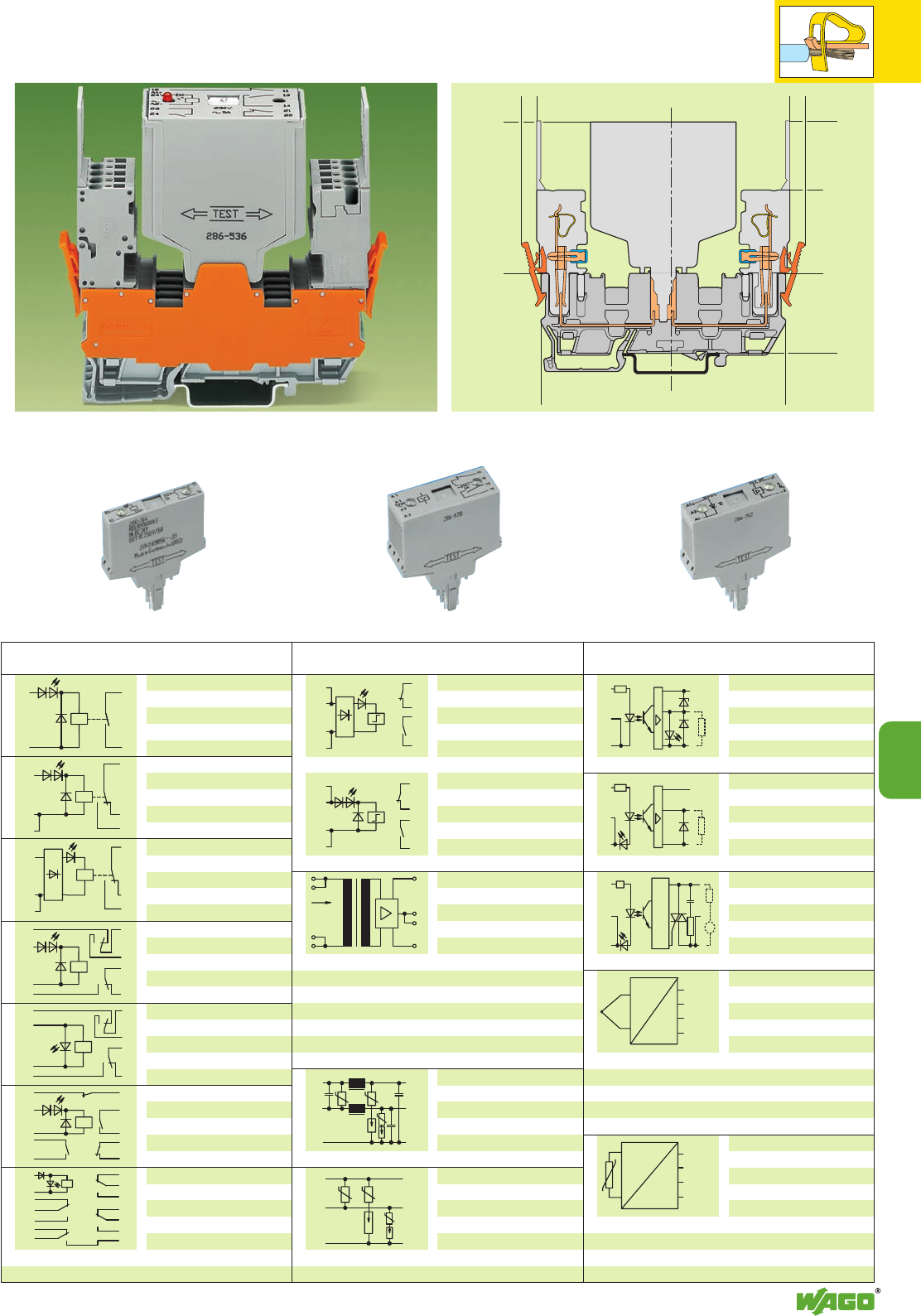
U, I
+24V
OUT
ERROR
0V
R
L
1
+
3
2
–
A1
+
A2
–
A2
–
R
L
1
+
3
2
–
A1
+
A2
–
A2
–
U, I
+UB
OUT
ERROR
0V
~
R
L
1
2
2
A1
+
A2
–
A2
–
~
~
~
LIN
N
PE
LOUT
N
PE
A1
~
A2
~
A1
~
A2
~
14
12
13
11
A1
+
A2
–
14
13
12
11
A2
–
A1
+
LIN
N
PE
LOUT
N
PE
I
+24V
0V
AC
Lout
Lin
13
14
A1
+
A2
–
14
21
22
11
24
12
A1
~
A2
~
A1
+
A2
–
14
21
22
11
24
12
14
12
11
A1
~
A2
~
A2
~
14
12
11
A2
–
A1
+
A2
–
23
24
14
21
22
13
12 11
A1
+
A2
–
A1
+
A2
–
12
11
14
44
22
21
24
42
41
32
31
34
9
31
<_____________52_____________>
<____28,5____><_____30_____>
<_____________________83,5___________________>
<________________________91 _____________________>
<__________43 __________>
5,5 5,5
<__
__>
<_______________________87,5____________________>
<__________46__________>
9
Electrical data are determined by the electronic components.
See also pages 9.17 and 9.19 for dimensions
Item Pack. unit
No. pcs Item Pack. unit
No. pcs Item Pack. unit
No. pcs
Optocoupler module
Input 24 V DC,
Output 24 V DC /500 mA
286-752 1
Module width 15 mm
Optocoupler module
Input 24 V DC,
Output 24 V DC /4 A
286-723 1
Module width 15 mm
Optocoupler module
Input 24 V DC,
Output 230 V AC /50 mA-1A
286-734 1
Module width 15 mm
Temperature transduce
modules with wire break
controlling (4-20 mA),
Thermocouple J: 0-750 °C
286-867 1
Thermocouple K: 0-1000 °C
286-868 1
Module width 20 mm
Temperature transducer
modules
from –30 °C to +150 °C (PT 100)
286-862/150-030 1
from 0°C to + 300 °C (PT 100)
286-862/000-300 1
for PT 100 and
from 0°C to + 100 °C (PT 1000)
PT 1000 elements 286-875 1
Module width 20 mm
Pulse relay modules,
286-570 230 V AC 1
286-571 24 V DC 1
1 break contact,
1 make contact
Module width 20 mm
Current flow
monitoring module
24 V AC
80 mA – 6 A
286-661 1
Module width 20 mm
Transient suppression
module
230 V DC ± 10 %
286-842 1
Module width 25 mm
Transient suppression
module
230 V AC
286-835 1
Module width 15 mm
completely with special
receptacle terminal block
Out--
put
Zero Volt switch
Switching relay module
286-364 1
24 V DC,
1 make contact
Module width 10 mm
Switching relay module
286-304 1
24 V DC,
1 change-over contact
Module width 15 mm
Switching relay module
286-508 1
230 V AC/DC,
1 change-over contact
Module width 15 mm
Switching relay module
286-312 1
24 V DC,
2 change-over contacts
Module width 20 mm
Switching relay module
286-516 1
230 V AC,
2 change-over contacts
Module width 20 mm
Switching relay module
286-336 1
24 V DC, 2 break contacts
and 2 make contacts
Module width 25 mm
Switching relay module
286-375
24 V DC
1
286-578
110/120 V AC
1
286-579
230 V AC
1
4 change-over contacts
Module width 35 mm
Types of Assembly with 1-Conductor Female Plugs
and Selection of Pluggable Modules (see also Full Line Catalog W4, Volume 3)
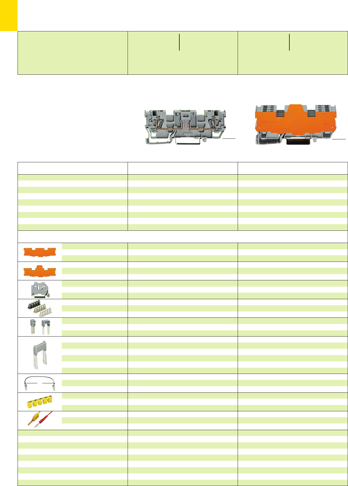
9
32
L
*U2 *U2
* For further approvals with corresponding ratings see section 15. **16 A, temperature limit of 85°C
Description Item Pack. unit
No. pcs Item Pack. unit
No. pcs
<__ 46 mm /1.81 in __>
<____________ 87.5 mm /3.44 in ____________>
X-COM®-SYSTEM
1-Conductor/1-Conductor Receptacle Terminal Blocks with 2 Jumper Positions
for Pluggable Modules (Fuse Plugs, Relay Modules, Optocoupler Modules etc.)
➊400 V = rated voltage
6 kV = rated surge voltage
3 = pollution degree
(see also section 15)
➋See application notes on pages 2.43 – 2.45
End and
intermediate plate
Separator plate,
oversized
Screwless
end stop
Insulation stop ➋,white
5 pcs/strip light grey
dark grey
Adjacent jumper, IN24 A
insulated
Alternate jumper
Staggered jumper
➋,from 1 to 2
insulated, from 1 to 3
width 5 mm /0.197 in from 1 to 4
from 1 to 5
:
from 1 to 8
Push-in type wire jumper ➋,
insulated, 9 A – conductor
cross section 0.75 mm2/AWG 18
Protective warning marker,
for 5 terminal blocks,
fits into screwdriver slot
Test plug, w. cable 500 mm/1’7.7’’
2 mm /0.079 in Ø
2.3 mm /0.091 in Ø
1.1 mm /0.043 in thick
grey 769-317 100 (4 x 25)
orange 769-318 100 (4 x 25)
1.1 mm /0.043 in thick
orange 769-319 100 (4 x 25)
6 mm /0.236 in wide
249-116 100 (4 x 25)
10 mm /0.394 in wide
249-117 50 (2 x 25)
0.08 – 0.2 mm2769-470 200 strips
0.25 – 0.5 mm2769-471 200 strips
0.75 – 1 mm2769-472 200 strips
grey 280-402 200 (8 x 25)
grey 280-409 100 (4 x 25)
IN24 A 780-452 100 (4 x 25)
780-453 100 (4 x 25)
780-454 100 (4 x 25)
780-455 50 (2 x 25)
:
780-458 50 (2 x 25)
L = 60 mm /2.362 in
249-125 10
L = 110 mm /4.331 in
249-126 10
L = 250 mm /9.843 in
249-127 10
yellow 280-415 100 (4 x 25)
red 210-136 50 (5 x 10)
yellow 210-137 50 (5 x 10)
1.1 mm /0.043 in thick
grey 769-317 100 (4 x 25)
orange 769-318 100 (4 x 25)
1.1 mm /0.043 in thick
orange 769-319 100 (4 x 25)
6 mm /0.236 in wide
249-116 100 (4 x 25)
10 mm /0.394 in wide
249-117 50 (2 x 25)
0.08 – 0.2 mm2769-470 200 strips
0.25 – 0.5 mm2769-471 200 strips
0.75 – 1 mm2769-472 200 strips
grey 280-402 200 (8 x 25)
grey 280-409 100 (4 x 25)
IN24 A 780-452 100 (4 x 25)
780-453 100 (4 x 25)
780-454 100 (4 x 25)
780-455 50 (2 x 25)
:
780-458 50 (2 x 25)
L = 60 mm /2.362 in
249-125 10
L = 110 mm /4.331 in
249-126 10
L = 250 mm /9.843 in
249-127 10
yellow 280-415 100 (4 x 25)
red 210-136 50 (5 x 10)
yellow 210-137 50 (5 x 10)
1-conductor/1-conductor receptacle terminal
blocks for pluggable modules, grey
with orange separator plate
4 poles, 11.1 mm 769-192/769-319 10
6 poles, 16.1 mm 769-193/769-319 5
8 poles, 21.1 mm 769-194/769-319 5
10 poles, 26.1 mm 769-195/769-319 5
1-conductor/1-conductor receptacle terminal
block, grey
2 poles 769-191 50
1-conductor/1-conductor receptacle terminal block
and
1-conductor/1-conductor receptacle terminal block
for pluggable modules,
suitable for DIN 35 rail acc. to EN 60715
<28.5 mm / >
1.12 in
<__ 46 mm /1.81 in __>
<____________ 87.5mm/3.44in ____________>
<28.5 mm / >
1.12 in
Accessories Appropriate marking system Mini-WSB (see section 14)
0.08 – 4 mm2AWG 28 – 12
400 V/6 kV/3 ➊300/600 V, 10/5 A U
16 A** 300 V, 10 A 2
Terminal block width 5 mm / 0.197 in
L8 – 9 mm / 0.33 in
0.08 – 4 mm2AWG 28 – 12
400 V/6 kV/3 ➊300/600 V, 10/5 A U
16 A** 300 V, 10 A 2
Terminal block width 5 mm / 0.197 in
L8 – 9 mm / 0.33 in
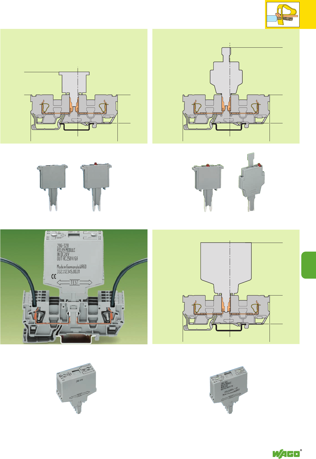
<________________________87,5________________________>
<____28,5____>
<____________46____________>
<___________46___________>
<____22____>
<________________________87,5________________________>
<____28,5____>
<____________46____________>
<________________________87,5________________________>
<____28,5____>
<____________46____________>
<___________83,5____________>
9
33
9
Electrical data are determined by the electronic components.
Types of Assembly with
Selection of Pluggable Modules (see also Full Line Catalog W4, Volume 3)
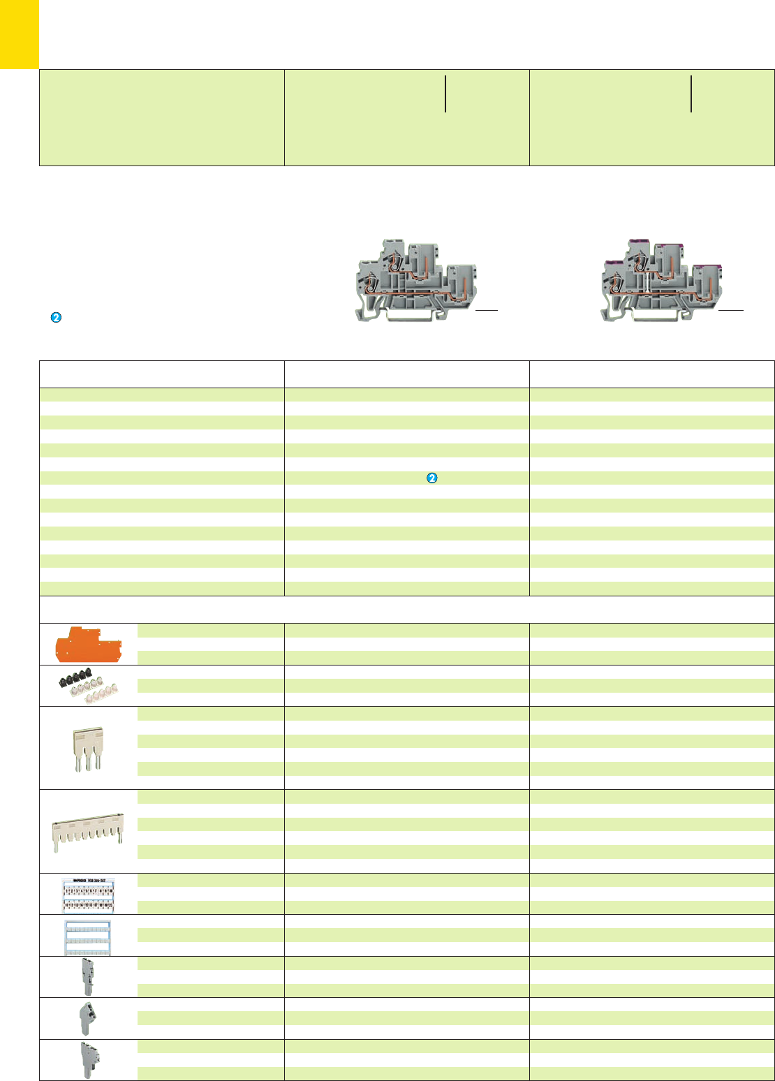
9
34
*YfJ:{ *YfJ:{
You can find double deck terminal blocks of series 870
in section 3
End and
intermediate plate
Insulation stop ➌, white
5 pcs/strip light grey
dark grey
Push-in type jumper bars,
light grey, insulated,
IN18 A
Push-in type jumper bars,
light grey, insulated,
IN18 A
WAGO WMB multi-marking
system, fits in all miniature WSB
receptacles
Miniature WSB quick marking
card, 10 strips with 10 markers
each, white with black printing
1-connector female plug,
straight
1-connector female plug,
angled
2-connector female plug
1 mm /0.039 in thick
grey 870-118 100 (4 x 25)
orange 870-119 100 (4 x 25)
0.08 – 0.2 mm2280-470 200 strips
0.25 – 0.5 mm2280-471 200 strips
0.75 – 1 mm2280-472 200 strips
2-way 870-402 200 (8 x 25)
3-way 870-403 200 (8 x 25)
4-way 870-404 200 (8 x 25)
5-way 870-405 100 (4 x 25)
::
10-way 870-410 100 (4 x 25)
from 1 to 3 870-433 200 (8 x 25)
from 1 to 4 870-434 200 (8 x 25)
from 1 to 5 870-435 100 (4 x 25)
::
from 1 to 10 870-440 100 (4 x 25)
see section 14
see section 14
see page 9.44
see page 9.46
cannot be used
* For further approvals with corresponding ratings see section 15.
Description
1-cond./1-pin double deck receptacle terminal block,
suitable for DIN 35 rail Printing 1st lev. 2nd lev.
––
blue –
– blue
––
Item Pack. unit
No. pcs
Through/through terminal blocks,
housing color grey
L/L 870-101 50
N/L 870-102 50
L/N 870-103 50
housing color blue
N/N 870-104 50
2-conductor/2-pin through terminal block,
internal commoning, housing color grey,
conductor entry position colored in violet
L870-108 50
2-conductor/2-pin through terminal block,
internal commoning, housing color blue,
conductor entry position colored in violet
N870-109 50
Item Pack. unit
No. pcs
X-COM®-SYSTEM
1-Conductor/1-Pin Double Deck Receptacle Terminal Blocks
Series 870
➊500 V = rated voltage
6 kV = rated surge voltage
3 = pollution degree
(see also section 15)
Suitable for Ex i applications
➌See application notes
on page 2.43 <____ 70 mm /2.76 in ____> <____ 70 mm /2.76 in ____>
Accessories Appropriate marking system WMB/Mini-WSB (see section 14)
<__ 40 mm /__>
1.57 in
<__ 40 mm / __>
1.57 in
0.08
–2.5 mm
2
/4 mm
2
“f -st”
AWG 28 – 12
500 V/6 kV/3 ➊300/600 V,
16 A 20/5 A
Terminal block width 5 mm / 0.197 in
L6 – 7 mm / 0.26 in
0.08
–2.5 mm
2
/4 mm
2
“f -st”
AWG 28 – 12
500 V/6 kV/3 ➊300/600 V,
16 A 20/5 A
Terminal block width 5 mm / 0.197 in
L6 – 7 mm / 0.26 in
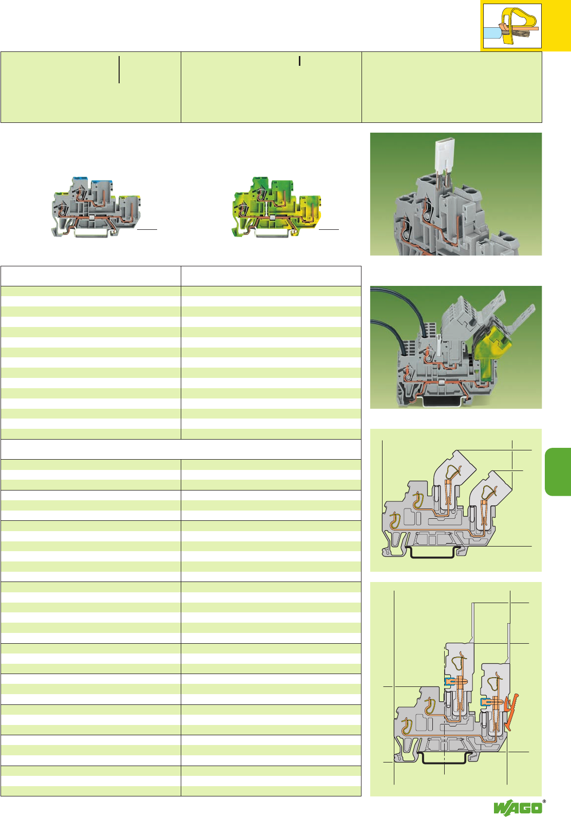
9
35
<___25____>
<______________67,1_______________>
<_______________69,6________________>
<____30,9_____>
<________39,9_________>
<________________71, 4 _______________>
<__________________80,4__________________>
<_________46,9_________>
<_____________59,4_____________>
9
*YfJ:{
*YfJ:{
Types of assembly
1 mm /0.039 in thick
grey 870-118 100 (4 x 25)
orange 870-119 100 (4 x 25)
0.08 – 0.2 mm2280-470 200 strips
0.25 – 0.5 mm2280-471 200 strips
0.75 – 1 mm2280-472 200 strips
2-way 870-402 200 (8 x 25)
3-way 870-403 200 (8 x 25)
4-way 870-404 200 (8 x 25)
5-way 870-405 100 (4 x 25)
::
10-way 870-410 100 (4 x 25)
from 1 to 3 870-433 200 (8 x 25)
from 1 to 4 870-434 200 (8 x 25)
from 1 to 5 870-435 100 (4 x 25)
::
from 1 to 10 870-440 100 (4 x 25)
see section 14
see section 14
see page 9.44
see page 9.46
cannot be used
Item Pack. unit
No. pcs
Ground (earth) conductor/through terminal blocks,
housing color grey
PE /N 870-117 50
PE /L 870-127 50
2-conductor/2-pin ground (earth) conductor
terminal block,
internal commoning, housing color green-yellow
PE 870-107 50
Item Pack. unit
No. pcs
<_____ 70 mm /2.76 in _____> <_____ 70 mm /2.76 in _____>
<__ 40 mm / __>
1.57 in
<__ 40 mm / __>
1.57 in
Using a push-in type jumper bar with double deck
terminal block 870-501 and 1-conductor/1-pin double
deck terminal block 870-101
Appropriate marking system WMB/Mini-WSB (see section 14)
0.08
–2.5 mm
2
/4 mm
2
“f -st”
AWG 28 – 12
500 V/6 kV/3 ➊300/600 V,
16 A 20/5 A
Terminal block width 5 mm / 0.197 in
L6 – 7 mm / 0.26 in
0.08
–2.5 mm
2
/4 mm
2
“f -st”
AWG 28 – 12
Terminal block width 5 mm / 0.197 in
L6 – 7 mm / 0.26 in
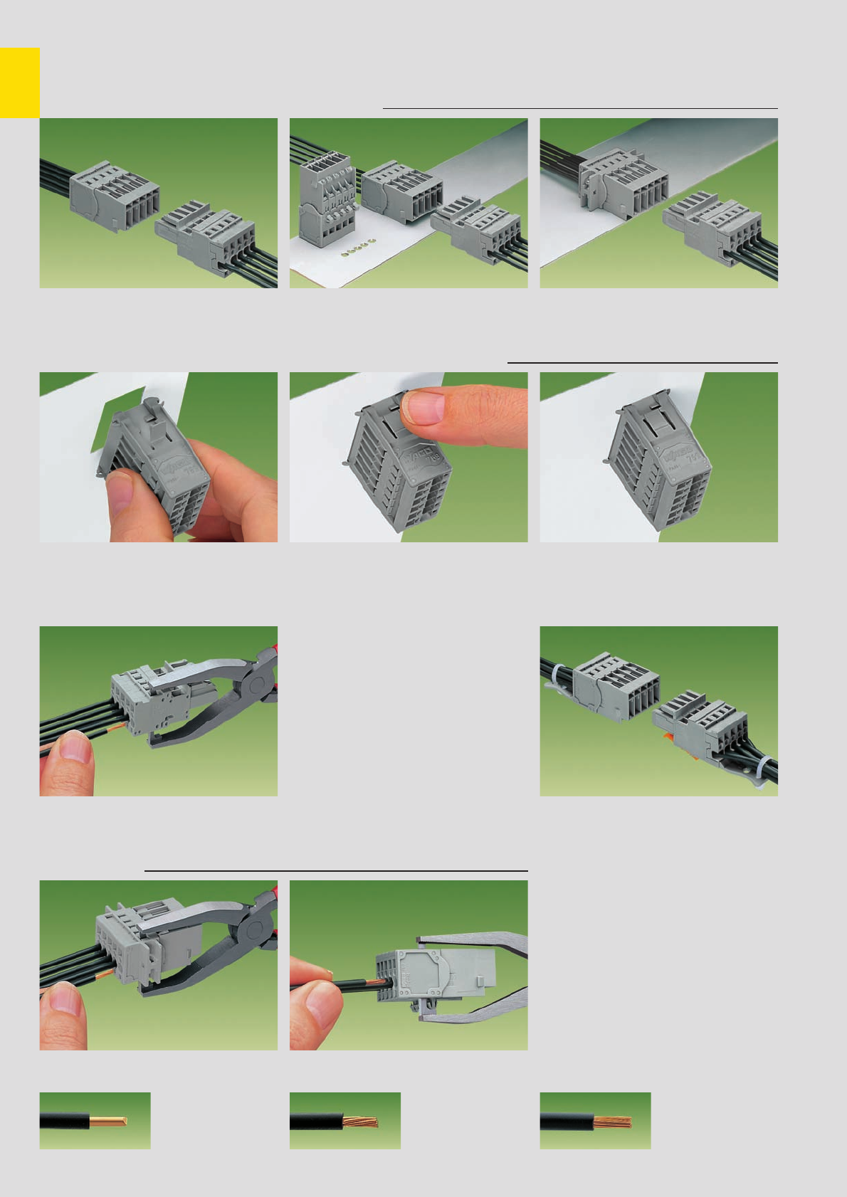
,
9
36
➀
➁
➀
➁
➀
➁
➀
CAGE CLAMP®
connects the following
copper wires: *
solid stranded
fine stranded,
also with tinned
single strands
Connection of the conductor with operating tool
Item No. 210-490 Connection of the conductor with operating tool
(which can also be used with male connectors with
CAGE CLAMP®connection and mounting feet)
* For aluminum wire see notes in section 15!
X-COM®-SYSTEM Male Connectors, Headers and Female Plugs
Series 769 . . .
Male connectors with CAGE CLAMP®connection
➀Male connector with CAGE CLAMP®connection
➁1-conductor female plug
Snap-in mounting without tools:
Male connectors with snap-in flanges
Operating tool
➀Male connector with CAGE CLAMP®connection
and mounting feet
➁1-conductor female plug
➀Male connector with CAGE CLAMP®connection
and fixing flanges
➁1-conductor female plug
Strain relief plates, can be snapped in male
connectors with CAGE CLAMP®connection
1 pole 769-410 100 (4 x 25)
2 to 3 poles 769-411 100 (4 x 25)
4 to 5 poles 769-412 100 (4 x 25)
6 to 9 poles 769-413 100 (4 x 25)
10 to 15 poles 769-414 100 (4 x 25)
Strain relief plates
Connection of the conductor – lateral wiring
with operating tool
Male connectors with CAGE CLAMP®connection and snap-in flanges
Operating tool
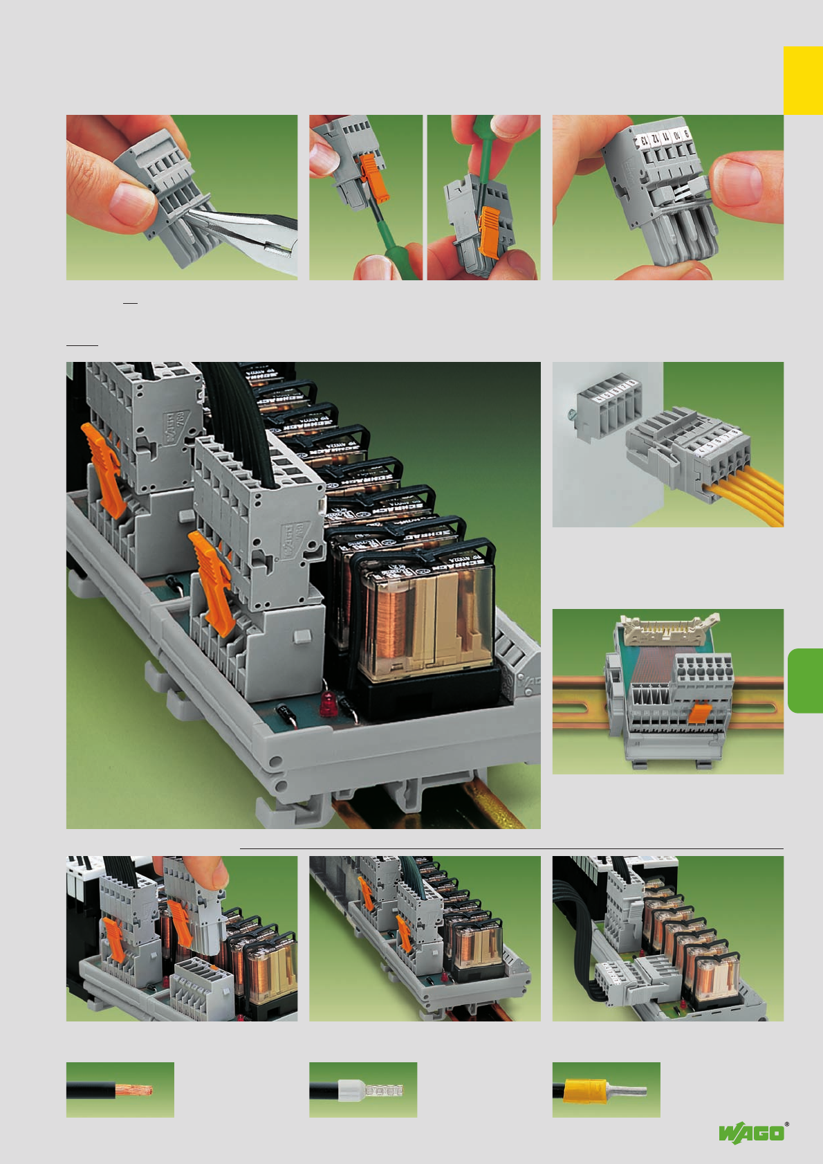
,
9
37
➀
➁
9
Example of application using a relay module
➀Headers with straight solder pins
➁1-conductor female plugs
Headers with solder pins:
Integration of PCB sub-assemblies into
the system wiring
Headers with solder pins for printed circuit boards
Note: Connectors used according to the regulations should not be connected or
disconnected under load. Connection of a female plug
Connection to a relay module inside the
switchgear cabinet
Header and 1-conductor female plug with lateral
locking levers
Coding
Coding a female plug – removal of coding
finger(s). Do not break off the first and last latch
position coding finger!
(see also page 9.8)
Commoning of 1-conductor female plugs with
miniature adjacent jumpers
CommonigLocking lever
Snapping in /removal of locking lever
Pluggable PCB connection
. . . Description and Handling
fine-stranded wire
with crimped pin terminal
fine-stranded wire
with crimped ferrule ➊
fine-stranded wire –
tip bonded
➊When using wires with ferrules, it is necessary to use a terminal block one size larger than the nominal cross section of the wire.

9
38
<_____40,2______>
<_22,2_>
<_18,3_>
>5
>
>
__>
3,7
<_____A_____>
<_____B_____>
__>
_)
_)
>
1,2
5__>
>
1,6
<_____40,2______>
<_22,2_>
<_18,3_>
>5
>
>
__>
3,7
(_14,8_) <_____A_____>
<_____B_____>
__>
_)
_)
>
1,2
5__>
>
1,6
__>
2,4 <
<__
<
4,5
<_22,2_>
<______40,2______>
<_18,3_>
(_ 15,6 _) 5
><
9,1 <>
<________C________>
5>
>
> <__
> <__
2,6
<_____A_____>
2,6
7, 8
2,5
<______B______>
__>
2,9
__>
2,9
>
__>
>
__>
><__24,6__>
7, 8 5,1
11,7
> <___28,5___>
*U2
*U2 *U2
Dimensions (in mm)
No. of Item Pack.-unit
poles No. pcs No. of Item Pack.-unit
poles No. pcs No. of Item Pack.-unit
poles No. pcs
X-COM®-SYSTEM
Male Connectors with CAGE CLAMP®Connection
Pin Spacing 5 mm / 0.197 in
Pin spacing 5 mm / 0.197 in, grey
0.08 – 4 mm2AWG 28 – 12
500 V/6 kV/3 300/600V, 10/5A U
32 A** 300 V, 10 A 2
L8 – 9 mm / 0.33 in
Pin spacing 5 mm / 0.197 in, grey
0.08 – 4 mm2AWG 28 – 12
500 V/6 kV/3 300/600V, 10/5A U
32 A** 300 V, 10 A 2
L8 – 9 mm / 0.33 in
Pin spacing 5 mm / 0.197 in, grey
0.08 – 4 mm2AWG 28 – 12
500 V/6 kV/3 300/600V, 10/5A U
32 A** 300 V, 10 A 2
L8 – 9 mm / 0.33 in
* For further approvals with corresponding ratings see section 15. ** See current-carrying capacity curve page 9.51 and www.wago.com
For female plugs
see pages 9.44 – 9.46
Code pin, orange,
for coding the female plugs
769-435 100 (4 x 25)
Operating tool
210-490 1
Fixing screw, M 2.5 x16
and hexagon nut M 2.5
769-499 100 (4 x 25)
Male connectors with CAGE CLAMP
®
connection and
snap-in mounting feet, f. plate thickness 0.6 – 1.2 mm,
fixing hole Ø 3.5 mm, w. mounting adapter 209-137
2769-602/001-000 100
3769-603/001-000 100
4769-604/001-000 100
5769-605/001-000 50
6769-606/001-000 50
7769-607/001-000 25
8769-608/001-000 25
9769-609/001-000 25
10 769-610/001-000 25
11 769-611/001-000 25
12 769-612/001-000 25
13 769-613/001-000 15
14 769-614/001-000 15
15 769-615/001-000 10
Male connectors with CAGE CLAMP®connection,
grey
2769-602 100
3769-603 100
4769-604 100
5769-605 50
6769-606 50
7769-607 25
8769-608 25
9769-609 25
10 769-610 25
11 769-611 25
12 769-612 25
13 769-613 15
14 769-614 15
15 769-615 10
Male connectors with CAGE CLAMP®connection
and fixing flanges, for screw or similar types of
fixing, for vertical or horizontal fixing, grey
2769-602/002-000 100
3769-603/002-000 50
4769-604/002-000 50
5769-605/002-000 50
6769-606/002-000 50
7769-607/002-000 25
8769-608/002-000 25
9769-609/002-000 25
10 769-610/002-000 25
11 769-611/002-000 25
12 769-612/002-000 25
13 769-613/002-000 15
14 769-614/002-000 10
15 769-615/002-000 10
Accessories Appropriate marking system Mini-WSB (see section 14)
For female plugs
see pages 9.44 – 9.46
Code pin, orange,
for coding the female plugs
769-435 100 (4 x 25)
Operating tool
210-490 1
Strain relief plate
see page 9.36
For female plugs
see pages 9.44 – 9.46
Code pin, orange,
for coding the female plugs
769-435 100 (4 x 25)
Operating tool
210-490 1
Mounting adapter for DIN 35
rail, width 6.5 mm
209-137 25
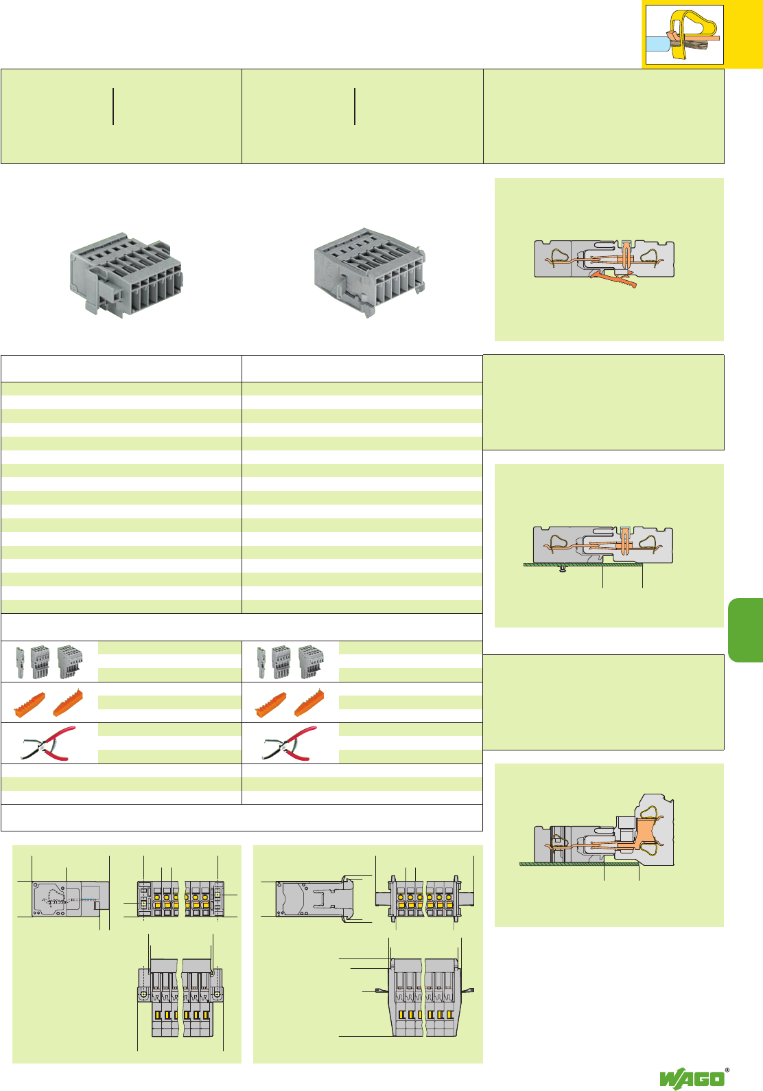
9
39
9
20*
<
<
<
<
17,5**
<_22,2_>
<______40,2______>
<_18,3_>
5
><
5>
>
<______L2______>
6,9><
11,4
><
<_____L1_____>
<_____L_____>
<________L3_______>
<_18,4_>
<_____A_____>
<__________D_________>
>
>
5
<______E______>
<_______F______>
<_23,4_>
<_____35,6_____>
<______40,8_____>
<_21,4 _>
<_24,4__>
*U2
Male connectors with
CAGE CLAMP®connection
Male connectors with
CAGE CLAMP®connection
and mounting feet
* Maximum dimensions when using 1-conductor female
plugs
Male connectors with
CAGE CLAMP®connection
and fixing flanges
** Maximum dimensions when using 2-conductor female
plugs
Male connectors with CAGE CLAMP®connection
for feedthrough applications, for screw or similar
types of fixing, for vertical or horizontal fixing, grey
2769-602/004-000 100
3769-603/004-000 50
4769-604/004-000 25
5769-605/004-000 25
6769-606/004-000 25
7769-607/004-000 25
8769-608/004-000 25
9769-609/004-000 25
10 769-610/004-000 25
11 769-611/004-000 25
12 769-612/004-000 15
13 769-613/004-000 15
14 769-614/004-000 10
15 769-615/004-000 10
A = No. of poles x pin spacing
B = A + 3.6 mm
C = A + 15.4 mm E = A + 4.9 mm
D = A + 21.3 mm F = A + 8.1 mm
L = (No. of poles - 1) x pin spacing + 6.2 mm
L 1 = L + 2.4 mm
L 2 = L + 7 mm
L 3 = L + 13.5 mm
Appropriate marking system Mini-WSB (see section 14)
For female plugs
see pages 9.44 – 9.46
Code pin, orange,
for coding the female plugs
769-435 100 (4 x 25)
Operating tool
210-490 1
No. of Item Pack.-unit
poles No. pcs
Pin spacing 5 mm / 0.197 in, grey
0.08 – 4 mm2AWG 28 – 12
500 V/6 kV/3
32 A**
L8 – 9 mm / 0.33 in
Male connectors with CAGE CLAMP®connection
and
snap-in flanges,
for mounting without tools
, grey
2769-602/005-000 50
3769-603/005-000 50
4769-604/005-000 25
5769-605/005-000 25
6769-606/005-000 25
7769-607/005-000 25
8769-608/005-000 20
9769-609/005-000 20
10 769-610/005-000 20
11 769-611/005-000 15
12 769-612/005-000 15
13 769-613/005-000 15
14 769-614/005-000 10
15 769-615/005-000 10
For female plugs
see pages 9.44 – 9.46
Code pin, orange,
for coding the female plugs
769-435 100 (4 x 25)
Operating tool
210-490 1
No. of Item Pack.-unit
poles No. pcs
Pin spacing 5 mm / 0.197 in, grey
0.08 – 4 mm2AWG 28 – 12
500 V/6 kV/3 300/600V, 10/5A U
32 A** 300 V, 10 A 2
L8 – 9 mm / 0.33 in
Cutout dimensions upon request/www.wago.com
Plate thickness
1 mm – 1.5 mm
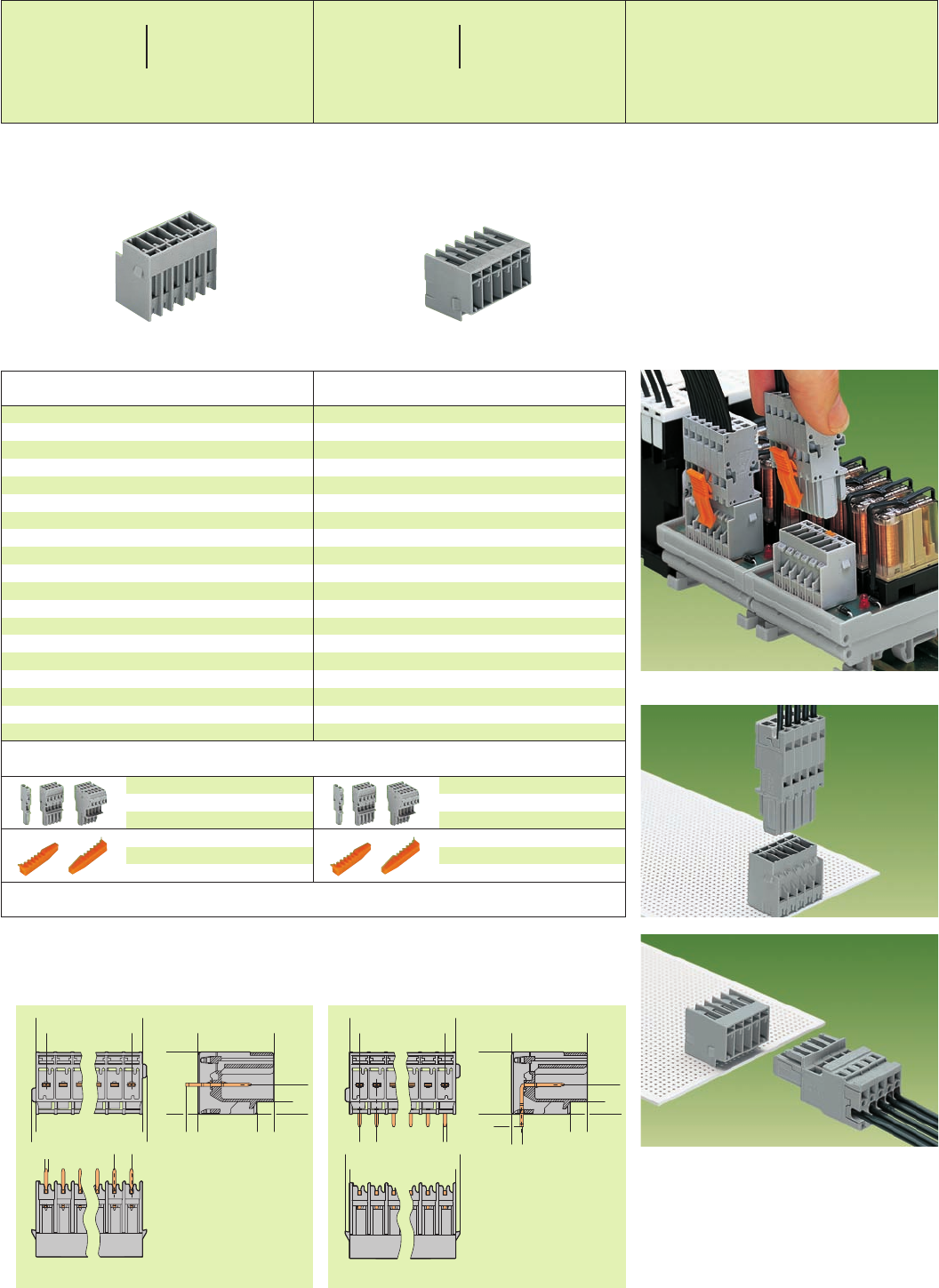
9
40
<___22,2___>
(_8,7 _)
<
3,7
__>
3,6
><__
<__18,3 __>
><_
3<
__>
3,2
<________L________>
><__
1,2
><__
1,2
<________L1________>
><__
1x1 5<
>
><5
><__
1,2
><__
1,2
<_________L1_________>
<___22,2___>
__> <
3,7
(_8,7 _)
><
3
><__
3,6
<__18,3 __>
<________L________>
><_
3<
__>
3,2
<
__>
1x1
><
5><5
*U2 *U2
Connection to a relay module inside the switchgear
cabinet
Accessories
Dimensions (in mm) Diameter of drilled hole: 1.4 +0.1mm
No. of Item Pack. unit
poles No. pcs No. of Item Pack. unit
poles No. pcs
For female plugs
see pages 9.44 – 9.46
Code pin, orange,
for coding the female plugs
769-435 100 (4 x 25)
For female plugs
see pages 9.44 – 9.46
Code pin, orange,
for coding the female plugs
769-435 100 (4 x 25)
X-COM®-SYSTEM
Headers with Solder Pins
Pin Spacing 5 mm / 0.197 in
* For further approvals with corresponding ratings see section 15. ** See current-carrying capacity curves page 9.50 and www.wago.com
Headers with straight solder pins, grey,
solder pin 1 x 1 mm
2769-632 200
3769-633 100
4769-634 50
5769-635 50
6769-636 50
7769-637 50
8769-638 25
9769-639 25
10 769-640 25
11 769-641 25
12 769-642 25
13 769-643 25
14 769-644 25
15 769-645 25
Headers with right angle solder pins, grey,
solder pin 1 x 1 mm
2769-662 200
3769-663 100
4769-664 50
5769-665 50
6769-666 50
7769-667 50
8769-668 25
9769-669 25
10 769-670 25
11 769-671 25
12 769-672 25
13 769-673 25
14 769-674 25
15 769-675 25
Pin spacing 5 mm / 0.197 in, grey
250 V/4 kV/3 300/600V, 10/5A U
500 V/4 kV/2 300 V, 10 A 2
32 A**
Pin spacing 5 mm / 0.197 in, grey
250 V/4 kV/3 300/600V, 10/5A U
500 V/4 kV/2 300 V, 10 A 2
32 A**
L = (No. of poles – 1) x pin spacing + 6.2 mm
L 1 = L + 2.4 mm
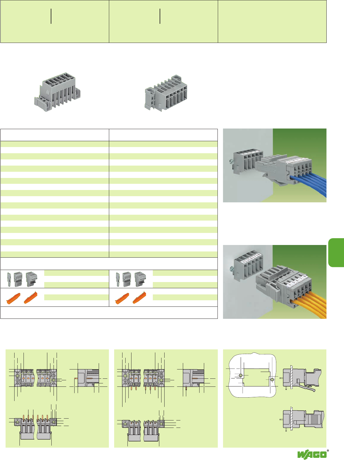
9
41
<
><
><
>
9,75
6,5
3
<
><
><
__>
9,95
6,5
3,2
>>
>
__>
2,8
6,9
<_ 18,3 _>
<__22,2__>
>
>
>
8,7
<_>3
(11,4 )
<______L______>
<_______L2_______>
<_________L3_________>
><
5
3
,
9
<__>
<______L1______>
><__
1,2 ><__
1,2
><__
2,8
<
>7,8
><__
5,1
<
___>
2,6
_) <__
2,6
____>
3,7
>(_5
<
<
7,1
< 15,5 >
<
>11,6
<___ L4 ___>
<_____ L5 _____>
<
<<____
<__
<
3,5
8,5
<_ 18,7 _>
<
3,2
<____ L6 ____>
10,5
<
<
><
9,75
><
><
6,5
3
><
9,95
><
><__
6,7
3,2
(11,4 )
<______L______>
<_______L2_______>
<_________L3_________>
><__
2,8
><__
6,9
<_18,3_>
><__
3,6
<
____>
3,7
8,7 <
>
<__22,2__>
<______L1______>
><
5><__
2,8
><
5,1
<
>7,8
><__
1,2
><__
1,2
3,9
<__ (___
_) 2,6
>
<
___>
2,6
>(_5
*U2 *U2
9
Header and 1-conductor female plug with locking levers
L = (No. of poles – 1) x pin spacing + 6.2 mm
L 1 = L + 2.4 mm
L 2 = L + 7 mm
L 3 = L + 13.5 mm
L 4 = No. of poles x pin spacing + 1.7 mm
L 5 = L 4 + 6.6 mm
L 6 = L 4 + 2.6 mm
Header and 1-conductor female plug with lateral
locking levers
Accessories
Dimensions (in mm) Diameter of drilled hole: 1.4 +0.1mm
No. of Item Pack. unit
poles No. pcs
Headers with Solder Pins and Fixing Flanges
Pin Spacing 5 mm/ 0.197 in
No. of Item Pack. unit
poles No. pcs
* For further approvals with corresponding ratings see section 15. ** See current-carrying capacity curves page 9.50 and www.wago.com
Headers with straight solder pins
with fixing flanges, grey,
solder pin 1 x 1 mm
2769-632/003-000 100
3769-633/003-000 100
4769-634/003-000 50
5769-635/003-000 50
6769-636/003-000 25
7769-637/003-000 25
8769-638/003-000 25
9769-639/003-000 25
10 769-640/003-000 25
11 769-641/003-000 25
12 769-642/003-000 25
13 769-643/003-000 15
14 769-644/003-000 15
15 769-645/003-000 15
Headers with right angle solder pins
with fixing flanges, grey,
solder pin 1 x 1 mm
2769-662/003-000 100
3769-663/003-000 100
4769-664/003-000 50
5769-665/003-000 50
6769-666/003-000 25
7769-667/003-000 25
8769-668/003-000 25
9769-669/003-000 25
10 769-670/003-000 25
11 769-671/003-000 25
12 769-672/003-000 25
13 769-673/003-000 15
14 769-674/003-000 15
15 769-675/003-000 15
For female plugs
see pages 9.44 – 9.46
Code pin, orange,
for coding the female plugs
769-435 100 (4 x 25)
For female plugs
see pages 9.44 – 9.46
Code pin, orange,
for coding the female plugs
769-435 100 (4 x 25)
Examples of application
Pin spacing 5 mm / 0.197 in, grey
250 V/4 kV/3 300/600V, 10/5A U
500 V/4 kV/2 300 V, 10 A 2
32 A**
Pin spacing 5 mm / 0.197 in, grey
250 V/4 kV/3 300/600V, 10/5A U
500 V/4 kV/2 300 V, 10 A 2
32 A**
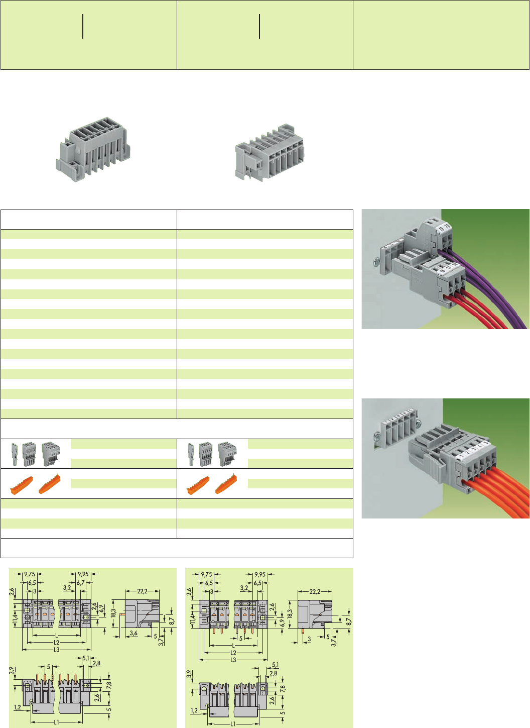
9
42
*U2 *U2
L = (No. of poles – 1) x pin spacing + 6.2 mm
L 1 = L + 2.4 mm
L 2 = L + 7 mm
L 3 = L + 13.5 mm
Header and 1-and 2-conductor female plugs
Header and 1-conductor female plug with lateral
locking levers
Accessories
Dimensions (in mm) Diameter of drilled hole: 1.4 +0.1mm
No. of Item Pack. unit
poles No. pcs
X-COM®-SYSTEM
Headers with Solder Pins and Fixing Flanges for Feedthrough Applications
Pin Spacing 5 mm / 0.197 in
No. of Item Pack. unit
poles No. pcs
Headers with right angle solder pins with fixing
flanges for feedthrough applications, grey,
solder pin 1 x 1 mm
2769-662/004-000 100
3769-663/004-000 100
4769-664/004-000 50
5769-665/004-000 50
6769-666/004-000 25
7769-667/004-000 25
8769-668/004-000 25
9769-669/004-000 25
10 769-670/004-000 25
11 769-671/004-000 25
12 769-672/004-000 25
13 769-673/004-000 15
14 769-674/004-000 15
15 769-675/004-000 15
For female plugs
see pages 9.44 – 9.46
Code pin, orange,
for coding the female plugs
769-435 100 (4 x 25)
Headers with straight solder pins with fixing
flanges for feedthrough applications, grey,
solder pin 1 x 1 mm
2769-632/004-000 100
3769-633/004-000 100
4769-634/004-000 50
5769-635/004-000 50
6769-636/004-000 25
7769-637/004-000 25
8769-638/004-000 25
9769-639/004-000 25
10 769-640/004-000 25
11 769-641/004-000 25
12 769-642/004-000 25
13 769-643/004-000 15
14 769-644/004-000 15
15 769-645/004-000 15
For female plugs
see pages 9.44 – 9.46
Code pin, orange,
for coding the female plugs
769-435 100 (4 x 25)
* For further approvals with corresponding ratings see section 15. ** See current-carrying capacity curves page 9.50 and www.wago.com
Examples of application
Pin spacing 5 mm / 0.197 in, grey
250 V/4 kV/3 300/600V, 10/5A U
500 V/4 kV/2 300 V, 10 A 2
32 A**
Pin spacing 5 mm / 0.197 in, grey
250 V/4 kV/3 300/600V, 10/5A U
500 V/4 kV/2 300 V, 10 A 2
32 A**
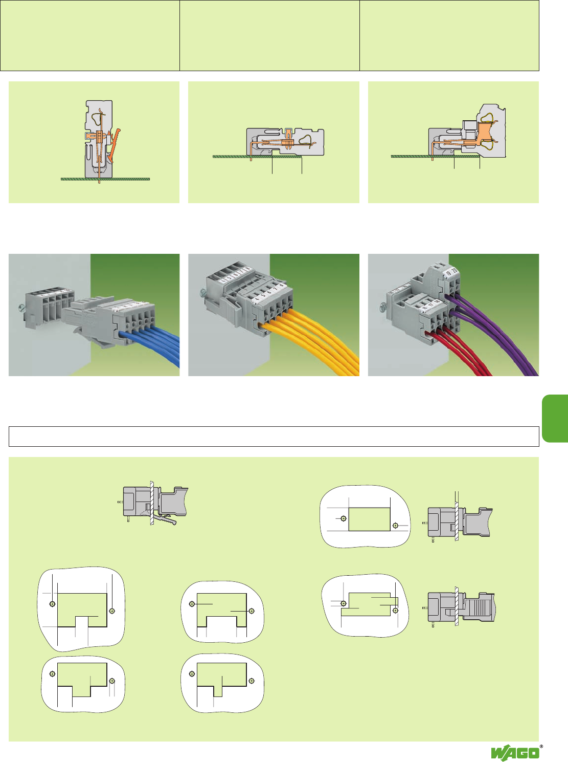
<_____ L4 _____>
>L10
< L11 >
<<
<
<
66,2
<__ L9 __>
>L8
<__
<
3,4
<14,8>
<
<
7, 9
__> <
3,2
>11,3
<__ L8 __>
<_____ L5 _____>
<______ L7 ______>
>
>
6,8
( 11,8 )
>
__>
4,8
<__
>3,2
<_ 21,5 _>
<
<
<_______ L5 _______>
<
<___ L4 ___>
<__
3,4
<
<
7, 9
(_14,8_)
______> <
max. 2
<
9
43
➀
➁
➀
➁
➀
➁
➂
<
<
17,5**
<
<
20*
9
Female plugs with bottom-mounted locking levers
Cutouts for
2-pole locking levers
(2- to 15-pole female plugs)
Layout for
locking levers
outer . . .
. . . inner
Cutouts for
single pole locking levers
Female plug without locking levers
Female plug with lateral locking levers
L 4 = No. of poles x pin spacing + 1.7 mm
L 5 = L4 + 6.6
L 7 = L4 + 9.4
L 8 = No. of poles V x pin spacing – 0.3 mm
L 9 = L8 + 11.6
L10 = No. of poles V x pin spacing + 0.6 mm
L11 = L10 + 5.4 mm
No. of poles V: Number of poles before the pole
with the locking lever attached
Types of Application
Headers with Solder Pins with 1-/2-Conductor Female Plugs
➀Header with fixing flanges
➁1-conductor female plug with
bottom-mounted locking levers
➀Header with fixing flanges
➁1-conductor female plug with
lateral locking levers
➀ Header with fixing flanges for feedthrough
application
➁1-conductor female plug
➂2-conductor female plug
* Maximum dimension when using 1-conductor female
plugs
** Maximum dimension when using 2-conductor female
plugs
Headers with straight solder pins Headers with right angle solder pins Headers with right angle solder pins
Dimensions (in mm) Cutouts for headers with fixing flanges for feedthrough applications and locking levers
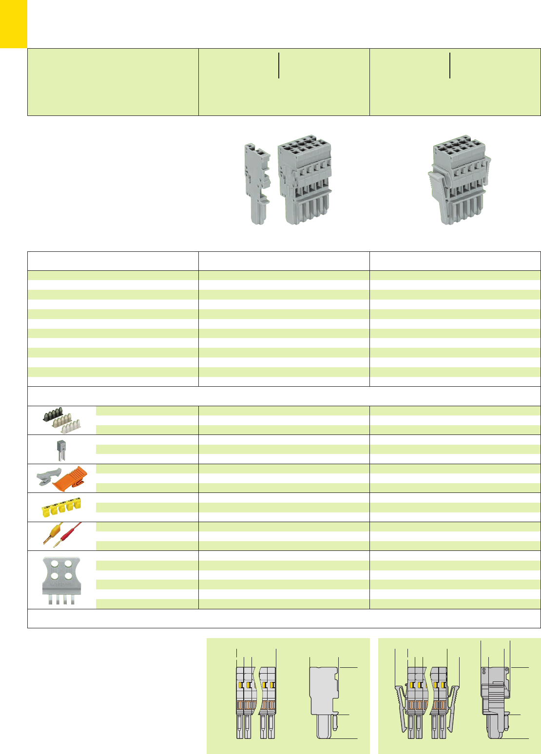
*U2KfJ:{
<_____L_____>
>
>
5<_18,3_>
<_____30_____>
<_________45,2_________>
8,1 <_____L_____>
>
>
5
>
7, 5
>
>
<_18,3_>
(_14, 7 _)
(_10 _)
<_____30_____>
<_________45,2_________>
9
44
*U2
Description
0.08 – 0.2 mm2769-470 200 strips
0.25 – 0.5 mm2769-471 200 strips
0.75 – 1 mm2769-472 200 strips
IN24 A
grey 769-402 100 (4 x 25)
Female plugs with 1 pole 2 poles and more
grey 769-428 769-430 100 (4 x 25)
orange 769-429 769-431 100 (4 x 25)
yellow 280-415 100 (4 x 25)
red 210-136 50 (5 x 10)
yellow 210-137 50 (5 x 10)
grey
1 pole 769-410 100 (4 x 25)
2 to 3 poles 769-411 100 (4 x 25)
4 to 5 poles 769-412 100 (4 x 25)
6 to 9 poles 769-413 100 (4 x 25)
10 to 15 poles 769-414 100 (4 x 25)
Insulation stop ➋,white
5 pcs/strip light grey
dark grey
Miniature adjacent jumper,
insulated, suitable for
1-conductor female plugs
Locking levers,
can be snapped on female plugs
Protective warning marker,
for 5 terminal blocks,
fits into screwdriver slot
Test plug, w. cable 500 mm/1’7.7’’
2 mm /0.079 in Ø
2.3 mm /0.091 in Ø
Strain relief plate,
snap-on typ,
for 1-conductor female plugs
1-conductor female plug,
to be fixed on receptacle terminal blocks
or male connectors
1-conductor female plug, green-yellow
Higher number of poles and/or mixed
(grey/green-yellow) on request
No. of Item Pack. unit
poles No. pcs
1-conductor female plugs,
with coding fingers, grey,
commoning possibility with miniature adjacent jumpers
1 pole 769-101 200
2 poles 769-102 100
3 poles 769-103 50
::
14 poles 769-114 10
15 poles 769-115 10
1-conductor female plug,
with coding fingers, green-yellow,
commoning possibility with miniature adjacent jumpers
1 pole 769-101/000-016 200
X-COM®-SYSTEM
1-Conductor Female Plugs
➊500 V = rated voltage
6 kV = rated surge voltage
3 = pollution degree
(see also section 15)
➋See application notes on page 2.43
No. of Item Pack. unit
poles No. pcs
1-conductor female plugs with lateral locking
levers, with coding fingers, grey,
commoning possibility with miniature adjacent jumpers
– only to be used for male connectors –
2 poles 769-102/021-000 50
3 poles 769-103/021-000 25
4 poles 769-104/021-000 25
::
9 poles 769-109/021-000 20
::
14 poles 769-114/021-000 10
15 poles 769-115/021-000 10
Female Plugs
with Locking Levers
0.08 – 0.2 mm2769-470 200 strips
0.25 – 0.5 mm2769-471 200 strips
0.75 – 1 mm2769-472 200 strips
IN24 A
grey 769-402 100 (4 x 25)
yellow 280-415 100 (4 x 25)
red 210-136 50 (5 x 10)
yellow 210-137 50 (5 x 10)
grey
1 pole 769-410 100 (4 x 25)
2 to 3 poles 769-411 100 (4 x 25)
4 to 5 poles 769-412 100 (4 x 25)
6 to 9 poles 769-413 100 (4 x 25)
10 to 15 poles 769-414 100 (4 x 25)
Accessories Appropriate marking system Mini-WSB (see section 14)
* For further approvals with corresponding ratings see section 15. ** See current-carrying capacity curves pages 9.48 – 9.51 and www.wago.com
L = Number of poles x module width
L = Number of poles x module width
0.08 – 4 mm2AWG 28 – 12
500 V/6 kV/3 ➊300/600 V, 10/5 A U
32 A** 300 V, 10 A 2
Module width 5 mm / 0.197 in
L8 – 9 mm / 0.33 in
Dimensions (in mm)
1-pole female plug
for example
●for phase selection in three-phase network
●as a test plug with rated current capability
●
simplified circuit expansion – addition of base
circuits requires only female plugs to be plugged in
0.08 – 4 mm2AWG 28 – 12
500 V/6 kV/3 ➊300/600 V, 10/5 A U
32 A** 300 V, 10 A 2
Module width 5 mm / 0.197 in
L8 – 9 mm / 0.33 in
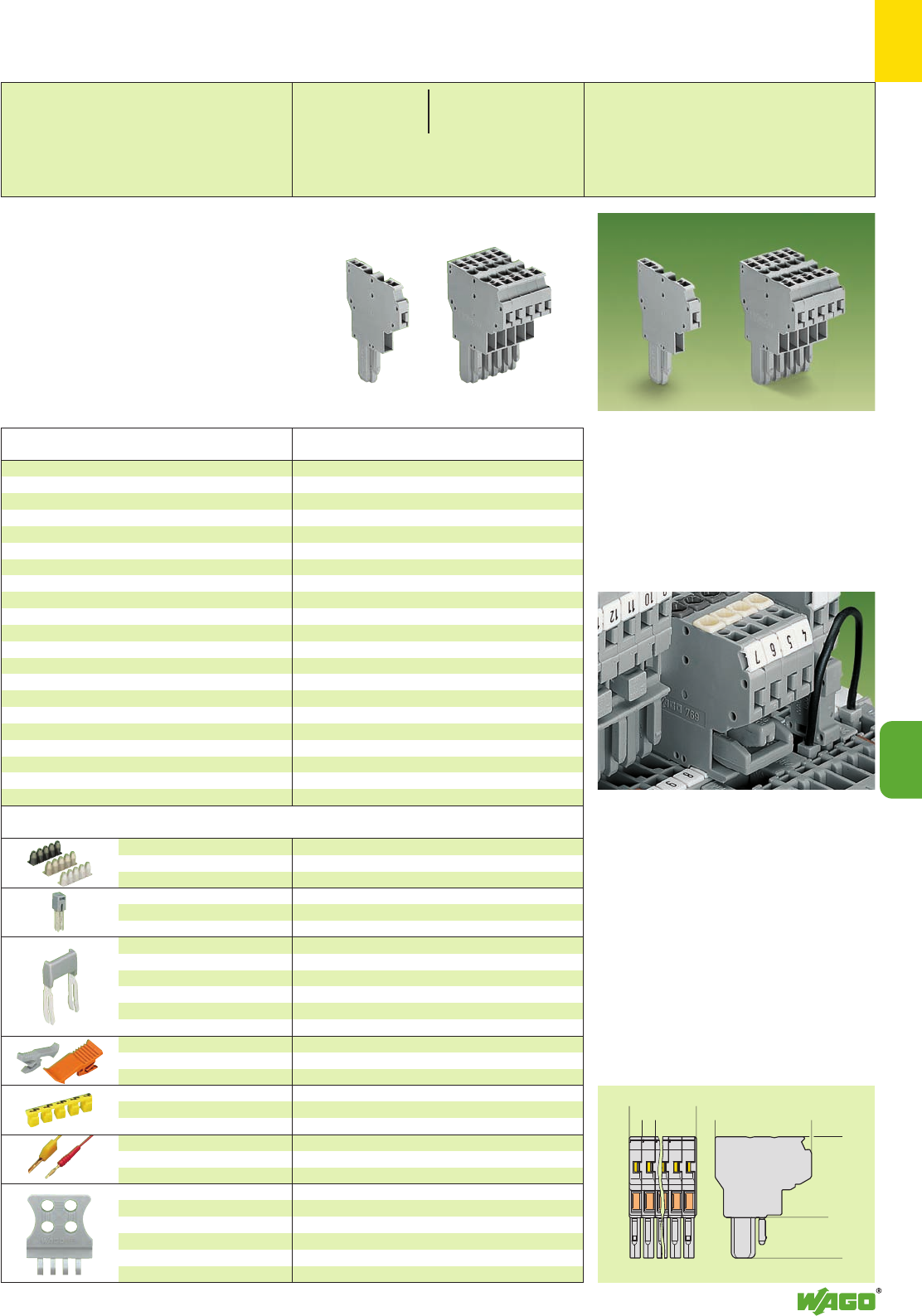
9
45
9
*U2fJ:{
<
>5
<____ L ____> <______ 35,9 _______>
<_____ 30 _____>
<_________ 45,2 ________>
0.08 – 0.2 mm2769-470 200 strips
0.25 – 0.5 mm2769-471 200 strips
0.75 – 1 mm2769-472 200 strips
N24 A
grey 280-402 200 (8 x 25)
IN24 A 780-452 100 (4 x 25)
780-453 100 (4 x 25)
780-454 100 (4 x 25)
780-455 50 (2 x 25)
:
780-458 50 (2 x 25)
Female plugs with 1 pole 2 poles and more
grey 769-428 769-430 100 (4 x 25)
orange 769-429 769-431 100 (4 x 25)
yellow 280-415 100 (4 x 25)
red 210-136 50 (2 x 25)
yellow 210-137 50 (2 x 25)
grey
1 pole 769-410 100 (4 x 25)
2 to 3 poles 769-411 100 (4 x 25)
4 to 5 poles 769-412 100 (4 x 25)
6 to 9 poles 769-413 100 (4 x 25)
10 to 15 poles 769-414 100 (4 x 25)
No. of Item Pack. unit
poles No. pcs
2-cond. female plugs,
with coding fingers, grey,
commoning possibility w. adjacent jumpers a. staggered jumpers
1 pole 769-121 100
2 poles 769-122 50
3 poles 769-123 25
4 poles 769-124 25
5 poles 769-125 25
6 poles 769-126 10
7 poles 769-127 10
8 poles 769-128 10
9 poles 769-129 10
10 poles 769-130 10
11 poles 769-131 5
12 poles 769-132 5
13 poles 769-133 5
14 poles 769-134 5
15 poles 769-135 5
2-conductor female plug,
with coding fingers, green-yellow, commoning possibility
with adjacent jumpers and staggered jumpers
1 pole 769-121/000-016 100
Application notes
Dimensions of the female plugs
Description
Insulation stop ➋,white
5 pcs/strip light grey
dark grey
Adjacent jumpers, insulated,
suitable for 2-conductor female
plugs
Staggered jumper
➋,from 1 to 2
insulated, from 1 to 3
width 5 mm /0.197 in, from 1 to 4
suitable for 2-conduc-
from 1 to 5
tor female plugs :
from 1 to 8
Locking levers,
can be snapped on female plugs
Protective warning marker,
for 5 terminal blocks,
fits into screwdriver slot
Test plug, w. cable 500 mm/1’7.7’’
2 mm /0.079 in Ø
2.3 mm /0.091 in Ø
Strain relief plate,
snap-on typ,
for 2-conductor female plugs
2-conductor female plug,
to be fixed on receptacle terminal blocks
or male connectors
2-conductor female plug, green-yellow
Higher number of poles and/or mixed
(grey/green-yellow) on request
2-Conductor Female Plugs
Accessories Appropriate marking system Mini-WSB (see section 14)
2-conductor female plugs
●commoning of signals from one sub-assembly
to the other (bus structure)
●use as a T-wire branch tap connection, as for
example use in lighting wiring
●higher number of connection possibilities
* For further approvals with corresponding ratings see section 15. ** See current-carrying capacity curves pages 9.48 – 9.51 and www.wago.com
L = Number of poles x module width
➊500 V = rated voltage
6 kV = rated surge voltage
3 = pollution degree
(see also section 15)
➋See application notes on pages 2.43/2.45
Commoning possibility of female plugs
●after de-plugging commoned potentials still
remain commoned
●use of the plug jumper instead of additional
wired jumpers
●can be used as a “hardware” key for safety
lockout
●as a commoning jumper for sensor circuits or
machine programming
0.08 – 4 mm2AWG 28 – 12
500 V/6 kV/3 ➊300/600 V, 10/5 A U
32 A** 300 V, 10 A 2
Module width 5 mm / 0.197 in
L8 – 9 mm / 0.33 in
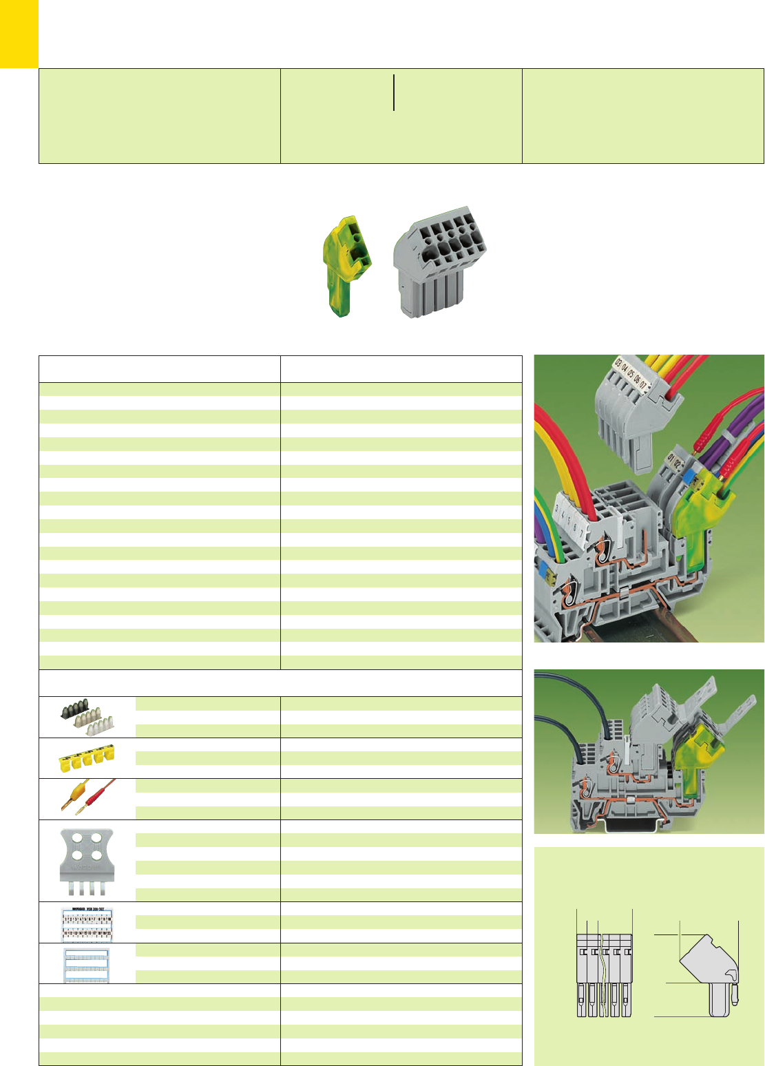
<___ 26,5 ___>
<
>5
<____ L ____>
<__ 21,9 __>
<______ 37,1 ______>
*U2fJ{
9
46
Accessories Appropriate marking system Mini-WSB/WMB (see section 14)
* For further approvals with corresponding ratings see section 15.
Description
0.08 – 0.2 mm2769-470 200 strips
0.25 – 0.5 mm2769-471 200 strips
0.75 – 1 mm2769-472 200 strips
yellow 280-415 100 (4 x 25)
red 210-136 50 (5 x 10)
yellow 210-137 50 (5 x 10)
grey
1 pole 769-410 100 (4 x 25)
2 to 3 poles 769-411 100 (4 x 25)
4 to 5 poles 769-412 100 (4 x 25)
6 to 9 poles 769-413 100 (4 x 25)
10 to 15 poles 769-414 100 (4 x 25)
see section 14
see section 14
Current-carrying capacity curves see www.wago.com
Insulation stop ➋,white
5 pcs/strip light grey
dark grey
Protective warning marker,
for 5 terminal blocks,
fits into screwdriver slot
Test plug, w. cable 500 mm/1’7.7’’
2 mm /0.079 in Ø
2.3 mm /0.091 in Ø
Strain relief plate,
snap-on typ,
for 1-conductor female plugs
WAGO WMB multi-marking
system, fits in all miniature WSB
receptacles
Miniature WSB quick marking
card, 10 strips with 10 markers
each, white with black printing
Angled female plug,
for use with receptacle terminal blocks of series 769 and
870 or male connectors
Angled female plug, green-yellow
Higher number of poles and/or mixed
(grey/green-yellow) on request
No. of Item Pack. unit
poles No. pcs
1-conductor angled female plugs,
with coding fingers, grey
1 pole 769-101/022-000 200
2 poles 769-102/022-000 100
3 poles 769-103/022-000 50
4 poles 769-104/022-000 50
5 poles 769-105/022-000 50
6 poles 769-106/022-000 25
7 poles 769-107/022-000 25
8 poles 769-108/022-000 25
9 poles 769-109/022-000 25
10 poles 769-110/022-000 25
11 poles 769-111/022-000 20
12 poles 769-112/022-000 20
13 poles 769-113/022-000 10
14 poles 769-114/022-000 10
15 poles 769-115/022-000 10
1-conductor angles female plug,
with coding fingers, green-yellow
1 pole 769-101/022-016 100
X-COM®-SYSTEM
Angled Female Plugs
➊500 V = rated voltage
6 kV = rated surge voltage
3 = pollution degree
(see also section 15)
➋See application notes on page 2.43
Examples of application
Dimensions of the female plugs
L = Number of poles x module width
0.08 – 4 mm2AWG 28 – 12
500 V/6 kV/3 ➊300/600 V, 10/5 A U
32 A** 300 V, 10 A 2
Module width 5 mm / 0.197 in
L8 – 9 mm / 0.33 in
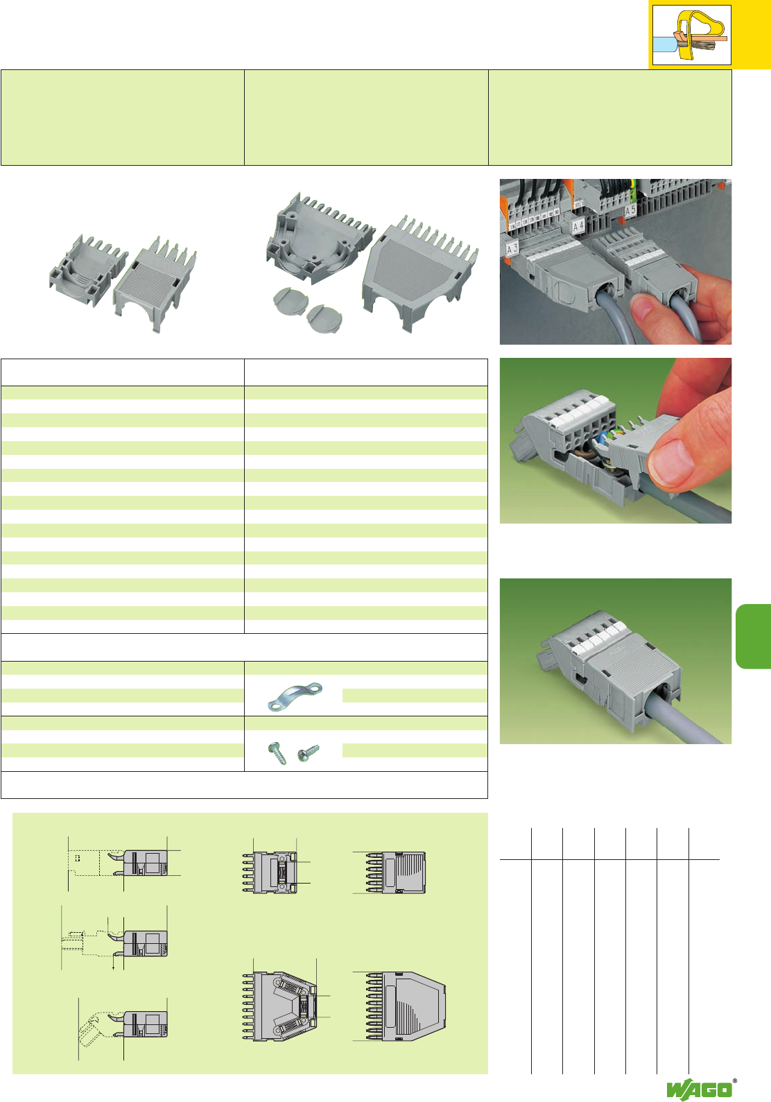
9
47
9
<__ L4 __>
<__ L5 __>
<______ L4 ______>
( D )
( D )
(18,3 )
<_____ L5 _____>
<__________ L1 __________>
<___________ L2 ___________>
<_________ L3 _________>
11,45
<____
>
7,6 <
>45,2
<_ 32,9 _>
<__ 40,2 __>
Snapping on strain relief housing
Female connector with strain relief housing
2 71.7 76.7 64.4 10 31.5 5
3 71.7 76.7 64.4 15 31.5 9.7
4 71.7 76.7 64.4 20 31.5 14
5 71.7 76.7 64.4 25 31.5 14
6 71.7 76.7 64.4 30 31.5 15.5
7 76.7 81.7 69.4 35 36.5 15.5
8 86.2 91.2 78.9 40 46 15.5
9 86.2 91.2 78.9 45 46 15.5
10 86.2 91.2 78.9 50 46 15.5
11 86.2 91.2 78.9 55 46 15.5
12 86.2 91.2 78.9 60 46 15.5
13 86.2 91.2 78.9 65 46 15.5
14 86.2 91.2 78.9 70 46 15.5
15 86.2 91.2 78.9 75 46 15.5
No. of L1L2L3L4L5D
poles
Dimensions for strain relief housings
Dimensions (in mm)
Accessories
(WSB marker cards see
section 14
)
Snap-on Type Strain Relief Housings for Series 769
Female Plugs and Male Connectors with CAGE CLAMP®Connection
Snap-on type strain relief housings suitable for
– straight and angled female plugs
with CAGE CLAMP®connection
– male connectors with CAGE CLAMP®
connection
2 – 5 poles
Snap-on type strain relief housings suitable for
– straight and angled female plugs
with CAGE CLAMP®connection
– male connectors with CAGE CLAMP®
connection
6 – 15 poles
Snap-on type strain relief housings,
pin spacing 5 mm/0.197 in, grey
consisting of: strain relief support
strain relief housing
2769-1602 ➊25
3769-1603 ➊25
4769-1604 ➊25
5769-1605 ➊25
➊ 1 cable outlet rear, 2- to 5-pole only suitable for
cable ties (Fa. Hellermann – not offered by WAGO)
not for cable clamp
No. of Item Pack. unit
poles No. pcs
Snap-on type strain relief housings,
pin spacing 5 mm/0.197 in, grey
consisting of: strain relief support
strain relief housing
6769-1606 ➊25
7769-1607 ➊25
8769-1608 ➋25
9769-1609 ➋25
10 769-1610 ➌25
11 769-1611 ➌25
12 769-1612 ➌25
13 769-1613 ➌25
14 769-1614 ➌25
15 769-1615 ➌25
➊
1 cable outlet rear
➋ 2 cable outlets, 1 cover
➌ 3 cable outlets, 2 covers
No. of Item Pack. unit
poles No. pcs
Cable clamp, for strain relief
209-174 25
Fixing screws, for cable clamp
209-173 50
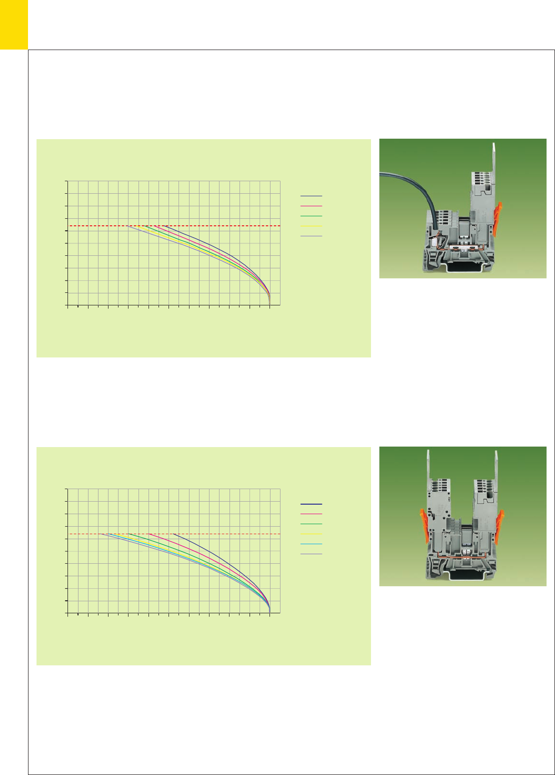
50
45
40
35
30
25
20
15
10
5
0
010 4020 30 50 60 8070 90 100
50
45
40
35
30
25
20
15
10
5
0
010 4020 30 50 60 8070 90 100
9
48
X-COM®-SYSTEM
Current-Carrying Capacity Curves for 1-Conductor/1-Pin and
2-Pin Receptacle Terminal Blocks and 1-Conductor Female Plugs
1-conductor/
1-pin receptacle terminal block 769-176
Cross section of conductor: 4 mm2/AWG 12
1-conductor female plugs 769-102 to 769-115
Cross section of conductor: 4 mm2/AWG 12
Length of the conductor: 1 m
Test current (A)
2-pin receptacle terminal block 769-156
1-conductor female plugs 769-102 to 769-115
Cross section of conductor: 4 mm2/AWG 12
Length of the conductor: 1 m
Test current (A)
2 poles
4 poles
5 poles
6 poles
15 poles
Ambient operating
temperature (°C)
Ambient operating
temperature (°C)
Rated voltage of the conductor
Rated voltage of the conductor
2 poles
4 poles
5 poles
6 poles
10 poles
15 poles
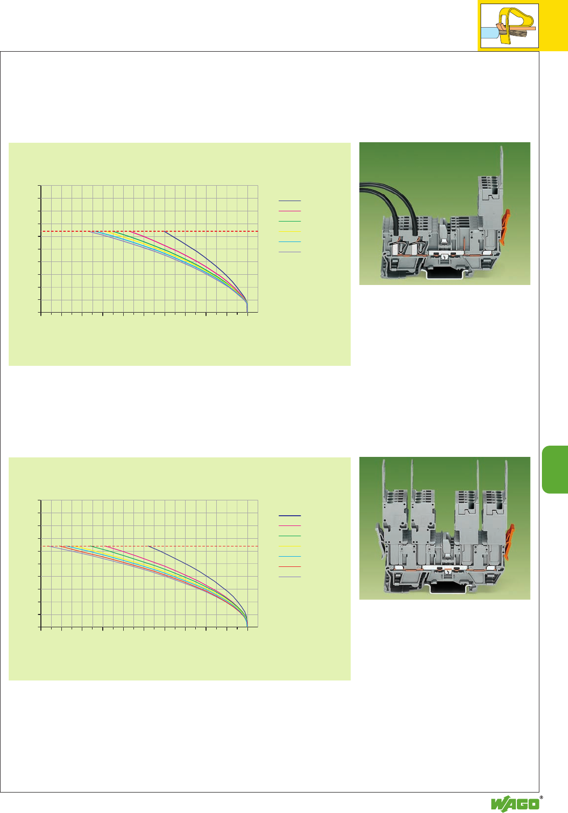
50
45
40
35
30
25
20
15
10
5
0
010 4020 30 50 60 8070 90 100
50
45
40
35
30
25
20
15
10
5
0
010 4020 30 50 60 8070 90 100
9
49
9
Current-Carrying Capacity Curves for 2-Conductor/2-Pin and
4-Pin Receptacle Terminal Blocks and 1-Conductor Female Plugs
Test current (A)
2-conductor/
2-pin receptacle terminal block 769-171
Cross section of conductor: 4 mm2/AWG 12
1-conductor female plugs 769-102 to 769-115
Cross section of conductor: 4 mm2/AWG 12
Length of the conductor: 1 m
4-pin receptacle terminal block 769-151
1-conductor female plugs 769-102 to 769-115
Cross section of conductor: 4 mm2/AWG 12
Length of the conductor: 1 m
Ambient operating
temperature (°C)
Ambient operating
temperature (°C)
Test current (A)
Rated voltage of the conductor
Rated voltage of the conductor
2 poles
4 poles
5 poles
6 poles
10 poles
15 poles
2 poles
4 poles
5 poles
6 poles
10 poles
12 poles
15 poles
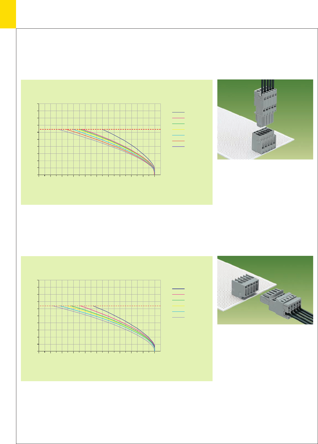
50
45
40
35
30
25
20
15
10
5
0
010 4020 30 50 60 8070 90 100
50
45
40
35
30
25
20
15
10
5
0
010 4020 30 50 60 8070 90 100
9
50
X-COM®-SYSTEM
Current-Carrying Capacity Curves
for
Headers with Straight and Right Angle Solder Pins and 1-Conductor Female Plugs
Headers with
straight solder pin 769-632 to 769-645
1-conductor female plugs 769-102 to 769-115
Cross section of conductor: 4 mm2/AWG 12
Length of the conductor: 1 m
Headers with
right angle solder pins 769-662 to 769-675
1-conductor female plugs 769-102 to 769-115
Cross section of conductor: 4 mm2/AWG 12
Length of the conductor: 1 m
Test current (A)
Test current (A)
Ambient operating
temperature (°C)
Ambient operating
temperature (°C)
Rated voltage of the conductor
Rated voltage of the conductor
2 poles
4 poles
5 poles
6 poles
10 poles
12 poles
15 poles
2 poles
4 poles
5 poles
6 poles
10 poles
15 poles
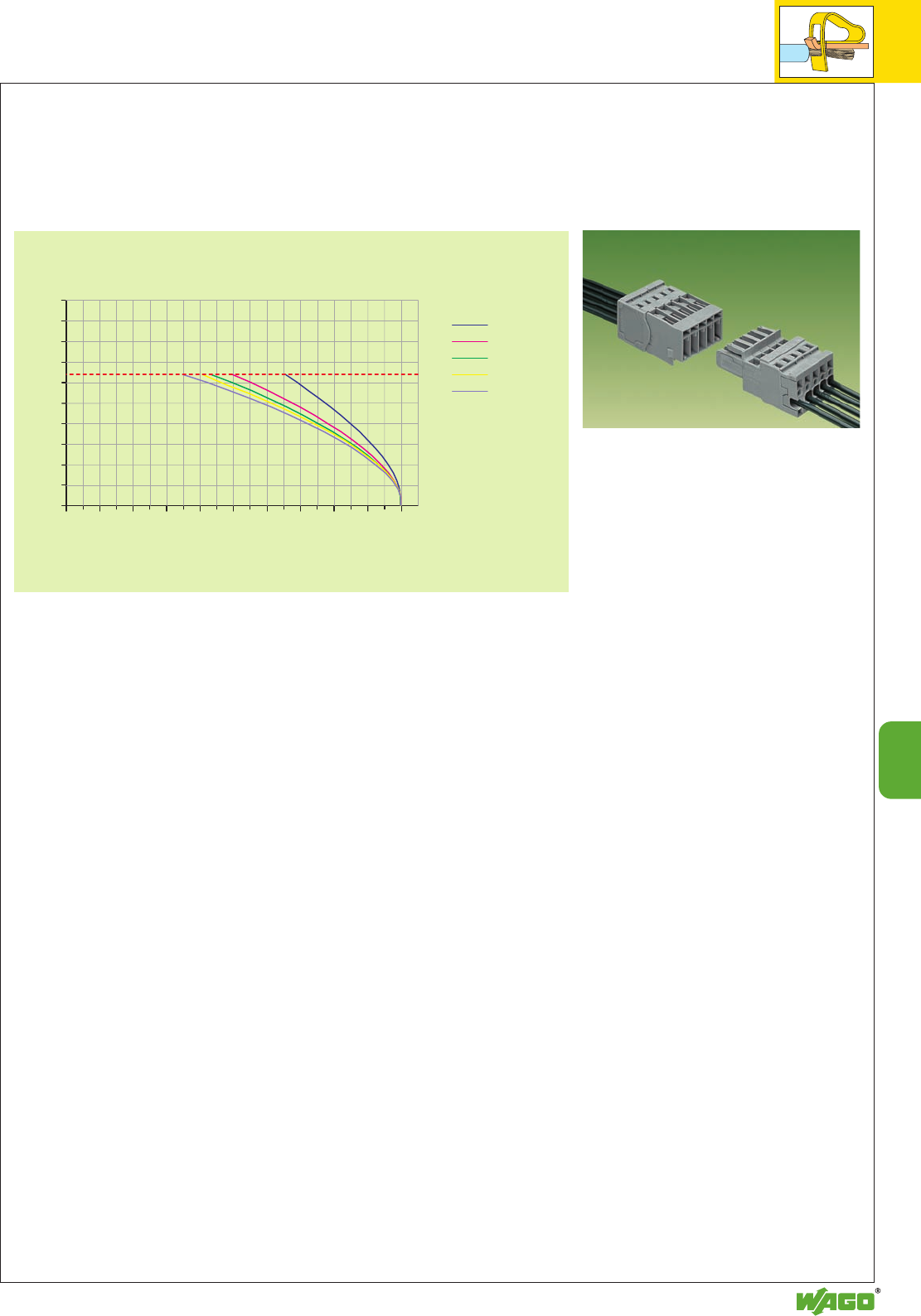
9
51
9
50
45
40
35
30
25
20
15
10
5
0
010 4020 30 50 60 8070 90 100
Current-Carrying Capacity Curves for Male Connectors with
CAGE CLAMP®Connection and 1-Conductor Female Plugs
Male connectors with
CAGE CLAMP®connection 769-602 to 769-615
Cross section of conductor: 4 mm2/AWG 12
1-conductor female plugs 769-102 to 769-115
Cross section of conductor: 4 mm2/AWG 12
Length of the conductor: 1 m
Test current (A)
Ambient operating
temperature (°C)
Rated voltage of the conductor
2 poles
4 poles
5 poles
6 poles
15 poles
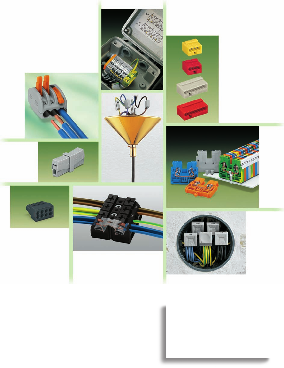
For special or standard
connection applications:
WAGO terminal strips and
connectors.
10
10
Terminal Strips and Connectors
Modular terminal blocks and terminal strips
with CAGE CLAMP®connection,
with fixing flanges or snap-in mounting feet,
Front-entry wiring,
– 2.5 mm2/4 mm2/ AWG 12 Series 869 10.6 – 10.9
– 2.5 mm2/ AWG 12 Series 264 10.10 – 10.14
– Test plug adapters for
terminal strips, series 264 Series 249 10.15
Side-entry wiring,
– 1.5 mm2/ AWG 16 Series 260 2.5 mm2/ AWG 14 Series 261
4 mm2/ AWG 12 Series 262 10.16 – 10.27
– Test plug adapters for terminal strips Series 260, 261 and 262 10.28
VOLUME 1
Lighting connectors, ”service“ connectors
– 2.5 mm2/ AWG 14 Series 224 10.30 – 10.31
MICRO push-wire connectors for junction boxes
– 0.8 Ø mm / AWG 20 Series 243 10.34 – 10.35
Push-wire connectors for junction boxes
– 1.5 mm2+ 2.5 mm2/ AWG 16 + 12 Series 273 and 773 10.36 – 10.37
Compact connectors for flexible conductors
– 2.5 mm2/ AWG 12 Series 222 10.38 – 10.39
Terminal strips
0.5 mm2to 4 mm2/ AWG 20 – 12 Series 862 10.40 – 10.43
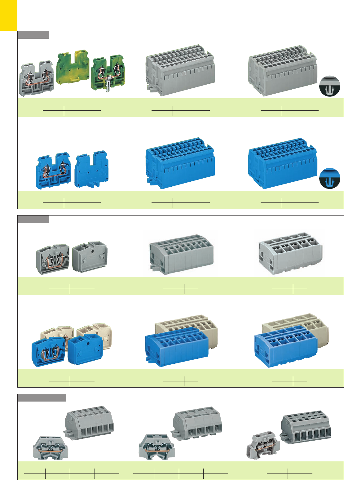
10
2
Series 261
Series 260 – 262
Series 264
Series 869
Modular Terminal Blocks and Terminal Strips
– Product Summary –
Modular terminal blocks Compact block terminal strips
mm2/AWG 2.5/14 /4/12
Page 10.8 – 10.9
with fixing flanges with snap-in mounting feet
Ex i Modular terminal blocks Ex i Compact block terminal strips
Modular terminal blocks and terminal strips
2- and 4-conductor terminal blocks with fixing flanges with snap-in mounting feet
mm2/AWG 2.5/14
Page 10.12 – 10.13
mm2/AWG 2.5/14
Page 10.14
Ex i Modular terminal blocks and terminal strips
Ex e II Modular terminal blocks and terminal strips
Modular terminal blocks and terminal strips with fixing flanges or snap-in mounting feet
with miniature WSB marker receptacle
2-conductor modular terminal blocks and terminal strips 4-conductor modular terminal blocks and terminal strips 2-conductor modular terminal blocks and terminal strips
mm2/AWG 1.5/16 2.5/14 4/12
Page 10.18 – 10.19 10.20 – 10.2110.26 – 10.27
mm2/AWG 2.5/14 /4/12
Page 10.7
mm2/AWG 2.5/14 /4/12
Page 10.7
mm2/AWG 2.5/14 /4/12
Page 10.8 – 10.9
with fixing flanges with snap-in mounting feet
mm2/AWG 2.5/14 /4/12
Page 10.7
mm2/AWG 2.5/14 /4/12
Page 10.7
mm2/AWG 2.5/14
Page 10.14
2- and 4-conductor terminal blocks with fixing flanges with snap-in mounting feet
mm2/AWG 2.5/14
Page 10.12 – 10.13
mm2/AWG 2.5/14
Page 10.14
mm2/AWG 2.5/14
Page 10.14
mm2/AWG 1.5/16 2.5/14 4/12
Page 10.18 – 10.19 10.20 – 10.2110.26 – 10.27
mm2/AWG 2.5/14
Page 10.24 – 10.25
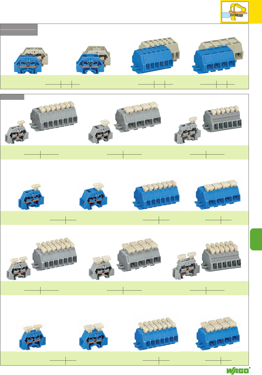
10
10
3
Series 262
Series 261 – 262
Series 261
Ex i Modular terminal blocks and terminal strips with fixing flanges or snap-in mounting feet
Ex e II Modular terminal blocks and terminal strips with fixing flanges or snap-in mounting feet
Ex i Modular term. blocks and term. strips, with push buttons on one side, fixing flanges or snap-in mounting feet
Ex i Modular term. blocks and term. strips, with push buttons on both sides, fixing flanges or snap-in mounting feet
2- and 4-conductor modular terminal blocks
2- and 4-conductor modular terminal blocks
2- and 4-conductor modular terminal blocks 2-conductor terminal strips 4-conductor terminal strips
2-conductor terminal strips
2-conductor terminal strips
4-conductor terminal strips
4-conductor terminal strips
Modular terminal blocks and terminal strips with push buttons on one side, fixing flanges or snap-in mounting
feet with miniature WSB marker receptacle
2-conductor modular terminal blocks and terminal strips2-conductor modular terminal blocks and terminal strips 4-conductor modular terminal blocks and terminal strips
with miniature WSB marker receptacle
Modular terminal blocks and terminal strips, with push buttons on both sides, fixing flanges or snap-in mounting feet
2-conductor modular terminal blocks and terminal strips 4-conductor modular terminal blocks and terminal strips 2-conductor modular terminal blocks and terminal strips
mm2/AWG 2.5/14 4/12
Page 10.21 10.27
mm2/AWG 2.5/14
Page 10.22 – 10.23
mm2/AWG 2.5/14
Page 10.22 – 10.23
mm2/AWG 2.5/14
Page 10.22 – 10.23
mm2/AWG 2.5/14
Page 10.22
mm2/AWG 2.5/14
Page 10.23
mm2/AWG 2.5/14
Page 10.23
mm2/AWG 2.5/14
Page 10.22 – 10.23
mm2/AWG 2.5/14
Page 10.22 – 10.23
mm2/AWG 2.5/14
Page 10.22 – 10.23
mm2/AWG 2.5/14
Page 10.22
mm2/AWG 2.5/14
Page 10.23
mm2/AWG 2.5/14
Page 10.23
mm2/AWG 2.5/14 4/12
Page 10.20 10.26
mm2/AWG 2.5/14 4/12
Page 10.21 10.27
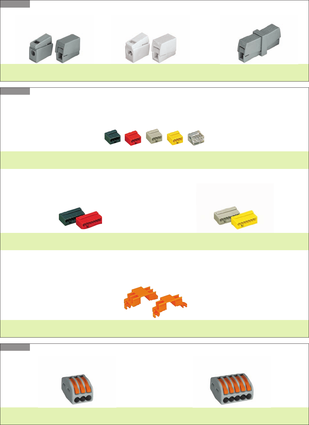
10
4
Series 243
Lighting connectors
Push-Wire and MICRO Push-Wire Connectors for Junction Boxes
– Product Summary –
Series 222
for 3-conductor connectors
Page 10.39
Compact connectors
Page 10.35
Mounting carriers
Series 224
2-conductor connectors
Page 10.31Page 10.31 Page 10.31
Service connector
Lighting connectors
MICRO push-wire connectors for junction boxes
4-conductor connectors
Page 10.34
8-conductor connectors
Page 10.34
for 5-conductor connectors
Page 10.39
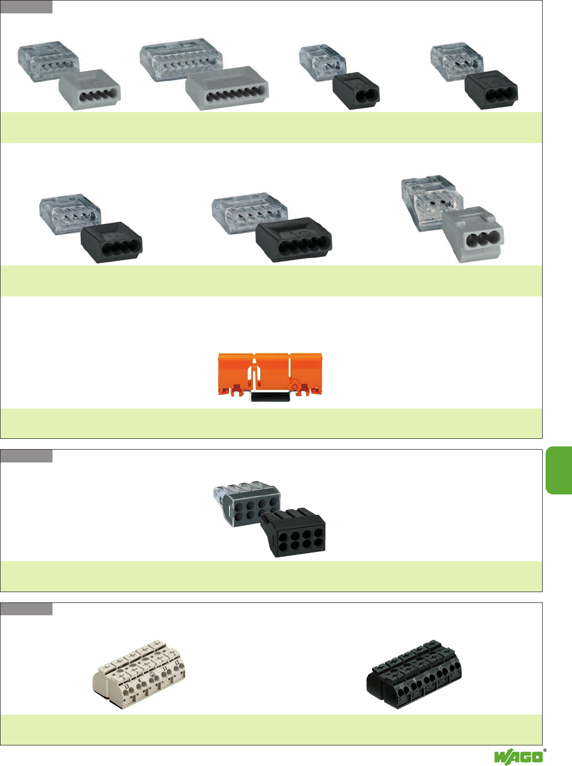
10
10
5
Series 273
Series 773
Series 862
Pages 10.42 – 10.43
4-conductor terminal strips
Page 10.37
Fixing carriers
Push-wire connectors for junction boxes
for 5-conductor connectors
Page 10.36
for 8-conductor connectors
Page 10.36
for 2-conductor connectors
Page 10.36
for 3-conductor connectors
Page 10.36
for 4-conductor connectors
Page 10.36
for 5-conductor connectors
Page 10.36
for 3-conductor connectors
Page 10.36
Push-wire connectors for junction boxes
Page 10.36
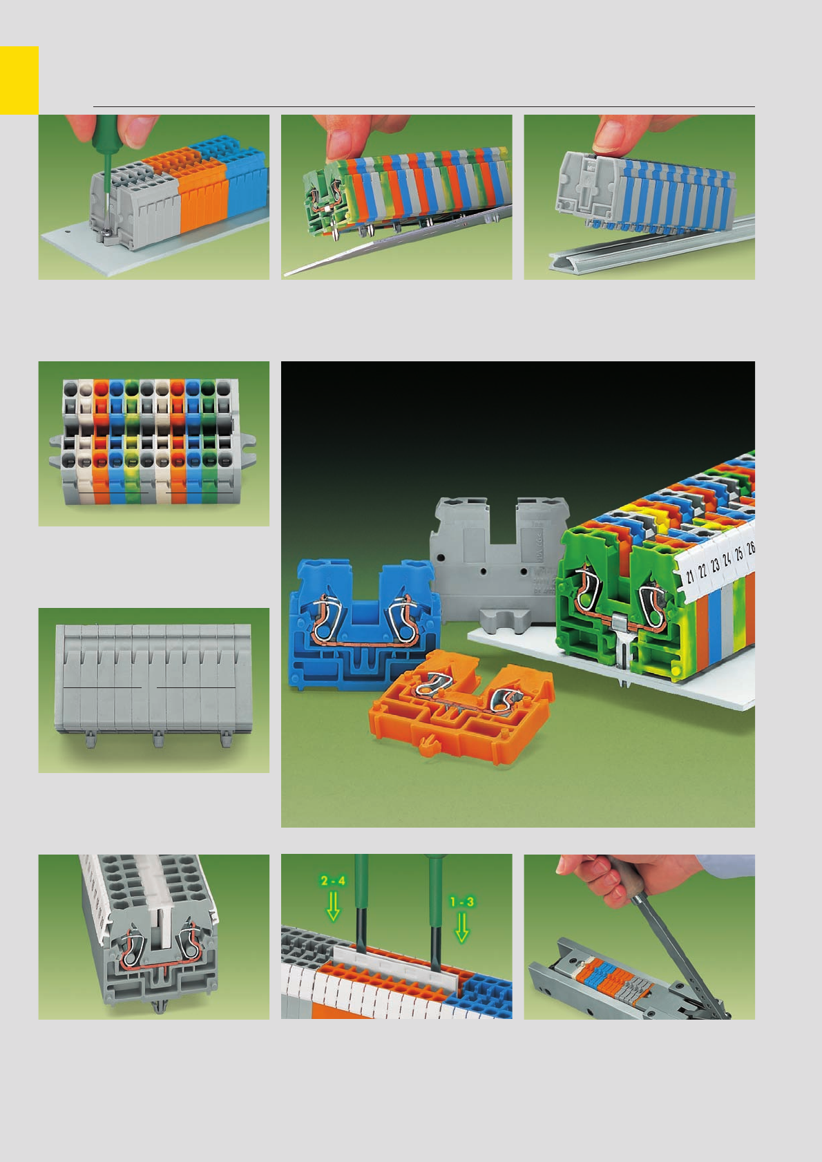
➊
➋➌
➍
➎
➏
10
6
Compact Terminal Strips with CAGE CLAMP COMPACT Connection
Description and Handling – Series 869
Fixing
Terminal strip with fixing flange,
screw fixing
Terminal strip with fixing flanges, consisting of:
end plate with fixing flange ➊
center terminal blocks ➋
end terminal blocks with fixing flange ➌
Terminal strip with mounting feet, consisting of:
end plate ➍/ center terminal blocks with/without
snap-in mounting feet ➎/ end terminal block
with/without snap-in mounting foot ➏
fine-stranded,
tip bonded
fine-stranded,
with crimped ferrule**
fine-stranded,
with crimped pin terminal
Push-in type jumper system
WAGO WMB Multi-marking system or
WAGO miniature WSB Quick marking system Push jumper bars down firmly until fully inserted!
When using multi-pole bars, push alternately on
right and then left side, successively until installed.
Terminal strips assembled by means of assembly
device
Item No. for the device 298-635
Terminal strip with snap-in mounting feet,
fixing in holes Terminal strip with snap-in mounting feet,
assembly onto special aluminum rail
CAGE CLAMP®connects
the following copper
wires:*
solid stranded
fine-stranded,
also with tinned
single strands
* For aluminum wire see notes in section 15!
** When using ferrules, the max. conductor cross section which can be accommodated is one size smaller than max. rating of terminal block
Marking
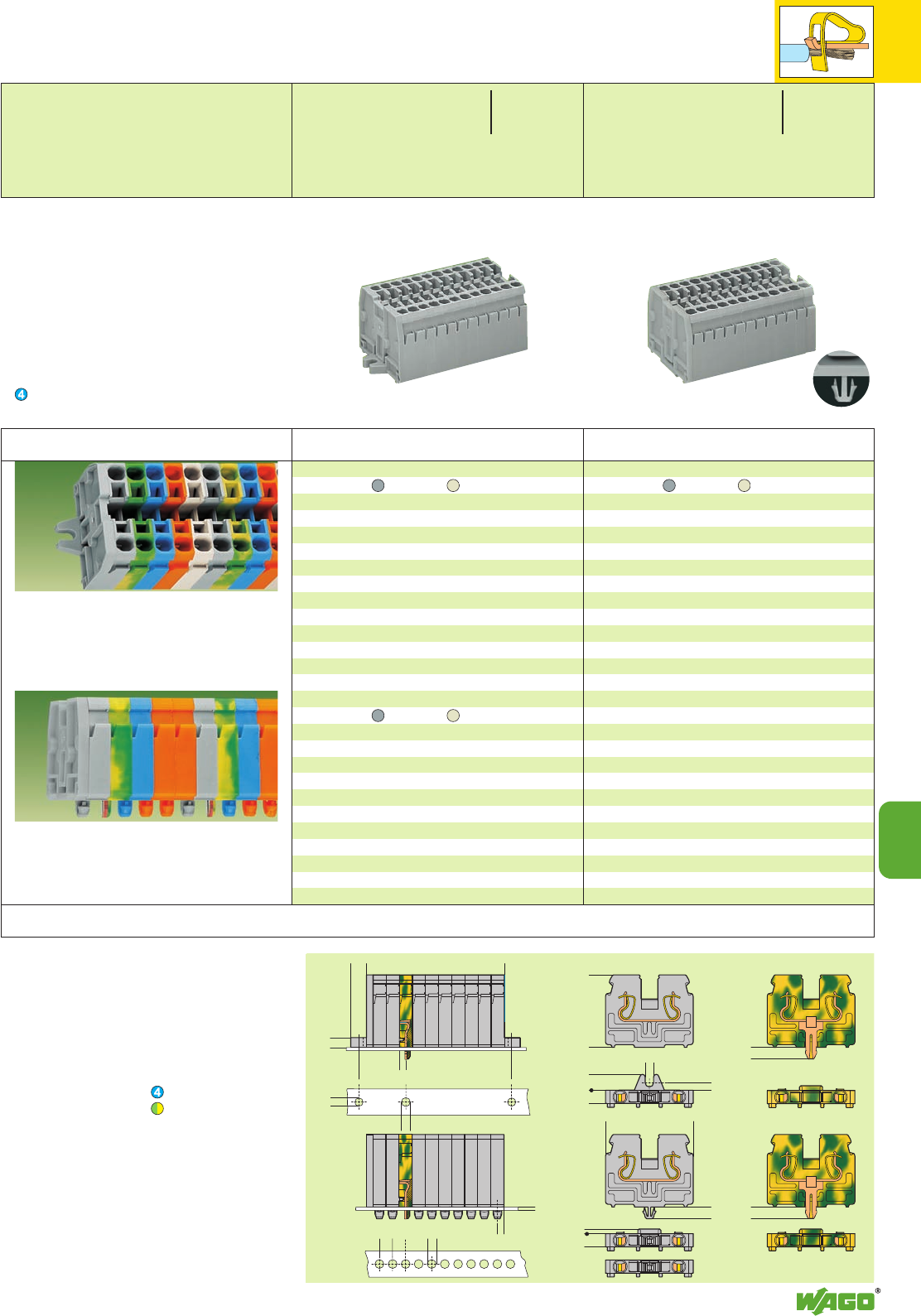
3,5
0,6/1,2
5
<_______
<
<__
__>
>
<______
<____27,6 ____>
<
<
6
<__
<
51,8
>
______>
<
<______
2,8(3,3)
4,5
<
<__
<_____33,4_____>
4,5
<
<__
4,5
<
<__
<__
5
<____________L____________>
>
<__
>
>
>
>
6
3,2 (4,2)
2,5
3,7
3,5
3,2 (4,2)
<______________L1______________>
>
>
>
__>
2,5
10
10
7
*UKf[
*UKf[
Terminal strips with fixing flanges M 3 or M 4,
for screw fixing or similar methods,
fixing hole diameter
3.2 mm Ø flange M 3
4.2 mm Ø flange M 4
Terminal strips with snap-in mounting feet,
for plate thickness 0.6 – 1.2 mm,
fixing hole diameter 3.5 + 0.1 mm Ø
Modular terminal blocks and terminal
strips
with fixing flanges
L = (No. of poles x pole width) + 2.5 mm
L1= L + 5.6 mm, with flange M 4 6.6 mm
Additional item nos. for terminal strips
blue .../000-006
green-yellow
.../000-017
Modular terminal blocks and terminal strips
with fixing flanges
L = (No. of poles x pole width) + 2.5 mm
* For further approvals with corresponding ratings see section 15. ** 10 A for push-in type jumper bars with different potentials, placed in parallel
Description
Terminal strips with fixing flanges M 3,
grey light grey
2869-102 869-132 100
3869-103 869-133 100
4869-104 869-134 100
5869-105 869-135 100
6869-106 869-136 50
7869-107 869-137 50
8869-108 869-138 50
9869-109 869-139 50
10 869-110 869-140 25
11 869-111 869-141 25
12 ➌869-112 869-142 25
Terminal strips with fixing flanges M 4,
grey light grey
2869-202 869-232 100
3869-203 869-233 100
4869-204 869-234 100
5869-205 869-235 100
6869-206 869-236 50
7869-207 869-237 50
8869-208 869-238 50
9869-209 869-239 50
10 869-210 869-240 25
11 869-211 869-241 25
12 ➌869-212 869-242 25
Terminal strips with snap-in mounint feet,
grey light grey
2869-152 869-182 100
3869-153 869-183 100
4869-154 869-184 100
5869-155 869-185 100
6869-156 869-186 50
7869-157 869-187 50
8869-158 869-188 50
9869-159 869-189 50
10 869-160 869-190 25
11 869-161 869-191 25
12 ➌869-162 869-192 25
No. of Item Item Pack.-unit
poles No. No. pcs No. of Item Item Pack.-unit
poles No. No. pcs
Compact Terminal Strips 2.5 mm2/4 mm2/ AWG 12
with Fixing Flanges or Snap-in Mounting Feet, Series 869
➊Max. diameter of insulation 4.4 mm /0.173 in
➋500 V = rated voltage
6 kV = rated surge voltage
3 = pollution degree
(see also section 15)
➌For longer strips and /or assemblies of different
colors contact factory.
Suitable for Ex i applications with blue insulating
housings
Dimensions for terminal strips (in mm)
0.08
–2.5 mm
2
/4 mm
2
“f-st”
➊AWG 28 – 12
500 V/6 kV/3 ➋300 /600 V,
24 A 20/5 A**
Pole width 5 mm / 0.197 in
L6 – 7 mm / 0.26 in
0.08
–2.5 mm
2
/4 mm
2
“f-st”
➊AWG 28 – 12
500 V/6 kV/3 ➋300 /600 V,
24 A 20/5 A**
Pole width 5 mm / 0.197 in
L6 – 7 mm / 0.26 in
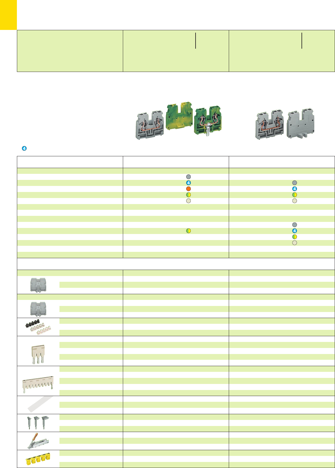
10
8
*YKf[
*YKf[
End plate with fixing flange M 3
2.5 mm /0.098 in thick
End plate with fixing flange M 4
2.5 mm /0.098 in thick
Insulation stop ➌,white
5 pcs/strip light grey
dark grey
Push-in type jumper bar,
light grey,
insulated,
IN18 A
Push-in type jumper bar,
light grey,
insulated,
IN18 A
Marker strip, transparent,
for central marking
– group marking –
Group marker carrier,
insert in jumper contact slot of
current bars
Assembly device, for the
assembly of terminal strips
Protective warning marker,
for 5 terminal blocks,
fits into screwdriver slot
grey 869-385 100 (4 x 25)
blue 869-388 100 (4 x 25)
green-yellow 869-389 100 (4 x 25)
light grey 869-387 100 (4 x 25)
grey 869-395 100 (4 x 25)
blue 869-398 100 (4 x 25)
green-yellow 869-399 100 (4 x 25)
light grey 869-397 100 (4 x 25)
0.08 – 0.2 mm2280-470 200 strips
0.25 – 0.5 mm2280-471 200 strips
0.75 – 1 mm2280-472 200 strips
2-way 870-402 200 (8 x 25)
3-way 870-403 200 (8 x 25)
4-way 870-404 200 (8 x 25)
::
10-way 870-410 100 (4 x 25)
from 1 to 3 870-433 200 (8 x 25)
from 1 to 4 870-434 200 (8 x 25)
from 1 to 5 870-435 100 (4 x 25)
::
from 1 to 10 870-440 100 (4 x 25)
1 m /3’.3’’ long, 7.5 mm /0.295 in
plain 709-196 10
see page 3.11
not suitable for Series 269-328
298-635 1
yellow 280-405 100 (4 x 25)
grey 869-385 100 (4 x 25)
blue 869-388 100 (4 x 25)
green-yellow 869-389 100 (4 x 25)
light grey 869-387 100 (4 x 25)
grey 869-395 100 (4 x 25)
blue 869-398 100 (4 x 25)
green-yellow 869-399 100 (4 x 25)
light grey 869-397 100 (4 x 25)
0.08 – 0.2 mm2280-470 200 strips
0.25 – 0.5 mm2280-471 200 strips
0.75 – 1 mm2280-472 200 strips
2-way 870-402 200 (8 x 25)
3-way 870-403 200 (8 x 25)
4-way 870-404 200 (8 x 25)
::
10-way 870-410 100 (4 x 25)
from 1 to 3 870-433 200 (8 x 25)
from 1 to 4 870-434 200 (8 x 25)
from 1 to 5 870-435 100 (4 x 25)
::
from 1 to 10 870-440 100 (4 x 25)
1 m /3’.3’’ long, 7.5 mm /0.295 in
plain 709-196 10
see page 3.11
298-635 1
gelb 280-405 100 (4 x 25)
* For further approvals with corresponding ratings see section 15. ** 10 A for push-in type jumper bars with different potentials, placed in parallel
Description
Center terminal blocks,
needed for terminal strips with
fixing flanges between end plate
and end terminal block
End terminal blocks with fixing
flange M 3 or M 4, for screw
fixing or similar methods, fixing
hole diameter 3.2 mm Ø (M 3)
or 4.2 mm Ø (M 4)
Center terminal blocks
grey 869-321 100
blue 869-324 100
orange 869-326 100
green-yellow 869-327 100
lichtgrau 869-329 100
Center terminal block with automatic push-
connect ground earth contact,
diameter of drilled hole: 3.5 +0.1 mm,
terminal blocks cannot be commoned!
green-yellow 869-328 100
End terminal blocks with fixing flange M 3,
3.2 mm Ø
grey 869-301 100
blue 869-304 100
green-yellow 869-307 100
light grey 869-309 100
End terminal blocks with fixing flange M 4,
4.2 mm Ø
grey 869-351 100
blue 869-354 100
green-yellow 869-357 100
light grey 869-359 100
Color Item Pack.-unit
No. pcs Color Item Pack.-unit
No. pcs
Modular Terminal Blocks with Fixing Flange 2.5 mm2/4 mm2/ AWG 12,
Series 869
Factory-assembled terminal strips, please contact factory for order form
➊Max. diameter of insulation 4.4 mm /0.173 in
➋500 V = rated voltage
6 kV = rated surge voltage
3 = pollution degree
(see also section 15)
➌Please see application notes on page 10.29
Suitable for Ex i applications
Accessories Appropriate marking system WMB/Mini-WSB (see section 14)
0.08
–2.5 mm
2
/4 mm
2
“f-st”
➊AWG 28 – 12
500 V/6 kV/3 ➋300 /600 V,
24 A 20/5 A**
Terminal block width 5 mm / 0.197 in
L6 – 7 mm / 0.26 in
0.08
–2.5 mm
2
/4 mm
2
“f-st”
➊AWG 28 – 12
500 V/6 kV/3 ➋300 /600 V,
24 A 20/5 A**
Terminal block width 5 mm / 0.197 in
L6 – 7 mm / 0.26 in
Testing
Removable terminal blocks
see pages 3.10 – 3.11
for modular terminal
blocks and terminal strips
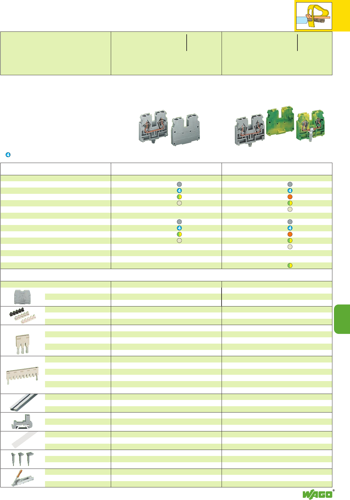
10
10
9
*YKf[
*YKf[
grey 869-375 100 (4 x 25)
blue 869-378 100 (4 x 25)
green-yellow 869-379 100 (4 x 25)
light grey 869-377 100 (4 x 25)
0.08 – 0.2 mm2280-470 200 strips
0.25 – 0.5 mm2280-471 200 strips
0.75 – 1 mm2280-472 200 strips
2-way 870-402 200 (8 x 25)
3-way 870-403 200 (8 x 25)
4-way 870-404 200 (8 x 25)
::
10-way 870-410 100 (4 x 25)
from 1 to 3 870-433 200 (8 x 25)
from 1 to 4 870-434 200 (8 x 25)
from 1 to 5 870-435 100 (4 x 25)
::
from 1 to 10 870-440 100 (4 x 25)
210-154 1
6 mm /0.236 in wide
grey 209-122 25
1 m /3’.3’’ long, 7.5 mm /0.295 in
plain 709-196 10
see page 3.11
not suitable for Series 269-328
298-635 1
grey 869-375 100 (4 x 25)
blue 869-378 100 (4 x 25)
green-yellow 869-379 100 (4 x 25)
light grey 869-377 100 (4 x 25)
0.08 – 0.2 mm2280-470 200 strips
0.25 – 0.5 mm2280-471 200 strips
0.75 – 1 mm2280-472 200 strips
2-way 870-402 200 (8 x 25)
3-way 870-403 200 (8 x 25)
4-way 870-404 200 (8 x 25)
::
10-way 870-410 100 (4 x 25)
from 1 to 3 870-433 200 (8 x 25)
from 1 to 4 870-434 200 (8 x 25)
from 1 to 5 870-435 100 (4 x 25)
::
from 1 to 10 870-440 100 (4 x 25)
210-154 1
6 mm /0.236 in wide
grey 209-122 25
1 m /3’.3’’ long, 7.5 mm /0.295 in
plain 709-196 10
see page 3.11
298-635 1
End plate for terminal blocks with snap-in
mounting foot
2.5 mm /0.098 in thick
Insulation stop ➌,white
5 pcs/strip light grey
dark grey
Push-in type jumper bar,
light grey,
insulated,
IN18 A
Push-in type jumper bar,
light grey,
insulated,
IN18 A
Aluminum carrier rail, 1000 mm/
3’.3’’ long, 18 mm /0.709 in wide,
7 mm /0.276 in high
Plastic end stop, with
WSB marking facility
for aluminum rail 210-154
Marker strip, transparent,
for central marking
– group marking –
Group marker carrier,
insert in jumper contact slot of
current bars
Assembly device, for the
assembly of terminal strips
Description
End terminal blocks
with/without snap-in
mounting foot,
for plate thickness 0.6 – 1.2 mm,
fixing hole diameter 3.5 +0.1mm Ø
Center terminal blocks
with/without snap-in
mounting foot,
for plate thickness 0.6 – 1.2 mm,
fixing hole diameter 3.5 +0.1mm Ø
End terminal blocks with snap-in mounting foot
grey 869-331 100
blue 869-334 100
green-yellow 869-337 100
light grey 869-339 100
End terminal blocks without snap-in mounting foot
grey 869-341 100
blue 869-344 100
green-yellow 869-347 100
light grey 869-349 100
Center terminal blocks with snap-in mounting foot
grey 869-311 100
blue 869-314 100
orange 869-316 100
green-yellow 869-317 100
light grey 869-319 100
Center term. blocks without snap-in mounting foot
grey 869-321 100
blue 869-324 100
orange 869-326 100
green-yellow 869-327 100
light grey 869-329 100
with automatic push-connect ground (earth) contact,
diameter
of drilled hole: 3.5
+0.1
mm Ø
Terminal blocks cannot be commoned !
green-yellow 869-328 100
Color Item Pack.-unit
No. pcs Color Item Pack.-unit
No. pcs
Modular Terminal Blocks with Snap-in Mounting Foot 2,5 mm2/4 mm2,
Series 869
Factory-assembled terminal strips, please contact factory for order form
* For further approvals with corresponding ratings see section 15. ** 10 A for push-in type jumper bars with different potentials, placed in parallel
for modular terminal
blocks and terminal strips
0.08
–2.5 mm
2
/4 mm
2
“f-st”
➊AWG 28 – 12
500 V/6 kV/3 ➋300 /600 V,
24 A 20/5 A**
Terminal block width 5 mm / 0.197 in
L6 – 7 mm / 0.26 in
0.08
–2.5 mm
2
/4 mm
2
“f-st”
➊AWG 28 – 12
500 V/6 kV/3 ➋300 /600 V,
24 A 20/5 A**
Terminal block width 5 mm / 0.197 in
L6 – 7 mm / 0.26 in
➊Max. diameter of insulation 4.4 mm /0.173 in
➋500 V = rated voltage
6 kV = rated surge voltage
3 = pollution degree
(see also section 15)
➌Please see application notes on page 10.29
Suitable for Ex i applications
Testing
Removable terminal blocks
see pages 3.10 – 3.11
Accessories Appropriate marking system WMB/Mini-WSB (see section 14)
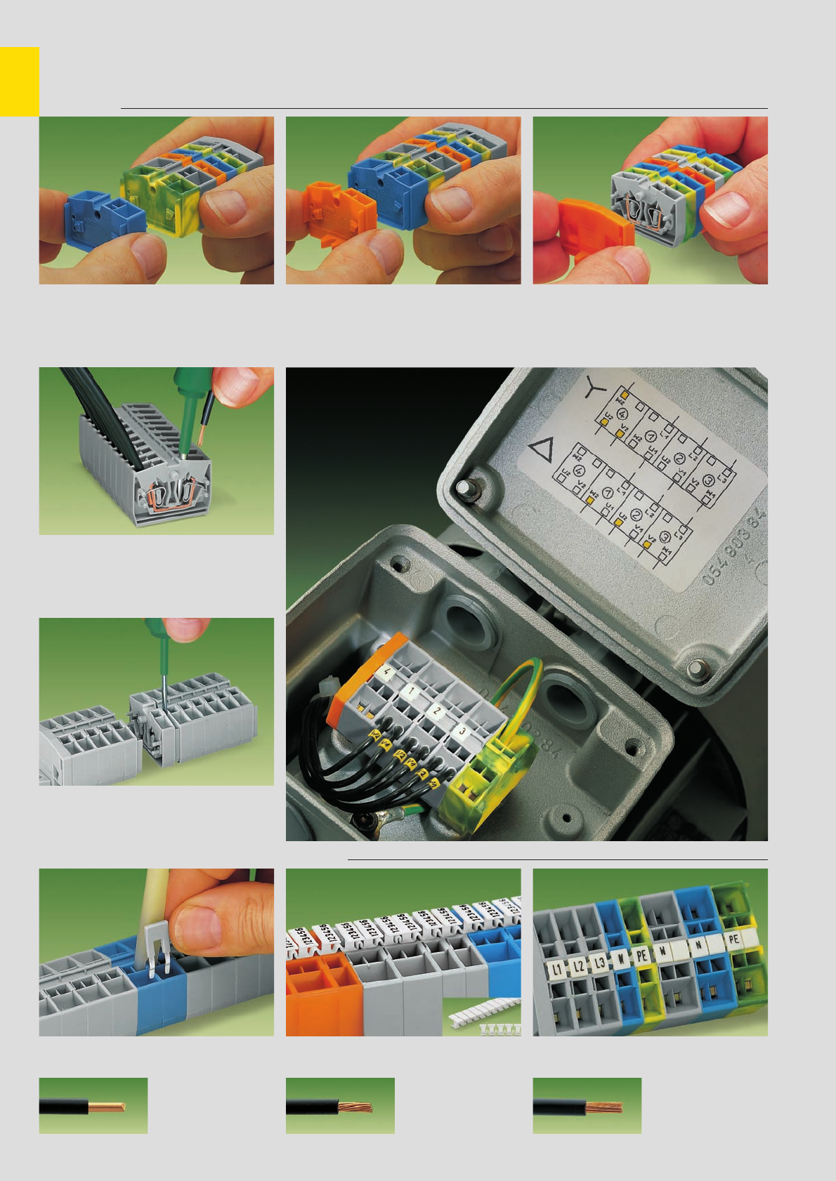
,
10
10
Modular Terminal Blocks and Terminal Strips with CAGE CLAMP®. . .
Series 264
Assembly
Assembly of modular terminal blocks
to terminal strips
CAGE CLAMP®connection
Connection of conductors
Removal
Removal of a terminal block
CAGE CLAMP®
connects the following
copper wires: *
solid stranded
fine stranded,
also with tinned
single strands
Commoning
Commoning with a jumper bar T marker tag
Marking
Marking
with miniature WSB Quick marking system
Mounting of an “end terminal block”
with fixing flange Mounting of an end plate
* For aluminum wire see notes in section 15!
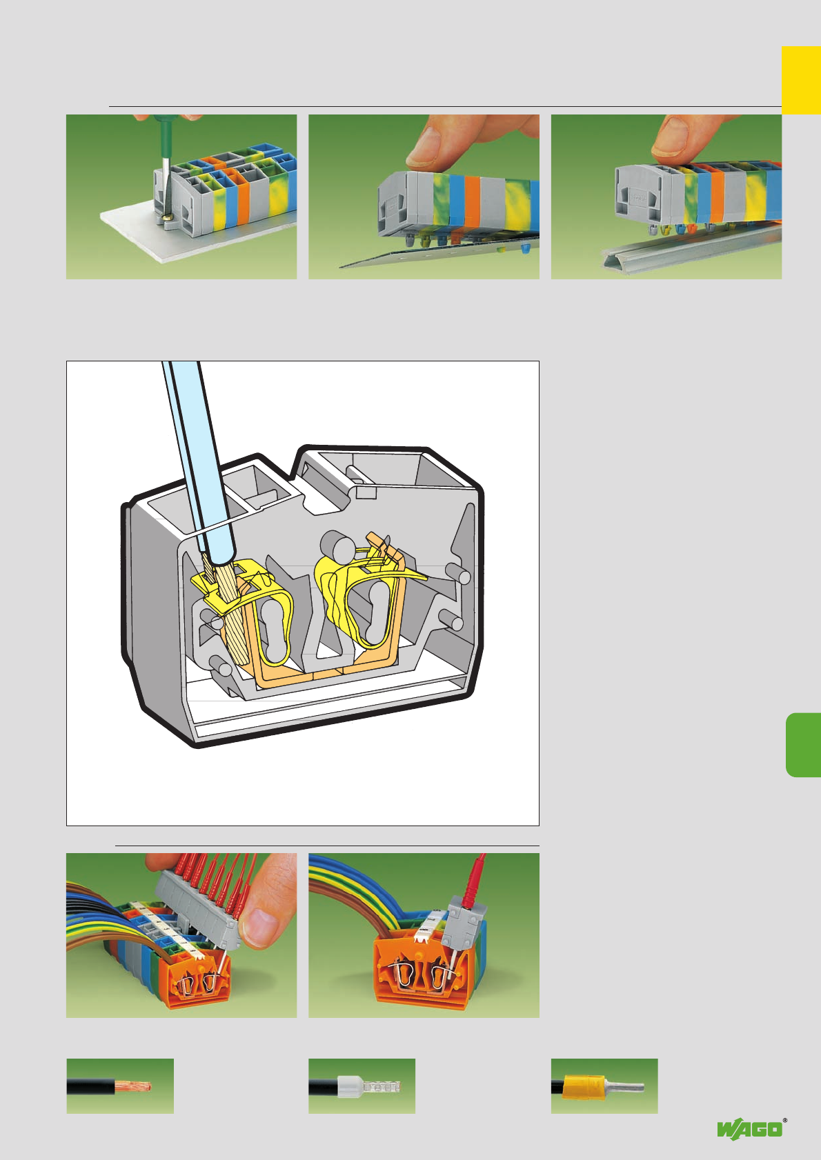
,
10
10
11
. . . Description and Handling
Fixing
Terminal strip with fixing flange,
screw fixing
fine-stranded wire –
tip bonded
fine-stranded wire
with crimped ferrule ➊fine-stranded wire
with crimped pin terminal
Testing
Testing with modular test plug adapters
– touch contact Testing with modular test plug adapter
– fully clamped by CAGE CLAMP®
Terminal strip with snap-in mounting feet,
fixing in holes Terminal strip with snap-in mounting feet,
assembly onto special aluminum rail
➊When using ferrules, the max. conductor cross section which can be accommodated is one size smaller than max. rating of terminal block.
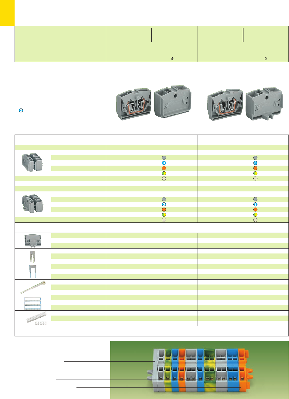
●
●
●
⎧
⎪
⎪
⎪
⎪
⎨
⎪
⎪
⎪
⎪
⎩
*U2QKfSDaJq:;{[ .4
*U2QfNSDaJq:;{[ .4
10
12
Complete terminal strips assembly with fixing flanges,
consisting of:
End plate with fixing flange
Center terminal blocks
End terminal block with fixing flange
* For further approvals with corresponding ratings see section 15.
Accessories for modular terminal blocks and terminal strips Appropriate marking system Mini-WSB (see section 14)
Description
Center terminal blocks, used between end terminal
block and end plate with fixing
flanges.
(see also application notes)
End terminal blocks with fixing flange,
for screw fixing or similar
methods,
fixing hole diameter 3.2 mm.
(see also application notes)
2-conductor center terminal blocks
6 mm /0.236 in wide
grey 264-321 100
blue 264-324 100
orange 264-326 100
green-yellow 264-327 100
light grey 4264-131 100
4-conductor center terminal blocks
10 mm /0.394 in wide
grey 264-351 100
blue 264-354 100
orange 264-356 100
green-yellow 264-357 100
light grey 4264-231 100
End plate with fixing
flange
4 mm/0.157 in thick
Comb type jumper bar,
2-way, insulated
Alternate comb type
jumper bar, insulated,
IN= INof terminal block
Operating tool,
insulated
Miniature WSB Quick marker
card, 10 strips with 10 markers
each, white with black printing
T marker tag,
6 characters per marker,
30 markers per tag
grey 264-361 25
orange 264-364 25
light grey 264-363 25
IN16 A
grey 264-402 200 (8 x 25)
reduce wire to 1.5 mm2/AWG 16 max.
2-way
for 4-cond. term. bl.
280-492 200 (8 x 25)
for 2-cond. term. bl.
281-492 100 (4 x 25)
2-way 280-432 1
for 2-cond. term. bl.
248-5 . . ➋5 cards
for 4-cond. term. bl.
264-9 . . ➋5 cards
from 5 mm/0.197 in to 6 mm/0.236 in
plain 209-290 50
Pre-printed markers on request
2-conductor end term. blocks with fixing flange
6 mm /0.236 in wide
grey 264-301 100
blue 264-304 100
orange 264-306 100
green-yellow 264-307 100
light grey 4264-130 100
4-conductor end term. blocks with fixing flange
10 mm /0.394 in wide
grey 264-331 100
blue 264-334 100
orange 264-336 100
green-yellow 264-337 100
light grey 4264-230 100
Color Item Pack.-unit
No. pcs Color Item Pack.-unit
No. pcs
Modular Terminal Blocks with Fixing Flange 2.5 mm2/ AWG 12,
Series 264
➊800 V = rated voltage
8 kV = rated surge voltage
3 = pollution degree
(see also section 15)
➋Please find all marking related item nos. in section 14.
Direct printing of fully assembled terminal strips upon
request
Suitable for Ex i applications
4Suitable for Ex e II applications
0.5 – 2.5 mm2AWG 20 – 12
750 V, 23 A
(see also section 13)
Application notes (Dimensions see page 10.14)
0.08 – 2.5 mm2AWG 28 – 12
800 V/8 kV/3 ➊600 V, 20 A U2
24 A
Term. bl. width 6 (10) mm / 0.236 (0.394) in
L8 – 9 mm / 0.33 in
0.08 – 2.5 mm2AWG 28 – 12
800 V/8 kV/3 ➊600 V, 20 A U2
24 A
Term. bl. width 6 (10) mm / 0.236 (0.394) in
L8 – 9 mm / 0.33 in
Test plug modules
see page 10.15
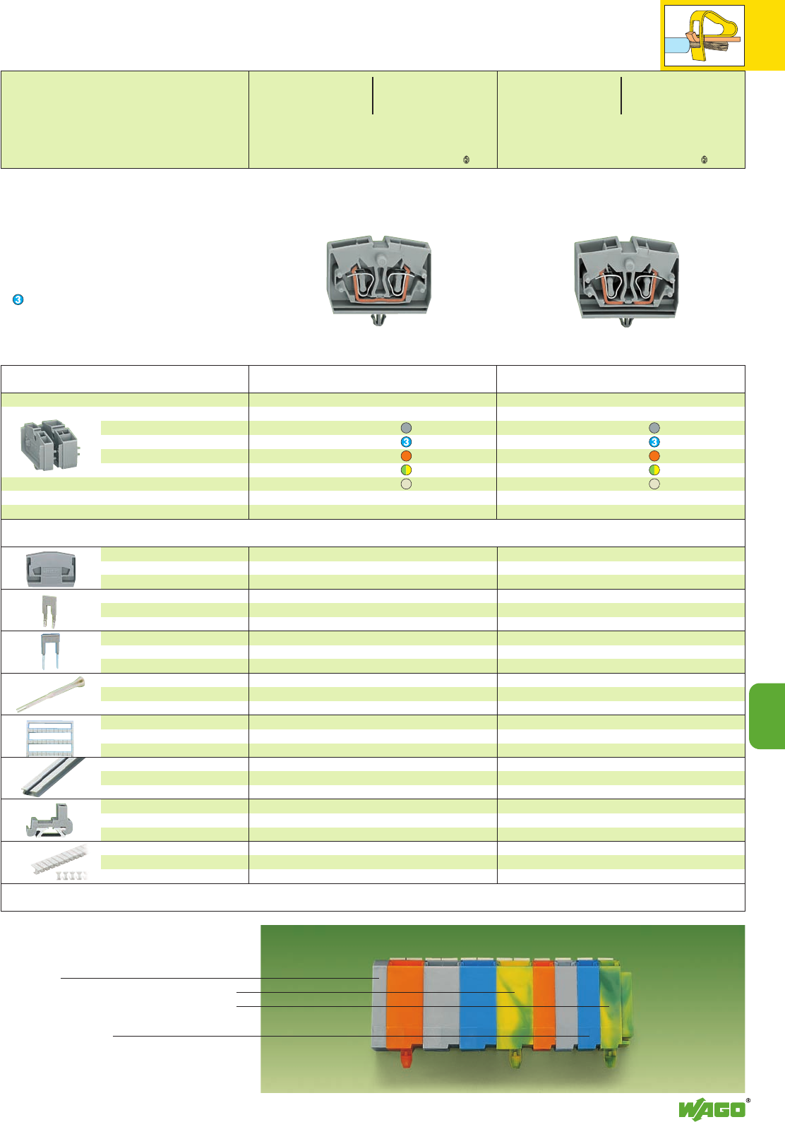
●
●●
●
●●●●●
*UY2QKfNSDaJq:;{[ .4 *UY2QKfNSDaJ:;{[ .4
10
10
13
Complete terminal strip assembly with snap-in
mounting feet, consisting of:
End plate
4-conductor term. block with snap-in mounting foot1)
2-conductor term. block with snap-in mounting foot1)
Center terminal blocks
1) at every 4th or 5th terminal block of the strip
* For further approvals with corresponding ratings see section 15.
Accessories for modular terminal blocks and terminal strips Appropriate marking system Mini-WSB (see section 14)
Description
Terminal blocks with snap-in mounting foot,
for plate thickness 0.6 – 1.2 mm,
fixing hole diameter 3.5 mm
2-conductor terminal blocks with snap-in
mounting foot, 6 mm /0.236 in wide
grey 264-311 100
blue 264-314 100
orange 264-316 100
green-yellow 264-317 100
light grey 4264-180 100
End plate, for terminal blocks
with snap-in mounting foot
4 mm/0.157 in thick
Comb type jumper bar,
2-way, insulated
Alternate comb type
jumper bar, insulated,
IN= INof terminal block
Operating tool,
insulated
Miniature WSB Quick marker
card, 10 strips with 10 markers
each, white with black printing
Aluminum carrier rail,
1000 x 18 x 7 mm
3’3” x 0.709 x 0.276 in
Plastic end stop,
with WSB marking facility,
for aluminum rail 210-154
T marker tag,
6 characters per marker,
30 markers per tag
grey 264-371 25
orange 264-374 25
light grey 264-373 25
IN16 A
grey 264-402 200 (8 x 25)
reduce wire to 1.5 mm2/AWG 16 max.
2-way 281-492 100 (4 x 25)
2-way 280-432 1
248-5 . . ➋5 cards
210-154 1
6 mm /0.236 in wide
grey 209-122 25
from 5 mm/0.197 in to 6 mm/0.236 in
plain 209-290 50
Pre-printed markers on request
grey 264-371 25
orange 264-374 25
light grey 264-373 25
IN16 A
grey 264-402 200 (8 x 25)
reduce wire to 1.5 mm2/AWG 16 max.
2-way 280-492 200 (8 x 25)
2-way 280-432 1
264-9 . . ➋5 cards
210-154 1
6 mm /0.236 in wide
grey 209-122 25
from 5 mm/0.197 in to 6 mm/0.236 in
plain 209-290 50
Pre-printed markers on request
4-conductor terminal blocks with snap-in
mounting foot, 10 mm /0.394 in wide
grey 264-341 100
blue 264-344 100
orange 264-346 100
green-yellow 264-347 100
light grey 4264-280 100
Color Item Pack.-unit
No. pcs Color Item Pack.-unit
No. pcs
➊800 V = rated voltage
8 kV = rated surge voltage
3 = pollution degree
(see also section 15)
➋Please find all marking related item nos. in section 14.
Direct printing of fully assembled terminal strips upon
request
Suitable for Ex i applications
4Suitable for Ex e II applications
0.5 – 2.5 mm2AWG 20 – 12
750 V, 23 A
(see also section 13)
Application notes (Dimensions see page 10.14)
Modular Terminal Blocks w. Snap-in Mounting Foot 2.5 mm2/ AWG 12,
Series 264
0.08 – 2.5 mm2AWG 28 – 12
800 V/8 kV/3 ➊600 V, 20 A U2
24 A
Term. bl. width 6 (10) mm / 0.236 (0.394) in
L8 – 9 mm / 0.33 in
0.08 – 2.5 mm2AWG 28 – 12
800 V/8 kV/3 ➊600 V, 20 A U2
24 A
Term. bl. width 6 (10) mm / 0.236 (0.394) in
L8 – 9 mm / 0.33 in
Test plug modules
see page 10.15
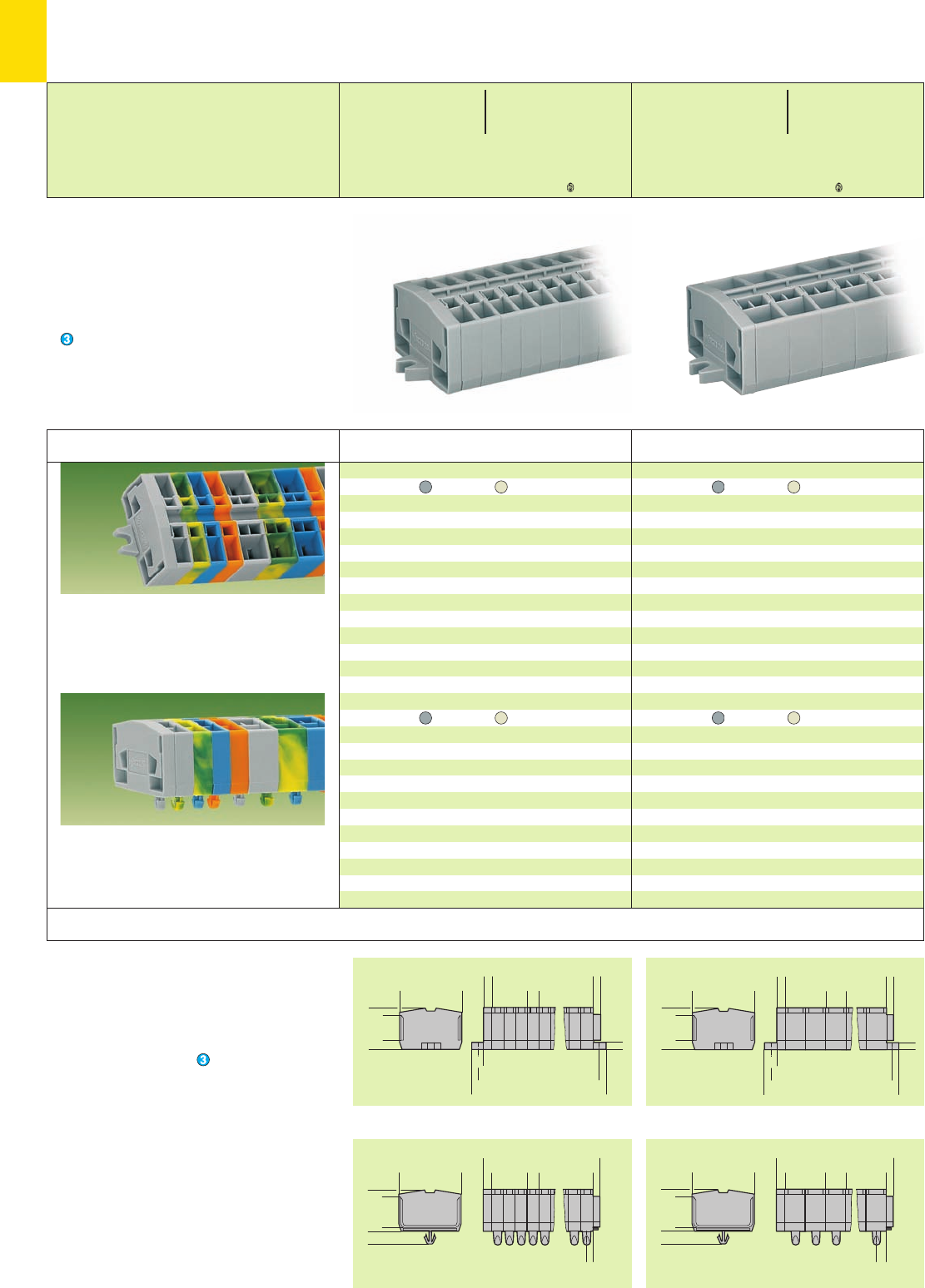
<22,1 >
(_12 _)
<___ 32___>
<
__>
3,6
<________ L________>
>
3
<
4
<
>
6
<____________ L2 ____________>
<__________ L1 __________>
<
>
6
(_12 _)
<___ 32___>
<
__>
3,6
<________ L________>
<
>
10
>
3
<
4
<
>
6
<____________ L2 ____________>
<__________ L1 __________>
<22,1 >
(15,8)
__
>
4,5
<___ 32___>
<
>
3
<
>
4
<__________ L__________>
<
>
6
<
>
3
<22,1 >
(15,8)
__
>
4,5
<___ 32___>
<
>
5
<
>
4
<__________ L__________>
<
>
10
<
>
3
<22,1 >
*U2QKfNSDaJq:;{[ .4 *U2QKfNaJq:;{[ .4
10
14
Terminal strips with fixing flanges,
for screw fixing or similar methods,
fixing hole diameter 3.2 mm
Terminal strips with snap-in mounting feet,
for plate thickness 0.6 – 1.2 mm,
fixing hole diameter 3.5 mm
Modular terminal blocks and terminal strips
with fixing flanges
L = No. of poles x pole width
L1= L + 9.6 mm
L2= L + 16 mm
Additional item nos. for colored terminal strips
blue .../000-006
Modular terminal blocks and terminal strips
with snap-in mounting feet
L = (No. of poles x pole width) + 7 mm
* For further approvals with corresponding ratings see section 15.
Description
2-conductor terminal strips with fixing flanges,
grey light grey 4
2264-102 264-132 100
3264-103 264-133 100
4264-104 264-134 100
5264-105 264-135 100
6264-106 264-136 100
7264-107 264-137 100
8264-108 264-138 100
9264-109 264-139 50
10 264-110 264-140 50
11 264-111 264-141 25
12 ➋264-112 264-142 25
2-conductor terminal strips with snap-in mounting
feet, grey light grey 4
2264-152 264-182 100
3264-153 264-183 100
4264-154 264-184 100
5264-155 264-185 100
6264-156 264-186 100
7264-157 264-187 100
8264-158 264-188 100
9264-159 264-189 50
10 264-160 264-190 50
11 264-161 264-191 25
12 ➋264-162 264-192 25
4-conductor terminal strips with fixing flanges,
grey light grey 4
2264-202 264-232 100
3264-203 264-233 100
4264-204 264-234 100
5264-205 264-235 100
6264-206 264-236 100
7264-207 264-237 100
8264-208 264-238 100
9264-209 264-239 50
10 264-210 264-240 50
11 264-211 264-241 25
12 ➋264-212 264-242 25
4-conductor terminal strips with snap-in mounting
feet, grey light grey 4
2264-252 264-282 100
3264-253 264-283 100
4264-254 264-284 100
5264-255 264-285 100
6264-256 264-286 100
7264-257 264-287 100
8264-258 264-288 50
9264-259 264-289 50
10 264-260 264-290 50
11 264-261 264-291 25
12 ➋264-262 264-292 25
No. of Item Item Pack.-unit
poles No. No. pcs No. of Item Item Pack.-unit
poles No. No. pcs
Terminal Strips with Fixing Flanges or Snap-in Mounting Feet 2.5 mm2/AWG 12,
Series 264
➊800 V = rated voltage
8 kV = rated surge voltage
3 = pollution degree
(see also section 15)
➋For longer strips and /or
assemblies of different
colors, contact factory.
Suitable for Ex i applications
with blue insulating housings
4Suitable for Ex e II applications
0.5 – 2.5 mm2AWG 20 – 12
750 V, 23 A
(see also section 13)
Dimensions for modular terminal blocks and terminal strips (in mm)
0.08 – 2.5 mm2AWG 28 – 12
800 V/8 kV/3 ➊600 V, 20 A U2
24 A
Pole width 6 mm / 0.236 in
L8 – 9 mm / 0.33 in
2 x 0.08 – 2.5 mm22 x AWG 28 – 12
800 V/8 kV/3 ➊600 V, 20 A U2
24 A
Pole width 10 mm / 0.394 in
L8 – 9 mm / 0.33 in
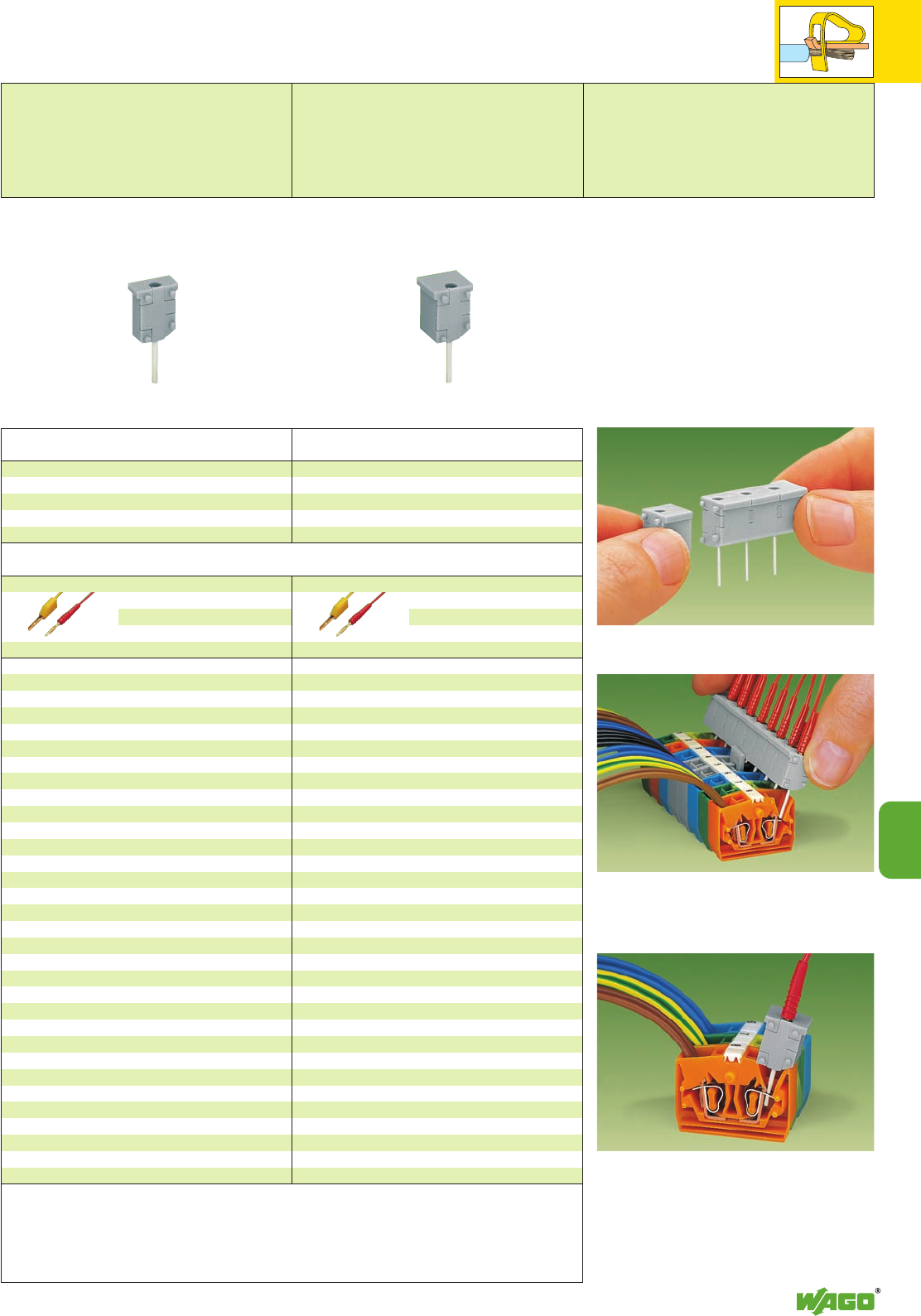
10
10
15
Assembly of multipole test plug module strips
Testing with touch contact at the CAGE CLAMP®
connection made of spring steel –
limited to a current of 0.5 A max.
Testing using CAGE CLAMP®connection on the current
bar – max. nominal current 6 A.
The CAGE CLAMP®clamps individual test contacts.
➊Max. test voltage 400 V/800 V only in test equipment, respecting the relevant air and creepage distances
➋In case of touch contacting, the max. test voltage must not exceed 48 V, test pins are not touchproof
➌Test current in case of touch contacting 0.5 A max.,
6 A if the test pins are firmly connected in the clamping units
Accessories
Test plug,
with
cable 500 mm/1’7.7’’
2 mm Ø, red
210-136 50 (5 x 10)
2.3 mm Ø, yel.
210-137 50 (5 x 10)
Test plug module,
Module width 6 mm /0.236 in,
for 2-conductor terminal blocks
grey 249-136 100 (4 x 25)
Test plug module,
Module width 10 mm /0.394 in,
for 4-conductor terminal blocks
grey 249-139 100 (4 x 25)
Item Pack.-unit
No. pcs Item Pack.-unit
No. pcs
Test Plug Modules for Modular Terminal Blocks and Terminal Strips,
Series 264
Module width 6 mm / 0.236 in
Test voltage 400 V ➊/ 48 V ➋
Test current 0.5 A / 6 A ➌
Average contact pressure 2.2 N per pin
Module width 10 mm / 0.394 in
Test voltage 800 V ➊/ 48 V ➋
Test current 0.5 A / 6 A ➌
Average contact pressure 2.2 N per pin
Test plug,
with
cable 500 mm/1’7.7’’
2 mm Ø, red
210-136 50 (5 x 10)
2.3 mm Ø, yel.
210-137 50 (5 x 10)
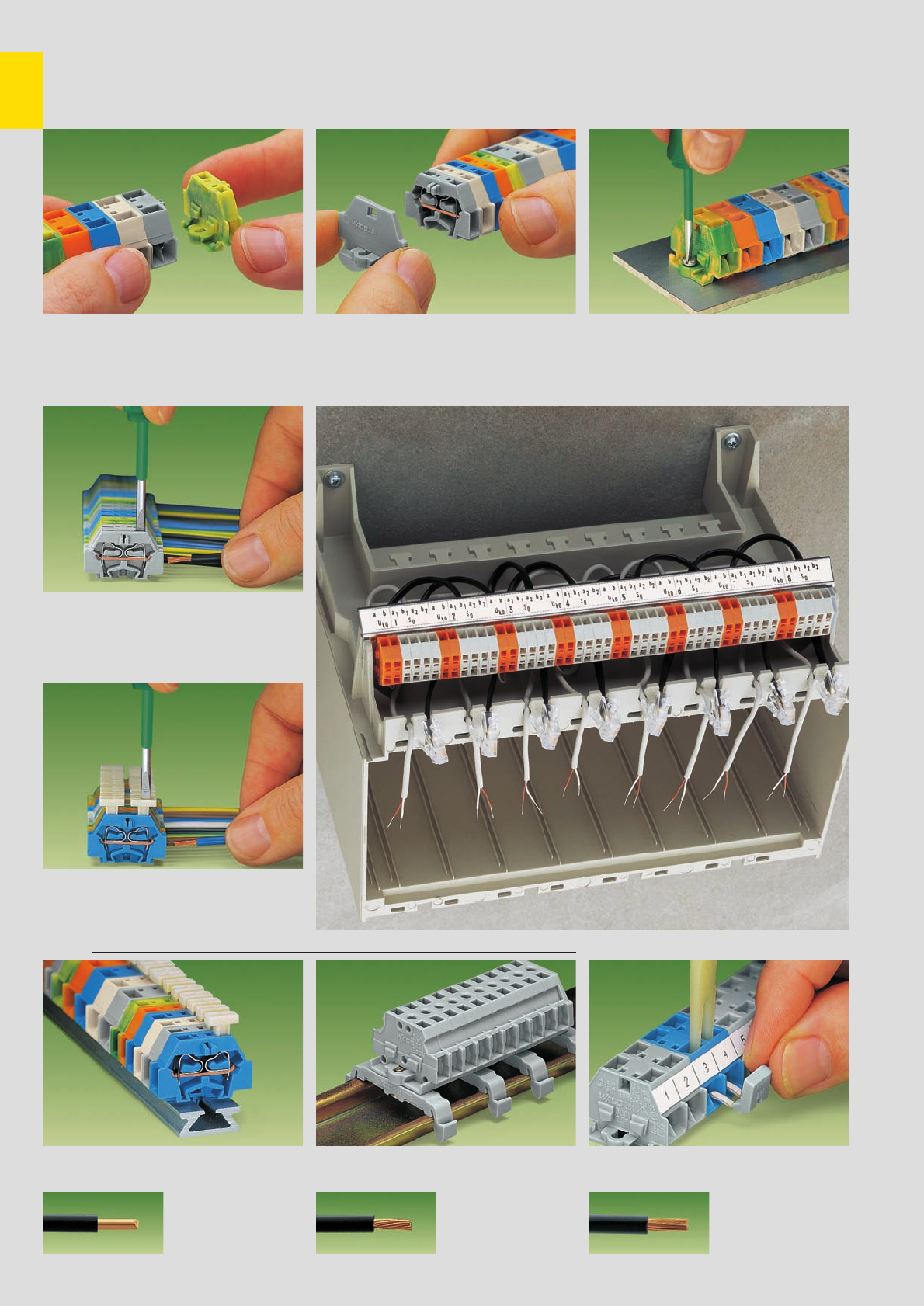
,
10
16
Modular Terminal Blocks and Terminal Strips with CAGE CLAMP®. . .
Series 260 to 262
Assembly Fixing
Assembly of modular terminal blocks
to terminal strips
CAGE CLAMP®connection
Connection of conductors
CAGE CLAMP®connection
Connection of conductors,
with push-buttons
CAGE CLAMP®
clamps the following
copper wires: *
solid stranded
fine stranded,
also with tinned
single strands
Types Commoning
Terminal strip with push-buttons on one side Terminal strip with marker receptacle
for miniature WSB Quick marking system Commoning with jumper bar
Mounting of an end plate Terminal strip with fixing flange,
screw fixing
* For aluminum wire see notes in section 15!
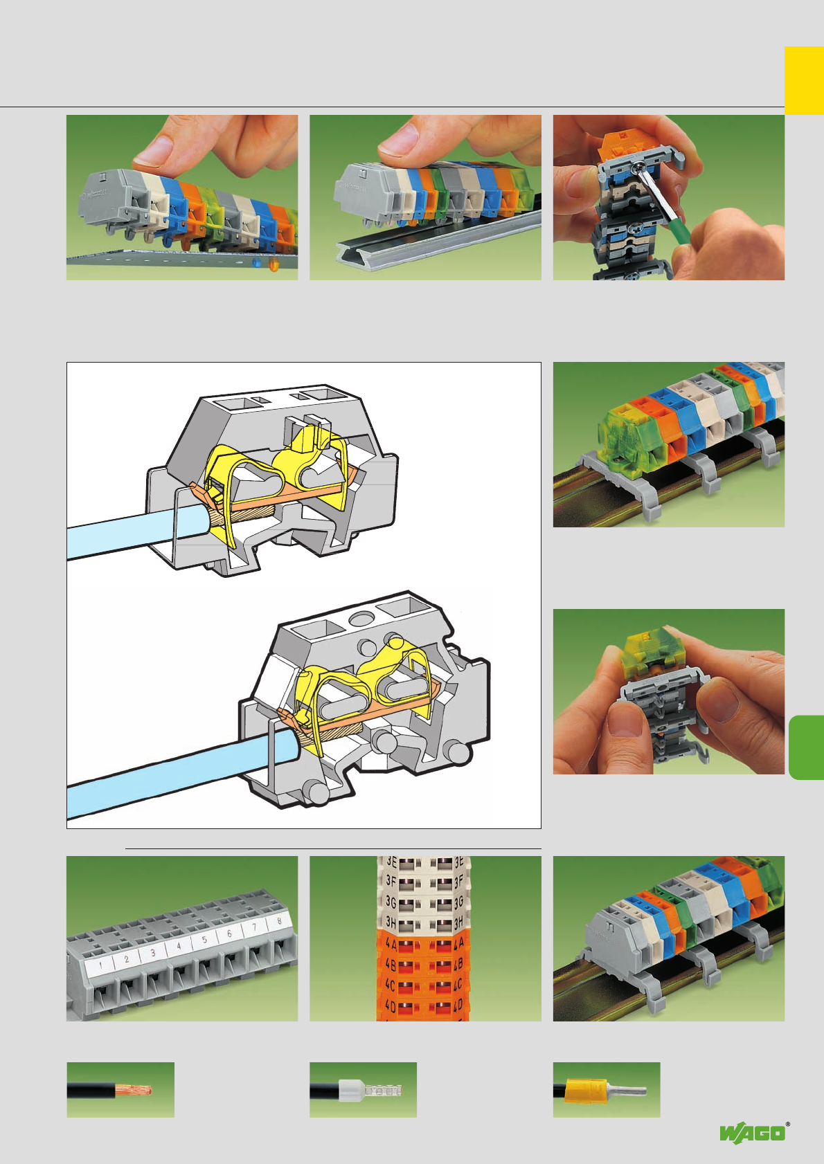
,
10
10
17
. . . Description and Handling
Terminal strip with snap-in mounting feet,
fixing in holes
Fixing
Terminal strip with fixing flange,
on DIN 35 rail
Fixing
Terminal strip with snap-in mounting feet,
assembly of mounting adapter 209-1201)
1) The distance between mounting adapters should
be 35 – 40 mm / 1.378 – 1.575 in max.
fine-stranded wire –
tip bonded
fine-stranded wire
with crimped ferrule ➊fine-stranded wire
with crimped pin terminal
Marking Fixing
Marking with self-adhesive marker strips Marking by direct printing Terminal strip with snap-in mounting feet
on DIN 35 rail
Terminal strip with snap-in mounting feet,
on special aluminum rail Terminal strip with fixing flange,
screw fixing of mounting adapter 209-1231)
➊ When using conductors with ferrules, it is necessary to use a terminal block one size larger than the nominal cross section of the conductor.
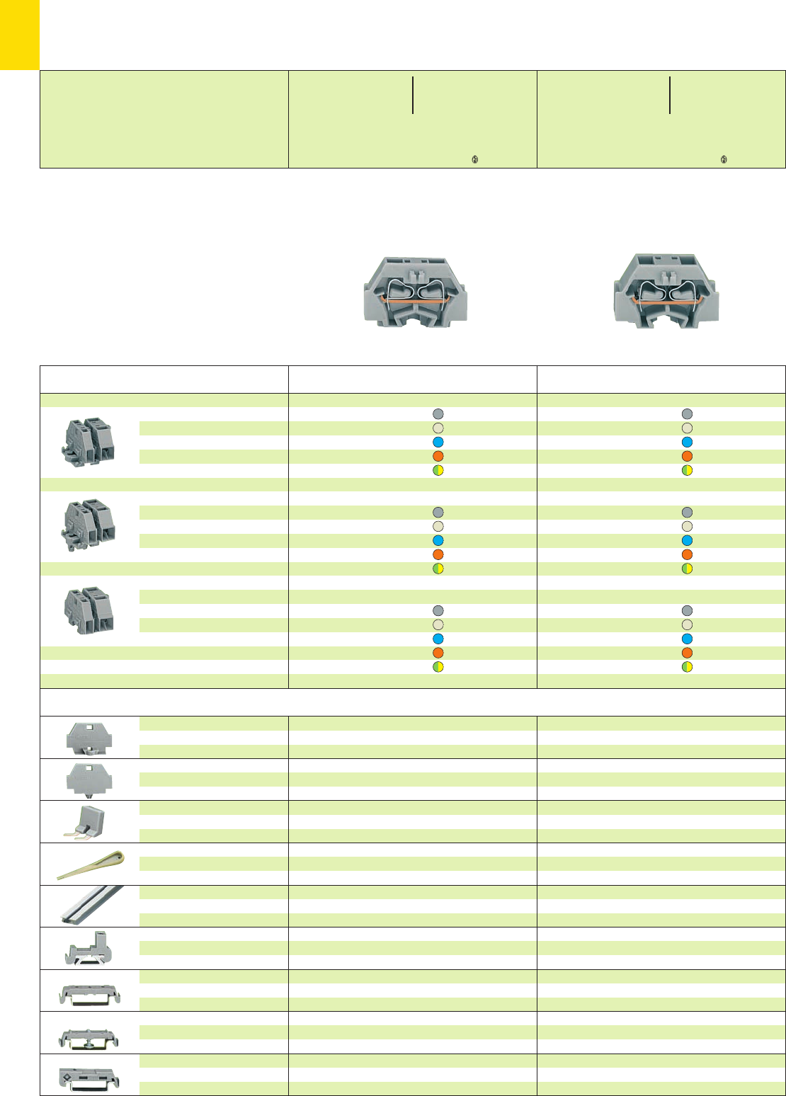
*U2QKfNSDaJ:;{[ . *U2QKfNSDaJ:;{[ .
10
18
* For further approvals with corresponding ratings see section 15.
Accessories for modular terminal blocks and terminal strips (Marking accessories see section 14)
Description
End plate
with fixing flange
End plate with snap-in
mounting foot
Comb type jumper bar,
insulated, 2-way
Operating tool, insulated,
for connecting the comb type
jumper bar
Aluminum carrier rail,
1000 x 18 x 7 mm
3’3” x 0.709 x 0.276 in
Plastic end stop,
with WSB marking facility,
for aluminum rail 210-154
Mounting adapter, for terminal
blocks with snap-in mounting
foot, for DIN 35 rail
Mounting adapter with
screw, for terminal blocks with
fixing flange, for DIN 35 rail
Mounting adapter
for DIN 35 rail,
can be used as end stop
grey 260-361 100 (2 x 50)
grey 260-371 100 (2 x 50)
IN10 A
grey 260-402 25
reduce wire to 1 mm2/AWG 18 max.
2-way 209-132 1
210-154 1
6 mm /0.236 in wide
grey 209-122 25
6 mm /0.236 in wide
grey 209-120 25
6 mm /0.236 in wide
grey 209-123 25
6.5 mm /0.256 in wide
grey 209-137 25
grey 260-361 100 (2 x 50)
grey 260-371 100 (2 x 50)
IN10 A
grey 260-402 25
reduce wire to 1 mm2/AWG 18 max.
2-way 209-132 1
210-154 1
6 mm /0.236 in wide
grey 209-122 25
6 mm /0.236 in wide
grey 209-120 25
6 mm /0.236 in wide
grey 209-123 25
6.5 mm /0.256 in wide
grey 209-137 25
Modular Terminal Blocks with
Fixing Flange or Snap-in Mounting Foot 1.5 mm2/ AWG 16,
Series 260
➊400 V = rated voltage
6 kV = rated surge voltage
3 = pollution degree
(see also section 15)
Color Item Pack.-unit
No. pcs
Terminal blocks with fixing flange,
for screw fixing or similar
methods, fixing hole
diameter 3.2 mm (with mounting
adapter 209-123 also for
DIN 35 rail)
Terminal blocks with snap-in mounting foot,
for plate thickness 0.6 – 1.2 mm,
fixing hole diameter 3.5 mm
(fits aluminum rail 210-154 or with
mounting adapter 209-120 for
DIN 35 rail)
End terminal block ➌,
without fixing foot, for terminal
strips with snap-in mounting feet
(see dimensioned drawings on
page 10.19)
2-conductor terminal blocks
grey 260-301 300 (6 x 50)
light grey 260-303 300 (6 x 50)
blue 260-304 300 (6 x 50)
orange 260-306 300 (6 x 50)
green-yellow 260-307 300 (6 x 50)
2-conductor terminal blocks
grey 260-311 300 (6 x 50)
light grey 260-313 300 (6 x 50)
blue 260-314 300 (6 x 50)
orange 260-316 300 (6 x 50)
green-yellow 260-317 300 (6 x 50)
2-conductor terminal blocks
grey 260-321 300 (6 x 50)
light grey 260-323 300 (6 x 50)
blue 260-324 300 (6 x 50)
orange 260-326 300 (6 x 50)
green-yellow 260-327 300 (6 x 50)
Color Item Pack.-unit
No. pcs
4-conductor terminal blocks
grey 260-331 300 (6 x 50)
light grey 260-333 300 (6 x 50)
blue 260-334 300 (6 x 50)
orange 260-336 300 (6 x 50)
green-yellow 260-337 300 (6 x 50)
4-conductor terminal blocks
grey 260-341 300 (6 x 50)
light grey 260-343 300 (6 x 50)
blue 260-344 300 (6 x 50)
orange 260-346 300 (6 x 50)
green-yellow 260-347 300 (6 x 50)
4-conductor terminal blocks
grey 260-351 300 (6 x 50)
ight grey 260-353 300 (6 x 50)
blue 260-354 300 (6 x 50)
orange 260-356 300 (6 x 50)
green-yellow 260-357 300 (6 x 50)
0.08 – 1.5 mm2AWG 28 – 16
400 V/6 kV/3 ➊300 V, 10 A U
18 A 300 V, 15 A 2
Terminal block width 5 mm / 0.197 in
L8 – 9 mm / 0.33 in
2 x 0.08 – 1.5 mm22 x AWG 28 – 16
400 V/6 kV/3 ➊300 V, 10 A U
18 A 300 V, 15 A 2
Terminal block width 8 mm / 0.315 in
L8 – 9 mm / 0.33 in
Test plug modules
see page 10.28
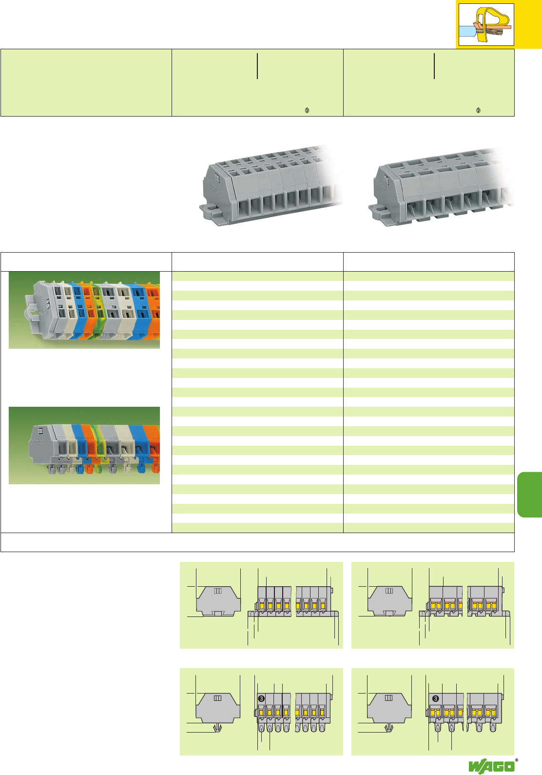
<__________ L__________>
>
5
>
>
>
2,5
___>
<______________ L2 ______________>
<____________ L 1 ____________>
__>
2,8
>
__>
6
<_ __ 17___ >
<_____ 25_____>
<_ __ 17___ >
<_____ 25_____> <__________ L__________>
>
8
>
>
>
2,5
__>
<______________ L2 ______________>
<____________ L 1 ____________>
__>
2,8
>
__>
6
>
1,4
<____________ L____________>
<
>
5
<
>
3
__>
2,2
__>
7, 2
__>
>
>
<_ __ 17___ >
>
4,5
<_____ 25_____>
<_ __ 17___ >
>
4,5
<_____ 25_____> <____________ L____________>
>
8
<
>
3
13,2
____>
5,2
____>
>
>
1,4
__> _)(_
*U2QKfNSD8aJ:;{[ . *U2QKfNSD8aJ:;{[ .
10
10
19
Terminal strips with fixing flanges,
for screw fixing or similar methods,
fixing hole diameter 3.2 mm
(with mounting adapter 209-123 also for DIN 35 rail)
Terminal strips with snap-in mounting feet,
for plate thickness 0.6 – 1.2 mm, fixing hole diameter
3.5 mm (fits aluminum rail 210-154
or with mounting adapter 209-120 for DIN 35 rail)
Modular terminal blocks and terminal strips
with fixing flanges
L = No. of poles x pole width
L1= L + 8.1 mm
L2= L + 14.5 mm
Modular terminal blocks and terminal strips
with snap-in mounting feet
➌ End terminal block;
see page 10.18
L = (No. of poles x pole width) + 4.4 mm
Description
2-conductor terminal strips with fixing flanges,
grey
2260-102 100
3260-103 100
4260-104 100
5260-105 100
6260-106 50
7260-107 50
8260-108 50
9260-109 50
10 260-110 25
11 260-111 25
12 ➋260-112 25
2-conductor terminal strips with snap-in
mounting feet, grey
2260-152 100
3260-153 100
4260-154 100
5260-155 100
6260-156 50
7260-157 50
8260-158 50
9260-159 50
10 260-160 25
11 260-161 25
12 ➋260-162 25
4-conductor terminal strips with fixing flanges,
grey
2260-202 100
3260-203 100
4260-204 100
5260-205 100
6260-206 50
7260-207 50
8260-208 50
9260-209 50
10 260-210 25
11 260-211 25
12 ➋260-212 25
4-conductor terminal strips with snap-in
mounting feet, grey
2260-252 100
3260-253 100
4260-254 100
5260-255 100
6260-256 50
7260-257 50
8260-258 50
9260-259 50
10 260-260 25
11 260-261 25
12 ➋260-262 25
No. of Item Pack.-unit
poles No. pcs No. of Item Pack.-unit
poles No. pcs
Terminal Strips with
Fixing Flanges or Snap-in Mounting Feet 1.5 mm2/ AWG 16,
Series 260
➊400 V = rated voltage
6 kV = rated surge voltage
3 = pollution degree
(see also section 15)
➋For longer strips and /or assemblies of different
colors, please contact factory
Dimensions for modular terminal blocks and terminal strips (in mm)
0.08 – 1.5 mm2AWG 28 – 16
400 V/6 kV/3 ➊300 V, 10 A U
18 A 300 V, 15 A 2
Pole width 5 mm / 0.197 in
L8 – 9 mm / 0.33 in
2 x 0.08 – 1.5 mm22 x AWG 28 – 16
400 V/6 kV/3 ➊300 V, 10 A U
18 A 300 V, 15 A 2
Pole width 8 mm / 0.315 in
L8 – 9 mm / 0.33 in
Test plug modules
see page 10.28
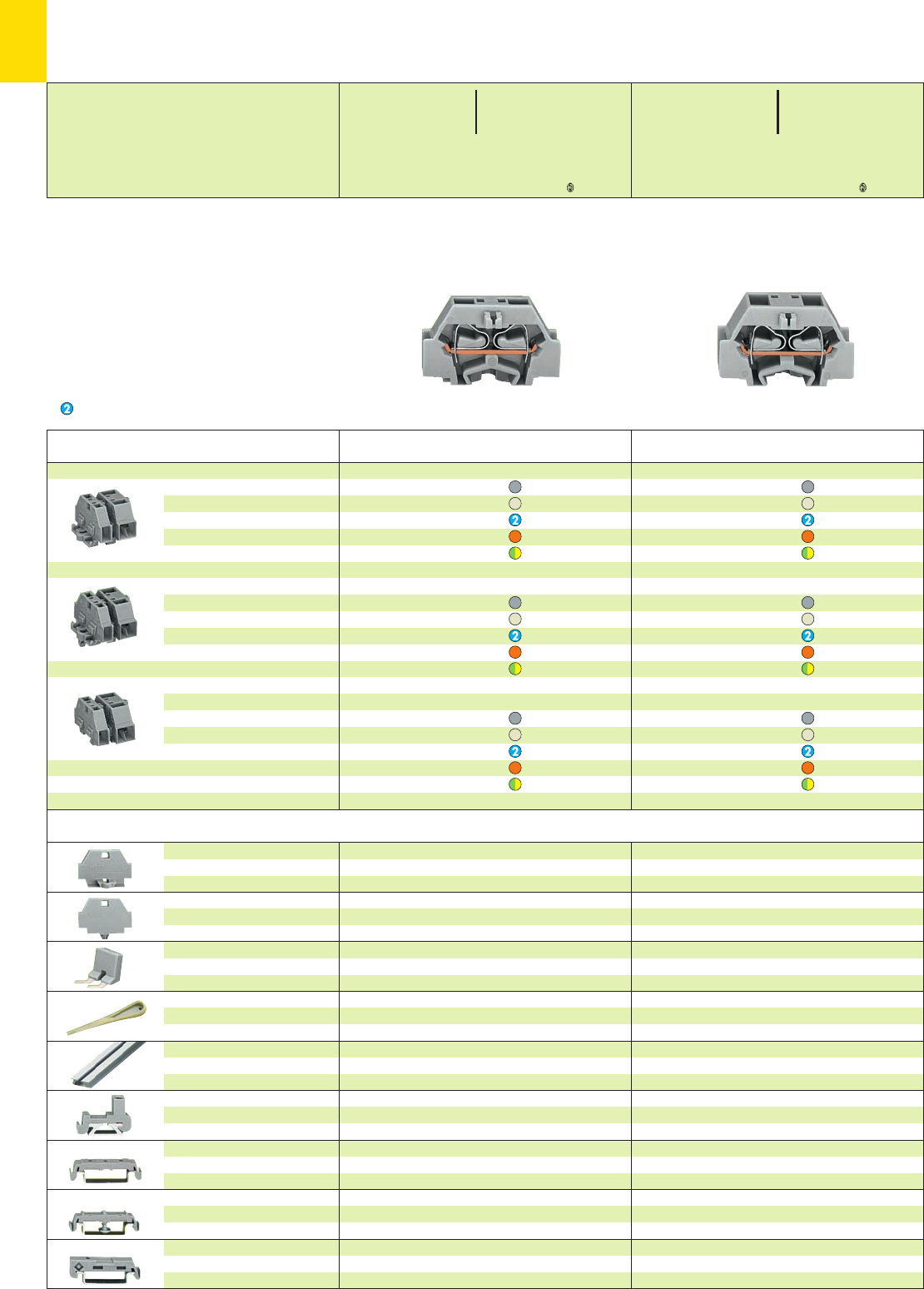
*U2QKfNSDaJq:;{[ . *U2QKfNSDaJq:;{[ .
10
20
* For further approvals with corresponding ratings see section 15.
Accessories for modular terminal blocks and terminal strips (Marking accessories see section 14)
Description
End plate
with fixing flange
End plate with snap-in
mounting foot
Comb type jumper bar,
insulated, 2-way
Operating tool, insulated,
for connecting the comb type
jumper bar
Aluminum carrier rail,
1000 x 18 x 7 mm
3’3” x 0.709 x 0.276 in
Plastic end stop,
with WSB marking facility,
for aluminum rail 210-154
Mounting adapter, for terminal
blocks with snap-in mounting
foot, for DIN 35 rail
Mounting adapter with
screw, for terminal blocks with
fixing flange, for DIN 35 rail
Mounting adapter
for DIN 35 rail,
can be used as end stop
grey 261-361 100 (2 x 50)
grey 261-371 100 (2 x 50)
IN16 A
grey 261-402 25
reduce wire to 1.5 mm2/AWG 16 max.
2-way 209-132 1
210-154 1
6 mm /0.236 in wide
grey 209-122 25
6 mm /0.236 in wide
grey 209-120 25
6 mm /0.236 in wide
grey 209-123 25
6.5 mm /0.256 in wide
grey 209-137 25
grey 261-361 100 (2 x 50)
grey 261-371 100 (2 x 50)
IN16 A
grey 261-402 25
reduce wire to 1.5 mm2/AWG 16 max.
2-way 209-132 1
210-154 1
6 mm /0.236 in wide
grey 209-122 25
6 mm /0.236 in wide
grey 209-120 25
6 mm /0.236 in wide
grey 209-123 25
6.5 mm /0.256 in wide
grey 209-137 25
Modular Terminal Blocks with
Fixing Flange or Snap-in Mounting Foot 2.5 mm2/ AWG 14,
Series 261
➊500 V = rated voltage
6 kV = rated surge voltage
3 = pollution degree
(see also section 15)
Suitable for Ex i applications
Color Item Pack.-unit
No. pcs
Terminal blocks with fixing flange,
for screw fixing or similar
methods, fixing hole
diameter 3.2 mm (with mounting
adapter 209-123 also for
DIN 35 rail)
Terminal blocks with snap-in mounting foot,
for plate thickness 0.6 – 1.2 mm,
fixing hole diameter 3.5 mm
(fits aluminum rail 210-154 or with
mounting adapter 209-120 for
DIN 35 rail)
End terminal block ➌,
without fixing foot, for terminal
strips with snap-in mounting feet
(see dimensioned drawings on
page 10.21)
2-conductor terminal blocks
grey 261-301 200 (4 x 50)
light grey 261-303 200 (4 x 50)
blue 261-304 200 (4 x 50)
orange 261-306 200 (4 x 50)
green-yellow 261-307 200 (4 x 50)
2-conductor terminal blocks
grey 261-311 200 (4 x 50)
light grey 261-313 200 (4 x 50)
blue 261-314 200 (4 x 50)
orange 261-316 200 (4 x 50)
green-yellow 261-317 200 (4 x 50)
2-conductor terminal blocks
grey 261-321 200 (4 x 50)
light grey 261-323 200 (4 x 50)
blue 261-324 200 (4 x 50)
orange 261-326 200 (4 x 50)
green-yellow 261-327 200 (4 x 50)
Color Item Pack.-unit
No. pcs
4-conductor terminal blocks
grey 261-331 200 (4 x 50)
light grey 261-333 200 (4 x 50)
blue 261-334 200 (4 x 50)
orange 261-336 200 (4 x 50)
green-yellow 261-337 200 (4 x 50)
4-conductor terminal blocks
grey 261-341 200 (4 x 50)
light grey 261-343 200 (4 x 50)
blue 261-344 200 (4 x 50)
orange 261-346 200 (4 x 50)
green-yellow 261-347 200 (4 x 50)
4-conductor terminal blocks
grey 261-351 200 (4 x 50)
light grey 261-353 200 (4 x 50)
blue 261-354 200 (4 x 50)
orange 261-356 200 (4 x 50)
green-yellow 261-357 200 (4 x 50)
0.08 – 2.5 mm2AWG 28 – 14
500 V/6 kV/3 ➊300/600V,15/5 A U
24 A 300/600 V, 20/5 A 2
Terminal block width 6 mm / 0.236 in
L8 – 9 mm / 0.33 in
2 x 0.08 – 2.5 mm22xAWG28–14
500 V/6 kV/3 ➊300/600V,15/5 A U
24 A 300/600V,20/5 A 2
Terminal block width 10 mm / 0.394 in
L8 – 9 mm / 0.33 in
Test plug modules
see page 10.28
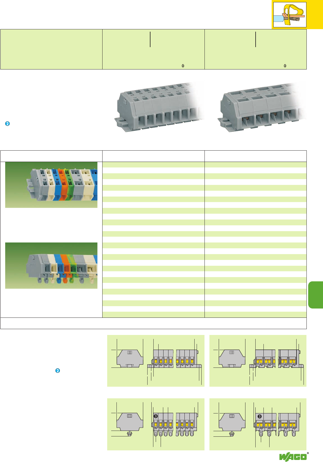
<__________ L__________>
>
6
>
>
>
2,5
___>
<______________ L2 ______________>
<____________ L 1 ____________>
__>
2,8
>
__>
6
<___ 18 ___>
<_____ 28 _____>
<_ __18 ___>
<_____ 28 _____> <__________ L__________>
>
10
>
>
>
2,5
___>
<______________ L2 ______________>
<____________ L 1 ____________>
__>
2,8
>
__>
6
>
1,4
<____________ L____________>
<
>
6
<
>
3
__>
3,2
__>
9,2
__>
>
>
< ___ 18 _ __>
>
4,5
<_____ 28 _____>
< ___ 18 ___>
>
4,5
<_____ 28 _____> <___________ L___________>
>
10
<
>
3
17, 2
____>
7, 2
____>
>
>
1,4
__> _)(_
*U2QKfSD8aJq:;{[ . *U2QKfSD8aJq:;{[ .
10
10
21
Terminal strips with fixing flanges,
for screw fixing or similar methods,
fixing hole diameter 3.2 mm
(with mounting adapter 209-123 also for DIN 35 rail)
Terminal strips with snap-in mounting feet,
for plate thickness 0.6 – 1.2 mm, fixing hole diameter
3.5 mm (fits aluminum rail 210-154
or with mounting adapter 209-120 for DIN 35 rail)
Modular terminal blocks and terminal strips
with fixing flanges
L = No. of poles x pole width
L1= L + 8.1 mm
L2= L + 14.5 mm
Additional item-Nos. for colored terminal strips
blue .../000-006
Modular terminal blocks and terminal strips
with snap-in mounting feet
➌ End terminal block;
see page 10.20
L = (No. of poles x pole width) + 4.4 mm
Description
2-conductor terminal strips with fixing flanges,
grey
2261-102 100
3261-103 100
4261-104 100
5261-105 100
6261-106 50
7261-107 50
8261-108 50
9261-109 50
10 261-110 25
11 261-111 25
12 ➍261-112 25
2-conductor terminal strips with snap-in
mounting feet, grey
2261-152 100
3261-153 100
4261-154 100
5261-155 100
6261-156 50
7261-157 50
8261-158 50
9261-159 50
10 261-160 25
11 261-161 25
12 ➍261-162 25
4-conductor terminal strips with fixing flanges,
grey
2261-202 100
3261-203 100
4261-204 100
5261-205 100
6261-206 50
7261-207 50
8261-208 50
9261-209 50
10 261-210 25
11 261-211 25
12 ➍261-212 25
4-conductor terminal strips with snap-in
mounting feet, grey
2261-252 100
3261-253 100
4261-254 100
5261-255 100
6261-256 50
7261-257 50
8261-258 50
9261-259 50
10 261-260 25
11 261-261 25
12 ➍261-262 25
No. of Item Pack.-unit
poles No. pcs No. of Item Pack.-unit
poles No. pcs
Terminal Strips with
Fixing Flanges or Snap-in Mounting Feet 2.5 mm2/ AWG 14,
Series 261
➊500 V = rated voltage
6 kV = rated surge voltage
3 = pollution degree
(see also section 15)
Suitable for Ex i applications with blue insulating hou-
sings
➍For longer strips and /or assemblies of different
colors,
please contact factory
Dimensions for modular terminal blocks and terminal strips (in mm)
0.08 – 2.5 mm2AWG 28 – 14
500 V/6 kV/3 ➊300/600 V,15/5 A U
24 A 300/600 V, 20/5 A 2
Pole width 6 mm / 0.236 in
L8 – 9 mm / 0.33 in
2 x 0.08 – 2.5 mm22xAWG28–14
500 V/6 kV/3 ➊300/600 V,15/5A U
24 A 300/600V, 20/5A 2
Pole width 10 mm / 0.394 in
L8 – 9 mm / 0.33 in
Test plug modules
see page 10.28
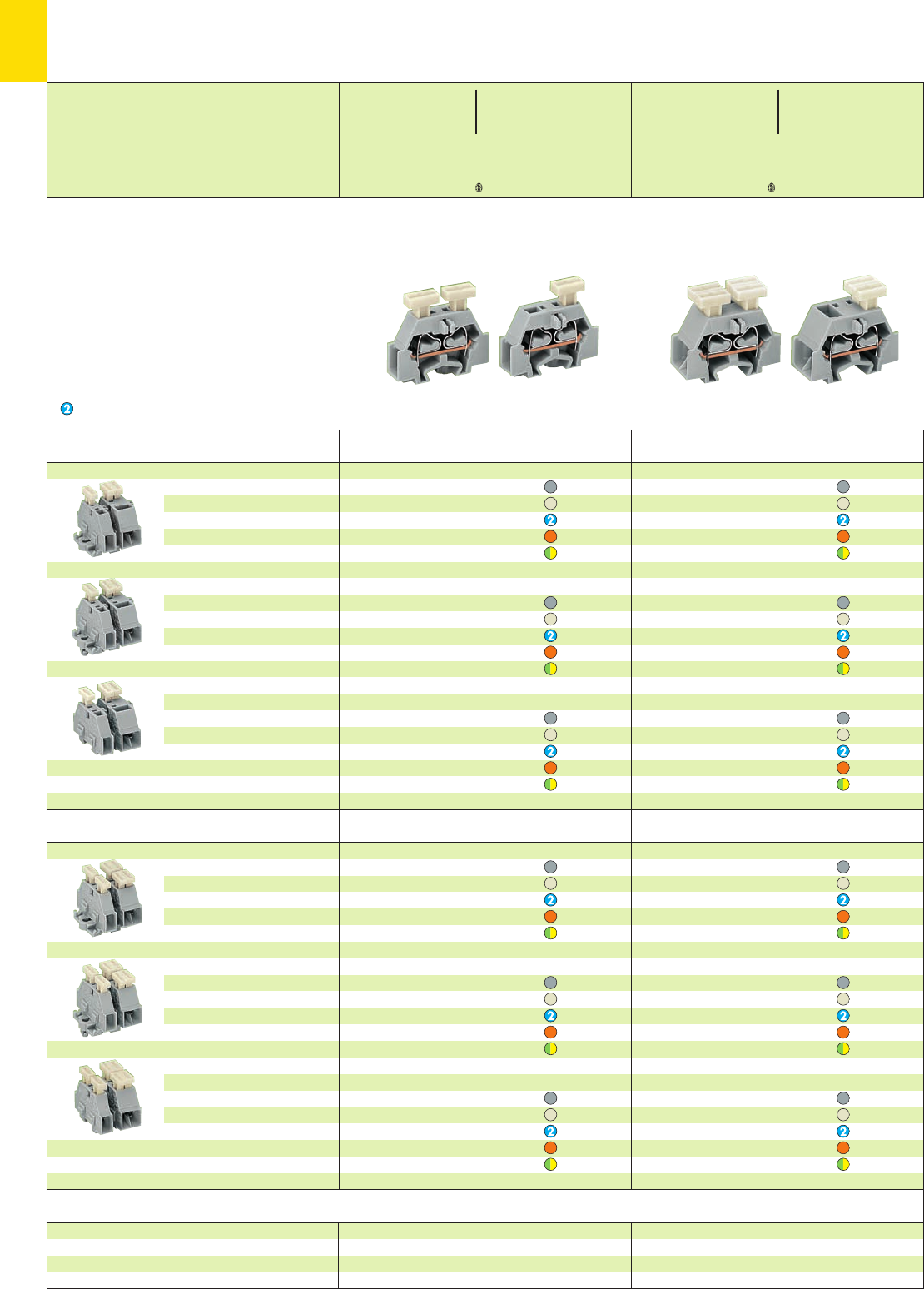
*UfDaJq{[ . *UfDaJq{[
10
22
* For further approvals with corresponding ratings see section 15.
with push buttons on both sides
Accessories for modular terminal blocks and terminal strips
with push button on one side
Modular Terminal Blocks with Push Buttons on One or Both Sides,
with Fixing Flange or Snap-in Mounting Foot 2.5 mm2/ AWG 14,
Series 261
➊500 V = rated voltage
6 kV = rated surge voltage
3 = pollution degree
(see also section 15)
Suitable for Ex i applications
Color Item Pack.-unit
No. pcs
Terminal blocks with fixing flange,
for screw fixing or similar
methods, fixing hole
diameter 3.2 mm (with mounting
adapter 209-123 also for
DIN 35 rail)
Terminal blocks with snap-in mounting foot,
for plate thickness 0.6 – 1.2 mm,
fixing hole diameter 3.5 mm
(fits aluminum rail 210-154 or with
mounting adapter 209-120 for
DIN 35 rail)
End terminal block ➌,
without fixing foot, for terminal
strips with snap-in mounting feet
(see dimensioned drawings on
page 10.23)
2-cond. term. block with push button on one side
grey 261-301/331-000 200 (4 x 50)
light grey 261-303/331-000 200 (4 x 50)
blue 261-304/331-000 200 (4 x 50)
orange 261-306/331-000 200 (4 x 50)
green-yellow 261-307/331-000 200 (4 x 50)
2-cond. term. block with push button on one side
grey 261-311/331-000 200 (4 x 50)
light grey 261-313/331-000 200 (4 x 50)
blue 261-314/331-000 200 (4 x 50)
orange 261-316/331-000 200 (4 x 50)
green-yellow 261-317/331-000 200 (4 x 50)
2-cond. term. block with push button on one side
grey 261-321/331-000 200 (4 x 50)
light grey 261-323/331-000 200 (4 x 50)
blue 261-324/331-000 200 (4 x 50)
orange 261-326/331-000 200 (4 x 50)
green-yellow 261-327/331-000 200 (4 x 50)
Color Item Pack.-unit
No. pcs
Color Item Pack.-unit
No. pcs Color Item Pack.-unit
No. pcs
4-cond. term. block with push button on one side
grey 261-331/332-000 200 (4 x 50)
light grey 261-333/332-000 200 (4 x 50)
blue 261-334/332-000 200 (4 x 50)
orange 261-336/332-000 200 (4 x 50)
green-yellow 261-337/332-000 200 (4 x 50)
4-cond. term. block with push button on one side
grey 261-341/332-000 200 (4 x 50)
light grey 261-343/332-000 200 (4 x 50)
blue 261-344/332-000 200 (4 x 50)
orange 261-346/332-000 200 (4 x 50)
green-yellow 261-347/332-000 200 (4 x 50)
4-cond. term. block with push button on one side
grey 261-351/332-000 200 (4 x 50)
light grey 261-353/332-000 200 (4 x 50)
blue 261-354/332-000 200 (4 x 50)
orange 261-356/332-000 200 (4 x 50)
green-yellow 261-357/332-000 200 (4 x 50)
Terminal blocks with fixing flange,
for screw fixing or similar
methods, fixing hole
diameter 3.2 mm (with mounting
adapter 209-123 also for
DIN 35 rail)
Terminal blocks with snap-in mounting foot,
for plate thickness 0.6 – 1.2 mm,
fixing hole diameter 3.5 mm
(fits aluminum rail 210-154 or with
mounting adapter 209-120 for
DIN 35 rail)
End terminal block ➌,
without fixing foot, for terminal
strips with snap-in mounting feet
(see dimensioned drawings on
page 10.23)
2-
cond. term. bl. with push buttons on both sides
grey 261-301/341-000 200 (4 x 50)
light grey 261-303/341-000 200 (4 x 50)
blue 261-304/341-000 200 (4 x 50)
orange 261-306/341-000 200 (4 x 50)
green-yellow 261-307/341-000 200 (4 x 50)
2-
cond. term. bl. with push buttons on both sides
grey 261-311/341-000 200 (4 x 50)
light grey 261-313/341-000 200 (4 x 50)
blue 261-314/341-000 200 (4 x 50)
orange 261-316/341-000 200 (4 x 50)
green-yellow 261-317/341-000 200 (4 x 50)
2-
cond. term. bl. with push buttons on both sides
grey 261-321/341-000 200 (4 x 50)
light grey 261-323/341-000 200 (4 x 50)
blue 261-324/341-000 200 (4 x 50)
orange 261-326/341-000 200 (4 x 50)
green-yellow 261-327/341-000 200 (4 x 50)
4-
cond. term. bl. with push buttons on both sides
grey 261-331/342-000 200 (4 x 50)
light grey 261-333/342-000 200 (4 x 50)
blue 261-334/342-000 200 (4 x 50)
orange 261-336/342-000 200 (4 x 50)
green-yellow 261-337/342-000 200 (4 x 50)
4-
cond. term. bl. with push buttons on both sides
grey 261-341/342-000 200 (4 x 50)
light grey 261-343/342-000 200 (4 x 50)
blue 261-344/342-000 200 (4 x 50)
orange 261-346/342-000 200 (4 x 50)
green-yellow 261-347/342-000 200 (4 x 50)
4-
cond. term. bl. with push buttons on both sides
grey 261-351/342-000 200 (4 x 50)
light grey 261-353/342-000 200 (4 x 50)
blue 261-354/342-000 200 (4 x 50)
orange 261-356/342-000 200 (4 x 50)
green-yellow 261-357/342-000 200 (4 x 50)
Mounting accessories
Marking accessories
see pages 10.20 and 10.21
see section 14
see pages 10.20 and 10.21
see section 14
0.08 – 2.5 mm2AWG 28 – 14
500 V/6 kV/3 ➊300/600 V, 15/5 A U
24 A
Terminal block width 6 mm / 0.236 in
L8 – 9 mm / 0.33 in
2 x 0.08 – 2.5 mm22xAWG28–14
500 V/6 kV/3 ➊300/600 V, 15/5A U
24 A
Terminal block width 10 mm / 0.394 in
L8 – 9 mm / 0.33 in
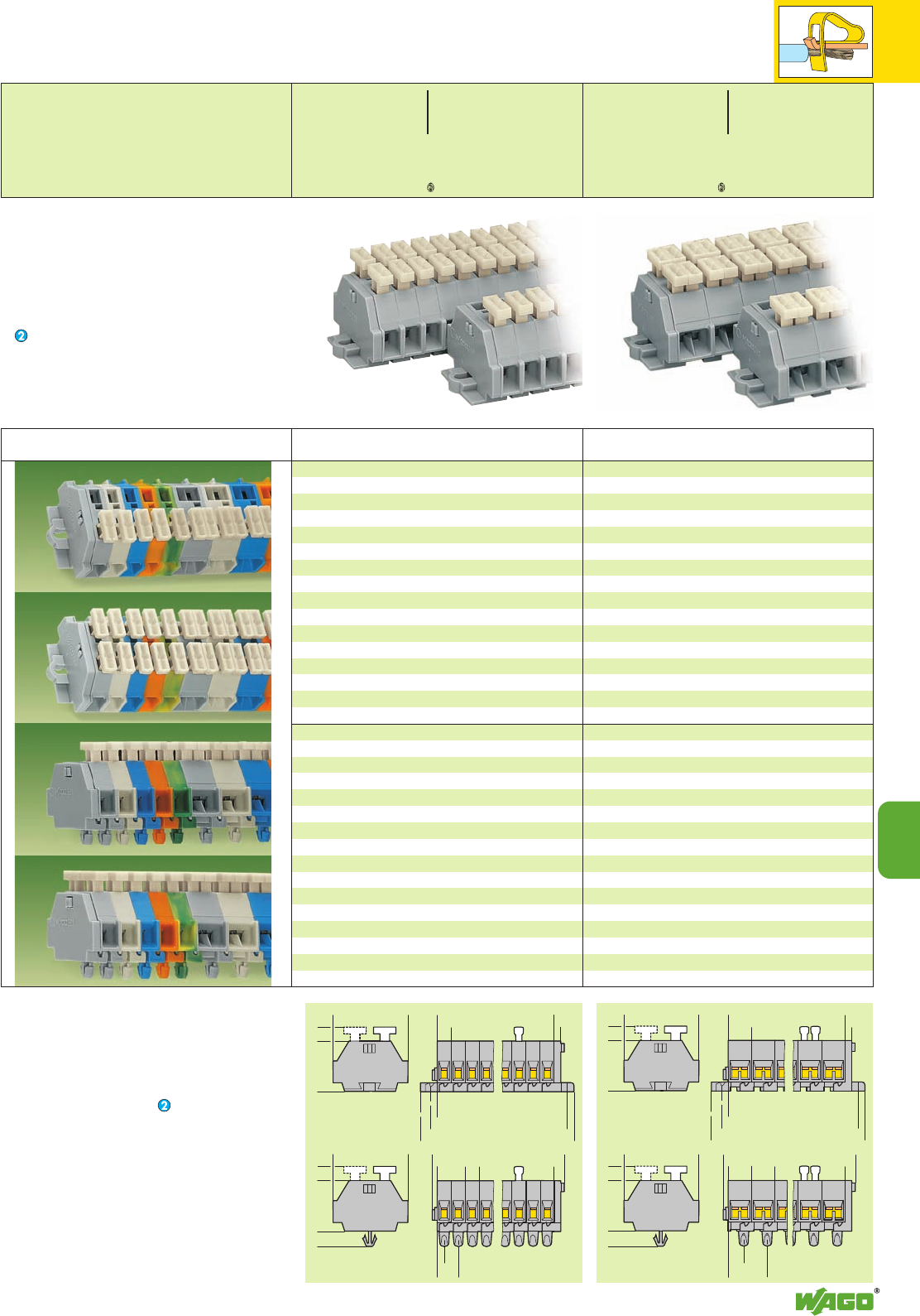
<__________ L__________>
>
6
>
>
>
2,5
___>
<______________ L2 ______________>
<____________ L 1 ____________>
__>
2,8
>
__>
6
<___ 18 ___>
<_____ 28 _____>
>
5,2
>
1,4
<____________ L____________>
<
>
6
<
>
3
__>
3,2
__>
9,2
___>
>
>
< ___ 18 _ __>
>
4,5
<_____ 28 _____>
>
5,2
➌
<_ __18 ___>
<_____ 28 _____> <__________ L__________>
>
10
>
>
>
2,5
___>
<______________ L2 ______________>
<____________ L 1 ____________>
__>
2,8
>
__>
6
>
5,2
< ___ 18 ___>
>
4,5
<_____ 28 _____> <____________ L____________>
>
10
<
>
3
17, 2
____>
7, 2
____>
>
>
1,4
__> _)(_
>
5,2
➌
*UfDaJq{[ . *UfDaJq{[
10
10
23
Modular terminal blocks and terminal strips
with fixing flanges
L = No. of poles x pole width
L1= L + 8.1 mm
L2= L + 14.5 mm
Additional item-Nos. for colored terminal strips
blue .../000-006
Modular terminal blocks and terminal strips
with snap-in mounting feet
➌ End terminal block;
see page 10.22
L = (No. of poles x pole width) + 4.4 mm
Description
2-conductor terminal strips with fixing flanges,
for screw fixing or similar methods, fixing hole
diameter 3.2 mm (with mounting adapter 209-123
also for DIN 35 rail)
with push buttons on one side, grey
2 – 12 ➍261-.../331-000 ➎
with push buttons on both sides, grey
2 – 12 ➍261-.../341-000 ➎
2-conductor terminal strips with snap-in mounting
feet, for plate thickness 0.6 – 1.2 mm, fixing hole
diameter 3.5 mm (fits aluminum rail 210-154 or with
mounting adapter 209-120 for DIN 35 rail)
with push buttons on one side, grey
2 – 12 ➍261-.../331-000 ➎
with push buttons on both sides, grey
2 – 12 ➍261-.../341-000 ➎
No. of Add. item No.
poles for
4-conductor terminal strips with fixing flanges,
for screw fixing or similar methods, fixing hole
diameter 3.2 mm (with mounting adapter 209-123
also for DIN 35 rail)
with push buttons on one side, grey
2 – 12 ➍261-.../332-000 ➎
with push buttons on both sides, grey
2 – 12 ➍261-.../342-000 ➎
4-conductor terminal strips with snap-in mounting
feet, for plate thickness 0.6 – 1.2 mm, fixing hole
diameter 3.5 mm (fits aluminum rail 210-154 or with
mounting adapter 209-120 for DIN 35 rail)
with push buttons on one side, grey
2 – 12 ➍261-.../332-000 ➎
with push buttons on both sides, grey
2 – 12 ➍261-.../342-000 ➎
No. of Add. item No.
poles for
Terminal Strips with Push Buttons on One or Both Sides,
with Fixing Flanges or Snap-in Mounting Feet
2.5 mm
2
/ AWG 14,
Series 261
➊500 V = rated voltage
6 kV = rated surge voltage
3 = pollution degree
(see also section 15)
Suitable for Ex i applications with blue insulating hou-
sings
➍For longer strips and /or assemblies of different
colors,
please contact factory
➎For item No. and packing-unit, see page 10.21
0.08 – 2.5 mm2AWG 28 – 14
500 V/6 kV/3 ➊300/600 V, 15/5A U
24 A
Pole width 6 mm / 0.236 in
L8 – 9 mm / 0.33 in
2 x 0.08 – 2.5 mm22xAWG28–14
500 V/6 kV/3 ➊300/600 V, 15/5A U
24 A
Pole width 10 mm / 0.394 in
L8 – 9 mm / 0.33 in
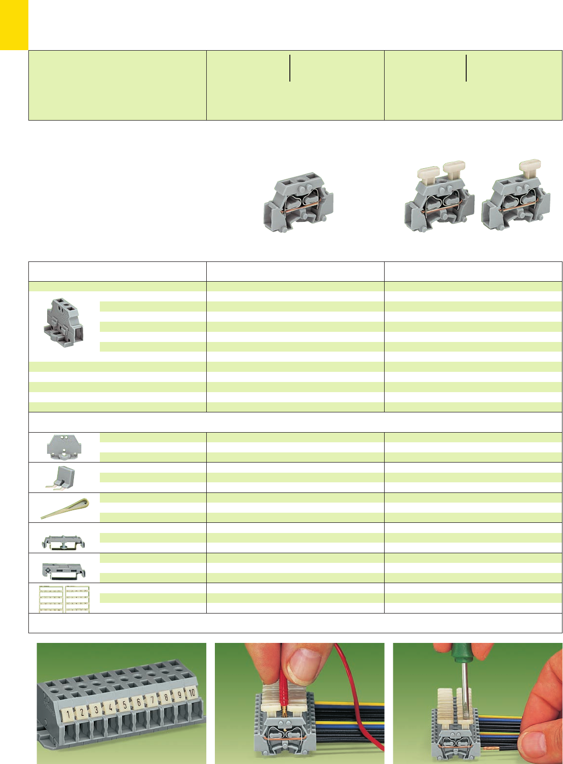
*U2SD;. *UD.
10
24
Marking with miniature WSB Quick marking system Touch contacting with a 2 mm /0.079 in test plug Connection of conductor with push button
* For further approvals with corresponding ratings see section 15.
Accessories for modular terminal blocks and terminal strips Appropriate marking system Mini-WSB
(see section 14)
Application notes
Description
End plate
with fixing flange
Comb type jumper bar,
insulated, 2-way
Operating tool, insulated,
for connecting the comb type
jumper bar
Mounting adapter with
screw, for terminal blocks with
fixing flange, for DIN 35 rail
Mounting adapter
for DIN 35 rail,
can be used as end stop
Miniature WSB Quick marker
card, 10 strips with 10 markers
each, white with black printing
grey 261-410 100 (2 x 50)
IN16 A
grey 261-402 25
reduce wire to 1.5 mm2/AWG 16 max.
2-way 209-132 1
6 mm /0.236 in wide
grey 209-123 25
6.5 mm /0.256 in wide
grey 209-137 25
see section 14
grey 261-410 100 (2 x 50)
IN16 A
grey 261-402 25
reduce wire to 1.5 mm2/AWG 16 max.
2-way 209-132 1
6 mm /0.236 in wide
grey 209-123 25
6.5 mm /0.256 in wide
grey 209-137 25
see section 14
Modular Terminal Blocks with Fixing Flange 2.5 mm2/ AWG 14,
with Marker Receptacle for the Miniature WSB Quick Marking System
Series 261
➊500 V = rated voltage
6 kV = rated surge voltage
3 = pollution degree
(see also section 15)
Item Pack.-unit
No. pcs
Terminal blocks with fixing flange,
for screw fixing or similar
methods, fixing hole
diameter 3.2 mm (with mounting
adapter 209-123 also for
DIN 35 rail)
Lateral marking facility for
miniature WSB Quick marking
system, test slot
2-conductor terminal block,
without push button
grey 261-411 200 (4 x 50)
Item Pack.-unit
No. pcs
2-conductor terminal block,
with push button on one side
grey 261-411/331-000 200 (4 x 50)
2-conductor terminal block,
with push buttons on both sides
grey 261-411/341-000 200 (4 x 50)
0.08 – 2.5 mm2AWG 28 – 14
500 V/6 kV/3 ➊300/600V,15/5 A U
24 A 300/600 V, 20/5 A 2
Terminal block width 6 mm / 0.236 in
L8 – 9 mm / 0.33 in
0.08 – 2.5 mm2AWG 28 – 14
500 V/6 kV/3 ➊300/600V,15/5 A U
24 A
Terminal block width 6 mm / 0.236 in
L8 – 9 mm / 0.33 in
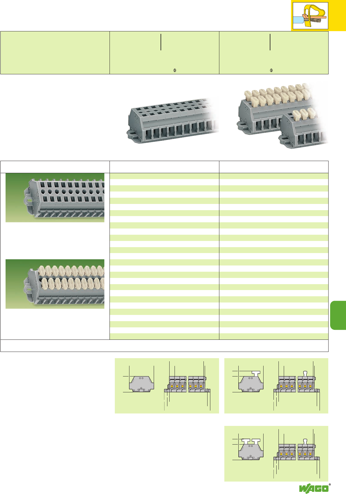
<_
18
_>
<____ 28___>
>
6
>
1,6
__>
__>
2,8
>
__>
6
<____________ L 2 ____________>
<____________ L 1
____________>
>
>
<_______ L______>
<_
18
_>
<____ 28___>
>
6
>
1,6
__>
__>
2,8
>
__>
6
<____________ L 2 ____________>
<____________ L 1
____________>
>
>
<_______ L______>
>
5,6
<_
18
_>
<____ 28___>
>
6
>
1,6
__>
__>
2,8
>
__>
6
<____________ L 2 ____________>
<____________ L 1 ____________>
>
>
<_______ L______>
>
5,6
*U2fSDaJq;{[ . *UfDaJq{[ .
10
10
25
Description
2-conductor terminal strips with fixing flanges,
without push button, grey
2261-422 100
3261-423 100
4261-424 100
5261-425 100
6261-426 50
7261-427 50
8261-428 50
9261-429 50
10 261-430 25
11 261-431 25
12 ➋261-432 25
2-conductor terminal strips with fixing flanges,
with push buttons on one side, grey
2261-422/331-000 100
3261-423/331-000 100
4261-424/331-000 100
5261-425/331-000 100
6261-426/331-000 50
7261-427/331-000 50
8261-428/331-000 50
9261-429/331-000 50
10 261-430/331-000 25
11 261-431/331-000 25
12 ➋261-432/331-000 25
2-conductor terminal strips with fixing flanges,
with push buttons on both sides, grey
2261-422/341-000 100
3261-423/341-000 100
4261-424/341-000 100
5261-425/341-000 100
6261-426/341-000 50
7261-427/341-000 50
8261-428/341-000 50
9261-429/341-000 50
10 261-430/341-000 25
11 261-431/341-000 25
12 ➋261-432/341-000 25
No. of Item Pack.-unit
poles No. pcs No. of Item Pack.-unit
poles No. pcs
Terminal Strips with Fixing Flanges 2.5 mm2/ AWG 14,
with Marker Receptacle for the Miniature WSB Quick Marking System
Series 261
➊500 V = rated voltage
6 kV = rated surge voltage
3 = pollution degree
(see also section 15)
➋For longer strips,
please contact factory
Dimensions for modular terminal blocks and terminal strips (in mm)
Terminal strips with fixing flanges,
for screw fixing or similar methods,
fixing hole diameter 3.2 mm
(with mounting adapter 209-123 also for DIN 35 rail)
Terminal strips with fixing flanges, with push
buttons on one or both sides of the strip,
for screw fixing or similar methods,
fixing hole diameter 3.2 mm
(with mounting adapter 209-123 also for DIN 35 rail)
Modular terminal blocks and terminal strips
with fixing flanges
L = No. of poles x pole width
L1= L + 7.2 mm
L2= L + 13.6 mm
0.08 – 2.5 mm2AWG 28 – 14
500 V/6 kV/3 ➊300/600 V, 15/5 A U
24 A 300/600 V, 20/5 A 2
Pole width 6 mm / 0.236 in
L8 – 9 mm / 0.33 in
0.08 – 2.5 mm2AWG 28 – 14
500 V/6 kV/3 ➊300/600 V, 15/5 A U
24 A
Pole width 6 mm / 0.236 in
L8 – 9 mm / 0.33 in
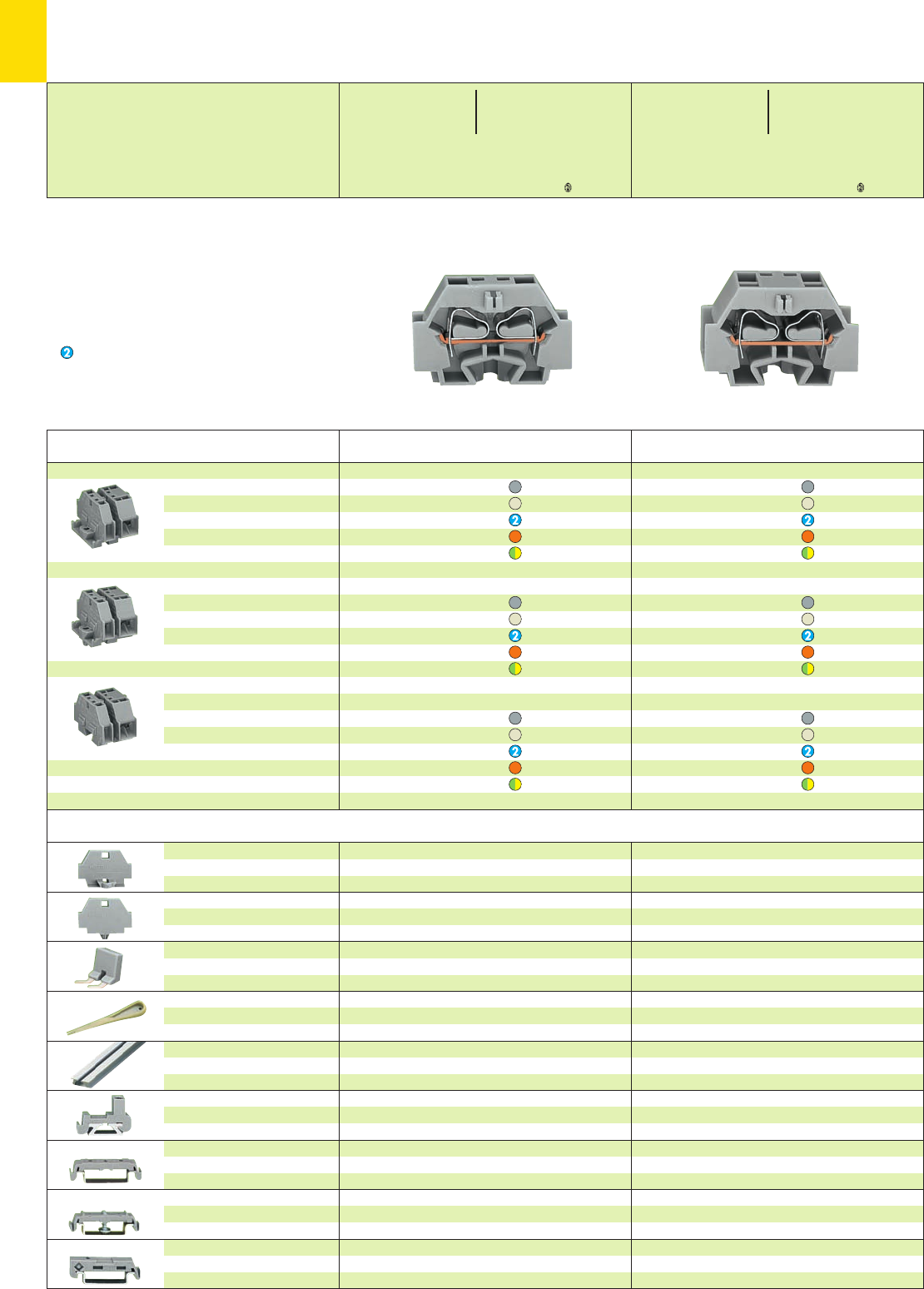
*U2QsKfNDaJq:;{[ .4 *U2QsKfNDaJq:;{[ .4
10
26
* For further approvals with corresponding ratings see section 15.
Accessories for modular terminal blocks and terminal strips (Marking accessories see section 14)
Description
End plate
with fixing flange
End plate with snap-in
mounting foot
Comb type jumper bar,
insulated, 2-way
Operating tool, insulated,
for connecting the comb type
jumper bar
Aluminum carrier rail,
1000 x 18 x 7 mm
3’3” x 0.709 x 0.276 in
Plastic end stop,
with WSB marking facility,
for aluminum rail 210-154
Mounting adapter, for terminal
blocks with snap-in mounting
foot, for DIN 35 rail
Mounting adapter with
screw, for terminal blocks with
fixing flange, for DIN 35 rail
Mounting adapter
for DIN 35 rail,
can be used as end stop
grey 262-361 50
light grey 262-363 50
grey 262-371 50
light grey 262-373 50
IN16 A
grey 262-402 25
reduce wire to 2.5 mm2/AWG 14 max.
2-way 209-132 1
210-154 1
6 mm /0.236 in wide
grey 209-122 25
6 mm /0.236 in wide
grey 209-120 25
6 mm /0.236 in wide
grey 209-123 25
6.5 mm /0.256 in wide
grey 209-137 25
Modular Terminal Blocks with
Fixing Flange or Snap-in Mounting Foot 4 mm2/ AWG 12,
Series 262
➊630 V = rated voltage
8 kV = rated surge voltage
3 = pollution degree
(see also section 15)
Suitable for Ex i applications
4Suitable for Ex e II applications
0.5 – 4 mm2AWG 20 – 12
550 V, 23 A
(see also section 13)
Color Item Pack.-unit
No. pcs
Terminal blocks with fixing flange,
for screw fixing or similar
methods, fixing hole
diameter 3.2 mm (with mounting
adapter 209-123 also for
DIN 35 rail)
Terminal blocks with snap-in mounting foot,
for plate thickness 0.6 – 1.2 mm,
fixing hole diameter 3.5 mm
(fits aluminum rail 210-154 or with
mounting adapter 209-120 for
DIN 35 rail)
End terminal block ➌,
without fixing foot, for terminal
strips with snap-in mounting feet
(see dimensioned drawings on
page 10.27)
2-conductor terminal blocks
grey 262-301 100 (2 x 50)
light grey 4262-130 100 (2 x 50)
blue 262-304 100 (2 x 50)
orange 262-306 100 (2 x 50)
green-yellow 262-307 100 (2 x 50)
2-conductor terminal blocks
grey 262-311 100 (2 x 50)
light grey 4262-180 100 (2 x 50)
blue 262-314 100 (2 x 50)
orange 262-316 100 (2 x 50)
green-yellow 262-317 100 (2 x 50)
2-conductor terminal blocks
grey 262-321 100 (2 x 50)
light grey 4262-181 100 (2 x 50)
blue 262-324 100 (2 x 50)
orange 262-326 100 (2 x 50)
green-yellow 262-327 100 (2 x 50)
4-conductor terminal blocks
grey 262-331 100 (2 x 50)
light grey 4262-230 100 (2 x 50)
blue 262-334 100 (2 x 50)
orange 262-336 100 (2 x 50)
green-yellow 262-337 100 (2 x 50)
4-conductor terminal blocks
grey 262-341 100 (2 x 50)
light grey 4262-280 100 (2 x 50)
blue 262-344 100 (2 x 50)
orange 262-346 100 (2 x 50)
green-yellow 262-347 100 (2 x 50)
4-conductor terminal blocks
grey 262-351 100 (2 x 50)
light grey 4262-281 100 (2 x 50)
blue 262-354 100 (2 x 50)
orange 262-356 100 (2 x 50)
green-yellow 262-357 100 (2 x 50)
Color Item Pack.-unit
No. pcs
0.08 – 4 mm2AWG 28 – 12
630 V/8 kV/3 ➊300/600 V, 20/5 A U
24 A 300/600 V, 25/5 A 2
Terminal block width 7 mm / 0.276 in
L9 – 10 mm / 0.37 in
2 x 0.08 –4mm
22xAWG28–12
630 V/8 kV/3 ➊300/600 V, 20/5 A U
32 A 300/600 V, 25/5 A 2
Terminal block width 12 mm / 0.472 in
L9 – 10 mm / 0.37 in
Test plug modules
see page 10.28
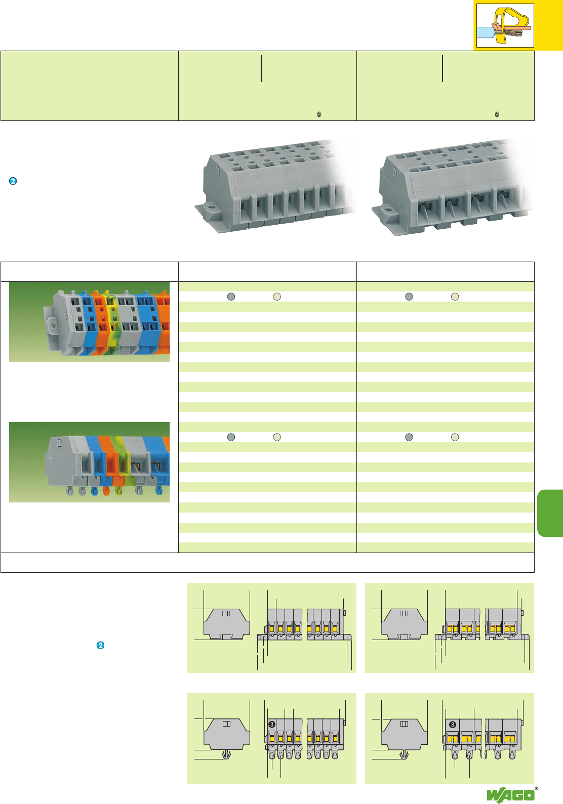
<__________ L__________>
>
7
<
>
>
>
2,5
__>
<______________ L2 ______________>
<____________ L 1 ____________>
__>
2,8
>
__>
6
<_ _ 23 __>
<___ 33,4 ___> <__________ L__________>
>
12
<
>
>
>
2,5
__>
<______________ L2 ______________>
<____________ L 1 ____________>
__>
2,8
>
__>
6
<_ _ 23 __>
<___ 33,4 ___>
>
1,4
<____________ L____________>
<
>
7
<
>
3
__>
11,2
___>
4,2
___>
>
>
>
4,5<_ _ 23 __>
<___ 33,4 ___>
>
4,5
<___________ L___________>
>
12
<
>
3
21, 2
_____>
9, 2
____>
>
>
1,4
__> _)(_
<_ _ 23 __>
<___ 33,4 ___>
*U2QKfNSDaJq:;{[ .4 *U2QKfNSDaJq:;{[ .4
10
10
27
Terminal strips with fixing flanges,
for screw fixing or similar methods,
fixing hole diameter 3.2 mm
(with mounting adapter 209-123 also for DIN 35 rail)
Terminal strips with snap-in mounting feet,
for plate thickness 0.6 – 1.2 mm, fixing hole diameter
3.5 mm (fits aluminum rail 210-154
or with mounting adapter 209-120 for DIN 35 rail)
Modular terminal blocks and terminal strips
with snap-in mounting feet
➌ End terminal block;
see page 10.26
L = (No. of poles x pole width) + 4.4 mm
Description
2-conductor terminal strips with fixing flanges,
grey light grey 4
2262-102 262-132 100
3262-103 262-133 100
4262-104 262-134 100
5262-105 262-135 100
6262-106 262-136 100
7262-107 262-137 100
8262-108 262-138 100
9262-109 262-139 50
10 262-110 262-140 50
11 262-111 262-141 25
12 ➍262-112 262-142 25
2-cond. terminal strips with snap-in mount. feet,
grey light grey 4
2262-152 262-182 100
3262-153 262-183 100
4262-154 262-184 100
5262-155 262-185 100
6262-156 262-186 100
7262-157 262-187 100
8262-158 262-188 100
9262-159 262-189 50
10 262-160 262-190 50
11 262-161 262-191 25
12 ➍262-162 262-192 25
4-conductor terminal strips with fixing flanges,
grey light grey 4
2262-202 262-232 100
3262-203 262-233 100
4262-204 262-234 100
5262-205 262-235 100
6262-206 262-236 100
7262-207 262-237 100
8262-208 262-238 100
9262-209 262-239 50
10 262-210 262-240 50
11 262-211 262-241 25
12 ➍262-212 262-242 25
4-cond. terminal strips with snap-in mount. feet,
grey light grey 4
2262-252 262-282 100
3262-253 262-283 100
4262-254 262-284 100
5262-255 262-285 100
6262-256 262-286 100
7262-257 262-287 100
8262-258 262-288 50
9262-259 262-289 50
10 262-260 262-290 50
11 262-261 262-291 25
12 ➍262-262 262-292 25
No. of Item-No. Pack.-unit
poles pcs No. of Item-No. Pack.-unit
poles pcs
Terminal Strips with
Fixing Flanges or Snap-in Mounting Feet 4 mm2/ AWG 12,
Series 262
➊630 V = rated voltage
8 kV = rated surge voltage
3 = pollution degree
(see also section 15)
Suitable for Ex i applications with blue insulating
housings
4Suitable for Ex e II applications
0.5 – 4 mm2AWG 20 – 12
550 V, 23 A
(see also section 13)
➍For longer strips and /or assemblies of different
colors,
please contact factory
Dimensions for modular terminal blocks and terminal strips (in mm)
0.08 – 4 mm2AWG 28 – 12
630 V/8 kV/3 ➊300/600 V, 20/5 A U
24 A 300/600 V, 25/5 A 2
Pole width 7 mm / 0.276 in
L9 – 10 mm / 0.37 in
2 x 0.08 –4mm
22xAWG28–12
630 V/8 kV/3 ➊300/600 V, 20/5 A U
24 A 300/600 V, 25/5 A 2
Pole width 12 mm / 0.472 in
L9 – 10 mm / 0.37 in
Modular terminal blocks and terminal strips
with fixing flanges
L = No. of poles x pole width
L1= L + 8.1 mm
L2= L + 14.5 mm
Additional item-Nos. for colored terminal strips
blue .../000-006
Test plug modules
see page 10.28
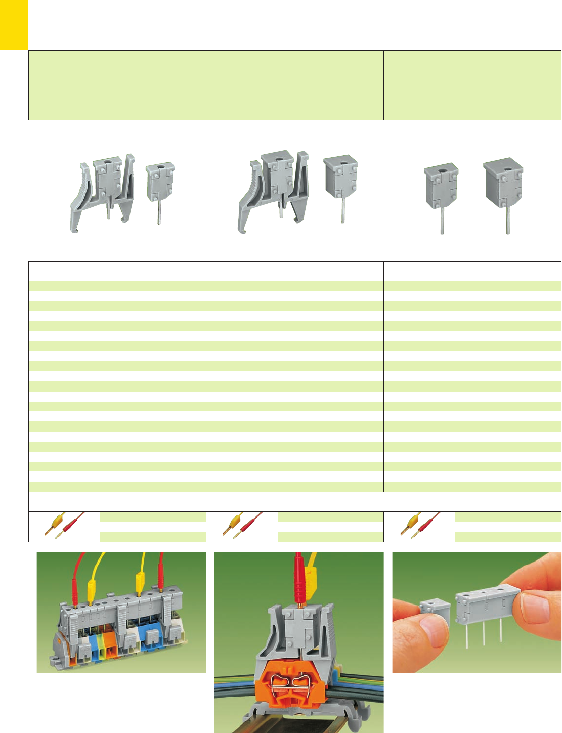
10
28
For the testing procedure, the test plug module
strips are snapped onto the terminal strip –
wired or unwired. As the contact is established by
touch contact at the CAGE CLAMP®spring (spring
steel), this kind of testing is limited to 0.5 A max.
Distance between locking devices should be
35 – 40 mm /1.378 – 1.575 in!
Testing with connected wires.
Assembly of multipole test plug module strips
➊ Max. test voltage 250 V to 800 V only in
test equipment, considering the air
and creepage distances
➋ In case of touch contacting the max. test voltage
must not exceed 48 V, test pins are not touchproof.
➌ Maximum test current in case of touch contacting is
0.5 A; 6 A if the test pins are firmly connected in the
clamping units
Accessories
Test plug, w. cable 500 mm/1’7. 7”
2 mm/0.079 in Ø, red
210-136 50
2.3 mm/0.091 in Ø, yel.
210-137 50
Test plug, w. cable 500 mm/1’7. 7”
2 mm/0.079 in Ø, red
210-136 50
2.3 mm/0.091 in Ø, yel.
210-137 50
Test plug, w. cable 500 mm/1’7. 7”
2 mm/0.079 in Ø, red
210-136 50
2.3 mm/0.091 in Ø, yel.
210-137 50
Test Plug Modules for Terminal Strips without Push Button
Series 260, 261 and 262
Suitable for series 260
Module width 5 mm / 0.197 in;
8 mm / 0.315 in
Test voltage 250 V / 500 V ➊, 48 V ➋
Test current 0.5 A / 6 A ➌
Average contact pressure 2.2 N per pin
Suitable for series 261
Module width 6 mm / 0.236 in;
10 mm / 0.394 in
Test voltage 400 V / 800 V ➊, 48 V ➋
Test current 0.5 A / 6 A ➌
Average contact pressure 2.2 N per pin
Suitable for series 262
Module width 7 mm / 0.276 in;
12 mm / 0.472 in
Test voltage 500 V / 800 V ➊, 48 V ➋
Test current 0.5 A / 6 A ➌
Average contact pressure 2.2 N per pin
Item Pack.-unit
No. pcs
Test plug module without locking device,
Module width 5 mm / 0.197 in
for 2-conductor terminal blocks
grey 249-135 100 (4 x 25)
Module width 8 mm / 0.315 in
for 4-conductor terminal blocks
grey 249-138 100 (4 x 25)
Test plug module with locking device,
Module width 5 mm / 0.197 in
for 2-conductor terminal blocks
grey 260-404 100 (4 x 25)
Module width 8 mm / 0.315 in
for 4-conductor terminal blocks
grey 260-405 100 (4 x 25)
Item Pack.-unit
No. pcs
Test plug module without locking device,
Module width 6 mm / 0.236 in
for 2-conductor terminal blocks
grey 249-136 100 (4 x 25)
Module width 10 mm / 0.394 in
for 4-conductor terminal blocks
grey 249-139 100 (4 x 25)
Test plug module without locking device,
Module width 6 mm / 0.236 in
for 2-conductor terminal blocks
grey 261-404 100 (4 x 25)
Module width 10 mm / 0.394 in
for 4-conductor terminal blocks
grey 261-405 100 (4 x 25)
Item Pack.-unit
No. pcs
Test plug module without locking device,
Module width 7 mm / 0.276 in
for 2-conductor terminal blocks
grey 249-137 100 (4 x 25)
Module width 12 mm / 0.472 in
for 4-conductor terminal blocks
grey 249-140 100 (4 x 25)
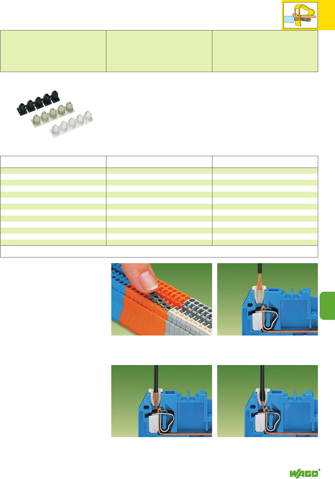
10
29
10
Insulation Stops for Terminal Strips of Series 869
for Conductors from 0.08 mm2– 1 mm2/ AWG 28 – 14
Insulation stop,
suitable for all front-entry compact
terminal blocks, series 869
Terminal block width 5 mm / 0.197 in
L8 – 9 mm / 0.33 in
For the wiring of programmable logic controllers
and microprocessor operated control circuits very
small wire sizes of fine-stranded conductors are
frequently used. These small conductors are so
flexible that they often deform when pushed
against the current bar in the terminal blocks. As
a result, the conductor insulation may be clamped
instead of the copper conductor, resulting in no
or very intermittent contact. This problem exists
with all types of terminal blocks currently offered
on the market. Consequently, unnecessary time is
spent on trouble shooting.
The insulation stop for compact terminal blocks is
the answer to solve these problems. It bundles the
cores of fine-stranded conductors automatically
when introduced into the clamping unit, without
any splaying, and reduces the conductor entry
hole to a defined cross sectional area so that the
insulation of these conductors cannot be introdu-
ced into the clamping unit.
The insulation stop is available as a dividable
5-pole strip for rail-mounted terminal strips of
series 869.
With the use of the insulation stop the conductor
stripped lengths related to the respective front-
entry rail-mounted terminal strip, remain
unchanged.
Push insulation stop into the conductor entry holes of
front-entry rail-mounted terminal blocks.
* Introduce stripped, untwisted conductor into
insulation stop . . .
* . . . the conductor is bundled . . .
* here with front-entry rail-mounted terminal block (section 2)
* . . . and the conductor insulation is prevented from
being pushed into the clamping unit by the positive
stop.
Item Pack.-unit
No. pcs
Insulation stop, 5 pcs/strip
white 280-470 200 strips
0.08 – 0.2 mm2➊/AWG 28 – 24
light grey 280-471 200 strips
0.25 – 0.5 mm2 /AWG 22 – 20
dark grey 280-472 200 strips
0.75 – 1 mm2 /AWG 18
➊ 0.2 mm2/AWG 24 solid
0.14 mm2/AWG 26 fine-stranded
Application notes
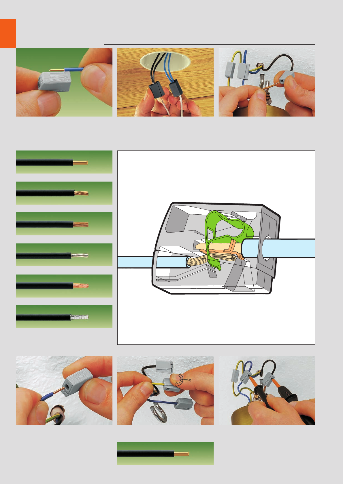
10
30
Lighting Connectors, Series 224
Description and Handling
Lighting (CAGE CLAMP®) side
Strip conductor 9 – 11 mm /0.39 in
solid
stranded
fine-stranded, also with tinned single strands
fine-stranded, tinned (up to 1.5 mm2/AWG 16)
fine-stranded, tip bonded
fine-stranded with ferrule (up to 1.5 mm2/AWG 16)
Installation/field (push-wire) side
To connect: Introduce stripped solid conductor
into circular entry and push to stop To remove: Hold conductor and twist connector
alternately left and right while pulling
the conductor
Testing through separate test slot
To connect: Press button fully and insert stripped
conductor into square entry and release To remove: Press button and withdraw conductor
* For aluminum wire see notes in section 15!
solid
The push-wire connection connects
the following copper wires:*
CAGE CLAMP®connects the
following copper wires:*
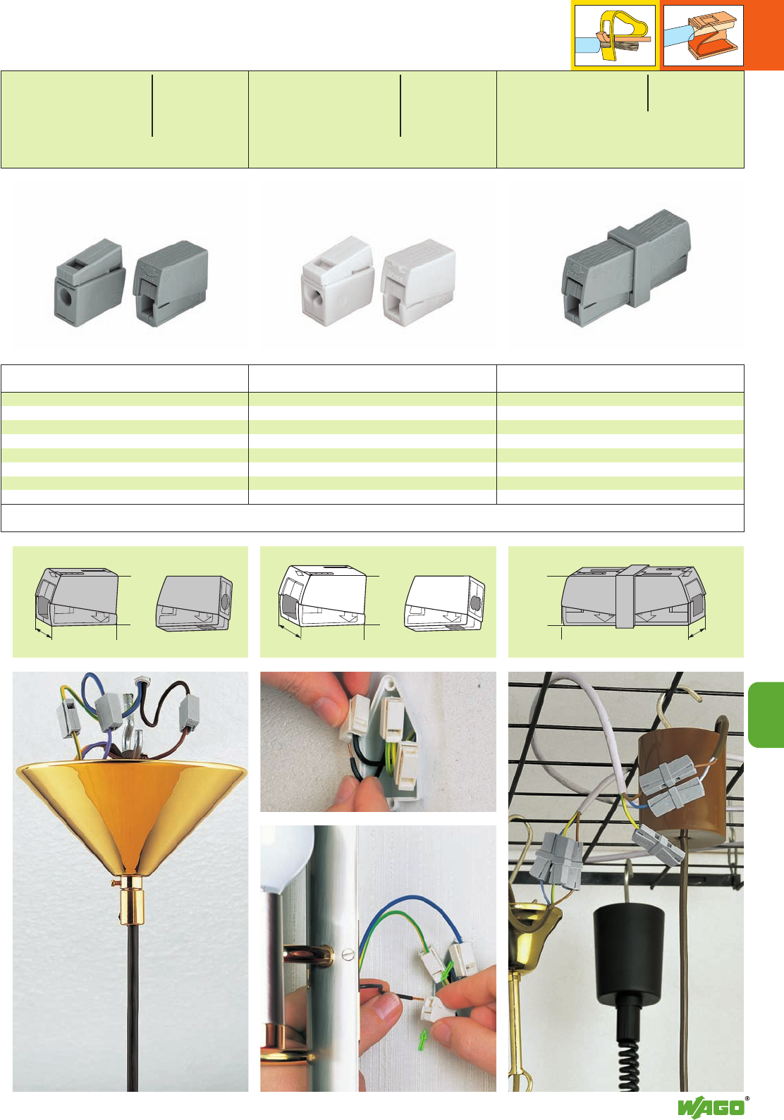
10
31
10
press
test
<____ 20,5 ____>
8,5
test
<_ 15,5 _>
test
press
test
<____ 20,5 ____>
9,5
<_ 15, 5 _>
press
8,5
test
test
<____________ 42 ____________>
<_ 15, 5 _>
*u2QOKfNSDFaAJ;[ *u2QOKfNSDFaAJ:; *u2QOKfNSDFaAJ:;
Lighting Connectors
”Service“ Connectors
Item Pack.-unit
No. pcs Item Pack.-unit
No. pcs Item Pack.-unit
No. pcs
Lighting connectors,
standard version, continuous
service temperature 105 °C,
grey 224-101 1000 (10 x 100)
version for increased continuous
service temperature of 120 °C,
black 224-104 100
2-conductor lighting connectors,
standard version, continuous
service temperature 105 °C,
white 224-112 1000 (10 x 100)
version for increased continuous
service temperature of 120 °C,
black 224-114 100
”Service“ connector
grey 224-201 50
Dimensions (in mm) ➊ in grounded (earthed) supply systems 400 V = rated voltage 4 kV = rated surge voltage 2 = pollution degree (see also section 15)
* For further approvals with corresponding ratings see section 15.
Installation side
1.0 – 2.5 mm2solid AWG 14 – 12
Lighting side
0.5 – 2.5 mm2rig.+ flex AWG 20 – 16
400 V/4 kV/2 ➊; 24 A 300 V, 20 Au2
l9 – 11 mm / 0.39 in
Installation side
1.0 – 2.5 mm2solid AWG 14 – 12
Lighting side
0.5 – 2.5 mm2rig.+ flex AWG 20 – 16
400 V/4 kV/2 ➊; 24 A 300 V, 20 Au2
l9 – 11 mm / 0.39 in
0.5 – 2.5 mm2rig.+ flex AWG 20 – 16
400 V/4 kV/2 ➊300 V, 20 Au2
24 A
l9 – 11 mm / 0.39 in
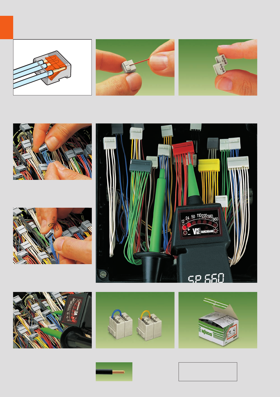
,
10
32
MICRO Push-Wire Connectors for Junction Boxes,➊Series 243
Description and Handling
Stripped length Connector strips
Push-wire connection
Connection: Insert stripped conductor FULLY.
Push-wire connection
Removal: Hold wire to be removed and twist
alternately left and right while pulling the
connector
Testing Commoning Packing units
Testing Commoned connector strips Box for use on site (example)
Contents series 243: 50 pcs 8-conductor
or 100 pcs 4-conductor
Strip solid wire 5 – 6 mm / 0.22 in Assembly of modular connectors to
connector strips
➊ For distribution connectors for e(Euro Installation Bus) see Full Line Catalog W4, volume 2, page 2.4
solid
Use contact paste “Alu-Plus”
when connecting aluminum wires
(see section 15)
The push-wire connection connects
the following copper wires:
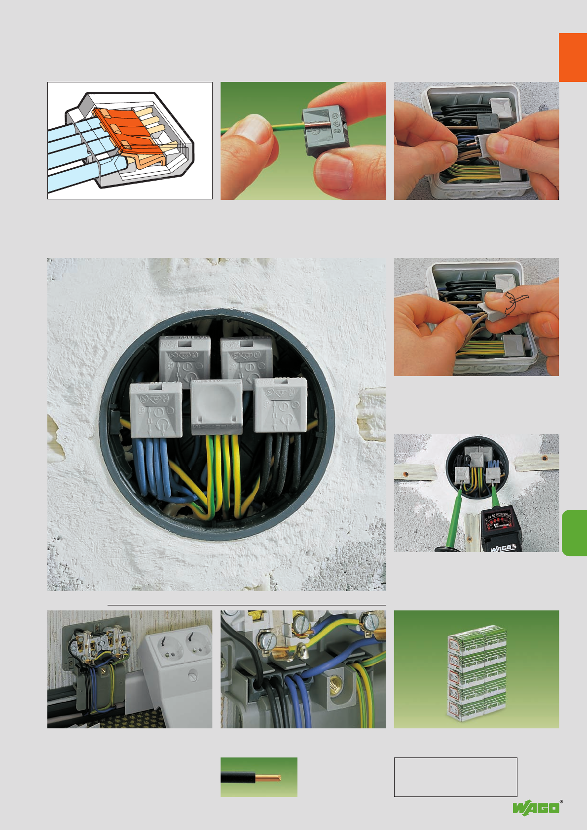
,
10
33
10
Push-wire connection
Removal: Hold wire to be removed and twist
alternately left and right while pulling the
connector
Testing
Testing
Applications Packing unit
Push-wire connectors used in a cable duct with double power outlet Wholesaler package with 10 boxes for
use on site
Strip solid conductor 10 mm – 13 mm / 0.45 in Connection: Insert stripped solid conductor FULLY
Push-Wire Connectors for Junction Boxes, Series 273
Description and Handling
Stripped length Push-wire connection
solid
Use contact paste “Alu-Plus”
when connecting aluminum wires
(see section 15)
The push-wire connection clamps
the following copper wires:
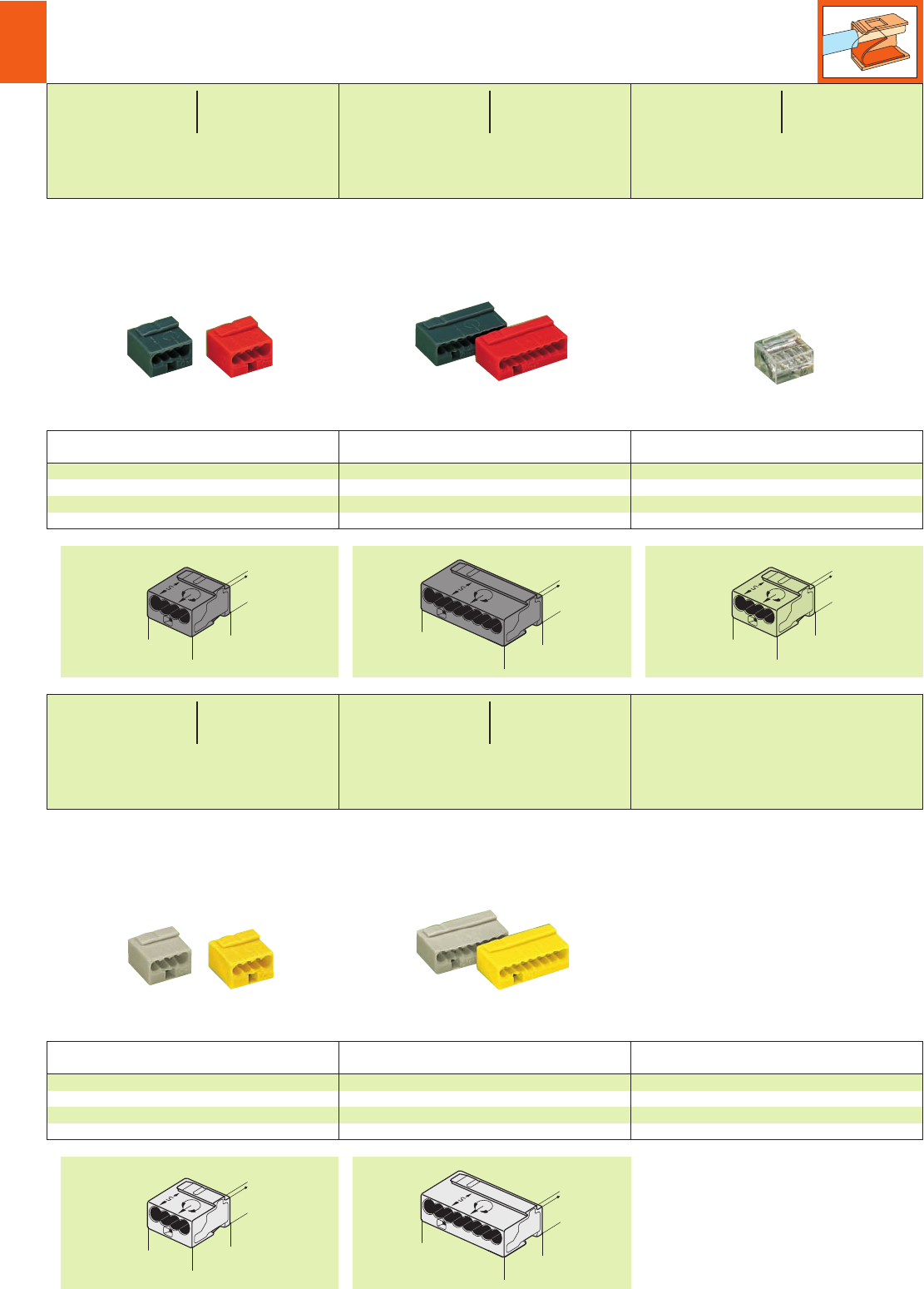
10
34
> 5,8 <
<_ _>
1
<_ _>
10
10
<_ _>
<______ ______>
10
18,4
1
> 5,8 <
> 5,8 <
<_ _>
1
<_ _>
10
10
> 5,8 <
<_ _>
1
<_ _>
10
10
<_ _>
<______ ______>
10
18,4
1
> 5,8 <
*U2QKfSDaq
*U2QKfNSDaq
*U2QKfSDaq *U2faq
*U2QKfNSDaq
* For further approvals with corresponding ratings see section 15.
** When using wires of the same diameter only, 0.5 Ø mm/AWG 24 or 1.0 Ø mm/AWG 18 are also possible.
MICRO Push-Wire Connectors for Junction Boxes
Series 243
Color Item Pack.-unit
No. pcs
MICRO push-wire connectors for junction boxes,
4-conductor connectors
dark grey 243-204 1000 (10 x 100)
red 243-804 1000 (10 x 100)
Color Item Pack.-unit
No. pcs
MICRO push-wire connectors for junction boxes,
8-conductor connectors
dark grey 243-208 500 (10 x 50)
red 243-808 500 (10 x 50)
Color Item Pack.-unit
No. pcs
MICRO push-wire connector for junction boxes,
4-conductor connectors
transparent 243-144 1000 (10 x 100)
Color Item Pack.-unit
No. pcs
MICRO push-wire connectors for junction boxes,
4-conductor connectors
light grey 243-304 1000 (10 x 100)
yellow 243-504 1000 (10 x 100)
Color Item Pack.-unit
No. pcs
MICRO push-wire connectors for junction boxes,
8-conductor connectors
light grey 243-308 500 (10 x 50)
yellow 243-508 500 (10 x 50)
➊ 100 V = rated voltage
1.5 kV = rated surge voltage
2 = pollution degree
(see also section 15)
4 x 0.6 – 0.8 Ø mm “s” ** 4 x AWG 22 – 20 “sol.” **
100 V/1.5 kV/2 ➊125 V, 7 A U
6 A 150 V, 7 A 2
l5 – 6 mm / 0.22 in
8 x 0.6 – 0.8 Ø mm “s” ** 8 x AWG 22 – 20 “sol.” **
100 V/1.5 kV/2 ➊125 V, 7 A U
6 A 150 V, 7 A 2
l5 – 6 mm / 0.22 in
4 x 0.4 – 0.5 Ø mm “s” 4 x AWG 26 – 24 “sol.”
100 V/1.5 kV/2 ➊125 V, 7 A U
6 A 150 V, 7 A 2
l5 – 6 mm / 0.22 in
4 x 0.6 – 0.8 Ø mm “s” ** 4 x AWG 22 – 20 “sol.” **
100 V/1.5 kV/2 ➊125 V, 7 A U
6 A 150 V, 7 A 2
l5 – 6 mm / 0.22 in
8 x 0.6 – 0.8 Ø mm “s” ** 8 x AWG 22 – 20 “sol.” **
100 V/1.5 kV/2 ➊125 V, 7 A U
6 A 150 V, 7 A 2
l5 – 6 mm / 0.22 in
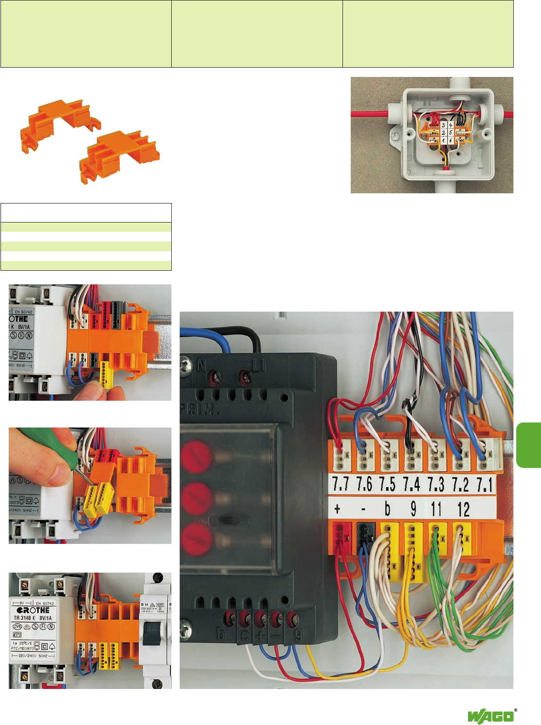
10
10
35
Example of house-bell application
– mounted on DIN 35 rail
Example of house communication application
Inserting a MICRO push-wire connector for junction
boxes into the carrier
Typical application in a terminal box for burglar alarm
system
Removal of MICRO push-wire connector from the carrier
Mounting carrier
for 4 push-wire connectors 243-112 50 (5 x 10)
for 6 push-wire connectors 243-113 50 (5 x 10)
Marker strip,
plain 243-110 1
Mounting Carrier for MICRO Push-Wire Connectors,
for DIN 35 Rail or Screw Fixing, Series 243
Quick fix mounting
Electrical installers have often expressed a desire
to be able to use the features of the
MICRO push-wire connectors on DIN rail appli-
cations in panels. They have realized that these
connectors are just as suitable in distribution
panels for easy connection of the smaller wires
used in low current applications. They are ideal
for the connection of telephone type wire used in
the connection of alarms, bells, door sensors,
communication systems, etc.
The mounting carrier is the professional solution.
It is available with mounting slots for 4 or 5
connectors. The 4- or 8-conductor MICRO push-
wire connectors are simply slid into the carrier,
but can be easily removed again.
The carrier is designed for easy mounting directly
to the DIN 35 rail, or to a panel, via a screw, by
use of the fixing flanges provided. A large
marking surface is provided for clear circuit iden-
tification. This may be directly marked with a
fiber tip pen, or by the use of pre-printed self-
adhesive marker strips.
Description Item Pack.-unit
No. pcs
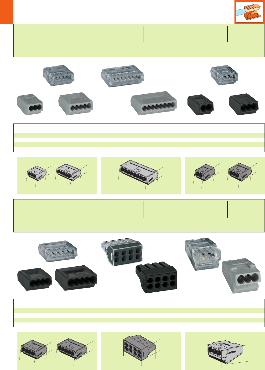
10
36
<__17, 5 __>
<18, 5 >
_>
_>
8,6
<11, 5 >
<__18 __>
_>
_>
8,6
<________26________>
<_18, 5 _>
__>
__>
8,6
<13, 5 >
<_19, 5 _>
_>
_>
9, 6
(10, 5 )
<_19, 5 _>
_>
_>
9, 6
<_____21____>
<_19, 5_>
_>
_>
9, 6
<__17, 5 __>
<_19, 5 _>
__>
__>
9, 6
<__17,5__>
<____
23,5
____>
<__15, 5 __>
*u2QOsKfNSDFaAJ9q:;[
*u2QOKfNSDFAJ9q:;[
*u2QOsKfNSDFAJ9:;[ *u2QOsKfNSDFbAJ:;[
*u2fNSDFaCB:;[
*u2QOsKfNSDFaAJ9q:;[
<_
__
_24___
__
>
<
_
_
19,5
_
_
>
<_
13,1
_>
Color Item Item
No. No.
Push-wire connectors for junction boxes,
4-cond. connectors 5-cond. connectors
dark grey 273-102 ➌273-105 ➌
transparent 273-254 ➌273-255 ➍
Pack.-unit ➌1000 (10 x 100) ➍500 (10 x 50)
Color Item Pack.-unit
No. pcs
Push-wire connectors for junction boxes,
3-conductor connectors
grey 273-403 500 (10 x 50)
transparent 273-453 500 (10 x 50)
Color Item Pack.-unit
No. pcs
Push-wire connectors for junction boxes,
8-conductor connectors
dark grey 773-208 500 (10 x 50)
transparent 773-108 500 (10 x 50)
Color Item Item Pack.-unit
No. No. pcs
Push-wire connectors for junction boxes,
3-cond. con. 5-cond. con.
grey 273-100 273-101 1000 (10 x 100)
transparent – 273-155 1000 (10 x 100)
* For further approvals with corresponding ratings see section 15.
** in grounded (earthed) supply systems When using wires of the same diameter only, ➊0.5 mm2/AWG 20 or ➋0.75 mm2/AWG 18 are also possible.
Push-Wire Connectors for Junction Boxes
Series 273 and 773
Color Item Pack.-unit
No. pcs
Push-wire connectors for junction boxes,
8-conductor connectors
grey 273-108 500 (10 x 50)
transparent 273-158 500 (10 x 50)
Color Item Item Pack.-unit
No. No. pcs
Push-wire connectors for junction boxes,
2-cond. con. 3-cond. con.
dark grey 273-112 273-104 1000 (10 x 100)
transparent 273-252 273-253 1000 (10 x 100)
4x1–2.5 mm2“s” ➋4 x AWG 18 –12“sol.”
5x1–2.5 mm2“s” ➋5 x AWG 18 –12“sol.”
400 V/ 4 kV/2** 600 V, 20 A u
24 A 600 V, 20 A 2
l10 – 13 mm / 0.45 in
8x1–2.5 mm2“s” ➋8 x AWG 18 –12“sol.”
400 V/ 4 kV/2** 600 V, 20 A u
24 A 600 V, 20 A 2
l10 – 13 mm / 0.45 in
3x1.5–4mm
2“s” 3 x AWG 14 –10“sol.”
400 V/ 4 kV/2** 600 V, 30 A u
32 A 600 V, 30 A 2
l12 – 15 mm / 0.53 in
3x0.75–1.5 mm2“s” ➊3 x AWG 18 – 16 “sol.”
5x0.75–1.5 mm2“s” ➊5 x AWG 18 – 16 “sol.”
400 V/ 4 kV/2** 600 V, 10 A u
18 A 600 V, 10 A 2
l10 – 13 mm / 0.45 in
8x0.75–1.5 mm2“s” ➊8 x AWG 18 – 16 “sol.”
400 V/ 4 kV/2** 600 V, 10 A u
18 A 600 V, 10 A 2
l10 – 13 mm / 0.45 in
2x1–2.5 mm2“s” ➋2 x AWG 18 – 12 “sol.”
3x1–2.5 mm2“s” ➋3 x AWG 18 – 12 “sol.”
400 V/ 4 kV/2** 600 V, 20 A u
24 A 600 V, 20 A 2
l10 – 13 mm / 0.45 in
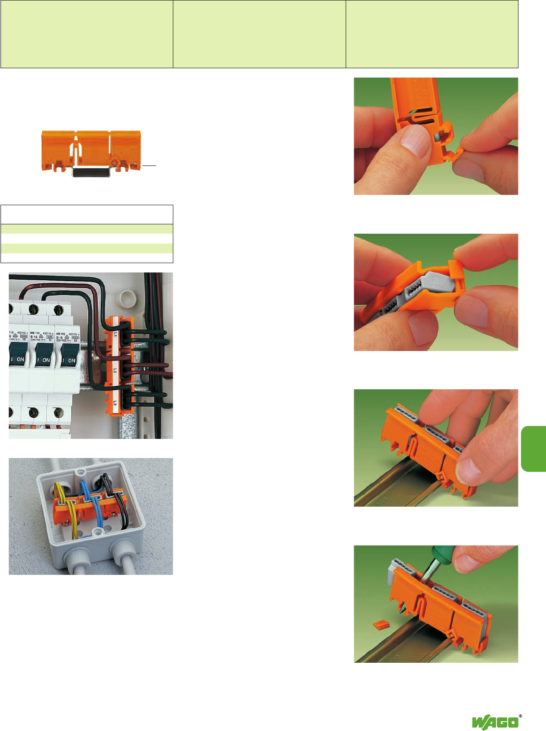
10
10
37
<__
… and use as end plate.
Removing from a carrier rail
Snap off cover …
Snapping on to carrier rail
FIXED IN POSITION – on a DIN 35 rail
FIXED IN POSITION – screw fixing
Mounting Carrier for Push-Wire Connectors for Junction Boxes,
for DIN 35 Rail or Screw Fixing, Series 273
Description Item Pack.-unit
No. pcs
One single carrier can hold up to 15 clamping
units in a very narrow space. Up to now this has
only been possible using rail-mounted terminal
blocks.
The advantages for you are:
●the carriers can be fixed quickly and easily:
on a DIN 35 rail or with screw fixing.
●a carrier can hold up to three 1.5 mm2/AWG
16 or 2.5 mm2/AWG 12 connectors of series
273 (excluding the 8 x 2.5 mm2version).
●the connectors can be easily exchanged.
●large marking area for self-adhesive marker
strips or for direct marking with permanent
fibre tip pen.
Mounting carrier 273-150 50 (5 x 10)
Marker strips, 48 strips per card,
plain 210-334 1 card
<________ 68 mm /2.68 in _______>
<21.5 mm / >
0.85 in
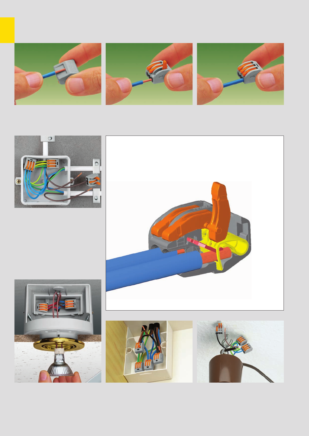
10
38
Compact Connector for Flexible Conductors with
CAGE CLAMP®COMPACT Connection
Description and Handling – Series 222
Connection: Push up lever and insert conductor . . . . . . then push down lever to its closed positionStrip wire 9 – 10 mm/0.37 in
Wiring of flexible conductors in a junction box
Individual design of low voltage lighting systems Connecting pre-wired and pre-fabricated compo-
nents, for example in mobile homes Lighting fixture connection with flexible conductors
and power feed
* For aluminum wire see notes in section 15!
**When using wires with ferrules, it is necessary to use a terminal block one size larger than the nominal cross section of the wire.
fine-stranded wire –
tip bonded
fine-stranded wire
with crimped ferrule**
fine-stranded wire
with crimped pin terminal
CAGE CLAMP®connects
the following copper
wires:*
solid stranded
fine-stranded,
also with tinned
single strands
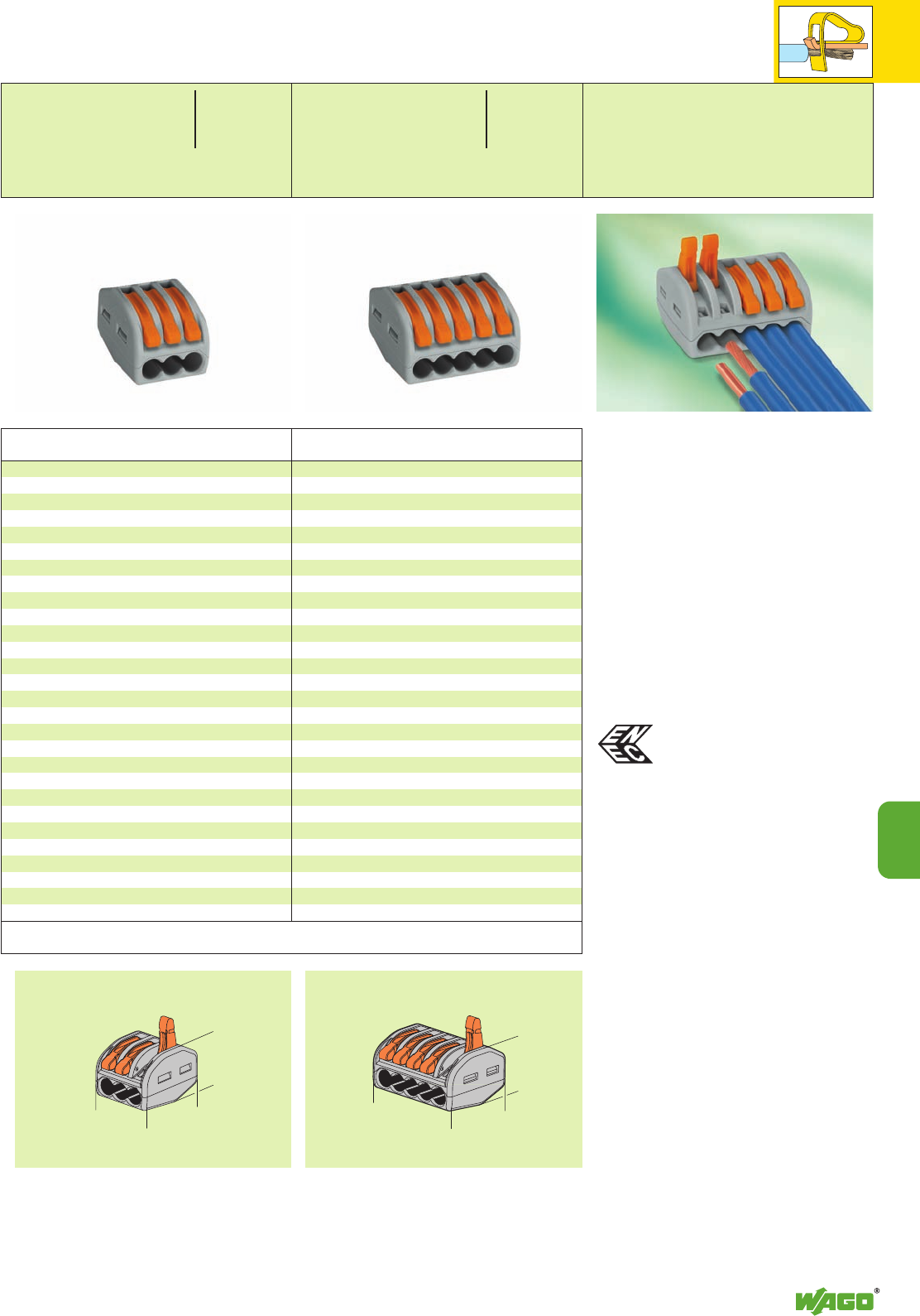
10
10
39
<___17 ___>
<_20,5 _>
<_14,5 _>
<_ 20,5 _>
<_ 14,5 _>
<____26,6 ____>
*uENEC
Compact connector,
3-wire connector,
with levers
continuous service temperature 85°C
grey 222-413 500 (10 x 50)
Item Pack. unit
No. pcs
Compact Connector for Flexible Conductors,
Series 222
➊ 400 V = rated voltage
4 kV = rated surge voltage
2 = pollution degree
(see also section 15)
Dimensions (in mm)
Compact connector
Connects up to 3 or 5 stripped fine-stranded
wires of 0.08 mm2/AWG 28 to 4 mm2/AWG 12
or solid or stranded wires up to 2.5 mm2/AWG
12, without tools.
This is how it works:
Open the clamping unit by levering one of the
small orange colored levers such that the lever
engages and keeps the clamping unit in its open
position. The wire can now be inserted, then the
lever can be returned to its closed position, flush
with the terminal block housing.
The safety:
The closed position of the lever reliably prevents
accidental unclamping of a connected wire.
The additional application safety, for any type of
conductor (solid, stranded, flexible), is confirmed
by approvals like ENEC or UL.
The ENEC mark is a European safety
mark including 20 countries.
3 x 0.08
–2.5mm
2
“s+ f-str“
AWG 28 – 12
4 mm2“f-str“
400 V/4 kV/2 ➊600 V, 20 A u
32 A
L9 – 10 mm / 0.37 in
* For further approvals with corresponding ratings see section 15.
Compact connector,
5-wire connector,
with levers
continuous service temperature 85°C
grey 222-415 400 (10 x 40)
Item Pack. unit
No. pcs
5 x 0.08
–2.5mm
2
“s+ f-str“
AWG 28 – 12
4 mm2“f-str“
400 V/4 kV/2 ➊600 V, 20 A
32 A
L9 – 10 mm / 0.37 in
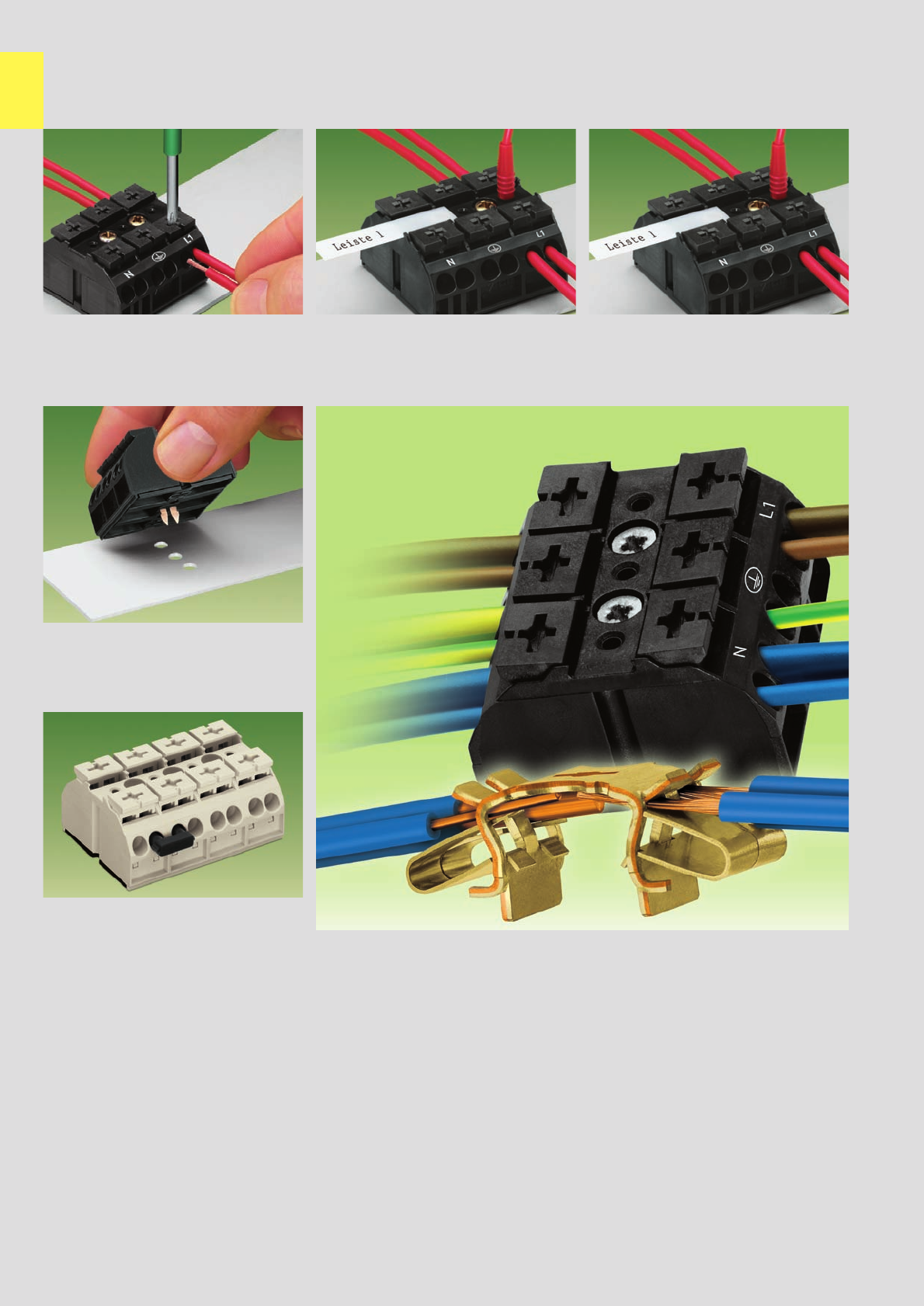
10
40
4-Conductor Terminal Strips with CAGE CLAMP®S connection . . .
Description and Handling – Series 862
Conductor connection Testing Marking
Features and Advantages
Marking
by direct printing
and/or marker strips
Testing with
test plug 2mm / 0.079 in Ø
4 conductors per pole
- for solid and flexible conductors
- mixed wiring with solid and flexible
conductors of different wire sizes
Makes an automatic contact to the mounting
plate.
A varnish coating is penetrated automatically.
This new connector series has been developed specifically to minimize the connection costs of electrical devices.
At the same time, the requirement for flexible assembly, for numerous electrical connection options and for easy handling were part of
the development.
●The new CAGE CLAMP®S allows the connection of up to four conductors with wire sizes from 0.5 mm2to 4 mm2/AWG 20 to 12.
Different cross sections can be used within one connector.
●For factory wiring, CAGE CLAMP®S allows the direct insertion of solid conductors or flexible conductors with crimped
ferrules* or ultrasonically bonded wire ends from 0.5 mm2up to 4 mm2/AWG 20 to 12.
(Length of bonded wire end min. 7 mm / 0.276 in)
●Automatic grounding contact available as an option.
●Snap-in mounting feet for fast assembly
●Push-buttons for easy handling with a commercially available screwdriver or by hand.
●Direct testing with test plug 2 mm / 0.079 in Ø
●Standard marking per pole or, for large quantities, in accordance with customer’s specification.
* For aluminum wire see notes in section 15!
** When using wires with ferrules, it is necessary to use a terminal block one size larger than the nominal cross section of the wire.
Commoning with jumper bar
Commoning
fine-stranded wire –
tip bonded
fine-stranded wire
with crimped ferrule**
fine-stranded wire
with crimped pin terminal
CAGE CLAMP®connects
the following copper
wires:*
solid stranded
fine-stranded,
also with tinned
single strands
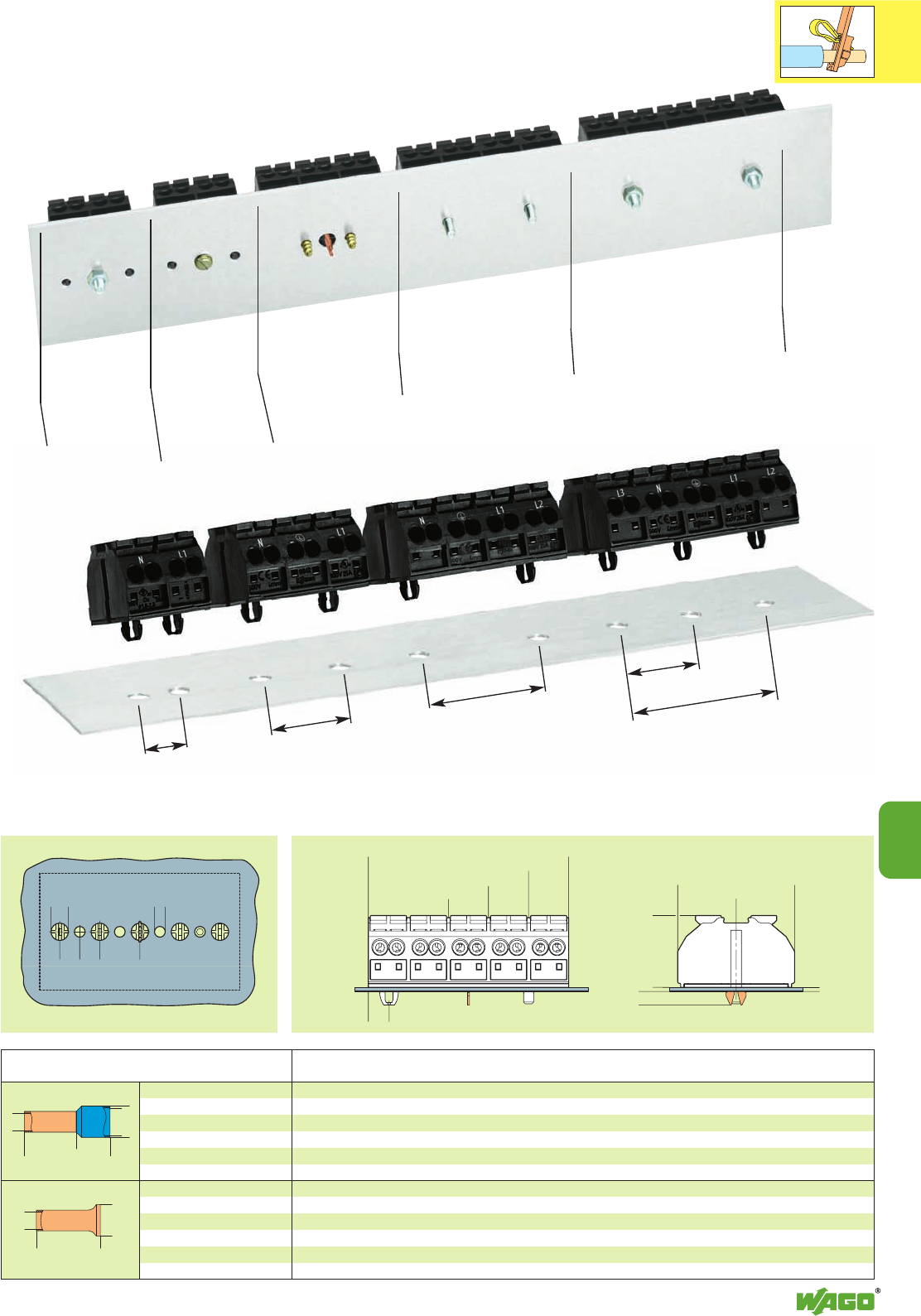
<___ ____> <
<> <____>
ø3,2
ø5,2
612
>
<>
6
<____ D ____>
<_______ L _______>
D2 <
<
<____ L1 ____>
<_ D1 _>
<__ D __>
<___________ L __________>
D2 <
<
10
10
41
12 24 36 24
48
Fixing by screw
and nut 3 mmØ
from top
Fixing from
below by self
tapping screw
2.9 mm Ø into
terminal housing
Fixing onto chassis
by self tapping screw
2.9 mm Ø from top
Fixing by screw 3 mm Ø
into thread in chassis
Fixing by screw and nut
3 mm Ø from top
Fixing by snap-in mounting feet
Dimensions (in mm)
Fixing Options
0.5 22 white 12.0 16.0 10.0 3.1 2.6 1.0 216-241 1000
0.75 20 grey 12.0 16.0 10.0 3.3 2.8 1.2 216-242 1000
1.0 18 red 12.0 16.0 10.0 3.5 3.0 1.4 216-243 1000
1.5 16 black 12.0 16.0 10.0 4.0 3.5 1.7 216-244 1000
0.5 22 10 10 2.1 1.0 216-141 1000
0.75 20 10 10 2.3 1.2 216-142 1000
1.0 18 10 10 2.5 1.4 216-143 1000
1.5 16 10 10 2.8 1.7 216-144 1000
Insulated ferrules
Uninsulated ferrules
Sleeve for Color Stripped length L L1 D D1 D2 Item Pack.-unit
mm2AWG mm mm No. pcs
Ferrules
<_24 (2poles)_>
<_____36 (3poles) _____>
<__________48 (4poles)_________>
<______________60 (5poles)______________>
<___17,5 ___>
<______>0,5-1,2
<___21,4 ___>
><4
<_________35________>
<_
>6
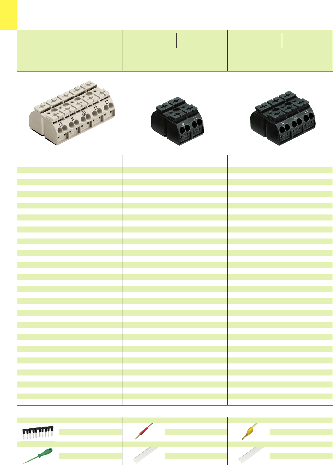
10
42
*U2ENEC *U2ENEC
Available in black or white
4-Conductor Device Connectors, 2 and 3 pole, 4 mm2/ AWG 12
with Unique Cost-Cutting Features
Series 862
Accessories DIN rail mounting of 862 Series see accessories page 10.26
Item No. Item No. Pack.-unit
black white pcs
Item No. Item No. Pack.-unit
black white pcs
without with
ground/earth contact
4 x 0.5 –4mm
24xAWG20–12
500 V/6 kV/3 300/600 V,
32 A 20/5 A U2
L10 – 11 mm / 0.41 in
4 x 0.5 –4mm
24xAWG20–12
500 V/6 kV/3 300/600 V,
32 A 20/5 A U2
L10 – 11 mm / 0.41 in
2 poles 3 poles
for fixing screw 3 mm/0.118 in Ø or
f. self tapping screw 2.9 mm/0.114 in Ø from top
without marking
L1-N
N-L1
f. self tapping screw 2.9 mm/0.114 in Ø from below
without marking
L1-N
N-L1
1 snap-in foot per pole
without marking
L1-N
N-L1
for fixing screw 3 mm/0.118 in Ø or
f. self tapping screw 2.9 mm/0.114 in Ø from top
without marking
3-N-L1
N-3-L1
N-3-L1
3-N-L1
1 snap-in foot per pole
without marking
3-N-L1
N-3-L1
N-3-L1
3-N-L1
snap-in feet at pos. 1+3
without marking
3-N-L1
N-3-L1
N-3-L1
3-N-L1
862-0552 862-0652 500
862-1552 862-1652 500
862-2552 862-2652 500
862-0562 862-0662 500
862-1562 862-1662 500
862-2562 862-2662 500
862-0532 862-0632 500
862-1532 862-1632 500
862-2532 862-2632 500
862-0503 862-0603 250
862-1503 862-1603 250
862-2503 862-2603 250
862-8503 862-8603 250
862-9503 862-9603 250
862-0533 862-0633 250
862-1533 862-1633 250
862-2533 862-2633 250
862-8533 862-8633 250
862-9533 862-9633 250
862-0593 862-0693 250
862-1593 862-1693 250
862-2593 862-2693 250
862-8593 862-8693 250
862-9593 862-9693 250
Test plug,
with cable 500 mm/1’7.7”
2 mm/0.079 in Ø, red
210-136 50 (5 x 10)
Marker strip, white, plain, for central marking;
7.5 mm wide, on roll, 50 m long
709-178 1
Test plug, with cable 500 m
m/1’7.7”
2.3 mm/0.091 in Ø, yellow
210-137 50 (5 x 10)
Marker strip, white, plain, for central marking;
7.5 mm wide, on roll, 300 m long
709-188 1
* For further approvals with corresponding ratings see section 15.
Comb type jumper bar,
can easily be inserted into the
wire entry,
32 A
862-482 5
Screwdriver, with partially insulated shaft
(3.5 x 0.5) mm
210-620 1
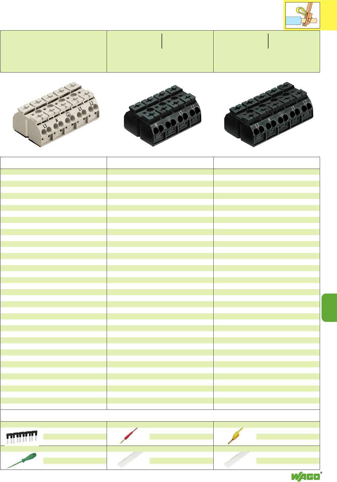
10
43
10
*U2ENEC *U2ENEC
Available in black or white
4 poles 5 poles
4-Conductor Device Connectors, 4 and 5 pole, 4 mm2/ AWG 12
with Unique Cost-Cutting Features
Series 862
4 x 0.5 –4mm
24xAWG20–12
500 V/6 kV/3 300/600 V,
32 A 20/5 A U2
L10 – 11 mm / 0.41 in
4 x 0.5 –4mm
24xAWG20–12
500 V/6 kV/3 300/600 V,
32 A 20/5 A U2
L10 – 11 mm / 0.41 in
Item No. Item No. Pack.-unit
black white pcs
Item No. Item No. Pack.-unit
black white pcs
without with
ground/earth contact
for fixing screw 3 mm/0.118 in Ø or
f. self tapping screw 2.9 mm/0.114 in Ø from top
without marking
3-N-L1-L2
N-3-L1-L2
N-3-L1-L2
3-N-L1-L2
1 snap-in foot per pole
without marking
3-N-L1-L2
N-3-L1-L2
N-3-L1-L2
3-N-L1-L2
snap-in feet at pos. 1+4
without marking
3-N-L1-L2
N-3-L1-L2
N-3-L1-L2
3-N-L1-L2
for fixing screw 3 mm/0.118 in Ø or
f. self tapping screw 2.9 mm/0.114 in Ø from top
without marking
3-N-L1-L2-L3
L3-N-3-L1-L2
L3-N-3-L1-L2
3-N-L1-L2-L3
1 snap-in foot per pole
without marking
3-N-L1-L2-L3
L3-N-3-L1-L2
L3-N-3-L1-L2
3-N-L1-L2-L3
snap-in feet at pos. 1+3+5
without marking
3-N-L1-L2-L3
L3-N-3-L1-L2
L3-N-3-L1-L2
3-N-L1-L2-L3
862-0504 862-0604 200
862-1504 862-1604 200
862-2504 862-2604 200
862-8504 862-8604 200
862-9504 862-9604 200
862-0534 862-0634 200
862-1534 862-1634 200
862-2534 862-2634 200
862-8534 862-8634 200
862-9534 862-9634 200
862-0594 862-0694 200
862-1594 862-1694 200
862-2594 862-2694 200
862-8594 862-8694 200
862-9594 862-9694 200
862-0505 862-0605 200
862-1505 862-1605 200
862-2505 862-2605 200
862-8505 862-8605 200
862-9505 862-9605 200
862-0525 862-0625 200
862-1525 862-1625 200
862-2525 862-2625 200
862-8525 862-8625 200
862-9525 862-9625 200
862-0515 862-0615 200
862-1515 862-1615 200
862-2515 862-2615 200
862-8515 862-8615 200
862-9515 862-9615 200
Accessories DIN rail mounting of 862 Series see accessories page 10.26
Test plug,
with cable 500 mm/1’7.7”
2 mm/0.079 in Ø, red
210-136 50 (5 x 10)
Marker strip, white, plain, for central marking;
7.5 mm wide, on roll, 50 m long
709-178 1
Test plug, with cable 500 m
m/1’7.7”
2.3 mm/0.091 in Ø, yellow
210-137 50 (5 x 10)
Marker strip, white, plain, for central marking;
7.5 mm wide, on roll, 300 m long
709-188 1
* For further approvals with corresponding ratings see section 15.
Comb type jumper bar,
can easily be inserted into the
wire entry,
32 A
862-482 5
Screwdriver, with partially insulated shaft
(3.5 x 0.5) mm
210-620 1
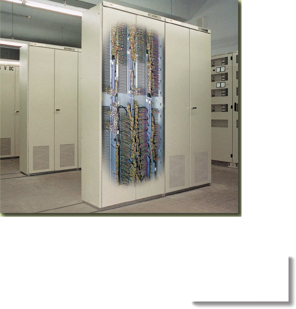
Safe patching despite high density
wiring:
WAGO matrix patchboards with
CAGE CLAMP®connection

11
11
Patching Systems and Busbar Terminal Blocks
3-conductor double potential terminal blocks
2.5 mm2/ AWG 12 Series 280 11.19
Busbar terminal blocks Series 812 11.20 – 11.21
Matrix patchboards Series 726 11.6 – 11.8
Common potential matrix assembly Series 726
– Marking on the patchboard side 11.10
– Marking on the supply side 11.11
Decade marker carriers for matrix patchboards 11.9
Insulation stop for matrix patchboards 11.9
Additional modules for matrix patchboards 11.9
Terminal blocks for matrix patching and
same potential terminal blocks 1.5 mm2/ AWG 16 Series 727 11.14 – 11.17
VOLUME 1
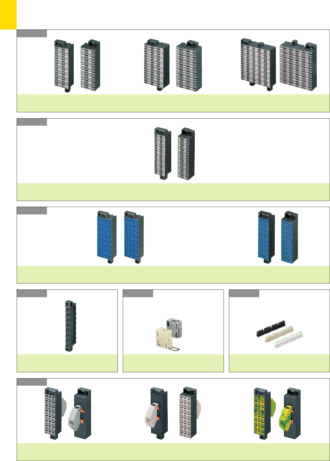
11
2
Series 726
Patching Systems
– Product Summary –
Series 726
Series 726
Series 726 Series 726 Series 726
Series 726
Matrix patchboards
Side 1 3 x 0.08 – 1.5 mm2/AWG 28 – 16
Side 2 3 x 0.08 – 1.5 mm2/AWG 28 – 16
32-, 48- and 80-pole – Pages 11.6 – 11.7
Side 1 3 x 0.08 – 1.5 mm2/AWG 28 – 16
Side 2 2 x 0.08 – 2.5 mm2/AWG 28 – 14
32-, 48- and 80-pole – Pages 11.6 – 11.7
Matrix patchboards
2 x 0.08 – 1.5 mm2/AWG 28 – 16
2 x 0.08 – 1.5 mm2/AWG 28 – 16
32-pole – Page 11.8
Ex i
Matrix
patchboards
Side 1 3 x 0.08 – 1.5 mm2/AWG 28 – 16
Side 2 3 x 0.08 – 1.5 mm2/AWG 28 – 16
32-, 48- and 80-pole – Pages 11.6 – 11.7
Side 1 3 x 0.08 – 1.5 mm2/AWG 28 – 16
Side 2 2 x 0.08 – 2.5 mm2/AWG 28 – 14
32-, 48- and 80-pole – Pages 11.6 – 11.7
2 x 0.08 – 1.5 mm2/AWG 28 – 16
2 x 0.08 – 1.5 mm2/AWG 28 – 16
32-pole – Page 11.8
Decade marker carrier
Page 11.9
Additional modules
Page 11.9
24 x 0.08 – 2.5 mm2/AWG 28 – 14
1/2 x 0.2 – 16 mm2/AWG 24 – 6
Page 11.10
1/2 x 0.2 – 16 mm2/AWG 24 – 6
24 x 0.08 – 2.5 mm2/AWG 28 – 14
Page 11.11
or
Common potential matrix patchboards
Insulation stop
Page 11.9
Slim line version
for 19’’ racks
Slim line version
for 19’’ racks
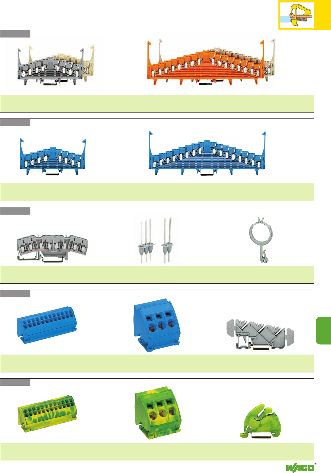
11
11
3
Series 280
Series 727
Series 727
Series 812
Series 812
4-level terminal blocks
Pages 11.14 – 11.15
Terminal blocks for matrix patching and potential terminal blocks
8-level terminal blocks
Pages 11.16 – 11.17
4-level terminal blocks
Pages 11.14 – 11.15
8-level terminal blocks
Pages 11.16 – 11.17
Ex i Terminal blocks for matrix patching and potential terminal blocks
3-conductor double potential terminal
block/
Terminal block for matrix patching
Pin modules Wire harness support
Page 11.19 Page 11.19 Page 11.19
4 mm2/ AWG 12
N/L
Page 11.21 Page 11.21
16 mm2/ AWG 6
N/L
Page 11.21
Busbar terminal blocks Insulated busbar carrier
4 mm2/ AWG 12
N/L
Page 11.21 Page 11.21
16 mm2/ AWG 6
N/L
Page 11.21
Ground (earth) busbar terminal blocks Ground (earth) busbar carrier
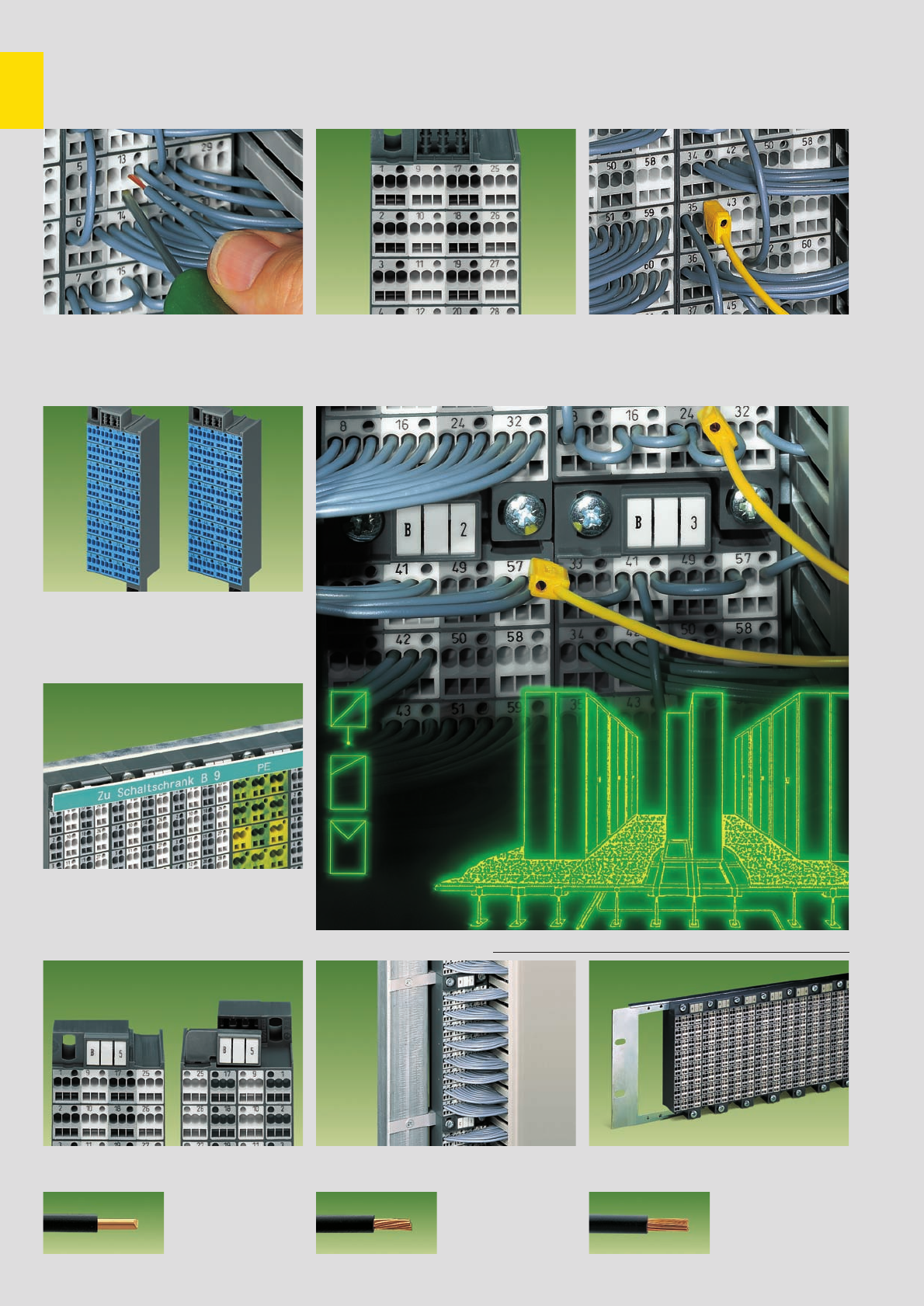
11
4
Matrix Patchboards with CAGE CLAMP®connection . . .
Series 726
Connection of wires with screwdriver
blade size (2.5 x 0.4) mm Item No. 210-119
CAGE CLAMP®connection
Blue matrix patchboards are suitable for
Ex i applications
Ex i versions
WFB Continuous marking strips. Fits into the
marker receptacle and the group marking carrier
of the matrix patchboard
Marking
Individual group marking
with WSB Quick marking system
Marking
Matrix patchboards in a frame
Examples of installation
Matrix patchboards in 19” rack
Marking of modules (factory marked)
Side 1: 1, 2, 3, 4 . . .
Marking of modules
Testing with test plug 2.3 mm/0.091 in Ø
Item No. 210-137
Testing
CAGE CLAMP®
connects the following
copper wires: *
solid stranded
fine stranded,
also with tinned
single strands
* For aluminum wire see notes in section 15!
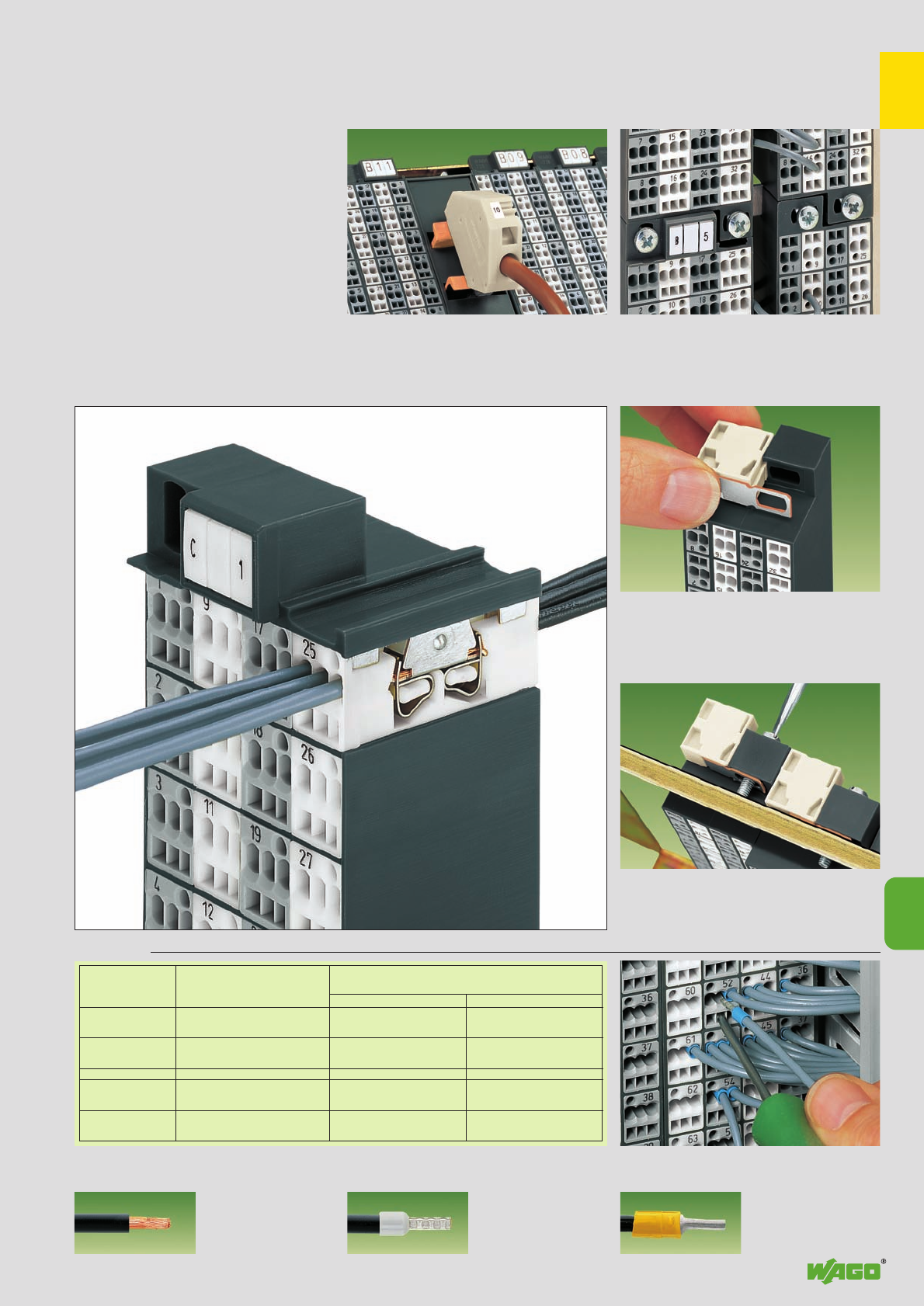
11
11
5
insulated uninsulated
Side 2
Side 1
Side 2
Side 1
Conductor cross section (mm2/AWG)
without ferrule
1.5/16
1.5/16
2.5/14
1.5/16
Conductor cross section (mm2/AWG)
with ferrule
Item No./Color
0.75/20 216-202/grey
0.75/20 216-202/grey
1.5/16 216-204/black
0.75/20 216-202/grey
Item No.
1.0/18 216-123
1.0/18 216-123
1.5/16 216-104
1.0/18 216-123
. . . Description and Handling
Snapping on an additional module with contact to
mounting frame
Assembly of a matrix patchboard with additional
module snapped on.
Direct connection to the mounting frame via
contact plate
Additional module
Additional module
Ferrules ➊
Connection of ferruled wires
Example shown here with (white)
supply terminal block
Common potential matrix assembly
Slim line matrix patchboard (lower right)
mounted upside down
Space Saving
fine-stranded wire –
tip bonded
fine-stranded wire
with crimped ferrule ➊fine-stranded wire
with crimped pin terminal
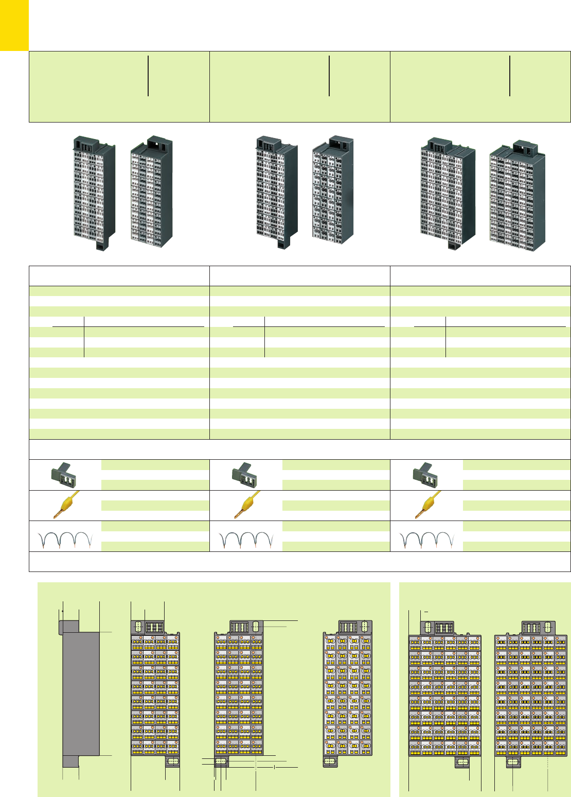
3,5 14,5
<____33___>
14,5
12,6
12,9
5,75
9,5
5
5
5,5
__> <
<__________________111__________________>
><
<___30___>
>< ><
<______44_____> <__31,5 __>
___>
><
> <__
><
<___________________121___________________>
<_____________________132_____________________>
<__
10,65
<__31,5 __>16,4
<____>
10,65 <____> >
<_________65,3________>
*U2fDa *U2fDa *U2fDa
11
6
➊
➊
➊
➊
➊
➊
➊
➊
Side 1
3 x 0.08 – 1.5 mm2Side 1
3 x 0.08 – 1.5 mm2Side 2
3 x 0.08 – 1.5 mm2
Side 2
3 x 0.08 – 1.5 mm2Side 2
2 x 0.08 – 2.5 mm2
Dimensions (in mm)
Accessories (Insulation stop see page 11.9)
No. of Item Pack.-unit
poles No. pcs No. of Item Pack.-unit
poles No. pcs
No. of Item Pack.-unit
poles No. pcs
Matrix patchboards, 32 poles, frame dark grey,
colors and numbering of modules on
sides 1 and 2 arranged vertically
Numbering
Colors of modules
grey white grey white
( 1 – 32) 1 – 8 9 – 16 17 – 24 25 – 32
(33 – 64) 33 – 40 41 – 48 49 – 56 57 – 64
32 ( 1 – 32) 726-121 20
32 (33 – 64) 726-122 20
Color of modules blue and numbering of modules on
sides 1 and 2 arranged vertically
32 ( 1 – 32) 726-141 20
32 (33 – 64) 726-142 20
suitable for Ex i applications
Matrix patchboards, 32 poles, frame dark grey,
colors and numbering of modules on
sides 1 and 2 arranged vertically
Numbering
Colors of modules
grey white grey white
( 1 – 32) 1 – 8 9 – 16 17 – 24 25 – 32
(33 – 64) 33 – 40 41 – 48 49 – 56 57 – 64
32 ( 1 – 32) 726-221 20
32 (33 – 64) 726-222 20
Color of modules blue and numbering of modules on
sides 1 and 2 arranged vertically
32 ( 1 – 32) 726-241 20
32 (33 – 64) 726-242 20
suitable for Ex i applications
Matrix patchboards, 48 poles, frame dark grey,
colors and numbering of modules on
sides 1 and 2 arranged vertically
Numbering
Colors of modules
grey white grey white
( 1 – 48) 1 – 8 9 – 16 17 – 24 25 – 32
33 – 40 41 – 48
48 ( 1 – 48) 726-421 10
Color of modules blue and numbering of modules on
sides 1 and 2 arranged vertically
48 ( 1 – 48) 726-441 10
suitable for Ex i applications
Group marking adapter
for side 2
726-902 50
Test plug, 2.3 mm /0.091 in Ø
yellow 210-137 50 (5 x 10)
with cable 500 mm /1’7.7’’
Wire comm. chain, insulated, 6 A
31 connections, 0.5 mm2, max. 50 V
grey 709-107 1
Group marking adapter
for side 2
726-902 50
Test plug, 2.3 mm /0.091 in Ø
yellow 210-137 50 (5 x 10)
with cable 500 mm /1’7.7’’
Wire comm. chain, insulated, 6 A
31 connections, 0.5 mm2, max. 50 V
grey 709-107 1
Group marking adapter
for side 2
726-902 50
Test plug, 2.3 mm /0.091 in Ø
yellow 210-137 50 (5 x 10)
with cable 500 mm /1’7.7’’
Wire comm. chain, insulated, 6 A
31 connections, 0.5 mm2, max. 50 V
grey 709-107 1
* For further approvals with corresponding ratings see section 15.
Matrix Patchboards
Side 1: 3 x 0.08 –1.5 mm2AWG 28 – 16
Side 2: 3 x 0.08 –1.5 mm2AWG 28 – 16
500 V/6 kV/3 300 V, 10 A U
10 A 300 V, 10 A 2
L8 – 10 mm / 0.35 in
Side 1: 3 x 0.08 –1.5 mm2AWG 28 – 16
Side 2: 3 x 0.08 –1.5 mm2AWG 28 – 16
500 V/6 kV/3 300 V, 10 A U
10 A 300 V, 10 A 2
L8 – 10 mm / 0.35 in
Side 1: 3 x 0.08 –1.5 mm2AWG 28 – 16
Side 2: 2 x 0.08 –2.5 mm2AWG 28 – 14
500 V/6 kV/3 300 V, 10 A U
10 A 300 V, 10 A 2
L8 – 10 mm / 0.35 in
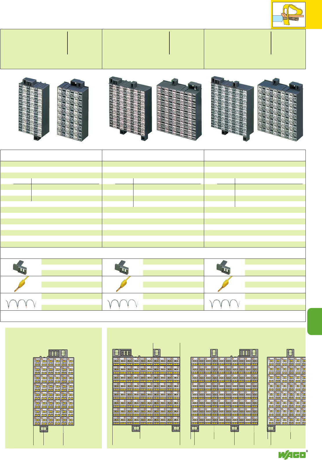
<__31,5 __>
16,4><________________107,9________________>
<____ 43 ____>
<_____44_____> <__31,5 __>
5,75
<________63,9________><__31,5__>
<__31,5__>
5,75
<________63,9_______
_
___>___>
*U2fDa *U2fDa *U2fDa
11
11
7
➊
➊
➊
➊
➊
➊
Side 2
2 x 0.08 – 2.5 mm2Side 1
3 x 0.08 – 1.5 mm2Side 2
3 x 0.08 – 1.5 mm2Side 2
2 x 0.08 – 2.5 mm2
No. of Item Pack.-unit
poles No. pcs No. of Item Pack.-unit
poles No. pcs
No. of Item Pack.-unit
poles No. pcs
Matrix patchboards, 48 poles, frame dark grey,
colors and numbering of modules on
sides 1 and 2 arranged vertically
Numbering
Colors of modules
grey white grey white
( 1 – 48) 1 – 8 9 – 16 17 – 24 25 – 32
33 – 40 41 – 48
48 ( 1 – 48) 726-521 10
Color of modules blue and numbering of modules on
sides 1 and 2 arranged vertically
48 ( 1 – 48) 726-541 10
suitable for Ex i applications
Matrix patchboards, 80 poles, frame dark grey,
colors and numbering of modules on
sides 1 and 2 arranged vertically
Numbering
Colors of modules
grey white grey white
( 1 – 80) 1 – 8 9 – 16 17 – 24 25 – 32
33 – 40 41 – 48 49 – 56 57 – 64
65 – 72 73 – 80
80 ( 1 – 80) 726-721 8
Color of modules blue and numbering of modules on
sides 1 and 2 arranged vertically
80 ( 1 – 80) 726-741 8
suitable for Ex i applications
Matrix patchboards, 80 poles, frame dark grey,
colors and numbering of modules on
sides 1 and 2 arranged vertically
Numbering
Colors of modules
grey white grey white
( 1 – 80) 1 – 8 9 – 16 17 – 24 25 – 32
33 – 40 41 – 48 49 – 56 57 – 64
65 – 72 73 – 80
80 ( 1 – 80) 726-821 8
Color of modules blue and numbering of modules on
sides 1 and 2 arranged vertically
80 ( 1 – 80) 726-841 8
suitable for Ex i applications
Group marking adapter
for side 2
726-902 50
Test plug, 2.3 mm /0.091 in Ø
yellow 210-137 50 (5 x 10)
with cable 500 mm /1’7.7’’
Wire comm. chain, insulated, 6 A
31 connections, 0.5 mm2, max. 50 V
grey 709-107 1
Group marking adapter
for side 2
726-902 50
Test plug, 2.3 mm /0.091 in Ø
yellow 210-137 50 (5 x 10)
with cable 500 mm /1’7.7’’
Wire comm. chain, insulated, 6 A
31 connections, 0.5 mm2, max. 50 V
grey 709-107 1
Group marking adapter
for side 2
726-902 50
Test plug, 2.3 mm /0.091 in Ø
yellow 210-137 50 (5 x 10)
with cable 500 mm /1’7.7’’
Wire comm. chain, insulated, 6 A
31 connections, 0.5 mm2, max. 50 V
grey 709-107 1
Side 1: 3 x 0.08 –1.5 mm2AWG 28 – 16
Side 2: 2 x 0.08 –2.5 mm2AWG 28 – 14
500 V/6 kV/3 300 V, 10 A U
10 A 300 V, 10 A 2
L8 – 10 mm / 0.35 in
Side 1: 3 x 0.08 –1.5 mm2AWG 28 – 16
Side 2: 3 x 0.08 –1.5 mm2AWG 28 – 16
500 V/6 kV/3 300 V, 10 A U
10 A 300 V, 10 A 2
L8 – 10 mm / 0.35 in
Side 1: 3 x 0.08 –1.5 mm2AWG 28 – 16
Side 2: 2 x 0.08 –2.5 mm2AWG 28 – 14
500 V/6 kV/3 300 V, 10 A U
10 A 300 V, 10 A 2
L8 – 10 mm / 0.35 in
(for the group marking the WAGO WSB Quick marking system or WFB Continuous marking strips can be used, see section 14)
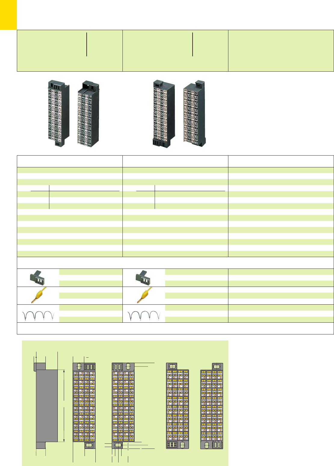
9,5
<___________________121___________________>
5
5
5,5
<_____________________132_____________________>
15,249,7
<___34,6 ___>
17,2
16,45
14,5
<___33___>
14,5
111
3,5 <__> <>
<__
<>
<__>
<>
<>
<><>
*U2fDa *U2fa
11
8
➊
➊
➊
➊
➊
➊
Version mounted upside down
Side 1/Side 2
2 x 0.08 – 1.5 mm2
Side 1
2 x 0.08 – 1.5 mm2Side 2
2 x 0.08 – 1.5 mm2
* For further approvals with corresponding ratings see section 15.
Dimensions (in mm)
Accessories
No. of Item Pack.-unit
poles No. pcs
No. of Item Pack.-unit
poles No. pcs
Matrix patchboards, 32 poles, frame dark grey,
colors and numbering of modules on
sides 1 and 2 arranged vertically
Numbering
Colors of modules
grey white grey white
( 1 – 32) 1 – 8 9 – 16 17 – 24 25 – 32
(33 – 64) 33 – 40 41 – 48 49 – 56 57 – 64
32 ( 1 – 32) 726-321 24
32 (33 – 64) 726-322 24
Color of module blue and numbering of modules on
sides 1 and 2 arranged vertically
32 ( 1 – 32) 726-341 24
32 (33 – 64) 726-342 24
suitable for Ex i applications
Matrix patchboards, 32 poles, mounted upside
down, frame dark grey, colors and numbering of
modules on sides 1 and 2 arranged vertically
Numbering
Colors of modules
grey white grey white
( 1 – 32) 1 – 8 9 – 16 17 – 24 25 – 32
(33 – 64) 33 – 40 41 – 48 49 – 56 57 – 64
32 ( 1 – 32) 726-325 24
32 (33 – 64) 726-326 24
Color of module blue and numbering of modules on
sides 1 and 2 arranged vertically
32 ( 1 – 32) 726-345 24
32 (33 – 64) 726-346 24
suitable for Ex i applications
Group marking adapter
for side 2
726-902 50
Test plug, 2.3 mm /0.091 in Ø
yellow 210-137 50 (5 x 10)
with cable 500 mm /1’7.7’’
Wire comm. chain, insulated, 6 A
31 connections, 0.5 mm2, max. 50 V
grey 709-107 1
Group marking adapter
for side 2
726-902 50
Test plug, 2.3 mm /0.091 in Ø
yellow 210-137 50 (5 x 10)
with cable 500 mm /1’7.7’’
Wire comm. chain, insulated, 6 A
31 connections, 0.5 mm2, max. 50 V
grey 709-107 1
Matrix Patchboards
Slim Line Version for 19” Racks
Side 1: 2 x 0.08 –1.5 mm2AWG 28 – 16
Side 2: 2 x 0.08 –1.5 mm2AWG 28 – 16
500 V/6 kV/3 300 V, 10 A U
10 A 300 V, 10 A 2
L8 – 10 mm / 0.35 in
Side 1: 2 x 0.08 –1.5 mm2AWG 28 – 16
Side 2: 2 x 0.08 –1.5 mm2AWG 28 – 16
500 V/6 kV/3 300 V, 10 A U
10 A 300 V, 10 A 2
L8 – 10 mm / 0.35 in
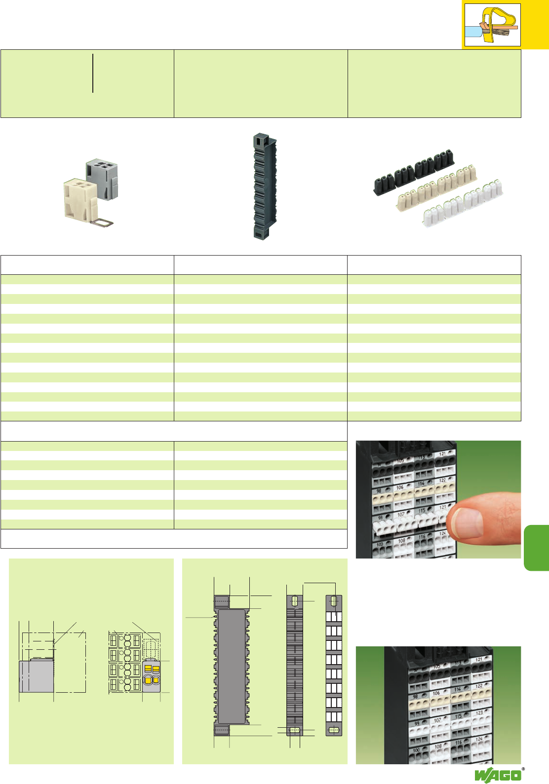
<_18,1_>
(10,4)
<14,5 >
<___20___>
5,5>
0
0
0
0
0
8
7
6
5
4
3
2
0
0
0
0
0
0
0
0
0
001
14,5
<___33___>
14,5
<_________________109_________________>
10,5
<_____________________132_____________________>
9,5
<___________________121___________________>
5,5
5
(_15_)14,5 <>
>
<>
>
<>
<>
*2
11
11
9
Marking
example
3 x WSB (5 mm)
8 x WSB
receptacle
at both sides
Direct contacting (additional module only,
with contact to mounting frame)
matrix patchboard
* For further approvals with corresponding ratings see section 15.
Dimensions (in mm)
Decade marker carrier, for matrix patchboards
dark grey 726-905 10
Color Item Pack.-unit
No. pcs
Additional Modules,
Decade Marker Carriers and
Insulation Stops for Matrix Patching Series 726
Additional modules, for matrix patchboards,
for snap-on fixing to the lower fixing element,
with CAGE CLAMP®
Additional module with contact to mounting frame
white 726-903 25
Additional module, insulated
grey 726-904 25
Color Item Pack.-unit
No. pcs
Insulation stop,
suitable for patchboard side 1
matrix patching 3 x 1.5 mm2/AWG 16
L8 – 10 mm / 0.35 in
Item Pack.-unit
No. pcs
Insulation stop, 4 x 3 pcs /strip
white 726-901 200 strips
0.08 – 0.2 mm2/AWG 28 – 24 “s“
(0.08 – 0.14 mm2/AWG 28 – 26 “f-st“)
light grey 726-906 200 strips
0.25 mm2/AWG 22 “s“
0.14 – 0.25 mm2/AWG 26 – 22 “f-st“
dark grey 726-907 200 strips
0.25 – 0.5 mm2/AWG 22 – 20 “s+f-st“
Note: Suitable for patchboard side 1 of matrix
patchboards 1.5 mm2 / AWG 16 (patchboards with
different front and back sides)
1 x 0.08 – 4 mm2AWG 28 – 12
1 x 0.08 – 2.5 mm2AWG 28 – 14
500 V/4 kV/3
10 A 300 V, 10 A 2
L9 mm / 0.35 in
Insert insulation stop into conductor entry holes of matrix
patchboard.
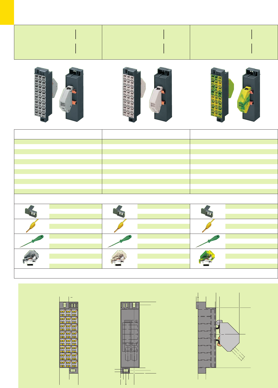
9,5
<___________________121___________________>
5
5
5,5
<_____________________132 _____________________>
15,249,7
<___34,6___>
17,2
16,45
<>
<>
<>
<>
<>
<__>
<
14,5
<______33 ______>
14,5
<__________________111__________________>
<_______49,3______>
6,5
1
3,5
<>
<__> <>
>
<___43,4_____>
11
10
Group marking adapter
for patchboard side
726-902 50
Test plug, 2.3 mm /0.091 in Ø
yellow 210-137 50 (5 x 10)
with cable 500 mm /1’7.7’’
Screwdrivers
(2.5 x0.4) mm
210-119 1
(5.5 x0.8) mm
210-121 1
Additional supply
terminal block
green-yellow
283-609 25
Group marking adapter
for patchboard side
726-902 50
Test plug, 2.3 mm /0.091 in Ø
yellow 210-137 50 (5 x 10)
with cable 500 mm /1’7.7’’
Screwdrivers
(2.5 x0.4) mm
210-119 1
(5.5 x0.8) mm
210-121 1
Additional supply
terminal block
grey 283-611 25
Dimensions (in mm)
Accessories (Marking accessories WSB quick marking system see section 14)
Item Pack.-unit
No. pcs
Item Pack.-unit
No. pcs
Item Pack.-unit
No. pcs
Group marking adapter
for patchboard side
726-902 50
Test plug, 2.3 mm /0.091 in Ø
yellow 210-137 50 (5 x 10)
with cable 500 mm /1’7.7’’
Screwdrivers
(2.5 x0.4) mm
210-119 1
(5.5 x0.8) mm
210-121 1
Additional supply
terminal block
grey 283-611 25
Common potential matrix patchboards, frame dark grey,
Supply side:
24 x 2 connections, numbering of modules arranged
vertically (1 – 24), color of module: grey,
Patchboard side:
with 1 supply terminal block incl. end plate
wire size 0.2 mm2to 16 mm2/AWG 24-6
grey 726-601 10
with 2 supply terminal blocks incl. end plate
wire size 0.2 mm2to 16 mm2/AWG 24-6
grey 726-602 10
Common potential matrix patchboards, frame dark grey,
Supply side:
24 x 2 connections, numbering of modules arranged
vertically (1 – 24), color of module: white,
Patchboard side:
with 1 supply terminal block incl. end plate
wire size 0.2 mm2to 16 mm2/AWG 24-6
white 726-611 10
with 2 supply terminal blocks incl. end plate
wire size 0.2 mm2to 16 mm2/AWG 24-6
white 726-612 10
Comm. pot. matrix pbds. f. gnd. earth cond., frame dark grey,
Supply side:
24 x 2 connections, numbering of modules arranged
vertically (1 – 24), color of module: green-yellow,
Patchboard side:
with 1 supply terminal block incl. end plate
wire size 0.2 mm2to 16 mm2/AWG 24-6
green-yellow 726-621 10
with 2 supply terminal blocks incl. end plate
wire size 0.2 mm2to 16 mm2/AWG 24-6
green-yellow 726-622 10
Common Potential Matrix Patchboards
Slime Line Version for 19” Racks
* For further approvals with corresponding ratings see section 15.
Supply side
2 x 0.08 – 2.5 mm2Patchboard side
1 x 0.2 – 16 mm2
or 2 x 0.2 – 16 mm2
Supply side: 24 A
24 x 2 x 0.08 – 2.5 mm2AWG 28 – 14
L8 – 10 mm / 0.35 in 300 V, 10 A 2
Patchboard side: 76 A
1 x 0.2 – 16 mm2AWG 24 – 6
or
2 x 0.2 – 16 mm2AWG 24 – 6
L16 – 17 mm / 0.65 in *U2fD
Supply side: 24 A
24 x 2 x 0.08 – 2.5 mm2AWG 28 – 14
L8 – 10 mm / 0.35 in 300 V, 10 A 2
Patchboard side: 76 A
1 x 0.2 – 16 mm2AWG 24 – 6
or
2 x 0.2 – 16 mm2AWG 24 – 6
L16 – 17 mm / 0.65 in *U2fD
Supply side: 24 A
24 x 2 x 0.08 – 2.5 mm2AWG 28 – 14
L8 – 10 mm / 0.35 in 300 V, 10 A 2
Patchboard side: 76 A
1 x 0.2 – 16 mm2AWG 24 – 6
or
2 x 0.2 – 16 mm2AWG 24 – 6
L16 – 17 mm / 0.65 in *U2fD
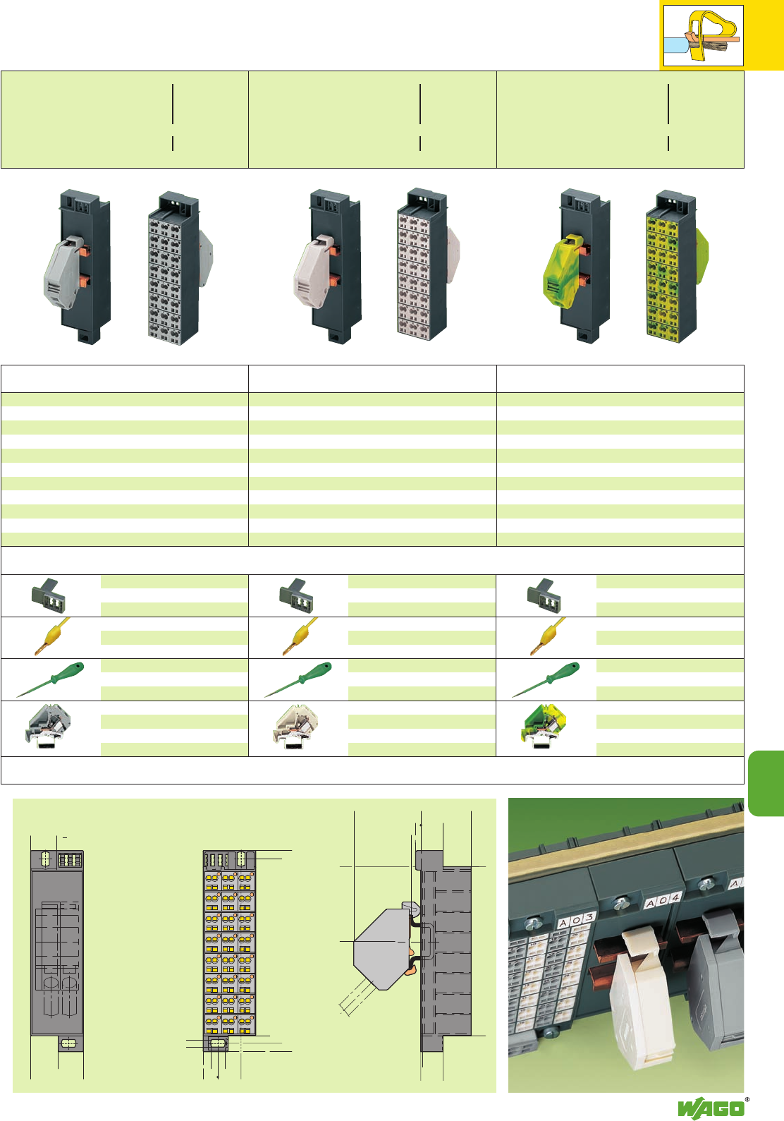
9,5
5
17,2
16,45
<>
<>
<>
<
<__>
14,5
<___33___>
<__________________111__________________>
<______49,3_____>
6,5
3,5
<___________________121___________________>
5
5,5
<_____________________132 _____________________>
15,249,7
<___34,6___> <
>
>
<__> <
<____43,4_____>
<__
14,5
1
<>
>
__>
>
11
11
11
Group marking adapter
for patchboard side
726-902 50
Test plug, 2.3 mm /0.091 in Ø
yellow 210-137 50 (5 x 10)
with cable 500 mm /1’7.7’’
Screwdrivers
(2.5x0.4)mm
210-119 1
(5.5x0.8)mm
210-121 1
Additional supply terminal
block
green-yellow
283-609 25
Group marking adapter
for patchboard side
726-902 50
Test plug, 2.3 mm /0.091 in Ø
yellow 210-137 50 (5 x 10)
with cable 500 mm /1’7.7’’
Screwdrivers
(2.5x0.4)mm
210-119 1
(5.5x0.8)mm
210-121 1
Additional supply terminal
block
grey 283-611 25
Dimensions (in mm)
Accessories (Marking accessories WSB quick marking system see section 14)
Item Pack.-unit
No. pcs
Item Pack.-unit
No. pcs
Item Pack.-unit
No. pcs
Group marking adapter
for patchboard side
726-902 50
Test plug, 2.3 mm /0.091 in Ø
yellow 210-137 50 (5 x 10)
with cable 500 mm /1’7.7’’
Screwdrivers
(2.5x0.4)mm
210-119 1
(5.5x0.8)mm
210-121 1
Additional supply terminal
block
white 283-610 25
Common potential matrix patchboards, frame dark grey,
Supply side:
with 1 terminal block incl. end plate
wire size 0.2 – 16 mm2/AWG 24-6
grey 726-651 10
with 2 terminal blocks incl. end plate
wire size 0.2 – 16 mm2/AWG 24-6
grey 726-652 10
Patchboard side:
24 x 2 connections, numbering of modules arranged
vertically (1 – 24), color of module: grey
Common potential matrix patchboards, frame dark grey,
Supply side:
with 1 terminal block incl. end plate
wire size 0.2 – 16 mm2/AWG 24-6
white 726-661 10
with 2 terminal blocks incl. end plate
wire size 0.2 – 16 mm2/AWG 24-6
white 726-662 10
Patchboard side:
24 x 2 connections, numbering of modules arranged
vertically (1 – 24), color of module: white
Common potential matrix patchboards, frame dark grey,
Supply side:
with 1 terminal block incl. end plate
wire size 0.2 – 16 mm2/AWG 24-6
green-yellow 726-671 10
with 2 terminal blocks incl. end plate
wire size 0.2 – 16 mm2/AWG 24-6
green-yellow 726-672 10
Patchboard side:
24 x 2 connections, numbering of modules arranged
vertically (1 – 24), color of module: green-yellow
Common Potential Matrix Patchboards
Slim Line Version, for 19” Racks, Supply Side/Patchboard Side
* For further approvals with corresponding ratings see section 15.
Supply side
1 x 0.2 – 16 mm2
or 2 x 0.2 – 16 mm2
Patchboard side
2 x 0.08 – 2.5 mm2
Supply side
: 76 A
1 x 0.2
– 16 mm
2
AWG 24 – 6
or 2 x 0.2
– 16 mm
2
AWG 24 – 6
L
16 – 17 mm / 0.65 in
300V,10AU
Patchboard side
: 24 A
24 x 2 x 0.08
– 2.5 mm
2
AWG 28 – 14
L
8 – 10 mm / 0.35
in *U2fD
Supply side
: 76 A
1 x 0.2
– 16 mm
2
AWG 24 – 6
or 2 x 0.2
– 16 mm
2
AWG 24 – 6
L
16 – 17 mm / 0.65 in
300V,10AU
Patchboard side
: 24 A
24 x 2 x 0.08
– 2.5 mm
2
AWG 28 – 14
L
8 – 10 mm / 0.35
in *U2fD
Supply side
: 76 A
1 x 0.2
– 16 mm
2
AWG 24 – 6
or 2 x 0.2
– 16 mm
2
AWG 24 – 6
L
16 – 17 mm / 0.65 in
300V,10AU
Patchboard side
: 24 A
24 x 2 x 0.08
– 2.5 mm
2
AWG 28 – 14
L
8 – 10 mm / 0.35
in *U2fD
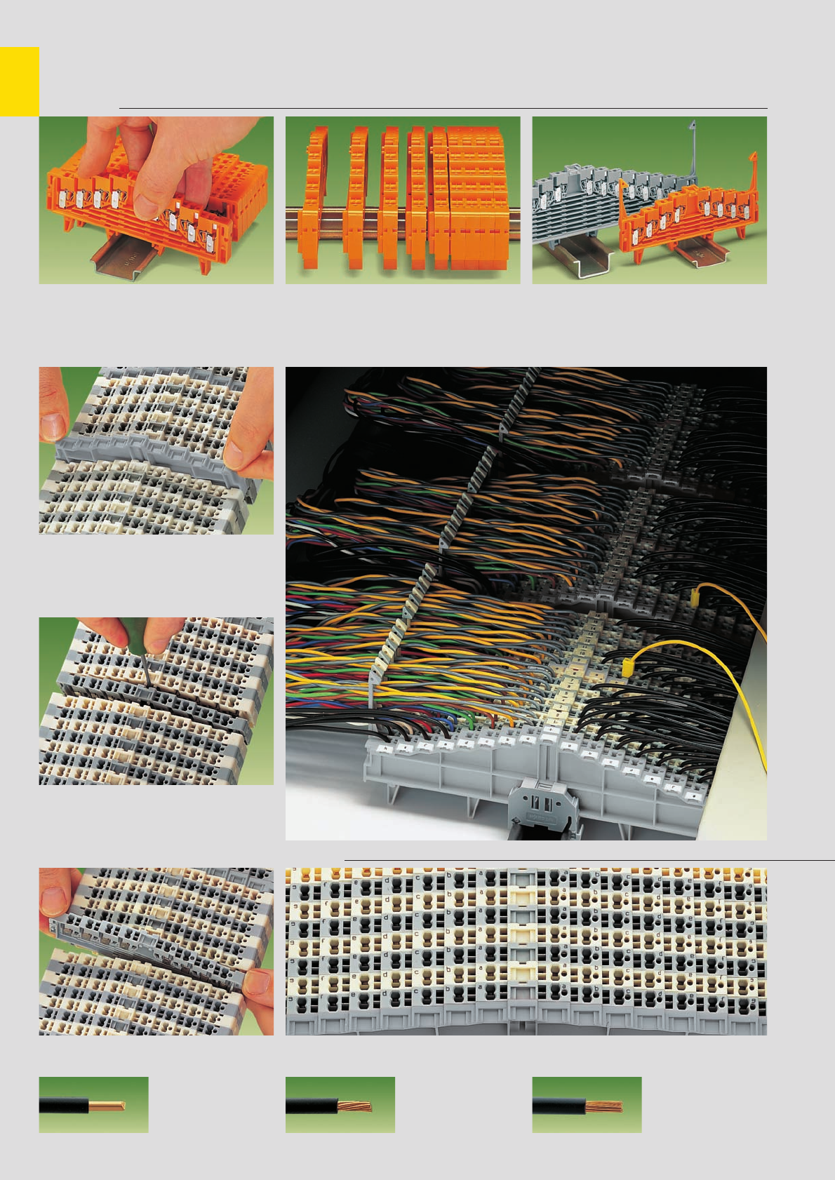
11
12
CAGE CLAMP®
connects the following
copper wires: *
solid stranded
fine stranded,
also with tinned
single strands
* For aluminum wire see notes in section 15!
Terminal Blocks for Matrix Patching and Same Potential Terminal Blocks
with CAGE CLAMP®connection, Series 727 . . .
Snap individual 4- or 8-level terminal blocks
onto the carrier rail . . .
Assembly
Grip end plate at both sides and
– push down (assembly)
– pull up (removal)
Assembly / Removal
Open the assembly by laterally sliding a block
using a screwdriver (2.5 x 0.4) mm . . .
Removal
. . . move terminal block laterally and remove
from the rail with a levering action
Removal
Marking of clamping units by direct printing
Marking
. . . and engage Terminal blocks for DIN 35 x 7.5 mm or
DIN 35 x 15 mm high are available
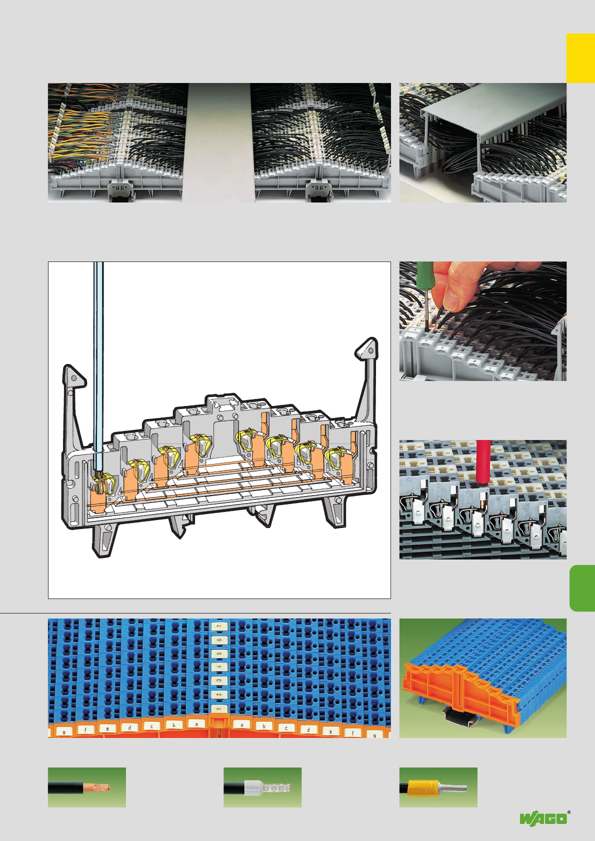
11
11
13
fine-stranded wire –
tip bonded
fine-stranded wire
with crimped ferrule ➊fine-stranded wire
with crimped pin terminal
Testing
Ex i versions
. . . Description and Handling
Connection/removal of conductors using a
screwdriver (2.5 x 0.4) mm
Special test contact for test plug 2.3 mm/0.091 in
Ø
CAGE CLAMP®connection
Marking of coordinates with the WMB Multi marking system or WSB Quick marking system Blue terminal blocks for matrix patching
are suitable for Ex i applications
When using terminal blocks with locking clips the
wiring space between the terminal strips can be
covered with a wiring duct cover*.
(*for suitable suppliers – please contact factory)
Example left: Main cables fed through locking clips on the field side
right: Control cables fed between locking clips
center: Wiring of the patching sides
Wiring space Matrix patching assembly
➊Max. cross section for uninsulated ferrules 1 mm2/AWG 18, for insulated ferrules 0.75 mm2/AWG 20.
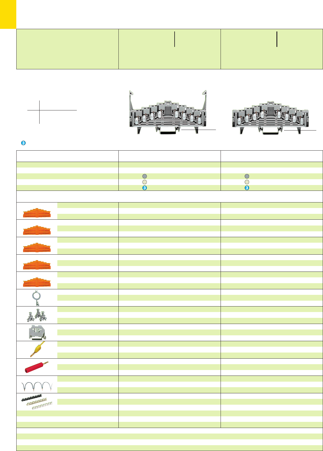
*U2fDaH *U2fDaH
11
14
Description
Accessories Appropriate marking system WMB/WSB (see section 14)
4-level terminal block for matrix patching ➋,
for DIN 35 rail
acc. to EN 60715
Item Item Pack.-unit
No. No. pcs Item Item Pack.-unit
No. No. pcs
with for for
locking clips DIN 35 x 7.5 DIN 35 x 15
grey 727-219 ➍727-229 ➍50
white 727-221 ➍727-231 ➍50
blue 727-223 ➍727-233 ➍50
without for for
locking clips DIN 35 x 7.5 DIN 35 x 15
grey 727-220 ➍727-230 ➍50
white 727-222 ➍727-232 ➍50
blue 727-224 ➍727-234 ➍50
4-level end plate,
without printing
4-level end plate,
numeric printing
4-level end plate,
alphanumeric printing
4-level end plate,
numeric printing
4-level end plate,
alphanumeric printing
Wire harness support,
see also page 11.19
WSB Double marker carrier,
for I/O markings
in the terminal block center
Screwless
end stop
Test plug, 2.3 mm /0.091 in Ø
with cable 500 mm /1’7.7’’
Reducing test plug,
from 4 mm /0.157 in Ø socket
to 2.3 mm /0.091 in Ø plug
Wire commoning chain,
insulated, 6 A, 32 connections,
0.5 mm2, max. 50 V
Insulation stop,
8 pcs/strip
0.08–0.14 mm
2
“f-st”/0.08–0.2 mm
2
“s”
0.14–0.25 mm
2
“f-st”
/0.25 mm
2
“s”
0.25–0.5 mm
2
“s + f-st”
7.62 mm /0.3 in thick
orange 727-217 25
7.62 mm /0.3 in thick
0-1-2-3--3-2-1-0
orange 727-205 25
7.62 mm /0.3 in thick
a-b-c-d--d-c-b-a
orange 727-206 25
7.62 mm /0.3 in thick
3-2-1-0--0-1-2-3
orange 727-207 25
7.62 mm /0.3 in thick
d-c-b-a--a-b-c-d
orange 727-208 25
grey 249-109 50
4 mm /0.157 in wide
209-128 200 (2 x100)
6 mm /0.236 in wide 249-116 100 (4 x 25)
10 mm /0.394 in wide 249-117 50 (2 x 25)
yellow 210-137 50 (5 x 10)
red 210-297 100 (4 x 25)
grey 709-107 1
white 727-197 200 (8 x 25)
light grey 727-198 200 (8 x 25)
dark grey 727-199 200 (8 x 25)
7.62 mm /0.3 in thick
orange 727-217 25
7.62 mm /0.3 in thick
0-1-2-3--3-2-1-0
orange 727-205 25
7.62 mm /0.3 in thick
a-b-c-d--d-c-b-a
orange 727-206 25
7.62 mm /0.3 in thick
3-2-1-0--0-1-2-3
orange 727-207 25
7.62 mm /0.3 in thick
d-c-b-a--a-b-c-d
orange 727-208 25
grey 249-109 50
4 mm /0.157 in wide
209-128 200 (2 x100)
6 mm /0.236 in wide 249-116 100 (4 x 25)
10 mm /0.394 in wide 249-117 50 (2 x 25)
yellow 210-137 50 (5 x 10)
red 210-297 100 (4 x 25)
grey 709-107 1
white 727-197 200 (8 x 25)
light grey 727-198 200 (8 x 25)
dark grey 727-199 200 (8 x 25)
0-1-2-3--3-2-1-0 . . . - . . . /021-000
a-b-c-d--d-c-b-a . . . - . . . /022-000
3-2-1-0--0-1-2-3 . . . - . . . /023-000
d-c-b-a--a-b-c-d . . . - . . . /024-000
➍Additional item no. for terminal blocks with marking
* For further approvals with corresponding ratings see section 15. ** if approved by the works expert
<_____________ 126 mm /4.96 in _____________> <_____________ 126 mm /4.96 in _____________>
4-Level Terminal Blocks for Matrix Patching 1.5 mm2/ AWG 16,
Series 727
Ex i**
application
➊250 V 60 V = peak value
4 kV ∧table 4, EN 50020
3
(see also section 15)
➋4 x pairs of contacts
on each level
Suitable for Ex i applications
<__ 62 mm/2.44 in __>
<_ 44.5 mm/ _>
1. 75 in
2 x 0.08 – 1.5 mm22 x AWG 28 – 16
250 V/4 kV/3 ➊300 V, 10 A U
12 A 300 V, 10 A 2
Terminal block width 7.62 mm / 0.3 in
L8 – 10 mm / 0.35 in
2 x 0.08 – 1.5 mm22 x AWG 28 – 16
250 V/4 kV/3 ➊300 V, 10 A U
12 A 300 V, 10 A 2
Terminal block width 7.62 mm / 0.3 in
L8 – 10 mm / 0.35 in
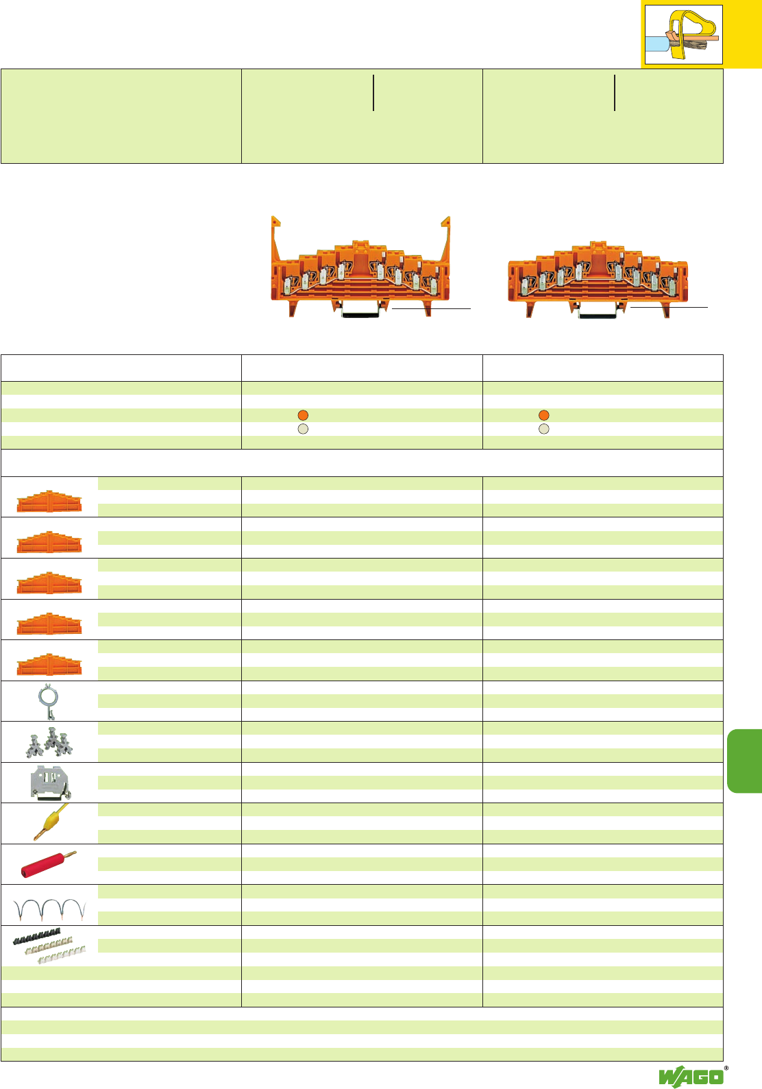
*U2fDaH *U2fDaH
11
11
15
0-1-2-3--3-2-1-0 . . . - . . . /021-000
a-b-c-d--d-c-b-a . . . - . . . /022-000
3-2-1-0--0-1-2-3 . . . - . . . /023-000
d-c-b-a--a-b-c-d . . . - . . . /024-000
➌Additional item no. for terminal blocks with marking
Description
4-level same potential terminal block ➋,
for DIN 35 rail
acc. to EN 60715
Item Item Pack.-unit
No. No. pcs Item Item Pack.-unit
No. No. pcs
with for for
locking clips DIN 35 x 7.5 DIN 35 x 15
orange 727-225 ➌727-235 ➌50
light grey 727-227 ➌727-237 ➌50
without for for
locking clips DIN 35 x 7.5 DIN 35 x 15
orange 727-226 ➌727-236 ➌50
light grey 727-228 ➌727-238 ➌50
4-level end plate,
without printing
4-level end plate,
numeric printing
4-level end plate,
alphanumeric printing
4-level end plate,
numeric printing
4-level end plate,
alphanumeric printing
Wire harness support,
see also page 11.19
WSB Double marker carrier,
for I/O markings
in the terminal block center
Screwless
end stop
Test plug, 2.3 mm /0.091 in Ø
with cable 500 mm /1’7.7’’
Reducing test plug,
from 4 mm /0.157 in Ø socket
to 2.3 mm /0.091 in Ø plug
Wire commoning chain,
insulated, 6 A, 32 connections,
0.5 mm2, max. 50 V
Insulation stop,
8 pcs/strip
0.08–0.14 mm
2
“f-st”/0.08–0.2 mm
2
“s”
0.14–0.25 mm
2
“f-st”
/0.25 mm
2
“s”
0.25–0.5 mm
2
“s + f-st”
7.62 mm /0.3 in thick
orange 727-217 25
7.62 mm /0.3 in thick
0-1-2-3--3-2-1-0
orange 727-205 25
7.62 mm /0.3 in thick
a-b-c-d--d-c-b-a
orange 727-206 25
7.62 mm /0.3 in thick
3-2-1-0--0-1-2-3
orange 727-207 25
7.62 mm /0.3 in thick
d-c-b-a--a-b-c-d
orange 727-208 25
grey 249-109 50
4 mm /0.157 in wide
209-128 200 (2 x100)
6 mm /0.236 in wide 249-116 100 (4 x 25)
10 mm /0.394 in wide 249-117 50 (2 x 25)
yellow 210-137 50 (5 x 10)
red 210-297 100 (4 x 25)
grey 709-107 1
white 727-197 200 (8 x 25)
light grey 727-198 200 (8 x 25)
dark grey 727-199 200 (8 x 25)
7.62 mm /0.3 in thick
orange 727-217 25
7.62 mm /0.3 in thick
0-1-2-3--3-2-1-0
orange 727-205 25
7.62 mm /0.3 in thick
a-b-c-d--d-c-b-a
orange 727-206 25
7.62 mm /0.3 in thick
3-2-1-0--0-1-2-3
orange 727-207 25
7.62 mm /0.3 in thick
d-c-b-a--a-b-c-d
orange 727-208 25
grey 249-109 50
4 mm /0.157 in wide
209-128 200 (2 x100)
6 mm /0.236 in wide 249-116 100 (4 x 25)
10 mm /0.394 in wide 249-117 50 (2 x 25)
yellow 210-137 50 (5 x 10)
red 210-297 100 (4 x 25)
grey 709-107 1
white 727-197 200 (8 x 25)
light grey 727-198 200 (8 x 25)
dark grey 727-199 200 (8 x 25)
* For further approvals with corresponding ratings see section 15.
➊250 V = rated voltage
4 kV = rated surge voltage
3 = pollution degree
(see also section 15)
➋All clamping units are connected
to the same current bar <_____________ 126 mm /4.96 in _____________>
4-Level Same Potential Terminal Blocks 1.5 mm2/ AWG 16,
Series 727
Accessories Appropriate marking system WMB/WSB (see section 14)
<_____________ 126 mm /4.96 in _____________>
<__ 62 mm/2.44 in __>
2 x 0.08 – 1.5 mm22 x AWG 28 – 16
250 V/4 kV/3 ➊300 V, 10 A U
18 A 300 V, 10 A 2
Terminal block width 7.62 mm / 0.3 in
L8 – 10 mm / 0.35 in
2 x 0.08 – 1.5 mm22 x AWG 28 – 16
250 V/4 kV/3 ➊300 V, 10 A U
18 A 300 V, 10 A 2
Terminal block width 7.62 mm / 0.3 in
L8 – 10 mm / 0.35 in
<_ 44.5 mm/ _>
1. 75 in
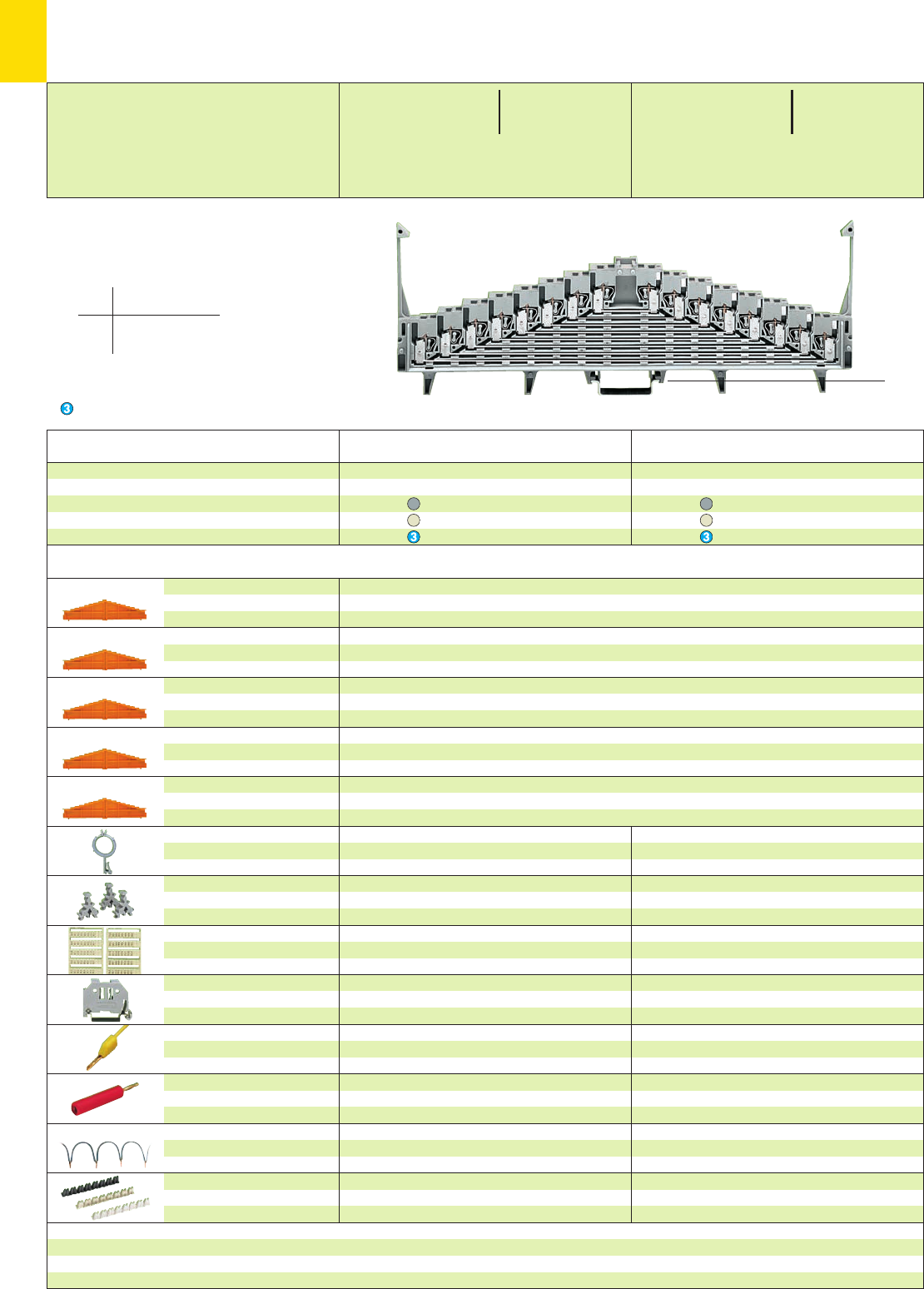
*U2fDaH *U2fDaH
11
16
Description
8-level terminal block for matrix patching ➋,
for DIN 35 rail
acc. to EN 60715
Item Item Pack.-unit
No. No. pcs Item Item Pack.-unit
No. No. pcs
with for for
locking clips DIN 35 x 7.5 DIN 35 x 15
grey 727-119 ➍727-129 ➍25
white 727-121 ➍727-131 ➍25
blue 727-123 ➍727-133 ➍25
without for for
locking clips DIN 35 x 7.5 DIN 35 x 15
grey 727-120 ➍727-130 ➍25
white 727-122 ➍727-132 ➍25
blue 727-124 ➍727-134 ➍25
8-level end plate,
without printing
numeric printing
alphanumeric printing
numeric printing
alphanumeric printing
Wire harness support,
see also page 11.19
WSB Double marker carrier,
for I /O markings
in the terminal block center
WSB Quick marking system,
for I /O markings
in the terminal block center
Screwless
end stop
Test plug, 2.3 mm /0.091 in Ø
with cable 500 mm /1’7.7’’
Reducing test plug,
from 4 mm /0.157 in Ø socket
to 2.3 mm /0.091 in Ø plug
Wire commoning chain,
insulated, 6 A, 32 connections,
0.5 mm2, max. 50 V
Insulation stop,
see right page
orange grey blue
7.62 mm /0.3 in thick
727-117 727-113 727-114
7.62 mm /0.3 in thick
0-1-2-3-4-5-6-7--7-6-5-4-3-2-1-0
727-105 727-155 727-159
7.62 mm /0.3 in thick
a-b-c-d-e-f-g-h--h-g-f-e-d-c-b-a
727-106 727-156 727-160
7.62 mm /0.3 in thick
7-6-5-4-3-2-1-0--0-1-2-3-4-5-6-7
727-107 727-157 727-161
7.62 mm /0.3 in thick
h-g-f-e-d-c-b-a--a-b-c-d-e-f-g-h
727-108 727-158 727-162
grey 249-109 50
4 mm /0.157 in wide
209-128 200 (2 x100)
209-933 to 5 cards
209-992 5 cards
see section 8
6 mm /0.236 in wide 249-116 100 (4 x 25)
10 mm /0.394 in wide 249-117 50 (2 x 25)
yellow 210-137 50 (5 x 10)
red 210-297 100 (4 x 25)
grey 709-107 1
white light grey
727-115 727-116 25
727-163 727-167 25
727-164 727-168 25
727-165 727-169 25
727-166 727-170 25
grey 249-109 50
4 mm /0.157 in wide
209-128 200 (2 x100)
209-933 bis 5 cards
209-992 5 cards
see section 8
6 mm /0.236 in wide 249-116 100 (4 x 25)
10 mm /0.394 in wide 249-117 50 (2 x 25)
yellow 210-137 50 (5 x 10)
red 210-297 100 (4 x 25)
grey 709-107 1
0-1-2-3-4-5-6-7--7-6-5-4-3-2-1-0 . . . - . . . /001-000
a-b-c-d-e-f-g-h--h-g-f-e-d-c-b-a . . . - . . . /002-000
7-6-5-4-3-2-1-0--0-1-2-3-4-5-6-7 . . . - . . . /003-000
h-g-f-e-d-c-b-a--a-b-c-d-e-f-g-h . . . - . . . /004-000
➍Additional item no. for terminal blocks with marking
* For further approvals with corresponding ratings see section 15. ** if approved by the works expert
Note: Only combine terminal blocks
and end plates that are colored grey/white/
light grey or orange/blue!
8-Level Terminal Blocks for Matrix Patching 1.5 mm2/ AWG 16,
Series 727
Accessories Appropriate marking system WMB/WSB (see section 14)
Ex i**
application
➊250 V 60 V = peak value
4 kV ∧table 4, EN 50020
3
(see also section 15)
➋8 x pairs of contacts
on each level
Suitable for Ex i applications
2 x 0.08 – 1.5 mm22 x AWG 28 – 16
250 V/4 kV/3 ➊300 V, 10 A U
12 A 300 V, 10 A 2
Terminal block width 7.62 mm / 0.3 in
L8 – 10 mm / 0.35 in
2 x 0.08 – 1.5 mm22 x AWG 28 – 16
250 V/4 kV/3 ➊300 V, 10 A U
12 A 300 V, 10 A 2
Terminal block width 7.62 mm / 0.3 in
L8 – 10 mm / 0.35 in
<___ 58.5 mm/2.3 in __>
<_______ 76 mm /2.99 in _______>
<_____________________________________ 226 mm /8.9 in _____________________________________>
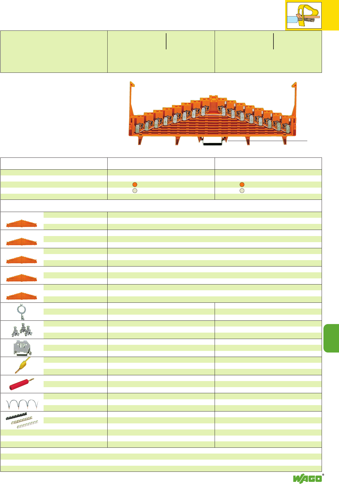
*U2fDaH *U2fDaH
11
11
17
Description
8-level same potential terminal block ➋,
for DIN 35 rail
acc. to EN 60715
Item Item Pack.-unit
No. No. pcs Item Item Pack.-unit
No. No. pcs
with for for
locking clips DIN 35 x 7.5 DIN 35 x 15
orange 727-125 ➌727-135 ➌25
light grey 727-127 ➌727-137 ➌25
without for for
locking clips DIN 35 x 7.5 DIN 35 x 15
orange 727-126 ➌727-136 ➌25
light grey 727-128 ➌727-138 ➌25
8-level end plate,
without printing
numeric printing
alphanumeric printing
numeric printing
alphanumeric printing
Wire harness support,
see also page 11.19
WSB Double marker carrier,
for I /O markings
in the terminal block center
Screwless
end stop
Test plug, 2.3 mm /0.091 in Ø
with cable 500 mm /1’7.7’’
Reducing test plug,
from 4 mm /0.157 in Ø socket
to 2.3 mm /0.091 in Ø plug
Wire commoning chain,
insulated, 6 A, 32 connections,
0.5 mm2, max. 50 V
Insulation stop,
8 pcs/strip
0.08–0.14 mm
2
“f-st”/0.08–0.2 mm
2
“s”
0.14–0.25 mm
2
“f-st”
/0.25 mm
2
“s”
0.25–0.5 mm
2
“s + f-st”
orange grey blue
7.62 mm /0.3 in thick
727-117 727-113 727-114
7.62 mm /0.3 in thick
0-1-2-3-4-5-6-7--7-6-5-4-3-2-1-0
727-105 727-155 727-159
7.62 mm /0.3 in thick
a-b-c-d-e-f-g-h--h-g-f-e-d-c-b-a
727-106 727-156 727-160
7.62 mm /0.3 in thick
7-6-5-4-3-2-1-0--0-1-2-3-4-5-6-7
727-107 727-157 727-161
7.62 mm /0.3 in thick
h-g-f-e-d-c-b-a--a-b-c-d-e-f-g-h
727-108 727-158 727-162
grey 249-109 50
4 mm /0.157 in wide
209-128 200 (2 x100)
6 mm /0.236 in wide 249-116 100 (4 x 25)
10 mm /0.394 in wide 249-117 50 (2 x 25)
yellow 210-137 50 (5 x 10)
red 210-297 100 (4 x 25)
grey 709-107 1
white 727-197 200 (8 x 25)
light grey 727-198 200 (8 x 25)
dark grey 727-199 200 (8 x 25)
white light grey
727-115 727-116 25
727-163 727-167 25
727-164 727-168 25
727-165 727-169 25
727-166 727-170 25
grey 249-109 50
4 mm /0.157 in wide
209-128 200 (2 x100)
6 mm /0.236 in wide 249-116 100 (4 x 25)
10 mm /0.394 in wide 249-117 50 (2 x 25)
yellow 210-137 50 (5 x 10)
red 210-297 100 (4 x 25)
grey 709-107 1
white 727-197 200 (8 x 25)
light grey 727-198 200 (8 x 25)
dark grey 727-199 200 (8 x 25)
0-1-2-3-4-5-6-7--7-6-5-4-3-2-1-0 . . . - . . . /001-000
a-b-c-d-e-f-g-h--h-g-f-e-d-c-b-a . . . - . . . /002-000
7-6-5-4-3-2-1-0--0-1-2-3-4-5-6-7 . . . - . . . /003-000
h-g-f-e-d-c-b-a--a-b-c-d-e-f-g-h . . . - . . . /004-000
➌Additional item no. for terminal blocks with marking
* For further approvals with corresponding ratings see section 15.
➊250 V = rated voltage
4 kV = rated surge voltage
3 = pollution degree
(see also section 15)
➋All clamping units are connected
to the same current bar <______________________________________ 226 mm /8.9 in ______________________________________>
Note: Only combine terminal blocks
and end plates that are colored grey/white/
light grey or orange/blue!
8-Level Same Potential Terminal Blocks 1.5 mm2/ AWG 16,
Series 727
Accessories Appropriate marking system WMB/WSB (see section 14)
<___ 58.5 mm/2.3 in __>
<_______ 76 mm/2.99 in _______>
2 x 0.08 – 1.5 mm22 x AWG 28 – 16
250 V/4 kV/3 ➊300 V, 10 A U
18 A 300 V, 10 A 2
Terminal block width 7.62 mm / 0.3 in
L8 – 10 mm / 0.35 in
2 x 0.08 – 1.5 mm22 x AWG 28 – 16
250 V/4 kV/3 ➊300 V, 10 A U
18 A 300 V, 10 A 2
Terminal block width 7.62 mm / 0.3 in
L8 – 10 mm / 0.35 in
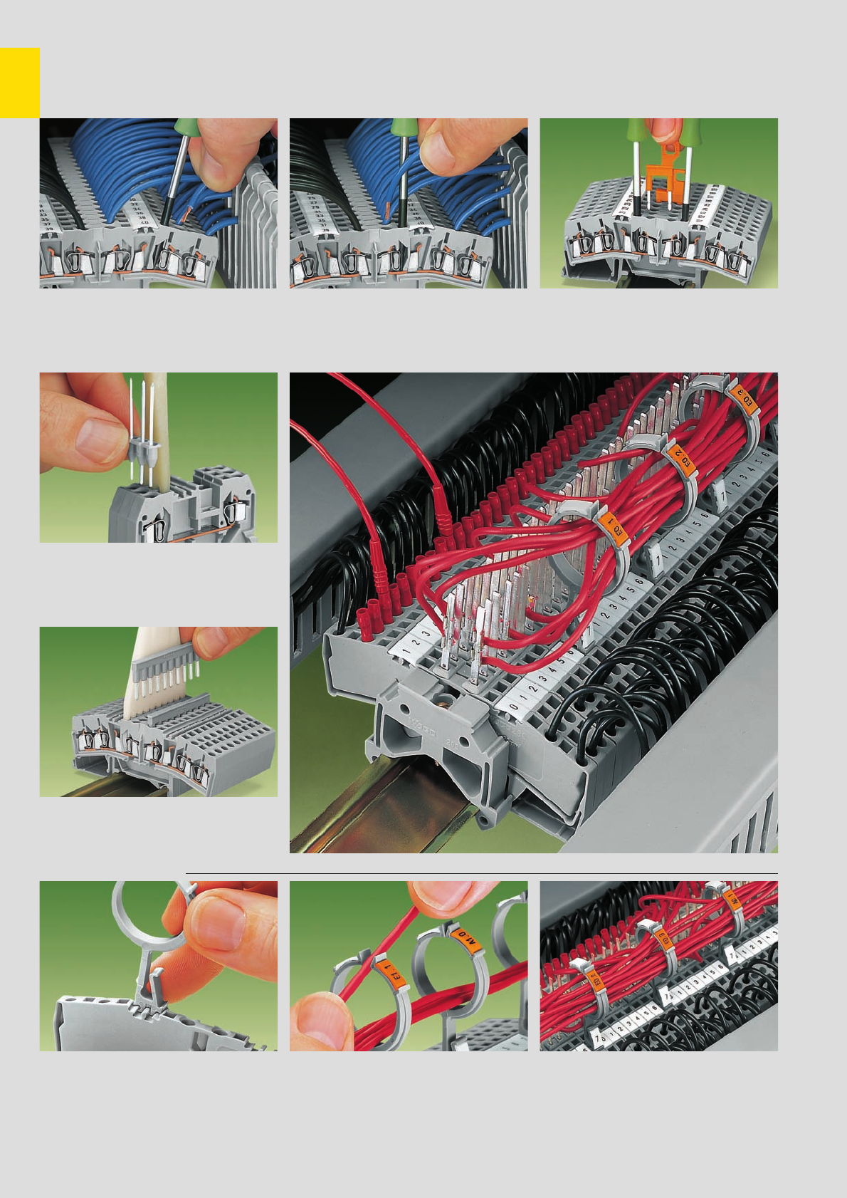
11
18
Rail-Mounted Terminal Blocks for Matrix Patching with CAGE CLAMP®
Description and Handling
Terminal blocks for matrix patching.
Connection/removal of wires on the terminal
blocks sides
Pin modules
Insertion of a pin module shown with terminal
blocks series 280
Comb type jumper bars
Used as potential multiplication.
Insertion of a 10-way comb type jumper bar
(only possible in the center)
Wire harness support
Introduction of a wire harness support
into the marker slot Insertion of a cable into the wire harness support 2 x group marking on top
1 x terminal block marking at the bottom
Terminal blocks for matrix patching.
Connection/removal in the terminal block center Used as disconnect terminal block.
Inserting disconnect jumpers
fine-stranded wire –
tip bonded
fine-stranded wire
with crimped ferrule**
fine-stranded wire
with crimped pin terminal
CAGE CLAMP®connects
the following copper
wires:*
solid stranded
fine-stranded,
also with tinned
single strands
* For aluminum wire see notes in section 15!
** When using wires with ferrules, it is necessary to use a terminal block one size larger than the nominal cross section of the wire.
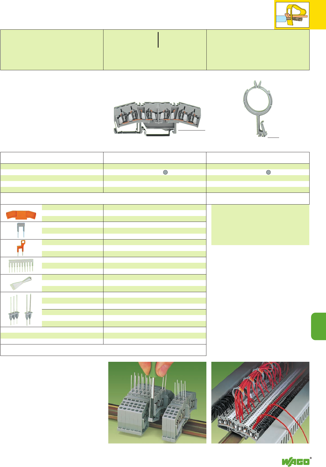
*U;
11
11
19
The maximum number of fine-stranded conductors
which can be supported by the system depends on
the wire size: 0.25 mm
2
/AWG 24 200 conductors
0.5 mm
2
/AWG 20 95 conductors
0.75 mm
2
/AWG 18 75 conductors
1mm
2
/AWG 18 65 conductors
1.5 mm
2
/AWG 16 45 conductors
2.5 mm
2
/AWG 14 30 conductors
In process automation systems, the matrix patch-
board is an essential element in measurement
and control techniques. Particularly in this kind of
application, use of the WAGO wire harness sup-
port can make wiring easier and more obvious.
WAGO 3-conductor front-entry double potential
terminal blocks of the 280 series (with or without
the addition of Wire-Wrap®or TERMI-POINT®
pins) are particularly suitable in this application.
They can be used for the linking of incoming field
wires, from items such as measuring devices or
servos etc., with the central process controller
devices, such as control consoles, panelboards or
PLCs, by means of matrix connections.
The WAGO wire harness suppoert elements are
pushed into the terminal blocks (about every 8th
one) to form an additional “cable-duct” above
the wiring level of the terminal blocks. Two mar-
ker slots are provided in each, the top ones may
be used for group marking, and the lower slot
for marking the terminal block.
Item Pack.-unit
No. pcs Item Pack.-unit
No. pcs
Application notes
Application notes
Description
5 mm /0.197 in thick
orange 280-333 25
grey 280-325 25
2-way 280-492 200 (8 x 25)
with pull-tab
2-way 280-494 200 (8 x 25)
2-way 280-482 200 (8 x 25)
3-way 280-483 200 (8 x 25)
10-way 280-490 50 (2 x 25)
2-way 280-432 1
3-way 280-433 1
10-way 280-440 1
1x 1mm 280-477 for Wire-Wrap
0.8 x 1.6 mm 280-475 for Termi-Point
0.8 x 2.4 mm 280-473 for Termi-Point
1x 1mm 280-478 for Wire-Wrap
0.8 x 1.6 mm 280-476 for Termi-Point
0.8 x 2.4 mm 280-474 for Termi-Point
End and
intermediate plate
Alternate comb type
jumper bar, insulated,
IN= INof terminal block
Disconnect jumper
terminal block, orange,
IN= INof terminal block
Comb type jumper bar,
insulated,
IN= INof terminal block
Operating tool,
insulated, for comb jumpers
2-pole pin modules, for
assembly on all front-entry rail-
mounted term. blocks series 280
3-pole pin modules, for
assembly on all front-entry rail-
mounted term. blocks series 280
Terminal block for matrix patching, for DIN 35 rail
Attention! These 3-conductor double potential
terminal blocks cannot be commonded with
adjacent jumpers!
3-conductor double potential terminal block
grey 280-675 50
Wire harness support
grey 249-109 50
In case of these 5 mm /0.197 in wide double
potential front-entry terminal blocks two 3-con-
ductor through terminal blocks are built into one
insulating housing on one level. Compared with
“standard” through terminal blocks the terminal
block width is only 2.5 mm /0.098 in.
On each side of the terminal block are marker
slots for WAGO WSB markers. By means of the
available accessories these terminal blocks can
also be used as 4-conductor disconnect terminal
blocks or multipliers of potential.
During mounting /dismounting using DIN 35 rail
please note that due to the protruding webs the
terminal blocks can only be inserted or removed
from the strip after having displaced the adjacent
terminal blocks (see also opposite photo).
Detaching: seperate terminal strip, displace individual
terminal block laterally and remove from the carrier rail
Terminal blocks for matrix patching
with wire harness support
➊800 V = rated voltage
8 kV = rated surge voltage
3 = pollution degree
(see also section 10)
800 V/8 kV/3 against ground (earth) and
adjacent terminal blocks.
500 V/6 kV/3 between both current rails.
(If used as disconnect terminal block or
multiplier of potential) <_________________ 93 mm /3.66 in _________________>
(28 mm /1.1in )
<_______ 50 mm /1.97 in _______>
Wire harness support
Rail-Mounted Terminal Blocks for Matrix Patching 2.5 mm2/ AWG 12,
Series 280
Wire Harness Support
* For further approvals with corresponding ratings see section 15.
Accessories Appropriate marking system WMB/WSB (see section 14)
0.08 – 2.5 mm2AWG 28 –12
800 V/8 kV/3 ➊300V,10AU
20 A
Terminal block width 5 mm / 0.197 in
L8 – 9 mm / 0.33 in
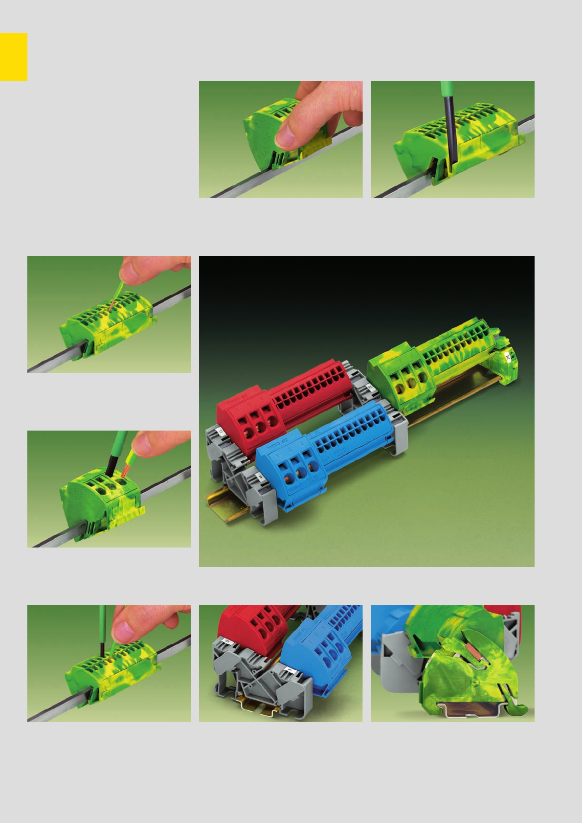
11
20
1.
2.
Busbar Terminal Blocks with CAGE CLAMP®
Description and Handling – Series 812
Using the series 812 busbar
terminal blocks in switchgear cabinets
and distribution boards allows simple
and safe potential distribution on
standard 10 x 3 mm busbars.
Tool-less snapping of self-locking
busbar terminal blocks onto the bus-
bar enables quick and easy assembly
as well as subsequent extension. The
busbar terminal blocks are available
in two different versions including
conductor cross sections from AWG 16
to AWG 6 (1.5 mm2- 16 mm2).
stranded
fine-stranded,
also with tinned
single strands
CAGE CLAMP®
connects the following
copper wires:*
solid
fine-stranded wire -
tip bonded
Open the clamping unit using a screwdriver
Carrier including a receptacle with locking device
for 10 x 3 mm busbar. The contact between the
busbar and the rail is made automatically by sim-
ply snapping the carrier onto the DIN 35 rail. One
end of the busbar is mounted onto the ground
(earth) busbar carrier, the other end is inserted into
the middle position of the insulated busbar carrier.
Snapping the ground (earth) busbar terminal block
onto the N-busbar
Unlock positions 1. and 2. to remove the ground
(earth) busbar terminal block
* For aluminum wire see notes in section 15!
Removing AWG 12 (4 mm
2
) and
AWG 6 (16 mm
2
) wires
Connecting AWG 6 (16 mm
2
) wires
Open the clamping unit with a screwdriver when
connecting solid, stranded and fine-stranded wires.
Carrier with 3 receptacles for 10 x 3 mm busbars
with locking device for easy mounting of the bus-
bars. The carriers can be snapped onto the DIN 35
rail or fixed on a panel with screw mounting.
Busbar carrier 812-140
Combination of AWG 12 (4 mm2) and AWG 6 (16 mm2) busbar terminal blocks
Connecting AWG 12 (4 mm
2
) wires
Due to the CAGE CLAMP®S connection, solid wires
can be inserted directly into the AWG 12 (4 mm2)
busbar terminal block, thus reducing wiring time
significantly.
Ground (earth) busbar carrier 812-141
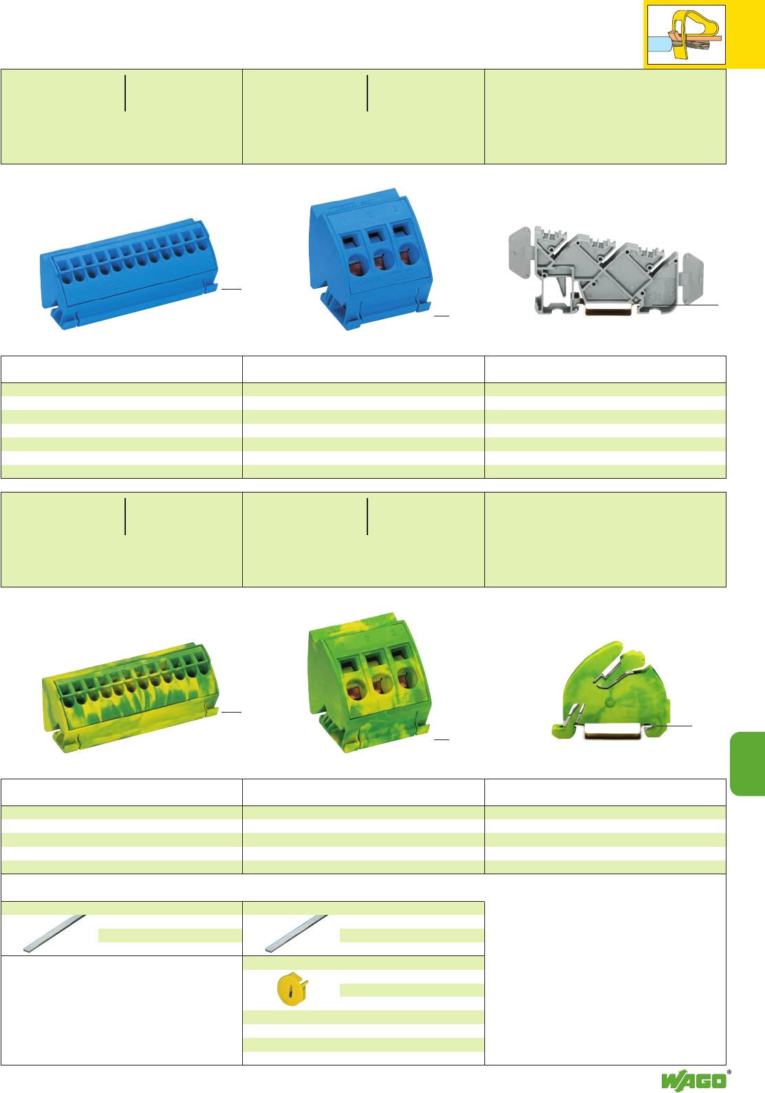
11
21
11
Item Pack.-unit
No. pcs
<____________ 75 mm /2.95 in ___________>
<__ 30 mm / ____>
1.18 in
<
27.5 mm/
>
1.08 in
<_ 38 mm /1.5 in >
<___ 42.5 mm /1.67 in _____>
<43.5 mm />
1.71 in
Item Pack.-unit
No. pcs
Busbar terminal blocks with CAGE CLAMP®S
4 mm2/AWG 12
light grey 812-101 10
dark grey 812-102 10
red 812-103 10
blue 812-104 10
Busbar terminal blocks with CAGE CLAMP®
16 mm2/AWG 6
light grey 812-111 12
dark grey 812-112 12
red 812-113 12
blue 812-114 12
Busbar Terminal Blocks with CAGE CLAMP®
Series 812
12 x 0.5 – 4 mm2AWG 20 – 12
1000 V/ 6 kV/ 3 ➊600 V
96 A**
Terminal block width 75 mm / 2.953 in
L10 mm / 0.39 in
3 x 1.5 – 16 mm2AWG 16 – 6
1000 V/ 6 kV/ 3* 600 V
96 A**
Terminal block width 38 mm / 1.496 in
L12 mm / 0.47 in
Item Pack.-unit
No. pcs
<____________ 75 mm /2.95 in ___________>
<__ 30 mm / ____>
1.18 in
<
27.5 mm/
>
1.08 in
<_ 38 mm /1.5 in >
<___ 42.5 mm /1.67 in _____>
<43.5 mm />
1.71 in
Item Pack.-unit
No. pcs
Ground (earth) busbar terminal block
with CAGE CLAMP®S 4 mm2/AWG 12
green-yellow 812-100 10
Ground (earth) busbar terminal block
with CAGE CLAMP® 16 mm2/AWG 6
green-yellow 812-110 12
Accessories
12 x 0.5 – 4 mm2AWG 20 – 12
Terminal block width 75 mm / 2.953 in
L10 mm / 0.39 in
3 x 1.5 – 16 mm2AWG 16 – 6
Terminal block width 38 mm / 1.496 in
L12 mm / 0.47 in
Item Pack.-unit
No. pcs
Insulated busbar carrier
812-140 25
Each busbar receptacle is equipped with one marking
position for WMB or WSB markers.
* Can only be used with insulated busbar carrier
812-140 and cover correctly mounted at the end
of the busbar.
Ground (earth) busbar carrier
with contact to DIN 35 rail
green-yellow 812-141 25
suitable for WMB or WSB marking system
N-busbar, copper, tinned,
10 x 3 mm /0.394 x 0.118 in,
IN140 A, 1000 mm/3’3’’ long
210-133 1
N-busbar, copper, tinned,
10 x 3 mm /0.394 x 0.118 in,
IN140 A, 1000 mm/3’3’’ long
210-133 1
Finger guard cover for busbar terminal blocks
16 mm2,
serves as touchproof protection
for unused clamping units
yellow 284-400 100 (4 x 25)
Note:
The busbar system is touch-proof provided
that there is no space left between the insulated
busbar carriers and the busbar terminal blocks.
Furthermore, the covers at the ends of the bus-
bar and the finger guard covers of the unused
clamping units of the AWG 6 (16 mm2) terminal
block must be correctly mounted.
<_________________ 80 mm /3.15 in _______________>
<__ 40.5 mm / __>
1.59 in
<_____ 54.5 mm /2.11 in _____>
<___ 36 m m/___>
1.42 in
** Current carrying capacity:
With a maximum total current of 96 A, the
clamping units of the busbar terminal block
can be loaded with the rated current of the
conductor cross sections approved. This only
applies when 10 x 3 mm busbars are used.
Other applications on request.
Item Pack.-unit
No. pcs
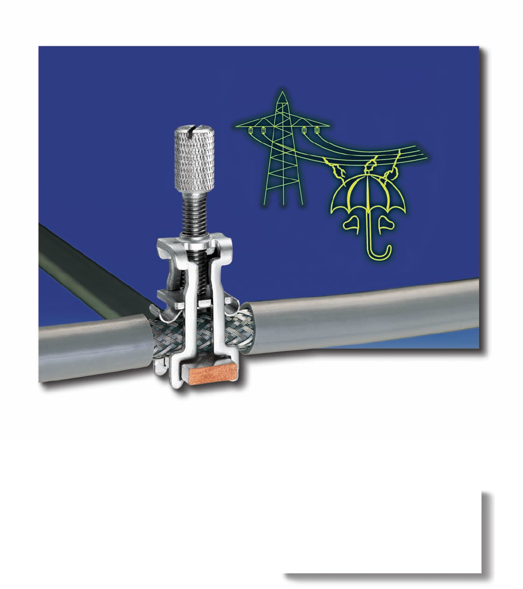
The shield (screen) connecting system
from WAGO offers high electrical and
mechanical safety for very flexible
applications.

12
12
VOLUME 1
Shield (Screen) Connecting System
Shield (screen) connecting system
Mounting options based on application, description and handling 12.3
Shield (screen) clamping saddles Series 790 12.4 – 12.5
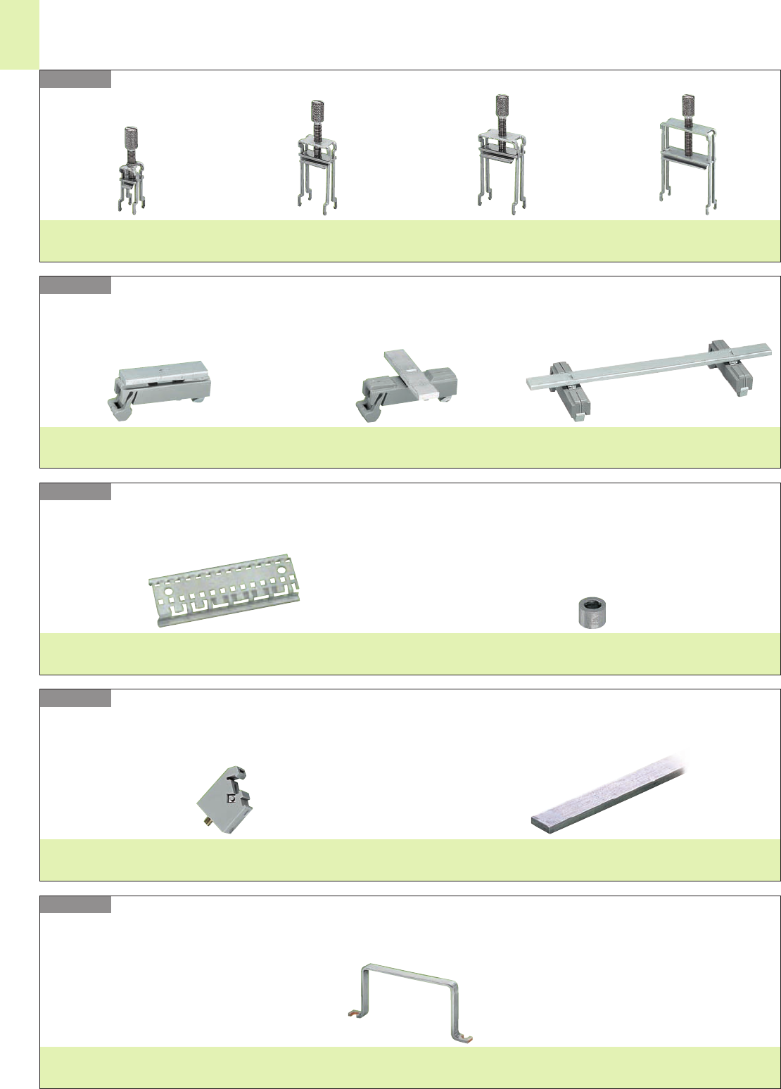
12
2
Series 790
Series 790
Series 790
Series 790
Series 790
Shield (Screen) Connecting System
– Product Summary –
Shield (screen) clamping saddle
11 mm /0.433 in wide
Page 12.4
with grounding foot
bar 90° to the rail
Page 12.4
with grounding foot
bar parallel to the rail
Page 12.4
with 2 grounding feet
bar parallel to the rail
Page 12.4
19 mm /0.748 in wide
Page 12.4
27 mm /1.063 in wide
Page 12.5
43 mm /1.693 in wide
Page 12.5
Carrier
with special perforations
Page 12.4
for special perforated carrier rail
Page 12.4
Carrier rail Stand off
Page 12.4
for insulated mounting foot
Page 12.4
Insulated mounting foot Straight busbar
Cu 10 mm (0.394 in) x 3 mm (0.118 in)
Pages 12.4/12.5
U-shaped busbar
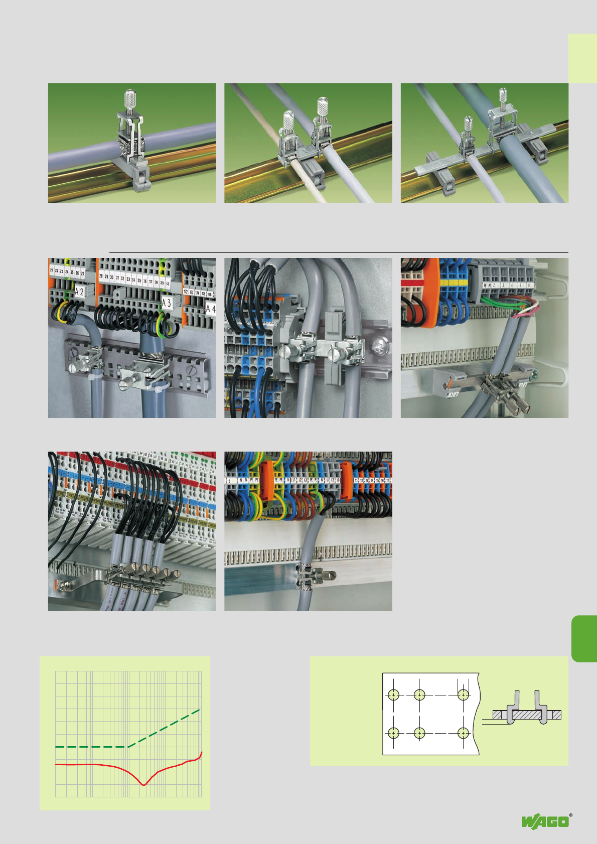
dB
0
- 10
- 20
- 30
- 40
- 50
- 60
- 70
- 80
- 90
-100
0,01 0,1 101100
MHz
><_____
><
2
<___14 ___>
(___X___)
<_________Y_________>
4<
>
12
3
12
max. 3
Admissible limiting value
Negative shield (screen) attenuation Hole dimensions for panel mounting
– carrier with grounding foot, busbar parallel to
the rail – insulated mounting carriers for a common shield
(screen) reference potential, independent of the
housing potential
– U-shaped copper busbar
10 mm (0.394 in) x 3 mm (0.118 in)
The WAGO shield
(screen) connecting
system is highly
effective because
the clamping unit
can be brought
very close to the
unshielded part of
the cable.
Additionally, the
spring material is
part of the clamping saddle, giving good electrical connection and compensating
for any deformation in the braiding. The system also acts as a partial strain relief.
– snap into any metal plate up to max. thickness
3 mm / 0.118 in
Shield (screen)
clamping saddle size
Distance X
11 mm 9.5 mm
Distance Y
19 mm 17.5 mm
27 mm 25.5 mm
43 mm 41.5 mm
Carrier with grounding foot*
45 mm/1.772 in long, busbar 90° to the rail
Item No. 790-113
Carrier with grounding foot*
45 mm/1.772 in long, busbar parallel to the rail
Item No. 790-114
Carrier with 2 grounding feet*
125 mm/4.921 in long, busbar parallel to the rail
Item No. 790-115
*for all sizes of shield (screen) clamping saddles
Shield (Screen) Connecting System
Description and Handling – Series 790
Applications
– on special slotted carrier rail
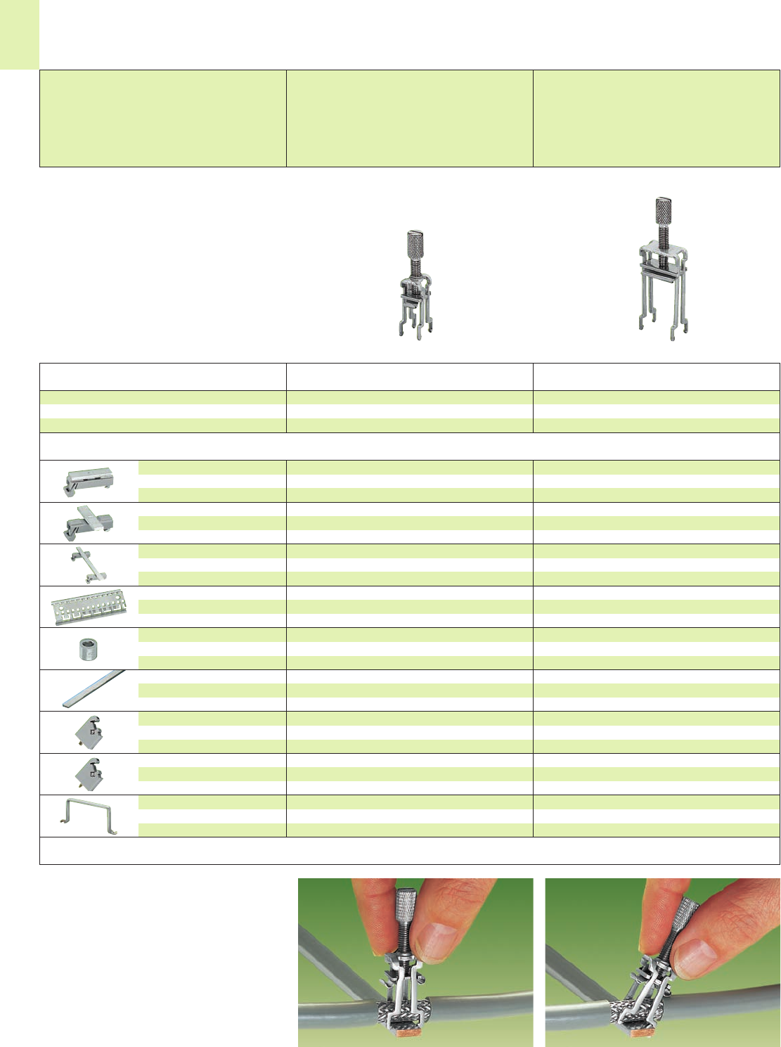
❚
❚
▼
❚
❚
▼
12
4
Note:
Cannot be used for the connection of ground (earth)
conductors!
Carrier w. grounding foot, bar 90° to
the rail, 10 mm (0.394 in) x 3 mm (0.118
in), bar a. foot – Cu w. tin plating
Carrier w. grounding foot, bar parallel
to the rail, 10 mm (0.394 in) x 3 mm
(0.118 in), bar a. foot – Cu w. tin plating
Carrier w. 2 grounding feet, bar par-
allel to the rail, 10 mm (0.394 in) x 3 mm
(0.118 in), bar a. foot – Cu w. tin plating
Carrier rail, special perforated,
1000 mm/3’.3’’ long, Cu with tin
plating, special lengths on request
Stand off, for special perforated
carrier rail, use M 5 size screw
Straight busbar,
10 mm (0.394 in) x 3 mm (0.118 in),
bar – Cu with tin plating
Insulated mounting foot,
for busbar, with standard screw
M 4 x 8 mm
Insulated mounting foot,
for busbar, with sheet metal screw
(3.5 x 9) mm
U-shaped busbar,
10 mm (0.394 in) x 3 mm (0.118 in),
Cu with tin plating
45 mm /1.772 in long
790-113 25
45 mm /1.772 in long
790-114 25
125 mm /4.921 in long
790-115 25
790-145 1
790-144 200 (2 x 100)
1000 mm /3’.3’’ long
210-133 20 (20 x 1)
30 mm /1.181 in long
790-133 20 (20 x 1)
50 mm /1.969 in long
790-134 20 (20 x 1)
grey 790-100 50 (2 x 25)
grey 790-101 50 (2 x 25)
Item nos. and dimensions,
see drawing on page 12.5
Accessories
Description Item Pack.-unit
No. pcs
Shield (Screen) Clamping Saddles
Shield (screen) clamping saddle,
11 mm / 0.433 in wide
For conductors with a diameter of up to
8 mm / 0.315 in
Shield (screen) clamping saddle, incl. knurled screw
Diameter of connectable conductor
Shield (screen) clamping saddle,
11 mm/0.433 in wide
up to 8 mm /0.315 in
790-108 50
Item Pack.-unit
No. pcs
45 mm /1.772 in long
790-113 25
45 mm /1.772 in long
790-114 25
125 mm /4.921 in long
790-115 25
790-145 1
790-144 200 (2 x 100)
1000 mm /3’.3’’ long
210-133 20 (20 x 1)
30 mm /1.181 in long
790-133 20 (20 x 1)
50 mm /1.969 in long
790-134 20 (20 x 1)
grey 790-100 50 (2 x 25)
grey 790-101 50 (2 x 25)
Item nos. and dimensions,
see drawing on page 12.5
Shield (screen) clamping saddle,
19 mm / 0.748 in wide
For conductors with a diameter of
7 mm / 0.276 in to 16 mm / 0.63 in
Shield (screen) clamping saddle, 19 mm /0.748 in wide
7 mm /0.276 in to 16 mm /0.63 in
790-116 50
Assembly Removal
The shield (screen) clamping saddle is shipped
ready for direct connection to the busbar 10 mm
(0.394 in) x 3 mm (0.118 in) or to a drilled moun-
ting plate. After connection, tighten the knurled
screw to complete the installation.
Recommended tightening torque: 0.5 Nm
To remove a shield (screen) clamping saddle,
unscrew until ratcheted mechanism is released,
then slightly tip saddle and remove the clamping
saddle.
Application notes
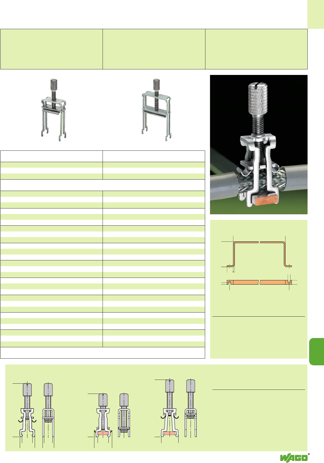
<__D__>
<______________E______________>
(_10,1 _)
<__17 __>
<__________F__________>
<_____________A_____________>
(_ 10 _)
<__ B__ > (_C_)
(_C+3_)
15 <_
3
>
><_
4
<_______________C_______________>
6
10
<>
<>
<_____________A_____________>
<_____B_____>
12
5
12
Installation position
delivery state
Closed position Removal position
Shield (screen) clamping saddle,
27 mm / 1.063 in wide
For conductors with a diameter of
6 mm / 0.236 in to 24 mm / 0.944 in
Dimensions in mm
Item No. AB CDE F
790-108 51 15 8 16 55 42
790-116 53 15 16 16 57 45
790-124 78 15 24 16 83 58
790-140 97 15 40 16 100 73
Item Pack.-unit
No. pcs
Shield (screen) clamping saddle,
43 mm / 1.693 in wide
For conductors with a diameter of
22 mm / 0.866 in to 40 mm / 1.575 in
Shield (screen) clamping saddle, 43 mm /1.693 in wide
22 mm /0.866 in to 40 mm /1.575 in
790-140 50
Item Pack.-unit
No. pcs
Shield (screen) clamping saddle,
27 mm /1.063 in wide
6 mm /0.236 in to 24 mm /0.944 in
790-124 50
45 mm /1.772 in long
790-113 25
45 mm /1.772 in long
790-114 25
125 mm /4.921 in long
790-115 25
790-145 1
790-144 200 (2 x 100)
1000 mm /3’.3’’ long
210-133 20 (20 x 1)
30 mm /1.181 in long
790-133 20 (20 x 1)
50 mm /1.969 in long
790-134 20 (20 x 1)
grey 790-100 50 (2 x 25)
grey 790-101 50 (2 x 25)
Item nos. and dimensions,
see drawing on on the right
45 mm /1.772 in long
790-113 25
45 mm /1.772 in long
790-114 25
125 mm /4.921 in long
790-115 25
790-145 1
790-144 200 (2 x 100)
1000 mm /3’.3’’ long
210-133 20 (20 x 1)
30 mm /1.181 in long
790-133 20 (20 x 1)
50 mm /1.969 in long
790-134 20 (20 x 1)
grey 790-100 50 (2 x 25)
grey 790-101 50 (2 x 25)
Item nos. and dimensions,
see drawing on on the right
Dimensions in mm Pack.unit
Item No. A B C pcs
790-190 63 60 83 25 (5 x 5)
suitable for I/O module series 750 (5 E/A)
790-191 100 60 118 25 (1 x 25)
suitable for I/O module series 750 (8 E/A)
790-192 63 35 83 25 (5 x 5)
790-193 100 35 118 25 (1 x 25)
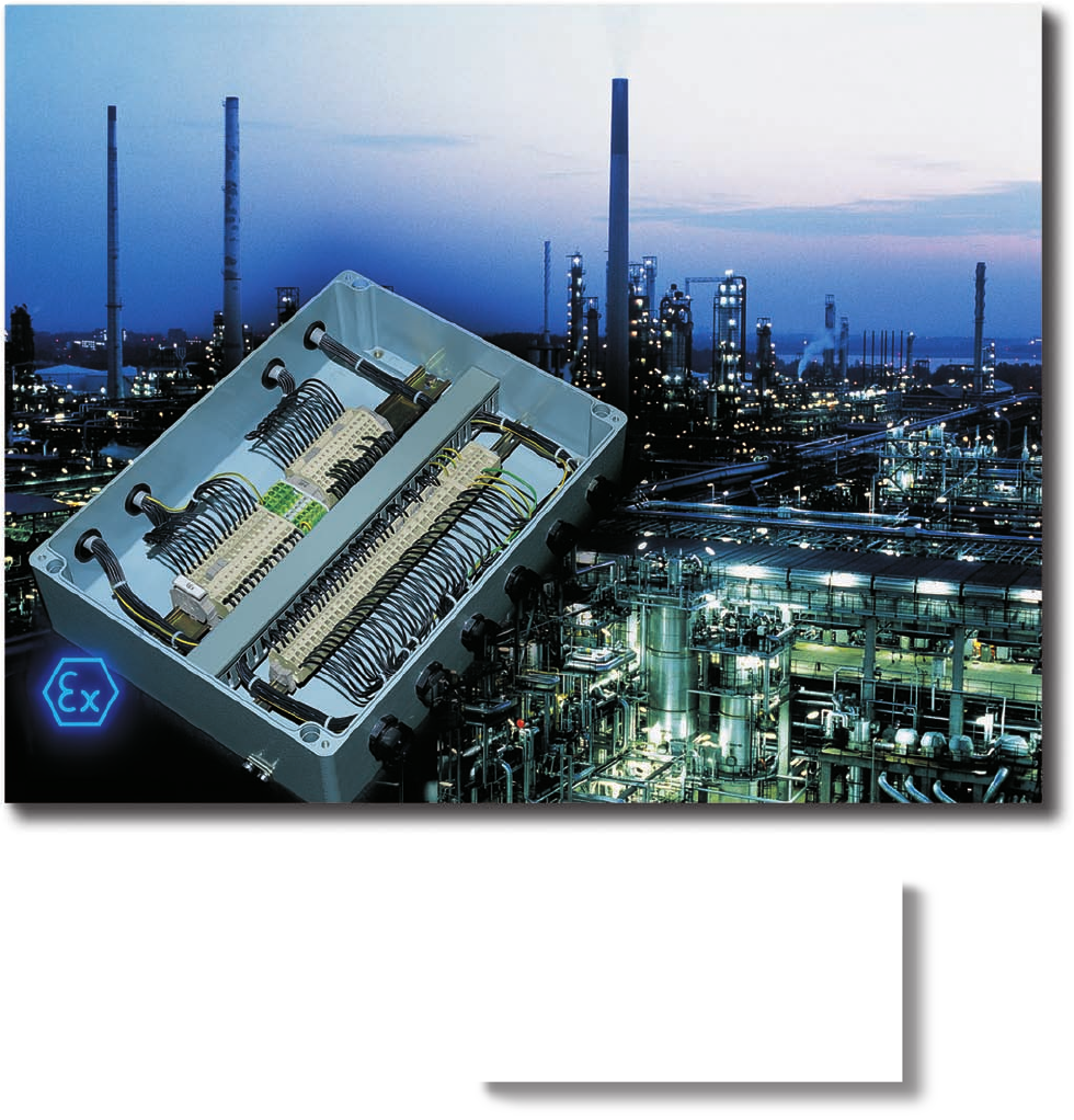
Forward-looking certification:
WAGO Ex e II terminal blocks with
an EC type-examination certificate
according to
Ex directive 94/9/EC (ATEX 100 a).
13
13
4
General technical information
for electrical equipment
in hazardous environments 13.2 – 13.9
VOLUME 1
All terminal blocks used in
hazardous environments “Ex e II“
have their item nos.
marked with the
4symbol
All terminal blocks used in
intrinsically safe current circuits ”Ex i“
have their item nos.
marked with the
symbol

13
2
Prerequisite for a potential explosion
danger is the realization of an explosi-
on endangered atmosphere. This can
occur wherever inflammable gases or
liquids are produced, processed, trans-
ported or stored.
Such hazardous environment can
form, for example, in chemical plants,
refineries, tank farms, vehicles, sewage
treatment plants, airports, grain mills or
sea ports.
GUIDELINE FOR THE BASIC
PRINCIPLES OF EXPLOSION
PROTECTION:
General requirement
The European Standard EN 60079-0 –
VDE classification 0170/0171 part 1 –
contains the general requirements for
the construction and testing of electrical
apparatus, which are determined for
use in potentially explosive atmosphe-
res.
It has to be ensured, that this equipment
does not cause an explosion of the
surrounding atmosphere. In addition to
the EN 60079-0 specification, the
(see page 13.3) European Standards
which relate to specific standards of
protection have to be considered.
Electrical equipment
Electrical equipment is any part which
serves as a whole or in parts for the
application of electrical energy.
Amongs these are equipment for the
production, transmission, distribution,
storage, controlling and use of electrical
energy, including telecommunication
systems.
Ex-components
Ex-components are parts of an electrical
equipment for hazardous environments
and are marked with the symbol “U”.
It is not allowed to use them alone in
hazardous environments and, in case
they should be used in these environ-
ments and in electrical equipment, an
additional certificate is required.
General Technical Information
for Electrical Equipment in Hazardous Environments

13
13
3
Ignition protection types
European Application
Designation Standard Explanation area
“o” EN 50015 Oil immersed apparatus: Zone 1 + 2
Electrical equipment or parts of same
immersed in oil.
“p” EN 50016 Pressurized apparatus: Zone 1 + 2
The ingress of the surrounding (explosive)
atmosphere into the housing of electrical
equipment is avoided by keeping the
ignition protection gas inside under
pressure.
“q” EN 50017 Powder filled apparatus: Zone 1 + 2
Filling of the electrical equipment
housing with fine grain sand prevents
the ignition of a surrounding
explosive atmosphere
by an electric arc generated
in the housing.
“d” EN 50018 Flameproof enclosure: Zone 1 + 2
Equipment which could ignite an explosive
atmosphere is encapsulated in a housing
which can resist an explosion pressure
within the housing.
“e” EN 50019 Increased safety: Zone 1 + 2
Measures have been undertaken in order
to achieve an increased degree of safety
by the avoidance of inadmissibly high
temperatures and the creation of sparks or
electric arcs.
“i” EN 50020 Intrinsic safety: Zone 1 + 2
Current circuit following
in which no sparks or special
thermal effects can occur and cause testing
an ignition of a certain explosive zone 0
atmosphere.
“n” EN 50021 Non-sparking: Zone 2
Electrical equipment of group II
for use in areas in which an explosive mixture
of gas, vapor or mist is unlikely
to occur during normal operation
and if it does it will be for a
short period.
“m” EN 50028 Cast encapsulation: Zone 1 + 2
Dangerous electrical equipment is embedded in
a cast mass. This corresponds approximately
to the known special protection type Ex s.
EN 50039 Instrinsically safe electrical systems “i” Zone 1 + 2
Assembly of interconnected electrical equipment following
in which the circuits intended for use, special
as a whole or in part, in hazardous environments testing
are intrinsically safe. It is documented zone 0
accordingly in the system description.
IEC / TS FISCO standard
60079-27 Electrical apparatus for explosive gas
atmospheres – Part 27: Fieldbus intrinsically
safe concept (FISCO) and Fieldbus non-incendive
concept (FNICO)
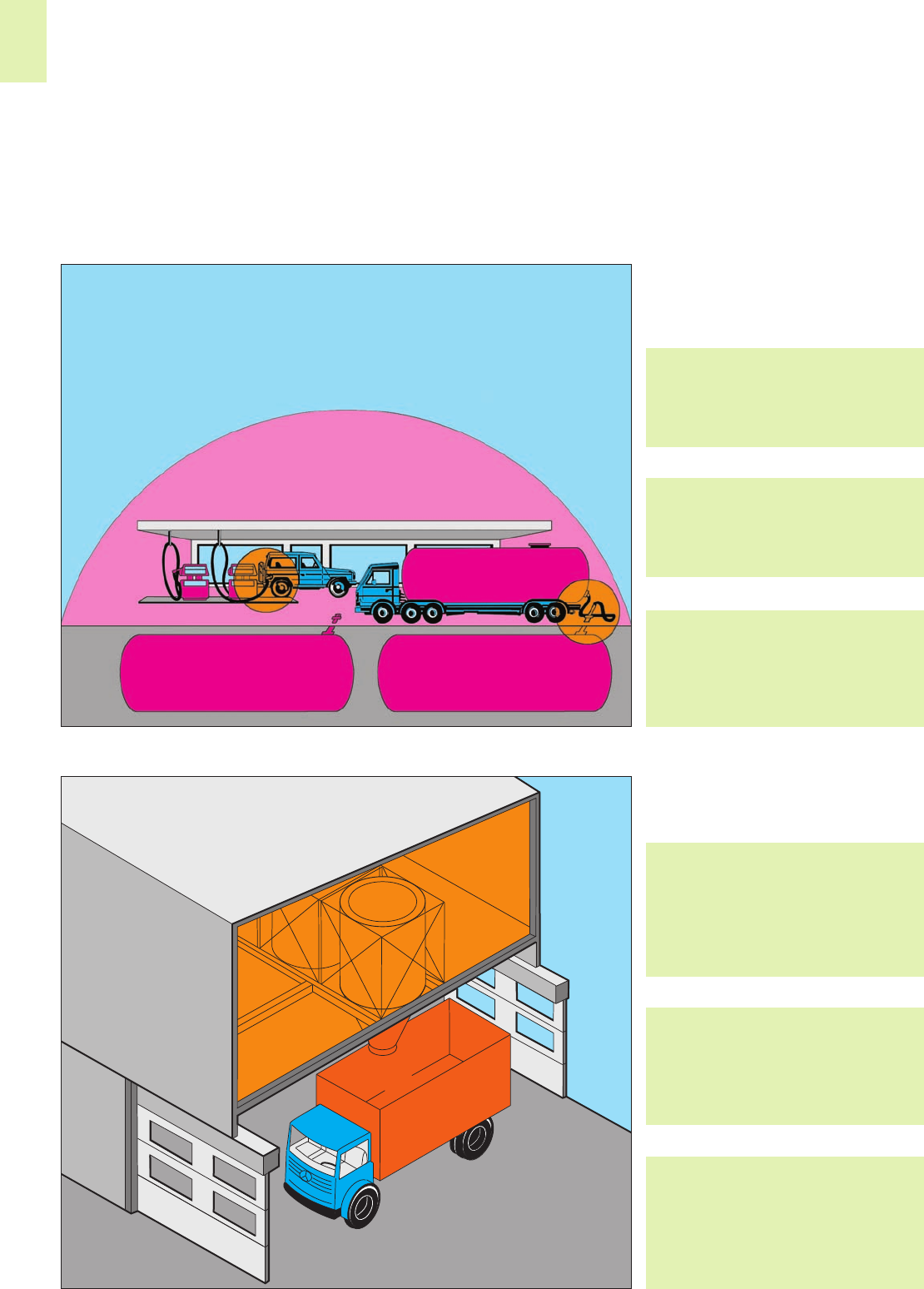
➊
13
4
➋
Zone 22
Zone 21
Zone 20
Hazardous environments
Hazardous environments are areas in
which the atmosphere may become ex-
plosive. Explosive atmosphere is defi-
ned as a mixture of ignitable sub-
stances in the form of gases, vapors or
mixtures with air under atmospheric
conditions in critically mixed ratios such
that excessive high temperature, arcs or
sparks may cause an explosion.
According to ElexV, EN 1127-1,
endangered areas are classified into
zones according to the probability of
the existence of a dangerous explosion
prone atmosphere as follows:
➊Areas explosion endangered as a
result of combustible gases, vapours or
mist
Zone 0
encompasses areas
in which an explosive gas/air mixture
is continuously present or present for
long periods.
Zone 1
encompasses areas
in which an explosive mixture can
occur during normal operation.
Zone 2
encompasses areas
in which an explosive mixture is unlikely
to occur under normal operation and
if it does it will be for a short period.
➋Areas explosion endangered due to
combustible dust
Zone 20
Area in which an explosive mixture in
the form of dust in air is continuously
present or present for long periods.
Dust deposits of a known thickness or
of an excessive thickness may build up.
Dust deposits alone are not synony-
mous with Zone 20.
Zone 21
Area in which an explosive mixture in
the form of dust in air can occur
during normal operation. Deposits of
combustible dust exist in general.
Zone 22
Area in which an explosive mixture in
the form of dust in air is unlikely to
occur during normal operation and if
it does it will be for a short period or
in which deposits of combustible dust
exist.
Zone 2
Zone 1
Zone 0
Zone 1
Zone 0 Zone 0
– Continued –
General Technical Information
for Electrical Equipment in Hazardous Environments

13
13
5
The table shows a comparison between the existing practice according
to ElexV, DIN VDE 0165-1991 and the new EN 1127-1:
Group II
Category Type of Adequate Comparable with new acc. to
protection safety with existing practice EN 1127
1 Ex atmosphere highest 2 protection Group II, Zone 0
is very probable, measures Zone 0 Zone 20
dust in air 2 errors Zone 10
2 From time to time increased equipment Group II, Zone 1
Ex atmosphere failure Zone 1 Zone 21
or
error
3 Low probability of normal trouble-free Group II, Zone 2
Ex atmosphere, operation Zone 2 Zone 22
settled dust Zone 11
The specification EN 60079-0 defines
two groups of electrical equipment for
hazardous environments:
Group l:
Electrical equipment for mines.
Group ll:
Electrical equipment for hazardous
environments other than mines.
Electrical apparatus in the chemical and
petrochemical industry is classed within
group ll.
Publication of the WBK Mining
Authority of March 1989.
Quotation: “ . . . terminal blocks for
which the type of protection Ex e ll
has been certified will also be
accepted for use in group I – Electri-
cal equipment of the type of protec-
tion – Increased safety “e”.
This statement can also be found in
point 12 of the EC Examination
Certificate stating that terminal blocks
are approved for Group I as well as
for Group II
(see page 13.8).
Depending on the maximum surface
temperature of the equipment, the
electrical equipment of group ll is defi-
ned in temperature classes T1 up to T 6.
The ambient temperature, which has to
be considered, is fixed at 40 °C (104 °F).
(Modifications of this value are possible
under certain conditions)
Terminal blocks for the type of protec-
tion – lncreased safety “e” – are gene-
rally classed in T6. When using terminal
blocks in equipment of temperature
class T1 up to T 5 it has to be ensured,
that the highest temperature on the
insulating parts does not exceed 85 °C
(185 °F).
The highest measured temperature rise
on the surface of the equipment shall
not exceed 40 K.
The resistance to heat of the insulating
material shall at least be 20 °C (68 °F)
above the highest operating tempera-
ture.
The resistance to low temperature is
sufficient if the insulating material
withstands a 24-hour storage at a tem-
perature of up to minus 60 °C (– 76 °F)
without destroying this type of protec-
tion.
Specific requirements
“Increased safety Ex e”
The European Standard EN 60079-7 –
1977 – VDE 0170/0171 part 6 –
contains the “special requirements” for
the construction and testing of electrical
equipment for the type of protection –
Increased safety “e” –, which are
intended for use in explosive atmos-
pheres.
This specification is a supplement to
EN 60079-0 and relates to such equip-
ment or parts thereof, which do not
produce arcs, sparks or dangerous
temperatures under normal operating
conditions.
This standard describes special measu-
res, which have to be observed to
obtain a safety degree according to
the type of protection - Increased
safety “e” –. Paragraph 4.2 “Terminal
blocks for external conductors” relates
to electrical equipment, such as rail-
mounted terminal blocks.
The following are the most important
design requirements for terminal blocks
for external electrical conductors:
They shall be
●sufficiently large to permit the reli-
able connection of external conduc-
tors with cross section of at least the
size related to the nominal current of
the equipment;
●they must be protected against self-
loosening and designed in such a
way that the external conductors
cannot slip out of their clamping
units;
●they must be designed in such a way
that sufficient contact pressure is
ensured without damaging the con-
dutors;
●their design must ensure that the
contact pressure does not change
with temperature cycling;
●for the connection of stranded con-
ductors they must be designed with a
spring connecting link;
●terminal blocks for conductor cross
section up to 4 mm2/AWG 12 shall
be so designed that smaller conduc-
tor cross sections may be connected
safely.
Temperature Max. surface temp.
class °C (°F)
T1 450 (842)
T2 300 (572)
T3 200 (392)
T4 135 (275)
T5 100 (212)
T6 85 (185)
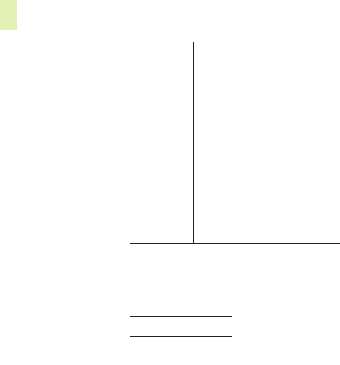
13
6
Types of wire and wire preparation
According to EN 60079-14 /DIN VDE
0165-1 the wire ends of stranded and
fine-stranded wire have to be protec-
ted against splaying, for example by
the use of cable lugs, ferrules, or by
the design of the terminal block
applied. Soldering alone is not suffi-
cient.
Connecting electrical equipment to
terminal blocks in an atmosphere with
a type of protection – Increased safety
“e” – the air and creepage distances
acccording to EN 60079-7/DIN VDE
0170/0171-6 must not be reduced.
Experience through the application of
terminal blocks in aggressive atmosphe-
res in the chemical industry demonstrate
that tinned copper ferrules (gastight) or
tinned copper pin-type cable sockets/
lugs are recommended when connec-
ting fine-stranded wires to terminal
blocks in corrosive atmospheres.
– Continued –
General Technical Information
for Electrical Equipment in Hazardous Environments
It is expressively forbidden to use insu-
lating parts for the transmission of
contact pressure. Terminal blocks with
sharp edges, which may damage the
conductor and others that can rotate or
be deformed permanently during
normal fixing, are not permissible.
Terminal blocks for connections inside
electrical equipment should not be
subjected to excessive mechanical
stress. They must comply with the condi-
tions for terminal blocks for external
electrical conductors.
The air distances between live parts of
different potentials are contained in the
table 1 with a minimum value of
3 mm for external connections.
The value of the creepage distances
depends on the working voltage, the
surface condition of the insulating parts
and the anti-tracking index of the insu-
lation material.
Grooves on the surface may only be
considered if they are at least 2.5 mm
wide and deep, and corrogations on
the surface only if their height is at
least 2.5 mm and their width corre-
sponds to the mechanical strength of
the material, however not smaller than
1 mm.
Table 1: Creepage and air distances
The classification of the insulating mate-
rials according to their tracking resis-
tance follows the Comparative Tracking
Index (CTI) and is contained in the table
2 as follows:
This classification is related to insulating
parts without grooves or corrogations.
If the insulating parts have grooves or
corrogations sufficiently large to be
considered, the minimum creepage
distances according to the values of the
insulating materials of the next higher
class apply, for ex. group I instead of
group II.
Under consideration of the ambient
temperature of 40°C (104°F) specified
for electrical equipment, the current
carrying capacity acc. to DIN/VDE
0298, part 4, table 10, of rubber insu-
lated conductors is reduced to 82 %, of
PVC-insulated conductors to 87 % of
the current carrying capacity, specified
for 30°C (86°F) ambient temperature
acc. to item 4.3.3. of DIN VDE 0298-4:
2003-08.
Table 2:
Tracking resistance of Insulating
materials
Material Comparative
group tracking index
I 600 ≤CTI
II 400 ≤CTI < 600
IIIa 175 ≤CTI < 400
V I II IIIa mm
102) 1.6 1.6 1.6 1.6
12.5 1.6 1.6 1.6 1.6
16 1.6 1.6 1.6 1.6
20 1.6 1.6 1.6 1.6
25 1.7 1.7 1.7 1.7
32 1.8 1.8 1.8 1.8
40 1.9 2.4 3.0 1.9
50 2.1 2.6 3.4 2.1
63 2.1 2.6 3.4 2.1
80 2.2 2.8 3.6 2.2
100 2.4 3.0 3.8 2.4
125 2.5 3.2 4 2.5
160 3.2 4 5 3.2
200 4 5 6.3 4
250 5 6.3 8 5
320 6.3 8 10 6
400 (440)*)8 10 12.5 6
500 (550)*)10 12.5 16 8
630 (690)*)12 16 20 10
800 16 20 25 12
1000 20 25 32 14
1250 22 26 32 18
1600 23 27 32 20
2000 25 28 32 23
2500 32 36 40 29
3200 40 45 50 36
4000 50 56 63 44
5000 63 71 80 50
6300 80 90 100 60
8000 100 110 125 80
10000 125 140 160 100
Voltage1)
Effective value
of AC voltage
or DC voltage
Minimum creepage
mm
Material group
Minimum
air distance
1) The indicated voltages are taken from the IEC 60664-1. The working voltage*) may exceed the voltage
indicated in the table by 10 %. This is based on the simplification of supply voltages according to table 3 b of
IEC 60664-1.
The indicated values for creepage and air distances are based on a maximum deviation of the supply voltage
of ± 10 %.
2) CTI values are not applicable for voltages of 10 V or less. Materials that do not meet the requirements of
material group III a can be used.
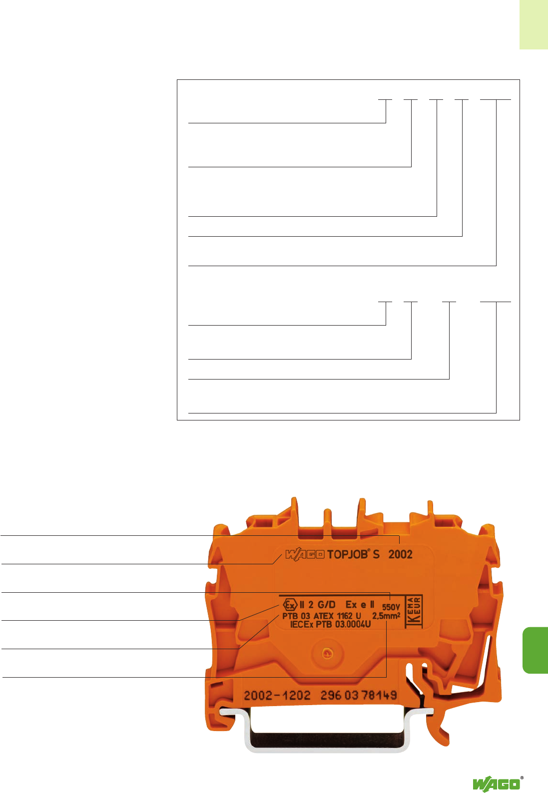
13
13
7
Approvals
Terminal blocks can be used in zones I
and II, provided that the terminal blocks
are in an enclosure that has a minimum
degree of protection IP 54 and an Ex e
certification.
Terminal blocks are considered EX com-
ponents, as they are only a part of the
equipment. Part certificates provided by
testing agencies serve as a basis for the
complete certification of conformity for
the installation.
An EC type examination certificate is
issued in accordance with the Explosion
Protection Directive 94/9/EG (ATEX
100 a).
In addition, IEXEx certificates can be
obtained from the appropriate accredi-
ted testing organizations (see also page
13.8) in accordance with the IECEx cer-
tification agreement, which is accepted
overall in Europe and currently in coun-
tries like Canada, China and Australia,
etc.
These certificates can be downloaded
from www.iecex.com.
The marking of the terminal blocks are in conformance with EC directive
94/9/EC ATEX 100 a and will be as follows:
The embossed type details on the ter-
minal blocks show the manufacturer’s
name, the series No., the type of pro-
tection Ex e II, the approval No., the
data of approval and the name of the
test house.
Example rear
Series
Manufacturer’s name
Nominal insulating voltage
Type of protection
Part certificate No.
Nominal cross section
(solid, stranded and fine-stranded
conductors)
4II 2 G Ex e II
Explosion prevention marking
Group II (for equipment used in areas in which an
explosive atmosphere might occur.)
Category 2 (high safety, equipment used in areas
[zones] in
which an explosive atmosphere can occur during normal
operation. The explosion protection has also to be guaranteed
even with frequent equipment malfunctions
.)
Gases
Explosion protection in Europe, type of protection “Increased Safety”,
Group II
Or 4I M 2 Ex e I
Explosion prevention marking
Group I (for equipment used in undergroud applications)
Mining applications
Explosion protection in Europe, type of protection “Increased Safety”,
Group I

13
8
– Continued –
General Technical Information
for Electrical Equipment in Hazardous Environments
According to UL Standard 60079-7
terminal blocks for Class I, Zone 1, Ex e
II hazardous locations can be approved
for Ex applications.
As a result of international harmoniza-
tion efforts the UL certificate can be
issued on the basis of a certificate
according to EN 60079-0 or
EN 60079-7, provided that the terminal
blocks have also been approved in
accordance with UL 1059 (ordinary
location).
If desired by the applicant, the product
can at the same time be approved in
accordance with the Canadian Stan-
dards E79-0-95 and E79-7-95 and
released for use in Canada.
The terminal blocks are marked with
YCl. I, Zn.1, AEx e II.
The WAGO terminal blocks specified in
this catalog have been granted the EC
type examination certificates.
The WAGO terminal blocks approved
for the ignition protection type Ex e II
are manufactured of flame resistant,
self-extinguishing Nylon 6.6. The same
applies to the other terminal blocks in
the non explosion endangered area.
A tracking resistance with a CTI value
of 600 as per IEC 60112 and a
constant operating temperature of
105°C/22°F in accordance with
IEC 60216-1 and -2 are provided.
To monitor the above described quality
features, all CAGE CLAMP®rail-moun-
ted terminal blocks with Ex e II appro-
val are subject to a factory part quality
control.

13
13
9
Special requirements
“intrinsic safety Ex i”
The European Standard EN 60079-11
– classification 0170/0171, part 7/08.03
– contains the special requirements for
the construction and testing of electrical
apparatus, designated for the type of
protection intrinsic safety “i” – in poten-
tially explosive atmospheres.
As opposed to other ignition protection
types, the ignition protection technique
intrinsic safety “i” does not only refer to
individual equipment, but to the com-
plete intrinsically safe current circuit.
A current circuit is termed intrinsically
safe when in normal operation and
with certain occurring fault conditions
no sparks and no thermal effects can
cause an ignition in a certain explosive
atmosphere.
It is important to distinguish between
●intrinsically safe electrical equipment
when all circuits are intrinsically safe
and
●a related electrical equipment inclu-
ding both intrinsically and non-intrin-
sically safe circuits, and being desi-
gned in such a way that it is
impossible for the non-intrinsically
safe circuits to affect the intrinsically
safe circuits.
Intrinsically safe electrical equipment
and intrinsically safe parts or related
electrical equipment are classified in
categories “ia” or “ib”.
Products classified Ex “ia” should not
cause any ignition when current is
applied in the following cases:
a) in normal service and the presence
of non-countable faults leading to
the most unfavorable condition;
b) in normal service and the presence
of one countable fault in addition to
the non-countable faults leading to
the most unfavorable condition;
c) in normal service and the presence
of two countable faults in addition to
the non-countable faults leading to
the most unfavorable condition.
Products classified Ex “ib” should not
cause any ignition when current is
applied in the following cases:
a) in normal service and the presence
of non-countable faults leading to
the most unfavorable condition;
b) in normal service and the presence
of one countable fault in addition to
the non-countable faults leading to
the most unfavorable condition.
No particular approval is necessary for
terminal blocks as plain mechanical
equipment for use in type of protection
Ex i applications, as they do not contain
a source of voltage and precise infor-
mation is available concerning the elec-
trical data and the temperature rise
performance.
They shall be identifiable for example
by their type designation and the fol-
lowing construction requirements have
to be observed:
●The air distance between bare, con-
ducting parts of terminal blocks of
different intrisically safe circuits has
to be equal or higher than the
values specified in the standard. In
addition, the air distances between
the terminal blocks must be so that
the air distances between bare, con-
ducting parts of the connected exter-
nal conductors is at least 6 mm for
one measurement. Each possible
motion of metallic parts that are not
rigidly fixed must be considered.
●When a possible connection has not
been considered during safety ana-
lysis, the minimum air distance bet-
ween grounded (earthed) metallic or
other conducting parts and the unin-
sulated conducting parts of the con-
ductors that are connected to the
terminal blocks must be 3 mm.
●The terminal block has to be marked
in a clear and distinct manner. If a
color is used, it shall be light blue
(approx. RAL 5015).
When using terminal blocks in intrinsi-
cally safe circuits, the following require-
ments have to be observed:
Terminal blocks used for intrinsically
safe circuits must be separated from
non-intrinsically safe circuits. This is
accomplished by several accepted
methods. First, intrinsically safe circuits
are separated by at least 50 mm of air
space from non-intrinsically safe circuits.
Second, intrinsically safe circuits are
housed in a separate enclosure. Third,
intrinsically safe terminal blocks are
separated from non-intrinsically safe
terminal blocks by either an insulated
partition or grounded metal partition.
The partition size must allow for either
1.5 mm or less distance from the sides
of the housing or provide at least
50 mm of creepage distance between
the intrinsically and non-intrinsically
safe circuits in all directions. The insula-
tion between an intrinsically safe circuit
and the chassis of an electrical equip-
ment or parts, which may be grounded
(earthed), has to withstand an effective
AC voltage corresponding to double
the value of the voltage of the intrinsi-
cally safe circuit or a minimum of at
least 500 V, depending on which value
is higher.
The insulation between an intrinsically
safe and a non-intrinsically safe circuit
has to withstand an effective AC volt-
age of 2 x nominal value (U) + 1 kV or
a minimum of 1.5 kV, whereby U
represents the total of the effective
voltages of the intrinsically safe and the
non-intrinsically safe circuit.
Short circuit between different intrinsi-
cally safe circuits could cause danger-
ous conditions. The insulation between
these circuits should withstand an effec-
tive voltage of at least 500 V AC or
2 U AC where U is the total of the
effective voltages of the related circuits.
According to the construction specifica-
tion EN 60079-14 (VDE 0165), stranded
and fine-stranded conductors in
intrinsically safe circuits have to be
protected against splayed ends, for
example by ferrules or pin terminals
or by the design of the terminal
blocks. Tinning of the conductor end
alone is not permissible.
For the connection of stranded and
fine-stranded conductors in terminal
blocks it is recommended to use in
corrosive atmosphere gastight tinned
copper ferrules or tinned copper pin
terminals.
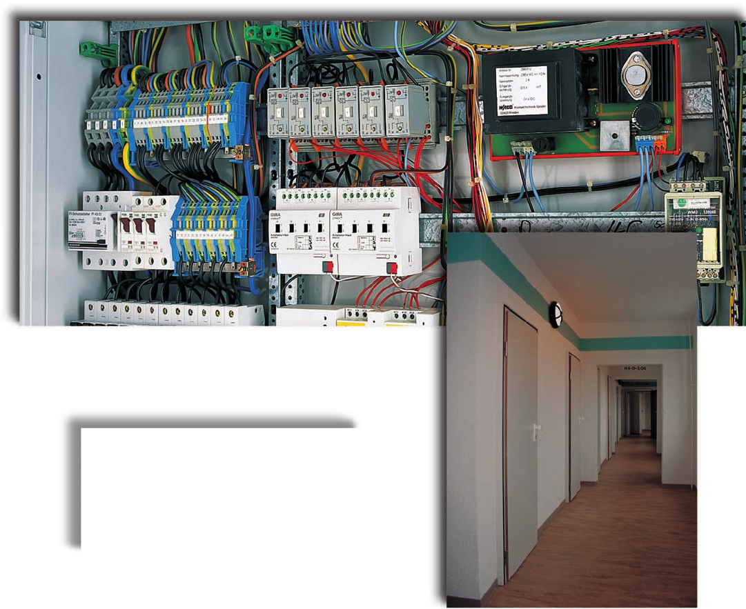
Reliable lighting means safety:
WAGO current flow monitoring modules
indicate the failure of corridor or stairwell
lighting in big residential buildings.

14
14
Marking and Mounting Accessories
Tools
Angled support bracket 14.36
Carrier rails 14.36 – 14.37
Collective carrier for jumpers 14.37
Covers 14.39
End stops for DIN 35 and DIN 15 rail 14.19/14.37
Group marker carriers and marker carriers 14.16 – 14.18
Marker branches 14.16
Marker carriers 14.16
Marker tags 14.16
Marking computer system 14.20 – 14.25
Marking system (vertically movable) 14.15
Miniature WSB Quick marking system 14.14
Mounting carrier 14.18
Stickers for operating instructions 14.40 – 14.41
T marker tag 14.14
WCB Combi marking system 14.17
WFB Countinuous marking strips 14.15
WMB Multi marking system 14.9 – 14.13
WSB Quick marking system 14.8 – 14.13
Contact paste “Alu-Plus” 14.48
Crimping tools for ferrules 14.44 – 14.45
Operating tools 14.42 – 14.43
Screwdrivers 14.42
Stripping tools 14.46
Testboy 14.47
Voltage testers 14.47
Wire cutter 14.49
VOLUME 1
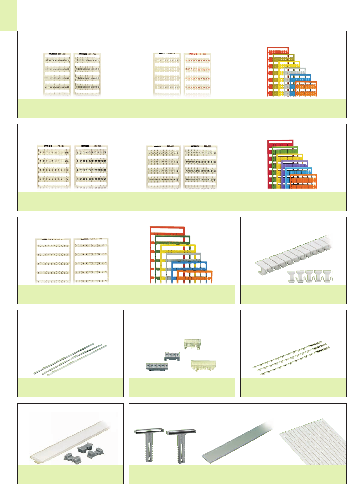
14
2
Page 14.15Page 14.15
Page 14.16Page 14.16Page 14.16
Page 14.14
colored miniature WSB Cards
Page 14.14
Miniature WSB Cards
Page 14.14
colored WMB or WSB Cards
Page 14.9
WMB or WSB Cards
with horizontal or vertical marking
Pages 14.9 – 14.13
colored WSB Cards
Page 14.9
WSB Cards with
vertical marking
Page 14.8
Marking Accessories
– Product Summary –
WSB Quick marking system for terminal block width 4 mm/0.157 in
WFB Continuous marking strips
WMB Multi marking system 4 mm to 4.2 mm (0.157 in – 0.165 in) and 5 mm to 5.2 mm (0.197 in – 0.205 in) and
WSB Quick marking system
Miniature WSB Quick marking system T marker tag
Marker tags Marker carriers for marker tags Marker branches
Vertically movable marking system
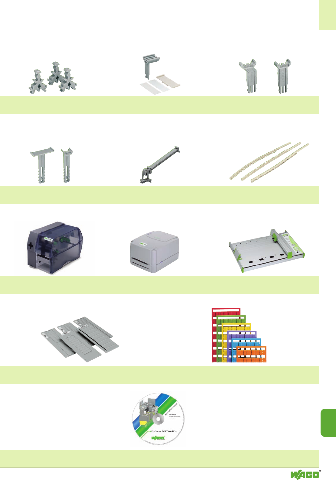
14
14
3
Software
Page 14.23
Marker cards, plain
Page 14.27
Interchangeable locating devices
Page 14.26
Plotter
Page 14.25
Thermal transfer printer
Page 14.24
Thermal transfer printer
Page 14.24
pivotable
group marker carrier
Page 14.17
WCB combi marker tags
Page 14.17
adjustable height
group marker carriers
Page 14.18
Group marker carriers for serie 282
Page 14.17
Group marker carriers
Page 14.18
WSB double marker carriers
Page 14.16
Marker carriers
ProServe
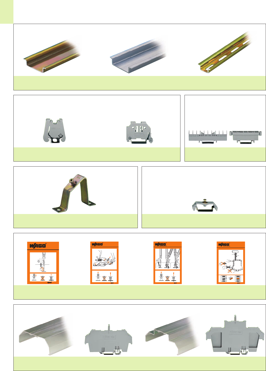
210-422
210-422
35–36
mm
285-171
+=
285-495
285-197 = TS 35 x 2.3 mm Cu
➀
➂
285-194
285-195
285-197
5°➃
➁
1.38 in
210-419
210-419
210-3 70
210-370
1 0
210- 186
210- 186
14
4
Type 2Type 1
Pages 14.38 – 14.39
Pages 14.40 – 14.41
Montagematerial
– Product Summary –
Stickers for operating instructions
Covers and cover carriers
for jumpers
Page 14.37
for DIN 35 rail
Page 14.19
for DIN 15 rail
Page 14.37
DIN 15 rail, steel /aluminum
Page 14.37
DIN 35 rail, steel /aluminum /copper
Page 14.36
Carrier rails
End stops Spare parts carrier
Page 14.36
Angled support bracket Mounting carrier
Page 14.18
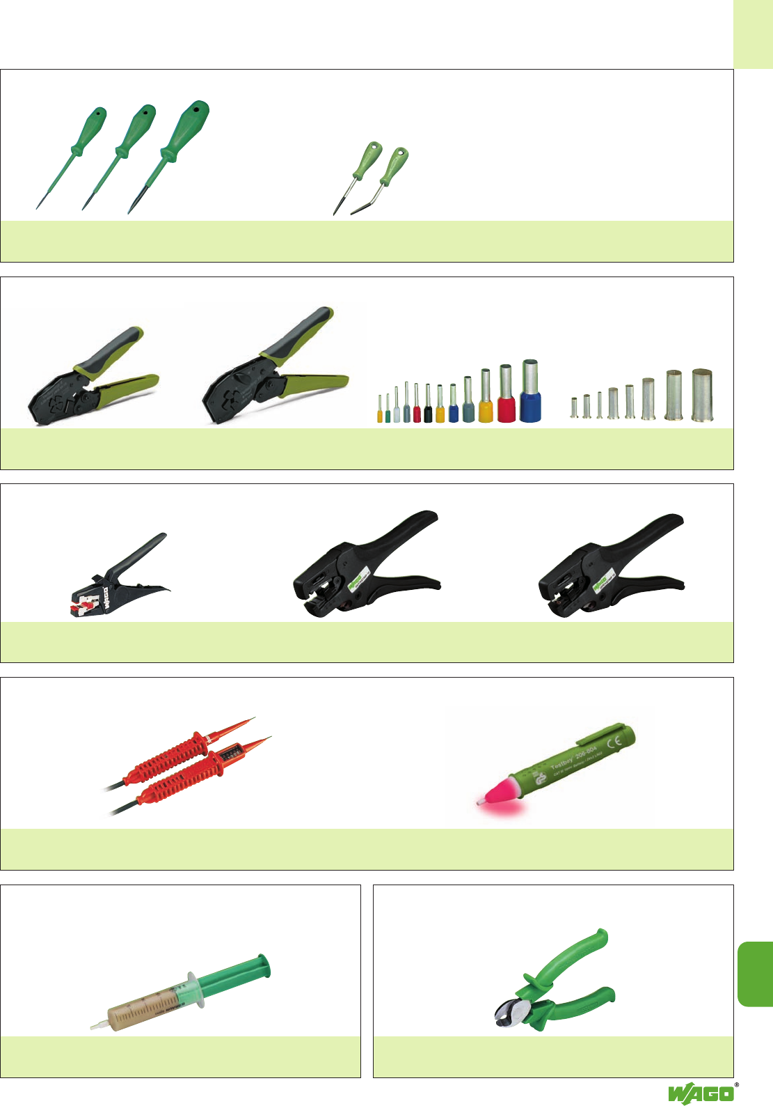
14
14
5
Page 14.49Page 14.48
Testboy
Page 14.47
Profipol
Page 14.47
from 0.25 mm2to 16 mm2
insulated and uninsulated
Page 14.45
Variocrimp 16
Page 14.44
Variocrimp 4
Page 14.44
Screwdrivers, short
Page 14.42
Screwdrivers
with partially insulated shaft
Page 14.42
Tools
– Product Summery –
Screwdrivers
Crimping Tools Ferrules
Voltage and Continuity Testers
Contact paste “Alu-Plus” Wire Cutter
Quickstrip 16
Page 14.46
Quickstrip 10
Page 14.46
Microstrip
Page 14.46
Wire Strippers
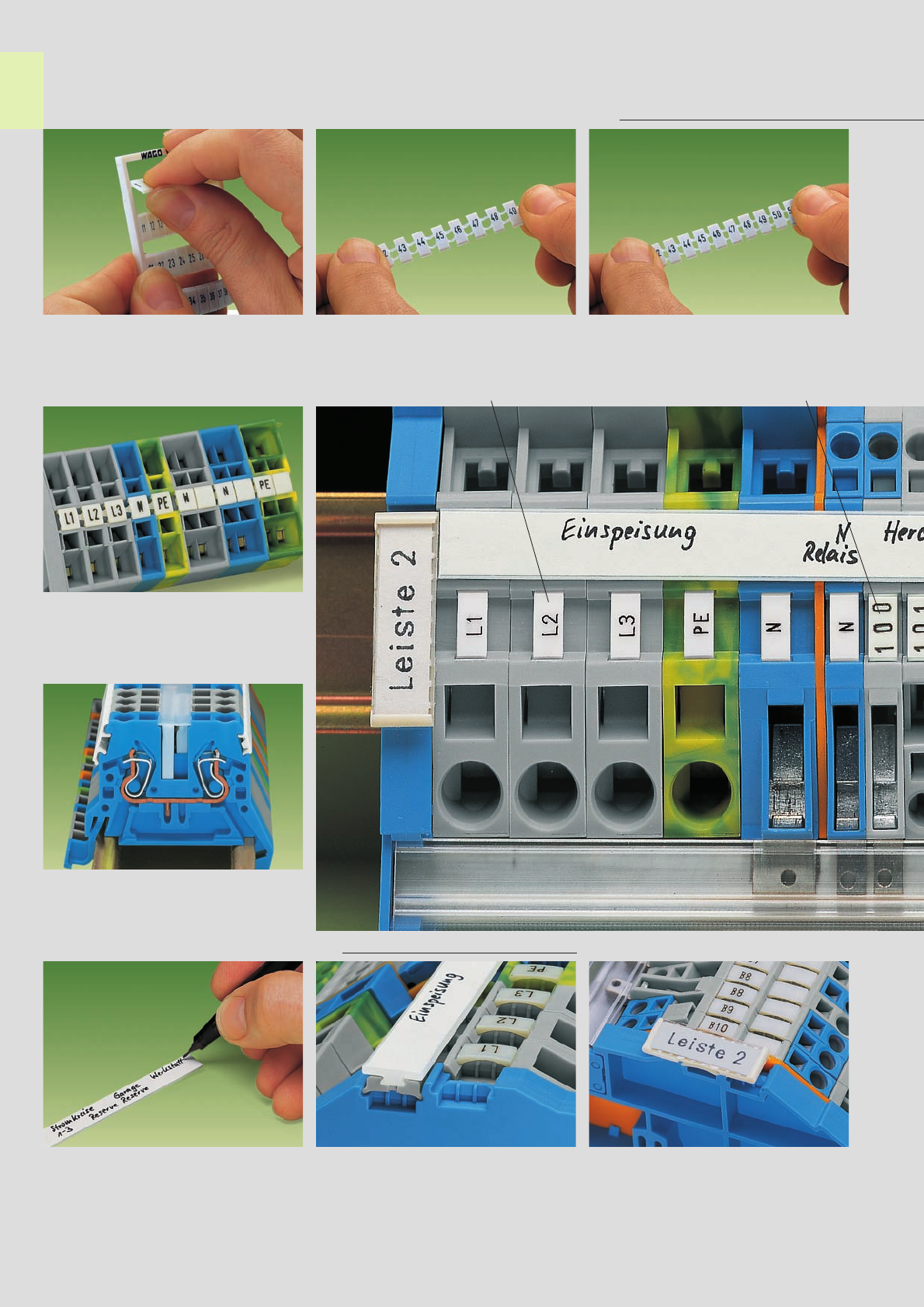
,
●
➊
➋
14
6
●
➌
Marking Accessories . . .
WMB (WAGO multi marking system) et WSB (WAGO Quick marking system)
Separation of a strip from the WMB or
WSB marker card
Miniature WSB
(WAGO Quick marking system) WSB Quick marking system
or WMB Multi marking system
Marking
with miniature WSB Quick marking system
Miniature WSB or WMB marking
➊Miniature WSB marking
➋WMB marking using miniature WSB marker
receptacles
WFB (WAGO Continuous marking strips)
Customized ink pen marking Adapter for WFB Continuous marking strips,
to be fixed every 10th terminal block
Group marking
Group marking on N-busbar carrier used as
end stop
Stretching of a strip – only for WSB marking
for terminal block widths
above 5 mm up to 6.2 mm
WCB Combi
marking system
Stretching of a strip – only for WMB marking
stretchable from 4 mm up to 4.2 mm
stretchable from 5 mm up to 5.2 mm
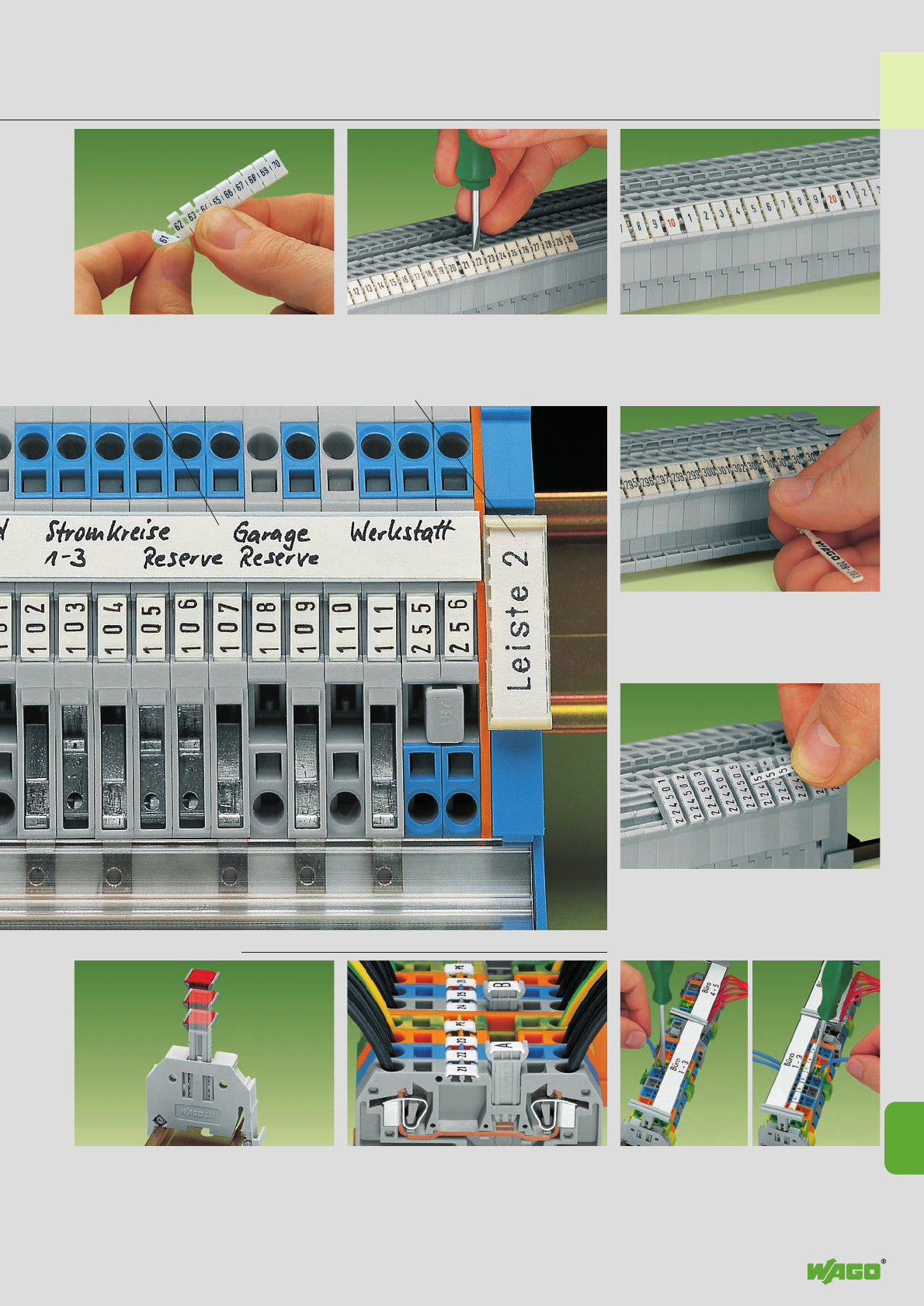
,
●
●
14
14
7
. . . Description and Handling
Snapping a strip into the marker receptacle profile
Marker branchesWFB Continuous marking strips Group marking
Snapping markers into the marker receptacle
profile
up to 2 branch markers, series 279
up to 3 branch markers, series 280 to 285
Marker tags
Snapping markers into marker carriers
Group marker carrier adjustable in height Additional continuous marking strips
Vertically movable marking systemGroup marker carriers
Additional group marking
WMB or WSB “decade” labelling
Separation of an individual marker from the strip,
for bigger terminal blocks
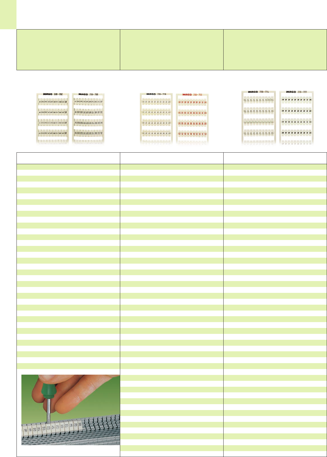
14
8
Vertical marking
Consecutive numbers each strip
10 strips with 10 markers for each card
for terminal block width 4 mm/0.157 in
Marking Item Pack.-unit
per card No. pcs
WAGO Quick Marking System WSB
for terminal block width 4 mm / 0.157 in
Vertical marking
Same numbers each strip
10 strips with 10 markers for each card
for terminal block width 4 mm/0.157 in
Marking Item Pack.-unit
per card No. pcs
Vertical marking
Same letters/symbols each strip
10 strips with 10 markers for each card
for terminal block width 4 mm/0.157 in
Marking Item Pack.-unit
per card No. pcs
Snapping a strip into the
double marker carrier
1 . . . 10 (10x) 209-702 5 cards
11 . . . 20 (10x) 209-703 5 cards
21 . . . 30 (10x) 209-704 5 cards
31 . . . 40 (10x) 209-705 5 cards
41 . . . 50 (10x) 209-706 5 cards
1 . . . 50 (2x) 209-766 5 cards
51 . . . 100 (2x) 209-707 5 cards
101 . . . 150 (2x) 209-708 5 cards
151 . . . 200 (2x) 209-709 5 cards
201 . . . 300 (1x) 209-710 5 cards
301 . . . 400 (1x) 209-711 5 cards
401 . . . 500 (1x) 209-712 5 cards
501 . . . 600 (1x) 209-713 5 cards
601 . . . 700 (1x) 209-714 5 cards
701 . . . 800 (1x) 209-715 5 cards
801 . . . 900 (1x) 209-716 5 cards
901 . . . 1000 (1x) 209-717 5 cards
1 . . . 9, ; (10x) 209-765 5 cards
for double deck terminal blocks
1, 3, 5, 7, 9, 11, . . . 99 and 2, 4, 6, 8, 10, 12, . . . 100 (1x)
249-700 5 cards
101, 103, 105, . . . 149 and 102, 104, 106, . . . 150 (2x)
249-701 5 cards
WSB Double marker carrier, 4 mm/0.157 in wide
suitable for all WSB and WMB marking systems
209-128 100
1/ 2 (each 50x) 209-718 5 cards
3/ 4 (each 50x) 209-719 5 cards
5/ 6 (each 50x) 209-720 5 cards
7/ 8 (each 50x) 209-721 5 cards
9/10 (each 50x) 209-722 5 cards
11/12 (each 50x) 209-723 5 cards
13/14 (each 50x) 209-724 5 cards
15/16 (each 50x) 209-725 5 cards
17/18 (each 50x) 209-726 5 cards
19/20 (each 50x) 209-727 5 cards
21/22 (each 50x) 209-728 5 cards
23/24 (each 50x) 209-729 5 cards
25/26 (each 50x) 209-730 5 cards
27/28 (each 50x) 209-731 5 cards
29/30 (each 50x) 209-732 5 cards
31/32 (each 50x) 209-733 5 cards
33/34 (each 50x) 209-734 5 cards
35/36 (each 50x) 209-735 5 cards
37/38 (each 50x) 209-736 5 cards
39/40 (each 50x) 209-737 5 cards
41/42 (each 50x) 209-738 5 cards
43/44 (each 50x) 209-739 5 cards
45/46 (each 50x) 209-740 5 cards
47/48 (each 50x) 209-741 5 cards
49/50 (each 50x) 209-742 5 cards
“Decade” marking with red printing,
2 strips each with same numbers
10 . . . 50 (each 20x) 209-753* 5 cards
60 . . . 100 (each 20x) 209-754* 5 cards
110 . . . 150 (each 20x) 209-755* 5 cards
160 . . . 200 (each 20x) 209-756* 5 cards
210 . . . 300 (each 10x) 209-757* 5 cards
310 . . . 400 (each 10x) 209-758* 5 cards
410 . . . 500 (each 10x) 209-759* 5 cards
510 . . . 600 (each 10x) 209-760* 5 cards
610 . . . 700 (each 10x) 209-761* 5 cards
710 . . . 800 (each 10x) 209-762* 5 cards
810 . . . 900 (each 10x) 209-763* 5 cards
910 . . . 1000 (each 10x) 209-764* 5 cards
* see also page 14.7
a, b, c, e, u, v, w, x, y, z (10x)
209-743 5 cards
R, S, T, U, V, W, X, Y, Z, Mp (10x)
209-744 5 cards
A, B, P, N, PE, PEN, L1, L2, L3, 3(10x)
209-745 5 cards
L1 (100x) 209-774 5 cards
L2 (100x) 209-775 5 cards
L3 (100x) 209-776 5 cards
N (100x) 209-777 5 cards
PE (100x) 209-778 5 cards
PEN (100x) 209-779 5 cards
3(100x) 209-780 5 cards
+/– (50x) 209-752 5 cards
for fuses (fuse plugs 281-5 . . )
F 1, . . ., F10; (10x) 209-787 5 cards
F11, . . ., F20; (10x) 209-700/209-124 5 cards
F21, . . ., F30; (10x) 209-700/209-125 5 cards
F31, . . ., F40; (10x) 209-700/209-126 5 cards
F41, . . ., F50; (10x) 209-700/209-127 5 cards
plain, 209-501 5 cards
for self-
marking
Marking pen 210-110 1
with fibre tip,
for permanent
marking
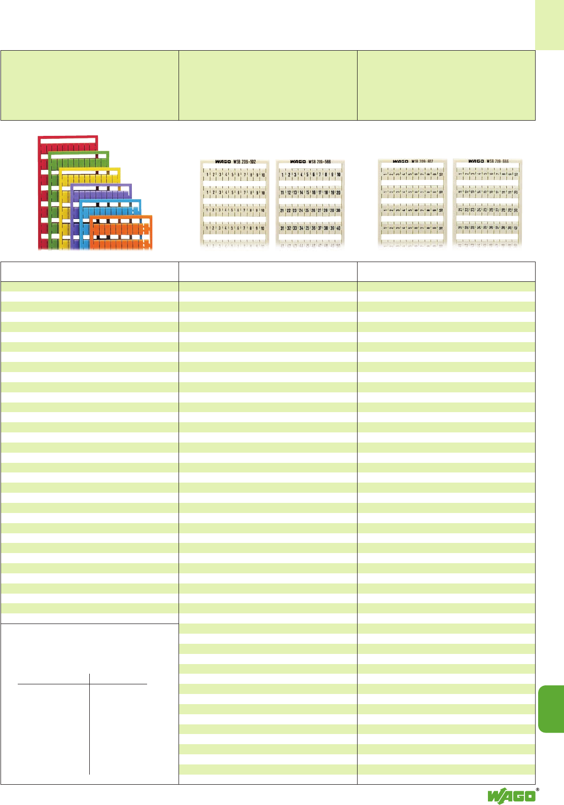
14
14
9
Horizontal marking
Consecutive numbers each strip
10 strips with 10 markers per card
for terminal block widths
5 - 17.5 mm/0.197 in - 0.689 in
(WSB/WMB)
4 - 4.2 mm/0.157 in - 0.165 in
(WMB)
Vertical marking
Consecutive numbers each strip
10 strips with 10 markers per card
for terminal block widths
5 - 17.5 mm/0.197 in - 0.689 in
(WSB/WMB)
4 - 4.2 mm/0.157 in - 0.165 in
(WMB)
WAGO Quick Marking System WSB➊
WAGO Multi Marking System WMB➊
Colored
Marker Cards
Marking Item Pack.-unit
per card No. pcs
Marking Item Pack.-unit
per card No. pcs
Colored marker cards
Horizontal/vertical marking
Additional item-Nos.
10 strips with 10 markers per card
for terminal block widths
5 - 17.5 mm/0.197 in - 0.689 in
(WSB/WMB)
4 - 4.2 mm/0.157 in - 0.165 in
(WMB)
Color Item
No.
1 . . . 10 (10x) 209-502 5 cards
11 . . . 20 (10x) 209-503 5 cards
21 . . . 30 (10x) 209-504 5 cards
31 . . . 40 (10x) 209-505 5 cards
41 . . . 50 (10x) 209-506 5 cards
51 . . . 60 (10x) 209-569 5 cards
61 . . . 70 (10x) 209-570 5 cards
71 . . . 80 (10x) 209-571 5 cards
81 . . . 90 (10x) 209-572 5 cards
91 . . . 100 (10x) 209-573 5 cards
1 . . . 50 (2x) 209-566 5 cards
51 . . . 100 (2x) 209-507 5 cards
101 . . . 150 (2x) 209-508 5 cards
151 . . . 200 (2x) 209-509 5 cards
201 . . . 300 (1x) 209-510 5 cards
301 . . . 400 (1x) 209-511 5 cards
401 . . . 500 (1x) 209-512 5 cards
501 . . . 600 (1x) 209-513 5 cards
601 . . . 700 (1x) 209-514 5 cards
701 . . . 800 (1x) 209-515 5 cards
801 . . . 900 (1x) 209-516 5 cards
901 . . . 1000 (1x) 209-517 5 cards
1 . . . 9, ; (10x) 209-565 5 cards
for double deck terminal blocks
1, 3, 5, . . . 99
and 2, 4, 6, . . . 100 (1x)
209-599 5 cards
for triple deck terminal blocks
1, 4, 7, . . . 99 (1x)
249-557 5 cards
100, 103, 106, . . . 198 (1x)
249-558 5 cards
plain, 209-501 5 cards
for self-
marking
Marking pen 210-110 1
with fibre tip,
for permanent
marking
1 . . . 10 (10x) 209-602 5 cards
11 . . . 20 (10x) 209-603 5 cards
21 . . . 30 (10x) 209-604 5 cards
31 . . . 40 (10x) 209-605 5 cards
41 . . . 50 (10x) 209-606 5 cards
51 . . . 60 (10x) 249-601 5 cards
61 . . . 70 (10x) 249-602 5 cards
71 . . . 80 (10x) 249-603 5 cards
81 . . . 90 (10x) 249-604 5 cards
91 . . . 100 (10x) 249-605 5 cards
1 . . . 50 (2x) 209-666 5 cards
51 . . . 100 (2x) 209-607 5 cards
101 . . . 150 (2x) 209-608 5 cards
151 . . . 200 (2x) 209-609 5 cards
201 . . . 300 (1x) 209-610 5 cards
301 . . . 400 (1x) 209-611 5 cards
401 . . . 500 (1x) 209-612 5 cards
501 . . . 600 (1x) 209-613 5 cards
601 . . . 700 (1x) 209-614 5 cards
701 . . . 800 (1x) 209-615 5 cards
801 . . . 900 (1x) 209-616 5 cards
901 . . . 1000 (1x) 209-617 5 cards
1001 . . . 1100 (1x) 209-688 5 cards
1101 . . . 1200 (1x) 209-669 5 cards
1201 . . . 1300 (1x) 209-670 5 cards
1301 . . . 1400 (1x) 209-671 5 cards
1401 . . . 1500 (1x) 209-672 5 cards
1501 . . . 1600 (1x) 209-901 5 cards
1601 . . . 1700 (1x) 209-902 5 cards
1701 . . . 1800 (1x) 209-903 5 cards
1801 . . . 1900 (1x) 209-912 5 cards
1901 . . . 2000 (1x) 209-913 5 cards
1 . . . 9, ; (10x) 209-665 5 cards
101, 101, 101, 102, . . .
. . .130, 130, 130 (1x) 209-667 5 cards
131, 131, 131, 132, . . .
. . .160, 160, 160 (1x) 209-668 5 cards
for double deck terminal blocks
1, 3, 5, 7, 9, 11, . . . 99 and 2, 4, 6, 8, 10, 12, . . . 100 (1x)
209-699 5 cards
101, 103, 105, . . . 149 and 102, 104, 106, . . . 150 (2x)
209-900 5 cards
for triple deck terminal blocks
1, 4, 7, . . . 99 (1x)
249-657 5 cards
100, 103, 106, . . . 198 (1x)
249-658 5 cards
Colored marker cards
All the markings shown are also available with
black printing on colored marker cards.
Add. item-No. for colored marker cards
yellow . . ./000-002
red . . ./000-005
blue . . ./000-006
grey . . ./000-007
orange . . ./000-012
light green . . ./000-017
green . . ./000-023
violet . . ./000-024
Ordering examples
Terminal block width 4 mm – WSB card
Marking 1 . . . 50 on yellow card
209-766/000-002
Terminal block width 4 mm – WMB card
Marking 1 . . . 50 on blue card
793-4566/000-006
Terminal block width 5 mm – WSB card
Marking 1 . . . 50 on red card
209-566/000-005
Terminal block width 5 mm – WMB card
Marking 1 . . . 50 on green card
793-5566/000-023
Note:
Please note that colored marker cards are normally on
longer delivery and more expensive than standard cards.
➊All WSB cards shown on this page are also
available as WMB cards with the same suffix.
Item no. see table:
WSB WMB
rigid
209- . . . 793- . . .
249- . . . 794- . . .
stretchable 5 – 5.2 mm
209- . . . 793-5 . . .
249- . . . 794-5 . . .
stretchable 4 – 4.2 mm
209- . . . 793-4 . . .
249- . . . 794-4 . . .
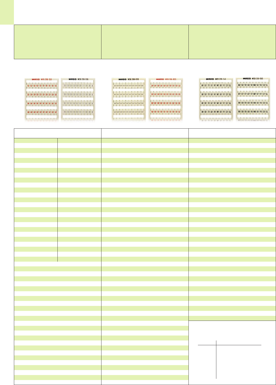
14
10
WAGO Quick Marking System WSB➊
WAGO Multi Marking System WMB➊
Horizontal marking
Same letters per strip
10 strips with 10 markers per card
for terminal block widths
5 - 17.5 mm/0.197 in - 0.689 in
(WSB/WMB)
4 - 4.2 mm/0.157 in - 0.165 in
(WMB)
Vertical marking
Same letters per strip
10 strips with 10 markers per card
for terminal block widths
5 - 17.5 mm/0.197 in - 0.689 in
(WSB/WMB)
4 - 4.2 mm/0.157 in - 0.165 in
(WMB)
Marking Item Pack.-unit
per card No. pcs
Marking Item Marking Item
per card No. per card No.
51/ 52
(50 each)
209-400
53/ 54
(50 each)
209-401
55/ 56
(50 each)
209-402
57/ 58
(50 each)
209-403
59/ 60
(50 each)
209-404
61/ 62
(50 each)
209-405
63/ 64
(50 each)
209-406
65/ 66
(50 each)
209-407
67/ 68
(50 each)
209-408
69/ 70
(50 each)
209-409
71/ 72
(50 each)
209-410
73/ 74
(50 each)
209-411
75/ 76
(50 each)
209-412
77/ 78
(50 each)
209-413
79/ 80
(50 each)
209-414
81/ 82
(50 each)
209-415
83/ 84
(50 each)
209-416
85/ 86
(50 each)
209-417
87/ 88
(50 each)
209-418
89/ 90
(50 each)
209-419
91/ 92
(50 each)
209-420
93/ 94
(50 each)
209-421
95/ 96
(50 each)
209-422
97/ 98
(50 each)
209-423
99/100
(50 each)
209-424
Horizontal marking
Consecutive letters/symbols per strip
10 strips with 10 markers per card
for terminal block widths
5 - 17.5 mm/0.197 in - 0.689 in
(WSB/WMB)
4 - 4.2 mm/0.157 in - 0.165 in
(WMB)
Marking Item Pack.-unit
per card No. pcs
1/ 2
(50 each)
209-618 5 cards
3/ 4
(50 each)
209-619 5 cards
5/ 6
(50 each)
209-620 5 cards
7/ 8
(50 each)
209-621 5 cards
9/10
(50 each)
209-622 5 cards
11/12
(50 each)
209-623 5 cards
13/14
(50 each)
209-624 5 cards
15/16
(50 each)
209-625 5 cards
17/18
(50 each)
209-626 5 cards
19/20
(50 each)
209-627 5 cards
21/22
(50 each)
209-628 5 cards
23/24
(50 each)
209-629 5 cards
25/26
(50 each)
209-630 5 cards
27/28
(50 each)
209-631 5 cards
29/30
(50 each)
209-632 5 cards
31/32
(50 each)
209-633 5 cards
33/34
(50 each)
209-634 5 cards
35/36
(50 each)
209-635 5 cards
37/38
(50 each)
209-636 5 cards
39/40
(50 each)
209-637 5 cards
41/42
(50 each)
209-638 5 cards
43/44
(50 each)
209-639 5 cards
45/46
(50 each)
209-640 5 cards
47/48
(50 each)
209-641 5 cards
49/50
(50 each)
209-642 5 cards
“Decade” marking with red printing,
2 strips each with same numbers
10 . . . 50
(20 each)
209-653* 5 cards
60 . . . 100
(20 each)
209-654* 5 cards
110 . . . 150
(20 each)
209-655* 5 cards
160 . . . 200
(20 each)
209-656* 5 cards
210 . . . 300
(10 each)
209-657* 5 cards
310 . . . 400
(10 each)
209-658* 5 cards
410 . . . 500
(10 each)
209-659* 5 cards
510 . . . 600
(10 each)
209-660* 5 cards
610 . . . 700
(10 each)
209-661* 5 cards
710 . . . 800
(10 each)
209-662* 5 cards
810 . . . 900
(10 each)
209-663* 5 cards
910 . . . 1000
(10 each)
209-664* 5 cards
* see also page 14.7
Pack.-unit pcs: 5 cards
“Decade” marking with red printing,
2 strips each with same numbers
10, 20 . . . 50
(20 each)
209-553* 5 cards
60, 70 . . . 100
(20 each)
209-554* 5 cards
110, 120 . . . 150
(20 each)
209-555* 5 cards
160, 170 . . . 200
(20 each)
209-556* 5 cards
210, 220 . . . 300
(10 each)
209-557* 5 cards
310, 320 . . . 400
(10 each)
209-558* 5 cards
410, 420 . . . 500
(10 each)
209-559* 5 cards
510, 520 . . . 600
(10 each)
209-560* 5 cards
610, 620 . . . 700
(10 each)
209-561* 5 cards
710, 720 . . . 800
(10 each)
209-562* 5 cards
810, 820 . . . 900
(10 each)
209-563* 5 cards
910, 920 . . .1000
(10 each)
209-564* 5 cards
* see also page14.7
1/ 2
(50 each)
209-518
3/ 4
(50 each)
209-519
5/ 6
(50 each)
209-520
7/ 8
(50 each)
209-521
9/10
(50 each)
209-522
11/12
(50 each)
209-523
13/14
(50 each)
209-524
15/16
(50 each)
209-525
17/18
(50 each)
209-526
19/20
(50 each)
209-527
21/22
(50 each)
209-528
23/24
(50 each)
209-529
25/26
(50 each)
209-530
27/28
(50 each)
209-531
29/30
(50 each)
209-532
31/32
(50 each)
209-533
33/34
(50 each)
209-534
35/36
(50 each)
209-535
37/38
(50 each)
209-536
39/40
(50 each)
209-537
41/42
(50 each)
209-538
43/44
(50 each)
209-539
45/46
(50 each)
209-540
47/48
(50 each)
209-541
49/50
(50 each)
209-542
U, V, W, N, PE, U, V, W, N, PE (10x)
209-474 5 cards
L1, L2, L3, N, PE, L1, L2, L3, N, PE (10x)
209-472 5 cards
U1, V1, W1, U1, V1, W1, U1, V1, W1, ; (10x)
209-487 5 cards
U2, V2, W2, U2, V2, W2, U2, V2, W2, ; (10x)
209-494 5 cards
U3, V3, W3, U3, V3, W3, U3, V3, W3, ; (10x)
209-495 5 cards
U4, V4, W4, U4, V4, W4, U4, V4, W4, ; (10x)
209-496 5 cards
U5, V5, W5, U5, V5, W5, U5, V5, W5, ; (10x)
209-497 5 cards
U6, V6, W6, U6, V6, W6, U6, V6, W6, ;
to
U9, V9, W9, U9, V9, W9, U9, V9, W9, ;
(2 each)
209-498 5 cards
R1, S1, T1, U1, V1, W1, X1, Y1, Z1, SL (10x)
209-546 5 cards
R2, S2, T2, U2, V2, W2, X2, Y2, Z2, SL (10x)
209-547 5 cards
R3, S3, T3, U3, V3, W3, X3, Y3, Z3, SL (10x)
209-548 5 cards
R4, S4, T4, U4, V4, W4, X4, Y4, Z4, SL
and
R5, S5, T5, U5, V5, W5, X5, Y5, Z5, SL
(5 each)
209-549 5 cards
R6, S6, T6, U6, V6, W6, X6, Y6, Z6, SL
to
R10, S10, T10, U10, V10, W10, X10, Y10, Z10, SL
(2 each)
209-550 5 cards
➊All WSB cards shown on this page are also
available as WMB cards with the same suffix.
Item no. see table:
WSB WMB
rigid
209-... 793-...
249-... 794-...
stretchable
5 – 5.2 mm 4 – 4.2 mm
209- . . . 793-5 . . . 793-4 . . .
249- . . . 794-5 . . . 793-4 . . .
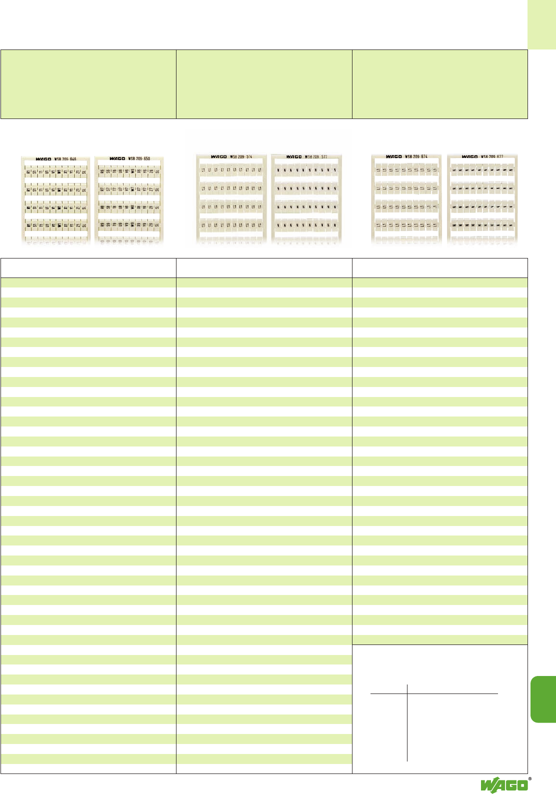
14
14
11
Horizontal marking
Same letters/symbols per strip
10 strips with 10 markers per card
for terminal block widths
5 - 17.5 mm/0.197 in - 0.689 in
(WSB/WMB)
4 - 4.2 mm/0.157 in - 0.165 in
(WMB)
Vertical marking
Same letters/symbols per strip
10 strips with 10 markers per card
for terminal block widths
5 - 17.5 mm/0.197 in - 0.689 in
(WSB/WMB)
4 - 4.2 mm/0.157 in - 0.165 in
(WMB)
Marking Item Pack.-unit
per card No. pcs
Marking Item Pack.-unit
per card No. pcs
Vertical marking
Consecutive letters/symbols per strip
10 strips with 10 markers per card
for terminal block widths
5 - 17.5 mm/0.197 in - 0.689 in
(WSB/WMB)
4 - 4.2 mm/0.157 in - 0.165 in
(WMB)
Marking Item Pack.-unit
per card No. pcs
a, b, c, e, u, v, w, x, y, z (10x)
209-543 5 cards
R, S, T, U, V, W, X, Y, Z, Mp (10x)
209-544 5 cards
A, B, P, N, PE, PEN, L1, L2, L3, 3(10x)
209-545 5 cards
L1 (100x) 209-574 5 cards
L2 (100x) 209-575 5 cards
L3 (100x) 209-576 5 cards
N (100x) 209-577 5 cards
PE (100x) 209-578 5 cards
PEN (100x) 209-579 5 cards
3(100x) 209-580 5 cards
R (100x) 209-581 5 cards
S (100x) 209-582 5 cards
T (100x) 209-583 5 cards
+/–
(50 each)
209-552 5 cards
U, V, W, N, PE, U, V, W, N, PE (10x)
249-674 5 cards
L1, L2, L3, N, PE, L1, L2, L3, N, PE (10x)
249-672 5 cards
U1, V1, W1, U1, V1, W1, U1, V1, W1, ; (10x)
209-687 5 cards
U2, V2, W2, U2, V2, W2, U2, V2, W2, ; (10x)
209-694 5 cards
U3, V3, W3, U3, V3, W3, U3, V3, W3, ; (10x)
209-695 5 cards
U4, V4, W4, U4, V4, W4, U4, V4, W4, ; (10x)
209-696 5 cards
U5, V5, W5, U5, V5, W5, U5, V5, W5, ; (10x)
209-697 5 cards
U6, V6, W6, U6, V6, W6, U6, V6, W6, ;
to
U9, V9, W9, U9, V9, W9, U9, V9, W9, ;
(2 each)
209-698 5 cards
R1, S1, T1, U1, V1, W1, X1, Y1, Z1, SL (10x)
209-646 5 cards
R2, S2, T2, U2, V2, W2, X2, Y2, Z2, SL (10x)
209-647 5 cards
R3, S3, T3, U3, V3, W3, X3, Y3, Z3, SL (10x)
209-648 5 cards
R4, S4, T4, U4, V4, W4, X4, Y4, Z4, SL
and
R5, S5, T5, U5, V5, W5, X5, Y5, Z5, SL
(5 each)
209-649 5 cards
R6, S6, T6, U6, V6, W6, X6, Y6, Z6, SL
to
R10, S10, T10, U10, V10, W10, X10, Y10, Z10, SL
(2 each)
209-650 5 cards
a, b, c, e, u, v, w, x, y, z (10x)
209-643 5 cards
R, S, T, U, V, W, X, Y, Z, Mp (10x)
209-644 5 cards
A, B, P, N, PE, PEN, L1, L2, L3, 3(10x)
209-645 5 cards
L1 (100x) 209-674 5 cards
L2 (100x) 209-675 5 cards
L3 (100x) 209-676 5 cards
N (100x) 209-677 5 cards
PE (100x) 209-678 5 cards
PEN (100x) 209-679 5 cards
3(100x) 209-680 5 cards
R (100x) 209-681 5 cards
S (100x) 209-682 5 cards
T (100x) 209-683 5 cards
+/–
(50 each)
209-652 5 cards
➊All WSB cards shown on this page are also
available as WMB cards with the same suffix.
Item no. see table:
WSB WMB
rigid
209-... 793-...
249-... 794-...
stretchable
5 – 5.2 mm 4 – 4.2 mm
209- . . . 793-5 . . . 793-4 . . .
249- . . . 794-5 . . . 793-4 . . .
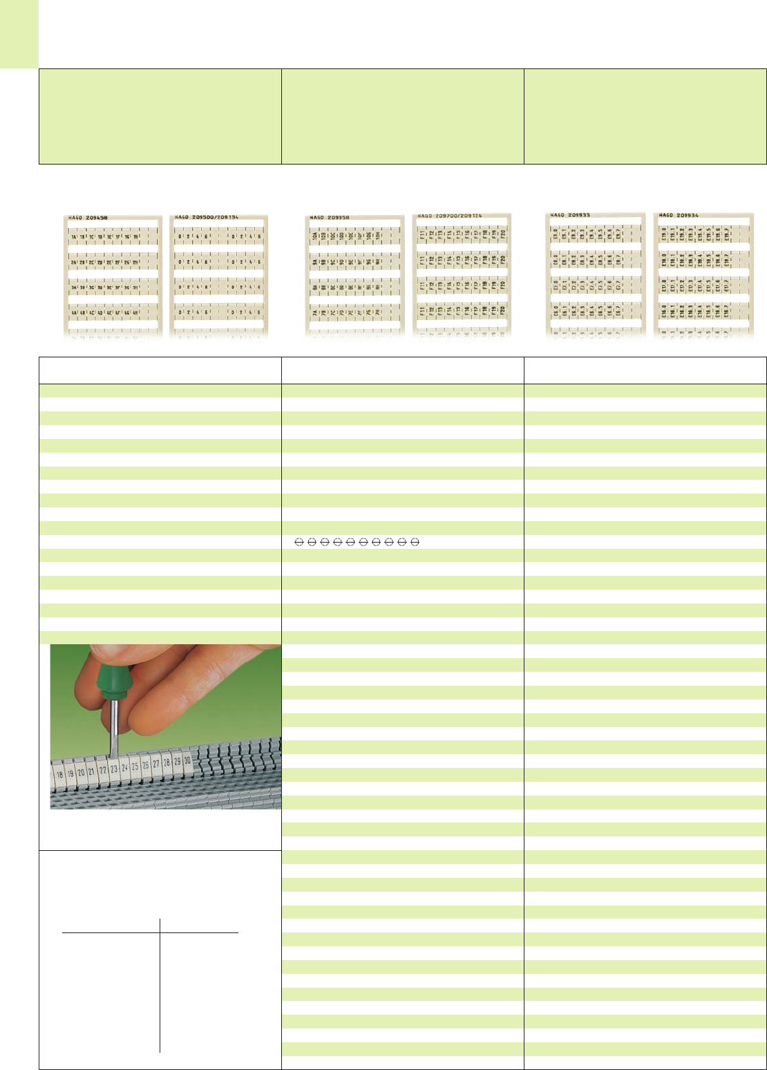
14
12
WAGO Quick Marking System WSB➊
WAGO Multi Marking System WMB➊
Horizontal marking
for subdistribution boxes (power stations)
10 strips with 10 markers per card
for terminal block widths
5 - 17.5 mm/0.197 in - 0.689 in
(WSB/WMB)
4 - 4.2 mm/0.157 in - 0.165 in
(WMB)
Vertical marking
for subdistribution boxes (power stations);
for relays, shielding (screenings), fuses;
10 strips with 10 markers per card
for terminal block widths
5 - 17.5 mm/0.197 in - 0.689 in
(WSB/WMB)
4 - 4.2 mm/0.157 in - 0.165 in
(WMB)
Vertical marking
for PLC input marking;
10 strips with 10 markers per card
for terminal block widths
5 - 17.5 mm/0.197 in - 0.689 in
(WSB/WMB)
4 - 4.2 mm/0.157 in - 0.165 in
(WMB)
Marking Item Pack.-unit
per card No. pcs
Marking Item Pack.-unit
per card No. pcs Marking Item Pack.-unit
per card No. pcs
Snapping a strip into the
double marker carrier
for subdistribution boxes (power stations)
1A, 1B, 1C, 1D, 1E, 1F, 1G, 1H, , ;
to
10A, 10B, 10C, 10D, 10E, 10F, 10G, 10H, , ; (1 each)
209-958 5 cards
0, 2, 4, 6, , , 0, 2, 4, 6; (5x)
1, 3, 5, 7, , , 1, 3, 5, 7; (5x)
209-600/209-073 5 cards
Symbol shield (screen) term. bl. acc. to DIN 40711
, , , , , , , , , ; (10x)
209-993 5 cards
for relays
A1, A2, A2, 11, 12, 14, A1, A2, A2, ; (5x)
11, 12, 14, A1, A2, A2, 11, 12, 14, ; (5x)
209-994 5 cards
12, A1, A2, 24, 11, 14, 21, 22, , ; (10x)
209-995 5 cards
A1, A1, A2, A2, 12, 11, 11, 14, , ; (10x)
209-996 5 cards
Iin, Iin, , Iout, Iout, 24 V, 11, 12, 14, 0V; (10x)
209-997 5 cards
A1, A2, A1, A2, RL, –, RL, –, , ; (10x)
209-998 5 cards
for fuse terminal blocks 281-6 . .
F 1, . . ., F10; (10x) 794-615 5 cards
F11, . . ., F20; (10x) 794-616 5 cards
F21, . . ., F30; (10x) 794-617 5 cards
F31, . . ., F40; (10x) 794-618 5 cards
F41, . . ., F50; (10x) 794-619 5 cards
for PLC input marking
E0.0, E0.1, E0.2, E0.3, E0.4, E0.5, E0.6, E0.7, , ;
to
E9.0, E9.1, E9.2, E9.3, E9.4, E9.5, E9.6, E9.7, , ; (1each)
209-933 5 cards
same as above, however
E10.0 to E19.7 (1 each)
209-934 5 cards
E20.0 to E29.7 (1 each)
209-935 5 cards
E30.0 to E39.7 (1 each)
209-936 5 cards
E40.0 to E49.7 (1 each)
209-937 5 cards
E50.0 to E59.7 (1 each)
209-938 5 cards
E60.0 to E69.7 (1 each)
209-939 5 cards
E70.0 to E79.7 (1 each)
209-940 5 cards
E80.0 to E89.7 (1 each)
209-941 5 cards
E90.0 to E99.7 (1 each)
209-942 5 cards
E100.0 to E109.7 (1 each)
209-943 5 cards
E110.0 to E119.7 (1 each)
209-944 5 cards
E120.0 to E129.7 (1 each)
209-945 5 cards
continued on next page
for subdistribution boxes (power stations)
1A, 1B, 1C, 1D, 1E, 1F, 1G, 1H, , ;
to
10A, 10B, 10C, 10D, 10E, 10F, 10G, 10H, , ; (1 each)
209-458 5 cards
0, 2, 4, 6, , , 0, 2, 4, 6; (5x)
1, 3, 5, 7, , , 1, 3, 5, 7; (5x)
209-500/209-134 5 cards
WSB Double marker carrier, 4 mm/0.157 in wide
suitable for all WSB and WMB marking systems
209-128 100
➊All WSB cards shown on this page are also
available as WMB cards with the same suffix.
Item no. see table:
WSB WMB
rigid
209- . . . 793- . . .
249- . . . 794- . . .
stretchable 5 – 5.2 mm
209- . . . 793-5 . . .
249- . . . 794-5 . . .
stretchable 4 – 4.2 mm
209- . . . 793-4 . . .
249- . . . 794-4 . . .
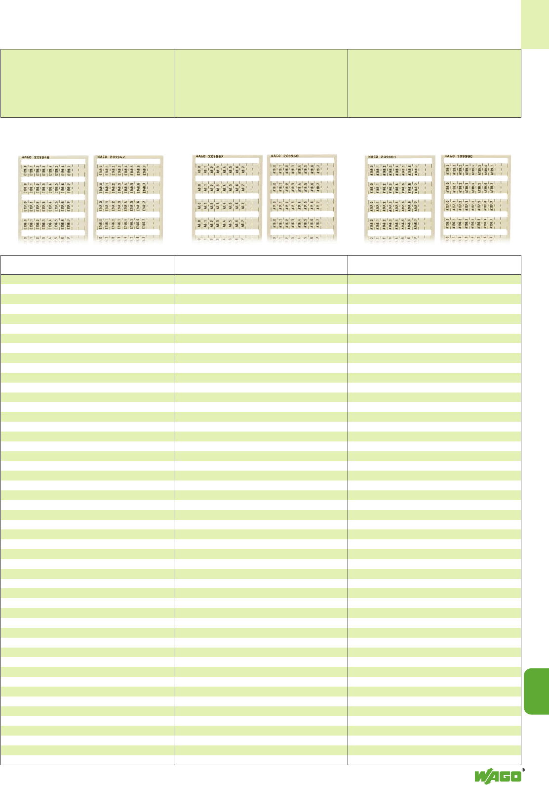
14
14
13
Vertical marking
for PLC input marking;
(continued)
10 strips with 10 markers per card
for terminal block widths
5 - 17.5 mm/0.197 in - 0.689 in
(WSB/WMB)
4 - 4.2 mm/0.157 in - 0.165 in
(WMB)
Vertical marking
for PLC output marking;
10 strips with 10 markers per card
for terminal block widths
5 - 17.5 mm/0.197 in - 0.689 in
(WSB/WMB)
4 - 4.2 mm/0.157 in - 0.165 in
(WMB)
Vertical marking
for PLC output marking;
(continued)
10 strips with 10 markers per card
for terminal block widths
5 - 17.5 mm/0.197 in - 0.689 in
(WSB/WMB)
4 - 4.2 mm/0.157 in - 0.165 in
(WMB)
Marking Item Pack.-unit
per card No. pcs
Marking Item Pack.-unit
per card No. pcs Marking Item Pack.-unit
per card No. pcs
for PLC input marking
E130.0, E130.1, E130.2, E130.3, E130.4, E130.5,
E130.6, E130.7, , ; to
E139.0, E139.1, E139.2, E139.3, E139.4, E139.5,
E139.6, E139.7, , ; (1 each)
209-946 5 cards
same as above, however
E140.0 to E149.7 (1 each)
209-947 5 cards
E150.0 to E159.7 (1 each)
209-948 5 cards
E160.0 to E169.7 (1 each)
209-949 5 cards
E170.0 to E179.7 (1 each)
209-950 5 cards
E180.0 to E189.7 (1 each)
209-959 5 cards
E190.0 to E199.7 (1 each)
209-960 5 cards
E200.0 to E209.7 (1 each)
209-961 5 cards
E210.0 to E219.7 (1 each)
209-962 5 cards
E220.0 to E229.7 (1 each)
209-963 5 cards
E230.0 to E239.7 (1 each)
209-964 5 cards
E240.0 to E249.7 (1 each)
209-965 5 cards
E250.0 to E259.7 (1 each)
209-966 5 cards
for PLC output marking
A0.0, A0.1, A0.2, A0.3, A0.4, A0.5, A0.6, A0.7, , ;
to
A9.0, A9.1, A9.2, A9.3, A9.4, A9.5, A9.6, A9.7, , ; (1 each)
209-967 5 cards
same as above, however
A10.0 to A19.7 (1 each)
209-968 5 cards
A20.0 to A29.7 (1 each)
209-969 5 cards
A30.0 to A39.7 (1 each)
209-970 5 cards
A40.0 to A49.7 (1 each)
209-971 5 cards
A50.0 to A59.7 (1 each)
209-972 5 cards
A60.0 to A69.7 (1 each)
209-973 5 cards
A70.0 to A79.7 (1 each)
209-974 5 cards
A80.0 to A89.7 (1 each)
209-975 5 cards
A90.0 to A99.7 (1 each)
209-976 5 cards
A100.0 to A109.7 (1 each)
209-977 5 cards
A110.0 to A119.7 (1 each)
209-978 5 cards
A120.0 to A129.7 (1 each)
209-979 5 cards
continued in next column
for PLC output marking
A130.0, A130.1, A130.2, A130.3, A130.4, A130.5,
A130.6, A130.7, , ; to
A139.0, A139.1, A139.2, A139.3, A139.4, A139.5,
A139.6, A139.7, , ; (1 each)
209-980 5 cards
same as above, however
A140.0 to A149.7 (1 each)
209-981 5 cards
A150.0 to A159.7 (1 each)
209-982 5 cards
A160.0 to A169.7 (1 each)
209-983 5 cards
A170.0 to A179.7 (1 each)
209-984 5 cards
A180.0 to A189.7 (1 each)
209-985 5 cards
A190.0 to A199.7 (1 each)
209-986 5 cards
A200.0 to A209.7 (1 each)
209-987 5 cards
A210.0 to A219.7 (1 each)
209-988 5 cards
A220.0 to A229.7 (1 each)
209-989 5 cards
A230.0 to A239.7 (1 each)
209-990 5 cards
A240.0 to A249.7 (1 each)
209-991 5 cards
A250.0 to A259.7 (1 each)
209-992 5 cards
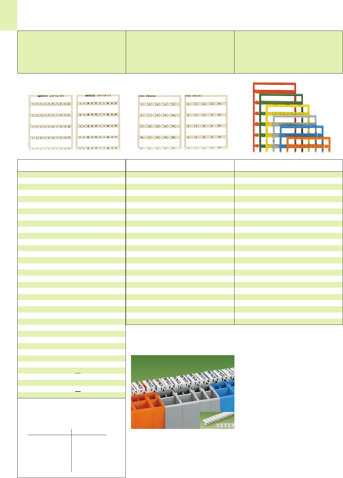
14
14
Miniature WSB Quick Marking System Mini-WSB➊
WAGO Multi Marking System WMB➊
for Terminal Blocks with Miniature WSB Marker Receptacles
Horizontal marking
Consecutive letters/symbols
each strip
10 strips with 10 markers for each card
ex. for 2-conductor terminal blocks
Series 264
Horizontal marking
Consecutive letters/symbols
each strip
10 strips with 10 markers for each card
ex. for 4-conductor terminal blocks
Series 264
Colored marker cards
Horizontal marking
Additional item-numbers
10 strips with 10 markers for each card
ex. for 2- and 4-cond. terminal blocks
Series 264
Marking Item Pack.-unit
per card No. pcs
Marking Item Pack.-unit
per card No. pcs Color Item
No.
1, , 2, , 3, , 4, , 5, ;
to
46, , 47, , 48, , 49, , 50, ; (1 each)
264-900 5 cards
U, , V, , W, , N, , PE, ; (10x)
264-901 5 cards
L1, , L2, , L3, , N, , PE, ; (10x)
264-902 5 cards
1, , 1, , 1, , 1, , 1, ; (10x)
264-903 5 cards
2, , 2, , 2, , 2, , 2, ; (10x)
264-904 5 cards
3, , 3, , 3, , 3, , 3, ; (10x)
264-905 5 cards
Colored marker cards
All markings stated opposite are also available with
black printing on colored marker cards.
Add. item-No. for colored marker cards
yellow . . ./000-002
red . . ./000-005
blue . . ./000-006
grey . . ./000-007
orange . . ./000-012
light green . . ./000-017
green . . ./000-023
violett . . ./000-024
Ordering example
Marking 41 . . . 50 on yellow card
248-506/000-002
Note:
Please note that colored marker cards are normally on
longer delivery and more expensive than standard
cards.
WAGO T Marker Tag
The T marker tag can be used with:
●series 264 modular terminal blocks and termi-
nal strips
and
●series 270 sensor and actuator terminal blocks
30 markers per tag, suitable for terminal block
widths from 5 mm/0.197 in to 6 mm/0.236 in,
Each marker can be marked with up to 6 charac-
ters
plain 209-290 50 pieces
Pre-printed markers on request
6 characters per marker
The new T marker tag fulfills the customer request
for larger marking areas for series 264 terminal
strips.
The T marker can be marked with up to 6 cha-
racters per marker and is snapped into the minia-
ture WSB marker receptacle.
Terminal strips in any combination of 2- and
4-conductor terminal blocks can be marked
without difficulty by stretching the tag.
1 . . . 10 (10x) 248-502 5 cards
11 . . . 20 (10x) 248-503 5 cards
21 . . . 30 (10x) 248-504 5 cards
31 . . . 40 (10x) 248-505 5 cards
41 . . . 50 (10x) 248-506 5 cards
51 . . . 60 (10x) 248-569 5 cards
61 . . . 70 (10x) 248-570 5 cards
71 . . . 80 (10x) 248-571 5 cards
81 . . . 90 (10x) 248-572 5 cards
91 . . . 100 (10x) 248-573 5 cards
1 . . . 50 (2x) 248-566 5 cards
U, V, W, N , P E , U, V, W, N , P E; (10 x)
248-474 5 cards
L1, L2, L3, N, PE, L1, L2, L3, N, PE; (10x)
248-472 5 cards
plain, 209-501 5 cards
for self-
marking
Marking pen 210-110 1
with fibre tip,
for permanent marking
Exemple
Marking Mini-WSB card WMB rigid
51 . . . 100 248-507 793-507
F1 . . . F10 249-615 794-615
Marking Mini-WSB card WMB 5-5,2
51 . . . 100 248-507 793-5507
F1 . . . F10 249-615 794-5615
➊All WSB cards shown on pages 14.9 to 14.11 are
also available as WMB cards with the same suffix.
Item no. see table:
WSB WMB
rigid
209- . . . 793- . . .
249- . . . 794- . . .
stretchable 5 – 5.2 mm
209- . . . 793- 5 . . .
249- . . . 794- 5 . . .
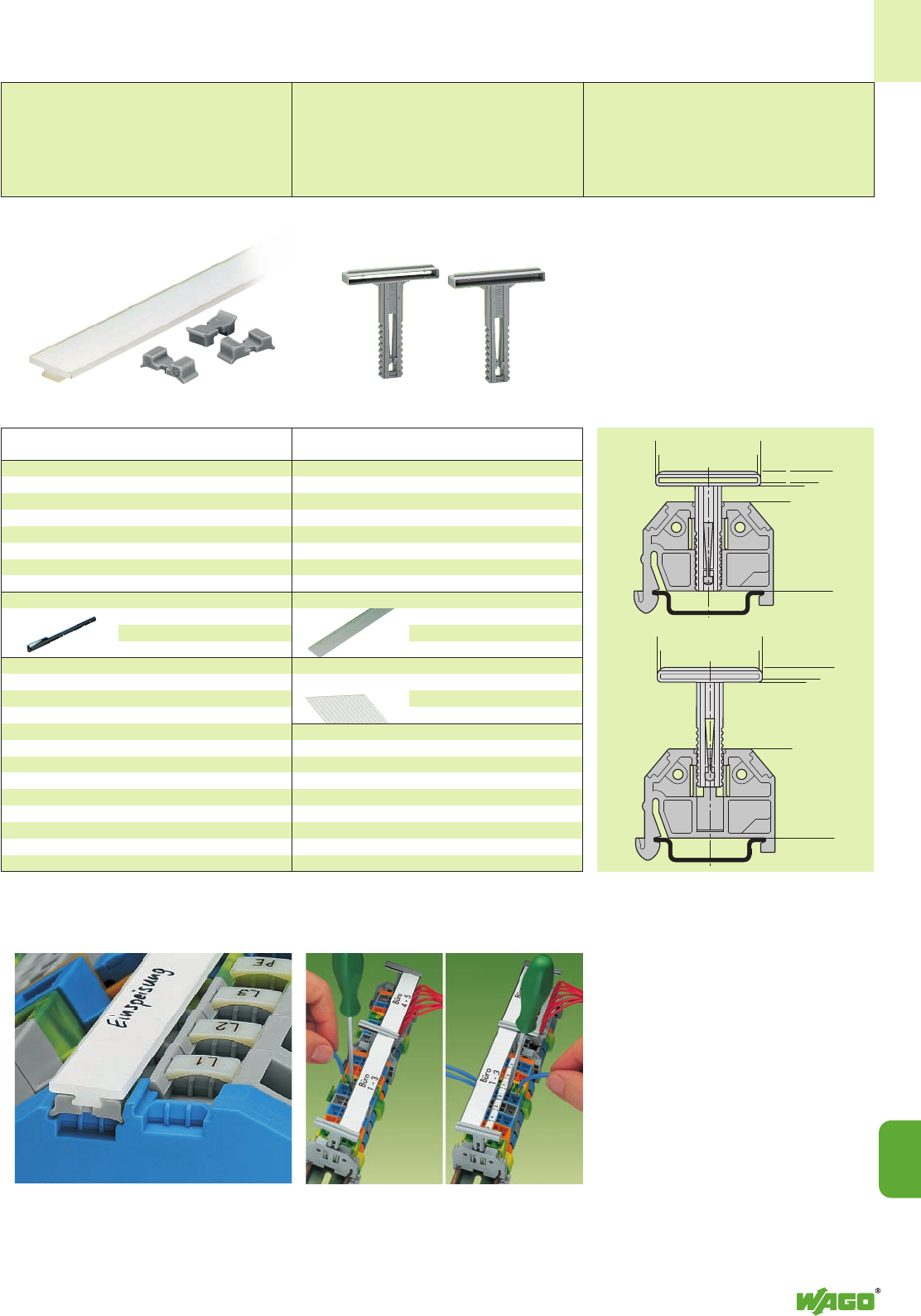
<_______31 _______>
<________33_______>
<______________53,6_____________>
<______________50_____________>
<______________49____________>
<Max = 21>
<_______31 _______>
<________33_______>
<_________37,6 ________>
<_________34_______>
<_________33______>
Min = 5
<________>
➊
➋
14
14
15
Adapter for WFB Continuous marker strips to be fixed
on every 10th terminal block approx.
WFB Continuous Marking Stips,
Vertically Movable Marking System
WFB Continuous marking strips
for self-marking and
Adapters for snap-in fixing
into the marker receptacles
Laterally movable marking system
Item Pack.-unit
No. pcs
WFB Continuous marking strips,
for self-marking for ex. with fibre tip marking pen
length 1000 mm /3.3’’ 210-612 10 (10 x 1)
Adapter for WFB Continuous marking strips,
for snap-in fixing into the marker receptacle
209-185 200 (8 x 25)
Fibre tip marking pen,
for permanent marking
210-110 1
Item Pack.-unit
No. pcs
Examples of marking
This system can be used as an additional group
marker carrier or continuous marking strip carrier
for terminal strips or rail-mounted single deck
terminal blocks, for example for series:
●terminal strips, series 264, for DIN 35 rails
●rail-mounted single deck terminal blocks,
series 279 to 284, with a maximum height of
49 mm /1.93 in from the upper edge of the
carrier rail (please allow also for the conductor
radius)
Carrier-through element,
adjustable in height
grey 709-118 ➊50 (2 x 25)
Carrier-end element,
adjustable in height
grey 709-119 ➋50 (2 x 25)
Receptacle for marking strips,
transparent, folded,
1 m long,16 mm wide,1.7 mm thick
709-120 1
Marking card, with 14 marking strips,
DIN-A-4, plain
709-193 1
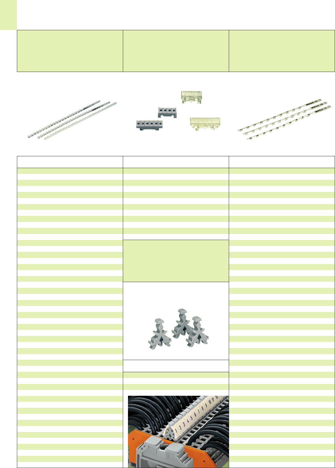
➊
➋
➌
➍
14
16
Item Pack.-unit
No. pcs
WSB Double marker carrier, 4 mm/0.157 in wide
suitable for all WSB and WMB marking systems
209-128 100
Marking Item Pack.-unit
per branch No. pcs
Item Pack.-unit
No. pcs
Marking Item Pack.-unit
per tag No. pcs
WAGO WSB Double marker carriers
Marker Tags,
Marker Carriers and
Marker Branches
WAGO marker tags
Horizontal marking
Identical numbers/letters each tag
20 markers per tag
WAGO marker carriers
for marker tags WAGO marker branches
Horizontal marking
Identical numbers/letters
each branch
10 markers per branch
for terminal block widths
4 – 17.5 mm / 0.157 – 0.689 in
plain 209-800 10 tags
1209-801 10 tags
2209-802 10 tags
3209-803 10 tags
4209-804 10 tags
5209-805 10 tags
6209-806 10 tags
7209-807 10 tags
8209-808 10 tags
9209-809 10 tags
0209-810 10 tags
A209-823 10 tags
B209-824 10 tags
C209-825 10 tags
D209-826 10 tags
E209-811 10 tags
F209-812 10 tags
G209-813 10 tags
H209-827 10 tags
I209-828 10 tags
J209-829 10 tags
K209-830 10 tags
L209-814 10 tags
M209-831 10 tags
N209-815 10 tags
O209-832 10 tags
P209-816 10 tags
Q209-833 10 tags
R209-834 10 tags
S209-835 10 tags
T209-836 10 tags
U209-817 10 tags
V209-818 10 tags
W209-819 10 tags
X209-820 10 tags
Y209-821 10 tags
Z209-822 10 tags
+209-837 10 tags
—209-838 10 tags
Quadruple marker carrier
209-115 ➊100
Sextuple marker carrier
209-116 ➋100
(see also page 14.7)
Quadruple transparent marker carrier ➌
209-125 100
Sextuple transparent marker carrier ➍
not for center marking
209-126 100
plain 209-300 10 branches
1209-301 10 branches
2209-302 10 branches
3209-303 10 branches
4209-304 10 branches
5209-305 10 branches
6209-306 10 branches
7209-307 10 branches
8209-308 10 branches
9209-309 10 branches
0209-310 10 branches
A209-323 10 branches
B209-324 10 branches
C209-325 10 branches
D209-326 10 branches
E209-311 10 branches
F209-312 10 branches
G209-313 10 branches
H209-327 10 branches
I209-328 10 branches
J209-329 10 branches
K209-330 10 branches
L209-314 10 branches
M209-331 10 branches
N209-315 10 branches
O209-332 10 branches
P209-316 10 branches
Q209-333 10 branches
R209-334 10 branches
S209-335 10 branches
T209-336 10 branches
U209-317 10 branches
V209-318 10 branches
W209-319 10 branches
X209-320 10 branches
Y209-321 10 branches
Z209-322 10 branches
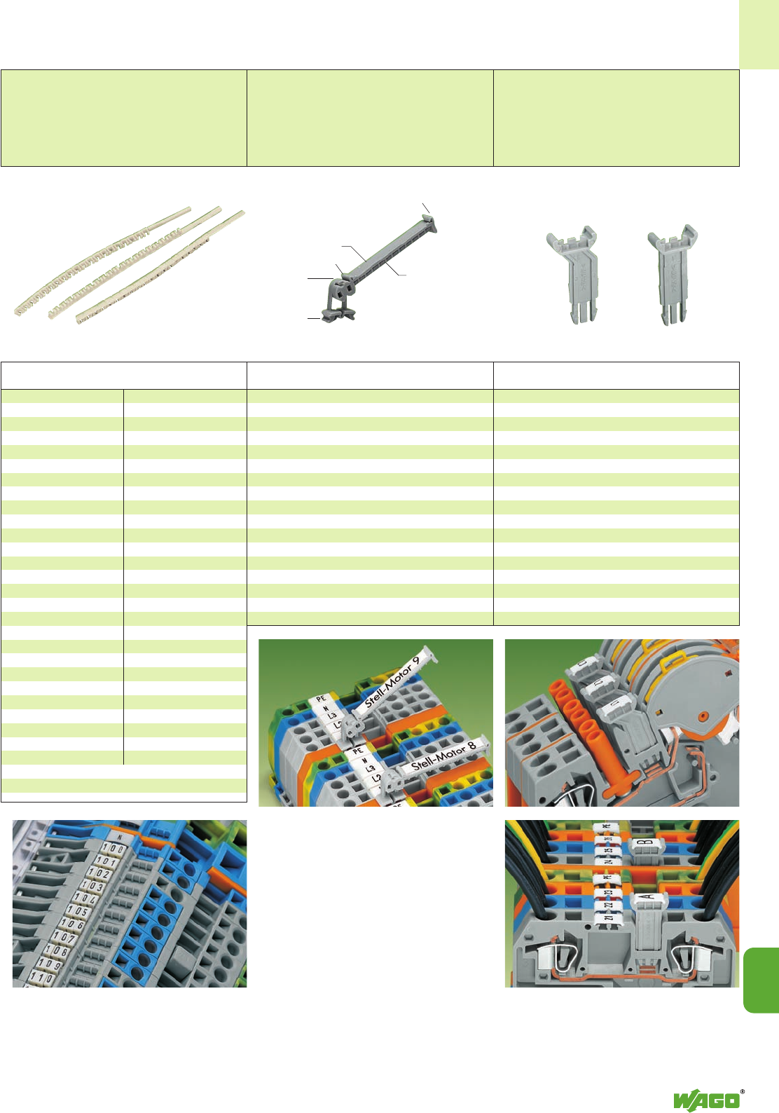
<__________ 35 _________>
<_11*_>
14
14
17
Level b
Level a
WAGO pivotable group marker carrier
– for rail-mounted terminal blocks from
5 mm/0.197 in on
and in spacer housings
WAGO group marker carriers
for terminal block series 282
Item Pack.-unit
No. pcs Item Pack.-unit
No. pcs
Pivotable group marker carrier
249-105 50
Marker card, 4 x 30 pcs per sheet
209-183 1 sheet
Protection cover, transparent
209-184 50
This pivotable group marker carrier has been
developed for group marking of rail-mounted
terminal blocks and brings together many requi-
rements of our customers.
●Can be used in all multiprofile marker
receptacles for rail-mounted terminal bocks
from 5 mm width on or in spacer housings as
shown in the picture
●Pivotable in 7 different stable positions, pro-
viding the best visual angle in case of difficult
mounting conditions
●Two levels for different marking systems
Level a:
for marker card (4 x 34) mm (see picture)
Level b:
for 12 WCB-Combi markers
(see left column)
* from upper edge of terminal block
The group marker carriers are available in two diffe-
rent versions:
– angled, for example for transformer terminal blocks
(picture below top)
209-144 50
– straight, for example for 2- and 3-conductor
terminal blocks (picture below bottom)
209-143 50
Appropriate marking systems:
WSB, WMB and WCB
The new group marker carriers make it possible
to mark subgroups in confined places.
These group marker carriers can be snapped into
the jumper contact positions of the terminal block
housing.
WCB Combi Marking System and
Group Marker Carrier
WCB Combi marking system
20 markers with identical
numbers/letters each tag
Marking Item Marking Item
per tag No. per tag No.
plain 249-200
1 (20x) 249-201
2 (20x) 249-202
3 (20x) 249-203
4 (20x) 249-204
5 (20x) 249-205
6 (20x) 249-206
7 (20x) 249-207
8 (20x) 249-208
9 (20x) 249-209
0 (20x) 249-210
1 . . . 0 (2x) 249-239
1. (20x) 249-241
2. (20x) 249-242
3. (20x) 249-243
4. (20x) 249-244
5. (20x) 249-245
6. (20x) 249-246
7. (20x) 249-247
8. (20x) 249-248
9. (20x) 249-249
0. (20x) 249-250
+ (20x) 249-237
— (20x) 249-238
A (20x) 249-211
B (20x) 249-212
C (20x) 249-213
D (20x) 249-214
E (20x) 249-215
F (20x) 249-216
G (20x) 249-217
H (20x) 249-218
I (20x) 249-219
J (20x) 249-220
K (20x) 249-221
L (20x) 249-222
M (20x) 249-223
N (20x) 249-224
O (20x) 249-225
P (20x) 249-226
Q (20x) 249-227
R (20x) 249-228
S (20x) 249-229
T (20x) 249-230
U (20x) 249-231
V (20x) 249-232
W (20x) 249-233
X (20x) 249-234
Y (20x) 249-235
Z (20x) 249-236
Pieces per packing unit: 10 tags
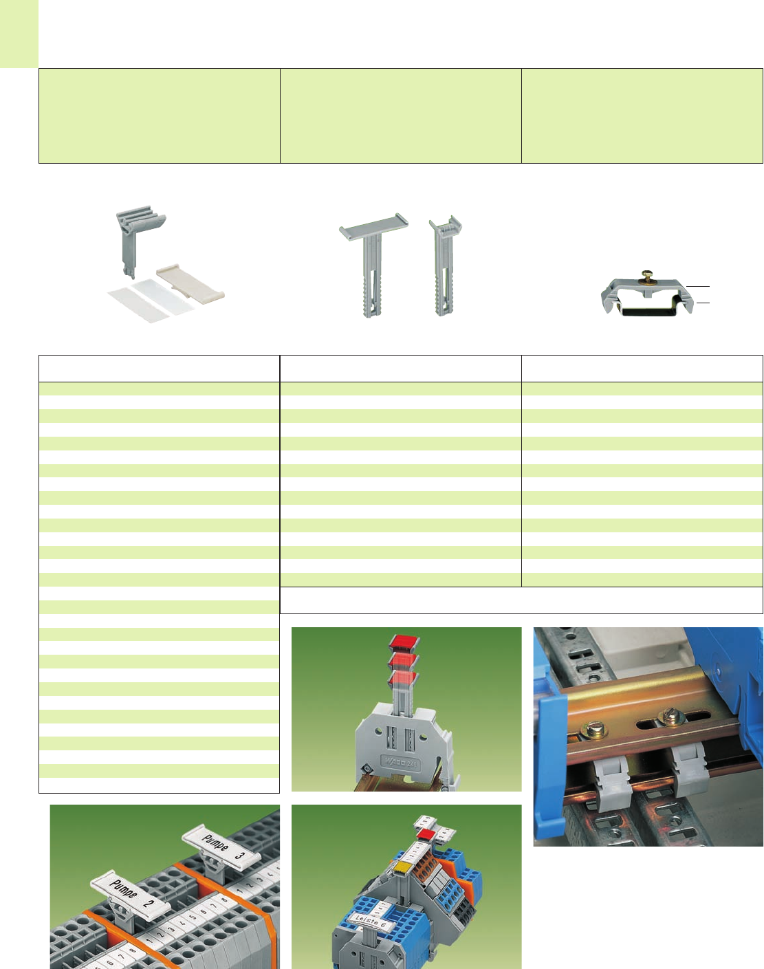
➋
➊
➊
➋➌
➍
14
18
<>
Item Pack.-unit
No. pcs
Application notes
Group Marker Carriers and
Mounting Carrier
Mounting carrier
for isolated mounting on rail
Mounting carrier,
for isolated mounting on DIN 35 rail
209-106 25
Isolated mounting of a carrier rail in a distribution
box for protection class 2.
Here shown with rail-mounted terminal blocks.
<__________ to 60 mm / __________>
2.36 in
Adjustable height group marker carriers
Item Pack.-unit
No. pcs
Adjustable height group marker carriers,
suitable for end stops 249-116 and 249-117
(see page 14.19)
for 1 marker card or self-adhesive label and transpa-
rent cover protection (see on the left)
249-119 ➊50 (2 x 25)
for 2 WSB Quick markers each,
3 WCB Combi markers
or
1 x continuous marking strip
249-118 ➋100 (4 x 25)
Receptacles for:
1 x marker card
2 x WSB (Quick marking) or
3 x WCB (Combi marking) or
1 x WFB (Continuous marking strips)
WAGO group marker carriers
Item Pack.-unit
No. pcs
Group marker carrier, for snapping into screwless end
stops, 10 mm /0.394 in wide, for center or side mounting
209-112 ➊50
Marker card . . ., from white cardboard,
for self-marking, 100 markers per sheet
209-113 ➋1 sheet
. . . or self-adhesive label,
for self-marking, 7 x 25 pcs per sheet
210-345 ➋1 sheet
Protection cover, transparent
209-114 ➌50
Group marker carrier, for jumper contact slots
of rail-mounted terminal blocks, for terminal block
widths 4 – 8 mm /0.157 – 0.315 in
for up to 3 WMB Markers or 8 branch markers,
15 mm /0.591 in wide
209-140 ➍50
for up to 2 WMB Markers or 5 branch markers,
10 mm /0.394 in wide
209-141 ➍50
for 1 WMB Marker or 2 branch markers,
5 mm /0.197 in wide
209-142 ➍50
7.2 mm /
0.28 in
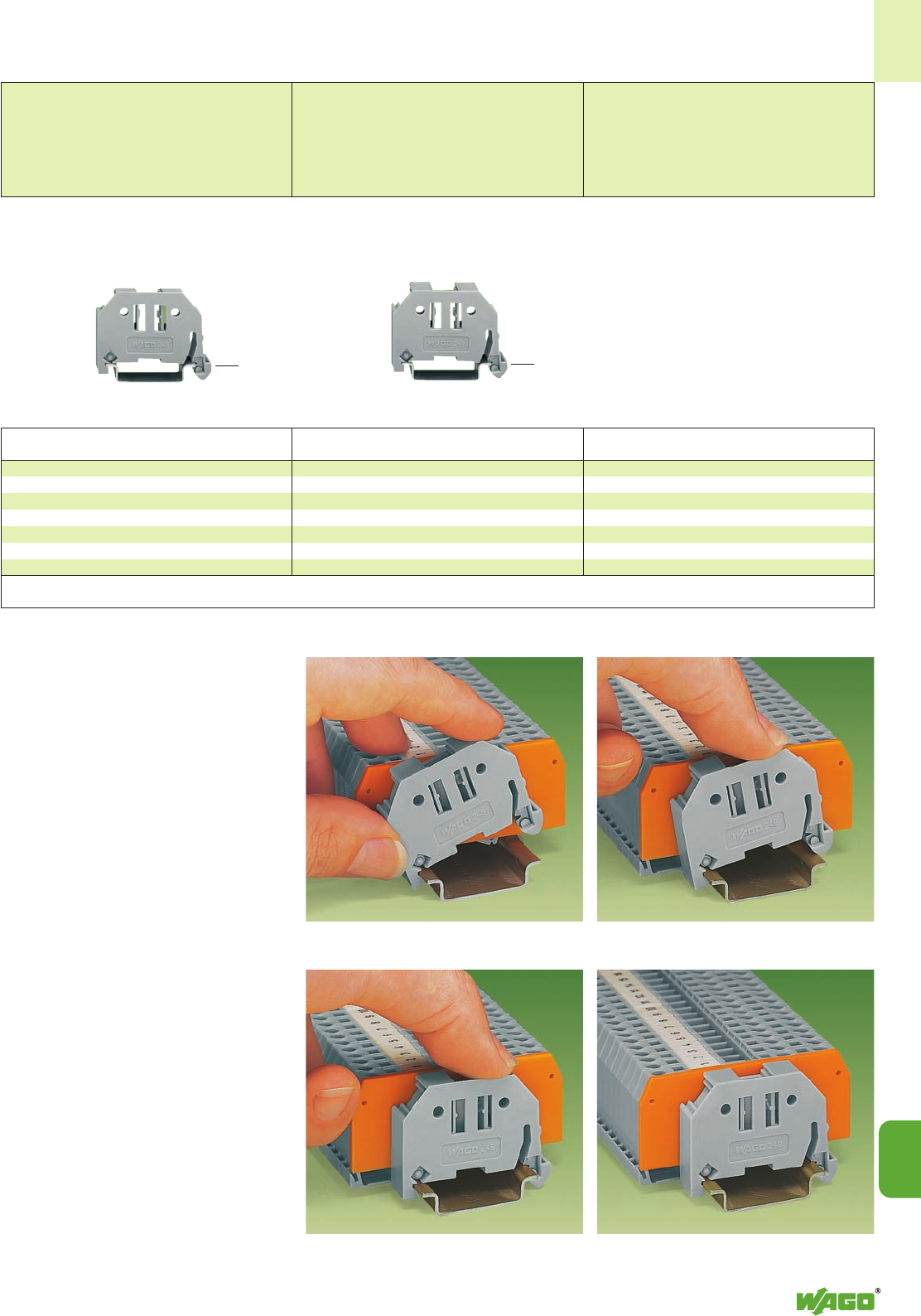
14
14
19
<__ 28 mm /__>
1.10 in
<__ 45 mm /1.77in __>
End Stop for DIN 35 Rail
End stop for DIN 35 rail,
End stop width 6 mm / 0.236 in End stop for DIN 35 rail,
End stop width 10 mm / 0.394 in
Fit – and forget! Assembling the new
WAGO screwless end stop is as simple and
quick as snapping a WAGO rail-mounted
terminal block onto the rail.
Without any tools!
This way rail-mounted terminal blocks
are safely secured, at low cost, against any
movement on all carrier rails DIN 35 acc. to
DIN EN 50022 (35 x 7.5 mm; 35 x 15 mm).
Entirely without screws!
The “secret” of the excellent tight fit lies in the
two small clamping plates which keep the end
stop in position, even if the rails are mounted
vertically.
Simply snap on and forget!
In addition, costs are considerably reduced
when using large numbers of end stops.
A further advantage is that three marker
receptacles for all WAGO marker systems for
rail-mounted terminal blocks and a snap-in
hole for WAGO adjustable height group
marker carriers offer individual marking
possibilities.
Item Pack.-unit
No. pcs
Item Pack.-unit
No. pcs
End stop, for DIN 35 rail
10 mm /0.394 in wide
249-117 50 (2 x 25)
End stop, for DIN 35 rail
6 mm /0.236 in wide
249-116 100 (4 x 25)
Application notes
Snap on . . .
. . . that’s it!
<__ 28 mm /__>
1.10 in
<__ 45 mm /1.77in __>
14
20
14
20
14
20
14
20
ProServe
No sooner said than done. ProServe®.
Service that simply works.
WAGO ProServe®
No sooner said than done. õ.
Service that simply works.
The benefits of ProServe are
at your disposal every day.
With unique features such as
accuracy checking, ProServe
does a lot of the work for you,
therefore saving you time and
money. Immediate access to
professional and sophisticated
services allows for error-free
applications, higher flexibility in
your daily business and better
customer service. With more
than 50 years of WAGO exper-
tise at your disposal, put ProSer-
ve to work for you in your next
application.
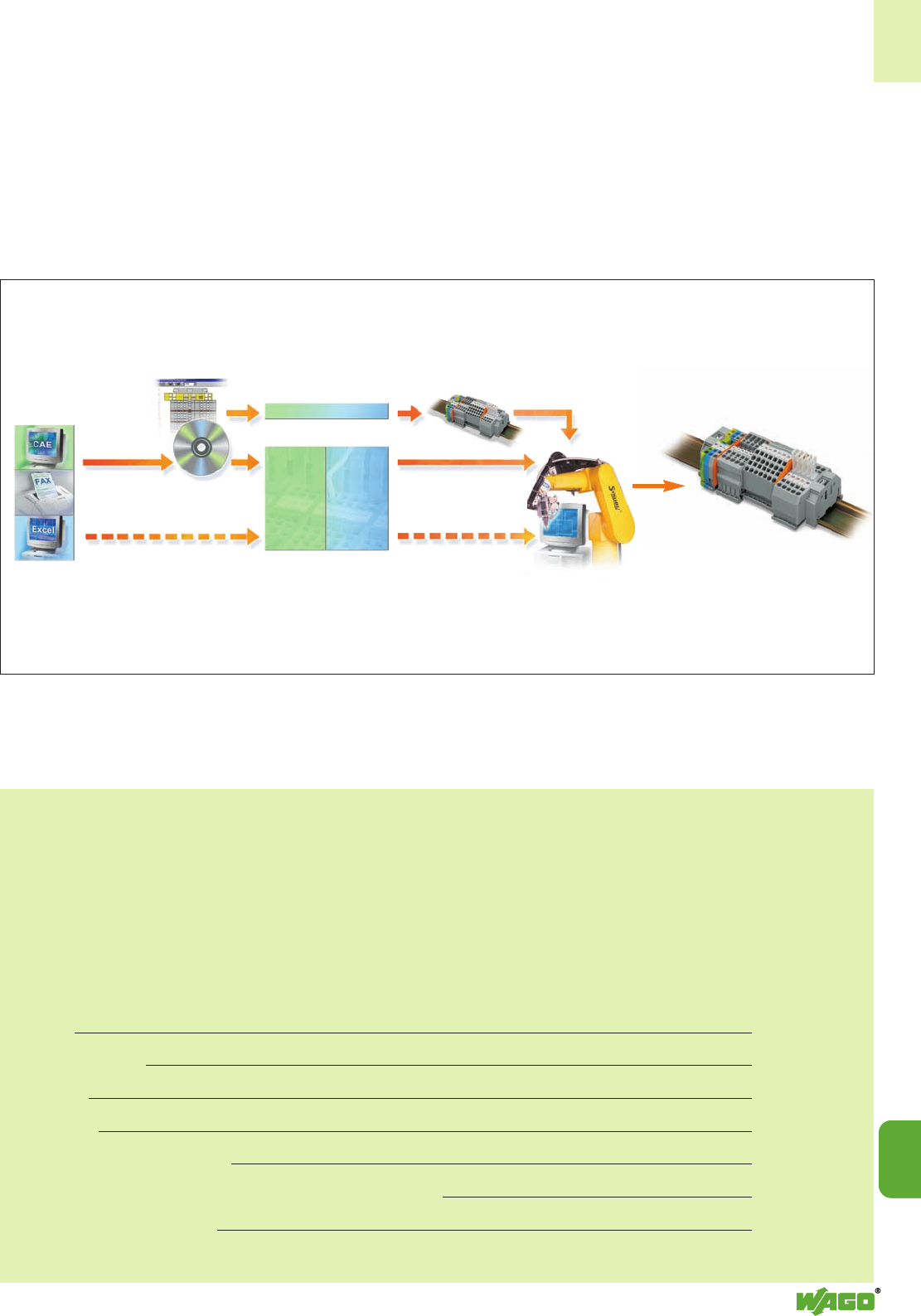
14
14
21
14
14
21
ASSEMBLY Service
Terminal block lists
Custom rail
ready for installation
Wiring with
CC-Matic®
Wire lists
DDS-C®
cabinet
layout
Data pre-
paration for
CC-Matic®
From the circuit diagram to automated wiring.
CONTENTS
ProServe
Page
Services 14.22
Software package 14.23
Hardware 14.24 – 14.25
Accessories 14.26
Markings/marking accessories 14.27
Matrix of devices supported by the ProServe marking service 14.28 – 14.29
Data sheets (printers/plotter) 14.30 – 14.34
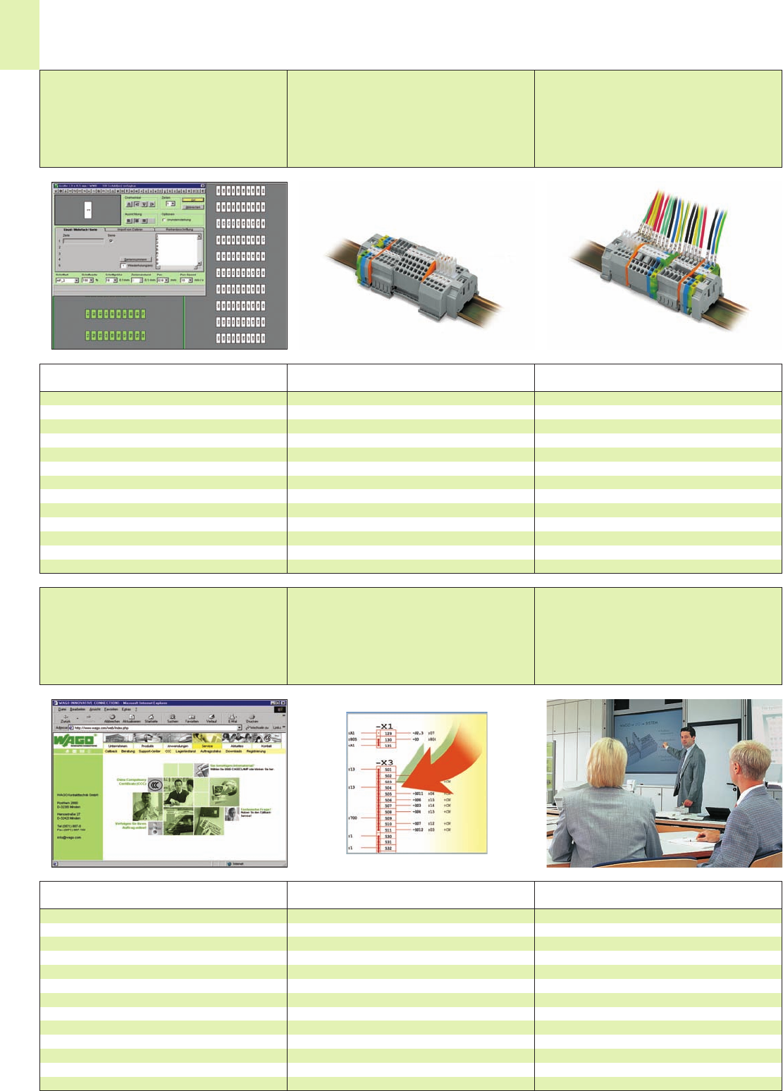
14
22
Description Description
Services
Marking service Assembly service for custom rail
assemblies
Wiring service
Special markings often require considerable manual
work. WAGO smartMARKING helps you minimize this
work and optimize the quality of the markings.
Simply send us your specifications.
We will do the rest.
by fax
via e-mail
via ProServe Software
The WAGO ProServe wiring service turns the custom
rail, ready for installation in a switchgear cabinet, into
a wired custom rail ready for connection.
Simply send us your specifications.
We will do the rest.
by fax
via e-mail
via ProServe Software
DescriptionDescription Description
www.wago.com Macros Training
Support-Center
Call-Back Service
Online Info Service
Online Catalog
www.wagocatalog.com
Product macros, i.e. completed product "drawings",
make CAD/CAE drawing faster and easier. The
EPLAN software version 5.4 includes macro data of
the WAGO-I/O-SYSTEM 750 for circuit diagrams,
plans and graphics. They can be easily incorporated
into the design process in much the same way custom
rail assemblies are installed in a switchgear cabinet.
Free update service at: www.wago.com
(Service/Downloads/Software/CAD/CAE)
WAGO smartDESIGNER
WAGO smartMARKING
WAGO productLOCATOR
WAGO seminars help you work optimally with innova-
tive products in a very short time. You will mainly learn
by doing without unnecessary teaching. The training
will have a cost saving effect for you by reducing the
time needed to effectively use our intelligent products.
Time is money!
Please register at www.wago.com/wagoweb/usa/
eng/service/training/index.htm
Description
Reduce your inventory and part numbers for WAGO
terminal blocks and accessories to a single part num-
ber: Rail assemblies ready for installation!
Simply send us your specifications.
We will do the rest.
by fax
via e-mail
via ProServe Software
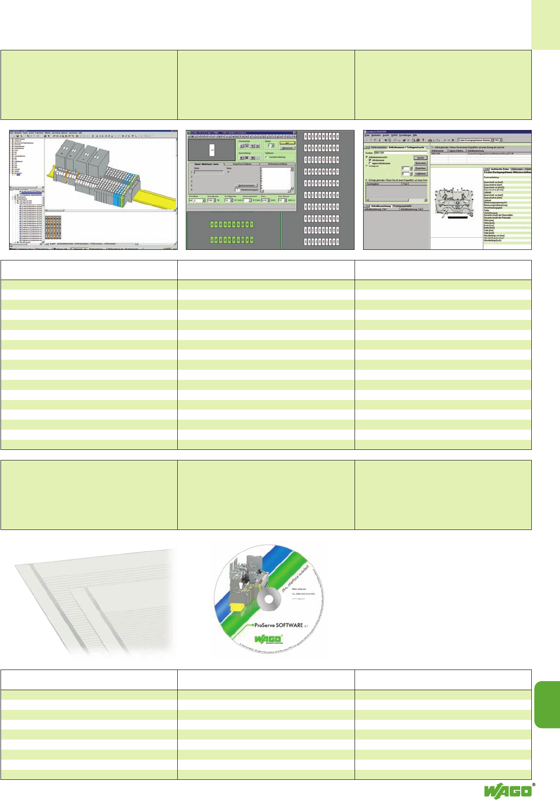
14
14
23
Description
Software Package
WAGO smartDESIGNER WAGO smartMARKING WAGO productLOCATOR
Innovative WAGO ProServe design service
Features overview:
Interactive 3D design of:
terminal blocks, connectors, PCB terminal blocks,
WAGO%SYSTEM, ELECTRONICC
Possibility of using your own custom part numbers
Intelligent, accuracy check feature
(AutoAudit function)
Data exchange with CAE, XLS, etc.
Creation of individual project libraries in addition to
the WAGO standard libraries
Possibility of designing and printing the marking
directly
13 languages
Updates via the Internet
Description
WAGO marker cards –
Simplification of terminal block markings.
WAGO SCRIPT helps you minimize the cost of custom
marking and optimize printing results.
WYSIWYG marking
Automatic calibration of the plotter
Import data from various CAE systems,
MS-Excel, WAGO smartDESIGNER
Marker cards for marking tag type:
WSB, miniature WSB, WTB, WMB etc.
with custom marking and competitor’s marking
Electronic symbol library
Text length check feature
13 languages
Updates via the Internet
Description
Full-function product search:
Interactive access to over 12,000 part numbers
Search by product groups or item numbers
Search by keywords or technical data
Import of custom part numbers
Create part lists with a single mouse-click
13 languages
Updates via the Internet
Description
ProServe SOFTWARE
Item No. 0888-0402/. . .
The software package includes:
WAGO smartDESIGNER
WAGO smartMARKING
WAGO productLOCATOR
WAGO wireLINK
Description Item
No.
Adhesive marker strips on cards DIN A4
pin spacings strips
can be chosen per card
Strip height 2.3 mm 100 x 210-331
Strip height 3 mm 80 x 210-332
Strip height 5 mm 48 x 210-334
Strip height 6 mm 40 x 210-333
Strip height 9 mm 40 x 210-335
Strip length 182 mm
Marking cards
(plain)
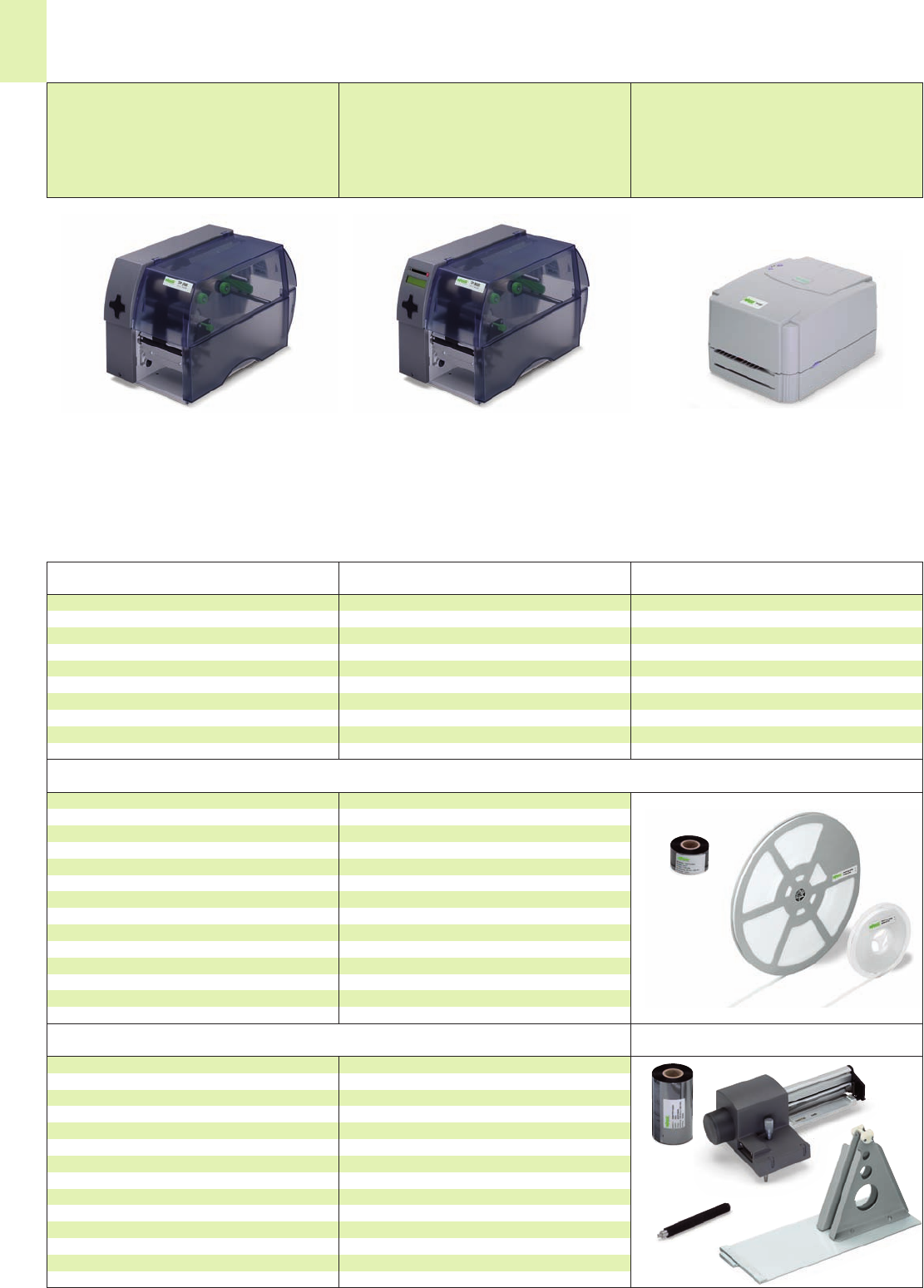
14
24
Description Item
No.
Description Item
No. Description Item
No.
Hardware
Thermal transfer printer TP 300Thermal transfer printers TP 298 Thermal transfer printer TP 297
Thermal transfer printer, TP 300 258-300
Resolution 300 dpi
– technical data on page 14.30
ProServe Software included
Thermal transfer printer, TP 298 258-298
Resolution 300 dpi, without display
– technical data on page 14.32
ProServe Software included
Thermal transfer printer, TP 297 258-297
Resolution 203 dpi, without display
– technical data on page 14.33
ProServe Software included
The printers are suitable for printing thermal transfer labels, cable markers, type labels, heat shrink tubes,
barcodes, etc.
Furthermore, they can be used to print marker strips of both TOPJOB®S and 870, 869, 862 as well as 270 series.
For exceptional print quality, the printers offer all the advantages and benefits of the thermal transfer technology.
For more information see data sheets beginning on page 11.16
Accessories required for the marking of marker strips
Ink ribbon for marker strips 258-145
resin, width 38 mm x 300 m
Optional accessories
Ink ribbon for labels
resin/wax, width 60 mm x 300 m 258-143
resin/wax, width 100 mm x 300 m 258-144
External coil mounting system 258-169
for 300 m rolls
Cutter
TP 298/300 258-161
Spare roller 258-162
Network card for TP 300 258-163
USB card for TP300 258-164
Label dispenser 258-165
Marker strips for series ...
... TOPJOB®S white, plain, width 11 mm,
50 m roll 2009-110
300 m roll 2009-130
... 870, 869, 862, 270
white, plain, width 7.5 mm
50 m roll 709-178
300 m roll 709-188
translucent, plain, width 7.5 mm
50 m roll 709-177
300 m roll 709-187
Carrying case for TP 300/298 258-171
Carrying case for TP 297 258-172
Retractable handle 258-173
for carrying case
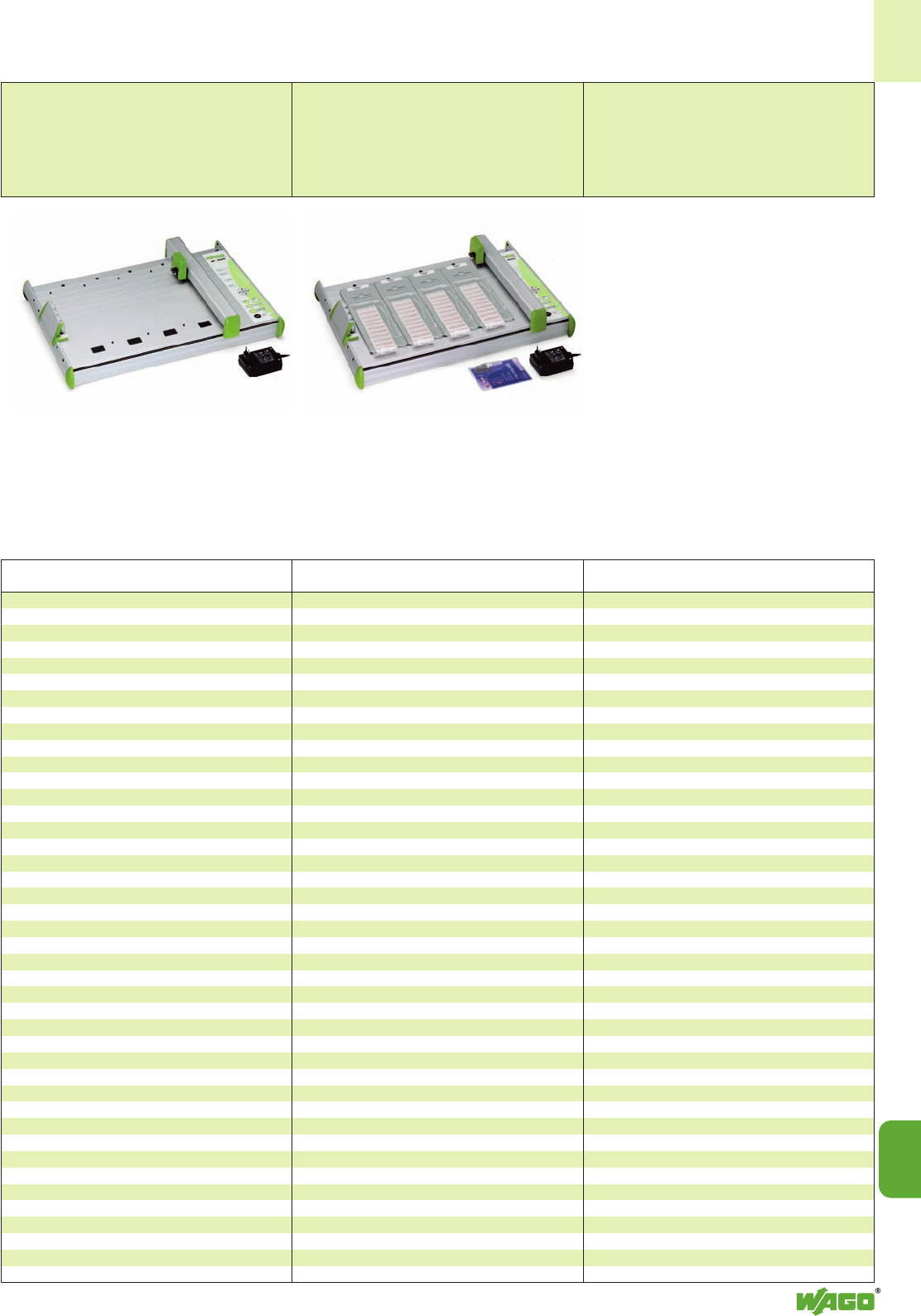
14
14
25
Plotter Full plotter package
Description Item
No.
Plotter IP 350 258-350
including power supply and centronics cable,
– technical data see page 14.34
WAGO plotter pen (shown page 11.12)
Line width 0.18 mm 258-226
Line width 0.25 mm 258-227
Line width 0.35 mm 258-228
Line width 0.50 mm 258-229
WAGO plotter pen (disposable)
Line width 0.25 mm 258-327
Line width 0.35 mm 258-328
WAGO cleaning set (shown page 11.12)
258-139
WAGO pen cleaner (shown page 11.12)
258-140
WAGO
i
nk cartridges
(
shown page 11.12
)
black, for permanent marking, not refillable (5 x 1 ml)
258-141
Carrier plate for Plotter IP 350 (shown page 11.12)
WSB 5 mm (209-501) 258-361
WSB 4 mm (209-701) 258-362
Mini-WSB (248-501) 258-363
Group marking carriers (209-112) 258-364
WMB 5 mm (793-501) 258-368
WMB 4 mm (793-4501) 258-368
For other carrier plates see page 11.12
Marker tags
(209-200) 258-369
Marker strips
(2009-110 + 2009-130 and 709- . . .) 258-410
WMB Inline
(2009-115 + 2009-135) 258-412
Version 1 258-350/000-001
1 plotter incl. power supply and centronics cable
1 ProServe software
4 WMB carrier plates 5 mm/0.197 in
20 WMB marker cards 5 mm/0.197 in
1 plotter pen, line width 0.25 mm (disposable)
1 plotter pen, line width 0.35 mm (disposable)
Version 2 258-350/000-002
1 plotter incl. power supply and centronics cable
1 ProServe Software
4 WSB carrier plates
20 WSB marker cards
1 plotter pen, line width 0.25 mm (disposable)
1 plotter pen, line width 0.35 mm (disposable)
Version 3 258-350/000-003
1 plotter incl. power supply and centronics cable
1 ProServe software
2 WMB (5 mm/0.197 in) carrier plates
2 miniature WSB carrier plates
10 WMB (5 mm/0.197 in) marker cards
10 miniature WSB marker cards
1 plotter pen, line width 0.25 mm (disposable)
1 plotter pen, line width 0.35 mm (disposable)
Version 4 258-350/000-004
1 plotter incl. power supply and centronics cable
1 ProServe software
1 WMB carrier plate 5 mm/0.197 in
1 WSB carrier plate 5 mm/0.197 in
1 miniature WSB carrier plate
1 WSB carrier plate 4 mm/0.157 in
5 WMB marker cards 5 mm/0.197 in
5 WSB marker cards 5 mm/0.197 in
5 miniature WSB marker cards
5 WMB marker cards 4 mm/0.157 in
1 plotter pen, line width 0.25 mm (disposable)
1 plotter pen, line width 0.35 mm (disposable)
Description Item
No.
The full plotter package, available in 4 ver-
sions, is suitable for marking any type of
WAGO marker card or competitor’s markers.
Includes the ProServe CD-ROM and WAGO
smartMARKING software.
Plotter suitable for marking any type of WAGO
marker card or competitor’s markers, including
the ProServe CD-ROM and WAGO smartMAR-
KING software.
Hardware
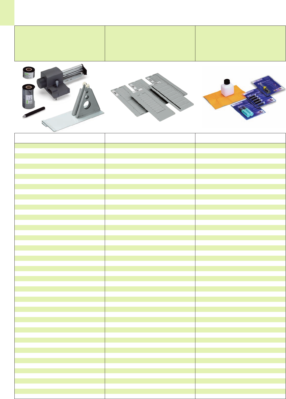
14
26
Description Item
No.
Description Item
No. Description Item
No.
Accessories
Accessories for thermal transfer printers Marker card carrier plates for
plotter IP 350
Plotter accessories
Ink ribbon for marker strips 258-145
resin, width 38 mm x 300 mm
Ink ribbon for labels
resin/wax, width 60 mm x 300 m 258-143
resin/wax, width 100 mm x 300 m 258-144
External coil mounting system 258-169
for 300 m rolls
Cutter
TP 298/300 258-161
Spare roller 258-162
Network card for TP300 258-163
USB card for TP300 258-164
Label dispenser 258-165
Carrying case for TP 300/298 258-171
Carrying case for TP 297 258-172
Retractable handle 258-173
for carrying case
Carrier plates for marker cards
WSB 5 mm/0.197 in (209-501) 258-361
WSB 4 mm/0.157 in (209-701) 258-362
Miniature WSB (248-501) 258-363
Group marking carriers (209-112 258-364
WMB 5 mm/0.197 in (793-501) 258-368
WMB 4 mm/0.157 in (793-4501) 258-368
Carrier plates for murrplastik
MP-400 258-370
KS 4/12, 4/18, 4/23, 4/30
MP-401 258-371
KES, KLG,KMR, KPX, KS 15x17/27/49/67, KSA, KSF,
KSI, KSK, KSO, KSS, KTE, KWI, SKS, WGO, KAB
BS 5/6 258-397
Carrier plates for Phoenix Contact
ZBM 258-372
ZB 258-373
ZBN 258-374
ZBFM 258-375
BNZ 258-377
BN-ZB 258-378
SS-ZB 258-379
PAB 258-381
GPE 258-382
BMK, ESL label sheets 258-383
Carrier plates for Siemens
Sirius 10 x 7, 20 x 7 258-384
22 x22 258-385
18 x28 258-386
Carrier plate for Weidmüller
MC Universal 258-387
MC SF4-6 258-388
Carrier plate for Wörtz/Allen-Bradley
Universal 258-389
Carrier plate for Möller
XB M22-XST 258-390
Carrier plate for Partex
PA+1 258-391
PA+2 258-392
PK2 PVC 258-393
Carrier plate for Entrelec
Universal 258-394
WAGO plotter pen
line width
0.18 mm/0.007 in 258-226
0.25 mm/0.010 in 258-227
0.35 mm/0.014 in 258-228
0.50 mm/0.020 in 258-229
The WAGO plotter pen is suitable for any kind of
smooth surfaces. No additional adapter is required.
WAGO plotter pen (disposable)
Line width 0.25 mm 258-327
Line width 0.35 mm 258-328
Cleaning set 258-139
suitable for cleaning all plotter pens
WAGO Pen Cleaner 258-140
WAGO ink cartridges, 258-141
black, for permanent marking,
not refillable (5 x1 ml)
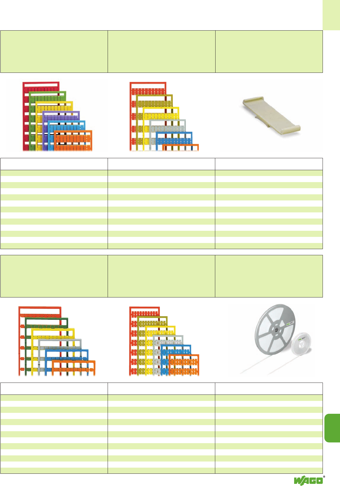
14
14
27
Description Item
No.
Description Item
No. Description Item
No.
Marking Accessories
Marker cards
(plain)
Marker cards
(plain)
Group marking carrier
Marker cards and tags
WSB 5 – 8 mm/0.197 in – 0.384 in 209-501
Additional item Nos.
for colored marker cards
yellow . . ./000-002
red . . ./000-005
blue . . ./000-006
grey . . ./000-007
orange . . ./000-012
light green . . ./000-017
green . . ./000-023
violet . . ./000-024
Marker cards and tags
WMB 5 mm/0.197 in 793-501
WMB 4 – 4.2 mm/0.157 in – 0.165 in 793-4501
WMB 5 – 5.2 mm/0.197 in – 0.205 in 793-5501
Additional item Nos. for colored marker cards
yellow . . ./000-002
red . . ./000-005
blue . . ./000-006
grey . . ./000-007
orange . . ./000-012
light green . . ./000-017
green . . ./000-023
violet . . ./000-024
Group marking carrier 209-112
for snapping into 10 mm/0.394 in wide
screwless end stops for center or side mounting
for carrier plate (258-364)
Description Item
No.
Description Item
No.
Marker cards
(plain)
Marker cards
(plain)
Marker cards and tags
Miniature WSB 248-501
Additional item Nos.
for colored marker cards
yellow . . ./000-002
red . . ./000-005
blue . . ./000-006
grey . . ./000-007
orange . . ./000-012
light green . . ./000-017
green . . ./000-023
violet . . ./000-024
Marker cards and tags
WSB 4 mm/0.157 in 209-701
Additional item Nos.
for colored marker cards
yellow . . ./000-002
red . . ./000-005
blue . . ./000-006
grey . . ./000-007
orange . . ./000-012
light green . . ./000-017
green . . ./000-023
violet . . ./000-024
Marker strips
Description Item
No.
Marker strips for series ...
... TOPJOB®S white, plain, width 11 mm,
50 m roll 2009-110
300 m roll 2009-130
... 870, 869, 862, 270
white, plain, width 7.5 mm
50 m roll 709-178
300 m roll 709-188
translucent, plain, width 7.5 mm
50 m roll 709-177
300 m roll 709-187
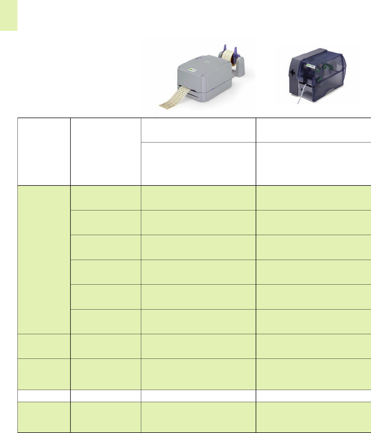
14
28 Matrix of Devices Supported by the ProServe Marking Service
Thermal transfer printer
TP 297
Thermal transfer printer
TP 298
1) suitable for series 870, 869, 862 and 270
2) suitable for the TOBJOB®S series
n.r. = not required
Version TP 297 TP 298
Printer Printer
Item No. 258-297 258-298
Marker Marker strips 7.5 mm 1)
carriers Item No. 50 m roll 709-177 709-177
Item No. 300 m roll — 709-187
Marker strips 11 mm 2)
Item No. 50 m roll 2009-110 2009-110
Item No. 300 m roll — 2009-130
WMB
Item No. — —
WSB 5 mm
Item No. — —
WSB 4 mm
Item No. — —
Miniature WSB
Item No. — —
Interfaces parallel serial
serial USB
Ethernet
Resolution
203 dpi X —
300 dpi — X
Labels X X
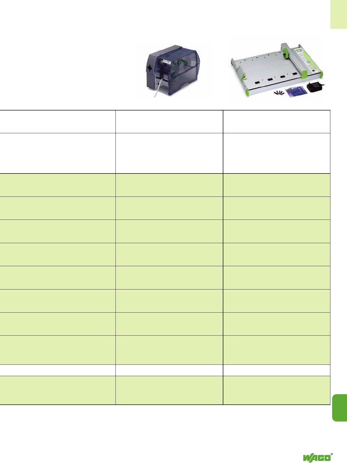
14
14
29
Thermal transfer printer
TP 300
Plotter
IP 350
TP 300 IP 350
Printer Plotter
258-300 258-350
709-177 709-177
709-187 709-187
2009-110 2009-110
2009-130 —
793-501
— 793-5401
793-5501
209-501
—209-701
— 248-501
parallel parallel
serial USB
—n.r.
X
X
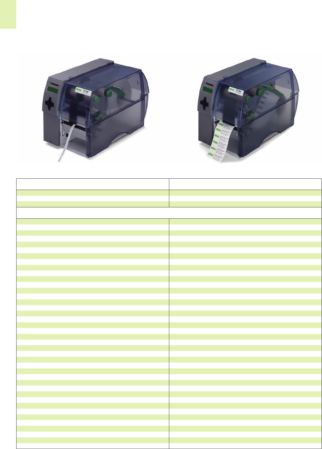
14
30
Thermal Transfer Printer TP 300
Electronics
Processor 32 Bit ColdFire 64 MHz
RAM 8MB
ROM 2 MB Flash
Slot for memory card standard
- CompactFlash Type 1
Real time clock standard
- for print-out of date and time
Operation panel as navigator pad 4/8
- keys/indicators
LCD-grafic display standard
- text 2 lines/20 characters, symbols
Interfaces
Serial RS 232 C standard
- 1200 up to 230 400 bauds/8 bit
RS 422, RS 485 optional
- 1200 up to 230 400 bauds/8 bit
Parallel Centronics standard
- bidirectional acc. to IEEE 1284
Ethernet 10/100 Base T, optional
LDP, RawIP-Printing, HTTP, SMTP,
DHCP, SNMP, Time, FTP
Wireless LAN on request
USB Slave for PC connection optional
Twinax / Coax Converter optional
- for IBM connection
USB Master for keyboard/scanner standard
Peripheral connection standard
Accessories (optional)
Cutter, dispense key, external unwinder, external rewinder, memory card Compact
Flash Type 1 up to 64 MB, PC-keyboard USB with 4 Hub, Compact PC-keyboard USB
Power supply 100 - 240 V ~ 50 /60 Hz, PFC
Operating temperature/humididy
non condensing 10 - 35 °C / 30 - 85 %
Safety regulations CE, FCC class 1
System Data
258-300 1
Item Pack.-unit
No. pcs
TP3
00 Resolution 300 dpi
Description
Subject to design changes
Printing method Thermal/thermal transfer
Printhead system Thick film
Print speed 150 mm/sec.
Print width 108.4 mm
Label material, Continuous mat. on rolls or paper transport
Thermal and standard paper, cardboard,
textil, plastic foil: PE, PP, PVC, PA
Material thickness/weight 0.07 - 0.3 mm / 60-300 g/m2
Supply roll
Roll diameter max. 210 mm
Core diameter 38.1 mm - 76 mm
Width of liner 120 mm
Label width 12 mm - 116 mm
Label height 5 - 1000 mm
Transfer ribbon
Ink inside or outside
Roll diameter max. 80 mm
Core diameter 25 mm
Running length variable max. 500 m
Width max. 114 mm
Internal rewinder
Total diameter max. 145 mm
Core diameter 38.1 mm
Winding direction only outside
Dimensions
Height, depth, width 274 mm, 446 mm, 242 mm
Weight 10 kg
Energy consumption max. 250 W
Label sensor
Distance to guide edge 4 mm - 57.5 mm
See-through/reflective sensor standard

14
14
31

14
32
Subject to design changes
Thermal Transfer Printer TP 298
Electronics
Processor 32 Bit ColdFire 64 MHz
RAM 8MB
ROM 4 MB Flash
Slot for memory card standard
- CompactFlash Type 1
Interfaces
Serial RS 232 C standard
Ethernet 10/100 Base T, standard
USB for PC connection standard
Accessories (optional)
Cutter, external unwinder, external rewinder,
memory card Compact Flash Type 16-512 MB
Power supply 100 - 240 V ~ 50 /60 Hz, PFC
Operating temperature/humididy
non condensing 10 - 35 °C / 30 - 85 %
Safety regulations CE, FCC class 1
System Data
258-298 1
Item Pack.-unit
No. pcs
TP 298 Resolution 300 dpi
Description
Printing method Thermal/thermal transfer
Printhead system Thick film
Print speed 100 mm/sec.
Print width 108.4 mm
Label material, Continuous mat. on rolls or paper transport
Thermal and standard paper, cardboard,
textil, plastic foil: PE, PP, PVC, PA
Material thickness/weight 0.07 mm - 0.3 mm / 60 g/m2-300 g/m2
Supply roll
Roll diameter max. 210 mm
Core diameter 38.1 mm - 76 mm
Width of liner 120 mm
Label width 12 mm - 116 mm
Label height 5 mm - 1000 mm
Transfer ribbon
Ink inside or outside
Roll diameter max. 80 mm
Core diameter 25 mm
Running length variable max. 500 m
Width max. 114 mm
Internal rewinder
Total diameter max. 145 mm
Core diameter 38.1 mm
Winding direction only outside
Dimensions
Height, depth, width 274 mm, 446 mm, 242 mm
Weight 9 kg
Energy consumption max. 200 W
Label sensor
Distance to guide edge 4 mm - 57.5 mm
See-through/reflective sensor standard
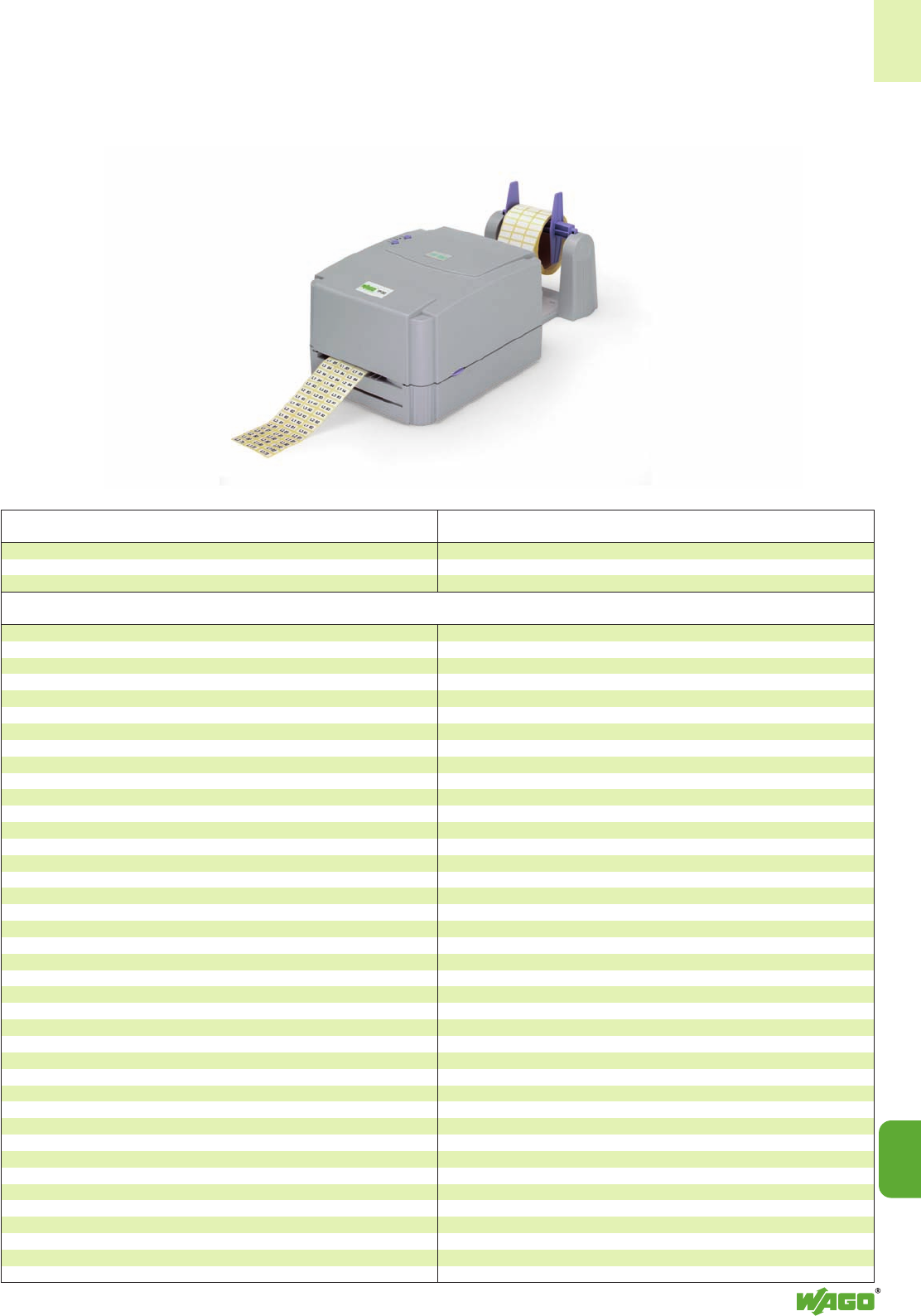
14
14
33
Subject to design changes
Thermal Transfer Printer TP 297
Core diameter min. 40 mm
Roll diameter 200 mm
Winding direction inside or outside
Transfer ribbon
Length max. 300 mm
Width max. 114 mm
Core diameter 1“
Ink inside or outside
Operation panel Pause and feed, error
Dimensions
Height, depth, width 145 mm, 215 mm, 200 mm
Depth with winder 450 mm
Net weight 1.5 kg
Power supply 100 - 240 V ~ 50 /60 Hz
Memory 1.5 MB Flash/2 MB DRAM
Label sensor Present sensor
Options
EPL-Zebra programming language, input keyboard
System Data
258-297 1
Item Pack.-unit
No. pcs
TP297 Resolution 203 dpi
Description
Printing method Thermal/thermal transfer
Printhead system Thin-film transfer head
Print resolution 203 dpi
Print speed max. 76 mm/sec.
Print width max. 104 mm
Font types all font types supported by Windows,
5 alphanumeric fonts, OCR-A + OCR-B
Character sets all character sets supported by Windows,
5 custom character sets
Font sizes all font sizes supported by Windows,
continuously adjustable
Font styles TTF-font types, 5 custom fonts
Print directions all directions supported by Windows
Barcodes
Code 39, Code 93
Code 128 A, B, C EAN-UPC Appendix 2 and 5
Codabar PDF417
EAN 8, 13, 128
EAN/UCC E
UPS Maxicode
Interleaved 2/5
All barcodes are variable in height, width and ratio. Includes digit check, printed
character quality check, and start/stop code.
Graphic formats every graphic format is supported by
Windows
Interfaces
Parallel Centronics IEEE 1284 compliant
RS 232
Peripheral connection Dispense edge
Labels and continuous material
Label material, Thermal and standard paper, plastic foil:
PE, PP, PVC, PA
Weight of adhesive labels 60 - 180g/m2
Weight of cardboard max. 180g/m2
Label width 12 - 116 mm
Width of liner max. 116 mm
Label height 10 - 2.286 mm
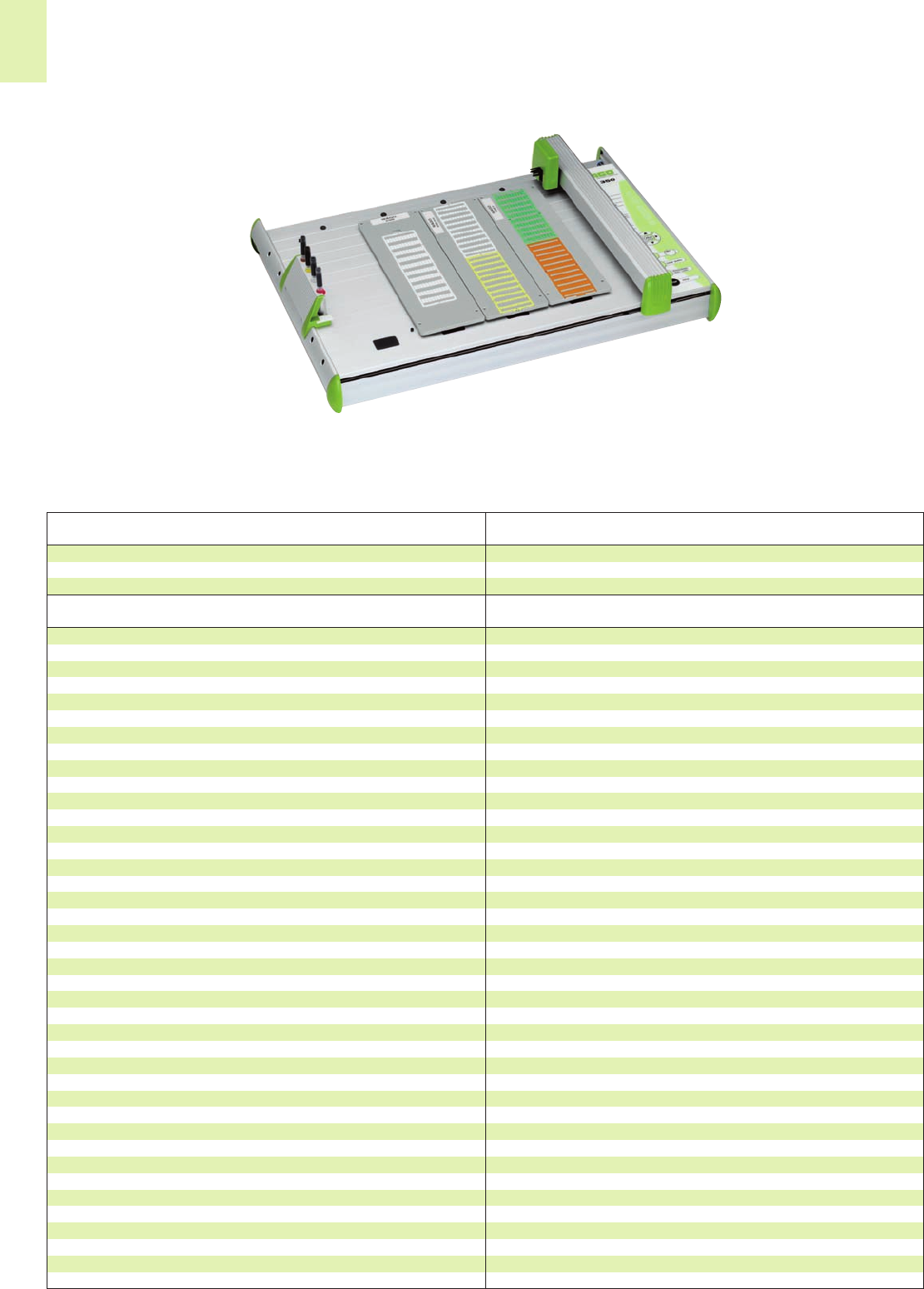
14
34
Subject to design changes
Plotter IP 350
Robust design made of aluminum frames
No calibration required. The plotters can be easily replaced.
Additional inputs and outputs are available to control the peripherical units.
Best possible sealing system of the plotter pens in the pen storage unit. This prevents
the ink from drying and clogging the pen tip. As such, the pens do not need to be
removed after plotting.
Markers with a maximum height of 10.5 mm can be plotted.
Plotting special markers up to 15 mm is also possible.
Preparatory functions, i.e. the plotter uses the pen in advance on a separate media to
start the ink flow thereby allowing the first marker to be printed perfectly.
The marking software automatically identifies the marker card carrier plate being used
by the plotter so that the most efficient combination of marker cards can be used for
the print job.
System Data
258-350 1
Item Pack.-unit
No. pcs
IP 350
Description
Plot area max. 440 mm x 305 mm
Interface parallel (centronics)
USB 1.1
Language HP-GL 7475A
Memory 16 MB
Speed max. 400 mm/sec.
Drive system Two-phase stepper motor
Pen storage unit max. 4 pens with best possible sealing system
Plotter pen Special plotter pens with HP receptacle
Addressable resolution 0.01 mm
Repeatability (accuracy) 0.05 mm
Repeatability
when changing the pen 0.05 mm using pens of best quality
Voltage supply via separate desktop power supply unit
equipped with exchangeable supply line
Voltage range Nominal voltage 120 - 240 V ~ 50 - 60 Hz
min. 90 V ~ max. 264 V ~
Current consumption 0.3 A max. at 220 V ~
Dimensions 660 mm x 440 mm x 125 mm
Weight 8kg
Environmental requirements Operating temperature: 10 °C - 35 °C
Relative air humidity: 35 % - 75%
Safety approvals acc. to UL-UL1950
CSA-950/VDE EN60950
Immunity to interference acc. to FCC Class B
FCC Part 15 and VDE Class B
EN 55022
Features
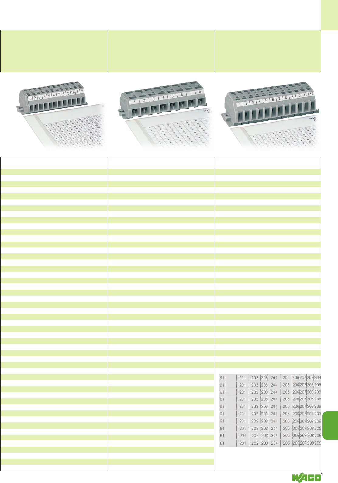
14
14
35
Marker Cards – Self-Adhesive Marker Strips
WAGO marker cards
for Series 260,
computer marked,
40 self-adhesive strips per card
Height of marker strip 6 mm/0.236 in
WAGO marker cards
for Series 261,
computer marked,
40 self-adhesive strips per card
Height of marker strip 6 mm/0.236 in
WAGO marker cards
for Series 262,
computer marked,
40 self-adhesive strips per card
Height of marker strip 6 mm/0.236 in
Marking Item Pack.-unit
No. pcs
Marking Item Pack.-unit
No. pcs Marking Item Pack.-unit
No. pcs
suitable for 2-conductor terminal strips
series 260
only with grid. spac.210-333/0500-0001 1 card
1 – 10 (120x) 210-333/0500-0002 1 card
11 – 20 (120x) 210-333/0500-0003 1 card
21 – 30 (120x) 210-333/0500-0004 1 card
31 – 40 (120x) 210-333/0500-0005 1 card
41 – 50 (120x) 210-333/0500-0006 1 card
51 – 60 (120x) 210-333/0500-0007 1 card
61 – 70 (120x) 210-333/0500-0008 1 card
71 – 80 (120x) 210-333/0500-0009 1 card
81 – 90 (120x) 210-333/0500-0010 1 card
91 – 100 (120x) 210-333/0500-0011 1 card
1 – 50 (20x) 210-333/0500-0021 1 card
L1(1440x) 210-333/0500-0074 1 card
L2(1440x) 210-333/0500-0075 1 card
L3(1440x) 210-333/0500-0076 1 card
N (1440x) 210-333/0500-0077 1 card
PE (1440x) 210-333/0500-0078 1 card
PEN (1440x) 210-333/0500-0079 1 card
suitable for 4-conductor terminal strips
series 260
only with grid. spac.210-333/0800-0001 1 card
1 – 10 (80x) 210-333/0800-0002 1 card
11 – 20 (80x) 210-333/0800-0003 1 card
21 – 30 (80x) 210-333/0800-0004 1 card
31 – 40 (80x) 210-333/0800-0005 1 card
41 – 50 (80x) 210-333/0800-0006 1 card
51 – 60 (80x) 210-333/0800-0007 1 card
61 – 70 (80x) 210-333/0800-0008 1 card
71 – 80 (80x) 210-333/0800-0009 1 card
81 – 90 (80x) 210-333/0800-0010 1 card
91 – 100 (80x) 210-333/0800-0011 1 card
1 – 40 (20x) 210-333/0800-0209 1 card
L1(880x) 210-333/0800-0074 1 card
L2(880x) 210-333/0800-0075 1 card
L3(880x) 210-333/0800-0076 1 card
N (880x) 210-333/0800-0077 1 card
PE (880x) 210-333/0800-0078 1 card
PEN (880x) 210-333/0800-0079 1 card
suitable for 2-conductor terminal strips
series 261
only with grid. spac.210-333/0600-0001 1 card
1 – 12 (80x) 210-333/0600-0103 1 card
13 – 24 (80x) 210-333/0600-0104 1 card
25 – 36 (80x) 210-333/0600-0105 1 card
37 – 48 (80x) 210-333/0600-0106 1 card
41 – 50 (80x) 210-333/0600-0006 1 card
51 – 60 (80x) 210-333/0600-0007 1 card
61 – 70 (80x) 210-333/0600-0008 1 card
71 – 80 (80x) 210-333/0600-0009 1 card
81 – 90 (80x) 210-333/0600-0010 1 card
91 – 100 (80x) 210-333/0600-0011 1 card
1 – 50 (20x) 210-333/0600-0021 1 card
L1(1200x) 210-333/0600-0074 1 card
L2(1200x) 210-333/0600-0075 1 card
L3(1200x) 210-333/0600-0076 1 card
N (1200x) 210-333/0600-0077 1 card
PE (1200x) 210-333/0600-0078 1 card
PEN (1200x) 210-333/0600-0079 1 card
suitable for 4-conductor terminal strips
series 261
only with grid. spac.210-333/1000-0001 1 card
1 – 16 (40x) 210-333/1000-0202 1 card
17 – 32 (40x) 210-333/1000-0204 1 card
33 – 48 (40x) 210-333/1000-0206 1 card
49 – 64 (40x) 210-333/1000-0110 1 card
65 – 80 (40x) 210-333/1000-0111 1 card
81 – 96 (40x) 210-333/1000-0112 1 card
97 – 112 (40x) 210-333/1000-0113 1 card
1 – 36 (20x) 210-333/1000-0208 1 card
L1(720x) 210-333/1000-0074 1 card
L2(720x) 210-333/1000-0075 1 card
L3(720x) 210-333/1000-0076 1 card
N (720x) 210-333/1000-0077 1 card
PE (720x) 210-333/1000-0078 1 card
PEN (720x) 210-333/1000-0079 1 card
suitable for 2-conductor terminal strips
series 262
only with grid. spac.210-333/0700-0001 1 card
1 – 20 (40x) 210-333/0700-0020 1 card
21 – 40 (40x) 210-333/0700-0108 1 card
41 – 60 (40x) 210-333/0700-0109 1 card
1 – 50 (20x) 210-333/0700-0021 1 card
L1(1040x) 210-333/0700-0074 1 card
L2(1040x) 210-333/0700-0075 1 card
L3(1040x) 210-333/0700-0076 1 card
N (1040x) 210-333/0700-0077 1 card
PE (1040x) 210-333/0700-0078 1 card
PEN (1040x) 210-333/0700-0079 1 card
suitable for 4-conductor terminal strips
series 262
only with grid. spac.210-333/1200-0001 1 card
1 – 12 (40x) 210-333/1200-0103 1 card
13 – 24 (40x) 210-333/1200-0104 1 card
25 – 36 (40x) 210-333/1200-0105 1 card
37 – 48 (40x) 210-333/1200-0106 1 card
49 – 60 (40x) 210-333/1200-0107 1 card
1 – 24 (20x) 210-333/1200-0203 1 card
L1(600x) 210-333/1200-0074 1 card
L2(600x) 210-333/1200-0075 1 card
L3(600x) 210-333/1200-0076 1 card
N (600x) 210-333/1200-0077 1 card
PE (600x) 210-333/1200-0078 1 card
PEN (600x) 210-333/1200-0079 1 card
Other markings with different spacings for
2- and 4-conductor terminal blocks available on
request.
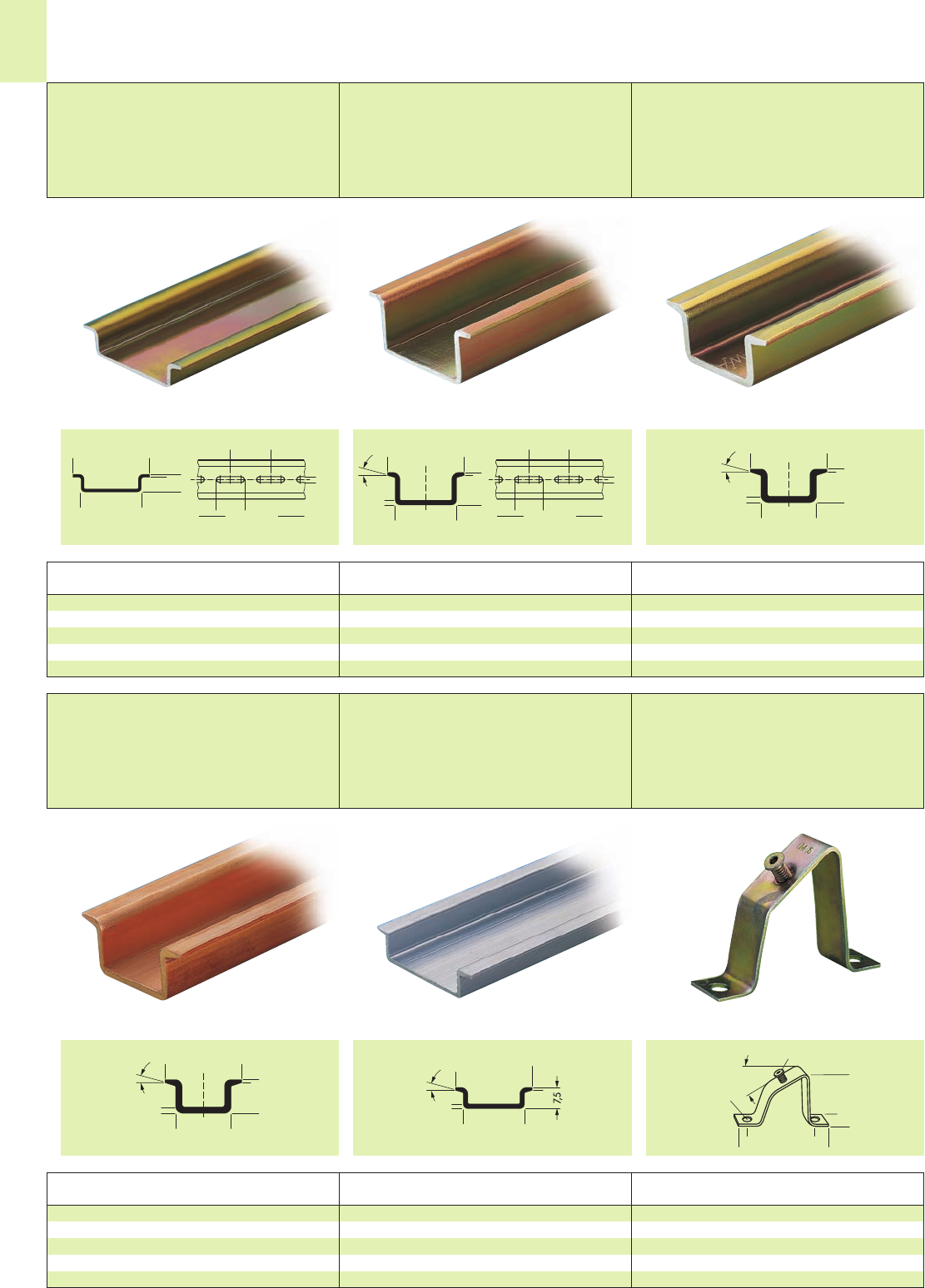
<____ 35 ____>
<___ 27 ___>
> 7, 5 <
> <_
1
<_ 36 _>
(_25_)
> <
5,2
2000±1,5
<____ 35 ____>
<___ 27 ___>
<_ 36 _>
(_25_)
> <
5,2
2000±1,5
> <_
1
15°
(_15 _)
> <_
1, 5
<____ 35 ____>
<__ 24 __>
> <_
1
15°
(_ 15 _)
_____> <
2,2-2,5
<____ 35 ____>
<__ 24 __>
> <_
1
15°
(_ 15 _)
_____> <
2,2-2,5
<____ 35 ____>
<__ 28,2 __>
> <
1
15°
> <_
1, 5
<__ 48 __>
<___ 60 ___>
35°
>18 <
<______ 72 ______>
Ø 7
M 5
14
36
Carrier Rails and Mounting Accessories
Carrier rail 35 x 7.5 mm,
1 mm/0.039 in thick,
acc. to EN 60715,
Steel, zinc-plated and yellow chromated
IN76 A (referred to a length of 1 m)
Carrier rail 35 x 15 mm,
1.5 mm/0.059 in thick,
acc. to EN 60715,
Steel, zinc-plated and yellow chromated
IN125 A (referred to a length of 1 m)
Carrier rail 35 x 15 mm,
2.3 mm/0.091 in thick,
acc. to EN 60715,
Steel, zinc-plated and yellow chromated
IN125 A (referred to a length of 1 m)
Item Item Pack.-unit
No. No. pcs
Item Item Pack.-unit
No. No. pcs Item Pack.-unit
No. pcs
1 m /3’3” long 2 m /6’6” long
Steel rail 35 x 7.5 mm,1 mm/0.039 in th., unslotted
210-229 210-113 10
Steel rail 35 x 7.5 mm,1 mm/0.039 in th., slotted
210-162 210-112 10
2 m /6’6” long
Steel rail 35 x15 mm,1.5 mm/0.059 in th., unslotted
210-114 10
Steel rail 35 x15 mm, 1.5 mm/0.059 in th., slotted
210-197 10
2 m /6’6” long
Steel rail 35x15 mm, 2.3 mm/0.091 in th., unslotted
210-118 10
Carrier rail 35 x 15 mm,
2.3 mm/0.091 in thick,
acc. to EN 60715,
Copper, unplated
IN309 A (referred to a length of 1 m)
Carrier rail 35 x 7.5 mm,
1.5 mm/0.059 in thick,
acc. to EN 60715,
Aluminum, unplated
IN76 A (referred to a length of 1 m)
Angled support bracket
steel, zinc-plated and yellow
chromated
Item Pack.-unit
No. pcs
Item Pack.-unit
No. pcs Item Pack.-unit
No. pcs
2 m /6’6” long
Copper carrier rail 35 x 15 mm,
2.3 mm/0.091 in thick, unslotted
210-198 10
2 m /6’6” long
Aluminum carrier rail 35 x 7.5 mm,
1.5 mm/0.059 in thick, unslotted
210-196 10
Angled support bracket, without screw
210-148 10
Screw M 5 x 8
210-149 100 (5 x 20)
All dimensions in mm All dimensions in mm All dimensions in mm
All dimensions in mm All dimensions in mm All dimensions in mm
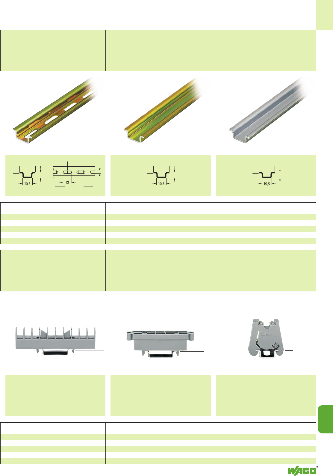
<_ 15 _>
> <_
1
<_ 20 _>
4,2
2000±1,5
5,5
<_ 15 _>
> <_
1
5,5
<_ 15 _>
> <_
1
5,5
14
14
37
Collective carrier for jumpers
282-369 25
suitable for jumpers for
transverse switching t. bl. 282-811 and
longitudinal switch. disc. t. bl. 282-821
Item Pack.-unit
No. pcs
The collective carrier can be snapped onto DIN 35
rails. It serves as a holder for jumpers, e.g. during
maintenance work.
(18.7 mm/ )
0.74 in
<_____________ 81.6 mm /3.21 in ______________>
Carrier rail 15 x 5.5 mm,
1 mm/0.039 in thick,
acc. to EN 60715,
Steel, zinc-plated and yellow chromated
IN57 A (referred to a length of 1 m)
Carrier rail 15 x 5.5 mm,
1 mm/0.039 in thick,
acc. to EN 60715,
Steel, zinc-plated and yellow chromated
IN57 A (referred to a length of 1 m)
Carrier rail 15 x 5.5 mm,
1 mm/0.039 in thick,
acc. to EN 60715,
Aluminum, unplated
IN57 A (referred to a length of 1 m)
Item Pack.-unit
No. pcs
Item Pack.-unit
No. pcs Item Pack.-unit
No. pcs
2 m /6’6” long
Steel carrier rail 15 x 5.5 mm,
1 mm/0.039 in thick, slotted
210-111 1
2 m /6’6” long
Steel carrier rail 15 x 5.5 mm,
1 mm/0.039 in thick, unslotted
210-295 1
2 m /6’6” long
Aluminum carrier rail 15 x 5.5 mm,
1 mm/0.039 in thick, unslotted
210-296 1
Collective carrier for standard and
special jumpers in longitudinal switching
disconnect terminal blocks and transverse
switching terminal blocks, Series 282,
can be snapped onto DIN 35 rail
Width 15.8 mm / 0.62 in
(= 2 x pitch 8 mm)
Collective carrier for adjacent jumpers,
for DIN 35 rail,
10.7 mm / 0.421 in wide
Screwless end stop,
for DIN 15 rail
6 mm / 0.236 in wide
Item Pack.-unit
No. pcs Item Pack.-unit
No. pcs
Collective carrier for adjacent jumpers
209-100 50 (2 x 25)
suitable for adjacent jumpers of series
279, 280, 281, 282 and 284
and banana plug series 215
The collective carrier can be snapped onto carrier
rails DIN 35. It serves for the storage of adjacent
jumpers for rail-mounted terminal blocks for use if
spares are necessary.
Screwless end stop, for DIN 15 rail
249-101 25
suitable for marking with WSB Quick marking system
All dimensions in mm All dimensions in mm All dimensions in mm
<__ 16 mm / __>
0.63 in
(18 mm /)
0.71 in
<__________ 74 mm /2.91 in __________> <23.2 mm /1.91 in >
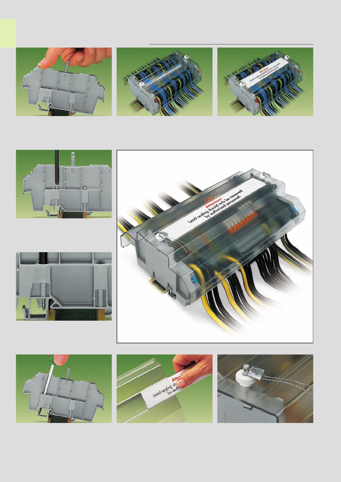
➋
➊
➋
➊
14
38
Transparent Covers for Rail-Mounted Terminal Blocks, Usable with Lead Seals
Description and Handling
A cover carrier is snapped
onto the rail
Mounting
Mounting
Mounting
Removal
Application
Screwing in the fixing screw ➊and the retaining
screw ➋
➊Fixing screw – prevents the cover carrier from
being moved on the rail
➋Retaining screw – prevents lifting off from rail
Removal of a cover carrier
from the carrier rail Pushing in a marking strip
into the cover
Marking
The cover may be sealed with a lead seal.
If the cover is used without a lead seal
the threaded stud can be broken off
Lead seal
Examples:
A cover, type 1, without . . . . . . or with safety warning
Cover, type 2, with safety warning
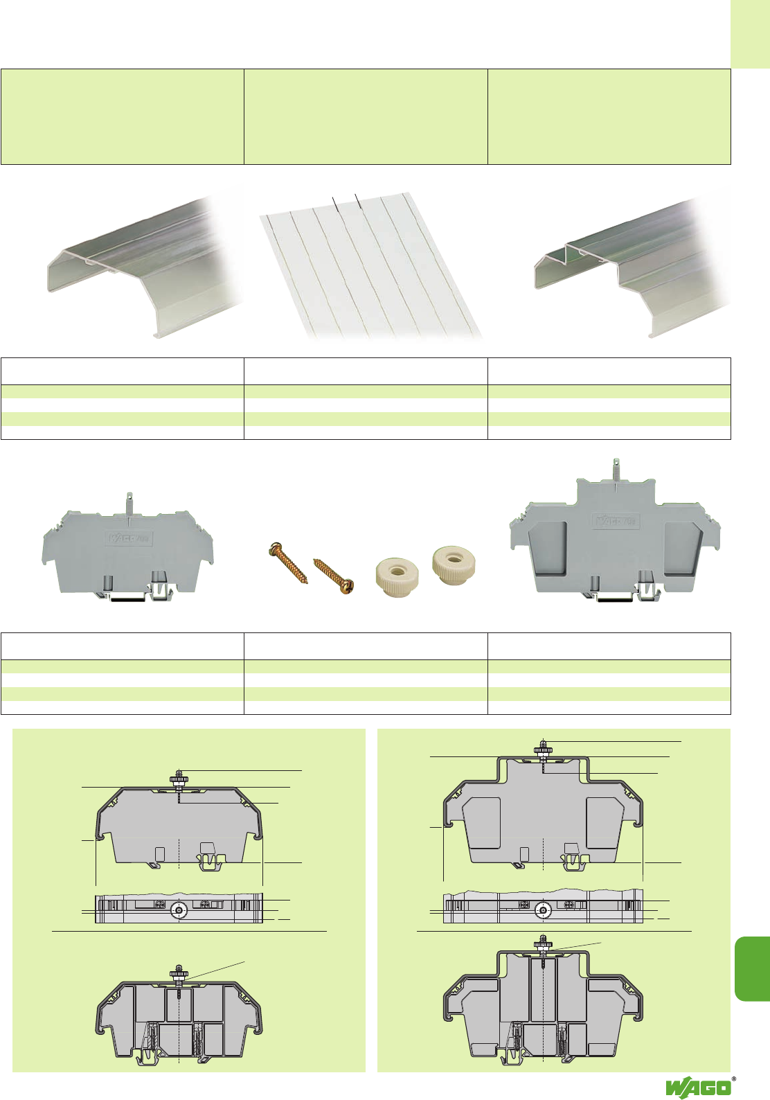
<____56,5_____>
<________72________>
<__________85__________>
<___________97,5____________>
2,5
> <__
<> 8<> 15
<_____________________160_______________________>
<_________________133 __________________>
<___47,5 ___>
<______60______>
<________73 ________>
>8<
>15 <
> <__
2,5 <____42 ____>
14
14
39
<_______ 297 mm /11.69 in ______>
_>30 mm /<_
1.18 in
back view
Diameter of drilled hole:
7±0,5
mm
back view Diameter of drilled hole:
7±0,5
mm
Item Pack.-unit
No. pcs
Cover, type 1,
1 m /3’3’’ long, suitable for cover carrier, type 1
transparent 709-153 10
Item Pack.-unit
No. pcs
Marker card with 6 marking strips,
plain 709-183 1
Diskette with WinWORD marking system
709-184 1
Item Pack.-unit
No. pcs
Cover, type 2,
1 m /3’3’’ long, suitable for cover carrier, type 2
transparent 709-154 1
Item Pack.-unit
No. pcs
Cover carrier, type 1,
incl. fixing/retaining screws and knurled nut
grey 709-167 10
Cover carrier, type 2,
incl. fixing/retaining screws and knurled nut
grey 709-168 10
Item Pack.-unit
No. pcs
Spare fixing/retaining screws
209-196 200 (8 x 25)
Spare knurled nut
210-549 100 (4 x 25)
Item Pack.-unit
No. pcs
Transparent Covers for Rail-Mounted Terminal Blocks,
Usable with Lead Seals
Covers and cover carriers, type 1
suitable for rail-mounted terminal blocks
series 279 to 282; 880
Miniature rail-mounted terminal blocks
series 264 and
sensor/actuator terminal blocks series 269
Covers and cover carriers, type 2, suitable for
rail-mounted terminal blocks series 283, 284,
285; double and triple deck terminal blocks
series 280/281; topJob rail-mounted terminal
blocks series 776, 777, 780 to 784;
sensor/actuator terminal blocks series 280
and disconnect and measuring terminal blocks
for transformer circuits series 282
Marker card for group marking
or safety warnings
Spare fixing/retaining screws
and
spare knurled nut
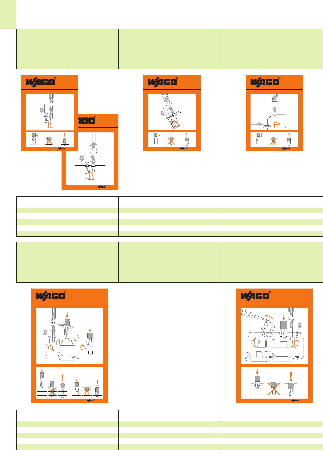
A
B
210-292
210-292
B
A
B
A
A
B
A
B
210-283
210-283
210-183
210-183
210-182
210-182
14
40
210-416
210-416
210-186
210-186
Item Pack.-unit
No. pcs Item Pack.-unit
No. pcs
Item Pack.-unit
No. pcs
Item Pack.-unit
No. pcs
Item Pack.-unit
No. pcs
Stickers for Operating Instructions*
for front-entry rail-mounted terminal blocks
(horizontal version)
for CAGE CLAMP®
Size 60 mm x 65 mm/2.36 in x 2.48 in
for front-entry rail-mounted terminal blocks
(angled version)
Size 60 mm x 65 mm/2.36 in x 2.48 in
for side-entry rail-mounted terminal
blocks
Size 60 mm x 65 mm/2.36 in x 2.48 in
Operating sticker,
for front-entry rail-mounted terminal blocks series
279 to 285 210-186 100
for CAGE CLAMP®,
210-416 100
Operating sticker,
for front-entry rail-mounted terminal blocks, angled type
series
280 and 281 210-183 100
Operating sticker,
for side-entry rail-mounted terminal blocks
series
279 to 284 210-182 100
for double and triple deck terminal blocks
Size 80 mm x 104 mm/3.15 in x 4.09 in
for disconnect terminal blocks
Size 80 mm x 104 mm/3.15 in x 4.09 in
Operating sticker,
for double and triple deck terminal blocks
series
280 and 281 210-292 100
Operating sticker,
for disconnect terminal blocks
series
280 210-283 100
* Note: Handling instructions for rail-mounted terminal blocks are included in each carton.
If self-adhesive stickers, as above, are required to give field wiring information – for example in enclosures, panels or switchboards – please order using the above part numbers.
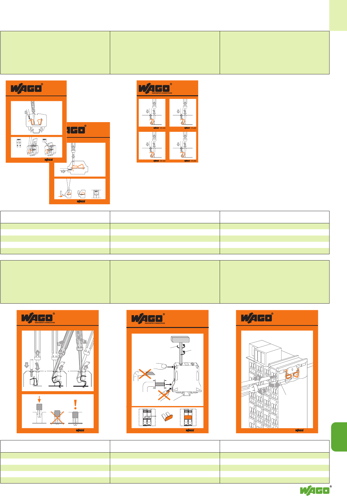
210-188/001-000
210-188/001-000
209 -132
210 -2 91
210 -2 91
280-432
264 264
210-419
210-419
210-422
210-422
35–36
mm
285-172
+=
285-495
285-197 = TS 35 x 2,3 mm Cu
➀
➂
285-194
285-195
285-197
5°➃
➁
1.38 in
210-407
210-407
(2,5 x 0,4) mm
210 -420
14
14
41
Item Pack.-unit
No. pcs
Item Pack.-unit
No. pcs
Item Pack.-unit
No. pcs
Item Pack.-unit
No. pcs
Item Pack.-unit
No. pcs
for front-entry miniature rail-mounted
terminal blocks
and front-entry terminal strips
Size 60 mm x 65 mm/2.36 in x 2.48 in
for rail mounted terminal blocks
with CAGE CLAMP®COMPACT
Size (1.18 x 1.26) in x 4
Operating sticker, for front-entry miniature
rail-mounted terminal blocks, series
264 210-291 100
rail-mounted terminal blocks, series
260 to 262 210-188/001-000 100
Operating sticker,
for rail-mounted terminal blocks
with CAGE CLAMP®COMPACT
series
870 210-420 100
for FIT CLAMP,
universal
Size 80 mm x 104 mm/3.15 in x 4.09 in
for high current terminal
Size 80 mm x 104 mm/3.15 in x 4.09 in
for matrix patchboards
Size 80 mm x 104 mm/3.15 in x 4.09 in
Operating sticker,
for FIT CLAMP, universal
series
290 210-419 100
Operating sticker,
for high current terminal blocks
series
285 210-422 100
Operating sticker,
for matrix patchboards
series
726 210-407 100
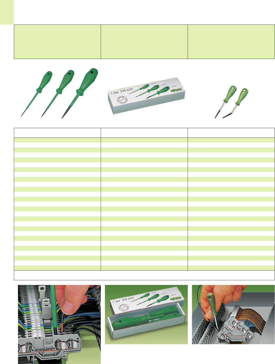
14
42
Item Pack.-unit
No. pcs
Application notes
Screwdrivers (DIN 5264)
for optimum handling
in terminal blocks and connectors
Operating Tools
Screwdriver, short, blade 3.5 mm x 0.5 mm/
0.138 in x 0.020 in,
suitable for series 260, 261, 262, 264, 280, 281, 869
210-257 1
Screwdriver, short angled, 3.5 mm x 0.5 mm/
0.138 in x 0.020 in, specially suitable for sensor and
actuator terminal blocks of series 280 or for
serie 260, 261, 262, 264, 280, 281, 869, 870, 880
210-258 1
The blade dimensions of the a. m. screwdrivers
(DIN 5264) are particularly appropriate for easy
operation of front-entry sensor and actuator terminal
blocks of series 280.
Item Pack.-unit
No. pcs Item Pack.-unit
No. pcs
Screwdrivers
with partially insulated shaft
for optimum handling
in terminal blocks and connectors
Screwdrivers
with partially insulated shaft
– Set –
Screwdriver with partially insulated shaft,
type 1, blade 2.5 x 0.4 mm /0.098 in x 0.016 in,
suitable for series 279, 726, 727, 2001
210-619 1
Screwdriver with partially insulated shaft,
type 2, blade 3.5 x 0.5 mm /0.137 in x 0.020 in,
suitable for series 260, 261, 262, 264, 270, 280, 281,
290, 775, 776, 777, 769, 780, 781, 869, 870, 880,
2002, 2004
210-620 1
Screwdriver with partially insulated shaft,
type 3, blade 5.5 x 0.8 mm /0.217 in x 0.031 in,
suitable for series 282, 283, 284, 285, 782, 783, 784,
785, 2006, 2010, 2016
210-621 1
Screwdrivers with partially insulated shaft,
– set –,
types 1 – 3 see left
210-622 1
The blade dimensions of the a. m. screwdrivers
are particularly appropriate for easy operation of
front-entry terminal blocks.
Set of screwdrivers in a box
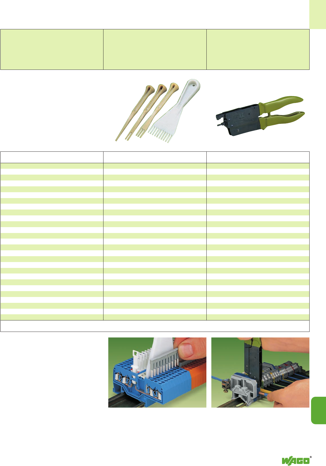
14
14
43
Item Pack.-unit
No. pcs
Plunger, for side-entry rail-mounted
terminal blocks
Operating tool,
for side-entry rail-mounted terminal blocks
series 279 and 280
210-143 1
Operating tool,
for side-entry rail-mounted terminal blocks
series 281, 282, 283 and 284
210-141 1
The plunger is placed into the upper operating slot of the
side-entry terminal block and the clamp is hooked into
the lateral operating hole. The contact is fully opened by
pressing the handles together until they engage – both
hands are then free for the preparation and introduction
of the conductor into the terminal block. When operating
the handles beyond the locked position the ratchet allows
the tool to open and be removed from the terminal
block.
Item Pack.-unit
No. pcs
Multipole operating tools
for front-entry terminal blocks (insulated)
Operating tools, solid non-conducting material
suitable for series 279
1-way 209-129 1
suitable for series 279
2-way 279-432 1
3-way 279-433 1
10-way 279-440 1
suitable for series 264*, 280, 281**
1-way 209-130 1
2-way 280-432 1
3-way 280-433 1
4-way 280-434 1
5-way 280-435 1
6-way 280-436 1
7-way 280-437 1
8-way 280-438 1
9-way 280-439 1
10-way 280-440 1
suitable for series 281
5-way 281-440 1
* only 1- and 2-way
** only up to 3-way
Commoning of front-entry through terminal blocks with
comb type jumper bars with the aid of a 10-way
operating tool.
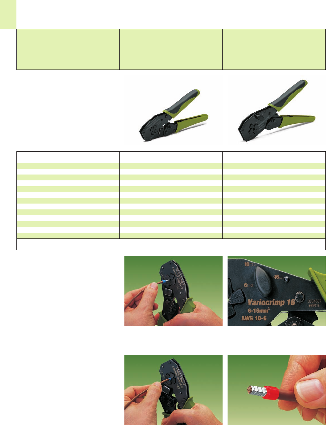
14
44
Crimping Tools
Variocrimp 4, Variocrimp 16
Variocrimp 4
Crimping tool for ferrules
insulated and uninsulated
from 0.25 mm2– 4 mm2/AWG 24 – 12
weight 400 g/0.882 lbs
Variocrimp 16
Crimping tool for ferrules
insulated and uninsulated
from 6 mm2– 16 mm2/AWG 10 – 6
weight 580 g/1.28 lbs
Item Pack.-unit
No. pcs Item Pack.-unit
No. pcs
Crimping tool Variocrimp 4,
0.25 mm2– 4 mm2/AWG 24 – 12
Crimping tool Variocrimp 16,
6 mm2– 16 mm2/AWG 10 – 6
206-204 1
206-216 1
Application notes
Description
Introduce conductor with ferrule into crimping station. Only for Variocrimp 16:
Adjust conductor cross section with opened tool.
Squeeze handles until ratchet mechanism is released. A perfect gastight crimp, both electrically and mechani-
cally reliable.
●With the Variocrimp 4 built-in crimping pressure
plates control the crimping force automatically
for the conductor cross section used.
With the Variocrimp 16 it is necessary to select
the wire gauge on the tool before crimping.
●Each tool has only one crimping station for all
the wire sizes handled.
●Uniform compact crimping from all four sides
for high conductor retention.
●No need to center the conductor in the ferrule
sleeve.
●Conductor and ferrule insertion possible from
both sides (for left- and right handed).
●Built-in ratchet to guarantee complete crimping
every time.
●Tools open automatically after crimping
operation is complete.
●Comfortable handles for operator.
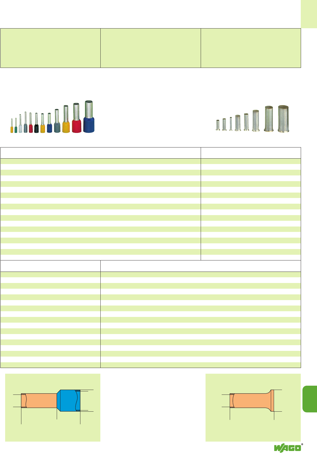
<_______ L1 _______>
<__ D1 __>
<____ D ____>
<_______________ L _______________>
D2<
<
<____ D ____>
<__________ L __________>
D2<
<
14
14
45
Insulated ferrules
For letters with the corresponding dimensions see
table above.
Uninsulated ferrules
For letters with the corresponding dimensions see
table above.
Sleeve for Stripped L D D2 Item Pack.-unit
mm2AWG length mm mm No. pcs
Sleeve for Color Stripped L L1 D D1 D2 Item Pack.-unit
mm2AWG length mm mm No. pcs
0.25 24 yellow 7.5 10.5 6.0 2.5 2.0 0.8 216-321 1000
0.25 24 yellow 9.5 12.5 8.0 2.5 2.0 0.8 216-301 1000
0.34 24 green 7.5 10.5 6.0 2.5 2.0 0.8 216-322 1000
0.34 24 green 9.5 12.5 8.0 2.5 2.0 0.8 216-302 1000
0.5 22 white 7.5 11.5 6.0 3.0 2.5 1.1 216-221 1000
0.5 22 white 9.5 13.5 8.0 3.0 2.5 1.1 216-201 1000
0.75 20 grey 8.0 12.0 6.0 3.3 2.8 1.3 216-222 1000
0.75 20 grey 10.0 14.0 8.0 3.3 2.8 1.3 216-202 1000
1.0 18 red 8.0 12.0 6.0 3.6 3.0 1.5 216-223 1000
1.0 18 red 10.0 14.0 8.0 3.6 3.0 1.5 216-203 1000
1.5 16 black 8.0 12.0 6.0 4.0 3.4 1.8 216-224 1000
1.5 16 black 10.0 14.0 8.0 4.0 3.4 1.8 216-204 1000
2.08 14 yellow 10.0 14.5 8.0 4.2 3.6 2.05 216-205 1000
2.5 14 blue 10.0 15.0 8.0 4.8 4.2 2.3 216-206 1000
4.0 12 grey 12.0 16.8 9.5 5.4 4.8 2.9 216-207 1000
6.0 10 yellow 14.0 20.0 12.0 6.8 6.2 3.5 216-208 100
10.0 8 red 16.0 21.0 12.0 8.1 7.5 4.6 216-209 100
16.0 6 blue 23.0 29.0 18.0 9.6 8.8 5.8 216-210 100
Ferrules
Insulated ferrules,
electrolytic copper, electro-tin plated,
acc. to DIN 46228, part 4/09.90
Uninsulated ferrules,
electrolytic copper, electro-tin plated,
acc. to DIN 46228, part 1/08.92
0.25 24 5 5 1.7 0.75 216-151 1000
0.25 24 7 7 1.7 0.75 216-131 1000
0.34 24 5 5 1.7 0.85 216-152 1000
0.34 24 7 7 1.7 0.85 216-132 1000
0.5 22 6 6 2.1 1.0 216-121 1000
0.5 22 8 8 2.1 1.0 216-101 1000
0.75 20 6 6 2.3 1.2 216-122 1000
0.75 20 8 8 2.3 1.2 216-102 1000
1.0 18 6 6 2.5 1.4 216-123 1000
1.0 18 8 8 2.5 1.4 216-103 1000
1.5 16 6 6 2.8 1.7 216-124 1000
1.5 16 8 8 2.8 1.7 216-104 1000
2.5 14 10 10 3.4 2.2 216-106 1000
4.0 12 10 10 4.0 2.8 216-107 1000
6.0 10 12 12 4.7 3.5 216-108 250
10.0 8 12 12 5.8 4.5 216-109 250
16.0 6 15 15 7.5 5.8 216-110 250
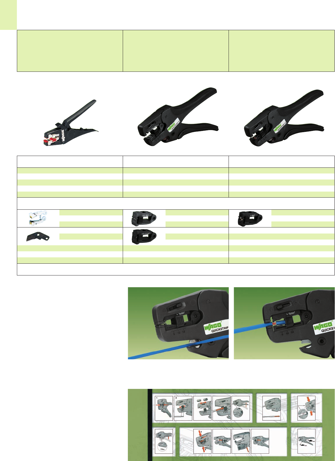
14
46
Application notes
Accessories
Item Pack.-unit
No. pcs Item Pack.-unit
No. pcs Item Pack.-unit
No. pcs
Stripping Tools
Microstrip wire stripper
0.14 mm2– 1.5 mm2/AWG 24 – 16
solid and stranded, with
wire cutter up to 1.5 mm2/AWG 16
solid and stranded
weight 76 g/0.166 lbs
Stripping and cutting tool Quickstrip 10
0.02 mm2– 10 mm2/AWG 28 – 8 stranded
(6 mm2/AWG 10 solid)
with wire cutter up to 10 mm2/AWG 8 stran-
ded (1.5 mm2/AWG 16 solid)
weight 136 g/0.3 lbs
Stripping and cutting tool Quickstrip 16
4 mm2– 16 mm2/AWG 12 – 6
with wire cutter up to 10 mm2/AWG 8 stran-
ded (1.5 mm2/AWG 16 solid)
weight 136 g/0.3 lbs
Microstrip wire stripper and cutter
206-501 1
Stripping and cutting tool Quickstrip 10
206-124 1
Stripping and cutting tool Quickstrip 16
206-125 1
Spare stripping unit,
complete
206-502 1
Spare blade,
for wire cutter
206-503 1
Standard blade cassette
0.02 - 10 mm2/AWG 34-8
206-126 1
“V” blade cassette
0.02 - 4 mm2/AWG 34-12 for PTFE
206-127 1
Blade cassette 16 mm2/AWG 6
4.0 - 16 mm2/AWG 12-6
206-128 1
Cutting of wire. Stripping of wire.
●Automatically adjusts to the wire size.
●No damage to wire strands.
●Gripping pressure of jaws adjusts
automatically to wire insulation diameter.
●Full cycle strip – jaws open after stripping,
ensures no nicked strands.
●Exact strip length may be set by sliding of red
setting stop.
●Replaceable stripping jaw assembly.
●Self-sharpening, fully protected wire cutter,
also replaceable.*
●Glass fiber reinforced polyamide tool body.
* applies for Microstrip
Handling description included.
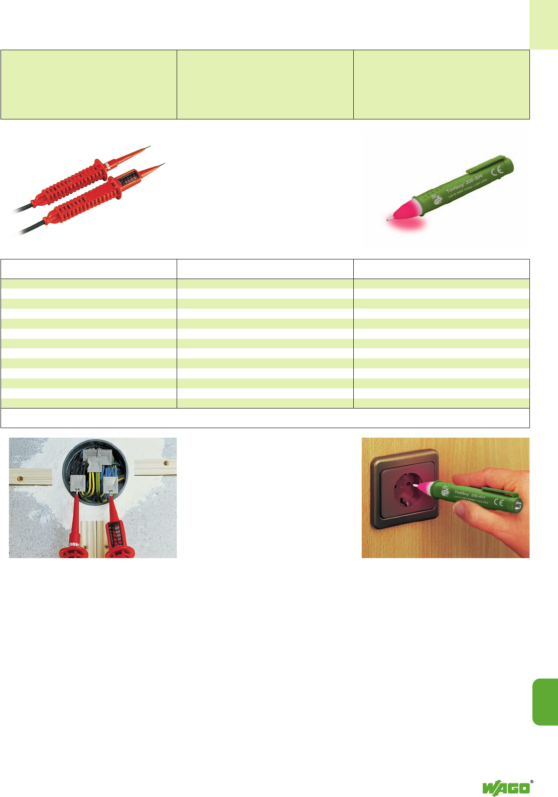
14
14
47
Application notes
Voltage testing at push-wire connectors
Item Pack.-unit
No. pcs
Voltage tester Profipol
AC 12 V to 400 V
DC 12 V to 500 V
weight 138 g/0.304 lbs
Voltage tester Profipol
206-802 1
Voltage range AC 12 V up to 400 V
DC 12 V up to 500 V
LED indication AC 12 V, 50 V, 100 V, 230 V, 400 V
DC 12 V, 60 V, 120 V, 280 V, 500 V
Type of protection IP 65
Operating time 30 s max.
Temperature range –10° up to + 50°C
●LED band provides clear voltage range
readings.
(white scale = AC voltage
red scale = DC voltage)
●LED indication of polarity
●double-pole voltage testing
●type of protection IP 65
●switching is not necessary
●85 cm long highly flexible and
nonskid test cable
Voltage Testers and Testboy
A device that will reliably detect A.C. voltages in cables,
sockets, fuses, switches, connector boxes, etc.
Testboy, with integrated flashlight
206-804 1
Voltage range 120 V up to AC 1000 V
Item Pack.-unit
No. pcs
Testboy
The following can be detected by the
WAGO Testboy:
●Live conductors
●Line breaks
●Blown fuses
●Defective switches
●Defective lamps
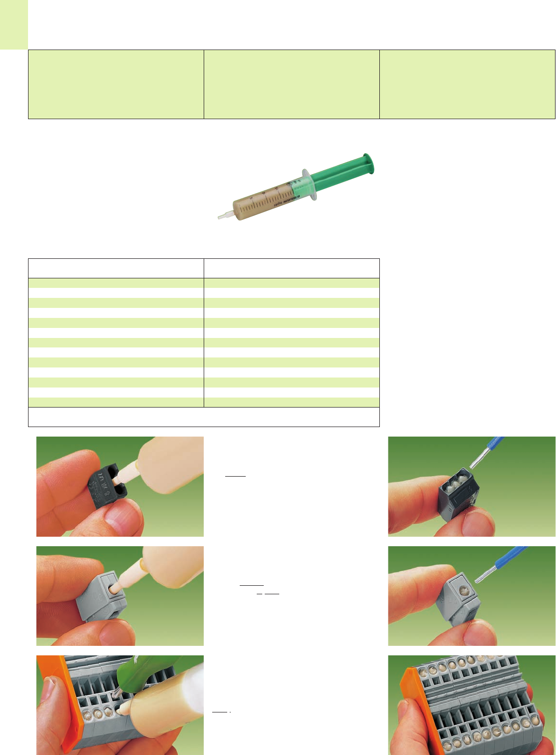
14
48
Description Item Pack.-unit
No. pcs
Application notes
Syringe
Contents: 20 ml contact paste “Alu-Plus”
249-130 20 (4 x 5)
WAGO Rail-mounted terminal blocks
(only up to 4 mm2/AWG 12)
1. For each conductor
entry: Insert nozzle of
the “Alu-Plus” syringe in
every open conductor
entry hole (one after
the other).
2. Press plunger down
until “Alu-Plus” has
filled each of these
holes.
Contact paste “Alu-Plus”
Use WAGO contact paste “Alu-Plus” when
connecting solid aluminum wires in WAGO
spring-clamp terminal blocks.
Please take note that the nominal currents must
be adapted to the reduced conductivity of the
aluminum wires:
2.5 mm2/AWG 14 = 16 A
4mm
2/AWG 12 = 22 A
WAGO contact paste “Alu-Plus”
for the safe wiring of solid➊aluminum
conductors up to 4 mm2/AWG 12
in WAGO spring-clamp terminal block
➊Aluminum conductors according to
IEC 61545, Class B, “Alloy 1370” with
a tensile strength of 90 – 180 N/mm2
and a tensile strain of 1 – 4 %.
WAGO contact paste “Alu-Plus” for the safe
wiring of solid aluminum wire up to 4 mm2/
AWG 12 in WAGO spring-clamp terminal blocks.
Cleaning and greasing of the aluminum wire is
no longer necessary. Use the WAGO contact
paste “Alu-Plus” instead, which is directely injected
into the conductor entry hole of WAGO terminal
blocks by means of the handy syringe.
Aluminum conductors that clearly indicate corrosion
effects (stained black) require mechanical clea-
ning.
This allows the easy connection of solid aluminum
wire (in case of multipole terminal blocks, can
also be mixed with copper wires).
WAGO “Alu-Plus”
●automatically destroys the oxide film during
clamping
●prevents fresh oxidation at the clamping point
●prevents electrolytic corrosion between
aluminum- and copper wires
(in the same terminal block)
●offers permanent protection against corrosion
It is, of course, also possible to apply the
WAGO “Alu-Plus” in addition on the whole
surface of the aluminum wire before clamping.
WAGO Push-wire connectors
2. Press plunger until
“Alu-Plus” is visible
in the other holes.
1. Push nozzle of the
“Alu-Plus” syringe into
the center conductor
entry hole of the
WAGO junction box
connector.
WAGO Lighting connectors
2. Press plunger down
until the “Alu-Plus”
has filled both holes.
1. Push nozzle of the
“Alu-Plus” syringe first
into the circular and
then into the square
conductor entry hole
of the WAGO lighting
connector.
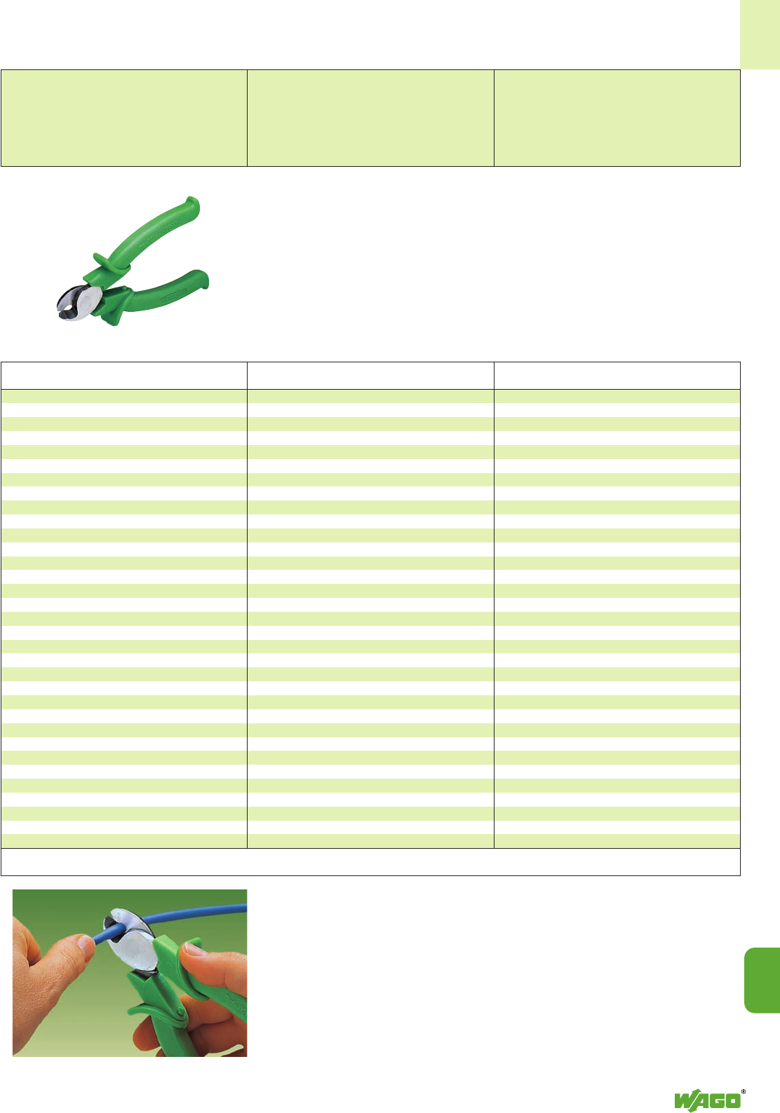
14
14
49
Application notes
Wire Cutter
Cutting of wire
Item Pack.-unit
No. pcs
Wire cutter
206-118 1
Wire cutter acc. to VDE
for copper and aluminum
wires up to 35 mm2/AWG 2
Weight 200 g / 0.441 lbs

15
15
VOLUME 1
Technical Section
International certification organizations
– Overview 15.2 – 15.3
– Updated list of all approvals available at www.wago.com
User guide to find approvals in our online catalog 15.4 – 15.5
– List of UL, CSA, CCA, ENEC and Ex approvals 15.6 – 15.12
CE marking and EC directives 15.13
IEC/EN specifications 15.14 – 15.15
Tests and testing procedures
– Mechanical tests
– Connection conditions 15.16 – 15.17
– Pull-out test 15.18
– Shock test 15.19
– Vibration test 15.20 – 15.21
– Electrical tests
– Temperature-rise test 15.22
– Current-carrying capacity curve (derating curve) 15.23
– Voltage drop test 15.24
– Short-time withstand current test 15.25
– Insulation parameters 15.26 – 15.31
– Power-frequency withstand voltage test 15.32
– Rated impulse withstand voltage test 15.32
– IP ratings for electrical equipment 15.32
– Material tests
– Needle flame test 15.33
– Glow-wire test 15.33
– Environmental tests
– Temperature cycling test 15.34
– Industrial atmospheres 15.34
– Salt spray test 15.35
– Quick change of temperature 15.35
– Damp heat (cyclic) 15.35
UL specifications – Underwriters Laboratories USA 15.36
– Tests and testing procedures according to UL standards
– Pull-out test 15.37
– Heat cycling test (cyclic temperature rise) 15.38
– Conditioning – temperature-rise test 15.39
– Grounding and bonding equipment 15.39
– Insulation coordination 15.40
– Flammability test 15.40
Connection of solid aluminum wires 15.41
Material specification
– Insulation materials 15.42 – 15.43
– Contact materials 15.44
– Contact surface 15.44
Index of item nos 15.45 – 15.55
Index 15.56 – 15.61
Addresses
– WAGO worldwide 15.62 – 15.63

15
2
Underwriters Laboratories UL
UUSA
http://www.ul.com
Underwriters Laboratories UL
uUSA
http://www.ul.com
Underwriters Laboratories cURus
YUSA
http://www.ul.com
Underwriters Laboratories cULus
rUSA
http://www.ul.com
Canadian Standards CSA
2Association
Canada
http://www.csa.ca
VDE-Gutachten mit VDE
vFertigungsüberwachung
Germany
http://www.vde.de/vde/html/e/home.htm
VDE – Deutscher Verband für
VElektrotechnik
Germany
http://www.vde.de
VDE – Prüfbericht
VDE Germany
Österreichischer Verband für ÖVE
OElektrotechnik Austria
http://www.ove.at
Schweizerischer SEV
sElektrotechnischer Verein
Schwitzerland
http://www.sev.ch/
N.V. tot Keuring van KEMA
KElektrotechnische Materialien
Netherlands
http://www.kema.nl
CENELEC CERTIFICATION AGREEMENT
N.V. tot Keuring van CCA
fElektrotechnische Materialien App. no.
Netherlands with NL
http://www.cenelec.org
Norges Elektriske NEMKO
Materialkontroll
NNorway
http://express.nemko.com
Svenska Elektriska SEMKO
Materielkontrollanstalten AB
SSweden
http://www.semko.com
Danmarks DEMKO
Elektriske Materielkontrol
DDenmark
http://www.demko.dk
CENELEC CERTIFICATION AGREEMENT
Danmarks Elektriske CCA
Materielkontrol App. no.
hDenmark with DK
http://www.cenelec.org
SETI – FEMKO
Sähkötarkastuskeskus
FElinspecktionscentralen
Finland
http://www.seti.fi
Sähkötarkastuskeskus FIMKO
FElinspecktionscentralen
Finland
http://www.fimko.com
South African Bureau SABS
jof Standards
South Africa
http://www.sabs.co.za
RosTesT ROSTEST
aRussland
http://www.rostest.ru
Departamentul CSM
qMoldovastandard
Moldova
http://www.moldova.md/ro/government/oll/
D_STAND/en/strcent2.htm
Certificate of Registration ASTA
AGreat Britain
http://www.astacertification.com
Rheinisch-Westfälischer RWTÜV
Technischer
RÜberwachungsverein e.V.
Germany
http://www.rwtuv.de
Abbreviation for
online search*
International Certification Organizations – Overview
A list of approvals (update: catalog deadline) is provided on
pages 15.6 to 15.12. Due to the numerous agencies and approvals as well as the
ever-increasing number of new products, our online catalog
provides you with complete up-to-date information at
www.wago.com
Abbreviation for
online search*
* see pages 15.4 and 15.5
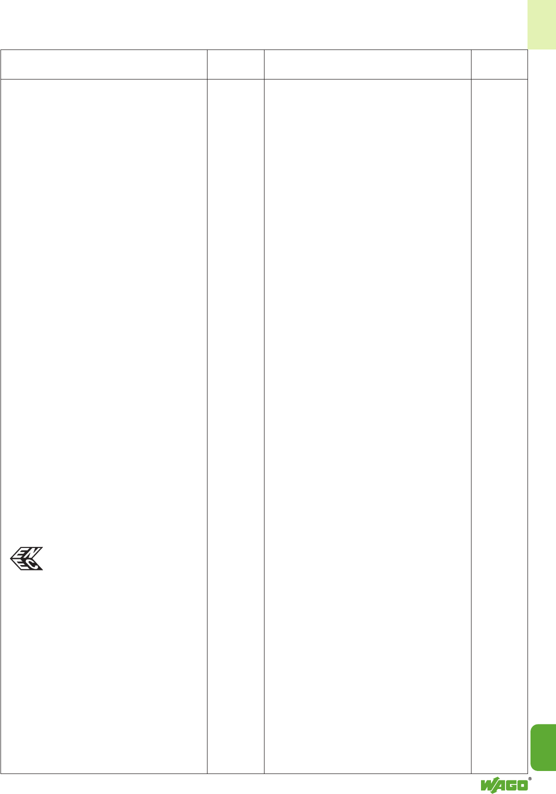
15
15
3
Elektrotechnick ´y v ´yskumn ´y EZU
a projektov ´y ústav
HCzech Republic
http://www.ezu.cz
Stowarzyszenie BBJ
Elektrykow Polskich
JPoland
http://www.bbj.pl
Stowarzyszenie SEP
Elektrykow Polskich
JPoland
http://www.sep.com.pl
Centre National d’Etudes CNET
mdes Télécommunications
France
http://www.lannion.cnet.fr
Laboratoire Central LCIE
des Industries Electriques
oFrance
http://www.lcie.fr
Fyzikálne Technick ´y FTZU
Zkusební Ústav,
-Ostrava-Radvanice
Czech Republic
http://www.ftzu.cz
Robbanásbiztos BKI
Villamos Berendezések
,Hungary
http://www.bki.hu
CB – TEST CERTIFICATE CB
CB India
http://www.ul-europe.com
CB – TEST CERTIFICATE CB
CB China
http://www.ul-europe.com
UL-International Demko A/S ENEC
Denmark
http://www.ul-europe.com
Abbreviation for
online search*
Abbreviation for
online search*
International Certification Organizations – Overview (continued)
Shipbuilding approvals
Germanischer Lloyd GL
gGermany
http://www.gl-group.com
Bureau Veritas BV
iFrance
http://www.bureauveritas.fr
Lloyd’s Register of Shipping LR
0Great Britain
http://www.lloydsregister.com
NV – Det Norske Veritas DNV
nNorway
http://www.dnv.com
Russian Maritime RMR
5Register of Shipping
CIS
http://www.rs-head.spb.ru
Polski Rejestr Statkóv PRS
&Poland
http://www.prs.pl
Korean Register of Shipping KR
.Korea
http://www.krs.co.kr
American Bureau of Shipping ABS
pUSA
http://www.eagle.org
Ex approvals
Physikalisch Technische PTB
Bundesanstalt
PGermany
Ex e II
http://www.ptb.de
Underwriters Laboratories cURus-EX
YUSA
http://www.ul.com
N.V. tot Keuring van KEMA-EX
KElektrotechnische Materialien
Netherland
http://www.kemaquality.com
GOSENERGO-Ex
GOSENERGONADZOR GOSENER
Russia GO-EX
Fyzikálne Technick ´y FTZU
Zkusební Ústav,
-Ostrava-Radvanice
Czech Republic
http://www.ftzu.cz
Robbanásbiztos BKI-EX
Villamos Berendezések
,Hungary
http://www.bki.hu
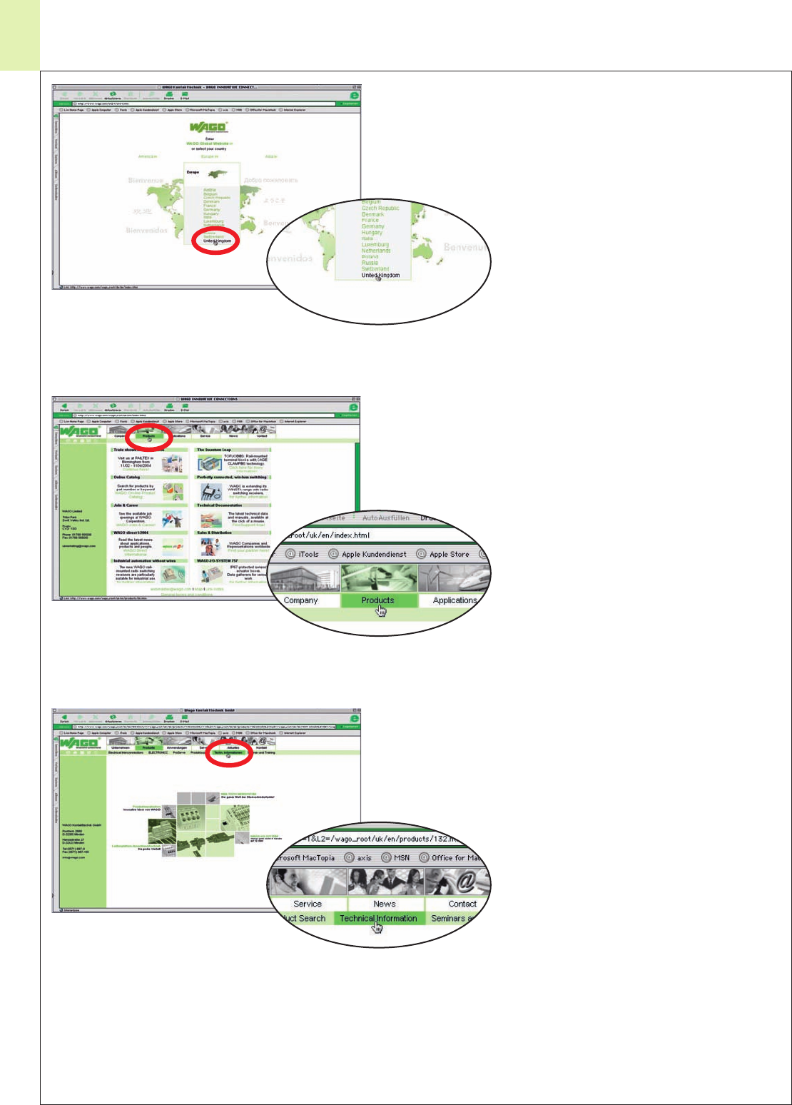
15
4
Approvals – User Guide
This guide will help you find approvals in our online catalog www.wago.com
1: Select “Country“
2: Select “Products“
3: Select “Technical Information“
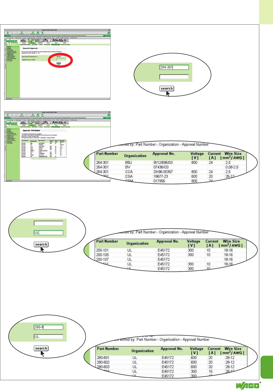
15
15
5
4: Entry 1
Item No.: e.g. “264-301“
Search result 1
All approvals related to that product will be
displayed.
Search result 2
All products approved by that agency will be
displayed.
Search result 3
The whole range of products approved by that
agency will be displayed.
4: Entry 2
Certification agency: e.g.“UL“
4: Entry 3
Certification agency and item num-
ber range:
e.g. “UL“ and Item-No. “280-6“ or
“280-60“

15
6
Approvals as per January 2004
281-623/ E45172 110 10 28-12
281-418
281-623/ E45172 30 10 28-12
281-541
281-623/ E45172 65 10 28-12
281-542
281-624 E45172 600 16 28-12
281-629 E45172 600 20 28-12
281-630 E45172 600 20 28-12
281-631 E45172 600 20 28-12
281-637 E45172 28-12
281-637/ E45172 28-12
999-950
281-651 E45172 600 20 28-12
281-652 E45172 600 20 28-12
281-653 E45172 600 20 28-12
281-654 E45172 600 20 28-12
281-656 E45172 300 10 28-12
281-657 E45172 28-12
281-657/ E45172 28-12
999-950
281-658 E45172 28-12
281-659 E45172 300 15 28-12
281-660 E45172 300 15 28-12
281-663 E45172 600 20 28-12
281-664 E45172 600 20 28-12
281-668 E45172 600 20 28-12
281-672 E45172 600 10 28-12
281-678 E45172 600 20 28-12
281-679 E45172 600 20 28-12
281-681 E45172 600 20 28-12
281-683 E45172 300 15 28-12
281-684 E45172 600 20 28-12
281-685 E45172 600 20 28-12
281-686 E45172 600 20 28-12
281-687 E45172 28-12
281-687/ E45172 28-12
999-950
281-691 E45172 600 20 28-12
281-90. E45172 600 20 28-12
281-907 E45172 28-12
281-907/ E45172 28-12
999-950
281-912 E45172 300 15 28-12
281-916 E45172 300 10 28-12
281-993 E45172 600 20 28-12
281-994 E45172 600 20 28-12
281-998 E45172 600 20 28-12
282-10. E45172 600 30 24-10
282-107 E45172 24-10
282-122 E45172 600 10 24-10
282-124 E45172 600 10 24-10
282-126 E45172 600 10 24-10
282-128 E45172 600 10 24-10
282-128/ E45172 24/110 10 24-10
281-413
282-128/ E45172 250 10 24-10
281-417
282-128/ E45172 24/110 10 24-10
281-418
282-131 E45172 300 30 24-10
282-133 E45172 300 30 24-10
282-135 E45172 300 30 24-10
282-601 E45172 600 30 24-10
282-604 E45172 600 30 24-10
282-607 E45172 24-10
282-607/ E45172 24-10
999-950
282-681 E45172 600 30 24-10
282-682 E45172 600 30 24-10
282-684 E45172 600 30 24-10
282-687 E45172 24-10
282-687/ E45172 24-10
999-950
282-691 E45172 600 30 24-10
282-694 E45172 600 30 24-10
282-695 E45172 600 30 24-10
282-696 E45172 600 30 24-10
282-697 E45172 600 30 24-10
282-698/ E45172 24 30 24-10
281-413
282-698/ E45172 12 30 24-10
281-429
282-698/ E45172 24 30 24-10
281-434
282-698/ E45172 24 30 24-10
281-449
282-699 E45172 600 30 24-10
282-8.. E45172 600 30 24-10
282-901 E45172 600 30 24-10
282-902 E45172 600 30 24-10
282-904 E45172 600 30 24-10
282-907 E45172 24-10
282-907/ E45172 24-10
999-950
282-992 E45172 600 30 24-10
282-993 E45172 600 30 24-10
283-101 E45172 600 65 24-6
283-104 E45172 600 65 24-6
283-107 E45172 24-6
280-687/ E45172 28-12
999-950
280-691 E45172 600 20 28-12
280-695 E45172 300 15 28-12
280-805 E45172 300 15 28-12
280-826 E45172 600 15 28-12
280-829 E45172 300 15 28-12
280-830 E45172 600 20 28-12
280-831 E45172 600 20 28-12
280-832 E45172 600 20 28-12
280-833 E45172 600 20 28-12
280-834 E45172 600 20 28-12
280-835 E45172 600 20 28-12
280-836 E45172 300 15 28-12
280-837 E45172 28-12
280-837/ E45172 28-12
999-950
280-838 E45172 28-12
280-839 E45172 300 15 28-12
280-868 E45172 600 15 28-12
280-869 E45172 600 15 28-12
280-870 E45172 600 15 24-10
280-871 E45172 600 15 28-12
280-874 E45172 600 15 28-12
280-875 E45172 600 15 28-12
280-876 E45172 600 15 28-12
280-879 E45172 600 15 28-12
280-880 E45172 600 15 28-12
280-881 E45172 600 15 28-12
280-882 E45172 600 15 28-12
280-883 E45172 600 15 28-12
280-884 E45172 600 15 28-12
280-885 E45172 600 15 28-12
280-90. E45172 600 20 28-12
280-907 E45172 28-12
280-907/ E45172 28-12
999-950
280-912 E45172 300 15 28-12
280-916 E45172 300 15 28-12
280-989 E45172 600 20 28-12
280-990 E45172 300 15 28-12
280-992 E45172 600 20 28-12
280-993 E45172 600 20 28-12
280-994 E45172 600 20 28-12
280-995 E45172 600 20 28-12
280-996 E45172 600 20 28-12
280-998 E45172 600 20 28-12
280-999 E45172 600 20 28-12
281-101 E45172 600 20 28-12
281-104 E45172 600 20 28-12
281-107 E45172 28-12
281-107/ E45172 28-12
999-950
281-601 E45172 600 20 28-12
281-603/ E45172 28-12
281-411
281-604 E45172 600 20 28-12
281-607 E45172 28-12
281-607/ E45172 28-12
999-950
281-610 E45172 300 10 28-12
281-611 E45172 600 10 28-12
281-611/ E45172 110/220 10 28-12
281-417
281-611/ E45172 110/220 10 28-12
281-418
281-611/ E45172 30/65 10 28-12
281-541
281-611/ E45172 30/65 10 28-12
281-542
281-612 E45172 600 10 28-12
281-612/ E45172 110/220 10 28-12
281-417
281-612/ E45172 110/220 10 28-12
281-418
281-612/ E45172 30/65 10 28-12
281-541
281-612/ E45172 30/65 10 28-12
281-542
281-613 E45172 600 10 28-12
281-613/ E45172 110/220 10 28-12
281-417
281-613/ E45172 110/220 10 28-12
281-418
281-613/ E45172 30/65 10 28-12
281-541
281-613/ E45172 30/65 10 28-12
281-542
281-616 E45172 600 10 28-12
281-619 E45172 600 20 28-12
281-620 E45172 600 20 28-12
281-622 E45172 600 10 28-12
281-622/ E45172 220 10 28-12
281-417
281-622/ E45172 110 10 28-12
281-418
281-622/ E45172 30 10 28-12
281-541
281-622/ E45172 65 10 28-12
281-542
281-623 E45172 600 10 28-12
281-623/ E45172 220 10 28-12
281-417
Vol- Cur- Cross
Item Approval- tage rent Section
No. No. V A AWG/mm2
Vol- Cur- Cross
Item Approval- tage rent Section
No. No. V A AWG/mm2
Vol- Cur- Cross
Item Approval- tage rent Section
No. No. V A AWG/mm2
Vol- Cur- Cross
Item Approval- tage rent Section
No. No. V A AWG/mm2
“sol/s“ = solid wiring “str“ = stranded wiring
UL –
UUnderwriters Laboratories
USA
243-204 E45172 125 22-18
243-208 E45172 125 22-18
243-304 E45172 125 22-18
243-308 E45172 125 22-18
243-504 E45172 125 22-18
243-508 E45172 125 22-18
243-804 E45172 125 22-18
243-808 E45172 125 22-18
260-1.. E45172 300 10 28-16
261-... E45172 300/600 15/5 28-14
262-... E45172 300/600 20/5 28-12
264-1.. E45172 600 20 28-12
264-2.. E45172 600 20 28-12
264-3.. E45172 600 20 28-12
264-357 E45172 28-12
264-7.. E45172 600 20 28-12
264-727 E45172 28-12
264-727/ E45172 28-12
999-950
264-737 E45172 28-12
264-737/ E45172 28-12
999-950
279-1.. E45172 600 10 28-16
279-604 E45172 600 10 28-16
279-621 E45172 600 10 28-16
279-623/ E45172 24 10 28-16
281-411
279-624/ E45172 24 10 28-16
281-413
279-626 E45172 600 10 28-16
279-68. E45172 600 10 28-16
279-687 E45172 28-16
279-687/ E45172 28-16
999-950
279-8.. E45172 600 10 28-16
279-837 E45172 28-16
279-837/ E45172 28-16
999-950
279-838 E45172 28-16
279-9.. E45172 600 10 28-16
279-907 E45172 28-16
279-907/ E45172 28-16
999-950
280-10. E45172 600 20 28-12
280-107 E45172 28-12
280-510 E45172 300/600 15/5 28-12
280-513 E45172 300 15 28-12
280-515 E45172 300 15 28-12
280-519 E45172 300 15 28-12
280-520 E45172 300 15 28-12
280-521 E45172 300 10 28-12
280-522 E45172 300 10 28-12
280-523 E45172 300 15 28-12
280-524 E45172 300 15 28-12
280-525 E45172 300 10 28-12
280-526 E45172 300 10 28-12
280-527 E45172 28-12
280-529 E45172 300 15 28-12
280-530 E45172 300 15 28-12
280-531 E45172 300 15 28-12
280-532 E45172 300 15 28-12
280-533 E45172 300 15 28-12
280-534 E45172 300 15 28-12
280-537 E45172 28-12
280-543 E45172 300 15 28-12
280-547 E45172 300/600 15 28-12
280-548 E45172 28-12
280-549 E45172 300/600 15 28-12
280-550 E45172 300/600 15 28-12
280-551 E45172 300/600 15 28-12
280-552 E45172 300/600 15 28-12
280-553 E45172 300 15 28-12
280-554 E45172 300 15 28-12
280-555 E45172 300 15 28-12
280-556 E45172 300 15 28-12
280-557 E45172 300/600 15 28-12
280-558 E45172 28-12
280-560 E45172 300 15 28-12
280-560/ E45172 24 15 28-12
281-434
280-561 E45172 300 6 28-12
280-561/ E45172 24 15 28-12
281-413
280-562 E45172 300 15 28-12
280-562/ E45172 300 15 28-12
281-411
280-562/ E45172 24 15 28-12
281-420
280-562/ E45172 24 15 28-12
281-434
280-563 E45172 300 10 28-12
280-564 E45172 300 15 28-12
280-564/ E45172 24 15 28-12
281-483
280-565 E45172 250 6,3 28-12
280-565/ E45172 250 6,3 28-12
280-321
280-566 E45172 300 10 28-12
280-566/ E45172 24 15 28-12
281-496
280-567 E45172 300 15 28-12
280-568 E45172 300 15 28-12
280-570 E45172 300 15 28-12
280-570/ E45172 24 15 28-12
281-434
280-571 E45172 300 6 28-12
280-571/ E45172 24 15 28-12
281-413
280-572 E45172 600 20 28-12
280-572/ E45172 300 15 28-12
281-411
280-572/ E45172 24 15 28-12
281-420
280-572/ E45172 24 15 28-12
281-434
280-573 E45172 300 10 28-12
280-574 E45172 300 15 28-12
280-574/ E45172 24 15 28-12
281-483
280-575 E45172 250 6,3 28-12
280-575/ E45172 250 6,3 28-12
280-320
280-576 E45172 300 10 28-12
280-576/ E45172 24 15 28-12
281-496
280-577 E45172 300 15 28-12
280-577/ E45172 24 15 28-12
281-496
280-578 E45172 300 15 28-12
280-580 E45172 300 15 28-12
280-580/ E45172 24 15 28-12
281-434
280-581/ E45172 24 15 28-12
281-413
280-583 E45172 300 15 28-12
280-584 E45172 300 15 28-12
280-584/ E45172 24 15 28-12
281-483
280-585 E45172 300 15 28-12
280-586 E45172 300 15 28-12
280-586/ E45172 24 15 28-12
281-496
280-587 E45172 300 15 28-12
280-588 E45172 250 6,3 28-12
280-588/ E45172 250 6,3 28-12
280-323
280-592 E45172 300 15 28-12
280-593 E45172 300 15 28-12
280-601 E45172 600 20 28-12
280-602 E45172 600 20 28-12
280-603 E45172 600 20 28-12
280-604 E45172 300 15 28-12
280-606 E45172 300 10 28-12
280-607 E45172 28-12
280-607/ E45172 28-12
999-950
280-610 E45172 300 10 28-12
280-612 E45172 300 15 28-12
280-616 E45172 300 10 28-12
280-621 E45172 600 15 28-12
280-622 E45172 300 15 28-12
280-624/ E45172 24 0,02 28-12
281-413
280-626 E45172 600 15 28-12
280-627 E45172 300 15 28-12
280-633 E45172 600 20 28-12
280-634 E45172 600 20 28-12
280-637 E45172 28-12
280-637/ E45172 28-12
999-950
280-640 E45172 28-12
280-641 E45172 600 20 28-12
280-649 E45172 300 15 28-12
280-651 E45172 600 20 28-12
280-653 E45172 600 20 28-12
280-654 E45172 600 20 28-12
280-656 E45172 300 10 28-12
280-671 E45172 600 20 28-12
280-672 E45172 600 20 28-12
280-675 E45172 600 10 28-12
280-676 E45172 300 15 28-12
280-677 E45172 28-12
280-677/ E45172 28-12
999-950
280-678 E45172 28-12
280-681 E45172 600 20 28-12
280-683 E45172 300 15 28-12
280-684 E45172 600 20 28-12
280-685 E45172 300 15 28-12
280-687 E45172 28-12

15
7
15
Vol- Cur- Cross
Item Approval- tage rent Section
No. No. V A AWG/mm2
Vol- Cur- Cross
Item Approval- tage rent Section
No. No. V A AWG/mm2
Vol- Cur- Cross
Item Approval- tage rent Section
No. No. V A AWG/mm2
Vol- Cur- Cross
Item Approval- tage rent Section
No. No. V A AWG/mm2
769-101/ E45171 600 20 28-12
022-016
769-102 E45171 600 20 28-12
|
769-115
769-102 E45172 300/600 10/5 28-12
769-121 E45172 300/600 10/5 28-12
|
769-135
769-121 E45171 600 20 28-12
|
769-135
769-121/ E45171 600 20 28-12
000-016
769-15. E45172 300/600 10/5 28-12
769-15. E45171 600 20 28-12
769-161 E45171 600 20 28-12
769-161 E45172 300/600 10/5 28-12
769-162/ E45172 300/600 10/5 28-12
769-313
769-162/ E45171 600 20 28-12
769-313
769-163/ E45172 300/600 10/5 28-12
769-313
769-163/ E45171 600 20 28-12
769-313
769-164/ E45171 600 20 28-12
769-313
769-164/ E45172 300/600 10/5 28-12
769-313
769-165/ E45171 600 20 28-12
769-313
769-165/ E45172 300/600 10/5 28-12
769-313
769-171 E45171 600 20 28-12
769-171 E45172 300/600 10/5 28-12
769-176 E45172 300/600 10/5 28-12
769-176 E45171 600 20 28-12
769-181 E45172 300/600 10/5 28-12
769-181 E45171 600 20 28-12
769-182/ E45171 600 20 28-12
769-314
769-182/ E45172 300/600 10/5 28-12
769-314
769-183/ E45172 300/600 10/5 28-12
769-314
769-184/ E45172 300/600 10/5 28-12
769-314
769-184/ E45171 600 20 28-12
769-314
769-185/ E45172 300/600 10/5 28-12
769-314
769-185/ E45171 600 20 28-12
769-314
769-191 E45172 300/600 10/5 28-12
769-191 E45171 600 20 28-12
769-192/ E45172 300/600 10/5 28-12
769-319
769-192/ E45171 600 20 28-12
769-319
769-193/ E45172 300/600 10/5 28-12
769-319
769-193/ E45171 600 20 28-12
769-319
769-194/ E45172 300/600 10/5 28-12
769-319
769-194/ E45171 600 20 28-12
769-319
769-195/ E45171 600 20 28-12
769-319
769-195/ E45172 300/600 10/5 28-12
769-319
769-20. E45171 600 20 28-12
769-20. E45172 300/600 10/5 28-12
769-207 E45171 28-12
769-207 E45172 28-12
769-208/ E45171 600 20 28-12
281-410
769-208/ E45172 300/600 10/5 28-12
281-410
769-208/ E45171 600 20 28-12
281-411
769-208/ E45172 300/600 10/5 28-12
281-411
769-209/ E45172 300/600 10/5 28-12
281-413
769-209/ E45171 600 20 28-12
281-413
769-209/ E45171 600 20 28-12
281-434
769-21. E45171 600 20 28-12
769-21. E45172 300/600 10/5 28-12
769-217 E45171 28-12
769-217 E45172 28-12
769-218/ E45171 600 20 28-12
281-410
769-218/ E45172 300/600 10/5 28-12
281-410
769-218/ E45172 300/600 10/5 28-12
281-411
769-218/ E45171 600 20 28-12
281-411
769-219/ E45171 600 20 28-12
281-413
769-219/ E45172 300/600 10/5 28-12
281-413
283-601 E45172 600 65 24-6
283-604 E45172 600 65 24-6
283-607 E45172 24-6
283-607/ E45172 24-6
999-950
283-609 E45172 24-6
283-671 E45172 600 65 24-6
283-672 E45172 600 65 24-6
283-674 E45172 600 65 24-6
283-677 E45172 24-6
283-677/ E45172 24-6
999-950
283-691 E45172 600 65 24-6
283-901 E45172 600 65 24-6
283-902 E45172 600 65 24-6
283-904 E45172 600 65 24-6
283-907 E45172 24-6
283-907/ E45172 24-6
999-950
283-992 E45172 600 65 24-6
283-998 E45172 600 65 24-6
284-101 E45172 600 50 24-8
284-104 E45172 600 50 24-8
284-107 E45172 24-8
284-601 E45172 600 50 24-8
284-604 E45172 600 50 24-8
284-607 E45172 24-8
284-607/ E45172 24-8
999-950
284-621 E45172 600 115 24-8
284-624 E45172 600 115 24-8
284-681 E45172 600 50 24-8
284-682 E45172 600 50 24-8
284-684 E45172 600 50 24-8
284-687 E45172 24-8
284-687/ E45172 24-8
999-950
284-691 E45172 600 50 24-8
284-901 E45172 600 50 24-8
284-902 E45172 600 50 24-8
284-904 E45172 600 50 24-8
284-907 E45172 24-8
284-907/ E45172 24-8
999-950
284-992 E45172 600 50 24-8
284-993 E45172 600 50 24-8
285-194 E45172 600 200 4-3/0"str"
285-195 E45172 600 200 4-3/0"str"
285-197 E45172 4-3/0"str"
285-634 E45172 600 115 10-2"s","str"
285-635 E45172 600 115 10-2"s","str"
285-637 E45172 10-2"s","str"
285-637/ E45172 10-2"s","str"
999-950
726-1.. E45172 300 10 28-16/28-18
726-2.. E45172 300 10 28-14/28-18
726-3.. E45172 300 10 28-16/28-18
726-4.. E45172 300 10 28-16/28-18
726-521 E45172 300 10 28-14/28-18
726-60. E45172 300 10 24-6/28-14
726-61. E45172 300 10 24-6/28-14
726-62. E45172 24-6/28-14
726-65. E45172 300 10 24-6/28-14
726-66. E45172 300 10 24-6/28-14
726-67. E45172 24-6/28-14
726-7.. E45172 300 10 28-16/28-18
726-8.. E45172 300 10 28-14/28-18
727-... E45172 300 10 28-16
769-101 E45172 300/600 10/5 28-12
|
769-115
769-101/ E45171 600 20 28-12
000-016
769-101/ E45172 300/600 10/5 28-12
021-000
|
769-115/
021-000
769-101/ E45171 600 20 28-12
022-000
|
769-115/
022-000
769-101/ E45172 300/600 10/5 28-12
022-000
|
769-115/
022-000
769-101/ E45172 300/600 10/5 28-12
022-016
769-219/ E45171 600 20 28-12
281-434
769-219/ E45172 300/600 10/5 28-12
281-434
769-22. E45171 600 20 28-12
769-22. E45172 300/600 10/5 28-12
769-227 E45171 28-12
769-227 E45172 28-12
769-228/ E45171 600 20 28-12
281-410
769-228/ E45172 300/600 10/5 28-12
281-410
769-228/ E45171 600 20 28-12
281-411
769-228/ E45172 300/600 10/5 28-12
281-411
769-229/ E45171 600 20 28-12
281-413
769-229/ E45172 300/600 10/5 28-12
281-413
769-229/ E45171 600 20 28-12
281-434
769-229/ E45172 300/600 10/5 28-12
281-434
769-23. E45171 600 20 28-12
769-23. E45172 300/600 10/5 28-12
769-237 E45172 10/5 28-12
769-237 E45171 28-12
769-238/ E45172 300/600 10/5 28-12
281-410
769-238/ E45171 600 20 28-12
281-410
769-238/ E45172 300/600 10/5 28-12
281-411
769-238/ E45171 600 20 28-12
281-411
769-239/ E45171 600 20 28-12
281-413
769-239/ E45172 300/600 10/5 28-12
281-413
769-239/ E45171 600 20 28-12
281-434
769-239/ E45172 300/600 10/5 28-12
281-434
769-602 E45172 300/600 10/5 28-12
|
769-615
769-602 E45171 600 20 28-12
|
769-602
769-602/ E45171 600 20 28-12
001-000
|
769-615/
001-000
769- E45172 300/600 10/5 28-12
001-000
|
769-615/
001-000
769-602/ E45172 300/600 10/5 28-12
002-000
|
769-615/
002-000
769-602/ E45171 600 20 28-12
002-000
|
769-615/
002-000
769-602/ E45171 600 20 28-12
004-000
|
769-615/
004-000
769-602/ E45172 300/600 10/5 28-12
004-000
|
769-615/
004-000
769-632 E45172 300/600 10/5 28-12
|
769-642
769-632 E45171 600 20 28-12
|
769-642
769-632/ E45171 600 20 28-12
003-000
|
769-642/
003-000
769-632/ E45171 600 20 28-12
004-000
|
769-642/
004-000
769-662 E45171 600 20 28-12
|
769-672
769-662 E45172 300/600 10/5 28-12
|
769-672
769-662/ E45171 600 20 28-12
003-000
|
769-672/
003-000
769-662/ E45171 600 20 28-12
004-000
|
769-672/
004-000
862-... E45172 300/600 20/5 20-12
2001-120 . E45172 600 15 22-14
2001-1207 E45172 22-14
2001-130 . E45172 600 15 22-14
2001-1307 E45172 22-14
2001-140. E45172 600 15 22-14
2001-1407 E45172 22-14
2002-120 . E45172 600 20 22-12
2002-1207 E45172 22-12
2002-130 . E45172 600 20 22-12
2002-1307 E45172 22-12
2002-140. E45172 600 20 22-12
2002-1407 E45172 22-12
2004-120 . E45172 600 30 20-10
2004-1207 E45172 20-10
2004-130 . E45172 600 30 20-10
2004-1307 E45172 20-10
2004-140. E45172 600 30 20-10
2004-1407 E45172 20-10
2006-120 . E45172 600 50 20-8
2006-1207 E45172 20-8
2006-130 . E45172 600 50 20-8
2006-1307 E45172 20-8
2016-120 . E45172 600 85 20-4
2016-1207 E45172 20-4
2016-130 . E45172 600 85 20-4
2016-1307 E45172 20-4
UL –
uUnderwriters Laboratories
USA
222-413 E69654 600 20 28-12"s","str"
224-101 E69654 300 20 14-12"s"/
20-16"s"/"str"
224-104 E69654 300 20 14-12"s"/
20-16"s"/"str"
224-112 E69654 300 4 18-16"s"/
20-16"s"/"str"
224-114 E69654 300 20 18-16"s"/
20-16"s"/"str"
224-201 E69654 300 20 20-16
273-100 E69654 600 10 20-16"s"
273-101 E69654 600 10 20-16"s"
273-102 E69654 600 20 18-12"s"
273-103 E69654 600 20 16-14"s"
273-104 E69654 600 20 18-12"s"
273-105 E69654 600 20 18-12"s"
273-108 E69654 600 10 20-16"s"
273-112 E69654 600 20 18-12"s"
273-153 E69654 600 10 20-16"s"
273-155 E69654 600 10 20-16"s"
273-158 E69654 600 10 20-16"s"
273-252 E69654 600 20 18-12"s"
273-253 E69654 600 20 18-12"s"
273-254 E69654 600 20 18-12"s"
273-255 E69654 600 20 18-12"s"
273-258 E69654 600 15 16-14"s"
273-403 E69654 600 30 10-12"s"
273-453 E69654 600 30 10-12"s"
773-208 E69654 600 20 18-12"s",
22-16str

15
8
Vol- Cur- Cross
Item Approval- tage rent Section
No. No. V A AWG/mm2
Vol- Cur- Cross
Item Approval- tage rent Section
No. No. V A AWG/mm2
Vol- Cur- Cross
Item Approval- tage rent Section
No. No. V A AWG/mm2
Vol- Cur- Cross
Item Approval- tage rent Section
No. No. V A AWG/mm2
CSA – Canadian Standard
2Association
Canada
224-1.. 154112- 300 14-12"s"/
1059435 20-16"rig"
224-201 154112- 300 20-16"rig"
1059435
243-20. 18677-31 150 22-20mixed/
(4x18)
243-30. 18677-31 150 22-20mixed/
(4x18)
243-50. 18677-31 150 22-20mixed/
(4x18)
243-80. 18677-31 150 22-20mixed/
(4x18)
260-... 18677-45 300 15 24-16
261-... 18677-45 300/600 20/5 26-14
262-... 18677-45 300/600 20/5 26-12
264-102 18677-23 600 20 26-12
264-3.7 18677-23 26-12
264-727 18677-23 26-12
264-727/ 18677-23 26-12
999-950
264-737 18677-23 26-12
264-737/ 18677-23 26-12
999-950
154112-
273-100 1059435 600 10 20-16"s"
273-101 1059435 600 10 20-16"s"
273-102 1059435 600 20 18-12"s"
273-103 1059435 600 10 20-16"s"
273-104 1059435 600 20 18-12"s"
273-105 1059435 600 20 18-12"s"
273-108 1059435 600 10 20-16"s"
273-112 1059435 600 20 18-12"s"
273-114 1059435 600 20 22-12"s"
273-153 1059435 600 10 20-16"s"
273-155 1059435 600 10 20-16"s"
273-158 1059435 600 10 20-16"s"
154112-
273-252 1059435 600 20 18-12"s"
273-253 1059435 600 20 18-12"s"
273-254 1059435 600 20 18-12"s"
273-255 1059435 600 20 18-12"s"
273-258 1059435 600 20 18-14"s"
154112-
273-4.. 1059435 600 30 14-10"s"
154112-
279-10. 1327715 600 15 28-16
154112-
279-604 1327715 600 15 28-16
279-621 1327715 600 15 28-16
279-626 1327715 600 15 28-16
279-68. 1327715 600 10 28-16
279-687 1327715 28-16
279-687/ 1327715 28-16
999-950
279-826 154112-1327715 600 15 28-16
279-83. 154112-1327715 600 10 28-16
279-837 154112-1327715 28-16
279-837/ 154112-1327715 28-16
999-950
279-838 154112-1327715 28-16
154112-
279-901 1327715 600 10 28-16
279-907 1327715 28-16
279-907/ 11327715 28-16
999-950
279-989 1327715 600 15 24-16
279-990 1327715 600 15 24-16
279-992 1327715 600 10 24-16
279-993 1327715 600 10 24-16
279-994 1327715 600 10 24-16
279-995 1327715 600 10 24-16
280-10. LR18677-5 600 20 28-12
280-107 18677-15 28-12
280-510 18677-27 600 20 28-12
280-513 18677-26 300/600 20/5 28-12
280-515 18677-52 300 15 28-12
280-519 18677-26 300/600 20/5 28-12
280-520 18677-26 300/600 20/5 28-12
280-521 18677-26 300/600 20/5 28-12
280-522 18677-26 300/600 20/5 28-12
280-523 18677-26 300/600 20/5 28-12
CUR US –
YUnderwriters Laboratories
USA
281-530 E45172 300 20 28-12
290-661 E45172 300/150 10 22-16"s"/"str"/
22-18"s"
290-664 E45172 300/150 10 22-16"s"/"str"/
22-18"s"
290-667 E45172 22-16"s"/"str"/
22-18"s"
290-681 E45172 300/150 10 28-12"sol"/"str"
290-684 E45172 300/150 10 28-12"sol"/"str"
290-687 E45172 28-12"sol"/"str"
290-901 E45172 300/150 10 28-12"sol"/"str"
290-904 E45172 300/150 10 28-12"sol"/"str"
290-907 E45172 28-12"sol"/"str"
290-961 E45172 300/150 10 22-16"s"/"str"/
22-18"s"
290-964 E45172 300/150 10 22-16"s"/"str"/
22-18"s"
290-967 E45172 22-16"s"/"str"/
22-18"s"
869-1.. E45172 300/600 20/5 28-12
869-2.. E45172 300/600 20/5 28-12
869-2.. E45172 300/600 20/5 28-12
870-101 E45172 300/600 20/5 28-12
870-102 E45172 300/600 20/5 28-12
870-103 E45172 300/600 20/5 28-12
870-104 E45172 300/600 20/5 28-12
870-107 E45172 28-12
870-108 E45172 300/600 20/5 28-12
870-109 E45172 300/600 20/5 28-12
870-117 E45172 300/600 20/5 28-12
870-127 E45172 300/600 20/5 28-12
870-501 E45172 300/600 20/5 28-12
870-502 E45172 300/600 20/5 28-12
870-503 E45172 300/600 20/5 28-12
870-504 E45172 300/600 20/5 28-12
870-507 E45172 28-12
870-508 E45172 300/600 20/5 28-12
870-509 E45172 300/600 20/5 28-12
870-517 E45172 300/600 20/5 28-12
870-527 E45172 300/600 20/5 28-12
870-531 E45172 300/600 20/5 28-12
870-532 E45172 300/600 20/5 28-12
870-533 E45172 300/600 20/5 28-12
870-534 E45172 300/600 20/5 28-12
870-535 E45172 300/600 20/5 28-12
870-536 E45172 300/600 20/5 28-12
870-377 E45172 28-12
870-538 E45172 300/600 20/5 28-12
870-539 E45172 300/600 20/5 28-12
870-551 E45172 300/600 20/5 28-12
870-553 E45172 300/600 20/5 28-12
870-556 E45172 300/600 20/5 28-12
870-557 E45172 28-12
870-558 E45172 300/600 20/5 28-12
870-559 E45172 300/600 20/5 28-12
870-567 E45172 300/600 20/5 28-12
870-577 E45172 300/600 20/5 28-12
870-68. E45172 300/600 20/5 28-12
870-83. E45172 300/600 20/5 28-12
870-90. E45172 300/600 20/5 28-12
870-907 E45172 28-12
870-91. E45172 300/600 20/5 28-12
870-917 E45172 28-12
880-68. E45172 600 20 28-12
880-687 E45172 28-12
880-831 E45172 600 20 28-12
880-832 E45172 600 20 28-12
880-834 E45172 600 20 28-12
880-837 E45172 28-12
880-90. E45172 600 20 28-12
880-907 E45172 28-12
280-524 18677-26 300/600 20/5 28-12
280-525 18677 300 15 28-12
280-526 18677 300 15 28-12
280-527 18677-26 300/600 20/5 28-12
280-529 18677-26 300/600 20/5 28-12
280-530 18677-26 300/600 20/5 28-12
280-531 18677 300 20 28-12
280-532 18677 300 20 28-12
280-533 18677-26 300/600 20/5 28-12
280-534 18677-26 300/600 20/5 28-12
280-537 18677-26 300/600 20/5 28-12
280-543 18677-26 300/600 20/5 28-12
280-547 18677-27 300/600 20/5 28-12
280-548 18677-27 300/600 20/5 28-12
280-549 18677-27 300/600 20/5 28-12
280-550 18677-27 300/600 20/5 28-12
280-551 18677-27 300/600 20/5 28-12
280-552 18677-27 300/600 20/5 26-14
280-554 18677-52 300 15 28-12
280-555 18677-52 300 15 28-12
280-556 18677-52 300 15 28-12
280-557 18677-52 300 15 28-12
280-558 18677-27 300/600 20/5 28-12
280-559 18677-52 300 15 28-12
280-56. 18677-52 300 15 28-12
280-56./... 18677-52 300 15 28-12
280-57. 18677-52 300 15 28-12
280-57./... 18677-52 300 15 28-12
280-580 18677-52 300 15 28-12
280-584 18677-52 300 15 28-12
280-584/ 18677-52 300 15 28-12
281-483
280-585 18677-52 300 15 28-12
280-586 18677-52 300 15 28-12
280-587 18677-52 300 15 28-12
280-588 18677-52 300 15 28-12
280-588/ 18677-52 300 15 28-12
280-323
280-592 18677-52 300 15 28-12
280-593 18677-52 300 15 28-12
280-60. 18677 600 25 28-12
280-607 18677-15 28-12
280-607/ 18677-15 28-14
999-950
280-610 18677 600 28-14
280-612 18677 600 15 28-14
280-616 18677 600 15 28-14
280-621 18677-7 600 15 28-14
280-622 18677-7 600 15 28-14
280-626 18677-7 600 20 28-12
280-627 18677-7 600 25 28-12
280-633 18677-7 600 25 28-12
280-634 18677-7 600 25 28-12
280-637 18677-15 28-12
280-637/ 18677-15 28-12
999-950
280-641 18677-7 600 25 28-12
280-646 18677 600 25 28-12
280-650 18677-26 600 15 28-12
280-651 18677 600 25 28-12
280-653 18677-22 600 15 28-12
280-654 18677 600 25 28-12
280-656 18677 600 25 28-12
280-671 18677-22 600 15 28-12
280-672 18677-22 600 15 28-12
280-676 18677-22 600 15 28-12
280-677 18677-15 28-12
280-677/ 18677-15 28-12
999-950
280-678 18677-15 28-12
280-681 18677 600 25 28-12
280-683 18677 600 25 28-12
280-684 18677 600 25 28-12
280-685 18677 600 25 28-12
280-686 18677 600 25 28-12
280-687 18677-15 28-12
280-687/ 18677-15 28-12
999-950
280-691 18677-22 600 15 28-12
280-695 18677-22 600 15 28-12
280-826 18677-22 600 15 28-12
280-830 18677-22 600 15 28-12
280-831 18677-22 600 25 28-12
280-832 18677-22 600 15 28-12
280-833 18677-22 600 15 28-12
280-834 18677-22 600 15 28-12
280-835 18677-22 600 15 28-12
280-836 18677-22 600 15 28-12
280-837 18677-52 28-12
280-837/ 18677-52 28-12
999-950
280-838 18677-22 28-12
280-850 18677-45
280-852 18677-45
280-856 18677-45 2
280-868 18677-52 300 15 28-12
280-869 18677-52 300 15 28-12
280-870 18677-53 300 5 24-10
280-870 18677-52 300 15 28-12
280-871 18677-52 300 15 28-12
280-874 18677-52 300 15 28-12
280-875 18677-52 300 15 28-12
280-876 18677-52 300 15 28-12
280-879 18677-52 300 15 28-12
280-88. 18677-52 300 15 28-12
280-901 18677 600 25 26-12
280-902 18677 600 25 26-12
280-903 18677-22 600 15 28-12
280-904 18677 600 25 26-12
280-905 18677-22 600 15 28-12
280-906 18677-22 600 15 28-12
280-907 18677-15 28-12
280-907/ 18677-15 26-14
999-950
280-912 18677 3 00 15 26-14
280-916 18677 3 00 15 26-14
280-946 18677-22 600 15 28-12
280-989 18677-22 600 15 28-12
280-99. 18677-22 600 15 28-12
281-10. 18677-5 600 65 26-12
281-107 18677-15 26-12
281-511 18677-45
281-512 18677-45
281-530 154112-1014215 300 25 28-12
281-601 18677-48 600 20 28-12
281-604 18677 600 20 26-12
281-607 18677-15 26-12
281-607/ 18677-15 26-12
999-950
281-610 18677 600 15 26-12
281-611 18677-36 600 10 2 8-12
281-611/ 18677-36 110/220 10 28-12
281-417
281-611/ 18677-36 110/220 10 28-12
281-418
281-611/ 18677-36 15/30 10 28-12
281-541
281-611/ 18677-36 30/65 10 28-12
281-542
281-612 18677-36 600 10 2 8-12
281-612/ 18677-36 110/220 10 28-12
281-417
281-612/ 18677-36 110/220 10 28-12
281-418
281-612/ 18677-36 15/30 10 28-12
281-541
281-612/ 18677-36 30/65 10 28-12
281-542
281-613 18677-36 600 10 2 8-12
281-613/ 18677-36 110/220 10 28-12
281-417
281-613/ 18677-36 110/220 10 28-12
281-418
281-613/ 18677-36 15/30 10 28-12
281-541
281-613/ 18677-36 30/65 10 28-12
281-542
281-619 18677-22 600 15 26-12
281-620 18677-22 600 10 28-12
281-622 18677-22 600 10 28-12
281-622/ 18677-36 110/220 10 28-12
281-417
281-622/ 18677-36 110/220 10 28-12
281-418
281-622/ 18677-36 15/30 10 28-12
281-541
281-622/ 18677-36 30/65 10 28-12
281-542
281-623 18677-36 600 10 28-12
281-623/ 18677-36 110/220 10 28-12
281-417
281-623/ 18677-36 110/220 10 28-12
281-418
281-623/ 18677-36 15/30 10 28-12
281-541
281-623/ 18677-36 30/65 10 28-12
281-542
281-624 18677-36 600 16 28-12
281-629 18677-36 600 10 28-12
281-630 18677 600 15 26-12
281-631 18677 600 15 26-12
281-637 18677-15 26-12
281-637/ 18677-15 26-12
999-950
281-651 18677 600 15 26-12
281-652 18677-22 600 15 28-12
281-653 18677-22 600 15 28-12
281-654 18677-22 600 15 28-12
281-656 18677-45 300 10 28-12
281-657 18677-15 26-12
281-657/ 18677-15 28-12
999-950
281-659 18677-22 600 15 28-12
281-660 18677-22 600 15 28-12
281-663 18677-22 600 15 28-12
281-664 18677-22 600 15 28-12
281-666 18677-22 600 15 28-12
281-668 18677-22 600 15 28-12
281-672 18677-36 600 10 28-12
281-678 18677-15 26-12
281-679 18677-22 600 15 28-12
281-681 18677 600 25 26-12
281-683 18677 600 15 26-12
281-684 18677 600 25 26-12
281-685 18677-22 600 15 28-12
281-686 18677-22 600 15 28-12
281-687 18677-15 26-12
281-687/ 18677-15 26-12
999-950

15
9
15
Vol- Cur- Cross
Item Approval- tage rent Section
No. No. V A AWG/mm2
Vol- Cur- Cross
Item Approval- tage rent Section
No. No. V A AWG/mm2
Vol- Cur- Cross
Item Approval- tage rent Section
No. No. V A AWG/mm2
Vol- Cur- Cross
Item Approval- tage rent Section
No. No. V A AWG/mm2
284-907/ 18677-52 24-8
999-950
284-992 18677-52 600 54 24-8
284-993 18677-52 600 54 24-8
285-19. 114112-1327714 600 210 4-3/0
285-197 154112-1327714 4-3/0
285-634 154112-1327714 600 140 8-2
285-635 154112-1327714 600 140 4-3/0
285-637 154112-1327714 8-2
285-992 154112-1151144 600 140 4-3/0
285-995 154112-1151144 600 210 4-3/0
726-1.. 154112-1101143 300 10 28-16field/
28-16patch
726-2.. 154112-1101143 300 10 28-14field/
28-16patch
726-321 154112-1101143 300 10 28-16field/
28-16patch
726-421 154112-1101143 300 10 28-16field/
28-16patch
726-521 154112-1101143 300 10 28-14field/
28-16patch
726-60. 15 4112-1101143 300 10 28-14
726-61. 154112-1101143 300 10 2 8-14
726-62. 154112-1101143 300 10 28-14
726-65. 154112-1101143 28-14
726-66. 15 4112-1101143 28-14
726-721 154112-1101143 300 10 28-16field/
28-16patch
726-821 154112-1101143 300 10 28-14field/
28-16patch
726-903 15 4112-1101143 300 10 18-12
726-904 154112-1101143 300 10 18-12
726-905 15 4112-1101143
727-1.. 18677-50 300 10 28-16
727-2.. 18677-50 300 10 28-16
769-101 154112-1466219 300 10 28-12
|
769-115
769-101/ 154112-1466219 300 10 28-12
000-016
769-101/ 154112-1466219 300 10 28-12
021-000
|
769-115/
021-000
769-101/ 154112-1466219 300 10 28-12
022-000
|
769-115/
022-000
769-121 154112-1466219 300 10 28-12
|
769-135
769-121/ 154112-1466219 300 10 28-12
000-016
769-15. 154112-1466219 300 10 28-12
769-160/ 154112-1466219 300 10 28-12
769-313
769-161 154112-1466219 300 10 28-12
769-161/ 154112-1466219 300 10 28-12
769-313
769-162/ 154112-1466219 300 10 28-12
769-313
769-163/ 154112-1466219 300 10 28-12
769-313
769-164/ 154112-1466219 300 10 28-12
769-313
769-165/154112-1466219 300 10 28-12
769-313
769-171 154112-1466219 300 10 28-12
769-176 154112-1466219 300 10 28-12
769-181 15 4112-14 66219 300 10 28-12
769-182/ 154112-1466219 300 10 28-12
769-314
769-183/ 154112-1466219 300 10 28-12
769-314
769-184/ 154112-1466219 300 10 28-12
769-314
769-185/ 154112-1466219 300 10 28-12
769-314
769-191 15 4112-14 66219 300 10 28-12
769-192/ 154112-1466219 300 10 28-12
769-319
769-193/ 154112-1466219 300 10 28-12
769-319
769-194/ 154112-1466219 300 10 28-12
769-319
769-195/ 154112-1466219 300 10 28-12
769-319
281-691 18677-22 600 15 28-12
281-901 18677 600 15 26-12
281-902 18677-22 600 15 28-12
281-903 18677-22 600 15 28-12
281-904 18677 600 15 26-12
281-905 18677-22 600 15 28-12
281-906 18677-22 600 15 28-12
281-907 18677-15 26-12
281-907/ 18677-15 26-12
999-950
281-912 18 677 300 15 2 6-12
281-916 18 677 300 15 2 6-12
281-992 18677-22 600 15 28-12
281-993 18677-22 600 15 28-12
281-994 18677-22 600 15 28-12
281-998 18677-22 600 15 28-12
282-10. 18677-5 600 40 24-10
282-107 18677-15 24-10
282-120 18677-7 250 10 24-10
282-122 18677-7 250 10 24-10
282-124 18677-7 220 10 24-10
282-126 18677-7 250 10 24-10
282-128 18677-7 250 10 24-10
282-128/ 18677-7 24 10 24-10
281-413
282-128/ 18677-7 220 10 24-10
281-417
282-128/ 18677-7 110 10 24-10
281-418
282-131 18677-7 300 24-10
282-133 18677-7 300 24-10
282-60. 18677-7 600 24-10
282-607 18677-15 24-10
282-607/ 18677-15 24-10
999-950
282-68. 18677-52 600 10 24-10
282-687 18677-52 24-10
282-687/ 18677-52 24-10
999-950
282-694 18677-52 600 40 24-10
282-695 18677-52 300 36 24-10
282-696 18677-52 24 30 24-10
282-697 18677-52 300 36 24-10
282-698 18677-52 600 30 24-10
282-698/ 18677-52 24 30 24-10
281-429
282-698/ 18677-52 24 30 24-10
281-449
282-699 18677-52 600 40 24-10
282-90. 18677-52 600 40 24-16
282-907 18677-52 24-10
282-907/ 18677-52 24-10
999-950
282-992 18677-52 600 40 24-10
282-993 18677-52 600 40 24-10
283-10. 18677-5 600 90 24-6
283-107 18677-52 24-6
283-107/ 18677-52 24-6
999-950
283-60. 18677-7 600 80 24-6
283-607 18677-52 24-6
283-607/ 18677-52 24-6
999-950
283-609 18677-52 24-6
283-671 18677-52 600 70 24-6
283-672 18677-52 600 70 24-6
283-674 18677-52 600 70 24-6
283-677 18677-52 24-6
283-677/ 18677-52 24-6
999-950
283-691 18677-22 600 90 24-6
283-90. 18677-52 600 70 24-6
283-907 18677-52 24-6
283-907/ 18677-52 24-6
999-950
283-992 18677-52 600 70 24-6
283-998 18677-52 600 70 24-6
284-10. 18677 600 65 24-8
284-107 18677 24-8
284-601 18677 600 40 24-8
284-604 18677 600 40 24-8
284-607 18677-52 24-8
284-607/ 18677-52 24-8
999-950
284-621 18677-22 600 110 1x10⁻²/
3x24-8
284-624 18677-22 600 110 1x10⁻²/
3x24-8
284-681 18677-52 600 54 24-8
284-682 18677-52 600 54 24-8
284-684 18677-52 600 54 24-8
284-687 18677-52 24-8
284-691 18677-7 600 24-8
284-901 18677-52 600 54 24-8
284-902 18677-52 600 54 24-8
284-904 18677-52 600 54 24-8
284-907 18677-52 24-8
769-201 154112-1466219 300 10 28-12
769-202 154112-1466219 300 10 28-12
769-203 154112-1466219 300 10 28-12
769-207 154112-1466219 28-12
769-208/ 154112-1466219 300 10 28-12
281-410
769-208/ 154112-1466219 300 10 28-12
281-411
769-209/ 154112-1466219 300 10 28-12
281-413
769-209/ 154112-1466219 300 10 28-12
281-443
769-21. 154112-1466219 300 10 28-12
769-217 154112-1466219 28-12
769-218/ 154112-1466219 300 10 28-12
281-410
769-218/ 154112-1466219 300 10 28-12
281-411
769-219/ 154112-1466219 300 10 28-12
281-413
769-219/ 154112-1466219 300 10 28-12
281-443
769-22. 154112-1466219 300 10 28-12
769-227 154112-1466219 28-12
769-228/ 154112-1466219 300 10 28-12
281-410
769-228/ 154112-1466219 300 10 28-12
281-411
769-229/ 154112-1466219 300 10 28-12
281-413
769-229/ 154112-1466219 300 10 28-12
281-443
769-23. 154112-1466219 300 10 28-12
769-237 154112-1466219 10 28-12
769-238/ 154112-1466219 300 10 28-12
281-410
769-238/ 154112-1466219 300 10 28-12
281-411
769-239/ 154112-1466219 300 10 28-12
281-413
769-239/ 154112-1466219 300 10 28-12
281-443
769-602 154112-1466219 300 10 28-12
|
769-606
769-602/ 154112-1466219 300 10 28-12
001-000
|
769-606/
001-000
769-602/ 154112-1466219 300 10 28-12
002-000
|
769-606/
002-000
769-602/ 154112-1466219 300 10 28-12
004-000
|
769-606/
004-000
769-608 154112-1466219 300 10 28-12
769-608/ 154112-1466219 300 10 28-12
001-000
769-608/ 154112-1466219 300 10 28-12
002-000
769-608/ 154112-1466219 300 10 28-12
004-000
769-610 154112-1466219 300 10 28-12
769-610/ 154112-1466219 300 10 28-12
001-000
769-610/ 154112-1466219 300 10 28-12
002-000
769-610/ 154112-1466219 300 10 28-12
004-000
769-612 154112-1466219 300 10 28-12
|
769-615
769-612/ 154112-1466219 300 10 28-12
001-000
|
769-615/
001-000
769-612/ 154112-1466219 300 10 28-12
002-000
|
769-615/
002-000
769-612/ 154112-1466219 300 10 28-12
004-000
|
769-615/
004-000
769-632 154112-1466219 300 10 28-12
|
769-636
769-632/ 154112-1466219 300 10 28-12
003-000
|
769-636/
003-000
769-632/ 154112-1466219 300 10 28-12
004-000
|
769-636/
004-000
769-638 154112-1466219 300 10 28-12
769-638/ 154112-1466219 300 10 28-12
003-000
769-638/ 154112-1466219 300 10 28-12
004-000
769-640 154112-1466219 300 10 28-12
769-640/ 154112-1466219 300 10 28-12
003-000
769-640/ 154112-1466219 300 10 28-12
004-000
769-642 154112-1466219 300 10 28-12
769-642/ 154112-1466219 300 10 28-12
003-000
769-642/ 154112-1466219 300 10 28-12
004-000
769-662 154112-1466219 300 10 28-12
|
769-666
769-662/ 154112-1466219 300 10 28-12
003-000
|
769-666/
003-000
769-662/ 154112-1466219 300 10 28-12
004-000
|
769-666/
004-000
769-668 154112-1466219 300 10 28-12
769-668/ 154112-1466219 300 10 28-12
003-000
769-668/ 154112-1466219 300 10 28-12
004-000
769-670 154112-1466219 300 10 28-12
769-670/ 154112-1466219 300 10 28-12
003-000
769-670/ 154112-1466219 300 10 28-12
004-000
769-672 154112-1466219 300 10 28-12
769-672/ 154112-1466219 300 10 28-12
003-000
769-672/ 154112-1466219 300 10 28-12
004-000
773-208 154112-1059435 600 20 12-18"s",
16-22str,
16-22*
862-... 1505030 300/600 20/5 20-12
2001-120 . 154112-1645434 600 15 22-14
2001-1207 154112-1645434 22-14
2001-130 . 154112-1645434 600 15 22-14
2001-1307 154112-1645434 22-14
2001-140 . 154112-1645434 600 15 22-14
2001-1407 154112-1645434 22-14
2002-120 . 154112-1536069 600 20 22-12
2002-1207 154112-1536069 22-12
2002-130 . 154112-1536069 600 20 22-12
2002-1307 154112-1536069 22-12
2002-140 . 154112-1536069 600 20 22-12
2002-1407 154112-1536069 22-12
2004-120 . 154112-1645435 600 30 20-10
2004-1207 154112-1645435 20-10
2004-130 . 154112-1645435 600 30 20-10
2004-1307 154112-1645435 20-10
2004-140 . 154112-1645435 600 30 20-10
2004-1407 154112-1645435 20-10
2006-120 . 154112-1543858 600 50 20-8
2006-1207 154112-1543858 20-8
2006-130 . 154112-1543858 600 50 20-8
2006-1307 154112-1543858 20-8
2010-120 . 154112-1645436 600 65 20-6
2010-1207 154112-1645436 20-6
2010-130 . 154112-1645436 600 65 20-6
2010-1307 154112-1645436 20-6
2016-120 . 154112-1579112 600 85 2 0-4
2016-1207 154112-1579112 2 0-4
2016-130 . 154112-1579112 600 85 2 0-4
2016-1307 154112-1579112 2 0-4

15
10
Vol- Cur- Cross
Item Approval- tage rent Section
No. No. V A AWG/mm2
Vol- Cur- Cross
Item Approval- tage rent Section
No. No. V A AWG/mm2
Vol- Cur- Cross
Item Approval- tage rent Section
No. No. V A AWG/mm2
Vol- Cur- Cross
Item Approval- tage rent Section
No. No. V A AWG/mm2
273-254 DK2017 400 24 2,5
273-255 DK2017 400 24 2,5
273-258 DK2017 400 24 2,5
273-403 DK2017 400 32 4
273-453 DK2017 400 32 4
279-1.. NL3710 800 18 1,5
279-604 NL3710 800 18 1,5
279-620/ NL3710 60 1,5
281-408
279-621 NL3710 800 18 1,5
279-623/ NL3710 250 1,5
281-410
279-623/ NL3710 250 18 1,5
281-411
279-624/ NL3710 24 1,5
281-413
279-624/ NL3710 24 1,5
281-434
279-626 NL3710 800 18 1,5
279-68. NL3710 800 18 1,5
279-687 NL3710 1,5
279-687/ NL3710 1,5
999-950
279-826 NL3710 800 18 1,5
279-83. NL3710 800 18 1,5
279-837 NL3710 1,5
279-837/ NL3710 1,5
999-950
279-838 NL3710 800 18 1,5
279-90. NL3710 800 18 1,5
279-907 NL3710 1,5
279-907/ NL3710 1,5
999-950
279-989 NL3710 800 18 1,5
279-990 NL3710 800 18 1,5
279-992 NL3710 800 18 1,5
279-993 NL3710 800 18 1,5
279-994 NL3710 800 18 1,5
279-995 NL3710 800 18 1,5
280-10. NL4912 800 24 2,5
280-107 NL4912 2,5
280-510 NL4912 500 20 2,5
280-513 NL4912 500 20 2,5
280-517 NL4912 500 20 2,5
280-519 NL4912 500 20 2,5
280-520 NL4912 500 20 2,5
280-521 NL4912 400 10 2,5
280-522 NL4912 400 10 2,5
280-523 NL4912 500 20 2,5
280-524 NL4912 500 20 2,5
280-525 NL4912 400 10 2,5
280-526 NL4912 400 10 2,5
280-527 NL4912 500 20 2,5
280-529 NL4912 500 20 2,5
280-530 NL4912 500 20 2,5
280-531 NL4912 500 6,3/20 2,5
280-532 NL4912 500 6,3/20 2,5
280-533 NL4912 500 20 2,5
280-534 NL4912 500 20 2,5
280-537 NL4912 500 20 2,5
280-543 NL4912 500 20 2,5
280-547 NL4912 500 20 2,5
280-548 NL4912 500 20 2,5
280-549 NL4912 500 20 2,5
280-550 NL4912 500 20 2,5
280-551 NL4912 500 20 2,5
280-552 NL4912 500 20 2,5
280-557 NL4912 500 20 2,5
280-558 NL4912 500 20 2,5
280-597 NL4912 500 20 2,5
280-601 NL4912 800 24 2,5
280-602 NL4912 800 24 2,5
280-603 NL4912 800 24 2,5
280-604 NL4912 800 24 2,5
280-606 NL4912 250 16 2,5
280-607 NL4912 2,5
280-607/ NL4912 2,5
999-950
280-610 NL4912 250 16 2,5
280-612 NL4912 400 16 2,5
280-613/... NL4912 250 16 2,5
280-615/ NL4912 250 16 2,5
281-412
280-615/ NL4912 250 16 2,5
281-428
280-616 NL4912 250 16 2,5
280-621 NL4912 800 24 2,5
280-622 NL4912 250 10 2,5
280-623/... NL4912 250 16 2,5
280-626 NL4912 800 24 2,5
280-627 NL4912 400 16 2,5
280-633 NL4912 800 24 2,5
280-634 NL4912 800 24 2,5
280-637 NL4912 2,5
280-637/ NL4912 2,5
999-950
280-640 NL4912 800 24 2,5
280-641 NL4912 800 24 2,5
280-645/ NL4912 250 16 2,5
281-412
CENELEC CERTIFICATION
AGREEMENT
hCCA-DK –
CCA-NL –
fN.V. tot Keuring van Elektro-
technische Materialien,
Netherland
According to the CENELEC Certification
Agreement, the CCA certificate is
recognized in the following European
countries:
Belgium, Denmark, Germany, Greece,
Spain, France, Ireland, Italy, Luxembourg,
Netherlands, Austria, Portugal, Finland,
Sweden, Great Britain, Czech Republic,
Estonia, Cyprus, Latvia, Lithuania, Hungary,
Malta, Poland, Slovenia, Slovakia
224-101 DK95-05205 400 24 0,5-2,5
224-104 DK95-05205 400 24 1-2,5/0,5-2,5
224-112 DK95-05205 400 24 1-2,5/0,5-2,5
224-114 DK95-05205 400 24 0,5-2,5
224-201 DK95-05205 400 24 0,5-2,5
243-144 DK97-01026 100 6 0,5-0,75
243-20. DK97-01026 100 6 0,5-0,75
243-30. DK97-01026 100 6 0,5-0,75
243-50. DK97-01026 100 6 0,5-0,75
243-804 DK97-01026 100 6 0,5-0,75
260-... DK96-00357 400 17,5 1,5
261-1.. DK96-00357 500 26 2,5
261-1../ DK96-00357 500 26 2,5
331-000
261-2.. DK96-00357 500 26 2,5
261-2../ DK96-00357 500 26 2,5
331-000
261-3.. DK96-00357 500 26 2,5
261-3../ DK96-00357 500 26 2,5
331-000
261-422 DK96-00357 500 26 2,5
|
261-432
261-422/ DK96-00357 500 26 2,5
|
261-432/
331-000
262-... DK96-00357 630 32 4
264-... DK96-00357 800 24 2,5
264-727 DK96-00357 2,5
264-727/ DK98-03984A 2,5
999-950
264-737 DK96-00357 2,5
264-737/ DK98-03984A 2,5
999-950
270-560 NL5432 250 18 2,5
270-560/... NL5432 24 18 2,5
270-564 NL5432 250 18 2,5
270-570 NL5432 250 18 2,5
270-570/... NL5432 24 18 2,5
270-572 NL5432 250 18 2,5
270-572/... NL5432 24 18 2,5
270-574 NL5432 250 18 2,5
270-574/... NL5432 24 18 2,5
270-577 NL5432 24 18 2,5
270-585 NL5432 250 18 2,5
270-585/... NL5432 24 18 2,5
270-586 NL5432 250 18 2,5
270-586 NL5432 24 18 2,5
273-100 DK2017 400 17,5 1,5
273-101 DK2017 400 18 1,5
273-102 DK2017 400 24 2,5
273-103 DK2017 400 24 2,5
273-104 DK2017 400 24 2,5
273-105 DK2017 400 24 2,5
273-108 DK2017 400 17,5 1,5
273-112 DK2017 400 24 2,5
273-153 DK2017 400 17,5 1,5
273-155 DK2017 400 17,5 1,5
273-158 DK2017 400 17,5 1,5
273-252 DK2017 400 24 2,5
273-253 DK2017 400 24 2,5
280-646 NL4912 800 24 2,5
280-649 NL4912 800 24 2,5
280-650 NL4912 800 24 2,5
280-651 NL4912 800 24 2,5
280-653 NL4912 800 24 2,5
280-654 NL4912 800 24 2,5
280-655/... NL4912 250 16 2,5
280-656 NL4912 800 24 2,5
280-671 NL4912 800 24 2,5
280-672 NL4912 800 24 2,5
280-673/ NL4912 250 24 2,5
281-410
280-673/ NL4912 250 24 2,5
281-411
280-676 NL4912 250 10 2,5
280-677 NL4912 2,5
280-677/ NL4912 2,5
999-950
280-678 NL4912 800 24 2,5
280-681 NL4912 800 24 2,5
280-683 NL4912 400 16 2,5
280-684 NL4912 800 24 2,5
280-685 NL4912 250 10 2,5
280-686 NL4912 250 16 2,5
280-687 NL4912 2,5
280-687/ NL4912 2,5
999-950
280-691 NL4912 800 24 2,5
280-695 NL4912 250 10 2,5
280-826 NL4912 800 24 2,5
280-83. NL4912 800 20 2,5
280-837 NL4912 2,5
280-837/ NL4912 2,5
999-950
280-868 NL4912 250 16 2,5
280-869 NL4912 250 16 2,5
280-870 NL4912 250 16 2,5
280-871 NL4912 250 16 2,5
280-874 NL4912 250 16 2,5
280-875 NL4912 250 16 2,5
280-876 NL4912 250 16 2,5
280-879 NL4912 250 16 2,5
280-88. NL4912 250 16 2,5
280-90. NL4912 800 24 2,5
280-907 NL4912 2,5
280-907/ NL4912 2,5
999-950
280-912 NL4912 400 16 2,5
280-915/... NL4912 250 16 2,5
280-916 NL4912 25 0 16 2,5
280-940/ NL4912 250 16 2,5
281-410
280-940/ NL4912 250 16 2,5
281-411
280-941/ NL4912 250 16 2,5
281-491
280-941/ NL4912 250 16 2,5
281-492
280-942/ NL4912 250 16 2,5
281-487
280-942/ NL4912 250 16 2,5
281-488
280-943/ NL4912 250 24 2,5
281-413
280-943/ NL4912 250 24 2,5
281-434
280-946 NL4912 800 24 2,5
280-989 NL4912 800 24 2,5
280-990 NL4912 800 24 2,5
280-992 NL4912 800 24 2,5
280-994 NL4912 800 24 2,5
280-995 NL4912 800 24 2,5
280-996 NL4912 800 24 2,5
280-998 NL4912 800 24 2,5
280-999 NL4912 800 24 2,5
281-10. NL4341 800 32 4,0
281-107 NL4341 2,5
281-530 NL4341 400 25 4,0
281-601 NL4341 800 32 4,0
281-603/ NL4341 250 4,0
281-400
281-603/ NL4341 250 4,0
281-401
281-603/ NL4341 250 4,0
281-410
281-603/ NL4341 250 4,0
281-411
281-604 NL4341 800 24 4,0
281-607 NL4341 4,0
281-607/ NL4341 4
999-950
281-610 NL4341 250 6,3 4,0
281-619 NL4341 500 26 4,0
281-620 NL4341 500 26 4,0
281-624 NL4341 800 16 4,0
281-629 NL4341 500 26 4,0
281-630 NL4341 500 26 4,0
281-631 NL4341 800 32 4,0
281-633/ NL4341 250 4,0
281-410
281-633/ NL4341 250 4,0
281-411
281-634/ NL4341 250 4,0
281-413
281-634/ NL4341 250 4,0
281-434
281-635/ NL4341 250 4,0
281-489
281-635/ NL4341 250 4,0
281-490
281-635/ NL4341 250 4,0
281-491
281-635/ NL4341 250 4,0
281-492
281-636/ NL4341 250 4,0
281-487
281-636/ NL4341 250 4,0
281-488
281-637 NL4341 2,5
281-637/ NL4341 2,5
999-950
281-651 NL4341 800 32 4,0
281-652 NL4341 800 26 4,0
281-653 NL4341 800 26 4,0
281-654 NL4341 800 26 4,0
281-656 NL4341 250 6,3 4,0
281-657 NL4341 4,0
281-657/ NL4341 4
999-950
281-658 NL4341 4,0
281-659 NL4341 400 10 4,0
281-660 NL4341 400 10 4,0
281-663 NL4341 800 26 4,0
281-664 NL4341 800 26 4,0
281-665/ NL4341 250 4,0
281-400
281-665/ NL4341 250 4,0
281-401
281-665/ NL4341 250 4,0
281-410
281-665/ NL4341 250 4,0
281-411
281-666 NL4341 400 10 4,0
281-668 NL4341 800 26 4,0
281-673/ NL4341 250 4,0
281-400
281-673/ NL4341 250 4,0
281-401
281-678 NL4341 800 32 4,0
281-679 NL4341 800 32 4,0
281-681 NL4341 800 32 4,0
281-683 NL4341 400 10 4,0
281-684 NL4341 800 32 4,0
281-685 NL4341 800 32 4,0
281-686 NL4341 800 32 4,0
281-687 NL4341 4,0
281-687/ NL4341 4
999-950
281-691 NL4341 800 24 4,0
281-90. NL4341 800 32 4,0
281-907 NL4341 4,0
281-907/ NL4341 4
999-950
281-912 NL4341 400 10 4,0
281-915/ NL4341 250 4,0
281-400
281-915/ NL4341 250 4,0
281-401
281-915/ NL4341 250 4,0
281-410
281-915/ NL4341 250 4,0
281-411
281-992 NL4341 800 32 4,0
281-993 NL4341 800 32 4,0
281-994 NL4341 800 32 4,0
281-998 NL4341 800 32 4,0
282-10. NL5448 800 41 6,0
282-107 NL5448 6,0
282-131 NL5448 400 41 6,0
282-133 NL5448 400 41 6,0
282-135 NL5448 400 41 6,0
282-60. NL5448 800 41 6,0
282-607 NL5448 6,0
282-607/ NL5448 6
999-950
282-68. NL5448 800 41 6,0
282-687 NL5448 6,0
282-687/ NL5448 6
999-950
282-691 NL5448 800 24 6,0
282-694 NL5448 800 41 6,0
282-695 NL5448 400 30 6,0
282-697 NL5448 400 30 6,0
282-699 NL5448 800 41 6,0
282-811 NL5448 500 30 6
282-821 NL5448 500 30 6
282-860 NL5448 500 30 6
282-865 NL5448 500 30 6
282-866 NL5448 500 30 6
282-870 NL5448 500 30 6
282-90. NL5448 800 32 6,0
282-907 NL5448 6,0

15
11
1515
Vol- Cur- Cross
Item Approval- tage rent Section
No. No. V A AWG/mm2
Vol- Cur- Cross
Item Approval- tage rent Section
No. No. V A AWG/mm2
Vol- Cur- Cross
Item Approval- tage rent Section
No. No. V A AWG/mm2
Vol- Cur- Cross
Item Approval- tage rent Section
No. No. V A AWG/mm2
727-125 D K96-00 447 25 0 18 1,5
|
727-128
727-129 DK96-00447 250 10 1,5
|
727-134
727-135 D K96-00 447 25 0 18 1,5
|
727-138
727-219 DK96-00447 250 4 1,5
|
727-224
727-225 DK96-00447 250 18 1,5
|
727-228
727-229 DK96-00447 250 4 1,5
|
727-234
727-235 DK96-00447 250 18 1,5
|
727-238
769-101 NL5212 500 16 4
|
769-115
769-101/ NL5212 500 16 4
022-000
|
769-115/
022-000
769-121 NL5212 500 16 4
|
769-135
769-121/ NL5212 500 16 4
000-016
769-151 NL5212 500 16 4
769-156 NL5212 500 16 4
769-161 NL5212 500 16 4
769-171 NL5212 500 16 4
769-176 NL5212 500 16 4
769-181 N L5212 500 16 4
769-201 NL5212 250 16 4
769-202 NL5212 400 16 4
769-203 NL5212 250 16 4
769-207 NL5212 4
769-211 NL5212 25 0 16 4
769-212 NL5212 400 16 4
769-213 NL5212 25 0 16 4
769-214 NL5212 500 16 4
769-217 NL5212 4
769-221 NL5212 250 16 4
769-222 NL5212 250 16 4
769-223 NL5212 250 16 4
769-227 NL5212 4
769-231 NL5212 250 16 4
769-232 NL5212 250 16 4
769-233 NL5212 250 16 4
769-237 NL5212 4
773-208 DK98-00459/ 400 24 0,75-2,5"s"/
1237A1 1,5-2,5"rig"
869-102 NL4534 500 24 2,5
|
869-112
869-132 NL4534 500 24 2,5
|
869-142
869-152 NL4534 500 24 2,5
|
869-162
869-182 NL4534 500 24 2,5
|
869-192
869-202 NL4534 500 24 2,5
|
869-212
869-232 NL4534 500 24 2,5
|
869-242 NL4534 500 24 2,5
869-3.. NL4534 500 24 2,5
869-3 . 7 NL4534
870-101 NL4981 500 2,5
870-102 NL4981 500 2,5
870-103 NL4981 500 2,5
870-104 NL4981 500 2,5
870-107 NL4981 2,5
870-108 NL4981 500 2,5
870-109 NL4981 500 2,5
870-117 NL4981 2,5
870-127 NL4981 2,5
870-501 NL4981 500 24 2,5
870-502 NL4981 500 24 2,5
870-503 NL4981 500 24 2,5
870-504 NL4981 500 24 2,5
870-507 NL4981 2,5
870-508 NL4981 500 2,5
870-509 NL4981 500 2,5
870-517 NL4981 500 24 2,5
282-907/ NL5448 6
999-950
282-992 NL5448 800 41 6,0
282-993 NL5448 800 41 6,0
283-10. NL3714 800 76 6,0
283-107 NL3714 16
283-60. NL3714 800 76 16
283-607 NL3714 16
283-607/ NL3714 16
999-950
283-609 NL3714 16
283-67. NL3714 800 76 16
283-677 NL3714 16
283-677/ NL3714 16
999-950
283-691 NL3714 800 76 16
283-90. NL3714 800 76 16
283-907 NL3714 16
283-907/ NL3714 16
999-950
283-992 NL3714 800 76 16
283-998 NL3714 16
284-10. NL3715 800 76 10
284-107 NL3715 10
284-60. NL3715 800 57 10
284-607 N L3715 10
284-607/ NL3715 10
999-950
284-621 NL-4207 500 125 35
284-624 NL-4207 500 125 35
284-68. NL3715 800 57 10
284-687 NL3715 10
284-687/ NL3715 10
999-950
284-691 N L3715 800 57 10
284-90. NL3715 800 57 10
284-907 N L3715 10
284-907/ NL3715 10
999-950
284-992 N L3715 10
284-993 NL3715 800 57 10
285-19. NL4639 1000 232 25
285-197 NL4639 25
285-197/ NL4639 25
999-950
285-634 NL4639 1000 125 35,0
285-635 NL4639 1000 125 35,0
285-637 NL4639 35,0
290-66. NL4750 500 1,5"f","str"/
1,0"s"/2,5
290-667 NL4750
290-68. NL4750 500 1,5"f","str"/
1,0"s"/2,5
290-687 NL4750
290-90. NL4750 500 1,5"f","str"/
1,0"s"/2,5
290-907 NL4750
290-96. NL4750 500 1,5"f","str"/
1,0"s"/2,5
290-967 NL4750
726-1.. DK96-00446 500 10 3x0,5-1,5
726-2.. DK96-00446 500 10 3x0,5-1,5/
2x0,5-2,5
726-3.. DK96-00446 500 10 2x0,5-1,5/
2x0,5-1,5
726-4.. DK96-00446 500 10 3x0,5-1,5
726-5.. DK96-00446 500 10 3x0,5-1,5/
2x0,5-2,5
726-602 DK-2119 24 0,5-2,5
726-611 DK-2119 76 0,5-16
726-612 DK-2119 24 0,5-2,5
726-621 DK-2119 76 0,5-16
726-622 DK-2119 24 0,5-2,5
726-651 DK-2119 76 0,5-16
726-652 DK-2119 24 0,5-2,5
726-661 DK-2119 76 0,5-16
726-662 DK-2119 24 0,5-2,5
726-671 DK-2119 76 0,5-16
726-672 DK-2119 24 0,5-2,5
726-721 DK96-00446 500 10 3x0,5-1,5
726-741 DK96-00446 500 10 3x0,5-1,5
726-8.. DK96-00446 500 10 3x0,5-1,5/
2x0,5-2,5
727-119 DK96-00447 250 10 1,5
|
727-124
870-527 NL4981 500 24 2,5
870-531 NL4981 500 2,5
870-532 NL4981 500 2,5
870-533 NL4981 500 2,5
870-534 NL4981 2,5
870-535 NL4981 500 24 2,5
870-536 NL4981 500 2,5
870-537 NL4981
870-538 NL4981 500 2,5
870-539 NL4981 500 2,5
870-551 NL4981 500 24 2,5
870-553 NL4981 500 24 2,5
870-556 NL4981 500 2,5
870-557 NL4981 2,5
870-558 NL4981 500 24 2,5
870-559 NL4981 500 24 2,5
870-567 NL4981 500 24 2,5
870-577 NL4981 500 24 2,5
870-681 NL4981 500 2,5
870-682 NL4981 500 2,5
870-684 NL4981 500 2,5
870-687 NL4981
870-831 NL4981 500 2,5
870-832 NL4981 2,5
870-834 NL4981 500 2,5
870-837 NL4981
870-901 NL4981 500 24 2,5
870-902 NL4981 500 24 2,5
870-904 NL4981 500 24 2,5
870-907 NL4981 2,5
870-917 NL4981 500 2,5
880-681 NL4090 800 25 4,0
880-682 NL4090 800 25 4,0
880-684 NL4090 800 25 4,0
880-687 NL4090 4,0
880-901 NL4090 800 25 4,0
880-902 NL4090 800 25 4,0
880-907 NL4090 800 25 4,0
2002-120 . NL5408 800 24 0,5-4
2002-1207 NL5408 0,5-4
2002-130 . NL5408 800 24 0,5-4
2002-1307 NL5408 0,5-4
2002-140 . NL5408 800 24 0,5-4
2002-1407 NL5408 0,5-4
2006-120 . NL5551 800 41 0,5-10
2006-1207 NL5551 0,5-10
2006-130 . NL5551 800 41 0,5-10
2006-1307 NL5551 0,5-10
2016-120 . NL5555 800 76 0,5-25 “f“
2016-1207 NL5555 0,5-25 “f“
2016-130 . NL5555 800 76 0,5-25 “f“
2016-1307 NL5555 0,5-25 “f“
ENEC15
UL-International Demko
A/S
Denmark
222-413 DK134401-01 450 32 0,5-4
862-... DK136402-01 500 32 20-12

15
12
PTB Physikalisch Technische
PBundesanstalt
Bundesrepublik Deutschland
EEx e II
262- . . . IECExPTB04.0004U550 23 4
with comb type jumper bar max 16 A
264- . . . IECExPTB04.0003U750 23 2,5
with comb type jumper bar max 16 A
279-687/ PTB00Atex3113U 1,5
999-950
279-837/ PTB00Atex3113U 1,5
999-950
279-907/ PTB00Atex3113U 1,5
999-950
279-989 PTB00Atex3113U 550 15 1,5
279-990 PTB00Atex3113U 550 15 1,5
with adjacent jumper max 15 A
279-992 PTB00Atex3113U 550 15 1,5
with adjacent jumper max 15 A
279-993 PTB00Atex3113U 550 15 1,5
with adjacent jumper max 15 A
279-994 PTB00Atex3113U 550 15 1,5
with adjacent jumper max 15 A
279-995 PTB00Atex3113U 550 15 1,5
280-607/ PTB98Atex3109U 2,5
999-950
280-637/ PTB98Atex3109U 2,5
999-950
280-677/ PTB98Atex3109U 2,5
999-950
280-687/ PTB98Atex3109U 2,5
999-950
280-691 PTB98Atex3109U 550 23 2,5
with adjacent jumper max 23 A
280-837/ PTB98Atex3109U 2,5
999-950
280-907/ PTB98Atex3109U 2,5
999-950
280-989 PTB98Atex3109U 550 22 2,5
280-990 PTB98Atex3109U 550 22 2,5
with adjacent jumper max 22 A
280-992 PTB98Atex3109U 550 23 2,5
with adjacent jumper max. 23 A
280-993 PTB98Atex3109U 550 22 2,5
with adjacent jumper max 22 A
280-994 PTB98Atex3109U 550 20 2,5
with adjacent jumper max 20 A
280-995 PTB98Atex3109U 550 20 2,5
with adjacent jumper max 20 A
280-996 PTB98Atex3109U 550 23 2,5
with adjacent jumper max 23 A
280-998 PTB98Atex3109U 550 23 2,5
with adjacent jumper max 20 A
280-999 PTB98Atex3109U 550 20 2,5
with adjacent jumper max 23 A
281-607/ PTB98Atex3110U 4
999-950
281-637/ PTB98Atex3110U 4
999-950
281-657/ PTB98Atex3110U 4
999-950
281-687/ PTB98Atex3110U 4
999-950
281-691 PTB98Atex3110U 550 30 4
with adjacent jumper max 26 A
281-907/ PTB98Atex3110U 4
999-950
281-992 PTB98Atex3110U 550 30 4
with adjacent jumper max 26 A
281-993 PTB98Atex3110U 550 30 4
with adjacent jumper max 26 A
281-994 PTB98Atex3110U 550 30 4
with adjacent jumper max 26 A
281-998 PTB98Atex3110U 550 30 4
with adjacent jumper max 26 A
282-607/ PTB98Atex3131U 6
999-950
282-687/ PTB98Atex3131U
999-950
282-691 PTB98Atex3131U 550 39 6
with adjacent jumper max 35 A
282-907/ PTB98Atex3131U
999-950
282-992 PTB98Atex3131U 550 39 6
with adjacent jumper max 35 A
282-993 PTB98Atex3131U 550 39 6
with adjacent jumper max 35 A
283-607/ PTB98Atex3132U 16
999-950
283-677/ PTB98Atex3132U 16
999-950
283-691 PTB98Atex3132U 550 72 16
with adjacent jumper max. 63 A
283-607/ PTB98Atex3132U 16
999-950
283-907/ PTB98Atex3132U 16
999-950
283-992 PTB98Atex3132U 550 68 16
with adjacent jumper max. 63 A
283-998 PTB98Atex3132U 550 68 16
284-607/ PTB98Atex3133U 10
999-950
284-687/ PTB98Atex3133U 10
999-950
284-691 PTB98Atex3133U 550 53 10
with adjacent jumper max. 53 A
284-907/ PTB98Atex3133U 10
999-950
284-992 PTB98Atex3133U 550 53 10
with adjacent jumper max 53 A
284-993 PTB98Atex3133U 550 53 10
with adjacent jumper max 53 A
2002-1201 IECExPTB03.0004U550 22 0,2-4
with push-in type jumper bar max 20 A
2002-1202 IECExPTB03.0004U550 22 0,2-4
with push-in type jumper bar max 20 A
2002-1204 IECExPTB03.0004U550 22 0,2-4
with push-in type jumper bar max 20 A
2002-1207 IECExPTB03.0004U 0,2-4
2002-1301 IECExPTB03.0004U550 22 0,2-4
with push-in type jumper bar max 20A
2002-1302 IECExPTB03.0004U550 22 0,2-4
with push-in type jumper bar max 20 A
2002-1304 IECExPTB03.0004U550 22 0,2-4
with push-in type jumper bar max 20 A
2002-1307 IECExPTB03.0004U 0,2-4
2002-1401 IECExPTB03.0004U550 22 0,2-4
with push-in type jumper bar max 20 A
2002-1402 IECExPTB03.0004U550 22 0,2-4
with push-in type jumper bar max 20 A
2002-1404 IECExPTB03.0004U550 22 0,2-4
with push-in type jumper bar max 20 A
2002-1407 IECExPTB03.0004U 0,2-4
Ex approvals for the US
market
In accordance with the National Electrical
Code (NEC), besides the popular
classification in divisions 1 and 2 (NEC
500), a new zone classification (NEC 505)
based on the IEC/CENELEC standards is
being implemented in the US market which
is experiencing a strong restructuration in
the area of intrinsically safe protection.
AREA CLASSIFICATION
Flammable MaterialFlammable Material Flammable
Material
Present ContinuouslyPresent Intermittently Present Abnormally
IEC/CENELEC Zone 0 Zone 1 Zone 2
Zone 20 - dustZone 21 - dust Zone 22 - dust
US NEC 505 Zone 0 Zone 1 Zone 2
NEC 500 Division 1 Division 2
IEC classification per IEC 79-10.
CENELEC classification per EN 60 079-10
US classification per ANSI/NFPA 70
National Electric Code (NEC) Article 500
or Article 505
Our terminal blocks are certified in
accordance with UL standard UL2279
“Electrical Equipment for Use in Class I,
Zone 0, 1 and 2 Hazardous (Classified)
Locations“ und are marked according to
the NEC 505 specifications.
cURus –
YUnderwriters Laboratories
USA
262- . . . E185892 600 20 24-12
264-1 . . E185892 600 20 28-12
264-2 . . E185892 600 20 28-12
264-2 . 7 E185892 28-12
264-3 . 7 E185892 28-12
264-7 . 7 E185892 28-12
264-7 . 7/ E185892 28-12
999-950
280-6 . 7 E185892 28-12
280-6 . 7/ E185892 28-12
999-950
280-691 E185892 600 20 28-12
280-9 . 7 E185892 28-12
280-9 . 7/ E185892 28-12
999-950
280-989 E185892 600 15 26-14
280-990 E185892 300 15 28-12
280-992 E185892 600 20 28-12
280-993 E185892 600 20 28-12
280-994 E185892 600 20 28-12
280-995 E185892 600 15 26-14
280-996 E185892 600 20 28-12
280-998 E185892 600 20 28-12
280-999 E185892 600 20 28-12
281-6 . 7 E185892 28-12
281-6 . 7/ E185892 28-12
999-950
281-691 E185892 28-12
281-907 E185892 28-12
281-907/ E185892 28-12
999-950
282-607 E185892 28-12
282-607/ E185892 24-10
999-950
282-691 E185892 24-10
283-607 E185892 28-12
283-607/ E185892 24-10
999-950
283-691 E185892 24-10
284-607 E185892 28-12
284-607/ E185892 24-8
999-950
284-691 E185892 24-8
Vol- Cur- Cross
Item Approval- tage rent Section
No. No. V A AWG/mm2
Vol- Cur- Cross
Item Approval- tage rent Section
No. No. V A AWG/mm2
Vol- Cur- Cross
Item Approval- tage rent Section
No. No. V A AWG/mm2
Vol- Cur- Cross
Item Approval- tage rent Section
No. No. V A AWG/mm2
Ex Approvals as per January 2004

15
15
13
CE conformity marking:
The CE conformity marking consists of
the characters ”CE“, with the following
script:
Communauté Européenne
(European Community)
The EC directives are legally binding
specifications of the European Commu-
nity. Their aim is the alignment of legal
and administrative specifications in the
various EC member countries, in order
to prevent trading hindrances arising
from different national specifications.
In order to launch a product on the
market it has to comply with the rele-
vant directives. Several directives may
apply for a product, for example the
EMC and the low voltage directives.
For WAGO products the following
EC directives apply:
73/23/EEC
– Low voltage directive
Within the low voltage directives, pro-
ducts are considered electrical equip-
ment if used for applications at nominal
voltages between 50 V and 1000 V for
alternating current and between 75 V
and 1500 V for direct current.
This directive applies for products such
as rail-mounted terminal blocks, termi-
nal blocks, modular terminal blocks, ter-
minal strips etc. which comply with the
specifications of the coordinated Euro-
pean standards and their specific parts,
for example EN 60 947 for rail-moun-
ted terminal blocks and EN 60 998 for
terminal blocks.
The CE marking is indicated on the
smallest packing-unit.
CE Marking and EC Directives
With the CE marking the manufacturer
proves the conformity of the product
with the relevant directives.
Apart from the CE marking, the manu-
facturer issues a declaration of EC con-
formity for the product. The manufactu-
rer has to keep this declaration of EC
conformity and present it on request to
a national surveillance authority.
89/336/EEC
– EMC directive
This directive applies to any appara-
tuses, equipment and systems containing
electric or electronic components. The
BAPT (Bundesamt für Post und Telekom-
munikation / Federal Office for Post
and Telecommunication) is authorized to
differ between elementary and complex
components. Elementary components
such as resistors, transformers, ICs,
relays etc. are not provided with mar-
king. As regards complex components
such as electro-motors, electronic cards
thermostats etc., the EMC directives
apply only if these components are sold
directly to the end user.
If the EMC directive applies to products,
these products are provided with the CE
marking on the housing. This marking
proves the conformity with the corre-
sponding standards.
89/392/EEC
– Machine directive
This directive applies to complete ma-
chines or equipment.
The manufacturers of machines or
equipment are obliged to use compo-
nents which meet the corresponding EC
directives, for example the low voltage
or EMC directives.
The conformity with these directives is
the precondition of the free exchange
of goods in Europe.
94/9/EC Ex directive,
ATEX 100a
Explosion proof devices
(additional information see section 13)

15
14
IEC 60079-7
EN 60079-7
VDE 0170/0171 part 6
/ Electrical apparatus for potentially
explosive atmospheres
- increased safety "e"
IEC 60079-11
EN 50020
VDE 0170/0171 part 7
/ Electrical apparatus for potentially
explosive atmospheres
- intrinsic safety "i"
IEC 60079-14
EN 60079-14
VDE 0165 part 1
/ Erection of electrical installations in
hazardous areas
IEC 60079-15
EN 60079-15
VDE 0170/0171 part 16
/ Electrical apparatus for potentially
explosive atmospheres
- Type of protection "n"
IEC 60038
HD 472 S1
VDE 0175
/IEC standard voltages
DIN VDE 0298 part 1
/ Application of cables and flexible
cords in power installations
- Recommended values for current
carrying capacities of cables for fixed
installation and for flexible cables
IEC 60112
EN 60112
VDE 0303 part 11
/ Method for determining the compa-
rative and the proof tracking indices
of solid insulating materials
IEC 60529
EN 60529
VDE 0470 part 1
/ Degrees of protection provided by
enclosures (IP-Code)
- Testing equipment and testing method
IEC 60439-1
EN 60439-1
VDE 0660 part 500
/ Low-voltage switchgear and control-
gear assemblies
- Type-tested and partially type-tested
assemblies
IEC 60439-3
EN 60439-3
VDE 0660 part 504
/- Particular requirements for low-vol-
tage switchgear and controlgear
assemblies intended to be installed in
places where unskilled persons have
access
- Distribution boards
IEC 61643-1
EN 61643-11
VDE 0675 part 6-11
/ Surge protective devices connected to
low-voltage power distribution
systems
- Performance requirements and testing
methods
IEC 60335-1
EN 60335-1
VDE 0700 part 1
/ Safety of household and similar elec-
trical appliances
- General requirements
IEC 60598-1
EN 60598-1
VDE 0711 part 1
/ Lighting fixtures
- General requirements and tests
IEC 60715
EN 60715
/- Standardized mounting on rails for
mechanical support of electrical
devices in switchgear and control-
gear installations
In particular the following standards apply to the design and the application of the terminal blocks and
connectors contained in this catalog:
IEC/EN Specifications
IEC 60364-1
VDE 0100-100
/.. Erection of power installations with
nominal voltages up to 1000 V
– Fundamental principles, assessment of
general characteristics, definitions
EN 50110-1
VDE 0105 part 1
/ Operation of electrical installations
IEC 61140
EN 61140
VDE 0140 part 1
/ Protection against electric shock
- Common aspects for installation and
equipment
VDE 0100 part 710
/ Erection of power installations with
nominal voltages up to 1000 V
- Requirements for special installations
or locations - Part 710: Medically used
areas
DIN VDE 0108 part 1
/ Power installation and safety power
supply in institutional facilities
-General
IEC 60664-1
EN 60664-1
VDE 0110 part 1
/ Insulation coordination for equipment
within low-voltage systems
- Principles, requirements and tests
IEC 60204-1
EN 60204-1
VDE 0113 part 1
/ Safety of machinery
- General requirements
VDE 0118 part 1
/ Installation of electrical equipment in
mines
- General requirements
IEC 60079-0
EN 60079-0
VDE 0170/0171 part 1
/ Electrical apparatus for potentially
explosive atmospheres
- General requirements

15
15
15
IEC 60999-1
EN 60999-1
VDE 0609 part 1
/ Connecting devices
-Electrical copper conductors -
Safety requirements for screw-type
and screwless-type clamping units
- General requirements and particular
requirements for clamping units for
conductors from 0.5 mm2up to 35
mm2 (included)
IEC 60999-2
EN 60999-2
/- Particular requirements for clamping
units for conductors above 35 mm2
up to 300 mm2 (included)
IEC 60998-1
EN 60998-1
VDE 0613 part 1
/ Connecting devices for low-voltage
circuits for household and similar pur-
poses
- General requirements
IEC 60998-2-1
EN 60998-2-1
VDE 0613 part 2-1
/- Special requirements for connecting
devices as standalone devices with
screw-type terminals
IEC 60998-2-2
EN 60998-2-2
VDE 0613 part 2-2
/- Special requirements for connecting
devices as standalone devices with
screwless-type terminals
IEC 60998-2-3
EN 60998-2-3
VDE 0613 part 2-3
/- Special requirements for connecting
devices as standalone devices with
insulation piercing clamping units
IEC 60998-2-5
EN 60998-2-5
/- Particular requirements for connec-
ting boxes (junction and/or tapping)
for terminals or connecting devices
IEC 60947-1
EN 60947-1
VDE 0660 part 100
/ Low-voltage switchgear and control-
gear
- General rules
IEC 60947-7-1
EN 60947-7-1
VDE 0611 part 1
/- Ancillary equipment;
Terminal blocks for copper
conductors
IEC 60947-7-2
EN 60947-7-2
VDE 0611 part 3
/- Ancillary equipment;
Ground (earth) conductor terminal
blocks
DIN VDE 0611 part 4
/ Terminal blocks for connecting copper
conductors;
- Distribution terminal blocks up to
6 mm2
IEC 60947-7-3
EN 60947-7-3
VDE 0611 part 6
/- Ancillary equipment; Safety require-
ments for fuse terminal blocks
IEC 61984
EN 61984
VDE 0627
/ Connectors – Safety requirements
and tests
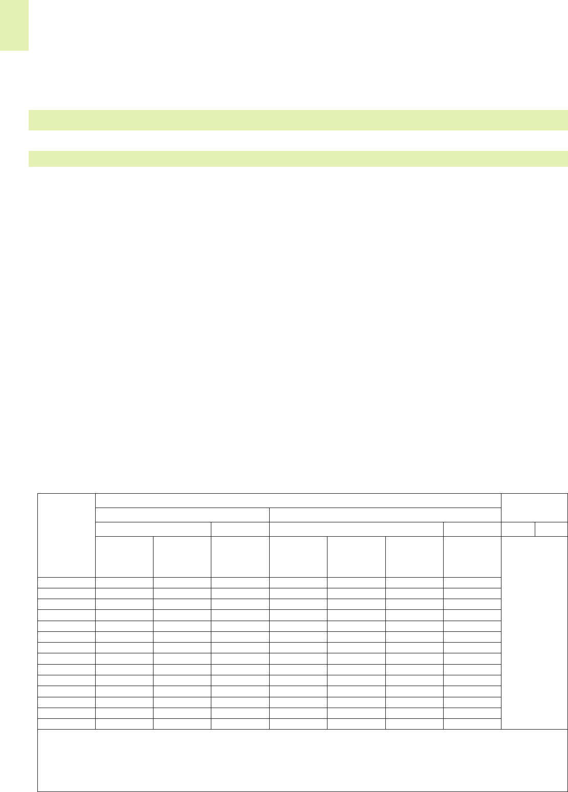
15
16
The CAGE CLAMP®Sis a further
development of the universal CAGE
CLAMP®allowing the connection of
solid, stranded and fine-stranded con-
ductors rated AWG 24 (0.2 mm2) to
AWG 6 (16 mm2) (AWG 4/25 mm2only
“f-st“) and offering all the benefits and
safety of the original CAGE CLAMP®
connection. Furthermore, using the
CAGE CLAMP®S connection technology,
solid and stranded conductors rated
AWG 20-6 (0.5 mm2- 16 mm2) as well
as fine-stranded conductors with crim-
ped ferrule rated from AWG 20 (0.5
mm2) to AWG 6 (16 mm2) can be
connected by simply pushing them in.
The conductor introduction hole is desi-
gned to ensure an optimum adaptation
to the insulation cross sections of con-
ductor rated cross sections, thus gua-
ranteeing good conductor guidance.
This is of particular importance for
applications subject to vibration.
In practice, there is always a danger of
very small cross section of fine-stranded
wire being fragile enough to allow it to
be pushed into the point where the
conductor insulation is being clamped
by the clamping unit.
In order to prevent resulting “accidental
contact“ we provide insulation stop
sleeves for WAGO rail-mounted termi-
nal blocks with cross section up to
AWG 12 (4 mm2) which avoid this dan-
ger even with conductors of AWG 28
(0.08 mm2) (see page 2.43).
Products such as connecting devices, rail-mounted terminal blocks and connectors, etc., have there own product-specific test
specifications. The following paragraphs which include the most important tests are both limited to describing the test
methods and explaining the test purpose. The values stated in the following paragraphs (e.g. voltages, temperatures, forces,
etc.) are solely for the purpose of clarification and may vary according to the test used.
Tests and Testing Procedures According to IEC/EN Standards
Conductor connection
Two connection systems have proven
themselves in the market for spring
clamp connectors:
The Push-wire connection in applica-
tions with exclusively solid conductors;
example for lighting and building
wiring, telecommunication, house
communication or alarm systems.
Conductor cross section range
0.28 mm2up to 4 mm2/
AWG 24 – AWG 12.
The CAGE CLAMP®connection as a
universal clamping system for solid
stranded and fine-stranded conductors
for applications in industrial electrotech-
nical and electronic engineering; prefe-
rentially for fine-stranded conductors in
the elevator industry, in power stations,
the chemical, automobile industry and
on board ships.
Conductor cross section range
0.08 mm2up to 35 mm2/
AWG 28 – AWG 2.
• Connecting conditions
Rated cross section and connectable conductors
I. According to IEC 60999-1 / EN 60999-1 / VDE 0609 part 1, table 1:
Theoretical diameter of the largest conductor Connectable
Rated Metric AWG/Kcmil conductors
cross- Rigid Flexible Rigid Flexible Rigid Flexible
section b) b) c)
Class B Class
I, K, M
Solid Stranded Solid Stranded Stranded
mm2mm mm mm Wire size mm mm mm
0.2 0.51 0.53 0.61 24 0.54 0.61 0.64
0.34 0.63 0.66 0.8 22 0.68 0.71 0.80
0.5 0.9 1.1 1.1 20 0.85 0.97 1.02
0.75 1.0 1.2 1.3 18 1.07 1.23 1.28 To be specified
1.01.21.41.5––––in the relevant
1.5 1.5 1.7 1.8 16 1.35 1.55 1.60 product
2.5 1.9 2.2 2.3a) 14 1.71 1.95 2.08 standard
4.0 2.4 2.7 2.9a) 12 2.15 2.45 2.70
6.0 2.9 3.3 3.9a) 10 2.72 3.09 3.36
10.0 3.7 4.2 5.1 8 3.34 3.89 4.32
16.0 4.6 5.3 6.3 6 4.32 4.91 5.73
25.0 – 6.6 7.8 4 5.45 6.18 7.26
35.0 – 7.9 9.2 2 6.87 7.78 9.02
NOTE: Diameters of the largest rigid and flexible conductors are based on Table 1 of IEC 60228 A und IEC 60344 and,
for AWG conductors, on ASTM B172-71 [4], IECA Publication S-19-81 [5], IECA Publication S-66-524 [6] and IECA Publication S-66-516 [7].
a) Dimensions for class 5 flexible conductors only, according to IEC 60228 A.
b) Nominal cross section + 5 %
c) Largest diameter for conductors of classes I, K, M + 5 %
Mechanical Tests
All WAGO products meet the requirements of the following mechanical tests.
In practical use the conductor cross sections are approx. 5 % below the values stated in the table!
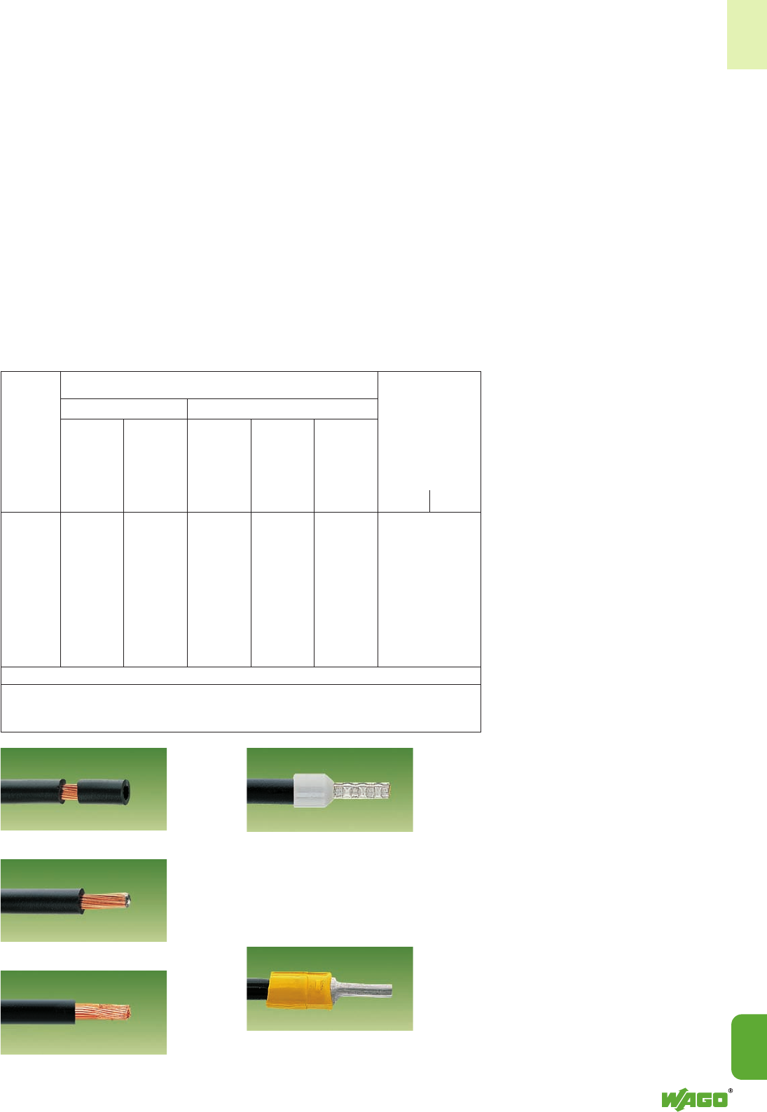
15
15
17
Partial stripping of the insulation The use of crimped ferrules
(gastight crimped)
With all anti-splaying methods which
increase the diameter of the conduc-
tor, it is necessary to use the terminal
block one size larger than the nomi-
nal cross section.
Tinning of the end of the conductors
Tip-bonding of conductor ends
II. According to IEC 60999-2, table 1:
This specification concerning clamping
units - IEC 60999-1/EN 60999-1/
VDE 0609 part 1, contains the follo-
wing requirement (paragraph 7.1):
Clamping units must be suitable for
connecting unprepared conductors.
With normal operating conditions this
direct clamping, i. e. the direct contact-
ing of the conductor at the current bar
of the terminal block, results in opti-
mum contact quality as any additional
risk factors arising in connection with
anti-splaying methods, are prevented.
Occasionally, due to wire handling on
site, conductor anti-splaying methods
may be necessary. Various methods
may be used (as illustrated below).
For applications in special areas with
extremely corrosive atmospheres, spe-
cial conditions apply.
In this case the use of solid copper
wires or fine-stranded copper wires
with properly crimped, tinned copper
ferrules or copper pin terminals is
recommended.
Thus the fine strands are crimped to a
dense inner core, like solid copper
wire. This action prevents the ingress of
the aggressive atmosphere (depending
on the ppm concentration), which can
diffuse into the conductor bundle along
the individual strands and hence cause
corrosion deposits between individual
strands and the clamping point.
1 conductor per clamping unit
A number of VDE-specifications specify
that only one conductor may be con-
nected to each clamping unit, for
example DIN VDE 0611, part 4/2.91,
clause 3.1.9
The same applies to the recommenda-
tions of the association of the German
automotive industry “Supply specifica-
tion for the electrical equipment of
machines, mechanical installations and
buildings in the automotive industry“
acc. to clause 15.1.1.3, draft 8.93.
Other VDE-specifications recommend
the connection of one conductor per
clamping unit unless the clamping unit
is specifically tested and approved for
the connection of several conductors:
VDE 0660, part 500, 08.00/
EN 60439-1: 1999, clause 7.8.3.7
VDE 0113, part 1, 11.98
EN 60 204-1: 1997, clause 14.1.1
VDE 0609, part 1, 12.00/
EN 60999-1:2000, clause 7.1
One conductor per clamping unit is
therefore recommended, to meet the
safety requirements of these relevant
specifications.
This WAGO principle is the basis for a
number of other technical and eco-
nomic advantages:
Each conductor may be installed or
removed without affecting previously
installed wires.
Each conductor is clamped indepen-
dently of the other. Any combinations
of conductor cross section or kind of
conductor (stranded and solid) can be
connected.
Multi-conductor 3- and 4-wire terminal
blocks may be selected, or a variety of
commoning jumpers may be chosen.
Theoretical diameter of the largest conductor
Rated Metric AWG/kcmil Connectable
cross conductors
section
Rigid fexibleaGage Rigid Flexible
stranded stranded
mm2mm mm mm mm Rigid Flexible
50 9.1 11.0 0 9.64 12.08
70 11.0 13.1 00 11.17 13.54
95 12.9 15.1 000 12.54 15.33
– – – 0000 14.08 17.22 To be specified
120 14.5 17.0 250 15.34 19.01 in the relevant
150 16.2 19.0 300 16.80 20.48 product
185 18.0 21.0 350 18.16 22.05 standard
– – – 400 19.42 24.05
240 20.6 24.0 500 21.68 26.57
300 23.1 27.0 600 23.82 30.03
a) Dimensions for class 5 flexible conductors only, according to IEC 60228A.
NOTE: Diameters of the largest rigid and flexible conductors are based on Table 1 and Table 3 of IEC 60228 A
and, for AWG conductors, on ASTM B 172-71 [1], IECA Publication S-19-81 [2],
IECA Publication S-66-524 [3] and IECA Publication S-66-516 [7].
or pin terminals (gastight crimped),
preferably produced from copper
with tinned surface.

15
18
This test simulates the mechanical stress on the clamping unit when, for example, the installer is pushing the conductor aside
so that the adjacent clamping unit can be better operated or when he wants to check if the wire is connected properly by
briefly pulling on it.
During the test, a pulling force is applied without jerks, for one minute, to the connected conductor. The pulling force is sel-
ected according to the cross-sectional area. The larger the cross-section of the conductor, the higher the pull-out force is
selected. For example, the pulling force is 40 N for a conductor having a cross-section of 1.5 mm2(AWG 16) and 100 N for
a conductor having a cross-section of 16 mm2(AWG 6). The values specified by the standard are the same for both
screw-clamp and spring-clamp terminal blocks. During the test, the conductor shall neither slip out of the clamping unit nor
break near the clamping unit.
Tests and Testing Procedures According to IEC/EN Standards (continued)
Mechanical Tests (continued)
Conductor pull-out forces
The clamping units of screwless terminal
blocks have to withstand the pull-out
forces as follows:
IEC 60947-1/EN 60947-1/VDE 0660,
part 100, table 5
Low-voltage switchgear and control-
gear, general rules
IEC 60947-7-1/EN 60947-7-1/
VDE 0611, part 1,
rail-mounted terminal blocks for copper
conductors
IEC 60998-2-1/EN 60998-2-1/
VDE 0613, part 2-1, table 104
IEC 60998-2-2/ EN 60998-2-2/VDE
0613, part 2-2, table 103
Connecting devices for low-voltage cir-
cuits for household and similar purpo-
ses.
Particular requirements for connecting
devices as separate entities with screw-
clamp or with screwless terminal blocks.
IEC 60999-1/EN 60999-1/VDE 0609,
part 1, table 3:
IEC 60999-2/EN 60999-2, table 2:
Safety requirements for screw-clamp
and screwless clamping units for electri-
cal copper conductors
• Pull-out test according to IEC/EN 60947-7-1, IEC/EN 60998-2-2, IEC/EN 60999-1
Rated cross-sectional area Pull-out forces according to IEC/EN
60947-7-1 60998-2-2 60999-1/ -2
mm2AWG/MCM N N N
0.224101010
0.34 22 15 15 15
0.520202020
0.75 18 30 30 30
1.0 –353535
1.516404040
2.514505050
4.012606060
6.010808080
10 8909090
16 6 100 100 100
25 4 135 135 135
– 3 156
35 2 190 190 190
– 1 236
50 0 236 236
70 00 285 285
95 000 351 351
– 0000 427 427
120 250 427 427
150 300 427 427
185 350 503 503
– 400 503 503
240 500 578 578
300 600 578 578
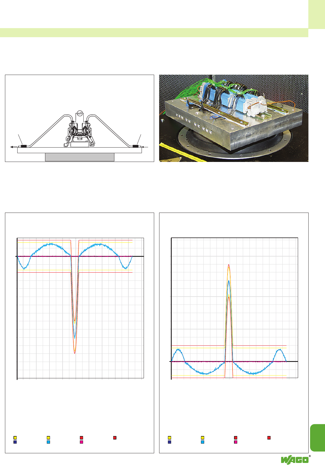
1400
1300
1200
1100
1000
900
800
700
600
500
400
300
200
100
0
-100
-200
0.4455 101520253035404550556065707580859095
1500
100
0
-100
-200
-300
-400
-500
-600
-700
-800
-900
-1000
-1100
-12 00
-13 00
-14 00
-15 00
0.4455 101520253035404550556065707580859095
200
15
15
19
b) b)
a) a)
The shock test is very similar to the vibration test (see pages 15.20 and 15.21) except that, instead of continuous vibrations,
single shocks are applied to the specimen. Shock tests are usually carried out with an acceleration of 20 g over 11 millise-
conds. Tests for special requirements often need much higher values. Just like vibration tests, shock tests are primarily used
to test the voltage drop variation or contact breaks, etc.
• Shock test according to IEC/EN 60068-2-27, 60068-2-30; Railway applications IEC/EN 61373
e.g. shock requirement
according to IEC/EN 60068-2-27
Half-sine shock
100 g acceleration 6 ms duration Direction of shock: 3 axes
3 shocks in positive direction and 3 shocks in negative direction.
Status: Stop
Cause: Number of shocks ready!
Date: 05.03.2004 Control: active
Time: 08:53:16 Total number of shocks: 4
Modulation: 100 %
Warning limits: inactive Top acceleration: 1017.34 m/s2
Turn-off limits: inactive Speed: 3.78 m/s
Time dependent course of the shock / 100 g, 6 ms
Negative direction
Upper warning limits Lower warning limits Upper turn-off limits Lower turn-off limits
Scheduled. curve of acc. Actual curve of acc. Measurement curve of acceleration
Status: Stop
Cause: Number of shocks ready!
Date: 05.03.2004 Control: active
Time: 08:52:00 Total number of shocks: 4
Modulation: 100 %
Warning limits: inactive Top acceleration: 1008.80 m/s2
Turn-off limits: inactive Speed: 3.77 m/s
Upper warning limits Lower warning limits Upper turn-off limits Lower turn-off limits
Scheduled. curve of acc. Actual curve of acc. Measurement curve of acceleration
Time dependent course of the shock / 100 g, 6 ms
Positive direction
Length of test conductor
between point a) and b)
100 mm
Length of test conductor
between point a) and b)
100 mm
Fixing point
It
Fixing point
a in m/s2a in m/s2
t in
ms
t in
ms
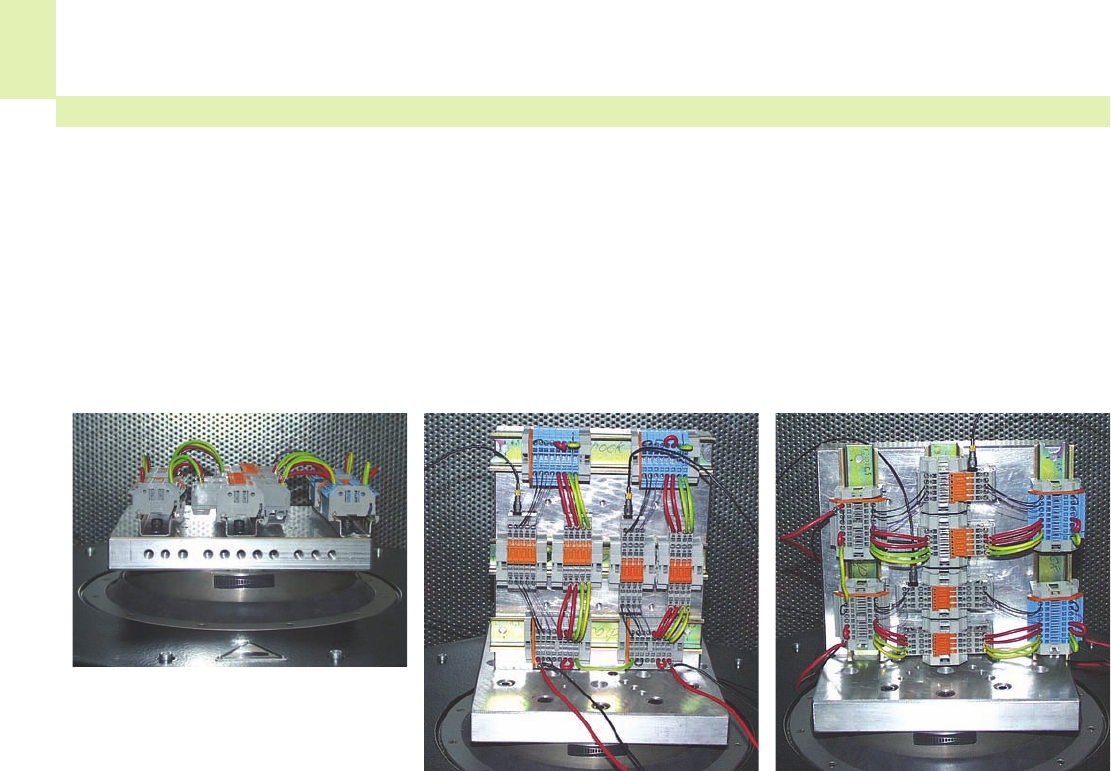
15
20
Tests and Testing Procedures According to IEC/EN Standards (continued)
Mechanical Tests (continued)
The vibration test is aimed at finding out if vibrations, such as those produced in the vicinity of machines or in vehicles, will
permanently affect the electrical connection or if contact breaks will occur during vibrations. Using a vibration table, the test
specimen is submitted to vibrations in each of the X, Y and Z axes (see pictures). The amplitude, the acceleration and
especially the frequency of the vibrations shall vary during the test.
For example, a common test is carried out using a wide frequency band up to 2000 Hz with different accelerations up
to 20 g and varying amplitudes up to 20 mm. The test duration can be 90 minutes per axis.
• Vibration test acc. to IEC/EN 60068-2-6; Shipbuilding GL, LR, DNV; Railway applications EN 61373
Apart from the standard tests mentio-
ned above, special test procedures are
carried out by the railway company,
for example, on rolling stock electrical
equipment or by shipping classification
societies such as Germanischen Lloyd,
Lloyd’s Register of Shipping, Det Norske
Veritas.
Though the requirements of such test
procedures are particularly high, test
arrangements are identical for all of
them. During vibrations, possible
contact breaks are monitored on an
oscilloscope. Voltage drop is measured
before and after the test to detect
permanent failures, i.e. checking if the
electrical resistance at the clamping unit
has not increased beyond the permissi-
ble limit. The smaller this value is, the
smaller the contact resistance of the
clamping unit will be.
Other types of test are carried out
using a single fixed frequency. The
exact test procedure shall vary consi-
derably depending on how the product
will be used. Some test specifications
require the determination of possible
resonant frequencies, i.e. finding out if
resonances will occur within the fre-
quency spectrum to be passed through.
Analysing the specimen behaviour
under the influence of resonant fre-
quencies is carried out using a special
testing procedure.
The test is passed if the conductor has
neither slipped out of the terminal block
nor been damaged, the maximum per-
missible voltage drop has not been
exceeded and neither contact breaks
have occured nor a defined break time
has been exceeded.
After the test, the specimens should
show no damage which could affect
subsequent operation.
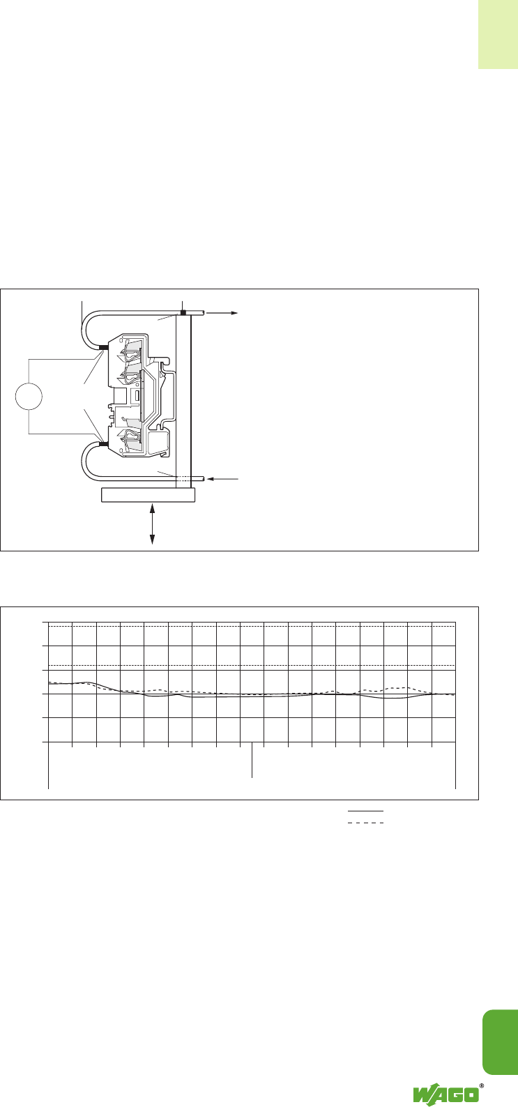
15
15
21
mV
5
4
3
2
1
0
3.2
4.8
Conductor fixing
Conductor fixing
Test wires
soldered
Direction
of oscillation
ΔV
max.
Voltage drop
per through contact in mV
I test
Vibration table
<_ approx. 90 mm _>
<_________________________________ Frequency range _________________________________>
<_____________ 5 Hz–250 Hz ____________><_____________ 250 Hz–5 Hz ____________>
Frequency cycle: 5 Hz to 250 Hz
Cycle time: 20 minutes,
logarithmic frequency
Amplitude
(at 5 Hz–16 Hz): 20 mm (peak to peak)
Acceleration
(at 16 Hz–250 Hz): 10 g
Vibration test set-up for self resonance
Frequency cycle Rail-mounted terminal block: Item-No. 280-681 Test specimen no. 1
Test current: 1/10 IN= 2.4 A Test specimen no. 2
For many years, the CAGE CLAMP®and CAGE CLAMP®S connections have been tested repeatedly for their resistance to
vibration in connection with approval tests.
In addition WAGO undertakes special
tests on the self resonance behaviour of
the terminal systems with varying termi-
nal block and conductor arrangements.
For the purpose of these tests a wide
frequency band is continuously run
through up to 2000 Hz with differing
acceleration up to 20 g and differing
amplitudes up to 20 mm.
The figure provides an example of the
additional vibration test configuration
for self resonance.
All WAGO spring clamp connections
meet these test requirements.
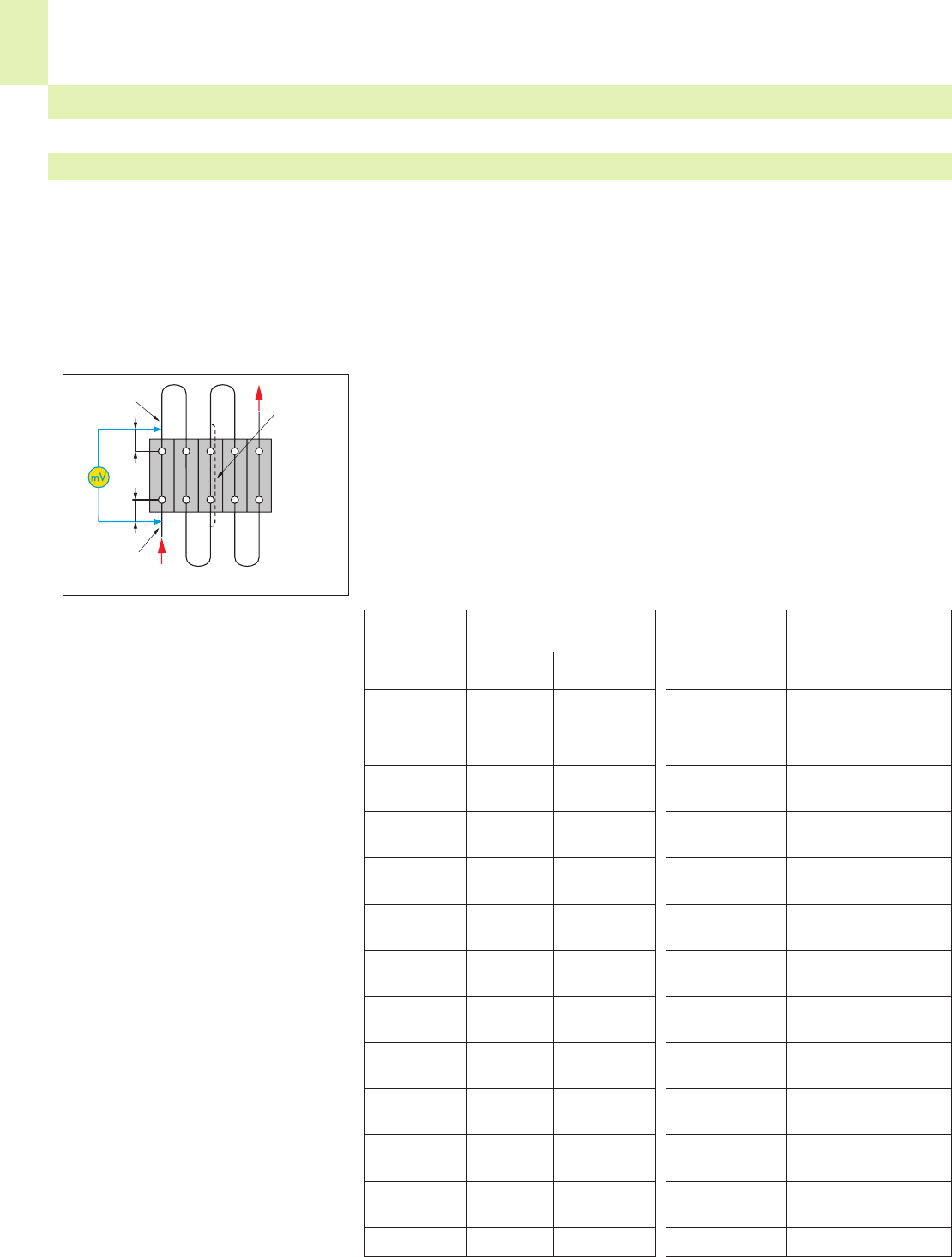
15
22
The temperature-rise test is necessary to test the terminal block as a whole, including the insulation housing at rated current,
at overload and under short circuit conditions.
Unless otherwise specified in the related equipment specification, e.g. by specifying the nominal currents of the equipment,
terminal blocks and connectors are tested with the current loads as specified in the respective construction specification.
For rail-mounted terminal blocks acc. to IEC 60947-7-1/EN 60947-7-1/VDE 0611 part 1 and terminal blocks acc. to IEC
60998-1/EN 60998-1/ VDE 0613 part 1 the temperature rise shall not exceed 45 Kelvin.
Test arrangement of the temperature-rise test
≤10 mm
Temperature
measurement
Wire Test current acc.
size IEC/EN
60947-7-1
Table 5
AWG/MCM A
24 4
22 6
20 8
18 10
–
16 16
14 22
12 29
10 38
850
667
490
2 121
1 139
0 162
00 185
000 217
0000 242
250 kcmil 271
300 kcmil 309
350 kcmil 353
500 kcmil 415
600 kcmil 520
Rated cross Test current acc.
section IEC/EN
60947-7-1 60998-1
Table 4 Table 2
mm2AA
0.2 4 4
0.34 5 5
0.5 6 6
0.75 9 9
1.0 13.5 13.5
1.5 17.5 17.5
2.5 24 24
4.0 32 32
6.0 41 41
10 57 57
16 76 76
25 101 101
35 125 125
–
50 150
70 192
95 232
–
120 269
150 309
185 353
240 415
300 520
Tests and Testing Procedures According to IEC/EN Standards (continued)
• Temperature-rise test according to IEC/EN 60947-7-1
Electrical Tests
All WAGO products meet the requirements of the following electrical tests.
≤10 mm
Measuring point
Voltage drop
Measuring point
Voltage drop It
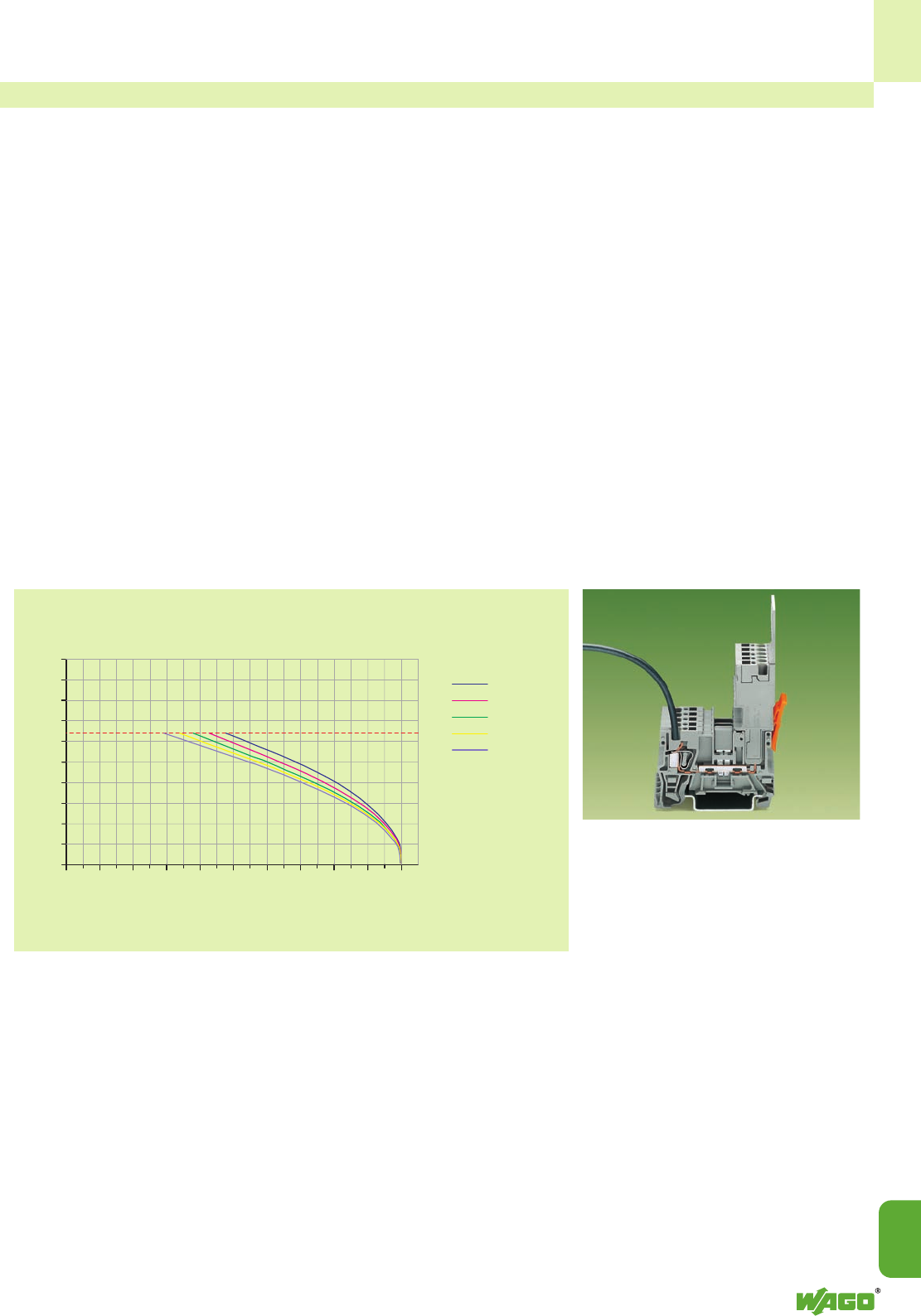
15
15
23
50
45
40
35
30
25
20
15
10
5
0
010 4020 30 50 60 8070 90 100
Both the constructional requirements and the current-carrying capacity of a connector must be checked by the user when
selecting connectors.
The current-carrying capacity depends on the cross section of the connected wire, the ambient temperature, the number of
simultaneously loaded poles, the internal resistance of the connector, the PCB layout if required and the connector materials
used. In accordance with the IEC/EN 60512-5-2 standard, the relation between the current, the ambient temperature and
the temperature rise up to the upper temperature limit of the connector is represented by a current-carrying capacity curve
(derating curve). The connector shall only be operated up to this temperature limit (sum of the self-generated heat and the
ambient temperature) without being damaged or destroyed during operation.
The way a current-carrying capacity curve (acc. to IEC/EN 60512-5-2) works is shown in the following application using the
X-COM®-SYSTEM: the basic curve of a 4-pole connection charged with 32 A per pole shows a maximum ambient tempe-
rature of 42°C using a conductor of cross section 4 mm2(AWG 12). The current must be reduced at higher ambient tempe-
ratures (e.g., to 19 A at 80°C).
• Current-carrying capacity curve (derating curve) according to IEC/EN 60512-5-2
1-conductor/1-pin
receptacle terminal block 769-176
Cross section of conductor:
4 mm2“f-st”/AWG 12 “f-st”
1-conductor female plugs: 769-102 to 769-115
Cross section of conductor:
4 mm2“f-st”/AWG 12 “f-st”
Length of the conductor: 1 m
Test current (A)
2 poles
4 poles
5 poles
6 poles
15 poles
Ambient opera-
ting
temperature (°C)
Number of poles
Rated current of the conductor
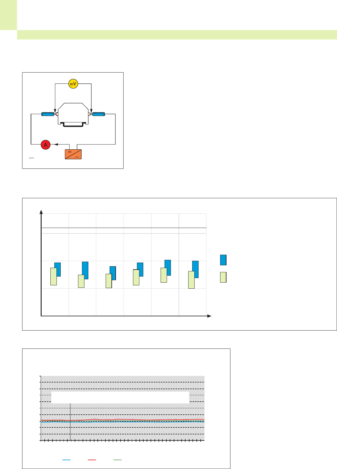
15
24
50
45
40
35
30
25
20
15
10
5
0
0
50
100
150
200
250
300
350
400
450
500
550
600
650
700
750
800
850
900
950
1000
1050
Tests and Testing Procedures According to IEC/EN Standards (continued)
Electrical Tests (continued)
The voltage drop test allows judgement of the quality of a clamping unit under vibration, temperature cycling, industrial cli-
mate and salt spray conditions in order to verify that the contact area is gastight.
• Voltage drop test according to IEC/EN 60947-7-1
Test arrangement for the voltage drop test
The change of voltage drop over lon-
ger periods under current load cycling
conditions is shown for the WAGO rail-
mounted terminal blocks series 285-195
(95 mm2/AWG 000) using fine-stranded
copper wires. The diagram shows that
the voltage drop is constant, far
beyond the 192 cycles required in IEC
60947-7-1.
(The voltage drop has been determined using the
rated current)
Typical variation of the voltage drops for solid and fine-stranded conductors of
CAGE CLAMP® rail-mounted terminal blocks of Series 280 to 285:
The CAGE CLAMP®and
CAGE CLAMP®S connections enclose
and contain flexible conductors. There-
fore, a variation of the voltage drop
with solid and fine-stranded conductors
is so small that its influence may be
neglected for the practical application
of the terminal blocks.
Example: Current load cycling test result for rail-mounted terminal blocks (item no. 285-195)
using 95 mm2(AWG 000) fine-stranded copper wires:
Voltage drop ΔV
per through contact in mV
fine-stranded
solid
Voltage drop ΔV
per through contact in mV
1 IPrüf
10
2,5 mm2/
AWG 14 4 mm2/
AWG 12 6 mm2/
AWG 10 10 mm2/
AWG 8 16 mm2/
AWG 6 35 mm2/
AWG 2
U1 U2 U3 (rail-mounted terminal block numbered 1 – 3)
Cycles (1 cycle: 0.5 h 232 A / 0.5 h 0 A
Voltage drop measured at the trough contacts of rail-mounted terminal
blocks numbered 1 – 3
3.2
2
1
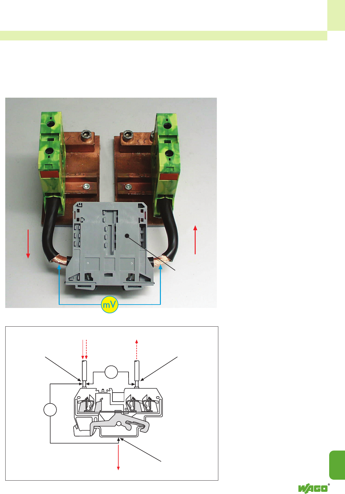
15
15
25
ICC
ICS
Apart from the rated current, which can be constantly applied to an electrical device, operation-related short peak currents
consistently occur in electrical installations when motors are started, for example. Also, in the event of a short circuit, a high
current can flow for a short time until the fuse element melts. Terminal blocks and connecting devices must be able to with-
stand such conditions. For example, a rail-mounted through terminal block shall be capable of withstanding for 1 s the
rated short-time withstand current which corresponds to 120 A/mm2of its rated cross-section, in accordance to IEC/EN
60947-7-1.
• Short-time withstand current test (short-circuit withstand capacity) according to IEC/EN 60947-7-1
The short circuit current of the 95 mm2 /
AWG 000 high current terminal block
(item no. 285-195) is 11400 A.
During the short-time withstand current
test, the ground (earth) conductor rail-
mounted terminal blocks are subjected
three times for 1 s each to a current
load of 120 A/mm2.
The voltage drop is the main factor for
passing the test (limiting value and con-
stant measured values).
Test
specimen
Measuring point Measuring point
Measuring point
UCC
UCS

15
26
<__________ T2 = 50 μs __________>
(_T _)
T1 = 1,2 μs
%
100
90
50
30
0
Tests and Testing Procedures According to IEC/EN Standards (continued)
Electrical Tests (continued)
• Insulation parameters according to IEC/EN 60664-1
The nominal supply voltages and the corresponding rated impulse voltages apply
for grounded (earthed) as well as for ungrounded (unearthed) circuits.
Nominal voltage Voltage line to neutral Rated impulse voltage2)
of the supply system1) derived from nominal voltages a.c. V
(mains) based on IEC 600383) or d.c. up to
V and including Overvoltage category4)
Three-phase Single-phase V I II III IV
50 330 500 800 1500
100 500 800 1500 2500
150 800 1500 2500 4000
230/400 277/480 120-240 300 1500 2500 4000 6000
400/690 600 2500 4000 6000 8000
1000 1000 4000 6000 8000 12000
1) See annex B for application to existing different low-voltage mains and their nominal voltages.
2) Equipment with these rated impulse voltages can be used in installations in accordance with IEC 60364-4-443.
3) The / mark indicates a 4-wire three-phase distribution system. The lower value is the voltage line-to-neutral,
while the higher value is the voltage line-to-line. Where only one value is indicated, it refers to 3-wire, three-pha-
se systems and specifies the value line-to-line.
4) See 2.2.2.1.1 for an explanation of the overvoltage categories.
û
u
The rated impulse voltage shall be selected from table 1 corresponding to the
overvoltage category specified and to the rated voltage of the equipment.
Table 1: Rated impulse voltages for equipment energized directly from the
low-voltage mains
(DIN EN 60664-1/VDE 0110, part 1)
➊ Voltage curve: 1.2/50 μs acc. IEC 60-1 / VDE 0432, part 1
Clearances and creepage distances
Generally applicable is:
The equipment specification contains
data for the measurement of clearan-
ces and creepage distances or refers to
the data contained in the new revised
edition of the basic standard DIN EN
60664-1/VDE 0110, part 1.
DIN EN 60664-1/VDE 0110, part 1
contains new clearance and creepage
distance data taking into consideration
the rules of insulation. That is the insula-
tion parameters of an equipment are
assigned to:
– the surge voltages expected,
– the parameters of the protection
device against surge voltage
and
– the expected environmental condi-
tions and the protection measures
against pollution.
The standard is based on IEC 60664-1,
with some modifications.
Clearances, rated impulse voltages,
overvoltage categories, pollution
degrees
Decisive for the proportioning of air
distances are the impulse voltages in
accordance with table 1.
This basis forms the
overvoltage category, i. e. the
allocation of the equipment to the
expected surge voltage, and the
conductor – earth voltage derived
from the rated line voltage in
installations with a grounded (earthed)
Y (star) point.
In ungrounded (unearthed) installations,
or in installations where the conductor
is not grounded (earthed), the voltage
between the conductors is applicable in
the same way as conductor voltage to
ground (earth).
Overvoltage categories for electrical equipment:
Specification of a specific impulse withstand category (overvoltage category) shall
be based on the following general explanation:
– Equipment of impulse withstand category I is equipment which is intended to
be connected to the fixed electrical installations of buildings. Protective means
are taken outside the equipment – either in the fixed installation or between the
fixed installation and the equipment – to limit transient overvoltages to the
specific level.
– Equipment of impulse withstand category II is equipment to be connected to
the fixed electrical installations of buildings.
NOTE: Examples of such equipment are household appliances, portable tools
and similar loads.
– Equipment of impulse withstand category III is equipment which is part of
the fixed electrical installations and other equipment where a higher degree of
availability is expected.
NOTE: Examples of such equipment are distribution boards, circuit breakers,
wiring systems (IEV 826-06-01, including cables, bus-bars, junction boxes, swit-
ches, socket-outlets) in the fixed installation, and equipment for industrial use
and some other equipment, e. g. stationary motors with permanent connection
to the fixed installation.
– Equipment of impulse withstand category IV is for use at or in the proximity
of the origin of the electrical installations of buildings upstream of the main
distribution board.
NOTE: Examples of such equipment are electricity meters, primary overcurrent
protection devices and ripple control units.
acc. to IEC 60-1 / VDE 0432, part 1
➊ Voltage pulse 1.2/50
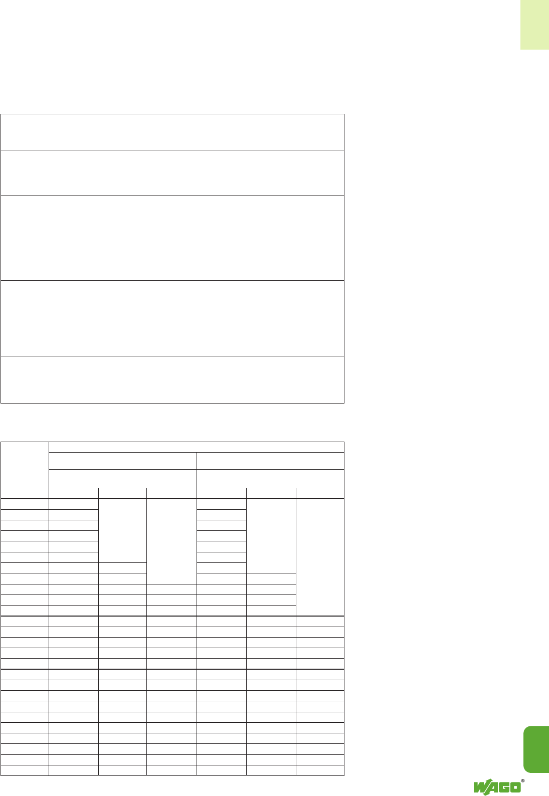
15
15
27
Pollution degree
Pollution factors are all solid, liquid or gaseous foreign matter which may reduce
the dielectric strength or the specific surface resistances.
Soiling is divided into 4 classes in accordance with the environmental conditions to
be expected:
Dimensioning of clearances
acc. to DIN EN 60664-1/VDE 0110,
part 1, table 2
Choose the minimum clearances in
accordance with the rated impulse
voltages and the degree of pollution.
For the operating life of the equipment
do not go below these minimum clea-
rances.
Table 2 contains a list of information for
the Case A, the inhomogeneous field,
and for the Case B, the homogeneous
field.
This covers an electric field with
essentially constant (Case B) or not
constant (Case A) voltage gradients
between the electrodes.
Equipment with a clearance in
accordance with Case A, in other
words rated for the most unfavour-
able case, can be employed
without evidence of impulse vol-
tage testing.
Equipment for which the clearances are
dimensioned acc. to Case B or between
A and B requires verification by the
impulse voltage test.
The clearances shown in table 2 are
applicable for an installation height of
up to 2000 m above sea level.
Values for clearances above 2000 m
must be multiplied by a high correction
factor in accordance with table 2.
Examples of pollution
degrees for assigned
areas:
pollution degree 1: No pollution or only dry, Electrical equipment in
non conductive pollution air-conditioned or clean
occurs. The pollution has dry rooms.
no influence.
pollution degree 2: Only non-conductive Electrical equipment in
pollution occurs except living areas, shops,
that occasionnally laboratories, test
temporary conductivity stations, mechanical
caused by condensation workshops and medical
is to be expected. rooms.
pollution degree 3: Conductive pollution Electrical equipment in
occurs or dry non- industrial and farming
conductive pollution occurs areas, unheated rooms,
which becomes conductive workshops and boiler
due to condensation which rooms.
is to be expected.
pollution degree 4: The pollution generates Electrical equipment for
persitent conductivity outdoor use.
caused by conductive dust
or by rain or wet conditions.
Table 2: Clearances to withstand transient overvoltages
(DIN EN 60664-1/VDE 0110, part 1)
1) This voltage is
– for functional insulation: the maximum impulse
voltage expected to occur across the clearance
(see 3.1.4.);
– for basic insulation directly exposed to or signi-
ficantly influenced by transient overvoltages from
the low-voltage mains (see 2.2.2.2, 2.2.2.3.1 and
3.1.5): the rated impulse voltage of the equipment;
– for other basic insulation (see 2.2.2.3.2.): the highest
impulse voltage that can occur in the circuit;
– for reinforced insulation, see 3.1.5.
2) Preferred values specified in 2.1.1.2.
3) For printed wiring material, the values for pollution
degree 1 apply except that the value shall not be less
than 0.04 mm, as specified in table 4.
4) The minimum clearances given for pollution degrees 2
and 3 are based on the reduced withstand characteri-
stics of the associated creepage distance under humidi-
ty conditions (see IEC 60664-5).
5) For parts or circuits within equipment subject to impulse
voltages according to 2.2.2.3.2, interpolation of values
is allowed. However, standardization is achieved by
using the preferred series of impulse voltage values in
2.1.1.2.
6) The dimensions for pollution degree 4 are as specified
for pollution degree 3, except that the minimum clea-
rance 1.6 mm.
Minimum clearances in air up to 2000 m above sea level
Case A Case B
(inhomogeneous field, see 1.3.15) (homogeneous field, see 1.3.14)
Pollution degree6) Pollution degree6)
123123
mm mm mm mm mm mm
0.332) 0.01 0.01
0.40 0.02 0.02
0.502) 0.04 0.04
0.60 0.06 0.23)4) 0.06 0.23)4)
0.802) 0.10 0.84) 0.10
1.0 0.15 0.15 0.84)
1.2 0.25 0.25 0.20
1.52) 0.5 0.5 0.30 0.30
2.0 1.0 1.0 1.0 0.45 0.45
2.52) 1.5 1.5 1.5 0.60 0.60
3.0 2.0 2.0 2.0 0.80 0.80
4.02) 3.0 3.0 3.0 1.2 1.2 1.2
5.0 4.0 4.0 4.0 1.5 1.5 1.5
6.02) 5.5 5.5 5.5 2.0 2.0 2.0
8.02) 8.0 8.0 8.0 3.0 3.0 3.0
10 11 11 11 3.5 3.5 3.5
12.2) 14 14 14 4.5 4.5 4.5
15 18 18 18 5.5 5.5 5.5
20 25 25 25 8 8 8
25 33 33 33 10 10 10
30 40 40 40 12.5 12.5 12.5
40 60 60 60 17 17 17
50 75 75 75 22 22 22
60 90 90 90 27 27 27
80 130 130 130 35 35 35
100 170 170 170 45 45 45
Required
impulse with-
stand voltage1)5)
kV
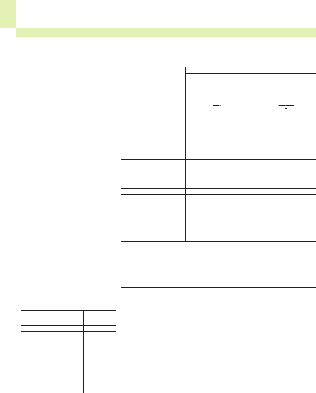
15
28
Tests and Testing Procedures According to IEC/EN Standards (continued)
Electrical Tests (continued)
• Insulation parameters according to IEC/EN 60664-1 (continued)
1) Line-to-earth insulation level for unearthed or impedance-earthed systems equals that for line-to-line because
the operating voltage to earth of any line can, in practice, approach full line-to-line voltage. This is because
the actual voltage to earth is determined by the insulation resistance and capacitive reactance of each line to
earth; thus, low (but acceptable) insulation resistance of one line can in effect earth it and raise the other two
to full line-to-line voltage to earth.
*)For relationship to rated voltage see 2.2.1.
**)These values correspond to the values in table 1.
Creepage distances,
Rated voltages,
Material groups
Criteria for the dimensioning of the
creepage distances are the rated vol-
tages, the degrees of pollution and the
material groups.
The pollution degrees specified for the
clearances and its quoted allocation to
locations is also applicable for
creepage distances.
The tables 3 a and 3 b of the
DIN EN 60664-1/VDE 0110, part 1
contain the rated voltages which have
to be considered for dimensioning the
minimum creepage distance.
Table 3 a: Single-phase 3- or 2-wire
AC or DC systems
Table A.2:
Height correction factors
(DIN EN 60664-1/VDE 0110, part 1)
Height Standard Multiplier
air pressure for
m kPa distance
2000 80 1
3000 70 1.14
4000 62 1.29
5000 54 1.48
6000 47 1.7
7000 41 1.95
8000 35.5 2.25
9000 30.5 2.62
10000 26.5 3.02
15000 12 6.67
20000 5.5 14.5
Voltages rationalized for table 4
Nominal voltage For insulation For insulation
of the supply line-to-line1) line-to-earth1)
system (mains)*)
All systems Three-wire systems
mid-point
earthed
VVV
12.5 12.5
24
25 25
30 32
42
48 50
50**)
60 63
30–60 63 32
100**)100
110
120 125
150**)160
220 250
110–220
120–240 250 125
300**)320
220–440 500 250
600**)630
480–960 1000 500
1000**)1000
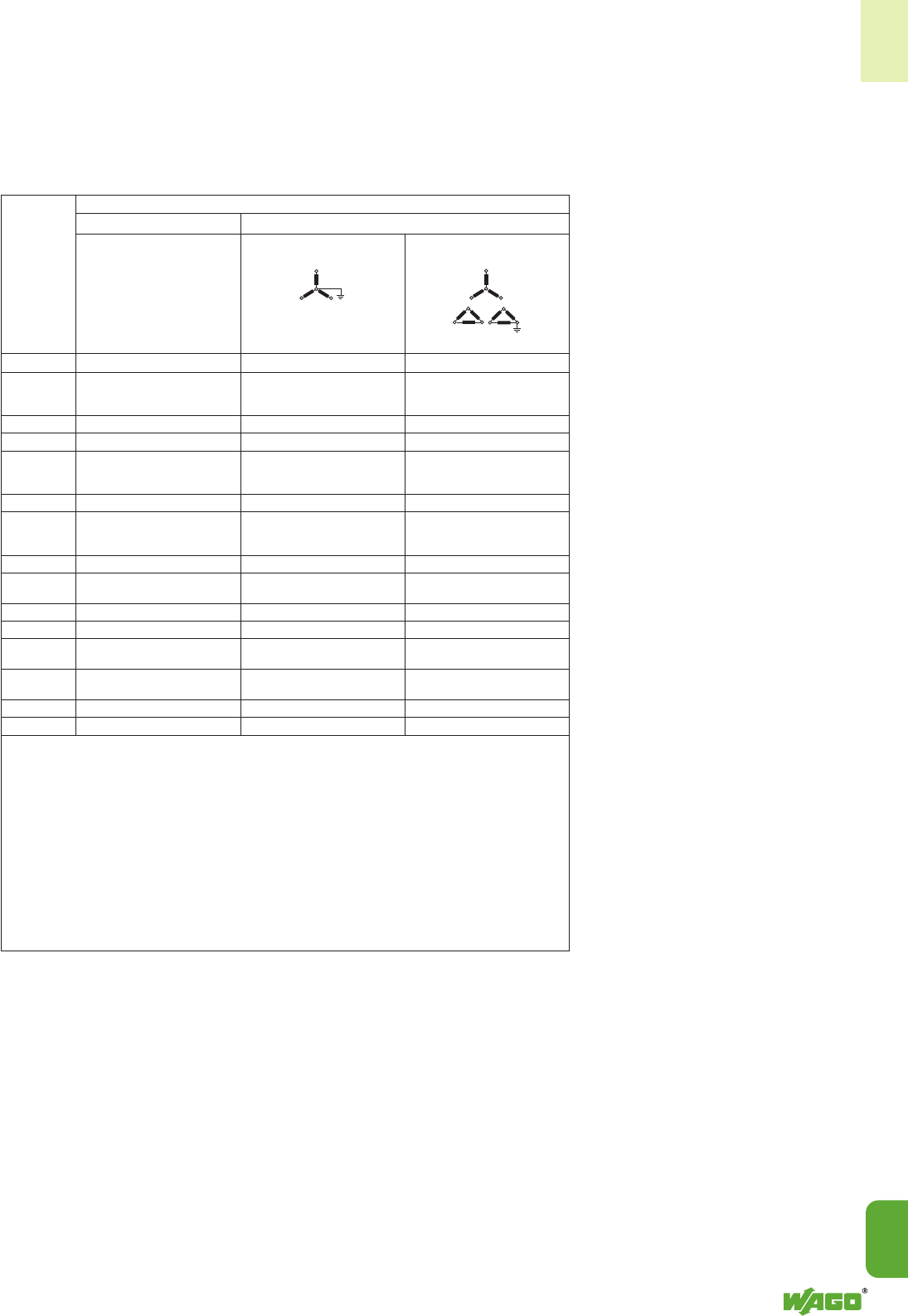
15
15
29
Material groups
Materials are separated into four
groups according to their CTI (Compa-
rative Tracking Index) as follows:
Material group I: 600 ≤CTI
Material group II: 400 ≤CTI < 600
Material group III a: 175 ≤CTI < 400
Material group III b: 100 ≤CTI < 175
The CTI values above refer to values
obtained, in accordance with
DIN EN 60112/VDE 0303, part 11,
on samples specially made for the
purpose and tested with solution A.
Table 3 b: Three-phase 3- or 4-wire
AC systems
Voltages rationalized for table 4
For insulation line-to-line For insulation line-to-line
Three-phase four-wire systems Three-phase three-wire systems
All systems neutral earthed2) unearthed1) or corner-earthed
VVVV
60 63 32 63
110
120 125 80 125
127
150**)160 160
208 200 125 200
220
230 250 160 250
240
300**)320 320
380
400 400 250 400
415
440 500 250 500
480
500 500 320 500
575 630 400 630
600**)630 630
660
690 630 400 630
720
830 800 500 800
960 1000 630 1000
1000**)1000 1000
Nominal
voltage
of the
supply
system
(mains)*)
1) Line-to-earth insulation level for unearthed or impedance-earthed systems equals that for line-to-line because
the operating voltage to earth of any line can, in practice, approach full line-to-line voltage. This is because the
actual voltage to earth is determined by the insulation resistance and capacitive reactance of each line to
earth; thus, low (but acceptable) insulation resistance of one line can in effect earth it and raise the other two to
full line-to-line voltage to earth.
2) For equipment for use on both three-phase four-wire and three-phase three-wire supplies,
earthed and unearthed, use the values for three-wire systems only.
*)For relationship to rated voltage see 2.2.1.
**)These values correspond to the values in table 1.

15
30
Table 4: Creepage distances to avoid failure due to tracking
Minimum creepage distances
Voltage 1) Printed wiring
r.m.s. material Pollution degree
Pollution degree
121 2 3
All material All mat. gr. All material Material group Material group
groups except IIIb groups I II III I II III2)
V mmmmmmmmmmmmmm mmmm
10 0.025 0.04 0.08 0.4 0.4 0.4 1 1 1
12.5 0.025 0.04 0.09 0.42 0.42 0.42 1.05 1.05 1.05
16 0.025 0.04 0.1 0.45 0.45 0.45 1.1 1.1 1.1
20 0.025 0.04 0.11 0.48 0.48 0.48 1.2 1.2 1.2
25 0.025 0.04 0.125 0.5 0.5 0.5 1.25 1.25 1.25
32 0.025 0.04 0.14 0.53 0.53 0.53 1.3 1.3 1.3
40 0.025 0.04 0.16 0.56 0.8 1.1 1.4 1.6 1.8
50 0.025 0.04 0.18 0.6 0.85 1.2 1.5 1.7 1.9
63 0.04 0.063 0.2 0.63 0.9 1.25 1.6 1.8 2
80 0.063 0.1 0.22 0.67 0.95 1.3 1.7 1.9 2.1
100 0.1 0.16 0.25 0.71 1 1.4 1.8 2 2.2
125 0.16 0.25 0.28 0.75 1.05 1.5 1.9 2.1 2.4
160 0.25 0.4 0.32 0.8 1.1 1.6 2 2.2 2.5
200 0.4 0.63 0.42 1 1.4 2 2.5 2.8 3.2
250 0.56 1 0.56 1.25 1.8 2.5 3.2 3.6 4
320 0.75 1.6 0.75 1.6 2.2 3.2 4 4.5 5
400 1 2 1 2 2.8 4 5 5.6 6.3
500 1.3 2.5 1.3 2.5 3.6 5 6.3 7.1 8.0
630 1.8 3.2 1.8 3.2 4.5 6.3 8 9 10
800 2.4 4 2.4 4 5.6 8 10 11 12.5
1000 3.2 5 3.2 5 7.1 10 12.5 14 16
1250 4.2 6.3 9 12.5 16 18 20
1600 5.6 8 11 16 20 22 25
2000 7.5 10 14 20 25 28 32
2500 10 12.5 18 25 32 36 40
3200 12.5 16 22 32 40 45 50
4000 16 20 28 40 50 56 63
5000 20 25 36 50 63 71 80
6300 25 32 45 63 80 90 100
8000 32 40 56 80 100 110 125
10000 40 50 71 100 125 140 160
12500 503) 633) 903) 1253)
16000 633) 803) 1103) 1603)
20000 803) 1003) 1403) 2003)
25000 1003) 1253) 1803) 2503)
32000 1253) 1603) 2203) 3203)
40000 1603) 2003) 2803) 4003)
50000 2003) 2503) 3603) 5003)
63000 2503) 3203) 4503) 6003)
1) This voltage is:
– for functional insulation: the working voltage;
– for basic and supplementary insulation of the circuit energized directly from the mains (see 2.2.1.1.1):
the voltage rationalized through table 3a or table 3b, based on the rated voltage of the equipment,
or the rated insulation voltage;
– for basic and supplementary insulation of systems, equipment and internal circuits not energized directly from the mains (see
2.2.1.1.2): the highest r. m. s. voltage which can occur in the system, equipment or internal circuit when supplied at rated voltage
and under the most onerous combination of conditions of operation within equipment rating.
2) Material group IIIb is not recommended for applications in pollution degree 3 above 630 V.
3) Provisional data based on extrapolation. Technical committees who have other information based on experience may use their
dimensions.
Tests and Testing Procedures According to IEC/EN Standards (continued)
Electrical Tests (continued)
• Insulation parameters according to IEC/EN 60664-1 (continued)

15
15
31
According to their application
WAGO terminal blocks and
connectors are suitable for the pol-
lution degrees 2 or 3 and for the
over-voltage categories II or III.
Example:
WAGO rail-mounted through
terminal blocks
acc. to IEC 60947-7-1/
EN 60947-7-1/VDE 0611, part 1
are dimensioned as follows:
800 V/8 kV/3,
i. e.
Rated voltage 800 V
Rated impulse voltage 8 kV
Pollution degree 3
Overvoltage category III
WAGO connecting terminal blocks
for household and similar fixed
electrical installation are classed
acc. to IEC 60998-1/ EN 60998-1/
VDE 0613, part 1, table 3.
Example:
WAGO Push-wire connectors
for junction boxes
are according to this standard
* 400 V/4 kV/2
* for grounded (earthed) circuits,
dimensioned for
Rated voltage 400 V
Rated impulse voltage 4 kV
Pollution degree 2
Overvoltage category III
Rated insulation Creepage distances, clearances
voltage
Vmm
≤130 1.5
> 130 and ≤250 3.0
> 250 and ≤450 4.0
> 450 and ≤750 6.0
> 750 8.0
Table 3: Clearances and creepage distances
(IEC 60998-1)
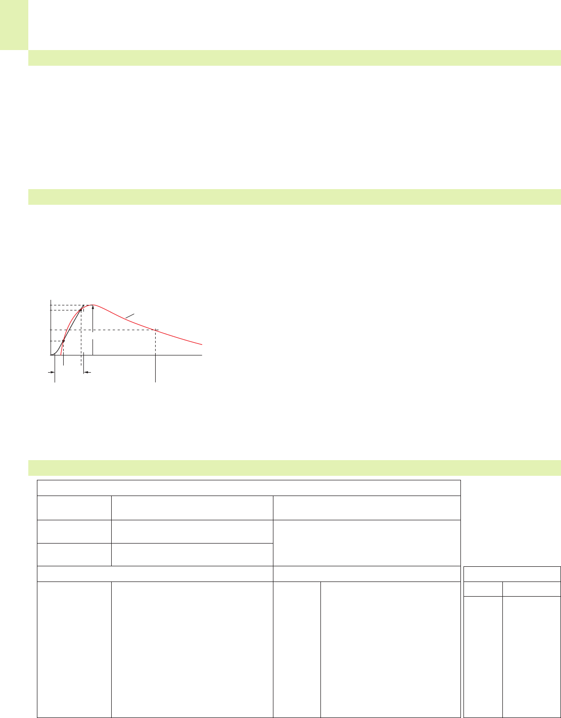
<__________ T2 = 50 μs __________>
(_T _)
T1 = 1,2 μs
%
100
90
50
30
0
15
32
This test procedure is used to verify the creepage distances. Creepage distances, i.e. the distances of creeping currents, are
caused by conductive impurities on the surface of the insulation housing. Apart from the amount of impurities to which a
terminal block, for example, is subjected, the plastic material and housing design are also involved in generating creeping
currents. The insulation material of the housing may be carbonized by a creeping current, which increases the conductivity
even more.
The specimen is tested using a power-frequency withstand voltage for a short time. For example, a rail-mounted terminal
block designed to operate at 800 V nominal voltage is usually tested using 2000 V alternating voltage for 1 minute. The
test is considered to be passed if no flashovers or breakdowns have occured.
Tests and Testing Procedures According to IEC/EN Standards (continued)
Electrical Tests (continued)
• Power-frequency withstand voltage test according to IEC/EN 60947-7-1, IEC/EN 60947-1
This test is used to verify the clearances of a product. In simplified terms, a clearance is the distance between two poles of a
terminal block. If this distance is too small, voltage peaks may cause flashovers or breakdowns. The arrangement of the
rated impulse withstand voltage test is identical to that of the power frequency withstand voltage test; the test voltages,
however, are comparatively higher and the testing times shorter, e.g. 7.3 kV over 50 μs (see figure).
• Rated impulse withstand voltage test according to IEC/EN 60947-7-1, IEC/EN 60947-1
Voltage pulse; measurement curve (red) and auxiliary curve (black) for
calculating the rate of rise of the pulse and the resulting (virtual) peak of the
curve
T Time interval for calculating the rate of rise
T1Front time (duration between start of impulse and reaching the peak)
T2Total pulse duration
The test values are the values at sea level as specified in the relevant test specification.
The values indicated in the catalog correspond to an altitude of 2000 m.
The test is considered to be passed if no flashovers or breakdowns have occured.
• IP ratings for electrical equipment acc. to IEC/EN 60529
<>
IP Vs. NEMA
Comparison
IP NEMA
Alphanumeric nomenclature for type of protection
Code letters Protection against touch and solid IP = Ingress Protection
IP objects or water
First characteristic Indicates degrees of protection against If the indication of the degree of protection
0 to 6 touch or solid objects requires only one characteristic, the other one
Second characteristic
Indicates degree of protection against will be replaced by an X
0 to 8 water
First characteristic:
IP 0X No protection against touch
or solid objects
IP 1X Protected against solid objects > 50 mm
IP 2X Protected against solid objects > 12 mm
(e. g. finger)
IP 3X Protected against solid objects > 2.5 mm
IP 4X Protected against solid objects > 1 mm
IP 5X Dust-protected (limited ingress,
no harmful deposit)
IP 6X Dust-tight (totally protected against dust)
Second characteristic:
IP X0 No protection against water
IP X1 Protected against vertically
dripping water
IP X2 Protected against dripping
water –15° angle
IP X3
Protected against water spray
IP X4
Protected against water splash
IP X5 Protected against water jet
IP X6 Protected against
powerful water jet
IP X7 Protected against temporary
immersion
IP X8 Protected against continuous
immersion
IP code NEMA Type
10 1
11 2
54 3
14 3R
54 3S
55 4 & 4X
52 5
67 6&6P
52 12 &12 K
54 13
û
u
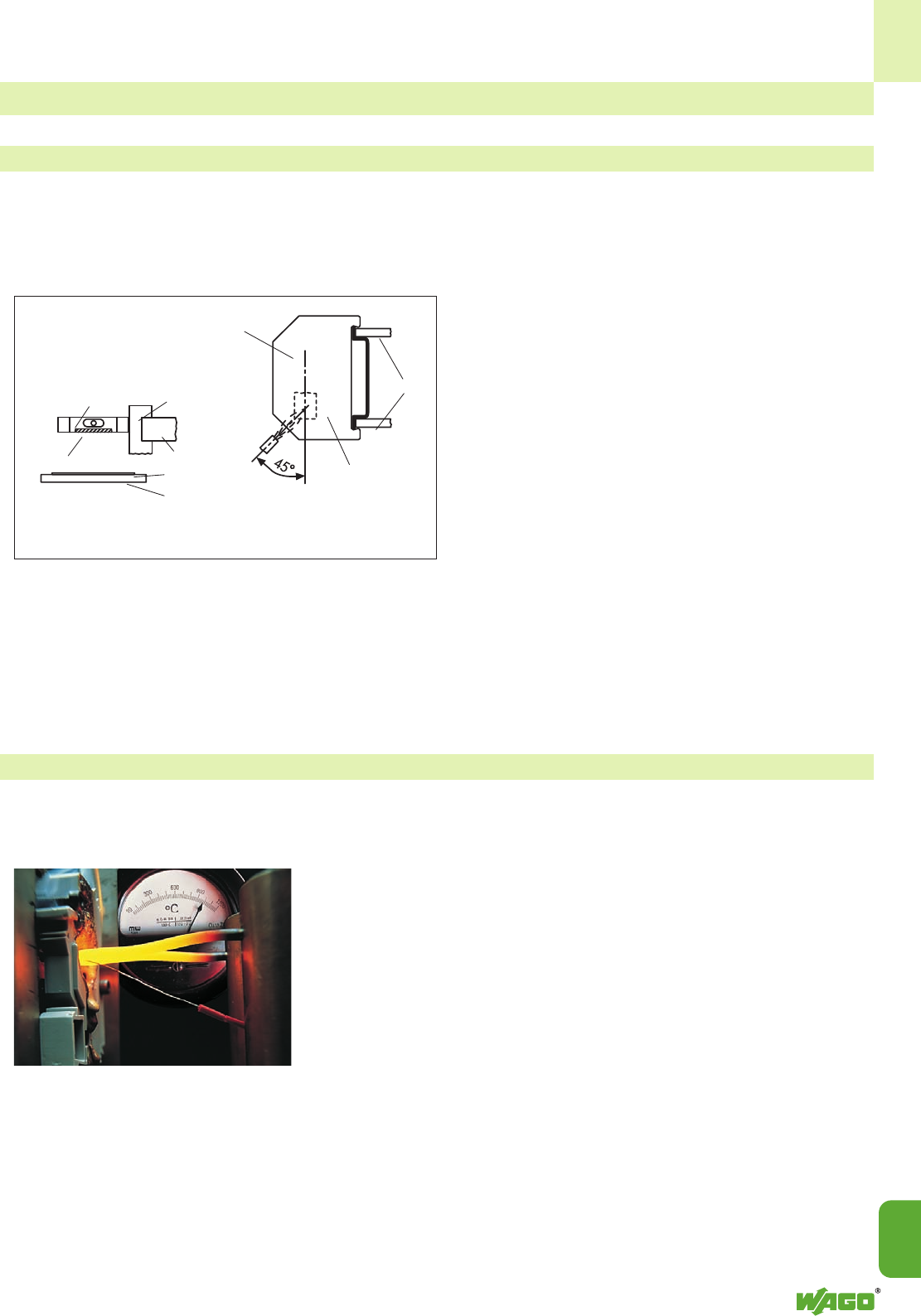
15
15
33
Tests and Testing Procedures According to IEC/EN Standards (continued)
• Needle flame test according to IEC/EN 60947-7-1
Material Tests
All WAGO products meet the requirements of the following material test.
This test simulates flames which may result under certain conditions (for example, a fault current over a creepage distance,
overloading of parts or components). Nearby parts can be affected by such flames. Not only the ignition of the test
specimen resulting from an intrinsic defect is tested, but also its behavior when other parts are ignited.
Flames should not be further fed by the insulation materials
used and expand to a larger fire. The test specimen is expo-
sed to a standard gas flame during a defined time period
(e.g. 10 seconds).
After the test flame has been removed, the specimen must
self-extinguish within 30 seconds. Furthermore, a layer of
tissue paper situated underneath the specimen should not be
ignited by glowing particles falling from the specimen.
• Glow-wire test according to IEC/EN 60695-2-11
In the event of failure, a high current may cause a conductor to glow.
However, the glowing conductor should
not cause ignition of the product invol-
ved (e.g. a rail-mounted terminal block).
For the glow-wire test the tip of the
glow-wire shall be pressed against a
surface of the test specimen (see pictu-
re).
The position of the test specimen, the
surface to be tested, the test duration
and the temperature of the glow-wire,
e.g. 960 °C for 30 seconds or 850 °C
for 5 seconds, are specified in the stan-
dards.
The test is considered to be passed if
there is no visible flames or permanent
glowing or if flames or glowing extin-
guish within 30 seconds after removal
of the glow-wire. For this test also, a
layer of tissue paper situated under-
neath the specimen shall not be ignated
by glowing particles falling from the
specimen.
Test arrangement Point of
test flame contact
Terminal block Support of the
terminal block
Lateral insulation wall Fixing means
Fixing means
Tissue paper
Pinewood board
Terminal block
Clamping part in the area
of the clamping unit
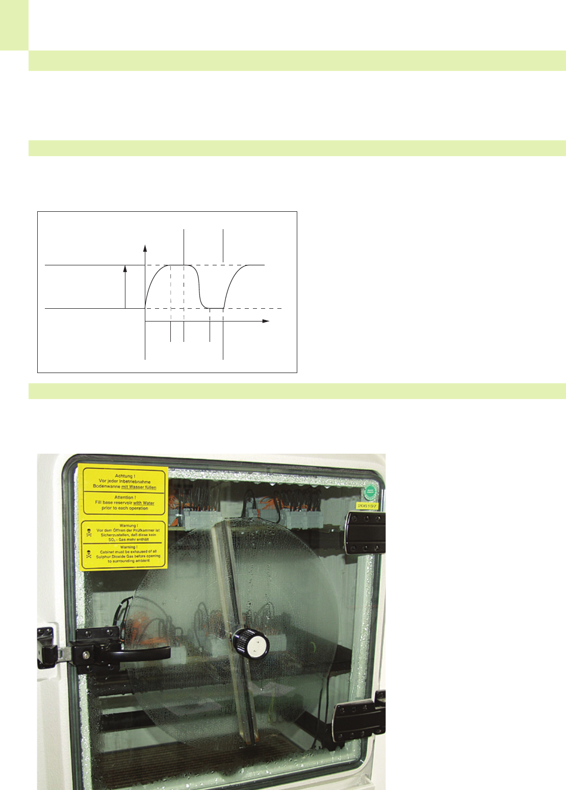
15
34
<20’><20’>10’10’
85
20
The following tests show how a product reacts when exposed to an aggressive environment. Climate chambers are used for
generating standard atmospheres which may affect the long-term constancy of clamping units.
Tests and Testing Procedures According to IEC/EN Standards (continued)
• Temperature cycling test acc. to IEC/EN 60947-7-1, IEC/EN 60998-2-2
Environmental Tests
All WAGO products meet the requirements of the following environmental tests.
This test shows the change of voltage drop over longer periods under temperature cycling conditions. The test procedure
usually consists of 192 temperature cycles, for example, each cycle having a duration of 60 minutes (see diagram).
The rated current is applied to the test specimen during the
temperature rise and when the temperature has reached its
maximum value; during the second half of the cycle the cur-
rent is zero. Voltage drop is measured every 24 cycles and
shall not exceed a maximum value or vary greatly. The vol-
tage drop measured at the end of the 192nd cycle shall not
exceed 1.5 times the value measured after the 24th cycle.
After the test an inspection shall show no changes impairing
further use of the product.
Temperature of
test chamber
incl. temperature
rise due to current
<_____ 1 cycle _____>
n
cycles
T (°C)
Test current
applied
No. current
applied
Test current
applied
• Industrial atmospheres acc. to EN ISO 6988, IEC 60068-2-42, IEC/EN 60068-2-60
Sulphur and its combustion products are particularly aggressive pollutants commonly found in industrial environments.
A test procedure simulating such corrosive conditions consists of exposing a test specimen to water condensation in variable
atmospheres containing sulphur dioxide.
A saturated atmosphere is first created
in a climatic chamber by heating an
aqueous sulphur dioxide solution. After
less than half an hour, the test specimen
is fully humidified by the condensing
vapors and exposed to this atmosphere
for eight hours.
After exposure to humid atmosphere,
the test specimen is submitted to dry
and cooler conditions at room tempe-
rature for 16 hours. Depending on the
test severity, the specimen is exposed to
both these conditions several times. The
gas tightness of the clamping unit is
checked by measuring the voltage
drop.
In other test procedures, products are
exposed to a dry corrosive gas atmos-
phere containing, for example, sulphi-
de, nitrogen and sulphur oxides or
chloric gas. These tests can be perfor-
med over 4 to 21 days.
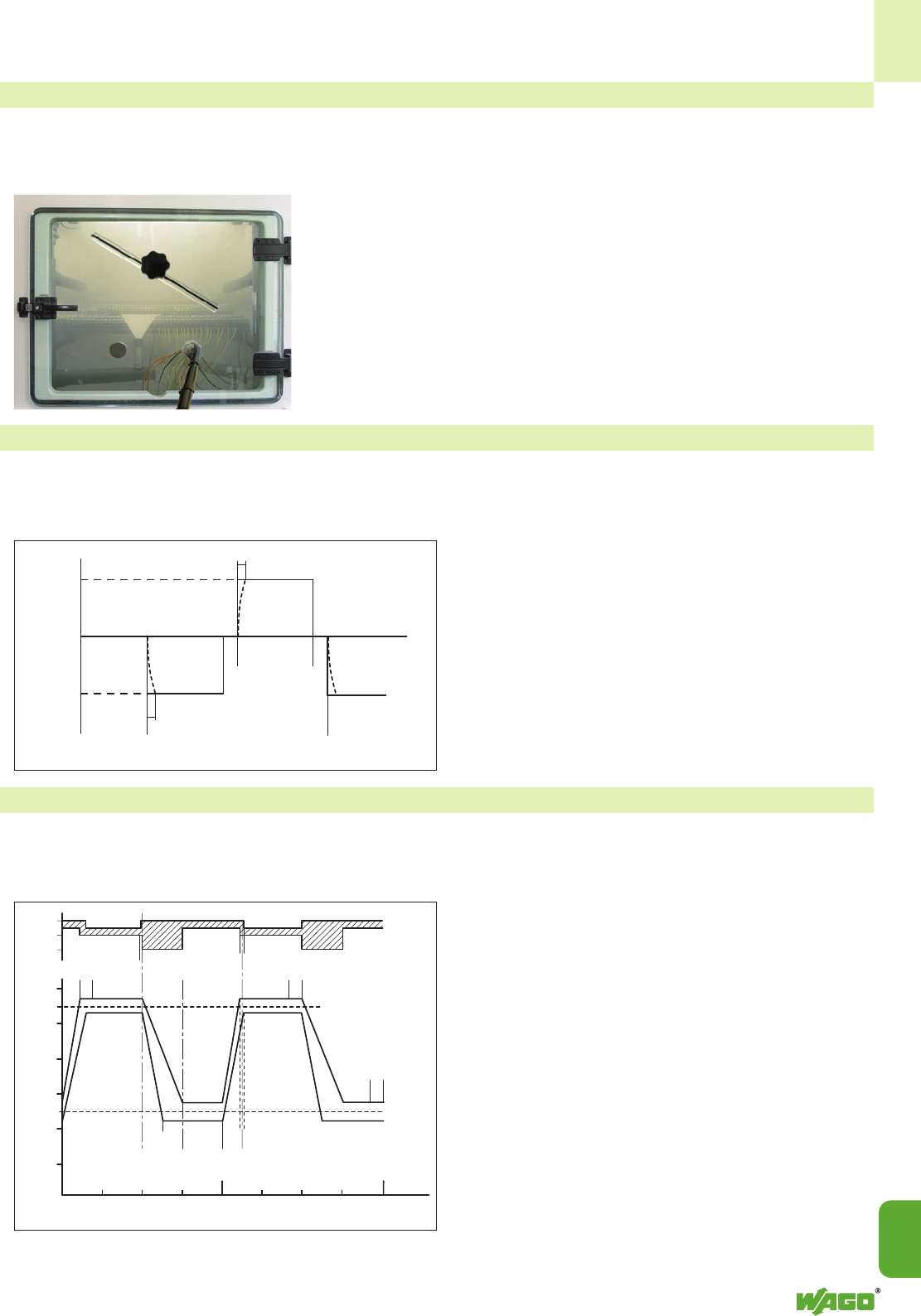
15
15
35
• Salt spray test acc. to IEC/EN 60068-2-11; GL, LR, DNV shipbuilding specifications
This test is similar to the test performed in water condensation alternating atmospheres, except that, instead of industrial
atmospheres, salt mist conditions will be simulated in a heated test chamber (see picture).
Depending on the test procedure being used, the test specimen is sprayed with
salt mist for up to 96 hours.
Salt spray tests are widely used, especially for ship approvals.
However, this test is performed differently than the test procedures described pre-
viously for general applications:
During a typical test, the specimen is sprayed with a salt solution for two hours
and is then stored at 100 % humidity for seven days.
This procedure is repeated four times.
Here too, measuring the voltage drop is used as an evaluation criterion.
• Quick change of temperature acc. to IEC/EN 60068-2-14
Without air-conditioning, distribution panels and terminal boxes are exposed to extreme changing seasonal dependent tem-
peratures on the open field side.
In process technology, for example, a terminal block is exposed to even quicker changes of temperature.
To simulate such conditions, the test specimen is exposed to
repeated temperature changes, for example, between TA-
40 °C (-40 °F) and TB+70 °C (158 °F).
The dwell time t1depends on the thermal capacity of the test
specimen and should be between maximum 3 h and mini-
mum 10 min and the transition time t22 - 3 min, 20 – 30 s
or less than 10 seconds.
The mechanical and electrical properties of the product are
checked at the end of the test.
• Damp heat, cyclic (12 + 12-hour cycle) acc. to IEC/EN 60068-2-30; GL, LR, DNV shipbuilding specifications
The object of this test is to determine the suitability of electrical equipment for use and storage under conditions of high
relative humidity when combined with cyclic temperature changes and, in general, producing condensation on the surface
of the specimen.
Apart from the salt spray tests, the damp heat test is also
used for ship approvals.
For this test the specimens are subjected to temperatures
varying cyclically between +25 °C (77 °F) and +55 °C
(131 °F) with a relative humidity of 95 % (for tolerances see
figure).
Functional tests are performed at defined times during the
storage period.
The electrical and mechanical properties of the product are
checked at the end of the test.
A Beginning of first cycle
B End of first and beginning of second cycle
Temperature in the
test chamber
<__________ 1st cycle _________>
Time t
≤t1
10
≤t1
10
TB
TA
BA
Temperature (°C ) ___> relative __>
humidity (%)
100
90
80
60
55
50
40
30
25
20
10
96 %
95 % 90 % 95 %
80 %
15 min <±15 min
Functional test
2 h
+ 57 °C
+ 53 °C
+ 28 °C
+ 22 °C
12 h
± 0,5 h
3 h
<6 h >
Specimen connected and switched on
1 cycle = 24 h
Specimen connected and switched off
except for functional tests
1 cycle = 24 h
Hours (h) __>
6 12182430 3642 48
___> < >
<>
Functional test
2h<>
(_)
<_________> 3 h
()
Functional test
2 h <>
<± 0,5 h
_)
_> <_
<_ <_
<_
_> _>
_>
t1t1
t2t2

15
36
WAGO terminal blocks and connectors are tested by Underwriters Laboratories Inc. according to one or more of the rele-
vant following UL standards:
– The Series 273 push-wire connectors for junction
boxes or the lighting connectors of Series 224 are
“splicing wire connectors“ and are certified accor-
ding to UL 486C. They are marked with the UL
Listed label uas stand-alone equipment.
– Rail-mounted terminal blocks or modular terminal
blocks (e.g. Series 280, TOPJOB®S or Series
260 – 262 terminal blocks) are approved as non-
stand-alone components according to UL 1059 in
connection with UL 486E.
– The X-COM®connector system is approved as
“terminal block“ according to UL 1059 in connec-
tion with UL 486E. It is defined for “field and fac-
tory wiring“ with a voltage of 300 V.
– Furthermore, it is approved as “connector for use
in data, signal, control and power applications“
according to UL 1977 for “factory wiring“ with
600 V (i.e. the clamping unit shall be wired under
controlled manufacturing conditions).
– Ex e II terminal blocks are approved according to
UL 60079-7.
– Ground (earth) terminal blocks are tested for gro-
unding and bonding applications according to UL
467. Components with the UR label Uare
“recognized products“. Additionally, after being
mounted in their special applications, these com-
ponents are submitted to an end product test
according to the relevant device or equipment
standard.
– Flammability and performance of the insulation
material are tested according to UL 94.
UL Specifications – Underwriters Laboratories USA
UL 486 C Splicing Wire Connectors
UL 1059 Standard for Terminal Blocks
UL 486 E Equipment Wiring Terminals for Use with
Aluminium and / or Copper Conductors
UL 1977 Component connectors for use in data, signal,
control and power applications
UL 60079-7 Electrical apparatus for explosive gas
atmospheres – Part 7: Increased safety
UL 467 Grounding and Bonding Equipment
UL 94 Tests for Flammability of Plastic Materials for
Parts in Devices and Appliances
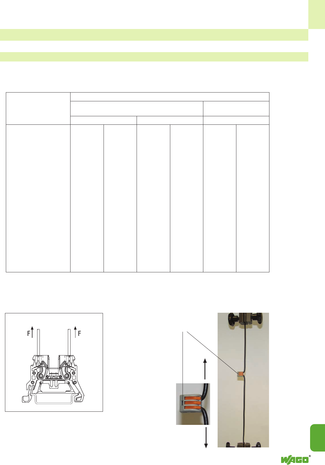
15
15
37
F
F
In this test, the connected wires are subjected to the appropriate pull-out forces specified in the following table without jerks
for one minute. Different test arrangements are to be used for rail-mounted terminal blocks and splicing wire connectors.
Test arrangement according to
UL 1059, UL 486 E:
• Pull-out test acc. to UL 1059, UL 486 E (rail-mounted terminal blocks), UL 486 C (splicing wire connectors)
Tests and Testing Procedures According to UL Standards
All WAGO products meet the requirements of the following tests.
Test arrangement according to
UL 486 C:
During the test, the conductor shall
neither slip out of the clamping unit
nor break near the clamping unit.
Size of conductor Pull-out force, pounds (N)
AWG UL 486 E, UL 486 C,
or table 14.1 table 13.1
kcmil (mm2) Copper Aluminum Copper
30 (0.05) 0.5 (2.2) - - 1.5 (6.9)
28 (0.08) 1 (4.5) - - 2 (8.9)
26 (0.13) 2 (8.9) - - 3 (13.4)
24 (0.20) 3 (13.4) - - 5 (22.3)
22 (0.32) 4.5 (20) - - 8 (35)
20 (0.52) 6.75 (30) - - 10 (44)
18 (0.82) 6.75 (30) - - 10 (44)
16 (1.3) 9 (40) - - 15 (66)
14 (2.1) 11.5 (50) - - 25 (111)
12 (3.3) 13.5 (60) 10 (44) 35 (155)
10 (5.3) 18 (80) 10 (44) 40 (178)
8 (8.4) 20.5 (90) 10 (44) 45 (200)
6 (13.3) 21 (94) 28 (124) 50 (222)
4 (21.2) 30 (133) 36 (160)
3 (26.7) 35 (156) 42 (187)
2 (33.6) 42 (186) 50 (222)
1 (42.4) 53 (236) 61 (271)
1/0 (53.5) 64 (285) 72 (320)
2/0 (67.4) 64 (285) 78 (347)
3/0 (85.0) 79 (351) 97 (432)
4/0 (107) 96 (427) 116 (516)
250 (127) 96 (427) 116 (516)
300 (152) 99 (441) 116 (516)
15
38
Test performed according to:
UL 1059
Test performed with maximum rated cross sectional area
Test current: 150% of the max. rated current
84 cycles of: 3 1/2 h “ON“ / 1/2 h “OFF“
The temperature rise is measured after the first and the 84th
cycle.
The temperature rise shall not exceed 5 °C (41 °F) after the
84th cycle compared to the temperature measured after the
first cycle.
UL Specifications – Underwriters Laboratories USA (continued)
Tests and Testing Procedures According to UL Standards (continued)
UL 486 C (splicing wire connectors),
UL 486 E (equipment wiring terminals)
Test performed with maximum rated cross sectional area
Test current: increased test current acc. to UL 486 C, table 9.1
UL 486 E, table 10.1
500 cycles of: 1 h “ON“ / 1 h “OFF“
1 1/2 h „ON“ / 1 1/2 h „OFF“
(from AWG 4/0 up to 400 kcmil acc. to UL 486 E)
Temperature rises on the terminal blocks and control wires
are measured and recorded after 1, 25, 50, 75, 100, 125,
175, 225, 275, 350, 425 and 500 cycles.
The temperature rise shall not exceed 125 °C (257 °F) and
the stability factor “S“ shall not exceed ± 10.
• Heat cycling test acc. to UL 1059, UL 486 C, UL 486 E
aSee paragraphs 7.12 and 10.1 (UL 486 E)
bValues are for 75°C (167°F), not more than 3 conductors in raceway or cable ampacities, National Electrical Code,
ANSI, NFPA 70-1999, except that for Nos. 14 –10 AWG copper wire and Nos. 12 –10 AWG aluminium wire,
the values are load-current ratings.
cSee paragraph 7.13 (UL 486 E)
dValues are for 75°C (167°F) single conductor in free air ampacities, National Electrical code, ANSI/NFPA 70-1999.
eValues are approximately 112 percent of the static heating test currents.
fValues for No. 8 AWG and larger conductors are approximately 140 percent of the static heating
test currents.
hValues in brackets apply to connectors with assigned ampere ratings.
Size of conductor Test currents for copper conductors (A)
UL 486 E, table 10.1 UL 486 C, table 9.1
AWG Assigned Heating cycling
or maximum Static Temperature ratingaStatic Heat
kcmil mm2Ampere ratingbheatingc,d,h 75°Ce,h 90°Cf,h heating cycling
30 (0.05) - 3 3.5 4 3 3.5
28 (0.08) - 3.5 4 5 3.5 4
26 (0.13) - 5.5 8 7 5.5 6
24 (0.20) - 7 8 10 7 8
22 (0.32) - 9 12 13 9 12
20 (0.52) - 12 16 17 12 16
18 (0.82) - 17 19 24 17 19
16 (1.3) - 18 20 31 18 20
14 (2.1) 15 [20] 30 [22] 33 [27] 40 30 33
12 (3.3) 20 [25] 35 [28] 39 [40] 54 35 39
10 (5.3) 30 [40] 50 [45] 56 [60] 75 50 56
8 (8.4) 50 70 80 100 70 80
6 (13.3) 65 95 105 131 95 105
4 (21.2) 85 125 140 175
3 (26.7) 100 145 165 205
2 (33.6) 115 170 190 240
1 (42.4) 130 195 220 275
1/0 (53.5) 150 230 255 320
2/0 (67.4) 175 265 300 370
3/0 (85.0) 200 310 345 435
4/0 (107) 230 360 405 505
250 (127) 255 405 445 565
300 (152) 285 445 500 625
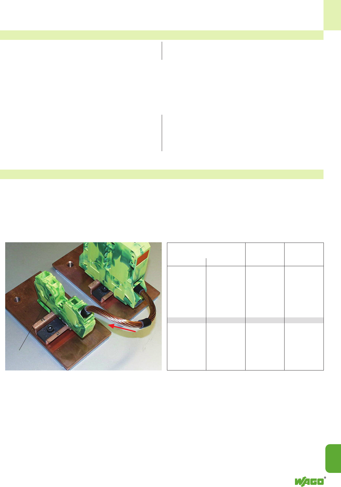
15
15
39
Test performed according to:
UL 1059 (rail-mounted terminal blocks) UL 486 C (splicing wire connectors)
• Conditioning – temperature-rise test acc. to UL 1059, UL 486 C
Conditioning:
The clamping units are pre-wired/pre-inserted 9 times using a conductor with maximum rated cross section. At the 10th
time, a new conductor is connected.
Then, a static heating test is performed.
Static heating test:
Test current: rated current of the terminal block
Test duration: 30 days
max. permissible
temperature rise: 30 °C (86 °F)
Test current: increased test current acc. to table 9.1
Test duration: 30 days
max. permissible
temperature rise: 50 °C (122 °F)
When used in “grounding and bonding“ equipment, terminal blocks, for example, shall withstand a short circuit test using
the test currents and test durations as specified in Table 14.1.
• Grounding and bonding equipment acc. to UL 467
In the following example, an AWG 2 (35 mm2)
ground (earth) conductor terminal block (285-635) is tested
for 6 seconds at a current of 3900 A.
Table 14.1
Size of conductor Test Test
Copper duration current
AWG mm2sA
14 (2.1) 4 300
12 (3.3) 4 470
10 (5.3) 4 750
8 (8.4) 4 1180
6 (13.3) 6 1530
4 (21.2) 6 2450
3 (26.7) 6 3100
2 (33.6) 6 3900
1 (42.4) 6 4900
1/0 (53.5) 9 5050
2/0 (67.4) 9 6400
3/0 (85.0) 9 8030
4/0 (107) 9 10100
250 MCM (127) 9 12000
After the test, the specimen shall show no evidence of damage such as cracking, breaking and melting or changes of
electrical properties.
I
Test specimen
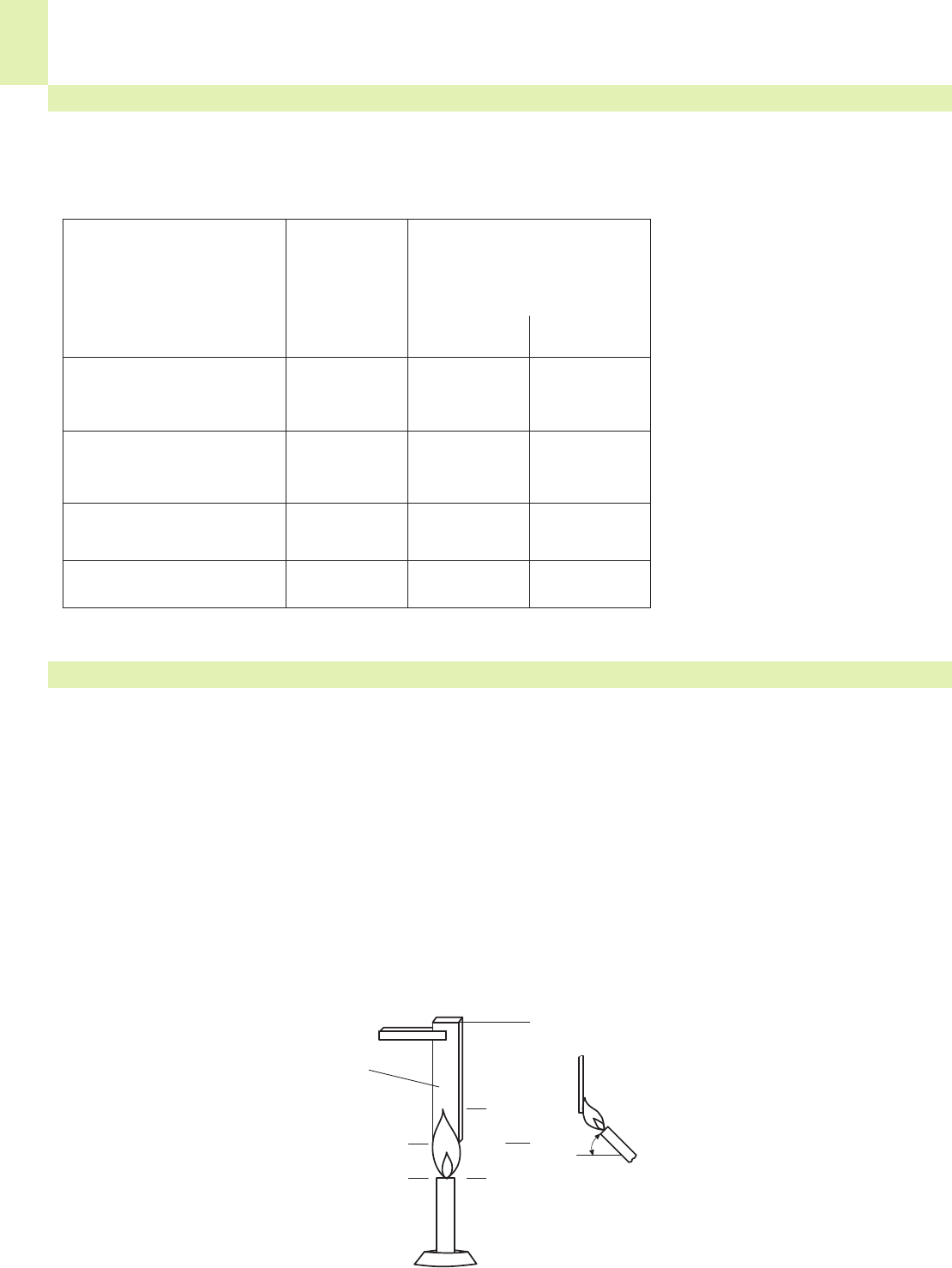
15
40
The table shows the potentials involved and the corresponding clearances and creepage distances required in the different
applications.
UL Specifications – Underwriters Laboratories USA (continued)
Tests and Testing Procedures According to UL Standards (continued)
• Insulation parameters acc. to UL 1059
Notes
1 A slot, groove, or the like, 0.013 inch
(0.33 mm) wide or less in the contour of the
insulating material is to be disregarded.
2 An air space of 0.013 inch (0.33 mm) or less
between a live part and an insulating surface
is to be disregarded for the purpose of measu-
ring over surface spacings.
aThe spacing between wiring terminals of oppo-
site polarity and the spacing between a wiring
terminal and a grounded dead metal part shall
not be less than 1/4 inch (6.4 mm) if short-cir-
cuiting or grounding of such terminals may
result from projecting strands of wire.
bsee paragraph 8.5 (UL 1059)
The spacings specified in item of table 8.1 are
applicable to a terminal block for use only in or
with industrial control equipment where the load
on any single circuit of the terminal block does
not exceed 15 amperes at 51 – 150 volts,
10 amperes at 151 – 300 volts, 5 amperes at
301 – 600 volts, or the maximum ampere
rating, whichever is less.
Minimum acceptable spacings for terminal blocks, UL standard 1059, Table 8.1
Spacings in inches (mm) between un-
insulated live parts of opposite polarity,
uninsulated live parts and uninsulated
grounded parts other than the enclosure
Application Potential involved Through Over
in volts air or oil surfaces
A. Service-including dead-front 51 – 150 1/2 (12,7) 3/4 (19,1)
switchboards, panelboards 151 – 300 3/4 (19,1) 1–1/4 (31,8)
service equipment, 301 – 600 1 (25,4) 2 (50,8)
and the like
B. Commercial appliances, 51 – 150 1/16a(1,6)a1/16a(1,6)a
including business equipment, 151 – 300 3/32a(2,4)a3/32a(2,4)a
electronic data processing 301 – 600 3/8 (9,5) 1/2 (12,7)
equipment, and the like
C. Industrial, general 51 – 150 1/8a(3,2)a1/4 (6,4)
151 – 300 1/4 (6,4) 3/8 (9,5)
301 – 600 3/8 (9,5) 1/2 (12,7)
D. Industrial, Devices having 51 – 300 1/16a(1,6)a1/8a(3,2)a
limited ratingsb301 – 600 3/16a(4,8)a3/8 (9,5)
This test is intended to provide an indication of a material’s ability to extinguish a flame, once ignited.
Several ratings can be applied based on the rate of burning, time to extinguish, ability to resist dripping, and after-glow
extinguishing time.
Each material tested may receive several ratings depending on the wall thickness.
UL 94 rating categories:
• Flammability test acc. to UL 94
V2
- specimen mounted vertically
- burning stops within 30 seconds after
the flame is removed
- flaming drips allowed
- after-glow extinguishes within max. 60
seconds
V1
- specimen mounted vertically
- burning stops within 30 seconds after
the flame is removed
- no flaming drips allowed
- after-glow extinguishes within max. 60
seconds
V0
- specimen mounted vertically
- burning stops within 10 seconds after
the flame is removed
- no flaming drips allowed
- after-glow extinguishes within max. 30
seconds
During the test, a 3/4 inch (19 mm) flame is applied for two 10 second intervals to the specified bar specimens held
vertically.
Test specimen
Dimensions in mm
<___ 19 ___>
<________ 127 ________>
(9,5 )
approx. 45°
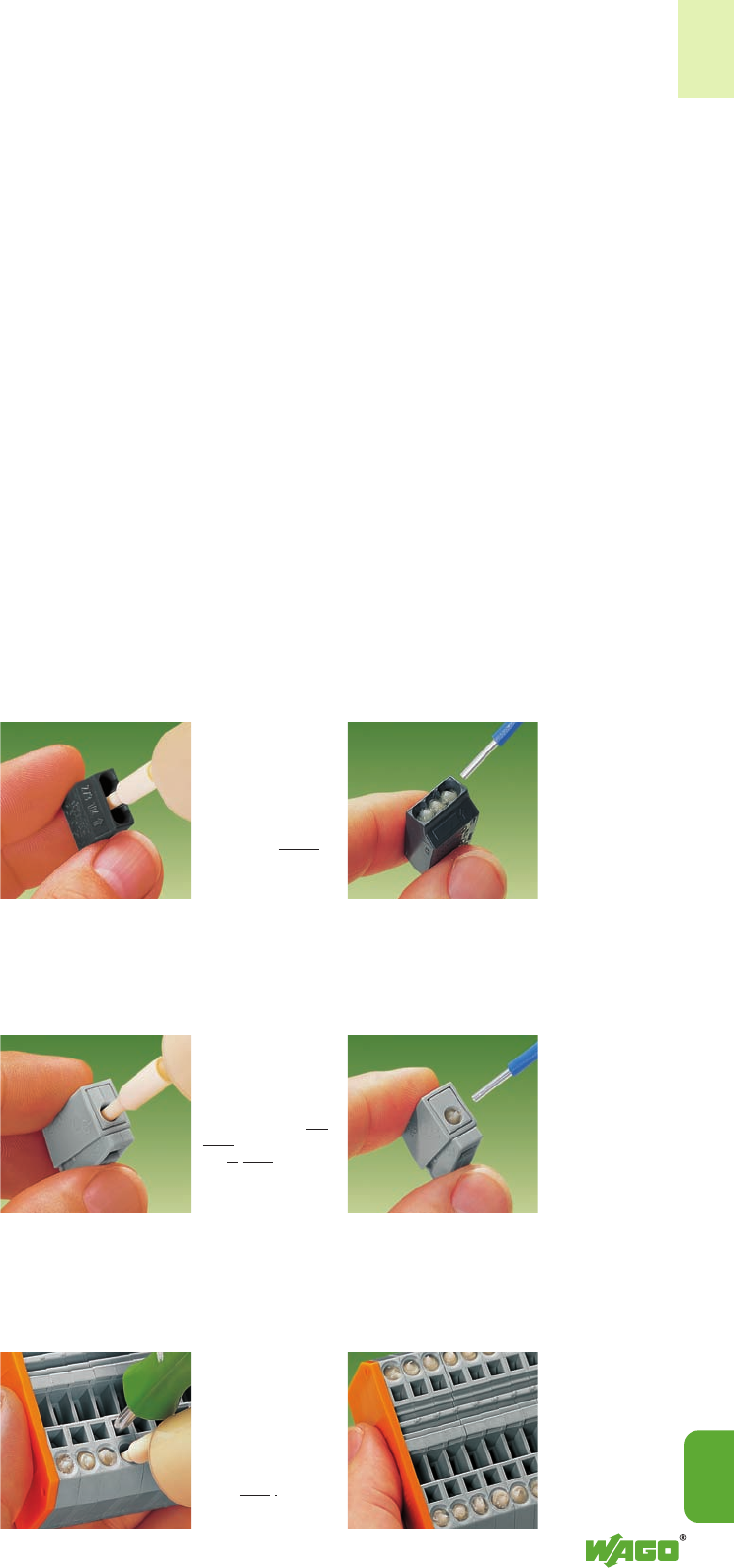
15
15
41
WAGO spring-clamp terminal blocks
are suitable for solid aluminum wires ➊
up to 4 mm2/ AWG 12 if
WAGO con-tact paste “Alu-Plus” is
used for the connection
(see page 14.48).
Please take into account that the
nominal currents must be adapted to
the reduced conductivity of the
aluminum wires:
2.5 mm2/ AWG 14 = 16 A
4mm
2/ AWG 12 = 22 A
Cleaning and greasing of the aluminum
conductor is no longer necessary. Use
the WAGO contact paste “Alu-Plus”
instead, which is directly injected into
the conductor entry hole of WAGO
terminal block by means of the handy
syringe.
This allows the easy connection of solid
aluminum wires (in case of multipole
terminal blocks, also mixed with copper
conductors).
WAGO “Alu-Plus”
●automatically destroys the oxide film
during clamping
●prevents fresh oxidation at the
clamping point
●prevents electrolytic corrosion bet-
ween aluminum- and copper con-
ductors (in the same terminal block)
●offers permanent protection against
corrosion
It is, of course, also possible to apply
the WAGO “Alu-Plus” directly on the
whole surface of the aluminum wire
before clamping.
WAGO “Alu-Plus” in the syringe
offers a higher degree of security
and cleanliness when connecting
solid wire aluminum conductors.
Filling is, for example, very quickly
performed on the three following
selected WAGO terminal blocks
(see description on the right).
➊ Aluminum wires in accordance with
IEC 61545, Class B, Alloy 1370, with a
tensile strength of 90 -180 N/mm2and
an elongation of 1 - 4 %.
Standard values: Tensile strength 90 -
180 MPa, elongation 1 - 4 %. (acc. to
EN 615.4.1)
How to proceed:
There are two possibilities to use the
contact paste when connecting solid
aluminum wires:
1. Apply WAGO “Alu-Plus” on the
whole surface of the aluminum wire
before clamping.
2. Or insert nozzle of the syringe in
every conductor entry hole of
WAGO terminal blocks as demon-
strated with the three examples.
These procedures invariably offer more
security and cleanliness in a quick and
easy way.
WAGO Push-wire connectors
for junction boxes
WAGO Lighting connectors
WAGO Insulated terminal blocks (only up to 4 mm2/AWG 12 rated cross section)
1. Push nozzle of
the “Alu-Plus” syrin-
ge first into the cir-
cular and then into
the square conduc-
tor entry hole of the
WAGO lighting
connector.
1. Push nozzle of
the “Alu-Plus” syrin-
ge in every conduc-
tor entry hole (one
after the other).
1. Push nozzle of
the “Alu-Plus” syrin-
ge into the center
conductor entry hole
of the WAGO junc-
tion box connector.
2. Press plunger
down
until “Alu-Plus”
is visible in the
other holes.
Connection of aluminum wires
2. Press plunger
down until the
“Alu-Plus” has
filled both holes.
2. Press plunger
down until
“Alu-Plus” has
filled each of
these holes.

15
42
For 40 years Nylon (PA 6.6 and PA 4.6) and Polycarbonate (PC) have been the preferred insulation materials for housings
of current carrying parts and accessories of terminal blocks and connectors (see table). They have been approved by
almost all international test houses.
Material Specification
Insulation materials
Table: Standard insulation materials
Material PA 6.6 PA 4.6 PC
Flammability
Flammability acc. to UL 94, rating categories V 0 V 2 V 2
Glow wire test acc. to IEC 60695-2-10/11+12 960 °C 850 °C 850 °C
Oxygen index 37 27 26
Anti tracking index acc. to IEC 60112 CTI 600 375 275
Temperature resistance under HDT/B (0,45 Mpa) short term 200 °C short term 280 °C 140 °C
mechanical stress permanent 105 °C permanent 115 °C 125 °C
Resistance to heat
Ball pressure test acc. to EN ISO 2039-1 125 °C passed 125 °C passed 125 °C passed
Testing device B
Surface resistivity 1010 – 1013 Ω1013 – 1016 Ω1015 Ω
Specific through resistance 1015 Ω/cm 109– 1015 Ω/cm 1013 Ω/cm
Dielectric strength 30 kV/mm 25 kV/mm 29 kV/mm

15
15
43
Nylon (PA 6.6)
WAGO uses a modified Nylon, free of
halogens, fluorcarbons, chlorinated
hydrocarbons, silicone, asbestos,
cadmium and formaldehyde.
It will not corrode, is hardly inflamma-
ble, self-extinguishing (V0 acc. to UL 94)
and is temperature-stabilized allowing
operation continuously at a tempera-
ture of 105 °C (221 °F).
This long-term resistance to temperatu-
re refers to UL-Index RTI-Mechanical
STR in order to guarantee an adequate
safety margin in terms of the electrical
and mechanical insulation.
The short-time upper temperature limit
is 200 °C (392 °F).
The same safety philosophy is the basis
of the indications of the lower limiting
temperature. The insulation material
can be handled at temperatures as low
as -35 °C (-31 °F) without damage. In
the assembled and wired condition all
WAGO products can be used at tem-
peratures as low as -60 °C (-76 °F).
The humidity absorbed from the envi-
ronment (up to 2.5 % on average) is
chemically bound to the Nylon structure
providing best elasticity and safety
against breaking.
In practical use the basic stabilization
provides sufficient protection against
damage by ozone or ultraviolet light
for many years. The resistance against
adverse climate conditions is good.
Nylon is also being used successfully in
tropical areas.
Insulating parts produced from Nylon
are resistent to termites. The material
does not offer a source of oxygen or
other biogenic elements to microorga-
nisms. The presence of anaerobic earth
bacteria, mould fungus and enzymes
does not result in degradation of the
material. The resistance to fuels, most
oils and fats, the most usually applied
detergents such as alcohol, Freon, Fri-
gen, carbon tetrachloride is excellent.
The resistance to acids is dependent
upon the kind of acid and its concen-
tration. More details upon request.
WAGO only accepts deliveries of insu-
lating materials with a certificate of
conformity and specified material test
results.
Nylon (PA 4.6)
In comparison with Nylon 6.6, Nylon
4.6 features a much higher dimensional
stability under heat. Its long-term tem-
perature resistance under mechanical
stress is 115 °C (239 °F). The long-term
heat resistance after 10,000 hours is
140 °C (284 °F). The short-time upper
temperature limit is 280 °C (536 °F) for
Nylon 4.6 used by WAGO.
For further information see table.
Polycarbonate (PC)
Some typical properties of Polycarbon-
ate include:
– excellent dimensional stability under
heat, high level of strength, stiffness,
hardness and viscosity up to 135 °C
(275 °F).
– good electrical properties, also un-
affected by exposure to moisture.
Its insulation properties are virtually
independent of the temperature and
humidity.
– high dimensional stability thanks to
low level of shrinkage due to low
water absorption (about 0.2 % rela-
tive humidity)
– high weathering resistance
– high resistance to energetic radiation
– self-extinguishing
– crystal-clear transparency and high
luster
The Polycarbonate used has a very
high viscosity and chemical resistance.
More details upon request.
Thanks to such properties as thermal
stability, nonflammability, transparancy
and viscosity, Polycarbonate is a high
quality material which has found a
wide use in electronic applications.

15
44
Electrolytic copper ECU, hard and extra-
hard as well as extra-hard copper
alloys are the standard materials for
the current carrying parts of all WAGO
products.
Material specification (continued)
Contact materials
This material combines excellent con-
ductivity and good chemical resistance
without risk of stress cracking.
The special tin alloy layer, the standard
surface for all current-carrying parts in
WAGO products, is the guarantee for
the excellent long-term protection
against corrosive substances. Further-
more, these layers make a gastight
contact which provides a durable tran-
sition resistance.
Contact surface
At the clamping unit the conductor is
pressed with a high contact pressure
into the soft tin layer. This defined
contact area is thereby protected
against corrosive influences.
The thick tin layer also ensures good
solderability of the solder pins of PCB
terminal blocks and connectors.
All WAGO clamping springs are pro-
duced from high quality carefully
selected austhenitic chrome nickel
spring steel (CrNi) with high tensile
strength which has proven its resistance
to corrosion in many years of practical
use.
It is resistant to salt sea air, town gas
and the industrial gases sulphur dioxide
and hydrogen sulfide.
At normal temperatures around 20 °C
(68 °F), the material is resistant to salt
solutions up to 30 % and dilute phos-
phoric acids up to 30 %.
Material of the clamping springs
After more than 20 years of practical
experience contact corrosion of the
chrome nickel spring steel in connection
with the contact material used by
WAGO and the copper conductors
connected to the clamping units could
not be noticed.
The relaxation of the material as a
function of the time and surrounding
temperatures up to 105 °C (221 °F) can
be neglected. Even at a temperature of
250 °C (482 °F) a relaxation of only
1.5% at a load of 500 N/mm2was
measured.
In certain product lines the clamping
springs are thermally treated at tempe-
ratures between 350 °C (662 °F) and
420 °C (788 °F) after their production.
This treatment results in a reduction of
internal stress due to the mechanical
deformation of the material and may
be noticed by a brownish colour of the
spring surface.
WAGO only accepts deliveries of
chrome nickel spring steel against certi-
ficates of conformity and after certain
material tests.

15
45
15
Index of Item Nos.
Item No. Page Item No. Page Item No. Page Item No. Page
Series 206
206-118 14.49
206-124 14.46
206-125 14.46
206-126 14.46
206-127 14.46
206-204 14.44
206-216 14.44
206-501 14.46
206-502 14.46
206-503 14.46
206-802 14.47
206-804 14.47
Series 209
209-100 14.37
209-106 14.18
209-107 7.13
209-108 7.13
209-112 14.18
209-113 14.18
209-114 14.18
209-115 14.16
209-116 14.16
209-120 10.18
209-122 10.9
209-123 10.18
209-125 14.16
209-126 14.16
209-128 14.8
209-129 14.43
209-130 14.43
209-132 10.18
209-137 9.38
209-140 14.18
209-141 14.18
209-142 14.18
209-143 14.17
209-144 14.17
209-170 2.9
209-173 9.47
209-174 9.47
209-183 14.17
209-184 14.17
209-185 14.15
209-190 2.13
209-191 2.13
209-196 14.39
209-290 14.14
209-3 . . 14.16
209-4 . . 14.10
209-5 . . 14.9
209-6 . . 14.9
209-7 . . 14.8
209-8 . . 14.16
209-9 . . 14.9
additional item no.
209-4 . . /000-002 14.9
209-4 . . /000-005 14.9
209-4 . . /000-006 14.9
209-4 . . /000-007 14.9
209-4 . . /000-012 14.9
209-4 . . /000-017 14.9
209-4 . . /000-023 14.9
209-4 . . /000-024 14.9
209-5 . . /000-002 14.9
209-5 . . /000-005 14.9
209-5 . . /000-006 14.9
209-5 . . /000-007 14.9
209-5 . . /000-012 14.9
209-5 . . /000-017 14.9
209-5 . . /000-023 14.9
209-5 . . /000-024 14.9
209-6 . . /000-002 14.9
209-6 . . /000-005 14.9
209-6 . . /000-006 14.9
209-6 . . /000-007 14.9
209-6 . . /000-012 14.9
209-6 . . /000-017 14.9
209-6 . . /000-023 14.9
209-6 . . /000-024 14.9
209-7 . . /000-002 14.9
209-7 . . /000-005 14.9
209-7 . . /000-006 14.9
209-7 . . /000-007 14.9
209-7 . . /000-012 14.9
209-7 . . /000-017 14.9
209-7 . . /000-023 14.9
209-7 . . /000-024 14.9
209-9 . . /000-002 14.9
209-9 . . /000-005 14.9
209-9 . . /000-006 14.9
209-9 . . /000-007 14.9
209-9 . . /000-012 14.9
209-9 . . /000-017 14.9
209-9 . . /000-023 14.9
209-9 . . /000-024 14.9
Series 210
210-103 7.34
210-110 14.8
210-111 14.37
210-112 14.36
210-113 14.36
210-114 14.36
210-118 14.36
210-123 7.34
210-133 12.4
210-136 2.13
210-137 2.13
210-141 14.43
210-143 14.43
210-148 14.36
210-149 14.36
210-154 10.9
210-182 14.40
210-183 14.40
210-186 14.40
210-188/001-000 14.41
210-196 14.36
210-197 14.36
210-198 14.36
210-254 7.18
210-257 14.42
210-258 14.42
210-283 14.40
210-291 14.41
210-292 14.40
210-295 14.37
210-296 14.37
210-331 14.23
210-332 14.23
210-333 14.23
210-333/0500-0001 14.35
210-333/0500-0002 14.35
210-333/0500-0003 14.35
210-333/0500-0004 14.35
210-333/0500-0005 14.35
210-333/0500-0006 14.35
210-333/0500-0007 14.35
210-333/0500-0008 14.35
210-333/0500-0009 14.35
210-333/0500-0010 14.35
210-333/0500-0011 14.35
210-333/0500-0021 14.35
210-333/0500-0074 14.35
210-333/0500-0075 14.35
210-333/0500-0076 14.35
210-333/0500-0077 14.35
210-333/0500-0078 14.35
210-333/0500-0079 14.35
210-333/0600-0001 14.35
210-333/0600-0006 14.35
210-333/0600-0007 14.35
210-333/0600-0008 14.35
210-333/0600-0009 14.35
210-333/0600-0010 14.35
210-333/0600-0011 14.35
210-333/0600-0021 14.35
210-333/0600-0074 14.35
210-333/0600-0075 14.35
210-333/0600-0076 14.35
210-333/0600-0078 14.35
210-333/0600-0079 14.35
210-333/0600-0103 14.35
210-333/0600-0104 14.35
210-333/0600-0105 14.35
210-333/0600-0106 14.35
210-333/0700-0001 14.35
210-333/0700-0020 14.35
210-333/0700-0021 14.35
210-333/0700-0074 14.35
210-333/0700-0075 14.35
210-333/0700-0076 14.35
210-333/0700-0077 14.35
210-333/0700-0078 14.35
210-333/0700-0079 14.35
210-333/0700-0108 14.35
210-333/0700-0109 14.35
210-333/0800-0001 14.35
210-333/0800-0002 14.35
210-333/0800-0003 14.35
210-333/0800-0004 14.35
210-333/0800-0005 14.35
210-333/0800-0006 14.35
210-333/0800-0007 14.35
210-333/0800-0008 14.35
210-333/0800-0009 14.35
210-333/0800-0010 14.35
210-333/0800-0011 14.35
210-333/0800-0074 14.35
210-333/0800-0075 14.35
210-333/0800-0076 14.35
210-333/0800-0077 14.35
210-333/0800-0078 14.35
210-333/0800-0079 14.35
210-333/0800-0209 14.35
210-333/1000-0001 14.35
210-333/1000-0074 14.35
210-333/1000-0075 14.35
210-333/1000-0076 14.35
210-333/1000-0077 14.35
210-333/1000-0078 14.35
210-333/1000-0079 14.35
210-333/1000-0110 14.35
210-333/1000-0111 14.35
210-333/1000-0112 14.35
210-333/1000-0113 14.35
210-333/1000-0202 14.35
210-333/1000-0204 14.35
210-333/1000-0206 14.35
210-333/1000-0208 14.35
210-333/1200-0001 14.35
210-333/1200-0074 14.35
210-333/1200-0075 14.35
210-333/1200-0076 14.35
210-333/1200-0077 14.35
210-333/1200-0078 14.35
210-333/1200-0079 14.35
210-333/1200-0103 14.35
210-333/1200-0104 14.35
210-333/1200-0105 14.35
210-333/1200-0106 14.35
210-333/1200-0107 14.35
210-333/1200-0203 14.35
210-334 14.23
210-345 14.18
210-370 14.40
210-407 14.41
210-411 14.40
210-412 7.18
210-413 7.19
210-414 7.19
210-415 7.18
210-416 14.40
210-417 14.41
210-419 14.41
210-420 14.41
210-422 14.41
210-423 7.21
210-424 7.21
210-490 9.38
210-549 14.39
210-612 14.15
210-619 14.42
210-620 14.42
210-621 14.42
210-622 14.42
210-701 14.28
210-702 14.28
210-703 14.28
210-704 14.28
210-705 14.28
210-706 14.28
210-707 14.28
210-708 14.28
210-709 14.28
210-731 14.28
210-732 14.28
210-733 14.28
210-734 14.28
Series 215
215-111 2.42
215-211 2.42
215-212 2.42
215-311 2.42
215-411 2.42
215-511 2.42
215-611 2.42
215-711 2.42
215-811 2.42
215-911 2.42
Series 216
216-101 14.45
216-102 14.45
216-103 14.45
216-104 14.45
216-106 14.45
216-107 14.45
216-108 14.45
216-109 14.45
216-110 14.45
216-121 14.45
216-122 14.45
216-123 14.45
216-124 14.45
216-131 14.45
216-132 14.45

15
46
Item No. Page Item No. Page Item No. Page Item No. Page
216-151 14.45
216-152 14.45
216-201 14.45
216-202 14.45
216-203 14.45
216-204 14.45
216-205 14.45
216-206 14.45
216-207 14.45
216-208 14.45
216-209 14.45
216-210 14.45
216-221 14.45
216-222 14.45
216-223 14.45
216-224 14.45
216-241 1.13
216-242 1.13
216-243 1.13
216-244 1.13
216-246 1.13
216-262 1.13
216-263 1.13
216-264 1.13
216-266 1.13
216-267 1.13
216-284 1.13
216-286 1.13
216-287 1.13
216-288 1.13
216-289 1.13
216-301 14.45
216-302 14.45
216-321 14.45
216-322 14.45
Series 222
222-413 10.39
222-415 10.39
Series 224
224-101 10.31
224-104 10.31
224-112 10.31
224-114 10.31
224-201 10.31
Series 243
243-110 10.35
243-112 10.35
243-113 10.35
243-144 10.34
243-204 10.34
243-208 10.34
243-304 10.34
243-308 10.34
243-504 10.34
243-508 10.34
243-804 10.34
243-808 10.34
Series 248
248-4. . 14.14
248-5 . . 14.14
additional item no.
248- . . . /000-002 14.14
248- . . . /000-005 14.14
248- . . . /000-006 14.14
248- . . . /000-007 14.14
248- . . . /000-012 14.14
248- . . . /000-017 14.14
248- . . . /000-023 14.14
248- . . . /000-024 14.14
Series 249
249-101 14.37
249-105 14.17
249-106 2.39
249-107 2.39
249-109 11.19
249-116 14.19
249-117 14.19
249-118 14.18
249-119 14.18
249-125 2.45
249-126 2.45
249-127 2.45
249-130 14.48
249-135 10.28
249-136 4.4
249-137 10.28
249-138 10.28
249-139 4.4
249-140 10.28
249-141 2.38
249-142 2.38
249-143 2.38
249-144 2.38
249-145 2.38
249-146 2.38
249-147 2.39
249-148 2.39
249-200 14.17
|
249-239
249-241 14.17
|
249-250
249-5 . . 14.9
249-553/000-002 7.18
249-554/000-006 7.19
249-557 14.9
249-558 14.9
249-601 14.9
|
249-605
249-615 14.12
|
249-619
249-657 14.9
249-658 14.9
249-672 14.11
249-674 14.11
249-7 . . 14.8
additional item no.
249-5 . . /000-002 14.9
249-5 . . /000-005 14.9
249-5 . . /000-006 14.9
249-5 . . /000-007 14.9
249-5 . . /000-012 14.9
249-5 . . /000-017 14.9
249-5 . . /000-023 14.9
249-5 . . /000-024 14.9
249-6 . . /000-002 14.9
249-6 . . /000-005 14.9
249-6 . . /000-006 14.9
249-6 . . /000-007 14.9
249-6 . . /000-012 14.9
249-6 . . /000-017 14.9
249-6 . . /000-023 14.9
249-6 . . /000-024 14.9
249-7 . . /000-002 14.9
249-7 . . /000-005 14.9
249-7 . . /000-006 14.9
249-7 . . /000-007 14.9
249-7 . . /000-012 14.9
249-7 . . /000-017 14.9
249-7 . . /000-023 14.9
249-7 . . /000-024 14.9
Series 258
258-139 14.26
258-140 14.26
258-141 14.26
258-143 14.24
258-144 14.24
258-145 14.26
258-146 14.26
258-147 14.26
258-161 14.24
258-162 14.24
258-163 14.24
258-164 14.24
258-165 14.24
258-169 14.24
258-170 14.24
258-171 14.24
258-172 14.24
258-173 14.24
258-226 14.26
258-227 14.26
258-228 14.26
258-229 14.26
258-297 14.33
258-298 14.32
258-300 14.30
258-327 14.26
258-328 14.26
258-350 14.34
258-350/000-001 14.25
258-350/000-002 14.25
258-350/000-003 14.25
258-350/000-004 14.25
258-361 14.26
258-362 14.26
258-363 14.26
258-364 14.26
258-368 14.26
258-369 14.25
258-370 14.26
258-371 14.26
258-372 14.26
258-373 14.26
258-374 14.26
258-375 14.26
258-377 14.26
258-378 14.26
258-379 14.26
258-380 14.26
258-381 14.26
258-382 14.26
258-383 14.26
258-384 14.26
258-385 14.26
258-386 14.26
258-387 14.26
258-388 14.26
258-389 14.26
258-390 14.26
258-391 14.26
258-392 14.26
258-393 14.26
258-394 14.26
258-397 14.26
258-410 14.25
258-412 14.25
Series 260
260-102 10.19
|
260-112
260-152 10.19
|
260-162
260-202 10.19
|
260-212
260-252 10.19
|
260-262
260-301 10.18
260-303 10.18
260-304 10.18
260-306 10.18
260-307 10.18
260-311 10.18
260-313 10.18
260-314 10.18
260-316 10.18
260-317 10.18
260-321 10.18
260-323 10.18
260-324 10.18
260-326 10.18
260-327 10.18
260-331 10.18
260-333 10.18
260-334 10.18
260-336 10.18
260-337 10.18
260-341 10.18
260-343 10.18
260-344 10.18
260-346 10.18
260-347 10.18
260-351 10.18
260-353 10.18
260-354 10.18
260-356 10.18
260-357 10.18
260-361 10.18
260-371 10.18
260-402 10.18
260-404 10.28
260-405 10.28
Series 261
261-102 10.21
|
261-112
261-102/331-000 10.23
|
261-112/331-000
261-102/341-000 10.23
|
261-112/341-000
261-152 10.21
|
261-162

15
47
15
Item No. Page Item No. Page Item No. Page Item No. Page
261-152/331-000 10.23
|
261-162/331-000
261-152/341-000 10.23
|
261-162/341-000
261-202 10.21
|
261-212
261-202/332-000 10.23
|
261-212/332-000
261-202/342-000 10.23
|
261-212/342-000
261-252 10.21
|
261-262
261-252/332-000 10.23
|
261-262/332-000
261-252/342-000 10.23
|
261-262/342-000
261-301 10.20
261-301/331-000 10.22
261-301/341-000 10.22
261-303 10.20
261-303/331-000 10.22
261-303/341-000 10.22
261-304 10.20
261-304/331-000 10.22
261-304/341-000 10.22
261-306 10.20
261-306/331-000 10.22
261-306/341-000 10.22
261-307 10.20
261-307/331-000 10.22
261-307/341-000 10.22
261-311 10.20
261-311/331-000 10.22
261-311/341-000 10.22
261-313 10.20
261-313/331-000 10.22
261-313/341-000 10.22
261-314 10.20
261-314/331-000 10.22
261-314/341-000 10.22
261-316 10.20
261-316/331-000 10.22
261-316/341-000 10.22
261-317 10.20
261-317/331-000 10.22
261-317/341-000 10.22
261-321 10.20
261-321/331-000 10.22
261-321/341-000 10.22
261-323 10.20
261-323/331-000 10.22
261-323/341-000 10.22
261-324 10.20
261-324/331-000 10.22
261-324/341-000 10.22
261-326 10.20
261-326/331-000 10.22
261-326/341-000 10.22
261-327 10.20
261-327/331-000 10.22
261-327/341-000 10.22
261-331 10.20
261-331/332-000 10.22
261-331/342-000 10.22
261-333 10.20
261-333/332-000 10.22
261-333/342-000 10.22
261-334 10.20
261-334/332-000 10.22
261-334/342-000 10.22
261-336 10.20
261-336/332-000 10.22
261-336/342-000 10.22
261-337 10.20
261-337/332-000 10.22
261-337/342-000 10.22
261-341 10.20
261-341/332-000 10.22
261-341/342-000 10.22
261-343 10.20
261-343/332-000 10.22
261-343/342-000 10.22
261-344 10.20
261-344/332-000 10.22
261-344/342-000 10.22
261-346 10.20
261-346/332-000 10.22
261-346/342-000 10.22
261-347 10.20
261-347/332-000 10.22
261-347/342-000 10.22
261-351 10.20
261-351/332-000 10.22
261-351/342-000 10.22
261-353 10.20
261-353/332-000 10.22
261-353/342-000 10.22
261-354 10.20
261-354/332-000 10.22
261-354/342-000 10.22
261-356 10.20
261-356/332-000 10.22
261-356/342-000 10.22
261-357 10.20
261-357/332-000 10.22
261-357/342-000 10.22
261-361 10.20
261-371 10.20
261-402 10.20
261-404 10.28
261-405 10.28
261-410 10.24
261-411 10.24
261-411/331-000 10.24
261-411/341-000 10.24
261-422 10.25
|
261-432
261-422/331-000 10.25
|
261-432/331-000
261-422/341-000 10.25
|
261-432/341-000
additional item no.
261-1 . . /000-006 10.21
261-1 . . /331-006
261-1 . . /341-006
261-2 . . /000-006 10.21
261-2 . . /332-006
261-2 . . /342-006
Series 262
262-102 10.27
|
262-112
262-130 10.26
262-132 10.27
|
262-142
262-152 10.27
|
262-162
262-180 10.26
262-181 10.26
262-182 10.27
|
262-192
262-202 10.27
|
262-212
262-230 10.26
262-232 10.27
|
262-242
262-252 10.27
|
262-262
262-280 10.26
262-281 10.26
262-282 10.27
|
262-292
262-301 10.26
262-304 10.26
262-306 10.26
262-307 10.26
262-311 10.26
262-314 10.26
262-316 10.26
262-317 10.26
262-321 10.26
262-324 10.26
262-326 10.26
262-327 10.26
262-331 10.26
262-334 10.26
262-336 10.26
262-337 10.26
262-341 10.26
262-344 10.26
262-346 10.26
262-347 10.26
262-351 10.26
262-354 10.26
262-356 10.26
262-357 10.26
262-361 10.26
262-363 10.26
262-371 10.26
262-373 10.26
262-402 10.26
additional item no.
262-1 . . /000-006 10.27
262-2 . . /000-006 10.27
Series 264
264-102 10.14
|
264-112
264-120 4.5
264-125 4.4
264-130 10.12
264-131 10.12
264-132 10.14
|
264-142
264-152 10.14
|
264-162
264-180 10.13
264-182 10.14
|
264-192
264-202 10.14
|
264-212
264-220 4.5
264-225 4.4
264-230 10.12
264-231 10.12
264-232 10.14
|
264-242
264-252 10.14
|
264-262
264-280 10.13
264-282 10.14
|
264-292
264-301 10.12
264-304 10.12
264-306 10.12
264-307 10.12
264-311 10.13
264-314 10.13
264-316 10.13
264-317 10.13
264-321 10.12
264-324 10.12
264-326 10.12
264-327 10.12
264-331 10.12
264-334 10.12
264-336 10.12
264-337 10.12
264-341 10.13
264-344 10.13
264-346 10.13
264-347 10.13
264-351 10.12
264-354 10.12
264-356 10.12
264-357 10.12
264-361 10.12
264-363 10.12
264-364 10.12
264-367 4.4
264-368 4.4
264-369 4.4
264-370 4.4
264-371 10.13
264-373 10.13
264-374 10.13
264-402 4.4
264-701 4.5
264-704 4.5
264-706 4.5
264-711 4.4
264-714 4.4
264-716 4.4
264-721 4.5
264-724 4.5
264-726 4.5
264-727 4.5
264-727/999-950 4.5
264-731 4.4
264-734 4.4
264-736 4.4
264-737 4.4
264-737/999-950 4.4
264-900 14.14
|
264-905

15
48
Item No. Page Item No. Page Item No. Page Item No. Page
additional item no.
264-1 . . /000-006 10.14
264-2 . . /000-006 10.14
264-9 . . /000-002 14.14
264-9 . . /000-005 14.14
264-9 . . /000-006 14.14
264-9 . . /000-007 14.14
264-9 . . /000-012 14.14
264-9 . . /000-017 14.14
264-9 . . /000-023 14.14
264-9 . . /000-024 14.14
Series 270
270-319 7.42
270-320 7.41
270-321 7.42
270-322 7.41
270-409 7.41
270-417 7.41
270-480 7.41
270-560 7.42
270-560/281-434 7.42
270-560/281-507 7.42
270-564 7.42
270-564/281-483 7.42
270-570 7.41
270-570/281-434 7.41
270-570/281-507 7.41
270-572 7.43
270-572/281-434 7.43
270-574 7.41
270-574/281-483 7.41
270-577 7.43
270-585 7.43
270-585/281-507 7.43
270-586 7.43
Series 273
273-100 10.36
273-101 10.36
273-102 10.36
273-104 10.36
273-105 10.36
273-108 10.36
273-112 10.36
273-150 10.37
273-155 10.36
273-158 10.36
273-252 10.36
273-253 10.36
273-254 10.36
273-255 10.36
273-403 10.36
273-453 10.36
Series 279
279-101 6.6
279-104 6.6
279-308 2.8
279-309 2.8
279-316 2.9
279-317 2.9
279-318 2.9
279-325 2.8
279-326 2.8
279-327 2.9
279-328 2.8
279-329 2.8
279-330 2.8
279-331 2.8
279-337 2.9
279-338 2.9
279-339 2.8
279-340 2.8
279-341 2.8
279-342 2.8
279-344 2.8
279-345 2.8
279-346 2.8
279-347 2.8
279-348 2.8
279-349 2.8
279-402 2.8
279-405 6.6
279-409 2.8
279-415 2.9
279-422 2.8
279-432 2.44
279-433 2.44
279-440 2.44
279-470 2.43
279-471 2.43
279-482 2.44
279-483 2.44
279-490 2.44
279-492 2.44
279-501 2.29
279-504 2.29
279-507 2.29
279-508 2.29
279-509 2.29
279-512 2.29
279-513 2.29
279-517 2.29
279-518 2.29
279-519 2.29
279-527 2.29
279-529 2.29
279-604 2.9
279-620/281-408 7.56
279-621 2.9
279-623/281-410 7.56
279-623/281-411 7.56
279-624/281-413 7.60
279-624/281-434 7.60
279-626 2.9
279-673/281-410 7.56
279-673/281-411 7.56
279-674/281-413 7.60
279-674/281-434 7.60
279-681 2.8
|
279-686
279-687 2.8
279-687/999-950 2.8
279-809/281-413 7.60
279-809/281-434 7.60
279-815/281-410 7.56
279-815/281-411 7.56
279-826 2.9
279-831 2.8
|
279-836
279-837 2.8
279-837/999-950 2.8
279-838 2.8
279-901 2.8
|
279-906
279-907 2.8
279-907/999-950 2.8
279-915/281-410 7.56
279-915/281-411 7.56
279-989 2.9
279-990 2.9
279-992 2.8
279-993 2.8
279-994 2.8
279-995 2.9
Series 280
280-101 6.6
280-104 6.6
280-107 6.6
280-301 6.6
280-302 6.6
280-303 2.34
280-304 2.34
280-305 2.34
280-306 2.34
280-308 2.10
280-309 2.10
280-310 2.10
280-311 2.10
280-312 2.12
280-313 2.12
280-314 2.10
280-315 2.10
280-316 2.11
280-317 2.11
280-318 2.12
280-319 7.46
280-320 7.49
280-321 7.46
280-322 6.6
280-323 7.49
280-324 2.10
280-325 11.19
280-326 2.10
280-327 2.11
280-328 2.12
280-330 2.12
280-331 2.12
280-332 6.6
280-333 11.19
280-334 2.10
280-335 2.10
280-336 2.34
280-337 2.11
280-338 2.12
280-339 2.34
280-340 2.30
280-341 2.30
280-342 2.30
280-343 2.30
280-344 2.10
280-346 2.10
280-348 2.12
280-352 2.10
280-353 2.10
280-354 2.12
280-355 2.12
280-356 2.10
280-357 2.10
280-358 2.10
280-359 2.10
280-362 2.12
280-363 2.12
280-364 2.11
280-365 2.11
280-366 2.30
280-369 2.30
280-371 7.8
280-373 7.9
280-374 7.8
280-376 7.9
280-402 2.13
280-404 2.9
280-405 6.6
280-409 2.13
280-415 2.13
280-418 2.40
280-419 2.40
280-422 2.13
280-432 2.44
280-433 2.44
280-434 14.43
280-435 14.43
280-436 14.43
280-437 14.43
280-438 14.43
280-439 14.43
280-440 2.44
280-470 2.43
280-471 2.43
280-472 2.43
280-473 11.19
280-474 11.19
280-475 11.19
280-476 11.19
280-477 11.19
280-478 11.19
280-482 2.44
280-483 2.44
280-490 2.44
280-492 2.44
280-494 11.19
280-510 2.35
280-513 2.32
280-514 2.31
280-515 7.51
280-517 2.30
280-519 2.30
280-520 2.30
280-521 2.31
280-522 2.31
280-523 2.30
280-524 2.30
280-525 2.31
280-526 2.31
280-527 2.30
280-529 2.30
280-530 2.30
280-531 2.31
280-533 2.30
280-534 2.30
280-537 2.30
280-543 2.32
280-547 2.34
280-548 2.34
280-549 2.34
280-550 2.34
280-551 2.34
280-552 2.34
280-553 7.46
280-554 7.55
280-555 7.55
280-556 7.55
280-557 2.34
280-558 2.34
280-559 7.47
280-560 7.46
280-560/281-434 7.47
280-561 7.46
280-561/281-413 7.47
280-562 7.52
280-562/281-411 7.52
280-562/281-420 7.53

15
49
15
Item No. Page Item No. Page Item No. Page Item No. Page
280-562/281-434 7.53
280-563 7.46
280-564 7.46
280-564/281-483 7.47
280-565 7.52
280-565/280-319 7.52
280-565/280-321 7.52
280-566 7.52
280-566/281-496 7.47
280-567 7.47
280-568 7.53
280-570 7.48
280-570/281-434 7.49
280-571 7.48
280-571/281-413 7.49
280-572 7.54
280-572/281-411 7.54
280-572/281-420 7.55
280-572/281-434 7.55
280-573 7.48
280-574 7.48
280-574/281-483 7.49
280-575 7.54
280-575/280-320 7.54
280-575/280-323 7.54
280-576 7.54
280-576/281-496 7.49
280-577 7.48
280-577/281-496 7.49
280-578 7.54
280-580 7.49
280-580/281-434 7.49
280-581/281-413 7.49
280-582 7.50
280-583 7.51
280-584 7.49
280-584/281-483 7.49
280-585 7.51
280-586 7.51
280-586/281-496 7.49
280-587 7.49
280-588 7.50
280-588/280-320 7.50
280-588/280-323 7.50
280-592 7.52
280-593 7.54
280-597 2.34
280-601 2.12
280-602 2.12
280-603 2.11
280-604 2.12
280-606 7.35
280-607 2.12
280-607/999-950 2.12
280-610 7.35
280-612 7.11
280-613/281-410 7.57
280-613/281-411 7.57
280-614 7.11
280-615/281-412 7.58
280-615/281-428 7.58
280-616 7.35
280-621 2.12
280-622 7.11
280-623/281-410 7.57
280-623/281-411 7.57
280-624/281-413 7.60
280-624/281-434 7.60
280-626 2.11
280-627 7.11
280-632 7.11
280-633 2.11
280-634 2.11
280-637 2.12
280-637/999-950 2.12
280-640 2.12
280-641 2.12
280-645/281-412 7.58
280-646 2.13
280-649 7.11
280-650 2.10
280-650/056-000 2.10
280-651 2.12
280-653 2.10
280-654 2.12
280-654/056-000 2.12
280-655/281-410 7.57
280-655/281-411 7.57
280-656 2.13
280-658/281-413 7.61
280-658/281-434 7.61
280-671 2.10
280-672 2.10
280-673/281-410 7.57
280-673/281-411 7.57
280-675 11.19
280-676 7.11
280-677 2.11
280-677/999-950 2.11
280-678 2.11
280-681 2.10
280-683 7.10
280-684 2.10
280-685 7.11
280-686 7.35
280-687 2.10
280-687/999-950 2.10
280-691 2.12
280-695 7.11
280-801/281-411 7.68
280-801/281-413 7.70
280-801/281-414 7.70
280-801/281-415 7.70
280-801/281-416 7.70
280-801/281-417 7.70
280-801/281-418 7.70
280-801/281-420 7.68
280-801/281-421 7.68
280-803/281-411 7.69
280-803/281-413 7.71
280-803/281-414 7.71
280-803/281-415 7.71
280-803/281-416 7.71
280-803/281-417 7.71
280-803/281-418 7.71
280-803/281-420 7.69
280-803/281-421 7.69
280-805 7.10
280-809/281-413 7.60
280-809/281-434 7.60
280-815/281-410 7.57
280-815/281-411 7.57
280-816 7.35
280-826 2.11
280-829 7.10
280-830 2.10
|
280-835
280-835/056-000 2.10
280-836 7.10
280-837 2.10
280-837/999-950 2.10
280-838 2.10
280-839 7.10
280-850 7.35
280-850/281-413 7.35
280-852 7.35
280-852/281-413 7.35
280-854 7.35
280-854/281-413 7.35
280-856 7.35
280-856/281-413 7.35
280-868 7.8
280-869 7.8
280-870 7.8
280-871 7.8
280-874 7.9
280-875 7.9
280-876 7.8
280-879 7.8
280-880 7.8
280-881 7.9
|
280-885
280-889 2.35
280-891 2.31
280-901 2.10
280-902 2.10
280-902/056-000 2.10
280-903 2.10
280-904 2.10
280-905 2.10
280-906 2.10
280-907 2.10
280-907/999-950 2.10
280-912 7.10
280-913 7.10
280-914 7.10
280-915/281-410 7.57
280-915/281-411 7.57
280-916 7.35
280-940/281-410 7.62
280-940/281-411 7.62
280-941/281-489 7.63
280-941/281-490 7.63
280-941/281-491 7.62
280-941/281-492 7.62
280-942/281-487 7.62
280-942/281-488 7.62
280-943/281-413 7.63
280-943/281-434 7.63
280-946 2.13
280-989 2.11
280-990 2.12
280-992 2.10
280-993 2.10
280-994 2.10
280-995 2.11
280-996 2.13
280-998 2.12
280-999 2.11
Series 281
281-101 6.6
281-104 6.6
281-107 6.6
281-301 6.6
281-302 6.6
281-309 7.30
281-311 7.30
281-312 2.17
281-313 2.17
281-316 2.17
281-317 2.17
281-318 2.17
281-322 6.6
281-324 2.16
281-326 2.16
281-327 2.17
281-328 2.16
281-329 2.16
281-330 2.16
281-331 2.16
281-332 6.6
281-333 6.5
281-334 2.16
281-335 2.16
281-336 6.5
281-337 2.17
281-338 2.16
281-339 2.16
281-340 2.33
281-341 2.33
281-342 2.33
281-343 2.33
281-344 2.16
281-345 2.16
281-346 2.16
281-347 2.16
281-348 2.17
281-349 2.16
281-350 2.16
281-353 2.17
281-354 2.17
281-355 2.16
281-356 2.16
281-357 2.17
281-358 2.17
281-365 2.37
281-366 2.37
281-402 2.17
281-405 6.6
281-407 2.13
281-409 2.17
281-415 2.17
281-418 2.40
281-419 2.40
281-421 2.32
281-422 2.16
281-440 2.44
281-470 2.43
281-471 2.43
281-472 2.43
281-482 2.44
281-483 2.44
281-485 2.44
281-490 2.44
281-492 2.44
281-503 7.34
281-511 7.34
281-512 7.34
281-512/281-417 7.34
281-512/281-418 7.34
281-512/281-501 7.34
281-530 2.37
281-531 2.37
281-532 2.37
281-601 2.17
281-603/281-400 7.58
281-603/281-401 7.58
281-603/281-410 7.58
281-603/281-411 7.58
281-604 2.17
281-607 2.17
281-607/999-950 2.17
281-610 7.34
281-611 7.30
281-611/281-417 7.31
281-611/281-418 7.31
281-611/281-541 7.30
281-611/281-542 7.30
281-612 7.30
281-612/281-417 7.31
281-612/281-418 7.31
281-612/281-541 7.30
281-612/281-542 7.30
281-613 7.32
281-613/281-417 7.33
281-613/281-418 7.33
281-613/281-541 7.32
281-613/281-542 7.32
281-616 7.30
281-619 2.33
281-620 2.33
281-622 7.30
281-622/281-417 7.31
281-622/281-418 7.31
281-622/281-541 7.30
281-622/281-542 7.30
281-623 7.32
281-623/281-417 7.33
281-623/281-418 7.33
281-623/281-541 7.32
281-623/281-542 7.32
281-624 7.31
281-629 2.33
281-630 2.33
281-631 2.17

15
50
Item No. Page Item No. Page Item No. Page Item No. Page
281-633/281-410 7.62
281-633/281-411 7.62
281-634/281-413 7.63
281-634/281-434 7.63
281-635/281-489 7.63
281-635/281-490 7.63
281-635/281-491 7.62
281-635/281-492 7.62
281-636/281-487 7.62
281-636/281-488 7.62
281-637 2.17
281-637/999-950 2.17
281-651 2.17
281-652 2.16
281-653 2.16
281-654 2.16
281-656 7.34
281-657 2.16
281-657/999-950 2.16
281-658 2.16
281-659 7.12
281-660 7.12
281-663 2.16
281-664 2.16
281-665/281-400 7.58
281-665/281-401 7.58
281-665/281-410 7.58
281-665/281-411 7.58
281-666 7.12
281-668 2.16
281-672 7.31
281-673/281-400 7.58
281-673/281-401 7.58
281-673/281-410 7.58
281-673/281-411 7.58
281-678 2.16
281-679 2.16
281-681 2.16
281-683 7.12
281-684 2.16
281-685 2.16
281-686 2.16
281-687 2.16
281-687/999-950 2.16
281-691 2.17
281-901 2.16
|
281-906
281-907 2.16
281-907/999-950 2.16
281-912 7.12
281-915/281-400 7.58
281-915/281-401 7.58
281-915/281-410 7.58
281-915/281-411 7.58
281-916 7.34
281-992 2.16
281-993 2.16
281-994 2.16
281-998 2.17
Series 282
282-101 6.7
282-104 6.7
282-107 6.7
282-120 7.36
282-122 7.36
282-124 7.37
282-126 7.37
282-128 7.36
282-128/281-413 7.37
282-128/281-417 7.37
282-128/281-418 7.37
282-131 7.26
282-133 7.26
282-135 7.27
282-137 7.22
282-138 7.27
|
282-141
282-301 6.7
282-302 6.7
282-308 2.18
282-309 2.18
282-311 7.36
282-312 7.36
282-314 7.26
282-315 7.26
282-316 2.18
282-317 2.18
282-318 2.18
282-322 6.7
282-325 2.18
282-326 2.18
282-327 2.18
282-328 2.18
282-329 2.18
282-330 2.18
282-331 2.18
282-332 6.7
282-333 7.22
282-334 7.22
282-337 2.18
282-338 2.18
282-339 2.18
282-340 2.18
282-341 2.18
282-342 2.18
282-357 2.26
282-358 2.26
282-360 7.21
282-361 7.21
282-365 7.21
282-366 7.21
282-367 2.26
282-368 2.26
282-369 14.37
282-370 7.21
282-372 7.21
282-373 7.21
282-374 7.21
282-384 7.18
282-385 7.18
282-386 7.18
282-387 7.18
282-390 7.18
282-391 7.18
282-392 7.18
282-402 2.18
282-405 6.7
282-409 2.18
282-415 2.18
282-422 2.18
282-424 7.18
282-432 7.21
282-433 7.21
282-434 7.21
282-442 7.21
282-443 7.21
282-444 7.21
282-451 7.36
282-452 7.37
282-453 7.37
282-454 7.36
282-457 7.36
282-458 7.36
282-601 2.18
282-604 2.18
282-607 2.18
282-607/999-950 2.18
282-638 7.23
282-639 7.23
282-640 7.23
282-641 7.23
282-681 2.18
282-682 2.18
282-684 2.18
282-687 2.18
282-687/999-950 2.18
282-691 2.18
282-694 7.22
282-695 7.22
282-696 7.25
282-697 7.22
282-698/281-413 7.24
282-698/281-429 7.24
282-698/281-434 7.24
282-698/281-449 7.24
282-699 7.22
282-811 7.21
282-821 7.21
282-860 7.19
282-865 7.18
282-866 7.19
282-870 7.18
282-881 7.18
282-882 7.18
282-883 7.18
282-884 7.18
282-901 2.18
282-902 2.18
282-904 2.18
282-907 2.18
282-907/999-950 2.18
282-992 2.18
282-993 2.18
Series 283
283-101 6.7
283-104 6.7
283-107 6.7
283-301 6.7
283-302 6.7
283-316 2.20
283-317 2.20
283-318 2.20
283-320 2.3
283-322 6.7
283-325 2.20
283-326 2.20
283-327 2.20
283-328 2.20
283-329 2.20
283-330 2.20
283-331 2.20
283-332 6.7
283-333 6.5
283-334 2.26
283-335 6.5
283-336 2.26
283-337 2.20
283-338 2.20
283-350 2.20
283-351 2.20
283-352 2.20
283-353 2.20
283-354 2.20
283-355 2.20
283-357 2.26
283-367 2.26
283-400 2.20
283-402 2.20
283-404 2.20
283-405 6.7
283-409 2.20
283-414 2.26
283-415 2.20
283-422 2.20
283-601 2.20
283-604 2.20
283-607 2.20
283-607/999-950 2.20
283-609 2.3
283-610 11.10
283-611 11.10
283-671 2.20
283-672 2.20
283-674 2.20
283-677 2.20
283-677/999-950 2.20
283-691 2.20
283-901 2.20
283-902 2.20
283-904 2.20
283-907 2.20
283-907/999-950 2.20
283-992 2.20
283-998 2.20
Series 284
284-101 6.7
284-104 6.7
284-107 6.7
284-301 6.7
284-302 6.7
284-308 2.19
284-309 2.19
284-316 2.19
284-317 2.19
284-318 2.19
284-322 6.7
284-325 2.19
284-326 2.19
284-327 2.19
284-328 2.19
284-329 2.19
284-330 2.19
284-331 2.19
284-332 6.7
284-333 6.5
284-334 2.26
284-335 2.26
284-336 2.26
284-337 2.19
284-338 2.19
284-339 2.19
284-340 2.19
284-341 2.19
284-342 2.19
284-343 6.5
284-344 2.26
284-345 2.26
284-346 2.26
284-357 2.26
284-358 2.26
284-367 2.26
284-368 2.26
284-400 2.19
284-402 2.19
284-405 6.7
284-409 2.19
284-412 2.25
284-413 2.26
284-414 2.26
284-415 2.19
284-422 2.19
284-601 2.19
284-604 2.19
284-607 2.19
284-607/999-950 2.19
284-621 2.25
284-624 2.25
284-681 2.19
284-682 2.19
284-684 2.19
284-687 2.19
284-687/999-950 2.19
284-691 2.19

15
51
15
Item No. Page Item No. Page Item No. Page Item No. Page
284-901 2.19
284-902 2.19
284-904 2.19
284-907 2.19
284-907/999-950 2.19
284-992 2.19
284-993 2.19
Series 285
285-169 2.24
285-170 2.24
285-172 2.24
285-194 2.24
285-195 2.24
285-197 2.24
285-197/999-950 2.24
285-401 2.21
285-407 2.24
285-416 2.21
285-435 2.21
285-495 2.24
285-634 2.21
285-635 2.21
285-637 2.21
285-637/999-950 2.21
285-992 2.21
285-995 2.24
Series 290
290-301 8.6
290-302 8.6
290-305 8.6
290-306 8.6
290-309 8.6
290-310 8.6
290-661 8.6
290-664 8.6
290-667 8.6
290-681 8.7
290-684 8.7
290-687 8.7
290-861 8.6
290-864 8.6
290-867 8.6
290-901 8.7
290-904 8.7
290-907 8.7
290-961 8.6
290-964 8.6
290-967 8.6
Series 298
298-635 10.8
Series 709
709-107 11.6
709-110 7.18
709-111 7.18
709-112 7.18
709-118 14.15
709-119 14.15
709-120 14.15
709-153 14.39
709-154 14.39
709-167 14.39
709-168 14.39
709-170 7.13
709-177 14.24
709-178 14.24
709-183 14.39
709-187 14.24
709-188 14.24
709-193 14.15
709-196 2.37
709-310 2.41
709-311 2.41
709-312 2.41
709-322 2.41
709-324 2.41
709-326 2.41
709-332 2.41
709-334 2.41
709-336 2.41
Series 726
726-121 11.6
726-122 11.6
726-141 11.6
726-142 11.6
726-221 11.6
726-222 11.6
726-241 11.6
726-242 11.6
726-321 11.8
726-322 11.8
726-325 11.8
726-326 11.8
726-341 11.8
726-342 11.8
726-345 11.8
726-346 11.8
726-421 11.6
726-441 11.6
726-521 11.7
726-541 11.7
726-601 11.10
726-602 11.10
726-611 11.10
726-612 11.10
726-621 11.10
726-622 11.10
726-651 11.11
726-652 11.11
726-661 11.11
726-662 11.11
726-671 11.11
726-672 11.11
726-721 11.7
726-741 11.7
726-821 11.7
726-841 11.7
726-901 11.9
726-902 11.6
726-903 11.9
726-904 11.9
726-905 11.9
726-906 11.9
726-907 11.9
Series 727
727-105 11.16
727-106 11.16
727-107 11.16
727-108 11.16
727-113 11.16
727-114 11.16
727-115 11.16
727-116 11.16
727-117 11.16
727-119 11.16
727-120 11.16
727-121 11.16
727-122 11.16
727-123 11.16
727-124 11.16
727-125 11.17
727-126 11.17
727-127 11.17
727-128 11.17
727-129 11.16
727-130 11.16
727-131 11.16
727-132 11.16
727-133 11.16
727-134 11.16
727-135 11.17
727-136 11.17
727-137 11.17
727-138 11.17
727-155 11.16
727-156 11.16
727-157 11.16
727-158 11.16
727-159 11.16
727-160 11.16
727-161 11.16
727-162 11.16
727-163 11.16
727-164 11.16
727-165 11.16
727-166 11.16
727-167 11.16
727-168 11.16
727-169 11.16
727-170 11.16
727-197 11.14
727-198 11.14
727-199 11.14
727-205 11.14
727-206 11.14
727-207 11.14
727-208 11.14
727-217 11.14
727-219 11.14
727-220 11.14
727-221 11.14
727-222 11.14
727-223 11.14
727-224 11.14
727-225 11.15
727-226 11.15
727-227 11.15
727-228 11.15
727-229 11.14
727-230 11.14
727-231 11.14
727-232 11.14
727-233 11.14
727-234 11.14
727-235 11.15
727-236 11.15
727-237 11.15
727-238 11.15
additional item no.
727- 1 . . /001-000 11.16
727- 1 . . /002-000 11.16
727- 1 . . /003-000 11.16
727- 1 . . /004-000 11.16
727- 2 . . /021-000 11.14
727- 2 . . /022-000 11.14
727- 2 . . /023-000 11.14
727- 2 . . /024-000 11.14
Series 734
734-326 3.11
734-327 3.11
734-328 3.11
734-329 3.11
Series 769
769-101 9.44
|
769-115
769-101/000-016 9.44
769-101/022-000 9.46
|
769-115/022-000
769-101/022-016 9.46
769-102/021-000 9.44
|
769-115/021-000
769-121 9.45
|
769-135
769-121/000-016 9.45
769-151 9.18
769-156 9.14
769-161 9.29
769-162/769-313 9.30
769-163/769-313 9.30
769-164/769-313 9.30
769-165/769-313 9.30
769-171 9.16
769-176 9.12
769-181 9.29
769-182/769-314 9.30
769-183/769-314 9.30
769-184/769-314 9.30
769-185/769-314 9.30
769-191 9.32
769-192/769-319 9.32
769-193/769-319 9.32
769-194/769-319 9.32
769-195/769-319 9.32
769-201 9.18
769-202 9.23
769-203 9.23
769-207 9.18
769-208/281-410 9.25
769-208/281-411 9.25
769-209/281-413 9.25
769-209/281-434 9.25
769-211 9.16
769-212 9.23
769-213 9.23
769-214 9.20
769-217 9.16
769-218/281-410 9.25
769-218/281-411 9.25
769-219/281-413 9.25
769-219/281-434 9.25
769-221 9.14
769-222 9.22
769-223 9.22
769-227 9.14
769-228/281-410 9.24
769-228/281-411 9.24
769-229/281-413 9.24
769-229/281-434 9.24
769-231 9.12
769-232 9.22

15
52
Item No. Page Item No. Page Item No. Page Item No. Page
769-233 9.22
769-237 9.12
769-238/281-410 9.24
769-238/281-411 9.24
769-239/281-413 9.24
769-239/281-434 9.24
769-301 9.18
769-302 9.18
769-303 9.16
769-304 9.16
769-305 9.14
769-306 9.14
769-307 9.12
769-308 9.12
769-309 9.23
769-310 9.23
769-311 9.23
769-312 9.23
769-313 9.23
769-314 9.23
769-315 9.20
769-316 9.20
769-317 9.32
769-318 9.32
769-319 9.32
769-402 9.44
769-410 9.44
|
769-414
769-428 9.44
769-429 9.44
769-430 9.44
769-431 9.44
769-435 9.14
769-470 9.12
769-471 9.12
769-472 9.12
769-499 9.38
769-602 9.38
|
769-615
769-602/001-000 9.38
|
769-615/001-000
769-602/002-000 9.38
|
769-615/002-000
769-602/004-000 9.39
|
769-615/004-000
769-602/005-000 9.39
|
769-615/005-000
769-632 9.40
|
769-645
769-632/003-000 9.41
|
769-645/003-000
769-632/004-000 9.42
|
769-645/004-000
769-662 9.40
|
769-675
769-662/003-000 9.41
|
769-675/003-000
769-662/004-000 9.42
|
769-675/004-000
769-1602 9.47
|
769-1605
769-1606 9.47
|
769-1615
Series 773
773-108 10.36
773-208 10.36
Series 780
780-452 2.45
|
780-458
Series 781
781-452 2.45
|
781-456
Series 790
790-100 12.4
790-101 12.4
790-108 12.4
790-113 12.4
790-114 12.4
790-115 12.4
790-116 12.4
790-124 12.5
790-133 12.4
790-134 12.4
790-140 12.5
790-144 12.4
790-145 12.4
790-190 12.5
790-191 12.5
790-192 12.5
790-193 12.5
Series 793
793-4 . . 14.9
793-5 . . 14.9
793-6 . . 14.9
793-9 . . 14.9
793-44 . . 14.9
793-45 . . 14.9
793-46 . . 14.9
793-49 . . 14.9
793-54 . . 14.9
793-55 . . 14.9
793-56 . . 14.9
793-59 . . 14.9
additional item no.
793-. . . /000-002 14.9
793-. . . /000-005 14.9
793-. . . /000-006 14.9
793-. . . /000-007 14.9
793-. . . /000-012 14.9
793-. . . /000-017 14.9
793-. . . /000-023 14.9
793-. . . /000-024 14.9
793-4 . . . /000-002 14.9
793-4 . . . /000-005 14.9
793-4 . . . /000-006 14.9
793-4 . . . /000-007 14.9
793-4 . . . /000-012 14.9
793-4 . . . /000-017 14.9
793-4 . . . /000-023 14.9
793-4 . . . /000-024 14.9
793-5 . . . /000-002 14.9
793-5 . . . /000-005 14.9
793-5 . . . /000-006 14.9
793-5 . . . /000-007 14.9
793-5 . . . /000-012 14.9
793-5 . . . /000-017 14.9
793-5 . . . /000-023 14.9
793-5 . . . /000-024 14.9
Series 794
794-5 . . 14.9
794-6 . . 14.9
794-45 . . 14.9
794-46 . . 14.9
794-55 . . 14.9
794-5553/000-002 7.21
794-5554/000-006 7.21
794-56 . . 14.9
additional item no.
794-. . . /000-002 14.9
794-. . . /000-005 14.9
794-. . . /000-006 14.9
794-. . . /000-007 14.9
794-. . . /000-012 14.9
794-. . . /000-017 14.9
794-. . . /000-023 14.9
794-. . . /000-024 14.9
794-4 . . . /000-002 14.9
794-4 . . . /000-005 14.9
794-4 . . . /000-006 14.9
794-4 . . . /000-007 14.9
794-4 . . . /000-012 14.9
794-4 . . . /000-017 14.9
794-4 . . . /000-023 14.9
794-4 . . . /000-024 14.9
794-5 . . . /000-002 14.9
794-5 . . . /000-005 14.9
794-5 . . . /000-006 14.9
794-5 . . . /000-007 14.9
794-5 . . . /000-012 14.9
794-5 . . . /000-017 14.9
794-5 . . . /000-023 14.9
794-5 . . . /000-024 14.9
Series 812
812-100 11.21
812-101 11.21
812-102 11.21
812-103 11.21
812-104 11.21
812-110 11.21
812-111 11.21
812-112 11.21
812-113 11.21
812-114 11.21
812-140 11.21
812-141 11.21
Series 862
862-0482 10.42
862-0503 10.42
862-0504 10.43
862-0505 10.43
862-0515 10.43
862-0525 10.43
862-0532 10.42
862-0533 10.42
862-0534 10.43
862-0552 10.42
862-0562 10.42
862-0593 10.42
862-0594 10.43
862-0603 10.42
862-0604 10.43
862-0605 10.43
862-0615 10.43
862-0625 10.43
862-0632 10.42
862-0633 10.42
862-0634 10.43
862-0652 10.42
862-0662 10.42
862-0694 10.43
862-1503 10.42
862-1504 10.43
862-1505 10.43
862-1515 10.43
862-1525 10.43
862-1532 10.42
862-1533 10.42
862-1534 10.43
862-1552 10.42
862-1562 10.42
862-1593 10.42
862-1594 10.43
862-1603 10.42
862-1604 10.43
862-1605 10.43
862-1615 10.43
862-1625 10.43
862-1632 10.42
862-1633 10.42
862-1634 10.43
862-1652 10.42
862-1662 10.42
862-1693 10.42
862-1694 10.43
862-2503 10.42
862-2504 10.43
862-2505 10.43
862-2515 10.43
862-2525 10.43
862-2532 10.42
862-2533 10.42
862-2534 10.43
862-2552 10.42
862-2562 10.42
862-2593 10.42
862-2594 10.43

15
53
15
Item No. Page Item No. Page Item No. Page Item No. Page
862-2603 10.42
862-2604 10.43
862-2605 10.43
862-2615 10.43
862-2625 10.43
862-2632 10.42
862-2633 10.42
862-2634 10.43
862-2652 10.42
862-2662 10.42
862-2693 10.42
862-2694 10.43
862-8503 10.42
862-8504 10.43
862-8505 10.43
862-8515 10.43
862-8525 10.43
862-8533 10.42
862-8534 10.43
862-8593 10.42
862-8594 10.43
862-9503 10.42
862-9504 10.43
862-9505 10.43
862-9515 10.43
862-9525 10.43
862-9533 10.42
862-9534 10.43
862-9593 10.42
862-9594 10.43
862-9603 10.42
862-9604 10.43
862-9605 10.43
862-9615 10.43
862-9625 10.43
862-9633 10.42
862-9634 10.43
862-9693 10.42
862-9694 10.43
Series 869
869-102 10.7
|
869-112
869-132 10.7
|
869-142
869-152 10.7
|
869-162
869-182 10.7
|
869-192
869-202 10.7
|
869-212
869-232 10.7
|
869-242
869-301 10.8
869-304 10.8
869-307 10.8
869-309 10.8
869-311 10.9
869-314 10.9
869-316 10.9
869-317 10.9
869-319 10.9
869-321 10.8
869-324 10.8
869-326 10.8
869-327 10.8
869-328 10.8
869-329 10.8
869-331 10.9
869-334 10.9
869-337 10.9
869-339 10.9
869-341 10.9
869-344 10.9
869-347 10.9
869-349 10.9
869-351 10.8
869-354 10.8
869-357 10.8
869-359 10.8
869-375 10.9
869-377 10.9
869-378 10.9
869-379 10.9
869-385 10.8
869-387 10.8
869-388 10.8
869-389 10.8
869-395 10.8
869-397 10.8
869-398 10.8
869-399 10.8
additional item no.
869- . . . /000-006 10.7
869- . . . /000-017 10.7
Series 870
870-101 9.34
870-102 9.34
870-103 9.34
870-104 9.34
870-107 9.35
870-108 9.34
870-109 9.34
870-117 9.35
870-118 9.34
870-119 9.34
870-127 9.35
870-182 3.11
870-183 3.11
870-184 3.11
870-402 3.6
|
870-410
870-425 3.11
870-426 3.11
870-427 3.11
870-433 3.6
|
870-440
870-501 3.8
870-502 3.8
870-503 3.8
870-504 3.8
870-507 3.8
870-508 3.8
870-509 3.8
870-517 3.8
870-518 3.8
870-519 3.8
870-527 3.8
870-531 3.8
870-532 3.8
870-533 3.8
870-534 3.8
870-535 3.8
870-536 3.8
870-537 3.9
870-538 3.9
870-539 3.9
870-540/281-410 7.64
870-540/281-411 7.64
870-541/281-489 7.65
870-541/281-490 7.65
870-541/281-491 7.64
870-541/281-492 7.64
870-542/281-487 7.65
870-542/281-488 7.65
870-543/281-413 7.65
870-543/281-434 7.65
870-551 3.9
870-553 3.9
870-556 3.9
870-557 3.9
870-558 3.9
870-559 3.9
870-567 3.9
870-568 3.9
870-569 3.9
870-573 3.8
870-574 3.8
870-577 3.9
870-590/281-410 7.66
870-590/281-411 7.66
870-590/281-675 7.66
870-590/281-676 7.66
870-593/281-413 7.67
870-593/281-434 7.67
870-596/281-673 7.67
870-596/281-674 7.67
870-681 3.6
870-682 3.6
870-684 3.6
870-687 3.6
870-826 3.7
870-831 3.6
870-832 3.6
870-834 3.6
870-837 3.6
870-901 3.6
870-902 3.6
870-904 3.6
870-907 3.6
870-907/999-950 3.6
870-909 3.6
870-911 3.7
870-912 3.7
870-914 3.7
870-917 3.7
870-923 3.6
870-924 3.6
870-928 3.6
870-929 3.6
870-933 3.6
870-934 3.6
870-943 3.6
870-944 3.6
870-946 3.6
870-947 3.6
870-948 3.6
870-949 3.6
870-951 3.9
870-961 3.8
Series 880
880-308 2.14
880-309 2.14
880-325 2.14
880-326 2.14
880-328 2.14
880-329 2.14
880-339 2.14
880-340 2.14
880-344 2.14
880-345 2.14
880-346 2.14
880-347 2.14
880-681 2.14
880-681/999-940 2.15
880-682 2.14
880-682/999-940 2.15
880-684 2.14
880-684/999-940 2.15
880-687 2.14
880-687/999-940 2.15
880-831 2.14
880-831/999-940 2.15
880-832 2.14
880-832/999-940 2.15
880-834 2.14
880-834/999-940 2.15
880-837 2.14
880-837/999-940 2.15
880-901 2.14
880-901/999-940 2.15
880-902 2.14
880-902/999-940 2.15
880-904 2.14
880-904/999-940 2.15
880-907 2.14
880-907/999-940 2.15
Series 2001
2001-172 1.6
2001-402 1.6
|
2001-410
2001-433 1.6
|
2001-440
2001-501 1.12
2001-549 1.12
2001-1201 1.6
2001-1202 1.6
2001-1204 1.6
2001-1207 1.6
2001-1301 1.6
2001-1302 1.6
2001-1304 1.6
2001-1307 1.6
2001-1401 1.6
2001-1402 1.6
2001-1404 1.6
2001-1407 1.6
Series 2002
2002-115 1.7
2002-171 1.7
2002-172 1.7
2002-402 1.7
|
2002-410
2002-433 1.7
|
2002-440
2002-501 1.12
2002-549 1.12
2002-1201 1.7
2002-1202 1.7
2002-1204 1.7
2002-1207 1.7
2002-1291 1.6
2002-1292 1.6
2002-1301 1.7
2002-1302 1.7
2002-1304 1.7

15
54
Item No. Page Item No. Page Item No. Page Item No. Page
2002-1307 1.7
2002-1391 1.6
2002-1392 1.6
2002-1401 1.7
2002-1402 1.7
2002-1404 1.7
2002-1407 1.7
2002-1491 1.6
2002-1492 1.6
Series 2004
2004-115 1.8
2004-171 1.8
2004-172 1.8
2004-402 1.8
|
2004-410
2004-433 1.8
|
2004-440
2004-501 1.12
2004-549 1.12
2004-1201 1.8
2004-1202 1.8
2004-1204 1.8
2004-1207 1.8
2004-1291 1.8
2004-1292 1.8
2004-1301 1.8
2004-1302 1.8
2004-1304 1.8
2004-1307 1.8
2004-1391 1.8
2004-1392 1.8
2004-1401 1.8
2004-1402 1.8
2004-1404 1.8
2004-1407 1.8
2004-1491 1.8
2004-1492 1.8
Series 2006
2006-115 1.9
2006-402 1.9
|
2006-405
2006-433 1.9
|
2006-435
2006-499 1.9
2006-1201 1.9
2006-1202 1.9
2006-1204 1.9
2006-1207 1.9
2006-1291 1.9
2006-1292 1.9
2006-1301 1.9
2006-1302 1.9
2006-1304 1.9
2006-1307 1.9
2006-1391 1.9
2006-1392 1.9
Series 2009
2009-110 14.24
2009-130 14.24
2009-174 1.12
2009-182 1.6
Series 2010
2010-115 1.10
2010-402 1.10
|
2010-405
2010-433 1.10
|
2010-435
2010-1201 1.10
2010-1202 1.10
2010-1204 1.10
2010-1207 1.10
2010-1291 1.10
2010-1292 1.10
2010-1301 1.10
2010-1302 1.10
2010-1304 1.10
2010-1307 1.10
2010-1391 1.10
2010-1392 1.10
Series 2016
2016-115 1.11
2016-402 1.11
|
2016-405
2016-433 1.11
|
2016-435
2016-499 1.10
2016-1201 1.11
2016-1202 1.11
2016-1204 1.11
2016-1207 1.11
2016-1291 1.11
2016-1292 1.11
2016-1301 1.11
2016-1302 1.11
2016-1304 1.11
2016-1307 1.11
2016-1391 1.11
2016-1392 1.11

15
15
55
Item No. Page Item No. Page Item No. Page Item No. Page

15
56
A
Page Page Page
f.-e. = front-entry s.-e. = side-entry
Actuator and
actuator LED terminal blocks 7.43
– for rail-mounted terminal blocks7.51 – 7.55
Actuator cables 3.30– 3.34
A/D converters
in DIN-rail-mountable enclosure 6.64 – 6.65
Additional modules for matrix patchboards11.9
Addressing software tool 3.22 – 3.25
Alternate comb type jumper bars 2.44
Analog input modules 1.114 – 1.131
Analog output modules 1.132 – 1.136
Analog signal conditioning modules
– pluggable 6.60 – 6.62
AND gate modules
– pluggable 6.54
Angled female connectors
see “MULTI CONNECTION SYSTEM”
– 100% protected against mismating Section 6
– standard version Section 7
Angled support bracket 14.36/10.9
AS-Interface master module 1.149
Approvals 15.2 and next pages /
12.2 and next pages /11.9
B
Back-up capacitor module (ELKO) 8.8
Ballast (choke) terminal blocks VOL. 4
Banana plugs 2.42
Binary spacer module 1.171
Bistable relays
– pluggable 6.31
– DIN-rail-mountable 6.73
Bridge rectifiers 6.51
Building automation see TOPLON®Section 5
Busbar terminal blocks 11.20 – 11.21
Bus coupler units for eapplications 2.4
C
CC-Link fieldbus coupler 1.54
CD ELECTRONICC Tools and Docs 1.174
CAGE CLAMP® connection 15.16 /12.22/
11.10 – 11.11
CAGE CLAMP®S connection 15.16 /12.22
CAL®fieldbus components Section 1
CANopen®
fieldbus components Sections 1, 2, 3
Capacitor terminal blocks VOL. 4
Carrier rails 14.36 – 14.37 /10.8
Carrier terminal blocks, f.-e. 7.34 – 7.35
– double deck terminal blocks 2.31
– triple deck terminal blocks 2.35
– X-COM®-SYSTEM 9.12 – 9.35
Carrier terminal blocks, f.-e. 6.24 – 6.62/
7.11 – 7.13 / 9.2 – 9.3
CC-Matic
see WAGO ”ProServe” Section 14/
Section 11/Section 10
CE marking 15.13 /12.19 /11.8
Center receptable
for fully polarized connectors
for lighting fixtures in dropped ceilings
VOL. 4
Changeover modules
– pluggable 6.50
Changeover rocker switch 6.50
Collective carrier for jumpers 14.37
Comb type jumper bars 2.44
Combi PCB terminal blocks 1.90
Common potential matrix
patchboards 11.10 –11.11
Common potential terminal blocks
and terminal blocks for matrix patching
– 4-level terminal blocks 11.14 – 11.15
– 8-level terminal blocks 11.16 – 11.17
Commoning strips for PCB terminal blocks 1.43
Compact block terminal blocks 10.8 –10.9
Compact block terminal strips 10.7
Compact connectors
for flexible conductors 10.39
Compact I/O system
WAGO%SYSTEM 752 2.0 – 2.15
Compact terminal blocks VOL. 4
Companies and representations 15.62 –15.63/
WAGO worldwide 12.68 –12.69/11.29
Conductor support for connector system
with phase pre-selection, for fluorescent
lighting fixtures VOL. 4
Configuration files 1.16 and next pages
Connecting system,
10 or 20 poles 10.10 – 10.11
Connection modules for sensors and actuators
– DIN-rail-mountable 6.82 – 6.83
Connection of aluminum wires 15.41/12.47
Connectors
– for eapplications 2.4
– for fluorescent lighting fixtures VOL. 4
– for in-line mounting of fluorescent
lighting fixtures VOL. 4
– for lighting fixtures
in dropped ceilings VOL. 4
– for PCBs 2.3 / 2.5
– MULTI CONNECTION SYSTEM
Sections 4 – 7
– 10- or 20-pole connectors
for racks 10.10 – 10.11
– WINSTA®Section 9
– wire-tap branch; 3- and 6-poles
(elevator shaft technology) 10.6 – 10.7
– with CAGE CLAMP®S connection 1.12
– with phase pre-selection for
fluorescent lighting fixtures VOL. 4
– X-COM®-SYSTEM Section 9 / Section 8
Connector system with phase pre-selection for
fluorescent lighting fixtures
– conductor supports VOL. 4
– conductor support with
field connection VOL. 4
– female connectors VOL. 4
– terminal blocks for field connection VOL. 4
Connectors for junction boxes 10.36 /10.39
Constant voltage sources
– DIN-rail-mountable 8.4 – 8.5
Contact paste “Alu Plus” 14.48 / 11.29
Continuity testers 14.47 /11.30 /10.11
converter, DC/DC
– DIN-rail-mountable 8.9
Cover for rail-mounted terminal blocks 14.39
Crimping tools
– for ferrules 14.44 /11.26
– for pin terminals VOL. 4
CT/VT terminal blocks 7.18 – 7.19
see “Disconnect/
Test terminal blocks”
Current-carrying capacity curves
– MULTI CONNECTION SYSTEM 7.66 – 7.67
– X-COM®-SYSTEM 9.48 – 9.51/8.11
Current flow monitoring modules
– pluggable 6.48 – 6.49
Current supplies
– constant voltage sources 8.4 – 8.5
– power supply units, DIN-rail-mountable
8.6 – 8.7
– power supply units in shielded-metal
housing 8.2 – 8.3
D
D/A converter in DIN-rail-mountable
enclosure 6.66 – 6.67
DALI/DSI master module 1.147
Data exchange coupler 1.60 – 1.61
Data exchange module 1.146
DC/DC converter
– DIN-rail-mountable 8.9
Decade marker carrier 11.9
Decentralized building automation
see TOPLON®Section 5
Derating curves,
see current-carrying capacity curves
DeviceNet®
fieldbus components Sections 1, 2, 3
Differential inputs and differential
measurement inputs
see "Analog input modules" 1.114 – 1.131
Digital input modules 1.82 – 1.99
Digital output modules 1.100 – 1.113
Digital pulse interface 1.142
Diode gate modules
– DIN-rail-mountable 6.78 – 6.79
– pluggable 6.53
Diode modules,
for carrier or through terminal blocks
– pluggable 7.68 – 7.69
Diode terminal blocks, f.-e. 7.56 – 7.58
– double deck terminal blocks 7.62 – 7.65
– triple deck terminal blocks 7.66 – 7.67
Disconnect terminal blocks
see “Disconnect/Test terminal blocks”
INDEX

15
57
15
Page Page
Pages ■W4 VOLUME 1 ■W4 VOLUME 2 ■W4 VOLUME 3 ■W4 VOLUME 4
Page
Disconnect terminal blocks, f.-e.
angled type
– with disconnect link 7.22
– with pivotable fuse holder 7.31
horizontal type
– double deck terminal blocks 2.31
– with disconnecting tab 7.10 – 7.12
Disconnect/Test terminal blocks, f.-e.
angled type, example:
– for use with voltage transformer
circuits 7.19
– for current transformer circuits 7.18
horizontal type
– with knife disconnect 7.10 – 7.12
– with pivotable disconnect link 7.8 – 7.9
Disconnect terminal blocks for test
and measurement, s.-e. 7.26 – 7.27
Distribution terminal blocks, f.-e. 2.25
Dividable terminal strips VOL. 4
DLL MODBUS®/TCP software 5.5
Documentation 11.24
Double deck headers
MULTI CONNECTION SYSTEM
pin spacings
– 3.5 mm 5.5
– 3.81 mm 5.11
Double deck terminal blocks, f.-e. 2.28 – 2.33/
3.8 – 3.9
– diode terminal blocks 7.62 – 7.65
– LED terminal blocks 7.63/7.65
Double deck terminal strips
for PCBs 1.32 – 1.35 /1.72
Double pin headers
see “MULTI CONNECTION SYSTEM MIDI”
7.17/7.31 /7.43 / 7.53
Double potential terminal blocks,
f.-e. 2.9/2.11/3.7
– for matrix patching 11.19
Down counter see "Up/down counters"
D-Sub fieldbus connection Sections 1, 2
E
EC directives 15.13 /12.19 /11.8
EDS files see "Configuration files"
eapplications
– connectors for fieldbus coupler units 2.4
– MICRO junction and distribution
connectors 2.4
8-level terminal blocks
for matrix patching 11.16
8-level common potential terminal blocks 11.17
Electronic modules Sections 6, 7, 8, 9
Electronic terminal blocks
see “Diode and LED terminal blocks” e.g.
Empty component plug housings for building
custom circuits
– on terminal blocks for
pluggable modules 9.2 – 9.3
– on carrier terminal blocks and through
terminal blocks 9.4
Empty housings for building
custom circuits Section 6
Enclosures for
WAGO%SYSTEM 750 1.184 – 1.189
End module 1.173
End stops
– for DIN 15 rail 14.37
– for DIN 35 rail 14.19 /10.9
ETHERNET®fieldbus components Section 1
Extended input voltage and temperature
range Section 6
Ex e II Double potential
terminal blocks, f.-e. 2.9 /2.11
Ex e II Miniature ground (earth) conductor ter-
minal blocks, f.-e.
– for DIN 15 rail 4.5
– for DIN 35 rail 4.4
Ex e II Miniature through terminal blocks, f.-e.
– for DIN 15 rail 4.5
– for DIN 35 rail 4.4
Ex e II Modular terminal blocks and terminal
strips with fixing flanges or mounting feet,
– f.-e. 10.12 – 10.14
– s.-e. 10.26 – 10.27
Ex e II PCB terminal blocks 1.22 – 1.23
Ex e II Through terminal blocks, f.-e.
angled type 2.12 – 2.13 /2.17
horizontal type 2.8 – 2.13 /2.16 – 2.21
– TOPJOB®SSection 1
Ex e II Through terminal blocks, s.-e. 2.24
Ex i Fieldbus modules Section 1
Ex i Terminal blocks
see “Through terminal blocks”
4Technical information Section 13
F
Fault indication modules
– pluggable 6.56 – 6.57
Feedthrough pluggable connectors for PCBs
see MULTI CONNECTION SYSTEM
Sections 6, 7
Feedthrough terminal blocks 3.7
Feedthrough terminal strips
– for PCBs 3.8 – 3.13
Female sockets
for elevator shaft technology 10.6 – 10.7
Female and male connectors
see “Connectors, for ex. for racks”
Female connectors
MULTI CONNECTION SYSTEM Sections 4 – 7
X-COM®-SYSTEM Section 9/Section 8
Female connectors for connecting system
with phase pre-selection for fluorescent
lighting fixtures VOL. 4
Female connectors for fully polarized
connection systems for lighting fixtures in
dropped ceilings VOL. 4
Female connectors with phase pre-selection
for fluorescent lighting fixtures VOL. 4
Female PCB connectors 2.3 + 2.5
Female PCB terminal blocks 2.5
Female plugs
MULTI CONNECTION SYSTEM
Sections 4 – 7
X-COM®-SYSTEM Section 9 / Section 8
Ferrules 1.13 /10.41/14.45/11.27
Fieldbus components Sections 1, 2, 3, 4, 5
Fieldbus connectors 1.178 – 1.182
Fieldbus controllers 1.66 – 1.81
Fieldbus couplers/controllers 1.18 – 1.65
Field side connection module 1.168 – 1.170
Filter modules 1.166 – 1.167
Firewire fieldbus coupler 1.56
FIT CLAMP connection (insulation
displacement connection) 8.4 – 8.7
Fixing adapter for push-wire connectors
– Series 243 10.35
– Series 273 10.35
Flip-Flop module 6.55
4-conductor terminal blocks,
see ”Through terminal blocks, ground (earth)
conductor terminal blocks etc.”
4-conductor terminal strips
for electrical devices 10.42 – 10.43
4-level terminal blocks for matrix patching
11.14 – 11.15
Fully polarized connectors for lighting fixtures
VOL. 4
Fully polarized connectors for lighting fixtures
in dropped ceilings VOL. 4
Function blocks for building automation 5.9
Function modules Section 6
Fuse modules, pluggable
– for carrier terminal blocks 7.34 – 7.35
– for carrier terminal blocks 6.52
Fuse terminal blocks, f.-e.
angled type
– for mini-automotive fuses 7.24 – 7.25
– with pivotable fuse holder 7.30 – 7.33
Fuse terminal blocks, s.-e. 7.36 – 7.37
G
Gate modules
– DIN-rail-mountable 6.78 – 6.81
– pluggable 6.53 – 6.55
Ground (earth) conductor
disconnect terminal blocks,
f.-e. 7.23
s.-e. 7.27
Ground (earth) conductor terminal blocks
with insulation displacement connection
(FIT CLAMP connection) 8.6 – 8.7

15
58
Page Page
M
Page
Ground (earth) conductor terminal blocks,
angled type, f.-e. 2.12 /2.17
– supply terminal blocks 2.3
horizontal type, f.-e. 2.8 – 2.21
– 5 mm wide; 4 mm22.14 – 2.15
– double deck terminal blocks 2.29 – 2.30 /
3.8 – 3.9
– TOPJOB®S
(rail-mounted) terminal blocks 1.6 – 1.11
– triple deck terminal blocks 2.34 – 2.35 / 3.9
Ground (earth) conductor terminal blocks,
s.-e. 6.6 – 6.7
– high current terminal blocks 2.24
Ground (earth) conductor terminal blocks,
miniature type
– for DIN 15 rail 3.7 /4.5
– for DIN 35 rail 3.6 /4.4
Group marker carriers 3.11/14.17 – 14.18
GSD files see "Configuration files"
H
Headers for double deck assembly
MULTI CONNECTION SYSTEM
pin spacings
– 5 mm 7.15
– 5.08 mm 7.30
Headers
MULTI CONNECTION SYSTEM
Sections 4 – 7
X-COM®-SYSTEM Section 9 / Section 8
High current PCB terminal blocks 1.46 – 1.51
High current terminal blocks 2.21 – 2.24
see Specialty Products Catalog
Rail-mounted screw-clamp
terminal blocks KSK 1.2
I
IEC/EN specifications 15.14 – 15.15/
11.20 – 11.21/11.7 – 11.9
I/O modules/fieldbus couplers,
programmable controllers
see WAGO%SYSTEM Section 1
I/O modules for severe conditions
– WAGO%SYSTEM 755 3.0 – 3.35
I/O modules
see WAGO%SYSTEM Section 1
I/O systems Sections 1, 2, 3, 4 ,5
I/O system module housing 1.15
II/O-LIGHTBUS fieldbus components Section 1
Incremental encoder interface
1.140 – 1.141
Index of item numbers 15.45 – 15.55
12.51 – 12.61
11.12 – 11.17
Indicator modules
see “LED gates, LED indicators,
LED terminal blocks”
Industrial compact PC 4.2 – 4.3
Insulated terminal blocks
– with/without push buttons on one
or both sides VOL. 4
– without push button VOL. 4
Insulation displacement connection
(FIT CLAMP connection) 8.4 – 8.7
Insulation stops
– for matrix patchboards 11.9
– for rail-mounted terminal blocks 2.43
– for terminal strips 10.29
I
NTERBUS®
fieldbus components Sections 1, 2, 3
Interface modules 6.92 – 6.103
– for connectors 6.100 – 6.101
– for ERNI mating connector 6.100
– for Harting mating connector 6.100
– for Siemens SIMATIC 6.102 – 6.103
– with header 6.99
– with subminiature D-connector 6.92 – 6.95
Interface modules for sensors and actuators
– DIN-rail-mountable 6.82 – 6.83
I
nterface software 5.5
Internal data bus extension 1.160 – 1.161
Intruder detection
see "Digital input modules" 1.99
J
Jumpers for rail-mounted terminal blocks
– push-in type wire jumpers 2.45
– staggered jumpers 2.45
– step-down jumpers 2.26 – 2.27
Junction and distribution connectors,
MICRO for eapplications 2.4
L
Lamp demonstration connector
(“Service” connector) 10.31/VOL. 4
Lamp test circuit gate modules
– DIN-rail-mountable 6.80
LED and neon indicators
– pluggable 7.70 – 7.71
LED gate modules
– DIN-rail-mountable 6.80
– pluggable 6.54
LED terminal blocks, f.-e. 7.60 – 7.61
– double deck terminal blocks 7.63/7.65
– triple deck terminal blocks 7.67
Library see TOPLON®Section 5
Lighting connectors 10.31/VOL. 4
Lighting control DALI/DSI 1.147
Lighting protection Section 7
Longitudinal switching
disconnect terminal blocks 7. 2 1
LONWORKS®fieldbus components Section 1
Male connectors
MULTI CONNECTION SYSTEM
Sections 4 – 7
X-COM®-SYSTEM Section 9 / Section 8
Male and female connectors
see “Connectors, for ex. for racks”
Male connectors for fully polarized connecting
systems for lighting fixtures in dropped
ceilings VOL. 4
Manuals for fieldbus components 1.174
Marker branches 14.16
Marker cards
– WAGO miniature WSB Quick marking
system (miniature WSB Cards)
14.14 /11.5 /10.19
– self-adhesive strips,
computer marked 14.35
– WAGO Multi marking system14.9 – 14.13/
(WMB Cards) 11.4 /10.19
– WAGO WSB Quick marking system
(WSB Cards) 14.8 – 14.13 /10.19
Marker cards
for WAGO group marker carriers 14.18
Marker carriers 14.16 – 14.18
Marker strips, 14.23/14.35
self-adhesive 11.22 – 11.23
Marker tags 14.16
Marking Section 14/Section 11/Section 10
Marking accessories
for terminal blocks Section 14 /Section 11
Marking computer system 14.20 – 14.35 /
11.6 – 11.20 /10.12 – 10.26
Marking pen with fibre tip 14.15 /11.4
Material specification
– insulation materials 15.42 – 15.43/
12.48 – 12.49
– contact materials 15.44/12.50
– contact surface 15.44/12.50
MICRO junction and distribution connectors
for eapplications 2.4
MICRO MULTI CONNECTION SYSTEM
100% protected against mismating
pin spacing 2.5 mm 4.4 – 4.6
MICRO push-wire connectors
for junction boxes 10.34
MIDI MULTI CONNECTION SYSTEM
pin spacing
– 5 mm 7.14 – 7.29
– 5 mm reflow soldering 7.16
– 5.08 mm 7.30 – 7.41
– 7.5 mm 7.42 – 7.51
– 7.62 mm 7.52 – 7.60
MIDI MULTI CONNECTION SYSTEM
100% protected against mismating
pin spacing
– 5 mm 6.6 – 6.17
– 7.5 mm 6.18 – 6.27
MINI MULTI CONNECTION SYSTEM
pin spacing
– 3.5 mm 5.4 – 5.9
– 3.5 mm PressIn technique 5.4
– 3.5 mm reflow soldering 5.7
– 3.81 mm 5.10 – 5.15
– 3.81 mm PressIn technique 5.10
Miniature ground (earth) conductor
terminal blocks, f.-e.
– for DIN 15 rail 3.7 /4.5
– for DIN 35 rail 3.6 /4.4
Miniature ground (earth) conductor terminal
blocks for Ex e II applications, f.-e.
– for DIN 15 rail 4.5
– for DIN 35 rail 4.4
f.-e. = front-entry s.-e. = side-entry

15
59
15
Page PagePage
Miniature switching relays 6.88 – 6.89
Miniature through terminal bolcks, f.-e.
– for DIN 15 rail 3.7 /4.5
– for DIN 35 rail 3.6 /4.4
Miniature through terminal bolcks
for Ex e II applications, f.-e.
– for DIN 15 rail 4.5
– for DIN 35 rail 4.4
Miniature WSB Quick marking system 14.14 /
(marker cards) 11.5 / 1.174 and next page
MODBUS®fieldbus components Section1
Modular feedthrough terminal blocks 3.7
Modular female PCB connectors 2.3
Modular I/O-System
WAGO%SYSTEM 750 1.0 – 1.189
Modular PCB terminal blocks
– fuse terminal blocks, terminal blocks,
terminal blocks for test
and measurement 1.60 – 1.65
– f.-e. 1.14 / 1.16
– f.-e. and s.-e. 1.18 / 1.28
– double conductor 1.88
– high current terminal
blocks 1.46 / 1.48 / 1.50
– single conductor 1.76 / 1.84 – 1.86
Modular terminal blocks
– with screw-clamp connection 1.91
Modular terminal blocks and terminal strips
see terminal strips and
modular terminal blocks
see PCB terminal blocks
Modular test plug adapters
see “Test plug adapters”
Module in DIN-rail-mountable enclosure
– with overvoltage protection 7.14 - 7.33
– switching relays 6.84 - 6.87
–
for building custom circuits
9.6 - 9.7
Modules for self-assembly 9.2 – 9.4
Monitoring modules,
current flow monitoring 6.48 – 6.49
Mounting accessories 14.36 – 14.37 /10.8
Mounting carrier, for isolated mounting
on DIN 35 rails 14.18
Mounting carriers and feet for snap-fit
mounting to PCBs 9.8 – 9.11
MULTI CONNECTION SYSTEM
MICRO 100% protected against mismating
– pin spacing 2.5 mm 4.4 – 4.6
MIDI 100% protected against mismating
pin spacings
– 5 mm 6.6 – 6.17
– 5 mm PressIn technique 6.7
– 7.5 mm 6.18 – 6.27
MIDI Standard
pin spacings
– 5 mm 7.14 – 7.29
– 5 mm reflow soldering 7.16
– 5.08 mm 7.30 – 7.41
– 7.5 mm 7.42 – 7.51
– 7.62 mm 7.52 – 7.60
MINI 100% protected against mismating
pin spacings
– 3.5 mm 5.4 – 5.9
– 3.5 mm PressIn technique 5.4
– 3.5 mm reflow soldering 5.7
– 3.81 mm 5.10 – 5.15
– 3.81 mm PressIn-Technik 5.10
MULTI CONNECTION SYSTEM
– accessories 7.61 – 7.65
MULTI CONNECTION SYSTEM
connection Sections 1, 2
Multifonction timing relay
– pluggable 6.35
Multilevel PCB terminal strips
– double deck terminal strips 1.32 – 1.35 /
1.72
– quadruple deck terminal strips 1.40 – 1.41
– triple deck terminal strips 1.36 – 1.39
Multilevel terminal blocks
– double deck terminal blocks 2.29 – 2.33
– quadruple deck terminal blocks 2.37
– triple deck terminal blocks 2.34 – 2.35
Multipole connectors 10.10 – 10.11
Multi-port device taps
for DeviceNet 10.6 – 10.7
Multirange timing relay
– pluggable 6.34
N
Neon indicator modules 7.70 – 7.71
O
Operating lever 7.64
Operating stickers 14.40 – 14.41 /11.23
Operating tools 14.42 – 14.43/
11.24 – 11.31 /Section 10
Optocoupler modules
– pluggable 6.36 – 6.43
– rail-mounted terminal blocks 6.17 – 6.21
Order forms upon request
OPC Server for MODBUS /TCP 5.5
Patching systems
– common potential matrix 11.10 – 11.11
Terminal blocks for matrix patching
– 3-conductor double potential
terminal blocks 11.19
Terminal blocks for matrix patching
and common potential terminal blocks
– 4-level terminal blocks 11.14 – 11.15
– 8-level terminal blocks 11.16 – 11.17
Matrix patchboards
with CAGE CLAMP®connection 11.6 – 11.8
PCB terminal blocks and PCB terminal strips
– with CAGE CLAMP®connection 1.7 – 1.67
and PressIn technique 1.52 – 1.53 /
1.56 – 1.57
and reflow soldering 1.31
– with push-wire connection 1.69 – 1.90
– with screw-clamp connection 1.91
Pin modules for rail-mounted terminal blocks
for Wire-Wrap and Thermi-Point 11.19
Pin terminals VOL. 4
Pluggable fuse modules
– for carrier terminal blocks 7.34 – 7.35
– for double deck terminal blocks 2.31
– for triple deck terminal blocks 2.35
– for pluggable modules 6.52
– X-COM®-SYSTEM 9.28 – 9.33
Pluggable on terminal blocks for pluggable
modules Sections 6, 7, 9
Pluggable wiring Section 1
Plugs
MULTI CONNECTION SYSTEM
Sections 4 – 7
X-COM®-SYSTEM Section 9 / Section 8
Plugs for elevator shaft technology 10.6 – 10.7
Power supply units
– rail-mountable 8.6 – 8.7
Power supply units in housing 8.2 – 8.3
PressIn technique
PCB terminal strips 1.52 – 1.53
1.56 – 1.57
MULTI CONNECTION SYSTEM
– 3.5 mm 5.4
– 3.81 mm 5.10
–5 mm 6.7
Primary switch mode power
supply units 8.2 – 8.3
PROFIBUS®fieldbus components
Sections 1, 2, 3
PROFIsafe, safety modules 1.150 – 1.153
Programmable fieldbus controllers 1.66 – 1.81
Programming interface, wireless 1.176
ProServe Section 14/
WAGO service Section 11/
Section 10
PROTECT Overvoltage and
lightning protection Section 7
PT 100 analog input module 1.128
Pulse width output module 1.138
Push-in type wire jumpers for rail-mounted
terminal blocks 2.45
Push-wire connection 15.16 /12.22
Push-wire connectors for junction boxes 10.36/
10.39
Pages ■W4 VOLUME 1 ■W4 VOLUME 2 ■W4 VOLUME 3 ■W4 VOLUME 4

15
60
Q
Page
S
Page Page
Quadruple deck rail-mounted terminal blocks
for fast electric motor wiring 2.37
Quadruple deck terminal strips
for PCBs 1.40 – 1.41
R
Radio adapter 1.176
Radio receiver 1.148
Rail-mountable modules
for self-assembly 6.81
Rail-mounted spacer blocks 2.10 /2.12
spacer 6.16/7.28
Rail-mounted terminal blocks
for hazardous environments Section 2
Rail-mounted terminal blocks
– for building custom circuits 9.5
–
with CAGE CLAMP
®
connection
2.6 – 2.37
– with CAGE CLAMP®COMPACT
connection 3.4 – 3.9
– with CAGE CLAMP®S connection 1.4 – 1.11
–
with coupler function
6.14 – 6.16
–
with FIT CLAMP (IDC) connection
8.4 – 8.7
– with overvoltage protection 7.4 - 7.7
Rail-mounted terminal blocks for fast electric
motor wiring (quadruple deck) 2.37
Railway applications Section 6
Relay modules
– DIN-rail-mountable 6.68 – 6.75
– in DIN-rail-mountable enclosure 6.84 - 6.87
– pluggable 6.24 – 6.35
– terminal blocks 6.14 – 6.16
Relay output modules 1.109 – 1.113
Relay sockets
– DIN-rail-mountable 6.76 – 6.77
– with miniature relay 6.88 - 6.89
Removable terminal block modules 3.11
Resettable fault indication modules
– pluggable 6.56 – 6.57
Resistance sensors 1.128
Resistive temperature device (RTD) 1.128
Resistor bridges (strain gauge) 1.131
Resistor gate modules
– DIN-rail-mountable 6.83
RJ 45 connection Section 1
RS 232 interface 1.143
RS 485 interface 1.144
S0 current meter interface 6.42 – 6.43
Safety I/O modules 1.150 – 1.153
Safety relays
– DIN-rail-mountable 6.75
Screwdrivers 14.42 /11.24
Sensor cables 3.30 – 3.34
Sensor terminal blocks
and sensor-LED terminal blocks 7.41 – 7.42
– for rail-mounted terminal blocks7.46 – 7.50
Separation module 1.172
Serial interface 1.143
Service “ProServe“ Section 14 /Section 11/
Section 10
Service and programming software
WAGO%SYSTEM 759 5.0 – 5.4
Service connectors 10.31/VOL. 4
Shield (screen) connecting system 12.3 – 12.5/
Shield (screen) clamping saddle 10.2 – 10.5
Shield (screen) terminal blocks,
angled type, f.-e. 2.12
horizontal type 2.8 / 2.10 /2.11 /2.16
– triple deck terminal blocks 2.34 – 2.35
Small terminal blocks
see “Miniature rail-mounted terminal blocks”
Software for building automation
WAGO%SYSTEM 759 5.6 – 5.13
Software 14.23/11.9
Spacers for sensor
and actuator terminal blocks 7.47/7.50
Spacer 2.10 /2.12
rail-mounted spacer blocks 6.16/7.28
Specialty I/O modules 1.136 – 1.146
Specifications IEC/EN 15.14 –15.15/
11.20 – 11.21/11.7 – 11.9
Specifications UL - Underwriters Laboratories
USA 15.36 – 15.40/12.42–12.46
Spring-clamp connection
see CAGE CLAMP®connection15.16 /12.22/
11.10 – 11.11
SSI transmitter interface 1.139
Staggered jumpers
for rail-mounted terminal blocks 2.45
Step-down jumpers for through terminal
blocks,
f.-e. 2.26 – 2.27
– TOPJOB®S1.9 – 1.11
s.-e. 6.5
Strain relief housings
for female plugs and male connectors
with CAGE CLAMP
®
connection 9.47
for MULTI CONNECTION SYSTEM
MIDI 7.62 – 7.63
MINI 5.15
for WINSTA®9.11 / 9.13 /9.15
Strain relief plates
for MULTI CONNECTION SYSTEM
MICRO 4.6
MIDI 7.61
MINI 5.14
Stripping tools 14.46/11.28/10.10
Supply modules 1.162 – 1.165
Supply terminal blocks
– single conductor ground (earth)
terminal block 2.3
Surge suppression devices
– as rail-mounted terminal block 7.4 – 7.7
– in DIN-rail-mountable inclosure 7.14 – 7.33
– pluggable modules 7.11 – 7.13
– terminal blocks 7.8 – 7.10
Switching modules, changeover
– pluggable 6.50
Switching relay modules
– in DIN-rail-mountable enclosure 6.84 - 6.87
– pluggable 6.24 – 6.35
– rail-mountable 6.68 – 6.75
– terminal blocks 6.14 – 6.16
System I/O modules 1.160 – 1.173
T
Technical information
– general 15.13 and next pages/
12.19 and next pages/
11.4 and next pages
– hazardous environments 13.2 – 13.9/11.6
Technical support 11.2 – 11.3
Temperature transducers for thermocouples
and PT 100 6.45 – 6.47
10- and 20-pole connectors
for ex. for racks 10.10 – 10.11
10 bit A/D or D/A converter in
DIN-rail-mountable enclosure 6.64 – 6.67
Terminal blocks and terminal strips
with fixing flanges or snap-in mounting feet,
– f.-e. 10.12 – 10.14
– s.-e. 10.18 – 10.27
Terminal blocks for field connection
for connecting system with phase
pre-selection for fluorescent lighting
fixtures VOL. 4
Terminal blocks for PCBs 1.79 – 1.81 /1.90 / 2.5
Terminal blocks for pluggable modules,
f.-e. Sections 6, 7, 9
Terminal blocks with
surge suppression devices 7.8 – 7.10
Terminal strips and modular terminal blocks
with fixing flanges or snap-in mounting feet
– f.-e. 10.7 – 10.14
– s.-e. 10.18 – 10.27
Terminal strips
for electrical devices 10.40 – 10.43
Terminal strips for PCBs
– double conductor 1.89
– double deck terminal
strips 1.32 – 1.35 / 1.72
– f.-e. 1.9 – 1.11 /1.15 /1.17 / 1.54 – 1.55 /
1.58 – 1.59 /1.69 – 1.71
– f.-e. and s.-e. 1.19 /1.29 / 1.73
– high current terminal strips 1.47/1.49/
1.51
– PressIn technique 1.52 – 1.53 /1.56 – 1.57
– quadruple deck terminal strips 1.40 – 1.41
– reflow soldering 1.31
– s.-e. 1.67
– single conductor 1.77/ 1.84 – 1.85 /1.87
– triple deck terminal strips 1.36 – 1.39
– with finger operated levers 1.20
– with locking slide 1.7
Terminal strips,
– compact terminal blocks VOL. 4
– dividable VOL. 4
– insulated terminal blocks with/without
push buttons on one or both sides VOL. 4
– without push button VOL. 4
f.-e. = front-entry s.-e. = side-entry

15
61
15
Page
W
Page
Test plug adapter and testing tap for
TOPJOB®S terminal blocks 1.12
Test plug modules for
– miniature rail-mounted
terminal blocks 10.15
– PCB terminal blocks series
255, 256, 257 1.21
– rail-mounted terminal blocks 2.38 – 2.41
Test plug modules
with CAGE CLAMP®S connection 1.12
Test plugs for
MULTI CONNECTION SYSTEM MIDI 7.65
Testboy 14.47 /11.30
Tests and testing procedures
– electrical tests 15.22 – 15.32/
12.28 –12.38
– environmental tests 15.34 – 15.35/
12.40 –12.41
– mechanical tests 15.16 – 15.21/
12.22 –12.27
– material tests 15.33/12.39
Thermocouple 1.130
3-conductor double potential
terminal blocks 11.19
3-conductor terminal blocks
see “Through terminal blocks,
ground (earth) conductor terminal
blocks etc.”
Through terminal blocks with insulation
displacement connection
(FIT CLAMP) 8.6 – 8.7
Through terminal blocks, f.-e.
angled type 2.12 – 2.13 /2.17
– for transformer circuits 7.18 – 7.19
– suitable for fuse terminal blocks
for automotive blade-type fuses 7.22
horizontal type 2.8 – 2.21
– 5 mm wide; 4 mm22.14 – 2.15
– double deck terminal blocks 2.29 – 2.33
– triple deck terminal blocks 2.34 – 2.35
– for pluggable modules 2.10 /2.12 /6.6
– with diodes or LED 7.54 – 7.59
– TOPJOB®S(rail-mounted)
terminal blocks 1.6 – 1.11
– distribution terminal blocks 2.25
Through terminal blocks, miniature
– for DIN 15 rail 3.7 /4.5
– for DIN 35 rail 3.6 /4.4
Through terminal blocks, s.-e. 6.6 – 6.7
– high current
through terminal blocks 2.24
Time delay relay modules
– pluggable 6.32 – 6.35
T marker tag 14.14
Tools 14.42 – 14.49/11.24 – 11.31/Section 10
TOPJOB®S terminal blocks with
CAGE CLAMP®S connection
– ground (earth) conductor
terminal blocks 1.6 – 1.11
– test plug adapter 1.12
– through terminal blocks 1.6 – 1.11
TOPLON®
Software for building automation
WAGO%SYSTEM 759 5.6 – 5.13
Transformer terminal blocks
for use on coil bobbins
– directly contacted
with the terminal blocks *)
– with connection adapters *)
*) brochure “Transformer terminal blocks”
Transient suppression devices
– pluggable modules 7.11 – 7.13
– terminal blocks 7.8 – 7.10
Transverse switching terminal blocks 7.21
Triple deck terminal blocks, f.-e. 2.34 – 2.35/3.9
– diode terminal blocks 7.66 – 7.67
– LED terminal blocks 7.67
Triple deck terminal strips for PCBs 1.36 – 1.39
TTY interface 1.145
2-conductor female connectors
see “MULTI CONNECTION SYSTEM”
– 100% protected against mismating Section 6
– standard version Section 7
2-conductor terminal blocks
see “Through terminal blocks, ground
(earth) conductor terminal blocks etc.”
U
UL specifications - Underwriters Laboratories
USA 15.36 and following pages/
12.42 and following pages
Up/down counters 1.136 – 1.137
User manuals for the
fieldbus components 1.174
V
Variable resistor terminal blocks, f.-e. 7.58
Vertically movable marking system 14.15
Voltage sources, constant 8.4 – 8.5
Voltage testers 14.47 / 11.30 /10.11
WAGO CAGE CLAMP® connection 15.16 /
12.22/11.10 – 11.11
WAGO CAGE CLAMP®S connection 15.16 /
12.22
WAGO I/O-CHECK 5.2
WAGO I/O-IPC 4.2 – 4.3
WAGO I/O-PRO 5.3
WAGO%System
Fieldbus components Sections 1, 2, 3, 4, 5
WAGO OPC 5.5
WAGO “Pro Serve” Section 14/Section 11/
Section 10
WAGO PROTECT Section 7
WAGO TOPLON®5.6 – 5.13
WAGO 15.62 –15.63 /12.68 –12.69
– worldwide 11.29
WCB Combi marking system 14.17 /10.19
WFB Continuous marking strips 14.15
Wire cutter 14.49 /11.31 /10.10
Wire harness support 11.19
Wire jumpers for rail-mounted terminal blocks
– push-in type 2.45
Wire-tap branch connectors
for ex.
in elevator shaft technology 10.6 – 10.7
Wiring, pluggable 1.176 – 1.177
WMB Multi marking system 14.9 – 14.13/
11.4 /10.19
WSB Quick marking system 14.8 – 14.13/
11.4 /10.19
X
X-COM®-SYSTEM
Carrier terminal blocks 9.12 – 9.35
Female connectors 9.44 – 9.46
Male connectors
– with CAGE CLAMP®connection9.38 – 9.39
Headers
– with solder pins 9.40 – 9.42
Pages ■W4 VOLUME 1 ■W4 VOLUME 2 ■W4 VOLUME 3 ■W4 VOLUME 4
V
Page

15
62 WAGO WORLDWIDE

15
15
63
WAGO Companies, Sales Offices and Representations
Argentina
AEA S.A.C.l.F.
Asunción 2130
(1419) Buenos Aires
Phone ++ 54 /11 /4574 1555
Fax ++ 54 /11 /4574 2400
Australia
NHP ELECTRICAL ENGINEERING
PRODUCTS PTY LTD
43-67 River Street
Richmond, Victoria, 3121
P.O. Box 199
Phone ++ 61/3/9429-2999
Fax ++ 61/3/9429-1075
Austria
WAGO Kontakttechnik Ges.m.b.H.
Laxenburger Straße 244
1230 Wien
Phone ++43/1/6150780
Fax ++43/1/6150775
Belgium
WAGO Kontakttechnik
Excelsiorlaan 11
1930 Zaventem
Phone ++ 32/2/717 90 90
Fax ++ 32/2/717 90 99
Brazil
WAGO Eletroeletrônicos Ltda
Rua Américo Simões 1470
São Roque da Chave – Itupeva – SP
13295-000
Phone ++ 55/11/4591 0199
Fax ++ 55/11/45910190
Canada
Please contact WAGO USA
Chile
Desimat Chile
Puerto Vespucio 9670
Pudahuel Santiago
Phone ++ 56-2-7470152
Fax ++ 56-2-7470153
China
WAGO ELECTRONIC (TIANJIN) Co. LTD
No. 8, 2nd Fl. 3rd Road
Wu Qing Development Area
Tianjin 301700
Phone ++ 86/22/59617688
Fax ++ 86/22/59617668
CIS Countries
WAGO Kontakttechnik
Moskau Office
ul. Lesnaya, 43, off. 329
127055 Moskau
Phone ++ 7/095/978 66 70
Fax ++ 7/095/978 66 90
Colombia
T.H.L. LTDA
Cra. 35 # 89- 35, Bogotá
Phone ++ 571/621 85 50
Fax ++571/6216028
Croatia
M.B.A. d.o.o. za trgovinu i zastupanje
Frana Supila 5,51211 Matulji HR
Phone ++ 00385 51 275-736
Fax ++ 00385 51 275-066
Czech Republic
WAGO Elektro spol. sr. o.
Nad Iesem 21
14700 Praha 4 – Hodkovi ˇcky
Phone ++ 420 261 090 143
Fax ++ 420 261 090 144
61400 Brno – Husovice
Phone ++ 420 545 423 010
Fax ++ 420 545 211 215
Denmark
WAGO Danmark
Filial af WAGO Kontakttechnik
GmbH & Co. KG
Lejrvej 29
3500 Værløse
Phone ++ 45 /44 35 77 77
Fax ++ 45 /44 35 77 87
Ecuador
INSETEC CIA. LTDA.
El Zurriago 177 y El Vengador
P. O. Box 17-16 - 016
Quito
Phone ++ 593 /2 /253 - 757
Fax ++ 593 /2 /461 - 833
Egypt
IBN Engineering Instrumentation & Control
71 a El Shaheed Ahmed Hamdi St.
King Faisal, Giza
Phone ++ 20-2-7214350
Fax ++ 20-2-7221709
Estonia
OÜ ELTARKO
Laki 14 – 502
10621 Tallinn
Phone ++ 372 651 7731
Fax ++ 372 651 7786
Finland
WAGO Kontakttechnik GmbH & Co. KG
Filial i Finland
Pulttitie 2A, 00880 Helsinki
Phone ++ 358-9-7744 060
Fax ++ 358-9-7744 0660
France
WAGO CONTACT S.A.
Paris Nord 2
83 rue des Chardonnerets
B.P. 55065 - Tremblay en France
95947- ROISSY CDG CEDEX
Phone ++ 33 /148172590
Fax ++ 33 /148632520
Germany
WAGO Kontakttechnik GmbH & Co. KG
Postfach 28 80 · 32385 Minden
Hansastraße 27 · 32423 Minden
Phone ++ 49/5 71/8 87-0
Fax ++ 49/5 71/8 87-169
info@wago.com
www.wago.com
Great Britain
WAGO Limited
Triton Park, Swift Valley Industrial Estate
RUGBY
Warwickshire, CV21 1SG
Phone ++ 44 /1788 /568008
Fax ++ 44 /1788 /568050
Greece
PANAGIOTIS SP. DIMOULAS-’BIOMAT’
Kritis Str. 26
10439 Athen
Phone ++ 30-210/8833337
Fax ++ 30-210/8834436
Hong Kong
National Concord Eng., Ltd.
Unit 2B-2,5/F, Cheung Fung Bldg.
23-39 Pak Tin Par Str. Tsuen Wan
New Territ., Hong Kong
Phone ++ 852/24 29 26 11
Fax ++ 852/24 29 21 64
Hungary
Maxima Plus Kft.
Ipari Park, Gyár u. 2, 2040 Budaörs
Phone ++ 36/23/502-170
Fax ++ 36/23/502-166
Iceland
S. Gudjonsson ehf
Audbrekku 9-11
P.O. Box 164
202 Kopavogur
Phone ++ 354 /520-4500
Fax ++ 354 /520 -4501
India
WAGO & CONTROLS (INDIA) LTD.
C-27, Sector-58, Phase-III,
Noida-201 301
Gautam Budh Nagar (U. P)
Phone ++ 91/120 /2 58 04 09/10
Fax ++ 91/120 /2 58 00 81
Indonesia
P.T. Timur Agungmulia Kencana
Graha Mulxindo, 2nd Floor
Jl. Sultan Iskandar Muda No. 88L
Jakarta 12240
Phone ++ 62/21/7228888
Fax ++ 62/21/7228338
Iran
Patsa Industry
No. 2, Bahar Str., Southern Shiraz Ave.
Tehran
P.O. Box.: 15875-1698, Zip Code: 14369
Phone ++ 98-21-88047626
Fax ++ 98-21-88040886
Ireland
Drives & Controls
Unit F4, Riverview Business Park
Nangor Road, Dublin 12
Phone ++ 353 /1/4604474
Fax ++ 353 /1/4604507
Israel
Transelectric Y. A. Ltd.
3 Galgalei Haplada St.
Old Industrial Zone
Kfar Saba 44422
Phone ++ 972 /9 /7640640
Fax ++ 972 /9 /7640641
Italy
WAGO ELETTRONICA SRL
Via Vittoria, 5/b
40068 S. Lazzaro di Savena (BO)
Phone ++ 39/051/627 2170
Fax ++ 39/051/627 2174
Japan
WAGO Co. of JAPAN Ltd.
Nittetsu ND-Tower Building 4F
Kameido 1-5-7
Koto-Ku, Tokyo 136-0071
Phone ++ 81/3/5627/2050
Fax ++ 81/3/5627/2055
Korea
Hankuk Sangsa Co. &
Mahani Electric Co. Ltd.
576-8, Bisan-2dong, Dongan-Ku
Anyang-City, Kyungki-Do., 431-821
Phone ++ 82/31/463 3300
Fax ++ 82/31/463 3398/9
Luxembourg
Contacter WAGO Belgium
Malaysia
WAGO Rep. Off. Malaysia
Leis. Comm. Square
806, Bl.A4, Pussat Dagang Setia Jaya
9, Jalan PJS 8/9
46150 Petaling Jaya, Selangor Darul Ehsan
Phone ++ 60-3-78771776
Fax ++ 60-3-7877 2776
HPH Materials (M) Sdn. Bhd.
4, Jalan Nilam 1/6, Subang Hi-Tech Ind. Park
40000 Shah Alam, Selangor D.E.
Phone ++ 60-3-5638 2213
Fax ++ 60-3-5638 8213
Mexico
Please contact WAGO USA
Morokko
Aser Automation SA
6 rue Molière-Quartier Racine
20100 Casablanca
Phone ++212 22 36 46 09/10
Fax ++ 212 22 36 46 01
Netherlands
WAGO Nederland
van Leeuwenhoekstraat 20-1
3846 CB Harderwijk
Phone ++ 31/341/ 439039
Fax ++ 31/341/ 439030
New Zealand
Engineering Computer Services Ltd.
Corner Te Rapa & Mahana Road
P.O. Box 20-204, Te Rapa, Hamilton
Phone ++ 64/7/849 2211
Fax ++ 64/7/849 2220
Norway
WAGO NORGE FILIAL AV
WAGO Kontakttechnik GmbH & Co. KG
Jerikoveien 20
1067 Oslo
Phone ++ 47-22 30 94 50
Fax ++ 47-22 30 94 51
Peru
Desimat Peru
Av Enrique Salazar Barreto 280
Surco-Lima 33
Phone ++ 51-1-2731892
Fax ++ 51-1-2720054
Philippines
Please contact WAGO Singapore
Poland
WAGO E LWAG sp. z o. o.
ul. Piékna 58 a, 50-506 Wrocíaw
Phone ++ 48 / 71/ 3 60 46 70/78
Fax ++48/71/3604699
Portugal
MORGADO & CA. LDA-SEDE
Estrada Exterior da
Circunvalação 3558/3560
Apartado 57, 4435 Rio Tinto
Phone ++ 351/22/9 77 06 00
Fax ++ 351/22/9 77 06 99
Qatar
Binghalib Engineering LLC.
P.O. Box 10069, Doha
Phone ++ 974/460 /1065
Fax ++ 974/460 /2092
Saudi Arabia
Al Quraishi Electrical Services of S.A.
P.O. Box 7386, Dammam-31462
Phone ++ 966/3 /85 725 37
Fax ++ 966/3 /85 725 41
Singapore
WAGO Electronic Pte Ltd
10 Upper Aljunied Link, # 04-04
York International, Industrial Building
Singapore 367904
Phone ++ 65/62866776
Fax ++ 65/62842425
Slovak Republic
WAGO Elektrik spol.s r.o.
Odborárska 52
83102 Bratislava
Phone/Fax ++ 421/2 /44458301
South Africa
Shorrock Automation (Pty) Ltd
Shorrock House, Rte. 21 Corp. Park
Nellmapius Drive, Irene Ext 30,
Centurion
Phone ++ 27/12/3454449
Fax ++ 27/12/3455145
Spain
DICOMAT S.L.
Avda. de la Industria, 36
Apartado Correos, 1.178
28108-Alcobendas (Madrid)
Phone ++ 34/91/6621362 (6 lineas)
Fax ++ 34/91/6610089
Sweden
WAGO Sverige
WAGO Kontakttechnik GmbH & Co. KG
Tyskland Filial
Box 639, 17527 Järfälla
Datavägen 9 A, 17543 Järfälla
Phone ++ 46-858410680
Fax ++46-858410699
Switzerland
WAGO CONTACT SA
Route de l’Industrie 19
1564 Domdidier
Phone ++41/26/6767500
Fax ++41/26/6767575
Syria
Zahabi Co.
8/5 Shouhadaa St., P.O. Box 8262
Aleppo
Phone ++ 963/21/2122 235/6
Fax ++ 963/21/2124 768
Taiwan R.O.C.
WAGO Taiwan
8/F., No. 48, Jing - An Road,
Chung- Ho City, 23556, Taipei Hsien.
Phone ++ 886/2/2244/2569
Fax ++ 886/2 /2244 /2658
Thailand
US Power Distribution Co., Ltd.
213/6-8 Rachada-Phisek Road
Dingdaeng Bangkok 10320
Phone ++ 66/2/2 7630 40
Fax ++ 66/2/27630 49
Turkey
SAROZ Dl¸S TIC. VE MܸS. LTD. ¸STI.
BOSTANCIYOLU CAD. SAV. SOK.
NO.: 20 KAT: 2 YUKARIDUDULLU
81230 ÜMRANIYE-ISTANBUL
Phone ++ 90/216 /4994777
Fax ++ 90/216 /4994776
United Arab Emirates (UAE)
Binghalib Engineering Ent.
Al Wasit Street
Industrial Area No. 2
P.O. Box 6969
Sharjah
Phone ++ 971/6 /5434111
Fax ++ 971/6 /5433747
USA
WAGO CORPORATION
N120 W19129 Freistadt Road
Germantown, Wl 53022
Phone ++ 1/262/255-6222
Fax ++ 1/262/255-3232
Toll-Free: 1-800-DIN RAIL
(3 4 6 - 7 2 45)
Venezuela
PETROBORNAS, C.A.
Av. Principal UD 304-Zona Ind. Los Pinos
C.C. Los Pinos-Local E
8015-Puerto Ordaz-Edo, Bolivar
Phone ++ 58/286 994 3406
Fax ++ 58/286 994 5249
Vietnam
Please contact WAGO Singapore
04.08.05 / E

Notes

Notes

Notes

Notes

Notes

Notes

WAGO Kontakttechnik GmbH & Co. KG
P.O. Box 28 80 · 32385 Minden
Hansastraße 27 · 32423 Minden
Germany
Phone +49/5 71/8 87-0
Fax +49/5 71/8 87-169
info@wago.com
www.wago.com
51163656 · 0888-4001/0003-3601 · W4 Volume 1 ED · 20.10. 2005 · JA 50954 · Printed in Germany · Subject to design changes
4 045454 115098
