16011089.001 503792 CB Certification
2016-04-11
: Pdf 503792 Cb Certification 503792_CB_Certification CertsReports 503792 ProductFiles
Open the PDF directly: View PDF ![]() .
.
Page Count: 86

www.tuv.com
<16011089 001> Page 2 of 73
TRF No.:IECEN60950_1B TRF originator: SGS Fimko
Copy of marking plate(s):
With Euro-plug: With BS plug:
The GS mark, T-mark, CE mark, indoor use and class II symbol are moulded on enclosure.
With Australian plug: With Indian plug:
These are representative labels, the others are identical to them except the model number and
input voltage
rang and output ratings as listed in the model list on page 5.
Summary of testing:
1. The tested samples comply with the requirements of this standard.
2. Compliance with the National requirements of countries which are same as national differences countries
as given in CB Bulletin 112A.
3. The models DSA-5W-05 FEU 050100, DSA-5W-12 FEU 082061 and DSA-5W-12 FEU 120042 have
been selected for test, and unless otherwise specified, the model DSA-5W-12 FEU 120042 was tested.
4. The models are in compliance with the requirements of subclause 2.5 (limited power source).
www.tuv.com
<16011089 001> Page 3 of 73
TRF No.:IECEN60950_1B TRF originator: SGS Fimko
Particulars: test item vs. test requirements
Equipment mobility .......................................:
Direct plug-in equipment
Operating condition .......................................:
Continuous
Mains supply tolerance (%) ...........................:
+ 10% / - 10% (as request by client)
Tested for IT power systems ........................:
Yes, Norway
IT testing, phase-phase voltage (V) .............:
230 (only for Norway)
Class of equipment .......................................:
Class II
Mass of equipment (kg).................................:
Approx. 0.08kg
Protection against ingress of water ..............:
IPX0
Test case verdicts
Test case does not apply to the test object ..:
N/A
Test item does meet the requirement ..........:
P(ass)
Test item does not meet the requirement ....:
F(ail)
Testing
Date of receipt of test item ...........................:
25 Oct, 2007
Date(s) of performance of test .....................:
25 Oct, 2007 – 30 Oct, 2007
General remarks
”This report is not valid as a CB Test Report unless appended by an approved CB Testing
Laboratory and appended to a CB Test Certificate issued by an NCB in accordance with IECEE 02”.
The test result presented in this report relate only to the object(s) tested.
This report shall not be reproduced, except in full, without the written approval of the Issuing testing
laboratory.
”(see Enclosure #)" refers to additional information appended to the report.
"(see appended table)" refers to a table appended to the report.
Throughout this report a point is used as the decimal separator.
Comments:
Summary of compliance with National Differences (for explanation of codes see below):
AT, AU, BE, CH, DE, DK, FI, FR, GB, GR, HU, IL, IN, IT, KE, MY, NL, NO, PL, SE, SG, SI, SK
AT=Austria, AU=Australia, BE=Belgium, CH=Switzerland, DE=Germany, DK=Denmark, FI=Finland,
FR=France, GB=United Kingdom, GR=Greece, HU=Hungary, IL=Israel, IN=India, IT=Italy, KE=Kenya,
MY=Malaysia, NL=The Netherlands, NO=Norway, PL=Poland, SE=Sweden, SG=Singapore, SI=Slovenia,
SK=Slovakia
All national differences of EU group considered according to EN 60950-1:2001, Annex ZA, Annex ZB and
Annex ZC on pages 28–37; National differences of Australia considered according to AS/NZS 60950.1-2003
on pages 53–59; EN 60950-1/A11 have been added to original TRF, see page 28-37.
The dimension of European plug checked according to EN 50075 (see appended table on page 60), the
British plug was evaluated according to BS1363 (see appended table on pages 61-62), the Australian plug
was evaluated according to AS/NZS 3112 (see appended table on pages 63-72). The Indian plug was
evaluated according to BS 4573 (see appended table on pages 73)
Factories:
1) Dee Van Electronics (Shenzhen) Co., Ltd.
The 5
th
Industrial District, Gongming, Bao An District, Shenzhen, Guangdong 518106, P.R. China
2) Dee Van Electronics (Longchuan) Co., Ltd.
Meichun Industrial District, Longchuan Country, Heyuan, Guangdong 517300, P.R. China
3) Dee Van Technology (Longchuan) Co., Ltd.
Meichun Industrial District, Longchuan Country, Heyuan, Guangdong 517300, P.R. China

www.tuv.com
<16011089 001> Page 4 of 73
TRF No.:IECEN60950_1B TRF originator: SGS Fimko
General product information:
Brief description of the test sample:
1. The equipment models DSA-5W-a Ab xy, DSA-5W-a Fb xy are Switching Adapter (direct plug-in type)
used for DC supply of IT or office equipment.
2. The power supply’s top enclosure is secured to bottom enclosure by ultrasonic welding.
3. The test items are pre-production samples without serial numbers.
4. The model reference is DSA-5W-a Ab xy, DSA-5W-a Fb xy, ‘a’ represents output voltage range, ‘b’
represents used plug type, ‘x’ represents the output voltage and ‘y’ represents the output current,
details see model list on page 5;
5. The plug pin holder of European plug and Indian plug were fixed into the enclosure of plug portion by a
screw. The pin parts of British plug and Australian plug were moulded into the enclosure of plug portion.
It is impossible to remain in the mains socket-outlet after removal of the adapter, details see photo
document.
6. The maximum ambient temperature is 40°C.
Difference between models:
1. The models DSA-5W-a Ab xy are identical to models DSA-5W-a Fb xy except for the model name and
input voltage range;
2. Transformer: The adaptors with different output voltage have different secondary winding of transformer,
details see model list in page 5;
3. R10, R11, R12, R13, R15, R17, C7, C9, D8, Z1, Z2, Z3: The parameters of these components depend
on output power and output voltage.
www.tuv.com
<16011089 001> Page 5 of 73
TRF No.:IECEN60950_1B TRF originator: SGS Fimko
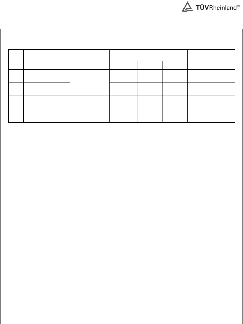
Model list:
DSA-5W-a Ab xy; DSA-5W-a Fb xy:
INPUT OUTPUT
No
MODEL
V, A V dc Max. A
Max. W
T1 sec winding
1 DSA-5W-05 Ab xy
5.0 – 8.1
1.00 5 0.35mmx14Ts
2 DSA-5W-12 Ab xy
200–240VAC,
50/60Hz, 0.2A
8.2-12.0 0.61 5 0.20mmx18Ts
3 DSA-5W-05 Fb xy
5.0 – 8.1
1.00 5 0.35mmx14Ts
4 DSA-5W-12 Fb xy
100–240VAC,
50/60Hz, 0.2A
8.2-12.0 0.61 5 0.20mmx18Ts
Note:
’a’ can be 05, 12;
‘b’ can be ‘EU’, ‘UK’, ‘US’, ‘CH’, ‘AU’, ‘KA’, ‘JP’ or ‘IN’, EU means European plug used, UK means British
plug used, US means American or Japanese plug used, CH means Chinese plug used, AU means
Australian plug used, KA means Korean plug used, JP means Japanese plug used, IN means Indian plug
used;
‘x’ is 3 digit number which represents the output voltage in Volt after dividing by 10, from 5.0V to 12.0V in
step of 0.1V, for example, 090 represents the output voltage is 9.0 V, 120 represents the output voltage is
12.0V;
‘y’ is 3 digit number which represents the output current in Ampere after dividing by 100 which is up to 1.0A
in step of 0.01A, for example, 041 represents the output current is 0.41A, 100 represents the output current
is 1.00A.
By multiplication of output voltage and output current, the type designations are limited through the
max. output power.
Only the European plug, British plug, Australian plug and Indian were considered in this report. Other types
of plug should be evaluated during national approval.
www.tuv.com
<16011089 001> Page 6 of 73
TRF No.:IECEN60950_1B TRF originator: SGS Fimko
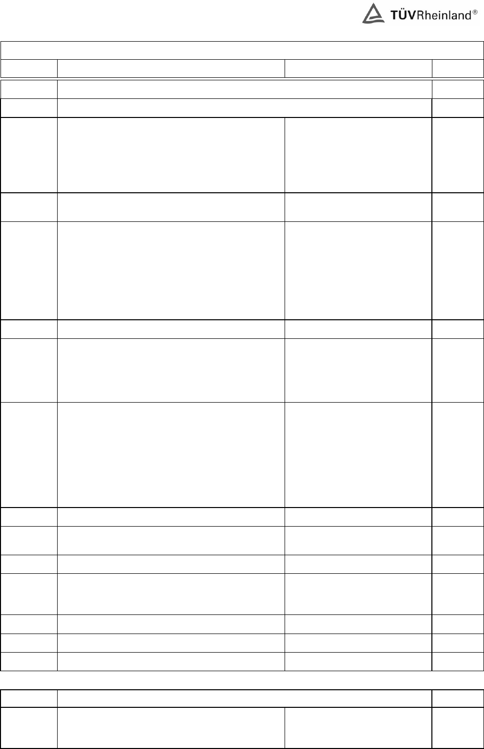
IEC 60950-1 / EN 60950-1
Clause Requirement – Test Result – Remark Verdict
1 GENERAL P
1.5 Components P
1.5.1 General Components which were found
to affect safety aspects comply
with the requirements of this
standard or within the safety
aspects of the relevant IEC
component standards.
P
Comply with IEC 60950 or relevant component
standard (see appended table 1.5.1) P
1.5.2 Evaluation and testing of components Components which are certified
to IEC and /or national
standards are used correctly
within their ratings.
Components not covered by
IEC standards are tested under
the conditions present in the
equipment.
P
1.5.3 Thermal controls No thermal controls provided. N/A
1.5.4 Transformers Transformer used are suitable
for their intended application
and comply with the relevant
requirements of the standard
and particularly Annex C.
P
1.5.5 Interconnecting cables Interconnection o/p cable to
other device is carrying only
SELV on an energy level below
240 VA.
→ Except for the insulation
material, there are no further
requirements for the o/p
interconnection cable.
P
1.5.6 Capacitors in primary circuits ...............................:
No such capacitor used. N/A
1.5.7 Double insulation or reinforced insulation bridged
by components See below. P
1.5.7.1 General P
1.5.7.2 Bridging capacitors Between primary side and
secondary: Y1-capacitor (CY1)
according to IEC 60384-14.
P
1.5.7.3 Bridging resistors No such resistor used. P
1.5.7.4 Accessible parts See clause 2.4 P
1.5.8 Components in equipment for IT power systems No such component N/A
1.6 Power interface P
1.6.1 AC power distribution systems IT power system for Norway
only, TN power system for
others
P
www.tuv.com
<16011089 001> Page 7 of 73
TRF No.:IECEN60950_1B TRF originator: SGS Fimko
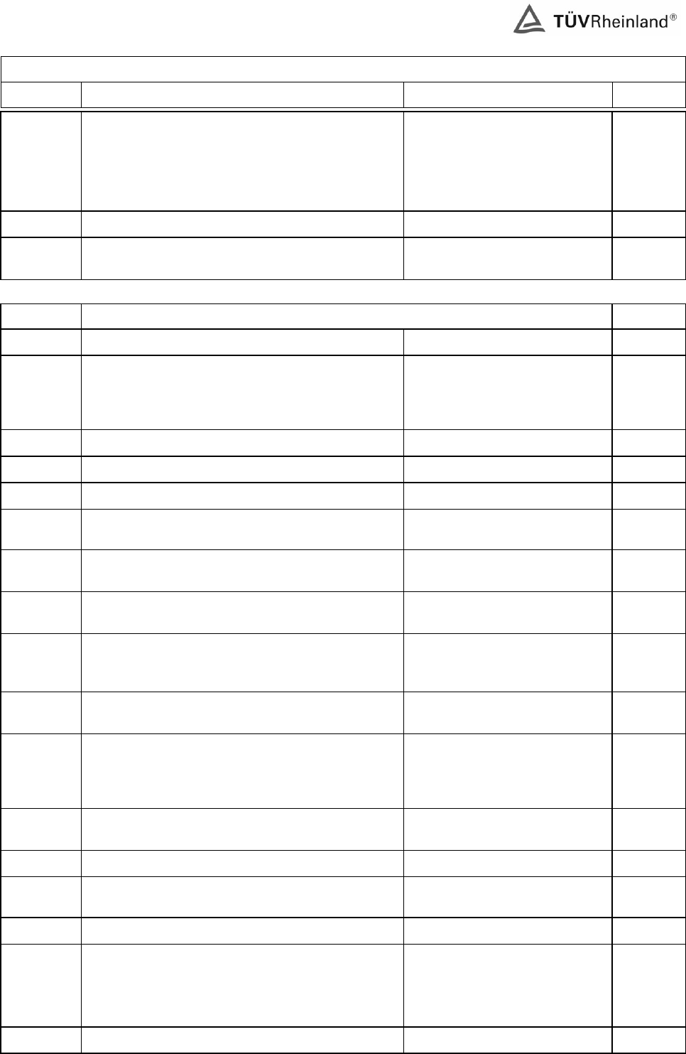
IEC 60950-1 / EN 60950-1
Clause Requirement – Test Result – Remark Verdict
1.6.2 Input current Highest load according to
1.2.2.1 for this equipment is the
operation with the max.
specified DC-load.
Results see appended table
P
1.6.3 Voltage limit of hand-held equipment Not hand-held equipment. N/A
1.6.4 Neutral conductor Class II equipment without earth
connection. N/A
1.7 Marking and instructions P
1.7.1 Power rating See below. P
Rated voltage(s) or voltage range(s) (V) .............:
AC100-240V for DSA-5W-a Fb
xy;
AC200-240V for DSA-5W-a Ab
xy
P
Symbol for nature of supply, for d.c. only .............:
Mains from AC source N/A
Rated frequency or rated frequency range (Hz) ..:
50/60Hz P
Rated current (mA or A) ......................................:
0.2A P
Manufacturer’s name or trademark or identification
mark .....................................................................:
Not shown / trademark of DVE
P
Type/model or type reference...............................:
DSA-5W-a Ab xy;
DSA-5W-a Fb xy P
Symbol for Class II equipment only .....................:
Double square symbol
provided. P
Other symbols ......................................................:
Additional symbols or marking
does not give rise to
misunderstanding.
P
Certification marks ...............................................:
Refer to the copy of the label
drawings for details. P
1.7.2 Safety instructions "User's Manual" provided that
contains information regarding
the maximum ambient
temperature.
P
1.7.3 Short duty cycles Equipment is designed for
continuous operation. N/A
1.7.4 Supply voltage adjustment ...................................:
No voltage selector. N/A
Methods and means of adjustment; reference to
installation instructions .........................................:
N/A
1.7.5 Power outlets on the equipment ..........................:
No power outlets provided. N/A
1.7.6 Fuse identification (marking, special fusing
characteristics, cross-reference) .........................:
Fusing resistor used, marking
adjacent to the fusing resistor
on PCB as:
RF1 4.7ohm 1W
P
1.7.7 Wiring terminals See below. N/A
www.tuv.com
<16011089 001> Page 8 of 73
TRF No.:IECEN60950_1B TRF originator: SGS Fimko
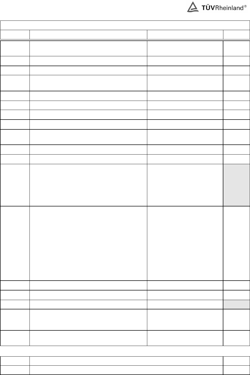
IEC 60950-1 / EN 60950-1
Clause Requirement – Test Result – Remark Verdict
1.7.7.1 Protective earthing and bonding terminals ..........:
Class II equipment without earth
connection. N/A
1.7.7.2 Terminal for a.c. mains supply conductors Direct plug-in equipment. N/A
1.7.7.3 Terminals for d.c. mains supply conductors No d.c. mains supply. N/A
1.7.8 Controls and indicators No safety related switches or
indicators.
N/A
1.7.8.1 Identification, location and marking .....................:
N/A
1.7.8.2 Colours ...............................................................:
N/A
1.7.8.3 Symbols according to IEC 60417 .........................:
N/A
1.7.8.4 Markings using figures ........................................:
N/A
1.7.9 Isolation of multiple power sources .....................:
Only one supply from the
mains. N/A
1.7.10 IT power distribution systems Only for Norway P
1.7.11 Thermostats and other regulating devices No such device. N/A
1.7.12 Language(s) .........................................................:
Installation instruction in
English and German.
Versions in other languages
have to be provided during the
corresponding national
approvals.
1.7.13 Durability The label was subjected to the
permanence of marking test.
The label was rubbed with cloth
soaked with water for 15 sec.
And then again for 15 sec. With
the cloth soaked with
petroleum spirit.
After this test there was no
damage to the label. The
marking on the label did not
fade. There was no curling nor
lifting of the label edge.
P
1.7.14 Removable parts No removable part. N/A
1.7.15 Replaceable batteries No battery provided. N/A
Language(s)..........................................................:
1.7.16 Operator access with a tool..................................:
No operator accessible area
that needs to be accessed by
the use of a tool.
N/A
1.7.17 Equipment for restricted access locations............:
Not limited for use in restricted
access locations. N/A
2 PROTECTION FROM HAZARDS P
2.1 Protection from electric shock and energy hazards P
www.tuv.com
<16011089 001> Page 9 of 73
TRF No.:IECEN60950_1B TRF originator: SGS Fimko
IEC 60950-1 / EN 60950-1
Clause Requirement – Test Result – Remark Verdict
2.1.1 Protection in operator access areas No access with test finger and
test pin to any parts with only
basic insulation to ELV or
hazardous voltage.
P
2.1.1.1 Access to energized parts See above. P
Test by inspection ................................................:
See above. P
Test with test finger ..............................................:
See above. P
Test with test pin ..................................................:
See above. P
Test with test probe .............................................:
No TNV. N/A
2.1.1.2 Battery compartments .........................................:
No battery compartment. N/A
2.1.1.3 Access to ELV wiring No ELV wiring in operator
accessible area. N/A
Working voltage (Vpeak or Vrms); minimum
distance (mm) through insulation
2.1.1.4 Access to hazardous voltage circuit wiring No hazardous voltage wiring in
operator accessible area. N/A
2.1.1.5 Energy hazards ....................................................:
Energy does not exceed 240VA
between any two points in
accessible parts (o/p connector
of secondary circuit). Results
see appended table 2.1.1.5. No
energy hazard in operator
access area.
P
2.1.1.6 Manual controls No manual controls. N/A
2.1.1.7 Discharge of capacitors in equipment No capacitor provided between
line and neutral. N/A
Time-constant (s); measured voltage (V).............:
2.1.2 Protection in service access areas No operator accessible area
that needs to be accessed by
the use of a tool.
N/A
2.1.3 Protection in restricted access locations Not limited for use in restricted
access locations. N/A
2.2 SELV circuits P
2.2.1 General requirements The secondary circuits were
tested as SELV. See 2.2.1 to
2.2.4.
P
2.2.2 Voltages under normal conditions (V) ..................:
Between any conductor of the
SELV circuits 42.4 V peak or
60 V d.c. are not exceeded.
See appended table 2.2.2.
P
www.tuv.com
<16011089 001> Page 10 of 73
TRF No.:IECEN60950_1B TRF originator: SGS Fimko
IEC 60950-1 / EN 60950-1
Clause Requirement – Test Result – Remark Verdict
2.2.3 Voltages under fault conditions (V).......................:
Single fault did not cause
excessive voltage in accessible
SELV circuits. Limits of 71V
peak and 120V d.c. were not
exceeded within 0.2 seconds
and limits 42.4V peak and 60V
d.c. were not exceeded for
longer than 0.2 seconds.
P
2.2.3.1 Separation by double insulation or reinforced
insulation (method 1) Double or reinforced for the
highest working voltage across
a particular insulation is
provided.
P
2.2.3.2 Separation by earthed screen (method 2) N/A
2.2.3.3 Protection by earthing of the SELV circuit
(method 3) N/A
2.2.4 Connection of SELV circuits to other circuits........:
See 2.2.2 and 2.2.3. P
2.3 TNV circuits N/A
2.3.1 Limits No TNV. N/A
Type of TNV circuits .............................................:
2.3.2
Separation from other circuits and from accessible
parts N/A
Insulation employed..............................................:
2.3.3 Separation from hazardous voltages N/A
Insulation employed..............................................:
2.3.4 Connection of TNV circuits to other circuits N/A
Insulation employed..............................................:
2.3.5 Test for operating voltages generated externally N/A
2.4 Limited current circuits P
2.4.1 General requirements P
2.4.2 Limit values P
Frequency (Hz) .....................................................:
(see appended table)
Measured current (mA).........................................:
(see appended table)
Measured voltage (V) ...........................................:
(see appended table)
Measured capacitance (µF)..................................:
2200pF
2.4.3 Connection of limited current circuits to other
circuits See 2.2.2 and 2.2.3. No direct
connection between SELV and
any primary circuit.
N/A
2.5 Limited power sources P
Inherently limited output N/A
www.tuv.com
<16011089 001> Page 11 of 73
TRF No.:IECEN60950_1B TRF originator: SGS Fimko
IEC 60950-1 / EN 60950-1
Clause Requirement – Test Result – Remark Verdict
Impedance limited output N/A
Overcurrent protective device limited output N/A
Regulating network limited output under normal
operating and single fault condition P
Regulating network limited output under normal
operating conditions and overcurrent protective
device limited output under single fault condition
N/A
Output voltage (V), output current (A), apparent
power (VA)............................................................:
(See appended table)
Current rating of overcurrent protective device (A)
2.6 Provisions for earthing and bonding P
2.6.1 Protective earthing Class II equipment. N/A
2.6.2 Functional earthing Secondary functional ground
separated to primary by
reinforced or double insulation.
P
2.6.3 Protective earthing and protective bonding
conductors N/A
2.6.3.1 General N/A
2.6.3.2 Size of protective earthing conductors N/A
Rated current (A), cross-sectional area (mm2),
AWG .....................................................................:
2.6.3.3 Size of protective bonding conductors N/A
Rated current (A), cross-sectional area (mm2),
AWG .....................................................................:
2.6.3.4 Resistance (Ω) of earthing conductors and their
terminations, test current (A) ................................:
N/A
2.6.3.5 Colour of insulation...............................................:
N/A
2.6.4 Terminals N/A
2.6.4.1 General N/A
2.6.4.2 Protective earthing and bonding terminals N/A
Rated current (A), type and nominal thread
diameter (mm) ......................................................:
2.6.4.3 Separation of the protective earthing conductor
from protective bonding conductors N/A
2.6.5 Integrity of protective earthing N/A
2.6.5.1 Interconnection of equipment N/A
2.6.5.2 Components in protective earthing conductors
and protective bonding conductors N/A
2.6.5.3 Disconnection of protective earth N/A
2.6.5.4 Parts that can be removed by an operator N/A
2.6.5.5 Parts removed during servicing N/A
www.tuv.com
<16011089 001> Page 12 of 73
TRF No.:IECEN60950_1B TRF originator: SGS Fimko
IEC 60950-1 / EN 60950-1
Clause Requirement – Test Result – Remark Verdict
2.6.5.6 Corrosion resistance N/A
2.6.5.7 Screws for protective bonding N/A
2.6.5.8 Reliance on telecommunication network or cable
distribution system No TNV N/A
2.7 Overcurrent and earth fault protection in primary circuits P
2.7.1 Basic requirements Equipment relies on 16A rated
fuse or circuit breaker of the wall
outlet installation protection of
the building installation in regard
to L to N short circuit.
Overcurrent protection is
provided by the fusing resistor.
P
Instructions when protection relies on building
installation Not applicable for pluggable
equipment type A. N/A
2.7.2 Faults not covered in 5.3 The protection device is well
dimensioned and mounted. P
2.7.3 Short-circuit backup protection Pluggable equipment type A.
Building installation is
considered as providing short-
circuit backup protection.
P
2.7.4 Number and location of protective devices ..........:
Over current protection by one
built-in fusing resistor. P
2.7.5 Protection by several devices Only one fusing resistor
provided. N/A
2.7.6 Warning to service personnel...............................:
No service work is necessary. N/A
2.8 Safety interlocks N/A
2.8.1 General principles No safety interlock. N/A
2.8.2 Protection requirements N/A
2.8.3 Inadvertent reactivation N/A
2.8.4 Fail-safe operation N/A
2.8.5 Moving parts N/A
2.8.6 Overriding N/A
2.8.7 Switches and relays N/A
2.8.7.1 Contact gaps (mm) ..............................................:
N/A
2.8.7.2 Overload test N/A
2.8.7.3 Endurance test N/A
2.8.7.4 Electric strength test N/A
2.8.8 Mechanical actuators N/A
2.9 Electrical insulation P
www.tuv.com
<16011089 001> Page 13 of 73
TRF No.:IECEN60950_1B TRF originator: SGS Fimko
IEC 60950-1 / EN 60950-1
Clause Requirement – Test Result – Remark Verdict
2.9.1 Properties of insulating materials Natural rubber, asbestos or
hygroscopic material is not
used.
P
2.9.2 Humidity conditioning 120hr P
Humidity (%) ........................................................:
95% R.H.
Temperature (°C) .................................................:
40°C
2.9.3 Grade of insulation Insulation complies with sub-
clauses 2.10, 4.5.1 and 5.2. P
2.10 Clearances, creepage distances and distances through insulation P
2.10.1 General See 2.10.3, 2.10.4 and 2.10.5. P
2.10.2 Determination of working voltage The rms and the peak voltage
were measured on the direct
plug-in adaptor.
The unit was connected to a
240Vac power supply and
floating secondary circuits was
assumed to be earthed at
the point by which the highest
working voltage is obtained.
Results see appended table
2.10.2.
P
2.10.3 Clearances See below and advantage of
annex G is not considered. P
2.10.3.1 General See below, Annex G was not
considered. P
2.10.3.2 Clearances in primary circuits Annex F and minimum
clearances considered. P
2.10.3.3 Clearances in secondary circuits P
2.10.3.4 Measurement of transient voltage levels No transient voltage across the
clearance lower than due or
normal.
N/A
2.10.4 Creepage distances (see appended table 2.10.3
and 2.10.4) P
CTI tests ...............................................................:
CTI rating for all materials of
min. 100.
2.10.5 Solid insulation See below. P
2.10.5.1 Minimum distance through insulation (see appended table 2.10.5) P
2.10.5.2 Thin sheet material Thin sheet material was not
used as reinforced insulation. N/A
Number of layers (pcs) .........................................:
Electric strength test
2.10.5.3 Printed boards No multi-layer PCBs provided. N/A
Distance through insulation N/A
www.tuv.com
<16011089 001> Page 14 of 73
TRF No.:IECEN60950_1B TRF originator: SGS Fimko
IEC 60950-1 / EN 60950-1
Clause Requirement – Test Result – Remark Verdict
Electric strength test for thin sheet insulating
material
Number of layers (pcs) .........................................:
N/A
2.10.5.4 Wound components Approved source of triple
insulated wire used as
seondary winding of T1.
P
Number of layers (pcs) .........................................:
3 P
Two wires in contact inside wound component;
angle between 45° and 90° ..................................:
By insulation tape. P
2.10.6 Coated printed boards No coated printed boards. N/A
2.10.6.1 General N/A
2.10.6.2 Sample preparation and preliminary inspection N/A
2.10.6.3 Thermal cycling N/A
2.10.6.4 Thermal ageing (°C) .............................................:
N/A
2.10.6.5 Electric strength test
2.10.6.6 Abrasion resistance test N/A
Electric strength test
2.10.7 Enclosed and sealed parts ...................................:
No hermetically sealed
component. N/A
Temperature T1=T2 + Tma – Tamb +10K (°C)....:
N/A
2.10.8 Spacings filled by insulating compound................:
No such component. N/A
Electric strength test
2.10.9 Component external terminations See appended table 2.10.2 and
2.10.3. P
2.10.10 Insulation with varying dimensions No such transformer used. N/A
3 WIRING, CONNECTIONS AND SUPPLY P
3.1 General P
3.1.1 Current rating and overcurrent protection Internal wiring is PVC insulated,
the wiring gauge is suitable for
current intended to be carried.
Internal wiring for primary power
distribution protected by built-in
fuse.
P
3.1.2 Protection against mechanical damage Wires do not touch sharp
edges which could damage the
insulation and cause hazard.
P
3.1.3 Securing of internal wiring The internal wiring are secured
by solder pins or tubing so that
loosening of the terminal
connections is unlikely.
P
www.tuv.com
<16011089 001> Page 15 of 73
TRF No.:IECEN60950_1B TRF originator: SGS Fimko
IEC 60950-1 / EN 60950-1
Clause Requirement – Test Result – Remark Verdict
3.1.4 Insulation of conductors The insulation of the individual
conductors are suitable for the
application and the working
voltage. For the insulation
material see 3.1.1.
(see appended table 5.2)
P
3.1.5 Beads and ceramic insulators Not used. N/A
3.1.6 Screws for electrical contact pressure No such screws provided. N/A
3.1.7 Insulating materials in electrical connections All current carrying connections
are metal to metal. N/A
3.1.8 Self-tapping and spaced thread screws Not used. N/A
3.1.9 Termination of conductors All conductors are reliable
secured. P
10 N pull test Force of 10 N applied to the
termination points of the
conductors.
P
3.1.10 Sleeving on wiring No sleeving used to provide
supplementary insulation. N/A
3.2 Connection to an a.c. mains supply or a d.c. mains supply P
3.2.1 Means of connection ............................................:
A mains plug, that is part of
direct plug-in equipment P
3.2.1.1 Connection to an a.c. mains supply See above P
3.2.1.2 Connection to a d.c. mains supply AC Source N/A
3.2.2 Multiple supply connections Only one supply connection. N/A
3.2.3 Permanently connected equipment Not permanently connected
equipment. N/A
Number of conductors, diameter (mm) of cable
and conduits ........................................................:
3.2.4 Appliance inlets Direct plug-in equipment. N/A
3.2.5 Power supply cords No power cord. N/A
3.2.5.1 AC power supply cords N/A
Type......................................................................:
Rated current (A), cross-sectional area (mm2),
AWG .....................................................................:
3.2.5.2 DC power supply cords AC Source. N/A
3.2.6 Cord anchorages and strain relief No power cord. N/A
Mass of equipment (kg), pull (N) ........................:
Longitudinal displacement (mm) ..........................:
3.2.7 Protection against mechanical damage Direct plug-in equipment. No
sharp edges. N/A
3.2.8 Cord guards No cord guard provided. N/A
www.tuv.com
<16011089 001> Page 16 of 73
TRF No.:IECEN60950_1B TRF originator: SGS Fimko
IEC 60950-1 / EN 60950-1
Clause Requirement – Test Result – Remark Verdict
D (mm); test mass (g) ..........................................:
Radius of curvature of cord (mm).........................:
3.2.9 Supply wiring space Not permanent connection or
non-detachable power cord
type.
N/A
3.3 Wiring terminals for connection of external conductors N/A
3.3.1 Wiring terminals Direct plug-in equipment. N/A
3.3.2 Connection of non-detachable power supply
cords N/A
3.3.3 Screw terminals N/A
3.3.4 Conductor sizes to be connected N/A
Rated current (A), cord/cable type, cross-
sectional
area (mm2) ...........................................................:
3.3.5 Wiring terminal sizes N/A
Rated current (A), type and nominal thread
diameter (mm) .....................................................:
3.3.6 Wiring terminals design N/A
3.3.7 Grouping of wiring terminals N/A
3.3.8 Stranded wire N/A
3.4 Disconnection from the mains supply P
3.4.1 General requirement Disconnect device provided. P
3.4.2 Disconnect devices Plug of this direct plug-in
equipment was used as
disconnected device.
P
3.4.3 Permanently connected equipment Not permanently connected
equipment. N/A
3.4.4 Parts which remain energized There is no parts remained with
hazardous voltage or energy in
the equipment when SPS is
separated from AC mains.
P
3.4.5 Switches in flexible cords No flexible cords. N/A
3.4.6 Single-phase equipment and d.c. equipment The mains plug disconnects
both poles simultaneously. P
3.4.7 Three-phase equipment Single phase equipment. N/A
3.4.8 Switches as disconnect devices See sub-clause 3.4.2. N/A
3.4.9 Plugs as disconnect devices See sub-clause 3.4.2. N/A
3.4.10 Interconnected equipment No interconnections using
hazardous voltages. N/A
3.4.11 Multiple power sources Only one supply connection
provided. N/A
www.tuv.com
<16011089 001> Page 17 of 73
TRF No.:IECEN60950_1B TRF originator: SGS Fimko
IEC 60950-1 / EN 60950-1
Clause Requirement – Test Result – Remark Verdict
3.5 Interconnection of equipment P
3.5.1 General requirements This power supply is not
considered for connection to
TNV.
P
3.5.2 Types of interconnection circuits ..........................:
Interconnection circuits of
SELV through the connector.
No ELV interconnection
circuits.
P
3.5.3 ELV circuits as interconnection circuits No ELV interconnection N/A
4 PHYSICAL REQUIREMENTS P
4.1 Stability N/A
Angle of 10° Direct plug-in equipment. N/A
Test: force (N).......................................................:
N/A
4.2 Mechanical strength P
4.2.1 General See below. After tests, unit
comply with 2.1.1, 2.6.1, 2.10
and 4.4.1.
P
4.2.2 Steady force test, 10 N 10N applied to components
other than parts serving as an
enclosure.
P
4.2.3 Steady force test, 30 N No internal enclosure. N/A
4.2.4 Steady force test, 250 N 250N applied to outer enclosure.
No energy or other hazards.
P
4.2.5 Impact test Direct plug-in equipment. N/A
Fall test N/A
Swing test N/A
4.2.6 Drop test No hazard as result from drop
test. P
4.2.7 Stress relief test After 7 hours at temperature of
75°C and cooling down to room
temperature, no shrinkage and
distortion or loosening any
enclosure part was noticeable
on the adapter.
Test was performed for all
sources of enclosure material.
P
4.2.8 Cathode ray tubes No CRT provided. N/A
Picture tube separately certified ...........................:
N/A
4.2.9 High pressure lamps No High pressure lamps
provided. N/A
4.2.10 Wall or ceiling mounted equipment; force (N) .....:
Direct plug-in equipment. N/A
www.tuv.com
<16011089 001> Page 18 of 73
TRF No.:IECEN60950_1B TRF originator: SGS Fimko
IEC 60950-1 / EN 60950-1
Clause Requirement – Test Result – Remark Verdict
4.3 Design and construction P
4.3.1 Edges and corners All edges and corners are
rounded and /or smoothed. P
4.3.2 Handles and manual controls; force (N)...............:
No handles or controls provided.
N/A
4.3.3 Adjustable controls No controls provided. N/A
4.3.4 Securing of parts No connection likely to be
exposed to mechanical stress is
provided in unit.
P
4.3.5 Connection of plugs and sockets No mismating of connectors,
plugs or sockets possible. P
4.3.6 Direct plug-in equipment The prevention of imposing to
undue strain on the socket-
outlet was done by construction
of the plug of adaptor.
For European plug: 0.02Nm;
For British plug: 0.02Nm;
For Australian plug: 0.02Nm;
For Indian plug: 0.05Nm
P
Dimensions (mm) of mains plug for direct plug-in :
(See attached partial test
reports)
P
Torque and pull test of mains plug for direct
plug-in; torque (Nm); pull (N) ................................:
See above. P
4.3.7 Heating elements in earthed equipment No heating elements provided.
N/A
4.3.8 Batteries No batteries provided. N/A
4.3.9 Oil and grease No heating elements provided.
N/A
4.3.10 Dust, powders, liquids and gases Equipment in intended use not
considered to be exposed to
these.
N/A
4.3.11 Containers for liquids or gases No container for liquid or gas. N/A
4.3.12 Flammable liquids.................................................:
No such flammable liquid. N/A
Quantity of liquid (l)...............................................:
N/A
Flash point (°C).....................................................:
N/A
4.3.13 Radiation; type of radiation ..................................:
No optical radiation present. N/A
4.3.13.1 General N/A
4.3.13.2 Ionizing radiation N/A
Measured radiation (pA/kg) .................................:
Measured high-voltage (kV) ................................:
Measured focus voltage (kV) ...............................:
CRT markings .....................................................:
4.3.13.3 Effect of ultraviolet (UV) radiation on materials
N/A
Part, property, retention after test, flammability
classification ........................................................:
N/A
www.tuv.com
<16011089 001> Page 19 of 73
TRF No.:IECEN60950_1B TRF originator: SGS Fimko
IEC 60950-1 / EN 60950-1
Clause Requirement – Test Result – Remark Verdict
4.3.13.4 Human exposure to ultraviolet (UV) radiation ......:
N/A
4.3.13.5 Laser (including LEDs) No optical radiation present. N/A
Laser class ...........................................................:
4.3.13.6 Other types ..........................................................:
N/A
4.4 Protection against hazardous moving parts N/A
4.4.1 General No moving parts. N/A
4.4.2 Protection in operator access areas N/A
4.4.3 Protection in restricted access locations N/A
4.4.4 Protection in service access areas N/A
4.5 Thermal requirements P
4.5.1 Maximum temperatures See appended table 4.5.1. P
Normal load condition per Annex L.......................:
See 1.6.2. P
4.5.2 Resistance to abnormal heat See appended table 4.5.2. P
4.6 Openings in enclosures P
4.6.1 Top and side openings No openings P
Dimensions (mm) ................................................:
4.6.2 Bottoms of fire enclosures No openings P
Construction of the bottom ...................................:
4.6.3 Doors or covers in fire enclosures No such things. N/A
4.6.4 Openings in transportable equipment No opening. N/A
4.6.5 Adhesives for constructional purposes No adhesive. N/A
Conditioning temperature (°C)/time (weeks) ........:
4.7 Resistance to fire P
4.7.1 Reducing the risk of ignition and spread of flame Use of materials with the
required flammability classes.
P
Method 1, selection and application of
components wiring and materials (see appended table 4.7) P
Method 2, application of all of simulated fault
condition tests N/A
4.7.2 Conditions for a fire enclosure See below. P
www.tuv.com
<16011089 001> Page 20 of 73
TRF No.:IECEN60950_1B TRF originator: SGS Fimko
IEC 60950-1 / EN 60950-1
Clause Requirement – Test Result – Remark Verdict
4.7.2.1 Parts requiring a fire enclosure With having the following parts:
Components in primary
Components in secondary
Components having
unenclosed arcing parts at
hazardous voltage or energy
level
Insulated wiring
The fire enclosure is required.
P
4.7.2.2 Parts not requiring a fire enclosure N/A
4.7.3 Materials P
4.7.3.1 General Parts mounted on PCB of
flammability class V-0 or better.
P
4.7.3.2 Materials for fire enclosures The fire enclosure is V-1 or
better material. P
4.7.3.3 Materials for components and other parts outside
fire enclosures No part outside fire enclosure. N/A
4.7.3.4 Materials for components and other parts inside
fire enclosures Internal components except
small parts are V-2 or better. P
4.7.3.5 Materials for air filter assemblies No air filters provided. N/A
4.7.3.6 Materials used in high-voltage components No high voltage components
provided. N/A
5 ELECTRICAL REQUIREMENTS AND SIMULATED ABNORMAL CONDITIONS P
5.1 Touch current and protective conductor current P
5.1.1 General See sub-clauses 5.1.2 to 5.1.6.
P
5.1.2 Equipment under test (EUT) EUT has only one mains
connection. P
5.1.3 Test circuit Equipment of figure 5A used. P
5.1.4 Application of measuring instrument Using measuring instrument in
annex D. P
5.1.5 Test procedure The touch current was
measured from mains to DC
output connector and to a 100
mm × 200 mm metal foil
wrapped on accessible non-
conductive parts (plastic
enclosure).
P
5.1.6 Test measurements See below. P
Test voltage (V) ...................................................:
See appended table 5.1.6.
Measured touch current (mA) ..............................:
See appended table 5.1.6.
Max. allowed touch current (mA) .........................:
See appended table 5.1.6.
Measured protective conductor current (mA) ......:
www.tuv.com
<16011089 001> Page 21 of 73
TRF No.:IECEN60950_1B TRF originator: SGS Fimko
IEC 60950-1 / EN 60950-1
Clause Requirement – Test Result – Remark Verdict
Max. allowed protective conductor current (mA) .:
5.1.7 Equipment with touch current exceeding 3.5 mA :
Neither stationary permanently
connected equipment nor
stationary pluggable equipment
type B.
N/A
5.1.8 Touch currents to and from telecommunication
networks and cable distribution systems and from
telecommunication networks
No TNV. N/A
5.1.8.1 Limitation of the touch current to a
telecommunication network and a cable
distribution system
N/A
Test voltage (V) ...................................................:
Measured touch current (mA) ..............................:
Max. allowed touch current (mA) .........................:
5.1.8.2 Summation of touch currents from
telecommunication networks ................................:
N/A
5.2 Electric strength P
5.2.1 General (see appended table 5.2) P
5.2.2 Test procedure (see appended table 5.2) P
5.3 Abnormal operating and fault conditions P
5.3.1 Protection against overload and abnormal
operation Output overload test, the most
unfavorable load test.
(see appended table 5.3)
P
5.3.2 Motors No motors. N/A
5.3.3 Transformers With the shorted o/p of the
transformer, no high
temperature of the transformer
was recorded.
Results of the short-circuit tests
see appended table 5.3 and
Annex C.
P
5.3.4 Functional insulation.............................................:
Method c). Test results see
appended table 5.3. P
5.3.5 Electromechanical components No electromechanical
component provided. N/A
5.3.6 Simulation of faults Results see appended table. P
5.3.7 Unattended equipment None of the listed components
was provided. N/A
5.3.8 Compliance criteria for abnormal operating and
fault conditions No fire propagated beyond the
equipment. No molten metal
was emitted. Electric strength
test primary to SELV was
passed.
P
www.tuv.com
<16011089 001> Page 22 of 73
TRF No.:IECEN60950_1B TRF originator: SGS Fimko
IEC 60950-1 / EN 60950-1
Clause Requirement – Test Result – Remark Verdict
6 CONNECTION TO TELECOMMUNICATION NETWORKS N/A
6.1 Protection of telecommunication network service persons, and users of other
equipment connected to the network, from hazards in the equipment N/A
6.1.1 Protection from hazardous voltages N/A
6.1.2 Separation of the telecommunication network from earth N/A
6.1.2.1 Requirements No TNV. N/A
Test voltage (V) ...................................................:
Current in the test circuit (mA) ............................:
6.1.2.2 Exclusions.............................................................:
N/A
6.2 Protection of equipment users from overvoltages on telecommunication networks N/A
6.2.1 Separation requirements No TNV. N/A
6.2.2 Electric strength test procedure N/A
6.2.2.1 Impulse test N/A
6.2.2.2 Steady-state test N/A
6.2.2.3 Compliance criteria
N/A
6.3 Protection of the telecommunication wiring system from overheating N/A
Max. output current (A).........................................:
No TNV.
Current limiting method ........................................:
7 CONNECTION TO CABLE DISTRIBUTION SYSTEMS N/A
7.1 Protection of cable distribution system service
persons, and users of other equipment
connected to the system, from hazardous
voltages in the equipment
Not connected to cable
distribution system N/A
7.2 Protection of equipment users from overvoltages
on the cable distribution system N/A
7.3 Insulation between primary circuits and cable
distribution systems N/A
7.3.1 General N/A
7.3.2 Voltage surge test N/A
7.3.3 Impulse test N/A
A ANNEX A, TESTS FOR RESISTANCE TO HEAT AND FIRE N/A
A.1 Flammability test for fire enclosures of movable equipment having a total mass
exceeding 18 kg, and of stationary equipment (see 4.7.3.2) N/A
A.1.1 Samples................................................................:
Wall thickness (mm).............................................:
www.tuv.com
<16011089 001> Page 23 of 73
TRF No.:IECEN60950_1B TRF originator: SGS Fimko
IEC 60950-1 / EN 60950-1
Clause Requirement – Test Result – Remark Verdict
A.1.2 Conditioning of samples; temperature (°C) ..........:
N/A
A.1.3 Mounting of samples ............................................:
N/A
A.1.4 Test flame (see IEC 60695-11-3) N/A
Flame A, B, C or D ...............................................:
A.1.5 Test procedure N/A
A.1.6 Compliance criteria N/A
Sample 1 burning time (s) ....................................:
Sample 2 burning time (s) ....................................:
Sample 3 burning time (s) ....................................:
A.2 Flammability test for fire enclosures of movable equipment having a total mass not
exceeding 18 kg, and for material and components located inside fire enclosures
(see 4.7.3.2 and 4.7.3.4)
N/A
A.2.1 Samples, material.................................................:
Wall thickness (mm).............................................:
A.2.2 Conditioning of samples N/A
A.2.3 Mounting of samples ...........................................:
N/A
A.2.4 Test flame (see IEC 60695-11-4) N/A
Flame A, B or C ...................................................:
A.2.5 Test procedure N/A
A.2.6 Compliance criteria N/A
Sample 1 burning time (s) ....................................:
Sample 2 burning time (s) ....................................:
Sample 3 burning time (s) ....................................:
A.2.7 Alternative test acc. To IEC 60695-2-2, cl. 4 and
8 N/A
Sample 1 burning time (s) ....................................:
Sample 2 burning time (s) ....................................:
Sample 3 burning time (s) ....................................:
A.3 Hot flaming oil test (see 4.6.2) N/A
A.3.1 Mounting of samples N/A
A.3.2 Test procedure N/A
A.3.3 Compliance criterion N/A
B ANNEX B, MOTOR TESTS UNDER ABNORMAL CONDITIONS (see 4.7.2.2 and
5.3.2)
N/A
B.1 General requirements No motor provided. N/A
Position ................................................................:
Manufacturer ........................................................:
Type .....................................................................:
www.tuv.com
<16011089 001> Page 24 of 73
TRF No.:IECEN60950_1B TRF originator: SGS Fimko
IEC 60950-1 / EN 60950-1
Clause Requirement – Test Result – Remark Verdict
Rated values .......................................................:
B.2 Test conditions N/A
B.3 Maximum temperatures N/A
B.4 Running overload test N/A
B.5 Locked-rotor overload test N/A
Test duration (days) .............................................:
Electric strength test: test voltage (V) ..................:
B.6 Running overload test for d.c. motors in
secondary circuits N/A
B.7 Locked-rotor overload test for d.c. motors in secondary circuits N/A
B.7.1 Test procedure N/A
B.7.2 Alternative test procedure; test time (h)................:
N/A
B.7.3 Electric strength test N/A
B.8 Test for motors with capacitors N/A
B.9 Test for three-phase motors N/A
B.10 Test for series motors N/A
Operating voltage (V) ...........................................:
C ANNEX C, TRANSFORMERS (see 1.5.4 and 5.3.3) P
Position ................................................................:
T1
Manufacturer ........................................................:
See appended table 1.5.1
Type .....................................................................:
See appended table 1.5.1
Rated values .......................................................:
Class B
Method of protection.............................................:
By protection circuit design.
C.1 Overload test See appended table 5.3. P
C.2 Insulation See appended table C.2. P
Protection from displacement of windings............:
By insulation tape P
D ANNEX D, MEASURING INSTRUMENTS FOR TOUCH-CURRENT TESTS
(see 5.1.4) P
D.1 Measuring instrument P
D.2 Alternative measuring instrument N/A
E ANNEX E, TEMPERATURE RISE OF A WINDING (see 1.4.13) N/A
F ANNEX F, MEASUREMENT OF CLEARANCES AND CREEPAGE DISTANCES
(see 2.10)
P
www.tuv.com
<16011089 001> Page 25 of 73
TRF No.:IECEN60950_1B TRF originator: SGS Fimko
IEC 60950-1 / EN 60950-1
Clause Requirement – Test Result – Remark Verdict
G ANNEX G, ALTERNATIVE METHOD FOR DETERMINING MINIMUM
CLEARANCES N/A
G.1 Summary of the procedure for determining
minimum clearances N/A
G.2 Determination of mains transient voltage (V) .......:
N/A
G.2.1 AC mains supply N/A
G.2.2 DC mains supply N/A
G.3 Determination of telecommunication network
transient voltage (V)..............................................:
N/A
G.4 Determination of required withstand voltage (V)...:
N/A
G.5 Measurement of transient levels (V).....................:
N/A
G.6 Determination of minimum clearances.................:
N/A
H ANNEX H, IONIZING RADIATION (see 4.3.13) N/A
J ANNEX J, TABLE OF ELECTROCHEMICAL POTENTIALS (see 2.6.5.6) N/A
Metal used ...........................................................:
No risk of corrosion.
K ANNEX K, THERMAL CONTROLS (see 1.5.3 and 5.3.7) N/A
K.1 Making and breaking capacity N/A
K.2 Thermostat reliability; operating voltage (V) .........:
N/A
K.3 Thermostat endurance test; operating voltage
(V) .......................................................................:
N/A
K.4 Temperature limiter endurance; operating voltage
(V) ........................................................................:
N/A
K.5 Thermal cut-out reliability N/A
K.6 Stability of operation N/A
L ANNEX L, NORMAL LOAD CONDITIONS FOR SOME TYPES OF ELECTRICAL
BUSINESS EQUIPMENT (see 1.2.2.1 and 4.5.1) P
L.1 Typewriters N/A
L.2 Adding machines and cash registers N/A
L.3 Erasers N/A
L.4 Pencil sharpeners N/A
L.5 Duplicators and copy machines N/A
L.6 Motor-operated files N/A
L.7 Other business equipment P
M ANNEX M, CRITERIA FOR TELEPHONE RINGING SIGNALS (see 2.3.1) N/A
M.1 Introduction No telephone signal. N/A
www.tuv.com
<16011089 001> Page 26 of 73
TRF No.:IECEN60950_1B TRF originator: SGS Fimko
IEC 60950-1 / EN 60950-1
Clause Requirement – Test Result – Remark Verdict
M.2 Method A N/A
M.3 Method B N/A
M.3.1 Ringing signal N/A
M.3.1.1 Frequency (Hz) ....................................................:
M.3.1.2 Voltage (V) ...........................................................:
M.3.1.3 Cadence; time (s), voltage (V) .............................:
M.3.1.4 Single fault current (mA).......................................:
M.3.2 Tripping device and monitoring voltage................:
N/A
M.3.2.1 Conditions for use of a tripping device or a
monitoring voltage N/A
M.3.2.2 Tripping device N/A
M.3.2.3 Monitoring voltage (V)...........................................:
N/A
N ANNEX N, IMPULSE TEST GENERATORS (see 2.10.3.4, 6.2.2.1, 7.3.2 and
clause G.5) N/A
N.1 ITU-T impulse test generators N/A
N.2 IEC 60065 impulse test generator N/A
P ANNEX P, NORMATIVE REFERENCES P
Q ANNEX Q, BIBLIOGRAPHY P
R ANNEX R, EXAMPLES OF REQUIREMENTS FOR QUALITY CONTROL
PROGRAMMES N/A
R.1 Minimum separation distances for unpopulated
coated printed boards (see 2.10.6) N/A
R.2 Reduced clearances (see 2.10.3) N/A
S ANNEX S, PROCEDURE FOR IMPULSE TESTING (see 6.2.2.3) N/A
S.1 Test equipment N/A
S.2 Test procedure N/A
S.3 Examples of waveforms during impulse testing N/A
T ANNEX T, GUIDANCE ON PROTECTION AGAINST INGRESS OF WATER
(see 1.1.2) N/A
U ANNEX U, INSULATED WINDING WIRES FOR USE WITHOUT INTERLEAVED
INSULATION (see 2.10.5.4) P
www.tuv.com
<16011089 001> Page 27 of 73
TRF No.:IECEN60950_1B TRF originator: SGS Fimko
IEC 60950-1 / EN 60950-1
Clause Requirement – Test Result – Remark Verdict
Approved TIW used.
V ANNEX V, AC POWER DISTRIBUTION SYSTEMS (see 1.6.1) P
V.1 Introduction P
V.2 TN power distribution systems P
V.3 TT power systems N/A
V.4 IT power systems IT-power system for Norway. P
W ANNEX W, SUMMATION OF TOUCH CURRENTS P
W.1 Touch current from electronic circuits See table 5.1.6 P
W.1.2 Earthed circuits N/A
W.2 Interconnection of several equipments N/A
W.2.1 Isolation N/A
W.2.2 Common return, isolated from earth N/A
W.2.3 Common return, connected to protective earth N/A
X ANNEX X, MAXIMUM HEATING EFFECT IN TRANSFORMER TESTS
(see clause C.1) P
X.1 Determination of maximum input current N/A
X.2 Overload test procedure P
Y ANNEX Y, ULTRAVIOLET LIGHT CONDITIONING TEST (see 4.3.13.3) N/A
Y.1 Test apparatus .....................................................:
N/A
Y.2 Mounting of test samples .....................................:
N/A
Y.3 Carbon-arc light-exposure apparatus ..................:
N/A
Y.4 Xenon-arc light exposure apparatus ....................:
N/A
www.tuv.com
<16011089 001> Page 28 of 73
TRF No.:IECEN60950_1B TRF originator: SGS Fimko
IEC 60950-1 / EN 60950-1
Clause Requirement – Test Result – Remark Verdict
EU Group Differences [C],
EU Special National Conditions [S], EU A-Deviations [A]
(EN 60950-1:2001, Annex ZB and Annex ZC)
P
General C: Delete all the "country" notes in the reference
document according to the following list:
1.1.5 Note 2 1.5.8 Note 2 1.6.1 Note
1.7.2 Note 4 1.7.12 Note 2 2.6 Note
2.2.3 Note 2.2.4 Note 2.3.2 Note 2, 7, 8
2.3.3 Note 1, 2 2.3.4 Note 2,3 2.7.1 Note
2.10.3.1 Note 4 3.2.1.1 Note 3.2.3 Note 1, 2
3.2.5.1 Note 2 4.3.6 Note 1,2 4.7.2.2 Note
4.7.3.1 Note 2 6.1.2.1 Note 6.1.2.2 Note
6.2.2 Note 6.2.2.1 Note 2 6.2.2.2 Note
7 Note 4 7.1 Note
G2.1 Note 1, 2 Annex H Note 2
Deleted. N/A
1.2.4.1 S (DK): Certain types of Class I appliances (see
3.2.1.1) may be provided with a plug not
establishing earthing conditions when inserted
into Danish socket-outlets.
Class II equipment. N/A
1.5.1 A (SE, Ordinance 1990:944 and
CH, Ordinance on environmentally hazardous
substances SR 814.013, Annex 3.2, Mercury):
Add
NOTE – Switches containing mercury such as
thermostats, relays and level controllers are not allowed.
No switch. N/A
1.5.8 S (NO): Due to the IT power system used (see
annex V, Fig. V.7), capacitors are required to be
rated for the applicable line-to-line voltage
(230 V).
Class II equipment. N/A
1.7.2 S (FI, NO, SE):
CLASS I PLUGGABLE EQUIPMENT
TYPE A
intended for connection to other
equipment or a network shall, if safety relies on
connection to protective earth or if surge
suppressors are connected between the network
terminals and accessible parts, have a marking
stating that the equipment must be connected to
an earthed mains socket-outlet.
The marking text in the applicable countries shall
be as follows:
Class II equipment. N/A
FI: "Laite on liitettävä suojamaadoituskoskettimilla
varustettuun pistorasiaan" Class II equipment. N/A
NO: "Apparatet må tilkoples jordet stikkontakt" Class II equipment. N/A
SE: "Apparaten skall anslutas till jordat uttag" Class II equipment. N/A
A (DK, Heavy Current Regulations): Supply cords
of class I equipment, which is delivered without a
plug, must be provided with a visible tag with the
following text:
Vigtigt!
Lederen med grøn/gul isolation må kun tilsluttes
en klemme mærket
eller
If essential for the safety of the equipment, the
tag must in addition be provided with a diagram
which shows the connection of the other
conductors, or be provided with the following text:
Class II equipment. N/A

www.tuv.com
<16011089 001> Page 29 of 73
TRF No.:IECEN60950_1B TRF originator: SGS Fimko
IEC 60950-1 / EN 60950-1
Clause Requirement – Test Result – Remark Verdict
"For tilslutning af de øvrige ledere, se
medfølgende instalationsvejledning."
1.7.5 S (DK): Socket-outlets for providing power to
other equipment shall be in accordance with the
Heavy Current Regulations, Section 107-2-D1,
Standard Sheet DK 1-3a, DK 1-5a or DK 1-7a,
when used on Class I equipment. For stationary
equipment the socket-outlet shall be in accor-
dance with Standard Sheet DK 1-1b or DK 1-5a.
No socket-outlet. N/A
1.7.5 A (DK, Heavy Current Regulations):
CLASS
II
EQUIPMENT
shall not be fitted with socket-
outlets for providing power to other equipment.
No socket outlet. N/A
1.7.12 A (DE, Gesetz über technische Arbeitsmittel
(Gerätesicherheitsgesetz) [Law on technical
labour equipment {Equipment safety law}], of 23
rd
October 1992, Article 3, 3
rd
paragraph, 2
nd
sentence, together with the "Allgemeine
Verwaltungsvorschrift zur Durchführung des
Zweiten Abschnitts des Gerätesicherheits-
gesetzes" [General administrative regulation on
the execution of the Second Section of the
Equipment safety law], of 10
th
January 1996,
article 2, 4
th
paragraph item 2):
Directions for use with rules to prevent certain
hazards for (among others) maintenance of the
technical labour equipment, also for imported
technical labour equipment shall be written in the
German language.
NOTE: Of this requirement, rules for use even only by service
personnel are not exempted.
Not labour equipment. N/A
1.7.15 A (CH, Ordinance on environmentally hazardous
substances SR 814.013):
Annex 4.10 of SR 814.013 applies for batteries.
No batteries. N/A
A (DE, Regulation on protection against hazards
by X-ray, of 8
th
January 1987, Article 5 [Operation
of X-ray emission source], clauses 1 to 4):
a) A licence is required by those who operate an
X-ray emission source.
b) A licence in accordance with Cl. 1 is not
required by those who operate an X-ray emission
source on which the electron acceleration voltage
does not exceed 20 kV if
1) the local dose rate at a distance of 0,1 m from
the surface does not exceed 1 Sv/h and
2) it is adequately indicated on the X-ray emission
source that
i) X-rays are generated and
ii) the electron acceleration voltage must not
exceed the maximum value stipulated by
the manufacturer or importer.
c) A licence in accordance with Cl. 1 is also not
required by persons who operate an X-ray
emission source on which the electron
acceleration voltage exceeds 20 kV if
No radiation. N/A
www.tuv.com
<16011089 001> Page 30 of 73
TRF No.:IECEN60950_1B TRF originator: SGS Fimko
IEC 60950-1 / EN 60950-1
Clause Requirement – Test Result – Remark Verdict
1) the X-ray emission source has been granted a
type approval and
2) it is adequately indicated on the X-ray emission
source that
i) X-rays are generated
ii) the device stipulated by the manufacturer or
importer guarantees that the maximum
permissible local dose rate in accordance
with the type approval is not exceeded and
iii) the electron acceleration voltage must not
exceed the maximum value stipulated by the
manufacturer or importer.
d) Furthermore, a licence in accordance with
Cl. 1 is also not required by persons who operate
X-ray emission sources on which the electron
acceleration voltage does not exceed 30 kV if
1) the X-rays are generated only by intrinsically
safe CRTs complying with Enclosure III, No. 6,
2) the values stipulated in accordance with
Enclosure III, No. 6.2 are limited by technical
measures and specified in the device and
3) it is adequately indicated on the X-ray emission
source that the X-rays generated are ade-
quately screened by the intrinsically safe CRT.
2.2.4 S (NO): Requirements according to this annex,
1.7.2 and 6.1.2.1 apply. Not TNV. N/A
2.3.2 S (NO): Requirements according to this annex,
6.1.2.1 apply. Not TNV. N/A
2.3.3 and
2.3.4 S (NO): Requirements according to this annex,
1.7.2 and 6.1.2.1 apply. Not TNV. N/A
2.6.3.3 S (GB): The current rating of the circuit shall be
taken as 13 A, not 16 A. Class II equipment. N/A
2.7.1 C: Replace the subclause as follows:
Basic requirements
To protect against excessive current, short-
circuits and earth faults in
PRIMARY CIRCUITS
,
protective devices shall be included either as
integral parts of the equipment or as parts of the
building installation, subject to the following, a), b)
and c):
a) except as detailed in b) and c), protective
devices necessary to comply with the
requirements of 5.3 shall be included as parts of
the equipment;
b) for components in series with the mains input
to the equipment such as the supply cord,
appliance coupler, r.f.i. filter and switch, short-
circuit and earth fault protection may be provided
by protective devices in the building installation;
c) it is permitted for
PLUGGABLE EQUIPMENT TYPE B
or
PERMANENTLY CONNECTED EQUIPMENT
, to rely
on dedicated overcurrent and short-circuit
Replaced. P
www.tuv.com
<16011089 001> Page 31 of 73
TRF No.:IECEN60950_1B TRF originator: SGS Fimko
IEC 60950-1 / EN 60950-1
Clause Requirement – Test Result – Remark Verdict
protection in the building installation, provided
that the means of protection, e.g. fuses or circuit
breakers, is fully specified in the installation
instructions.
If reliance is placed on protection in the building
installation, the installation instructions shall so
state, except that for
PLUGGABLE EQUIPMENT TYPE
A
the building installation shall be regarded as
providing protection in accordance with the rating
of the wall socket outlet.
S (GB): To protect against excessive currents
and short-circuits in the
PRIMARY CIRCUIT OF
DIRECT PLUG
-
IN EQUIPMENT
, protective device shall
be included as integral parts of the
DIRECT PLUG
-
IN EQUIPMENT
.
Built-in fusible resistor was
used as protective device. P
2.7.2 C: Void. N/A
2.10.2 C: Replace in the first line "(see also 1.4.7)" by
"(see also 1.4.8)". Replaced. P
2.10.3.1 S (NO): Due to the IT power distribution system
used (see annex V, Fig. V.7), the
A
.
C
.
MAINS
SUPPLY
voltage is considered to be equal to the
line-to-line voltage and will remain at 230 V in
case of a single earth fault
Considered. P
3.2.1.1 S (CH): Supply cords of equipment having a
RATED CURRENT
not exceeding 10 A shall be
provided with a plug complying with SEV 1011 or
IEC 60884-1 and one of the following dimension
sheets:
SEV 6532-2.1991, Plug type 15, 3P+N+PE 250/400 V, 10 A
SEV 6533-2.1991, Plug type 11, L+N 250 V, 10 A
SEV 6534-2.1991, Plug type 12, L+N+PE 250 V, 10 A
In general, EN 60309 applies for plugs for
currents exceeding 10 A. However, a 16 A plug
and socket-outlet system is being introduced in
Switzerland, the plugs of which are according to
the following dimension sheets, published in
February 1998:
SEV 5932-2.1998, Plug type 25, 3L+N+PE 230/400 V, 16 A
SEV 5933-2.1998, Plug type 21, L+N 250 V, 16 A
SEV 5934-2.1998, Plug type 23, L+N+PE 250 V, 16 A
Direct plug-in equipment. N/A

www.tuv.com
<16011089 001> Page 32 of 73
TRF No.:IECEN60950_1B TRF originator: SGS Fimko
IEC 60950-1 / EN 60950-1
Clause Requirement – Test Result – Remark Verdict
S (DK): Supply cords of single-phase equipment
having a rated current not exceeding 13 A shall
be provided with a plug according to the Heavy
Current Regulations, Section 107-2-D1.
CLASS I EQUIPMENT
provided with socket-outlets
with earth contacts or which are intended to be
used in locations where protection against
indirect contact is required according to the wiring
rules shall be provided with a plug in accordance
with standard sheet DK 2-1a or DK 2-5a.
If ply-phase equipment and single-phase
equipment having a
RATED CURRENT
exceeding
13 A is provided with a supply cord with a plug,
this plug shall be in accordance with the Heavy
Current Regulations, Section 107-2-D1 or
EN 60309-2.
Direct plug-in equipment.
N/A
S (ES): Supply cords of single-phase equipment
having a rated current not exceeding 10 A shall
be provided with a plug according to
UNE 20315:1994.
Supply cords of single-phase equipment having a
rated current not exceeding 2,5 A shall be
provided with a plug according to
UNE-EN 50075:1993.
CLASS I EQUIPMENT
provided with socket-outlets
with earth contacts or which are intended to be
used in locations where protection against
indirect contact is required according to the wiring
rules, shall be provided with a plug in accordance
with standard UNE 20315:1994.
If poly-phase equipment is provided with a supply
cord with a plug, this plug shall be in accordance
with UNE-EN 60309-2.
Direct plug-in equipment. N/A
S (GB): Apparatus which is fitted with a flexible
cable or cord and is designed to be connected to
a mains socket conforming to BS 1363 by means
of that flexible cable or cord and plug, shall be
fitted with a 'standard plug' in accordance with
Statutory Instrument 1768:1994 – The Plugs and
Socket etc. (Safety) Regulations 1994, unless
exempted by those regulations.
NOTE – 'Standard plug' is defined in SI 1768:1994 and
essentially means an approved plug conforming to BS 1363
or an approved conversion plug.
Direct plug-in equipment. N/A
S (IE): Apparatus which is fitted with a flexible
cable or cord and is designed to be connected to
a mains socket conforming to I.S. 411 by means
of that flexible cable or cord and plug, shall be
fitted with a 13 A plug in accordance with
Statutory Instrument 525:1997 – National
Standards Authority of Ireland (section 28) (13 A
Plugs and Conversion Adaptors for Domestic
Use) Regulations 1997.
Direct plug-in equipment. N/A
www.tuv.com
<16011089 001> Page 33 of 73
TRF No.:IECEN60950_1B TRF originator: SGS Fimko
IEC 60950-1 / EN 60950-1
Clause Requirement – Test Result – Remark Verdict
3.2.3 C: Delete Note 1 and in Table 3A, delete the
conduit sizes in parentheses. Deleted. N/A
3.2.5.1 C: Replace
"60245 IEC 53" by "H05 RR-F";
"60227 IEC 52" by "H03 VV-F or H03 VVH2-F";
"60227 IEC 53" by "H05 VV-F or H05 VVH2-F2".
In Table 3B, replace the first four lines by the
following:
Up to and including 6 0,75
1)
Over 6 up to and including 10 (0,75)
2)
1,0
Over 10 up to and including 16 (1,0)
3)
1,5
In the Conditions applicable to Table 3B delete
the words "in some countries" in condition
1)
.
In Note 1, applicable to Table 3B, delete the
second sentence.
Replaced. N/A
3.2.5.1 S (GB): A power supply cord with conductor of
1,25 mm
2
is allowed for equipment with a rated
current over 10 A and up to and including 13 A.
Direct plug-in equipment. N/A
3.3.4 C: In table 3D, delete the fourth line: conductor
sizes for 10 to 13 A, and replace with the
following:
Deleted. N/A
"Over 10 up to and including 16
1,5 to 2,5 1,5 to 4"
Delete the fifth line: conductor sizes for 13 to
16 A.
3.3.4 S (GB): The range of conductor sizes of flexible
cords to be accepted by terminals for equipment
with a
RATED CURRENT
of over 10 A up to and
including 13 A is:
- 1,25 mm
2
to 1,5 mm
2
nominal cross-sectional
area.
Direct plug-in equipment. N/A
4.3.6 S (GB): The torque test is performed using a
socket outlet complying with BS 1363 and the
plug part of
DIRECT PLUG
-
IN EQUIPMENT
shall be
assessed to BS 1363: Part 1, 12.1, 12.2, 12.3,
12.9, 12.11, 12.12, 12.16 and 12.17, except that
the test of 12.17 is performed at not less than
125 °C.
See IEC 60950-1 and attached
BS 1363 test report. P
S (IE):
DIRECT PLUG
-
IN EQUIPMENT
is known as
plug similar devices. Such devices shall comply
with Statutory Instrument 526:1997 – National
Standards Authority of Ireland (Section 28)
(Electrical plugs, plug similar devices and sockets
for domestic use) Regulations, 1997.
See IEC 60950-1 and attached
BS 1363 test report. P
4.3.13.6 C: Add the following note:
NOTE Attention is drawn to 1999/519/EC: Council
Recommendation on the limitation of exposure of the general
public to electromagnetic fields 0 Hz to 300 GHz. Standards
taking into account this recommendation are currently under
development.
Added. N/A
6.1.2.1 S (FI, NO, SE): Add the following text between
the first and second paragraph: No TNV. N/A

www.tuv.com
<16011089 001> Page 34 of 73
TRF No.:IECEN60950_1B TRF originator: SGS Fimko
IEC 60950-1 / EN 60950-1
Clause Requirement – Test Result – Remark Verdict
If this insulation is solid, including insulation
forming part of a component, it shall at least
consist of either
- two layers of thin sheet material, each of which
shall pass the electric strength test below, or
- one layer having a distance through insulation of
at least 0,4 mm, which shall pass the electric
strength test below.
If this insulation forms part of a semiconductor
component (e.g. an optocoupler), there is no
distance through insulation requirement for the
insulation consisting of an insulating compound
completely filling the casing, so that
CLEARANCES
AND CREEPAGE DISTANCES
do not exist, if the
component passes the electric strength test in
accordance with the compliance clause below
and in addition
- passes the tests and inspection criteria of 2.10.8
with an electric strength test of 1,5 kV multiplied
by 1,6 (the electric strength test of 2.10.7 shall be
performed using 1,5 kV), and
- is subject to
ROUTINGE TESTING
for electric
strength during manufacturing, using a test
voltage of 1,5 kV.
It is permitted to bridge this insulation with a
capacitor complying with EN 132400:1994,
subclass Y2.
A capacitor classified Y3 according to
EN 132400:1994, may bridge this insulation
under the following conditions:
- the insulation requirements are satisfied by
having a capacitor classified Y3 as defined by
EN 132400, which in addition to the Y3 testing, is
tested with an impulse test of 2,5 kV defined in
EN 60950:2000, 6.2.2.1;
- the additional testing shall be performed on all
the test specimens as described in EN 132400;
- the impulse test of 2,5 kV is to be performed
before the endurance test in EN 132400, in the
sequence of tests as described in EN 132400.
6.1.2.2 S (FI, NO, SE): The exclusions are applicable for
PERMANENTLY CONNECTED EQUIPMENT
and
PLUGGABLE EQUIPMENT TYPE B
and equipment
intended to be used in a
RESTRICTED ACCESS
LOCATION
where equipotential bonding has been
applied, e.g. in a telecommunication centre, and
which has provision for a permanently connected
PROTECTIVE EARTHING CONDUCTOR
and is provided
with instructions for the installation of that
conductor by a service person.
No TNV. N/A
www.tuv.com
<16011089 001> Page 35 of 73
TRF No.:IECEN60950_1B TRF originator: SGS Fimko
IEC 60950-1 / EN 60950-1
Clause Requirement – Test Result – Remark Verdict
7.1 S (FI, NO, SE): Requirements according to this
annex, 6.1.2.1 and 6.1.2.2 apply with the term
TELECOMMUNICATION NETWORK
in 6.1.2 being
replaced by the term
CABLE DISTRIBUTION SYSTEM
.
No TNV. N/A
G.2.1 S (NO): Due to the IT power distribution system
used (see annex V, Fig. V.7), the
A
.
C
.
MAINS
SUPPLY
voltage is considered to be equal to the
line-to-line voltage, and will remain at 230 V in
case of a single earth fault.
Annex G not applied for. N/A
Annex H C: Replace the last paragraph of this annex by:
At any point 10 cm from the surface of the
operator access area, the dose rate shall not
exceed 1 µSv/h (0,1 mR/h) (see note). Account is
taken of the background level.
Replace the notes as follows:
NOTE These values appear in Directive 96/29/Euratom.
Delete Note 2.
Replaced. N/A
Annex P C: Replace the text of this annex by:
See annex ZA.
Replaced. N/A
Annex Q C: Replace the title of IEC 61032 by "Protection of persons and equipment by
enclosures – Probes for verification".
Add the following notes for the standards indicated:
IEC 60127 NOTE Harmonized as EN 60127 (Series) (not modified)
IEC 60269-2-1 NOTE Harmonized as HD 630.2.1 S4:2000 (modified)
IEC 60529 NOTE Harmonized as EN 60529:1991 (not modified)
IEC 61032 NOTE Harmonized as EN 61032:1998 (not modified)
IEC 61140 NOTE Harmonized as EN 61140:2001 (not modified)
ITU-T Recommendation K.31
NOTE in Europe, the suggested document is EN 50083-1.
P

www.tuv.com
<16011089 001> Page 36 of 73
TRF No.:IECEN60950_1B TRF originator: SGS Fimko
IEC 60950-1 / EN 60950-1
Clause Requirement – Test Result – Remark Verdict
Annex ZA C: NORMATIVE REFERENCES TO INTERNATIONAL PUBLICATIONS WITH
THEIR RELEVANT EUROPEAN PUBLICATIONS
This European Standard incorporates, by dated or undated reference, provisions
from other publications. These normative references are cited at the appropriate
places in the text and the publications are listed hereafter. For dated references,
subsequent amendments to or revisions of any of these publications apply to this
European Standard only when incorporated in it by amendment or revision. For
undated references, the latest edition of the publication referred to applies
(including amendments).
NOTE When an international publication has been modified by common modifications, indicated by
(mod), the relevant EN/HD applies.
P
IEC 60050-151
IEC 60050-195
EN 60065:1998 + corr. June 1999 IEC 60065 (mod):1998
EN 60073:1996 IEC 60073:1996
HD 566 S1:1990 IEC 60085:1984
HD 214 S2:1980 IEC 60112:1979
HD 611.4.1.S1:1992 IEC 60216-4-1:1990
HD 21
1)
Series IEC 60227 (mod) Series
HD 22
2)
Series IEC 60245 (mod) Series
EN 60309 Series IEC 60309 Series
EN 60317-43:1997 IEC 60317-43:1997
EN 60320 Series IEC 60320 (mod) Series
HD 384.3 S2:1995 IEC 60364-3 (mod):1993
HD 384.4.41 S2:1996 IEC 60364-4-41 (mod):1992
3)
EN 132400:1994
4)
+ A2:1998 + A3:1998 + A4:2001 IEC 60384-14:1993
EN 60417-1 IEC 60417-1
HD 625.1 S1:1996 + corr. Nov. 1996 IEC 60664-1 (mod):1992
EN 60695-2-2:1994 IEC 60695-2-2:1991
EN 60695-2-11:2001 IEC 60695-2-11:2000
IEC 60695-2-20:1995
IEC 60695-10-2:1995
IEC 60695-11-3:2000
IEC 60695-11-4:2000
EN 60695-11-10:1999 IEC 60695-11-10:1999
EN 60695-11-20:1999 IEC 60695-11-20:1999
EN 60730-1:2000 IEC 60730-1:1999 (mod)
EN 60825-1:1994 + corr. Febr. 1995 +
A11:1996 + corr. July 1997 IEC 60825-1:1993
EN 60825-2:2000 IEC 60825-2:2000
IEC 60825-9:1999
EN 60851-3:1996 IEC 60851-3:1996
EN 60851-5:1996 IEC 60825-5:1996
EN 60851-6:1996 IEC 60851-6:1996
IEC 60885-1:1987
EN 60990:1999 IEC 60990:1999
IEC 61058-1:2000
EN 61965:2001 IEC 61965:2000
EN ISO 178:1996 ISO 178:1993
EN ISO 179 Series ISO 179 Series
EN ISO 180:2000 ISO 180:1993
ISO 261:1998
ISO 262:1998
EN ISO 527 Series ISO 527 Series
ISO 386:1984
EN ISO 4892 Series ISO 4892 Series

www.tuv.com
<16011089 001> Page 37 of 73
TRF No.:IECEN60950_1B TRF originator: SGS Fimko
IEC 60950-1 / EN 60950-1
Clause Requirement – Test Result – Remark Verdict
ISO 7000:1989
EN ISO 8256:1996 ISO 8256:1990
ISO 9772:1994
EN ISO 9773:1998 ISO 9773:1998
ITU-T:1988 Recommendation K.17
ITU-T:2000 Recommendation K.21
1) The HD 21 series is related to, but not directly equivalent with the IEC 60227 series
2) The HD 22 series is related to, but not directly equivalent with the IEC 60245 series
3) IEC 60364-4-41:1992 is superseded by IEC 60364-4-41:2001
4) EN 132400, Sectional Specification: Fixed capacitors for electromagnetic interference suppression
and connection to the supply mains (Assessment level D), and its amendments are related to, but not
directly equivalent to IEC 60384-14
www.tuv.com
<16011089 001> Page 38 of 73
TRF No.:IECEN60950_1B TRF originator: SGS Fimko
1.5.1 TABLE: list of critical components P
Object/part no. Manufacturer/
trademark Type/model Technical data Standard Mark(s) of
conformity
Transformer
(T1)
Dee Van
Enterprise
Co., Ltd.
90E5W0005-xxH
90E5W0012-xxH
(xx can be 00–
99)
Pri. Winding
(pin 1-A):
0.16mmx2px21Ts
(pin A-2):
0.16mmx126Ts
Auxiliary primary
winding (pin 4-3):
0.16mmx12Ts
Shield winding:
0.16mmx2px21Ts
Sec. Winding of
90E5W0005-xxH
(pin B-C):
0.35mmx14Ts
Sec. Winding of
90E5W0012-xxH
(pin B-C):
0.20mmx18Ts
Class B
Applicable part
of IEC 60950-1
and according
to IEC 60085
Tested with
appliance
Triple insulated
wire for
secondary
winding
Furukawa
Electric Co.,
Ltd.
TEX-E Class B IEC/EN 60950-1
VDE
(Alt.) Kuo Kuang SEFU-B Class B IEC/EN 60950-1
VDE
(Alt.) Cosmolink TIW-M Class B IEC/EN 60950-1
VDE
Fusing resistor
(RF1) TZAI YUAN KNF 4.7ohm; 1W -- Tested with
appliance
(Alt.) VIS
Electronics
Ltd.
FRT 4.7ohm; 1W -- Tested with
appliance
(Alt.) Jiangsu
Xinyang
Electronics
Ltd.
RF10 4.7ohm; 1W -- Tested with
appliance
(Alt.) Dong Guan
Anson
Electronics
Co., Ltd.
FKN 4.7ohm; 1W -- Tested with
appliance
Diode (D1-D4) Various Various Min. 1A; 800V -- --
Storage Cap.
(C1, C2) Various Various 1.0-10µF;
Min. 400VDC; 105°C
-- --

www.tuv.com
<16011089 001> Page 39 of 73
TRF No.:IECEN60950_1B TRF originator: SGS Fimko
Common Choke
(L1) Dee Van
Enterprise
Co., Ltd.
30D003330-xxH
(xx can be 00–
99)
Pin 1-2:
0.09mmx330Ts;
min. 3mH; 130°C
-- --
(Alt.) Dee Van
Enterprise
Co., Ltd.
30D003400-xxH
(xx can be 00-99)
Pin 1-2:
0.12x400.5Ts,
min. 3.0mH,
130°C
-- --
Y capacitor
(CY1)
(Optional)
TDK CD Max. 2200pF,
AC250V, 25/125/56/B,
Y1 type.
IEC/EN 60384-
14 VDE
(Alt.) Murata KX Max. 2200pF,
AC250V, 25/125/21,
Y1 type.
IEC/EN 60384-
14 VDE
(Alt.) Success SE, SB Max. 2200pF,
AC250V, 30/125/56/C,
Y1 type.
IEC/EN 60384-
14 VDE
(Alt.) JYA-NAY JN Max. 2200pF,
AC250V, 25/125/21/C,
Y1 type.
IEC/EN 60384-
14 VDE
(Alt.) Jyh Chung JD Max. 2200pF,
AC250V, 25/125/21/C,
Y1 type.
IEC/EN 60384-
14 VDE
(Alt.) Welson WD Max. 2200pF,
AC250V, 25/125/21/C,
Y1 type.
IEC/EN 60384-
14 VDE
(Alt) Chyun Fuh CD Max. 2200pF;
AC250V;
25/085/21/C, Y1 type
IEC/EN 60384-
14 VDE
(Alt) Jin Yang X1Y1 Max. 2200pF;
AC250V;
25/085/21/C, Y1 type
IEC/EN 60384-
14 VDE
(Alt) Songtian CD Max. 2200pF,
AC400V, 25/125/21/C,
Y1 type
IEC/EN 60384-
14 VDE
Euro-plug
Dee Van
Enterprise
Co., Ltd.
DVE 2.5A; 250VAC EN 50075 TÜV
Rheinland
(J 2156136)
BS plug Dee Van
Enterprise
Co., Ltd.
DVE-UK 0.3A; 250VAC BS 1363 Tested with
appliance
- Pin sleeve of
BS plug Nan Ya plastic
Corp. 6410G5 PA66, V-0, 130°C -- UL E130155
www.tuv.com
<16011089 001> Page 40 of 73
TRF No.:IECEN60950_1B TRF originator: SGS Fimko
Australian plug
portion Dee Van
Enterprise Co.,
Ltd.
DVE-AU AC 250V, 0.3A AS/NZS 3112 Tested with
appliance
- Pin sleeve for
AU plug Dupont FR50 PA66, V-0, 130°C -- UL E41938
Indian plug Dee Van
Enterprise
Co., Ltd.
DVE-IN AC 250V, 0.3A BS 4573 Tested with
appliance
- Pin holder for
Indian plug GE Plastic SE1X PPE+PS, V-1, 105°C -- UL E121562
Enclosure GE Plastic SE1X PPE+PS, V-1, 105°C,
thickness: min.
2.0mm,
-- UL E121562
Insulation tape Symbio 35660Y/MY130 130°C -- UL E50292
Shrinkable tube
Shenzhen
Woer RSFR 125°C, VW-1, 600V -- UL E203950
(Alt.) Various Various 125°C, VW-1, 600V -- UL
PCB WuZhou WZ-2 V-0 or better;
min. 130°C -- UL E170968
(Alt.) Various Various V-0 or better;
min. 130°C -- UL
Primary lead
wire Dong Ju 1007 80°C; min. 24AWG;
VW-1. -- UL E189674
(Alt.) Various Various 80°C; min. 24AWG;
VW-1 -- UL
Output cord Xin Ya
Electronics 2468 80°C, 22AWG Min.
VW-1
-- UL E170689
(Alt.) Various Various 80°C, 22AWG Min.
VW-1
-- UL
Output cord (if
the part in
enclosure
covered with
heat shrinkable
tube)
Various Various 60°C, 22AWG Min.
VW-1 -- UL
Note(s): --
1.6.2 TABLE: electrical data (in normal conditions) P
Fuse #
Irated
(mA) U (V) P (W) I (mA) Ifuse (mA)
Condition/status
Model DSA-5W-05 FEU 050100
RF1 -- 90 7.4 138 138 Rated load at 50 Hz
RF1 -- 90 7.4 140 140 Rated load at 60 Hz
RF1 200 100 7.4 127 127 Rated load at 50 Hz
RF1 200 100 7.4 129 129 Rated load at 60 Hz
www.tuv.com
<16011089 001> Page 41 of 73
TRF No.:IECEN60950_1B TRF originator: SGS Fimko
RF1 200 240 7.9 62 62 Rated load at 50 Hz
RF1 200 240 7.9 68 68 Rated load at 60 Hz
RF1 -- 264 8.2 60 60 Rated load at 50 Hz
RF1 -- 264 8.2 65 65 Rated load at 60 Hz
Model DSA-5W-12 FEU 082061
RF1 -- 90 6.6 118 118 Rated load at 50 Hz
RF1 -- 90 6.6 119 119 Rated load at 60 Hz
RF1 200 100 6.4 108 108 Rated load at 50 Hz
RF1 200 100 6.5 110 110 Rated load at 60 Hz
RF1 200 240 7.0 53 53 Rated load at 50 Hz
RF1 200 240 7.1 54 54 Rated load at 60 Hz
RF1 -- 264 7.4 52 52 Rated load at 50 Hz
RF1 -- 264 7.3 53 53 Rated load at 60 Hz
Model DSA-5W-12 FEU 120041
RF1 -- 90 6.5 122 122 Rated load at 50 Hz
RF1 -- 90 6.5 125 125 Rated load at 60 Hz
RF1 200 100 6.5 115 115 Rated load at 50 Hz
RF1 200 100 6.5 117 117 Rated load at 60 Hz
RF1 200 240 7.3 61 61 Rated load at 50 Hz
RF1 200 240 7.3 63 63 Rated load at 60 Hz
RF1 -- 264 7.6 57 57 Rated load at 50 Hz
RF1 -- 264 7.6 60 60 Rated load at 60 Hz
Note(s):--
2.1.1.5 TABLE: max. V, A, VA test P
Voltage (rated)
(V) Current (rated)
(A) Voltage (max.)
(V) Current (max.)
(A) VA (max.)
(VA)
Model DSA-5W-05 FEU 050100
5.0 1.00 5.9 1.40 5.2
Model DSA-5W-12 FEU 120041
12.0 0.41 13.4 0.64 6.0
Note(s):
Test voltage: 264 V
Test frequency: 60 Hz
2.1.1.7 TABLE: discharge test N/A
Condition
τ
calculated
(s)
τ
measured
(s)
t u→ 0V
(s) Comments
www.tuv.com
<16011089 001> Page 42 of 73
TRF No.:IECEN60950_1B TRF originator: SGS Fimko
Note(s): --
2.2.2 TABLE: Hazardous voltage measurement P
max. Voltage Transformer Location
V peak V d.c.
Voltage Limitation
Component
Model DSA-5W-12 FEU 120041
T1 Pin B-C 48.3 -- D8
Output -- 13.6 --
Note(s):
Test voltage: 240 V
Test frequency: 60 Hz
2.2.3 TABLE: SEL voltage measurement P
Location Voltage measured (V) Comments
Model DSA-5W-12 FEU 120041
Output 0 Short-circuit D8, circuit protected immediately.
Note(s): --
2.4.2 TABLE: limited current circuit measurement P
Location Voltage
(V) Current
(mA) Freq.
(Hz) Limit
(mA) Comments
Model DSA-5W-12 FEU 120041
CY1 9.6 4.8 58k 40.6 --
Note(s):
1. Capacitance of CY1: 2200pF
2.5 TABLE: limited power source measurement P
Limits Measured Verdict
Model DSA-5W-12 FEU 120041
Uoc = 13.4 V (measured under no load conditions)
According to Table 2B (normal condition)
current (in A) ≤8 0.56 P
apparent power (in VA) ≤5*Uoc= 67.0 6.0 P
According to Table 2B (Z1 short-circuited)
current (in A) ≤8 0 (unit shut down immediately)
P
apparent power (in VA) ≤5*Uoc= 67.0 0 (unit shut down immediately)
P
www.tuv.com
<16011089 001> Page 43 of 73
TRF No.:IECEN60950_1B TRF originator: SGS Fimko
According to Table 2B (C10 short-circuited)
current (in A) ≤8 0 (unit shut down immediately)
P
apparent power (in VA) ≤5*Uoc= 67.0 0 (unit shut down immediately)
P
Model DSA-5W-05 FEU 050100
Uoc = 5.9 V (measured under no load conditions)
According to Table 2B (normal condition)
current (in A) ≤8 1.40 P
apparent power (in VA) ≤5*Uoc= 29.5 5.2 P
According to Table 2B (Z1 short-circuited)
current (in A) ≤8 0 (unit shut down immediately)
P
apparent power (in VA) ≤5*Uoc= 29.5 0 (unit shut down immediately)
P
According to Table 2B (C10 short-circuited)
current (in A) ≤8 0.79
(unit shut down immediately)
P
apparent power (in VA) ≤5*Uoc= 29.5 0.53
(unit shut down immediately)
P
Note(s): --
2.6.3.3 TABLE: ground continue test N/A
Location Resistance measured (mΩ)
Comments
Note(s): --
2.10.2 Table: working voltage measurement P
Location RMS voltage (V)
Peak voltage (V)
Comments
Model DSA-5W-12 FEU 120041
T1 pin 1-B 122 364
T1 pin 2-B 216 508 Highest working voltage
T1 pin 4-B 123 326
T1 pin 3-B 129 333
T1 pin 1-C 125 408
T1 pin 2-C 202 496
T1 pin 4-C 125 339
T1 pin 3-C 129 351
Note(s):
Test voltage: 240 V
Test frequency: 60 Hz
www.tuv.com
<16011089 001> Page 44 of 73
TRF No.:IECEN60950_1B TRF originator: SGS Fimko
2.10.3 and
2.10.4 TABLE: clearance and creepage distance measurements P
Clearance cl and creepage
distance dcr at/of: Up
(V) U r.m.s.
(V) Required
cl (mm) cl
(mm) Required
dcr (mm)
dcr
(mm)
Unit: primary components
(with 10N) → secondary
components (with 10N)
508 250 4.4 6.8 5.0 7.8
Unit: core of T1 (with 10N) →
secondary components (with
10N)
508 250 4.4 6.6 5.0 6.6
PCB: primary → secondary
traces under transformer 508 250 4.4 7.9 5.0 7.9
PCB: primary → secondary
traces 508 250 4.4 6.7 5.0 6.7
Unit: primary components →
accessible part (outside
enclosure)
508 250 4.4 6.5 5.0 6.5
L, N before fusing resistor 420 250 1.5 2.7 2.5 2.7
Two pins of fusing resistor 420 250 1.5 2.7 2.5 2.7
Note(s):
1) Functional insulation shorted, see sub-clause 5.3.4.
2) Reinforced insulation provided between primary and secondary winding.
2.10.5 TABLE: distance through insulation measurements P
Distance through insulation di at/of: U r.m.s.
(V) Test voltage
(V) Required di
(mm) di
(mm)
Enclosure material (reinforced insulation) 250 3000 0.4 2.0
Note(s):
1.) Further details are provided in table 1.5.1.
2.) Test voltages are a.c.
4.5.1 TABLE: temperature rise measurements P
test voltage (V) ..................................................... :
a): 90 V, 60 Hz
b): 264 V, 50 Hz
t1 (°C) .................................................................. :
40.0
t2 (°C) .................................................................. :
40.0
Rise ∆T of part/at: T (°C) allowed T
max
(°C)
Test voltage: a) b) --
Model DSA-5W-05 FEU 050100
Plug portion 47.5 45.8 --
T1 winding 98.8 97.1 110
T1 core 97.4 94.8 110
www.tuv.com
<16011089 001> Page 45 of 73
TRF No.:IECEN60950_1B TRF originator: SGS Fimko
Y capacitor CY1 74.9 70.3 85
Linear Filter L1 winding 78.2 83.4 130
PCB under Q1 105.5 107.5 130
PCB under D8 91.3 89.5 130
Electrolytic Capacitor C2 87.0 88.5 105
Primary lead wire 60.0 59.3 80
Output cord 59.4 56.7 80
Enclosure (inside) 64.5 62.3 105
Enclosure (outside) 55.9 53.6 95
Ambient 40.0 40.0 --
Model DSA-5W-12 FEU 082061
Plug portion 45.7 44.8 --
T1 winding 102.3 88.7 110
T1 core 100.1 86.3 110
Y capacitor CY1 76.6 66.6 85
Linear Filter L1 winding 77.1 71.2 130
PCB under Q1 112.5 89.3 130
PCB under D8 88.9 79.7 130
Electrolytic Capacitor C2 97.1 81.5 105
Primary lead wire 60.1 55.8 80
Output cord 65.5 59.5 80
Enclosure (inside) 64.1 57.9 105
Enclosure (outside) 58.1 53.4 95
Ambient 40.0 40.0 --
Model DSA-5W-12 FEU 120041
Plug portion 46.8 46.4 --
T1 winding 98.9 95.7 110
T1 core 96.5 92.1 110
Y capacitor CY1 70.7 67.3 85
Linear Filter L1 winding 75.9 75.7 130
PCB under Q1 105.8 91.6 130
PCB under D8 78.0 76.0 130
Electrolytic Capacitor C2 87.9 80.8 105
Primary lead wire 67.2 68.0 80
Output cord 60.9 59.0 80
Enclosure (inside) 59.5 56.9 105
Enclosure (outside) 55.3 53.1 95
www.tuv.com
<16011089 001> Page 46 of 73
TRF No.:IECEN60950_1B TRF originator: SGS Fimko
Ambient 40.0 40.0 --
Temperature rise ∆T of winding: R
1
(Ω) R
2
(Ω) T
(°C) Allowed
T
max
(°C)
insulation
class
-- -- -- -- -- --
-- -- -- -- -- --
Note(s):
The temperatures were measured under worst case normal mode defined in 1.2.2.1 and as described in sub-
clause 1.6.2 and at voltages as described above.
With a rated maximum ambient temperature of 40 °C, the maximum temperature rises are calculated as
follows:
Winding components providing safety isolation:
- Class B for T1 → Tmax = 120°C-10°C = 110°C (thermocouple method)
Components with maximum absolute temperature of:
- Electrolytic Capacitor 105 °C
- Y Capacitor 85 °C
- PCB 130 °C
- L1 winding 130 °C
- Output cord 80 °C
- Primary lead wire 105 °C
- enclosure (inside) 105 °C
Operator touchable surface with maximum temperature rise of:
- 95°C
4.5.2 TABLE: ball pressure test of thermoplastic parts P
allowed impression diameter (mm) ................. :
≤ 2 mm
Part Test temperature
(°C) Impression diameter
(mm)
Pin sleeving material for BS plug 125 1.0
Plug holder material for Euro-plug 125 1.0
Plug holder material for Indian plug 125 1.0
Pin sleeving material of Australian plug 125 1.0
PCB 125 1.0
Enclosure 125 1.3
Note(s):
1. The bobbin material of T1 and L1 is phenolic, no test is required.
4.6.1, 4.6.2
Table: enclosure openings P
Location Size (mm) Comments
Bottom -- No openings
Sides -- No openings
Top -- No openings
Note(s):--
www.tuv.com
<16011089 001> Page 47 of 73
TRF No.:IECEN60950_1B TRF originator: SGS Fimko
4.7 Table: resistance to fire N/A
Part Manufacturer of material Type of material Thickness
(mm) Flammability
class
Note(s): refer to table 1.5.1 for details.
5.1.6 TABLE: touch current measurement P
Condition L→ terminal A
(mA) N → terminal A
(mA) Limit
(mA) Comments
Model DSA-5W-12 FEU 120041
System ON 0.18 0.18 0.25 Test location: o/p connector
System ON 0.01 0.01 0.25 Test location: enclosure wrapped with
metal foil
Note(s):
Test voltage: 264 V
Test frequency: 60 Hz
5.2 TABLE: electric strength tests and impulse tests P
Test voltage applied between: Test voltage (V) Breakdown
Unit: primary circuit to secondary circuit 4240 V d.c. No
Unit: primary circuit to accessible enclosure 3000 V a.c. No
T1: primary winding to secondary winding 3000 V a.c. No
T1: core to secondary winding 3000 V a.c. No
Note(s): --
5.3 TABLE: fault condition tests P
ambient temperature (°C) ................................. :
40°C if not specified
model/type of power supply .............................. :
--
manufacturer of power supply .......................... :
Dee Van
rated markings of power supply ....................... :
See model list
No.
Component no. Fault
Test
voltage (V)
Test
time Fuse
no. Fuse
current (A)
Result
Model DSA-5W-12 FEU 120041
www.tuv.com
<16011089 001> Page 48 of 73
TRF No.:IECEN60950_1B TRF originator: SGS Fimko
1 D1 s-c 264 1 s RF1
-- With fusible resistor type KNF:
RF1 opened immediately, no
hazards.
With fusible resistor type FKN:
RF1 opened immediately, no
hazards.
With fusible resistor type RF10:
RF1 opened immediately, no
hazards.
With fusible resistor type FRT:
RF1 opened immediately, D3
damaged, no hazards.
Repeated 10 times each on
these fusible resistors and got
same result.
2 C1 s-c 264 1 s RF1
-- With fusible resistor type KNF:
RF1 opened immediately, L1
damaged, no hazards.
With fusible resistor type FKN:
RF1 opened immediately, no
hazards.
With fusible resistor type RF10:
RF1 opened immediately, no
hazards.
With fusible resistor type FRT:
RF1 opened immediately, D1,
D3 damaged, no hazards
Repeated 10 times each on
these fusible resistors and got
same result.
3 C2 s-c 264 1 s RF1
-- With fusible resistor type KNF:
RF1 opened immediately, L1
damaged, no hazards.
With fusible resistor type FKN:
RF1 opened immediately, no
hazards.
With fusible resistor type RF10:
RF1 opened immediately, no
hazards.
With fusible resistor type FRT:
RF1 opened immediately, D1,
D3 damaged, no hazards
Repeated 10 times each on
these fusible resistors and got
same result.
4 C3 s-c 264 30 min
RF1
0.05 Unit work normally, no hazards.
5 D5 s-c 264 30 min
RF1
0.06 Unit work normally, no hazards.
www.tuv.com
<16011089 001> Page 49 of 73
TRF No.:IECEN60950_1B TRF originator: SGS Fimko
6 Q1 pin c-e s-c 264 1 s RF1
-- With fusible resistor type KNF:
RF1 opened immediately, L1
damaged, no hazards.
With fusible resistor type FKN:
RF1 opened immediately, no
hazards.
With fusible resistor type RF10:
RF1 opened immediately, no
hazards.
With fusible resistor type FRT:
RF1 opened immediately, no
hazards.
Repeated 10 times each on
these fusible resistors and got
same result.
7 Q1 pin c-b s-c 264 1 s RF1
-- With fusible resistor type KNF:
RF1 opened immediately, L1,
R9, Q1, Z1, D7 damaged, no
hazards.
With fusible resistor type FKN:
RF1 opened immediately, no
hazards.
With fusible resistor type RF10:
RF1 opened immediately, no
hazards.
With fusible resistor type FRT:
RF1 opened immediately, no
hazards
Repeated 10 times each on
these fusible resistors and got
same result.
8 Q1 pin b-e s-c 264 5 min
RF1
0.01 Unit shut down immediately, no
hazards.
9 Z1 s-c 264 5 min
RF1
0.01 Unit shut down immediately, no
hazards.
10
Z2 s-c 264 30 min
RF1
0.06 Unit worked normally, no
hazards.
11
D6 s-c 264 5 min
RF1
0.01 Unit shut down immediately, no
hazards.
www.tuv.com
<16011089 001> Page 50 of 73
TRF No.:IECEN60950_1B TRF originator: SGS Fimko
12
D7 s-c 264 1 s RF1
-- With fusible resistor type KNF:
RF1 opened immediately, L1,
R9, Q1, Z1 damaged, no
hazards.
With fusible resistor type FKN:
RF1 opened immediately,Q1
damaged, no hazards.
With fusible resistor type RF10:
RF1 opened immediately, Q1
damaged, no hazards.
With fusible resistor type FRT:
RF1 opened immediately, Q1
damaged, no hazards.
Repeated 10 times each on
these fusible resistors and got
same result.
13
C8 s-c 264 1 s RF1
-- With fusible resistor type KNF:
RF1 opened immediately, L1,
R9, Q1, Q2, Z1, D7, D8
damaged, no hazards.
With fusible resistor type FKN:
RF1 opened immediately, Q1
damaged, no hazards.
With fusible resistor type RF10:
RF1 opened immediately, Q1
damaged, no hazards.
With fusible resistor type FRT:
RF1 opened immediately, Q1
damaged, no hazards.
Repeated 10 times each on
these fusible resistors and got
same result.
14
C10 s-c 264 30 min
RF1
0.23 Unit shut down immediately, no
hazards.
15
T1 pin 3-4 s-c 264 5 min
RF1
0.02 Unit shutdown immediately, no
hazards.
16
T1 pin B-C s-c 264 5 min
RF1
0.01 Unit shut down immediately, no
hazards.
17
D9 s-c 264 5 min
RF1
0.01 Unit shut down immediately, no
hazards.
18
C7 s-c 264 5 min
RF1
0.01 Unit shutdown immediately, no
hazards.
19
Output o-l 264 2 h RF1
0.07 The output overload to 0.64A,
T1 coil = 100°C at ambient
temperature 23°C, no hazards.
20
Output s-c 264 5 min
RF1
0.01 Unit shut down immediately, no
hazards.
Model DSA-5W-05 FEU 050100
21
Output o-l 264 1.8 h
RF1
0.08 The output overload to 1.40A,
T1 coil = 102°C at ambient
temperature 23°C, no hazards.
www.tuv.com
<16011089 001> Page 51 of 73
TRF No.:IECEN60950_1B TRF originator: SGS Fimko
22
Output s-c 264 5 min
RF1
0.01 Unit shut down immediately, no
hazards.
Model DSA-5W-12 FEU 082061
23
Output o-l 264 2 h RF1
0.06 The output overload to 0.82A,
T1 coil = 102°C at ambient
temperature 24°C, no hazards.
24
Output s-c 264 5 min
RF1
0.01 Unit shut down immediately, no
hazards.
Note(s): - In fault column, where s-c=short-circuited, o-l= over-loaded, o-c= open-circuited.
C.2 Safety isolation transformer P
Construction details:
Transformer part name: T1
Manufacturer: see table 1.5.1
Type: see table 1.5.1
Recurring peak voltage 508 Vpeak
Required clearance for reinforced
insulation (from table 2H and 2J) 4.4 mm
Effective voltage rms 250 Vrms
Required creepage distance for reinforced
insulation (from table 2L) 5.0 mm
Measured min. creepage distance
Location inside (mm) outside (mm)
prim-sec TIW used 8.6
core-sec TIW used 8.6
prim-core -- --
Measured min. clearances
prim-sec TIW used 8.6
core-sec TIW used 8.6
prim-core -- --
Construction:
Concentric windings on EF-16 size bobbin. 2 layer of insulation tape between primary (enamelled copper wire)
and secondary windings (triple insulation wire), 2 layers on outer winding. Winding ends additionally fixed with
tape, outer winding is secondary.
Pin numbers

www.tuv.com
<16011089 001> Page 52 of 73
TRF No.:IECEN60950_1B TRF originator: SGS Fimko
Prim. 1→2; 4→3
Sec. B→C
Bobbin
Material Hitachi, Phenolic, type CP-J-8800
Thickness 1.0 mm
Electric strength test
With AC 3000V after humidity treatment
Result Pass
www.tuv.com
<16011089 001>
Page 53 of 73
National Differences
Clause Requirement − Test Result – Remark Verdict
Australian National Differences according to CB Bulletin No. CB Bulletin No. 112A, December 2006
APPENDIX
Australian National Differences according to CB Bulletin No. 112A, December
2006 (AS/NZS 60950.1:2003)
(IEC Publication 60950-1:2001)
P
EXPLANATION FOR ABBREVIATIONS
P=Pass, F=Fail, N/A=Not applicable. Placed in the column to the right.
Annex ZZ Variations
Between the definitions for "Person, service" and
"Range, rated frequency" insert the following:
1.2
Potential ignition source 1.2.12.201
Inserted. P
1.2.12.15 After the definition of 1.2.12.15, add the following:
1.2.12.201 Potential ignition source:
Possible fault which can start a fire if the open-
circuit voltage measured across an interruption or
faulty contact exceeds a value of 50 V (peak) a.c.
or d.c. and the product of the peak value of this
voltage and the measured r.m.s. current under
normal operating conditions exceeds 15 VA.
Such a faulty contact or interruption in an
electrical connection includes those which may
occur in conductive patterns on printed boards.
NOTE 201: An electronic protection circuit may be
used to prevent such a fault from becoming a
potential ignition source.
NOTE 202: This definition is from AS/NZS
60065:2003.
Added. P
1.5.1 Add the following to the end of first paragraph:
"or the relevant Australian/New Zealand
Standard."
Added. P
1.5.2 Add the following to the end of first and third dash
items:
"or the relevant Australian/New Zealand
Standard."
Added and see plug test
report.
P
2.1 Delete the Note. Deleted P
3.2.3 Delete Note 2. Deleted N/A
Modify Table 3B as follows:
Rated current of
equipment A Nominal
cross-
sectional
area mm
2
AWG or kcmil
(cross-sectional
area in mm
2
)
see note 2
Over 0.2 up to
and including 3 0.5
1)
18 [0.8]
Over 3 up to and
including 7.5 0.75 16 [1.3]
3.2.5
Over 7.5 up to
and including 10 (0.75)
2)
1.00
16 [1.3]
Replaced. N/A
www.tuv.com
<16011089 001>
Page 54 of 73
National Differences
Clause Requirement − Test Result – Remark Verdict
Australian National Differences according to CB Bulletin No. CB Bulletin No. 112A, December 2006
Over 10 up to
and including 16 (1.0)
3)
1.5 14 [2]
Replace footnote 1) with the following:
1)
This nominal cross-
sectional area is only
allowed for C
lass II appliances if the length of the
power supply cord, measured between the point
where the cord, or cord guard, enters the
appliances, and the entry to the plug does not
exceed 2 m (0.5 mm² three-
core supply flexible
cords are not permitted; see AS/NZS 3191).
Delete Note 1.
4.3.6 Replace paragraph three with:
Equipment with a plug portion, suitable for
insertion into a 10 A 3-pin flat-pin socket-outlet
complying with AS/NZS 3112, shall comply with
the requirements in AS/NZS 3112 for equipment
with integral pins for insertion into socket-outlets.
Replaced. N/A
4.3.13.5 Add the following to the end of the first paragraph:
", or AS/NZS 2211.1"
Added. P
4.7 Add the following paragraph:
For alternative tests refer to clause 4.7.201.
Added. P
4.7.201 Add the following after clause 4.7.3.6:
4.7.201 Resistance to fire - Alternative tests
Added. P
4.7.201.1 General
Parts of non-metallic material shall be resistant to
ignition and spread of fire.
This requirement does not apply to decorative
trims, knobs and other parts unlikely to be ignited
or to propagate flames originating from inside the
apparatus, or the following:
(a) Components that are contained in an
enclosure having a flammability category of
FV-0 according to AS/NSZ 4695.707 and
having openings only for the connecting wires
filling the openings completely, and for the
ventilation not exceeding 1 mm in width
regardless of the length.
(b) The following parts which would contribute
negligible fuel to a fire:
- small mechanical parts, the mass of which
does not exceed 4 g, such as mounting
parts, gears, cams, belts and bearings;
- small electrical components, such as
capacitors with a volume not exceeding
1750 mm
3
, integrated circuits, transistors and
optocoupler packages, if these components
are mounted on material flammability
category FV-1 or better according to AS/NZS
Enclosure, PCB, bobbin, pin
sleeving
P

www.tuv.com
<16011089 001>
Page 55 of 73
National Differences
Clause Requirement − Test Result – Remark Verdict
Australian National Differences according to CB Bulletin No. CB Bulletin No. 112A, December 2006
4695.707
NOTE - In considering how to minimize
propagation of fire and what “small parts” are,
account should be taken of the cumulative effect
of small parts adjacent to each other for the
possible effect of propagating fire from one part to
another.
Compliance is checked by tests of 4.7.201.2,
4.7.201.3, 4.7.201.4 and 4.7.201.5.
For the base materials of printed boards,
compliance is checked by the test of 4.7.201.5.
The tests shall be carried out on parts of non-
metallic material, which have been removed from
the apparatus. When the glow-wire test is carried
out, the parts shall be placed in the same
orientation, as they would be in normal use.
These tests are not carried out on internal wiring.
4.7.201.2 Parts of non-metallic material are subjected to
glow wire test of AS/NZS 4695.2.11, which is
carried out at 550 °C.
Parts for which the glow-wire test cannot be
carried out, such as those made of soft or foamy
material, shall meet the requirements specified in
ISO 9772 for category FH-3 material. The glow-
wire test shall be not carried out on parts of
materials classified at least FH-3 according to
ISO 9772 provided that the sample was not
thicker than the relevant part.
Enclosure P
4.7.201.3 Testing of insulating materials
Parts of insulating materials supporting potential
ignition sources shall be subject to the glow-wire
test of AN/NZS 4695.2.11, which is carried out at
750 °C.
The test shall be also carried out on other parts of
insulating material which are within a distance of
3 mm of the connection.
NOTE - Contacts in components such as switch
contacts are considered to be connections.
For parts, which withstand the glow-wire test but
produce a flame, other parts above the
connection within the envelope of a vertical
cylinder having a diameter of 20 mm and a height
of 50 mm shall be subjected to the needle-flame
test. However, parts shielded by a barrier which
meets the needle-flame test shall not be tested.
The needle-flame test shall be made in
accordance with AS/NZS 4695.2.2 with the
following modifications:
5 Severities
Replace with:
PCB, bobbin, Pin sleeve P

www.tuv.com
<16011089 001>
Page 56 of 73
National Differences
Clause Requirement − Test Result – Remark Verdict
Australian National Differences according to CB Bulletin No. CB Bulletin No. 112A, December 2006
The duration of application of the test flame shall
be 30 s 1 s.
8 Test procedure
8.2 Modification:
Replace the first sentence with:
The specimen shall be arranged so that the flame
can be applied to a vertical or horizontal edge as
shown in the examples of figure 1.
8.4 Modification:
The first paragraph does not apply.
Addition:
If possible, the flame shall be applied at least
10 mm from a corner.
8.5 Replacement:
The test shall be made on one specimen. If the
specimen does not withstand the test, the test
may be repeated on two further specimens, both
of which shall then withstand the test.
10 Evaluation of test results
Replace with:
The duration of burning (t
b
) shall not exceed 30 s.
However, for printed circuit boards, it shall not
exceed 15 s.
The needle-flame test shall not be carried out on
parts of material classified as V-0 or V-1
according to IEC 60695-11-10, provided that the
sample tested was not thicker than the relevant
part.
4.7.201.4 Testing in the event of non-extinguishing material
If parts, other than enclosures, do not withstand
the glow-wire tests of 4.7.201.3, by failure to
extinguish within 30 s after the removal of the
glow-wire tip, the needle-flame test detailed in
4.7.201.3 is made on all parts of non-metallic
material which are within a distance of 50 mm or
which are likely to be impinged upon by flame
during the tests of 4.7.201.3. Parts shielded by a
separate barrier which meets the needle-flame
test need not to be tested.
NOTE 1 - If the enclosure does not withstand the
glow-wire test the equipment is considered to
have failed to meet the requirement of clause
4.7.201 without the need for consequential
testing.
NOTE 2 - If other parts do not withstand the glow-
wire test due to ignition of the tissue paper and if
this indicates that burring or glowing particles can
Added. N/A

www.tuv.com
<16011089 001>
Page 57 of 73
National Differences
Clause Requirement − Test Result – Remark Verdict
Australian National Differences according to CB Bulletin No. CB Bulletin No. 112A, December 2006
fall onto an external surface underneath the
equipment, the equipment is considered to have
failed to meet the requirement of clause 4.7.201
without the need for consequential testing.
NOTE 3 - Parts likely to be impinged upon by the
flame are considered to be those within the
envelope of a vertical cylinder having a radius of
10 mm and a height equal to the height of the
flame, positioned above the point of the material
supporting in contact with or in close proximity to
connections.
4.7.201.5 Testing of printed boards
The base material of printed boards is subjected
to needle-flame test to Clause 4.7.201.3. The
flame is applied to the edge of the board where
the heat sink effect is lowest when the board is
positioned as in normal use. The flame shall not
be applied to an edge, consisting of broken
perforations, unless the edge is less than 3 mm
for a potential ignition source.
The test is not carried out if the –
- Printed board does not carry any potential
ignition source;
- Base material of printed boards, on which the
available apparent power at a connection
exceeds 15 VA operating at a voltage
exceeding 50 V and equal or less than 400 V
(peak) a.c. or d.c. under normal operating
conditions, is of flammability category FV-1 or
better according to AS/NZS 4695.707, or the
printed boards are protected by an enclosure
meeting the flammability category FV-0
according to AS/NZS 4695.707, or made of
metal, having openings only for connecting
wires which fill the opening completely, or
- Base material of printed boards, on which the
available apparatus power at a connection
exceeds 15 VA operating at a voltage
exceeding 400 V (peak) a.c. or d.c. under
normal operating conditions, and base material
printed boards supporting spark gaps which
provide protection against overvoltages, is of
flammability category FV-0 according to
AS/NSZ 4695.707 or the printed boards are
contained in a metal enclosure, having
openings only for connecting wires fill the
openings completely.
Compliance is determined using the smallest
thickness of the material.
NOTE - Available apparent power is the
maximum apparent power, which can be drawn
from the supplying circuit through a resistive load
whose value is chosen to maximise the apparent
power for more than 2 min when the circuit
Added. N/A

www.tuv.com
<16011089 001>
Page 58 of 73
National Differences
Clause Requirement − Test Result – Remark Verdict
Australian National Differences according to CB Bulletin No. CB Bulletin No. 112A, December 2006
supplied is disconnected.
6.2.2 Add the following after the first paragraph:
In Australia (this variation does not apply in New
Zealand), compliance with 6.2.2 is checked by the
tests of both 6.2.2.1 and 6.2.2.2.
Delete the note.
No TNV. N/A
6.2.2.1 Delete Note 2.
Add the following after the first paragraph:
In Australia (this variation does not apply in New
Zealand), the electrical separation is subjected to
10 impulses of alternating polarity, using the
impulse test generator of annex N for 10/700 µs
impulses. The interval between successive
impulses is 60 s and the initial voltage, Uc, is:
- for 6.2.1 a):
7.0 kV for hand-held telephones and for
headsets and 2.5 kV for other equipment; and
- for 6.2.1b) and 6.2.1c):
1.5 kV.
NOTE 201 - The 7 kV impulse simulates lightning
surges on typical rural and semi-rural network
lines.
NOTE 202 – The 2.5 kV impulse for 6.2.1a) was
chosen to ensure adequacy of the insulation
concerned and does not necessarily simulate
likely overvoltages.
No TNV. N/A
6.2.2.2 Delete the note.
Add the following after the second paragraph:
In Australia (this variation does not apply in New
Zealand), the a.c. test voltage is:
- for 6.2.1a): 3 kV; and
- for 6.2.1b) and 6.2.1c): 1.5 kV.
NOTE 201 – Where there are capacitors across
the insulation under test, it is recommended that
d.c. test voltages are used.
NOTE 202 – The 3 kV and 1.5 kV values have
been determined considering the low frequency
induced voltages from the power supply
distribution system.
No TNV. N/A
Annex P Add the following Normative References to Annex
P:
IEC 60065, Audio, Video and similar electronic
apparatus - Safety requirements
AS/NZS 3112, Approval and test specification -
Plugs and socket-outlets
AS/NZS 3191, Approval and test specification -
Added. P
www.tuv.com
<16011089 001>
Page 59 of 73
National Differences
Clause Requirement − Test Result – Remark Verdict
Australian National Differences according to CB Bulletin No. CB Bulletin No. 112A, December 2006
Electric flexible cords
AS/NZS 4695.707, Fire hazard testing of
electrotechnical products - Methods of test for the
determination of the flammability of solid electrical
insulating materials when exposed to an igniting
source

www.tuv.com
<16011089 001>
Page 60 of 73
EN 50075 (Partial)
Clause Requirement − Test Result – Remark Verdict
7 Dimensions P
Plug shall comply with Standard Sheet 1 P
Between two pins (pin base) 18.0 – 19.2 mm
18.4
mm P
Between two pins (pin top) 17.0 – 18.0 mm
17.3
mm P
Diameter of pin (metallic part) 4
± 0.06
mm 4.0
mm P
Diameter of pin (pin base) max. 4.0 mm 3.8
mm P
Diameter of pin (middle part) max. 3.8 mm 3.5
mm P
Pin length 19
± 0.5
mm 19.4
mm P
Length of pin except metal part 10
+ 1.0
mm 10.3
mm P
Shape of pin top Round shape
P
Length of plug base 35.3
± 0.7
mm 35.5
mm P
Width of plug base 13.7
± 0.7
mm 13.8
mm P
Diagonal dimension of plug base
within a distance of 18mm <26.1
± 0.5
mm
<26.1
± 0.5
mm
26.4
26.3
mm
mm
P
Note: Only the dimensions of Euro-plug have been measured and recorded since it is a certified plug (see
table 1.5.1).
www.tuv.com
<16011089 001>
Page 61 of 73
BS 1363 (Partial)
Clause Requirement − Test Result – Remark Verdict
12 Construction P
12.1 Disposition of the pins is same as fig. 4 P
12.2 Plugs shall comply with fig. 4 P
Disposition of pins
P
Between E and left plane
max. 25.37 mm
24.30
mm P
Between E and right plane
max. 25.37 mm
24.32
mm P
Between E and L
11.05~11.18mm
11.08
mm P
Between E and N
11.05~11.18mm
11.08
mm P
Between L or N and top plane
max. 34.6mm
27.74
mm P
Between E and L, N
22.10~22.36mm
22.30
mm P
Radius of top right corner
min. 15mm
15.50
mm P
Radius of top left corner
min. 15mm
15.50
mm P
Shape of earth pin
P
Length
22.23~23.23mm
22.60
mm P
Width
7.80~8.05mm
8.00
mm P
Thickness
3.90~4.05mm
4.00
mm P
Length of chamfer
1.35~1.85mm
1.68
mm P
Angle of chamfer
58°~62°
59
°
P
Shape of L and N pin
P
Length
17.2~18.2mm
17.80
mm P
Width
6.22~6.48mm
6.30
mm P
Thickness
3.90~4.05mm
4.00
mm P
Length of insulating material
max. 9.5mm
9.36
mm P
Length of conductive material
max. 9.2mm
8.44
mm P
Length of chamfer
1.35~1.85mm
1.56
mm P
Angle of chamfer
58°~62°
59
°
P
Maintenance of these dimensions not rely on the
terminal screws P
The plug portion should enter the gauge fully with a
force less than 10N was applied to the centre of
the sample at right angle.
Complied, sample was entered
into the gauge fully with a force
of 10N.
P
12.3 No part of a line or neutral pin shall be less than
9,5mm from the periphery of the plug measured
along the engagement surface.
Complied, both line and neutral
pin are measured larger that
9.5mm
P
12.9 Plug pins were constructed of brass Complied. P

www.tuv.com
<16011089 001>
Page 62 of 73
BS 1363 (Partial)
Clause Requirement − Test Result – Remark Verdict
12.9.1 Exposed surface of plug pins were smooth and
free from burrs or sharp edges and other
irregularities, which could cause damage or
excessive wear to sockets or shutters.
Complied. P
12.9.4 The adaptor plug pins were tested as specified in
the standard. Complied. After being
subjected to a forced of 1100N,
the pin portion could fit the
relevant gauge.
P
12.9.5 The adaptor plug pins were tested as specified in
the standard. Complied. After being
subjected to 5000 insertions
and withdraws, the shutters of
the socket-outlet can operate
satisfactorily and the socket
contact is safely shielded.
P
12.9.6 Each pin of the adaptor was subjected to a torque
of 1Nm for 60s as specified in the standard. Complied. After the test, the pin
portion could fit the relevant
gauge.
P
12.11 The adaptors were tested as specified in the
standard. After being placed in an oven at 70°C for
1 hour, each pin of the samples was subjected for
60 sec. to a pull of 100N in the oven.
Complied. After the above test,
no plug pin was detached and
the plug pins could fit the
relevant gauge.
P
12.12 The degree of flexibility of mounting of the plug
pins was checked according to 12.12.1 Complied. During the test, no
declination was observed to the
plug pins (limit: Max. 3° 30’).
P
12.16 Line and neutral plug pin shall be fitted with
insulating sleeves. The dimensions of the pin and
sleeve shall fall within the specific limit.
Complied. Both line and neutral
pins were fitted with insulating
sleeves.
P
12.17.1 Plug pin sleeve shall be compliance with 12.17.2 to
12.17.4 Complied. P
12.17.2 Electric strength test applied between the metal
part of plug pin and the sleeve (1250±30V) Complied. No breakdown and
flashover occur.
P
12.17.3 Abrasion test for plug pin sleeve
The plug pin sleeves were subjected to 20000
movements of abrasion as specified in the
standard.
Complied. After the test, the
sleeves showed no damage
that impaired further use and
could satisfy the electric
strength test in 12.17.2
P
12.17.4 Resistance to deformation
The plug pins with sleeves were placed in a
heating cabinet at 200°C and tested according to
the standard for 120min.
Complied. After the tests, the
thicknesses of sleeve of plug
pins (line and neutral pins)
remaining at the impression
point were reduced by less
than 5%.
P
Notes: clause 12.4, 12.5, 12.6, 12.7, 12.8, 12.9.2, 12.9.3, 12.10, 12.13, 12.14, 12.15 were not
applicable.
www.tuv.com
<16011089 001>
Page 63 of 73
AS/NZS 3112 (Partial)
Clause Requirement − Test Result – Remark Verdict
J1 Scope P
This Appendix applies to only the plug portion of
equipment with integral pins and shall be read in
conjunction with section 2 contained in the body
of this standard. Where the term ‘plug’ is used in
section 2 it shall be taken to mean the plug
portion of equipment with integral pins.
Plug portion with integrated pins
P
J2 Requirements for plug portion P
J2.1 definition P
J2.2 requirments See below. P
J2.2.1 Plug pins of plug portions P
Material for pins Copper alloy containing 62%
copper. P
Assembly of pins P
Form of pin P
Insulation of plug pin P
J2.2.2 Ratings and dimensions for low voltage plug
portions Comply with 10A 250V two-pin
plug.
P
General P
Compliance with dimensional requirements of
Figure 2.1 See attached dimension table. P
J2.2.3 Internal connections for plug portions No earthing pin. N/A
J2.2.4 Arrangement of earthing connections for plug
portions No earthing pin. N/A
J2.2.5 Configuration of plug portions P
J2.2.6.1 General P
J2.2.6.2 High voltage test (3112.2.13.3) P
The plug shall withstand without failure an a. c.
voltage of the value indicated in Table 2.3,
applied between the parts set our in Items (a)
and (c) of Clause 2.13.2 for 1 min in each case.
P
The plug shall further withstand, without failure,
a voltage of 3500 V a. c. applied between the
parts set out in Items (b) and (d) of Clause
2.13.2 for 1 min in each case.
P
The insulation of insulated pin plugs shall
withstand a voltage of 1 250V a. c. for 1 min
applied in accordance with Clause 2.13.2(e).
P
J2.2.6.3 Mechanical strength of pin tests P
www.tuv.com
<16011089 001>
Page 64 of 73
AS/NZS 3112 (Partial)
Clause Requirement − Test Result – Remark Verdict
J2.2.6.3.1 Tumbling barrel test (3112.2.13.7.1) P
The tumbling barrel test is applied to determine
the mechanical strength of the plug pins. P
Three samples which have not been subjected
to any previous test are tested to the
requirements of Clause 2.13.7 however, the test
is modified for plug portions of equipment with
integral pins as follows:
P
A sample of equipment with integral pins is
dropped – P
a) 500 times if the mass of the specimen does
not exceed 250 g. The pins being straightened
after 100 drops and at the completion of the test
to pass through the appropriate gauge of Figure
A1, B1 or F1; and
Weight: 75g.
500 times.
P
b) 250 times if the mass of the specimen
exceeds 250 g. The pins being straightened
after 25 drops and at the completion of the test
to pass through the appropriate gauge of Figure
A1, B1 or F1
N/A
J2.2.6.3.2 Pin bending test P
The pins of the plug portion of three samples
not subjected to any previous tests shall be
tested for compliance with the pin bending test
of clause 2.13.7.2.
P
All flat-pins of plugs rated up to and including 15
A shall be subjected to a pin bending test. P

www.tuv.com
<16011089 001>
Page 65 of 73
AS/NZS 3112 (Partial)
Clause Requirement − Test Result – Remark Verdict
Three sample plugs not subjected to any
previous tests shall be tested as follows:
Pins of assembled plugs shall be tested by
clamping the plug in a rigid holding block and
applying a bending force, as shown in Figure
2.8, to the pin under test.
The pins shall be straight at the beginning of the
test. If there is any doubt about the straightness
of the pin, it shall be checked by the appropriate
plug gauge shown in Appendices A, B or F.
The point of application of the force shall be 14
±0.5 mm from the face of the plug.
The direction of the force shall be along a line
parallel to the face of the plug.
Active and neutral pins shall be forced towards
the centroid of the plug and then back to the
starting point.
On the first sample plug, any earth pin shall be
forced but in one direction only and then back to
the starting point.On the second sample plug,
any earth pin shall be forced in the opposite
direction to that used for testing the first sample
plug. On the third sample plug, any earth pin
shall be forced in the direction that gave the
least favourable result during testing of the first
two sample plugs.
NOTE: This is intended to simulate damage that
may occur when a plug is walked on and bent
pins are straightened.
The distance moved from the point of
application shall be 7.5+/-0.3 mm, and then the
pin shall be forced back to the starting point.
Any ’spring-back' is ignored
NOTE: ’Spring-back' means that the pin is
allowed to move back to a position less than the
travel distance, when the force is removed.
The travel from the starting point, to the end
point (7,5 mm), and back to the starting point is
one cycle (i.e. one cycle is two separate
movements).
The speed of deflections shall be a maximum of
50 mm/s, without intentional delay between
consecutive movements within each cycle.
The interval between successive cycles shall be
a minimum of 10 s.
The duration of one cycle shall be a maximum
of 60 s.
The pins shall be tested for 20 complete cycles.
After the tests the pins shall be inspected with
normal or corrected to normal vision.
P

www.tuv.com
<16011089 001>
Page 66 of 73
AS/NZS 3112 (Partial)
Clause Requirement − Test Result – Remark Verdict
The pin shall not be broken off.
NOTE: Cracking of the pin, less than full
thickness, is not deemed to be broken off.
If in doubt pins shall be disassembled from the
plug and any insulation removed,
NOTE: In some cases the break may be below
the face of the plug or the insulation may hold
the broken pieces together, retaining electrical
contact.
P
J2.2.6.4 Temperature rise test (3112.2.13.8) The test current have been
specified and tested with the
integral adaptor.
P
2.13.8 Temperature rise test P
Plugs shall be so constructed that they comply
with the following temperature rise test:
a) Non-rewireable plugs are tested as
delivered (specially prepared sample
with access to terminals for
temperature measurement).
b) Rewireable plugs are fitted with
polyvinyl chloride flexible cords with
conductors having the minimum cross-
sectional area specified in the
manufacturers instructions.
Non-rewireable plugs P
The terminal screws or nuts are tightened with a
torque equal to two-thirds of that specified in
test No.5.
NOTE: To ensure normal cooling of the
terminals, the conductors connected to plugs
should have a length of at least 1 m.
No screws or nuts used. N/A
The test socket shall consist of a fixed socket
outlet of a type complying with this Standard.
NOTE: In the case of a dispute, the test should
be repeated using a new socket outlet.
Direct plug-in equipment. N/A
The fixed socket outlet shall be mounted in an
appropriate metal-wall box installed in a draught
free position, and fitted with PVC insulated
conductors at least 2.5 m long, having nominal
cross-sectional areas as shown in Table 3.4.
Direct plug-in equipment. N/A
The cables supplying the socket outlet shall be
enclosed for a distance of 1 m in conduit
terminated at the wall box.
Direct plug-in equipment. N/A
The plug is inserted into the socket outlet and
an alternating current of 1.1 times rated current
is passed for 1 h.
P
www.tuv.com
<16011089 001>
Page 67 of 73
AS/NZS 3112 (Partial)
Clause Requirement − Test Result – Remark Verdict
The temperature of the flexible cord terminal is
determined by means of melting particles,
colour changing indicators or thermocouples, so
chosen and positioned that they have negligible
effect on the temperature being determined.
Direct plug-in equipment. N/A
The temperature rise of the terminals shall not
exceed 45 K. P
J2.2.6.5 Securement of pins (3112.2.13.9) P
Movement of pins (2.13.9.1) P
Plugs shall be tested for pin movement by
clamping the pin or pins not under test in a rigid
holding block positioned 5 ±0.5 mm from the
plug face and applying a force of 18±1 N to the
pin under test. The design of the block shall be
such that the pin under test shall not come into
contact with the block during the test.
P
Except for non-rewireable plugs, the test shall
be carried out without a cord attached to the
plug, and with the terminal screws loosened
sufficiently to allow a 1mm2 conductor to be
connected.
N/A
The plug and test equipment shall be
preconditioned at a temperature of 40±1ºC for 1
h, without the test force applied. Throughout the
test, all parts of the plug and test equipment
shall be maintained at this temperature.
P
For all plugs, the point of application of the force
of the plug along the pins, and the direction of
the force shall be-
a) in both directions along the line perpendicular
to the plane of the pin, and passing through the
centre of the pin; and
b) in that plane in both directions along a line at
right angles to that specified in Item(a).
P
Over a period of 10 s, the force shall be
gradually applied to each of the pins in the
manner prescribed in Items (a) and (b),
maintained at its maximum value for 10 s, and
then released. The deflection of the pins shall
be measured along the line of force relative to
the face of the rigid holding block during the
period when the force is applied. The maximum
deflection shall not exceed 2.0 mm.
P
www.tuv.com
<16011089 001>
Page 68 of 73
AS/NZS 3112 (Partial)
Clause Requirement − Test Result – Remark Verdict
Following the test on all pins of a plug
conforming to Figure 2.1, any distortion 5 min
after the completion of the test on the last pin
shall be such that it will not prevent the plug
from being inserted in the appropriate standard
gauges shown in Appendix A, Appendix B and
Appendix F without the application of undue
force.
P
For other types of plugs, any distortion after 5
min shall be such as will not prevent the plug
being inserted into an appropriate socket-outlet
without the application of undue force.
N/A
Fixing of pins (2.13.9.2) P
A separate sample of a plug shall be heated to
a temperature of 50±20ºC for 1 h and
maintained at that temperature during the whole
of tests, including the 5 min period after removal
of the test load.
P
The plug shall be held firmly in such a manner
that there will be no undue squeezing or
distortion of the body, and the means of holding
shall not assist in maintaining the pins in their
original position,
P
Each pin, in turn, shall have applied to it a force
which, over a period of 10 s, shall be increased
steadily to 60+0.6N and held at this value for 10
min.
P
Two tests on each pin shall be conducted, one
with the direction of force along the length of the
pin towards the body of the plug, and the other
with the direction of force along the length o f
the pin away from the body.
P
The attachment of pins shall be considered
inadequate if any pin is displaced relative to the
adjacent material of the body by more than 2.4
mm at any time during these tests, or if any pin
fails to return to within 0.8 mm of its nominal
length specified in Figure 2.1 within 5 min of the
removal of the test force,
P
J2.2.6.6 Additional tests for plugs with insulated pins
(3112.2.13.13) P
2.13.13 Additional tests on the insulation
material of insulated pin plugs P
2.13.13.1 General P

www.tuv.com
<16011089 001>
Page 69 of 73
AS/NZS 3112 (Partial)
Clause Requirement − Test Result – Remark Verdict
The material of the pin-insulation shall be
resistant to the stresses to which it may be
subjected at the high temperature likely to occur
in conditions approaching the bad connection
conditions and at low temperatures in particular
conditions of service.
P
Compliance shall be checked by the tests of
Clause 2.13.13.2 to 2.13.13.5 P
(a) Pressure test at high temperature
(2.13.13.2) P
A specimen of one insulated pin only shall be
subjected to the following test by means of the
apparatus shown in Figure 2.2. This apparatus
shall have a blade having a round shape with a
diameter of 6 mm and a thickness of 0.7 mm.
P
The specimen shall be placed in position as
shown in the Figure 2.5 and a force of 2.5 N
shall be applied through the blade to specimen.
P
The apparatus, with the specimen in position,
shall be maintained for 2 h in a heating cabinet
at a temperature of 160+5ºC. The specimen
shall then be removed from the apparatus and
within 10 s, cooled by immersion in cold water.
P
The thickness of the insulation shall be
measured immediately at the point of
impression.
P
The thickness within the area of the impression
shall be not less than 50% of the thickness
measured before the test.
The impression no more than
50% P
Visual inspection shall be made and no cracks
on the insulation material shall be visible with
normal, or corrected to normal, vision without
additional magnification, and the dimension of
the insulating material shall not have changed
below the minimum size shown in Figure 2.4.
P
(b) Static damp heat test (2.13.13.3) P
An insulated pin plug shall be subjected to two
damp heat cycles in accordance with IEC
60068-2-30. Db (12+12 h cycle), 95% relative
humidity, lower temperature 25+3ºC and upper
temperature 40ºC.
P
www.tuv.com
<16011089 001>
Page 70 of 73
AS/NZS 3112 (Partial)
Clause Requirement − Test Result – Remark Verdict
After this treatment and after recovery to room
temperature, the specimen shall be subjected
to-
a) the insulation resistance test in
accordance with CLAUSE 2.13.2(E);
b) high voltage test in accordance with
Clause 2.13.3 and;
c) abrasion test in accordance with Clause
2.13.13.6.
NOTE: At the manufacturer’s option, the same
sample may be used for this test and the low
temperature test (see Clause 2.13.13.4) and a
single abrasion test may be done.
P
(c) Low temperature test (2.13.13.4) P
An insulated pin plug shall be maintained at –
15+2ºC for at least 24 h and returned to room
temperature.
P
The specimen shall be subjected to –
a) the insulation resistance test in
accordance with Clause 2.13.2(e);
b) high voltage test in accordance with
Clause 2.13.3 and;
c) abrasion test in accordance with Clause
2.13.13.6.
NOTE: At the manufacturer’s option, the same
sample may be used for this test and the static
damp heat test (see Clause 2.13.13.3) and a
single abrasion test may be done.
P
(d) Impact test at low temperature (2.13.13.5) P
A specimen of one insulated pin only shall be
subjected to an impact test by means of the
apparatus shown in Figure 2.6. The mass of the
falling weight shall be 100+1 g.
P
The apparatus, on a sponge rubber pad 40 mm
thick, together with the specimen, shall be
maintained at –15+20ºC for at least 24 h.
P
At the end of this period, the specimen shall be
placed in position, as shown in Figure 2.6, and
the falling weight shall be allowed to fall from a
height of 100mm. Four impacts shall be applied
successively to the same specimen, rotating it
through 90º between impacts.
P

www.tuv.com
<16011089 001>
Page 71 of 73
AS/NZS 3112 (Partial)
Clause Requirement − Test Result – Remark Verdict
After the test the specimen shall be allowed to
return to room temperature and then examined,
No cracks of the insulating material shall be
visible with normal, or corrected to normal,
vision without additional magnification.
NOTE: The cooling period of 14 h includes the
time necessary to cool down the apparatus.
P
(e) Abrasion test (2.13.13.6) P
An insulated pin of an insulated pin plug shall be
subjected to the following test by means of an
apparatus as shown in Figure 2.7.
P
The test apparatus comprises a horizontally
disposed beam, which shall be pivoted about its
centre point. A short length of steel wire, 1 mm
in diameter and bent into a U-shape, the base
of the U being straight, shall be rigidly attached,
at both ends, to one end of the beam, so that
the straight part projects below the beam and
shall be parallel to the axis of the beam pivot.
P
The plug shall be held in a suitable clamp in
such a position that the straight part of the steel
wire rests on the major axis face of the plug pin,
at right angles to it. The pin shall slope
downwards at an angle of 10º to the horizontal.
P
The beam shall be loaded so that the wire
exerts a force of 4 N on the pin. P
The plug shall be moved backwards and
forwards in horizontal direction in the plane of
the axis of the beam, so that the wire rubs along
the pin. The length of the pin thus abraded shall
be approximately 9 mm, of which approximately
7 mm shall be over the insulation.
P
The number of movement s shall be 20 000 (10
000 in each direction) and the rate of operation
shall be 30 movements per min.
P
After the test, the pins shall show no damage
which may affect safety or impair the further use
of the plug, in particular, the insulating sleeve
shall not have punctured or rucked up.
P
J2.2.6.7 Equipment with integral pins intended to be
supported by the contacts of a socket-outlet Torque: 0.03 Nm P
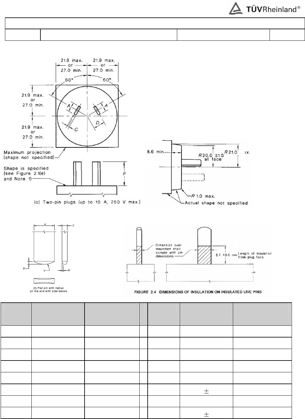
www.tuv.com
<16011089 001>
Page 72 of 73
AS/NZS 3112 (Partial)
Clause Requirement − Test Result – Remark Verdict
Symbol
Requirement
(mm)
Measured (mm)
Symbol
Requirement
(mm)
Measured (mm)
A 6.2 – 6.5 6.3
K 60 ° 60°
C 1.58 – 1.78 1.60
L > 8.6 10.5
D 7.92 7.96
M R 19.0 – 21.0 20.7
F 16.66 – 17.46 17.20
N < R 1.0 0.9
G < 21.9 or > 27.0
20.7
P 8.2 – 9.2 8.3
H < 21.9 or > 27.0
20.7
S 0.90 0.10 0.98
I < 21.9 or > 27.0
20.7
V 6.0 6.0
J < 21.9 or > 27.0
20.7
R 0.35 0.05 0.32
G
H
K
I
J
L
M
O
P
N
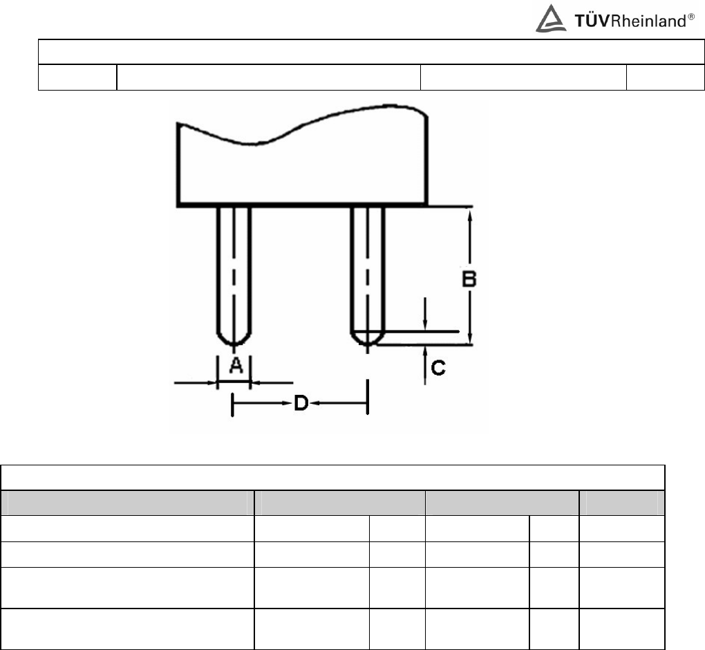
www.tuv.com
<16011089 001>
Page 73 of 73
BS 4573 (Partial)
Clause Requirement − Test Result – Remark Verdict
Plug dimensions (BS 4573: 1970)
Location Requirement Measured Verdict
A: Diameter of plug pins 5.08±0.03 mm 5.07 mm P
B: Length of projection of plug pins 15.87+1.0 mm 15.9 mm P
C: Length of radiuses portion at the
end of plug pins 1.57+0.25 mm 1.65 mm P
D: Nominal distance the centers of
plug pins 16.66±0.03 mm 16.67 mm P
Note: Each of the above values is the average value of three samples.
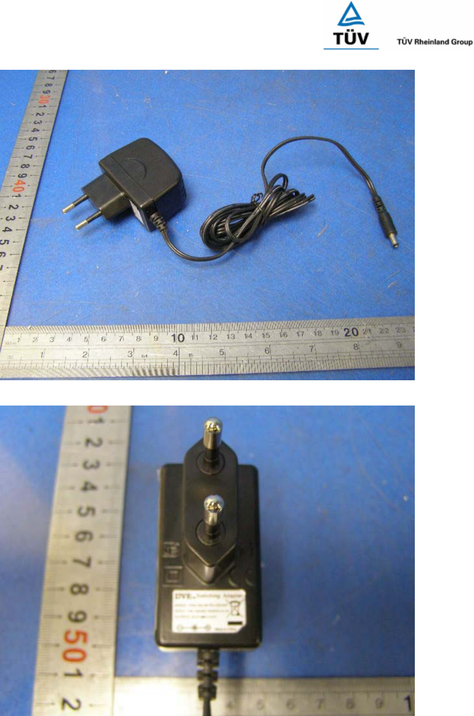
Report Number: 16011089 001
Model: DSA-5W-a Ab xy; DSA-5W-a Fb xy
Page 1 of 11
Picture 1
Picture 2
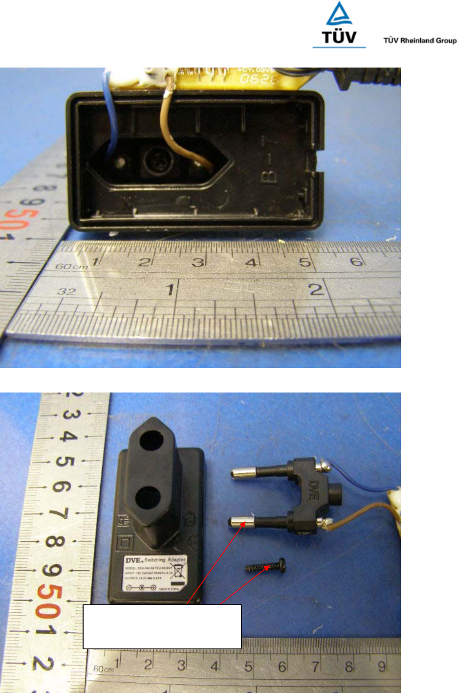
Report Number: 16011089 001
Model: DSA-5W-a Ab xy; DSA-5W-a Fb xy
Page 2 of 11
Picture 3
Picture 4
European plug pins were
fixed into enclosure by a
screw.
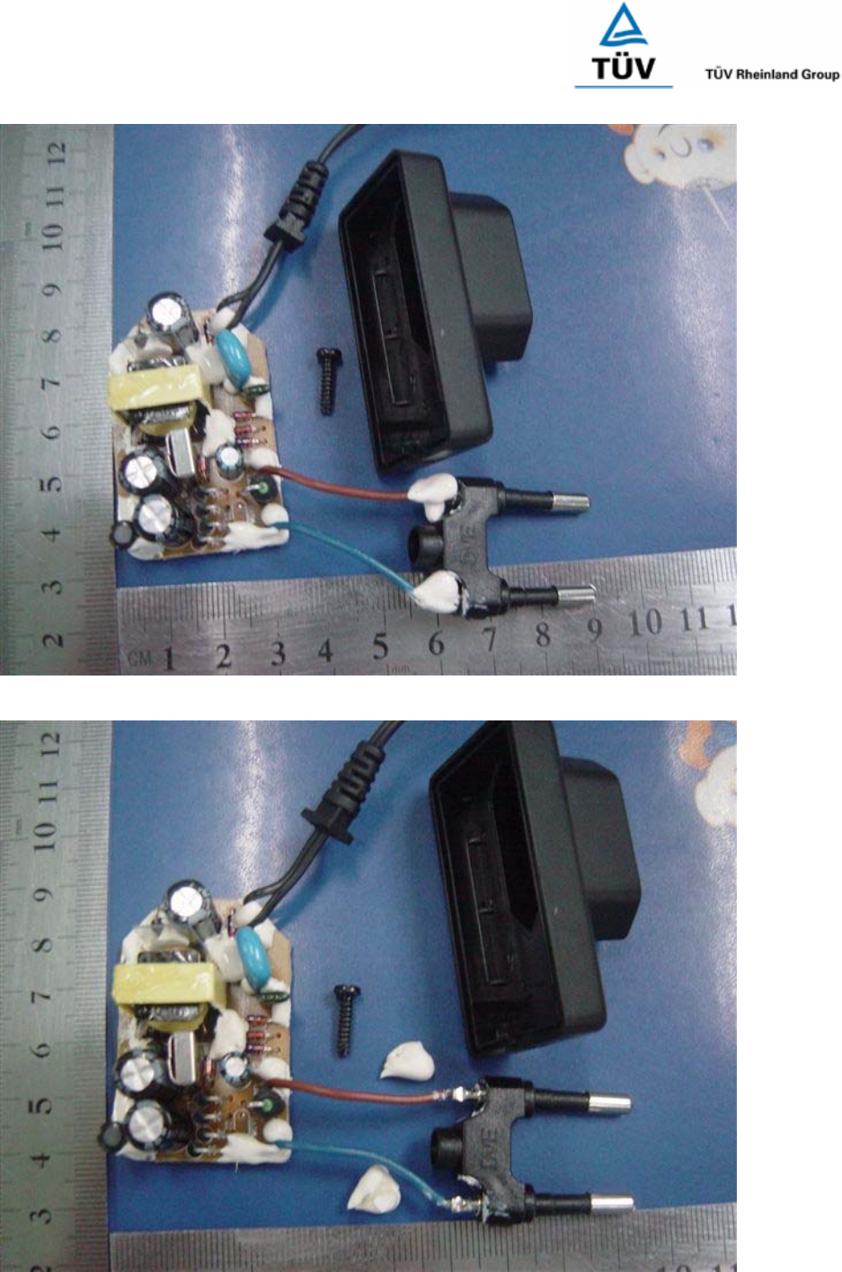
Report Number: 16011089 001
Model: DSA-5W-a Ab xy; DSA-5W-a Fb xy
Page 3 of 11
Picture 5
Picture 6
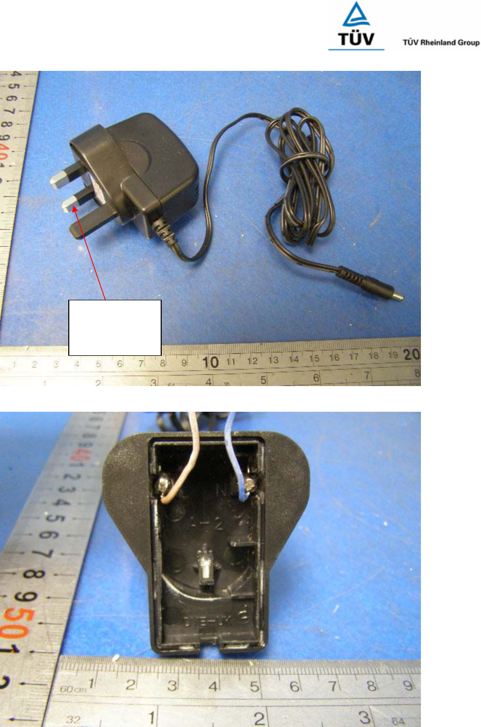
Report Number: 16011089 001
Model: DSA-5W-a Ab xy; DSA-5W-a Fb xy
Page 4 of 11
Picture 7
Picture 8
UK plug pins
were molded
into enclosure.
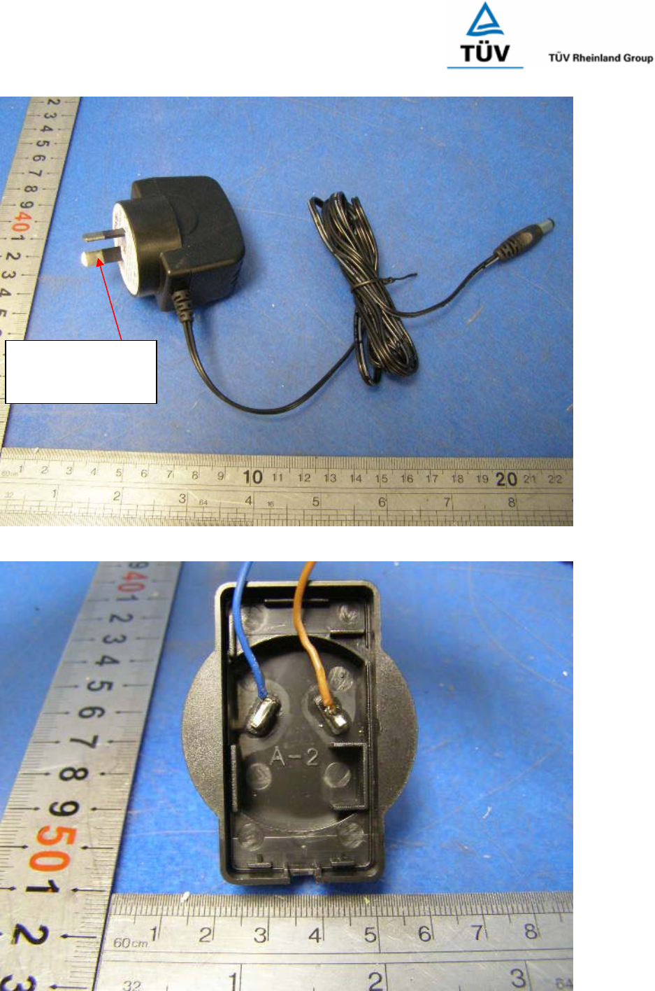
Report Number: 16011089 001
Model: DSA-5W-a Ab xy; DSA-5W-a Fb xy
Page 5 of 11
Picture 9
Picture 10
Australian plug
pins were molded
into enclosure.
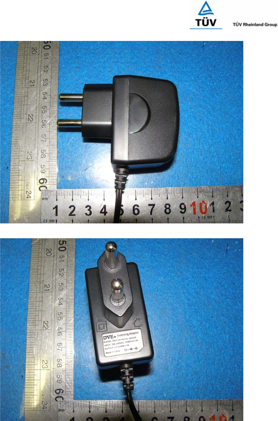
Report Number: 16011089 001
Model: DSA-5W-a Ab xy; DSA-5W-a Fb xy
Page 6 of 11
Picture 11
Picture 12
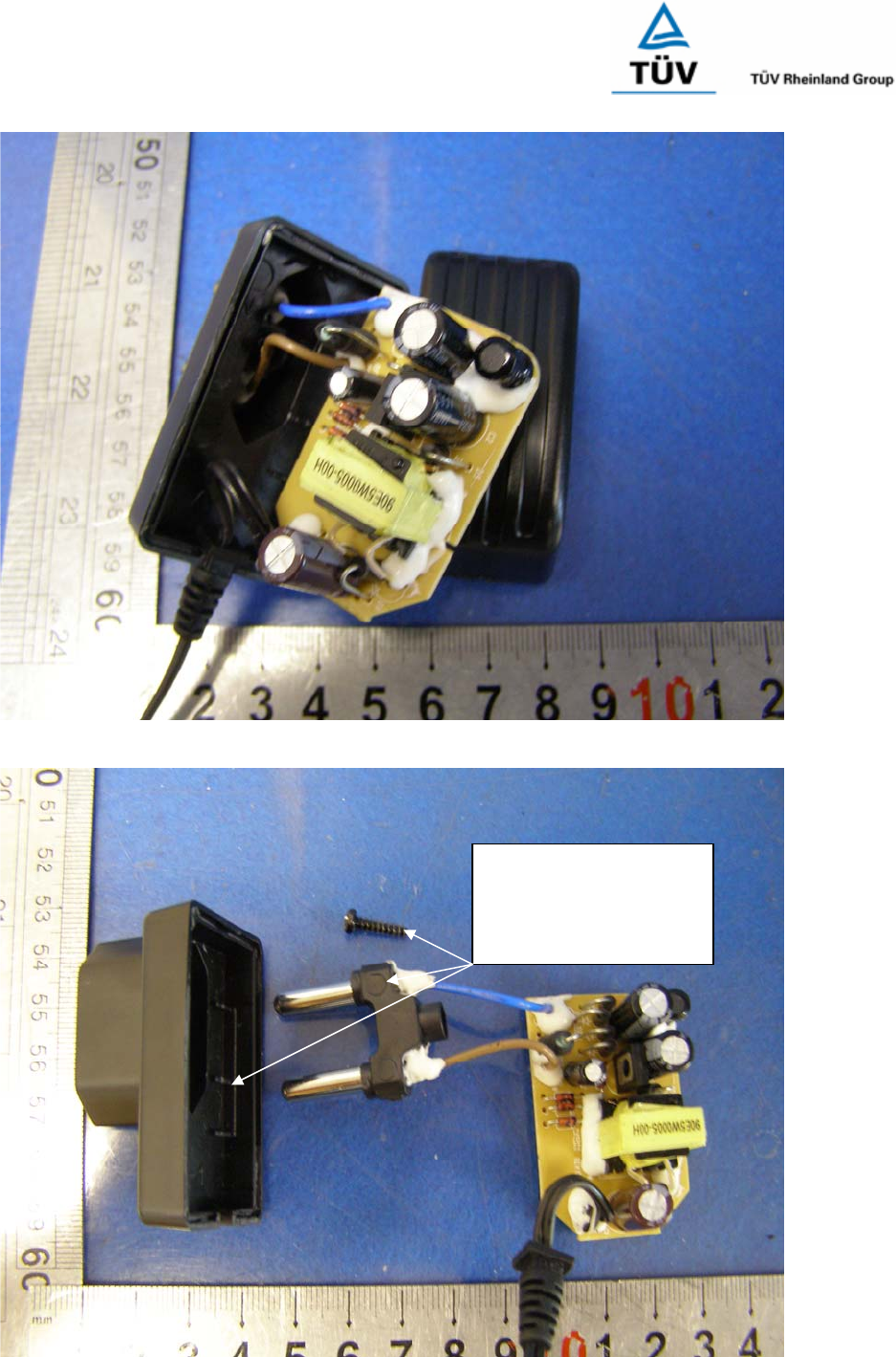
Report Number: 16011089 001
Model: DSA-5W-a Ab xy; DSA-5W-a Fb xy
Page 7 of 11
Picture 13
Picture 14
The plug holder of
Indian plug is fixed
into enclosure by
screw.
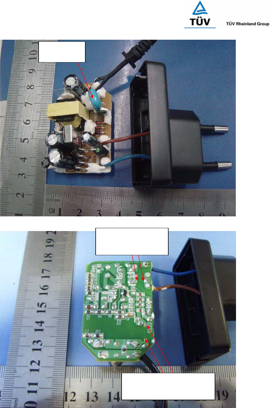
Report Number: 16011089 001
Model: DSA-5W-a Ab xy; DSA-5W-a Fb xy
Page 8 of 11
Picture 15
Picture 16
The cr and cl between
primary and secondary trace
on PCB is 6.7mm.
The cr and cl between
two pins of fusing
resistor is 2.7mm.
Y capacitor
is optional
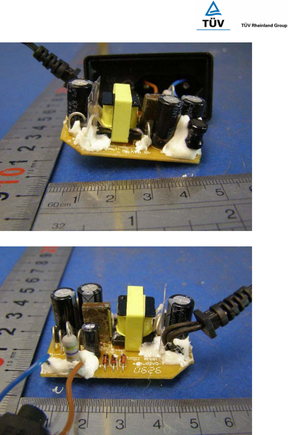
Report Number: 16011089 001
Model: DSA-5W-a Ab xy; DSA-5W-a Fb xy
Page 9 of 11
Picture 17
Picture 18
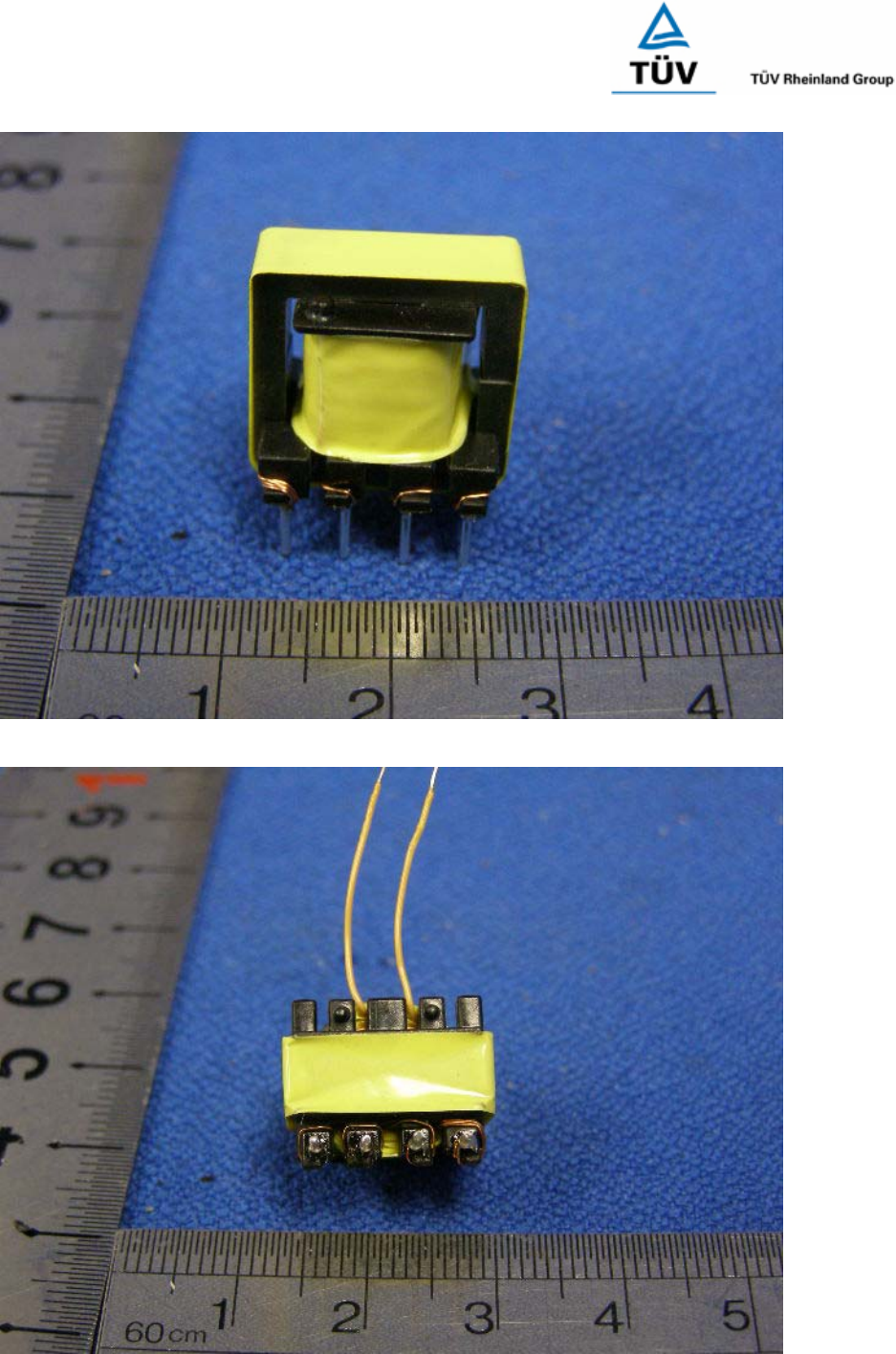
Report Number: 16011089 001
Model: DSA-5W-a Ab xy; DSA-5W-a Fb xy
Page 10 of 11
Picture 19
Picture 20
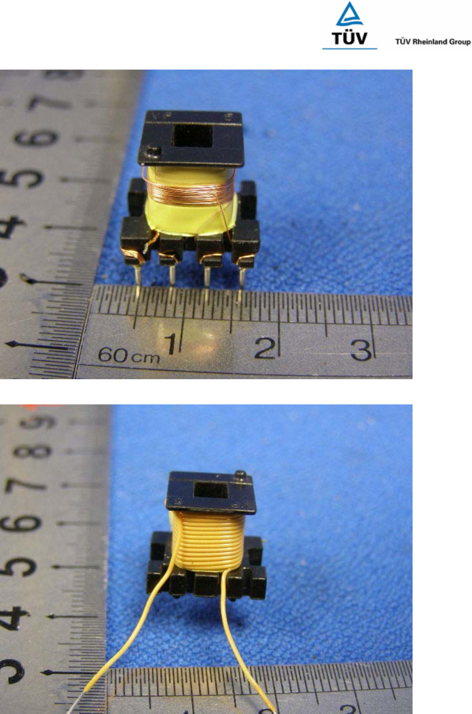
Report Number: 16011089 001
Model: DSA-5W-a Ab xy; DSA-5W-a Fb xy
Page 11 of 11
Picture 21
Picture 22
