09_Nov03_ Brochure
92810-Brochure 92810-Brochure 92810-Brochure 786680 Batch2_1 unilog cesco-content
51422-Brochure- 1 51422-Brochure-_1 51422-Brochure-_1 786680 Batch2_1 unilog cesco-content
2014-05-16
: Pdf 51422-Brochure 1 51422-Brochure_1 786680 Batch2_1 unilog
Open the PDF directly: View PDF ![]() .
.
Page Count: 146 [warning: Documents this large are best viewed by clicking the View PDF Link!]
November 2003
CA08101001E For more information visit:
www.cutler-hammer.eaton.com
Contents
Transformers 9-1
9
Vol. 1, Ref. No. [0301]
Transformers
Description Page
General Purpose Transformers
Single-Phase, Types EP, DS-3, 60 Hz . . . . . . . . . . . . . . . . . . . . . . . . . . . . . .
9-2
Three-Phase, Types EPT, DT-3, 60 Hz . . . . . . . . . . . . . . . . . . . . . . . . . . . . .
9-8
Three-Phase, Types EPT, DT-3, 50/60 Hz . . . . . . . . . . . . . . . . . . . . . . . . . . .
9-19
Electrostatically Shielded Transformers
. . . . . . . . . . . . . . . . . . . . . . . . . . . . .
9-26
Energy Efficient Transformers . . . . . . . . . . . . . . . . . . . . . . . . . . . . . . . . . . . . . 9-31
NEMA TP-1-1996 . . . . . . . . . . . . . . . . . . . . . . . . . . . . . . . . . . . . . . . . . . . . .
9-33
Low Temperature Rise . . . . . . . . . . . . . . . . . . . . . . . . . . . . . . . . . . . . . . . . .
9-36
Energy Efficient Harmonic MitigatingTransformers . . . . . . . . . . . . . . . . . . . 9-38
K Factor Transformers
. . . . . . . . . . . . . . . . . . . . . . . . . . . . . . . . . . . . . . . . . . .
9-41
Drive Isolation Transformers
. . . . . . . . . . . . . . . . . . . . . . . . . . . . . . . . . . . . . .
9-50
Mini-Power Centers
. . . . . . . . . . . . . . . . . . . . . . . . . . . . . . . . . . . . . . . . . . . . .
9-57
Totally Enclosed Non-Ventilated Transformers
. . . . . . . . . . . . . . . . . . . . . . .
9-59
Class I, Division 2, Groups C and D Transformers
. . . . . . . . . . . . . . . . . . . . .
9-61
Open Type Core and Coil Assembly Transformers
. . . . . . . . . . . . . . . . . . . . .
9-63
Filtered Noise Isolation Transformers
. . . . . . . . . . . . . . . . . . . . . . . . . . . . . . .
9-65
Low Sound Transformers
. . . . . . . . . . . . . . . . . . . . . . . . . . . . . . . . . . . . . . . . .
9-67
Marine Duty Transformers
. . . . . . . . . . . . . . . . . . . . . . . . . . . . . . . . . . . . . . . .
9-70
Buck-Boost Transformers
. . . . . . . . . . . . . . . . . . . . . . . . . . . . . . . . . . . . . . . . .
9-72
Autotransformer
. . . . . . . . . . . . . . . . . . . . . . . . . . . . . . . . . . . . . . . . . . . . . . . .
9-88
Industrial Control Transformers
Type MTA . . . . . . . . . . . . . . . . . . . . . . . . . . . . . . . . . . . . . . . . . . . . . . . . . . .
9-89
Type MTC . . . . . . . . . . . . . . . . . . . . . . . . . . . . . . . . . . . . . . . . . . . . . . . . . . .
9-94
Type MTE . . . . . . . . . . . . . . . . . . . . . . . . . . . . . . . . . . . . . . . . . . . . . . . . . . .
9-96
Type MTK . . . . . . . . . . . . . . . . . . . . . . . . . . . . . . . . . . . . . . . . . . . . . . . . . . .
9-105
CE Marked. . . . . . . . . . . . . . . . . . . . . . . . . . . . . . . . . . . . . . . . . . . . . . . . . . .
9-110
Type AP . . . . . . . . . . . . . . . . . . . . . . . . . . . . . . . . . . . . . . . . . . . . . . . . . . . . .
9-118
General Purpose and Industrial Control Transformers
Options and Accessories . . . . . . . . . . . . . . . . . . . . . . . . . . . . . . . . . . . . . . .
9-120
Technical Data and Specifications . . . . . . . . . . . . . . . . . . . . . . . . . . . . . . .
9-122
Product Selection . . . . . . . . . . . . . . . . . . . . . . . . . . . . . . . . . . . . . . . . . . . . .
9-136
Catalog Numbering System . . . . . . . . . . . . . . . . . . . . . . . . . . . . . . . . . . . .
9-138
Price Modifications. . . . . . . . . . . . . . . . . . . . . . . . . . . . . . . . . . . . . . . . . . . .
9-141
Glossary of Transformer Terms. . . . . . . . . . . . . . . . . . . . . . . . . . . . . . . . . .
9-142
Frequently Asked Questions . . . . . . . . . . . . . . . . . . . . . . . . . . . . . . . . . . . .
9-144
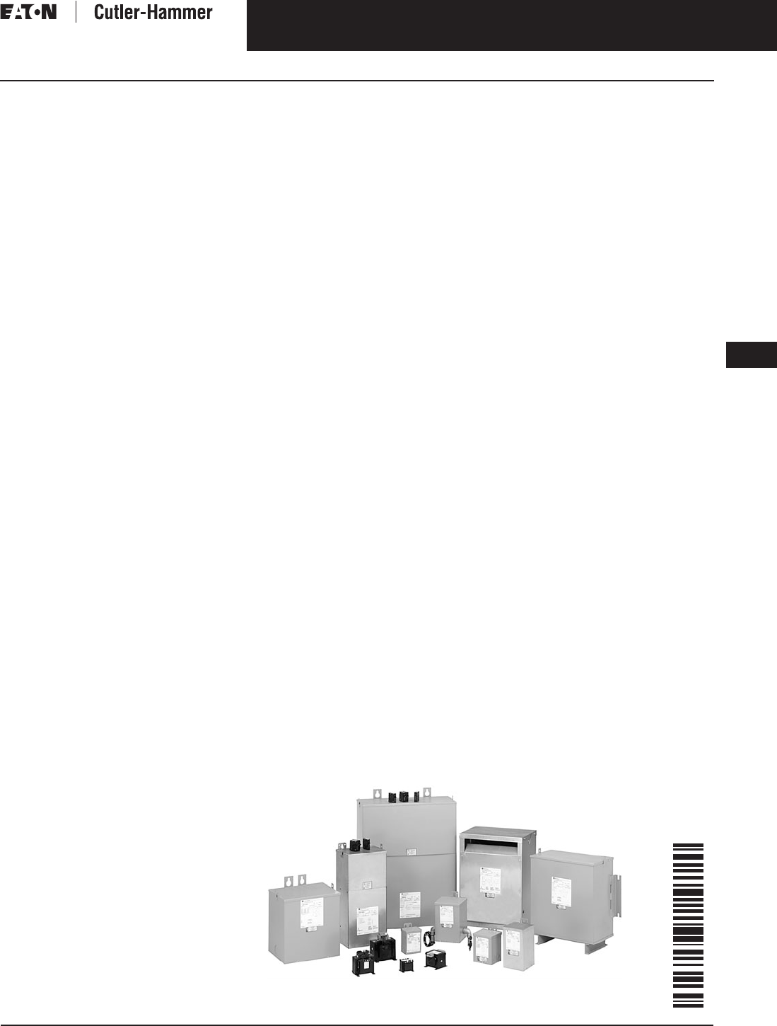
Dry-Type Transformer Family

November 2003
9-2
For more information visit:
www.cutler-hammer.eaton.com
CA08101001E
Transformers
9
General Purpose Transformers
Single-Phase, Types EP, DS-3, 60 Hz
Vol. 1, Ref. No. [0302]
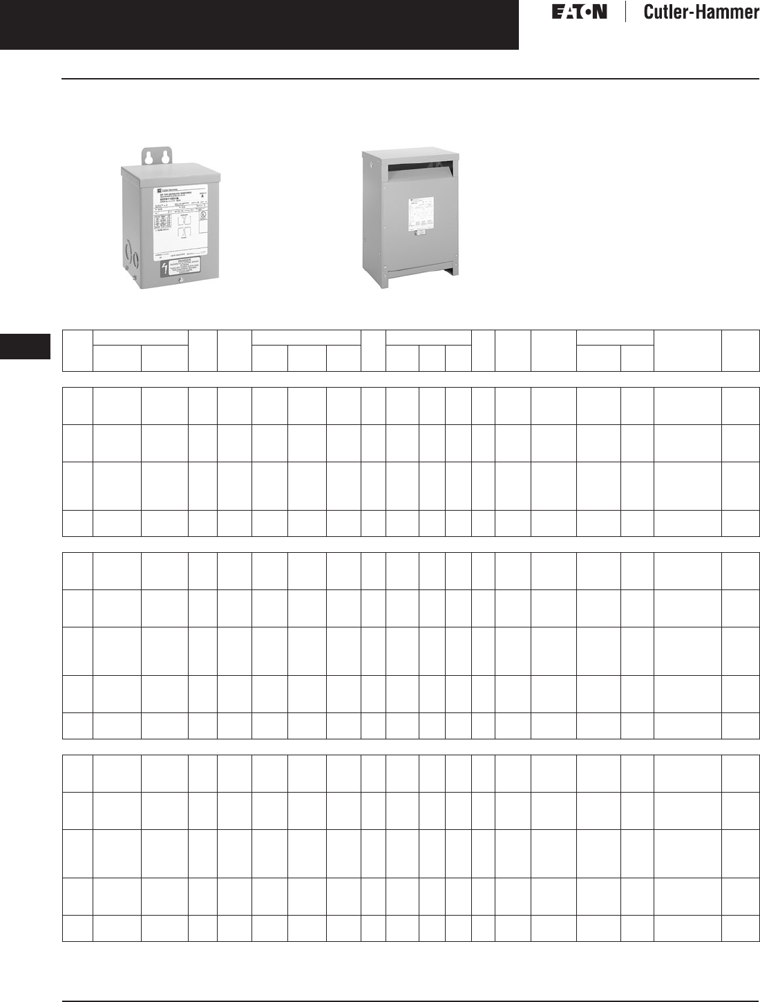
Single-Phase, Types EP,
DS-3, 60 Hz
Type EP 3-25 kVA
Product Description
Type EP
■
Sand and Resin Encapsulated design.
■
Suitable for indoor or outdoor
applications.
■
Totally enclosed, non-ventilated
enclosures.
■
Enclosures are NEMA
3R rated.
■
Mountable in any position indoors
and upright only outdoors.
■
185ºC Insulation System, 115ºC rise
standard.
■
Available in ratings through 37.5 kVA
and 4160 volts primary.
Type DS-3
■
Ventilated, NEMA 2 enclosure
standard.
■
Suitable for indoor applications,
outdoors when weathershields are
also installed.
■
Upright mounting only.
■
220ºC Insulation System, 150ºC
rise standard.
■
Available in single-phase ratings
15 – 167 kVA and up to 4160 volts
primary.
Application Description
The basic purpose of a transformer
is voltage transformation as near as
practically possible to the load for
economy and distribution of power.
Typical loads for dry-type distribution
transformers include lighting, heating,
air conditioners, fans, and machine
tools. Such loads are found in com-
mercial, institutional, industrial,
and residential structures.
Features, Benefits
and Functions
■
UL
listed.
■
60 Hz operation.
■
Short-term overload capability
as required by ANSI.
■
Meet NEMA ST-20 sound levels.
Standards and Certifications
Industry Standards
All Cutler-Hammer dry-type distribution
and control transformers by Eaton
Corporation are built and tested in
accordance with applicable NEMA,
ANSI and IEEE Standards. All 600 volt
class transformers are UL listed unless
otherwise noted.
Seismically Qualified
Cutler-Hammer manufactured dry-type
distribution transformers are seismi-
cally qualified, and exceed require-
ments of the Uniform Building Code
(UBC) and California Code Title 24.
Options and Accessories
Please refer to
Page 9-120
.
Product Specifications
Frequency
Cutler-Hammer standard dry-type
distribution transformers are designed
for 60 Hertz operation. Transformers
required for other frequencies are
available and must be specifically
designed.
Overload Capability
Short-term overload is designed into
transformers as required by ANSI.
dry-type distribution transformers
will deliver 200% nameplate load for
one-half hour; 150% load for one hour;
and 125% load for four hours without
being damaged provided that a con-
stant 50% load precedes and follows
the overload. See ANSI C57.96-01.250
for additional limitations.
Continuous overload capacity is not
deliberately designed into a trans-
former because the design objective is
to be within the allowed winding tem-
perature rise with nameplate loading.
Insulation System and Temperature Rise
Industry standards classify insulation
systems and rise as shown below:
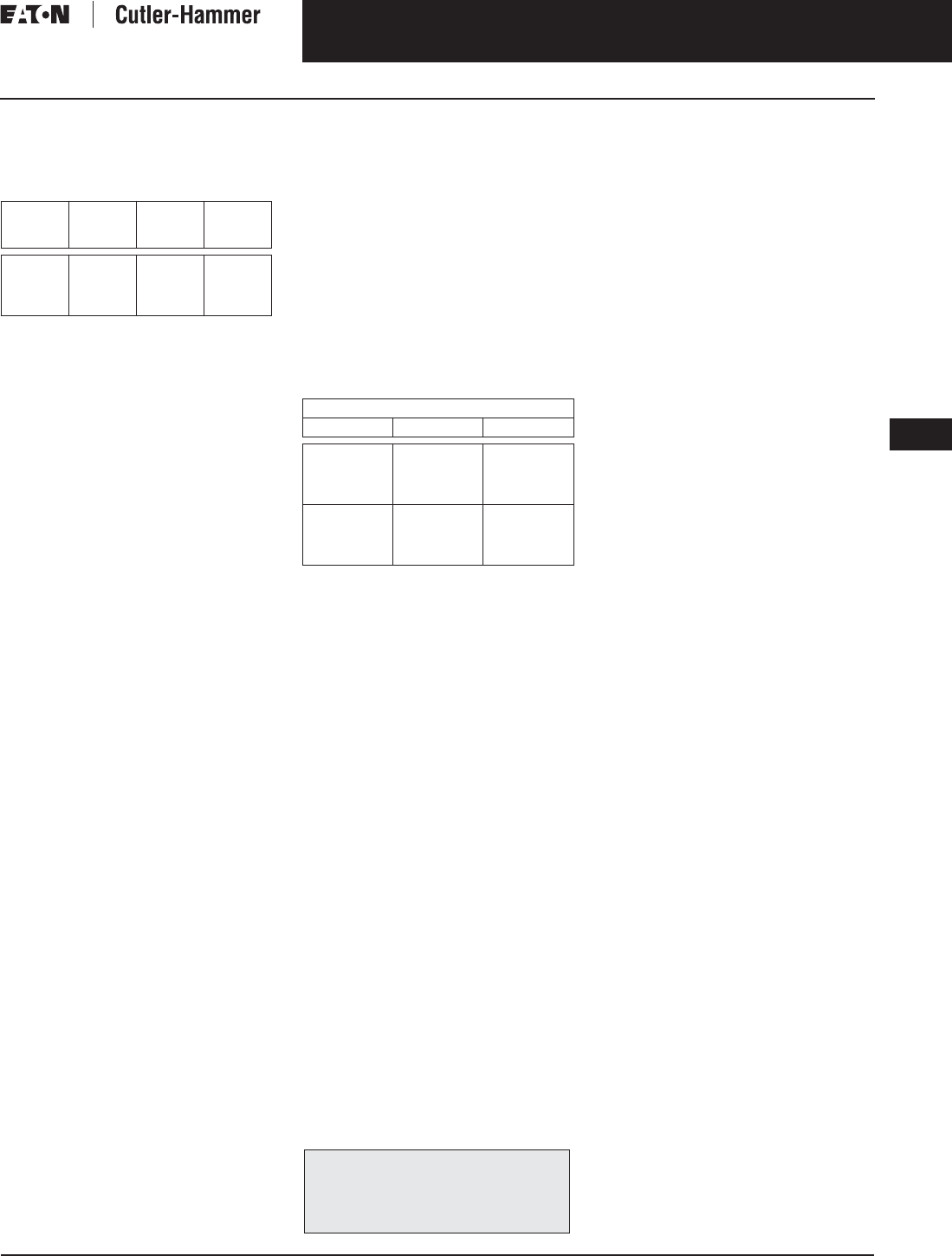
Table 9-1. Insulation System Classification
The design life of transformers having
different insulation systems is the
same — the lower temperature systems
are designed for the same life as the
higher temperature systems.
Enclosures
Cutler-Hammer ventilated transform-
ers, Type DS-3, utilize a NEMA 2 rated
(drip-proof) enclosure as standard,
and are rated NEMA 3R with the addi-
tion of weathershields. Cutler-Hammer
encapsulated transformers, Type EP,
utilize a NEMA 3R rated enclosure
as standard.
Sound Levels
All Cutler-Hammer 600 volt class
general purpose dry-type distribution
transformers are designed to meet
NEMA ST-20 sound levels listed here.
These are the sound levels measured
in a soundproof environment. Actual
sound levels measured at an installa-
tion will likely be higher due to electri-
cal connections and environmental
conditions. Lower sound levels are
available and should be specified
when the transformer is going to
be installed in an area where sound
may be a concern.
Table 9-2. Average Sound Levels
Ambient +
Winding
Rise
+
Hot
Spot
=
Temp.
Class
40°C
40°C
40°C
40°C
55°C
80°C
115°C
150°C
10°C
30°C
30°C
30°C
105°C
150°C
185°C
220°C
NEMA ST-20 Average Sound Level in dB
kVA Ventilated Encapsulated
0 – 9
10 – 50
51 – 150
151 – 300
40
45
50
55
45
50
55
57
301 – 500
501 – 700
701 – 1000
1001 – 1500
60
62
64
65
59
61
63
64

November 2003
CA08101001E For more information visit:
www.cutler-hammer.eaton.com
9-3
Transformers
9
General Purpose Transformers
Single-Phase, Types EP, DS-3, 60 Hz
Vol. 1, Ref. No. [0303]
Winding Terminations
Primary and secondary windings are
terminated in the wiring compartment.
Encapsulated units have copper leads
or stabs brought out for connections.
Ventilated transformers have leads
brought out to aluminum pads that
are pre-drilled to accept Cu/Al lugs.
Lugs are not supplied with these
transformers.
Eaton’s Cutler-Hammer
business recommends external cables
be rated 90°C (sized at 75°C ampacity)
for encapsulated designs and 75°C for
ventilated designs.
Series-Multiple Windings
Series-multiple windings consist of
2 similar coils in each winding which
can be connected in series or parallel
(multiple). Transformers with series-
multiple windings are designated with
an “X” or “/” between the voltage
ratings, such as voltages of “120/240”
or “240 X 480.” If the series-multiple
winding is designated by an “X,” the
winding can be connected only for a
series or parallel. With the “/” designa-
tion, a mid-point also becomes avail-
able in addition to the series or parallel
connection. As an example, a 120 X
240 winding can be connected for
either 120 (parallel) or 240 (series), but
a 120/240 winding can be connected
for 120 (parallel), or 240 (series), or 240
with a 120 mid-point.
Technical Data
and Specifications
Please refer to
Page 9-122
.
The following pages provide listings for most
standard transformer ratings and styles.
For other ratings or styles not shown, or for
special enclosure types (including stainless
steel) refer to Eaton’s Cutler-Hammer business.
November 2003
9-4
For more information visit:
www.cutler-hammer.eaton.com
CA08101001E
Transformers
9
General Purpose Transformers
Single-Phase, Types EP, DS-3, 60 Hz
Vol. 1, Ref. No. [0304]
Product Selection
Additional Product Selection information begins on
Page 9-136
.
Type EP 3-37.5 kVA Type DS-3 15-167 kVA
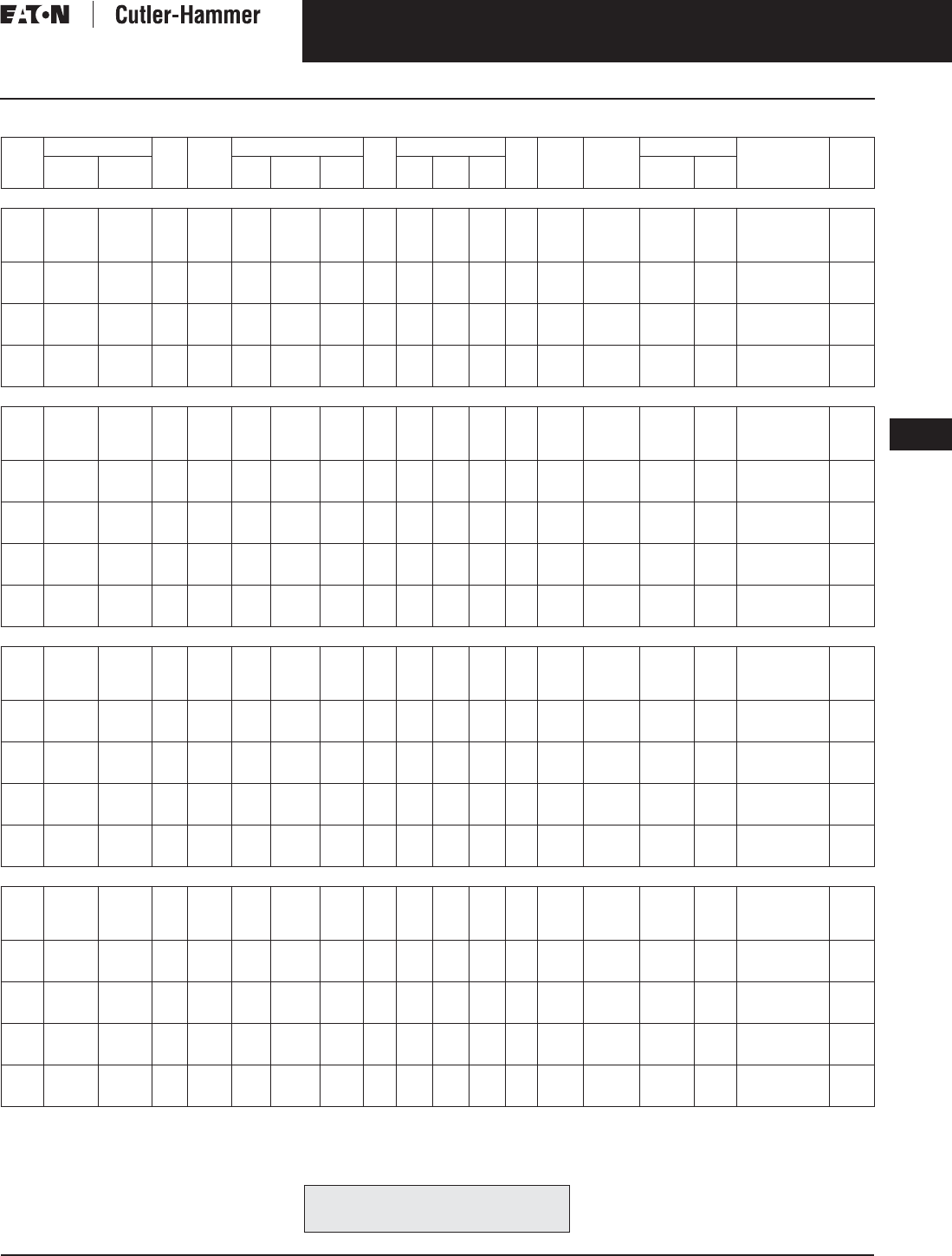
Table 9-3. Single-Phase Selection Information — Types EP, DS-3, 60 Hz
Contact Eaton’s Cutler-Hammer business for availability of 0.05 – 0.25 kVA designs.
1@+5%, 2@-5% at 240 volts primary; 2@+2.5%, 4@-2.5% at 480 volts primary.
Note:
Contact your local Cutler-Hammer sales office for CE Mark transformer requirements.
kVA Full Cap. Taps Type °C
Temp.
Rise
Dimensions (Inches) Wt.
Lbs.
Dimensions (mm) Wt.
kg
Frame Wiring
Diagram
Number
Weathershield Style
Number
Price
U.S. $
FCAN FCBN H W D H W D Catalog
Number
Price
U.S. $
120 x 240 Volts to 120/240 Volts
.5
1
1.5
—
—
—
—
—
—
EP
EP
EP
115
115
115
6-1/2
8-3/8
10-3/4
4-7/8
6
6-3/16
4-5/8
5-3/4
6-1/8
13
31
40
165
213
273
124
152
157
117
146
156
6
14
18
FR57
FR59A
FR67
3E
3E
3E
Indoor-
Outdoor
—
—
—
S10N11S51N
S10N11S01N
S10N11S16N
400.
720.
890.
2
3
5
—
—
—
—
—
—
EP
EP
EP
115
115
115
10-3/4
14-1/8
16
6-3/16
7-3/4
10-3/8
6-1/8
8
9-7/8
40
65
113
273
359
406
157
197
263
156
203
251
18
29
51
FR68
FR176
FR177
3E
3E
3E
Indoor-
Outdoor
—
—
—
S10N11S02N
S10N11S03N
S10N11S05N
965.
1,050.
1,425.
7.5
10
15
25
—
—
—
—
—
—
—
—
EP
EP
EP
EP
115
115
115
115
16
19
19
22-3/8
10-3/8
13-3/8
13-3/8
16-3/8
9-7/8
10-1/2
10-1/2
14-1/2
123
191
216
375
406
482
482
568
263
339
339
416
251
266
266
368
55
87
98
170
FR178
FR179
FR180
FR182
3E
3E
3E
3E
Indoor-
Outdoor
—
—
—
—
S10N11S07N
S10N11S10N
S10N11S15N
S10N11S25N
1,830.
2,225.
2,780.
4,370.
37.5
50
DS-3
DS-3
150
150
37-5/8
37-5/8
22-5/8
22-5/8
19-1/2
19-1/2
306
340
956
956
574
574
495
495
139
154
FR817
FR818
3XD
3XD
WS11
WS11
350.
350.
T10P11S37
T10P11S50
5,490.
6,670.
208 Volts to 120/240 Volts
.5
1
1.5
—
—
—
—
—
—
EP
EP
EP
115
115
115
6-1/2
8-3/8
10-3/4
4-7/8
6
6-3/16
4-5/8
5-3/4
6-1/8
13
31
40
165
213
273
124
152
157
117
146
156
6
14
18
FR57
FR59A
FR67
26A
26A
26A
Indoor-
Outdoor
—
—
—
S29N11S51N
S29N11S01N
S29N11S16N
410.
625.
770.
2
3
5
—
—
—
—
—
—
EP
EP
EP
115
115
115
10-3/4
14-1/8
16
6-3/16
7-3/4
10-3/8
6-1/8
8
9-7/8
40
65
113
273
359
406
157
197
263
156
203
251
18
29
51
FR68
FR176
FR177
26A
26A
26A
Indoor-
Outdoor
—
—
—
S29N11S02N
S29N11S03N
S29N11S05N
985.
1,200.
1,775.
7.5
10
15
25
—
—
—
—
—
—
—
—
EP
EP
EP
EP
115
115
115
115
16
19
19
22-3/8
10-3/8
13-3/8
13-3/8
16-3/8
9-7/8
10-1/2
10-1/2
14-1/8
123
193
216
375
406
482
482
568
263
339
339
416
251
266
266
359
55
87
98
170
FR178
FR179
FR180
FR182
26A
26A
26A
26A
Indoor-
Outdoor
—
—
—
—
S29N11S07N
S29N11S10N
S29N11S15N
S29N11S25N
2,350.
2,830.
3,350.
4,780.
25
37.5
50
2@+2.5%
2@+2.5%
2@+2.5%
4@-2.5%
4@-2.5%
4@-2.5%
DS-3
DS-3
DS-3
150
150
150
31-1/4
37-5/8
37-5/8
22-5/8
22-5/8
22-5/8
17-1/2
19-1/2
19-1/2
212
306
340
793
956
956
574
574
574
445
495
495
96
139
154
FR816
FR817
FR818
260A
260A
260A
WS11
WS11
WS11
350.
350.
350.
T29M11S25
T29M11S37
T29M11S50
3,740.
4,580.
5,560.
75
100
2@+2.5%
1@+5%
4@-2.5%
2@-5%
DS-3
DS-3
150
150
42-1/8
42-1/8
24
24
23-3/8
23-3/8
510
600
1070
1070
610
610
594
594
232
272
FR819
FR820
260A
260A
WS16
WS16
800.
800.
T29M11S75
T29R11S99
7,860.
9,760.
277 Volts to 120/240 Volts
.5
1
1.5
—
—
—
—
—
EP
EP
EP
115
115
115
6-1/2
8-3/8
10-3/4
4-7/8
6
6-3/16
4-5/8
5-3/4
6-1/8
13
31
40
165
213
273
124
152
157
117
146
156
6
14
18
FR57
FR59A
FR67
514B
514B
514B
Indoor-
Outdoor
—
—
—
S27N11S51A
S27N11S01A
S27N11S16A
410.
625.
770.
2
3
5
—
—
—
—
—
—
EP
EP
EP
115
115
115
10-3/4
14-1/8
16
6-3/16
7-3/4
10-3/8
6-1/8
8
9-7/8
40
65
113
273
359
405
157
197
263
156
203
251
18
29
51
FR68
FR176
FR177
514B
514B
514B
Indoor-
Outdoor
—
—
—
S27N11S02A
S27N11S03N
S27N11S05N
985.
1,200.
1,775.
7.5
10
15
25
—
—
—
—
—
—
—
—
EP
EP
EP
EP
115
115
115
115
16
19
19
22-3/8
10-3/8
13-3/8
13-3/8
16-3/8
9-7/8
10-1/2
10-1/2
14-1/8
123
193
216
375
406
482
482
568
263
339
339
416
251
266
266
359
55
87
98
170
FR178
FR179
FR180
FR182
514B
514B
514B
514B
Indoor-
Outdoor
—
—
—
—
S27N11S07N
S27N11S10N
S27N11S15N
S27N11S25N
2,350.
2,830.
3,350.
4,780.
25
37.5
50
2@+2.5%
2@+2.5%
2@+2.5%
4@-2.5%
4@-2.5%
4@-2.5%
DS-3
DS-3
DS-3
150
150
150
31-1/4
37-5/8
37-5/8
22-5/8
22-5/8
22-5/8
17-1/2
19-1/2
19-1/2
212
306
340
793
956
956
574
574
574
445
495
495
96
139
154
FR816
FR817
FR818
262C
262C
262C
WS11
WS11
WS11
350.
350.
350.
T27M11S25
T27M11S37
T27M11S50
3,740.
4,580.
5,560.
75
100
2@+2.5%
2@+2.5%
4@-2.5%
4@-2.5%
DS-3
DS-3
150
150
42-1/8
42-1/8
24
24
23-3/8
23-3/8
510
600
1070
1070
610
610
594
594
232
272
FR819
FR820
262C
262C
WS16
WS16
800.
800.
T27M11S75
T27M11S99
7,860.
9,760.
Discount Symbol . . . . . . . . . . . . . . . . . . . . . . . . .
DT-1

November 2003
CA08101001E For more information visit:
www.cutler-hammer.eaton.com
9-5
Transformers
9
General Purpose Transformers
Single-Phase, Types EP, DS-3, 60 Hz
Vol. 1, Ref. No. [0305]
Table 9-4. Single-Phase Selection Information — Types EP, DS-3, 60 Hz
1@+10% FCBN at 240 volts; 2@+5% FCBN at 480 volts.
2@+5% FCBN at 240 volts; 4@+2.5% FCBN at 480 volts.
1@+5%, 2@-5% at 240 volts primary; 2@+2.5%, 4@-2.5% at 480 volts primary.
480V primary to 120/240 volts secondary.
Note: Contact your local Cutler-Hammer sales office for CE Mark transformer requirements.
kVA Full Cap. Taps Type °C
Temp.
Rise
Dimensions (Inches) Wt.
Lbs.
Dimensions (mm) Wt.
kg
Frame Wiring
Diagram
Number
Weathershield
Style
Number
Price
U.S. $
FCAN FCBN H W D H W D Catalog
Number
Price
U.S. $
240 x 480 Volts to 120/240 Volts
.050
.075
.100
—
—
—
—
—
—
EP
EP
EP
115
115
115
6-1/2
6-1/2
6-1/2
3-7/8
3-7/8
3-7/8
3-1/2
3-1/2
3-1/2
7
7
7
165
165
165
98
98
98
89
89
89
3
3
3
FR52
FR53
FR54
3A
3A
3A
Indoor-
Outdoor
—
—
—
S20N11S81N
S20N11S85N
S20N11S82N
75.
85.
95.
.150
.25
.5
—
—
—
—
—
—
EP
EP
EP
115
115
115
6-1/2
6-1/2
6-1/2
3-7/8
4-7/8
4-7/8
3-1/2
3-7/8
4-5/8
8
12
13
165
165
165
98
124
124
89
98
117
4
5
6
FR55
FR56
FR57
3A
3A
3A
Indoor-
Outdoor
—
—
—
S20N11S83N
S20N11S26N
S20N11S51N
110.
135.
170.
.75
1
1.5
—
—
—
—
—
—
EP
EP
EP
115
115
115
8-3/8
8-3/8
10-3/4
6
6
6-3/16
5-3/4
5-3/4
6-1/8
21
31
40
213
213
273
152
152
157
146
146
156
10
14
18
FR58A
FR59A
FR67
3A
3A
3A
Indoor-
Outdoor
—
—
—
S20N11S76N
S20N11S01N
S20N11S16N
220.
260.
320.
2
3
3
—
—
—
—
EP
EP
EP
115
115
115
10-3/4
14-1/8
14-1/8
6-3/16
7-3/4
7-3/4
6-1/8
8
8
40
65
65
273
359
359
157
197
197
156
203
203
18
29
29
FR68
FR176
FR176
3A
3A
9A
Indoor-
Outdoor
—
—
—
S20N11S02N
S20N11S03N
S20K11S03N
410.
500.
525.
5
5
7.5
—
—
—
—
EP
EP
EP
115
115
115
16
16
16
10-3/8
10-3/8
10-3/8
9-7/8
9-7/8
9-7/8
113
113
123
406
406
406
263
263
263
251
251
251
51
51
55
FR177
FR177
FR178
3A
9A
3A
Indoor-
Outdoor
—
—
—
S20N11S05N
S20K11S05N
S20N11S07N
740.
775.
980.
7.5
10
10
—
—
EP
EP
EP
115
115
115
16
19
19
10-3/8
13-3/8
13-3/8
9-7/8
10-1/2
10-1/2
123
193
193
406
482
482
263
339
339
251
266
266
55
87
87
FR178
FR179
FR179
9A
3A
9A
Indoor-
Outdoor
—
—
—
S20K11S07N
S20N11S10N
S20K11S10N
1,030.
1,180.
1,240.
15
15
25
—
—
—
—
EP
EP
EP
115
115
115
19
19
22-3/8
13-3/8
13-3/8
16-3/8
10-1/2
10-1/2
14-1/2
216
216
375
482
482
568
339
339
416
266
266
368
98
98
170
FR180
FR180
FR182
3A
23A
3A
Indoor-
Outdoor
—
—
—
S20N11S15N
S20L11S15N
S20N11S25N
1,540.
1,600.
1,900.
25
37.5
EP
EP
115
115
22-3/8
28-1/4
16-3/8
22-5/8
14-1/2
14-5/8
375
950
568
717
416
575
368
371
170
432
FR182
FR300A
23A
23A
Indoor-
Outdoor
—
—
S20L11S25N
S20L11S37
2,250.
9,400.
15
25
37.5
DS-3
DS-3
DS-3
150
150
150
30-1/4
31-1/4
37-5/8
16-7/8
22-5/8
22-5/8
15-7/8
17-1/2
19-1/2
147
212
306
768
793
956
428
574
574
402
445
495
67
96
139
FR815
FR816
FR817
3XA
3XA
3XA
WS15
WS11
WS11
350.
350.
350.
T20P11S15
T20P11S25
T20P11S37
1,440.
1,870.
2,290.
50
75
100
167
2@+2.5%
4@-2.5%
DS-3
DS-3
DS-3
DS-3
150
150
150
150
37-5/8
42-1/8
42-1/8
62-1/2
22-5/8
24
24
30
19-1/2
23-3/8
23-3/8
34
340
510
600
1200
956
1070
1070
1597
574
610
610
762
495
594
594
863
154
232
272
545
FR818
FR819
FR820
FR814
3XA
3XA
3XA
288A
WS11
WS16
WS16
WS13
350.
800.
800.
800.
T20P11S50
T20P11S75
T20P11S99
T48M11S67D
3,220.
3,930.
4,880.
9,500.
For other ratings or styles not shown, or for
special enclosure types (including stainless
steel) refer to Eaton’s Cutler-Hammer business. Discount Symbol . . . . . . . . . . . . . . . . . . . . . . . . . DT-1

November 2003
9-6
For more information visit: www.cutler-hammer.eaton.com CA08101001E
Transformers
9
General Purpose Transformers
Single-Phase, Types EP, DS-3, 60 Hz Vol. 1, Ref. No. [0306]
Table 9-5. Single-Phase Selection Information — Types EP, DS-3, 60 Hz
NEMA 3R, 316 stainless steel enclosure.
Note: Contact your local Cutler-Hammer sales office for CE Mark transformer requirements.
kVA Full Cap. Taps Type °C
Temp.
Rise
Dimensions (Inches) Wt.
Lbs.
Dimensions (mm) Wt.
kg
Frame Wiring
Diagram
Number
Weathershield Style
Number
Price
U.S. $
FCAN FCBN H W D H W D Catalog
Number
Price
U.S. $
190/200/208/220 x 380/400/416/440 Volts to 110/220 Volts 50/60 Hz — Export Model IP 22 Rated
.5
1
1.5
2
—
—
—
—
—
—
—
—
EP
EP
EP
EP
115
115
115
115
10-3/4
10-3/4
10-3/4
11-1/8
6-1/8
6-1/8
6-1/8
7-3/4
6-5/8
6-5/8
6-5/8
8
42
42
46
70
273
273
273
281
155
155
155
197
166
166
166
203
19
19
21
33
FR67
FR67
FR67
FR176
538A
538A
538A
538A
Indoor-
Outdoor
—
—
—
—
S40N14S51CE
S40N14S01CE
S40N14S16CE
S40N14S02CE
760.
830.
1,030.
1,225.
3
5
7.5
—
—
—
—
—
—
EP
EP
EP
115
115
115
12-7/8
12-7/8
15-7/8
10-3/8
10-3/8
13-3/8
9-7/8
9-7/8
10-5/8
113
140
193
326
326
402
264
264
340
251
251
267
51
63
87
FR177
FR178
FR179
538A
538A
538A
Indoor-
Outdoor
—
—
—
S40N14S03CE
S40N14S05CE
S40N14S07CE
1,570.
2,000.
2,625.
10
15
—
—
—
—
EP
EP
115
115
15-7/8
17-1/8
13-3/8
16-3/8
10-5/8
14-1/8
216
375
402
433
340
415
267
359
98
170
FR180
FR182
538A
538A
Indoor-
Outdoor
—
—
S40N14S10CE
S40N14S15CE
3,160.
4,060.
240 x 480 Volts to 120/240 Volts Stainless Steel
3
5
7.5
—
—
—
—
—
—
EP
EP
EP
115
115
115
14-1/8
16
16
7-11/16
10-3/8
10-3/8
8
9-7/8
9-7/8
65
113
123
359
406
406
195
263
263
203
251
251
29
51
55
FR176
FR177
FR178
3A
3A
3A
Indoor-
Outdoor
—
—
—
S20N11S03SS
S20N11S05SS
S20N11S07SS
750.
1,110.
1,470.
10
15
25
—
—
—
—
—
—
EP
EP
EP
115
115
115
19
19
21-5/16
13-3/8
13-3/8
16-3/8
10-1/2
10-1/2
14-1/8
179
216
375
482
482
566
339
339
416
266
266
359
87
98
170
FR179
FR180
FR182
3A
3A
3A
Indoor-
Outdoor
—
—
—
S20N11S10SS
S20N11S15SS
S20N11S25SS
1,770.
2,200.
2,850.
480 Volts to 120/240 Volts
1
1.5
2
—
—
—
2@-5%
2@-5%
2@-5%
EP
EP
EP
115
115
115
8-3/8
10-3/4
10-3/4
6
6-3/16
6-3/16
5-3/4
6-1/8
6-1/8
31
40
40
213
273
273
152
157
157
146
156
156
14
18
18
FR59A
FR67
FR68
2D
2D
2D
Indoor-
Outdoor
—
—
—
S48G11S01N
S48G11S16N
S48G11S02N
312.
385.
495.
3
3
5
—
2@+2.5%
—
2@-5%
2@+2.5%
2@-5%
EP
EP
EP
115
115
115
14-1/8
14-1/8
16
7-3/4
7-3/4
10-3/8
8
8
9-7/8
65
65
113
359
359
406
197
197
263
203
203
251
29
29
51
FR176
FR176
FR177
2D
16A
2D
Indoor-
Outdoor
—
—
—
S48G11S03N
S48D11S03N
S48G11S05N
600.
600.
890.
5
7.5
7.5
2@+2.5%
—
2@+2.5%
2@+2.5%
2@-5%
2@+2.5%
EP
EP
EP
115
115
115
16
16
16
10-3/8
10-3/8
10-3/8
9-7/8
9-7/8
9-7/8
113
123
123
406
406
406
263
263
263
251
251
251
51
55
55
FR177
FR178
FR178
16A
2D
16A
Indoor-
Outdoor
—
—
—
S48D11S05N
S48G11S07N
S48D11S07N
890.
1,180.
1,180.
10
10
15
—
2@+2.5%
—
2@-5%
2@+2.5%
2@-5%
EP
EP
EP
115
115
115
19
19
19
13-3/8
13-3/8
13-3/8
10-1/2
10-1/2
10-1/2
193
193
216
482
482
482
339
339
339
266
266
266
87
87
98
FR179
FR179
FR180
2D
16A
2D
Indoor-
Outdoor
—
—
—
S48G11S10N
S48D11S10N
S48G11S15N
1,415.
1,415.
1,850.
15
25
25
2@+2.5%
—
2@+2.5%
2@+2.5%
2@-5%
4@-2.5%
EP
EP
EP
115
115
115
19
22-3/8
20-3/4
13-3/8
16-3/8
19-1/8
10-1/2
14-1/8
13-5/8
216
375
175
482
568
525
339
416
483
266
359
349
98
170
80
FR180
FR182
FR132
16A
2D
83A
Indoor-
Outdoor
—
—
—
S48D11S15N
S48G11S25N
S48M11S25N
1,850.
2,395.
2,395.
480 Volts to 120/240 Volts Stainless Steel, Copper Windings
10
15
25
2@+2.5%
2@+2.5%
2@+2.5%
2@+2.5%
2@+2.5%
4@-2.5%
EP
EP
EP
115
115
115
19
19
20-3/4
13-3/8
13-3/8
19-1/8
10-1/2
10-1/2
13-5/8
208
235
175
482
482
525
339
339
483
266
266
349
94
106
80
FR179
FR180
FR132
16A
16A
83A
Indoor-
Outdoor
—
—
—
S48D11S10SSCU
S48D11S15SSCU
S48M11S25SSCU
2,620.
3,500.
4,430.
600 Volts to 120/240 Volts
.5
.75
1
—
—
—
2@-5%
2@-5%
2@-5%
EP
EP
EP
115
115
115
6-1/2
8-3/8
8-3/8
4-7/8
6
6
4-5/8
5-3/4
5-3/4
13
21
31
165
213
213
124
152
152
117
146
146
6
10
14
FR57
FR58A
FR59A
2I
2I
2I
Indoor-
Outdoor
—
—
—
S60G11S51N
S60G11S76N
S60G11S01N
255.
330.
390.
1.5
2
3
—
—
—
2@-5%
2@-5%
2@-5%
EP
EP
EP
115
115
115
10-3/4
10-3/4
14-1/8
6-3/16
6-3/16
7-3/4
6-1/8
6-1/8
8
40
40
65
273
273
359
157
157
197
156
156
203
18
18
29
FR67
FR68
FR176
2I
2I
2I
Indoor-
Outdoor
—
—
—
S60G11S16N
S60G11S02N
S60G11S03N
475.
610.
740.
5
7.5
10
—
—
—
2@-5%
2@-5%
2@-5%
EP
EP
EP
115
115
115
16
16
19
10-3/8
10-3/8
13-3/8
9-7/8
9-7/8
10-1/2
113
123
193
406
406
482
263
263
339
251
251
266
51
55
87
FR177
FR178
FR179
2I
2I
2I
Indoor-
Outdoor
—
—
—
S60G11S05N
S60G11S07N
S60G11S10N
1,110.
1,460.
1,760.
15
25
25
—
—
2 @ 2.5%
4@-2.5%
4@-2.5%
4@-2.5%
EP
EP
EP
115
115
115
19
22-3/8
20-3/4
13-3/8
16-3/8
19-1/8
10-1/2
14-1/8
13-5/8
216
375
175
482
568
525
339
416
483
266
359
349
98
170
80
FR180
FR182
FR132
527A
527A
83B
Indoor-
Outdoor
—
—
—
S60J11S15N
S60J11S25N
S60M11S25N
2,400.
2,825.
2,825.
25
37.5
50
2@+2.5%
2@+2.5%
2@+2.5%
4@-2.5%
4@-2.5%
4@-2.5%
DS-3
DS-3
DS-3
150
150
150
31-1/4
37-5/8
37-5/8
22-5/8
22-5/8
22-5/8
17-1/2
19-1/2
19-1/2
212
306
340
793
956
956
574
574
574
445
495
495
96
139
154
FR816
FR817
FR818
276B
276B
276B
WS11
WS11
WS11
350.
350.
350.
T60M11S25B
T60M11S37
T60M11S50D
2,240.
2,750.
3,340.
75
100
167
2@+2.5%
2@+2.5%
2@+2.5%
4@-2.5%
4@-2.5%
4@-2.5%
DS-3
DS-3
DS-3
150
150
150
42-1/8
42-1/8
62-7/8
24
24
30
23-3/8
23-3/8
34
510
600
1200
1070
1070
1597
610
610
762
594
594
863
232
272
545
FR819
FR820
FR814
276B
276B
288B
WS16
WS16
WS13
800.
800.
800.
T60M11S75
T60M11S99
T60M11S67A
4,720.
5,860.
11,400.
For other ratings or styles not shown, or for
special enclosure types (including stainless
steel) refer to Eaton’s Cutler-Hammer business. Discount Symbol . . . . . . . . . . . . . . . . . . . . . . . . . DT-1

November 2003
CA08101001E For more information visit: www.cutler-hammer.eaton.com
9-7
Transformers
9
General Purpose Transformers
Single-Phase, Types EP, DS-3, 60 Hz
Vol. 1, Ref. No. [0307]
Table 9-6. Single-Phase Selection Information — Types EP, DS-3, 60 Hz
No UL label.
Refer to your Cutler-Hammer sales office.
NEMA 3R enclosure and/or UL label available at additional cost. Specify at time of order entry if required.
Not seismic qualified.
kVA Full Cap. Taps Type °C
Temp.
Rise
Dimensions (Inches) Wt.
Lbs.
Dimensions (mm) Wt.
kg
Frame Wiring
Diagram
Number
Weathershield Style
Number
Price
U.S. $
FCAN FCBN H W D H W D Catalog
Number
Price
U.S. $
2400 Volts to 120/240 Volts
1.5 — — EP 115 10-3/4 6-3/16 6-1/8 40 273 157 156 181 FR68 18A Recom-
mended
Indoor
Only
—
S42N11S16N 3,100.
3
5
10
15
25
—
—
—
—
—
4@-2.5%
4@-2.5%
4@-2.5%
4@-2.5%
4@-2.5%
EP
EP
EP
EP
EP
115
115
115
115
115
16
16
19
22-3/8
26-3/8
10-3/8
10-3/8
13-3/8
16-3/8
16-3/8
9-7/8
9-7/8
10-1/2
14-1/8
14-1/8
113
123
216
375
405
406
406
482
566
668
263
263
339
416
416
251
251
266
359
359
51
55
87
170
183
FR177
FR178
FR179
FR182
FR190
12A
12A
12A
12A
12A
Recom-
mended
Indoor
Only
—
—
—
—
—
S42J11S03N
S42J11S05N
S42J11S10N
S42J11S15N
S42J11S25N
3,290.
3,460.
4,930.
5,830.
8,270.
37.5
50
75
100
2@+2.5%
2@+2.5%
2@+2.5%
2@+2.5%
2@-2.5%
2@-2.5%
2@-2.5%
2@-2.5%
DS-3
DS-3
DS-3
DS-3
150
150
150
150
28
30
30
36
22
24
24
27
20
26
26
26
300
420
500
570
684
732
732
879
537
586
586
659
488
635
635
635
137
191
228
260
Recom-
mended
Indoor
Only
—
—
—
—
T42D11S37
T42D11S50
T42D11S75
T42D11S99
5,500.
6,350.
7,860.
8,600.
2400 Volts to 240/480 Volts
37.5
50
2@+2.5%
2@+2.5%
2@-2.5%
2@-2.5%
DS-3
DS-3
150
150
28
30
22
24
20
26
300
420
684
732
537
586
488
635
137
191
Recom-
mended
Indoor
Only
—
—
T42D21S37
T42D21S50
5,500.
6,350.
4160 Volts to 120/240 Volts
1.5 — — EP 115 10-3/4 6-3/16 6-1/8 40 273 157 156 181 FR68 524G Recom-
mended
Indoor
Only
—
S46N11S16N 2,580.
3
5
10
15
—
—
—
—
4@-2.5%
4@-2.5%
4@-2.5%
4@-2.5%
EP
EP
EP
EP
115
115
115
115
16
16
19
22-5/16
10-3/8
10-3/8
13-3/8
16-3/8
9-7/8
9-7/8
10-1/2
14-1/8
113
123
193
375
406
406
482
566
263
263
339
416
251
251
266
359
51
55
87
170
FR177
FR178
FR179
FR182
12B
12B
12B
12B
Recom-
mended
Indoor
Only
—
—
—
—
S46J11S03N
S46J11S05N
S46J11S10A
S46J11S15A
3,295.
3,460.
4,930.
5,830.
25
37.5
50
2@+2.5%
2@+2.5%
2@+2.5%
2@-2.5%
2@-2.5%
2@-2.5%
DS-3
DS-3
DS-3
150
150
150
28
28
30
22
22
24
20
20
26
280
300
420
984
684
732
537
537
586
488
488
635
128
137
191
Recom-
mended
Indoor
Only
—
—
—
T46D11S25
T46D11S37
T46D11S50
4,800.
5,500.
6,350.
75
100
167
2@+2.5%
2@+2.5%
2@+2.5%
2@-2.5%
2@-2.5%
2@-2.5%
DS-3
DS-3
DS-3
150
150
150
30
36
50
24
27
33
26
26
35
500
570
1000
732
879
1220
586
659
806
635
635
854
228
260
455
Recom-
mended
Indoor
Only
—
—
—
T46D11S75
T46D11S99
T46D11S67
7,860.
8,600.
16,800.
4160 Volts to 240/480 Volts
37.5
50
75
100
2@+2.5%
2@+2.5%
2@+2.5%
2@+2.5%
2@-2.5%
2@-2.5%
2@-2.5%
2@-2.5%
DS-3
DS-3
DS-3
DS-3
150
150
150
150
28
30
30
36
22
24
24
27
20
26
26
26
300
420
500
570
684
732
732
879
537
586
586
659
488
635
635
635
137
191
228
260
Recom-
mended
Indoor
Only
—
—
—
—
T46D21S37
T46D21S50
T46D21S75
T46D21S99
5,500.
6,350.
7,860.
8,600.
For other ratings or styles not shown, or for
special enclosure types (including stainless
steel) refer to Eaton’s Cutler-Hammer business. Discount Symbol . . . . . . . . . . . . . . . . . . . . . . . . . DT-1

November 2003
9-8
For more information visit: www.cutler-hammer.eaton.com CA08101001E
Transformers
9
General Purpose Transformers
Three-Phase, Types EPT, DT-3, 60 Hz Vol. 1, Ref. No. [0308]
Three-Phase, Types EPT,
DT-3, 60 Hz
Type EPT Encapsulated
Product Description
Type EPT
■Sand and Resin Encapsulated design.
■Suitable for indoor or outdoor
applications.
■Totally enclosed, non-ventilated
enclosures.
■Enclosures are NEMA 3R rated.
■Mountable in any position indoors
and upright only outdoors.
■185ºC Insulation System, 115ºC rise
standard.
■Available in ratings through 75 kVA
and 4160 volts primary.
Type DT-3
■Ventilated, NEMA 2 enclosure
standard.
■Suitable for indoor applications,
outdoors when weathershields are
also installed.
■Upright mounting only.
■220ºC Insulation System, 150ºC rise
standard.
■Available in three-phase ratings
15 – 1500 kVA and up to 4160 volts
primary.
Application Description
The basic purpose of a transformer
is voltage transformation as near as
practically possible to the load for
economy and distribution of power.
Typical loads for dry-type distribution
transformers include lighting, heating,
air conditioners, fans and machine
tools. Such loads are found in com-
mercial, institutional, industrial and
residential structures.
Features, Benefits
and Functions
■UL listed.
■60 Hz operation standard,
50/60 Hz operation available.
■Short-term overload capability as
required by ANSI.
■Meet NEMA ST-20 sound levels.
Standards and Certifications
Industry Standards
All Cutler-Hammer dry-type distribution
and control transformers are built and
tested in accordance with applicable
NEMA, ANSI and IEEE Standards. All
600 volt class transformers are UL
listed unless otherwise noted.
Seismically Qualified
Cutler-Hammer manufactured dry-type
distribution transformers are seismi-
cally qualified, and exceed require-
ments of the Uniform Building Code
(UBC) and California Code Title 24.
Options and Accessories
Please refer to Page 9-120.
Product Specifications
Frequency
Cutler-Hammer standard dry-type
distribution transformers are designed
for 60 Hertz operation. Transformers
required for other frequencies are
available and must be specifically
designed.
Overload Capability
Short-term overload is designed into
transformers as required by ANSI.
dry-type distribution transformers
will deliver 200% nameplate load for
one half hour; 150% load for one hour;
and 125% load for four hours without
being damaged provided that a con-
stant 50% load precedes and follows
the overload. See ANSI C57.96-01.250
for additional limitations.
Continuous overload capacity is not
deliberately designed into a trans-
former because the design objective is
to be within the allowed winding tem-
perature rise with nameplate loading.
The following pages provide listings for most
standard transformer ratings and styles.
For other ratings or styles not shown, or for
special enclosure types (including stainless
steel) refer to Eaton’s Cutler-Hammer business.
CA08101001E For more information visit: www.cutler-hammer.eaton.com
9-9
Transformers
November 2003
9
General Purpose Transformers
Three-Phase, Types EPT, DT-3, 60 Hz
Vol. 1, Ref. No. [0309]
Insulation System and Temperature Rise
Industry standards classify insulation
systems and rise as shown below:
Table 9-7. Insulation System Classification
The design life of transformers having
different insulation systems is the
same — the lower temperature systems
are designed for the same life as the
higher temperature systems.
Enclosures
Eaton’s Cutler-Hammer ventilated
transformers, Type DT-3, utilize a
NEMA 2 rated (drip-proof) enclosure
as standard, and are rated NEMA 3R
with the addition of weathershields.
Cutler-Hammer encapsulated trans-
formers, Type EPT, utilize a NEMA 3R
rated enclosure as standard.
Sound Levels
All Cutler-Hammer 600 volt class gen-
eral purpose dry-type distribution
transformers are designed to meet
NEMA ST-20 sound levels listed here.
These are the sound levels measured
in a soundproof environment. Actual
sound levels measured at an installa-
tion will likely be higher due to electri-
cal connections and environmental
conditions Lower sound levels are
available and should be specified
when the transformer is going to be
installed in an area where sound may
be a concern.
Table 9-8. Average Sound Levels
Applies to general purpose ventilated
transformers only.
Winding Terminations
Primary and secondary windings are
terminated in the wiring compartment.
Encapsulated units have copper leads
or stabs brought out for connections.
Ventilated transformers have leads
brought out to aluminum pads that are
pre-drilled to accept Cu/Al lugs. Lugs are
not supplied with these transformers.
The Cutler-Hammer business recom-
mends external cables be rated 90°C
(sized at 75°C ampacity) for encapsu-
lated designs and 75°C for ventilated
designs.
Ambient +
Winding
Rise
+
Hot
Spot
=
Temp.
Class
40°C
40°C
40°C
40°C
55°C
80°C
115°C
150°C
10°C
30°C
30°C
30°C
105°C
150°C
185°C
220°C
NEMA ST-20 Average Sound level (dB)
kVA Ventilated Encapsulated
0 – 9
10 – 50
51 – 150
151 – 300
40
45
50
55
45
50
55
57
301 – 500
501 – 700
701 – 1000
1001 – 1500
60
62
64
65
59
61
63
64
The following pages provide listings for most
standard transformer ratings and styles.
For other ratings or styles not shown, or for
special enclosure types (including stainless
steel) refer to Eaton’s Cutler-Hammer business.
Series-Multiple Windings
Series-multiple windings consist of
2 similar coils in each winding which
can be connected in series or parallel
(multiple). Transformers with series-
multiple windings are designated with
an “X” or “/” between the voltage
ratings, such as voltages of “120/240”
or “240 X 480.” If the series-multiple
winding is designated by an “X,” the
winding can be connected only for a
series or parallel. With the “/” designa-
tion, a mid-point also becomes avail-
able in addition to the series or parallel
connection. As an example, a 120 X
240 winding can be connected for
either 120 (parallel) or 240 (series), but
a 120/240 winding can be connected
for 120 (parallel), or 240 (series), or
240 with a 120 mid-point.
Technical Data
and Specifications
Please refer to Page 9-122.

November 2003
9-10
For more information visit: www.cutler-hammer.eaton.com CA08101001E
Transformers
9
General Purpose Transformers
Three-Phase, Types EPT, DT-3, 60 Hz Vol. 1, Ref. No. [0310]
Product Selection
Additional Product Selection information begins on Page 9-136.
Table 9-9. Three-Phase Selection Information — Types EPT, DT-3, 60 Hz
Refer to your Cutler-Hammer sales office.
Note: Contact your local Cutler-Hammer sales office for CE Mark transformer requirements.
kVA Full Cap. Taps Type °C
Temp.
Rise
Dimensions (Inches) Wt.
Lbs.
Dimensions (mm) Wt.
kg
Frame Wiring
Diagram
Number
Weathershield Style
Number
Price
U.S. $
FCAN FCBN H W D H W D Catalog
Number
Price
U.S. $
208 ∆ Volts to 480Y/277 Volts
15
30
45
2@+2.5%
2@+2.5%
2@+2.5%
4@-2.5%
4@-2.5%
4@-2.5%
DT-3
DT-3
DT-3
150
150
150
25
30-1/8
30-1/8
20-1/8
20-1/8
20-1/8
14-1/8
14-1/8
14-1/8
152
230
310
635
765
765
511
511
511
359
359
359
69
104
140
FR909
FR910A
FR912A
280E
280E
280E
WS31
WS31
WS31
350.
350.
350.
V29M47T15N
V29M47T30N
V29M47T45N
2,030.
2,590.
3,150.
75
112.5
150
2@+2.5%
2@+2.5%
2@+2.5%
4@-2.5%
4@-2.5%
4@-2.5%
DT-3
DT-3
DT-3
150
150
150
39-3/8
39-3/8
46-1/8
26-1/8
26-1/8
28
19-1/8
19-1/8
23
480
600
760
1000
1000
1171
663
663
660
486
486
585
217
272
344
FR914B
FR915B
FR916A
280E
280E
280E
WS33
WS33
WS19
350.
350.
350.
V29M47T75N
V29M47T12N
V29M47T49N
4,460.
6,450.
8,100.
225
300
500
1@+5%
1@+5%
—
2@-5%
2@-5%
2@-5%
DT-3
DT-3
DT-3
150
150
150
62-1/4
62-1/4
75
31-1/4
31-1/4
44-1/2
30-1/4
30-1/4
36
1600
1600
2400
1581
1581
1905
794
794
1130
768
768
914
728
728
1088
FR918A
FR918A
FR919
333B
333B
290B
WS34
WS34
WS35
800.
800.
1,360.
V29R47T22N
V29R47T33N
V29G47T55N
11,850.
15,000.
22,400.
220 ∆ Volts to 190Y/110 Volts
3
6
9
—
—
—
2@-5%
2@-5%
2@-5%
EPT
EPT
EPT
115
115
115
13-3/8
15-7/8
15-7/8
15-15/16
16-1/2
16-1/2
8-5/16
9-7/8
9-7/8
116
143
166
340
403
403
405
419
419
211
251
251
53
65
75
FR201
FR200
FR103
70I
70I
70I
Indoor-
Outdoor
—
—
—
Y25G19T03A
Y25G19T06A
Y25G19T09A
1,380.
1,680.
2,170.
15
30
45
—
2@+2.5%
2@+2.5%
2@-5%
4@-2.5%
4@-2.5%
EPT
EPT
EPT
115
115
115
17-3/8
26-5/8
26-1/2
19-11/16
25-1/4
28-1/2
10-7/16
12-3/4
14-5/8
275
422
660
442
676
673
500
638
724
265
324
372
125
191
299
FR95
FR243
FR244
Indoor-
Outdoor
—
—
—
Y25G19T15A
Y25M19T30A
Y25M19T45A
2,730.
5,200.
6,500.
15
30
45
2@+2.5%
2@+2.5%
2@+2.5%
4@-2.5%
4@-2.5%
4@-2.5%
DT-3
DT-3
DT-3
150
150
150
25
30-1/8
30-1/8
20-1/8
20-1/8
20-1/8
14-1/8
14-1/8
14-1/8
152
230
310
635
765
765
511
511
511
359
359
359
69
104
141
FR909
FR910A
FR912A
280Q
280Q
280Q
WS31
WS31
WS31
350.
350.
350.
V25M19T15A
V25M19T30A
V25M19T45A
1,825.
2,330.
2,840.
75
112.5
150
2@+2.5%
2@+2.5%
2@+2.5%
4@-2.5%
4@-2.5%
4@-2.5%
DT-3
DT-3
DT-3
150
150
150
39-3/8
39-3/8
46-1/8
26-1/8
26-1/8
28
19-1/8
19-1/8
23
480
600
760
1000
1000
1171
664
664
712
486
486
585
218
273
345
FR914B
FR915B
FR916A
280Q
280Q
280Q
WS33
WS33
WS19
350.
350.
350.
V25M19T75A
V25M19T12A
V25M19T49A
4,010.
5,800.
7,290.
225
300
500
1@+5%
1@+5%
—
2@-5%
2@-5%
2@-5%
DT-3
DT-3
DT-3
150
150
150
62-1/4
62-1/4
75
31-1/4
31-1/4
44-1/2
30-1/4
30-1/4
36
1600
1600
2400
1581
1581
1905
794
794
1130
768
768
914
728
728
1088
FR918A
FR918A
FR919
289F
289F
289F
WS34
WS34
WS35
800.
800.
1,360.
V25R19T22A
V25R19T33A
V25G19T55A
10,660.
13,500.
21,600.
220 ∆ Volts to 208Y/120 Volts
3
6
9
—
—
—
2@-5%
2@-5%
2@-5%
EPT
EPT
EPT
115
115
115
13-3/8
15-7/8
15-7/8
15-15/16
16-1/2
16-1/2
8-5/16
9-7/8
9-7/8
116
143
166
340
403
403
405
419
419
211
251
251
53
65
75
FR201
FR200
FR103
70Q
70Q
70Q
Indoor-
Outdoor
—
—
—
Y25G28T03A
Y25G28T06A
Y25G28T09A
1,590.
1,935.
1,700.
15
30
45
—
2@+2.5%
2@+2.5%
2@-5%
4@-2.5%
4@-2.5%
EPT
EPT
EPT
115
115
115
17-3/8
26-3/8
26-1/2
19-11/16
25-1/4
28-1/2
10-7/16
12-3/4
14-5/8
275
422
660
442
676
673
500
638
724
265
324
372
125
191
299
FR95
FR243
FR244
70Q
84AF
84AF
Indoor-
Outdoor
—
—
—
Y25G28T15A
Y25M28T30A
Y25M28T45A
2,510.
6,000.
7,500.
15
30
45
2@+2.5%
2@+2.5%
2@+2.5%
4@-2.5%
4@-2.5%
4@-2.5%
DT-3
DT-3
DT-3
150
150
150
25
30-1/8
30-1/8
20-1/8
20-1/8
20-1/8
14-1/8
14-1/8
14-1/8
152
230
310
635
765
765
511
511
511
359
359
359
69
104
141
FR909
FR910A
FR912A
280Q
280Q
280Q
WS31
WS31
WS31
350.
350.
350.
V25M28T15A
V25M28T30A
V25M28T45A
1,825.
2,330.
2,840.
75
112.5
150
2@+2.5%
2@+2.5%
2@+2.5%
4@-2.5%
4@-2.5%
4@-2.5%
DT-3
DT-3
DT-3
150
150
150
39-3/8
39-3/8
46-1/8
26-1/8
26-1/8
28
19-1/8
19-1/8
23
480
600
760
1000
1000
1171
664
664
712
486
486
585
218
273
345
FR914B
FR915B
FR916A
280Q
280Q
280Q
WS33
WS33
WS19
350.
350.
350.
V25M28T75A
V25M28T12A
V25M28T49A
4,010.
5,800.
7,290.
225
300
500
1@+5%
1@+5%
—
2@-5%
2@-5%
2@-5%
DT-3
DT-3
DT-3
150
150
150
56
62-1/4
75
31-1/4
31-1/4
44-1/2
24-1/4
30-1/4
36
1100
1600
2400
1422
1581
1905
794
794
1130
616
768
914
499
728
1088
FR917
FR918A
FR919
289F
289F
289F
WS34
WS34
WS35
800.
800.
1,360.
V25R28T22A
V25R28T33A
V25G28T55A
10,660.
13,500.
21,600.
220 ∆ Volts to 380Y/220 Volts
3
6
9
—
—
—
2@-5%
2@-5%
2@-5%
EPT
EPT
EPT
115
115
115
13-3/8
15-7/8
15-7/8
15-15/16
16-1/2
16-1/2
8-5/16
9-7/8
9-7/8
116
143
166
340
403
403
405
419
419
211
251
251
53
65
75
FR201
FR200
FR103
70X
70X
70X
Indoor-
Outdoor
—
—
—
Y25G37T03A
Y25G37T06A
Y25G37T09A
1,590.
1,935.
2,505.
15
30
45
—
2@+2.5%
2@+2.5%
2@-5%
4@-2.5%
4@-2.5%
EPT
EPT
EPT
115
115
115
17-3/8
26-5/8
26-1/2
19-11/16
25-1/4
28-1/2
10-7/16
12-3/4
14-5/8
275
422
660
442
676
673
500
638
724
265
324
372
125
191
299
FR95
FR243
FR244
70X
84AF
84AF
Indoor-
Outdoor
—
—
—
Y25G37T15A
Y25M37T30A
Y25M37T45A
3,150.
6,000.
7,500.
15
30
45
2@+2.5%
2@+2.5%
2@+2.5%
4@-2.5%
4@-2.5%
4@-2.5%
DT-3
DT-3
DT-3
150
150
150
25
30-1/8
30-1/8
20-1/8
20-1/8
20-1/8
14-1/8
14-1/8
14-1/8
152
230
310
635
765
765
511
511
511
359
359
359
69
104
141
FR909
FR910A
FR912A
280Q
280Q
280Q
WS31
WS31
WS31
350.
350.
350.
V25M37T15A
V25M37T30A
V25M37T45A
1,890.
2,415.
2,940.
75
112.5
150
2@+2.5%
2@+2.5%
2@+2.5%
4@-2.5%
4@-2.5%
4@-2.5%
DT-3
DT-3
DT-3
150
150
150
39-3/8
39-3/8
46-1/8
26-1/8
26-1/8
28
19-1/8
19-1/8
23
480
600
760
1000
1000
1171
664
664
712
486
486
585
218
273
345
FR914B
FR915B
FR916A
280Q
280Q
280Q
WS33
WS33
WS19
350.
350.
350.
V25M37T75A
V25M37T12A
V25M37T49A
4,155.
6,020.
7,560.
225
300
500
1@+5%
1@+5%
—
2@-5%
2@-5%
2@-5%
DT-3
DT-3
DT-3
150
150
150
56
62-1/4
75
31-1/4
31-1/4
44-1/2
24-1/4
30-1/4
36
1100
1600
2400
1422
1581
1905
794
794
1130
616
768
914
499
728
1088
FR917
FR918A
FR919
289F
289F
289F
WS34
WS34
WS35
800.
800.
1,360.
V25R37T22A
V25R37T33A
V25G37T55A
11,060.
14,000.
21,600.
For other ratings or styles not shown, or for
special enclosure types (including stainless
steel) refer to Eaton’s Cutler-Hammer business. Discount Symbol . . . . . . . . . . . . . . . . . . . . . . . . DT-1
November 2003
CA08101001E For more information visit: www.cutler-hammer.eaton.com
9-11
Transformers
9
General Purpose Transformers
Three-Phase, Types EPT, DT-3, 60 Hz
Vol. 1, Ref. No. [0311]
Table 9-10. Three-Phase Selection Information — Types EPT, DT-3, 60 Hz
Floor mount only.
Refer to your Cutler-Hammer sales office.
Note: Contact your local Cutler-Hammer sales office for CE Mark transformer requirements.
kVA Full Cap. Taps Type °C
Temp.
Rise
Dimensions (Inches) Wt.
Lbs.
Dimensions (mm) Wt.
kg
Frame Diagram
Wiring
Number
Weathershield Style
Number
Price
U.S. $
FCAN FCBN H W D H W D Catalog
Number
Price
U.S. $
240 ∆ Volts to 208Y/120 Volts
9
15
30
45
—
—
2@+2.5%
2@+2.5%
2@-5%
2@-5%
4@-2.5%
4@-2.5%
EPT
EPT
EPT
EPT
115
115
115
115
15-7/8
17-3/8
26-5/8
26-1/2
16-1/2
19-3/4
25-1/4
28-1/2
9-7/8
10-1/2
12-3/4
14-5/8
166
275
422
660
403
441
676
673
419
499
638
723
251
265
323
371
75
124
191
299
FR103
FR95
FR243
FR244
70C
70C
84C
84C
Indoor-
Outdoor
—
—
—
—
Y24G28T09N
Y24G28T15N
Y24M28T30N
Y24M28T45N
2,510.
3,150.
6,000.
7,500.
15
30
45
2@+2.5%
2@+2.5%
2@+2.5%
4@-2.5%
4@-2.5%
4@-2.5%
DT-3
DT-3
DT-3
150
150
150
25
30-1/8
30-1/8
20-1/8
20-1/8
20-1/8
14-1/8
14-1/8
14-1/8
152
230
310
635
765
765
511
511
511
359
359
359
69
104
140
FR909
FR910A
FR912A
280C
280C
280C
WS31
WS31
WS31
350.
350.
350.
V24M28T15B
V24M28T30N
V24M28T45N
1,825.
2,330.
2,840.
75
112.5
150
2@+2.5%
2@+2.5%
2@+2.5%
4@-2.5%
4@-2.5%
4@-2.5%
DT-3
DT-3
DT-3
150
150
150
39-3/8
39-3/8
46-1/8
26-1/8
26-1/8
28
19-1/8
19-1/8
23
480
600
760
1000
1000
1171
663
663
712
486
486
585
217
272
344
FR914B
FR915B
FR916A
280C
280C
280C
WS33
WS33
WS19
350.
350.
350.
V24M28T75N
V24M28T12N
V24M28T49N
4,010.
5,800.
7,290.
225
300
500
1@+5%
1@+5%
—
2@-5%
2@-5%
2@-5%
DT-3
DT-3
DT-3
150
150
150
62-1/4
64-1/4
75
31-1/4
31-1/4
44-1/2
24-1/4
30-1/4
36
1100
1600
2400
1422
1581
1905
793
794
1130
616
768
914
499
728
1088
FR918A
FR918A
FR919
289A
289A
290A
WS34
WS34
WS35
800.
800.
1,360.
V24R28T22N
V24R28T33N
V24G28T55N
10,660.
15,600.
22,600.
380 ∆ Volts to 190Y/110 Volts
3
6
9
15
—
—
—
—
2@-5%
2@-5%
2@-5%
2@-5%
EPT
EPT
EPT
EPT
115
115
115
115
13-3/8
15-7/8
15-7/8
17-3/8
15-15/16
16-1/2
16-1/2
19-11/16
8-5/16
9-7/8
9-7/8
10-7/16
116
143
166
275
340
403
403
442
405
419
419
500
211
251
251
265
53
65
75
125
FR201
FR200
FR103
FR95
70F
70F
70F
70F
Indoor-
Outdoor
—
—
—
—
Y38G19T03A
Y38G19T06A
Y38G19T09A
Y38G19T15A
1,220.
1,480.
1,920.
2,415.
30
45
75
2@+2.5%
2@+2.5%
2@+2.5%
4@-2.5%
4@-2.5%
4@-2.5%
EPT
EPT
EPT
115
115
115
26-5/8
26-1/2
32-1/4
25-1/4
28-1/2
30-1/8
12-3/4
14-5/8
15-5/8
422
660
1275
676
673
781
638
724
765
324
372
397
191
299
580
FR243
FR244
FR245
84AC
84AC
84AC
Indoor-
Outdoor
—
—
—
Y38M19T30A
Y38M19T45A
Y38M19T75A
4,600.
5,750.
7,150.
15
30
45
2@+2.5%
2@+2.5%
2@+2.5%
4@-2.5%
4@-2.5%
4@-2.5%
DT-3
DT-3
DT-3
150
150
150
25
30-1/8
30-1/8
20-1/8
20-1/8
20-1/8
14-1/8
14-1/8
14-1/8
152
230
310
635
765
765
511
511
511
359
359
359
69
104
141
FR909
FR910A
FR912A
280L
280L
280L
WS31
WS31
WS31
350.
350.
350.
V38M19T15A
V38M19T30A
V38M19T45A
1,800.
2,000.
2,500.
75
112.5
150
2@+2.5%
2@+2.5%
2@+2.5%
4@-2.5%
4@-2.5%
4@-2.5%
DT-3
DT-3
DT-3
150
150
150
39-3/8
39-3/8
46-1/8
26-1/8
26-1/8
28
19-1/8
19-1/8
23
480
600
760
1000
1000
1171
664
664
712
486
486
585
218
273
345
FR914B
FR915B
FR916A
280L
280L
280L
WS33
WS33
WS19
350.
350.
350.
V38M19T75A
V38M19T12A
V38M19T49A
3,400.
4,900.
6,850.
225
300
500
2@+2.5%
2@+2.5%
2@+2.5%
4@-2.5%
4@-2.5%
4@-2.5%
DT-3
DT-3
DT-3
150
150
150
56
62-1/4
75
31-1/4
31-1/4
44-1/2
24-1/4
30-1/4
36
1100
1600
2400
1422
1581
1905
794
794
1130
616
768
914
499
728
1088
FR917
FR918A
FR919
280L
WS34
WS34
WS35
800.
800.
1,360.
V38M19T22A
V38M19T33A
V38M19T55A
9,100.
11,500.
18,500.
380 ∆ Volts to 208Y/120 Volts
3
6
9
15
—
—
—
—
2@-5%
2@-5%
2@-5%
2@-5%
EPT
EPT
EPT
EPT
115
115
115
115
13-3/8
15-7/8
15-7/8
17-3/8
15-15/16
16-1/2
16-1/2
19-11/16
8-5/16
9-7/8
9-7/8
10-7/16
116
143
166
275
340
403
403
442
405
419
419
500
211
251
251
265
53
65
75
125
FR201
FR200
FR103
FR95
70D
70D
70D
70D
Indoor-
Outdoor
—
—
—
—
Y38G28T03A
Y38G28T06A
Y38G28T09A
Y38G28T15A
1,275.
1,550.
2,005.
2,520.
30
45
75
2@+2.5%
2@+2.5%
2@+2.5%
4@-2.5%
4@-2.5%
4@-2.5%
EPT
EPT
EPT
115
115
115
26-5/8
26-1/2
32-1/4
25-1/4
28-1/2
30-1/8
12-3/4
14-5/8
15-5/8
422
660
1275
676
673
781
638
724
765
324
372
397
191
299
580
FR243
FR244
FR245
84R
84R
84R
Indoor-
Outdoor
—
—
—
Y38M28T30A
Y38M28T45A
Y38M28T75A
4,600.
5,750.
7,130.
15
30
45
2@+2.5%
2@+2.5%
2@+2.5%
4@-2.5%
4@-2.5%
4@-2.5%
DT-3
DT-3
DT-3
150
150
150
25
30-1/8
30-1/8
20-1/8
20-1/8
20-1/8
14-1/8
14-1/8
14-1/8
152
230
310
635
765
765
511
511
511
359
359
359
69
104
141
FR909
FR910A
FR912A
280L
280L
280L
WS31
WS31
WS31
350.
350.
350.
V38M28T15A
V38M28T30A
V38M28T45A
1,800.
2,000.
2,500.
75
112.5
150
2@+2.5%
2@+2.5%
2@+2.5%
4@-2.5%
4@-2.5%
4@-2.5%
DT-3
DT-3
DT-3
150
150
150
39-3/8
39-3/8
46-1/8
26-1/8
26-1/8
28
19-1/8
19-1/8
23
480
600
760
1000
1000
1171
664
664
712
486
486
585
218
273
345
FR914B
FR915B
FR916A
280L
280L
280L
WS33
WS33
WS19
350.
350.
350.
V38M28T75A
V38M28T12A
V38M28T49A
3,400.
4,900.
6,850.
225
300
500
2@+2.5%
2@+2.5%
2@+2.5%
4@-2.5%
4@-2.5%
4@-2.5%
DT-3
DT-3
DT-3
150
150
150
56
62-1/4
75
31-1/4
31-1/4
44-1/2
24-1/4
30-1/4
36
1100
1600
2400
1422
1581
1905
794
794
1130
616
768
914
499
728
1088
FR917
FR918A
FR919
280L
280L
WS34
WS34
WS35
800.
800.
1,360.
V38M28T22A
V38M28T33A
V38M28T55A
9,100.
11,500.
18,500.
380 ∆ Volts to 220Y/127 Volts
3
6
9
15
—
—
—
—
2@-5%
2@-5%
2@-5%
2@-5%
EPT
EPT
EPT
EPT
115
115
115
115
13-3/8
15-7/8
15-7/8
17-3/8
15-15/16
16-1/2
16-1/2
19-11/16
8-5/16
9-7/8
9-7/8
10-7/16
116
143
166
275
340
403
403
442
405
419
419
500
211
251
251
265
53
65
75
125
FR201
FR200
FR103
FR95
70F
70F
70F
70F
Indoor-
Outdoor
—
—
—
—
Y38G31T03A
Y38G31T06A
Y38G31T09A
Y38G31T15A
1,220.
1,480.
1,920.
2,415.
30
45
75
2@+2.5%
2@+2.5%
2@+2.5%
4@-2.5%
4@-2.5%
4@-2.5%
EPT
EPT
EPT
115
115
115
26-5/8
26-1/2
32-1/4
25-1/4
28-1/2
30-1/8
12-3/4
14-5/8
15-5/8
422
660
1275
676
673
781
638
724
765
324
372
397
191
299
580
FR243
FR244
FR245
84R
84R
84R
Indoor-
Outdoor
—
—
—
Y38M31T30A
Y38M31T45A
Y38M31T75A
4,600.
5,750.
7,130.
15
30
45
2@+2.5%
2@+2.5%
2@+2.5%
4@-2.5%
4@-2.5%
4@-2.5%
DT-3
DT-3
DT-3
150
150
150
25
30-1/8
30-1/8
20-1/8
20-1/8
20-1/8
14-1/8
14-1/8
14-1/8
152
230
310
635
765
765
511
511
511
359
359
359
69
104
141
FR909
FR910A
FR912A
280L
280L
280L
WS31
WS31
WS31
350.
350.
350.
V38M31T15A
V38M31T30A
V38M31T45A
1,800.
2,000.
2,500.
75
112.5
150
2@+2.5%
2@+2.5%
2@+2.5%
4@-2.5%
4@-2.5%
4@-2.5%
DT-3
DT-3
DT-3
150
150
150
39-3/8
39-3/8
46-1/8
26-1/8
26-1/8
28
19-1/8
19-1/8
23
480
600
760
1000
1000
1171
664
664
712
486
486
585
218
273
345
FR914B
FR915B
FR916A
280L
280L
280L
WS33
WS33
WS19
350.
350.
350.
V38M31T75A
V38M31T12A
V38M31T49A
3,400.
4,900.
6,850.
225
300
500
2@+2.5%
2@+2.5%
2@+2.5%
4@-2.5%
4@-2.5%
4@-2.5%
DT-3
DT-3
DT-3
150
150
150
56
62-1/4
75
31-1/4
31-1/4
44-1/2
24-1/4
30-1/4
36
1100
1600
2400
1422
1581
1905
794
794
1130
616
768
914
499
728
1088
FR917
FR918A
FR919
280L
280L
275H
WS34
WS34
WS35
800.
800.
1,360.
V38M31T22A
V38M31T33A
V38M31T55A
9,100.
11,500.
18,500.
For other ratings or styles not shown, or for
special enclosure types (including stainless
steel) refer to Eaton’s Cutler-Hammer business. Discount Symbol . . . . . . . . . . . . . . . . . . . . . . . . . DT-1

November 2003
9-12
For more information visit: www.cutler-hammer.eaton.com CA08101001E
Transformers
9
General Purpose Transformers
Three-Phase, Types EPT, DT-3, 60 Hz Vol. 1, Ref. No. [0312]
Table 9-11. Three-Phase Selection Information — Types EPT, DT-3, 60 Hz
Refer to your Cutler-Hammer sales office.
Floor mount only.
Note: Contact your local Cutler-Hammer sales office for CE Mark transformer requirements.
kVA Full Cap. Taps Type °C
Temp.
Rise
Dimensions (Inches) Wt.
Lbs.
Dimensions (mm) Wt.
kg
Frame Wiring
Diagram
Number
Weathershield Style
Number
Price
U.S. $
FCAN FCBN H W D H W D Catalog
Number
Price
U.S. $
380 ∆ Volts to 220 ∆ Volts
3
6
9
15
—
—
—
—
2@-5%
2@-5%
2@-5%
2@-5%
EPT
EPT
EPT
EPT
115
115
115
115
13-3/8
15-7/8
15-7/8
17-3/8
15-15/16
16-1/2
16-1/2
19-11/16
8-5/16
9-7/8
9-7/8
10-7/16
116
143
166
275
340
403
403
442
405
419
419
500
211
251
251
265
53
65
75
125
FR201
FR200
FR103
FR95
74K
74K
74K
74K
Indoor-
Outdoor
—
—
—
—
Y38G25T03A
Y38G25T06A
Y38G25T09A
Y38G25T15A
1,220.
1,480.
1,920.
2,415.
30
45
75
2@+2.5%
2@+2.5%
2@+2.5%
4@-2.5%
4@-2.5%
4@-2.5%
EPT
EPT
EPT
115
115
115
26-5/8
26-1/2
32-1/4
25-1/4
28-1/2
30-1/8
12-3/4
14-5/8
15-5/8
422
660
1275
676
673
819
638
724
765
324
372
397
191
299
580
FR243
FR244
FR245
Indoor-
Outdoor
—
—
—
Y38M25T30A
Y38M25T45A
Y38M25T75A
4,600.
5,750.
7,150.
15
30
45
2@+2.5%
2@+2.5%
2@+2.5%
4@-2.5%
4@-2.5%
4@-2.5%
DT-3
DT-3
DT-3
150
150
150
25
30-1/8
30-1/8
20-1/8
20-1/8
20-1/8
14-1/8
14-1/8
14-1/8
152
230
310
635
765
765
511
511
511
359
359
359
69
104
141
FR909
FR910A
FR912A
281D
281D
281D
WS31
WS31
WS31
350.
350.
350.
V38M25T15A
V38M25T30A
V38M25T45A
1,800.
2,000.
2,500.
75
112.5
150
2@+2.5%
2@+2.5%
2@+2.5%
4@-2.5%
4@-2.5%
4@-2.5%
DT-3
DT-3
DT-3
150
150
150
39-3/8
39-3/8
46-1/8
26-1/8
26-1/8
28
19-1/8
19-1/8
23
480
600
760
1000
1000
1171
664
664
712
486
486
585
218
273
345
FR914B
FR915B
FR916A
281D
281D
281D
WS33
WS33
WS19
350.
350.
350.
V38M25T75A
V38M25T12A
V38M25T49A
3,400.
4,900.
6,850.
225
300
500
2@+2.5%
2@+2.5%
2@+2.5%
4@-2.5%
4@-2.5%
4@-2.5%
DT-3
DT-3
DT-3
150
150
150
56
62-1/4
75
31-1/4
31-1/4
44-1/2
24-1/4
30-1/4
36
1100
1600
2400
1422
1581
1905
794
794
1130
616
768
914
499
728
1088
FR917
FR918A
FR919
281D
281D
WS34
WS34
WS35
800.
800.
1,360.
V38M25T22A
V38M25T33A
V38M25T55A
9,100.
11,500.
18,500.
380 ∆ Volts to 380Y/220 Volts
3
6
9
15
—
—
—
—
2@-5%
2@-5%
2@-5%
2@-5%
EPT
EPT
EPT
EPT
115
115
115
115
13-3/8
15-7/8
15-7/8
17-3/8
15-15/16
16-1/2
16-1/2
19-11/16
8-5/16
9-7/8
9-7/8
10-7/16
116
143
166
275
340
403
403
442
405
419
419
500
211
251
251
265
53
65
75
125
FR201
FR200
FR103
FR95
70D
70D
70D
70D
Indoor-
Outdoor
—
—
—
—
Y38G37T03A
Y38G37T06A
Y38G37T09A
Y38G37T15A
1,380.
1,670.
2,170.
2,730.
30
45
75
2@+2.5%
2@+2.5%
2@+2.5%
4@-2.5%
4@-2.5%
4@-2.5%
EPT
EPT
EPT
115
115
115
26-5/8
26-1/2
32-1/4
25-1/4
28-1/2
30-1/8
12-3/4
14-5/8
15-5/8
422
660
1275
676
673
819
638
724
765
324
372
397
191
299
580
FR243
FR244
FR245
84H
84H
84H
Indoor-
Outdoor
—
—
—
Y38M37T30A
Y38M37T45A
Y38M37T75A
5,200.
6,500.
8,060.
15
30
45
2@+2.5%
2@+2.5%
2@+2.5%
4@-2.5%
4@-2.5%
4@-2.5%
DT-3
DT-3
DT-3
150
150
150
25
30-1/8
30-1/8
20-1/8
20-1/8
20-1/8
14-1/8
14-1/8
14-1/8
152
230
310
635
765
765
511
511
511
359
359
359
69
104
141
FR909
FR910A
FR912A
280L
280L
280L
WS31
WS31
WS31
350.
350.
350.
V38M37T15A
V38M37T30A
V38M37T45A
1,890.
2,415.
2,940.
75
112.5
150
2@+2.5%
2@+2.5%
2@+2.5%
4@-2.5%
4@-2.5%
4@-2.5%
DT-3
DT-3
DT-3
150
150
150
39-3/8
39-3/8
46-1/8
26-1/8
26-1/8
28
19-1/8
19-1/8
23
480
600
760
1000
1000
1171
664
664
712
486
486
585
218
273
345
FR914B
FR915B
FR916A
280L
280L
280L
WS33
WS33
WS19
350.
350.
350.
V38M37T75A
V38M37T12A
V38M37T49A
4,160.
6,020.
7,560.
225
300
500
2@+2.5%
2@+2.5%
2@+2.5%
4@-2.5%
4@-2.5%
4@-2.5%
DT-3
DT-3
DT-3
150
150
150
56
62-1/4
75
31-1/4
31-1/4
44-1/2
24-1/4
30-1/4
36
1100
1600
2400
1422
1581
1905
794
794
1130
616
768
914
499
728
1088
FR917
FR918A
FR919
280L
280L
WS34
WS34
WS35
800.
800.
1,360.
V38M37T22A
V38M37T33A
V38M37T55A
11,060.
14,000.
22,400.
380 ∆ Volts to 480Y/277 Volts
3
6
9
15
—
—
—
—
2@-5%
2@-5%
2@-5%
2@-5%
EPT
EPT
EPT
EPT
115
115
115
115
13-3/8
15-7/8
15-7/8
17-3/8
15-15/16
16-1/2
16-1/2
19-11/16
8-5/16
9-7/8
9-7/8
10-7/16
116
143
166
275
340
403
403
442
405
419
419
500
211
251
251
265
53
65
75
125
FR201
FR200
FR103
FR95
70F
70F
70F
70F
Indoor-
Outdoor
—
—
—
—
Y38G47T03A
Y38G47T06A
Y38G47T09A
Y38G47T15A
1,590.
1,935.
2,505.
3,150.
30
45
75
2@+2.5%
2@+2.5%
2@+2.5%
4@-2.5%
4@-2.5%
4@-2.5%
EPT
EPT
EPT
115
115
115
26-5/8
26-1/2
32-1/4
25-1/4
28-1/2
30-1/8
12-3/4
14-5/8
15-5/8
422
660
1275
676
673
819
638
724
765
324
372
397
191
299
580
FR243
FR244
FR245
84AB
84AB
84AB
Indoor-
Outdoor
—
—
—
Y38M47T30A
Y38M47T45A
Y38M47T75A
6,000.
7,500.
9,300.
15
30
45
2@+2.5%
2@+2.5%
2@+2.5%
4@-2.5%
4@-2.5%
4@-2.5%
DT-3
DT-3
DT-3
150
150
150
25
30-1/8
30-1/8
20-1/8
20-1/8
20-1/8
14-1/8
14-1/8
14-1/8
152
230
310
635
765
765
511
511
511
359
359
359
69
104
141
FR909
FR910A
FR912A
280L
280L
280L
WS31
WS31
WS31
350.
350.
350.
V38M47T15A
V38M47T30A
V38M47T45A
2,090.
2,675.
3,260.
75
112.5
150
2@+2.5%
2@+2.5%
2@+2.5%
4@-2.5%
4@-2.5%
4@-2.5%
DT-3
DT-3
DT-3
150
150
150
39-3/8
39-3/8
46-1/8
26-1/8
26-1/8
28
19-1/8
19-1/8
23
480
600
760
1000
1000
1171
664
664
712
486
486
585
218
273
345
FR914B
FR915B
FR916A
280L
280L
280L
WS33
WS33
WS19
350.
350.
350.
V38M47T75A
V38M47T12A
V38M47T49A
4,600.
6,665.
8,370.
225
300
500
2@+2.5%
2@+2.5%
2@+2.5%
4@-2.5%
4@-2.5%
4@-2.5%
DT-3
DT-3
DT-3
150
150
150
56
62-1/4
75
31-1/4
31-1/4
44-1/2
24-1/4
30-1/4
36
1100
1600
2400
1422
1581
1905
794
794
1130
616
768
914
499
728
1088
FR917
FR918A
FR919
280L
280L
WS34
WS34
WS35
800.
800.
1,360.
V38M47T22A
V38M47T33A
V38M47T55A
12,245.
15,500.
24,800.
For other ratings or styles not shown, or for
special enclosure types (including stainless
steel) refer to Eaton’s Cutler-Hammer business. Discount Symbol . . . . . . . . . . . . . . . . . . . . . . . . DT-1

November 2003
CA08101001E For more information visit: www.cutler-hammer.eaton.com
9-13
Transformers
9
General Purpose Transformers
Three-Phase, Types EPT, DT-3, 60 Hz
Vol. 1, Ref. No. [0313]
Table 9-12. Three-Phase Selection Information — Types EPT, DT-3, 60 Hz
Refer to your Cutler-Hammer sales office.
Floor mount only.
Not seismic qualified.
Note: Contact your local Cutler-Hammer sales office for CE Mark transformer requirements.
kVA Full Cap. Taps Type °C
Temp.
Rise
Dimensions (Inches) Wt.
Lbs.
Dimensions (mm) Wt.
kg
Frame Wiring
Diagram
Number
Weathershield Style
Number
Price
U.S. $
FCAN FCBN H W D H W D Catalog
Number
Price
U.S. $
416 ∆ Volts to 208Y/120 Volts
3
6
9
15
—
—
—
—
2@-5%
2@-5%
2@-5%
2@-5%
EPT
EPT
EPT
EPT
115
115
115
115
13-3/8
15-7/8
15-7/8
17-3/8
15-15/16
16-1/2
16-1/2
19-11/16
8-5/16
9-7/8
9-7/8
10-7/16
116
143
166
275
340
403
403
442
405
419
419
500
211
251
251
265
53
65
75
125
FR201
FR200
FR103
FR95
70V
70V
70V
70V
Indoor-
Outdoor
—
—
—
—
Y43G28T03A
Y43G28T06A
Y43G28T09A
Y43G28T15A
1,275.
1,550.
2,005.
2,520.
30
45
75
2@+2.5%
2@+2.5%
2@+2.5%
4@-2.5%
4@-2.5%
4@-2.5%
EPT
EPT
EPT
115
115
115
26-5/8
26-1/2
32-1/4
25-1/4
28-1/2
30-1/8
12-3/4
14-5/8
15-5/8
422
660
1275
676
673
819
638
724
765
324
372
397
191
299
580
FR243
FR244
FR245
84I
84I
84I
Indoor-
Outdoor
—
—
—
Y43M28T30A
Y43M28T45A
Y43M28T75A
4,600.
5,750.
7,150.
15
30
45
2@+2.5%
2@+2.5%
2@+2.5%
4@-2.5%
4@-2.5%
4@-2.5%
DT-3
DT-3
DT-3
150
150
150
25
30-1/8
30-1/8
20-1/8
20-1/8
20-1/8
14-1/8
14-1/8
14-1/8
152
230
310
635
765
765
511
511
511
359
359
359
69
104
141
FR909
FR910A
FR912A
280P
280P
280P
WS31
WS31
WS31
350.
350.
350.
V43M28T15A
V43M28T30A
V43M28T45A
1,800.
2,000.
2,530.
75
112.5
150
2@+2.5%
2@+2.5%
2@+2.5%
4@-2.5%
4@-2.5%
4@-2.5%
DT-3
DT-3
DT-3
150
150
150
39-3/8
39-3/8
46-1/8
26-1/8
26-1/8
28
19-1/8
19-1/8
23
480
600
760
1000
1000
1171
664
664
712
486
486
585
218
273
345
FR914B
FR915B
FR916A
280P
280P
280P
WS33
WS33
WS19
350.
350.
350.
V43M28T75A
V43M28T12A
V43M28T49A
3,450.
4,950.
6,850.
225
300
500
2@+2.5%
2@+2.5%
2@+2.5%
4@-2.5%
4@-2.5%
4@-2.5%
DT-3
DT-3
DT-3
150
150
150
56
62-1/4
75
31-1/4
31-1/4
44-1/2
24-1/4
30-1/4
36
1100
1600
2400
1422
1581
1905
794
794
1130
616
768
914
499
728
1088
FR917
FR918A
FR919
280P
280P
WS34
WS34
WS35
800.
800.
1,360.
V43M28T22A
V43M28T33A
V43M28T55A
9,080.
11,500.
18,500.
440 ∆ Volts to 220Y/127 Volts
3
6
9
15
—
—
—
—
2@-5%
2@-5%
2@-5%
2@-5%
EPT
EPT
EPT
EPT
115
115
115
115
13-3/8
15-7/8
15-7/8
17-3/8
15-15/16
16-1/2
16-1/2
19-11/16
8-5/16
9-7/8
9-7/8
10-7/16
116
143
166
275
340
403
403
442
405
419
419
500
211
251
251
265
53
65
75
125
FR201
FR200
FR103
FR95
70G
70G
70G
70G
Indoor-
Outdoor
—
—
—
—
Y44G31T03A
Y44G31T06A
Y44G31T09A
Y44G31T15A
1,590.
1,935.
2,505.
3,150.
30
45
75
2@+2.5%
2@+2.5%
2@+2.5%
4@-2.5%
4@-2.5%
4@-2.5%
EPT
EPT
EPT
115
115
115
26-5/8
26-1/2
32-1/4
25-1/4
28-1/2
30-1/8
12-3/4
14-5/8
15-5/8
422
660
1275
676
673
819
638
724
765
324
372
397
191
299
580
FR243
FR244
FR245
84O
84O
84O
Indoor-
Outdoor
—
—
—
Y44M31T30A
Y44M31T45A
Y44M31T75A
4,600.
5,750.
7,150.
15
30
45
2@+2.5%
2@+2.5%
2@+2.5%
4@-2.5%
4@-2.5%
4@-2.5%
DT-3
DT-3
DT-3
150
150
150
25
30-1/8
30-1/8
20-1/8
20-1/8
20-1/8
14-1/8
14-1/8
14-1/8
152
230
310
635
765
765
511
511
511
359
359
359
69
104
141
FR909
FR910A
FR912A
280J
280J
280J
WS31
WS31
WS31
350.
350.
350.
V44M31T15A
V44M31T30A
V44M31T45A
1,800.
2,000.
2,500.
75
112.5
150
2@+2.5%
2@+2.5%
2@+2.5%
4@-2.5%
4@-2.5%
4@-2.5%
DT-3
DT-3
DT-3
150
150
150
39-3/8
39-3/8
46-1/8
26-1/8
26-1/8
28
19-1/8
19-1/8
23
480
600
760
1000
1000
1171
664
664
712
486
486
585
218
273
345
FR914B
FR915B
FR916A
280J
280J
280J
WS33
WS33
WS19
350.
350.
350.
V44M31T75A
V44M31T12A
V44M31T49A
3,420.
4,945.
6,220.
225
300
500
2@+2.5%
2@+2.5%
2@+2.5%
4@-2.5%
4@-2.5%
4@-2.5%
DT-3
DT-3
DT-3
150
150
150
56
62-1/4
75
31-1/4
31-1/4
44-1/2
24-1/4
30-1/4
36
1100
1600
2400
1422
1581
1905
794
794
1130
616
768
914
499
728
1088
FR917
FR918A
FR919
280J
280J
275F
WS34
WS34
WS35
800.
800.
1,360.
V44M31T22A
V44M31T33A
V44M31T55A
9,100.
11,500.
18,500.
480 ∆ Volts to 208Y/120 Volts
3
6
6
—
—
2@+2.5%
2@-5%
2@-5%
2@-2.5%
EPT
EPT
EPT
115
115
115
13-3/8
15-7/8
15-7/8
16
16-1/2
16-1/2
8-3/8
9-7/8
9-7/8
116
143
143
339
403
403
404
419
419
211
251
251
52
64
64
FR201
FR200
FR200
70A
70A
72B
Indoor-
Outdoor
—
—
—
Y48G28T03N
Y48G28T06N
Y48D28T06N
1,060.
1,290.
1,290.
9
9
9
—
—
2@+2.5%
2@-5%
4@-2.5%
2@-2.5%
EPT
EPT
EPT
115
115
115
15-7/8
15-7/8
15-7/8
16-1/2
16-1/2
16-1/2
9-7/8
9-7/8
9-7/8
166
166
166
403
403
403
419
419
419
251
251
251
75
75
75
FR103
FR103
FR103
70A
503A
72B
Indoor-
Outdoor
—
—
—
Y48G28T09N
Y48J28T09N
Y48D28T09N
1,670.
1,670.
1,670.
15
15
15
—
—
2@+2.5%
2@-5%
4@-2.5%
2@-2.5%
EPT
EPT
EPT
115
115
115
17-3/8
17-3/8
17-3/8
19-11/16
19-11/16
19-11/16
10-7/16
10-7/16
10-7/16
275
275
275
441
441
441
499
499
499
265
265
265
124
124
124
FR95
FR95
FR95
70A
72A
72B
Indoor-
Outdoor
—
—
—
Y48G28T15N
Y48J28T15N
Y48D28T15N
2,100.
2,100.
2,100.
30
45
75
2@+2.5%
2@+2.5%
2@+2.5%
4@-2.5%
4@-2.5%
4@-2.5%
EPT
EPT
EPT
115
115
115
26-5/8
26-1/2
32-1/4
25-1/4
28-1/2
30-1/8
12-3/4
14-5/8
15-5/8
422
660
1275
676
673
819
638
723
765
323
371
397
191
299
580
FR243
FR244
FR245
84A
84A
84A
Indoor-
Outdoor
—
—
—
Y48M28T30N
Y48M28T45N
Y48M28T75N
4,000.
5,000.
6,800.
15
30
37.5
2@+2.5%
2@+2.5%
2@+2.5%
4@-2.5%
4@-2.5%
4@-2.5%
DT-3
DT-3
DT-3
150
150
150
25
30-1/8
30-1/8
20-1/8
20-1/8
20-1/8
14-1/8
14-1/8
14-1/8
152
239
310
635
765
765
511
511
511
359
359
359
69
108
140
FR909
FR910A
FR911A
280B
280B
280B
WS31
WS31
WS31
350.
350.
350.
V48M28T15B
V48M28T30K
V48M28T37K
1,350.
1,725.
2,040.
45
50
75
2@+2.5%
2@+2.5%
2@+2.5%
4@-2.5%
4@-2.5%
4@-2.5%
DT-3
DT-3
DT-3
150
150
150
30-1/8
39-3/8
39-3/8
20-1/8
26-1/8
26-1/8
14-1/8
19-1/8
19-1/8
310
480
480
765
1000
1000
511
663
663
359
485
486
140
217
217
FR912A
FR913B
FR914B
280B
280B
280B
WS31
WS33
WS33
350.
350.
350.
V48M28T45K
V48M28T50J
V48M28T75J
2,100.
2,920.
2,970.
112.5
150
225
2@+2.5%
2@+2.5%
2@+2.5%
4@-2.5%
4@-2.5%
4@-2.5%
DT-3
DT-3
DT-3
150
150
150
39-3/8
46-1/8
56
26-1/8
28
31-1/4
19-1/8
23
24-1/4
600
760
1100
1000
1171
1422
663
712
793
486
585
616
272
344
499
FR915B
FR916A
FR917
280B
280B
280B
WS33
WS19
WS34
350.
350.
800.
V48M28T12H
V48M28T49K
V48M28T22L
4,300.
5,400.
7,900.
300
500
750
1000
2@+2.5%
2@+2.5%
2@+2.5%
1@+3.5%
4@-2.5%
4@-2.5%
4@-2.5%
1@-3.5%
DT-3
DT-3
DT-3
DT-3
150
150
150
150
62-1/4
75
75
68
31-1/4
44-1/2
44-1/2
64
30-1/4
36
36
45
1600
2400
2900
4350
1581
1905
1905
1727
794
1130
1130
1625
768
914
914
1143
728
1088
1315
1972
FR918A
FR919
FR920
280B
275A
275A
WS34
WS35
WS35
800.
1,360.
1,360.
—
V48M28T33K
V48M28T55G
V48M28T77F
V48W28T11G
10,000.
16,000.
26,000.
46,500.
For other ratings or styles not shown, or for
special enclosure types (including stainless
steel) refer to Eaton’s Cutler-Hammer business. Discount Symbol . . . . . . . . . . . . . . . . . . . . . . . . . DT-1

November 2003
9-14
For more information visit: www.cutler-hammer.eaton.com CA08101001E
Transformers
9
General Purpose Transformers
Three-Phase, Types EPT, DT-3, 60 Hz Vol. 1, Ref. No. [0314]
Table 9-13. Three-Phase Selection Information — Types EPT, DT-3, 60 Hz
Floor mount only.
Refer to your Cutler-Hammer sales office.
Not seismic qualified.
NEMA 3R, 316 stainless steel enclosure.
Note: Contact your local Cutler-Hammer sales office for CE Mark transformer requirements.
kVA Full Cap. Taps Type °C
Temp.
Rise
Dimensions (Inches) Wt.
Lbs.
Dimensions (mm) Wt.
kg
Frame Wiring
Diagram
Number
Weathershield Style
Number
Price
U.S. $
FCAN FCBN H W D H W D Catalog
Number
Price
U.S. $
480 ∆ Volts to 208Y/120 Volts — Copper Windings
15
30
45
75
2@+2.5%
2@+2.5%
2@+2.5%
2@+2.5%
2@-2.5%
4@-2.5%
4@-2.5%
4@-2.5%
EPT
EPT
EPT
EPT
115
115
115
115
17-3/8
26-5/8
26-1/2
32-1/4
19-11/16
25-1/4
28-1/2
30-1/8
10-7/16
12-3/4
14-5/8
15-5/8
300
505
745
1450
441
676
673
819
499
638
723
765
265
323
371
397
136
230
339
659
FR95
FR243
FR244
FR245
72B
84A
84A
84A
Indoor-
Outdoor
—
—
—
—
Y48D28T15CU
Y48M28T30CU
Y48M28T45CU
Y48M28T75CU
2,860.
5,440.
6,800.
9,100.
15
30
45
75
2@+2.5%
2@+2.5%
2@+2.5%
2@+2.5%
4@-2.5%
4@-2.5%
4@-2.5%
4@-2.5%
DT-3
DT-3
DT-3
DT-3
150
150
150
150
25
30-1/8
30-1/8
39-3/8
20-1/8
20-1/8
20-1/8
26-1/8
14-1/8
14-1/8
14-1/8
19-1/8
172
300
370
550
635
765
765
1000
511
511
511
663
359
359
359
486
78
136
168
250
FR909
FR910A
FR912A
FR914B
280B
280B
280B
280B
WS31
WS31
WS31
WS33
350.
350.
350.
350.
V48M28T15CU
V48M28T30CU
V48M28T45CU
V48M28T75CU
2,000.
2,380.
2,890.
4,390.
112.5
150
225
300
2@+2.5%
2@+2.5%
2@+2.5%
2@+2.5%
4@-2.5%
4@-2.5%
4@-2.5%
4@-2.5%
DT-3
DT-3
DT-3
DT-3
150
150
150
150
39-3/8
46-1/8
56
62-1/4
26-1/8
28
31-1/4
31-1/4
19-1/8
23
24-1/4
30-1/4
675
850
1200
2150
1000
1171
1422
1581
663
712
793
794
486
585
616
768
307
386
545
977
FR915B
FR916A
FR917
FR918A
280B
280B
280B
280B
WS33
WS19
WS34
WS34
350.
350.
800.
800.
V48M28T12CU
V48M28T49CU
V48M28T22CU
V48M28T33CU
6,000.
8,200.
11,030.
14,000.
500
750
1000
2@+2.5%
2@+2.5%
1@+3.5%
4@-2.5%
4@-2.5%
1@-3.5%
DT-3
DT-3
DT-3
150
150
150
75
75
68
44-1/2
44-1/2
64
36
36
45
3100
3600
5500
1905
1905
1727
1130
1130
1625
914
914
1143
1409
1636
2500
FR919
FR920
275A
275A
WS35
WS35
1,360.
1,360.
—
V48M28T55CU
V48M28T77CU
V48W28T11CU
22,350.
38,000.
65,100.
480 ∆ Volts to 208Y/120 Volts Stainless Steel
3
6
9
15
—
2@+2.5%
2@+2.5%
2@+2.5%
2@-5%
2@-2.5%
2@-2.5%
2@-2.5%
EPT
EPT
EPT
EPT
115
115
115
115
13-7/8
15-7/8
15-7/8
17-3/8
16
16-1/2
16-1/2
19-11/16
8-3/8
9-7/8
9-7/8
10-7/16
116
143
143
275
340
403
403
441
405
419
419
499
211
251
251
265
53
65
75
124
FR201
FR200
FR103
FR95
70A
72B
72B
72B
Indoor-
Outdoor
—
—
—
—
Y48G28T03SS
Y48D28T06SS
Y48D28T09SS
Y48D28T15SS
1,590.
1,935.
2,500.
3,150.
30
45
75
2@+2.5%
2@+2.5%
2@+2.5%
4@-2.5%
4@-2.5%
4@-2.5%
EPT
EPT
EPT
115
115
115
26-5/8
26-1/2
32-1/4
25-1/4
28-1/2
30-1/8
12-3/4
14-5/8
15-5/8
422
660
1275
676
673
819
638
723
765
323
371
397
191
299
453
FR243
FR244
FR245
84A
84A
84A
Indoor-
Outdoor
—
—
—
Y48M28T30SS
Y48M28T45SS
Y48M28T75SS
6,000.
7,500.
9,300.
480 ∆ Volts to 208Y/120 Volts Stainless Steel, Copper Windings
15
30
45
2@+2.5%
2@+2.5%
2@+2.5%
2@-2.5%
4@-2.5%
4@-2.5%
EPT
EPT
EPT
115
115
115
17-3/8
26-5/8
26-1/2
19-11/16
25-1/4
28-1/2
10-7/16
12-3/4
14-5/8
300
504
745
441
676
673
499
638
723
265
323
371
136
229
338
FR95
FR243
FR244
72B
84A
84A
Indoor-
Outdoor
—
—
—
Y48D28T15SSCU
Y48M28T30SSCU
Y48M28T45SSCU
3,880.
7,400.
9,250.
480 ∆ Volts to 220Y/127 Volts
3
6
9
15
—
—
—
—
2@-5%
2@-5%
2@-5%
2@-5%
EPT
EPT
EPT
EPT
115
115
115
115
13-3/8
15-7/8
15-7/8
17-3/8
15-15/16
16-1/2
16-1/2
19-11/16
8 5/16
9-7/8
9-7/8
10-7/16
116
143
166
275
340
403
403
442
405
419
419
500
211
251
251
265
53
65
75
125
FR201
FR200
FR103
FR95
70A
70A
70A
70A
Indoor-
Outdoor
—
—
—
—
Y48G31T03A
Y48G31T06A
Y48G31T09A
Y48G31T15A
1,590.
1,935.
2,505.
3,150.
30
45
75
2@+2.5%
2@+2.5%
2@+2.5%
4@-2.5%
4@-2.5%
4@-2.5%
EPT
EPT
EPT
115
115
115
26-5/8
26-1/2
32-1/4
25-1/4
28-1/2
30-1/8
12-3/4
14-5/8
15-5/8
422
660
1275
676
673
819
638
724
765
324
372
397
191
299
580
FR243
FR244
FR245
84K
84K
84K
Indoor-
Outdoor
—
—
—
Y48M31T30A
Y48M31T45A
Y48M31T75A
4,600.
5,750.
7,150.
15
30
45
2@+2.5%
2@+2.5%
2@+2.5%
4@-2.5%
4@-2.5%
4@-2.5%
DT-3
DT-3
DT-3
150
150
150
25
30-1/8
30-1/8
20 1/8
20-1/8
20-1/8
14 1/8
14-1/8
14-1/8
152
230
310
635
765
765
511
511
511
359
359
359
69
104
141
FR909
FR910A
FR912A
280B
280B
280B
WS31
WS31
WS31
350.
350.
350.
V48M31T15A
V48M31T30A
V48M31T45A
1,550.
2,000.
2,415.
75
112.5
150
2@+2.5%
2@+2.5%
2@+2.5%
4@-2.5%
4@-2.5%
4@-2.5%
DT-3
DT-3
DT-3
150
150
150
39-3/8
39-3/8
46-1/8
26-1/8
26-1/8
28
19-1/8
19-1/8
23
480
600
760
1000
1000
1171
664
664
712
486
486
585
218
273
345
FR914B
FR915B
FR916A
280B
280B
280B
WS33
WS33
WS19
350.
350.
350.
V48M31T75A
V48M31T12A
V48M31T49A
3,415.
4,945.
6,210.
225
300
500
2@+2.5%
2@+2.5%
2@+2.5%
4@-2.5%
4@-2.5%
4@-2.5%
DT-3
DT-3
DT-3
150
150
150
56
62-1/4
75
31-1/4
31-1/4
44-1/2
24-1/4
30-1/4
36
1100
1600
2400
1422
1581
1905
794
794
1130
616
768
914
499
728
1088
FR917
FR918A
FR919
280B
280B
275A
WS34
WS34
WS35
800.
800.
1,360.
V48M31T22A
V48M31T33A
V48M31T55A
9,100.
11,500.
18,500.
For other ratings or styles not shown, or for
special enclosure types (including stainless
steel) refer to Eaton’s Cutler-Hammer business. Discount Symbol . . . . . . . . . . . . . . . . . . . . . . . . . DT-1
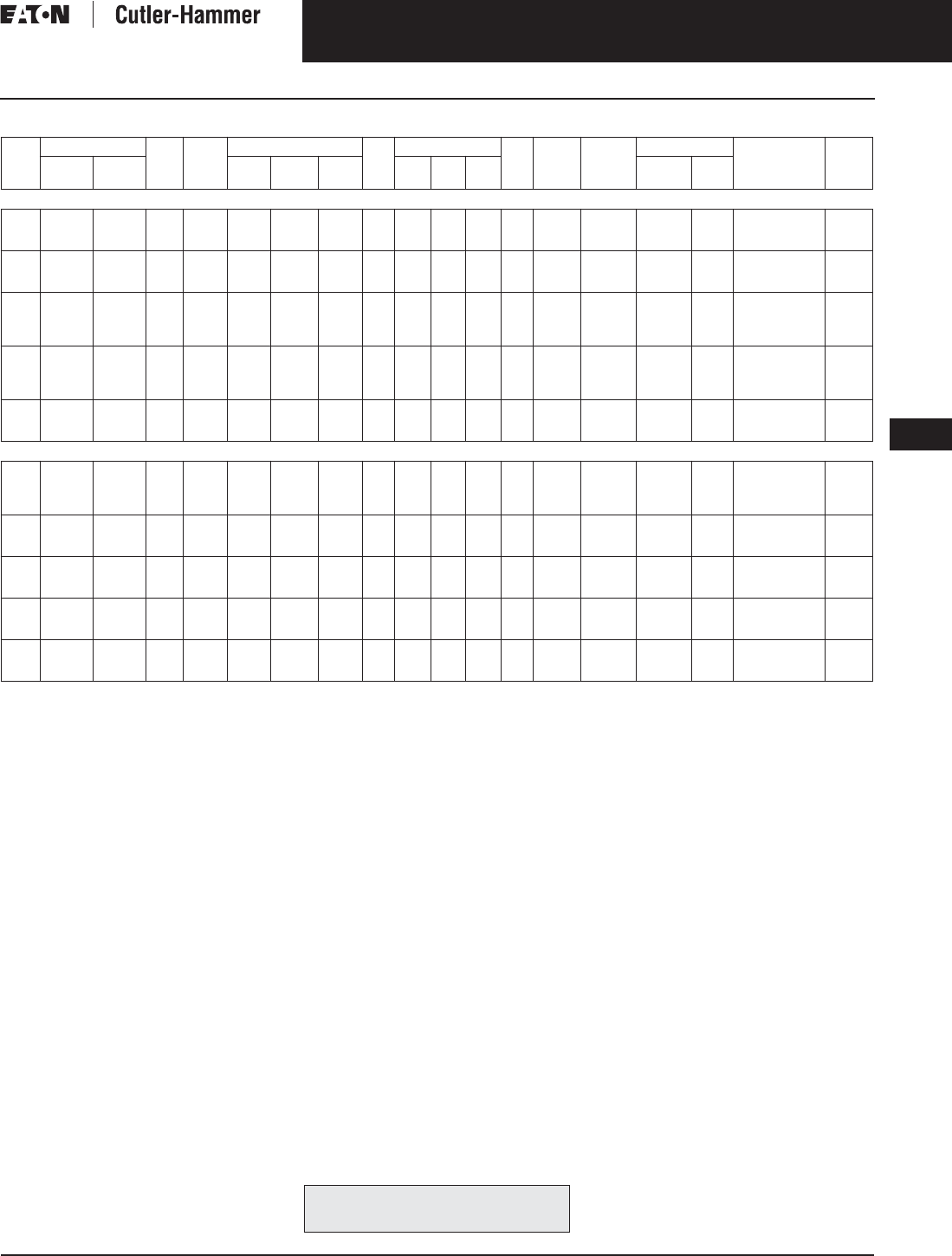
November 2003
CA08101001E For more information visit: www.cutler-hammer.eaton.com
9-15
Transformers
9
General Purpose Transformers
Three-Phase, Types EPT, DT-3, 60 Hz
Vol. 1, Ref. No. [0315]
Table 9-14. Three-Phase Selection Information — Types EPT, DT-3, 60 Hz
Center Tap capacity limited to 5% of rated kVA.
Do not include 120 volt lighting tap.
Refer to your Cutler-Hammer sales office.
Not seismic qualified.
Floor mount only.
Note: Contact your local Cutler-Hammer sales office for CE Mark transformer requirements.
kVA Full Cap. Taps Type °C
Temp.
Rise
Dimensions (Inches) Wt.
Lbs.
Dimensions (mm) Wt.
kg
Frame Wiring
Diagram
Number
Weathershield Style
Number
Price
U.S. $
FCAN FCBN H W D H W D Catalog
Number
Price
U.S. $
480 ∆ Volts to 240 ∆ Volts With 120 Volt Lighting Tap on B Phase
3
6
9
—
—
—
2@-5%
2@-5%
4@-2.5%
EPT
EPT
EPT
115
115
115
13-3/8
15-7/8
15-7/8
16
16-1/2
16-1/2
8-3/8
9-7/8
9-7/8
116
143
166
339
403
403
404
419
419
211
251
251
52
64
75
FR201
FR200
FR103
74A
74A
73A
Indoor-
Outdoor
—
—
—
Y48G24T03N
Y48G24T06N
Y48J24T09N
1,190.
1,450.
1,870.
15
30
45
—
2@+2.5%
2@+2.5%
4@-2.5%
4@-2.5%
4@-2.5%
EPT
EPT
EPT
115
115
115
17-3/8
26-5/8
26-1/2
19-3/4
25-1/4
28-1/2
10-1/2
12-3/4
14-5/8
275
422
660
441
676
673
499
638
723
265
323
371
124
191
299
FR95
FR243
FR244
73A
85A
85A
Indoor-
Outdoor
—
—
—
Y48J24T15N
Y48M24T30N
Y48M24T45N
2,350.
4,480.
5,600.
15
30
45
75
2@+2.5%
2@+2.5%
2@+2.5%
2@+2.5%
4@-2.5%
4@-2.5%
4@-2.5%
4@-2.5%
DT-3
DT-3
DT-3
DT-3
150
150
150
150
25
30-1/8
30-1/8
39-3/8
20-1/8
20-1/8
20-1/8
26-1/8
14-1/8
14-1/8
14-1/8
19-1/8
152
230
310
480
635
765
765
1000
511
511
511
663
359
359
359
486
69
104
140
217
FR909
FR910A
FR912A
FR914B
282B
282B
282B
282B
WS31
WS31
WS31
WS33
350.
350.
350.
350.
V48M22T15B
V48M22T30N
V48M22T45N
V48M22T75N
1,550.
2,000.
2,500.
3,420.
112.5
150
225
300
2@+2.5%
2@+2.5%
2@+2.5%
2@+2.5%
4@-2.5%
4@-2.5%
4@-2.5%
4@-2.5%
DT-3
DT-3
DT-3
DT-3
150
150
150
150
39-3/8
46-1/8
56
62-1/4
26-1/8
28-1/8
31-1/4
31-1/4
19-1/8
23
24-1/4
30-1/4
600
760
1100
1600
1000
1171
1422
1581
663
712
793
794
486
585
616
768
272
344
499
728
FR915B
FR916A
FR917
FR918A
282B
282B
282B
282B
WS33
WS19
WS34
WS34
350.
350.
800.
800.
V48M22T12N
V48M22T49N
V48M22T22N
V48M22T33N
4,900.
6,210.
9,100.
11,500.
500
750
1000
2@+2.5%
2@+2.5%
1@+3.5%
4@-2.5%
4@-2.5%
1@-3.5%
DT-3
DT-3
DT-3
150
150
150
75
75
68
44-1/2
44-1/2
64
36
36
45
2400
2900
4350
1905
1905
1727
1130
1130
1625
914
914
1143
1088
1315
1972
FR919
FR920
291A
291A
WS35
WS35
1,360.
1,360.
—
V48M22T55N
V48M22T77N
V48W22T11N
18,500.
32,600.
53,500.
480 ∆ Volts to 380Y/220 Volts
3
6
9
15
—
—
—
—
2@-5%
2@-5%
2@-5%
2@-5%
EPT
EPT
EPT
EPT
115
115
115
115
13-3/8
15-7/8
15-7/8
17-3/8
15-15/16
16-1/2
16-1/2
19-11/16
8-5/16
9-7/8
9-7/8
10-7/16
116
143
166
275
340
403
403
442
405
419
419
500
211
251
251
265
53
65
75
125
FR201
FR200
FR103
FR95
70R
70R
70R
70R
Indoor-
Outdoor
—
—
—
—
Y48G37T03A
Y48G37T06A
Y48G37T09A
Y48G37T15A
1,590.
1,935.
2,505.
3,150.
30
45
75
2@+2.5%
2@+2.5%
2@+2.5%
4@-2.5%
4@-2.5%
4@-2.5%
EPT
EPT
EPT
115
115
115
26-5/8
26-1/2
32-1/4
25-1/4
28-1/2
30-1/8
12-3/4
14-5/8
15-5/8
422
660
1275
676
673
819
638
724
765
324
372
397
191
299
580
FR243
FR244
FR245
84A
84A
84A
Indoor-
Outdoor
—
—
—
Y48M37T30A
Y48M37T45A
Y48M37T75A
4,600.
5,750.
7,150.
15
30
45
2@+2.5%
2@+2.5%
2@+2.5%
4@-2.5%
4@-2.5%
4@-2.5%
DT-3
DT-3
DT-3
150
150
150
25
30-1/8
30-1/8
20-1/8
20-1/8
20-1/8
14-1/8
14-1/8
14-1/8
152
230
310
635
765
765
511
511
511
359
359
359
69
104
141
FR909
FR910A
FR912A
280B
280B
280B
WS31
WS31
WS31
350.
350.
350.
V48M37T15A
V48M37T30A
V48M37T45A
1,800.
2,000.
2,500.
75
112.5
150
2@+2.5%
2@+2.5%
2@+2.5%
4@-2.5%
4@-2.5%
4@-2.5%
DT-3
DT-3
DT-3
150
150
150
39-3/8
39-3/8
46-1/8
26-1/8
26-1/8
28
19-1/8
19-1/8
23
480
600
760
1000
1000
1171
664
664
712
486
486
585
218
273
345
FR914B
FR915B
FR916A
280B
280B
280B
WS33
WS33
WS19
350.
350.
350.
V48M37T75A
V48M37T12A
V48M37T49A
3,400.
4,900.
6,850.
225
300
500
2@+2.5%
2@+2.5%
2@+2.5%
4@-2.5%
4@-2.5%
4@-2.5%
DT-3
DT-3
DT-3
150
150
150
56
62-1/4
75
31-1/4
31-1/4
44-1/2
24-1/4
30-1/4
36
1100
1600
2400
1422
1581
1905
794
794
1130
616
768
914
499
728
1088
FR917
FR918A
FR919
280B
280B
275A
WS34
WS34
WS35
800.
800.
1,360.
V48M37T22A
V48M37T33A
V48M37T55A
9,100.
11,500.
18,500.
For other ratings or styles not shown, or for
special enclosure types (including stainless
steel) refer to Eaton’s Cutler-Hammer business. Discount Symbol . . . . . . . . . . . . . . . . . . . . . . . . . DT-1

November 2003
9-16
For more information visit: www.cutler-hammer.eaton.com CA08101001E
Transformers
9
General Purpose Transformers
Three-Phase, Types EPT, DT-3, 60 Hz Vol. 1, Ref. No. [0316]
Table 9-15. Three-Phase Selection Information — Types EPT, DT-3, 60 Hz
Floor mount only.
Refer to your Cutler-Hammer sales office.
Note: Contact your local Cutler-Hammer sales office for CE Mark transformer requirements.
kVA Full Cap. Taps Type °C
Temp.
Rise
Dimensions (Inches) Wt.
Lbs.
Dimensions (mm) Wt.
kg
Frame Wiring
Diagram
Number
Weathershield Style
Number
Price
U.S. $
FCAN FCBN H W D H W D Catalog
Number
Price
U.S. $
480 ∆ Volts to 380 ∆ Volts
3
6
9
15
—
—
—
—
2@-5%
2@-5%
2@-5%
2@-5%
EPT
EPT
EPT
EPT
115
115
115
115
13-3/8
15-7/8
15-7/8
17-3/8
15-15/16
16-1/2
16-1/2
19-11/16
8-5/16
9-7/8
9-7/8
10-7/16
116
143
166
275
340
403
403
442
405
419
419
500
211
251
251
265
53
65
75
125
FR201
FR200
FR103
FR95
74B
74B
74B
74B
Indoor-
Outdoor
—
—
—
—
Y48G38T03A
Y48G38T06A
Y48G38T09A
Y48G38T15A
1,590.
1,935.
2,505.
3,150.
30
45
75
2@+2.5%
2@+2.5%
2@+2.5%
4@-2.5%
4@-2.5%
4@-2.5%
EPT
EPT
EPT
115
115
115
26-5/8
26-1/2
32-1/4
25-1/4
28-1/2
30-1/8
12-3/4
14-5/8
15-5/8
422
660
1275
676
673
819
638
724
765
324
372
397
191
299
580
FR243
FR244
FR245
85A
85A
85A
Indoor-
Outdoor
—
—
—
Y48M38T30A
Y48M38T45A
Y48M38T75A
4,600.
5,750.
7,150.
15
30
45
2@+2.5%
2@+2.5%
2@+2.5%
4@-2.5%
4@-2.5%
4@-2.5%
DT-3
DT-3
DT-3
150
150
150
25
30-1/8
30-1/8
20-1/8
20-1/8
20-1/8
14-1/8
14-1/8
14-1/8
152
230
310
635
765
765
511
511
511
359
359
359
69
104
141
FR909
FR910A
FR912A
281B
281B
281B
WS31
WS31
WS31
350.
350.
350.
V48M38T15A
V48M38T30A
V48M38T45A
1,500.
2,000.
2,500.
75
112.5
150
2@+2.5%
2@+2.5%
2@+2.5%
4@-2.5%
4@-2.5%
4@-2.5%
DT-3
DT-3
DT-3
150
150
150
39-3/8
39-3/8
46-1/8
26-1/8
26-1/8
28
19-1/8
19-1/8
23
480
600
760
1000
1000
1171
664
664
712
486
486
585
218
273
345
FR914B
FR915B
FR916A
281B
281B
281B
WS33
WS33
WS19
350.
350.
350.
V48M38T75A
V48M38T12A
V48M38T49A
3,400.
4,900.
6,850.
225
300
500
2@+2.5%
2@+2.5%
2@+2.5%
4@-2.5%
4@-2.5%
4@-2.5%
DT-3
DT-3
DT-3
150
150
150
56
62-1/4
75
31-1/4
31-1/4
44-1/2
24-1/4
30-1/4
36
1100
1600
2400
1422
1581
1905
794
794
1130
616
768
914
499
728
1088
FR917
FR918A
FR919
281B
281B
274B
WS34
WS34
WS35
800.
800.
1,360.
V48M38T22A
V48M38T33A
V48M38T55A
9,100.
11,500.
18,500.
480 ∆ Volts to 416Y/240 Volts
3
6
9
15
—
—
—
—
2@-5%
2@-5%
2@-5%
2@-5%
EPT
EPT
EPT
EPT
115
115
115
115
13-3/8
15-7/8
15-7/8
17-3/8
15-15/16
16-1/2
16-1/2
19-11/16
8-5/16
9-7/8
9-7/8
10-7/16
116
143
166
275
340
403
403
442
405
419
419
500
211
251
251
265
53
65
75
125
FR201
FR200
FR103
FR95
70A
70A
70A
70A
Indoor-
Outdoor
—
—
—
—
Y48G51T03A
Y48G51T06A
Y48G51T09A
Y48G51T15A
1,590.
1,935.
2,505.
3,150.
30
45
75
2@+2.5%
2@+2.5%
2@+2.5%
4@-2.5%
4@-2.5%
4@-2.5%
EPT
EPT
EPT
115
115
115
26-5/8
26-1/2
32-1/4
25-1/4
28-1/2
30-1/8
12-3/4
14-5/8
15-5/8
422
660
1275
676
673
819
638
724
765
324
372
397
191
299
580
FR243
FR244
FR245
84E
84E
84E
Indoor-
Outdoor
—
—
—
Y48M51T30A
Y48M51T45A
Y48M51T75A
4,600.
5,750.
7,150.
15
30
45
2@+2.5%
2@+2.5%
2@+2.5%
4@-2.5%
4@-2.5%
4@-2.5%
DT-3
DT-3
DT-3
150
150
150
25
30-1/8
30-1/8
20-1/8
20-1/8
20-1/8
14-1/8
14-1/8
14-1/8
152
230
310
635
765
765
511
511
511
359
359
359
69
104
141
FR909
FR910A
FR912A
280B
280B
280B
WS31
WS31
WS31
350.
350.
350.
V48M51T15A
V48M51T30A
V48M51T45A
2,110.
2,350.
2,940.
75
112.5
150
2@+2.5%
2@+2.5%
2@+2.5%
4@-2.5%
4@-2.5%
4@-2.5%
DT-3
DT-3
DT-3
150
150
150
39-3/8
39-3/8
46-1/8
26-1/8
26-1/8
28
19-1/8
19-1/8
23
480
600
760
1000
1000
1171
664
664
712
486
486
585
218
273
345
FR914B
FR915B
FR916A
280B
280B
280B
WS33
WS33
WS19
350.
350.
350.
V48M51T75A
V48M51T12A
V48M51T49A
4,000.
5,750.
8,040.
225
300
500
2@+2.5%
2@+2.5%
2@+2.5%
4@-2.5%
4@-2.5%
4@-2.5%
DT-3
DT-3
DT-3
150
150
150
56
62-1/4
75
31-1/4
31-1/4
44-1/2
24-1/4
30-1/4
36
1100
1600
2400
1422
1581
1905
794
794
1130
616
768
914
499
728
1088
FR917
FR918A
FR919
280B
280B
275A
WS34
WS34
WS35
800.
800.
1,360.
V48M51T22A
V48M51T33A
V48M51T55A
10,680.
13,500.
21,700.
480 ∆ Volts to 440Y/254 Volts
3
6
9
15
—
—
—
—
2@-5%
2@-5%
2@-5%
2@-5%
EPT
EPT
EPT
EPT
115
115
115
115
13-3/8
15-7/8
15-7/8
17-3/8
15-15/16
16-1/2
16-1/2
19-11/16
8-5/16
9-7/8
9-7/8
10-7/16
116
143
166
275
340
403
403
442
405
419
419
500
211
251
251
265
53
65
75
125
FR201
FR200
FR103
FR95
Indoor-
Outdoor
—
—
—
—
Y48G35T03A
Y48G35T06A
Y48G35T09A
Y48G35T15A
1,590.
1,935.
2,505.
3,150.
30
45
75
2@+2.5%
2@+2.5%
2@+2.5%
4@-2.5%
4@-2.5%
4@-2.5%
EPT
EPT
EPT
115
115
115
26-5/8
26-1/2
32-1/4
25-1/4
28-1/2
30-1/8
12-3/4
14-5/8
15-5/8
422
660
1275
676
673
819
638
724
765
324
372
397
191
299
580
FR243
FR244
FR245
84A
84A
84A
Indoor-
Outdoor
—
—
—
Y48M35T30A
Y48M35T45A
Y48M35T75A
4,600.
5,750.
7,150.
15
30
45
2@+2.5%
2@+2.5%
2@+2.5%
4@-2.5%
4@-2.5%
4@-2.5%
DT-3
DT-3
DT-3
150
150
150
25
30-1/8
30-1/8
20-1/8
20-1/8
20-1/8
14-1/8
14-1/8
14-1/8
152
230
310
635
765
765
511
511
511
359
359
359
69
104
141
FR909
FR910A
FR912A
280B
280B
280B
WS31
WS31
WS31
350.
350.
350.
V48M35T15A
V48M35T30A
V48M35T45A
1,800.
2,000.
2,500.
75
112.5
150
2@+2.5%
2@+2.5%
2@+2.5%
4@-2.5%
4@-2.5%
4@-2.5%
DT-3
DT-3
DT-3
150
150
150
39-3/8
39-3/8
46-1/8
26-1/8
26-1/8
28
19-1/8
19-1/8
23
480
600
760
1000
1000
1171
664
664
712
486
486
585
218
273
345
FR914B
FR915B
FR916A
280B
280B
280B
WS33
WS33
WS19
350.
350.
350.
V48M35T75A
V48M35T12A
V48M35T49A
3,400.
4,900.
6,850.
225
300
500
2@+2.5%
2@+2.5%
2@+2.5%
4@-2.5%
4@-2.5%
4@-2.5%
DT-3
DT-3
DT-3
150
150
150
56
62-1/4
75
31-1/4
31-1/4
44-1/2
24-1/4
30-1/4
36
1100
1600
2400
1422
1581
1905
794
794
1130
616
768
914
499
728
1088
FR917
FR918A
FR919
280B
280B
WS34
WS34
WS35
800.
800.
1,360.
V48M35T22A
V48M35T33A
V48M35T55A
9,100.
11,500.
18,500.
For other ratings or styles not shown, or for
special enclosure types (including stainless
steel) refer to Eaton’s Cutler-Hammer business. Discount Symbol . . . . . . . . . . . . . . . . . . . . . . . . . DT-1

November 2003
CA08101001E For more information visit: www.cutler-hammer.eaton.com
9-17
Transformers
9
General Purpose Transformers
Three-Phase, Types EPT, DT-3, 60 Hz
Vol. 1, Ref. No. [0317]
Table 9-16. Three-Phase Selection Information — Types EPT, DT-3, 60 Hz
No UL label. Contact your local Cutler-Hammer sales office if UL label is required.
Refer to your Cutler-Hammer sales office.
NEMA 3R enclosure and/or UL label available at an additional cost. Specify at time of order entry if required.
Not seismic qualified.
Note: Contact your local Cutler-Hammer sales office for CE Mark transformer requirements.
kVA Full Cap. Taps Type °C
Temp.
Rise
Dimensions (Inches) Wt.
Lbs.
Dimensions (mm) Wt.
kg
Frame Wiring
Diagram
Number
Weathershield Style
Number
Price
U.S. $
FCAN FCBN H W D H W D Catalog
Number
Price
U.S. $
480 ∆ Volts to 480Y/277 Volts
9
15
30
45
2@+2.5%
2@+2.5%
2@+2.5%
2@+2.5%
2@-2.5%
2@-2.5%
4@-2.5%
4@-2.5%
EPT
EPT
EPT
EPT
115
115
115
115
15-7/8
17-3/8
26-5/8
26-1/2
16-1/2
19-3/4
25-1/4
28-1/2
9-7/8
10-1/2
12-3/4
14-5/8
166
275
422
660
403
441
676
673
419
499
638
723
251
265
323
371
75
124
191
299
FR103
FR95
FR243
FR244
72C
72C
84D
84D
Indoor-
Outdoor
—
—
—
—
Y48D47T09N
Y48D47T15N
Y48M47T30N
Y48M47T45N
2,170.
2,730.
5,200.
6,500.
15
30
45
75
2@+2.5%
2@+2.5%
2@+2.5%
2@+2.5%
4@-2.5%
4@-2.5%
4@-2.5%
4@-2.5%
DT-3
DT-3
DT-3
DT-3
150
150
150
150
25
30-1/8
30-1/8
39-3/8
20-1/8
20-1/8
20-1/8
26-1/8
14-1/8
14-1/8
14-1/8
19-1/8
152
230
310
480
635
765
765
1000
511
511
511
663
359
359
359
486
69
104
140
217
FR909
FR910A
FR912A
FR914B
280B
280B
280B
280B
WS31
WS31
WS31
WS33
350.
350.
350.
350.
V48M47T15B
V48M47T30N
V48M47T45G
V48M47T75F
1,830.
2,330.
2,840.
4,010.
112.5
150
225
2@+2.5%
2@+2.5%
2@+2.5%
4@-2.5%
4@-2.5%
4@-2.5%
DT-3
DT-3
DT-3
150
150
150
39-3/8
46-1/8
56
26-1/8
28
31-1/4
19-1/8
23
24-1/4
600
760
1100
1000
1171
1422
663
712
793
486
585
616
272
344
499
FR915B
FR916A
FR917
280B
280B
280B
WS33
WS19
WS34
350.
350.
800.
V48M47T12E
V48M47T49F
V48M47T22F
5,810.
7,290.
10,670.
300
500
750
2@+2.5%
2@+2.5%
2@+2.5%
4@-2.5%
4@-2.5%
4@-2.5%
DT-3
DT-3
DT-3
150
150
150
62-1/4
75
75
31-1/4
44-1/2
44-1/2
30-1/4
36
36
1600
2400
2900
1581
1905
1905
794
1130
1130
768
914
914
728
1088
1315
FR918A
FR919
FR920
280B
275A
275A
WS34
WS35
WS35
800.
1,360.
1,360.
V48M47T33E
V48M47T55F
V48M47T77A
13,500.
21,600.
35,100.
600 ∆ Volts to 208Y/120 Volts
9
15
30
45
—
—
2@+2.5%
2@+2.5%
2@-5%
2@-5%
4@-2.5%
4@-2.5%
EPT
EPT
EPT
EPT
115
115
115
115
15-7/8
17-3/8
26-5/8
26-1/2
16-1/2
19-3/4
25-1/4
28-1/2
9-7/8
10-1/2
12-3/4
14-5/8
166
275
422
660
403
441
676
673
419
499
638
723
251
265
323
371
75
124
191
299
FR103
FR95
FR243
FR244
70B
70B
84B
84B
Indoor-
Outdoor
—
—
—
—
Y60G28T09N
Y60G28T15N
Y60M28T30N
Y60M28T45N
2,000.
2,520.
4,800.
6,000.
15
30
45
2@+2.5%
2@+2.5%
2@+2.5%
4@-2.5%
4@-2.5%
4@-2.5%
DT-3
DT-3
DT-3
150
150
150
25
30-1/8
30-1/8
20-1/8
20-1/8
20-1/8
14-1/8
14-1/8
14-1/8
152
230
310
635
765
765
511
511
511
359
359
359
69
104
140
FR909
FR910A
FR912A
280A
280A
280A
WS31
WS31
WS31
350.
350.
350.
V60M28T15A
V60M28T30N
V60M28T45H
2,390.
2,390.
2,990.
75
112.5
150
2@+2.5%
2@+2.5%
2@+2.5%
4@-2.5%
4@-2.5%
4@-2.5%
DT-3
DT-3
DT-3
150
150
150
39-3/8
39-3/8
46-1/8
26-1/8
26-1/8
28
19-1/8
19-1/8
23
480
600
760
1000
1000
1171
663
663
712
486
486
585
217
272
344
FR914B
FR915B
FR916A
280A
280A
280A
WS33
WS33
WS19
350.
350.
350.
V60M28T75G
V60M28T12F
V60M28T49F
4,061.
5,860.
8,190.
225
300
500
2@+2.5%
2@+2.5%
2@+2.5%
4@-2.5%
4@-2.5%
4@-2.5%
DT-3
DT-3
DT-3
150
150
150
56
62-1/4
75
31-1/4
31-1/4
44-1/2
24-1/4
30-1/4
36
1100
1600
2400
1422
1581
1905
793
794
1130
616
768
914
499
728
1088
FR917
FR918A
FR919
280A
280A
275C
WS34
WS34
WS35
800.
800.
1,360.
V60M28T22G
V60M28T33F
V60M28T55A
10,870.
13,740.
22,100.
600 ∆ Volts to 240 ∆ Volts
30
45
2@+2.5%
2@+2.5%
4@-2.5%
4@-2.5%
EPT
EPT
115
115
26-5/8
26-1/2
25-1/4
28-1/2
12-3/4
14-5/8
422
660
676
673
638
723
323
371
191
299
FR243
FR244
85B
85B
Indoor-
Outdoor
—
—
Y60M24T30N
Y60M24T45N
5,000.
6,250.
15
30
45
2@+2.5%
2@+2.5%
2@+2.5%
4@-2.5%
4@-2.5%
4@-2.5%
DT-3
DT-3
DT-3
150
150
150
25
30-1/8
30-1/8
20-1/8
20-1/8
20-1/8
14-1/8
14-1/8
14-1/8
152
230
310
635
765
765
511
511
511
359
359
359
69
104
140
FR909
FR910A
FR912A
281A
281A
281A
WS31
WS31
WS31
350.
350.
350.
V60M24T15A
V60M24T30A
V60M24T45H
2,390.
2,390.
2,990.
75
112.5
150
2@+2.5%
2@+2.5%
2@+2.5%
4@-2.5%
4@-2.5%
4@-2.5%
DT-3
DT-3
DT-3
150
150
150
39-3/8
39-3/8
46-1/8
26-1/8
26-1/8
28
19-1/8
19-1/8
23
480
600
760
1000
1000
1171
663
663
712
486
486
585
217
272
344
FR914B
FR915B
FR916A
281A
281A
281A
WS33
WS33
WS19
350.
350.
350.
V60M24T75G
V60M24T12E
V60M24T49F
4,061.
5,860.
8,190.
225
300
500
2@+2.5%
2@+2.5%
2@+2.5%
4@-2.5%
4@-2.5%
4@-2.5%
DT-3
DT-3
DT-3
150
150
150
56
62-1/4
75
31-1/4
31-1/4
44-1/2
24-1/4
30-1/4
36
1100
1600
2400
1422
1581
1905
793
794
1130
616
768
914
499
728
1088
FR917
FR918A
FR919
281A
281A
274A
WS34
WS34
WS35
800.
800.
1,360.
V60M24T22G
V60M24T33F
V60M24T55A
10,870.
13,740.
22,100.
2400 ∆ Volts to 208Y/120 Volts
3
6
9
2@+2.5%
2@+2.5%
2@+2.5%
2@-2.5%
2@-2.5%
2@-2.5%
EPT
EPT
EPT
115
115
115
10
11
12
18-7/8
25
29
6-1/2
7-1/2
8-1/2
115
160
210
254
279
305
479
635
737
165
191
216
52
73
95
FR102
FR97
FR96
65B
65B
65B
Recom-
ended
Indoor
Only
—
Y42D28T03N
Y42D28T06N
Y42D28T09N
5,630.
6,450.
8,070.
15
30
2@+2.5%
2@+2.5%
2@-2.5%
2@-2.5%
EPT
EPT
115
115
18-1/2
27-11/16
21
20-11/16
10-1/2
12
340
475
470
703
533
525
267
305
154
216
FR195
FR196
65B
65B
Recom-
ended
Indoor
Only
—
—
Y42D28T15N
Y42D28T30N
10,200.
13,400.
45
75
112.5
2@+2.5%
2@+2.5%
2@+2.5%
2@-2.5%
2@-2.5%
2@-2.5%
DT-3
DT-3
DT-3
150
150
150
32-1/2
32-1/2
36
30
30
33
24
24
26
460
620
800
826
902
914
762
762
838
610
610
660
209
282
364
Recom-
ended
Indoor
Only
—
—
—
V42D28T45G
V42D28T75H
V42D28T12H
7,500.
8,950.
9,450.
150
225
300
2@+2.5%
2@+2.5%
2@+2.5%
2@-2.5%
2@-2.5%
2@-2.5%
DT-3
DT-3
DT-3
150
150
150
36
50
51
33
39-3/4
39-3/4
26
37
37
980
1450
1620
914
1270
1010
838
1010
1010
660
940
940
445
659
736
Recom-
ended
Indoor
Only
—
—
—
V42D28T49K
V42D28T22J
V42D28T33J
11,400.
15,600.
21,000.
500
750
1000
2@+2.5%
2@+2.5%
2@+2.5%
2@-2.5%
2@-2.5%
2@-2.5%
DT-3
DT-3
DT-3
150
150
150
59
75
90
48-3/4
44-1/2
69
41
36
42
2400
3300
4500
1238
1905
2286
1238
1130
1753
1041
914
1067
1091
1498
2043
FR920
FR922
266A
266A
Recom-
ended
Indoor
Only
—
—
—
V42D28T55G
V42D28T77
V42D28T11
32,000.
42,000.
52,000.
For other ratings or styles not shown, or for
special enclosure types (including stainless
steel) refer to Eaton’s Cutler-Hammer business. Discount Symbol . . . . . . . . . . . . . . . . . . . . . . . . . DT-1

November 2003
9-18
For more information visit: www.cutler-hammer.eaton.com CA08101001E
Transformers
9
General Purpose Transformers
Three-Phase, Types EPT, DT-3, 60 Hz Vol. 1, Ref. No. [0318]
Table 9-17. Three-Phase Selection Information — Types EPT, DT-3, 60 Hz
NEMA 3R enclosure and/or UL label available at additional cost. Specify at time of order entry if required.
Not seismic qualified.
Refer to your Cutler-Hammer sales office.
No UL label.
kVA Full Cap. Taps Type °C
Temp.
Rise
Dimensions (Inches) Wt.
Lbs.
Dimensions (mm) Wt.
kg
Frame Wiring
Diagram
Number
Weathershield Style
Number
Price
U.S. $
FCAN FCBN H W D H W D Catalog
Number
Price
U.S. $
2400 ∆ Volts to 480Y/277 Volts
45
75
112.5
2@+2.5%
2@+2.5%
2@+2.5%
2@-2.5%
2@-2.5%
2@-2.5%
DT-3
DT-3
DT-3
150
150
150
32-1/2
32-1/2
36
30
30
33
24
24
26
460
620
800
826
902
914
762
762
838
610
610
660
209
282
364
Recom-
mended
Indoor
Only
—
—
—
V42D47T45G
V42D47T75F
V42D47T12F
7,500.
8,950.
9,450.
150
225
300
2@+2.5%
2@+2.5%
2@+2.5%
2@-2.5%
2@-2.5%
2@-2.5%
DT-3
DT-3
DT-3
150
150
150
36
50
51
33
39-3/4
39-3/4
26
37
37
980
1450
1620
914
1270
1010
838
1010
1010
660
940
940
445
659
736
Recom-
mended
Indoor
Only
—
—
—
V42D47T49G
V42D47T22H
V42D47T33G
11,400.
15,600.
21,000.
500
750
1000
2@+2.5%
2@+2.5%
2@+2.5%
2@-2.5%
2@-2.5%
2@-2.5%
DT-3
DT-3
DT-3
150
150
150
59
48-3/4
41
2400
1238
1238
1041
1091
Recom-
mended
Indoor
Only
—
—
—
V42D47T55H
V42D47T77
V42D47T11A
32,000.
42,000.
52,000.
4160 ∆ Volts to 208Y/120 Volts
3
6
9
2@+2.5%
2@+2.5%
2@+2.5%
2@-2.5%
2@-2.5%
2@-2.5%
EPT
EPT
EPT
115
115
115
10
11
12
18-7/8
25
29
6-1/2
7-1/2
8-1/2
115
160
210
254
279
305
479
635
737
165
191
216
52
73
95
FR102
FR97
FR96
65C
65C
65C
Recom-
mended
Indoor
Only
—
—
—
Y46D28T03N
Y46D28T06N
Y46D28T09N
5,800.
6,450.
8,070.
15
30
2@+2.5%
2@+2.5%
2@-2.5%
2@-2.5%
EPT
EPT
115
115
18-1/2
27-11/16
21
20-11/16
10-1/2
12
340
475
470
703
533
525
267
305
154
216
FR195
FR196
65C
65C
Recom-
mended
Indoor
Only
—
—
Y46D28T15N
Y46D28T30N
10,200.
13,400.
45
75
112.5
150
2@+2.5%
2@+2.5%
2@+2.5%
2@+2.5%
2@-2.5%
2@-2.5%
2@-2.5%
2@-2.5%
DT-3
DT-3
DT-3
DT-3
150
150
150
150
32-1/2
32-1/2
36
36
30
30
33
33
24
24
26
26
460
620
800
980
826
902
914
914
762
762
838
838
610
610
660
660
209
282
364
445
Recom-
mended
Indoor
Only
—
—
—
—
V46D28T45H
V46D28T75H
V46D28T12H
V46D28T49K
7,500.
8,950.
9,450.
11,400.
225
300
500
2@+2.5%
2@+2.5%
2@+2.5%
2@-2.5%
2@-2.5%
2@-2.5%
DT-3
DT-3
DT-3
150
150
150
50
51
59
39-3/4
39-3/4
48-3/4
37
37
41
1450
1620
2400
1270
1010
1238
1010
1010
1238
940
940
1041
659
736
1091
Recom-
mended
Indoor
Only
—
—
—
V46D28T22J
V46D28T33J
V46D28T55H
15,600.
21,000.
32,000.
750
1000
1500
2@+2.5%
2@+2.5%
2@+2.5%
2@-2.5%
2@-2.5%
2@-2.5%
DT-3
DT-3
DT-3
150
150
150
Recom-
mended
Indoor
Only
—
—
—
V46D28T77
V46D28T11
V46D28T14
42,000.
52,000.
65,000.
4160 ∆ Volts to 240 ∆ Volts
45
75
112.5
2@+2.5%
2@+2.5%
2@+2.5%
2@-2.5%
2@-2.5%
2@-2.5%
DT-3
DT-3
DT-3
150
150
150
32-1/2
32-1/2
36
30
30
33
24
24
26
460
620
800
826
902
914
762
762
838
610
610
660
209
282
364
Recom-
mended
Indoor
Only
—
—
—
V46D24T45F
V46D24T75F
V46D24T12F
7,500.
8,950.
9,450.
150
225
300
2@+2.5%
2@+2.5%
2@+2.5%
2@-2.5%
2@-2.5%
2@-2.5%
DT-3
DT-3
DT-3
150
150
150
36
50
51
33
39-3/4
39-3/4
26
37
37
980
1450
1620
914
1270
1010
838
1010
1010
660
940
940
445
659
736
Recom-
mended
Indoor
Only
—
—
—
V46D24T49H
V46D24T22G
V46D24T33G
11,400.
15,600.
21,000.
500
750
1000
2@+2.5%
2@+2.5%
2@+2.5%
2@-2.5%
2@-2.5%
2@-2.5%
DT-3
DT-3
DT-3
150
150
150
59
48-3/4
41
2400
1238
1238
1041
1091
—
—
Recom-
mended
Indoor
Only
—
—
—
V46D24T55B
V46D24T77
V46D24T11A
32,000.
42,000.
52,000.
4160 ∆ Volts to 480Y/277 Volts
45
75
112.5
2@+2.5%
2@+2.5%
2@+2.5%
2@-2.5%
2@-2.5%
2@-2.5%
DT-3
DT-3
DT-3
150
150
150
32-1/2
32-1/2
36
30
30
33
24
24
26
460
620
800
826
902
914
762
762
838
610
610
660
209
282
364
Recom-
mended
Indoor
Only
—
—
—
V46D47T45G
V46D47T75G
V46D47T12G
7,500.
8,950.
9,450.
150
225
300
2@+2.5%
2@+2.5%
2@+2.5%
2@-2.5%
2@-2.5%
2@-2.5%
DT-3
DT-3
DT-3
150
150
150
36
50
51
33
39-3/4
39-3/4
26
37
37
980
1450
1620
914
1270
1010
838
1010
1010
660
940
940
445
659
736
Recom-
mended
Indoor
Only
—
—
—
V46D47T49J
V46D47T22H
V46D47T33H
11,400.
15,600.
21,000.
500
750
1000
2@+2.5%
2@+2.5%
2@+2.5%
2@-2.5%
2@-2.5%
2@-2.5%
DT-3
DT-3
DT-3
150
150
150
59
48-3/4
41
2400
1238
1238
1041
1091
Recom-
mended
Indoor
Only
—
—
—
V46D47T55H
V46D47T77
V46D47T11
32,000.
42,000.
52,000.
1500 2@+2.5% 2@-2.5% DT-3 150
—
V46D47T14F 65,000.
For other ratings or styles not shown, or for
special enclosure types (including stainless
steel) refer to Eaton’s Cutler-Hammer business. Discount Symbol . . . . . . . . . . . . . . . . . . . . . . . . DT-1
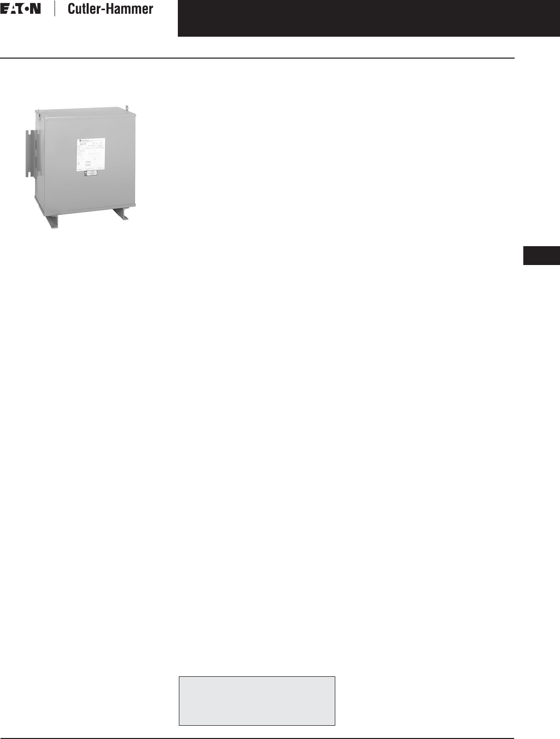
November 2003
CA08101001E For more information visit: www.cutler-hammer.eaton.com
9-19
Transformers
9
General Purpose Transformers
Three-Phase, Types EPT, DT-3, 50/60 Hz
Vol. 1, Ref. No. [0319]
Three-Phase, Types EPT,
DT-3, 50/60 Hz
Type EPT Encapsulated
Product Description
Type EPT
■Sand and Resin Encapsulated design.
■Suitable for indoor or outdoor
applications.
■Totally enclosed, non-ventilated
enclosures.
■Enclosures are NEMA 3R rated.
■Mountable in any position indoors
and upright only outdoors.
■185ºC Insulation System, 115ºC rise
standard.
■Available in ratings through 75 kVA
and 4160 volts primary.
Type DT-3
■Ventilated, NEMA 2 enclosure
standard.
■Suitable for indoor applications,
outdoors when weathershields are
also installed.
■Upright mounting only.
■220ºC Insulation System, 150ºC rise
standard.
■Available in three-phase ratings
15 – 1500 kVA and up to 4160 volts
primary.
Application Description
The basic purpose of a transformer
is voltage transformation as near as
practically possible to the load for
economy and distribution of power.
Typical loads for dry-type distribution
transformers include lighting, heating,
air conditioners, fans and machine
tools. Such loads are found in com-
mercial, institutional, industrial and
residential structures.
Features, Benefits
and Functions
■UL listed.
■60 Hz operation standard,
50/60 Hz operation available.
■Short-term overload capability
as required by ANSI.
■Meet NEMA ST-20 sound levels.
Standards and Certifications
Industry Standards
All Cutler-Hammer dry-type distribu-
tion and control transformers are built
and tested in accordance with applica-
ble NEMA, ANSI and IEEE Standards.
All 600 volt class transformers are UL
listed unless otherwise noted.
Seismically Qualified
Cutler-Hammer manufactured dry-type
distribution transformers are seismi-
cally qualified, and exceed require-
ments of the Uniform Building Code
(UBC) and California Code Title 24.
Options and Accessories
Please refer to Page 9-120.
Product Specifications
Frequency
Cutler-Hammer standard dry-type dis-
tribution transformers are designed
for 60 Hertz operation. Transformers
required for other frequencies are
available and must be specifically
designed.
Overload Capability
Short-term overload is designed into
transformers as required by ANSI.
dry-type distribution transformers
will deliver 200% nameplate load for
one-half hour; 150% load for one hour;
and 125% load for four hours without
being damaged provided that a con-
stant 50% load precedes and follows
the overload. See ANSI C57.96-01.250
for additional limitations.
Continuous overload capacity is not
deliberately designed into a trans-
former because the design objective is
to be within the allowed winding tem-
perature rise with nameplate loading.
The following pages provide listings for most
standard transformer ratings and styles.
For other ratings or styles not shown, or for
special enclosure types (including stainless
steel) refer to Eaton’s Cutler-Hammer business.

November 2003
9-20
For more information visit: www.cutler-hammer.eaton.com CA08101001E
Transformers
9
General Purpose Transformers
Three-Phase, Types EPT, DT-3, 50/60 Hz Vol. 1, Ref. No. [0320]
Insulation System and Temperature Rise
Industry standards classify insulation
systems and rise as shown below:
Table 9-18. Insulation System Classification
The design life of transformers having
different insulation systems is the
same — the lower temperature systems
are designed for the same life as the
higher temperature systems.
Enclosures
Eaton’s Cutler-Hammer ventilated
transformers, Type DT-3, utilize a
NEMA 2 rated (drip-proof) enclosure
as standard, and are rated NEMA 3R
with the addition of weathershields.
Cutler-Hammer encapsulated trans-
formers, Type EPT, utilize a NEMA 3R
rated enclosure as standard.
Sound Levels
All Cutler-Hammer 600 volt class gen-
eral purpose dry-type distribution
transformers are designed to meet
NEMA ST-20 sound levels listed here.
These are the sound levels measured
in a soundproof environment. Actual
sound levels measured at an installa-
tion will likely be higher due to electri-
cal connections and environmental
conditions. Lower sound levels are
available and should be specified
when the transformer is going to
be installed in an area where sound
may be a concern.
Table 9-19. Average Sound Levels
Applies to general purpose ventilated
transformers only.
Winding Terminations
Primary and secondary windings are
terminated in the wiring compartment.
Encapsulated units have copper leads
or stabs brought out for connections.
Ventilated transformers have leads
brought out to aluminum pads that
are pre-drilled to accept Cu/Al lugs.
Lugs are not supplied with these
transformers. The Cutler-Hammer
business recommends external cables
be rated 90°C (sized at 75°C ampacity)
for encapsulated designs and 75°C for
ventilated designs.
Series-Multiple Windings
Series-multiple windings consist of
2 similar coils in each winding which
can be connected in series or parallel
(multiple). Transformers with series-
multiple windings are designated with
an “X” or “/” between the voltage
ratings, such as voltages of “120/240”
or “240 X 480.” If the series-multiple
winding is designated by an “X,” the
winding can be connected only for a
series or parallel. With the “/” designa-
tion, a mid-point also becomes avail-
able in addition to the series or parallel
connection. As an example, a 120 X
240 winding can be connected for
either 120 (parallel) or 240 (series), but
a 120/240 winding can be connected
for 120 (parallel), or 240 (series), or
240 with a 120 mid-point.
Technical Data
and Specifications
Please refer to Page 9-122.
Ambient +
Winding
Rise
+
Hot
Spot
=
Temp.
Class
40°C
40°C
40°C
40°C
55°C
80°C
115°C
150°C
10°C
30°C
30°C
30°C
105°C
150°C
185°C
220°C
NEMA ST-20 Average Sound Level (dB)
kVA Ventilated Encapsulated
0 – 9
10 – 50
51 – 150
151 – 300
40
45
50
55
45
50
55
57
301 – 500
501 – 700
701 – 1000
1001 – 1500
60
62
64
65
59
61
63
64
The following pages provide listings for most
standard transformer ratings and styles.
For other ratings or styles not shown, or for
special enclosure types (including stainless
steel) refer to Eaton’s Cutler-Hammer business.

November 2003
CA08101001E For more information visit: www.cutler-hammer.eaton.com
9-21
Transformers
9
General Purpose Transformers
Three-Phase, Types EPT, DT-3, 50/60 Hz
Vol. 1, Ref. No. [0321]
Product Selection
Additional Product Selection information begins on Page 9-136.
Table 9-20. Three-Phase Selection Information — Types EPT, DT-3, 50/60 Hz
Note: For 50/60 Hz single-phase transformers contact your local Cutler-Hammer sales office.
Refer to your Cutler-Hammer sales office.
Note: Contact your local Cutler-Hammer sales office for CE Mark transformer requirements.
kVA Full Cap. Taps Type °C
Temp.
Rise
Dimensions (Inches) Wt.
Lbs.
Dimensions (mm) Wt.
kg
Frame Wiring
Diagram
Number
Weathershield Style
Number
Price
U.S. $
FCAN FCBN H W D H W D Catalog
Number
Price
U.S. $
380 ∆ Volts to 208Y/120 Volts, 50/60 Hz
3
6
9
—
—
—
2@-5%
2@-5%
2@-5%
EPT
EPT
EPT
115
115
115
15-7/8
15-7/8
17-3/8
16-1/2
16-1/2
19-11/16
9-7/8
9-7/8
10-7/16
165
190
275
403
403
442
419
419
500
251
251
265
75
86
125
FR200
FR103
FR95
70D
70D
70D
Indoor-
Outdoor
—
—
—
Y38G28T03X
Y38G28T06X
Y38G28T09X
1,600.
1,950.
2,525.
15
30
45
—
2@+2.5%
2@+2.5%
2@-5%
4@-2.5%
4@-2.5%
EPT
EPT
EPT
115
115
115
15-15/16
26-5/8
26-1/2
25-3/4
25-1/4
28-1/2
8-3/8
12-3/4
14-5/8
350
490
790
405
676
673
654
638
724
213
324
372
159
223
359
FR96
FR243
FR244
70D
84W
84W
Indoor-
Outdoor
—
—
—
Y38G28T15X
Y38M28T30X
Y38M28T45X
3,175.
5,800.
7,250.
15
30
45
2@+2.5%
2@+2.5%
2@+2.5%
4@-2.5%
4@-2.5%
4@-2.5%
DT-3
DT-3
DT-3
150
150
150
30-1/8
30-1/8
39-3/8
20-1/8
20-1/8
26-1/8
14-1/8
14-1/8
19-1/8
230
310
480
765
765
1000
511
511
664
359
359
486
104
141
218
FR910A
FR912A
FR914B
280L
280L
280L
WS31
WS31
WS33
350.
350.
350.
V38M28T15X
V38M28T30X
V38M28T45X
2,260.
2,520.
3,150.
75
112.5
150
2@+2.5%
2@+2.5%
2@+2.5%
4@-2.5%
4@-2.5%
4@-2.5%
DT-3
DT-3
DT-3
150
150
150
39-3/8
46-1/8
56
26-1/8
28
31-1/4
19-1/8
23
30-1/4
600
760
1100
1000
1171
1422
664
712
794
486
585
616
273
345
499
FR915B
FR916A
FR917
280L
280L
280L
WS33
WS19
WS34
350.
350.
800.
V38M28T75X
V38M28T12X
V38M28T49X
4,280.
6,170.
9,100.
225
300
500
2@+2.5%
2@+2.5%
2@+2.5%
4@-2.5%
4@-2.5%
4@-2.5%
DT-3
DT-3
DT-3
150
150
150
62-1/4
75
75
31-1/4
44-1/2
44-1/2
30-1/4
36
36
1600
2400
2900
1581
1905
1905
794
1130
1130
768
914
914
728
1088
1315
FR918A
FR919
FR920
280L
280L
WS34
WS35
WS35
800.
1,360.
1,360.
V38M28T22X
V38M28T33X
V38M28T55X
11,500.
18,300.
23,100.
380 ∆ Volts to 220Y/127 Volts, 50/60 Hz
3
6
9
—
—
—
2@-5%
2@-5%
2@-5%
EPT
EPT
EPT
115
115
115
15-7/8
15-7/8
17-3/8
16-1/2
16-1/2
19-11/16
9-7/8
9-7/8
10-7/16
165
190
275
403
403
442
419
419
500
251
251
265
75
86
125
FR200
FR103
FR95
70F
70F
70F
Indoor-
Outdoor
—
—
—
Y38G31T03X
Y38G31T06X
Y38G31T09X
1,540.
1,860.
2,420.
15
30
45
—
2@+2.5%
2@+2.5%
2@-5%
4@-2.5%
4@-2.5%
EPT
EPT
EPT
115
115
115
15-15/16
26-5/8
26-1/2
25-3/4
25-1/4
28-1/2
8-3/8
12-3/4
14-5/8
350
490
790
405
676
673
654
638
724
213
324
372
159
223
359
FR96
FR243
FR244
70F
84H
84H
Indoor-
Outdoor
—
—
—
Y38G31T15X
Y38M31T30X
Y38M31T45X
3,040.
5,800.
7,250.
15
30
45
2@+2.5%
2@+2.5%
2@+2.5%
4@-2.5%
4@-2.5%
4@-2.5%
DT-3
DT-3
DT-3
150
150
150
30-1/8
30-1/8
39-3/8
20-1/8
20-1/8
26-1/8
14-1/8
14-1/8
19-1/8
230
310
480
765
765
1000
511
511
664
359
359
486
104
141
218
FR910A
FR912A
FR914B
280L
280L
280L
WS31
WS31
WS33
350.
350.
350.
V38M31T15X
V38M31T30X
V38M31T45X
2,270.
2,520.
3,150.
75
112.5
150
2@+2.5%
2@+2.5%
2@+2.5%
4@-2.5%
4@-2.5%
4@-2.5%
DT-3
DT-3
DT-3
150
150
150
39-3/8
46-1/8
56
26-1/8
28
31-1/4
19-1/8
23
24-1/4
600
760
1100
1000
1171
1422
664
712
794
486
585
616
273
345
499
FR915B
FR916A
FR917
280L
280L
280L
WS33
WS19
WS34
350.
350.
800.
V38M31T75X
V38M31T12X
V38M31T49X
4,300.
6,170.
8,570.
225
300
500
2@+2.5%
2@+2.5%
2@+2.5%
4@-2.5%
4@-2.5%
4@-2.5%
DT-3
DT-3
DT-3
150
150
150
62-1/4
75
75
31-1/4
44-1/2
44-1/2
30-1/4
36
36
1600
2400
2900
1581
1905
1905
794
1130
1130
768
914
914
728
1088
1315
FR918A
FR919
FR920
280L
275H
275H
WS34
WS35
WS35
800.
1,360.
1,360.
V38M31T22X
V38M31T33X
V38M31T55X
11,375.
18,300.
23,100.
380 ∆ Volts to 380Y/220 Volts, 50/60 Hz
3
6
9
—
—
—
2@-5%
2@-5%
2@-5%
EPT
EPT
EPT
115
115
115
15-7/8
15-7/8
17-3/8
16-1/2
16-1/2
19-11/16
9-7/8
9-7/8
10-7/16
165
190
275
403
403
442
419
419
500
251
251
265
75
86
125
FR200
FR103
FR95
70D
70D
70D
Indoor-
Outdoor
—
—
—
Y38G37T03X
Y38G37T06X
Y38G37T09X
1,740.
2,100.
2,740.
15
30
45
—
2@+2.5%
2@+2.5%
2@-5%
4@-2.5%
4@-2.5%
EPT
EPT
EPT
115
115
115
15-15/16
26-5/8
26-1/2
25-3/4
25-1/4
28-1/2
8-3/8
12-3/4
14-5/8
350
490
790
405
676
673
654
638
724
213
324
372
159
223
359
FR96
FR243
FR244
70D
84H
84H
Indoor-
Outdoor
—
—
—
Y38G37T15X
Y38M37T30X
Y38M37T45X
3,440.
6,550.
8,190.
15
30
45
2@+2.5%
2@+2.5%
2@+2.5%
4@-2.5%
4@-2.5%
4@-2.5%
DT-3
DT-3
DT-3
150
150
150
30-1/8
30-1/8
39-3/8
20-1/8
20-1/8
26-1/8
14-1/8
14-1/8
19-1/8
230
310
480
765
765
1000
511
511
664
359
359
486
104
141
218
FR910A
FR912A
FR914B
280L
280L
280L
WS31
WS31
WS33
350.
350.
350.
V38M37T15X
V38M37T30X
V38M37T45X
2,380.
3,040.
3,700.
75
112.5
150
2@+2.5%
2@+2.5%
2@+2.5%
4@-2.5%
4@-2.5%
4@-2.5%
DT-3
DT-3
DT-3
150
150
150
39-3/8
46-1/8
56
26-1/8
28
31-1/4
19-1/8
23
24-1/4
600
760
1100
1000
1171
1422
664
712
794
486
585
616
273
345
499
FR915B
FR916A
FR917
280L
280L
280L
WS33
WS19
WS34
350.
350.
800.
V38M37T75X
V38M37T12X
V38M37T49X
5,240.
7,580.
9,525.
225
300
500
2@+2.5%
2@+2.5%
2@+2.5%
4@-2.5%
4@-2.5%
4@-2.5%
DT-3
DT-3
DT-3
150
150
150
62-1/4
75
75
31-1/4
44-1/2
44-1/2
30-1/4
36
36
1600
2400
2900
1581
1905
1905
794
1130
1130
768
914
914
728
1088
1315
FR918A
FR919
FR920
280L
280L
WS34
WS35
WS35
800.
1,360.
1,360.
V38M37T22X
V38M37T33X
V38M37T55X
13,930.
17,640.
28,220.
For other ratings or styles not shown, or for
special enclosure types (including stainless
steel) refer to Eaton’s Cutler-Hammer business. Discount Symbol . . . . . . . . . . . . . . . . . . . . . . . . . DT-1

November 2003
9-22
For more information visit: www.cutler-hammer.eaton.com CA08101001E
Transformers
9
General Purpose Transformers
Three-Phase, Types EPT, DT-3, 50/60 Hz Vol. 1, Ref. No. [0322]
Table 9-21. Three-Phase Selection Information — Types EPT, DT-3, 50/60 Hz
Refer to your Cutler-Hammer sales office.
Note: Contact your local Cutler-Hammer sales office for CE Mark transformer requirements.
kVA Full Cap. Taps Type °C
Temp.
Rise
Dimensions (Inches) Wt.
Lbs.
Dimensions (mm) Wt.
kg
Frame Wiring
Diagram
Number
Weathershield Style
Number
Price
U.S. $
FCAN FCBN H W D H W D Catalog
Number
Price
U.S. $
380 ∆ Volts to 416Y/240 Volts, 50/60 Hz
3
6
9
—
—
—
2@-5%
2@-5%
2@-5%
EPT
EPT
EPT
115
115
115
15-7/8
15-7/8
17-3/8
16-1/2
16-1/2
19-11/16
9-7/8
9-7/8
10-7/16
165
190
275
403
403
442
419
419
500
251
251
265
75
86
125
FR200
FR103
FR95
Indoor-
Outdoor
—
—
—
Y38G51T03X
Y38G51T06X
Y38G51T09X
1,685.
2,440.
3,160.
15
30
45
—
2@+2.5%
2@+2.5%
2@-5%
4@-2.5%
4@-2.5%
EPT
EPT
EPT
115
115
115
15-15/16
26-5/8
26-1/2
25-3/4
25-1/4
28-1/2
8-3/8
12-3/4
14-5/8
350
490
790
405
676
673
654
638
724
213
324
372
159
223
359
FR96
FR243
FR244
Indoor-
Outdoor
—
—
—
Y38G51T15X
Y38M51T30X
Y38M51T45X
3,970.
7,560.
9,450.
15
30
45
2@+2.5%
2@+2.5%
2@+2.5%
4@-2.5%
4@-2.5%
4@-2.5%
DT-3
DT-3
DT-3
150
150
150
30-1/8
30-1/8
39-3/8
20-1/8
20-1/8
26-1/8
14-1/8
14-1/8
19-1/8
230
310
480
765
765
1000
511
511
664
359
359
486
104
141
218
FR910A
FR912A
FR914B
280L
280L
280L
WS31
WS31
WS33
350.
350.
350.
V38M51T15X
V38M51T30X
V38M51T45X
2,360.
3,020.
3,675.
75
112.5
150
2@+2.5%
2@+2.5%
2@+2.5%
4@-2.5%
4@-2.5%
4@-2.5%
DT-3
DT-3
DT-3
150
150
150
39-3/8
46-1/8
56
26-1/8
28
31-1/4
19-1/8
23
24-1/4
600
760
1100
1000
1171
1422
664
712
794
486
585
616
273
345
499
FR915B
FR916A
FR917
280L
280L
280L
WS33
WS19
WS34
350.
350.
800.
V38M51T75X
V38M51T12X
V38M51T49X
5,200.
7,525.
9,450.
225
300
500
2@+2.5%
2@+2.5%
2@+2.5%
4@-2.5%
4@-2.5%
4@-2.5%
DT-3
DT-3
DT-3
150
150
150
62-1/4
75
75
31-1/4
44-1/2
44-1/2
30-1/4
36
36
1600
2400
2900
1581
1905
1905
794
1130
1130
768
914
914
728
1088
1315
FR918A
FR919
FR920
280L
WS34
WS35
WS35
800.
1,360.
1,360.
V38M51T22X
V38M51T33X
V38M51T55X
13,820.
17,500.
28,000.
400 ∆ Volts to 208Y/120 Volts, 50/60 Hz
3
6
9
—
—
—
2@-5%
2@-5%
2@-5%
EPT
EPT
EPT
115
115
115
15-7/8
15-7/8
17-3/8
16-1/2
16-1/2
19-11/16
9-7/8
9-7/8
10-7/16
165
190
275
403
403
442
419
419
500
251
251
265
75
86
125
FR200
FR103
FR95
66E
66E
66E
Indoor-
Outdoor
—
—
—
Y39G28T03X
Y39G28T06X
Y39G28T09X
1,540.
1,860.
2,525.
15
30
45
—
2@+2.5%
2@+2.5%
2@-5%
4@-2.5%
4@-2.5%
EPT
EPT
EPT
115
115
115
15-15/16
26-5/8
26-1/2
25-3/4
25-1/4
28-1/2
8-3/8
12-3/4
14-5/8
350
490
790
405
676
673
654
638
724
213
324
372
159
223
359
FR96
FR243
FR244
66E
84Z
84Z
Indoor-
Outdoor
—
—
—
Y39G28T15X
Y39M28T30X
Y39M28T45X
3,175.
5,200.
7,250.
15
30
45
2@+2.5%
2@+2.5%
2@+2.5%
4@-2.5%
4@-2.5%
4@-2.5%
DT-3
DT-3
DT-3
150
150
150
30-1/8
30-1/8
39-3/8
20-1/8
20-1/8
26-1/8
14-1/8
14-1/8
19-1/8
230
310
480
765
765
1000
511
511
664
359
359
486
104
141
218
FR910A
FR912A
FR914B
280K
280K
280K
WS31
WS31
WS33
350.
350.
350.
V39M28T15X
V39M28T30X
V39M28T45X
2,380.
3,040.
3,700.
75
112.5
150
2@+2.5%
2@+2.5%
2@+2.5%
4@-2.5%
4@-2.5%
4@-2.5%
DT-3
DT-3
DT-3
150
150
150
39-3/8
46-1/8
56
26-1/8
28
31-1/4
19-1/8
23
24-1/4
600
760
1100
1000
1171
1422
664
712
794
486
585
616
273
345
499
FR915B
FR916A
FR917
280K
280K
280K
WS33
WS19
WS34
350.
350.
800.
V39M28T75X
V39M28T12X
V39M28T49X
5,230.
7,570.
9,500.
225
300
500
2@+2.5%
2@+2.5%
2@+2.5%
4@-2.5%
4@-2.5%
4@-2.5%
DT-3
DT-3
DT-3
150
150
150
62-1/4
75
75
31-1/4
44-1/2
44-1/2
30-1/4
36
36
1600
2400
2900
1581
1905
1905
794
1130
1130
768
914
914
728
1088
1315
FR918A
FR919
FR920
280K
WS34
WS35
WS35
800.
1,360.
1,360.
V39M28T22X
V39M28T33X
V39M28T55X
13,900.
17,600.
28,160.
400 ∆ Volts to 400Y/231 Volts, 50/60 Hz
3
6
9
—
—
—
2@-5%
2@-5%
2@-5%
EPT
EPT
EPT
115
115
115
15-7/8
15-7/8
17-3/8
16-1/2
16-1/2
19-11/16
9-7/8
9-7/8
10-7/16
165
190
275
403
403
442
419
419
500
251
251
265
75
86
125
FR200
FR103
FR95
70U
70U
70U
Indoor-
Outdoor
—
—
—
Y39G34T03X
Y39G34T06X
Y39G34T09X
1,740.
2,100.
2,740.
15
30
45
—
2@+2.5%
2@+2.5%
2@-5%
4@-2.5%
4@-2.5%
EPT
EPT
EPT
115
115
115
15-15/16
26-5/8
26-1/2
25-3/4
25-1/4
28-1/2
8-3/8
12-3/4
14-5/8
350
490
790
405
676
673
654
638
724
213
324
372
159
223
359
FR96
FR243
FR244
70U
84V
84V
Indoor-
Outdoor
—
—
—
Y39G34T15X
Y39M34T30X
Y39M34T45X
3,440.
5,200.
7,250.
15
30
45
2@+2.5%
2@+2.5%
2@+2.5%
4@-2.5%
4@-2.5%
4@-2.5%
DT-3
DT-3
DT-3
150
150
150
30-1/8
30-1/8
39-3/8
20-1/8
20-1/8
26-1/8
14-1/8
14-1/8
19-1/8
230
310
480
765
765
1000
511
511
664
359
359
486
104
141
218
FR910A
FR912A
FR914B
280K
280K
280K
WS31
WS31
WS33
350.
350.
350.
V39M34T15X
V39M34T30X
V39M34T45X
2,380.
3,040.
3,700.
75
112.5
150
2@+2.5%
2@+2.5%
2@+2.5%
4@-2.5%
4@-2.5%
4@-2.5%
DT-3
DT-3
DT-3
150
150
150
39-3/8
46-1/8
56
26-1/8
28
31-1/4
19-1/8
23
24-1/4
600
760
1100
1000
1171
1422
664
712
794
486
585
616
273
345
499
FR915B
FR916A
FR917
280K
280K
280K
WS33
WS19
WS34
350.
350.
800.
V39M34T75X
V39M34T12X
V39M34T49X
5,230.
7,570.
9,500.
225
300
500
2@+2.5%
2@+2.5%
2@+2.5%
4@-2.5%
4@-2.5%
4@-2.5%
DT-3
DT-3
DT-3
150
150
150
62-1/4
75
75
31-1/4
44-1/2
44-1/2
30-1/4
36
36
1600
2400
2900
1581
1905
1905
794
1130
1130
768
914
914
728
1088
1315
FR918A
FR919
FR920
280K
WS34
WS35
WS35
800.
1,360.
1,360.
V39M34T22X
V39M34T33X
V39M34T55X
13,900.
17,600.
28,160.
For other ratings or styles not shown, or for
special enclosure types (including stainless
steel) refer to Eaton’s Cutler-Hammer business. Discount Symbol . . . . . . . . . . . . . . . . . . . . . . . . . DT-1

November 2003
CA08101001E For more information visit: www.cutler-hammer.eaton.com
9-23
Transformers
9
General Purpose Transformers
Three-Phase, Types EPT, DT-3, 50/60 Hz
Vol. 1, Ref. No. [0323]
Table 9-22. Three-Phase Selection Information — Types EPT, DT-3, 50/60 Hz
Refer to your Cutler-Hammer sales office.
Center Tap capacity limited to 5% of rated kVA.
Note: Contact your local Cutler-Hammer sales office for CE Mark transformer requirements.
kVA Full Cap. Taps Type °C
Temp.
Rise
Dimensions (Inches) Wt.
Lbs.
Dimensions (mm) Wt.
kg
Frame Wiring
Diagram
Number
Weathershield Style
Number
Price
U.S. $
FCAN FCBN H W D H W D Catalog
Number
Price
U.S. $
416 ∆ Volts to 208Y/120 Volts, 50/60 Hz
3
6
9
—
—
—
2@-5%
2@-5%
2@-5%
EPT
EPT
EPT
115
115
115
15-7/8
15-7/8
17-3/8
16-1/2
16-1/2
19-11/16
9-7/8
9-7/8
10-7/16
165
190
275
403
403
442
419
419
500
251
251
265
75
86
125
FR200
FR103
FR95
70V
70V
70V
Indoor-
Outdoor
—
—
—
Y43G28T03X
Y43G28T06X
Y43G28T09X
1,600.
1,950.
2,525.
15
30
45
—
2@+2.5%
2@+2.5%
2@-5%
4@-2.5%
4@-2.5%
EPT
EPT
EPT
115
115
115
15-15/16
26-5/8
26-1/2
25-3/4
25-1/4
28-1/2
8-3/8
12-3/4
14-5/8
350
490
790
405
676
673
654
638
724
213
324
372
159
223
359
FR96
FR243
FR244
70V
84I
84I
Indoor-
Outdoor
—
—
—
Y43G28T15X
Y43M28T30X
Y43M28T45X
3,175.
5,800.
7,250.
15
30
45
2@+2.5%
2@+2.5%
2@+2.5%
4@-2.5%
4@-2.5%
4@-2.5%
DT-3
DT-3
DT-3
150
150
150
30-1/8
30-1/8
39-3/8
20-1/8
20-1/8
26-1/8
14-1/8
14-1/8
19-1/8
230
310
480
765
765
1000
511
511
664
359
359
486
104
141
218
FR910A
FR912A
FR914B
280P
280P
280P
WS31
WS31
WS33
350.
350.
350.
V43M28T15X
V43M28T30X
V43M28T45X
2,260.
2,520.
3,150.
75
112.5
150
2@+2.5%
2@+2.5%
2@+2.5%
4@-2.5%
4@-2.5%
4@-2.5%
DT-3
DT-3
DT-3
150
150
150
39-3/8
46-1/8
56
26-1/8
28
31-1/4
19-1/8
23
24-1/4
600
760
1100
1000
1171
1422
664
712
794
486
585
616
273
345
499
FR915B
FR916A
FR917
280P
280P
280P
WS33
WS19
WS34
350.
350.
800.
V43M28T75X
V43M28T12X
V43M28T49X
4,570.
6,230.
8,570.
225
300
500
2@+2.5%
2@+2.5%
2@+2.5%
4@-2.5%
4@-2.5%
4@-2.5%
DT-3
DT-3
DT-3
150
150
150
62-1/4
75
75
31-1/4
44-1/2
44-1/2
30-1/4
36
36
1600
2400
2900
1581
1905
1905
794
1130
1130
768
914
914
728
1088
1315
FR918A
FR919
FR920
280P
WS34
WS35
WS35
800.
1,360.
1,360.
V43M28T22X
V43M28T33X
V43M28T55X
11,450.
18,300.
23,400.
416 ∆ Volts to 220 ∆ Volts With 110 Volt Lighting Tap on B Phase, 50/60 Hz
15
30
45
2@+2.5%
2@+2.5%
2@+2.5%
4@-2.5%
4@-2.5%
4@-2.5%
DT-3
DT-3
DT-3
150
150
150
30-1/8
30-1/8
39-3/8
20-1/8
20-1/8
26-1/8
14-1/8
14-1/8
19-1/8
230
310
480
765
765
1000
511
511
664
359
359
486
104
141
218
FR910A
FR912A
FR914B
282J
282J
282J
WS31
WS31
WS33
350.
350.
350.
V43M26T15X
V43M26T30X
V43M26T45X
1,960.
2,520.
3,045.
75
112.5
150
2@+2.5%
2@+2.5%
2@+2.5%
4@-2.5%
4@-2.5%
4@-2.5%
DT-3
DT-3
DT-3
150
150
150
39-3/8
46-1/8
56
26-1/8
28
31-1/4
19-1/8
23
24-1/4
600
760
1100
1000
1171
1422
664
712
794
486
585
616
273
345
499
FR915B
FR916A
FR917
282J
282J
282J
WS33
WS19
WS34
350.
350.
800.
V43M26T75X
V43M26T12X
V43M26T49X
4,310.
6,235.
7,830.
225
300
500
2@+2.5%
2@+2.5%
2@+2.5%
4@-2.5%
4@-2.5%
4@-2.5%
DT-3
DT-3
DT-3
150
150
150
62-1/4
75
75
31-1/4
44-1/2
44-1/2
30-1/4
36
36
1600
2400
2900
1581
1905
1905
794
1130
1130
768
914
914
728
1088
1315
FR918A
FR919
FR920
282J
WS34
WS35
WS35
800.
1,360.
1,360.
V43M26T22X
V43M26T33X
V43M26T55X
11,450.
14,500.
23,200.
416 ∆ Volts to 220Y/127 Volts, 50/60 Hz
3
6
9
—
—
—
2@-5%
2@-5%
2@-5%
EPT
EPT
EPT
115
115
115
15-7/8
15-7/8
17-3/8
16-1/2
16-1/2
19-11/16
9-7/8
9-7/8
10-7/16
165
190
275
403
403
442
419
419
500
251
251
265
75
86
125
FR200
FR103
FR95
70V
70V
70V
Indoor-
Outdoor
—
—
—
Y43G31T03X
Y43G31T06X
Y43G31T09X
1,550.
1,890.
2,340.
15
30
45
—
2@+2.5%
2@+2.5%
2@-5%
4@-2.5%
4@-2.5%
EPT
EPT
EPT
115
115
115
15-15/16
26-5/8
26-1/2
25-3/4
25-1/4
28-1/2
8-3/8
12-3/4
14-5/8
350
490
790
405
676
673
654
638
724
213
324
372
159
223
359
FR96
FR243
FR244
70V
Indoor-
Outdoor
—
—
—
Y43G31T15X
Y43M31T30X
Y43M31T45X
3,050.
5,800.
7,250.
15
30
45
2@+2.5%
2@+2.5%
2@+2.5%
4@-2.5%
4@-2.5%
4@-2.5%
DT-3
DT-3
DT-3
150
150
150
30-1/8
30-1/8
39-3/8
20-1/8
20-1/8
26-1/8
14-1/8
14-1/8
19-1/8
230
310
480
765
765
1000
511
511
664
359
359
486
104
141
218
FR910A
FR912A
FR914B
280S
280S
280S
WS31
WS31
WS33
350.
350.
350.
V43M31T15X
V43M31T30X
V43M31T45X
2,260.
2,520.
3,150.
75
112.5
150
2@+2.5%
2@+2.5%
2@+2.5%
4@-2.5%
4@-2.5%
4@-2.5%
DT-3
DT-3
DT-3
150
150
150
39-3/8
46-1/8
56
26-1/8
28
31-1/4
19-1/8
23
24-1/4
600
760
1100
1000
1171
1422
664
712
794
486
585
616
273
345
499
FR915B
FR916A
FR917
280S
280S
280S
WS33
WS19
WS34
350.
350.
800.
V43M31T75X
V43M31T12X
V43M31T49X
4,570.
6,230.
8,570.
225
300
500
2@+2.5%
2@+2.5%
2@+2.5%
4@-2.5%
4@-2.5%
4@-2.5%
DT-3
DT-3
DT-3
150
150
150
62-1/4
75
75
31-1/4
44-1/2
44-1/2
30-1/4
36
36
1600
2400
2900
1581
1905
1905
794
1130
1130
768
914
914
728
1088
1315
FR918A
FR919
FR920
280S
WS34
WS35
WS35
800.
1,360.
1,360.
V43M31T22X
V43M31T33X
V43M31T55X
11,450.
18,300.
23,400.
416 ∆ Volts to 240 ∆ Volts, 50/60 Hz
3
6
9
—
—
—
2@-5%
2@-5%
2@-5%
EPT
EPT
EPT
115
115
115
15-7/8
15-7/8
17-3/8
16-1/2
16-1/2
19-11/16
9-7/8
9-7/8
10-7/16
165
190
275
403
403
442
419
419
500
251
251
265
75
86
125
FR200
FR103
FR95
74I
74I
74I
Indoor-
Outdoor
—
—
—
Y43G24T03X
Y43G24T06X
Y43G24T09X
1,550.
1,890.
2,430.
15
30
45
—
2@+2.5%
2@+2.5%
2@-5%
4@-2.5%
4@-2.5%
EPT
EPT
EPT
115
115
115
15-15/16
26-5/8
26-1/2
25-3/4
25-1/4
28-1/2
8-3/8
12-3/4
14-5/8
350
490
790
405
676
673
654
638
724
213
324
372
159
223
359
FR96
FR243
FR244
74I
Indoor-
Outdoor
—
—
—
Y43G24T15X
Y43M24T30X
Y43M24T45X
3,060.
5,820.
7,280.
15
30
45
2@+2.5%
2@+2.5%
2@+2.5%
4@-2.5%
4@-2.5%
4@-2.5%
DT-3
DT-3
DT-3
150
150
150
30-1/8
30-1/8
39-3/8
20-1/8
20-1/8
26-1/8
14-1/8
14-1/8
19-1/8
230
310
480
765
765
1000
511
511
664
359
359
486
104
141
218
FR910A
FR912A
FR914B
281AD
281AD
281AD
WS31
WS31
WS33
350.
350.
350.
V43M24T15X
V43M24T30X
V43M24T45X
1,960.
2,520.
3,045.
75
112.5
150
2@+2.5%
2@+2.5%
2@+2.5%
4@-2.5%
4@-2.5%
4@-2.5%
DT-3
DT-3
DT-3
150
150
150
39-3/8
46-1/8
56
26-1/8
28
31-1/4
19-1/8
23
24-1/4
600
760
1100
1000
1171
1422
664
712
794
486
585
616
273
345
499
FR915B
FR916A
FR917
281AD
281AD
281AD
WS33
WS19
WS34
350.
350.
800.
V43M24T75X
V43M24T12X
V43M24T49X
4,310.
6,235.
7,830.
225
300
500
2@+2.5%
2@+2.5%
2@+2.5%
4@-2.5%
4@-2.5%
4@-2.5%
DT-3
DT-3
DT-3
150
150
150
62-1/4
75
75
31-1/4
44-1/2
44-1/2
30-1/4
36
36
1600
2400
2900
1581
1905
1905
794
1130
1130
768
914
914
728
1088
1315
FR918A
FR919
FR920
281AD
WS34
WS35
WS35
800.
1,360.
1,360.
V43M24T22X
V43M24T33X
V43M24T55X
11,450.
14,500.
23,200.
For other ratings or styles not shown, or for
special enclosure types (including stainless
steel) refer to Eaton’s Cutler-Hammer business. Discount Symbol . . . . . . . . . . . . . . . . . . . . . . . . . DT-1
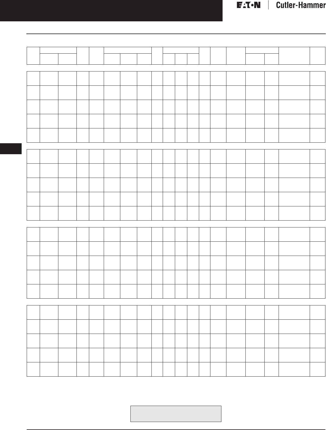
November 2003
9-24
For more information visit: www.cutler-hammer.eaton.com CA08101001E
Transformers
9
General Purpose Transformers
Three-Phase, Types EPT, DT-3, 50/60 Hz Vol. 1, Ref. No. [0324]
Table 9-23. Three-Phase Selection Information — Types EPT, DT-3, 50/60 Hz
Refer to your Cutler-Hammer sales office.
Note: Contact your local Cutler-Hammer sales office for CE Mark transformer requirements.
kVA Full Cap. Taps Type °C
Temp.
Rise
Dimensions (Inches) Wt.
Lbs.
Dimensions (mm) Wt.
kg
Frame Wiring
Diagram
Number
Weathershield Style
Number
Price
U.S. $
FCAN FCBN H W D H W D Catalog
Number
Price
U.S. $
416 ∆ Volts to 416Y/240 Volts, 50/60 Hz
3
6
9
—
—
—
2@-5%
2@-5%
2@-5%
EPT
EPT
EPT
115
115
115
15-7/8
15-7/8
17-3/8
16-1/2
16-1/2
19-11/16
9-7/8
9-7/8
10-7/16
165
190
275
403
403
442
419
419
500
251
251
265
75
86
125
FR200
FR103
FR95
66F
66F
66F
Indoor-
Outdoor
—
—
—
Y43G51T03X
Y43G51T06X
Y43G51T09X
1,550.
1,890.
2,340.
15
30
45
—
2@+2.5%
2@+2.5%
2@-5%
4@-2.5%
4@-2.5%
EPT
EPT
EPT
115
115
115
15-15/16
26-5/8
26-1/2
25-3/4
25-1/4
28-1/2
8-3/8
12-3/4
14-5/8
350
490
790
405
676
673
654
638
724
213
324
372
159
223
359
FR195
FR243
FR244
66F
84J
84J
Indoor-
Outdoor
—
—
—
Y43G51T15X
Y43M51T30X
Y43M51T45X
3,050.
5,800.
7,250.
15
30
45
2@+2.5%
2@+2.5%
2@+2.5%
4@-2.5%
4@-2.5%
4@-2.5%
DT-3
DT-3
DT-3
150
150
150
30-1/8
30-1/8
39-3/8
20-1/8
20-1/8
26-1/8
14-1/8
14-1/8
19-1/8
230
310
480
765
765
1000
511
511
664
359
359
486
104
141
218
FR910A
FR912A
FR914B
280S
280S
280S
WS31
WS31
WS33
350.
350.
350.
V43M51T15X
V43M51T30X
V43M51T45X
2,110.
2,350.
2,940.
75
112.5
150
2@+2.5%
2@+2.5%
2@+2.5%
4@-2.5%
4@-2.5%
4@-2.5%
DT-3
DT-3
DT-3
150
150
150
39-3/8
46-1/8
56
26-1/8
28
31-1/4
19-1/8
23
24-1/4
600
760
1100
1000
1171
1422
664
712
794
486
585
616
273
345
499
FR915B
FR916A
FR917
280S
280S
280S
WS33
WS19
WS34
350.
350.
800.
V43M51T75X
V43M51T12X
V43M51T49X
4,260.
5,800.
7,980.
225
300
500
2@+2.5%
2@+2.5%
2@+2.5%
4@-2.5%
4@-2.5%
4@-2.5%
DT-3
DT-3
DT-3
150
150
150
62-1/4
75
75
31-1/4
44-1/2
44-1/2
30-1/4
36
36
1600
2400
2900
1581
1905
1905
794
1130
1130
768
914
914
728
1088
1315
FR918A
FR919
FR920
280S
275N
275N
WS34
WS35
WS35
800.
1,360.
1,360.
V43M51T22X
V43M51T33X
V43M51T55X
10,660.
17,040.
21,790.
480 ∆ Volts to 208Y/120 Volts, 50/60 Hz
3
6
9
—
—
—
2@-5%
2@-5%
2@-5%
EPT
EPT
EPT
115
115
115
15-7/8
15-7/8
17-3/8
16-1/2
16-1/2
19-11/16
9-7/8
9-7/8
10-7/16
165
190
275
403
403
442
419
419
500
251
251
265
75
86
125
FR200
FR103
FR95
70A
70A
70A
Indoor-
Outdoor
—
—
—
Y48G28T03X
Y48G28T06X
Y48G28T09X
1,340.
1,630.
2,110.
15
30
45
—
2@+2.5%
2@+2.5%
2@-5%
4@-2.5%
4@-2.5%
EPT
EPT
EPT
115
115
115
15-15/16
26-5/8
26-1/2
25-3/4
25-1/4
28-1/2
8-3/8
12-3/4
14-5/8
350
490
790
405
676
673
654
638
724
213
324
372
159
223
359
FR96
FR243
FR244
70A
84A
84A
Indoor-
Outdoor
—
—
—
Y48G28T15X
Y48M28T30X
Y48M28T45X
2,650.
5,200.
6,500.
15
30
45
2@+2.5%
2@+2.5%
2@+2.5%
4@-2.5%
4@-2.5%
4@-2.5%
DT-3
DT-3
DT-3
150
150
150
30-1/8
30-1/8
39-3/8
20-1/8
20-1/8
26-1/8
14-1/8
14-1/8
19-1/8
230
310
480
765
765
1000
511
511
664
359
359
486
104
141
218
FR910A
FR912A
FR914B
280B
280B
280B
WS31
WS31
WS33
350.
350.
350.
V48M28T15X
V48M28T30X
V48M28T45X
1,720.
2,175.
2,650.
75
112.5
150
2@+2.5%
2@+2.5%
2@+2.5%
4@-2.5%
4@-2.5%
4@-2.5%
DT-3
DT-3
DT-3
150
150
150
39-3/8
46-1/8
56
26-1/8
28
31-1/4
19-1/8
23
24-1/4
600
760
1100
1000
1171
1422
664
712
794
486
585
616
273
345
499
FR915B
FR916A
FR917
280B
280B
280B
WS33
WS19
WS34
350.
350.
800.
V48M28T75X
V48M28T12X
V48M28T49X
3,750.
6,170.
6,810.
225
300
500
2@+2.5%
2@+2.5%
2@+2.5%
4@-2.5%
4@-2.5%
4@-2.5%
DT-3
DT-3
DT-3
150
150
150
62-1/4
75
75
31-1/4
44-1/2
44-1/2
30-1/4
36
36
1600
2400
2900
1581
1905
1905
794
1130
1130
768
914
914
728
1088
1315
FR918A
FR919
FR920
280B
275A
275A
WS34
WS35
WS35
800.
1,360.
1,360.
V48M28T22X
V48M28T33X
V48M28T55X
9,900.
12,800.
20,160.
480 ∆ Volts to 220Y/127 Volts, 50/60 Hz
3
6
9
—
—
—
2@-5%
2@-5%
2@-5%
EPT
EPT
EPT
115
115
115
15-7/8
15-7/8
17-3/8
16-1/2
16-1/2
19-11/16
9-7/8
9-7/8
10-7/16
165
190
275
403
403
442
419
419
500
251
251
265
75
86
125
FR200
FR103
FR95
70A
70A
70A
Indoor-
Outdoor
—
—
—
Y48G31T03X
Y48G31T06X
Y48G31T09X
2,000.
2,440.
3,160.
15
30
45
—
2@+2.5%
2@+2.5%
2@-5%
4@-2.5%
4@-2.5%
EPT
EPT
EPT
115
115
115
15-15/16
26-5/8
26-1/2
25-3/4
25-1/4
28-1/2
8-3/8
12-3/4
14-5/8
350
490
790
405
676
673
654
638
724
213
324
372
159
223
359
FR96
FR243
FR244
70A
84K
84K
Indoor-
Outdoor
—
—
—
Y48G31T15X
Y48M31T30X
Y48M31T45X
3,970.
5,800.
7,250.
15
30
45
2@+2.5%
2@+2.5%
2@+2.5%
4@-2.5%
4@-2.5%
4@-2.5%
DT-3
DT-3
DT-3
150
150
150
30-1/8
30-1/8
39-3/8
20-1/8
20-1/8
26-1/8
14-1/8
14-1/8
19-1/8
230
310
480
765
765
1000
511
511
664
359
359
486
104
141
218
FR910A
FR912A
FR914B
280B
280B
280B
WS31
WS31
WS33
350.
350.
350.
V48M31T15X
V48M31T30X
V48M31T45X
1,960.
2,520.
3,060.
75
112.5
150
2@+2.5%
2@+2.5%
2@+2.5%
4@-2.5%
4@-2.5%
4@-2.5%
DT-3
DT-3
DT-3
150
150
150
39-3/8
46-1/8
56
26-1/8
28
31-1/4
19-1/8
23
24-1/4
600
760
1100
1000
1171
1422
664
712
794
486
585
616
273
345
499
FR915B
FR916A
FR917
280B
280B
280B
WS33
WS19
WS34
350.
350.
800.
V48M31T75X
V48M31T12X
V48M31T49X
4,310.
6,230.
7,850.
225
300
500
2@+2.5%
2@+2.5%
2@+2.5%
4@-2.5%
4@-2.5%
4@-2.5%
DT-3
DT-3
DT-3
150
150
150
62-1/4
75
75
31-1/4
44-1/2
44-1/2
30-1/4
36
36
1600
2400
2900
1581
1905
1905
794
1130
1130
768
914
914
728
1088
1315
FR918A
FR919
FR920
280B
275A
275A
WS34
WS35
WS35
800.
1,360.
1,360.
V48M31T22X
V48M31T33X
V48M31T55X
11,375.
14,500.
23,100.
480 ∆ Volts to 380Y/220 Volts, 50/60 Hz
3
6
9
—
—
—
2@-5%
2@-5%
2@-5%
EPT
EPT
EPT
115
115
115
15-7/8
15-7/8
17-3/8
16-1/2
16-1/2
19-11/16
9-7/8
9-7/8
10-7/16
165
190
275
403
403
442
419
419
500
251
251
265
75
86
125
FR200
FR103
FR95
70R
70R
70R
Indoor-
Outdoor
—
—
—
Y48G37T03X
Y48G37T06X
Y48G37T09X
2,000.
2,440.
3,160.
15
30
45
—
2@+2.5%
2@+2.5%
2@-5%
4@-2.5%
4@-2.5%
EPT
EPT
EPT
115
115
115
15-15/16
26-5/8
26-1/2
25-3/4
25-1/4
28-1/2
8-3/8
12-3/4
14-5/8
350
490
790
405
676
673
654
638
724
213
324
372
159
223
359
FR96
FR243
FR244
70R
70R
Indoor-
Outdoor
—
—
—
Y48G37T15X
Y48M37T30X
Y48M37T45X
3,970.
5,800.
7,250.
15
30
45
2@+2.5%
2@+2.5%
2@+2.5%
4@-2.5%
4@-2.5%
4@-2.5%
DT-3
DT-3
DT-3
150
150
150
30-1/8
30-1/8
39-3/8
20-1/8
20-1/8
26-1/8
14-1/8
14-1/8
19-1/8
230
310
480
765
765
1000
511
511
664
359
359
486
104
141
218
FR910A
FR912A
FR914B
280B
280B
280B
WS31
WS31
WS33
350.
350.
350.
V48M37T15X
V48M37T30X
V48M37T45X
2,270.
2,520.
3,150.
75
112.5
150
2@+2.5%
2@+2.5%
2@+2.5%
4@-2.5%
4@-2.5%
4@-2.5%
DT-3
DT-3
DT-3
150
150
150
39-3/8
46-1/8
56
26-1/8
28
31-1/4
19-1/8
23
24-1/4
600
760
1100
1000
1171
1422
664
712
794
486
585
616
273
345
499
FR915B
FR916A
FR917
280B
280B
280B
WS33
WS19
WS34
350.
350.
800.
V48M37T75X
V48M37T12X
V48M37T49X
4,300.
6,175.
8,570.
225
300
500
2@+2.5%
2@+2.5%
2@+2.5%
4@-2.5%
4@-2.5%
4@-2.5%
DT-3
DT-3
DT-3
150
150
150
62-1/4
75
75
31-1/4
44-1/2
44-1/2
30-1/4
36
36
1600
2400
2900
1581
1905
1905
794
1130
1130
768
914
914
728
1088
1315
FR918A
FR919
FR920
280B
275A
275A
WS34
WS35
WS35
800.
1,360.
1,360.
V48M37T22X
V48M37T33X
V48M37T55X
11,375.
18,300.
23,100.
For other ratings or styles not shown, or for
special enclosure types (including stainless
steel) refer to Eaton’s Cutler-Hammer business. Discount Symbol . . . . . . . . . . . . . . . . . . . . . . . . DT-1

November 2003
CA08101001E For more information visit: www.cutler-hammer.eaton.com
9-25
Transformers
9
General Purpose Transformers
Three-Phase, Types EPT, DT-3, 50/60 Hz
Vol. 1, Ref. No. [0325]
Table 9-24. Three-Phase Selection Information — Types EPT, DT-3, 50/60 Hz
Refer to your Cutler-Hammer sales office.
Note: Contact your local Cutler-Hammer sales office for CE Mark transformer requirements.
kVA Full Cap. Taps Type °C
Temp.
Rise
Dimensions (Inches) Wt.
Lbs.
Dimensions (mm)
Wt.
kg
Frame Wiring
Diagram
Number
Weathershield Style
Number
Price
U.S. $
FCAN FCBN H W D H W D Catalog
Number
Price
U.S. $
480 ∆ Volts to 400Y/231 Volts, 50/60 Hz
3
6
9
—
—
—
2@-5%
2@-5%
2@-5%
EPT
EPT
EPT
115
115
115
15-7/8
15-7/8
17-3/8
16-1/2
16-1/2
19-11/16
9-7/8
9-7/8
10-7/16
165
190
275
403
403
442
419
419
500
251
251
265
75
86
125
FR200
FR103
FR95
70A
70A
70A
Indoor-
Outdoor
—
—
—
Y48G34T03X
Y48G34T06X
Y48G34T09X
2,000.
2,440.
3,160.
15
30
45
—
2@+2.5%
2@+2.5%
2@-5%
4@-2.5%
4@-2.5%
EPT
EPT
EPT
115
115
115
15-15/16
26-5/8
26-1/2
25-3/4
25-1/4
28-1/2
8-3/8
12-3/4
14-5/8
350
490
790
405
676
673
654
638
724
213
324
372
159
223
359
FR96
FR243
FR244
70A
Indoor-
Outdoor
—
—
—
Y48G34T15X
Y48M34T30X
Y48M34T45X
3,970.
5,800.
7,250.
15
30
45
2@+2.5%
2@+2.5%
2@+2.5%
4@-2.5%
4@-2.5%
4@-2.5%
DT-3
DT-3
DT-3
150
150
150
30-1/8
30-1/8
39-3/8
20-1/8
20-1/8
26-1/8
14-1/8
14-1/8
19-1/8
230
310
480
765
765
1000
511
511
664
359
359
486
104
141
218
FR910A
FR912A
FR914B
280B
280B
280B
WS31
WS31
WS33
350.
350.
350.
V48M34T15X
V48M34T30X
V48M34T45X
2,270.
2,520.
3,150.
75
112.5
150
2@+2.5%
2@+2.5%
2@+2.5%
4@-2.5%
4@-2.5%
4@-2.5%
DT-3
DT-3
DT-3
150
150
150
39-3/8
46-1/8
56
26-1/8
28
31-1/4
19-1/8
23
24-1/4
600
760
1100
1000
1171
1422
664
712
794
486
585
616
273
345
499
FR915B
FR916A
FR917
280B
280B
280B
WS33
WS19
WS34
350.
350.
800.
V48M34T75X
V48M34T12X
V48M34T49X
4,300.
6,170.
8,570.
225
300
500
2@+2.5%
2@+2.5%
2@+2.5%
4@-2.5%
4@-2.5%
4@-2.5%
DT-3
DT-3
DT-3
150
150
150
62-1/4
75
75
31-1/4
44-1/2
44-1/2
30-1/4
36
36
1600
2400
2900
1581
1905
1905
794
1130
1130
768
914
914
728
1089
1315
FR918A
FR919
FR920
280B
WS34
WS35
WS35
800.
1,360.
1,360.
V48M34T22X
V48M34T33X
V48M34T55X
11,375.
14,375.
23,050.
480 ∆ Volts to 480Y/277 Volts, 50/60 Hz
3
6
9
—
—
—
2@-5%
2@-5%
2@-5%
EPT
EPT
EPT
115
115
115
15-7/8
15-7/8
17-3/8
16-1/2
16-1/2
19-11/16
9-7/8
9-7/8
10-7/16
165
190
275
403
403
442
419
419
500
251
251
265
75
86
125
FR200
FR103
FR95
70L
70L
70L
Indoor-
Outdoor
—
—
—
Y48G47T03X
Y48G47T06X
Y48G47T09X
2,000.
2,440.
3,160.
15
30
45
—
2@+2.5%
2@+2.5%
2@-5%
4@-2.5%
4@-2.5%
EPT
EPT
EPT
115
115
115
15-15/16
26-5/8
26-1/2
25-3/4
25-1/4
28-1/2
8-3/8
12-3/4
14-5/8
350
490
790
405
676
673
654
638
724
213
324
372
159
223
359
FR96
FR243
FR244
70L
84D
84D
Indoor-
Outdoor
—
—
—
Y48G47T15X
Y48M47T30X
Y48M47T45X
3,970.
6,550.
8,190.
15
30
45
2@+2.5%
2@+2.5%
2@+2.5%
4@-2.5%
4@-2.5%
4@-2.5%
DT-3
DT-3
DT-3
150
150
150
30-1/8
30-1/8
39-3/8
20-1/8
20-1/8
26-1/8
14-1/8
14-1/8
19-1/8
230
310
480
765
765
1000
511
511
664
359
359
486
104
141
218
FR910A
FR912A
FR914B
280B
280B
280B
WS31
WS31
WS33
350.
350.
350.
V48M47T15X
V48M47T30X
V48M47T45X
2,305.
2,935.
3,575.
75
112.5
150
2@+2.5%
2@+2.5%
2@+2.5%
4@-2.5%
4@-2.5%
4@-2.5%
DT-3
DT-3
DT-3
150
150
150
39-3/8
46-1/8
56
26-1/8
28
31-1/4
19-1/8
23
24-1/4
600
760
1100
1000
1171
1422
664
712
794
486
585
616
273
345
499
FR915B
FR916A
FR917
280B
280B
280B
WS33
WS19
WS34
350.
350.
800.
V48M47T75X
V48M47T12X
V48M47T49X
5,050.
7,320.
9,180.
225
300
500
2@+2.5%
2@+2.5%
2@+2.5%
4@-2.5%
4@-2.5%
4@-2.5%
DT-3
DT-3
DT-3
150
150
150
62-1/4
75
75
31-1/4
44-1/2
44-1/2
30-1/4
36
36
1600
2400
2900
1581
1905
1905
794
1130
1130
768
914
914
728
1089
1315
FR918A
FR919
FR920
280B
275A
275A
WS34
WS35
WS35
800.
1,360.
1,360.
V48M47T22X
V48M47T33X
V48M47T55X
13,440.
17,000.
27,200.
For other ratings or styles not shown, or for
special enclosure types (including stainless
steel) refer to Eaton’s Cutler-Hammer business. Discount Symbol . . . . . . . . . . . . . . . . . . . . . . . . . DT-1
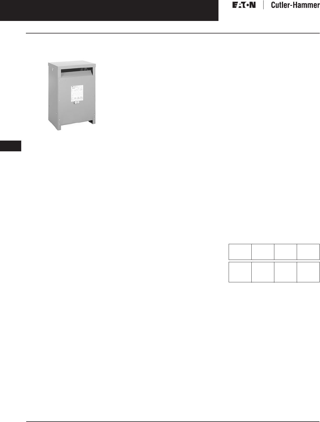
November 2003
9-26
For more information visit: www.cutler-hammer.eaton.com CA08101001E
Transformers
9
Electrostatically Shielded Transformers
Single- and Three-Phase Types EP, DS-3, EPT, DT-3, 60 Hz Vol. 1, Ref. No. [0326]
Single- and Three-Phase,
Types EP, DS-3, EPT, DT-3, 60 Hz
Type DT-3
Product Description
Types EP, EPT
■Sand and Resin Encapsulated design.
■Suitable for indoor or outdoor
applications.
■Totally enclosed, non-ventilated
enclosures.
■Enclosures are NEMA 3R rated.
■Mountable in any position indoors
and upright only outdoors.
■185ºC Insulation System, 115ºC
rise standard.
■Available in single-phase ratings
through 37.5 kVA and 4160 volts
primary (EP).
■Available in three-phase ratings
through 75 kVA and 4160 volts
primary (EPT).
Types DS-3, DT-3
■Ventilated, NEMA 2 enclosure
standard.
■Suitable for indoor applications,
outdoors when weathershields are
also installed.
■Upright mounting only.
■220ºC Insulation System, 150ºC
rise standard.
■Available in single-phase ratings
15 – 167 kVA and up to 4160 volts
primary (DS-3).
■Available in three-phase ratings
15 – 1500 kVA and up to 4160 volts
primary (DT-3).
Application Description
Electrostatically shielded transformers
are used to protect sensitive electrical
equipment from undesirable high fre-
quency signals commonly generated
by lighting, switching surges, motors,
and SCRs feeding noise back into the
line. An electrostatic shield, consisting
of a single turn of aluminum foil placed
between the primary and secondary
winding, is used to provide from
30 to 70 dB attenuation of wide band
line-to-ground (common mode) noise.
Typical uses of shielded isolation
transformers include:
■Suppression of transients and noise
which travels from its source to the
sensitive load equipment.
■Suppression of noise and transients
at the point where the noise or
transients are originating, thus
preventing them from backfeeding
from the source to the feeders.
■Transform one voltage level to
another.
■Isolate one circuit from another.
Features, Benefits
and Functions
■UL listed.
■60 Hz operation standard,
50/60 Hz operation available.
■Short-term overload capability
as required by ANSI.
■Meet NEMA ST-20 sound levels.
Standards and Certifications
Industry Standards
All Cutler-Hammer dry-type distribution
and control transformers by Eaton
Corporation are built and tested in
accordance with applicable NEMA,
ANSI and IEEE Standards. All 600 volt
class transformers are UL listed unless
otherwise noted.
Seismically Qualified
Cutler-Hammer manufactured dry-type
distribution transformers are seismi-
cally qualified, and exceed require-
ments of the Uniform Building Code
(UBC) and California Code Title 24.
Options and Accessories
Please refer to Page 9-120.
Product Specifications
Frequency
Cutler-Hammer standard dry-type dis-
tribution transformers are designed
for 60 Hertz operation. Transformers
required for other frequencies are
available and must be specifically
designed.
Overload Capability
Short-term overload is designed into
transformers as required by ANSI.
dry-type distribution transformers
will deliver 200% nameplate load for
one-half hour; 150% load for one hour;
and 125% load for four hours without
being damaged provided that a con-
stant 50% load precedes and follows
the overload. See ANSI C57.96-01.250
for additional limitations.
Continuous overload capacity is not
deliberately designed into a trans-
former because the design objective is
to be within the allowed winding tem-
perature rise with nameplate loading.
Insulation System and Temperature Rise
Industry standards classify insulation
systems and rise as shown below:
Table 9-25. Insulation System Classification
The design life of transformers having
different insulation systems is the
same — the lower temperature systems
are designed for the same life as the
higher temperature systems.
Enclosures
Cutler-Hammer ventilated
transformers, Types DS-3 and DT-3
utilize a NEMA 2 rated (drip-proof)
enclosure as standard, and are rated
NEMA 3R with the addition of
weathershields. Cutler-Hammer
encapsulated transformers, Types
EP and EPT, utilize a NEMA 3R rated
enclosure as standard.
Ambient +
Winding
Rise
+
Hot
Spot
=
Temp.
Class
40°C
40°C
40°C
40°C
55°C
80°C
115°C
150°C
10°C
30°C
30°C
30°C
105°C
150°C
185°C
220°C

November 2003
CA08101001E For more information visit: www.cutler-hammer.eaton.com
9-27
Transformers
9
Electrostatically Shielded Transformers
Single- and Three-Phase, Types EP, 60 Hz
Vol. 1, Ref. No. [0327]
Sound Levels
All Eaton’s Cutler-Hammer 600 volt
class general purpose dry-type distri-
bution transformers are designed to
meet NEMA ST-20 sound levels listed
here. These are the sound levels mea-
sured in a soundproof environment.
Actual sound levels measured at an
installation will likely be higher due to
electrical connections and environ-
mental conditions. Lower sound levels
are available and should be specified
when the transformer is going to
be installed in an area where sound
may be a concern.
Table 9-26. Average Sound Levels
Winding Terminations
Primary and secondary windings are
terminated in the wiring compartment.
Encapsulated units have copper leads or
stabs brought out for connections. Venti-
lated transformers have leads brought
out to aluminum pads that are pre-
drilled to accept Cu/Al lugs. Lugs are not
supplied with these transformers. The
Cutler-Hammer business recommends
external cables be rated 90°C (sized at
75°C ampacity) for encapsulated
designs and 75°C for ventilated designs.
Series-Multiple Windings
Series-multiple windings consist of
2 similar coils in each winding which
can be connected in series or parallel
(multiple). Transformers with series-
multiple windings are designated with
an “X” or “/” between the voltage
ratings, such as voltages of “120/240”
or “240 X 480.” If the series-multiple
winding is designated by an “X,” the
winding can be connected only for a
series or parallel. With the “/” designa-
tion, a mid-point also becomes avail-
able in addition to the series or parallel
connection. As an example, a 120 X 240
winding can be connected for either
120 (parallel) or 240 (series), but a
120/240 winding can be connected
for 120 (parallel), or 240 (series), or
240 with a 120 mid-point.
Technical Data
and Specifications
Please refer to Page 9-122.
Product Selection
Additional Product Selection information begins on Page 9-136.
Table 9-27. Single-Phase Selection Information — Types EP, 60 Hz
Note: Contact your local Cutler-Hammer sales office for CE Mark transformer requirements.
NEMA ST-20 Average Sound Level in dB
kVA Ventilated Encapsulated
0 – 9
10 – 50
51 – 150
151 – 300
40
45
50
55
45
50
55
57
301 – 500
501 – 700
701 – 1000
1001 – 1500
60
62
64
65
59
61
63
64
kVA Full Cap. Taps Type °C
Temp.
Rise
Dimensions (Inches) Wt.
Lbs.
Dimensions (mm) Wt.
kg
Frame Wiring
Diagram
Number
Weathershield Style
Number
Price
U.S. $
FCAN FCBN H W D H W D Catalog
Number
Price
U.S. $
120 x 240 Volts to 120/240 Volts
3
5
7.5
—
—
—
—
—
—
EP
EP
EP
115
115
115
14-1/8
16
16
7-3/4
10-3/8
10-3/8
8
9-7/8
9-7/8
65
113
123
359
406
406
197
263
263
203
251
251
29
51
55
FR176
FR177
FR178
90B
90B
90B
Indoor-
Outdoor
—
—
—
S10N11E03N
S10N11E05N
S10N11E07N
1,155.
1,560.
2,010.
10
15
25
—
—
—
—
—
—
EP
EP
EP
115
115
115
19
19
22-3/8
13-3/8
13-3/8
16-3/8
10-1/2
10-1/2
14-1/8
193
216
375
482
482
568
339
339
416
266
266
359
87
98
170
FR179
FR180
FR182
90B
90B
90B
Indoor-
Outdoor
—
—
—
S10N11E10N
S10N11E15N
S10N11E25N
2,450.
3,350.
4,800.
120 Volts to 120 Volts
3
5
7.5
—
—
—
—
—
—
EP
EP
EP
115
115
115
14-1/8
16
16
7-3/4
10-3/8
10-3/8
8
9-7/8
9-7/8
65
113
123
359
406
406
197
263
263
203
251
251
29
51
55
FR176
FR177
FR178
77A
77A
77A
Indoor-
Outdoor
—
—
—
S12N12E03N
S12N12E05N
S12N12E07N
1,155.
1,560.
2,010.
10
15
25
—
—
—
—
—
—
EP
EP
EP
115
115
115
19
19
22-3/8
13-3/8
13-3/8
16-3/8
10-1/2
10-1/2
14-1/8
193
216
375
482
482
568
339
339
416
266
266
359
87
98
170
FR179
FR180
FR182
77A
77A
77A
Indoor-
Outdoor
—
—
—
S12N12E10N
S12N12E15N
S12N12E25N
2,450.
3,350.
4,800.
208 Volts to 120/240 Volts
3
5
7.5
—
—
—
—
—
—
EP
EP
EP
115
115
115
14-1/8
16
16
7-3/4
10-3/8
10-3/8
8
9-7/8
9-7/8
65
113
123
359
406
406
197
263
263
203
251
251
29
51
55
FR176
FR177
FR178
578A
578A
578A
Indoor-
Outdoor
—
—
—
S29N11E03N
S29N11E05N
S29N11E07N
1,320.
1,950.
2,585.
10
15
25
—
—
—
—
—
—
EP
EP
EP
115
115
115
19
19
22-3/8
13-3/8
13-3/8
16-3/8
10-1/2
10-1/2
14-1/8
193
216
375
482
482
568
339
339
416
266
266
359
87
98
170
FR179
FR180
FR182
578A
578A
578A
Indoor-
Outdoor
—
—
—
S29N11E10N
S29N11E15N
S29N11E25N
3,100.
3,650.
5,200.
208 Volts to 208 Volts
3
5
7.5
—
—
—
—
—
—
EP
EP
EP
115
115
115
14-1/8
16
16
7-3/4
10-3/8
10-3/8
8
9-7/8
9-7/8
65
113
123
359
406
406
197
263
263
203
251
251
29
51
55
FR176
FR177
FR178
77B
77B
77B
Indoor-
Outdoor
—
—
—
S29N29E03N
S29N29E05N
S29N29E07N
1,320.
1,950.
2,585.
10
15
25
—
—
—
—
—
—
EP
EP
EP
115
115
115
19
19
22-3/8
13-3/8
13-3/8
16-3/8
10-1/2
10-1/2
14-1/8
193
216
375
482
482
568
339
339
416
266
266
359
87
98
170
FR179
FR180
FR182
77B
77B
77B
Indoor-
Outdoor
—
—
—
S29N29E10N
S29N29E15N
S29N29E25N
3,100.
3,350.
5,200.
For other ratings or styles not shown, or for
special enclosure types (including stainless
steel) refer to Eaton’s Cutler-Hammer business. Discount Symbol . . . . . . . . . . . . . . . . . . . . . . . . . DT-1

November 2003
9-28
For more information visit: www.cutler-hammer.eaton.com CA08101001E
Transformers
9
Electrostatically Shielded Transformers
Single-Phase, Types EP, DS-3, 60 Hz Vol. 1, Ref. No. [0328]
Table 9-28. Single-Phase Selection Information — Types EP, DS-3, 60 Hz
2@+5% FCBN at 240 volts; 4@-2.5% FCBN at 480 volts.
1@+5%, 2@-5% at 240 volts primary; 2@+2.5%, 4@-2.5% at 480 volts primary.
Note: Contact your local Cutler-Hammer sales office for CE Mark transformer requirements.
kVA Full Cap. Taps Type °C
Temp.
Rise
Dimensions (Inches) Wt.
Lbs.
Dimensions (mm) Wt.
kg
Frame Wiring
Diagram
Number
Weathershield Style
Number
Price
U.S. $
FCAN FCBN H W D H W D Catalog
Number
Price
U.S. $
240 Volts to 240 Volts
3
5
7.5
—
—
—
—
—
—
EP
EP
EP
115
115
115
14-1/8
16
16
7-3/4
10-3/8
10-3/8
8
9-7/8
9-7/8
65
113
123
359
406
406
197
263
263
203
251
251
29
51
55
FR176
FR177
FR178
77C
77C
77C
Indoor-
Outdoor
—
—
—
S24N24E03N
S24N24E05N
S24N24E07N
1,155.
1,560.
2,010.
10
15
25
—
—
—
—
—
—
EP
EP
EP
115
115
115
19
19
22-3/8
13-3/8
13-3/8
16-3/8
10-1/2
10-1/2
14-1/8
193
216
375
482
482
568
339
339
416
266
266
359
87
98
170
FR179
FR180
FR182
77C
77C
77C
Indoor-
Outdoor
—
—
—
S24N24E10N
S24N24E15N
S24N24E25N
2,450.
3,350.
4,800.
277 Volts to 120/240 Volts
3
5
7.5
—
—
—
—
—
—
EP
EP
EP
115
115
115
14-1/8
16
16
7-3/4
10-3/8
10-3/8
8
9-7/8
9-7/8
65
113
123
359
406
406
197
263
263
203
251
251
29
51
55
FR176
FR177
FR178
513B
513B
513B
Indoor-
Outdoor
—
—
—
S27N11E03N
S27N11E05N
S27N11E07N
1,320.
1,950.
2,585.
10
15
25
—
—
—
—
—
—
EP
EP
EP
115
115
115
19
19
22-3/8
13-3/8
13-3/8
16-3/8
10-1/2
10-1/2
14-1/8
193
216
375
482
482
568
339
339
416
266
266
359
87
98
170
FR179
FR180
FR182
513B
513B
513B
Indoor-
Outdoor
—
—
—
S27N11E10N
S27N11E15N
S27N11E25N
3,100.
3,650.
5,200.
240 x 480 Volts to 120/240 Volts
.25
.50
.75
—
—
—
—
—
—
EP
EP
EP
115
115
115
6-1/2
6-1/2
8-3/8
4-7/8
4-7/8
6
3-7/8
4-5/8
5-3/4
12
13
21
165
165
213
124
124
152
98
117
146
5
6
10
FR56
FR57
FR58A
90A
90A
90A
Indoor-
Outdoor
—
—
—
S20N11E26A
S20N11E51A
S20N11E76A
150.
190.
245.
1
1.5
2
—
—
—
—
—
—
EP
EP
EP
115
115
115
8-3/8
10-3/4
10-3/4
6
6-3/16
6-3/16
5-3/4
6-1/8
6-1/8
31
40
40
213
273
273
152
157
157
146
156
156
14
18
18
FR59A
FR67
FR68
90A
90A
90A
Indoor-
Outdoor
—
—
—
S20N11E01A
S20N11E16A
S20N11E02A
290.
355.
450.
3
5
7.5
—
—
—
—
—
—
EP
EP
EP
115
115
115
14-1/8
16
16
7-11/16
10-3/8
10-3/8
8
9-7/8
9-7/8
65
113
123
359
406
406
195
263
263
203
251
251
29
51
55
FR176
FR177
FR178
90A
90A
90A
Indoor-
Outdoor
—
—
—
S20N11E03A
S20N11E05A
S20N11E07A
550.
815.
1,080.
10
15
25
—
—
—
—
EP
EP
EP
115
115
115
19
19
22-3/8
13-3/8
13-3/8
16-3/8
10-1/2
10-1/2
14-1/8
193
216
375
482
482
568
339
339
416
266
266
359
87
98
170
FR179
FR180
FR182
90A
90A
526A
Indoor-
Outdoor
—
—
—
S20N11E10A
S20N11E15A
S20L11E25A
1,300.
1,750.
2,475.
15
25
37.5
DS-3
DS-3
DS-3
150
150
150
30-1/4
31-1/4
37-5/8
16-7/8
22-5/8
22-5/8
15-7/8
17-1/2
19-1/2
147
212
306
768
793
953
428
574
574
402
445
495
67
96
139
FR815
FR816
FR817
261A
261A
261A
WS15
WS11
WS11
350.
350.
350.
T20P11E15
T20P11E25
T20P11E37
1,600.
2,075.
2,540.
50
75
100
DS-3
DS-3
DS-3
150
150
150
37-5/8
42-1/8
42-1/8
22-5/8
24
24
19-1/2
23-3/8
23-3/8
340
510
600
953
1070
1070
574
610
610
495
594
594
154
233
274
FR818
FR819
FR820
261A
261A
261A
WS11
WS16
WS16
350.
800.
800.
T20P11E50
T20P11E75
T20P11E99
3,080.
4,350.
5,400.
For other ratings or styles not shown, or for
special enclosure types (including stainless
steel) refer to Eaton’s Cutler-Hammer business. Discount Symbol . . . . . . . . . . . . . . . . . . . . . . . . . DT-1

November 2003
CA08101001E For more information visit: www.cutler-hammer.eaton.com
9-29
Transformers
9
Electrostatically Shielded Transformers
Three-Phase, Types EPT, DT-3, 60 Hz
Vol. 1, Ref. No. [0329]
Table 9-29. Three-Phase Selection Information — Types EPT, DT-3, 60 Hz
Refer to your Cutler-Hammer sales office.
Not seismic qualified.
Note: Contact your local Cutler-Hammer sales office for CE Mark transformer requirements.
kVA Full Cap. Taps Type °C
Temp.
Rise
Dimensions (Inches) Wt.
Lbs.
Dimensions (mm) Wt.
kg
Frame Wiring
Diagram
Number
Weathershield Style
Number
Price
U.S. $
FCAN FCBN H W D H W D Catalog
Number
Price
U.S. $
208 ∆ Volts to 208Y/120 Volts
15
15
30
2@+2.5%
2@+2.5%
2@+2.5%
2@-2.5%
4@-2.5%
4@-2.5%
EPT
DT-3
DT-3
115
150
150
17-3/8
25
30-1/8
19-3/4
20-1/8
20-1/8
10-1/2
14-1/8
14-1/8
275
152
230
441
635
765
502
511
511
266
359
359
124
69
104
FR95
FR909
FR910A
86A
283A
283A
Indoor-
Outdoor
WS31
WS31
—
—
350.
350.
Y29D28E15B
—
V29M28E15A
V29M28E30B
2,950.
—
2,080.
2,660.
45
75
112.5
2@+2.5%
2@+2.5%
1@+5%
4@-2.5%
4@-2.5%
2@-5%
DT-3
DT-3
DT-3
150
150
150
30-1/8
39-3/8
39-3/8
20-1/8
26-1/8
26-1/8
14-1/8
19-1/8
19-1/8
310
480
600
765
1000
1000
511
663
663
359
485
485
140
217
272
FR912A
FR914B
FR915B
283A
283A
287A
WS31
WS33
WS33
350.
350.
350.
V29M28E45B
V29M28E75B
V29R28E12B
3,235.
4,575.
6,620.
150
225
300
1@+5%
1@+5%
1@+5%
2@-5%
2@-5%
2@-5%
DT-3
DT-3
DT-3
150
150
150
46-1/8
62-1/4
62-1/4
28
31-1/4
31-1/4
23
30-1/4
30-1/4
760
1600
1600
1171
1581
1581
712
794
794
585
768
768
344
728
728
FR916A
FR918A
FR918A
287A
287A
287A
WS19
WS34
WS34
350.
800.
800.
V29R28E49B
V29R28E22B
V29R28E33B
8,300.
12,100.
15,400.
480 ∆ Volts to 208Y/120 Volts
3
6
9
15
2@+2.5%
2@+2.5%
2@+2.5%
2@+2.5%
2@-2.5%
2@-2.5%
2@-2.5%
2@-2.5%
EPT
EPT
EPT
EPT
115
115
115
115
13-3/8
15-7/8
15-7/8
17-3/8
15-5/16
16-1/2
16-1/2
19-3/4
8-5/16
9-7/8
9-7/8
10-1/2
116
143
166
275
339
403
403
441
404
419
419
419
211
251
251
251
52
64
75
75
FR201
FR200
FR103
FR95
86B
86B
86B
86B
Indoor-
Outdoor
—
—
—
—
Y48D28E03A
Y48D28E06A
Y48D28E09N
Y48D28E15B
1,165.
1,420.
1,840.
2,310.
15
30
45
2@+2.5%
2@+2.5%
2@+2.5%
4@-2.5%
4@-2.5%
4@-2.5%
DT-3
DT-3
DT-3
150
150
150
25
30-1/8
30-1/8
20-1/8
20-1/8
20-1/8
14-1/8
14-1/8
14-1/8
152
239
310
635
765
765
511
511
511
359
359
359
69
108
140
FR909
FR910A
FR912A
283B
283B
283B
WS31
WS31
WS31
350.
350.
350.
V48M28E15B
V48M28E30B
V48M28E45B
1,485.
1,900.
2,310.
75
112.5
150
2@+2.5%
2@+2.5%
2@+2.5%
4@-2.5%
4@-2.5%
4@-2.5%
DT-3
DT-3
DT-3
150
150
150
39-3/8
39-3/8
46-1/8
26-1/8
26-1/8
28
19-1/8
19-1/8
23
480
600
760
1000
1000
1171
663
663
712
485
485
585
217
272
344
FR914B
FR915B
FR916A
283B
283B
283B
WS33
WS33
WS19
350.
350.
350.
V48M28E75B
V48M28E12B
V48M28E49B
3,270.
4,945.
6,200.
225
300
500
2@+2.5%
2@+2.5%
2@+2.5%
4@-2.5%
4@-2.5%
4@-2.5%
DT-3
DT-3
DT-3
150
150
150
56
62-1/4
75
31-1/4
31-1/4
44-1/2
24-1/4
30-1/4
36
1100
1600
2400
1422
1581
1905
793
794
1130
616
768
914
499
728
1088
FR917
FR918A
FR919
283B
283B
292A
WS34
WS34
WS35
800.
800.
1,360.
V48M28E22B
V48M28E33B
V48M28E55G
9,000.
11,500.
18,400.
750
1000
2@+2.5%
1@+3.5%
4@-2.5%
1@-3.5%
DT-3
DT-3
150
150
75
68
44-1/2
64
36
45
2900
4350
1905
1727
1130
1625
914
1143
1315
1912
FR920 292A
WS35
1,360.
—
V48M28E77B
V48W28E11A
28,600.
51,200.
480 ∆ Volts to 208Y/120 Volts — Copper Windings
15
30
45
2@+2.5%
2@+2.5%
2@+2.5%
4@-2.5%
4@-2.5%
4@-2.5%
DT-3
DT-3
DT-3
150
150
150
25
30-1/8
30-1/8
20-1/8
20-1/8
20-1/8
14-1/8
14-1/8
14-1/8
172
300
370
635
765
765
511
511
511
359
359
359
78
136
168
FR909
FR910A
FR912A
283B
283B
283B
WS31
WS31
WS31
350.
350.
350.
V48M28E15CU
V48M28E30CU
V48M28E45CU
2,300.
2,520.
3,180.
75
112.5
150
2@+2.5%
2@+2.5%
2@+2.5%
4@-2.5%
4@-2.5%
4@-2.5%
DT-3
DT-3
DT-3
150
150
150
39-3/8
39-3/8
46-1/8
26-1/8
26-1/8
28
19-1/8
19-1/8
23
550
675
850
1000
1000
1171
663
663
712
485
485
585
250
307
386
FR914B
FR915B
FR916A
283B
283B
283B
WS33
WS33
WS19
350.
350.
350.
V48M28E75CU
V48M28E12CU
V48M28E49CU
4,830.
6,600.
9,020.
225
300
500
2@+2.5%
2@+2.5%
2@+2.5%
4@-2.5%
4@-2.5%
4@-2.5%
DT-3
DT-3
DT-3
150
150
150
56
62-1/4
75
31-1/4
31-1/4
44-1/2
24-1/4
30-1/4
36
1200
2150
2400
1422
1581
1905
793
794
1130
616
768
914
545
977
1088
FR917
FR918A
FR919
283B
283B
292A
WS34
WS34
WS35
800.
800.
1,360.
V48M28E22CU
V48M28E33CU
V48M28E55CU
12,150.
15,200.
24,590.
480 ∆ Volts to 480Y/277 Volts
9
15
2@+2.5%
2@+2.5%
2@-2.5%
2@-2.5%
EPT
EPT
115
115
15-7/8
17-3/8
16-1/2
19-3/4
9-7/8
10-1/2
166
275
403
441
419
419
251
266
75
75
FR103
FR95
86C
86C
Indoor-
Outdoor
—
—
Y48D47E09N
Y48D47E15B
2,380.
3,000.
30
45
75
2@+2.5%
2@+2.5%
2@+2.5%
4@-2.5%
4@-2.5%
4@-2.5%
DT-3
DT-3
DT-3
150
150
150
30-1/8
30-1/8
39-3/8
20-1/8
20-1/8
26-1/8
14-1/8
14-1/8
19-1/8
230
310
480
765
765
1000
511
511
663
359
359
485
104
140
217
FR910A
FR912A
FR914B
283B
283B
283B
WS31
WS31
WS33
350.
350.
350.
V48M47E30B
V48M47E45B
V48M47E75B
2,560.
3,120.
4,410.
112.5
150
225
2@+2.5%
2@+2.5%
2@+2.5%
4@-2.5%
4@-2.5%
4@-2.5%
DT-3
DT-3
DT-3
150
150
150
39-3/8
46-1/8
56
26-1/8
28
31-1/4
19-1/8
23
24-1/4
600
760
1100
1000
1171
1422
663
712
793
485
585
616
272
344
499
FR915B
FR916A
FR917
283B
283B
283B
WS33
WS19
WS34
350.
350.
800.
V48M47E12B
V48M47E49B
V48M47E22B
6,390.
8,000.
11,730.
300
500
750
2@+2.5%
2@+2.5%
2@+2.5%
4@-2.5%
4@-2.5%
4@-2.5%
DT-3
DT-3
DT-3
150
150
150
62-1/4
75
75
31-1/4
44-1/2
44-1/2
30-1/4
36
36
1600
2400
2900
1581
1905
1905
794
1130
1130
768
914
914
728
1088
1315
FR918A
FR919
FR920
283B
292A
292A
WS34
WS35
WS35
800.
1,360.
1,360.
V48M47E33B
V48M47E55G
V48M47E77A
14,850.
23,750.
38,600.
For other ratings or styles not shown, or for
special enclosure types (including stainless
steel) refer to Eaton’s Cutler-Hammer business. Discount Symbol . . . . . . . . . . . . . . . . . . . . . . . . . DT-1
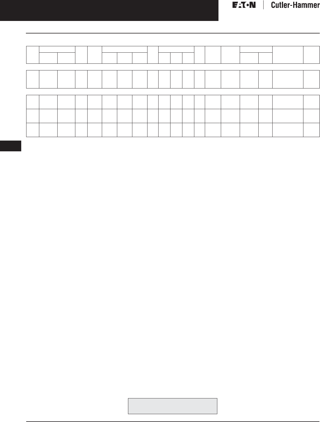
November 2003
9-30
For more information visit: www.cutler-hammer.eaton.com CA08101001E
Transformers
9
Electrostatically Shielded Transformers
Three-Phase, Types EPT, DT-3, 60 Hz Vol. 1, Ref. No. [0330]
Table 9-30. Three-Phase Selection Information — Types EPT, DT-3, 60 Hz
Center Tap capacity limited to 5% of rated kVA.
Note: Contact your local Cutler-Hammer sales office for CE Mark transformer requirements.
kVA Full Cap. Taps Type °C
Temp.
Rise
Dimensions (Inches) Wt.
Lbs.
Dimensions (mm) Wt.
kg
Frame Wiring
Diagram
Number
Weathershield Style
Number
Price
U.S. $
FCAN FCBN H W D H W D Catalog
Number
Price
U.S. $
480 ∆ Volts to 240 ∆ Volts
3
6
9
15
—
—
—
—
2@-5%
2@-5%
4@-2.5%
4@-2.5%
EPT
EPT
EPT
EPT
115
115
115
115
13-3/8
15-7/8
15-7/8
17-3/8
16
16-1/2
16-1/2
19-3/4
8-3/8
9-7/8
9-7/8
10-1/2
116
143
166
275
339
403
403
441
404
419
419
502
211
251
251
266
52
64
75
75
FR201
FR200
FR103
FR95
88A
88A
505B
505B
Indoor-
Outdoor
—
—
—
—
Y48G24E03A
Y48G24E06A
Y48J24E09A
Y48J24E15A
1,310.
1,590.
2,060.
2,585.
480 ∆ Volts to 240 ∆ Volts With 120 Volt Lighting Tap on B Phase
15
30
45
2@+2.5%
2@+2.5%
2@+2.5%
4@-2.5%
4@-2.5%
4@-2.5%
DT-3
DT-3
DT-3
150
150
150
25
30-1/8
30-1/8
20-1/8
20-1/8
20-1/8
14-1/8
14-1/8
14-1/8
152
230
310
635
765
765
511
511
511
359
359
359
69
104
140
FR909
FR910A
FR912A
284B
284B
284B
WS31
WS31
WS31
350.
350.
350.
V48M22E15B
V48M22E30A
V48M22E45A
1,700.
2,200.
2,750.
75
112.5
150
2@+2.5%
2@+2.5%
2@+2.5%
4@-2.5%
4@-2.5%
4@-2.5%
DT-3
DT-3
DT-3
150
150
150
39-3/8
39-3/8
46-1/8
26-1/8
26-1/8
28
19-1/8
19-1/8
23
480
600
760
1000
1000
1171
663
663
712
485
485
585
217
272
344
FR914B
FR915B
FR916A
284B
284B
284B
WS33
WS33
WS19
350.
350.
350.
V48M22E75A
V48M22E12A
V48M22E49A
3,760.
5,390.
6,830.
225
300
500
2@+2.5%
2@+2.5%
2@+2.5%
4@-2.5%
4@-2.5%
4@-2.5%
DT-3
DT-3
DT-3
150
150
150
56
62-1/4
75
31-1/4
31-1/4
44-1/2
24-1/4
30-1/4
36
1100
1600
2400
1422
1581
1905
793
794
1130
616
768
914
499
728
1088
FR917
FR918A
FR919
284B
284B
293A
WS34
WS34
WS35
800.
800.
1,360.
V48M22E22A
V48M22E33A
V48M22E55A
10,000.
12,650.
20,150.
For other ratings or styles not shown, or for
special enclosure types (including stainless
steel) refer to Eaton’s Cutler-Hammer business. Discount Symbol . . . . . . . . . . . . . . . . . . . . . . . . DT-1
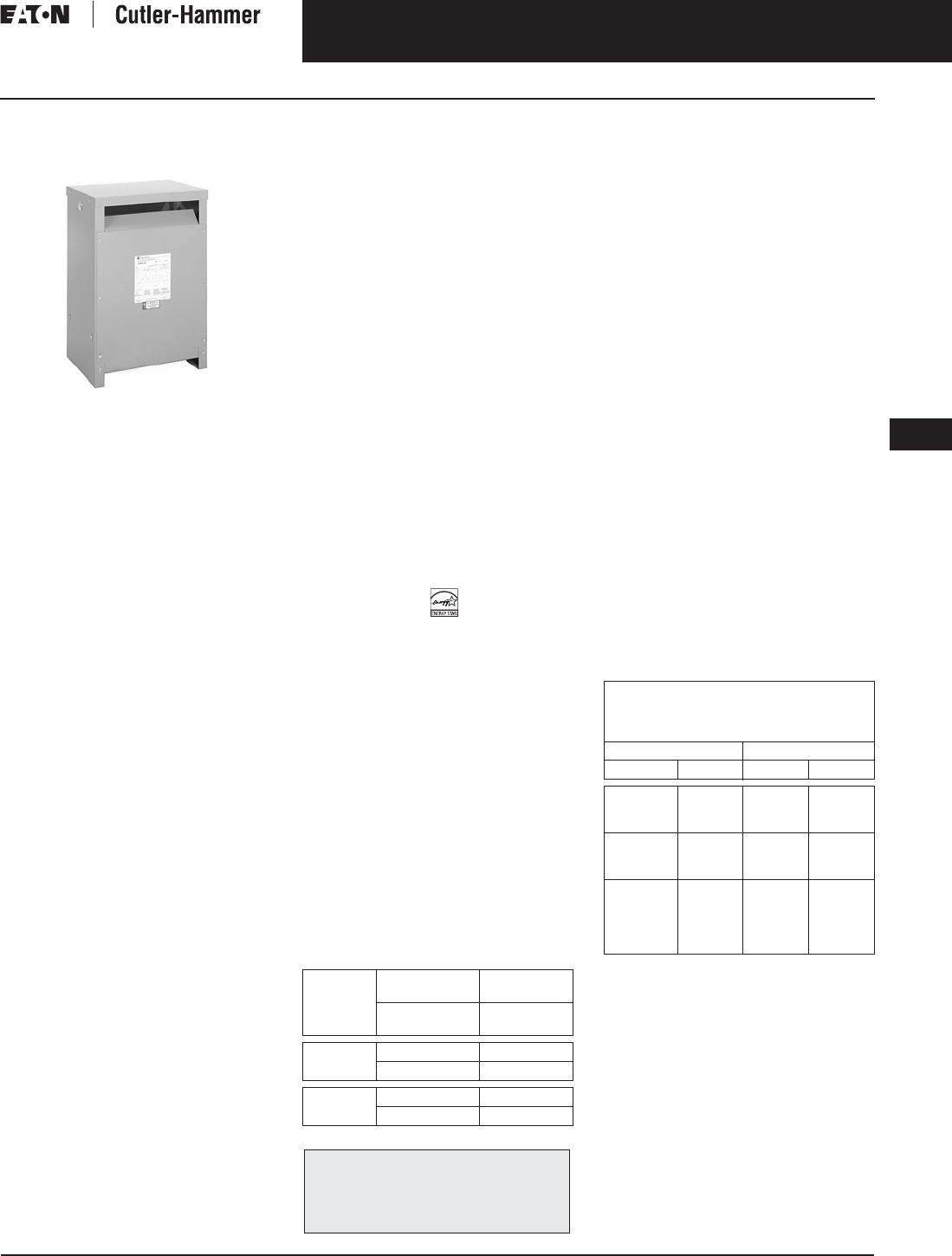
November 2003
CA08101001E For more information visit: www.cutler-hammer.eaton.com
9-31
Transformers
9
Energy Efficient Transformers
Single- and Three-Phase, Types EP, DS-3, EPT, DT-3, 60 Hz
Vol. 1, Ref. No. [0331]
Single- and Three-Phase,
Types EP, DS-3, EPT, DT-3, 60 Hz
Type DT-3
Product Description
Types EP, EPT
■Sand and Resin Encapsulated design.
■Suitable for indoor or outdoor
applications.
■Totally enclosed, non-ventilated
enclosures.
■Enclosures are NEMA 3R rated.
■Mountable in any position indoors
and upright only outdoors.
■185ºC Insulation System, 115ºC rise
standard.
■Available in single-phase ratings
through 37.5 kVA and 4160 volts
primary (EP).
■Available in three-phase ratings
through 75 kVA and 4160 volts
primary (EPT).
Types DS-3, DT-3
■Ventilated, NEMA 2 enclosure
standard.
■Suitable for indoor applications,
outdoors when weathershields are
also installed.
■Upright mounting only.
■220ºC Insulation System, 150ºC rise
standard.
■Available in single-phase ratings
15 – 167 kVA and up to 4160 volts
primary (DS-3).
■Available in three-phase ratings
15 – 1500 kVA and up to 4160 volts
primary (DT-3).
Application Description
Low Temperature Rise Energy Efficient
transformers are designed with lower
than normal conductor and total
losses. Temperature rise is therefore
lower resulting in greatly improved life
expectancies and substantial increases
in overload capabilities. 80°C and
115°C rise transformers can help cut
operating expenses for systems
requiring unit loading at 80 to 100% of
the nameplate rating, 24 hours a day,
or where load growth is expected.
A 115°C rise transformer can carry
a continuous 15% overload, and the
80°C rise a 30% overload, without
exceeding the insulation rating or
seriously reducing the life expectancy
of the transformer. However, when
operating in an overload condition,
the internal temperature increases
as a result of the higher conductor
losses. Efficiency decreases under this
condition. Since transformers operate
beyond nameplate capacities usually
during peak load periods, the
benefits remain.
NEMA TP-1-1996, compliant
Energy Efficient Transformers are
specifically designed to meet the
energy efficiency standards set forth
in NEMA Standards publication,
TP-1-1996, “Guide for Determining
Energy Efficiency for Distribution
Transformers.” Surveys have shown
that the average loading of low volt-
age dry-type distribution transformers,
over a 24 hour period, is approxi-
mately 35%. NEMA TP-1 compliant
transformers are optimized to offer
maximum efficiency at 35% of name-
plate rating. In applications where the
Eaton’s Cutler-Hammer low tempera-
ture rise (115ºC or 80ºC) product offers
significant energy savings.
The range of products covered by
NEMA TP-1-1996 are:
Table 9-31. NEMA TP-1-1996 Product Range
Transformers that are currently specifi-
cally excluded from the scope of
NEMA Standard TP-1-1996 include:
■Liquid-filled transformers below
10 kVA.
■Dry-type transformers below 15 kVA.
■ac and dc drives transformers.
■Rectifier transformers and transform-
ers designed for high harmonics.
■Autotransformers.
■Non-distribution transformers, such
as UPS transformers.
■Special impedance, regulation, or
harmonic transformers.
■Regulating transformers.
■Sealed and non-ventilated
transformers.
■Retrofit transformers.
■Machine tool transformers.
■Welding transformers.
■Transformers with tap ranges
greater than 15%.
■Transformers with a frequency other
than 60 Hz.
■Grounding transformers.
■Testing transformers.
Efficiency levels set forth in
NEMA TP-1-1996.
Table 9-32. NEMA TP-1-1996 Efficiency Levels
Features, Benefits
and Functions
■UL listed.
■60 Hz operation (except as noted).
■Short-term overload capability as
required by ANSI.
■Meet NEMA ST-20 sound levels.
Voltage
Class
Primary
Voltage
34.5 kV
and below
Secondary
Voltage
600 V
and below
Dry-Type
Rating
Single-Phase 10 – 833 kVA
Three-Phase 15 – 2500 kVA
Liquid
Rating
Single-Phase 10 – 833 kVA
Three-Phase 15 – 2500 kVA
The following pages provide listings for most
standard transformer ratings and styles.
For other ratings or styles not shown, or for
special enclosure types (including stainless
steel) refer to Eaton’s Cutler-Hammer business.
Tables of Energy Efficiency
NEMA Class 1 Efficiency Levels
dry-type Distribution Transformers —
Low Voltage
Single-Phase Three-Phase
kVA Efficiency kVA Efficiency
15
25
37.5
97.7
98.0
98.2
15
30
45
97.0
97.5
97.7
50
75
100
98.3
98.5
98.6
75
112.5
150
98.0
98.2
98.3
167
250
333
—
—
98.7
98.8
98.9
—
—
225
300
500
750
1000
98.5
98.6
98.7
98.8
98.9

November 2003
9-32
For more information visit: www.cutler-hammer.eaton.com CA08101001E
Transformers
9
Energy Efficient Transformers
Single- and Three-Phase, Types EP, DS-3, EPT, DT-3, 60 Hz Vol. 1, Ref. No. [0332]
Standards and Certifications
Industry Standards
All Cutler-Hammer dry-type distribution
and control transformers by Eaton
Corporation are built and tested in
accordance with applicable NEMA,
ANSI and IEEE Standards. All 600 volt
class transformers are UL listed unless
otherwise noted.
Seismically Qualified
Cutler-Hammer manufactured dry-type
distribution transformers are seismi-
cally qualified, and exceed require-
ments of the Uniform Building Code
(UBC) and California Code Title 24.
Options and Accessories
Please refer to Page 9-120.
Product Specifications
Frequency
Cutler-Hammer standard dry-type dis-
tribution transformers are designed
for 60 Hertz operation. Transformers
required for other frequencies are
available and must be specifically
designed.
Overload Capability
Short-term overload is designed into
transformers as required by ANSI.
dry-type distribution transformers
will deliver 200% nameplate load for
one half hour; 150% load for one hour;
and 125% load for four hours without
being damaged provided that a con-
stant 50% load precedes and follows
the overload. See ANSI C57.96-01.250
for additional limitations.
Continuous overload capacity is not
deliberately designed into a trans-
former because the design objective is
to be within the allowed winding tem-
perature rise with nameplate loading.
Insulation System and Temperature Rise
Industry standards classify insulation
systems and rise as shown below:
Table 9-33. Insulation System Classification
The design life of transformers having
different insulation systems is the
same — the lower temperature systems
are designed for the same life as the
higher temperature systems.
Enclosures
Cutler-Hammer ventilated transform-
ers, Types DS-3 and DT-3, utilize a
NEMA 2 rated (drip-proof) enclosure
as standard, and are rated NEMA 3R
with the addition of weathershields.
Cutler-Hammer encapsulated trans-
formers, Types EP and EPT, utilize a
NEMA 3R rated enclosure.
Sound Levels
All Cutler-Hammer 600 volt class
general purpose dry-type distribution
transformers are designed to meet
NEMA ST-20 sound levels listed here.
These are the sound levels measured
in a soundproof environment. Actual
sound levels measured at an installa-
tion will likely be higher due to electri-
cal connections and environmental
conditions. Lower sound levels are
available and should be specified
when the transformer is going to
be installed in an area where sound
may be a concern.
Table 9-34. Average Sound Levels
Winding Terminations
Primary and secondary windings are
terminated in the wiring compartment.
Encapsulated units have copper leads
or stabs brought out for connections.
Ventilated transformers have leads
brought out to aluminum pads that
are pre-drilled to accept Cu/Al lugs.
Lugs are not supplied with these
transformers. The Cutler-Hammer
business recommends external cables
be rated 90°C (sized at 75°C ampacity)
for encapsulated designs and 75°C for
ventilated designs.
Series-Multiple Windings
Series-multiple windings consist of
2 similar coils in each winding which
can be connected in series or parallel
(multiple). Transformers with series-
multiple windings are designated with
an “X” or “/” between the voltage
ratings, such as voltages of “120/240”
or “240 X 480.” If the series-multiple
winding is designated by an “X,” the
winding can be connected only for a
series or parallel. With the “/” designa-
tion, a mid-point also becomes avail-
able in addition to the series or parallel
connection. As an example, a 120 X
240 winding can be connected for
either 120 (parallel) or 240 (series), but
a 120/240 winding can be connected
for 120 (parallel), or 240 (series), or
240 with a 120 mid-point.
Technical Data
and Specifications
Please refer Page 9-122.
Ambient +
Winding
Rise
+
Hot
Spot
=
Temp.
Class
40°C
40°C
40°C
40°C
55°C
80°C
115°C
150°C
10°C
30°C
30°C
30°C
105°C
150°C
185°C
220°C
NEMA ST-20 Average Sound Level (dB)
kVA Ventilated Encapsulated
0 – 9
10 – 50
51 – 150
151 – 300
40
45
50
55
45
50
55
57
301 – 500
501 – 700
701 – 1000
1001 – 1500
60
62
64
65
59
61
63
64
The following pages provide listings for most
standard transformer ratings and styles.
For other ratings or styles not shown, or for
special enclosure types (including stainless
steel) refer to Eaton’s Cutler-Hammer business.

November 2003
CA08101001E For more information visit: www.cutler-hammer.eaton.com
9-33
Transformers
9
NEMA TP-1 Energy Efficient Transformers
Single-Phase, Type DS-3
Vol. 1, Ref. No. [0333]
Product Selection
Additional Product Selection information begins on Page 9-136.
Table 9-35. Single-Phase Selection Information — Type DS-3 60 Hz NEMA TP-1 Compliant, Labeled
+1 – 5%, -2 – 5% at 240 volts primary; +2 – 2.5%, -4 – 2.5% at 480 volts primary.
480 volt primary only.
kVA Full Cap. Taps Type °C
Temp.
Rise
Dimensions (Inches) Wt.
Lbs.
Dimensions (mm) Wt.
kg
Frame Wiring
Diagram
Number
Weathershield Style
Number
Price
U.S. $
FCAN FCBN H W D H W D Catalog
Number
Price
U.S. $
240 x 480 Volts to 120/240 Volts, Aluminum Windings
15
25
37.5
50
DS-3
DS-3
DS-3
DS-3
150
150
150
150
31-1/4
31-1/4
37-5/8
42-1/8
22-5/8
22-5/8
22-5/8
24
17-1/2
17-1/2
19-1/2
23-3/8
212
212
306
510
768
768
956
1070
428
428
574
610
402
402
495
594
67
67
139
232
816
816
817
819
3XA
3XA
3XA
3XA
WS11
WS11
WS11
WS16
350.
350.
350.
800.
T20P11S15EE
T20P11S25EE
T20P11S37EE
T20P11S50EE
1,810.
2,420.
2,860.
3,500.
75
100
167
2@+2.5%
4@-2.5%
DS-3
DS-3
DS-3
150
150
150
42-1/8
62-1/2
62-1/2
24
30
30
23-3/8
34
34
510
1200
1200
1070
1597
1597
610
762
762
594
863
863
232
545
545
819
814
814
3XA
3XA
288A
WS16
WS13
WS13
800.
800.
800.
T20P11S75EE
T20P11S99EE
T48M11S67EE
4,910.
6,020.
13,300.
15
25
37.5
DS-3
DS-3
DS-3
115
115
115
31-1/4
31-1/4
37-5/8
22-5/8
22-5/8
22-5/8
17-1/2
17-1/2
19-1/2
212
212
340
768
768
956
428
428
574
402
402
495
67
67
154
816
816
818
3XA
3XA
3XA
WS11
WS11
WS11
350.
350.
350.
T20P11F15EE
T20P11F25EE
T20P11F37EE
2,120.
2,820.
3,380.
50
75
100
DS-3
DS-3
DS-3
115
115
115
42-1/8
42-1/8
62-1/2
24
24
30
23-3/8
23-3/8
34
510
510
1200
1070
1070
1597
610
610
762
594
594
863
232
232
545
819
819
814
3XA
3XA
288A
WS16
WS16
WS13
800.
800.
800.
T20P11F50EE
T20P11F75EE
T20P11F99EE
4,100.
5,790.
7,080.
15
25
37.5
DS-3
DS-3
DS-3
80
80
80
31-1/4
37-5/8
37-5/8
22-5/8
22-5/8
22-5/8
17-1/2
19-1/2
19-1/2
212
306
340
768
956
956
428
574
574
402
495
495
67
139
154
816
817
818
3XA
3XA
3XA
WS11
WS11
WS11
350.
350.
350.
T20P11B15EE
T20P11B25EE
T20P11B37EE
2,540.
3,400.
4,010.
50
75
100
DS-3
DS-3
DS-3
80
80
80
42-1/8
42-1/8
62-1/2
24
24
30
23-3/8
23-3/8
34
510
600
1200
1070
1070
1597
610
610
762
594
594
863
232
272
545
819
820
814
3XA
3XA
288A
WS16
WS16
WS13
800.
800.
800.
T20P11B50EE
T20P11B75EE
T20P11B99EE
4,900.
6,900.
9,220.
240 x 480 Volts to 120/240 Volts, Copper Windings
15
25
37.5
50
DS-3
DS-3
DS-3
DS-3
150
150
150
150
31-1/4
37-5/8
37-5/8
37-5/8
22-5/8
22-5/8
22-5/8
22-5/8
17-1/2
19-1/2
19-1/2
19-1/2
237
345
345
381
768
956
956
956
428
574
574
574
402
495
495
495
108
158
158
173
816
817
817
818
3XA
3XA
3XA
3XA
WS11
WS11
WS11
WS11
350.
350.
350.
350.
T20P11S15CUEE
T20P11S25CUEE
T20P11S37CUEE
T20P11S50CUEE
2,450.
3,280.
3,890.
4,750.
75
100
167
2@+2.5%
4@-2.5%
DS-3
DS-3
DS-3
150
150
150
42-1/8
62-1/2
62-1/2
24
30
30
23-3/8
34
34
614
1440
1440
1070
1597
1597
610
762
762
594
863
863
279
655
655
819
814
814
3XA
288A
288A
WS16
WS13
WS13
800.
800.
800.
T20P11S75CUEE
T20P11S99CUEE
T48M11S67CUEE
6,660.
8,220.
16,625.
15
25
37.5
DS-3
DS-3
DS-3
115
115
115
31-1/4
37-5/8
37-5/8
22-5/8
22-5/8
22-5/8
17-1/2
19-1/2
19-1/2
237
345
381
768
956
956
428
574
574
402
495
495
108
158
173
816
817
818
3XA
3XA
3XA
WS11
WS11
WS11
350.
350.
350.
T20P11F15CUEE
T20P11F25CUEE
T20P11F37CUEE
2,810.
3,760.
4,440.
50
75
100
DS-3
DS-3
DS-3
115
115
115
42-1/8
42-1/8
62-1/2
24
24
30
23-3/8
23-3/8
34
614
614
1440
1070
1070
1597
610
610
762
594
594
863
279
279
655
819
819
814
3XA
3XA
288A
WS16
WS16
WS13
800.
800.
800.
T20P11F50CUEE
T20P11F75CUEE
T20P11F99CUEE
5,430.
7,620.
9,350.
15
25
37.5
DS-3
DS-3
DS-3
80
80
80
31-1/4
37-5/8
37-5/8
22-5/8
22-5/8
22-5/8
17-1/2
19-1/2
19-1/2
237
345
381
768
956
956
428
574
574
402
495
495
108
158
173
816
817
818
3XA
3XA
3XA
WS11
WS11
WS11
350.
350.
350.
T20P11B15CUEE
T20P11B25CUEE
T20P11B37CUEE
3,260.
4,360.
5,150.
50
75
100
2@+2.5%
4@-2.5%
DS-3
DS-3
DS-3
80
80
80
42-1/8
42-1/8
62-1/2
24
24
30
23-3/8
23-3/8
34
614
700
1440
1070
1070
1597
610
610
762
594
594
863
279
318
655
819
820
814
3XA
3XA
288A
WS16
WS16
WS13
800.
800.
800.
T20P11B50CUEE
T20P11B75CUEE
T48M11B99CUEE
6,300.
8,850.
11,610.
208 Volts to 120/240 Volts, Aluminum Windings
15
25
37.5
50
2@+2.5%
2@+2.5%
2@+2.5%
2@+2.5%
4@-2.5%
4@-2.5%
4@-2.5%
4@-2.5%
DS-3
DS-3
DS-3
DS-3
150
150
150
150
31-1/4
31-1/4
37-5/8
42-1/8
22-5/8
22-5/8
22-5/8
24
17-1/2
17-1/2
19-1/2
23-3/8
212
212
306
510
768
768
956
1070
428
428
574
610
402
402
495
594
67
67
139
232
816
816
817
819
260A
260A
260A
260A
WS11
WS11
WS11
WS16
350.
350.
350.
800.
T29M11S15EE
T29M11S25EE
T29M11S37EE
T29M11S50EE
3,015.
5,275.
6,460.
7,840.
75
100
1@+5%
2@+2.5%
2@-5%
4@-2.5%
DS-3
DS-3
150
150
42-1/8
62-1/2
24
30
23-3/8
34
510
1200
1070
1597
610
762
594
863
232
545
819
814
551A
260A
WS16
WS13
800.
800.
T29R11S75EE
T29M11S99EE
11,085.
13,770.
277 Volts to 120/240 Volts, Aluminum Windings
15
25
37.5
50
2@+2.5%
2@+2.5%
2@+2.5%
2@+2.5%
4@-2.5%
4@-2.5%
4@-2.5%
4@-2.5%
DS-3
DS-3
DS-3
DS-3
150
150
150
150
31-1/4
31-1/4
37-5/8
42-1/8
22-5/8
22-5/8
22-5/8
24
17-1/2
17-1/2
19-1/2
23-3/8
212
212
306
510
768
768
956
1070
428
428
574
610
402
402
495
594
67
67
139
232
816
816
817
819
262C
262C
262C
262C
WS11
WS11
WS11
WS16
350.
350.
350.
800.
T27M11S15EE
T27M11S25EE
T27M11S37EE
T27M11S50EE
3,015.
5,275.
6,460.
7,840.
75
100
2@+2.5%
2@+2.5%
4@-2.5%
4@-2.5%
DS-3
DS-3
150
150
42-1/8
62-1/2
24
30
23-3/8
34
510
1200
1070
1597
610
762
594
863
232
545
819
814
262C
262C
WS16
WS13
800.
800.
T27M11S75EE
T27M11S99EE
11,085.
13,770.
For other ratings or styles not shown, or for
special enclosure types (including stainless
steel) refer to Eaton’s Cutler-Hammer business. Discount Symbol . . . . . . . . . . . . . . . . . . . . . . . . . DT-1
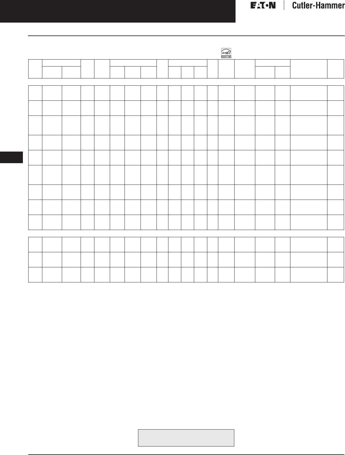
November 2003
9-34
For more information visit: www.cutler-hammer.eaton.com CA08101001E
Transformers
9
NEMA TP-1 Energy Efficient Transformers
Three-Phase, Type DT-3 Vol. 1, Ref. No. [0334]
Table 9-36. Three-Phase Selection Information — Type DT-3 60 Hz NEMA TP-1 Compliant, Labeled
Refer to your local Cutler-Hammer sales office.
Note: Additional voltage combinations are available. Contact your local Cutler-Hammer sales office for assistance if the voltage you require is
not included in this catalog.
kVA Full Cap. Taps Type °C
Temp.
Rise
Dimensions (Inches) Wt.
Lbs.
Dimensions (mm) Wt.
kg
Frame Wiring
Diagram
Number
Weathershield Style
Number
Price
U.S. $
FCAN FCBN H W D H W D Catalog
Number
Price
U.S. $
480 Volts to 208Y/120 Volts, Aluminum Windings
15
30
45
1@+2.5%
2@+2.5%
2@+2.5%
3@-2.5%
4@-2.5%
4@-2.5%
DT-3
DT-3
DT-3
150
150
150
25
30
30
20-1/8
20-1/8
20-1/8
14-1/8
14-1/8
14-1/8
152
310
310
635
762
762
511
511
511
359
359
359
69
140
140
909
912A
912A
375A
280B
280B
WS31
WS31
WS31
350.
350.
350.
V48U28T15EE
V48M28T30EE
V48M28T45EE
1,830.
2,330.
2,840.
75
112.5
150
2@+2.5%
2@+2.5%
2@+2.5%
4@-2.5%
4@-2.5%
4@-2.5%
DT-3
DT-3
DT-3
150
150
150
39-1/4
39-1/4
46-5/8
26-1/8
26-1/8
28
19-1/8
19-1/8
23
480
600
785
995
995
1183
663
663
710
486
486
584
217
272
357
914B
915B
916A
280B
280B
280B
WS33
WS33
WS19
350.
350.
350.
V48M28T75EE
V48M28T12EE
V48M28T49EE
4,025.
5,850.
7,300.
225
300
500
750
2@+2.5%
2@+2.5%
2@+2.5%
2@+2.5%
4@-2.5%
4@-2.5%
4@-2.5%
4@-2.5%
DT-3
DT-3
DT-3
DT-3
150
150
150
150
56-1/4
62-1/4
75
75
31-1/4
31-1/4
44-1/2
44-1/2
24-1/4
30-1/4
35-3/4
35-3/4
1100
1444
2400
2900
1427
1579
1905
1905
793
793
1129
1129
616
768
908
908
499
656
1088
1315
917
918A
919
920
280B
280B
275A
275A
WS34
WS34
WS35
WS35
800.
800.
1,360.
1,360.
V48M28T22EE
V48M28T33EE
V48M28T55EE
V48M28T77EE
10,680.
13,500.
21,800.
36,800.
15
30
45
1@+2.5%
2@+2.5%
2@+2.5%
3@-2.5%
4@-2.5%
4@-2.5%
DT-3
DT-3
DT-3
115
115
115
25
30
39-1/4
20-1/8
20-1/8
26-1/8
14-1/8
14-1/8
19-1/8
152
310
480
635
762
995
511
511
663
359
359
486
69
140
217
909
912A
914B
375A
280B
280B
WS31
WS31
WS33
350.
350.
350.
V48U28F15EE
V48M28F30EE
V48M28F45EE
2,380.
2,840.
3,475.
75
112.5
150
2@+2.5%
2@+2.5%
2@+2.5%
4@-2.5%
4@-2.5%
4@-2.5%
DT-3
DT-3
DT-3
115
115
115
39-1/4
39-1/4
46-5/8
26-1/8
26-1/8
28
19-1/8
19-1/8
23
600
600
785
995
995
1183
663
663
710
486
486
584
272
272
357
915B
915B
916A
280B
280B
280B
WS33
WS33
WS19
350.
350.
350.
V48M28F75EE
V48M28F12EE
V48M28F49EE
5,290.
7,215.
9,850.
225
300
500
750
2@+2.5%
2@+2.5%
2@+2.5%
2@+2.5%
4@-2.5%
4@-2.5%
4@-2.5%
4@-2.5%
DT-3
DT-3
DT-3
DT-3
115
115
115
115
56-1/4
75
75
75
31-1/4
44-1/2
44-1/2
44-1/2
24-1/4
35-3/4
35-3/4
35-3/4
1100
2400
2900
2900
1427
1905
1905
1905
793
1129
1129
1129
616
908
908
908
499
1088
1315
1315
917
919
920
920
280B
275A
275A
275A
WS34
WS34
WS35
WS35
800.
800.
1,360.
1,360.
V48M28F22EE
V48M28F33EE
V48M28F55EE
V48M28F77EE
13,150.
16,490.
25,070.
40,365.
15
30
45
2@+2.5%
2@+2.5%
2@+2.5%
4@-2.5%
4@-2.5%
4@-2.5%
DT-3
DT-3
DT-3
80
80
80
30
30
39-1/4
20-1/8
20-1/8
26-1/8
14-1/8
14-1/8
19-1/8
230
310
480
762
762
995
511
511
663
359
359
486
104
140
217
910A
912A
914B
280B
280B
280B
WS31
WS31
WS33
350.
350.
350.
V48M28B15EE
V48M28B30EE
V48M28B45EE
2,800.
3,250.
4,085.
75
112.5
150
2@+2.5%
2@+2.5%
2@+2.5%
4@-2.5%
4@-2.5%
4@-2.5%
DT-3
DT-3
DT-3
80
80
80
39-1/4
46-5/8
56-1/4
26-1/8
28
31-1/4
19-1/8
23
24-1/4
600
785
1100
995
1183
1427
663
710
793
486
584
616
272
357
499
915B
916A
917
280B
280B
280B
WS33
WS19
WS34
350.
350.
800.
V48M28B75EE
V48M28B12EE
V48M28B49EE
6,190.
8,450.
11,550.
225
300
500
2@+2.5%
2@+2.5%
2@+2.5%
4@-2.5%
4@-2.5%
4@-2.5%
DT-3
DT-3
DT-3
80
80
80
62-1/4
75
75
31-1/4
44-1/2
44-1/2
30-1/4
35-3/4
35-3/4
1444
2400
2900
1579
1905
1905
793
1129
1129
768
908
908
656
1088
1315
918A
919
920
280B
275A
275A
WS34
WS35
WS35
800.
1,360.
1,360.
V48M28B22EE
V48M28B33EE
V48M28B55EE
15,450.
19,350.
29,430.
480 Volts to 240 Volts with 120 Volt Lighting Tap Phase B, Aluminum Windings
15
30
45
1@+2.5%
2@+2.5%
2@+2.5%
3@-2.5%
4@-2.5%
4@-2.5%
DT-3
DT-3
DT-3
150
150
150
25
30
39-1/4
20-1/8
20-1/8
26-1/8
14-1/8
14-1/8
19-1/8
152
310
480
635
762
995
511
511
663
359
359
486
69
140
217
909
912A
914B
282B
282B
WS31
WS31
WS33
350.
350.
350.
V48U22T15EE
V48M22T30EE
V48M22T45EE
2,095.
2,800.
3,500.
75
112.5
150
2@+2.5%
2@+2.5%
2@+2.5%
4@-2.5%
4@-2.5%
4@-2.5%
DT-3
DT-3
DT-3
150
150
150
39-1/4
39-1/4
46-5/8
26-1/8
26-1/8
28
19-1/8
19-1/8
23
600
600
785
995
995
1183
663
663
710
486
486
584
272
272
357
915B
915B
916A
282B
282B
282B
WS33
WS33
WS19
350.
350.
350.
V48M22T75EE
V48M22T12EE
V48M22T49EE
4,830.
7,020.
8,760.
225
300
500
2@+2.5%
2@+2.5%
2@+2.5%
4@-2.5%
4@-2.5%
4@-2.5%
DT-3
DT-3
DT-3
150
150
150
56-1/4
75
75
31-1/4
44-1/2
44-1/2
24-1/4
35-3/4
35-3/4
1100
2400
2900
1427
1905
1905
793
1129
1129
616
908
908
499
1088
1315
917
919
920
282B
282B
291A
WS34
WS35
WS35
800.
1,360.
1,360.
V48M22T22EE
V48M22T33EE
V48M22T55EE
12,850.
16,300.
26,500.
For other ratings or styles not shown, or for
special enclosure types (including stainless
steel) refer to Eaton’s Cutler-Hammer business. Discount Symbol . . . . . . . . . . . . . . . . . . . . . . . . . DT-1
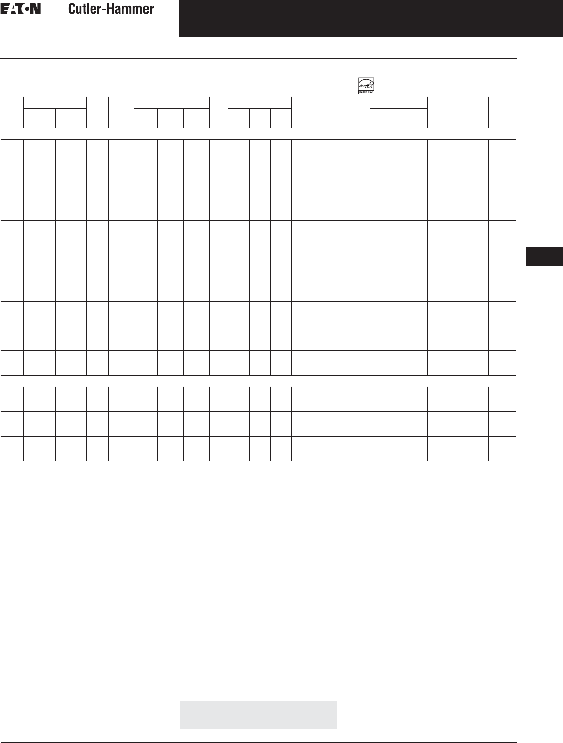
November 2003
CA08101001E For more information visit: www.cutler-hammer.eaton.com
9-35
Transformers
9
NEMA TP-1 Energy Efficient Transformers
Three-Phase, Type DT-3
Vol. 1, Ref. No. [0335]
Table 9-36. (Continued) Three-Phase Selection Information — Type DT-3 60 Hz NEMA TP-1 Compliant, Labeled
Refer to your local Cutler-Hammer sales office.
Note: Additional voltage combinations are available. Contact your local Cutler-Hammer sales office for assistance if the voltage you require is
not included in this catalog.
kVA Full Cap. Taps Type °C
Temp.
Rise
Dimensions (Inches) Wt.
Lbs.
Dimensions (mm) Wt.
kg
Frame Wiring
Diagram
Number
Weathershield Style
Number
Price
U.S. $
FCAN FCBN H W D H W D Catalog
Number
Price
U.S. $
480 Volts to 208Y/120 Volts, Copper Windings
15
30
45
2@+2.5%
2@+2.5%
2@+2.5%
4@-2.5%
4@-2.5%
4@-2.5%
DT-3
DT-3
DT-3
150
150
150
25
30
30
20-1/8
20-1/8
20-1/8
14-1/8
14-1/8
14-1/8
172
370
370
635
762
762
511
511
511
359
359
359
78
168
168
909
912A
912A
280B
280B
280B
WS31
WS31
WS31
350.
350.
350.
V48M28T15CUEE
V48M28T30CUEE
V48M28T45CUEE
2,800.
3,170.
3,870.
75
112.5
150
2@+2.5%
2@+2.5%
2@+2.5%
4@-2.5%
4@-2.5%
4@-2.5%
DT-3
DT-3
DT-3
150
150
150
39-1/4
39-1/4
46-5/8
26-1/8
26-1/8
28
19-1/8
19-1/8
23
675
675
870
995
995
1183
663
663
710
486
486
584
307
307
391
915B
915B
916A
280B
280B
280B
WS33
WS33
WS19
350.
350.
350.
V48M28T75CUEE
V48M28T12CUEE
V48M28T49CUEE
5,470.
7,960.
9,940.
225
300
500
750
2@+2.5%
2@+2.5%
2@+2.5%
2@+2.5%
4@-2.5%
4@-2.5%
4@-2.5%
4@-2.5%
DT-3
DT-3
DT-3
DT-3
150
150
150
150
56-1/4
62-1/4
75
75
31-1/4
31-1/4
44-1/2
44-1/2
24-1/4
30-1/4
35-3/4
35-3/4
1200
1894
3100
3600
1427
1579
1905
1905
793
793
1129
1129
616
768
908
908
545
861
1409
1636
917
918A
919
920
280B
280B
275A
275A
WS34
WS34
WS35
WS35
800.
800.
1,360.
1,360.
V48M28T22CUEE
V48M28T33CUEE
V48M28T55CUEE
V48M28T77CUEE
15,500.
18,500.
29,800.
47,390.
15
30
45
2@+2.5%
2@+2.5%
2@+2.5%
2@-2.5%
4@-2.5%
4@-2.5%
DT-3
DT-3
DT-3
115
115
115
25
30
39-1/4
20-1/8
20-1/8
26-1/8
14-1/8
14-1/8
19-1/8
172
370
550
635
762
995
511
511
663
359
359
486
78
168
250
909
912A
914B
266W
280B
280B
WS31
WS31
WS33
350.
350.
350.
V48D28F15CUEE
V48M28F30CUEE
V48M28F45CUEE
3,210.
3,825.
4,690.
75
112.5
150
2@+2.5%
2@+2.5%
2@+2.5%
4@-2.5%
4@-2.5%
4@-2.5%
DT-3
DT-3
DT-3
115
115
115
39-1/4
39-1/4
46-5/8
26-1/8
26-1/8
28
19-1/8
19-1/8
23
675
675
870
995
995
1183
663
663
710
486
486
584
307
307
391
915B
915B
916A
280B
280B
280B
WS33
WS33
WS19
350.
350.
350.
V48M28F75CUEE
V48M28F12CUEE
V48M28F49CUEE
7,140.
9,740.
13,300.
225
300
500
750
2@+2.5%
2@+2.5%
2@+2.5%
2@+2.5%
4@-2.5%
4@-2.5%
4@-2.5%
4@-2.5%
DT-3
DT-3
DT-3
DT-3
115
115
115
115
56-1/4
75
75
75
31-1/4
44-1/2
44-1/2
44-1/2
24-1/4
35-3/4
35-3/4
35-3/4
1200
3100
3100
3600
1427
1905
1905
1905
793
1129
1129
1129
616
908
908
908
545
1409
1409
1636
917
919
919
920
280B
275A
275A
275A
WS34
WS35
WS35
WS35
800.
1,360.
1,360.
1,360.
V48M28F22CUEE
V48M28F33CUEE
V48M28F55CUEE
V48M28F77CUEE
17,750.
22,250.
33,790.
52,000.
15
30
45
2@+2.5%
2@+2.5%
2@+2.5%
4@-2.5%
4@-2.5%
4@-2.5%
DT-3
DT-3
DT-3
80
80
80
30
30
39-1/4
20-1/8
20-1/8
26-1/8
14-1/8
14-1/8
19-1/8
300
370
675
762
762
995
511
511
663
359
359
486
136
168
307
910A
912A
915B
280B
280B
280B
WS31
WS31
WS33
350.
350.
350.
V48M28B15CUEE
V48M28B30CUEE
V48M28B45CUEE
3,780.
4,130.
5,510.
75
112.5
150
2@+2.5%
2@+2.5%
2@+2.5%
4@-2.5%
4@-2.5%
4@-2.5%
DT-3
DT-3
DT-3
80
80
80
39-1/4
46-5/8
56-1/4
26-1/8
28
31-1/4
19-1/8
23
24-1/4
675
870
1200
995
1183
1427
663
710
793
486
584
616
307
391
545
915B
916A
917
280B
280B
280B
WS33
WS19
WS34
350.
350.
800.
V48M28B75CUEE
V48M28B12CUEE
V48M28B49CUEE
8,350.
11,400.
15,600.
225
300
500
2@+2.5%
2@+2.5%
2@+2.5%
4@-2.5%
4@-2.5%
4@-2.5%
DT-3
DT-3
DT-3
80
80
80
62-1/4
75
75
31-1/4
44-1/2
44-1/2
30-1/4
35-3/4
35-3/4
1894
3100
3600
1579
1905
1905
793
1129
1129
768
908
908
861
1409
1636
918A
919
920
280B
275A
275A
WS34
WS35
WS35
800.
1,360.
1,360.
V48M28B22CUEE
V48M28B33CUEE
V48M28B55CUEE
20,860.
26,120.
37,060.
480 Volts to 240 Volts with 120 Volt Lighting Tap Phase B, Copper Windings
15
30
45
1@+2.5%
2@+2.5%
2@+2.5%
3@-2.5%
4@-2.5%
4@-2.5%
DT-3
DT-3
DT-3
150
150
150
25
30
39-1/4
20-1/8
20-1/8
26-1/8
14-1/8
14-1/8
19-1/8
172
370
550
635
762
995
511
511
663
359
359
486
78
168
250
909
912A
914B
282B
282B
WS31
WS31
WS33
350.
350.
350.
V48U22T15CUEE
V48M22T30CUEE
V48M22T45CUEE
2,830.
3,790.
4,730.
75
112.5
150
2@+2.5%
2@+2.5%
2@+2.5%
4@-2.5%
4@-2.5%
4@-2.5%
DT-3
DT-3
DT-3
150
150
150
39-1/4
39-1/4
46-5/8
26-1/8
26-1/8
28
19-1/8
19-1/8
23
675
675
870
995
995
1183
663
663
710
486
486
584
307
307
391
915B
915B
916A
282B
282B
282B
WS33
WS33
WS19
350.
350.
350.
V48M22T75CUEE
V48M22T12CUEE
V48M22T49CUEE
6,470.
9,480.
11,850.
225
300
500
2@+2.5%
2@+2.5%
2@+2.5%
4@-2.5%
4@-2.5%
4@-2.5%
DT-3
DT-3
DT-3
150
150
150
56-1/4
75
75
31-1/4
44-1/2
44-1/2
24-1/4
35-3/4
35-3/4
1200
3100
3600
1427
1905
1905
793
1129
1129
616
908
908
545
1409
1636
917
919
920
282B
282B
291A
WS34
WS35
WS35
800.
1,360.
1,360.
V48M22T22CUEE
V48M22T33CUEE
V48M22T55CUEE
17,380.
21,900.
35,800.
For other ratings or styles not shown, or for
special enclosure types (including stainless
steel) refer to Eaton’s Cutler-Hammer business. Discount Symbol . . . . . . . . . . . . . . . . . . . . . . . . . DT-1

November 2003
9-36
For more information visit: www.cutler-hammer.eaton.com CA08101001E
Transformers
9
Low Temperature Rise Energy Efficient Transformers
Single-Phase, Type DS-3 Vol. 1, Ref. No. [0336]
Table 9-37. Single-Phase Selection Information — Type DS-3, 60 Hz Low Temperature Rise
+1 – 5%, -2 – 5% at 240 volts primary; +2 – 2.5%, -4 – 2.5% at 480 volts primary.
480 volt primary only.
kVA Full Cap. Taps Type °C
Temp.
Rise
Dimensions (Inches) Wt.
Lbs.
Dimensions (mm) Wt.
kg
Frame Wiring
Diagram
Number
Weathershield Style
Number
Price
U.S. $
FCAN FCBN H W D H W D Catalog
Number
Price
U.S. $
240 x 480 Volts to 120/240 Volts
15
25
37.5
DS-3
DS-3
DS-3
80
80
80
30-1/4
31-1/4
37-5/8
16-7/8
22-5/8
22-5/8
15-7/8
17-1/2
19-1/2
147
212
306
768
793
953
428
574
574
402
445
495
67
96
139
FR816
FR817
FR818
3XA
3XA
3XA
WS11
WS11
WS11
350.
350.
350.
T20P11B15
T20P11B25
T20P11B37
1,980.
2,560.
3,125.
50
75
100
2@+2.5%
4@-2.5%
DS-3
DS-3
DS-3
80
80
80
37-5/8
42-1/8
62-1/8
22-5/8
24
30
19-1/2
23-3/8
34
340
510
1150
953
1070
1597
574
610
762
495
594
863
154
233
612
FR819
FR820
FR814
3XA
3XA
288A
WS16
WS16
WS13
800.
800.
800.
T20P11B50
T20P11B75
T48M11B99A
3,790.
5,350.
8,900.
15
25
37.5
DS-3
DS-3
DS-3
115
115
115
30-1/4
31-1/4
37-5/8
16-7/8
22-5/8
22-5/8
15-7/8
17-1/2
19-1/2
147
212
306
768
793
953
428
574
574
402
445
495
67
96
139
FR815
FR816
FR817
3XA
3XA
3XA
WS15
WS11
WS11
350.
350.
350.
T20P11F15
T20P11F25
T20P11F37
1,680.
2,200.
2,660.
50
75
100
DS-3
DS-3
DS-3
115
115
115
37-5/8
42-1/8
42-1/8
22-5/8
24
24
19-1/2
23-3/8
23-3/8
340
510
600
953
1070
1070
574
610
610
495
594
594
154
233
274
FR818
FR819
FR820
3XA
3XA
3XA
WS11
WS16
WS16
350.
800.
800.
T20P11F50
T20P11F75
T20P11F99
3,170.
4,520.
5,630.
For other ratings or styles not shown, or for
special enclosure types (including stainless
steel) refer to Eaton’s Cutler-Hammer business. Discount Symbol . . . . . . . . . . . . . . . . . . . . . . . . . DT-1

November 2003
CA08101001E For more information visit: www.cutler-hammer.eaton.com
9-37
Transformers
9
Low Temperature Rise Energy Efficient Transformers
Three-Phase, Types EPT and DT-3
Vol. 1, Ref. No. [0337]
Table 9-38. Three-Phase Selection Information — Types EPT, DT-3, 60 Hz Low Temperature Rise
Refer to your Cutler-Hammer sales office.
No UL label. Contact your local Cutler-Hammer sales office if UL label is required.
Note: Contact your local Cutler-Hammer sales office for CE Mark transformer requirements.
kVA Full Cap. Taps Type °C
Temp.
Rise
Dimensions (Inches) Wt.
Lbs.
Dimensions (mm) Wt.
kg
Frame Wiring
Diagram
Number
Weathershield Style
Number
Price
U.S. $
FCAN FCBN H W D H W D Catalog
Number
Price
U.S. $
480 ∆ Volts to 208Y/120 Volts
15
30
45
75
2@+2.5%
2@+2.5%
2@+2.5%
2@+2.5%
4@-2.5%
4@-2.5%
4@-2.5%
4@-2.5%
DT-3
DT-3
DT-3
DT-3
80
80
80
80
30-1/8
30-1/8
39-3/8
39-3/8
20-1/8
20-1/8
26-1/8
26-1/8
14-1/8
14-1/8
19-1/8
19-1/8
230
310
480
600
765
765
1000
1000
511
511
663
663
359
359
486
486
104
140
217
272
FR910A
FR912A
FR914B
FR915B
280B
280B
280B
280B
WS31
WS31
WS33
WS33
350.
350.
350.
350.
V48M28B15A
V48M28B30R
V48M28B45R
V48M28B75R
1,830.
2,350.
2,860.
4,040.
112.5
150
225
300
2@+2.5%
2@+2.5%
2@+2.5%
2@+2.5%
4@-2.5%
4@-2.5%
4@-2.5%
4@-2.5%
DT-3
DT-3
DT-3
DT-3
80
80
80
80
46-1/8
56
62-1/4
75
28
31-1/4
31-1/4
44-1/2
23
24-1/4
30-1/4
36
820
1100
1600
2400
1171
1422
1581
1905
712
793
794
1130
585
616
768
914
371
499
728
1088
FR916A
FR917
FR918A
FR919
280B
280B
280B
280B
WS19
WS34
WS34
WS35
350.
800.
800.
1,360.
V48M28B12R
V48M28B49P
V48M28B22P
V48M28B33R
5,850.
7,350.
10,670.
13,700.
500
750
1000
2@+2.5%
—
1@+4.2%
4@-2.5%
—
1@-4.2%
DT-3
—
DT-3
80
—
80
75
—
44-1/2
—
35-3/4
—
3000
—
1905
—
1131
—
908
—
1365
—
FR920
—
275A
—
WS35
—
1,360.
—
—
V48M28B55R
V48D28B77
V48T28B11R
22,000.
35,100.
65,100.
15
30
45
75
2@+2.5%
2@+2.5%
2@+2.5%
2@+2.5%
4@-2.5%
4@-2.5%
4@-2.5%
4@-2.5%
DT-3
DT-3
DT-3
DT-3
115
115
115
115
25
30-1/8
30-1/8
39-3/8
20-1/8
20-1/8
20-1/8
26-1/8
14-1/8
14-1/8
14-1/8
19-1/8
152
230
310
480
635
765
765
1000
511
511
511
663
359
359
359
486
69
104
140
217
FR909
FR910A
FR912A
FR914B
280B
280B
280B
280B
WS31
WS31
WS31
WS33
350.
350.
350.
350.
V48M28F15B
V48M28F30R
V48M28F45R
V48M28F75R
1,570.
2,000.
2,440.
3,450.
112.5
150
225
300
2@+2.5%
2@+2.5%
2@+2.5%
2@+2.5%
4@-2.5%
4@-2.5%
4@-2.5%
4@-2.5%
DT-3
DT-3
DT-3
DT-3
115
115
115
115
39-3/8
46-1/8
56
62-1/4
26-1/8
28
31-1/4
31-1/4
19-1/8
23
24-1/4
30-1/4
600
760
1100
1600
1000
1171
1422
1581
663
712
793
794
486
585
616
768
272
344
499
728
FR915B
FR916A
FR917
FR918A
280B
280B
280B
280B
WS19
WS33
WS34
WS34
350.
350.
800.
800.
V48M28F12R
V48M28F49P
V48M28F22P
V48M28F33P
4,950.
6,250.
9,100.
11,750.
500
750
1000
2@+2.5%
1@+3.5%
1@+4.2%
4@-2.5%
1@-3.5%
1@-4.2%
DT-3
DT-3
DT-3
115
115
115
75
44-1/2
36
2400
1905
1130
914
1088
FR919
275A
WS35
1,360.
—
—
V48M28F55P
V48W28F77T
V48T28F11R
18,750.
31,200.
55,550.
480 ∆ Volts to 208Y/120 Volts, Copper Windings
9
15
30
45
2@+2.5%
2@+2.5%
2@+2.5%
2@+2.5%
2@-2.5%
4@-2.5%
4@-2.5%
4@-2.5%
EPT
DT-3
DT-3
DT-3
80
80
80
80
17-3/8
30-1/8
30-1/8
39-3/8
19-11/16
20-1/8
20-1/8
26-1/8
10-7/16
14-1/8
14-1/8
19-1/8
300
300
370
550
441
765
765
1000
499
511
511
663
265
359
359
486
136
136
168
250
FR95
FR910A
FR912A
FR914B
72B
280B
280B
280B
Indoor-
Outdoor
WS31
WS31
WS33
—
—
350.
350.
350.
Y48D28B09CU
—
V48M28B15CU
V48M28B30CU
V48M28B45CU
3,000.
—
2,700.
3,100.
3,940.
75
112.5
150
225
2@+2.5%
2@+2.5%
2@+2.5%
2@+2.5%
4@-2.5%
4@-2.5%
4@-2.5%
4@-2.5%
DT-3
DT-3
DT-3
DT-3
80
80
80
80
39-3/8
46-1/8
56
62-1/4
26-1/8
28
31-1/4
31-1/4
19-1/8
20-3/16
24-1/4
30-1/4
675
850
1200
2150
1000
1171
1422
1581
663
712
793
794
486
585
616
768
307
386
545
977
FR915B
FR916A
FR917
FR918A
280B
280B
280B
280B
WS33
WS19
WS34
WS34
350.
350.
800.
800.
V48M28B75CU
V48M28B12CU
V48M28B49CU
V48M28B22CU
5,970.
8,160.
11,150.
14,900.
300
500
750
2@+2.5%
2@+3.1%
1@+3.5%
4@-2.5%
2@-3.1%
1@-3.5%
DT-3
DT-3
DT-3
80
80
80
75
44-1/2
36
3100
1905
1130
914
1409
FR919
280B
WS35
1,360.
—
—
V48M28B33CU
V48M28B55CU
V48W28B77CU
18,660.
33,700.
44,500.
15
30
45
75
2@+2.5%
2@+2.5%
2@+2.5%
2@+2.5%
4@-2.5%
4@-2.5%
4@-2.5%
4@-2.5%
DT-3
DT-3
DT-3
DT-3
115
115
115
115
25
30-1/8
30-1/8
39-3/8
20-1/8
20-1/8
20-1/8
26-1/8
14-1/8
14-1/8
14-1/8
19-1/8
172
300
370
550
635
765
765
1000
511
511
511
663
359
359
359
486
78
136
168
250
FR909
FR910A
FR912A
FR914B
280B
280B
280B
280B
WS31
WS31
WS31
WS33
350.
350.
350.
350.
V48M28F15CU
V48M28F30CU
V48M28F45CU
V48M28F75CU
2,300.
2,740.
3,350.
5,100.
112.5
150
225
2@+2.5%
2@+2.5%
2@+2.5%
4@-2.5%
4@-2.5%
4@-2.5%
DT-3
DT-3
DT-3
115
115
115
39-3/8
46-1/8
56
26-1/8
28
31-1/4
19-1/8
23
24-1/4
675
850
1200
1000
1171
1422
663
712
793
486
585
616
307
386
545
FR915B
FR916A
FR917
280B
280B
280B
WS19
WS33
WS34
350.
350.
800.
V48M28F12CU
V48M28F49CU
V48M28F22CU
6,960.
9,510.
12,690.
300
500
750
2@+2.5%
2@+2.5%
1@+3.5%
4@-2.5%
4@-2.5%
1@-3.5%
DT-3
DT-3
DT-3
115
115
115
62-1/4
75
31-1/4
44-1/2
30-1/4
36
2150
3100
1581
1905
794
1130
768
914
977
1409
FR918A
FR919
280B
275A
WS34
WS35
800.
1,360.
—
V48M28F33CU
V48M28F55CU
V48W28F77CU
16,000.
25,950.
39,500.
480 ∆ Volts to 240 ∆ Volts
30
45
75
2@+2.5%
2@+2.5%
2@+2.5%
4@-2.5%
4@-2.5%
4@-2.5%
DT-3
DT-3
DT-3
80
80
80
30-1/8
39-3/8
39-3/8
20-1/8
26-1/8
26-1/8
14-1/8
19-1/8
19-1/8
310
480
600
765
1000
1000
511
663
663
359
486
486
140
217
272
FR912A
FR914B
FR915B
281B
281B
281B
WS31
WS33
WS33
350.
350.
350.
V48M24B30R
V48M24B45P
V48M24B75P
2,700.
3,400.
4,630.
112.5
150
225
2@+2.5%
2@+2.5%
2@+2.5%
4@-2.5%
4@-2.5%
4@-2.5%
DT-3
DT-3
DT-3
80
80
80
46-1/8
56
62-1/4
28
31-1/4
31-1/4
23
24-1/4
30-1/4
760
1100
1600
1171
1422
1581
712
793
794
585
616
768
344
499
728
FR916A
FR917
FR918A
281B
281B
281B
WS19
WS34
WS34
350.
800.
800.
V48M24B12P
V48M24B49P
V48M24B22P
6,660.
9,250.
12,300.
300
500
2@+2.5%
2@+3.1%
4@-2.5%
2@-3.1%
DT-3
DT-3
80
80
75
44-1/2
36
2400
1905
1130
914
1088
FR919
281B
WS35
1,360.
—
V48M24B33P
V48X24B55N
15,525.
26,400.
30
45
75
2@+2.5%
2@+2.5%
2@+2.5%
4@-2.5%
4@-2.5%
4@-2.5%
DT-3
DT-3
DT-3
115
115
115
30-1/8
30-1/8
39-3/8
20-1/8
20-1/8
26-1/8
14-1/8
14-1/8
19-1/8
230
310
480
765
765
1000
511
511
663
359
359
486
104
140
217
FR910A
FR912A
FR914B
281B
281B
281B
WS31
WS31
WS33
350.
350.
350.
V48M24F30P
V48M24F45P
V48M24F75P
2,300.
2,900.
3,950.
112.5
150
225
2@+2.5%
2@+2.5%
2@+2.5%
4@-2.5%
4@-2.5%
4@-2.5%
DT-3
DT-3
DT-3
115
115
115
39-3/8
46-1/8
56
26-1/8
28
31-1/4
19-1/8
23
24-1/4
600
760
1100
1000
1171
1422
663
712
793
486
585
616
272
344
499
FR915B
FR916A
FR917
281B
281B
281B
WS19
WS33
WS34
350.
350.
800.
V48M24F12P
V48M24F49P
V48M24F22P
5,640.
7,140.
10,470.
300
500
750
2@+2.5%
2@+2.5%
1@+3.5%
4@-2.5%
4@-2.5%
1@-3.5%
DT-3
DT-3
DT-3
115
115
115
62-1/4
75
31-1/4
44-1/2
30-1/4
36
1600
2400
1581
1905
794
1130
768
914
728
1088
FR918A
FR919
281B
274B
WS34
WS35
800.
1,360.
—
V48M24F33P
V48M24F55N
V48W24F77N
13,225.
21,050.
37,450.
For other ratings or styles not shown, or for
special enclosure types (including stainless
steel) refer to Eaton’s Cutler-Hammer business. Discount Symbol . . . . . . . . . . . . . . . . . . . . . . . . . DT-1

November 2003
9-38
For more information visit: www.cutler-hammer.eaton.com CA08101001E
Transformers
9
Energy Efficient Harmonic Mitigating Transformers
Three-Phase, Type DT-3 HMT, 60 Hz Vol. 1, Ref. No. [0338]
Energy Efficient Harmonic
Mitigating Transformers
Product Description
Three-Phase, Type DT-3 HMT, 60 Hz
■Harmonic mitigating (cancellation)
transformers are a cost-effective
means of treating harmful harmonics
in an electrical distribution system.
■Reducing harmonic content in elec-
trical systems can result in a more
reliable electrical system, lower
maintenance costs, less downtime,
fewer equipment malfunctions, and
lower cooling system capacity.
■Available in a variety of phase-shift
configurations that allow flexibility
to target specific harmonics.
■Harmonic treatment via electro-
magnetic flux cancellation.
■May be installed as a stand-alone
transformer, or included in IFS
■Available in three-phase ratings
15 – 300 kVA, up to 600 volts primary.
Application Description
Eaton’s Cutler-Hammer harmonic miti-
gating transformers are available in
three phase-shift configurations. Type
NON is 0° phase-shift; Type NEG is -
15°; and Type POS is +15° phase-shift.
The harmonic profile of a specific load
will determine which of these trans-
formers, or combination of transform-
ers, is best suited for a particular
application. As with any method of
treating harmonics, the load profile
needs to be known.
Type NON harmonic mitigating trans-
formers are ideally suited for applica-
tions where the nonlinear loads are
single-phase. Such devices as com-
puters, lighting ballasts, office equip-
ment, diagnostic equipment, cash
registers, and other electronic equip-
ment are all common single-phase
loads that generate harmonic currents.
Single-phase loads, such as those pre-
viously mentioned, generate harmonic
profiles that are rich in 3rd and other
triplen (9th, 15th, 21st, …) harmonic
currents. Type NON harmonic mitigat-
ing transformers treat triplen harmon-
ics in the secondary windings such
that these harmonics are not coupled
into the primary delta.
In addition to treating triplen harmon-
ics, Types POS and NEG harmonic mit-
igating transformers may be used in
pairs to treat 5th, 7th, and higher order
harmonics commonly generated by
three-phase loads. As with Type NON
transformers, POS and NEG treat tri-
plen harmonics in the secondary of
each transformer. 5th, 7th and other
higher order harmonics pass through
the transformers and are canceled in
the common bus that feeds the pair of
transformers. It is not necessary for
the POS and NEG transformers to be
located in the same room to achieve
harmonic treatment. In order to attain
maximum harmonic treatment, every
effort should be made to balance the
nonlinear loads phase-to-phase as well
as between multiple transformers.
Features and Benefits
■480 volt delta to 208Y/120 volt
standard. Additional voltage
combinations available.
■150°C, 115°C, or 80°C temperature
rise available.
■Copper windings and terminals
standard.
■NEMA TP-1 energy efficient and
labeled.
■200% rated neutral.
■Single electrostatic shield for atten-
uation of common mode and trans-
verse mode noise.
■Approximately 98% efficient when
operated in systems with 100%
nonlinear load profiles.
■Low zero sequence impedance and
zero sequence reactance.
■220°C insulation system.
■Third party tested for harmonic per-
formance and energy efficiency.
■Meets NEMA ST-20 sound standards.
Standards and Certifications
Industry Standards
All Cutler-Hammer dry-type transform-
ers by Eaton Corporation are built and
tested in accordance with applicable
NEMA, ANSI, and IEEE Standards.
Harmonic Mitigating Transformers are
UL listed.
Seismic Qualified
Cutler-Hammer manufactured dry-type
distribution transformers are seismi-
cally qualified, and exceed the require-
ments of the Uniform Building Code
(UBC) and California Code Title 24.
Options and Accessories
Harmonic mitigating transformers are
available with the same options and
accessories as general purpose venti-
lated transformers. Please refer to
Page 9-120.

November 2003
CA08101001E For more information visit: www.cutler-hammer.eaton.com
9-39
Transformers
9
Energy Efficient Harmonic Mitigating Transformers
Three-Phase, Type DT-3 HMT, 60 Hz
Vol. 1, Ref. No. [0339]
Product Specifications
Frequency
Cutler-Hammer standard dry-type dis-
tribution transformers are designed
for 60 Hz operation. Transformers
required for other frequencies are
available and must be specifically
designed.
Overload Capacity
Short-term overload is designed into
transformers as required by ANSI. Dry-
type distribution transformers will
deliver 200% nameplate load for one-
half hour; 150% load for one hour;
and 125% load for four hours without
being damaged provided that a con-
stant 50% load precedes and follows
the overload. See ANSI C57.96-01.250
for additional limitations.
Continuous overload capacity is not
deliberately designed into a trans-
former because the design objective is
to be within the allowed winding tem-
perature rise with nameplate loading.
Insulation System and Temperature Rise
Industry standards classify insulation
systems and rise as shown below:
Table 9-39. Insulation System Classification
The design life of transformers having
different insulation systems is the
same — the lower temperature sys-
tems are designed for the same life as
the higher temperature systems.
Enclosures
Cutler-Hammer ventilated transform-
ers, Types DS-3 and DT-3 utilize a
NEMA 2 rated (drip-proof) enclosure
as a standard, and are rated NEMA 3R
with the addition of weathershields.
Cutler-Hammer encapsulated trans-
formers, Types EP and EPT, utilize a
NEMA 3R rated enclosure as standard.
Sound Levels
All Cutler-Hammer 600 volt class gen-
eral purpose dry-type distribution
transformers are designed to meet
NEMA ST-20 levels listed here. Lower
sound levels are available and must be
designed specially.
Table 9-40. Average Sound Levels
Table 9-41. Type NON Harmonic Mitigating Transformer Selection Information
Ambient +
Winding
Rise
+
Hot
Spot
=
Temp.
Class
40°C
40°C
40°C
40°C
55°C
80°C
115°C
150°C
10°C
30°C
30°C
30°C
105°C
150°C
185°C
220°C
NEMA ST-20 Average Sound Level (dB)
kVA Ventilated Encapsulated
0 – 9
10 – 50
51 – 150
151 – 300
40
45
50
55
45
50
55
57
301 – 500
501 – 700
701 – 1000
1001 – 1500
60
62
64
65
59
61
63
64
kVA Full Cap. Taps Type °C
Temp .
Rise
Dimensions (Inches) Wt.
Lbs.
Dimensions (mm) Wt.
kg
Frame Wiring
Diagram
Number
Weathershield Style
Number
Price
U.S. $
FCAN FCBN H W D H W D Catalog
Number
Price
U.S. $
480 ∆ Volts to 208Y/120 Volts, Shielded, Copper Windings, NEMA TP-1 Energy Efficient, 0-Degree Phase-shift
15
30
45
2@+2.5%
2@+2.5%
2@+2.5%
4@-2.5%
4@-2.5%
4@-2.5%
DT-3
DT-3
DT-3
150
150
150
30
30
39-1/4
20-1/4
20-1/4
26-1/4
14-1/4
14-1/4
19-1/4
320
420
650
762
762
997
514
514
667
362
362
489
145
191
295
910A
912A
914B
200X
200X
200X
WS31
WS31
WS33
350.
350.
350.
X48M28T15CUEENON
X48M28T30CUEENON
X48M28T45CUEENON
6,070.
7,430.
9,100.
75
112.5
150
2@+2.5%
2@+2.5%
2@+2.5%
4@-2.5%
4@-2.5%
4@-2.5%
DT-3
DT-3
DT-3
150
150
150
46-5/8
56-1/4
62-1/4
28
31-1/4
31-1/4
23
24-1/4
30-1/4
850
2000
2170
1184
1429
1581
711
794
794
584
616
768
386
909
986
916A
917
918A
200X
200X
200X
WS19
WS34
WS34
350.
800.
800.
X48M28T75CUEENON
X48M28T12CUEENON
X48M28T49CUEENON
11,710.
15,450.
21,400.
225
300
2@+2.5%
2@+2.5%
4@-2.5%
2@-2.5%
DT-3
DT-3
150
150
75
75
44-1/2
44-1/2
35-3/4
35-3/4
3100
3300
1905
1905
1130
1130
908
908
1409
1500
919
919
201X
201X
WS35
WS35
1,360.
1,360.
X48M28T22CUEENON
X48M28T33CUEENON
26,250.
36,300.
15
30
45
2@+2.5%
2@+2.5%
2@+2.5%
4@-2.5%
4@-2.5%
4@-2.5%
DT-3
DT-3
DT-3
115
115
115
30
30
39-1/4
20-1/4
20-1/4
26-1/4
14-1/4
14-1/4
19-1/4
320
420
650
762
762
997
514
514
667
362
362
489
145
191
295
910A
912A
914B
200X
200X
200X
WS31
WS31
WS33
350.
350.
350.
X48M28F15CUEENON
X48M28F30CUEENON
X48M28F45CUEENON
6,620.
8,110.
9,930.
75
112.5
150
2@+2.5%
2@+2.5%
2@+2.5%
4@-2.5%
4@-2.5%
4@-2.5%
DT-3
DT-3
DT-3
115
115
115
46-5/8
56-1/4
62-1/4
28
31-1/4
31-1/4
23
24-1/4
30-1/4
850
2000
2170
1184
1429
1581
711
794
794
584
616
768
386
909
986
916A
917
918A
200X
200X
200X
WS19
WS34
WS34
350.
800.
800.
X48M28F75CUEENON
X48M28F12CUEENON
X48M28F49CUEENON
12,770.
16,850.
23,330.
225
300
2@+2.5%
2@+2.5%
4@-2.5%
4@-2.5%
DT-3
DT-3
115
115
75
75
44-1/2
44-1/2
35-3/4
35-3/4
3100
3300
1905
1905
1130
1130
908
908
1409
1500
919
919
201X
201X
WS35
WS35
1,360.
1,360.
X48M28F22CUEENON
X48M28F33CUEENON
28,700.
39,500.
For other ratings or styles not shown, or for
special enclosure types (including stainless
steel) refer to Eaton’s Cutler-Hammer business. Discount Symbol . . . . . . . . . . . . . . . . . . . . . . . . . DT-1
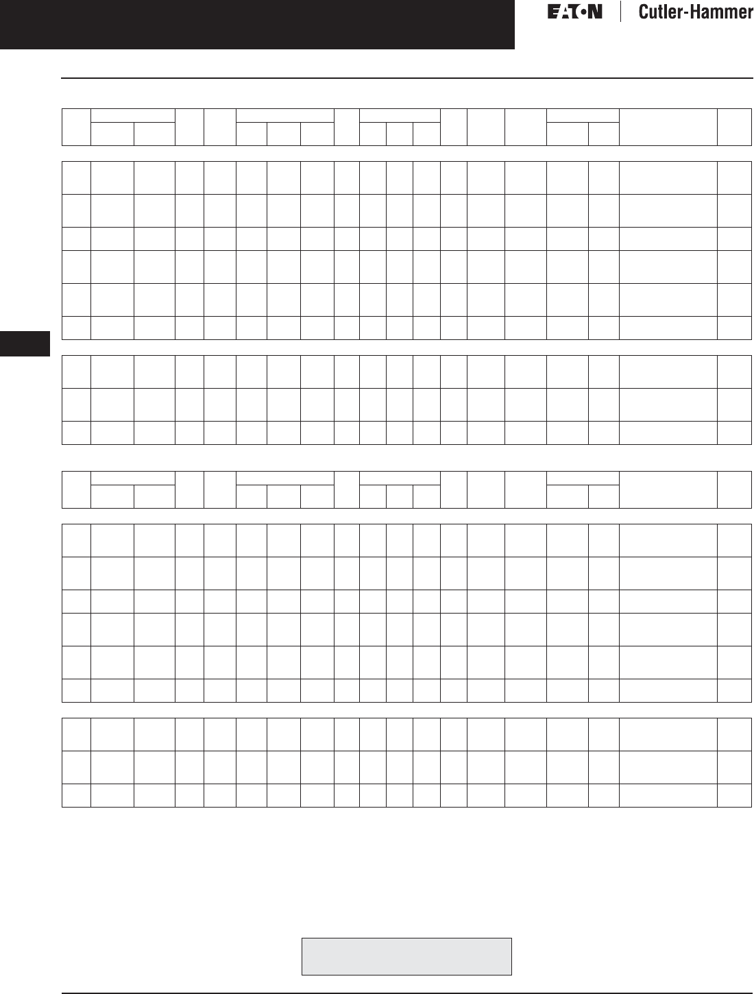
November 2003
9-40
For more information visit: www.cutler-hammer.eaton.com CA08101001E
Transformers
9
Energy Efficient Harmonic Mitigating Transformers
Three-Phase, Type DT-3 HMT, 60 Hz Vol. 1, Ref. No. [0340]
Table 9-42. Type POS Harmonic Mitigating Transformer Selection Information
Table 9-43. Type NEG Harmonic Mitigating Transformer Selection Information
kVA Full Cap. Taps Type °C
Temp .
Rise
Dimensions (Inches) Wt.
Lbs.
Dimensions (mm) Wt.
kg
Frame Wiring
Diagram
Number
Weathershield Style
Number
Price
U.S. $
FCAN FCBN H W D H W D Catalog
Number
Price
U.S. $
480 ∆ Volts to 208Y/120 Volts. No Thermal Sensor, Shielded, Copper Windings, NEMA TP-1 Energy Efficient, +15-Degree Phase-shift
15
30
45
2@+2.5%
2@+2.5%
2@+2.5%
4@-2.5%
4@-2.5%
4@-2.5%
DT-3
DT-3
DT-3
150
150
150
30
30
39-1/4
20-1/4
20-1/4
26-1/4
14-1/4
14-1/4
19-1/4
320
420
650
762
762
997
514
514
667
362
362
489
145
191
295
910A
912A
914B
200X
200X
200X
WS31
WS31
WS33
350.
350.
350.
X48M28T15CUEEPOS
X48M28T30CUEEPOS
X48M28T45CUEEPOS
8,060.
9,085.
12,030.
75
112.5
150
2@+2.5%
2@+2.5%
2@+2.5%
4@-2.5%
4@-2.5%
4@-2.5%
DT-3
DT-3
DT-3
150
150
150
46-5/8
56-1/4
62-1/4
28
31-1/4
31-1/4
23
24-1/4
30-1/4
850
2000
2170
1184
1429
1581
711
794
794
584
616
768
386
909
986
916A
917
918A
200X
200X
200X
WS19
WS34
WS34
350.
800.
800.
X48M28T75CUEEPOS
X48M28T12CUEEPOS
X48M28T49CUEEPOS
14,890.
20,160.
28,500.
225
300
2@+2.5%
2@+2.5%
4@-2.5%
4@-2.5%
DT-3
DT-3
150
150
75
75
44-1/2
44-1/2
35-3/4
35-3/4
3100
3300
1905
1905
1130
1130
908
908
1409
1500
919
919
201X
201X
WS35
WS35
1,360.
1,360.
X48M28T22CUEEPOS
X48M28T33CUEEPOS
33,300.
37,900.
15
30
45
2@+2.5%
2@+2.5%
2@+2.5%
4@-2.5%
4@-2.5%
4@-2.5%
DT-3
DT-3
DT-3
115
115
115
30
30
39-1/4
20-1/4
20-1/4
26-1/4
14-1/4
14-1/4
19-1/4
320
420
650
762
762
997
514
514
667
362
362
489
145
191
295
910A
912A
914B
200X
200X
200X
WS31
WS31
WS33
350.
350.
350.
X48M28F15CUEEPOS
X48M28F30CUEEPOS
X48M28F45CUEEPOS
8,770.
9,900.
13,100.
75
112.5
150
2@+2.5%
2@+2.5%
2@+2.5%
4@-2.5%
4@-2.5%
4@-2.5%
DT-3
DT-3
DT-3
115
115
115
46-5/8
56-1/4
62-1/4
28
31-1/4
31-1/4
23
24-1/4
30-1/4
850
2000
2170
1184
1429
1581
711
794
794
584
616
768
386
909
986
916A
917
918A
200X
200X
200X
WS19
WS34
WS34
350.
800.
800.
X48M28F75CUEEPOS
X48M28F12CUEEPOS
X48M28F49CUEEPOS
16,200.
21,900.
31,000.
225
300
2@+2.5%
2@+2.5%
4@-2.5%
4@-2.5%
DT-3
DT-3
115
115
75
75
44-1/2
44-1/2
35-3/4
35-3/4
3100
3300
1905
1905
1130
1130
908
908
1409
1500
919
919
201X
201X
WS35
WS35
1,360.
1,360.
X48M28F22CUEEPOS
X48M28F33CUEEPOS
34,900.
39,900.
480 ∆ Volts to 208Y/120 Volts. Single Thermal Sensor Included, Shielded, Copper Windings, NEMA TP-1 Energy Efficient, +15-Degree Phase-shift
15
30
45
2@+2.5%
2@+2.5%
2@+2.5%
4@-2.5%
4@-2.5%
4@-2.5%
DT-3
DT-3
DT-3
115
115
115
30
30
39-1/4
20-1/4
20-1/4
26-1/4
14-1/4
14-1/4
19-1/4
320
420
650
762
762
997
514
514
667
362
362
489
145
191
295
910A
912A
914B
200X
200X
200X
WS31
WS31
WS33
350.
350.
350.
X48M28F15TCUEEPOS
X48M28F30TCUEEPOS
X48M28F45TCUEEPOS
8,790.
9,920.
13,120.
75
112.5
150
2@+2.5%
2@+2.5%
2@+2.5%
4@-2.5%
4@-2.5%
4@-2.5%
DT-3
DT-3
DT-3
115
115
115
46-5/8
56-1/4
62-1/4
28
31-1/4
31-1/4
23
24-1/4
30-1/4
850
2000
2170
1184
1429
1581
711
794
794
584
616
768
386
909
986
916A
917
918A
200X
200X
200X
WS19
WS34
WS34
350.
800.
800.
X48M28F75TCUEEPOS
X48M28F12TCUEEPOS
X48M28F49TCUEEPOS
16,250.
22,000.
31,100.
225
300
2@+2.5%
2@+2.5%
4@-2.5%
4@-2.5%
DT-3
DT-3
115
115
75
75
44-1/2
44-1/2
35-3/4
35-3/4
3100
3300
1905
1905
1130
1130
908
908
1409
1500
919
919
201X
201X
WS35
WS35
1,360.
1,360.
X48M28F22TCUEEPOS
X48M28F33TCUEEPOS
35,000.
43,000.
kVA Full Cap. Taps Type °C
Temp .
Rise
Dimensions (Inches) Wt.
Lbs.
Dimensions (mm) Wt.
kg
Frame Wiring
Diagram
Number
Weathershield Style
Number
Price
U.S. $
FCAN FCBN H W D H W D Catalog
Number
Price
U.S. $
480 ∆ Volts to 208Y/120 Volts. No Thermal Sensor, Shielded, Copper Windings, NEMA TP-1 Energy Efficient, -15-Degree Phase-shift
15
30
45
2@+2.5%
2@+2.5%
2@+2.5%
4@-2.5%
4@-2.5%
4@-2.5%
DT-3
DT-3
DT-3
150
150
150
30
30
39-1/4
20-1/4
20-1/4
26-1/4
14-1/4
14-1/4
19-1/4
320
420
650
762
762
997
514
514
667
362
362
489
145
191
295
910A
912A
914B
200X
200X
200X
WS31
WS31
WS33
350.
350.
350.
X48M28T15CUEENEG
X48M28T30CUEENEG
X48M28T45CUEENEG
8,060.
9,085.
12,030.
75
112.5
150
2@+2.5%
2@+2.5%
2@+2.5%
4@-2.5%
4@-2.5%
4@-2.5%
DT-3
DT-3
DT-3
150
150
150
46-5/8
56-1/4
62-1/4
28
31-1/4
31-1/4
23
24-1/4
30-1/4
850
2000
2170
1184
1429
1581
711
794
794
584
616
768
386
909
986
916A
917
918A
200X
200X
200X
WS19
WS34
WS34
350.
800.
800.
X48M28T75CUEENEG
X48M28T12CUEENEG
X48M28T49CUEENEG
14,890.
20,160.
28,500.
225
300
2@+2.5%
2@+2.5%
4@-2.5%
4@-2.5%
DT-3
DT-3
150
150
75
75
44-1/2
44-1/2
35-3/4
35-3/4
3100
3300
1905
1905
1130
1130
908
908
1409
1500
919
919
201X
201X
WS35
WS35
1,360.
1,360.
X48M28T22CUEENEG
X48M28T33CUEENEG
33,300.
37,900.
15
30
45
2@+2.5%
2@+2.5%
2@+2.5%
4@-2.5%
4@-2.5%
4@-2.5%
DT-3
DT-3
DT-3
115
115
115
30
30
39-1/4
20-1/4
20-1/4
26-1/4
14-1/4
14-1/4
19-1/4
320
420
650
762
762
997
514
514
667
362
362
489
145
191
295
910A
912A
914B
200X
200X
200X
WS31
WS31
WS33
350.
350.
350.
X48M28F15CUEENEG
X48M28F30CUEENEG
X48M28F45CUEENEG
8,770.
9,900.
13,100.
75
112.5
150
2@+2.5%
2@+2.5%
2@+2.5%
4@-2.5%
4@-2.5%
4@-2.5%
DT-3
DT-3
DT-3
115
115
115
46-5/8
56-1/4
62-1/4
28
31-1/4
31-1/4
23
24-1/4
30-1/4
850
2000
2170
1184
1429
1581
711
794
794
584
616
768
386
909
986
916A
917
918A
200X
200X
200X
WS19
WS34
WS34
350.
800.
800.
X48M28F75CUEENEG
X48M28F12CUEENEG
X48M28F49CUEENEG
16,200.
21,900.
31,000.
225
300
2@+2.5%
2@+2.5%
4@-2.5%
4@-2.5%
DT-3
DT-3
115
115
75
75
44-1/2
44-1/2
35-3/4
35-3/4
3100
3300
1905
1905
1130
1130
908
908
1409
1500
919
919
201X
201X
WS35
WS35
1,360.
1,360.
X48M28F22CUEENEG
X48M28F33CUEENEG
34,900.
39,900.
480 ∆ Volts to 208Y/120 Volts. Single Thermal Sensor Included, Shielded, Copper windings, NEMA TP-1 Energy Efficient, -15-Degree Phase-shift
15
30
45
2@+2.5%
2@+2.5%
2@+2.5%
4@-2.5%
4@-2.5%
4@-2.5%
DT-3
DT-3
DT-3
115
115
115
30
30
39-1/4
20-1/4
20-1/4
26-1/4
14-1/4
14-1/4
19-1/4
320
420
650
762
762
997
514
514
667
362
362
489
145
191
295
910A
912A
914B
200X
200X
200X
WS31
WS31
WS33
350.
350.
350.
X48M28F15TCUEENEG
X48M28F30TCUEENEG
X48M28F45TCUEENEG
8,790.
9,920.
13,120.
75
112.5
150
2@+2.5%
2@+2.5%
2@+2.5%
4@-2.5%
4@-2.5%
4@-2.5%
DT-3
DT-3
DT-3
115
115
115
46-5/8
56-1/4
62-1/4
28
31-1/4
31-1/4
23
24-1/4
30-1/4
850
2000
2170
1184
1429
1581
711
794
794
584
616
768
386
909
986
916A
917
918A
200X
200X
200X
WS19
WS34
WS34
350.
800.
800.
X48M28F75TCUEENEG
X48M28F12TCUEENEG
X48M28F49TCUEENEG
16,250.
22,000.
31,100.
225
300
2@+2.5%
2@+2.5%
4@-2.5%
4@-2.5%
DT-3
DT-3
115
115
75
75
44-1/2
44-1/2
35-3/4
35-3/4
3100
3300
1905
1905
1130
1130
908
908
1409
1500
919
919
201X
201X
WS35
WS35
1,360.
1,360.
X48M28F22TCUEENEG
X48M28F33TCUEENEG
35,000.
43,000.
For other ratings or styles not shown, or for
special enclosure types (including stainless
steel) refer to Eaton’s Cutler-Hammer business. Discount Symbol . . . . . . . . . . . . . . . . . . . . . . . . . DT-1
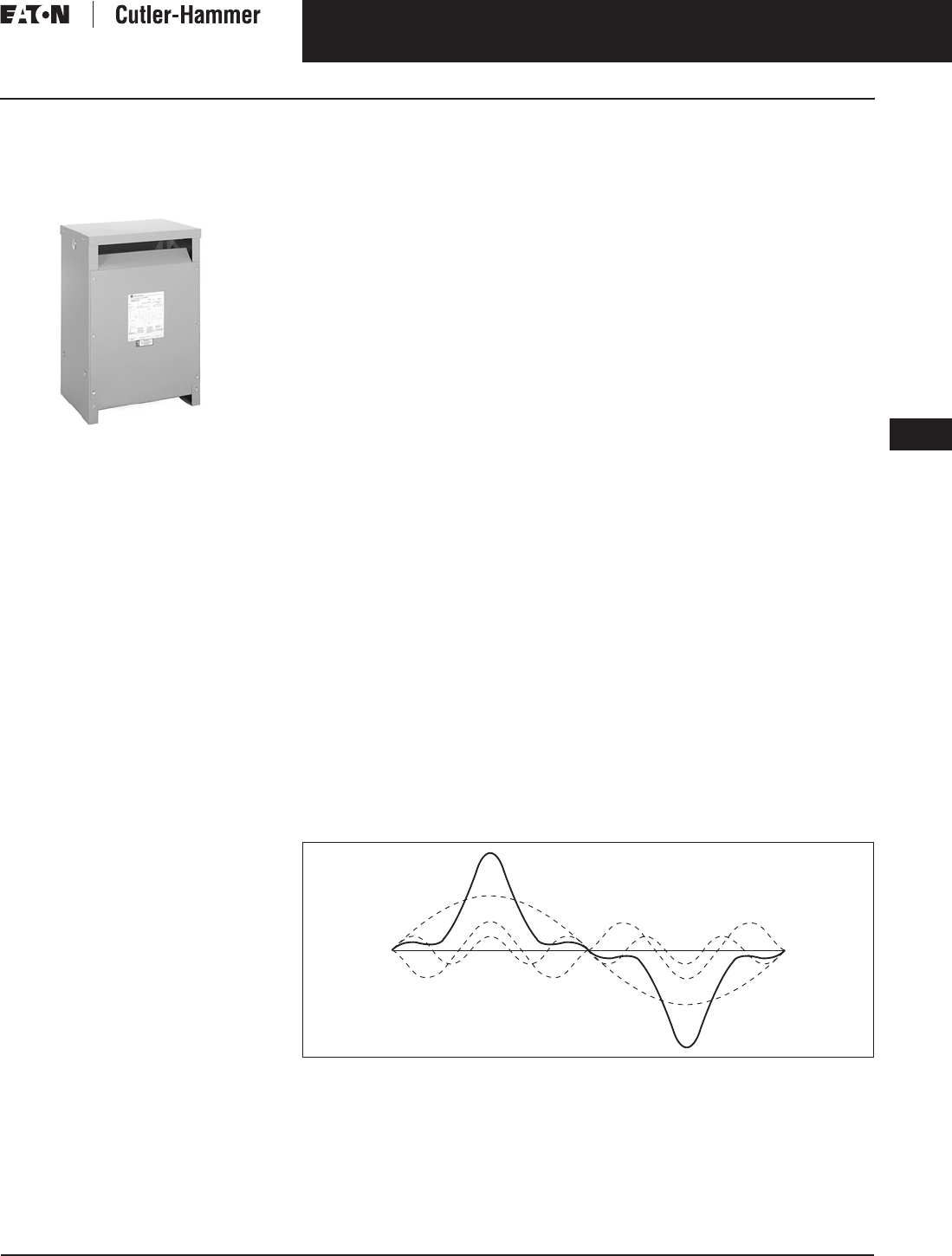
November 2003
CA08101001E For more information visit: www.cutler-hammer.eaton.com
9-41
Transformers
9
K Factor Transformers
Single- and Three-Phase
Vol. 1, Ref. No. [0341]
K Factor Transformers
Single- and Three-Phase, Type KT,
60 Hz, for Nonlinear Loads
Type KT
Product Description
■Suitable for indoor or outdoor
applications (with weathershield).
■Ventilated enclosures.
■220°C Insulation system, 150°C Rise
standard (self extinguishing).
Application Description
Cutler-Hammer KT Transformers by
Eaton Corporation include several
major design improvements that
address the problems caused by non-
linear loads and harmonics. They are
designed to withstand the effects of
harmonic currents without exceeding
the temperature rating of the insulation
system. The KT design compensates
for the stresses on a transformer’s
winding insulation which prevents
insulation breakdown and premature
failure. The net result is longer
transformer life.
Design Features
Core
A high grade, nonaging, silicon steel
with high magnetic permeability pro-
vides reduced core induction levels,
preventing saturation as a result of the
higher frequency harmonics and result-
ant peak voltages. In a core approach-
ing saturation, the current in the coil
will increase as voltage drops because
the core cannot absorb the additional
magnetic flux. This core also provides
reduced eddy currents or induced cur-
rents in the steel caused by the high
ratios of peak-to-rms currents and volt-
ages found in harmonic loads.
Coils
Windings are continuous wound alu-
minum or optional copper construc-
tion sized and configured to reduce
overheating caused by harmonic
currents. These coils reduce skin and
proximity effect losses which occur
when current carrying conductors
next to each other and coiled around
steel generate magnetic fields. These
magnetic fields push the currents
in the conductors away from each
other causing increased losses and
additional heating.
Neutral Bus
The neutral bus is sized and configured
to accommodate at least 200% of the
rated current. This compensates for
the increased neutral currents found in
non-linear loads thus reducing heat.
The K Factor
A common industry term for the
amount of harmonics produced by a
given load is the K Factor. The larger
the K Factor, the more harmonics are
present. Linear loads, for example
have a K Factor of 1. Transformers
may carry a K Factor rating to define
the transformer’s ability to withstand
the additional heating generated by
harmonic currents.
Calculating the K Factor
All nonlinear waveforms can be bro-
ken down mathematically into a funda-
mental frequency and its harmonics.
IEEE C57.110 establishes a direct
relationship between these harmonics
and transformer heating. Underwriters
Laboratories has established a similar
relation-ship, the K Factor, which is
derived by summing the square of
the percentage current at a given har-
monic level multiplied by the square
of the harmonic order.
K = ∑(Ih)2(h)2
Ih = Percent Current at Harmonic h
h = Harmonic Order, i.e., 3rd, 5th, 7th
For example, a load that is 90% of the
fundamental, 30% of the third harmonic,
and 20% of the fifth harmonic would
yield (.9)2(1)2 + (.3)2(3)2 + (.2)2(5)2 or
a K Factor of 2.62. This load would
require a Cutler-Hammer KT-4 Trans-
former with a K Factor rating of 4.
Transformers that carry a K Factor
rating define the transformer’s ability to
withstand a given harmonic load while
operating within the transformer’s
insulation class.
An analysis of harmonic loads and
a calculation of the K Factor must be
made to properly apply transformers
in any building or facility. Note that
the calculated K Factor is not constant
since non-linear loads change
throughout the day as equipment
and lighting is turned off and on.
These harmonic loads also change
over the life of the building or facility
as equipment is added or removed.
Harmonic Currents
Harmonic currents are found in nonlin-
ear loads. These currents are generated
by various types of equipment includ-
ing switching mode power supplies
that abruptly switch current on and
off during each line cycle. Switching
mode power supplies or diodecapacitor
Figure 9-1. Harmonic currents found in non-linear loads cause wave shape distortion and create
added stresses on transformers.

November 2003
9-42
For more information visit: www.cutler-hammer.eaton.com CA08101001E
Transformers
9
K Factor Transformers
Single- and Three-Phase Vol. 1, Ref. No. [0342]
power supplies convert ac line voltage
to low voltage dc. This process accom-
plished by charging capacitors during
each line cycle with narrow pulses of
current that are time-coincident with
line voltage peaks. Examples of this
equipment include electronic ballasts
for fluorescent lighting,
personal computers, printers, fax
machines, electronic and medical
test equipment, uninterruptible power
supplies, and solid-state motor drives.
Note: Nonlinear is synonymous with the
term non-sinusoidal.
Features, Benefits
and Functions
■600 volt class standard.
■Three-phase, 480∆ – 208Y/120 volt
standard.
■Single-phase, 240 x 480 volt –
120/240 volt standard.
■150°C rise standard, 80ºC and 115ºC
available.
■Three-phase neutrals sized for 200%
of rated current.
■Electrostatic shield.
Note: Electrostatic shields do not reduce
harmonic levels. However, because of the
nature of switching mode loads, these
shields do reduce transient noise in the
system which may affect sensitive com-
puter loads.
■Aluminum windings (copper
optional).
■Class 220°C insulation.
■Reduced core flux density.
Note: Reduced core flux prevents the core
from saturation and overheating due to
voltage distortions caused by harmonic
currents.
■Indoor enclosures (weathershields
optional, for outdoor applications).
■Coils designed to minimize stray
losses.
■K4, K13 standard.
■K9, K20, K30, K40, K50 optional.
■Low sound level (-3 dB, -5 dB)
available as options.
Standards and Certifications
Industry Standards
All Cutler-Hammer dry-type distribution
and control transformers by Eaton
Corporation are built and tested in
accordance with applicable NEMA,
ANSI and IEEE Standards. All 600 volt
class transformers are UL listed unless
otherwise noted.
Seismically Qualified
Cutler-Hammer manufactured dry-type
distribution transformers are seismi-
cally qualified, and exceed require-
ments of the Uniform Building Code
(UBC) and California Code Title 24.
Options and Accessories
Please refer to Page 9-120.
Product Specifications
Frequency
Cutler-Hammer standard dry-type dis-
tribution transformers are designed for
60 Hertz operation. Transformers
required for other frequencies are avail-
able and must be specifically designed.
Overload Capability
Short-term overload is designed into
transformers as required by ANSI.
dry-type distribution transformers
will deliver 200% nameplate load for
one-half hour; 150% load for one hour;
and 125% load for four hours without
being damaged provided that a con-
stant 50% load precedes and follows
the overload. See ANSI C57.96-01.250
for additional limitations.
Continuous overload capacity is not
deliberately designed into a trans-
former because the design objective is
to be within the allowed winding tem-
perature rise with nameplate loading.
Insulation System and Temperature Rise
Industry standards classify insulation
systems and rise as shown below:
Table 9-44. Insulation System Classification
The design life of transformers having
different insulation systems is the
same — the lower temperature systems
are designed for the same life as the
higher temperature systems.
Enclosures
Cutler-Hammer ventilated transformers,
Type KT, utilize a NEMA 2 rated (drip-
proof) enclosure as standard, and are
rated NEMA 3R with the addition of
weathershields.
Sound Levels
All Cutler-Hammer 600 volt class gen-
eral purpose dry-type distribution
transformers are designed to meet
NEMA ST-20 sound levels listed here.
These are the sound levels measured
in a soundproof environment. Actual
sound levels measured at an installa-
tion will likely be higher due to electri-
cal connections and environmental
conditions Lower sound levels are
available and should be specified
when the transformer is going to be
installed in an area where sound may
be a concern.
Table 9-45. Average Sound Levels
Winding Terminations
Primary and secondary windings are
terminated in the wiring compartment.
Ventilated transformers have leads
brought out to aluminum pads that
are pre-drilled to accept Cu/Al lugs.
Lugs are not supplied with these
transformers. The Cutler-Hammer
business recommends external cables
be rated 75°C for ventilated designs.
Technical Data
and Specifications
Please refer to Page 9-122.
Product Selection
Additional Product Selection
information begins on Page 9-136.
Ambient +
Winding
Rise
+
Hot
Spot
=
Temp.
Class
40°C
40°C
40°C
40°C
55°C
80°C
115°C
150°C
10°C
30°C
30°C
30°C
105°C
150°C
185°C
220°C
The following pages provide listings for most
standard transformer ratings and styles.
For other ratings or styles not shown, or for
special enclosure types (including stainless
steel) refer to Eaton’s Cutler-Hammer business.
NEMA ST-20 Average Sound Level (dB)
kVA Ventilated Encapsulated
0 – 9
10 – 50
51 – 150
151 – 300
40
45
50
55
45
50
55
57
301 – 500
501 – 700
701 – 1000
1001 – 1500
60
62
64
65
59
61
63
64
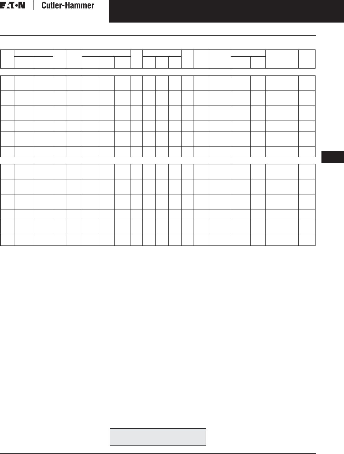
November 2003
CA08101001E For more information visit: www.cutler-hammer.eaton.com
9-43
Transformers
9
K Factor Transformers
Single-Phase
Vol. 1, Ref. No. [0343]
Table 9-46. Single Phase Selection Information — Type KS-4 — Transformers for Non-Sinusoidal Current Loads with K Factor Up to 4
1@ +5%, 2@ -5% at 240 volt primary; 2@ +2.5%, 4@ -2.5% at 480 volt primary.
Note: Contact your local Cutler-Hammer sales office for CE Mark transformer requirements.
kVA Full Cap. Taps Type °C
Temp.
Rise
Dimensions (Inches) Wt.
Lbs.
Dimensions (mm) Wt.
kg
Frame Wiring
Diagram
Number
Weathershield Style
Number
Price
U.S. $
FCAN FCBN H W D H W D Catalog
Number
Price
U.S. $
240 x 480 Volts to 120/240 Volts, Aluminum Windings
15
25
37.5
KS-4
KS-4
KS-4
150
150
150
31-1/4
31-1/4
37-5/8
22-5/8
22-5/8
22-5/8
17-1/2
17-1/2
19-1/2
147
212
306
768
768
956
428
428
574
402
402
495
67
96
139
815
816
817
261A
261A
261A
WS15
WS11
WS11
350.
350.
350.
HT20P11S15
HT20P11S25
HT20P11S37
1,970.
2,655.
3,240.
50
75
100
KS-4
KS-4
KS-4
150
150
150
37-5/8
42-1/8
42-1/8
22-5/8
24
24
19-1/2
23-3/8
23-3/8
340
510
600
956
1070
1070
574
610
610
495
594
594
154
232
272
818
819
820
261A
261A
261A
WS11
WS16
WS16
350.
800.
800.
HT20P11S50
HT20P11S75
HT20P11S99
3,830.
5,560.
6,910.
15
25
37.5
KS-4
KS-4
KS-4
115
115
115
30-1/4
31-1/4
37-5/8
16-7/8
22-5/8
22-5/8
15-7/8
17-1/2
19-1/2
147
212
306
768
768
956
428
428
574
402
402
495
67
67
139
815
816
817
261A
261A
261A
WS15
WS11
WS11
350.
350.
350.
HT20P11F15
HT20P11F25
HT20P11F37
2,305.
3,040.
3,740.
50
75
KS-4
KS-4
115
115
37-5/8
42-1/8
22-5/8
24
19-1/2
23-3/8
340
600
956
1070
574
610
495
594
154
272
818
820
261A
261A
WS11
WS16
350.
800.
HT20P11F50
HT20P11F75
4,450.
6,495.
15
25
37.5
KS-4
KS-4
KS-4
80
80
80
31-1/4
37-5/8
37-5/8
22-5/8
22-5/8
22-5/8
17-1/2
19-1/2
19-1/2
212
306
340
768
956
956
428
574
574
402
495
495
67
139
154
816
817
818
261A
261A
261A
WS11
WS11
WS11
350.
350.
350.
HT20P11B15
HT20P11B25
HT20P11B37
2,680.
3,600.
4,435.
50
75
KS-4
KS-4
80
80
42-1/8
42-1/8
24
24
23-3/8
23-3/8
510
600
1070
1070
610
610
594
594
232
272
819
820
261A
261A
WS16
WS16
800.
800.
HT20P11B50
HT20P11B75
5,210.
7,580.
240 x 480 Volts to 120/240 Volts, Copper Windings
15
25
37.5
KS-4
KS-4
KS-4
150
150
150
30-1/4
31-1/4
37-5/8
16-7/8
22-5/8
22-5/8
15-7/8
17-1/2
19-1/2
165
237
345
768
768
956
428
428
574
402
402
495
75
108
158
815
816
817
261A
261A
261A
WS15
WS11
WS11
350.
350.
350.
HT20P11S15CU
HT20P11S25CU
HT20P11S37CU
2,760.
3,720.
4,540.
50
75
100
KS-4
KS-4
KS-4
150
150
150
37-5/8
42-1/8
42-1/8
22-5/8
24
24
19-1/2
23-3/8
23-3/8
381
614
700
956
1070
1070
574
610
610
495
594
594
173
279
318
818
819
820
261A
261A
261A
WS11
WS16
WS16
350.
800.
800.
HT20P11S50CU
HT20P11S75CU
HT20P11S99CU
5,365.
7,785.
9,680.
15
25
37.5
KS-4
KS-4
KS-4
115
115
115
30-1/4
31-1/4
37-5/8
16-7/8
22-5/8
22-5/8
15-7/8
17-1/2
19-1/2
165
237
345
768
768
956
428
428
574
402
402
495
75
108
158
815
816
817
261A
261A
261A
WS15
WS11
WS11
350.
350.
350.
HT20P11F15CU
HT20P11F25CU
HT20P11F37CU
3,230.
4,260.
5,240.
50
75
KS-4
KS-4
115
115
37-5/8
42-1/8
22-5/8
24
19-1/2
23-3/8
381
700
956
1070
574
610
495
594
173
318
818
820
261A
261A
WS11
WS16
350.
800.
HT20P11F50CU
HT20P11F75CU
6,230.
9,095.
15
25
37.5
KS-4
KS-4
KS-4
80
80
80
31-1/4
37-5/8
37-5/8
22-5/8
22-5/8
22-5/8
17-1/2
19-1/2
19-1/2
237
345
381
768
956
956
428
574
574
402
495
495
108
158
173
816
817
818
261A
261A
261A
WS11
WS11
WS11
350.
350.
350.
HT20P11B15CU
HT20P11B25CU
HT20P11B37CU
3,750.
5,045.
6,210.
50
75
KS-4
KS-4
80
80
42-1/8
42-1/8
24
24
23-3/8
23-3/8
614
700
1070
1070
610
610
594
594
279
318
819
820
261A
261A
WS16
WS16
800.
800.
HT20P11B50CU
HT20P11B75CU
7,300.
10,615.
For other ratings or styles not shown, or for
special enclosure types (including stainless
steel) refer to Eaton’s Cutler-Hammer business. Discount Symbol . . . . . . . . . . . . . . . . . . . . . . . . . DT-1
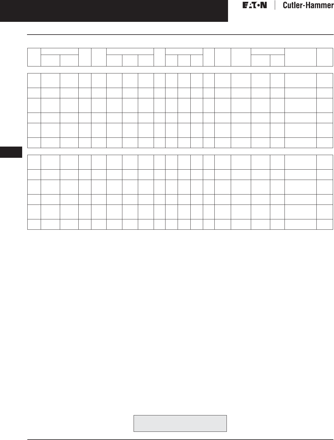
November 2003
9-44
For more information visit: www.cutler-hammer.eaton.com CA08101001E
Transformers
9
K Factor Transformers
Single-Phase Vol. 1, Ref. No. [0344]
Table 9-47. Single Phase Selection Information — Type KS-13 — Transformers for Non-Sinusoidal Current Loads with K Factor Up to 13
1@ +5%, 2@ -5% at 240 volt primary; 2@ +2.5%, 4@ -2.5% at 480 volt primary.
Note: Contact your local Cutler-Hammer sales office for CE Mark transformer requirements.
kVA Full Cap. Taps Type °C
Temp.
Rise
Dimensions (Inches) Wt.
Lbs.
Dimensions (mm) Wt.
kg
Frame Wiring
Diagram
Number
Weathershield Style
Number
Price
U.S. $
FCAN FCBN H W D H W D Catalog
Number
Price
U.S. $
240 x 480 Volts to 120/240 Volts, Aluminum Windings
15
25
37.5
KS-13
KS-13
KS-13
150
150
150
30-1/4
37-5/8
37-5/8
16-7/8
22-5/8
22-5/8
15-7/8
19-1/2
19-1/2
147
306
340
768
956
956
428
574
574
402
495
495
67
139
154
815
817
818
261A
261A
261A
WS15
WS11
WS11
350.
350.
350.
NT20P11S15
NT20P11S25
NT20P11S37
2,620.
3,520.
4,320.
50
75
KS-13
KS-13
150
150
42-1/8
42-1/8
24
24
23-3/8
23-3/8
510
600
1070
1070
610
610
594
594
232
272
819
820
261A
261A
WS16
WS16
800.
800.
NT20P11S50
NT20P11S75
5,100.
7,400.
15
25
37.5
KS-13
KS-13
KS-13
115
115
115
31-1/4
37-5/8
37-5/8
22-5/8
22-5/8
22-5/8
17-1/2
19-1/2
19-1/2
212
306
340
768
956
956
428
574
574
402
495
495
67
139
154
816
817
818
261A
261A
261A
WS11
WS11
WS11
350.
350.
350.
NT20P11F15
NT20P11F25
NT20P11F37
3,060.
4,050.
4,980.
50
75
KS-13
KS-13
115
115
42-1/8
42-1/8
24
24
23-3/8
23-3/8
510
600
1070
1070
610
610
594
594
232
272
819
820
261A
261A
WS16
WS16
800.
800.
NT20P11F50
NT20P11F75
5,920.
8,660.
15
25
37.5
KS-13
KS-13
KS-13
80
80
80
31-1/4
37-5/8
37-5/8
22-5/8
22-5/8
22-5/8
17-1/2
19-1/2
19-1/2
212
306
340
768
956
956
428
574
574
402
495
495
67
139
154
816
817
818
261A
261A
261A
WS11
WS11
WS11
350.
350.
350.
NT20P11B15
NT20P11B25
NT20P11B37
3,560.
4,800.
5,900.
50
75
KS-13
KS-13
80
80
42-1/8
42-1/8
24
24
23-3/8
23-3/8
510
600
1070
1070
610
610
594
594
232
272
819
820
261A
261A
WS16
WS16
800.
800.
NT20P11B50
NT20P11B75
6,940.
10,100.
240 x 480 Volts to 120/240 Volts, Copper Windings
15
25
37.5
KS-13
KS-13
KS-13
150
150
150
30-1/4
37-5/8
37-5/8
16-7/8
22-5/8
22-5/8
15-7/8
19-1/2
19-1/2
165
345
381
768
956
956
428
574
574
402
495
495
75
158
173
815
817
818
261A
261A
261A
WS15
WS11
WS11
350.
350.
350.
NT20P11S15CU
NT20P11S25CU
NT20P11S37CU
3,670.
4,930.
6,050.
50
75
KS-13
KS-13
150
150
42-1/8
42-1/8
24
24
23-3/8
23-3/8
614
700
1070
1070
610
610
594
594
279
318
819
820
261A
261A
WS16
WS16
800.
800.
NT20P11S50CU
NT20P11S75CU
7,140.
10,360.
15
25
37.5
KS-13
KS-13
KS-13
115
115
115
31-1/4
37-5/8
37-5/8
22-5/8
22-5/8
22-5/8
17-1/2
19-1/2
19-1/2
237
345
381
768
956
956
428
574
574
402
495
495
108
158
173
816
817
818
261A
261A
261A
WS11
WS11
WS11
350.
350.
350.
NT20P11F15CU
NT20P11F25CU
NT20P11F37CU
4,285.
5,670.
6,975.
50
75
KS-13
KS-13
115
115
42-1/8
42-1/8
24
24
23-3/8
23-3/8
614
700
1070
1070
610
610
594
594
279
318
819
820
261A
261A
WS16
WS16
800.
800.
NT20P11F50CU
NT20P11F75CU
8,290.
12,125.
15
25
37.5
KS-13
KS-13
KS-13
80
80
80
31-1/4
37-5/8
37-5/8
22-5/8
22-5/8
22-5/8
17-1/2
19-1/2
19-1/2
237
345
381
768
956
956
428
574
574
402
495
495
108
158
173
816
817
818
261A
261A
261A
WS11
WS11
WS11
350.
350.
350.
NT20P11B15CU
NT20P11B25CU
NT20P11B37CU
4,985.
6,720.
8,260.
50
75
KS-13
KS-13
80
80
42-1/8
42-1/8
24
24
23-3/8
23-3/8
614
700
1070
1070
610
610
594
594
279
318
819
820
261A
261A
WS16
WS16
800.
800.
NT20P11B50CU
NT20P11B75CU
9,720.
14,140.
For other ratings or styles not shown, or for
special enclosure types (including stainless
steel) refer to Eaton’s Cutler-Hammer business. Discount Symbol . . . . . . . . . . . . . . . . . . . . . . . . . DT-1

November 2003
CA08101001E For more information visit: www.cutler-hammer.eaton.com
9-45
Transformers
9
K Factor Transformers
Three-Phase
Vol. 1, Ref. No. [0345]
Table 9-48. Type KT-4 — Transformers for Non-Sinusoidal Current Loads with K Factor Up to 4
Note: Contact your local Cutler-Hammer sales office for CE Mark transformer requirements.
Note: For Energy Star labeled K factor transformers, contact your local Cutler-Hammer sales office.
kVA Full Cap. Taps Type °C
Temp.
Rise
Dimensions (Inches) Wt.
Lbs.
Dimensions (mm) Wt.
kg
Frame Wiring
Diagram
Number
Weathershield Style
Number
Price
U.S. $
FCAN FCBN H W D H W D Catalog
Number
Price
U.S. $
480 ∆ Volts to 208Y/120 Volts
15
30
45
2@+2.5%
2@+2.5%
2@+2.5%
4@-2.5%
4@-2.5%
4@-2.5%
KT
KT
KT
150
150
150
30-1/8
30-1/8
30-1/8
20-1/8
20-1/8
20-1/8
14-1/8
14-1/8
14-1/8
230
230
310
765
765
765
511
511
511
359
359
359
104
104
140
FR910A
FR910A
FR912A
283B
283B
283B
WS31
WS31
WS31
350.
350.
350.
H48M28T15A
H48M28T30A
H48M28T45A
1,850.
2,570.
3,090.
75
112.5
150
2@+2.5%
2@+2.5%
2@+2.5%
4@-2.5%
4@-2.5%
4@-2.5%
KT
KT
KT
150
150
150
39-3/8
39-3/8
56
26-1/8
26-1/8
31-1/4
19-1/8
19-1/8
24-1/4
480
600
1100
1000
1000
1422
663
663
793
485
485
616
217
272
499
FR914B
FR915B
FR917
283B
283B
283B
WS33
WS33
WS34
350.
350.
800.
H48M28T75A
H48M28T12A
H48M28T49A
4,360.
5,975.
8,015.
225
300
500
2@+2.5%
2@+2.5%
2@+2.5%
4@-2.5%
4@-2.5%
4@-2.5%
KT
KT
KT
150
150
150
56
75
75
31-1/4
44-1/2
44-1/2
24-1/4
36
36
1100
2400
2800
1422
1905
1905
793
1130
1130
616
914
914
499
1088
1270
FR917
FR919
FR919
283B
292A
292A
WS34
WS35
WS35
800.
1,360.
1,360.
H48M28T22A
H48M28T33B
H48M28T55A
11,910.
16,330.
25,060.
15
30
45
2@+2.5%
2@+2.5%
2@+2.5%
4@-2.5%
4@-2.5%
4@-2.5%
KT
KT
KT
115
115
115
30-1/8
30-1/8
39-3/8
20-1/8
20-1/8
26-1/8
14-1/8
14-1/8
19-1/8
230
230
480
765
765
1000
511
511
663
359
359
485
104
104
217
FR910A
FR910A
FR914B
283B
283B
283B
WS31
WS31
WS33
350.
350.
350.
H48M28F15A
H48M28F30A
H48M28F45A
2,040.
2,820.
3,400.
75
112.5
150
2@+2.5%
2@+2.5%
2@+2.5%
4@-2.5%
4@-2.5%
4@-2.5%
KT
KT
KT
115
115
115
39-3/8
46-1/8
56
26-1/8
28
31-1/4
19-1/8
23
24-1/4
600
760
1100
1000
1171
1422
663
712
793
485
585
616
272
344
499
FR915B
FR916A
FR917
283B
283B
283B
WS33
WS19
WS34
350.
350.
800.
H48M28F75A
H48M28F12A
H48M28F49A
4,690.
6,540.
8,530.
225
300
500
2@+2.5%
2@+2.5%
2@+2.5%
4@-2.5%
4@-2.5%
4@-2.5%
KT
KT
KT
115
115
115
62-1/4
75
90
31-1/4
44-1/2
69
30-1/4
36
42
1600
2400
4500
1581
1905
2286
794
1130
1752
768
914
1066
728
1088
2041
FR918A
FR919
FR922
283B
292A
292A
WS34
WS35
WS36
800.
1,360.
1,360.
H48M28F22A
H48M28F33A
H48M28F55A
13,040.
19,060.
27,560.
15
30
45
2@+2.5%
2@+2.5%
2@+2.5%
4@-2.5%
4@-2.5%
4@-2.5%
KT
KT
KT
80
80
80
30-1/8
30-1/8
39-3/8
20-1/8
20-1/8
26-1/8
14-1/8
14-1/8
19-1/8
230
310
480
765
765
1000
511
511
663
359
359
485
104
140
217
FR910A
FR912A
FR914B
283B
283B
283B
WS31
WS31
WS33
350.
350.
350.
H48M28B15A
H48M28B30A
H48M28B45A
2,350.
2,970.
4,475.
75
112.5
150
2@+2.5%
2@+2.5%
2@+2.5%
4@-2.5%
4@-2.5%
4@-2.5%
KT
KT
KT
80
80
80
39-3/8
56
56
26-1/8
31-1/4
31-1/4
19-1/8
24-1/4
24-1/4
600
1100
1100
1000
1422
1422
663
793
793
485
616
616
272
499
499
FR915B
FR917
FR917
283B
283B
283B
WS33
WS34
WS34
350.
800.
800.
H48M28B75A
H48M28B12A
H48M28B49A
5,680.
8,000.
11,660.
225
300
500
2@+2.5%
2@+2.5%
2@+2.5%
4@-2.5%
4@-2.5%
4@-2.5%
KT
KT
KT
80
80
80
62-1/4
75
75
31-1/4
44-1/2
44-1/2
30-1/4
36
35-3/4
1600
2400
3600
1581
1905
1905
794
1130
1129
768
914
908
728
1088
1636
FR918A
FR919
FR920
283B
292A
292A
WS34
WS35
WS35
800.
1,360.
1,360.
H48M28B22A
H48M28B33A
H48M28B55A
16,430.
21,200.
32,480.
480 ∆ Volts to 208Y/120 Volts (Copper Windings)
15
30
45
2@+2.5%
2@+2.5%
2@+2.5%
4@-2.5%
4@-2.5%
4@-2.5%
KT
KT
KT
150
150
150
30-1/8
30-1/8
30-1/8
20-1/8
20-1/8
20-1/8
14-1/8
14-1/8
14-1/8
300
300
370
765
765
765
511
511
511
359
359
359
136
136
168
FR910A
FR910A
FR912A
283B
283B
283B
WS31
WS31
WS31
350.
350.
350.
H48M28T15CU
H48M28T30CU
H48M28T45CU
2,260.
2,750.
3,545.
75
112.5
150
2@+2.5%
2@+2.5%
2@+2.5%
4@-2.5%
4@-2.5%
4@-2.5%
KT
KT
KT
150
150
150
39-3/8
39-3/8
56
26-1/8
26-1/8
31-1/4
19-1/8
19-1/8
24-1/4
675
675
1200
1000
1000
1422
663
663
793
485
485
616
306
306
545
FR914B
FR915B
FR917
283B
283B
283B
WS33
WS33
WS34
350.
350.
800.
H48M28T75CU
H48M28T12CU
H48M28T49CU
5,215.
6,315.
9,020.
225
300
500
2@+2.5%
2@+2.5%
2@+2.5%
4@-2.5%
4@-2.5%
4@-2.5%
KT
KT
KT
150
150
150
56
62-1/4
75
31-1/4
31-1/4
44-1/2
24-1/4
30-1/4
36
1200
2150
3600
1422
1581
1905
793
794
1130
616
768
914
545
977
1636
FR917
FR918A
FR919
283B
292A
292A
WS34
WS34
WS35
800.
800.
1,360.
H48M28T22CU
H48M28T33CU
H48M28T55CU
12,510.
18,530.
26,300.
15
30
45
2@+2.5%
2@+2.5%
2@+2.5%
4@-2.5%
4@-2.5%
4@-2.5%
KT
KT
KT
115
115
115
30-1/8
30-1/8
39-3/8
20-1/8
20-1/8
26-1/8
14-1/8
14-1/8
19-1/8
300
300
575
765
765
1000
511
511
663
359
359
485
136
136
261
FR910A
FR910A
FR914B
283B
283B
283B
WS31
WS31
WS33
350.
350.
350.
H48M28F15CU
H48M28F30CU
H48M28F45CU
2,770.
3,850.
4,635.
75
112.5
150
2@+2.5%
2@+2.5%
2@+2.5%
4@-2.5%
4@-2.5%
4@-2.5%
KT
KT
KT
115
115
115
39-3/8
46-1/2
56
26-1/8
28
31-1/4
19-1/8
23
24-1/4
675
850
1200
1000
1171
1422
663
712
793
485
585
616
306
386
545
FR915B
FR916A
FR917
283B
283B
283B
WS33
WS19
WS34
350.
350.
800.
H48M28F75CU
H48M28F12CU
H48M28F49CU
5,420.
7,075.
9,690.
225
300
500
2@+2.5%
2@+2.5%
2@+2.5%
4@-2.5%
4@-2.5%
4@-2.5%
KT
KT
KT
115
115
115
62-1/4
75
75
31-1/4
44-1/2
44-1/2
30-1/4
36
35-3/4
2150
3100
3600
1581
1905
1905
794
1130
1129
768
914
908
977
1409
1636
FR918A
FR919
FR920
283B
292A
292A
WS34
WS35
WS35
800.
1,360.
—
H48M28F22CU
H48M28F33CU
H48M28F55CU
15,675.
22,860.
28,940.
15
30
45
2@+2.5%
2@+2.5%
2@+2.5%
4@-2.5%
4@-2.5%
4@-2.5%
KT
KT
KT
80
80
80
30-1/8
30-1/8
39-3/8
20-1/8
20-1/8
26-1/8
14-1/8
14-1/8
19-1/8
300
370
575
765
765
1000
511
511
663
359
359
485
136
168
261
FR910A
FR912A
FR914B
283B
283B
283B
WS31
WS31
WS33
350.
350.
350.
H48M28B15CU
H48M28B30CU
H48M28B45CU
3,145.
4,360.
5,370.
75
112.5
150
2@+2.5%
2@+2.5%
2@+2.5%
4@-2.5%
4@-2.5%
4@-2.5%
KT
KT
KT
80
80
80
39-3/8
56
56
26-1/8
31-1/4
31-1/4
19-1/8
24-1/4
24-1/4
675
1200
1200
1000
1422
1422
663
793
793
485
616
616
306
545
545
FR915B
FR917
FR917
283B
283B
283B
WS33
WS34
WS34
350.
800.
800.
H48M28B75CU
H48M28B12CU
H48M28B49CU
6,760.
9,240.
12,060.
225
300
500
2@+2.5%
2@+2.5%
2@+2.5%
4@-2.5%
4@-2.5%
4@-2.5%
KT
KT
KT
80
80
80
62-1/4
75
75
31-1/4
44-1/2
44-1/2
30-1/4
36
35-3/4
2150
3100
3600
1581
1905
1905
794
1130
1129
768
914
908
977
1409
1636
FR918A
FR919
FR920
283B
292A
292A
WS34
WS35
WS35
800.
1,360.
1,360.
H48M28B22CU
H48M28B33CU
H48M28B55CU
18,050.
26,100.
34,200.
For other ratings or styles not shown, or for
special enclosure types (including stainless
steel) refer to Eaton’s Cutler-Hammer business. Discount Symbol . . . . . . . . . . . . . . . . . . . . . . . . . DT-1

November 2003
9-46
For more information visit: www.cutler-hammer.eaton.com CA08101001E
Transformers
9
K Factor Transformers
Three-Phase Vol. 1, Ref. No. [0346]
Table 9-49. Type KT-13 — Transformers for Non-Sinusoidal Current Loads with K Factor Up to 13
Refer to your Cutler-Hammer sales office.
Not Seismic Qualified.
Note: Contact your local Cutler-Hammer sales office for CE Mark transformer requirements.
Note: For Energy Star labeled K factor transformers, contact your local Cutler-Hammer sales office.
kVA Full Cap. Taps Type °C
Temp.
Rise
Dimensions (Inches) Wt.
Lbs.
Dimensions (mm) Wt.
kg
Frame Wiring
Diagram
Number
Weathershield Style
Number
Price
U.S. $
FCAN FCBN H W D H W D Catalog
Number
Price
U.S. $
480 ∆ Volts to 208Y/120 Volts
15
30
45
2@+2.5%
2@+2.5%
2@+2.5%
4@-2.5%
4@-2.5%
4@-2.5%
KT
KT
KT
150
150
150
30-1/8
30-1/8
39-3/8
20-1/8
20-1/8
26-1/8
14-1/8
14-1/8
19-1/8
230
310
480
765
765
1000
511
511
663
359
359
485
104
140
217
FR910A
FR912A
FR914B
283B
283B
283B
WS31
WS31
WS33
350.
350.
350.
N48M28T15A
N48M28T30A
N48M28T45A
1,970.
2,845.
3,370.
75
112.5
150
2@+2.5%
2@+2.5%
2@+2.5%
4@-2.5%
4@-2.5%
4@-2.5%
KT
KT
KT
150
150
150
39-3/8
46-1/8
56
26-1/8
28
31-1/4
19-1/8
23
24-1/4
600
760
1100
1000
1171
1422
663
712
793
485
585
616
272
344
499
FR915B
FR916A
FR917
283B
283B
283B
WS33
WS19
WS34
350.
350.
800.
N48M28T75A
N48M28T12A
N48M28T49A
4,660.
6,535.
8,780.
225
300
500
2@+2.5%
2@+2.5%
2@+2.5%
4@-2.5%
4@-2.5%
4@-2.5%
KT
KT
KT
150
150
150
62-1/4
75
90
31-1/4
44-1/2
69
30-1/4
36
42
1600
2400
4500
1581
1905
2286
794
1130
1752
768
914
1066
728
1088
2041
FR918A
FR919
FR922
283B
292A
292A
WS34
WS35
WS36
800.
1,360.
1,360.
N48M28T22A
N48M28T33A
N48M28T55A
12,140.
17,870.
27,570.
15
30
45
2@+2.5%
2@+2.5%
2@+2.5%
4@-2.5%
4@-2.5%
4@-2.5%
KT
KT
KT
115
115
115
30-1/8
30-1/8
39-3/8
20-1/8
20-1/8
26-1/8
14-1/8
14-1/8
19-1/8
230
310
480
765
765
1000
511
511
663
359
359
485
104
140
217
FR910A
FR912A
FR914B
283B
283B
283B
WS31
WS31
WS33
350.
350.
350.
N48M28F15A
N48M28F30A
N48M28F45A
2,410.
2,985.
3,890.
75
112.5
150
2@+2.5%
2@+2.5%
2@+2.5%
4@-2.5%
4@-2.5%
4@-2.5%
KT
KT
KT
115
115
115
39-3/8
46-1/8
56
26-1/8
28
31-1/4
19-1/8
23
24-1/4
600
760
1100
1000
1171
1422
663
712
793
485
585
616
272
344
499
FR915B
FR916A
FR917
283B
283B
283B
WS33
WS19
WS34
350.
350.
800.
N48M28F75A
N48M28F12A
N48M28F49A
5,315.
8,120.
9,560.
225
300
500
2@+2.5%
2@+2.5%
2@+2.5%
4@-2.5%
4@-2.5%
4@-2.5%
KT
KT
KT
115
115
115
62-1/4
75
90
31-1/4
44-1/2
69
30-1/4
36
42
1600
2400
4500
1581
1905
2286
794
1130
1752
768
914
1066
728
1088
2041
FR918A
FR919
FR922
283B
292A
292A
WS34
WS35
WS36
800.
1,360.
1,360.
N48M28F22A
N48M28F33A
N48M28F55A
13,390.
20,100.
30,400.
15
30
45
2@+2.5%
2@+2.5%
2@+2.5%
4@-2.5%
4@-2.5%
4@-2.5%
KT
KT
KT
80
80
80
30-1/8
30-1/8
39-3/8
20-1/8
20-1/8
26-1/8
14-1/8
14-1/8
19-1/8
230
310
480
765
765
1000
511
511
663
359
359
485
104
140
217
FR910A
FR912A
FR914B
283B
283B
283B
WS31
WS31
WS33
350.
350.
350.
N48M28B15A
N48M28B30A
N48M28B45A
2,840.
3,730.
4,755.
75
112.5
150
2@+2.5%
2@+2.5%
2@+2.5%
4@-2.5%
4@-2.5%
4@-2.5%
KT
KT
KT
80
80
80
46-1/8
56
62-1/4
28
31-1/4
31-1/4
23
24-1/4
30-1/4
760
1100
1600
1171
1422
1581
712
793
794
585
616
768
344
499
728
FR916A
FR917
FR918A
283B
283B
283B
WS33
WS34
WS34
350.
350.
800.
N48M28B75A
N48M28B12A
N48M28B49A
6,160.
8,840.
12,565.
225
300
2@+2.5%
2@+2.5%
4@-2.5%
4@-2.5%
KT
KT
80
80
75
75
44-1/2
44-1/2
36
36
2400
3600
1905
1905
1130
1130
914
914
1088
1636
FR919
FR919
292A
292A
WS35
WS35
1,360.
1,360.
N48M28B22A
N48M28B33CU
17,140.
26,780.
480 ∆ Volts to 208Y/120 Volts (Copper Windings)
15
30
45
2@+2.5%
2@+2.5%
2@+2.5%
4@-2.5%
4@-2.5%
4@-2.5%
KT
KT
KT
150
150
150
30-1/8
30-1/8
39-3/8
20-1/8
20-1/8
26-1/8
14-1/8
14-1/8
19-1/8
300
370
575
65
765
1000
511
511
663
359
359
485
136
168
261
FR910A
FR912A
FR914B
283B
283B
283B
WS31
WS31
WS33
350.
350.
350.
N48M28T15CU
N48M28T30CU
N48M28T45CU
2,540.
2,890.
4,270.
75
112.5
150
2@+2.5%
2@+2.5%
2@+2.5%
4@-2.5%
4@-2.5%
4@-2.5%
KT
KT
KT
150
150
150
39-3/8
46-1/8
56
26-1/8
28
31-1/4
19-1/8
23
24-1/4
675
850
1200
1000
1171
1422
663
712
793
485
585
616
306
386
545
FR915B
FR916A
FR917
283B
283B
283B
WS33
WS19
WS34
350.
350.
800.
N48M28T75CU
N48M28T12CU
N48M28T49CU
5,690.
7,460.
9,770.
225
300
500
2@+2.5%
2@+2.5%
2@+2.5%
4@-2.5%
4@-2.5%
4@-2.5%
KT
KT
KT
150
150
150
62-1/4
75
31-1/4
44-1/2
30-1/4
36
2150
3100
1581
1905
794
1130
768
914
977
1409
FR918A
FR919
283B
292A
WS34
WS35
800.
1,360.
—
N48M28T22CU
N48M28T33CU
N48M28T55CU
13,440.
22,330.
28,930.
15
30
45
2@+2.5%
2@+2.5%
2@+2.5%
4@-2.5%
4@-2.5%
4@-2.5%
KT
KT
KT
115
115
115
30-1/8
30-1/8
39-3/8
20-1/8
20-1/8
26-1/8
14-1/8
14-1/8
19-1/8
300
370
575
65
765
1000
511
511
663
359
359
485
136
168
261
FR910A
FR912A
FR914B
283B
283B
283B
WS31
WS31
WS33
350.
350.
350.
N48M28F15CU
N48M28F30CU
N48M28F45CU
2,785.
3,295.
4,430.
75
112.5
150
2@+2.5%
2@+2.5%
2@+2.5%
4@-2.5%
4@-2.5%
4@-2.5%
KT
KT
KT
115
115
115
39-3/8
46-1/8
56
26-1/8
28
31-1/4
19-1/8
23
24-1/4
675
850
1200
1000
1171
1422
663
712
793
485
585
616
360
386
545
FR915B
FR916A
FR917
283B
283B
283B
WS33
WS19
WS34
350.
350.
800.
N48M28F75CU
N48M28F12CU
N48M28F49CU
6,290.
9,025.
11,950.
225
300
500
2@+2.5%
2@+2.5%
2@+2.5%
4@-2.5%
4@-2.5%
4@-2.5%
KT
KT
KT
115
115
115
62-1/4
75
31-1/4
44-1/2
30-1/4
36
2150
3100
1581
1905
794
1130
768
914
977
1409
FR918A
FR919
283B
292A
WS34
WS35
800.
1,360.
—
N48M28F22CU
N48M28F33CU
N48M28F55CU
16,300.
24,560.
31,850.
15
30
45
2@+2.5%
2@+2.5%
2@+2.5%
4@-2.5%
4@-2.5%
4@-2.5%
KT
KT
KT
80
80
80
30-1/8
30-1/8
39-3/8
20-1/8
20-1/8
26-1/8
14-1/8
14-1/8
19-1/8
300
370
575
65
765
1000
511
511
663
359
359
485
136
168
261
FR910A
FR912A
FR914B
283B
283B
283B
WS31
WS31
WS33
350.
350.
350.
N48M28B15CU
N48M28B30CU
N48M28B45CU
3,125.
4,140.
5,570.
75
112.5
150
2@+2.5%
2@+2.5%
2@+2.5%
4@-2.5%
4@-2.5%
4@-2.5%
KT
KT
KT
80
80
80
46-1/8
56
62-1/4
28
31-1/4
31-1/4
23
24-1/4
30-1/4
950
1200
2150
1171
1422
1581
712
793
794
585
616
768
431
545
977
FR916A
FR917
FR917
283B
283B
283B
WS33
WS34
WS34
350.
350.
800.
N48M28B75CU
N48M28B12CU
N48M28B49CU
7,100.
10,270.
13,480.
225
300
2@+2.5%
2@+2.5%
4@-2.5%
4@-2.5%
KT
KT
80
80
75
75
44-1/2
44-1/2
36
36
3100
3600
1905
1905
1130
1130
914
914
1409
1636
FR919
FR919
292A
292A
WS35
WS35
1,360.
1,360.
N48M28B22CU
N48M28B33CU
20,520.
26,780.
For other ratings or styles not shown, or for
special enclosure types (including stainless
steel) refer to Eaton’s Cutler-Hammer business. Discount Symbol . . . . . . . . . . . . . . . . . . . . . . . . DT-1

November 2003
CA08101001E For more information visit: www.cutler-hammer.eaton.com
9-47
Transformers
9
K Factor Transformers
Three-Phase
Vol. 1, Ref. No. [0347]
Table 9-50. Type KT-20 — Transformers for Non-Sinusoidal Current Loads with K Factor Up to 20
Refer to your Cutler-Hammer sales office.
Not Seismic Qualified.
Note: Contact your local Cutler-Hammer sales office for CE Mark transformer requirements.
Note: For Energy Star labeled K factor transformers, contact your local Cutler-Hammer sales office.
kVA Full Cap. Taps Type °C
Temp.
Rise
Dimensions (Inches) Wt.
Lbs.
Dimensions (mm) Wt.
kg
Frame Wiring
Diagram
Number
Weathershield Style
Number
Price
U.S. $
FCAN FCBN H W D H W D Catalog
Number
Price
U.S. $
480 ∆ Volts to 208Y/120 Volts
15
30
45
2@+2.5%
2@+2.5%
2@+2.5%
4@-2.5%
4@-2.5%
4@-2.5%
KT
KT
KT
150
150
150
30-1/8
30-1/8
39-3/8
20-1/8
20-1/8
26-1/8
14-1/8
14-1/8
19-1/8
230
310
480
765
765
1000
511
511
663
358
358
485
104
140
217
FR910A
FR912A
FR914B
283B
283B
283B
WS31
WS31
WS33
350.
350.
350.
G48M28T15A
G48M28T30A
G48M28T45A
2,050.
3,010.
3,960.
75
112.5
150
2@+2.5%
2@+2.5%
2@+2.5%
4@-2.5%
4@-2.5%
4@-2.5%
KT
KT
KT
150
150
150
39-3/8
46-1/8
56
26-1/8
28
31-1/4
19-1/8
23
24-1/4
600
760
1100
1000
1171
1422
663
712
793
485
585
616
272
344
499
FR915B
FR916A
FR917
283B
283B
283B
WS33
WS19
WS34
350.
350.
800.
G48M28T75A
G48M28T12A
G48M28T49A
5,600.
8,780.
9,860.
225
300
500
2@+2.5%
2@+2.5%
2@+2.5%
4@-2.5%
4@-2.5%
4@-2.5%
KT
KT
KT
150
150
150
62-1/4
75
31-1/4
44-1/2
30-1/4
36
1600
2400
1581
1905
794
1130
768
914
728
1088
FR918A
FR919
283B
292A
WS34
WS35
800.
1,360.
—
G48M28T22A
G48M28T33A
G48M28T55A
13,420.
18,530.
30,700.
15
30
45
2@+2.5%
2@+2.5%
2@+2.5%
4@-2.5%
4@-2.5%
4@-2.5%
KT
KT
KT
115
115
115
30-1/8
30-1/8
39-3/8
20-1/8
20-1/8
26-1/8
14-1/8
14-1/8
19-1/8
230
310
480
765
765
1000
511
511
663
358
358
485
104
140
217
FR910A
FR912A
FR914B
283B
283B
283B
WS31
WS31
WS33
350.
350.
350.
G48M28F15A
G48M28F30A
G48M28F45A
2,655.
3,460.
4,560.
75
112.5
150
2@+2.5%
2@+2.5%
2@+2.5%
4@-2.5%
4@-2.5%
4@-2.5%
KT
KT
KT
115
115
115
46-1/8
56
62-1/4
28
31-1/4
31-1/4
23
24-1/4
30-1/4
780
1100
1600
1171
1422
1581
712
793
794
585
616
768
354
499
728
FR916A
FR917
FR918A
283B
283B
283B
WS33
WS34
WS34
350.
350.
800.
G48M28F75A
G48M28F12A
G48M28F49A
6,440.
9,220.
10,850.
225
300
500
2@+2.5%
2@+2.5%
2@+2.5%
4@-2.5%
4@-2.5%
4@-2.5%
KT
KT
KT
115
115
115
75
75
44-1/2
44-1/2
36
36
2400
3100
1905
1905
1130
1130
914
914
1088
1315
FR919
FR920
283B
292A
WS35
WS35
800.
1,360.
—
G48M28F22A
G48M28F33A
G48M28F55A
15,600.
20,650.
35,300.
15
30
45
2@+2.5%
2@+2.5%
2@+2.5%
4@-2.5%
4@-2.5%
4@-2.5%
KT
KT
KT
80
80
80
30-1/8
39-3/8
39-3/8
20-1/8
26-1/8
26-1/8
14-1/8
19-1/8
19-1/8
230
480
600
765
1000
1000
511
663
663
358
485
485
140
217
272
FR912A
FR914B
FR915B
283B
283B
283B
WS31
WS31
WS31
350.
350.
350.
G48M28B15A
G48M28B30A
G48M28B45A
2,990.
4,060.
5,350.
75
112.5
150
2@+2.5%
2@+2.5%
2@+2.5%
4@-2.5%
4@-2.5%
4@-2.5%
KT
KT
KT
80
80
80
46-1/8
56
62-1/4
28
31-1/4
31-1/4
23
24-1/4
30-1/4
860
1100
1600
1171
1422
1581
712
793
794
585
616
768
389
499
728
FR916A
FR917
FR918A
283B
283B
283B
WS33
WS34
WS34
350.
350.
800.
G48M28B75A
G48M28B12A
G48M28B49A
7,560.
9,860.
13,400.
225
300
2@+2.5%
2@+2.5%
4@-2.5%
4@-2.5%
KT
KT
80
80
75
44-1/2
36
2400
1905
1130
914
1088
FR919
283B
WS35
800.
—
G48M28B22A
G48M28B33A
19,800.
25,700.
480 ∆ Volts to 208Y/120 Volts (Copper Windings)
15
30
45
2@+2.5%
2@+2.5%
2@+2.5%
4@-2.5%
4@-2.5%
4@-2.5%
KT
KT
KT
150
150
150
30-1/8
30-1/8
39-3/8
20-1/8
20-1/8
26-1/8
14-1/8
14-1/8
19-1/8
300
370
575
765
765
1000
511
511
663
358
358
485
136
168
261
FR910A
FR912A
FR914B
283B
283B
283B
WS31
WS31
WS33
350.
350.
350.
G48M28T15CU
G48M28T30CU
G48M28T45CU
2,770.
4,120.
5,430.
75
112.5
150
2@+2.5%
2@+2.5%
2@+2.5%
4@-2.5%
4@-2.5%
4@-2.5%
KT
KT
KT
150
150
150
39-3/8
46-1/8
56
26-1/8
28
31-1/4
19-1/8
23
24-1/4
675
850
1200
1000
1171
1422
663
712
793
485
585
616
306
386
545
FR915B
FR916A
FR917
283B
283B
283B
WS33
WS19
WS34
350.
350.
800.
G48M28T75CU
G48M28T12CU
G48M28T49CU
7,660.
11,400.
12,820.
225
300
500
2@+2.5%
2@+2.5%
2@+2.5%
4@-2.5%
4@-2.5%
4@-2.5%
KT
KT
KT
150
150
150
62-1/4
75
31-1/4
44-1/2
30-1/4
36
2150
3100
1581
1905
794
1130
768
914
977
1409
FR918A
FR919
283B
292A
WS34
WS35
800.
1,360.
—
G48M28T22CU
G48M28T33CU
G48M28T55CU
17,400.
24,560.
39,900.
15
30
45
2@+2.5%
2@+2.5%
2@+2.5%
4@-2.5%
4@-2.5%
4@-2.5%
KT
KT
KT
115
115
115
30-1/8
30-1/8
39-3/8
20-1/8
20-1/8
26-1/8
14-1/8
14-1/8
19-1/8
300
370
575
765
765
1000
511
511
663
358
358
485
136
168
261
FR910A
FR912A
FR914B
283B
283B
283B
WS31
WS31
WS33
350.
350.
350.
G48M28F15CU
G48M28F30CU
G48M28F45CU
3,180.
4,665.
6,140.
75
112.5
150
2@+2.5%
2@+2.5%
2@+2.5%
4@-2.5%
4@-2.5%
4@-2.5%
KT
KT
KT
115
115
115
46-1/8
56
62-1/4
28
31-1/4
31-1/4
23
24-1/4
30-1/4
780
1200
2150
1171
1422
1581
712
793
794
585
616
768
354
545
977
FR916A
FR917
FR918A
283B
283B
283B
WS33
WS34
WS34
350.
350.
800.
G48M28F75CU
G48M28F12CU
G48M28F49CU
8,680.
12,300.
13,800.
225
300
500
2@+2.5%
2@+2.5%
2@+2.5%
4@-2.5%
4@-2.5%
4@-2.5%
KT
KT
KT
115
115
115
75
75
44-1/2
44-1/2
36
36
3100
3600
1905
1905
1130
1130
914
914
1409
1636
FR919
FR920
283B
292A
WS35
WS35
800.
1,360.
—
G48M28F22CU
G48M28F33CU
G48M28F55CU
18,800.
27,000.
46,000.
15
30
45
2@+2.5%
2@+2.5%
2@+2.5%
4@-2.5%
4@-2.5%
4@-2.5%
KT
KT
KT
80
80
80
30-1/8
39-3/8
39-3/8
20-1/8
26-1/8
26-1/8
14-1/8
19-1/8
19-1/8
370
575
675
765
1000
1000
511
663
663
358
485
485
168
261
306
FR912A
FR914B
FR915B
283B
283B
283B
WS31
WS31
WS33
350.
350.
350.
G48M28B15CU
G48M28B30CU
G48M28B45CU
3,480.
5,270.
6,740.
75
112.5
150
2@+2.5%
2@+2.5%
2@+2.5%
4@-2.5%
4@-2.5%
4@-2.5%
KT
KT
KT
80
80
80
46-1/8
56
62-1/4
28
31-1/4
31-1/4
23
24-1/4
30-1/4
860
1200
2150
1171
1422
1581
712
793
794
585
616
768
389
545
977
FR916A
FR917
FR918A
283B
283B
283B
WS33
WS34
WS34
350.
350.
800.
G48M28B75CU
G48M28B12CU
G48M28B49CU
9,520.
14,050.
15,780.
225
300
2@+2.5%
2@+2.5%
4@-2.5%
4@-2.5%
KT
KT
80
80
75
44-1/2
36
3100
1905
1130
914
1409
FR919
292A
WS35
1,360.
—
G48M28B22CU
G48M28B33CU
21,470.
29,650.
For other ratings or styles not shown, or for
special enclosure types (including stainless
steel) refer to Eaton’s Cutler-Hammer business. Discount Symbol . . . . . . . . . . . . . . . . . . . . . . . . . DT-1

November 2003
9-48
For more information visit: www.cutler-hammer.eaton.com CA08101001E
Transformers
9
K Factor Transformers
Three-Phase Vol. 1, Ref. No. [0348]
Table 9-51. Type KT-4 — Transformers for Non-Sinusoidal Current Loads with K Factor Up to 4
Table 9-52. Type KT-13 — Transformers for Non-Sinusoidal Current Loads with K Factor Up to 13
Note: Contact your local Cutler-Hammer sales office for CE Mark transformer requirements.
Note: For Energy Star labeled K factor transformers, contact your local Cutler-Hammer sales office.
kVA Full Cap. Taps Type °C
Temp.
Rise
Dimensions (Inches) Wt.
Lbs.
Dimensions (mm) Wt.
kg
Frame Wiring
Diagram
Number
Weathershield Style
Number
Price
U.S. $
FCAN FCBN H W D H W D Catalog
Number
Price
U.S. $
208 ∆ Volts to 208Y/120 Volts
15
30
45
75
2@+2.5%
2@+2.5%
2@+2.5%
2@+2.5%
4@-2.5%
4@-2.5%
4@-2.5%
4@-2.5%
KT
KT
KT
KT
150
150
150
150
30-1/8
30-1/8
30-1/8
39-3/8
20-1/8
20-1/8
20-1/8
26-1/8
14-1/8
14-1/8
14-1/8
19-1/8
230
230
310
480
765
765
765
1000
511
511
511
664
359
359
359
486
104
104
141
218
FR910A
FR910A
FR912A
FR914B
283A
283A
283A
283A
WS31
WS31
WS31
WS33
350.
350.
350.
350.
H29M28T15A
H29M28T30A
H29M28T45A
H29M28T75A
2,590.
3,590.
4,320.
6,100.
112.5
150
225
300
1@+5%
1@+5%
1@+5%
—
2@-5%
2@-5%
2@-5%
2@-5%
KT
KT
KT
KT
150
150
150
150
39-3/8
56
62-1/4
75
26-1/8
31-1/4
31-1/4
44-1/2
19-1/8
24-1/4
30-1/4
36
600
1100
1600
2400
1000
1422
1581
1905
664
794
794
1130
486
616
768
914
273
499
728
1089
FR915B
FR917
FR918A
FR919
325A
287A
287A
297B
WS33
WS34
WS34
WS35
350.
800.
800.
1,360.
H29R28T12A
H29R28T49A
H29R28T22A
H29G28T33A
7,940.
11,200.
16,670.
22,800.
15
30
45
75
2@+2.5%
2@+2.5%
2@+2.5%
2@+2.5%
4@-2.5%
4@-2.5%
4@-2.5%
4@-2.5%
KT
KT
KT
KT
115
115
115
115
30-1/8
30-1/8
39-3/8
39-3/8
20-1/8
20-1/8
26-1/8
26-1/8
14-1/8
14-1/8
19-1/8
19-1/8
230
230
480
600
765
765
1000
1000
511
511
664
664
359
359
486
486
104
104
218
273
FR910A
FR910A
FR914B
FR915B
283A
283A
283A
283A
WS31
WS31
WS33
WS33
350.
350.
350.
350.
H29M28F15A
H29M28F30A
H29M28F45A
H29M28F75A
2,850.
3,940.
4,750.
6,550.
112.5
150
225
300
1@+5%
1@+5%
1@+5%
—
2@-5%
2@-5%
2@-5%
2@-5%
KT
KT
KT
KT
115
115
115
115
46-1/8
56
62-1/4
75
28
31-1/4
31-1/4
44-1/2
23
24-1/4
30-1/4
36
760
1100
1600
2400
1171
1422
1581
1905
712
794
794
1130
585
616
768
914
345
499
728
1089
FR916A
FR917
FR918A
FR919
325A
287A
287A
297B
WS19
WS34
WS34
WS35
350.
800.
800.
1,360.
H29R28F12A
H29R28F49A
H29R28F22A
H29G28F33A
9,150.
11,900.
18,200.
26,600.
15
30
45
75
2@+2.5%
2@+2.5%
2@+2.5%
2@+2.5%
4@-2.5%
4@-2.5%
4@-2.5%
4@-2.5%
KT
KT
KT
KT
80
80
80
80
30-1/8
30-1/8
39-3/8
39-3/8
20-1/8
20-1/8
26-1/8
26-1/8
14-1/8
14-1/8
19-1/8
19-1/8
230
310
480
600
765
765
1000
1000
511
511
664
664
359
359
486
486
104
141
218
273
FR910A
FR912A
FR914B
FR915B
283A
283A
283A
283A
WS31
WS31
WS33
WS33
350.
350.
350.
350.
H29M28B15A
H29M28B30A
H29M28B45A
H29M28B75A
3,290.
4,150.
6,260.
7,950.
112.5
150
225
1@+5%
1@+5%
1@+5%
2@-5%
2@-5%
2@-5%
KT
KT
KT
80
80
80
56
56
75
31-1/4
31-1/4
44-1/2
24-1/4
24-1/4
36
1100
1100
2400
1422
1422
1905
794
794
1130
616
616
914
499
499
1089
FR917
FR917
FR919
287A
287A
297B
WS34
WS34
WS35
800.
800.
—
H29R28B12A
H29R28B49A
H29R28B22A
11,100.
16,300.
23,000.
kVA Full Cap. Taps Type °C
Temp.
Rise
Dimensions (Inches) Wt.
Lbs.
Dimensions (mm) Wt.
kg
Frame Wiring
Diagram
Number
Weathershield Style
Number
Price
U.S. $
FCAN FCBN H W D H W D Catalog
Number
Price
U.S. $
208 ∆ Volts to 208Y/120 Volts
15
30
45
75
2@+2.5%
2@+2.5%
2@+2.5%
2@+2.5%
4@-2.5%
4@-2.5%
4@-2.5%
4@-2.5%
KT
KT
KT
KT
150
150
150
150
30-1/8
30-1/8
39-3/8
39-3/8
20-1/8
20-1/8
26-1/8
26-1/8
14-1/8
14-1/8
19-1/8
19-1/8
230
310
480
600
765
765
1000
1000
511
511
664
664
359
359
486
486
104
141
218
273
FR910A
FR912A
FR914B
FR915B
283A
283A
283A
283A
WS31
WS31
WS33
WS33
350.
350.
350.
350.
N29M28T15A
N29M28T30A
N29M28T45A
N29M28T75A
2,760.
3,980.
4,720.
6,520.
112.5
150
225
300
1@+5%
1@+5%
1@+5%
—
2@-5%
2@-5%
2@-5%
2@-5%
KT
KT
KT
KT
150
150
150
150
46-1/8
56
62-1/4
75
28
31-1/4
31-1/4
44-1/2
23
24-1/4
30-1/4
36
820
1100
1600
2400
1171
1422
1581
1905
712
794
794
1130
585
616
768
914
372
499
728
1089
FR916A
FR917
FR918A
FR919
287A
287A
287A
297B
WS19
WS34
WS34
WS35
350.
800.
800.
1,360.
N29R28T12A
N29R28T49A
N29R28T22A
N29G28T33A
9,150.
12,300.
17,000.
25,000.
15
30
45
75
2@+2.5%
2@+2.5%
2@+2.5%
2@+2.5%
4@-2.5%
4@-2.5%
4@-2.5%
4@-2.5%
KT
KT
KT
KT
115
115
115
115
30-1/8
30-1/8
39-3/8
39-3/8
20-1/8
20-1/8
26-1/8
26-1/8
14-1/8
14-1/8
19-1/8
19-1/8
230
310
480
600
765
765
1000
1000
511
511
664
664
359
359
486
486
104
141
218
273
FR910A
FR912A
FR914B
FR915B
283A
283A
283A
283A
WS31
WS31
WS33
WS33
350.
350.
350.
350.
N29M28F15A
N29M28F30A
N29M28F45A
N29M28F75A
3,175.
4,580.
5,430.
7,500.
112.5
150
225
300
1@+5%
1@+5%
1@+5%
—
2@-5%
2@-5%
2@-5%
2@-5%
KT
KT
KT
KT
115
115
115
115
46-1/8
56
62-1/4
75
28
31-1/4
31-1/4
44-1/2
23
24-1/4
30-1/4
36
860
1100
1600
2400
1171
1422
1581
1905
712
794
794
1130
585
616
768
914
389
499
728
1089
FR916A
FR917
FR918A
FR919
287A
287A
287A
297B
WS19
WS34
WS34
WS35
350.
800.
800.
1,360.
N29R28F12A
N29R28F49A
N29R28F22A
N29G28F33A
10,520.
14,150.
19,550.
28,700.
15
30
45
75
2@+2.5%
2@+2.5%
2@+2.5%
2@+2.5%
4@-2.5%
4@-2.5%
4@-2.5%
4@-2.5%
KT
KT
KT
KT
80
80
80
80
30-1/8
30-1/8
39-3/8
46-1/8
20-1/8
20-1/8
26-1/8
28
14-1/8
14-1/8
19-1/8
23
230
310
480
820
765
765
1000
1171
511
511
664
712
359
359
486
585
104
141
218
389
FR910A
FR912A
FR914B
FR916A
283A
283A
283A
283A
WS31
WS31
WS33
WS33
350.
350.
350.
350.
N29M28B15A
N29M28B30A
N29M28B45A
N29M28B75A
3,720.
5,370.
6,370.
8,800.
112.5
150
225
1@+5%
1@+5%
—
2@-5%
2@-5%
2@-5%
KT
KT
KT
80
80
80
56
62-1/4
75
31-1/4
31-1/4
44-1/2
24-1/4
30-1/4
36
1200
1600
2400
1422
1581
1905
794
794
1130
616
768
914
544
728
1089
FR917
FR918A
FR919
287A
287A
297B
WS34
WS34
WS35
350.
800.
1,360.
N29R28B12A
N29R28B49A
N29G28B22A
12,350.
16,600.
22,900.
For other ratings or styles not shown, or for
special enclosure types (including stainless
steel) refer to Eaton’s Cutler-Hammer business. Discount Symbol . . . . . . . . . . . . . . . . . . . . . . . . . DT-1

November 2003
CA08101001E For more information visit: www.cutler-hammer.eaton.com
9-49
Transformers
9
K Factor Transformers
Three-Phase
Vol. 1, Ref. No. [0349]
Table 9-53. Type KT-4 — Transformers for Non-Sinusoidal Current Loads with K Factor Up to 4
Table 9-54. Type KT-13 — Transformers for Non-Sinusoidal Current Loads with K Factor Up to 13
Note: Contact your local Cutler-Hammer sales office for CE Mark transformer requirements.
Note: For Energy Star labeled K factor transformers, contact your local Cutler-Hammer sales office.
kVA Full Cap. Taps Type °C
Temp.
Rise
Dimensions (Inches) Wt.
Lbs.
Dimensions (mm) Wt.
kg
Frame Wiring
Diagram
Number
Weathershield Style
Number
Price
U.S. $
FCAN FCBN H W D H W D Catalog
Number
Price
U.S. $
480 ∆ Volts to 480Y/277 Volts
15
30
45
75
2@+2.5%
2@+2.5%
2@+2.5%
2@+2.5%
4@-2.5%
4@-2.5%
4@-2.5%
4@-2.5%
KT
KT
KT
KT
150
150
150
150
30-1/8
30-1/8
30-1/8
39-3/8
20-1/8
20-1/8
20-1/8
26-1/8
14-1/8
14-1/8
14-1/8
19-1/8
230
230
310
480
765
765
765
1000
511
511
511
664
359
359
359
486
104
104
141
218
FR910A
FR910A
FR912A
FR914B
283B
283B
283B
283B
WS31
WS31
WS31
WS33
350.
350.
350.
350.
H48M47T15A
H48M47T30A
H48M47T45A
H48M47T75A
2,220.
3,100.
3,700.
5,230.
112.5
150
225
300
2@+2.5%
2@+2.5%
2@+2.5%
2@+2.5%
4@-2.5%
4@-2.5%
4@-2.5%
4@-2.5%
KT
KT
KT
KT
150
150
150
150
39-3/8
56
62-1/4
75
26-1/8
31-1/4
31-1/4
44-1/2
19-1/8
24-1/4
30-1/4
36
600
1100
1600
2400
1000
1422
1581
1905
664
794
794
1130
486
616
768
914
273
499
728
1089
FR915B
FR917
FR918A
FR919
283B
283B
283B
292A
WS33
WS34
WS34
WS35
350.
800.
800.
1,360.
H48M47T12A
H48M47T49A
H48M47T22A
H48M47T33A
7,170.
9,610.
14,290.
19,590.
15
30
45
75
2@+2.5%
2@+2.5%
2@+2.5%
2@+2.5%
4@-2.5%
4@-2.5%
4@-2.5%
4@-2.5%
KT
KT
KT
KT
115
115
115
115
30-1/8
30-1/8
39-3/8
39-3/8
20-1/8
20-1/8
26-1/8
26-1/8
14-1/8
14-1/8
19-1/8
19-1/8
230
230
480
600
765
765
1000
1000
511
511
664
664
359
359
486
486
104
104
218
273
FR910A
FR910A
FR914B
FR915B
283B
283B
283B
283B
WS31
WS31
WS33
WS33
350.
350.
350.
350.
H48M47F15A
H48M47F30A
H48M47F45A
H48M47F75A
2,550.
3,560.
4,250.
6,010.
112.5
150
225
300
2@+2.5%
2@+2.5%
2@+2.5%
2@+2.5%
4@-2.5%
4@-2.5%
4@-2.5%
4@-2.5%
KT
KT
KT
KT
115
115
115
115
46-1/8
56
62-1/4
75
28
31-1/4
31-1/4
44-1/2
23
24-1/4
30-1/4
36
960
1100
1600
2400
1171
1422
1581
1905
712
794
794
1130
585
616
768
914
434
499
728
1089
FR916A
FR917
FR918A
FR919
283B
283B
283B
292A
WS19
WS34
WS34
WS35
350.
800.
800.
1,360.
H48M47F12A
H48M47F49A
H48M47F22A
H48M47F33A
8,250.
11,060.
16,440.
22,540.
15
30
45
75
2@+2.5%
2@+2.5%
2@+2.5%
2@+2.5%
4@-2.5%
4@-2.5%
4@-2.5%
4@-2.5%
KT
KT
KT
KT
80
80
80
80
30-1/8
30-1/8
39-3/8
39-3/8
20-1/8
20-1/8
26-1/8
26-1/8
14-1/8
14-1/8
19-1/8
19-1/8
230
310
480
600
765
765
1000
1000
511
511
664
664
359
359
486
486
104
141
218
273
FR910A
FR912A
FR914B
FR915B
283B
283B
283B
283B
WS31
WS31
WS33
WS33
350.
350.
350.
350.
H48M47B15A
H48M47B30A
H48M47B45A
H48M47B75A
2,995.
4,185.
4,990.
7,050.
112.5
150
225
300
2@+2.5%
2@+2.5%
2@+2.5%
2@+2.5%
4@-2.5%
4@-2.5%
4@-2.5%
4@-2.5%
KT
KT
KT
KT
80
80
80
80
56
56
62-1/4
75
31-1/4
31-1/4
31-1/4
44-1/2
24-1/4
24-1/4
30-1/4
36
1100
1100
1600
2400
1422
1422
1581
1905
794
794
794
1130
616
616
768
914
499
499
728
1089
FR917
FR917
FR918A
FR919
283B
283B
283B
292A
WS34
WS34
WS34
WS35
800.
800.
800.
1,360.
H48M47B12A
H48M47B49A
H48M47B22A
H48M47B33A
9,680.
12,970.
19,290.
26,440.
kVA Full Cap. Taps Type °C
Temp.
Rise
Dimensions (Inches) Wt.
Lbs.
Dimensions (mm) Wt.
kg
Frame Wiring
Diagram
Number
Weathershield Style
Number
Price
U.S. $
FCAN FCBN H W D H W D Catalog
Number
Price
U.S. $
480 ∆ Volts to 480Y/277 Volts
15
30
45
75
2@+2.5%
2@+2.5%
2@+2.5%
2@+2.5%
4@-2.5%
4@-2.5%
4@-2.5%
4@-2.5%
KT
KT
KT
KT
150
150
150
150
30-1/8
30-1/8
39-3/8
39-3/8
20-1/8
20-1/8
26-1/8
26-1/8
14-1/8
14-1/8
19-1/8
19-1/8
230
310
480
600
765
765
1000
1000
511
511
664
664
359
359
486
486
104
141
218
273
FR910A
FR912A
FR914B
FR915B
283B
283B
283B
283B
WS31
WS31
WS33
WS33
350.
350.
350.
350.
N48M47T15A
N48M47T30A
N48M47T45A
N48M47T75A
2,360.
3,415.
4,040.
5,590.
112.5
150
225
300
2@+2.5%
2@+2.5%
2@+2.5%
2@+2.5%
4@-2.5%
4@-2.5%
4@-2.5%
4@-2.5%
KT
KT
KT
KT
150
150
150
150
46-1/8
56
62-1/4
75
28
31-1/4
31-1/4
44-1/2
23
24-1/4
30-1/4
36
760
1100
1600
2400
1171
1422
1581
1905
712
794
794
1130
585
616
768
914
345
499
728
1089
FR916A
FR917
FR918A
FR919
283B
283B
283B
292A
WS19
WS34
WS34
WS35
350.
800.
800.
1,360.
N48M47T12A
N48M47T49A
N48M47T22A
N48M47T33A
7,840.
10,530.
14,560.
21,440.
15
30
45
75
2@+2.5%
2@+2.5%
2@+2.5%
2@+2.5%
4@-2.5%
4@-2.5%
4@-2.5%
4@-2.5%
KT
KT
KT
KT
115
115
115
115
30-1/8
30-1/8
39-3/8
39-3/8
20-1/8
20-1/8
26-1/8
26-1/8
14-1/8
14-1/8
19-1/8
19-1/8
230
310
480
600
765
765
1000
1000
511
511
664
664
359
359
486
486
104
141
218
273
FR910A
FR912A
FR914B
FR915B
283B
283B
283B
283B
WS31
WS31
WS33
WS33
350.
350.
350.
350.
N48M47F15A
N48M47F30A
N48M47F45A
N48M47F75A
2,715.
3,930.
4,650.
6,430.
112.5
150
225
300
2@+2.5%
2@+2.5%
2@+2.5%
2@+2.5%
4@-2.5%
4@-2.5%
4@-2.5%
4@-2.5%
KT
KT
KT
KT
115
115
115
115
46-1/8
56
62-1/4
75
28
31-1/4
31-1/4
44-1/2
23
24-1/4
30-1/4
36
760
1100
1600
2400
1171
1422
1581
1905
712
794
794
1130
585
616
768
914
345
499
728
1089
FR916A
FR917
FR918A
FR919
283B
283B
283B
292A
WS19
WS34
WS34
WS35
350.
800.
800.
1,360.
N48M47F12A
N48M47F49A
N48M47F22A
N48M47F33A
9,020.
12,120.
16,750.
24,670.
15
30
45
75
2@+2.5%
2@+2.5%
2@+2.5%
2@+2.5%
4@-2.5%
4@-2.5%
4@-2.5%
4@-2.5%
KT
KT
KT
KT
80
80
80
80
30-1/8
30-1/8
39-3/8
46-1/8
20-1/8
20-1/8
26-1/8
28
14-1/8
14-1/8
19-1/8
23
230
310
480
760
765
765
1000
1171
511
511
664
712
359
359
486
585
104
141
218
345
FR910A
FR912A
FR914B
FR916A
283B
283B
283B
283B
WS31
WS31
WS33
WS33
350.
350.
350.
350.
N48M47B15A
N48M47B30A
N48M47B45A
N48M47B75A
3,180.
4,600.
5,450.
7,540.
112.5
150
225
300
2@+2.5%
2@+2.5%
2@+2.5%
2@+2.5%
4@-2.5%
4@-2.5%
4@-2.5%
4@-2.5%
KT
KT
KT
KT
80
80
80
80
56
62-1/4
75
75
31-1/4
31-1/4
44-1/2
44-1/2
24-1/4
30-1/4
36
36
1100
1600
2400
3600
1422
1581
1905
1905
794
794
1130
1130
616
768
914
914
499
728
1089
1636
FR917
FR918A
FR919
FR919
283B
283B
292A
292A
WS34
WS34
WS35
WS35
350.
800.
1,360.
1,360.
N48M47B12A
N48M47B49A
N48M47B22A
N48M47B33CU
10,580.
14,200.
19,650.
36,440.
For other ratings or styles not shown, or for
special enclosure types (including stainless
steel) refer to Eaton’s Cutler-Hammer business. Discount Symbol . . . . . . . . . . . . . . . . . . . . . . . . . DT-1
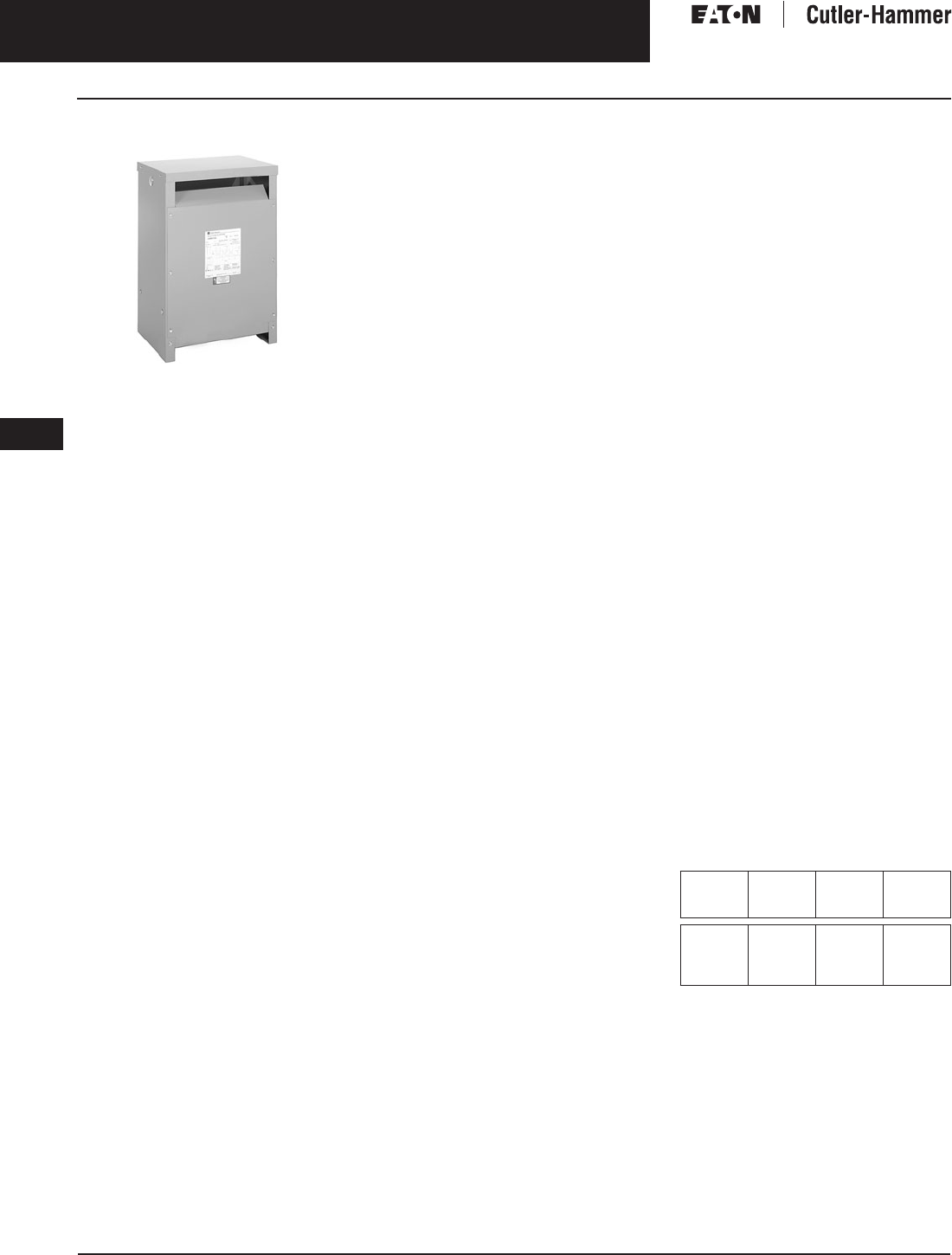
November 2003
9-50
For more information visit: www.cutler-hammer.eaton.com CA08101001E
Transformers
9
Drive Isolation Transformers
Three-Phase Vol. 1, Ref. No. [0350]
Three-Phase, Type MD, 60 Hz
Type MD
Product Description
■Suitable for indoor or outdoor
applications (with weathershield).
■Ventilated enclosures.
■220°C Insulation system, 150°C Rise
standard (self extinguishing).
■Available in ratings from
7.5 through 1500 kVA.
Application Description
Drive isolation transformers are specif-
ically designed for use with ac and dc
adjustable speed drives. Two winding
drive isolation transformers provide:
■Electrical isolation between the
incoming line and the drive circuitry.
■Voltage conversion of input line to
standard drive input voltages.
■Minimized line disturbances
caused by SCR (silicon controlled
rectifiers) firing.
■Reduced short circuit currents and
voltage line transients.
Drive isolation transformers are
specifically sized to the drive kVA
requirements and are braced to
withstand the mechanical stresses
of current reversals and short circuits
associated with SCR drives.
Features, Benefits
and Functions
■UL listed.
■60 Hz operation
(50/60 Hz operation available).
■Short-term overload capability as
required by ANSI.
■Primary and secondary terminals
are front accessible for fast and
easy connection.
■Slotted screw mounting holes
in enclosure and cover reduce
installation time.
■Sound dampening pads, which
isolate the core and coil from the
case, reduce noise levels to meet
NEMA ST-20.
■Core laminations of precision
sheared grain oriented silicon steel
are hand stacked to insure quiet
operation.
■Terminations are clearly marked for
easy identification.
■Three-phase transformers have
one 5% full capacity tap above and
below nominal voltage for incoming
source adjustment.
■Units are suitable for continuous o
per-
ation in a 40°C ambient maximum.
■Full current neutral.
■Thermoguard protection embedded
in coils to indicate that high temper-
atures (approximately 190°C) are
present.
■Three coil delta-wye configurations
are used throughout the product line.
Standards and Certifications
■ANSI C89.2
■NEMA ST-20
■UL 506
■UL 1561
Seismic Qualified
All Cutler-Hammer manufactured dry-
type distribution transformers by
Eaton Corporation are seismically
qualified, and exceed requirements of
the Uniform Building Code (UBC) and
California Code Title 24.
Options and Accessories
■Copper windings.
■Non-standard voltages.
■50/60 Hz designs.
■Delta-delta configuration.
■80°C or 115°C rise designs.
■Totally enclosed non-ventilated.
■Electrostatic shields.
Please refer to Page 9-120.
Product Specifications
Frequency
Cutler-Hammer standard dry-type dis-
tribution transformers are designed
for 60 Hz operation. Transformers
required for other frequencies are
available and must be specifically
designed.
Overload Capability
Short-term overload is designed into
transformers as required by ANSI.
dry-type distribution transformers
will deliver 200% nameplate load for
one-half hour; 150% load for one-hour;
and 125% load for four-hours without
being damaged provided that a con-
stant 50% load precedes and follows
the overload. See ANSI C57.96-01.250
for additional limitations.
Continuous overload capacity is not
deliberately designed into a trans-
former because the design objective is
to be within the allowed winding tem-
perature rise with nameplate loading.
Insulation System and Temperature Rise
Industry standards classify insulation
systems and rise as shown below:
Table 9-55. Insulation System Classification
The design life of transformers having
different insulation systems is the
same — the lower temperature systems
are designed for the same life as the
higher temperature systems.
Ambient +
Winding
Rise
+
Hot
Spot
=
Temp.
Class
40°C
40°C
40°C
40°C
55°C
80°C
115°C
150°C
10°C
30°C
30°C
30°C
105°C
150°C
185°C
220°C

November 2003
CA08101001E For more information visit: www.cutler-hammer.eaton.com
9-51
Transformers
9
Drive Isolation Transformers
Three-Phase
Vol. 1, Ref. No. [0351]
Enclosures
Eaton’s Cutler-Hammer ventilated
transformers, Type MD, utilize a NEMA
2 rated (drip-proof) enclosure as stan-
dard, and are rated NEMA 3R with the
addition of weathershields.
Sound Levels
All Cutler-Hammer 600 volt class gen-
eral purpose dry-type distribution
transformers are designed to meet
NEMA ST-20 sound levels listed here.
These are the sound levels measured
in a soundproof environment. Actual
sound levels measured at an installa-
tion will likely be higher due to electri-
cal connections and environmental
conditions. Lower sound levels are
available and should be specified
when the transformer is going to
be installed in an area where sound
may be a concern.
Table 9-56. Average Sound Levels
Winding Terminations
Primary and secondary windings are
terminated in the wiring compartment.
Ventilated transformers have leads
brought out to aluminum pads that
are pre-drilled to accept Cu/Al lugs.
Lugs are not supplied with these
transformers. The Cutler-Hammer
business recommends external cables
be rated 75°C for ventilated designs.
Technical Data
and Specifications
Please refer to Page 9-122.
NEMA ST-20 Average Sound Level (dB)
kVA Ventilated Encapsulated
0 – 9
10 – 50
51 – 150
151 – 300
40
45
50
55
45
50
55
57
301 – 500
501 – 700
701 – 1000
1001 – 1500
60
62
64
65
59
61
63
64

November 2003
9-52
For more information visit: www.cutler-hammer.eaton.com CA08101001E
Transformers
9
Drive Isolation Transformers
Three-Phase Vol. 1, Ref. No. [0352]
Product Selection
Additional Product Selection information begins on Page 9-136.
Table 9-57. Drive Isolation Transformers
Refer to your Cutler-Hammer sales office.
Not Seismic Qualified.
Note: Contact your local Cutler-Hammer sales office for CE Mark transformer requirements.
Hp kVA Full Cap. Taps Type °C
Temp.
Rise
Dimensions (Inches) Wt.
Lbs.
Dimensions (mm) Wt.
kg
Frame Wiring
Diagram
Number
Weathershield Style
Number
Price
U.S. $
FCAN FCBN H W D H W D Catalog
Number
Price
U.S. $
208 ∆ Volts to 230Y/133 Volts
5
7.5
10
7.5
11
14
1@+5%
1@+5%
1@+5%
1@-5%
1@-5%
1@-5%
DT-3
DT-3
DT-3
150
150
150
25
25
25
20-1/8
20-1/8
20-1/8
14-1/8
14-1/8
14-1/8
152
152
152
635
635
635
511
511
511
358
358
358
69
69
69
FR909
FR909
FR909
286L
286L
286L
WS31
WS31
WS31
350.
350.
350.
MD075E85
MD11E85
MD14E85
1,400.
1,450.
1,550.
15
20
25
20
27
34
1@+5%
1@+5%
1@+5%
1@-5%
1@-5%
1@-5%
DT-3
DT-3
DT-3
150
150
150
30-1/8
30-1/8
30-1/8
20-1/8
20-1/8
20-1/8
14-1/8
14-1/8
14-1/8
230
230
310
765
765
765
511
511
511
358
358
358
104
104
140
FR910A
FR910A
FR912A
286L
286L
286L
WS31
WS31
WS31
350.
350.
350.
MD20E85
MD27E85
MD34E85
1,920.
2,195.
2,430.
30
40
50
40
51
63
1@+5%
1@+5%
1@+5%
1@-5%
1@-5%
1@-5%
DT-3
DT-3
DT-3
150
150
150
30-1/8
39-3/8
39-3/8
20-1/8
26-1/8
26-1/8
14-1/8
19-1/8
19-1/8
310
480
480
765
1000
1000
511
663
663
358
485
485
140
217
217
FR912A
FR914B
FR914B
286L
286L
286L
WS31
WS33
WS33
350.
350.
350.
MD40E85
MD51E85
MD63E85
2,800.
3,165.
3,580.
60
75
100
75
93
118
1@+5%
1@+5%
1@+5%
1@-5%
1@-5%
1@-5%
DT-3
DT-3
DT-3
150
150
150
39-3/8
39-3/8
46-1/8
26-1/8
26-1/8
28
19-1/8
19-1/8
23
480
600
760
1000
1000
1171
663
663
712
485
485
585
217
272
344
FR914B
FR915B
FR916A
286L
286L
286L
WS33
WS33
WS19
350.
350.
350.
MD75E85
MD93E85
MD118E85
3,875.
4,650.
5,440.
125
150
200
145
175
220
1@+5%
1@+5%
1@+5%
1@-5%
1@-5%
1@-5%
DT-3
DT-3
DT-3
150
150
150
46-1/8
56
56
28
31-1/4
31-1/4
23
24-1/4
24-1/4
760
1100
1200
1171
1422
1422
712
793
793
585
616
616
344
499
499
FR916A
FR917
FR917
286L
286L
286L
WS19
WS34
WS34
350.
800.
800.
MD145E85
MD175E85
MD220E85
6,350.
8,030.
9,300.
250
300
275
330
1@+5%
1@+5%
1@-5%
1@-5%
DT-3
DT-3
150
150
62-1/4
75
31-1/4
44-1/2
30-1/4
36
1600
2200
1581
1905
794
1130
768
914
728
1000
FR918A
FR919
286L
WS34
WS35
800.
1,360.
MD275E85
MD330E85
10,880.
12,925.
208 ∆ Volts to 460Y/266 Volts
5
7.5
10
7.5
11
14
1@+5%
1@+5%
1@+5%
1@-5%
1@-5%
1@-5%
DT-3
DT-3
DT-3
150
150
150
25
25
25
20-1/8
20-1/8
20-1/8
14-1/8
14-1/8
14-1/8
152
152
152
635
635
635
511
511
511
358
358
358
69
69
69
FR909
FR909
FR909
286L
286L
286L
WS31
WS31
WS31
350.
350.
350.
MD075E86
MD11E86
MD14E86
1,400.
1,450.
1,550.
15
20
25
20
27
34
1@+5%
1@+5%
1@+5%
1@-5%
1@-5%
1@-5%
DT-3
DT-3
DT-3
150
150
150
30-1/8
30-1/8
30-1/8
20-1/8
20-1/8
20-1/8
14-1/8
14-1/8
14-1/8
230
230
310
765
765
765
511
511
511
358
358
358
104
104
140
FR910A
FR910A
FR912A
286L
286L
286L
WS31
WS31
WS31
350.
350.
350.
MD20E86
MD27E86
MD34E86
1,920.
2,195.
2,430.
30
40
50
40
51
63
1@+5%
1@+5%
1@+5%
1@-5%
1@-5%
1@-5%
DT-3
DT-3
DT-3
150
150
150
30-1/8
39-3/8
39-3/8
20-1/8
26-1/8
26-1/8
14-1/8
19-1/8
19-1/8
310
480
480
765
1000
1000
511
663
663
358
485
485
140
217
217
FR912A
FR914B
FR914B
286L
286L
286L
WS31
WS33
WS33
350.
350.
350.
MD40E86
MD51E86
MD63E86
2,800.
3,165.
3,580.
60
75
100
75
93
118
1@+5%
1@+5%
1@+5%
1@-5%
1@-5%
1@-5%
DT-3
DT-3
DT-3
150
150
150
39-3/8
39-3/8
46-1/8
26-1/8
26-1/8
28
19-1/8
19-1/8
23
480
600
760
1000
1000
1171
663
663
712
485
485
585
217
272
344
FR914B
FR915B
FR916A
286L
286L
286L
WS33
WS33
WS19
350.
350.
350.
MD75E86
MD93E86
MD118E86
3,875.
4,650.
5,440.
125
150
200
145
175
220
1@+5%
1@+5%
1@+5%
1@-5%
1@-5%
1@-5%
DT-3
DT-3
DT-3
150
150
150
46-1/8
56
56
28
31-1/4
31-1/4
23
24-1/4
24-1/4
760
1100
1200
1171
1422
1422
712
793
793
585
616
616
344
499
499
FR916A
FR917
FR917
286L
286L
286L
WS19
WS34
WS34
350.
800.
800.
MD145E86
MD175E86
MD220E86
6,350.
8,030.
9,300.
250
300
275
330
1@+5%
1@+5%
1@-5%
1@-5%
DT-3
DT-3
150
150
62-1/4
75
31-1/4
44-1/2
30-1/4
36
1600
2200
1581
1905
794
1130
768
914
728
1000
FR918A
FR919
286L
WS34
WS35
800.
1,360.
MD275E86
MD330E86
10,880.
12,925.
230 ∆ Volts to 230Y/133 Volts
5
7.5
10
7.5
11
14
1@+5%
1@+5%
1@+5%
1@-5%
1@-5%
1@-5%
DT-3
DT-3
DT-3
150
150
150
25
25
25
20-1/8
20-1/8
20-1/8
14-1/8
14-1/8
14-1/8
152
152
152
635
635
635
511
511
511
358
358
358
69
69
69
FR909
FR909
FR909
286A
286A
286A
WS31
WS31
WS31
350.
350.
350.
MD075E88
MD11E88
MD14E88
1,400.
1,450.
1,550.
15
20
25
20
27
34
1@+5%
1@+5%
1@+5%
1@-5%
1@-5%
1@-5%
DT-3
DT-3
DT-3
150
150
150
30-1/8
30-1/8
30-1/8
20-1/8
20-1/8
20-1/8
14-1/8
14-1/8
14-1/8
230
230
310
765
765
765
511
511
511
358
358
358
104
104
140
FR910A
FR910A
FR912A
286A
286A
286A
WS31
WS31
WS31
350.
350.
350.
MD20E88
MD27E88
MD34E88
1,920.
2,195.
2,430.
30
40
50
40
51
63
1@+5%
1@+5%
1@+5%
1@-5%
1@-5%
1@-5%
DT-3
DT-3
DT-3
150
150
150
30-1/8
39-3/8
39-3/8
20-1/8
26-1/8
26-1/8
14-1/8
19-1/8
19-1/8
310
480
480
765
1000
1000
511
663
663
358
485
485
140
217
217
FR912A
FR914B
FR914B
286A
286A
286A
WS31
WS33
WS33
350.
350.
350.
MD40E88
MD51E88
MD63E88
2,800.
3,165.
3,580.
60
75
100
75
93
118
1@+5%
1@+5%
1@+5%
1@-5%
1@-5%
1@-5%
DT-3
DT-3
DT-3
150
150
150
39-3/8
39-3/8
46-1/8
26-1/8
26-1/8
28
19-1/8
19-1/8
23
480
600
760
1000
1000
1171
663
663
712
485
485
585
217
272
344
FR914B
FR915B
FR916A
286A
286A
286A
WS33
WS33
WS19
350.
350.
350.
MD75E88
MD93E88
MD118E88
3,875.
4,650.
5,440.
125
150
200
145
175
220
1@+5%
1@+5%
1@+5%
1@-5%
1@-5%
1@-5%
DT-3
DT-3
DT-3
150
150
150
46-1/8
56
56
28
31-1/4
31-1/4
23
24-1/4
24-1/4
760
1100
1200
1171
1422
1422
712
793
793
585
616
616
344
499
499
FR916A
FR917
FR917
286A
286A
286A
WS19
WS34
WS34
350.
800.
800.
MD145E88
MD175E88
MD220E88
6,350.
8,030.
9,300.
250
300
400
275
330
440
1@+5%
1@+5%
1@+5%
1@-5%
1@-5%
1@-5%
DT-3
DT-3
DT-3
150
150
150
62-1/4
75
31-1/4
44-1/2
30-1/4
36
1600
2200
1581
1905
794
1130
768
914
728
1000
FR918A
FR919
286A
WS34
WS35
800.
1,360.
—
MD275E88
MD330E88
MD440E88
10,880.
12,925.
18,900.
500
600
700
800
550
660
770
880
1@+5%
1@+5%
1@+5%
1@+5%
1@-5%
1@-5%
1@-5%
1@-5%
DT-3
DT-3
DT-3
DT-3
150
150
150
150
—
—
—
—
MD550E88
MD660E88
MD770E88
MD880E88
22,800.
27,600.
34,400.
39,300.
For other ratings or styles not shown, or for
special enclosure types (including stainless
steel) refer to Eaton’s Cutler-Hammer business. Discount Symbol . . . . . . . . . . . . . . . . . . . . . . . . . DT-1
November 2003
CA08101001E For more information visit: www.cutler-hammer.eaton.com
9-53
Transformers
9
Drive Isolation Transformers
Three-Phase
Vol. 1, Ref. No. [0353]
Table 9-58. Drive Isolation Transformers
Refer to your Cutler-Hammer sales office.
Not Seismic Qualified.
Note: Contact your local Cutler-Hammer sales office for CE Mark transformer requirements.
Hp kVA Full Cap. Taps Type °C
Temp.
Rise
Dimensions (Inches) Wt.
Lbs.
Dimensions (mm) Wt.
kg
Frame Wiring
Diagram
Number
Weathershield Style
Number
Price
U.S. $
FCAN FCBN H W D H W D Catalog
Number
Price
U.S. $
230 ∆ Volts to 460Y/266 Volts
5
7.5
10
15
7.5
11
14
20
1@+5%
1@+5%
1@+5%
1@+5%
1@-5%
1@-5%
1@-5%
1@-5%
DT-3
DT-3
DT-3
DT-3
150
150
150
150
25
25
25
30-1/8
20-1/8
20-1/8
20-1/8
20-1/8
14-1/8
14-1/8
14-1/8
14-1/8
152
152
152
230
635
635
635
765
511
511
511
511
358
358
358
358
69
69
69
104
FR909
FR909
FR909
FR910A
286A
286A
286A
286A
WS31
WS31
WS31
WS31
350.
350.
350.
350.
MD075E89
MD11E89
MD14E89
MD20E89
1,400.
1,450.
1,550.
1,920.
20
25
30
27
34
40
1@+5%
1@+5%
1@+5%
1@-5%
1@-5%
1@-5%
DT-3
DT-3
DT-3
150
150
150
30-1/8
30-1/8
30-1/8
20-1/8
20-1/8
20-1/8
14-1/8
14-1/8
14-1/8
230
310
310
765
765
765
511
511
511
358
358
358
104
140
140
FR910A
FR912A
FR912A
286A
286A
286A
WS31
WS31
WS31
350.
350.
350.
MD27E89
MD34E89
MD40E89
2,195.
2,430.
2,800.
40
50
60
51
63
75
1@+5%
1@+5%
1@+5%
1@-5%
1@-5%
1@-5%
DT-3
DT-3
DT-3
150
150
150
39-3/8
39-3/8
39-3/8
26-1/8
26-1/8
26-1/8
19-1/8
19-1/8
19-1/8
480
480
480
1000
1000
1000
663
663
663
485
485
485
217
217
217
FR914B
FR914B
FR914B
286A
286A
286A
WS33
WS33
WS33
350.
350.
350.
MD51E89
MD63E89
MD75E89
3,165.
3,580.
3,875.
75
100
125
93
118
145
1@+5%
1@+5%
1@+5%
1@-5%
1@-5%
1@-5%
DT-3
DT-3
DT-3
150
150
150
39-3/8
46-1/8
46-1/8
26-1/8
28
28
19-1/8
23
23
600
760
760
1000
1171
1171
663
712
712
485
585
585
272
344
344
FR915B
FR916A
FR916A
286A
286A
286A
WS33
WS33
WS19
350.
350.
350.
MD93E89
MD118E89
MD145E89
4,650.
5,440.
6,350.
150
200
250
175
220
275
1@+5%
1@+5%
1@+5%
1@-5%
1@-5%
1@-5%
DT-3
DT-3
DT-3
150
150
150
56
56
62-1/4
31-1/4
31-1/4
31-1/4
24-1/4
24-1/4
30-1/4
1100
1200
1600
1422
1422
1581
793
793
794
616
616
768
499
499
728
FR917
FR917
FR918A
286A
286A
286A
WS34
WS34
WS34
800.
800.
800.
MD175E89
MD220E89
MD275E89
8,030.
9,300.
10,880.
300
400
500
330
440
550
1@+5%
1@+5%
1@+5%
1@-5%
1@-5%
1@-5%
DT-3
DT-3
DT-3
150
150
150
75
44-1/2
36
2200
1905
1130
914
1000
FR919
321A
WS35
1,360.
—
—
MD330E89
MD440E89
MD550E89
12,925.
18,900.
22,800.
600
700
800
660
770
880
1@+5%
1@+5%
1@+5%
1@-5%
1@-5%
1@-5%
DT-3
DT-3
DT-3
150
150
150
—
—
—
MD660E89
MD770E89
MD880E89
27,600.
34,400.
39,300.
230 ∆ Volts to 575Y/332 Volts
5
7.5
10
7.5
11
14
1@+5%
1@+5%
1@+5%
1@-5%
1@-5%
1@-5%
DT-3
DT-3
DT-3
150
150
150
25
25
25
20-1/8
20-1/8
20-1/8
14-1/8
14-1/8
14-1/8
152
152
152
635
635
635
511
511
511
358
358
358
69
69
69
FR909
FR909
FR909
286A
286A
286A
WS31
WS31
WS31
350.
350.
350.
MD075E90
MD11E90
MD14E90
1,400.
1,450.
1,550.
15
20
25
20
27
34
1@+5%
1@+5%
1@+5%
1@-5%
1@-5%
1@-5%
DT-3
DT-3
DT-3
150
150
150
30-1/8
30-1/8
30-1/8
20-1/8
20-1/8
20-1/8
14-1/8
14-1/8
14-1/8
230
230
310
765
765
765
511
511
511
358
358
358
104
104
140
FR910A
FR910A
FR912A
286A
286A
286A
WS31
WS31
WS31
350.
350.
350.
MD20E90
MD27E90
MD34E90
1,920.
2,195.
2,430.
30
40
50
40
51
63
1@+5%
1@+5%
1@+5%
1@-5%
1@-5%
1@-5%
DT-3
DT-3
DT-3
150
150
150
30-1/8
39-3/8
39-3/8
20-1/8
26-1/8
26-1/8
14-1/8
19-1/8
19-1/8
310
480
480
765
1000
1000
511
663
663
358
485
485
140
217
217
FR912A
FR914B
FR914B
286A
286A
286A
WS31
WS33
WS33
350.
350.
350.
MD40E90
MD51E90
MD63E90
2,800.
3,165.
3,580.
60
75
100
75
93
118
1@+5%
1@+5%
1@+5%
1@-5%
1@-5%
1@-5%
DT-3
DT-3
DT-3
150
150
150
39-3/8
39-3/8
46-1/8
26-1/8
26-1/8
28
19-1/8
19-1/8
23
480
600
760
1000
1000
1171
663
663
712
485
485
585
217
272
344
FR914B
FR915B
FR916A
286A
286A
286A
WS33
WS33
WS19
350.
350.
350.
MD75E90
MD93E90
MD118E90
3,875.
4,650.
5,440.
125
150
200
145
175
220
1@+5%
1@+5%
1@+5%
1@-5%
1@-5%
1@-5%
DT-3
DT-3
DT-3
150
150
150
46-1/8
56
56
28
31-1/4
31-1/4
23
24-1/4
24-1/4
760
1100
1200
1171
1422
1422
712
793
793
585
616
616
344
499
499
FR916A
FR917
FR917
286A
286A
286A
WS19
WS34
WS34
350.
800.
800.
MD145E90
MD175E90
MD220E90
6,350.
8,030.
9,300.
250
300
400
275
330
440
1@+5%
1@+5%
1@+5%
1@-5%
1@-5%
1@-5%
DT-3
DT-3
DT-3
150
150
150
62-1/4
75
31-1/4
44-1/2
30-1/4
36
1600
2200
1581
1905
794
1130
768
914
728
1000
FR918A
FR919
286A
WS34
WS35
800.
1,360.
—
MD275E90
MD330E90
MD440E90
10,880.
12,925.
18,900.
500
600
700
550
660
770
1@+5%
1@+5%
1@+5%
1@-5%
1@-5%
1@-5%
DT-3
DT-3
DT-3
150
150
150
—
—
—
MD550E90
MD660E90
MD770E90
22,800.
27,600.
34,400.
For other ratings or styles not shown, or for
special enclosure types (including stainless
steel) refer to Eaton’s Cutler-Hammer business. Discount Symbol . . . . . . . . . . . . . . . . . . . . . . . . . DT-1

November 2003
9-54
For more information visit: www.cutler-hammer.eaton.com CA08101001E
Transformers
9
Drive Isolation Transformers
Three-Phase Vol. 1, Ref. No. [0354]
Table 9-59. Drive Isolation Transformers
Refer to your Cutler-Hammer sales office.
Not Seismic Qualified.
Note: Contact your local Cutler-Hammer sales office for CE Mark transformer requirements.
Hp kVA Full Cap. Taps Type °C
Temp.
Rise
Dimensions (Inches) Wt.
Lbs.
Dimensions (mm) Wt.
kg
Frame Wiring
Diagram
Number
Weathershield Style
Number
Price
U.S. $
FCAN FCBN H W D H W D Catalog
Number
Price
U.S. $
460 ∆ Volts to 230Y/133 Volts
5
7.5
10
15
7.5
11
14
20
1@+5%
1@+5%
1@+5%
1@+5%
1@-5%
1@-5%
1@-5%
1@-5%
DT-3
DT-3
DT-3
DT-3
150
150
150
150
25
25
25
30-1/8
20-1/8
20-1/8
20-1/8
20-1/8
14-1/8
14-1/8
14-1/8
14-1/8
152
152
152
230
635
635
635
765
511
511
511
511
358
358
358
358
69
69
69
104
FR909
FR909
FR909
FR910A
286D
286D
286D
286D
WS31
WS31
WS31
WS31
350.
350.
350.
350.
MD075E91
MD11E91
MD14E91
MD20E91
1,400.
1,450.
1,550.
1,920.
20
25
30
27
34
40
1@+5%
1@+5%
1@+5%
1@-5%
1@-5%
1@-5%
DT-3
DT-3
DT-3
150
150
150
30-1/8
30-1/8
30-1/8
20-1/8
20-1/8
20-1/8
14-1/8
14-1/8
14-1/8
230
310
310
765
765
765
511
511
511
358
358
358
104
140
140
FR910A
FR912A
FR912A
286D
286D
286D
WS31
WS31
WS31
350.
350.
350.
MD27E91
MD34E91
MD40E91
2,195.
2,430.
2,800.
40
50
60
51
63
75
1@+5%
1@+5%
1@+5%
1@-5%
1@-5%
1@-5%
DT-3
DT-3
DT-3
150
150
150
39-3/8
39-3/8
39-3/8
26-1/8
26-1/8
26-1/8
19-1/8
19-1/8
19-1/8
480
480
480
1000
1000
1000
663
663
663
485
485
485
217
217
217
FR914B
FR914B
FR914B
286D
286D
286D
WS33
WS33
WS33
350.
350.
350.
MD51E91
MD63E91
MD75E91
3,165.
3,580.
3,875.
75
100
125
93
118
145
1@+5%
1@+5%
1@+5%
1@-5%
1@-5%
1@-5%
DT-3
DT-3
DT-3
150
150
150
39-3/8
46-1/8
46-1/8
26-1/8
28
28
19-1/8
23
23
600
760
760
1000
1171
1171
663
712
712
485
585
585
272
344
344
FR915B
FR916A
FR916A
286D
286D
286D
WS33
WS19
WS19
350.
350.
350.
MD93E91
MD118E91
MD145E91
4,650.
5,440.
6,350.
150
200
250
175
220
275
1@+5%
1@+5%
1@+5%
1@-5%
1@-5%
1@-5%
DT-3
DT-3
DT-3
150
150
150
56
56
62-1/4
31-1/4
31-1/4
31-1/4
24-1/4
24-1/4
30-1/4
1100
1200
1600
1422
1422
1581
793
793
794
616
616
768
499
499
728
FR917
FR917
FR918A
286D
286D
286D
WS34
WS34
WS34
800.
800.
800.
MD175E91
MD220E91
MD275E91
8,030.
9,300.
10,880.
300
400
500
330
440
550
1@+5%
1@+5%
1@+5%
1@-5%
1@-5%
1@-5%
DT-3
DT-3
DT-3
150
150
150
75
75
75
44-1/2
44-1/2
44-1/2
36
36
36
2200
2200
2900
1905
1905
1905
1130
1130
1130
914
914
914
1000
1000
1315
FR919
FR919
FR920
318E
318E
318E
WS35
WS35
WS35
1,360.
1,360.
1,360.
MD330E91
MD440E91
MD550E91
12,925.
18,900.
22,800.
600
700
800
660
770
880
1@+5%
1@+5%
1@+5%
1@-5%
1@-5%
1@-5%
DT-3
DT-3
DT-3
150
150
150
75
75
44-1/2
44-1/2
36
36
2900
2900
1905
1905
1130
1130
914
914
1315
1315
FR920
FR920
318E
318E
WS35
WS35
1,360.
1,360.
—
MD660E91
MD770E91
MD880E91
27,600.
34,400.
39,300.
—
—
—
1000
1250
1500
1@+5%
1@+5%
1@+5%
1@-5%
1@-5%
1@-5%
DT-3
DT-3
DT-3
150
150
150
—
—
—
MD1000E91
MD1250E91
MD1500E91
42,570.
49,500.
78,600.
460 ∆ Volts to 460Y/266 Volts
5
7.5
10
15
7.5
11
14
20
1@+5%
1@+5%
1@+5%
1@+5%
1@-5%
1@-5%
1@-5%
1@-5%
DT-3
DT-3
DT-3
DT-3
150
150
150
150
25
25
25
30-1/8
20-1/8
20-1/8
20-1/8
20-1/8
14-1/8
14-1/8
14-1/8
14-1/8
152
152
152
230
635
635
635
765
511
511
511
511
358
358
358
358
69
69
69
104
FR909
FR909
FR909
FR910A
286D
286D
286D
286D
WS31
WS31
WS31
WS31
350.
350.
350.
350.
MD075E92
MD11E92
MD14E92
MD20E92
1,400.
1,450.
1,550.
1,920.
20
25
30
27
34
40
1@+5%
1@+5%
1@+5%
1@-5%
1@-5%
1@-5%
DT-3
DT-3
DT-3
150
150
150
30-1/8
30-1/8
30-1/8
20-1/8
20-1/8
20-1/8
14-1/8
14-1/8
14-1/8
230
310
310
765
765
765
511
511
511
358
358
358
104
140
140
FR910A
FR912A
FR912A
286D
286D
286D
WS31
WS31
WS31
350.
350.
350.
MD27E92
MD34E92
MD40E92
2,195.
2,430.
2,800.
40
50
60
51
63
75
1@+5%
1@+5%
1@+5%
1@-5%
1@-5%
1@-5%
DT-3
DT-3
DT-3
150
150
150
39-3/8
39-3/8
39-3/8
26-1/8
26-1/8
26-1/8
19-1/8
19-1/8
19-1/8
480
480
480
1000
1000
1000
663
663
663
485
485
485
217
217
217
FR914B
FR914B
FR914B
286D
286D
286D
WS33
WS33
WS33
350.
350.
350.
MD51E92
MD63E92
MD75E92
3,165.
3,580.
3,875.
75
100
125
93
118
145
1@+5%
1@+5%
1@+5%
1@-5%
1@-5%
1@-5%
DT-3
DT-3
DT-3
150
150
150
39-3/8
46-1/8
46-1/8
26-1/8
28
28
19-1/8
23
23
600
760
760
1000
1171
1171
663
712
712
485
585
585
272
344
344
FR915B
FR916A
FR916A
286D
286D
286D
WS33
WS19
WS19
350.
350.
350.
MD93E92
MD118E92
MD145E92
4,650.
5,440.
6,350.
150
200
250
175
220
275
1@+5%
1@+5%
1@+5%
1@-5%
1@-5%
1@-5%
DT-3
DT-3
DT-3
150
150
150
56
56
62-1/4
31-1/4
31-1/4
31-1/4
24-1/4
24-1/4
30-1/4
1100
1200
1600
1422
1422
1581
793
793
794
616
616
768
499
499
728
FR917
FR917
FR918A
286D
286D
286D
WS34
WS34
WS34
800.
800.
800.
MD175E92
MD220E92
MD275E92
8,030.
9,300.
10,880.
300
400
500
330
440
550
1@+5%
1@+5%
1@+5%
1@-5%
1@-5%
1@-5%
DT-3
DT-3
DT-3
150
150
150
75
75
75
44-1/2
44-1/2
44-1/2
36
36
36
2200
2200
2900
1905
1905
1905
1130
1130
1130
914
914
914
1000
1000
1315
FR919
FR919
FR919
318E
318E
318E
WS35
WS35
WS35
1,360.
1,360.
1,360.
MD330E92
MD440E92
MD550E92
12,925.
18,900.
22,800.
600
700
800
660
770
880
1@+5%
1@+5%
1@+5%
1@-5%
1@-5%
1@-5%
DT-3
DT-3
DT-3
150
150
150
75
75
44-1/2
44-1/2
36
36
2900
2900
1905
1905
1130
1130
914
914
1315
1315
FR920
FR920
318E
318E
WS35
WS35
1,360.
1,360.
—
MD660E92
MD770E92
MD880E92
27,600.
34,400.
39,300.
—
—
—
1000
1250
1500
1@+5%
1@+5%
1@+5%
1@-5%
1@-5%
1@-5%
DT-3
DT-3
DT-3
150
150
150
—
—
—
MD1000E92
MD1250E92
MD1500E92
42,570.
49,500.
78,600.
For other ratings or styles not shown, or for
special enclosure types (including stainless
steel) refer to Eaton’s Cutler-Hammer business. Discount Symbol . . . . . . . . . . . . . . . . . . . . . . . . . DT-1

November 2003
CA08101001E For more information visit: www.cutler-hammer.eaton.com
9-55
Transformers
9
Drive Isolation Transformers
Three-Phase
Vol. 1, Ref. No. [0355]
Table 9-60. Drive Isolation Transformers
Refer to your Cutler-Hammer sales office.
Not Seismic Qualified.
Note: Contact your local Cutler-Hammer sales office for CE Mark transformer requirements.
Hp kVA Full Cap. Taps Type °C
Temp.
Rise
Dimensions (Inches) Wt.
Lbs.
Dimensions (mm) Wt.
kg
Frame Wiring
Diagram
Number
Weathershield Style
Number
Price
U.S. $
FCAN FCBN H W D H W D Catalog
Number
Price
U.S. $
460 ∆ Volts to 575Y/332 Volts
5
7.5
10
7.5
11
14
1@+5%
1@+5%
1@+5%
1@-5%
1@-5%
1@-5%
DT-3
DT-3
DT-3
150
150
150
25
25
25
20-1/8
20-1/8
20-1/8
14-1/8
14-1/8
14-1/8
152
152
152
635
635
635
511
511
511
358
358
358
69
69
69
FR909
FR909
FR909
286D
286D
286D
WS31
WS31
WS31
350.
350.
350.
MD075E93
MD11E93
MD14E93
1,400.
1,450.
1,550.
15
20
25
20
27
34
1@+5%
1@+5%
1@+5%
1@-5%
1@-5%
1@-5%
DT-3
DT-3
DT-3
150
150
150
30-1/8
30-1/8
30-1/8
20-1/8
20-1/8
20-1/8
14-1/8
14-1/8
14-1/8
230
230
310
765
765
765
511
511
511
358
358
358
104
104
140
FR910A
FR910A
FR912A
286D
286D
286D
WS31
WS31
WS31
350.
350.
350.
MD20E93
MD27E93
MD34E93
1,920.
2,195.
2,430.
30
40
50
40
51
63
1@+5%
1@+5%
1@+5%
1@-5%
1@-5%
1@-5%
DT-3
DT-3
DT-3
150
150
150
30-1/8
39-3/8
39-3/8
20-1/8
26-1/8
26-1/8
14-1/8
19-1/8
19-1/8
310
480
480
765
1000
1000
511
663
663
358
485
485
140
217
217
FR912A
FR914B
FR914B
286D
286D
286D
WS31
WS33
WS33
350.
350.
350.
MD40E93
MD51E93
MD63E93
2,800.
3,165.
3,580.
60
75
100
75
93
118
1@+5%
1@+5%
1@+5%
1@-5%
1@-5%
1@-5%
DT-3
DT-3
DT-3
150
150
150
39-3/8
39-3/8
46-1/8
26-1/8
26-1/8
28
19-1/8
19-1/8
20-1/8
480
600
760
1000
1000
1171
663
663
712
485
485
585
217
272
344
FR914B
FR915B
FR916A
286D
286D
286D
WS33
WS33
WS19
350.
350.
350.
MD75E93
MD93E93
MD118E93
3,875.
4,650.
5,440.
125
150
200
145
175
220
1@+5%
1@+5%
1@+5%
1@-5%
1@-5%
1@-5%
DT-3
DT-3
DT-3
150
150
150
46-1/8
56
56
28
31-1/4
31-1/4
23
24-1/4
24-1/4
760
1100
1200
1171
1422
1422
712
793
793
585
616
616
344
499
499
FR916A
FR917
FR917
286D
286D
286D
WS19
WS34
WS34
350.
800.
800.
MD145E93
MD175E93
MD220E93
6,350.
8,030.
9,300.
250
300
400
275
330
440
1@+5%
1@+5%
1@+5%
1@-5%
1@-5%
1@-5%
DT-3
DT-3
DT-3
150
150
150
62-1/4
75
75
31-1/4
44-1/2
44-1/2
30-1/4
36
36
1600
2200
2200
1581
1905
1905
794
1130
1130
768
914
914
728
1000
1000
FR918A
FR919
FR919
286D
318E
318E
WS34
WS35
WS35
800.
1,360.
1,360.
MD275E93
MD330E93
MD440E93
10,880.
12,925.
18,900.
500
600
700
550
660
770
1@+5%
1@+5%
1@+5%
1@-5%
1@-5%
1@-5%
DT-3
DT-3
DT-3
150
150
150
75
75
75
44-1/2
44-1/2
44-1/2
36
36
36
2900
2900
2900
1905
1905
1905
1130
1130
1130
914
914
914
1315
1315
1315
FR920
FR920
FR920
318E
318E
318E
WS35
WS35
WS35
1,360.
1,360.
1,360.
MD550E93
MD660E93
MD770E93
22,800.
27,600.
34,400.
575 ∆ Volts to 230Y/133 Volts
5
7.5
10
15
7.5
11
14
20
1@+5%
1@+5%
1@+5%
1@+5%
1@-5%
1@-5%
1@-5%
1@-5%
DT-3
DT-3
DT-3
DT-3
150
150
150
150
25
25
25
30-1/8
20-1/8
20-1/8
20-1/8
20-1/8
14-1/8
14-1/8
14-1/8
14-1/8
152
152
152
230
635
635
635
765
511
511
511
511
358
358
358
358
69
69
69
104
FR909
FR909
FR909
FR910A
286H
286H
286H
286H
WS31
WS31
WS31
WS31
350.
350.
350.
350.
MD075E94
MD11E94
MD14E94
MD20E94
1,400.
1,450.
1,550.
1,920.
20
25
30
27
34
40
1@+5%
1@+5%
1@+5%
1@-5%
1@-5%
1@-5%
DT-3
DT-3
DT-3
150
150
150
30-1/8
30-1/8
30-1/8
20-1/8
20-1/8
20-1/8
14-1/8
14-1/8
14-1/8
230
310
310
765
765
765
511
511
511
358
358
358
104
140
140
FR910A
FR912A
FR912A
286H
286H
286H
WS31
WS31
WS31
350.
350.
350.
MD27E94
MD34E94
MD40E94
2,195.
2,430.
2,800.
40
50
60
51
63
75
1@+5%
1@+5%
1@+5%
1@-5%
1@-5%
1@-5%
DT-3
DT-3
DT-3
150
150
150
39-3/8
39-3/8
39-3/8
26-1/8
26-1/8
26-1/8
19-1/8
19-1/8
19-1/8
480
480
480
1000
1000
1000
663
663
663
485
485
485
217
217
217
FR914B
FR914B
FR914B
286H
286H
286H
WS33
WS33
WS33
350.
350.
350.
MD51E94
MD63E94
MD75E94
3,165.
3,580.
3,875.
75
100
125
93
118
145
1@+5%
1@+5%
1@+5%
1@-5%
1@-5%
1@-5%
DT-3
DT-3
DT-3
150
150
150
39-3/8
46-1/8
46-1/8
26-1/8
28
28
19-1/8
23
23
600
760
760
1000
1171
1171
663
712
712
485
585
585
272
344
344
FR915B
FR916A
FR916A
286H
286H
286H
WS33
WS19
WS19
350.
350.
350.
MD93E94
MD118E94
MD145E94
4,650.
5,440.
6,350.
150
200
250
175
220
275
1@+5%
1@+5%
1@+5%
1@-5%
1@-5%
1@-5%
DT-3
DT-3
DT-3
150
150
150
56
56
62-1/4
31-1/4
31-1/4
31-1/4
24-1/4
24-1/4
30-1/4
1100
1200
1600
1422
1422
1581
793
793
794
616
616
768
499
499
728
FR917
FR917
FR918A
286H
286H
286H
WS19
WS34
WS34
350.
800.
800.
MD175E94
MD220E94
MD275E94
8,030.
9,300.
10,880.
300
400
500
330
440
550
1@+5%
1@+5%
1@+5%
1@-5%
1@-5%
1@-5%
DT-3
DT-3
DT-3
150
150
150
75
75
75
44-1/2
44-1/2
44-1/2
36
36
36
2200
2200
2900
1905
1905
1905
1130
1130
1130
914
914
914
1000
1000
1315
FR919
FR919
FR920
WS35
WS35
WS35
1,360.
1,360.
1,360.
MD330E94
MD440E94
MD550E94
12,925.
18,900.
22,800.
600
700
800
660
770
880
1@+5%
1@+5%
1@+5%
1@-5%
1@-5%
1@-5%
DT-3
DT-3
DT-3
150
150
150
75
75
44-1/2
44-1/2
36
36
2900
2900
1905
1905
1130
1130
914
914
1315
1315
FR920
FR920
WS35
WS35
1,360.
1,360.
—
MD660E94
MD770E94
MD880E94
27,600.
34,400.
39,300.
—
—
—
1000
1250
1500
1@+5%
1@+5%
1@+5%
1@-5%
1@-5%
1@-5%
DT-3
DT-3
DT-3
150
150
150
—
—
—
MD1000E94
MD1250E94
MD1500E94
42,570.
49,500.
78,600.
For other ratings or styles not shown, or for
special enclosure types (including stainless
steel) refer to Eaton’s Cutler-Hammer business. Discount Symbol . . . . . . . . . . . . . . . . . . . . . . . . . DT-1

November 2003
9-56
For more information visit: www.cutler-hammer.eaton.com CA08101001E
Transformers
9
Drive Isolation Transformers
Three-Phase Vol. 1, Ref. No. [0356]
Table 9-61. Drive Isolation Transformers
Refer to your Cutler-Hammer sales office.
Not Seismic Qualified.
Note: Contact your local Cutler-Hammer sales office for CE Mark transformer requirements.
Hp kVA Full Cap. Taps Type °C
Temp.
Rise
Dimensions (Inches) Wt.
Lbs.
Dimensions (mm) Wt.
kg
Frame Wiring
Diagram
Number
Weathershield Style
Number
Price
U.S. $
FCAN FCBN H W D H W D Catalog
Number
Price
U.S. $
575 ∆ Volts to 460Y/266 Volts
5
7.5
10
15
7.5
11
14
20
1@+5%
1@+5%
1@+5%
1@+5%
1@-5%
1@-5%
1@-5%
1@-5%
DT-3
DT-3
DT-3
DT-3
150
150
150
150
25
25
25
30-1/8
20-1/8
20-1/8
20-1/8
20-1/8
14-1/8
14-1/8
14-1/8
14-1/8
152
152
152
230
635
635
635
765
511
511
511
511
358
358
358
358
69
69
69
104
FR909
FR909
FR909
FR910A
286H
286H
286H
286H
WS31
WS31
WS31
WS31
350.
350.
350.
350.
MD075E95
MD11E95
MD14E95
MD20E95
1,400.
1,450.
1,550.
1,920.
20
25
30
27
34
40
1@+5%
1@+5%
1@+5%
1@-5%
1@-5%
1@-5%
DT-3
DT-3
DT-3
150
150
150
30-1/8
30-1/8
30-1/8
20-1/8
20-1/8
20-1/8
14-1/8
14-1/8
14-1/8
230
310
310
765
765
765
511
511
511
358
358
358
104
140
140
FR910A
FR912A
FR912A
286H
286H
286H
WS31
WS31
WS31
350.
350.
350.
MD27E95
MD34E95
MD40E95
2,195.
2,430.
2,800.
40
50
60
51
63
75
1@+5%
1@+5%
1@+5%
1@-5%
1@-5%
1@-5%
DT-3
DT-3
DT-3
150
150
150
39-3/8
39-3/8
39-3/8
26-1/8
26-1/8
26-1/8
19-1/8
19-1/8
19-1/8
480
480
480
1000
1000
1000
663
663
663
485
485
485
217
217
217
FR914B
FR914B
FR914B
286H
286H
286H
WS33
WS33
WS33
350.
350.
350.
MD51E95
MD63E95
MD75E95
3,165.
3,580.
3,875.
75
100
125
93
118
145
1@+5%
1@+5%
1@+5%
1@-5%
1@-5%
1@-5%
DT-3
DT-3
DT-3
150
150
150
39-3/8
46-1/8
46-1/8
26-1/8
28
28
19-1/8
23
23
600
760
760
1000
1171
1171
663
712
712
485
585
585
272
344
344
FR915B
FR916A
FR916A
286H
286H
286H
WS33
WS19
WS19
350.
350.
350.
MD93E95
MD118E95
MD145E95
4,650.
5,440.
6,350.
150
200
250
175
220
275
1@+5%
1@+5%
1@+5%
1@-5%
1@-5%
1@-5%
DT-3
DT-3
DT-3
150
150
150
56
56
62-1/4
31-1/4
31-1/4
31-1/4
24-1/4
24-1/4
30-1/4
1100
1200
1600
1422
1422
1581
793
793
794
616
616
768
499
499
728
FR917
FR917
FR918A
286H
286H
286H
WS34
WS34
WS34
800.
800.
800.
MD175E95
MD220E95
MD275E95
8,030.
9,300.
10,880.
300
400
500
330
440
550
1@+5%
1@+5%
1@+5%
1@-5%
1@-5%
1@-5%
DT-3
DT-3
DT-3
150
150
150
75
75
75
44
44
44
36
36
36
2200
2200
2900
1905
1905
1905
1130
1130
1130
914
914
914
1000
1000
1315
FR919
FR919
FR920
318F
318F
318F
WS35
WS35
WS35
1,360.
1,360.
1,360.
MD330E95
MD440E95
MD550E95
12,925.
18,900.
22,800.
600
700
800
660
770
880
1@+5%
1@+5%
1@+5%
1@-5%
1@-5%
1@-5%
DT-3
DT-3
DT-3
150
150
150
75
75
44-1/2
44-1/2
36
36
2900
2900
1905
1905
1130
1130
914
914
1315
1315
FR920
FR920
318F
318F
WS35
WS35
1,360.
1,360.
—
MD660E95
MD770E95
MD880E95
27,600.
34,400.
39,300.
—
—
—
1000
1250
1500
1@+5%
1@+5%
1@+5%
1@-5%
1@-5%
1@-5%
DT-3
DT-3
DT-3
150
150
150
—
—
—
MD1000E95
MD1250E95
MD1500E95
42,570.
49,500.
78,600.
575 ∆ Volts to 575Y/332 Volts
5
7.5
10
7.5
11
14
1@+5%
1@+5%
1@+5%
1@-5%
1@-5%
1@-5%
DT-3
DT-3
DT-3
150
150
150
25
25
25
20-1/8
20-1/8
20-1/8
14-1/8
14-1/8
14-1/8
152
152
152
635
635
635
511
511
511
358
358
358
69
69
69
FR909
FR909
FR909
286H
286H
286H
WS31
WS31
WS31
350.
350.
350.
MD075E96
MD11E96
MD14E96
1,400.
1,450.
1,550.
15
20
25
20
27
34
1@+5%
1@+5%
1@+5%
1@-5%
1@-5%
1@-5%
DT-3
DT-3
DT-3
150
150
150
30-1/8
30-1/8
30-1/8
20-1/8
20-1/8
20-1/8
14-1/8
14-1/8
14-1/8
230
230
310
765
765
765
511
511
511
358
358
358
104
104
140
FR910A
FR910A
FR912A
286H
286H
286H
WS31
WS31
WS31
350.
350.
350.
MD20E96
MD27E96
MD34E96
1,920.
2,195.
2,430.
30
40
50
40
51
63
1@+5%
1@+5%
1@+5%
1@-5%
1@-5%
1@-5%
DT-3
DT-3
DT-3
150
150
150
30-1/8
39-3/8
39-3/8
20-1/8
26-1/8
26-1/8
14-1/8
19-1/8
19-1/8
310
480
480
765
1000
1000
511
663
663
358
485
485
140
217
217
FR912A
FR914B
FR914B
286H
286H
286H
WS31
WS33
WS33
350.
350.
350.
MD40E96
MD51E96
MD63E96
2,800.
3,165.
3,580.
60
75
100
75
93
118
1@+5%
1@+5%
1@+5%
1@-5%
1@-5%
1@-5%
DT-3
DT-3
DT-3
150
150
150
39-3/8
39-3/8
46-1/8
26-1/8
26-1/8
28
19-1/8
19-1/8
23
480
600
760
1000
1000
1171
663
663
712
485
485
585
217
272
344
FR914B
FR915B
FR916A
286H
286H
286H
WS33
WS33
WS19
350.
350.
350.
MD75E96
MD93E96
MD118E96
3,875.
4,650.
5,440.
125
150
200
145
175
220
1@+5%
1@+5%
1@+5%
1@-5%
1@-5%
1@-5%
DT-3
DT-3
DT-3
150
150
150
46-1/8
56
56
28
31-1/4
31-1/4
23
24-1/4
24-1/4
760
1100
1200
1171
1422
1422
712
793
793
585
616
616
344
499
499
FR916A
FR917
FR917
286H
286H
286H
WS19
WS34
WS34
350.
800.
800.
MD145E96
MD175E96
MD220E96
6,350.
8,030.
9,300.
250
300
400
275
330
440
1@+5%
1@+5%
1@+5%
1@-5%
1@-5%
1@-5%
DT-3
DT-3
DT-3
150
150
150
62-1/4
75
75
31-1/4
44-1/2
44-1/2
30-1/4
36
36
1600
2200
2200
1581
1905
1905
794
1130
1130
768
914
914
728
1000
1000
FR918A
FR919
FR919
286H
WS34
WS35
WS35
800.
1,360.
1,360.
MD275E96
MD330E96
MD440E96
10,880.
12,925.
18,900.
500
600
700
550
660
770
1@+5%
1@+5%
1@+5%
1@-5%
1@-5%
1@-5%
DT-3
DT-3
DT-3
150
150
150
75
75
44-1/4
44-1/4
36
36
2900
2900
1905
1905
1130
1130
914
914
1315
1315
FR920
FR920
WS35
WS35
1,360.
1,360.
—
MD550E96
MD660E96
MD770E96
22,800.
27,600.
34,400.
For other ratings or styles not shown, or for
special enclosure types (including stainless
steel) refer to Eaton’s Cutler-Hammer business. Discount Symbol . . . . . . . . . . . . . . . . . . . . . . . . . DT-1
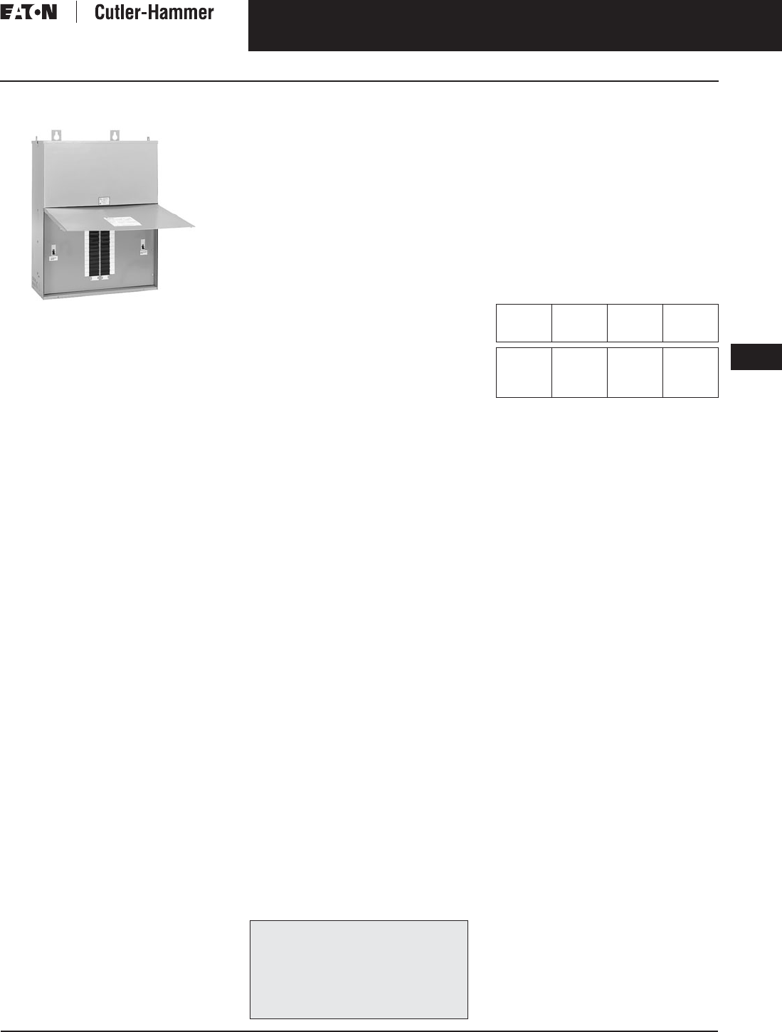
November 2003
CA08101001E For more information visit: www.cutler-hammer.eaton.com
9-57
Transformers
9
Mini-Power Centers
Single- and Three-Phase
Vol. 1, Ref. No. [0357]
Mini-Power Centers
Three-Phase Mini-Power Center
Product Description
■Sand and Resin Encapsulated design.
■Suitable for indoor or outdoor
applications.
■185°C Insulation system, 115°C
Rise standard.
Application Description
A Mini-Power Center combines three
individual components into one NEMA
Type 3R enclosure: a main breaker, an
encapsulated single-phase (Type EP)
or three-phase (EPT) Dry-Type Trans-
former, and a secondary distribution
loadcenter with main breaker. Inter-
connecting wiring is completed at the
factory. Mini-Power Centers are used
wherever there is a 480 volt or 600 volt
distribution system and loads requiring
208Y/120 volt, 3-phase or 120/240 volt
single-phase. Typical installations
include:
■Industrial plant assembly lines.
■Plant expansions.
■Test equipment.
■Temporary construction site power.
■Sewage disposal plants.
■Warehouses.
■Car washes.
■Parking lots.
■Commercial buildings.
Features, Benefits
and Functions
■UL listed, CSA certified.
■60 Hz operation.
■Indoor-Outdoor, NEMA 3R.
■Primary main breaker.
■Secondary main breaker (Type BR
feeder breakers not included).
■All live parts enclosed for personnel
safety.
■Cover is hinged to prevent removal
and can be padlocked.
■
Cores are grounded with a copper lead.
■Ground bar is supplied to permit
grounding of individual secondary
circuits.
■Neutral bar is grounded to case.
■Feeder circuits can be easily added
or changed using Type BR plug-in
breakers.
■Suitable for service entrance.
■Aluminum windings and loadcenter
chassis standard.
■Short-term overload capability as
required by ANSI.
■Meet NEMA ST-20 sound levels.
Standards and Certifications
Industry Standards
All Cutler-Hammer dry-type distribution
and control transformers by Eaton
Corporation are built and tested in
accordance with applicable NEMA,
ANSI, and IEEE Standards. All 600 volt
class transformers are UL listed unless
otherwise noted.
Seismically Qualified
Cutler-Hammer manufactured dry-type
distribution transformers are seismi-
cally qualified, and exceed require-
ments of the Uniform Building Code
(UBC) and California Code Title 24.
Options and Accessories
Please refer to Page 9-120.
Product Specifications
Frequency
Cutler-Hammer standard dry-type dis-
tribution transformers are designed
for 60 Hz operation. Transformers
required for other frequencies must be
specifically designed.
Overload Capability
Short-term overload is designed into
transformers as required by ANSI.
dry-type distribution transformers
will deliver 200% nameplate load for
one-half hour; 150% load for one-hour;
and 125% load for four-hours without
being damaged provided that a con-
stant 50% load precedes and follows
the overload. See ANSI C57.96-01.250
for additional limitations.
Continuous overload capacity is not
deliberately designed into a trans-
former because the design objective is
to be within the allowed winding tem-
perature rise with nameplate loading.
Insulation System and Temperature Rise
Industry standards classify insulation
systems and rise as shown below:
Table 9-62. Insulation System Classification
The design life of transformers having
different insulation systems is the
same — the lower temperature systems
are designed for the same life as
the higher temperature systems.
Sound Levels
All Cutler-Hammer 600 volt class general
purpose dry-type distribution transform-
ers are designed to meet NEMA ST-20
sound levels listed here. These are the
sound levels measured in a soundproof
environment. Actual sound levels mea-
sured at an installation will likely be higher
due to electrical connections and environ-
mental conditions. Lower sound levels are
available and should be specified when
the transformer is going to be installed in
an area where sound may be a concern.
Winding Terminations
The Cutler-Hammer business recom-
mends external cables be rated 90°C
(sized at 75°C ampacity) for encapsu-
lated designs and 75°C for ventilated
designs.
Technical Data
and Specifications
Please refer to Page 9-122.
The following pages provide listings for most
standard transformer ratings and styles.
For all-copper and bolt-on-breaker designs,
contact Eaton’s Cutler-Hammer business.
For other ratings or styles not shown, or for
special enclosure types (including stainless
steel) refer to the Cutler-Hammer business.
Ambient +
Winding
Rise
+
Hot
Spot
=
Temp.
Class
40°C
40°C
40°C
40°C
55°C
80°C
115°C
150°C
10°C
30°C
30°C
30°C
105°C
150°C
185°C
220°C

November 2003
9-58
For more information visit: www.cutler-hammer.eaton.com CA08101001E
Transformers
9
Mini-Power Centers
Single-Phase and Three-Phase Vol. 1, Ref. No. [0358]
Product Selection
Additional Product Selection information begins on Page 9-136.
Table 9-63. Single-Phase — Mini-Power Centers
Table 9-64. Three-Phase — Mini-Power Centers
Primary breakers with higher interrupting capacity available. For HFD breaker, add suffix “H.” For FD breaker, add suffix “F.” For FDC breaker,
add suffix “C.” Main breakers are fixed only.
Combinations can be selected.
Feeder breakers not included, use Eaton’s Cutler-Hammer Type BR.
Note: For 316 grade stainless steel enclosure replace 10th character of catalog number with an “SS” suffix, i.e., P48G11S03SS.
Note: For all-copper, bolt-on breaker designs, contact the Cutler-Hammer business.
kVA Full
Cap.
Taps
FCBN
Dimensions (Inches) Wt.
Lbs.
Dimensions
(mm)
Wt.
kg
Frame Wiring
Diagram
Number
Main Circuit Breaker Feeder
Breakers
Max. Number
Max.
Amp
Style
Number
Price
U.S. $
HWDHWD Primary Secondary
1-Pole 2-Pole
480 Volts to 120/240 Volts
3
5
7.5
2@-5%
2@-5%
2@-5%
27-1/2
29-1/2
29-1/2
12-9/16
12-9/16
12-9/16
9-3/4
9-3/4
9-3/4
105
110
125
698
749
749
319
319
319
248
248
248
47
50
56
FR283
FR284
FR284
97A3K
110A5K
109A7K
EHD2015
EHD2020
EHD2030
BR215
BR225
BR230
8
12
12
4
6
6
12
20
30
P48G11S03P
P48G11S05P
P48G11S07P
2,100.
2,940.
3,540.
10
15
25
2@-5%
2@-5%
2@-5%
38-1/8
38-1/8
43-7/8
13-1/2
13-1/2
16-3/8
11-7/8
11-7/8
14-5/8
180
215
373
968
968
1115
342
342
417
301
301
372
82
98
169
FR285
FR286
FR287
108A10K
107A15K
106A25K
EHD2040
EHD2060
EHD2100
BR250
BR270
BR2125
12
20
26
6
10
13
40
60
100
P48G11S10P
P48G11S15P
P48G11S25P
3,720.
5,000.
7,240.
600 Volts to 120/240 Volts
5
7.5
10
2@-5%
2@-5%
2@-5%
29-1/2
29-1/2
38-1/8
12-9/16
12-9/16
13-1/2
9-3/4
9-3/4
11-7/8
110
125
180
749
749
968
319
319
342
248
248
301
50
56
82
FR284
FR284
FR285
110B5K
109B7K
108B10K
FDB2015
FDB2030
FDB2040
BR225
BR230
BR250
12
12
12
6
6
6
20
30
40
P60G11S05P
P60G11S07P
P60G11S10P
3,785.
4,040.
4,240.
15
25
2@-5%
2@-5%
38-1/8
43-7/8
13-1/2
16-3/8
11-7/8
14-5/8
215
373
968
1115
342
417
301
372
98
169
FR286
FR287
107B15K
106B25K
FDB2060
FDB2100
BR270
BR2125
20
26
10
13
60
100
P60G11S15P
P60G11S25P
5,640.
8,310.
kVA Full
Cap.
Taps
FCBN
Dimensions (Inches) Wt.
Lbs.
Dimensions
(mm)
Wt.
kg
Frame Wiring
Diagram
Number
Main Circuit Breaker
Feeder
Breakers
Max. Number
Max.
Amp
Style
Number
Price
U.S. $
HWDHWD Primary Secondary
1-Pole 2-Pole
480 ∆ Volts to 208Y/120 Volts
15
22.5
30
2@-5%
2@-5%
2@-5%
36-1/8
40-7/8
41-7/8
28-3/4
29-7/8
29-7/8
9-3/8
13-5/8
13-5/8
320
565
635
917
1038
1063
730
759
759
238
346
346
145
256
288
FR289A
FR290A
FR291A
105A15K
103A21K
104A30K
EHD3040
EHD3070
EHD3090
BR350
BR370
BR3100
18
18
24
6
6
8
40
60
80
P48G28T15P
P48G28T21P
P48G28T30P
7,420.
9,225.
11,750.
600 ∆ Volts to 208Y/120 Volts
15
22.5
30
2@-5%
2@-5%
2@-5%
36-1/8
40-7/8
41-7/8
28-3/4
29-7/8
29-7/8
9-3/8
13-5/8
13-5/8
320
565
635
917
1038
1063
730
759
759
238
346
346
145
256
288
FR289A
FR290A
FR291A
105D15K
103B21K
104B30K
FDB3030
FDB3050
FDB3070
BR350
BR370
BR3100
18
18
24
6
6
8
40
60
80
P60G28T15P
P60G28T21P
P60G28T30P
8,685.
10,860.
15,150.
For other ratings or styles not shown, or for
special enclosure types (including stainless
steel) refer to Eaton’s Cutler-Hammer business. Discount Symbol . . . . . . . . . . . . . . . . . . . . . . . . . DT-1
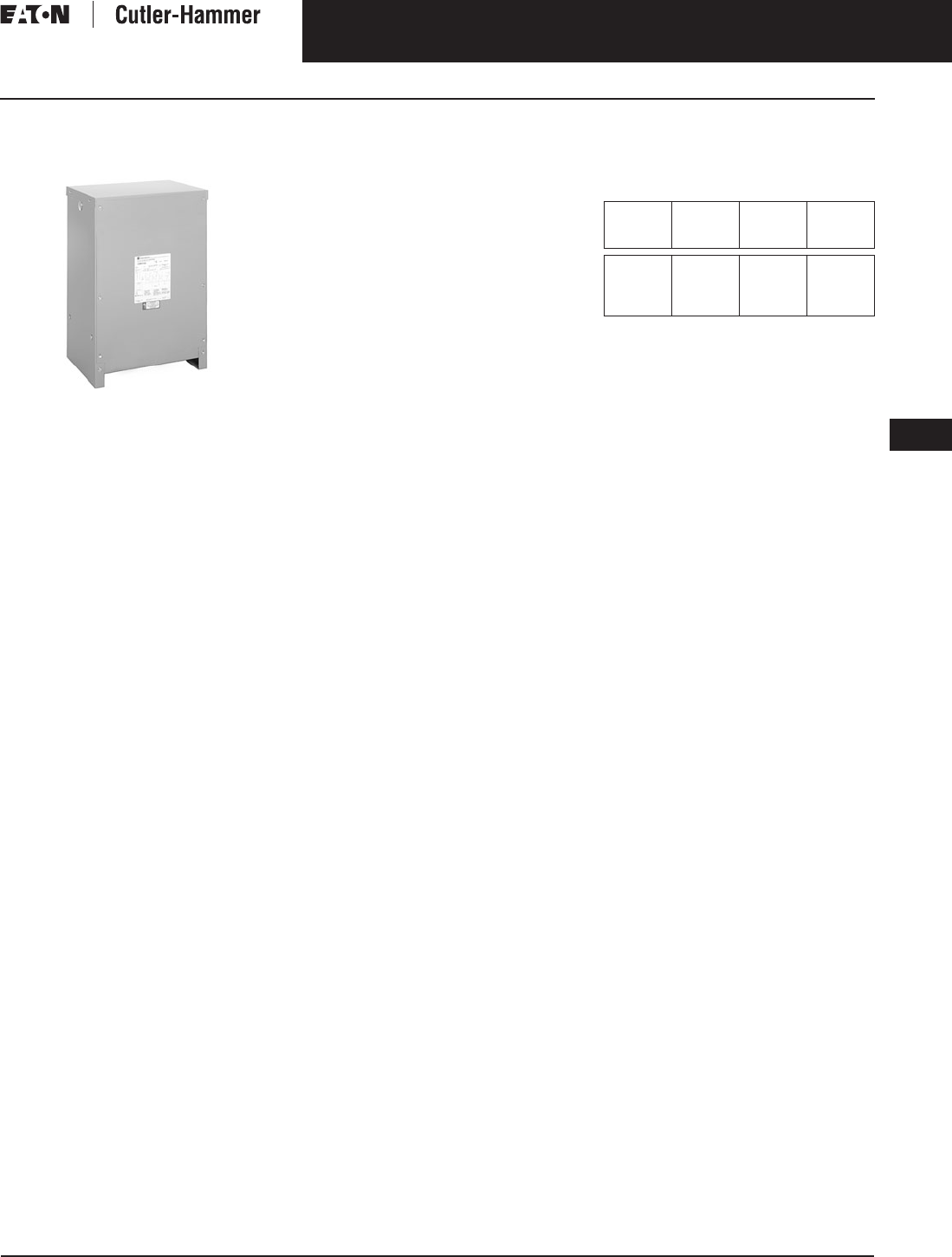
November 2003
CA08101001E For more information visit: www.cutler-hammer.eaton.com
9-59
Transformers
9
Totally Enclosed Non-Ventilated Transformers
Single- and Three-Phase
Vol. 1, Ref. No. [0359]
Single- and Three-Phase,
Types DS-3E, DT-3E, 60 Hz
Three-Phase Type DT-3E
Totally Enclosed Non-Ventilated
Product Description
■Suitable for indoor or outdoor
applications.
■Totally enclosed, non-ventilated
enclosures.
■220°C insulation system,
150°C rise standard.
Application Description
Totally enclosed non-ventilated dry-
type transformers are for special appli-
cations, where because of adverse
atmospheric conditions it is desirable
to use a dry-type non-ventilated trans-
former vs. the ventilated standard unit,
which has openings in its enclosure
to allow air to flow directly over the
core and coil.
In applications where the atmosphere
contains conductive, corrosive, or
combustible materials, which might
damage a transformer, or lint and dust
flyings which might block the ventila-
tion passages, the non-ventilated
transformer is highly suited. It has
no openings in the enclosure. Heat
is dissipated by radiating from the
surface area of the enclosure. Conse-
quently, the enclosures are larger
than those of the standard ventilated
type. Non-ventilated transformers are
suited for application in the textile,
chemical, automotive, petrochemical,
foundry, cement, food, paper, and
other industries where the transformer
is subject to spray or washdown
conditions.
Features, Benefits
and Functions
■60 Hz operation
(50/60 Hz operation available).
■Short-term overload capability
as required by ANSI.
■Meet NEMA ST-20 sound levels.
Standards and Certifications
Industry Standards
All Cutler-Hammer dry-type distribution
and control transformers by Eaton
Corporation are built and tested in
accordance with applicable NEMA,
ANSI, and IEEE Standards.
Seismically Qualified
Cutler-Hammer manufactured dry-type
distribution transformers are seismi-
cally qualified, and exceed require-
ments of the Uniform Building Code
(UBC) and California Code Title 24.
Options and Accessories
Please refer to Page 9-120.
Product Specifications
Frequency
Cutler-Hammer standard dry-type dis-
tribution transformers are designed
for 60 Hz operation. Transformers
required for other frequencies are
available and must be specifically
designed.
Overload Capability
Short-term overload is designed into
transformers as required by ANSI.
dry-type distribution transformers
will deliver 200% nameplate load for
one-half hour; 150% load for one-hour;
and 125% load for four-hours without
being damaged provided that a con-
stant 50% load precedes and follows
the overload. See ANSI C57.96-01.250
for additional limitations.
Continuous overload capacity is not
deliberately designed into a trans-
former because the design objective is
to be within the allowed winding tem-
perature rise with nameplate loading.
Insulation System and Temperature Rise
Industry standards classify insulation
systems and rise as shown below:
Table 9-65. Insulation System Classification
The design life of transformers having
different insulation systems is the
same — the lower temperature systems
are designed for the same life as the
higher temperature systems.
Enclosures
Cutler-Hammer totally enclosed, non-
ventilated transformers, Types DS-3E
and DT-3E, utilize a NEMA 3R rated
enclosure as standard.
Winding Terminations
Primary and secondary windings are
terminated in the wiring compartment.
Totally enclosed non-ventilated trans-
formers have leads brought out to
aluminum pads that are pre-drilled
to accept Cu/Al lugs. Lugs are not
supplied with these transformers.
The Cutler-Hammer business recom-
mends external cables be rated 75°C
for ventilated designs.
Series-Multiple Windings
Series-multiple windings consist of
2 similar coils in each winding which
can be connected in series or parallel
(multiple). Transformers with series-
multiple windings are designated with
an “X” or “/” between the voltage
ratings, such as voltages of “120/240”
or “240 X 480.” If the series-multiple
winding is designated by an “X,” the
winding can be connected only for a
series or parallel. With the “/” designa-
tion, a mid-point also becomes available
in addition to the series or parallel
connection. As an example, a 120 X 240
winding can be connected for either
120 (parallel) or 240 (series), but a
120/240 winding can be connected
for 120 (parallel), or 240 (series), or
240 with a 120 mid-point.
Technical Data
and Specifications
Please refer to Page 9-122.
Ambient +
Winding
Rise
+
Hot
Spot
=
Temp.
Class
40°C
40°C
40°C
40°C
55°C
80°C
115°C
150°C
10°C
30°C
30°C
30°C
105°C
150°C
185°C
220°C

November 2003
9-60
For more information visit: www.cutler-hammer.eaton.com CA08101001E
Transformers
9
Totally Enclosed Non-Ventilated Transformers
Single- and Three-Phase Vol. 1, Ref. No. [0360]
Product Selection
Additional Product Selection information begins on Page 9-136.
Table 9-66. Single-Phase Selection Information — Type DS-3E, 60 Hz
Table 9-67. Three-Phase Selection Information — Type DT-3E, 60 Hz
Types DS-3 and DT-3 non-ventilated transformers are not UL listed.
Transformers Type EPT 75 kVA and smaller three-phase, and Type EP 25 kVA and smaller single-phase, are furnished non-ventilated normally,
as standard (and are UL listed). See General Purpose Transformers.
Note: Contact your local Cutler-Hammer sales office for availability of additional Totally Enclosed Non-Ventilated Transformers.
Note: Contact your local Cutler-Hammer sales office for CE Mark transformer requirements.
kVA Type °C
Temp.
Rise
Dimensions (Inches) Weight
Lbs.
Dimensions (mm) Weight
kg
Frame Wiring
Diagram
Number
Style
Number
Price
U.S. $
HWD HWD
240 x 480 Volts to 120/240 Volts +1 – 5%, -2 – 5% at 240 Volts Primary; +2 – 2.5%, -4 – 2.5% at 480 Volts primary.
37.5
50
DS-3E
DS-3E
150
150
42-1/8
42-1/8
24
24
23-3/8
23-3/8
600
720
1070
1070
610
610
594
594
274
329
FR820N
FR820N
3XA
3XA
T20P11S37NV
T20P11S50NV
4,330.
5,400.
kVA Type °C
Temp.
Rise
Dimensions (Inches) Weight
Lbs.
Dimensions (mm) Weight
kg
Frame Wiring
Diagram
Number
Style
Number
Price
U.S. $
HWD H WD
480 ∆ Volts to 208Y/120 Volts +2 – 2.5% FCAN, 4 – 2.5% FCBN Taps
30
45
75
DT-3E
DT-3E
DT-3E
150
150
150
39-1/4
39-1/4
46-1/2
26-1/8
26-1/8
28
19-1/8
19-1/8
23
480
600
760
995
995
1171
663
663
712
486
486
585
217
272
344
FR914AN
FR915AN
FR916AN
280B
280B
280B
V48M28T30NV
V48M28T45NV
V48M28T75NV
3,080.
4,400.
5,500.
112.5
150
225
300
DT-3E
DT-3E
DT-3E
DT-3E
150
150
150
150
56
56
75
75
31-1/4
31-1/4
44-1/2
44-1/2
24-1/2
24-1/2
36
36
1100
1300
2400
2900
1422
1422
1905
1905
793
793
1130
1130
622
622
914
914
499
589
1088
1315
FR917N
FR918AN
FR919N
FR920N
280B
280B
275A
275A
V48M28T12NV
V48M28T49NV
V48M28T22NV
V48M28T33NV
8,000.
10,100.
16,000.
26,000.
For other ratings or styles not shown, or for
special enclosure types (including stainless
steel) refer to Eaton’s Cutler-Hammer business. Discount Symbol . . . . . . . . . . . . . . . . . . . . . . . . . DT-1
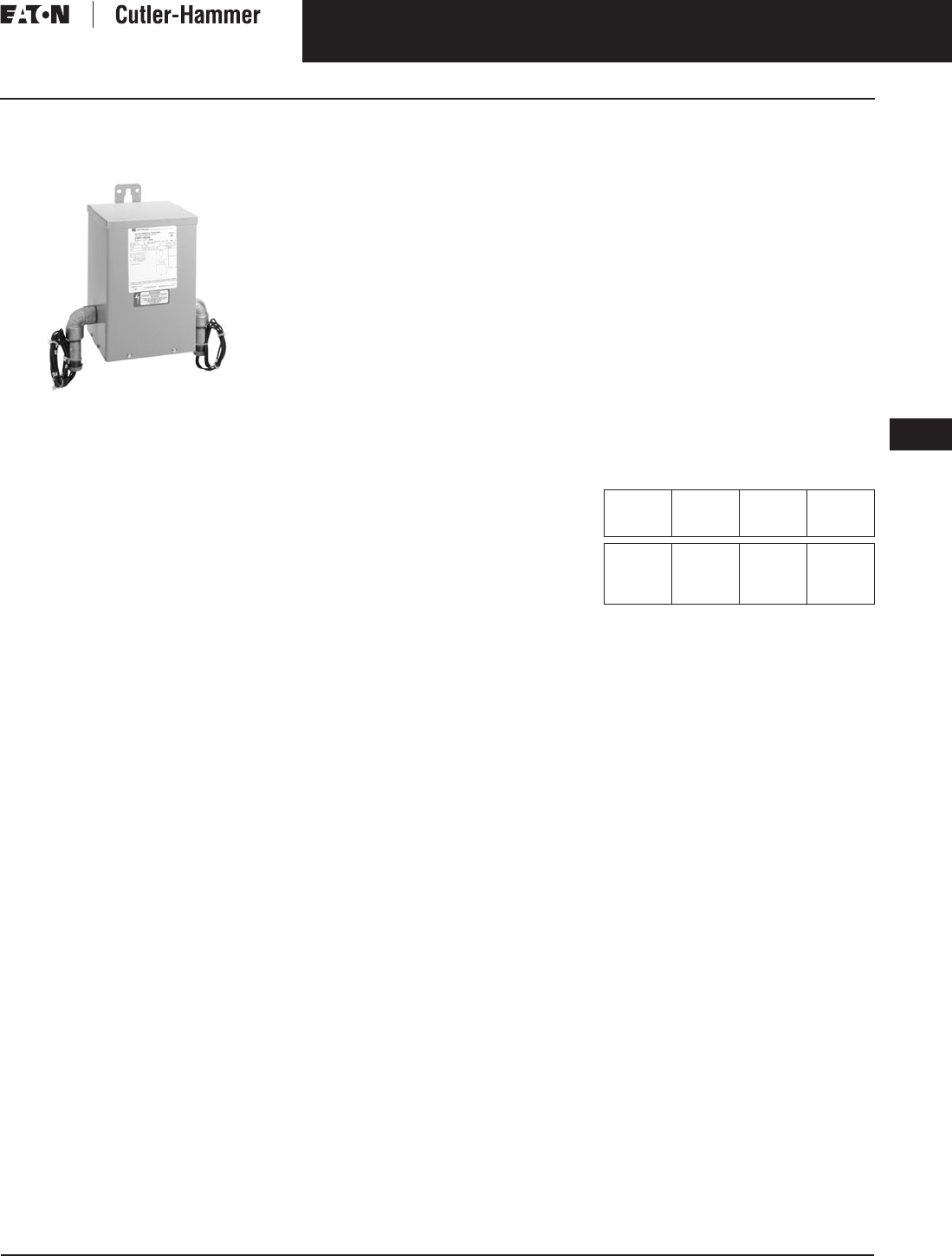
November 2003
CA08101001E For more information visit: www.cutler-hammer.eaton.com
9-61
Transformers
9
Class I, Division 2, Groups C and D Transformers
Single- and Three-Phase
Vol. 1, Ref. No. [0361]
Single- and Three-Phase,
Types EPZ, EPTZ, 60 Hz
Single-Phase Type EPZ Encapsulated
Product Description
■Sand and Resin Encapsulated design.
■Suitable for indoor or outdoor
applications.
■Totally enclosed, non-ventilated
enclosures.
■185°C Insulation system, 115°C
Rise standard.
■Mountable in any position indoors.
Upright only outdoors.
■Available in ratings up to 600 volts
primary, 37.5 kVA single-phase,
75 kVA three-phase.
Application Description
Type EPZ and EPTZ transformers are
labeled as “Suitable for use in Class I,
Division 2, Groups C and D locations,
as defined by NEC Article 501, with
NEC-recommended installation proce-
dures for dry-type transformers rated
under 600 volts nominal operation.”
A Class I, Division 2 location per
Section 500 of the NEC is defined as:
6. A location in which volatile
flammable liquids or gases are
handled, processed or used, but
which normally will be confined
within closed containers or sys-
tems from which they can escape
only in case of accidental rupture
or breakdown of the container
or system.
7. Or, a location where ignitable
concentrations of gases or vapors
are normally prevented by positive
mechanical ventilation and which
might become hazardous through
failure of the ventilation equipment.
8. Or, a location that is adjacent to
a Class I, Division 1 location and
ignitable concentrations of gases or
vapors might occasionally enter.
Atmospheres classified by NEC Section
500 as Group C may contain gases or
vapors such as ethyl ether, ethylene, or
the equivalent. Atmospheres classified
as Group D may contain gases or
vapors such as acetone, ammonia,
benzene, butane, cyclopropane, ethanol,
gasoline, hexane, methanol, methane,
natural gas, naphtha, propane, or the
equivalent.
Features, Benefits
and Functions
■NEMA 3R enclosure.
■60 Hz operation.
■Aluminum windings (copper
optional).
■Short-term overload capability as
required by ANSI.
■Meet NEMA ST-20 sound levels.
■Long leads to ease wiring to
junction box.
Standards and Certifications
Industry Standards
All Cutler-Hammer dry-type distribu-
tion and control transformers by Eaton
Corporation are built and tested in
accordance with applicable NEMA,
ANSI, and IEEE Standards.
Seismically Qualified
Cutler-Hammer manufactured dry-type
distribution transformers are seismi-
cally qualified, and exceed require-
ments of the Uniform Building Code
(UBC) and California Code Title 24.
Options and Accessories
Please refer to Page 9-120.
Product Specifications
Frequency
Cutler-Hammer standard dry-type dis-
tribution transformers are designed
for 60 Hz operation. Transformers
required for other frequencies are
available and must be specifically
designed.
Overload Capability
Short-term overload is designed into
transformers as required by ANSI.
dry-type distribution transformers
will deliver 200% nameplate load for
one-half hour; 150% load for one-hour;
and 125% load for four-hours without
being damaged provided that a con-
stant 50% load precedes and follows
the overload. See ANSI C57.96-01.250
for additional limitations.
Continuous overload capacity is not
deliberately designed into a trans-
former because the design objective is
to be within the allowed winding tem-
perature rise with nameplate loading.
Insulation System and Temperature Rise
Industry standards classify insulation
systems and rise as shown below:
Table 9-68. Insulation System Classification
The design life of transformers having
different insulation systems is the
same — the lower temperature systems
are designed for the same life as the
higher temperature systems.
Enclosures
Cutler-Hammer encapsulated
transformers, Types EPZ and EPTZ,
utilize a NEMA 3R rated enclosure.
Sound Levels
All Cutler-Hammer 600 volt class gen-
eral purpose dry-type distribution
transformers are designed to meet
NEMA ST-20 sound levels listed here.
These are the sound levels measured
in a soundproof environment. Actual
sound levels measured at an installa-
tion will likely be higher due to electri-
cal connections and environmental
conditions. Lower sound levels are
available and should be specified
when the transformer is going to be
installed in an area where sound may
be a concern.
Ambient +
Winding
Rise
+
Hot
Spot
=
Temp.
Class
40°C
40°C
40°C
40°C
55°C
80°C
115°C
150°C
10°C
30°C
30°C
30°C
105°C
150°C
185°C
220°C
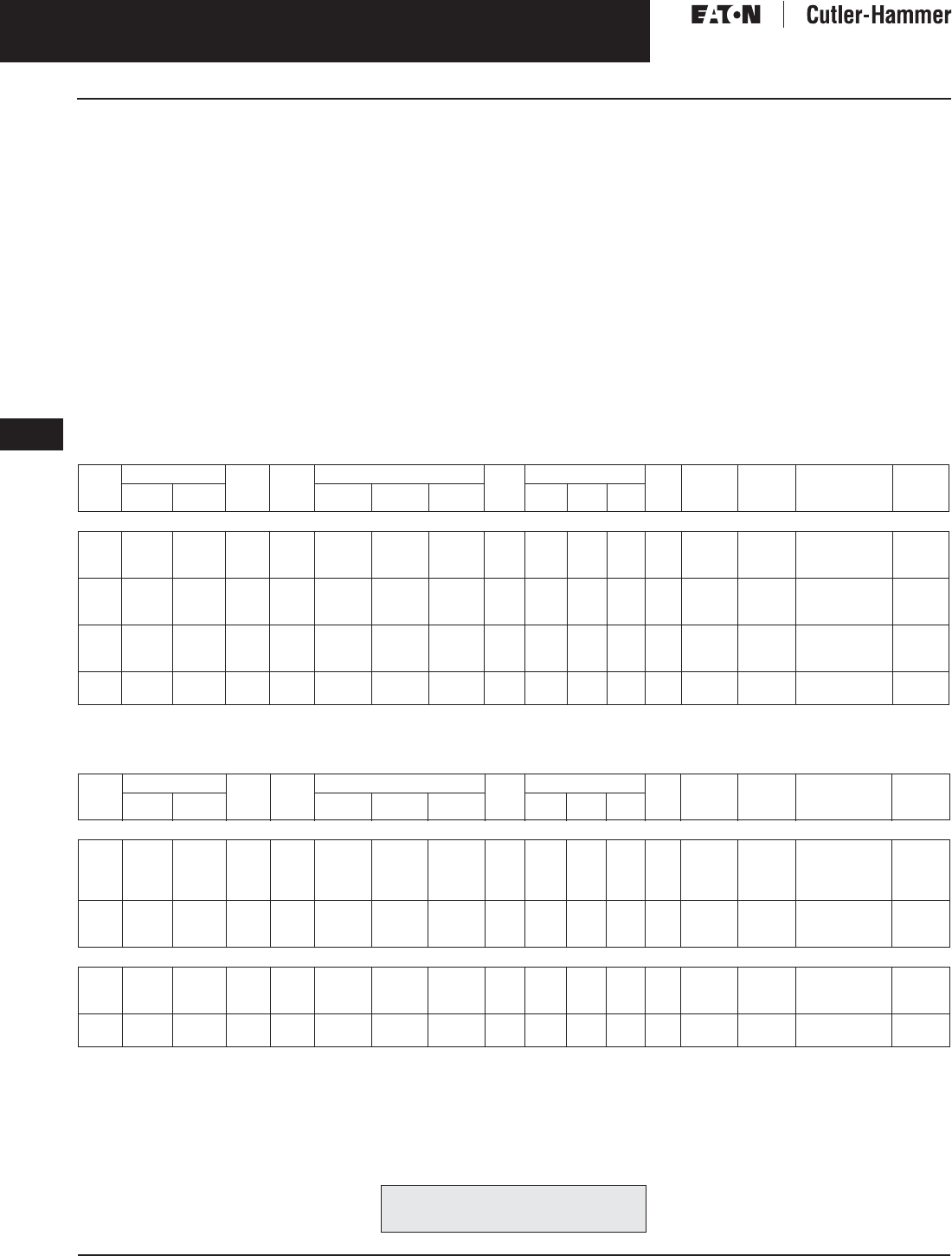
November 2003
9-62
For more information visit: www.cutler-hammer.eaton.com CA08101001E
Transformers
9
Class I, Division 2, Groups C and D Transformers
Single- and Three-Phase Vol. 1, Ref. No. [0362]
Winding Terminations
Lugs are not supplied with these trans-
formers. Eaton’s Cutler-Hammer busi-
ness recommends external cables be
rated 90°C (sized at 75°C ampacity) for
encapsulated designs and 75°C for ven-
tilated designs.
Nominal and tap leads come out of
the transformer through pipe elbows.
Connections should be made to an
adjacent explosion-proof junction box.
Unused tap leads must be properly
insulated prior to energization. EPZ
and EPTZ transformers are not UL listed.
Series-Multiple Windings
Series-multiple windings consist of 2
similar coils in each winding which can
be connected in series or parallel (multi-
ple). Transformers with series-multiple
windings are designated with an “X” or
“/” between the voltage ratings, such as
voltages of “120/240” or “240 X 480.”
If the series-multiple winding is desig-
nated by an “X,” the winding can be
connected only for a series or parallel.
With the “/” designation, a mid-point
also becomes available in addition to
the series or parallel connection. As an
example, a 120 X 240 winding can be
connected for either 120 (parallel) or
240 (series), but a 120/240 winding can
be connected for 120 (parallel), or 240
(series), or 240 with a 120 mid-point.
Technical Data
and Specifications
Please refer to Page 9-122.
Product Selection
Additional Product Selection information begins on Page 9-136.
Table 9-69. Single-Phase Selection Information — Type EPZ, 60 Hz
Dimensions do not include the conduit for cable entry and exit.
Note: For 316 grade stainless steel enclosure replace 10th character of catalog number with an “SS” suffix.
Table 9-70. Three-Phase Selection Information — Type EPTZ, 60 Hz
Dimensions do not include the conduit for cable entry and exit.
Center Tap capacity limited to 5% of rated kVA.
Note: For 316 grade stainless steel enclosure replace 10th character of catalog number with an “SS” suffix.
Note: Contact your local Cutler-Hammer sales office for CE Mark transformer requirements.
kVA Full Cap. Taps Type °C
Temp.
Rise
Dimensions (Inches) Wt.
Lbs.
Dimensions (mm) Wt.
kg
Frame Wiring
Diagram
Number
Style
Number
Price
U.S. $
FCAN FCBN H W D H W D
480 Volts to 120/240 Volts
.05
.75
1
—
—
—
—
—
—
EPZ
EPZ
EPZ
115
115
115
6-1/2
8-3/8
8-3/8
4-7/8
6
6
4-5/8
5-3/4
5-3/4
13
21
31
165
213
213
124
152
152
118
146
146
6
10
14
FR57H
FR58AH
FR59AH
524H
524H
524H
Z48N11S51A
Z48N11S76A
Z48N11S01A
510.
675.
805.
1.5
2
3
—
—
—
—
—
—
EPZ
EPZ
EPZ
115
115
115
10-3/4
10-3/4
14-1/8
6-3/16
6-3/16
7-3/4
6-1/8
6-1/8
8
40
40
65
273
273
359
157
157
197
156
156
203
18
18
30
FR67H
FR68H
FR176H
524H
524H
524H
Z48N11S16A
Z48N11S02A
Z48N11S03A
975.
1,185.
1,370.
5
7.5
10
—
—
—
—
—
—
EPZ
EPZ
EPZ
115
115
115
16
16
19
10-3/8
10-3/8
13-3/8
9-7/8
9-7/8
10-1/2
113
123
193
406
406
483
264
264
340
232
232
267
51
56
88
FR177H
FR178H
FR179H
524H
524H
524H
Z48N11S05A
Z48N11S07A
Z48N11S10A
1,985.
2,375.
2,870.
15
25
—
—
—
—
EPZ
EPZ
115
115
19
22-3/8
13-3/8
16-3/8
10-1/2
14-1/2
216
375
483
567
340
416
267
359
98
170
FR180H
FR182H
524H
524H
Z48N11S15A
Z48N11S25A
3,530.
5,190.
kVA Full Cap. Taps Type °C
Temp.
Rise
Dimensions (Inches) Wt.
Lbs.
Dimensions (mm) Wt.
kg
Frame Wiring
Diagram
Number
Style
Number
Price
U.S. $
FCAN FCBN H W D H W D
480 ∆ Volts to 208Y/120 Volts Three-Phase
3
6
9
15
—
—
—
—
2@-5%
2@-5%
2@-5%
2@-5%
EPTZ
EPTZ
EPTZ
EPTZ
115
115
115
115
13-3/8
15-7/8
15-7/8
17-3/8
16
16-1/2
16-1/2
19-11/16
8-3/8
9-7/8
9-7/8
10-7/16
116
143
166
275
340
403
403
442
405
419
419
500
211
251
251
265
53
65
75
125
FR201H
FR200H
FR103H
FR95H
70A
70A
70A
70A
Z48G28T03A
Z48G28T06A
Z48G28T09A
Z48G28T15A
2,645.
3,085.
3,825.
5,470.
30
45
75
—
—
—
2@-5%
2@-5%
2@-5%
EPTZ
EPTZ
EPTZ
115
115
115
26-5/8
26-1/2
30-3/4
25-1/4
28-1/2
30-1/8
12-3/4
14-5/8
15-5/8
422
660
1275
676
673
781
638
724
765
324
372
397
191
299
580
FR243H
FR244H
FR245H
66A
66A
66A
Z48G28T30A
Z48G28T45A
Z48G28T75A
9,720.
11,130.
14,490.
480 ∆ Volts to 240 ∆ Volts with 120 Volt Lighting Tap on B Phase
6
9
15
—
—
—
2@-5%
2@-5%
2@-5%
EPTZ
EPTZ
EPTZ
115
115
115
13-1/8
14-15/16
21-3/4
19-9/16
21-7/8
22-5/16
6-1/4
7-3/8
11-3/8
115
160
340
333
379
552
497
556
567
158
187
289
52
73
155
FR102H
FR97H
FR195H
95A
95A
95A
Z48G22T06A
Z48G22T09A
Z48G22T15A
3,395.
4,205.
6,010.
30
45
—
—
2@-5%
2@-5%
EPTZ
EPTZ
115
115
26-5/8
26-1/2
25-1/4
28-1/2
12-3/4
14-5/8
422
660
676
673
638
724
324
372
191
299
FR243H
FR244H
95A
95A
Z48G22T30A
Z48G22T45A
10,690.
12,230.
For other ratings or styles not shown, or for
special enclosure types (including stainless
steel) refer to Eaton’s Cutler-Hammer business. Discount Symbol . . . . . . . . . . . . . . . . . . . . . . . . . DT-1
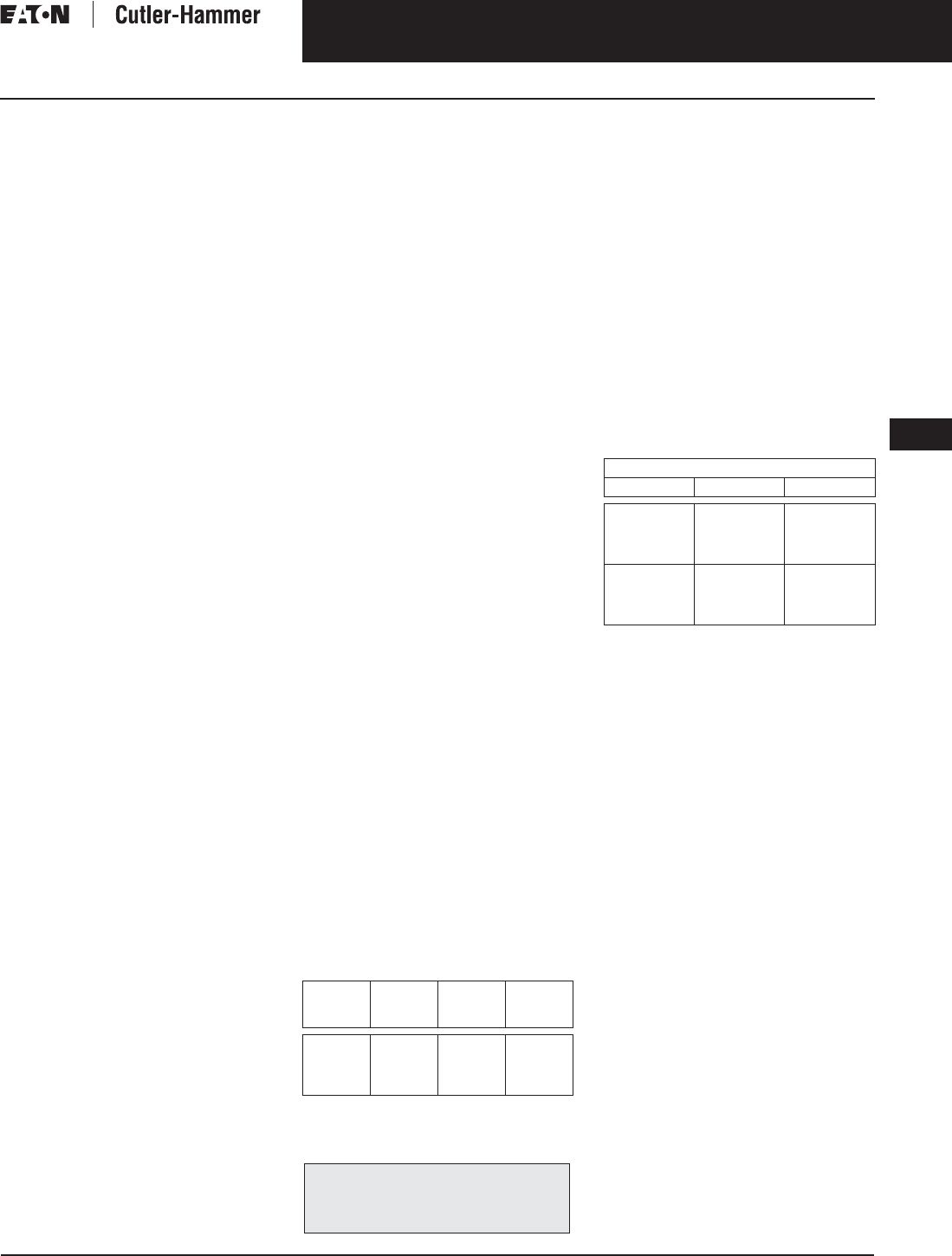
November 2003
CA08101001E For more information visit: www.cutler-hammer.eaton.com
9-63
Transformers
9
Open Type Core and Coil Assembly Transformers
Single- and Three-Phase
Vol. 1, Ref. No. [0363]
Single- and Three-Phase,
Types DS-3C, DT-3C, 60 Hz
Product Description
■220°C insulation system, 150°C
Rise standard.
■Aluminum windings
(copper optional).
Application Description
The basic purpose of a transformer
is voltage transformation as near as
practically possible to the load for
economy and distribution of power.
Typical loads for dry-type distribution
transformers include lighting, heating,
air conditioners, fans, and machine
tools. Such loads are found in
commercial, institutional, industrial,
and residential structures.
Open core and coil assemblies are
typically used by panel builders and
equipment OEM customers who
incorporate the entire transformer
into their structures. A versatile option
to purchasing a standard, enclosed
transformer and discarding the
unneeded enclosure parts.
Features, Benefits
and Functions
■ (UL recognized).
■60 Hz operation standard,
50/60 Hz operation available.
■Short-term overload capability as
required by ANSI.
■Meet NEMA ST-20 sound levels.
Standards and Certifications
Industry Standards
All Cutler-Hammer dry-type distribu-
tion and control transformers by Eaton
Corporation are built and tested in
accordance with applicable NEMA,
ANSI, and IEEE Standards.
Seismically Qualified
All Cutler-Hammer manufactured dry-
type distribution transformers are seis-
mically qualified, and exceed require-
ments of the Uniform Building Code
(UBC) and California Code Title 24.
Options and Accessories
Please refer to Page 9-120.
Product Specifications
Frequency
Cutler-Hammer standard dry-type distri-
bution transformers are designed for 60
Hz operation. Transformers required for
other frequencies are available and
must be specifically designed.
Overload Capability
Short-term overload is designed into
transformers as required by ANSI.
dry-type distribution transformers
will deliver 200% nameplate load for
one-half hour; 150% load for one-hour;
and 125% load for four-hours without
being damaged provided that a con-
stant 50% load precedes and follows
the overload. See ANSI C57.96-01.250
for additional limitations.
Continuous overload capacity is not
deliberately designed into a trans-
former because the design objective is
to be within the allowed winding tem-
perature rise with nameplate loading.
Insulation System and Temperature Rise
Industry standards classify insulation
systems and rise as shown below:
Table 9-71. Insulation System Classification
The design life of transformers having
different insulation systems is the
same — the lower temperature systems
are designed for the same life as the
higher temperature systems.
Sound Levels
All Cutler-Hammer 600 volt class general
purpose dry-type distribution transform-
ers are designed to meet NEMA ST-20
sound levels listed here. These are the
sound levels measured in a soundproof
environment. Actual sound levels mea-
sured at an installation will likely be higher
due to electrical connections and environ-
mental conditions. Lower sound levels are
available and should be specified when
the transformer is going to be installed in
an area where sound may be a concern.
Table 9-72. Average Sound Levels
Winding Terminations
Lugs are not supplied with these
transformers. The Cutler-Hammer
business recommends external cables
be rated 90°C (sized at 75°C ampacity)
for encapsulated designs and 75°C
for ventilated designs.
Series-Multiple Windings
Series-multiple windings consist of 2
similar coils in each winding which
can be connected in series or parallel
(multiple). Transformers with series-
multiple windings are designated with
an “X” or “/” between the voltage
ratings, such as voltages of “120/240”
or “240 X 480.” If the series-multiple
winding is designated by an “X,” the
winding can be connected only for a
series or parallel. With the “/” designa-
tion, a mid-point also becomes avail-
able in addition to the series or parallel
connection. As an example, a 120 X
240 winding can be connected for
either 120 (parallel) or 240 (series), but
a 120/240 winding can be connected
for 120 (parallel), or 240 (series), or 240
with a 120 mid-point.
Technical Data
and Specifications
Please refer to Page 9-122.
Ambient +
Winding
Rise
+
Hot
Spot
=
Temp.
Class
40°C
40°C
40°C
40°C
55°C
80°C
115°C
150°C
10°C
30°C
30°C
30°C
105°C
150°C
185°C
220°C
The following pages provide listings for most
standard transformer ratings and styles.
For other ratings or styles not shown, refer
to Eaton’s Cutler-Hammer business.
NEMA ST-20 Average Sound Level (dB)
kVA Ventilated Encapsulated
0 – 9
10 – 50
51 – 150
151 – 300
40
45
50
55
45
50
55
57
301 – 500
501 – 700
701 – 1000
1001 – 1500
60
62
64
65
59
61
63
64
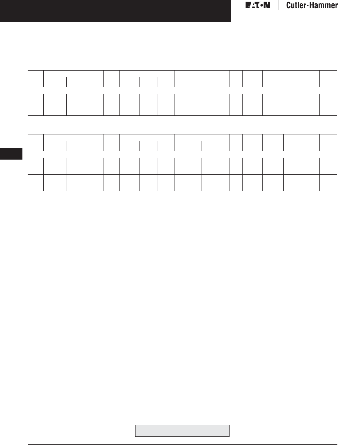
November 2003
9-64
For more information visit: www.cutler-hammer.eaton.com CA08101001E
Transformers
9
Open Type Core and Coil Assembly Transformers
Single- and Three-Phase Vol. 1, Ref. No. [0364]
Product Selection
Additional Product Selection information begins on Page 9-136.
Table 9-73. Single-Phase Selection Information — Type DS-3C, 60 Hz
1@+5%, 2@–5% at 240 volts primary; 2@+2.5%, 4@–2.5% at 480 volts primary.
Table 9-74. Three-Phase Selection Information — Type DT-3C, 60 Hz
Note: Contact your local Cutler-Hammer sale offices for availability of additional Open Type Core and Coil Assemblies.
Note: Contact your local Cutler-Hammer sales office for CE Mark transformer requirements.
kVA Full Cap. Taps Type °C
Temp.
Rise
Dimensions (Inches) Wt.
Lbs.
Dimensions (mm) Wt.
kg
Frame Wiring
Diagram
Number
Style
Number
Price
U.S. $
FCAN FCBN H W D H W D
240 x 480 Volts to 120/240 Volts
15
25
37.5
50
DS-3C
DS-3C
DS-3C
DS-3C
150
150
150
150
30-1/4
31-1/4
37-5/8
37-5/8
16-7/8
22-5/8
22-5/8
22-5/8
15-7/8
17-1/2
19-1/2
19-1/2
147
212
306
340
768
793
953
953
428
574
574
574
402
445
495
495
67
96
139
154
FR815C
FR816C
FR817C
FR818C
3XA
3XA
3XA
3XA
T20P11S15ZZ
T20P11S25ZZ
T20P11S37ZZ
T20P11S50ZZ
1,440.
1,870.
2,290.
2,780.
kVA Full Cap. Taps Type °C
Temp.
Rise
Dimensions (Inches) Wt.
Lbs.
Dimensions (mm) Wt.
kg
Frame Wiring
Diagram
Number
Style
Number
Price
U.S. $
FCAN FCBN H W D H W D
480 ∆ Volts to 208Y/120 Volts
15
30
45
2@+2.5%
2@+2.5%
2@+2.5%
4@-2.5%
4@-2.5%
4@-2.5%
DT-3C
DT-3C
DT-3C
150
150
150
20-5/16
23-13/16
24-3/4
20-1/8
20-1/8
20-1/8
14
14
14
128
195
250
516
605
629
511
511
511
356
356
356
58
89
114
FR909C
FR910C
FR912C
280B
280B
280B
V48M28T15ZZ
V48M28T30ZZ
V48M28T45ZZ
1,350.
1,725.
2,100.
75
112.5
150
2@+2.5%
2@+2.5%
2@+2.5%
4@-2.5%
4@-2.5%
4@-2.5%
DT-3C
DT-3C
DT-3C
150
150
150
29-3/8
31-3/8
41-7/16
25-5/16
25-5/16
25-5/16
19
19
20
395
530
656
746
797
1052
643
643
643
483
483
508
180
241
298
FR914C
FR915C
FR916C
280B
280B
280B
V48M28T75ZZ
V48M28T12ZZ
V48M28T49ZZ
2,970.
4,300.
5,400.
For other ratings or styles not shown, refer
to Eaton’s Cutler-Hammer business. Discount Symbol . . . . . . . . . . . . . . . . . . . . . . . . . DT-1

November 2003
CA08101001E For more information visit: www.cutler-hammer.eaton.com
9-65
Transformers
9
Filtered Noise Isolation Transformers
Three-Phase
Vol. 1, Ref. No. [0365]
Three-Phase, 60 Hz
Product Description
■Ventilated enclosures.
■Indoor applications standard.
■220°C insulation system,
150°C rise standard.
■Aluminum windings
(copper available as option).
■Electrostatic shield.
■Surge suppression providing
protection from voltage surges
and spikes.
■120 dB common mode noise
attenuation.
■60 dB transverse mode noise
attenuation.
Application Description
The basic purpose of a transformer
is voltage transformation as near as
practically possible to the load for
economy and distribution of power.
Typical loads for dry-type distribution
transformers include lighting, heating,
air conditioners, fans, and machine
tools. Such loads are found in
commercial, institutional, industrial,
and residential structures.
Features, Benefits
and Functions
■UL listed.
■60 Hz operation standard,
50/60 Hz operation available.
■Short-term overload capability
as required by ANSI.
■Meet NEMA ST-20 sound levels.
Standards and Certifications
Industry Standards
All Cutler-Hammer dry-type distribution
and control transformers by Eaton
Corporation are built and tested in
accordance with applicable NEMA,
ANSI, and IEEE Standards. All 600 volt
class transformers are UL listed unless
otherwise noted.
Options and Accessories
Please refer to Page 9-120.
Product Specifications
Frequency
Cutler-Hammer standard dry-type dis-
tribution transformers are designed
for 60 Hz operation. Transformers
required for other frequencies are
available and must be specifically
designed.
Overload Capability
Short-term overload is designed into
transformers as required by ANSI.
dry-type distribution transformers
will deliver 200% nameplate load for
one-half hour; 150% load for one-hour;
and 125% load for four-hours without
being damaged provided that a con-
stant 50% load precedes and follows
the overload. See ANSI C57.96-01.250
for additional limitations.
Continuous overload capacity is not
deliberately designed into a trans-
former because the design objective is
to be within the allowed winding tem-
perature rise with nameplate loading.
Insulation System and Temperature Rise
Industry standards classify insulation
systems and rise as shown below:
Table 9-75. Insulation System Classification
The design life of transformers having
different insulation systems is the
same — the lower temperature systems
are designed for the same life as the
higher temperature systems.
Enclosures
Cutler-Hammer ventilated transformers,
Types DS-3, DT-3, MD, and KT, utilize a
NEMA 2 rated (drip-proof) enclosure
as standard, and are rated NEMA 3R
with the addition of weathershields.
Sound Levels
All Cutler-Hammer 600 volt class general
purpose dry-type distribution transform-
ers are designed to meet NEMA ST-20
sound levels listed here. These are the
sound levels measured in a soundproof
environment. Actual sound levels mea-
sured at an installation will likely be higher
due to electrical connections and environ-
mental conditions. Lower sound levels are
available and should be specified when
the transformer is going to be installed in
an area where sound may be a concern.
Table 9-76. Average Sound Levels
Applies to general purpose ventilated
transformers only.
Winding Terminations
Primary and secondary windings are ter-
minated in the wiring compartment. Ven-
tilated transformers have leads brought
out to aluminum pads that are pre-drilled
to accept Cu/Al lugs. Lugs are not sup-
plied with these transformers. The
Cutler-Hammer business recommends
external cables be rated 75°C for venti-
lated designs.
Series-Multiple Windings
Series-multiple windings consist of
2 similar coils in each winding which
can be connected in series or parallel
(multiple). Transformers with series-
multiple windings are designated with
an “X” or “/” between the voltage
ratings, such as voltages of “120/240”
or “240 X 480.” If the series-multiple
winding is designated by an “X,” the
winding can be connected only for a
series or parallel. With the “/” designa-
tion, a mid-point also becomes avail-
able in addition to the series or parallel
connection. As an example, a 120 X
240 winding can be connected for
either 120 (parallel) or 240 (series), but
a 120/240 winding can be connected
for 120 (parallel), or 240 (series),
or 240 with a 120 mid-point.
Technical Data
and Specifications
Please refer to Page 9-122.
Ambient +
Winding
Rise
+
Hot
Spot
=
Temp.
Class
40°C
40°C
40°C
40°C
55°C
80°C
115°C
150°C
10°C
30°C
30°C
30°C
105°C
150°C
185°C
220°C
The following pages provide listings for most
standard transformer ratings and styles.
For other ratings or styles not shown, or for
special enclosure types (including stainless
steel) refer to Eaton’s Cutler-Hammer business.
kVA NEMA Average
Sound Level in dB
0 – 9
10 – 50
51 – 150
151 – 300
40
45
50
55
301 – 500
501 – 700
701 – 1000
1001 – 1500
60
62
64
65
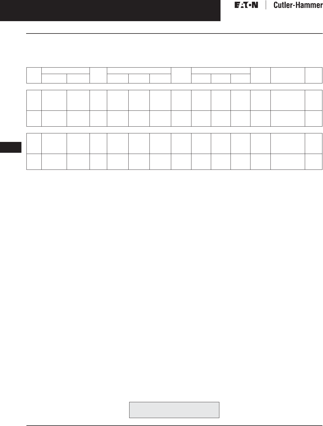
November 2003
9-66
For more information visit: www.cutler-hammer.eaton.com CA08101001E
Transformers
9
Filtered Noise Isolation Transformers
Three-Phase Vol. 1, Ref. No. [0366]
Product Selection
Additional Product Selection information begins on Page 9-136.
Table 9-77. Filtered Noise Isolation Transformers
Not Seismic Qualified.
kVA Full Cap. Taps °C
Temp.
Rise
Dimensions (Inches) Weight
Lbs.
Dimensions (mm) Weight
kg
Style
Number
Price
U.S. $
FCAN FCBN H W D H W D
480 ∆ Volts to 208Y/120 Volts
15
30
45
75
2@+2.5%
2@+2.5%
2@+2.5%
2@+2.5%
4@-2.5%
4@-2.5%
4@-2.5%
4@-2.5%
150
150
150
150
27-3/8
32-1/4
32-1/4
35-3/4
19
24
24
32
16-9/16
18-1/16
18-1/16
23-11/16
210
320
385
555
695
819
819
908
483
610
610
813
421
459
459
602
95
145
175
252
F48M28T15A
F48M28T30A
F48M28T45A
F48M28T75A
5,670.
6,950.
8,175.
10,400.
112.5
150
225
2@+2.5%
2@+2.5%
2@+2.5%
4@-2.5%
4@-2.5%
4@-2.5%
150
150
150
40
46
48
32
35
38-1/2
23-11/16
23-11/16
28-15/16
720
880
1120
1016
1168
1219
813
889
978
602
602
735
327
400
509
F48M28T12A
F48M28T49A
F48M28T22A
11,700.
16,060.
20,650.
208 ∆ Volts to 208Y/120 Volts
15
30
45
75
1@+5%
1@+5%
1@+5%
1@+5%
2@-5%
2@-5%
2@-5%
2@-5%
150
150
150
150
27-3/8
32-1/4
32-1/4
35-3/4
19
24
24
32
16-9/16
18-1/16
18-1/16
23-11/16
210
320
385
555
695
819
819
908
483
610
610
813
421
459
459
602
95
145
175
252
F29R28T15A
F29R28T30A
F29R28T45A
F29R28T75A
6,520.
8,800.
10,200.
13,400.
112.5
150
225
1@+5%
1@+5%
1@+5%
2@-5%
2@-5%
2@-5%
150
150
150
40
46
48
32
35
38-1/2
23-11/16
23-11/16
28-15/16
720
880
1120
1016
1168
1219
813
889
978
602
602
735
327
400
509
F29R28T12A
F29R28T49A
F29R28T22A
15,850.
23,500.
26,790.
For other ratings or styles not shown, or for
special enclosure types (including stainless
steel) refer to Eaton’s Cutler-Hammer business. Discount Symbol . . . . . . . . . . . . . . . . . . . . . . . . . DT-1

November 2003
CA08101001E For more information visit: www.cutler-hammer.eaton.com
9-67
Transformers
9
Low Sound Transformers
Single- and Three-Phase
Vol. 1, Ref. No. [0367]
Single- and Three-Phase, 60 Hz
Type DT-3 Low Sound Transformer
Product Description
Types EP, EPT
■Sand and Resin Encapsulated design.
■Suitable for indoor or outdoor
applications.
■Totally enclosed, non-ventilated
enclosures.
■Enclosures are NEMA 3R rated.
■Mountable in any position indoors
and upright only outdoors.
■185ºC Insulation System, 115ºC rise
standard.
■Available in single-phase ratings
through 37.5 kVA and 4160 volts
primary (EP).
■Available in three-phase ratings
through 75 kVA and 4160 volts
primary (EPT).
Types DS-3, DT-3
■Ventilated, NEMA 2 enclosure
standard.
■Suitable for indoor applications,
outdoors when weathershields are
also installed.
■Upright mounting only.
■220ºC Insulation System, 150ºC rise
standard.
■Available in single-phase ratings
15 – 167 kVA and up to 4160 volts
primary (DS-3).
■Available in three-phase ratings
15 – 1500 kVA and up to 4160 volts
primary (DT-3).
Application Description
Low sound transformers are designed
to have average sound levels 3 dB
below NEMA ST-20 standards.
Note: Sound levels are measured in a
sound room, not at the installation.
These quieter transformers are ideal
for noise sensitive installations such as
schools, hospitals, libraries, and offices.
Proper installation procedures should
be used to achieve maximum benefit.
Features, Benefits
and Functions
■UL listed.
■60 Hz operation.
■Short-term overload capability as
required by ANSI.
Standards and Certifications
Industry Standards
All Cutler-Hammer dry-type distribution
and control transformers by Eaton
Corporation are built and tested in
accordance with applicable NEMA,
ANSI, and IEEE Standards. All 600 volt
class transformers are UL listed unless
otherwise noted.
Seismically Qualified
Cutler-Hammer manufactured dry-type
distribution transformers are seismi-
cally qualified, and exceed require-
ments of the Uniform Building Code
(UBC) and California Code Title 24.
Options and Accessories
Please refer to Page 9-120.
Product Specifications
Frequency
Cutler-Hammer standard dry-type dis-
tribution transformers are designed
for 60 Hz operation. Transformers
required for other frequencies are
available and must be specifically
designed.
Overload Capability
Short-term overload is designed into
transformers as required by ANSI.
dry-type distribution transformers
will deliver 200% nameplate load for
one-half hour; 150% load for one-hour;
and 125% load for four-hours without
being damaged provided that a con-
stant 50% load precedes and follows
the overload. See ANSI C57.96-01.250
for additional limitations.
Continuous overload capacity is not
deliberately designed into a trans-
former because the design objective is
to be within the allowed winding tem-
perature rise with nameplate loading.
Insulation System and Temperature Rise
Industry standards classify insulation
systems and rise as shown below:
Table 9-78. Insulation System Classification
The design life of transformers having
different insulation systems is the
same — the lower temperature systems
are designed for the same life as the
higher temperature systems.
Enclosures
Cutler-Hammer ventilated transformers,
Types DS-3, DT-3, MD, and KT, utilize a
NEMA 2 rated (drip-proof) enclosure
as standard, and are rated NEMA 3R
with the addition of weathershields.
The following pages provide listings for most
standard transformer ratings and styles.
For other ratings or styles not shown, or for
special enclosure types (including stainless
steel) refer to Eaton’s Cutler-Hammer business.
Ambient +
Winding
Rise
+
Hot
Spot
=
Temp.
Class
40°C
40°C
40°C
40°C
55°C
80°C
115°C
150°C
10°C
30°C
30°C
30°C
105°C
150°C
185°C
220°C
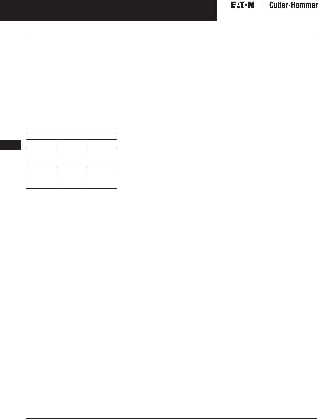
November 2003
9-68
For more information visit: www.cutler-hammer.eaton.com CA08101001E
Transformers
9
Low Sound Transformers
Single- and Three-Phase Vol. 1, Ref. No. [0368]
Sound Levels
All Eaton’s Cutler-Hammer 600 volt
class general purpose dry-type distri-
bution transformers are designed to
meet NEMA ST-20 sound levels listed
here. These are the sound levels mea-
sured in a soundproof environment.
Actual sound levels measured at an
installation will likely be higher due to
electrical connections and environ-
mental conditions. Lower sound levels
are available and should be specified
when the transformer is going to
be installed in an area where sound
may be a concern.
Table 9-79. Average Sound Levels
Winding Terminations
Primary and secondary windings are
terminated in the wiring compartment.
Ventilated transformers have leads
brought out to aluminum pads that
are pre-drilled to accept Cu/Al lugs.
Lugs are not supplied with these
transformers. The Cutler-Hammer
business recommends external cables
be rated 75°C for ventilated designs.
Series-Multiple Windings
Series-multiple windings consist of
2 similar coils in each winding which
can be connected in series or parallel
(multiple). Transformers with series-
multiple windings are designated with
an “X” or “/” between the voltage
ratings, such as voltages of “120/240”
or “240 X 480.” If the series-multiple
winding is designated by an “X,” the
winding can be connected only for
a series or parallel. With the “/”
designation, a mid-point also becomes
available in addition to the series or
parallel connection. As an example, a
120 X 240 winding can be connected
for either 120 (parallel) or 240 (series),
but a 120/240 winding can be con-
nected for 120 (parallel), or 240
(series), or 240 with a 120 mid-point.
Technical Data
and Specifications
Please refer to Page 9-122.
NEMA ST-20 Average Sound Level (dB)
kVA Ventilated Encapsulated
0 – 9
10 – 50
51 – 150
151 – 300
40
45
50
55
45
50
55
57
301 – 500
501 – 700
701 – 1000
1001 – 1500
60
62
64
65
59
61
63
64

November 2003
CA08101001E For more information visit: www.cutler-hammer.eaton.com
9-69
Transformers
9
Low Sound Transformers
Three-Phase
Vol. 1, Ref. No. [0369]
Product Selection
Additional Product Selection information begins on Page 9-136.
Table 9-80. Low Sound Transformers Type DT-3, 60 Hz
Note: Contact Cutler-Hammer for availability of lower sound level designs.
Note: Contact your local Cutler-Hammer sales office for CE Mark transformer requirements.
kVA Full Cap. Taps Type °C
Temp.
Rise
Dimensions (Inches) Wt.
Lbs.
Dimensions (mm) Wt.
kg
Frame Wiring
Diagram
Number
Weathershield Style
Number
Price
U.S. $
FCAN FCBN H W D H W D Catalog
Number
Price
U.S. $
480 ∆ Volts to 208Y/120 Volts — Aluminum Windings
15
30
45
2@+2.5%
2@+2.5%
2@+2.5%
4@-2.5%
4@-2.5%
4@-2.5%
DT-3
DT-3
DT-3
150
150
150
30-1/8
30-1/8
30-1/8
20-1/8
20-1/8
20-1/8
14-1/8
14-1/8
14-1/8
230
310
310
765
765
765
511
511
511
359
359
359
69
141
141
FR910A
FR912A
FR912A
280B
280B
280B
WS31
WS31
WS31
350.
350.
350.
V48M28T15LS42
V48M28T30LS42
V48M28T45LS42
1,590.
2,050.
2,520.
75
112.5
150
2@+2.5%
2@+2.5%
2@+2.5%
4@-2.5%
4@-2.5%
4@-2.5%
DT-3
DT-3
DT-3
150
150
150
39-1/4
46-1/8
56
26-1/8
28
31-1/4
19-1/8
23
24-1/4
600
760
1100
1000
1171
1422
664
712
794
486
585
616
273
345
499
FR915B
FR916A
FR917
280B
280B
280B
WS33
WS19
WS34
350.
350.
800.
V48M28T75LS47
V48M28T12LS47
V48M28T49LS47
3,530.
5,075.
6,370.
225
300
500
2@+2.5%
2@+2.5%
2@+2.5%
4@-2.5%
4@-2.5%
4@-2.5%
DT-3
DT-3
DT-3
150
150
150
56
62-1/4
75
31-1/4
31-1/4
44-1/2
24-1/4
30-1/4
36
1100
1600
2400
1422
1581
1905
794
794
1130
616
768
914
499
728
1089
FR917
FR918A
FR919
280B
280B
275A
WS34
WS34
WS35
800.
800.
1,360.
V48M28T22LS52
V48M28T33LS52
V48M28T55LS57
9,325.
11,800.
18,900.
15
30
45
2@+2.5%
2@+2.5%
2@+2.5%
4@-2.5%
4@-2.5%
4@-2.5%
DT-3
DT-3
DT-3
115
115
115
30-1/8
30-1/8
39-3/8
20-1/8
20-1/8
26-1/8
14-1/8
14-1/8
19-1/8
230
310
480
765
765
1000
511
511
664
359
359
486
69
141
218
FR910A
FR912A
FR914B
280B
280B
280B
WS31
WS31
WS33
350.
350.
350.
V48M28F15LS42
V48M28F30LS42
V48M28F45LS42
1,890.
2,330.
2,840.
75
112.5
150
2@+2.5%
2@+2.5%
2@+2.5%
4@-2.5%
4@-2.5%
4@-2.5%
DT-3
DT-3
DT-3
115
115
115
39-3/8
46-1/8
56
26-1/8
28
31-1/4
19-1/8
23
24-1/4
600
760
1100
1000
1171
1422
664
712
794
486
585
616
273
345
499
FR915B
FR916A
FR917
280B
280B
280B
WS33
WS19
WS34
350.
350.
800.
V48M28F75LS47
V48M28F12LS47
V48M28F49LS47
4,010.
5,805.
7,290.
225
300
500
2@+2.5%
2@+2.5%
2@+2.5%
4@-2.5%
4@-2.5%
4@-2.5%
DT-3
DT-3
DT-3
115
115
115
62-1/4
62-1/4
75
31-1/4
31-1/4
44-1/2
30-1/4
30-1/4
36
1600
1600
2400
1581
1581
1905
794
794
1130
768
768
914
728
728
1089
FR918A
FR918A
FR919
280B
280B
275A
WS34
WS34
WS35
800.
800.
1,360.
V48M28F22LS52
V48M28F33LS52
V48M28F55LS57
10,660.
13,700.
21,700.
15
30
45
2@+2.5%
2@+2.5%
2@+2.5%
4@-2.5%
4@-2.5%
4@-2.5%
DT-3
DT-3
DT-3
80
80
80
30-1/8
30-1/8
39-3/8
20-1/8
20-1/8
26-1/8
14-1/8
14-1/8
19-1/8
230
310
480
765
765
1000
511
511
664
359
359
486
104
141
218
FR910A
FR912A
FR914B
280B
280B
280B
WS31
WS31
WS33
350.
350.
350.
V48M28B15LS42
V48M28B30LS42
V48M28B45LS42
2,160.
2,680.
3,360.
75
112.5
150
2@+2.5%
2@+2.5%
2@+2.5%
4@-2.5%
4@-2.5%
4@-2.5%
DT-3
DT-3
DT-3
80
80
80
46-1/8
46-1/8
56
28
28
31-1/4
23
23
24-1/4
760
760
1100
1171
1171
1422
712
712
794
585
585
616
345
345
499
FR916A
FR916A
FR917
280B
280B
280B
WS19
WS19
WS34
350.
350.
800.
V48M28B75LS47
V48M28B12LS47
V48M28B49LS47
4,610.
6,660.
8,370.
225
300
2@+2.5%
2@+2.5%
4@-2.5%
4@-2.5%
DT-3
DT-3
80
80
62-1/4
75
31-1/4
44-1/2
30-1/4
36
1600
2400
1581
1905
794
1130
768
914
728
1089
FR918A
FR919
280B
275A
WS34
WS35
800.
1,360.
V48M28B22LS52
V48M28B33LS52
12,245.
16,000.
480 ∆ Volts to 208Y/120 Volts — Copper Windings
15
30
45
2@+2.5%
2@+2.5%
2@+2.5%
4@-2.5%
4@-2.5%
4@-2.5%
DT-3
DT-3
DT-3
150
150
150
25
30-1/8
30-1/8
20-1/8
20-1/8
20-1/8
14-1/8
14-1/8
14-1/8
172
300
370
635
765
765
511
511
511
359
359
359
78
136
168
FR909
FR910A
FR912A
280B
280B
280B
WS31
WS31
WS31
350.
350.
350.
V48M28T15CULS42
V48M28T30CULS42
V48M28T45CULS42
3,000.
2,770.
3,360.
75
112.5
150
2@+2.5%
2@+2.5%
2@+2.5%
4@-2.5%
4@-2.5%
4@-2.5%
DT-3
DT-3
DT-3
150
150
150
39-3/8
39-3/8
46-1/8
26-1/8
26-1/8
28
19-1/8
19-1/8
23
550
675
850
1000
1000
1171
664
664
712
486
486
585
250
361
386
FR914B
FR915B
FR916A
280B
280B
280B
WS33
WS33
WS19
350.
350.
350.
V48M28T75CULS47
V48M28T12CULS47
V48M28T49CULS47
5,050.
6,900.
9,510.
225
300
500
2@+2.5%
2@+2.5%
2@+2.5%
4@-2.5%
4@-2.5%
4@-2.5%
DT-3
DT-3
DT-3
150
150
150
56
62-1/4
75
31-1/4
31-1/4
44-1/2
24-1/4
30-1/4
36
1200
2150
3100
1422
1581
1905
794
794
1130
616
768
914
545
977
1409
FR917
FR918A
FR919
280B
280B
275A
WS34
WS34
WS35
800.
800.
1,360.
V48M28T22CULS52
V48M28T33CULS52
V48M28T55CULS57
12,690.
16,000.
25,800.
15
30
45
2@+2.5%
2@+2.5%
2@+2.5%
4@-2.5%
4@-2.5%
4@-2.5%
DT-3
DT-3
DT-3
115
115
115
25
30-1/8
30-1/8
20-1/8
20-1/8
20-1/8
14-1/8
14-1/8
14-1/8
172
300
370
635
765
765
511
511
511
359
359
359
78
136
168
FR909
FR910A
FR912A
280B
280B
280B
WS31
WS31
WS31
350.
350.
350.
V48M28F15CULS42
V48M28F30CULS42
V48M28F45CULS42
2,600.
3,150.
3,800.
75
112.5
150
2@+2.5%
2@+2.5%
2@+2.5%
4@-2.5%
4@-2.5%
4@-2.5%
DT-3
DT-3
DT-3
115
115
115
39-3/8
39-3/8
46-1/8
26-1/8
26-1/8
28
19-1/8
19-1/8
23
550
675
850
1000
1000
1171
664
664
712
486
486
585
250
361
386
FR914B
FR915B
FR916A
280B
280B
280B
WS33
WS33
WS19
350.
350.
350.
V48M28F75CULS47
V48M28F12CULS47
V48M28F49CULS47
5,750.
7,860.
10,700.
225
300
500
2@+2.5%
2@+2.5%
2@+2.5%
4@-2.5%
4@-2.5%
4@-2.5%
DT-3
DT-3
DT-3
115
115
115
56
62-1/4
75
31-1/4
31-1/4
44-1/2
24-1/4
30-1/4
36
1200
2150
3100
1422
1581
1905
794
794
1130
616
768
914
545
977
1409
FR917
FR918A
FR919
280B
280B
275A
WS34
WS34
WS35
800.
800.
1,360.
V48M28F22CULS52
V48M28F33CULS52
V48M28F55CULS57
14,340.
18,000.
29,300.
15
30
45
2@+2.5%
2@+2.5%
2@+2.5%
4@-2.5%
4@-2.5%
4@-2.5%
DT-3
DT-3
DT-3
80
80
80
30-1/8
30-1/8
39-3/8
20-1/8
20-1/8
26-1/8
14-1/8
14-1/8
19-1/8
300
370
550
765
765
1000
511
511
664
359
359
486
136
168
250
FR910A
FR912A
FR914B
280B
280B
280B
WS31
WS31
WS33
350.
350.
350.
V48M28B15CULS42
V48M28B30CULS42
V48M28B45CULS42
3,000.
3,280.
4,370.
75
112.5
150
2@+2.5%
2@+2.5%
2@+2.5%
4@-2.5%
4@-2.5%
4@-2.5%
DT-3
DT-3
DT-3
80
80
80
46-1/8
46-1/8
56
28
28
31-1/4
23
23
24-1/4
850
850
1200
1171
1171
1422
712
712
794
585
585
616
386
386
545
FR916A
FR916A
FR917
280B
280B
280B
WS19
WS19
WS34
350.
350.
800.
V48M28B75CULS47
V48M28B12CULS47
V48M28B49CULS47
6,630.
9,090.
12,400.
225
300
2@+2.5%
2@+2.5%
4@-2.5%
4@-2.5%
DT-3
DT-3
80
80
62-1/4
75
31-1/4
44-1/2
30-1/4
36
2150
3100
1581
1905
794
1130
768
914
728
1409
FR918A
FR919
280B
275A
WS34
WS35
800.
1,360.
V48M28B22CULS52
V48M28B33CULS52
16,650.
20,950.
For other ratings or styles not shown, or for
special enclosure types (including stainless
steel) refer to Eaton’s Cutler-Hammer business. Discount Symbol . . . . . . . . . . . . . . . . . . . . . . . . . DT-1

November 2003
9-70
For more information visit: www.cutler-hammer.eaton.com CA08101001E
Transformers
9
Marine Duty Transformers
Single- and Three-Phase Vol. 1, Ref. No. [0370]
Single- and Three-Phase,
Types EPM, DS-3M, EPTM,
DT-3M, 60 Hz
Product Description
Types EP, EPT
■Sand and Resin Encapsulated design.
■Suitable for indoor or outdoor
applications.
■Totally enclosed, non-ventilated
enclosures.
■Enclosures are NEMA 3R rated.
■Mountable in any position indoors
and upright only outdoors.
■185ºC Insulation System, 115ºC rise
standard.
■Copper windings standard.
■Available in single-phase ratings
through 37.5 kVA and 4160 volts
primary (EP).
■Available in three-phase ratings
through 75 kVA and 4160 volts
primary (EPT).
Types DS-3, DT-3
■Ventilated, NEMA 2 enclosure
standard.
■Suitable for indoor applications,
outdoors when weathershields are
also installed.
■Upright mounting only.
■220ºC Insulation System, 115ºC rise
standard.
■Copper windings standard
■Available in single-phase ratings
15 – 167 kVA and up to 4160 volts
primary (DS-3).
■Available in three-phase ratings
15 – 1500 kVA and up to 4160 volts
primary (DT-3).
Application Description
The basic purpose of a transformer
is voltage transformation as near as
practically possible to the load for
economy and distribution of power.
Typical loads for dry-type distribution
transformers include lighting, heating,
air conditioners, fans, and machine
tools. Such loads are found in com-
mercial, institutional, industrial, and
residential structures.
Features, Benefits
and Functions
■UL listed.
■Meets IEEE-45 specifications.
■Meets Public Health Service
Publication 393 (Rodent Protection).
■Meets ABS (American Bureau of
Shipping) specification.
■60 Hz operation.
■115°C temperature rise standard.
■Copper windings standard.
■Short-term overload capability as
required by ANSI.
■Meet NEMA ST-20 sound levels.
Standards and Certifications
Industry Standards
All Cutler-Hammer dry-type distribution
and control transformers by Eaton
Corporation are built and tested in
accordance with applicable NEMA,
ANSI, and IEEE Standards. All 600 volt
class transformers are UL listed unless
otherwise noted.
Options and Accessories
Please refer to Page 9-120.
Product Specifications
Frequency
Cutler-Hammer standard dry-type dis-
tribution transformers are designed
for 60 Hz operation. Transformers
required for other frequencies are
available and must be specifically
designed.
Overload Capability
Short-term overload is designed into
transformers as required by ANSI.
dry-type distribution transformers
will deliver 200% nameplate load for
one-half hour; 150% load for one-hour;
and 125% load for four-hours without
being damaged provided that a con-
stant 50% load precedes and follows
the overload. See ANSI C57.96-01.250
for additional limitations.
Continuous overload capacity is not
deliberately designed into a trans-
former because the design objective is
to be within the allowed winding tem-
perature rise with nameplate loading.
Insulation System and Temperature Rise
Industry standards classify insulation
systems and rise as shown below:
Table 9-81. Insulation System Classification
The design life of transformers having
different insulation systems is the
same — the lower temperature systems
are designed for the same life as the
higher temperature systems.
Enclosures
Cutler-Hammer ventilated transformers,
Types DS-3M, DT-3M, utilize a NEMA 2
rated (drip-proof) enclosure as stan-
dard, and are rated NEMA 3R with the
addition of weathershields. Cutler-
Hammer encapsulated transformers,
Types EPM, EPTM, utilize a NEMA 3R
rated enclosure.
Sound Levels
All Cutler-Hammer 600 volt class gen-
eral purpose dry-type distribution
transformers are designed to meet
NEMA ST-20 sound levels listed here.
These are the sound levels measured
in a soundproof environment. Actual
sound levels measured at an installa-
tion will likely be higher due to electri-
cal connections and environmental
conditions. Lower sound levels are
available and should be specified
when the transformer is going to be
installed in an area where sound may
be a concern.
Table 9-82. Average Sound Levels
Applies to general purpose ventilated
transformers only.
Ambient +
Winding
Rise
+
Hot
Spot
=
Temp.
Class
40°C
40°C
40°C
40°C
55°C
80°C
115°C
150°C
10°C
30°C
30°C
30°C
105°C
150°C
185°C
220°C
kVA NEMA Average
Sound Level in dB
0 – 9
10 – 50
51 – 150
151 – 300
40
45
50
55
301 – 500
501 – 700
701 – 1000
1001 – 1500
60
62
64
65
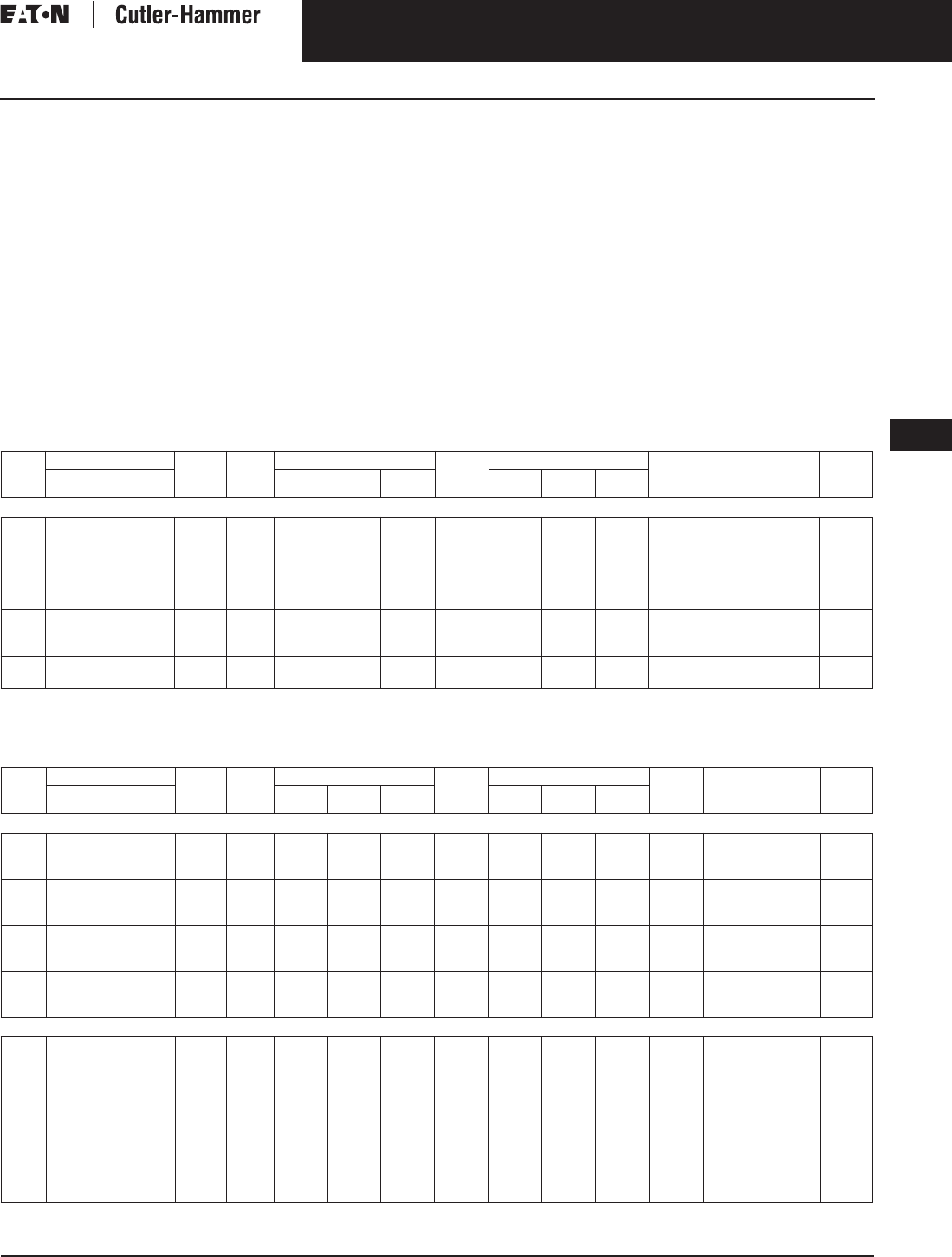
November 2003
CA08101001E For more information visit: www.cutler-hammer.eaton.com
9-71
Transformers
9
Marine Duty Transformers
Single- and Three-Phase
Vol. 1, Ref. No. [0371]
Winding Terminations
Primary and secondary windings are
terminated in the wiring compartment.
Encapsulated units have copper leads
or stabs brought out for connections.
Ventilated transformers have leads
brought out to aluminum pads that are
pre-drilled to accept Cu/Al lugs. Lugs
are not supplied with these transform-
ers. Eaton’s Cutler-Hammer business
recommends external cables be rated
90°C (sized at 75°C ampacity) for
encapsulated designs and 75°C for
ventilated designs.
Series-Multiple Windings
Series-multiple windings consist of 2
similar coils in each winding which can
be connected in series or parallel (multi-
ple). Transformers with series-multiple
windings are designated with an “X”
or “/” between the voltage ratings, such
as voltages of “120/240” or “240 X 480.”
If the series-multiple winding is desig-
nated by an “X,” the winding can be
connected only for a series or parallel.
With the “/” designation, a mid-point
also becomes available in addition to
the series or parallel connection. As
an example, a 120 X 240 winding can
be connected for either 120 (parallel) or
240 (series), but a 120/240 winding can
be connected for 120 (parallel), or 240
(series), or 240 with a 120 mid-point.
Technical Data
and Specifications
Please refer to Page 9-122.
Product Selection
Additional Product Selection information begins on Page 9-136.
Table 9-83. Marine Duty Transformers Single-Phase Selection Information — Types EPM, DS-3M, 60 Hz
Per ABS Requirements, all Marine Duty Transformers are 115ºC and Copper Windings
Not seismic qualified.
Taps 1 @ +5%, 2 @ –5% at 240 volts; 2 @ +2.5%, 4 @ 2.5% at 480 volts.
Table 9-84. Marine Duty Transformers Three-Phase Selection Information — Types EPTM, DT-3M, 60 Hz
Per ABS Requirements, all Marine Duty Transformers are 115ºC and Copper Windings
Not seismic qualified.
kVA Full Cap. Taps Type °C
Temp.
Rise
Dimensions (Inches) Weight
Lbs.
Dimensions (mm) Weight
kg
Style
Number
Price
U.S. $
FCAN FCBN Height Width Depth Height Width Depth
240 x 480 Volts to 120/240 Volts
3
5
7.5
—
—
—
—
—
—
EPM
EPM
EPM
115
115
115
14-3/4
15
23
7
8
12-1/2
7
7-1/2
8
70
100
170
375
381
584
178
203
318
178
191
203
32
45
77
Q20N11S03CU
Q20N11S05CU
Q20N11S07CU
1,320.
1,450.
1,880.
10
15
25
—
—
—
—
EPM
EPM
DS-3M
115
115
115
23
23
31
12-1/2
13
16
8
14
19
180
170
270
584
584
787
318
330
406
203
356
483
82
77
122
Q20N11S10CU
Q20N11S15CU
R20P11F25CU
2,280.
2,780.
3,580.
37.5
50
75
DS-3M
DS-3M
DS-3M
115
115
115
35
35
39
19-1/2
19-1/2
24
21
21
25
420
490
650
889
889
991
495
495
610
533
533
635
191
222
295
R20P11F37CU
R20P11F50CU
R20P11F75CU
4,570.
5,360.
6,860.
100
167
DS-3M
DS-3M
115
115
50
50
32
32
28-1/2
28-1/2
920
1160
1270
1270
813
813
724
724
417
526
R20P11F99CU
R20P11F67CU
9,130.
14,900.
kVA Full Cap. Taps Type °C
Temp.
Rise
Dimensions (Inches) Weight
Lbs.
Dimensions (mm) Weight
kg
Style
Number
Price
U.S. $
FCAN FCBN H W D H W D
480 ∆ Volts to 208Y/120 Volts
3
6
9
2@+2.5%
2@+2.5%
2@+2.5%
2@-2.5%
2@-2.5%
2@-2.5%
EPTM
EPTM
EPTM
115
115
115
16-1/2
19
21-1/2
12-1/2
16-1/2
17-7/16
6
6
7
100
190
275
419
483
546
318
419
443
152
152
178
45
86
125
L48D28T03CU
L48D28T06CU
L48D28T09CU
2,230.
2,510.
2,720.
15
30
45
2@+2.5%
2@+2.5%
2@+2.5%
4@-2.5%
4@-2.5%
4@-2.5%
DT-3M
DT-3M
DT-3M
115
115
115
22
29
29
16-3/4
21-1/2
21-1/2
15
19-1/2
19-1/2
190
305
405
559
737
737
425
546
546
381
495
495
86
138
184
M48M28F15CU
M48M28F30CU
M48M28F45CU
3,085.
3,950.
5,350.
75
112.5
150
2@+2.5%
2@+2.5%
2@+2.5%
4@-2.5%
4@-2.5%
4@-2.5%
DT-3M
DT-3M
DT-3M
115
115
115
38
41
41
26
32
32
21
25-1/2
25-1/2
650
850
1020
965
1041
1041
660
813
813
533
648
648
295
386
463
M48M28F75CU
M48M28F12CU
M48M28F49CU
7,010.
8,500.
10,850.
225
300
500
2@+2.5%
2@+2.5%
2@+2.5%
4@-2.5%
2@-2.5%
2@-2.5%
DT-3M
DT-3M
DT-3M
115
115
115
51-1/2
51-1/2
59
39-1/2
39-1/2
48-1/2
34
34
38
1450
1680
2550
1308
1308
1499
1003
1003
1232
864
864
965
658
762
1157
M48M28F22CU
M48D28F33CU
M48D28F55CU
14,830.
19,200.
31,020.
480 ∆ Volts to 240 ∆ Volts
6
9
15
30
2@+2.5%
2@+2.5%
2@+2.5%
2@+2.5%
2@-2.5%
2@-2.5%
4@-2.5%
4@-2.5%
EPTM
EPTM
DT-3M
DT-3M
115
115
115
115
19
21-1/2
22
29
16-1/2
17-7/16
16-3/4
21-1/2
6
7
15
19-1/2
190
275
190
305
483
546
559
737
419
443
425
546
152
178
318
495
86
125
86
138
L48D24T06CU
L48D24T09CU
M48M24F15CU
M48M24F30CU
2,510.
2,880.
3,085.
3,950.
45
75
112.5
2@+2.5%
2@+2.5%
2@+2.5%
4@-2.5%
4@-2.5%
4@-2.5%
DT-3M
DT-3M
DT-3M
115
115
115
29
38
41
21-1/2
26
32
19-1/2
21
25-1/2
405
650
850
737
965
1041
546
660
813
495
533
648
184
295
386
M48M24F45CU
M48M24F75CU
M48M24F12CU
5,350.
7,010.
8,500.
150
225
300
500
2@+2.5%
2@+2.5%
2@+2.5%
2@+2.5%
4@-2.5%
4@-2.5%
2@-2.5%
2@-2.5%
DT-3M
DT-3M
DT-3M
DT-3M
115
115
115
115
41
51-1/2
51-1/2
59
32
39-1/2
39-1/2
48-1/2
25-1/2
34
34
38
1020
1450
1680
2550
1041
1308
1308
1499
813
1003
1003
1232
648
864
864
965
463
658
762
1157
M48M24F49CU
M48M24F22CU
M48D24F33CU
M48D24F55CU
10,850.
14,890.
19,200.
32,775.
Discount Symbol . . . . . . . . . . . . . . . . . . . . . . . . . DT-1
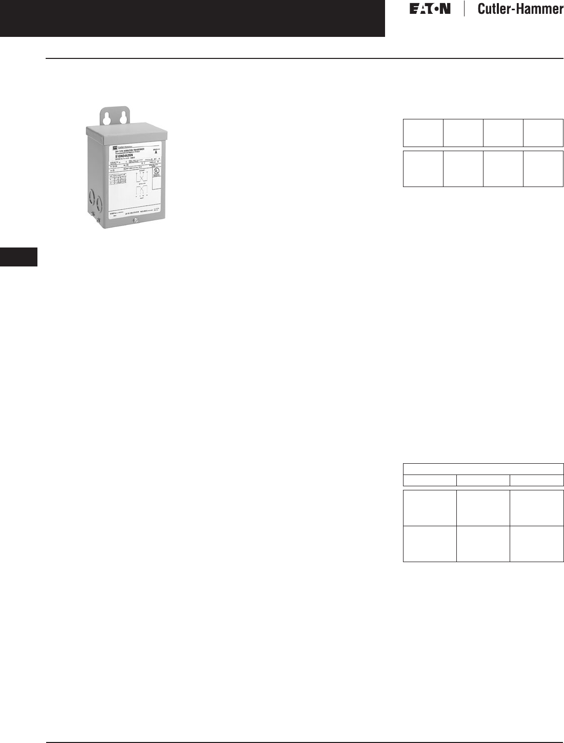
November 2003
9-72
For more information visit: www.cutler-hammer.eaton.com CA08101001E
Transformers
9
Buck-Boost Transformers
Single- and Three-Phase Vol. 1, Ref. No. [0372]
Single- and Three-Phase
Applications, 60 Hz
Type EP
Product Description
Types EP, EPT
■Sand and Resin Encapsulated design.
■Suitable for indoor or outdoor
applications.
■Totally enclosed, non-ventilated
enclosures.
■Enclosures are NEMA 3R rated.
■Mountable in any position indoors
and upright only outdoors.
■185ºC Insulation System, 115ºC rise
standard.
■Available in single-phase ratings
through 37.5 kVA and 4160 volts
primary (EP).
■Available in three-phase ratings
through 75 kVA and 4160 volts
primary (EPT).
Application Description
A buck-boost transformer is used
to provide an economical method of
correcting a lower or higher voltage
rating more suitable for efficient oper-
ation of electrical equipment. Type EP
Buck-Boost transformers are small
kVA, single-phase transformers with
dual primary and dual secondary
windings and are usually connected as
autotransformers by utilizing one unit
for single-phase applications and
either two or three units banked for
three-phase operation. They are pri-
marily used for motor operation and
should not be used for motor control
circuits, to correct fluctuating line
voltage or to obtain a neutral on a
delta system.
Features, Benefits
and Functions
■UL listed.
■60 Hz operation.
■600 volt class insulation.
■Short-term overload capability
as required by ANSI.
■Meet NEMA ST-20 sound levels.
Standards and Certifications
Industry Standards
All Cutler-Hammer dry-type distribution
and control transformers by Eaton
Corporation are built and tested in
accordance with applicable NEMA,
ANSI, and IEEE Standards. All 600 volt
class transformers are UL listed unless
otherwise noted.
Seismically Qualified
Cutler-Hammer manufactured dry-type
distribution transformers are seismi-
cally qualified, and exceed require-
ments of the Uniform Building Code
(UBC) and California Code Title 24.
Options and Accessories
Please refer to Page 9-120.
Product Specifications
Frequency
Cutler-Hammer buck-boost transform-
ers are designed for 60 Hz operation.
Overload Capability
Short-term overload is designed into
transformers as required by ANSI.
dry-type distribution transformers
will deliver 200% nameplate load for
one-half hour; 150% load for one-hour;
and 125% load for four-hours without
being damaged provided that a con-
stant 50% load precedes and follows
the overload. See ANSI C57.96-01.250
for additional limitations.
Continuous overload capacity is not
deliberately designed into a trans-
former because the design objective is
to be within the allowed winding tem-
perature rise with nameplate loading.
Insulation System and Temperature Rise
Industry standards classify insulation
systems and rise as shown below:
Table 9-85. Insulation System Classification
The design life of transformers having
different insulation systems is the
same — the lower temperature systems
are designed for the same life as the
higher temperature systems.
Enclosures
Cutler-Hammer encapsulated buck-
boost transformers utilize a NEMA 3R
rated enclosure.
Sound Levels
All Cutler-Hammer 600 volt class gen-
eral purpose dry-type distribution
transformers are designed to meet
NEMA ST-20 sound levels listed here.
These are the sound levels measured
in a soundproof environment. Actual
sound levels measured at an installa-
tion will likely be higher due to electri-
cal connections and environmental
conditions. Lower sound levels are
available and should be specified
when the transformer is going to be
installed in an area where sound may
be a concern.
Table 9-86. Average Sound Levels
Winding Terminations
Primary and secondary windings are
terminated in the wiring compartment.
Encapsulated units have copper leads
or stabs brought out for connections.
Lugs are not supplied with these
transformers. The Cutler-Hammer
business recommends external cables
be rated 90°C (sized at 75°C ampacity)
for encapsulated designs.
Ambient +
Winding
Rise
+
Hot
Spot
=
Temp.
Class
40°C
40°C
40°C
40°C
55°C
80°C
115°C
150°C
10°C
30°C
30°C
30°C
105°C
150°C
185°C
220°C
NEMA ST-20 Average Sound Level (dB)
kVA Ventilated Encapsulated
0 – 9
10 – 50
51 – 150
151 – 300
40
45
50
55
45
50
55
57
301 – 500
501 – 700
701 – 1000
1001 – 1500
60
62
64
65
59
61
63
64

November 2003
CA08101001E For more information visit: www.cutler-hammer.eaton.com
9-73
Transformers
9
Buck-Boost Transformers
Single- and Three-Phase
Vol. 1, Ref. No. [0373]
Series-Multiple Windings
Series-multiple windings consist of 2
similar coils in each winding which
can be connected in series or parallel
(multiple). Transformers with series-
multiple windings are designated with
an “X” or “/” between the voltage
ratings, such as voltages of “120/240”
or “240 X 480.” If the series-multiple
winding is designated by an “X,” the
winding can be connected only for a
series or parallel. With the “/” designa-
tion, a mid-point also becomes avail-
able in addition to the series or parallel
connection. As an example, a 120 X
240 winding can be connected for
either 120 (parallel) or 240 (series), but
a 120/240 winding can be connected
for 120 (parallel), or 240 (series),
or 240 with a 120 mid-point.
Technical Data
and Specifications
Please refer to Page 9-122.
Note: When installation is to be made on a
grounded system, consideration must be
given to the resulting voltage. Thus, on a
208 grounded wye/120 system the voltage
can be boosted to 240 volts but the voltage
to ground will be 139 volts. If 240/120 volts
with a mid-point ground is needed, a stan-
dard two-winding transformer must be used.
The following formulas can be used to
calculate specific requirements.
For Single-Phase:
For Three-Phase:
Product Selection
For quick selection data, refer to the
tables on the following pages.
Selection Requirements
You should have the following
information before selecting a
buck-boost transformer.
Line Voltage
The voltage that you want to buck
(decrease) or boost (increase). This
can be found by measuring the supply
line voltage with a voltmeter.
Load Voltage
The voltage at which your equipment
is designed to operate. This is listed on
the nameplate of the load equipment.
Load Amperes or Load kVA
You do not need to know both — one
or the other is sufficient for selection
purposes. This information usually can
be found on the nameplate of the
equipment that you want to operate.
Frequency
The supply line frequency must be the
same as the frequency of the equip-
ment to be operated — Eaton’s Cutler-
Hammer Buck-Boost Transformers
operate at 60 Hz only.
Phase
The supply line should be the same as
the equipment to be operated — either
single or three-phase.
Transformer Interconnection
For three-phase applications, intercon-
nections of transformers should be
made in a junction box. Two or three
transformers may be used depending
on an open delta (2) or wye (3)
connection.
5-Step Selector
The tables which follow will simplify
the selection of the buck-boost trans-
formers. There are no calculations
needed; simply follow these 5 steps.
1. Refer to the table having the same
output voltage as the equipment
you want to operate. For example,
if you are installing a 240 volt 6 kVA
single-phase load use Selection
Table 9-91.
2. Select the available line voltage
across the top of the chart which
is closest to the actual supply volt-
age. Therefore, for example, if the
available line voltage is 213 volts,
use the 212 volt column.
3. Read down the column until you
reach an output kVA or amps rat-
ing equal to or greater than the
load requirements. Since 6 kVA, in
the example, is not listed, use the
next higher rating or 7.5 kVA.
4. Read across to the far left columns
for the catalog number and quan-
tity of transformers for your appli-
cation. In this case, you will need
one (1) catalog number
S10N06A01N.
5. Connect the buck-boost trans-
former(s) you have selected in
accordance with the connection
diagram specified at the bottom of
the available line voltage column.
In this example, Diagram “F”
would be used.
Note: For 1-phase connections and 3-phase
open delta connections, inputs and outputs
may be reversed. kVA capacity remains
constant.
Additional Product Selection
information begins on Page 9-136.
LOAD kVA
Load Voltage x
Full Line Amperes
1000
---------------------------------------------=
LOAD kVA
Line Load Voltage x 1.73 x
Full Load Amperes
1000
------------------------------------------------------------------=
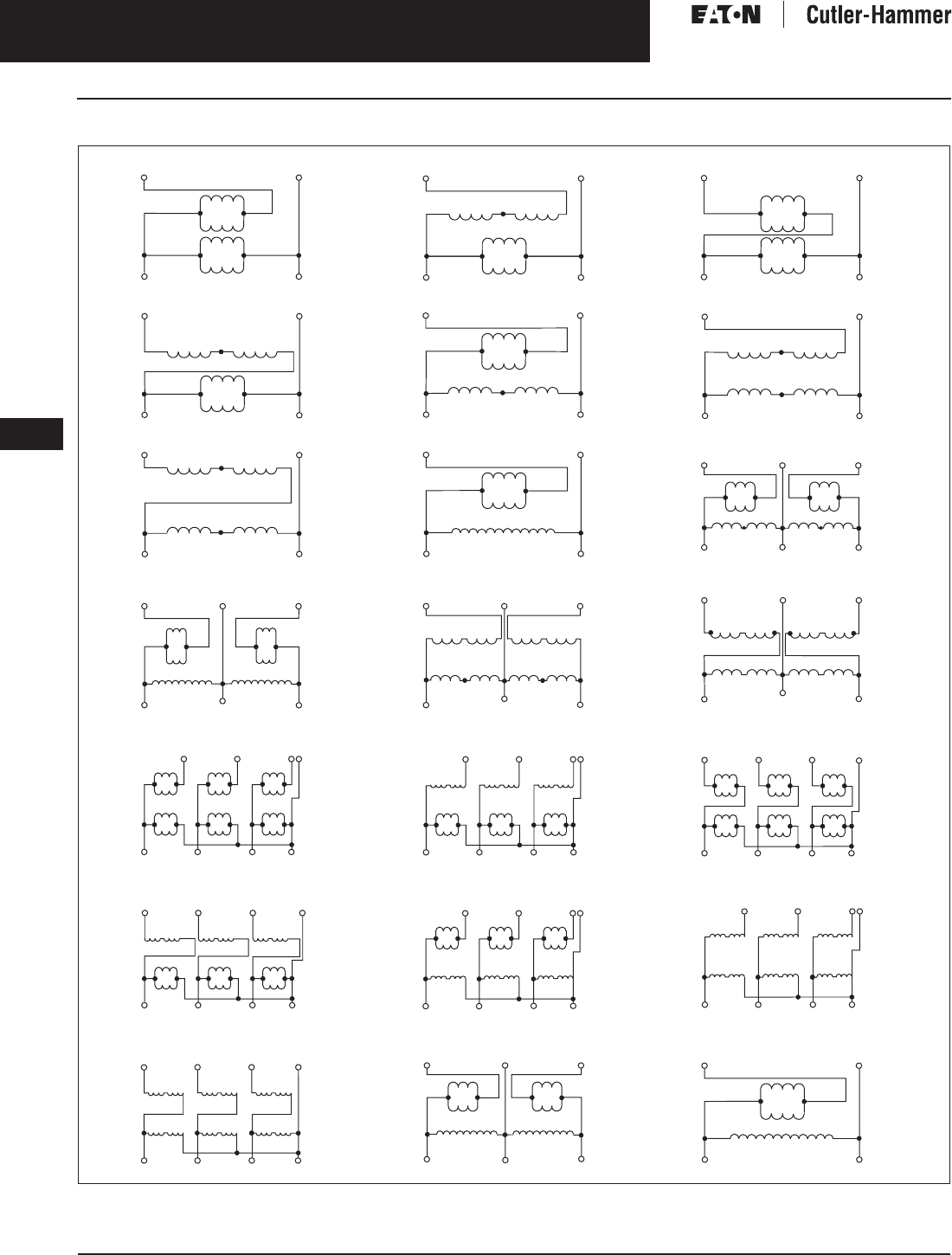
November 2003
9-74
For more information visit: www.cutler-hammer.eaton.com CA08101001E
Transformers
9
Buck-Boost Transformers
Single- and Three-Phase Vol. 1, Ref. No. [0374]
Wiring Diagrams
Figure 9-2. Buck-Boost Transformers Wiring Diagrams
WARNING! If input is 3-wire, “neutral” connection must be isolated and insulated! When used to supply a 3-phase, 4-wire load, the source must be
3-phase, 4-wire wye.
H4 H3
H1H2
H4 H3
H1H2
Neutral
H4 H3
H1H2
High Voltage
Low Voltage
X2 X4 X2 X4 X2 X4
X1 X3 X1 X3 X1 X3
Low Voltage Neutral
High Voltage
X3 X4
X1 X2
X3 X4
X1 X2
X3 X4
X1 X2
H3 H1 H3 H1 H3 H1
H2 H4 H2 H4 H2H4
X1
H4 H3
H1H2
H4 H3
H1H2
Neutral
H4 H3
H1H2
X3 X1 X3 X1 X3
Low Voltage
High Voltage
X2 X4 X2 X4 X2 X4
Low Voltage Neutral
High Voltage
X3 X4
X1 X2
H4 H3
H1H2
X3 X4
X1 X2
H4 H3
H1H2
X3 X4
X1 X2
H4 H3
H1H2
X1
Neutral
X2
X3
X4
X1
X2
X3
X4
X1
X2
X3
X4
Low Voltage
High Voltage
H3
H2
H1
H4
H3
H2
H1
H4
H3
H2
H1
H4
High Voltage
Low Voltage
H4 H3 H2 H1 H1 H2 H3 H4
X1 X2 X3 X4 X4 X3 X2 X1
High Voltage
X3 X4
X2X1
H1
H2
Low Voltage
High Voltage
X3 X4
X2X1
H1H2H4 H3
Low Voltage
Low Voltage
High Voltage
X3 X4X2X1
H4 H3
H1H2
Low Voltage
High Voltage
X3 X4
X2X1
H4 H3
H1H2
Low Voltage
X3 X4X2X1
H4 H3
H1H2
High Voltage
Low Voltage
X3 X4X2X1
H1H2H4 H3
High Voltage
Neutral
X2 X4 X2 X4 X2 X4
High Voltage
Low Voltage
H3 H1 H3 H1 H3 H1
H2 H4 H2 H4 H2H4
X1 X3 X1 X3 X1 X3
Low Voltage
X3 X4
X1 X2
H4 H3
H1H2
X3 X4
X1 X2
H4 H3
H1H2
X3 X4
X1 X2
H4 H3
H1H2
Neutral
High Voltage
High Voltage
X3 X4
X2X1
H1
H4
Low Voltage
Low Voltage
X3 X4
X2X1
H4 H3
H1H2
High Voltage
Low Voltage
High Voltage
H4 H3 H2 H1 H1 H2 H3 H4
X4 X3 X2 X1X1 X2 X3 X4
Low Voltage
High Voltage
X3 X4X2X1
H1H2H4 H3
High Voltage
Low Voltage
X4 X3
X1X2
X3 X4
X2X1
H4 H3 H2 H1 H1 H2 H3 H4
High Voltage
Low Voltage
H4 H1 H1 H4
X4 X3
X1X2
X3 X4
X2X1
X4 X3
X3 X4
High Voltage
Low Voltage
H2 H1 H1 H2
X1
X2
X2X1
Diagram A Diagram B Diagram C
Diagram D Diagram E Diagram F
Diagram G Diagram H Diagram I
Diagram J Diagram K Diagram L
Diagram M Diagram N Diagram O
Diagram P Diagram Q Diagram R
Diagram S Diagram T Diagram U

November 2003
CA08101001E For more information visit: www.cutler-hammer.eaton.com
9-75
Transformers
9
Buck-Boost Transformers
Single- and Three-Phase
Vol. 1, Ref. No. [0375]
Table 9-87. Selection Information
kVA °C Temp.
Rise
Dimensions (Inches) Weight
Lbs.
Dimensions (mm) Weight
kg
Frame Style
Number
Price
U.S. $
Height Width Depth Height Width Depth
120 x 240 Volts to 12/24 Volts
.05
.10
.15
115
115
115
6-1/2
6-1/2
6-1/2
3-7/8
3-7/8
3-7/8
3-1/2
3-1/2
3-1/2
7
7
8
165
165
165
98
98
98
89
89
89
3
3
4
FR52
FR54
FR55
S10N04A81N
S10N04A82N
S10N04A83N
100.
105.
115.
.25
.50
.75
115
115
115
6-1/2
6-1/2
8-3/8
4-7/8
4-7/8
6
3-7/8
4-5/8
5-3/4
12
13
21
165
165
213
124
124
152
98
117
146
5
5
10
FR56
FR57
FR58A
S10N04A26N
S10N04A51N
S10N04A76N
150.
175.
230.
1
1.5
2
115
115
115
8-3/8
10-3/4
10-3/4
6
6-3/16
6-3/16
5-3/4
6-1/8
6-1/8
31
40
40
213
273
273
152
157
157
146
156
156
14
18
18
FR59A
FR67
FR68
S10N04A01N
S10N04A16N
S10N04A02N
270.
360.
470.
3
5
7.5
115
115
115
14-1/8
16
16
7-11/16
10-3/8
10-3/8
8
9-7/8
9-7/8
65
113
123
359
406
406
195
263
263
203
251
251
29
51
55
FR176
FR177
FR178
S10N04A03N
S10N04A05N
S10N04A07N
635.
1,180.
1,650.
120 x 240 Volts to 16/32 Volts
.05
.10
.15
115
115
115
6-1/2
6-1/2
6-1/2
3-7/8
3-7/8
3-7/8
3-1/2
3-1/2
3-1/2
7
7
8
165
165
165
98
98
98
89
89
89
3
3
4
FR52
FR54
FR55
S10N06A81N
S10N06A82N
S10N06A83N
100.
105.
115.
.25
.50
.75
115
115
115
6-1/2
6-1/2
8-3/8
4-7/8
4-7/8
6
3-7/8
4-5/8
5-3/4
12
13
21
165
165
213
124
124
152
98
117
146
5
5
10
FR56
FR57
FR58A
S10N06A26N
S10N06A51N
S10N06A76N
150.
175.
230.
1
1.5
2
115
115
115
8-3/8
10-3/4
10-3/4
6
6-3/16
6-3/16
5-3/4
6-1/8
6-1/8
31
40
40
213
273
273
152
157
157
146
156
156
14
18
18
FR59A
FR67
FR68
S10N06A01N
S10N06A16N
S10N06A02N
270.
360.
470.
3
5
7.5
115
115
115
14-1/8
16
16
7-11/16
10-3/8
10-3/8
8
9-7/8
9-7/8
65
113
123
359
406
406
195
263
263
203
251
251
29
51
55
FR176
FR177
FR178
S10N06A03N
S10N06A05N
S10N06A07N
635.
1,180.
1,650.
240 x 480 Volts to 24/48 Volts
.05
.10
.15
115
115
115
6-1/2
6-1/2
6-1/2
3-7/8
3-7/8
3-7/8
3-1/2
3-1/2
3-1/2
7
7
8
165
165
165
98
98
98
89
89
89
3
3
4
FR52
FR54
FR55
S20N08A81N
S20N08A82N
S20N08A83N
110.
125.
135.
.25
.50
.75
115
115
115
6-1/2
6-1/2
8-3/8
4-7/8
4-7/8
6
3-7/8
4-5/8
5-3/4
12
13
21
165
165
213
124
124
152
98
117
146
5
5
10
FR56
FR57
FR58A
S20N08A26N
S20N08A51N
S20N08A76N
165.
210.
270.
1
1.5
2
115
115
115
8-3/8
10-3/4
10-3/4
6
6-3/16
6-3/16
5-3/4
6-1/8
6-1/8
31
40
40
213
273
273
152
157
157
146
156
156
14
18
18
FR59A
FR67
FR68
S20N08A01N
S20N08A16N
S20N08A02N
310.
420.
570.
3
5
7.5
115
115
115
14-1/8
16
16
7-11/16
10-3/8
10-3/8
8
9-7/8
9-7/8
65
113
123
359
406
406
195
263
263
203
251
251
29
51
55
FR176
FR177
FR178
S20N08A03N
S20N08A05N
S20N08A07N
740.
1,290.
2,000.
Discount Symbol . . . . . . . . . . . . . . . . . . . . . . . . . DT-1

November 2003
9-76
For more information visit: www.cutler-hammer.eaton.com CA08101001E
Transformers
9
Buck-Boost Transformers
Single-Phase Vol. 1, Ref. No. [0376]
Table 9-88. Single-Phase 115 Volt Output Required, 60 Hz
Additional wiring trough may be required.
Refer to Page 9-74 for Buck-Boost wiring diagrams.
Note: Output voltage for lower input voltage can be found by: x Input Actual Voltage = Output New Voltage.
Note: Output kVA available at reduced input voltage can be found by: x Output kVA = New kVA Rating.
Units
Required
Unit
kVA
Input Available Voltage Style
Number
Price
U.S. $
84 91 96 100 102
Output Output Output Output Output
kVA Amps kVA Amps kVA Amps kVA Amps kVA Amps
1
1
1
.05
.05
.10
—
.13
—
—
1.14
—
—
.18
—
—
1.56
—
.24
—
.48
2.09
—
4.17
—
.31
—
—
2.70
—
—
.36
—
—
3.13
—
S10N04A81N
S10N06A81N
S10N04A82N
100.
100.
105.
1
1
1
.10
.15
.15
.26
—
.39
2.29
—
3.44
.36
—
.54
3.12
—
4.69
—
.72
—
—
6.25
—
.62
—
.93
5.41
—
8.12
.72
—
1.08
6.25
—
9.37
S10N06A82N
S10N04A83N
S10N06A83N
105.
115.
115.
1
1
1
.25
.25
.50
—
.659
—
—
5.73
—
—
.899
—
—
7.81
—
1.2
—
2.4
10.4
—
20.8
—
1.56
—
—
13.5
—
—
1.8
—
—
15.6
—
S10N04A26N
S10N06A26N
S10N04A51N
150.
150.
175.
1
1
1
.50
.75
.75
1.32
—
1.98
11.5
—
17.2
1.8
—
2.7
15.6
—
23.4
—
3.6
—
—
31.2
—
3.11
—
4.67
27.1
—
40.6
3.59
—
5.39
31.2
—
46.8
S10N06A51N
S10N04A76N
S10N06A76N
175.
230.
230.
1
1
1
1
1
1.5
—
2.64
—
—
22.9
—
—
3.59
—
—
31.2
—
4.79
—
7.2
41.7
—
62.5
—
6.23
—
—
54.1
—
—
7.19
—
—
62.5
—
S10N04A01N
S10N06A01N
S10N04A16N
270.
270.
360.
1
1
1
1.5
2
2
3.95
—
5.27
34.4
—
45.8
5.39
—
7.19
46.9
—
62.5
—
9.58
—
—
83.3
—
9.34
—
12.5
81.2
—
108
10.8
—
14.4
93.7
—
125
S10N06A16N
S10N04A02N
S10N06A02N
360.
470.
470.
1
1
1
3
3
5
—
7.92
—
—
68.7
—
—
10.77
—
—
93.6
—
14.37
—
23.95
125.1
—
208.5
—
18.69
—
—
162.3
—
—
21.57
—
—
187.5
—
S10N04A03N
S10N06A03N
S10N04A05N
635.
635.
1,180.
1
1
1
5
7.5
7.5
13.2
—
19.8
115
—
172
18
—
27
156
—
234
—
36
—
—
312
—
31.15
—
46.7
270.5
—
406
35.95
—
53.9
312.5
—
468
S10N06A05N
S10N04A07N
S10N06A07N
1,180.
1,650.
1,650.
Connection Diagram DBBCA
Units
Required
Unit
kVA
Input Available Voltage Style
Number
Price
U.S. $
105 127 130 138 146
Output Output Output Output Output
kVA Amps kVA Amps kVA Amps kVA Amps kVA Amps
1
1
1
.05
.05
.10
.48
—
.96
4.17
—
8.33
.54
—
1.1
4.58
—
9.17
—
.41
—
—
3.54
—
.29
—
.58
2.5
—
5.0
—
.23
—
—
1.98
—
S10N04A81N
S10N06A81N
S10N04A82N
100.
100.
105.
1
1
1
.10
.15
.15
—
1.44
—
—
12.5
—
—
1.6
—
—
13.7
—
.82
—
1.3
7.08
—
10.6
—
.87
—
—
7.5
—
.46
—
.69
3.95
—
5.93
S10N06A82N
S10N04A83N
S10N06A83N
105.
115.
115.
1
1
1
.25
.25
.50
2.39
—
4.79
20.8
—
41.6
2.63
—
5.27
22.9
—
45.8
—
2.03
—
—
17.7
—
1.44
—
2.87
12.5
—
25
—
1.14
—
—
9.88
—
S10N04A26N
S10N06A26N
S10N04A51N
150.
150.
175.
1
1
1
.50
.75
.75
—
7.19
—
—
62.4
—
—
7.9
—
—
68.7
—
4.07
—
6.1
35.4
—
53.1
—
4.31
—
—
37.5
—
2.27
—
3.41
19.8
—
29.6
S10N06A51N
S10N04A76N
S10N06A76N
175.
230.
230.
1
1
1
1
1
1.5
9.58
—
14.4
83.3
—
125
10.5
—
15.8
91.7
—
137
—
8.14
—
—
70.8
—
5.75
—
8.62
50
—
75
—
4.55
—
—
39.5
—
S10N04A01N
S10N06A01N
S10N04A16N
270.
270.
360.
1
1
1
1.5
2
2
—
19.2
—
—
16.7
—
—
21.1
—
—
183
—
12.2
—
16.3
106
—
142
—
11.5
—
—
100
—
6.82
—
9.10
59.3
—
79.2
S10N06A16N
S10N04A02N
S10N06A02N
360.
470.
470.
1
1
1
3
3
5
28.7
—
47.9
249.9
—
416.5
31.5
—
52.5
275.1
—
458.5
—
24.4
—
—
212.4
—
17.3
—
28.7
150
—
250
—
13.6
—
—
118.5
—
S10N04A03N
S10N06A03N
S10N04A05N
635.
635.
1,180.
1
1
1
5
7.5
7.5
—
71.9
—
—
624
—
—
79
—
—
687
—
40.7
—
61
354
—
531
—
43.1
—
—
357
—
22.7
—
34.1
197.5
—
296
S10N06A05N
S10N04A07N
S10N06A07N
1,180.
1,650.
1,650.
Connection Diagram AAABB
Discount Symbol . . . . . . . . . . . . . . . . . . . . . . . . DT-1
Rated Output Voltage
Rated Input Voltage
--------------------------------------------------
Actual Input Voltage
Rated Input Voltage
------------------------------------------------

November 2003
CA08101001E For more information visit: www.cutler-hammer.eaton.com
9-77
Transformers
9
Buck-Boost Transformers
Single-Phase
Vol. 1, Ref. No. [0377]
Table 9-89. Single-Phase 120 Volt Output Required, 60 Hz
Additional wiring trough may be required.
Refer to Page 9-74 for Buck-Boost wiring diagrams.
Note: Output voltage for lower input voltage can be found by: x Input Actual Voltage = Output New Voltage.
Note: Output kVA available at reduced input voltage can be found by: x Output kVA = New kVA Rating.
Units
Required
Unit
kVA
Input Available Voltage Style
Number
Price
U.S. $
88 95 100 104 106
Output Output Output Output Output
kVA Amps kVA Amps kVA Amps kVA Amps kVA Amps
1
1
1
.05
.05
.10
—
.14
—
—
1.15
—
—
.19
—
—
1.56
—
.25
—
.50
2.09
—
4.17
—
.33
—
—
2.70
—
—
.38
—
—
3.13
—
S10N04A81N
S10N06A81N
S10N04A82N
100.
100.
105.
1
1
1
.10
.15
.15
.28
—
.41
2.29
—
3.44
.38
—
.56
3.12
—
4.69
—
.75
—
—
6.25
—
.65
—
.98
5.41
—
8.12
.75
—
1.12
6.25
—
9.37
S10N06A82N
S10N04A83N
S10N06A83N
105.
115.
115.
1
1
1
.25
.25
.50
—
.687
—
—
5.73
—
—
.937
—
—
7.81
—
1.25
—
2.5
10.4
—
20.8
—
1.62
—
—
13.5
—
—
1.87
—
—
15.6
—
S10N04A26N
S10N06A26N
S10N04A51N
150.
150.
175.
1
1
1
.50
.75
.75
1.37
—
2.06
11.5
—
17.2
1.87
—
2.82
15.6
—
23.4
—
3.75
—
—
31.2
—
3.25
—
4.87
27.1
—
40.6
3.75
—
5.62
31.2
—
46.8
S10N06A51N
S10N04A76N
S10N06A76N
175.
230.
230.
1
1
1
1
1
1.5
—
2.75
—
—
22.9
—
—
3.75
—
—
31.2
—
5
—
7.5
41.7
—
62.5
—
6.5
—
—
54.1
—
—
7.5
—
—
62.5
—
S10N04A01N
S10N06A01N
S10N04A16N
270.
270.
360.
1
1
1
1.5
2
2
4.12
—
5.5
34.4
—
45.8
5.62
—
7.5
46.9
—
62.5
—
10
—
—
83.3
—
9.75
—
13
81.2
—
108
11.2
—
15
93.7
—
125
S10N06A16N
S10N04A02N
S10N06A02N
360.
470.
470.
1
1
1
3
3
5
—
8.25
—
—
68.7
—
—
11.25
—
—
93.6
—
15
—
25
125.1
—
208.5
—
19.5
—
—
162.3
—
—
22.5
—
—
187.5
—
S10N04A03N
S10N06A03N
S10N04A05N
635.
635.
1,180.
1
1
1
5
7.5
7.5
13.75
—
20.6
114.5
—
172
18.75
—
28.2
156
—
234
—
37.5
—
—
312
—
32.5
—
48.7
270.5
—
406
37.5
—
56.2
312.5
—
468
S10N06A05N
S10N04A07N
S10N06A07N
1,180.
1,650.
1,650.
Connection Diagram DB BCA
Units
Required
Unit
kVA
Input Available Voltage Style
Number
Price
U.S. $
109 132 136 144 152
Output Output Output Output Output
kVA Amps kVA Amps kVA Amps kVA Amps kVA Amps
1
1
1
.05
.05
.10
.5
—
1.0
4.17
—
8.33
.55
—
1.1
4.58
—
9.17
—
.43
—
—
3.54
—
.3
—
.6
2.5
—
5.0
—
.24
—
—
1.98
—
S10N04A81N
S10N06A81N
S10N04A82N
100.
100.
105.
1
1
1
.10
.15
.15
—
1.5
—
—
12.5
—
—
1.6
—
—
13.7
—
.85
—
1.27
7.08
—
10.6
—
.9
—
—
7.5
—
.48
—
.71
3.95
—
5.93
S10N06A82N
S10N04A83N
S10N06A83N
105.
115.
115.
1
1
1
.25
.25
.50
2.5
—
5
20.8
—
41.6
2.75
—
5.5
22.9
—
45.8
—
2.12
—
—
17.7
—
1.5
—
3
12.5
—
25
—
1.19
—
—
9.88
—
S10N04A26N
S10N06A26N
S10N04A51N
150.
150.
175.
1
1
1
.50
.75
.75
—
7.5
—
—
62.4
—
—
8.25
—
—
68.7
—
4.25
—
6.37
35.4
—
53.1
—
4.5
—
—
37.5
—
2.37
—
3.56
19.8
—
29.6
S10N06A51N
S10N04A76N
S10N06A76N
175.
230.
230.
1
1
1
1
1
1.5
10
—
15
83.3
—
125
11
—
16.5
91.7
—
137
—
8.5
—
—
70.8
—
6
—
9
50
—
75
—
4.75
—
—
39.5
—
S10N04A01N
S10N06A01N
S10N04A16N
270.
270.
360.
1
1
1
1.5
2
2
—
20
—
—
167
—
—
22
—
—
183
—
12.7
—
17
106
—
142
—
12
—
—
100
—
7.12
—
9.5
59.3
—
79.2
S10N06A16N
S10N04A02N
S10N06A02N
360.
470.
470.
1
1
1
3
3
5
30
—
50
249.9
—
416.5
33
—
55
275.1
—
458.5
—
25.5
—
—
212.4
—
18
—
30
150
—
250
—
14.25
—
—
118.5
—
S10N04A03N
S10N06A03N
S10N04A05N
635.
635.
1,180.
1
1
1
5
7.5
7.5
—
75
—
—
624
—
—
82.5
—
—
687
—
42.5
—
63.7
354
—
531
—
45
—
—
375
—
23.7
—
35.6
197.5
—
296
S10N06A05N
S10N04A07N
S10N06A07N
1,180.
1,650.
1,650.
Connection Diagram AAABB
Rated Output Voltage
Rated Input Voltage
--------------------------------------------------
Actual Input Voltage
Rated Input Voltage
------------------------------------------------
Discount Symbol. . . . . . . . . . . . . . . . . . . . . . . . DT-1

November 2003
9-78
For more information visit: www.cutler-hammer.eaton.com CA08101001E
Transformers
9
Buck-Boost Transformers
Single-Phase Vol. 1, Ref. No. [0378]
Table 9-90. Single-Phase 230 Volt Output Required, 60 Hz
Additional wiring trough may be required.
Refer to Page 9-74 for Buck-Boost wiring diagrams.
Note: Output voltage for lower input voltage can be found by: x Input Actual Voltage = Output New Voltage.
Note: Output kVA available at reduced input voltage can be found by: x Output kVA = New kVA Rating.
Units
Required
Unit
kVA
Input Available Voltage Style
Number
Price
U.S. $
199 203 207 209 216
Output Output Output Output Output
kVA Amps kVA Amps kVA Amps kVA Amps kVA Amps
1
1
1
.05
.05
.10
—
.31
—
—
1.36
—
—
.36
—
—
1.56
—
.43
—
.86
1.88
—
3.75
.48
—
.96
2.08
—
4.17
—
.72
—
—
3.12
—
S10N04A81N
S10N06A81N
S10N04A82N
100.
100.
105.
1
1
1
.10
.15
.15
.62
—
.93
2.71
—
4.06
.72
—
1.08
3.12
—
4.69
—
1.29
—
—
5.62
—
—
1.44
—
—
6.25
—
1.44
—
2.16
6.25
—
9.37
S10N06A82N
S10N04A83N
S10N06A83N
105.
115.
115.
1
1
1
.25
.25
.50
—
1.55
—
—
6.77
—
—
1.8
—
—
7.81
—
2.15
—
4.31
9.37
—
18.7
2.39
—
4.79
10.4
—
20.8
—
3.59
—
—
15.6
—
S10N04A26N
S10N06A26N
S10N04A51N
150.
150.
175.
1
1
1
.50
.75
.75
3.11
—
4.66
13.5
—
20.3
3.6
—
5.4
15.6
—
23.4
—
6.46
—
—
28.2
—
—
7.19
—
—
31.2
—
7.19
—
10.8
31.2
—
46.8
S10N06A51N
S10N04A76N
S10N06A76N
175.
230.
230.
1
1
1
1
1
1.5
—
6.23
—
—
27.1
—
—
7.2
—
—
31.2
—
8.62
—
12.9
37.5
—
56.2
9.58
—
14.4
41.7
—
62.5
—
14.4
—
—
62.5
—
S10N04A01N
S10N06A01N
S10N04A16N
270.
270.
360.
1
1
1
1.5
2
2
9.34
—
12.5
40.6
—
54.2
10.8
—
14.4
46.9
—
62.5
—
17.2
—
—
75
—
—
19.2
—
—
83.3
—
21.6
—
28.7
93.7
—
125
S10N06A16N
S10N04A02N
S10N06A02N
360.
470.
470.
1
1
1
3
3
5
—
18.6
—
—
81.3
—
—
21.6
—
—
93.6
—
25.8
—
43.1
112.5
—
187.5
28.7
—
47.9
125.1
—
208.5
—
43.2
—
—
187.5
—
S10N04A03N
S10N06A03N
S10N04A05N
635.
635.
1,180.
1
1
1
5
7.5
7.5
31.1
—
46.6
135.5
—
203
36
—
54
156
—
234
—
64.6
—
—
282
—
—
71.9
—
—
312
—
72
—
108
312.5
—
468
S10N06A05N
S10N04A07N
S10N06A07N
1,180.
1,650.
1,650.
Connection Diagram GF GF E
Units
Required
Unit
kVA
Input Available Voltage Style
Number
Price
U.S. $
219 242 246 253 260
Output Output Output Output Output
kVA Amps kVA Amps kVA Amps kVA Amps kVA Amps
1
1
1
.05
.05
.10
.96
—
1.92
4.16
—
8.33
1.0
—
2.01
4.38
—
8.75
—
.77
—
—
3.34
—
.53
—
1.05
2.29
—
4.58
—
.41
—
—
1.77
—
S10N04A81N
S10N06A81N
S10N04A82N
100.
100.
105.
1
1
1
.10
.15
.15
—
2.87
—
—
12.5
—
—
3.02
—
—
13.1
—
1.53
—
2.3
6.67
—
10.0
—
1.58
—
—
6.87
—
.82
—
1.22
3.54
—
5.31
S10N06A82N
S10N04A83N
S10N06A83N
105.
115.
115.
1
1
1
.25
.25
.50
4.79
—
9.58
20.8
—
41.6
5.03
—
10.1
21.9
—
43.7
—
3.83
—
—
16.7
—
2.63
—
5.27
11.5
—
22.9
—
2.04
—
—
8.85
—
S10N04A26N
S10N06A26N
S10N04A51N
150.
150.
175.
1
1
1
.50
.75
.75
—
14.4
—
—
62.4
—
—
15.1
—
—
65.6
—
7.67
—
11.5
33.3
—
50
—
7.9
—
—
34.4
—
4.07
—
6.11
17.7
—
26.6
S10N06A51N
S10N04A76N
S10N06A76N
175.
230.
230.
1
1
1
1
1
1.5
19.2
—
28.7
83.3
—
125
20.1
—
30.2
87.5
—
131
—
15.3
—
—
66.7
—
10.5
—
15.8
45.8
—
68.7
—
8.15
—
—
35.4
—
S10N04A01N
S10N06A01N
S10N04A16N
270.
270.
360.
1
1
1
1.5
2
2
—
38.3
—
—
167
—
—
40.2
—
—
175
—
23
—
30.7
100
—
133
—
21.1
—
—
91.7
—
12.2
—
16.3
53.1
—
70.8
S10N06A16N
S10N04A02N
S10N06A02N
360.
470.
470.
1
1
1
3
3
5
57.6
—
96
249.9
—
416.5
60.3
—
100.5
262.5
—
437.5
—
45.9
—
—
200.1
—
31.5
—
52.5
137.4
—
229
—
24.4
—
—
106.2
—
S10N04A03N
S10N06A03N
S10N04A05N
635.
635.
1,180.
1
1
1
5
7.5
7.5
—
144
—
—
624
—
—
151
—
—
656
—
76.5
—
115
333.5
—
500
—
79
—
—
344
—
40.7
—
61.1
177
—
266
S10N06A05N
S10N04A07N
S10N06A07N
1,180.
1,650.
1,650.
Connection Diagram EE E F F
Discount Symbol. . . . . . . . . . . . . . . . . . . . . . . . . DT-1
Rated Output Voltage
Rated Input Voltage
--------------------------------------------------
Actual Input Voltage
Rated Input Voltage
------------------------------------------------
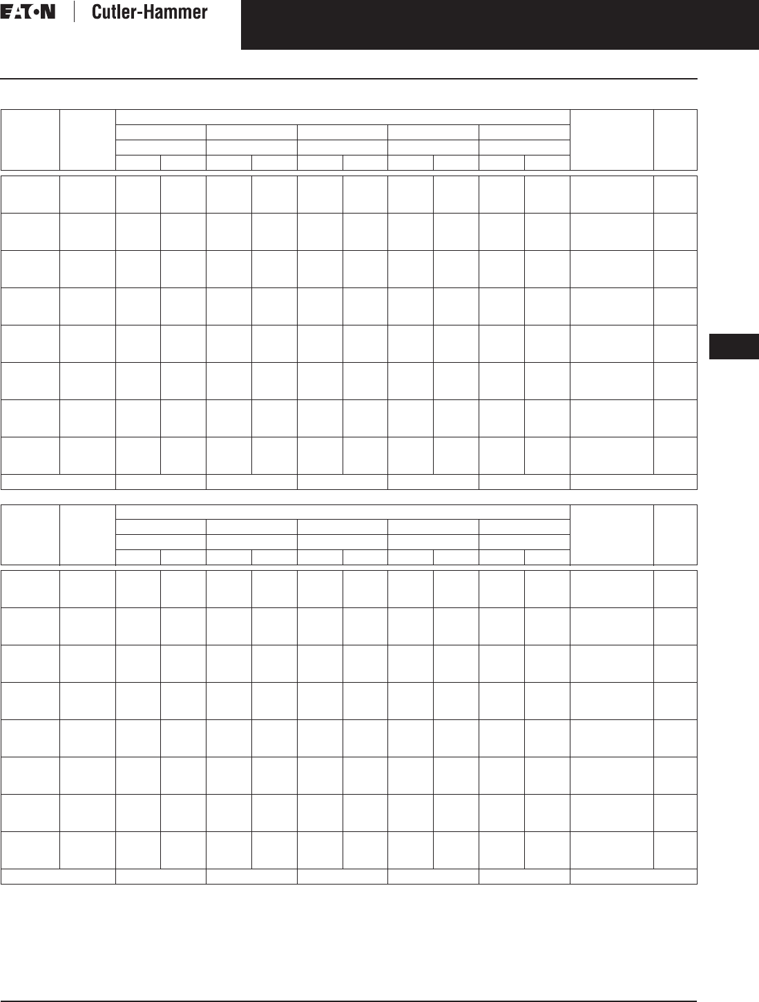
November 2003
CA08101001E For more information visit: www.cutler-hammer.eaton.com
9-79
Transformers
9
Buck-Boost Transformers
Single-Phase
Vol. 1, Ref. No. [0379]
Table 9-91. Single-Phase 240 Volt Output Required, 60 Hz
Additional wiring trough may be required.
Refer to Page 9-74 for Buck-Boost wiring diagrams.
Note: Output voltage for lower input voltage can be found by: x Input Actual Voltage = Output New Voltage.
Note: Output kVA available at reduced input voltage can be found by: x Output kVA = New kVA Rating.
Units
Required
Unit
kVA
Input Available Voltage Style
Number
Price
U.S. $
208 212 216 218 225
Output Output Output Output Output
kVA Amps kVA Amps kVA Amps kVA Amps kVA Amps
1
1
1
.05
.05
.10
—
.32
—
—
1.35
—
—
.38
—
—
1.56
—
.45
—
.9
1.88
—
3.75
.5
—
1.0
2.08
—
4.17
—
.75
—
—
3.12
—
S10N04A81N
S10N06A81N
S10N04A82N
100.
100.
105.
1
1
1
.10
.15
.15
.65
—
.98
2.71
—
4.06
.75
—
1.12
3.12
—
4.69
—
1.35
—
—
5.62
—
—
1.5
—
—
6.25
—
1.5
—
2.25
6.25
—
9.37
S10N06A82N
S10N04A83N
S10N06A83N
105.
115.
115.
1
1
1
.25
.25
.50
—
1.62
—
—
6.77
—
—
1.87
—
—
7.81
—
2.25
—
4.5
9.37
—
18.7
2.5
—
5
10.4
—
20.8
—
3.75
—
—
15.6
—
S10N04A26N
S10N06A26N
S10N04A51N
150.
150.
175.
1
1
1
.50
.75
.75
3.25
—
4.87
13.5
—
20.3
3.75
—
5.62
15.6
—
23.4
—
6.75
—
—
28.2
—
—
7.5
—
—
31.2
—
7.5
—
11.2
31.2
—
46.8
S10N06A51N
S10N04A76N
S10N06A76N
175.
230.
230.
1
1
1
1
1
1.5
—
6.5
—
—
27.1
—
—
7.5
—
—
31.2
—
9
—
13.5
37.5
—
56.2
10
—
15
41.7
—
62.5
—
15
—
—
62.5
—
S10N04A01N
S10N06A01N
S10N04A16N
270.
270.
360.
1
1
1
1.5
2
2
9.75
—
13
40.6
—
54.2
11.2
—
15
46.9
—
62.5
—
18
—
—
75
—
—
20
—
—
83.3
—
22.5
—
30
93.7
—
125
S10N06A16N
S10N04A02N
S10N06A02N
360.
470.
470.
1
1
1
3
3
5
—
19.5
—
—
81.3
—
—
22.5
—
—
93.6
—
27
—
45
112.5
—
187
30
—
50
125.1
—
208
—
45
—
—
187.5
—
S10N04A03N
S10N06A03N
S10N04A05N
635.
635.
1,180.
1
1
1
5
7.5
7.5
32.5
—
48.7
135
—
203
37.5
—
56.2
156
—
234
—
67.5
—
—
282
—
—
75
—
—
312
—
75
—
112
312
—
468
S10N06A05N
S10N04A07N
S10N06A07N
1,180.
1,650.
1,650.
Connection Diagram GF GF E
Units
Required
Unit
kVA
Input Available Voltage Style
Number
Price
U.S. $
229 252 256 264 272
Output Output Output Output Output
kVA Amps kVA Amps kVA Amps kVA Amps kVA Amps
1
1
1
.05
.05
.10
1.0
—
2.0
4.16
—
8.33
1.05
—
2.1
4.38
—
8.75
—
.8
—
—
3.33
—
.55
—
1.1
2.29
—
4.58
—
.42
—
—
1.77
—
S10N04A81N
S10N06A81N
S10N04A82N
100.
100.
105.
1
1
1
.10
.15
.15
—
3.0
—
—
12.5
—
—
3.15
—
—
13.1
—
1.6
—
2.4
6.67
—
10.0
—
1.65
—
—
6.87
—
.85
—
1.27
3.54
—
5.31
S10N06A82N
S10N04A83N
S10N06A83N
105.
115.
115.
1
1
1
.25
.25
.50
5
—
10
20.8
—
41.6
5.25
—
10.5
21.9
—
43.7
—
4
—
—
16.7
—
2.75
—
5.5
11.5
—
22.9
—
2.12
—
—
8.85
—
S10N04A26N
S10N06A26N
S10N04A51N
150.
150.
175.
1
1
1
.50
.75
.75
—
15
—
—
62.4
—
—
15.7
—
—
65.6
—
8
—
12
33.3
—
50
—
8.25
—
—
34.4
—
4.25
—
6.37
17.7
—
26.6
S10N06A51N
S10N04A76N
S10N06A76N
175.
230.
230.
1
1
1
1
1
1.5
20
—
30
83.3
—
125
21
—
31.5
87.5
—
131
—
16
—
—
66.7
—
11
—
16.5
45.8
—
68.7
—
8.5
—
—
35.4
—
S10N04A01N
S10N06A01N
S10N04A16N
270.
270.
360.
1
1
1
1.5
2
2
—
40
—
—
167
—
—
42
—
—
175
—
24
—
32
100
—
133
—
22
—
—
91.7
—
12.7
—
17
53.1
—
70.8
S10N06A16N
S10N04A02N
S10N06A02N
360.
470.
470.
1
1
1
3
3
5
60
—
100
249.9
—
416.5
63
—
105
262.5
—
437.5
—
48
—
—
200.1
—
33
—
55
137.4
—
229
—
25.5
—
—
106.2
—
S10N04A03N
S10N06A03N
S10N04A05N
635.
635.
1,180.
1
1
1
5
7.5
7.5
—
150
—
—
624
—
—
157
—
—
656
—
80
—
120
333
—
500
—
82.5
—
—
344
—
42.5
—
63.7
177
—
266
S10N06A05N
S10N04A07N
S10N06A07N
1,180.
1,650.
1,650.
Connection Diagram EEEFF
Rated Output Voltage
Rated Input Voltage
--------------------------------------------------
Actual Input Voltage
Rated Input Voltage
------------------------------------------------
Discount Symbol . . . . . . . . . . . . . . . . . . . . . . . . . DT-1

November 2003
9-80
For more information visit: www.cutler-hammer.eaton.com CA08101001E
Transformers
9
Buck-Boost Transformers
Three-Phase Vol. 1, Ref. No. [0380]
Table 9-92. Three-Phase Open Delta Connection 230 Volt Output Required, 60 Hz
Additional wiring trough may be required.
Refer to Page 9-74 for Buck-Boost wiring diagrams.
Note: Output voltage for lower input voltage can be found by: x Input Actual Voltage = Output New Voltage.
Note: Output kVA available at reduced input voltage can be found by: x Output kVA = New kVA Rating.
Units
Required
Unit
kVA
Input Available Voltage Style
Number
Price
U.S. $
199 203 207 209 216
Output Output Output Output Output
kVA Amps kVA Amps kVA Amps kVA Amps kVA Amps
2
2
2
.05
.05
.10
—
.54
—
—
1.35
—
—
.62
—
—
1.56
—
.75
—
1.49
1.87
—
3.75
.83
—
1.66
2.08
—
4.17
—
1.24
—
—
3.12
—
S10N04A81N
S10N06A81N
S10N04A82N
100.
100.
105.
2
2
2
.10
.15
.15
1.08
—
1.62
2.71
—
4.06
1.24
—
1.87
3.12
—
4.69
—
2.24
—
—
5.62
—
—
2.49
—
—
6.25
—
2.49
—
3.73
6.25
—
9.37
S10N06A82N
S10N04A83N
S10N06A83N
105.
115.
115.
2
2
2
.25
.25
.50
—
2.7
—
—
6.77
—
—
3.11
—
—
7.81
—
3.3
—
7.47
9.37
—
18.7
4.15
—
8.3
10.4
—
20.8
—
6.22
—
—
15.6
—
S10N04A26N
S10N06A26N
S10N04A51N
150.
150.
175.
2
2
2
.50
.75
.75
5.39
—
8.09
13.5
—
20.3
6.22
—
9.33
15.6
—
23.4
—
11.2
—
—
28.2
—
—
12.4
—
—
31.2
—
12.4
—
18.7
31.2
—
46.8
S10N06A51N
S10N04A76N
S10N06A76N
175.
230.
230.
2
2
2
1
1
1.5
—
10.8
—
—
27.1
—
—
12.4
—
—
31.2
—
14.9
—
22.4
37.5
—
56.2
16.6
—
24.9
41.7
—
62.5
—
24.9
—
—
62.5
—
S10N04A01N
S10N06A01N
S10N04A16N
270.
270.
360.
2
2
2
1.5
2
2
16.2
—
21.6
40.6
—
54.2
18.7
—
24.9
46.9
—
62.5
—
29.9
—
—
75
—
—
33.2
—
—
83.3
—
37.3
—
49.8
93.7
—
125
S10N06A16N
S10N04A02N
S10N06A02N
360.
470.
470.
2
2
2
3
3
5
—
32.4
—
—
81.3
—
—
32.7
—
—
93.6
—
44.7
—
74.7
112.5
—
187
49.8
—
83
125.1
—
208
—
74.7
—
—
187.5
—
S10N04A03N
S10N06A03N
S10N04A05N
635.
635.
1,180.
2
2
2
5
7.5
7.5
53.9
—
80.9
135
—
203
62.2
—
93.3
156
—
234
—
112
—
—
282
—
—
124
—
—
312
—
124
—
187
312.5
—
468
S10N06A05N
S10N04A07N
S10N06A07N
1,180.
1,650.
1,650.
Connection Diagram LKLKI
Units
Required
Unit
kVA
Input Available Voltage Style
Number
Price
U.S. $
219 242 246 253 260
Output Output Output Output Output
kVA Amps kVA Amps kVA Amps kVA Amps kVA Amps
2
2
2
.05
.05
.10
1.66
—
3.32
4.17
—
8.33
1.74
—
3.48
4.37
—
8.75
—
1.33
—
—
3.33
—
.91
—
1.83
2.29
—
4.58
—
.70
—
—
1.77
—
S10N04A81N
S10N06A81N
S10N04A82N
100.
100.
105.
2
2
2
.10
.15
.15
—
4.98
—
—
12.5
—
—
5.23
—
—
13.1
—
2.65
—
3.98
6.67
—
10.0
—
2.74
—
—
6.87
—
1.41
—
2.12
3.54
—
5.13
S10N06A82N
S10N04A83N
S10N06A83N
105.
115.
115.
2
2
2
.25
.25
.50
8.3
—
16.6
20.8
—
41.7
8.71
—
17.4
21.9
—
43.7
—
6.64
—
—
16.7
—
4.56
—
9.73
11.5
—
22.9
—
3.52
—
—
8.85
—
S10N04A26N
S10N06A26N
S10N04A51N
150.
150.
175.
2
2
2
.50
.75
.75
—
24.9
—
—
62.4
—
—
26.1
—
—
65.6
—
13.3
—
19.9
33.3
—
50
—
13.7
—
—
34.4
—
7.05
—
10.6
17.7
—
26.6
S10N06A51N
S10N04A76N
S10N06A76N
175.
230.
230.
2
2
2
1
1
1.5
33.2
—
49.8
83.3
—
125
34.8
—
52.3
87.5
—
131
—
26.5
—
—
66.7
—
18.3
—
27.4
45.8
—
68.7
—
14.1
—
—
35.4
—
S10N04A01N
S10N06A01N
S10N04A16N
270.
270.
360.
2
2
2
1.5
2
2
—
66.4
—
—
167
—
—
69.7
—
—
175
—
39.8
—
53.1
100
—
133
—
36.5
—
—
91.7
—
21.2
—
28.2
53.1
—
70.8
S10N06A16N
S10N04A02N
S10N06A02N
360.
470.
470.
2
2
2
3
3
5
99.6
—
166
249.9
—
417
104.4
—
174
262.5
—
437
—
79.5
—
—
200
—
54.9
—
91.3
137.4
—
229
—
42.3
—
—
106.2
—
S10N04A03N
S10N06A03N
S10N04A05N
635.
635.
1,180.
2
2
2
5
7.5
7.5
—
249
—
—
624
—
—
261
—
—
656
—
133
—
199
333
—
500
—
137
—
—
344
—
70.5
—
106
177
—
266
S10N06A05N
S10N04A07N
S10N06A07N
1,180.
1,650.
1,650.
Connection Diagram IIIKK
Rated Output Voltage
Rated Input Voltage
--------------------------------------------------
Actual Input Voltage
Rated Input Voltage
------------------------------------------------
Discount Symbol . . . . . . . . . . . . . . . . . . . . . . . . . DT-1

November 2003
CA08101001E For more information visit: www.cutler-hammer.eaton.com
9-81
Transformers
9
Buck-Boost Transformers
Three-Phase
Vol. 1, Ref. No. [0381]
Table 9-93. Three-Phase Open Delta Connection 240 Volt Output Required, 60 Hz
Additional wiring trough may be required.
Refer to Page 9-74 for Buck-Boost wiring diagrams.
Note: Output voltage for lower input voltage can be found by: x Input Actual Voltage = Output New Voltage.
Note: Output kVA available at reduced input voltage can be found by: x Output kVA = New kVA Rating.
Units
Required
Unit
kVA
Input Available Voltage Style
Number
Price
U.S. $
208 212 216 218 225
Output Output Output Output Output
kVA Amps kVA Amps kVA Amps kVA Amps kVA Amps
2
2
2
.05
.05
.10
—
.56
—
—
1.35
—
—
.65
—
—
1.56
—
.73
—
1.56
1.87
—
3.75
.87
—
1.73
2.08
—
4.17
—
1.3
—
—
3.12
—
S10N04A81N
S10N06A81N
S10N04A82N
100.
100.
105.
2
2
2
.10
.15
.15
1.13
—
1.69
2.71
—
4.06
1.3
—
1.95
3.12
—
4.69
—
2.34
—
—
5.62
—
—
2.6
—
—
6.25
—
2.6
—
3.9
6.25
—
9.37
S10N06A82N
S10N04A83N
S10N06A83N
105.
115.
115.
2
2
2
.25
.25
.50
—
2.81
—
—
6.77
—
—
3.25
—
—
7.81
—
3.9
—
7.79
9.37
—
18.7
4.33
—
8.66
10.4
—
20.8
—
6.49
—
—
15.6
—
S10N04A26N
S10N06A26N
S10N04A51N
150.
150.
175.
2
2
2
.50
.75
.75
5.63
—
8.44
13.5
—
20.3
6.5
—
9.75
15.6
—
23.4
—
11.7
—
—
28.2
—
—
13
—
—
31.2
—
13
—
19.5
31.2
—
46.8
S10N06A51N
S10N04A76N
S10N06A76N
175.
230.
230.
2
2
2
1
1
1.5
—
11.3
—
—
27.1
—
—
13
—
—
31.2
—
15.6
—
23.4
37.5
—
56.2
17.3
—
26
41.7
—
62.5
—
26
—
—
62.5
—
S10N04A01N
S10N06A01N
S10N04A16N
270.
270.
360.
2
2
2
1.5
2
2
16.9
—
22.5
40.6
—
54.2
19.5
—
26
46.9
—
62.5
—
31.2
—
—
75
—
—
34.6
—
—
83.3
—
39
—
52
93.7
—
125
S10N06A16N
S10N04A02N
S10N06A02N
360.
470.
470.
2
2
2
3
3
5
—
33.9
—
—
81.3
—
—
39
—
—
93.6
—
46.8
—
77.9
112.5
—
187
51.9
—
86.6
125.1
—
208
—
78
—
—
187.5
—
S10N04A03N
S10N06A03N
S10N04A05N
635.
635.
1,180.
2
2
2
5
7.5
7.5
56.3
—
84.4
135
—
203
65
—
97.5
156
—
234
—
117
—
—
282
—
—
130
—
—
312
—
130
—
195
312
—
468
S10N06A05N
S10N04A07N
S10N06A07N
1,180.
1,650.
1,650.
Connection Diagram LKLKI
Units
Required
Unit
kVA
Input Available Voltage Style
Number
Price
U.S. $
229 252 256 264 272
Output Output Output Output Output
kVA Amps kVA Amps kVA Amps kVA Amps kVA Amps
2
2
2
.05
.05
.10
1.73
—
3.46
4.16
—
8.33
1.82
—
3.64
4.37
—
8.75
—
1.38
—
—
3.33
—
.95
—
1.91
2.29
—
4.58
—
.74
—
—
1.77
—
S10N04A81N
S10N06A81N
S10N04A82N
100.
100.
105.
2
2
2
.10
.15
.15
—
5.19
—
—
12.5
—
—
5.45
—
—
13.1
—
2.77
—
4.15
6.67
—
10.0
—
2.86
—
—
6.87
—
1.47
—
2.21
3.54
—
5.31
S10N06A82N
S10N04A83N
S10N06A83N
105.
115.
115.
2
2
2
.25
.25
.50
8.66
—
17.3
20.8
—
41.6
9.09
—
18.2
21.9
—
43.7
—
6.92
—
—
16.7
—
4.76
—
9.53
11.5
—
22.9
—
3.68
—
—
8.85
—
S10N04A26N
S10N06A26N
S10N04A51N
150.
150.
175.
2
2
2
.50
.75
.75
—
26
—
—
62.4
—
—
27.3
—
—
65.6
—
13.8
—
20.8
33.3
—
50
—
14.3
—
—
34.4
—
7.36
—
11
17.7
—
26.6
S10N06A51N
S10N04A76N
S10N06A76N
175.
230.
230.
2
2
2
1
1
1.5
34.6
—
51.9
83.3
—
125
36.4
—
54.5
87.5
—
131
—
27.7
—
—
66.7
—
19.1
—
28.6
45.8
—
68.7
—
14.7
—
—
35.4
—
S10N04A01N
S10N06A01N
S10N04A16N
270.
270.
360.
2
2
2
1.5
2
2
—
69.3
—
—
167
—
—
72.7
—
—
175
—
41.5
—
55.4
100
—
133
—
38.1
—
—
91.7
—
22.1
—
29.4
53.1
—
70.8
S10N06A16N
S10N04A02N
S10N06A02N
360.
470.
470.
2
2
2
3
3
5
103.8
—
173
249.9
—
416
109.2
—
182
262.5
—
437
—
83.1
—
—
200
—
57.3
—
95.3
137.4
—
229
—
44.1
—
—
106.2
—
S10N04A03N
S10N06A03N
S10N04A05N
635.
635.
1,180.
2
2
2
5
7.5
7.5
—
260
—
—
624
—
—
273
—
—
656
—
138
—
208
333
—
500
—
143
—
—
344
—
73.6
—
110
177
—
266
S10N06A05N
S10N04A07N
S10N06A07N
1,180.
1,650.
1,650.
Connection Diagram IIIKK
Rated Output Voltage
Rated Input Voltage
--------------------------------------------------
Actual Input Voltage
Rated Input Voltage
------------------------------------------------
Discount Symbol . . . . . . . . . . . . . . . . . . . . . . . . . DT-1
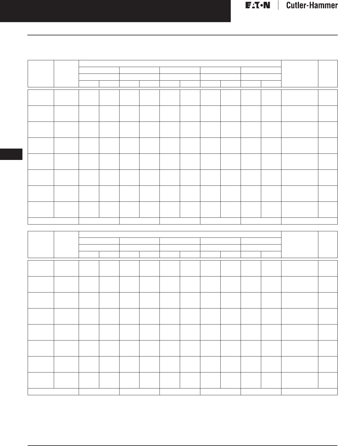
November 2003
9-82
For more information visit: www.cutler-hammer.eaton.com CA08101001E
Transformers
9
Buck-Boost Transformers
Three-Phase Vol. 1, Ref. No. [0382]
Table 9-94. Three-Phase Wye Connection 208 Volt Output Required, 60 Hz
Note: WARNING! Three-phase autotransformers should never be used to obtain 4-wire output with 3-wire input. 4-wire output requires
4-wire wye input.
Additional wiring trough may be required.
Refer to Page 9-74 for Buck-Boost wiring diagrams.
Note: Output voltage for lower input voltage can be found by: x Input Actual Voltage = Output New Voltage.
Note: Output kVA available at reduced input voltage can be found by: x Output kVA = New kVA Rating.
Units
Required
Unit
kVA
Input Available Voltage Style
Number
Price
U.S. $
152 164 173 180 184
Output Output Output Output Output
kVA Amps kVA Amps kVA Amps kVA Amps kVA Amps
3
3
3
.05
.05
.10
—
.41
—
—
1.15
—
—
.56
—
—
1.56
—
.75
—
1.50
2.08
—
4.17
—
.98
—
—
2.71
—
—
1.12
—
—
3.12
—
S10N04A81N
S10N06A81N
S10N04A82N
100.
100.
105.
3
3
3
.10
.15
.15
.82
—
1.24
2.29
—
3.44
1.12
—
1.69
3.12
—
4.69
—
2.25
—
—
6.25
—
1.95
—
2.92
5.41
—
8.12
2.25
—
3.73
6.25
—
9.37
S10N06A82N
S10N04A83N
S10N06A83N
105.
115.
115.
3
3
3
.25
.25
.50
—
2.06
—
—
5.73
—
—
2.81
—
—
7.81
—
3.75
—
7.5
10.4
—
20.8
—
4.87
—
—
13.5
—
—
5.62
—
—
15.6
—
S10N04A26N
S10N06A26N
S10N04A51N
150.
150.
175.
3
3
3
.50
.75
.75
4.12
—
6.19
11.5
—
17.2
5.62
—
8.44
15.6
—
23.4
—
11.2
—
—
31.2
—
9.75
—
14.6
27.1
—
40.6
11.2
—
16.8
31.2
—
46.8
S10N06A51N
S10N04A76N
S10N06A76N
175.
230.
230.
3
3
3
1
1
1.5
—
8.25
—
—
22.9
—
—
11.2
—
—
31.2
—
15
—
22.5
41.7
—
62.5
—
19.5
—
—
54.1
—
—
22.5
—
—
62.5
—
S10N04A01N
S10N06A01N
S10N04A16N
270.
270.
360.
3
3
3
1.5
2
2
12.4
—
16.5
34.4
—
45.8
16.9
—
22.5
46.9
—
62.5
—
30
—
—
83.3
—
29.2
—
39
81.2
—
108
33.7
—
45
93.7
—
125
S10N06A16N
S10N04A02N
S10N06A02N
360.
470.
470.
3
3
3
3
3
5
—
24.7
—
—
68.7
—
—
33.6
—
—
93.6
—
45
—
75
125
—
208
—
58.5
—
—
162.3
—
—
67.5
—
—
187.5
—
S10N04A03N
S10N06A03N
S10N04A05N
635.
635.
1,180.
3
3
3
5
7.5
7.5
41.2
—
61.9
115
—
172
56.2
—
84.4
156
—
234
—
112
—
—
312
—
97.5
—
146
271
—
406
112
—
168
312
—
468
S10N06A05N
S10N04A07N
S10N06A07N
1,180.
1,650.
1,650.
Connection Diagram PNNOM
Units
Required
Unit
kVA
Input Available Voltage Style
Number
Price
U.S. $
189 229 236 250 264
Output Output Output Output Output
kVA Amps kVA Amps kVA Amps kVA Amps kVA Amps
3
3
3
.05
.05
.10
1.5
—
3.0
4.16
—
8.33
1.65
—
3.3
4.58
—
9.17
—
1.27
—
—
3.54
—
.9
—
1.8
2.5
—
5.0
—
.71
—
—
1.98
—
S10N04A81N
S10N06A81N
S10N04A82N
100.
100.
105.
3
3
3
.10
.15
.15
—
4.5
—
—
12.5
—
—
4.95
—
—
13.7
—
2.55
—
3.82
7.08
—
10.6
—
2.7
—
—
7.5
—
1.42
—
2.14
3.95
—
5.93
S10N06A82N
S10N04A83N
S10N06A83N
105.
115.
115.
3
3
3
.25
.25
.50
7.5
—
15
20.8
—
41.6
8.25
—
16.5
22.9
—
45.8
—
6.35
—
—
17.7
—
4.5
—
9
12.5
—
25
—
3.56
—
—
9.88
—
S10N04A26N
S10N06A26N
S10N04A51N
150.
150.
175.
3
3
3
.50
.75
.75
—
22.5
—
—
62.4
—
—
24.7
—
—
68.7
—
12.7
—
19
35.4
—
53.1
—
13.5
—
—
37.5
—
7.12
—
10.7
19.3
—
29.3
S10N06A51N
S10N04A76N
S10N06A76N
175.
230.
230.
3
3
3
1
1
1.5
30
—
45
83.3
—
125
33
—
49.5
91.7
—
137
—
25.5
—
—
70.8
—
18
—
27
50
—
75
—
14.2
—
—
39.5
—
S10N04A01N
S10N06A01N
S10N04A16N
270.
270.
360.
3
3
3
1.5
2
2
—
60
—
—
167
—
—
66
—
—
183
—
38.2
—
51
106
—
142
—
361
—
—
100
—
21.4
—
28.5
59.3
—
79.2
S10N06A16N
S10N04A02N
S10N06A02N
360.
470.
470.
3
3
3
3
3
5
90
—
150
249.9
—
416
99
—
165
275.1
—
458
—
76.5
—
—
212.4
—
54
—
90
150
—
250
—
46.2
—
—
118.5
—
S10N04A03N
S10N06A03N
S10N04A05N
635.
635.
1,180.
3
3
3
5
7.5
7.5
—
225
—
—
624
—
—
274
—
—
687
—
127
—
190
354
—
531
—
135
—
—
375
—
71.2
—
107
198
—
293
S10N06A05N
S10N04A07N
S10N06A07N
1,180.
1,650.
1,650.
Connection Diagram MMMN N
Rated Output Voltage
Rated Input Voltage
--------------------------------------------------
Actual Input Voltage
Rated Input Voltage
------------------------------------------------
Discount Symbol . . . . . . . . . . . . . . . . . . . . . . . . . DT-1

November 2003
CA08101001E For more information visit: www.cutler-hammer.eaton.com
9-83
Transformers
9
Buck-Boost Transformers
Three-Phase
Vol. 1, Ref. No. [0383]
Table 9-95. Three-Phase Wye Connection 230 Volt Output Required, 60 Hz
Note: WARNING! Three-phase autotransformers should never be used to obtain 4-wire output with 3-wire input. 4-wire output requires
4-wire wye input.
Additional wiring trough may be required.
Refer to Page 9-74 for Buck-Boost wiring diagrams.
Note: Output voltage for lower input voltage can be found by: x Input Actual Voltage = Output New Voltage.
Note: Output kVA available at reduced input voltage can be found by: x Output kVA = New kVA Rating.
Units
Required
Unit
kVA
Input Available Voltage Style
Number
Price
U.S. $
183 192 199 208 218
Output Output Output Output Output
kVA Amps kVA Amps kVA Amps kVA Amps kVA Amps
3
3
3
.05
.05
.10
—
.62
—
—
1.56
—
.83
—
1.66
2.08
—
4.17
—
.54
—
—
1.35
—
1.65
—
3.3
4.58
—
9.17
1.66
—
3.32
4.17
—
8.35
S10N04A81N
S10N06A81N
S10N04A82N
100.
100.
105.
3
3
3
.10
.15
.15
1.25
—
1.87
3.12
—
4.69
—
2.49
—
—
6.25
—
1.08
—
1.62
2.71
—
4.06
—
4.95
—
—
13.7
—
—
4.98
—
—
12.5
—
S10N06A82N
S10N04A83N
S10N06A83N
105.
115.
115.
3
3
3
.25
.25
.50
—
3.11
—
—
7.81
—
4.15
—
8.3
10.4
—
20.8
—
2.70
—
—
6.77
—
8.2
—
16.5
22.9
—
45.8
8.3
—
16.6
20.9
—
41.7
S10N04A26N
S10N06A26N
S10N04A51N
150.
150.
175.
3
3
3
.50
.75
.75
6.22
—
9.33
15.6
—
23.4
—
12.4
—
—
31.2
—
5.39
—
8.09
13.5
—
20.3
—
24.7
—
—
68.8
—
—
24.9
—
—
62.6
—
S10N06A51N
S10N04A76N
S10N06A76N
175.
230.
230.
3
3
3
1
1
1.5
—
12.5
—
—
31.2
—
16.6
—
24.9
41.7
—
62.5
—
10.8
—
—
27.1
—
33
—
49.5
91.7
—
137
33.2
—
49.8
83.5
—
125
S10N04A01N
S10N06A01N
S10N04A16N
270.
270.
360.
3
3
3
1.5
2
2
18.7
—
24.9
46.9
—
62.5
—
33.2
—
—
83.3
—
16.2
—
21.6
40.6
—
54.2
—
66
—
—
183
—
—
66.4
—
—
167
—
S10N06A16N
S10N04A02N
S10N06A02N
360.
470.
470.
3
3
3
3
3
5
—
37.5
—
—
93.6
—
49.8
—
83
125.1
—
208
—
32.4
—
—
81.3
—
99
—
165
275
—
458
99.6
—
166
250.5
—
417
S10N04A03N
S10N06A03N
S10N04A05N
635.
635.
1,180.
3
3
3
5
7.5
7.5
62.2
—
93.3
156
—
234
—
124
—
—
312
—
53.9
—
80.9
135
—
203
—
247
—
—
688
—
—
249
—
—
626
—
S10N06A05N
S10N04A07N
S10N06A07N
1,180.
1,650.
1,650.
Connection Diagram NNSMQ
Units
Required
Unit
kVA
Input Available Voltage Style
Number
Price
U.S. $
242 245 253 260 265
Output Output Output Output Output
kVA Amps kVA Amps kVA Amps kVA Amps kVA Amps
3
3
3
.05
.05
.10
1.74
—
3.48
4.37
—
8.75
—
1.33
—
—
3.33
—
.91
—
1.83
2.29
—
4.58
—
.70
—
—
1.77
—
—
.62
—
—
1.56
—
S10N04A81N
S10N06A81N
S10N04A82N
100.
100.
105.
3
3
3
.10
.15
.15
—
5.23
—
—
13.1
—
2.65
—
3.98
6.67
—
10.0
—
2.74
—
—
6.87
—
1.41
—
2.12
3.54
—
5.31
1.25
—
1.87
3.12
—
4.69
S10N06A82N
S10N04A83N
S10N06A83N
105.
115.
115.
3
3
3
.25
.25
.50
8.71
—
17.4
21.9
—
43.7
—
6.63
—
—
16.7
—
4.56
—
9.31
11.5
—
22.9
—
3.52
—
—
8.85
—
—
3.11
—
—
7.81
—
S10N04A26N
S10N06A26N
S10N04A51N
150.
150.
175.
3
3
3
.50
.75
.75
—
26.1
—
—
65.6
—
13.3
—
19.9
33.3
—
50
—
13.7
—
—
34.4
—
7.05
—
10.6
17.7
—
26.6
6.22
—
9.33
15.6
—
23.4
S10N06A51N
S10N04A76N
S10N06A76N
175.
230.
230.
3
3
3
1
1
1.5
34.8
—
52.3
87.5
—
131
—
26.5
—
—
66.7
—
18.3
—
27.4
45.8
—
68.7
—
14.1
—
—
35.4
—
—
12.5
—
—
31.2
—
S10N04A01N
S10N06A01N
S10N04A16N
270.
270.
360.
3
3
3
1.5
2
2
—
69.7
—
—
175
—
39.8
—
53.1
100
—
133
—
36.6
—
—
91.6
—
21.2
—
28.2
53.1
—
70.8
18.7
—
24.9
46.9
—
62.5
S10N06A16N
S10N04A02N
S10N06A02N
360.
470.
470.
3
3
3
3
3
5
104.4
—
174
262.5
—
437
—
79.5
—
—
200
—
54.9
—
91.3
137.4
—
229
—
42.3
—
—
106.2
—
—
37.5
—
—
93.6
—
S10N04A03N
S10N06A03N
S10N04A05N
635.
635.
1,180.
3
3
3
5
7.5
7.5
—
261
—
—
656
—
133
—
199
333
—
500
—
137
—
—
344
—
70.5
—
106
177
—
266
62.2
—
93.3
156
—
234
S10N06A05N
S10N04A07N
S10N06A07N
1,180.
1,650.
1,650.
Connection Diagram QQRRS
Rated Output Voltage
Rated Input Voltage
--------------------------------------------------
Actual Input Voltage
Rated Input Voltage
------------------------------------------------
Discount Symbol . . . . . . . . . . . . . . . . . . . . . . . . . DT-1

November 2003
9-84
For more information visit: www.cutler-hammer.eaton.com CA08101001E
Transformers
9
Buck-Boost Transformers
Three-Phase Vol. 1, Ref. No. [0384]
Table 9-96. Three-Phase Wye Connection 240 Volt Output Required, 60 Hz
Note: WARNING! Three-phase autotransformers should never be used to obtain 4-wire output with 3-wire input. 4-wire output requires
4-wire wye input.
Additional wiring trough may be required.
Refer to Page 9-74 for Buck-Boost wiring diagrams.
Note: Output voltage for lower input voltage can be found by: x Input Actual Voltage = Output New Voltage.
Note: Output kVA available at reduced input voltage can be found by: x Output kVA = New kVA Rating.
Units
Required
Unit
kVA
Input Available Voltage Style
Number
Price
U.S. $
190 200 208 218 228
Output Output Output Output Output
kVA Amps kVA Amps kVA Amps kVA Amps kVA Amps
3
3
3
.05
.05
.10
—
.65
—
—
1.65
—
.86
—
1.73
2.08
—
4.17
—
1.27
—
—
3.05
—
.86
—
1.73
2.08
—
4.17
1.73
—
3.46
4.17
—
8.34
S10N04A81N
S10N06A81N
S10N04A82N
100.
100.
105.
3
3
3
.10
.15
.15
1.3
—
1.95
3.12
—
4.69
—
2.59
—
—
6.25
—
2.55
—
3.82
6.12
—
9.16
—
2.59
—
—
6.25
—
—
5.20
—
—
12.5
—
S10N06A82N
S10N04A83N
S10N06A83N
105.
115.
115.
3
3
3
.25
.25
.50
—
3.25
—
—
7.81
—
4.32
—
8.65
10.4
—
20.8
—
6.3
—
—
15.1
—
4.32
—
8.65
10.4
—
20.8
8.66
—
17.3
20.9
—
41.7
S10N04A26N
S10N06A26N
S10N04A51N
150.
150.
175.
3
3
3
.50
.75
.75
6.5
—
9.75
15.6
—
23.4
—
13
—
—
31.2
—
12.7
—
19.2
30.4
—
46
—
13
—
—
31.2
—
—
26
—
—
62.6
—
S10N06A51N
S10N04A76N
S10N06A76N
175.
230.
230.
3
3
3
1
1
1.5
—
13
—
—
31.2
—
17.3
—
25.9
41.7
—
62.5
—
25.5
—
—
61.2
—
17.3
—
25.9
41.7
—
62.5
34.6
—
52
83.4
—
125
S10N04A01N
S10N06A01N
S10N04A16N
270.
270.
360.
3
3
3
1.5
2
2
19.5
—
26
46.9
—
62.5
—
34.6
—
—
83.3
—
38.2
—
51
91.6
—
122.4
—
34.6
—
—
83.3
—
—
69.3
—
—
167
—
S10N06A16N
S10N04A02N
S10N06A02N
360.
470.
470.
3
3
3
3
3
5
—
39
—
—
93.6
—
51.9
—
86.5
125.1
—
208
—
76.5
—
—
183.6
—
51.9
—
86.5
125.1
—
208
103.8
—
173
250.2
—
417
S10N04A03N
S10N06A03N
S10N04A05N
635.
635.
1,180.
3
3
3
5
7.5
7.5
65
—
97.5
156
—
234
—
130
—
—
312
—
127.2
—
192
305.2
—
460
—
130
—
—
312
—
—
260
—
—
626
—
S10N06A05N
S10N04A07N
S10N06A07N
1,180.
1,650.
1,650.
Connection Diagram NNMR Q
Units
Required
Unit
kVA
Input Available Voltage Style
Number
Price
U.S. $
252 256 264 272 277
Output Output Output Output Output
kVA Amps kVA Amps kVA Amps kVA Amps kVA Amps
3
3
3
.05
.05
.10
1.85
—
3.64
4.37
—
8.75
—
1.39
—
—
3.33
—
.95
—
1.91
2.29
—
4.58
—
.74
—
—
1.77
—
—
.65
—
—
1.56
—
S10N04A81N
S10N06A81N
S10N04A82N
100.
100.
105.
3
3
3
.10
.15
.15
—
5.46
—
—
13.1
—
2.77
—
4.16
6.67
—
10.0
—
2.86
—
—
6.87
—
1.47
—
2.21
3.54
—
5.31
1.3
—
1.95
3.12
—
4.69
S10N06A82N
S10N04A83N
S10N06A83N
105.
115.
115.
3
3
3
.25
.25
.50
9.09
—
18.2
21.9
—
43.7
—
6.93
—
—
16.7
—
4.76
—
9.53
11.5
—
22.9
—
3.68
—
—
8.85
—
—
3.25
—
—
7.81
—
S10N04A26N
S10N06A26N
S10N04A51N
150.
150.
175.
3
3
3
.50
.75
.75
—
27.3
—
—
65.6
—
13.9
—
20.8
33.3
—
50
—
14.3
—
—
34.4
—
7.36
—
11
17.7
—
26.6
6.5
—
9.75
15.6
—
23.4
S10N06A51N
S10N04A76N
S10N06A76N
175.
230.
230.
3
3
3
1
1
1.5
36.4
—
54.6
87.5
—
131
—
27.7
—
—
66.7
—
19.1
—
28.6
45.8
—
68.7
—
14.7
—
—
35.4
—
—
13
—
—
31.2
—
S10N04A01N
S10N06A01N
S10N04A16N
270.
270.
360.
3
3
3
1.5
2
2
—
72.8
—
—
175
—
41.6
—
55.4
100
—
133
—
38.1
—
—
91.7
—
22.1
—
29.5
53.1
—
70.8
19.5
—
26
46.9
—
62.5
S10N06A16N
S10N04A02N
S10N06A02N
360.
470.
470.
3
3
3
3
3
5
109.2
—
182
262.5
—
437
—
83.1
—
—
200
—
57.3
—
95.3
137.4
—
229
—
44.1
—
—
106.2
—
—
39
—
—
93.6
—
S10N04A03N
S10N06A03N
S10N04A05N
635.
635.
1,180.
3
3
3
5
7.5
7.5
—
273
—
—
656
—
139
—
208
333
—
500
—
143
—
—
344
—
73.6
—
110
177
—
266
65
—
97.5
156
—
234
S10N06A05N
S10N04A07N
S10N06A07N
1,180.
1,650.
1,650.
Connection Diagram QQRRS
Rated Output Voltage
Rated Input Voltage
--------------------------------------------------
Actual Input Voltage
Rated Input Voltage
------------------------------------------------
Discount Symbol . . . . . . . . . . . . . . . . . . . . . . . . . DT-1

November 2003
CA08101001E For more information visit: www.cutler-hammer.eaton.com
9-85
Transformers
9
Buck-Boost Transformers
Three-Phase
Vol. 1, Ref. No. [0385]
Table 9-97. Three-Phase Wye Connection 460 Volt Output Required, 60 Hz
Note: WARNING! Three-phase autotransformers should never be used to obtain 4-wire output with 3-wire input. 4-wire output requires
4-wire wye input.
Additional wiring trough may be required.
Refer to Page 9-74 for Buck-Boost wiring diagrams.
Note: Output voltage for lower input voltage can be found by: x Input Actual Voltage = Output New Voltage.
Note: Output kVA available at reduced input voltage can be found by: x Output kVA = New kVA Rating.
Units
Required
Unit
kVA
Input Available Voltage Style
Number
Price
U.S. $
406 418 432 438 424 436 450
Output Output Output Output Output Output Output
kVA Amps kVA Amps kVA Amps kVA Amps kVA Amps kVA Amps kVA Amps
3
3
3
.05
.05
.10
—
1.25
—
—
1.57
—
1.66
—
3.31
2.08
—
4.15
—
2.49
—
—
3.12
—
3.22
—
6.62
4.04
—
8.31
—
1.3
—
1.7
1.56
—
2.1
—
3.5
—
—
4.2
—
2.6
—
—
3.13
—
S10N04A81N
S10N06A81N
S10N04A82N
100.
100.
105.
3
3
3
.10
.15
.15
2.49
—
3.73
3.12
—
4.68
—
4.97
—
—
6.24
—
4.97
—
7.46
6.24
—
9.36
—
9.94
—
—
12.48
—
2.6
—
3.9
3.12
—
4.68
—
5.2
—
—
6.25
—
5.2
—
7.8
6.25
—
9.38
S10N06A82N
S10N04A83N
S10N06A83N
105.
115.
115.
3
3
3
.25
.25
.50
—
6.22
—
—
7.81
—
8.28
—
16.6
10.39
—
20.84
—
12.4
—
—
15.56
—
16.6
—
33.2
20.84
—
41.67
—
6.5
—
—
7.82
—
8.7
—
17.4
10.4
—
20.9
—
13
—
—
15.6
—
S10N04A26N
S10N06A26N
S10N04A51N
150.
150.
175.
3
3
3
.50
.75
.75
12.5
—
18.7
15.69
—
23.47
—
24.8
—
—
31.12
—
24.69
—
37.3
31.25
—
46.82
—
49.6
—
—
62.25
—
13
—
19.5
15.6
—
23.4
—
26
—
—
31.2
—
26
—
39
31.2
—
46.9
S10N06A51N
S10N04A76N
S10N06A76N
175.
230.
230.
3
3
3
1
1
1.5
—
24.9
—
—
31.25
—
33.1
—
49.7
41.54
—
62.38
—
49.7
—
—
62.38
—
66.2
—
99.4
83.09
—
124.75
—
26
—
—
31.2
—
35
—
52
42
—
62.5
—
52
—
—
62.5
—
S10N04A01N
S10N06A01N
S10N04A16N
270.
270.
360.
3
3
3
1.5
2
2
37.3
—
49.7
46.94
—
62.38
—
66.3
—
—
83.22
—
74.6
—
99.5
93.63
—
124.88
—
133
—
—
166.93
—
39
—
52
46.8
—
62.5
—
69
—
—
82.9
—
78
—
104
93.8
—
125
S10N06A16N
S10N04A02N
S10N06A02N
360.
470.
470.
3
3
3
3
3
5
—
74.6
—
—
93.63
—
99.3
—
166
124.64
—
208.35
—
149
—
—
187.01
—
198.6
—
322
249.27
—
404.16
—
78
—
—
93.8
—
104
—
174
125
—
209.2
—
156
—
—
187.6
—
S10N04A03N
S10N06A03N
S10N04A05N
635.
635.
1,180.
3
3
3
5
7.5
7.5
125
—
187
156.89
—
235
—
248
—
—
311
—
249
—
373
312.53
—
468
—
496
—
—
622
—
130
—
195
156.3
—
234
—
260
—
—
312
—
260
—
390
312.7
—
469
S10N06A05N
S10N04A07N
S10N06A07N
1,180.
1,650.
1,650.
Connection
Diagram
RRQQRRQ
Rated Output Voltage
Rated Input Voltage
--------------------------------------------------
Actual Input Voltage
Rated Input Voltage
------------------------------------------------
Discount Symbol . . . . . . . . . . . . . . . . . . . . . . . . . DT-1

November 2003
9-86
For more information visit: www.cutler-hammer.eaton.com CA08101001E
Transformers
9
Buck-Boost Transformers
Single-Phase Vol. 1, Ref. No. [0386]
Table 9-98. Single-Phase Required, 60 Hz
Additional wiring trough may be required.
Refer to Page 9-74 for Buck-Boost wiring diagrams.
Note: Output voltage for lower input voltage can be found by: x Input Actual Voltage = Output New Voltage.
Note: Output kVA available at reduced input voltage can be found by: x Output kVA = New kVA Rating.
Units
Required
Unit
kVA
Input Available Voltage/Output Voltage Style
Number
Price
U.S. $
200/240 230/277 346/380 362/380 378/416 416/457
Output Output Output Output Output Output
kVA Amps kVA Amps kVA Amps kVA Amps kVA Amps kVA Amps
1
1
1
.25
.50
.75
1.25
2.50
3.75
5.2
10.4
15.6
1.44
2.88
4.32
5.2
10.4
15.6
1.98
3.95
5.93
5.2
10.4
15.6
3.95
7.90
11.9
10.4
20.8
31.2
2.16
4.33
6.49
5.2
10.4
15.6
2.38
4.76
7.14
5.2
10.4
15.6
S20N08A26N
S20N08A51N
S20N08A76N
165.
210.
270.
1
1
1
1
1.5
2
5.00
7.50
10.00
20.8
31.2
41.6
5.76
8.64
11.5
20.8
31.2
41.6
7.90
11.9
15.8
20.8
31.2
41.6
15.8
23.8
31.6
41.6
62.5
83.3
8.65
13.0
17.3
20.8
31.2
41.6
9.52
14.3
19.0
20.8
31.2
41.6
S20N08A01N
S20N08A16N
S20N08A02N
310.
420.
570.
1
1
1
3
5
7.5
15.0
25.0
37.5
62.5
104.0
156.0
17.3
28.8
43.2
62.5
104.0
156.0
23.8
39.5
59.3
62.5
104.0
156.0
47.5
79.0
118.6
125.0
208.0
312.0
26.0
43.3
64.9
62.5
104.0
156.0
28.6
47.6
71.4
62.5
104.0
156.0
S20N08A03N
S20N08A05N
S20N08A07N
740.
1,290.
2,000.
Connection
Diagram
BBFEF F
Units
Required
Unit
kVA
Input Available Voltage/Output Voltage Style
Number
Price
U.S. $
436/480 458/480 277/230 480/456 504/480 528/480
Output Output Output Output Output Output
kVA Amps kVA Amps kVA Amps kVA Amps kVA Amps kVA Amps
1
1
1
.25
.50
.75
2.50
4.99
7.49
5.2
10.4
15.6
4.99
9.98
15.0
10.4
20.8
31.2
1.44
2.88
4.33
6.26
12.5
18.8
5.23
10.4
15.7
11.4
22.8
34.2
5.47
10.9
16.4
11.4
22.8
34.2
2.75
5.49
8.24
5.72
11.4
17.2
S20N08A26N
S20N08A51N
S20N08A76N
165.
210.
270.
1
1
1
1
1.5
2
9.98
15.0
20.0
20.8
31.2
41.6
20.0
30.0
40.0
41.6
62.5
83.3
5.76
8.64
11.5
25.0
37.6
50.1
20.9
31.3
41.8
45.6
68.4
91.2
21.8
32.8
43.7
45.6
68.4
91.2
11.0
16.5
22.0
22.9
34.3
45.8
S20N08A01N
S20N08A16N
S20N08A02N
310.
420.
570.
1
1
1
3
5
7.5
30.0
49.9
74.9
62.5
104.0
156.0
60.0
99.8
149.8
125.0
208.0
312.0
17.3
28.8
43.2
75.3
125.3
187.9
62.7
104.5
156.8
136.0
227.0
341.0
65.2
108.0
163.0
136.0
227.0
341.0
33.0
54.9
82.4
68.8
114.4
171.6
S20N08A03N
S20N08A05N
S20N08A07N
740.
1,290.
2,000.
Connection
Diagram
FEBEEF
Rated Output Voltage
Rated Input Voltage
--------------------------------------------------
Actual Input Voltage
Rated Input Voltage
------------------------------------------------
Discount Symbol . . . . . . . . . . . . . . . . . . . . . . . . . DT-1

November 2003
CA08101001E For more information visit: www.cutler-hammer.eaton.com
9-87
Transformers
9
Buck-Boost Transformers
Three-Phase
Vol. 1, Ref. No. [0387]
Table 9-99. Three-Phase Required, 60 Hz
Refer to Page 9-74 for Buck-Boost wiring diagrams.
Additional wiring trough may be required.
Note: Output voltage for lower input voltage can be found by: x Input Actual Voltage = Output New Voltage.
Note: Output kVA available at reduced input voltage can be found by: x Output kVA = New kVA Rating.
Unit
kVA
Input Available Voltage/Output Voltage Style
Number
Price
U.S. $
362/380 346/416 430/473 400/480 436/480
Output Output Output Output Output
kVA Amps kVA Amps kVA Amps kVA Amps kVA Amps
.25
.50
.75
6.52
13.0
19.6
10.4
20.8
31.2
3.75
7.50
11.2
5.2
10.4
15.6
4.26
8.52
12.8
5.2
10.4
15.6
4.33
8.65
13.0
5.2
10.4
15.6
4.33
8.65
13.0
5.2
10.4
15.6
S20N08A26N
S20N08A51N
S20N08A76N
165.
210.
270.
1
1.5
2
26.1
39.1
52.2
41.6
62.4
83.2
15.0
22.5
30.0
20.8
31.2
41.6
17.0
25.5
34.1
20.8
31.2
41.6
17.3
26.0
34.6
20.8
31.2
41.6
17.3
26.0
34.6
20.8
31.2
41.6
S20N08A01N
S20N08A16N
S20N08A02N
310.
420.
570.
3
5
7.5
78.4
130.4
195.6
125.0
208.0
312.0
45.0
75.1
112.6
62.5
104.0
156.0
51.2
85.2
127.8
62.5
104.0
156.0
52.0
86.6
129.9
62.5
104.0
156.0
52.0
86.6
129.9
62.5
104.0
156.0
S20N08A03N
S20N08A05N
S20N08A07N
740.
1,290.
2,000.
Connection Diagram INKNK
Units Required 23232
Unit
kVA
Input Available Voltage/Output Voltage Style
Number
Price
U.S. $
460/483 457/380 504/480 528/480
Output Output Output Output
kVA Amps kVA Amps kVA Amps kVA Amps
.25
.50
.75
8.7
17.4
26.1
10.4
20.8
31.2
4.12
8.23
12.3
6.25
12.5
18.8
9.08
18.2
27.2
10.9
21.8
32.8
4.76
9.51
14.3
5.72
11.4
17.2
S20N08A26N
S20N08A51N
S20N08A76N
165.
210.
270.
1
1.5
2
34.8
52.2
69.6
41.6
62.4
83.2
16.5
24.7
32.9
25.0
37.5
50.0
36.3
54.5
72.6
43.7
65.5
87.4
19.0
28.5
38.0
22.9
34.3
45.8
S20N08A01N
S20N08A16N
S20N08A02N
310.
420.
570.
3
5
7.5
104.6
174.0
261.0
125.0
208.0
312.0
49.5
82.3
123.5
75.2
125.1
187.6
109.7
181.6
272.4
131.3
218.4
327.6
57.2
95.1
142.7
68.8
114.4
171.6
S20N08A03N
S20N08A05N
S20N08A07N
740.
1,290.
2,000.
Connection Diagram INIK
Units Required 2322
Rated Output Voltage
Rated Input Voltage
--------------------------------------------------
Actual Input Voltage
Rated Input Voltage
------------------------------------------------
Discount Symbol . . . . . . . . . . . . . . . . . . . . . . . . . DT-1
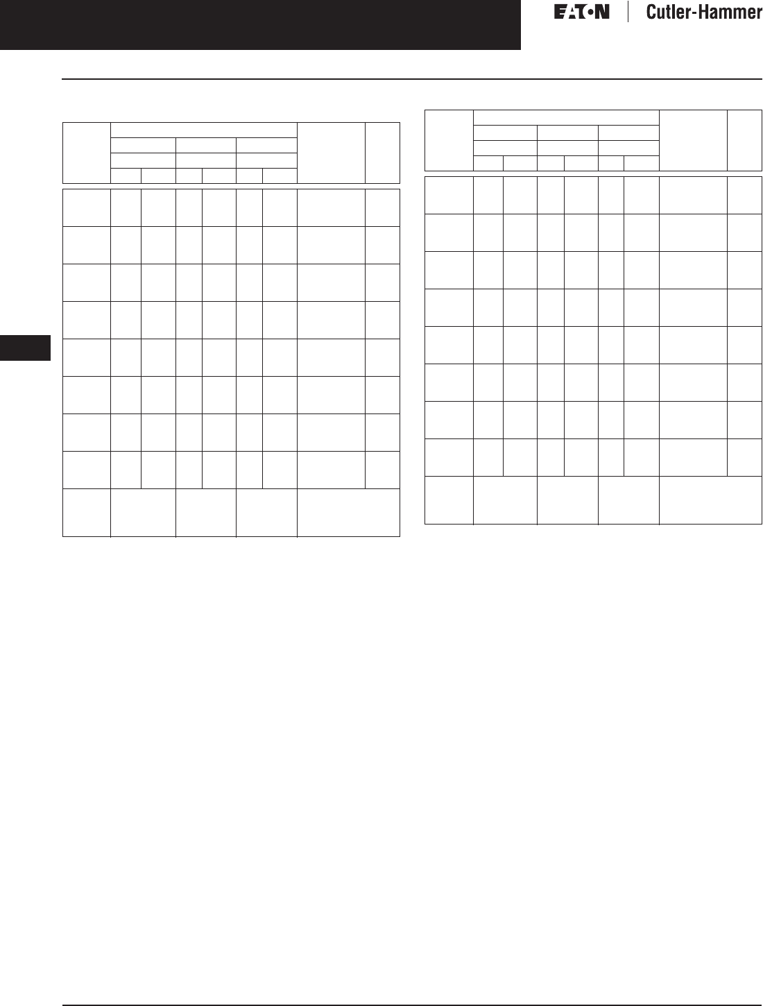
November 2003
9-88
For more information visit: www.cutler-hammer.eaton.com CA08101001E
Transformers
9
Buck-Boost Transformers
Autotransformer Applications Vol. 1, Ref. No. [0388]
Table 9-100. Three-Phase Open Delta Connection 480 Volt Output
Required, 60 Hz
Additional wiring trough may be required.
On transformers supplied with standard taps, taps must be placed at
nominal settings.
Refer to Page 9-74 for Buck-Boost wiring diagrams.
Table 9-101. Single-Phase 480 Volt Output Required, 60 Hz
Additional wiring trough may be required.
On transformers supplied with standard taps, taps must be placed at
nominal settings.
Refer to Page 9-74 for Buck-Boost wiring diagrams.
Note: Autotransformers can be used only where local electric codes
permit and isolation of the two circuits is not required.
Note: Output voltage for lower input voltage can be found by: x Input Actual Voltage = Output New Voltage.
Note: Output kVA available at reduced input voltage can be found by: x Output kVA = New kVA Rating.
Units
Required
Input Available Voltage Style
Number
Price
U.S.
600 575 575
Output Output Output
kVA Amps kVA Amps kVA Amps
2
2
2
4.3
—
6.5
5.1
—
7.8
—
—
—
—
—
—
—
4.1
—
—
4.9
—
S20N11S51N
S60G11S51N
S20N11S76N
170.
255.
220.
2
2
2
—
8.6
—
—
10.3
—
—
—
—
—
—
—
6.2
—
8.3
7.4
—
9.9
S60G11S76N
S20N11S01N
S60G11S01N
330.
260.
390.
2
2
2
13.0
—
17.2
15.6
—
20.6
—
—
—
—
—
—
—
12.4
—
—
14.9
—
S20N11S16N
S60G11S16N
S20N11S02N
320.
475.
410.
2
2
2
—
25.8
—
—
31
—
—
—
—
—
—
—
16.5
—
24.8
19.8
—
29.8
S60G11S02N
S20N11S03N
S60G11S03N
610.
500.
740.
2
2
2
43.2
—
65
51.9
—
78.1
—
—
—
—
—
—
—
41
—
—
49.3
—
S20N11S05N
S60G11S05N
S20N11S07N
740.
1,110.
980.
2
2
2
—
86
—
—
103.4
—
—
—
83
—
—
99.8
62
—
—
74.5
—
—
S60G11S07N
S20N11S10N
S60G11S10N
1,460.
1,180.
1,760.
2
2
2
130
—
216
156.3
—
259.8
—
124
—
—
149.1
—
—
—
—
—
—
—
S20N11S15N
S60N11S15N
T20P11S25
1,540.
2,400.
1,870.
2
2
2
—
324
432
—
389.7
519.6
207
—
—
248.9
—
—
—
—
—
—
—
—
S60J11S25N
T20P11S37
T20P11S50
2,825.
2,290.
3,220.
Connec-
tion
Diagram
IJT
Units
Required
Input Available Voltage Style
Number
Price
U.S.
600 575 575
Output Output Output
kVA Amps kVA Amps kVA Amps
1
1
1
2.5
—
3.7
5.2
—
7.7
—
—
—
—
—
—
—
2.4
—
—
5
—
S20N11S51N
S60G11S51N
S20N11S76N
170.
255.
220.
1
1
1
—
5.0
—
—
10.4
—
—
—
—
—
—
—
3.6
—
4.8
7.5
—
10
S60G11S76N
S20N11S01N
S60G11S01N
330.
260.
390.
1
1
1
7.5
—
10
15.6
—
20.8
—
—
—
—
—
—
—
7.2
—
—
15
—
S20N11S16N
S60G11S16N
S20N11S02N
320.
475.
410.
1
1
1
—
15
—
—
31.2
—
—
—
—
—
—
—
9.6
—
14.3
20
—
29.7
S60G11S02N
S20N11S03N
S60G11S03N
610.
500.
740.
1
1
1
25
—
37.5
52
—
78.1
—
—
—
—
—
—
—
24
—
—
50
—
S20N11S05N
S60G11S05N
S20N11S07N
740.
1,110.
980.
1
1
1
—
50
—
—
104.1
—
—
—
43
—
—
100
36
—
—
75
—
—
S60G11S07N
S20N11S10N
S60G11S10N
1,460.
1,180.
1,760.
1
1
1
75
—
125
156.2
—
260.4
—
72
—
—
150
—
—
—
—
—
—
—
S20N11S15N
S60N11S15N
T20P11S25
1,540.
2,400.
1,870.
1
1
1
—
187
250
—
389.6
520.8
120
—
—
250
—
—
—
—
—
—
—
—
S60J11S25N
T20P11S37
T20P11S50
2,825.
2,290.
3,220.
Connec-
tion
Diagram
EHU
Rated Output Voltage
Rated Input Voltage
--------------------------------------------------
Actual Input Voltage
Rated Input Voltage
------------------------------------------------
Discount Symbol . . . . . . . . . . . . . . . . . . . . . . . . . DT-1
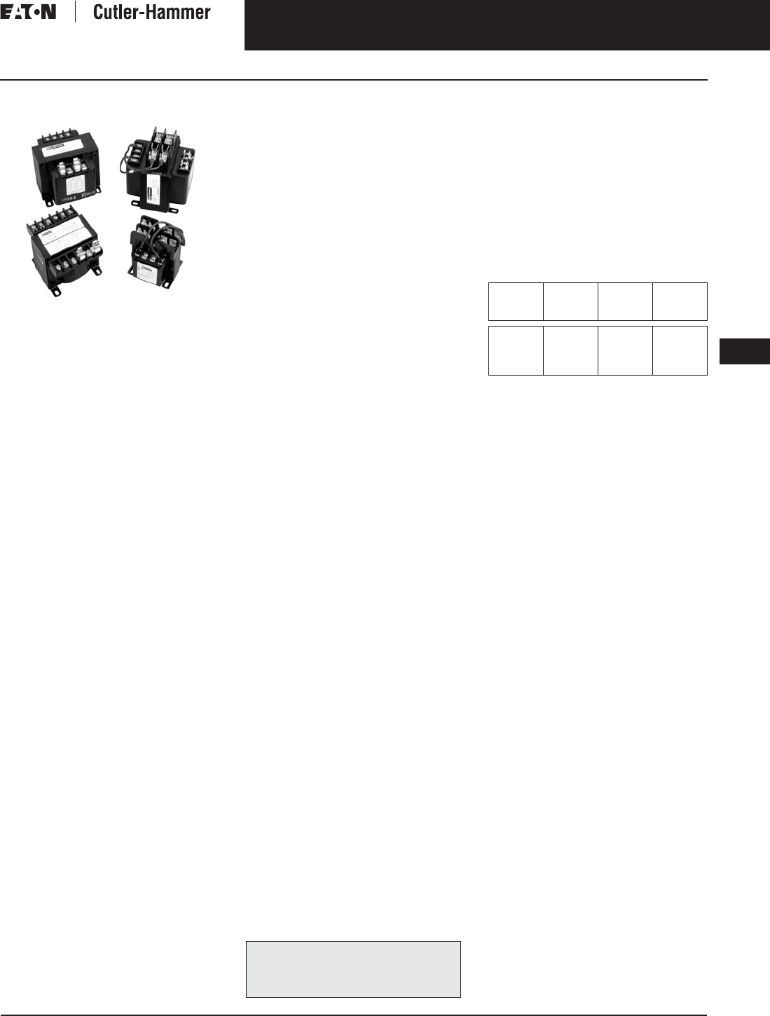
November 2003
CA08101001E For more information visit: www.cutler-hammer.eaton.com
9-89
Transformers
9
Industrial Control Transformers
Type MTA
Vol. 1, Ref. No. [0389]
Type MTA
Type MTA Transformer
Product Description
■Varnish impregnated core and
coil design.
■Suitable for indoor applications.
■Open core and coil design.
Application Description
Machine Tool and Industrial Control
Transformers provide stepped-down
voltages to machine tool control
devices enabling control circuits to
be isolated from all power and lighting
circuits. This allows the use of ground-
ed or ungrounded circuits that are
independent of the power or lighting
grounds; greater safety is afforded the
operator. The control transformer line
is particularly adaptable on applica-
tions where compact construction
is demanded.
Features, Benefits
and Functions
■UL recognized component for units
rated 1000 VA and below.
■CSA certified for units rated 1000 VA
and below.
■55ºC rise, 105ºC insulation system.
■60 Hz operation standard.
■100% tested to verify product quality.
■Performance equals or exceeds
requirements of ANSI/NEMA ST-1.
■Regulation exceeds ANSI/NEMA
requirements for all ratings.
■Each unit must pass rigid tests for
turns ratio, insulation, continuity,
and over potential.
■50 – 5000 VA ratings.
Standards and Certifications
Industry Standards
All Cutler-Hammer dry-type distribu-
tion and control transformers by Eaton
Corporation are built and tested in
accordance with applicable NEMA,
ANSI, and IEEE Standards.
Product Specifications
Frequency
Cutler-Hammer Type MTA control
transformers are designed for 60 Hertz
operation. Transformers required for
other frequencies are available and
must be specifically designed.
Insulation System and Temperature Rise
Industry standards classify insulation
systems and rise as shown below:
Table 9-102. Insulation System Classification
The design life of transformers having
different insulation systems is the
same — the lower temperature systems
are designed for the same life as the
higher temperature systems.
Series-Multiple Windings
Series-multiple windings consist of
2 similar coils in each winding which
can be connected in series or parallel
(multiple). Transformers with series-
multiple windings are designated with
an “X” or “/” between the voltage
ratings, such as voltages of “120/240”
or “240 X 480.” If the series-multiple
winding is designated by an “X,” the
winding can be connected only for a
series or parallel. With the “/” designa-
tion, a mid-point also becomes avail-
able in addition to the series or parallel
connection. As an example, a 120 X
240 winding can be connected for
either 120 (parallel) or 240 (series), but
a 120/240 winding can be connected
for 120 (parallel), or 240 (series), or 240
with a 120 mid-point.
Technical Data
and Specifications
Please refer to Page 9-122.
The following pages provide listings for most
standard transformer ratings and styles.
For other ratings or styles not shown, refer
to Eaton’s Cutler-Hammer business.
Ambient +
Winding
Rise
+
Hot
Spot
=
Temp.
Class
40°C
40°C
40°C
40°C
55°C
80°C
115°C
150°C
10°C
30°C
30°C
30°C
105°C
150°C
185°C
220°C
November 2003
9-90
For more information visit: www.cutler-hammer.eaton.com CA08101001E
Transformers
9
Industrial Control Transformers
Type MTA Vol. 1, Ref. No. [0390]
Overcurrent Protection Tables
Overcurrent protection on both the primary and secondary sides of transformers are specified in UL 508 and the National
Electrical Code. The maximum acceptable ratings are shown below. Due to high inrush currents present when a transformer
is initially energized, it is recommended that the primary fuse be time delay to prevent nuisance trips during startup.
Table 9-103. Maximum Acceptable Rating of Primary Overcurrent Protection
Note: If the rated primary current is less than 2 amperes, the maximum rating of the overcurrent device is 300% for power circuits, shown
above, or 500% for control circuits, shown above (in brackets). If the rated primary current is 2 amperes or more, the maximum rating of the
overcurrent device is 250%. All figures assume secondary overcurrent protection per NEC/UL.
References: NEC 430-72 (c) exception 2, 450-3 (b) 1 & 2, UL 508 32.7, UL 845 11.16 and 11.17.
Table 9-104. Maximum Acceptable Rating of Secondary Overcurrent Protection
Note: If the rated secondary current is less than 9 amperes, the maximum rating of the overcurrent device is 167%; 9 amperes or more, the maximum
rating of the overcurrent device is 125%. If 125% does not correspond to a standard fuse rating, the next highest standard rating may be used.
References: NEC 430-72 (c) exception 2, 450-3 (b) 1 & 2, UL 508 32.7, UL 845 11.16 and 11.17.
Primary
Voltage
VA Rating
25 50 75 100 150 200 250 300 350 500 750 1000 1500 2000 3000 5000 7000
115 6/10
(1)
1-1/4
(2)
1-8/10
(3-2/10)
2-1/2
(4)
3-1/2
(6-1/4)
5
(8)
455810152025———
120 6/10
(1)
1-1/4
(2)
1-8/10
(3)
2-1/4
(4)
3-1/2
(6-1/4)
5
(8)
455810151520———
200 3/10
(6/10)
3/4
(1-1/4)
1-1/8
(1-8/10)
1-1/2
(2-1/2)
2-1/4
(3-1/2)
3
(5)
3-1/2
(6-1/4)
4-1/2
(7-1/2)
5
(8)
4-1/2 7 9 15 15 20 — —
208 3/10
(6/10)
6/10
(1-1/8)
1
(1-8/10)
1-4/10
(2-1/4)
2
(3-1/2)
2-8/10
(4-1/2)
3-1/2
(6)
4
(7)
5
(8)
46812152030—
220 3/10
(1/2)
6/10
(1-1/8)
1
(1-6/10)
1-1/4
(2-1/4)
2
(3-2/10)
2-1/2
(4-1/2)
3-2/10
(5-6/10)
4
(6-1/4)
4-1/2
(7-1/2)
46812152030—
230 3/10
(1/2)
6/10
(1)
8/10
(1-6/10)
1-1/4
(2)
1-8/10
(3-2/10)
2-1/2
(4)
3-2/10
(5)
3-1/2
(6-1/4)
4-1/2
(7-1/2)
46810152030—
240 3/10
(1/2)
6/10
(1)
8/10
(1-1/2)
1-1/4
(2)
1-8/10
(3)
2-1/4
(4)
3
(5)
3-1/2
(6-1/4)
4
(7)
3-1/2 5 7 10 15 20 30 —
277 1/4
(4/10)
1/2
(8/10)
8/10
(1-1/4)
1
(1-8/10)
1-6/10
(2-1/2)
2
(3-1/2)
2-1/2
(4-1/2)
3-2/10
(5)
3-1/2
(6-1/4)
5
(9)
569121525—
380 3/16
(3/10)
3/10
(6/10)
1/2
(8/10)
3/4
(1-1/4)
1-1/8
(1-8/10)
1-1/2
(2-1/2)
1-8/10
(3-2/10)
2-1/4
(3-1/2)
2-1/2
(4-1/2)
3-1/2
(6-1/4)
5-6/10
(9)
4-1/2 6-1/4 9 15 20 25
400 3/16
(3/10)
3/10
(6/10)
1/2
(8/10)
3/4
(1-1/4)
1-1/8
(1-8/10)
1-1/2
(2-1/2)
1-8/10
(3)
2-1/4
(3-1/2)
2-1/2
(4)
3-1/2
(6-1/4)
5-6/10
(9)
4-1/2 6-1/4 9 12 15 20
416 15/100
(3/10)
3/10
(6/10)
1/2
(8/10)
6/10
(1-1/8)
1
(1-8/10)
1-4/10
(2-1/4)
1-8/10
(3)
2
(3-1/2)
2-1/2
(4)
3-1/2
(6)
5
(9)
468121520
440 15/100
(1/4)
3/10
(1/2)
1/2
(8/10)
6/10
(1-1/8)
1
(1-6/10)
1-1/4
(2-1/4)
1-6/10
(2-8/10)
2
(3-2/10)
2-1/4
(3-1/2)
3-2/10
(5)
5
(8)
468121520
460 15/100
(1/4)
3/10
(1/2)
4/10
(8/10)
6/10
(1)
8/10
(1-1/2)
1-1/4
(2)
1-6/10
(2-1/2)
1-8/10
(3-2/10)
2-1/4
(3-2/10)
3-2/10
(5)
4-1/2
(8)
3-1/2 6 8 12 15 20
480 15/100
(1/4)
3/10
(1/2)
4/10
(3/4)
6/10
(1)
8/10
(1-1/2)
1-1/4
(2)
1-1/2
(2-1/2)
1-8/10
(3)
2
(3-1/2)
3
(5)
4-1/2
(7-1/2)
3-1/2 5 7 10 15 20
550 1/8
(2/10)
1/4
(4/10)
4/10
(6/10)
1/2
(8/10)
8/10
(1-1/4)
1
(1-8/10)
1-1/4
(2-1/4)
1-6/10
(2-1/2)
1-8/10
(3)
2-1/2
(4-1/2)
4
(6-1/4)
54-1/2 6 9 15 15
575 1/8
(2/10)
1/4
(4/10)
3/10
(6/10)
1/2
(8/10)
3/4
(1-1/4)
1
(1-6/10)
1-1/4
(2)
1-1/2
(2-1/2)
1-8/10
(3)
2-1/2
(4)
3
(6-1/4)
54-1/2 6 9 15 15
600 1/8
(2/10)
2/10
(4/10)
3/10
(6/10)
1/2
(8/10)
3/4
(1-1/4)
8/10
(1-6/10)
1-1/4
(2)
1-1/2
(2-1/2)
1-6/10
(2-8/10)
2-1/4
(4)
3-1/2
(6-1/4)
54691515
Secondary
Voltage
VA Rating
25 50 75 100 150 200 250 300 350 500 750 1000 1500 2000 3000 5000
12
24
3-1/2
1-6/10
7
3-2/10
10
5
15
6-1/4
20
10
30
12
—
15
—
20
—
20
—
30
—
—
—
—
—
—
—
—
—
—
—
—
90
95
100
4/10
4/10
4/10
8/10
8/10
8/10
1-1/4
1-1/4
1-1/4
1-8/10
1-6/10
1-6/10
2-1/2
2-1/2
2-1/2
3-1/2
3-1/2
3-2/10
4-1/2
4
4
5
5
5
6-1/4
6
5-6/10
9
8
8
12
12
12
15
15
15
30
20
20
30
30
30
—
—
—
—
—
—
110
115
120
3/10
3/10
3/10
3/4
6/10
6/10
1-1/8
1
1
1-1/2
1-4/10
1-1/4
2-1/4
2
2
3
2-8/10
2-1/2
3-1/2
3-1/2
3-2/10
4-1/2
4
4
5
5
4-1/2
7-1/2
7
6-1/4
10
10
10
15
15
15
20
20
20
30
30
20
—
—
—
—
—
—
220
230
240
15/100
15/100
15/100
3/10
3/10
3/10
1/2
1/2
1/2
3/4
6/10
6/10
1-1/8
1
1
1-1/2
1-4/10
1-1/4
1-8/10
1-8/10
1-6/10
2-1/4
2
2
2-1/2
2-1/2
2-1/2
3-1/2
3-1/2
3-2/10
5-6/10
5
5
7
7
7
9
8
8
15
15
12
20
20
20
30
30
30

November 2003
CA08101001E For more information visit: www.cutler-hammer.eaton.com
9-91
Transformers
9
Industrial Control Transformers
Types MTA, MTC and AP
Vol. 1, Ref. No. [0391]
Wiring Diagrams
Type MTA and MTC Control Transformers
Table 9-105. Wiring for Diagram 1
Figure 9-3. Diagram 1
Table 9-106. Wiring for Diagram 2
Figure 9-4. Diagram 2
Table 9-107. Wiring for Diagram 3
Figure 9-5. Diagram 3
Table 9-108. Wiring for Diagram 4
Figure 9-6. Diagram 4
Type AP Control Transformers
Table 9-109. Wiring for Diagram 5
Figure 9-7. Diagram 5
Volts Connect Lines
AB
460
230
—
—
H2 to H3
H1 to H3 and H2 to H4
H1-H4
H1-H4
115 — — X1-X2
Volts Connect Lines
AB
575
460
230
—
416
380
—
208
H2 to H3
H2 to H3
H1 to H3 and H2 to H4
H1 to H3 and H2 to H5
H1-H5
H1-H4
H1-H4
H1-H5
115
95
115
95
—
—
X1-X3
X1-X2
H1 H3 H2 H4
X2 X1
H1 H3 H2 H5
X3 X1
H4
X2
Volts Connect Lines
AB
460
230
—
—
H2 to H3
H1 to H3 and H2 to H4
H1-H4
H1-H4
230
115
—
—
X2 to X3
X1 to X3 and X2 to X4
X1-X4
X1-X4
Volts Connect Lines
AB
115 115 — H1-H2
12 24 — X1-X2
H1 H3 H2 H4
X4 X2 X3 X1
H1 H2
X2 X1
Volts Connect Lines
AB
480
240
—
—
H2 to H3
H1 to H3 and H2 to H4
H1-H4
H1-H4
240
115
—
—
X2 to X3
X1 to X3 and X2 to X4
X1-X4
X1-X4
H1 H3 H2 H4
X4 X2 X3 X1

November 2003
9-92
For more information visit: www.cutler-hammer.eaton.com CA08101001E
Transformers
9
Industrial Control Transformers
Type MTA Vol. 1, Ref. No. [0392]
Product Selection
Additional Product Selection information begins on Page 9-136.
Table 9-110. Type MTA
See Page 9-91 for Wiring Diagrams.
Note: For additional information refer to the Cutler-Hammer Industrial Control Transformer Binder B1228A.
VA Dimensions (Inches) Weight
Lbs.
Dimensions (mm) Weight
kg
Frame Wiring
Diagram
Style
Number
Price
U.S.
Height Width Depth Height Width Depth
230/460 Volts to 115 Volts, 60 Hz
50 (Use Type MTC – C0050C2A)
75
100
3-3/16
3-3/16
3-3/4
3-3/4
3-3/4
4
3
4
80
80
95
95
95
102
1.4
1.8
FR1510
FR1512
1
1
C0075A2F
C0100A2F
74.00
76.50
150
200
250
3-3/16
3-13/16
3-13/16
3-3/4
4-1/2
4-1/2
4-3/4
4-1/2
5
6
7
8
80
96
96
95
114
114
95
114
127
2.7
3.2
3.6
FR1520
FR1714
FR1717
1
1
1
C0150A2F
C0200A2F
C0250A2F
88.00
110.00
131.00
300
350
500
3-13/16
3-13/16
4-3/8
4-1/2
4-1/2
5-1/4
5-1/2
6
5-5/8
10
12
15
96
96
111
114
114
133
139
152
143
4.5
5.4
6.8
FR1723
FR1727
FR1923
1
1
1
C0300A2F
C0350A2F
C0500A2F
143.00
154.00
189.00
750
1000
1500
4-3/8
5-1/4
6
5-1/4
6-1/8
6-7/8
6-1/8
6-3/4
7-1/2
19
19
27
111
133
152
133
155
174
155
171
190
8.6
8.6
12.3
FR1931
FRC613
FRC614
1
1
1
C0750A2F
C1000A2F
C1500A2F
249.00
396.00
521.00
2000
3000
5000
5-7/8
6-1/2
7-5/8
6-7/8
8-3/16
8-15/16
8-1/2
8-3/4
10-1/4
36
52
79
149
165
193
174
207
227
215
222
260
16.3
23.6
35.8
FRC827
FRC828
FRC829
1
1
1
C2000A2F
C3000A2F
C5000A2F
624.00
835.00
1,320.00
230/460 Volts to 115/230 Volts, 60 Hz
50
75
100
2-19/32
3-3/16
3-3/16
3
3-3/4
3-3/4
3-1/4
3-3/4
4
2
3
4
65
80
80
76
95
95
82
95
102
.9
1.4
1.8
FR1310
FR1510
FR1512
3
3
3
C0050A2G
C0075A2G
C0100A2G
94.00
102.00
110.00
150
200
250
3-3/16
3-13/16
3-13/16
3-3/4
4-1/2
4-1/2
4-3/4
4-1/2
5
6
7
8
80
96
96
95
114
114
95
114
127
2.7
3.2
3.6
FR1520
FR1714
FR1717
3
3
3
C0150A2G
C0200A2G
C0250A2G
121.00
137.00
154.00
300
350
500
3-13/16
3-13/16
4-3/8
4-1/2
4-1/2
5-1/4
6
6
6-1/4
10
12
15
96
96
111
114
114
133
152
152
158
4.5
5.4
6.8
FR1727
FR1727
FR1930
3
3
3
C0300A2G
C0350A2G
C0500A2G
165.00
177.00
210.00
750
1000
1500
5-1/4
5-1/4
6
6-1/8
6-1/8
6-7/8
6-3/4
6-3/4
7-1/2
19
19
27
133
133
152
155
155
174
171
171
190
8.6
8.6
12.3
FRC613
FRC613
FRC614
3
3
3
C0750A2G
C1000A2G
C1500A2G
269.00
409.00
542.00
2000
3000
5000
5-7/8
6-1/2
5-5/8
6-7/8
8-3/16
8-15/16
8-1/2
8-3/4
10-1/4
36
52
79
149
165
193
174
207
227
215
222
260
16.3
23.6
35.8
FRC827
FRC828
FRC829
3
3
3
C2000A2G
C3000A2G
C5000A2G
650.00
865.00
1,390.00
For other ratings or styles not shown, refer
to Eaton’s Cutler-Hammer business. Discount Symbol . . . . . . . . . . . . . . . . . . . . . . . . . DT-1

November 2003
CA08101001E For more information visit: www.cutler-hammer.eaton.com
9-93
Transformers
9
Industrial Control Transformers
Type MTA
Vol. 1, Ref. No. [0393]
Table 9-111. Type MTA
See Page 9-91 for Wiring Diagrams.
Note: For additional information refer to the Cutler-Hammer Industrial Control Transformer Binder B1228A.
VA Dimensions (Inches) Weight
Lbs.
Dimensions (mm) Weight
kg
Frame Wiring
Diagram
Style
Number
Price
U.S.
Height Width Depth Height Width Depth
230/460/575 Volts to 115/95 Volts, 50/60 Hz
50
75
100
2-19/32
3-3/16
3-3/16
3
3-3/4
3-3/4
3-3/4
4
4 3/4
2
4
5
98
80
80
76
95
95
95
102
120
1.5
1.8
2.7
FR1314
FR1512
FR1517
2A
2A
2A
C0050A3C
C0075A3C
C0100A3C
94.
102.
110.
150
200
250
3-13/16
3-13/16
3-13/16
4-1/2
4-1/2
4-1/2
4-1/2
5
5-1/2
7
8
10
96
96
96
114
114
114
114
127
139
3.2
3.6
4.5
FR1714
FR1717
FR1723
2A
2A
2A
C0150A3C
C0200A3C
C0250A3C
121.
137.
169.
300
350
500
3-13/16
4-3/8
4-3/8
4-1/2
5-1/4
5-1/4
6
5-5/8
6-1/8
12
14
17
96
111
111
114
133
133
152
143
155
5.4
6.8
8.6
FR1730
FR1923
FR1931
2A
2A
2A
C0300A3C
C0350A3C
C0500A3C
176.
194.
246.
750
1000
1500
4-3/8
6
5-7/8
5-1/4
6-7/8
6-7/8
7-3/4
7-1/2
8-1/2
27
24
34
111
152
149
133
174
174
196
190
215
12.3
10.9
15.4
FR1943
FRC614
FRC827
2A
2A
2A
C0750A3C
C1000A3C
C1500A3C
280.
568.
753.
115 Volts to 24 Volts, 50/60 Hz
50
100
200
2-19/32
3-3/16
3-13/16
3
3-3/4
4-1/2
3-3/4
4-1/8
4-1/2
2
5
7
65
80
96
76
95
114
82
104
114
.9
2.3
3.2
FR1310
FR1513
FR1714
4B
4B
4B
C0050A3B
C0100A3B
C0200A3B
97.
116.
137.
208/380/416 Volts to 115/95 Volts, 50/60 Hz
50
100
150
200
2-19/32
3-3/16
3-13/16
3-13/16
3
3-3/4
4-1/2
4-1/2
3-3/4
4-3/4
4-1/2
5
3
5
7
8
98
80
96
96
76
95
114
114
95
120
114
127
1.5
2.3
3.2
3.6
FR1314
FR1516
FR1714
FR1717
2B
2B
2B
2B
C0050A3D
C0100A3D
C0150A3D
C0200A3D
94.
110.
121.
137.
250
300
500
3-13/16
3-13/16
4-3/8
4-1/2
4-1/2
5-1/4
5-1/2
6
6-1/8
10
13
18
96
96
111
114
114
133
139
152
155
4.5
5.4
8.6
FR1723
FR1730
FR1931
2B
2B
2B
C0250A3D
C0300A3D
C0500A3D
169.
176.
246.
750
1000
1500
4-3/8
6
5-7/8
5-1/4
6-7/8
6-7/8
7-3/4
7-1/2
8-1/2
27
25
33
111
152
149
133
174
174
196
190
215
12.3
10.9
15.4
FR1943
FRC614
FRC827
2B
2B
2B
C0750A3D
C1000A3D
C1500A3D
280.
555.
753.
For other ratings or styles not shown, refer
to Eaton’s Cutler-Hammer business. Discount Symbol . . . . . . . . . . . . . . . . . . . . . . . . . DT-1
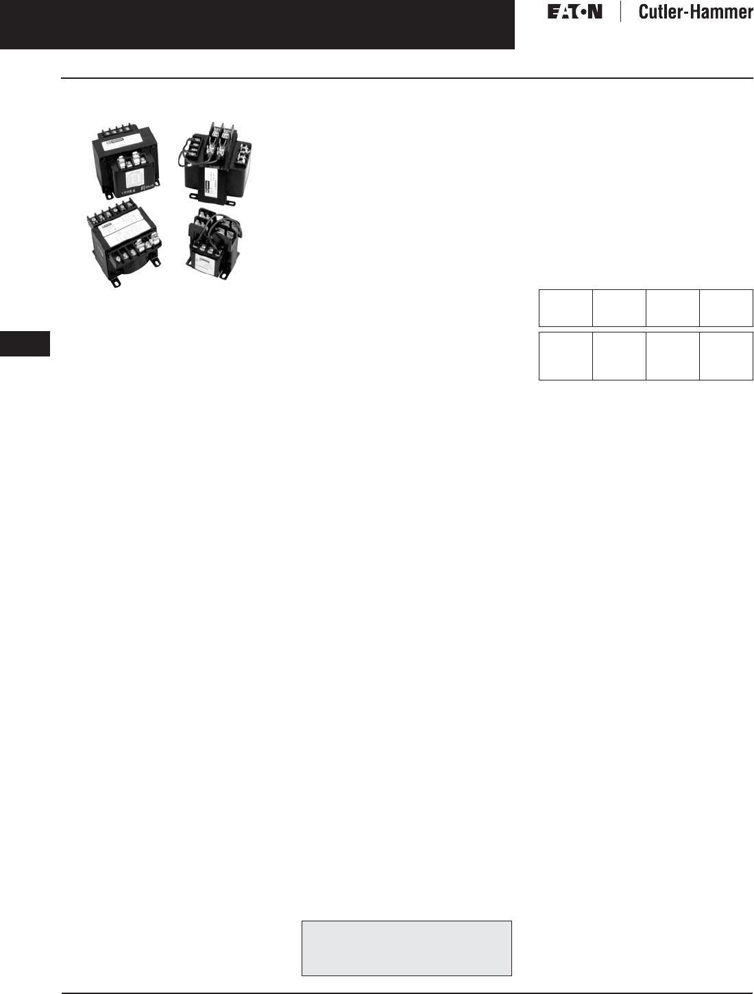
November 2003
9-94
For more information visit: www.cutler-hammer.eaton.com CA08101001E
Transformers
9
Industrial Control Transformers
Type MTC Vol. 1, Ref. No. [0394]
Type MTC
Type MTC Transformers
Product Description
■Varnish impregnated core and
coil design.
■Suitable for indoor applications.
Application Description
Transformers provide stepped down
voltages to machine tool control
devices enabling control circuits to be
isolated from all power and lighting
circuits. This allows the use of
grounded or ungrounded circuits that
are independent of the power or light-
ing grounds; greater safety is afforded
the operator. The control transformer
line is particularly adaptable on appli-
cations where compact construction
is demanded. The MTC line is similar
to the MTA line except it provides
increased regulation.
Features, Benefits
and Functions
■Designed specifically for loads
requiring extremely good regulation
— 10% – 200% better regulation
than Type MTA.
■UL recognized component for units
rated 1000 VA and below.
■CSA certified for units rated 1000 VA
and below.
■50/60 Hz operation standard.
■100% tested to verify product quality.
■Each unit must pass rigid tests for
turns ratio, insulation, continuity,
and over potential.
■Performance equals or exceeds
requirements of ANSI/NEMA ST-1.
■Regulation exceeds ANSI/NEMA
requirements for all ratings.
■50 – 5000 VA ratings.
■55ºC rise, 105ºC insulation system.
Standards and Certifications
Industry Standards
All Cutler-Hammer dry-type distribu-
tion and control transformers by Eaton
Corporation are built and tested in
accordance with applicable NEMA,
ANSI, and IEEE Standards.
Product Specifications
Frequency
Cutler-Hammer standard dry-type dis-
tribution transformers are designed
for 60 Hz operation. Transformers
required for other frequencies are
available and must be specifically
designed.
Insulation System and Temperature Rise
Industry standards classify insulation
systems and rise as shown below:
Table 9-112. Insulation System Classification
The design life of transformers having
different insulation systems is the
same — the lower temperature systems
are designed for the same life as the
higher temperature systems.
Series-Multiple Windings
Series-multiple windings consist of 2
similar coils in each winding which
can be connected in series or parallel
(multiple). Transformers with series-
multiple windings are designated with
an “X” or “/” between the voltage
ratings, such as voltages of “120/240”
or “240 X 480.” If the series-multiple
winding is designated by an “X,” the
winding can be connected only for a
series or parallel. With the “/” designa-
tion, a mid-point also becomes avail-
able in addition to the series or parallel
connection. As an example, a 120 X
240 winding can be connected for
either 120 (parallel) or 240 (series), but
a 120/240 winding can be connected
for 120 (parallel), or 240 (series), or 240
with a 120 mid-point.
Technical Data
and Specifications
Please refer to Page 9-122.
The following pages provide listings for most
standard transformer ratings and styles.
For other ratings or styles not shown, refer
to Eaton’s Cutler-Hammer business.
Ambient +
Winding
Rise
+
Hot
Spot
=
Temp.
Class
40°C
40°C
40°C
40°C
55°C
80°C
115°C
150°C
10°C
30°C
30°C
30°C
105°C
150°C
185°C
220°C

November 2003
CA08101001E For more information visit: www.cutler-hammer.eaton.com
9-95
Transformers
9
Industrial Control Transformers
Type MTC
Vol. 1, Ref. No. [0395]
Product Selection
Additional Product Selection information begins on Page 9-136.
Table 9-113. Type MTC
See Page 9-91 for Wiring Diagrams.
Note: For additional information refer to the Cutler-Hammer Industrial Control Transformer Binder B1228A.
Table 9-114. Type MTC with Integrally Mounted 30 Amperes, 600 volt Class with 2-Pole Primary Fuse Block for Rejection Type Fuses
(Fuses Not Included)
See Page 9-91 for Wiring Diagrams.
Note: For additional information refer to the Cutler-Hammer Industrial Control Transformer Binder B1228A.
VA Dimensions (Inches) Weight
Lbs.
Dimensions (mm) Weight
kg
Frame Wiring
Diagram
Style
Number
Price
U.S.
Height Width Depth Height Width Depth
240/480 Volts to 120 Volts, 60 Hz
230/460 Volts to 115 Volts, 50/60 Hz
220/440 Volts to 110 Volts, 50/60 Hz
50
75
100
2-19/32
2-19/32
2-7/8
3
3
3-3/8
3-3/4
3-3/4
4
2
3
3
66
66
73
76
76
86
95
95
102
.9
1.4
1.4
FR1310
FR1314
FR1413
1
1
1
C0050C2A
C0075C2A
C0100C2A
67.00
78.50
84.00
150
200
250
3-3/16
3-13/16
3-13/16
3-3/4
4-1/2
4-1/2
4-3/4
4-1/2
5
6
7
8
81
97
97
95
114
114
121
114
127
2.7
3.2
3.6
FR1517
FR1714
FR1717
1
1
1
C0150C2A
C0200C2A
C0250C2A
100.00
116.00
144.00
300
350
500
3-13/16
3-13/16
4-3/8
4-1/2
4-1/2
5-1/4
5-3/8
6
6-1/8
10
11
20
97
97
111
114
114
133
137
152
156
4.5
5.0
9.1
FR1722
FR1726
FR1931
1
1
1
C0300C2A
C0350C2A
C0500C2A
154.00
169.00
206.00
750
1000
1500
4-3/8
5-7/16
6-1/8
5-1/4
6-3/8
6-7/8
7-3/4
7-1/2
8-3/8
28
34
35
111
138
156
133
162
175
197
191
213
12.7
15.4
15.9
FR1934
FR2236
FRC822
1
1
1
C0750C2A
C1000C2A
C1500C2A
272.00
402.00
564.00
2000
3000
5000
6
7-3/8
7-7/8
6-3/4
8-7/16
8-11/16
8-1/2
8-3/4
11
38
53
82
152
187
200
171
214
221
216
222
279
17.3
24.1
37.2
FRC823
FRC824
FRC825
1
1
1
C2000C2A
C3000C2A
C5000C2A
676.00
934.00
1,445.00
VA Dimensions (Inches) Weight
Lbs.
Dimensions (mm) Weight
kg
Frame Wiring
Diagram
Style
Number
Price
U.S.
Height Width Depth Height Width Depth
240/480 Volts to 120 Volts, 60 Hz
230/460 Volts to 115 Volts, 50/60 Hz
220/440 Volts to 110 Volts, 50/60 Hz
50
75
100
150
3-7/8
3-7/8
4-5/32
4-15/32
3
3
3-3/8
3-3/4
3-3/4
3-3/4
4
4-3/4
2.2
3.2
3.2
6.2
98
98
106
114
76
76
86
95
83
95
102
121
1.0
1.5
1.5
2.8
FR1310
FR1314
FR1413
FR1517
1
1
1
1
C0050C2AFB
C0075C2AFB
C0100C2AFB
C0150C2AFB
88.00
101.00
106.00
123.00
200
250
300
5-3/32
5-3/32
5-3/32
4-1/2
4-1/2
4-1/2
4-1/2
5
5-3/8
7.2
8.2
10.2
129
129
129
114
114
114
114
127
137
3.3
3.7
4.7
FR1714
FR1717
FR1722
1
1
1
C0200C2AFB
C0250C2AFB
C0300C2AFB
138.00
166.00
176.00
350
500
750
5-3/32
5-21/32
5-21/32
4-1/2
5-1/4
5-1/4
6
6-1/8
7-3/4
11.2
20.2
28.2
129
144
144
114
133
133
152
156
197
5.1
9.2
12.8
FR1726
FR1931
FR1934
1
1
1
C0350C2AFB
C0500C2AFB
C0750C2AFB
191.00
227.00
294.00
1000
1500
2000
6-23/32
7-13/32
7-9/32
6-3/8
6-7/8
6-3/4
7-1/2
8-3/8
8-1/2
34.2
35.2
38.2
171
188
185
162
175
171
191
213
216
15.5
16.0
17.4
FR2236
FRC822
FRC823
1
1
1
C1000C2AFB
C1500C2AFB
C2000C2AFB
424.00
585.00
697.00
Discount Symbol . . . . . . . . . . . . . . . . . . . . . . . . . DT-1
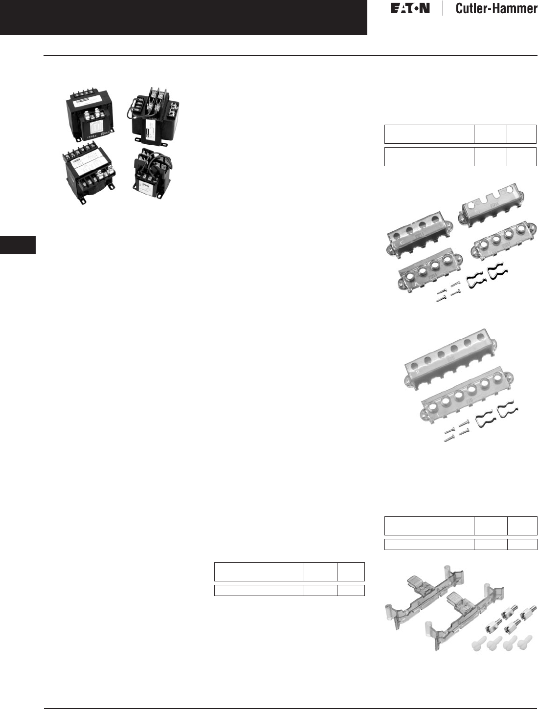
November 2003
9-96
For more information visit: www.cutler-hammer.eaton.com CA08101001E
Transformers
9
Industrial Control Transformers
Type MTE Vol. 1, Ref. No. [0396]
Type MTE
Type MTE Transformers
Product Description
■Epoxy-encapsulated coils.
Application Description
Transformers provide stepped down
voltages to machine tool control
devices enabling control circuits to be
isolated from all power and lighting
circuits. This allows the use of
grounded or ungrounded circuits that
are independent of the power or light-
ing grounds; greater safety is afforded
the operator. The control transformer
line is particularly adaptable on appli-
cations where compact construction
is demanded.
Note: The MTG, “open core-coil design”
has been superseded by the epoxy-
encapsulated core-coil design MTE with
no change to dimensions or functionality.
Features, Benefits
and Functions
■UL listed.
■CSA certified.
■Epoxy encapsulated.
■Laminations of high quality silicon
steel to minimize core losses and
optimize performance.
■Copper magnet wire for high
quality, efficient operation.
■Secondary fuse clips where
applicable.
■Optional primary fusing.
■Molded in terminals.
■50/60 Hz operation.
■55°C rise, 105ºC insulation system.
■Performance meets/exceeds
requirements of ANSI/NEMA ST-1.
■Regulation exceeds ANSI/NEMA
requirements for all ratings.
■25 – 1500 VA ratings.
■Molded-in terminals for maximum
durability.
Standards and Certifications
Industry Standards
All Cutler-Hammer dry-type distribution
and control transformers by Eaton
Corporation are built and tested in
accordance with applicable NEMA,
ANSI, and IEEE Standards. All 600 volt
class transformers are UL listed unless
otherwise noted.
Options and Accessories
Primary Fuse Kit
The primary fuse kit includes a 2-pole
class CC fuse block, instructions, and
all associated mounting and wiring
hardware. Fuses are not included.
When installed, the primary fuse kit
will add a maximum of 11/16 inch to
the transformer depth and 1-15/16
inches to the transformer height.
Table 9-115. Primary Fuse Kit
Finger-Safe Terminal Covers (Optional)
■Fits CE marked designs 50 – 750 VA.
■Fits MTE designs.
25 – 750 VA.
Table 9-116. Finger-Safe Terminal Covers
Finger-Safe Terminal Covers — FSK4
Finger-Safe Terminal Covers — FSK6
Finger-Safe Primary Fuse Block Covers
■Fits 2-pole primary fuse blocks on
MTE designs.
Table 9-117. Finger-Safe Primary Fuse
Block Covers
Finger-Safe Primary Fuse Block Covers
Description Catalog
Number
Price
U.S. $
Primary Fuse Kit PFK1 26.
Description Catalog
Number
Price
U.S. $
4 Terminal Transformers
6 Terminal Transformers
FSK4
FSK6
24.
25.
Description Catalog
Number
Price
U.S. $
Primary Fuse Block Covers FSKFB 38.
Discount Symbol . . . . . . . . . . . . . . . . . . . . . . . . . DT-1
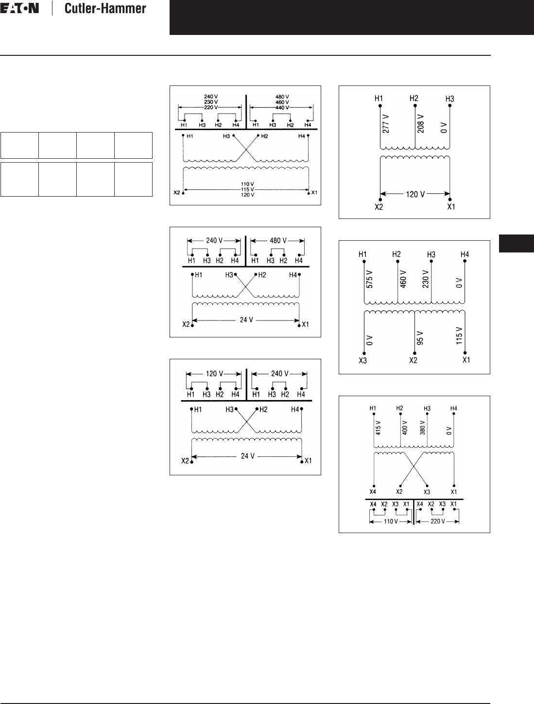
November 2003
CA08101001E For more information visit: www.cutler-hammer.eaton.com
9-97
Transformers
9
Industrial Control Transformers
Type MTE
Vol. 1, Ref. No. [0397]
Product Specifications
Insulation System and Temperature Rise
Industry standards classify insulation
systems and rise as shown below:
Table 9-118. Insulation System Classification
The design life of transformers having
different insulation systems is the
same — the lower temperature systems
are designed for the same life as the
higher temperature systems.
Series-Multiple Windings
Series-multiple windings consist of
2 similar coils in each winding which
can be connected in series or parallel
(multiple). Transformers with series-
multiple windings are designated with
an “X” or “/” between the voltage
ratings, such as voltages of “120/240”
or “240 X 480.” If the series-multiple
winding is designated by an “X,” the
winding can be connected only for a
series or parallel. With the “/” designa-
tion, a mid-point also becomes avail-
able in addition to the series or parallel
connection. As an example, a 120 X
240 winding can be connected for
either 120 (parallel) or 240 (series), but
a 120/240 winding can be connected
for 120 (parallel), or 240 (series),
or 240 with a 120 mid-point.
Technical Data
and Specifications
Please refer to Page 9-122.
Ambient +
Winding
Rise
+
Hot
Spot
=
Temp.
Class
40°C
40°C
40°C
40°C
55°C
80°C
115°C
150°C
10°C
30°C
30°C
30°C
105°C
150°C
185°C
220°C
Wiring Diagrams
Figure 9-8. Diagram 1
Figure 9-9. Diagram 2
Figure 9-10. Diagram 3
Figure 9-11. Diagram 4
Figure 9-12. Diagram 5
Figure 9-13. Diagram 6

November 2003
9-98
For more information visit: www.cutler-hammer.eaton.com CA08101001E
Transformers
9
Industrial Control Transformers
Type MTE Vol. 1, Ref. No. [0398]
Wiring Diagrams
Figure 9-14. Diagram 7
Figure 9-15. Diagram 8
Figure 9-16. Diagram 9
Figure 9-17. Diagram 10
Figure 9-18. Diagram 11
Figure 9-19. Diagram 12
Figure 9-20. Diagram 13
Figure 9-21. Diagram 14
Figure 9-22. Diagram 15
Figure 9-23. Diagram 16
H1
H
3
H2
H4
H1
H
3
H2
H4
H1
H
3
H2
H4
X4
X2
X
3
X1
X4
X2
X
3
X1
X4
X2
X
3
X1
24
0
V
480 V
240 V
12
0
V
H1
H2
X2
X1
600
V
5
7
5
V
550
V
24 V
2
3
V
22 V
H1
H2
X2
X1
42
0
V
4
00
V
380
V
24 V
2
3
V
22 V
H1
H2
H
3
H4
H
5
X
3
X2
X1
5
50
,
575
,
600 V
4
40
,
460
,
480 V
380
,
400
,
416 V
2
20
,
230
,
240 V
2
3
/
24
/
25
1
10
,
115
,
120
V
0
V
0
V
X4
X
3
X2
X1
H1
H2
H
3
H4
H
5
H
6
5
7
5
V
460
V
400
V
230
V
208
V
0
V
0
V
24 V
1
1
5
V
230
V
X4
X
3
X2
X1
H1
H2
H
3
H4
H
5
H
6
5
7
5
V
460
V
400
V
230
V
208
V
0
V
0
V
0
V
1
1
5
V
1
1
5
V
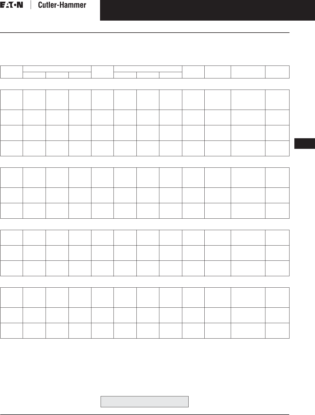
November 2003
CA08101001E For more information visit: www.cutler-hammer.eaton.com
9-99
Transformers
9
Industrial Control Transformers
Type MTE
Vol. 1, Ref. No. [0399]
Product Selection
Additional Product Selection information begins on Page 9-136.
Table 9-119. Type MTE — Product Selection
See Page 9-97 for Wiring Diagrams.
Note: For additional information refer to the Cutler-Hammer Industrial Control Transformer Binder B1228A.
VA Dimensions (Inches) Weight
Lbs.
Dimensions (mm) Weight
kg
Wiring
Diagram
Style
Number
Price
U.S. $
Height Width Depth Height Width Depth
Primary: 240 x 480, 230 x 460, 220 x 440 with Jumpers
Secondary: 120/115/110 with Fuse Clips for 13/32 x 1-1/2 Fuses
25
50
75
100
2-9/16
2-9/16
2-9/16
2-7/8
3
3
3
3-3/8
2-1/2
3
3-1/2
3-3/8
1.7
2.6
3.5
4.2
65
65
65
73
76
76
76
86
64
76
89
86
.8
1.2
1.6
1.9
1
1
1
1
C0025E2A
C0050E2A
C0075E2A
C0100E2A
72.00
53.50
64.00
69.00
150
200
250
3-3/16
3-13/16
3-13/16
3-3/4
4-1/2
4-1/2
4
4
4-3/8
6.7
8.5
10.0
81
97
97
95
114
114
102
102
111
3.0
3.9
4.5
1
1
1
C0150E2A
C0200E2A
C0250E2A
82.00
101.00
117.00
300
350
500
3-13/16
3-13/16
4-3/4
4-1/2
4-1/2
5-1/4
4-3/4
5-1/4
5-1/2
11.3
13.6
19.2
97
97
121
114
114
133
121
133
140
5.1
6.2
8.7
1
1
1
C0300E2A
C0350E2A
C0500E2A
126.00
138.00
173.00
750
1000
1500
4-3/4
5-11/16
6-3/8
5-1/4
6-3/4
7-1/2
7
6-7/16
7-3/8
28.1
29.5
40.0
121
144
162
133
171
191
178
164
187
12.8
13.4
18.1
1
1
1
C0750E2A
C1000E2A
C1500E2A
238.00
634.00
851.00
Primary: 240 x 480 with Jumpers
Secondary: 24 with Fuse Clips for 13/32 x 1-1/2 Fuses (through 500 VA)
50
75
100
150
2-9/16
2-9/16
2-7/8
3-3/16
3
3
3-3/8
3-3/4
3
3-1/2
3-3/8
4
2.7
3.5
4.2
6.7
65
65
73
81
76
76
86
95
76
89
86
102
1.2
1.6
1.9
3.0
2
2
2
2
C0050E2B
C0075E2B
C0100E2B
C0150E2B
62.00
73.00
82.00
107.00
200
250
300
3-13/16
3-13/16
3-13/16
4-1/2
4-1/2
4-1/2
4
4-3/8
4-3/4
8.5
10.1
11.4
97
97
97
114
114
114
102
111
121
3.9
4.6
5.2
2
2
2
C0200E2B
C0250E2B
C0300E2B
129.00
147.00
161.00
350
500
750
3-13/16
4-3/4
4-3/4
4-1/2
5-1/4
5-1/4
5-1/4
5-5/8
7
13.4
17.5
28.1
97
121
121
114
133
133
133
143
178
6.1
7.9
12.8
2
2
2
C0350E2B
C0500E2B
C0750E2B
174.00
203.00
263.00
Primary: 120 x 240 with Jumpers
Secondary: 24 with Fuse Clips for 13/32 x 1-1/2 Fuses
50
75
100
2-9/16
2-9/16
2-7/8
3
3
3-3/8
3
3-1/2
3-3/8
2.6
3.6
4.4
65
65
73
76
76
86
76
89
56
1.2
1.6
2.0
3
3
3
C0050E1B
C0075E1B
C0100E1B
62.00
72.50
82.00
150
200
250
3-3/16
3-13/16
3-13/16
3-3/4
4-1/2
4-1/2
4
4
4-3/8
6.7
8.3
10.1
81
97
97
95
114
114
102
102
111
3.0
3.8
4.6
3
3
3
C0150E1B
C0200E1B
C0250E1B
107.00
129.00
147.00
300
350
500
3-13/16
3-13/16
4-3/4
4-1/2
4-1/2
5-1/4
4-3/4
5-1/4
5-5/8
11.2
13.2
17.5
97
97
121
114
114
133
121
133
143
5.1
6.0
7.9
3
3
3
C0300E1B
C0350E1B
C0500E1B
161.00
174.00
203.00
Primary: 208/277
Secondary: 120 with Fuse Clips for 13/32 x 1-1/2 Fuses
50
75
100
150
2-9/16
2-9/16
2-7/8
3-3/16
3
3
3-3/8
3-3/4
3
3-1/2
3-3/8
4
2.9
3.8
4.5
6.9
65
65
73
81
76
76
86
95
76
89
86
102
1.3
1.7
2.0
3.1
4
4
4
4
C0050E3A
C0075E3A
C0100E3A
C0150E3A
60.50
71.50
81.50
104.00
200
250
300
3-13/16
3-13/16
3-13/16
4-1/2
4-1/2
4-1/2
4
4-3/8
4-3/4
8.7
10.2
11.4
97
97
97
114
114
114
102
111
121
3.9
4.6
5.2
4
4
4
C0200E3A
C0250E3A
C0300E3A
127.00
144.00
158.00
350
500
750
3-13/16
4-3/4
4-3/4
4-1/2
5-1/4
5-1/4
5-1/4
5-3/8
7
13.7
17.2
25.7
97
121
121
114
133
133
133
136
178
6.2
7.8
11.7
4
4
4
C0350E3A
C0500E3A
C0750E3A
171.00
196.00
263.00
For other ratings or styles not shown, refer
to Eaton’s Cutler-Hammer business. Discount Symbol . . . . . . . . . . . . . . . . . . . . . . . . . DT-1

November 2003
9-100
For more information visit: www.cutler-hammer.eaton.com CA08101001E
Transformers
9
Industrial Control Transformers
Type MTE Vol. 1, Ref. No. [0400]
Table 9-120. Type MTE — Product Selection
See Page 9-98 for Wiring Diagrams.
Secondary fuse clips are not available on this catalog number.
Note: For additional information refer to the Cutler-Hammer Industrial Control Transformer Binder B1228A.
VA Dimensions (Inches) Weight
Lbs.
Dimensions (mm) Weight
kg
Wiring
Diagram
Style
Number
Price
U.S. $
Height Width Depth Height Width Depth
Primary: 240 x 480 with Jumpers
Secondary: 120 x 240 with Jumpers, Secondary Fuse Clips not Applicable
50
75
100
150
2-9/16
2-9/16
2-7/8
3-3/16
3
3
3-3/8
3-3/4
3
3-1/2
3-3/8
4
2.6
3.5
4.2
6.7
65
65
73
81
76
76
86
95
76
89
86
102
1.2
1.6
1.9
3.1
11
11
11
11
C0050E2CXX
C0075E2CXX
C0100E2CXX
C0150E2CXX
68.
75.
82.
107.
200
250
300
3-13/16
3-13/16
3-13/16
4-1/2
4-1/2
4-1/2
4
4-3/8
4-7/8
8.5
10.0
11.8
97
97
97
114
114
114
102
111
124
3.9
4.6
5.4
11
11
11
C0200E2CXX
C0250E2CXX
C0300E2CXX
129.
144.
158.
350
500
750
3-13/16
4-3/4
4-3/4
4-1/2
5-1/4
5-1/4
5-1/4
5-1/4
7
13.6
17.5
26.4
97
121
121
114
133
133
133
133
178
6.2
8.0
12.0
11
11
11
C0350E2CXX
C0500E2CXX
C0750E2CXX
171.
196.
263.
Primary: 550/575/600
Secondary: 110/115/120 with for 13/32 x 1-1/2 Fuses
50
75
100
150
2-9/16
2-9/16
2-7/8
3-3/16
3
3
3-3/8
3-3/4
3
3-1/2
3-3/8
4
2.7
3.6
4.2
6.8
65
65
73
81
76
76
86
95
76
89
86
102
1.2
1.6
1.9
3.1
10
10
10
10
C0050E4C
C0075E4C
C0100E4C
C0150E4C
85.
92.
101.
117.
200
250
300
3-13/16
3-13/16
3-13/16
4-1/2
4-1/2
4-1/2
4
4-3/8
4-3/4
8.4
10.0
11.3
97
97
97
114
114
114
102
111
121
3.8
4.6
5.1
10
10
10
C0200E4C
C0250E4C
C0300E4C
129.
158.
171.
350
500
750
3-13/16
4-3/4
4-3/4
4-1/2
5-1/4
5-1/4
5-1/4
5-3/8
7
13.6
16.8
25.7
97
121
121
114
133
133
133
137
178
6.2
7.6
11.7
10
10
10
C0350E4C
C0500E4C
C0750E4C
186.
200.
267.
Primary: 380/400/415
Secondary: 22/23/24 with Fuse Clips for 13/32 x 1-1/2 Fuses
50
75
100
2-9/16
2-9/16
2-7/8
3
3
3-3/8
3
3-1/2
3-3/8
2.5
3.5
4.0
65
65
73
76
76
86
76
89
86
1.1
1.6
1.8
13
13
13
C0050E4H
C0075E4H
C0100E4H
92.
98.
107.
150
200
250
3-3/16
3-13/16
3-13/16
3-3/4
4-1/2
4-1/2
4
4
4-3/8
6.5
8.2
10.0
81
97
97
95
114
114
102
102
111
3.0
3.7
4.5
13
13
13
C0150E4H
C0200E4H
C0250E4H
124.
134.
163.
300
350
500
3-13/16
3-13/16
4-3/4
4-1/2
4-1/2
5-1/4
4-3/4
5-1/4
5-1/2
11.0
13.6
17.7
97
97
121
114
114
133
121
133
140
5.0
6.2
8.0
13
13
13
C0300E4H
C0350E4H
C0500E4H
178.
192.
208.
Primary: 550/575/600
Secondary: 22/23/24 with Fuse Clips for 13/32 x 1-1/2 Fuses
50
75
100
150
2-9/16
2-9/16
2-7/8
3-3/16
3
3
3-3/8
3-3/4
3
3-1/2
3 3/8
4
2.5
3.5
4.0
6.5
65
65
73
81
76
76
86
95
76
89
86
102
1.1
1.6
1.8
3.0
12
12
12
12
C0050E4W
C0075E4W
C0100E4W
C0150E4W
92.
98.
107.
117.
200
250
300
3-13/16
3-13/16
3-13/16
4-1/2
4-1/2
4-1/2
4
4-3/8
4-3/4
8.2
10.0
11.0
97
97
97
114
114
114
102
111
121
3.7
4.5
5.0
12
12
12
C0200E4W
C0250E4W
C0300E4W
131.
159.
173.
350
500
750
3-13/16
4-3/4
4-1/2
4-1/2
5-1/4
5-1/4
5-1/4
5-1/2
7-3//8
13.6
17.7
28.0
97
121
114
114
133
133
133
140
187
6.2
8.0
12.7
12
12
12
C0350E4W
C0500E4W
C0750E4WXX
188.
203.
270.
For other ratings or styles not shown, refer
to Eaton’s Cutler-Hammer business. Discount Symbol . . . . . . . . . . . . . . . . . . . . . . . . . DT-1

November 2003
CA08101001E For more information visit: www.cutler-hammer.eaton.com
9-101
Transformers
9
Industrial Control Transformers
Type MTE
Vol. 1, Ref. No. [0401]
Table 9-121. Types MTE — Product Selection
See Pages 9-97 and 9-98 for Wiring Diagrams.
Type MTG Open Core-Coil Universal Design has been superseded by Type MTE Epoxy Encapsulated Universal Design with no changes to form,
fit or function.
Type MTE Epoxy Encapsulated Universal Design.
Note: For additional information refer to the Cutler-Hammer Industrial Control Transformer Binder B1228A.
VA Dimensions (Inches) Weight
Lbs.
Dimensions (mm) Weight
kg
Wiring
Diagram
Style
Number
Price
U.S. $
Height Width Depth Height Width Depth
Primary: 230/460/575
Secondary: 115/95 with Fuse Clips for 13/32 x 1-1/2 Fuses
50
75
100
150
2-9/16
2-7/8
2-7/8
3-3/16
3
3-3/8
3-3/8
3-3/4
3
3-3/8
3-7/8
4-1/4
3.5
4.5
6.0
7.7
65
73
73
81
76
86
86
95
76
86
98
108
1.6
2.0
2.7
3.5
5
5
5
5
C0050E3C
C0075E3C
C0100E3C
C0150E3C
85.50
92.50
102.00
118.00
200
250
300
3-13/16
3-13/16
3-13/16
4-1/2
4-1/2
4-1/2
4-1/4
4-3/4
5-1/8
9.0
9.7
11.7
97
97
97
114
114
114
108
121
130
4.1
4.4
5.3
5
5
5
C0200E3C
C0250E3C
C0300E3C
131.00
161.00
174.00
350
500
750
4-3/4
4-3/4
4-3/4
5-1/4
5-1/4
5-1/4
5
5-5/8
7
16.5
21.5
28.0
121
121
121
133
133
133
127
143
178
7.5
9.8
12.7
5
5
5
C0350E3C
C0500E3C
C0750E3C
189.00
203.00
271.00
Primary: 380/400/415
Secondary: 110 x 220 with Jumpers; Fuse Clips not Applicable
50
75
100
150
2-9/16
2-9/16
2-7/8
3-3/16
3
3
3-3/8
3-3/4
3
3-1/2
3-9/16
4
3.0
4.0
5.2
7.0
65
65
73
81
76
76
86
95
76
89
90
102
1.4
1.8
2.4
3.2
6
6
6
6
C0050E4D
C0075E4D
C0100E4D
C0150E4D
85.00
92.00
101.00
117.00
200
250
300
3-13/16
3-13/16
3-13/16
4-1/2
4-1/2
4-1/2
4
4-3/8
4-3/4
8.7
10.2
11.0
97
97
97
114
114
114
102
111
121
3.9
4.6
5.0
6
6
6
C0200E4D
C0250E4D
C0300E4D
129.00
158.00
171.00
350
500
750
3-13/16
4-3/4
4-3/4
4-1/2
5-1/4
5-1/4
5-1/4
5-3/8
7
13.0
20.0
28.0
97
121
121
114
133
133
133
136
178
5.9
9.1
12.7
6
6
6
C0350E4D
C0500E4D
C0750E4D
186.00
200.00
267.00
Primary: 200/220/440, 208/230/460, 240/480
Secondary: 23/110, 24/115, 25/120 with Fuse Clips for 13/32 x 1-1/2 Fuses
50
75
100
2-9/16
2-7/8
3-3/16
3
3-3/8
3-3/4
3-1/4
3-1/2
5-5/8
3.4
4.8
5.9
65
73
81
76
86
95
83
89
143
1.5
2.2
2.7
7
7
7
C0050E5E
C0075E5E
C0100E5E
76.50
83.00
92.50
150
200
250
3-3/16
3-13/16
3-13/16
3-3/4
4-1/2
4-1/2
4-3/8
4-1/2
5-1/4
7.9
10.6
13.9
81
97
97
95
114
114
111
114
133
3.6
4.8
6.3
7
7
7
C0150E5E
C0200E5E
C0250E5E
117.00
139.00
161.00
300
350
500
4-3/4
4-3/4
4-3/4
5-1/4
5-1/4
5-1/4
5-1/8
5-3/8
6-7/8
15.5
16.8
23.4
121
121
121
133
133
133
130
136
175
7.0
7.6
10.6
7
7
7
C0300E5E
C0350E5E
C0500E5E
177.00
184.00
222.00
Universal Design (MTE Epoxy Encapsulated)
Primary: 240/416/480/600, 230/400/460/575, 220/380/440/550, 208/500
Secondary: 99/120/130, 95/115/125, 91/110/120, 85/100/110 with Fuse Clips for 13/32 x 1-1/2 Fuses
50
100
150
250
2-7/8
3-3/16
3-13/16
3-13/16
3-3/8
3-3/4
4-1/2
4-1/2
4
4-5/8
4-7/16
5-7/8
4.0
6.6
8.8
14.7
73
81
97
97
86
95
114
114
102
117
113
149
1.8
3.0
4.0
6.7
8
8
8
8
C0050E6U
C0100E6U
C0150E6U
C0250E6U
150.00
159.00
165.00
197.00
350
500
750
4-7/16
4-7/16
5-3/4
5-1/4
5-1/4
6-3/4
5-5/8
7
5-11/16
18.6
25.6
30.5
113
113
146
133
133
171
143
178
144
8.4
11.6
13.8
8
8
8
C0350E6U
C0500E6U
C0750E6U
228.00
287.00
332.00
For other ratings or styles not shown, refer
to Eaton’s Cutler-Hammer business. Discount Symbol . . . . . . . . . . . . . . . . . . . . . . . . . DT-1

November 2003
9-102
For more information visit: www.cutler-hammer.eaton.com CA08101001E
Transformers
9
Industrial Control Transformers
Type MTE Vol. 1, Ref. No. [0402]
Table 9-122. Transformers with Primary Fuse Blocks — Product Selection
See Page 9-97 for Wiring Diagrams.
Note: For additional information refer to the Cutler-Hammer Industrial Control Transformer Binder B1228A.
VA Dimensions (Inches) Weight
Lbs.
Dimensions (mm) Weight
kg
Wiring
Diagram
Style
Number
Price
U.S. $
Height Width Depth Height Width Depth
Primary: 240 x 480, 230 x 460, 220 x 440 with Jumpers and Two-Pole Primary Fuse Block for Rejection Type Fuses
Secondary: 120/115/110 with Fuse Clips for 13/32 x 1-1/2 Fuses
50
75
100
3-15/16
3-15/16
4-1/4
3
3
3-3/8
3
3-1/2
3-3/8
2.8
3.7
4.4
100
100
108
76
76
86
76
89
86
1.3
1.7
2.0
1
1
1
C0050E2AFB
C0075E2AFB
C0100E2AFB
71.00
82.00
87.00
150
200
250
4-9/16
5-3/16
5-3/16
3-3/4
4-1/2
4-1/2
4
4
4-3/8
6.9
8.7
10.2
116
132
132
95
114
114
102
102
111
3.1
3.9
4.6
1
1
1
C0150E2AFB
C0200E2AFB
C0250E2AFB
101.00
119.00
136.00
300
350
500
5-3/16
5-3/16
6-1/8
4-1/2
4-1/2
5-1/4
4-3/4
5-1/4
5-1/2
11.5
13.8
19.4
132
132
156
114
114
133
121
133
140
5.2
6.3
8.8
1
1
1
C0300E2AFB
C0350E2AFB
C0500E2AFB
143.00
156.00
191.00
750
1000
1500
6-1/8
7-1/16
7-3/4
5-1/4
6-3/4
7-1/2
7
6-7/16
7-3/8
28.3
29.7
40.2
156
179
197
133
171
191
178
164
187
12.8
13.4
18.1
1
1
1
C0750E2AFB
C1000E2AFB
C1500E2AFB
256.00
651.00
868.00
Primary: 240 x 480 with Jumpers and Two-Pole Primary Fuse Block for Rejection Type Fuses
Secondary: 24 with Fuse Clips for 13/32 x 1-1/2 Fuses
50
75
100
3-15/16
3-15/16
4-1/4
3
3
3-3/8
3
3-1/2
3-3/8
2.8
3.8
4.4
100
100
108
76
76
86
76
89
86
1.3
1.7
2.1
2
2
2
C0050E2BFB
C0075E2BFB
C0100E2BFB
80.00
90.50
101.00
150
200
250
4-9/16
5-3/16
5-3/16
3-3/4
4-1/2
4-1/2
4
4
4-3/8
6.9
8.7
10.3
116
132
132
95
114
114
102
102
111
3.1
3.9
4.7
2
2
2
C0150E2BFB
C0200E2BFB
C0250E2BFB
125.00
147.00
164.00
300
350
500
5-3/16
5-3/16
6-1/8
4-1/2
4-1/2
5-1/4
4-3/4
5-1/4
5-5/8
11.6
13.6
17.7
132
132
156
114
114
133
121
133
143
5.3
6.2
8.0
2
2
2
C0300E2BFB
C0350E2BFB
C0500E2BFB
179.00
192.00
222.00
Primary: 120 x 240 with Jumpers and Two-Pole Primary Fuse Block for Rejection Type Fuses
Secondary: 24 with Fuse Clips for 13/32 x 1-1/2 Fuses
50
75
100
3-15/16
3-15/16
4-1/4
3
3
3-3/8
3
3 1/2
3 3/8
2.8
3.8
4.6
100
100
108
76
76
86
76
89
86
1.3
1.7
2.1
3
3
3
C0050E1BFB
C0075E1BFB
C0100E1BFB
80.00
90.50
101.00
150
200
250
4-9/16
5-3/16
5-3/16
3-3/4
4-1/2
4-1/2
4
4
4 3/8
6.9
8.5
10.3
116
132
132
95
114
114
102
102
111
3.1
3.9
4.7
3
3
3
C0150E1BFB
C0200E1BFB
C0250E1BFB
125.00
147.00
164.00
300
350
500
5-3/16
5-3/16
6-1/8
4-1/2
4-1/2
5-1/4
4 3/4
5 1/4
5 5/8
11.4
13.4
17.7
132
132
156
114
114
133
121
133
143
5.2
6.1
8.0
3
3
3
C0300E1BFB
C0350E1BFB
C0500E1BFB
180.00
192.00
222.00
Primary: 208/277 with Two-Pole Primary Fuse Block for Rejection Type Fuses
Secondary: 120 with Fuse Clips for 13/32 x 1-1/2 Fuses
50
75
100
3-15/16
3-15/16
4-1/4
3
3
3-3/8
3
3-1/2
3-3/8
3.1
4.0
4.7
100
100
108
76
76
86
76
89
86
1.4
1.8
2.1
4
4
4
C0050E3AFB
C0075E3AFB
C0100E3AFB
78.50
90.00
100.00
150
200
250
4-9/16
5-3/16
5-3/16
3-3/4
4-1/2
4-1/2
4
4
4-3/8
7.1
8.9
10.4
116
132
132
95
114
114
102
102
111
3.2
4.0
4.7
4
4
4
C0150E3AFB
C0200E3AFB
C0250E3AFB
122.00
145.00
162.00
300
350
500
5-3/16
5-3/16
6-1/8
4-1/2
4-1/2
5-1/4
4-3/4
5-1/4
5-3/8
11.6
13.9
17.4
132
132
156
114
114
133
121
133
143
5.3
6.3
7.9
4
4
4
C0300E3AFB
C0350E3AFB
C0500E3AFB
176.00
188.00
213.00
For other ratings or styles not shown, refer
to Eaton’s Cutler-Hammer business. Discount Symbol . . . . . . . . . . . . . . . . . . . . . . . . . DT-1

November 2003
CA08101001E For more information visit: www.cutler-hammer.eaton.com
9-103
Transformers
9
Industrial Control Transformers
Type MTE
Vol. 1, Ref. No. [0403]
Table 9-123. Transformers with Primary Fuse Blocks — Product Selection
See Page 9-98 for Wiring Diagrams.
Note: For additional information refer to the Cutler-Hammer Industrial Control Transformer Binder B1228A.
VA Dimensions (Inches) Weight
Lbs.
Dimensions (mm) Weight
kg
Wiring
Diagram
Style
Number
Price
U.S. $
Height Width Depth Height Width Depth
Primary: 550/575/600 with Two-Pole Primary Fuse Block for Rejection Type Fuses
Secondary: 110/115/120 with Fuse Clips for 13/32 x 1-1/2 Fuses
50
75
100
150
3-15/16
3-15/16
4-1/4
4-9/16
3
3
3 -3/8
3-3/4
3
3-1/2
3 3/8
4
2.9
3.8
4.4
7.0
100
100
108
116
76
76
86
95
76
89
86
102
1.3
1.7
2.0
3.2
10
10
10
10
C0050E4CFB
C0075E4CFB
C0100E4CFB
C0150E4CFB
103.
110.
119.
135.
200
250
300
5-3/16
5-3/16
5-3/16
4-1/2
4-1/2
4-1/2
4
4 3/8
4 3/4
8.6
10.2
11.5
132
132
132
114
114
114
102
111
121
3.9
4.6
5.2
10
10
10
C0200E4CFB
C0250E4CFB
C0300E4CFB
147.
176.
188.
350
500
750
5-3/16
6-1/8
6-1/8
4-1/2
5-1/4
5-1/4
5 1/4
5 3/8
7
13.8
17.0
25.9
132
156
156
114
133
133
133
137
178
6.3
7.7
11.8
10
10
10
C0350E4CFB
C0500E4CFB
C0750E4CFB
204.
218.
285.
Primary: 380/400/415 with Two-Pole Primary Fuse Block for Rejection Type Fuses
Secondary: 22/23/24 with Fuse Clips for 13/32 x 1-1/2 Fuses
50
75
100
2-9/16
2-9/16
2-7/8
3
3
3-3/8
3
3-1/2
3-3/8
2.6
3.7
4.2
65
65
73
76
76
86
76
89
86
1.2
1.7
1.9
13
13
13
C0050E4HFB
C0075E4HFB
C0100E4HFB
110.
115.
125.
150
200
250
3-3/16
3-13/16
3-13/16
3-3/4
4-1/2
4-1/2
4
4
4-3/8
6.7
8.4
10.2
81
97
97
95
114
114
102
102
111
3.0
3.8
4.6
13
13
13
C0150E4HFB
C0200E4HFB
C0250E4HFB
142.
152.
181.
Primary: 550/575/600 with Two-Pole Primary Fuse Block for Rejection Type Fuses
Secondary: 22/23/24 with Fuse Clips for 13/32 x 1-1/2 Fuses
50
75
100
2-9/16
2-9/16
2-7/8
3
3
3-3/8
3
3-1/2
3-3/8
2.7
3.7
4.2
65
65
73
76
76
86
76
89
86
1.2
1.7
1.9
12
12
12
C0050E4WFB
C0075E4WFB
C0100E4WFB
110.
115.
125.
150
200
250
3-3/16
3-13/16
3-13/16
3-3/4
4-1/2
4-1/2
4
4
4-3/8
6.7
8.4
10.2
81
97
97
95
114
114
102
102
111
3.0
3.8
4.6
12
12
12
C0150E4WFB
C0200E4WFB
C0250E4WFB
135.
150.
178.
For other ratings or styles not shown, refer
to Eaton’s Cutler-Hammer business. Discount Symbol . . . . . . . . . . . . . . . . . . . . . . . . . DT-1

November 2003
9-104
For more information visit: www.cutler-hammer.eaton.com CA08101001E
Transformers
9
Industrial Control Transformers
Type MTE Vol. 1, Ref. No. [0404]
Table 9-124. Transformers with Primary Fuse Blocks — Product Selection
See Pages 9-97 and 9-98 for Wiring Diagrams.
Type MTG Open Core-Coil Universal Design has been superseded by Type MTE Epoxy Encapsulated Universal Design with no changes to form,
fit or function.
Type MTE Epoxy Encapsulated Universal Design.
Note: For additional information refer to the Cutler-Hammer Industrial Control Transformer Binder B1228A.
VA Dimensions (Inches) Weight
Lbs.
Dimensions (mm) Weight
kg
Wiring
Diagram
Style
Number
Price
U.S. $
Height Width Depth Height Width Depth
Primary: 230/460/575 with Two-Pole Primary Fuse Block for Rejection Type Fuses
Secondary: 115/95 with Fuse Clips for 13/32 x 1-1/2 Fuses
50
75
100
3-13/16
4-1/4
4-1/4
3
3-3/8
3-3/8
3
3-3/8
3-7/8
3.7
4.7
6.2
97
108
108
76
86
86
76
86
98
1.7
2.1
2.8
5
5
5
C0050E3CFB
C0075E3CFB
C0100E3CFB
104.
111.
119.
150
200
250
4-9/16
5-3/16
5-3/16
3-3/4
4-1/2
4-1/2
4-1/4
4-1/4
4-3/4
7.9
9.2
9.9
116
132
132
95
114
114
108
108
121
3.6
4.2
4.5
5
5
5
C0150E3CFB
C0200E3CFB
C0250E3CFB
136.
150.
179.
300
350
500
5-3/16
6-1/8
6-1/8
4-1/2
5-1/4
5-1/4
5-1/8
5
5-7/8
11.9
16.7
21.7
132
156
156
114
133
133
130
127
149
5.4
7.6
9.9
5
5
5
C0300E3CFB
C0350E3CFB
C0500E3CFB
192.
206.
221.
Primary: 380/400/415 with Two-Pole Primary Fuse Block for Rejection Type Fuses
Secondary: 110 x 220 with Jumpers; Fuse Clips Not Available
50
75
100
3-15/16
3-15/16
4-1/4
3
3
3-3/8
3
3-1/2
3-9/16
3.2
4.2
5.4
100
100
108
76
76
86
76
89
90
1.5
1.9
2.5
6
6
6
C0050E4DFB
C0075E4DFB
C0100E4DFB
103.
110.
119.
150
200
250
4-9/16
5-3/16
5-3/16
3-3/4
4-1/2
4-1/2
4
4
4-3/8
7.2
8.9
10.4
116
132
132
95
114
114
102
102
111
3.3
4.0
4.7
6
6
6
C0150E4DFB
C0200E4DFB
C0250E4DFB
135.
147.
176.
300
350
500
5-3/16
5-3/16
6-1/8
4-1/2
4-1/2
5-1/4
4-3/4
5-1/4
5-5/8
11.2
13.2
20.2
132
132
156
114
114
133
121
133
143
5.1
6.0
9.2
6
6
6
C0300E4DFB
C0350E4DFB
C0500E4DFB
188.
204.
218.
Primary: 200/220/440, 208/230/460, 240/480 with Two-Pole Primary Fuse Block for Rejection Type Fuses
Secondary: 23/110, 24/115, 25/120 with Fuse Clips for 13/32 x 1-1/2 Fuses
50
75
100
3-15/16
4-1/4
4-9/16
3
3-3/8
3-3/4
3-1/4
3-1/2
3-5/8
3.6
5.0
6.1
100
108
116
76
86
95
83
89
92
1.6
2.3
2.8
7
7
7
C0050E5EFB
C0075E5EFB
C0100E5EFB
94.
101.
111.
150
200
250
4-9/16
5-3/16
5-3/16
3-3/4
4-1/2
4-1/2
4-3/8
4-1/2
5-1/4
8.1
10.8
14.1
116
132
132
95
114
114
111
114
133
3.7
4.9
6.4
7
7
7
C0150E5EFB
C0200E5EFB
C0250E5EFB
135.
157.
180.
300
350
500
6-1/8
6-1/8
6-1/8
5-1/4
5-1/4
5-1/4
5-1/8
5-3/8
6-7/8
15.7
17.0
23.6
156
156
156
133
133
133
130
136
175
7.1
7.7
10.7
7
7
7
C0300E5EFB
C0350E5EFB
C0500E5EFB
195.
202.
239.
Universal Design (MTE Epoxy Encapsulated)
Primary: 240/416/480/600, 230/400/460/575, 220/380/440/550, 208/500 with Two-Pole Primary Fuse Block for Rejection Type Fuses
Secondary: 99/120/130, 95/115/125, 91/110/120, 85/100/110 with Fuse Clips for 13/32 x 1-1/2 Fuses
50
100
150
4-1/4
4-9/16
5-3/16
3-3/8
3-3/4
4-1/2
4
4-5/8
4-7/16
4.2
6.8
9.0
108
116
132
86
95
114
102
117
113
1.9
3.1
4.1
8
8
8
C0050E6UFB
C0100E6UFB
C0150E6UFB
167.
178.
183.
250
350
500
5-3/16
5-13/16
5-13/16
4-1/2
5-1/4
5-1/4
5-7/8
5-5/8
7
14.9
18.8
25.8
132
148
148
114
133
133
149
143
178
6.8
8.5
11.7
8
8
8
C0250E6UFB
C0350E6UFB
C0500E6UFB
215.
246.
306.
For other ratings or styles not shown, refer
to Eaton’s Cutler-Hammer business. Discount Symbol . . . . . . . . . . . . . . . . . . . . . . . . . DT-1

November 2003
CA08101001E For more information visit: www.cutler-hammer.eaton.com
9-105
Transformers
9
Industrial Control Transformers
Type MTK
Vol. 1, Ref. No. [0405]
Type MTK
Type MTK Transformers
Product Description
■Epoxy resin-impregnated coil.
■Economical solution for high
inrush applications.
Application Description
Transformers provide stepped down
voltages to machine tool control
devices enabling control circuits to be
isolated from all power and lighting
circuits. This allows the use of
grounded or ungrounded circuits that
are independent of the power or light-
ing grounds; greater safety is afforded
the operator. The control transformer
line is particularly adaptable on appli-
cations where compact construction
is demanded.
Features, Benefits
and Functions
■UL listed.
■CSA certified.
■Epoxy resin impregnated coil design.
■Copper magnet wire for high
quality, efficient operation.
■50/60 Hz operation.
■115°C rise, 180ºC insulation system.
■Performance meets/exceeds
requirements of ANSI/NEMA ST-1.
■Regulation exceeds ANSI/NEMA
requirements for all ratings.
■500 – 5000 VA ratings.
Standards and Certifications
Industry Standards
All Cutler-Hammer dry-type distribution
and control transformers by Eaton
Corporation are built and tested in
accordance with applicable NEMA,
ANSI, and IEEE Standards. All 600 volt
class transformers are UL listed unless
otherwise noted.
Product Specifications
Insulation System and Temperature Rise
Industry standards classify insulation
systems and rise as shown below:
Table 9-125. Insulation System Classification
The design life of transformers having
different insulation systems is the
same — the lower temperature systems
are designed for the same life as the
higher temperature systems.
Series-Multiple Windings
Series-multiple windings consist of 2
similar coils in each winding which
can be connected in series or parallel
(multiple). Transformers with series-
multiple windings are designated with
an “X” or “/” between the voltage
ratings, such as voltages of “120/240”
or “240 X 480.” If the series-multiple
winding is designated by an “X,” the
winding can be connected only for a
series or parallel. With the “/” designa-
tion, a mid-point also becomes avail-
able in addition to the series or parallel
connection. As an example, a 120 X
240 winding can be connected for
either 120 (parallel) or 240 (series), but
a 120/240 winding can be connected
for 120 (parallel), or 240 (series), or 240
with a 120 mid-point.
Technical Data
and Specifications
Please refer to Page 9-122.
The following pages provide listings for most
standard transformer ratings and styles.
For other ratings or styles not shown, refer
to Eaton’s Cutler-Hammer business.
Ambient +
Winding
Rise
+
Hot
Spot
=
Temp.
Class
40°C
40°C
40°C
40°C
55°C
80°C
115°C
150°C
10°C
30°C
30°C
30°C
105°C
150°C
185°C
220°C
November 2003
9-106
For more information visit: www.cutler-hammer.eaton.com CA08101001E
Transformers
9
Industrial Control Transformers
Type MTK Vol. 1, Ref. No. [0406]
Wiring Diagrams
Figure 9-24. Diagram 1
Figure 9-25. Diagram 2
Figure 9-26. Diagram 3
Figure 9-27. Diagram 4
Figure 9-28. Diagram 5
Figure 9-29. Diagram 6
Figure 9-30. Diagram 7
Figure 9-31. Diagram 8
Figure 9-32. Diagram 9
Figure 9-33. Diagram 10
Figure 9-34. Diagram 11
H1
H
3
H2
H4
H1
H
3
H2
H4
H1
H
3
H2
H4
X4
X2
X
3
X1
X4
X2
X
3
X1
X4
X2
X
3
X1
24
0
V
480 V
240 V
12
0
V

November 2003
CA08101001E For more information visit: www.cutler-hammer.eaton.com
9-107
Transformers
9
Industrial Control Transformers
Type MTK
Vol. 1, Ref. No. [0407]
Wiring Diagrams
Figure 9-35. Diagram 12
Figure 9-36. Diagram 13
Figure 9-37. Diagram 14
Figure 9-38. Diagram 15
Figure 9-39. Diagram 16
H1
H2
X2
X1
600
V
5
7
5
V
550
V
24 V
2
3
V
22 V
H1
H2
X2
X1
42
0
V
4
00
V
380
V
24 V
2
3
V
22 V
H1
H2
H
3
H4
X
3
X2
X1
5
50
,
575
,
600 V
4
40
,
460
,
480 V
380
,
400
,
416 V
2
20
,
230
,
240 V
2
3
/
24
/
25
1
10
,
115
,
120
V
0
V
X4
X
3
X2
X1
H1
H2
H
3
H4
H
5
H
6
5
7
5
V
460
V
400
V
230
V
208
V
0
V
0
V
24 V
1
1
5
V
230
V
X4
X
3
X2
X1
H1
H2
H
3
H4
H
5
H
6
5
7
5
V
460
V
400
V
230
V
208
V
0
V
0
V
0
V
1
1
5
V
1
1
5
V

November 2003
9-108
For more information visit: www.cutler-hammer.eaton.com CA08101001E
Transformers
9
Industrial Control Transformers
Type MTK Vol. 1, Ref. No. [0408]
Product Selection
Additional Product Selection information begins on Page 9-136.
Table 9-126. Type MTK — Product Selection
See Page 9-106 and for Wiring Diagrams.
Note: For additional information refer to the Cutler-Hammer Industrial Control Transformer Binder B1228A.
VA Dimensions (Inches) Weight
Lbs.
Dimensions (mm) Weight
kg
Wiring
Diagram
Style
Number
Price
U.S. $
Height Width Depth Height Width Depth
Primary: 240 x 480, 230 x 460, 220 x 440
Secondary: 120/115/110
500
750
1000
1500
3-13/16
4-7/16
4-7/16
5-11/16
4-1/2
5-1/2
5-1/4
6-3/4
6
6-1/2
7-7/8
6-3/4
13.0
19.5
29.8
30.0
97
113
113
144
114
133
133
171
152
165
200
171
5.9
8.9
13.6
13.6
1
1
1
1
C0500K2A
C0750K2A
C1000K2A
C1500K2A
154.
215.
298.
413.
2000
3000
5000
5-11/16
7-9/16
7-9/16
6-3/4
9
9
7
7-1/2
7-3/4
38.0
53.0
89.0
144
192
192
171
229
229
178
191
197
17.3
24.1
40.5
1
1
1
C2000K2A
C3000K2A
C5000K2A
452.
700.
1,160.
Primary: 208/277
Secondary: 120
1000
1500
2000
5-3/8
5-11/16
5-11/16
6-3/8
6-3/4
6-3/4
7-1/8
7-1/2
8-1/4
29.0
33.0
43.0
137
144
144
162
171
171
181
191
210
13.1
15.0
19.5
4
4
4
C1000K3A
C1500K3A
C2000K3A
329.
452.
497.
3000
5000
7-5/8
10-3/16
9
9
8-1/4
10-1/2
64.0
102.0
194
259
229
229
210
267
29.0
46.3
4
4
C3000K3A
C5000K3A
770.
1,270.
Primary: 230/460/575
Secondary: 115/95
1000
1500
2000
5-3/8
5-11/16
7-9/16
6-3/8
6-3/4
9
7-1/8
8-1/4
7-9/16
29.2
33.5
42.5
137
144
192
162
171
229
184
210
192
13.3
15.2
19.3
5
5
5
C1000K3C
C1500K3C
C2000K3C
339.
462.
511.
3000
5000
7-9/16
7-3/16
9
9
8-5/8
13-1/2
63.7
102.0
192
259
229
229
219
343
29.0
46.4
5
5
C3000K3C
C5000K3C
798.
1,310.
Primary: 208/380/416
Secondary: 115/95
1000
1500
2000
5-3/8
5-11/16
5-11/16
6-3/8
6-3/4
6-3/4
7-1/8
8-1/4
9-1/4
29.0
43.0
55.0
137
144
144
162
171
171
181
210
235
13.1
19.5
25.0
9
9
9
C1000K3D
C1500K3D
C2000K3D
339.
462.
511.
3000
5000
7-5/8
10-3/16
9
9
8-5/8
11
74.0
108.0
194
259
229
229
219
279
33.5
49.0
9
9
C3000K3D
C5000K3D
798.
1,310.
Primary: 550/575/600
Secondary: 110/115/120
1000
1500
2000
5-3/8
5-11/16
5-11/16
6-3/8
6-3/4
6-3/4
7-1/8
7-1/2
8-1/4
29.0
33.0
43.0
137
144
144
162
171
171
181
191
210
13.1
15.0
19.5
10
10
10
C1000K4C
C1500K4C
C2000K4C
339.
462.
511.
3000
5000
7-5/8
10-3/16
9
9
8-1/4
10-1/2
64.0
102.0
194
259
229
229
210
267
29.0
46.3
10
10
C3000K4C
C5000K4C
798.
1,310.
Primary: 380/400/415
Secondary: 110 x 220
1000
1500
2000
5-11/16
5-11/16
5-11/16
6-3/4
6-3/4
6-3/4
6-1/2
7-1/2
8-1/4
28.0
33.0
43.0
144
144
144
171
171
171
165
191
210
12.7
15.0
19.5
6
6
6
C1000K4D
C1500K4D
C2000K4D
332.
455.
504.
3000
5000
7-5/8
10-3/16
9
9
8-1/4
10-1/2
64.0
102.0
194
259
229
229
210
267
29.0
46.3
6
6
C3000K4D
C5000K4D
784.
1,280.
For other ratings or styles not shown, refer
to Eaton’s Cutler-Hammer business. Discount Symbol . . . . . . . . . . . . . . . . . . . . . . . . . DT-1

November 2003
CA08101001E For more information visit: www.cutler-hammer.eaton.com
9-109
Transformers
9
Industrial Control Transformers
Type MTK
Vol. 1, Ref. No. [0409]
Table 9-127. Type MTK — Product Selection
See Page 9-106 for Wiring Diagrams.
Note: For additional information refer to the Cutler-Hammer Industrial Control Transformer Binder B1228A.
VA Dimensions (Inches) Weight
Lbs.
Dimensions (mm) Weight
kg
Wiring
Diagram
Style
Number
Price
U.S. $
Height Width Depth Height Width Depth
Primary: 240 x 480 with Jumpers
Secondary: 120 x 240 with Jumpers, Secondary Fuse Clips Not Applicable
1000
1500
2000
4-7/16
5-11/16
5-3/4
5-1/4
6-3/4
6-3/4
7-7/8
7-1/4
8
26.4
31.0
40.0
113
144
146
133
171
171
200
184
203
12.0
14.1
18.2
11
11
11
C1000K2CXX
C1500K2CXX
C2000K2CXX
329.
462.
599.
3000
5000
7-5/8
7-5/8
9
9
7-1/2
9-1/4
56.0
85.5
194
194
229
229
191
235
25.5
28.9
11
11
C3000K2CXX
C5000K2CXX
770.
1,270.
Primary: 120 x 240 with Jumpers
Secondary: 24
750
1000
4-1/2
4-1/2
5-1/4
5-1/4
6-3/4
8-3/4
19.0
26.4
114
114
133
133
171
222
8.6
12.0
3
3
C0750K1B
C1000K1B
276.
413.
Primary: 240/416/480/600, 230/400/460/575, 220/380/440/550, 208/500
Secondary: 99/120/130, 95/115/125, 91/110/120, 85/100/110
1000
1500
2000
5-3/4
5-3/4
5-3/4
6-3/4
6-3/4
6-3/4
6-1/2
7-7/8
9-3/16
26.5
38.5
52.0
146
146
146
171
171
171
165
200
233
12.0
17.5
23.6
8
8
8
C1000K6U
C1500K6U
C2000K6U
511.
746.
928.
3000
5000
7-3/4
9-7/8
9
9
7-1/2
10-1/2
68.0
105.0
197
248
229
229
191
267
30.9
47.7
8
8
C3000K6U
C5000K6U
1,305.
1,700.
For other ratings or styles not shown, refer
to Eaton’s Cutler-Hammer business. Discount Symbol . . . . . . . . . . . . . . . . . . . . . . . . . DT-1
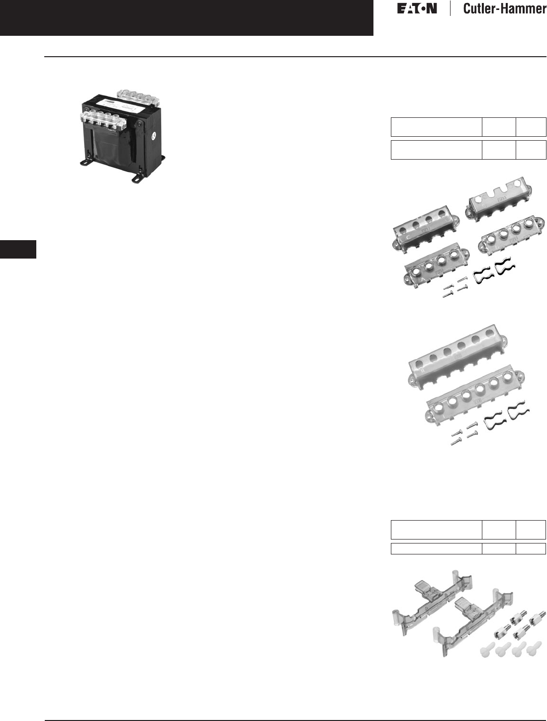
November 2003
9-110
For more information visit: www.cutler-hammer.eaton.com CA08101001E
Transformers
9
Industrial Control Transformers
CE Marked Vol. 1, Ref. No. [0410]
CE Marked
Terminal Type A
Application Description
Transformers provide stepped down
voltages to machine tool control devices
enabling control circuits to be isolated
from all power and lighting circuits.
This allows the use of grounded or
ungrounded circuits that are indepen-
dent of the power or lighting grounds;
greater safety is afforded the operator.
The control transformer line is particu-
larly adaptable on applications where
compact construction is demanded.
Features, Benefits
and Functions
Type MTE
■UL listed.
■CSA certified.
■Epoxy encapsulated coil design.
■Copper magnet wire for high
quality, efficient operation.
■Laminations of high quality silicon
steel to minimize core losses and
optimize performance.
■Molded-in terminals.
■50/60 Hz operation.
■55°C rise, class 105 insulation.
■Performance meets/exceeds
requirements of ANSI/NEMA ST-1.
■Regulation exceeds ANSI/NEMA
requirements for all ratings.
■Non-short circuit proof transformer,
isolation type.
Type MTK
■UL listed.
■CSA certified.
■Epoxy resin-impregnated coil design.
■Copper magnet wire for high
quality, efficient operation.
■50/60 Hz operation.
■115°C rise, 180°C insulation system.
■Performance meets/exceeds
requirements of ANSI/NEMA ST-1.
■Regulation exceeds ANSI/NEMA
requirements for all ratings.
■500 – 5000 VA ratings.
Standards and Certifications
Industry Standards
All Cutler-Hammer dry-type distribution
and control transformers by Eaton
Corporation are built and tested in
accordance with applicable NEMA,
ANSI, and IEEE Standards. All 600 volt
class transformers are UL listed unless
otherwise noted.
Options and Accessories
Protection Index IP00
When terminal covers are installed on
primary and secondary, and fuse block
covers are used, the Protection Index
is IP20.
Finger-Safe Terminal Covers (Optional)
■Fits CE marked designs 50 – 750 VA.
■Fits MTE designs 25 – 750 VA.
Table 9-128. Finger-Safe Terminal Covers
Finger-Safe Terminal Covers — FSK4
Finger-Safe Terminal Covers — FSK6
Finger-Safe Primary Fuse Block Covers
■Fits 2-pole primary fuse blocks on
MTE designs.
Table 9-129. Finger-Safe Primary Fuse
Block Covers
Finger-Safe Primary Fuse Block Covers
Description Catalog
Number
Price
U.S. $
4 Terminal Transformers
6 Terminal Transformers
FSK4
FSK6
24.
25.
Description Catalog
Number
Price
U.S. $
Primary Fuse Block Covers FSKFB 38.
Discount Symbol . . . . . . . . . . . . . . . . . . . . . . . . . DT-1
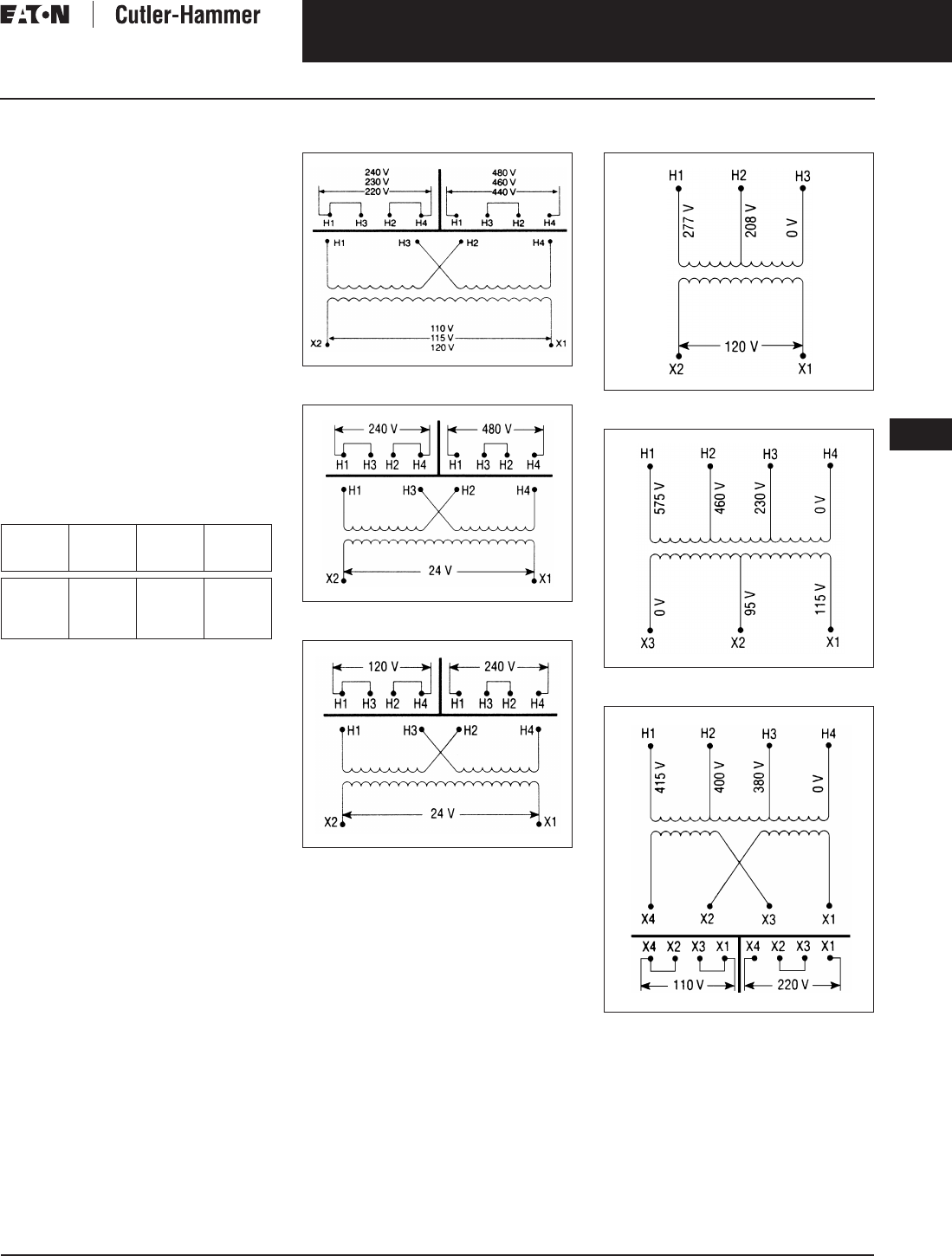
November 2003
CA08101001E For more information visit: www.cutler-hammer.eaton.com
9-111
Transformers
9
Industrial Control Transformers
CE Marked
Vol. 1, Ref. No. [0411]
Product Specifications
Overload Capability
Short-term overload is designed into
transformers as required by ANSI.
Basically, dry-type distribution trans-
formers will deliver 200% nameplate
load for one-half hour; 150% load for
one-hour; and 125% load for four-hours
without being damaged provided that
a constant 50% load precedes and
follows the overload. See ANSI
C57.96-01.250 for additional limitations.
Continuous overload capacity is not
deliberately designed into a trans-
former because the design objective is
to be within the allowed winding tem-
perature rise with nameplate loading.
Insulation System and Temperature Rise
Industry standards classify insulation
systems and rise as shown below:
Table 9-130. Insulation System Classification
The design life of transformers having
different insulation systems is the
same — the lower temperature systems
are designed for the same life as the
higher temperature systems.
Series-Multiple Windings
Series-multiple windings consist of
2 similar coils in each winding which
can be connected in series or parallel
(multiple). Transformers with series-
multiple windings are designated with
an “X” or “/” between the voltage
ratings, such as voltages of “120/240”
or “240 X 480.” If the series-multiple
winding is designated by an “X,” the
winding can be connected only for a
series or parallel. With the “/” designa-
tion, a mid-point also becomes avail-
able in addition to the series or parallel
connection. As an example, a 120 X
240 winding can be connected for
either 120 (parallel) or 240 (series), but
a 120/240 winding can be connected
for 120 (parallel), or 240 (series), or 240
with a 120 mid-point.
Technical Data
and Specifications
Please refer to Page 9-122.
Ambient +
Winding
Rise
+
Hot
Spot
=
Temp.
Class
40°C
40°C
40°C
40°C
55°C
80°C
115°C
150°C
10°C
30°C
30°C
30°C
105°C
150°C
185°C
220°C
Wiring Diagrams
Figure 9-40. Diagram 1
Figure 9-41. Diagram 2
Figure 9-42. Diagram 3
Figure 9-43. Diagram 4
Figure 9-44. Diagram 5
Figure 9-45. Diagram 6
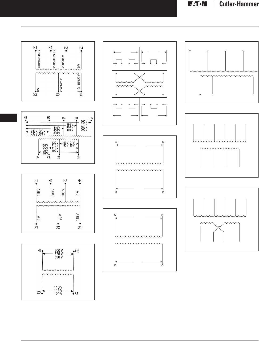
November 2003
9-112
For more information visit: www.cutler-hammer.eaton.com CA08101001E
Transformers
9
Industrial Control Transformers
CE Marked Vol. 1, Ref. No. [0412]
Wiring Diagrams
Figure 9-46. Diagram 7
Figure 9-47. Diagram 8
Figure 9-48. Diagram 9
Figure 9-49. Diagram 10
Figure 9-50. Diagram 11
Figure 9-51. Diagram 12
Figure 9-52. Diagram 13
Figure 9-53. Diagram 14
Figure 9-54. Diagram 15
Figure 9-55. Diagram 16
H1
H
3
H2
H4
H1
H
3
H2
H4
H1
H
3
H2
H4
X4
X2
X
3
X1
X4
X2
X
3
X1
X4
X2
X
3
X1
24
0
V
480 V
240 V
12
0
V
H1
H2
X2
X1
600
V
5
7
5
V
550
V
24 V
2
3
V
22 V
H1
H2
X2
X1
42
0
V
4
00
V
380
V
24 V
2
3
V
22 V
H1
H2
H
3
H4
X
3
X2
X1
5
50
,
575
,
600 V
4
40
,
460
,
480 V
380
,
400
,
416 V
2
20
,
230
,
240 V
2
3
/
24
/
25
1
10
,
115
,
120
V
0V
0
V
X4
X
3
X2
X1
H1
H2
H
3
H4
H
5
H
6
5
7
5
V
460
V
400
V
230
V
208
V
0
V
0
V
24 V
1
1
5
V
230
V
X4
X
3
X2
X1
H1
H2
H
3
H4
H
5
H
6
5
7
5
V
460
V
400
V
230
V
208
V
0
V
0
V
0
V
1
1
5
V
1
1
5
V

November 2003
CA08101001E For more information visit: www.cutler-hammer.eaton.com
9-113
Transformers
9
Industrial Control Transformers
CE Marked
Vol. 1, Ref. No. [0413]
Product Selection
Additional Product Selection information begins on Page 9-136.
Table 9-131. Type MTE CE Marked IP00
See Pages 9-111 and 9-112 for Wiring Diagrams.
Note: Transformers are designed to operate in a maximum ambient of 40°C.
Contact your local Cutler-Hammer sales office for availability on additional CE Marked control transformers.
VA Dimensions (Inches) Weight
Lbs.
Dimensions (mm) Weight
kg
Wiring
Diagram
Style
Number
Price
U.S. $
Height Width Depth Height Width Depth
Primary: 240 x 480, 230 x 460, 220 x 440 with Jumpers
Secondary: 120/115/110
50
75
100
150
2-9/16
2-7/8
3-3/16
3-13/16
3
3-3/8
3-3/4
4-1/2
3-3/8
3-1/2
3-5/8
4
3.5
4.8
5.9
8.5
65
73
81
97
76
86
95
114
86
89
92
102
1.6
2.2
2.7
3.9
1
1
1
1
CE0050E2A
CE0075E2A
CE0100E2A
CE0150E2A
98.
110.
122.
149.
200
250
300
3-13/16
3-13/16
3-13/16
4-1/2
4-1/2
4-1/2
4-1/2
4-3/4
5-1/4
10.6
11.3
13.2
97
97
97
114
114
114
114
121
133
4.8
5.1
6.0
1
1
1
CE0200E2A
CE0250E2A
CE0300E2A
159.
206.
217.
350
500
750
4-3/4
4-3/4
4-3/4
5-1/4
5-1/4
5-1/4
5
6
7-3/8
14.9
21.0
29.8
121
121
121
133
133
133
127
152
187
6.8
9.5
13.5
1
1
1
CE0350E2A
CE0500E2A
CE0750E2A
252.
274.
406.
Primary: 240 x 480 with Jumpers
Secondary: 24
50
75
100
150
2-9/16
2-7/8
3-3/16
3-13/16
3
3-3/8
3-3/4
4-1/2
3-1/4
3-1/4
3-5/8
4
3.4
4.2
5.9
8.5
65
73
81
97
76
86
95
114
83
83
92
102
1.5
1.9
2.7
3.9
2
2
2
2
CE0050E2B
CE0075E2B
CE0100E2B
CE0150E2B
109.
119.
135.
168.
200
250
300
3-13/16
3-13/16
3-13/16
4-1/2
4-1/2
4-1/2
4-1/4
4-3/4
5-1/4
10.6
11.3
13.2
97
97
97
114
114
114
108
121
133
4.5
5.1
6.0
2
2
2
CE0200E2B
CE0250E2B
CE0300E2B
179.
227.
246.
350
500
750
4-3/4
4-3/4
4-3/4
5-1/4
5-1/4
5-1/4
5
5-1/2
7
14.9
19.2
28.1
121
121
121
133
133
133
127
140
178
6.8
8.7
12.8
2
2
2
CE0350E2B
CE0500E2B
CE0750E2B
276.
301.
441.
Primary: 120 x 240 with Jumpers
Secondary: 24
50
75
100
150
2-9/16
2-7/8
3-3/16
3-13/16
3
3-3/8
3-3/4
4-1/2
3-1/4
3-1/4
3-5/8
4
3.4
4.2
5.9
8.5
65
73
81
97
76
86
95
114
83
83
92
102
1.5
1.9
2.7
3.9
3
3
3
3
CE0050E1B
CE0075E1B
CE0100E1B
CE0150E1B
109.
119.
135.
168.
200
250
300
3-13/16
3-13/16
3-13/16
4-1/2
4-1/2
4-1/2
4-1/4
4-3/4
5-1/4
10.6
11.3
13.2
97
97
97
114
114
114
108
121
133
4.5
5.1
6.0
3
3
3
CE0200E1B
CE0250E1B
CE0300E1B
179.
227.
246.
350
500
750
4-3/4
4-3/4
4-3/4
5-1/4
5-1/4
5-1/4
5
5-1/2
7-3/8
14.9
19.2
29.8
121
121
121
133
133
133
127
140
187
6.8
8.7
13.5
3
3
3
CE0350E1B
CE0500E1B
CE0750E1B
276.
301.
441.
Primary: 550/575/600
Secondary: 110/115/120
50
75
100
150
2-9/16
2-7/8
3-3/16
3-13/16
3
3-3/8
3-3/4
4-1/2
3-3/8
3-1/2
3-5/8
4
3.5
4.8
5.9
8.5
65
73
81
97
76
86
95
114
86
89
92
102
1.6
2.2
2.7
3.9
10
10
10
10
CE0050E4C
CE0075E4C
CE0100E4C
CE0150E4C
107.
118.
133.
166.
200
250
300
3-13/16
3-13/16
3-13/16
4-1/2
4-1/2
4-1/2
4-1/2
4-3/4
5-1/4
10.6
11.3
13.2
97
97
97
114
114
114
114
121
133
4.8
5.1
6.0
10
10
10
CE0200E4C
CE0250E4C
CE0300E4C
177.
224.
243.
350
500
750
4-3/4
4-3/4
4-3/4
5-1/4
5-1/4
5-1/4
5
6
7-3/8
14.9
21.0
29.8
121
121
121
133
133
133
127
152
187
6.8
9.5
13.5
10
10
10
CE0350E4C
CE0500E4C
CE0750E4C
273.
298.
438.
For other ratings or styles not shown, refer
to Eaton’s Cutler-Hammer business. Discount Symbol . . . . . . . . . . . . . . . . . . . . . . . . . DT-1

November 2003
9-114
For more information visit: www.cutler-hammer.eaton.com CA08101001E
Transformers
9
Industrial Control Transformers
CE Marked Vol. 1, Ref. No. [0414]
Table 9-132. Type MTE CE Marked IP00
See Pages 9-111 and 9-112 for Wiring Diagrams.
Note: Transformers are designed to operate in a maximum ambient of 40°C.
Contact your local Cutler-Hammer sales office for availability on additional CE Marked control transformers.
VA Dimensions (Inches) Weight
Lbs.
Dimensions (mm) Weight
kg
Wiring
Diagram
Style
Number
Price
U.S. $
Height Width Depth Height Width Depth
Primary: 380/400/415
Secondary: 110 x 220 with Jumpers
50
75
100
150
2-9/16
2-7/8
3-3/16
3-13/16
3
3-3/8
3-3/4
4-1/2
3-1/2
3-1/2
3-5/8
4
3.5
4.8
5.9
8.5
65
73
81
97
76
86
95
114
89
89
92
102
1.6
2.2
2.7
3.9
6
6
6
6
CE0050E4D
CE0075E4D
CE0100E4D
CE0150E4D
143.
154.
166.
194.
200
250
300
3-13/16
3-13/16
3-13/16
4-1/2
4-1/2
4-1/2
4-1/2
4-3/4
5-1/4
10.6
11.3
13.2
97
97
97
114
114
114
114
121
133
4.8
5.1
6.0
6
6
6
CE0200E4D
CE0250E4D
CE0300E4D
206.
268.
281.
350
500
750
3-13/16
4-3/4
4-3/4
4-1/2
5-1/4
5-1/4
5-1/2
6
7-3/8
15.2
21.0
29.8
97
121
121
114
133
133
140
152
187
6.9
9.5
13.5
6
6
6
CE0350E4D
CE0500E4D
CE0750E4D
327.
357.
630.
Primary: 200/220/440, 208/230/460, 240/480
Secondary: 23/110, 24/115, 25/120
50
75
100
2-7/8
3-3/16
3-3/16
3-3/8
3-3/4
3-3/4
3-1/4
3-5/8
4-3/8
4.2
5.9
7.9
65
81
81
86
95
95
83
92
111
1.9
2.7
3.6
7
7
7
CE0050E5E
CE0075E5E
CE0100E5E
133.
147.
165.
150
200
250
3-13/16
3-13/16
3-13/16
4-1/2
4-1/2
4-1/2
4-1/4
5
5-1/2
10.0
12.8
15.2
97
97
97
114
114
114
108
127
140
4.5
5.8
6.9
7
7
7
CE0150E5E
CE0200E5E
CE0250E5E
201.
214.
278.
300
350
500
4-3/4
4-3/4
4-3/4
5-1/4
5-1/4
5-1/4
5-3/8
5-1/2
7-1/4
16.8
19.2
27.0
121
121
121
133
133
133
137
140
184
7.6
8.7
12.3
7
7
7
CE0300E5E
CE0350E5E
CE0500E5E
300.
339.
375.
For other ratings or styles not shown, refer
to Eaton’s Cutler-Hammer business. Discount Symbol . . . . . . . . . . . . . . . . . . . . . . . . . DT-1
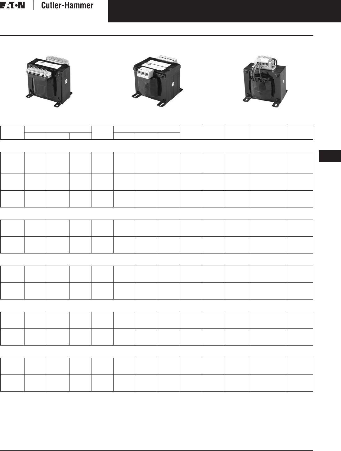
November 2003
CA08101001E For more information visit: www.cutler-hammer.eaton.com
9-115
Transformers
9
Industrial Control Transformers
CE Marked
Vol. 1, Ref. No. [0415]
Factory Mounted Finger-Safe Terminal Covers
Terminal Type A Terminal Type B Terminal Type C
Table 9-133. Type MTK CE Marked with Factory Mounted Finger-Safe Terminal Covers IP20
See Pages 9-111 and 9-112 for Wiring Diagrams.
Note: For additional information refer to the Cutler-Hammer Industrial Control Transformer Binder B1228A.
Contact your local Cutler-Hammer sales office for availability on additional CE Marked control transformers.
VA Dimensions (Inches) Weight
Lbs.
Dimensions (mm) Weight
kg
Terminal
Type
Wiring
Diagram
Style
Number
Price
U.S. $
Height Width Depth Height Width Depth
Primary: 240 x 480, 230 x 460, 220 x 440 with Jumpers
Secondary: 120/115/110
250
300
350
500
4
4
4
4
4-1/2
4-1/2
4-1/2
4-1/2
4-5/16
4-7/8
5-3/16
5-5/8
8.8
11.0
11.2
14.8
102
102
102
102
114
114
114
114
110
124
132
143
4.0
5.0
5.1
6.7
A
A
A
A
1
1
1
1
CE0250K2AFS
CE0300K2AFS
CE0350K2AFS
CE0500K2AFS
206.
218.
227.
234.
750
1000
1500
4-1/2
5-5/16
7-1/2
5-1/4
6-3/8
6-3/4
5-15/16
5-5/16
6-1/8
18.0
26.3
40.0
114
135
191
133
162
172
151
135
156
8.2
11.9
18.1
A
A
C
1
1
1
CE0750K2AFS
CE1000K2AFS
CE1500K2AFS
320.
497.
686.
2000
3000
5000
7-1/2
9-3/8
9-3/8
6-3/4
9
9
6-7/16
6-1/4
8-3/4
45.1
65.2
104.8
191
238
238
172
229
229
164
159
222
20.5
29.6
47.5
C
C
C
1
1
1
CE2000K2AFS
CE3000K2AFS
CE5000K2AFS
753.
1,115.
1,595.
Primary: 240 x 480 with Jumpers
Secondary: 24
250
300
350
5-5/8
5-5/8
5-5/8
4-1/2
4-1/2
4-1/2
3-1/4
3-5/8
4-3/16
8.2
9.5
12.2
143
143
143
114
114
114
83
92
106
3.7
4.3
5.5
C
C
C
2
2
2
CE0250K2BFS
CE0300K2BFS
CE0350K2BFS
260.
276.
293.
500
750
1000
5-5/8
6-1/2
7-3/16
4-1/2
5-1/4
6-3/8
4-11/16
5-15/16
5-9/16
14.4
19.5
26.2
143
165
183
114
133
162
119
151
141
6.5
8.9
11.9
C
C
C
2
2
2
CE0500K2BFS
CE0750K2BFS
CE1000K2BFS
313.
368.
543.
Primary: 120 x 240 with Jumpers
Secondary: 24
250
300
350
5-5/8
5-5/8
5-5/8
4-1/2
4-1/2
4-1/2
3-1/4
3-5/8
4-3/16
8.3
9.3
12.0
143
143
143
114
114
114
83
92
106
3.8
4.2
5.4
C
C
C
3
3
3
CE0250K1BFS
CE0300K1BFS
CE0350K1BFS
260.
276.
293.
500
750
1000
5-5/8
6-1/2
7-3/16
4-1/2
5-1/4
6-3/8
4-13/16
5-15/16
5-9/16
14.4
19.5
25.2
143
165
183
114
133
162
122
151
141
6.5
8.9
11.4
C
C
C
3
3
3
CE0500K1BFS
CE0750K1BFS
CE1000K1BFS
313.
368.
543.
Primary: 200/220/440, 208/230/460, 240/480
Secondary: 23/110, 24/115, 25/120
250
300
350
3-7/8
3-7/8
3-7/8
4-1/2
4-1/2
4-1/2
4-7/16
4-3/4
5-3/16
12.5
14.0
15.3
98
98
98
114
114
114
113
121
140
5.7
6.3
6.9
B
B
B
7
7
7
CE0250K5EFS
CE0300K5EFS
CE0350K5EFS
267.
287.
328.
500
750
1000
5-1/16
7-3/16
7-3/16
5-1/4
6-3/8
6-3/8
6-1/4
5-13/16
6-3/16
20.8
29.8
30.2
129
183
183
133
162
162
159
148
157
9.4
13.5
13.7
B
C
C
7
7
7
CE0500K5EFS
CE0750K5EFS
CE1000K5EFS
345.
595.
665.
Primary: 220/380/440/550, 230/400/460/575, 240/416/480/600
Secondary: 23/110, 24/115, 25/120
250
300
350
3 7/8
3-7/8
4-7/16
4 1/2
4-1/2
5-1/4
5 3/8
5-11/16
5-1/2
14.3
15.8
16.5
98
98
113
114
114
133
137
144
140
6.5
7.2
7.5
B
B
B
14
14
14
CE0250K2UFS
CE0300K2UFS
CE0350K2UFS
400.
413.
452.
500
750
1000
5-1/16
7-3/16
7-3/16
5-1/4
6-3/8
6-3/8
6-3/16
5-11/16
6-7/8
20.5
28.8
39.4
129
183
183
133
162
162
157
144
175
9.3
13.1
17.9
B
C
C
14
14
14
CE0500K2UFS
CE0750K2UFS
CE1000K2UFS
539.
606.
693.
Discount Symbol . . . . . . . . . . . . . . . . . . . . . . . . . DT-1

November 2003
9-116
For more information visit: www.cutler-hammer.eaton.com CA08101001E
Transformers
9
Industrial Control Transformers
CE Marked Vol. 1, Ref. No. [0416]
Table 9-134. Type MTK CE Marked with Factory Mounted Finger-Safe Terminal Covers IP20
See Pages 9-111 and 9-112 for Wiring Diagrams.
24 volt secondary only available through 1000 VA.
Note: For additional information refer to the Cutler-Hammer Industrial Control Transformer Binder B1228A.
Contact your local Cutler-Hammer sales office for availability on additional CE Marked control transformers.
VA Dimensions (Inches) Weight
Lbs.
Dimensions (mm) Weight
kg
Terminal
Type
Wiring
Diagram
Style
Number
Pricing
U.S. $
Height Width Depth Height Width Depth
Primary: 208/230/400/460/575
Secondary: 24 /115/230
250
300
350
500
3-7/8
3-7/8
4-7/16
4-7/16
4-1/2
4-1/2
5-1/4
5-1/4
5-1/2
6-1/16
5-3/4
7-5/16
14.9
17.4
17.8
26.6
98
98
113
113
114
114
133
133
140
154
146
186
6.8
7.9
8.1
12.1
B
B
B
B
15
15
15
15
CE0250K2VFS
CE0300K2VFS
CE0350K2VFS
CE0500K2VFS
424.
452.
487.
546.
750
1000
1500
5-15/16
7-1/2
7-1/2
6-3/8
6-3/4
6-3/4
6-3/16
6-7/8
6-3/4
32.5
44.0
45.4
151
191
191
162
172
172
157
175
172
14.7
20.0
20.6
B
C
C
15
15
16
CE0750K2VFS
CE1000K2VFS
CE1500K2WFS
753.
840.
865.
2000
3000
5000
9-3/8
9-3/8
9-3/8
9
9
9
6-1/4
8-1/8
9-15/16
58.6
92.9
127.4
238
238
238
229
229
229
159
206
252
26.6
42.1
57.8
C
C
C
16
16
16
CE2000K2WFS
CE3000K2WFS
CE5000K2WFS
1,020.
1,295.
1,585.
Primary: 240/416/480/600, 230/400/460/575, 220/380/440/550, 208/500
Secondary: 99/120/130, 95/115/125, 91/110/120, 85/100/110
250
300
350
4
4
4
4-1/2
4-1/2
4-1/2
5-1/16
5-1/2
5-1/2
11.4
13.6
14.2
102
102
102
114
114
114
135
140
140
5.2
6.2
6.4
A
A
A
8
8
8
CE0250K6UFS
CE0300K6UFS
CE0350K6UFS
410.
424.
455.
500
750
1000
4-1/2
4-1/2
5-1/4
5-1/4
5-1/4
6-3/8
5-5/8
5-5/8
6-1/16
17.4
27.5
27.9
114
114
133
133
133
162
143
187
154
7.9
12.5
12.6
A
A
A
8
8
8
CE0500K6UFS
CE0750K6UFS
CE1000K6UFS
539.
634.
711.
1500
2000
3000
5-13/16
7-5/8
8-1/4
6-3/4
9
9
6-5/16
5-3/4
6-9/16
43.1
56.0
76.2
148
194
210
172
229
229
160
146
167
19.5
25.4
34.6
A
B
B
8
8
8
CE1500K6UFS
CE2000K6UFS
CE3000K6UFS
847.
991.
1,265.
Discount Symbol . . . . . . . . . . . . . . . . . . . . . . . . . DT-1

November 2003
CA08101001E For more information visit: www.cutler-hammer.eaton.com
9-117
Transformers
9
Industrial Control Transformers
CE Marked
Vol. 1, Ref. No. [0417]
Table 9-135. Acceptable Rating of Primary Overcurrent Protection for CE Marked Control Transformers
Table 9-136. Acceptable Maximum Rating of Secondary Overcurrent Protection
Note: For values over 6.3A use 10 x 38 mm time-lag (IEC - 269-3-1). T
a = 40°C Control Type
Fuses 10 x 38 mm (13/32” x 1-1/2”) Time-lag (IEC 269)
Sec. Voltage 50 75 100 150 200 250 300 350 500 750
115
120
200
2.0
2.0
1.0
2.0
2.0
2.0
4.0
4.0
2.0
4.0
4.0
4.0
6.0
6.0
4.0
6.0
6.0
4.0
8.0
8.0
4.0
10.0
10.0
6.0
12.0
12.0
8.0
20.0
20.0
12.0
208
220
230
1.0
1.0
1.0
2.0
1.0
1.0
2.0
2.0
2.0
4.0
4.0
4.0
4.0
4.0
4.0
4.0
4.0
4.0
4.0
4.0
4.0
6.0
6.0
6.0
8.0
6.0
6.0
12.0
10.0
10.0
240
277
380
1.0
.5
.5
1.0
1.0
1.0
2.0
1.0
1.0
4.0
2.0
2.0
4.0
4.0
2.0
4.0
4.0
4.0
4.0
4.0
4.0
4.0
4.0
4.0
6.0
6.0
6.0
10.0
8.0
6.0
400
415
440
.5
.5
.5
.5
.5
.5
1.0
1.0
1.0
2.0
1.0
1.0
2.0
2.0
2.0
4.0
4.0
2.0
4.0
4.0
4.0
4.0
4.0
4.0
4.0
4.0
4.0
6.0
6.0
6.0
460
480
550
.5
.5
.5
.5
.5
.5
1.0
.5
.5
1.0
1.0
1.0
2.0
2.0
1.0
2.0
2.0
2.0
4.0
4.0
2.0
4.0
4.0
4.0
4.0
4.0
4.0
6.0
6.0
4.0
575
600
.5
.5
.5
.5
.5
.5
1.0
1.0
1.0
2.0
2.0
2.0
2.0
2.0
4.0
4.0
4.0
4.0
4.0
4.0
Miniature Fuses 5 x 20 mm Time-lag (IEC 127-2/III)
Sec. Voltage 50 75 100 150 200 250 300 350 500 750
23
24
25
2.50
2.50
2.50
4.00
4.00
4.00
5.00
5.00
5.00
8.00
8.00
8.00
10.0
10.0
10.0
12.00
12.00
12.00
16.00
16.00
16.00
16.00
16.00
16.00
25.00
25.00
25.00
—
32.00
32.00
90
95
100
.63
.63
.50
1.00
.80
.80
1.25
1.25
1.00
2.00
1.60
1.60
2.50
2.50
2.00
3.15
3.15
2.50
4.00
4.00
3.15
4.00
4.00
4.00
6.30
6.30
5.00
10.00
8.00
8.00
110
115
120
.50
.50
.50
.80
.80
.63
1.00
1.00
1.00
1.60
1.60
1.25
2.00
2.00
2.00
2.50
2.50
2.50
3.15
3.15
2.50
4.00
3.15
3.15
5.00
5.00
5.00
8.00
8.00
6.30
220
230
240
.25
.25
.25
.40
.40
.315
.50
.50
.50
.80
.80
.63
1.00
1.00
1.00
1.25
1.25
1.25
1.60
1.60
1.25
1.60
1.60
1.60
2.50
2.50
2.50
4.00
4.00
3.15
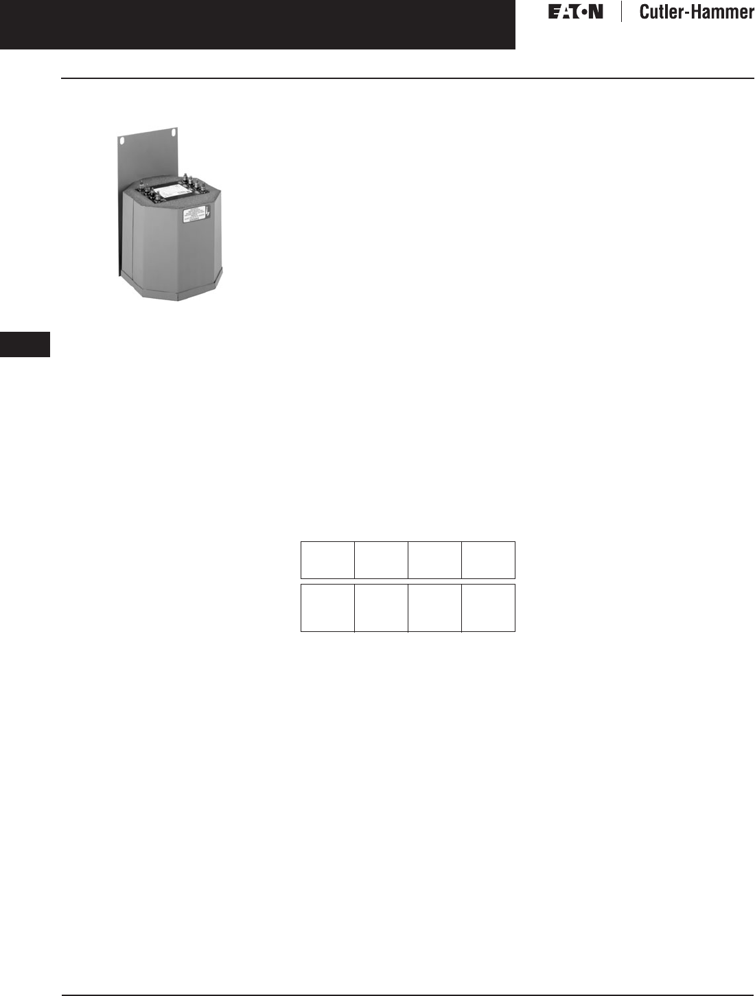
November 2003
9-118
For more information visit: www.cutler-hammer.eaton.com CA08101001E
Transformers
9
Industrial Control Transformers
Type AP Vol. 1, Ref. No. [0418]
Type AP
Type AP Transformer
Product Description
■Sand and resin encapsulated
designs.
Application Description
Transformers provide stepped down
voltages to machine tool control
devices enabling control circuits to be
isolated from all power and lighting
circuits. This allows the use of
grounded or ungrounded circuits that
are independent of the power or light-
ing grounds; greater safety is afforded
the operator. The control transformer
line is particularly adaptable on appli-
cations where compact construction
is demanded.
Features, Benefits
and Functions
■UL recognized.
■Resin encapsulated.
■60 Hz operation.
■115°C winding rise.
■Convenient screw-type terminal
board.
■Bottom or side/wall mounting
designs.
■Performance meets/exceeds
requirements of ANSI/NEMA ST-1.
■Regulation exceeds ANSI/NEMA
requirements for all ratings.
Standards and Certifications
Industry Standards
All Cutler-Hammer dry-type distribution
and control transformers by Eaton
Corporation are built and tested in
accordance with applicable NEMA,
ANSI, and IEEE Standards.
Product Specifications
Overload Capability
Short-term overload is designed into
transformers as required by ANSI.
dry-type distribution transformers
will deliver 200% nameplate load for
one-half hour; 150% load for one-hour;
and 125% load for four-hours without
being damaged provided that a con-
stant 50% load precedes and follows
the overload. See ANSI C57.96-01.250
for additional limitations.
Continuous overload capacity is not
deliberately designed into a trans-
former because the design objective is
to be within the allowed winding tem-
perature rise with nameplate loading.
Insulation System and Temperature Rise
Industry standards classify insulation
systems and rise as shown below:
Table 9-137. Insulation System Classification
The design life of transformers having
different insulation systems is the
same — the lower temperature systems
are designed for the same life as the
higher temperature systems.
Sound Levels
All Cutler-Hammer 600 volt class gen-
eral purpose dry-type distribution
transformers are designed to meet
NEMA ST-20 levels.
Winding Terminations
Cutler-Hammer business recommends
external cables be rated 90ºC (sized
at 75°C ampacity) for encapsulated
designs.
Series-Multiple Windings
Series-multiple windings consist of
2 similar coils in each winding which
can be connected in series or parallel
(multiple). Transformers with series-
multiple windings are designated with
an “X” or “/” between the voltage
ratings, such as voltages of “120/240”
or “240 X 480.” If the series-multiple
winding is designated by an “X,” the
winding can be connected only for a
series or parallel. With the “/” designa-
tion, a mid-point also becomes avail-
able in addition to the series or parallel
connection. As an example, a 120 X
240 winding can be connected for
either 120 (parallel) or 240 (series), but
a 120/240 winding can be connected
for 120 (parallel), or 240 (series), or 240
with a 120 mid-point.
Technical Data
and Specifications
Please refer to Page 9-122.
Ambient +
Winding
Rise
+
Hot
Spot
=
Temp.
Class
40°C
40°C
40°C
40°C
55°C
80°C
115°C
150°C
10°C
30°C
30°C
30°C
105°C
150°C
185°C
220°C
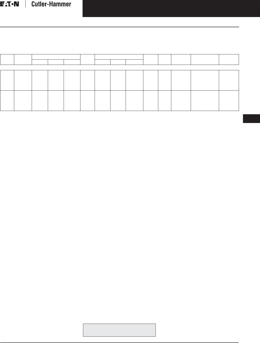
November 2003
CA08101001E For more information visit: www.cutler-hammer.eaton.com
9-119
Transformers
9
Industrial Control Transformers
Type AP
Vol. 1, Ref. No. [0419]
Product Selection
Additional Product Selection information begins on Page 9-136.
Table 9-138. Type AP
See Page 9-91 for Wiring Diagrams.
Note: For additional information refer to the Cutler-Hammer Industrial Control Transformer Binder B1228A.
kVA Mounting Dimensions (Inches) Weight
Lbs.
Dimensions (mm) Weight
kg
Frame Wiring
Diagram
Style
Number
Price
U.S. $
Height Width Depth Height Width Depth
240/480 Volts to 120/240 Volts, 60 Hz
3
5
7.5
10
15
Bottom
Bottom
Bottom
Bottom
Bottom
8-5/16
10-3/4
10-3/4
10-3/4
12
9-9/16
10-3/4
10-3/4
10-3/4
13-3/16
8-13/16
8 -11/16
10-3/16
11-3/8
10-7/16
65
104
129
148
197
227
273
273
273
305
243
273
273
273
335
224
221
259
289
265
29.5
47.2
58.6
67.2
89.4
FR133
FR99
FR100
FR101
FR134
5
5
5
5
5
C0003P7GB
C0005P7GB
C0007P7GB
C0010P7GB
C0015P7GB
1,375.
1,710.
2,350.
2,930.
3,970.
3
5
7.5
10
15
Side/Wall
Side/Wall
Side/Wall
Side/Wall
Side/Wall
9-3/4
11-5/8
11-5/8
11-5/8
12-7/8
8-13/16
8-11/16
10-13/16
11-3/8
10-7/16
9-9/16
10-3/4
10-3/4
10-3/4
13-3/16
65
104
129
148
197
248
295
295
295
327
224
221
275
289
265
243
273
273
273
335
29.5
47.2
58.6
67.2
89.4
FR292
FR256
FR257
FR258
FR259
5
5
5
5
5
C0003P7GS
C0005P7GS
C0007P7GS
C0010P7GS
C0015P7GS
1,375.
1,710.
2,350.
2,930.
3,970.
For other ratings or styles not shown, or for
special enclosure types (including stainless
steel) refer to Eaton’s Cutler-Hammer business. Discount Symbol . . . . . . . . . . . . . . . . . . . . . . . . . DT-1
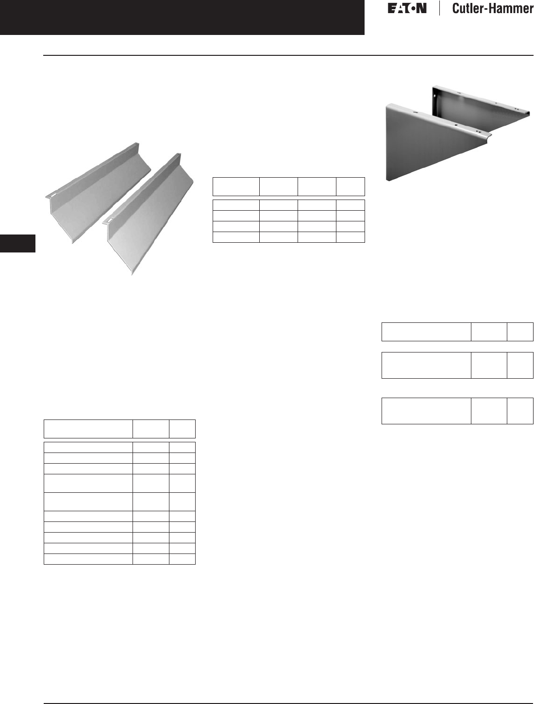
November 2003
9-120
For more information visit: www.cutler-hammer.eaton.com CA08101001E
Transformers
9
General Purpose & Industrial Control Transformers
Options, Accessories and Parts Vol. 1, Ref. No. [0420]
Options and Accessories
(Order Separately)
Weathershield Kit
Note: For 316 grade stainless steel add the
suffix ‘S’ to the catalog number.
Weathershield Kit
A weathershield kit consisting of a
front and rear cover shield must be
installed on all ventilated dry-type dis-
tribution transformers when the unit is
located outdoors. The shields protect
the transformer top ventilation open-
ings against rain but allow for proper
ventilation. Field installation hardware
is not required. Refer to specific trans-
former listing for selection of weather-
shield kit. Proper installation provides
a NEMA 3R rating.
Table 9-139. Weathershield Kit
Effective June 1, 2001 frame numbers will
have a prefix of FR, i.e., FR819. Dimensions,
accessories, etc. are still applicable as if the
FR did not exist.
For stainless steel weathershields, add the
suffix “S” to a catalog number, i.e., WS31S.
Terminal Extension Kit
A terminal extension kit is used to
allow front access to the rear terminals
on most 500 and 750 kVA transformers
(transformers on frames 919 and 920)
when insufficient space is available at
the rear of the transformer. Eaton’s
Cutler-Hammer business recommends
a minimum of 6-inch clearance from
the wall to maintain proper ventilation.
Table 9-140. Terminal Extension Kit
Effective June 1, 2001 frame numbers will
have a prefix of FR, i.e., FR819. Dimensions,
accessories, etc. are still applicable as if the
FR did not exist.
Wall Mounting Bracket
Wall Mounting Bracket
Wall mounting brackets are used to
wall mount most 15 through 75 kVA
and some 100 and 112.5 kVA Type
DS-3 and DT-3 transformers. See
availability guide. This bracket allows
for 6-inch clearance from the wall as
recommended by the Cutler-Hammer
business.
Wall mounting brackets fit the
following frames.
Table 9-141. Availability Guide —
Wall Mounting Bracket WMB01
Effective June 1, 2001 frame numbers will
have a prefix of FR, i.e., FR819. Dimensions,
accessories, etc. are still applicable as if the
FR did not exist.
Fits Frame
Size(s)
Catalog
Number
Price
U.S. $
809, 810, 811, 816, 817, 818 WS11 350.
814 WS13 800.
819, 820 WS16 800.
808, 909, 910, 911, 912,
910A, 911A, 912A
WS31 350.
812, 813, 913A, 913B, 914A,
915A, 916, 914B, 915B
WS33 350.
916A WS19 350.
917, 918, 918A WS34 800.
919, 920 WS35 1,360.
922 WS36 1,360.
815 WS15 350.00
Fits Frame
Size(s)
Bus
Material
Catalog
Number
Price
U.S. $
919 Aluminum EXT55AL 500.
919 Copper EXT55CU 750.
920 Aluminum EXT77AL 500.
920 Copper EXT77CU 750.
Frame
Sizes
Catalog
Number
Price
U.S. $
Type DS-3 (Single-Phase Compatible)
809, 810, 811, 812, 813, 815,
816, 817, 818, 819, 820, 835,
836, 837, 814A
WMB01 275.
Type DT-3, K-Factor, Drive Isolation
(Three-Phase Compatible)
909, 910, 911, 912, 910A,
911A, 912A, 913A, 913B,
914A, 914B, 915A, 915B
WMB01 275.
Discount Symbol . . . . . . . . . . . . . . . . . . . . . . . . . DT-1

November 2003
CA08101001E For more information visit: www.cutler-hammer.eaton.com
9-121
Transformers
9
General Purpose & Industrial Control Transformers
Options, Accessories and Parts
Vol. 1, Ref. No. [0421]
Table 9-142. Terminal Lug Kits for Type DT-3 Transformers
Table 9-143. Rodent Screens
Effective June 1, 2001 frame numbers will have a prefix of FR, i.e.
FR819. Dimensions, accessories, etc. are still applicable as if the FR did
not exist.
Table 9-144. Replacement Parts for Mini-Power Centers
Table 9-145. Case Parts for Ventilated Units
Effective June 1, 2001 frame numbers will have a prefix of FR, i.e., FR819. Dimensions, accessories, etc. are still applicable as if the FR did not exist.
Note: Parts listed are for standard catalog listed transformers. Units with modifications may require different parts.
(Frame No. from transformer nameplate required).
Note: Transformer nameplate and UL label are not field replaceable.
Typical
Sizing
Terminal Lugs Hardware Catalog
Number
Price
U.S. $
Cable Range Quantity Bolt Size Quantity
15 – 37.5 kVA Single-Phase
15 – 45 kVA Three-Phase
#14 – #2
#6 – 250 kcmil
8
4
1/4-20 x 3/4 8 LKS1 95.
50 – 75 kVA Single-Phase
75 – 112.5 kVA Three-Phase
#6 – 250 kcmil 12 1/4-20 x 3/4
1/4-20 x 1-3/4
8
8
LKS2 190.
100 – 167 kVA Single-Phase
150 – 300 kVA Three-Phase
#6 – 250 kcmil
#2 – 600 kcmil
3
22
1/4-20 x 3/4
3/8-16 x 2
3
16
LKS3 740.
500 kVA Three-Phase #2 – 600 kcmil 29 3/8-16 x 2 18 LKS4 900.
Description Frame
Size(s)
Catalog
Number
Price
U.S. $
Rodent screens are used to
discourage entry by birds
or rodents
909
910A, 911, 912
913B, 914B, 915B
RS01
RS02
RS03
350.
350.
350.
916
917, 918, 918A
919, 920
916A
922
RS04
RS05
RS06
RS07
RS08
800.
800.
1,360.
800.
1,360.
Frame Deadfront Cover
(Breaker Cover)
Front Cover
283
284
285
286
287
47-37503
47-37503-2
47-37503-3
47-37503-4
47-37503-5
7074C98H04
7074C98H01
7074C98H02
7074C98H02
7074C98H03
289
290
291
47-37459
47-37459-2
47-37459-3
7074C44H01
7074C44H02
7074C44H03
289A
290A
291A
47-42072-1
47-42072-2
47-42072-3
7074C44H01
7074C44H02
7074C44H03
Frame(s) Panels Top Cover
Front or Back Side (2 required per transformer) Bottom
Part Number Part Number
Three-Phase, 600 Volt Class
909
910, 911, 912
913A, 914A, 915A
916
917, 918
7073C37P01
1714C46P01
1714C47P03
1714C60P01
1714C65P01
1714C44P03
1714C44P01
1714C44P07
1714C56P01
1714C64P01
7073C20P05
7073C20P01
7073C20P02
7073C20P03
7073C20P04
1714C45P01
1714C45P01
1714C45P02
1714C58P01
1714C67P01
919, 920 2D46331P03 (Upper Panel)
2D46331P04 (Lower Panel)
2D46332P01
2D46331P01 (Cutout Cover Plate)
—
—
2D46331P02
922 2D46391H03 (Back Upper Panel)
2D46391H06 (Front Upper Panel)
2D46391H08 (Lower Panel)
2D46392H01 —
—
—
2D46391H02
918A 47-41801 47-41800 47-41799 47-41802
910A, 911A, 912A
913B, 914B, 915B
916A
47-40592
47-40580
47-41790
47-40591
47-40578
47-41789
47-40589
47-41792
47-41788
1714C45P01
1714C45P02
47-41791
Single-Phase, 600 Volt Class
809
810, 811, 835
812, 813, 836, 837, 838
814
7073C16P03
7073C16P01
7073C16P02
7073C54P01
7073C18P04
7073C18P01
7073C18P02
7073C18P05
7073C14P03
7073C14P01
7073C14P02
7073C14P04
7073C17P01
7073C17P01
7073C17P02
7073C17P03
815
816
817, 818
819, 820
47-39433
47-40452
47-40457
47-40574
47-39430
47-40451
47-40456
47-40573
47-39429
47-40449
47-40454
47-40459
47-39431
47-40453
47-40458
47-40575
Discount Symbol . . . . . . . . . . . . . . . . . . . . . . . . . DT-1
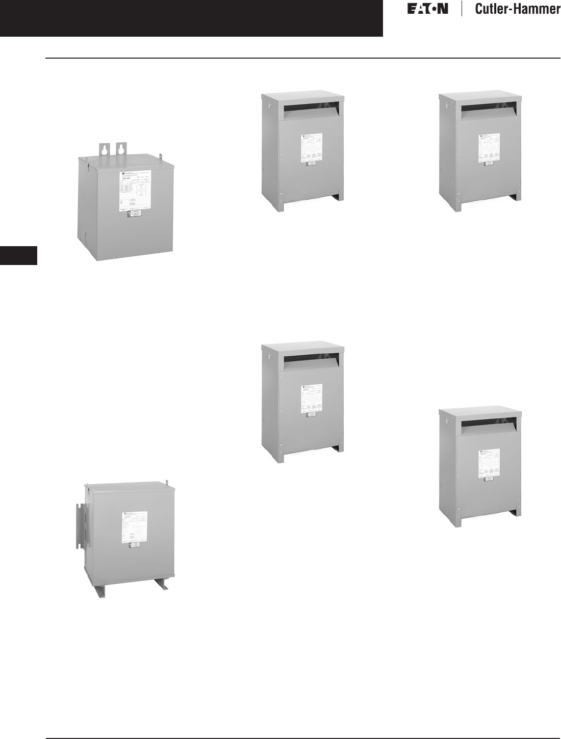
November 2003
9-122
For more information visit: www.cutler-hammer.eaton.com CA08101001E
Transformers
9
General Purpose & Industrial Control Transformers
Technical Data and Specifications Vol. 1, Ref. No. [0422]
Technical Data
and Specifications
General Purpose — EP
Sand and Resin Encapsulated
EP Sand and Resin Encapsulated
Cutler-Hammer EP general purpose
transformers by Eaton Corporation are
single-phase, sand and resin encapsu-
lated designs suitable for indoor or
outdoor applications. The totally-
enclosed non-ventilated NEMA 3R
enclosure makes it ideally suited for
use in areas that contain dust, mois-
ture, or corrosive fumes. Available in
ratings through 37.5 kVA and 4160
volts, type EP transformers can be
mounted in any position for indoor
installations and in upright positions
only for outdoor installations. Type EP
transformers utilize a 185°C insulation
system with 115°C rise standard.
General Purpose — EPT
Sand and Resin Encapsulated
EPT Sand and Resin Encapsulated
Type EPT sand and resin encapsulated,
3-phase transformers are available in
ratings of 3 – 75 kVA, up to 4160 volts
primary. The totally-enclosed non-ven-
tilated NEMA 3R enclosure makes the
EPT ideally suited for outdoor as well
as indoor locations. Type EPT trans-
formers utilize a 185°C insulation
system with 115°C standard.
General Purpose — DS-3 Ventilated
DS-3 Ventilated
DS-3 general purpose transformers are
single-phase ventilated units designed
primarily for indoor locations (also for
outdoor with the addition of weather-
shields). The DS-3 utilizes a 220°C
insulation system with 150°C rise and
is available in ratings of 15 – 167 kVA
and up to 4160 volts primary.
General Purpose — DT-3 Ventilated
Three-Phase DT-3 Ventilated
The three-phase DT-3 ventilated
dry-type is available in ratings of
15 – 1500 kVA and up to 4160 volts. Its
220°C insulation system (150°C rise)
is self-extinguishing. DT-3 enclosures
are designed for indoor locations
(or outdoors on 600 volts and below
with addition of weathershields).
Non-Linear (K-factor)
Non-Linear Transformer
Non-linear transformers are designed
to withstand the overheating effects
caused by harmonics resulting from
non-linear (non-sinusoidal) loads.
Office equipment using solid-state
switching power supplies such as
computers, laser printers, and copiers
are sources of harmonic distortion in
power systems. Non-linear transformers
are specifically designed for these
applications. Their coils are designed
to reduce stray losses, their cores have
reduced induction levels, and their
neutrals can carry at least 200% of
normal phase current.
Energy Efficient
NEMA TP-1-1996 — Energy Efficient
Cutler-Hammer low temperature rise
units are a solution for improved
energy efficiency. Their lower conductor
losses result in energy conservation
and their lower rise give longer insula-
tion life. Available in ratings through
1000 kVA, 115°C or 80°C rise, all Cutler-
Hammer energy efficient units through
750 kVA are UL listed and utilize the
220°C insulation system.
NEMA TP-1-1996 Energy Efficient
transformers are specifically designed
to meet the strict efficiency standards
set forth in NEMA Standard TP-1-1996.
Cores and coils are optimized to pro-
vide maximum efficiency at 35% of
nameplate rating.
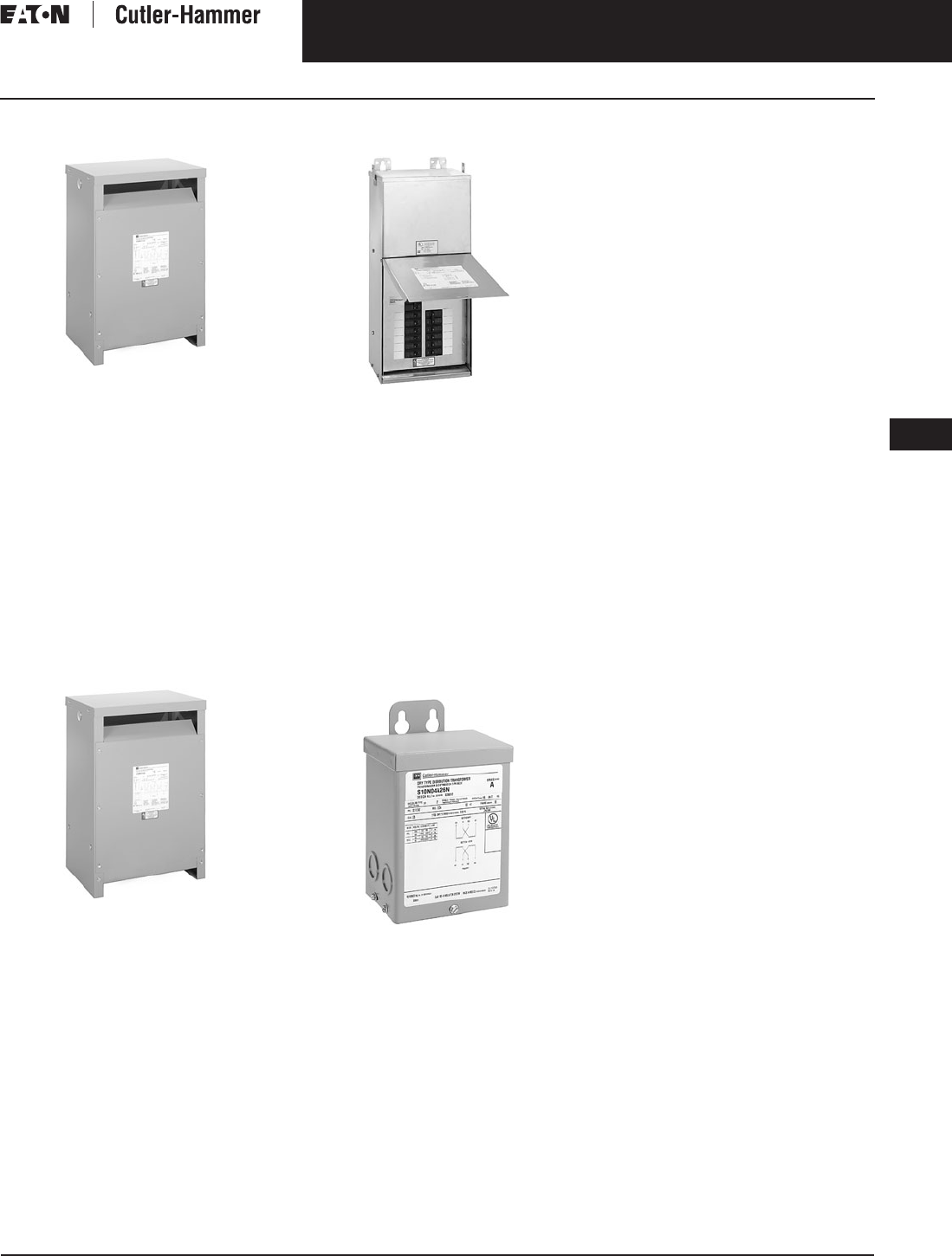
November 2003
CA08101001E For more information visit: www.cutler-hammer.eaton.com
9-123
Transformers
9
General Purpose & Industrial Control Transformers
Technical Data and Specifications
Vol. 1, Ref. No. [0423]
Shielded Isolation
Shielded Isolation Transformer
“Sensitive” loads such as input circuits
of computers, hospital operating
rooms, microprocessors, require
additional protection from electrical
disturbances. The Cutler-Hammer
Shielded Isolation transformer by
Eaton Corporation uses an electro-
static shield grounded to the trans-
former case to attenuate electrical
disturbances on the line from being
transmitted to the load. Shielded Isola-
tion units are similar in design and
ratings to the EP, EPT, DS-3, and DT-3.
ac Adjustable Frequency Drive
and dc Motor Drive Isolation
Drive Isolation Transformer
Drive Isolation transformers are
designed especially for 3-phase SCR
controlled, variable speed motor
drives. Sized by hp and common
motor voltages, the Drive Isolation
transformer is braced to withstand the
mechanical stresses associated with a
motor drive. Drive Isolation units are
available in ventilated designs (150°C
rise) 5 – 800+ hp (through 1500 kVA).
Epoxy encapsulated designs (115°C
rise) are available in 5 – 20 hp designs
by custom order.
Mini-Power Center
Mini-Power Center
The Mini-Power Center replaces 3 indi-
vidual components — a main breaker,
transformer, and panelboard — by
combining all 3 into one unit. All inter-
connecting wiring is performed at the
factory. Eaton’s Cutler-Hammer
Mini-Power Centers are available with
primary main breakers rated up to 600
volts, 100 amperes; encapsulated EP
or EPT transformers through 30 kVA;
and secondary panelboards with main
breakers and provisions for up to 24
one-pole feeder breakers. NEMA 3R
enclosure is standard.
Buck-Boost Transformer
Buck-Boost Transformer
Buck-Boost transformers have 120 x 240
or 240 x 480 volt primaries with 12/24,
16/32, or 24/48 volt secondaries. Their
primary use is as auto-transformers for
slight upward (“boost”) or downward
(“buck”) adjustments in voltages.
Eaton’s Cutler-Hammer
Buck-Boost
transformers
are encapsulated designs
with totally-enclosed non-ventilated
enclosures. Units are 1-phase, but can
be installed as a 3-phase bank.
Customer-Furnished Connecting Cables
Eaton’s Cutler-Hammer recommends
external cables be rated 90°C (sized at
75°C ampacity) for encapsulated
designs and 75°C for ventilated
designs. Primary and secondary termi-
nal lugs are not included. Lug kits are
available separately.
Overload Capability
Short-term overload capacity is
designed
into transformers as required
by ANSI. dry-type distribution trans-
formers will deliver 200% nameplate
load for one-half hour; 150% load for
one hour; and 125% load for four
hours without being damaged pro-
vided that a constant 50% load pre-
cedes and follows the overload. See
ANSI C57.96-01.250 for additional
limitations.
Continuous overload capacity is not
deliberately designed into a trans-
former because the design objective is
to be within the allowed winding tem-
perature rise with nameplate loading.
Seismically Qualified
Eaton’s Cutler-Hammer manufactured
dry-type distribution transformers are
seismically qualified, and exceed
requirements of the Uniform Building
Code (UBC) and California Code Title 24.
Taps
Primary taps are available in most
ratings to allow compensation for
source voltage variations.
Series-Multiple Windings
Series-multiple windings consist of 2
similar coils in each winding which
can be connected in series or parallel
(multiple). Transformers with series-
multiple windings are designated with a
“X” or “/” between the voltage ratings,
such as voltages of “120/240” or “240
x 480.” If the series-multiple winding is
designated by an “X,” the winding can
be connected only for a series or parallel.
With the “/” designation, a midpoint
also becomes available in addition to
the series or parallel connection. As an
example, a 120 x 240 winding can be
connected for either 120 (parallel) OR
240 (series), but a 120/240 winding can
be connected for 120 (parallel), or 240
(series), or 240 with a 120 midpoint.
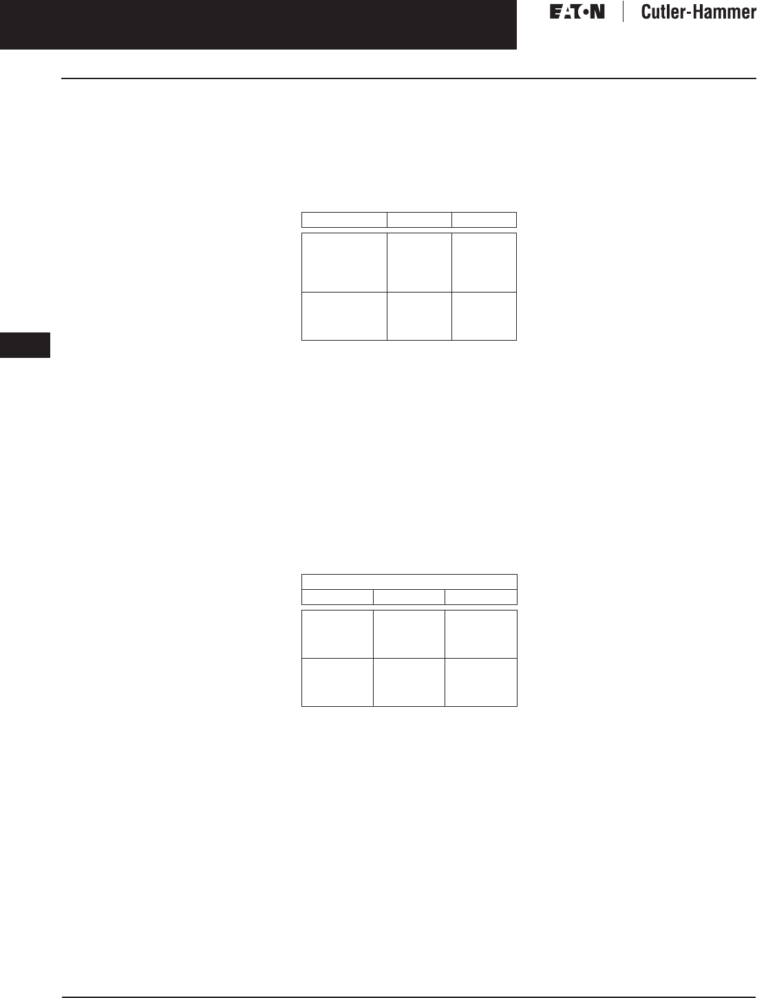
November 2003
9-124
For more information visit: www.cutler-hammer.eaton.com CA08101001E
Transformers
9
General Purpose & Industrial Control Transformers
Technical Data and Specifications Vol. 1, Ref. No. [0424]
Enclosures
Eaton’s Cutler-Hammer ventilated
transformers, Types DS-3, DT-3, MD,
and KT, utilize a NEMA 2 rated (drip-
proof) enclosure as standard, and are
rated NEMA 3R with the addition of
weathershields. Cutler-Hammer
encapsulated (Types EP, EPT, EPZ,
and EPTZ) and totally enclosed,
non-ventilated (Types DS-3E and
DT-3E) transformers utilize a NEMA
3R rated enclosure.
Buck-Boost Transformers
An autotransformer has only one
winding, and is therefore smaller and
more economical than the conventional
two-winding transformer. In an
autotransformer, the primary and sec-
ondary are electrically and mechani-
cally connected together. The required
secondary voltage is obtained by
“tapping-off” from the single winding.
Buck-Boost autotransformers are insu-
lated units with 120 x 240 or 240 x 480
volt primaries and 12/24, 16/32, or 24/48
volt secondaries and provide a very
economical method for minor voltage
adjustments where circuit isolation is
not needed.
Autotransformers can be used only
where local electrical codes permit
and isolation of the two circuits is
not required.
Non-Linear Ratings
The transformers shall be specifically
designed to supply circuits with a
harmonic profile equal to or less than
a K-factor of 4 or 13 as described
below without exceeding specified
temperature rise.
Table 9-146. Non-Linear Ratings
Sound Levels
All Cutler-Hammer 600 volt class gen-
eral purpose dry-type distribution
transformers are designed to meet
NEMA ST-20 sound levels listed here.
These are the sound levels measured
in a soundproof environment. Actual
sound levels measured at an installa-
tion will likely be higher due to electri-
cal connections and environmental
conditions. Lower sound levels are
available and should be specified
when the transformer is going to be
installed in an area where sound may
be a concern.
Table 9-147. Average Sound Levels
All Cutler-Hammer general purpose
dry-type distribution transformers are
designed with sound levels lower than
NEMA ST-20 maximum levels. However,
consideration should be given to the
specific location of the transformers
and their installation to minimize the
potential for sound transmission to
surrounding structures and sound re-
flection. It is suggested that the follow-
ing installation methods be included:
1. If possible, mount the transformer
away from corners of wall or
ceilings. For installation which
must be near a corner, use sound-
absorbing materials on the walls
and ceilings if necessary to
eliminate reflection.
2. Provide a solid foundation for
mounting the transformer and
then use vibration dampening
mounts if not already provided in
the transformer (Cutler-Hammer
encapsulated EP/EPT designs uti-
lize a special encapsulation sys-
tem and ventilated DS/DT-3
designs contain a built-in vibration
dampening system to minimize
and isolate sound transmission).
3. Provide flexible conduit to make the
connections to the transformer.
4. Locate the transformer as far as
possible from areas where high
sound levels are undesirable.
Harmonic K-4 K-13
Fundamental
3rd
5th
7th
9th
100.0%
34.0%
22.0%
3.0%
1.0%
100.0%
70.0%
42.0%
5.0%
3.0%
11th
13th
15th
17th
.7%
.5%
.3%
.3%
3.0%
1.0%
.7%
.6%
NEMA ST-20 Average Sound Level (dB)
kVA Ventilated Encapsulated
0 – 9
10 – 50
51 – 150
151 – 300
40
45
50
55
45
50
55
57
301 – 500
501 – 700
701 – 1000
1001 – 1500
60
62
64
65
59
61
63
64

November 2003
CA08101001E For more information visit: www.cutler-hammer.eaton.com
9-125
Transformers
9
General Purpose & Industrial Control Transformers
Technical Data and Specifications
Vol. 1, Ref. No. [0425]
Table 9-148. Rated Line Amperes for kVA and Voltages of Single-Phase Transformers
Note: Line Current = (kVA x 1000)/Line Voltage
Table 9-149. Rated Line Amperes for kVA and Voltages of Three-Phase Transformers
Note: Three-Phase Line Current = (kVA x 1000)/(Line Voltage x 1.732)
Amperes
for kVA
Voltage
120 208 220 240 277 480 600 2400 4160
.25
.50
.75
2.0
4.2
6.3
1.2
2.4
3.6
1.1
2.3
3.4
1.0
2.1
3.1
.9
1.8
2.7
.5
1.0
1.6
.4
.8
1.3
.10
.21
.31
.06
.12
.18
1
1.5
2
8.3
12.5
16.7
4.8
7.2
9.6
4.5
6.8
9.1
4.2
6.2
8.3
3.6
5.4
7.2
2.1
3.1
4.2
1.7
2.5
3.3
.42
.63
.83
.24
.36
.48
3
5
7.5
25
41
62
14.4
24.0
36
13.6
22.7
34
12.5
20.8
31
10.8
18.0
27
6.2
10.4
15.6
5.0
8.3
12.5
1.2
2.1
3.1
.72
1.2
1.8
10
15
25
83
125
208
48
72
120
45
68
114
41
62
104
36
54
90
20.8
31
52
16.7
25
41
4.2
6.2
10.4
2.4
3.6
6.0
37.5
50
75
312
416
625
180
240
360
170
227
341
156
208
312
135
180
270
78
104
156
62
83
125
15.6
20.8
31.3
9.0
12.0
18.0
100
167
833
1391
480
802
455
759
416
695
361
602
208
347
166
278
41.7
69.6
24.0
40.1
Amperes
for kVA
Voltage
208 240 380 480 600 2400 4160
3
6
9
8.3
16.6
25
7.2
14.4
21.6
4.6
9.1
13.7
3.6
7.2
10.8
2.9
5.8
8.6
.72
1.4
2.2
.42
.83
1.2
15
22.5
30
41.7
62.4
83.4
36.1
54.1
72.3
22.8
34.2
45.6
18.0
27.1
36.1
14.4
21.6
28.9
3.6
5.4
7.2
2.1
3.1
4.2
37.5
45
50
104
124
139
90.3
108
120
57.0
68.4
76
45.2
54.2
60.1
36.1
43.4
48.1
9.0
10.8
12.0
5.2
6.3
6.9
75
112.5
150
208
312
416
180
270
360
114
171
228
90
135
180
72
108
144
18.0
27.1
36.1
10.4
15.6
20.8
225
300
500
624
832
1387
541
721
1202
342
456
760
270
360
601
216
288
481
54.2
72.2
120
31.3
41.6
69.4
750
1000
2084
2779
1806
2408
1140
1519
903
1204
723
963
180
241
104
139

November 2003
9-126
For more information visit: www.cutler-hammer.eaton.com CA08101001E
Transformers
9
General Purpose & Industrial Control Transformers
Technical Data and Specifications Vol. 1, Ref. No. [0426]
Typical Dimensions and Technical Data
Table 9-150. Typical Data for 600-Volt Class General Purpose dry-type Transformers
Typical values for aluminum windings. Contact Eaton’s Cutler-Hammer business for values of copper windings.
For Types DS-3 and DT-3 transformers and all K-factor transformers, allow 6-inch (152.4 mm) clearance between rear of transformer and wall.
Actual impedance may be ± 7.5%.
Type EPT transformers 3-15 kVA are T-T connected.
Refer to the Cutler-Hammer business.
Note: Performance data is based upon 480 volt Delta primary and a 208Y/120 volt secondary for three-phase transformers; 240 x 480 volt
primary and a 120/240 volt secondary for single-phase transformers. All data is subject to future revision.
Note: Refer to the Cutler-Hammer business for 5 kV class information. All data is subject to future revision.
Type kVA Dimensions (Inches) Weight Lbs. Losses in Watts Efficiency % Regulation Sound
Level
dB
Height Width Depth Al Cu N.L. Total 1/4
Load
1/2
Load
3/4
Load
Full
Load
100%
P. F.
80%
P. F.
% Imp.
EP
115°C
Rise
.05
.075
.10
.15
6-1/2
6-1/2
6-1/2
6-1/2
3-7/8
3-7/8
3-7/8
3-7/8
3-1/2
3-1/2
3-1/2
3-1/2
—
—
—
—
7
7
7
8
6
7
5
7
9
14
15
20
65.3
66.0
82.4
83.4
79.6
79.0
86.9
88.2
84.3
82.5
87.7
88.9
85.6
82.8
86.5
87.8
5.9
9.4
10.3
9.0
6.4
9.2
10.6
9.6
6.5
9.8
11.0
9.8
45
45
45
45
.25
.5
.75
1
6-1/2
6-1/2
8-3/8
8-3/8
4-7/8
4-7/8
6
6
3-7/8
4-5/8
5-1/2
5-1/2
—
—
—
—
12
13
20
30
14
20
29
24
29
47
57
60
79.0
85.1
86.0
90.8
87.2
90.3
91.3
93.9
89.5
91.4
92.7
94.5
89.6
91.4
92.9
94.4
5.9
5.5
3.9
3.8
7.5
7.0
5.0
4.9
7.5
6.9
5.0
4.9
45
45
45
45
1.5
2
3
5
10-1/2
10-1/2
14-1/4
16
6-3/8
6-3/8
71-1/16
10-3/8
6-1/8
6-1/8
8
9-7/8
65
113
—
—
40
40
69
120
30
30
61
104
90
100
135
215
92.5
94.2
92.0
91.8
94.7
95.7
95.0
95.0
95.0
95.8
95.7
95.8
94.6
95.4
95.7
95.9
4.1
3.6
2.5
2.3
5.2
4.7
3.5
3.3
5.2
4.7
3.5
3.4
45
45
45
45
7.5
10
15
25
16
19
19
22-5/16
10-3/8
13-3/8
13-3/8
16-3/8
9-7/8
10-1/2
10-1/2
14-1/8
123
193
216
385
133
208
235
414
129
153
209
191
250
295
435
440
93.2
93.9
94.4
96.8
96.0
96.3
96.6
98.0
96.7
97.0
97.1
98.3
95.9
97.2
97.2
98.4
1.5
1.5
1.6
1.1
2.4
2.5
2.8
2.5
2.5
2.8
3.0
3.1
45
50
50
50
EPT
115°C
Rise
3
6
9
15
13-3/8
15-7/8
15-7/8
17-3/8
15-15/16
16-1/2
16-1/2
19-11/16
8-5/16
9-7/8
9-7/8
10-7/16
116
143
166
275
123
153
178
300
110
145
195
265
165
275
375
545
87.3
90.9
91.6
93.0
92.6
94.5
95.0
95.7
94.3
95.5
95.9
96.5
94.9
95.7
96.1
96.6
2.1
2.2
2.0
1.9
6.1
3.1
2.8
3.1
7.9
3.7
3.0
3.3
45
45
45
50
30
45
75
26-5/8
26-1/2
30-3/4
25-1/8
28-1/2
30-1/8
12-3/4
14-5/8
15-5/8
422
660
1275
504
745
1450
250
300
400
665
740
945
96.5
97.2
97.7
97.7
98.2
98.6
98.0
98.4
98.8
97.9
98.5
98.8
1.5
1.0
.8
2.5
2.1
1.6
2.7
2.4
1.9
50
50
55
DS-3
150°C
Rise
15
25
37.5
50
30-1/4
31-1/4
37-5/8
37-5/8
16-7/8
22-5/8
22-5/8
22-5/8
15-7/8
17-1/2
19-1/2
19-1/2
147
212
306
340
165
237
343
381
200
200
250
250
465
790
1160
1595
94.7
97.1
97.4
97.3
96.6
97.7
97.8
97.7
97.1
97.5
97.5
97.4
97.1
97.2
97.2
96.9
1.9
2.5
2.6
2.9
3.4
4.2
4.3
5.7
3.7
4.5
4.6
6.5
45
45
45
45
75
100
167
42-1/8
42-1/8
62-7/8
24
24
30
23-3/8
23-3/8
34
510
560
1200
570
620
1350
350
400
650
2175
2825
3270
97.4
97.8
98.0
97.8
98.0
98.4
97.6
97.7
98.3
97.2
97.3
98.3
2.6
2.7
1.8
5.5
6.0
5.2
6.4
7.3
6.8
50
50
55
DT-3
150°C
Rise
15
30
45
75
25
30-1/8
30-1/8
39-3/8
20-1/8
20-1/8
20-1/8
26-1/8
14-1/8
14-1/8
14-1/8
19-1/8
152
230
310
480
172
300
370
550
155
250
300
400
665
1795
1685
2535
95.2
95.5
97.2
97.2
96.4
95.9
98.2
97.6
96.3
95.3
98.4
97.2
95.8
94.4
98.5
96.7
3.5
5.3
1.1
3.0
5.2
7.8
3.7
4.8
5.3
7.9
5.0
5.1
45
45
45
50
112.5
150
225
300
39-3/8
46-5/8
56
62-1/4
26-1/8
28
31-1/4
31-1/4
19-1/8
23
24-1/4
30-1/4
600
785
1100
1600
675
870
1200
2150
600
700
900
1100
3830
4430
5795
7065
96.9
97.5
97.9
98.0
97.3
97.8
98.1
98.3
97.0
97.6
97.9
98.1
96.5
97.2
97.5
97.7
3.4
2.7
2.4
2.2
5.8
5.2
5.4
5.3
6.2
5.8
6.4
6.5
50
50
55
55
500
750
1000
75
75
76
44-1/2
44-1/2
60
36
36
50
2400
2900
4530
3100
3600
5400
1500
2100
6875
10090
98.6
98.5
98.9
98.9
98.8
98.8
98.7
98.7
1.2
1.3
3.7
4.6
4.9
6.3
60
64
64
DT-3
115°C
Rise
15
30
45
75
25
30-1/8
30-1/8
39-3/8
20-1/8
20-1/8
20-1/8
26-1/8
14-1/8
14-1/8
14-1/8
19-1/8
152
230
310
480
172
300
370
550
155
250
300
400
655
1460
1475
2060
95.3
95.7
96.7
97.1
96.4
96.3
97.4
97.7
96.3
95.8
97.2
97.6
95.9
95.0
96.9
97.3
3.4
4.6
2.7
2.3
4.8
6.3
4.1
3.9
4.8
6.4
4.2
4.2
45
45
45
50
112.5
150
225
300
39-3/8
46-5/8
56
62-1/4
26-1/8
28
31-1/4
31-1/4
19-1/8
23
24-1/4
30-1/4
600
785
1100
1600
675
870
1200
2150
600
700
900
1100
3220
4340
5640
5950
97.4
97.5
97.8
98.0
97.8
97.8
98.1
98.2
97.6
97.6
97.9
98.0
97.3
97.2
97.6
97.7
2.5
2.6
2.4
2.2
4.6
5.1
5.8
5.5
5.1
5.8
7.2
6.8
50
50
55
55
500
750
75
76
44-1/2
60
36
50
2400
4530
3100
5400
1500
5955
98.5
98.9
99.0
98.8
1.0
4.0
5.5
60
64
DT-3
80°C
Rise
15
30
45
30-1/8
30-1/8
39-3/8
20-1/8
20-1/8
26-1/8
14-1/8
14-1/8
19-1/8
230
310
480
300
370
550
250
300
400
505
810
1135
93.3
95.8
96.1
95.9
97.2
97.4
96.6
97.5
97.6
96.7
97.4
97.5
1.7
1.8
1.7
2.5
2.7
2.8
2.5
2.7
2.9
45
45
45
75
112.5
150
39-3/8
46-5/8
56
26-1/8
28
31-1/4
19-1/8
23
24-1/4
600
785
1100
675
870
1200
600
700
900
1855
2930
2170
96.5
97.2
97.4
97.6
97.8
98.4
97.7
97.8
98.6
97.6
97.5
98.6
1.8
2.1
.9
3.4
3.9
2.5
3.8
4.3
3.0
50
50
50
225
300
500
62-1/4
75
76
31-1/4
44-1/2
60
30-1/4
36
50
1600
2400
4190
2150
3100
4650
1100
1500
4425
3940
97.7
97.8
98.3
98.6
98.3
98.7
98.1
98.7
1.6
.9
3.9
2.6
4.7
3.3
55
55
60
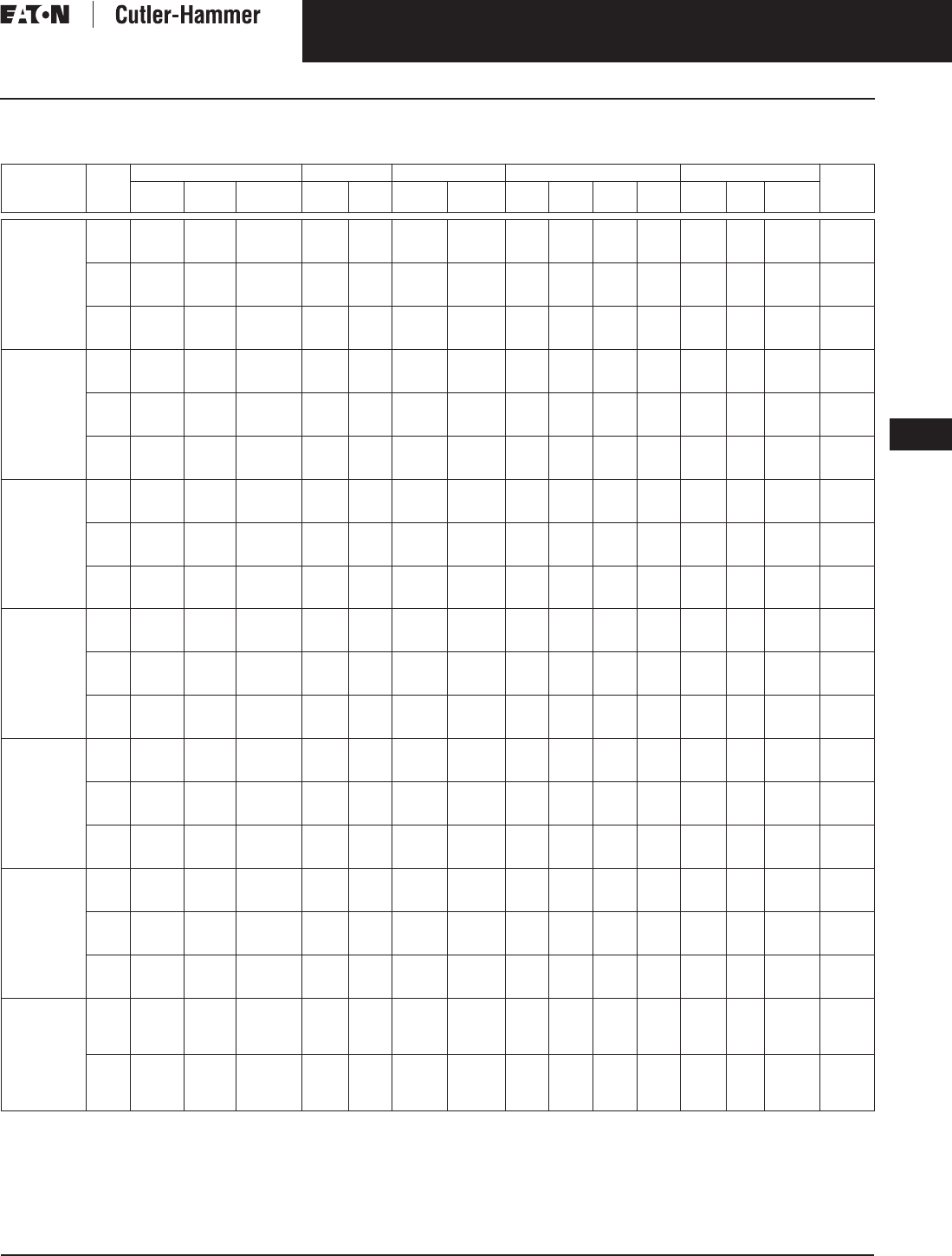
November 2003
CA08101001E For more information visit: www.cutler-hammer.eaton.com
9-127
Transformers
9
General Purpose & Industrial Control Transformers
Technical Data and Specifications
Vol. 1, Ref. No. [0427]
Typical Dimensions and Technical Data
Table 9-151. Typical Data for 600-Volt Class NEMA TP-1 and Non-linear Transformers
Typical values for aluminum windings. Contact Eaton’s Cutler-Hammer business for values of copper windings.
For Type DT-3 transformers and all K Factor transformers, allow 6-inch (152.4 mm) clearance between rear of transformer and wall.
Actual impedance may be ± 7.5%.
Refer to the Cutler-Hammer business.
Note: Performance data is based upon 480 volt Delta primary and a 208Y/120 volt secondary for three-phase transformers; 240 x 480 volt
primary and a 120/240 volt secondary for single-phase transformers. All data is subject to future revision.
Note: Performance Data is based on a 480 delta primary and a 208Y/120 secondary. All data is subject to future revision.
Type kVA Dimensions (Inches) Weight Lbs. Losses in Watts Efficiency % Regulation Sound
Level
dB
Height Width Depth Al Cu N.L. Total 1/4
Load
1/2
Load
3/4
Load
Full
Load
100%
P. F.
80%
P. F.
% Imp.
DT-3
150ºC
Rise
NEMA TP-1
15
30
45
25
30-1/8
30-1/8
20-1/8
20-1/8
20-1/8
14-1/8
14-1/8
14-1/8
152
230
310
172
300
370
80
100
170
822
1674
1885
98.6
97.3
97.5
96.3
96.7
97.2
95.4
95.6
96.5
94.3
94.4
95.6
3.3
3.6
2.7
4.8
5.1
4.4
6.4
7
5.9
45
45
45
75
112.5
150
39-3/8
39-3/8
46-1/2
26-1/8
26-1/8
28
19-1/8
19-1/8
23
480
600
800
550
675
1000
230
360
480
2534
3290
3552
98
98
98.2
97.7
97.9
98.2
97.1
97.4
97.8
96.4
96.9
97.4
2.1
2.3
1.6
4.3
4.6
3.8
5.7
5.9
5.3
50
50
50
225
300
500
56
62-1/4
75
31-1/4
31-1/4
44-1/2
24-1/4
30-1/4
36
1250
1600
2400
1800
2150
3100
565
730
1350
6783
7477
8031
98.3
98.4
98.5
98
98.3
98.7
97.5
97.9
98.5
96.8
97.3
98.2
2.3
1.9
1.4
6.4
5.7
4.9
8.4
7.6
6.4
55
55
60
K-4
150°C
Rise
15
30
45
30-1/8
30-1/8
30-1/8
20-1/8
20-1/8
20-1/8
14-1/8
14-1/8
14-1/8
230
230
310
300
300
370
250
250
300
1090
1990
2110
92.2
95.2
96.3
93.5
95.3
96.5
92.9
94.3
95.8
91.8
93.0
94.9
3.5
3.7
2.6
5.1
6.0
4.3
5.2
6.3
4.5
45
45
45
75
112.5
150
39-3/8
39-3/8
56
26-1/8
26-1/8
31-1/4
19-1/8
19-1/8
24-1/4
480
600
1100
675
675
1200
400
600
900
2840
3870
5250
97.0
97.1
96.8
97.1
97.3
97.1
96.6
96.8
96.7
95.9
96.2
96.1
2.3
2.8
2.2
4.3
5.5
4.2
4.8
6.2
4.7
50
50
55
225
300
500
56
75
75
31-1/4
44-1/2
44-1/2
24-1/4
36
36
1100
2400
2800
1200
3100
3600
900
1100
1500
7270
8420
9620
97.6
97.9
98.5
97.6
97.9
98.8
97.1
97.5
98.7
96.5
96.9
98.5
1.1
1.6
.7
4.1
5.6
3.7
5.3
7.7
5.5
55
55
60
K-4
115°C
Rise
15
30
45
30-1/8
30-1/8
39-3/8
20-1/8
20-1/8
26-1/8
14-1/8
14-1/8
19-1/8
230
230
480
300
300
575
250
250
400
950
1840
2090
92.4
95.4
95.8
93.9
95.5
96.7
93.5
94.6
96.4
92.6
93.5
95.9
3.3
3.6
1.9
4.4
5.7
3.1
4.4
5.9
3.2
45
45
45
75
112.5
150
39-3/8
46-5/8
56
26-1/8
28
31-1/4
19-1/8
23
24-1/4
600
785
1100
675
870
1200
600
700
900
2360
3760
4260
96.2
96.8
97.0
96.9
97.2
97.4
96.7
96.8
97.2
96.2
96.2
96.7
2.1
2.8
1.9
3.8
4.9
3.9
4.2
5.4
4.5
50
50
50
225
300
500
62-1/4
75
90
31-1/4
44-1/2
69
30-1/4
36
42
1600
2400
4500
2150
3100
1100
1500
2600
4620
4980
5360
97.6
97.8
97.7
98.1
98.5
98.4
98.0
98.5
98.5
97.7
98.4
98.4
1.4
.8
.7
4.1
2.4
4.1
5.3
3.0
6.1
55
55
60
K-4
80°C
Rise
15
30
45
30-1/8
30-1/8
39-3/8
20-1/8
20-1/8
26-1/8
14-1/8
14-1/8
19-1/8
230
310
480
300
370
575
250
300
400
670
990
1170
92.8
95.4
96.0
94.7
96.5
97.0
94.7
96.3
97.0
94.2
95.9
96.6
2.0
1.8
3.1
3.1
2.7
3.2
3.1
2.8
3.3
45
45
45
75
112.5
150
39-3/8
56
56
26-1/8
31-1/4
31-1/4
19-1/8
24-1/4
24-1/4
600
1100
1100
675
1200
1200
600
900
900
2290
2610
3090
96.2
96.4
97.2
97.0
97.3
97.8
96.8
97.3
97.7
96.3
97.0
97.4
1.8
1.4
1.4
3.5
2.9
3.7
3.9
3.3
4.6
50
50
50
225
300
500
62-1/4
75
31-1/4
44-1/2
30-1/4
36
1600
2400
2150
3100
1100
1500
4320
5060
97.6
97.8
98.1
98.5
98.0
98.6
97.6
98.6
1.7
.7
4.6
2.4
5.9
3.2
55
55
60
K-13
150°C
Rise
15
30
45
30-1/8
30-1/8
39-3/8
20-1/8
20-1/8
26-1/8
14-1/8
14-1/8
19-1/8
230
310
480
300
370
575
250
300
400
900
1370
1730
92.5
95.1
95.7
94.1
95.9
96.4
93.7
95.5
96.1
92.9
94.7
95.5
2.5
2.3
2.0
3.9
3.6
3.1
4.1
3.7
3.2
45
45
45
75
112.5
150
39-3/8
46-5/8
56
26-1/8
28
31-1/4
19-1/8
23
24-1/4
600
785
1100
675
870
1200
600
700
900
2270
3370
4270
96.2
96.9
97.0
97.0
97.3
97.4
96.8
97.0
97.1
96.3
96.5
96.7
3.5
2.5
1.8
4.0
4.6
3.8
4.0
5.1
4.4
50
50
50
225
300
500
62-1/4
75
90
31-1/4
44-1/2
69
30-1/4
36
42
1600
2400
4500
2150
3100
1100
1500
2600
5080
5310
5625
97.5
97.7
97.7
97.9
98.4
98.4
97.7
98.4
98.5
97.3
98.3
98.4
1.7
.9
.6
4.2
2.5
3.3
5.2
3.2
4.7
55
55
60
K-13
115°C
Rise
15
30
45
30-1/8
30-1/8
39-3/8
20-1/8
20-1/8
26-1/8
14-1/8
14-1/8
19-1/8
230
310
480
300
370
575
250
300
400
790
1070
1300
92.6
95.3
95.9
94.4
96.4
96.9
94.2
96.1
96.8
93.5
95.6
96.4
2.4
1.8
1.6
3.5
2.4
3.0
3.6
2.4
3.3
45
45
45
75
112.5
150
39-3/8
46-5/8
56
26-1/8
28
31-1/4
19-1/8
23
24-1/4
600
785
1100
675
870
1200
600
700
900
1960
3140
3480
96.3
96.9
97.1
97.2
97.4
97.7
97.1
97.2
97.5
96.7
96.7
97.2
1.8
1.7
1.5
3.3
3.5
3.8
3.6
4.8
4.6
50
50
50
225
300
500
62-1/4
75
90
31-1/4
44-1/2
69
30-1/4
36
42
1600
2400
4500
2150
3100
1100
1500
2600
4200
4780
5360
97.6
97.8
97.7
98.1
98.5
98.4
98.0
98.5
98.5
97.7
98.4
98.4
1.6
.8
.7
4.2
2.4
3.3
5.3
3.1
4.7
55
55
60
K-13
80°C
Rise
15
30
45
75
30-1/8
30-1/8
39-3/8
46-5/8
20-1/8
20-1/8
26-1/8
28
14-1/8
14-1/8
19-1/8
23
230
310
480
785
300
370
575
870
250
300
400
700
690
990
1120
1800
92.7
95.4
96.0
95.8
94.7
96.5
97.1
97.0
94.6
96.3
97.0
97.0
94.1
95.9
96.7
96.8
2.3
1.8
1.4
1.6
3.3
2.7
2.7
3.0
3.4
2.8
3.0
3.3
45
45
45
50
112.5
150
225
300
56
62-1/4
75
75
31-1/4
31-1/4
44-1/2
44-1/2
24-1/4
30-1/4
36
36
1100
1600
2400
—
1200
2150
3100
3600
900
1100
1500
2100
2210
2350
2470
2860
96.4
96.8
97.1
97.1
97.5
97.8
98.2
98.2
97.5
97.9
98.3
98.4
97.3
97.8
98.3
98.4
1.1
.9
.6
.7
2.7
2.6
2.0
2.8
3.4
3.4
2.5
3.8
50
50
55
55
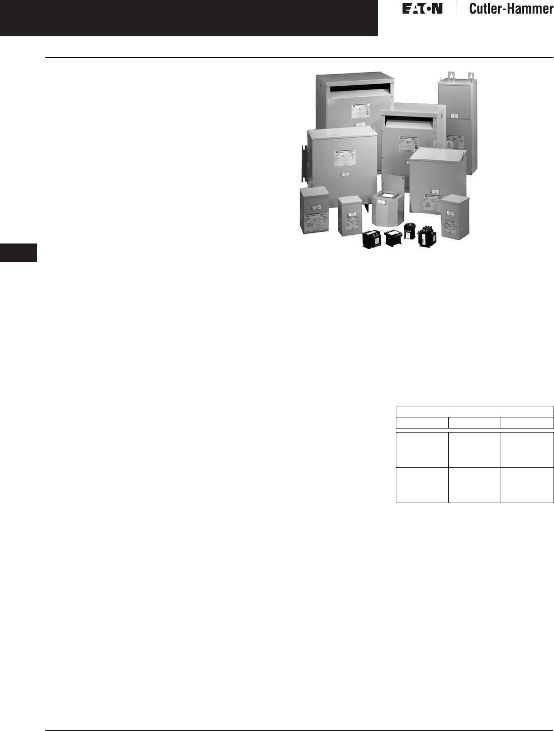
November 2003
9-128
For more information visit: www.cutler-hammer.eaton.com CA08101001E
Transformers
9
General Purpose & Industrial Control Transformers
Technical Data and Specifications Vol. 1, Ref. No. [0428]
Typical Specifications —
General Purpose
(1000 kVA and Below)
General
Furnish and install, single-phase and
three-phase general purpose individu-
ally mounted dry-type transformers of
the two-winding type, self-cooled, with
ratings and voltages as indicated on
the drawings. Transformers shall be
manufactured by Eaton’s Cutler-
Hammer business.
Transformers shall be designed, manu-
factured, and tested in accordance with
all the latest applicable ANSI, NEMA
and IEEE standards. All 600-volt class
transformers through 1000 kVA shall
be UL listed and bear the UL label.
Transformers shall be designed for
continuous operation at rated kVA,
for 24 hours a day, 365 days a year
operation, with normal life expectancy
as defined in ANSI C57.96.
Insulation Systems
Transformers shall be insulated as
follows:
■Type EP or EPT:
0.050 through 75 kVA: 185°C insula-
tion system.
■Type DS-3 or DT-3:
15 kVA and above: 220°C (Class R)
insulation system.
Required performance shall be
obtained without exceeding the above
indicated temperature rise in a 40°C
maximum ambient, with a 30°C
average over 24 hours.
All insulation materials shall be flame-
retardant and shall not support com-
bustion as defined in ASTM Standard
Test Method D635.
Core and Coil Assemblies
Transformer core shall be constructed
with high grade, non-aging, silicon
steel with high magnetic permeability,
and low hysteresis and eddy current
losses. Maximum magnetic flux densi-
ties shall be substantially below the
saturation point. The transformer core
volume shall allow efficient trans-
former operation at 10% above the
nominal tap voltage. The core lamina-
tions shall be tightly clamped and
compressed. Coils shall be wound of
electrical grade [aluminum] [copper]
and continuous wound construction.
BIL (Basic Impulse Level) for all 600-
volt class windings shall be 10 kV.
Cutler-Hammer Family of Dry-Type Distribution Transformers
On encapsulated units rated [75 kVA
and below] [15 kVA and below] [9 kVA
and below] the core and coil assembly
shall be completely encapsulated in
a proportioned mixture of resin and
aggregate to provide a moistureproof,
shock resistant seal. The core and coil
encapsulation system shall minimize
the sound level.
On ventilated units rated [15 kVA and
above] [30 kVA and above] [112.5 kVA
and above] the core and coil assembly
shall be impregnated with non-
hygroscopic, thermosetting varnish
and cured to reduce hot spots and seal
out moisture. The assembly shall be
installed on vibration-absorbing pads.
Enclosures
The enclosure shall be made of heavy
gauge steel and shall be finished
utilizing a continuous process of
degreasing, cleaning, and phosphatiz-
ing, followed by electrostatic deposi-
tion of a thermosetting polyester
powder coating and subsequent
baking. The coating color shall be
ANSI 61 and shall be UL recognized for
outdoor use. The maximum tempera-
ture on top of the enclosure shall not
exceed 90°C.
On units rated [75 kVA and below]
[15 kVA and below] [9 kVA and below]
encapsulated the enclosure construc-
tion shall be totally enclosed, non-
ventilated, NEMA 3R, with lifting
provisions.
On units rated [15 kVA and above]
[30 kVA and above] [112.5 kVA and
above] the enclosure construction
shall be ventilated, NEMA 2, drip-
proof, with lifting provisions. All
ventilation openings shall be protected
against falling dirt. On outdoor units,
provide suitable weathershields over
ventilation openings. To ensure proper
ventilation, locate the unit at least 6
inches (152.4 mm) from the adjacent
wall or structure.
Sound Levels
Transformer average sound levels
shall not exceed the following ANSI
and NEMA levels for self-cooled
ratings measured in accordance
with NEMA ST-20.
Table 9-152. Average Sound Levels
Tests
The following tests shall be performed
as standard on all transformers:
1. Ratio tests at the rated voltage
connection and at all tap
connections.
2. Polarity and phase relation tests
on the rated voltage connection.
3. Applied potential tests.
4. Induced potential test.
5. No-load and excitation current at
rated voltage on the rated voltage
connection.
NEMA ST-20 Average Sound Level (dB)
kVA Ventilated Encapsulated
0 – 9
10 – 50
51 – 150
151 – 300
40
45
50
55
45
50
55
57
301 – 500
501 – 700
701 – 1000
1001 – 1500
60
62
64
65
59
61
63
64

November 2003
CA08101001E For more information visit: www.cutler-hammer.eaton.com
9-129
Transformers
9
General Purpose & Industrial Control Transformers
Technical Data and Specifications
Vol. 1, Ref. No. [0429]
Typical Specifications —
Dry-Type Transformers for
Non-Linear Loads
General
Furnish and install, individually
mounted dry-type transformers of the
two-winding type, self-cooled, with
ratings and voltages as indicated on
the drawings.
Transformers shall be manufactured
by Eaton’s Cutler-Hammer business.
Transformers shall be designed,
manufactured, and tested in accor-
dance with all the latest applicable
ANSI, NEMA and IEEE standards. All
600-volt class transformers through
500 kVA shall be UL listed as suitable
for non-sinusoidal current loads with
K factor not to exceed [4] [13] [20].
Insulation Systems
Transformers shall be insulated with a
UL recognized 220°C (Class R) insula-
tion system. Winding temperature rise
shall be (80°C) (115°C) (150°C).
Required performance shall be
obtained without exceeding the above
indicated temperature rise in a 40°C
maximum ambient, with a 30°C
average.
All insulation materials shall be flame-
retardant and shall not support com-
bustion as defined in ASTM Standard
Test Method D635.
Core and Coil Assemblies
Transformer core shall be constructed
with high grade, non-aging, silicon
steel with high magnetic permeability,
and low hysteresis and eddy current
losses. Maximum magnetic flux densi-
ties shall be substantially below the
saturation point. The transformer core
volume shall allow efficient trans-
former operation at 10% above the
nominal tap voltage. The core lamina-
tions shall be tightly clamped and
compressed.
Transformer coils shall be wound of
electrical grade [aluminum] [copper]
conductor with continuous wound
construction. An electrostatic shield
consisting of a single turn of alumi-
num shall be placed between the
primary and secondary winding and
grounded to the transformer core. BIL
(Basic Impulse Level) for all 600-volt
class windings shall be 10 kV.
The core and coil assembly shall be
impregnated with non-hygroscopic,
thermosetting varnish and cured to
reduce hot spots and seal out mois-
ture. The assembly shall be installed
on vibration-absorbing pads.
The neutral conductor shall be rated to
carry 200% of normal phase current.
Sound Levels
Transformer average sound levels
shall not exceed the following ANSI
and NEMA levels for self-cooled
ratings measured in accordance
with NEMA ST-20.
Table 9-153. Average Sound Levels
Enclosures
The enclosure shall be made of heavy
gauge steel and shall be finished utiliz-
ing a continuous process of degreas-
ing, cleaning, and phosphatizing,
followed by electrostatic deposition of
a polymer polyester powder coating
and baking. The coating color shall be
ANSI 61 and shall be UL recognized for
outdoor use. The maximum tempera-
ture on top of the enclosure shall not
exceed 90°C.
The enclosure construction shall be
ventilated, NEMA 2, drip-proof, with
lifting provisions. All ventilation open-
ings shall be protected against falling
dirt. On outdoor units, provide suitable
weathershields over ventilation
openings. To ensure proper ventila-
tion, locate the unit at least 6 inches
(152.4 mm) from the adjacent wall
or structure.
Non-Linear Ratings
The transformers shall be specifically
designed to supply circuits with a
harmonic profile equal to or less than
a K Factor of 4 or 13 as described
below without exceeding [80°C]
[115°C] [150°C] temperature rise.
Table 9-154. Non-Linear Ratings
Tests
The following tests shall be performed
as standard on all transformers:
1. Ratio tests at the rated voltage
connection and at all tap
connections.
2. Polarity and phase relation tests
on the rated voltage connection.
3. Applied potential tests.
4. Induced potential test.
5. No-load and excitation current at
rated voltage on the rated voltage
connection.
NEMA ST-20 Average Sound Level (dB)
kVA Ventilated Encapsulated
0 – 9
10 – 50
51 – 150
151 – 300
40
45
50
55
45
50
55
57
301 – 500
501 – 700
701 – 1000
1001 – 1500
60
62
64
65
59
61
63
64
Harmonic K-4 K-13
Fundamental
3rd
5th
100.0%
34.0%
22.0%
100.0%
70.0%
42.0%
7th
9th
11th
3.0%
1.0%
.7%
5.0%
3.0%
3.0%
13th
15th
17th
.5%
.3%
.3%
1.0%
.7%
.6%
Further Information . . . . . . . . . . . . . B.36B.01.S.E
For a complete product
specification in CSI format,
see the Cutler-Hammer
Product Specification Guide . . . . . Section 16462

November 2003
9-130
For more information visit: www.cutler-hammer.eaton.com CA08101001E
Transformers
9
General Purpose & Industrial Control Transformers
Technical Data and Specifications Vol. 1, Ref. No. [0430]
Typical Specifications —
Low Temperature Rise
Energy Efficient
General
Furnish and install, three-phase low
temperature rise energy efficient dry-
type transformers of the two-winding
type, self-cooled, with ratings (kVA)
as indicated on the drawings.
Transformers shall be manufactured
by Eaton’s Cutler-Hammer business.
Transformers shall be designed, manu-
factured, and tested in accordance with
all applicable ANSI/NEMA and IEEE
standards, and shall be listed by
Underwriters Laboratories, Inc. and
bear the UL label.
Transformers shall be designed for
continuous operation at rated kVA,
24 hours a day, 365 days a year, with
normal life expectancy as defined in
ANSI C57.96.
Insulation System and
Temperature Rise
Transformers shall be insulated with
a 220°C (Class R) insulation system.
Transformers shall be 115°C rise
(80°C rise) and shall be capable of
carrying a 15% continuous overload,
(80°C rise transformers a continuous
30% overload) without exceeding a
150°C rise. Required performance shall
be obtained without exceeding the
above rise in a 40°C maximum,
30°C average ambient temperature.
All insulation materials shall be flame-
retardant and shall not support com-
bustion as defined in ASTM Standard
Test Method D635.
Core and Coil Assemblies
Transformer core shall be constructed
with high grade, non-aging, silicon
steel with high magnetic permeability,
and low hysteresis and eddy current
losses. Maximum magnetic flux
densities shall be substantially below
the saturation point. The core volume
shall allow efficient transformer opera-
tion at 10% above the nominal tap
voltage. The core laminations shall
be tightly clamped and compressed.
Coils shall be wound of electrical
grade [aluminum] [copper] with
continuous wound construction. BIL
(Basic Impulse Level) for all 600-volt
class windings shall be 10 kV.
The core and coil assembly shall be
impregnated with non-hygroscopic,
thermosetting varnish and cured to
reduce hot spots and seal out mois-
ture. The assembly shall be installed
on vibration-absorbing pads.
Enclosures
The enclosure shall be made of heavy
gauge steel and shall be finished utiliz-
ing a continuous process of degreas-
ing, cleaning, and phosphatizing,
followed by electrostatic deposition of
a polymer polyester powder coating
and subsequent baking. The coating
color shall be ANSI 61 and shall be UL
recognized for outdoor use.
The enclosure construction shall be
ventilated, NEMA 2, drip-proof, with
lifting provisions. All ventilation
openings shall be protected against
falling dirt. To ensure proper ventila-
tion, locate the unit at least 6 inches
(152.4 mm) from the adjacent wall
or structure.
All transformers shall be equipped
with a wiring compartment suitable
for conduit entry and large enough to
allow convenient wiring. The maxi-
mum temperature on top of the
enclosure shall not exceed 90°C.
Sound Levels
Transformer average sound levels
shall not exceed the following
ANSI/NEMA levels for self-cooled
ratings measured in accordance
with NEMA ST-20.
Table 9-155. Average Sound Levels
Tests
The following tests shall be performed
as standard on all transformers:
1. Ratio tests at the rated voltage
connection and at all tap
connections.
2. Polarity and phase relation tests
on the rated voltage connection.
3. Applied potential tests.
4. Induced potential test.
5. No-load and excitation current at
rated voltage on the rated voltage
connection.
NEMA ST-20 Average Sound Level (dB)
kVA Ventilated Encapsulated
0 – 9
10 – 50
51 – 150
151 – 300
40
45
50
55
45
50
55
57
301 – 500
501 – 700
701 – 1000
1001 – 1500
60
62
64
65
59
61
63
64
For a complete product
specification in CSI format,
see the Cutler-Hammer
Product Specification Guide . . . . . Section 16461

November 2003
CA08101001E For more information visit: www.cutler-hammer.eaton.com
9-131
Transformers
9
General Purpose & Industrial Control Transformers
Technical Data and Specifications
Vol. 1, Ref. No. [0431]
Typical Specifications —
Isolation Transformers with
Electrostatic Shielding
General
Furnish and install, single-phase and
three-phase general purpose individu-
ally mounted dry-type transformers
of the two-winding type, self-cooled,
with ratings and voltages as indicated
on the drawings. Transformers shall
be manufactured by Eaton’s Cutler-
Hammer business.
Transformers shall be designed, manu-
factured, and tested in accordance with
all the latest applicable ANSI, NEMA
and IEEE standards. All 600-volt class
transformers through 1000 kVA shall
be UL listed and bear the UL label.
Transformers shall be designed for
continuous operation at rated kVA,
for 24 hours a day, 365 days a year
operation, with normal life expectancy
as defined in ANSI C57.96.
Insulation Systems
Transformers shall be insulated as
follows:
■Type EP or EPT:
0.050 through 75 kVA: 185°C insula-
tion system which superseded
Class F, based on 115°C rise.
■Type DS-3 or DT-3:
15 kVA and above: 220°C (Class R)
insulation system which superseded
Class H, based on 150°C rise.
Required performance shall be
obtained without exceeding the above
indicated temperature rise in a 40°C
maximum ambient.
All insulation materials shall be flame-
retardant and shall not support com-
bustion as defined in ASTM Standard
Test Method D635.
Core and Coil Assemblies
Transformer core shall be constructed
with high grade, non-aging, silicon
steel with high magnetic permeability,
and low hysteresis and eddy current
losses. Maximum magnetic flux
densities shall be substantially below
the saturation point. The transformer
core volume shall allow efficient
transformer operation at 10% above
the nominal tap voltage. The core
laminations shall be tightly clamped
and compressed.
Transformer coils shall be wound of elec-
trical grade aluminum and continuous
wound construction. An electrostatic
shield consisting of a single turn of
[aluminum] [copper] shall be placed
between the primary and secondary
winding and grounded to the trans-
former core. BIL (Basic Impulse Level) for
all 600-volt class windings shall be 10 kV.
On units rated [75 kVA and below]
[15 kVA and below] [9 kVA and below]
the core and coil assembly shall be
completely encapsulated in a propor-
tioned mixture of resin and aggregate
to provide a moistureproof, shock
resistant seal. The core and coil
encapsulation system shall minimize
the sound level.
On units rated [15 kVA and above]
[30 kVA and above] [112.5 kVA and
above] the core and coil assembly
shall be impregnated with non-
hygroscopic, thermosetting varnish
and cured to reduce hot spots and seal
out moisture. The assembly shall be
installed on vibration-absorbing pads.
Enclosures
The enclosure shall be made of heavy
gauge steel and shall be finished utiliz-
ing a continuous process of degreas-
ing, cleaning, and phosphatizing,
followed by electrostatic deposition
of a thermosetting polyester powder
coating and baking. The coating color
shall be ANSI 61 and shall be UL
recognized for outdoor use. The
maximum temperature on top of the
enclosure shall not exceed 90°C.
On units rated [75 kVA and below]
[15 kVA and below] [9 kVA and below]
encapsulated, the enclosure construc-
tion shall be totally enclosed, non-
ventilated, NEMA 3R, with lifting
provisions.
On units rated [15 kVA and above] [30
kVA and above] [112.5 kVA and above]
the enclosure construction shall be
ventilated, NEMA 2, drip-proof, with
lifting provisions. All ventilation
openings shall be protected against
falling dirt. On outdoor units, provide
suitable weathershields over ventilation
openings. To ensure proper ventila-
tion, locate the unit at least 6 inches
(152.4 mm) from the adjacent wall
or structure.
Sound Levels
Transformer average sound levels
shall not exceed the following ANSI
and NEMA levels for self-cooled
ratings measured in accordance
with NEMA ST-20.
Table 9-156. Average Sound Levels
Tests
The following tests shall be performed
as standard on all transformers:
1. Ratio tests at the rated voltage
connection and at all tap
connections.
2. Polarity and phase relation tests
on the rated voltage connection.
3. Applied potential tests.
4. Induced potential test.
5. No-load and excitation current at
rated voltage on the rated voltage
connection.
NEMA ST-20 Average Sound Level (dB)
kVA Ventilated Encapsulated
0 – 9
10 – 50
51 – 150
151 – 300
40
45
50
55
45
50
55
57
301 – 500
501 – 700
701 – 1000
1001 – 1500
60
62
64
65
59
61
63
64

November 2003
9-132
For more information visit: www.cutler-hammer.eaton.com CA08101001E
Transformers
9
General Purpose & Industrial Control Transformers
Technical Data and Specifications Vol. 1, Ref. No. [0432]
Typical Specification —
ac Adjustable Frequency
Drive Isolation Transformers
General
Furnish and install, single-phase and
three-phase general purpose individu-
ally mounted dry-type transformers
of the two-winding type, self-cooled,
with ratings and voltages for input
application as indicated on the draw-
ings. Transformers shall be manufac-
tured by Eaton’s Cutler-Hammer
business.
Transformers shall be designed, manu-
factured, and tested in accordance with
all the latest applicable ANSI, NEMA
and IEEE standards. All 600-volt class
transformers through 550 kVA shall be
UL listed and bear the UL label.
Transformers shall be designed for
continuous operation at rated kVA, for
24 hours a day, 365 days a year opera-
tion, with normal life expectancy as
defined in ANSI C57.96.
Insulation Systems
Transformers shall be insulated with
a UL recognized 220°C (Class R)
insulation system.
Required performance shall be
obtained without exceeding the above
indicated temperature rise in a 40°C
maximum ambient, with a 30°C
average over 24 hours.
All insulation materials shall be flame-
retardant and shall not support com-
bustion as defined in ASTM Standard
Test Method D635.
Core and Coil Assemblies
Transformer core shall be constructed
with high grade, non-aging, silicon
steel with high magnetic permeability,
and low hysteresis and eddy current
losses. Maximum magnetic flux densi-
ties shall be substantially below the
saturation point. The transformer core
volume shall allow efficient trans-
former operation at 10% above the
nominal tap voltage. The core lamina-
tions shall be tightly clamped and
compressed. Coils shall be wound of
electrical grade [aluminum] [copper]
and continuous wound construction.
BIL (Basic Impulse Level) for all 600-
volt class windings shall be 10 kV.
A temperature sensing device shall
be imbedded in the center coil.
The core and coil assembly shall be
impregnated with non-hygroscopic,
thermosetting varnish and cured to
reduce hot spots and seal out mois-
ture. The assembly shall be installed
on vibration-absorbing pads.
Enclosures
The enclosure shall be made of heavy
gauge steel and shall be finished utiliz-
ing a continuous process of degreas-
ing, cleaning, and phosphatizing,
followed by electrostatic deposition
of a thermosetting polyester powder
coating and subsequent baking. The
coating color shall be ANSI 61 and
shall be UL recognized for outdoor
use. The maximum temperature
on top of the enclosure shall not
exceed 90°C.
The enclosure construction shall be
ventilated, NEMA 2, drip-proof, with
lifting provisions. All ventilation
openings shall be protected against
falling dirt. To ensure proper ventila-
tion, locate the unit at least 6 inches
(152.4 mm) from the adjacent wall
or structure. On outdoor units, pro-
vide suitable weathershields over
ventilation openings.
Sound Levels
Transformer average sound levels
shall not exceed the following ANSI
and NEMA levels for self-cooled
ratings measured in accordance
with NEMA ST-20.
Table 9-157. Average Sound Levels
The following table lists the recom-
mended kVA size of the drive isolation
transformer for a specific horsepower
requirement.
Table 9-158. Three-Phase
NEMA ST-20 Average Sound Level (dB)
kVA Ventilated Encapsulated
0 – 9
10 – 50
51 – 150
151 – 300
40
45
50
55
45
50
55
57
301 – 500
501 – 700
701 – 1000
1001 – 1500
60
62
64
65
59
61
63
64
Horsepower
ac Motor
kVA
Minimum
5
7.5
10
7.5
11
14
15
20
25
20
27
34
30
40
50
40
51
63
60
75
100
75
93
118
125
150
200
145
175
220
250
300
400
275
330
440
500
600
700
550
660
770
For a complete product
specification in CSI format,
see the Cutler-Hammer
Product Specification Guide . . . . . Section 16461
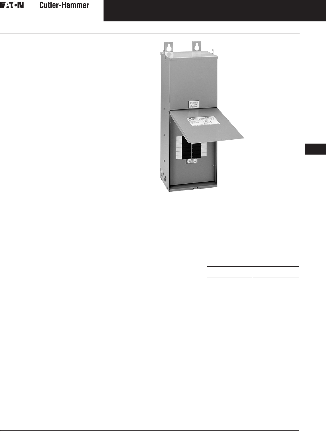
November 2003
CA08101001E For more information visit: www.cutler-hammer.eaton.com
9-133
Transformers
9
General Purpose & Industrial Control Transformers
Technical Data and Specifications
Vol. 1, Ref. No. [0433]
Typical Specifications —
Mini-Power Centers (3 – 30 kVA)
General
Furnish and install, single-phase and
three-phase general purpose individu-
ally mounted mini-power centers of
the two-winding type, self-cooled, with
ratings and voltages as indicated on
the drawings. Mini-power centers shall
be manufactured by Eaton’s Cutler-
Hammer business.
Units shall be designed, manufac-
tured, and tested in accordance with
all the latest applicable ANSI, NEMA,
IEEE, CSA and UL standards, and shall
be UL listed and CSA certified and
bear the UL and CSA labels.
Units shall be designed for continuous
operation at rated kVA, 24 hours a day,
365 days a year operation, with normal
life expectancy as defined in ANSI C57.96.
Each mini-power center shall include
a main primary breaker with an inter-
rupting rating of 14 kA at 277/480 volts;
an encapsulated dry-type transformer
and a secondary panelboard with main
breaker rated 10 kA interrupting rating
at 120/240 volts.
a. All interconnecting wiring
between the primary breaker
and transformer, secondary
main breaker and transformer,
and distribution section shall
be factory installed. Main
primary, secondary and feeder
breakers shall be enclosed with
a padlockable hinged door.
b. The secondary distribution
section shall accommodate one
inch, plug-in breakers with
10 kA interrupting capacity.
Insulation System
Transformers shall be insulated with a
185°C insulation system.
Required performance shall be
obtained without exceeding the
above indicated temperature rise in a
40°C maximum ambient, with a 30°C
average over 24 hours.
All insulation materials shall be flame-
retardant and shall not support com-
bustion as defined in ASTM Standard
Test Method D635.
Core and Coil Assemblies
Transformer core shall be constructed
with high grade, non-aging, silicon
steel with high magnetic permeability,
and low hysteresis and eddy current
losses. Maximum magnetic flux densi-
ties shall be substantially below the
saturation point.
Mini-Power Center
The transformer core volume shall
allow efficient transformer operation
at 10% above the nominal tap voltage.
The core laminations shall be tightly
clamped and compressed. Coils shall
be wound of electrical grade alumi-
num with continuous wound construc-
tion. BIL (Basic Impulse Level) for all
600-volt class windings shall be 10 kV.
The core and coil assembly shall be
completely encapsulated in a propor-
tioned mixture of resin and aggregate
to provide a moistureproof, shock
resistant seal. The core and coil encap-
sulation system shall minimize the
sound level.
Enclosures
The enclosure shall be made of heavy
gauge steel and shall be finished utiliz-
ing a continuous process of degreas-
ing, cleaning, and phosphatizing,
followed by electrostatic deposition
of a thermosetting polymer polyester
powder coating and subsequent bak-
ing. The coating color shall be ANSI 61
and shall be UL recognized for outdoor
use. Mini-power centers shall be
equipped with a wiring compartment
suitable for conduit entry and large
enough to allow convenient wiring.
The maximum temperature on top of
the enclosure shall not exceed 90°C.
The core of the transformer shall be
grounded to the enclosure. The enclo-
sure shall be totally enclosed, non-
ventilated, NEMA 3R, with lifting eyes.
Sound Levels
Transformer average sound levels
shall not exceed the following
ANSI/NEMA levels for self-cooled
ratings measured in accordance
with NEMA ST-20.
Table 9-159. Average Sound Levels
Tests
The following tests shall be performed
as standard on all transformers:
1. Ratio tests at the rated voltage
connection and at all tap
connections.
2. Polarity and phase relation tests
on the rated voltage connection.
3. Applied potential tests.
4. Induced potential test.
5. No-load and excitation current at
rated voltage on the rated voltage
connection.
kVA NEMA Average
Sound Level in dB
0 – 9
10 – 30
45
50
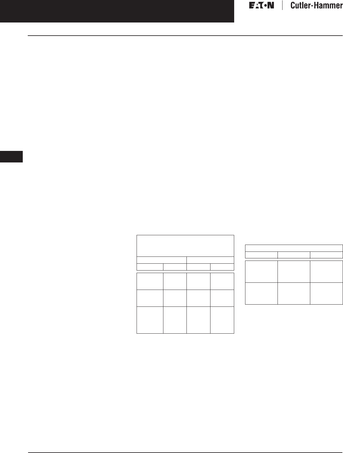
November 2003
9-134
For more information visit: www.cutler-hammer.eaton.com CA08101001E
Transformers
9
General Purpose & Industrial Control Transformers
Technical Data and Specifications Vol. 1, Ref. No. [0434]
Typical Specification –—
NEMA TP-1-1996 Compliant
Energy Efficient Transformers
General
Furnish and install, three-phase
energy efficient dry-type transformers
that comply with NEMA Standard
TP-1-1996. Transformers shall be of
the two-winding type, self-cooled,
with ratings (kVA) as indicated on the
drawings. Transformer’s losses shall
conform to NEMA TP-1 requirements.
Transformers shall bear the Energy
Star® label and be manufactured by
Eaton’s Cutler-Hammer business.
Transformers shall be designed, manu-
factured, and tested in accordance with
all the latest applicable ANSI, NEMA
and IEEE standards, and shall be listed
by Underwriters Laboratories and bear
the UL label.
Transformers shall be designed for
continuous operation at rated kVA, for
24 hours a day, 365 days a year, with
normal life expectancy as defined in
ANSI C57.96.
Insulation System and
Temperature Rise
Transformers shall be insulated with
a 220°C (Class R) insulation system.
Transformers shall be 150°C rise and
shall be capable of carrying a 15% con-
tinuous overload without exceeding a
150°C rise. Required performance shall
be obtained without exceeding the
above rise in a 40°C maximum, 30°C
average ambient temperature.
All insulation materials shall be retar-
dant and shall not support combustion
as defined in ASTM Standard Test
Method D635.
Core and Coil Assemblies
Transformer core shall be constructed
with high grade, non-aging, silicon
steel with high magnetic permeability,
and low hysteresis and eddy current
losses. Maximum magnetic flux densi-
ties shall be substantially below the
saturation point. The transformer core
volume shall allow efficient trans-
former operation at 10% above the
nominal tap voltage. The core lamina-
tions shall be tightly clamped and
compressed. Coils shall be wound of
electrical grade [aluminum] [copper]
and continuous wound construction.
BIL (Basic Impulse Level) for all 600-
volt class windings shall be 10 kV.
The core and coil assembly shall be
impregnated with non-hygroscopic,
thermosetting varnish and cured to
reduce hot spots and seal out mois-
ture. The assembly shall be installed
on vibration-absorbing pads.
Efficiency
Transformers shall be energy efficient
with minimum efficiencies as set forth
per NEMA TP-1-1996 when operated at
35% of full load capacity.
Table 9-160. NEMA TP-1-1996 Efficiency Levels
Enclosures
The enclosure shall be made of heavy
gauge steel and shall be finished utiliz-
ing a continuous process of degreas-
ing, cleaning, and phosphatizing,
followed by electrostatic deposition
of a thermosetting polyester powder
coating and subsequent baking.
The coating color shall be ANSI 61
and shall be UL recognized for
outdoor use.
The enclosure construction shall be
ventilated, NEMA 2, drip-proof, with
lifting provisions. All ventilation
openings shall be protected against
falling dirt. To ensure proper ventila-
tion, locate the unit at least 6 inches
(152.4 mm) from the adjacent wall
or structure.
All transformers shall be equipped
with a wiring compartment suitable
for conduit entry and large enough
to allow convenient wiring. The maxi-
mum temperature on top of the
enclosure shall not exceed 90°C.
Sound Levels
Transformer average sound levels shall
not exceed the following ANSI and
NEMA levels for self-cooled ratings.
Table 9-161. Average Sound Levels
Tests
The following tests shall be performed
as standard on all transformers:
1. Ratio tests at the rated voltage
connection and at all tap
connections.
2. Polarity and phase relation tests
on the rated voltage connection.
3. Applied potential tests.
4. Induced potential test.
5. No-load and excitation current at
rated voltage on the rated voltage
connection.
Tables of Energy Efficiency
NEMA Class 1 Efficiency Levels
dry-type Distribution Transformers —
Low Voltage
Single-Phase Three-Phase
kVA Efficiency kVA Efficiency
15
25
37.5
97.7
98.0
98.2
15
30
45
97.0
97.5
97.7
50
75
100
98.3
98.5
98.6
75
112.5
150
98.0
98.2
98.3
167
250
333
—
—
98.7
98.8
98.9
—
—
225
300
500
750
1000
98.5
98.6
98.7
98.8
98.9
NEMA ST-20 Average Sound Level (dB)
kVA Ventilated Encapsulated
0 – 9
10 – 50
51 – 150
151 – 300
40
45
50
55
45
50
55
57
301 – 500
501 – 700
701 – 1000
1001 – 1500
60
62
64
65
59
61
63
64

November 2003
CA08101001E For more information visit: www.cutler-hammer.eaton.com
9-135
Transformers
9
General Purpose & Industrial Control Transformers
Technical Data and Specifications
Vol. 1, Ref. No. [0435]
Standards and Certification
Cutler-Hammer Dry-Type Distribution Transformers by Eaton Corporation are approved, listed, recognized or may comply
with the following standards.
Table 9-162. Engineering Standards
Applies to .05 – 1 kVA.
Applies to 25 – 50 kVA.
Applies to 25 kVA.
Applies to 15 – 25 kVA.
Applies to 37.5 kVA.
Applies to 3 kVA.
Applies to 5 – 9 kVA.
Applies to 30 – 75 kVA.
Applies to 30 kVA.
Applies to 3 – 10 kVA.
Applies to 15 – 30 kVA.
Applies to 25 – 167 kVA.
Applies to 30 – 750 kVA.
Applies to 30 – 500 kVA.
In addition to the above standards, Cutler-Hammer Dry-Type Distribution transformers are also manufactured in compliance
with the applicable standards listed below.
Note: Not all of the following standards apply to every transformer.
■NEC: National Electrical Code.
■NEMA ST-1: Specialty Transformers (C89.1) (control transformers).
■NEMA ST-20: General Purpose Transformers.
■NEMA TP-1: Guide for Determining Energy Efficiency for Distribution Transformers.
■NEMA 250: Enclosures for Electrical Equipment (1000 volts maximum).
■IEEE C57.12.01: General Requirements for Dry-Type Distribution and Power Transformers (including those with
solid-cast and/or resin-encapsulated windings).
■ANSI C57.12.70: Terminal Markings and Connections for Distribution and Power Transformers.
■ANSI C57.12.91: Standard Test Code for Dry-Type Distribution and Power Transformers.
■CSA C22 No. 47-M90: Air-Cooled Transformers (Dry-Type).
■CSA C9-M1981: Dry-Type Transformers.
■CSA C22.2 No. 66: Specialty Transformers.
■CSA 802-94: Maximum Losses for Distribution, Power, and Dry-Type Transformers.
■NEMA TP-2: Standard Test Method for Measuring the Energy Consumption of Distribution Transformers.
Catalog
Product
Name
UL
Standard
UL/cUL
File
Number
UL Listed
Control
Number
cUL Energy
Efficiency
File Number
CSA
File
Number
Insulation
System
Temp/ºC
kVA
Single-
Phase
kVA
Three-
Phase
Applicable
IEC
Standard
Industrial Control Transformer
MTA 506 E10156 591H — LR60545 105 .05 – 5 N/A 61558
MTC 506 E10156 591H — LR60545 105 .05 – 5 N/A 61558
MTE 506 E46323 702X — LR27533 105 .025 – 1.5 N/A 61558
MTG 506 E46323 702X — LR27533 105 .05 – 1.0 N/A 61558
MTK 506 E46323 702X — LR27533 180 .05 – 5 N/A 61558
Encapsulated Transformer
AP 506 E10156 591H — — 180 3 – 10 N/A 61558
AP 1561 E78389 591H — — 180 15 N/A 61558
EP 506 E10156 591H — LR60545 180 .05 – 10 N/A 61558
EP 1561 E78389 591H EV157 LR60545 180 15 – 50 N/A 61558 /726
EPT 506 E10156 591H — LR60545 180 N/A 3 – 9 61558 /726
EPT 1561 E78389 591H EV157 LR60545 180 N/A 15 – 75 726
MPC 506 /1561 E53449 591H — LR60546 180 3 – 25 15 – 30 —
Ventilated Transformer
DS-3 1561 E78389 591H EV157 LR60545 220 15 – 167 N/A 60726
DT-3 1561 E78389 591H EV157 LR60545 220 N/A 15 – 750 60726
KT 1561 E78389 591H EV157 —220 N/A 9 – 500 N/A

November 2003
9-136
For more information visit: www.cutler-hammer.eaton.com CA08101001E
Transformers
9
General Purpose & Industrial Control Transformers
Technical Data and Specifications Vol. 1, Ref. No. [0436]
Product Selection
Single-Phase Transformers
How to Select Single-Phase Units
1. Determine the primary (source)
voltage — the voltage presently
available.
2. Determine the secondary (load)
voltage — the voltage needed at
the load.
3. Determine the kVA load:
— If the load is defined in kVA, a
transformer can be selected from
the tabulated data.
— If the load rating is given in
amperes, determine the load kVA
from the below chart. To determine
kVA when volts and amperes are
known, use the formula:
kVA = Volts x Amperes
1000
— If the load is an ac motor, deter-
mine the minimum transformer
kVA from the chart at
the right.
— Select a transformer rating
equal to or greater than the
load kVA.
4. Define tap arrangements needed.
5. Define temperature rise.
Using the above procedure, select
the transformer from the listings in
this catalog.
Table 9-163. Single-Phase ac Motors
If motors are started more than once per hour, increase minimum transformer kVA by 20%.
Note: When motor service factor is greater than 1, increase full load amperes proportionally.
Example: If service factor is 1.15, increase above ampere values by 15%.
Table 9-164. Full Load Current in Amperes — Single-Phase Circuits
Horsepower Full Load Amperes Minimum
Transformer kVA
115 Volts 208 Volts 220 Volts 230 Volts
1/6
1/4
1/3
4.4
5.8
7.2
2.4
3.2
4.0
2.3
3.0
3.8
2.2
2.9
3.6
.53
.70
.87
1/2
3/4
1
9.8
13.8
16
5.4
7.6
8.8
5.1
7.2
8.4
4.9
6.9
8
1.18
1.66
1.92
1-1/2
2
3
20
24
34
11.0
13.2
18.7
10.4
12.5
17.8
10
12
17
2.40
2.88
4.10
5
7-1/2
10
56
80
100
30.8
44
55
29.3
42
52
28
40
50
6.72
9.6
12.0
kVA Voltage
120 208 220 240 277 480 600 2400 4160
.25
.50
.75
2.0
4.2
6.3
1.2
2.4
3.6
1.1
2.3
3.4
1.0
2.1
3.1
.9
1.8
2.7
.5
1.0
1.6
.4
.8
1.3
.10
.21
.31
.06
.12
.18
1
1.5
2
8.3
12.5
16.7
4.8
7.2
9.6
4.5
6.8
9.1
4.2
6.2
8.3
3.6
5.4
7.2
2.1
3.1
4.2
1.7
2.5
3.3
.42
.63
.83
.24
.36
.48
3
5
7.5
25
41
62
14.4
24.0
36
13.6
22.7
34
12.5
20.8
31
10.8
18.0
27
6.2
10.4
15.6
5.0
8.3
12.5
1.2
2.1
3.1
.72
1.2
1.8
10
15
25
83
125
208
48
72
120
45
68
114
41
62
104
36
54
90
20.8
31
52
16.7
25
41
4.2
6.2
10.4
2.4
3.6
6.0
37.5
50
75
312
416
625
180
240
360
170
227
341
156
208
312
135
180
270
78
104
156
62
83
125
15.6
20.8
31.3
9.0
12.0
18.0
100
167
833
1391
480
802
455
759
416
695
361
602
208
347
166
278
41.7
69.6
24.0
40.1

November 2003
CA08101001E For more information visit: www.cutler-hammer.eaton.com
9-137
Transformers
9
General Purpose & Industrial Control Transformers
Technical Data and Specifications
Vol. 1, Ref. No. [0437]
Three-Phase Transformers
How to Select Three-Phase Units
1. Determine the primary (source)
voltage — the voltage presently
available.
2. Determine the secondary (load)
voltage — the voltage needed at
the load.
3. Determine the kVA load:
— If the load is defined in kVA, a
transformer can be selected from
the tabulated data.
— If the load rating is given in
amperes, determine the load kVA
from the below chart. To determine
kVA when volts and amperes are
known, use the formula:
kVA = Volts x Amperes x 1.732
1000
— If the load is an ac motor, deter-
mine the minimum transformer
kVA from the chart at
the right.
— Select a transformer rating
equal to or greater than the
load kVA.
4. Define tap arrangements needed.
5. Define temperature rise.
Using the above procedure, select
the transformer from the listings in
this catalog.
Table 9-165. Three-Phase ac Motors
If motors are started more than once per hour, increase minimum transformer kVA by 20%.
Note: When motor service factor is greater than 1, increase full load amperes proportionally.
Example: If service factor is 1.15, increase above ampere values by 15%.
Table 9-166. Full Load Current in Amperes — Three-Phase Circuits
Horsepower Full Load Amperes Minimum
Transformer kVA
208 Volts 230 Volts 380 Volts 460 Volts 575 Volts
1/2
3/4
1
2.2
3.1
4.0
2.0
2.8
3.6
1.2
1.7
2.2
1.0
1.4
1.8
.8
1.1
1.4
.9
1.2
1.5
1-1/2
2
3
5.7
7.5
10.7
5.2
6.8
9.6
3.1
4.1
5.8
2.6
3.4
4.8
2.1
2.7
3.9
2.1
2.7
3.8
5
7-1/2
10
16.7
24
31
15.2
22
28
9.2
14
17
7.6
11
14
6.1
9
11
6.3
9.2
11.2
15
20
25
46
59
75
42
54
68
26
33
41
21
27
34
17
22
27
16.6
21.6
26.6
30
40
50
88
114
143
80
104
130
48
63
79
40
52
65
32
41
52
32.4
43.2
52
60
75
100
170
211
273
154
192
248
93
116
150
77
96
124
62
77
99
64
80
103
125
150
200
342
396
528
312
360
480
189
218
291
156
180
240
125
144
192
130
150
200
kVA Voltage
208 240 380 480 600 2400 4160
3
6
9
8.3
16.6
25
7.2
14.4
21.6
4.6
9.1
13.7
3.6
7.2
10.8
2.9
5.8
8.6
.72
1.4
2.2
.42
.83
1.2
15
22.5
30
41.7
62.4
83.4
36.1
54.1
72.3
22.8
34.2
45.6
18.0
27.1
36.1
14.4
21.6
28.9
3.6
5.4
7.2
2.1
3.1
4.2
37.5
45
50
104
124
139
90.3
108
120
57.0
68.4
76
45.2
54.2
60.1
36.1
43.4
48.1
9.0
10.8
12.0
5.2
6.3
6.9
75
112.5
150
208
312
416
180
270
360
114
171
228
90
135
180
72
108
144
18.0
27.1
36.1
10.4
15.6
20.8
225
300
500
624
832
1387
541
721
1202
342
456
760
270
360
601
216
288
481
54.2
72.2
120
31.3
41.6
69.4
750
1000
2084
2779
1806
2408
1140
1519
903
1204
723
963
180
241
104
139
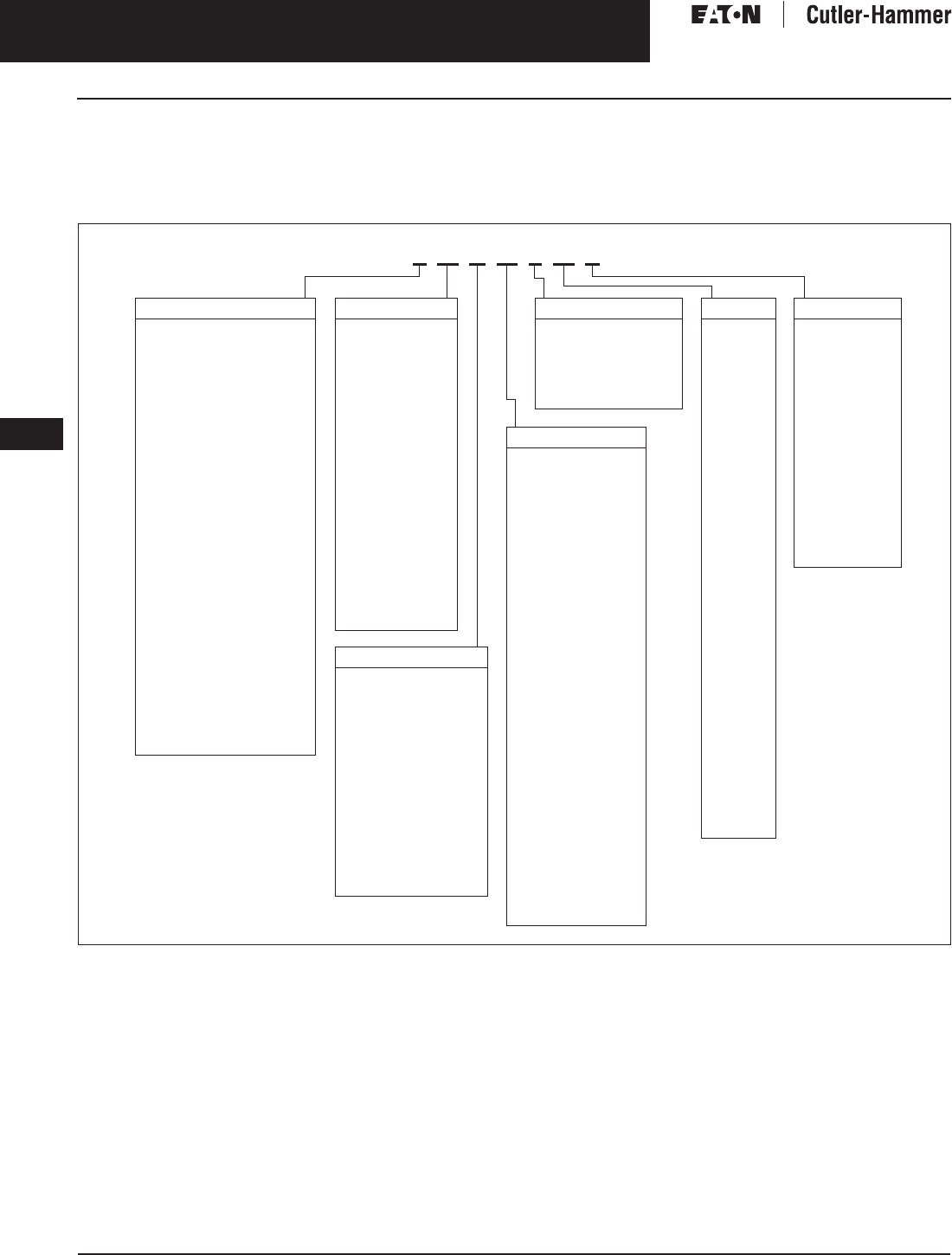
November 2003
9-138
For more information visit: www.cutler-hammer.eaton.com CA08101001E
Transformers
9
General Purpose & Industrial Control Transformers
Catalog Numbering System Vol. 1, Ref. No. [0438]
Catalog Numbering System
Note: Contact your local Cutler-Hammer sales office for voltage combinations not shown. Use table for catalog number breakdown only.
Do not use to create catalog numbers since all combinations may not be valid.
Table 9-167. General Purpose, Energy Efficient, Mini-Power Center, Shielded Isolation, Non-Linear, Buck-Boost, Marine Duty Transformers —
Example: S20N11S05A
Model number is not used on newly designed/redesigned transformers.
Copper windings.
Stainless steel (utilizes 316 stainless steel, does not imply a NEMA 4X rating).
Open type core and coil assembly.
Totally enclosed non-ventilated DS-3 or DT-3.
50/60 Hz.
Low sound design. LS47 indicates low sound equal to 47 dB; LS42 indicates 42 dB.
Fungus proof.
Certified test report of standard production tests.
Certified sound level report.
CE marked.
Thermal indicator embedded in center coil. Suffix “TT” indicates two thermal indicators of different temperature ratings, are installed.
NEMA TP-1 Energy Star Energy Efficient.
0º phase-shift
+15º phase-shift
-15º phase-shift
Note: For the Cutler-Hammer Industrial Control Transformers Catalog Numbering System see Page 9-140.
Secondary Voltage
04 = 12/24
06 = 16/32
08 = 24/48
14 = 110/220
12 = 120
10 = 120 x 240
11 = 120/240
54 = 127/254
19 = 190Y/110
28 = 208Y/120
29 = 208
25 = 220 Delta
31 = 220Y/127
26 = 220∆/110 Midtap
22 = 240∆/120 Midtap
64 = 240Y139
24 = 240 Delta
20 = 240 x 480
21 = 240/480
27 = 277
38 = 380 Delta
37 = 380Y/220
34 = 400Y/231
51 = 416Y/240
35 = 440Y/254
62 = 460Y/266
47 = 480Y/277
48 = 480 Delta
60 = 600 Delta
61 = 600Y/346
42 = 2400
41 = 4160Y/2400
46 = 4160
49 = 4800
Type
S= EP (1-Ph encapsulated)
Y= EPT (3-Ph encapsulated)
T= DS-3 (1-Ph ventilated)
V= DT-3 (3-Ph ventilated)
P= Mini-Power Center
Z= Class 1 Division 2
Groups C and D
X= Harmonic Mitigating
(3-ph ventilated)
Non-Linear
H= KT-4 (3-Ph ventilated)
B= KT-9 (3-Ph ventilated)
N= KT-13 (3-Ph ventilated)
G= KT-20 (3-Ph ventilated)
J= KT-30 (3-Ph ventilated)
A= KT-40 (3-Ph ventilated)
K= KT-50 (3-Ph ventilated)
HT = KT-4 (1-Ph ventilated)
NT= KT-13 (1-Ph ventilated)
GT= KT-20 (1-Ph ventilated)
Marine Duty
Q= EPM Marine
(1-Ph encapsulated)
L= EPTM Marine
(3-Ph encapsulated)
R= DS-3M Marine
(1-Ph ventilated)
M= DT-3M Marine
(3-Ph ventilated)
Primary Voltage
13 = 110 x 220
12 = 120
10 = 120 x 240
29 = 208
72 = 200
25 = 220
23 = 230
24 = 240
20 = 240 x 480
27 = 277
38 = 380
39 = 400
43 = 416
44 = 440
45 = 450
48 = 480
57 = 575
60 = 600
42 = 2400
46 = 4160
49 = 4800
40 = Export Model
Taps
D= 2@+2.5%, 2@-2.5%
E= 1@+5%, 1@-5%
F= 1@-10%
G= 2@-5%
J= 4@-2.5%
K= 1@-10% x 2@-5%
L= 2@-5% x 4@-2.5%
M= 2@+2.5%, 4@-2.5%
N= None
R= 1@+5%, 2@-5%
P= 1@+5%, 2@-5% x
2@+2.5%, 4@-2.5%
T= 1@+4.2%, 1@-4.2%
U= 1@+2.5%, 3@-2.5%
W= 1@+3.5%, 1@-3.5%
X= 2@+3.1%, 2 @-3.1%
Phase
A= Buck and Boost
B= 80°C Rise
F= 115°C Rise
E= Electrostatic Shield
S= Single
T= Three
Suffix Options
A...Z =
CU =
SS =
ZZ =
NV =
X=
LS_ _ =
AF =
TR =
SR =
CE =
T =
EE =
NON =
POS =
NEG =
kVA
81 = .05
85 = .075
82 = .10
83 s= .15
26 = .25
51 = .50
76 = .75
01 = 1
16 = 1.5
02 = 2
03 = 3
05 = 5
06 = 6
07 = 7.5
09 = 9
10 = 10
15 = 15
21 = 22.5
25 = 25
30 = 30
37 = 37.5
45 = 45
50 = 50
75 = 75
99 = 100
12 = 112.5
49 = 150
67 = 167
22 = 225
52 = 250
33 = 300
54 = 333
55 = 500
60 = 600
77 = 750
11 = 1000
14 = 1500
S 20 N 11 S 05 A

November 2003
CA08101001E For more information visit: www.cutler-hammer.eaton.com
9-139
Transformers
9
General Purpose & Industrial Control Transformers
Catalog Numbering System
Vol. 1, Ref. No. [0439]
Catalog Numbering System
Note: Contact your local Cutler-Hammer sales office for voltage combinations not shown. Use table for catalog number breakdown only.
Do not use to create catalog numbers since all combinations may not be valid.
Table 9-168. Motor Drive Isolation Transformers — Example: MD145E89B
For other tap combinations, contact your local Cutler-Hammer sales office.
Type
MD = DT-3
HD = KT-4
ND = KT-13
kVA
075 = 7.5
11 = 11
14 = 14
20 = 20
27 = 27
34 = 34
40 = 40
51 = 51
63 = 63
75 = 75
93 = 93
118 = 118
145 = 145
175 = 175
220 = 220
275 = 275
330 = 330
440 = 440
550 = 550
660 = 660
770 = 770
880 = 880
1000 = 1000
1250 = 1250
1500 = 1500
Taps
D = 2@+2.5%, 2@-2.5%
E = 1@+5%, 1@-5%
Voltage
Primary Secondary
82 =
83 =
84 =
85 =
86 =
87 =
88 =
89 =
90 =
91 =
92 =
93 =
94 =
95 =
96 =
97 =
98 =
230∆
208∆
240∆
208∆
208∆
208∆
230∆
230∆
230∆
460∆
460∆
460∆
575∆
575∆
575∆
575∆
600∆
208Y/120
208Y/120
480∆
230Y/133
460Y/266
480∆
230Y/133
460Y/266
575Y/332
230Y/133
460Y/266
575Y/332
230Y/133
460Y/266
575Y/332
480∆
480∆
Suffix Options
Y= Encapsulated
(Type EPT) design
ES = Electrostatic Shield
CU = Copper Windings
F= 115°C Rise
B= 80°C Rise
X= 50/60 Hz
MD 145 E 89 B
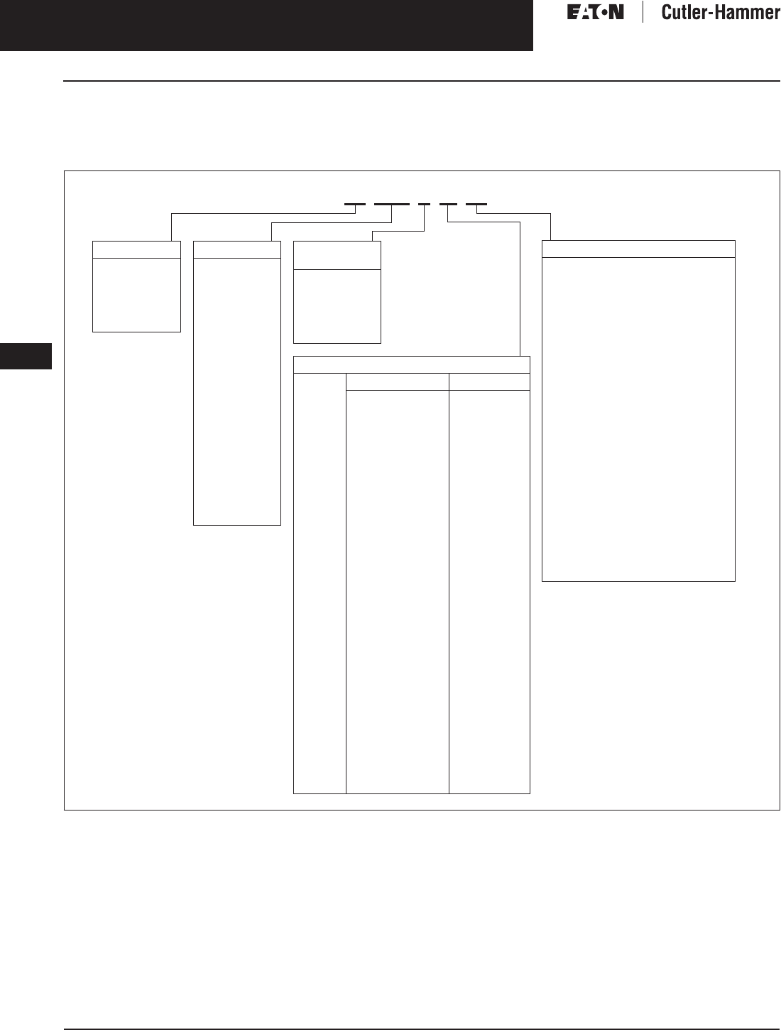
November 2003
9-140
For more information visit: www.cutler-hammer.eaton.com CA08101001E
Transformers
9
General Purpose & Industrial Control Transformers
Catalog Numbering System Vol. 1, Ref. No. [0440]
Catalog Numbering System
Note: Contact your local Cutler-Hammer sales office for voltage combinations not shown. Use table for catalog number breakdown only.
Do not use to create catalog numbers since all combinations may not be valid.
Table 9-169. Industrial Control Transformers, CE Marked Control Transformers — Example: CE0250G2FES
Note: For the Cutler-Hammer dry-type Transformers Catalog Numbering System see Page 9-138 and 9-139.
Type
C= Industrial
Control
Transformer
CE= CE Marked
Control
Transformer
VA Rating
0025 = 25
0050 = 50
0075 = 75
0100 = 100
0150 = 150
0200 = 200
0250 = 250
0300 = 300
0350 = 350
0500 = 500
0750 = 750
1000 = 1000
1500 = 1500
2000 = 2000
3000 = 3000
5000 = 5000
Type AP Only:
0003 = 3000
0005 = 5000
0007 = 7500
0010 = 10000
0015 = 15000
Transformer
Design
A= MTA
C= MTC
E= MTE
G= MTG
K= MTK
P= AP
Voltage
Primary Secondary
AC =
AG =
1B =
2A =
2B =
2C =
2F =
2G =
2U =
2V =
2W =
3A =
3B =
3C =
3D =
4B =
4C =
4D =
4E =
4H =
4W =
5E =
6U =
7G =
(Type AP
Only)
380 x 415
208/240/277/380/480
120 x 240
240 x 480,
230 x 460,
220 x 440
240 x 480
240 x 480
230/460
230/460
220/380/440/550,
230/400/460/575,
240/416/480/600
208/230/400/460/575
208/230/400/460/575
208/277
115
230/460/575
208/380/416
208/230/460/575
550/575/600
380/400/415
208/230/460/575
380/400/415
550/575/600
200/220/440,
208/230/460,
240/480
240/416/480/600,
230/400/460/575,
220/380/440/550,
208/500
240 x 480
24
24
24
120/115/110
24
120 x 240
115
115/230
23/110, 24/115,
25/120
24/115/230
115/230
120
24
115/95
115/95
24
110/115/120
110 x 220
115
22/23/24
22/23/24
23/110, 24/115,
25/120
99/120/130,
95/115/125,
91/110/120,
85/100/110
120/240
Modifications
Type MTE/MTG/MTK
FB = Factory mounted 2-pole primary
fuse block for rejection type fuses
FBN = Factory mounted 2-pole primary
fuse block for non-rejection
type fuses
Q= Secondary fuse clips for
1/4 x 1-1/4 inch fuses
XX = No Secondary fuse clips
RT = Ring type terminals for
connection to fuse block
ES = Electrostatic shield
FS = Factory mounted finger safe
terminal shields
Type AP
B= Bottom mounted
S= Side/wall mounted
ES = Electrostatic shield
CU = Copper windings
Type MTA/MTC
FB = Factory mounted 3-pole fuse
block (2-pole primary rejection
type with 1-pole secondary
non-rejection type)
ES = Electrostatic shield
L= Lead terminations
CE 0250 G 2F ES

November 2003
CA08101001E For more information visit: www.cutler-hammer.eaton.com
9-141
Transformers
9
General Purpose & Industrial Control Transformers
Price Modifications
Vol. 1, Ref. No. [0441]
Modifications to General Purpose
Units NOT Registered in VISTA
Note: These rules apply only to list prices and
not to net priced standard transformers. Prior
to applying these pricing rules, verify that the
style number you require is not already regis-
tered in VISTA with a valid list price. List prices
in VISTA take precedence over all manually
calculated list prices. List price additions for
special transformers are intended to be
applied to the “base design” nearest to your
application. “Base design” is typically a stan-
dard 150°C rise, aluminum wound transformer
with the same electrical configuration as the
special unit you require, i.e., delta-delta con-
nected, or delta-wye connected.
List Price Additions
Rule 1. Special Primary/Secondary
Voltages
If either one or both are non-standard
(not listed in the catalog section for that
particular transformer type), add 10%.
Rule 2. Copper Windings
The standard winding material is alu-
minum. For copper windings, add 35%.
Note: For units rated 1000 kVA and
above, refer to the Eaton’s Cutler-Hammer
business.
Rule 3. Temperature Rise
For 115°C rise, when 150°C rise is
standard, on units rated 750 kVA and
below, add 15%.
For 80°C rise, when 150°C rise is
standard, on units rated 500 kVA and
below, add 35%.
For 80°C rise, when 115°C rise encap-
sulated is standard, on units rated 45
kVA and below, add 25%.
Rule 4. Electrostatic Shields
For electrostatic shields, which form
a ground plane between the high and
low voltage windings, add 10%.
Rule 5. Stainless Steel
For transformers with stainless steel
enclosures, add 30%.
Rule 6. 50 Hertz
The standard frequency is 60 Hertz.
For 50 Hertz, add 25%.
Note: For units rated 1000 kVA and above,
refer to the Cutler-Hammer business.
Rule 7. Special Sound Levels
When sound levels below NEMA stan-
dard ST-20 are required, add 5% per
decibel below NEMA standard levels.
This rule cannot be applied to K Factor
nonlinear transformers. Contact your
Cutler-Hammer representative for spe-
cial sound requirements, such as low
sound K-factor nonlinear products and
requirements for sound levels exceed-
ing 5 dB below NEMA standards.
Rule 8. Fungus Proofing
Fungus proofing consists of spraying
all equipment within the wiring com-
partment with a fungicidal varnish.
Add suffix AF to style number if this
treatment is required. List price addi-
tions are:
Encapsulated design $250.00/unit
Ventilated design $500.00/unit
Rule 9. Non-Standard Taps
Standard high voltage taps are listed
in this catalog. When more than the
listed taps are required, refer to Divi-
sion. Additional taps are available
in 2.5% steps only, up to a maximum
of 6 taps.
Rule 10. Double Neutral
For three-phase applications where a
200% neutral is required, add 5%.
Rule 11. Lighting Tap
A lighting tap is available on the sec-
ondary (delta only) winding of a three-
phase unit rated 30 through 300 kVA.
Tap is limited to 5% rated kVA.
For a 120 V single-phase tap, add 15%.
Rule 12. NEMA TP-1 Energy Efficient
For ventilated transformers that
meet the NEMA TP-1 and Energy Star
energy efficiency standards, add 40%.
Rule 13. CE Marked
For single-phase encapsulated, or
ventilated transformers that comply
with European standards and have a
CE Mark, add 10%.
Rule 14. CSA Labeled
For transformers that are CSA labeled,
add 10%.
Rule 15. Thermal Indicators
Thermal indicators are included as
standard in Cutler-Hammer Type MD
Motor Drive Isolation transformers.
Thermal indicators are set to activate
at a temperature of 190°C.
The Cutler-Hammer standard is to
install one indicator in the center coil.
To have thermal indicators installed in
transformers other than Motor Drive
Isolation, add $500.00 List Price/Set.
Rule 16. Certified Test Reports
Factory certified test reports are avail-
able only when they are requested at
the time of order entry. The following
Certified Test Reports are available:
A. Certified Report of Standard
Production Tests:
Suffix TR $500.00/unit
List Price addition
B. Certified Report of NEMA Sound
Level Tests:
Suffix SR $1,500.00/unit
List Price addition
Add the appropriate Suffix from above
to the style number when requesting
these Certified Test Reports.
Net Price Additions
Note: Apply after all list price modifications
and discounts are calculated.
Rule 1. Special Drawings
When paper print factory drawings are
required, add $25.00 net per item.
When sepia paper reproducible factory
drawings are required, add $100.00
net per item.
When aperture cards are required, add
$50.00 net per item.

November 2003
9-142
For more information visit: www.cutler-hammer.eaton.com CA08101001E
Transformers
9
General Purpose & Industrial Control Transformers
Glossary Vol. 1, Ref. No. [0442]
Glossary of Transformer Terms
Air Cooled: A transformer which is
cooled by the natural circulation of air
around, or through, the core and coils
Ambient Noise Level: The existing
noise level of the area surrounding the
transformer, prior to energizing the
transformer.
Ambient Temperature: The tempera-
ture of the air surrounding the trans-
former into which the heat of the
transformer is dissipated.
Attenuation: A decrease in signal power
or voltage. Unit of measure is dB.
Autotransformer: A transformer in
which part of the winding is common to
both the primary and secondary circuits.
Banked: Two or more single-phase
transformers wired together to supply
a three-phase load. Three single-phase
transformers can be “banked” together
to support a three-phase load. For
example, three 10 kVA single-phase
transformers “banked” together will
have a 30 kVA three-phase capacity.
BIL: Basic Impulse Level. The ability
of a transformer’s insulation system
to withstand high voltage surges.
All Eaton’s Cutler-Hammer 600V-class
transformers have a 10 kV BIL rating.
Buck-Boost: The name of a standard,
single-phase, two-winding transformer
application with the low voltage sec-
ondary windings connected as an
autotransformer for boosting (increas-
ing) or bucking (decreasing) voltages in
small amounts. Applications can either
be single phase or three phase.
Center Tap: A tap at the mid-point of
a winding. The center tap on three-
phase delta-delta transformers is
called a lighting tap. It provides 5%
of the transformer’s kVA for single-
phase loads.
Certified Tests: Actual values taken
during production tests and certified
as applying to a given unit shipped
on a specific order. Certified tests are
serial number specific.
Common Mode: Electrical noise
or voltage fluctuation that occurs
between all of the line leads and the
common ground, or between ground
and line or neutral.
Compensated Transformer: A trans-
former with a turns ratio that provides a
higher than nameplate output (second-
ary) voltage at no load, and nameplate
output (secondary) voltage at rated load.
It is common for small transformers
(2 kVA and less) to be compensated.
Conductor Losses: Losses (expressed
in watts) in a transformer which are
incidental to carrying a load: coil resis-
tance, stray loss due to stray fluxes in
the windings, core clamps, etc., as well
as circulating currents (if any) in paral-
lel windings. Also called load losses.
Core Losses: Losses (expressed in watts)
caused by magnetization of the core
and its resistance to magnetic flux.
Also called no-load losses or excitation
losses. Core losses are always present
when the transformer is energized.
Delta Connection: A standard three-
phase connection with the ends of
each phase winding connected in
series to form a closed loop with each
phase 120 degrees from the other.
Sometimes referred to as 3-wire.
Dielectric Tests: Tests which consist
of the application of a voltage higher
than the rated voltage for a specified
time for the purpose of determining
the adequacy against breakdowns of
insulating materials and spacings
under normal conditions.
Dry-Type Transformer: A transformer
in which the core and coils are not
immersed in a liquid.
Efficiency: The ratio of the power output
from a transformer to the total power
input. Typically expressed as a %.
Electrostatic Shield: Copper or other
conducting sheet placed between
primary and secondary windings,
and grounded to reduce electrical
interference and to provide additional
protection from line-to-line or line-
to-ground noise.
Encapsulated Transformer: A trans-
former with its coils either dipped or
cast in an epoxy resin or other encap-
sulating substance.
Excitation Current: No Load Current.
The current that flows in any winding
used to excite the transformer when all
other windings are open-circuited. It is
usually expressed in percent of the rated
current of a winding in which it is mea-
sured. Also called magnetizing current.
FCAN: “Full Capacity Above Normal”
taps. Designates the transformer will
deliver its rated kVA when connected
to a voltage source which is higher
than the rated primary voltage.
FCBN: “Full Capacity Below Normal”
taps. Designates the transformer will
deliver its rated kVA when connected
to a voltage source which is lower than
the rated primary voltage.
Frequency: On ac circuits, designates the
number of times that polarity alternates
from positive to negative and back again
per second such as 60 cycles per second.
Typically measured in Hertz (Hz).
Ground: Connecting one side of a
circuit to the earth through low resis-
tance or low impedance paths to help
prevent transmitting electrical shock
to personnel.
Hp: Horsepower. The energy required
to raise 33,000 pounds a distance of
one foot in one minute. 1 hp is equal to
746 watts.
Harmonic: A sinusoidal waveform with
a frequency that is an integral multiple
of the fundamental frequency (60 Hz).
Hi Pot: A standard test on dry-type
transformers consisting of extra-high
potentials (voltages) connected to the
windings. Used to check the integrity
of insulation materials and clearances.
Impedance: The retarding forces of
current in an ac circuit; the current-lim-
iting characteristics of a transformer.
Symbol = Z
Inductance: In electrical circuits, the
opposition to a change in the flow of
electrical current. Symbol = L
Inducted Potential Test: A standard
dielectric test of transformer insula-
tion. Verifies the integrity of insulating
materials and electrical clearances.
Insulation: Material with a high
electrical resistance.
Insulation Materials: Those materials
used to insulate the transformer’s
electrical windings from each other
and ground.
Isolating Transformer: A transformer
where the input (primary) windings
are not connected to the output
(secondary) windings (i.e., electrically
isolated).
K Factor: A common industry term for
the amount of harmonics produced by
a given load. The larger the K Factor,
the more harmonics that are present.
Also used to define a transformer’s
ability to withstand the additional heat-
ing generated by harmonic currents.
kVA: Kilovolt-ampere. Designates the
output that a transformer can deliver
for a specified time at a rated second-
ary voltage and rated frequency
without exceeding the specified
temperature rise.
1000 VA = 1 kVA

November 2003
CA08101001E For more information visit: www.cutler-hammer.eaton.com
9-143
Transformers
9
General Purpose & Industrial Control Transformers
Glossary
Vol. 1, Ref. No. [0443]
Load Losses: I2R losses in windings.
Also see Conductor Losses
Mid-Tap: See Center Tap
Noise Level: The relative intensity of
sound, measured in decibels (dB).
NEMA Standard ST-20 outlines the
maximum allowable noise level for
dry-type transformers.
Non-Ventilated Transformer: A trans-
former where the core and coil assem-
bly is mounted inside an enclosure
with no openings for ventilation. Also
referred to as Totally Enclosed Non-
Ventilated (TENV).
No Load Losses: Losses in a trans-
former that is excited at rated voltage
and frequency but which is not supply-
ing a load. No load losses include core
losses, dielectric losses, and conductor
losses in the winding due to the excit-
ing current. Also referred to as Excita-
tion Losses.
Percent IR (% resistance): Voltage drop
due to resistance at rated current in
percent of rated voltage.
Percent IX (% reactance): Voltage drop
due to reactance at rated current in
percent of rated voltage.
Percent IZ (% impedance): Voltage
drop due to impedance at rated cur-
rent in percent of rated voltage.
Phase: Type of ac electrical circuit; usu-
ally single-phase 2- or 3-wire, or three-
phase 3- or 4-wire.
Polarity Test: A standard test on trans-
formers to determine instantaneous
direction of the voltages in the primary
compared to the secondary.
Primary Taps: Taps added to the pri-
mary (input) winding. See Tap.
Primary Voltage: The input circuit
voltage.
Power Factor: the cosine of the phase
angle between a voltage and a current.
Ratio Test: A standard test of trans-
formers to determine the ratio of the
input (primary) voltage to the output
(secondary) voltage.
Reactance: The effect of inductive and
capacitive components of a circuit pro-
ducing other than unity power factor.
Regulation: Usually expressed as the
percent change in output voltage
when the load goes from full load to
no load.
Scott T Connection: Connection for
three-phase transformers. Instead of
using three sets of coils for a three-
phase load, the transformer utilizes
only two sets of coils.
Star Connection: Same as a wye
connection.
Step-down Transformer: A trans-
former where the input voltage is
higher than the output voltage.
Step-up Transformer: A transformer
where the input voltage is less than
the output voltage.
Tap: A connection brought out of a
winding at some point between its
extremities, usually to permit chang-
ing the voltage or current ratio. Taps
are typically used to compensate for
above or below rated input voltage,
in order to provide the rated output
voltage. See FCAN and FCBN.
Temperature Class: The maximum
temperature that the insulation system
of a transformer can continuously
withstand. The common insulation
classes are 105, 150, 180 (also 185)
and 220.
Temperature Rise: The increase over
ambient temperature of the windings
due to energizing and loading the
transformer.
Total Losses: The sum of the no-load
losses and load losses.
Transformer Tests: Per NEMA ST-20,
routine transformer production tests
are performed on each transformer
prior to shipment. These tests are:
Ratio tests on the rated voltage con-
nection; Polarity and Phase Relation
tests on the rated connection; No-load
and Excitation current tests at rated
voltage on the rated voltage connec-
tion and Applied Potential and Induced
Potential tests. Special tests include
sound level testing.
Transverse Mode: Electrical noise or
voltage disturbance that occurs
between phase and neutral, or from
spurious signals across metallic hot
line and the neutral conductor.
Turns Ratio: The ratio of the number
of turns in the high voltage winding
to that in the low voltage winding.
Typical Test Data: Tests that were
performed on similar units that were
previously manufactured and tested.
UL (Underwriter’s Laboratories):
An independent safety testing
organization.
Universal Taps: A combination of six
primary voltage taps consisting of
2@+2-1/2% FCAN and 4@-2-1/2% FCBN.
Wye Connection: A standard 3-wire
transformer connection with similar
ends of single-phase coils connected
together. The common point forms
the electrical neutral point and may be
grounded. Also referred to as 3-phase
4-wire. To obtain the line-to-neutral
voltage, divide the line voltage by
3 (1.732).

November 2003
9-144
For more information visit: www.cutler-hammer.eaton.com CA08101001E
Transformers
9
General Purpose & Industrial Control Transformers
Frequently Asked Questions Vol. 1, Ref. No. [0444]
Frequently Asked Questions About Transformers
Can 60 Hz transformers be used at other
frequencies?
Transformers rated for 60 Hz can
be applied to circuits with a higher
frequency, as long as the nameplate
voltages are not exceeded. The higher
the frequency that you apply to a 60 Hz
transformer, the less voltage regula-
tion you will have. 60 Hz transformers
may be used at lower frequencies but
only at reduced voltages correspond-
ing to the reduction in frequency.For
example, a 480 to 120 volt 60 Hz trans-
former can carry rated kVA at 50 Hz but
ONLY when applied as a 400 to 100
volt transformer (50/60 x 480 = 400).
Can single-phase transformers be used
on a three-phase source?
Yes. Any single-phase transformer can
be used on a three-phase source by
connecting the primary terminals of
the single-phase transformer to any
two wires of a three-phase system.
It does not matter whether the three-
phase source is three-phase 3-wire
or three-phase 4-wire. The output of
the transformer will be single-phase.
Can transformers be used to create three-
phase power from a single-phase system?
No. Single-phase transformers alone
cannot be used to create the phase-
shifts required for a three-phase sys-
tem. Phase shifting devices (reactors
or capacitors) or phase converters in
conjunction with transformers are
required to change single-phase
power to three-phase.
What considerations need to be taken into
account when operating transformers
at high altitudes?
At altitudes greater than 3,300 feet
(1,000 meters), the density of the air
is lesser than at lower elevations. This
reduces the ability of the air surround-
ing a transformer to cool it, so the
temperature rise of the transformer
is increased. Therefore, when a trans-
former is being installed at altitudes
greater than 3,300 feet above sea level,
it is necessary to derate the nameplate
kVA by 0.3% for each 330 feet (100
meters) in excess of 3,300 feet.
What considerations need to be taken into
account when operating transformers
where the ambient temperature is high?
Eaton’s Cutler-Hammer dry-type trans-
formers are designed in accordance
with ANSI standards to operate in
areas where the average maximum
ambient temperature is 40°C. For oper-
ation in ambient temperatures above
40°C, there are two options:
1. Order a custom designed trans-
former made for the specific
application.
2. Derate the nameplate kVA of a
standard transformer by 8% for
each 10°C of ambient above 40°C.
What is the normal life expectancy of
a transformer?
When a transformer is operated under
ANSI/IEEE basic loading conditions
(ANSI C57.96), the normal life expect-
ancy of a transformer is 20 years. The
ANSI/IEEE basic loading conditions are:
A. The transformer is continuously
loaded at rated kVA and rated
voltages.
B. The average temperature of the
ambient air during any 24-hour
period is equal to 30°C and at
no time exceeds 40°C
C. The altitude where the transformer
is installed does not exceed 3,300
feet (1,000 meters).
What are Insulation Classes?
Insulation classes were originally used
to distinguish insulating materials
operating at different temperatures.
In the past, letters were used for the
different designations. Recently, insu-
lation system temperatures (°C) have
replaced the letters’ designations.
Table 9-170. Insulation Classes
How do you know if the enclosure
temperature is too hot?
UL and CSA standards strictly regulate
the highest temperature that an
enclosure can reach. For ventilated
transformers, the temperature of the
enclosure should not increase by more
than 50°C in a 40°C ambient at full rated
current. For encapsulated transformers,
the temperature of the enclosure
should not increase by more than 65°C
in a 25°C ambient at full rated current.
This means that it is permissible for the
temperature of the enclosure to reach
90°C (194°F). Although this temperature
is very warm to the touch, it is within
the allowed standards. A thermometer
should be used to measure enclosure
temperatures, not your hand.
Can transformers be reverse-connected
(reverse-fed)?
Yes, with limitations. Cutler-Hammer
single-phase transformers rated 3 kVA
and larger can be reverse-connected
without any loss of kVA capacity or
any adverse effects. Transformers
rated 2 kVA and below, because there
is a turns ratio compensation on the
low voltage winding that adjusts volt-
age between no load and full load con-
ditions, should not be reverse-fed.
Three-phase transformers with either
delta-delta or delta-wye configurations
can also be reverse-connected for
step-up operation. When reverse-
feeding a delta-wye connected trans-
former, there are two important con-
siderations to take into account: (1)
The neutral is not connected, only the
three-phase wires of the wye system
are connected, (2) the ground strap
between X0 and the enclosure must be
removed. Due to high inrush currents
that may be created in these applica-
tions, it is recommended that you do
not reverse-feed transformers rated
more than 75 kVA. The preferred solu-
tion is to purchase a Cutler-Hammer
step up transformer designed specifi-
cally for your application.
Previous
Designation
Insulation
System
Rating (°C)
Class A
Class B
Class F
105
150
180
Class H
Class R
220
220

November 2003
CA08101001E For more information visit: www.cutler-hammer.eaton.com
9-145
Transformers
9
General Purpose & Industrial Control Transformers
Frequently Asked Questions
Vol. 1, Ref. No. [0445]
Can transformers be connected in parallel?
Yes, with certain restrictions. For single-phase transformers
being connected in parallel, the voltages and impedances of the
transformers must be equal (impedances must be within 7.5%
of each other). For three-phase transformers, the same restric-
tions apply as for single-phase transformers, plus the phase
shift of the transformers must be the same. For example, a
delta-wye-connected transformer (30° phase shift) must be
connected in parallel with another delta-wye-connected trans-
former, not a delta-delta connected transformer (0° phase shift).
Why is the impedance of a transformer important?
The impedance of a transformer is important because it is
used to determine the interrupting rating and trip rating of
the circuit protection devices on the load or line side of the
transformer. To calculate the maximum short circuit current
on the load side of a transformer, use the following formula:
Full load current for single-phase circuits is:
and for three-phase circuits the full load current is:
Example: For a standard three-phase, 75 kVA transformer,
rated 480 volt delta primary and 208Y/120 volt secondary
(catalog number V48M28T75J) and impedance equal to
5.1%, the full load current is:
The maximum short circuit load current is:
The circuit breaker or fuse on the secondary side of this
transformer would have to have a minimum interrupting
capacity of 4,083 amperes at 208 volts. NEMA ST-20 (1992).
A similar transformer with lower impedance would require
a primary circuit breaker or fuse with a higher interrupting
capacity.
What clearances are required around transformers when they
are installed?
All dry-type transformers depend upon the circulation of
air for cooling, therefore it is important that the flow of air
around a transformer not be impeded. UL 1561 requires that
there be no less than 6 inches (152.4 mm) clearance between
any side of a transformer with ventilation openings and any
wall or obstruction. In compliance with NEC 450-9, Eaton’s
Cutler-Hammer ventilated transformers have a note on their
nameplates requiring a minimum of 6 inches (152.4 mm)
clearance from the ventilation openings and walls or other
obstructions. This clearance only addresses the ventilation
needs of the transformer. There may be additional local
codes and standards that affect installation clearances.
Transformers should not be mounted in such a manner that
one unit will contribute to the additional heating of another
unit, beyond allowable temperature limits…for example
where two units are mounted on a wall one above the other.
NEMA is the registered trademark and service mark of the
National Electrical Manufacturers Association. UL is a feder-
ally registered trademark of Underwriters Laboratories Inc.
Uniform Building Code (UBC) is a trademark of the Interna-
tional Conference of Building Officials (ICBO). CSA is a regis-
tered trademark of the Canadian Standards Association.
National Electrical Code and NEC are registered trademarks
of the National Fire Protection Association, Quincy, Mass.
Maximum Short Circuit
Load Current (Amps)
Full Load Current (Amps)
Transformer Impedence
-------------------------------------------------------------------
=
Nameplate Volt-Amps
Load (output) Voltage
-----------------------------------------------------------
Nameplate Volt-Amps
Load (output) Volts 3×
--------------------------------------------------------------------
75,000 VA
208V x 1.732
--------------------------------- 208.2 A=
208.2 A
.051
------------------- 4,082.4 A=

November 2003
9-146
For more information visit: www.cutler-hammer.eaton.com CA08101001E
Transformers
9
Vol. 1, Ref. No. [0446]
This page intentionally left blank.
