Mise En
102283-Catalog 102283-Catalog 102283-Catalog 786210 Batch8 unilog cesco-content
2014-09-27
: Pdf 536491-Attachment 536491-Attachment 786210 Batch8 unilog
Open the PDF directly: View PDF ![]() .
.
Page Count: 445 [warning: Documents this large are best viewed by clicking the View PDF Link!]

1.1
In 1898 Thomas & Betts was founded in New York. The corporate
head quarters now reside in Memphis, Tennessee with the company
being listed on the New York stock exchange. Thomas & Betts has now
over 100 years of experience of successfully supplying quality products
to the market by using innovative design and manufacturing
techniques. Thomas & Betts is a global player having presence in
Europe, North & Central America, Australia and the Far- & Middle East.
Worldwide the 12,000 employees are dedicated to ensuring that
Thomas & Betts is fast, flexible and customer focused.
The basis of Thomas & Betts product superiority has always been
innovative engineering. No other company can match our record of
“firsts” in product development that increases performance whilst
reducing installation time and human error. To name three:
The first Solderless Lug, a boost to safety in complex electrical instal-
lations.
Color-Keyed
®
system of compression connectors designed to ensure
that proper installation procedures were used, quickly became the
industry standard.
The original Ty-Rap
®
cable ties were introduced to manage complex
wire harnesses used in aircraft manufacturing. The Ty-Rap
®
cable ties
are designed to make the task of fastening, bundling, clamping and
managing wires easier and quicker for professional applications as well
as home improvement specialists and do-it-yourself enthusiasts and
can be used in the most adverse conditions: heat, humidity, cold…
When reliability and performance are required, knowledgeable professio-
nals
turn to the original Ty-Rap
®
cable tie.
The first Ty-Rap
®
cable ties were used in 1958,
which means that in 2008 we celebrate the
50th anniversary of Ty-Rap
®
.
The European Headquarters are located at
Rhode-St-Genèse near Brussels. From a logistics
point of view we have a Centralised European Distribution Centre in La
Louvière, Belgium, supplying to our customers throughout Europe.
Our manufacturing sites throughout Europe include Germany, France,
Hungary, UK and The Netherlands.
Whilst one of our main business remains in the Electrical Products,
Thomas & Betts also has leading brands along with significant market
share in Emergency Lighting, Safety Systems, Steel Structures, Commu-
nications, Electronic Systems Protection, Earthing and Lightning
protection.
Maintaining the technical excellence of existing products along with
new product innovation is part of our core competence as we continue
to provide competitive solutions to our customers across the world.
1
Thomas & Betts • www.tnb-europe.com

1.1
2
Thomas & Betts • www.tnb-europe.com
Your European Connection
EUROPEAN HEADQUARTERS
Thomas & Betts
200 Chaussée de Waterloo
B-1640 Rhode-St-Genèse
Belgium
Tel: +32 (0) 2 359 82 00
Fax: +32 (0) 2 359 82 01
EUROPEAN Customer Service
Garocentre
Rue de l'Yser 260/D11
B-7110 Houdeng-Goegnies
Belgium
Tel: +32 (0) 64 88 63 88
Fax: +32 (0) 64 88 65 50
UNITED KINGDOM
Wilford Road
Nottingham NG2 1EB
United Kingdom
Tel: +44 (0)115 964 3700
Fax: +44 (0)115 986 0538
FRANCE
Route de Saint-Martin d'Ordon
89330 Piffonds
France
Tel: +33 386 86 48 55
Fax: +33 386 86 48 44
Service Client
Tel: +33 (0)1 41 83 16 95/96
Fax: +33 (0)1 41 83 16 97
ITALY
Via Paracelso 26
Centro Colleoni
I-20041 Agrate Brianza - Milano
Italia
Tel: +39 039 657 90 28/22/34
Fax: +39 039 657 90 77
Servizio Clientela
Tel: +39 039 657 90 32
Fax: +39 039 657 90 80
MIDDLE EAST
Thomas & Betts Ltd.Br.
Office 107 5EA East Wing
Dubai Airport Free Zone
PO Box 54567
Dubai
United Arab Emirates
Tel: +9714 609 1635
Fax: +9714 609 1636
GERMANY
AUSTRIA / SWITZERLAND /
EAST EUROPE /
THE NETHERLANDS / NORDIC
Thomas & Betts Vertriebs GmbH
Lindberghstrasse 5
D-64625 Bensheim
Deutschland
Tel: +49 (0) 6251 669 0
Fax: +49 (0) 6251 669 155
Customer Service
Tel: +49 (0) 6251 669 199/165/132
Fax: +49 (0) 6251 669 176
1.1
3
Thomas & Betts • www.tnb-europe.com
Fastening systems 4
Electrical and mechanical
spring steel fasteners 146
Heat shrink systems 224
Conduit & fittings 260
Termination systems 338
Index 446

4
Thomas & Betts • www.tnb-europe.com
1.1
Make sure it’s secure
with Ty-Rap®cable ties
5
Thomas & Betts • www.tnb-europe.com
1.1
FASTENING SYSTEMS
1.1 PREMIUM CABLE TIES WITH STEEL LOCKING BARB 4
Features & Benefits 8
Premium cable ties with steel locking barb 10
Product reference structure 10
Polyamide 6.6 cable ties - Natural 11
Polyamide 6.6 cable ties - UV-resistant black 12
Polyamide 6.6 cable ties - Natural - Euroslot packaging 13
Polyamide 6.6 cable ties - UV-resistant black - Euroslot packaging 14
Polyamide 6.6 cable ties - Workbench boxes 15
Polyamide 6.6 cable ties - Coloured 16
Polyamide 6.6 cable ties - Multi-coloured 17
Printed cable ties 17
Polyamide 6.6 cable ties - Flame retardant 18
Polyamide 6.6 cable ties - Heat stabilised 19
Polyamide 6.6 cable ties - Heat stabilised + UV-resistant 20
Polyamide 4.6 cable ties - Extra high temperature 21
Polyamide 12 cable ties - UV-resistant 22
Polypropylene cable ties - Weatherable 23
Detectable cable ties 24
Fluoropolymer cable ties - ECTFE 25
Fluoropolymer cable ties - ETFE 26
Special ties with steel locking barb 27
Integrated mounting hole cable ties 27
Panel mounting cable ties 28
Blind mounting cable ties 29
Integrated peg / nail cable ties 31
Releasable cable ties 32
Cable ties with identification tag 36
Identification tags 38
Cable support system with metallic locking barb 39
Pre-assembled Deltec cable ties 39
Strap on reel 40
Double locking heads 41
Deltec Kits 42
Cable spacers, bases, hangers 42
1.2 ALL-PLASTIC CABLE TIES 44
1.3 STAINLESS STEEL CABLE TIES 64
1.4 MOUNTING BASES & ACCESSORIES 74
1.5 CABLE PROTECTION SYSTEMS 112
1.6 CABLE TIE TOOLING 122
1.7 MATERIAL SPECIFICATIONS 134

6
Thomas & Betts • www.tnb-europe.com
1.1
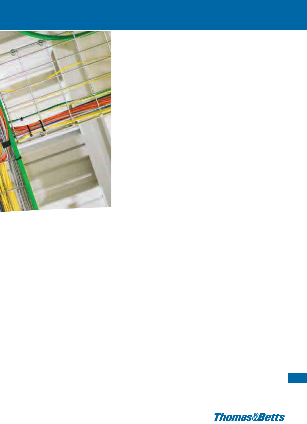
Make sure it’s secure
with Ty-Rap®cable ties
Thomas & Betts invented the Ty-Rap®cable tie to solve the
problem of harnessing the hundreds of wires used in
manufacturing aircraft and revolutionised the world of
fastening. Today, the Ty-Rap®brand remains the bench-
mark for excellence and innovation in wire management.
Thomas & Betts’ broad offering of cable ties is designed to make
the task of fastening, bundling, clamping and managing wires
easier and quicker for industrial applications, construction, com-
munications, utility and OEM professionals as well as home im-
provement specialists and do-it-yourself enthusiasts.
7
Thomas & Betts • www.tnb-europe.com
1.1
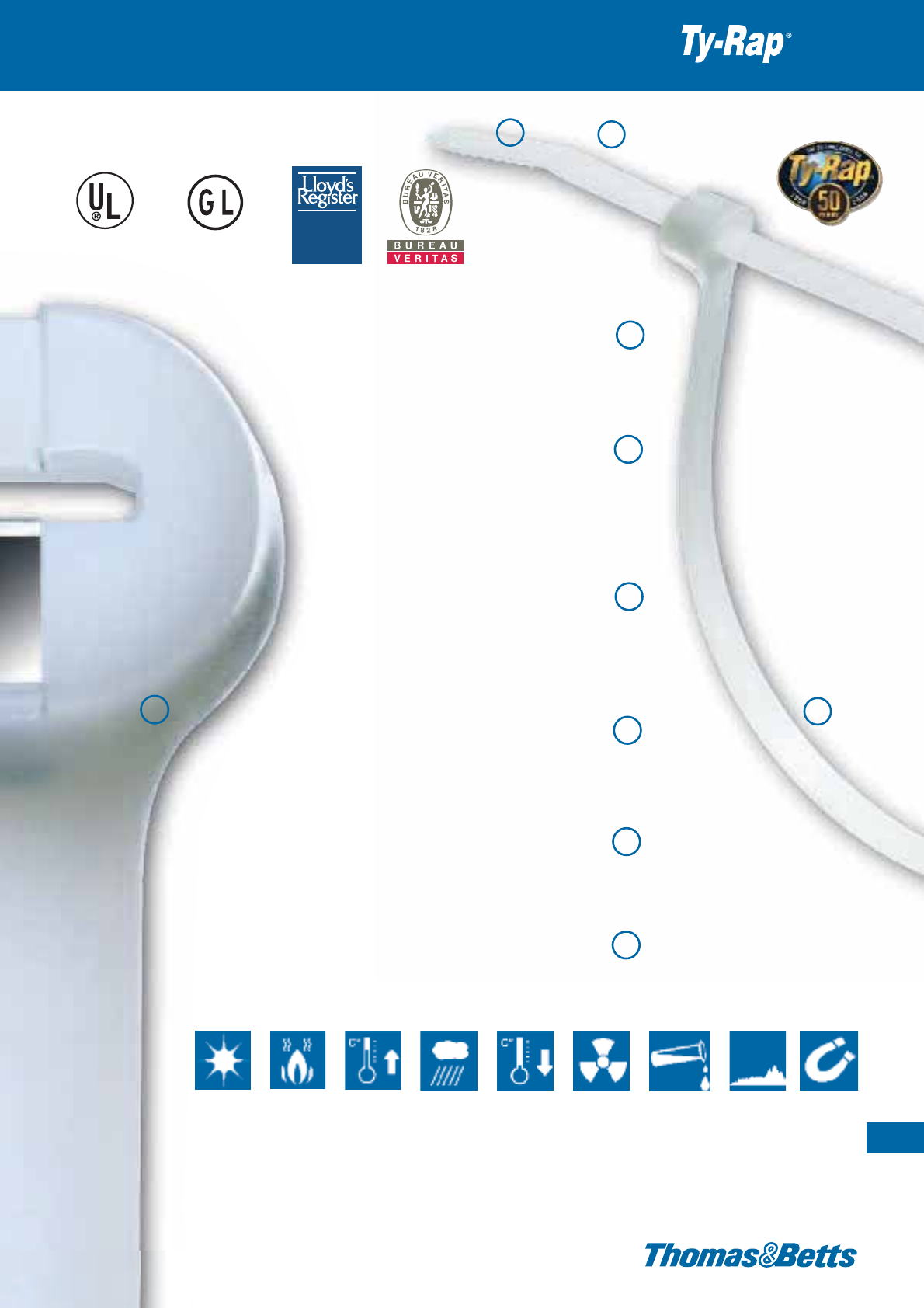
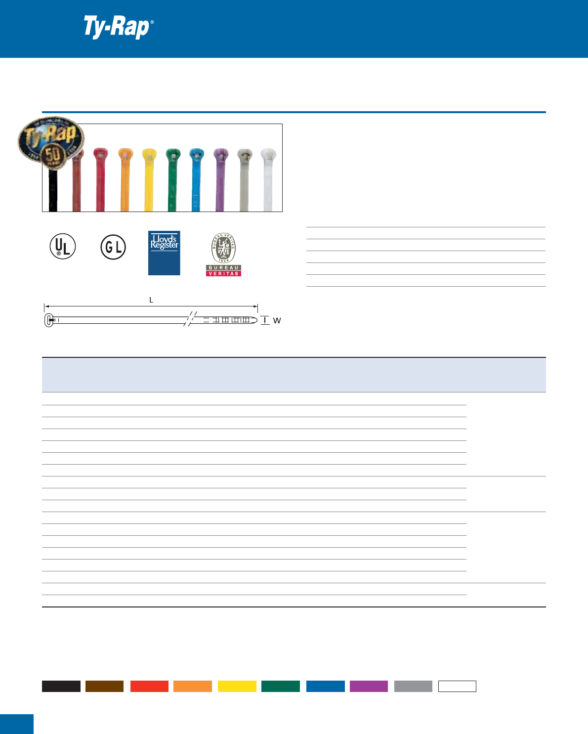
Ty-Rap®Premium Cable Ties with
Steel Locking Barb to bundle,
secure and manage your cables
When strength, aesthetics, reliability and performance are re-
quired, knowledgeable professionals turn to the original and the
best source for cable ties and accessories.
The corrosion-proof, non-magnetic stainless steel locking device
inside the tie head guarantees the strongest and most durable
locking you will ever find on the market. Ty-Rap®can be used in
the most adverse conditions: humidity, heat, cold,…
Engineered for labour savings and high performance, Ty-Rap®
cable ties are commonly used in a variety of applications.
When you choose a Ty-Rap®cable tie from Thomas & Betts, you
can count on quality, performance and innovation to make your
work easier.
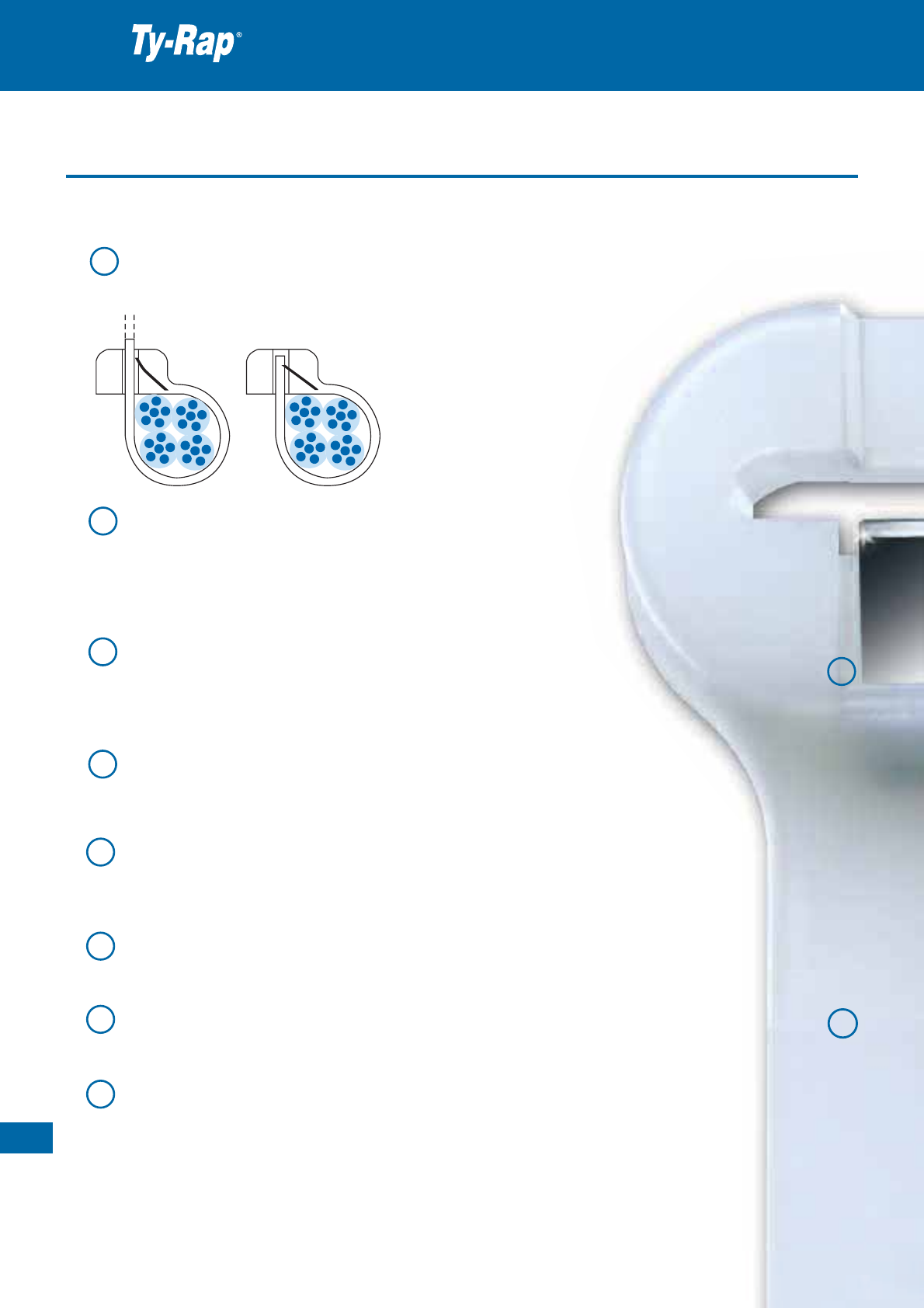
“The Grip of Steel” Non-Magnetic Stainless Steel Locking Barb – marine grade
type 316 - that firmly anchors inside the tie head, ensures a strong, reliable and long
lasting fastening under adverse conditions.
Rounded Edges, on the head and the strap, provide a comfortable
handling of the ties and prevent sharp edges from damaging the cables.
This gradual transition from the strap to the head protects the material
against breaking at this most critical point. The edges of the head are
also rounded off to offer maximum protection from injury.
Smooth, Notchless Body, reduces stress concentration points, making the
Ty-Rap
®
ties stronger and thinner than conventional ties with notched bodies.
The low-profile design of the head allows secure tying in tight spaces.
No serration, means infinite adjustment (tensioned right every time).
Ribbed and Stippled Surface,
to prevent the tie from slipping around and along the bundle under vibration
conditions and external shock.
Angled Tail (turned up)
for fast and easy insertion into the locking head
and ideally suited to being picked up from a flat work area.
Non-Slip Tail, for an easy grip
and pulling through the head during tensioning.
Extensive Range of Approvals:
Germanischer Lloyd, Lloyd’s Register of Shipping, Bureau Veritas, UL, VG and MIL.
Most Extensive Choice of Special Materials:
in addition to Polyamide 6.6 (standard, UV-resistant, heat stabilised, flame retardant,
heat stabilised / UV-resistant), Polyamide 4.6 (extra high temperature) and Polyamide 12,
the Ty-Rap
®
ties are available in Polypropylene, Fluoropolymer (ECTFE), Fluoropolymer
(ETFE) and the recently introduced Detectable Polyamide 6.6 and Detectable Polypropylene.
UL 94 V-0, UL 94 V-2 and UL 94 HB.
1
3
1
2
3
4
5
6
7
8
Thomas & Betts • www.tnb-europe.com
1.1
8
Features & Benefits
Premium cable ties with steel locking barb
UV-resistant Flame
retardant
Heat
resistant
Weather-
proof
Low
temperature
flexibility
Radiation
resistant
Chemically
resistant
Low smoke
Wide Range of Size Combinations:
several lengths up to 1143 mm, in 6 typical widths with
a tensile strength up to 780N, to fasten cable bundles
with a diameter up to 330mm.
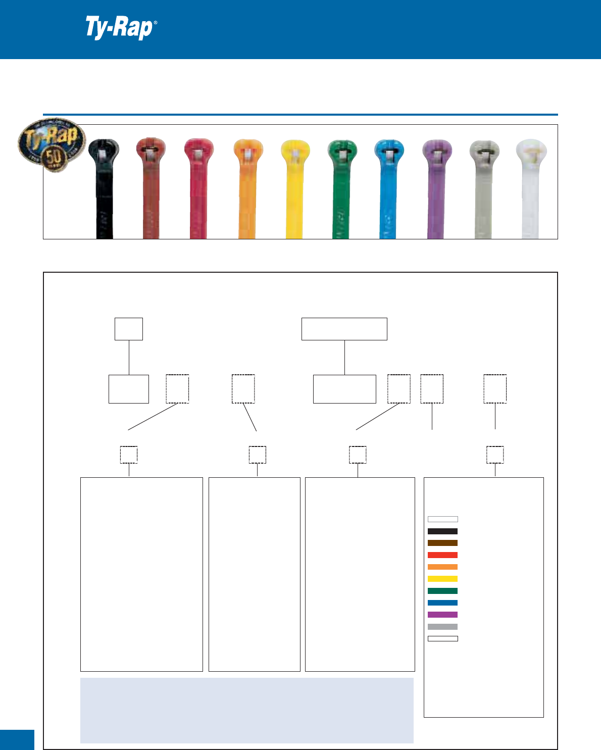
Wide Choice of Colours:
10 standard colours are available, along
with a range of special colours and the
capability to supply customised pre-printed
ties on demand, in any one of the 10 standard
colours.
Dedicated Tooling,
to ensure that the excess end of the Ty-Rap
®
tie
is automatically cut off and the slight over cut
retracts into the head, eliminating the risk of
injury from protruding sharp edges.
Different Types of Packaging,
including the unique “workbench boxes” for fast
working without problems or losses. Recyclable packaging
for a better contribution to the environment.
Outstanding Range of Special Ties,
all with the famous stainless steel locking device:
ties with mounting hole or integrated peg/nail,
panel mounting ties, identification ties with integrated label,...
Broad Range of Mounting Bases and Accessories.
24
5
6
9
10
11
12
13
14
9
Thomas & Betts • www.tnb-europe.com
1.1
TYPE
T Y P E
APPROVED
A P P R O V ED
E49405
Detectable
10
Thomas & Betts • www.tnb-europe.com
1.1
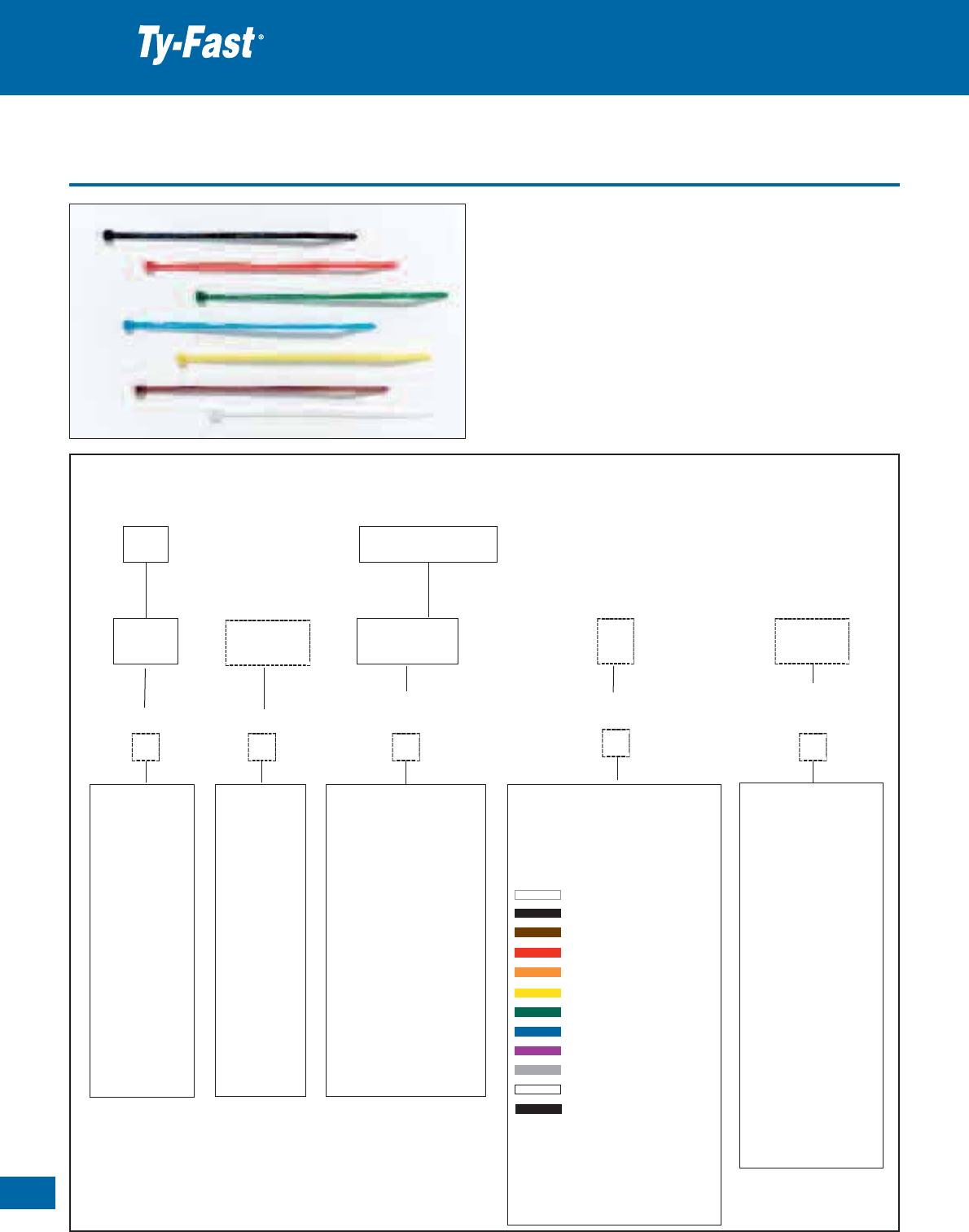
Product reference structure
Premium cable ties with steel locking barb
Example:
To the standard Product Reference, you can add special order codes for: material, packaging size, material properties and colours.
TY XXXXM
Tie
Material
Dimension Code
TY 25 MC 5 X
– Standard,
Polyamide 6.6
H – Heat stabilised
Polyamide 6.6
(+105 °C)
HT – High temperature
resistant Polyamide 4.6
(+150 °C)
C – Polyamide 12
P – Polypropylene
Z – ETFE Fluoropolymer
V – ECTFE Fluoropolymer
D–
Toughened weatherable
acetal*
–Standard,
1000/500 pieces
B – Workbench box,
1000 pieces
5 – Small bags
100/50 pieces
X – UV-resistant
■
X-A – UV-resistant
■
and heat stabilised
(+105°C)
FR –
Flame-retardant
▲
according to
UL 94 V-0
-NDT– Detectable
Polyamide 6.6
-PDT– Detectable buoyant
Polypropylene
●
RAL (TY23, TY24
and TY25 only)
= natural
0 = black 9017
1 = brown 8004
2 = red 3027
3 = orange 2003
4 = yellow 1018
5 = green 6017
6 = blue 5012
7 = purple 4005
8 = grey 7032
9 = white 9001
Note:
When ordering types
conforming to MIL 3367,
colour “9” corresponds to
“natural”
Packaging size Material properties Colour
●Available in 1000/500 packs only
■UV-resistant material, colour: black
▲Flame-retardant material, colour: milky white (approx. RAL 1013)
* Only for Deltec cable ties
R
Rack
Bag with Euroslot
Note: Nylon (Polyamide) is inherently susceptible to environmental conditions. Ty-Rap
®
cable ties are moisturised to optimum performance levels at
machine-side and should be stored in cool dry areas out of direct sunlight. Cable ties are packaged in plastic bags to contain moisture and should
remain sealed until ready for use.

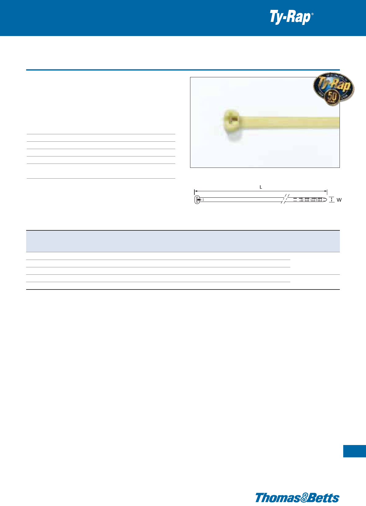
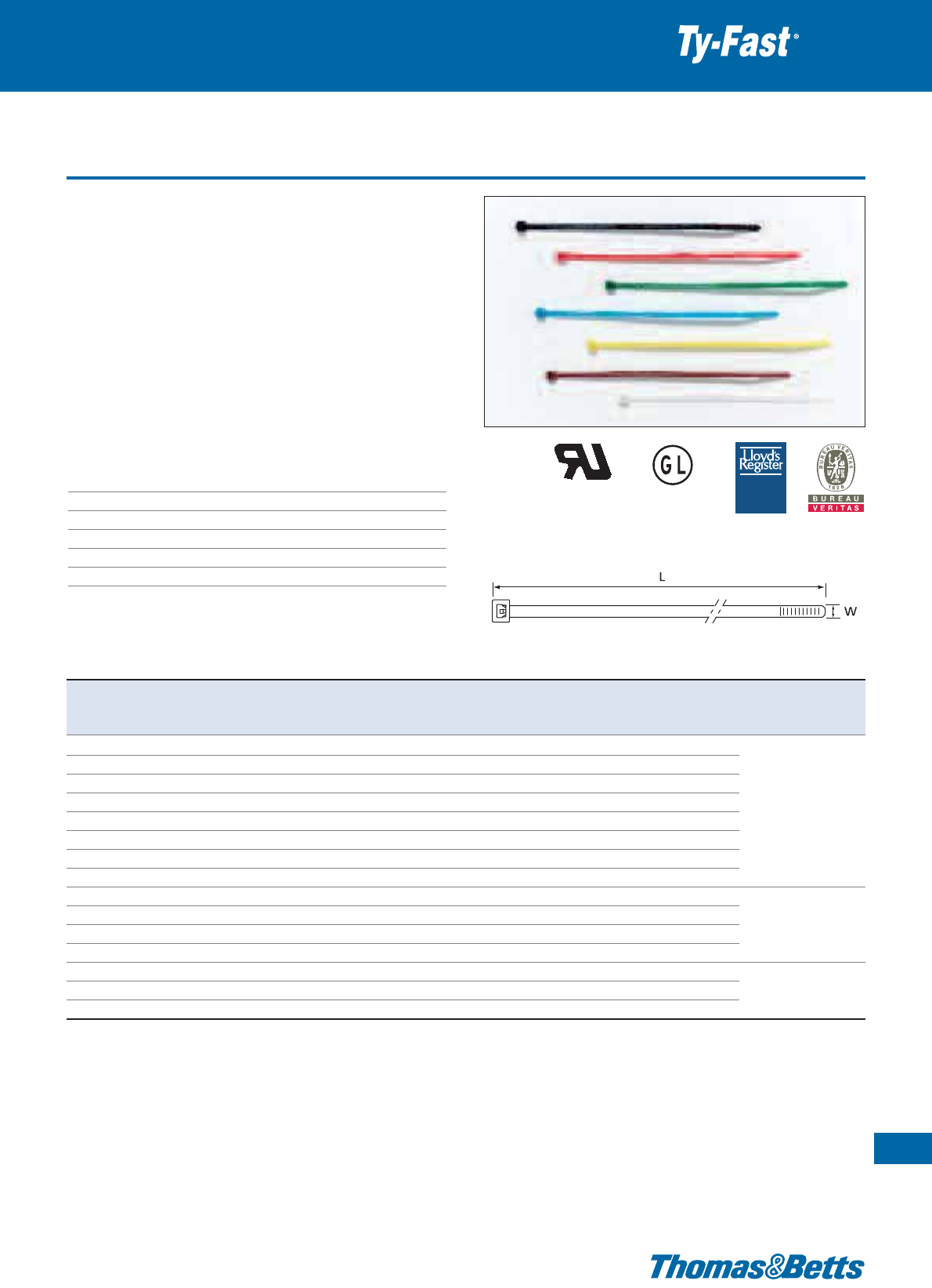
Polyamide 6.6 cable ties - Natural
The main characteristics of the Ty-Rap
®
cable ties are shown on pages
8 and 9.
• Standard version (Polyamide 6.6), to cover most indoor applications
• Several lengths and 6 typical widths with a tensile strength up to
780N, to cover the most demanding applications
• Wide range of colours
• Packaging: OEM bulk quantities in recyclable polythene bags
• Also available in small bags with Euroslot (see page 13) and in
workbench boxes (see page 15)
Technical Information
Material - Moulding Polyamide 6.6
Material - Locking barb 316 grade stainless steel
Temperature range -40°C to +85°C
Colour Natural (other colours see page 16)
Flammability rating UL 94 V-2
Other properties Halogen free, Silicone free
Premium cable ties with steel locking barb
11
Thomas & Betts • www.tnb-europe.com
1.1
TYPE
T Y P E
APPROVED
A P P R O V ED
E49405
Product Ref. MIL Spec. Length Width Thickness Bundle diameter Minimum tensile Quantity Tooling
L W from ... to strength
[mm] [mm] [mm] [mm] [N] [pieces]
TY23M MS-3367-4 92 2.4 1.0 2 - 16 80 1000
TY232M – 203 2.4 1.0 2 - 50 80 1000
TY234M – 356 2.4 1.0 2 - 102 80 1000 ERG50
TY24M MS-3367-5 140 3.6 1.1 2 - 29 180 1000 WT193A
TY242M – 204 3.6 1.1 2 - 50 180 1000
TY26M – 284 3.6 1.1 2 - 76 130 1000
TY244M – 368 3.6 1.1 2 - 103 130 1000
TY25M MS-3367-1 186 4.8 1.3 3.5 - 45 220 1000 ERG50
TY253M MS-3367-7 295 4.8 1.3 3.5 - 78 220 1000 ERG120
TY28M MS-3367-2 361 4.8 1.4 3.5 - 102 220 1000 WT193A
TY271M – 150 7.6 1.5 6 - 31 540 500
TY272M – 223 6.9 1.6 6 - 50 540 500
TY27M MS-3367-3 340 6.9 1.6 6 - 90 540 500 ERG120
TY275M – 457 6.9 1.6 6 - 127 540 500 L-500-EU
TY277M – 617 6.9 1.6 6 - 177 540 500
TY29M MS-3367-6 771 6.9 1.5 6 - 229 540 500
TY53510M – 889 8.2 1.7 to 254 780 50 WT3D
TY54513M – 1143 8.2 1.7 to 330 780 50 L-500-EU
Description of product reference structure: see page 10
Description of materials and properties: see pages 134 to 145
For tooling specifications: see pages 122 to 133
* Some approvals may not be applicable to all the Product References. Contact your Sales Office for approvals limitations
****

12
Thomas & Betts • www.tnb-europe.com
1.1
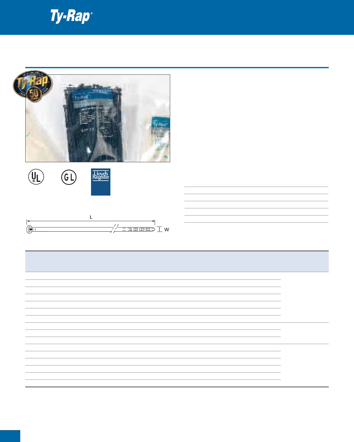
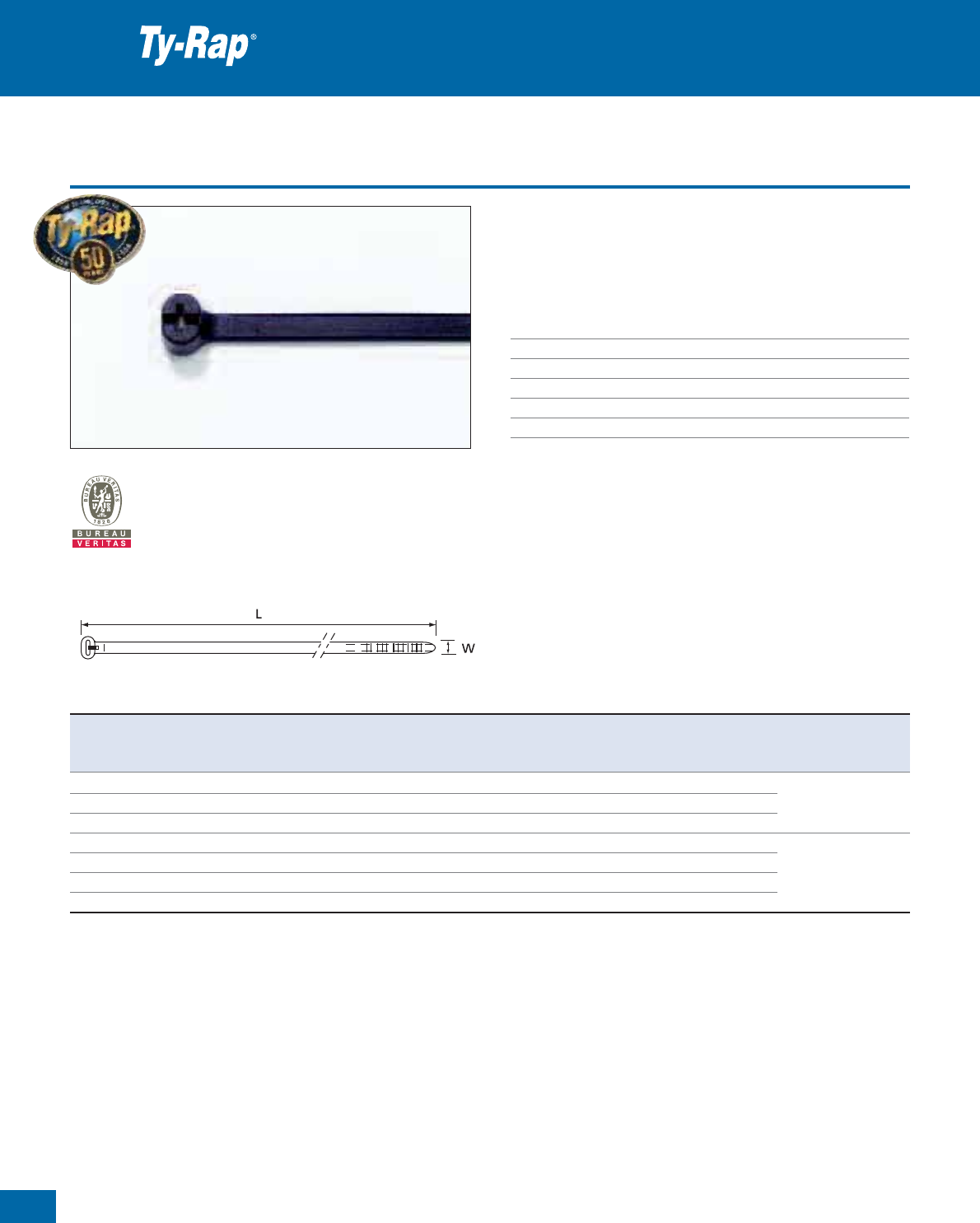
Polyamide 6.6 cable ties - UV-resistant black
The main characteristics of the Ty-Rap
®
cable ties are shown on pages
8and9.
• UV-resistant version, especially recommended for outdoor appli-
cations
• Also available in heat stabilised + UV-resistant version, for outdoor
applications that also require a resistance to high temperature
(+105 °C). See page 20 (TY...MX-A series)
• Several lengths and 6 typical widths with a tensile strength up to
780N, to cover the most demanding applications
• Packaging: OEM bulk quantities in recyclable polythene bags
• Also available in small bags with Euroslot (see page 14) and in
workbench boxes (see page 15)
Technical Information
Material - Moulding Polyamide 6.6
Material - Locking barb 316 grade stainless steel
Temperature range -40°C to +85°C
Colour Black
Flammability rating UL 94 V-2
Other properties UV-resistant, Halogen free, Silicone free
Premium cable ties with steel locking barb
TYPE
T Y P E
APPROVED
A P P R O V ED
E49405
Product Ref. MIL Spec. Length Width Thickness Bundle diameter Minimum tensile Quantity Tooling
L W from ... to strength
[mm] [mm] [mm] [mm] [N] [pieces]
TY23MX MS-3367-4 92 2.4 1.0 2 - 16 80 1000
TY232MX – 203 2.4 1.0 2 - 50 80 1000 ERG50
TY234MX – 356 2.4 1.0 2 - 102 80 1000 WT193A
TY24MX MS-3367-5 140 3.6 1.1 2 - 29 180 1000
TY242MX – 204 3.6 1.1 2 - 50 180 1000
TY26MX – 284 3.6 1.1 2 - 76 130 1000
TY244MX – 368 3.6 1.1 2 - 103 130 1000
TY25MX MS-3367-1 186 4.8 1.3 3.5 - 45 220 1000 ERG50
TY253MX MS-3367-7 295 4.8 1.3 3.5 - 78 220 1000 ERG120
TY28MX MS-3367-2 361 4.8 1.4 3.5 - 102 220 1000 WT193A
TY271MX – 150 7.6 1.5 6 - 31 540 500
TY272MX – 223 6.9 1.6 6 - 50 540 500 ERG120
TY27MX MS-3367-3 340 6.9 1.6 6 - 90 540 500 L-500-EU
TY275MX – 457 6.9 1.6 6 - 127 540 500
TY277MX – 617 6.9 1.6 6 - 177 540 500
TY29MX MS-3367-6 771 6.9 1.5 6 - 229 540 500
TY53510MX – 889 8.2 1.7 to 254 780 50 WT3D
TY54513MX – 1143 8.2 1.7 to 330 780 50 L-500-EU
Description of product reference structure: see page 10
Description of materials and properties: see pages 134 to 145
For tooling specifications: see pages 122 to 133
* Some approvals may not be applicable to all the Product References. Contact your Sales Office for approvals limitations
***

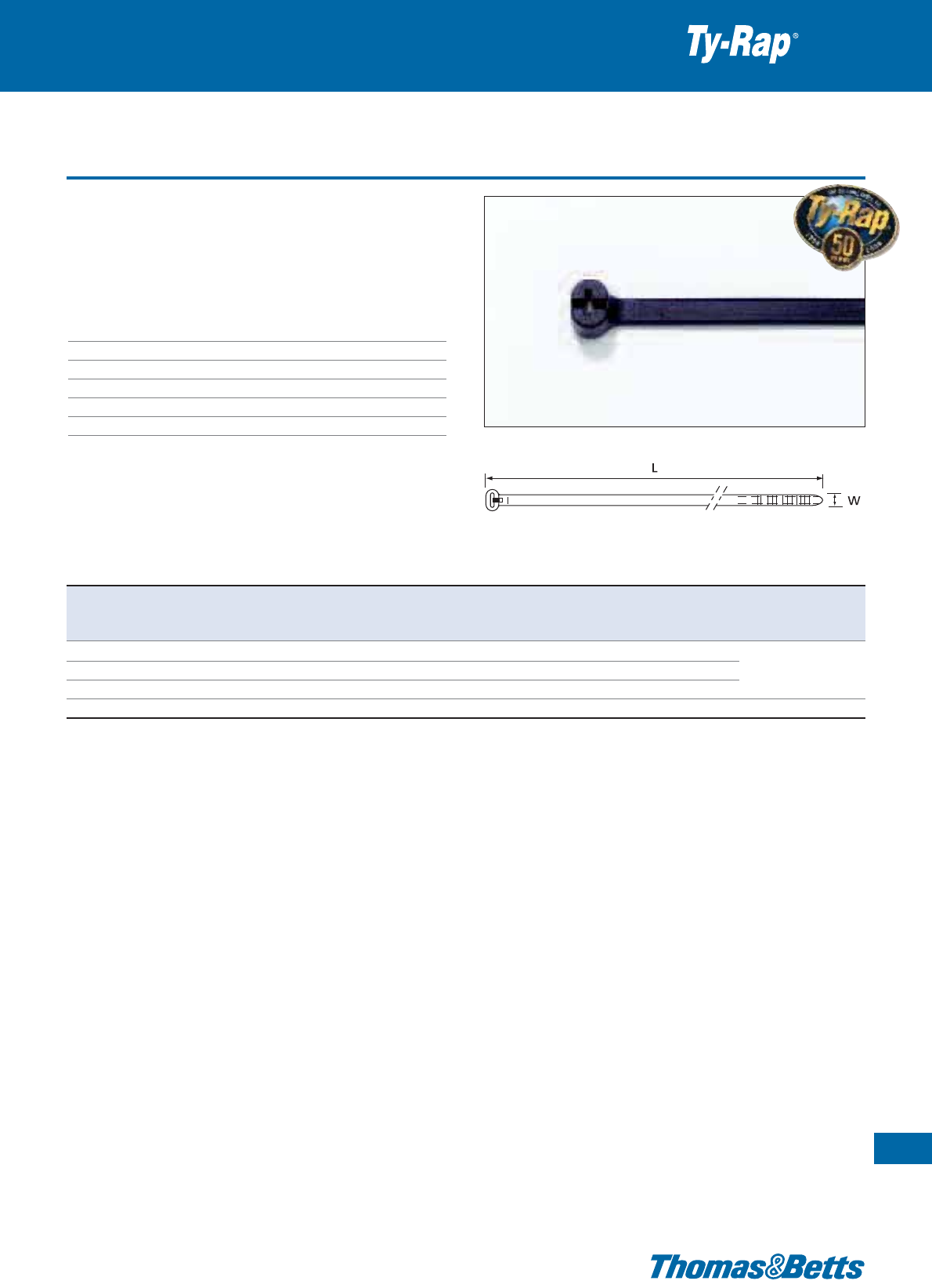
Polyamide 6.6 cable ties - Natural - Euroslot packaging
The main characteristics of the Ty-Rap
®
cable ties are shown on pages
8 and 9.
• Standard version (Polyamide 6.6), to cover most indoor applications
• Packaging in small polythene bags with Euroslot, ideal for display
and point-of-sales promotion (rack)
• Several lengths and 6 typical widths with a tensile strength up to
780N, to cover the most demanding applications
• Very convenient for small series production: 100 pieces (for cable
ties from 2.4 mm to 4.8 mm width) or 50 pieces (for cable ties
7.0 mm width and above)
Technical Information
Material - Moulding Polyamide 6.6
Material - Locking barb 316 grade stainless steel
Temperature range -40°C to +85°C
Colour Natural**
Flammability rating UL 94 V-2
Other properties Halogen free, Silicone free
Premium cable ties with steel locking barb
13
Thomas & Betts • www.tnb-europe.com
1.1
TYPE
T Y P E
APPROVED
A P P R O V ED
Product Ref. MIL Spec. Length Width Thickness Bundle diameter Minimum tensile Quantity Tooling
L W from ... to strength
[mm] [mm] [mm] [mm] [N] [pieces]
TY523MR MS-3367-4 92 2.4 1.0 2 - 16 80 100
TY5232MR – 203 2.4 1.0 2 - 50 80 100
TY5234M* – 356 2.4 1.0 2 - 102 80 100 ERG50
TY524MR MS-3367-5 140 3.6 1.1 2 - 29 180 100 WT193A
TY5242MR – 204 3.6 1.1 2 - 50 180 100
TY526MR – 284 3.6 1.1 2 - 76 130 100
TY5244MR – 368 3.6 1.1 2 - 103 130 100
TY525MR MS-3367-1 186 4.8 1.3 3.5 - 45 220 100 ERG50
TY5253MR MS-3367-7 295 4.8 1.3 3.5 - 78 220 100 ERG120
TY528MR MS-3367-2 361 4.8 1.4 3.5 - 102 220 100 WT193A
TY5271MR – 150 7.6 1.5 6 - 31 540 50
TY5272MR – 223 6.9 1.6 6 - 50 540 50
TY527MR MS-3367-3 340 6.9 1.6 6 - 90 540 50 ERG120
TY5275M* – 457 6.9 1.6 6 - 127 540 50 L-500-EU
TY5277M* – 617 6.9 1.6 6 - 177 540 50
TY529M* MS-3367-6 771 6.9 1.5 6 - 229 540 50
* Product References TY5234M, TY5275M, TY5277M and TY529M have no Euroslot
** For other colours, please contact your Sales Office
*** Some approvals may not be applicable to all the Product References. Contact your Sales Office for approvals limitations
Description of Product Reference structure: see page 10
Description of materials and properties: see pages 134 to 145
For tooling specifications: see pages 122 to 133
E49405
*** *** *** ***
14
Thomas & Betts • www.tnb-europe.com
1.1
Polyamide 6.6 cable ties - UV-resistant black - Euroslot packaging
The main characteristics of the Ty-Rap
®
cable ties are shown on pages
8and9.
• UV-resistant version, especially recommended for outdoor applica-
tions
• Packaging in small polythene bags with Euroslot, ideal for display
and point-of-sales promotion (rack)
• Several lengths and 6 typical widths with a tensile strength up to
780N, to cover the most demanding applications
• Very convenient for small series production: 100 pieces (for cable ties
from 2.4 mm to 4.8 mm width) or 50 pieces (for cable ties 7.0 mm
width and above)
Technical Information
Material - Moulding Polyamide 6.6
Material - Locking barb 316 grade stainless steel
Temperature range -40°C to +85°C
Colour Black
Flammability rating UL 94 V-2
Other properties UV-resistant, Halogen free, Silicone free
Premium cable ties with steel locking barb
Product Ref. MIL Spec. Length Width Thickness Bundle diameter Minimum tensile Quantity Tooling
L W from ... to strength
[mm] [mm] [mm] [mm] [N] [pieces]
TY523MXR MS-3367-4 92 2.4 1.0 2 - 16 80 100
TY5232MXR – 203 2.4 1.0 2 - 50 80 100
TY5234MX* – 356 2.4 1.0 2 - 102 80 100 ERG50
TY524MXR MS-3367-5 140 3.6 1.1 2 - 29 180 100 WT193A
TY5242MXR – 204 3.6 1.1 2 - 50 180 100
TY526MXR – 284 3.6 1.1 2 - 76 130 100
TY5244MXR – 368 3.6 1.1 2 - 103 130 100
TY525MXR MS-3367-1 186 4.8 1.3 3.5 - 45 220 100 ERG50
TY5253MXR MS-3367-7 295 4.8 1.3 3.5 - 78 220 100 ERG120
TY528MXR MS-3367-2 361 4.8 1.4 3.5 - 102 220 100 WT193A
TY5271MXR – 150 7.6 1.5 6 - 31 540 50
TY5272MXR – 223 6.9 1.6 6 - 50 540 50 ERG120
TY527MXR MS-3367-3 340 6.9 1.6 6 - 90 540 50 L-500-EU
TY5275MX* – 457 6.9 1.6 6 - 127 540 50
TY5277MX* – 617 6.9 1.6 6 - 177 540 50
TY529MX* MS-3367-6 771 6.9 1.6 6 - 229 540 50
* Product References TY5234MX, TY5275MX, TY5277MX and TY529MX have no Euroslot
** Some approvals may not be applicable to all the Product References. Contact your Sales Office for approvals limitations
Description of Product Reference structure: see page 10
Description of materials and properties: see pages 134 to 145
For tooling specifications: see pages 122 to 133
TYPE
T Y P E
APPROVED
A P P R O V ED
E49405
** ** **
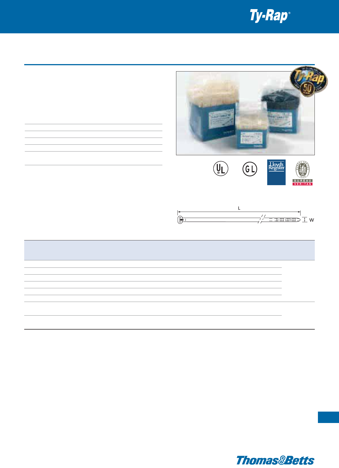
Polyamide 6.6 cable ties - Workbench boxes
• An attractive packaging option for high volume manual assembly:
1000 pieces in a workbench box - easy to reach, hence timesaving
• This user-friendly packaging allows fast working without prob-
lems or losses
Technical Information
Material - Moulding Polyamide 6.6
Material - Locking barb 316 grade stainless steel
Temperature range -40°C to +85°C
Colour Natural or UV-resistant black**
Flammability rating UL 94 V-2
Other properties Halogen free, Silicone free,
UV-resistant (black)
Premium cable ties with steel locking barb
15
Thomas & Betts • www.tnb-europe.com
1.1
Product Ref. MIL Spec. Colour Length Width Thickness Bundle diameter Minimum tensile Quantity Tooling
L W from ... to strength
[mm] [mm] [mm] [mm] [N] [pieces]
TYB23M MS-3367-4 natural 92 2.4 1.0 2 - 16 80 1000
TYB23MX MS-3367-4 UV-resistant black 92 2.4 1.0 2 - 16 80 1000
TYB232M – natural 203 2.4 1.0 2 - 50 80 1000 ERG50
TYB232MX – UV-resistant black 203 2.4 1.0 2 - 50 80 1000 WT193A
TYB24M MS-3367-5 natural 140 3.6 1.1 2 - 29 180 1000
TYB24MX MS-3367-5 UV-resistant black 140 3.6 1.1 2 - 29 180 1000
TYB25M MS-3367-1 natural 186 4.8 1.3 3.5 - 45 220 1000
ERG50, ERG120
TYB25MX MS-3367-1 UV-resistant black 186 4.8 1.3 3.5 - 45 220 1000 WT193A
* Some approvals may not be applicable to all the Product References. Contact your Sales Office for approvals limitations
** For other colours, please contact your Sales Office.
Description of Product Reference structure: see page 10
Description of materials and properties: see pages 134 to 145
For tooling specifications: see pages 122 to 133
TYPE
T Y P E
APPROVED
A P P R O V ED
E49405
****
16
Thomas & Betts • www.tnb-europe.com
1.1
Polyamide 6.6 cable ties - Coloured
•
Wide choice of colours: 10 standard colours are available, along with
a range of special colours and the capability to supply customised
pre-printed ties on demand, in any one of the 10 standard colours.
•
Several lengths and 6 typical widths with a tensile strength up to
780N, to cover the most demanding applications
Technical Information
Material - Moulding Polyamide 6.6
Material - Locking barb 316 grade stainless steel
Temperature range -40°C to +85°C
Colour See table
Flammability rating UL 94 V-2
Other properties Halogen free, Silicone free
Premium cable ties with steel locking barb
TYPE
T Y P E
APPROVED
A P P R O V ED
E49405
**
**** **
Product Ref. MIL Spec. Length Width Thickness Bundle diameter Minimum tensile Quantity Tooling
L W from ... to strength
[mm] [mm] [mm] [mm] [N] [pieces]
TY23M-* MS-3367-4 92 2.4 1.0 2 - 16 80 1000
TY232M-* – 203 2.4 1.0 2 - 50 80 1000
TY234M-* – 356 2.4 1.0 2 - 102 80 1000 ERG50
TY24M -* MS-3367-5 140 3.6 1.1 2 - 29 180 1000 WT193A
TY242M-* – 204 3.6 1.1 2 - 50 180 1000
TY26M-* – 284 3.6 1.1 2 - 76 130 1000
TY244M-* – 368 3.6 1.1 2 - 103 130 1000
TY25M-* MS-3367-1 186 4.8 1.3 3.5 - 45 220 1000 ERG50
TY253M-* MS-3367-7 295 4.8 1.3 3.5 - 78 220 1000 ERG120
TY28M-* MS-3367-2 361 4.8 1.4 3.5 - 102 220 1000 WT193A
TY271M-* – 150 7.6 1.5 6 - 31 540 500
TY272M-* – 223 6.9 1.6 6 - 50 540 500
TY27M-* MS-3367-3 340 6.9 1.6 6 - 90 540 500 ERG120
TY275M-* – 457 6.9 1.6 6 - 127 540 500 L-500-EU
TY277M-* – 617 6.9 1.6 6 - 177 540 500
TY29M-* MS-3367-6 771 6.9 1.5 6 - 229 540 500
TY53510M-* – 889 8.2 1.7 to 254 780 50 WT3D
TY54513M-* – 1143 8.2 1.7 to 330 780 50 L-500-EU
Description of Product Reference structure: see page 10
Description of materials and properties: see pages 134 to 145
For tooling specifications: see pages 122 to 133
For cable ties in a specific colour, replace * in the Product Reference by the colour code:
0 = black, 1 = brown, 2 = red, 3 = orange, 4 = yellow, 5 = green, 6 = blue, 7 = purple, 8 = grey and 9 = white
For example: TY23M-1 defines a brown TY23M cable tie. Contact your Sales Office for product availability.
** Some approvals may not be applicable to all the Product References. Contact your Sales office for approvals limitations
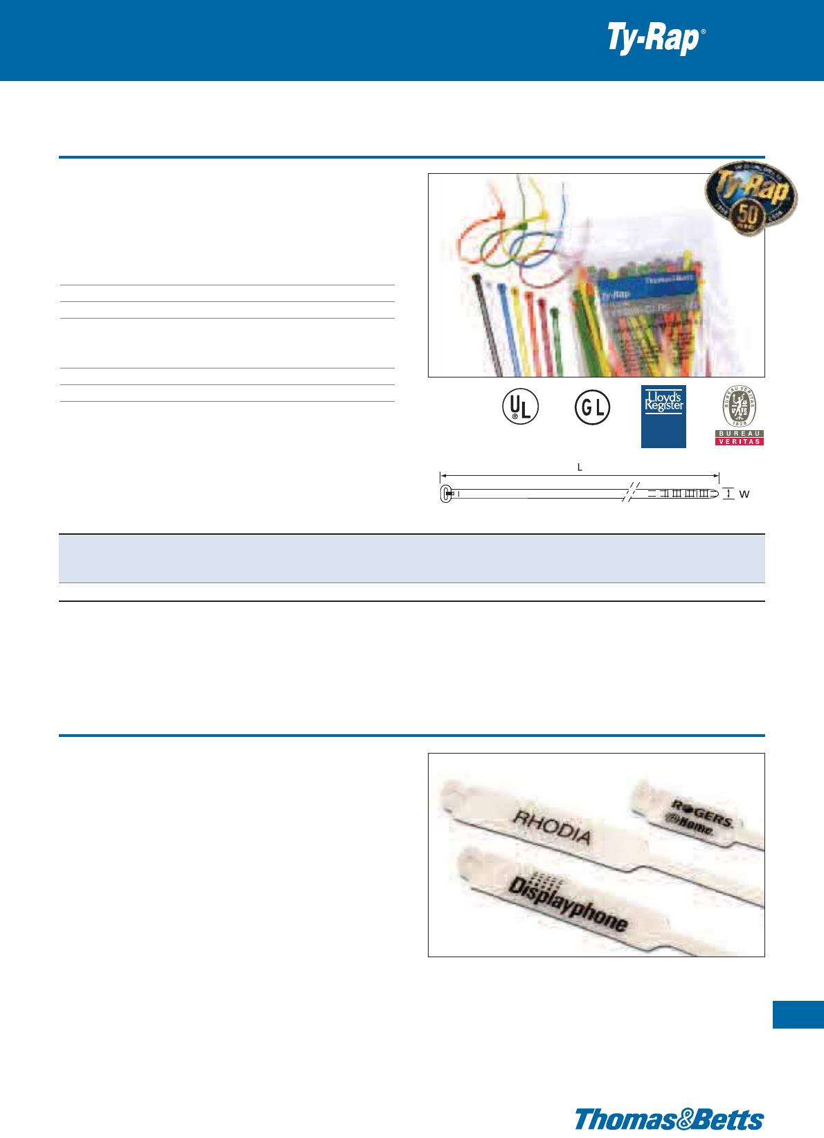
Polyamide 6.6 cable ties - Multi-coloured
• Multi-coloured TY25M cable ties in a single, convenient package
• Supplied in bags of 100 ties containing ten ties of each of the ten
standard colours (TY25M-0 to TY25M-9)
Technical Information
Material - Moulding Polyamide 6.6
Material - Locking barb 316 grade stainless steel
Temperature range -40°C to + 85°C
Colour Black, brown, red, orange, yellow,
green, blue, purple, grey, white
(10 ties of each colour)
Flammability rating UL 94 V-2
Other properties Halogen free, Silicone free
Premium cable ties with steel locking barb
17
Thomas & Betts • www.tnb-europe.com
1.1
E49405
Product Ref. Length Width Thickness Bundle diameter Minimum tensile Quantity Tooling
L W from ... to strength
[mm] [mm] [mm] [mm] [N] [pieces]
TY525M-CLRS 186 4.8 1.3 3.5 - 45 220 100 ERG50, ERG120, WT193A
Description of Product Reference structure: see page 10
Description of materials and properties: see pages 134 to 145
For tooling specifications: see pages 122 to 133
Printed cable ties
Premium cable ties with steel locking barb
Thomas & Betts extends its highly respected existing capabilities in
cable tie manufacture with its in-house printing equipment in order to
respond flexibly to customer requirements and to allow rapid delivery.
This service is offered for ties having a width of minimum 4.6 mm
(batches of minimum 5,000 ties approximately)
• The cable tie is printed using a Hot foil transfer process
• The print is highly durable
• The basic character set is in accordance with DIN1451- (3 mm
character height)
• Text colours: Red, Orange, Yellow, Bright-Yellow, Green, Blue,
Brown, Dark-Brown, Black, White
Please contact your Sales Office for other character sets and special
stamping designs.
TYPE
T Y P E
APPROVED
A P P R O V ED

18
Thomas & Betts • www.tnb-europe.com
1.1
Polyamide 6.6 cable ties - Flame retardant
• Flame retardant version. Ideal for use when low flammability and
low smoke are necessary such as public transport, tunnels, etc.
Technical Information
Material - Moulding Polyamide 6.6
Material - Locking barb 316 grade stainless steel
Temperature range -40°C to +85°C
Colour White
Flammability rating UL 94 V-0
Other properties Halogen free, Silicone free
Premium cable ties with steel locking barb
E49405
Product Ref. Length Width Thickness Bundle diameter Minimum tensile Quantity Tooling
L W from ... to strength
[mm] [mm] [mm] [mm] [N] [pieces]
TY23MFR 92 2.4 1.0 2 - 16 80 1000 ERG50
TY232MFR 203 2.4 1.0 2 - 50 80 1000 WT193A
TY24MFR 140 3.6 1.1 2 - 29 180 1000
TY25MFR 186 4.8 1.1 3.5 - 45 220 1000 ERG50, ERG120
TY28MFR 360 4.8 1.1 3.5 - 102 220 1000 WT193A
TY27MFR 340 7.0 1.6 6 - 90 540 500 ERG120, L-500-EU
Description of Product Reference structure: see page 10
Description of materials and properties: see pages 134 to 145
For tooling specifications: see pages 122 to 133
Polyamide 6.6 cable ties - Heat stabilised
• Heat stabilised version, for applications up to 105°C.
Technical Information
Material - Moulding Polyamide 6.6
Material - Locking barb 316 grade stainless steel
Temperature range -40°C to +105°C
Colour Natural (may have a greenish tint)
Flammability rating UL 94 V-2
Other properties Halogen free, Silicone free
Premium cable ties with steel locking barb
19
Thomas & Betts • www.tnb-europe.com
1.1
E49405
Product Ref. Length Width Thickness Bundle diameter Minimum tensile Quantity Tooling
L W from ... to strength
[mm] [mm] [mm] [mm] [N] [pieces]
TYH23M / TYHB23M 92 2.4 1.0 2 - 16 80 1000
TYH232M 203 2.4 1.0 2 - 50 80 1000
TYH24M 140 3.6 1.1 2 - 29 130 1000 ERG50
TYH242M* 208 3.6 1.1 2 - 50 130 1000 WT193A
TYH26M 284 3.6 1.1 2 - 76 130 1000
TYH25M 186 4.8 1.1 3.5 - 45 220 1000 ERG50
TYH253M* 290 4.8 1.1 3.5 - 78 220 1000 ERG120
TYH28M 360 4.8 1.1 3.5 - 102 220 1000 WT193A
TYH272M* 222 7.6 1.6 6 - 50 540 500 ERG120
TYH27M 340 7.0 1.6 6 - 90 540 500 L-500-EU
TYH29M* 771 6.9 1.5 6 - 229 530 500
* Not UL recognised
Description of Product Reference structure: see page 10
Description of materials and properties: see pages 134 to 145
For tooling specifications: see pages 122 to 133
20
Thomas & Betts • www.tnb-europe.com
1.1
Polyamide 6.6 cable ties - Heat stabilised + UV-resistant
• Heat stabilised + UV-resistant version, for outdoor applications
that also require a resistance to high temperature (+105°C)
•
For OEM and MRO applications like: transportation, lawn / garden /
farm / construction equipment, recreational vehicles
Technical Information
Material - Moulding Polyamide 6.6
Material - Locking barb 316 grade stainless steel
Temperature range -40°C to +105°C
Colour Black
Flammability rating UL 94 V-2
Other properties UV-resistant, heat stabilised,
Halogen free, Silicone free
Premium cable ties with steel locking barb
E49405
Product Ref. Length Width Thickness Bundle diameter Minimum tensile Quantity Tooling
L W from ... to strength
[mm] [mm] [mm] [mm] [N] [pieces]
TY23MX-A 92 2.3 0.9 2 - 16 80 1000
TY24MX-A 140 3.6 1.1 2 - 29 180 1000 ERG50, ERG120*
TY25MX-A 186 4.8 1.2 3.5 - 45 220 1000 WT193A
TY27MX-A 340 6.9 1.6 6 - 89 540 500 ERG120, L-500-EU
* ERG120 can not be used with TY23MX-A and TY24MX-A
Description of Product Reference structure: see page 10
Description of materials and properties: see pages 134 to 145
For tooling specifications: see pages 122 to 133
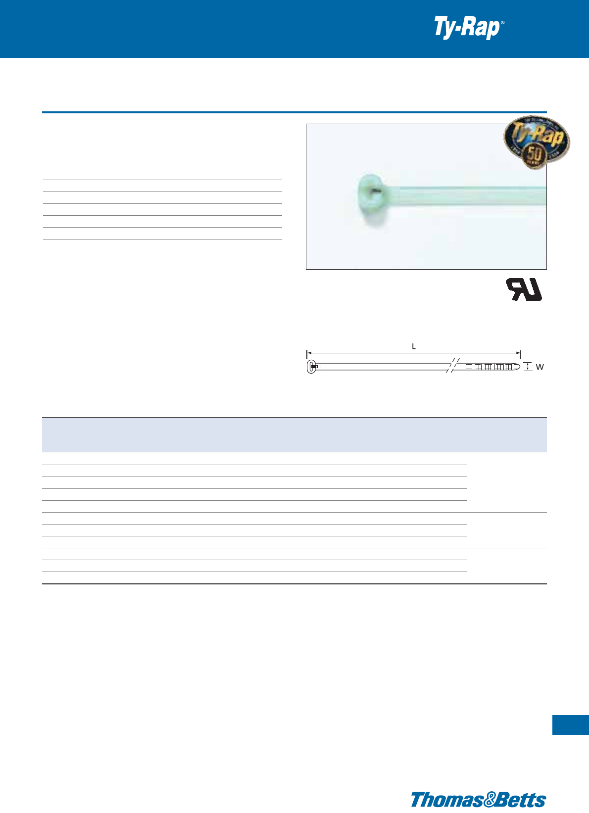
Polyamide 4.6 cable ties - Extra high temperature
• Extreme continuous temperature rating: -40°C to +150°C (in air)
• For high temperature environments in industrial, OEM, MRO and
commercial construction applications such as: metal processing,
paper mills, lighting, automotive
Technical Information
Material - Moulding Polyamide 4.6
Material - Locking barb 316 grade stainless steel
Temperature range -40°C to +150°C
Colour Light green
Flammability rating UL 94 V-2
Other properties Extra high temperature resistant,
Halogen free, Silicon free
Premium cable ties with steel locking barb
21
Thomas & Betts • www.tnb-europe.com
1.1
Product Ref. Length Width Thickness Bundle diameter Minimum tensile Quantity Tooling
L W from ... to strength
[mm] [mm] [mm] [mm] [N] [pieces]
TYHT23M 92 2.3 0.9 2 - 16 80 1000
TYHT25M 186 4.8 1.2 3.5 - 45 220 1000 ERG120*, ERG50
TYHT28M 360 4.8 1.3 3.5 - 102 220 1000 WT193A
TYHT27M 340 6.9 1.6 6 - 89 540 500 ERG120, L-500-EU
TYHT277M 617 7.0 1.6 6 - 177 540 500
* ERG120 can not be used with TYHT23M
Description of Product Reference structure: see page 10
Description of materials and properties: see pages 134 to 145
For tooling specifications: see pages 122 to 133
22
Thomas & Betts • www.tnb-europe.com
1.1
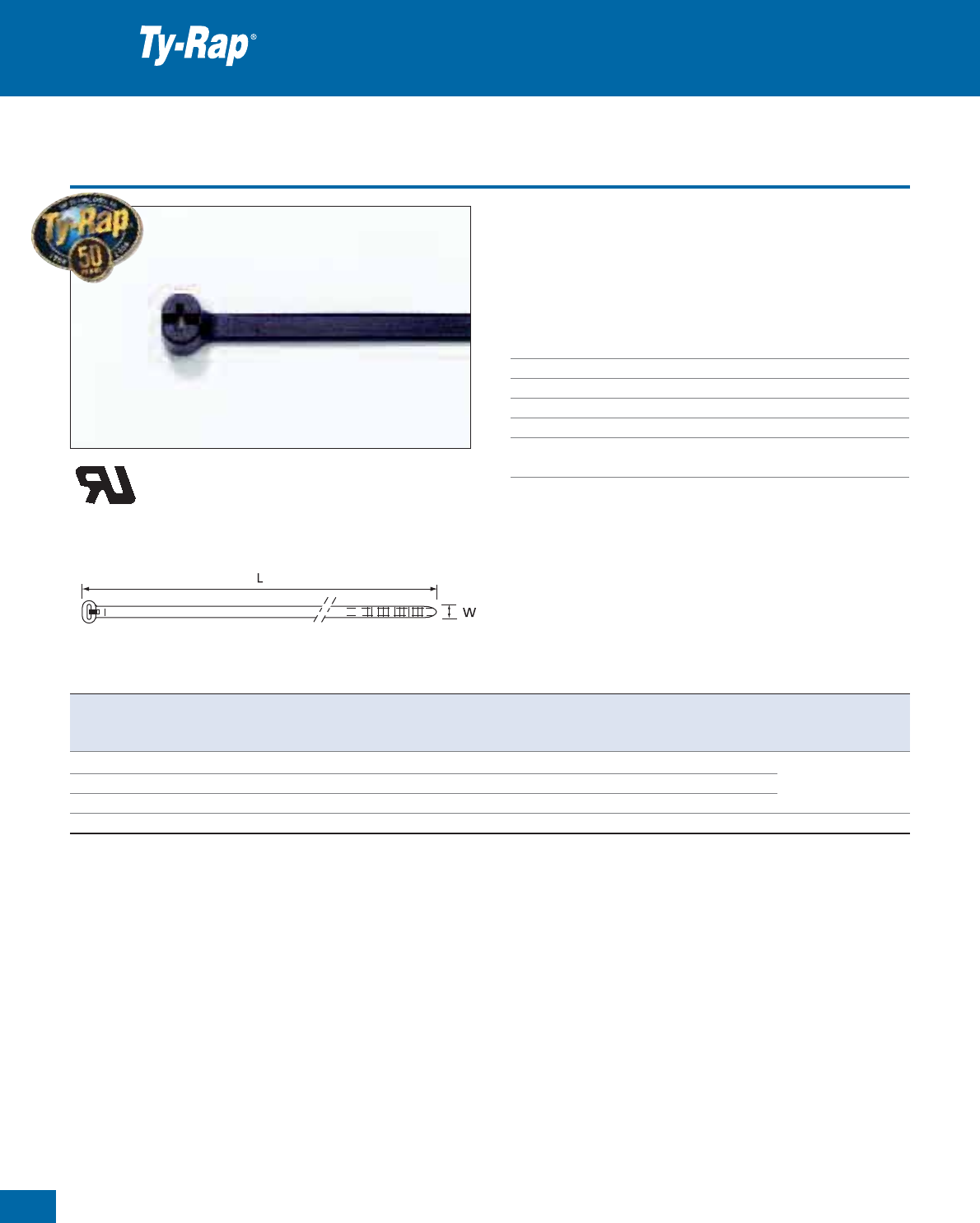
Polyamide 12 cable ties - UV-resistant
• Polyamide 12 UV-resistant version, remains flexible in cold & dry
environments.
• Ages better and has a better chemical resistance than Polyamide 6.6
Technical Information
Material - Moulding Polyamide 12
Material - Locking barb 316 grade stainless steel
Temperature range -40°C to +85°C
Colour Black
Flammability rating UL 94 V-2
Other properties UV-resistant, Halogen free, Silicone free
Premium cable ties with steel locking barb
Product Ref. Length Width Thickness Bundle diameter Minimum tensile Quantity Tooling
L W from ... to strength
[mm] [mm] [mm] [mm] [N] [pieces]
TYC25MX 186 4.8 1.1 3.5 - 45 150 1000 ERG50
TYC525MX 186 4.8 1.1 3.5 - 45 150 100 ERG120
TYC28MX 360 4.8 1.1 3.5 - 102 150 1000 WT193A
TYC272MX 222 7.6 1.6 6 - 50 380 500
TYC27MX 340 7.0 1.6 6 - 90 380 500 ERG120
TYC527MX 340 7.0 1.6 6 - 90 380 50 L-500-EU
TYC29MX 771 7.6 1.6 6 - 229 380 500
Description of Product Reference structure: see page 10
Description of materials and properties: see pages 134 to 145
For tooling specifications: see pages 122 to 133
Polypropylene cable ties - Weatherable
• Polypropylene weatherable version, for increased resistance to
chemicals
• Resistant against inorganic acids, polyhydric alcohols, neutral and
basic salts
Technical Information
Material - Moulding Polypropylene
Material - Locking barb 316 grade stainless steel
Temperature range -40°C to +85°C
Colour Black
Flammability rating UL 94 HB
Other properties UV-resistant, Halogen free, Silicone free
Premium cable ties with steel locking barb
23
Thomas & Betts • www.tnb-europe.com
1.1
Product Ref. Length Width Thickness Bundle diameter Minimum tensile Quantity Tooling
L W from ... to strength
[mm] [mm] [mm] [mm] [N] [pieces]
TYP23MX 92 2.4 1.0 2 - 16 50 1000
TYP25MX 186 4.8 1.1 3.5 - 45 130 1000 ERG50
TYP28MX 360 4.8 1.1 3.5 - 102 130 1000 WT193A
TYP27MX 340 7.0 1.6 6 - 90 270 500 ERG120, L-500-EU
Description of Product Reference structure: see page 10
Description of materials and properties: see pages 134 to 145
For tooling specifications: see pages 122 to 133
24
Thomas & Betts • www.tnb-europe.com
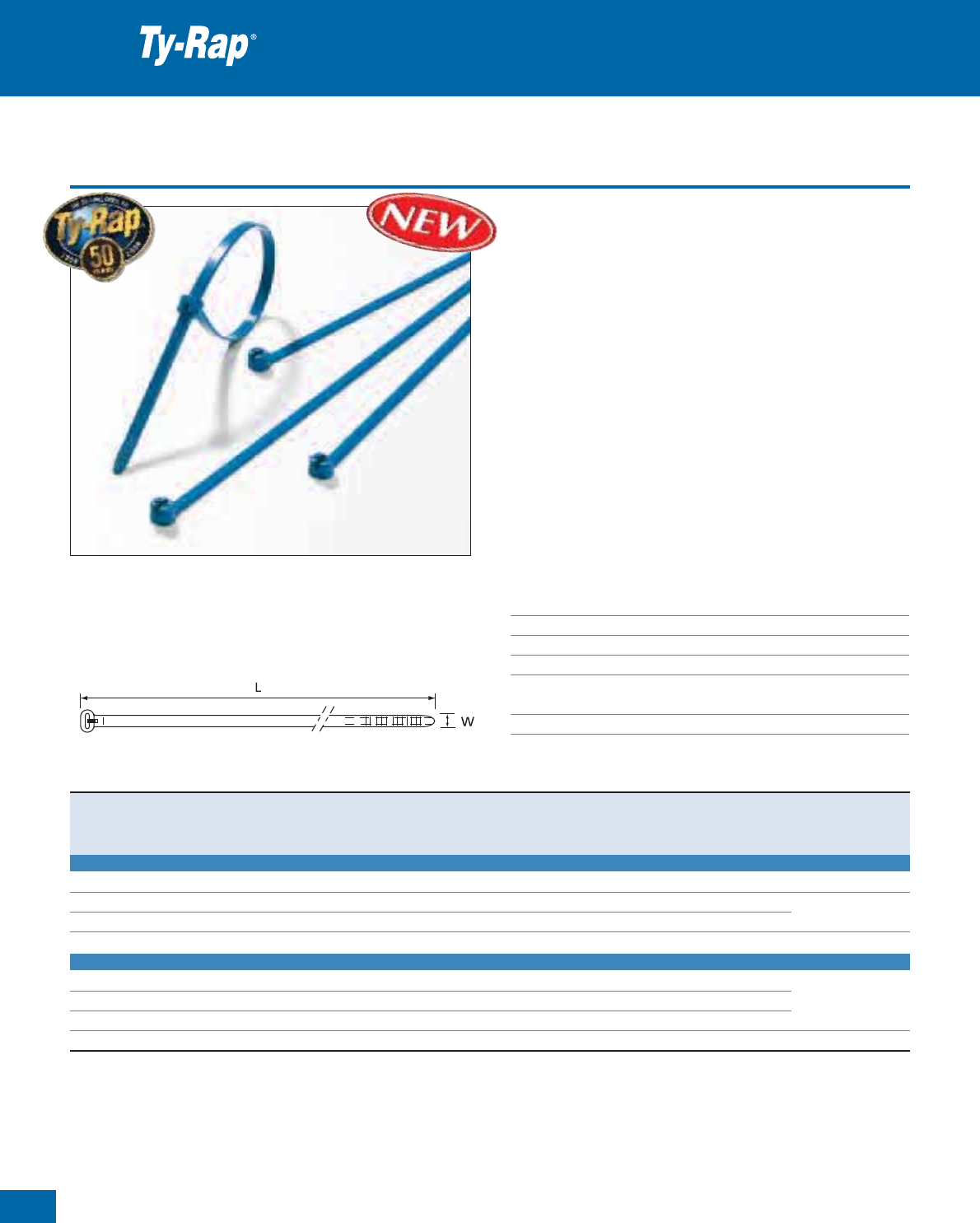
Detectable cable ties
The new Ty-Rap
®
Detectable Cable Ties from Thomas & Betts incor-
porate a unique compound (patent pending) that can be detected by
X-Ray equipment, metal detectors and visual inspection equipment.
Particularly recommended for applications in food, pharmaceutical
and other contamination-sensitive industries using detection systems,
where cable tie installation residuals (cut tails) are not allowed in the
finished product.
• Detectable by metal detectors set at minimum 1.5 mm diameter
ferrous sphere
• Detectable by X-Ray equipment
• Bright blue colour for an easy visual detection
• Help achieve the HACCP EU-Directive
• Available in standard Polyamide 6.6 or in buoyant Polypropylene
version for liquid-processing applications
• Available in 4 different sizes in convenient small bags with Euroslot
Technical Information
Material - Moulding Polyamide 6.6 or Polypropylene
Material - Locking barb 316 grade stainless steel
Temperature range -40°C to +85°C
Colour Bright blue
Flammability rating UL 94 V-2 (Polyamide 6.6)
UL 94 HB (Polypropylene)
Other properties Halogen free, silicone free
Premium cable ties with steel locking barb
1.1
Product Ref. Material Length Width Bundle diameter Minimum tensile Quantity Tooling
L W from...to strength
[mm] [mm] [mm] [N] [pieces]
DETECTABLE POLYAMIDE 6.6
TY523M-NDT Polyamide 6.6 92 2.4 2 - 16 80 100 ERG50, WT193A
TY525M-NDT Polyamide 6.6 186 4.8 3.5 - 45 220 100 ERG50, ERG120
TY528M-NDT Polyamide 6.6 360 4.8 3.5 - 102 220 100 WT193A
TY527M-NDT Polyamide 6.6 340 7.0 6 - 90 540 50 ERG120, L-500-EU
DETECTABLE POLYPROPYLENE
TY523M-PDT Polypropylene 92 2.4 2 - 16 50 100
TY525M-PDT Polypropylene 186 4.8 3.5 - 45 130 100 ERG50, WT193A
TY528M-PDT Polypropylene 360 4.8 3.5 - 102 130 100
TY527M-PDT Polypropylene 340 7.0 6 - 90 270 50 ERG120, L-500-EU
Description of Product Reference structure: see page 10
Description of materials and properties: see pages 134 to 145
For tooling specifications: see pages 122 to 133
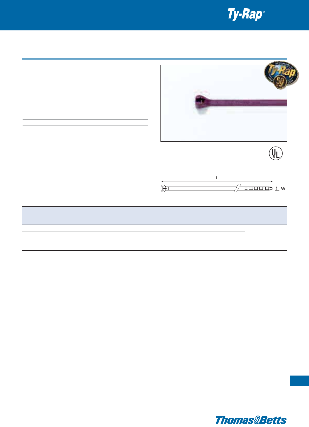
Fluoropolymer cable ties - ECTFE
• Outstanding characteristic: lower smoke density when burnt
• Recommended for applications where smoke generation is a con-
cern, such as plenum areas
Technical Information
Material - Moulding Fluoropolymer ECTFE
Material - Locking barb 316 grade stainless steel
Temperature range -46°C to +140°C
Colour Maroon
Flammability rating UL 94 V-0
Other properties UV-resistant, low smoke
Premium cable ties with steel locking barb
25
Thomas & Betts • www.tnb-europe.com
1.1
E49405
Product Ref. Length Width Thickness Bundle diameter Minimum tensile Quantity Tooling
L W from ... to strength
[mm] [mm] [mm] [mm] [N] [pieces]
TYV23M 92 2.4 1.0 2 - 16 80 1000 ERG50
TYV523M 92 2.4 1.0 2 - 16 80 100 WT193A
TYV25M 186 4.8 1.1 3.5 - 45 220 1000 ERG50, ERG120
TYV525M 186 4.8 1.1 3.5 - 45 220 100 WT193A
Description of Product Reference structure: see page 10
Description of materials and properties: see pages 134 to 145
For tooling specifications: see pages 122 to 133
26
Thomas & Betts • www.tnb-europe.com
1.1
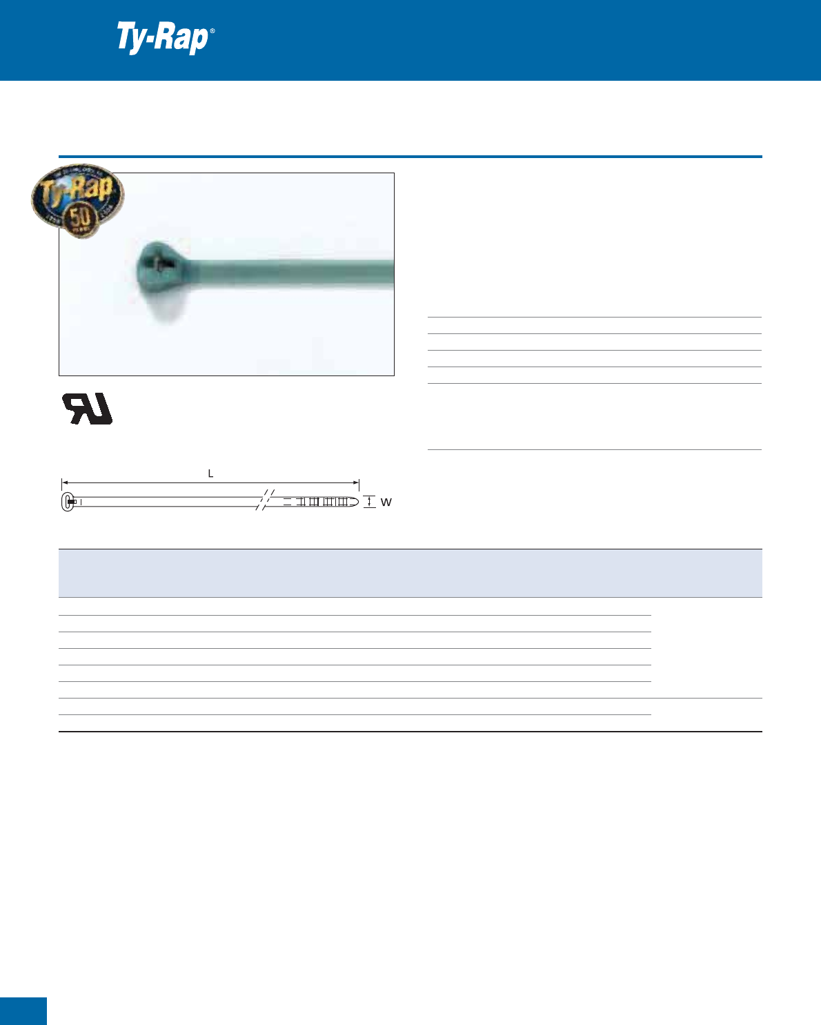
Fluoropolymer cable ties - ETFE
•
ETFE Fluoropolymer
version, resistant to chemicals and to radiation
• Non-outgassing properties for zero gravity applications
• The best all around plastic material for cable ties
• Typical applications include: nuclear, power plants, space industry,
etc.
Technical Information
Material - Moulding Fluoropolymer ETFE
Material - Locking barb 316 grade stainless steel
Temperature range -46°C to +150°C
Colour Aquamarine
Flammability rating UL 94 V-0
Other properties UV-resistant, Silicone free, inert to most
solvents and chemicals, hydrolytically
stable, radiation resistant. Non-outgassing
properties for zero gravity applications.
Premium cable ties with steel locking barb
Product Ref. Length Width Thickness Bundle diameter Minimum tensile Quantity Tooling
L W from ... to strength
[mm] [mm] [mm] [mm] [N] [pieces]
TYZ23M* 92 2.4 1.0 2 - 16 80 1000
TYZ523M* 92 2.4 1.0 2 - 16 80 100
TYZ25M 186 4.8 1.1 3.5 - 45 220 1000 ERG50
TYZ525M 186 4.8 1.1 3.5 - 45 220 100 ERG120**
TYZ28M 360 4.8 1.1 3.5 - 102 220 500 WT193A
TYZ528M 360 4.8 1.1 3.5 - 102 220 100
TYZ27M 340 7.0 1.6 6 - 90 540 100 ERG120, L-500-EU
TYZ527M 340 7.0 1.6 6 - 90 540 50
* Product Ref. TYZ23M and TYZ523M are UL listed (E49405), all other items are UL recognized
** ERG120 not to be used on TYZ23M
Description of Product Reference structure: see page 10
Description of materials and properties: see pages 134 to 145
For tooling specifications: see pages 122 to 133
E49405
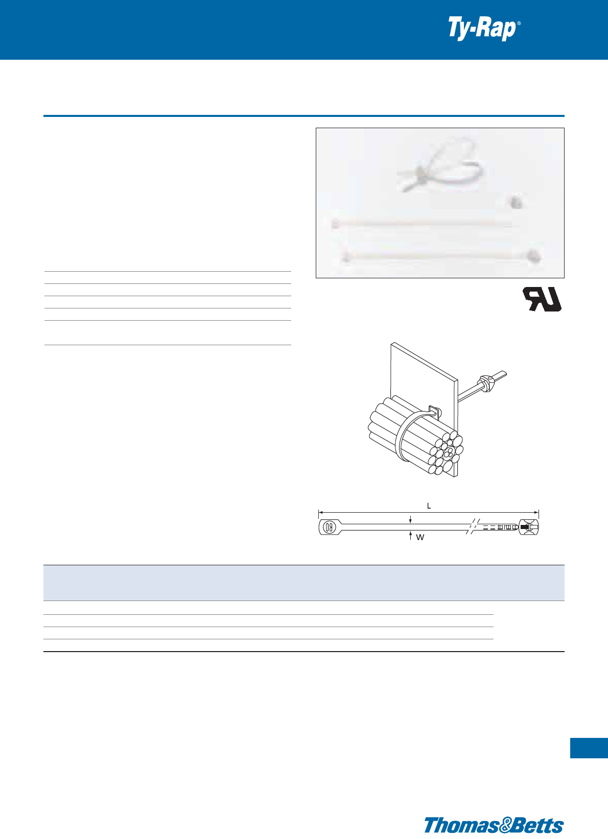
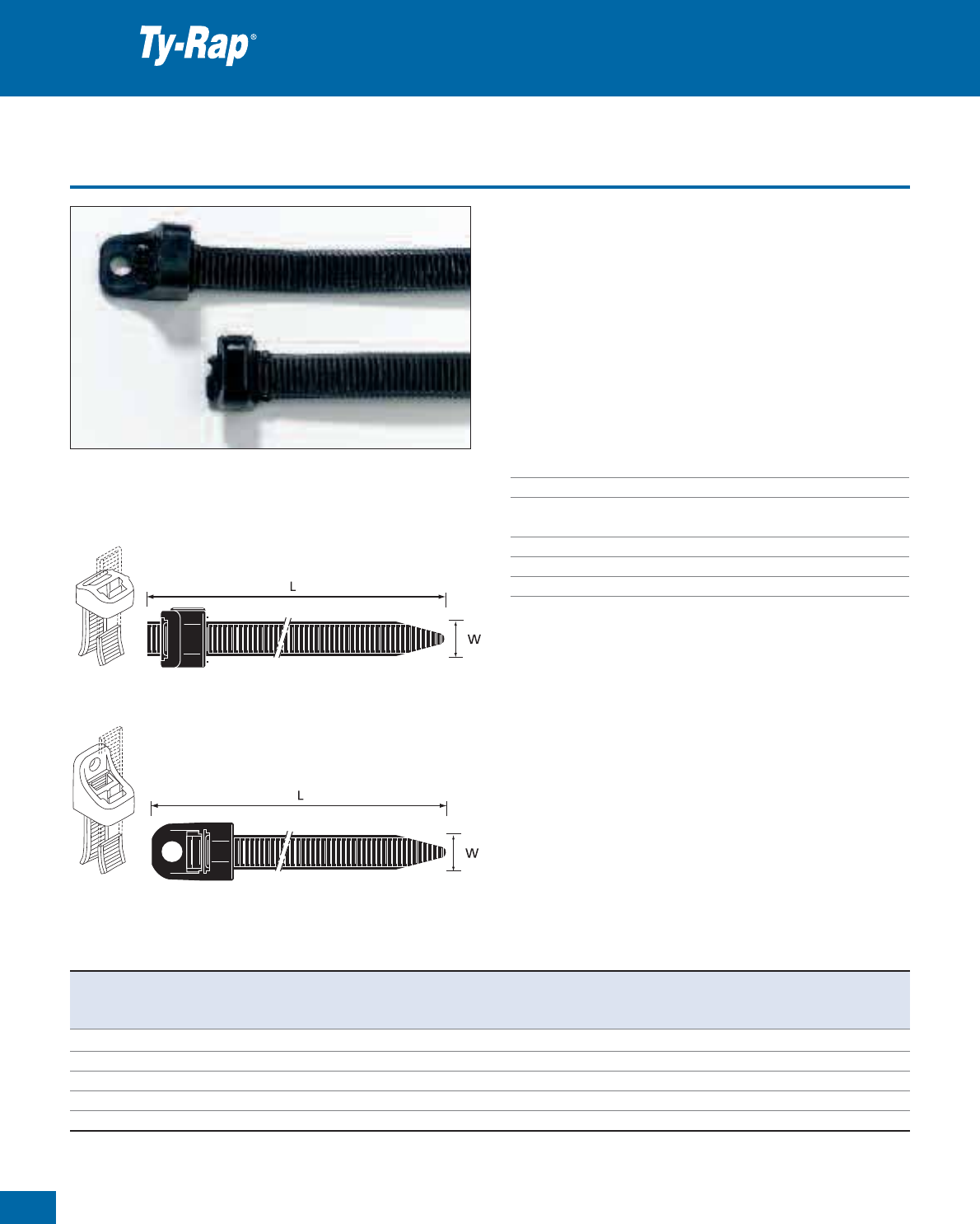
Integrated mounting hole cable ties
• Can be directly mounted onto a support with screws, bolts or rivets
• Mounting and bundling in one maintenance-friendly assembly.
•
Typical application: cable harness manufacture and pre- and end-
mounting of bundles and parts. Maintenance friendly mounting of
cables, tubes and parts in all types and sizes of machines and
installations - indoor and outdoor.
Technical Information
Material - Moulding Polyamide 6.6
Material - Locking barb 316 grade stainless steel
Temperature range -40°C to +85°C
Colour Natural or UV-resistant black (see table)
Flammability rating UL 94 V-2
Other properties UV-resistant (black), Halogen free
Silicone free
Special ties with steel locking barb
27
Thomas & Betts • www.tnb-europe.com
1.1
E49405
VG
approved
VG95387
part 4, type B
TY...M, TY...MX TYF35M, TYF535M
Product Ref. Colour Diameter of Length Width Thickness Bundle diameter Minimum Quantity Tooling
mounting hole L W from ... to tensile strength
[mm] [mm] [mm] [mm] [mm] [N] [pieces]
TY33M natural 3.0 102 2.3 0.9 2 - 16 80 1000
TY533M natural 3.0 102 2.3 0.9 2 - 16 80 100
TY33MX UV-resistant black 3.0 102 2.3 0.9 2 - 16 80 1000 ERG50
TY533MX UV-resistant black 3.0 102 2.3 0.9 2 - 16 80 100 WT193A
TY34M natural 4.4 151 3.5 1.0 2 - 29 180 1000
TY534M natural 4.4 151 3.5 1.0 2 - 29 180 100
TY34MX UV-resistant black 4.4 151 3.5 1.0 2 - 29 180 1000
TY534MX UV-resistant black 4.4 151 3.5 1.0 2 - 29 180 100
TY635M natural 4.0 198 4.7 1.1 3.5 - 45 220 1000
TY635MX UV-resistant black 4.0 198 4.7 1.1 3.5 - 45 220 1000
TY35M natural 5.1 199 4.7 1.1 3.5 - 45 220 1000
TY535M natural 5.1 199 4.7 1.1 3.5 - 45 220 100
ERG50
TY35MX UV-resistant black 5.1 199 4.7 1.1 3.5 - 45 220 1000
ERG120
TY535MX UV-resistant black 5.1 199 4.7 1.1 3.5 - 45 220 100
WT193A
TY1435M natural 6.7 198 4.7 1.1 3.5 - 45 220 1000
TY37M natural 6.7 356 7.7 2.0 6 - 90 540 500
TY537M natural 6.7 356 7.7 2.0 6 - 90 540 50
ERG120
TY37MX UV-resistant black 6.7 356 7.7 2.0 6 - 90 540 500
L-500-EU
TY537MX UV-resistant black 6.7 356 7.7 2.0 6 - 90 540 50
TYF35M natural 4.0 186 4.7 1.2 3.5 - 45 220 1000
ERG50, ERG120
TYF535M natural 4.0 186 4.7 1.2 3.5 - 45 220 100
WT193A
* Some approvals may not be applicable to all the Product References. Contact your Sales Office for approvals limitations
Description of Product Reference structure: see page 10
Description of materials and properties: see pages 134 to 145
For tooling specifications: see pages 122 to 133
***
28
Thomas & Betts • www.tnb-europe.com
1.1
Panel mounting cable ties
• Fastening and clip-mounting in one
• Fast pre- or on-site-assembly for a range of panel thickness up to
4.0 mm
• Fast and secure clip-mounting
Technical Information
Material - Moulding Polyamide 6.6
Material - Locking barb 316 grade stainless steel
Temperature range -40°C to +85°C
Colour Natural or UV-resistant black (see table)
Flammability rating UL 94 V-2
Other properties UV-resistant (black), Halogen free
Silicone free
Special ties with steel locking barb
E49405
TY...
696-...
*
*
Product Ref. Colour Diameter Length Width Thickness Bundle Minimum Suitable for Quantity Tooling
of mounting L W diameter tensile board/wall
hole from ... to strength thickness from to
[mm] [mm] [mm] [mm] [mm] [N] [mm] [pieces]
ANCHOR TYPE
TY54SM natural 4.5 - 5.2 150 3.5 1.0 2 - 32 130 0.1 - 2.5 1000 ERG50
TY54SMX UV-resistant black 4.5 - 5.2 150 3.5 1.0 2 - 32 130 0.1 - 2.5 1000 ERG120**
TY38M natural 6.4 - 6.7 200 4.7 1.3 3.5 - 44
220 1.0 - 4.0
1000 WT193A
TY38MX UV-resistant black 6.4 - 6.7 200 4.7 1.3 3.5 - 44
220 1.0 - 4.0
1000
STANDARD TYPE
696-41836 natural 5.8 - 7.5 197 4.8 1.1 3.5 - 45
220 2.2 - 3.7
1000 ERG50 , ERG120
696-41836X UV-resistant black 5.8 - 7.5 197 4.8 1.1 3.5 - 45 220 2.2 - 3.7 1000 WT193A
* Some approvals may not be applicable to all the Product References. Contact your Sales Office for approvals limitations
** ERG120 only to be used with TY38M and TY38MX
Description of Product Reference structure: see page 10
Description of materials and properties: see pages 134 to 145
For tooling specifications: see pages 122 to 133
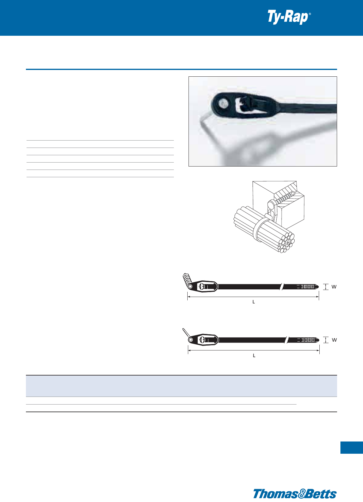
Blind mounting cable ties
Special ties with steel locking barb
29
Thomas & Betts • www.tnb-europe.com
1.1
• Suitable for hard-to-reach areas
• Fast hidden mounting on walls and vehicle chassis
• Twist off the locking head
• Pull the tie end through the fastening hole
• Place locking head on tie end
• Pull tight and cut off excess
• In the locked state, the locking head neatly covers the mounting
hole
Technical Information
Material - Moulding Polyamide 6.6
Material - Locking barb 316 grade stainless steel
Temperature range -40°C to +85°C
Colour Natural or UV-resistant black (see table)
Flammability rating UL 94 V-2
Other properties UV-resistant (black), Halogen free
Silicone free
E49405
Product Ref. Colour Diameter Length Width Thickness Bundle diameter Minimum Quantity Tooling
of mounting L W from ... to tensile strength
[mm] [mm] [mm] [mm] [mm] [N] [pieces]
TYG34M natural 6.4 - 7.0 160 3.6 1.1 2 - 32 180 1000
TYG534M natural 6.4 - 7.0 160 3.6 1.1 2 - 32 180 100
ERG50
TYG34MX UV-resistant black 6.4 - 7.0 160 3.6 1.1 2 - 32 180 1000
WT193A
TYG534MX UV-resistant black 6.4 - 7.0 160 3.6 1.1 2 - 32 180 100
Description of Product Reference structure: see page 10
Description of materials and properties: see pages 134 to 145
For tooling specifications: see pages 122 to 133

30
Thomas & Betts • www.tnb-europe.com
1.1
Blind mounting cable ties
• Suitable for hard-to-reach areas
• Fast hidden mounting on walls and vehicle chassis
• Ideal for mounting on vehicle chassis. Can still be released before
final tensioning
• In the locked state, the locking head neatly covers the mounting
hole
Technical Information
Material Polyamide 6.6
Temperature range -40°C to +85°C
Colour UV-resistant black
Flammability rating UL 94 V-2
Other properties UV-resistant, Halogen free, Silicone free
Special ties
Product Ref. Diameter of Length Width Thickness Bundle diameter Minimum Quantity Tooling
mounting hole L W from ... to tensile strength
[mm] [mm] [mm] [mm] [mm] [N] [pieces]
TY41M 8.1 - 17.3 244 5.7 1.7 5 - 60 300 500 ERG120
TY541M 8.1 - 17.3 244 5.7 1.7 5 - 60 300 50
Description of Product Reference structure: see page 10
Description of materials and properties: see pages 134 to 145
For tooling specifications: see pages 122 to 133
Integrated peg / nail cable ties
• TY545MX, with integrated nail for mounting onto wood or similar
materials
• TY544MX, with integrated peg for mounting onto porous concrete
or similar materials (masonry)
• Very simple application
Technical Information
Material - Moulding Polyamide 6.6
Material - Locking barb 316 grade stainless steel
Temperature range -40°C to +85°C
Colour UV-resistant black
Flammability rating UL 94 V-2
Other properties UV-resistant, Halogen free, Silicone free
Special ties with steel locking barb
31
Thomas & Betts • www.tnb-europe.com
1.1
TY544MX
TY545MX
Product Ref. Diameter of Length Width Thickness Bundle diameter Minimum Mounting Quantity Tooling
mounting hole L W from ... to tensile strength hole depth
[mm] [mm] [mm] [mm] [mm] [N] [mm] [pieces]
TY544MX 6.4 200 4.6 1.0 3.5 - 45
220 25 min.
50 ERG50, ERG120
TY545MX – 200 4.7 1.0 4.7 - 38.1 220 – 50 WT193A
Description of Product Reference structure: see page 10
Description of materials and properties: see pages 134 to 145
For tooling specifications: see pages 122 to 133
32
Thomas & Betts • www.tnb-europe.com
1.1
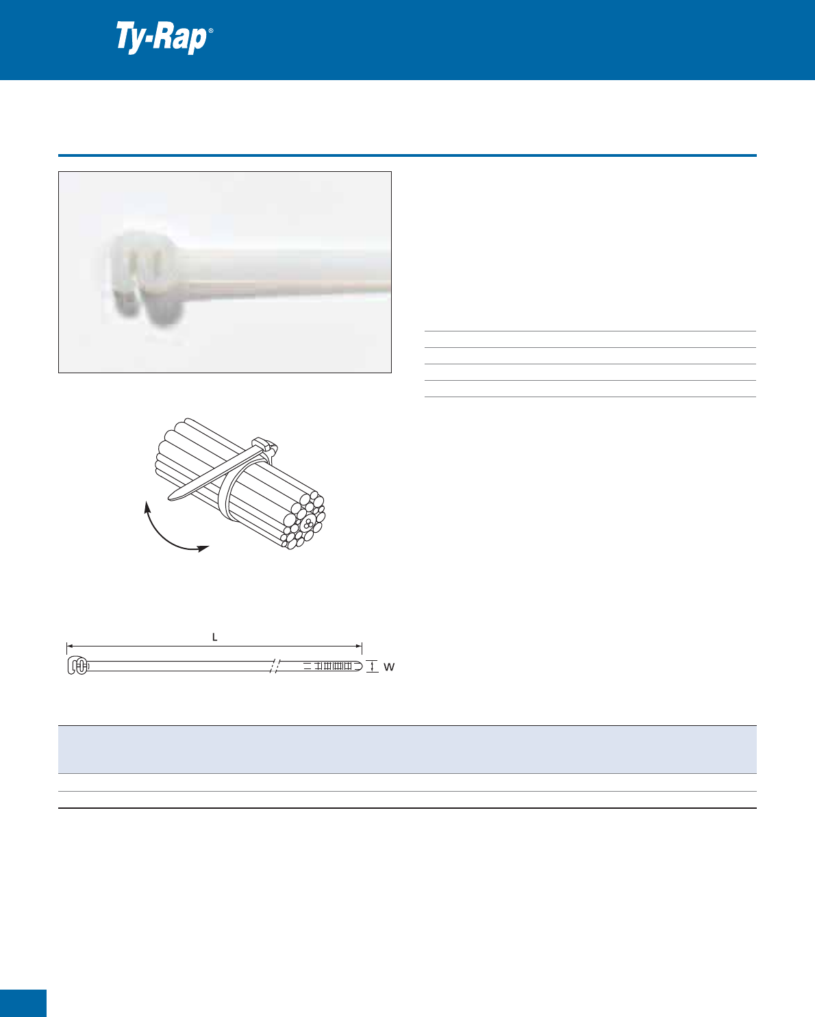
Releasable cable ties
Special ties
• For temporary but strong bundling, especially during control box
wiring
• Very simple application
• Available in 2 lengths for different applications
• May be re-used many times
• No tooling necessary
Technical Information
Material Polyamide 6.6
Temperature range -40°C to +85°C
Colour Natural
Flammability rating UL 94 V-2
Other properties Halogen free, Silicone free
Pull end of tie through head. Turn tie end back on itself and insert
into side of clip. To open, release tie end from clip and open tie.
Product Ref. Length Width Thickness Bundle diameter Minimum Quantity
L W from ... to tensile strength
[mm] [mm] [mm] [mm] [N] [pieces]
TYR505 190 4.7 1.19 10 - 44 220 100
TYR508 364 4.7 1.19 10 - 102 220 100
Description of Product Reference structure: see page 10
Description of materials and properties: see pages 134 to 145
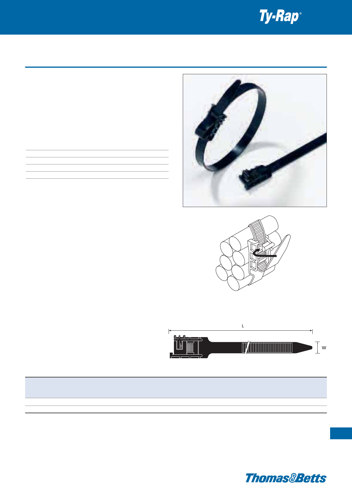
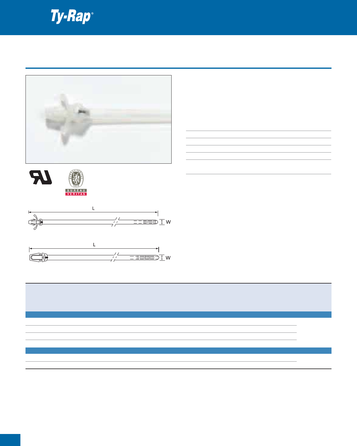
Releasable lashing ties with incorporated fastener
• Rugged one-piece construction, for heavy-duty applications
• Releasable and re-usable, ideal for temporary installations
• Fast and durable
• Easy handling
• No tooling necessary
• Specially developed accessories, like the wall plug TC5359 and
the mounting bases TC5355 to TC5357 (see page 95 for details)
Technical Information
Material Polyamide 6.6
Temperature range -40°C to +85°C
Colour UV-resistant black
Flammability rating UL 94 V-2
Other properties UV-resistant, Halogen free, Silicone free
Special ties
33
Thomas & Betts • www.tnb-europe.com
1.1
Introduce the cable tie tail into the lower slot in the head. Tighten the tie
and pull it back. Slide in the tie under the catch from the side until it snaps
into position.
Product Ref. Length Width Thickness Bundle diameter Minimum Quantity
L W from ... to tensile strength
[mm] [mm] [mm] [mm] [N] [pieces]
TY409 483 12.7 2.0 45 - 121 890 100
TY5409 483 12.7 2.0 45 - 121 890 25
Description of Product Reference structure: see page 10
Description of materials and properties: see pages 134 to 145
34
Thomas & Betts • www.tnb-europe.com
1.1
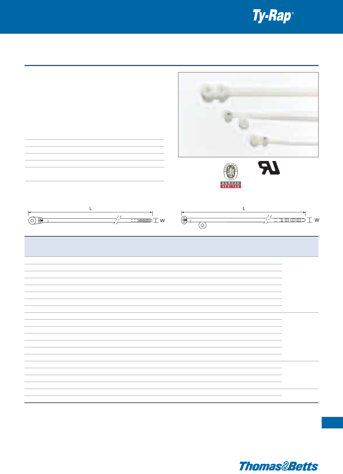
Releasable 2-piece lashing ties, pre-assembled version
• Heavy-duty lashing ties, in cut lengths with pre-assembled heads
• Also available on reel with separate heads (see page 35)
• UV-resistant Polypropylene, ideal for applications where chemical
resistance is important (heads in weatherable rigid Polyamide 6.6)
• Extremely robust (670N)
• Easily releasable & reusable
• 2 types of head: type A: no mounting hole
type B: with mounting hole
• Typical applications: Indoor and outdoor fastening of cables, pipes
and other parts in industry, shipbuilding, chemical industry etc
Technical Information
Material - Tie Weatherable Polypropylene
Material - Head Polyamide 6.6
Temperature range Head: -40°C to +85°C
Tie: -55°C to +110°C
Colour UV-resistant black
Flammability rating UL 94 V-2
Other properties UV-resistant, Halogen free
Special ties
TY54XXPX
TY53418PX
Product Ref. Diameter of Length Width Thickness Bundle diameter Minimum Quantity
mounting hole L W from ... to tensile strength
[mm] [mm] [mm] [mm] [mm] [N] [pieces]
TY53418PX 6.9 457 13.2 1.9 45 - 127 670 25
TY5418PX – 457 13.2 1.8 45 - 127 670 25
TY5424PX – 610 13.2 1.8 10 - 178 670 25
TY5442PX – 1067 13.2 1.8 10 - 305 670 10
TY5460PX – 1524 13.2 1.8 10 - 457 670 10
Description of Product Reference structure: see page 10
Description of materials and properties: see pages 134 to 145
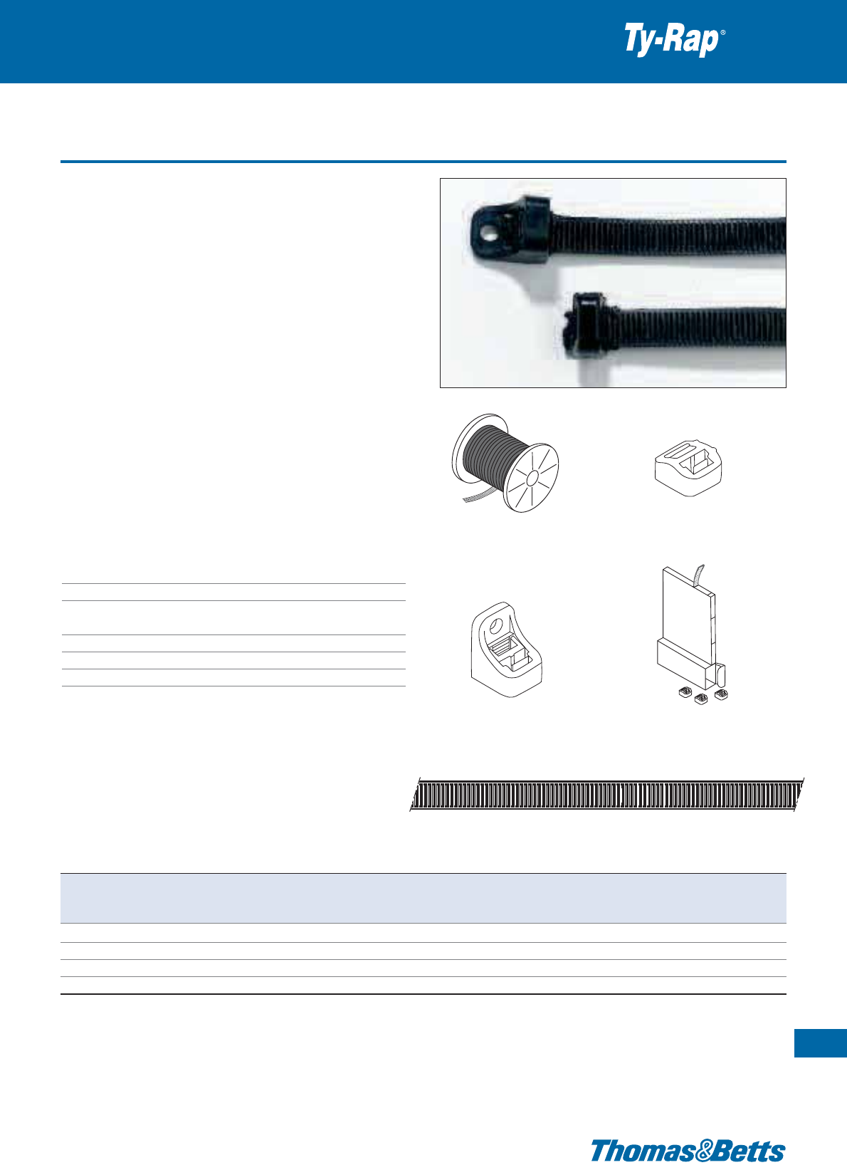
Releasable 2-piece lashing ties on reel with separate heads
• Heavy-duty lashing ties on reel with separate heads
• Also available in cut lengths with pre-assembled heads
(see page 34)
• UV-resistant Polypropylene, ideal for applications where chemical
resistance is important (heads in weatherable rigid Polyamide 6.6)
• Extremely robust (670N)
• Easily releasable & reusable
• 2 types of head: type A: no mounting hole
type B: with mounting hole
• Typical applications: Indoor and outdoor fastening of cables, pipes
and other parts in industry, shipbuilding, chemical industry etc.
•Product Ref. 696-41563: lashing tie on reel (300 m), in weather-
able Polypropylene
•Product Ref. 696-41562: separate head, type A (no mounting
hole), weatherable Polyamide 6.6 (200 pieces)
•Product Ref. 696-41614: separate head, type B (with mounting
hole), weatherable Polyamide 6.6 (200 pieces) Mounting hole:
Ø 6.9 mm
•Product Ref. TY4100PX: kit containing 30 m of lashing tie on
reel + 50 separate heads, type A
Technical Information
Material - Tie Weatherable Polypropylene
Material - Head Polyamide 6.6
Temperature range Head: -40°C to +85°C
Tie: -55°C to +110°C
Colour UV-resistant black
Flammability rating UL 94 V-2
Other properties UV-resistant, Halogen free
Special ties
35
Thomas & Betts • www.tnb-europe.com
1.1
696-41563
TY4100PX
696-41614
696-41562
696-41563
Product Ref. Lashing tie, dimensions Separate locking heads Min. tensile strength
length width thickness Quantity type of assembly
[mm] [mm] [mm] [pieces] [N]
696-41563 300 13.2 1.8 – – 670
696-41562 – – – 200 Type A, no mounting hole 670
696-41614 – – – 200 Type B, with mounting hole 670
TY4100PX 30 13.2 1.8 50 Type A, no mounting hole 670
Description of Product Reference structure: see page 10
Description of materials and properties: see pages 134 to 145
36
Thomas & Betts • www.tnb-europe.com
1.1
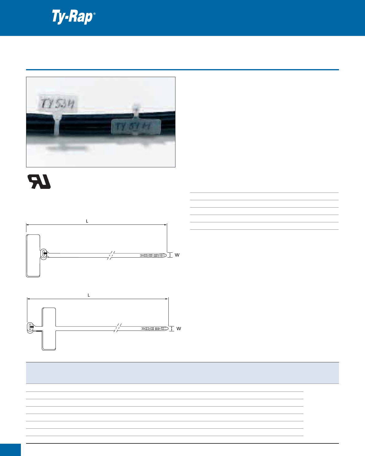
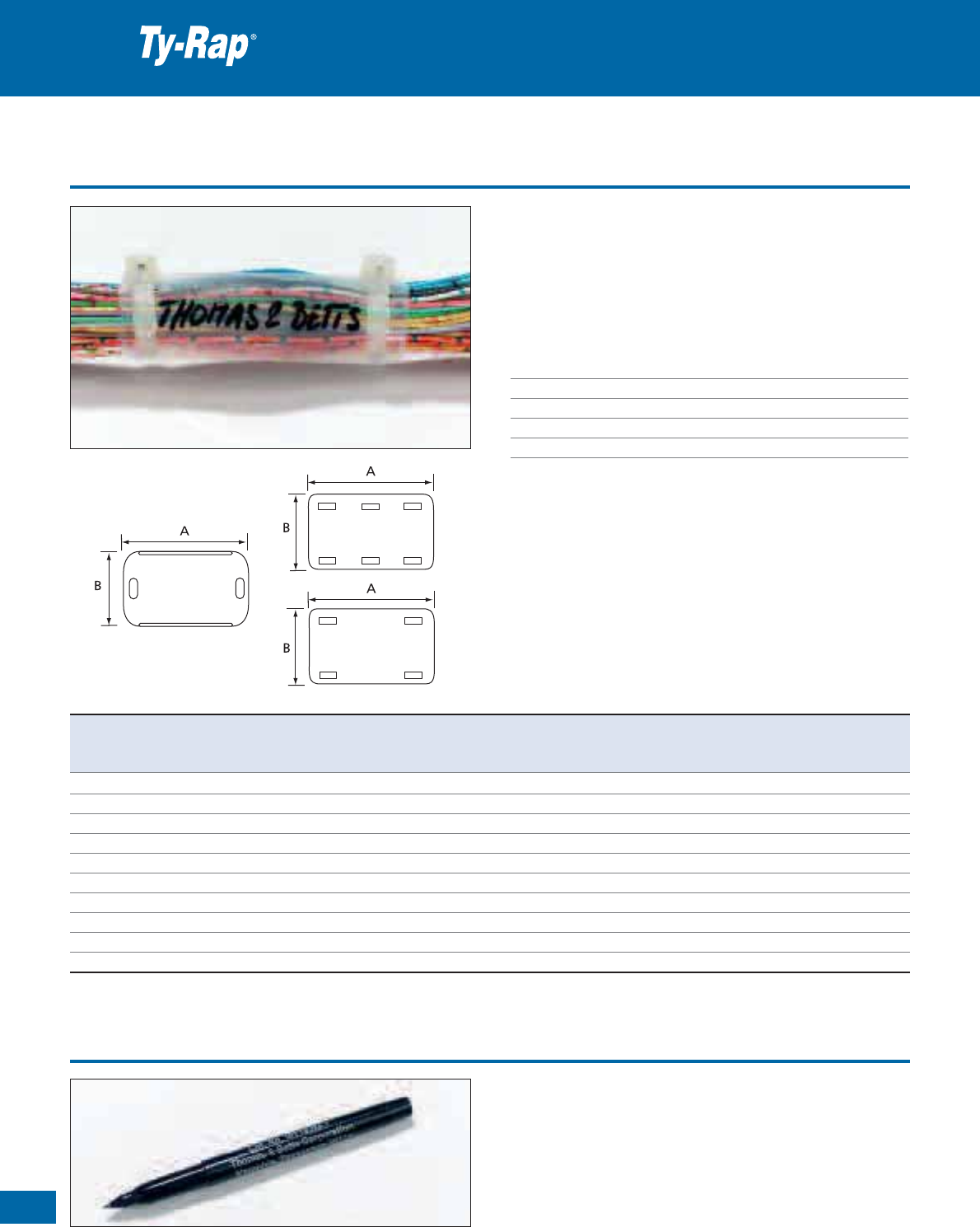
Cable ties with identification tag
• Identification ties with incorporated label for durable marking and
tying
• Label forms onto the bundle for types TY512M, TY51M and pro-
trudes for ties TY532M and TY53M
• Type 51M is MIL (MS-3368-5) approved
• Trouble-free installation
• Simple marking on the roughened writing surface using the special
marking pen WT163M-1 (black ink) or WT163M-3 (red ink) - See
page 38
• All edges are rounded to make installation easier
• Available in bulk packaging (500 / 1000 pieces) or in small pack-
aging (100 pieces)
Technical Information
Material - Moulding Polyamide 6.6
Material - Locking barb 316 grade stainless steel
Temperature range -40°C to +85°C
Colour Natural
Flammability rating UL 94 V-2
Other properties Halogen free, Silicone free
Special ties with steel locking barb
TY53M, TY553M, TY532M, TY5532M
TY51M, TY551M, TY512M, TY5512M
E49405
Product Ref. MIL Spec. Length Width Thickness Bundle diameter Minimum tensile Label Quantity Tooling
L W from ... to strength dimensions
[mm] [mm] [mm] [mm] [N] [mm] [pieces]
TY51M MS-3368-5 92 2.4 1.0 10 - 16 80 25.4 x 7.9
500
TY551M MS-3368-5 92 2.4 1.0 10 - 16 80 25.4 x 7.9
100
TY512M – 210 2.4 1.0 10 - 51 80 25.4 x 7.9
1000 ERG50
TY5512M – 210 2.4 1.0 10 - 51 80 25.4 x 7.9
100 WT193A
TY53M – 102 2.4 1.0 2 - 16 80 20.6 x 9.3
500
TY553M – 102 2.4 1.0 2 - 16 80 20.6 x 9.3
100
TY532M – 212 2.4 1.0 2 - 51 80 20.6 x 9.3 1000
TY5532M – 212 2.4 1.0 2 - 51 80 20.6 x 9.3 100
For other materials and colours contact your Sales Office
Description of Product Reference structure: see page 10
Description of materials and properties: see pages 134 to 145
For tooling specifications: see pages 122 to 133
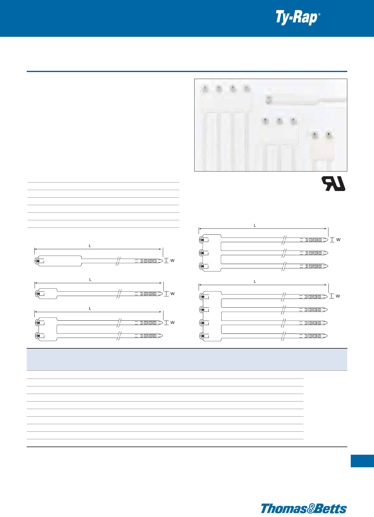
Cable ties with identification tag
• Identification ties with incorporated label for durable marking and tying
• Label forms onto the bundle
• 5 different versions, up to 4 straps, in bulk and small packaging
• 4 versions (up to 3 straps) are Mil-specified
• Trouble free installation
• Labelling of bundles up to 102 mm diameter
• Simple marking on the roughened writing surface using the special
marking pen WT163M-1 / WT163M-3 (black or red)
• All edges are rounded and surfaces smoothed to make installation
easier
Technical Information
Material - Moulding Polyamide 6.6
Material - Locking barb 316 grade stainless steel
Temperature range -40°C to +85°C
Colour Natural
Approvals MIL: MS-3368 -1, -2, -3, -4
Flammability rating UL 94 V-2
Other properties Halogen free, Silicone free
Special ties with steel locking barb
37
Thomas & Betts • www.tnb-europe.com
1.1
E49405
TY
48M,
TY5
48M
TY
46M,
TY5
46M
TY46MD, TY546MD
TY46MT, TY546MT
TY46MF, TY546MF
Product Ref. MIL Spec. Length Width Thickness Bundle diameter Minimum tensile Label Quantity Tooling
L W from ... to strength dimensions
[mm] [mm] [mm] [mm] [N] [mm] [pieces]
TY48M MS-3368-2 360 4.8 1.1 19 - 102
220 13.1 x 57.2
1000
TY548M MS-3368-2 360 4.8 1.1 19 - 102
220 13.1 x 57.2
100
TY46M MS-3368-1 184 4.8 1.1 9.5 - 45
220 13.1 x 27.0
1000
ERG50
TY546M MS-3368-1 184 4.8 1.1 9.5 - 45
220 13.1 x 27.0
100
ERG120
TY46MD MS-3368-3 184 4.8 1.1 9.5 - 45
220 x 2 29.7 x 27.0
500
WT193A
TY546MD MS-3368-3 184 4.8 1.1 9.5 - 45
220 x 2 29.7 x 27.0
50
TY46MT MS-3368-4 184 4.8 1.1 9.5 - 45
220 x 3 46.0 x 27.0
500
TY546MT MS-3368-4 184 4.8 1.1 9.5 - 45
220 x 3 46.0 x 27.0
100
TY46MF – 184 4.8 1.1 9.5 - 45 220 x 4 63.1 x 27.0 250
TY546MF – 184 4.8 1.1 9.5 - 45 220 x 4 63.1 x 27.0 50
For other materials and colours contact your Sales Office
Description of Product Reference structure: see page 10
Description of materials and properties: see pages 134 to 145
For tooling specifications: see pages 122 to 133
38
Thomas & Betts • www.tnb-europe.com
1.1
Identification tags
Special ties
• Optimally suited for fast and long-lasting writing on Polyamide
surfaces
• Fast-drying ink
• The ink is resistant to humidity, oil and light solvents
•Nontoxic
• Available in 2 colours of ink
•Product. Ref.
WT163M-1:
black ink
•Product. Ref.
WT163M-3:
red ink
• Tie fastening labels
• For use in combination with the special marking pen WT163M-1
& WT163M-3 from Thomas & Betts, or with a hot foil marking
• For secure labelling of bundles, parts etc
• Available in 3 shapes to suit all design requirements
Technical Information
Material Polyamide 6.6
Temperature range -40°C to +85°C
Colour Natural
Flammability rating UL 94 V-2
Other properties Halogen free, Silicone free
TC223-TB
TC123-TB to
TC128-TB
TC224-TB to
TC228-TB
Product Ref. Height Width Label Area for label For tie width Weight Quantity
A B thickness height width up to
[mm] [mm] [mm] [mm] [mm] [mm] [g/100] [pieces]
TC123-TB 19.6 32.0 0.3 9.5 32.0 4.8 17 1000
TC124-TB 19.6 38.0 0.3 9.5 38.0 4.8 18 1000
TC125-TB 19.6 44.7 0.3 9.5 44.7 4.8 19 1000
TC126-TB 19.6 51.0 0.3 9.5 51.0 4.8 31 1000
TC128-TB 19.6 63.5 0.3 9.5 63.5 4.8 35 1000
TC223-TB 19.6 32.3 1.0 18.0 24.0 4.8 37 1000
TC224-TB 19.6 38.0 0.5 9.5 38.0 4.8 34 1000
TC225-TB 19.6 44.7 0.5 9.5 44.7 4.8 40 1000
TC226-TB 19.6 51.0 0.5 9.5 51.0 4.8 39 1000
TC228-TB 19.6 63.5 0.5 9.5 63.5 4.8 51 1000
Special marking pen
Special ties
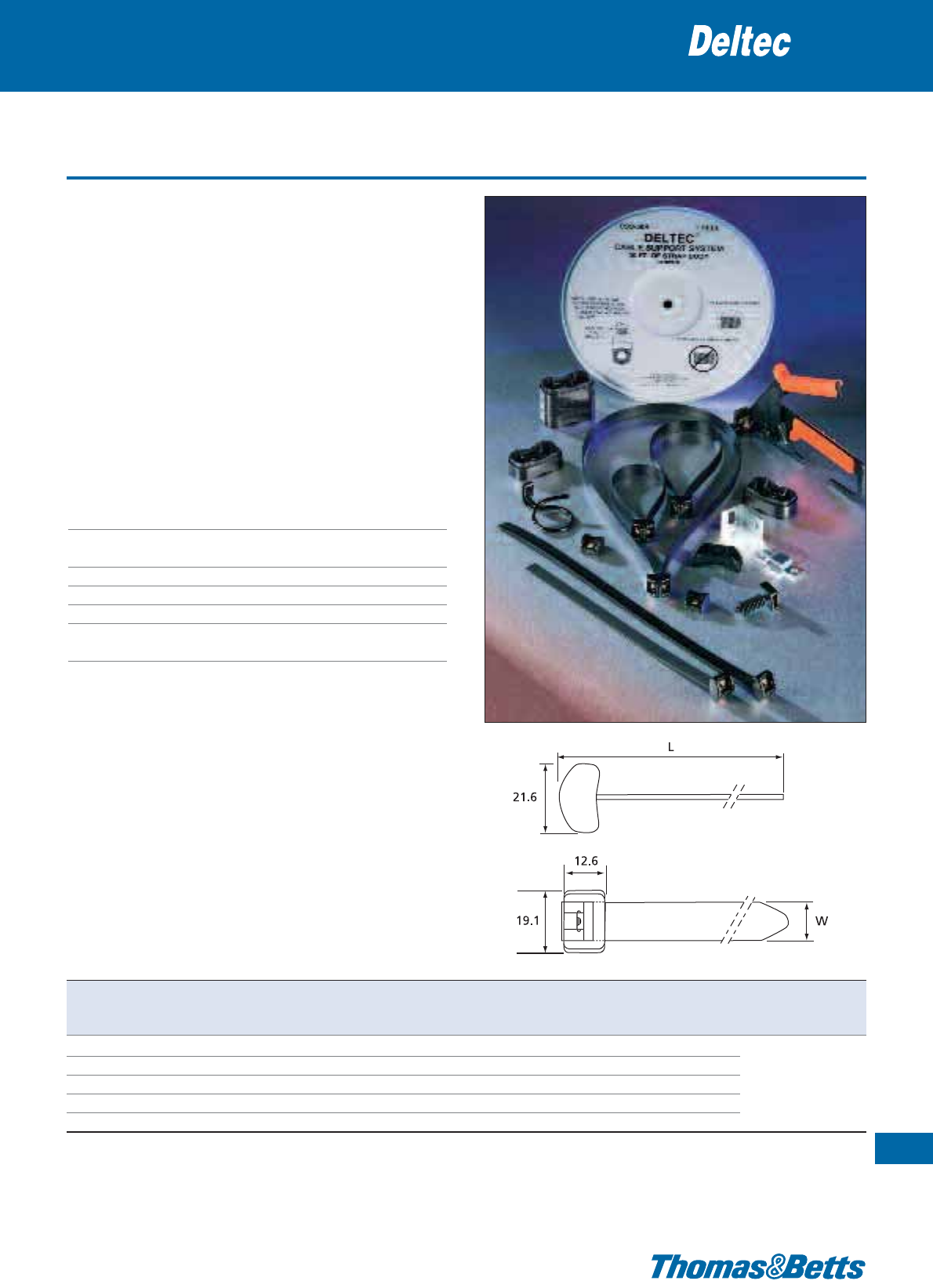
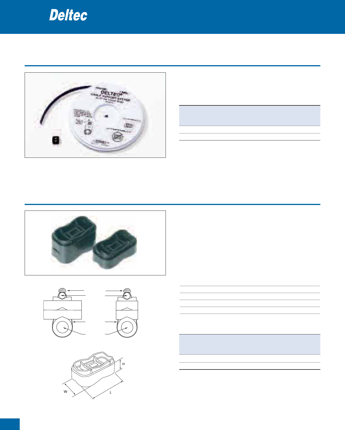
Pre-assembled Deltec cable ties
• Provides a strong, long-life and cost saving method of securing
communication and overhead cables
• Double locking head with corrosion resistant locking barbs in copper
alloy
• Proven years of service: designed to last a minimum of
20 years outdoor
• No sharp edges: operator friendly, cable friendly!
• Easy to install, low installation costs
• Extremely robust ties, with high tensile strength (1110N) after fas-
tening
• Available either in pre-cut and pre-assembled lengths, or on reels
with separate heads for total flexibility
• Choice of specific spacers and accessories
• Month and year of manufacture stamped into strap material
Technical Information
Material - Strap & head Toughened weatherable acetal
Material - Locking barb Marine grade, corrosion-resistant
copper alloy
Temperature range -40°C to +85°C
Flammability rating UL 94 HB
Colour Black
Other properties UV-resistant, Halogen free, superior
resistance to moisture and salt environments
Cable support system with metallic locking barb
39
Thomas & Betts • www.tnb-europe.com
1.1
Product Ref. Length Width Bundle diameter Minimum tensile Quantity Tooling
L W max. strength
[mm] [mm] [mm] [N] [pieces]
TYD510M 1300.5 10.0 390 1110 100
CSS-100 254.0 12.7 60 1110 50 WT3D
TYD5135M 342.9 12.7 90 1110 25 L-500-EU
CSS-160 406.4 12.7 110 1110 50
TYD5270M 685.8 12.7 200 1110 10
For tooling specifications: see pages 122 to 133
Note: the recommended maximum continuous static loading for the Deltec straps is 90 N per strap. For best results suggested spacing is 35 to 40 cm.
It is the responsibility of the user to determine whether or not their application meets our recommendation.
40
Thomas & Betts • www.tnb-europe.com
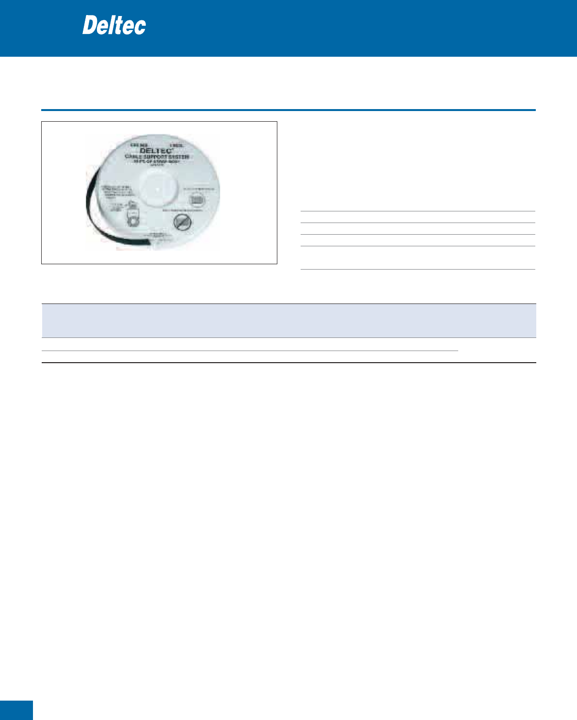
1.1
Straponreel
• Strap on reel, with separate head
• Total flexibility & no waste: cut at the desired length
• Easy to store: reduced inventory
• User friendly
Technical Information
Material Toughened weatherable acetal
Temperature range -40°C to +85°C
Flammability rating UL 94 HB
Colour Black
Other properties UV-resistant, Halogen free, superior resis-
tance to moisture and salt environments
Cable support system with metallic locking barb
Product Ref. Length per reel Width Minimum tensile Quantity Tooling
L W strength
[m] [mm] [N] [reels]
TYD-50R 15.2 12.7 1110 1 WT3D
696-41794 304.8 12.7 1110 1 L-500-EU
For tooling specifications: see pages 122 to 133
Note: the recommended maximum continuous static loading for the Deltec straps is 90 N per strap. For best results suggested spacing is 35 to 40 cm. It is the
responsibility of the user to determine whether or not their application meets our recommendation.
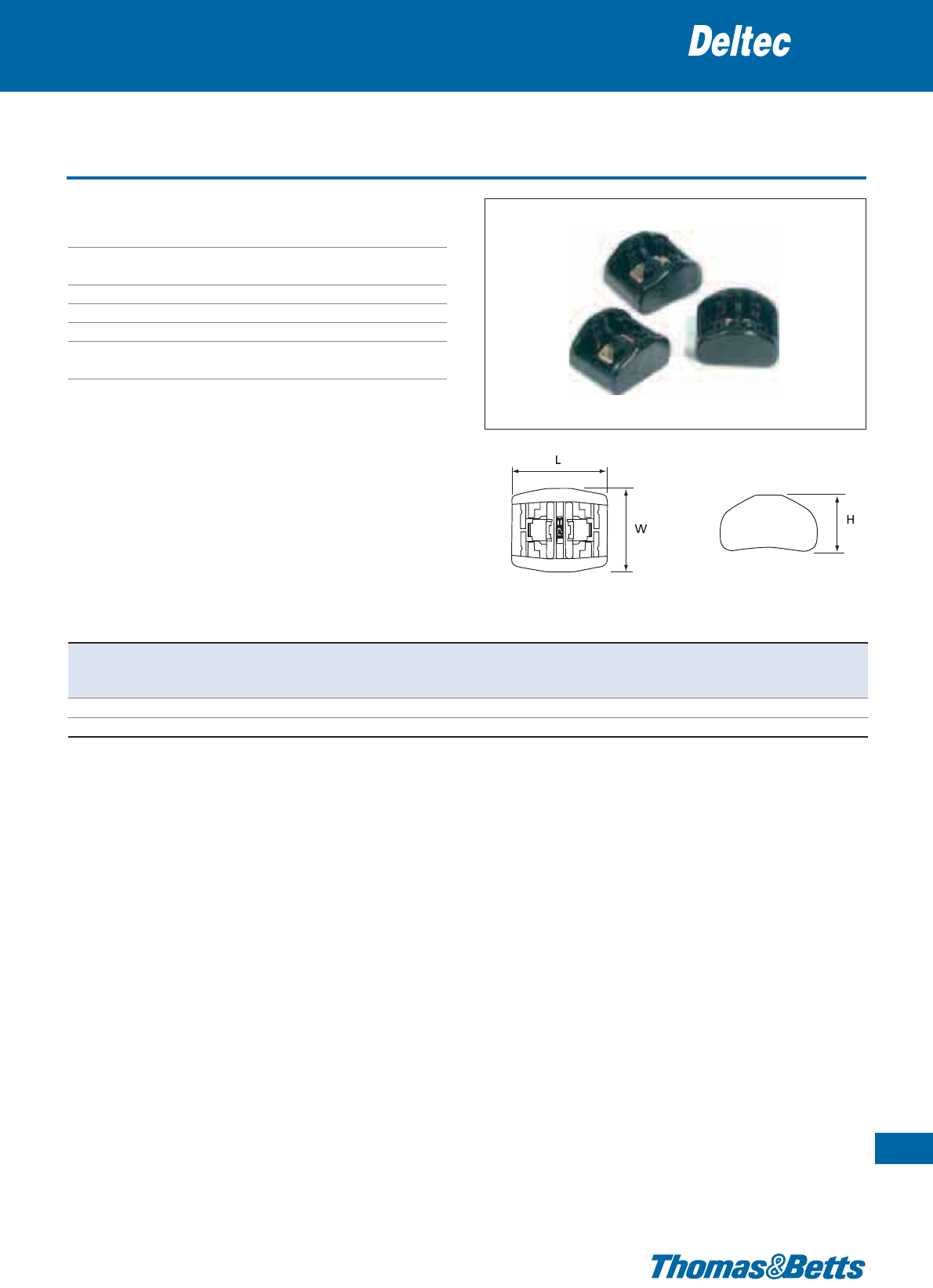
Double locking heads
Technical Information
Material - moulding Toughened weatherable acetal
Material - locking barb Marine grade, corrosion-resistant
copper alloy
Temperature range -40°C to +85°C
Flammability rating UL 94 HB
Colour Black
Other properties UV-resistant, Halogen free, superior resis-
tance to moisture and salt environments
Cable support system with metallic locking barb
41
Thomas & Betts • www.tnb-europe.com
1.1
Product Ref. Length Width Height Quantity
LWH
[mm] [mm] [mm] [pieces]
TYD-LH 21.6 19.1 12.6 25
696-41795 21.6 19.1 12.6 1000
To be assembled with Deltec strap on reel see page 40
42
Thomas & Betts • www.tnb-europe.com
1.1
Deltec Kits
• Convenient kits containing several reels of strap and separate
locking heads, to provide all you need to be efficient on the field
• 2 configurations to match your need
Cable support system with metallic locking barb
Product Ref. Reels Locking heads
Length per reel Quantity Quantity
[mm] [reels] [pieces]
CSS-5K 15.2 5 150
CSS-10K 15.2 10 300
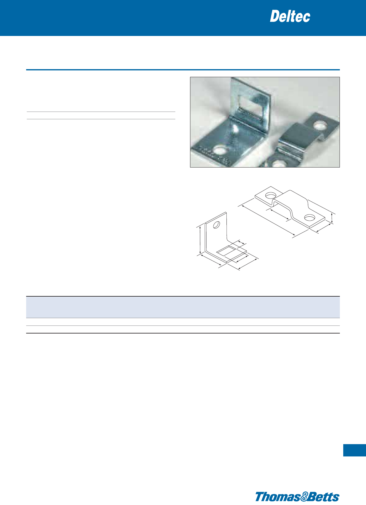
Cable spacers
Cable support system with metallic locking barb
• Stackable height in 12.7 mm increments, for any desired spacing
and all cable sizes - no need to stock multiple sizes of individual
height spacers
• Designed to retain strap on each side and cradle the cable, providing
restricted movement of spacer and preventing damage to cable
• Suitable for coaxial cables
• Can be used for parallel routing or for perpendicular cables
Technical Information
Material Weather-resistant polypropylene
Temperature range -40°C to +85°C
Flammability rating UL 94 HB
Colour Black
Other properties UV-resistant, Halogen free
cable tie
cable tie
cable
cable
Product Ref. Length Width Height Quantity
LWH
[mm] [mm] [mm] [pieces]
TCP5255 53.3 30.5 12.7 25
TCP360 53.3 30.5 12.7 100
43
Thomas & Betts • www.tnb-europe.com
1.1
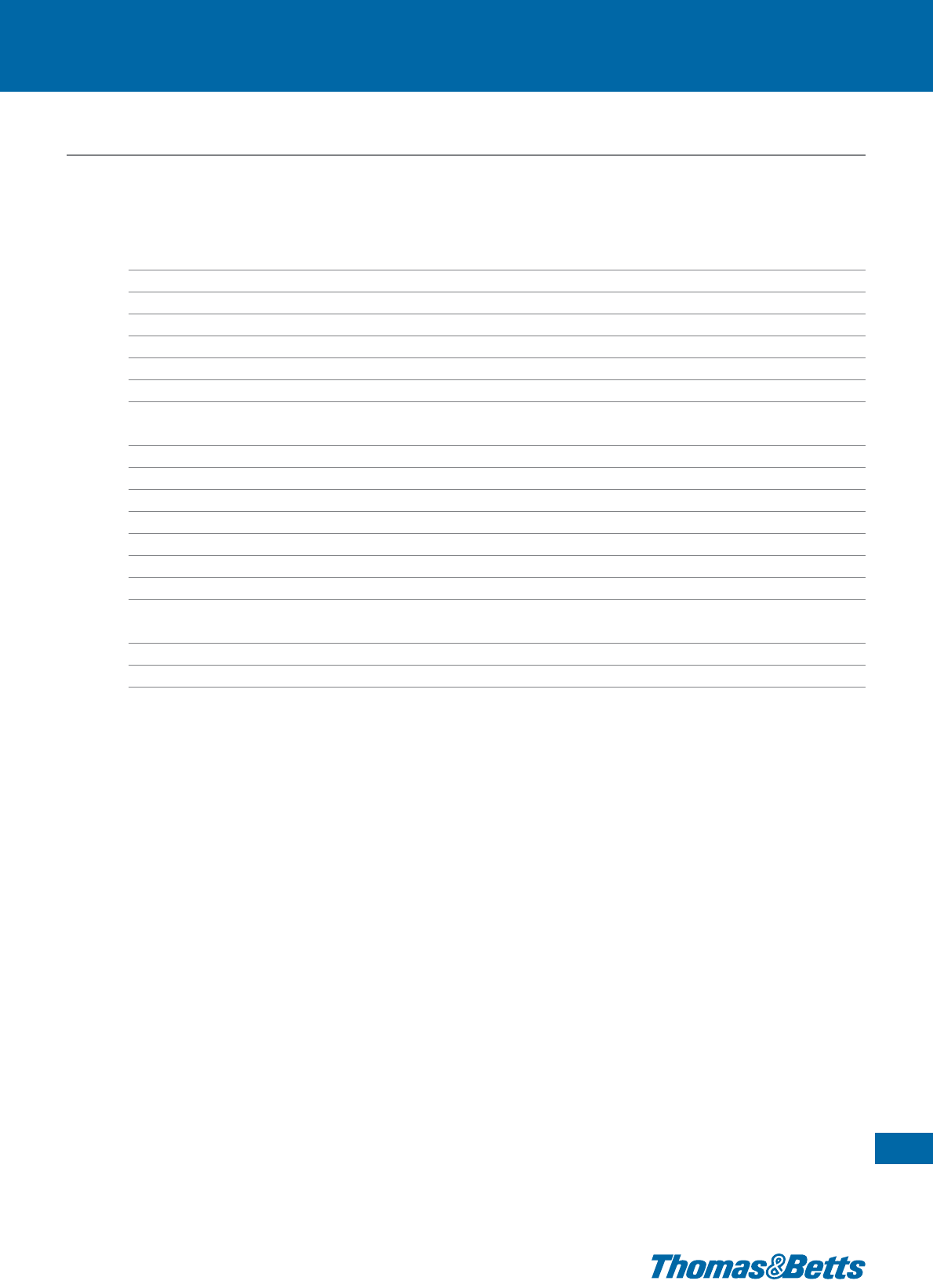
A
C
B
A
B
DC
E
D
CSS-H
CSS-B
Product Ref. Dimensions Mounting hole Quantity
A B C D E diameter
[mm] [mm] [mm] [mm] [mm] [mm] [pieces]
CSS-B 48.4 14.3 7.1 15.1 5.6 6.7 (2x) 50
CSS-H 22.5 22.2 29.8 13.6 8.3 6.9 50
Note: see pages 79 to 100 for other mounting bases in Nylon
Base and hanger
• To secure the cables to all types of surfaces
Technical Information
Material Zinc plated steel
Colour Metallic
Cable support system with metallic locking barb

44
Thomas & Betts • www.tnb-europe.com
1.2
Ty-Fast®, Col-Ty™,
Safe-Ty™ and Ty-Grip™
All plastic cable ties
45
Thomas & Betts • www.tnb-europe.com
1.2
FASTENING SYSTEMS
1.1 PREMIUM CABLE TIES WITH STEEL LOCKING BARB 4
1.2 ALL-PLASTIC CABLE TIES 44
All-plastic cable ties 48
Product reference structure 48
Standard cable ties 49
Standard cable ties - Jar 50
Extra-long cable ties 51
Heavy-duty cable ties 52
UL 94 V-0 flame retardant cable ties 53
Special all-plastic cable ties 54
Integrated mounting hole cable ties 54
Releasable panel mounting cable ties 55
Releasable cable ties 56
Cable ties with identification tag 57
Special double-headed ties 58
Low profile in-line fasteners 59
Hook & Loop fasteners 60
Heavy-duty installation ties 62
Heavy-duty double headed installation ties 62
Accessories 63
1.3 STAINLESS STEEL CABLE TIES 64
1.4 MOUNTING BASES & ACCESSORIES 74
1.5 CABLE PROTECTION SYSTEMS 112
1.6 CABLE TIE TOOLING 122
1.7 MATERIAL SPECIFICATIONS 134
46
Thomas & Betts • www.tnb-europe.com
1.2
Ty-Fast®, Col-Ty™,
Safe-Ty™ and Ty-Grip™
All plastic cable ties
Thomas & Betts offers a complete range of all plastic cable
ties to cover the most demanding applications.
Ty-Fast®All plastic ties
The all-plastic cable ties are available in lengths from 91 mm to
1214 mm and widths from 2.4 mm to 13.2 mm, offering a loop
tensile strength up to 1120 N. Those cable ties will satisfy
bundling requirements up to 381 mm. Those cable ties are halogen
and silicone free Polyamide 6.6 and are available in 12 different
colours.

47
Thomas & Betts • www.tnb-europe.com
1.2
All plastic ties
Heavy duty installation ties
Low profile inline fasteners
Hook & loop fasteners
Ty-Fast®cable ties meet international standards such as UL,
Germanischer Lloyd, Lloyd’s Register of Shipping, Bureau Veritas,
Mil-Specifications and QPL. State-of-the-art robotic and raw
material handling equipment assures product and material
integrity throughout the manufacturing process. The integrally
formed Polyamide pawl combines low insertion and high locking
strength.
A rounded, low-profile head makes for less snags, tails have im-
proved two-sided finger grip design that helps the operator grasp
and pull ties snug. The Sure Grip tab keeps the tail from popping
out while being threaded, then holds it securely for final tightening
by hand or tool.
Heavy duty installation ties
Col-Ty™ - the heavy-duty installation tie - is mainly used for securing
and bundling of cables in the utility and construction industries.
Col-Ty™ - made of Polyamide 12 - is ideal for hazardous environ-
ments, low temperatures and humidity. Col-Ty™ is conform to
EDF HN33/S/62 and its low profile double locking head with ser-
ration on the outer side of the tie eliminates the risk of damage
to the cable.
Low-profile inline fasteners
The Safe-Ty™ design from Thomas & Betts is ideal for use where
precision bundling is required and clearance is a necessity. A
unique saddle back design curves to form a snug fit around the
bundle, and allows for easy pull-trough in bulkheads and any
other tight spaces.
Hook & loop fasteners
Ty-Grip™ cable ties are very easy to release and re-use, making
them ideal for applications where changes are anticipated or
continuous access is required. There is no risk of over-tightening
the cables, which makes the Ty-Grip™ hook & loop fasteners ideal
for specific applications in fiber optics, computer network wiring,
telecom cables, etc.
48
Thomas & Betts • www.tnb-europe.com
Product reference structure
All-plastic cable ties
Note: Nylon (Polyamide) is inherently susceptible to environmental conditions. Ty-Fast
®
cable ties are moisturised to optimum performance levels at machine-
side and should be stored in cool dry areas out of direct sunlight. Cable ties are packaged in plastic bags to contain moisture and should remain sealed until
ready for use.
1.2
Example:
TY XXXX
Tie Dimension Code
TY 18
100 X100
Standard cable
ties with a
width up to
13.2 mm
for lengths
from 91 mm
up to
1214 mm
18 = 2.4 mm / (80N)
40 = 3.6 mm / (180N)
50 = 4.6 mm / (220N)
120 = 7.6 mm / (540N)
175 = 8.8 mm / (780N)
250 = 13.2 mm / (1120N)
All product references are made
of halogen free Polyamide 6.6,
UL 94 V-2, operating
temperature -40°C to +85°C
blank = natural
X = black, UV-stabilized
1 = brown
2=red
3 = orange
4 = yellow
5 = green
6=blue
7=purple
8=grey
9 = white
20 = black
39 = Heat stabilised, temperature
range: -40°C to +105°C, natural
* X = outdoor use, UV-stabilised,
(UL 94 HB for TY...-120X range),
black
Tie Length Code
Tie Width /
Tensile Strength Code
Additional code for
packaging
Colour / Material
[Blank] =
Bulk packaging (1000 /
500 / 50 ties according
tothesizeofthetie)
50 = 50 ties in a bag
with Euroslot
(only for Prod. Ref.
TY400-120)
100 = 100 ties in a bag
with Euroslot (not
available for Prod. Ref.
TY400-120 & TY800-
120)
Standard cable ties
State-of-the-art robotic and raw material handling equipment assures
product and material integrity throughout the manufacturing process.
• The integrally formed Polyamide pawl combines low insertion and
high locking strength
• A rounded, low-profile head makes for less snags
• Tails have improved two-sided finger grip design that helps the
operator grasp and pull ties snug
• Sure Grip tab keeps the tail from popping out while being
threaded, then holds it securely for final tightening by hand or tool
• Quick and easy pull through increases productivity, reduces opera-
tor fatigue
Technical Information
Material Polyamide 6.6 (*)
Temperature range -40°C to +85°C
Colour Natural as standard colour (*)
Approvals MIL: MS 3367-x (see table)
Flammability rating UL 94 V-2
Other properties Halogen free, Silicone free
(*) For other materials and colours see the product reference structure
page 48
All-plastic cable ties
49
Thomas & Betts • www.tnb-europe.com
1.2
TYPE
T Y P E
APPROVED
A P P R O V ED
E49405
Product Ref. MIL Spec. Length Width Bundle diameter Minimum tensile Quantity Tooling
L W from ... to strength
[mm] [mm] [mm] [N] [pieces]
TY075-18 MS-3367-4 91 2.4 1.6 - 20 80 1000
TY100-18 – 112 2.4 1.6 - 25 80 1000
TY125-18 – 136 2.4 1.6 - 32 80 1000
TY200-18 – 203 2.4 1.6 - 50 80 1000 ERG50
TY125-40 MS-3367-5 141 3.5 1.6 - 32 180 1000 WT193A
TY200-40 – 205 3.5 1.6 - 50 180 1000
TY300-40 – 290 3.5 1.6 - 76 180 1000
TY400-40 – 368 3.5 1.6 - 102 180 1000
TY175-50 MS-3367-1 186 4.6 1.6 - 44 220 1000 ERG50
TY225-50 – 226 4.6 1.6 - 57 220 1000 ERG120
TY300-50 – 291 4.6 1.6 - 76 220 1000 WT193A
TY400-50 MS-3367-2 366 4.6 1.6 - 102 220 1000
TY200-120 – 219 7.6 4.8 - 50 540 500 ERG120
TY400-120 MS-3367-3 375 7.6 4.8 - 102 540 500 L-500-EU
TY800-120 – 706 7.6 4.8 - 203 540 50 WT3D
** Some approvals may not be applicable to all the Product References. Contact your Sales office for approvals limitations
Description of Product Reference structure: see page 48
Description of materials and properties: see pages 134 to 145
For tooling specifications: see pages 122 to 133
** ** ** **
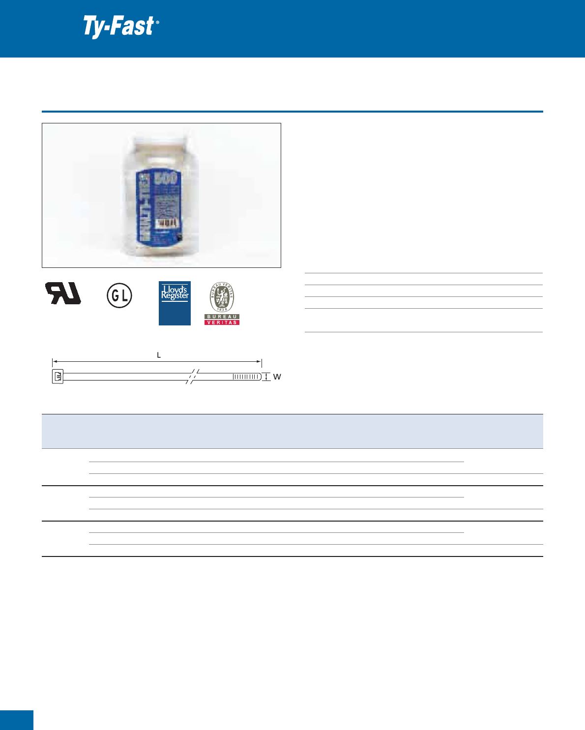
50
Thomas & Betts • www.tnb-europe.com
1.2
Standard cable ties - Jars
• Ty-Fast®cable ties packed in an attractive plastic jar
• Ideal product for the distribution market
• Different dimensions in the same packaging: 112 mm x 2.4 mm,
141 mm x 3.6 mm and 186 mm x 4.7 mm
• Tensile strength from 80N to 220N
• Available in 3 different packaging configurations: 1 in natural
cable ties and 2 in black cable ties
• Ideal product when small volumes are needed for various appli-
cations
Technical Information
Material Polyamide 6.6
Temperature range -40°C to +85°C
Colour Natural or UV-resistant black (see table)
Flammability rating UL 94 V-2
Other properties UV-resistant (black) Halogen free,
Silicone free
All-plastic cable ties
TYPE
T Y P E
APPROVED
A P P R O V ED
E49405
Product Ref. Content Colour Mil Spec. Length Width Bundle diameter Minimum Quantity Tooling
L W from ... to tensile strength
[mm] [mm] [mm] [N] [pieces]
JTN-500 TY100-18-100 natural - 112 2.4 1.6 - 25 80 2 x 100 ERG50, WT193A
TY125-40-100 natural MS-3367-5 141 3.6 1.6 - 32 180 1 x 100
TY175-50-100 natural MS-3367-1 186 4.7 1.6 - 44 220 2 x 100 ERG50, ERG120, WT193A
JTB-500 TY100-18-X-100 UV-resistant black - 112 2.4 1.6 - 25 80 2 x 100 ERG50, WT193A
TY125-40-X-100 UV-resistant black MS-3367-5 141 3.6 1.6 - 32 180 1 x 100
TY175-50-X-100 UV-resistant black MS-3367-1 186 4.7 1.6 - 44 220 2 x 100 ERG50, ERG120, WT193A
JTB1-500 TY100-18-X-100 UV-resistant black - 112 2.4 1.6 - 25 80 2 x 100 ERG50, WT193A
TY125-40-X-100 UV-resistant black MS-3367-5 141 3.6 1.6 - 32 180 2 x 100
TY175-50-X-100 UV-resistant black MS-3367-1 186 4.7 1.6 - 44 220 1 x 100 ERG50, ERG120, WT193A
Description of Product Reference structure: see page 48
Description of materials and properties: see pages 134 to 145
For tooling specifications: see pages 122 to 133
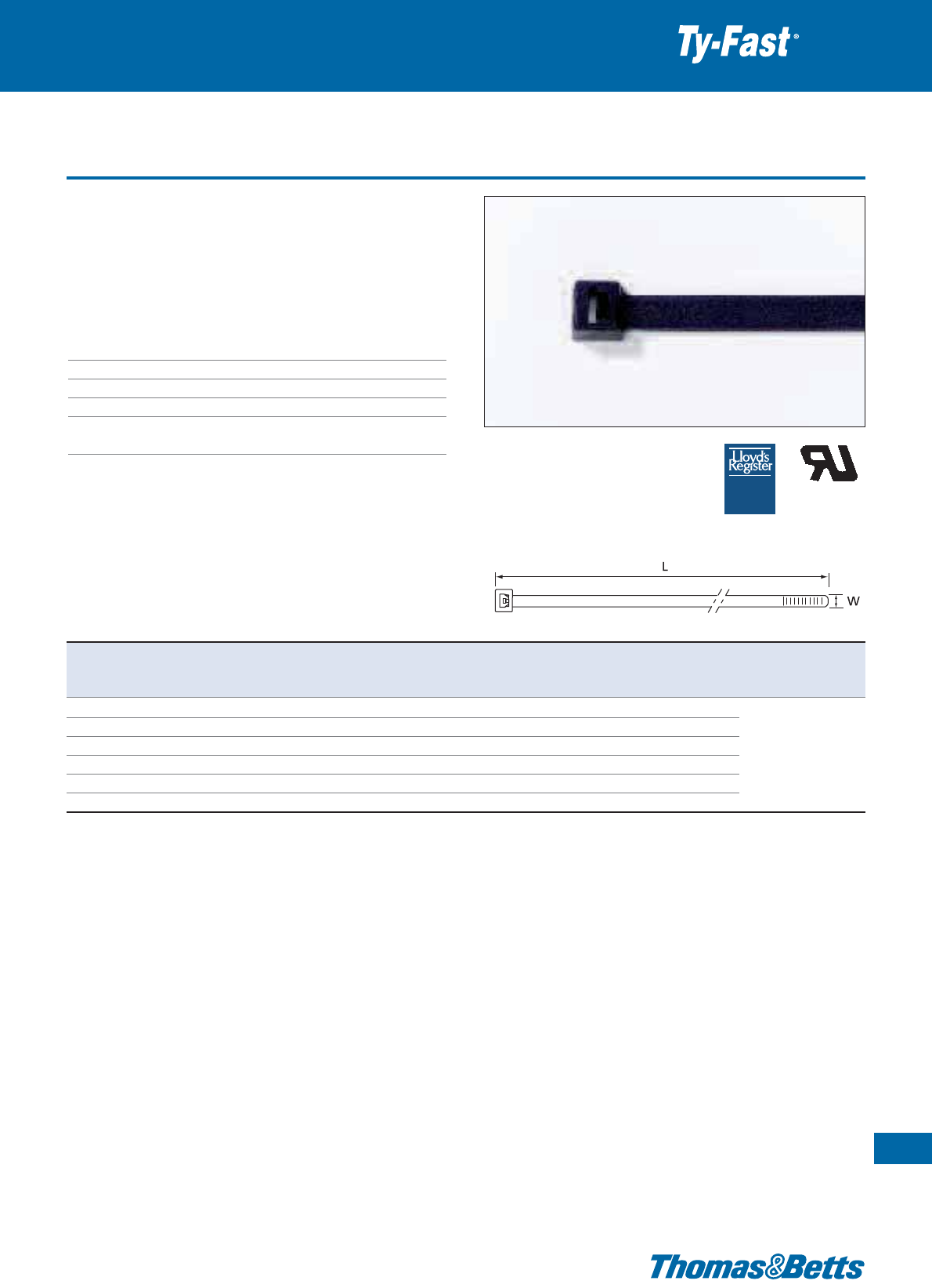
Extra-long cable ties
• Extremely long ties (up to 1214 mm)
• Robust construction (780N), for demanding applications where
superior tensile strength is required
• The extra long Ty-Fast®ties are available in natural colour for indoor
applications and in UV-resistant black for outdoor applications
Technical Information
Material Polyamide 6.6
Temperature range -40°C to +85°C
Colour Natural or UV-resistant black (see table)
Flammability rating UL 94 V-2
Other properties UV-resistant (black)
Halogen free, Silicone free
All-plastic cable ties
51
Thomas & Betts • www.tnb-europe.com
1.2
TYPE
T Y P E
APPROVED
A P P R O V ED
E49405
Product Ref. Colour Length Width Bundle diameter Minimum tensile Quantity Tooling
L W from ... to strength
[mm] [mm] [mm] [N] [pieces]
L-36-175-0-L UV-resistant black 930 8.8 5 - 273 780 50
L-36-175-9-L Natural 930 8.8 5 - 273 780 50 WT3D
L-41-175-0-L UV-resistant black 1036 8.8 5 - 305 780 50 L300FR
L-41-175-9-L Natural 1036 8.8 5 - 305 780 50 L-500-EU
L-48-175-0-L UV-resistant black 1214 8.8 5 - 381 780 50
L-48-175-9-L Natural 1214 8.8 5 - 381 780 50
Description of materials and properties: see pages 134 to 145
For tooling specifications: see pages 122 to 133
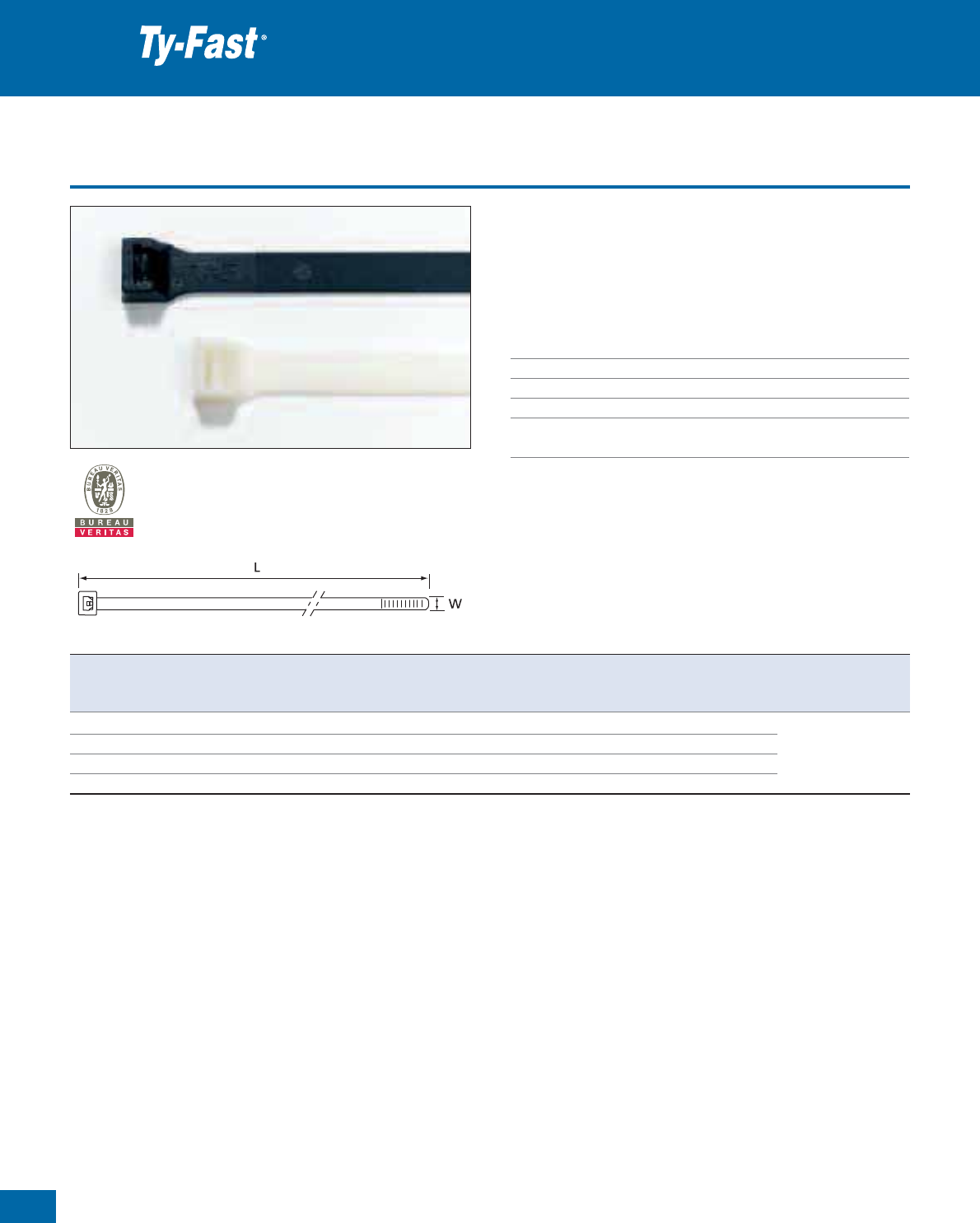
52
Thomas & Betts • www.tnb-europe.com
1.2
Heavy-duty cable ties
• Extremely robust ties (1120N), for demanding applications where
extreme tensile strength is required
• Available in natural colour for indoor applications and in UV-
resistant black for outdoor applications
Technical Information
Material Polyamide 6.6
Temperature range -40°C to +85°C
Colour Natural or UV-resistant black (see table)
Flammability rating UL 94 V-2
Other properties UV-resistant (black)
Halogen free, Silicone free
All-plastic cable ties
Product Ref. Colour Length Width Bundle diameter Minimum tensile Quantity Tooling
L W from ... to strength
[mm] [mm] [mm] [N] [pieces]
TYL300M natural 300 13.2 75 1120 50
TYL300MX UV-resistant black 300 13.2 75 1120 50 L-500-EU
TYL546M natural 546 13.2 140 1120 50
TYL546MX UV-resistant black 546 13.2 140 1120 50
Description of Product Reference structure: see page 48
Description of materials and properties: see pages 134 to 145
For tooling specifications: see pages 122 to 133
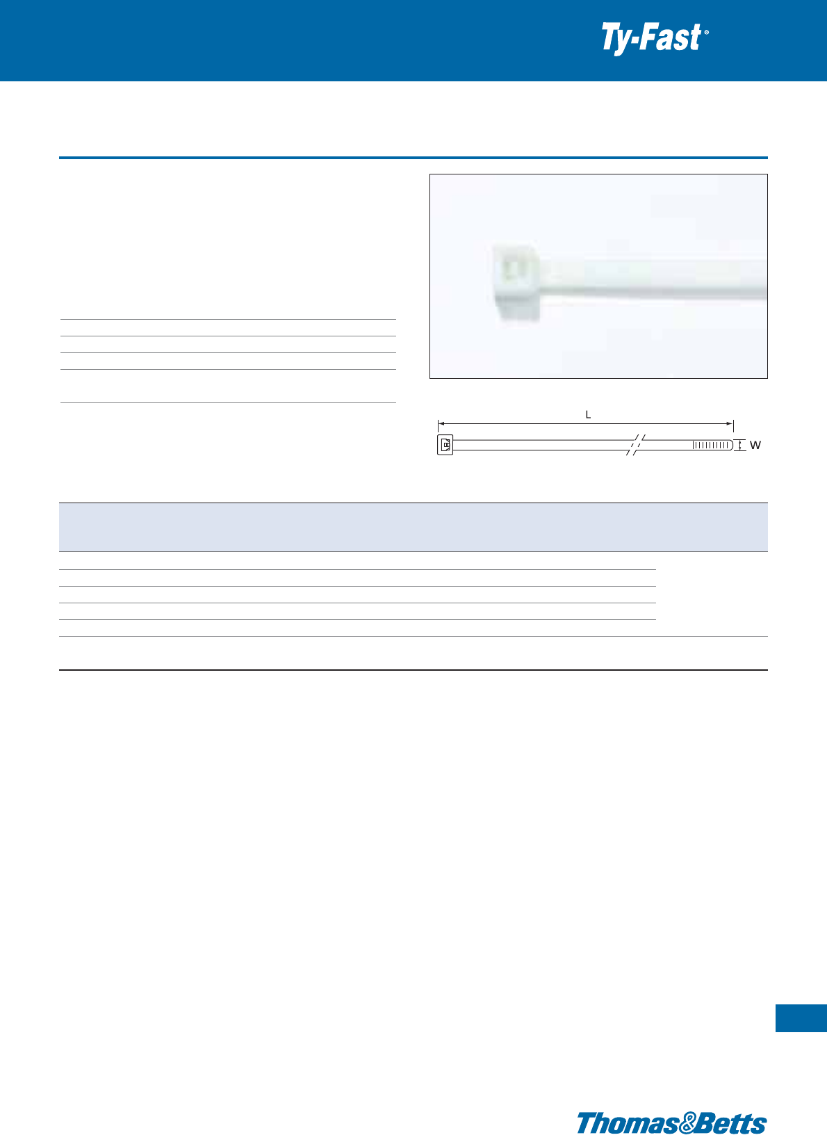
UL 94 V-0 flame retardant cable ties
•
Similar to our Ty-Rap
®
range of flame retardant ties, these all-plastic
ties are made from low smoke flame retardant Polyamide 6.6 and
meet the requirements of UL 94 V-0.
•
Ideal for use where low flammability and low smoke are necessary
such as public transport / buildings, tunnels etc.
Technical Information
Material Polyamide 6.6
Temperature range -40°C to +85°C
Colour Milky white
Flammability rating UL 94 V-0
Other properties Limited fire hazard (low smoke)
Halogen free, Silicone free
All-plastic cable ties
53
Thomas & Betts • www.tnb-europe.com
1.2
Product Ref. Length Width Bundle diameter Minimum tensile Quantity Tooling
L W from ... to strength
[mm] [mm] [mm] [N] [pieces]
TS1025HF 100 2.5 2 - 24 90 100
TS1435HF 140 3.5 2.5 - 36 180 100 ERG50
TS2045HF 200 4.5 3 - 51 220 100 WT193A
TS2845HF 280 4.5 5 - 76 220 100
TS3645HF 360 4.5 5 - 101 220 100
ERG120, L-500-EU
TS3675HF 360 7.5 5 - 101 540 100 WT3D
Description of materials and properties: see pages 134 to 145
For tooling specifications: see pages 122 to 133
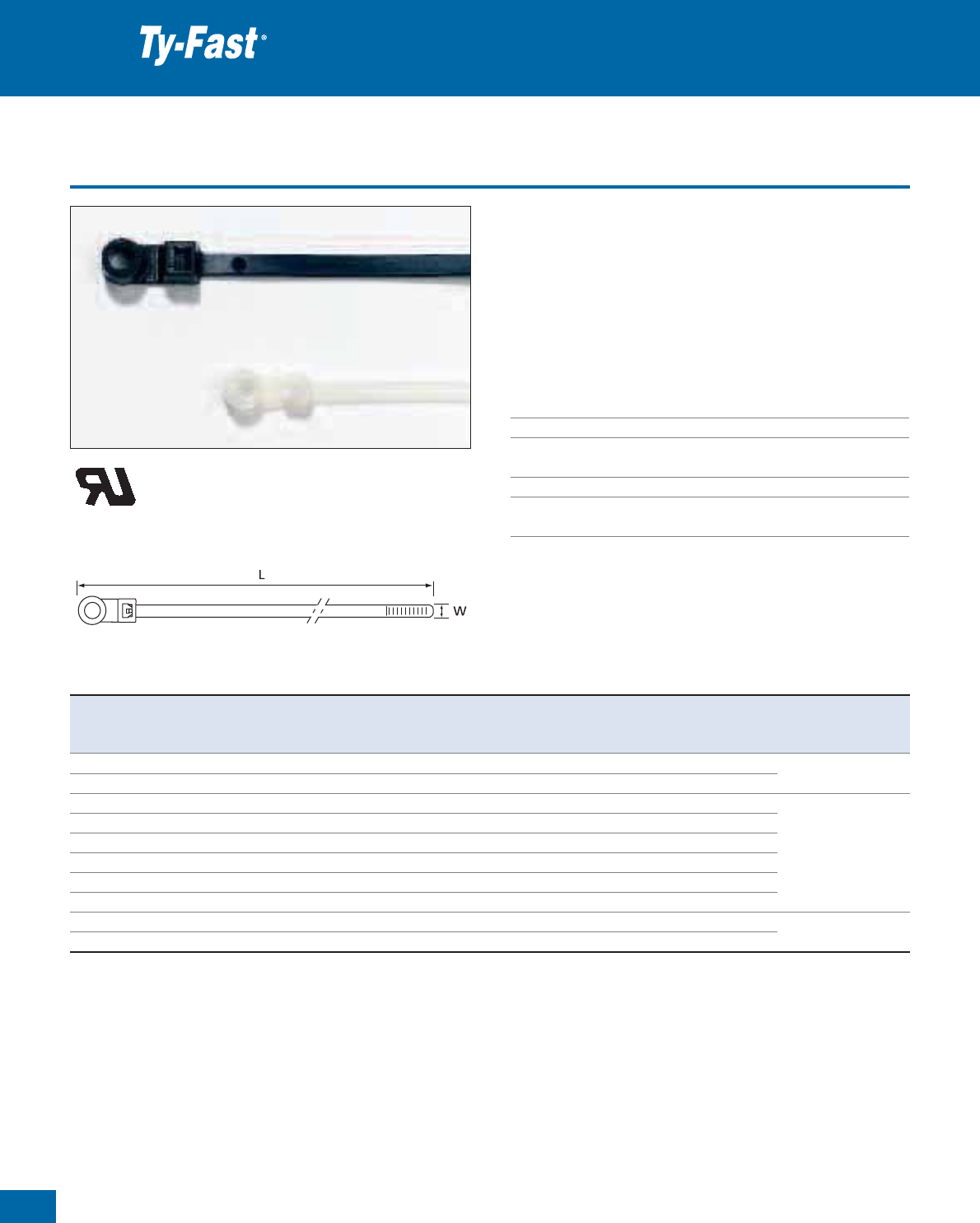
54
Thomas & Betts • www.tnb-europe.com
1.2
Integrated mounting hole cable ties
• Cable tie can be directly mounted onto a support with screws,
bolts or rivets.
• Mounting and bundling in one maintenance-friendly assembly.
• Cable harness manufacture and pre- and end- mounting of bundles
and parts.
• UV-resistant version, especially recommended for outdoor appli-
cations
Technical Information
Material Polyamide 6.6
Temperature range -40°C to +85°C
Colour Natural or UV-resistant black
(see table)
Flammability rating UL 94 V-2
Other properties UV-resistant (black)
Halogen free, Silicone free
Special all-plastic cable ties
E49405
Product Ref. Colour Length Width Fixing Bundle diameter Minimum tensile Quantity Tooling
L W screw size from ... to strength
[mm] [mm] [mm] [N] [pieces]
L-5-30MH-0-C UV-resistant black 152 3.3 M4 2 - 32 130 100 ERG50
L-5-30MH-9-C natural 152 3.3 M4 2 - 32 130 100 WT193A
L-7-50MH-0-C UV-resistant black 208 4.7 M5 2 - 44 220 100 ERG50
L-7-50MH-9-C natural 208 4.7 M5 2 - 44 220 100 ERG120
L-11-50MH-0-C UV-resistant black 314 4.7 M5 2 - 76 220 100 WT193A
L-11-50MH-9-C natural 314 4.7 M5 2 - 76 220 100 WT3D
L-14-50MH-0-C UV-resistant black 382 4.7 M5 2 - 102 220 100
L-14-50MH-9-C natural 382 4.7 M5 2 - 102 220 100
L-14-120MH-0-C UV-resistant black 382 7.6 M6 5 - 102 540 100 ERG120
L-14-120MH-9-C natural 382 7.6 M6 5 - 102 540 100 L-500-EU, WT3D
Description of materials and properties: see pages 134 to 145
For tooling specifications: see pages 122 to 133
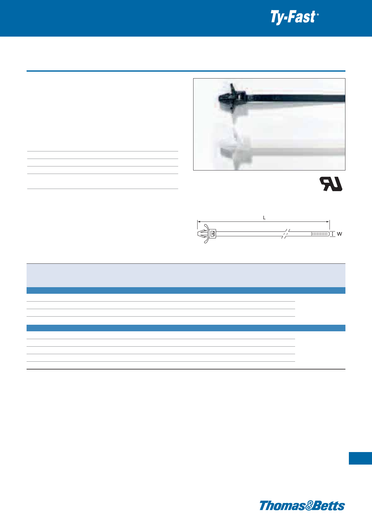
Releasable panel mounting cable ties
• Fastening and clip-mounting in one
• Fast pre- or on-site-assembly for a range of panel thickness up to
2.7 mm
• Fast and secure clip-mounting
• For use in 6.35 mm mounting hole
• Product References containing xxx-PMR-xxx are releasable
Technical Information
Material Polyamide 6.6
Temperature range -40°C to +85°C
Colour Natural or UV-resistant black (see table)
Flammability rating UL 94 V-2
Other properties UV-resistant (black)
Halogen free, Silicone free
Special all-plastic cable ties
55
Thomas & Betts • www.tnb-europe.com
1.2
E49405
Product Ref. Colour Length Width Bundle diameter Minimum tensile Quantity Tooling
L W from ... to strength
[mm] [mm] [mm] [N] [pieces]
STANDARD PANEL MOUNTING TIES
L-5-50PM-0-C UV-resistant black 147 4.8 2 - 25 220 100 ERG50, ERG120
L-5-50PM-9-D natural 147 4.8 2 - 25 220 1000 L-500-EU
L-7-50PM-0-C UV-resistant black 208 4.8 2 - 44 220 100 WT193A
L-7-50PM-9-C natural 208 4.8 2 - 44 220 100
RELEASABLE PANEL MOUNTING TIES
TB-4-50PMR-9-C-EU* natural 110 4.8 2 - 22 220 100 ERG50, ERG120
L-5-50PMR-0-C UV-resistant black 147 4.8 2 - 25 220 100 L-500-EU
L-5-50PMR-9-C natural 147 4.8 2 - 25 220 100 WT193A
L-7-50PMR-0-C UV-resistant black 208 4.8 2 - 44 220 100 WT1-TB, WT2-TB
L-7-50PMR-9-C natural 208 4.8 2 - 44 220 100
Description of materials and properties: see pages 134 to 145
For tooling specifications: see pages 122 to 133
* Not UL registered
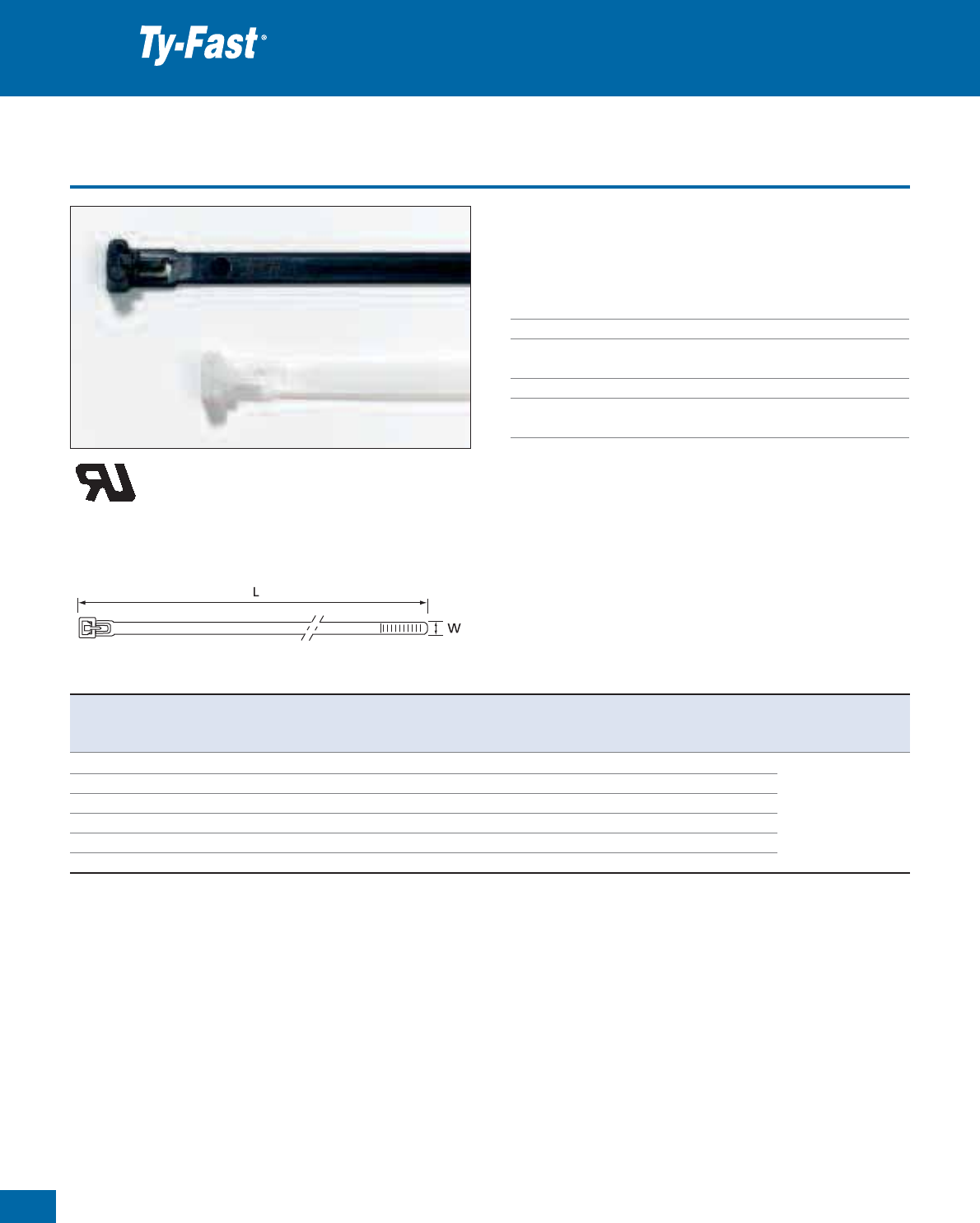
56
Thomas & Betts • www.tnb-europe.com
1.2
Releasable cable ties
Special all-plastic cable ties
• Easy releasable and re-usable. UV-resistant version, especially
recommended for outdoor applications.
Technical Information
Material Polyamide 6.6
Temperature range -40°C to +85°C
Colour Natural or UV-resistant black
(see table)
Flammability rating UL 94 V-2
Other properties UV-resistant (black)
Halogen free, Silicone free
Product Ref. Colour Length Width Bundle diameter Minimum tensile Quantity Tooling
L W from ... to strength
[mm] [mm] [mm] [N] [pieces]
L-5-50R-0-C UV-resistant black 150 7.5 3 - 32 220 100
L-5-50R-9-C natural 150 7.5 3 - 32 220 100
L-8-50R-0-C UV-resistant black 198 7.5 3 - 51 220 100 ERG120
L-8-50R-9-C natural 198 7.5 3 - 51 220 100 L-500-EU
L-10-50R-0-C UV-resistant black 298 7.5 3 - 76 220 100 WT3D
L-10-50R-9-C natural 298 7.5 3 - 76 220 100
Description of materials and properties: see pages 134 to 145
For tooling specifications: see pages 122 to 133
E49405
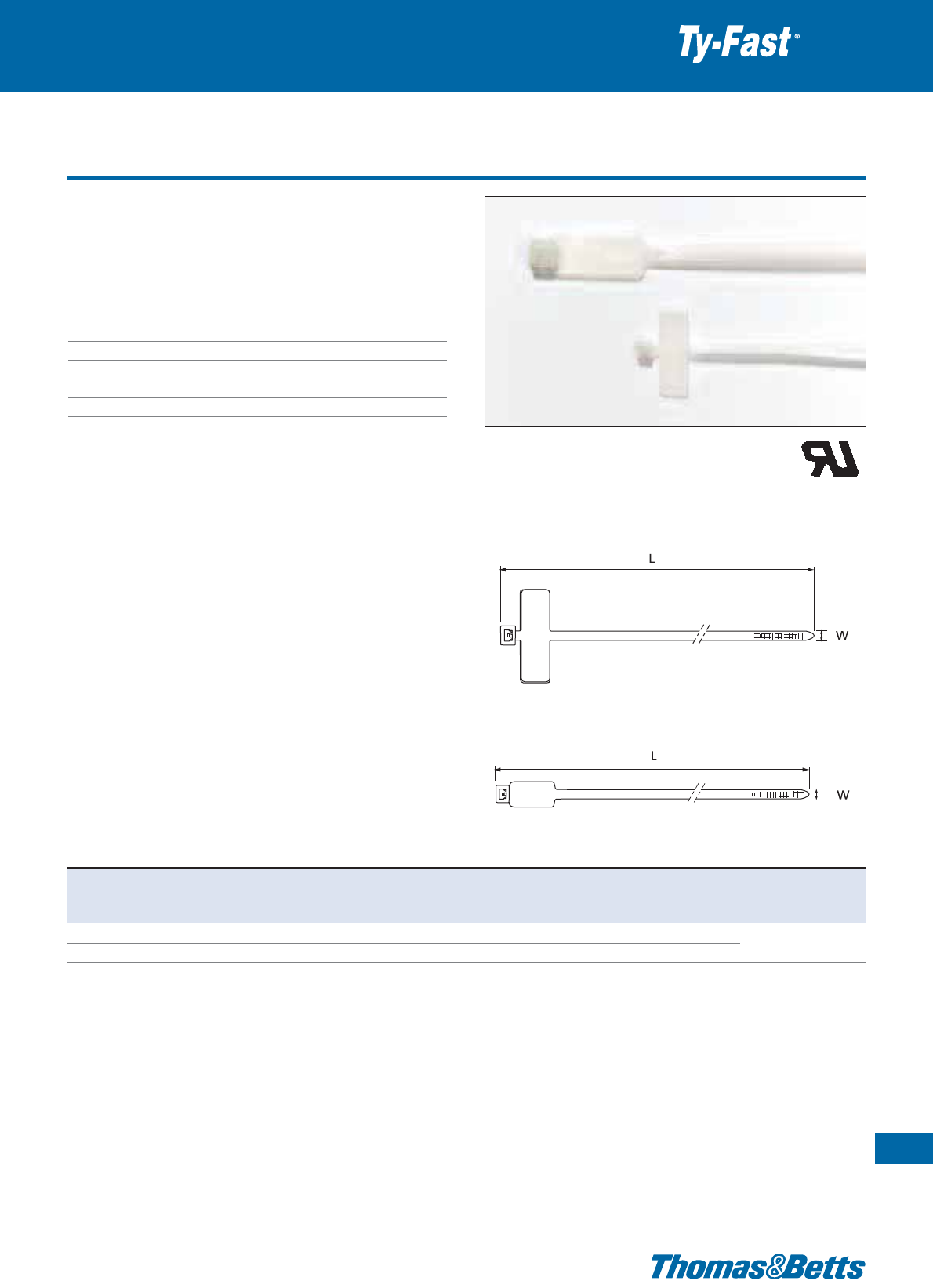
Cable ties with identification tag
• Identification ties with incorporated label for durable marking and
tying.
• Simple marking on the roughened writing surface using the special
marking pen WT163M-1 (black ink) or WT163M-3 (red ink)
Technical Information
Material Polyamide 6.6
Temperature range -40°C to +85°C
Colour Natural
Flammability rating UL 94 V-2
Other properties Halogen free, Silicone free
Special all-plastic cable ties
57
Thomas & Betts • www.tnb-europe.com
1.2
L-4-18ID-9-C
L-7-50ID-9-C
Product Ref. Length Width Label Bundle diameter Minimum tensile Quantity Tooling
L W dimensions max. strength
[mm] [mm] [mm] [mm] [N] [pieces]
L-4-18ID-9-C 102 2.5 7.9 x 24.7 19 80 100 ERG50
L-4-18ID-9-M 102 2.5 7.9 x 24.7 19 80 1000 WT193A
L-7-50ID-9-C 200 4.7 30 x 13.3 44 220 100 ERG50, ERG120
L-7-50ID-9-M 200 4.7 30 x 13.3 44 220 1000 WT193A, L-500-EU
Description of materials and properties: see pages 134 to 145
For tooling specifications: see pages 122 to 133
E49405
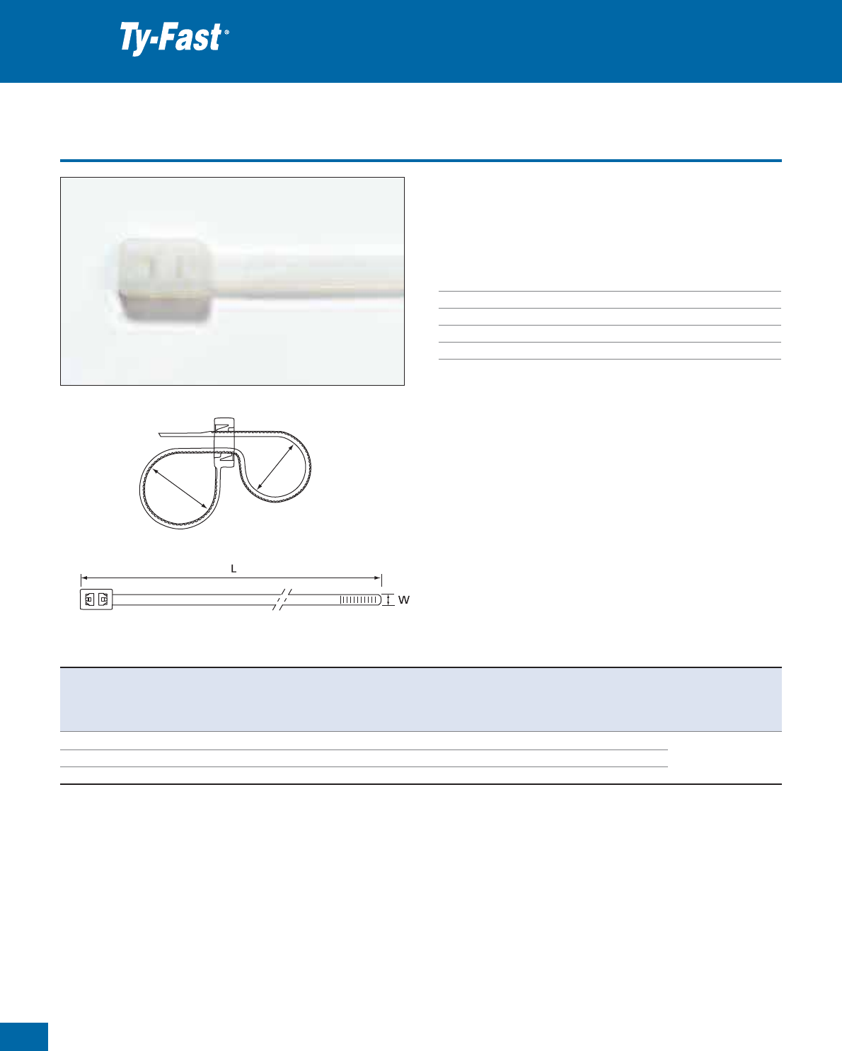
58
Thomas & Betts • www.tnb-europe.com
1.2
Special double-headed ties
• The double-headed ties allow the parallel routing of two bundles
of cable with one single tie.
• Available in 3 different lengths.
Technical Information
Material Polyamide 6.6
Temperature range -40°C to +85°C
Colour Natural
Flammability rating UL 94 V-2
Other properties Halogen free, Silicone free
Special all-plastic cable ties
Loop 1
Loop 2
Product Ref. Length Width Bundle diameter Minimum tensile Quantity Tooling
L W Loop 1 Loop 2 strength
from ... to from ... to
[mm] [mm] [mm] [mm] [N] [pieces]
TB-50RLDH 200 4.8 2.5 - 47 2.0 - 45 220 1000 ERG50, ERG120
TB-12-50RLDH 300 4.8 2.5 - 72 2.0 - 70 220 1000 WT193A
TB-15-50RLDH 370 4.8 2.5 - 100 2.0 - 97 220 1000 L-500-EU
Description of materials and properties: see pages 134 to 145
For tooling specifications: see pages 122 to 133
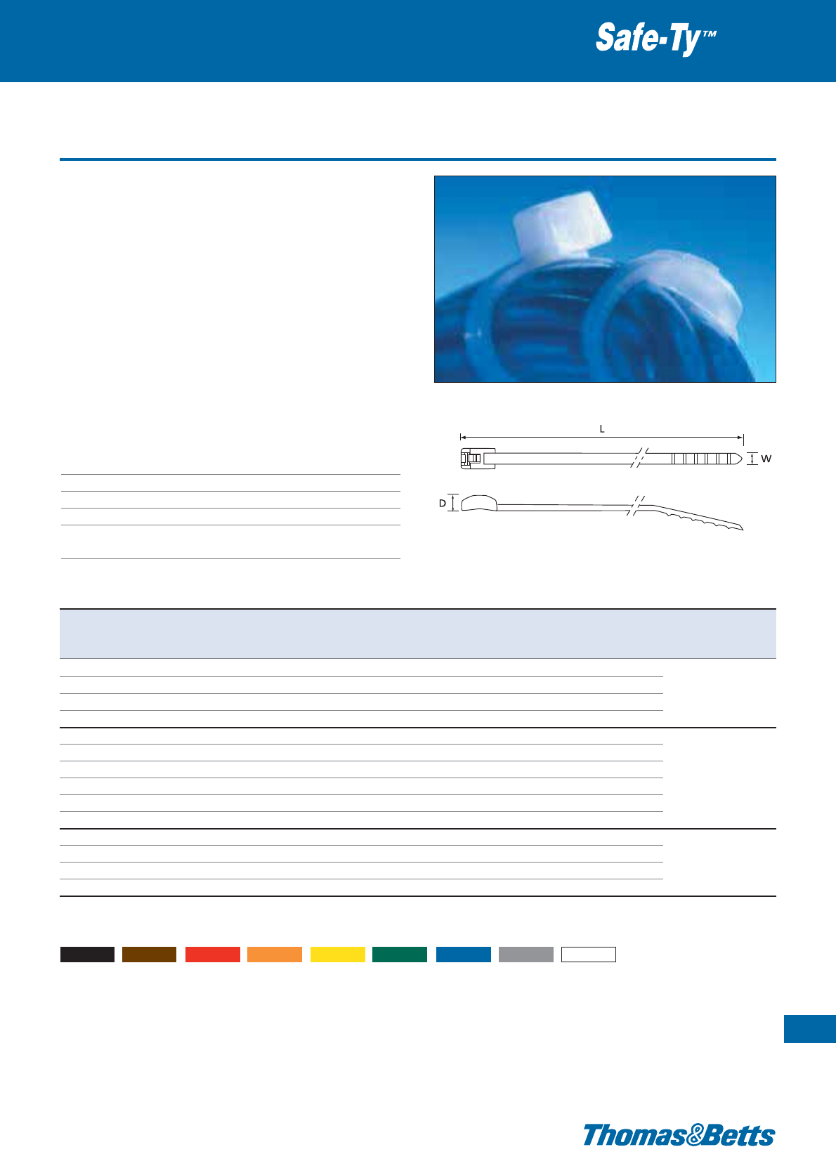
Low profile in-line fasteners
The Safe-Ty™ design from Thomas & Betts is ideal for use where
precision bundling is required and clearance is a necessity. A unique
saddle back design curves to form a snug fit around the bundle, and
allows for easy pull-through in bulkheads and any other tight spaces.
• Low-profile, contoured head reduces clearance required for the
bundle and enhances the appearance of your harness
• The safe-guard wall eliminates exposure to sharp edges
• The saddle back fits snug against the contour of the wiring
harness
• Sizes and colours available to accommodate various requirements
• Recommended in all applications where the aesthetics and the
user’s safety can be a concern (thanks to the rounded edges):
playgrounds, supermarket displays,...
Technical Information
Material Polyamide 6.6
Temperature range -40°C to +85°C
Colour Natural or UV-resistant (see table)
Flammability rating UL 94 V-2
Other properties UV-resistant (black), Halogen free
Silicone free
Special all-plastic cable ties
59
Thomas & Betts • www.tnb-europe.com
1.2
Product Ref. Colour Length Width Bundle diameter Minimum Quantity ** Tooling
L W D from ... to tensile strength
[mm] [mm] [mm] [mm] [N] [pieces]
SF100-18 natural* 118 2.4 3.2
3.2 -
25.4
80
100 / 1000
SF100-18X
UV-resistant black
118 2.4 3.2
3.2 -
25.4
80
100 / 1000 ERG50
SF200-18 natural* 206 2.4 3.2
3.2 -
50.8
80
100 / 1000 WT193A
SF200-18X
UV-resistant black
206 2.4
3.2
3.2 - 50.8
80
100 / 1000
SF175-50 natural* 201 4.7
4.5
4.7 - 44.5
220
100 / 1000
SF175-50X
UV-resistant black
201 4.7
4.5
4.7 - 44.5
220
100 / 1000 ERG50
SF300-50 natural* 288 4.7
4.5
4.7 - 76.2
220
100 / 1000 ERG120
SF300-50X
UV-resistant black
288 4.7
4.5
4.7 - 76.2
220
100 / 1000 WT193A
SF400-50 natural* 369 4.7
4.5
9.5 - 101.6
220
100 / 1000 L-500-EU
SF400-50X
UV-resistant black
369 4.7
4.5
9.5 - 101.6
220
100 / 1000
SF400-120 natural* 370 7.6
6.9
9.5 - 101.6
540
100 / 1000
SF400-120X
UV-resistant black
370 7.6
6.9
9.5 - 101.6
540
100 / 1000 ERG120
SF600-120 natural* 533 7.6
6.9
9.5 - 152.4
540
100 / 1000 L-500-EU
SF600-120X
UV-resistant black
533 7.6
6.9
9.5 - 152.4
540
100 / 1000 WT3D
* For other colours add colour suffix to Product Reference: 0 = black, 1 = brown, 2 = red, 3 = orange, 4 = yellow, 5 = green, 6 = blue, 8 = grey and
9 = white. For example: SF-175-50-2 (red)
** Standard quantity = 1000. For bags of 100 add -100 to the product reference, for example. SF100-18-100.
Description of materials and properties: see pages 134 to 145
For tooling specifications: see pages 122 to 133
Note: Nylon (Polyamide) is inherently susceptible to environmental conditions. Safe-Ty™ cable ties are moisturised to optimum performance levels at machine-
side and should be stored in cool dry areas out of direct sunlight. Cable ties are packaged in plastic bags to contain moisture and should remain sealed until
ready for use.

60
Thomas & Betts • www.tnb-europe.com
1.2
Hook & Loop fasteners
Special cable ties
These handy ties are very easy to release and re-use, making them
ideal for applications where changes are anticipated or continuous
access is required.
• Quick bundling and re-adjustable tension
• No risk of over-tightening the cables, which makes the Ty-Grip™
Hook & Loop fasteners ideal for specific applications in fibre
optics, computer network wiring, telecom cables, etc.
• Multiple colours available for identifying specific bundles
• Different sizes available to accommodate varying bundle diameters
• Screw-mount and self-adhesive mounting bases provide multiple
mounting options
Technical Information FO Series
Material hook side Polyamide
Material loop side Low density Polyethylene
Temperature range -20°C to +104°C
Colour Standard colour: black - see note after table
Flammability rating UL 94 HB
Peel-off strength 0.8N/cm
Technical Information FOL Series
Material hook Polyamide
Temperature range -20°C to +93°C
Colour Standard colour: black - see note after table
Flammability rating UL 94 HB
Peel-off strength 0.8N/cm
Product Ref. Maximum bundle ø Length Width Tensile strength Quantity
[mm] [mm] [mm] [N][pieces]
FO SERIES LOOP TIES
FO200-40-0 50.8 228.6
12.7
180 10
FO200-50-0 50.8 228.6
19.1
220 10
FO350-40-0 88.9 330.2
12.7
180 10
FO350-50-0 88.9 330.2
19.1
220 10
FOL SERIES BUCKLE TIES
FOL300-50-0 76.2 304.8
19.1
220 10
FOL500-50-0 127.0 457.2
19.1
220 10
Standard colour: black
Replace “-0” in the Product Reference by the corresponding colour code: 1 = brown, 2 = red, 3 = orange, 4 = yellow,
5 = green, 6 = blue, 8 = grey and 9 = white
For example: FO 200-40-2 defines a red FO200-40 type fastener
Contact your Sales Office for Product Availability in the other colours
FO series loop ties are ideal for wrapping pre-determined bundle
diameters thanks to the convenient slotted head.
FOL series buckle ties provide added strength and stability thanks to
the high performance polyamide buckle.
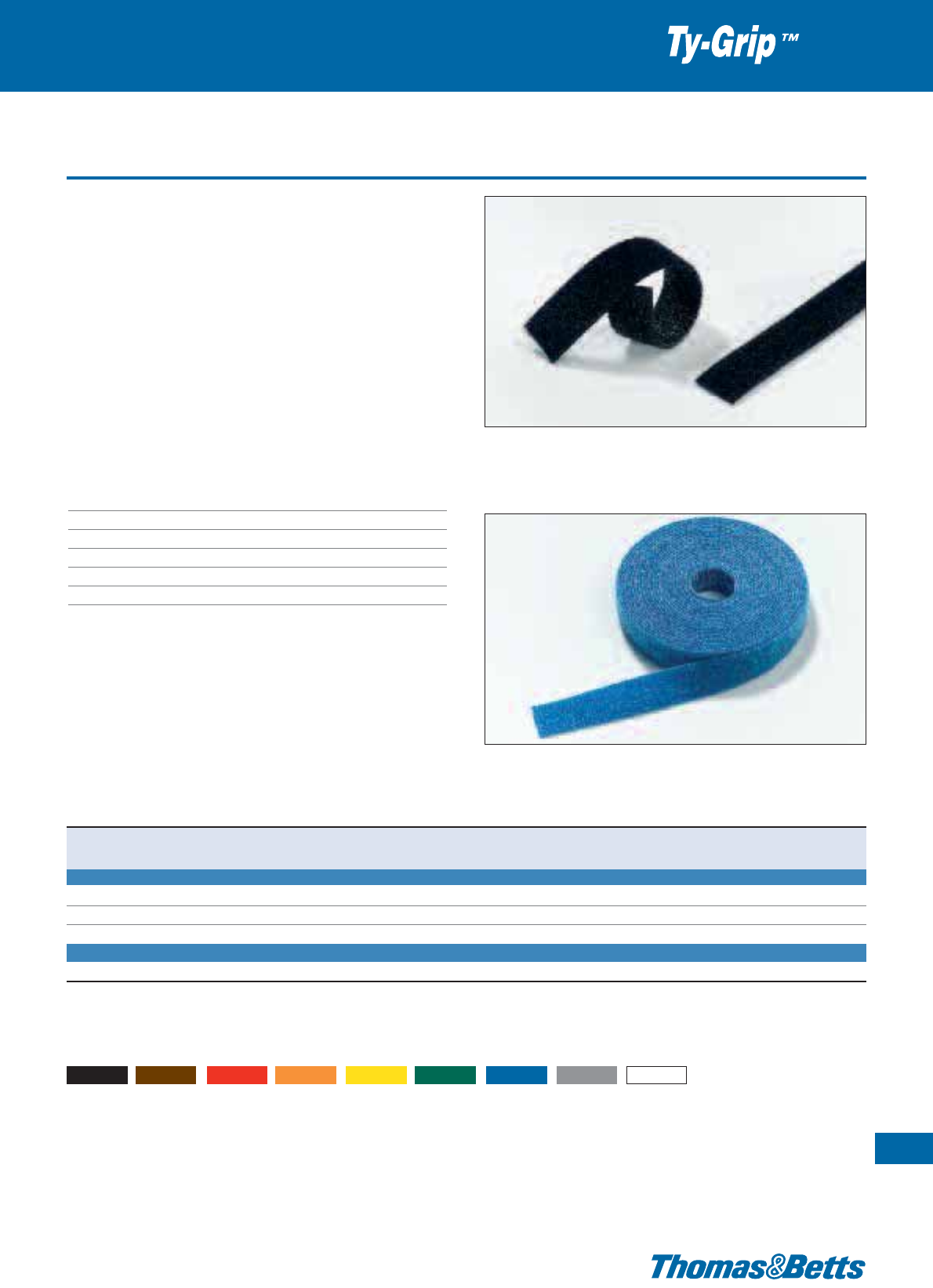
Hook & Loop fasteners
These handy ties are very easy to release and re-use, making them
ideal for applications where changes are anticipated or continuous
access is required.
• Quick bundling and re-adjustable tension
• No risk of over-tightening the cables, which makes the Ty-Grip™
Hook & Loop fasteners ideal for specific applications in fibre
optics, computer network wiring, telecom cables, etc
• Multiple colours available for identifying specific bundles
• Different sizes available to accommodate varying bundle diame-
ters
• Screw-mount and self-adhesive mounting bases provide multiple
mounting options
Technical Information FOS and FOR Series
Material hook side Polyamide
Material loop side Low density Polyethylene
Temperature range -20°C to +104°C
Colour Standard colour: black - see note after table
Flammability rating UL 94 HB
Peel-off strength 0.8N/cm
Special cable ties
61
Thomas & Betts • www.tnb-europe.com
1.2
FOS series strip ties are pre-cut which makes bundling easy.
FOR series rolled hook and loop allows customers to conveniently cut
pieces to desired lengths, eliminating waste.
Product Ref. Maximum bundle ø Length Width Tensile strength Quantity
[mm] [mm] [mm] [N] [pieces]
FOS SERIES STRIP TIES
FOS150-50-0 38.1 152.4
19.1
220 10
FOS320-50-0 81.3 304.8
19.1
220 10
FOS500-50-0 127.0 457.2
19.1
220 10
FOR SERIES ROLLED STRIP
FOR180-50-0 Various 4572.0
19.1
220
1
Standard colour: black
Replace “-0” in the Product Reference by the corresponding colour code: 1 = brown, 2 = red, 3 = orange, 4 = yellow,
5 = green, 6 = blue, 8 = grey and 9 = white
For example: FOS150-50-2 defines a red FOS150-50 type fastener
Contact your Sales Office for Product Availability in the other colours
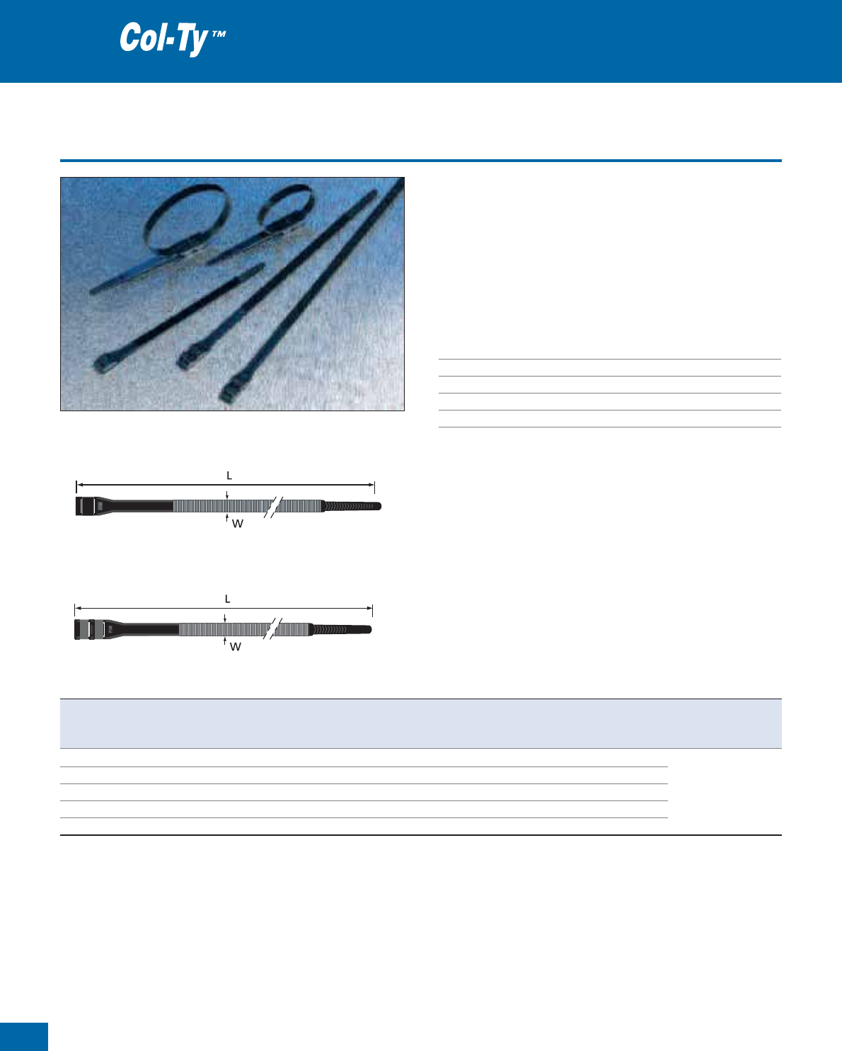
62
Thomas & Betts • www.tnb-europe.com
1.2
Heavy-duty double headed installation ties
• For securing and bundling of cables in the utility and construction
industries
• Low profile double locking head*
• Serrations on the outer side of the tie eliminates the risk of damage
to the cable
• Ideal for hazardous environments, low temperatures and humidity
• Conform to EDF HN33/S/62
Technical Information
Material Polyamide 12
Temperature range -40°C to +80°C
Colour Black
Flammability rating UL 94 HB
Other properties UV-resistant
Heavy-duty installation ties
Double locking head
Single locking head
Product Ref. Length Width Thickness Bundle diameter Minimum tensile Quantity Tooling
L W from ... to strength
[mm] [mm] [mm] [mm] [N][pieces]
CT-9-180-0-C* 180 9 1.8 10 - 42
440 100
CT-9-260-0-C 260 9 2.0 15 - 62
520 100 L300-FR
CT-9-360-0-C 360 9 2.0 25 - 92
520 100 L-500-EU
CT-9-500-0-C 510 9 2.4 74 - 140
550 100 WT3D
CT-9-750-0-C 760 9 2.4 74 - 220 550 100
* Product Ref. CT-9-180-0-C has a single locking head
Description of materials and properties: see pages 134 to 145
For tooling specifications: see pages 122 to 133
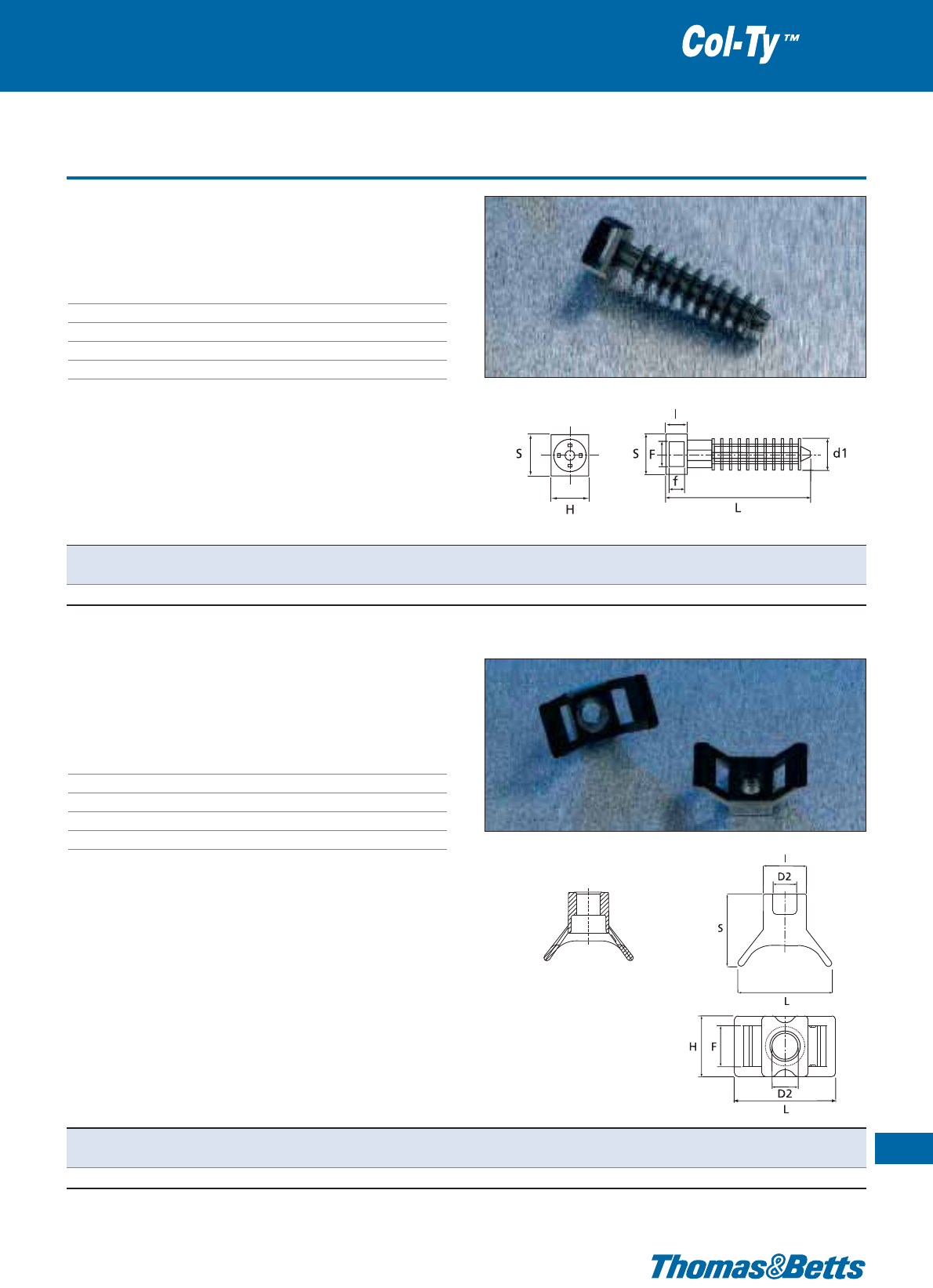
Accessories
• Wall plug suitable for ø 8 mm hole
• Simply drill hole and hammer the plug in
Technical Information
Material Polyamide 11/12
Temperature range -40°C to +80°C
Colour Black
Flammability rating UL 94 HB
Other properties UV-resistant
Heavy-duty installation ties
63
Thomas & Betts • www.tnb-europe.com
1.2
Product Ref. L Ød1 S H I F f Quantity
[mm] [mm] [mm] [mm] [mm] [mm] [mm] [pieces]
CT-5359 43.1 9.6 13.2 16
6.3 9.5
2.4 100
Product Ref. L I S H F d2 Quantity
[mm] [mm] [mm] [mm] [mm] [mm] [pieces]
CT-3401 22.9 10.5 17.6 13.8 9.4 5.9 100
• Use 5 mm screw
• Cradle for ties up to 9 mm wide
Technical Information
Material Polyamide 11/12
Temperature range -40°C to +80°C
Colour Black
Flammability rating UL 94 HB
Other properties UV-resistant
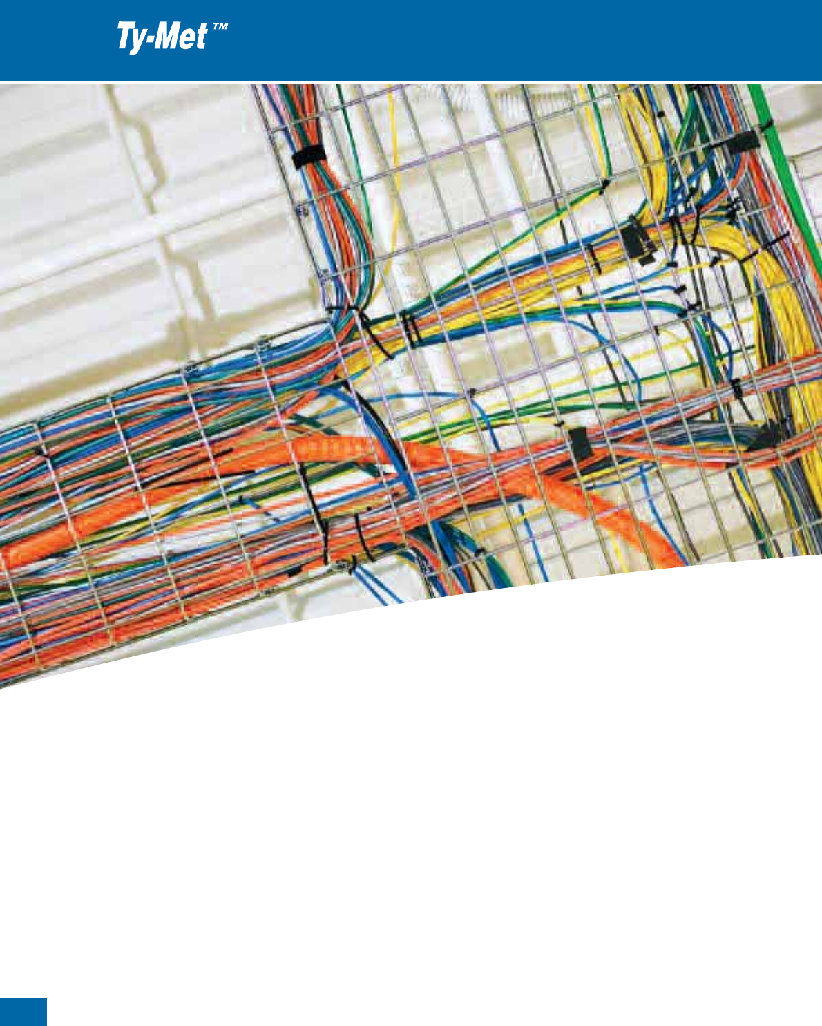
64
Thomas & Betts • www.tnb-europe.com
Ty-Met™ Stainless Steel
cable ties
1.3

65
Thomas & Betts • www.tnb-europe.com
FASTENING SYSTEMS
1.1 PREMIUM CABLE TIES WITH STEEL LOCKING BARB 4
1.2 ALL-PLASTIC CABLE TIES 44
1.3 STAINLESS STEEL CABLE TIES 64
Features & Benefits 68
Ball-Lock Type - uncoated 69
Ball-Lock Type - coated 70
Ladder Type - uncoated 71
Ladder Type - coated 72
Releasable Type 73
1.4 MOUNTING BASES & ACCESSORIES 74
1.5 CABLE PROTECTION SYSTEMS 112
1.6 CABLE TIE TOOLING 122
1.7 MATERIAL SPECIFICATIONS 134
1.3
66
Thomas & Betts • www.tnb-europe.com
1.3
Ty-Met™ Stainless Steel
cable ties
The Ty-Met™ stainless steel ties are the ultimate solution
to install your cables in extreme conditions and hazardous
areas, indoor and outdoor, such as the petrochemical and
food processing industries, power stations, mining, ship-
building, offshore and other aggressive environments.
The Ty-Met™ stainless steel ties provide a high mechanical
strength combined with chemical durability and temperature
resistance.
They are available in three different types:
• Ball-Lock Type: quick and reliable self-locking mechanism
• Ladder Type: easy application and strong locking system
• Releasable Type: can be unfastened for re-use

67
Thomas & Betts • www.tnb-europe.com
1.3
Ty-Met™ stainless steel ties:
the ultimate solution to install
your cables in extreme conditions
and hazardous areas
All types are available in a broad range of lengths and two different
widths, providing extreme levels of tensile strength. Two grades of
non-magnetic stainless steel (304 & 316) and a coated and an
uncoated version are available to cover most applications.
Ty-Met™ cable ties have international approvals such as UL,
Germanischer Lloyd, Lloyd’s Register and Det Norske Veritas.
Two grades of non-magnetic stainless steel are available:
- 304 grade stainless steel, for standard applications
- 316 grade (marine grade) stainless steel, for extra corrosion
resistance
Available in uncoated version (for high temperature applications)
or in fully coated version with non-toxic, halogen free Polyester
coating, for a superior protection of cables and installer’s hands
and for an improved insulation between dissimilar materials.
Halogen free, corrosion proof and resistant to salt water.
A range of dedicated hand tools completes the product offering.
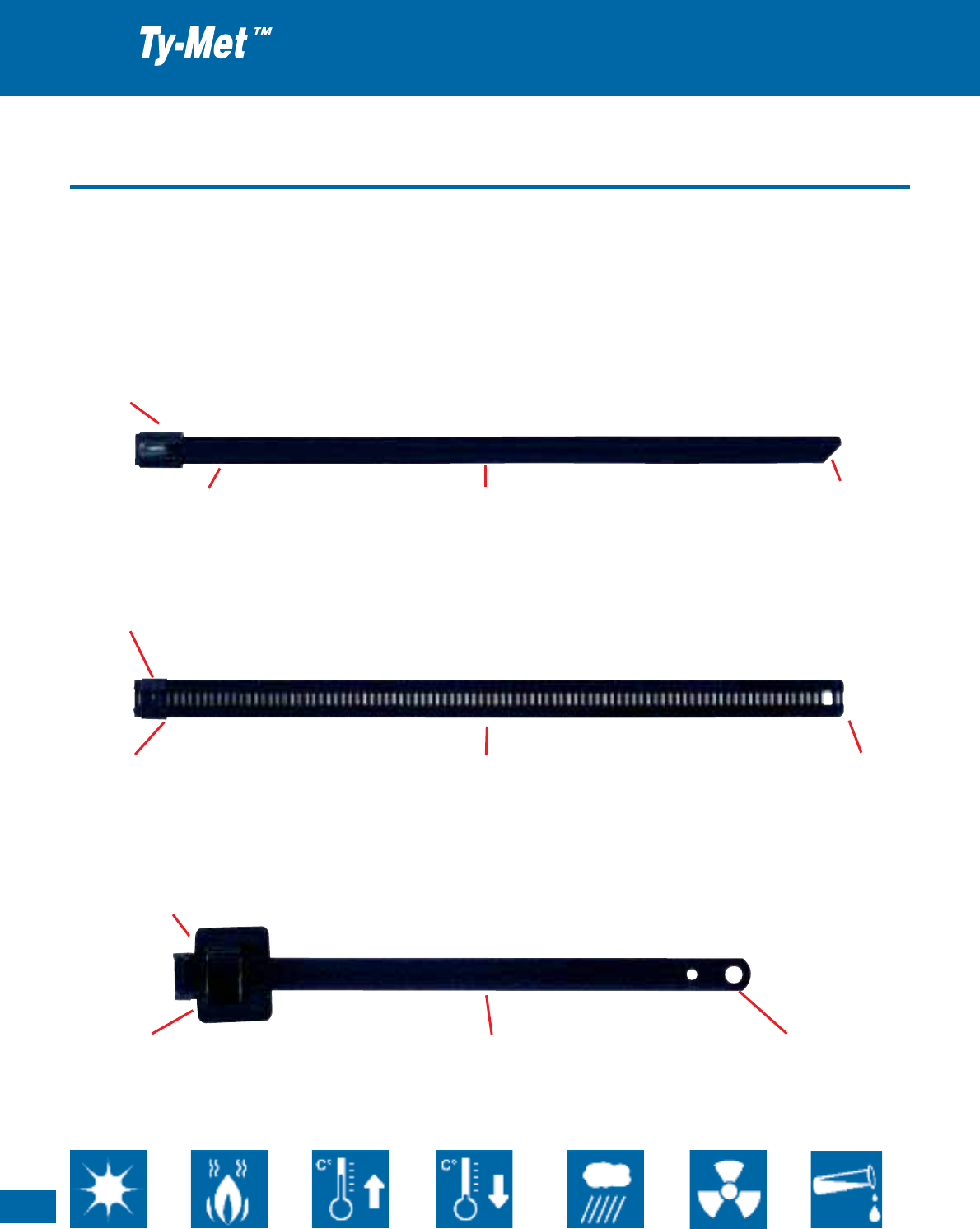
68
Thomas & Betts • www.tnb-europe.com
1.3
Features & Benefits
The Ty-Met™ stainless steel ties are available in three different
types:
•Ball-Lock Type: quick and reliable self-locking mechanism
•Ladder Type: easy application and strong locking system
•Releasable Type: can be unfastened for re-use
Stainless steel cable ties
Ball-Lock Type
Rounded edges and smooth surfaces, for
fast and safe hand installation
Angled / rounded tail,
for safer handling and easier insertion
Uncoated or fully coated
with non-toxic, Halogen free Polyester
Easy application and strong self-locking mechanism (steel ball), with low insertion force
Ladder Type
Low profile, flat head (no sharp edges),
for easy and safe installation
Larger slot at the end,
allows the use of a hook-type tool
Uncoated or fully coated
with non-toxic, Halogen free Polyester
Self-locking mechanism (pawl and ratchet)
Releasable Type
Additional ears canbebentbackoverthefas-
tened tie to increase the tensile strength
Can be installed by hand,
and if necessary, the slots at the end
allow the use of a hook-type tool
Fully coated
with non-toxic, Halogen free Polyester
The unique buckle design allows the tie to be unfastened for re-use
UV-resistant Fire-proof Heat
resistant
Low temperature
flexibility
Weatherproof Radiation
resistant
Chemically
resistant
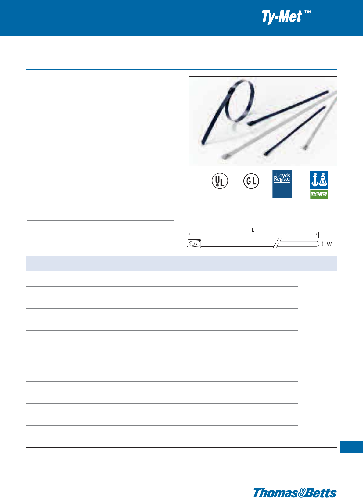
Ball-Lock Type - uncoated
Stainless steel cable ties
69
Thomas & Betts • www.tnb-europe.com
1.3
TYPE
T Y P E
APPROVED
A P P R O V ED
E49405*
***
TYPE
APPROVED
PRODUCTS
* Some approvals may not be applicable to all the
Product References. Contact your Sales Office for
approvals limitations
• “Ball-Lock” self-locking mechanism
• Uncoated version, for high temperature applications
• Suitable for indoor and outdoor applications
• Two grades of non-magnetic stainless steel:
- 304 grade stainless steel, for standard applications
- 316 grade (marine grade) stainless steel, for extra corrosion
resistance
• Dedicated tooling: either Prod. Ref. CT3 for manual cutting, or
Prod. Ref. CT6 for tension setting tool with automatic cutting
• Applications: Installation of cables and pipes in extreme conditions
and hazardous areas, indoor and outdoor, such as: Petrochemical
and food processing industries, power stations, mining, ship-
building, offshore, other aggressive environments
Technical Information
Material A. 304 grade non-magnetic stainless steel
B. 316 grade non-magnetic stainless steel
Temperature range -80°C to +538°C
Colour Metallic
Flammability rating Absolutely fireproof
Other properties UV-resistant
Product Ref. Product Ref. Length x Material thickness
Max. bundle
ø
Tensile strength Quantity Tooling
Stainless steel 304 Stainless steel 316 width [mm]
[mm] [mm] [N] [pieces]
YLS-4.6-100A YLS-4.6-100B 100 x 4.6
0.26
20
440
100
YLS-4.6-125A YLS-4.6-125B 125 x 4.6
0.26
22
440
100
YLS-4.6-150A YLS-4.6-150B 150 x 4.6
0.26
24
440
100
YLS-4.6-200A YLS-4.6-200B 200 x 4.6
0.26
50
440
100
YLS-4.6-300A YLS-4.6-300B 300 x 4.6
0.26
80
440
100
YLS-4.6-360A YLS-4.6-360B 360 x 4.6
0.26
100
440
100
YLS-4.6-520A YLS-4.6-520B 520 x 4.6
0.26
150
440
100
YLS-4.6-680A YLS-4.6-680B 680 x 4.6
0.26
200
440
100
YLS-4.6-840A YLS-4.6-840B 840 x 4.6
0.26
250
440
100
YLS-4.6-1000A YLS-4.6-1000B 1000 x 4.6
0.26
300
440
100
YLS-4.6-1200A YLS-4.6-1200B 1200 x 4.6
0.26
365
440
100
YLS-4.6-1400A YLS-4.6-1400B 1400 x 4.6
0.26
425
440
100 CT3
YLS-7.9-100A YLS-7.9-100B 100 x 7.9
0.26
20
1110
100 CT6
YLS-7.9-125A YLS-7.9-125B 125 x 7.9
0.26
22
1110
100
YLS-7.9-150A YLS-7.9-150B 150 x 7.9
0.26
24
1110
100
YLS-7.9-200A YLS-7.9-200B 200 x 7.9
0.26
50
1110
100
YLS-7.9-300A YLS-7.9-300B 300 x 7.9
0.26
80
1110
100
YLS-7.9-360A YLS-7.9-360B 360 x 7.9
0.26
100
1110
100
YLS-7.9-520A YLS-7.9-520B 520 x 7.9
0.26
150
1110
100
YLS-7.9-680A YLS-7.9-680B 680 x 7.9
0.26
200
1110
100
YLS-7.9-840A YLS-7.9-840B 840 x 7.9
0.26
250
1110
100
YLS-7.9-1000A YLS-7.9-1000B 1000 x 7.9
0.26
300
1110
100
YLS-7.9-1200A YLS-7.9-1200B 1200 x 7.9
0.26
365
1110
100
YLS-7.9-1400A YLS-7.9-1400B 1400 x 7.9
0.26
425
1110
100
Description of materials and properties: see pages 134 to 145
For tooling specifications: see pages 122 to 133
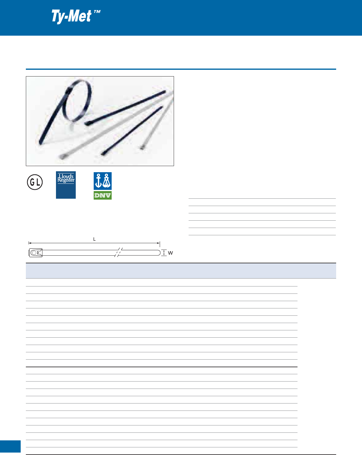
70
Thomas & Betts • www.tnb-europe.com
1.3
Ball-Lock Type - coated
• “Ball-Lock” self-locking mechanism
• Fully coated version with non-toxic, halogen free Polyester coating,
for a superior protection of cables and installer’s hands and for
an improved insulation between dissimilar materials.
• Suitable for indoor and outdoor applications
• 316 grade (marine grade) stainless steel, for extra corrosion resis-
tance
• Dedicated tooling: either Prod. Ref. CT3 for manual cutting, or
Prod. Ref. CT6 for tension setting tool with automatic cutting
• Applications: Installation of cables and pipes in extreme conditions
and hazardous areas, indoor and outdoor, such as: petrochemical
and food processing industries, power stations, mining, ship-
building, offshore, other aggressive environments
Technical Information
Material 316 grade non-magnetic stainless steel
Coating Polyester
Temperature range -80°C to +150°C
Colour Black
Flammability rating Absolutely fireproof
Other properties UV-resistant, Halogen free, non toxic
Stainless steel cable ties
TYPE
T Y P E
APPROVED
A P P R O V ED
***
TYPE
APPROVED
PRODUCTS
* Some approvals may not be applicable to all the Product References.
Contact your Sales Office for approvals limitations
Product Ref. Length x Material thickness
Max. bundle
ø
Tensile strength Quantity Tooling
width
[mm] [mm] [mm] [N] [pieces]
YLS-4.6-100BC 100 x 4.6
0.36
20
440
100
YLS-4.6-125BC 125 x 4.6
0.36
22
440
100
YLS-4.6-150BC 150 x 4.6
0.36
24
440
100
YLS-4.6-200BC 200 x 4.6
0.36
50
440
100
YLS-4.6-300BC 300 x 4.6
0.36
80
440
100
YLS-4.6-360BC 360 x 4.6
0.36
100
440
100
YLS-4.6-520BC 520 x 4.6
0.36
150
440
100
YLS-4.6-680BC 680 x 4.6
0.36
200
440
100
YLS-4.6-840BC 840 x 4.6
0.36
250
440
100
YLS-4.6-1000BC 1000 x 4.6
0.36
300
440
100
YLS-4.6-1200BC 1200 x 4.6
0.36
365
440
100
YLS-4.6-1400BC 1400 x 4.6
0.36
425
440
100 CT3
YLS-7.9-100BC 100 x 7.9
0.36
20
530
100 CT6
YLS-7.9-125BC 125 x 7.9
0.36
22
530
100
YLS-7.9-150BC 150 x 7.9
0.36
24
530
100
YLS-7.9-200BC 200 x 7.9
0.36
50
530
100
YLS-7.9-300BC 300 x 7.9
0.36
80
530
100
YLS-7.9-360BC 360 x 7.9
0.36
100
530
100
YLS-7.9-520BC 520 x 7.9
0.36
150
530
100
YLS-7.9-680BC 680 x 7.9
0.36
200
530
100
YLS-7.9-840BC 840 x 7.9
0.36
250
530
100
YLS-7.9-1000BC 1000 x 7.9
0.36
300
530
100
YLS-7.9-1200BC 1200 x 7.9
0.36
365
530
100
YLS-7.9-1400BC 1400 x 7.9
0.36
425
530
100
Description of materials and properties: see pages 134 to 145
For tooling specifications: see pages 122 to 133
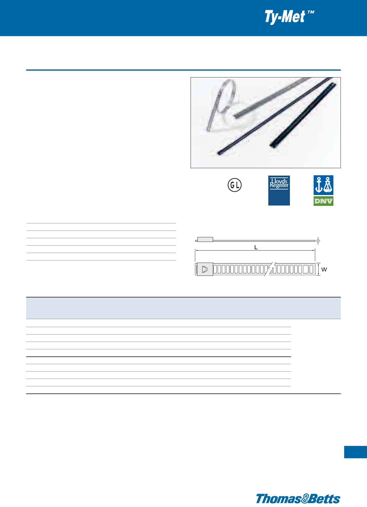
Ladder Type - uncoated
The Ladder Type stainless steel ties from Thomas & Betts have a flat,
low profile head for easy application.
• Strong self-locking mechanism (pawl and ratchet), requires no
time consuming crimping or folding operations
• Flat and low profile head (no sharp edge), for easy installation
• Corrosion resistant 316 grade stainless steel for high mechanical
and chemical durability
• Uncoated version for high temperature applications
• Increased usable length (slots up to the end of the tail), allows
larger bundle diameters with the same tie length
• Larger slot at the end, allows the use of a hook-type tool
• Applications:
Installation of cables and pipes in extreme conditions
and hazardous areas, indoor and outdoor, such as:
petrochemical
and food processing industries, power stations, mining, shipbuil-
ding, offshore and other aggressive environments
Technical Information
Material 316 grade stainless steel
Coating Uncoated
Temperature range -80°C to +538°C
Colour Metallic
Flammability rating Absolutely fireproof
Other properties UV-resistant
Stainless steel cable ties
71
Thomas & Betts • www.tnb-europe.com
1.3
TYPE
T Y P E
APPROVED
A P P R O V ED
T
TYPE
APPROVED
PRODUCTS
Product Ref. Length Width Thickness Max. Bundle Minimum Quantity Tooling
L W T diameter tensile strength
[mm]
[mm] [mm] [mm] [N] [pieces]
YLD-7-150-B 150 7.0
0.30
43
445 100
YLD-7-225-B 225 7.0
0.30
67
445 100
YLD-7-300-B 300 7.0
0.30
91
445 100 CT1-TB
YLD-7-450-B 450 7.0
0.30
139
445 100 CT2-TB
YLD-7-610-B 610 7.0
0.30
190
445 100 CT3
YLD-12-150-B 150 12.0
0.35
43
890 100 CT4-TB
YLD-12-225-B 225 12.0
0.35
67
890 100 CT5
YLD-12-300-B 300 12.0
0.35
91
890 100 WT3S
YLD-12-450-B 450 12.0
0.35
139
890 100
YLD-12-610-B 610 12.0
0.35
190
890 100
Description of materials and properties: see pages 134 to 145
For tooling specifications: see pages 122 to 133
* Some approvals may not be applicable to all the Product References. Contact your Sales Office for approvals limitations
***
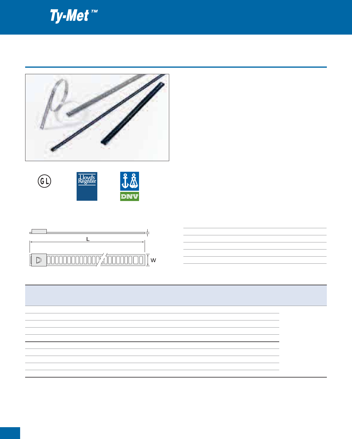
72
Thomas & Betts • www.tnb-europe.com
1.3
Ladder Type - coated
The Ladder Type stainless steel ties from Thomas & Betts have a flat,
low profile head for easy application.
• Strong self-locking mechanism (pawl and ratchet), requires no
time consuming crimping or folding operations
• Flat and low profile head (no sharp edge), for easy installation
• Corrosion resistant 316 grade stainless steel for high mechanical
and chemical durability
• Fully coated version with non-toxic, Halogen free Polyester coa-
ting, for a superior protection of cables and installer’s hands and
for an improved insulation between dissimilar materials
• Increased usable length (slots up to the end of the tail), allows
larger bundle diameters with the same tie length
• Larger slot at the end, allows the use of a hook-type tool
• Applications:
Installation of cables and pipes in extreme conditions
and hazardous areas, indoor and outdoor, such as:
petrochemical
and food processing industries, power stations, mining, shipbuil-
ding, offshore and other aggressive environments
Technical Information
Material 316 grade stainless steel
Coating Polyester
Temperature range -80°C to +150°C
Colour Black
Flammability rating Absolutely fireproof
Other properties UV-resistant, Halogen free, non-toxic
Stainless steel cable ties
TYPE
T Y P E
APPROVED
A P P R O V ED
T
TYPE
APPROVED
PRODUCTS
Product Ref. Length Width Thickness Max. Bundle Minimum Quantity Tooling
L W T diameter tensile strength
[mm]
[mm] [mm] [mm] [N] [pieces]
YLD-7-150-BC 150 7.0
0.41
43
445 100
YLD-7-225-BC 225 7.0
0.41
67
445 100
YLD-7-300-BC 300 7.0
0.41
91
445 100 CT1-TB
YLD-7-450-BC 450 7.0
0.41
139
445 100 CT2-TB
YLD-7-610-BC 610 7.0
0.41
190
445 100 CT3
YLD-12-150-BC 150 12.0
0.46
43
890 100 CT4-TB
YLD-12-225-BC 225 12.0
0.46
67
890 100 CT5
YLD-12-300-BC 300 12.0
0.46
91
890 100 WT3S
YLD-12-450-BC 450 12.0
0.46
139
890 100
YLD-12-610-BC 610 12.0
0.46
190
890 100
Description of materials and properties: see pages 134 to 145
For tooling specifications: see pages 122 to 133
* Some approvals may not be applicable to all the Product References. Contact your Sales Office for approvals limitations
***

Releasable Type
Stainless steel cable ties
73
Thomas & Betts • www.tnb-europe.com
1.3
The Releasable Type stainless steel ties from Thomas & Betts have a
unique buckle design that allows the ties to be unfastened for re-use.
• Releasable and re-usable
• Corrosion resistant 316 grade stainless steel for high mechanical
and chemical durability
• Fully coated version with non-toxic, Halogen free Polyester coating,
for a superior protection of cables and installer’s hands and for an
improved insulation between dissimilar materials
• Fast, easy and reliable installation - can be installed by hand and if
necessary, the slots at the end of the tie allow the use of a hook-
type tool
• The additional ears can be bent back over the fastened tie to in-
crease the tensile strength
• Applications:
Installation of cables and pipes in extreme conditions
and hazardous areas, indoor and outdoor, such as:
petrochemical
and food processing industries, power stations, mining, shipbuil-
ding, offshore and other aggressive environments
Technical Information
Material 316 grade stainless steel
Coating Polyester
Temperature range -80°C to +150°C
Colour Black
Flammability rating Absolutely fireproof
Other properties UV-resistant, Halogen free, non-toxic
TYPE
T Y P E
APPROVED
A P P R O V ED
TYPE
APPROVED
PRODUCTS
T
Product Ref. Length Width Thickness Max. Bundle Minimum Quantity Tooling
L W T diameter tensile strength
[mm]
[mm] [mm] [mm] [N] [pieces]
YRL-5-150-BC 150 5.0
0.61
35
334 (1334 for DNV)
100
YRL-5-230-BC 230 5.0
0.61
60
334 (1334 for DNV)
100
YRL-5-330-BC 330 5.0
0.61
95
334 (1334 for DNV)
100
YRL-5-450-BC 450 5.0
0.61
130
334 (1334 for DNV)
100
YRL-5-650-BC 650 5.0
0.61
195
334 (1334 for DNV)
100 CT1-TB
YRL-10-150-BC 150 10.0
0.61
35
1112 (2000 for DNV)
100 CT2-TB
YRL-10-230-BC 230 10.0
0.61
60
1112 (2000 for DNV)
100 CT4-TB
YRL-10-330-BC 330 10.0
0.61
95
1112 (2000 for DNV)
100
YRL-10-450-BC 450 10.0
0.61
130
1112 (2000 for DNV)
100
YRL-10-650-BC 650 10.0
0.61
195
1112 (2000 for DNV)
100
YRL-10-750-BC 750 10.0
0.61
225
1112 (2000 for DNV)
100
YRL-10-900-BC 900 10.0
0.61
270
1112 (2000 for DNV)
100
Description of materials and properties: see pages 134 to 145
For tooling specifications: see pages 122 to 133
* Some approvals may not be applicable to all the Product References. Contact your Sales Office for approvals limitations
***

74
Thomas & Betts • www.tnb-europe.com
1.4
Mounting Bases,
Cable Clamps & Other
Fastening Accessories

75
Thomas & Betts • www.tnb-europe.com
1.4
FASTENING SYSTEMS
1.1 PREMIUM CABLE TIES WITH STEEL LOCKING BARB 4
1.2 ALL-PLASTIC CABLE TIES 44
1.3 STAINLESS STEEL CABLE TIES 64
1.4 MOUNTING BASES & ACCESSORIES 74
Overview 78
Mounting bases 79
Cable clamps 101
Accessories for flat cables 109
1.5 CABLE PROTECTION SYSTEMS 112
1.6 CABLE TIE TOOLING 122
1.7 MATERIAL SPECIFICATIONS 134
76
Thomas & Betts • www.tnb-europe.com
1.4
To complement the range of premium cable ties,
Thomas & Betts has also developed an extensive range of
mounting bases, cable clamps and other fastening acces-
sories, to provide a professional solution to the most
demanding applications in cable management.
A wide range of material is offered, from the classic Polyamide
6.6 to the high performance
Fluoropolymer ETFE
for applications
in tough conditions.
To better suit each kind of applications, these products exist in a
wide choice of shape & design, and with different mounting
methods, from self-adhesive to glue and / or screw mounting.
Ty-Rap®and Ty-Fast®
Accessories

77
Thomas & Betts • www.tnb-europe.com
1.4
Mounting Bases,
Cable Clamps & Other
Fastening Accessories
In particular, with the new high performance mounting bases
(TC345 series), Thomas & Betts is now offering a mounting base
that leads the industry with more features and better performance:
- new design & materials, for increased performance
- special adhesive formulation, specifically for Nylon Mounting
bases
Typical applications include wiring in:
- control boxes & machine control devices
- office equipment & home appliances
- military & medical equipment
- lighting & electronic equipment
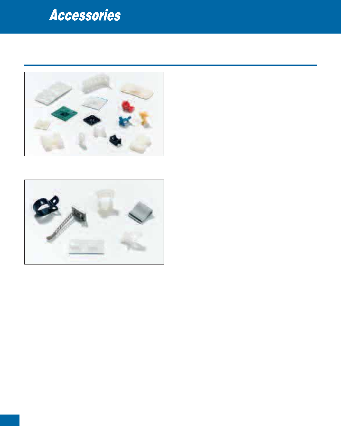
Thomas & Betts • www.tnb-europe.com
Overview
Self-adhesive mounting bases and clamps for screw and
rivet mounting
The main difference between a mounting base and a cable clamp is
the way the cable bundle can be mounted: while the cable bundle is
attached directly to the clamp, the mounting base requires a cable tie
to hold the bundle.
Thomas & Betts offers a wide range of mounting bases and cable
clamps,
which can be self-adhesive or for screw and rivet mounting.
• Standard material: Polyamide 6.6
• Available in different types / material to suit any application
• Available in a wide range of sizes
• Temperature range: -40°C to +85°C (+105°C for short periods)
• Low profile design
• Easy to install
• Extremely strong and durable adhesive
• The self-adhesive film is foam backed (0.8 mm) to compensate
for any irregularities on the mounting surface
• When applicable Thomas & Betts accessories are UL recognised
Typical applications
Wiring of:
• Control boxes
• Vehicles
• Office equipment
• Machine control devices
• Machine construction
• Military equipment
• Aeronautics
• Railway industry
• Electronic equipment
• Home appliances
• Lighting
• Medical equipment
Mounting Bases & Accessories
1.4
78
Mounting bases
Cable clamps
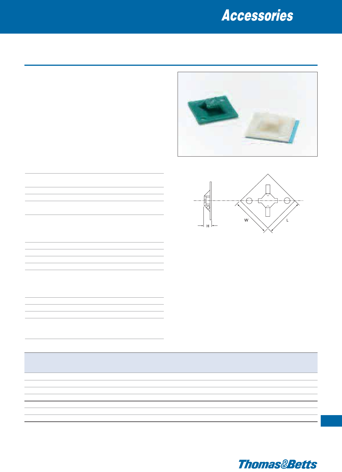
2-way entry
• Can be used in 2-way entry style for cable ties having a width up
to 7.6 mm
• For cable ties having a width up to 4.8 mm, the mounting bases
can be used in 4-way entry style
• Choice of 3 materials: standard Polyamide 6.6 (natural), UV-resistant
Polyamide 6.6 (black), Polyamide 6.6 flame retardant and ETFE
Fluoropolymer (aquamarine)
• Supplied either on a rubber based (synthetic polymer) closed cell
foam adhesive (installation: self-adhesive and/or screw) or with-
out self-adhesive (installation: screw and/or 2-component glue*)
Technical Information
TC347, TC347A, TC5347AR, TC347X
and TC5347AX
Material Polyamide 6.6
Temperature range -40°C to +85°C
(Self-adhesive version: 0°C to +65°C)
Flammability rating UL 94 V-2
Colour (see table)
Other properties UV-resistant (black), Halogen free,
Silicone free
Technical Information
TC347FR (Flame retardant)
Material Polyamide 6.6
Temperature range -40°C to +85°C
Flammability rating UL 94 V-0
Colour Natural
Other properties Halogen free, Silicone free
Technical Information
TCZ347 (Fluoropolymer)
Material ETFE Fluoropolymer
Temperature range -46°C to +150°C
Flammability rating UL 94 V-0
Colour Aquamarine
Other properties Silicone free, inert to most solvents and
chemicals, hydrolytically stable, radiation
resistant
Mounting bases
Thomas & Betts • www.tnb-europe.com
1.4
79
Product Ref. Colour Mounting Dimensions
For tie width Mounting Quantity
method H W L
up to hole ø
[mm] [mm] [mm] [mm] [mm]
[pieces]
TC347 natural screw / glue*
7.8
28.6 28.6 7.6 4.4 (2x) 1000
TC347X UV-resistant black screw / glue*
7.8
28.6 28.6 7.6 4.4 (2x) 1000
TC347FR natural / flame retardant screw / glue*
7.8
28.6 28.6 7.6 4.4 (2x) 1000
TCZ347 aquamarine screw / glue*
7.8
28.6 28.6 7.6 4.4 (2x) 500
TC347A natural self-adhesive / screw
8.5
29.0 29.0 7.6 4.4 (2x) 1000
TC5347AR natural self-adhesive / screw
8.5
29.0 29.0 7.6 4.4 (2x) 100
TC5347AX UV-resistant black self-adhesive / screw
8.5
29.0 29.0 7.6 4.4 (2x) 100
* Glue = Product Ref. TC2PA (see page 137 for specifications)
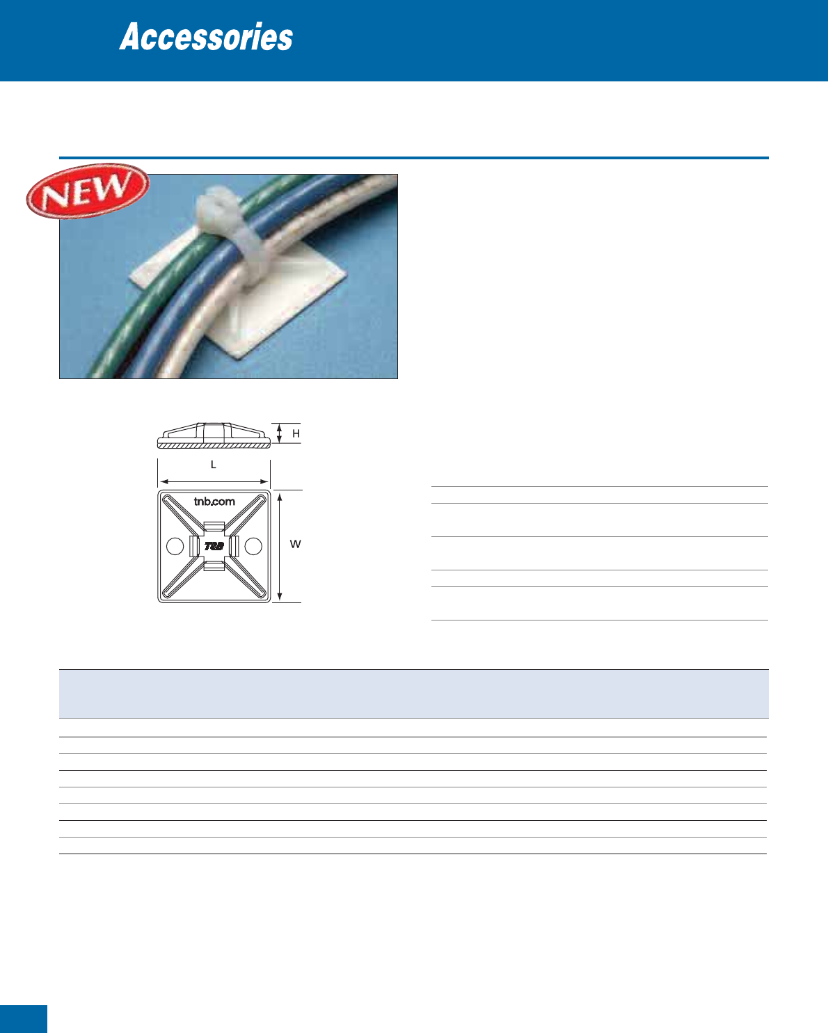
80
Thomas & Betts • www.tnb-europe.com
1.4
4-way entry - high performance
• New design & materials, for increased performance
• Low profile shape (height: 5.1 mm), to save space and reduce the
torque forces on the mounting base
• Ramped cable tie entries, for easier insertion of the cable tie
• Longer struts (up to the edges of the base), for better adhesion
• Special adhesive formulation (specifically for Nylon mounting
bases) for high pull-off strength
• 2 kinds of self-adhesive material:
- rubber-based, for immediate adhesion (15 minutes set-up time)
- acrylic based, to have the possibility of repositioning the mounting
base initially (set-up time: 24 to 72 hours)
• Two holes to have the possibility to use additional screws, for even
stronger installations when required
• Supplied on two-up lining, for easy removal of the lining
Technical Information
Material - Moulding Polyamide or UV-resistant Polyamide
or flame retardant Polyamide (See table)
Material - Self-adhesive Rubber based or acrylic based (See table)
Temperature range -40°C to +85°C
(Self-adhesive version: 0°C to +65°C)
Flammability rating UL 94 V-2 or
UL 94 V-0 (for flame retardant Polyamide)
Colours Natural or UV-resistant black (see table)
Other properties UV-resistant (black), Halogen free,
Silicone free
Mounting bases
Product Ref.
Colour Mounting method Dimensions For tie Mounting Quantity
L W H width up to holes ø
[mm] [mm] [mm] [mm] [mm]
[pieces]
TC345 natural glue* / screws 28.6 28.6 5.1 5.2 4.0 1000
TC345A natural self-adhesive (rubber based) / screws 28.6 28.6 5.1 5.2 4.0 1000
TC5345A natural self-adhesive (rubber based) / screws 28.6 28.6 5.1 5.2 4.0 100
TC345AX UV-resistant black self-adhesive (rubber based) / screws 28.6 28.6 5.1 5.2 4.0 1000
TC5345AX UV-resistant black self-adhesive (rubber based) / screws 28.6 28.6 5.1 5.2 4.0 100
TC345AFR natural / flame retardant self-adhesive (rubber based) / screws 28.6 28.6 5.1 5.2 4.0 1000
TC345AHTFR natural / flame retardant self-adhesive (acrylic based) / screws 28.6 28.6 5.1 5.2 4.0 1000
TC5345AHTFR natural / flame retardant self-adhesive (acrylic based) / screws 28.6 28.6 5.1 5.2 4.0 100
* Glue = Product Ref TC2PA (see page 137 for specifications)
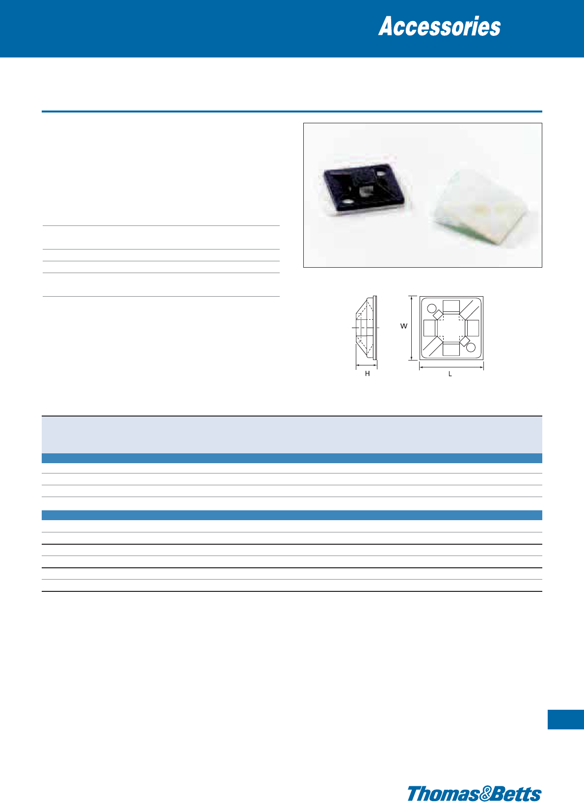
4-way entry
• Supplied either on a rubber based (synthetic polymer) closed cell
foam adhesive or without self adhesive (installation: screw and/or
2 component glue*)
• Available in standard Polyamide 6.6 (natural) or UV-resistant
Polyamide 6.6 (black)
Technical Information
Material Polyamide 6.6
Temperature range -40°C to +85°C
(Self-adhesive version: 0°C to +65°C)
Flammability rating UL 94 V-2
Colours Natural or UV-resistant black (see table)
Other properties UV-resistant (black), Halogen free,
Silicone free
Mounting bases
81
Thomas & Betts • www.tnb-europe.com
1.4
Product Ref. Colour Mounting Dimensions
For tie width Mounting Quantity
method L W H
up to hole ø
[mm] [mm] [mm] [mm] [mm]
[pieces]
FOR TIE WIDTH UP TO 3.0 MM
TC050x050A natural self-adhesive 12.7 12.7 4.5 3.0 – 1000
TC050x050A-C natural self-adhesive 12.7 12.7 4.5 3.0 – 100
TC050x050AX UV-resistant black self-adhesive 12.7 12.7 4.5 3.0 – 1000
TC050x050AX-C UV-resistant black self-adhesive 12.7 12.7 4.5 3.0 – 100
FOR TIE WIDTH UP TO 3.6 MM
TC344 natural screw / glue* 19.1 19.1 4.9 3.6 3.0 1000
TC5344 natural screw / glue* 19.1 19.1 4.9 3.6 3.0 100
TC344A natural self-adhesive / screw 19.1 19.1 4.9 3.6 3.0 1000
TC5344AR natural self-adhesive / screw 19.1 19.1 4.9 3.6 3.0 100
TC344AX UV-resistant black self-adhesive / screw 19.1 19.1 4.9 3.6 3.0 1000
TC5344AX UV-resistant black self-adhesive / screw 19.1 19.1 4.9 3.6 3.0 100
* Glue = Product Ref TC2PA (see page 137 for specifications)
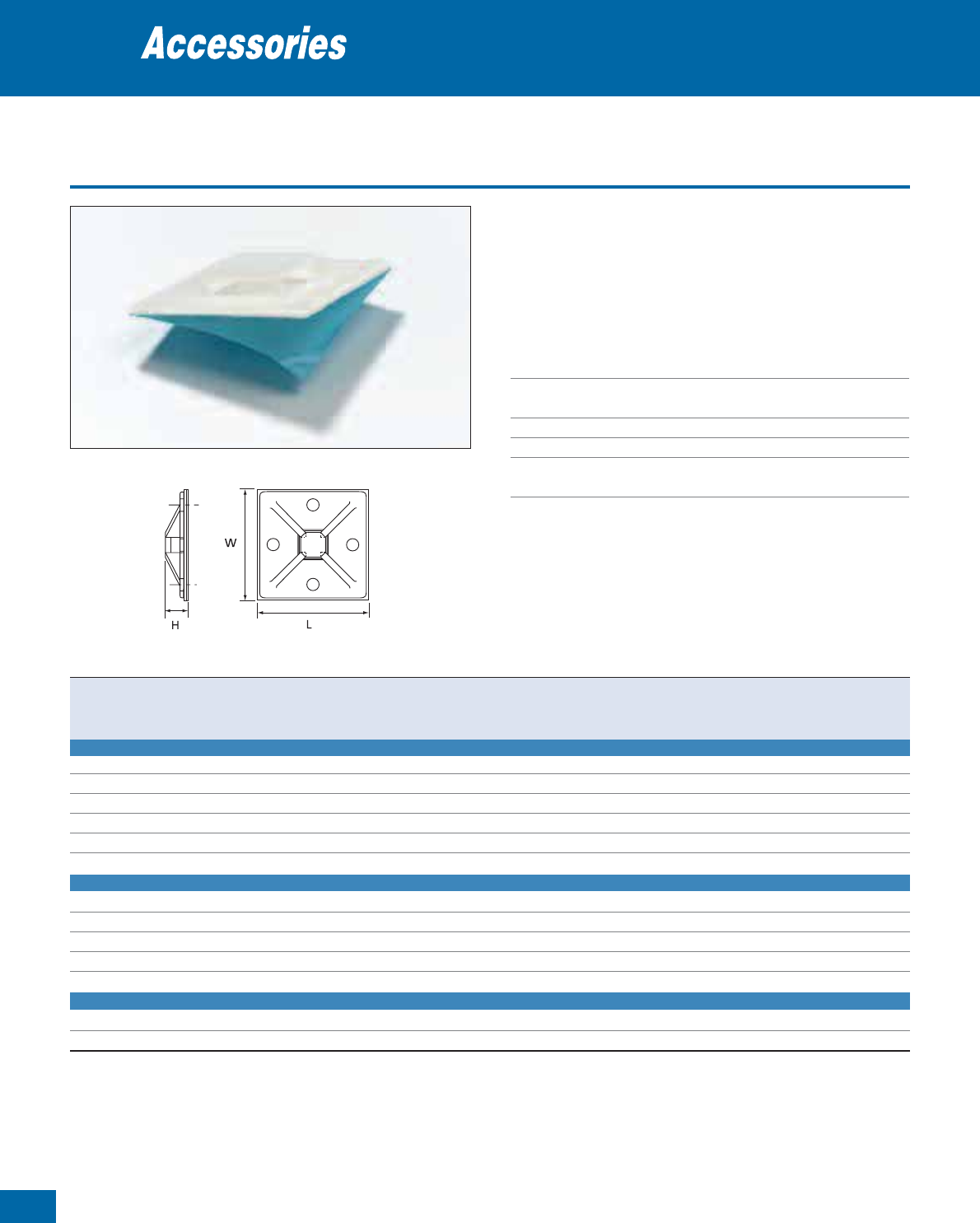
82
Thomas & Betts • www.tnb-europe.com
1.4
4-way entry - for wide cable ties
• Supplied either on a rubber based (synthetic polymer) closed cell
foam adhesive or without self adhesive (installation: screw and/or
2 component glue*)
• Available in standard Polyamide 6.6 (natural) or UV-resistant
Polyamide 6.6 (black)
Technical Information
Material Polyamide 6.6
Temperature range -40°C to +85°C
(Self-adhesive version: 0°C to +65°C)
Flammability rating UL 94 V-2
Colours Natural or UV-resistant black (see table)
Other properties UV-resistant (black), Halogen free,
Silicone free
Mounting bases
Product Ref. Colour Mounting Dimensions
For tie width Mounting Quantity
method L W H
up to hole ø
[mm] [mm] [mm] [mm] [mm]
[pieces]
FOR TIE WIDTH UP TO 7.9 MM (38.1 MM x 38.1 MM BASE)
TC150x150 natural screw / glue* 38.1 38.1 7.4 7.9 4.3 500
TC150x150L natural screw / glue* 38.1 38.1 7.4 7.9 4.3 50
TC150x150A natural self-adhesive / screw 38.1 38.1 7.4 7.9 4.3 500
TC150x150A-L natural self-adhesive / screw 38.1 38.1 7.4 7.9 4.3 50
TC150x150AX UV-resistant black self-adhesive / screw 38.1 38.1 7.4 7.9 4.3 500
TC150x150AX-L UV-resistant black self-adhesive / screw 38.1 38.1 7.4 7.9 4.3 50
FOR TIE WIDTH UP TO 7.9 MM (50.8 MM x 50.8 MM BASE)
TC200x200 natural screw / glue* 50.8 50.8 7.4 7.9 4.3 500
TC200x200L natural screw / glue* 50.8 50.8 7.4 7.9 4.3 50
TC200x200A natural self-adhesive / screw 50.8 50.8 7.4 7.9 4.3 500
TC200x200A-L natural self-adhesive / screw 50.8 50.8 7.4 7.9 4.3 50
TC200x200AX UV-resistant black self-adhesive / screw 50.8 50.8 7.4 7.9 4.3 500
FOR TIE WIDTH UP TO 19.1 MM (50.8 MM x 50.8 MM BASE)
TC368 natural screw / glue* 50.8 50.8 6.6 19.1 4.3 500
TC368A natural self-adhesive / screw 50.8 50.8 6.6 19.1 4.3 500
* Glue = Product Ref TC2PA (see page 137 for specifications)
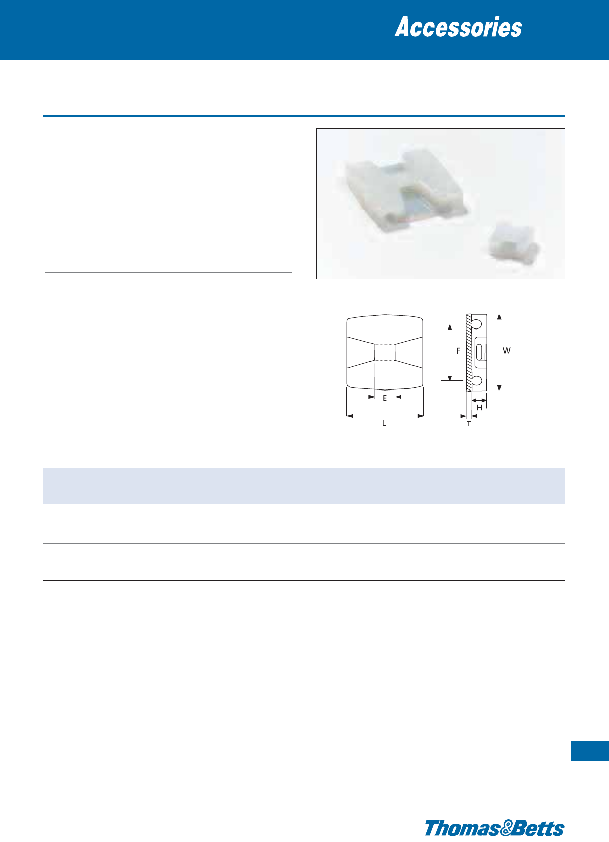
Low profile plates
• Low profile
• Easy to use
• Available in several materials
• Self-adhesive or to be glued with 2-component glue*
Technical Information
Material Polyamide 6.6
Temperature range -40°C to +85°C
(Self-adhesive version: 0°C to +65°C)
Colour Natural or UV-resistant black (see table)
Flammability rating UL 94 V-2
Other properties Halogen free, Silicone free,
UV-resistant (black)
Mounting bases
83
Thomas & Betts • www.tnb-europe.com
1.4
Product Ref. Colour Mounting method Dimensions For tie width Weight Quantity
HTWLEF upto
[mm] [mm] [mm] [mm] [mm] [mm] [mm] [g/100] [pieces]
TC817-TB natural glue* 4.8 – 11.0
11.0
– – 4.8 51 1000
TC342 natural glue* 5.7 –
29.0 29.0
7.5 21.0 4.8 340 1000
TC342X UV-resistant black glue* 5.7 –
29.0 29.0
7.5 21.0 4.8 340 1000
TC342A natural self-adhesive 5.7 0.8
29.0 29.0
7.5 21.0 4.8 360 1000
TC5342A natural self-adhesive 5.7 0.8
29.0 29.0
7.5 21.0 4.8 360 100
TC342A-X UV-resistant black self-adhesive 5.7 0.8
29.0 29.0
7.5 21.0 4.8 360 1000
* Glue = Product Ref. TC2PA (see page 137 for specifications)
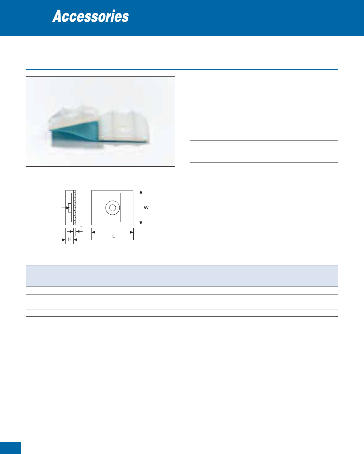
84
Thomas & Betts • www.tnb-europe.com
1.4
Self-adhesive mounting cradle
• Accepts cable ties to 7.6 mm width
• Supplied “two-up” on closed cell foam with synthetic polymer
“rubber” based adhesive
• Use M3.5 self-tapping screw for added strength if desired
Technical Information
Material Polyamide 6.6
Temperature range 0°C to +65°C
Colour Natural or UV-resistant black (see table)
Mounting method Self adhesive and/or screw
Flammability rating UL 94 V-2
Other properties UV-resistant (black), Halogen free,
Silicone free
Mounting bases
Slot
Product Ref. Colour Dimensions
For tie width Quantity
HTLW
up to
[mm] [mm] [mm] [mm] [mm]
[pieces]
MCNY-1250-9-L natural 7.2
0.8 31.7
25.4 7.6 50
MCNY-1250-9-C natural 7.2
0.8 31.7
25.4 7.6 100
MCNY-1250-9-D natural 7.2
0.8 31.7
25.4 7.6 500
MCNY-1250-0-C UV-resistant black 7.2
0.8 31.7
25.4 7.6 100
* Glue = Product Ref. TC2PA (see page 137 for specifications)
For other colours and quantities please contact your Sales Office
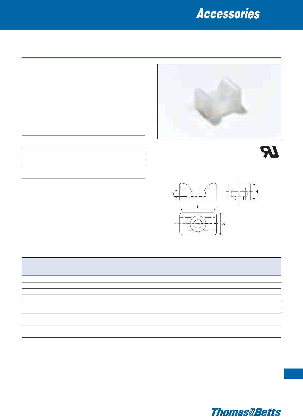
Saddle support
• Tie mounting bases with supporting saddle
• For screw- or rivet-mounting
• The prism-shape of the saddle prevents twisting around the fixture
• High strength through compact design
• Non-conductive, non-corrosive, resistant to fuels, lubricants and
most chemicals
• Available in UV-resistant, heat stabilised black version
Technical Information
Material Polyamide 6.6 or
heat stabilised Polyamide 6.6
Temperature range -40°C to +85°C (Natural)
-40°C to +105°C (UV-resistant black)
Colour Natural or UV-resistant black (see table)
Mounting method Screw
Flammability rating UL 94 V-2
Other properties Halogen free, Silicone free, UV-resistant
(black)
Mounting bases
85
Thomas & Betts • www.tnb-europe.com
1.4
Product Ref. Colour Dimensions
For tie width Mounting Quantity
HWL D
up to hole ø
[mm]
[mm] [mm] [mm] [mm] [mm]
[pieces]
TC140 natural 6.7 8.7 14.2
1.8
2.4 3.0 500
TC5140 natural 6.7 8.7 14.2
1.8
2.4 3.0 100
TC141 natural 7.5 11.1 17.0
2.3
4.8 3.8 500
TC5141 natural 7.5 11.1 17.0
2.3
4.8 3.8 100
TC142 natural 10.7 14.2 23.4
2.9
7.6 5.2 500
TC5142 natural 10.7 14.2 23.4
2.9
7.6 5.2 100
TC142X* UV-resistant black / 10.7 14.2 23.4
2.9
7.6 5.2 500
heat stabilised
TC5142X* UV-resistant black / 10.7 14.2 23.4
2.9
7.6 5.2 100
heat stabilised
For other colours and quantities please contact your Sales Office
* Are not UL recognised
E49405
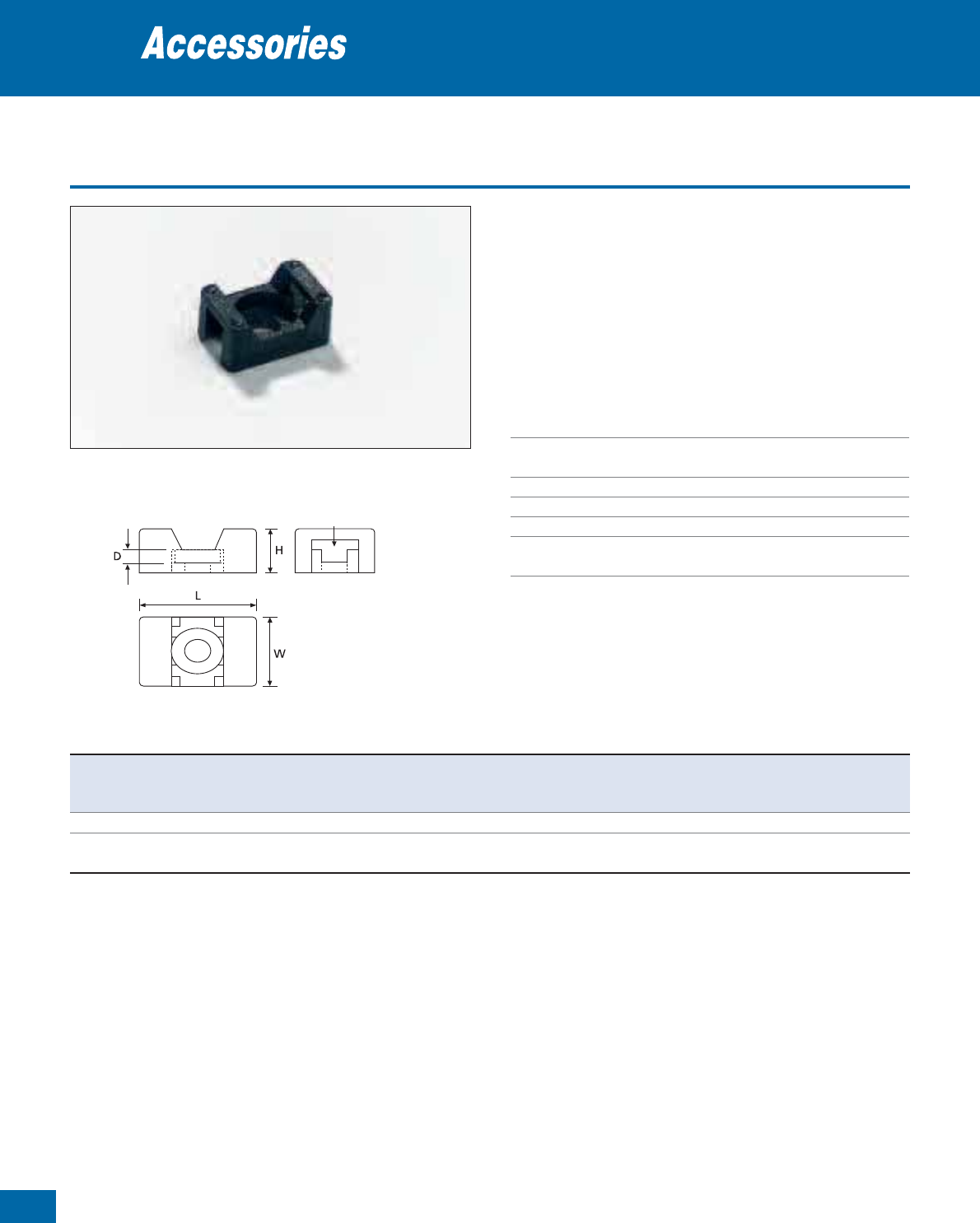
86
Thomas & Betts • www.tnb-europe.com
1.4
Saddle support
• Tie mounting bases with supporting saddle
• For screw- or rivet-mounting
• The prism-shape of the saddle prevents twisting around the fixture
• High strength through compact design
• Non-conductive, non-corrosive, resistant to fuels, lubricants and
most chemicals
• Available in UV-resistant, heat stabilised black version
Technical Information
Material Polyamide 6.6 or
heat stabilised Polyamide 6.6
Temperature range -40°C to +85°C (Natural)
-40°C to +105°C (UV-resistant black)
Colour Natural or UV-resistant black
Mounting method Screw
Flammability rating UL 94 V-2
Other properties Halogen free, Silicone free, UV-resistant
(black)
Mounting bases
Slot
Product Ref. Colour Dimensions
For tie width Mounting Quantity
HWL D
up to hole ø
[mm]
[mm] [mm] [mm] [mm] [mm]
[pieces]
SMNY-001-9-D natural 7.1 9.8
15.2
4.7 4.8 4.2 500
SMNY-001-0-D UV-resistant black 7.1 9.8
15.2
4.7 4.8 4.2 500
heat stabilised
For other colours and quantities please contact your Sales Office
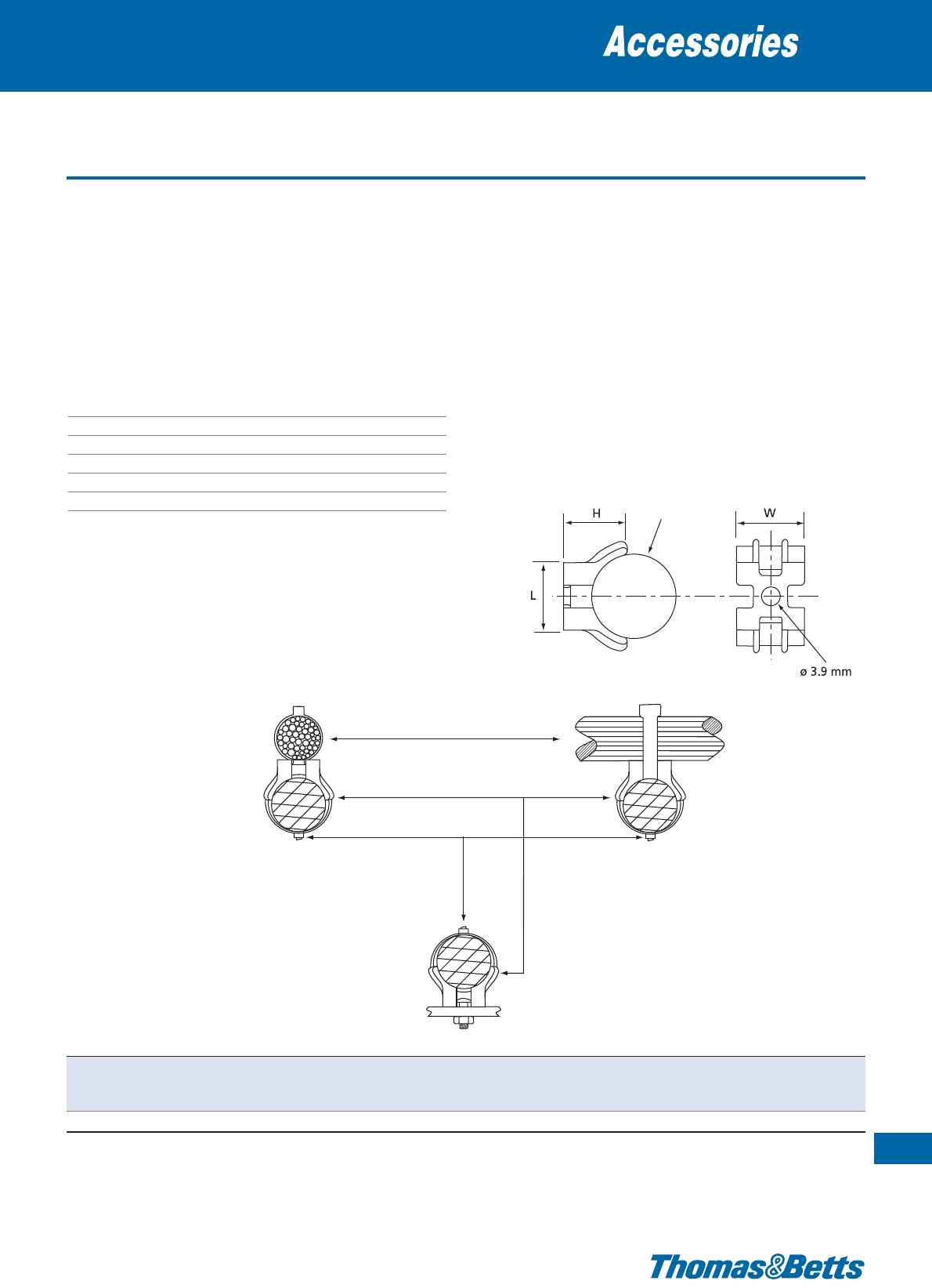
Saddle-type mounting base
The saddle-type mounting bases allow 3 possible cable mounting:
• the cables can be attached to a flat surface on which the base is
screwed
• the cable bundles can be mounted in parallel
• the cable bundles can be mounted crosswise
Can also be used for the mounting of cylindrical objects having a
diameter between 12.7 and 31.8 mm
Technical Information
Material Polyamide 6.6
Temperature range -40°C to +85°C
Colour Natural
Mounting method Screw
Flammability rating UL 94 V-2
Other properties Halogen free, Silicone free
Mounting bases
87
Thomas & Betts • www.tnb-europe.com
1.4
Diameter from
12.7 to 31.8 mm
D
Saddle mounting plate
Thomas & Betts
Ty-Rap®cable ties
Wire bundle
Product Ref. Dimensions
For tie width Mounting Weight Quantity
HW
L D up to hole ø
[mm] [mm] [mm] [mm] [mm] [mm]
[g/100] [pieces]
TC92 14.3 15.1
15.1
12.7 - 31.8 4.8 3.9 143 100
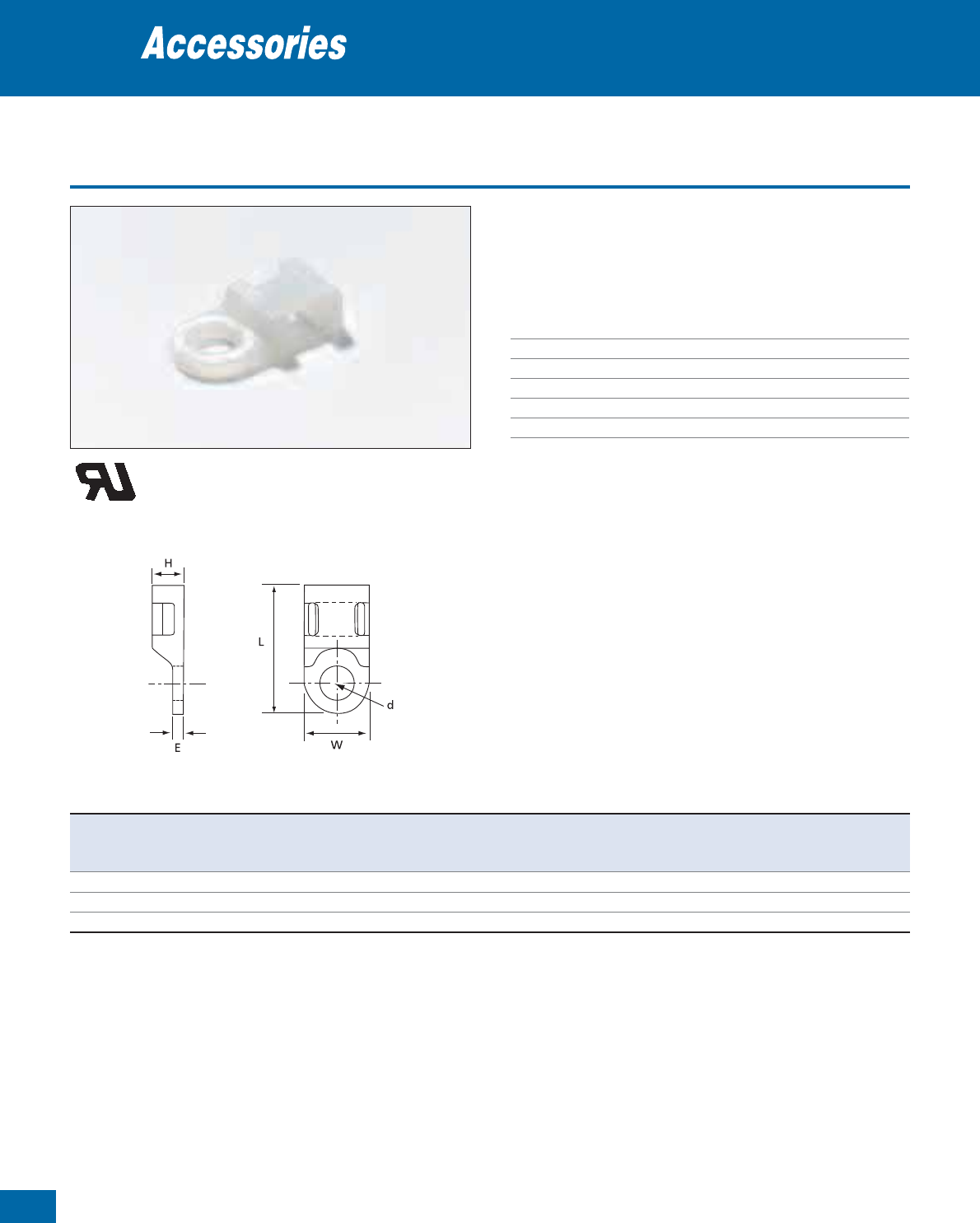
88
Thomas & Betts • www.tnb-europe.com
1.4
Screw-mounted miniature bases
• Low profile mounting base
• For screw- or rivet-mounting
• Easy to use thanks to the cable tie insertion guide
Technical Information
Material Polyamide 6.6
Temperature range -40°C to +85°C
Colour Natural
Mounting method Fillister-head screw
Flammability rating UL 94 V-2
Other properties Halogen free, Silicone free
Mounting bases
T&B
Product Ref. Dimensions
For tie width
Mounting hole ø
Weight Quantity
H W L E up to d
[mm] [mm] [mm] [mm] [mm] [mm]
[g/100] [pieces]
TC814-TB 4.8 9.5
19.1
2.0 4.8 3.3 44 1000
TC112-TB 4.8 9.5
19.1
2.0 4.8 4.4 44 1000
TC812-TB 4.8 9.5
19.1
2.0 4.8 5.1 44 1000
For other colours and quantities please contact your Sales Office
E49405
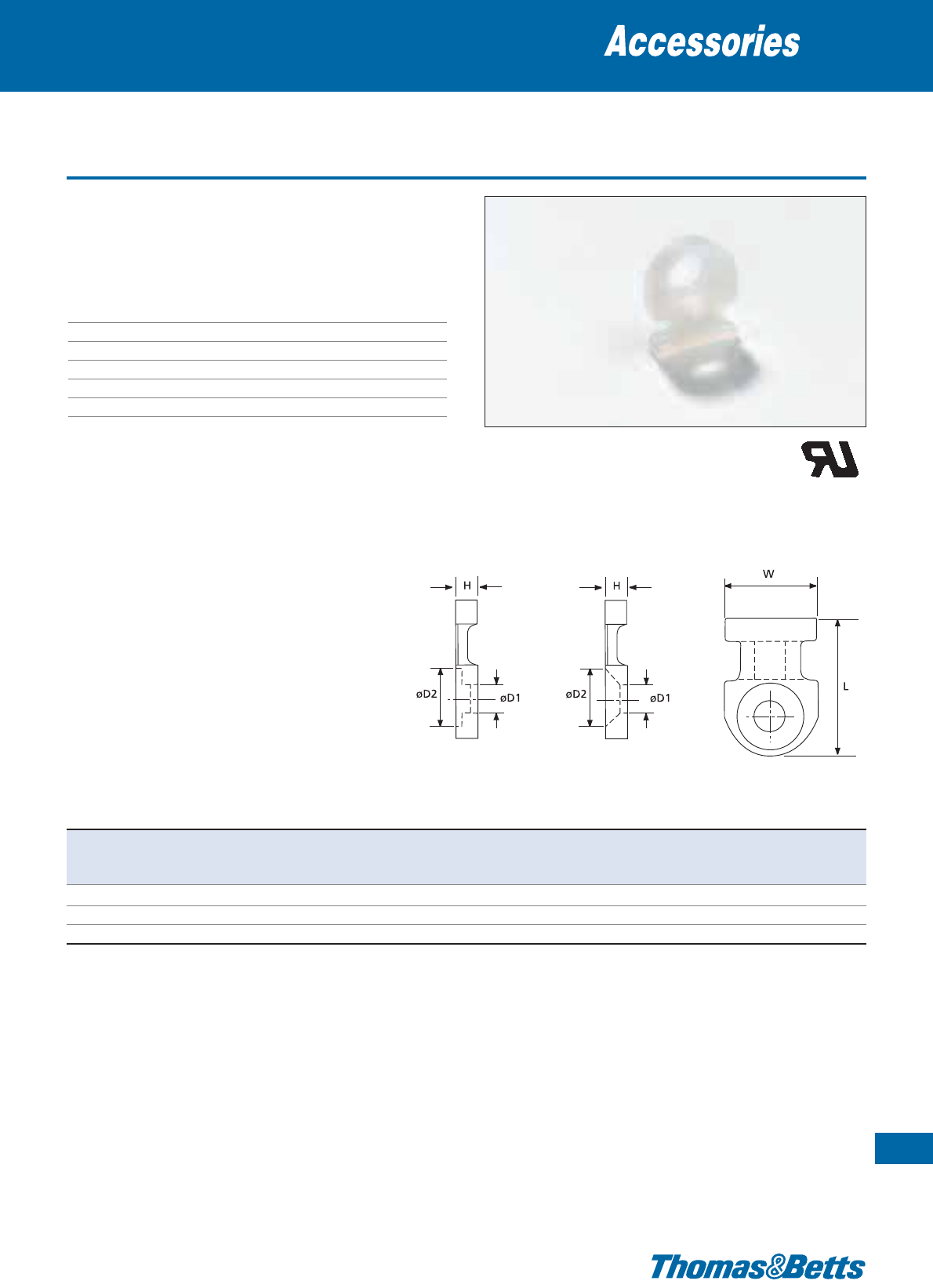
Screw-mounted miniature bases
• Extremely low profile
• For screw- or rivet-mounting
• Easy to use thanks to the cable tie insertion guide
Technical Information
Material Polyamide 6.6
Temperature range -40°C to +85°C
Colour Natural
Mounting method Screw
Flammability rating UL 94 V-2
Other properties Halogen free, Silicone free
Mounting bases
89
Thomas & Betts • www.tnb-europe.com
1.4
TC104
TC102
TC804-TB
Product Ref. Dimensions
For tie width
Mounting hole
Weight Quantity
HWL upto øD1øD2
[mm] [mm] [mm] [mm] [mm] [mm]
[g/100] [pieces]
TC804-TB 2.4 7.9
10.2
2.4 2.3 4.7 11 1000
TC104 2.4 7.9
10.3
2.4 3.4 6.5 11 1000
TC102 3.2 12.7
19.1
4.8 4.4 8.7 50 1000
For other colours and quantities please contact your Sales Office
E49405
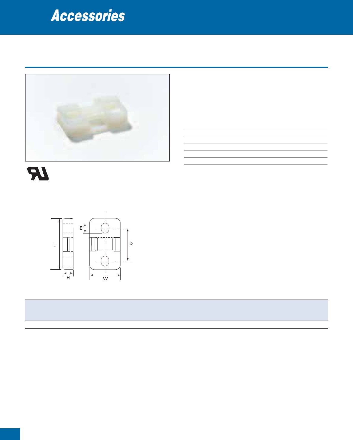
90
Thomas & Betts • www.tnb-europe.com
1.4
Screw-mounted - for wide cable ties
• Extremely low profile
• For screw- or rivet-mounting
• Easy to use thanks to the cable tie insertion guide
• Secure fixing with 2 fastening holes
Technical Information
Material Polyamide 6.6
Temperature range -40°C to +85°C
Colour Natural
Mounting method 2 screws
Flammability rating UL 94 V-2
Other properties Halogen free, Silicone free
Mounting bases
Product Ref. Dimensions
For tie width
Mounting hole ø
Weight Quantity
HW L D E upto
[mm] [mm] [mm] [mm] [mm] [mm] [mm]
[g/100] [pieces]
TC815-TB 6.4 19.1
31.2
19.9 6.4 7.6 5.3 278 50
0
For other colours and quantities please contact your Sales Office
E49405
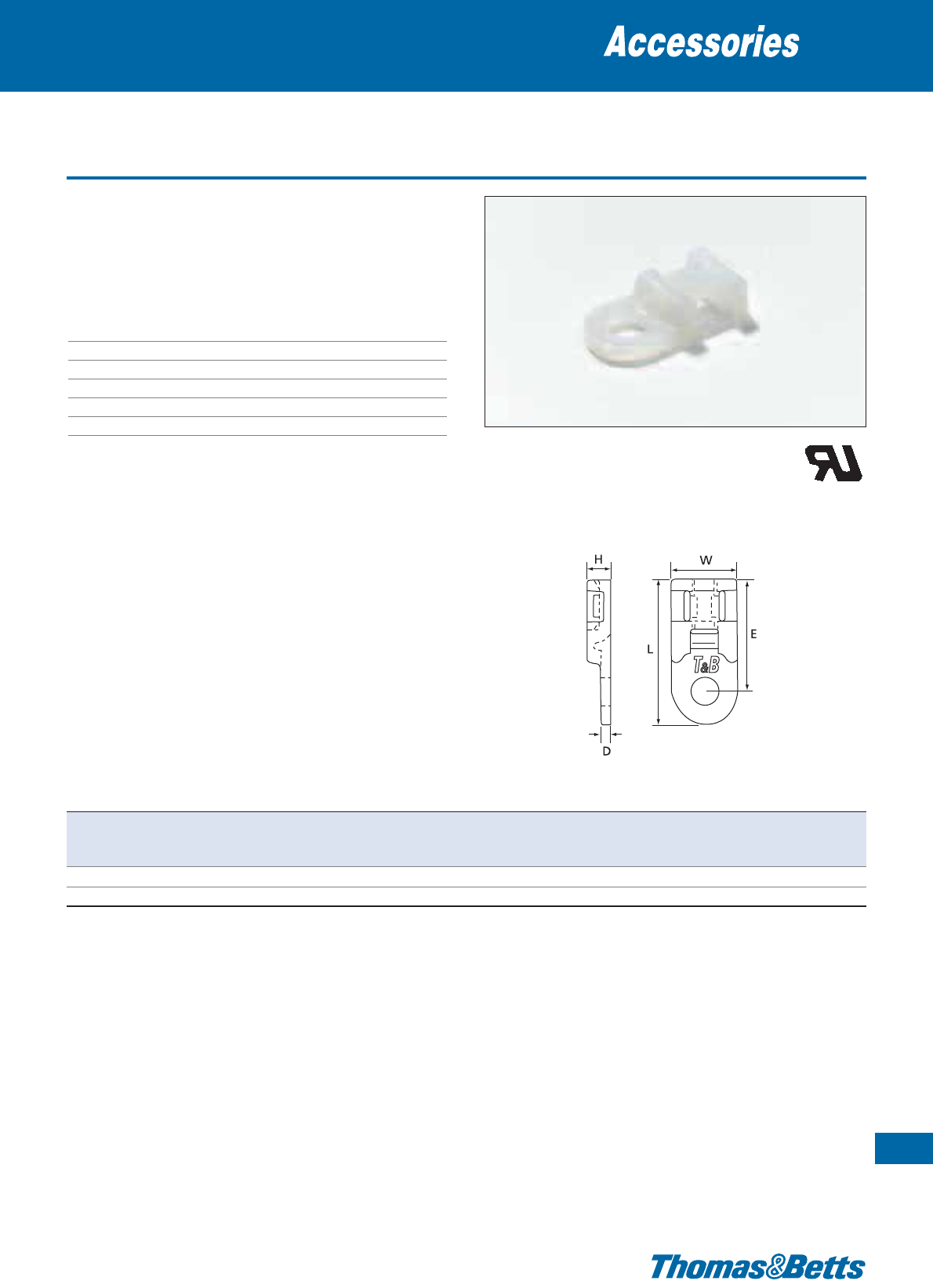
Screw-mounted - for crosswise fastening
• Extremely low profile
• For screw- or rivet-mounting
• Easy to use thanks to the cable tie insertion guide
• Two ties can be fastened crosswise to securely fix cable intersections
Technical Information
Material Polyamide 6.6
Temperature range -40°C to +85°C
Colour Natural
Mounting method Screw
Flammability rating UL 94 V-2
Other properties Halogen free, Silicone free
Mounting bases
91
Thomas & Betts • www.tnb-europe.com
1.4
Product Ref. Dimensions
For tie width
Mounting hole ø
Weight Quantity
HW L D E upto
[mm] [mm] [mm] [mm] [mm] [mm] [mm]
[g/100] [pieces]
TC828-TB 3.8 10.1
22.5
1.5 13.4 4.8 4.3 46 1000
TC5828 3.8 10.1
22.5
1.5 13.4 4.8 4.3 46 100
E49405
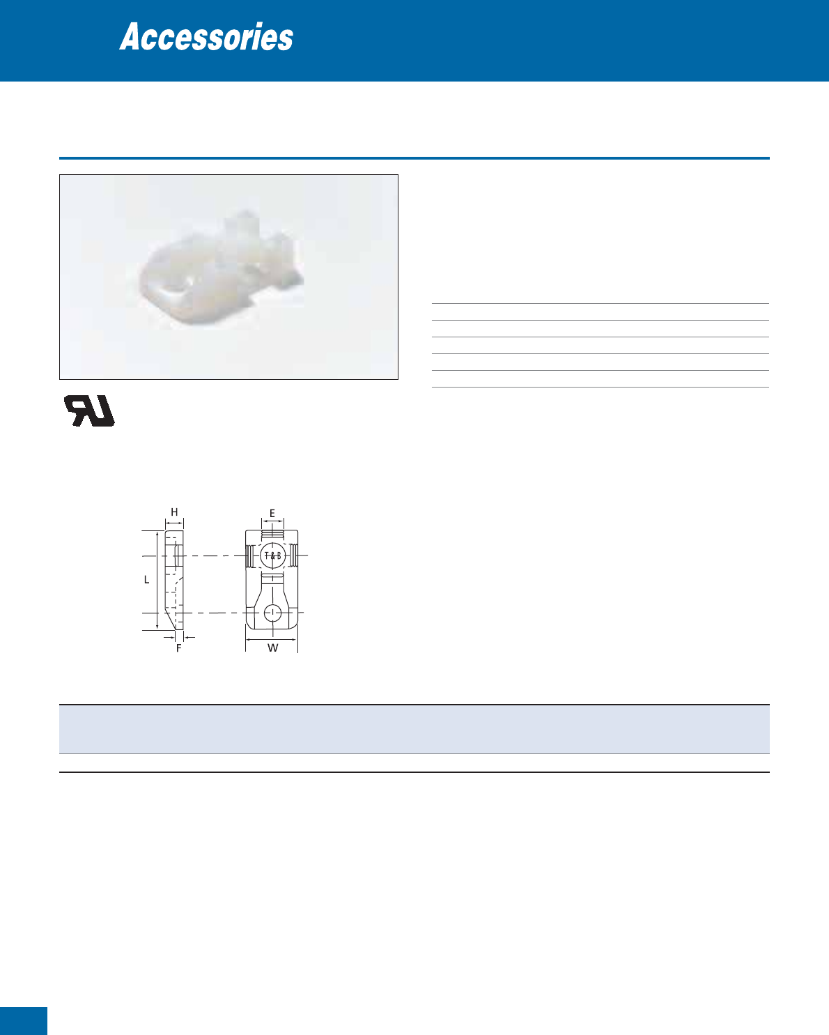
92
Thomas & Betts • www.tnb-europe.com
1.4
Screw-mounted - for crosswise fastening
• Extremely low profile
• For screw- or rivet-mounting
• Easy to use thanks to the cable tie insertion guide
• Two ties can be fastened crosswise to securely fix cable intersections
Technical Information
Material Polyamide 6.6
Temperature range -40°C to +85°C
Colour Natural
Mounting method Screw
Flammability rating UL 94 V-2
Other properties Halogen free, Silicone free
Mounting bases
Product Ref. Dimensions
For tie width
Mounting hole ø
Weight Quantity
HW L E F upto
[mm] [mm] [mm] [mm] [mm] [mm] [mm]
[g/100] [pieces]
TC826-TB 5.7 12.7
23.8
5.3 2.0 4.8 4.4 102 1000
For other colours and quantities please contact your Sales Office
E49405

Screw-mounted supporting bases
• Supporting mounting base with strong hold thanks to 2 mounting
holes
• Can be screwed or riveted
• Allows double and/or crosswise (two ties) fixing
• For parallel and through mounting with support
• Suitable for large bundle diameters
Technical Information
Material Polyamide 6.6
Temperature range -40°C to +85°C
Colour Natural
Mounting method 2 screws
Flammability rating UL 94 V-2
Other properties Halogen free, Silicone free
Mounting bases
93
Thomas & Betts • www.tnb-europe.com
1.4
Product Ref. Dimensions For tie width Mounting Weight Quantity
H W L G E F up to hole ø
[mm] [mm] [mm] [mm] [mm] [mm] [mm] [mm]
[g/100] [pieces]
TC106 25.4 19.1
25.4
12.7 4.6 16.5 7.6 3.3 (x 2) 435 200
TC109 11.1 9.9
14.3
7.1 1.7 7.0 4.8 2.4 (x 2) 45 1000
E49405
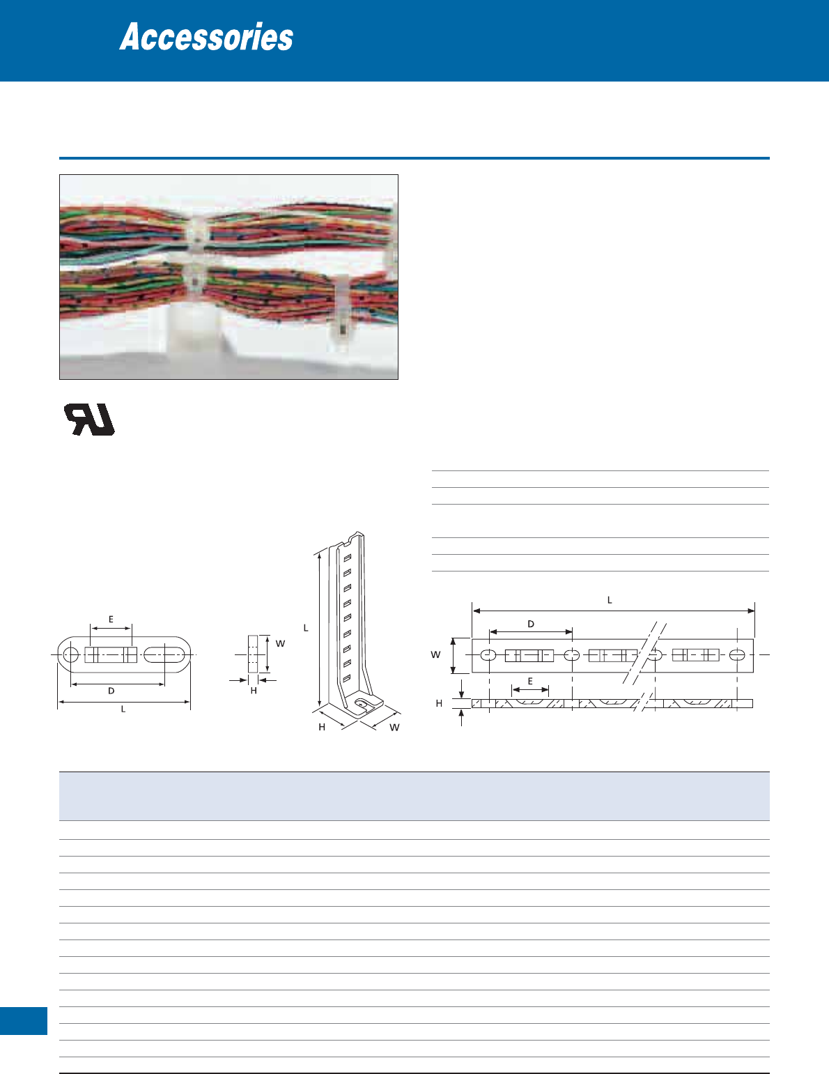
94
Thomas & Betts • www.tnb-europe.com
1.4
Screw-mounted strips for multiple bundling
• Tie mounting strips for up to 6 bundles simultaneously
• When mounted, the tie is guided through the clamp for fast
assembly
Product Ref. TC1101 to TC1117
• Simple and strong flat mounting beams for fixing multiple cables,
bundles or components
• Mil. Specified (MS-3339-...-...)
• VG approved (VG 95387, item 2)
Product Ref. TC375 and TC376
• For vertical and double-side mounting
Product Ref. TC101 and TC103
• Elongated fastening hole on one end allows greater flexibility dur-
ing mounting
Technical Information
Material Polyamide 6.6
Temperature range -40°C to +85°C
Colour Natural
Mounting method 2 screws (1 screw for Prod. Ref. TC376
& TC375)
Flammability rating UL 94 V-2
Other properties Halogen free, Silicone free
Mounting bases
TC101 & TC103
TC375 &
TC376
Product Ref. Mil Spec. Dimensions Max. number For tie width Mounting Weight Quantity
H W L D E of bundles up to hole ø
[mm] [mm] [mm] [mm] [mm] [mm] [mm]
[g/100] [pieces]
TC101 – 3.2
12.7
50.0 35.6 9.5 1 4.8 5.2 151 1000
TC103 – 5.1
15.8
79.0 59.6 18.6 1 7.6 6.9 505 500
TC1101 MS-3339-1-9 3.2
12.7
44.0 31.8 9.5 1 4.8 3.7 160 100
TC1102 MS-3339-2-9 3.2
12.7
76.0 31.8 9.5 2 4.8 3.7 280 100
TC1103 MS-3339-3-9 3.2
12.7
108.0 31.8 9.5 3 4.8 3.7 400 100
TC1104 MS-3339-4-9 3.2
12.7
140.0 31.8 9.5 4 4.8 3.7 520 100
TC1105 MS-3339-5-9 3.2
12.7
171.0 31.8 9.5 5 4.8 3.7 650 100
TC1112 MS-3339-11-9 5.2
15.9
244.0 38.1 14.3 6 7.6 3.7 1679 100
TC1113 MS-3339-6-9 5.2
15.9
53.3 38.1 14.3 1 7.6 3.7 385 100
TC1114 MS-3339-7-9 5.2
15.9
91.4 38.1 14.3 2 7.6 3.7 658 100
TC1115 MS-3339-8-9 5.2
15.9
130.0 38.1 14.3 3 7.6 3.7 914 100
TC1116 MS-3339-9-9 5.2
15.9
168.0 38.1 14.3 4 7.6 3.7 1190 100
TC1117 MS-3339-10-9 5.2
15.9
206.0 38.1 14.3 5 7.6 3.7 1141 100
TC375 – 19.1
17.5
93.0 – 6.4 5 4.8 4.8 486 100
TC376 – 17.0
17.5
44.0 – 6.4 2 4.8 4.8 253 100
For other colours and quantities please contact your Sales Office
TC1101 ... TC1117
E49405
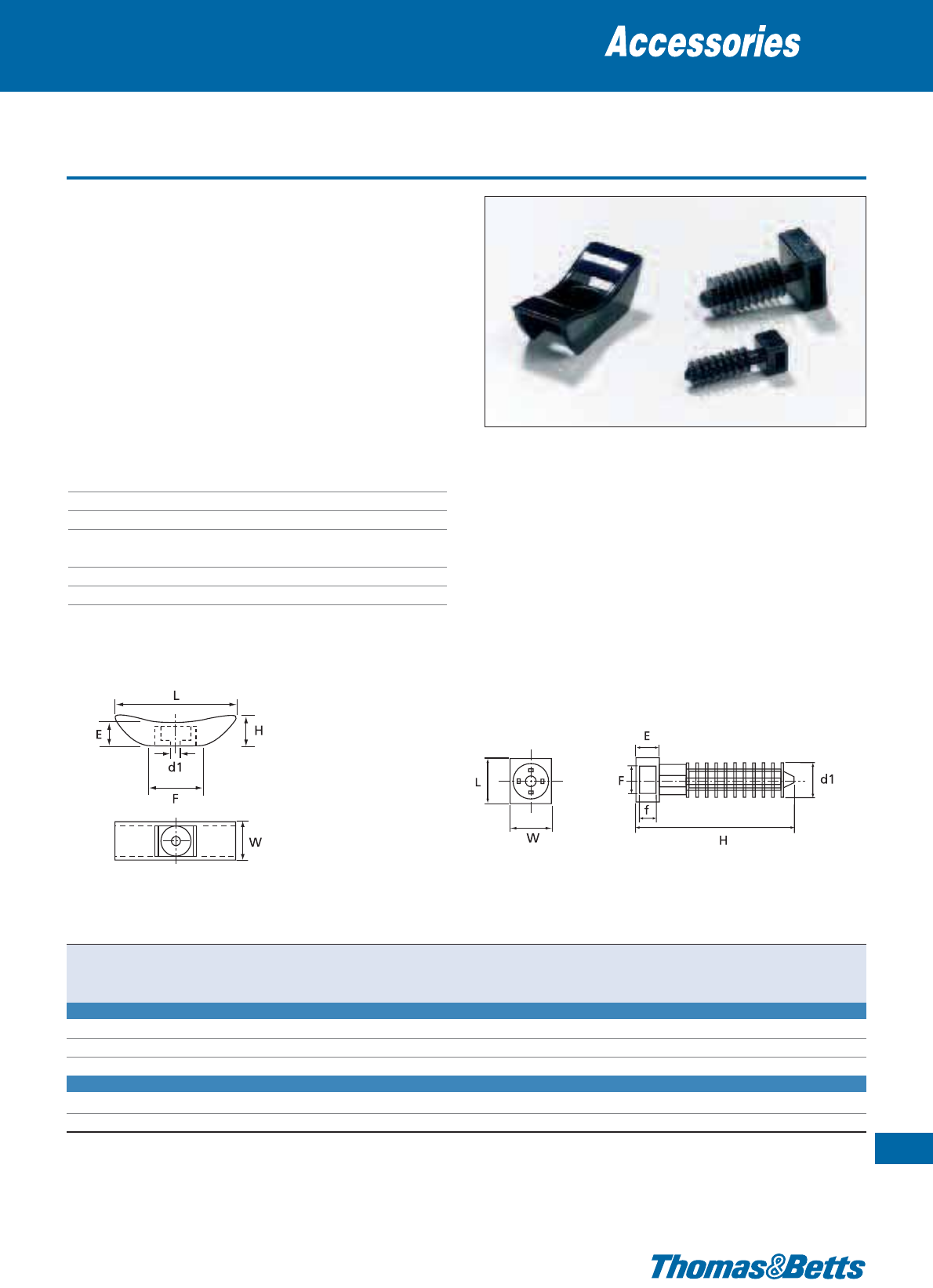
Weather resistant - Heavy-duty
• Tie mounting base for outdoor installation
• A strong, weatherproof and durable outdoor fastening solution
for pipes, hoses, cables, etc.
Product Ref. TC5358 and TC5359
• Built-in plug for mounting into walls
• Easy to install: the plug is simply hammered into a hole
• The lamellar plug ensures high tensile strength and durability
Product Ref. TC5355 to TC5357
• For screw-fastening
• Ergonomically shaped for trouble-free installation
Technical Information
Material UV-stabilised Polyamide 6.6
Temperature range -40°C to +85°C
Colour Black
Mounting method Screw (for Product ref. TC5355 to
TC5357 only)
Flammability rating UL 94 V-2
Other properties UV-resistant, Halogen free, Silicone free
Mounting bases
95
Thomas & Betts • www.tnb-europe.com
1.4
TC5355-TC5356-TC5357 TC5358-TC5359
Product Ref. Dimensions For tie width Mounting hole ø Weight Quantity
H W L E F f up to d1
[mm] [mm] [mm] [mm] [mm] [mm] [mm] [mm]
[g/100] [pieces]
MOUNTING CRADLE
TC5355
15.9
19.1 44.5 11.1 28.6 – 12.7 4.6 500 25
TC5356
15.9
19.1 44.5 11.1 28.6 – 12.7 5.2 500 25
TC5357
15.9
19.1 44.5 11.1 28.6 – 12.7 6.7 500 25
WALL PLUG
TC5358
31.8
9.9 9.9 7.1 5.6 2.3 4.8 6.4 (in wall) 120 100
TC5359
38.4
19.1 19.1 8.1 14.0 3.1 12.7 9.5 (in wall) 320 50
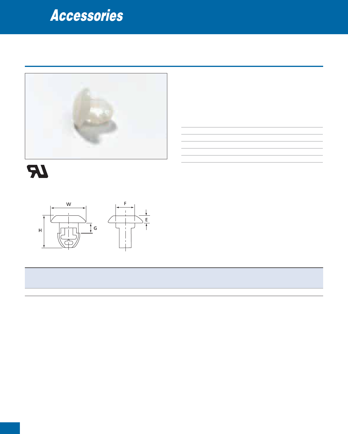
96
Thomas & Betts • www.tnb-europe.com
1.4
Clip-in mounting bases for blind mounting
• Clip-in tie mounting bases for housings, faceplates etc
• With fastening clip for blind-mounting and two openings for two
2.8 mm or 4.8 mm ties
• Low profile
Technical Information
Material Polyamide 6.6
Temperature range -40°C to +85°C
Colour Natural
Mounting method Clip in
Flammability rating UL 94 V-2
Other properties Halogen free, Silicone free
Mounting bases
Product Ref. Dimensions Panel thickness For tie width Mounting Weight Quantity
H W G E F from…to upto holeø
[mm] [mm] [mm] [mm] [mm] [mm] [mm] [mm]
[g/100] [pieces]
TC121-TB 10.4 11.2 3.4 2.0 6.1 0.1 - 3.2 2.4 and 4.8 6.3 31 1000
E49405
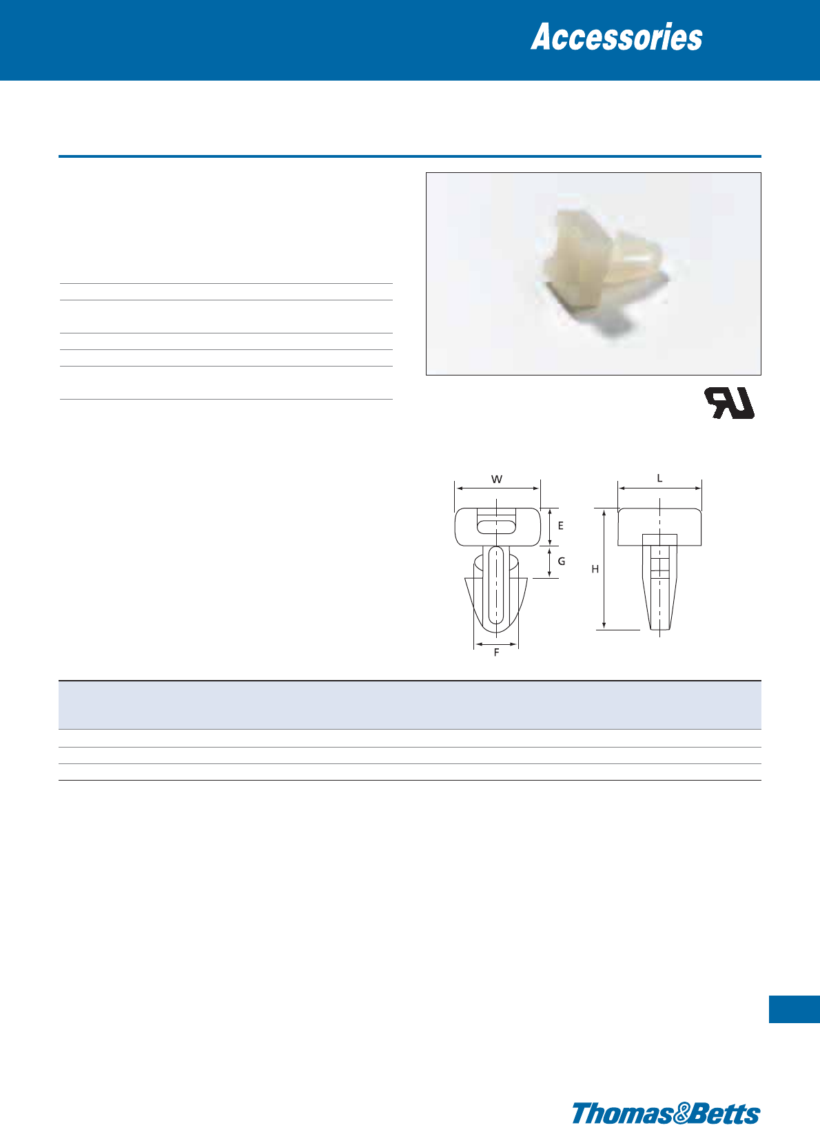
Clip-in mounting bases for surface mounting
• Clip-in tie mounting bases for housings, faceplates etc
• With fastening clip for surface mounting
• Low profile
Technical Information
Material Polyamide 6.6
Temperature range -40°C to +85°C
Colour Natural (TC823-TB & TC5823)
UV-resistant black (TC823X)
Mounting method Clip in
Flammability rating UL 94 V-2
Other properties UV-resistant (black), Halogen free,
Silicone free
Mounting bases
97
Thomas & Betts • www.tnb-europe.com
1.4
T&B
Product Ref. Dimensions Panel thickness For tie width Mounting Weight Quantity
H W L G E F from … to up to hole ø
[mm] [mm] [mm] [mm] [mm] [mm] [mm] [mm] [mm]
[g/100] [pieces]
TC823-TB 16.8 11.1
11.1
3.6 5.1 5.8 0.1 - 3.2 4.8 6.2 - 6.5 68 1000
TC5823 16.8 11.1
11.1
3.6 5.1 5.8 0.1 - 3.2 4.8 6.2 - 6.5 68 100
TC823X* 16.8 11.1
11.1
3.6 5.1 5.8 0.1 - 3.2 4.8 6.2 - 6.5 68 1000
For other colours and quantities please contact your Sales Office
* Not UL recognised
E49405
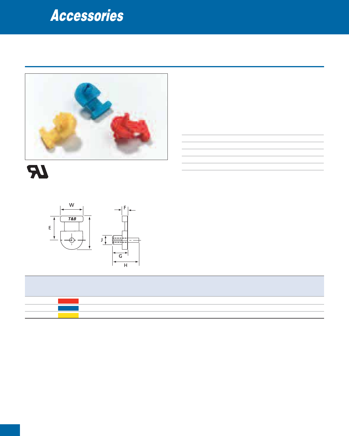
98
Thomas & Betts • www.tnb-europe.com
1.4
Rivet-mounted bases
• Low profile mounting base with integrated rivet
• Easy to install into normal or blind holes: just hammer in the ex-
panding harbour
• Parts are colour-coded according to hole diameter to avoid con-
fusion
Technical Information
Material Polyamide 6.6
Temperature range -40°C to +85°C
Colour See table
Mounting method Rivet mounted
Flammability rating UL 94 V-2
Other properties Halogen free, Silicone free
Mounting bases
L
Product Ref. Colour Dimensions For tie width Mounting Weight Quantity
W L F E G H J upto holeø
[mm] [mm] [mm] [mm] [mm] [mm] [mm] [mm] [mm]
[g/100] [pieces]
TC116-TB red
12.7
19.1 3.2 13.9 8.6 15 3.9 4.8 3.7 70.5 1000
TC118-TB blue
12.7
19.1 3.2 13.9 8.6 15 4.5 4.8 4.4 71.0 1000
TC120 yellow
12.7
19.1 3.2 13.9 8.6 15 5.2 4.8 4.9 71.5 1000
E49405
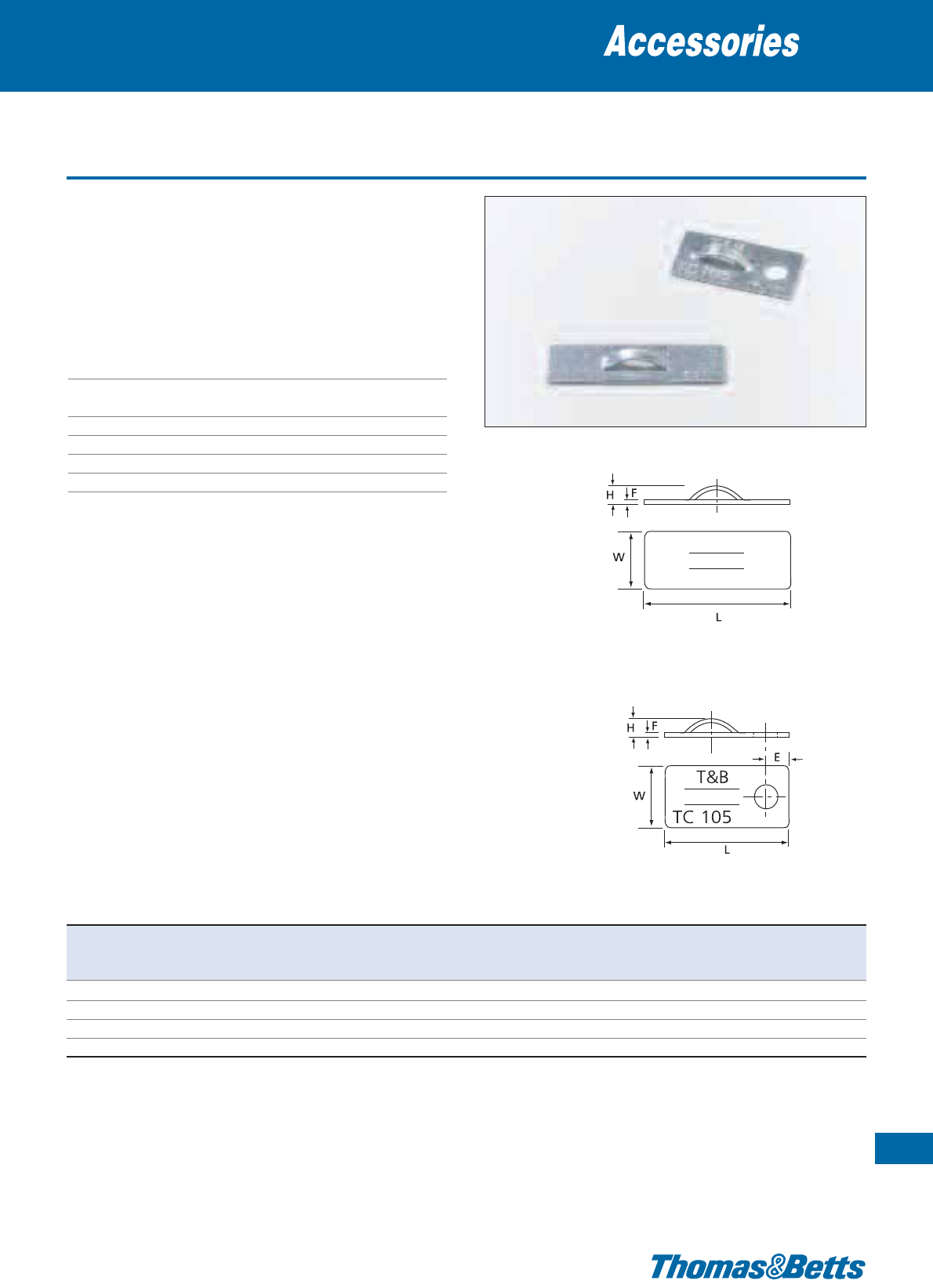
Aluminium plates
• Very strong mounting base for gluing or screw mounting or
self-adhesive mounting
• Low profile
• Soft material can be perfectly shaped onto any support
• Lightweight
• Does not age even under extreme temperatures
Technical Information
Material Aluminium (3003, ASTMB-209)
Temperature range -100°C to +450°C
(Self-adhesive version: 0°C to +65°C)
Colour Metallic
Mounting method Glue (*) and / or screw or self-adhesive
Flammability rating Fire proof
Other properties UV-resistant
Mounting bases
99
Thomas & Betts • www.tnb-europe.com
1.4
TC824-TB
TC105 and TC105AP
Product Ref. Mounting Dimensions For tie width Mounting Weight Quantity
method H W L E F up to hole ø
[mm] [mm] [mm] [mm] [mm] [mm] [mm]
[g/100] [pieces]
TC105AP self-adhesive / screw 3.8
13.2
25.4 4.8 0.8 4.8 4.9 67 1000
TC105 screw 3.8
13.2
25.4 4.8 0.8 4.8 4.9 67 1000
TC5105 screw 3.8
13.2
25.4 4.8 0.8 4.8 4.9 67 100
TC824-TB 2-component glue* 3.8
9.5
34.9 – 0.8 4.8 – 69 1000
* Glue = Product Ref TC2PA (see page 137 for specifications)
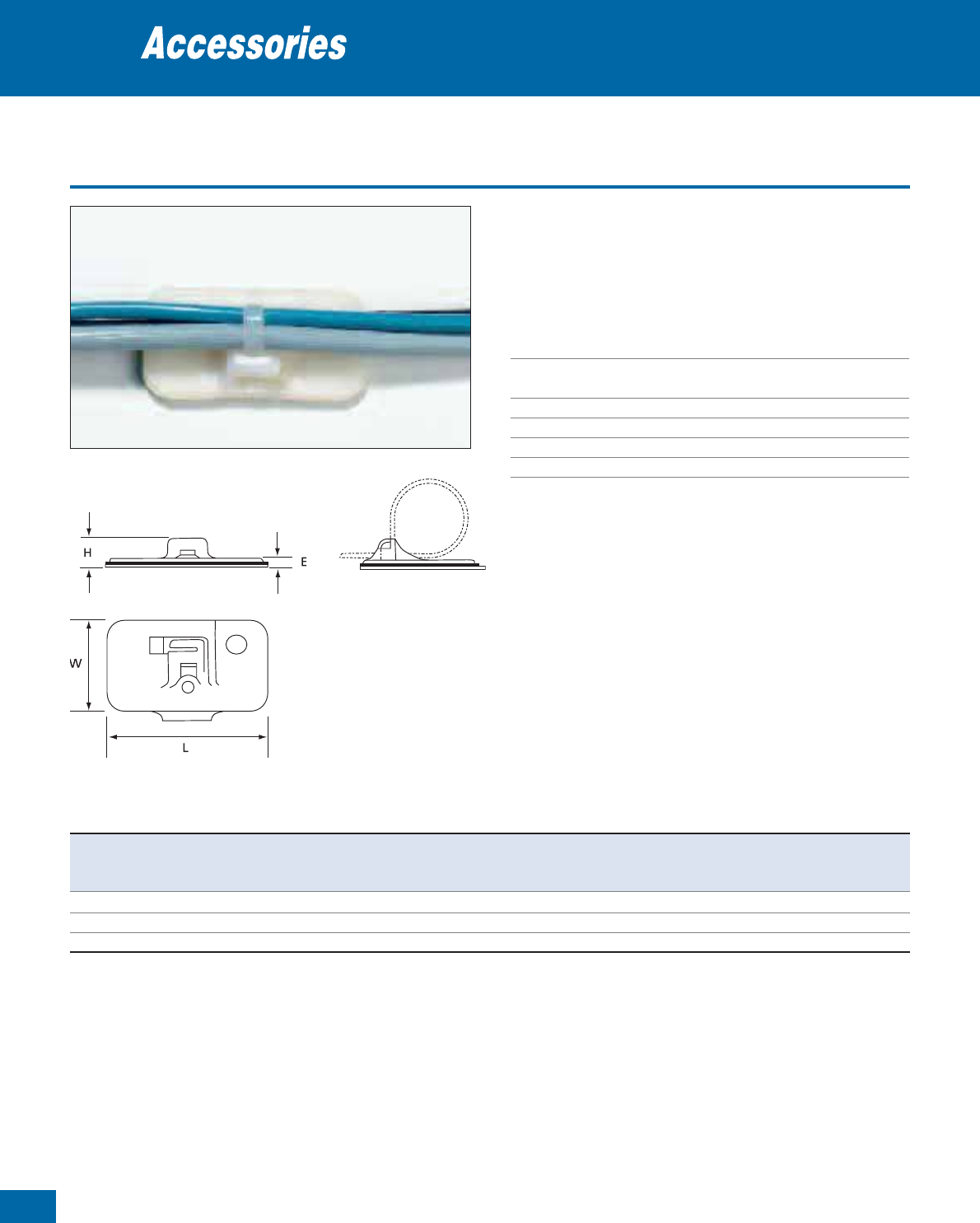
100
Thomas & Betts • www.tnb-europe.com
1.4
Special mounting bases for Ty-Rap®cable ties
• Easy to install: The Ty-Rap®is slid into the mounting base before
its installation
• Recommended for use with Ty-Rap®cable ties TY25M, TY253M
and TY28M (see page 11)
Technical Information
Material Polyamide 6.6
Temperature range -40°C to +85°C
(Self-adhesive version: 0°C to +65°C)
Colour Natural
Mounting method Self-adhesive and / or screw-mounting
Flammability rating UL 94 V-2
Other properties Halogen free, Silicone free
Mounting bases
T
&
B
Product Ref. Mounting Dimensions For tie width Adhesive strength Hole Weight Quantity
method H W L E up to on steel diameter
[mm] [mm] [mm] [mm] [mm] [N/cm] [mm]
[g/100] [pieces]
TC353A self-adhesive / screw 9.1
25.4
50.9 2.5 4.8 72 3.8 320 100
TC5353A self-adhesive / screw 9.1
25.4
50.9 2.5 4.8 72 3.8 320 25
TC353 screw 8.4
26.5
52.0 1.4 4.8 -- 3.8 320 100
See page 137 for self-adhesive material specifications.
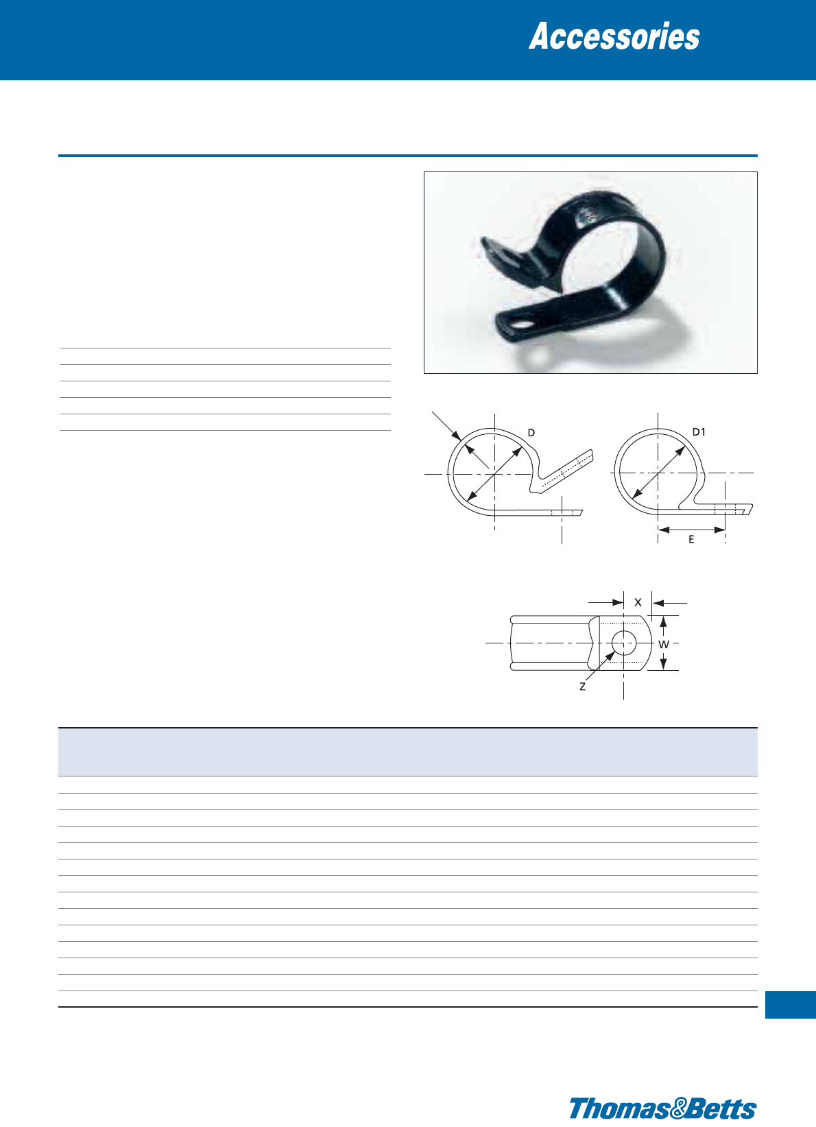
Heat stabilised self-aligning clamps
• Moulded-in saddle washer enhances performance and appearance
• Self-alignment feature makes this clamp ideal for assembly appli-
cations
• 14 diameters and 2 widths with mounting holes for M4 and M5
screws
• Item numbers moulded-in for easy identification
• Indoor application
Technical Information
Material Heat-stabilised Polyamide 6.6
Temperature range -40°C to +105°C
Colour Black
Mounting method Screw
Flammability rating UL 94 V-2
Other properties Halogen free, Silicone free
Cable clamps
101
Thomas & Betts • www.tnb-europe.com
1.4
T
Product Ref. Dimensions Quantity
D nominal diameter D1 closed diameter E T W Z X
[mm] [mm] [mm] [mm] [mm] [mm] [mm]
[pieces]
W4NY-125-0-C 3.17 2.89 8.46 1.02 9.52 4.24 6.53 100
W4NY-187-0-C 4.76 4.36 9.02 1.02 9.52 4.24 5.53 100
W4NY-250-0-C 6.34 5.94 9.70 1.02 9.52 4.24 4.83 100
W4NY-312-0-C 7.93 7.54 10.71 1.02 9.52 4.24 5.21 100
W4NY-375-0-C 9.52 9.11 11.53 1.02 9.52 4.24 5.33 100
W4NY-500-0-C 12.69 12.29 12.45 1.02 9.52 4.24 6.76 100
W6NY-562-0-C 14.28 13.90 16.68 1.52 12.69 5.15 5.99 100
W6NY-625-0-C 15.87 15.46 16.17 1.52 12.69 5.15 7.37 100
W6NY-687-0-C 17.46 17.06 17.63 1.52 12.69 5.15 8.31 100
W6NY-750-0-C 19.04 18.64 18.44 1.52 12.69 5.15 8.28 100
W6NY-812-0-C 20.63 20.24 19.71 1.52 12.69 5.15 8.20 100
W6NY-875-0-C 22.22 21.81 18.62 1.52 12.69 5.15 7.87 100
W6NY-1000-0-C 25.39 24.99 22.38 1.52 12.69 5.15 7.42 100
W6NY-1250-0-C 31.73 31.16 25.65 1.52 12.69 5.15 8.61 100
Also available in quantities of 1,000 pieces. For other colours please contact your Sales Office
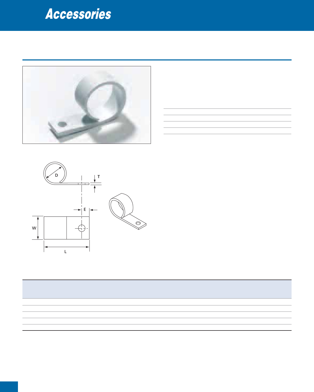
102
Thomas & Betts • www.tnb-europe.com
1.4
Rigid PVC clamps
• Open mounting clips
• Easy to use: cables, for example, are simply pushed sideways into
the clip one by one
Technical Information
Material Rigid PVC
Temperature range -40°C to +50°C
Colour White
Mounting method Screw
Flammability rating UL 94 V-2
Cable clamps
Product Ref. Dimensions Mounting Weight Quantity
øD W L T E hole ø
[mm] [mm] [mm] [mm] [mm] [mm] [g/100]
[pieces]
TC70 6.4 9.9 22.2 1.2 6.4 5.2 49 100
TC71 12.7 9.9 29.0 1.6 6.4 5.2 123 100
TC72 20.6 13.1 36.9 2.0 6.4 5.2 259 100
TC73 25.4 13.1 46.8 2.4 6.4 5.2 399 100
TC74 38.1 13.1 58.3 2.8 6.4 5.2 608 100
For other quantities please contact your Sales Office
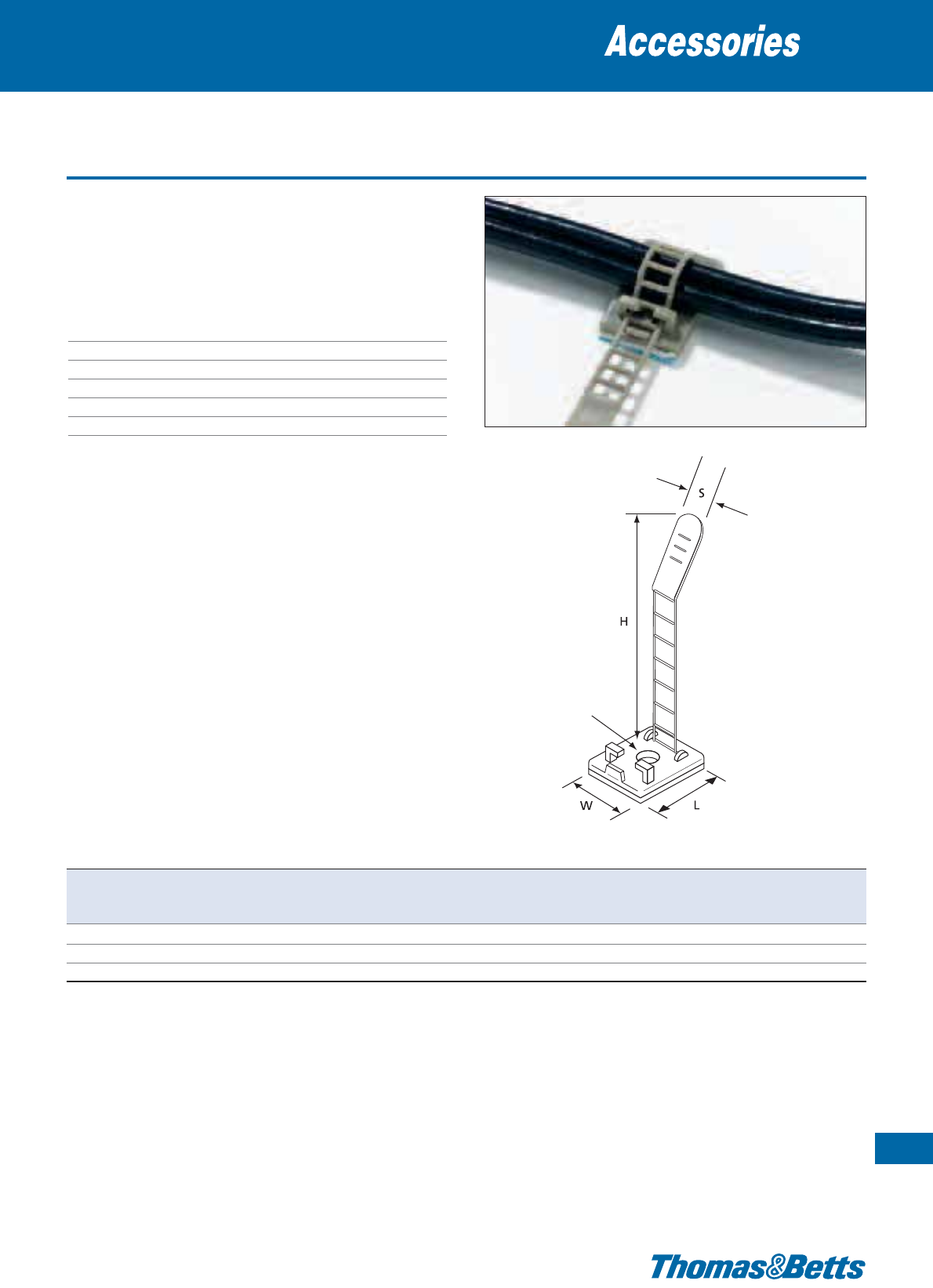
Adjustable, ladder style clamps
• Ladder style fastener is easily released and refastened
• Supplied “single-cut” on a rubber based closed cell foam adhesive
• In addition, can also be mounted with a screw, for improved pull-
off strength
Technical Information
Material Polyamide 6.6
Temperature range 0°C to +65°C
Colour Grey
Mounting method Self adhesive and / or screw-mounting
Flammability rating UL 94 V-2 (clamp)
Other properties Halogen free, Silicone free
Cable clamps
103
Thomas & Betts • www.tnb-europe.com
1.4
Screw Hole
Product Ref. Dimensions Bundle Screw hole Quantity
H W L S diameter range diameter
[mm] [mm] [mm] [mm] [mm] [mm]
[pieces]
ULNY-013-8-C 59.5 18 25 8 3 - 12.7 2.79 100
ULNY-018-8-C 79.4 21 30 12 5 - 21.0 2.79 100
ULNY-023-8-C 85.5 25 35 14 7 - 25.0 3.43 100
For other quantities please contact your Sales Office
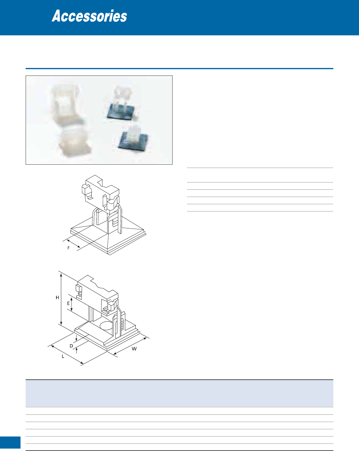
104
Thomas & Betts • www.tnb-europe.com
1.4
Latching clamps
• Re-usable tie mounting clamps
• For self-adhesive and / or screw- or rivet mounting
• One-piece design with integrated releasable lock
• The inner profile protects sensitive cables, fibre optics etc
• Desired height can be set in 3 or 6 ratchet steps
• The large base surface area and the strong adhesive film guarantees
a high adhesive strength
• The self-adhesive film is foam backed (0.8 mm) to compensate
for any irregularities on the mounting surface
Technical Information
Material Polyamide 6.6
Temperature range -40°C to +85°C
(Self-adhesive version: 0°C to +65°C)
Colour Natural
Mounting method Self adhesive or screw-mounting
Flammability rating UL 94 V-2
Other properties Halogen free, Silicone free
Cable clamps
TC349A-TB
TC5349A-TB
TC350
TC5350
TC350A-TB
TC5350A-TB
Product Ref. Mounting Dimensions Mounting Weight Quantity
method H H W L D E Height of F Width of hole ø
max. min. clamping area clamping area
[mm] [mm] [mm] [mm] [mm]
from ... to [mm]
[mm] [mm]
[g/100] [pieces]
TC349A-TB self-adhesive 14.5 11.5 25.0 25.0 2.7 6 - 8.5 6 – 120 1000
TC5349A-TB self-adhesive 14.5 11.5 25.0 25.0 2.7 6 - 8.5 6 – 120 100
TC350A-TB self-adhesive / screw 22.0 18.0 25.0 25.0 4.7 6 - 12.5 15 4.3 400 1000
TC5350A-TB self-adhesive / screw 22.0 18.0 25.0 25.0 4.7 6 - 12.5 15 4.3 400 100
TC350 screw 21.3 17.2 25.0 25.0 4.0 6 - 12.5 15 4.3 380 1000
TC5350 screw 21.3 17.2 25.0 25.0 4.0 6 - 12.5 15 4.3 380 100
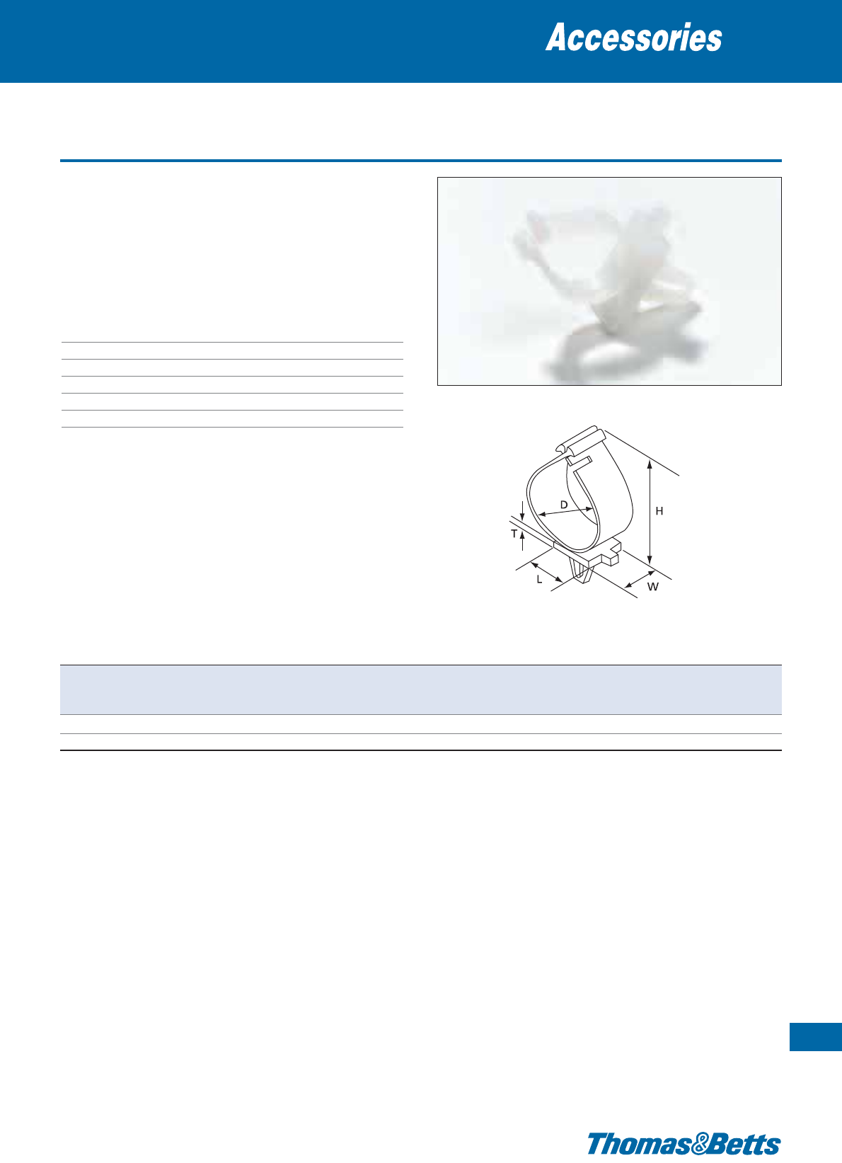
Re-openable clamps
Cable clamps
105
Thomas & Betts • www.tnb-europe.com
1.4
• Simple installation
• Can be mounted by clipping-in or gluing
• For series production or as a temporary support during wiring
installation
• Clip ends are rounded for comfortable re-opening
• Product Ref. TC95 features 2-stage lock
Technical Information
Material Polyamide 6.6
Temperature range -40°C to +85°C
Colour Natural
Mounting method Clip in
Flammability rating UL 94 V-2
Other properties Halogen free, Silicone free
Product Ref. Dimensions For wall thickness Mounting hole ø Weight Quantity
HWLDT from…to
[mm] [mm] [mm] [mm] [mm] [mm] [mm]
[g/100] [pieces]
TC88 22.6 12.7 19.1 12.7 2.5 2.5 - 3.6 5.7 - 7 115 100
TC95 40.5 12.7 19.1 25.4 2.5 2.5 - 3.6 5.7 - 7 278 100

106
Thomas & Betts • www.tnb-europe.com
1.4
Re-openable clamps with springs
• Holding clips with rubberised fabric tape
• The built-in springs hold the cable bundle safely in the desired
position
• The upper clip end is rounded for easy addition of cables
• Strong fixing due to two mounting holes, aligned along the axis
of the cable bundle
Technical Information
Material - Body Polyamide 6.6
Material - Elastic Rayon & natural rubber
Material - Spring Steel
Temperature range -40°C to +85°C
Colour Natural
Mounting method 2 screws
Flammability rating UL 94 V-2 (body)
Other properties Halogen free
Cable clamps
Product Ref. Dimensions Max. bundle ø Mounting hole ø Weight Quantity
HLWEF
[mm] [mm] [mm] [mm] [mm] [mm] [mm]
[g/100] [pieces]
TC86 46
44.5
31.8 22.2 2.5 19 3.9 860 25
TC87 58
62.7
38.1 25.4 2.5 32 3.9 1950 25
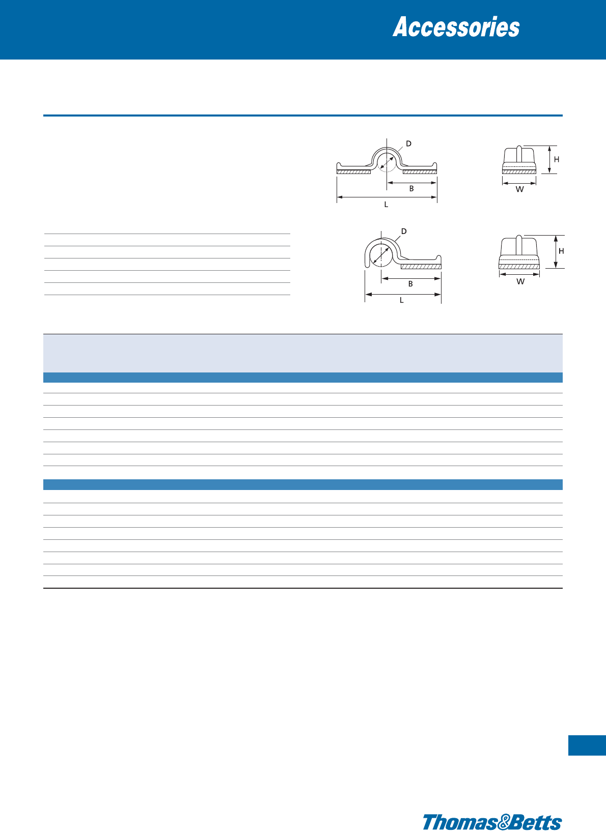
Self-adhesive press clips
Cable clamps
107
Thomas & Betts • www.tnb-europe.com
1.4
• Available in “full clip” version (PCNY series) or “half clip” version
(HCNY series)
• 4 sizes to accommodate bundles up to 12 mm
• Clips are provided “two-up” on a rubber based closed cell foam
adhesive
Technical Information
Material Polyamide 6.6 (clip)
Temperature range 0°C to +65°C
Colour Natural
Mounting method Self-adhesive
Flammability rating UL 94 V-2
Other properties Halogen free, Silicone free
PCNY
HCNY
Product Ref. Dimensions Quantity
DL B HW
[mm] [mm] [mm] [mm] [mm]
[pieces]
FULL PRESS CLIPS
PCNY-125-9-C 3.17 19.30 9.65 5.36 9.52 100
PCNY-125-9-D 3.17 19.30 9.65 5.36 9.52 500
PCNY-250-9-C 6.35 35.05 17.52 8.23 12.69 100
PCNY-250-9-D 6.35 35.05 17.52 8.23 12.69 500
PCNY-375-9-C 9.52 37.32 18.61 11.29 15.87 100
PCNY-375-9-D 9.52 37.32 18.61 11.29 15.87 500
PCNY-500-9-C 12.69 40.57 20.19 14.85 19.05 100
PCNY-500-9-D 12.69 40.57 20.19 14.85 19.05 500
HALF PRESS CLIPS
HCNY-125-9-C 3.17 12.52 9.65 4.57 9.52 100
HCNY-125-9-M 3.17 12.52 9.65 4.57 9.52 1000
HCNY-250-9-C 6.35 21.97 17.52 8.25 12.69 100
HCNY-250-9-M 6.35 21.97 17.52 8.25 12.69 1000
HCNY-375-9-C 9.52 24.88 19.05 10.54 15.87 100
HCNY-375-9-M 9.52 24.88 19.05 10.54 15.87 1000
HCNY-500-9-C 12.69 28.19 20.83 14.22 19.05 100
HCNY-500-9-M 12.69 28.19 20.83 14.22 19.05 1000

108
Thomas & Betts • www.tnb-europe.com
1.4
Self-adhesive clips for round cable
• Diverse cable clamps for bundle diameters from 4 mm to 15.8 mm
• Clips are provided two-up on a rubber based closed cell foam
adhesive
• Flexible centre tongue for removal or addition of cables
Technical Information
Material Polyamide 6.6 (clip)
Temperature range 0°C to +65°C
Colour Natural or black
Mounting method Self-adhesive
Flammability rating UL 94 V-2
Other properties Halogen free, Silicone free
Cable clamps
Product Ref. Colour Dimensions Max. bundle ø Quantity
HLW
[mm] [mm] [mm]
[mm] [pieces]
RANY-160-9-D natural 6.4 16.0 14.8 4.0 500
RANY-280-9-D natural 10.4 25.4 25.4 7.1 500
RANY-280-0-D black 10.4 25.4 25.4 7.1 500
RANY-530-9-D natural 15.8 25.4 25.4 13.5 500
RANY-620-9-D natural 14.2 31.8 28.5 15.8 500
For other quantities please contact your Sales Office
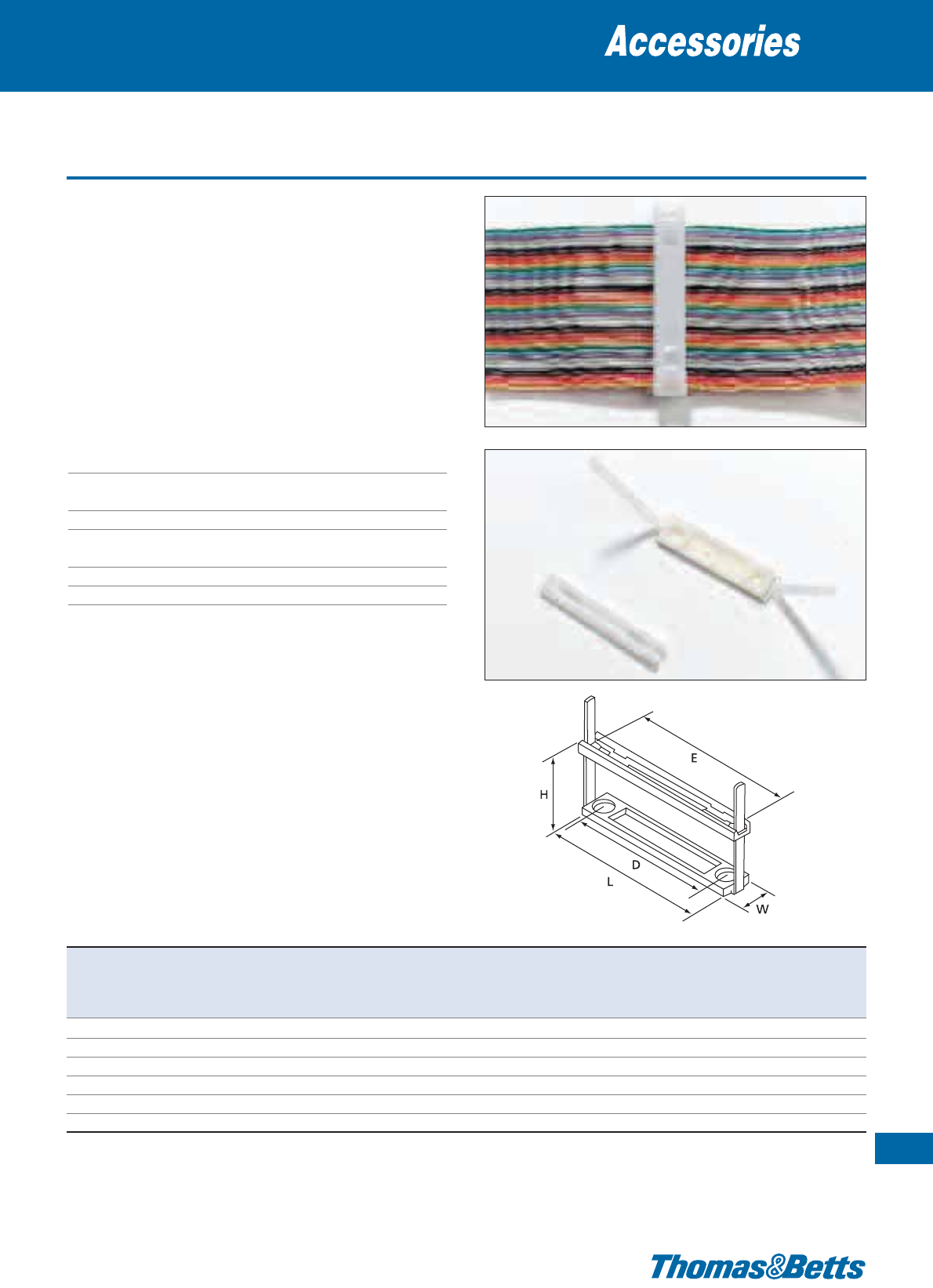
Cable clamps
• This system allows the secure and neat fixing of between 1 and
25 ribbon cables
• Clamp height adapts accurately to the desired number of ribbon
cables
• Suitable for ribbon cables up to 60 conductors with a pitch of
1.27 mm (76.2 mm wide)
• Can be re-opened for later addition or removal of a cable
• Very strong hold
• All versions can be mounted with countersunk-head screws or rivets
• Some versions have an additional self-adhesive foam, for fast
mounting
Technical Information
Material Polyamide 6.6 (clip)
Temperature range -40°C to +85°C
(Self-adhesive version: 0°C to +65°C)
Colour Natural
Mounting method Self-adhesive and / or for screw-
or rivet-mounting
Flammability rating UL 94 V-2
Other properties Halogen free, Silicone free
Accessories for flat cables
109
Thomas & Betts • www.tnb-europe.com
1.4
Product Ref. Mounting Dimensions Adhesive strength Weight Quantity
method H H W L D E on steel/
max. min. mounting centres inner width fastening hole
[mm] [mm] [mm] [mm]
from ... to [mm]
[mm]
[g/100] [pieces]
FCC-1 countersunk screws 21.0 8.0 12.7 32.5 – 25.4 M4 260 50
FCC-1A
countersunk screws / self-adhesive
21.0 8.8 12.7 32.5 – 25.4 76 N/cm 275 50
FCC-2 countersunk screws 36.0 8.0 12.7 57.9 39.1 50.8 M4 340 50
FCC-2A
countersunk screws / self-adhesive
36.0 8.8 12.7 57.9 39.1 50.8 76 N/cm 390 50
FCC-3 countersunk screws 36.0 8.0 12.7 83.3 64.5 76.2 M4 475 50
FCC-3A
countersunk screws / self-adhesive
36.0 8.8 12.7 83.3 64.5 76.2 76 N/cm 490 50
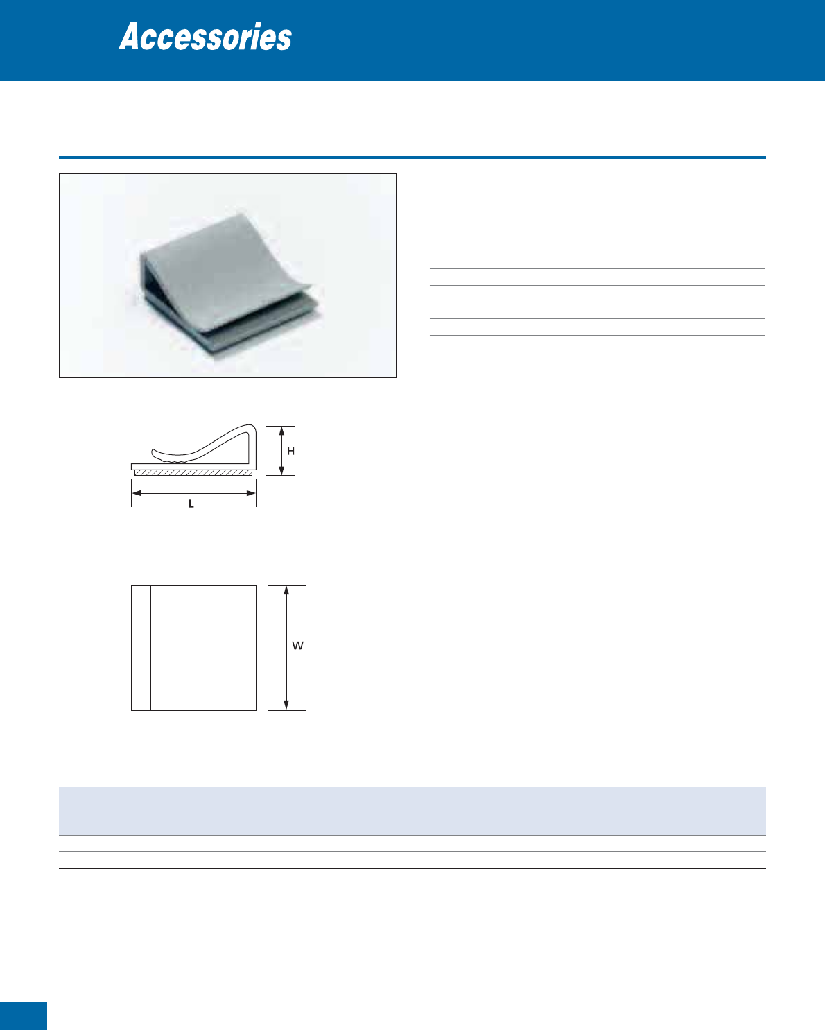
110
Thomas & Betts • www.tnb-europe.com
1.4
PVC cable-clips
Accessories for flat cables
• Low profile clip for single or multiple layers of flat ribbon cable
• “Single cut” on a rubber based closed cell foam adhesive
Technical Information
Material PVC (clip)
Temperature range 0°C to +65°C
Colour Grey
Mounting method Self-adhesive
Flammability rating UL 94 V-0 (clip)
Other properties UV-resistant
Product Ref. Dimensions Quantity
HL W
[mm] [mm] [mm]
[pieces]
FRPV-1000-8-C 5.8 27 25.4 100
FRPV-1000-8-D 5.8 27 25.4 500

Clips with flexible leg
• Low profile clip for single or multiple layers of flat ribbon cable
• Flexible centre leg allows for easy removal and replacement of
desired cable
• Non-conductive, non-corrosive, resistant to fuels, lubricants and
most chemicals
• FANY supplied “two-up” on a rubber based closed cell foam
adhesive
• FSNY type has an additional mounting hole for screw mounting
(M4 screw)
Technical Information
Material Polyamide 6.6 (clip)
Temperature range -40°C to +85°C
(Self-adhesive version: 0°C to +65°C)
Colour Natural
Mounting method Self-adhesive or screw
Flammability rating UL 94 V-2 (clip)
Other properties Halogen free, Silicone free
Accessories for flat cables
Thomas & Betts • www.tnb-europe.com
1.4
FANY FSNY
Product Ref. Mounting Dimensions Quantity
method H L W
[mm] [mm] [mm]
[pieces]
FSNY-812-9-C M4 screw 3.17 30.15 25.40 100
FANY-812-9-C self-adhesive 7.14 25.40 25.40 100
FANY-812-9-D self-adhesive 7.14 25.40 25.40 500
For other quantities please contact your Thomas & Betts Sales Office
111
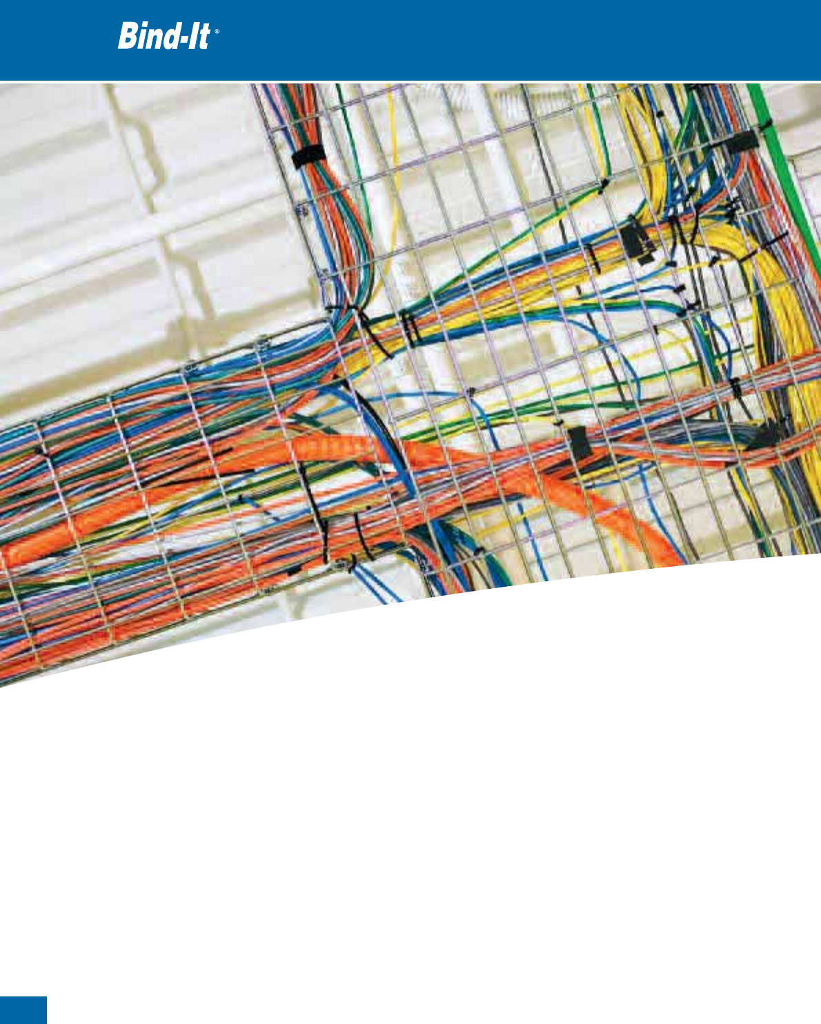
112
Thomas & Betts • www.tnb-europe.com
1.5
Bind-It®
Cable Protection Systems
113
Thomas & Betts • www.tnb-europe.com
1.5
FASTENING SYSTEMS
1.1 PREMIUM CABLE TIES WITH STEEL LOCKING BARB 4
1.2 ALL-PLASTIC CABLE TIES 44
1.3 STAINLESS STEEL CABLE TIES 64
1.4 MOUNTING BASES & ACCESSORIES 74
1.5 CABLE PROTECTION SYSTEMS 112
Wrap-around woven sleeving 116
Wrap-around woven sleeving - Flame retardant 117
Braided sleeving 118
Braided sleeving - Flame retardant 119
Spiral wrap 120
Extruded grommeting 121
1.6 CABLE TIE TOOLING 122
1.7 MATERIAL SPECIFICATIONS 134

1.5
Bind-It®
Cable Protection Systems
The Cable Protection Systems (CPS) from Thomas & Betts
captures different products:
- Wrap-around woven sleeving
- Braided sleeving
- Spiral wrap
- Extruded grommeting
The wrap-around sleeving – better known under the name
Bind-It®- is a tough but lightweight sleeve used to bundle and
protect wires and cables from abrasion, sharp edges and chafing.
Bind-It®is a self-wrapping sleeve that is very quick and easy to
install and remove. Bind-It®is also available in a flame retardant
version. No heat is necessary to seal the ends of this product. The
ends can be secured by using Ty-Rap®cable ties.
Thomas & Betts • www.tnb-europe.com
114

The braided sleeving of Thomas & Betts is used for bundling and
protecting cables. The braided sleeving is a closed sleeve available
in a flame and a non-flame retardant version. This product is
mainly used inside cabinets and enclosures. To stop the end of the
sleeving fraying it is necessary to heat seal the ends using a
“hotwire” device.
Spiral wrap is mainly used for protection of bundles. This product
is available in a natural and UV-resistant version and supplied in a
Euroslot bag, ideal for the distribution market.
Finally the extruded grommeting of Thomas & Betts is used to line
panel edges and knock-outs where the chafing of passing wires
is a concern. In most applications, grommeting will grip tightly by
itself.
Cable Protection Systems,
to protect and bundle wires
and cables.
1.5
Thomas & Betts • www.tnb-europe.com
115
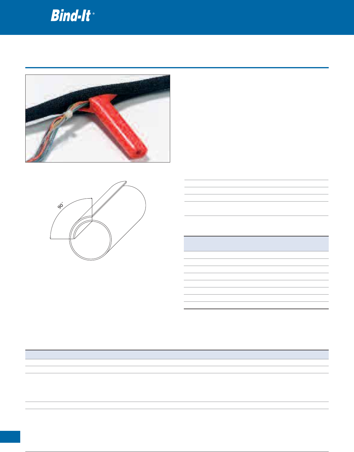
116
Thomas & Betts • www.tnb-europe.com
1.5
Wrap-around woven sleeving
• Offers excellent protection for cable assemblies against abrasion
• No heat is required to seal the ends of this product as with tradi-
tional braided sleeving
• With its wrap-around design, it can be installed on assemblies
where the wires are already terminated or wires need to be
broken-out
•Bind-It
®is available in nominal sizes from 5 mm to 38 mm
• A professional assembly tool is supplied for the 5 mm, 8 mm and
13 mm nominal sizes
• Product is supplied black as standard with a white version available
on request
Technical Information
Material Mono and multifilaments of polyester
Temperature range -70°C to +125°C
Melt temperature +256°C (ASTM D-2117)
Colour Black
Flammability rating Self-extinguishing, type B (FMVSS-302 Test
method D45 1333)
Cable protection systems
Property Test method Typical performance
Low temperature flexibility MIL-DTL-23053E -70°C
Smoke density ASTM E-1354 Pending
Hard Vacuum ASTM E-595
• TML (Mass) 0.63 %
• CVCM (Condensation) 0.16 %
• WVR (Steam) 0.06 %
Corrosivity MIL-I-23053 No corrosive smoke
Fluid resistance MIL-I-23053 Tensile retention
• Jet fuel: JP-41 100 %
• Hydraulic fluid: (MIL-H-5606) 100 %
• Lube oil: (MIL-I-7808) 100 %
• De-icing fluid: (MIL-A-8243) 100 %
• Salt Water: (O-S-1926) 100 %
Material Specification
Product Ref. Nominal
Size* Length per mini-reel
[mm] [m]
CPS05W-150 5 150
CPS08W-100 8 100
CPS13W-50 13 50
CPS19W-25 19 25
CPS25W-25 25 25
CPS29W-25 29 25
CPS32W-15 32 15
CPS38W-15 38 15
* Nominal size is determined by wrapping the product around a mandrel of
a given size to obtain 90 degrees of overlap (average value).
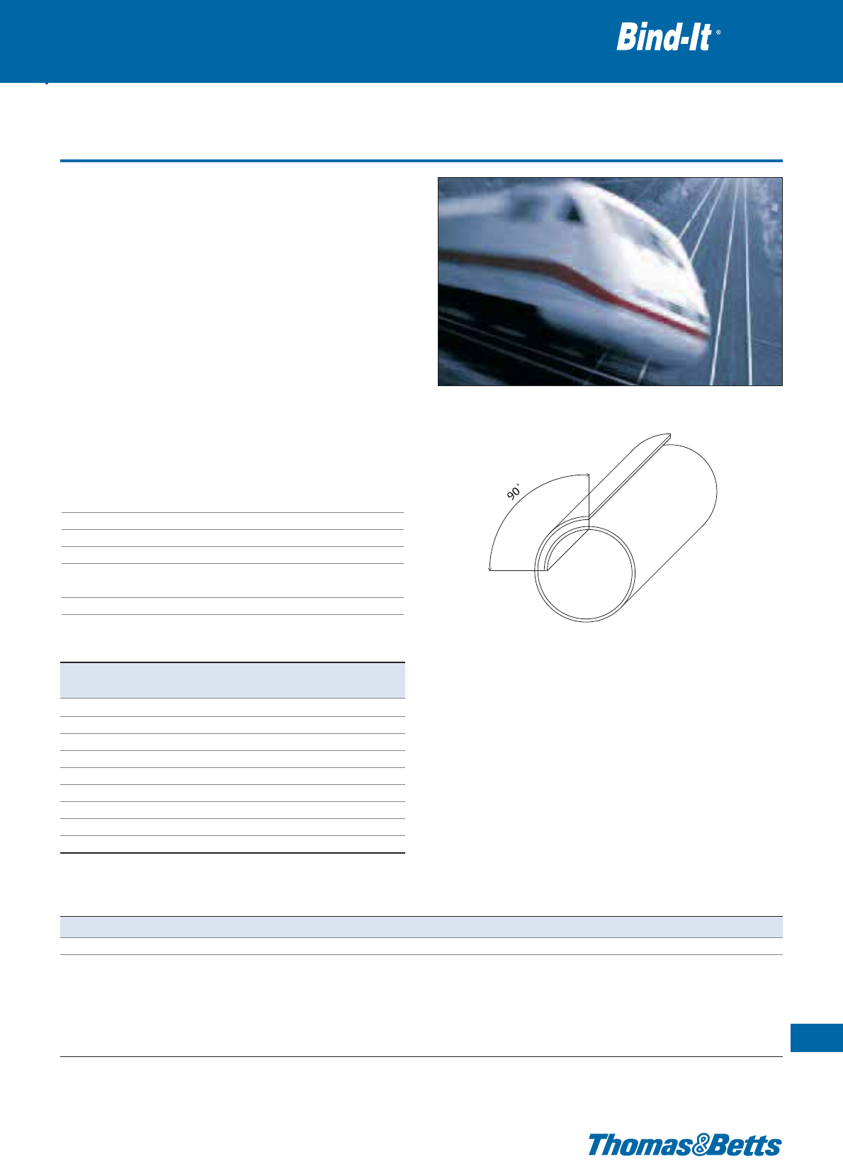
Wrap-around woven sleeving - Flame retardant
• Wrap-around sleeving manufactured from flame-retardant poly-
ester monofilaments and multifilaments
• Designed for mechanical protection and maintenance of wire and
cable bundles
• Its construction with 100% covering ratio provides excellent
cut-through and abrasion resistance
• Bind-It®has many applications in the marine, railway and electronic
industries
• No heat is required to seal the ends of this product as with tradi-
tional braided sleeving
• With its wrap-around design, it can be installed on assemblies where
the wires are already terminated or wires need to be broken-out
• Bind-It®is available in nominal sizes from 5 mm to 50 mm
• A professional assembly tool is supplied for the 5 mm, 8 mm and
13 mm nominal sizes
• For a UL version please contact your Sales Office
Technical Information
Material Mono and multifilaments of polyester
Temperature range -50°C to +125°C
Melt temperature +250°C (ASTM D-2117)
Colour Black
Flammability rating Flame retardant (I3-F2) according to
NF16 101 & NF16 102
Other properties Halogen free, Silicone free
Cable protection systems
117
Thomas & Betts • www.tnb-europe.com
1.5
Product Ref. Nominal
Size* Length per mini-reel
[mm] [m]
CPS05W-150-FR 5 150
CPS08W-100-FR 8 100
CPS13W-50-FR 13 50
CPS19W-25-FR 19 25
CPS25W-25-FR 25 25
CPS29W-25-FR 29 25
CPS32W-25-FR 32 25
CPS38W-25-FR 38 25
CPS50W-25-FR 50 25
Property Test method Typical performance
Low temperature flexibility MIL-DTL-23053E -50°C
Fluid resistance MIL-I-23053 Tensile retention
• Jet fuel: JP-41 100 %
• Hydraulic fluid: (MIL-H-5606) 100 %
• Lube oil: (MIL-I-7808) 100 %
• De-icing fluid: (MIL-A-8243) 100 %
• Salt Water: (O-S-1926) 100 %
Material Specification
* Nominal size is determined by wrapping the product around a mandrel of
a given size to obtain 90 degrees of overlap (average value).
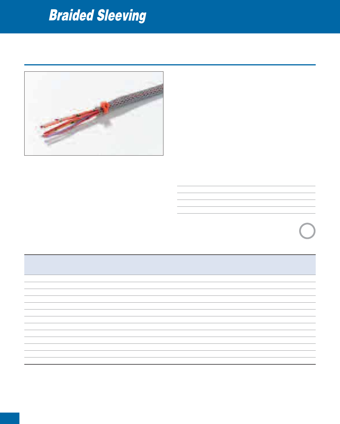
118
Thomas & Betts • www.tnb-europe.com
1.5
Braided sleeving
• Standard colour – black or grey
• Non-flame retardant Polyester rated at UL 94 V-2
• Available in nominal diameters from 3 to 50 mm to cover bundle
diameters of 1 to 66 mm, giving flexibility when adding to or
removing cables from wire looms
• For use in temperature ranges from -50°C to +150°C
• Good chemical resistance
• Halogen free
• For protecting and bundling cables and wires inside cabinets and
enclosures
To stop the ends of the sleeving fraying it is necessary to heat seal the
ends using a “hotwire” device. (see Product Ref. WT-HSG)
Technical Information
Material Polyester
Temperature range -50°C to +150°C
Colour Black or grey
Flammability rating UL 94 V-2
Other properties Good chemical resistance, Halogen free
Cable protection systems
1:2
Product Ref. Product Ref. Nominal Diameter Expandable Length per
Black Grey as supplied Diameter Range mini-reel
[mm] [mm] [m]
CPS3B-100 CPS3G-100 3 1 - 5 100
CPS4B-100 CPS4G-100 4 2 - 7 100
CPS5B-100 CPS5G-100 5 3 - 9 100
CPS6B-100 CPS6G-100 6 4 - 11 100
CPS8B-100 CPS8G-100 8 5 - 12 100
CPS10B-100 CPS10G-100 10 7 - 15 100
CPS12B-50 CPS12G-50 12 8 - 17 50
CPS15B-50 CPS15G-50 15 10 - 20 50
CPS20B-25 CPS20G-25 20 14 - 26 25
CPS25B-25 CPS25G-25 25 18 - 34 25
CPS30B-25 CPS30G-25 30 20 - 40 25
CPS40B-25 CPS40G-25 40 30 - 50 25
CPS50B-25 CPS50G-25 50 40 - 66 25
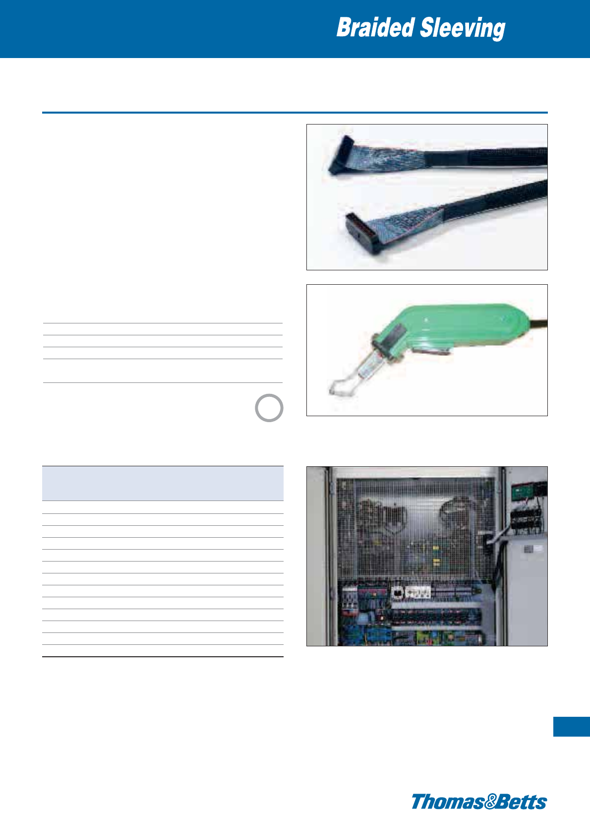
Braided sleeving - Flame retardant
• Standard colour – black with grey identification yarn
• Flame-retardant polyester, rated at UL 94 V-0
• Available in nominal diameters from 3 mm to 50 mm to cover
bundle diameters of 2 mm to 60 mm, giving flexibility when
adding to or removing cables from wire looms
• For use in temperature ranges from -50°C to +150°C
• Good chemical resistance
• Excellent abrasion resistance
• For protecting and bundling cables and wires inside cabinets and
enclosures
To stop the ends of the sleeving fraying it is necessary to heat seal the
ends using a “hotwire” device. (see Product Ref. WT-HSG)
Technical Information
Material Flame-retardant polyester
Temperature range -50°C to +150°C
Colour Black with grey identification yarn
Flammability rating UL 94 V-0
Other properties Good chemical resistance, excellent
abrasion resistance
Cable protection systems
119
Thomas & Betts • www.tnb-europe.com
1.5
Product Ref. WT-HSG
Product Ref. Nominal Diameter Expandable Length per
as supplied Diameter Range mini-reel
[mm] [mm] [m]
CPS3B-100-V0 3 2 - 5 100
CPS4B-100-V0 4 3 - 7 100
CPS5B-100-V0 5 4 - 9 100
CPS6B-100-V0 6 5 - 11 100
CPS8B-100-V0 8 7 - 13 100
CPS10B-50-V0 10 9 - 15 50
CPS12B-50-V0 12 11 - 17 50
CPS15B-50-V0 15 13 - 20 50
CPS20B-50-V0 20 18 - 25 50
CPS25B-50-V0 25 22 - 30 50
CPS30B-50-V0 30 27 - 40 50
CPS40B-50-V0 40 35 - 50 50
CPS50B-50-V0 50 45 - 60 50
Grey sleeving and other lengths available to special order, please contact
your Sales Office
1:2
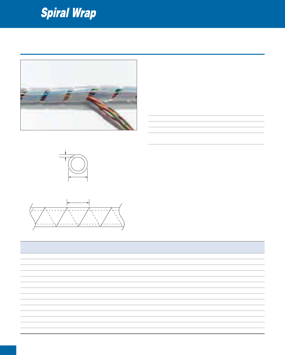
120
Thomas & Betts • www.tnb-europe.com
1.5
Spiral wrap
• For protection of bundles from 4 mm to 130 mm
• Install gapped for greater flexibility or butted for maximum abrasion
resistance, insulation and rigidity
• Counter-clockwise cut
• Delivered in bags with Euroslot
• Available in natural and UV-resistant black Polyethylene
Technical Information
Material Polyethylene
Temperature range -40°C to +100°C
Colour Natural and UV-resistant black
Flammability rating UL 94 HB
Other properties UV-resistant (black), Halogen free,
Silicone free
Cable protection systems
Nominal thickness
Outer diameter
Pitch
Product Ref. Colour Outer diameter Pitch Nominal thickness Min. - max. bundle ø Length
[mm] [mm] [mm] [mm] [m]
SRPE-6-9 natural 6.0 7.0 0.5 4 - 50 10
SRPE-8-9 natural 8.0 10.8 0.5 6 - 60 10
SRPE-10-9 natural 10.0 11.4 0.8 7.5 - 60 10
SRPE-12-9 natural 12.0 13.9 0.9 9 - 65 10
SRPE-15-9 natural 15.0 15.0 1.0 12 - 70 10
SRPE-19-9 natural 19.0 18.2 1.3 15 - 100 10
SRPE-24-9 natural 24.0 19.6 1.5 20 - 130 10
SRPE-6-0 UV-resistant black 6.0 7.0 0.5 4 - 50 10
SRPE-8-0 UV-resistant black 8.0 10.8 0.5 6 - 60 10
SRPE-10-0 UV-resistant black 10.0 11.4 0.8 7.5 - 60 10
SRPE-12-0 UV-resistant black 12.0 13.9 0.9 9 - 65 10
SRPE-15-0 UV-resistant black 15.0 15.0 1.0 12 - 70 10
SRPE-19-0 UV-resistant black 19.0 18.2 1.3 15 - 100 10
SRPE-24-0 UV-resistant black 24.0 19.6 1.5 20 - 130 10
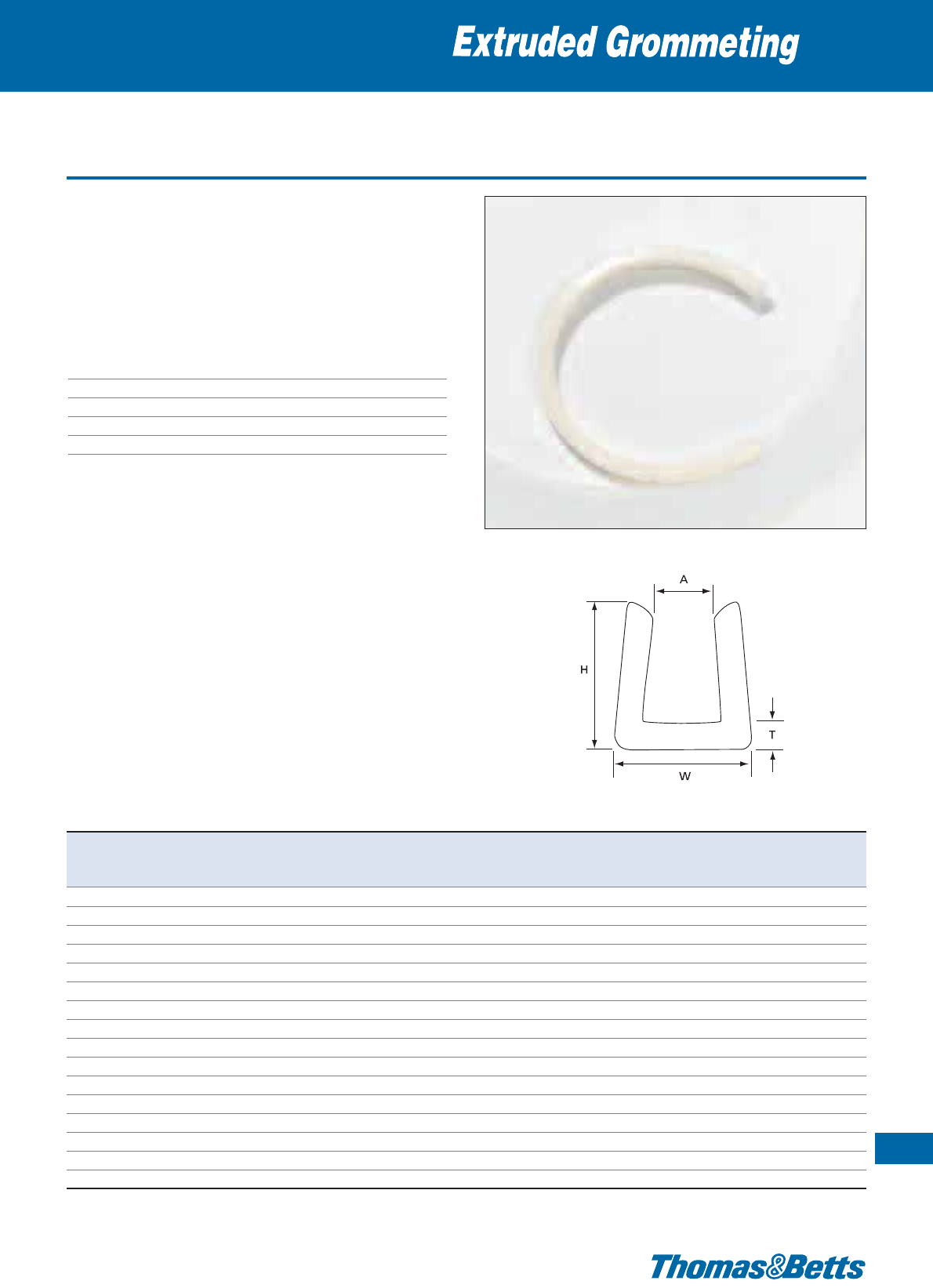
Extruded grommeting
• Used to line panel edges and knock-outs where the chafing of
passing wires is a concern
• Available in 8 stock sizes in 30.5 m lengths for panels from 1 mm
to 6.35 mm
• In most applications, grommeting will grip tightly by itself, if not,
a touch of Epoxy will keep it in place
Technical Information
Material Polyamide 6.6
Temperature range -40°C to +85°C
Colour Natural or black
Flammability rating UL 94 V-2
Other properties Halogen free, Silicone free
Cable protection systems
121
Thomas & Betts • www.tnb-europe.com
1.5
Product Ref. Colour Internal width Thickness Length per reel
ATHW
[mm] [mm] [mm] [mm] [m]
GRNY-040-9-C natural 1.01 1.01 4.82 3.17 30.5
GRNY-052-9-C natural 1.32 1.01 4.82 3.17 30.5
GRNY-062-9-C natural 1.57 1.14 5.08 4.32 30.5
GRNY-085-9-C natural 2.15 1.14 5.08 4.32 30.5
GRNY-100-9-C natural 2.54 1.14 5.58 5.33 30.5
GRNY-125-9-C natural 3.17 1.27 5.58 5.23 30.5
GRNY-187-9-C natural 4.74 1.27 6.85 6.98 30.5
GRNY-250-9-C natural 6.35 1.27 7.11 9.39 30.5
GRNY-040-0-C black 1.01 1.01 4.82 3.17 30.5
GRNY-052-0-C black 1.32 1.01 4.82 3.17 30.5
GRNY-062-0-C black 1.57 1.14 5.08 4.32 30.5
GRNY-085-0-C black 2.15 1.14 5.08 4.32 30.5
GRNY-100-0-C black 2.54 1.14 5.58 5.33 30.5
GRNY-125-0-C black 3.17 1.27 5.58 5.23 30.5
GRNY-187-0-C black 4.74 1.27 6.85 6.85 30.5
GRNY-250-0-C black 6.35 1.27 7.11 9.39 30.5

122
Thomas & Betts • www.tnb-europe.com
Ty-Rap®and Ty-Met™
Tooling
1.6

123
Thomas & Betts • www.tnb-europe.com
1.6
FASTENING SYSTEMS
1.1 PREMIUM CABLE TIES WITH STEEL LOCKING BARB 4
1.2 ALL-PLASTIC CABLE TIES 44
1.3 STAINLESS STEEL CABLE TIES 64
1.4 MOUNTING BASES & ACCESSORIES 74
1.5 CABLE PROTECTION SYSTEMS 112
1.6 CABLE TIE TOOLING 122
Selection chart 126
Tools for plastic cable ties 127
Tools for stainless steel ties 131
1.7 MATERIAL SPECIFICATIONS 134

124
Thomas & Betts • www.tnb-europe.com
Ty-Rap®and Ty-Met™
Tooling
Thomas & Betts offers a comprehensive range of tooling
to complement the full range of cable ties.
The range includes low-cost tools for maintenance and
small batch requirements, as well as robust and ergonomic
tools with tension setting and automatic cutting.
In particular, the new ERG50 and ERG120 tools provide a superior
level of reliability and performance, combined with enhanced
ergonomics and comfort of use.
These ergonomic tools, with adjustable tension and automatic
cutting, are ideally suited for efficiently installing all kinds of plastic
cable ties in industrial (Original Equipment Manufacturers,
Maintenance and Repair Organisations, etc) and construction
applications.
1.6

125
Thomas & Betts • www.tnb-europe.com
Cable tie fastening tools to install,
tension and cut
plastic and metal ties
1.6
ERG50 & ERG120
Superior reliability and performance
• Developed to meet the market needs for a more rugged and
longer lasting tool
• Designed to integrate the greatest number of features in the
market
Enhanced ergonomics and comfort of use
• First class design and materials, for maximum convenience
• As a result, the operator is subject to less stress, less fatigue and
less risk of trauma due to long term use (such as Carpal Tunnel
Syndrome)
Increased efficiency
• Exclusive features for quick set-up and fast installation
• Confidence to achieve a highly professional result, installation
after installation
126
Thomas & Betts • www.tnb-europe.com
Selection guide
Fastening tools
Tooling Ref. Features Tensioning Cutting For cable ties Page
TOOLING FOR PLASTIC TIES
ERG50 Ergonomic hand tool with superior level adjustable automatic 2.4 mm - 4.8 mm 127
of reliability and performance
WT199 Semi- automatic MIL specified hand tool adjustable automatic 2.4 mm - 4.8 mm 128
(MIL. Nr. MS-90387-1)
WT193A Robust construction, ideal for adjustable automatic 2.4 mm - 4.8 mm 128
industrial mass finishing applications
like cable-tree assemblies
WT1-TB Basic tensioning tool, intended for basic twist cut 2.4 mm - 4.8 mm 130
maintenance and small batch use
ERG120 Ergonomic hand tool with superior level adjustable automatic 4.8 mm - 7.6 mm 127
of reliability and performance
WT197 Semi-automatic MIL specified hand tool adjustable automatic 4.8 mm - 7.6 mm 128
(MIL. Nr. MS-90387-2)
WT2-TB Basic tensioning tool, intended for basic twist cut 4.8 mm - 7.6 mm 130
maintenance and small batch use
L300-FR Rugged construction with field basic manual 7.6 mm-9mm 129
proven durability
WT3D Robust metal body with plastic hand-grips, basic twist cut 7.6 mm - 12.7 mm 129
designed for tensioning and cutting
heavy-duty cable ties
L-500-EU Rugged metallic construction adjustable automatic 4.7 mm - 13.3 mm 129
TOOLING FOR TY-MET™ STAINLESS STEEL TIES
CT1-TB Tensioning hook provides extra-leverage basic no cutting Releasable 133
for tensioning the ties by hand & Ladder Type
CT2-TB Basic hand tool basic no cutting Releasable 132
& Ladder Type
CT4-TB Bantam tool, unique 3-way handle can be basic manual Releasable 133
used in various positions. Especially useful & Ladder Type
in tight areas with minimal access
WT3S A robust metallic hand tool with basic no cutting Ladder Type 132
rubber grips
CT3 Economic tensioning tool basic manual Ladder & 131
Ball-Lock Type
CT5 Adjustable tension setting tool adjustable automatic Ladder Type 131
with automatic cutting
CT6 Adjustable tension setting tool adjustable automatic Ball-Lock Type 131
with automatic cutting
1.6

Tools for plastic cable ties
The new ERG50 and ERG120 tools from Thomas & Betts provide a
superior level of reliability and performance, combined with enhanced
ergonomics and comfort of use.
These ergonomic tools, with adjustable tension and automatic
cutting, are ideally suited for efficiently installing all kinds of plastic
cable ties in industrial (Original Equipment Manufacturers, Mainte-
nance and Repair Organisations, etc) and construction applications.
Developed to meet the market needs for a more rugged and longer
lasting tool, and to integrate the greatest number of features in the
market:
•
360° rotating nose (patented), allows the tool to be used in any
position
•
Tension adjustment lock, for constant tension setting
•
Quick tension-adjustment wheel located towards the front for
easy access and fast changes
•
Adjustable handle span fits large and small hands.
•
Anti-recoil mechanism (patented) reduces vibration shock
•
First class design and materials: ergonomic shape with rounded
edges, soft rubber handles, well balanced center of gravity
•
Longest stroke length on the market (25.4 mm), meaning less
tensioning cycles, for time and cost saving
•
High / low force setting (patent pending), for a selection between
“high force & long stroke” or “low force & short stroke”
•The cable tie is cut flush to the head, with no remaining protrusion,
and the cut tail remains captive in the tool for a cleaner installation
•
Easy access to spare blade nest, always a spare blade at hand
(each tool is supplied with a spare blade)
Technical Information ERG50
Tool type Ergonomic hand tool
Nose colour Black
For type of cable tie Plastic ties
Fortiewidth 2.4mm-4.8mm
Features Adjustable tension setting, automatic
cutting, retraction of the strap end after
application of Ty-Rap
®
cable ties
Weight 260 g
Dimensions[LxWxH] 178x127x38mm
Replacement blades Product Ref. ERG50B
Technical Information ERG120
Tool type Ergonomic hand tool
Nose colour Orange
For type of cable tie Plastic ties
Fortiewidth 4.8mm-7.6mm
Features Adjustable tension setting, automatic
cutting, retraction of the strap end after
application of Ty-Rap
®
cable ties
Weight 278 g
Dimensions[LxWxH] 178x127x38mm
Replacement blades Product Ref. ERG120B
Fastening tools
127
Thomas & Betts • www.tnb-europe.com
1.6
ERG120
ERG50
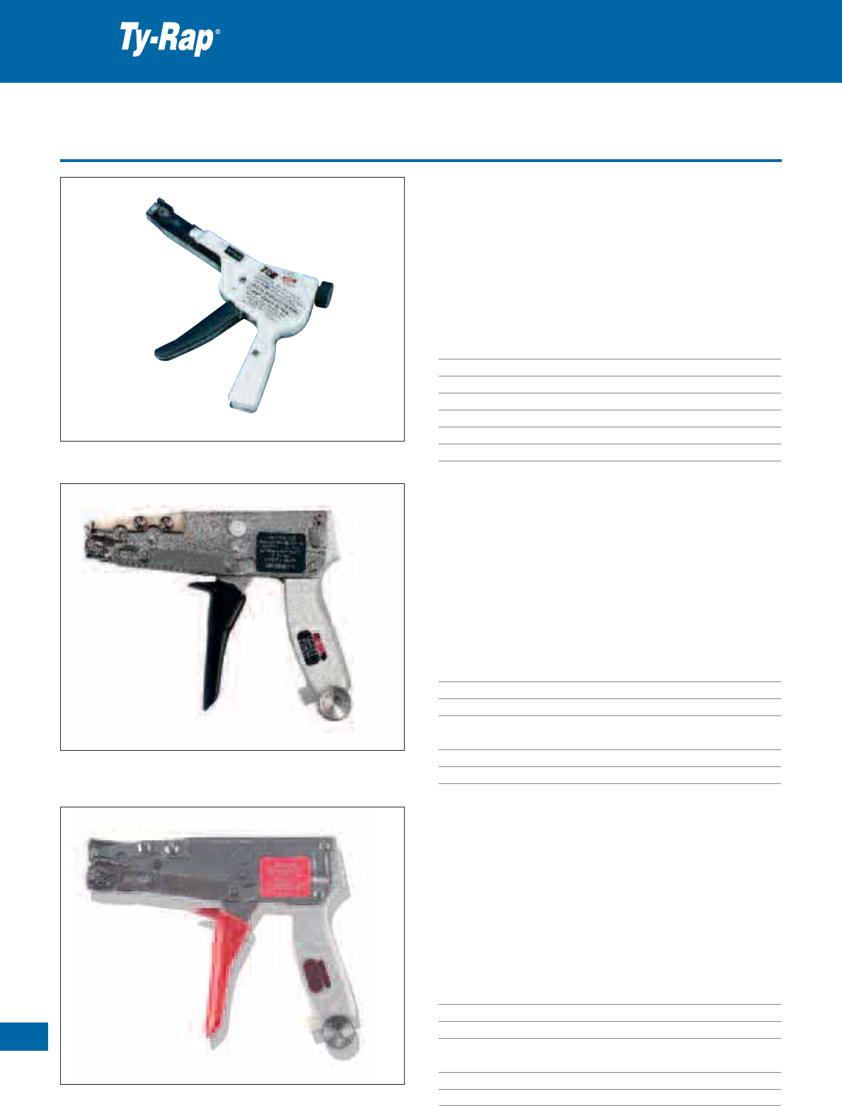
128
Thomas & Betts • www.tnb-europe.com
1.6
Tools for plastic cable ties
Product Ref.: WT193A
• High quality hand tool, to bind, tension and cut in one operation
• Solid lightweight metal body
• Tension setting to ensure product consistency
• Robust construction, ideal for industrial mass finishing applications
like cable-tree assemblies
Technical Information
Tool type Heavy-duty hand tool
For type of cable tie Plastic ties
For tie width 2.4 mm - 4.8 mm
Features Adjustable tension setting, automatic cutting
Weight 300 g
Dimensions [L x W x H] 182 x 135 x 19.5 mm
Replacement blades Product Ref. R464201
Product Ref.: WT199
• Semi- automatic hand tool
• MIL. Nr. MS-90387-1
• Tension setting to ensure product consistency
• Robust metal construction
• Ideal for industrial mass finishing applications like cable tree as-
semblies, for example in the military industry
Technical Information
Tool type Semi-automatic hand tool
For type of cable tie Plastic ties
For tie width 2.4 mm - 4.8 mm
Features Adjustable tension setting, automatic
cutting, MIL specified (MS-90387-1)
Weight 410 g
Dimensions [L x W x H] 163 x 134 x 24 mm
Product Ref.: WT197
• Semi-automatic hand tool
• MIL. Nr. MS-90387-2
• Tension setting to ensure product consistency
• Robust metal construction
• Ideal for industrial mass finishing applications like cable tree
assemblies, for example in the military industry
Technical Information
Tool type Semi-automatic hand tool
For type of cable tie Plastic ties
For tie width 4.8 mm - 7.6 mm
Features Adjustable tension setting, automatic
cutting, MIL specified (MS-90387-2)
Weight 420 g
Dimensions [L x W x H] 165 x 135 x 29 mm
Fastening tools
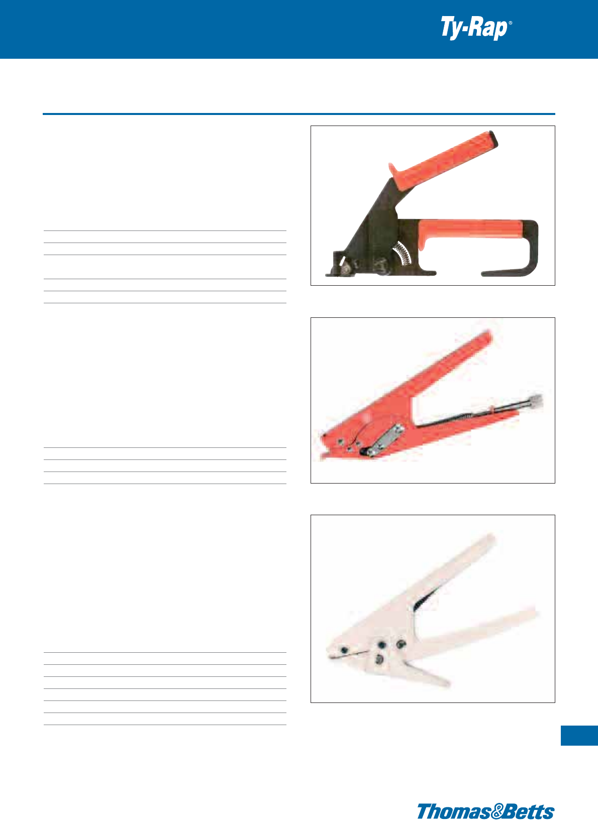
Tools for plastic cable ties
Product Ref.: WT3D
• Designed for tensioning and cutting heavy-duty cable ties
• Robust metal body with plastic hand-grips
Technical Information
Tool type Hand tool for Deltec ties, Col-Ty™
installation ties and other wide cable ties
For type of cable tie Plastic ties
Fortiewidth 7.6mm-12.7mm
Features Tensioning, manual cutting (by twisting
the tool)
Weight 225 g
Dimensions [L x W x H] 178 x 112 x 20 mm
Product Ref.: L-500-EU
• Rugged metallic construction makes this tool ideal for use with
our 4.7 mm to 13.3 mm wide ties
• Set tension adjuster to give desired tie tightness
• Pull trigger and tie is automatically tensioned and cut
Technical Information
Tool type Hand tool
For type of cable tie Plastic ties
Fortiewidth 4.7mm-13.3mm
Features Tensioning, automatic cutting
Product Ref.: L300-FR
• Rugged construction makes this tool ideal for use with our
7.6 mm to 9 mm wide ties
• Pull tie to desired tension and pull trigger to cut excess flush at
cable tie head
• Field proven durability
Technical Information
Tool type Hand tool for Col-Ty™ installation ties
and other wide cable ties
Colour White
For type of cable tie Plastic ties
Fortiewidth 7.6mm-9mm
Features Tensioning, manual cutting
Weight 330 g
Dimensions[LxWxH] 195x100x25mm
Fastening tools
129
Thomas & Betts • www.tnb-europe.com
1.6
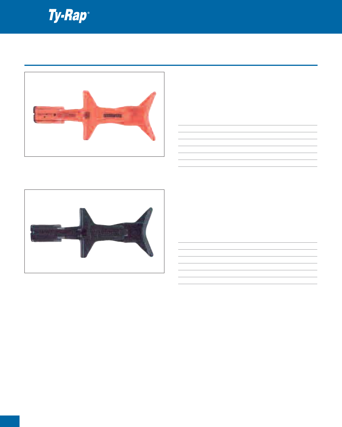
130
Thomas & Betts • www.tnb-europe.com
1.6
Tools for plastic cable ties
Product Ref.: WT1-TB
• Twist-and-cut tensioning tool in plastic, intended for maintenance
and small batch use
Technical Information
Tool type Low-cost hand tool
Colour Orange
For type of cable tie Plastic ties
For tie width 2.4 mm - 4.8 mm
Features Basic tensioning, twist cut
Weight 28.4 g
Dimensions [L x W x H] 134 x 55 x 27 mm
Product Ref.: WT2-TB
• Twist-and-cut tensioning tool in plastic, intended for maintenance
and small batch use
Technical Information
Tool type Low-cost hand tool
Colour Black
For type of cable tie Plastic ties
For tie width 4.8 mm - 7.6 mm
Features Basic tensioning, twist cut
Weight 28.4 g
Dimensions [L x W x H] 134 x 55 x 27 mm
Fastening tools
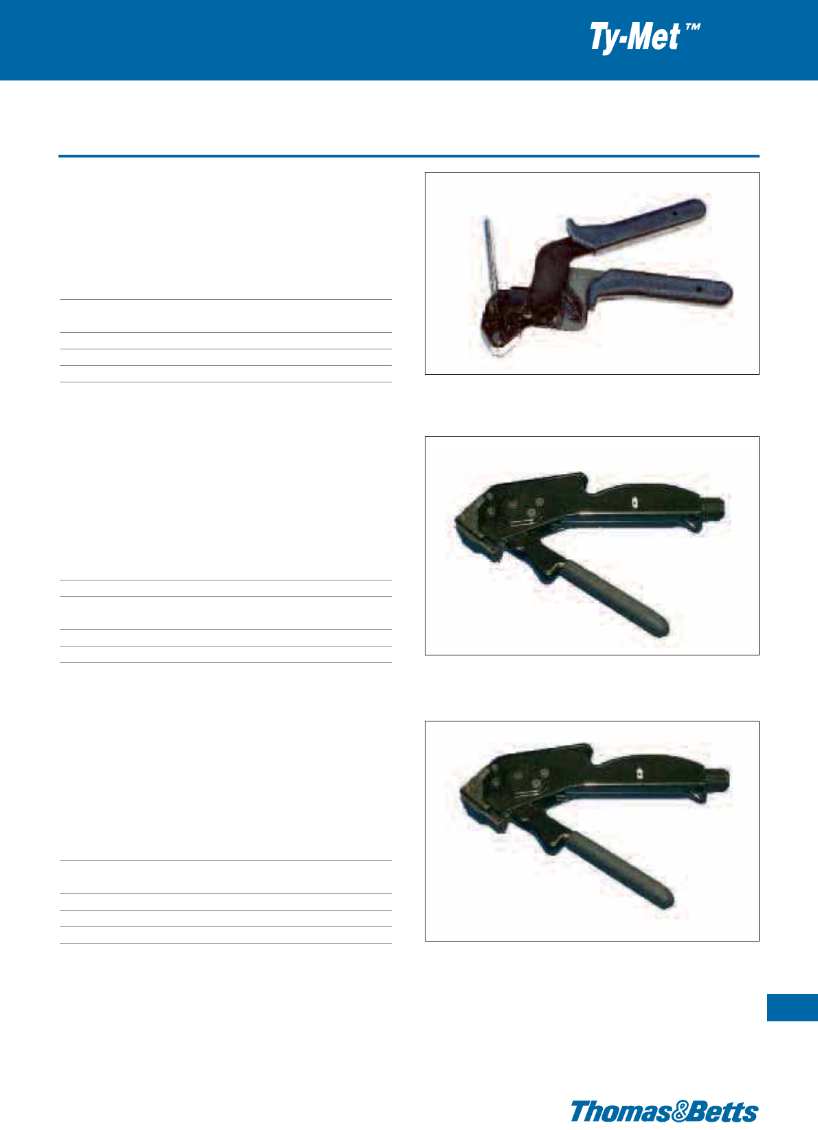
Tools for stainless steel ties
Product Ref.: CT3
• Cost-effective tensioning tool
• Cut-off by hand-activated lever
Technical Information
Tool type Hand tool
For type of cable tie Ladder Type & Ball-Lock Type stainless
steel ties, coated and uncoated
Features Tensioning, manual cutting
Weight 550 g
Dimensions [L x W x H] 210 x155 x 35 mm
Product Ref.: CT5
• Suitable for coated and uncoated Ladder Type stainless steel ties
• Adjustable tension settings
• Automatic cutting once desired tension has been reached
Technical Information
Tool type Tension setting hand tool
For type of cable tie Ladder Type stainless steel ties
Features Adjustable tension setting,
automatic cutting
Weight 430 g
Dimensions [L x W x H] 173 x 158 x 22 mm
Product Ref.: CT6
• Suitable for coated and uncoated Ball-Lock Type stainless steel ties
• Adjustable tension settings
• Automatic cutting once desired tension has been reached
Technical Information
Tool type Tension setting hand tool
For type of cable tie Ball-Lock Type stainless steel ties,
coated and uncoated
Features Adjustable tension setting, automatic cutting
Weight 430 g
Dimensions[LxWxH] 173x158x22mm
Fastening tools
131
Thomas & Betts • www.tnb-europe.com
1.6
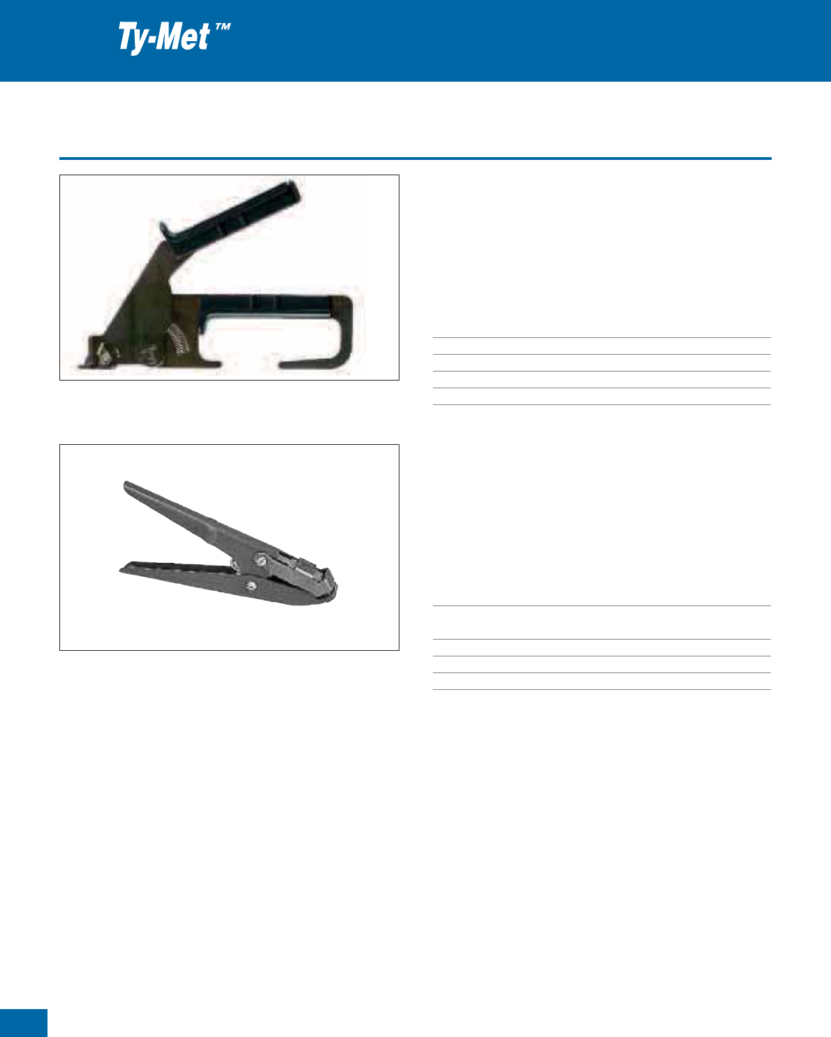
132
Thomas & Betts • www.tnb-europe.com
1.6
Tools for stainless steel ties
Product Ref.: WT3S
• A robust metallic hand tool with rubber grips designed for ten-
sioning Ladder Type stainless steel ties
• After tensioning, the stainless steel ties can easily be cut with side-
cutters
Technical Information
Tool type Hand tool
For type of cable tie Ladder Type stainless steel ties
Features Tensioning, no cutting
Weight 225 g
Dimensions [L x W x H] 178 x 112 x 20 mm
Product Ref.: CT2-TB
• Cable tie tensioner suitable for Releasable Type and Ladder Type
stainless steel ties
• Tensions the ties to their optimum holding power with a simple
squeeze: a flick of the wrist and they’re locked tight
Technical Information
Tool type Hand tool
For type of cable tie Releasable Type and Ladder Type
stainless steel ties
Features Tensioning, no cutting
Weight 300 g
Dimensions [L x W x H] 195 x 90 x 30 mm
Fastening tools
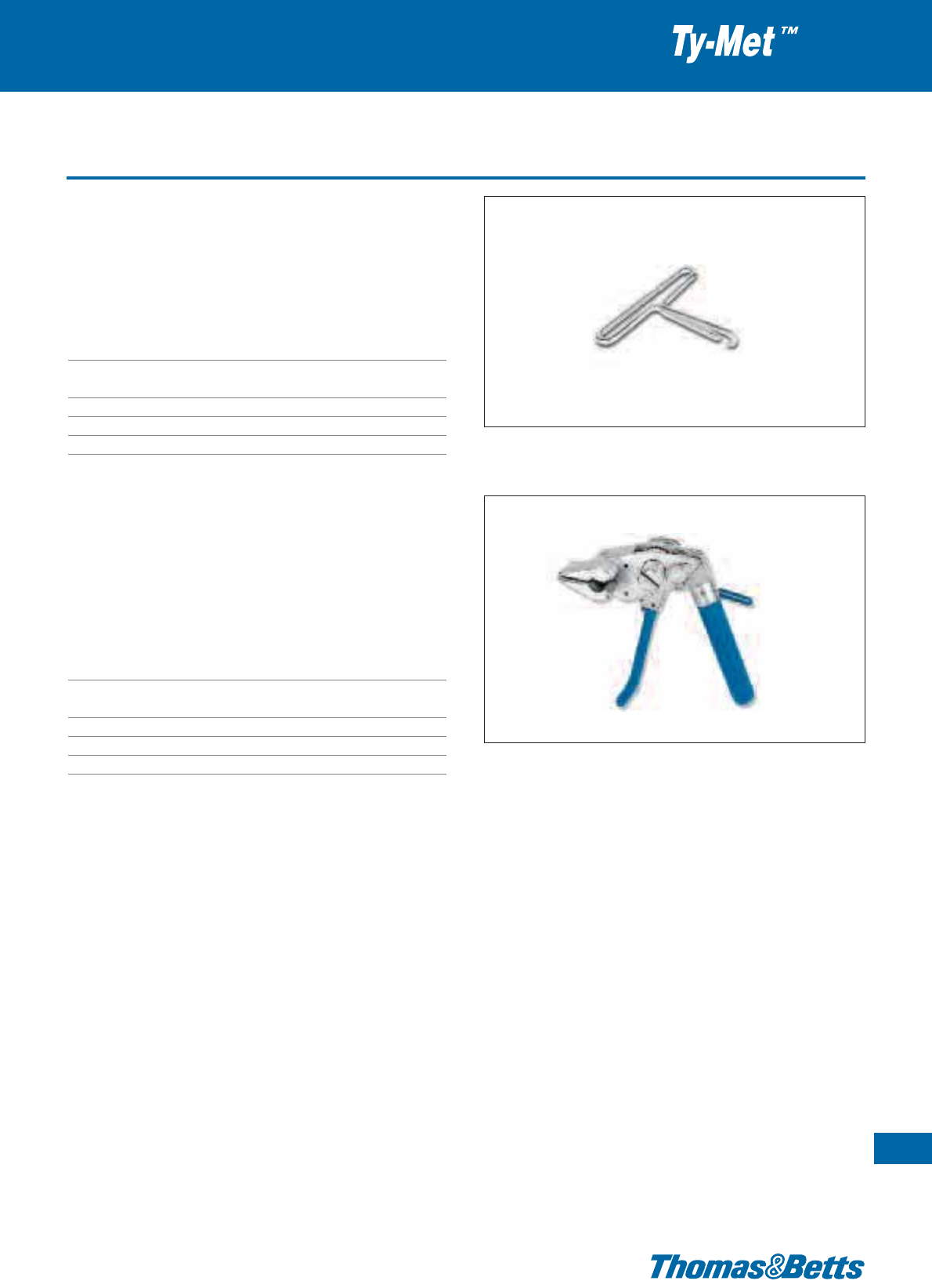
Tools for stainless steel ties
Product Ref.: CT1-TB
• Tensioning hook suitable for Releasable Type and Ladder Type
stainless steel ties
• Provides extra-leverage for tensioning the ties by hand
Technical Information
Tool type Hand tool
For type of cable tie Releasable Type and Ladder Type
stainless steel ties
Features Tensioning, no cutting
Weight 50 g
Dimensions [L x W x H] 85 x 106 x 15 mm
Product Ref.: CT4-TB
• Bantam tool, suitable for Releasable Type and Ladder Type stainless
steel ties
• Unique 3-way handle can be used in various positions. Especially
useful in tight areas with minimal access
Technical Information
Tool type Hand tool
For type of cable tie Releasable Type and Ladder Type
stainless steel ties
Features Tensioning, manual cutting
Weight 1200 g
Dimensions [L x W x H] 156 x 180 x 80 mm
Fastening tools
133
Thomas & Betts • www.tnb-europe.com
1.6
134
Thomas & Betts • www.tnb-europe.com
Material specifications
1.7
Thomas & Betts • www.tnb-europe.com
FASTENING SYSTEMS
1.1 PREMIUM CABLE TIES WITH STEEL LOCKING BARB 4
1.2 ALL-PLASTIC CABLE TIES 44
1.3 STAINLESS STEEL CABLE TIES 64
1.4 MOUNTING BASES & ACCESSORIES 74
1.5 CABLE PROTECTION SYSTEMS 112
1.6 CABLE TIE TOOLING 122
1.7 MATERIAL SPECIFICATIONS 134
UL flammability ratings 136
Adhesive material specifications 137
Material selection and specifications 138
Unit conversion factors 145
135
1.7
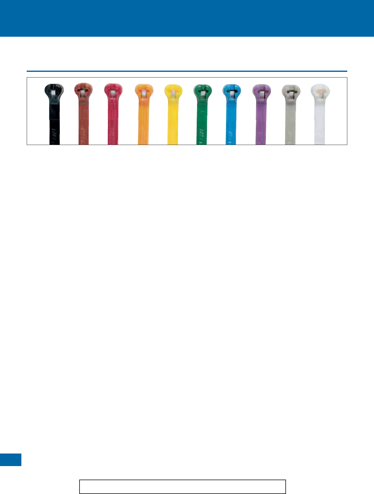
136
Thomas & Betts • www.tnb-europe.com
UL flammability ratings
Materials specifications
1.7
Nylon 6.6 = Polyamide 6.6 is Halogen-free and Silicone-free.
Flammability ratings for selecting cable ties
Note: Flammability ratings of cable tie materials per UL as follows.
These tests for flammability of plastic material are intended to serve as
a preliminary indication of acceptability with respect to flammability
for particular applications.
UL 94 vertical burn test procedures
Test specimens of the material, with dimensions 127 x 12.7 mm (5"x
1/2"), with the thickness intended for use in the end product, are
tested in both the manufactured condition and in the aged state. The
test requires that the specimen be supported in a vertical fixture and a
precisely controlled flame applied for a 10 second period. The flame is
removed and the duration of flaming is noted. If the flame
extinguishes, a second exposure to flame for 10 seconds is applied and
duration of flaming is again noted. It is observed and recorded
whether or not test specimens drip flaming particles that ignite a
cotton swab.
Materials classed 94 V-0:
A material classed 94 V-0 shall:
A Not have any specimens that burn with flaming combustion for
more than 10 seconds after either application of the test flame
B Not have a total flaming combustion time exceeding 50 seconds
for the 10 flame applications for each set of five specimens
C Not have any specimens that burn with flaming or glowing
combustion up to the holding fixture
D Not have any specimens that drip flaming particles that ignite the
dry absorbent surgical cotton located 304.8 mm (12") below the
test specimen
E Not have any specimens with glowing combustion that persists
for more than 30 seconds after the second removal of the test
flame
Materials classed 94 V-1:
A material classed 94 V-1 shall:
A Not have any specimens that burn with flaming combustion for
more than 30 seconds after either application of the test flame
B Not have a total flaming combustion time exceeding 250 seconds
for the 10 flame applications for each set of five specimens
C Not have any specimens that burn with flaming or glowing
combustion up to the holding fixture
D Not have any specimens that drip flaming particles that ignite
the dry absorbent surgical cotton located 304.8 mm (12")
below the test specimen
E Not have any specimens with glowing combustion that persists
for more than 60 seconds after the second removal of the test
flame.
Materials classed 94 V-2:
A material classed 94 V-2 shall:
A Not have any specimens that burn with flaming combustion
for more than 30 seconds after either application of the test
flame
B Not have a total flaming combustion time exceeding 250 seconds
for the 10 flame applications for each set of five specimens
C Not have any specimens that burn with flaming or glowing
combustion up to the holding fixture
D Be permitted to have specimens that drip flaming particles that
burn only briefly, some of which ignite the dry absorbent sur-
gical cotton placed 304.8 mm (12") below the test specimen
E Not have any specimens with glowing combustion that persists
for more than 60 seconds after the second removal of the test
flame
UL 94 horizontal burn (HB) test procedures
The test uses a 1/2 inch x 5 inches (12.7 mm x 127 mm) specimen
held at one end in a horizontal position with marks at 1 inch (25.4
mm) and 5 inches (127 mm) from the free end. A flame is applied to
the free end for 30 seconds or until the flame front reaches the 1 inch
(25.4 mm) mark. If combustion continues the duration is timed
between the 1 inch (25.4 mm) mark and the 5 inch (127 mm) mark. If
combustion stops before the 5 inch (127 mm) mark, the time of
combustion and the damaged length between the two marks are
recorded. A set of three specimens are tested.
Materials classed 94 HB
A material that is less than 0.118 inch (3 mm) in thickness will be
classified 94HB if it has a burning rate of less than 3 inches (76.2 mm)
per minute or stops burning before the 5 inches (127 mm) mark. If
one specimen from the set of three fails to comply, then a second set
of three are tested. All three of this second set must comply. HB rated
materials are considered “self-extinguishing”. This is the lowest (least
flame retardant) UL94 rating.
Adhesive material specifications
Materials specifications
137
Thomas & Betts • www.tnb-europe.com
1.7
Property Method Unit of measure Rubber based Acrylic based
(self-adhesive) (2 component glue)
Coated Sides – each 2 2
Foam Density – Kg/m3 96.9 96.9
Peel Adhesion PSTC 1 N/cm width 10.9
ASTM D 1000 Average 8.8
Shear Adhesion
22°C 50% RH PSTC 7 Hours 100 + 8 +
22°C Occasional Wetting N/m2 68971 15174
Tensile Strength ASTM D 412 PSI 100 100 +
Tear Resistance ASTM D 624 N/cm 52.6 52.6 +
Elongation at Break – % 400 200
Service Temperature –°CMin-18-29
– °C Max +66 +79
Flammability ASTM D 624 Slow Burn Slow Burn
Product Ref.: TC2PA
• 2 component glue
• Consists of one tube each of adhesive and activator
• Easy application
• Stable and durable adhesion
• Applicable on all Polyamide and Aluminium mounting bases
and cable clamps
• Also applicable on concrete and other porous surfaces
• UV resistant
Technical Information
Description 2 component glue
Weight 0.21 kg
Important note: The quality of installation of the glue mounted and self-
adhesive mounting bases depend a lot on the state of the mounting surfaces
(smooth or rough, clean or dirty, presence of oil, grease, dust, etc) and on
the dexterity of the installer.
Thomas & Betts can not control these external parameters and therefore can
not accept any responsibility about the performances of the glue mounted
mounting bases and self-adhesive mounted bases.
Installation instructions for self-adhesive mounting bases
Installation instructions for Product Ref. :
TC2PA (2 component glue)
• Mounting surfaces should be cleaned before application
• The liquid adhesive in the tube is to be spread onto the mounting
surface. It can be used on most rough surfaces (like concrete)
• The activator liquid is then spread onto the surface of the mounting
base
• Place the surface of the mounting base in contact with the surface
where it has to be mounted, position the mounting base correctly
and then press firmly
• Repositioning the mounting base remains possible only for a few
seconds
• Do not use the mounting base immediately after installation. The
Acrylic-based adhesive requires a set-up time that can be influ-
enced by factors such as temperature (allow 24 - 72 hours for
maximum performance)
• Temperature of installation needs to be above +20°C
• Mounting surfaces should be cleaned with alcohol based (IPA)
cleaner before application
• The self-adhesive mounting bases have a double-sided adhesive
tape made of synthetic foam, covered by a protecting foil.
• To install the self-adhesive mounting base, remove the protecting
foil and press the mounting base onto the cleaned surface
• The thickness of the self-adhesive foam (0.8 mm) compensates
the irregularities of the application surfaces and allows installa-
tions on structured surfaces of cabinet doors, on sheet metal, on
machines, etc
• The adhesion is achieved immediately during the installation,
which means that later repositioning is not possible
138
Thomas & Betts • www.tnb-europe.com
1.7
Material selection and specifications
Materials specifications
UV-resistant Flame retardant Heat resistant Weatherproof Low
temperature
flexibility
Radiation
resistant
Chemically re-
sistant
Polyamide 6.6
• Thermoplastic material used in cable ties for universal applications
in the industry
• Excellent resistance to shocks, chemicals, oils and temperature
fluctuations
• High surface hardness and a small coefficient of friction
• Flammability rating: UL 94 V-2
• Halogen free and Silicone free
• Available in natural version or in a wide range of colours
• Indoor applications
Polyamide 6.6, weather resistant
• Similar to Polyamide 6.6, but recommended for outdoor applica-
tions
• UV-resistant
• Halogen free and Silicone free
• Colour: black
• Flammability rating: UL 94 V-2
Polyamide 6.6, heat stabilised
• Similar to Polyamide 6.6, but increased operating temperatures,
up to 105°C
• Excellent tensile strength
• High temperature resistance
• Colour: natural (may have a greenish tint)
• Flammability rating: UL 94 V-2
Polyamide 6.6, heat stabilised and UV-resistant
• Similar to Polyamide 6.6, but recommended for outdoor applica-
tions and/or high temperature applications, up to 105°C
• Combines the features & benefits of Polyamide 6.6, weather re-
sistant and Polyamide 6.6, heat stabilised
• Colour: black
• Flammability rating: UL 94 V-2
Polyamide 6.6, flame retardant
• Excellent flammability rating: UL 94 V-0
• Ideal in areas where human life is at risk
• Colour: white
Polyamide 6.6, detectable
• Similar to Polyamide 6.6, but contains a compound detectable
by metal detectors (tested and rated at 1.5 mm diameter ferrous
sphere setting) and X-ray equipment
• Colour: bright blue, also contributes to visual detection
• Especially recommend for the food industry, and for any other
contamination sensitive industry using detection equipment
• Halogen free and silicone free
• Flammability rating: UL 94 V-2
Thomas & Betts offers cable ties and accessories in a wide variety of
materials, each suited for specific environments. The purpose of this
document, therefore, is to assist in choosing the best material for a
particular application.
The effects of weathering, flame, chemicals, extreme temperatures
and radiation on the different materials is clearly presented in tabular
Low smoke
form. This will facilitate the choice of the best material for the
application.
Having determined the most suitable material, one can choose from
the wide variety of cable ties, identification ties, mounting bases,
lashing ties, etc., offered by Thomas & Betts.
Selecting the right material for your applications
Material specifications
Note: Nylon (Polyamide) is inherently susceptible to environmental conditions. Polyamide 6.6 cable ties are moisturised to optimum performance
levels at machine-side and should be stored in cool dry areas out of direct sunlight. Cable ties are packaged in plastic bags to contain moisture and
should remain sealed until ready for use.
Detectable
Material selection and specifications
Materials specifications
139
Thomas & Betts • www.tnb-europe.com
1.7
Polyamide 4.6, extra high temperature (150°C)
• Similar to Polyamide 6.6, but outstanding resistance to high tem-
peratures up to 150°C
• Halogen free and silicone free
• Colour: light green
• Flammability rating: UL 94 V-2
Polyamide 12, weather resistant
• Extremely flexible, also at low temperatures
• Ages better than Polyamide 6.6
• UV-resistant and weatherproof
• Better chemical resistance than Polyamide 6.6
• Colour: black
• Flammability rating: UL 94 V-2
Polypropylene, weather resistant
• Resistant against inorganic acids, polyhydric alcohols, neutral and
basic salts
• Resists a number of other chemicals
• UV resistant
• Lower tensile strength than Polyamide 6.6
• Colour: black
• Flammability rating: UL 94 HB
Polypropylene, detectable
• Similar to standard Polypropylene, but contains a compound
detectable by metal detectors (tested and rated at 1.5 mm dia-
meter ferrous sphere setting) and X-ray equipment
• Colour: bright blue, also contributes to visual detection
• Buoyant (floats on the surface), for use in liquid-processing appli-
cations
• Especially recommend for the food industry, and for any other
contamination sensitive industry using detection equipment
• Halogen free and silicone free
• Flammability rating: UL 94 HB
ETFE Fluoropolymer
• Tensile strength slightly lower than Polyamide 6.6
• ETFE Fluoropolymer is inert to most solvents and chemicals,
hydrolytically stable, UV and weather resistant
• Radiation resistant (meets IEEE383) and approved for nuclear
plant use
• Non-outgassing properties for zero gravity applications
• Very high temperature resistance
• Flammability rating: UL 94 V-0
• The best all around plastic material for cable ties
• Colour: aquamarine
ECTFE Fluoropolymer
• Similar to ETFE Fluoropolymer in performance
• Outstanding characteristic: lower smoke density when burnt
• Recommended for applications where smoke generation is a con-
cern, such as plenum areas
• Colour: maroon
• Flammability rating: UL 94 V-0
Toughened weatherable acetal
• Excellent resistance to a wide variety of solvents, esters, oils,
greases, gasoline and other petroleum hydrocarbons
• Resistant to weak acids and bases
• Excellent resistance to UV (weatherable acetal)
• Limited self-extinguishing properties
• Colour: black
• Flammability rating: UL 94 HB
302/304 Stainless Steel
316 Stainless Steel
• Superior corrosion resistance
• Excellent tensile strengths at extreme temperatures
• High resistance to chemicals, acids and radiation
• 316 grade has a better resistance to saltwater corrosion and can
be supplied with a halogen free coating
• Extensively used in offshore, rail and petrochemical industries
140
Thomas & Betts • www.tnb-europe.com
1.7
Material selection and specifications
Materials specifications
General
There is a number of factors to be considered when choosing the
proper materials for a specific environment. It is extremely difficult to
provide data on all the possible combinations or conditions that can
occur and therefore, it is recommended that this information be used
as a guideline and that cable tie samples be tested in the intended
application, by the user, to determine suitability.
Polyamide
6.6
Polyamide
6.6
Polyamide
6.6
Polyamide
6.6 heat
Polyamide
6.6
weather resistant* heat stabilised stabilised UV resistant flame retardant
PA6.6 UV PA6.6 HS PA6.6 HSUV PA6.6 FR PA6.6
Material Code TY...M TY...MX TYH...M TY...MXA TY...MFR
TY... TY...X TY...39 TS...HF
Max. operating +85°C +85°C +105°C +105°C +85°C
temperature
Min. operating temp. -40°C -40°C -40°C -40°C -40°C
UL flammability rating V-2 V-2 V-2 V-2 V-0
Specific density 1.14 1.14 1.14 1.14 1.16
Water absorption 2.5 - 3.1% 2.5 - 3.1% 2.5 - 3.1% 2.5 - 3.1% 3.0 - 3.5%
(24h/ASTM)
Colours Natural** Black Natural*** Black White
E-module (N/mm
2
)2000 2000 2000 2000 1400
Notch impact 2-20 2-20 2-20 2-20 3-25
strength conform
DIN 53453
(KJ/m
2
)
UV resistant
■■
Flame retardant
■
Heat resistant
■■
Enhanced weatherability
■
Flexible at low temperatures
Radiation resistant
Chemically resistant See table 2 (pages 142 - 144)
Halogen free
■■ ■ ■ ■
Silicon free
■■ ■ ■ ■
* 2% Carbon for military specifications
** Can be supplied in a wide range of colours
*** May have a greenish tint
Table 1 - Information on cable tie materials
How to use Table 1:
If your application is in an extremely cold environment, three materials
will answer your need:
ETFE Fluoropolymer
, Polyamide 12 and
stainless steel. If you also require high tensile strength, then stainless
steel is your best choice. Where high strength is not required,
Polyamide 12 might be your choice as it is the less costly.
This information is based on data provided by the manufacturers of
the specific materials listed and is provided only as a general guide. No
specific recommendation is intended. As each application may vary,
testing should be conducted by the user in the intended environment.
Table 1 gives relative performance ratings of the different materials we
offer. Chemical resistance is shown in Table 2

Material selection and specifications
Materials specifications
141
Thomas & Betts • www.tnb-europe.com
1.7
Material Code
STANDARD POLYAMIDE 6.6 PA6.6
WEATHER RESISTANT POLYAMIDE 6.6 UV PA6.6
HEAT-STABILISED POLYAMIDE 6.6 HS PA6.6
HEAT-STABILISED UV RESISTANT POLYAMIDE 6.6 HSUV PA6.6
FLAME RETARDANT POLYAMIDE 6.6 FR PA6.6
HIGH TEMPERATURE POLYAMIDE 4.6 HT PA4.6
WEATHER RESISTANT POLYAMIDE 12 UV PA12
POLYPROPYLENE PP
WEATHER RESISTANT POLYPROPYLENE UV PP
ETFE FLUOROPOLYMER
TZ
ECTFE FLUOROPOLYMER
HAL
TOUGHENED WEATHERABLE ACETAL DEL
STAINLESS STEEL SS
Material codes used in tables
Polyamide
4.6
Polyamide
12
Polypropylene ETFE ECTFE Toughened Stainless
high temperature weather resistant weather resistant weatherable acetal Steel
HT PA4.6 UV PA12 UV PP TZ HAL DEL SS
TYHT...M TYC...MX TYP...MX TYZ...M TYV...M TYD... YRL.. or YLD...
CSS or YLS...
TY...PX
+150°C +85°C +85°C +150°C +140°C +85°C +538°C
+150°C for coated
-40°C -40°C -40°C -46°C -40°C -40°C -80°C
V-2 V-2 HB V-0 V-0 HB Excellent
1.18 1.02 0.90 - 0.91 1.67 - 1.75 – – 7.95
1.3% 0.7 - 1.1% 0.01 - 0.03% 0.02% – – 0%
Light green Black Black Aquamarine Maroon Black Metallic / Black
3200 1600 1100-1300 1000 – – 193000
3.5-13 3-17 o.B. – – 122J(IZOD)
■■■■■■
■■ ■
■■■■
■■■■■■
■■
■■
■■■ ■■
■■■■■■■
142
Thomas & Betts • www.tnb-europe.com
1.7
Material selection and specifications
Materials specifications
Reagents Concentration HS PA6.6 HAL DEL PA6.6 UV PA6.6 FR PA6.6 UV PA12 PP UVPP TZ SS
Arsenic Acid 40% – – – – – – – E E – E
Acetaldehyde 50% S – – S S S – – – – –
Acetone 100% E E F E E E E E E E E
Aluminum Hydroxide AQ – E – – – – – E E E E
Ammonia All – E – – – – E E E E
Ammonium Carbonate 5% S E – S S S E E E E E
Ammonium Hydroxide 10% E E F E E E – E E E E
Ammonium Nitrate – – E – – – – E E E E E
Ammonium Sulfate 10% – E – – – – S S S S S
Barium Carbonate All – E – – – – E E E E E
Barium Chloride 5% NR – NR NR NR E E E E E
Barium Sulfate 10% E – E E E E E E E E
Barium Sulfide 10% S – S S S E E E E E
Benzene 100% E E F E E E E S S E E
Benzoic Acid 100% NR E – NR NR NR E E E E E
Butyric Acid 50% NR E – NR NR NR – E E E E
Calcium Carbonate AQ – E – – – – – E E E E
Calcium Hydroxide 20% – F E – – – – E E E E
Calcium Hydrochlorite 2 NR – – NR NR NR – F F F F
Calcium Sulfate 2% – E – – – – – E E E E
Carbon Tetrachloride 100% E E E E E E E F F E E
Chlorine (WET) – NR – – NR NR NR – F F F F
Chlorine (DRY) – NR – – NR NR NR – NR NR F F
Chloroacetic Acid 30% NR – – NR NR NR – – – F F
Chloroform 100% – E – – – – F F F E E
Chromic Acid 50% NR S – NR NR NR – F F F F
Citric Acid 50% S E E S S S E E E E E
Copper Cyanide 10% – E – – – – – E E E E
Copper Nitrate 50% – E – – – – – E E E E
Cider – – E – – – – – E E E E
Dichloroethane 100% – E – – – – – – – E E
Diethyl Ether 100% – E S – – – E E E E E
Ethyl Alcohol 100% S E – S S S E E E E E
Ethyl Chloride 100% – S E – – – F F F E E
Ethylene Glycol 100% E E S E E E – E E E E
Ferric Hydroxide All – E – – – – – E E E E
Ferric Nitrate 10% – E – – – – – E E E E
Ferrous Sulfate 10% – E – – – – – E E E E
Fuel Oil 100% – E – – – – E – – E E
Ratings
E = Excellent
S = Satisfactory
F = Fair
NR = Not Recommended
(AQ = Aqueous)
Table 2 - Resistance of available materials to various chemicals at 21°C
Material selection and specifications
Materials specifications
143
Thomas & Betts • www.tnb-europe.com
1.7
Reagents Concentration HS PA6.6 HAL DEL PA6.6 UV PA6.6 FR PA6.6 UV PA12 PP UVPP TZ SS
Furfural 100% – E – – – – – F F E E
Gallic Acid AQ – E – – – – – – – E E
Gasoline 100% E E – E E E – S S E E
Glycerine 100% – E – – – – E E E – E
Hydrocyanic Acid All – E – – – – – E E E E
Hydrogen Peroxide 30% NR E F NR NR NR S E E E E
Hydrogen Sulfide Dry NR E – NR NR NR E E E E E
Iodoform 100% – E – – – – – – – E E
Isopropyl Alohol 100% S E – S S S E E E E E
Jet Fuel 100% E E – E E E – S S E E
Lactic Acid 10% E E – E E E S E E E E
Lanolin 10% E E – E E E E E E E E
Lead Acetate 5% – E – – – – – E E E E
Linseed Oil 10% E E E E E E E E E E E
Magnesium Carbonate All – E – – – – E E E E E
Magnesium Chloride 10% F – – F F F F F F F F
Magnesium Nitrate All – E – – – – E E E E E
Malic Acid AQ – E – – – – – E E E E
Mercury 100% – E – – – – E E E E E
Methyl Alcohol 100% S E – S S S E E E E E
Methyl Chloride 100% – S – – – – – S S E E
MethylEthyl Ketone 100% – E F – – – E E E E E
Naptha 100% – E – – – – – E E E E
Nitric Acid 30% NR E NR NR NR NR – E E E E
Nitric Acid 30-70% NR S NR NR NR NR – F F S E
Nitrous Acid 5% – E – – – – – F F E E
Oieic Acid 100% – E S – – – – E E E E
Oxalic Acid 10% – E – – – – S E E E E
Paraffin 100% E E – E E E E E E E E
PetroleumEther 100% – E – – – – E F F E E
Phenol 90% NR E NR NR NR NR – E E E E
Phosphoric Acid 10% NR E – NR NR NR – E E E E
Picric Acid 1% – E – – – – – E E E E
Potassium Bromide AQ – – – – – – – S S S S
Potassium Carbonate 1% – E – – – – E E E E E
Potassium Chlorate AQ – E – – – – S E E E E
Potassium Dichromate 40% NR E – NR NR NR F E E E E
Potassium Ferrocyanide 25% – E – – – – – E E E E
Potassium Hydroxide 5% S E – S S S – E E E E
Ratings
E = Excellent
S = Satisfactory
F = Fair
NR = Not Recommended
(AQ = Aqueous)
Table 2 - Resistance of available materials to various chemicals at 21°C

144
Thomas & Betts • www.tnb-europe.com
1.7
Material selection and specifications
Materials specifications
Reagents Concentration HS PA6.6 HAL DEL PA6.6 UV PA6.6 FR PA6.6 UV PA12 PP UVPP TZ SS
Potassium Iodide All – E – – – – E E E E E
Potassium Nitrate 50% F E – F F F E E E E E
Potassium Permanganate 5% NR E S NR NR NR NR E E E E
PotassiumSulfate 5% – E – – – – E E E E E
PotassiumSulfide AQ – E – – – – – E E E E
Propyl Alcohol 100% E E – E E E – E E E E
Silver Nitrate 10% – E – – – – E E E E E
Sodium Acetate 60% E E – E E E – E E E E
Sodium Bicarbonate All E E – E E E E E E E E
Sodium Bisulfate 10% – E E – – – E E E E E
Sodium Borate All – E – – – – – E E E E
Sodium Carbonate 5% E E S E E E E E E E E
Sodium Chlorate 25% – E E – – – S E E E E
Sodium Chloride 2% E E S E E E E E E E E
Sodium Fluoride 5% – – – – – – – F F F F
Sodium Hydroxide 10% E E S E E E E E E E E
Sodium Hyposulfite AQ – E – – – – – – – E E
Sodium Nitrate 5% E E – E E E E E E E E
Sodium Nitrite AQ – E – – – – S E E E E
Sodium Perchlorate 10% – E – – – – – – – E E
Sodium Phosphate 5% – E – – – – E E E E E
Sodium Sulfate 5% S E – S E E E E E E E
Sodium Thiosulfate 5% – – S – – – S S S S S
Stearic Acid 100% – E – – – – F E E E E
Sulfur 100% – E – – – – E E E E E
Sulfur Dioxide All NR E – NR NR NR E E E E E
Sulfuric Acid Conc. NR E NR NR NR NR – S S E E
Sulfuric Acid 5% NR F F NR NR NR F F F F F
Tannic Acid 10% – E – – – – – E E E E
Tartaric Acid 50% – E E – – – E E E E E
Tetrahydrofuran 100% – F E – – – S F F E E
Toluene 100% E E F E E E E F F E F
Xylene 100% E – E E E E F F E E
Zinc Chloride 70% F E NR F F F E E E E E
Zinc Nitrate AQ – E – – – – E E E E E
Zinc Sulfate AQ – E – – – – E E E E E
Ratings
E = Excellent
S = Satisfactory
F = Fair
NR = Not Recommended
(AQ = Aqueous)
Table 2 - Resistance of available materials to various chemicals at 21°C

Unit conversion factors
Materials specifications
145
Thomas & Betts • www.tnb-europe.com
1.7
Unit x Constant = Unit
BTU 778.0 foot-pound (ft x lb)
BTU 1054.8 Joules
BTU 0.293 Watt-hours (W x h)
centimetres (cm) 0.032808 feet (ft)
centimetres (cm) 0.3937 inches (in)
centimetres (cm) 0.00001 kilometres (km)
centimetres (cm) 0.010 metres (m)
centimetres (cm) 10.0 millimetres (mm)
circular mils 0.00064516 circular millimetres
circular mils 0.0000007854 inches
2
(in
2
)
circular mils 0.000506671 square millimetres (mm
2
)
circular mils 0.7854 mils
2
cubic centimetre (cm
3
) 0.000035314 cubic foot (ft
3
)
cubic centimetre (cm
3
) 0.061023 cubic inch (in
3
)
cubic centimetre (cm
3
) 0.000001 cubic metre (m
3
)
cubic centimetre (cm
3
) 0.0026417 gallons
cubic foot (ft
3
) 17280. cubic inch (in
3
)
cubic foot (ft
3
) 28317.016 cubic centimetre (cm
3
)
cubic inch (in
3
) 0.00057870 cubic feet (ft
3
)
cubic inch (in
3
) 0.000016387 cubic metre (m
3
)
cubic inch (in
3
) 16.387162 cubic centimetre (cm
3
)
cubic metre (m
3
) 1000000.0 centimetre (cm)
cubic metre (m
3
) 35.314456 cubic foot (ft
3
)
cubic metre (m
3
) 264.17 gallons
foot (ft) 0.00018939 miles
foot (ft) 0.33333 yards (yd)
foot (ft) 12 inches (in)
foot (ft) 0.00030480 kilometres (km)
foot (ft) 0.30480 metres (m)
foot (ft) 30.480 centimetres (cm)
foot (ft) 304.80 millimetres (mm)
foot/pound (ft/lb) 0.00067197 metres/grams (m/g)
foot-pound (ft x lb) 0.001285 BTU
foot-pound (ft x lb) 1.356 Joules (J)
foot/pound (ft/lb) 0.1383 kilogram/metre (kg/m)
gallons (US) 3.785332 litres (l)
Unit x Constant = Unit
gallons 0.13368 cubic foot (ft
3
)
gallons 231.0 cubic inch (in
3
)
gallons 3785.332 cubic centimetres (cm
3
)
grams (g) 15.432 grains
gram/centimetre
3
(gm/cm
3
) 0.0361275 pounds/in
3
(lb/in
3
)
horsepower (hp) 33000.0 ft x lb/min
horsepower (hp) 550.0 ft x lb/sec
horsepower (hp) 745.7 Watts (W)
inch (in) 0.027178 yards (yd)
inch (in) 0.083333 feet (ft)
inch (in) 0.00002540 kilometre (km)
inch (in) 0.025400 metre (m)
inch (in) 2.54000514 centimetre (cm)
inch (in) 25.4000514 millimetre (mm)
inch (in) 1000.0 mils
Joules 0.000948 BTU
Joules 107 ergs
liters (l) 61.0250 cubic inch (in
3
)
metres (m) 1.093611 yard (yd)
metres (m) 3.2808333 feet (ft)
metres (m) 39.37 inch (in)
metres (m) 100.0 centimetre (cm)
miles 1760.0 yards (yd)
miles 5280.0 feet (ft)
miles 1.6093 kilometre (km)
millimetres (mm) 0.0032808 feet (ft)
millimetres (mm) 0.03937 inch (in)
millimetres (mm) 0.001 metres (m)
millimetres (mm) 0.01 centimetres (cm)
millimetres (mm) 39.3701 mils
millimetres (mm) 1000.0 microns (μm)
Watts (W) 44.25 ft x lb/minute
Watts (W) 0.737562 ft x lb/sec
Watts (W) 0.001341 horsepower (hp)
Watt-hours (W x h) 3.41266 BTU

146
Thomas & Betts • www.tnb-europe.com
2
E-Klips®
Electrical and
Mechanical Spring
Steel Fasteners

147
Thomas & Betts • www.tnb-europe.com
2
E-KLIPS®ELECTRICAL AND MECHANICAL SPRING STEEL FASTENERS
2.1 GIRDER AND PURLIN 151
2.2 ROD 155
2.3 CONDUIT 168
2.4 CABLE 185
2.5 CEILING 191
2.6 DECKING 194
2.7 PIPE 200
2.8 FAST-LOCK 204
2.9 SUSPENSION 205
2.10 MISCELLANEOUS 210

148
Thomas & Betts • www.tnb-europe.com
2
E-Klips®Electrical and
Mechanical Spring
Steel Fasteners
Reduced installation
Every E-Klips®spring steel fastener has been developed to
reduce installation time. They are easy to install using a
hammer, screwdriver, spanner or pliers.
History
The E-Klips®spring steel fasteners range has been manufactured
in the UK for over 25 years. Formerly known as Furse Fastway
they offer a quick, easy and reliable method of fixing services to
steelwork without the need for bracket making, drilling holes or
the use of nuts and bolts. Previously sold under the Furse Fastway

149
Thomas & Betts • www.tnb-europe.com
2
E-Klips®spring steel fasteners
range provides a fixing for almost
every application including:
Cables, trunking, cable tray,
conduit, pipework, ducting, light
fittings, suspended ceilings,…
brand, the E-Klips®electrical and mechanical fixing systems have
now been integrated into the Thomas & Betts product portfolio.
Quality Assurance
E-Klips®is registered for BS EN ISO 9001 and has a comprehen-
sive test and inspection programme so that all products comply
with our specifications, whether they are of our own manufac-
ture or from a quality approved source. This is to ensure that all
order requirements are met. Any further details required on quality
are available on request.
F.M.R.C. Approval
F.M. approval indicates that the product has been tested and
approved by the Factory Mutual Research Corporation (F.M.R.C.)
for use in buildings where fire regulations and environmental
concerns would apply
Load Rating
The load rating of E-Klips®fasteners is expressed as a maximum
static load limit. This is the stationary vertical load limit for a fixing
product and incorporates a significant safety factor. Where fas-
teners are combined, the load rating is determined by the lowest
rated fastener. If the load rating of the steel work is less than that
of the fastener, this becomes the maximum static load rating for
the system. For further information please contact the sales office.
Materials
E-Klips®products are manufactured using steel in accordance to
BSEN1449 - part 1.15 CS70. Furthermore products are annealed
and oiled. All components are hardened and aust tempered using
the shaker hearth furnace method to give a final hardness reading
of 400-450 HV-10 Vickers.
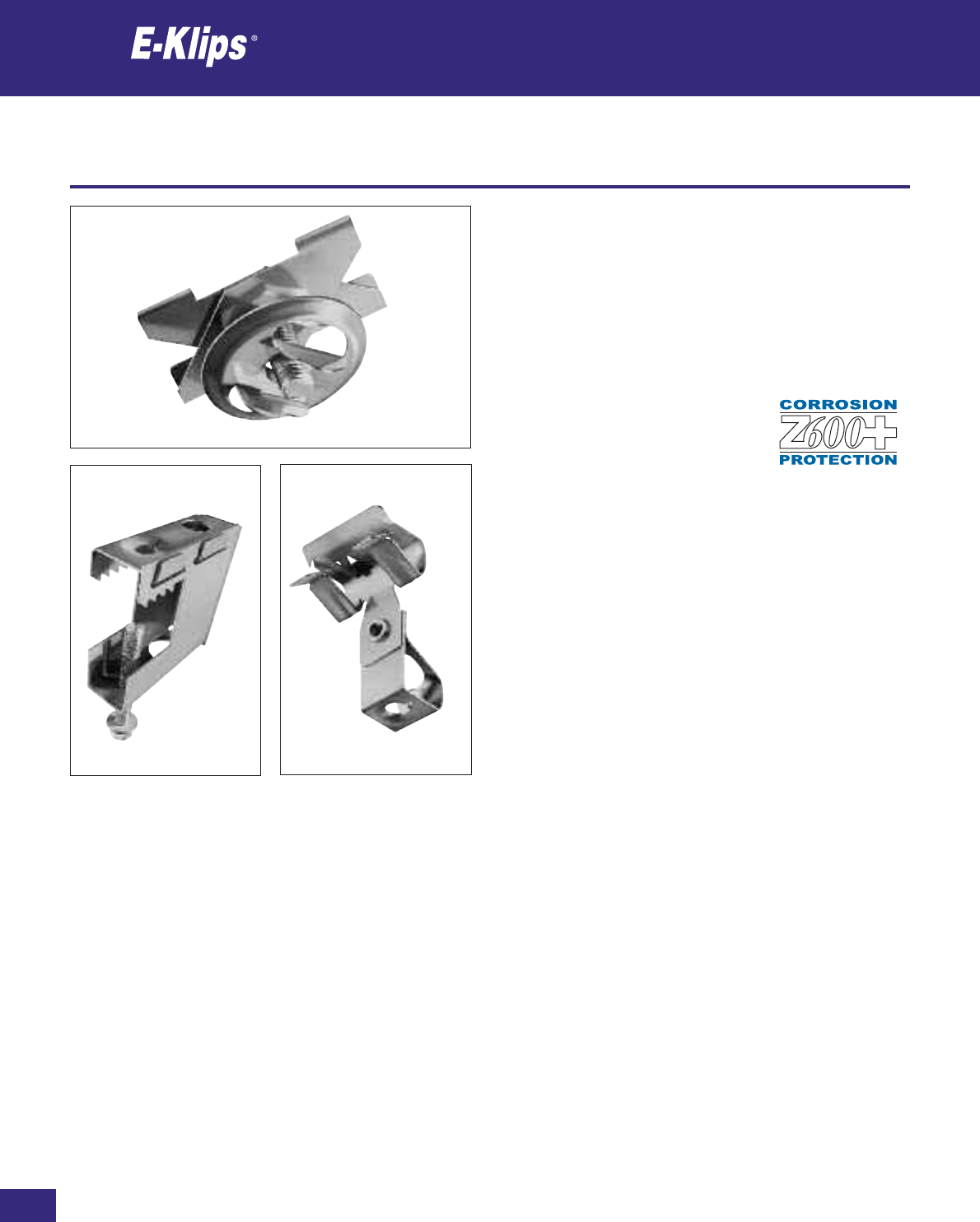
150
Thomas & Betts • www.tnb-europe.com
2
Protection against corrosion
Protection against corrosion
The majority of E-Klips spring steel fasteners are zinc coated. The clips
have a zinc silver coloured sacrificial coating which deposits two layers
of zinc and an application of a waterproof topcoat. This gives a high
level of protection against first white corrosion and then red rust
according to ASTM-B695-90 or equivalent. The corrosion resistance
is measured by a salt spray test conforming to ASTM-B-117-90,
DIN 50021 or equivalent.
E-Klips zinc plated products are salt spray
rated to a minimum of 600 hours and are
coded F8+.
Key to finishes and applications:
F1 Electroplated zinc finish, generally 8-12 microns thick with
chromate coating, approximately 72 hours salt spray resistance
ASTM-B117-90, DIN 50021, suitable for indoor, non-corrosive
environments.
F2 Galvanised, generally hot dipped to a thickness of 50-70
microns, suitable for indoor and outdoor, humid and mildly
corrosive environments.
F3 Stainless steel, suitable for indoor and outdoor and mildly
corrosive environments.
F4 Painted finish to compliment indoor applications.
F5 Black phosphate finish in accordance with BS3189 Class 1
suitable to achieve 72 hours salt spray rating for indoor, non-
corrosive environments.
F6 Self colour, unfinished and unprotected product for indoor
applications.
F7 Flexible plastic coating with good chemical and corrosion
resistance to protect the base material.
F8+ Zinc silver coloured sacrificial coating (Z600+), enhanced by an
application of waterproof topcoat giving a corrosion resistance
of more than 600 hours, for use in indoor and outdoor humid
and mildly corrosive environments. Coating is completely
chromium free.
Electrical and mechanical spring steel fasteners
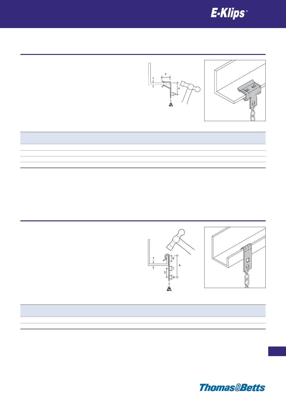
Girder clips for chain and wire
Girder and Purlin
151
Thomas & Betts • www.tnb-europe.com
2.1
Product Ref. T Ø A B Load rating Material Quantity
[mm] [mm] [mm] [mm] [kg] finishes* [pieces]
AH-153 1.5-3 6.5 16 12.5 72 F8+ 100
AH-38 3-8 6.5 18 20.3 90 F8+ 100
AH-814 8-14 6.5 26 20.3 90 F8+ 100
AH-1420 14-20 6.5 30 26.6 90 F8+ 100
Product Ref. T Ø A B C D Load rating Material Quantity
[mm] [mm] [mm] [mm] [mm] [mm] [kg] finishes* [pieces]
AV-155 1.5-5 6.5 42 14 6.5 12 72 F8+ 100
AV-57 5-7 6.5 42 15 6.5 12 72 F8+ 100
Purlin clips for chain and wire
Girder and Purlin
* See page 150 for material finishes
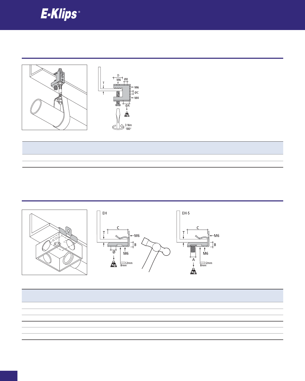
152
Thomas & Betts • www.tnb-europe.com
2.1
Girder clamps for threaded rod
Girder and Purlin
* See page 150 for material finishes
Product Ref. T ØA ØB ØC D Load rating Material Quantity
[mm] [mm] [mm] [mm] [mm] [kg] finishes* [pieces]
FH-65 Max 18 12.7 6.5 6.5 19.5 45 F8+ 100
FH-107 Max 18 10.7 10.7 6.5 19.5 45 F8+ 100
Girder clips for conduit boxes
Girder and Purlin
Product Ref. T Ø A B C Load rating Material Quantity
[mm] [mm] [mm] [mm] [mm] [kg] finishes* [pieces]
EH-38 3-8 7 – 7.5 33 45 F8+ 100
EH-814 8-14 7 – 7.5 33 45 F8+ 100
EH-1420 14-20 7 – 7.5 33 45 F8+ 100
EH-38S 3-8 – M6x10 7.5 33 45 F8+ 100
EH-814S 8-14 – M6x10 7.5 33 45 F8+ 100
EH-1420S 14-20 – M6x10 7.5 33 45 F8+ 100
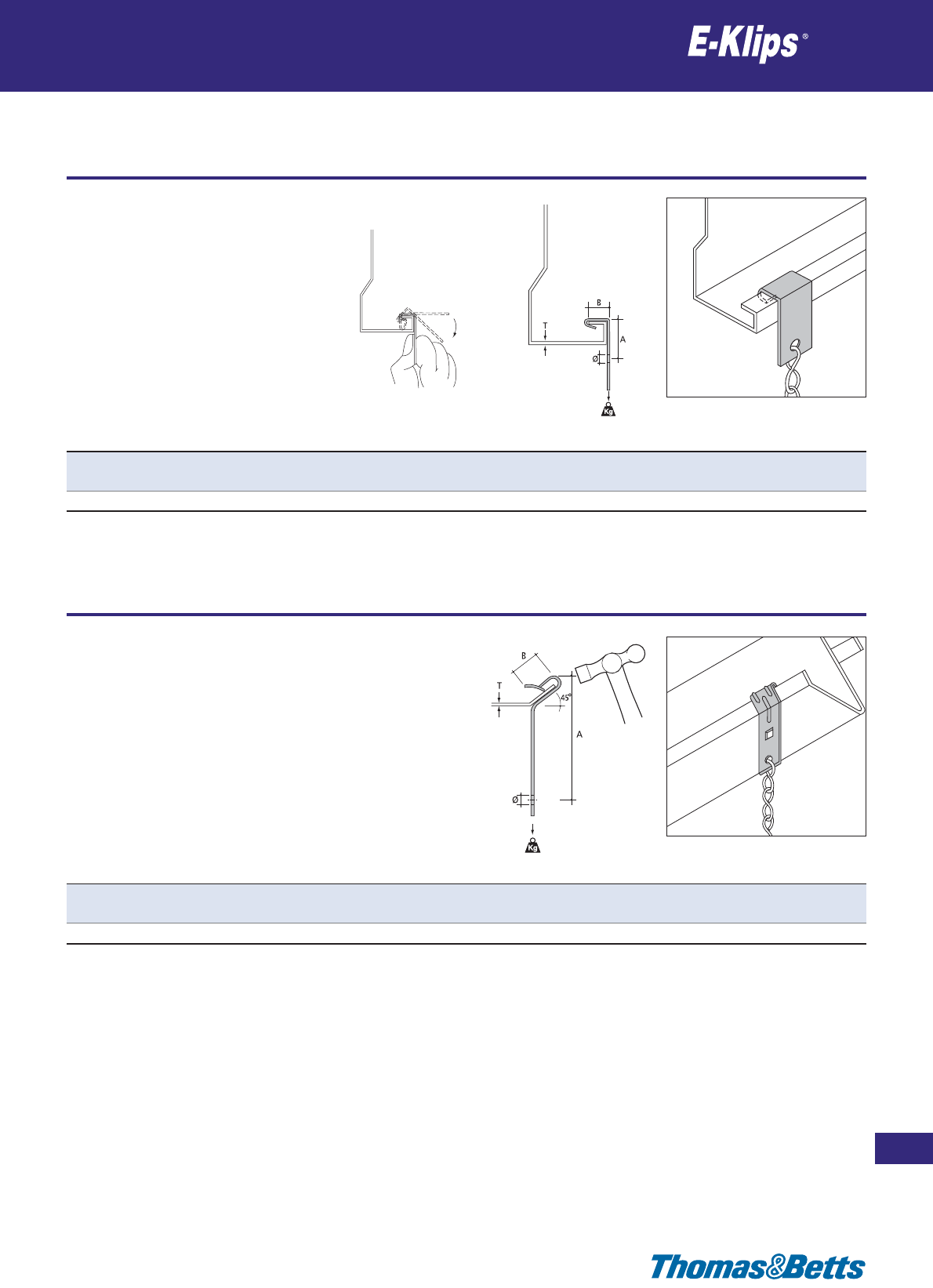
Purlin clips for chain and wire
Girder and Purlin
153
Thomas & Betts • www.tnb-europe.com
2.1
* See page 150 for material finishes
Product Ref. T Ø A B Load rating Material Quantity
[mm] [mm] [mm] [mm] [kg] finishes* [pieces]
RM-055 0.5-5 6.5 53 15 45 F8+ 100
Product Ref. T Ø A B Load rating Material Quantity
[mm] [mm] [mm] [mm] [kg] finishes* [pieces]
SM-125 ≤3.0 6.5 37 12.5 20 F2 100
Purlin clips for chain and wire
Girder and Purlin
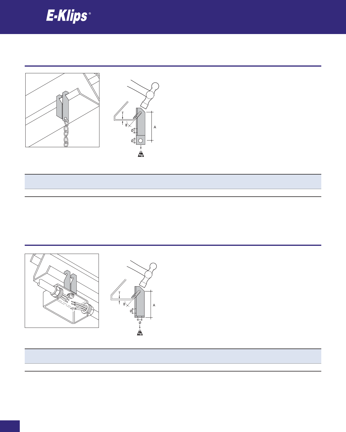
154
Thomas & Betts • www.tnb-europe.com
2.1
Purlin clips for chain and wire
Girder and Purlin
* See page 150 for material finishes
Product Ref. T Ø A B Load rating Material Quantity
[mm] [mm] [mm] [kg] finishes* [pieces]
VM-03 0-3 6.5 48 45˚ 45 F8+ 100
Product Ref. T Ø A B Load rating Material Quantity
[mm] [mm] [mm] [kg] finishes* [pieces]
TM-03 0-3 6.5 43 45˚ 45 F8+ 100
Purlin clips for conduit boxes
Girder and Purlin
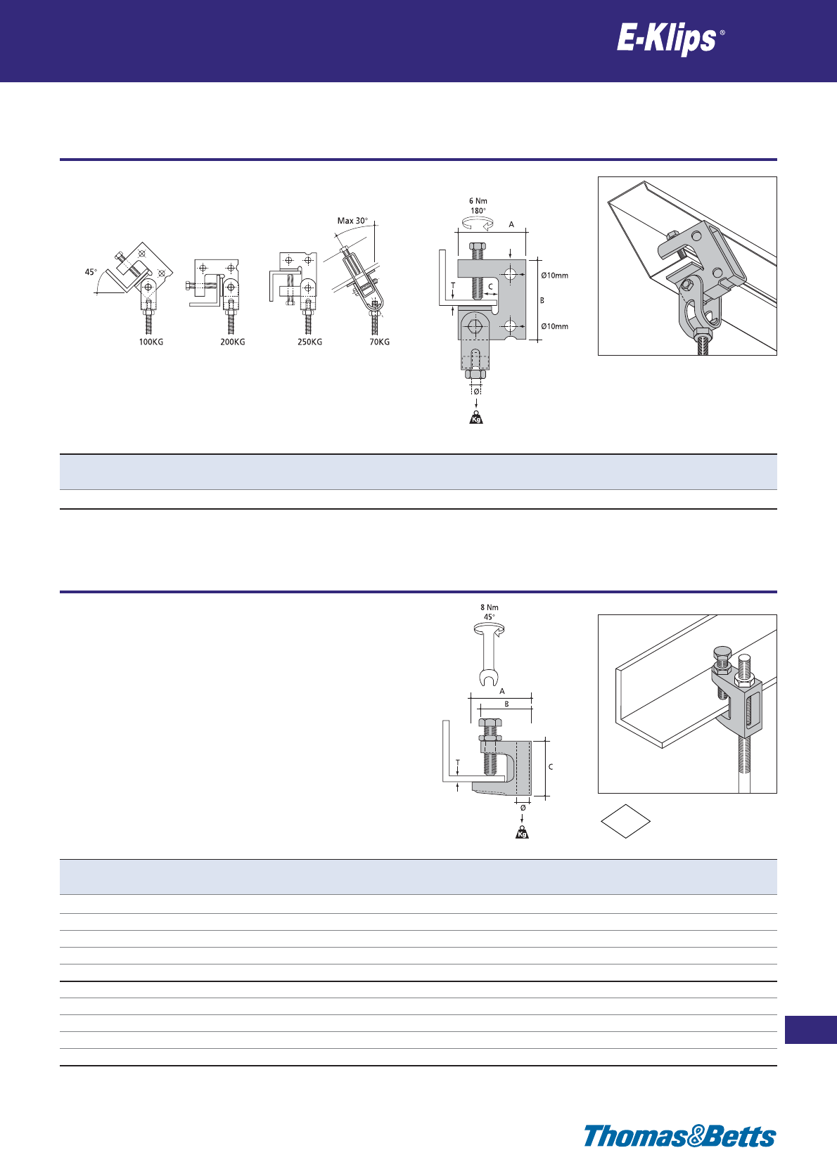
Girder clamps for threaded rod
Rod
155
Thomas & Betts • www.tnb-europe.com
2.2
* See page 150 for material finishes
FM
Product Ref. T Ø A B C Load rating Material Quantity
[mm] [mm] [mm] [mm] [kg] finishes* [pieces]
SRH Max 25 M10 71 60 12 200 F8+ 10
Product Ref. T Ø A B C Load rating Material Quantity
[mm] [mm] [mm] [mm] [mm] [kg] finishes* [pieces]
FC-7 Max 19 7 50 42 45 120 F1 25
FC-9 Max 19 9 50 42 45 120 F1 25
FC-11 Max 19 11 50 42 45 250 F1 25
FC-13 Max 23 13 59 49 54 350 F1 25
FC-17 Max 28 17 58 55 58 550 F1 25
FC-6T Max 19 M6 50 42 45 120 F1 25
FC-8T Max 19 M8 50 42 45 120 F1 25
FC-10T Max 19 M10 50 42 45 250 F1 25
FC-12T Max 23 M12 59 49 54 350 F1 25
FC-16T Max 28 M16 58 55 58 550 F1 25
Girder clamps for threaded rod
Rod
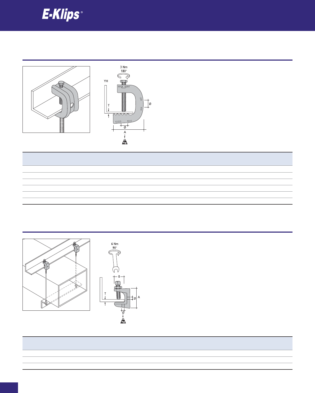
156
Thomas & Betts • www.tnb-europe.com
2.2
Girder clamps for threaded rod
Rod
* See page 150 for material finishes
Product Ref. T Ø A B Load rating Material Quantity
[mm] [mm] [mm] [kg] finishes* [pieces]
BH-6T Max 18 M6 40 22 60 F1 25
BH-8T Max 18 M8 40 22 60 F1 25
BH-10T Max 18 M10 40 22 60 F1 25
Product Ref. T Ø A Load rating Material Quantity
[mm] [mm] [mm] [kg] finishes* [pieces]
YH-1021 10-21 14 47 110 F2 25
YH-1533 15-33 14 60 110 F2 25
YH-3247 32-47 14 70 110 F2 25
SSYH-1021 10-21 14 47 110 F3 25
SSYH-1533 15-33 14 60 110 F3 25
SSYH-3247 32-47 14 70 110 F3 25
Girder clamps for threaded rod
Rod

Girder clamps for threaded rod
Rod
157
Thomas & Betts • www.tnb-europe.com
2.2
* See page 150 for material finishes
Product Ref. ØA Load rating Material Quantity
[kg] finishes* [pieces]
FM-313T M6/M8/M10 10 F8+ 100
FM-320T M6/M8/M10 10 F8+ 100
Product Ref. T Ø A B Load rating Material Quantity
[mm] [mm] [mm] [mm] [kg] finishes* [pieces]
PD ≤4121585 40 F2 50
Rod
Rod
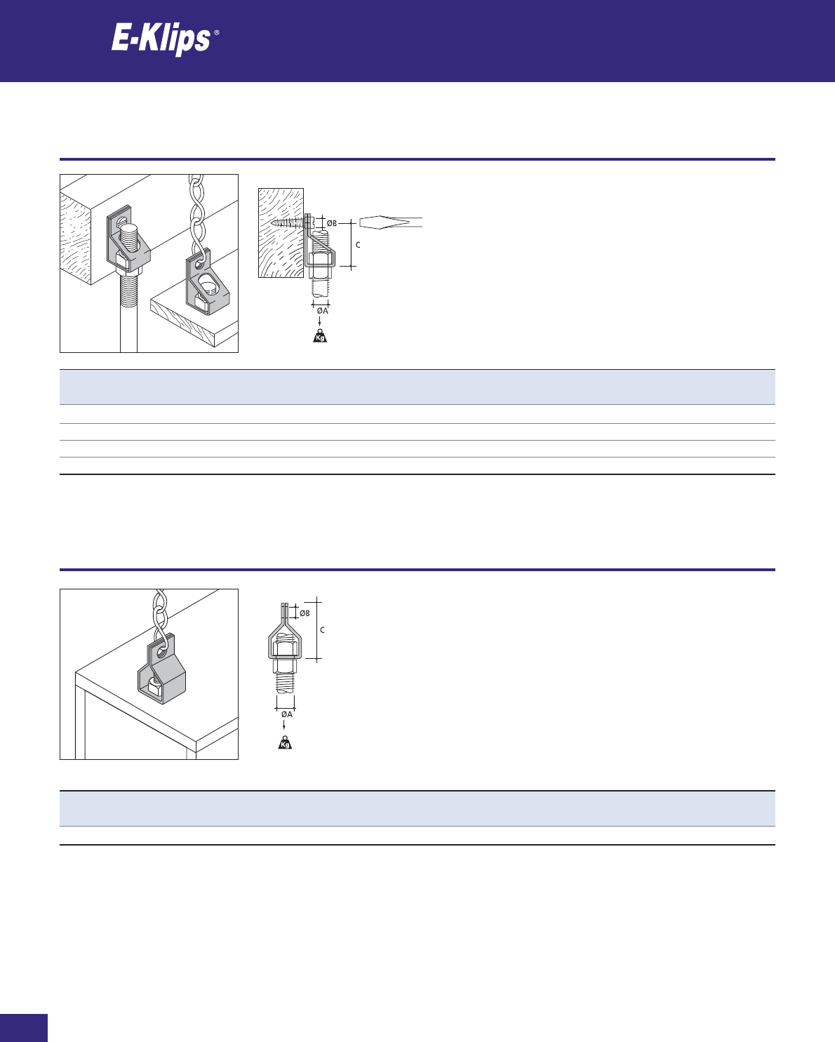
158
Thomas & Betts • www.tnb-europe.com
2.2
Rod
Rod
* See page 150 for material finishes
Product Ref. ØA ØB C Load rating Material Quantity
[mm] [mm] [mm] [kg] finishes* [pieces]
AM-127 12.7 6.5 28 68 F8+ 100
AM-6T M6 6.5 28 68 F8+ 100
AM-8T M8 6.5 28 68 F8+ 100
AM-10T M10 6.5 28 68 F8+ 100
Product Ref. ØA ØB C Load rating Material Quantity
[mm] [mm] [mm] [kg] finishes* [pieces]
YM-127 12.7 6.5 30 90 F8+ 100
Rod
Rod
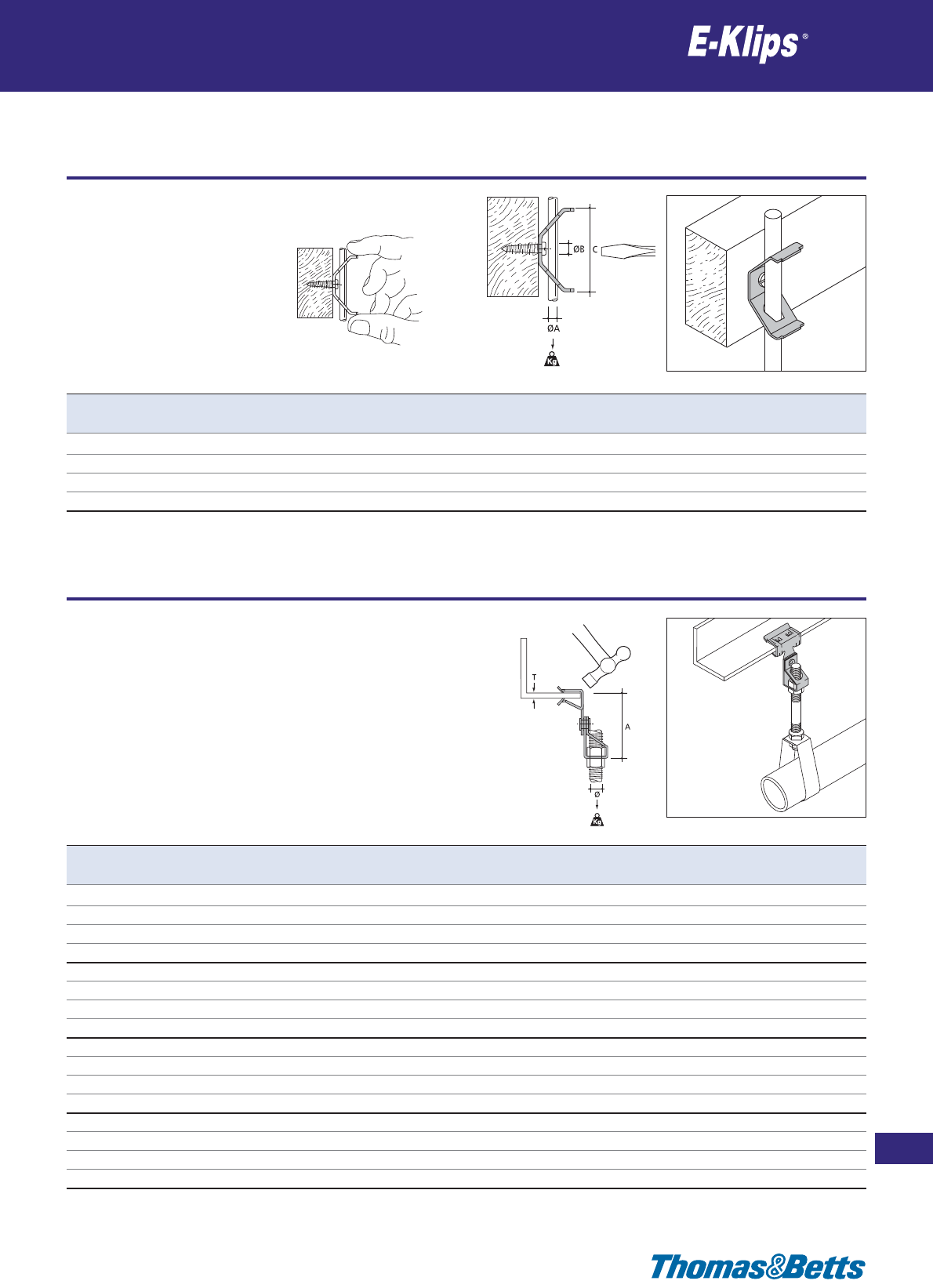
Rod
Rod
159
Thomas & Betts • www.tnb-europe.com
2.2
* See page 150 for material finishes
Product Ref. ØA ØB C Load rating Material Quantity
[mm] [mm] [mm] [kg] finishes* [pieces]
BM-4 4/M4 6.5 45 90 F8+ 100
BM-6 6/M6 6.5 45 90 F8+ 100
BM-8 8/M8 6.5 45 90 F8+ 100
BM-10 10/M10 6.5 45 90 F8+ 100
Product Ref. T Ø A Load rating Material Quantity
[mm] [mm] [mm] [kg] finishes* [pieces]
AH153-AM127 1.5-3 12.7 44 68 F8+ 25
AH38-AM127 3-8 12.7 46 68 F8+ 25
AH814-AM127 8-14 12.7 54 68 F8+ 25
AH1420-AM127 14-20 12.7 66 68 F8+ 25
AH153-AM6T 1.5-3 M6 44 68 F8+ 25
AH38-AM6T 3-8 M6 46 68 F8+ 25
AH814-AM6T 8-14 M6 54 68 F8+ 25
AH1420-AM6T 14-20 M6 66 68 F8+ 25
AH153-AM8T 1.5-3 M8 44 68 F8+ 25
AH38-AM8T 3-8 M8 46 68 F8+ 25
AH814-AM8T 8-14 M8 54 68 F8+ 25
AH1420-AM8T 14-20 M8 66 68 F8+ 25
AH153-AM10T 1.5-3 M10 44 68 F8+ 25
AH38-AM10T 3-8 M10 46 68 F8+ 25
AH814-AM10T 8-14 M10 54 68 F8+ 25
AH1420-AM10T 14-20 M10 66 68 F8+ 25
Girder clips for hanging threaded rod
Rod

160
Thomas & Betts • www.tnb-europe.com
2.2
Girder clips for hanging threaded rod
Rod
Product Ref. T Ø A Load rating Material Quantity
[mm] [mm] [mm] [kg] finishes* [pieces]
AH153-YM127 1.5-3 12.7 48 72 F8+ 25
AH38-YM127 3-8 12.7 48 90 F8+ 25
AH814-YM127 8-14 12.7 56 90 F8+ 25
AH1420-YM127 14-20 12.7 70 90 F8+ 25
Product Ref. T Ø Load rating Material Quantity
[mm] [mm] [kg] finishes* [pieces]
AH153-BM4 1.5-3 4/M4 72 F8+ 25
AH38-BM4 3-8 4/M4 90 F8+ 25
AH814-BM4 8-14 4/M4 90 F8+ 25
AH1420-BM4 14-20 4/M4 90 F8+ 25
AH153-BM6 1.5-3 6/M6 72 F8+ 25
AH38-BM6 3-8 6/M6 90 F8+ 25
AH814-BM6 8-14 6/M6 90 F8+ 25
AH1420-BM6 14-20 6/M6 90 F8+ 25
AH153-BM8 1.5-3 8/M8 72 F8+ 25
AH38-BM8 3-8 8/M8 90 F8+ 25
AH814-BM8 8-14 8/M8 90 F8+ 25
AH1420-BM8 14-20 8/M8 90 F8+ 25
AH153-BM10 1.5-3 10/M10 72 F8+ 25
AH38-BM10 3-8 10/M10 90 F8+ 25
AH814-BM10 8-14 10/M10 90 F8+ 25
AH1420-BM10 14-20 10/M10 90 F8+ 25
Girder clips for hanging threaded rod
Rod
* See page 150 for material finishes

Girder clips for hanging threaded rod
Rod
161
Thomas & Betts • www.tnb-europe.com
2.2
* See page 150 for material finishes
Product Ref. T Ø A B Load rating Material Quantity
[mm] [mm] [mm] [mm] [kg] finishes* [pieces]
AHB-153 1.5-3 6.5 22 12.5 20 F8+ 100
AHB-38 3-8 6.5 25 20.3 20 F8+ 100
AHB-814 8-14 6.5 26 20.3 20 F8+ 100
AHB-1420 14-20 6.5 27 26.6 20 F8+ 100
Product Ref. T Ø A Load rating Material Quantity
[mm] [mm] [mm] [kg] finishes* [pieces]
AV155-AM127 1.5-5 12.7 70 68 F8+ 25
AV155-AM6T 1.5-5 M6 70 68 F8+ 25
AV155-AM8T 1.5-5 M8 70 68 F8+ 25
AV155-AM10T 1.5-5 M10 70 68 F8+ 25
AV57-AM127 5-7 12.7 70 68 F8+ 25
AV57-AM6T 5-7 M6 70 68 F8+ 25
AV57-AM8T 5-7 M8 70 68 F8+ 25
AV57-AM10T 5-7 M10 70 68 F8+ 25
Purlin clips for hanging threaded rod
Rod
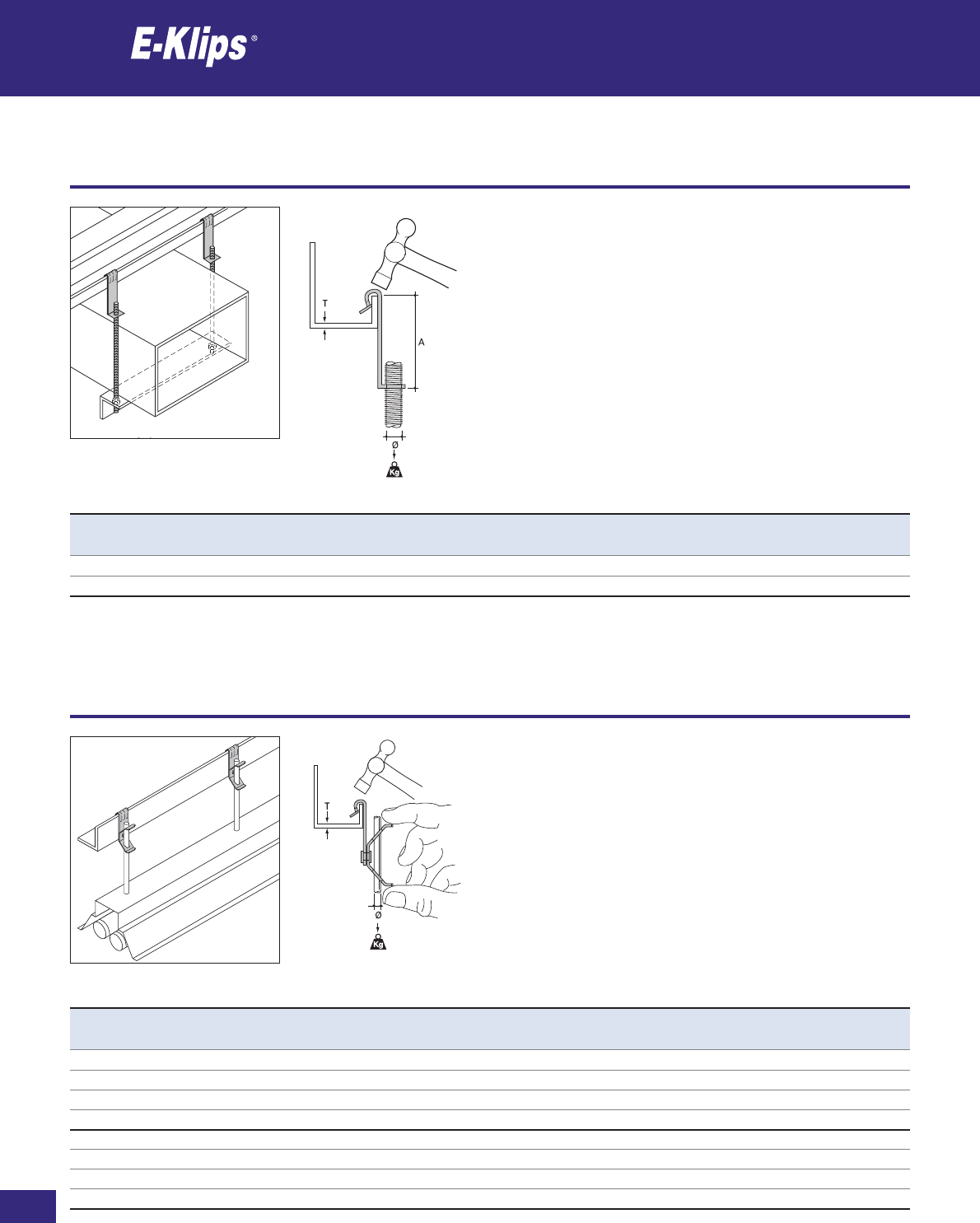
162
Thomas & Betts • www.tnb-europe.com
2.2
Purlin clips for hanging threaded rod
Rod
* See page 150 for material finishes
Product Ref. T Ø A Load rating Material Quantity
[mm] [mm] [kg] finishes* [pieces]
AVB-6T 1.5-5 M6 34 20 F8+ 100
AVB-8T 1.5-5 M8 34 20 F8+ 100
Product Ref. T Ø Load rating Material Quantity
[mm] [mm] [kg] finishes* [pieces]
AV155-BM4 1.5-5 4/M4 72 F8+ 25
AV155-BM6 1.5-5 6/M6 72 F8+ 25
AV155-BM8 1.5-5 8/M8 72 F8+ 25
AV155-BM10 1.5-5 10/M10 72 F8+ 25
AV57-BM4 5-7 4/M4 72 F8+ 25
AV57-BM6 5-7 6/M6 72 F8+ 25
AV57-BM8 5-7 8/M8 72 F8+ 25
AV57-BM10 5-7 10/M10 72 F8+ 25
Purlin clips for hanging rod
Rod

Purlin clips for hanging threaded rod
Rod
163
Thomas & Betts • www.tnb-europe.com
2.2
* See page 150 for material finishes
Product Ref. T Ø A B Load rating Material Quantity
[mm] [mm] [mm] [mm] [kg] finishes* [pieces]
SM125-AM127 ≤3.0 12.7 65 12.5 20 F2 25
SM125-AM6T ≤3.0 M6 65 12.5 20 F2 25
SM125-AM8T ≤3.0 M8 65 12.5 20 F2 25
SM125-AM10T ≤3.0 M10 65 12.5 20 F2 25
ØB
C
C
ØB
Product Ref. ØA ØB C Load rating Material Quantity
[mm] [mm] [mm] [kg] finishes* [pieces]
UM44-AM6T M6 6.5 69 68 F8+ 25
UM44-AM8T M8 6.5 69 68 F8+ 25
UM44-AM10T M10 6.5 69 68 F8+ 25
UM44-AM127 12.7 6.5 69 68 F8+ 25
UM44-YM127 12.7 6.5 71 90 F8+ 25
Fastening clips for threaded rod
Rod

164
Thomas & Betts • www.tnb-europe.com
2.2
Fastening clips for rod
Rod
* See page 150 for material finishes
Product Ref. ØA ØB C Load rating Material Quantity
[mm] [mm] [mm] [kg] finishes* [pieces]
UM44-BM4 4/M4 6.5 39 90 F8+ 25
UM44-BM6 6/M6 6.5 39 90 F8+ 25
UM44-BM8 8/M8 6.5 39 90 F8+ 25
UM44-BM10 10/M10 6.5 39 90 F8+ 25
Product Ref. T Ø Load rating Material Quantity
[mm] [mm] [kg] finishes* [pieces]
FH107-AM127 Max 18 12.7 45 F8+ 25
FH107-AM6T Max 18 M6 45 F8+ 25
FH107-AM8T Max 18 M8 45 F8+ 25
FH107-AM10T Max 18 M10 45 F8+ 25
Girder clamps for hanging threaded rod
Rod

Girder clamps for hanging rod
Rod
165
Thomas & Betts • www.tnb-europe.com
2.2
* See page 150 for material finishes
Product Ref. T Ø Load rating Material Quantity
[mm] [mm] [kg] finishes* [pieces]
FH107-BM4 Max 18 4/M4 45 F8+ 25
FH107-BM6 Max 18 6/M6 45 F8+ 25
FH107-BM8 Max 18 8/M8 45 F8+ 25
FH107-BM10 Max 18 10/M10 45 F8+ 25
Product Ref. ØA ØB C D Load rating Material Quantity
[mm] [mm] [mm] [kg] finishes* [pieces]
VM03-AM127 12.7 6.5 77 45˚ 45 F8+ 25
VM03-AM6T M6 6.5 77 45˚ 45 F8+ 25
VM03-AM8T M8 6.5 77 45˚ 45 F8+ 25
VM03-AM10T M10 6.5 77 45˚ 45 F8+ 25
Purlin clips for hanging threaded rod
Rod
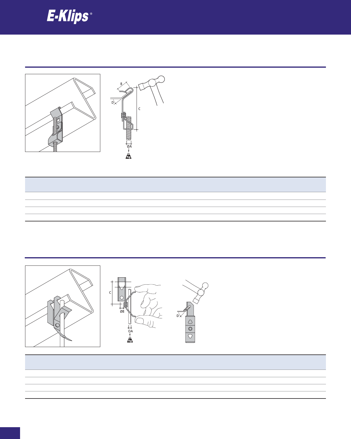
166
Thomas & Betts • www.tnb-europe.com
2.2
Purlin clips for hanging threaded rod
Rod
* See page 150 for material finishes
Product Ref. ØA B C D Load rating Material Quantity
[mm] [mm] [mm] [kg] finishes* [pieces]
RM055-AM127 12.7 15 77 45˚ 45 F8+ 25
RM055-AM6T M6 15 77 45˚ 45 F8+ 25
RM055-AM8T M8 15 77 45˚ 45 F8+ 25
RM055-AM10T M10 15 77 45˚ 45 F8+ 25
Product Ref. ØA ØB C D Load rating Material Quantity
[mm] [mm] [mm] [kg] finishes* [pieces]
VM03-BM4 4/M4 6.5 48 45˚ 45 F8+ 25
VM03-BM6 6/M6 6.5 48 45˚ 45 F8+ 25
VM03-BM8 8/M8 6.5 48 45˚ 45 F8+ 25
VM03-BM10 10/M10 6.5 48 45˚ 45 F8+ 25
Purlin clips for hanging rod
Rod

Rod connectors
Rod
167
Thomas & Betts • www.tnb-europe.com
2.2
* See page 150 for material finishes
Product Ref. Ø A Load rating Material Quantity
[mm] [kg] finishes* [pieces]
TL6 M6 35 160 F2 25
TL8 M8 35 160 F2 25
TL10 M10 35 300 F2 25
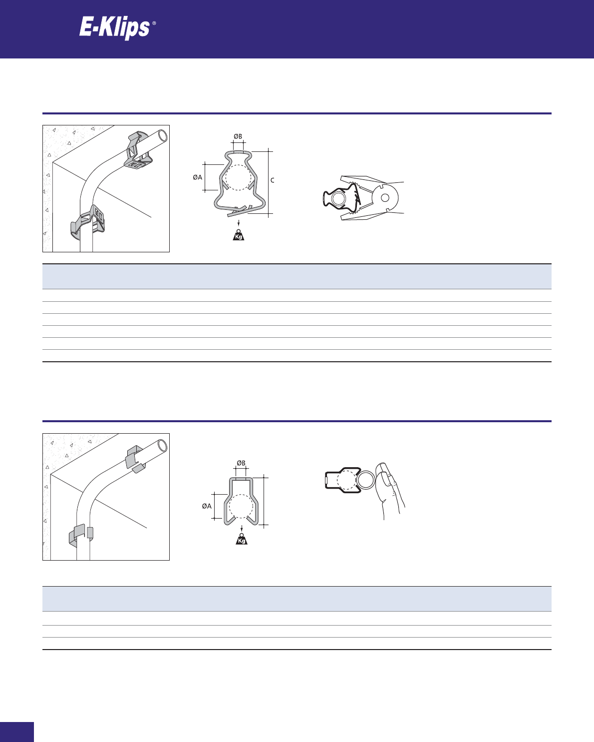
168
Thomas & Betts • www.tnb-europe.com
2.3
Wall fixing clips for conduits
Conduits
* See page 150 for material finishes
C
Product Ref. ØA ØB C PG Type Load rating Material Quantity
[mm] [mm] [mm] [kg] finishes* [pieces]
GM-1219 12-19 6.5 44 7/9/11 45 F8+ 100
GM-1926 19-26 6.5 44 13.5/16 45 F8+ 100
GM-2632 26-32 6.5 55 21 45 F8+ 100
GM-3240 32-40 6.5 68 29 45 F8+ 100
GM-4047 40-47 6.5 79 36 45 F8+ 100
GM-4757 47-57 6.5 87 36/42 45 F8+ 100
Product Ref. ØA ØB C PG Type Load rating Material Quantity
[mm] [mm] [mm] [kg] finishes* [pieces]
JM-1825 18-22 6.5 33 11/13.5/16 11 F8+ 100
JM-2229 22-29 6.5 38 16/21 11 F8+ 100
JM-2933 29-33 6.5 43 – 11 F8+ 100
Wall fixing clips for conduits
Conduits
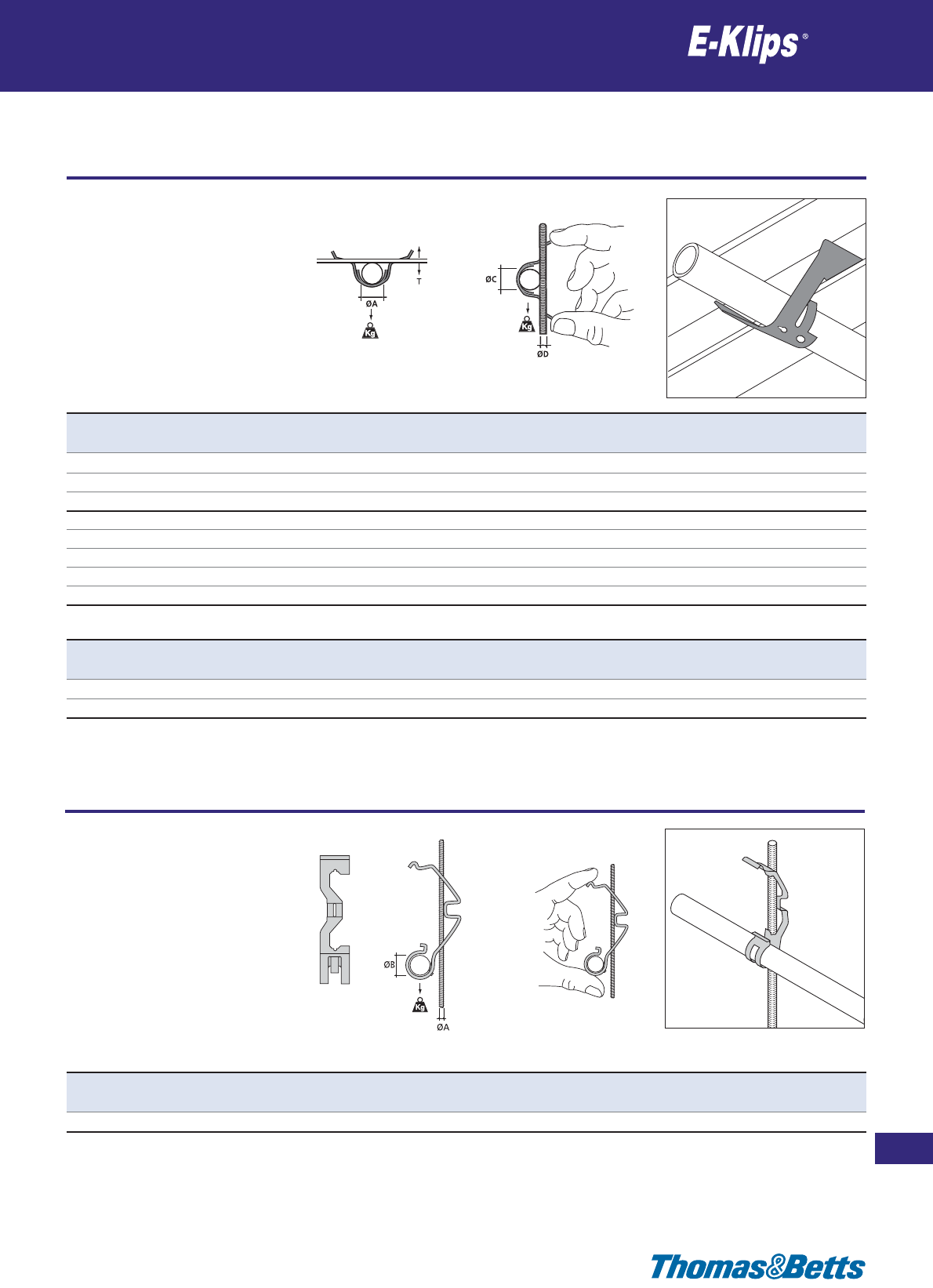
Rod clips for conduits
Conduits
169
Thomas & Betts • www.tnb-europe.com
2.3
* See page 150 for material finishes
Product Ref. T ØA PG Type Load rating Material Quantity
[mm] [mm] [kg] finishes* [pieces]
FM-313T 3-5 16-25 11/13.5/16 45 F8+ 100
6-9 16-20 11/13.5 45 F8+ 100
9-13 16 11 45 F8+ 100
FM-320T 3-5 20-38 13.5/16/21/29 45 F8+ 100
6-9 20-35 13.5/16/21 45 F8+ 100
9-13 20-30 13.5/16/21 45 F8+ 100
13-16 20-25 13.5/16 45 F8+ 100
16-20 20 13.5 45 F8+ 100
Product Ref. ØA ØB Load rating Material Quantity
[mm] [mm] [kg] finishes* [pieces]
FM-1116 3-6 10-18 11 F5 100
Product Ref. ØC ØD PG Type Load rating Material Quantity
[mm] [kg] finishes* [pieces]
FM-313T 20 Max M6/M8/M10 11 22 F8+ 100
FM-320T 40 Max M6/M8/M10 29 22 F8+ 100
Rod clips for conduits
Conduits
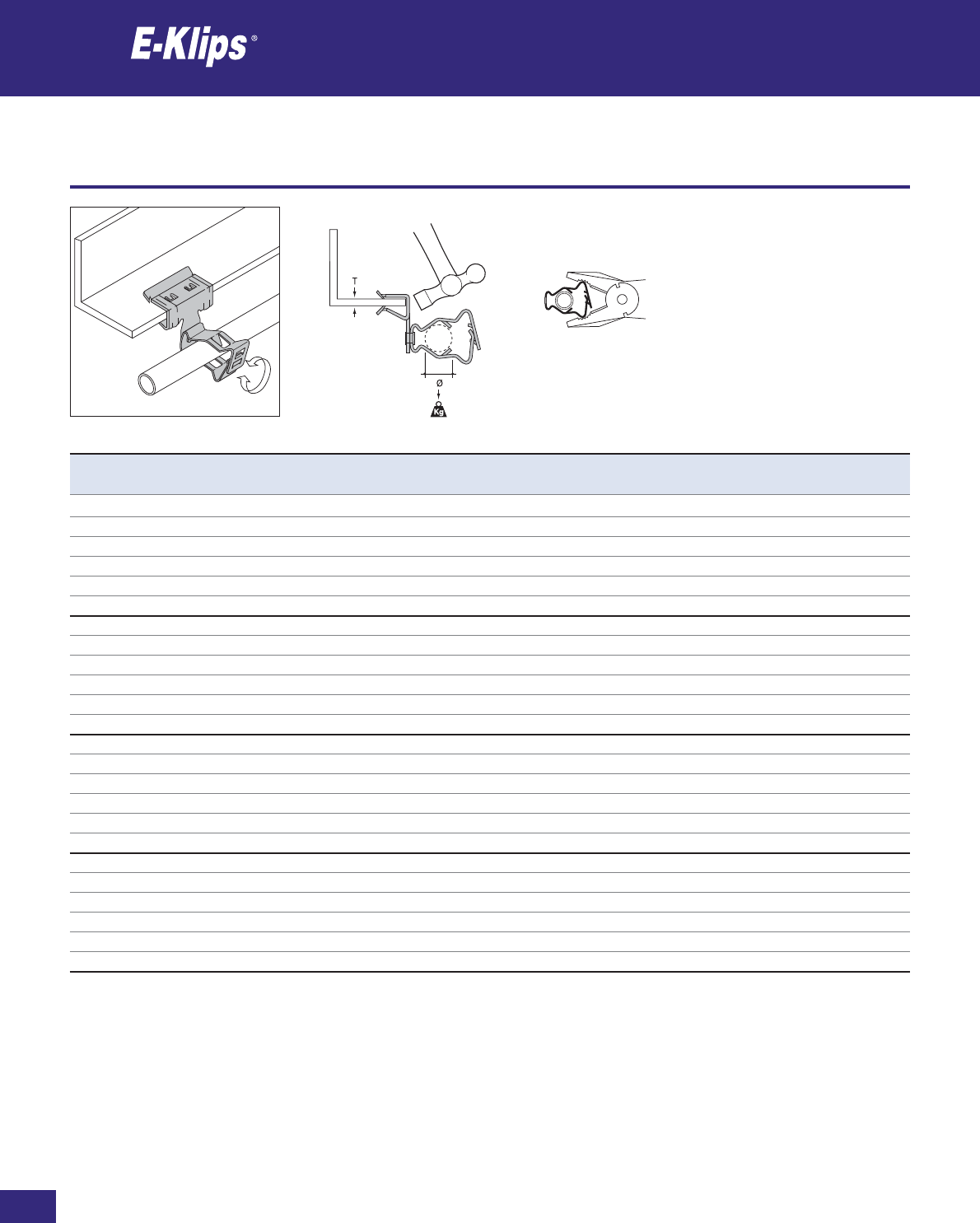
170
Thomas & Betts • www.tnb-europe.com
2.3
Girder clips for conduits
Conduits
* See page 150 for material finishes
Product Ref. T Ø PG Type Load rating Material Quantity
[mm] [mm] [kg] finishes* [pieces]
AH153-GM1219 1.5-3 12-19 7/9/11 12 F8+ 25
AH153-GM1926 1.5-3 19-26 13.5/16 12 F8+ 25
AH153-GM2632 1.5-3 26-32 21 12 F8+ 25
AH153-GM3240 1.5-3 32-40 29 12 F8+ 25
AH153-GM4047 1.5-3 40-47 36 12 F8+ 25
AH153-GM4757 1.5-3 47-57 36/42 12 F8+ 25
AH38-GM1219 3-8 12-19 7/9/11 12 F8+ 25
AH38-GM1926 3-8 19-26 13.5/16 12 F8+ 25
AH38-GM2632 3-8 26-32 21 12 F8+ 25
AH38-GM3240 3-8 32-40 29 12 F8+ 25
AH38-GM4047 3-8 40-47 36 12 F8+ 25
AH38-GM4757 3-8 47-57 36/42 12 F8+ 25
AH814-GM1219 8-14 12-19 7/9/11 12 F8+ 25
AH814-GM1926 8-14 19-26 13.5/16 12 F8+ 25
AH814-GM2632 8-14 26-32 21 12 F8+ 25
AH814-GM3240 8-14 32-40 29 12 F8+ 25
AH814-GM4047 8-14 40-47 36 12 F8+ 25
AH814-GM4757 8-14 47-57 36/42 12 F8+ 25
AH1420-GM1219 14-20 12-19 7/9/11 12 F8+ 25
AH1420-GM1926 14-20 19-26 13.5/16 12 F8+ 25
AH1420-GM2632 14-20 26-32 21 12 F8+ 25
AH1420-GM3240 14-20 32-40 29 12 F8+ 25
AH1420-GM4047 14-20 40-47 36 12 F8+ 25
AH1420-GM4757 14-20 47-57 36/42 12 F8+ 25

Girder clips for conduits
Conduits
171
Thomas & Betts • www.tnb-europe.com
2.3
* See page 150 for material finishes
Product Ref. T Ø PG Type Load rating Material Quantity
[mm] [mm] [kg] finishes* [pieces]
AH38-JM1825 3-8 18-22 11/13.5/16 7 F8+ 25
AH38-JM2229 3-8 22-29 16/21 7 F8+ 25
AH38-JM2933 3-8 29-33 – 7 F8+ 25
AH814-JM1825 8-14 18-22 11/13.5/16 7 F8+ 25
AH814-JM2229 8-14 22-29 16/21 7 F8+ 25
AH814-JM2933 8-14 29-33 – 7 F8+ 25
AH1420-JM1825 14-20 18-22 11/13.5/16 7 F8+ 25
AH1420-JM2229 14-20 22-29 16/21 7 F8+ 25
AH1420-JM2933 14-20 29-33 – 7 F8+ 25
Product Ref. T Ø PG Type Load rating Material Quantity
[mm] [mm] [kg] finishes* [pieces]
AH38-JM1825R 3-8 18-22 11/13.5/16 7 F8+ 25
AH38-JM2229R 3-8 22-29 16/21 7 F8+ 25
AH814-JM1825R 8-14 18-22 11/13.5/16 7 F8+ 25
AH814-JM2229R 8-14 22-29 16/21 7 F8+ 25
AH814-JM2933R 8-14 29-33 – 7 F8+ 25
AH1420-JM1825R 14-20 18-22 11/13.5/16 7 F8+ 25
AH1420-JM2229R 14-20 22-29 16/21 7 F8+ 25
AH1420-JM2933R 14-20 29-33 – 7 F8+ 25
Girder clips for conduits
Conduits
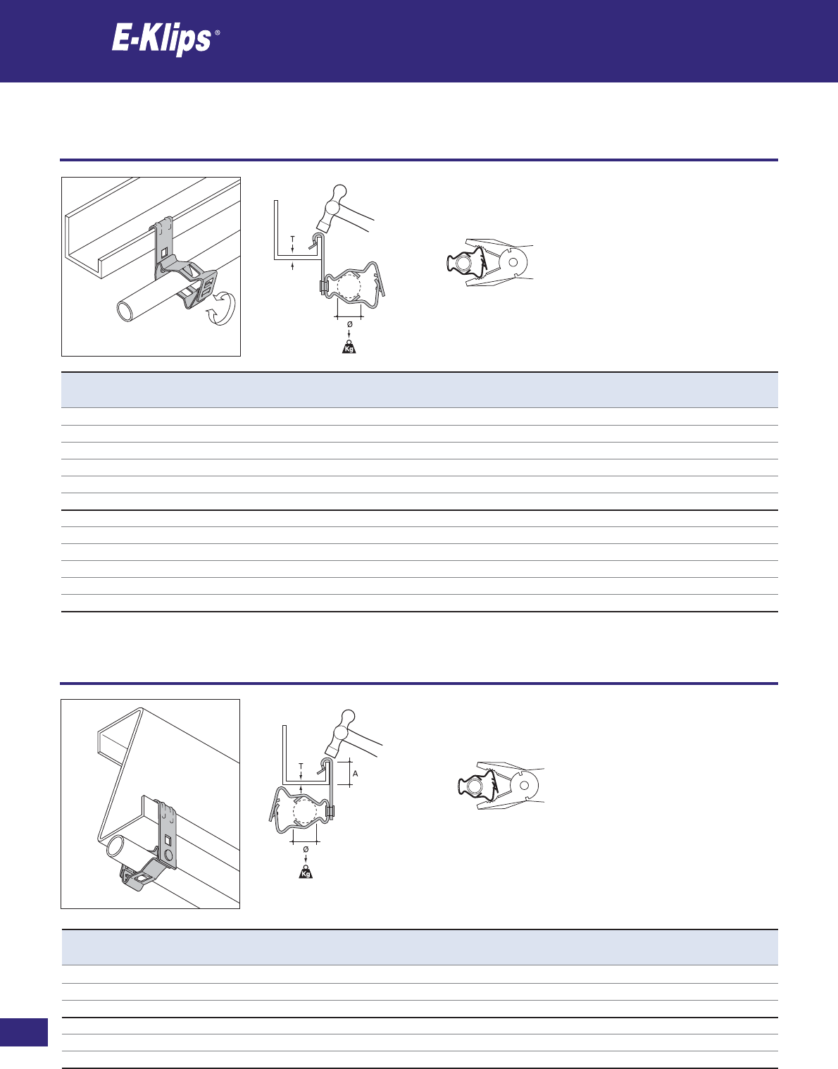
172
Thomas & Betts • www.tnb-europe.com
2.3
Purlin clips for conduits
Conduits
* See page 150 for material finishes
Product Ref. T Ø PG Type A Load rating Material Quantity
[mm] [mm] [mm] [kg] finishes* [pieces]
AV155-GM1219R 1.5-5 12-19 7/9/11 Max 15 12 F8+ 25
AV155-GM1926R 1.5-5 19-26 13.5/16 Max 12 12 F8+ 25
AV155-GM2632R 1.5-5 26-32 21 Max 25 12 F8+ 25
AV57-GM1219R 5-7 12-19 7/9/11 Max 15 12 F8+ 25
AV57-GM1926R 5-7 19-26 13.5/16 Max 12 12 F8+ 25
AV57-GM2632R 5-7 26-32 21 Max 25 12 F8+ 25
Product Ref. T Ø PG Type Load rating Material Quantity
[mm] [mm] [kg] finishes* [pieces]
AV155-GM1219 1.5-5 12-19 7/9/11 12 F8+ 25
AV155-GM1926 1.5-5 19-26 13.5/16 12 F8+ 25
AV155-GM2632 1.5-5 26-32 21 12 F8+ 25
AV155-GM3240 1.5-5 32-40 29 12 F8+ 25
AV155-GM4047 1.5-5 40-47 36 12 F8+ 25
AV155-GM4757 1.5-5 47-57 36/42 12 F8+ 25
AV57-GM1219 5-7 12-19 7/9/11 12 F8+ 25
AV57-GM1926 5-7 19-26 13.5/16 12 F8+ 25
AV57-GM2632 5-7 26-32 21 12 F8+ 25
AV57-GM3240 5-7 32-40 29 12 F8+ 25
AV57-GM4047 5-7 40-47 36 12 F8+ 25
AV57-GM4757 5-7 47-57 36/42 12 F8+ 25
Purlin clips for conduits
Conduits
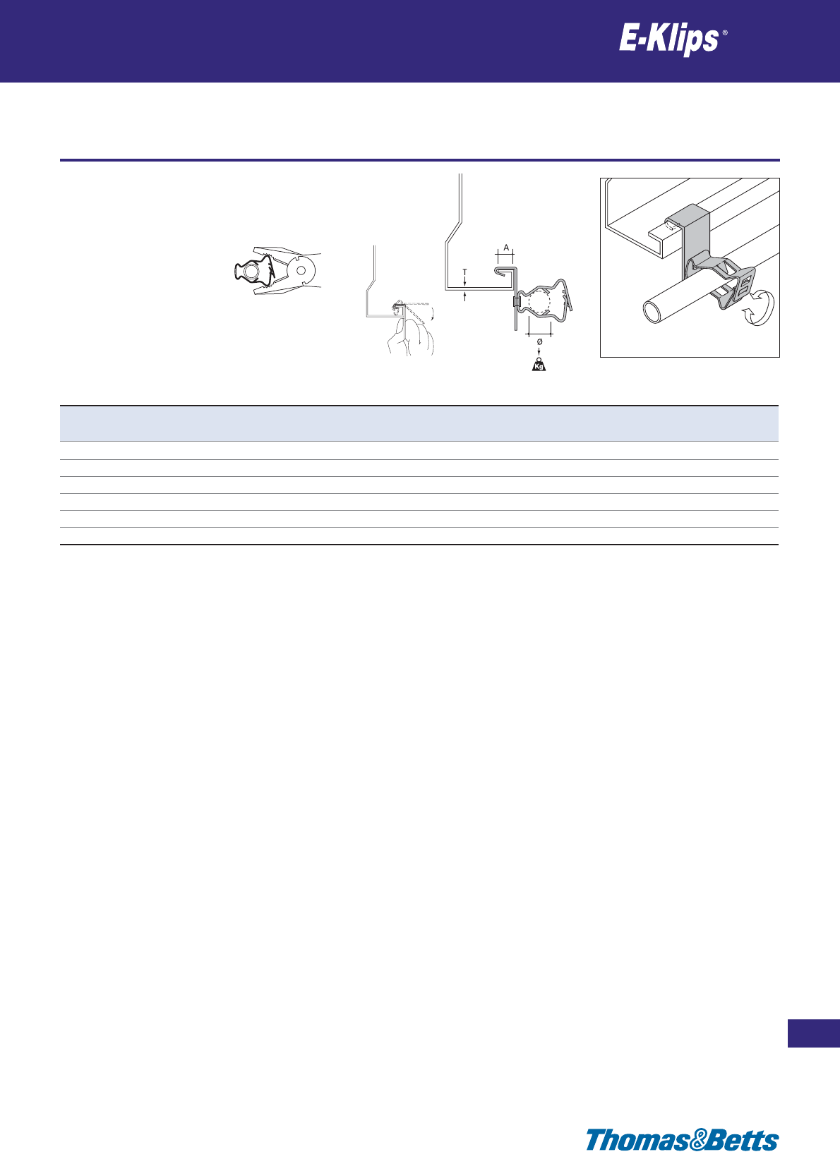
Purlin clips for conduits
Conduits
173
Thomas & Betts • www.tnb-europe.com
2.3
* See page 150 for material finishes
Product Ref. T Ø PG Type A Load rating Material Quantity
[mm] [mm] [mm] [kg] finishes* [pieces]
SM125-GM1219 ≤3.0 12-19 7/9/11 12.5 12 F2 25
SM125-GM1926 ≤3.0 19-26 13.5/16 12.5 12 F2 25
SM125-GM2632 ≤3.0 26-32 21 12.5 12 F2 25
SM125-GM3240 ≤3.0 32-40 29 12.5 12 F2 25
SM125-GM4047 ≤3.0 40-47 36 12.5 12 F2 25
SM125-GM4757 ≤3.0 47-57 36/42 12.5 12 F2 25
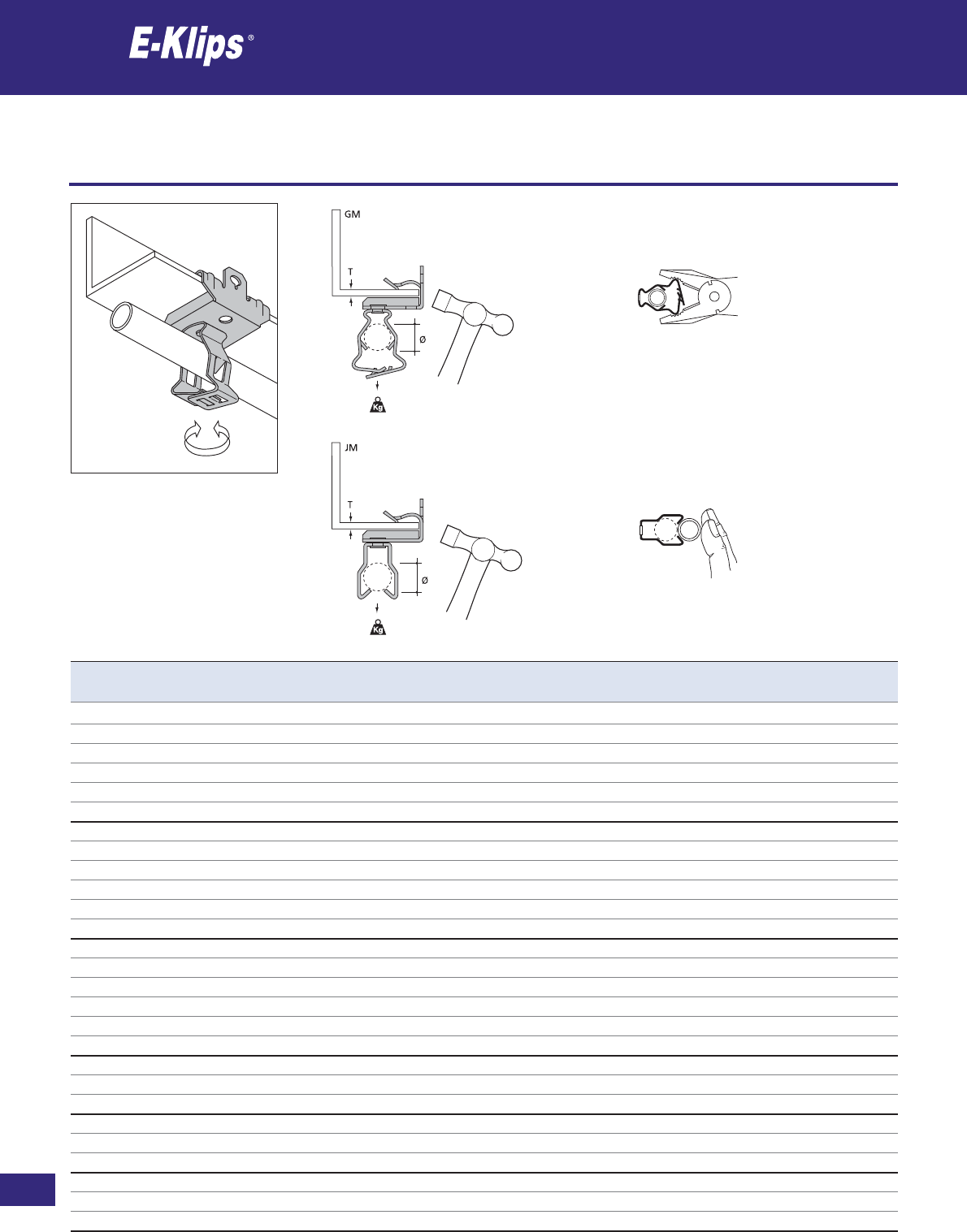
174
Thomas & Betts • www.tnb-europe.com
2.3
Girder clips for conduits
Conduits
* See page 150 for material finishes
Product Ref. T Ø PG Type Load rating Material Quantity
[mm] [mm] [kg] finishes* [pieces]
EH38-GM1219 3-8 12-19 7/9/11 45 F8+ 25
EH38-GM1926 3-8 19-26 13.5/16 45 F8+ 25
EH38-GM2632 3-8 26-32 21 45 F8+ 25
EH38-GM3240 3-8 32-40 29 45 F8+ 25
EH38-GM4047 3-8 40-47 36 45 F8+ 25
EH38-GM4757 3-8 47-57 36/42 45 F8+ 25
EH814-GM1219 8-14 12-19 7/9/11 45 F8+ 25
EH814-GM1926 8-14 19-26 13.5/16 45 F8+ 25
EH814-GM2632 8-14 26-32 21 45 F8+ 25
EH814-GM3240 8-14 32-40 29 45 F8+ 25
EH814-GM4047 8-14 40-47 36 45 F8+ 25
EH814-GM4757 8-14 47-57 36/42 45 F8+ 25
EH1420-GM1219 14-20 12-19 7/9/11 45 F8+ 25
EH1420-GM1926 14-20 19-26 13.5/16 45 F8+ 25
EH1420-GM2632 14-20 26-32 21 45 F8+ 25
EH1420-GM3240 14-20 32-40 29 45 F8+ 25
EH1420-GM4047 14-20 40-47 36 45 F8+ 25
EH1420-GM4757 14-20 47-57 36/42 45 F8+ 25
EH38-JM1825 3-8 18-22 11/13.5/16 11 F8+ 25
EH38-JM2229 3-8 22-29 16/21 11 F8+ 25
EH38-JM2933 3-8 29-33 – 11 F8+ 25
EH814-JM1825 8-14 18-22 11/13.5/16 11 F8+ 25
EH814-JM2229 8-14 22-29 16/21 11 F8+ 25
EH814-JM2933 8-14 29-33 – 11 F8+ 25
EH1420-JM1825 14-20 18-22 11/13.5/16 11 F8+ 25
EH1420-JM2229 14-20 22-29 16/21 11 F8+ 25
EH1420-JM2933 14-20 29-33 – 11 F8+ 25

Girder clips for conduits
Conduits
175
Thomas & Betts • www.tnb-europe.com
2.3
* See page 150 for material finishes
Product Ref. T ØA ØB C Material Quantity
[mm] [mm] [mm] finishes* [pieces]
EH38-P15 3-8 15 M6 22 F8+** 25
EH38-P22 3-8 22 M6 22 F8+** 25
EH38-P28 3-8 28 M6 22 F8+** 25
EH814-P15 8-14 15 M6 22 F8+** 25
EH814-P22 8-14 22 M6 22 F8+** 25
EH814-P28 8-14 28 M6 22 F8+** 25
EH1420-P15 14-20 15 M6 22 F8+** 25
EH1420-P22 14-20 22 M6 22 F8+** 25
EH1420-P28 14-20 28 M6 22 F8+** 25
** Conduit clips P15, P22 and P28 are made of Polypropylene
Product Ref. T A B C Material Quantity
[mm] [mm] [mm] [mm] finishes* [pieces]
EH38-RCC13 3-8 13 51 – F8+ 25
EH38-RCC15 3-8 15 53 – F8+ 25
EH814-RCC13 8-14 13 51 – F8+ 25
EH814-RCC15 8-14 15 53 – F8+ 25
EH1420-RCC13 14-20 13 51 – F8+ 25
EH1420-RCC15 14-20 15 53 – F8+ 25
RCC-6-FU – 6 – 29 F8+ 100
RCC-8 – 8 – 31 F8+ 100
RCC-10 – 10 – 33 F8+ 100
RCC-13 – 13 – 36 F8+ 100
RCC-15 – 15 – 38 F8+ 100
RCC-20 – 20 – 43 F8+ 100
RCC-25 – 25 – 48 F8+ 100
Girder clips for conduits / cables
Conduits
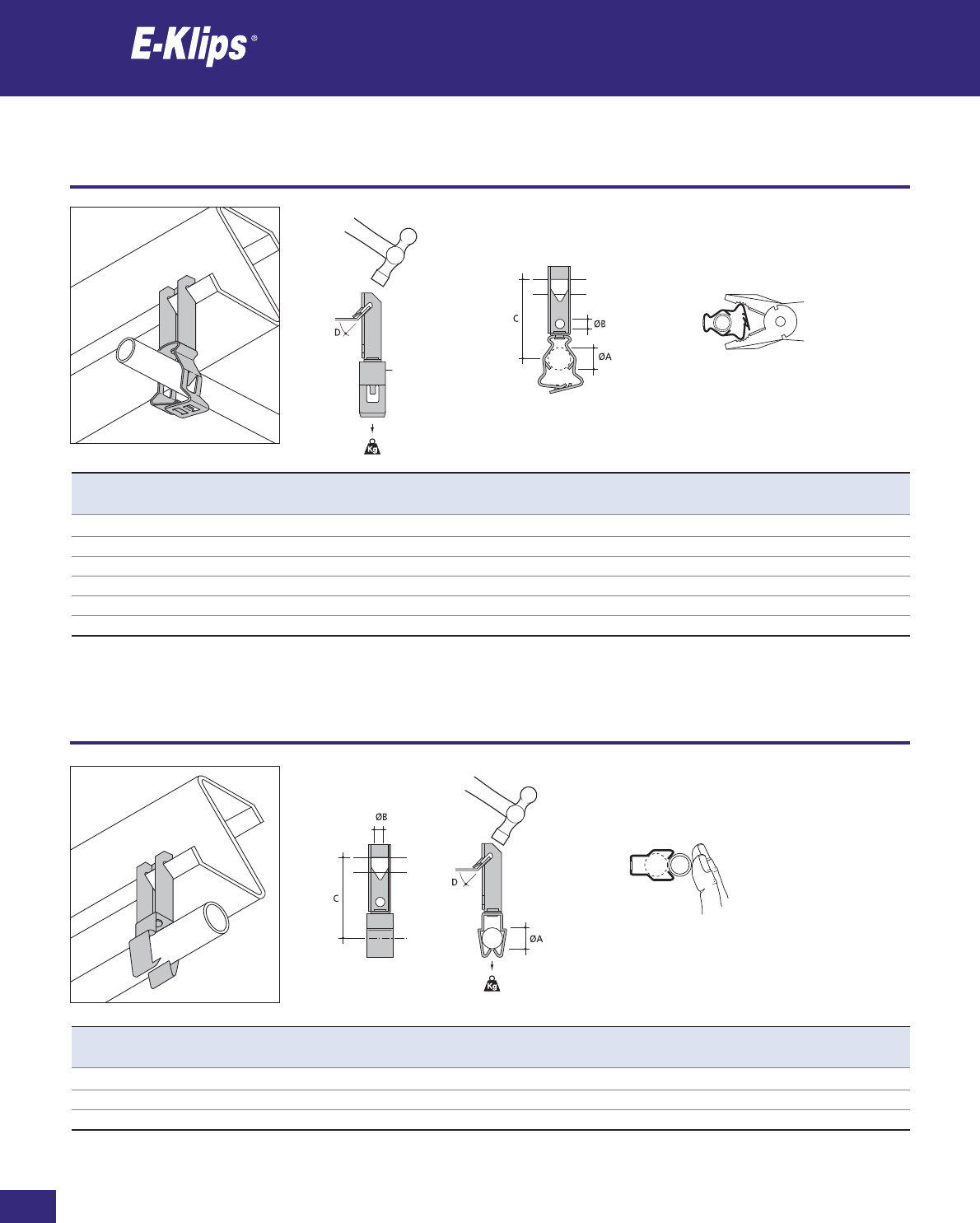
176
Thomas & Betts • www.tnb-europe.com
2.3
Purlin clips for conduits
Conduits
* See page 150 for material finishes
Product Ref. ØA ØB C D PG Type Load rating Material Quantity
[mm] [mm] [mm] [kg] finishes* [pieces]
TM03-GM1219 12-19 6.5 58 45˚ 7/9/11 45 F8+ 25
TM03-GM1926 19-26 6.5 59 45˚ 13.5/16 45 F8+ 25
TM03-GM2632 26-32 6.5 70 45˚ 21 45 F8+ 25
TM03-GM3240 32-40 6.5 74 45˚ 29 45 F8+ 25
TM03-GM4047 40-47 6.5 80 45˚ 36 45 F8+ 25
TM03-GM4757 47-57 6.5 80 45˚ 36/42 45 F8+ 25
Product Ref. ØA ØB C D PG Type Load rating Material Quantity
[mm] [mm] [mm] [kg] finishes* [pieces]
TM03-JM1825 18-22 6.5 63 45˚ 11/13.5/16 11 F8+ 25
TM03-JM2229 22-29 6.5 64 45˚ 13.5/21 11 F8+ 25
TM03-JM2933 29-33 6.5 69 45˚ – 11 F8+ 25
Purlin clips for conduits
Conduits
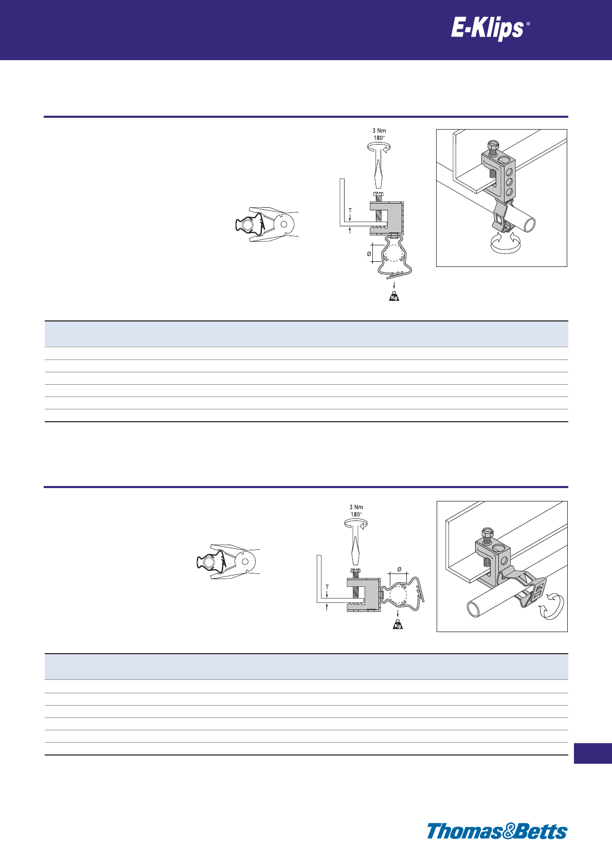
Girder clamps for conduits
Conduits
177
Thomas & Betts • www.tnb-europe.com
2.3
* See page 150 for material finishes
Product Ref. T Ø PG Type Load rating Material Quantity
[mm] [mm] [kg] finishes* [pieces]
FH65-GM1219 Max 18 12-19 7/9/11 45 F8+ 25
FH65-GM1926 Max 18 19-26 13.5/16 45 F8+ 25
FH65-GM2632 Max 18 26-32 21 45 F8+ 25
FH65-GM3240 Max 18 32-40 29 45 F8+ 25
FH65-GM4047 Max 18 40-47 36 45 F8+ 25
FH65-GM4757 Max 18 47-57 36/42 45 F8+ 25
Product Ref. T Ø PG Type Load rating Material Quantity
[mm] [mm] [kg] finishes* [pieces]
FH107-GM1219 Max 18 12-19 7/9/11 12 F8+ 25
FH107-GM1926 Max 18 19-26 13.5/16 12 F8+ 25
FH107-GM2632 Max 18 26-32 21 12 F8+ 25
FH107-GM3240 Max 18 32-40 29 12 F8+ 25
FH107-GM4047 Max 18 40-47 36 12 F8+ 25
FH107-GM4757 Max 18 47-57 36/42 12 F8+ 25
Girder clamps for conduits
Conduits
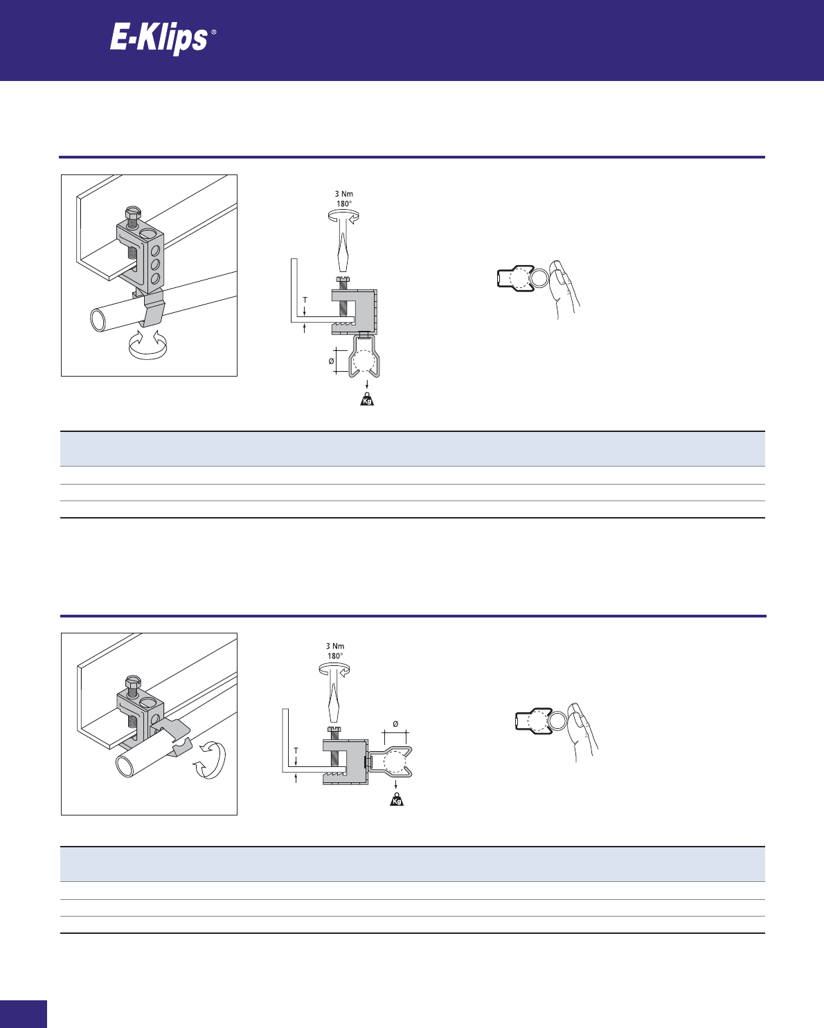
178
Thomas & Betts • www.tnb-europe.com
2.3
Girder clamps for conduits
Conduits
* See page 150 for material finishes
Product Ref. T Ø PG Type Load rating Material Quantity
[mm] [mm] [kg] finishes* [pieces]
FH65-JM1825 Max 18 18-22 11/13.5/16 11 F8+ 25
FH65-JM2229 Max 18 22-29 13.5/21 11 F8+ 25
FH65-JM2933 Max 18 29-33 – 11 F8+ 25
Product Ref. T Ø PG Type Load rating Material Quantity
[mm] [mm] [kg] finishes* [pieces]
FH107-JM1825 Max 18 18-22 11/13.5/16 7 F8+ 25
FH107-JM2229 Max 18 22-29 13.5/21 7 F8+ 25
FH107-JM2933 Max 18 29-33 – 7 F8+ 25
Girder clamps for conduits
Conduits
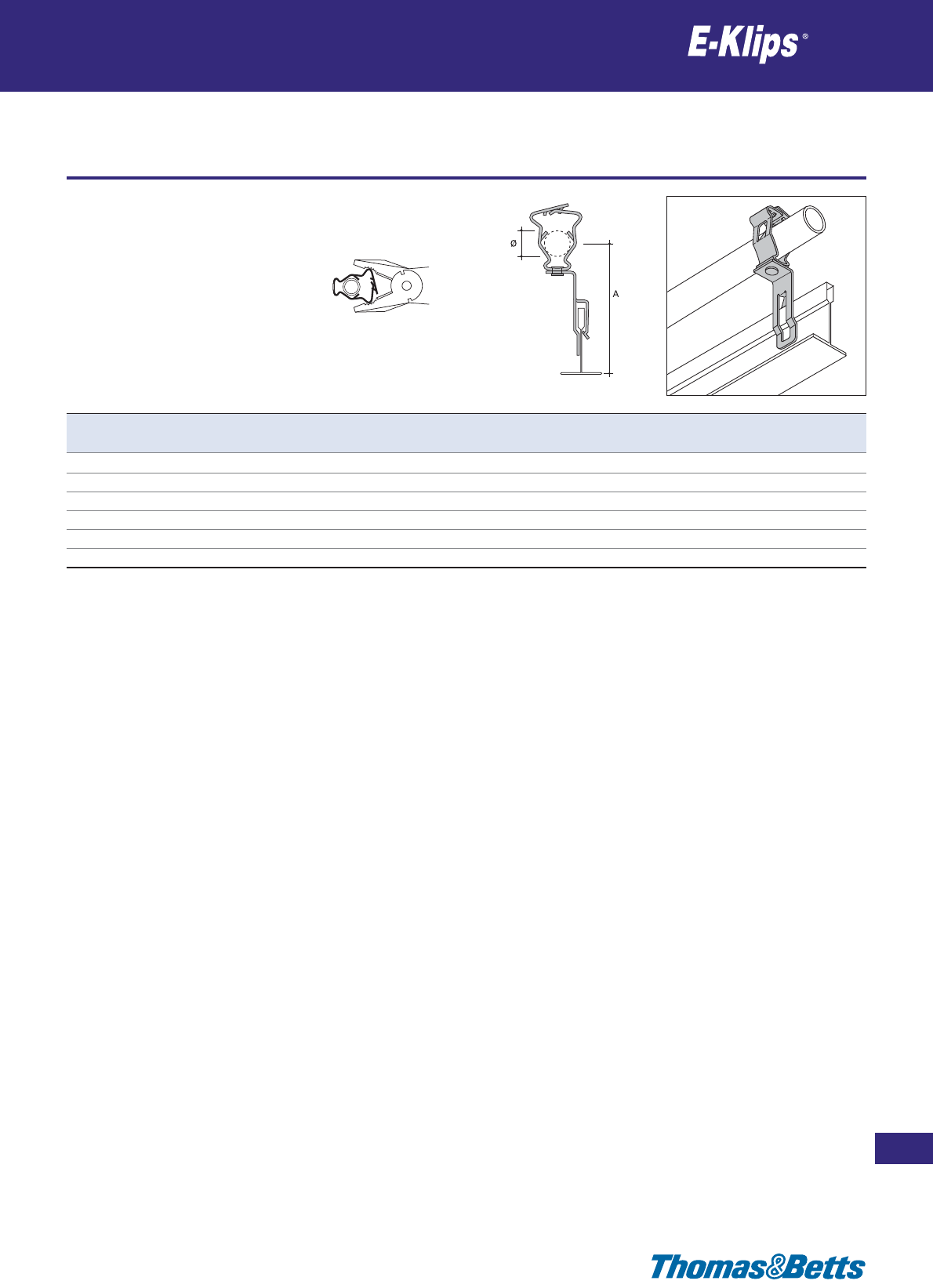
T-bow clips for conduits
Conduits
179
Thomas & Betts • www.tnb-europe.com
2.3
* See page 150 for material finishes
Product Ref. Ø A PG Type Material Quantity
[mm] [mm] finishes* [pieces]
PMB65-GM1219 12-19 74 7/9/11 F8+ 25
PMB65-GM1926 19-26 75 13.5/16 F8+ 25
PMB65-GM2632 26-32 86 21 F8+ 25
PMB65-GM3240 32-40 90 29 F8+ 25
PMB65-GM4047 40-47 92 36 F8+ 25
PMB65-GM4757 47-57 90 36/42 F8+ 25
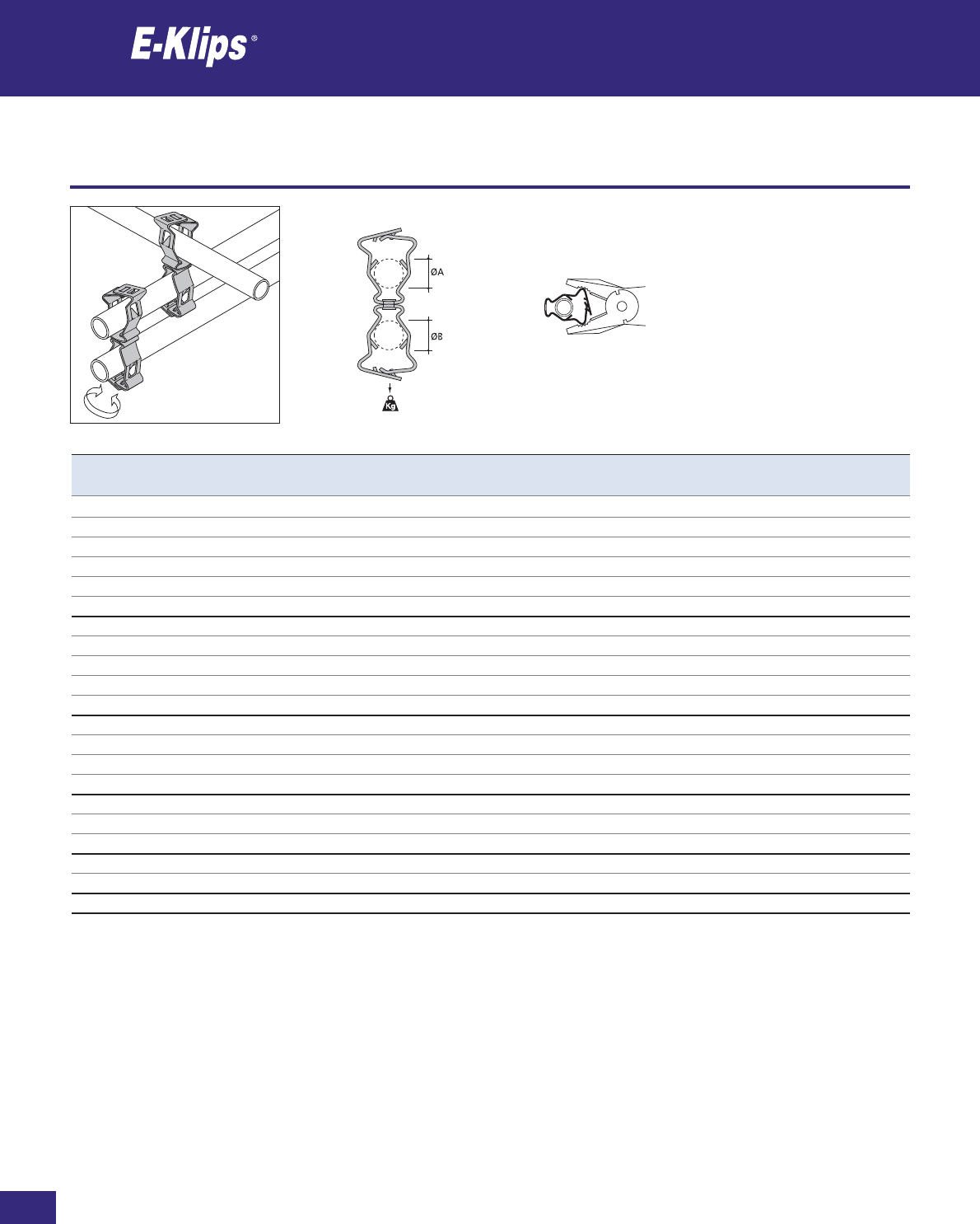
180
Thomas & Betts • www.tnb-europe.com
2.3
Clips for attaching conduits to conduits
Conduits
* See page 150 for material finishes
Product Ref. ØA ØB PG Type Load rating Material Quantity
[mm] [mm] [kg] finishes* [pieces]
GM1219-GM1219 12-19 12-19 7/9/11 45 F8+ 25
GM1219-GM1926 12-19 19-26 13.5/16 45 F8+ 25
GM1219-GM2632 12-19 26-32 21 45 F8+ 25
GM1219-GM3240 12-19 32-40 29 45 F8+ 25
GM1219-GM4047 12-19 40-47 36 45 F8+ 25
GM1219-GM4757 12-19 47-57 36/42 45 F8+ 25
GM1926-GM1926 19-26 19-26 13.5/16 45 F8+ 25
GM1926-GM2632 19-26 26-32 21 45 F8+ 25
GM1926-GM3240 19-26 32-40 29 45 F8+ 25
GM1926-GM4047 19-26 40-47 36 45 F8+ 25
GM1926-GM4757 19-26 47-57 36/42 45 F8+ 25
GM2632-GM2632 26-32 26-32 21 45 F8+ 25
GM2632-GM3240 26-32 32-40 29 45 F8+ 25
GM2632-GM4047 26-32 40-47 36 45 F8+ 25
GM2632-GM4757 26-32 47-57 36/42 45 F8+ 25
GM3240-GM3240 32-40 32-40 29 45 F8+ 25
GM3240-GM4047 32-40 40-47 36 45 F8+ 25
GM3240-GM4757 32-40 47-57 36/42 45 F8+ 25
GM4047-GM4047 40-47 40-47 36 45 F8+ 25
GM4047-GM4757 40-47 47-57 36/42 45 F8+ 25
GM4757-GM4757 47-57 47-57 36/42 45 F8+ 25
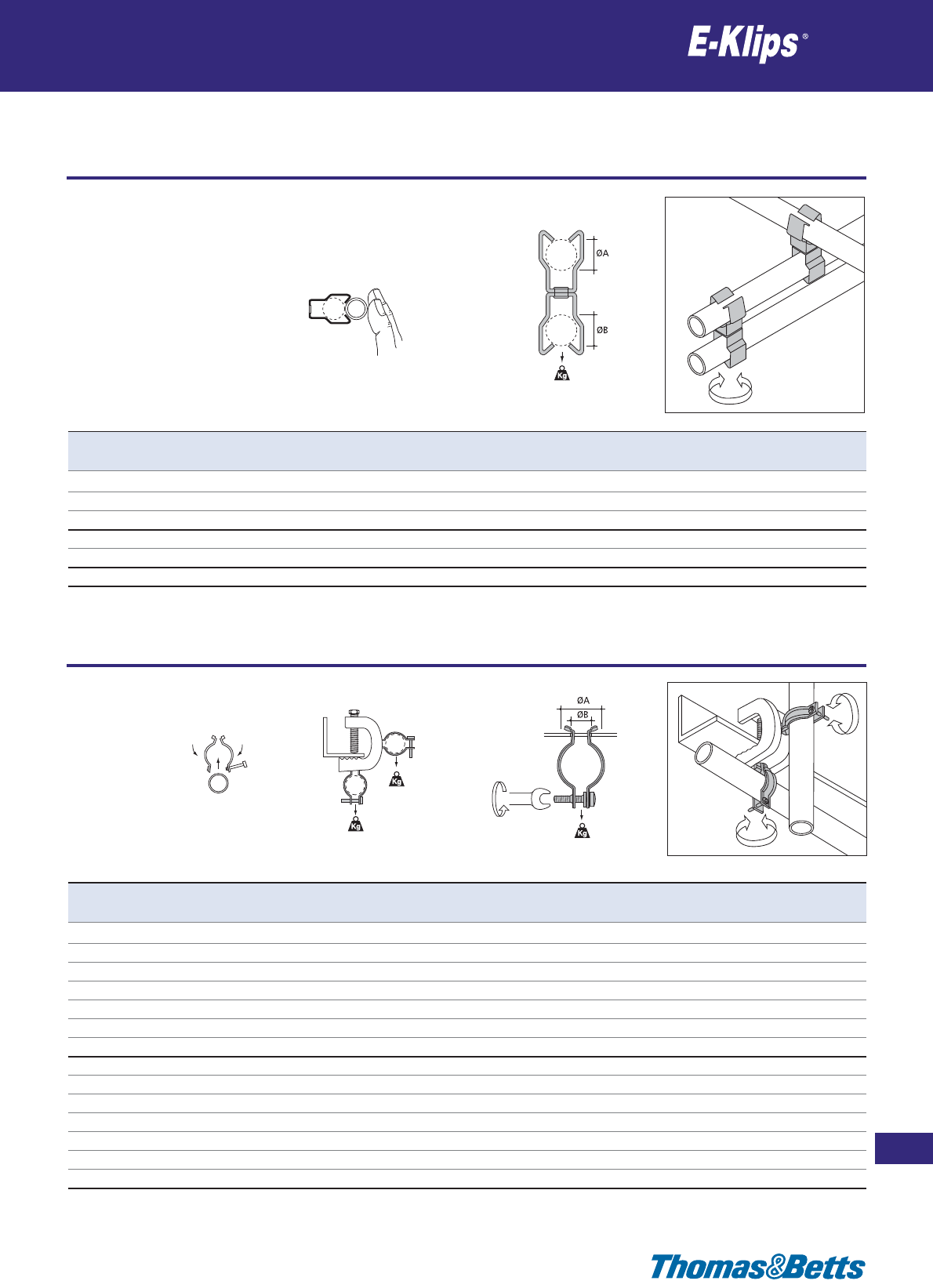
Clips for attaching conduits to conduits
Conduits
181
Thomas & Betts • www.tnb-europe.com
2.3
* See page 150 for material finishes
#1
3Nm
90°
Product Ref. ØA ØB PG Type Load rating #1 Load rating #2 Material Quantity
[mm] [mm] [kg] [kg] finishes* [pieces]
YHR-1618 16-18 14 11 40 15 F2 100
YHR-1821 18-21 14 13.5/16 40 15 F2 100
YHR-2427 24-27 14 21 40 15 F2 100
YHR-3034 30-34 14 29 40 15 F2 50
YHR-3438 34-38 14 29 40 15 F2 50
YHR-4751 47-51 14 36 40 15 F2 50
YHR-5963 59-63 14 48 40 15 F2 25
SSYHR-1618 16-18 14 11 40 15 F3 100
SSYHR-1821 18-21 14 13.5/16 40 15 F3 100
SSYHR-2427 24-27 14 21 40 15 F3 100
SSYHR-3034 30-34 14 29 40 15 F3 50
SSYHR-3438 34-38 14 29 40 15 F3 50
SSYHR-4751 47-51 14 36 40 15 F3 50
SSYHR-5963 59-63 14 48 40 15 F3 25
Product Ref. ØA ØB PG Type Load rating Material Quantity
[mm] [mm] [kg] finishes* [pieces]
JM1825-JM1825 18-22 18-22 11/13.5/16 11 F8+ 25
JM1825-JM2229 18-22 22-29 16/21 11 F8+ 25
JM1825-JM2933 18-22 29-33 – 11 F8+ 25
JM2229-JM2229 22-29 22-29 16/21 11 F8+ 25
JM2229-JM2933 22-29 29-33 – 11 F8+ 25
JM2933-JM2933 29-33 29-33 – 11 F8+ 25
#2
#1
Girder clamps for conduits
Conduits
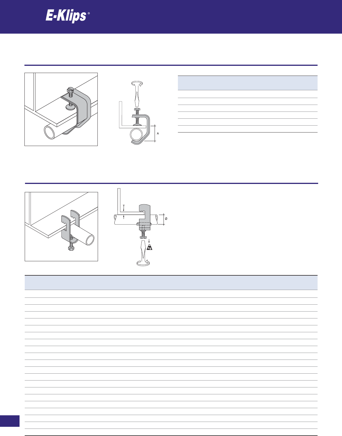
182
Thomas & Betts • www.tnb-europe.com
2.3
Girder clamps for conduits / pipes
Conduits
* See page 150 for material finishes
2Nm
360°
5Nm
Product Ref. A Material Quantity
[mm] finishes* [pieces]
ECH-33 33 F2 25
ECH-37 37 F2 25
ECH-41 41 F2 25
ECH-45 45 F2 25
ECH-49 49 F2 25
ECH-53 53 F2 25
Product Ref. T Ø Load rating Material Quantity
[mm] [mm] [kg] finishes* [pieces]
RA-0612 Max 12 6-12 60 F2 25
RA-1014 Max 12 10-14 60 F2 25
RA-1216 Max 12 12-16 60 F2 25
RA-1418 Max 12 14-18 60 F2 25
RA-1822 Max 12 18-22 60 F2 25
RA-2226 Max 12 22-26 80 F2 25
RA-2630 Max 12 26-30 80 F2 25
RA-3034 Max 12 30-34 80 F2 25
RA-3438 Max 12 34-38 100 F2 25
RA-3842 Max 12 38-42 100 F2 25
RA-4246 Max 12 42-46 100 F2 25
RA-4650 Max 12 46-50 100 F2 25
RA-5054 Max 12 50-54 100 F2 25
RA-5458 Max 12 54-58 100 F2 25
RA-5864 Max 12 58-64 100 F2 25
RA-6470 Max 12 64-70 100 F2 25
RA-7076 Max 12 70-76 100 F2 25
RA-7682 Max 12 76-82 100 F2 25
RA-8290 Max 12 82-90 100 F2 25
RA-90100 Max 12 90-100 100 F2 25
RA-100110 Max 12 100-110 100 F2 25
Girder clamps for conduits / pipes
Conduits
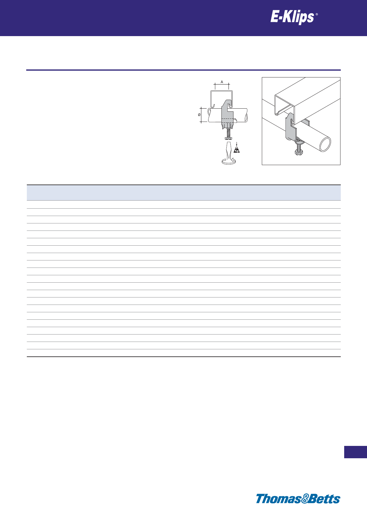
Girder clamps for conduits / pipes
Conduits
183
Thomas & Betts • www.tnb-europe.com
2.3
* See page 150 for material finishes
5Nm
Product Ref. A Ø Load rating Material Quantity
[mm] [mm] [kg] finishes* [pieces]
S-0612 Min 18 6-12 60 F2 25
S-1014 Min 18 10-14 60 F2 25
S-1216 Min 18 12-16 60 F2 25
S-1418 Min 18 14-18 60 F2 25
S-1822 Min 18 18-22 60 F2 25
S-2226 Min 18 22-26 80 F2 25
S-2630 Min 18 26-30 80 F2 25
S-3034 Min 18 30-34 80 F2 25
S-3438 Min 18 34-38 100 F2 25
S-3842 Min 18 38-42 100 F2 25
S-4246 Min 18 42-46 100 F2 25
S-4650 Min 18 46-50 100 F2 25
S-5054 Min 18 50-54 100 F2 25
S-5458 Min 18 54-58 100 F2 25
S-5864 Min 18 58-64 100 F2 25
S-6470 Min 18 64-70 100 F2 25
S-7076 Min 18 70-76 100 F2 25
S-7682 Min 18 76-82 100 F2 25
S-8290 Min 18 82-90 100 F2 25
S-90100 Min 18 90-100 100 F2 25
S-100110 Min 18 100-110 100 F2 25
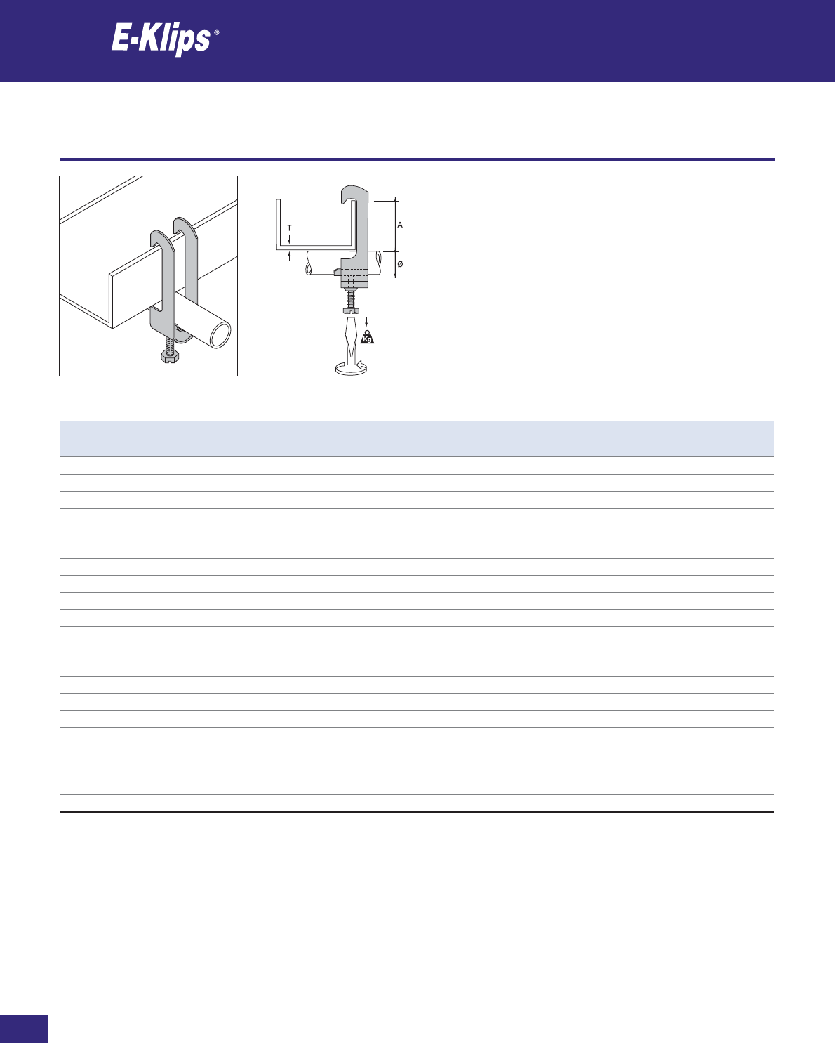
184
Thomas & Betts • www.tnb-europe.com
2.3
Girder clamps for conduits / pipes
Conduits
* See page 150 for material finishes
5Nm
Product Ref. T Ø A Load rating Material Quantity
[mm] [mm] [mm] [kg] finishes* [pieces]
H-0612 Max 6 6-12 Max 40 80 F2 25
H-1014-FU Max 6 10-14 Max 40 80 F2 25
H-1216 Max 6 12-16 Max 40 80 F2 25
H-1418 Max 6 14-18 Max 40 80 F2 25
H-1822 Max 6 18-22 Max 40 80 F2 25
H-2226 Max 6 22-26 Max 40 80 F2 25
H-2630 Max 6 26-30 Max 40 80 F2 25
H-3034 Max 6 30-34 Max 40 80 F2 25
H-3438 Max 6 34-38 Max 40 100 F2 25
H-3842 Max 6 38-42 Max 40 100 F2 25
H-4246 Max 6 42-46 Max 40 100 F2 25
H-4650 Max 6 46-50 Max 40 100 F2 25
H-5054 Max 6 50-54 Max 40 100 F2 25
H-5458 Max 6 54-58 Max 40 100 F2 25
H-5864 Max 6 58-64 Max 40 100 F2 25
H-6470 Max 6 64-70 Max 40 100 F2 25
H-7076 Max 6 70-76 Max 40 100 F2 25
H-7682 Max 6 76-82 Max 40 100 F2 25
H-8290 Max 6 82-90 Max 40 100 F2 25
H-90100 Max 6 90-100 Max 40 100 F2 25
H-100110 Max 6 100-110 Max 40 100 F2 25
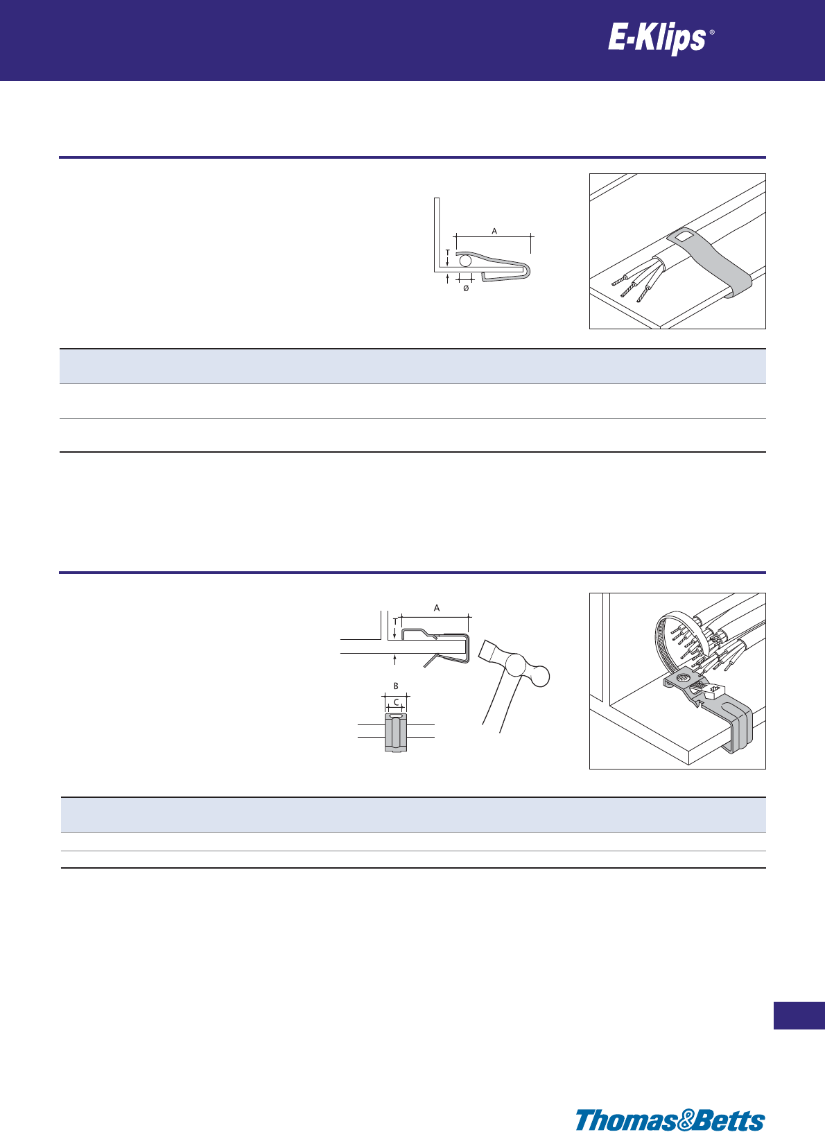
Girder clips for single cables
Cable
185
Thomas & Betts • www.tnb-europe.com
2.4
* See page 150 for material finishes
Product Ref. T Ø A Material Quantity
[mm] [mm] [mm] finishes* [pieces]
LM-38 3-5 6-16 46 F8+ 100
5-8 3-10
LM-811 8-9 7-20 46 F8+ 100
10-11 7-12
Girder clips for multi cables
Cable
Product Ref. T A B C Material Quantity
[mm] [mm] [mm] [mm] finishes* [pieces]
GH-310 3-10 52 16 10 F8+ 100
GH-1018 10-18 52 16 10 F8+ 100
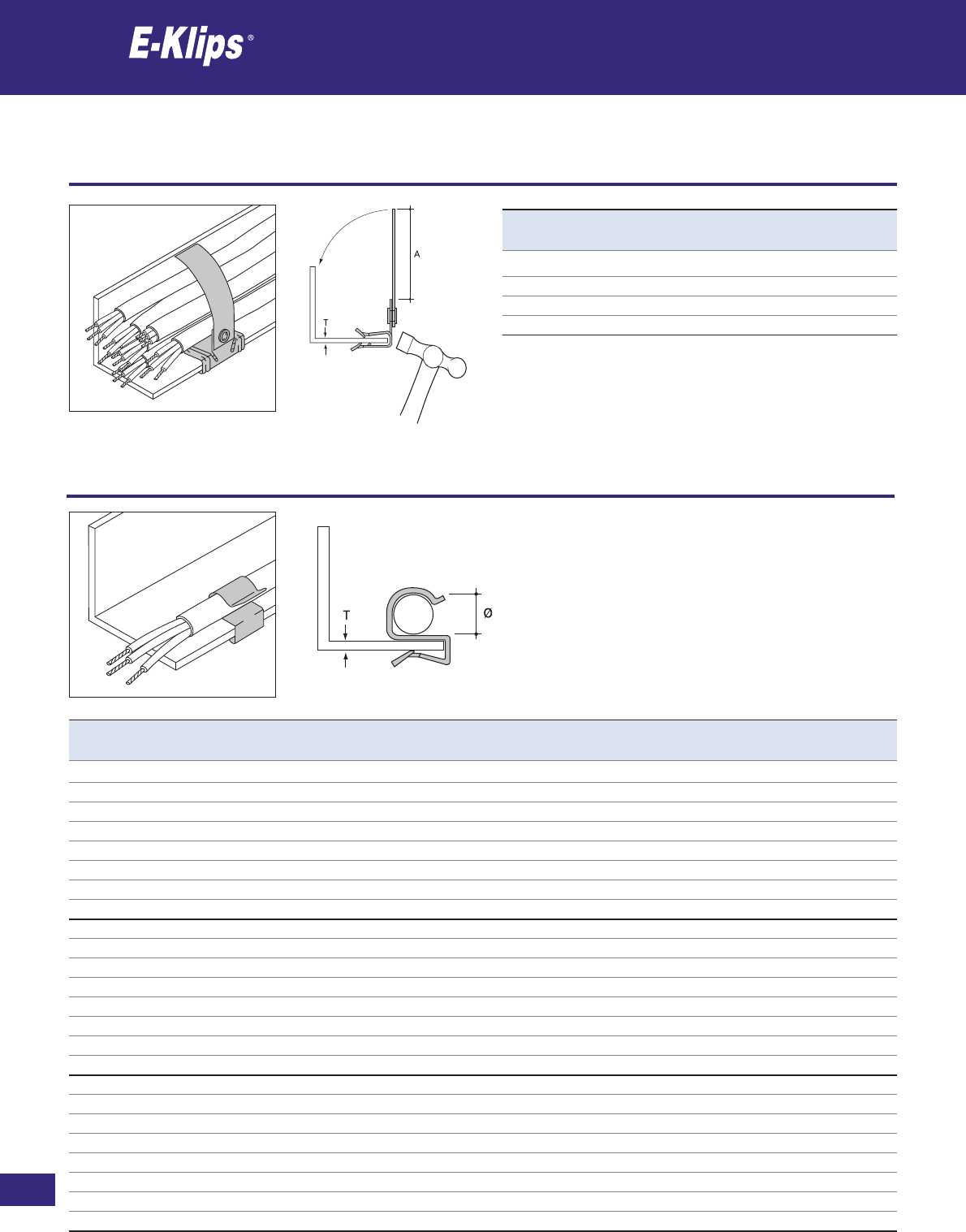
186
Thomas & Betts • www.tnb-europe.com
2.4
Girder clips for multi cables
Cable
* See page 150 for material finishes
Product Ref. T A Material Quantity
[mm] [mm] finishes* [pieces]
AH153-B 1.5-3 65 F8+ 25
AH38-B 3-8 58 F8+ 25
AH814-B 8-14 58 F8+ 25
AH1420-B 14-20 58 F8+ 25
Product Ref. T Ø Material Quantity
[mm] [mm] finishes* [pieces]
ECS-4555 2-4 4.5-5.5 F8+ 100
ECS-67 2-4 6-7 F8+ 100
ECS-89 2-4 8-9 F8+ 100
ECS-1011 2-4 10-11 F8+ 100
ECS-1214 2-4 12-14 F8+ 100
ECS-1519 2-4 15-18 F8+ 100
ECS-2024 2-4 19-24 F8+ 100
ECS-2532 2-4 25-32 F8+ 100
ECM-4555 4-7 4.5-5.5 F8+ 100
ECM-67 4-7 6-7 F8+ 100
ECM-89 4-7 8-9 F8+ 100
ECM-1011 4-7 10-11 F8+ 100
ECM-1214 4-7 12-14 F8+ 100
ECM-1519 4-7 15-18 F8+ 100
ECM-2024 4-7 19-24 F8+ 100
ECM-2532 4-7 25-32 F8+ 100
ECL-4555 8-12 4.5-5.5 F8+ 100
ECL-67 8-12 6-7 F8+ 100
ECL-89 8-12 8-9 F8+ 100
ECL-1011 8-12 10-11 F8+ 100
ECL-1214 8-12 12-14 F8+ 100
ECL-1519 8-12 15-18 F8+ 100
ECL-2024 8-12 19-24 F8+ 100
ECL-2532 8-12 25-32 F8+ 100
Girder clips for single cables
Cable
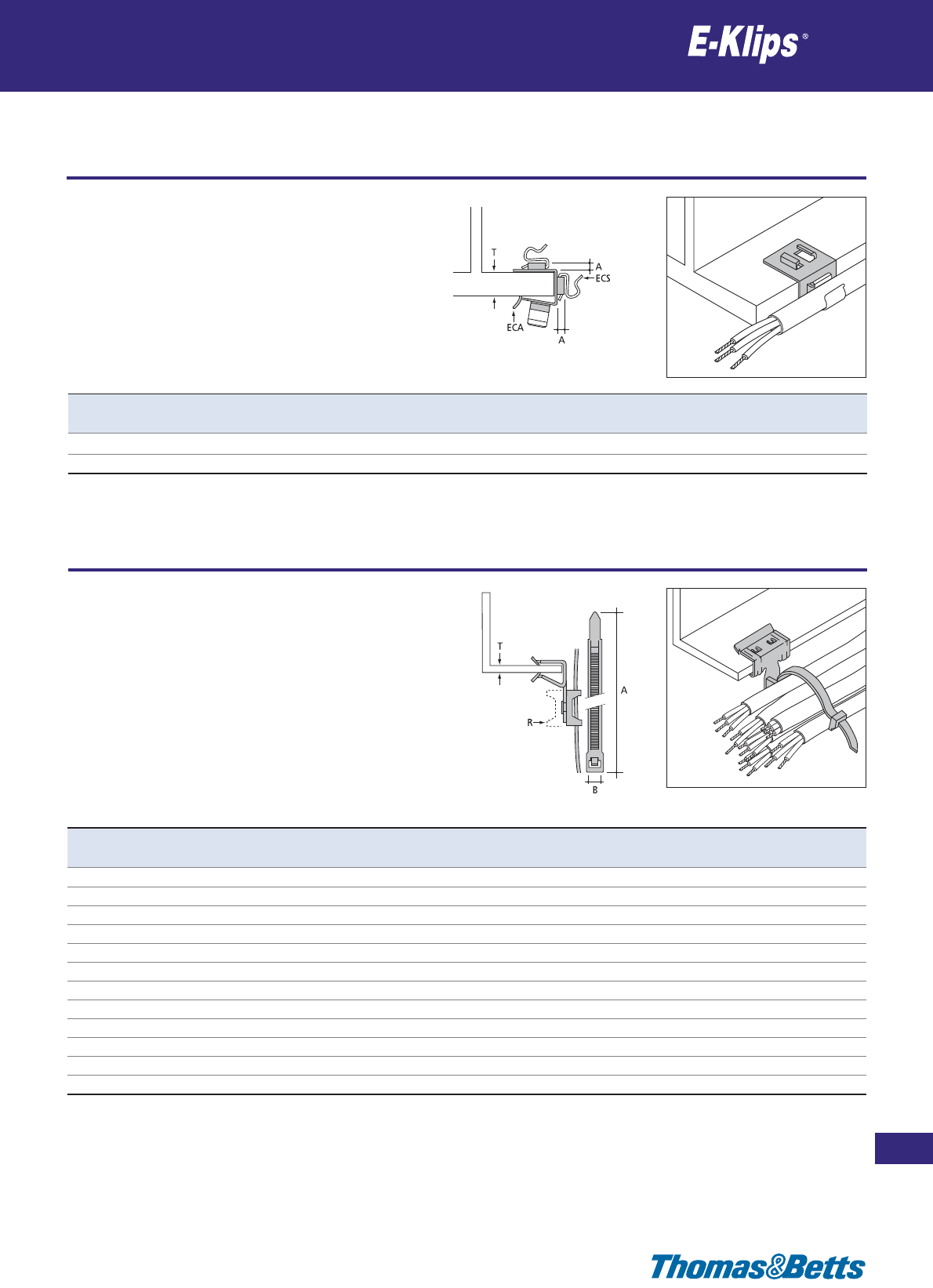
Girder clips for single cables
Cable
187
Thomas & Betts • www.tnb-europe.com
2.4
* See page 150 for material finishes
Product Ref. T A Material Quantity
[mm] [mm] finishes* [pieces]
ECA-1215 12-15 2-4 F8+ 100
ECA-1520 15-20 2-4 F8+ 100
Product Ref. T A B Material Quantity
[mm] [mm] [mm] finishes* [pieces]
AH153-CT2 1.5-3 200 7.6 F8+** 25
AH153-CT2R 1.5-3 200 7.6 F8+** 25
AH153-CT4 1.5-3 370 7.6 F8+** 25
AH38-CT2 3-8 200 7.6 F8+** 25
AH38-CT2R 3-8 200 7.6 F8+** 25
AH38-CT4 3-8 370 7.6 F8+** 25
AH814-CT2 8-14 200 7.6 F8+** 25
AH814-CT2R 8-14 200 7.6 F8+** 25
AH814-CT4 8-14 370 7.6 F8+** 25
AH1420-CT2 14-20 200 7.6 F8+** 25
AH1420-CT2R 14-20 200 7.6 F8+** 25
AH1420-CT4 14-20 370 7.6 F8+** 25
** Mounting Bases and Cable Ties are made of polyamide 6.6
Girder clips, mounting base and cable tie for cable bundles
Cable
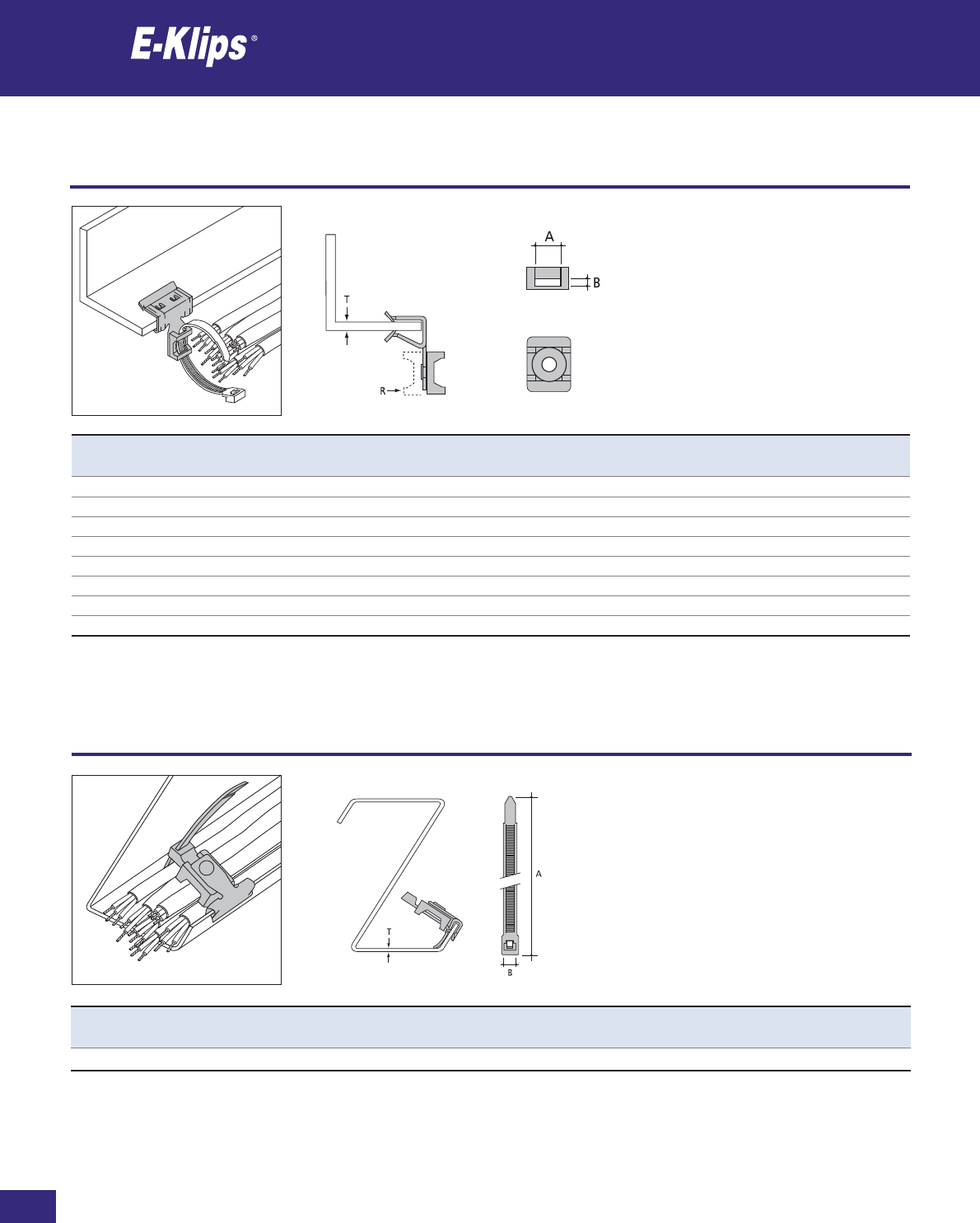
188
Thomas & Betts • www.tnb-europe.com
2.4
Girder clips and mounting base for cable bundles
Cable
* See page 150 for material finishes
Product Ref. T A B Material Quantity
[mm] [mm] [mm] finishes* [pieces]
AH153-M 1.5-3 9 3.5 F8+** 25
AH153-MR 1.5-3 9 3.5 F8+** 25
AH38-M 3-8 9 3.5 F8+** 25
AH38-MR 3-8 9 3.5 F8+** 25
AH814-M 8-14 9 3.5 F8+** 25
AH814-MR 8-14 9 3.5 F8+** 25
AH1420-M 14-20 9 3.5 F8+** 25
AH1420-MR 14-20 9 3.5 F8+** 25
** Mounting Bases are made of polyamide 6.6
Product Ref. T A B Material Quantity
[mm] [mm] [mm] finishes* [pieces]
AH153-CT2R 1.5-3 200 7.6 F8+** 25
** Mounting Bases and Cable Ties are made of polyamide 6.6
Purlin clips, mounting base and cable tie for cable bundles
Cable
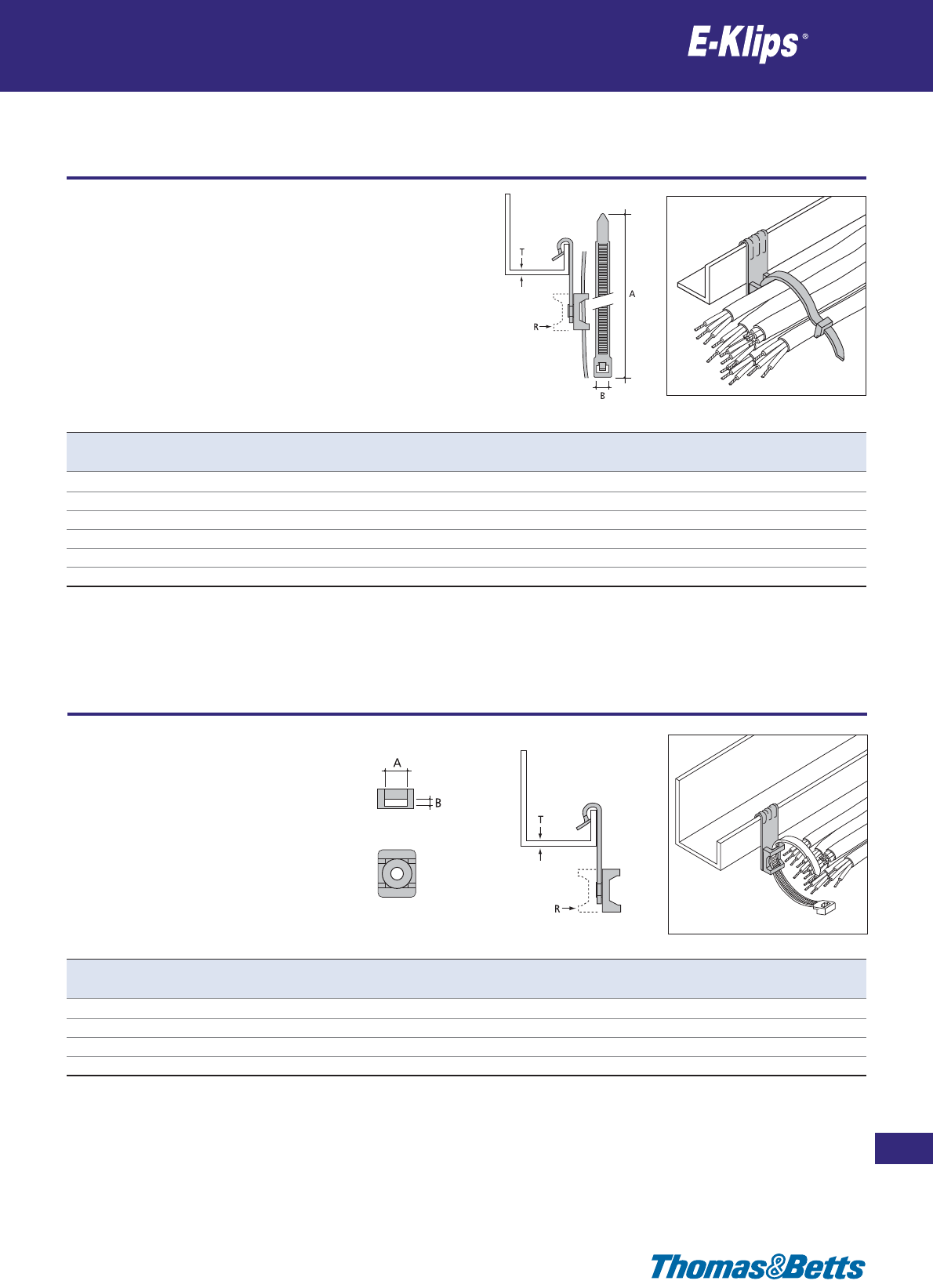
Girder clips, mounting base and cable tie for cable bundles
Cable
189
Thomas & Betts • www.tnb-europe.com
2.4
* See page 150 for material finishes
Product Ref. T A B Material Quantity
[mm] [mm] [mm] finishes* [pieces]
AV155-CT2 1.5-5 200 7.6 F8+** 25
AV155-CT2R 1.5-5 200 7.6 F8+** 25
AV155-CT4 1.5-5 370 7.6 F8+** 25
AV57-CT2 5-7 200 7.6 F8+** 25
AV57-CT2R 5-7 200 7.6 F8+** 25
AV57-CT4 5-7 370 7.6 F8+** 25
** Mounting Bases and Cable Ties are made of polyamide 6.6
Product Ref. T A B Material Quantity
[mm] [mm] [mm] finishes* [pieces]
AV155-M 1.5-5 9 3.5 F8+** 25
AV155-MR 1.5-5 9 3.5 F8+** 25
AV57-M 5-7 9 3.5 F8+** 25
AV57-MR 5-7 9 3.5 F8+** 25
** Mounting Bases are made of polyamide 6.6
Purlin clips and mounting base for cable bundles
Cable
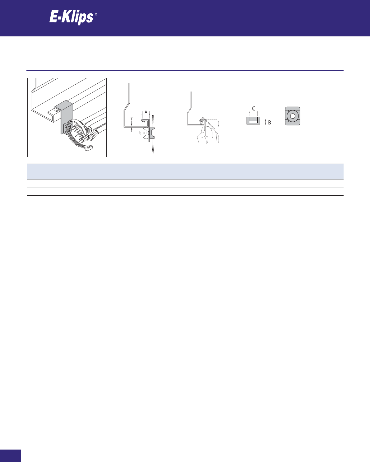
190
Thomas & Betts • www.tnb-europe.com
2.4
Purlin clips and mounting base for cable bundles
Cable
* See page 150 for material finishes
Product Ref. T A B C Material Quantity
[mm] [mm] [mm] [mm] finishes* [pieces]
SM125-M ≤3.0 9 3.5 12.5 F2** 25
SM125-MR ≤3.0 9 3.5 12.5 F2** 25
** Mounting Bases are made of polyamide 6.6
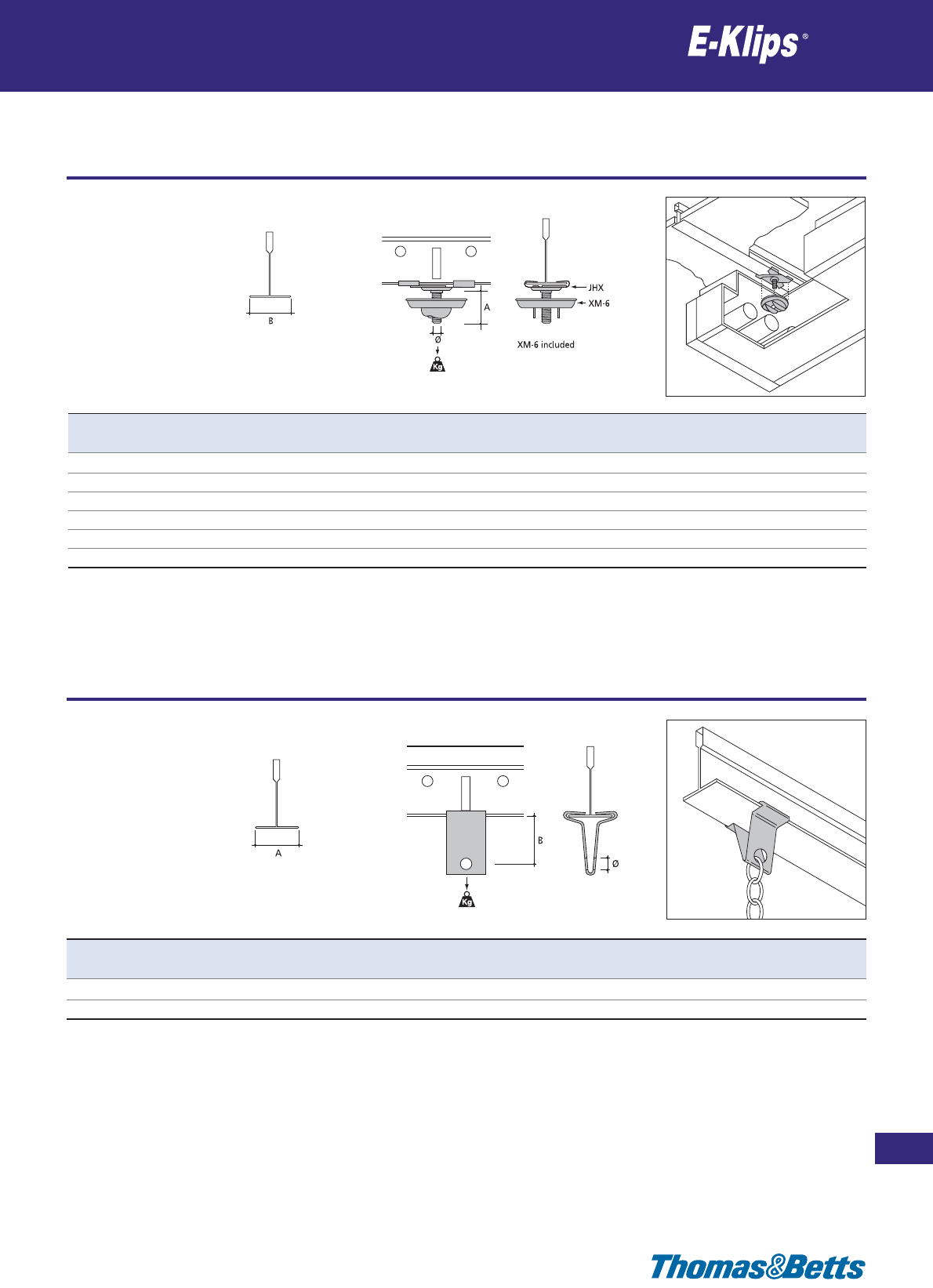
Suspended ceiling clips
Ceiling
191
Thomas & Betts • www.tnb-europe.com
2.5
* See page 150 for material finishes
Product Ref. Ø A B Load rating Material Quantity
[mm] [mm] [mm] [kg] finishes* [pieces]
JHX-16SW M6 16 25 9 F4 100
JHX-16S M6 16 25 22 F8+ 100
JHX-38S M6 38 25 22 F8+ 100
JHX-50S M6 50 25 22 F8+ 100
JHX-72S M6 72 25 22 F8+ 100
JH-15SW M6 15 15 22 F4 100
JH-15SW in White
Product Ref. Ø A B Load rating Material Quantity
[mm] [mm] [mm] [kg] finishes* [pieces]
LH-25 7 25 20 18 F1 100
LH-25W 7 25 20 18 F4 100
LH-25W in White
Suspended ceiling clips
Ceiling
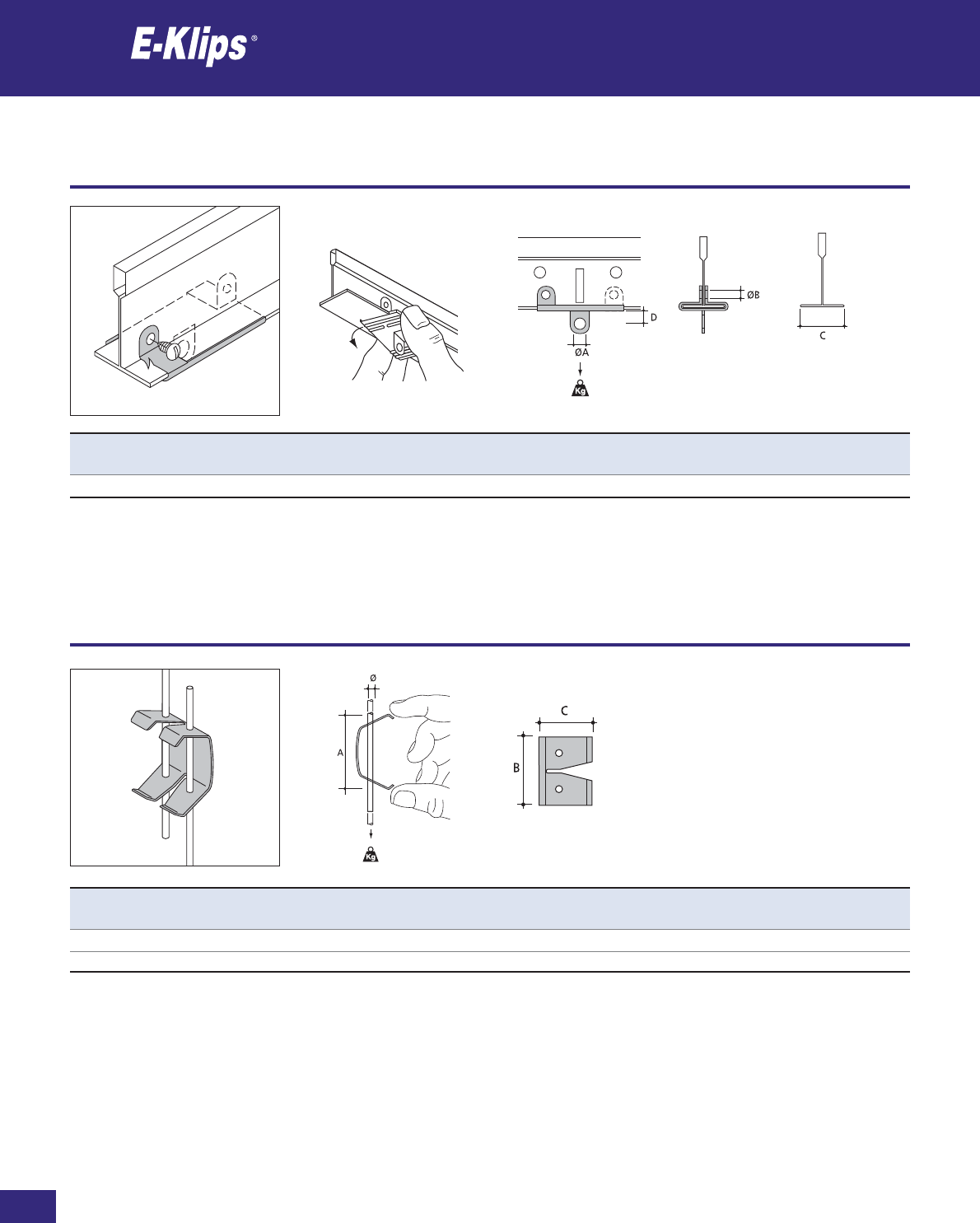
192
Thomas & Betts • www.tnb-europe.com
2.5
Suspended ceiling clips
Ceiling
* See page 150 for material finishes
Product Ref. Ø A B C Load rating Material Quantity
[mm] [mm] [mm] [mm] [kg] finishes* [pieces]
ADS-3 3 55 30 18 100 F1 100
ADS-4 4 55 30 18 100 F1 100
Product Ref. ØA ØB C D Load Rating Material Quantity
[mm] [mm] [mm] [mm] [kg] finishes* [pieces]
KH-6W 6 3 25 7 22 F4 100
KH-6W in White
Suspended ceiling hangers
Ceiling
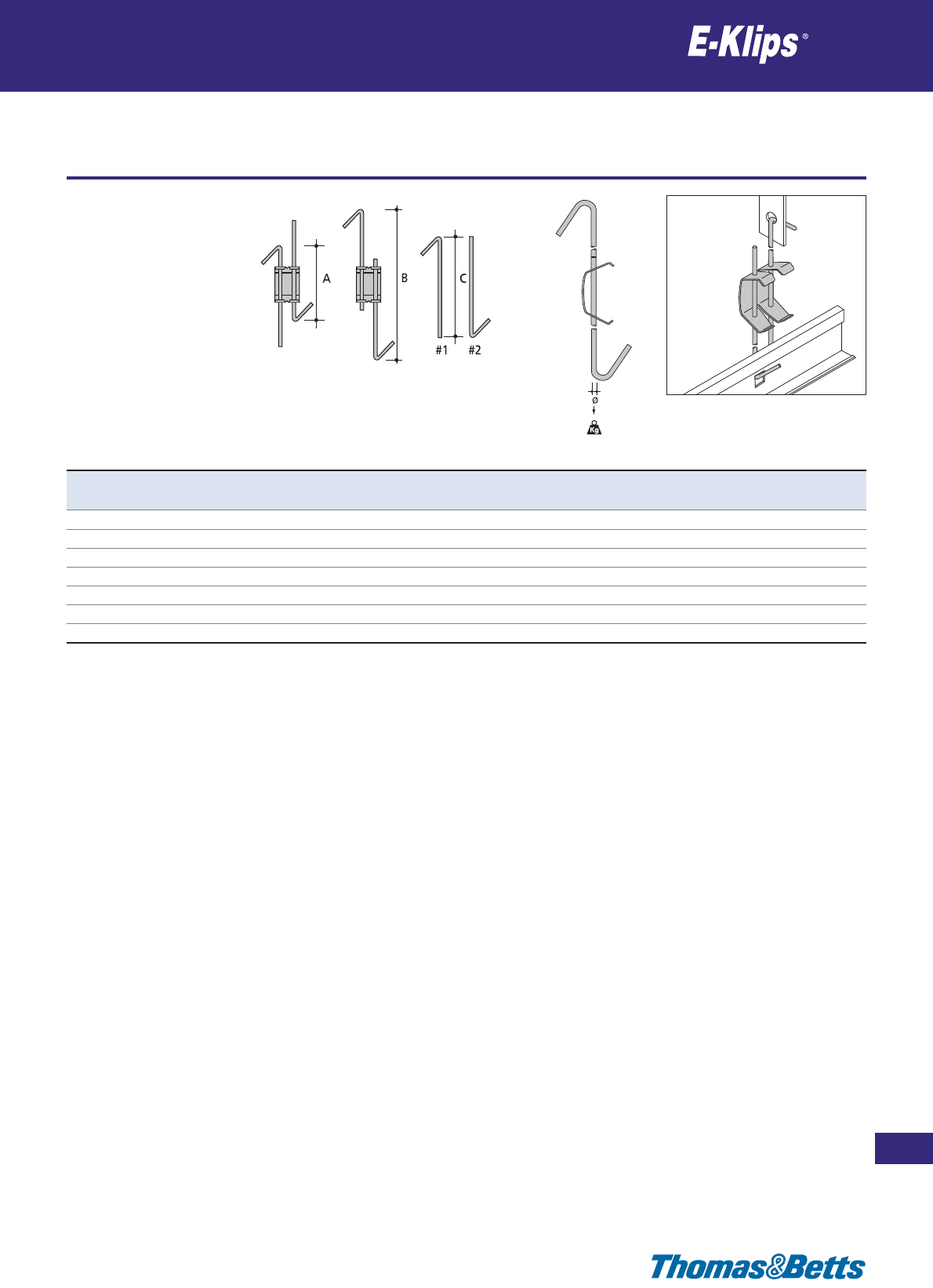
Suspended ceiling hangers
Ceiling
193
Thomas & Betts • www.tnb-europe.com
2.5
* See page 150 for material finishes
Product Ref. Ø A B C#1 C#2 Load rating Material Quantity
[mm] [mm] [mm] [mm] [mm] [kg] finishes* [pieces]
ADSH10-30 4 100 300 190 190 100 F1 25
ADSH30-60 4 300 600 340 340 100 F1 25
ADSH60-100 4 600 1000 540 540 100 F1 25
ADSH100-125 4 1000 1250 990 340 100 F1 25
ADSH125-150 4 1250 1500 1040 540 100 F1 25
ADSH150-175 4 1500 1750 1290 540 100 F1 25
ADSH175-200 4 1750 2000 1540 540 100 F1 25
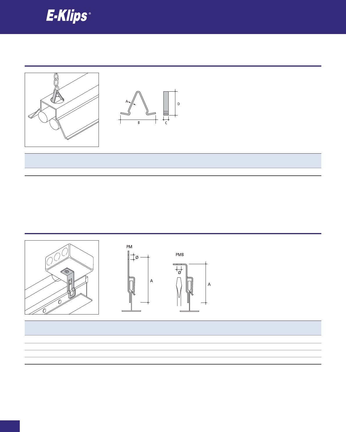
194
Thomas & Betts • www.tnb-europe.com
2.6
Clips for chain hanging
Decking
* See page 150 for material finishes
Product Ref. A B C D Material Quantity
[mm] [mm] [mm] [mm] finishes* [pieces]
V-1 1 50.8 8 35 F1 100
Product Ref. Ø A Material Quantity
[mm] [mm] finishes* [pieces]
PMB-6T M6 59 F8+ 100
PMB-65 6.5 59 F8+ 100
PM-6T M6 71 F8+ 100
PM-65 6.5 71 F8+ 100
T-bar clips for conduit boxes
Decking
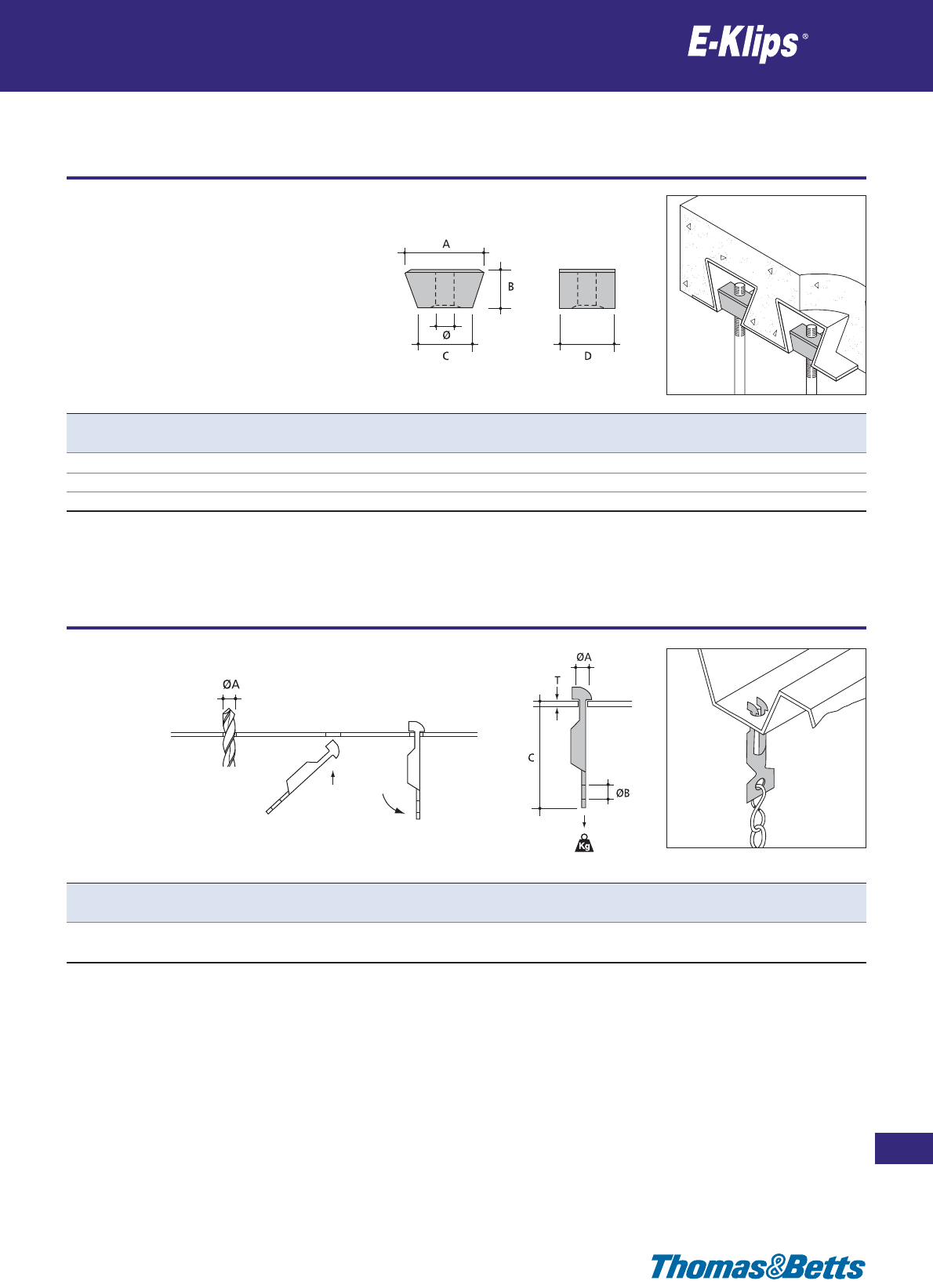
Wedge nuts
Decking
195
Thomas & Betts • www.tnb-europe.com
2.6
* See page 150 for material finishes
Product Ref. Ø A B C D Load rating Material Quantity
[mm] [mm] [mm] [mm] [kg] finishes* [pieces]
WN6 M6 25 13 19 12 20 F1 100
WN8 M8 25 13 19 12 36 F1 100
WN10 M10 25 13 19 12 58 F1 100
Product Ref. T ØA ØB C Load rating Material Quantity
[mm] [mm] [mm] [mm] [kg] finishes* [pieces]
NH-083 0.8-2 7 6.5 45 45 F8+ 100
2-3 90
Decking clips for chain and wire
Decking
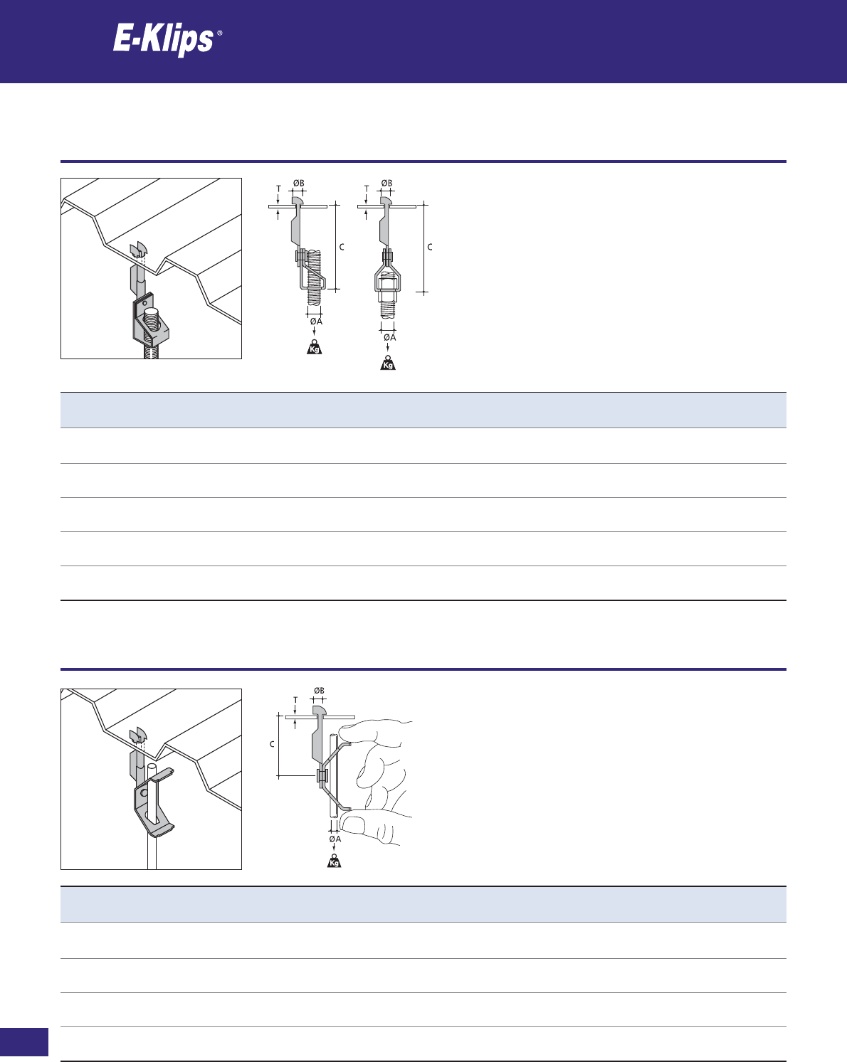
196
Thomas & Betts • www.tnb-europe.com
2.6
Decking clips for threaded rod
Decking
* See page 150 for material finishes
Product Ref. T ØA ØB C Load rating Material Quantity
[mm] [mm] [mm] [mm] [kg] finishes* [pieces]
NH083-AM127 0.8-2 12.7 7 74 45 F8+ 25
2-3 68
NH083-AM6T 0.8-2 M6 7 74 45 F8+ 25
2-3 68
NH083-AM8T 0.8-2 M8 7 74 45 F8+ 25
2-3 68
NH083-AM10T 0.8-2 M10 7 74 45 F8+ 25
2-3 68
NH083-YM127 0.8-2 12.7 7 76 45 F8+ 25
2-3 90
Product Ref. T ØA ØB C Load rating Material Quantity
[mm] [mm] [mm] [mm] [kg] finishes* [pieces]
NH083-BM4 0.8-2 4 7 45 45 F8+ 25
2-3 90
NH083-BM6 0.8-2 6 7 45 45 F8+ 25
2-3 90
NH083-BM8 0.8-2 8 7 45 45 F8+ 25
2-3 90
NH083-BM10 0.8-2 10 7 45 45 F8+ 25
2-3 90
Decking clips for rod
Decking

Decking clips for threaded rod
Decking
197
Thomas & Betts • www.tnb-europe.com
2.6
* See page 150 for material finishes
Product Ref. A B C Ø Load rating Material Quantity
[mm] [mm] [mm] [mm] [kg] finishes* [pieces]
DWH-6T 50 40 15 M6 100 F1 25
DWH-8T 50 40 15 M8 100 F1 25
DWH-10T 50 40 15 M10 100 F1 25
Product Ref. A B C Ø Load rating Material Quantity
[mm] [mm] [mm] [mm] [kg] finishes* [pieces]
DMH-6T 50 40 34 M6 150 F1 25
DMH-8T 50 40 34 M8 150 F1 25
DMH-10T 50 40 34 M10 150 F1 25
Decking clips for threaded rod
Decking
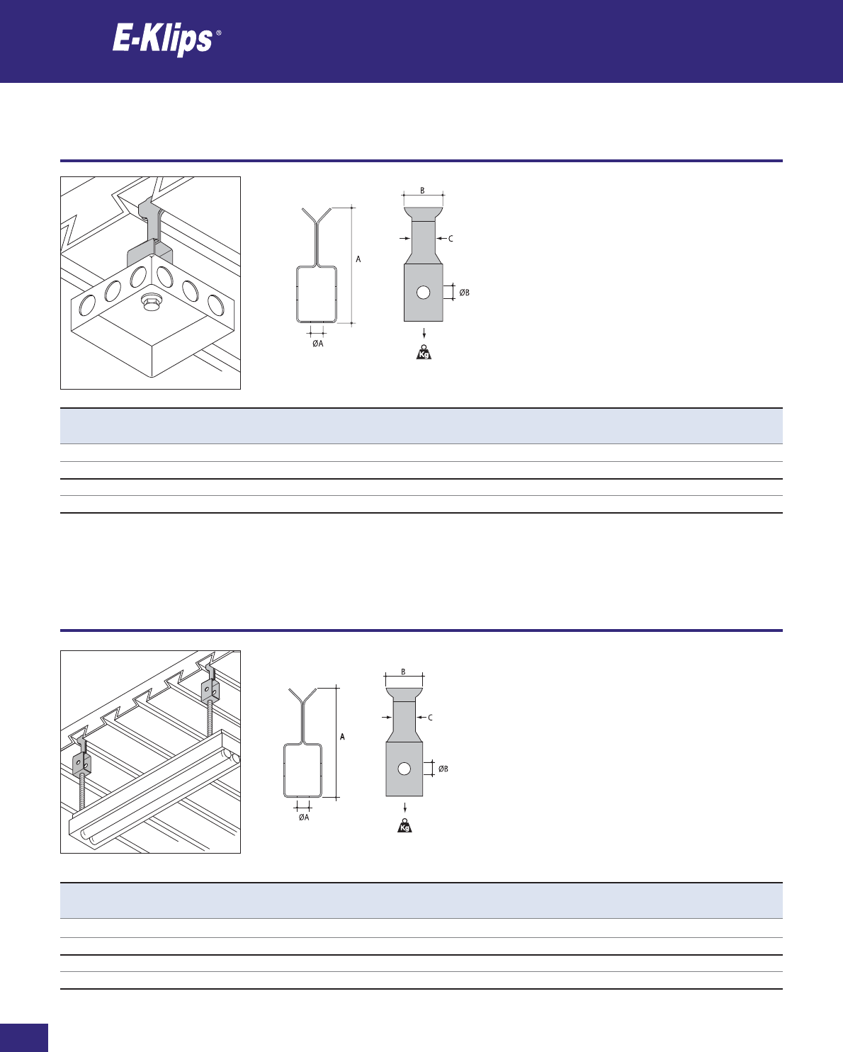
198
Thomas & Betts • www.tnb-europe.com
2.6
Decking clips for conduit boxes
Decking
* See page 150 for material finishes
Product Ref. ØA ØB A B C Load rating Material Quantity
[mm] [mm] [mm] [mm] [mm] [kg] finishes* [pieces]
DH1217-105 10.5 6.5 60 20 11.5 60 F3 100
DH1217-65 6.5 6.5 60 20 11.5 60 F3 100
DH1722-105 10.5 6.5 60 25 16.5 60 F3 100
DH1722-65 6.5 6.5 60 25 16.5 60 F3 100
Product Ref. ØA ØB A B C Load rating Material Quantity
[mm] [mm] [mm] [mm] [mm] [kg] finishes* [pieces]
DH1217-M8 M8 6.5 60 20 11.5 60 F3 100
DH1217-M10 M10 6.5 60 20 11.5 60 F3 100
DH1722-M8 M8 6.5 60 25 16.5 60 F3 100
DH1722-M10 M10 6.5 60 25 16.5 60 F3 100
Decking clips for threaded rod
Decking
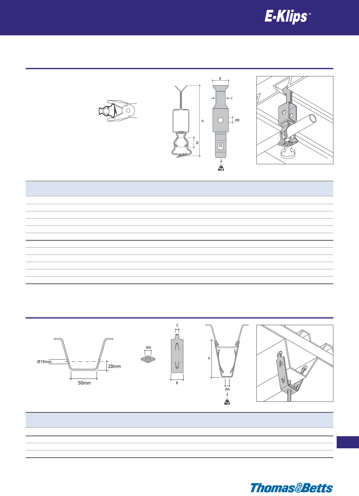
Decking clips for conduits
Decking
199
Thomas & Betts • www.tnb-europe.com
2.6
* See page 150 for material finishes
Product Ref. Ø A B C Load rating Material Quantity
[mm] [mm] [mm] [mm] [kg] finishes* [pieces]
DH1217-GM1219 12-19 104 20 11.5 45 F3 25
DH1217-GM1926 19-26 104 20 11.5 45 F3 25
DH1217-GM2632 26-32 115 20 11.5 45 F3 25
DH1217-GM3240 32-40 128 20 11.5 45 F3 25
DH1217-GM4047 40-47 139 20 11.5 45 F3 25
DH1217-GM4757 47-57 147 20 11.5 45 F3 25
DH1722-GM1219 12-19 104 25 16.5 45 F3 25
DH1722-GM1926 19-26 104 25 16.5 45 F3 25
DH1722-GM2632 26-32 115 25 16.5 45 F3 25
DH1722-GM3240 32-40 128 25 16.5 45 F3 25
DH1722-GM4047 40-47 139 25 16.5 45 F3 25
DH1722-GM4757 47-57 147 25 16.5 45 F3 25
Decking clips for threaded rod
Decking
Product Ref. ØA A B C Load rating Material Quantity
[mm] [mm] [mm] [mm] [kg] finishes* [pieces]
DH-50 10.5 100 30 8 75 F8+ 50
DHN-6T M6 – – – 75 F8+ 50
DHN-8T M8 – – – 75 F8+ 50
DHN-10T M10 – – – 75 F8+ 50
DHN
DH-50
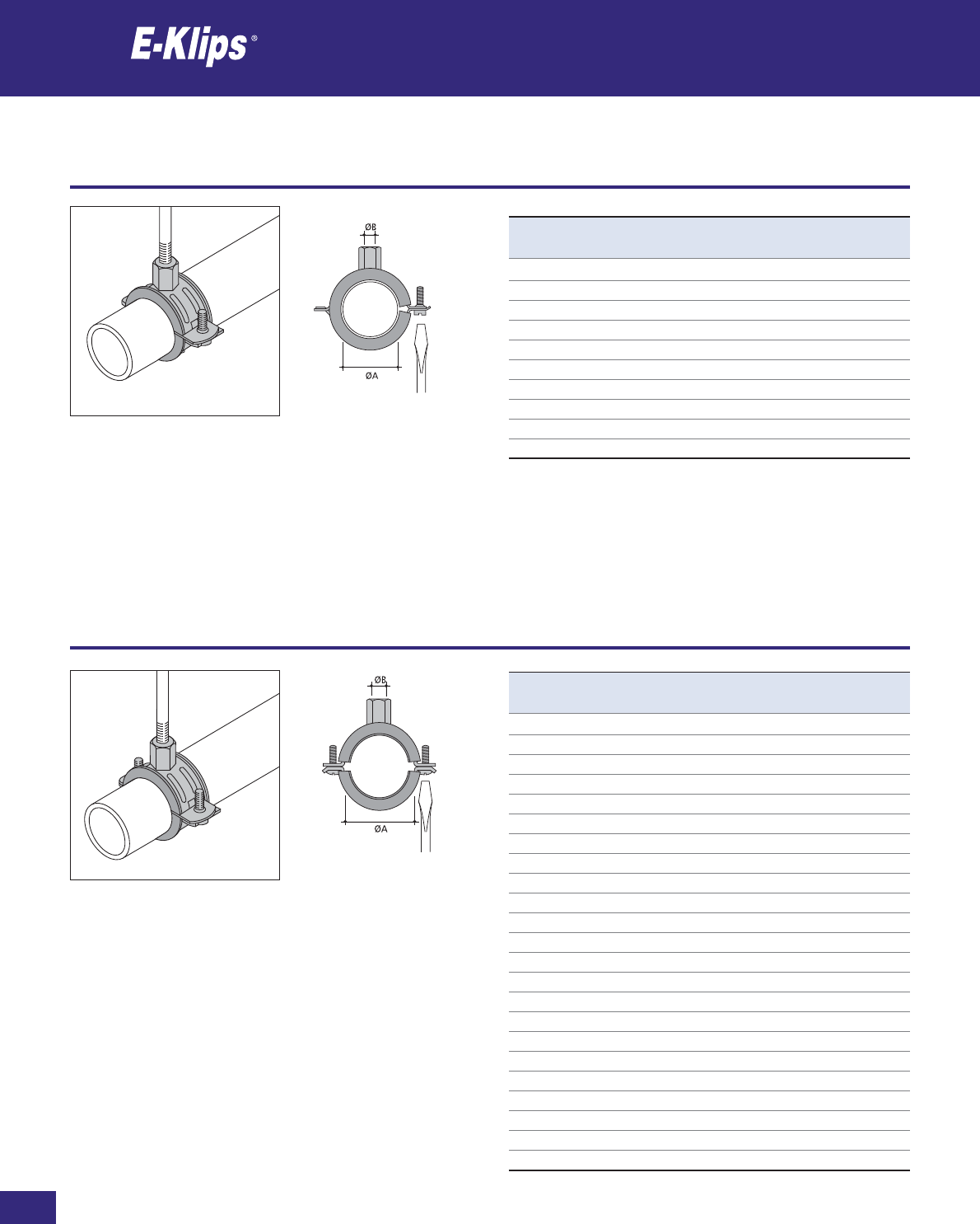
200
Thomas & Betts • www.tnb-europe.com
2.7
Lined pipe hangers for threaded rod
Pipe
* See page 150 for material finishes
Product Ref. ØA ØB Material Quantity
[mm] finishes* [pieces]
PCH-1415 14-15 M8/M10 F1 50
PCH-1618 16-18 M8/M10 F1 50
PCH-2022 20-22 M8/M10 F1 50
PCH-2528 25-28 M8/M10 F1 50
PCH-3335 33-35 M8/M10 F1 50
PCH-3638 36-38 M8/M10 F1 25
PCH-4244 42-44 M8/M10 F1 25
PCH-4850 48-50 M8/M10 F1 25
PCH-5254 52-54 M8/M10 F1 25
PCH-5760 57-60 M8/M10 F1 25
DIN4109
Product Ref. ØA ØB Material Quantity
[mm] finishes* [pieces]
PCS-1519 15-19 M8/M10 F1 50
PCS-2025 20-25 M8/M10 F1 50
PCS-2630 26-30 M8/M10 F1 50
PCS-3236 32-36 M8/M10 F1 50
PCS-3843 38-43 M8/M10 F1 25
PCS-4751 47-51 M8/M10 F1 25
PCS-5358 53-58 M8/M10 F1 25
PCS-6064 60-64 M8/M10 F1 25
PCS-6872 68-72 M8/M10 F1 25
PCS-7580 75-80 M8/M10 F1 25
PCS-8186 81-86 M8/M10 F1 25
PCS-8792 87-92 M8/M10 F1 25
PCS-99105 99-105 M8/M10 F1 25
PCS-107112 107-112 M8/M10 F1 25
PCS-113118 113-118 M8/M10 F1 25
PCS-125130 125-130 M8/M10 F1 25
PCS-132137 132-137 M8/M10 F1 25
PCS-138142 138-142 M8/M10 F1 25
PCS-148152 148-152 M8/M10 F1 25
PCS-159166 159-166 M8/M10 F1 25
PCS-200212 200-212 M8/M10 F1 25
PCS-215220 215-220 M8/M10 F1 25
PCS-248252 248-252 M8/M10 F1 25
DIN4109
Lined pipe hangers for threaded rod
Pipe
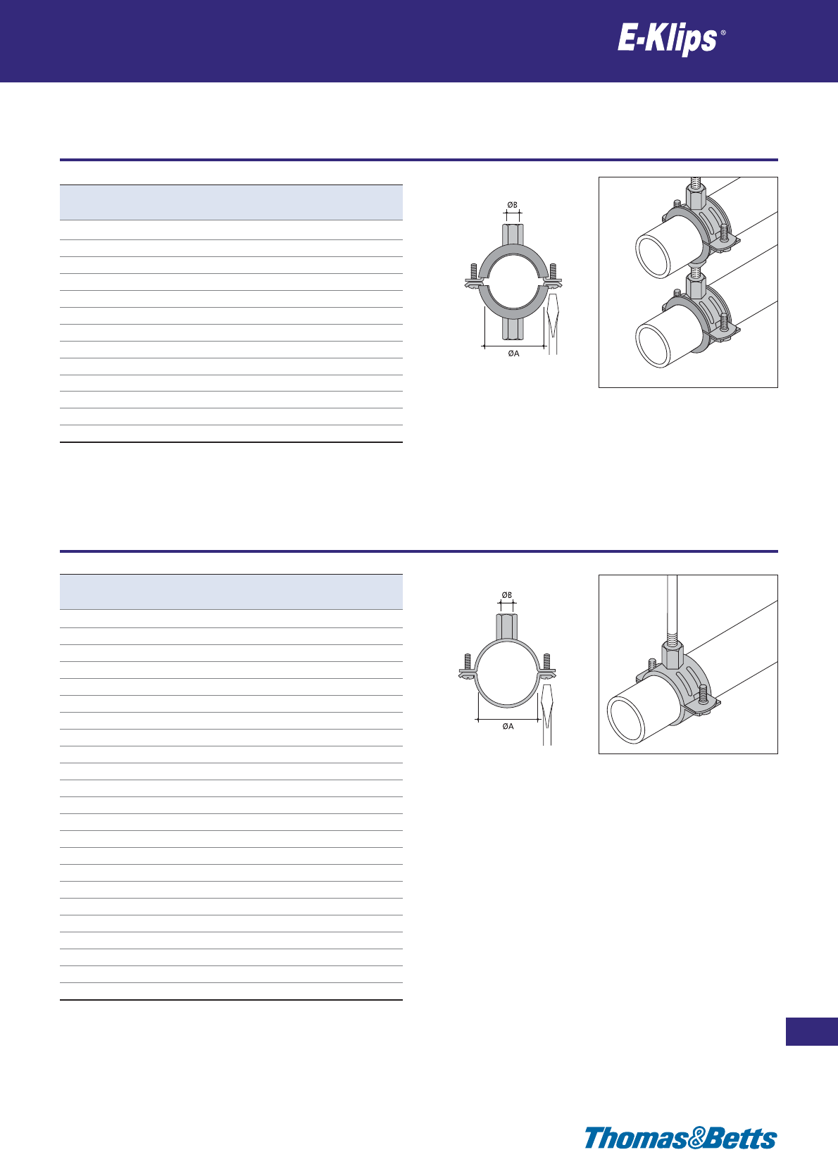
Lined pipe hangers for threaded rod
Pipe
201
Thomas & Betts • www.tnb-europe.com
2.7
* See page 150 for material finishes
Product Ref. ØA ØB Material Quantity
[mm] finishes* [pieces]
PCSD-1518 15-18 M8/M10 F1 50
PCSD-2024 20-24 M8/M10 F1 50
PCSD-2630 26-30 M8/M10 F1 50
PCSD-3236 32-36 M8/M10 F1 50
PCSD-3842 38-42 M8/M10 F1 25
PCSD-4750 47-50 M8/M10 F1 25
PCSD-6064 60-64 M8/M10 F1 25
PCSD-7580 75-80 M8/M10 F1 25
PCSD-8590 85-90 M8/M10 F1 25
PCSD-100106 100-106 M8/M10 F1 25
PCSD-114119 114-119 M8/M10 F1 25
PCSD-133140 133-140 M8/M10 F1 25
PCSD-159165 159-165 M8/M10 F1 25
DIN4109
Product Ref. ØA ØB Material Quantity
[mm] finishes* [pieces]
PB-1519 15-19 M8/M10 F1 50
PB-2025 20-25 M8/M10 F1 50
PB-2630 26-30 M8/M10 F1 50
PB-3236 32-36 M8/M10 F1 50
PB-3843 38-43 M8/M10 F1 25
PB-4751 47-51 M8/M10 F1 25
PB-5358 53-58 M8/M10 F1 25
PB-6064 60-64 M8/M10 F1 25
PB-6872 68-72 M8/M10 F1 25
PB-7580 75-80 M8/M10 F1 25
PB-8186 81-86 M8/M10 F1 25
PB-8792 87-92 M8/M10 F1 25
PB-99105 99-105 M8/M10 F1 25
PB-107112 107-112 M8/M10 F1 25
PB-113118 113-118 M8/M10 F1 25
PB-125130 125-130 M8/M10 F1 25
PB-132137 132-137 M8/M10 F1 25
PB-138142 138-142 M8/M10 F1 25
PB-148152 148-152 M8/M10 F1 25
PB-159166 159-166 M8/M10 F1 25
PB-200212 200-212 M8/M10 F1 25
PB-215220 215-220 M8/M10 F1 25
PB-248252 248-252 M8/M10 F1 25
Unlined pipe hangers for threaded rod
Pipe
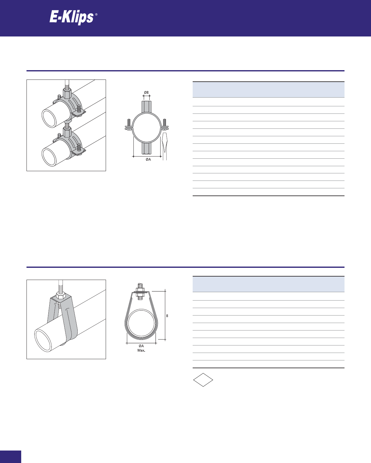
Thomas & Betts • www.tnb-europe.com
Unlined pipe hangers for threaded rod
Pipe
* See page 150 for material finishes
FM
Product Ref. ØA ØB Material Quantity
[mm] finishes* [pieces]
PBD-1518 15-18 M8/M10 F1 50
PBD-2024 20-24 M8/M10 F1 50
PBD-2630 26-30 M8/M10 F1 50
PBD-3236 32-36 M8/M10 F1 50
PBD-3842 38-42 M8/M10 F1 25
PBD-4750 47-50 M8/M10 F1 25
PBD-6064 60-64 M8/M10 F1 25
PBD-7580 75-80 M8/M10 F1 25
PBD-8590 85-90 M8/M10 F1 25
PBD-100106 100-106 M8/M10 F1 25
PBD-114119 114-119 M8/M10 F1 25
PBD-133140 133-140 M8/M10 F1 25
PBD-159165 159-165 M8/M10 F1 25
Product Ref. ØA B Material Quantity
[mm] [mm] finishes* [pieces]
PH-20-FU 20 64 F2 25
PH-25-FU 25 72 F2 25
PH-32 32 83 F2 25
PH-40 40 96 F2 25
PH-50 50 113 F2 25
PH-65 65 132 F2 25
PH-80 80 156 F2 25
PH-100 100 215 F2 10
PH-125 125 242 F2 10
PH-150 150 279 F2 10
202
2.7
Filbow hangers for threaded rod
Pipe
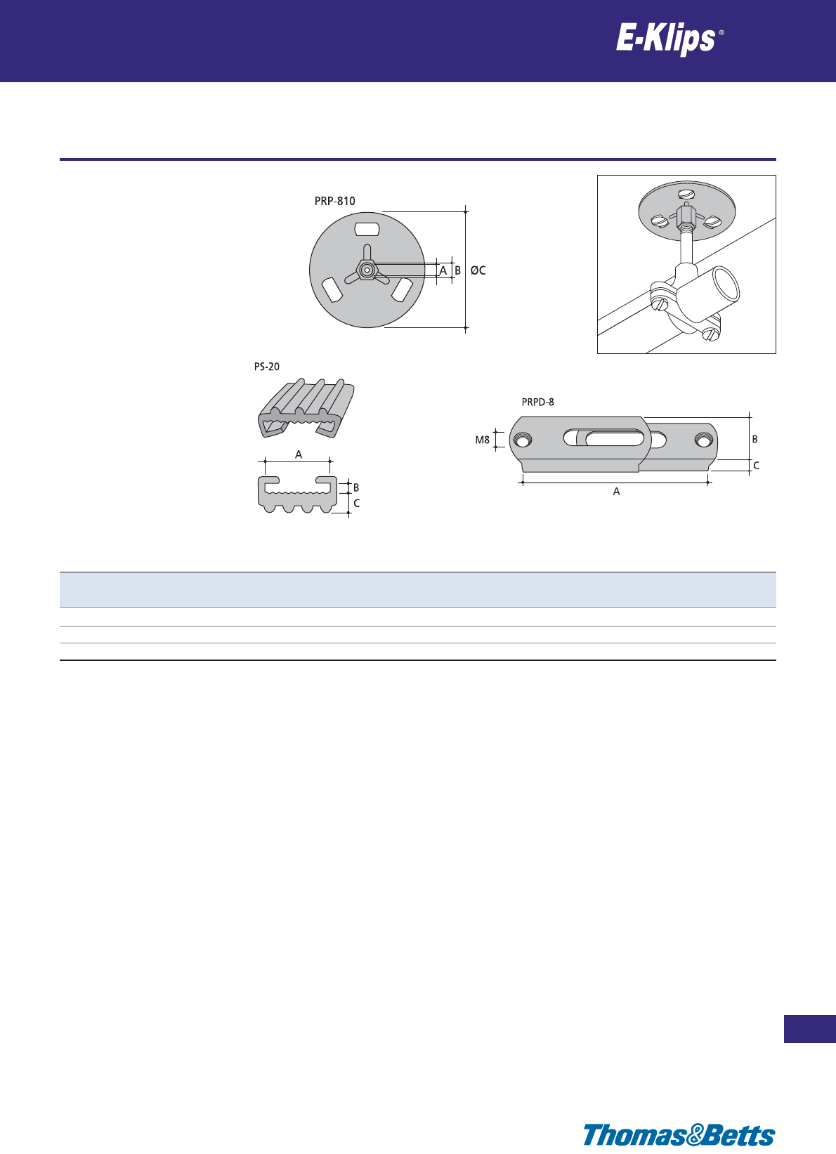
Pipe
Pipe
Thomas & Betts • www.tnb-europe.com
* See page 150 for material finishes
2.7
203
Product Ref. A B C Material Quantity
[mm] [mm] [mm] finishes* [pieces]
PRP-810 M8 M10 76 F1 25
PRPD-8 50-95 27 10 F1 25
PS-20 20 2.0 4.5 – 20m
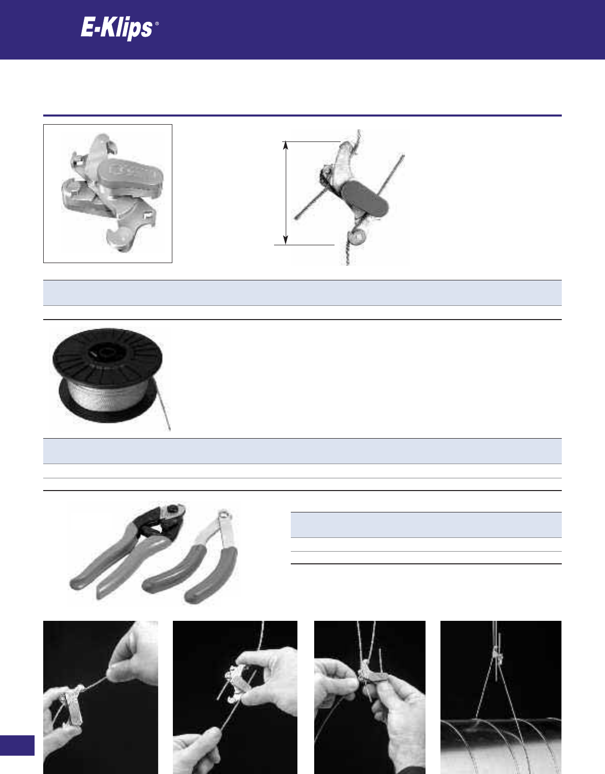
204
Thomas & Betts • www.tnb-europe.com
2.8
Fast-Lock wire suspension
Fast-Lock
* See page 150 for material finishes
Product Ref. Ø A Load rating Material Quantity
[mm] [mm] [kg] finishes* [pieces]
FL-2250 1-2 60 50 F6 25
Product
Ref.
Ø B A Load
rating
Material Quantity
[mm] [mm] [m] [kg] finishes* [pieces]
CW050-2 2 7x7 50 80 F2 1
CW100-2 2 7x7 100 80 F2 1
Product Ref. Ø Quantity
[mm] [pieces]
WC-1 1-4 1
WC-7 1-4 1
WC-7
WC-1
A
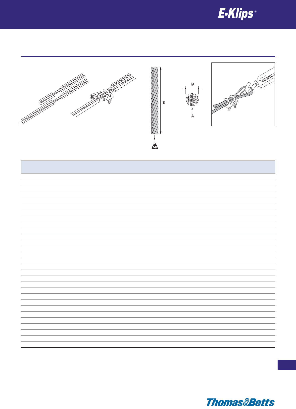
Catenary wire
Suspension
205
Thomas & Betts • www.tnb-europe.com
2.9
* See page 150 for material finishes
Product
Ref.
ØABLoad
rating
Material Quantity
[mm] [mm] [m] [kg] finishes* [pieces]
CW100-2 2 7 x 7 100 80 F2 1
CW30-3 3 7 x 7 30 190 F2 1
CW50-3 3 7 x 7 50 190 F2 1
CW100-3 3 7 x 7 100 190 F2 1
CW30-4 4 7 x 7 30 350 F2 1
CW50-4 4 7 x 7 50 350 F2 1
CW100-4 4 7 x 7 100 350 F2 1
CW30-6 6 7 x 7 30 760 F2 1
CW50-6 6 7 x 7 50 760 F2 1
CW100-6 6 7 x 7 100 760 F2 1
SSCW100-2 2 7 x 7 100 80 F3 1
SSCW30-3 3 7 x 7 30 190 F3 1
SSCW50-3 3 7 x 7 50 190 F3 1
SSCW100-3 3 7 x 7 100 190 F3 1
SSCW30-4 4 7 x 7 30 350 F3 1
SSCW50-4 4 7 x 7 50 350 F3 1
SSCW100-4 4 7 x 7 100 350 F3 1
SSCW30-6 6 7 x 7 30 760 F3 1
SSCW50-6 6 7 x 7 50 760 F3 1
SSCW100-6 6 7 x 7 100 760 F3 1
CW30-3PVC 3 7 x 7 30 190 F2 + PVC 1
CW50-3PVC 3 7 x 7 50 190 F2 + PVC 1
CW100-3PVC 3 7 x 7 100 190 F2 + PVC 1
CW30-4PVC 4 7 x 7 30 350 F2 + PVC 1
CW50-4PVC 4 7 x 7 50 350 F2 + PVC 1
CW100-4PVC 4 7 x 7 100 350 F2 + PVC 1
CW30-6PVC 6 7 x 7 30 760 F2 + PVC 1
CW50-6PVC 6 7 x 7 50 760 F2 + PVC 1
CW100-6PVC 6 7 x 7 50 760 F2 + PVC 1
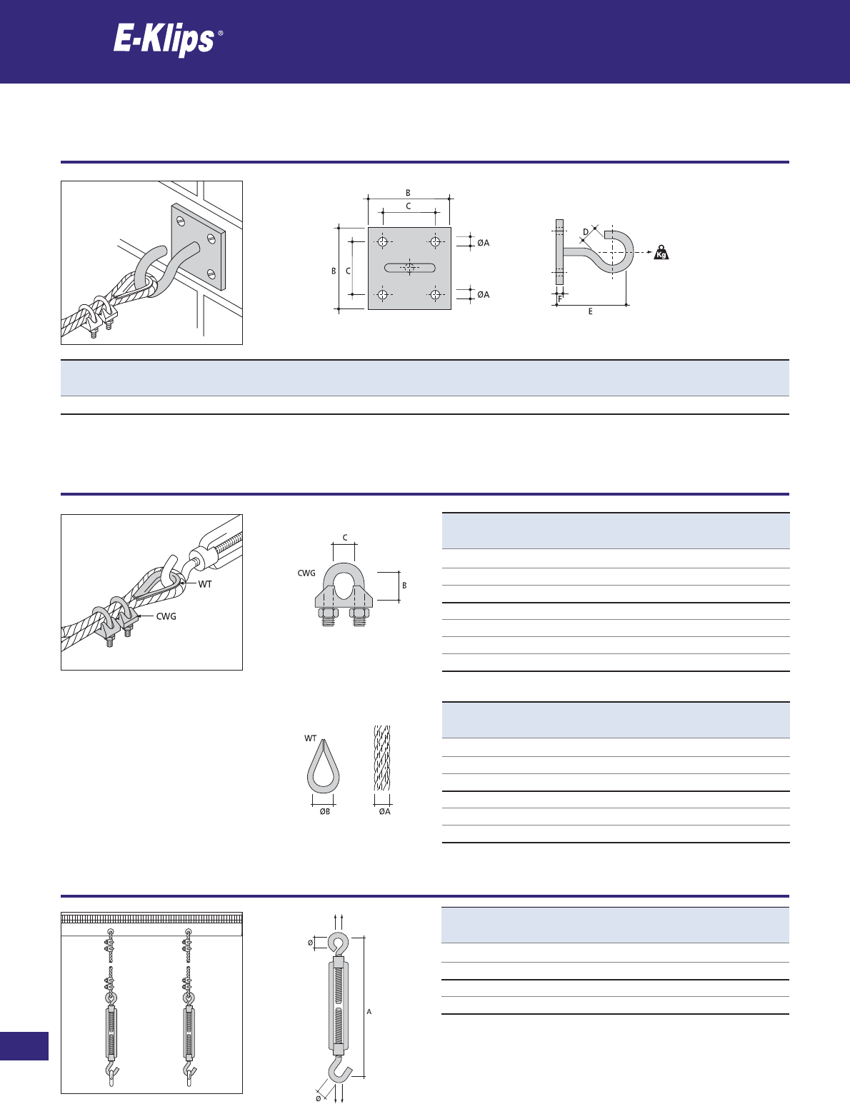
206
Thomas & Betts • www.tnb-europe.com
2.9
Suspension
Suspension
* See page 150 for material finishes
Product Ref. ØA B C D E F Load rating Material Quantity
[mm] [mm] [mm] [mm] [mm] [mm] [kg] finishes* [pieces]
HW50 5.5 50 32 8 55 5 25 F2 10
Product Ref. ØA B C Material Quantity
[mm] [mm] [mm] finishes* [pieces]
CWG-23 2-3 Max 9 6.5 F2 25
CWG-4 4 Max 12 7.0 F2 25
CWG-6 6 Max 18 8.0 F2 25
SSCWG-2 2 Max 9 6.5 F3 1
SSCWG-3 3 Max 9 6.5 F3 1
SSCWG-4 4 Max 12 7.0 F3 1
SSCWG-6 6 Max 18 8.0 F3 1
Product Ref. ØA ØB Material Quantity
[mm] [mm] finishes* [pieces]
WT-23 2-3 10 F2 25
WT-34 3-4 14 F2 25
WT-6-FU 6 16 F2 25
SSWT-2 2 10 F3 1
SSWT-34 3-4 14 F3 1
SSWT-6 6 16 F3 1
Product Ref. Ø A Material Quantity
[mm] [mm] finishes* [pieces]
CWT-23 10 155-245 F2 10
CWT-46 12 230-325 F2 10
SSCWT-23 10 155-245 F3 10
SSCWT-46 12 230-325 F3 10
Suspension for catenary wire
Suspension
Suspension
Suspension

Suspension
Suspension
207
Thomas & Betts • www.tnb-europe.com
2.9
* See page 150 for material finishes
Product Ref. A Ø Material Quantity
[mm] [mm] finishes* [pieces]
LS-32 152 Max 32 F6 10
LS-38 178 Max 38 F6 10
LS-48 203 Max 48 F6 10
LS-54 228 Max 54 F6 10
LS-60 254 Max 60 F6 10
LS-72 305 Max 72 F6 10
Product
Ref.
T A B Load
rating
Material Quantity
[mm] [mm] [mm] [kg] finishes* [pieces]
MM65-AH153 1.5-3 6.3 36 72 F8+ 25
MM65-AH38 3-8 6.3 38 90 F8+ 25
MM65-AH814 8-14 6.3 46 90 F8+ 25
MM65-AH1420 14-20 6.3 58 90 F8+ 25
NM65-AH153 1.5-3 6.3 58 72 F8+ 25
NM65-AH38 3-8 6.3 60 90 F8+ 25
NM65-AH814 8-14 6.3 68 90 F8+ 25
NM65-AH1420 14-20 6.3 80 90 F8+ 25
Girder clips for perforated band
Suspension
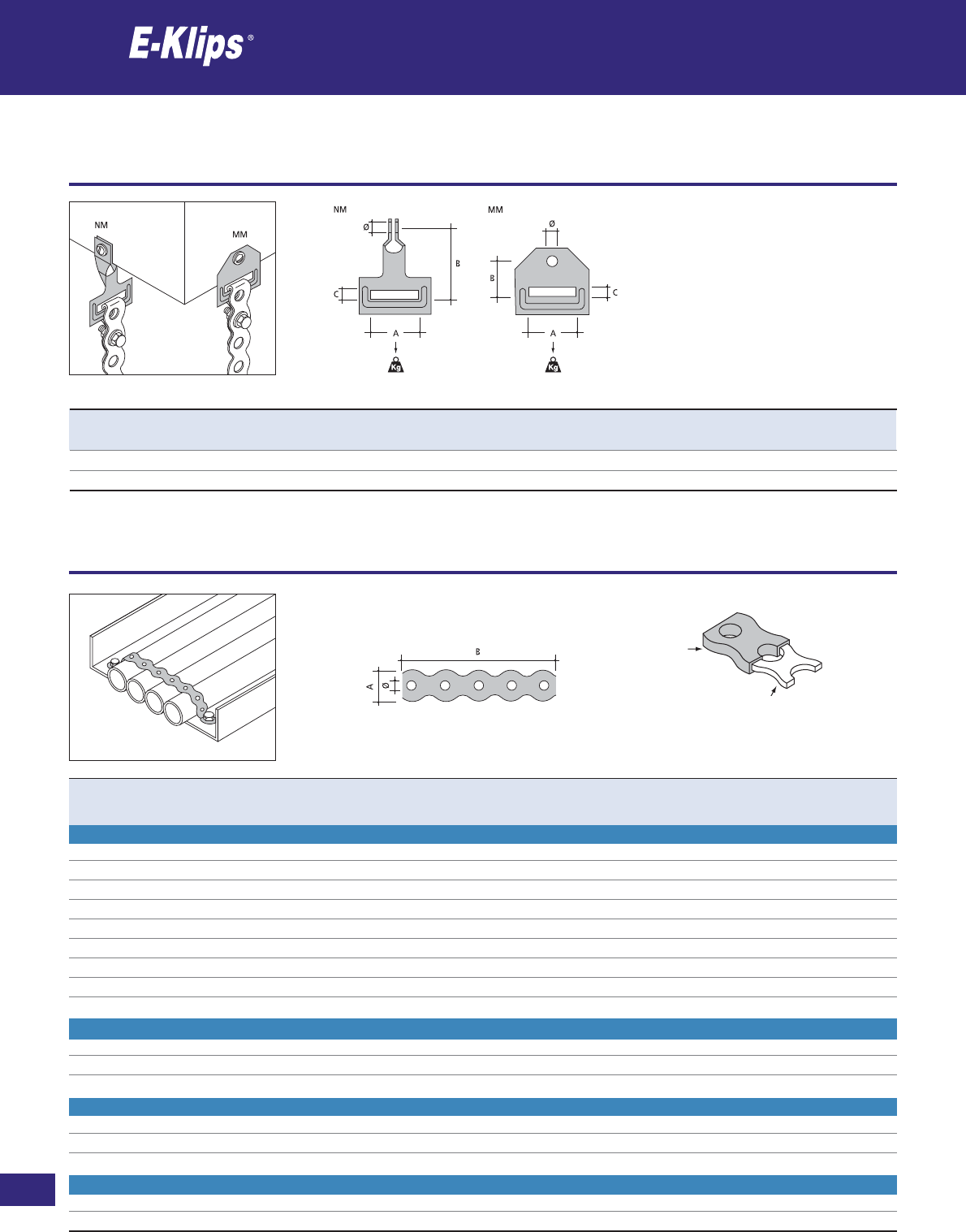
208
Thomas & Betts • www.tnb-europe.com
2.9
Suspension for perforated band
Suspension
* See page 150 for material finishes
Product Ref. Colour Ø A B Load rating Material Quantity
[mm] [mm] [m] [kg] finishes* [pieces]
PLASTIC **
SP-13B black 4 13 10 37 F7 1
SP-19B black 6.5 19 10 42 F7 1
SP-27B black 7.5 27 10 90 F7 1
SP-13O orange 4 13 10 37 F7 1
SP-19O orange 6.5 19 10 42 F7 1
SP-13R-FU red 4 13 10 37 F7 1
SP-19R-FU red 6.5 19 10 42 F7 1
SP-13W white 4 13 10 37 F7 1
SP-19W white 6.5 19 10 42 F7 1
GALVANISED
SG-12-FU – 5 12 10 37 F2 1
SG-18 – 7 18 10 42 F2 1
SG-26 – 8 26 10 90 F2 1
STAINLESS STEEL
SS-12 – 5 12 10 43 F3 1
SS-18-FU – 7 18 10 48 F3 1
SS-26 – 8 26 10 100 F3 1
COPPER
SC-12 – 5 12 10 16 F6 1
SC-18 – 7 18 10 21 F6 1
** Material: Plascoat PPA 571
Product Ref. Ø A B C Load rating Material Quantity
[mm] [mm] [mm] [mm] [kg] finishes* [pieces]
MM-65 6.5 28 20 6.3 90 F8+ 100
NM-65 6.5 28 42 6.3 90 F8+ 100
Perforated band
Suspension
Plastic**
Galvanised
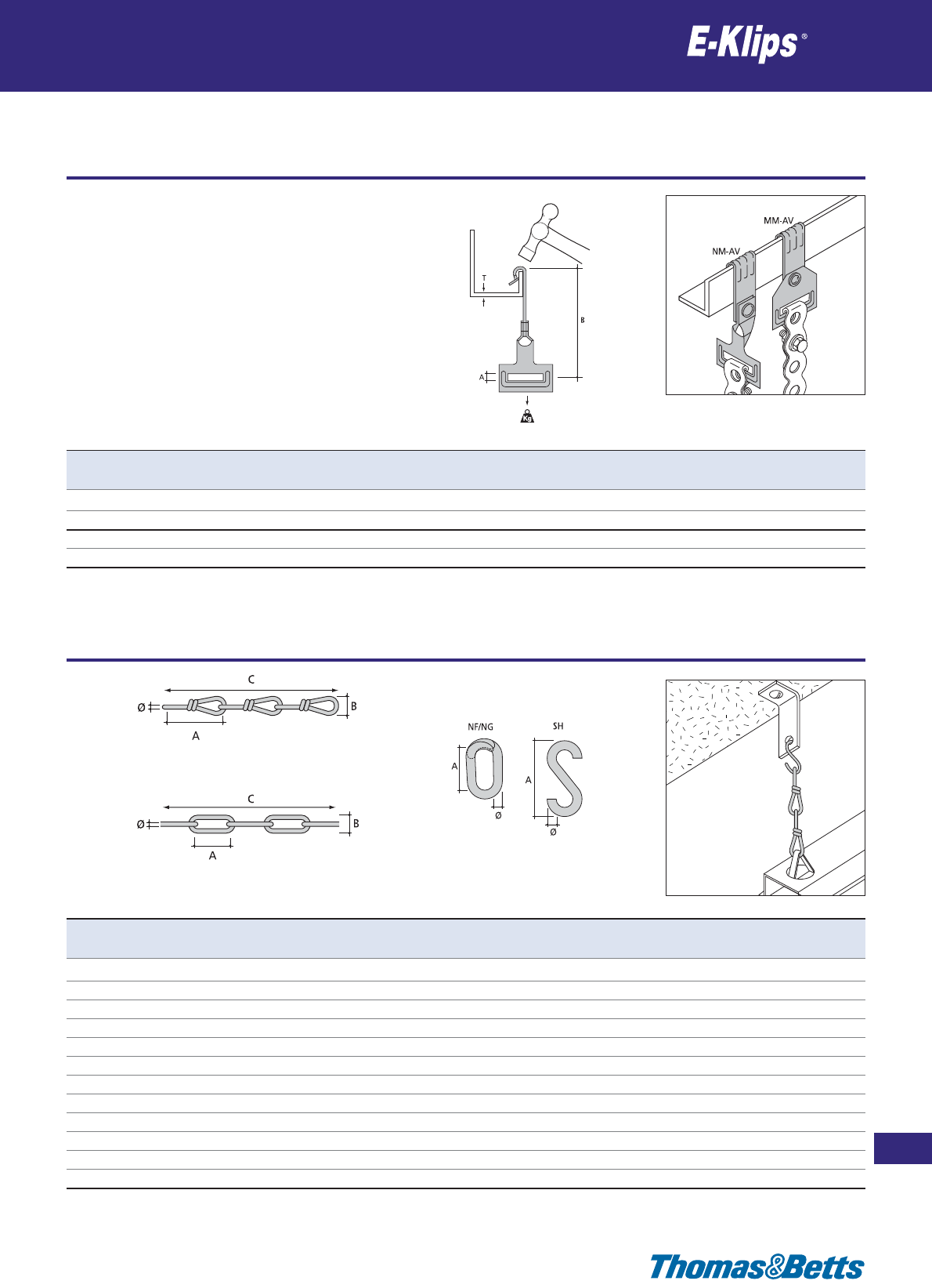
Purlin clips for perforated band
Suspension
209
Thomas & Betts • www.tnb-europe.com
2.9
* See page 150 for material finishes
KG - Electroplate DIN 5685
KF - Hot Dip Galvanised DIN 5685
KN - Stainless Steel DIN 763
KK- Electroplate DIN 5686
Product Ref. Ø A B C Load rating Material Quantity
[mm] [mm] [mm] [m] [kg] finishes* [pieces]
KK-20 1.8 25 8 30 70 F1 1
KK-30 2.8 39 12.5 30 190 F1 1
KG-3 3 26 12 30 45 F1 1
KG-4 4 32 16 30 80 F1 1
KF-3 3 26 12 30 45 F2 1
KF-4 4 32 16 30 80 F2 1
KN-2 2 22 8 30 50 F3 1
KN-3 3 26 12 30 120 F3 1
NG-4 4 20 – – – F1 100
NF-4 4 20 – – – F2 100
SH-4 4 35 – – 20 F1 100
SH-5 5 45 – – 30 F1 100
Product
Ref.
T A B Load
rating
Material Quantity
[mm] [mm] [mm] [kg] finishes* [pieces]
MM65-AV155 1.5-5 6.3 62 72 F8+ 25
MM65-AV57 5-7 6.3 62 72 F8+ 25
NM65-AV155 1.5-5 6.3 84 72 F8+ 25
NM65-AV57 5-7 6.3 84 72 F8+ 25
Metal chain
Suspension

210
Thomas & Betts • www.tnb-europe.com
2.10
Fixing plates
Miscellaneous
* See page 150 for material finishes
Product Ref. Ø A B C Load rating Material Quantity
[mm] [mm] [mm] [mm] [kg] finishes* [pieces]
CMP-400 M8 x 25 90 45 35 45 F2 20
Product Ref. T ØA C D E Material Quantity
[mm] [mm] [mm] [mm] [mm] finishes* [pieces]
DM-6T 2.5-4 M6 12.6 25 16 F1 100
XM-6 – M6 10.0 32 – F8+ 100
Speed nuts
Miscellaneous
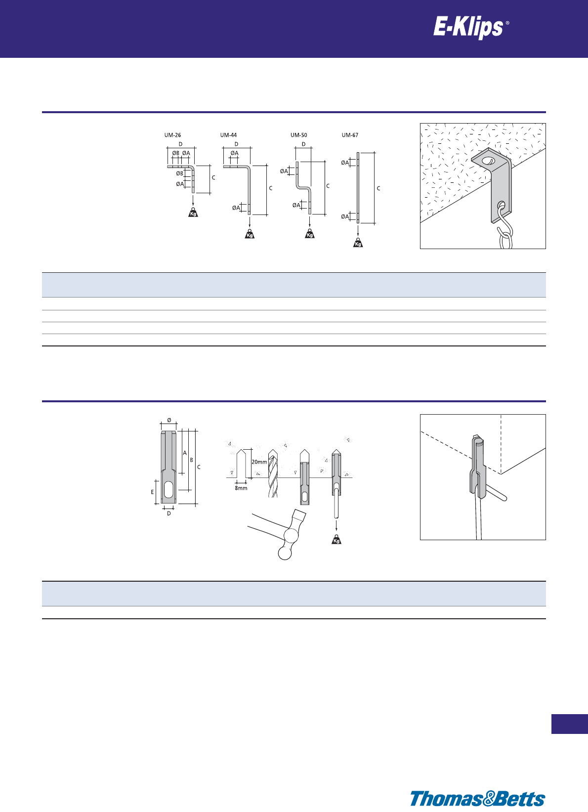
Miscellaneous
Miscellaneous
211
Thomas & Betts • www.tnb-europe.com
2.10
* See page 150 for material finishes
Product Ref. ØA ØB C D Load rating Material Quantity
[mm] [mm] [mm] [mm] [kg] finishes* [pieces]
UM-26 6.5 4.6 26 26 90 F2 100
UM-44 6.5 – 44 26 90 F8+ 100
UM-50 6.5 4.6 50 26 70 F2 100
UM-67 6.5 – 67 – 90 F8+ 100
Product Ref. Ø A B C D E Load rating Material Quantity
[mm] [mm] [mm] [mm] [mm] [mm] [kg] finishes* [pieces]
A100 8.75 25 34 42 5 10 40 F1 100
Miscellaneous
Miscellaneous
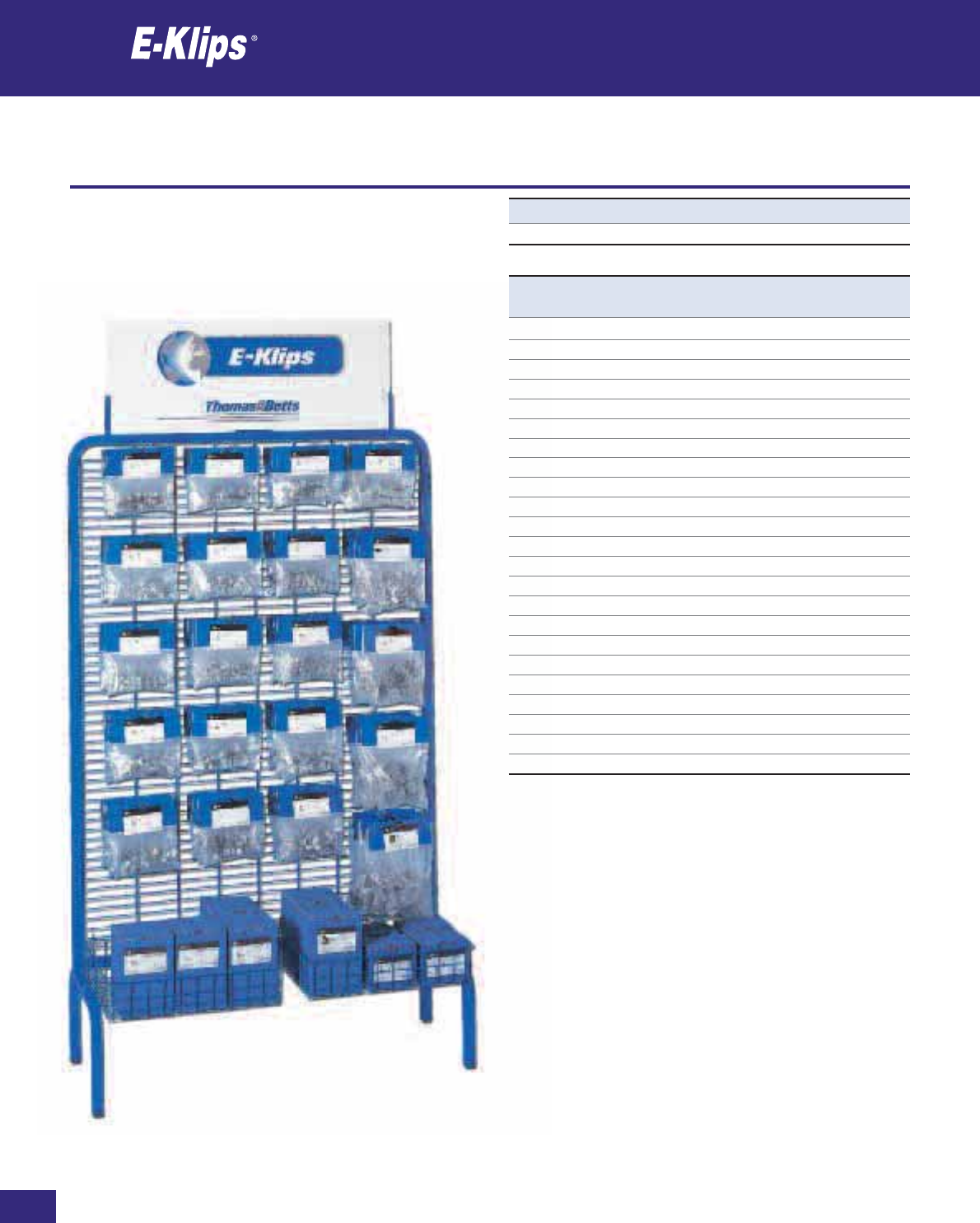
Thomas & Betts • www.tnb-europe.com
Merchandiser Unit
Miscellaneous
Product Ref. Quantity
Included [number of packages]
AH38-GM1926 2
AH814-GM1926 2
AV155-AM6T 2
AV155-AM10T 2
FC-11 2
PPAH38 4
PPAH814 4
PPAV155 4
PPFH65 4
PPJHX16S 4
PPECS89 4
PPECS1011 4
PPECS1214 4
PPECS1519 4
PPECS2024 4
PPECM89 4
PPECM1011 4
PPECM2024 4
PPECL89 4
PPECL1011 4
PPECL1214 4
PPECL1519 4
PPECL2024 4
Product Ref. Description
EKLIPSUNIT Complete merchandiser unit
2.10
212
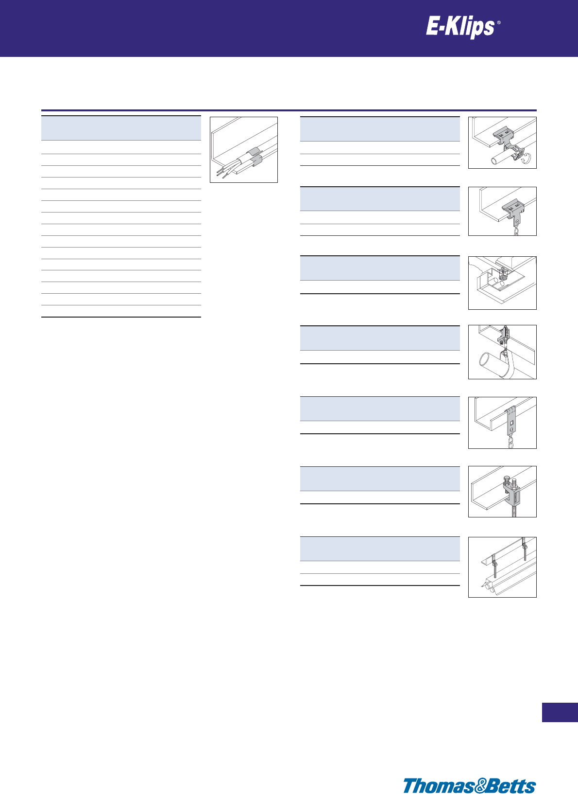
Merchandiser Unit
Miscellaneous
213
Thomas & Betts • www.tnb-europe.com
Product Ref. Quantity
[pieces]
PPECS89 25
PPECS1011 25
PPECS1214 25
PPECS1519 25
PPECS2024 25
PPECM89 25
PPECM1011 25
PPECM1214 25
PPECM1519 25
PPECM2024 25
PPECL89 25
PPECL1011 25
PPECL1214 25
PPECL1519 25
PPECL2024 25
Product Ref. Quantity
[pieces]
AH38-GM1926 25
AH814-GM1926 25
Product Ref. Quantity
[pieces]
PPAH38 25
PPAH814 25
Product Ref. Quantity
[pieces]
PPJHX16S 25
Product Ref. Quantity
[pieces]
PPFH65 25
Product Ref. Quantity
[pieces]
PPAV155 25
Product Ref. Quantity
[pieces]
FC-11 25
Product Ref. Quantity
[pieces]
AV155-AM6T 25
AV155-AM10T 25
2.10

214
Thomas & Betts • www.tnb-europe.com
3.1
Shrink-Kon®
To insulate and
protect cables
215
Thomas & Betts • www.tnb-europe.com
3.1
INSULATION SYSTEMS
3.1 HEAT SHRINK TECHNOLOGIES 214
Selection guide 218
Thin wall heat shrink tubing 220
Product reference structure 220
Type PLG - HSB boxes 221
Type PLG - flexible 222
Type PLG - pre-cut bags 224
Shrink-Kon®Set 225
Type CMP - dual listed 226
Type MLP - flexible for high specifications 227
Type GYS - flexible green and yellow 229
Type GYS - HSB boxes 230
Type PIG - very flexible for highly contoured components 231
Type PIG - HSB boxes 232
Type PKG - flexible for moist environments 233
Type PKG - HSB boxes 235
Type KYN - semi-rigid transparent 236
Type VIT - highly flexible, flame retardant 237
Type ZHFR - flexible, halogen free & flame retardant 238
Type SSB - Shrink-Shield 239
Medium & thick wall heat shrink tubing and tooling 240
Type TBM - rated for 600V, 90°C continuous use 240
Type TBW - rated for 600V, 90°C continuous use 241
Low voltage kits up to 600V 242
Type TEB - cable breakouts 243
Type TEC - end caps 244
TBTA-ZH - self amalgamating tape 245
Hot Air Tool 246
Technical Information 247
3.2 RESIN TECHNOLOGIES 248

216
Thomas & Betts • www.tnb-europe.com
3.1
Shrink-Kon®
Heat shrink technologies
Thomas & Betts has you covered when it comes to insula-
tion!
•Easytouse
• Heat shrinkable
• Heavy, medium, and thin walls products
Shrink-Kon®Thin Wall Tubing
Manufactured from crosslinked Polyolefin, these products are
used to insulate bare Sta-Kon®and Color Keyed®connectors and
splices. They also provide a degree of strain relief and may be
used to harness wires. Available in cut pieces or reels.
Featured Products Include:
• Single wall non-lined 2:1 and 3:1 thin wall tubing
•
3:1 and 4:1 dual wall adhesive lined thin-wall PKG series provides
excellent flexibility with environmental sealing capability

217
Thomas & Betts • www.tnb-europe.com
3.1
Protect against moisture,
corrosion, and abrasion!
• Transparent heat shrink tubing for use on power connections
and data connections
• Zero Halogen and flame retardant version for use in contained
areas
Shrink-Kon®Medium Wall Tubing
More flexible than heavy-wall products, with excellent resistance
to impact and abrasion.
• Seals and protects cable splices and terminations
• Thermoplastic adhesive liner guarantees complete environmen-
tal protection and insulation
Thick Wall Shrink-Kon®Heat-Shrinkable Insulators
When it comes to moisture-proofing connections and termina-
tions, Thomas & Betts’s heat-shrinkable tubing, cable breakouts
and end caps have proven themselves over years of service to the
industry. Made of thermally stabilized cross-linked polyolefin, these
heat-shrinkable insulators can be used over lead, steel, aluminum,
copper, standard plastic, and elastomeric insulating materials.
Thomas & Betts heat-shrinkable insulators are designed to be easy
to use. They provide an appropriate level of insulation and abrasion
protection.
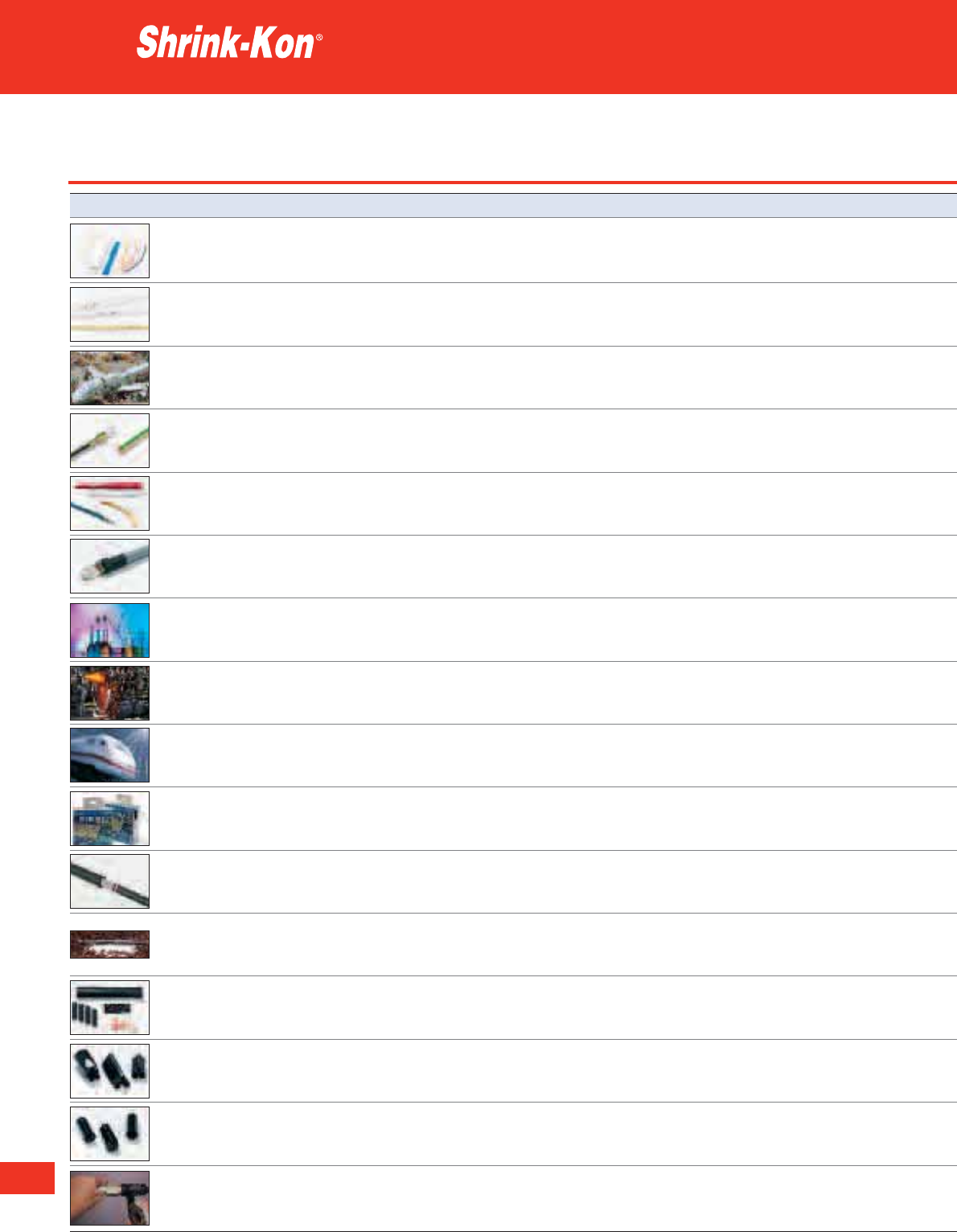
218
Thomas & Betts • www.tnb-europe.com
3.1
Selection guide
Heat shrink technologies
Product type General description Typical application
PLG/ Multipurpose tube in General purpose, flexible heat shrink tubing
PLG in HSB Boxes flexible polyolefin for the protection, insulation and bundling
of cables
CMP Multipurpose tube in Typical applications are mechanical and electrical
flexible polyolefin-Dual listed insulation, corrosion protection, bundling,
mechanical protection and much more
MLP Multipurpose tube in flexible Typical applications are insulation, corrosion
polyolefin-Dual listed protection, component strain relief and connections
in applications requiring the highest specifications
(e.g. aeronautical and military)
GYS/ Striped green and yellow, For identifying and marking earthing
GYS in HSB Boxes Flexible polyolefin connectors and cables
PIG/ Very flexible polyolefin, For highly contoured components
PIG in HSB Boxes High shrink ratio with large diameter variations.
Green and yellow for earthing applications
PKG/ Flexible polyolefin, High shrink ratio, Adhesive-lined heat shrink tubing ideal
PKG in HSB Boxes adhesive bonds to plastics, for a moisture-resistant insulation
rubber, neoprene, steel and polyethylene
KYN High specifications, semi-rigid Kynar
®
* Ideal for specific applications where mechanical
heat shrink tubing with excellent and chemical protection are required.
mechanical and electrical Enables see through inspections
insulation performance
VIT High flexibility Viton
®
** Its specificity make it the product of choice
fluoroelastomer for enhanced for heavy-duty conditions e.g. sensors in
protection in extreme electrical, vehicle engine compartments
chemical and thermal environments
ZHFR Zero halogen, low smoke, Particularly recommended for use in
flexible heat shrink tubing contained areas and with Halogen free
wires and cables
SSB
Insulation and shielding in one process Typical applications including shielding of both
Inner aluminium layer and silver coloured power and signal cables to reduce EMI
outer PVC/Polyester layer radiation and susceptibility
TBM Medium heat shrink tubing For a variety of low voltage applications
ideal for the protection of cable joints where lighter weight and greater flexibility
and terminations in low voltage are important
power applications
TBW Thick wall heat shrink ideal for This heavy wall product provides maximum
underground low voltage power reliability for insulating and protecting
applications and terminations cable joints
VMS Medium and heavy wall cable jointing kit Low voltage jointing applications
(Low voltage kits) for polymeric insulated cables
TEB Medium and heavy wall adhesive To insulate and seal low voltage cable
lined heat shrink cable breakouts crutches
TEC Medium and heavy wall adhesive To seal and protect cable-ends against
lined heat shrink end caps the ingress of moisture and contamination
TBTA-ZH Self-amalgamating tape which Flawless electrical stability
(Self amalgamating tape) provides a thick insulating layer and for long term resistance to moisture
penetration
* Kynar
®
is a registered trademark of ATOFINA
** Viton
®
is a registered trademark of DuPont de Nemours

219
Thomas & Betts • www.tnb-europe.com
3.1
Characteristics Shrink ratio Temperature range Flame rating Certification(s) Page
Single wall 2:1 -55°C to +125°C Flame retardant*** 221
Single wall 2:1 -55°C to +125°C Flame retardant*** UL, CSA 226
Single wall 2:1 -55°C to +135°C Flame retardant*** UL, CSA, MIL 227
Single wall 2:1 -55°C to +135°C Flame retardant MIL 229
Single wall 3:1 -55°C to +135°C Flame retardant*** MIL 231
Dual wall 3:1 and 4:1 -55°C to +110°C Flame retardant*** 233
(outer jacket)
Non polyolefin: crosslinked 2:1 -55°C to +175°C High flame retardancy MIL 236
polyvinylidene fluoride
(Kynar
®
*)
Non polyolefin: crosslinked 2:1 -55°C to +220°C High flame retardancy MIL 237
fluoroelastomer (Viton
®
**)
Single wall 2:1 -40°C to +105°C Flame retardant DEF STAN 238
Dual wall 2:1 -10°C to +125°C - 239
Medium wall 3:1 -55°C to +110°C Non Flame retardant 240
Thick wall 3:1 -55°C to +110°C Non Flame retardant 241
Medium and thick wall 3:1 -55°C to +110°C Non Flame retardant 242
Medium and thick wall >2:1 -55°C to +100°C Non Flame retardant 243
Medium and thick wall >2:1 -55°C to +100°C Non Flame retardant 244
EPR based tape 1:3 -55°C to +105°C Flame retardant 245
* Kynar
®
is a registered trademark of ATOFINA
** Viton
®
is a registered trademark of DuPont de Nemours
*** except transparent version
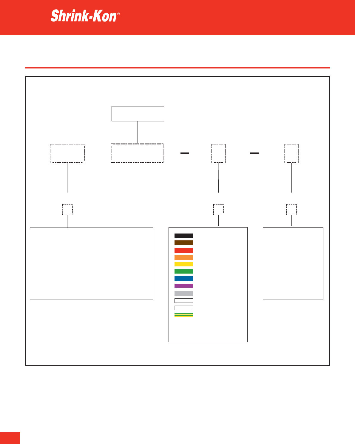
220
Thomas & Betts • www.tnb-europe.com
3.1
Product reference structure
Thin wall heat shrink tubing
Example:
XXXX
Type of heat shrink
Expanded diameter as supplied
in thousandths of an inch
PLG 1000 0 A
PLG = flexible
CMP = Dual listed
MLP = flexible for high specifications
GYS = flexible green and yellow
PIG = very flexible for highly contoured components
PKG = flexible for moist environments
KYN = semi-rigid transparent
VIT = highly flexible, flame retardant
ZHFR = flexible, halogen free & flame retardant
0 = black (standard)
1 = brown
2=red
3 = orange
4 = yellow
5 = green
6 = blue
7 = violet
8=grey
9 = white
C = transparent
E = green / yellow
See product page for colour
availability
Colour Packaging type*
A = 1,22 m cut lengths
B = reels
BG = reels
C = 0,6 m cut lengths
D=box
E = mini-reels
* Not necessary for PLG-
HSB boxes
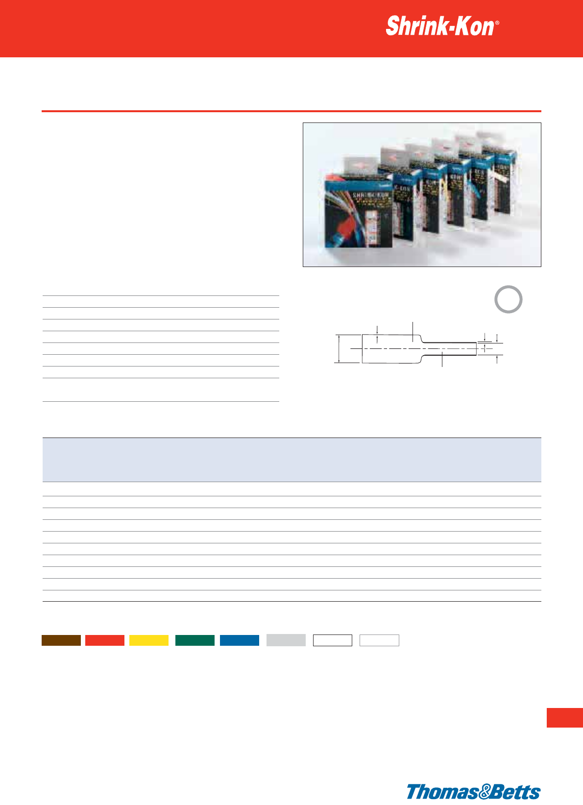
Type PLG - HSB boxes
• PLG heat shrink tubing in a compact, handy sized box used for
electrical maintenance and repair
• Convenient amount of heat shrink, for small users
• Offered in 10 sizes to cover a heat shrink range from Ø 1.2 mm
to Ø 25.4 mm
• Stackable boxes for easy storage
• Flexible, rapid shrinkage, non-melting for effective electrical
insulation
• Flame retardant
• Available colours: see below (see page 220 for product reference
structure)
Technical Information
Wall thickness Thin
Shrink ratio 2:1
Tube characteristics Single wall
Temperature range -55°C to +125°C
Shrinking temperature +110°C
Material Crosslinked polyolefin
IP rating IP60
Standard colour Black
Other properties Silicone, Cadmium and Lead free
Transparent version: Halogen free
Thin wall heat shrink tubing
221
Thomas & Betts • www.tnb-europe.com
3.1
Product Ref. Expanded diameter Fully recovered Wall thickness Wall thickness Length
as supplied diameter before shrinking after shrinking per box
Ddzw
[inch] [mm] [mm] [mm] [mm] [m]
HSB46
3
/
64
1.2 0.6 0.20 0.4 12.0
HSB63
1
/
16
1.6 0.8 0.20 0.4 12.0
HSB93
3
/
32
2.4 1.2 0.25 0.5 11.5
HSB125
1
/
8
3.2 1.6 0.25 0.5 11.5
HSB187
3
/
16
4.7 2.4 0.25 0.5 9.5
HSB250
1
/
4
6.4 3.2 0.30 0.6 7.5
HSB375
3
/
8
9.5 4.7 0.30 0.6 6.5
HSB500
1
/
2
12.7 6.4 0.30 0.7 6.0
HSB750
3
/
4
19.1 9.5 0.40 0.7 5.0
HSB1000 1 25.4 12.7 0.45 0.8 3.3
For other colours add colour suffix to Product Reference:
1 = brown, 2 = red, 4 = yellow, 5 = green, 6 = blue, 8 = grey, 9 = white and C = transparent
Expanded
Recovered
D
w
d
z
2:1
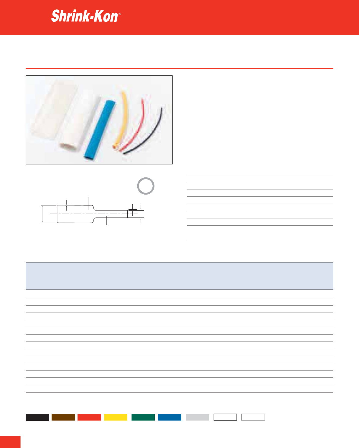
222
Thomas & Betts • www.tnb-europe.com
3.1
Type PLG - flexible
• Multi-purpose use for insulation, bundling, identification, strain
relief and much more
• Heat shrink tubing with 14 nominal diameters to enclose com-
ponents from Ø 1.2 mm to Ø 101.6 mm
• Flame retardant
• Flexible, rapid shrinkage, non melting for effective electrical
insulation
• Available colours: see below (see page 220 for product reference
structure)
• Special colours available on request
Technical Information
Wall thickness Thin
Shrink ratio 2:1
Tube characteristics Single wall
Temperature range -55°C to +125°C
Shrinking temperature +110°C
Material Crosslinked polyolefin
IP rating IP60
Standard colour Black
Other properties Silicone, Cadmium and Lead free
Transparent version: Halogen free
Thin wall heat shrink tubing
Product Ref. Expanded diameter Fully recovered Wall thickness Wall thickness Total length Quantity
as supplied diameter before shrinking after shrinking per box per box
Ddzw
[inch] [mm] [mm] [mm] [mm] [m] [pieces 1.22m]
PLG46-0-A
3
/
64
1.2 0.6 0.20 0.4 30.5 25
PLG63-0-A
1
/
16
1.6 0.8 0.20 0.4 30.5 25
PLG93-0-A
3
/
32
2.4 1.2 0.25 0.5 30.5 25
PLG125-0-A
1
/
8
3.2 1.6 0.25 0.5 30.5 25
PLG187-0-A
3
/
16
4.7 2.4 0.25 0.5 30.5 25
PLG250-0-A
1
/
4
6.4 3.2 0.30 0.6 30.5 25
PLG375-0-A
3
/
8
9.5 4.8 0.30 0.6 30.5 25
PLG500-0-A
1
/
2
12.7 6.4 0.40 0.7 30.5 25
PLG750-0-A
3
/
4
19.1 9.5 0.40 0.7 12.2 10
PLG1000-0-A 1 25.4 12.7 0.45 0.8 12.2 10
PLG1500-0-A 1
1
/
2
38.0 19.0 0.50 1.0 6.1 5
PLG2000-0-A 2 50.8 25.4 0.55 1.1 6.1 5
PLG3000-0-A 3 76.2 38.1 0.65 1.3 2.4 2
PLG4000-0-A 4 101.6 50.8 0.70 1.4 1.2 1
For other colours add colour suffix to Product Reference:
0 = black, 1 = brown, 2 = red, 4 = yellow, 5 = green, 6 = blue, 8 = grey, 9 = white and C = transparent
Expanded
Recovered
D
w
d
z
2:1
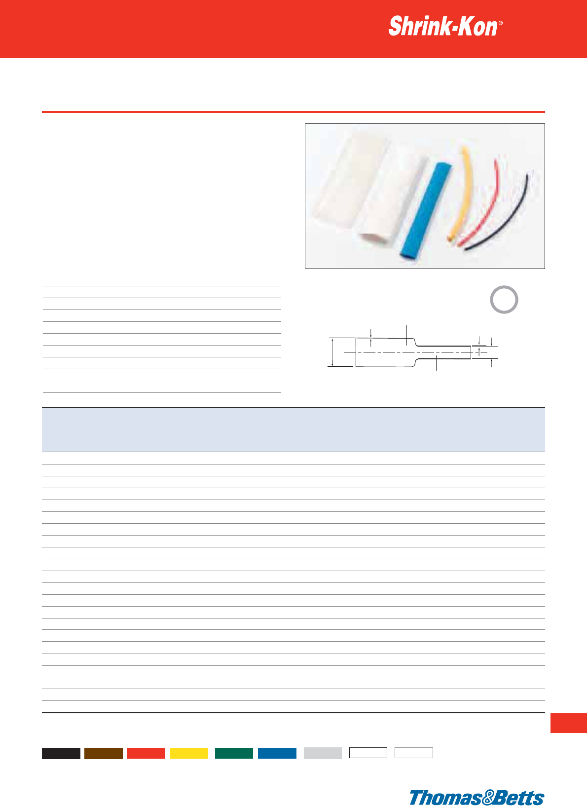
Type PLG - flexible
• Multi-purpose use for insulation, bundling, identification, strain
relief and much more
• Heat shrink tubing with 14 nominal diameters to enclose
components from Ø 1.2 mm to Ø 101.6 mm
• Flame retardant
• Flexible, rapid shrinkage, non-melting for effective electrical insula-
tion
• Available colours: see below (see page 220 for product reference
structure)
• Special colours available on request
Technical Information
Wall thickness Thin
Shrink ratio 2:1
Tube characteristics Single wall
Temperature range -55°C to +125°C
Shrinking temperature +110°C
Material Crosslinked polyolefin
IP rating IP60
Standard colour Black
Other properties Silicone, Cadmium and Lead free
Transparent version: Halogen free
Thin wall heat shrink tubing
223
Thomas & Betts • www.tnb-europe.com
3.1
Product Ref. Expanded diameter Fully recovered Wall thickness Wall thickness Length
as supplied diameter before shrinking after shrinking per
D d z w reel mini-reel
[inch] [mm] [mm] [mm] [mm] [m] [m]
PLG46-0-E
3
/
64
1.2 0.6 0.20 0.4 – 150
PLG63-0-E
1
/
16
1.6 0.8 0.20 0.4 – 150
PLG93-0-E
3
/
32
2.4 1.2 0.25 0.5 – 150
PLG125-0-E
1
/
8
3.2 1.6 0.25 0.5 – 150
PLG187-0-B
3
/
16
4.7 2.4 0.25 0.5 300 –
PLG187-0-E
3
/
16
4.7 2.4 0.25 0.5 – 75
PLG250-0-B
1
/
4
6.4 3.2 0.30 0.6 300 –
PLG250-0-E
1
/
4
6.4 3.2 0.30 0.6 – 75
PLG375-0-B
3
/
8
9.5 4.8 0.30 0.6 150 –
PLG375-0-E
3
/
8
9.5 4.8 0.30 0.6 – 75
PLG500-0-B
1
/
2
12.7 6.4 0.40 0.7 100 –
PLG500-0-E
1
/
2
12.7 6.4 0.40 0.7 – 50
PLG750-0-B
3
/
4
19.1 9.5 0.40 0.7 50 –
PLG750-0-E
3
/
4
19.1 9.5 0.40 0.7 – 30
PLG1000-0-B 1 25.4 12.7 0.45 0.8 50 –
PLG1000-0-E 1 25.4 12.7 0.45 0.8 – 30
PLG1500-0-B 1
1
/
2
38.1 19.0 0.50 1.0 50 –
PLG1500-0-E 1
1
/
2
38.1 19.0 0.50 1.0 – 30
PLG2000-0-B 2 50.8 25.4 0.55 1.1 50 –
PLG2000-0-E 2 50.8 25.4 0.55 1.1 – 30
PLG3000-0-B 3 76.2 38.1 0.65 1.3 25 –
PLG4000-0-B 4 101.6 50.8 0.70 1.4 25 –
For other colours add colour suffix to Product Reference:
0 = black, 1 = brown, 2 = red, 4 = yellow, 5 = green, 6 = blue, 8 = grey, 9 = white and C = transparent
Expanded
Recovered
D
w
d
z
2:1
224
Thomas & Betts • www.tnb-europe.com
3.1
Type PLG - pre-cut bags
• The Shrink-Kon®Pre-cut packs of PLG heat shrink are available to
replenish the Shrink-Kon®Set or for use on displays
• 9 different expanded diameters
• 6 different colours
• Packed in small quantities
• Flexible, rapid shrinkage, non-melting for effective electrical
insulation
• Flame retardant
• Available colours: see below (see page 220 for product reference
structure)
Technical Information
Wall thickness Thin
Shrink ratio 2:1
Tube characteristics Single wall
Temperature range -55°C to +125°C
Shrinking temperature +110°C
Material Crosslinked polyolefin
IP rating IP60
Other properties Silicone, Cadmium and Lead free
Transparent version: Halogen free
Thin wall heat shrink tubing
Expanded
Recovered
D
w
d
z
Product Ref. Expanded diameter Fully recovered Wall thickness Wall thickness Colour Length Quantity
as supplied diameter before shrinking after shrinking
Ddzw
[inch] [mm] [mm] [mm] [mm] [cm] [pieces]
PLG 63-0-5R
1
/
16
1.6 0.8 0.20 0.4 Black 550
PLG 63-C-5R
1
/
16
1.6 0.8 0.20 0.4 Transparent 5 50
PLG 93-0-5R
3
/
32
2.4 1.2 0.25 0.5 Black 550
PLG 93-C-5R
3
/
32
2.4 1.2 0.25 0.5 Transparent 5 50
PLG125-9-10R
1
/
8
3.2 1.6 0.25 0.5 White 10 25
PLG125-4-10R
1
/
8
3.2 1.6 0.25 0.5 Yellow 10 25
PLG125-C-10R
1
/
8
3.2 1.6 0.25 0.5 Transparent 10 25
PLG125-0-10R
1
/
8
3.2 1.6 0.25 0.5 Black 10 25
PLG187-0-10R
3
/
16
4.8 2.4 0.25 0.5 Black 10 25
PLG187-6-5R
3
/
16
4.8 2.4 0.25 0.5 Blue 540
PLG187-4-5R
3
/
16
4.8 2.4 0.25 0.5 Yellow 5 40
PLG187-C-5R
3
/
16
4.8 2.4 0.25 0.5 Transparent 5 40
PLG250-6-10R
1
/
4
6.4 3.2 0.30 0.6 Blue 10 20
PLG250-0-10R
1
/
4
6.4 3.2 0.30 0.6 Black 10 20
PLG250-9-5R
1
/
4
6.4 3.2 0.30 0.6 White 5 40
PLG250-4-5R
1
/
4
6.4 3.2 0.30 0.6 Yellow 5 40
PLG375-0-10R
3
/
8
9.5 4.7 0.30 0.6 Black 10 15
PLG375-6-10R
3
/
8
9.5 4.7 0.30 0.6 Blue 10 15
PLG500-2-10R
1
/
2
12.7 6.4 0.40 0.7 Red 10 15
PLG500-0-18R
1
/
2
12.7 6.4 0.40 0.7 Black 18 8
PLG750-6-10R
3
/
4
19.1 9.5 0.40 0.7 Blue 10 10
PLG750-0-18R
3
/
4
19.1 9.5 0.40 0.7 Black 18 6
PLG1000-0-18R 1 25.4 12.7 0.45 0.8 Black 18 3
Other dimensions or colours available upon request.
2:1
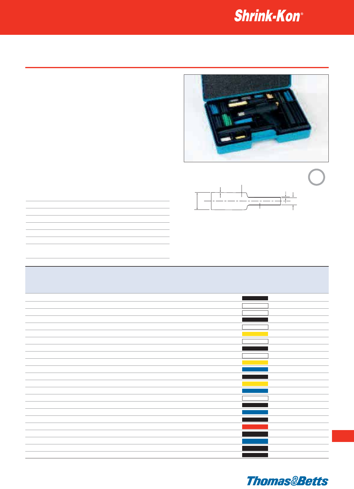
Shrink-Kon®Set
• A kit comprising PLG heat shrink with or without hot air tool in a
handy carry case
• Maintenance and repair, research and development, small series
manufacture and much more
• 9 different expanded diameters
• 6 different colours
• 23 types
• Flame retardant
• Case made from shock-resistant plastic
• All types available in refill packages
•Product Ref.: SK-1400GTG (with GR121)
•Product Ref.: SK-1400GTG-UK (with GR321)
•Product Ref.: SK-1400G (without hot air tool)
See page 246 for tooling specifications
Technical Information
Wall thickness Thin
Shrink ratio 2:1
Tube characteristics Single wall
Temperature range -55°C to +125°C
Shrinking temperature +110°C
Material Crosslinked polyolefin
IP rating IP60
Other properties Silicone, Cadmium and Lead free
Transparent version: Halogen free
Thin wall heat shrink tubing
225
Thomas & Betts • www.tnb-europe.com
3.1
Set contents Expanded diameter Fully recovered Wall thickness Wall thickness Colour Length Quantity
Product Ref.
as supplied diameter before shrinking after shrinking
Ddzw
[inch] [mm] [mm] [mm] [mm] [cm] [pieces]
PLG63-0
1
/
16
1.6 0.8 0.20 0.4 Black 520
PLG63-C
1
/
16
1.6 0.8 0.20 0.4 Transparent 5 20
PLG93-C
3
/
32
2.4 1.2 0.25 0.5 Transparent 5 20
PLG93-0
3
/
32
2.4 1.2 0.25 0.5 Black 10 15
PLG125-C
1
/
8
3.2 1.6 0.25 0.5 Transparent 10 15
PLG125-4
1
/
8
3.2 1.6 0.25 0.5 Yellow 10 10
PLG125-9
1
/
8
3.2 1.6 0.25 0.5 White 10 10
PLG125-0
1
/
8
3.2 1.6 0.25 0.5 Black 10 12
PLG187-C
3
/
16
4.8 2.4 0.25 0.5 Transparent 5 10
PLG187-4
3
/
16
4.8 2.4 0.25 0.5 Yellow 5 10
PLG187-6
3
/
16
4.8 2.4 0.25 0.5 Blue 520
PLG187-0
3
/
16
4.8 2.4 0.25 0.5 Black 10 12
PLG250-4
1
/
4
6.4 3.2 0.30 0.6 Yellow 5 16
PLG250-6
1
/
4
6.4 3.2 0.30 0.6 Blue 10 12
PLG250-9
1
/
4
6.4 3.2 0.30 0.6 White 5 16
PLG250-0
1
/
4
6.4 3.2 0.30 0.6 Black 10 10
PLG375-6
3
/
8
9.5 4.8 0.30 0.6 Blue 10 10
PLG375-0
3
/
8
9.5 4.8 0.30 0.6 Black 18 4
PLG500-2
1
/
2
12.7 6.4 0.40 0.7 Red 10 6
PLG500-0
1
/
2
12.7 6.4 0.40 0.7 Black 18 4
PLG750-6
3
/
4
19.1 9.5 0.40 0.7 Blue 10 4
PLG750-0
3
/
4
19.1 9.5 0.40 0.7 Black 18 4
PLG1000-0 1 25.4 12.7 0.45 0.8 Black 18 3
Expanded
Recovered
D
w
d
z
2:1
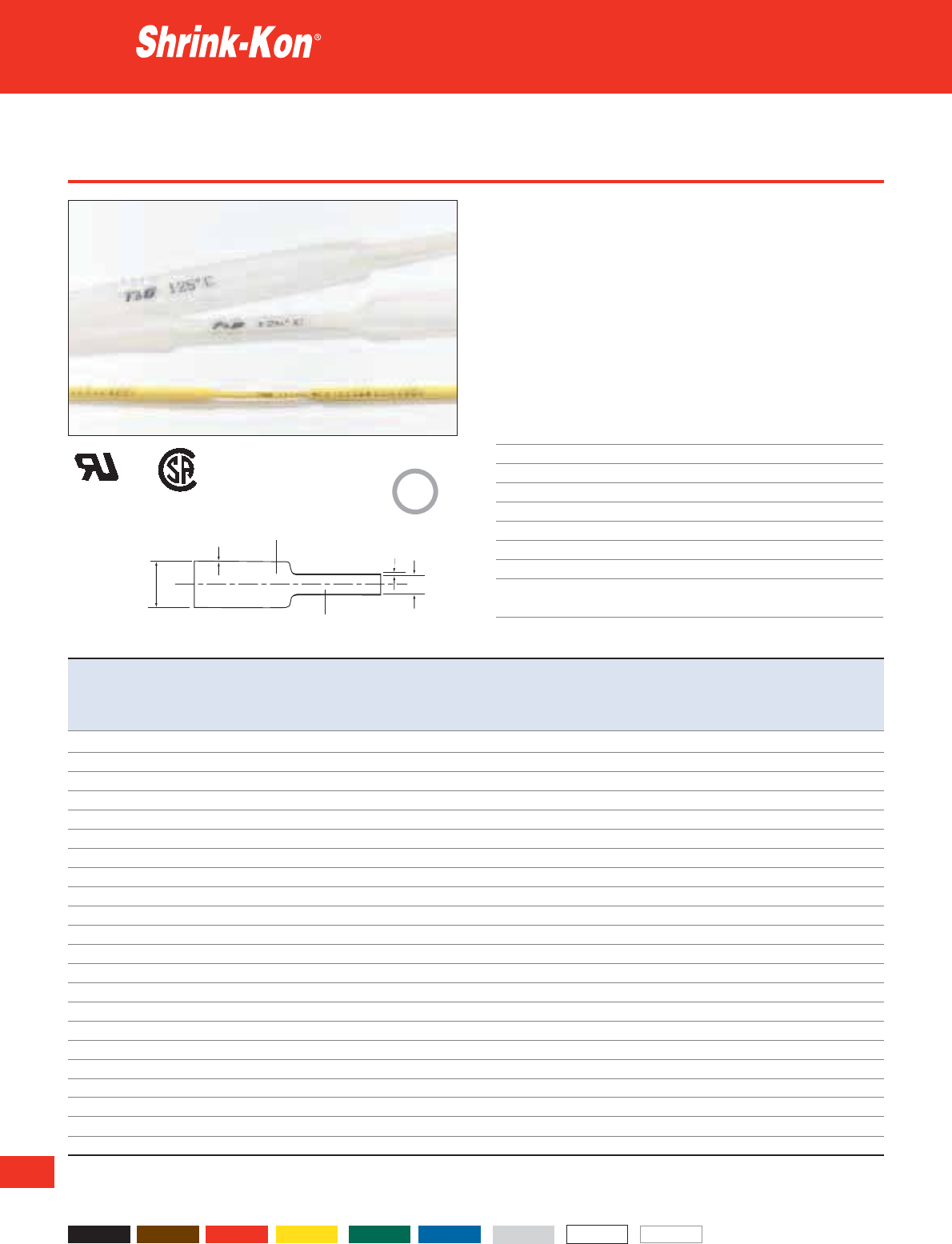
226
Thomas & Betts • www.tnb-europe.com
3.1
Type CMP - dual listed
• Typical applications are mechanical and electrical insulation, cor-
rosion protection, bundling, mechanical protection and much
more
• Internal diameters from 1.2 mm to 51 mm
• Flame retardant
• Flammability per UL 224
• The tubing is marked
• Available colours: see below (see page 220 for product reference
structure)
Technical Information
Wall thickness Thin
Shrink ratio 2:1
Tube characteristics Single wall
Temperature range -55°C to +125°C
Shrinking temperature +110°C
Material Crosslinked polyolefin
IP rating IP60
Standard colour Black
Other properties Silicon, Cadmium and Lead free
Transparent version: Halogen free
Thin wall heat shrink tubing
Product Ref. Expanded diameter Fully recovered Wall thickness Wall thickness Length Total length Quantity
as supplied diameter before shrinking after shrinking per reel per box per box
Ddzw
[inch] [mm] [mm] [mm] [mm] [m] [m] [pieces 1.22m]
CMP46-0-A
3
/
64
1.2 0.6 0.20 0.4 – 30.5 25
CMP46-0-BG
3
/
64
1.2 0.6 0.20 0.4 300 – –
CMP63-0-A
1
/
16
1.6 0.8 0.20 0.4 – 30.5 25
CMP63-0-BG
1
/
16
1.6 0.8 0.20 0.4 300 – –
CMP93-0-A
3
/
32
2.4 1.2 0.25 0.5 – 30.5 25
CMP93-0-BG
3
/
32
2.4 1.2 0.25 0.5 300 – –
CMP125-0-A
1
/
8
3.2 1.6 0.25 0.5 – 30.5 25
CMP125-0-BG
1
/
8
3.2 1.6 0.25 0.5 300 – –
CMP187-0-A
3
/
16
4.7 2.4 0.25 0.5 – 30.5 25
CMP187-0-BG
3
/
16
4.7 2.4 0.25 0.5 300 – –
CMP250-0-A
1
/
4
6.4 3.2 0.30 0.6 – 30.5 25
CMP250-0-BG
1
/
4
6.4 3.2 0.30 0.6 300 – –
CMP375-0-A
3
/
8
9.5 4.8 0.30 0.6 – 30.5 25
CMP375-0-BG
3
/
8
9.5 4.8 0.30 0.6 150 – –
CMP500-0-A
1
/
2
12.7 6.4 0.30 0.7 – 30.5 25
CMP500-0-BG
1
/
2
12.7 6.4 0.30 0.7 100 – –
CMP750-0-A
3
/
4
19.1 9.5 0.40 0.7 – 12.2 10
CMP750-0-BG
3
/
4
19.1 9.5 0.40 0.7 50 – –
CMP1000-0-A 1 25.4 12.7 0.45 0.8 – 12.2 10
CMP1000-0-BG 1 25.4 12.7 0.45 0.8 50 – –
CMP1500-0-BG 1
1
/
2
38.0 19.0 0.50 1.0 50 – –
CMP2000-0-BG 2 51.0 25.4 0.55 1.1 50 – –
* Transparent version not UL recognized
For other colours add colour suffix to Product Reference:
0 = black, 1 = brown, 2 = red, 4 = yellow, 5 = green, 6 = blue, 8 = grey, 9 = white and C = transparent
Expanded
Recovered
D
w
d
z
2:1
E79546 702106
*

Type MLP - flexible for high specifications
• Typical applications are insulation, corrosion protection, compo-
nent strain relief and connections in applications requiring the
highest specifications (e.g. aeronautical and military applications)
• Internal diameters from 1.2 mm to 25.4 mm
• Dual Listed
• Meets MIL-DTL-23053/5 requirements, Class 1 and Class 2
• Weather UV-resistant
• Good chemical resistance
• Flame retardant
• Available colours: see below (see page 220 for product reference
structure)
Technical Information
Wall thickness Thin
Shrink ratio 2:1
Tube characteristics Single wall
Temperature range -55°C to +135°C
Shrinking temperature +90°C
Material Crosslinked polyolefin
IP rating IP60
Standard colour Black
Other properties Silicone, Cadmium and Lead free
Transparent version: Halogen free
Thin wall heat shrink tubing
227
Thomas & Betts • www.tnb-europe.com
3.1
Product Ref. Expanded diameter Fully recovered Wall thickness Wall thickness Total length Quantity
as supplied diameter before shrinking after shrinking per box per box
Ddzw
[inch] [mm] [mm] [mm] [mm] [m] [pieces 1.22m]
MLP46-0-A
3
/
64
1.2 0.6 0.20 0.4 30.5 25
MLP63-0-A
1
/
16
1.6 0.8 0.20 0.4 30.5 25
MLP93-0-A
3
/
32
2.4 1.2 0.25 0.5 30.5 25
MLP125-0-A
1
/
8
3.2 1.6 0.25 0.5 30.5 25
MLP187-0-A
3
/
16
4.7 2.4 0.25 0.5 30.5 25
MLP250-0-A
1
/
4
6.4 3.2 0.30 0.6 30.5 25
MLP375-0-A
3
/
8
9.5 4.8 0.30 0.6 30.5 25
MLP500-0-A
1
/
2
12.7 6.4 0.30 0.7 30.5 25
MLP750-0-A
3
/
4
19.1 9.5 0.40 0.7 12.2 10
MLP1000-0-A 1 25.4 12.7 0.45 0.8 12.2 10
For other colours add colour suffix to Product Reference:
0 = black, 1 = brown, 2 = red, 4 = yellow, 5 = green, 6 = blue, 8 = grey, 9 = white and C = transparent
Expanded
Recovered
D
w
d
z
2:1
E79546 702106
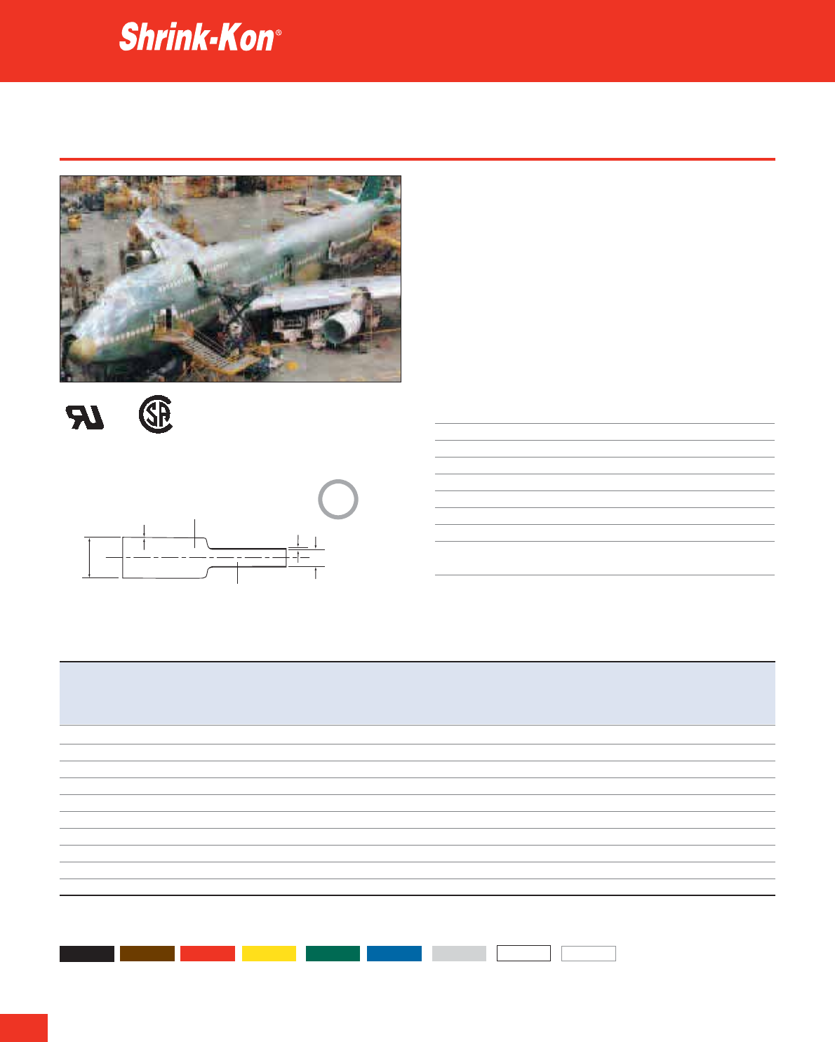
228
Thomas & Betts • www.tnb-europe.com
3.1
Type MLP - flexible for high specifications
• Typical applications are insulation, corrosion protection, component
strain relief and connections in applications requiring the highest
specifications (e.g. aeronautical and military applications)
• Internal diameters from 1.2 mm to 25.4 mm
• Dual Listed
• Meets MIL-DTL-23053/5 requirements, Class 1 and Class 2
• Weather UV-resistant
• Good chemical resistance
• Flame retardant
• Available colours: see below (see page 220 for product reference
structure)
Technical Information
Wall thickness Thin
Shrink ratio 2:1
Tube characteristics Single wall
Temperature range -55°C to +135°C
Shrinking temperature +90°C
Material Crosslinked polyolefin
IP rating IP60
Standard colour Black
Other properties Silicone, Cadmium and Lead free
Transparent version: Halogen free
Thin wall heat shrink tubing
Product Ref. Expanded diameter Fully recovered Wall thickness Wall thickness Length
as supplied diameter before shrinking after shrinking per reel
Ddzw
[inch] [mm] [mm] [mm] [mm] [m]
MLP46-0-BG
3
/
64
1.2 0.6 0.20 0.4 300
MLP63-0-BG
1
/
16
1.6 0.8 0.20 0.4 300
MLP93-0-BG
3
/
32
2.4 1.2 0.25 0.5 300
MLP125-0-BG
1
/
8
3.2 1.6 0.25 0.5 300
MLP187-0-BG
3
/
16
4.7 2.4 0.25 0.5 300
MLP250-0-BG
1
/
4
6.4 3.2 0.30 0.6 300
MLP375-0-BG
3
/
8
9.5 4.8 0.30 0.6 150
MLP500-0-BG
1
/
2
12.7 6.4 0.30 0.7 100
MLP750-0-BG
3
/
4
19.1 9.5 0.40 0.7 50
MLP1000-0-BG 1 25.4 12.7 0.45 0.8 50
For other colours add colour suffix to Product Reference:
0 = black, 1 = brown, 2 = red, 4 = yellow, 5 = green, 6 = blue, 8 = grey, 9 = white and C = transparent
Expanded
Recovered
D
w
d
z
2:1
E79546 702106
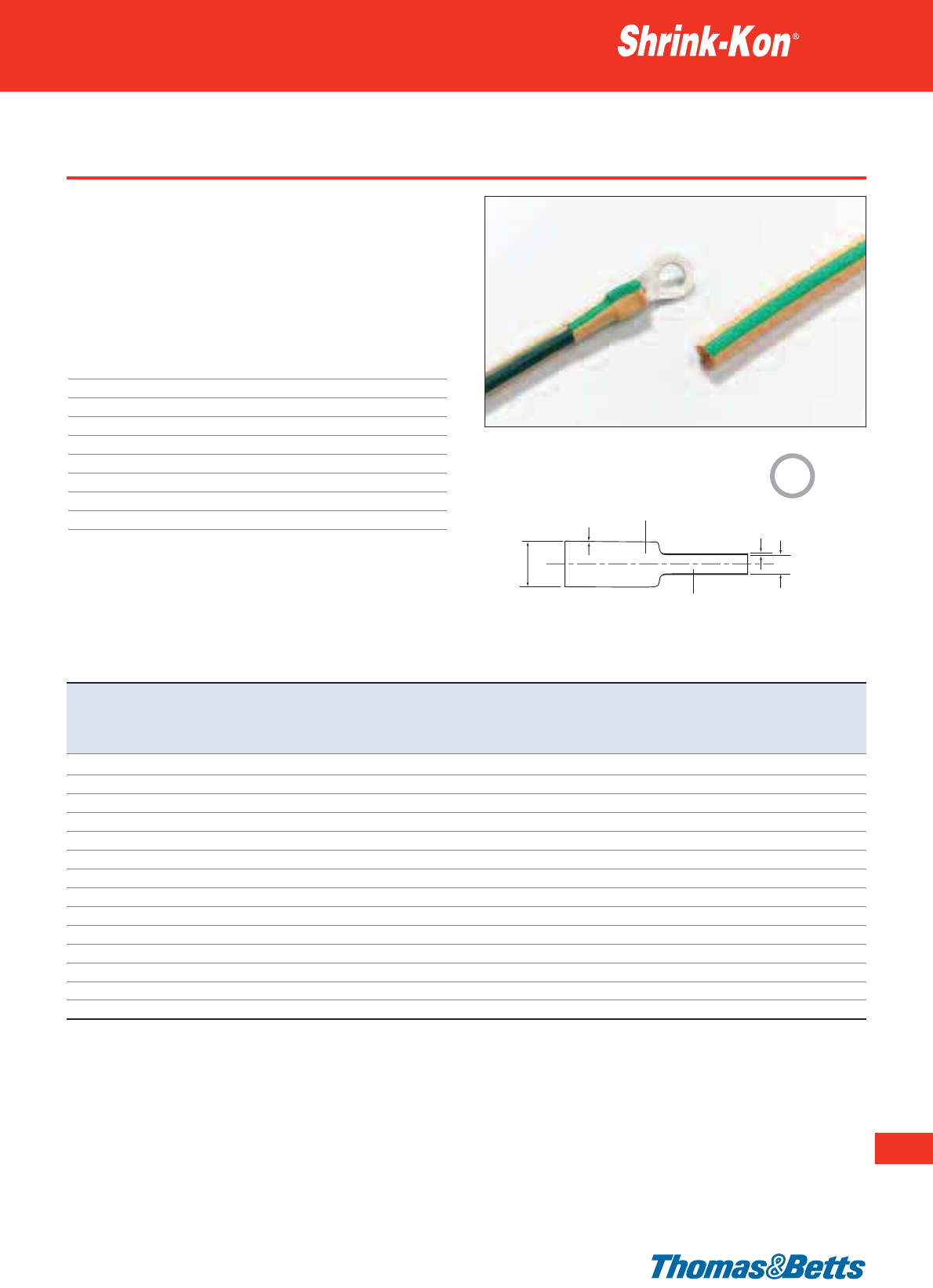
Type GYS - flexible green and yellow
• For identifying and marking earthing connectors and cables
• Mechanical and electrical insulation, corrosion protection
• Internal diameters from 3.2 mm to 25.4 mm
• Flame retardant
• Meets MIL-DTL-23053/5 requirements, Class 1 and Class 2
(see page 220 for product reference structure)
Technical Information
Wall thickness Thin
Shrink ratio 2:1
Tube characteristics Single wall
Temperature range -55°C to +135°C
Shrinking temperature +90°C
Material Crosslinked polyolefin
IP rating IP60
Standard colour Green / Yellow striped
Other properties Silicone, Cadmium and Lead free
Thin wall heat shrink tubing
229
Thomas & Betts • www.tnb-europe.com
3.1
Product Ref. Expanded diameter Fully recovered Wall thickness Wall thickness Length Total length Quantity
as supplied diameter before shrinking after shrinking per mini-reel per box per box
Ddzw
[inch] [mm] [mm] [mm] [mm] [m] [m] [pieces 1.22m]
GYS125-E-A
1
/
8
3.2 1.6 0.25 0.51 – 30.5 25
GYS125-E-E
1
/
8
3.2 1.6 0.25 0.51 150 – –
GYS187-E-A
3
/
16
4.8 2.4 0.25 0.51 – 30.5 25
GYS187-E-E
3
/
16
4.8 2.4 0.25 0.51 75 – –
GYS250-E-A
1
/
4
6.4 3.2 0.32 0.64 – 30.5 25
GYS250-E-E
1
/
4
6.4 3.2 0.32 0.64 75 – –
GYS375-E-A
3
/
8
9.5 4.8 0.32 0.64 – 30.5 25
GYS375-E-E
3
/
8
9.5 4.8 0.32 0.64 75 – –
GYS500-E-A
1
/
2
12.7 6.4 0.32 0.64 – 30.5 25
GYS500-E-E
1
/
2
12.7 6.4 0.32 0.64 50 – –
GYS750-E-A
3
/
4
19.1 9.5 0.38 0.76 – 12.2 10
GYS750-E-E
3
/
4
19.1 9.5 0.38 0.76 30 – –
GYS1000-E-A 1 25.4 12.7 0.45 0.89 – 12.2 10
GYS1000-E-E 1 25.4 12.7 0.45 0.89 30 – –
Expanded
Recovered
D
w
d
z
2:1
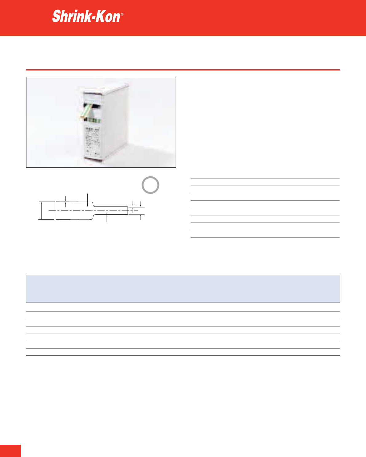
230
Thomas & Betts • www.tnb-europe.com
3.1
Type GYS - HSB boxes
• For identifying and marking earthing connectors and cables
• GYS heat shrink in a compact, handy sized box
• Convenient amount of heat shrink, for small users
• Offered in 7 sizes to cover a heat shrink range from 3.2 mm to
25.4 mm diameters
• Stackable boxes for easy storage
• Flame retardant
• Meets MIL-DTL-23053/5 requirements, Class 1 and Class 2
• Mechanical and electrical insulation, corrosion protection
(see page 220 for product reference structure)
Technical Information
Wall thickness Thin
Shrink ratio 2:1
Tube characteristics Single wall
Temperature range -55°C to +135°C
Shrinking temperature +90°C
Material Crosslinked polyolefin
IP rating IP60
Standard colour Green / Yellow striped
Other properties Silicone, Cadmium and Lead free
Thin wall heat shrink tubing
Product Ref. Expanded diameter Fully recovered Wall thickness Wall thickness Length
as supplied diameter before shrinking after shrinking per box
Ddzw
[inch] [mm] [mm] [mm] [mm] [m]
GYS125-E-D
1
/
8
3.2 1.6 0.25 0.51 11.5
GYS187-E-D
3
/
16
4.8 2.4 0.25 0.51 9.5
GYS250-E-D
1
/
4
6.4 3.2 0.32 0.64 7.5
GYS375-E-D
3
/
8
9.5 4.8 0.32 0.64 6.5
GYS500-E-D
1
/
2
12.7 6.4 0.32 0.64 6.0
GYS750-E-D
3
/
4
19.1 9.5 0.38 0.76 5.0
GYS1000-E-D 1 25.4 12.7 0.45 0.89 3.3
Expanded
Recovered
D
w
d
z
2:1
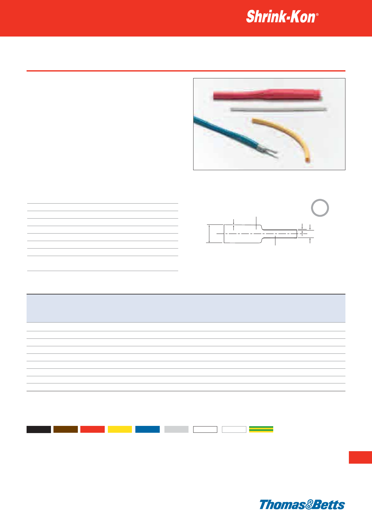
Type PIG - very flexible for highly contoured components
• Heat shrink tubing to enclose highly contoured components with
large diameter variations. Provides mechanical and electrical pro-
tection
• Meets UL 224 requirements
• Internal diameters from 1.6 mm to 40 mm
• Excellent mechanical strength
• Resistant to common fluids and solvents
• Flame retardant
• Meets MIL-DTL-23053/5 requirements, Class 1 and Class 2 (ex-
cept green / yellow version)
• Available colours: see below (see page 220 for product reference
structure)
• Special colours available on request
Technical Information
Wall thickness Thin
Shrink ratio 3:1
Tube characteristics Single wall
Temperature range -55°C to +135°C
Shrinking temperature +90°C
Material Crosslinked polyolefin
IP rating IP60
Standard colour Black
Other properties Silicone, Cadmium and Lead free
Transparent version: Halogen free
Thin wall heat shrink tubing
231
Thomas & Betts • www.tnb-europe.com
3.1
Product Ref. Expanded diameter Fully recovered Wall thickness Wall thickness Length
as supplied diameter before shrinking after shrinking per reel
Ddzw
[inch] [mm] [mm] [mm] [mm] [m]
PIG0150-0-B*
1
/
16
1.6 0.5 0.15 0.45 300
PIG0301-0-B*
1
/
8
3.2 1.0 0.18 0.55 300
PIG0451-0-B
3
/
16
4.5 1.5 0.20 0.60 300
PIG0602-0-B
1
/
4
6.4 2.0 0.22 0.65 300
PIG0903-0-B
3
/
8
9.5 3.0 0.25 0.75 150
PIG1204-0-B
1
/
2
12.7 4.0 0.25 0.75 100
PIG1806-0-B
3
/
4
19.0 6.0 0.27 0.80 50
PIG2408-0-B 1 25.4 8.0 0.33 1.00 50
PIG4013-0-B 1
1
/
2
40.0 13.0 0.38 1.15 50
* Not available in green / yellow
For other colours add colour suffix to Product Reference:
0 = black, 1 = brown, 2 = red, 4 = yellow, 6 = blue, 8 = grey, 9 = white, C = transparent and E = green / yellow striped
Expanded
Recovered
D
w
d
z
3:1
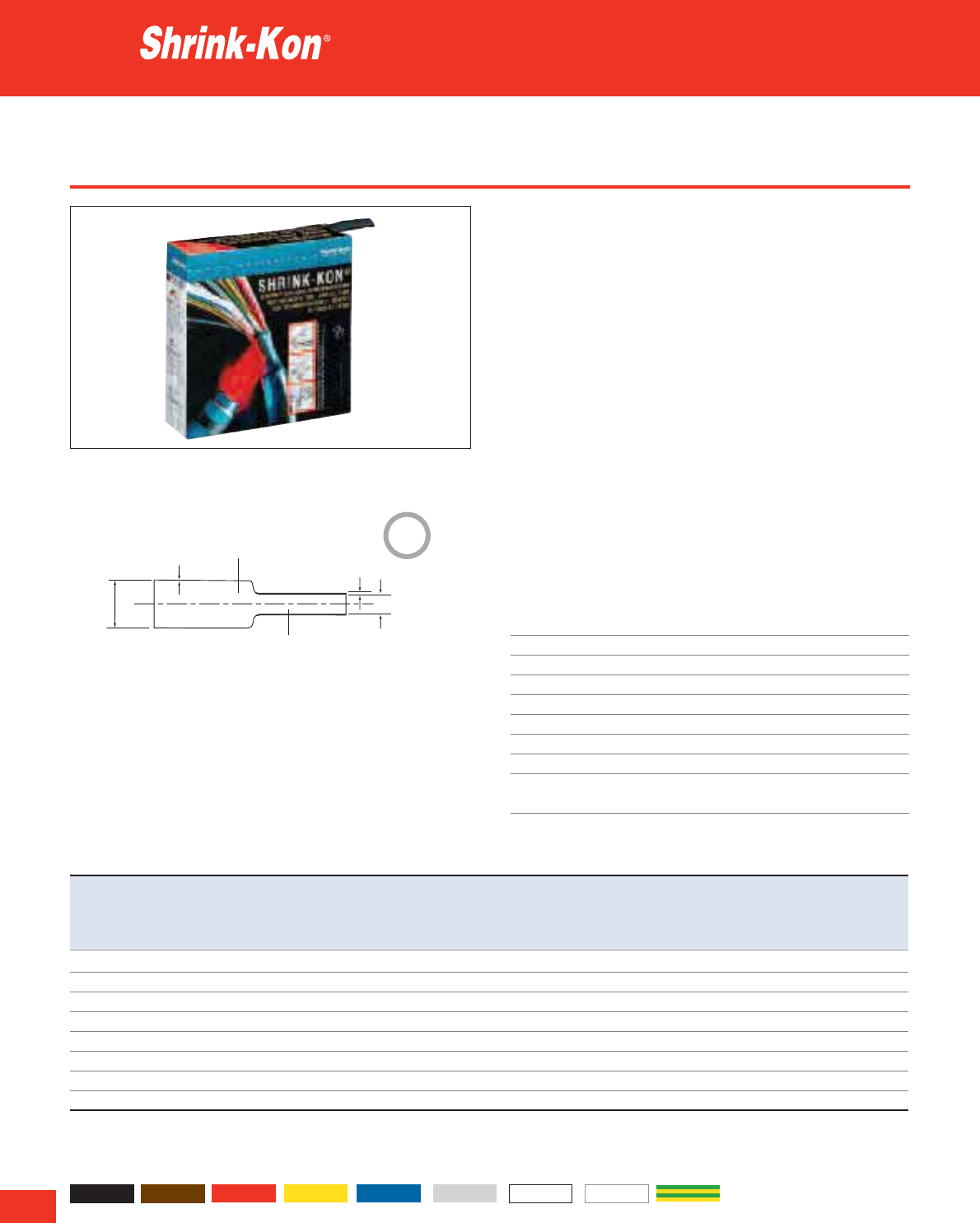
232
Thomas & Betts • www.tnb-europe.com
3.1
Type PIG - HSB boxes
• PIG heat shrink in a compact, handy sized box
• Workshop, installation, laboratory and much more
• Heat shrink tubing to enclose highly contoured components with
large diameter variations. Provides mechanical and electrical
protection
• Convenient amount of heat shrink, for small users
• Offered in 8 sizes to cover a heat shrink range from Ø 1.6 mm to
Ø25.4mm
• Stackable boxes for easy storage
• Meets UL 224 requirements
• Excellent mechanical strength
• Resistant to common fluids and solvents
• Flame retardant
• Meets MIL-DTL-23053/5 requirements, Class 1 and Class 2
(except green / yellow version)
• Available colours: see below (see page 220 for product reference
structure)
• Special colours available on request
Technical Information
Wall thickness Thin
Shrink ratio 3:1
Tube characteristics Single wall
Temperature range -55°C to +135°C
Shrinking temperature +90°C
Material Crosslinked polyolefin
IP rating IP60
Standard colour Black
Other properties Silicone, Cadmium and Lead free
Transparent version: Halogen free
Thin wall heat shrink tubing
Product Ref. Expanded diameter Fully recovered Wall thickness Wall thickness Length
as supplied diameter before shrinking after shrinking per box
Ddzw
[inch] [mm] [mm] [mm] [mm] [m]
PIG0150-0-D*
1
/
16
1.6 0.5 0.15 0.45 10.5
PIG0301-0-D*
1
/
8
3.2 1.0 0.18 0.55 10.0
PIG0451-0-D
3
/
16
4.5 1.5 0.20 0.60 9.0
PIG0602-0-D
1
/
4
6.4 2.0 0.22 0.65 7.0
PIG0903-0-D
3
/
8
9.5 3.0 0.25 0.75 6.0
PIG1204-0-D
1
/
2
12.7 4.0 0.25 0.75 5.5
PIG1806-0-D
3
/
4
19.0 6.0 0.27 0.80 4.5
PIG2408-0-D 1 25.4 8.0 0.33 1.00 3.3
* Not available in green/yellow
For other colours add colour suffix to Product Reference:
0 = black, 1 = brown, 2 = red, 4 = yellow, 6 = blue, 8 = grey, 9 = white, C = transparent and E = green / yellow striped
Expanded
Recovered
D
w
d
z
3:1
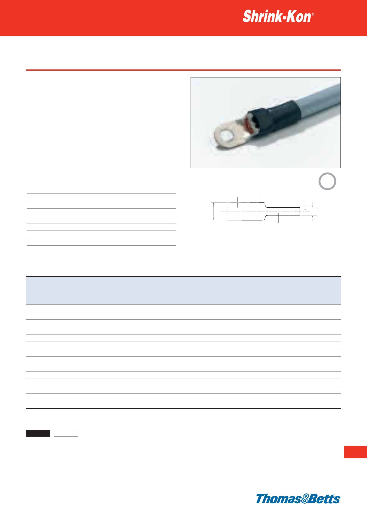
Type PKG - flexible for moist environments
Thin wall heat shrink tubing
233
Thomas & Betts • www.tnb-europe.com
3.1
Expanded
Recovered
D
w
d
z
Product Ref. Expanded diameter Fully recovered Wall thickness Wall thickness Length Total length Quantity
as supplied diameter before shrinking after shrinking per reel per bag per bag
Ddzw
[mm] [mm] [mm] [mm] [m] [m] [pieces 0.6 m]
PKG0301-0-B 3.0 1.0 0.4 1.0 300 – –
PKG0301-0-C 3.0 1.0 0.4 1.0 – 12.0 20
PKG0602-0-B 6.0 2.0 0.5 1.0 300 – –
PKG0602-0-C 6.0 2.0 0.5 1.0 – 9.0 15
PKG0903-0-B 9.0 3.0 0.5 1.4 150 – –
PKG0903-0-C 9.0 3.0 0.5 1.4 – 6.0 10
PKG1204-0-B 12.0 4.0 0.5 1.8 100 – –
PKG1204-0-C 12.0 4.0 0.5 1.8 – 5.4 9
PKG1806-0-B 18.0 6.0 0.6 2.2 50 – –
PKG1806-0-C 18.0 6.0 0.6 2.2 – 3.6 6
PKG2408-0-B 24.0 8.0 0.7 2.5 50 – –
PKG2408-0-C 24.0 8.0 0.7 2.5 – 3.0 5
PKG4013-0-B 40.0 13.0 0.7 2.5 30 – –
PKG4013-0-C 40.0 13.0 0.7 2.5 – 2.4 4
For other colours add colour suffix to Product Reference:
0 = black and C = transparent
3:1
• Crosslinked modified Polyolefin with thermoplastic adhesive lining
• Particularly suitable for corrosion and damp protected casings as
well as highly contoured components
• Flame retardant
• Moisture resistant, good chemical resistance
• High mechanical stability
• The high shrink ratio and flexibility of this range allows the user
maximum coverage with minimal parts
• The adhesive lining bonds to plastic, rubber, neoprene, steel and
polyethylene
• Available colours: see below (see page 220 for product reference
structure)
Technical Information
Wall thickness Thin
Shrink ratio 3:1
Tube characteristics Dual wall
Temperature range -55°C to +110°C (outer jacket)
Shrinking temperature +95°C
Material Crosslinked polyolefin with adhesive lining
IP rating IP65
Standard colour Black
Other properties Silicone, Cadmium and Lead free

234
Thomas & Betts • www.tnb-europe.com
3.1
Type PKG - flexible for moist environments
• Crosslinked modified Polyolefin with thermoplastic adhesive lining
• Particularly suitable for corrosion and damp protected casings as
well as highly contoured components
• Flame retardant
• Moisture resistant, good chemical resistance
• High mechanical stability
• The high shrink ratio and flexibility of this range allows the user
maximum coverage with minimal parts
• The adhesive lining bonds to plastic, rubber, neoprene, steel and
polyethylene
• Available colours: see below (see page 220 for product reference
structure)
Technical Information
Wall thickness Thin
Shrink ratio 4:1
Tube characteristics Dual wall
Temperature range -55°C to +110°C (outer jacket)
Shrinking temperature +95°C
Material Crosslinked polyolefin with adhesive lining
IP rating IP65
Standard colour Black
Other properties Silicone, Cadmium and Lead free
Thin wall heat shrink tubing
Expanded
Recovered
D
w
d
z
4:1
Product Ref. Expanded diameter Fully recovered Wall thickness Wall thickness Length Total length Quantity
as supplied diameter before shrinking after shrinking per reel per bag per bag
Ddzw
[mm] [mm] [mm] [mm] [m] [m] [pieces 0.6m]
PKG0401-0-B 4.0 1.0 0.4 1.0 300 – –
PKG0401-0-C 4.0 1.0 0.4 1.0 – 12.0 20
PKG0802-0-B 8.0 2.0 0.5 1.0 150 – –
PKG0802-0-C 8.0 2.0 0.5 1.0 – 9.0 15
PKG1203-0-B 12.0 3.0 0.5 1.4 100 – –
PKG1203-0-C 12.0 3.0 0.5 1.4 – 6.0 10
PKG1604-0-B 16.0 4.0 0.5 1.7 50 – –
PKG1604-0-C 16.0 4.0 0.5 1.7 – 5.4 9
PKG2406-0-B 24.0 6.0 0.6 2.1 50 – –
PKG2406-0-C 24.0 6.0 0.6 2.1 – 3.0 5
PKG3208-0-B 32.0 8.0 0.7 2.4 50 – –
PKG3208-0-C 32.0 8.0 0.7 2.4 – 3.0 5
PKG5213-0-B 52.0 13.0 0.7 2.4 30 – –
PKG5213-0-C 52.0 13.0 0.7 2.4 – 1.8 3
For other colours add colour suffix to Product Reference:
0 = black and C = transparent
Type PKG - HSB boxes
• PKG heat shrink in a compact, handy sized box
• Convenient amount of heat shrink, for small users
• Particularly suitable for corrosion and damp protected casings as
well as highly contoured components
• Offered in 6 sizes to cover a heat shrink range from Ø 3.0 mm to
Ø 24.0 mm
• Stackable boxes for easy storage
• The adhesive lining bonds to plastic, rubber, neoprene, steel and
polyethylene
• Flame retardant
• Moisture resistant
• Available colours: see below (see page 220 for product reference
structure)
Technical Information
Wall thickness Thin
Shrink ratio 3:1
Tube characteristics Dual wall
Temperature range -55°C to +110°C (outer jacket)
Shrinking temperature +95°C
Material Crosslinked polyolefin with adhesive lining
IP rating IP65
Standard colour Black
Other properties Silicone, Cadmium and Lead free
Thin wall heat shrink tubing
235
Thomas & Betts • www.tnb-europe.com
3.1
Product Ref. Expanded diameter Fully recovered Wall thickness Wall thickness Length
as supplied diameter before shrinking after shrinking per box
Ddz w
[mm] [mm] [mm] [mm] [m]
PKG0301-0-D 3.0 1.0 0.4 1.0 5.0
PKG0602-0-D 6.0 2.0 0.5 1.0 3.5
PKG0903-0-D 9.0 3.0 0.5 1.4 3.0
PKG1204-0-D 12.0 4.0 0.5 1.8 2.5
PKG1806-0-D 18.0 6.0 0.6 2.2 2.0
PKG2408-0-D 24.0 8.0 0.7 2.5 1.5
For other colours add colour suffix to Product Reference:
0 = black and C = transparent
Expanded
Recovered
D
w
d
z
3:1
236
Thomas & Betts • www.tnb-europe.com
3.1
Type KYN - semi-rigid transparent
• In areas of heavy mechanical loads, high temperatures and chemi-
cal stress. Insulation in densely packed wiring, in heating elements
and much more
• Internal diameters from 1.2 mm to 25.4 mm
• High mechanical strength
• Excellent electrical insulation performance
• High flame retardancy
• Highly abrasion and cut resistant
• Resistant to Diesel
• Very good resistance against chemicals and solvents
• Meets MIL-DTL-23053/8 requirements
Technical Information
Wall thickness Thin
Shrink ratio 2:1
Tube characteristics Single wall
Temperature range -55°C to +175°C
Shrinking temperature +175°C
Material Crosslinked and rigid
Polyvinylidene Fluoride (Kynar
®
*)
IP rating IP60
Standard colour Transparent
Other properties Silicone, Cadmium, Lead and
Halogen free
* registered trademark of ATOFINA
Thin wall heat shrink tubing
Expanded
Recovered
D
w
d
z
2:1
Product Ref. Expanded diameter Fully recovered Wall thickness Wall thickness Total length Quantity
as supplied diameter before shrinking after shrinking per box per box
Ddzw
[inch] [mm] [mm] [mm] [mm] [m] [pieces 1.22m]
KYN46-C-A
3
/
64
1.2 0.6 0.12 0.25 30.5 25
KYN63-C-A
1
/
16
1.6 0.8 0.12 0.25 30.5 25
KYN93-C-A
3
/
32
2.4 1.2 0.12 0.25 30.5 25
KYN125-C-A
1
/
8
3.2 1.6 0.12 0.25 30.5 25
KYN187-C-A
3
/
16
4.8 2.4 0.12 0.25 30.5 25
KYN250-C-A
1
/
4
6.4 3.2 0.15 0.30 12.2 10
KYN375-C-A
3
/
8
9.5 4.8 0.15 0.30 12.2 10
KYN500-C-A
1
/
2
12.7 6.0 0.15 0.30 12.2 10
KYN750-C-A
3
/
4
19.1 9.5 0.20 0.40 12.2 10
KYN1000-C-A 1 25.4 12.7 0.25 0.50 12.2 10
Type VIT - highly flexible, flame retardant
• High flexibility makes it suitable even under heavy-duty conditions
e.g. sensors in vehicle engine compartments
• Excellent strength and resistance against corrosive fluids even at
high temperatures
• Internal diameters from 3.2 mm to 38.1 mm
• Offers excellent resistance to aggressive fuels and chemicals
• High flame retardancy
• Meets MIL-DTL-23053/13 requirements
Technical Information
Wall thickness Thin
Shrink ratio 2:1
Tube characteristics Single wall
Temperature range -55°C to +220°C
Shrinking temperature +175°C
Material Viton
®
*, Crosslinked fluoroelastomer
IP rating IP60
Standard colour Black
Other properties Silicone, Cadmium and Lead free
*Viton
®
is a registered trademark of DuPont.
Thin wall heat shrink tubing
237
Thomas & Betts • www.tnb-europe.com
3.1
Product Ref. Expanded diameter Fully recovered Wall thickness Wall thickness Total length Quantity
as supplied diameter before shrinking after shrinking per box per box
Ddzw
[inch] [mm] [mm] [mm] [mm] [m] [pieces 0.6m]
VIT125-0-C
1
/
8
3.2 1.6 0.40 0.8 6.0 10
VIT187-0-C
3
/
16
4.8 2.4 0.45 0.9 6.0 10
VIT250-0-C
1
/
4
6.4 3.2 0.45 0.9 6.0 10
VIT375-0-C
3
/
8
9.5 4.8 0.45 0.9 4.8 8
VIT500-0-C
1
/
2
12.7 6.4 0.45 0.9 4.2 7
VIT750-0-C
3
/
4
19.1 9.5 0.55 1.3 3.6 6
VIT1000-0-C 1 25.4 12.7 0.70 1.4 2.4 4
VIT1500-0-C 1
1
/
2
38.1 19.0 0.80 1.9 1.8 3
Expanded
Recovered
D
w
d
z
2:1
238
Thomas & Betts • www.tnb-europe.com
3.1
Type ZHFR - flexible, Halogen free & flame retardant
• Flexible
• Low smoke generation when burnt
• Halogen free
• Flame retardant
• Particularly recommended for use in contained areas and with
Halogen free wires and cables
• Meets DEF STAN 59-97, issue 3, type 8
• Available colours: see below (see page 220 for product reference
structure)
• Special colours available on request
Technical Information
Wall thickness Thin
Shrink ratio 2:1
Tube characteristics Single wall
Temperature range -40°C to +105°C
Shrinking temperature +115°C
Material Crosslinked polyolefin
IP rating IP60
Standard colour Black
Other properties Silicone, Cadmium, Lead and Halogen free
Thin wall heat shrink tubing
Product Ref. Expanded diameter Fully recovered Wall thickness Length
as supplied diameter after shrinking per mini-reel
Ddw
[inch] [mm] [mm] [mm] [m]
ZHFR93-0-E
3
/
32
2.4 0.8 0.45 135
ZHFR125-0-E
1
/
8
3.2 1.6 0.51 135
ZHFR187-0-E
3
/
16
4.8 2.4 0.51 70
ZHFR250-0-E
1
/
4
6.4 3.2 0.64 70
ZHFR375-0-E
3
/
8
9.5 4.8 0.64 70
ZHFR500-0-E
1
/
2
12.7 6.4 0.64 45
ZHFR750-0-E
3
/
4
19.1 9.5 0.76 25
ZHFR1000-0-E 1 25.4 12.7 0.89 25
For other colours add colour suffix to Product Reference:
0 = black, 4 = yellow, 9 = white
Expanded
Recovered
D
w
d
2:1
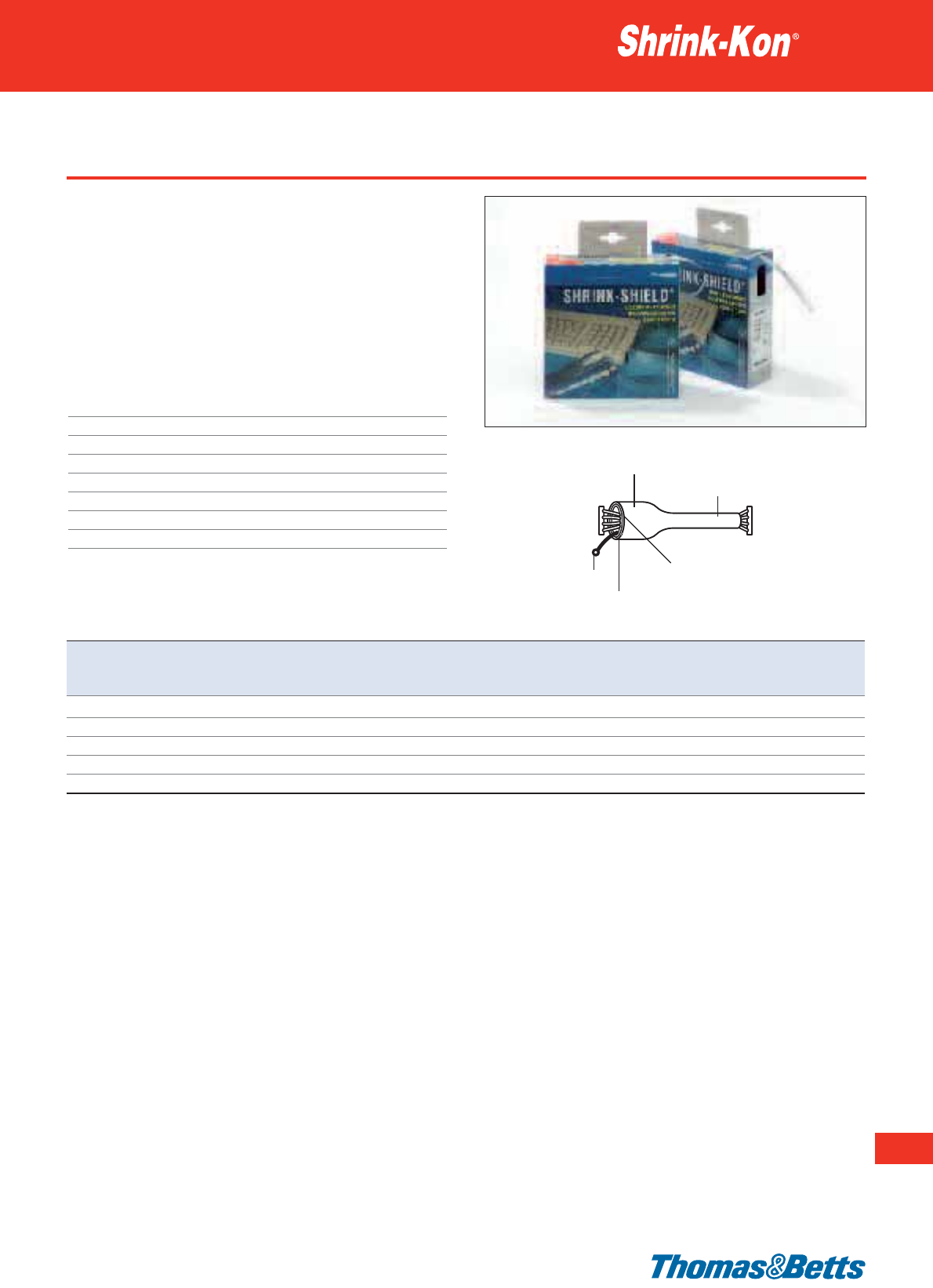
Type SSB - Shrink-Shield
• Insulation and shielding in one process
• Shrink-Shield in the handy format of the HSB boxes
• Typical applications including shielding of both power and signal
cables to reduce EMI radiation and susceptibility
• Inner aluminium layer and silver coloured outer PVC/Polyester
layer
• Shrinks from 90°C
• Fulfills UL 224 VW-1 requirements
Technical Information
Wall thickness Thin
Shrink ratio 2:1
Tube characteristics Dual wall
Temperature range -10°C to +125°C
Shrinking temperature +90°C
Material outer layer PVC & Polyester
Material inner layer Aluminium
Standard colour Silver
Thin wall heat shrink tubing
239
Thomas & Betts • www.tnb-europe.com
3.1
Product Ref. Flat width Expanded diameter Fully recovered Wall thickness Length per
as supplied diameter after shrinking box
[mm] [mm] [mm] [mm] [m]
SSB010-1 12.5 6.4 3.2 0.14 10
SSB015-1 16.0 9.6 4.8 0.14 8
SSB020-1 22.0 13.0 6.5 0.14 7
SSB025-1 27.0 16.0 8.0 0.14 6
SSB040-1 42.0 25.4 12.7 0.14 4
For technical information on the shielding please consult the information available on the European online catalogue.
Before shrinkage
After shrinkage
Outer layer: PVC & Polyester
Inner layer: Aluminium
Ground lead wire

Thomas & Betts • www.tnb-europe.com
3.1
Type TBM - rated for 600V, 90°C continuous use
• TBM is an excellent product for sealing and insulating cable
splices, connections, terminations and jacket repairs where light
weight and high flexibility are required
• The tubing is designed to withstand the severe mechanical
requirements of submersible and direct-buried installations
• High resistance to abrasion, corrosion and chemicals
• Excellent weatherability
• 11 standard sizes in medium wall: internal diameters from
10.2 mm to 228.6 mm
• Meets requirements of ESI 09-11
Technical Information
Wall thickness Medium
Shrink ratio 3:1
Tube characteristics Dual wall
Temperature range -55°C to +110°C
Shrinking temperature +120°C
Material Crosslinked polyolefin with thermoplastic
adhesive liner
IP rating IP67
Standard colour Black
Other properties Silicone, Halogen, Cadmium and Lead free
Medium wall heat shrink tubing
Expanded
Recovered
D
w
d
3:1
Product Ref. Expanded diameter Fully recovered Wall thickness Length Quantity
as supplied diameter after shrinking per bag per bag
Ddw
[mm] [mm] [mm] [m] [pieces 1.22m]
TBM0400 10.2 3.8 2.0 6.1 5
TBM0750 19.1 5.6 2.0 6.1 5
TBM0950 24.1 8.1 2.0 3.6 3
TBM1100 27.9 10.2 2.0 3.6 3
TBM1500 38.1 12.7 2.0 2.4 2
TBM2050 52.1 19.1 2.0 1.2 1
TBM2750 69.9 25.4 2.0 1.2 1
TBM3500 88.9 30.0 2.4 1.2 1
TBM4700 119.4 39.9 2.7 1.2 1
TBM6700 170.2 58.4 2.8 1.2 1
TBM9000 228.6 77.0 3.0 1.2 1
Do not stock at temperatures over 40°C. Do not expose directly to sun rays for long periods.
240
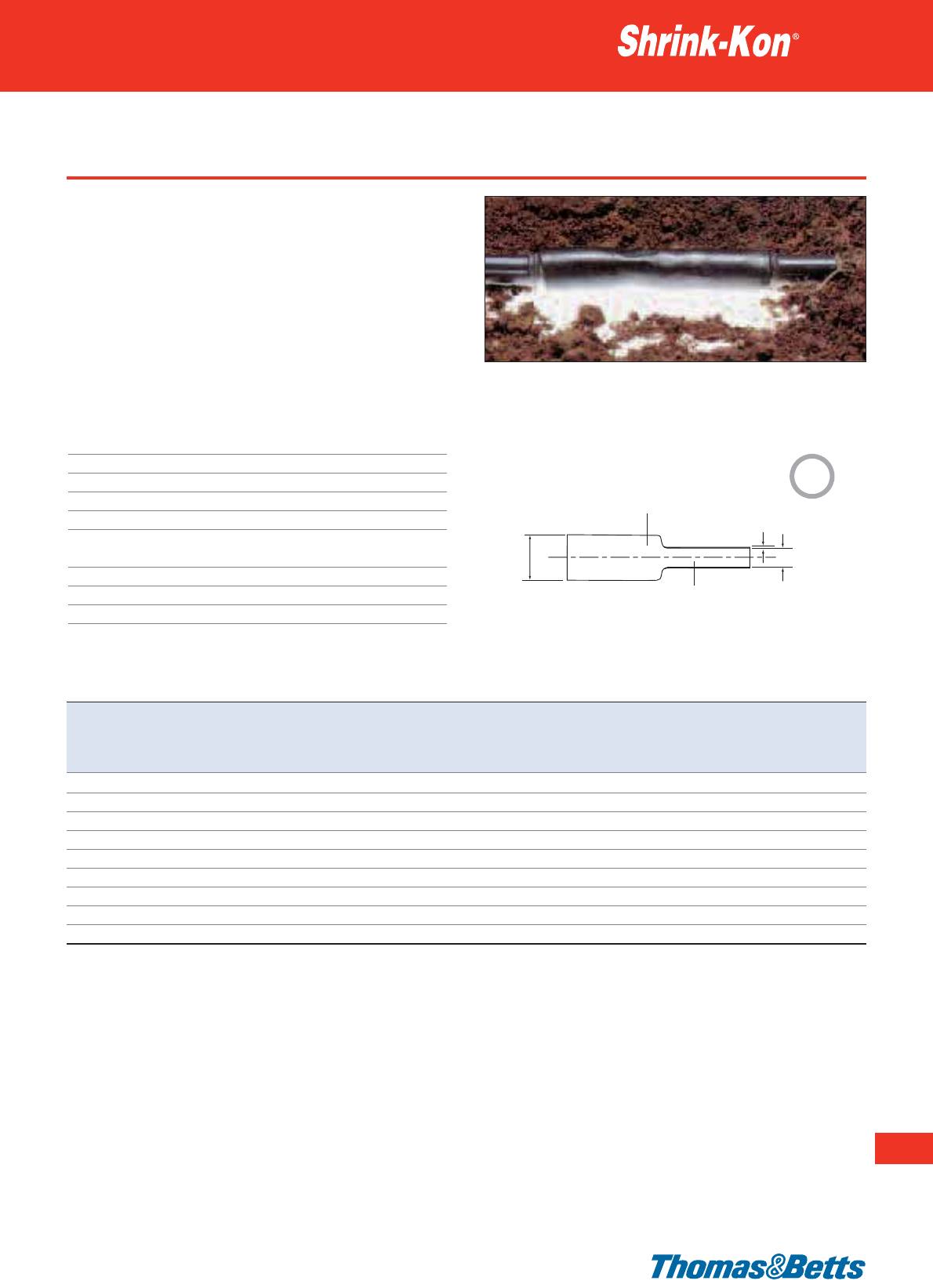
Type TBW - rated for 600V, 90°C continuous use
• TBW is an excellent product for sealing and insulating cable
splices, connections, terminations and jacket repairs.
• The tubing is designed to withstand the severe mechanical
requirements of submersible and direct-buried installations
• Low voltage power applications 600V
• High resistance to abrasion, corrosion and chemicals
• Excellent weatherability
• 9 standard sizes in thick wall: internal diameters from 8.9 mm to
119.9 mm
• Meets requirements of ESI 09-11
Technical Information
Wall thickness Thick
Shrink ratio 3:1
Tube characteristics Dual wall
Temperature range -55°C to +110°C
Shrinking temperature +120°C
Material Crosslinked polyolefin with thermoplastic
adhesive liner
IP rating IP67
Standard colour Black
Other properties Silicone, Halogen, Cadmium and Lead free
Thick wall heat shrink tubing
Thomas & Betts • www.tnb-europe.com
3.1
Product Ref. Expanded diameter Fully recovered Wall thickness Length Quantity
as supplied diameter after shrinking per bag per bag
Dd w
[mm] [mm] [mm] [m] [pieces 1.22m]
TBW0350 8.9 3.0 1.8 6.1 5
TBW0500 13.0 4.1 2.4 6.1 5
TBW0750 19.1 6.1 2.4 6.1 5
TBW1100 27.9 8.9 3.0 2.4 2
TBW1500 38.1 11.9 4.1 2.4 2
TBW2000 50.8 16.0 4.1 1.2 1
TBW2700 68.1 22.1 4.1 1.2 1
TBW3500 89.9 30.0 4.1 1.2 1
TBW4700 119.9 39.9 4.3 1.2 1
Do not stock at temperatures over 40°C. Do not expose directly to sun rays for long periods.
241
Expanded
Recovered
D
w
d
3:1
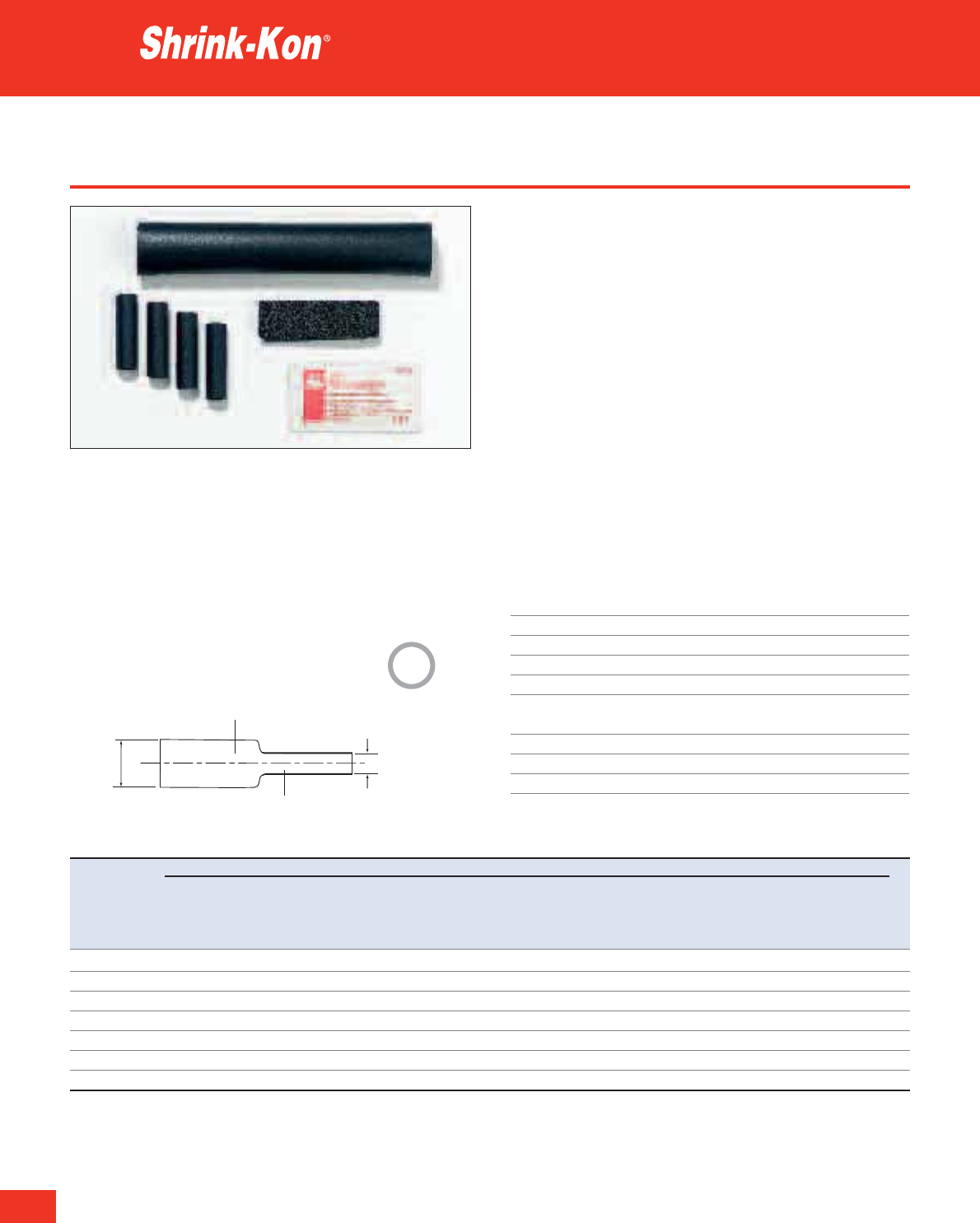
242
Thomas & Betts • www.tnb-europe.com
3.1
Low voltage kits up to 600V
• VMS heat shrinkable sleeves (TBM and TBW) are suitable for joint-
ing multi-core, polymeric insulated energy cables in the low voltage
range
• Quick, simple installation
• Exceptionally good electrical insulation and environmental protec-
tion
• Good mechanical load-bearing ability
• No maintenance time necessary
• Unlimited storage life
• Tested to DIN 47632 / VDE 0278 Part 1 and 3
Standard Content
• 1 Outer sleeve (TBW)
• 4 Inner sleeves (TBM) for VMS2 to VMS9, 5 inner sleeves for VMS1
• Cleaning cloths
• Abrasive cloth
• Installation instructions
Technical Information
Wall thickness Medium (TBM) and thick (TBW)
Shrink ratio 3:1
Tube characteristics Dual wall
Temperature range -55°C to +110°C
Shrinking temperature +120°C
Material Crosslinked polyolefin with thermoplastic
adhesive liner
IP rating IP67
Standard colour Black
Other properties Silicone and Halogen free
Medium and Thick wall heat shrink tubing
Product Ref. CONTENT PER KIT
Wire range Inner sleeves Shrinkage Length Outer sleeve Shrinkage Length
Expanded Recovered Expanded Recovered
Dd D d
[mm
2
] [pieces] [mm] [mm] [mm] [pieces] [mm] [mm] [mm]
VMS1 1.5 - 6 5 12 3 50 1 30 10 200
VMS2 2.5 - 16 4 12 3 125 1 40 12 500
VMS3 6 - 35 4 20 6 125 1 54 18 500
VMS6 16 - 50 4 20 6 250 1 70 25 700
VMS7 35 - 150 4 30 10 300 1 90 30 800
VMS8 120 - 240 4 40 12 300 1 90 30 800
VMS9 185 - 300 4 54 18 300 1 120 40 900
3:1
Expanded
Recovered
Dd
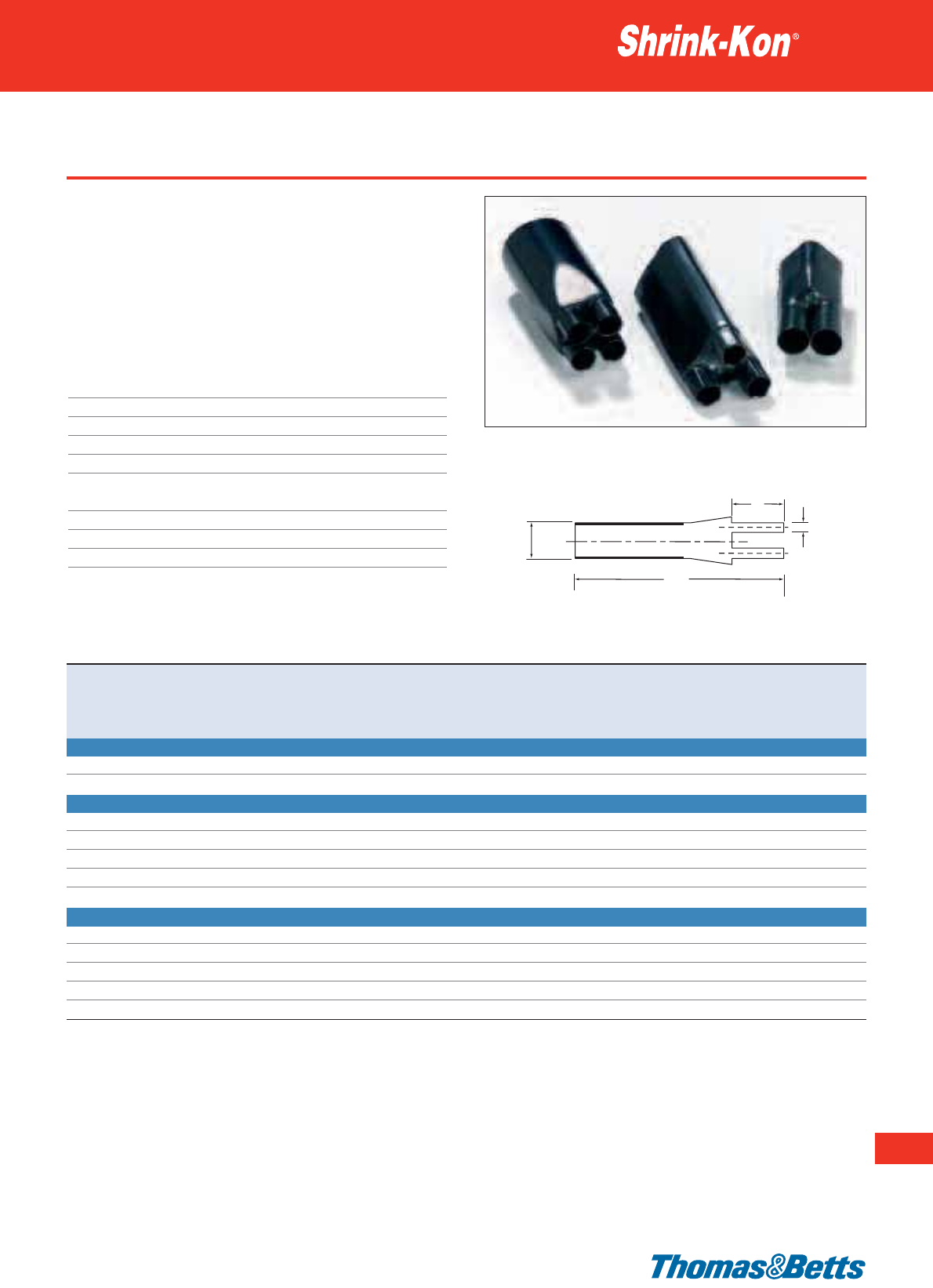
Type TEB - cable breakouts
• Cable Breakouts are designed for the insulation and sealing of
cable crutches
• They offer extreme strain relief and mechanical protection
• Adhesive line provides complete sealing
• UV-resistant
• They also provide good insulation and resistance to common
fluids and solvents
Technical Information
Wall thickness Medium and thick
Shrink ratio Various
Tube characteristics Dual wall
Temperature range -55°C to +100°C
Shrinking temperature +135°C
Material Crosslinked polyolefin with thermoplastic
adhesive liner
IP rating IP67
Standard colour Black
Other properties Silicone, Halogen, Cadmium and Lead free
Medium and Thick wall heat shrink tubing
243
Thomas & Betts • www.tnb-europe.com
3.1
Product Ref. Breakout Main ø Finger ø Cable Core Overall Recovered Recovered Number Quantity
Expanded Recovered Expanded recovered size Ø range Ø range Full Finger of break-
D d Length L Length l outs
[mm] [mm] [mm] [mm] [mm
2
] [mm] [mm] [mm] [mm] [pieces]
TEB2 2-BREAKOUTS
TEB2-30/15 30 9.4 15 4.1 – – – 84.6 27.0 2 10
TEB2-50/21 50 24.0 21 7.0 – – – 107.1 30.6 2 10
TEB3 3-BREAKOUTS
TEB3-38/11 38 14.0 11 4.0
10 - 25 5.1 - 7.7 16.5 - 22.0
110.0 20.0 3 10
TEB3-60/24 60 22.0 24 8.0
35 - 70 8.8 - 12.0 24.5 - 32.0
185.0 45.0 3 10
TEB3-80/36 80 33.0 36 16.0
95 - 150 13.7 - 17.0 36.0 - 44.0
210.0 50.0 3 10
TEB3-110/48 110 47.0 48 20.0
185 - 300 17.0 - 24.3 49.0 - 62.0
260.0 75.0 3 10
TEB3-125/55 125 47.0 55 20.0
185 - 500 17.0 - 31.1 49.0 - 77.5
260.0 75.0 3 10
TEB4 4-BREAKOUTS
TEB4-38/11 38 14.0 11 4.0 10 - 25 5.1 - 7.7 17.5 - 24.5 110.0 20.0 4 10
TEB4-55/20 55 22.0 20 8.5 35 - 50 8.8 - 10.0 27.0 - 31.0 190.0 45.0 4 10
TEB4-72/25 72 22.0 25 8.5 35 - 70 8.8 - 12.0 27.0 - 35.5 190.0 45.0 4 10
TEB4-100/35 100 33.0 35 14.0 95 - 150 13.7 - 17.0 40.0 - 49.0 215.0 50.0 4 10
TEB4-125/54 125 47.0 54 22.0 185 - 400 19.2 - 27.4 54.5 - 69.0 245.0 72.0 4 10
D
l
d
L
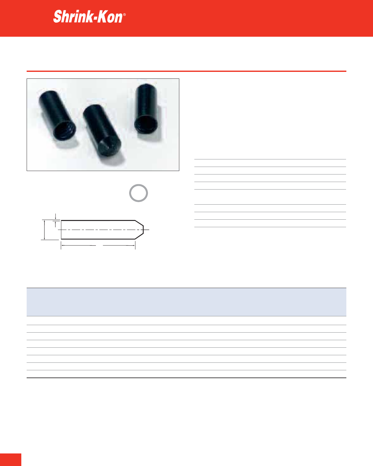
244
Thomas & Betts • www.tnb-europe.com
3.1
Type TEC - end caps
• End Caps are designed to seal and to protect cable-ends against
the ingress of moisture and contamination
• They offer extreme strain relief and mechanical protection
• Adhesive line provides complete sealing
• They also provide optimal sealing and resistance to chemicals and
solvents
• UV-resistant
Technical Information
Wall thickness Medium and thick
Shrink ratio > 2:1
Tube characteristics Dual wall
Temperature range -55°C to +100°C
Shrinking temperature +120°C
Material Crosslinked polyolefin with thermoplastic
adhesive liner
IP rating IP67
Standard colour Black
Other properties Silicone, Halogen, Cadmium and Lead free
Medium and Thick wall heat shrink tubing
Product Ref. Expanded diameter Fully recovered Recovered Wall thickness Cable Quantity
as supplied diameter length after shrinking diameter
DL T
[mm] [mm] [mm] [mm] [mm
2
] [pieces]
TEC15/4.5 15.0 4.5 44.0 1.0 5 - 12 100
TEC25/9 25.0 9.0 69.0 2.7 10 - 22 50
TEC36/15 36.0 15.0 93.0 2.8 17 - 30 10
TEC55/25 55.0 25.0 107.0 3.3 28 - 47 10
TEC80/40 80.0 40.0 127.0 3.6 45 - 70 10
TEC102/60 102.0 60.0 152.0 3.6 68 - 90 5
TEC124/60 124.0 60.0 152.0 3.6 75 - 110 5
TEC148/57 148.0 57.0 152.0 4.5 80 - 135 5
T
D
L
>
2:1
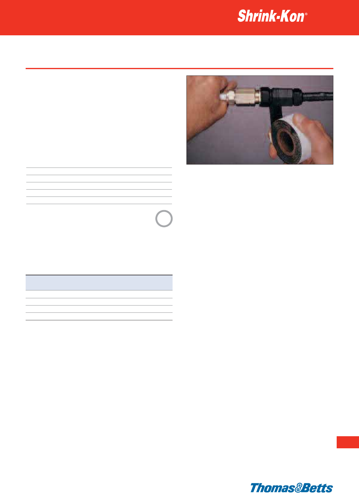
TBTA-ZH - self amalgamating tape
• Self amalgamating tape
• Thomas & Betts TBTA-ZH tape provides a thick insulating layer
with flawless electrical stability and a long term resistance to
moisture penetration, which demands waterproofing
• To repair and maintain cable sleeving up to 30 Kv
• For installations, where open flame and heat may not be used
• Excellent resistance to UV rays and Ozone
• Easy to apply - no tools or heating required
• Excellent protection at low temperatures
Technical Information
Stretch ratio 3:1
Temperature range -55°C to +105°C
Material EPR based tape
IP rating IP67
Standard colour Black
Other properties Silicone, Halogen, Cadmium and Lead free
Heat shrink technologies
245
Thomas & Betts • www.tnb-europe.com
3.1
Product Ref. Roll length Width Thickness
[m] [mm] [mm]
TBTA-ZH-19 9.0 19 0.76
TBTA-ZH-25 9.0 25 0.76
TBTA-ZH-38 9.0 38 0.76
TBTA-ZH-51 9.0 51 0.76
3:1
TBTA-ZH must be stretched on application for the self-adhesive prop-
erties to be activated. TBTA-ZH has a stretch ratio of more than 3:1.
Installation notes
1. The surface of the connection and the cable entry must be clean
2. TBTA-ZH should be used under high tension as the stretching
process activates the adhesive
3. By wrapping the TBTA-ZH tape around the cable, a sealed casing
is created
4. If a cable or pipe needs protection, the TBTA-ZH tape should be
wrapped around itself twice at the beginning point and then
should overlap throughout by 50%. This means that the tape
will also stretch when the cable is under tension
5. Finally, the surface (see point 4) should be covered once more
using 100% tape overlap
6. At the end, the tape should be held at the overlap point and torn
off
7. To conclude the installation, the ripped off end should be pressed
firmly to close.
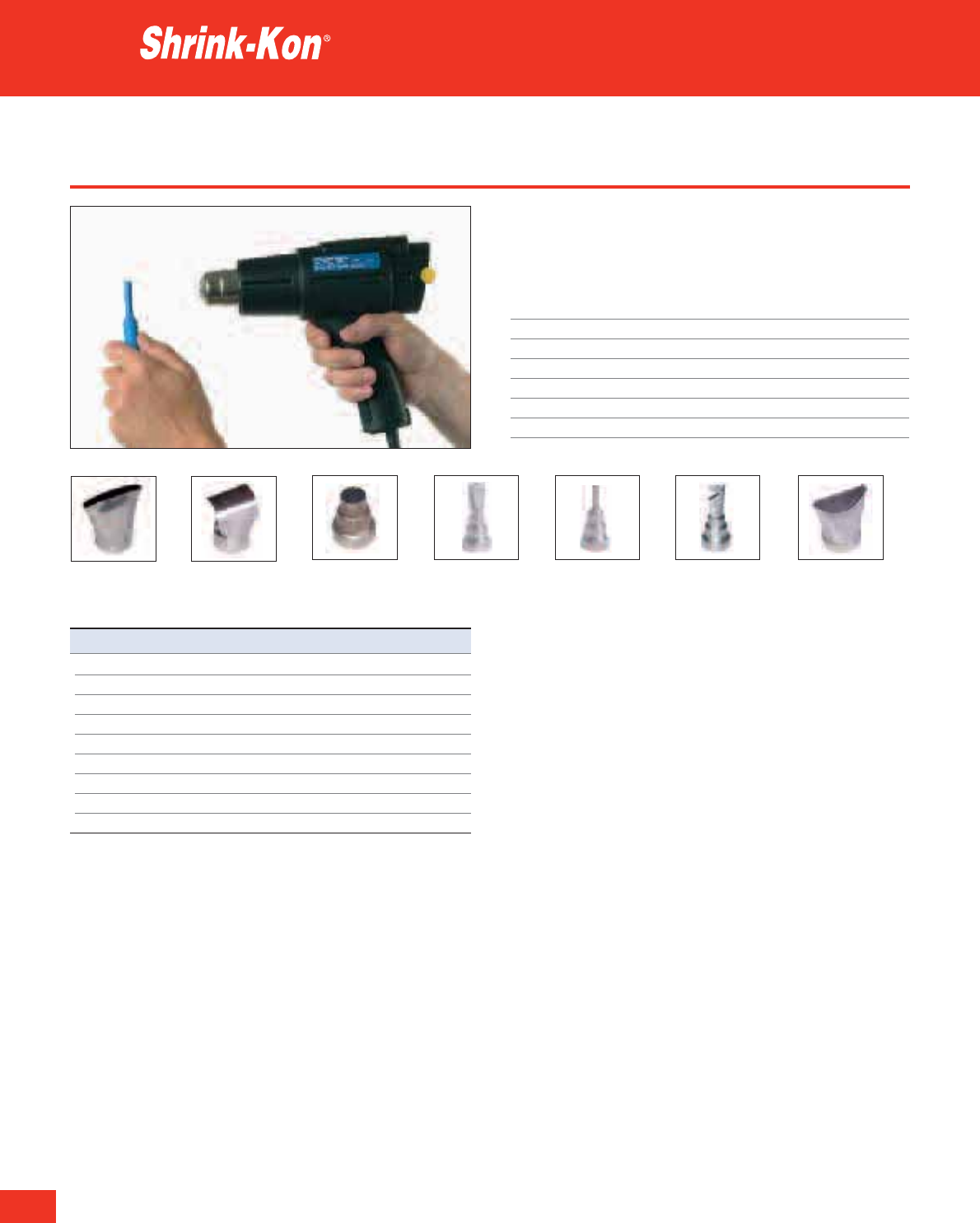
Thomas & Betts • www.tnb-europe.com
Hot air tool
The Hot Air Tool from Thomas & Betts achieves a rapid shrink action.
This tool is ideal for industrial and military applications.
Technical Information
Property Typical performance
Power Consumption 1400W
Temperature +350°C to +500°C
Air Flow 350 / 500 l/min
Static pressure max. 1250 Pa
Weight 570 g
Electronics Flicker-conformity
Heat shrink technologies
WT992GR WT993GR WT999GR
WT994GR WT995GR WT996GR WT998GR
Product Ref. Description
GR121 Hot Air Tool (European Plug and WT993GR nozzle)
GR321 Hot Air Tool (UK Plug and WT993GR nozzle)
WT992GR Wide slot nozzle
WT993GR Reflector nozzle
WT994GR Reduction nozzle Ø 20mm
WT995GR Welding nozzle
WT996GR Overlap welding nozzle
WT998GR Solder sleeve reflector nozzle
WT999GR Glass protection nozzle
246
3.1
Technical Information
Heat shrink technologies
247
Thomas & Betts • www.tnb-europe.com
3.1
Product name Material Mechanical Operating Shrink Expanded Silicon Cadmium Non Spec. Longitudinal Tensile Strength Elongation Ultimate
Behaviour temp. Ratio Diameter free + Lead free Halogen Gravity Shrinkage after after Elongation
Heatshock Heatshock
Test Method ASTM-D 792 ASTM-D 2671
(3)
IEC 811-1-2
(4)
IEC844-1-2
(4)
ISO/R 1183
(2)
IEC 811-1-3
(5)
ASTM-D 2671
(3)
DEF Stan 59-97
(1)
ASTM-D 2671
(3)
ASTM-D 638
(9)
A-I
(1)
ASTM-D 638
(9)
PLG PE-Polyolefin Flexible -55°C to +125°C 2:1 1.2-101.6mm /
3
/
64
”-4” Yes Yes No* 1.3g / cm3(1) -10% (3) 13 MPa / 4h at 200°C (4) 400% / 4h at 200°C (4) 450%
CMP PE-Polyolefin Flexible -55°C to +125°C 2:1 1.2-51.0mm /
3
/
64
”-2” Yes Yes No* 1.3g / cm3(1) -10% (3) 13 MPa / 4h at 200°C (4) 400% / 4h at 200°C (4) 450%
MLP PE-Polyolefin Flexible -55°C to +135°C 2:1 1.2-25.4mm /
3
/
64
”-1” Yes Yes No* 1.3g / cm3(1) -5% (3) 19 MPa / 4h at 250°C (5) No cracking or flowing (3) 500%
GYS PE-Polyolefin Flexible -55°C to +135°C 2:1 3.2-25.4mm /
1
/
8
”-1” Yes Yes No 1.3g / cm3(1) -10% (3) 14 MPa / 4h at 200°C (4) 400% / 4h at 200°C (4) 450%
PIG PE-Polyolefin Very Flexible -55°C to +135°C 3:1 1.6-40.0mm /
1
/
16
”-1
1
/2” Yes Yes No 1.3g / cm3(1) -5% (3) 19 MPa / 4h at 250°C (5) No cracking or flowing (3) 500%
PIG green yellow PE-Polyolefin Very Flexible -55°C to +135°C 3:1 4.5-40.0mm /
3
/
16
”-1
1
/2” Yes Yes No 1.3g / cm3(1) -10% (3) 14 MPa / 4h at 200°C (4) 400% / 4h at 200°C (4) 450%
PIG clear PE-Polyolefin Very Flexible -55°C to +135°C 3:1 1.6-40.0mm /
1
/
16
”-1
1
/2” Yes Yes Yes 1.0g / cm3(1) -5% (3) 15 MPa / 4h at 250°C (5) No cracking or flowing (3) 550%
PKG PE-Polyolefin Flexible -55°C to +110°C 3:1 / 4:1 3.0-52.0mm /
1
/
16
”-2” Yes Yes No 1.3g / cm3(1) -15%(3:1) (3) /-18%(4:1) (3) 15 MPa / 4h at 200°C (4) 360% / 4h at 200°C (4) 400%
KYN Kynar** PVDF Semi-Rigid -55°C to +175°C 2:1 1.2-25.4mm /
3
/
64
”-1” Yes Yes No 1.8g / cm3(1) -6% (3) 48 MPa / 4h at 250°C (4) 300% / 4h at 250°C (4) 450%
VIT Viton*** Flexible -55°C to +220°C 2:1 3.2-38.1mm /
1
/
8
”-1
1
/
2
” Yes Yes No 1.9g / cm3(1) -10% (3) 17 MPa / 4h at 300°C (4) 250% / 4h at 300°C (4) 520%
ZHFR PE-Polyolefin Flexible -40°C to +105°C 2:1 2.4-25.4mm /
3
/
32
”-1” Yes Yes Yes 1.45g / cm3(2) -10% (3) 9 MPa / 4h at 150°C 100% / 4h at 150°C (3) 200%
TBM PE-Polyolefin Semi-Rigid -55°C to +110°C 3:1 10.2-228.6mm Yes Yes Yes 1.10g / cm3(1) +1% to -10% (3) 4h at 225°C No cracking or flowing (3) 600%
TBW PE-Polyolefin Semi-Rigid -55°C to +110°C 3:1 8.9-119.9mm Yes Yes Yes 1.10g / cm3(1) +1% to -10% 4h at 225°C No cracking or flowing (3) 550%
LV-Kit PE-Polyolefin Semi-Rigid -55°C to +110°C 3:1 various Yes Yes Yes 1.10g / cm3+1% to -10% 4h at 225°C No cracking or flowing -/-
TEB PE-Polyolefin Semi-Rigid -55°C to +100°C various 30.0-125.0mm Yes Yes Yes 1.10g / cm3-15% 6MPa (3) 9) 200% (3) (9) 300%
TEC PE-Polyolefin Semi-Rigid -55°C to +100°C various 15.0-148.0mm Yes Yes Yes 1.10g / cm3-15% 6MPa (3) 9) 200% (3) (9) 300%
TBTA-ZH EPR-Tape Flexible -55°C to +105°C 1:3 19.0-51.0mm Yes Yes Yes -/- -/- -/- -/- 750%
Product Tensile Secant Tensile Strength Elongation after Low temp. Combustion behaviour / Shrink Storage Resistance Water Fungus Dielectric Spec. Volume
name Strength Modulus after heat aging heat aging Flexibility Flammability temp. temp. against Absorption Resistance Strength Resistance
Chemicals
Test IEC 60684-2
(6)
ASTM-D 882
(10)
UL 224
(11)
UL 224
(11)
,ISO37
(13)
ASTM-D 2671 Meth. C
(27)
UL 224 VW-1
(11)
, UL 224
(14)
VDE 0472
(19)
IEC-243
(24)
Method ISO 37
(7)
Def Stan 59-97
(31)
ASTM-D 2671
(3)
ASTM-D 2671
(3)
ASTM-D 876
(15)
, ASTM-D 635
(16)
ISO-62
(20)
VDE 0303 Part 2
(25)
ASTM-D412
(8)
IEC811-1-2
(4)
IEC811-1-2
(4)
FMVSS 302
(17)
, ESI 09-13
(18)
ASTM-D 570
(21)
ASTM-D 149
(28)
ASTM-D 638M
(9)
ISO-188
(12)
ISO-188
(12)
ASTM-D 257
(32)
Def Stan 59-97
(31)
Def Stan 59-97
(31)
Def Stan 59-97
(31)
ASTM-D 638
(9)
ASTM-D 638
(9)
ASTM-D 267 Proc. A
(33)
PLG 15 MPa
(6)
175 MPa max.
(10)
12 MPa / 168h at 158°C
(11)
300% / 168h at 158°C
(11)
Does not break at -55°C
(27)
Flame retardant****
(14) (17)
+110°C +30°C Good 0.3%
(19)
Very good 24kV / mm
(25)
10.
15 Ohms x cm
CMP 15 MPa
(6)
175 MPa max.
(10)
12 MPa / 168h at 158°C
(11)
300% / 168h at 158°C
(11)
Does not break at -55°C
(27)
Flame retardant****
(14) (17)
+110°C +30°C Good 0.3%
(19)
Very good 24kV / mm
(25)
10.
15.Ohms x cm
MLP 17 MPa
(6)
175 MPa max.
(10)
13 MPa / 168h at 175°C
(3)
300% / 168h at 175°C
(3)
Does not break at -55°C
(27)
Flame retardant****
(14) (17)
+90°C +30°C Good 0.2%
(19)
Very good 24kV / mm
(25)
10.
16 Ohms x cm
GYS 15 MPa
(6)
175 MPa max.
(10)
12 MPa / 168h at 175°C
(11)
300% / 168h at 175°C
(11)
Does not break at -55°C
(27)
Flame retardant****
(14)
+90°C +30°C Good 0.2%
(19)
Very good 24kV / mm
(25)
10.
16 Ohms x cm
PIG 17 MPa
(6)
175 MPa max.
(10)
13 MPa / 168h at 175°C
(3)
300% / 168h at 175°C
(3)
Does not break at -55°C
(27)
Flame retardant****
(14) (17)
+90°C +30°C Good 0.2%
(19)
Very good 24kV / mm
(25)
10.
16 Ohms x cm
PIG green yellow 15 MPa
(6)
175 MPa max.
(10)
12 MPa / 168h at 175°C
(11)
300% / 168h at 175°C
(11)
Does not break at -55°C
(27)
Flame retardant****
(14)
+90°C +30°C Good 0.2%
(19)
Very good 24kV / mm
(25)
10.
16 Ohms x cm
PIG clear 20 MPa
(6)
175 MPa max.
(10)
18 MPa / 168h at 175°C
(3)
500% / 168h at 175°C
(3)
Does not break at -55°C
(27)
Passed per FMVSS 302
(14) (17)
+90°C +30°C Good 0.2%
(19)
Very good 24kV / mm
(25)
10.
16 Ohms x cm
PKG 15 MPa
(6)
175 MPa max. 12 MPa / 168h at 158°C
(4)
320% / 168h at 158°C
(4)
Does not break at -55°C
(27)
Flame retardant****
(15) (17)
+95°C +30°C Good 0.2%
(19)
Very good 22kV / mm
(25)
10.
14 Ohms x cm
KYN 50 MPa
(6)
750 MPa max.
(10)
40 MPa / 168h at 158°C
(4)
230% / 168h at 158°C
(4)
Does not break at -55°C
(27)
Flame retardant
(11)
+175°C +30°C Very good 0.07%
(19)
Very good 31.5kV / mm
(25)
10.
13 Ohms x cm
VIT 18 MPa
(6)
70 MPa max.
(10)
14 MPa / 168h at 158°C
(4)
220% / 168h at 158°C
(4)
Does not break at -55°C
(27)
Flame retardant
(33)
+175°C +30°C Very good 0.2%
(19)
Very good 16kV / mm
(25)
10.
13 Ohms x cm
ZHFR 10 MPa
(6)
175 MPa max.
(10)
12 MPa / 168h at 158°C 150% / 168h at 158°C
(3)
Does not break at -40°C
(27)
Flame retardant
(16)
+115°C +30°C Good 0.2%
(21)
Very good 24kV / mm
(24)
10.
16 Ohms x cm
to excellent
TBM 14.5 MPa
(7) (8)
90MPa
(31)
12MPa
(3) (9)
500% / 168h at 150°C
(3) (13)
Does not break at -55°C
(27)
Non Flame retardant +120°C +30°C Good 0.2%
(21)
Very good 20kV / mm
(24) (28)
10.
16 Ohms x cm
TBW 14.5 MPa
(7) (8)
90MPa
(31)
-/- 500% / 168h at 150°C
(3) (13)
Does not break at -55°C
(27)
Non Flame retardant +120°C +30°C Good 0.2%
(21)
Very good 20kV / mm
(28)
10.
16 Ohms x cm
LV-Kit -/- 90MPa
(31)
12MPa
(3) (9)
500%
(3) (9)
Does not break at -55°C Non Flame retardant +120°C +30°C Good 0.2% Very good 20kV / mm 10.
16 Ohms x cm
TEB 10 MPa
(9)
80MPa
(31)
9 MPa / 168h at 120°C
(12)
250% / 168h at 120°C
(12)
-55°C Non Flame retardant
(18)
+135°C +30°C Good 1%
(20)
Very good 12kV / mm 10.
11 Ohms x cm
TEC 12 MPa
(9)
80MPa
(31)
10 MPa / 168h at 120°C
(12)
250% / 168h at 120°C
(12)
-55°C
(27)
Non Flame retardant +120°C +30°C Good 1%
(20)
Very good 12kV / mm
(24)
10.
12 Ohms x cm
TBTA-ZH 2.5 MPa
(31)
-/- -/- n.a. -/- Flame retardant n.a. +30°C Good 0.06%
(31)
Very good 30kV / mm
(31)
n.a.
*Transparent version is halogen free
** Kynar is a registered trademark of ATOFINA
*** VITON is a registered trademark of DuPont
**** Except transparent version
***** Outer Jacket only

248
Thomas & Betts • www.tnb-europe.com
3.2
Rezi-Kon™
Cast resin joints

Thomas & Betts • www.tnb-europe.com
INSULATION SYSTEMS
3.1 HEAT SHRINK TECHNOLOGIES 214
3.2 RESIN TECHNOLOGIES 248
Straight joints for non-armoured cables 252
Straight joints for armoured cables 253
Straight joints for control cables 254
Straight joints for telephone cables 255
Branch joints for non-armoured cables 256
Branch joints for armoured cables 257
Resin bags 258
Insulated connectors 258
Separate earth kits 259
249
3.2

Thomas & Betts • www.tnb-europe.com
Rezi-Kon™
Cast resin joints
The new range of Rezi-Kon™ cast resin joints from
Thomas & Betts provide a convenient and reliable solution
for splicing and branching low voltage cables, in applica-
tions like street and leisure lighting, airfield lighting,
utility / home connections.
The Rezi-Kon™ cable joints are made of a Polycarbonate shell
filled with a Polyurethane resin, which provides a watertight
connection that can be immediately operational.
They are available in two styles, for a complete range of cable
sizes from 1.5 to 400 mm2:
- straight: for splicing or repairing existing cables
- branch: for tapping a new cable on an existing line
250
3.2

Thomas & Betts • www.tnb-europe.com
A range of high performance
cast resin joints, for a quick and
reliable installation on the field
• Suitable for voltages up to 3.6 kV
• Easy to use on the field: no heat source or power required
• Quick and easy to install, immediately operational
• Can be buried
• Watertight: protection against water ingress from the cable and
from the shell
• Excellent electrical properties
• BS EN 50393-2006 compliant
• Halogen free
• The shell and the resin meet the requirements of the petro-
chemical industry and are suitable for immersion in hydrocar-
bons
• Exclusive shell design, with a unique “clip“ system for easy
assembly and watertight closing
• Transparent shell, for a better inspection before and during the
casting
• High grade Polycarbonate: UV-resistant, impact resistant,
chemical resistant, flame retardant
• 2-component Polyurethane resin
• Reduced exothermic properties (generates little heat during the
reaction of polymerisation), therefore suitable for all kinds of
cables (power, phone, control)
• Duo-bag packaging: pre-filled bag for correct mix ratio and safe
mixing (no contact with the components)
• Range of exclusive insulated connectors 251
3.2
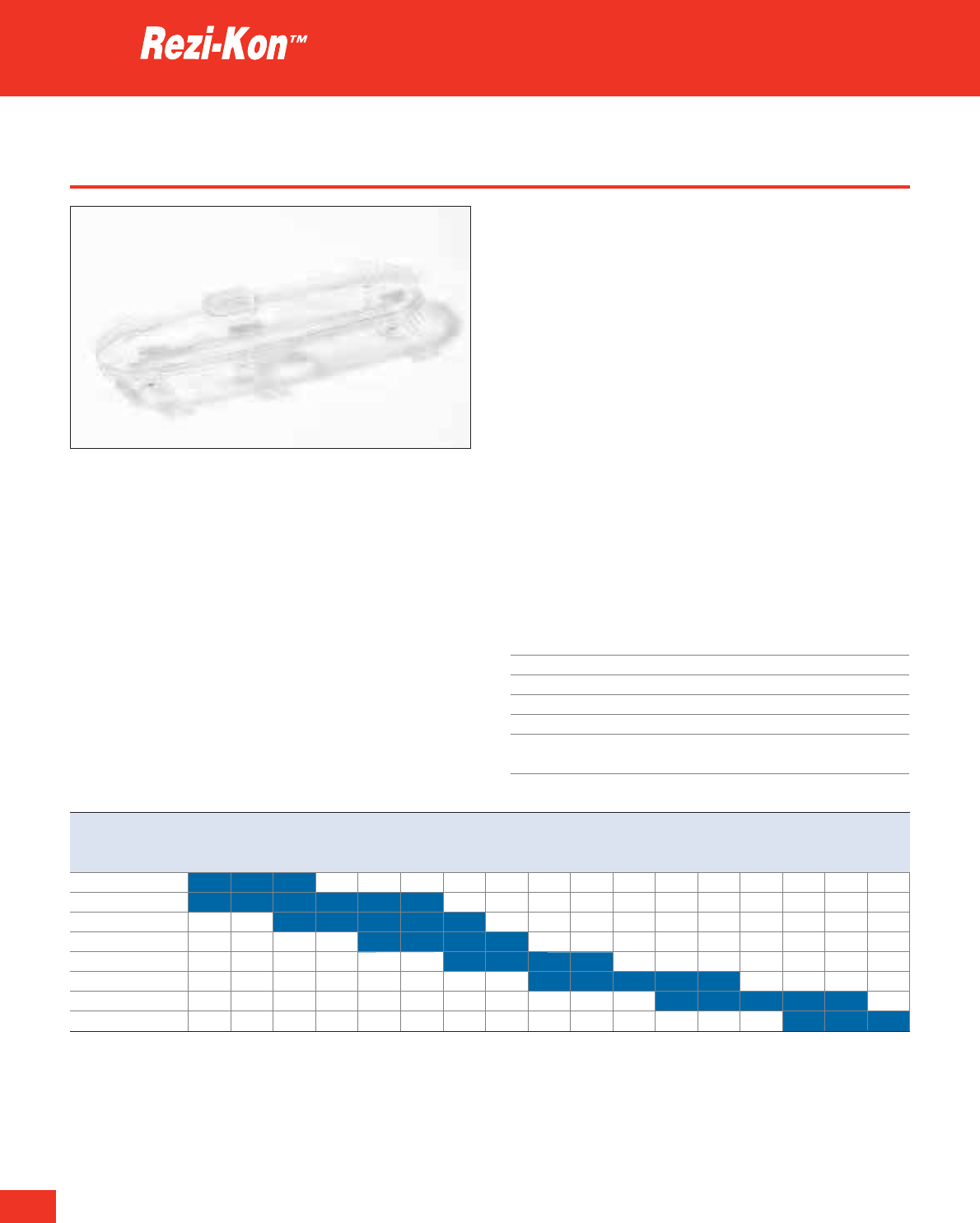
252
Thomas & Betts • www.tnb-europe.com
3.2
Straight joints for non-armoured cables
A range of high performance cast resin joints, for a quick and
reliable installation on the field with a watertight protection.
Recommended for the connection of low voltage non-armoured
cables (up to 3.6 kV), from 1.5 to 400 mm2.
• Watertight protection, both longitudinal (from inside the cable)
and transversal (from the shell)
• For permanent installation
• Easy to install, allows easy cable crossing
• BS EN 50393-2006 compliant
• The shell and the resin meet the requirements of the petro-
chemical industry and are suitable for immersion in hydrocarbons
Each kit is supplied in a box containing:
- 1 Polycarbonate shell (upper and lower halves)
- the 2-component Polyurethane resin, in pre-filled duo-bag
containing the correct volume to suit the size of cable joint
- a pair of gloves, a reel of tape, a strip of sand paper, an instruc-
tion sheet
Technical Information
Material PC - Polycarbonate and PU - Polyurethane
Voltage 3.6 kV
IP Rating Watertight
Flammability rating Flame retardant
Colour Transparent
Other properties Halogen free, good chemical resistance,
UV-resistant, impact resistant
Resin technologies
Product ref. Conductor cross section
[mm
2
]
1.5 2.5 4 6 10 16 25 35 50 70 95 120 150 185 240 300 400
CRJ-S4
CRJ-S10
CRJ-S16
CRJ-S25
CRJ-S50
CRJ-S120
CRJ-S240
CRJ-S400
Tables are valid for non-armoured cables with four conductors
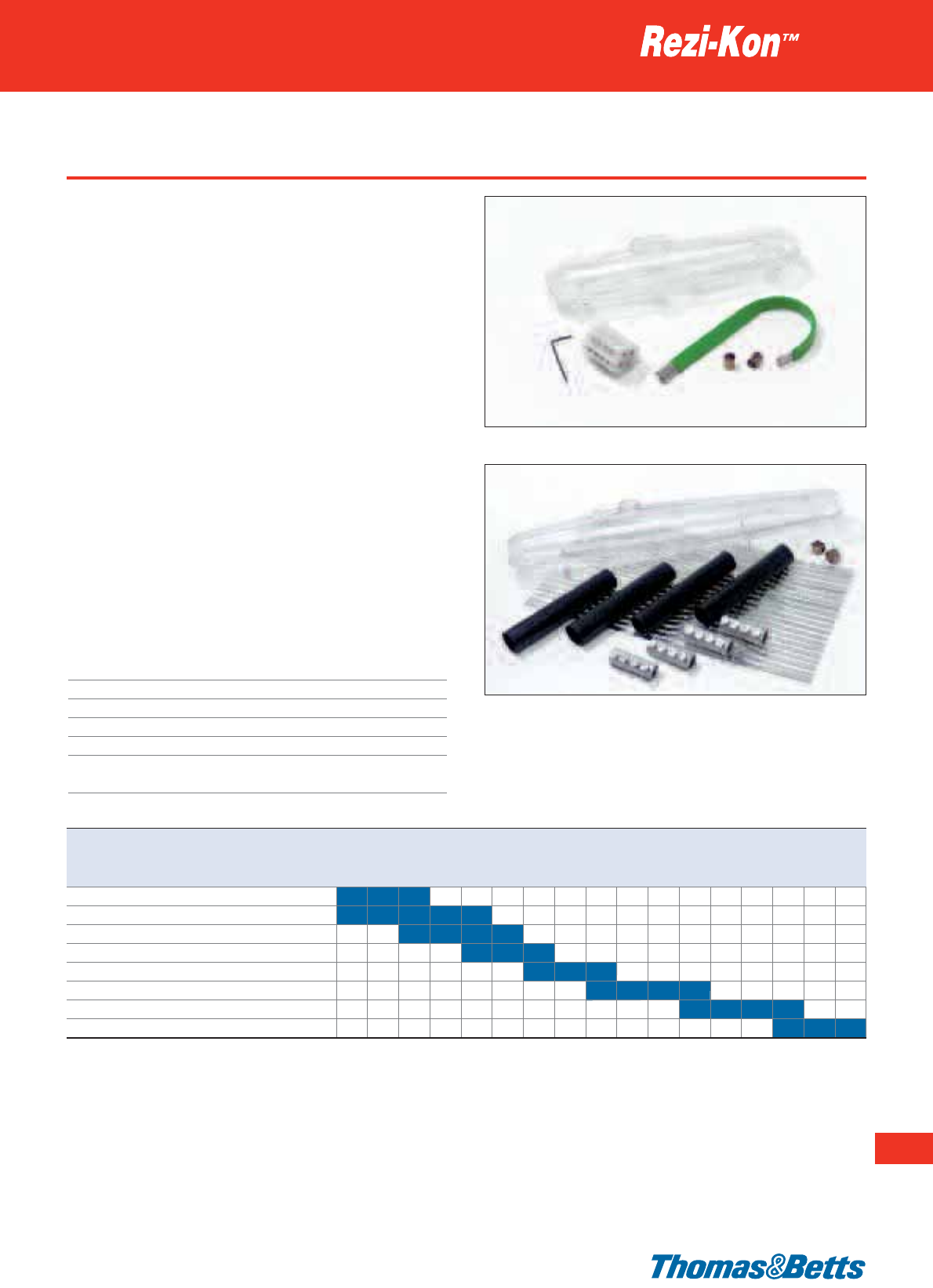
Straight joints for armoured cables
A range of high performance cast resin joints, for a quick and
reliable installation on the field with a watertight protection.
Recommended for the connection of low voltage armoured cables
(up to 3.6 kV), from 1.5 to 400 mm2.
• Available in 2 versions: with mechanical connectors or without
connector
•
Watertight protection, both longitudinal (from inside the
cable) and transversal (from the shell)
• For permanent installation
•
Easy to install, allows easy cable crossing
• BS EN 50393-2006 compliant
• The shell and the resin meet the requirements of the petro-
chemical industry and are suitable for immersion in hydrocarbons
Each kit is supplied in a box containing:
-
1 Polycarbonate shell (upper and lower halves)
- the 2-component Polyurethane resin, in pre-filled duo-bag
containing the correct volume to suit the size of cable joint
- an earth kit: 2 constant force springs + 1 braided cable
- a pair of gloves, a reel of tape, a strip of sand paper, an
instruction sheet
Technical Information
Material*** PC - Polycarbonate and PU - Polyurethane
Voltage 3.6 kV
IP Rating Watertight
Flammability rating Flame retardant
Colour Transparent
Other properties Halogen free, good chemical resistance,
UV-resistant, impact resistant
Resin technologies
253
Thomas & Betts • www.tnb-europe.com
3.2
Product Ref. with Product Ref. Conductor cross section
insulated connector without connector
[mm
2
]
1.5 2.5 4 6 10 16 25 35 50 70 95 120 150 185 240 300 400
CRJ-S4-UK-CO CRJ-S4-UK
CRJ-S10-UK-CO CRJ-S10-UK
CRJ-S16-UK-CO CRJ-S16-UK
CRJ-S25-UK-CO CRJ-S25-UK
CRJ-S50-UK-CO CRJ-S50-UK
CRJ-S120-UK-CO CRJ-S120-UK
CRJ-S240-UK-CO* CRJ-S240-UK**
CRJ-S400-UK-CO* CRJ-S400-UK**
* Supplied with non-insulated mechanical connectors and heat shrink sleeves. The earth kit is a cage shaped conductor
** The earth kit is a cage shaped conductor
*** Material: Styrene and PU -
Polyurethane for Product Ref.
CRJ-S400-UK-CO and CRJ-S400-UK
Table is valid for armoured cables with four conductors
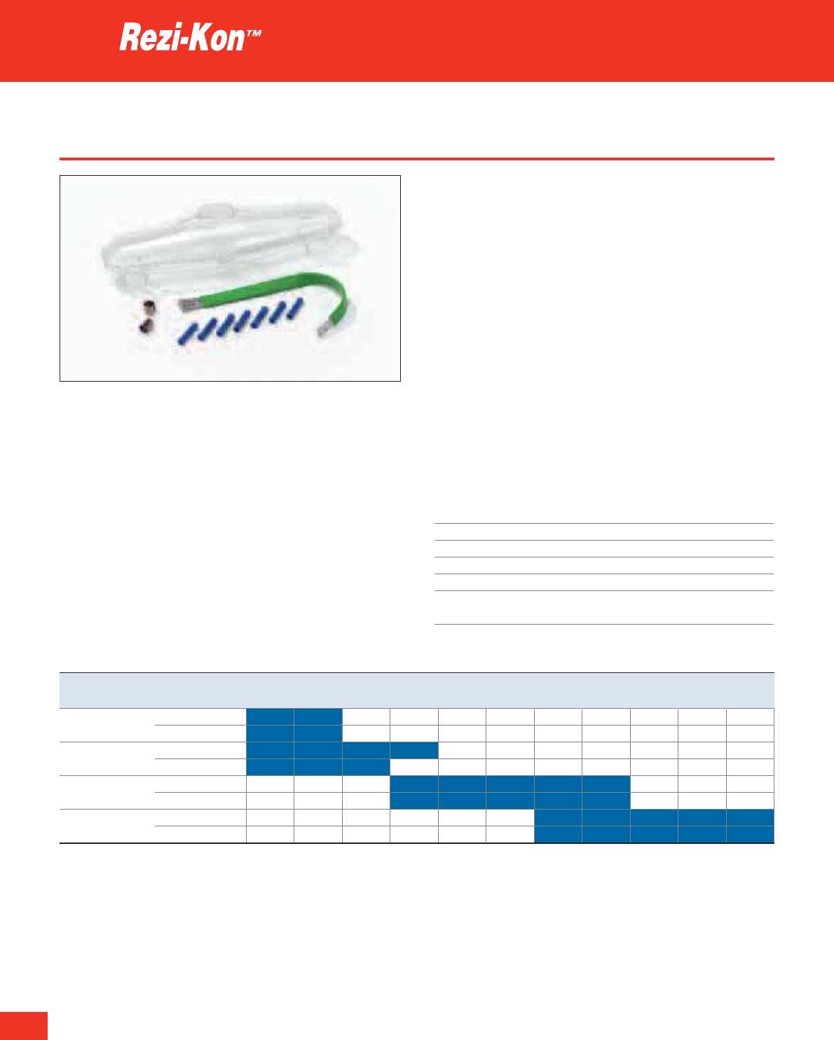
254
Thomas & Betts • www.tnb-europe.com
Straight joints for control cables
A range of high performance cast resin joints, for a quick and reliable
installation on the field. Recommended for the connection of multi-
core control cables (up to 48 cores).
• Watertight protection, both longitudinal (from inside the cable)
and transversal (from the shell)
• For permanent installation
• Easy to install, allows easy cable crossing
Each kit is supplied in a box containing:
- 1 Polycarbonate shell (upper and lower halves)
- the 2-component Polyurethane resin, in pre-filled duo-bag con-
taining the correct volume to suit the size of cable joint
- an earth kit: 2 constant force springs + 1 braided cable
- the adequate quantity of insulated crimp connectors (butt splices)
- a pair of gloves, a reel of tape, a strip of sand paper, an instruc-
tion sheet
Technical Information
Material PC - Polycarbonate and PU - Polyurethane
Voltage 3.6 kV
IP Rating Watertight
Flammability rating Flame retardant
Colour Transparent
Other properties Halogen free, good chemical resistance,
UV-resistant, impact resistant
Resin technologies
3.2
Product Ref. Conductor cross section 2 4 5 7 8 10 11 16 27 30 48
[mm
2
] cores cores cores cores cores cores cores cores cores cores cores
CRJ-SCC4-UK-CO 1.5
2.5
CRJ-SCC8-UK-CO 1.5
2.5
CRJ-SCC16-UK-CO 1.5
2.5
CRJ-SCC48-UK-CO 1.5
2.5
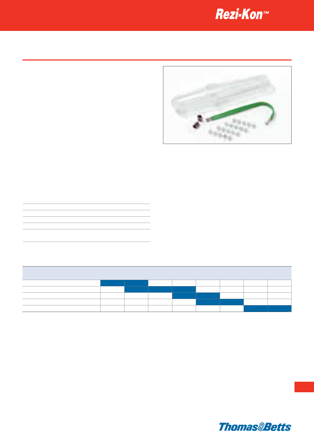
Straight joints for telephone cables
A range of high performance cast resin joints, for a quick and reliable
installation on the field. Recommended for the connection of multi-
pair telephone cables (up to 100 pairs).
• Watertight protection, both longitudinal (from inside the cable)
and transversal (from the shell)
• For permanent installation
• Easy to install, allows easy cable crossing
Each kit is supplied in a box containing:
- 1 Polycarbonate shell (upper and lower halves)
- the 2-component Polyurethane resin, in pre-filled duo-bag con-
taining the correct volume to suit the size of cable joint
- an earth kit: 2 constant force springs + 1 braided cable
- the adequate quantity of insulation displacement connectors
(IDC)
- a pair of gloves, a reel of tape, a strip of sand paper, an instruc-
tion sheet
Technical Information
Material PC - Polycarbonate and PU - Polyurethane
Voltage 3.6 kV
IP Rating Watertight
Flammability rating Flame retardant
Colour Transparent
Other properties Halogen free, good chemical resistance,
UV-resistant, impact resistant
Resin technologies
255
Thomas & Betts • www.tnb-europe.com
3.2
Product Ref. Conductor cross section 2 5 10 15 25 40 50 100
[mm
2
]
pairs pairs pairs pairs pairs pairs pairs pairs
CRJ-ST5-UK-CO 0.9
CRJ-ST15-UK-CO 0.9
CRJ-ST25-UK-CO 0.9
CRJ-ST50-UK-CO 0.9
CRJ-ST100-UK-CO 0.9
Thomas & Betts • www.tnb-europe.com
Branch joints for non-armoured cables
A range of high performance cast resin joints, for a quick and
reliable installation on the field with a watertight protection.
Recommended for the connection of low voltage non-armoured
cables (up to 3.6 kV), from 1.5 to 400 mm2.
• Watertight protection, both longitudinal (from inside the cable)
and transversal (from the shell)
• For permanent installation
• Easy to install, allows easy cable crossing
• BS EN 50393-2006 compliant
• The shell and the resin meet the requirements of the petro-
chemical industry and are suitable for immersion in hydrocarbons
Each kit is supplied in a box containing:
- 1 Polycarbonate shell (upper and lower halves)
- the 2-component Polyurethane resin, in pre-filled duo-bag con-
taining the correct volume to suit the size of cable joint
- a pair of gloves, a reel of tape, a strip of sand paper, an instruc-
tion sheet
Technical Information
Material PC - Polycarbonate and PU - Polyurethane
Voltage 3.6 kV
IP Rating Watertight
Flammability rating Flame retardant
Colour Transparent
Other properties Halogen free, good chemical resistance,
UV-resistant, impact resistant
Resin technologies
3.2
256
Product Ref. Conductor cross section
[mm
2
]
1.5 2.5 4 6 10 16 25 35 50 70 95 120 150 185 240 300 400
CRJ-SB4 Main cable
Branch cable
CRJ-SB10 Main cable
Branch cable
CRJ-SB25 Main cable
Branch cable
CRJ-SB50* Main cable
Branch cable
CRJ-SB120* Main cable
Branch cable
CRJ-SB240* Main cable
Branch cable
CRJ-SB400* Main cable
Branch cable
* Shell in Styrene
Tables are valid for non-armoured cables with four conductors
Branch joints for armoured cables
A range of high performance cast resin joints, for a quick and
reliable installation on the field with a watertight protection.
Recommended for making cable taps, with low voltage armoured
cable (up to 3.6 kV), from 1.5 to 400 mm2.
• Available in 2 versions: with mechanical connectors or without
connector
• Watertight protection, both longitudinal (from inside the cable)
and transversal (from the shell)
• For permanent installation
• Easy to install
• BS EN 50393-2006 compliant
• The shell and the resin meet the requirements of the petro-
chemical industry and are suitable for immersion in hydrocarbons
Each kit is supplied in a box containing:
- 1 Polycarbonate shell (upper and lower halves)
- the 2-component Polyurethane resin, in pre-filled duo-bag
containing the correct volume to suit the size of cable joint
- an earth kit: 3 constant force springs + 1 braided cable
- a pair of gloves, a reel of tape, a strip of sand paper, an instruc-
tion sheet
Resin technologies
257
Thomas & Betts • www.tnb-europe.com
3.2
Technical Information
Material PC - Polycarbonate and PU - Polyurethane
Voltage 3.6 kV
IP Rating Watertight
Flammability rating Flame retardant
Colour Transparent
Other properties Halogen free, good chemical resistance,
UV-resistant, impact resistant
Product Ref. Product Ref. Conductor cross section
with connectors without connectors
[mm
2
]
1.5 2.5 4 6 10 16 25 35 50 70 95 120 150 185 240 300 400
SERVICE BRANCH JOINTS
CRJ-SB4-UK-CO CRJ-SB4-UK Main cable
Branch cable
CRJ-SB10-UK-CO CRJ-SB10-UK Main cable
Branch cable
CRJ-SB25-UK-CO CRJ-SB25-UK Main cable
Branch cable
CRJ-SB50-UK-CO* CRJ-SB50-UK* Main cable
Branch cable
CRJ-SB120-UK-CO* CRJ-SB120-UK* Main cable
Branch cable
CRJ-SB240-UK-CO* CRJ-SB240-UK* Main cable
Branch cable
CRJ-SB400-UK-CO* CRJ-SB400-UK* Main cable
Branch cable
MAIN BRANCH JOINTS
CRJ-MB120-UK-CO* CRJ-MB120-UK* Main cable
Branch cable
CRJ-MB240-UK-CO* CRJ-MB240-UK* Main cable
Branch cable
CRJ-MB400-UK-CO* CRJ-MB400-UK* Main cable
Branch cable
* Shell in Styrene
Table is valid for armoured cables with four conductors
258
Thomas & Betts • www.tnb-europe.com
3.2
Resin bags
The convenient pre-filled duo-bag guarantees a correct mix ratio
and a safe mixing, by preventing the installer from having possible
contact with the components.
• 2-component Polyurethane in ready-to-mix duo-bag packaging
• No need to open the bag, just remove the separation for a safe
mixing without contact with the components
• Pre-filled duo-bag, always the correct mix ratio and the exact
volume for the joint size
• Low exothermic properties, can be used with all kind of cables
(power, phone, control)
• For permanent application
• Excellent electrical and mechanical properties: good elasticity and
adhesion to all kinds of cables
• Transparent bag, for a better inspection of the mixing process
• Specific colour after mixing: beige
• 3 years shelf life (outer protective envelope in aluminium)
• BS EN 50393-2006 compliant
• Meet the requirements of the petrochemical industry and are
suitable for immersion in hydrocarbons
• Halogen free.
Resin technologies
Product Ref. Volume Weight Quantity
[litre] [g] [pieces]
CRJ-PU-0075 0.075 107 1
CRJ-PU-0175 0.175 250 1
CRJ-PU-0300 0.300 429 1
CRJ-PU-0550 0.550 787 1
CRJ-PU-1000 1 1287 1
CRJ-PU-2000 2 2860 1
CRJ-PU-3000 3 4290 1
Insulated connectors
Exclusive connectors, specially designed for the straight Rezi-Kon™
joints.
• Safe and easy connection: the 4 conductors always remain sepa-
rated from each other
• Insulation in Polypropylene, contacts in brass
• 4 screws per contact
• Suitable for voltages up to 1 kV
Technical Information
Material Brass
Insulation P.P. - Polypropylene
Voltage 1 kV
Colour White
Resin technologies
Product Ref. Cable range Quantity
[mm
2
] [pieces]
CRJ-IC-010 0.75 - 10 1
CRJ-IC-025 4 - 25 1
CRJ-IC-050 16 - 50 1
CRJ-IC-120 35 - 120 1
Separate earth kits
A range of separate earth kits, to achieve the earth continuity of
armoured cables. Available for straight joints and branch joints.
Each kit consists of:
- a piece of insulated braided cable, or round cable (for the small-
est S4 and SB4 sizes) or cage-shape conductor (for the large size
joints)
- 2 or 3 pieces of Constant Force Springs (2 for straight joints, 3 for
branch joints)
Resin technologies
259
Thomas & Betts • www.tnb-europe.com
3.2
Product Ref. Shape For joint kit* Quantity
[pieces]
EARTH KITS FOR STRAIGHT JOINTS
CRJ-EK-S4 round CRJ-S4-XX-YY 1
CRJ-EK-S10 braided CRJ-S10-XX-YY 1
CRJ-EK-S16 braided CRJ-S16-XX-YY 1
CRJ-EK-S25 braided CRJ-S25-XX-YY 1
CRJ-EK-S50 braided CRJ-S50-XX-YY 1
CRJ-EK-S120 braided CRJ-S120-XX-YY 1
CRJ-EK-S240 cage CRJ-S240-XX-YY 1
CRJ-EK-S400 cage CRJ-S400-XX-YY 1
EARTH KITS FOR BRANCH JOINTS
CRJ-EK-SB4 round CRJ-SB4
-XX-YY
1
CRJ-EK-SB10
braided
CRJ-SB10
-XX-YY
1
CRJ-EK-SB25
braided
CRJ-SB25
-XX-YY
1
CRJ-EK-SB50
braided
CRJ-SB50
-XX-YY
1
CRJ-EK-SB120
braided
CRJ-SB120
-XX-YY
1
CRJ-EK-SB240
braided
CRJ-SB240
-XX-YY
1
CRJ-EK-SB400
braided
CRJ-SB400
-XX-YY
1
* XX can be left empty or replaced by UK
YY can be left empty or replaced by CO
Braided cable
Cage-shape conductor
260
Thomas & Betts • www.tnb-europe.com
4.1
Flexible conduits
Excellent mechanical
strength and flexibility
for use in demanding
environments
261
Thomas & Betts • www.tnb-europe.com
4.1
CONDUIT & FITTINGS
4.1 FLEXIBLE CONDUITS 260
Selection guide 264
Shureseal™ flexible metallic liquidtight conduits 266
Type TBEF - universal 266
Type TBDL - dual listed UL & CSA 267
Type TBOR - oil resistant 268
Type TBEHC - extreme heat / cold 269
Type TBZH - zero halogen 270
Shureseal™ flexible non-metallic liquidtight conduits 271
Type TYPEA - smooth outer surface 271
Type EFC - with strengthened inner coil 272
Type LTC - smooth outer surface 273
Type LTC-GY - smooth outer surface 274
Shureflex®ultra-flexible galvanised steel conduits 275
Type UGS - uncovered version 275
Type PGS - covered version 276
Shureflex®ultra-flexible nylon conduits 277
Type LG - light grade 277
Type SG - standard grade 278
Type MG - medium grade 279
Type EG - extra flexible grade 280
Material specifications 281
4.2 FITTINGS & ACCESSORIES 284
4.3 SHURESEAL™ CABLE GLANDS 330
262
Thomas & Betts • www.tnb-europe.com
4.1
Shureseal™ and Shureflex®
Flexible conduits
Thomas & Betts ... The Complete Product Line
For a century, Thomas & Betts has been a recognised
leader in electrical conduits & fittings. Industry standards
such as Chase Nipples and Erickson Couplings were intro-
duced by Thomas & Betts and are still popular in the
industry. This leadership continues. Here’s why.
The Shureseal™ flexible metallic liquidtight conduits
provide an excellent protection for electrical cables against:
aggressive media, pressure loads, moisture and liquid, chemicals
and oil, dust and pollution, extreme temperatures.
All grades of Shureseal™ conduits are constructed using an in-
terlocking, convoluted, heavy-duty galvanised steel core. De-
pending on the grade and size of the conduit, a packing material
263
Thomas & Betts • www.tnb-europe.com
4.1
Excellent mechanical strength
and flexibility for use
in demanding environments
is added to the convolutions of the core to improve performance.
Finally, a smooth jacket is extruded over the steel core to give pro-
tection and improve flexing properties.
Ideal for applications which require resistance to bending strain
vibration or similar forces.
The Shureseal™ flexible non-metallic liquidtight conduits
offer an excellent protection for electrical cables combined with an
outstanding flexibility, a strong resistance to chemicals and a good
level of mechanical resistance. Their smooth inner surface ensures
that cables and conductors can be fed through with ease.
Ideal for applications which require resistance to bending strain,
vibration or similar forces, the range of Shureseal™ flexible,
non-metallic liquidtight conduits is installable with the appropri-
ate fittings available in the Shureseal™ range.
The Shureflex®system of ultra-flexible metallic conduits in
galvanised steel offers an economic solution for the protection of
cables in industrial and commercial applications.
They have an excellent resistance to crushing, vibrations and
bending, as well as high flexibility and pull off strength.
The Shureflex®conduits are also available in stainless steel upon
request.
The new range of Shureflex®Nylon conduit and fittings
provides all the benefits of a Halogen free, flexible watertight
system of protection for electrical cables.
The Shureflex®Nylon conduits are made from Halogen free
Polyamide 6 (PA6) and Polyamide 12 (PA12) and are recom-
mended for the insulation and the mechanical protection of
electrical cables, in accordance with EN60204 (Machine Safety).
With its wide range of fittings and accessories, this system is
ideally suitable for all types of applications in general wiring,
industrial equipment, machine tools and machinery, production
equipment, control equipment, robotics, automotive, trans-
portation, railway.
264
Thomas & Betts • www.tnb-europe.com
4.1
Selection guide
Flexible conduits
Conduit Features Typical Applications Flexible High Oil and
type mechanical chemical
strength resistant
SHURESEAL™ FLEXIBLE METALLIC LIQUIDTIGHT CONDUITS
TBEF Flexible, VDE approved, Standard multi-purpose conduit B yes
for heavy-duty use
TBDL UL / CSA approved, silicone free Export-oriented mechanical B yes
for heavy-duty use, multi-purpose and plant engineering
(USA, Canada etc.)
TBOR Same as TBEF – plus high resistance Mechanical engineering with B yes yes
to oil and chemicals high exposure to oil or chemicals
TBEHC Remains flexible at extreme Same as TBEF but for higher B yes yes
temperatures temperatures
TBZH Halogen-free, low smoke and flexible Where human life is at risk e.g. B yes
underground, railway stations
SHURESEAL™ FLEXIBLE NON-METALLIC LIQUIDTIGHT CONDUITS
TYPEA Multi-layer construction, Robotics, export version A yes yes
UL / CSA approved
EFC Highly flexible, crush-resistant, OEM: flexing component A yes yes
very good chemical resistance wiring protection, fiber optic
cable protection etc
LTC Smooth inner and outer surfaces, Industrial applications: machinery, A yes yes
UL & CSA listed food processing equipment, etc
LTC-GY Smooth inner and outer surfaces, Commercial applications: A yes yes
UL & CSA listed, grey indoor & outdoor lighting, etc
SHUREFLEX
®
FLEXIBLE METALLIC CONDUITS
UGS Extremely flexible, even at industrial Industrial and commercial A yes
and commercial applications such as applications such as lighting, security
extremely high and low temperatures cameras and underfloor wiring
PGS Flexible, PVC-covered* Industrial and commercial applications B yes
such as lighting, security cameras
and underfloor wiring
SHUREFLEX
®
ULTRA-FLEXIBLE NYLON CONDUITS
LG Halogen-free Polyamide 6 General wiring, machine tools, A yes yes
Very flexible and cost effective industrial equipment and
Easy installation (push-mount fitting) automotive
SG Halogen-free Polyamide 6 General wiring, machine tools, A yes yes
Very flexible and light industrial equipment and
Easy installation (push-mount fitting) automotive
MG Halogen-free Polyamide 6 Machine tools and machinery, A yes yes
Flexible with increased industrial equipment, railway
mechanical strength
Easy installation (push-mount fitting)
EG Halogen-free Polyamide 12 Demanding applications requiring A yes yes
Extremely flexible, even at negative repetitive bending and flexing
temperatures and in very dry atmosphere movements: robotics, automation,
Easy installation (push-mount fitting) production equipment
A = ultra flexible, B = flexible
* LFH (Limited Fire Hazard) covering is available upon request
** Only applicable when correctly installed with Thomas & Betts fittings
*** Fittings with IP65 rating are available upon request for the PGS conduits
265
Thomas & Betts • www.tnb-europe.com
4.1
Zero Low Limited Flame Tempe- IP Standard Material Material UL CSA Page
halogen acid fire retardant rature rating** colour Covering Core file Nr file Nr
hazard rating
yes -25 to IP67 black PVC galvanised 266
+105°C steel
yes -25 to IP67 black PVC galvanised E125517 LL91693 267
+105°C steel
yes -25 to IP67 black PVC galvanised 268
+105°C steel
yes -50 to IP67 black Polyester galvanised 269
+130°C steel
yes yes yes yes -25 to IP67 black Olefin galvanised 270
+90°C steel
-20 to IP66 orange 2 layers E95745 232580 271
+60°C of PVC
-18 to IP65 black reinforced E96548 LL067241 272
+60°C PVC
-18 to IP65 black PVC E95745 LL80349 273
+105°C
-18 to IP65 grey PVC E95745 LL80349 274
+80°C
yes yes yes yes -50 to IP40 metallic galvanised 275
+300°C steel
yes * yes -25 to IP54*** black PVC galvanised 276
+70°C steel
yes yes yes yes -40 to IP66/IP69K black PA6 E96548 277
+105°C
yes yes yes yes -40 to IP66/IP69K black PA6 E96548 278
+105°C
yes yes yes yes -40 to IP66/IP69K black PA6 E96548 279
+105°C
yes yes -50 to IP66/IP69K black PA12 280
+90°C
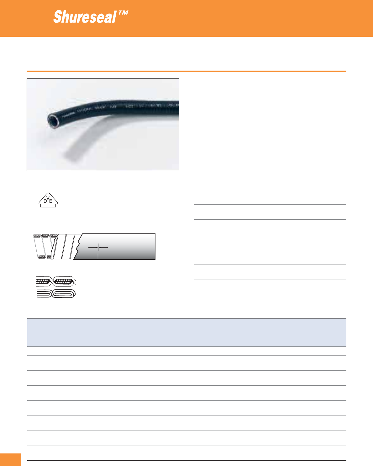
266
Thomas & Betts • www.tnb-europe.com
4.1
Type TBEF - universal
• TBEF (now integrating the TBHT grade) conduit with heavy duty
double interlocked / single interlocked (with packing) galvanised
steel core
• Universal conduit for all liquidtight applications requiring good
mechanical strength and flexibility: machinery, conveyors, etc.
• Cotton packing for high flexibility (up to 1
1
/
4
“)
• High performance acid and oil resistant, self-extinguishing PVC
jacket
• High mechanical stability
• Tested and certified in accordance with DIN VDE 0605:1982-04
(File Nr: 24058-5410-0050 / 32CRB F41 / LR, Document Nr.: 131354)
• Marked lengths (every 1 m) for quick and easy measuring and
cutting
Technical Information
Outer jacket PVC, self-extinguishing within 30 seconds
Core Galvanised steel
Packing Cotton (up to 1
1
/
4”)
Colour Black or grey**
Temperature range Static: -25°C to +105°C
Flexing: -5°C to +105°C
Voltage breakdown > 2 kV
(flash test)
Insulation resistance > 100 MOhm
IP rating IP67, when correctly installed with
Shureseal™ liquidtight fittings
** (Grey available upon request. Suffix = G, e.g. TBEF0250-50G)
Flexible metallic liquidtight conduits
Product Ref. Nominal Metric Length Internal External Min. Mechanical values Weight Type
size size diameter diameter bending min. tensile min. compression of
radius strength strength packaging
[inch] [mm] [m] [mm] [mm] [mm] [N] [N] [kg/100 m]
TBEF0250-50*
1
/
4
10 50 6.2 11.4 45 500 1250 20.0 A
TBEF0312-50*
5
/
16
12 50 10.0 14.4 50 500 1250 22.2 A
TBEF0375-10
3
/
8
16 10 12.5 17.8 50 1000 1250 41.9 A
TBEF0375-75
3
/
8
16 75 12.5 17.8 50 1000 1250 41.9 B
TBEF0500-10
1
/
2
20 10 16.0 21.1 75 1000 1250 48.1 A
TBEF0500-60
1
/
2
20 60 16.0 21.1 75 1000 1250 48.1 B
TBEF0750-10
3
/
4
25 10 21.0 26.4 90 1000 1250 68.9 A
TBEF0750-50
3
/
4
25 50 21.0 26.4 90 1000 1250 68.9 C
TBEF1000-30 1 32 30 26.0 33.1 110 1000 1250 97.5 C
TBEF1250-30 1
1
/
4
40 30 34.8 41.8 130 1000 1250 123.3 C
TBEF1500-15* 1
1
/
2
50 15 40.4 47.7 190 2500 1250 144.8 C
TBEF2000-15* 2 63 15 51.6 60.0 250 2500 1250 161.0 C
TBEF2500-15* 2
1
/
2
75 15 63.3 72.6 480 2500 1250 298.0 C
TBEF3000-7* 3 90 7 78.4 88.4 760 2500 1250 327.8 C
TBEF4000-7* 4 115 7 102.1 113.8 860 2500 1250 394.4 C
* Not VDE approved
Packaging sizes: A = box 370 x 370 x 180 mm, B = box 500 x 500 x 275 mm, C = reel 800 mm ø
See page 281 for explanations on min. bending radius and temperature ranges
For Shureseal™ liquidtight fittings see pages 290 to 301
1
/
4
”-1
1
/
4
”
1
1
/
2
”-4”
Length marking

Type TBDL - dual listed UL & CSA
• Type TBDL with UL / CSA approval, heavy duty double interlocked
/ single interlocked galvanised steel core
• Export and North-America oriented applications: multi-national
projects, power plant, ...
• Copper wire packing for improved grounding (up to 1
1
/
4
”)
• High performance, acid- and oil-resistant PVC jacket, self-
extinguishing in accordance with UL360
• Extremely high mechanical stability
• Marked lengths (every 1 m) for quick and easy measuring and
cutting
• Silicone free
Technical Information
Outer jacket PVC, self-extinguishing in 60 seconds
Core Galvanised steel
Packing Flat copper conductor (up to 1
1
/
4”)
Colour Black
Temperature range Static: -25°C to +105°C
(+120°C intermittent)
Flexing: -5°C to +105°C
UL rating: -10°C to +60°C
CSA rating: -10°C to +75°C
IP rating IP67, when correctly installed with
Shureseal™ liquidtight fittings
Flexible metallic liquidtight conduits
267
Thomas & Betts • www.tnb-europe.com
4.1
Product Ref. Nominal Metric Length Internal External Min. Mechanical values Weight Type
size size diameter diameter bending min. tensile min. compression of
radius strength strength packaging
[inch] [mm] [m] [mm] [mm] [mm] [N] [N] [kg/100 m]
TBDL0375-75
3
/
8
16 75 12.5 17.8 50 1000 4000 39.4 B
TBDL0500-60
1
/
2
20 60 16.0 21.1 80 1000 4000 48.5 B
TBDL0750-50
3
/
4
25 50 21.0 26.4 105 1000 1250 66.3 C
TBDL1000-30 1 32 30 26.0 33.1 165 1000 4000 112.0 C
TBDL1250-30 1
1
/
4
40 30 34.8 41.8 200 1000 1250 160.0 C
TBDL1500-15 1
1
/
2
50 15 40.4 47.7 280 2500 4000 193.5 C
TBDL2000-15 2 63 15 51.6 60.0 355 2500 1250 253.0 C
Packaging sizes: B = box 500 x 500 x 275 mm, C = reel 800 mm ø
See page 281 for explanations on min. bending radius and temperature ranges
Other sizes available upon request - please contact your Sales Office
For Shureseal™ liquidtight fittings see pages 290 to 301
3
/
8
”-1
1
/
4
”
1
1
/
2
”-2”
091693 E125517
Length marking
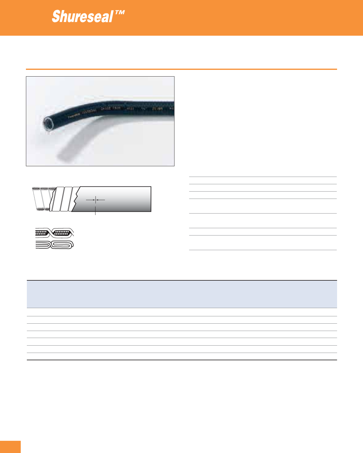
268
Thomas & Betts • www.tnb-europe.com
4.1
Type TBOR - oil resistant
• Type TBOR, with heavy duty double interlocked / single inter-
locked (with packing) galvanised steel core
• Applications in greasy environments: machine tools, assembly
machines, hydraulic machinery
• Cotton packing for high flexibility (up to 1
1
/
4
“)
• High performance acid- and oil-resistant PVC outer jacket, self-
extinguishing within 30 seconds
• High mechanical stability in accordance with DIN 49 012
• Marked lengths (every 1m) for quick and easy measuring and
cutting
Technical Information
Outer jacket PVC, self-extinguishing within 30 seconds
Core Galvanised steel
Packing Cotton (up to 1
1
/
4”)
Colour Black
Temperature range Static: -25°C to +105°C
Flexing: -5°C to +105°C
Voltage breakdown > 2 kV
(flash test)
Insulation resistance > 100 MOhm
IP rating IP67, when correctly installed with
Shureseal™ liquidtight fittings
Flexible metallic liquidtight conduits
Product Ref. Nominal Metric Length Internal External Min.
Mechanical values
Weight Type
size size diameter diameter bending min. tensile min. compression of
radius strength strength packaging
[inch] [mm] [m] [mm] [mm] [mm] [N] [N] [kg/100 m]
TBOR0375-75
3
/
8
16 75 12.5 17.8 50 1000 1250 41.9 B
TBOR0500-60
1
/
2
20 60 16.0 21.1 75 1000 1250 48.1 B
TBOR0750-50
3
/
4
25 50 21.0 26.4 90 1000 1250 68.9 C
TBOR1000-30 1 32 30 26.0 33.1 110 1000 1250 97.5 C
TBOR1250-30 1
1
/
4
40 30 34.8 41.8 130 1000 1250 123.3 C
TBOR1500-15 1
1
/
2
50 15 40.4 47.7 190 2500 1250 144.8 C
TBOR2000-15 2 63 15 51.6 60.0 250 2500 1250 161.0 C
Packaging sizes: B = box 500 x 500 x 275 mm, C = reel 800 mm ø
See page 281 for explanations on min. bending radius and temperature ranges
Other sizes available upon request - please contact your Sales Office
For
Shureseal™
liquidtight fittings see pages 290 to 301
3
/
8
”-1
1
/
4
”
1
1
/
2
”-2”
Length marking
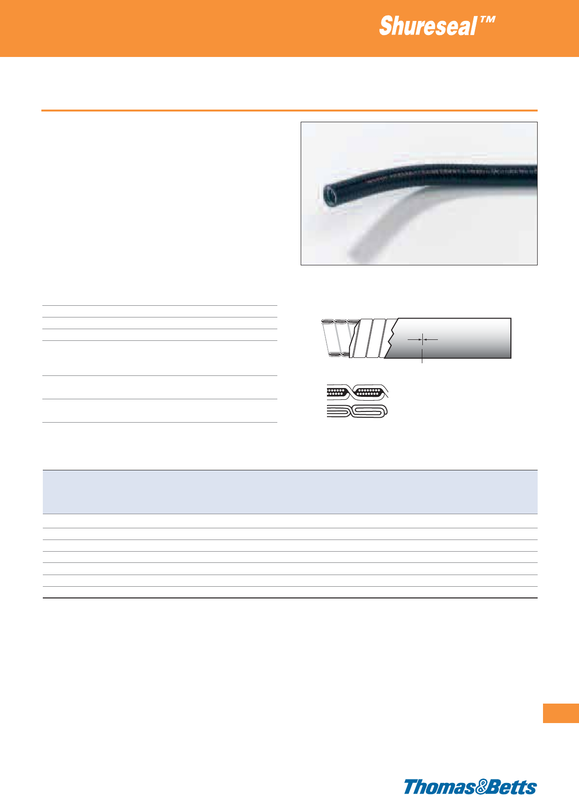
Type TBEHC - extreme heat/cold
• Applications at extreme temperatures: refrigeration, transportation,
industrial HVAC, heavy industries
• Very high tolerance to extreme changes in temperature
• Heavy duty double interlocked / single interlocked (with packing)
galvanised steel core
• Cotton packing for high flexibility (up to 1
1
/
4
“)
• High performance acid- and oil-resistant Polyester jacket, self-
extinguishing according to UL 94 V-2
• High mechanical stability in accordance with DIN 49 012
• Marked lengths (every 1m) for quick and easy measuring and
cutting
Technical Information
Outer jacket Polyester, self-extinguishing
within 30 seconds
Core Galvanised steel
Packing Cotton (up to 1
1
/
4”)
Colour Black
Temperature range Static: -50°C to +130°C
(+150°C intermittent)
Flexing: -5°C to +130°C
Voltage breakdown > 2 kV
(flash test)
IP rating IP67, when correctly installed with
Shureseal™ liquidtight fittings
Flexible metallic liquidtight conduits
269
Thomas & Betts • www.tnb-europe.com
4.1
3
/
8
”-1
1
/
4
”
1
1
/
2
”-2”
Length marking
Product Ref. Nominal Metric Length Internal External Min.
Mechanical values
Weight Type
size size diameter diameter bending min. tensile min. compression of
radius strength strength packaging
[inch] [mm] [m] [mm] [mm] [mm] [N] [N] [kg/100 m]
TBEHC0375-30
3
/
8
16 30 12.5 17.8 50 1000 1250 40.7 B
TBEHC0500-30
1
/
2
20 30 16.0 21.1 75 1000 1250 45.0 B
TBEHC0750-30
3
/
4
25 30 21.0 26.4 90 1000 1250 64.5 C
TBEHC1000-30 1 32 30 26.0 33.1 110 1000 1250 90.7 C
TBEHC1250-30 1
1
/
4
40 30 34.8 41.8 130 1000 1250 112.6 C
TBEHC1500-15 1
1
/
2
50 15 40.4 47.7 190 2500 1250 134.5 C
TBEHC2000-15 2 63 15 51.6 60.0 250 2500 1250 148.7 C
Packaging sizes: B= box 500 x 500 x 275 mm, C= reel 800 mm ø
See page 281 for explanations on min. bending radius and temperature ranges
Other sizes available upon request - please contact your Sales Office
For Shureseal™ liquidtight fittings see pages 290 to 301
Special fittings (HT series) rated at 150°C are now available for high temperature applications - please contact your Sales Office for product availability.
TBEHC conduits with 316 grade stainless steel core (TBEHCSS series) can be available upon request - please contact your Sales Office for product availability
and Minimum Order Quantities.

270
Thomas & Betts • www.tnb-europe.com
4.1
Type TBZH - zero halogen
• Halogen free and low smoke outer jacket
• Ideal for applications where human lives can be a concern: public
transportation, metro, train,...
• Heavy duty double interlocked / single interlocked (with packing)
galvanised steel core
• Cotton packing for high flexibility (up to 1
1
/
4
“)
• High performance acid- and oil-resistant Olefin outer jacket, self-
extinguishing within 30 seconds
• For use in safety areas (tunnels, public areas and transportation
equipment)
• Marked lengths (every 1m) for quick and easy measuring and
cutting
• NFF16-101 / NFF16-102 tested:
I index = I3 (oxygen index = 40.7), F index = F1
Technical Information
Outer jacket Olefin, self-extinguishing within 30 seconds
Core Galvanised steel
Packing Cotton (up to 1
1
/
4”)
Colour Black
Temperature range Static: -25°C to +90°C
Flexing: -5°C to +90°C
Voltage breakdown > 2 kV
(flash test)
Insulation resistance > 100 MOhm
IP rating IP67, when correctly installed with
Shureseal™ liquidtight fittings
Flexible metallic liquidtight conduits
Product Ref. Nominal Metric Length Internal External Min.
Mechanical values
Weight Type
size size diameter diameter bending min. tensile min. compression of
radius strength strength packaging
[inch] [mm] [m] [mm] [mm] [mm] [N] [N] [kg/100 m]
TBZH0375-75
3
/
8
16 75 12.5 17.8 60 1000 1250 41.9 B
TBZH0500-60
1
/
2
20 60 16.0 21.1 90 1000 1250 48.1 B
TBZH0750-50
3
/
4
25 50 21.0 26.4 110 1000 1250 68.9 C
TBZH1000-30 1 32 30 26.0 33.1 130 1000 1250 97.5 C
TBZH1250-30 1
1
/
4
40 30 34.8 41.8 160 1000 1250 123.3 C
TBZH1500-15 1
1
/
2
50 15 40.4 47.7 230 2500 1250 144.8 C
TBZH2000-15 2 63 15 51.6 60.0 300 2500 1250 161.0 C
Packaging sizes: B= box 500 x 500 x 275 mm, C = reel 800 mm ø
For Shureseal™ liquidtight fittings see pages 290 to 301
See page 281 for explanations on min. bending radius and temperature ranges
5
/
16
”-1
1
/
4
”
1
1
/
2
”-2”
Length marking
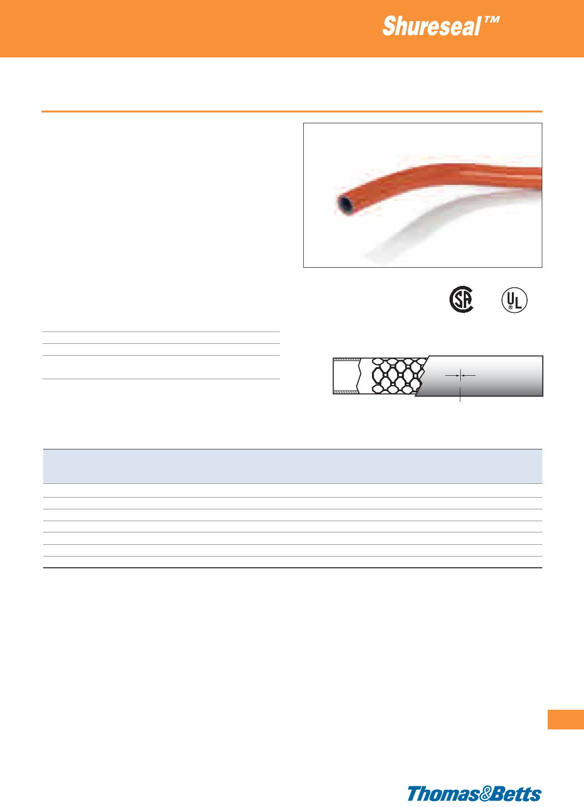
Type TYPEA - smooth outer surface
• UL and CSA approved
• Double layer construction offers a high level of mechanical stability
for plastic tubing
• The Nylon lining between the 2 layers ensures a high level of
flexibility
• High performance, durable acid- and oil resistant PVC outer jacket
• Perfectly designed for fittings which have to be safe, secure and
electrically insulated
• Marked in lengths of 1 foot / 30.48 cm for quick and easy
measuring and cutting
• High retention assured when used in association with T&B special
fittings (Product Ref. 37XX and 63XX)
(see pages 302 and 303)
Technical Information
Material 2 layers of PVC with a woven Nylon
fabric in between
Colour Orange
Temperature range -20°C to +60°C
IP rating IP66, when correctly installed with
Shureseal™ liquidtight fittings
Flexible non-metallic liquidtight conduits
271
Thomas & Betts • www.tnb-europe.com
4.1
Length marking
Product Ref. Nominal Metric Length Internal External Min. bending Weight
size size diameter diameter radius
[inch] [mm] [m] [mm] [mm] [mm] [kg/100 m]
TYPEA38-250
3
/
8
16 76.2 12.32 19.63 63.5 23.3
TYPEA50-200
1
/
2
20 61.0 15.75 23.62 76.2 33.3
TYPEA75-175
3
/
4
25 53.3 20.70 29.72 101.6 46.7
TYPEA100-100 1 32 30.5 26.16 36.58 152.4 63.3
TYPEA125-100 1
1
/
4
40 30.5 34.80 46.36 177.8 93.3
TYPEA150-50 1
1
/
2
50 15.2 40.26 52.83 203.2 120.0
TYPEA200-50 2 63 15.2 52.71 65.79 228.6 180.0
For Shureseal™ liquidtight fittings for non-metallic conduits see pages 302 and 303
See page 281 for explanations on min. bending radius and temperature ranges
232580 E
95745

272
Thomas & Betts • www.tnb-europe.com
4.1
Type EFC - with strengthened inner coil
• UL Type B liquidtight flexible non-metallic conduit, OEM grade
• Highly flexible, liquidtight plastic tubing with strengthened inner
coil
• UV-resistant and weatherproof
• High chemical resistance
• UL recognised under File No. E 96548
• CSA approved File No. LL 067241
• Crush-resistant due to stiffening effects of strengthened inner coil
• The ultra-smooth inner surface ensures that cables and conduc-
tors can be fed through very easily
• Can be used with plastic or metallic T&B “Bullet” fittings (see
pages 304 to 308)
Technical Information
Material PVC
Colour Black or orange* or blue*
Temperature range -18°C to +75°C (CSA)
-18°C to +60°C (UL)
IP rating IP65, when correctly installed with
Shureseal™ liquidtight fittings
Flexible non-metallic liquidtight conduits
Product Ref. Nominal Metric Length Internal External Min. bending Weight Type of
size size diameter diameter radius packaging
[inch] [mm] [m] [mm] [mm] [mm] [kg/100 m]
EFC025
1
/
4
10 30.5 10.0 14.6 20 7.3 reel
EFC038
3
/
8
16 30.5 12.3 18.0 25 10.7 reel
EFC050
1
/
2
20 30.5 15.8 21.3 30 12.4 reel
EFC075
3
/
4
25 30.5 20.8 26.7 40 15.3 reel
EFC100 1 32 30.5 26.4 33.4 50 23.8 reel
EFC125 1
1
/
4
40 30.5 35.1 42.2 60 31.6 reel
EFC150 1
1
/
2
50 15.2 40.0 48.3 70 43.8 reel
EFC200 2 63 15.2 51.3 60.3 85 59.5 reel
For Shureseal™ “Bullet” fittings see pages 304 to 308
* For other colours add colour suffix to Product Reference. (e.g. EFC025-1 for orange conduit)
Standard colour = black, 1 = orange, 2 = blue
See page 281 for explanations on min. bending radius and temperature ranges
External
Ø
LL067241 E96548
Internal
Ø
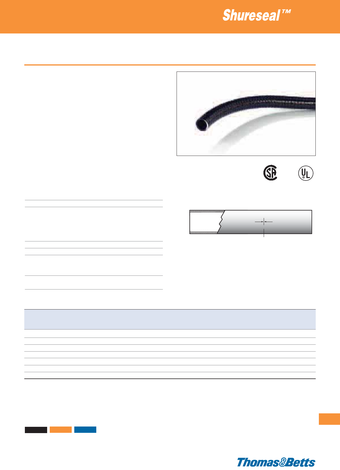
Type LTC - smooth outer surface
• UL Type B liquidtight flexible non-metallic conduit,
industrial grade
• UL listed (E95745), CSA approved (LL80349)
• Highly flexible, with smooth outer jacket
• UV-resistant and weatherproof
• High chemical resistance
• The smooth inner surface ensures that cables and conductors can
be fed through very easily
• Marked lengths (every 1 foot = 30.5 cm) for quick and easy
measuring and cutting
• Can be used with plastic or metallic Shureseal™ “Bullet” fittings
(see pages 304 to 308)
• Recommended industrial applications include: food processing
equipment, extensions from wireways, sensor and microswitch
control consoles
Technical Information
Material PVC
Colour Black or blue* or orange*
Temperature range -18°C to +105°C
CSA rating: -18°C to +75°C
UL rating: -18°C to +105°C (dry)
-18°C to +70°C (oil)
-18°C to +60°C (wet)
Voltage rating 600V
Flammability rating UL1660
UL specifications Oil resistant: yes
Outdoor applications: yes (black version only)
Direct burial: yes
IP rating IP65, when correctly installed with Shureseal™
plastic or metallic “Bullet” fittings
Flexible non-metallic liquidtight conduits
273
Thomas & Betts • www.tnb-europe.com
4.1
Product Ref. Nominal Metric Length Internal External Weight
size size diameter diameter
[inch] [mm] [m] [mm] [mm] [kg/100 m]
LTC038
3
/
8
16 30.5 12.3 18.0 19.0
LTC050
1
/
2
20 30.5 15.8 21.3 22.0
LTC075
3
/
4
25 30.5 20.8 26.7 27.2
LTC100-TB 1 32 30.5 26.4 33.4 42.3
LTC125-TB 1
1
/
4
40 30.5 35.1 42.2 56.1
LTC150-TB 1
1
/
2
50 15.2 40.0 48.3 77.8
LTC200 2 63 15.2 51.3 60.3 105.7
Suitable for use in hazardous location where general purpose equipment is specifically permitted by the NEC Class I Div. 2, Class II, Div. 1 & 2 Class III, Div. 1 & 2,
NEC 501-4(b) 502-4(a)(b) 503-3(a)(b).
Other lengths can be available - please contact your Sales Office for availability
For Shureseal™ “Bullet” fittings, see pages 304 to 308
* For other colours add colour suffix to Product Reference. (e.g. LTC050-1 for orange conduit)
Standard colour = black, 1 = orange, 2 = blue
Length marking
LL80349 E95745

274
Thomas & Betts • www.tnb-europe.com
4.1
Type LTC-GY - smooth outer surface
• UL Type B liquidtight flexible non-metallic conduit, commercial
grade
• UL listed (E95745), CSA approved (LL80349)
• Highly flexible, with smooth outer jacket
• UV-resistant and weatherproof
• High chemical resistance
• The smooth inner surface ensures that cables and conductors can
be fed through very easily
• Can be used with plastic or metallic Shureseal™ “Bullet” fittings
(see pages 304 to 308)
• Recommended for commercial applications
Technical Information
Material PVC
Colour Grey
Temperature range -18°C to +80°C
UL rating: -18°C to +80°C (dry)
-18°C to +70°C (oil)
-18°C to +60°C (wet)
Voltage rating 600V
UL specifications Oil resistant: yes
Outdoor applications: yes
Direct burial: yes
IP rating IP65, when correctly installed with
Shureseal™ plastic or metallic “Bullet”
fittings
Flexible non-metallic liquidtight conduits
Product Ref. Nominal Metric Length Internal External Weight
size size diameter diameter
[inch] [mm] [m] [mm] [mm] [kg/100 m]
LTC038GY
3
/
8
16 30.5 12.3 18.0 19.0
LTC050GY
1
/
2
20 30.5 15.8 21.3 22.0
LTC075GY
3
/
4
25 30.5 20.8 26.7 27.2
LTC100GY 1 32 30.5 26.4 33.4 42.3
LTC125GY 1
1
/
4
40 30.5 35.1 42.2 56.1
LTC150GY 1
1
/
2
50 15.2 40.0 48.3 77.8
LTC200GY 2 63 15.2 51.3 60.3 105.7
Other lengths can be available – please contact your Sales Office for availability
For Shureseal™ “Bullet” fittings, see pages 304 to 308
Length marking
LL80349 E95745
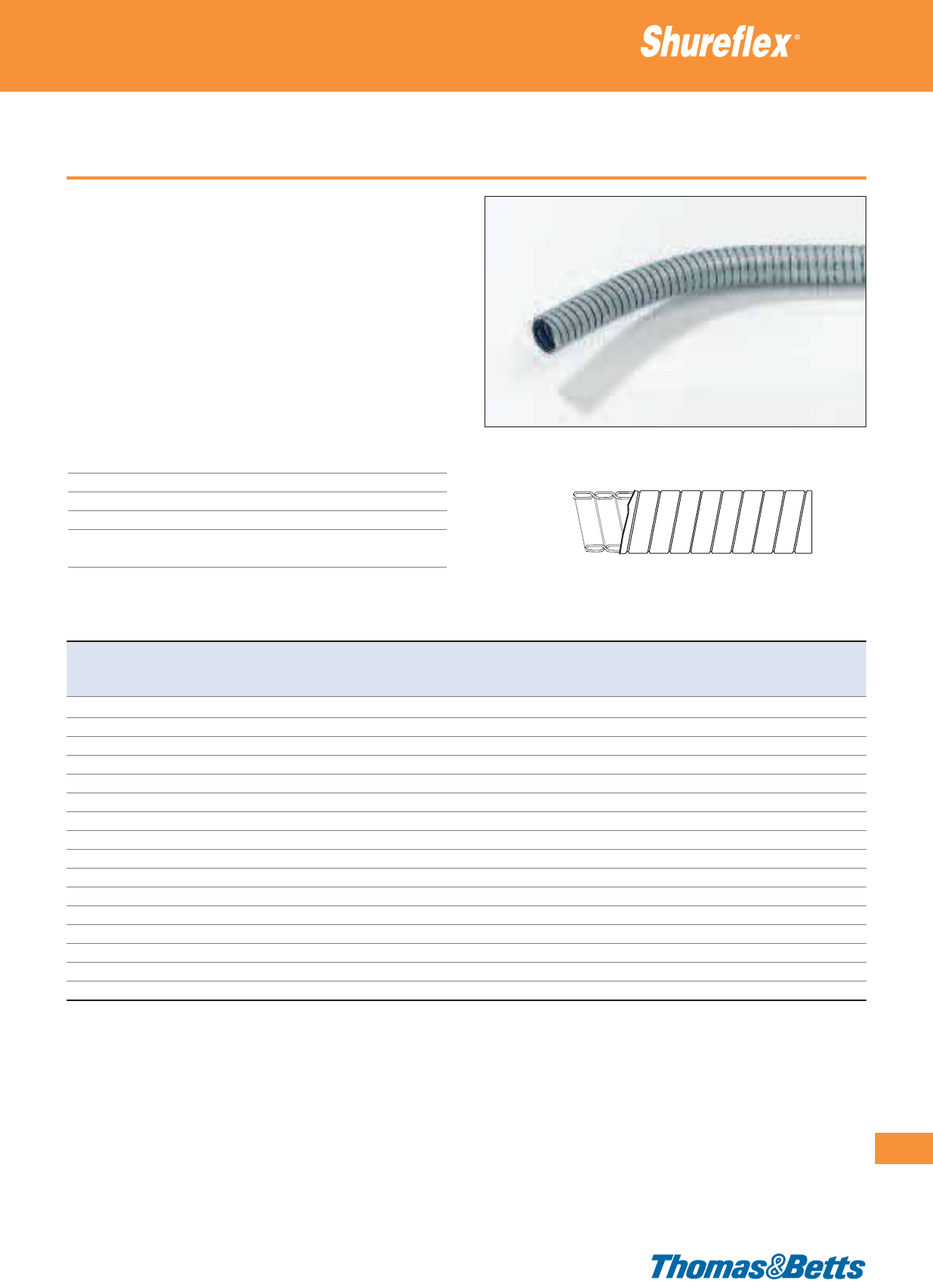
Type UGS - uncovered version
• Highly crush-resistant with an excellent pull off strength
• An economic solution for the protection of cables in industrial
and commercial applications where there is flexing, bending or
vibration
• Stainless steel grade 316 conduits and fittings are available for
specialised applications. Please contact your Sales Office for any
specific requirements
• Wide choice of male fittings (fixed or swivel) with PG or metric
threads, as well as a space saver version
• Typical applications include amongst others: lighting, security
cameras, underfloor wiring, transport and machine-tools
Technical Information
Outer jacket None
Core Continuous spiral in galvanised steel
Colour Metallic
Temperature range -50°C to +300°C
IP rating IP40, when correctly installed with
Shureflex
®
fittings
Ultra-flexible galvanised steel conduits
275
Thomas & Betts • www.tnb-europe.com
4.1
Product Ref. Nominal Length Min. inner Max. outer Min. bending Weight Type of
size diameter diameter radius packaging
[mm] [m] [mm] [mm] [mm] [kg/100 m]
UGS1010 10 10 7.0 9.6 20 8.4 box
UGS1030 10 30 7.0 9.6 20 8.4 box
UGS1210 12 10 10.0 12.8 20 12.9 box
UGS1230 12 30 10.0 12.8 20 12.9 box
UGS1610 16 10 12.9 16.1 24 15.6 box
UGS1630 16 30 12.9 16.1 24 15.6 box
UGS2010 20 10 17.0 20.2 32 21.7 box
UGS2030 20 30 17.0 20.2 32 21.7 box
UGS2510 25 10 21.1 24.7 32 27.0 box
UGS2530 25 30 21.1 24.7 32 27.0 box
UGS3210 32 10 28.4 32.0 32 36.0 box
UGS3220 32 20 28.4 32.0 32 36.0 box
UGS4010 40 10 36.4 40.1 44 45.5 box
UGS4020 40 20 36.4 40.1 44 45.5 box
UGS5010 50 10 48.2 53.2 95 98.5 box
UGS5020 50 20 48.2 53.2 95 98.5 box
For T&B Shureflex
®
fittings see pages 313 and 314
For stainless steel grade 316 conduits please contact your Sales Office
See page 281 for explanations on min. bending radius and temperature ranges
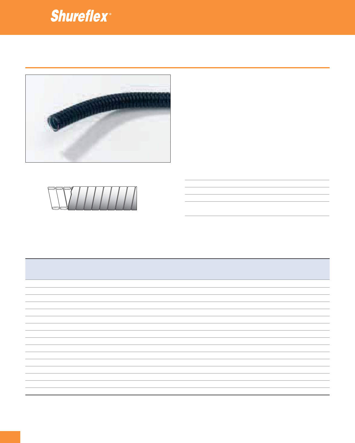
276
Thomas & Betts • www.tnb-europe.com
4.1
Type PGS - covered version
• Highly crush-resistant with an excellent pull off strength
• Improved IP rating (IP54), compared to the uncovered conduits
(special fittings with IP65 rating are also available upon request)
• An economic solution for the protection of cables in industrial
and commercial applications where there is flexing, bending or
vibration
• Wide choice of male fittings (fixed or swivel) and female fittings
(fixed), both with PG or metric threads, as well as a space saver
version
• Typical applications include amongst others: lighting, security
cameras, underfloor wiring, transport and machine-tools
Technical Information
Outer jacket Low acid PVC*
Core Continuous spiral in galvanised steel
Colour Black
Temperature range -25°C to +70°C
IP rating IP54, (or IP65 **), when correctly
installed with Shureflex
®
fittings
* Limited Fire Hazard covering available upon request
** With special fitting, upon request
Ultra-flexible galvanised steel conduits
Product Ref. Nominal Length Min. inner Max. outer Min. bending Weight Type of
size diameter diameter radius packaging
[mm] [m] [mm] [mm] [mm] [kg/100 m]
PGS1010 10 10 7.0 10.3 30 12.5 box*
PGS1030 10 30 7.0 10.3 30 12.5 box*
PGS1210 12 10 10.0 13.8 30 19.8 box*
PGS1230 12 30 10.0 13.8 30 19.8 box*
PGS1610 16 10 12.9 17.1 35 23.1 box*
PGS1630 16 30 12.9 17.1 35 23.1 box*
PGS2010 20 10 17.0 21.2 40 31.4 box*
PGS2030 20 30 17.0 21.2 40 31.4 box*
PGS2510 25 10 21.1 25.7 50 38.5 box*
PGS2530 25 30 21.1 25.7 50 38.5 box*
PGS3210 32 10 28.4 33.0 60 51.7 box*
PGS3220 32 20 28.4 33.0 60 51.7 box*
PGS4010 40 10 36.4 41.1 80 64.4 box*
PGS4020 40 20 36.4 41.1 80 64.4 box*
PGS5010 50 10 48.2 54.9 180 116.0 box*
PGS5020 50 20 48.2 54.9 180 116.0 box*
* Packed in a cardboard box which contains a reel
For T&B Shureflex
®
fittings see pages 315 and 316
See page 281 for explanations on min. bending radius and temperature ranges
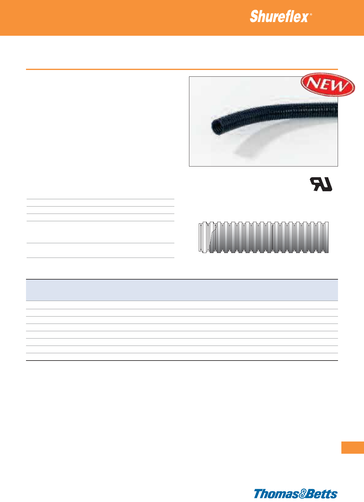
Type LG - Light grade (PA6)
• Specially modified Polyamide 6
• Light grade: cost effective version
• Resistant to fuel, mineral oils, greases and diluted bases
• To be used with the Shureflex®Nylon Fittings to provide a water-
tight system (rated IP66) without the need for any additional
accessory
• For the insulation and the mechanical protection of electrical
cables in industrial applications, in accordance with EN60204
(Machine Safety)
• Typical applications include: general wiring, machine tools, industrial
equipment, control equipment and automotive
• For slit version please contact your sales office for product avail-
ability
Technical Information
Material Polyamide 6
Colour Black
Temperature range -40°C to +105°C (intermittent: to +150°C)
Flammability rating UL 94 HB
IP rating IP66, with Shureflex
®
Nylon fittings
IP69K, with Shureflex
®
Nylon fittings and
additional Shureflex
®
washer and O-ring
Other properties Halogen, Phosphor and Cadmium free,
UV-resistant
Ultra-flexible nylon conduits
277
Thomas & Betts • www.tnb-europe.com
4.1
Product Ref. Nominal Length Internal External Min. bending Type of
size diameter diameter radius packaging
[mm] [m] [mm] [mm] [mm]
NY-LG07-BK50 7 50 6.3 10.0 15 reel
NY-LG10-BK50 10 50 9.7 13.0 20 reel
NY-LG12-BK50 12 50 12.2 15.8 30 reel
NY-LG17-BK50 17 50 16.8 21.2 40 reel
NY-LG23-BK50 23 50 22.6 28.5 55 reel
NY-LG29-BK50 29 50 28.3 34.5 65 reel
NY-LG36-BK30 36 30 36.3 42.5 80 reel
NY-LG48-BK30 48 30 47.4 54.5 95 reel
For Shureflex
®
Nylon Fittings & Accessories: see pages 317 to 325
See page 281 for explanations on min. bending radius and temperature ranges
E96548
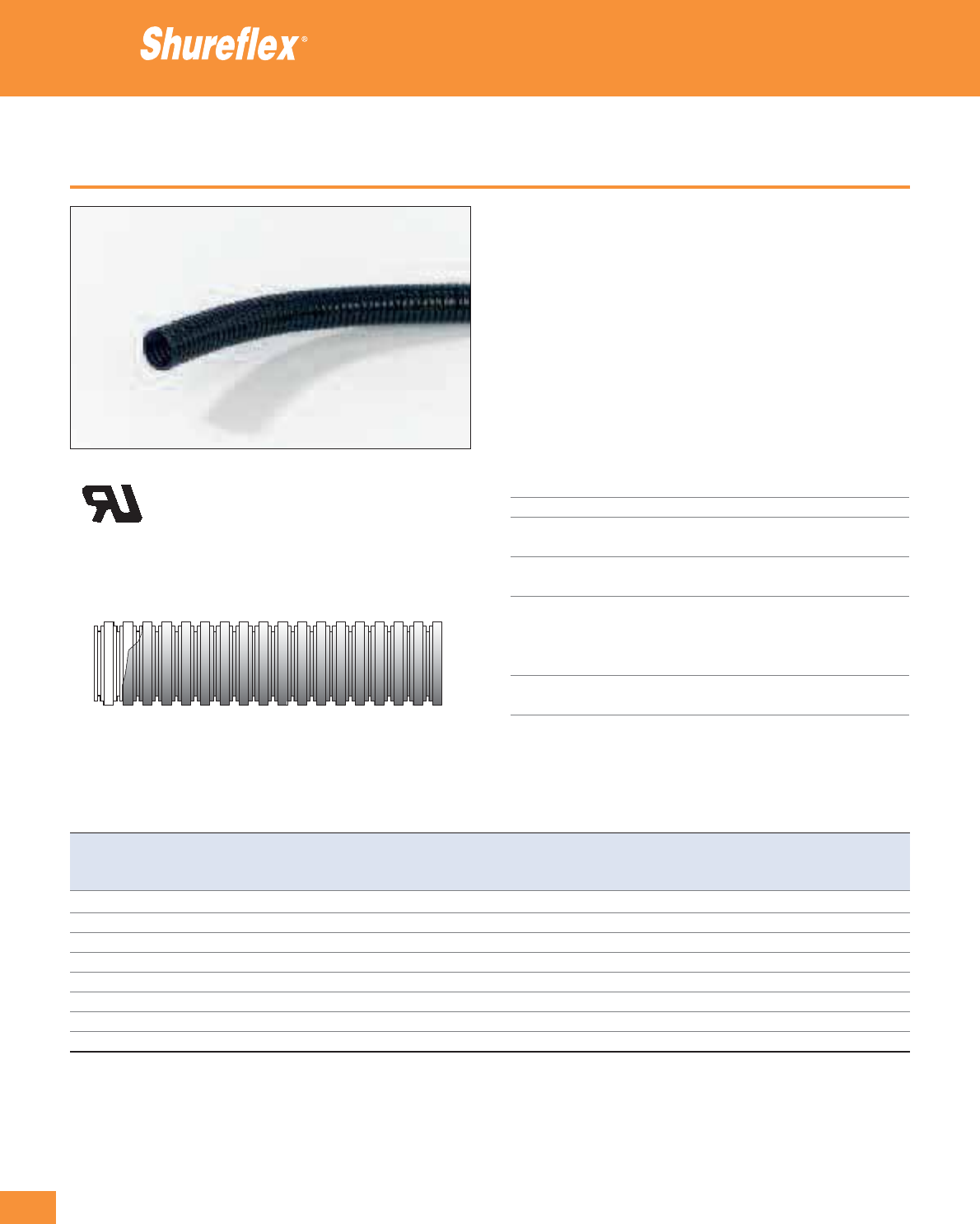
278
Thomas & Betts • www.tnb-europe.com
4.1
Type SG - Standard grade (PA6)
• High performance Polyamide 6
• Standard grade: very flexible and light
• Resistant to fuel, mineral oils, greases and diluted bases
• To be used with the Shureflex®Nylon Fittings to provide a water-
tight system (rated IP66) without the need for any additional
accessory
• For the insulation and the mechanical protection of electrical
cables in industrial applications, in accordance with EN60204
(Machine Safety)
• Typical applications include: general wiring, machine tools, in-
dustrial equipment, control equipment and automotive
Technical Information
Material Polyamide 6
Colour Black
Temperature range -40°C to +105°C
(intermittent: to +150°C)
Flammability rating UL 94 V-2 (produced from
UL 94 V-0 raw material)
IP rating IP66, with Shureflex
®
Nylon fittings
IP69K, with Shureflex
®
Nylon fittings
and additional Shureflex
®
washer
and O-ring
Other properties Halogen, Phosphor and Cadmium free,
UV-resistant
Ultra-flexible nylon conduits
E96548
Product Ref. Nominal Length Internal External Min. bending Type of
size diameter diameter radius packaging
[mm] [m] [mm] [mm] [mm]
NY-SG07-BK50 7 50 6.3 10.0 15 reel
NY-SG10-BK50 10 50 9.7 13.0 20 reel
NY-SG12-BK50 12 50 12.2 15.8 30 reel
NY-SG17-BK50 17 50 16.8 21.2 40 reel
NY-SG23-BK50 23 50 22.6 28.5 55 reel
NY-SG29-BK50 29 50 28.3 34.5 65 reel
NY-SG36-BK30 36 30 36.3 42.5 80 reel
NY-SG48-BK30 48 30 47.4 54.5 95 reel
For Shureflex
®
Nylon Fittings & Accessories: see pages 317 to 325
See page 281 for explanations on min. bending radius and temperature ranges
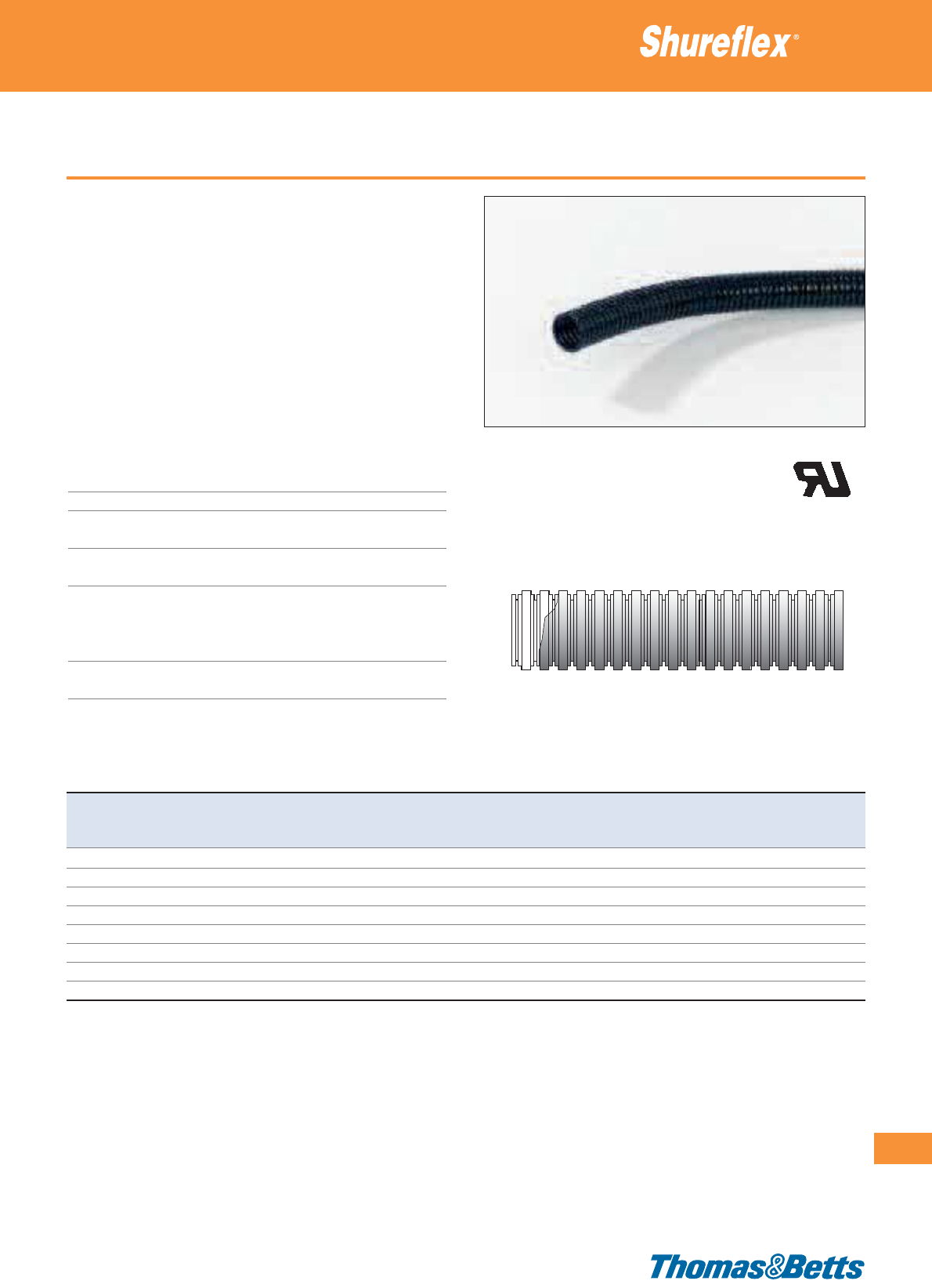
Type MG - Medium grade (PA6)
• High performance Polyamide 6
• Medium grade: flexible with increased mechanical strength (crush
and impact resistance)
• Resistant to fuel, mineral oils, greases and diluted bases
• To be used with the Shureflex®Nylon Fittings to provide a water-
tight system (rated IP66) without the need for any additional
accessory
• For the insulation and the mechanical protection of electrical
cables in industrial applications, in accordance with EN60204
(Machine Safety)
• Typical applications include: machine tools and machinery, indus-
trial equipment, production equipment and railway industry
Technical Information
Material Polyamide 6
Colour Black
Temperature range -40°C to +105°C
(intermittent: to +150°C)
Flammability rating UL 94 V-2 (produced from
UL 94 V-0 raw material)
IP rating IP66, with Shureflex
®
Nylon fittings
IP69K, with Shureflex
®
Nylon fittings
and additional Shureflex
®
washer
and O-ring
Other properties Halogen, Phosphor and Cadmium free,
UV-resistant
Ultra-flexible nylon conduits
279
Thomas & Betts • www.tnb-europe.com
4.1
Product Ref. Nominal Length Internal External Min. bending Type of
size diameter diameter radius packaging
[mm] [m] [mm] [mm] [mm]
NY-MG07-BK50 7 50 6.2 10.0 20 reel
NY-MG10-BK50 10 50 9.6 13.0 25 reel
NY-MG12-BK50 12 50 12.0 15.8 35 reel
NY-MG17-BK30 17 30 16.5 21.2 50 reel
NY-MG23-BK30 23 30 22.3 28.5 60 reel
NY-MG29-BK30 29 30 28.2 34.5 70 reel
NY-MG36-BK30 36 30 36.0 42.5 85 reel
NY-MG48-BK30 48 30 47.1 54.5 100 reel
For Shureflex
®
Nylon Fittings & Accessories: see pages 317 to 325
See page 281 for explanations on min. bending radius and temperature ranges
E96548
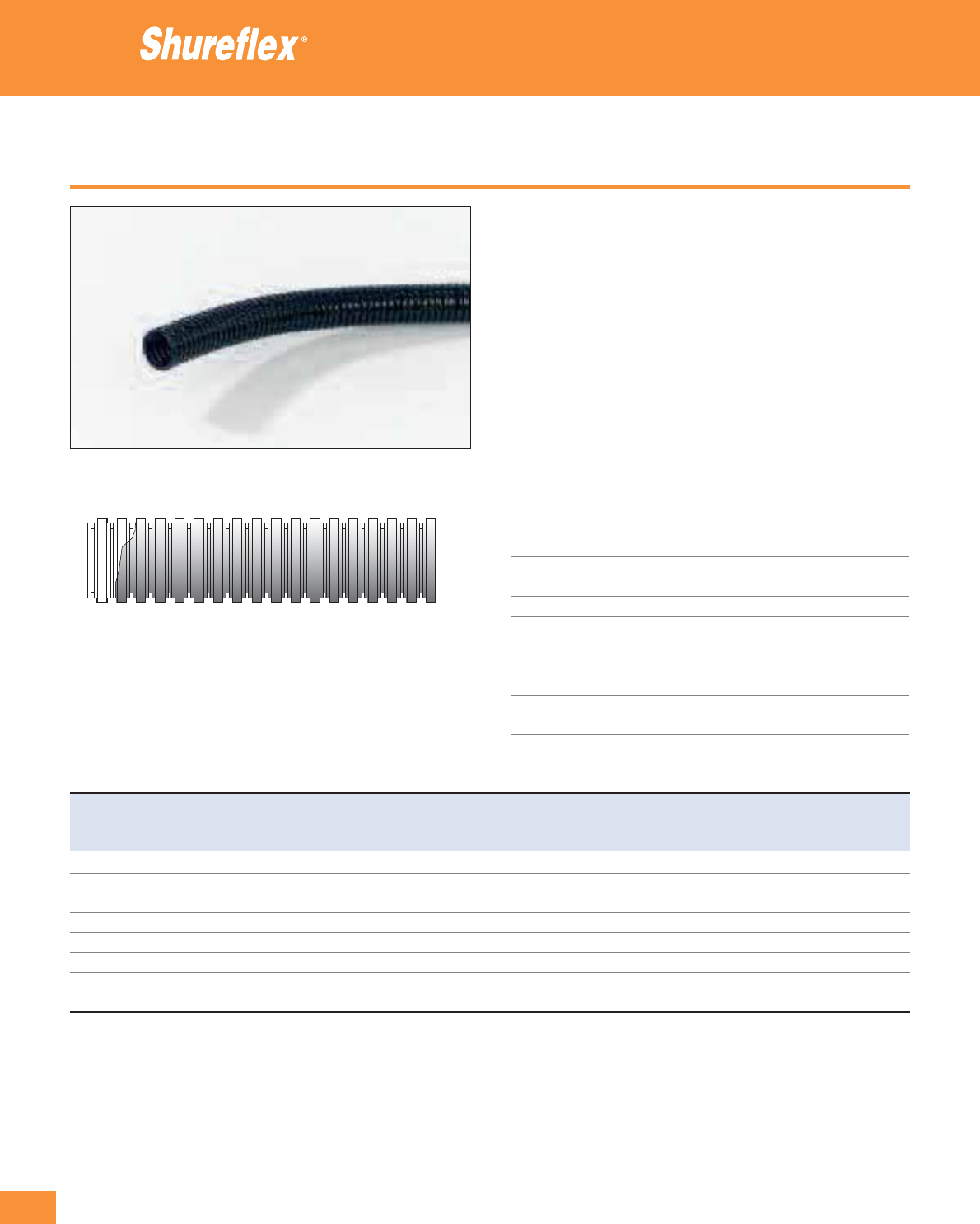
280
Thomas & Betts • www.tnb-europe.com
4.1
Type EG - Extra Flexible grade (PA12)
• High performance Polyamide 12
• Extremely flexible, even at negative temperatures and in very dry
atmospheres
• Resistant to fuel, mineral oils, greases and diluted bases
• To be used with the Shureflex®Nylon Fittings to provide a water-
tight system (rated IP66) without the need for any additional
accessory
• For the insulation and the mechanical protection of electrical
cables in industrial applications, in accordance with EN60204
(Machine Safety)
• Especially recommended for demanding applications requiring
repetitive bending and flexing movements, such as robotics,
automation, production equipment
Technical Information
Material Polyamide 12
Colour Black
Temperature range -50°C to +90°C
(intermittent: to +140°C)
Flammability rating UL 94 HB
IP rating IP66, with Shureflex
®
Nylon fittings
IP69K, with Shureflex
®
Nylon fittings
and additional Shureflex
®
washer
and O-ring
Other properties Halogen, Phosphor and Cadmium free,
UV-resistant
Ultra-flexible nylon conduits
Product Ref. Nominal Length Internal External Min. bending Type of
size diameter diameter radius packaging
[mm] [m] [mm] [mm] [mm]
NY-EG07-BK50 7 50 6.5 10.0 20 reel
NY-EG10-BK50 10 50 9.5 13.0 25 reel
NY-EG12-BK50 12 50 12.0 15.8 35 reel
NY-EG17-BK30 17 30 16.4 21.2 50 reel
NY-EG23-BK30 23 30 22.6 28.5 60 reel
NY-EG29-BK30 29 30 28.1 34.5 70 reel
NY-EG36-BK10 36 10 36.0 42.5 85 reel
NY-EG48-BK10 48 10 47.5 54.5 100 reel
For Shureflex
®
Nylon Fittings & Accessories: see pages 317 to 325
See page 281 for explanations on min. bending radius and temperature ranges
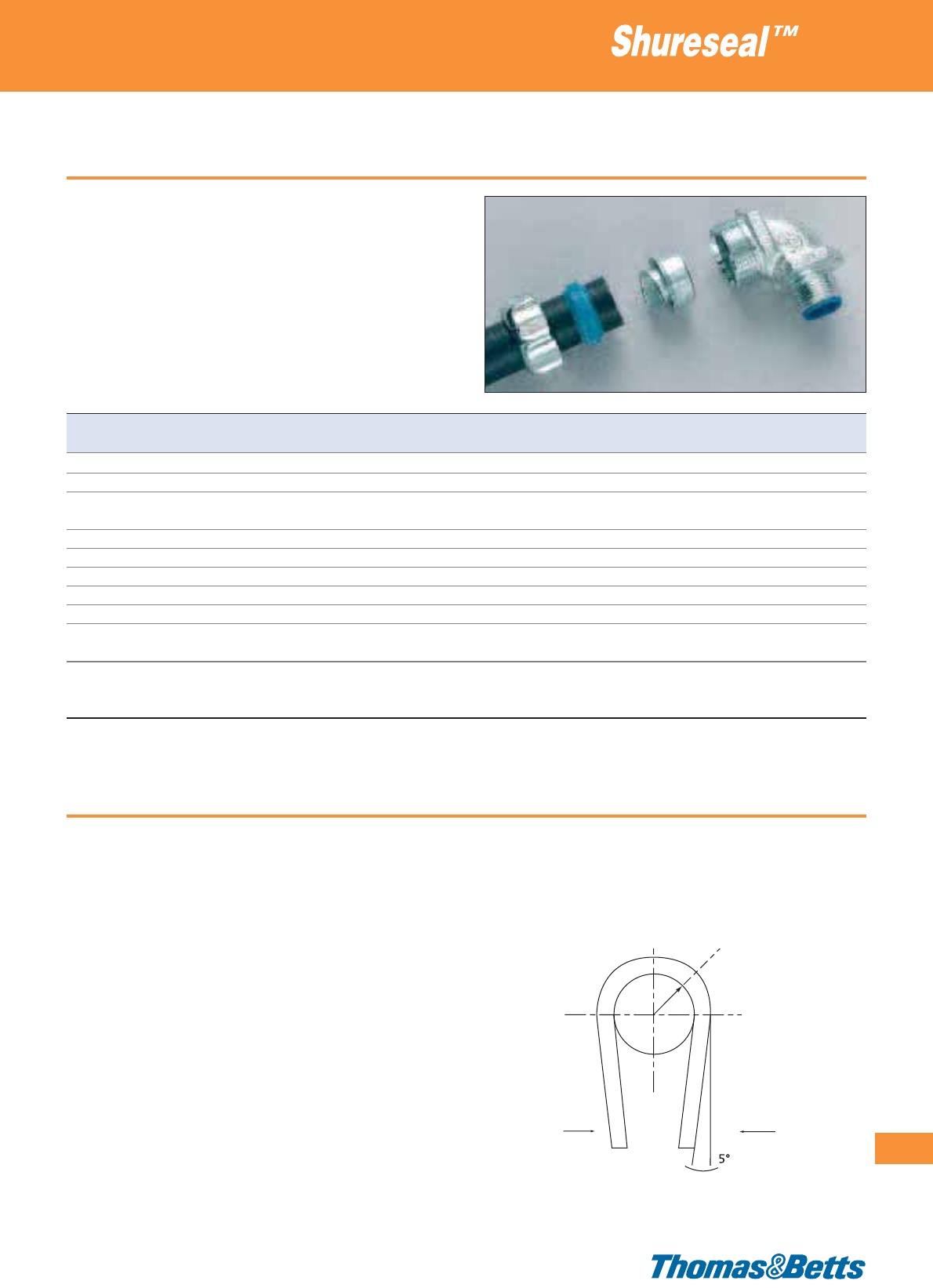
Degree of protection (IP rating)
Degrees of Protection of enclosures according to DIN 40050
IEC 144/529
IP (Ingress Protection) and 2 figures (IPXY) indicates the protection
class, the first figure X indicating the degree of protection against
ingress of solid foreign objects, and the second figure Y indicating
the degree of protection against ingress of water.
Material specifications
281
Thomas & Betts • www.tnb-europe.com
4.1
Degree of protection Protection of equipment Degree of protection Protection of equipment
X against ingress of solid foreign objects Y against ingress of water
0 Non-protected 0 Non-protected
1 Protected against solid foreign objects of 50 mm ø & greater 1 Protected against vertically falling water drops
2 Protected against solid foreign objects of 12.5 mm ø & greater 2 Protected against vertically falling water drops
when enclosure is tilted up to 15°
3 Protected against solid foreign objects of 2.5 mm ø & greater 3 Protected against spraying water
4 Protected against solid foreign objects of 1.0 mm ø & greater 4 Protected against splashing water
5 Dust-protected 5 Protected against water jets
6 Dust-tight 6 Protected against powerful water jets
7 Protected against the effects of temporary immersion in water
8 Protected against the effects of continuous
immersion in water subject to agreement
9K Protected against the effects of high-pressure, high
temperature steam cleaning: spray nozzle with 80 °C water at
8–10 MPa (80–100 bar) pressure (according to DIN 40050-9)
(CHART-IP Protection in accordance with DIN 40050 / IEC 144/529 )
Mandrel Radius =
Minimum Bending Radius
A flexible conduit is able to bend repetitively without permanent
deformation. A way to compare the flexibility of different conduits
is to define the amplitude of the bending that they can withstand,
for example by bending the conduit around a cylindrical object
(mandrel) of known radius.
While bending the conduit around a mandrel of large radius remains
easy, this operation is getting more and more stringent when the
radius is decreased, and the smallest radius that can be reached
before damaging the conduit is called the Minimum Bending Radius.
Therefore the conduits having smaller Minimum Bending Radius can
be qualified as more flexible.
The method for checking the conduit bending is carried out by bend-
ing the conduit half turn around a solid mandrel at the Minimum
Bending Radius.
As materials get stiffer at low temperatures, the use of the conduits
in flexing mode is limited to a narrower range of temperatures than
their use in static mode, as shown in the technical specifications of
the conduits.
The Minimum Bending Radius shown in the tables is suitable for
both the flexing mode (within the flexing temperature range) and
the static mode (within the static temperature range)
Minimum Bending Radius
Material specifications
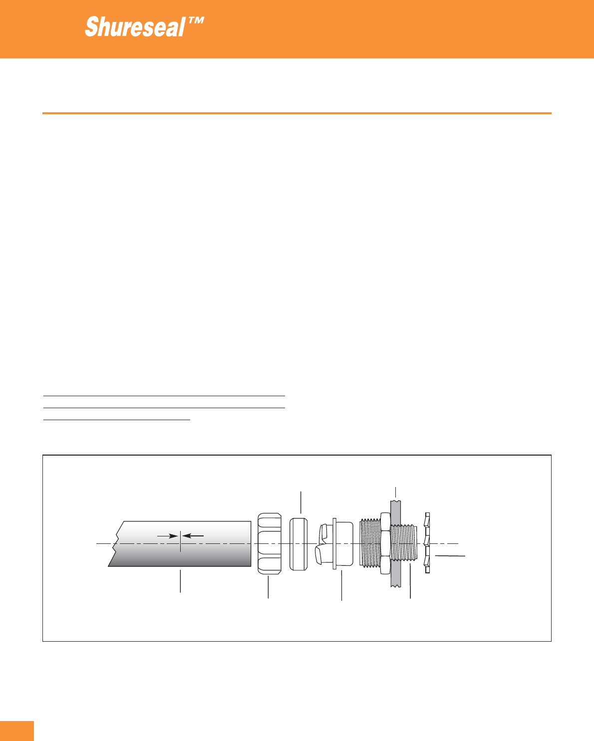
282
Thomas & Betts • www.tnb-europe.com
4.1
Prescriptions & specifications
Specifications
Shureseal™ fittings and conduits satisfy the following specifications:
• for heavy industrial applications in accordance with DIN 49012.
• according to IP67 rating
• according to DIN/VDE 0650, section, 2.1.1b
• according to BS731, part 1
• and have the necessary approvals
(UL/CSA and VDE)
Installation
Installation is simple. The fitting screws easily onto the conduit, with-
out the need for special tools. The fitting can be removed
and re-used again at any time. The fitting also performs excellently
against severe vibration. The conduit is not deformed by the fitting.
In tests, the fittings have been shown to be extremely secure and
guarantee a high level of security and reliability.
Material specifications
Shureseal™ Conduit
Gland nut
Housing
Threaded body
Sealing ring
Ground cone
Locknut
Length marking
Conduits: directions for use
Below are a few short extracts taken from the relevant prescriptions.
VDE 0113/12.73
Metal tubing, pipes and conduits must be used in accordance with
the prescribed safety standard.
Paragraph 10.3 1 states that all conduits must be designed to protect
against the expected demands made on the product. This is to say,
for example, that cable can only be fed through conduit if it is suit-
ably protected from liquids, dust (IP-Protection) and other foreign
substances.
Surfaces with which the laid conduits come into contact - such as
edges, threads etc. should not damage the insulation of the conduit.
Fittings: directions for use
Conduits and fitting assemblies must be installed in accordance with
VDE 0113.
It is not adequate just to feed the conduit into a housing. The con-
duit must be installed using a lock nut and fitting, which ensure a
good electrical connection between the conduit and housing. The
conduit must not reduce the protective capability of the housing.
In order to ensure the effective installation of the conduit, it is
important not only to use a suitable conduit but also to use the
appropriate type of fitting. (see IEC-204)
Material specifications table
This chart gives an indication of the capabilities of the Shureseal™
liquidtight flexible metallic conduits. It is extremely difficult to pro-
vide data on all possible combinations or conditions that can occur.
Material specifications
283
Thomas & Betts • www.tnb-europe.com
4.1
G = Good
L = Limited
P = Poor
T = No data available
likely to have minor effect
Chemical TBEF TBOR TBHC TBZH TBDL EFC TYPEA PGS
LTC
LTC-GY
OILS AND HYDROCARBONS
ASTM Oil No 1 T T G P T G – T
ASTM Oil No 2 T T G P L – – L
ASTM Oil No 3 T T G P T L L T
Diesel Oil T T T T T L L T
Lubricating Oil L L G L L G G L
Paraffin Oil G G T T G G – G
Petrol G G L T G – – G
Skydrol 500B T T G T T – P T
Transformer Oil T T T T T – – T
Vegetable Oils T T T T T – G T
ORGANIC SOLVENTS
Acetone P P L P P P P P
Benzene P P L P P P P P
Ethyl Alcohol P P L L P G L P
Ethylene Glycol L L G T L G G L
Eteon 12 T T G T T – – T
Methyl Alcohol P P G L P G L P
Methyl Ethyl Ketone T T L P T P P T
Toluene 100 % P P L L P P P P
Turpentine 100 % L L T L L L L L
White Spirit T T T L T – – T
ACIDS AND SALTS GIVING ACID SOLUTIONS
Acetic Acid 10 % G G G T G G G G
Acetic Acid 20% L L G T L – – L
Hydrochloric Acid 10 % – – – – – – G –
Hydrochloric Acid 20 % L L L P L G – L
Hydrochloric Acid 40 % – – – – – – L –
Lactic Acid (90%) T T T T T P – T
Oxalic Acid G G T T G G G G
Zinc Chloride G G G T G G G G
BASES AND SALTS GIVING BASIC SOLUTIONS
Aluminium Chloride (10%) G G G G G G G G
Sodium Hydroxide (20%) T T G G T G G T
Sodium Hydroxide (45%) T T L L T G G T
OTHERS
Ozone Gas G G T T G – – G
Sea Water G G G G G G G G
Therefore it is recommended that this information should be used as
a guideline and that the conduit should be tested in the intended
application by the user, to determine suitability. If you have specific
requirements, please contact Technical Support.

284
Thomas & Betts • www.tnb-europe.com
4.2
Fittings
Metal and plastic fittings
with positive sealing
against liquids and dust
285
Thomas & Betts • www.tnb-europe.com
4.2
CONDUIT & FITTINGS
4.1 FLEXIBLE CONDUITS 260
4.2 FITTINGS & ACCESSORIES 284
Selection guide 288
Shureseal™ liquidtight fittings for metallic conduits 290
Product description 290
Straight fittings 292
90° fittings 294
45° fittings 296
Stainless steel fitting 298
Chase fittings 300
Female hub and adaptor fitting 301
Shureseal™ liquidtight fittings for non-metallic conduits 302
Type TYPEA 302
Type EFC / LTC / LTC-GY 304
Shureseal™ accessories for liquidtight fittings 309
Sealing washers 309
Locknuts 310
Wire mesh adaptor 311
Replacement parts 312
Shureflex®fittings for ultra-flexible galvanised steel conduits 313
Type UGS - uncovered conduits 313
Type PGS - covered conduits 315
Shureflex®fittings for ultra-flexible nylon conduits 317
Straight fittings 318
90° fittings 319
45° fittings 320
T-splits 321
Shureflex®accessories for nylon conduits & fittings 322
Sealing washer 322
O-ring 323
Locknut 324
Mounting brackets 325
Rigid and intermediate metal conduit fittings 326
Metallic fittings for threadless conduits 326
Metallic couplings for threadless conduits 327
Plastic bushing 328
Other Thomas & Betts conduit and fittings 329
4.3 SHURESEAL™ CABLE GLANDS 330

286
Thomas & Betts • www.tnb-europe.com
4.2
Shureseal™
and Shureflex®
Fittings & Accessories
All our high-performance products are designed to deliver
excellent reliability as well as ease of installation in virtually
any application. Thomas & Betts offers two ranges of
fittings for it’s Shureseal™ and Shureflex®flexible conduits
Shureseal™ liquidtight fittings for metallic conduits
Thomas & Betts offers the largest and most technologically
advanced line of liquidtight fittings in the industry, including
connectors for highly-specialised applications such as power
and petrochemical plants, paper mills, robot manufacturers,
packaging equipment, machine tool building, and other OEM
and MRO applications. At Thomas & Betts, we integrate the
287
Thomas & Betts • www.tnb-europe.com
4.2
Metal and Plastic fittings
with positive sealing
against liquids and dust
latest manufacturing technologies with the highest quality ma-
terials available. So you can be assured of reliable, liquidtight
products that offer improved on-the-job performance and reduced
installation time and costs.
Shureseal™ liquidtight fittings for non-metallic conduits
This engineering breakthrough meets the demand for a tough,
reusable, non-metallic liquidtight fitting for use with TYPEA, EFC,
LTC conduits or flexible tubing.
The BULLET®non-metallic fitting provides a reliable liquidtight seal
that combines high pullout resistance and ease of installation.
Shureflex®fittings for galvanised steel conduits
Wide choice of fittings especially manufactured for Shureflex®
galvanised steel conduits
• Manufactured in nickel-plated brass for a professional quality
and finish
• Highly crush resistant with an excellent pull-off strength
Ideal for industrial and commercial applications where flexibility,
crush and vibration resistance are required
Offers an economic solution for the protection of cables for
industrial and commercial applications
Shureflex®fittings for nylon conduits
The Shureflex®Nylon conduit and fittings from Thomas & Betts
provide all the benefits of a Halogen free, flexible watertight
system of protection for electrical cables.
In particular, the high performance fitting, with its unique self-
locking mechanism, allows a quick and secure installation with a
watertight protection and an outstanding mechanical strength.
With four different grades of conduits and a wide range of fittings
and accessories available in black, this system is ideally suitable for
all types of applications in general wiring, industrial equipment,
machine tools and machinery, production equipment, control
equipment, robotics, automotive, transportation, railway.
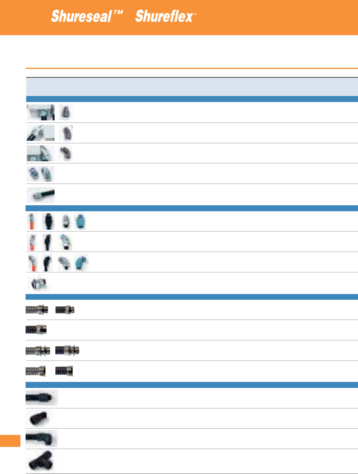
288
Thomas & Betts • www.tnb-europe.com
4.2
Selection guide
Fittings and accessories
Fitting style Conduit TB series TYPEA EFC LTC series
type
SHURESEAL™ FLEXIBLE METALLIC LIQUIDTIGHT CONDUITS
straight Flexible metallic liquidtight conduits X
45° angled Flexible metallic liquidtight conduits X
90° angled Flexible metallic liquidtight conduits X
chase Flexible metallic liquidtight conduits X
hub & adaptor Flexible metallic liquidtight conduits X
SHURESEAL™ FLEXIBLE NON-METALLIC LIQUIDTIGHT CONDUITS
straight Flexible non-metallic liquidtight conduits X X X
45° angled Flexible non-metallic liquidtight conduits X X X
90° angled Flexible non-metallic liquidtight conduits X X X
chase Flexible non-metallic liquidtight conduits X X
SHUREFLEX
®
FLEXIBLE METALLIC CONDUITS
straight male Flexible metallic conduits
straight female Flexible metallic conduits
swiveled Flexible metallic conduits
chase Flexible metallic conduits
SHUREFLEX
®
ULTRA-FLEXIBLE NYLON CONDUITS
straight Ultra-flexible nylon conduits
45° angled Ultra-flexible nylon conduits
90° angled Ultra-flexible nylon conduits,
T-split Ultra-flexible nylon conduits

289
Thomas & Betts • www.tnb-europe.com
4.2
UGS NY series ISO metric NPT Imperial PG UNEF Approvals Material IP rating Page
PGS thread thread thread thread thread
X X X X UL / CSA steel / IP67 292
stainless steel
X X X X UL / CSA steel / IP67 296
stainless steel
X X X X UL / CSA steel / IP67 294
stainless steel
UL / CSA steel IP67 300
X X X UL / CSA steel IP67 301
X X UL / CSA / meets steel / IP65 / IP66 from 302
coast guard cg293 thermoplastic to 307
X X UL / CSA steel / IP65 / IP66 from 302
thermoplastic to 307
X X UL / CSA / meets steel / IP65 / IP66 from 302
coast guard cg293 thermoplastic to 307
steel IP65 308
X X X brass IP40 / IP54 from 313
to 316
X X X brass IP40/IP54 from313
to 316
X X X brass IP40/IP54 from313
to 316
Xbrass IP40 / IP54 from 313
to 316
X X X UL Polyamide 6 IP66 / IP69K 318
X X X UL Polyamide 6 IP66 / IP69K 319
X X X UL Polyamide 6 IP66 / IP69K 320
XPolyamide 6 IP66 / IP69K 321
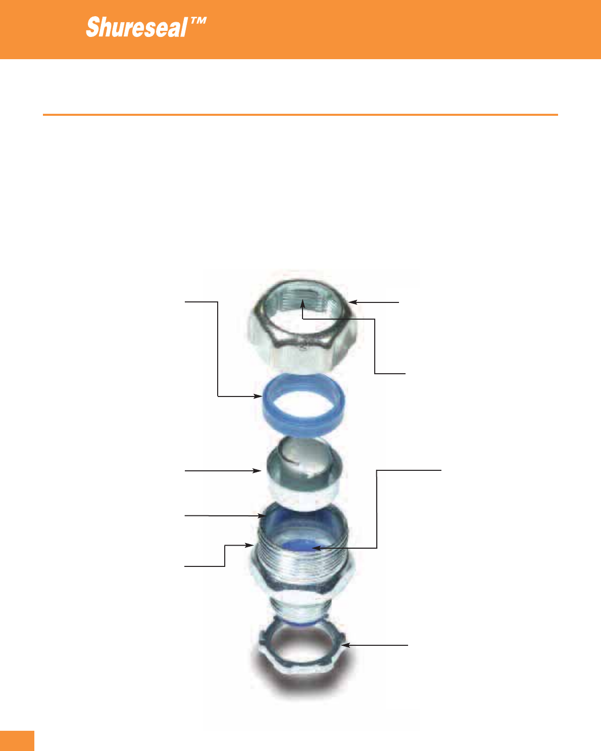
290
Thomas & Betts • www.tnb-europe.com
4.2
Product description
Liquidtight fittings for flexible metallic conduits
A standard fitting assembly is made of 4 pieces:
1. A screw body with a nylon throat on the connection side
2. The ground cone
3. The patented Nylon sealing ring
4. A gland nut
In addition, a locknut is supplied with the fittings with NPT thread.
Double Bevelled Sealing Ring
Unique sealing mechanism to prevent
backwards installation. Look for the
unique T&B Blue colour, ensuring the
highest quality liquidtight product
available.
Safe Edge™ Ground Cone
Provides superior bonding, stronger
pullout and easy threading into the
conduit core. The electrical continuity
is ensured while the rounded edge
protects the cable.
Double Plating for superior corrosion
protection. Zinc plating with clear
Chromate finish.
Precision Rolled Threads
provides smooth, easy installations
and is stronger than cut threads. The
body is drawn steel for exceptional
strength and quality.
Sure-Tight™ Gland Nuts deflects water
away from connector and prevents
“pooling” of moisture. Look for the
distinctive “Pumpkin” appearance
of the gland nut.
Self-Cleaning Threads inside the gland
nut keep dirt and grime out of
the threads as you tighten.
Heat Curled Insulator
curled inside the body provides excellent wire
protection and easier glide of the conductors
through and into the fitting. Also, the
heat-curled finish gives the insulator more
strength compared to “glue-in” versions. Look
for the distinctive blue insulator for your
assurance of T&B quality.
Case-Hardened Locknut with Teeth
provides superior strength and electrical
bonding and can be installed without a
wrench in the enclosure.
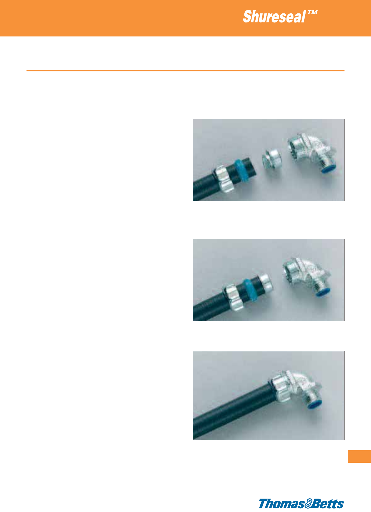
Product description
When correctly installed, the Shureseal™ fittings produce a positive
seal against oil, liquids, moisture and dust.
The main features of the assembly include:
• a high resistance to conduit pull-off and a great resistance to
vibration from machines
• an excellent earth continuity
• simplicity of installation: ability to install quickly by hand (or with
standard spanners or wrenches, but no special tools are needed)
• the fittings will not damage or distort the flexible conduit.
• the nylon throat bush makes it easier to pull wires through with-
out risk of damage.
• the fittings have a rugged construction and can be disconnected
and reused.
• available with N.P.T., Imperial, P.G. and metric (l.S.O.) threads
• excellent IP ratings
The patented ground cone design offers the following advantages:
• it compresses the metallic convolutions of the conduit, providing
a high quality ground contact with low impedance and a high
conduit pull-off resistance
• the single helical thread on the ground cone is easy to install with-
out cross threading
• it tolerates variations in conduit diameters and convolution pitch
• its rolled-over edge protects the conductors
The patented sealing ring design has the following exclusive features:
• it grips and seals the conduit without damaging the conduit jacket
• its symmetrical shape assures a foolproof assembly
• it ensures a positive seal against oils, liquids, moisture and dust
The range of fittings includes 5 different styles:
• straight version
• 45° version
• 90° version
• “Chase” = compact version for confined spaces, behind panels
and boxes
• “Female Hub” version, for connecting flexible conduit direct to
rigid conduit and flexible conduits
Approvals
• C.E.G.B. approved (UK)
• UL listed Liquidtight File No E 23018
• ISO threads per BS 4568
• PG threads per DIN 40430
• Canadian Standard Association: File No. 002884,
File No. LR 52391, File No. LR 82069
Liquidtight fittings for flexible metallic conduits
291
Thomas & Betts • www.tnb-europe.com
4.2
Easy assembly without the requirement of any special
tooling
1. Slide the gland nut and the sealing ring onto the conduit
2. Screw the ground cone into the conduit (between the convolu-
tions) as far as possible
3. Screw the body and the gland nut together and tighten
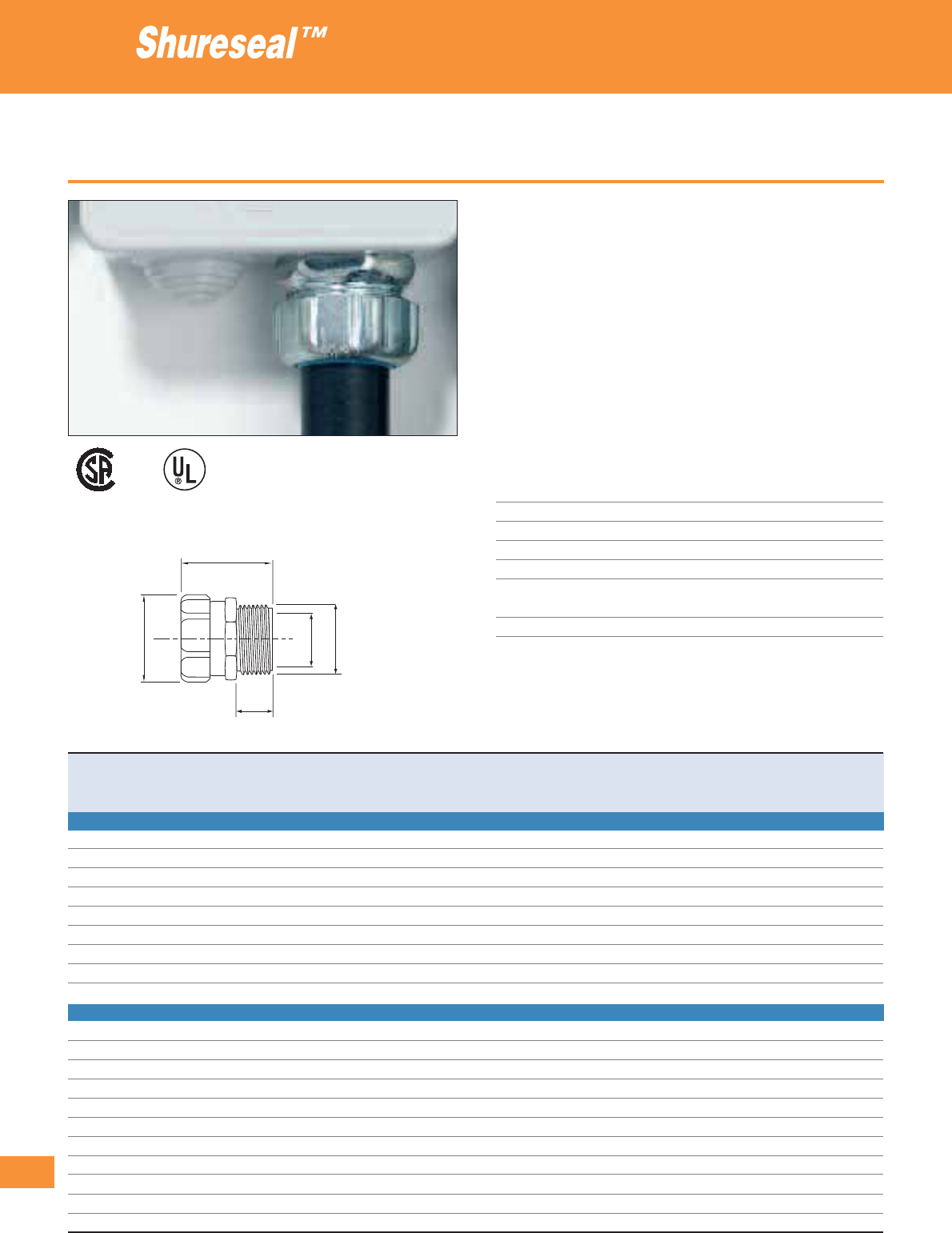
292
Thomas & Betts • www.tnb-europe.com
4.2
Straight fittings
• High-performance fittings for Shureseal™ Liquidtight conduits
• Safe and effective installation without any efforts
• The fitting is composed of 4 parts: the threaded body, the zinc
plated steel ground cone, the nylon sealing ring and the gland
nut ensuring an easy assembly without the need for specific tools
• The steel ground cone which is screwed into the conduit ensures
an excellent earthing continuity and pull-off strength, as well as
a very good resistance against vibrations
• Re-useable and independent replacement parts
• Special fittings (HT series) rated at 150°C are available for high
temperature applications - please contact your Sales Office for
product availability
Technical Information
Conduit type Shureseal™ flexible metallic conduit
Style Straight
Thread Metric (I.S.O.) and PG
IP rating IP67
Material Galvanised steel chromate finish
Inner sleeve and Polyamide
sealing ring
Colour Metallic
Liquidtight fittings for flexible metallic conduits
002884
E23018
B
A
C
DF
D=Min.innerø
Product Ref. For conduit size Thread Dimensions Weight Quantity
size A B C D F
[inch] [mm] [mm] [mm] [mm] [mm] [mm] [kg/100] [pieces]
STRAIGHT FITTING WITH METRIC (I.S.O.) THREAD
9306*
5
/
16
12 M16 22 36 12 10.0 16.0 5.1 25
9307
5
/
16
12 M20 22 36 12 10.0 20.0 5.1 25
9330*
1
/
4
10 M16 22 36 12 6.0 16.0 3.5 25
9331*
1
/
4
10 M20 22 36 12 6.0 20.0 3.5 25
9360
3
/
8
16 M16 29 40 16 11.0 16.0 6.3 25
9361
3
/
8
16 M20 29 40 16 11.0 20.0 6.3 25
9362
1
/
2
20 M20 35 42 16 14.5 20.0 8.1 25
9363
3
/
4
25 M25 42 45 16 20.0 25.0 12.6 25
9364 1 32 M32 47 54 15 25.0 32.0 23.0 5
STRAIGHT FITTING WITH PG THREAD
7329
1
/
4
10 PG 7 12 23 6 5.6 12.2 2.2 25
7330*
1
/
4
10 PG 9 21 36 12 6.0 15.2 3.5 25
7360*
5
/
16
12 PG 9 26 36 12 10.0 15.2 5.1 25
7361
3
/
8
16 PG 11 29 40 14 11.0 18.6 6.3 25
7362
3
/
8
16 PG 13.5 29 40 14 11.0 20.4 6.3 25
7363
1
/
2
20 PG 16 35 41 14 14.5 22.5 8.1 25
7364
3
/
4
25 PG 21 42 43 14 20.0 28.3 12.6 25
7365 1 32 PG 29 47 56 19 25.0 37.0 23.0 5
7366 1
1
/
4
40 PG 36 58 67 21 33.5 47.0 41.4 5
7367 1
1
/
2
50 PG 42 69 72 21 38.5 54.0 47.3 2
7368 2 63 PG 48 83 81 21 49.5 59.3 72.0 1
* The products with a * are not UL/CSA approved
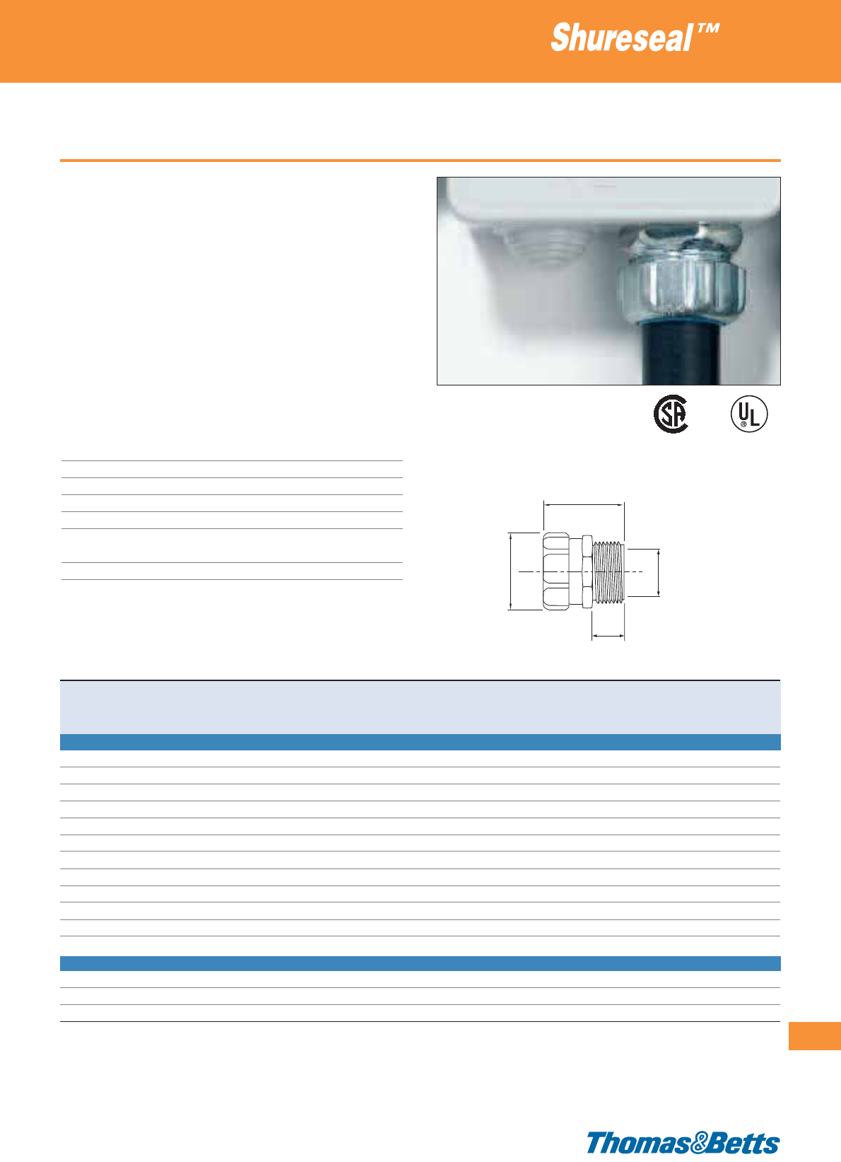
Straight fittings
• High-performance fittings for Shureseal™ Liquidtight conduits
• Safe and effective installation without any efforts
• The fitting is composed of 4 parts: the threaded body, the zinc
plated steel ground cone, the nylon sealing ring and the gland
nut ensuring an easy assembly without the need for specific tools
• A locknut is supplied with the fittings with NPT thread
• The steel ground cone which is screwed into the conduit ensures
an excellent earthing continuity and pull-off strength, as well as
a very good resistance against vibrations
• Re-useable and independent replacement parts
• Special fittings (HT series) rated at 150°C are available for high
temperature applications - please contact your Sales Office for
product availability
Technical Information
Conduit type Shureseal™ flexible metallic conduit
Style Straight
Thread NPT and Imperial
IP rating IP67
Material Galvanised steel chromate finish
Inner sleeve and Polyamide
sealing ring
Colour Metallic
Liquidtight fittings for flexible metallic conduits
293
Thomas & Betts • www.tnb-europe.com
4.2
002884
E23018
Product Ref. For conduit size Thread Dimensions Weight Quantity
size A B C D
[inch] [mm] [inch] [mm] [mm] [mm] [mm] [kg/100] [pieces]
STRAIGHT FITTING WITH NPT THREAD (SUPPLIED WITH LOCKNUT)
5229*
1
/
4
10
1
/
4
”21 35 12 6.0 3.5 25
5330*
5
/
16
12
3
/
8
” 25 35 12 10.0 5.1 25
5331
3
/
8
16
1
/
2
” 29 38 14 11.0 6.3 25
5332
1
/
2
20
1
/
2
” 35 40 14 14.5 8.1 25
5333
3
/
4
25
3
/
4
” 42 41 14 20.0 12.6 25
5334-TB 1 32 1” 48 52 19 25.0 23.0 10
5335 1
1
/
4
40 1
1
/
4
” 58 64 21 33.5 41.4 5
5336 1
1
/
2
50 1
1
/
2
” 69 68 21 38.5 47.3 2
5337 2 63 2” 83 78 22 49.5 72.0 5
5338 2
1
/
2
75 2
1
/
2
” 95 105 25 61.0 135.5 5
5339 3 90 3” 114 108 25 75.0 168.8 5
5340 4 115 4” 140 114 29 99.0 275.4 1
STRAIGHT FITTING WITH IMPERIAL THREAD
6365 1
1
/
4
40 1
1
/
2
” 58 64 21 33.5 41.4 5
6366 1
1
/
2
50 2” 69 68 21 38.5 47.3 2
6367 2 63 2
1
/
2
” 83 78 22 49.5 72.0 5
* The products with a * are not UL/CSA approved and are supplied without locknut
B
A
C
D
D=Min.innerø
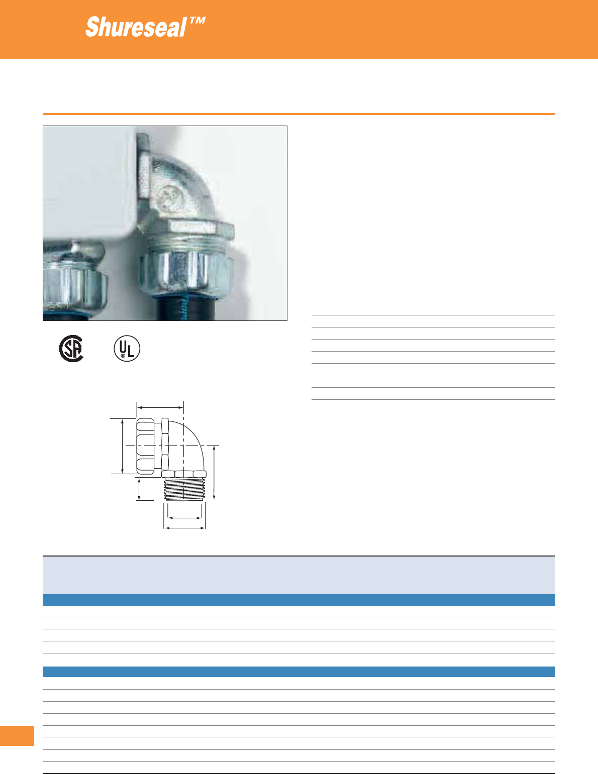
294
Thomas & Betts • www.tnb-europe.com
4.2
90° fittings
• High-performance fittings for Shureseal™ Liquidtight conduits
• Safe and effective installation without any efforts
• The fitting is composed of 4 parts: the threaded body, the zinc
plated steel ground cone, the nylon sealing ring and the gland
nut ensuring an easy assembly without the need for specific tools
• The steel ground cone which is screwed into the conduit ensures
an excellent earthing continuity and pull-off strength, as well as
a very good resistance against vibrations
• Re-useable and independent replacement parts
• Special fittings (HT series) rated at 150°C are available for high
temperature applications - please contact your Sales Office for
product availability
Technical Information
Conduit type Shureseal™ flexible metallic conduit
Style 90°
Thread Metric (I.S.O.) and PG
IP rating IP67
Material Galvanised steel chromate finish
Inner sleeve and Polyamide
sealing ring
Colour Metallic
Liquidtight fittings for flexible metallic conduits
A
B
E
C
D
F
D=Min.innerø
Product Ref. For conduit size Thread Dimensions Weight Quantity
size A B C D E F
[inch] [mm] [mm] [mm] [mm] [mm] [mm] [mm] [kg/100] [pieces]
90° FITTING WITH METRIC (I.S.O.) THREAD
9350
3
/
8
16 M16 28 35 16 10.1 34 16.0 12.6 25
9351
3
/
8
16 M20 28 35 16 10.1 34 20.0 12.6 25
9352-TB
1
/
2
20 M20 34 39 16 14.5 34 20.0 14.4 25
9353-TB
3
/
4
25 M25 42 43 16 20.0 38 25.0 20.2 10
9354-TB 1 32 M32 47 48 23 25.0 43 32.0 30.6 5
90° FITTING WITH PG THREAD
7351
3
/
8
16 PG 11 29 37 14 11.0 33 18.6 12.6 25
7352
3
/
8
16 PG 13.5 29 37 14 11.0 33 20.4 12.6 25
7353
1
/
2
20 PG 16 35 40 14 14.5 37 22.5 14.4 25
7354
3
/
4
25 PG 21 42 44 14 20.0 39 28.3 20.2 5
7355 1 32 PG 29 47 56 21 25.0 48 37.0 30.6 5
7356 1
1
/
4
40 PG 36 58 70 21 33.5 56 47.0 54.0 5
7357 1
1
/
2
50 PG 42 69 75 21 38.5 61 54.0 72.0 2
7358 2 63 PG 48 83 87 24 49.5 66 59.3 103.5 1
002884
E23018

90° fittings
• High-performance fittings for Shureseal™ Liquidtight conduits
• Safe and effective installation without any efforts
• The fitting is composed of 4 parts: the threaded body, the zinc
plated steel ground cone, the nylon sealing ring and the gland
nut ensuring an easy assembly without the need for specific tools
• A locknut is supplied with the fittings with NPT thread
• The steel ground cone which is screwed into the conduit ensures
an excellent earthing continuity and pull-off strength, as well as
a very good resistance against vibrations
• Re-useable and independent replacement parts
• Special fittings (HT series) rated at 150°C are available for high
temperature applications - please contact your Sales Office for
product availability
Technical Information
Conduit type Shureseal™ flexible metallic conduit
Style 90°
Thread NPT and Imperial
IP rating IP67
Material Galvanised steel chromate finish
Inner sleeve and Polyamide
sealing ring
Colour Metallic
Liquidtight fittings for flexible metallic conduits
295
Thomas & Betts • www.tnb-europe.com
4.2
A
B
E
C
DD=Min.innerø
002884
E23018
Product Ref. For conduit size Thread Dimensions Weight Quantity
size A B C D E
[inch] [mm] [inch] [mm] [mm] [mm] [mm] [mm] [kg/100] [pieces]
90° FITTING WITH NPT THREAD (SUPPLIED WITH LOCKNUT)
5351
3
/
8
16
1
/
2
” 29 35 14 11.0 33 12.6 25
5352
1
/
2
20
1
/
2
” 35 40 14 14.5 37 14.4 25
5353
3
/
4
25
3
/
4
” 42 45 14 20.0 39 20.2 10
5354 1 32 1” 48 56 19 25.0 48 30.6 5
5355 1
1
/
4
40 1
1
/
4
” 58 70 21 33.5 56 54.0 5
5356 1
1
/
2
50 1
1
/
2
” 69 75 21 38.5 61 72.0 5
5357 2 63 2” 83 287 22 49.5 66 103.5 2
5358 2
1
/
2
75 2
1
/
2
” 95 225 25 61.0 149 270.0 1
5359 3 90 3” 114 260 25 75.0 219 393.8 1
5360 4 115 4” 140 321 29 99.0 299 551.0 1
90° FITTING WITH IMPERIAL THREAD
6355 1
1
/
4
40 1
1
/
2”
58 64 21 33.5 56 54.0 5
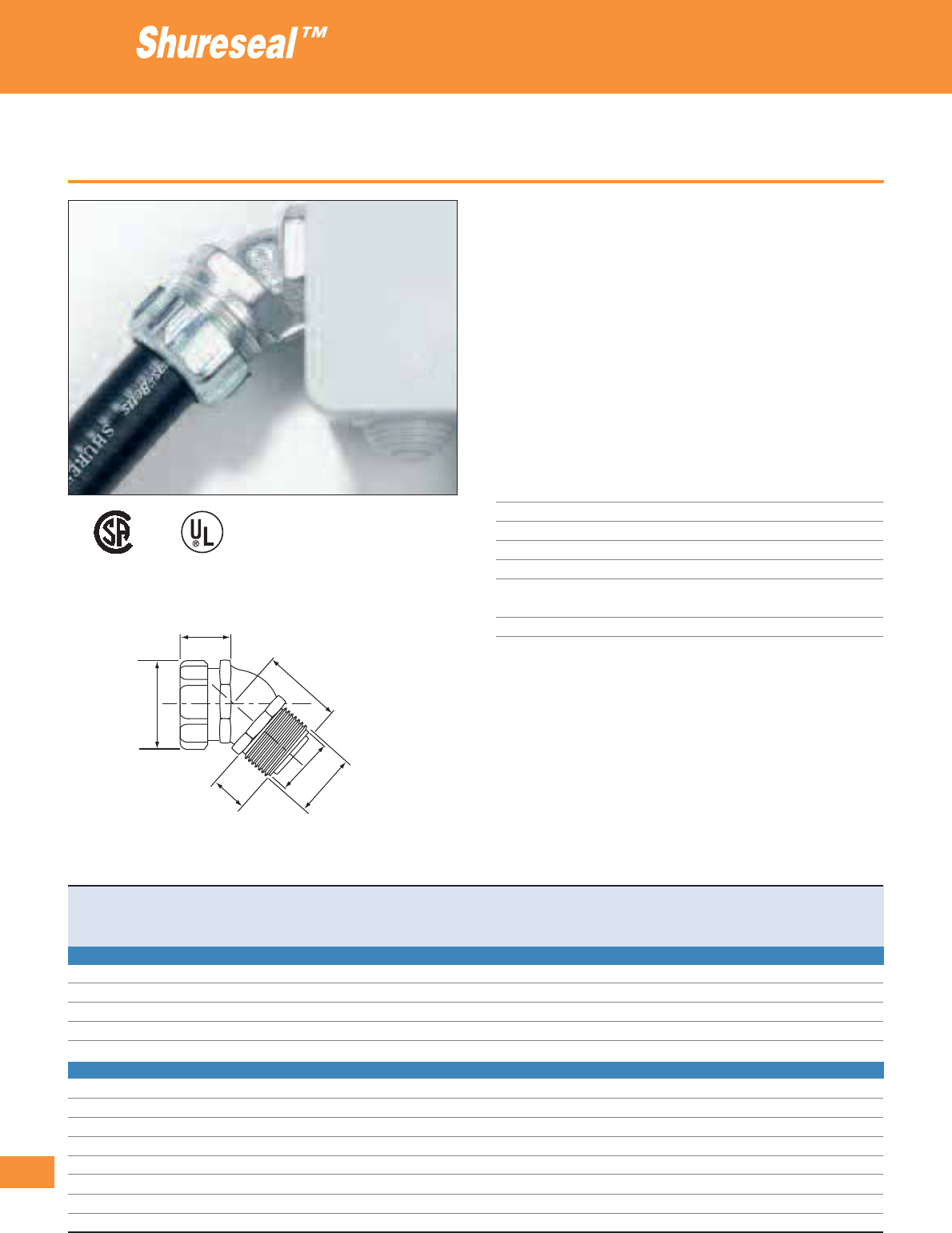
296
Thomas & Betts • www.tnb-europe.com
4.2
45° fittings
• High-performance fittings for Shureseal™ Liquidtight conduits
• Safe and effective installation without any efforts
• The fitting is composed of 4 parts: the threaded body, the zinc
plated steel ground cone, the nylon sealing ring and the gland
nut ensuring an easy assembly without the need for specific tools
• The steel ground cone which is screwed into the conduit ensures
an excellent earthing continuity and pull-off strength, as well as
a very good resistance against vibrations
• Re-useable and independent replacement parts
• Special fittings (HT series) rated at 150°C are available for high
temperature applications - please contact your Sales Office for
product availability
Technical Information
Conduit type Shureseal™ flexible metallic conduit
Style 45°
Thread Metric (I.S.O.) and PG
IP rating IP67
Material Galvanised steel chromate finish
Inner sleeve and Polyamide
sealing ring
Colour Metallic
Liquidtight fittings for flexible metallic conduits
B
A
E
C
D
F
D=Min.innerø
Product Ref. For conduit size Thread Dimensions Weight Quantity
size A B C D E F
[inch] [mm] [mm] [mm] [mm] [mm] [mm] [mm] [kg/100] [pieces]
45° FITTING WITH METRIC (I.S.O.) THREAD
9340
3
/
8
16 M16 28 35 16 10.1 34 16.0 12.6 25
9341
3
/
8
16 M20 28 35 16 10.1 34 20.0 12.6 25
9342
1
/
2
20 M20 34 39 16 14.5 34 20.0 14.4 25
9343-TB
3
/
4
25 M25 42 43 16 20.0 38 25.0 20.2 10
9344 1 32 M32 47 48 23 25.0 43 32.0 30.6 5
45° FITTING WITH PG THREAD
7341
3
/
8
16 PG 11 29 37 14 11.0 33 18.6 12.6 25
7342
3
/
8
16 PG 13.5 29 37 14 11.0 33 20.4 12.6 25
7343
1
/
2
20 PG 16 35 40 14 14.5 37 22.5 14.4 25
7344-TB
3
/
4
25 PG 21 42 44 14 20.0 39 28.3 20.2 5
7345 1 32 PG 29 47 56 21 25.0 48 37.0 30.6 5
7346 1
1
/
4
40 PG 36 58 70 21 33.5 56 47.0 54.0 5
7347 1
1
/
2
50 PG 42 69 75 21 38.5 61 54.0 72.0 2
7348-TB 2 63 PG 48 83 87 24 49.5 66 59.3 103.5 1
002884
E23018
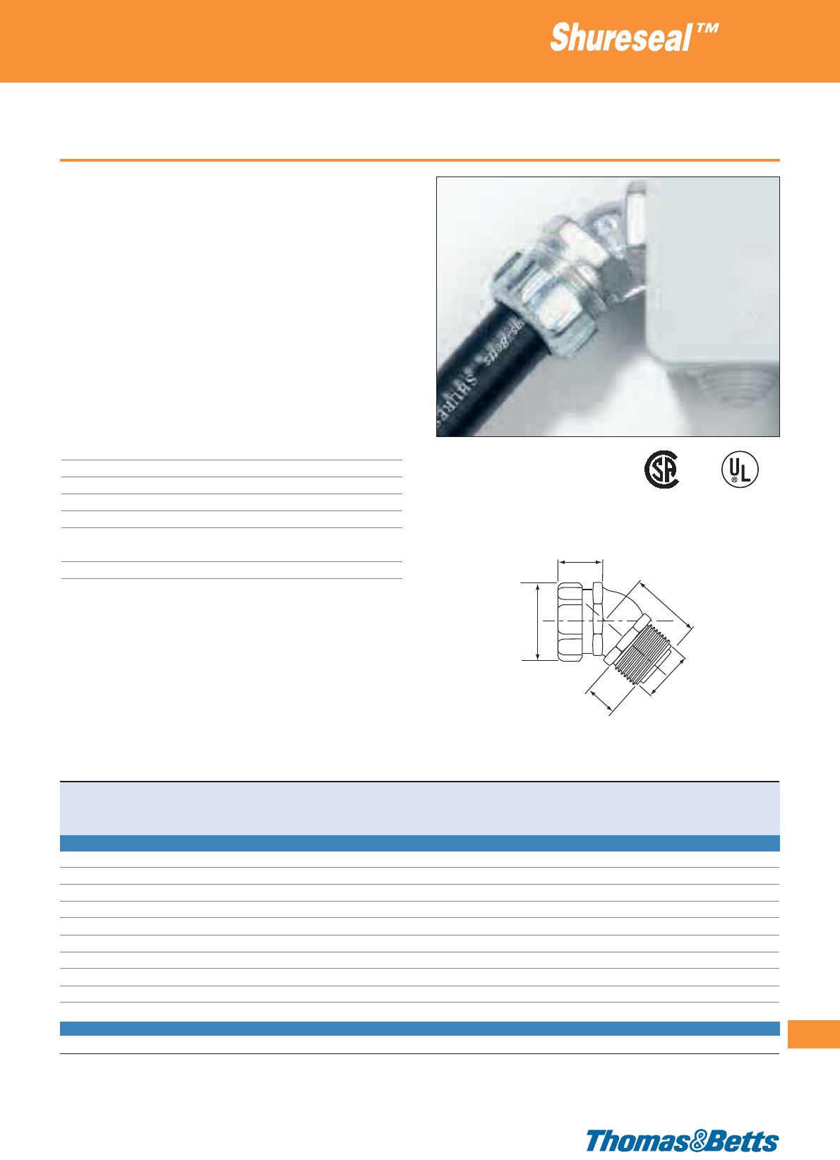
45° fittings
• High-performance fittings for Shureseal™ Liquidtight conduits
• Safe and effective installation without any efforts
• The fitting is composed of 4 parts: the threaded body, the zinc
plated steel ground cone, the nylon sealing ring and the gland
nut ensuring an easy assembly without the need for specific tools
• A locknut is supplied with the fittings with NPT thread
• The steel ground cone which is screwed into the conduit ensures
an excellent earthing continuity and pull-off strength, as well as
a very good resistance against vibrations
• Re-useable and independent replacement parts
• Special fittings (HT series) rated at 150°C are available for high
temperature applications - please contact your Sales Office for
product availability
Technical Information
Conduit type Shureseal™ flexible metallic conduit
Style 45°
Thread NPT and Imperial
IP rating IP67
Material Galvanised steel chromate finish
Inner sleeve and Polyamide
sealing ring
Colour Metallic
Liquidtight fittings for flexible metallic conduits
297
Thomas & Betts • www.tnb-europe.com
4.2
B
A
E
C
D
D=Min.innerø
002884
E23018
Product Ref. For conduit size Thread Dimensions Weight Quantity
size A B C D E
[inch] [mm] [inch] [mm] [mm] [mm] [mm] [mm] [kg/100] [pieces]
45° FITTING WITH NPT THREAD (SUPPLIED WITH LOCKNUT)
5341
3
/
8
16
1
/
2
” 29 35 14 11.0 33 12.6 25
5342
1
/
2
20
1
/
2
” 35 40 14 14.5 37 14.4 25
5343
3
/
4
25
3
/
4
” 42 45 14 20.0 39 20.2 10
5344 1 32 1” 48 56 19 25.0 48 30.6 5
5345 1
1
/
4
40 1
1
/
4
” 58 70 21 33.5 56 54.0 5
5346 1
1
/
2
50 1
1
/
2
” 69 75 21 38.5 61 72.0 2
5347 2 63 2” 83 287 22 49.5 66 103.5 1
5348* 2
1
/
2
75 2
1
/
2
” 95 225 25 61.0 149 270.0 1
5349* 3 90 3” 114 260 25 75.0 219 393.8 1
5350* 4 115 4” 140 321 29 99.0 299 551.0 1
45° FITTING WITH IMPERIAL THREAD
6346 1
1
/
2
50 2” 69 68 21 38.5 61 72.0 2
* The Product Ref. with a * are not UL/CSA approved
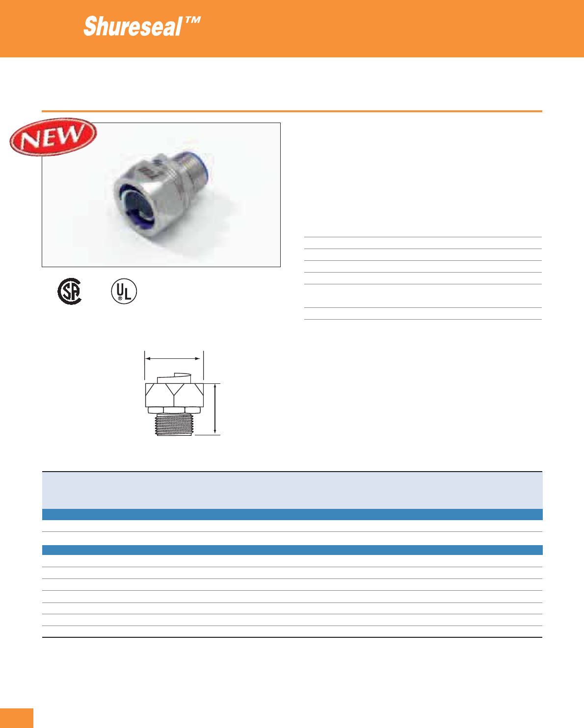
298
Thomas & Betts • www.tnb-europe.com
4.2
Straight stainless steel fittings
• Ideal for industrial MRO and OEM applications in food and be-
verage, pharmaceutical, petrochemical, wastewater, salt water,
and other corrosive environments
• 304 stainless steel body and gland-nut resists corrosion far better
than other metallic fittings
• Stronger, more UV-resistant than non metallic fittings
Technical Information
Conduit type Shureseal™ flexible metallic conduit
Style straight
Thread Metric (I.S.O.) and NPT
IP rating IP67
Material 304 stainless steel
Inner sleeve and Blue Polyamide
sealing ring
Colour Metallic
Liquidtight fittings for flexible metallic conduits
002884 E23018
Product Ref. For conduit size Thread Dimensions Weight Quantity
size A B
[inch] [mm] [mm] [mm] [kg/100] [pieces]
STRAIGHT FITTING WITH METRIC (I.S.O.) THREAD
9361SST
3
/
8
16 M20 34.5 27.0 5.2 25
9362SST
1
/
2
20 M20 34.5 30.0 6.2 25
STRAIGHT FITTING WITH NPT THREAD
5331SST-EU
3
/
8
16
3
/
8
34.5 25.9 5.2 25
5332SST-EU
1
/
2
20
1
/
2
34.5 30.0 6.2 25
5333SST-EU
3
/
4
25
3
/
4
35.3 34.8 8.9 25
5334SST-EU 1 32 1 39.7 45.0 17.9 5
5335SST 1
1
/
4
40 1
1
/
4
43.7 53.9 27.9 5
5336SST 1
1
/
2
50 1
1
/
2
51.3 63.0 43.8 5
5337SST 2 63 2 59.3 77.2 73.5 2
B
A
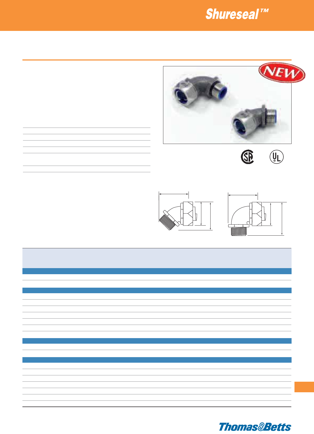
45° and 90° stainless steel fittings
• Ideal for industrial MRO and OEM applications in food and
beverage, pharmaceutical, petrochemical, wastewater, salt water,
and other corrosive environments
• 304 stainless steel body and gland-nut resists corrosion far better
than other metallic fittings
• Stronger, more UV-resistant than non metallic fittings
Technical Information
Conduit type Shureseal™ flexible metallic conduit
Style 45° and 90°
Thread Metric (I.S.O.) and NPT
IP rating IP67
Material 304 stainless steel
Inner sleeve and Blue Polyamide
sealing ring
Colour Metallic
Liquidtight fittings for flexible metallic conduits
299
Thomas & Betts • www.tnb-europe.com
4.2
002884 E23018
Product Ref. For conduit size Thread Dimensions Weight Quantity
size A B C
[inch] [mm] [mm] [mm] [mm] [kg/100] [pieces]
45° FITTING WITH METRIC (I.S.O.) THREAD
9341SST
3
/
8
16 M20 46.7 27.0 - 7.5 25
9342SST
1
/
2
20 M20 41.2 30.0 - 10.6 25
45° FITTING WITH NPT THREAD
5341SST-EU
3
/
8
16
3
/
8
46.7 25.9 36.3 7.5 25
5342SST-EU
1
/
2
20
1
/
2
41.2 30.0 51.8 10.6 25
5343SST-EU
3
/
4
25
3
/
4
59.0 34.8 49.0 15.7 10
5344SST-EU 1 32 1
72.6 45.0 60.2 26.5 5
5345SST 1
1
/
4
40 1
1
/
4
84.6 53.9 71.1 45.2 5
5346SST 1
1
/
2
50 1
1
/
2
100.1 63.0 86.1 69.1 2
5347SST 2 63 2 120.1
77.2 107.4 125.0 1
90° FITTING WITH METRIC (I.S.O.) THREAD
9351SST
3
/
8
16 M20 49.5 27.0 - 9.5 25
9352SST
1
/
2
20 M20 53.9 30.0 - 14.5 25
90° FITTING WITH NPT THREAD
5351SST-EU
3
/
8
16
3
/
8
49.5 25.9 46.7 9.5 25
5352SST-EU
1
/
2
20
1
/
2
53.9 30.0 52.6 14.5 25
5353SST-EU
3
/
4
25
3
/
4
62.7 34.8 62.0 22.0 10
5354SST-EU 1 32 1 75.7 45.0 73.7 31.7 5
5355SST 1
1
/
4
40 1
1
/
4
89.7 53.9 85.3 57.6 5
5356SST 1
1
/
2
50 1
1
/
2
105.7 63.0 98.6 82.9 2
5357SST 2 63 2 218.4 77.2 119.1 143.0 1
B
A
CB
A
C

300
Thomas & Betts • www.tnb-europe.com
4.2
“Chase” fittings, straight or right-angled
• High-performance fittings for Shureseal™ liquidtight conduits
• Special compact version (CHASE) for space-saving assembly,
thanks to the male nipple (supplied with the fitting) that can be
screwed into the female thread of the body
• Safe and effective installation without any efforts
• The fitting is composed of 6 parts: the threaded body, the steel
ground cone, the nylon sealing ring, the gland nut, the sealing
washer and a male nipple, ensuring an easy assembly without the
need for specific tools
• The steel ground cone which is screwed into the conduit ensures
an excellent earthing continuity and pull-off strength, as well as
a very good resistance against vibrations
• Re-useable and independent replacement parts
Technical Information
Conduit type Shureseal™ flexible metallic conduit
Style/thread Straight, 90° angled / NPT threads
IP rating IP67
Material Zinc plated steel
Insulation throat and Polyamide
sealing ring
Colour Metallic
Liquidtight fittings for flexible metallic conduits
Product Ref. For conduit Dimensions For wall thickness Installation hole Weight Quantity
size A B C (D) up to diameter
[inch] [mm] [mm] [mm] [mm] [mm] [mm] [kg/100] [pieces]
STRAIGHT CHASE FITTING (SUPPLIED WITH MALE NIPPLE AND SEALING WASHER)
5361
3
/
8
16 35 30 3.2 5 22.2 8.1 25
5362
1
/
2
20 35 36 4.7 5 22.2 9.9 25
5363
3
/
4
25 41 44 6.3 8 27.8 15.4 25
5364 1 32 52 50 6.3 10 33.3 29.0 10
5365 1
1
/
4
40 60 69 7.9 12 44.5 58.0 5
5366 1
1
/
2
50 69 75 9.5 13 50.8 68.0 2
5367 2 63 76 88 9.5 15 63.5 99.7 1
5368 2
1
/
2
75 100 107 11.1 15 76.2 199.4 1
5369 3 90 105 125 17.2 17 92.1 253.7 1
5370 4 115 111 155 19.0 19 117.5 407.7 1
90° CHASE FITTING (SUPPLIED WITH MALE NIPPLE AND SEALING WASHER)
5371
3
/
8
16 38 30 3.2 5 22.2 8.1 25
5372
1
/
2
20 37 36 4.7 5 22.2 9.9 25
5373
3
/
4
25 48 44 6.3 8 27.8 18.1 10
5374 1 32 57 50 6.3 10 33.3 30.8 5
E23018
002884
Nipple
Comparison
A A
B B
C
C
D
(wall thickness)
Chase
Sealing washer
Standard
C

Female hub and adaptor fittings
• Special type hub fitting with female (internal) thread for connecting
flexible conduits to rigid conduits or for connecting 2 flexible
conduits together (using male fittings)
• Special type adaptor fitting with female (internal) thread for
connecting flexible conduits to AN-MS connector shells (such as
MIL-C-5015 connectors and accessories)
• Safe and effective installation without any efforts
• The fitting is composed of 4 parts: the threaded body, the zinc
plated steel ground cone, the nylon sealing ring and the gland
nut ensuring an easy assembly without the need for specific tools
• The steel ground cone which is screwed into the conduit ensures
an excellent earthing continuity and pull-off strength, as well as
a very good resistance against vibrations
• Re-useable and independent replacement parts
Technical Information
Conduit type Shureseal™ flexible metallic conduits
Style Straight
Thread NPT, Metric (I.S.O.) and UNEF female threads
IP rating IP67
Material Zinc plated steel
Insulation throat and Polyamide
sealing ring
Colour Metallic
Liquidtight fittings for flexible metallic conduits
301
Thomas & Betts • www.tnb-europe.com
4.2
Female thread
E23018
002884
A
B
C
Product Ref. For conduit Inner AN-MS connector Dimensions Weight Quantity
size thread Shell size A B C
[inch] [mm] [mm] [mm] [mm] [kg/100] [pieces]
STRAIGHT FEMALE HUB FITTING WITH METRIC (I.S.O.) THREAD
9270
3
/
8
16 M16 – 28 40 15 7.0 25
9271
3
/
8
16 M20 – 30 40 15 7.2 25
9272
1
/
2
20 M20 – 34 43 15 10.0 25
9273
3
/
4
25 M25 – 42 45 15 14.5 25
9274 1 32 M32 – 47 54 15 19.0 5
STRAIGHT FEMALE HUB FITTING WITH NPT THREAD
5271
3
/
8
16
1
/
2
” – 25 40 15 7.2 25
5272
1
/
2
20
1
/
2
” – 32 43 15 10.0 25
5273
3
/
4
25
3
/
4
” – 38 44 15 14.5 25
5274 1 32 1” – 44 54 20 19.0 10
5275 1
1
/
4
40 1
1
/
4
” – 58 64 20 32.6 5
5276 1
1
/
2
50 1
1
/
2
” – 70 68 20 54.4 5
5277 2 63 2” – 88 78 25 72.5 5
STRAIGHT ADAPTORS FITTING WITH UNEF THREAD
LTA03810
3
/
8
16
5
/
8
” - 24 UNEF-2B 10SL, 12, 12S 25.4 11.9 – 6.8 25
LTA03814
3
/
8
16
3
/
4
” - 20 UNEF-2B 14, 14S 25.4 11.9 – 7.3 25
LTA05014
1
/
2
20
3
/
4
” - 20 UNEF-2B 14, 14S 31.8 23.8 – 8.7 25
LTA05016
1
/
2
20
7
/
8
” - 20 UNEF-2B 16, 16S 31.8 23.8 – 8.7 25
LTA05018
1
/
2
20 1” - 20 UNEF-2B 18 31.8 23.8 – 8.7 25
LTA07516
3
/
4
25
7
/
8
” - 20 UNEF-2B 16, 16S 38.1 27.0 – 13.6 25
LTA07518
3
/
4
25 1” - 20 UNEF-2B 18 38.1 27.0 – 13.6 25
LTA07520
3
/
4
25
13
/
16
” - 18 UNEF-2B 20, 22 38.1 27.0 – 13.6 25
LTA10020 1 32
13
/
16
” - 18 UNEF-2B 20, 22 43.7 44.5 – 21.0 10
LTA10024 1 32
17
/
16
” - 18 UNEF-2B 25, 28 43.7 44.5 – 21.0 10
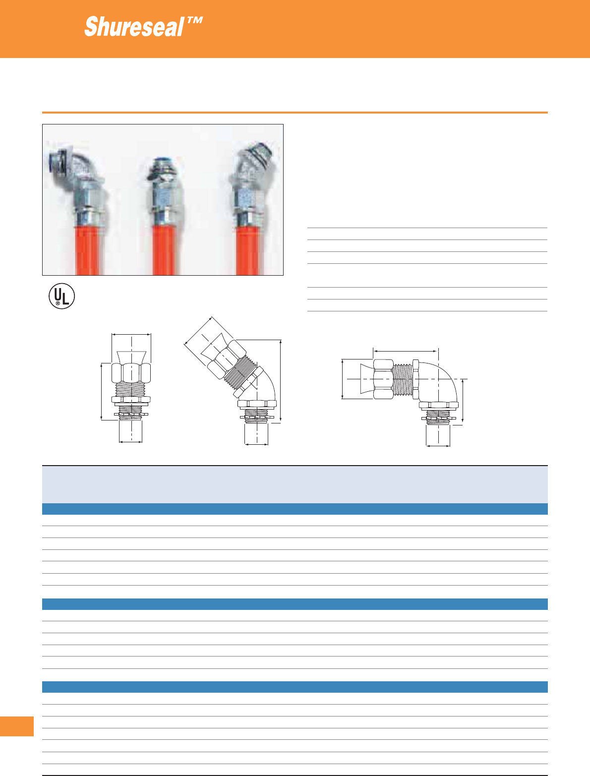
302
Thomas & Betts • www.tnb-europe.com
4.2
Type TYPEA - metallic fittings
• Easy installation
• Inner polyamide sleeve for protection of conductors
• Liquid- and dust-tight in accordance with IP66
• High mechanical stability (high retention)
• Supplied with locknut and sealing washer
Technical Information
Conduit type Shureseal™ conduit type TYPEA
Style/thread Straight, 45°, 90° / NPT thread
IP rating IP66
Material Galvanised steel, chromate finish
Connecting sleeve and Polyamide 6.6
internal insulation
Sealing washer Santoprene
Colour Metallic
Liquidtight fittings for non-metallic conduits
Product Ref. For conduit Thread Dimensions Weight Quantity
size size A B C D
[inch] [mm] [inch] [mm] [mm] [mm] [mm] [kg/100] [pieces]
STRAIGHT FITTING WITH NPT THREAD (SUPPLIED WITH LOCKNUT AND SEALING WASHER)
3720-TB*
3
/
8
16
1
/
2
29.4 51.0 12.0 – 8.2 25
3721-TB
1
/
2
20
1
/
2
34.9 54.0 16.0 – 9.1 25
3722-TB
3
/
4
25
3
/
4
41.3 57.2 21.0 – 13.6 25
3723 1 32 1 47.6 63.5 26.0 – 23.6 10
3724-TB 1
1
/
4
40 1
1
/
4
60.3 76.2 35.0 – 40.0 5
3725 1
1
/
2
50 1
1
/
2
69.9 85.7 41.0 – 59.0 2
3726 2 63 2 89.7 92.1 50.0 – 118.0 1
45° FITTING WITH NPT THREAD (SUPPLIED WITH LOCKNUT AND SEALING WASHER)
3730-TB*
3
/
8
16
1
/
2
29.4 51.6 12.0 – 5.4 25
3731-TB
1
/
2
20
1
/
2
34.9 65.1 16.0 – 8.2 25
3732
3
/
4
25
3
/
4
41.3 76.2 21.0 – 20.8 10
3733-TB 1 32 1 47.6 88.9 26.0 – 31.2 5
3734-TB 1
1
/
4
40 1
1
/
4
60.3 104.8 35.0 – 54.4 5
3735-TB 1
1
/
2
50 1
1
/
2
69.9 123.8 41.0 – 77.0 2
90° FITTING WITH NPT THREAD (SUPPLIED WITH LOCKNUT AND SEALING WASHER)
3740*
3
/
8
16
1
/
2
29.4 41.3 12.0 33.3 5.0 25
3741
1
/
2
20
1
/
2
34.9 44.5 16.0 35.7 7.7 25
3742
3
/
4
25
3
/
4
41.3 57.2 21.0 39.7 22.6 10
3743-TB 1 32 1 47.6 65.1 26.0 47.6 30.7 5
3744-TB 1
1
/
4
40 1
1
/
4
60.3 82.6 35.0 57.2 54.4 5
3745 1
1
/
2
50 1
1
/
2
69.9 88.9 41.0 60.3 77.0 2
3746-TB 2 63 2 89.7 104.8 53.2 73.0 145.0 1
* The Product Ref. with a * are not UL approved
E23018
A
A
A
B
B
B
CC
C
D
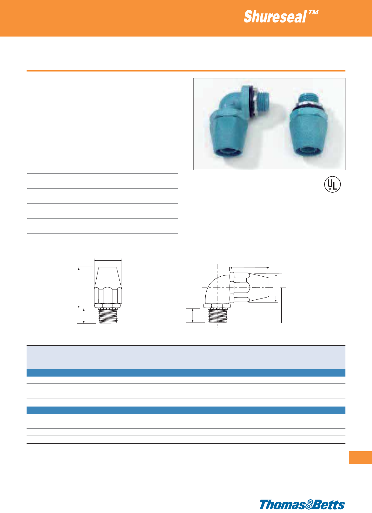
Type TYPEA - plastic fittings
• Easy installation
• High strength, chemical resistant, non-burning, non dripping
thermoplastic construction
• Smooth insulated body throughout for maximum dielectric
strength
• Ideal for corrosion resistant applications
• Liquid- and dust-tight in accordance with IP66
• Serrated design provides high mechanical pullout strength
• Supplied with steel locknut and sealing O-ring
Technical Information
Conduit type Shureseal™ conduit type TYPEA
Style Straight, 90°
Thread NPT
IP rating IP66
Material Thermoplastic
Gland nut Thermoplastic
O-Ring Neoprene
Locknut Steel, case hardened and zinc plated
Colour Blue
Flammability rating UL 94 V-0
Liquidtight fittings for non-metallic conduits
303
Thomas & Betts • www.tnb-europe.com
4.2
E23018
Product Ref. For conduit Thread Dimensions Quantity
size size A B C D
[inch] [mm] [inch] [mm] [mm] [mm] [mm] [pieces]
STRAIGHT PLASTIC FITTING WITH NPT THREAD (SUPPLIED WITH LOCKNUT AND SEALING ‘O’ RING)
6302
1
/
2
20
1
/
2
37.6 57.9 14.5 – 20
6303
3
/
4
25
3
/
4
44.7 62.5 19.1 – 10
6304 1 32 1 53.3 67.6 24.4 – 5
6305 1
1
/
4
40 1
1
/
4
67.8 78.5 32.0 – 5
90° PLASTIC FITTING WITH NPT THREAD (SUPPLIED WITH LOCKNUT AND SEALING ‘O’ RING)
6322
1
/
2
20
1
/
2
37.6 39.6 14.5 39.9 10
6323
3
/
4
25
3
/
4
44.7 44.2 19.1 43.4 10
6324 1 32 1 53.3 45.2 24.4 50.8 5
6325 1
1
/
4
40 1
1
/
4
67.8 54.1 32.0 61.2 5
MEETS
COAST
GUARD
CG293
A
B
B
C
C
D
A
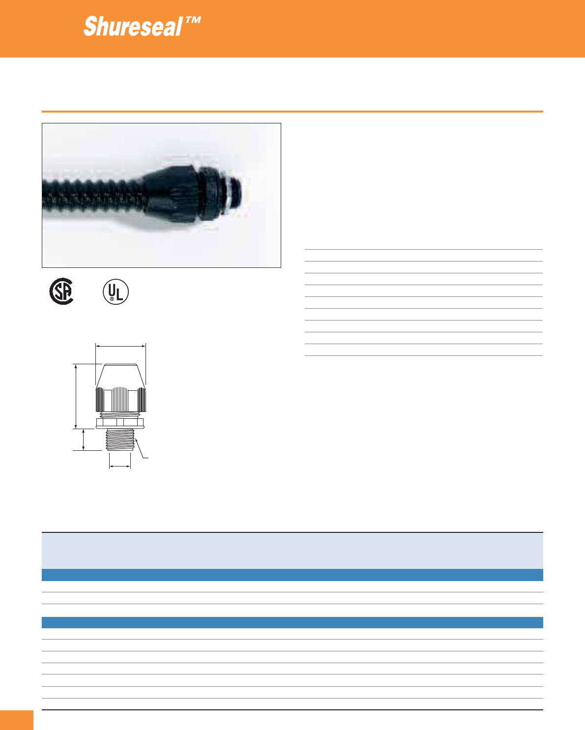
304
Thomas & Betts • www.tnb-europe.com
4.2
Type EFC / LTC / LTC-GY - plastic Bullet fittings
• Liquid-tight, dust-tight and oil-resistant
• Thomas & Betts patented quick connecting feature designed to
prevent unlocking
• The spiral-shaped EFC conduit coil locks into fitting
• No loose pieces - secure against vibration
• Supplied with sealing washer O-ring
• Fittings with NPT threads are supplied with locknut
Technical Information
Conduit type Shureseal™ conduit type EFC / LTC / LTC-GY
Style Straight
Thread NPT and Metric (I.S.O.)
IP rating IP65
Material UV-resistant thermoplastic
Locknut Zinc plated steel
O-ring Nitryl
Colour Black
Temperature range -45°C to +105°C
Flammability rating Self-extinguishing according to UL 94 V-2
Liquidtight fittings for non-metallic conduits
E23018
LR52391
D
E
Thread
C
A
F*
* Variable dimensions
Product Ref. For conduit Thread size Dimensions D Min. throat F* Weight Quantity
size E A C diameter Approx.
[inch] [mm] [mm] [mm] [mm] [mm] [kg/100] [pieces]
STRAIGHT FITTING WITH METRIC (I.S.O.) THREAD
LT38PISO20
3
/
8
16 M20 14.5 34.4 10.6 40.5 3.9 20
LT50PISO20
1
/
2
20 M20 14.5 36.8 14.0 41.6 4.1 20
LT75PISO25
3
/
4
25 M25 14.8 44.2 18.8 44.6 6.3 10
STRAIGHT FITTING WITH NPT THREAD (SUPPLIED WITH LOCKNUT)
LT38P
3
/
8
16
1
/
2
” 14.5 34.4 10.6 40.5 3.9 20
LT50P
1
/
2
20
1
/
2
” 14.5 36.8 14.0 41.6 4.1 20
LT75P
3
/
4
25
3
/
4
” 14.8 44.2 18.8 44.6 6.3 10
LT100P 1 32 1” 18.4 52.5 23.9 48.8 9.9 5
LT125P 1
1
/
4
40 1
1
/
4
” 19.1 63.4 31.9 55.0 15.2 5
LT150P 1
1
/
2
50 1
1
/
2
” 19.5 70.7 36.9 59.8 21.3 2
LT200P 2 63 2” 20.2 85.4 47.8 66.2 34.0 1
* Dimensions F are after assembly (approx.)
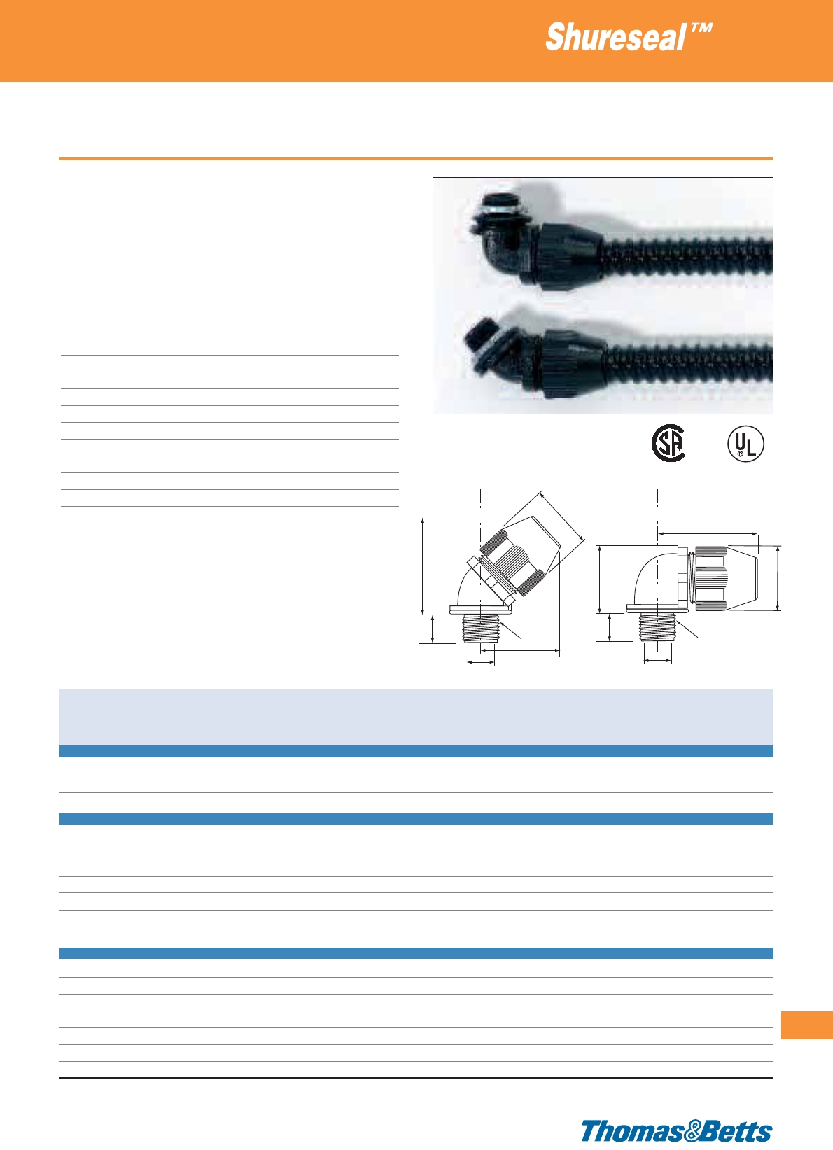
Type EFC / LTC / LTC-GY - plastic Bullet fittings
• Liquid-tight, dust-tight and oil-resistant
• Thomas & Betts patented quick connecting feature designed to
prevent unlocking
• The spiral-shaped EFC conduit coil locks into fitting
• No loose pieces - secure against vibration
• Supplied with sealing washer O-ring
• Fittings with NPT threads are supplied with locknut
Technical Information
Conduit type Shureseal™ conduit type EFC / LTC / LTC-GY
Style 45°, 90°
Thread NPT and Metric (I.S.O.)
IP rating IP65
Material UV-resistant thermoplastic
Locknut Zinc plated steel
O-ring Nitryl
Colour Black
Temperature range -45°C to +105°C
Flammability rating Self-extinguishing according to UL 94 V-2
Liquidtight fittings for non-metallic conduits
305
Thomas & Betts • www.tnb-europe.com
4.2
G*
B
A
D
E
Thread
G
*
E
Thread
C
D
C
A
F*
Product Ref. For conduit Thread size Dimensions D Min. throat F* G* Weight Quantity
size E A B C diameter Approx. Approx.
[inch] [mm] [mm] [mm] [mm] [mm] [mm] [mm] [kg/100] [pieces]
90° FITTING WITH METRIC (I.S.O.) THREAD
LT938PISO20
3
/
8
16 M20 14.5 35.0 34.4 10.6 – 47.8 4.9 20
LT950PISO20
1
/
2
20 M20 14.5 37.8 36.8 14.0 – 50.4 4.9 20
LT975PISO25
3
/
4
25 M25 14.8 45.5 44.2 18.8 – 56.0 7.8 10
90° FITTING WITH NPT THREAD (SUPPLIED WITH LOCKNUT)
LT938P
3
/
8
16
1
/
2
” 14.5 35.0 34.4 10.6 – 47.8 4.9 10
LT950P
1
/
2
20
1
/
2
” 14.5 37.8 36.8 14.0 – 50.4 4.9 10
LT975P
3
/
4
25
3
/
4
” 14.8 45.5 44.2 18.8 – 56.2 7.8 10
LT9100P 1 32 1” 18.4 53.4 44.2 23.9 – 63.7 12.6 5
LT9125P 1
1
/
4
40 1
1
/
4
” 19.1 65.1 52.5 31.9 – 72.5 21.3 2
LT9150P 1
1
/
2
50 1
1
/
2
” 19.5 72.5 63.4 36.9 – 79.9 36.3 2
LT9200P 2 63 2” 20.2 87.2 70.7 47.8 – 93.3 40.8 1
45° FITTING WITH NPT THREAD (SUPPLIED WTH LOCKNUT)
LT438P
3
/
8
16
1
/
2
” 14.5 – 34.4 10.6 39.0 35.1 4.8 20
LT450P
1
/
2
20
1
/
2
” 14.5 – 36.8 14.0 40.4 37.8 5.0 20
LT475P
3
/
4
25
3
/
4
” 14.8 – 44.2 18.8 46.3 45.5 7.4 10
LT4100P 1 32 1” 18.4 – 52.5 23.9 51.7 53.4 11.7 5
LT4125P 1
1
/
4
40 1
1
/
4
” 19.0 – 43.4 31.9 60.6 65.1 20.9 5
LT4150P 1
1
/
2
50 1
1
/
2
” 19.5 – 70.7 36.9 66.1 72.5 24.7 2
LT4200P 2 63 2” 20.2 – 85.4 47.8 77.5 87.2 38.1 1
* Dimensions F and G are after assembly (approx.)
E23018
LR52391
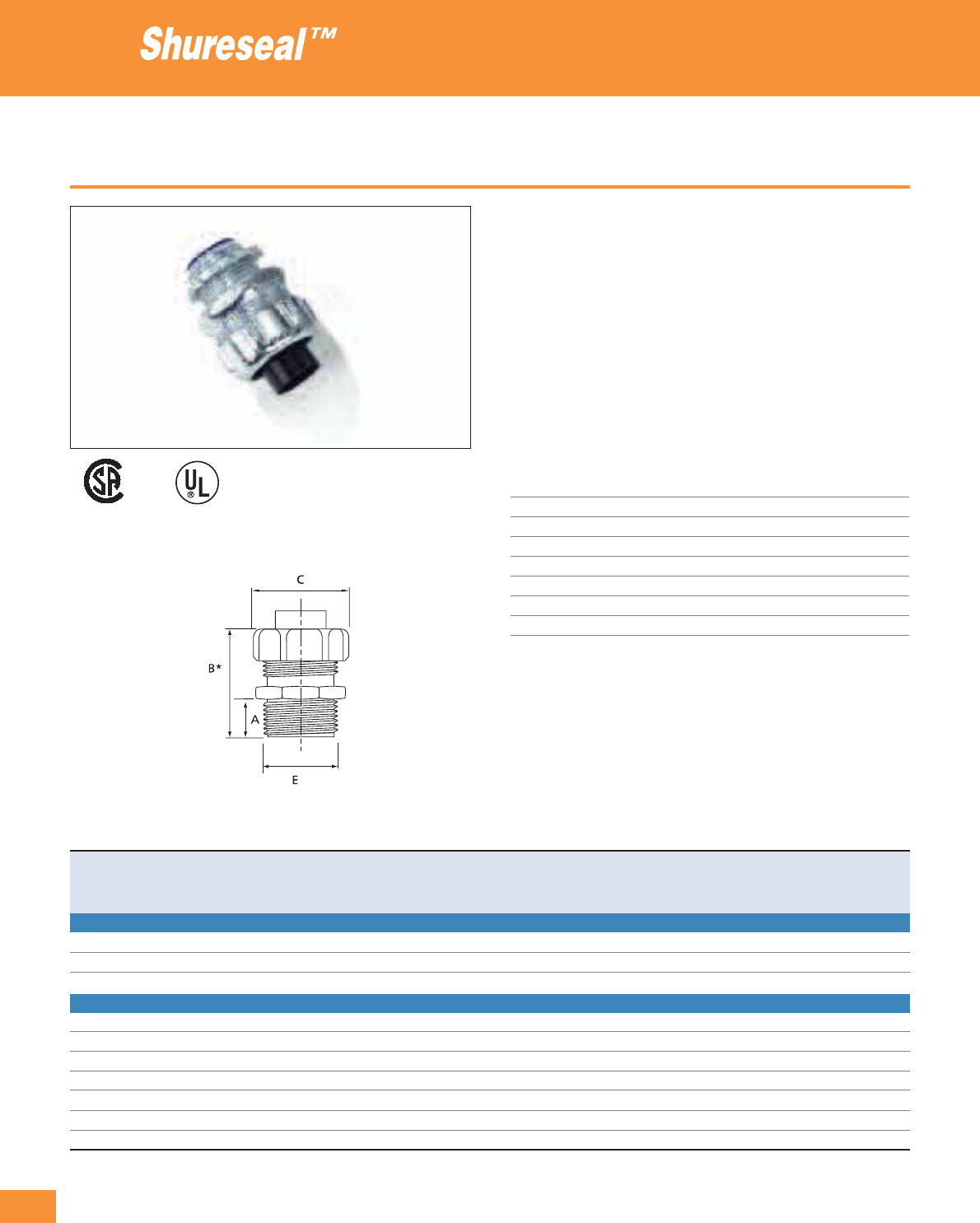
306
Thomas & Betts • www.tnb-europe.com
4.2
Type EFC / LTC / LTC-GY - metallic Bullet fittings
• Robust construction, ideal for demanding applications like in the
railway industry (can be used with other kind of conduits and
hoses commonly used in the railway industry, such as textile
inserted rubber hoses,...)
• Liquid-tight, dust-tight and oil-resistant
• Thomas & Betts patented quick connecting feature designed to
prevent unlocking
• Separate rotating attachment for easy fitting of conduit
• Spiral-shaped EFC conduit coil locks into fitting
• No loose pieces - secure against vibration
• Delivered with locknut
Technical Information
Conduit type Shureseal™ conduit type EFC / LTC / LTC-GY
Style Straight
Thread NPT and Metric (I.S.O.)
IP rating IP65
Material Zinc plated steel
Gland nut Zinc steel
Insert Nylon
Colour Metallic
Liquidtight fittings for non-metallic conduits
E23018
LR52391
Product Ref. For conduit Thread size Dimensions Weight Quantity
size E A B* C
[inch] [mm] [mm] [mm] [mm] [kg/100] [pieces]
STRAIGHT FITTING WITH METRIC (I.S.O) THREAD
LT38M-ISO20
3
/
8
16 M20 14.3 38.1 29.4 5.8 25
LT50M-ISO20
1
/
2
20 M20 14.3 39.7 34.9 7.7 25
LT75M-ISO25
3
/
4
25 M25 15.9 41.2 42.1 10.9 25
STRAIGHT FITTING WITH NPT THREAD
LT38M
3
/
8
16
3
/
8
” 14.3 38.1 29.4 5.8 25
LT50M
1
/
2
20
1
/
2
” 14.3 39.7 34.9 7.7 25
LT75M
3
/
4
25
3
/
4
” 15.9 41.2 42.1 10.9 25
LT100M 1 32 1” 19.0 52.4 47.6 16.1 10
LT125M 1
1
/
4
40 1
1
/
4
” 20.6 63.5 60.3 28.9 5
LT150M 1
1
/
2
50 1
1
/
2
” 20.6 68.2 69.8 46.7 2
LT200M 2 63 2” 20.6 77.8 88.1 69.9 1
* Dimensions shown with a (*) are after assembly (approx.)
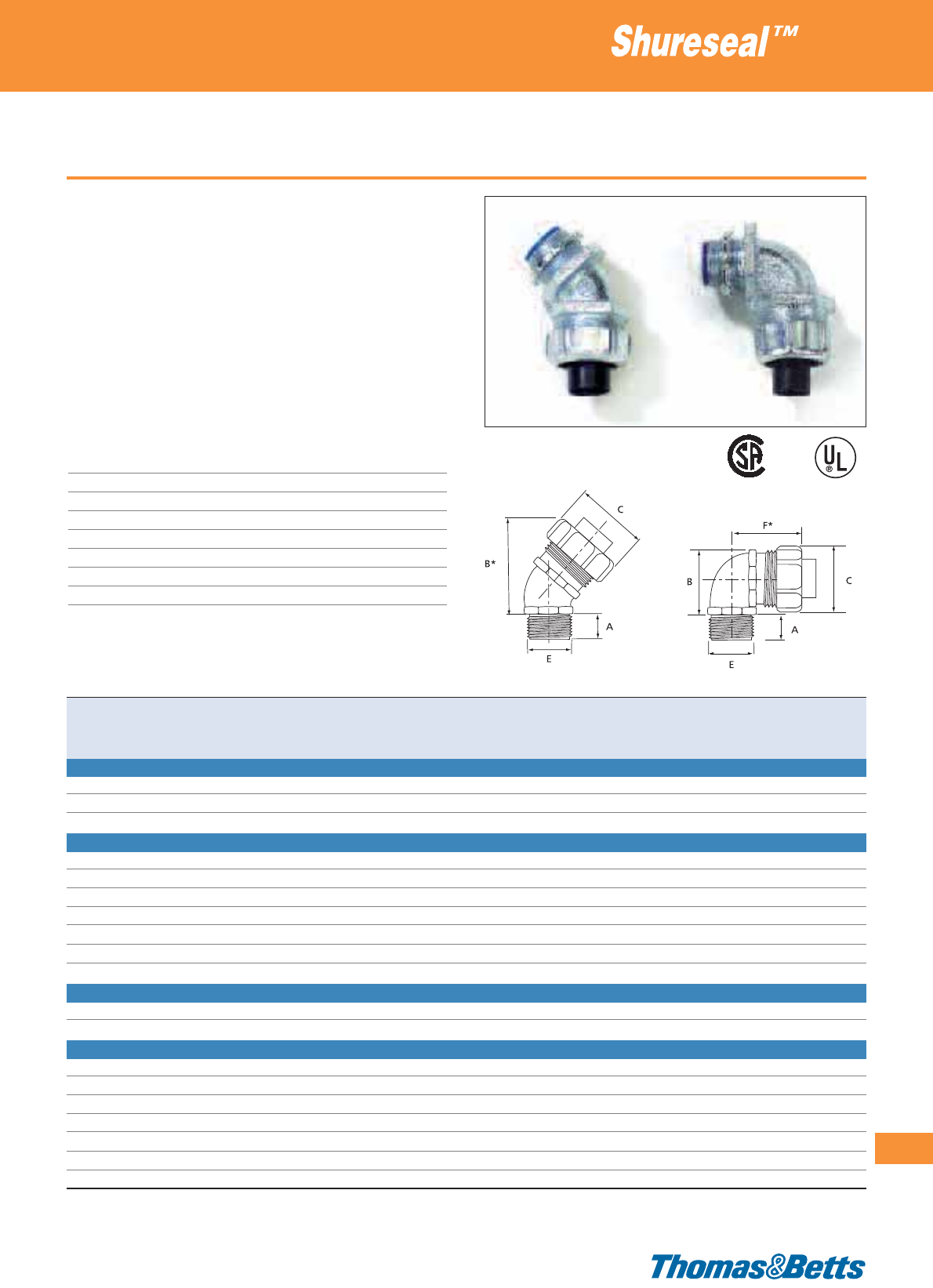
Type EFC / LTC / LTC-GY - metallic Bullet fittings
• Robust construction, ideal for demanding applications like in the
railway industry (can be used with other kind of conduits and
hoses commonly used in the railway industry, such as textile
inserted rubber hoses,...)
• Liquid-tight, dust-tight and oil-resistant
• Thomas & Betts patented quick connecting feature designed to
prevent unlocking
• Separate rotating attachment for easy fitting of conduit
• Spiral-shaped EFC conduit coil locks into fitting
• No loose pieces - secure against vibration
• Delivered with locknut
Technical Information
Conduit type Shureseal™ conduit type EFC / LTC / LTC-GY
Style 45°, 90°
Thread NPT and Metric (I.S.O.)
IP rating IP65
Material Zinc plated steel
Gland nut Zinc steel
Insert Nylon
Colour Metallic
Liquidtight fittings for non-metallic conduits
307
Thomas & Betts • www.tnb-europe.com
4.2
Product Ref. For conduit Thread size Dimensions Weight Quantity
size E A B C F*
[inch] [mm] [mm] [mm] [mm] [mm] [kg/100] [pieces]
90° FITTING WITH METRIC (I.S.O) THREAD
LT938M-ISO20
3
/
8
16 M20 15.9 33.3 29.4 34.9 9.4 25
LT950M-ISO20
1
/
2
20 M20 15.9 36.5 34.9 39.7 13.2 25
LT975M-ISO25
3
/
4
25 M25 15.9 44.4 42.1 44.4 18.1 25
90° FITTING WITH NPT THREAD
LT938M
3
/
8
16
3
/
8
” 15.9 33.3 29.4 34.9 9.4 25
LT950M
1
/
2
20
1
/
2
” 15.9 36.5 34.9 39.7 13.2 25
LT975M
3
/
4
25
3
/
4
” 15.9 44.4 42.1 44.4 18.1 25
LT9100M 1 32 1” 20.6 49.2 47.6 55.5 30.2 10
LT9125M 1
1
/
4
40 1
1
/
4
” 20.6 63.5 60.3 69.8 55.7 5
LT9150M 1
1
/
2
50 1
1
/
2
” 20.6 71.4 69.8 74.6 76.4 2
LT9200M 2 63 2” 22.2 88.9 88.1 87.3 116.6 1
45° FITTING WITH METRIC (I.S.O) THREAD
LT438M-ISO20
3
/
8
16 M20 14.3 49.8* 29.4 – 7.7 25
LT450M-ISO20
1
/
2
20 M20 14.3 47.6* 34.9 – 14.2 25
45° FITTING WITH NPT THREAD
LT438M
3
/
8
16
3
/
8
” 14.3 49.8* 29.4 – 7.7 25
LT450M
1
/
2
20
1
/
2
” 14.3 47.6* 34.9 – 14.2 25
LT475M
3
/
4
25
3
/
4
” 14.3 54.0* 42.1 – 18.6 10
LT4100M 1 32 1” 20.6 57.1* 47.6 – 25.5 5
LT4125M 1
1
/
4
40 1
1
/
4
” 20.6 69.8* 60.3 – 49.6 5
LT4150M 1
1
/
2
50 1
1
/
2
” 20.6 69.8* 69.8 – 68.0 2
LT4200M 2 63 2” 22.2 98.4* 88.1 – 99.8 1
* Dimensions shown with a (*) are after assembly (approx.)
E23018
LR52391
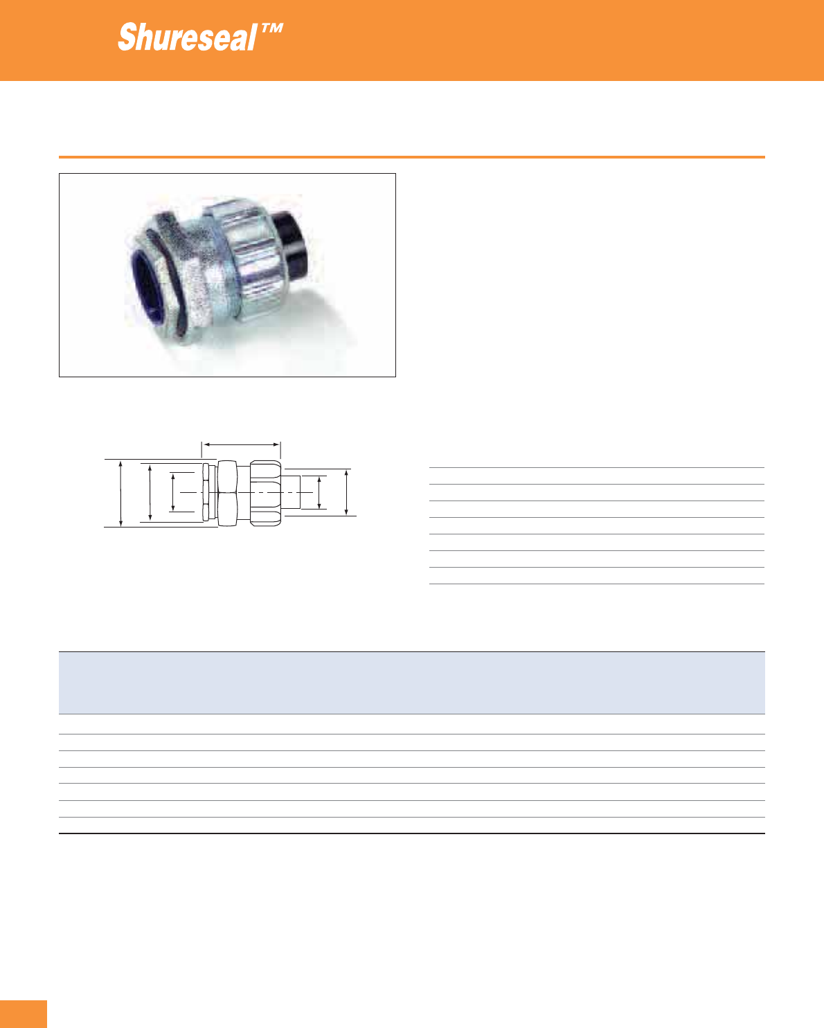
308
Thomas & Betts • www.tnb-europe.com
4.2
Type EFC / LTC / LTC-GY - metallic Bullet, chase fitting
• Metallic fitting, designed for type - EFC / LTC / LTC-GY flexible
plastic conduit
• Special version (Chase) for space saving assembly, thanks to the
male nipple that can be screwed into the female thread of the
body
• Liquid-tight, dust-tight and oil-resistant
• Robust construction, ideal for demanding applications like in the
railway industry (can be used with other kind of conduits and
hoses commonly used in the railway industry, such as textile
inserted rubber hoses,...)
• Spiral-shaped EFC conduit coil locks into fitting
• The fitting is composed of 5 components: nipple with insulation
throat, O-ring, body, insert and gland nut (Product Ref. LT6275MI
also includes an additional sleeve)
Technical Information
Conduit type Shureseal™ conduit type EFC / LTC / LTC-GY
Style Straight
IP rating IP65
Material Zinc plated steel
Gland nut Zinc plated steel
Insert Nylon
O-ring Neoprene
Colour Metallic
Liquidtight fittings for non-metallic conduits
ABC F
D
Product Ref. For conduit Dimensions
size øA* B C D øE* øF*
across flats across flats approx.
[inch] [mm] [mm] [mm] [mm] [mm] [mm] [mm]
LT638MI
3
/
8
16 14.5 24 30 30 12.4 18.4
LT650MI
1
/
2
20 14.5 24 30 30 15.4 22.0
LT675MI
3
/
4
25 18.0 32 36 36 20.0 29.0
LT6100MI 1 32 23.5 40 41 41 26.0 35.0
LT6125MI 1
1
/
4
40 31.0 45 60 60 34.0 44.5
LT6150MI 1
1
/
2
50 38.0 54 65 65 39.0 50.0
LT6275MI - - 60.0 78 93 125 65.0 70.0
* ø A = inner diameter in fitting
ø E = min. inner diameter of conduit
ø F = max. outer diameter of conduit
E
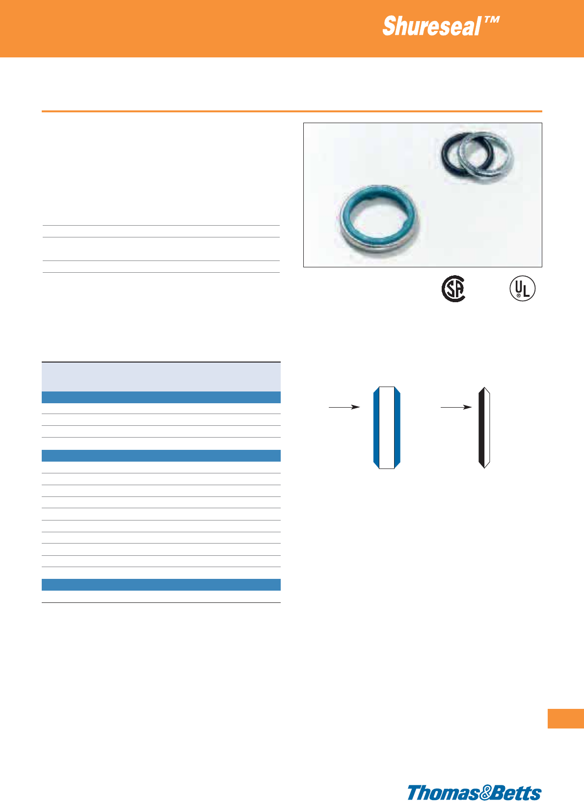
Sealing washers
• Design locks resilient sealing material in steel
• Steel retainer protects seal from extruding out under torque and
limits compression to an optimum predetermined value; provides
high quality seal
• Resilient material flows and seals rough surfaces
Technical Information
Fitting Type Shureseal™ and Shureflex
®
fittings
Thread NPT, Metric (I.S.O.) and Imperial
Material Chromated galvanised steel, with blue
Buna-N rubber or black synthetic rubber
Colour Metallic
Accessories for liquidtight fittings
309
Thomas & Betts • www.tnb-europe.com
4.2
Product Ref. Thread size Weight Quantity
[kg/100] [pieces]
SEALING WASHERS FOR METRIC (I.S.O.) FITTINGS
051-72123-1* M16 0.2 100
035-72272-1* M20 0.2 100
035-72272-2* M25 0.3 100
035-72272-3* M32 0.3 100
SEALING WASHERS FOR NPT FITTINGS
5261*
3
/
8
”0.2 50
5262
1
/
2
”0.2 50
5263
3
/
4
”0.3 25
5264 1” 0.3 25
5265 1
1
/
4
”1.8 5
5266 1
1
/
2
”1.9 5
5267 2” 2.0 5
5268 2
1
/
2
”2.2 5
5269 3” 2.9 5
5270 4” 3.8 5
SEALING WASHERS FOR IMPERIAL FITTINGS
035-72272-4 1
1
/
2
” 1.8 100
* The Product Ref. with a * are not UL approved
E13938
002884
Box side
52XX 051-XXXXX-X
035-XXXXX-X
Box side
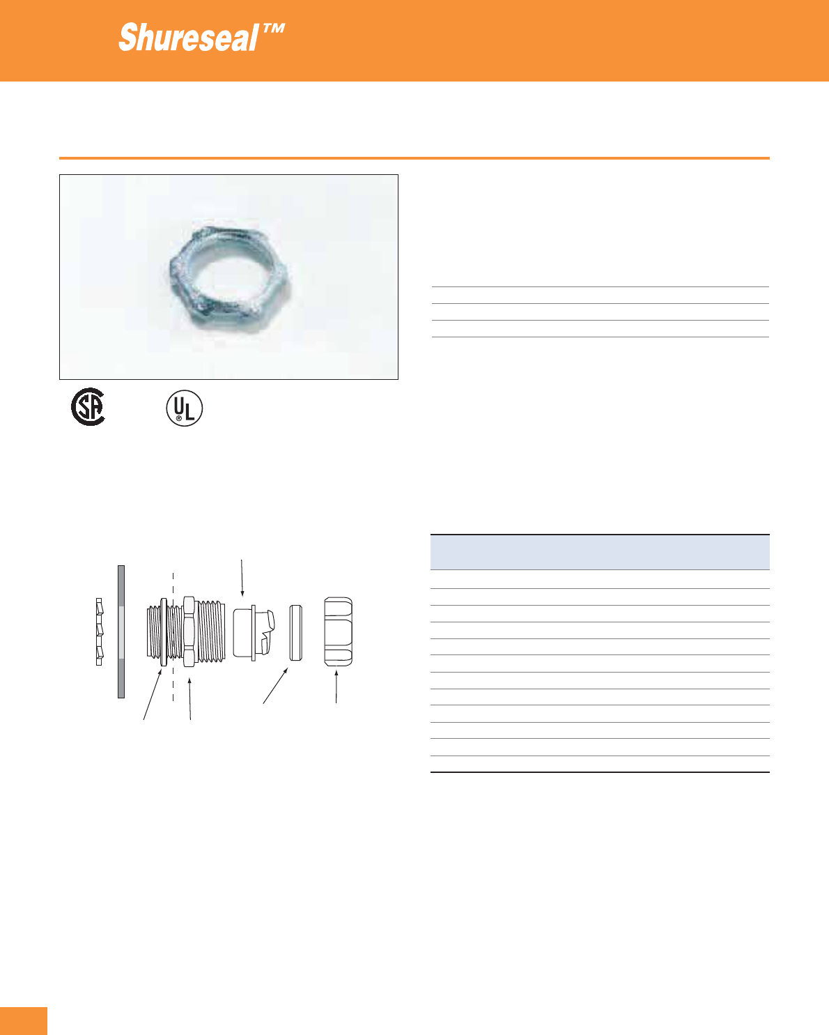
310
Thomas & Betts • www.tnb-europe.com
4.2
Locknuts
•Case-Hardened Locknut with Teeth provides superior strength
and electrical bonding and can be installed without a wrench in
the enclosure.
Technical Information
Fitting Type Shureseal™ fittings
Thread NPT
Material Galvanised steel, chromated
Colour Metallic
Accessories for liquidtight fittings
Product Ref. Thread size Weight Quantity
[inch] [kg/100] [pieces]
139
1
/
4
0.4 100
140
3
/
8
0.5 100
141
1
/
2
0.5 100
142-TB
3
/
4
0.9 100
143 1 1.8 50
144 1
1
/
4
3.2 50
145 1
1
/
2
4.0 50
146-TB 2 6.3 25
147 2
1
/
2
11.7 15
148 3 18.0 5
149 3
1
/
2
19.8 5
150 4 23.4 5
E23018
004484
Locknut
Sealing washer Body of
standard fitting
Sealing ring
Ground cone
Gland nut
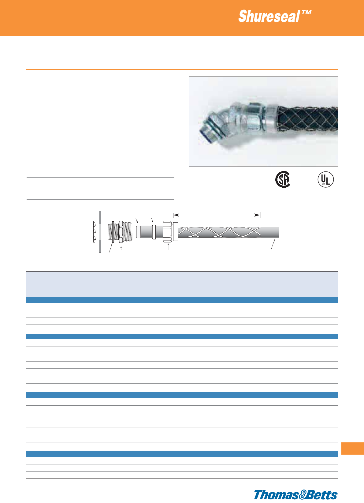
Wire mesh adaptor
• Strain Relief Wire Mesh adaptor with integrated gland nut
• Simple installation: just replace the existing gland nut in the fitting
with the wire mesh adaptor
• Provides a support function (strain relief), to protect the conduit
at the point of connection
• Rounded corners ensure secure attachment of the conduit without
the risk of damage
• Anti-corrosive
Technical Information
Fitting Type Shureseal™ liquidtight fittings for metallic
conduits (straight, 45°, 90°, chase, female hub)
Thread Replaces the standard gland nut
Material Gland nut: zinc plated steel
Collar: aluminium, Wire mesh: aluminium
Colour Metallic
Accessories for liquidtight fittings
311
Thomas & Betts • www.tnb-europe.com
4.2
Wire mesh adaptor with gland nut
Locknut
E13938
E23018
002884
004484
A
Product Conduit Straight 45° fitting 90° fitting Chase Chase 90° Adapter Weight Quantity
Ref. size fitting fitting fitting
[inch] [mm] [prod. ref.] [prod. ref.] [prod. ref.] [prod. ref.] [prod. ref.] [prod. ref.] [kg/100] [pieces]
FOR FITTINGS WITH ISO THREAD
WMG-LT1
3
/
8
16 9360, 9361 9340, 9341 9350, 9351 – – 9270, 9271 2.5 10
WMG-LT2
1
/
2
20 9362 9342 9352-TB – – 9272 4.0 10
WMG-LT3
3
/
4
25 9363 9343-TB 9353-TB – – 9273 5.0 10
WMG-LT4 1 32 9364 9344 9354-TB – – 9274 10.0 10
FOR FITTINGS WITH PG THREAD
WMG-LT1
3
/
8
16 7361, 7362 7341, 7342 7351, 7352 – – – 2.5 10
WMG-LT2
1
/
2
20 7363 7343 7353 – – – 4.0 10
WMG-LT3
3
/
4
25 7364 7344-TB 7354 – – – 5.0 10
WMG-LT4 1 32 7365 7345 7355 – – – 10.0 10
WMG-LT5 1
1
/
4
40 7366 7346 7356 – – – 17.0 2
WMG-LT6 1
1
/
2
50 7367 7347 7357 – – – 29.0 2
WMG-LT7 2 63 7368 7348-TB 7358 – – – 43.0 5
FOR FITTINGS WITH NPT THREAD
WMG-LT1
3
/
8
16 5331 5341 5351 5361 5371 5271 2.5 10
WMG-LT2
1
/
2
20 5332 5342 5352 5362 5372 5272 4.0 10
WMG-LT3
3
/
4
25 5333 5343 5353 5363 5373 5273 5.0 10
WMG-LT4 1 32 5334-TB 5344 5354 5364 5374 5274 10.0 10
WMG-LT5 1
1
/
4
40 5335 5345 5355 5365 – 5275 17.0 2
WMG-LT6 1
1
/
2
50 5336 5346 5356 5366 – 5276 29.0 2
WMG-LT7 2 63 5337 5347 5357 5367 – 5277 43.0 5
FOR FITTINGS WITH IMPERIAL THREAD
WMG-LT5 1
1
/
4
40 6365 – 6355 – – – 17.0 2
WMG-LT6 1
1
/
2
50 6366 6346 6356 – – – 29.0 2
WMG-LT7 2 63 6367 6347 – – – – 43.0 5
Sealing ringGround cone
Body of
standard fitting
is inserted instead of
the standard gland nut of the fitting
Shureseal™ conduit
Sealing washer
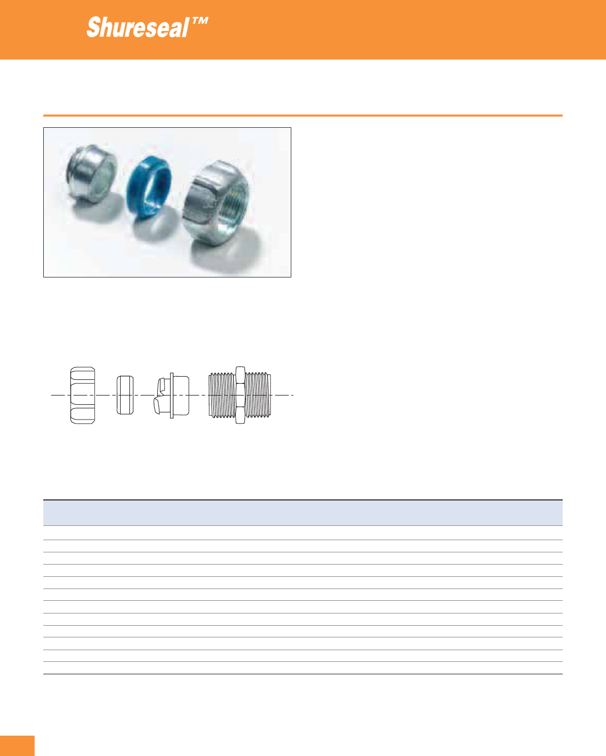
312
Thomas & Betts • www.tnb-europe.com
4.2
Replacement parts
If after some time the fitting is released and needs to be re-secured,
the seal and the ground cone should be replaced.
The following accessories are appropriate for all the standard
liquidtight Shureseal™ fittings for metallic conduits:
•Steel ground cone: it provides a high quality ground contact with
low impedance and high conduit pull-off resistance. The single
helical thread on ground cone is easy to install by hand without
cross threading. It tolerates variations in conduit diameters and
convolution pitch. Its rolled-over edge protects the conductors.
Manufactured in zinc plated steel.
•Sealing ring: it grips and seals the conduit without damaging the
conduit jacket. Its symmetrical shape assures a foolproof assem-
bly. It ensures a positive seal against oils, liquids, moisture and
dust. Made from high-performance nylon. Colour: blue.
•Gland nut: rugged construction, made of zinc plated steel. Rein-
forced corners to allow hand screwing.
Accessories for liquidtight fittings
Fitting replacement parts
Ground cone
Sealing ring
Gland nut
Ground cone Sealing ring Gland nut Conduit size
Product Ref. Product Ref. Product Ref.
[inch] [mm]
R 719124 – –
1
/
4
10
IR 719123 7 R68301 7 R68201
5
/
16
12
R 719101 IR 763101 R 735540
3
/
8
16
R 719125 IR 763102 R 735503
1
/
2
20
R 719126 IR 763108 R 735504
3
/
4
25
R 719127 IR 763104 R 735522 1 32
IR 719128 IR 763105 IR 735509 1
1
/
4
40
IR 719129 IR 763106 IR 723418 1
1
/
2
50
053-71814-127 053-71814-137 053-71814-7 2 63
053-71814-128 053-71814-28 053-71814-8 2
1
/
2
75
053-71814-129 053-71814-29 053-71814-9 3 90
053-71814-130 053-71814-30 053-71814-10 4 115
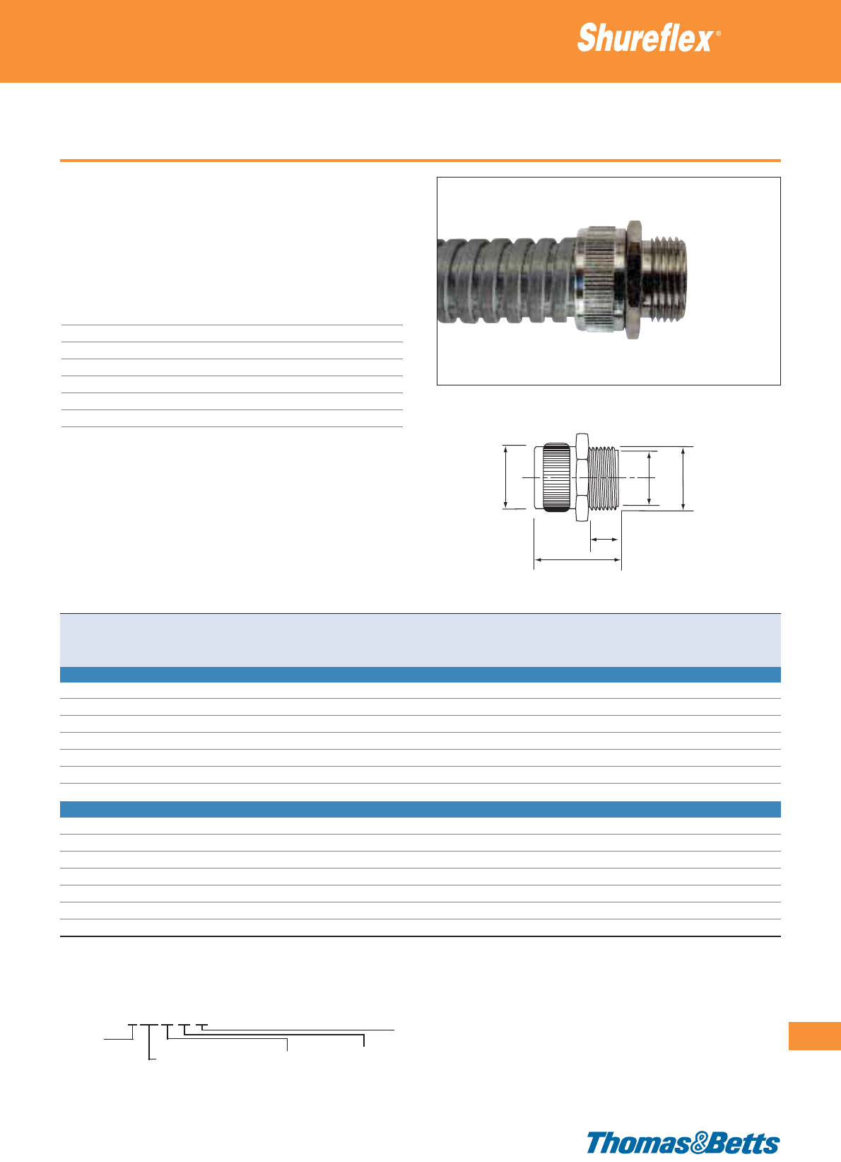
Type UGS - uncovered conduit
• Wide choice of fittings especially manufactured for Shureflex®
conduits
• Highly crush resistant with an excellent pull-off strength
• Ideal for industrial and commercial applications where flexibility,
crush and vibration resistance are required
Technical Information
Conduit type Shureflex
®
type UGS uncovered conduits*
Style Straight fixed male
Thread Metric (I.S.O.) and PG
IP rating IP40
Material Nickel-plated brass
Colour Metallic
Temperature range -50°C to +300°C
* Can also be used with Shureflex
®
stainless steel conduits
Fittings for ultra-flexible galvanised steel conduit
313
Thomas & Betts • www.tnb-europe.com
4.2
UFMM1616
U = Uncovered
Conduit FM = Fixed Male
SM = Swivel Male
SS = Space Saver
For conduit:
10, 12, 16, 20, 25,
32,40or50mm
Thread size
(PG or Metric)
Thread:
M=Metric
PG = PG
Product reference structure
BA
C
D
E
Type UFM
Product Ref. Conduit type Thread Dimensions Weight Quantity
size A B C D E
[mm] [mm] [mm] [mm] [mm] [g/100] [pieces]
TYPE UFMM: FIXED STRAIGHT FITTING WITH METRIC (I.S.O.) MALE THREAD
UFMM1616 UGS1610 / UGS1630 M16 16 10.8 19 10 24.5 550 25
UFMM1620 UGS1610 / UGS1630 M20 20 10.8 24 10 24.5 900 25
UFMM2020 UGS2010 / UGS2030 M20 20 14.8 24 10 24.5 700 25
UFMM2525 UGS2510 / UGS2530 M25 25 18.8 30 12 28.0 450 10
UFMM3232 UGS3210 / UGS3220 M32 32 25.8 36 13 29.0 350 5
UFMM4040 UGS4010 / UGS4020 M40 40 33.8 46 15 31.5 450 5
UFMM5050 UGS5010 / UGS5020 M50 50 41.8 55 15 33.0 400 2
TYPE UFMPG: FIXED STRAIGHT FITTING WITH PG MALE THREAD
UFMPG1007 UGS1010 / UGS1030 PG7 12.5 4.8 14.0 5.0 16.5 271 25
UFMPG1209 UGS1210 / UGS1230 PG9 15.2 7.8 17.0 8.0 21.5 532 25
UFMPG1611 UGS1610 / UGS1630 PG11 18.6 10.9 20.0 12.0 28.0 750 25
UFMPG2016 UGS2010 / UGS2030 PG16 22.5 14.9 24.0 12.0 28.0 1100 25
UFMPG2521 UGS2510 / UGS2530 PG21 28.3 18.9 30.0 13.5 31.0 650 10
UFMPG3229 UGS3210 / UGS3220 PG29 37.0 25.9 40.0 15.0 33.0 350 5
UFMPG4036 UGS4010 / UGS4020 PG36 47.0 33.9 49.6 17.0 36.0 900 5
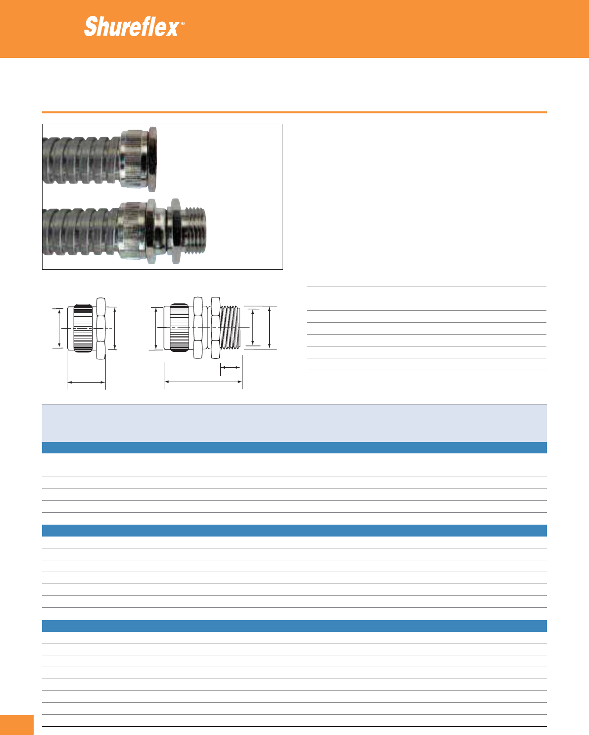
314
Thomas & Betts • www.tnb-europe.com
4.2
Type UGS - uncovered conduit
• Wide choice of fittings especially manufactured for Shureflex
®
conduits
• Highly crush resistant with an excellent pull-off strength
• Ideal for industrial and commercial applications where flexibility,
crush and vibration resistance are required
• The swivel fittings improve the flexibility and decrease the stress
in the connection of the conduit
• The space saver version, with its compact design, is perfectly
appropriate for applications in confined spaces and to install the
fitting directly on a panel
Technical Information
Conduit type Shureflex
®
type UGS uncovered conduits*
Style Straight swivel male and straight space
saver
Thread Metric (I.S.O.) and PG
IP rating IP40
Material Nickel-plated brass
Colour Metallic
Temperature range -50°C to +300°C
* Can also be used with Shureflex
®
stainless steel conduits
Fittings for ultra-flexible galvanised steel conduit
BA
BCC
E
D
E
Type USS Type USM
Product Ref. Conduit type Thread Dimensions Weight Quantity
size A B C D E
[mm] [mm] [mm] [mm] [mm] [g/100] [pieces]
TYPE USMM: SWIVEL STRAIGHT FITTING WITH METRIC (I.S.O.) MALE THREAD
USMM1616 UGS1610 / UGS1630 M16 16 10.8 19 10 34.3 850 25
USMM2020 UGS2010 / UGS2030 M20 20 14.8 24 10 34.3 1020 25
USMM2525 UGS2510 / UGS2530 M25 25 18.8 30 12 40.5 840 10
USMM3232 UGS3210 / UGS3220 M32 32 25.8 36 13 41.5 850 5
USMM4040 UGS4010 / UGS4020 M40 40 33.8 46 15 47.3 730 5
USMM5050 UGS5010 / UGS5020 M50 50 41.8 55 15 47.0 750 2
TYPE USMPG: SWIVEL STRAIGHT FITTING WITH PG MALE THREAD
USMPG1007 UGS1010 / UGS1030 PG7 12.5 4.8 14 5 22.0 550 25
USMPG1209 UGS1210 / UGS1230 PG9 15.2 7.8 17 8 30.3 750 25
USMPG1611 UGS1610 / UGS1630 PG11 18.6 10.9 20 12 38.0 1150 25
USMPG2016 UGS2010 / UGS2030 PG16 22.5 14.9 24 12 38.0 1300 25
USMPG2521 UGS2510 / UGS2530 PG21 28.3 18.9 30 12 41.0 1000 10
USMPG3229 UGS3210 / UGS3220 PG29 37.0 25.9 40 15 46.0 800 5
USMPG4036 UGS4010 / UGS4020 PG36 47.0 33.9 49 17 51.0 1250 5
TYPE USSM: SPACE SAVER STRAIGHT FITTING (NO THREAD)
USSM1010 UGS1010 / UGS1030 – – 4.8 14 – 11.5 255 25
USSM1212 UGS1210 / UGS1230 – – 7.8 16 – 13.5 351 25
USSM1616 UGS1610 / UGS1630 – – 10.8 19 – 14.5 470 25
USSM2020 UGS2010 / UGS2030 – – 14.8 24 – 14.5 662 25
USSM2525 UGS2510 / UGS2530 – – 18.8 30 – 16.0 370 10
USSM3232 UGS3210 / UGS3220 – – 25.8 36 – 16.0 254 5
USSM4040 UGS4010 / UGS4020 – – 33.8 46 – 16.0 322 5
USSM5050 UGS5010 / UGS5020 – – 41.8 55 – 18.0 200 2

Type PGS - covered conduit
• Wide choice of fittings especially manufactured for Shureflex®
covered conduit
• Highly crush resistant with an excellent pull-off strength
• Improved IP rating (IP54) compared to the uncovered conduit
• Special IP65 rated fittings available on request
• Ideal for industrial and commercial applications where flexibility,
crush and vibration resistance are required
Technical Information
Conduit Type Shureflex
®
type PGS covered conduit
Style Straight fixed male and female
Thread Metric (I.S.O.) and PG
IP rating IP54
Material Nickel-plated brass
Colour Metallic
Temperature range -50°C to +300°C*
* PGS conduit temperature -25°C to +70°C
Fittings for ultra-flexible galvanised steel conduit
315
Thomas & Betts • www.tnb-europe.com
4.2
PFMM1616
P = Covered
Conduit FM=FixedMale SM=SwivelMale
FF = Fixed Female SS = Space Saver For conduit:
10, 12, 16, 20, 25, 32, 40 or 50 mm
Thread size
(PG or Metric)
Thread:
M=Metric
PG=PG
Product reference Structure
A
B
C
D
E
Type PFF
A
B
C
D
E
Type PFM
Product Ref. Conduit type Thread Dimensions Weight Quantity
size A B C D E
[mm] [mm] [mm] [mm] [mm] [g/100] [pieces]
TYPE PFMM: FIXED STRAIGHT FITTING WITH METRIC (I.S.O.) MALE THREAD
PFMM1616 PGS1610 / PGS1630 M16 16 10.8 19 10 24.5 550 25
PFMM1620 PGS1610 / PGS1630 M20 20 10.8 24 10 24.5 900 25
PFMM2020 PGS2010 / PGS2030 M20 20 14.8 24 10 24.5 700 25
PFMM2525 PGS2510 / PGS2530 M25 25 18.8 30 12 28.0 450 10
PFMM3232 PGS3210 / PGS3220 M32 32 25.8 36 13 29.0 350 5
PFMM4040 PGS4010 / PGS4020 M40 40 33.8 46 15 31.5 450 5
PFMM5050 PGS5010 / PGS5020 M50 50 41.8 55 15 33.0 400 2
TYPE PFMPG: FIXED STRAIGHT FITTING WITH PG MALE THREAD
PFMPG1007 PGS1010 / PGS1030 PG7 12.5 4.8 14.0 8.0 16.5 270 25
PFMPG1209 PGS1210 / PGS1230 PG9 15.2 7.8 17.0 8.0 21.5 483 25
PFMPG1611 PGS1610 / PGS1630 PG11 18.6 10.9 20.0 12.0 28.0 550 25
PFMPG2016 PGS2010 / PGS2030 PG16 22.5 14.9 24.0 12.0 28.0 1050 25
PFMPG2521 PGS2510 / PGS2530 PG21 28.3 18.9 30.0 13.5 31.0 650 10
PFMPG3229 PGS3210 / PGS3220 PG29 37.0 25.9 40.0 15.0 33.0 1150 5
PFMPG4036 PGS4010 / PGS4020 PG36 47.0 33.9 49.6 17.0 36.0 450 5
TYPE PFFM: FIXED STRAIGHT FITTING WITH METRIC (I.S.O.) FEMALE THREAD
PFFM1616 PGS1610 / PGS1630 M16 16 10.8 19 10 23.5 552 25
PFFM2020 PGS2010 / PGS2030 M20 20 14.8 24 10 23.5 765 25
PFFM2525 PGS2510 / PGS2530 M25 25 18.8 30 12 28.0 511 10
PFFM3232 PGS3210 / PGS3220 M32 32 25.8 36 13 28.0 292 5
PFFM4040 PGS4010 / PGS4020 M40 40 33.8 46 15 30.5 535 5
TYPE PFFPG: FIXED STRAIGHT FITTING WITH PG FEMALE THREAD
PFFPG1209 PGS1210 / PGS1230 PG9 15.2 7.8 19 8 20.5 389 25
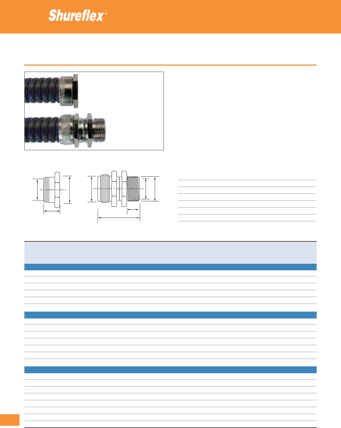
316
Thomas & Betts • www.tnb-europe.com
4.2
Type PGS - covered conduit
• Wide choice of fittings especially manufactured for Shureflex®
covered conduit
• Highly crush resistant with an excellent pull-off strength
• Improved IP rating (IP54) compared to the uncovered conduit
• Special IP65 rated fittings available on request
• Ideal for industrial and commercial applications where flexibility,
crush and vibration resistance are required
• The swivel fittings improve the flexibility and decrease the stress
in the connection of the conduit
• The space saver version, with its compact design, is perfectly
appropriate for applications in confined spaces and to install the
fitting directly on a panel
Technical Information
Conduit Type Shureflex
®
type PGS covered conduit
Style Straight swivel male, straight space saver
Thread Metric (I.S.O.) and PG
IP rating IP54
Material Nickel-plated brass
Colour Metallic
Temperature range -50°C to +300°C*
* PGS conduit temperature -25°C to +70°C
Fittings for ultra-flexible galvanised steel conduit
Product Ref. Conduit type Thread Dimensions Weight Quantity
size A B C D E
[mm] [mm] [mm] [mm] [mm] [g/100] [pieces]
TYPE PSMM: SWIVEL STRAIGHT FITTING WITH METRIC (I.S.O.) MALE THREAD
PSMM1616 PGS1610 / PGS1630 M16 16 10.8 19 10 34.3 860 25
PSMM2020 PGS2010 / PGS2030 M20 20 14.8 24 10 34.3 1060 25
PSMM2525 PGS2510 / PGS2530 M25 25 18.8 30 12 40.5 850 10
PSMM3232 PGS3210 / PGS3220 M32 32 25.8 36 13 41.5 800 5
PSMM4040 PGS4010 / PGS4020 M40 40 33.8 46 15 47.3 850 5
PSMM5050 PGS5010 / PGS5020 M50 50 41.8 55 15 47.0 700 2
TYPE PSMPG: SWIVEL STRAIGHT FITTING WITH PG MALE THREAD
PSMPG1007 PGS1010 / PGS1030 PG7 12.5 4.8 14.0 8 22.0 280 25
PSMPG1209 PGS1210 / PGS1230 PG9 15.2 7.8 17.0 8 30.3 550 25
PSMPG1611 PGS1610 / PGS1630 PG11 18.6 10.9 20.0 12 38.0 1100 25
PSMPG2016 PGS2010 / PGS2030 PG16 22.5 14.9 24.0 12 38.0 1300 25
PSMPG2521 PGS2510 / PGS2530 PG21 28.3 18.9 30.0 12 41.0 950 10
PSMPG3229 PGS3210 / PGS3220 PG29 37.0 25.9 40.0 15 46.0 750 5
PSMPG4036 PGS4010 / PGS4020 PG36 47.0 33.9 49.6 17 51.0 850 5
TYPE PSSM: SPACE SAVER STRAIGHT FITTING (NO THREAD)
PSSM1010 PGS1010 / PGS1030 – – 4.8 14 – 11.5 203 25
PSSM1212 PGS1210 / PGS1230 – – 7.8 16 – 13.5 296 25
PSSM1616 PGS1610 / PGS1630 – – 10.8 19 – 14.5 405 25
PSSM2020 PGS2010 / PGS2030 – – 14.8 24 – 14.5 560 25
PSSM2525 PGS2510 / PGS2530 – – 18.8 30 – 16.0 350 10
PSSM3232 PGS3210 / PGS3220 – – 25.8 36 – 16.0 240 5
PSSM4040 PGS4010 / PGS4020 – – 33.8 46 – 16.0 382 5
PSSM5050 PGS5010 / PGS5020 – – 41.8 55 – 18.0 213 2
BC
E
Type PSS
A
B
C
D
E
Type PSM
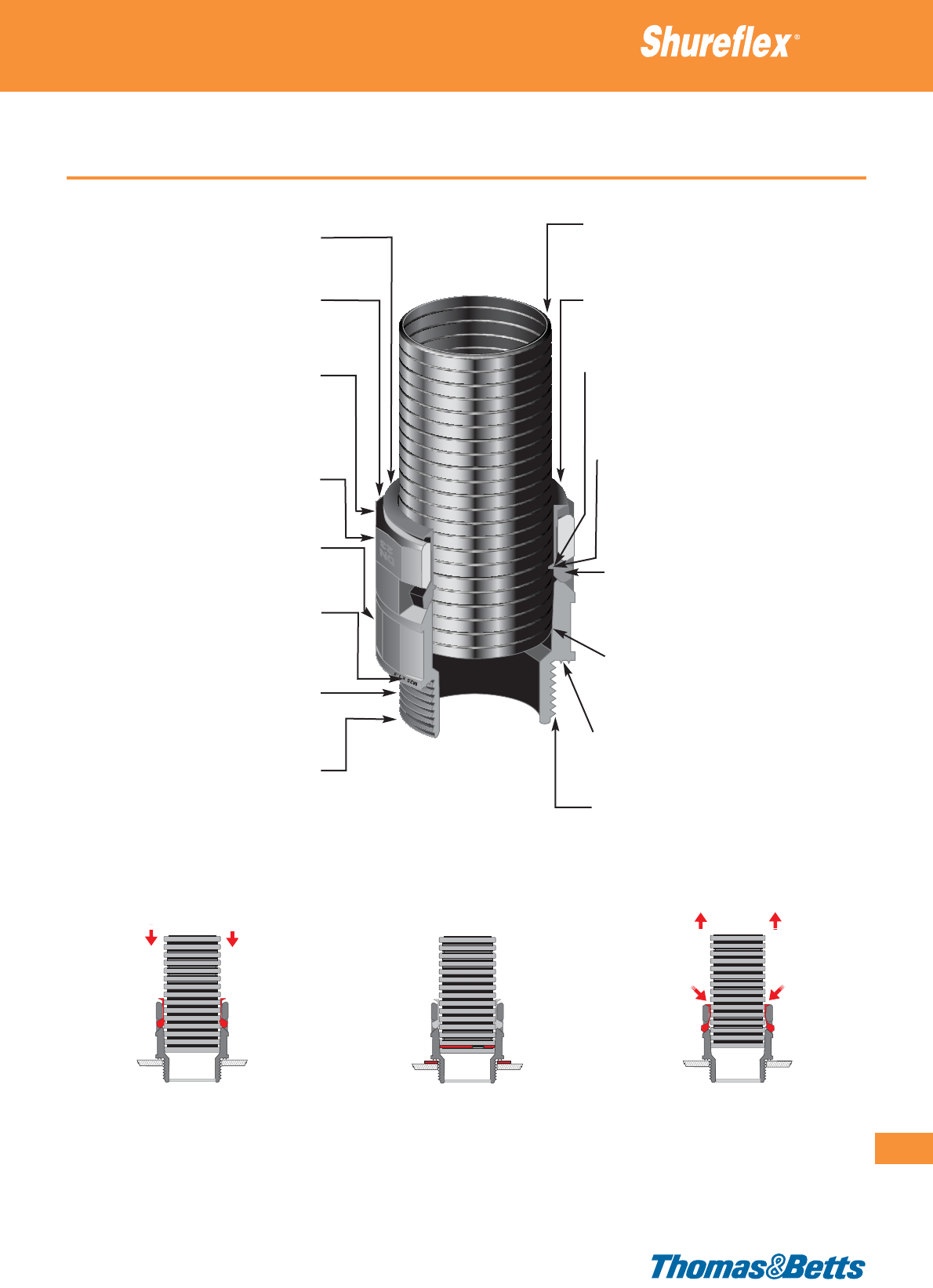
Product description
Fittings for ultra-flexible nylon conduits
317
Thomas & Betts • www.tnb-europe.com
4.2
Installation with IP66 protection Installation with IP69K protection Easily released & removed
“One piece assembly” fitting, no loose
piece, handy to use, requires no tool
Twelve flat edges, for easy tightening
Solid construction: robust design, shock
resistant and high quality material (Halogen
free Polyamide 6), for a durable perform-
ance
Conduit size marking on the fitting,
for immediate identification
Six flat edges, for spanner tightening
Thread style/size marking,
for immediate identification
Optional O-ring and sealing washer,
for IP69K rating
Range of accessories: locknuts for panel
mounting, mounting brackets for attaching
the conduits, T-splits for connecting 3
conduits together
Three grades of Halogen free flexible
conduits, available in 8 sizes, with an excellent
combination of flexibility and mechanical strength
Release ring, for easy removal without any tool
Self-locking (push-fit): mounting and locking at
the same time, for a quick and easy installation
After mounting, the fitting can rotate freely
on the conduit, allowing the possibility to
pre-mount the straight fittings on the conduits
before the final installation on the support
(without causing the cables to be twisted)
Crown of self-locking clips around the
whole circumference of the conduit, for a
secure locking and a superior pull-off strength
Tapered fitting body, providing a standard
IP66 watertight system, without the
need for any additional accessory
Broad contact base, with 2 built-in sealing rings
Availableinstraight,90°and45°versions,
with Metric (I.S.O.) and PG threads
One push and you’re ready
• Self-locking (push-fit) installation: simply
push the conduit completely into the
fitting. Mounting and locking the fitting
are done simultaneously
• Optional sealing washer can be used
(placed around the thread of the fitting), in
combination with an optional O-ring
(inserted in the first groove of the conduit)
• Just press the release ring of the fitting and
pull the conduit out. No tool is required!

318
Thomas & Betts • www.tnb-europe.com
4.2
Straight fittings
• High quality Polyamide (PA6)
• UV and shock resistant
• Secure: self-locking (push-fit) installation onto the conduit
• Quick and easy to install and remove, no tool required
• Strong: high pull-off strength thanks to the self-locking clips
around the whole circumference of the conduit
• Handy: “one-piece assembly” construction, no loose parts
• Watertight: IP66 rating as standard, without additional accessories
• Sealing washers and O-rings available (delivered separately) for
the applications requiring a maximum IP rating (IP69K)
• Locknuts (delivered separately) are available for installations on
panels and enclosures
Technical Information
Conduit type Shureflex
®
Nylon conduits
Style / thread Straight / Metric (I.S.O.), PG thread
IP rating IP66 (standard), IP69K (with additional
Shureflex
®
washer and O-ring)
Material Polyamide 6
Colour Black
Temperature range -30°C to +100°C (intermittent: to +150°C)
Flammability rating UL 94 V-2 (produced from UL 94 V-0 raw
material)
Other properties Halogen, Phosphor and Cadmium free,
UV-resistant. Good resistance to fuel,
mineral oils, greases and diluted bases
Fittings for ultra-flexible nylon conduits
Product Ref. For conduit Thread Inner Dimensions Spanner Weight Quantity
size size diameter A B C D size
[mm] [mm] [mm] [mm] [mm] [mm] [mm] [kg/100] [pieces]
STRAIGHT FITTING WITH METRIC (I.S.O.) THREAD
NY-SF07-BKM12 7 M12 x 1.5 6.5 35.0 11.0 19.0 17.0 15 0.4 100
NY-SF10-BKM16 10 M16 x 1.5 10.0 37.0 11.0 21.0 21.0 18 0.6 100
NY-SF12-BKM16 12 M16 x 1.5 10.0 37.0 11.0 26.0 25.5 20 0.7 100
NY-SF12-BKM20 12 M20 x 1.5 14.0 37.0 11.0 31.0 25.5 20 0.8 100
NY-SF17-BKM20 17 M20 x 1.5 14.5 44.0 11.0 31.0 30.0 27 1.2 100
NY-SF23-BKM25 23 M25 x 1.5 18.5 48.0 12.0 37.0 37.0 34 1.6 50
NY-SF29-BKM32 29 M32 x 1.5 25.5 52.0 15.0 46.0 46.0 42 2.8 30
NY-SF36-BKM40 36 M40 x 1.5 32.0 60.0 19.0 54.0 54.0 50 3.9 20
NY-SF48-BKM50 48 M50 x 1.5 42.0 61.0 19.0 69.0 69.0 66 6.2 10
STRAIGHT FITTING WITH PG THREAD
NY-SF07-BKPG7 7 PG7 8.0 35.5 11.5 19.0 17.0 15 0.4 100
NY-SF10-BKPG9 10 PG9 10.3 37.5 11.5 21.0 21.0 18 0.6 100
NY-SF12-BKPG11 12 PG11 14.0 37.5 11.5 26.0 25.5 20 0.8 100
NY-SF17-BKPG13 17 PG13.5 14.0 44.5 11.5 31.0 28.0 27 1.2 100
NY-SF17-BKPG16 17 PG16 17.0 44.5 11.5 31.0 29.0 27 1.2 100
NY-SF23-BKPG21 23 PG21 22.0 48.5 12.5 37.0 36.5 34 1.6 50
NY-SF29-BKPG29 29 PG29 30.0 49.5 12.5 46.0 46.0 42 2.8 30
NY-SF36-BKPG36 36 PG36 37.5 55.0 14.0 54.0 56.0 50 3.9 20
NY-SF48-BKPG48 48 PG48 50.0 56.0 14.0 69.0 69.5 66 5.6 10
See pages 322 to 325 for locknuts and accessories
E96548
Spanner
Thread
inner ø
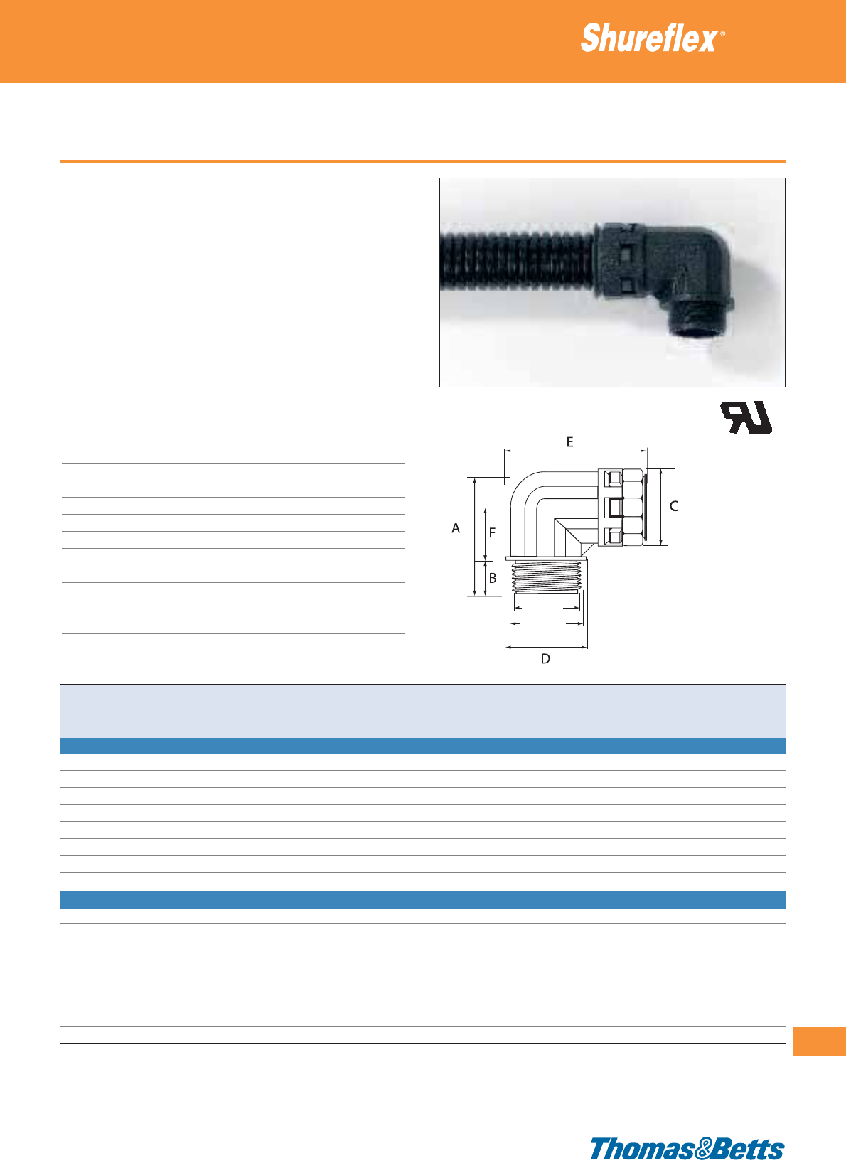
90° fittings
• High quality Polyamide (PA6)
• UV and shock resistant
• Secure: self-locking (push-fit) installation onto the conduit
• Quick and easy to install and remove, no tool required
• Strong: high pull-off strength thanks to the self-locking clips
around the whole circumference of the conduit
• Handy: “one-piece assembly” construction, no loose parts
• Watertight: IP66 rating as standard, without additional accessories
• Sealing washers and O-rings available (delivered separately) for
the applications requiring a maximum IP rating (IP69K)
• Locknuts (delivered separately) are available for installations on
panels and enclosures
Technical Information
Conduit type Shureflex
®
Nylon conduits
Style / thread 90° / Metric (I.S.O.), PG thread
IP rating IP66 (standard), IP69K (with additional
Shureflex
®
washer and O-ring)
Material Polyamide 6
Colour Black
Temperature range -30°C to +100°C (intermittent: to +150°C)
Flammability rating UL 94 V-2 (produced from
UL 94 V-0 raw material)
Other properties Halogen, Phosphor and Cadmium free,
UV-resistant. Good resistance to fuel,
mineral oils, greases and diluted bases
Fittings for ultra-flexible nylon conduits
319
Thomas & Betts • www.tnb-europe.com
4.2
Product Ref. For conduit Thread Inner Dimensions Weight Quantity
size size diameter A B C D E F
[mm] [mm] [mm] [mm] [mm] [mm] [mm] [mm] [kg/100] [pieces]
90° FITTING WITH METRIC (I.S.O.) THREAD
NY-90F10-BKM16 10 M16 x 1.5 10.0 35.0 11.0 21.0 21.0 42.5 11.0 0.9 50
NY-90F12-BKM16 12 M16 x 1.5 10.5 39.0 11.0 25.0 23.0 44.0 15.0 1.3 50
NY-90F12-BKM20 12 M20 x 1.5 12.3 39.0 11.0 25.0 26.0 45.5 15.0 1.3 50
NY-90F17-BKM20 17 M20 x 1.5 14.5 45.0 11.0 30.0 30.0 58.0 18.0 2.2 50
NY-90F23-BKM25 23 M25 x 1.5 18.5 53.0 12.0 36.5 37.0 66.0 23.0 3.4 30
NY-90F29-BKM32 29 M32 x 1.5 25.5 66.0 15.0 45.0 46.0 76.0 27.0 5.5 20
NY-90F36-BKM40 36 M40 x 1.5 32.0 79.0 19.0 54.0 55.0 89.0 33.0 9.2 10
NY-90F48-BKM50 48 M50 x 1.5 42.0 92.0 19.0 68.0 69.0 103.0 39.0 15.0 10
90° FITTING WITH PG THREAD
NY-90F10-BKPG9 10 PG9 10.3 35.0 11.5 21.0 21.5 42.5 11.0 0.8 50
NY-90F12-BKPG11 12 PG11 14.0 39.0 11.5 25.0 25.0 45.0 15.0 1.1 50
NY-90F17-BKPG13 17 PG13.5 14.0 45.0 11.5 30.0 27.0 56.5 18.0 2.2 50
NY-90F17-BKPG16 17 PG16 17.0 45.0 11.5 30.0 29.0 57.5 18.0 1.9 50
NY-90F23-BKPG21 23 PG21 22.0 53.0 12.5 37.0 36.5 65.5 23.0 3.0 30
NY-90F29-BKPG29 29 PG29 30.0 65.0 12.5 45.0 46.0 76.0 28.0 4.6 20
NY-90F36-BKPG36 36 PG36 37.5 79.0 14.0 54.0 56.0 89.5 33.0 7.5 10
NY-90F48-BKPG48 48 PG48 50.0 92.0 14.0 68.0 69.5 103.5 39.0 11.7 10
See pages 322 to 325 for locknuts and accessories
Thread
inner ø
E96548
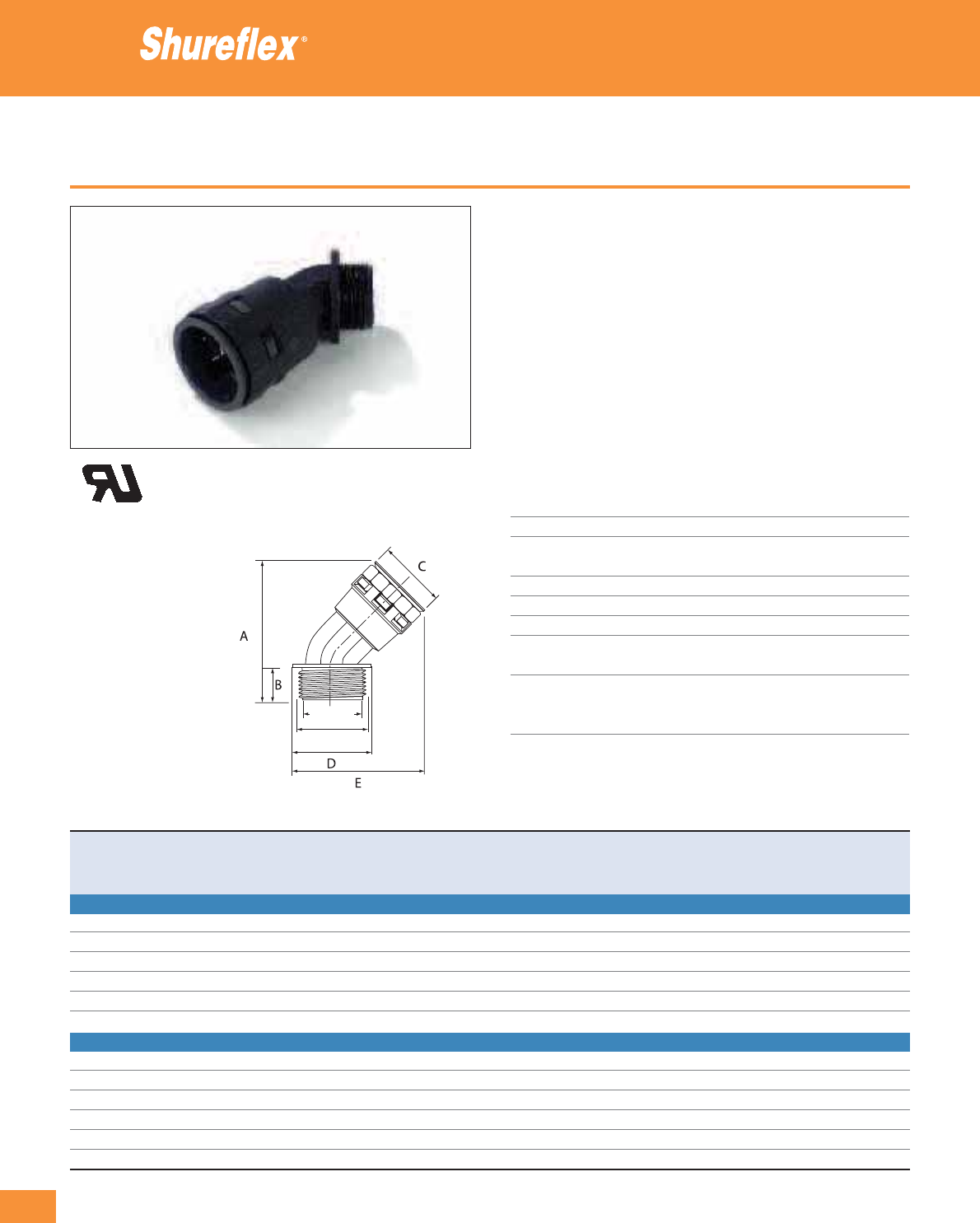
320
Thomas & Betts • www.tnb-europe.com
4.2
45° fittings
• High quality Polyamide (PA6)
• UV and shock resistant
• Secure: self-locking (push-fit) installation onto the conduit
• Quick and easy to install and remove, no tool required
• Strong: high pull-off strength thanks to the self-locking clips
around the whole circumference of the conduit
• Handy: “one-piece assembly” construction, no loose parts
• Watertight: IP66 rating as standard, without additional accessories
• Sealing washers and O-rings available (delivered separately) for
the applications requiring a maximum IP rating (IP69K)
• Locknuts (delivered separately) are available for installations on
panels and enclosures
Technical Information
Conduit type Shureflex
®
Nylon conduits
Style / thread 45° / Metric (I.S.O.), PG thread
IP rating IP66 (standard), IP69K (with additional
Shureflex
®
washer and O-ring)
Material Polyamide 6
Colour Black
Temperature range -30°C to +100°C (intermittent: to +150°C)
Flammability rating UL 94 V-2 (produced from
UL 94 V-0 raw material)
Other properties Halogen, Phosphor and Cadmium free,
UV-resistant. Good resistance to fuel,
mineral oils, greases and diluted bases
Fittings for ultra-flexible nylon conduits
Product Ref. For conduit Thread Inner Dimensions Weight Quantity
size size diameter A B C D E
[mm] [mm] [mm] [mm] [mm] [mm] [mm] [kg/100] [pieces]
45° FITTING WITH METRIC METRIC (I.S.O.) THREAD
NY-45F12-BKM16 12 M16 x 1.5 10.5 50.0 11.0 24.0 23.0 45.0 0.9 50
NY-45F17-BKM20 17 M20 x 1.5 11.5 60.0 11.0 29.0 27.0 56.0 1.4 50
NY-45F23-BKM25 23 M25 x 1.5 18.5 70.0 12.0 37.0 34.0 67.0 2.2 30
NY-45F29-BKM32 29 M32 x 1.5 25.7 80.0 15.0 45.0 41.0 76.0 3.6 10
NY-45F36-BKM40 36 M40 x 1.5 32.0 96.0 19.0 53.0 50.0 90.0 5.4 10
NY-45F48-BKM50 48 M50 x 1.5 42.0 109.0 19.0 67.0 60.0 106.0 8.4 5
45° FITTING WITH PG THREAD
NY-45F12-BKPG11 12 PG11 11.5 50.0 11.0 24.0 26.0 47.0 0.9 50
NY-45F17-BKPG16 17 PG16 14.7 60.0 11.0 29.0 30.0 58.0 1.5 50
NY-45F23-BKPG21 23 PG21 18.5 69.0 11.0 37.0 37.0 69.0 2.2 30
NY-45F29-BKPG29 29 PG29 25.5 78.0 12.0 45.0 46.0 79.0 3.7 10
NY-45F36-BKPG36 36 PG36 32.0 90.0 13.0 53.0 56.0 94.0 5.5 10
NY-45F48-BKPG48 48 PG48 42.0 102.0 13.0 67.0 69.0 112.0 8.8 5
See pages 322 to 325 for locknuts and accessories
Thread
inner ø
E96548

T-splits
• High quality Polyamide (PA6)
• UV and shock resistant
• Secure: self-locking (push-fit) installation onto the conduit
• Quick and easy to install and remove, no tool required
• Strong: high pull-off strength thanks to the self-locking clips
around the whole circumference of the conduit
• Handy: “one-piece assembly” construction, no loose parts
• Watertight: IP66 rating as standard, without additional accessories
• O-rings are available (delivered separately) for the applications
requiring a maximum IP rating (IP69K)
• Can be used with all the types of Shureflex®ultra-flexible nylon
conduits, from 10 mm to 36 mm nominal sizes
Technical Information
Conduit type Shureflex
®
Nylon conduits
Style T-split
IP rating IP66 (standard)
IP69K (with additional Shureflex
®
O-ring)
Material Polyamide 6
Colour Black
Temperature range -30°C to +100°C (intermittent: to +150°C)
Flammability rating UL 94 V-2 (produced from UL 94 V-0 raw
material)
Other properties Halogen, Phosphor and Cadmium free,
UV-resistant. Good resistance to fuel,
mineral oils, greases and diluted bases
Fittings for ultra-flexible nylon conduits
321
Thomas & Betts • www.tnb-europe.com
4.2
Product Ref. For conduit Thread Inner Dimensions Weight Quantity
size size diameter A B C D E
[mm] [mm] [mm] [mm] [mm] [mm] [mm] [kg/100] [pieces]
NY-T10-BK 10 (3x) M4 (2x) 11.2 (3x) 46.0 72.0 20.0 (3x) 19.0 27.0 1.5 20
NY-T12-BK 12 (3x) M4 (2x) 12.8 (3x) 52.0 81.0 23.5 (3x) 20.5 30.0 2.1 20
NY-T17-BK 17 (3x) M5 (2x) 18.0 (3x) 63.0 96.0 29.0 (3x) 28.0 35.0 3.4 20
NY-T23-BK 23 (3x) M5 (2x) 25.5 (3x) 76.0 117.0 37.0 (3x) 36.0 40.0 5.3 10
NY-T29-BK 29 (3x) M5 (2x) 31.5 (3x) 85.0 128.0 45.0 (3x) 41.5 41.0 8.6 5
NY-T36-BK 36 (3x) M6 (2x) 38.5 (3x) 97.0 144.0 53.0 (3x) 50.5 46.0 11.7 5
See pages 322 to 325 for accessories
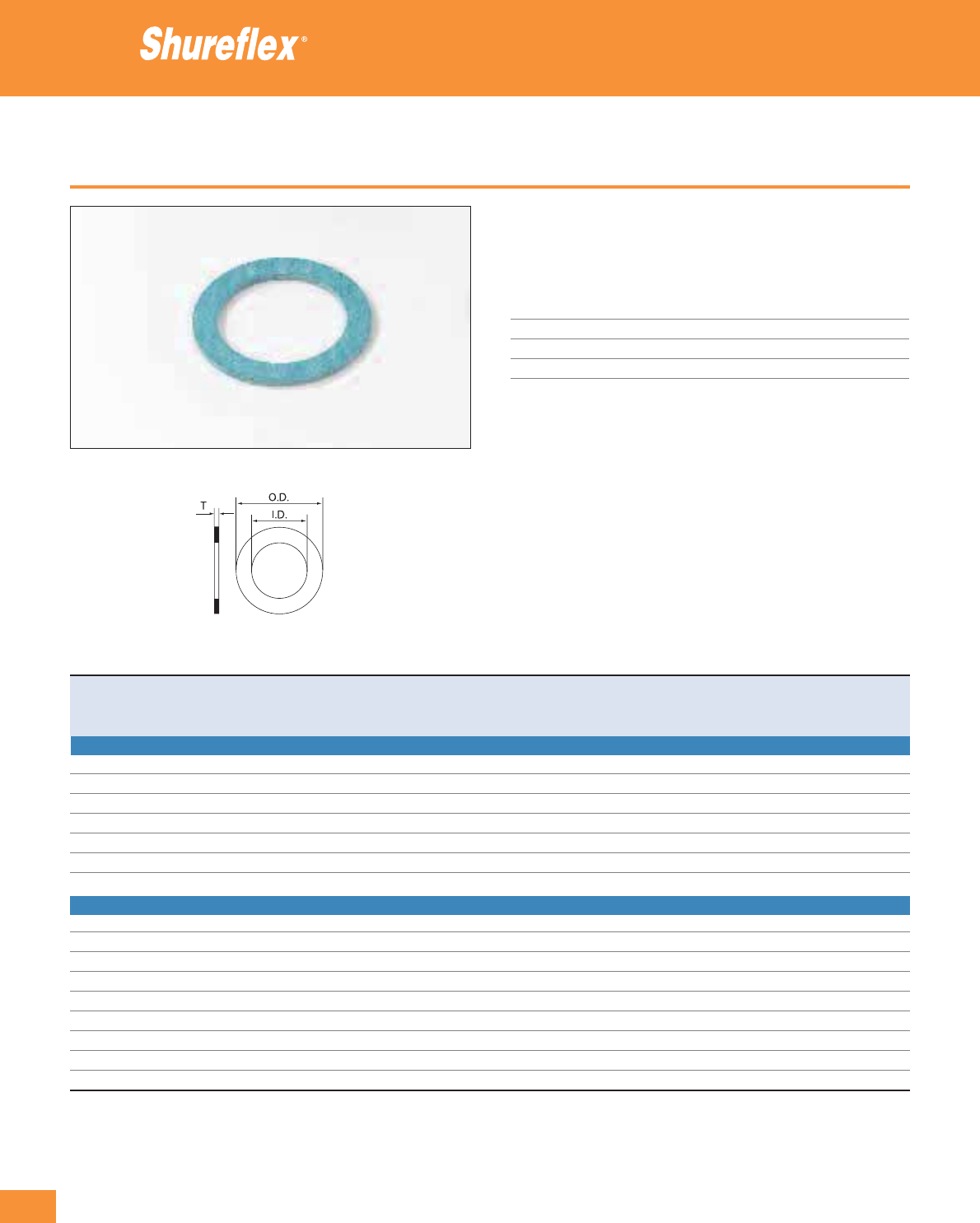
322
Thomas & Betts • www.tnb-europe.com
4.2
Sealing washers
• To be placed around the thread of the Shureflex®Nylon fitting,
between the fitting and the entry panel
Technical Information
Fitting type Shureflex
®
Nylon fittings
Material Deformable, asbestos free material
Colour Blue
Temperature range -40°C to +200°C
Accessories for nylon conduit and fittings
Product Ref. Thread Inner diameter Outer diameter Thickness Weight Quantity
size I.D. O.D. T
[mm] [mm] [mm] [kg/100] [pieces]
SEALING WASHERS FOR METRIC (I.S.O.) THREAD
NY-SW-M12 M12 12 18 1.5 0.04 100
NY-SW-M16 M16 16 22 1.5 0.05 100
NY-SW-M20 M20 20 27 1.5 0.07 100
NY-SW-M25 M25 25 35 1.5 0.14 50
NY-SW-M32 M32 32 43 1.5 0.19 30
NY-SW-M40 M40 40 55 1.5 0.34 20
NY-SW-M50 M50 50 69 1.5 0.50 10
SEALING WASHERS FOR PG THREAD
NY-SW-PG7 PG7 12.4 18 1.5 0.04 100
NY-SW-PG9 PG9 15.2 21 1.5 0.04 100
NY-SW-PG11 PG11 18.6 26 1.5 0.07 100
NY-SW-PG13 PG13.5 20.4 29 1.5 0.09 100
NY-SW-PG16 PG16 22.5 33 1.5 0.13 100
NY-SW-PG21 PG21 28.3 39 1.5 0.29 50
NY-SW-PG29 PG29 37.0 49 1.5 0.34 30
NY-SW-PG36 PG36 47.0 59 1.5 0.25 20
NY-SW-PG48 PG48 59.3 71 1.5 0.30 10

O-rings
• To be inserted in the first groove of the Shureflex®Nylon conduit,
prior to the insertion of the conduit into the fitting
Technical Information
Conduit type Shureflex
®
Nylon conduits
Material NBR70 elastomer
Colour Black
Temperature range -30°C to +100°C
Accessories for nylon conduit and fittings
323
Thomas & Betts • www.tnb-europe.com
4.2
Product
Ref.
Conduit Inner diameter Diameter Weight Quantity
size I.D. T
[mm] [mm] [mm] [kg/100] [pieces]
NY-OR-07 7 6.35 1.27 0.004 100
NY-OR-10 10 10.00 1.30 0.011 100
NY-OR-12 12 11.50 1.50 0.013 100
NY-OR-17 17 16.00 1.80 0.022 100
NY-OR-23 23 22.00 2.00 0.037 50
NY-OR-29 29 29.00 2.00 0.036 30
NY-OR-36 36 34.00 2.30 0.073 20
NY-OR-48 48 44.60 2.40 0.110 10
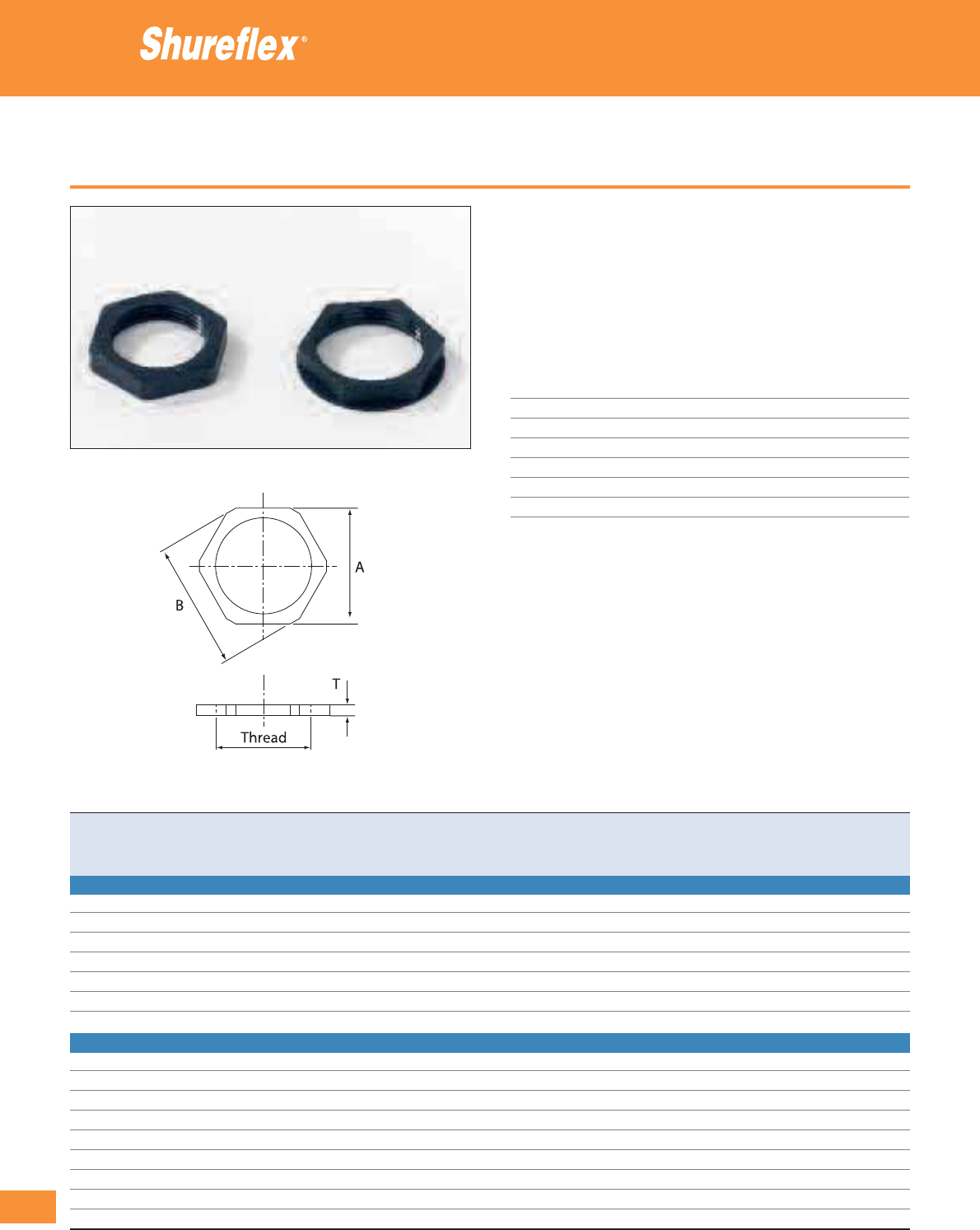
324
Thomas & Betts • www.tnb-europe.com
4.2
Hexagonal locknuts
• For mounting the Shureflex
®
Nylon fittings on panels and enclosures
• High quality Polyamide (PA6)
• Shock resistant
• Thread style and thread size marked on the locknut for immediate
identification
• Good resistance to mineral oils, greases and fuel
Technical Information
Fitting type Shureflex
®
Nylon fittings
Thread Metric (I.S.O.), PG
Material Polyamide 6
Colour Black
Temperature range -30°C to +100°C
Flammability rating UL 94 V-2
Other properties Halogen, Phosphor and Cadmium free
Accessories for nylon conduit and fittings
Product Ref. Thread Dimensions Weight Quantity
size A - spanner size B - Across corner T - thickness
[mm] [mm] [mm] [kg/100] [pieces]
LOCKNUT WITH METRIC (I.S.O.) THREAD
NY-LNBK-M12 M12 17 18.0 5 0.09 100
NY-LNBK-M16 M16 22 24.0 5 0.14 100
NY-LNBK-M20 M20 26 28.0 6 0.20 100
NY-LNBK-M25 M25 32 35.0 6 0.30 100
NY-LNBK-M32 M32 42 47.0 7 0.60 100
NY-LNBK-M40 M40 52 57.5 7 0.88 50
NY-LNBK-M50 M50 62 68.0 9 1.66 50
LOCKNUT WITH PG THREAD
NY-LNBK-PG7 PG7 15 16.5 4.5 0.05 100
NY-LNBK-PG9 PG9 19 20.9 4.5 0.11 100
NY-LNBK-PG11 PG11 22 24.2 5.0 0.12 100
NY-LNBK-PG13 PG13.5 24 26.4 5.5 0.17 100
NY-LNBK-PG16 PG16 27 29.7 6.0 0.25 100
NY-LNBK-PG21 PG21 32 35.2 6.5 0.29 100
NY-LNBK-PG29 PG29 41 45.1 7.5 0.48 50
NY-LNBK-PG36 PG36 54 59.4 9.0 0.79 20
NY-LNBK-PG48 PG48 67 73.7 9.5 1.16 1
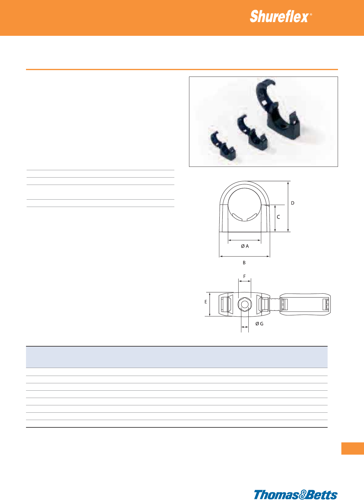
Mounting brackets
• A range of mounting brackets for quickly and easily attaching the
Shureflex®Nylon conduits to existing equipment
• Screw mounted (with 1 screw) for secure installation
• Quick installation: the cover is just snapped after inserting the
conduit
• The conduits can rotate freely in the mounting bracket
• Releasable and re-usable
• Resistant to UV, to oils, greases, fuels, cleaning fluids and synthetic
fluids
Technical Information
Conduit type Shureflex
®
Nylon conduits
Material Polyamide 6.6
Colour Black
Temperature range -40°C to +120°C
(intermittent: to +150°C)
Other properties Halogen free, UV resistant
Accessories for nylon conduit and fittings
325
Thomas & Betts • www.tnb-europe.com
4.2
Product Ref. Conduit Dimensions ØG Weight Quantity
size A B C D E F Installation hole
[mm] [mm] [mm] [mm] [mm] [mm] [mm] [g/piece] [pieces]
NY-MB-07 7 22.6 12.9 23.3 11.6 7.5 4.2 1.9 10
NY-MB-10 10 22.6 12.9 23.3 11.6 7.5 4.2 1.7 10
NY-MB-12 12 26.7 15.1 26.9 13.7 8.8 5.1 2.6 10
NY-MB-17 17 33.8 19.5 34.9 17.5 10.4 6.1 4.8 10
NY-MB-23 23 43.8 23.4 43.7 20.7 10.3 6.1 8.6 10
NY-MB-29 29 52.8 26.9 51.6 23.2 10.2 6.2 12.7 10
NY-MB-36 36 64.5 32.4 62.5 27.0 10.2 6.2 19.5 5
NY-MB-48 48 81.0 38.5 77.0 32.1 10.2 6.2 34.7 5
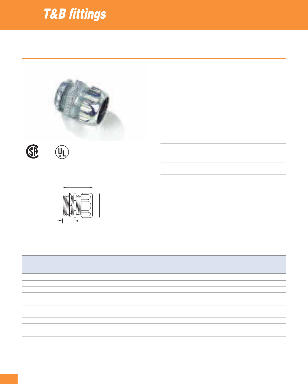
326
Thomas & Betts • www.tnb-europe.com
4.2
Metallic fittings for threadless conduits
• Makes a permanent connection and eliminates the need for cutting
a thread on the rigid conduit.
• A split steel ring with diagonal serrations grips the conduit and
bites into it for positive ground.
• Insulation helps to guarantee continuity of service with protection
of the conductor at the critical point: the bushing
• Available in 2 versions, with or without nylon insert
• Components: gland nut, steel ring, steel spacer (only for sizes up
to 1 inch), body (with or without insert), locknut
Technical Information
Conduit Type Metallic rigid conduits
Style Straight
Thread NPT (up to 1”) or NPS (larger than 1”)
Material Zinc plated steel or malleable iron
Gland nut Zinc plated steel (up to 1”) or malleable
iron (larger sizes)
Locknut Zinc plated steel
Insert Nylon
Rigid and intermediate metal conduit fittings
E23018
002884
Product Ref. Product Ref. For conduit Thread Dimensions Weight Weight Quantity Quantity
insulated non-insulated size size A B C insulated non-insulated insulated non-insulated
[inch] [mm] [mm] [mm] [kg/100] [kg/100] [pieces] [pieces]
8123 8121
1
/
2
1
/
2
” NPT 31.0 42.9 38.1 9.1 9.5 10 25
8223 8221
3
/
4
3
/
4
” NPT 38.9 44.5 38.1 12.0 11.7 10 25
8323 8321 1 1” NPT 48.4 50.8 14.3 18.1 18.0 5 5
8423 8421 1
1
/
4
1
1
/
4
” NPS 34.9 61.9 27.0 36.3 34.7 5 5
8523 8521 1
1
/
2
1
1
/
2
” NPS 68.3 66.7 19.1 40.8 48.8 2 2
8623 8621 2 2” NPS 82.6 71.4 21.4 72.6 71.2 2 2
8723-TB 8721 2
1
/
2
2
1
/
2
” NPS 104.8 96.8 28.6 154.2 160.6 2 2
8823-TB 8821 3 3” NPS 123.8 101.6 13.5 181.4 195.0 1 1
8853 8851 3
1
/
2
3
1
/
2
” NPS 139.7 104.8 28.6 220.0 226.8 1 1
8973 8971 4 4” NPS 153.2 123.8 28.6 275.0 283.5 1 1
Note: insulated version also available in right angled (elbow) style up to 2”
C
A
B
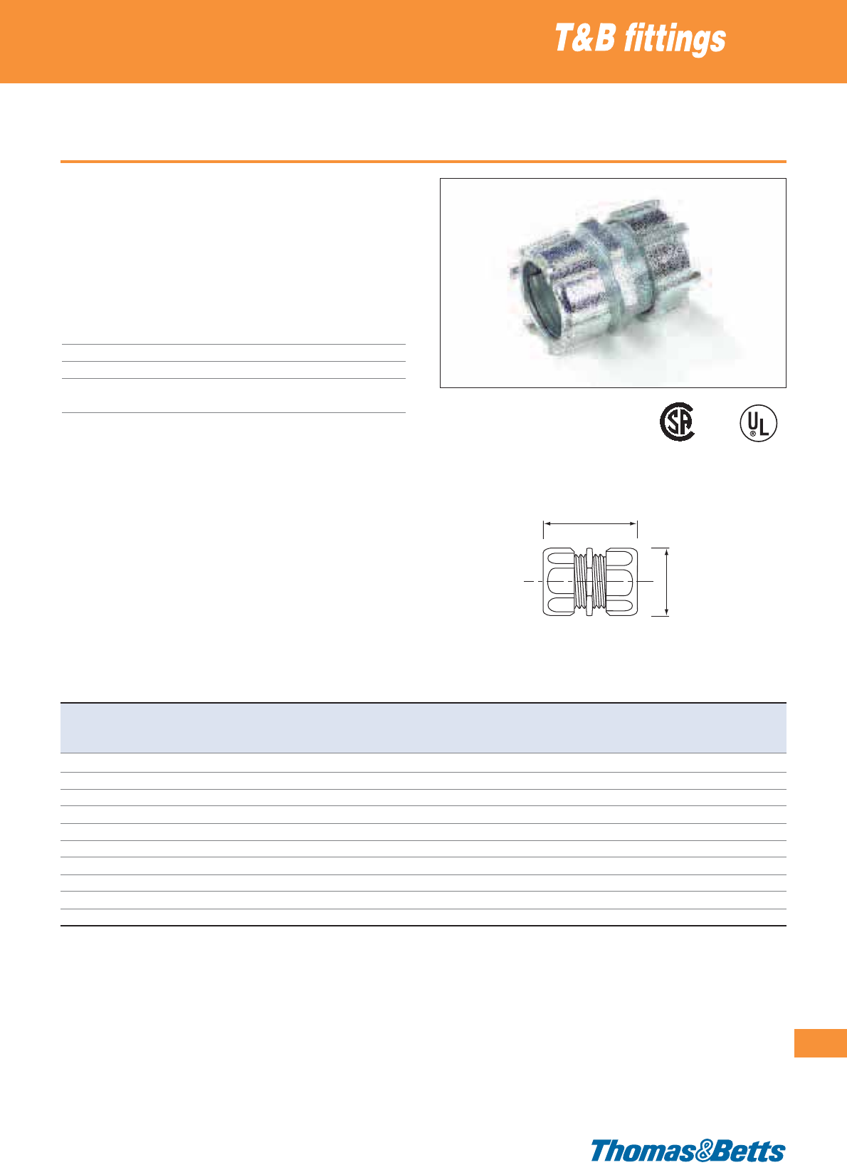
Metallic couplings for threadless conduits
• Easy coupling between 2 rigid conduits
• Eliminates the need for cutting a thread on the rigid conduits
• When tightened with a wrench, they form a UL listed and CSA
approved concrete-tight connection
• Components: 2 gland nuts, steel ring, steel spacer (only for sizes
up to 1 inch), body
Technical Information
Conduit Type Metallic rigid conduits
Style Straight
Material Zinc plated malleable iron or steel
Gland nut Zinc plated steel (up to 1”) or malleable
iron (larger sizes)
Rigid and intermediate metal conduit fittings
327
Thomas & Betts • www.tnb-europe.com
4.2
Product Ref. For conduit Dimensions Weight Quantity
size A B
[inch] [mm] [mm] [kg/100] [pieces]
8120
1
/
2
32.5 50.8 8.2 25
8220
3
/
4
40.5 58.7 14.6 25
8320 1 47.6 68.3 22.2 5
8420 1
1
/
4
60.3 71.4 54.0 5
8520 1
1
/
2
66.7 92.1 68.5 2
8620 2 82.6 96.8 98.9 2
8720 2
1
/
2
100.0 136.5 227.7 2
8820 3 119.1 139.7 258.6 1
8850 3
1
/
2
131.8 139.7 317.5 1
8970 4 144.5 139.7 378.8 1
A
B
E23018
002884
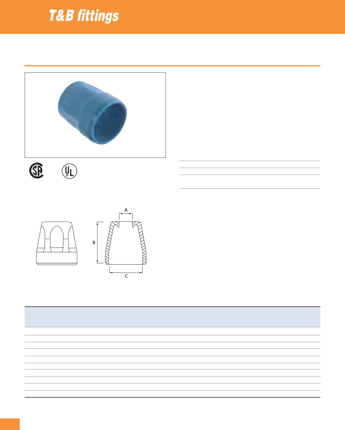
328
Thomas & Betts • www.tnb-europe.com
4.2
Plastic bushing
• For threadless rigid conduits and intermediate metal conduits
• When assembled to the end of a threadless conduit, provides a
well rounded insulating surface over which conductors may be
pulled or on which conductors may bear while in service.
• Designed to be popped onto, and bush, conduit end.
• Fast easy installation without screws
• High impact thermoplastic construction, for applications up to
+105°C
• Flammability rating UL 94 V-1
Technical Information
Conduit Type Metallic rigid conduits
Style Straight
Material UL 94 V-1 rated thermoplastic
Conformity UL514, ANSI C80.4, ANSI C33.84
NFPA 70-1978 (ANSI)
Rigid and intermediate metal conduit fittings
Product Ref. For conduit Dimensions Weight Quantity
size A B C
[inch] [mm] [mm] [mm] [kg/100] [pieces]
TRIB50
1
/
2
15.1 15.1 27.0 0.4 50
TRIB75
3
/
4
19.8 35.3 31.8 1.1 50
TRIB100 1 25.4 38.1 39.7 1.5 25
TRIB125 1
1
/
4
23.8 41.3 48.8 2.9 10
TRIB150 1
1
/
2
38.9 42.1 55.2 4.3 5
TRIB200 2 50.0 46.0 68.3 7.9 2
TRIB250 2
1
/
2
59.9 50.8 82.6 7.7 2
TRIB300 3 74.2 56.4 99.2 5.0 2
TRIB350 3
1
/
2
85.7 58.7 113.1 14.7 2
TRIB400 4 97.6 61.1 127.0 14.7 2
E13938
2884
4484
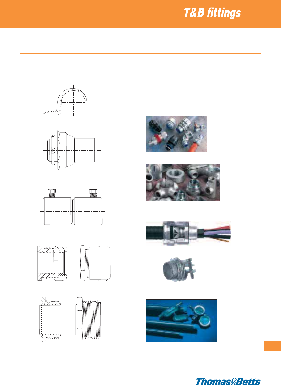
Other Thomas & Betts Conduit and Fittings
329
Thomas & Betts • www.tnb-europe.com
4.2
Examples of other fittings and accessories for the rigid and inter-
mediate metal conduit:
• Conduit straps and supports
• Uncoated and PVC-coated hubs for threaded rigid conduits
• Set screw connectors and couplings
• Threaded Erickson couplings
• Insulated nipples and bushings
The product ranges shown in this catalogue represent only a small
part of the extensive range of conduits and fittings that Thomas &
Betts offer on a global scale, including among others:
• Other special fittings for flexible metallic conduits (e.g. PVC coated
fittings, aluminium fittings, fittings with revolving grounding lug,
etc)
• Conduit outlet bodies, for ordinary and hazardous locations
• Explosion proof conduit outlet bodies, elbows, reducers, plugs,
adapters and couplings
• Explosion proof aluminium sealing fittings
• STAR Teck metal clad cable glands for harsh and corrosive
environments
• Non-metallic sheathed cable glands
• OCAL, corrosion resistant PVC-coated rigid conduits, junction
boxes and accessories
For more detailed information on these products, please visit the Thomas & Betts global web site: www.tnb-europe.com and / or contact your Sales Office
for product availability.
330
Thomas & Betts • www.tnb-europe.com
4.3
Cable glands
Providing strain relief
and sealing
for cable entries

331
Thomas & Betts • www.tnb-europe.com
4.3
CONDUIT & FITTINGS
4.1 FLEXIBLE CONDUITS 260
4.2 FITTINGS & ACCESSORIES 284
4.3 SHURESEAL™ CABLE GLANDS 330
Metallic cable glands 334
Plastic cable glands 336
Housing entry tubes with strain relief 337
332
Thomas & Betts • www.tnb-europe.com
4.3
Whatever the application.
Whatever the size.
Thomas & Betts is your
connection to tough,
versatile cable glands.
333
Thomas & Betts • www.tnb-europe.com
4.3
Shureseal™ Cable glands
Providing strain relief and sealing
for cable entries
The Liquidtight cable glands take twice the cable range of
most ordinary strain relief connectors. T&B’s cable glands
allow you to reduce your inventory and save time, with
one connector that can do the work of two. The sturdy
nylon material of the plastic cable glands adds corrosion
resistance to your installation.
Thomas & Betts offers a complete line of rugged, reliable cable
glands. All fittings are produced to the highest standards, com-
bining innovative design and precision manufacturing methods to
provide the products you need for your specific applications.
Combining proven performance, installation advantages and
availability of ranges, T&B is also your connection to lower installed
costs for the life of your cord and cable requirements.
Standard application
• Provide means for passing a cable into an enclosure, through
a bulkhead or into a rigid conduit.
• Form a mechanical grip and water and/or oil resistant seal for
round cables.
• Form a non-slip connection or termination for flexible cable.
Features
• Extended range with superior strain relief.
• Reduced overall size fits into tighter spaces.
• Gland nut designed to restrict cable bending.

334
Thomas & Betts • www.tnb-europe.com
4.3
Straight metallic cable glands
• Special construction prevents twisting and ensures effective strain
relief
Technical Information
Style/thread Straight / NPT and metric (I.S.O.)
IP rating IP65
Material Zinc or zinc plated steel
Gland nut Steel or zinc plated steel
Seal Neoprene or rubber
Colour Metallic
Temperature range -35°C to +105°C
Cable glands
E13938
004484
002884
Product ref. Material Material Material Cable ø range Thread Dimensions Quantity
body seal nut from...to size A B C
[mm] [mm] [mm] [mm] [pieces]
STRAIGHT METALLIC CABLE GLAND WITH METRIC (I.S.O.) THREAD
9520* zinc plated steel Neoprene zinc plated steel 3.2 - 6.3 M20 28.6 42.0 14.3 25
9521-EU* zinc plated steel Neoprene zinc plated steel 6.3 - 9.5 M20 28.6 42.0 14.3 25
9522-EU* zinc plated steel Neoprene zinc plated steel 9.5 - 12.7 M20 28.6 42.0 14.3 25
9523* zinc plated steel Neoprene zinc plated steel 11.4 - 14.2 M20 28.6 42.0 14.3 25
9524-EU* zinc plated steel Neoprene zinc plated steel 12.7 - 15.8 M20 34.9 44.5 15.0 25
STRAIGHT METALLIC CABLE GLAND WITH NPT THREAD
2920 zinc rubber zinc plated steel 3.2 - 9.5
1
/
2
28.6 44.5 15.9 25
2921 zinc rubber zinc plated steel 7.9 - 14.2
1
/
2
28.6 44.5 15.9 25
2922 zinc rubber zinc plated steel 12.7 - 19.1
1
/
2
34.9 44.5 15.9 10
2930 zinc rubber zinc plated steel 3.2 - 9.5
3
/
4
34.9 45.2 19.1 10
2931 zinc rubber zinc plated steel 7.9 - 14.2
3
/
4
34.9 45.2 19.1 10
2932 zinc rubber zinc plated steel 12.7 - 19.1
3
/
4
34.9 45.2 19.1 10
2940 zinc rubber zinc plated steel 7.9 - 14.2 1 34.9 44.5 20.6 10
2941 zinc rubber zinc plated steel 12.7 - 19.1 1 34.9 44.5 20.6 10
2942 zinc rubber zinc plated steel 17.8 - 24.1 1 41.3 47.6 20.6 10
2520 zinc Neoprene steel 3.2 - 6.4
1
/
2
29.4 42.9 15.9 25
2521 zinc Neoprene steel 6.4 - 9.5
1
/
2
29.4 42.9 15.9 25
2522 zinc Neoprene steel 9.5 - 12.7
1
/
2
29.4 42.9 15.9 25
2523 zinc Neoprene steel 11.4 - 14.2
1
/
2
29.4 42.9 15.9 25
2524 zinc Neoprene steel 12.7 - 15.9
1
/
2
34.9 44.5 15.9 25
2525 zinc Neoprene steel 15.9 - 19.1
1
/
2
34.9 44.5 15.9 25
2558 zinc Neoprene steel 22.4 - 27.1 1
1
/
4
53.2 54.8 20.6 5
2559 zinc Neoprene steel 27.1 - 30.6 1
1
/
4
53.2 54.8 20.6 5
2562 zinc Neoprene steel 20.6 - 25.4 1
1
/
2
59.5 63.5 17.5 5
2563 zinc Neoprene steel 25.4 - 30.1 1
1
/
2
59.5 63.9 17.5 5
2574 zinc Neoprene steel 34.9 - 41.3 2 71.4 66.7 17.5 1
2575 zinc Neoprene steel 41.3 - 47.6 2 71.4 66.7 17.5 1
* The Product Ref. with a * are not CSA approved
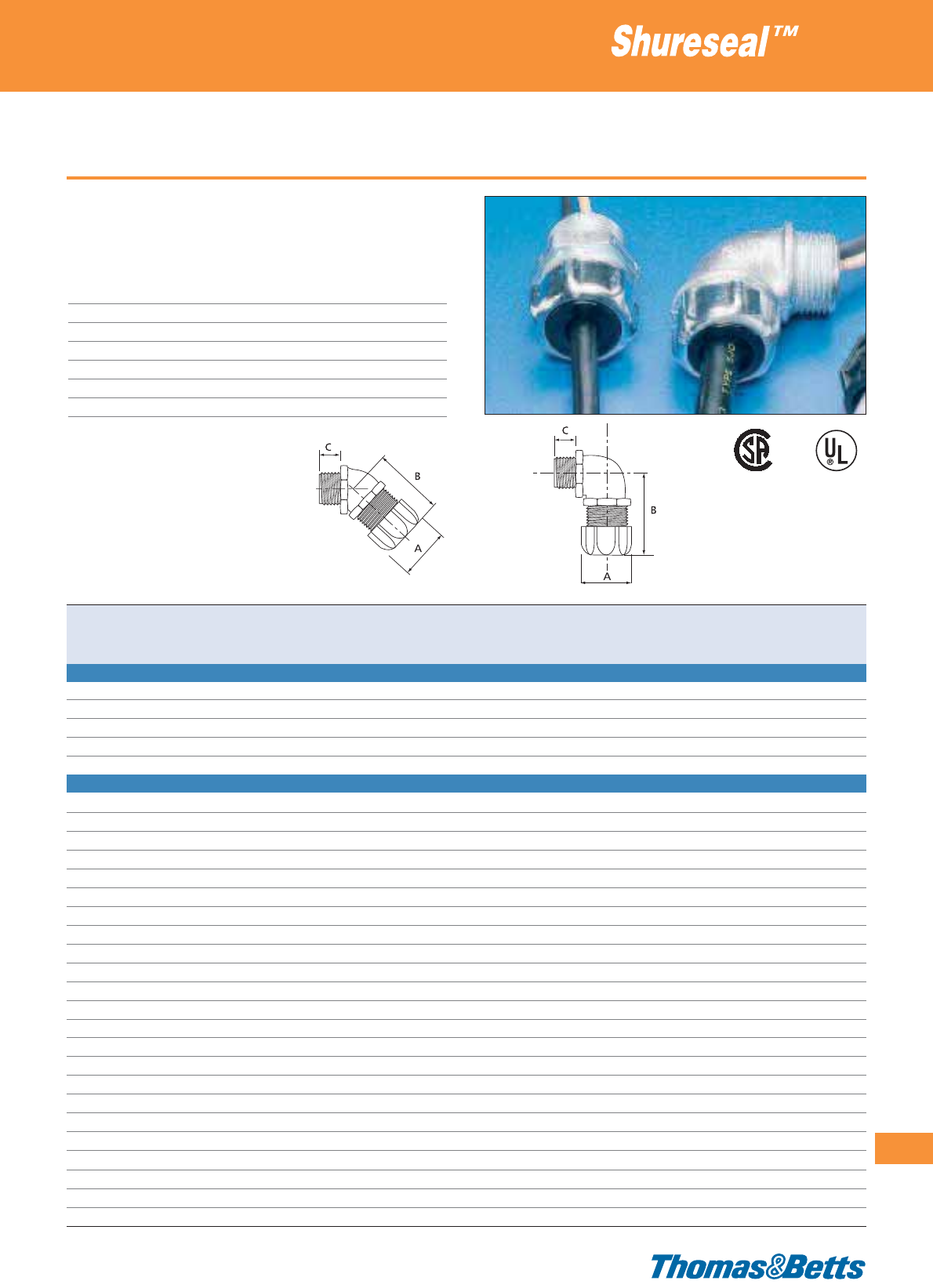
45° and 90° metallic cable glands
• Special construction prevents twisting and ensures effective strain
relief
Technical Information
Style/thread 45° and 90° / NPT
IP rating IP65
Material Zinc or zinc plated steel
Gland nut Steel or zinc plated steel
Seal Neoprene or rubber
Colour Metallic
Temperature range -35°C to +105°C
Cable glands
335
Thomas & Betts • www.tnb-europe.com
4.3
E13938
052391
002884
004484
Product ref. Material Material Material Cable ø range Thread Dimensions Quantity
body seal nut from...to size A B C
[mm] [mm] [mm] [mm] [pieces]
90° METALLIC CABLE GLAND WITH NPT THREAD
4960 zinc plated steel rubber steel 3.2 - 9.5
1
/
2
28.6 44.5 15.9 25
4961 zinc plated steel rubber steel 7.9 - 14.2
1
/
2
28.6 44.5 15.9 25
4970 zinc plated steel rubber steel 3.2 - 9.5
3
/
4
34.9 45.2 17.5 10
4971 zinc plated steel rubber steel 7.9 - 14.2
3
/
4
34.9 45.2 17.5 10
4972 zinc plated steel rubber steel 12.7 - 19.0
3
/
4
34.9 45.2 17.5 10
45° METALLIC CABLE GLAND WITH NPT THREAD
2200 zinc plated malleable iron Neoprene zinc plated steel 3.2 - 6.3
1
/
2
29.4 32.5 14.3 25
2201 zinc plated malleable iron Neoprene zinc plated steel 6.3 - 9.5
1
/
2
29.4 32.5 14.3 25
2202 zinc plated malleable iron Neoprene zinc plated steel 9.5 - 12.7
1
/
2
29.4 32.5 14.3 25
2203 zinc plated malleable iron Neoprene zinc plated steel 11.4 - 14.2
1
/
2
29.4 32.5 14.3 25
2204 zinc plated malleable iron Neoprene zinc plated steel 12.7 - 15.9
1
/
2
34.9 35.7 14.3 10
2205 zinc plated malleable iron Neoprene zinc plated steel 15.9 - 19.1
1
/
2
34.9 35.7 14.3 10
2206-TB zinc plated malleable iron Neoprene zinc plated steel 3.2 - 6.3
3
/
4
34.9 35.7 15.9 10
2207-TB zinc plated malleable iron Neoprene zinc plated steel 6.3 - 9.5
3
/
4
34.9 35.7 15.9 10
2208-TB zinc plated malleable iron Neoprene zinc plated steel 9.5 - 12.7
3
/
4
34.9 35.7 15.9 10
2209 zinc plated malleable iron Neoprene zinc plated steel 12.7 - 15.9
3
/
4
34.9 35.7 15.9 10
2210 zinc plated malleable iron Neoprene zinc plated steel 15.9 - 19.1
3
/
4
34.9 35.7 15.9 10
2211 zinc plated malleable iron Neoprene zinc plated steel 19.1 - 22.2
3
/
4
42.9 38.1 38.1 10
2213 zinc plated malleable iron Neoprene zinc plated steel 9.5 - 12.7 1 34.9 38.1 19.8 5
2214 zinc plated malleable iron Neoprene zinc plated steel 12.7 - 15.9 1 34.9 38.1 19.8 5
2215 zinc plated malleable iron Neoprene zinc plated steel 15.9 - 19.1 1 34.9 38.1 19.8 5
2216 zinc plated malleable iron Neoprene zinc plated steel 19.1 - 22.2 1 42.9 37.3 19.8 5
2217 zinc plated malleable iron Neoprene zinc plated steel 22.2 - 25.0 1 42.9 37.3 19.8 5
2218 zinc plated malleable iron Neoprene zinc plated steel 22.3 - 27.0 1 53.2 50.0 19.8 5
2219 zinc plated malleable iron Neoprene zinc plated steel 27.0 - 30.1 1 53.2 50.0 19.8 5
2220-TB zinc plated malleable iron Neoprene zinc plated steel 22.3 - 27.0 1
1
/
4
53.2 48.4 20.6 2
2221 zinc plated malleable iron Neoprene zinc plated steel 27.0 - 30.1 1
1
/
4
53.2 48.4 20.6 2
2222 zinc plated malleable iron Neoprene zinc plated steel 30.1 - 34.9 1
1
/
4
59.5 57.2 20.6 2
2223 zinc plated malleable iron Neoprene zinc plated steel 34.9 - 37.7 1
1
/
4
59.5 57.2 20.6 2
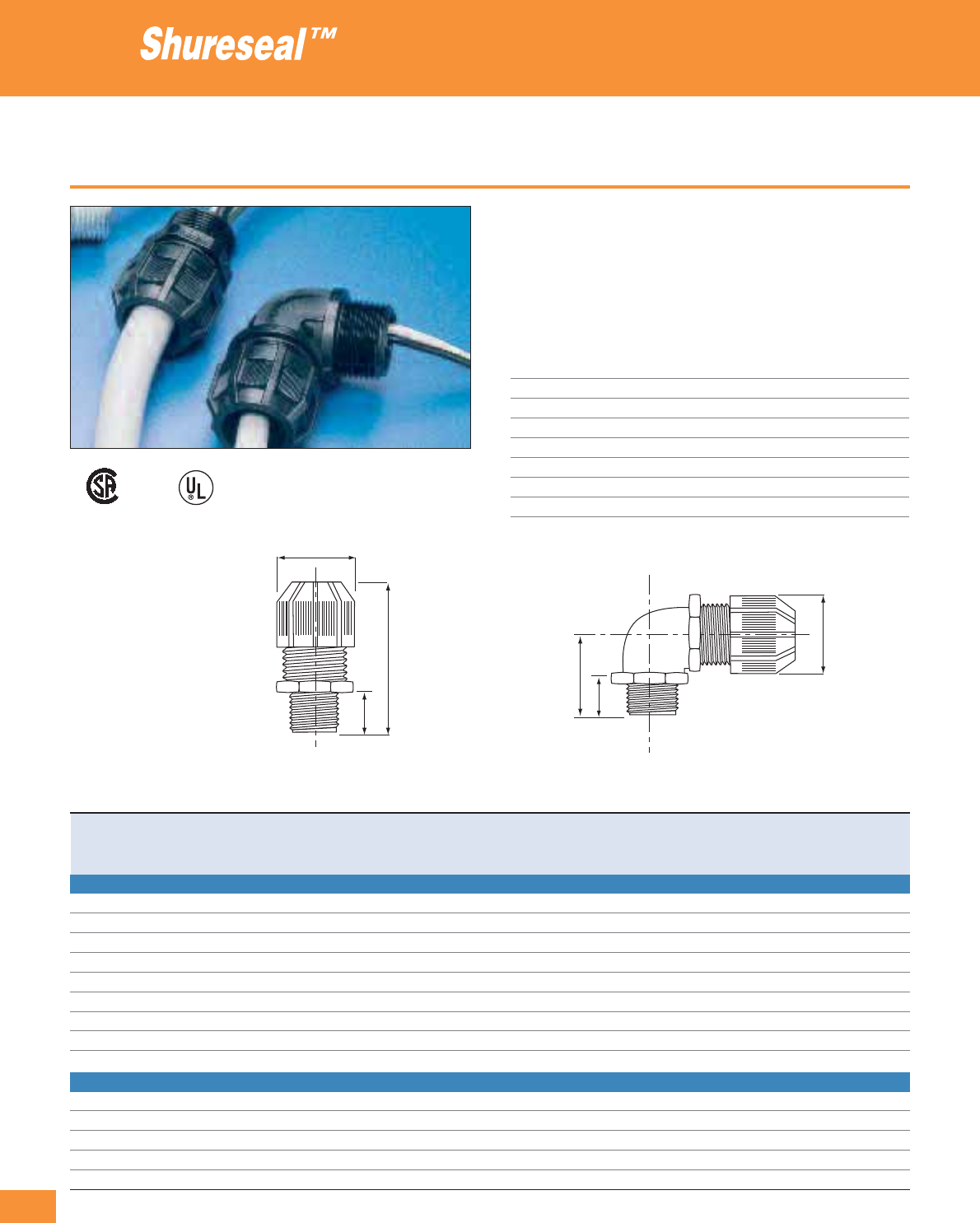
336
Thomas & Betts • www.tnb-europe.com
4.3
Plastic cable glands
• High performance plastic cable fittings
• Special construction prevents twisting and ensures effective strain
relief
• Easy to install
• For all cable sizes between 3.2 and 24.1 mm of outer diameter
Technical Information
Style/thread Straight and 90° / NPT threads
IP rating IP65
Material UV resistant polyamide 6.6.
Steel locknut Chromate finished steel or zinc
Seal Neoprene
Colour Black
Flammability rating UL 94 V-2
Temperature range -34°C to +105°C
Cable glands
Product ref. Cable diameter range Thread Dimensions Quantity
from...to size A B C
[mm] [inch] [mm] [mm] [mm] [pieces]
STRAIGHT PLASTIC CABLE GLAND WITH NPT THREAD
2920NM 3.2 - 9.5
1
/
2
26.2 54.0 15.9 25
2921NM 7.9 - 14.2
1
/
2
26.2 54.0 15.9 25
2922NM 12.7 - 19.0
1
/
2
35.7 54.0 15.9 25
2930NM 3.2 - 9.5
3
/
4
35.7 55.6 15.9 10
2931NM 7.9 - 14.2
3
/
4
35.7 55.6 15.9 10
2932NM 12.7 - 14.2
3
/
4
35.7 55.6 15.9 10
2940NM 7.9 - 14.2 1 35.7 59.5 19.8 10
2941NM 12.7 - 19.0 1 35.7 59.5 19.8 10
2942NM 17.8 - 24.1 1 42.5 60.3 19.8 10
90° PLASTIC CABLE GLAND WITH NPT THREAD
4960NM 3.2 - 9.5
1
/
2
30.9 31.8 15.9 25
4961NM 7.9 - 14.2
1
/
2
30.9 31.8 15.9 25
4970NM 3.2 - 9.5
3
/
4
35.7 34.9 15.9 10
4971NM 7.9 - 14.2
3
/
4
35.7 34.9 15.9 10
4972NM 12.7 - 19.0
3
/
4
35.7 34.9 15.9 10
E13938
052391
A
A
C
B
B
C
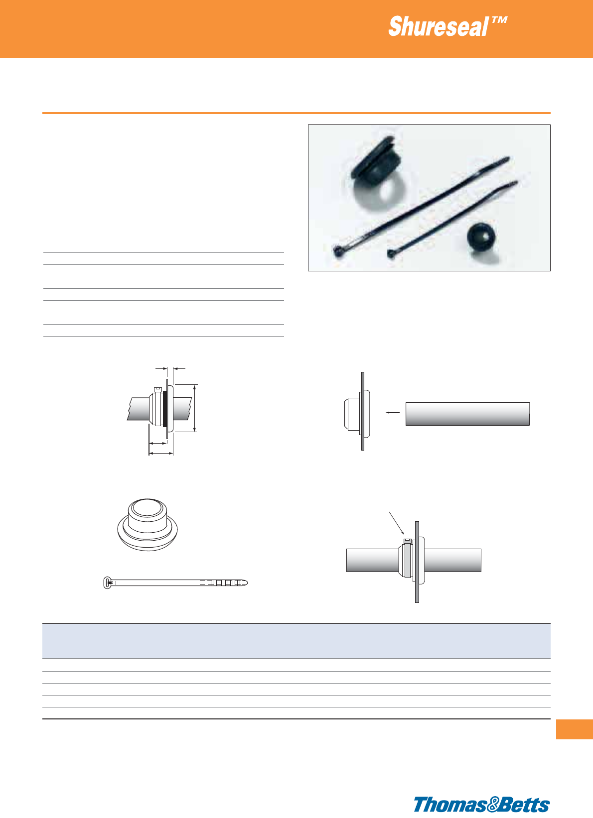
Housing entry tubes with strain relief ties
• Highly elastic material allows passing of single wires
• Resistant to chemicals
• Weatherproof
• Simple and fast installation
• Supplied with a UV-resistant Ty-Rap®cable tie (see chapter 1 for
cable tie specifications) for strong, secure and watertight strain-
relief
Technical Information
Material - Housing Neoprene
Material - Tie Polyamide 6.6, UV-resistant
Temperature range -30°C to +110°C for the housing
-40°C to +85°C for the cable tie
Colour Black (housing and tie)
Flammability rating UL 514 (housing)
UL 94 V-2 (cable tie)
Other properties Halogen free, Silicone free
Cable glands
337
Thomas & Betts • www.tnb-europe.com
4.3
Product Ref. Dimensions for cable ø ø of hole for panel Type of Weight Quantity
A B D E from … to in panel thickness up to included
[mm] [mm] [mm] [mm] [mm] [mm] [mm] cable tie [g/100] [pieces]
7401 18.6 24 13.6 5.0 4.0 - 9.0 16 2.2 TY24MX 420 10
7402 18.7 28 13.7 5.0 7.0 - 12.0 19 2.2 TY25MX 690 10
7403 22.0 34 17.0 5.0 12.0 - 18.0 25 2.2 TY25MX 1100 10
7404 24.0 43 19.0 5.0 18.0 - 25.0 32 2.2 TY25MX 1500 5
7405 24.5 51 18.5 6.0 25.0 - 32.0 38 2.2 TY25MX 1950 5
E
B
A
D

338
Thomas & Betts • www.tnb-europe.com
5.1
Sta-Kon®
Solderless crimp
connectors to
terminate cables

339
Thomas & Betts • www.tnb-europe.com
5.1
TERMINATION SYSTEMS
5.1 STA-KON®- CRIMP TERMINALS 338
Selection guide 342
Insulated terminals 344
Ring terminals 344
Fork terminals 347
Pin terminals & Blade terminals 350
Bootlace ferrules 352
Disconnect terminals 353
Sectional terminal block 356
Bullet disconnects 356
Butt splices 358
Wire joints 359
Quick splices 359
Non-insulated terminals 360
Ring terminals 360
Fork terminals 361
Pin terminal 362
Butt splices 362
Copper tube ring terminals 363
Disconnect terminals 365
Tabs for soldering 367
Screw mounted disconnect tabs 368
Crimping tools 370
Plier type crimping tools 370
Standard crimping tools 370
Ergonomic hand tools with interchangeable dies 372
Ergonomic hand tools with fixed die 372
Large hand tool 374
Hydraulic tools 375
Tooling and die selection chart 376
Stripping & cutting tools 377
Ergonomic hand tools 377
Standard hand tools 378
Heavy-duty cable cutters 381
5.2 COLOR-KEYED®- POWER CABLE CONNECTORS 382
5.3 DRAGON TOOTH®- MAGNET WIRE TERMINALS 396
5.4 SHIELD-KON®- SHIELDED CABLE CONNECTORS 428

340
Thomas & Betts • www.tnb-europe.com
5.1
Sta-Kon®Solderless
crimp connectors
Experience the Sta-Kon®advantage!
Thomas & Betts developed the first tool-applied solderless
terminals and connectors more than 60 years ago in
response to industry awareness of the need for better
performance of electrical systems.
Since then, the crimping technology, in which a permanent join-
ing of wires / cables to connectors is achieved by the insertion of
a conductor into the barrel of the connector, which is then com-
pressed to form a solid joint, has proven its many advantages year
after year. Reliability of connection, low installed cost, low level of
skill required to produce repeatable and quality crimps, environ-
mental compliance (versus soldering for instance) are examples of
benefits that have given this technology its natural superiority.

341
Thomas & Betts • www.tnb-europe.com
5.1
Wide range of styles,
materials and
application tools
Easy entry design
This feature makes wire insertion faster and easier. Chamfering
eliminates wire strand “hang up” and departure upon insertion
into the terminal’s barrel. The loss of even a couple of wire strands
can have negative results on electrical efficiency and resistance to
mechanical strain.
Brazed seam / tubular construction
Sta-Kon®connectors have a barrel with brazed seam (or a tubu-
lar construction), which provides increased mechanical properties
(no barrel separation during the crimp process, higher wire pull-
out force) and electrical properties (reduced chances of wirestrand
loss and electrical failure) compared to butted seam connectors.
Wide range of styles, materials and application tools
Extensive range of styles to suit the various applications: rings,
forks, blades, pins, bootlace ferrules, disconnects, splices…
Non-insulated or insulated with various types of material (Poly-
carbonate, Vinyl, Polyamide, Tefzel®…) according to the specific
requirements.
Complete range of tooling, from ergonomic hand tool to pneu-
matic and hydraulic power tools.
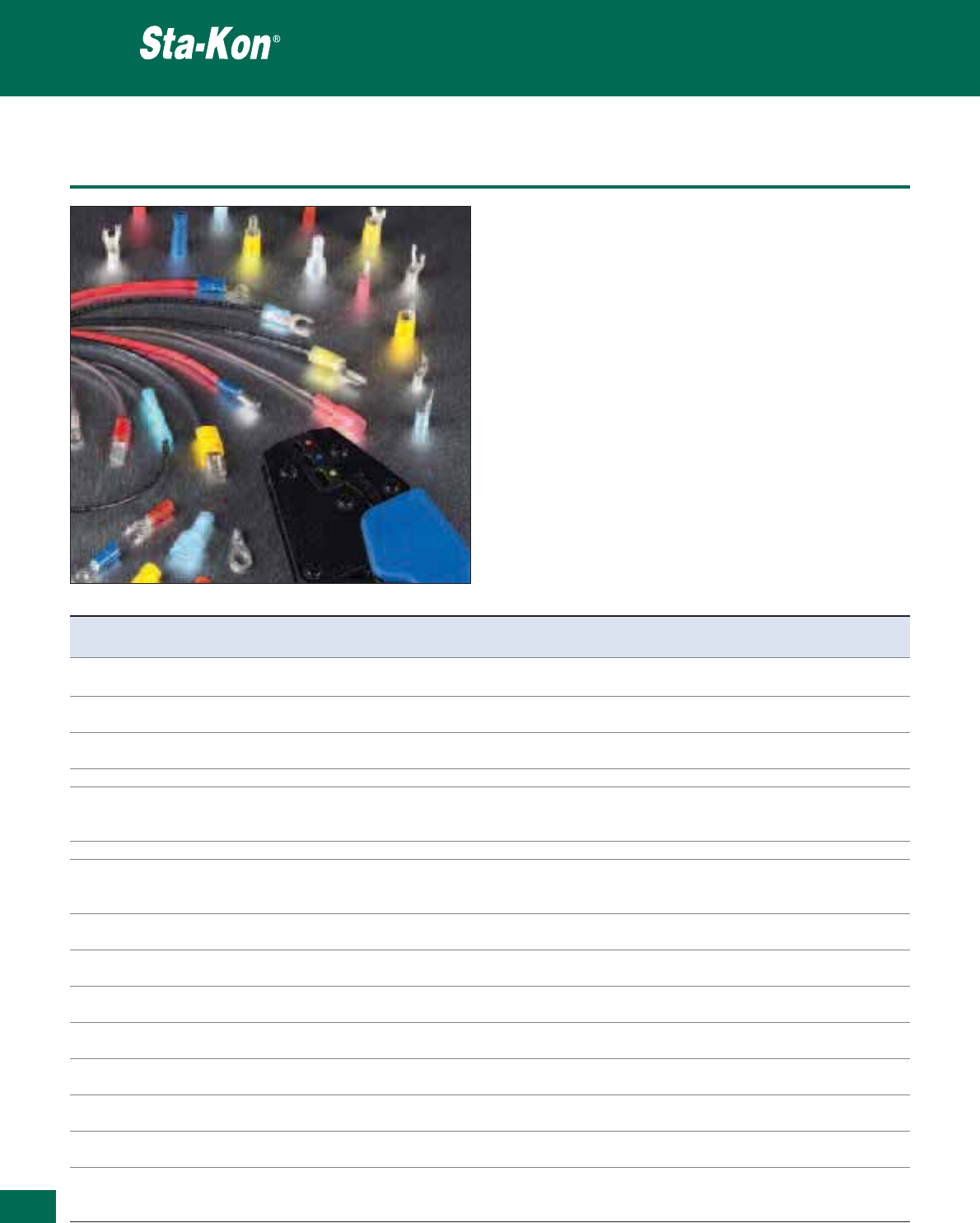
342
Thomas & Betts • www.tnb-europe.com
5.1
Selection guide
With the Sta-Kon®range of solderless terminals, Thomas & Betts
offer a complete termination system:
• Terminals for wires / cables from 0.25 to 150 mm2
• Insulated, non-insulated, disconnects and splices
• Copper lugs and compression connectors
• Standard and unique products for specific applications
• Products for harsh or ambient environments
• Low to high volume applications
• Complete range of tooling, from ergonomic hand tool to
pneumatic and hydraulic power tools
Sta-Kon®terminals are available in insulated and non insulated
versions (including copper tube terminals)
Crimp terminals
Features Benefits Insulated Non insulated Copper
terminals terminals tube lugs
Easy entry design Avoid wire hang up and allows fast x x x
and secure insertion of the conductor
High conductivity electrolytic copper Superior conductivity and low contact x x x
resistance with a strong connection
Disconnects in brass with min. 70% copper Improved mechanical properties x x
(spring effect)
Electro-tin plating Maximum corrosion resistance x x
The contact area on the terminal Better resistance to mechanical deformations x x
(e.g. in forks, rings,...) is harder than
the crimp area
Brazed seam (*) No barrel separation during crimping x x
Internal barrel serrations (with some terminals) Better contact (low contact resistance) x x
and improved mechanical properties
(against vibration and pull out)
Cable size and bolt size marking Instant identification and selection of the terminal x x x
(on most terminals)
Dimensional specifications according to Standardised dimensioning x
DIN 46235 and DIN 46234
Several styles: Rings, Forks, Blades, pins, To cover all types of application x x
bootlace ferrules, Male and female disconnects, …
Special styles: Copper tube ring terminals, To cover specific applications x x
PCB terminals (DIN 46244)
Colour coded insulators, according to Instant identification and selection of the terminal x
DIN cable sizes
Several insulation materials: Multiple temperature and flammability rating x
PVC (Vinyl), PA (Nylon), PC, Tefzel®
Specifications According to DIN specifications MIL, UL, x x x
CSA approved terminals available upon request
Dedicated tooling range: xxx
crimp tools Reliable and high quality crimps, for all kind of volumes
cable strippers and cutters Standard, ergonomic and heavy duty ranges
Tefzel
®
is a registered trademark of DuPont de Nemours
(*) Note: some non-insulated terminals have a copper tube construction, for maximum resistance against barrel opening during the crimp process
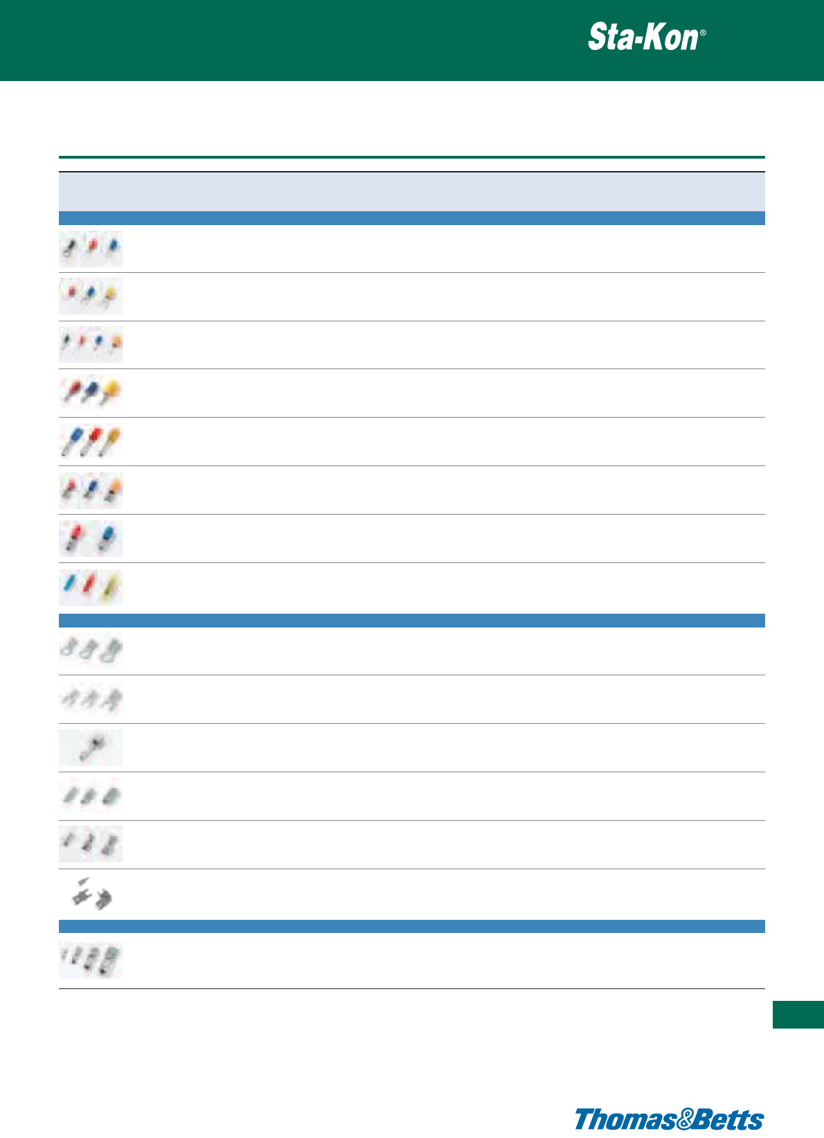
Selection guide
Crimp terminals
343
Thomas & Betts • www.tnb-europe.com
5.1
Terminal type Material Plating Marking Metal Insulation Colour Cable Flammability Page
barrel
coding insertion rating N°
INSULATED TERMINALS
Ring Copper Tin plated Wire size & Brazed PC / PVC / PA yes Easy entry UL 94 V-0 & 344
bolt size seam UL 94 V-2
Fork Copper Tin plated Wire size & Brazed PC / PVC / PA yes Easy entry UL 94 V-0 & 347
bolt size seam UL 94 V-2
Pin Electrolytic Tin plated - Brazed PC yes Easy entry UL 94 V-2 350
Copper seam
Blade Electrolytic Tin plated Wire size Brazed PC yes Easy entry UL 94 V-2 351
Copper seam
Bootlace Copper Tin plated - Copper PA yes - UL 94 V-2 352
tube
Disconnect Brass with Tin plated - Brazed PC / PVC / PA yes Easy entry UL 94 V-0 & 353
70% copper** seam* UL 94 V-2
Bullet Phosphor Tin plated - Brazed PC / PVC yes Easy entry UL 94 V-0 & 356
bronze / Brass seam* UL 94 V-2
Splice Electrolytic Tin plated - Brazed PA / PC / yes Easy entry UL 94 V-2 358
Copper / Brass seam heat shrink
insulation / PP
NON-INSULATED TERMINALS
Ring Electrolytic Electro- Wire size & Brazed - - Easy entry - 360
Copper tin plating bolt size seam
Fork Electrolytic Electro- Wire size & Brazed - - Easy entry - 361
Copper tin plating bolt size seam
Pin Electrolytic Tin plated - - - - - - 362
Copper
Splice Copper Tin plated - Tubular - - Easy entry - 362
construction
Disconnect Brass with Tin plated - - - - - - 365
70% copper
Solder tabs Brass with Tin plated - - - - - - 367
70% copper
COPPER TUBE LUGS
Ring Electrolytic Tin plated Wire size & Copper - - Easy entry - 363
Copper bolt size tube
* Non brazed, with brass support sleeve
** 100% Brass for MTB1-TB
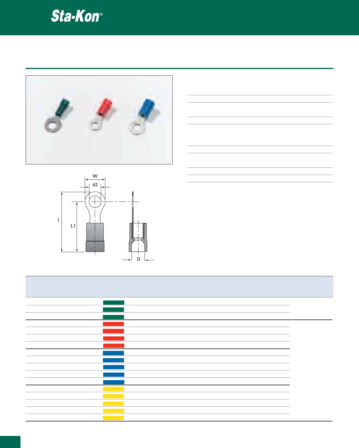
344
Thomas & Betts • www.tnb-europe.com
5.1
Polycarbonate insulated ring terminals
Technical Information
Material Electrolytic copper
Plating Tin plated
Marking Wire size and bolt size stamped on
the tongue
Metal barrel Brazed seam to prevent barrel separation
Insulation PC = Polycarbonate
High temperature applications,
excellent deformation characteristics
Temperature resistance +115°C / +125°C
Colour coding of the According to the wire size
insulation
Cable insertion Easy entry
Flammability rating UL 94 V-2
Insulated terminals
Product Ref. Wire size range Colour Stud hole size Dimensions Weight Quantity Crimping
d2 W L D L1 tool*
[mm
2
] [mm] [mm] [mm] [mm] [g/100] [pieces]
RZ 3 0.25 - 0.75 Green M 3 5.5 18.0 3.2 15.0 36 100
RZ 4 0.25 - 0.75 Green M 4 7.5 21.0 3.2 17.5 45 100 ERG2510
RZ 5 0.25 - 0.75 Green M 5 9.0 22.0 3.2 17.5 51 100
RA3RR 0.5 - 1.5 Red M 3 5.5 19.0 4.0 16.0 60 100
RA4RR 0.5 - 1.5 Red M 4 7.0 20.5 4.0 17.0 71 100
RA5RR 0.5 - 1.5 Red M 5 9.0 22.5 4.0 18.0 79 100
RA6RR 0.5 - 1.5 Red M 6 11.0 26.5 4.0 21.0 96 100
RB 3 1.5 - 2.5 Blue M 3 5.5 19.0 4.5 16.0 75 100
RB 4-EU 1.5 - 2.5 Blue M 4 7.0 20.5 4.5 17.0 92 100 ERG2000KE
RB 5 1.5 - 2.5 Blue M 5 9.0 22.5 4.5 18.0 96 100 ERG2001A
RB 6 1.5 - 2.5 Blue M 6 11.0 26.5 4.5 21.0 117 100 WT2124Y
RB 8 1.5 - 2.5 Blue M 8 14.0 27.5 4.5 21.0 141 100
RC 4 4.0 - 6.0 Yellow M 4 8.0 24.0 6.4 20.5 158 50
RC 5 4.0 - 6.0 Yellow M 5 9.0 25.0 6.4 20.5 166 50
RC 6-EU 4.0 - 6.0 Yellow M 6 11.0 28.5 6.4 23.0 179 50
RC 8 4.0 - 6.0 Yellow M 8 14.0 31.0 6.4 24.0 220 50
RC 10 E 4.0 - 6.0 Yellow M 10 17.0 34.0 6.4 25.5 245 50
* Use selection chart to determine die set (see page 376)
See pages 370 to 376 for tooling specifications
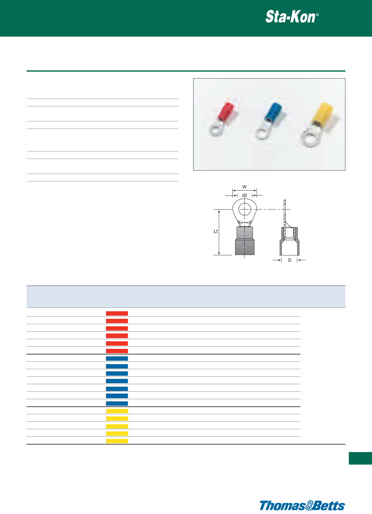
Nylon insulated ring terminals DIN 46237
Technical Information
Material Copper
Plating Tin plated
Marking Wire size and bolt size stamped on the
tongue
Metal barrel Brazed seam to prevent barrel separation
Insulation PA = Polyamide
Ideal for harsh environments, excellent
chemical, impact and abrasion resistance
Temperature resistance +85°C / +105°C
Colour coding of the According to the wire size
insulation
Flammability rating UL 94 V-2
Insulated terminals
345
Thomas & Betts • www.tnb-europe.com
5.1
Product Ref. Wire size range Colour Stud hole size Dimensions Weight Quantity Crimping
d2 W L1 D tool*
[mm
2
] [mm] [mm] [mm] [g/100] [pieces]
TRA 3 0.5 - 1.5 Red M 3 5.5 17.5 4.0 70 100
TRA 35 0.5 - 1.5 Red M 3.5 6.6 20.4 4.0 67 100
TRA 4 0.5 - 1.5 Red M 4 8.0 21.8 4.0 76 100
TRA 5 0.5 - 1.5 Red M 5 8.0 21.8 4.0 79 100
TRA 6 0.5 - 1.5 Red M 6 11.6 27.5 4.0 108 100
TRA 8 0.5 - 1.5 Red M 8 11.6 27.5 4.0 134 100
TRB 3 1.5 - 2.5 Blue M 3 6.0 20.6 4.5 79 100
TRB35 1.5-2.5 Blue M 3.5 8.5 23.0 4.5 76 100 ERG2000KE
TRB 4 1.5 - 2.5 Blue M 4 8.5 23.0 4.5 79 100 ERG2001A
TRB 5 1.5 - 2.5 Blue M 5 9.5 22.9 4.5 89 100 WT2124Y
TRB 6 1.5 - 2.5 Blue M 6 12.0 28.0 4.5 117 100
TRB 8 1.5 - 2.5 Blue M 8 12.0 28.0 4.5 148 100
TRB10 1.5-2.5 Blue M 10 13.6 31.7 4.5 204 100
TRC 4-EU 4.0 - 6.0 Yellow M 4 7.4 26.7 6.4 158 100
TRC 5-EU 4.0 - 6.0 Yellow M 5 9.5 26.7 6.4 175 100
TRC 6-EU 4.0 - 6.0 Yellow M 6 12.0 32.7 6.4 187 100
TRC 8 4.0 - 6.0 Yellow M 8 15.0 34.9 6.4 230 100
TRC 10 4.0 - 6.0 Yellow M 10 15.0 34.9 6.4 296 100
* Use selection chart to determine die set (see page 376)
See pages 370 to 376 for tooling specifications
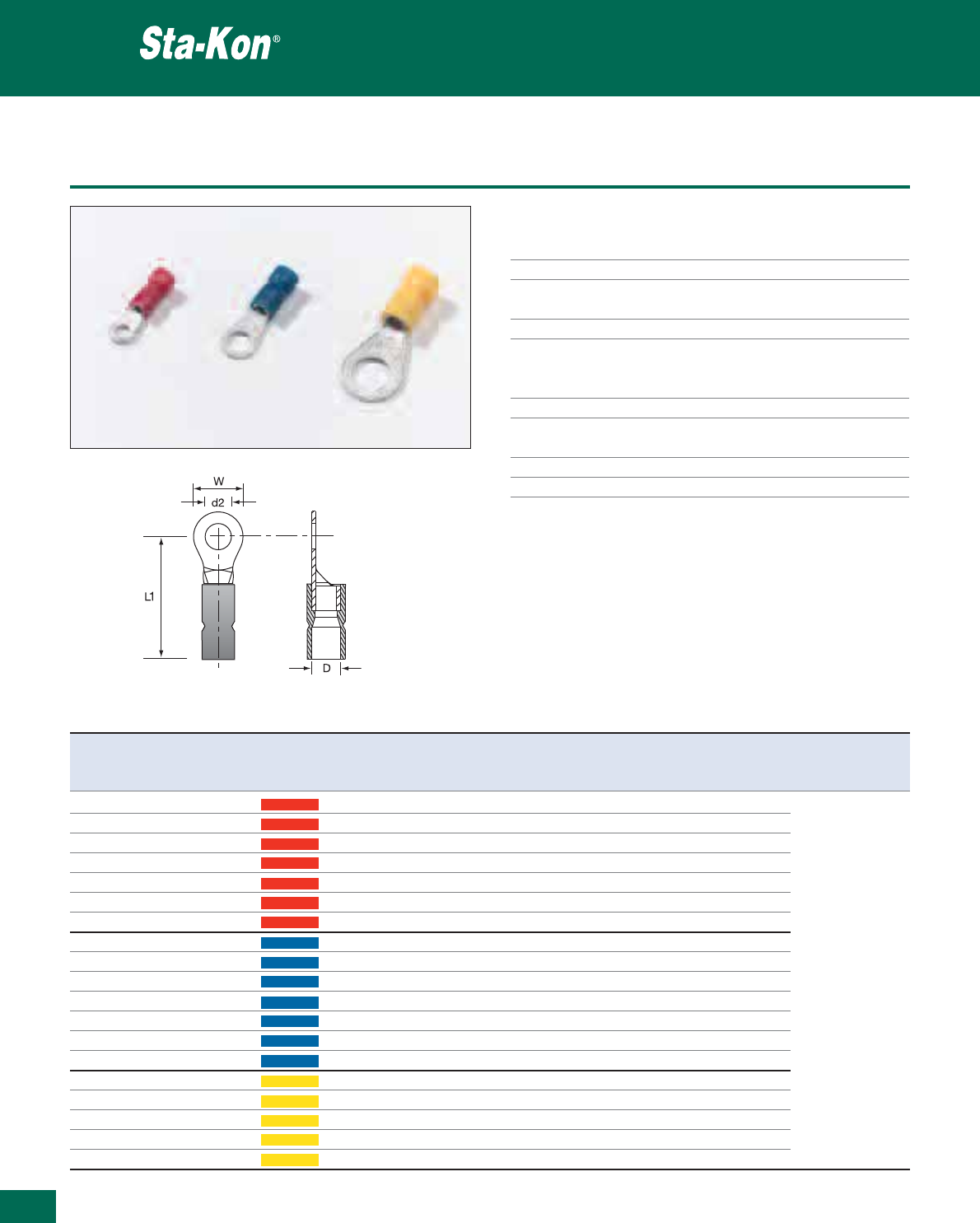
346
Thomas & Betts • www.tnb-europe.com
5.1
Vinyl insulated ring terminals DIN 46237
Technical Information
Material Copper
Plating Tin plated
Marking Wire size and bolt size stamped on the
tongue
Metal barrel Brazed seam to prevent barrel separation
Insulation PVC = Polyvinylchloride (Vinyl)
Economical yet premium quality,
moisture resistant
Max. electrical rating +75°C / 600 Volts max
Colour coding of the According to the wire size
insulation
Cable insertion Easy entry
Flammability rating UL 94 V-0
Insulated terminals
Product Ref. Wire size range Colour Stud hole size Dimensions Weight Quantity Crimping
d2 W L1 D tool*
[mm
2
] [mm] [mm] [mm] [g/100] [pieces]
VB3RR 0.5 - 1.5 Red M 3 6.0 17.2 4.0 68 100
VB35RR 0.5 - 1.5 Red M 3.5 6.0 17.2 4.0 69 100
VB4RR 0.5 - 1.5 Red M 4 8.0 18.2 4.0 73 100
VB5RR 0.5 - 1.5 Red M 5 10.0 19.2 4.0 92 100
VB6RR 0.5 - 1.5 Red M 6 10.0 19.2 4.0 87 100
VB8RR 0.5 - 1.5 Red M 8 14.0 23.2 4.0 139 100
VB10RR 0.5 - 1.5 Red M 10 14.0 23.2 4.0 100 100
VB3BR 1.5 - 2.5 Blue M 3 6.0 17.5 4.5 80 100 ERG2000KE
VB35BR 1.5 - 2.5 Blue M 3.5 6.0 17.5 4.5 94 100 ERG2001A
VB4BR 1.5 - 2.5 Blue M 4 8.0 18.5 4.5 83 100 WT2124Y
VB5BR 1.5 - 2.5 Blue M 5 10.0 20.5 4.5 110 100
VB6BR 1.5 - 2.5 Blue M 6 11.0 22.5 4.5 122 100
VB8BR 1.5 - 2.5 Blue M 8 14.0 23.5 4.5 146 100
VB10BR 1.5 - 2.5 Blue M 10 15.0 23.5 4.5 204 100
VB4YR 4.0 - 6.0 Yellow M 4 8.0 22.1 6.3 167 100
VB5YR 4.0 - 6.0 Yellow M 5 10.0 23.1 6.3 196 100
VB6YR 4.0 - 6.0 Yellow M 6 11.0 24.1 6.3 195 100
VB8YR 4.0 - 6.0 Yellow M 8 14.0 27.1 6.3 250 100
VB10YR 4.0 - 6.0 Yellow M 10 18.0 29.1 6.3 305 100
* Use selection chart to determine die set (see page 376)
See pages 370 to 376 for tooling specifications
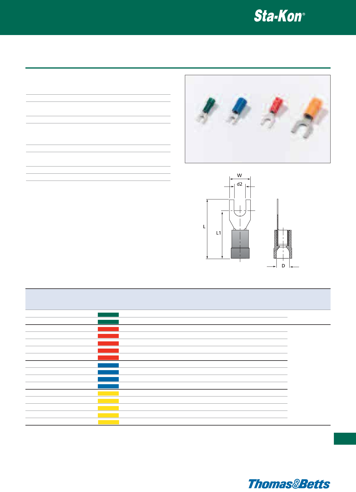
Polycarbonate insulated fork terminals
Technical Information
Material Electrolytic copper
Plating Tin plated
Marking Wire size and bolt size stamped on the
tongue
Metal barrel Brazed seam to prevent barrel separation
Insulation PC = Polycarbonate
High temperature applications,
excellent deformation characteristics
Temperature resistance +115°C / +125°C
Colour coding of the According to the wire size
insulation
Cable insertion Easy entry
Flammability rating UL 94 V-2
Insulated terminals
347
Thomas & Betts • www.tnb-europe.com
5.1
Product Ref. Wire size range Colour Stud hole size Dimensions Weight Quantity Crimping
d2 W L D L1 tool*
[mm
2
] [mm] [mm] [mm] [mm] [g/100] [pieces]
RZ 3F 0.25 - 0.75 Green M 3 5.5 18.0 3.2 15.0 41 100
RZ 4F 0.25 - 0.75 Green M 4 7.5 21.0 3.2 17.5 41 100
ERG2510
RA 3F 0.5 - 1.5 Red M 3 5.5 18.0 4.0 15.0 60 100
RA 35F 0.5 - 1.5 Red M 3.5 5.5 21.0 4.0 17.5 62 100
RA 4F 0.5 - 1.5 Red M 4 7.0 20.5 4.0 17.0 64 100
RA 5F 0.5 - 1.5 Red M 5 9.0 22.5 4.0 18.0 75 100
RA 6F 0.5 - 1.5 Red M 6 11.0 26.5 4.0 21.0 90 100
RB 3F 1.5 - 2.5 Blue M 3 5.5 19.0 4.5 16.0 72 100
RB 4F 1.5 - 2.5 Blue M 4 7.0 20.5 4.5 17.0 84 100 ERG2000KE
RB 5F 1.5 - 2.5 Blue M 5 9.0 22.5 4.5 18.0 96 100 ERG2001A
RB 6F 1.5 - 2.5 Blue M 6 11.0 26.5 4.5 21.0 113 100 WT2124Y
RC 4F 4.0 - 6.0 Yellow M 4 8.0 24.0 6.4 20.5 159 50
RC 5F 4.0 - 6.0 Yellow M 5 9.0 25.0 6.4 20.5 161 50
RC 6F 4.0 - 6.0 Yellow M 6 11.0 28.5 6.4 23.0 174 50
RC 8F 4.0 - 6.0 Yellow M 8 14.0 31.0 6.4 24.0 207 50
RC 10F 4.0 - 6.0 Yellow M 10 18.0 36.0 6.4 27.0 280 50
* Use selection chart to determine die set (see page 376)
See pages 370 to 376 for tooling specifications
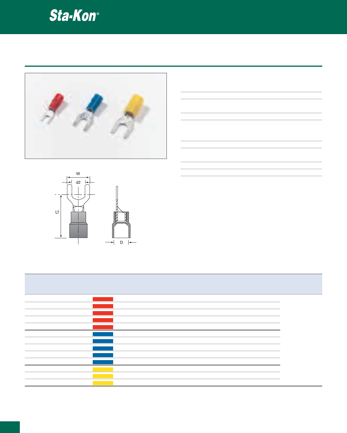
348
Thomas & Betts • www.tnb-europe.com
5.1
Nylon insulated fork terminals DIN 46237
Technical Information
Material Copper
Plating Tin plated
Marking Wire size and bolt size stamped on the
tongue
Metal barrel Brazed seam to prevent barrel separation
Insulation PA = Polyamide
Ideal for harsh environments, excellent
chemical, impact and abrasion resistance
Temperature resistance +85°C / +105°C
Colour coding of the According to the wire size (DIN)
insulation
Cable insertion Easy entry
Flammability rating UL 94 V-2
Insulated terminals
Product Ref. Wire size range Colour Stud hole size Dimensions Weight Quantity Crimping
d2 W L1 D tool*
[mm
2
] [mm] [mm] [mm] [g/100] [pieces]
TRA 3F 0.5 - 1.5 Red M 3 5.7 22.0 4.0 65 100
TRA 35F 0.5 - 1.5 Red M 3.5 6.2 22.0 4.0 62 100
TRA 4F 0.5 - 1.5 Red M 4 7.2 22.0 4.0 70 100
TRA 5F 0.5 - 1.5 Red M 5 8.0 22.0 4.0 92 100
TRA 6F 0.5 - 1.5 Red M 6 10.8 23.0 4.0 102 100 ERG2000KE
TRB3F 1.5-2.5 Blue M 3 5.7 22.2 4.5 81 100 ERG2001A
TRB 35F 1.5 - 2.5 Blue M 3.5 6.2 22.2 4.5 74 100 WT2124Y
TRB4F 1.5-2.5 Blue M 4 7.2 22.2 4.5 80 100
TRB5F 1.5-2.5 Blue M 5 8.0 22.2 4.5 110 100
TRB6F 1.5-2.5 Blue M 6 10.8 23.5 4.5 122 100
TRC 4F 4.0 - 6.0 Yellow M 4 8.2 26.7 6.4 163 100
TRC 5F 4.0 - 6.0 Yellow M 5 9.0 26.7 6.4 182 100
TRC 6F 4.0 - 6.0 Yellow M 6 12.0 30.3 6.4 190 100
* Use selection chart to determine die set (see page 376)
See pages 370 to 376 for tooling specifications
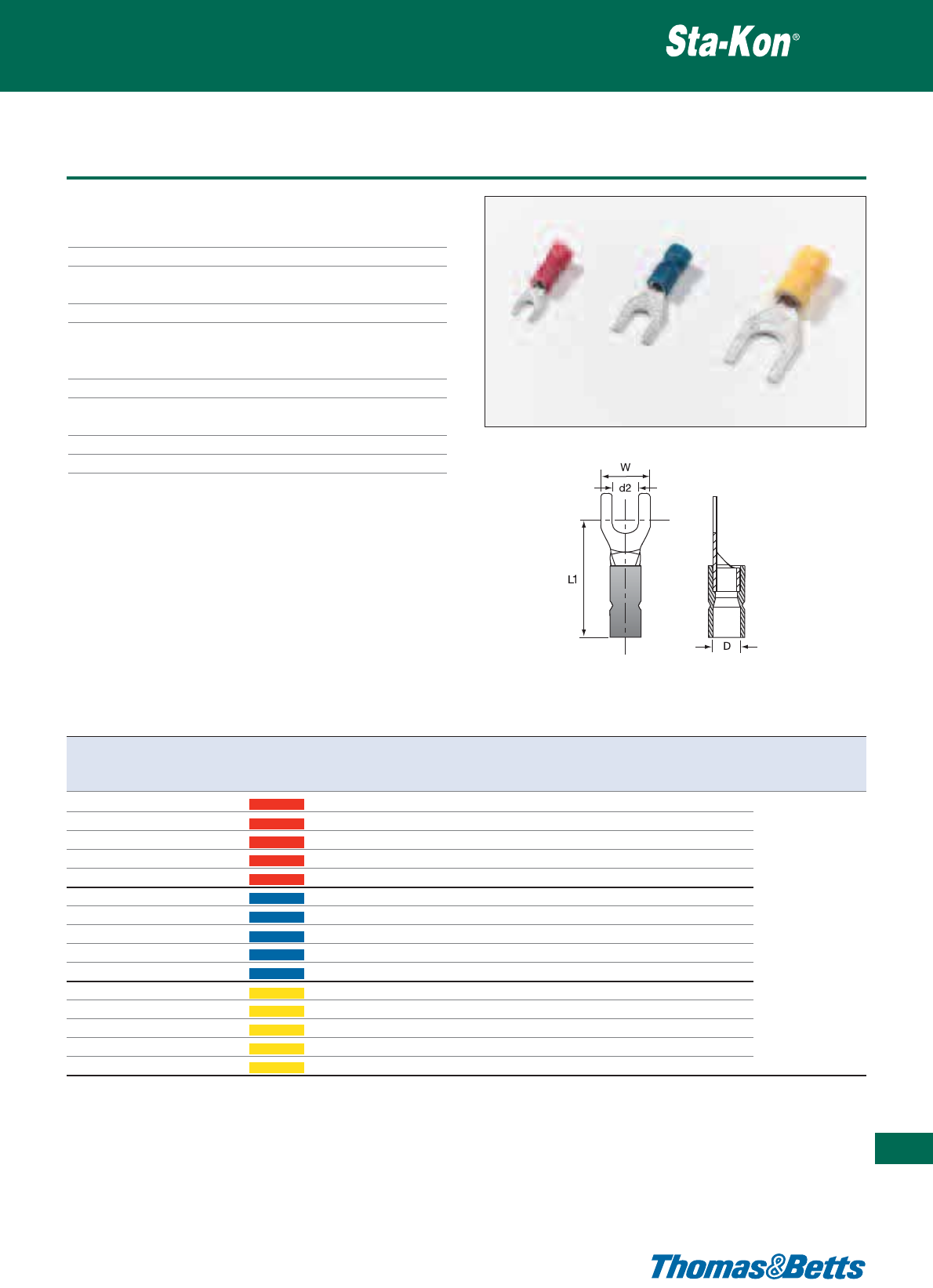
Vinyl insulated fork terminals DIN 46237
Technical Information
Material Copper
Plating Tin plated
Marking Wire size and bolt size stamped on the
tongue
Metal barrel Brazed seam to prevent barrel separation
Insulation PVC = Polyvinylchloride (Vinyl)
Economical yet premium quality,
moisture resistant
Max. electrical rating +75°C / 600 Volts
Colour coding of the According to the wire size
insulation
Cable insertion Easy entry
Flammability rating UL 94 V-0
Insulated terminals
349
Thomas & Betts • www.tnb-europe.com
5.1
Product Ref. Wire size Colour Stud hole size Dimensions Weight Quantity Crimping
range
d2 W L1 D tool*
[mm
2
] [mm] [mm] [mm] [g/100] [pieces]
VB3RF 0.5 - 1.5 Red M 3 6.0 17.2 4.0 68 100
VB35RF 0.5 - 1.5 Red M 3.5 6.0 17.2 4.0 68 100
VB4RF 0.5 - 1.5 Red M 4 6.8 18.2 4.0 73 100
VB5RF 0.5 - 1.5 Red M 5 10.0 19.2 4.0 92 100
VB6RF 0.5 - 1.5 Red M 6 11.0 21.2 4.0 103 100
VB3BF 1.5 - 2.5 Blue M 3 5.5 19.5 4.5 90 100 ERG2000KE
VB35BF 1.5 - 2.5 Blue M 3.5 6.0 17.5 4.5 97 100 ERG2001A
VB4BF 1.5 - 2.5 Blue M 4 6.8 19.2 4.5 83 100 WT2124Y
VB5BF 1.5 - 2.5 Blue M 5 10.0 20.5 4.5 110 100
VB6BF 1.5 - 2.5 Blue M 6 11.0 22.5 4.5 121 100
VB4YF 4.0 - 6.0 Yellow M 4 8.0 22.1 6.3 169 100
VB5YF 4.0 - 6.0 Yellow M 5 10.0 23.1 6.3 189 100
VB6YF 4.0 - 6.0 Yellow M 6 11.0 24.1 6.3 200 100
VB8YF 4.0 - 6.0 Yellow M 8 14.0 27.1 6.3 235 100
VB10YF 4.0 - 6.0 Yellow M 10 18.0 29.1 6.3 305 100
* Use selection chart to determine die set (see page 376)
See pages 370 to 376 for tooling specifications
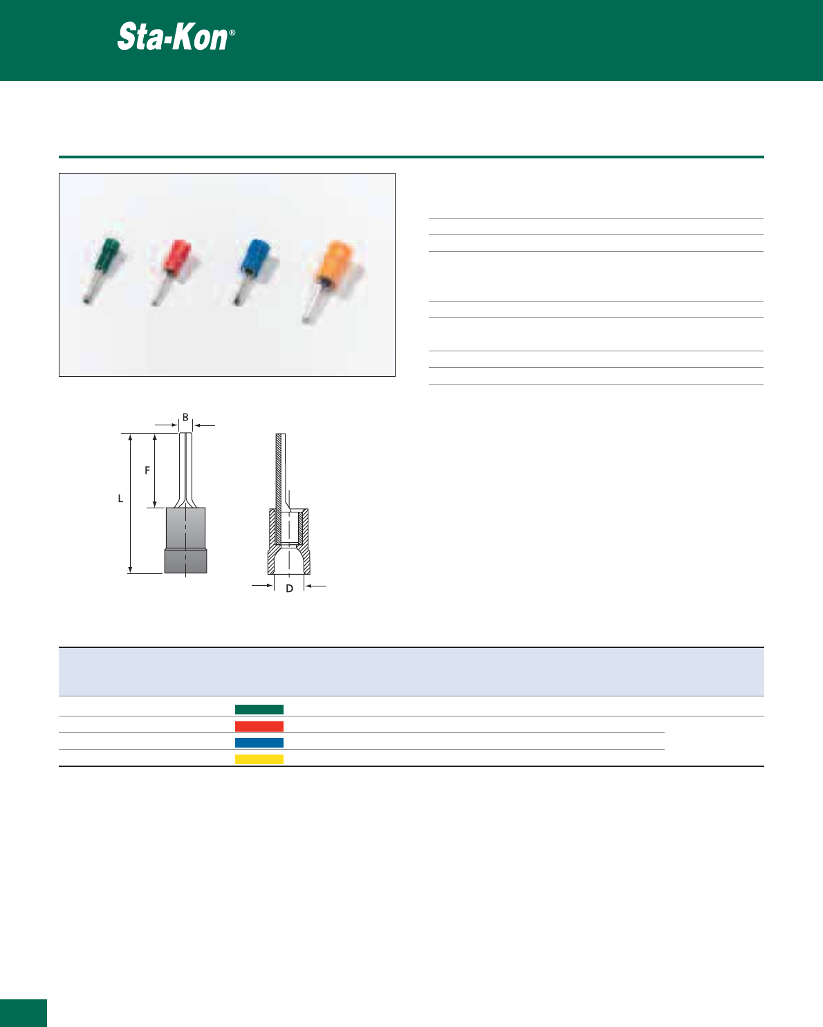
350
Thomas & Betts • www.tnb-europe.com
5.1
Polycarbonate insulated pin terminals DIN 46231
Technical Information
Material Electrolytic copper
Plating Tin plated
Metal barrel Brazed seam to prevent barrel separation
Insulation PC = Polycarbonate
High temperature applications,
excellent deformation characteristics
Temperature resistance +115°C / +125°C
Colour coding of the According to the wire size
insulation
Cable insertion Easy entry
Flammability rating UL 94 V-2
Insulated terminals
Product Ref. Wire size range Colour Dimensions Weight Quantity Crimping
L F B D tool*
[mm
2
] [mm] [mm] [mm] [mm] [g/100] [pieces]
RZ P 0.25 - 0.75 Green 22.0 12.0 1.8 3.2 47 100 ERG2510
RA P 0.5 - 1.5 Red 22.0 12.0 1.9 4.0 67 100 ERG2000KE
RB P 1.5 - 2.5 Blue 22.0 12.0 1.9 4.5 80 100 ERG2001A
RC P 4.0 - 6.0 Yellow 27.0 14.0 2.8 6.4 175 50 WT2124Y
* Use selection chart to determine die set (see page 376)
See pages 370 to 376 for tooling specifications

Polycarbonate insulated blade terminals DIN 46231
Technical Information
Material Electrolytic copper
Plating Tin plated
Marking Wire size stamped on the tongue
Metal barrel Brazed seam to prevent barrel separation
Insulation PC = Polycarbonate
High temperature applications,
excellent deformation characteristics
Temperature resistance +115°C / +125°C
Colour coding of the According to the wire size (DIN)
insulation
Cable insertion Easy entry
Flammability rating UL 94 V-2
Insulated terminals
351
Thomas & Betts • www.tnb-europe.com
5.1
Product Ref. Wire size range Colour Dimensions Weight Quantity Crimping
L F B t D tool*
[mm
2
] [mm] [mm] [mm] [mm] [mm] [g/100] [pieces]
RZ PP 0.25 - 0.75 Green 20.0 10.0 2.5 0.5 3.2 39 100 ERG2510
RA PP** 0.5 - 1.5 Red 22.0 11.5 2.9 0.7 4.5 60 100 ERG2000KE
RB PP** 1.5 - 2.5 Blue 22.0 11.5 2.9 0.7 4.5 78 100 ERG2001A
RC PP*** 4.0 - 6.0 Yellow 27.0 13.0 4.0 1.0 6.7 120 100 WT2124Y
* Use selection chart to determine appropriate die set (see page 376)
** With locking tab
*** Product Ref. RCPP: PVC insulation and no easy entry
See pages 370 to 376 for tooling specifications
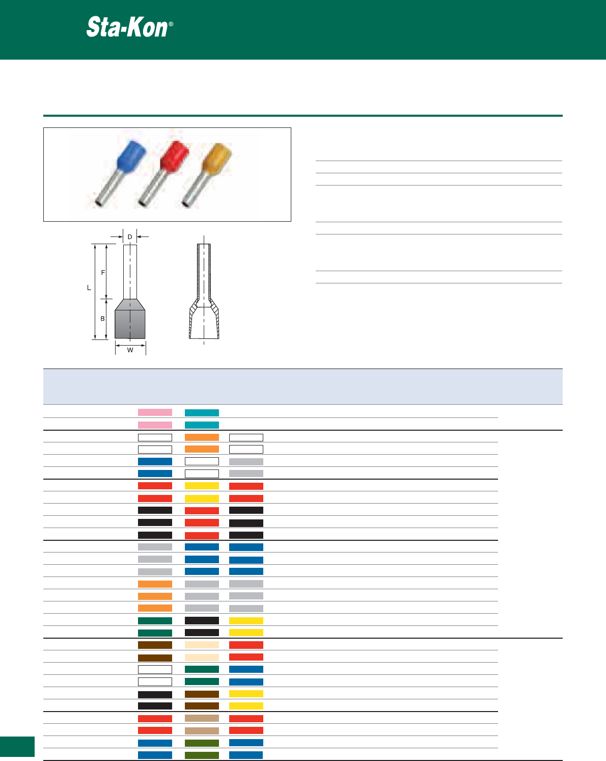
352
Thomas & Betts • www.tnb-europe.com
5.1
Nylon insulated bootlace ferrules
Technical Information
Material Copper
Plating Tin plated
Metal barrel Copper tube
Insulation PA = Polyamide
Ideal for harsh environments, excellent
chemical, impact and abrasion resistance
Electrical rating +105°C / 300 Volts max
Colour coding of the According to the wire size and the
insulation country standard
F=France, D=DIN, G=Germany
Flammability rating UL 94 V-2
Insulated terminals
Product Ref. Wire size French German Din Dimensions Weight Quantity Crimping
colour* colour* colour* F L W B D tool**
[mm
2
] [mm] [mm] [mm] [mm] [mm] [g/100] [pieces]
N-0306C* 0.30 Pink Turquoise NA 6.0 10.4 1.9 1.1 4.4 4.2 1000 TBZ3
N-0308C* 0.30 Pink Turquoise NA 8.0 12.4 1.9 4.4 1.1 4.9 1000
N-0508C* 0.50 White Orange White 8.0 14.0 2.6 6.0 1.3 8.1 1000
N-0510C* 0.50 White Orange White 10.0 16.0 2.6 6.0 1.3 8.5 1000
N-7508C* 0.75 Blue White Grey 8.0 14.3 2.8 6.3 1.5 9.0 1000
N-7512C* 0.75 Blue White Grey 12.0 18.3 2.8 6.3 1.5 12.0 1000
N-1008C* 1.00 Red Yellow Red 8.0 14.3 3.0 6.3 1.7 10.0 1000
N-1012C* 1.00 Red Yellow Red 12.0 18.3 3.0 6.3 1.7 14.0 1000
N-1508C* 1.50 Black Red Black 8.0 14.3 3.5 6.3 2.0 12.0 1000
N-1510C* 1.50 Black Red Black 10.0 16.36 3.5 6.3 2.0 13.0 1000 ERG2000KE
N-1518C* 1.50 Black Red Black 18.0 24.3 3.5 6.3 2.0 19.0 1000 ERG2106
N-2508C* 2.50 Grey Blue Blue 8.0 15.4 4.0 7.4 2.6 19.0 1000 TBZ3
N-2512C* 2.50 Grey Blue Blue 12.0 19.4 4.0 7.4 2.6 21.0 1000
N-2518C* 2.50 Grey Blue Blue 18.0 25.4 4.0 7.4 2.6 27.0 1000
N-4010C* 4.00 Orange Grey Grey 10.0 17.4 4.5 7.4 3.2 28.0 1000
N-4012C* 4.00 Orange Grey Grey 12.0 19.4 4.5 7.4 3.2 31.0 1000
N-4018C* 4.00 Orange Grey Grey 18.0 25.4 4.5 7.4 3.2 42.0 1000
N-6012C* 6.00 Green Black Yellow 12.0 20.5 6.0 8.5 3.9 45.0 1000
N-6018C* 6.00 Green Black Yellow 18.0 26.5 6.0 8.5 3.9 57.0 1000
N-10012C* 10.00 Brown Ivory Red 12.0 20.8 7.5 8.8 4.9 59.0 1000
N-10018C* 10.00 Brown Ivory Red 18.0 26.8 7.5 8.8 4.9 76.0 1000
N-16012C* 16.00 White Green Blue 12.0 22.0 8.7 10.0 6.2 68.0 500
N-16018C* 16.00 White Green Blue 18.0 28.0 8.7 10.0 6.2 103.0 500
N-25016C* 25.00 Black Brown Yellow 16.0 28.0 11.0 12.0 7.9 126.0 500
N-25022C* 25.00 Black Brown Yellow 22.0 34.0 11.0 12.0 7.9 154.0 250 ERG2000KE
N-35016C* 35.00 Red Beige Red 16.0 30.0 12.5 14.0 8.7 164.0 200
N-35025C* 35.00 Red Beige Red 25.0 39.0 12.5 14.0 8.7 202.0 200
N-50020C* 50.00 Blue Olive Blue 20.0 36.0 15.0 16.0 10.9 311.0 100
N-50025C* 50.00 Blue Olive Blue 25.0 41.0 15.0 16.0 10.9 361.0 100
* For French Colour codes please add suffix “F” e.g. N-0508CF, for German Colour codes please add suffix “G” e.g. N-0508CG,
for Din Colour codes add suffix ”D” e.g. N-0508CD.
** Use selection chart to determine appropriate die set (see page 376)
See pages 370 to 376 for tooling specifications
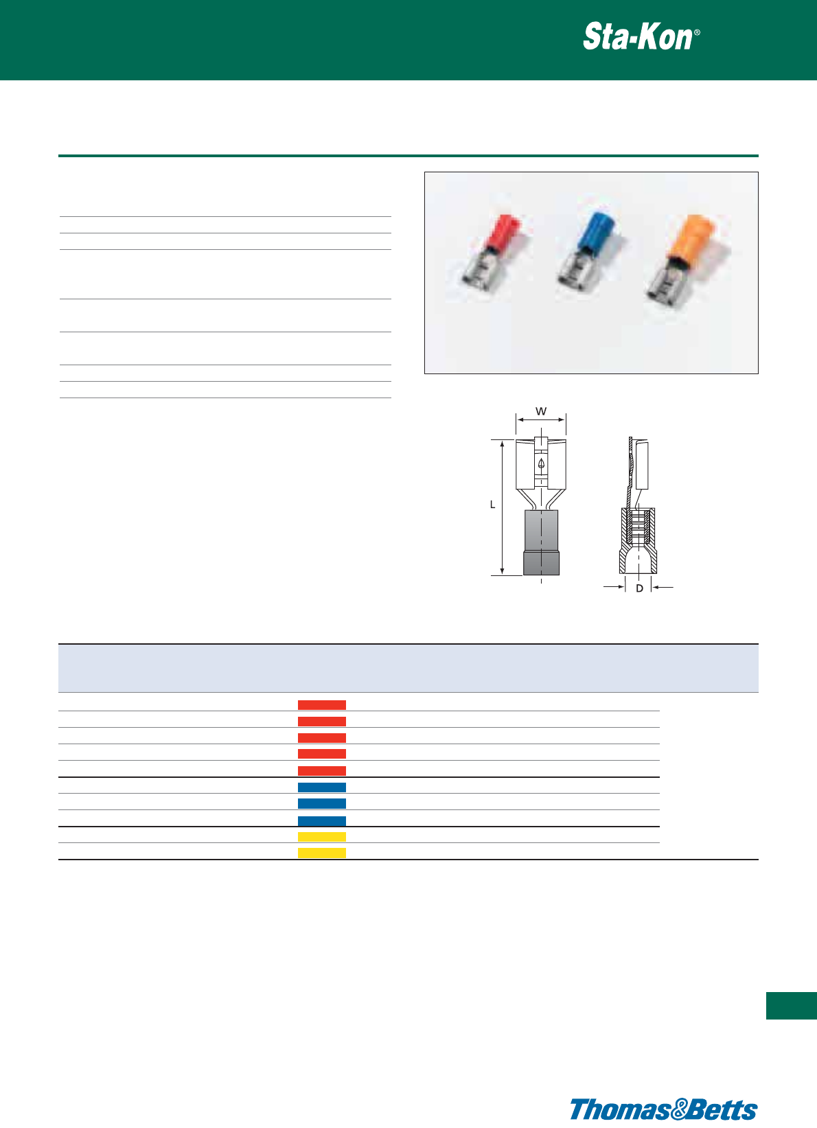
Insulated female disconnects DIN 46245
Technical Information
Material Brass with 70% copper
Plating Tin plated
Metal barrel Brazed seam to prevent barrel separation
Insulation PC = Polycarbonate
High temperature applications,
excellent deformation characteristics
Temperature resistance +115°C / +125°C
(For PVC insulation +65°C / +75°C)
Colour coding of the According to the wire size (DIN)
insulation
Cable insertion Easy entry
Flammability rating UL 94 V-2
Insulated terminals
353
Thomas & Betts • www.tnb-europe.com
5.1
Product Ref. Wire size range For male Colour Dimensions Weight Quantity Crimping
tab size
L D W tool*
[mm
2
] [mm x mm] [mm] [mm] [mm] [g/100] [pieces]
RA 28 0.5 - 1.5 2.8 x 0.8 Red 18.5 3.3 3.5 60 100
RA 29 0.5 - 1.5 2.8 x 0.5 Red 18.5 3.3 3.5 60 100
RA 48** 0.5 - 1.5 4.8 x 0.8 Red 19.0 3.7 5.7 82 100
RA 49** 0.5 - 1.5 4.8 x 0.5 Red 19.0 3.7 5.7 83 100
RA 63 0.5 - 1.5 6.3 x 0.8 Red 20.0 4.0 7.6 96 100 ERG2000KE
RB 48** 1.5 - 2.5 4.8 x 0.5 Blue 19.0 4.4 5.7 91 100 ERG2001A
RB 49** 1.5 - 2.5 4.8 x 0.8 Blue 19.0 4.4 5.7 87 100 WT2124Y
RB 63 1.5 - 2.5 6.3 x 0.8 Blue 20.0 4.5 7.6 106 100
RC 63 4.0 - 6.0 6.3 x 0.8 Yellow 24.0 6.4 7.6 183 50
RC 95** 4.0 - 6.0 9.5 x 1.2 Yellow 31.0 6.2 11.0 233 50
* Use selection chart to determine the appropriate die set (see page 376)
** Non-brazed with support sleeve and PVC insulation, not easy entry
See pages 370 to 376 for tooling specifications
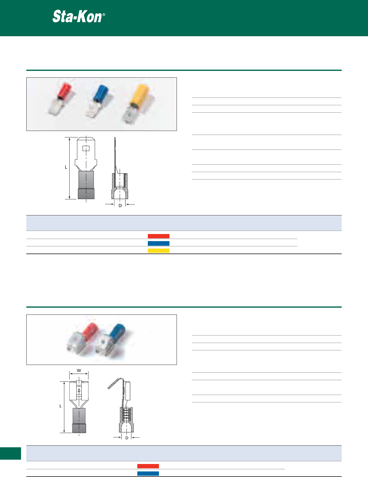
354
Thomas & Betts • www.tnb-europe.com
5.1
Insulated male disconnects DIN 46245
Technical Information
Material Brass with 70% copper
Plating Tin plated
Metal barrel Brazed seam to prevent barrel separation
Insulation PC = Polycarbonate
High temperature applications,
excellent deformation characteristics
Temperature resistance +115°C / +125°C
(For PVC insulation +65°C / +75°C)
Colour coding of the According to the wire size (DIN)
insulation
Cable insertion Easy entry
Flammability rating UL 94 V-2
Insulated terminals
Product Ref. Wire size range Male tab size Colour Dimensions [mm] Weight Quantity Crimping
[mm
2
] [mm x mm] L D [g/100] [pieces] tool*
RA 63M 0.5 - 1.5 6.3 x 0.8 Red 22.0 4.0 107 100 ERG2000KE
RB 63M 1.5 - 2.5 6.3 x 0.8 Blue 22.0 4.5 107 100 ERG2001A
RC 63M** 4.0 - 6.0 6.3 x 0.8 Yellow 25.0 6.3 155 50 WT2124Y
** PVC insulation. no easy entry and non brazed, with brass support sleeve
* Use selection chart to determine appropriate die set (see page 376)
See pages 370 to 376 for tooling specifications
Product Ref. Wire size range For tab size Colour Dimensions [mm] Weight Quantity Crimping
[mm
2
] [mm x mm] L D W [g/100] [pieces] tool*
RA 63T 0.5 - 1.5 6.3 x 0.8 Red 22.0 3.7 7.4 135 100 ERG2000KE
RB 63T 1.5 - 2.5 6.3 x 0.8 Blue 22.0 4.3 7.5 146 100 ERG2001A, WT2124Y
* Use selection chart to determine appropriate die set (see page 376)
See pages 370 to 376 for tooling specifications
Insulated piggy back disconnects DIN 46245
Insulated terminals
Technical Information
Material Brass with 70% copper
Plating Tin plated
Metal barrel Non brazed, with brass support sleeve
Insulation PVC = Polyvinylchloride (Vinyl)
Economical yet premium quality,
moisture resistant
Temperature resistance +65°C / +75°C
Colour coding of the According to the wire size (DIN)
insulation
Flammability rating UL 94 V-0
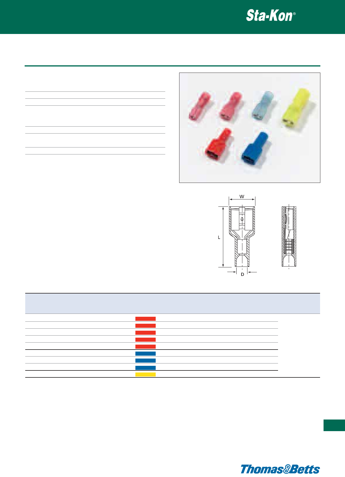
Fully insulated female disconnects
Technical Information
Material Brass with 70% copper
Plating Tin plated
Metal barrel Non brazed, with brass support sleeve
Insulation PA = Polyamide
Ideal for harsh environments, excellent
chemical, impact and abrasion resistance
Temperature resistance +85°C / +105°C
Colour coding of the According to the wire size (DIN)
insulation
Flammability rating UL 94 V-2
Insulated terminals
355
Thomas & Betts • www.tnb-europe.com
5.1
Product Ref. Wire size range For male tab size Colour Dimensions Weight Quantity Crimping
W L D tool*
[mm
2
] [mm x mm] [mm] [mm] [mm] [g/100] [pieces]
RA 28V 0.5 - 1.5 2.8 x 0.8 Red 5.0 19.3 3.8 110 100
RA 29V 0.5 - 1.5 2.8 x 0.5 Red 5.0 19.3 3.8 110 100
RA 48V 0.5 - 1.5 4.8 x 0.8 Red 7.4 20.2 3.6 115 100
RA 49V 0.5 - 1.5 4.8 x 0.5 Red 7.4 20.2 3.6 115 100 ERG2000KE
RA 63V** 0.5 - 1.5 6.3 x 0.8 Red 8.8 21.0 4.0 123 100 ERG2001A
RB 48V 1.5 - 2.5 4.8 x 0.8 Blue 7.1 19.5 3.9 120 100 WT2124Y
RB 49V 1.5 - 2.5 4.8 x 0.5 Blue 7.1 19.5 3.9 120 100
RB 63V** 1.5 - 2.5 6.3 x 0.8 Blue 8.8 21.0 4.5 132 100
RC 63V 4.0 - 6.0 6.3 x 0.8 Yellow 9.0 26.0 5.3 215 50
* Use selection chart to determine appropriate die set (see page 376)
** Easy entry and brazed barrel, polycarbonate insulator
See pages 370 to 376 for tooling specifications
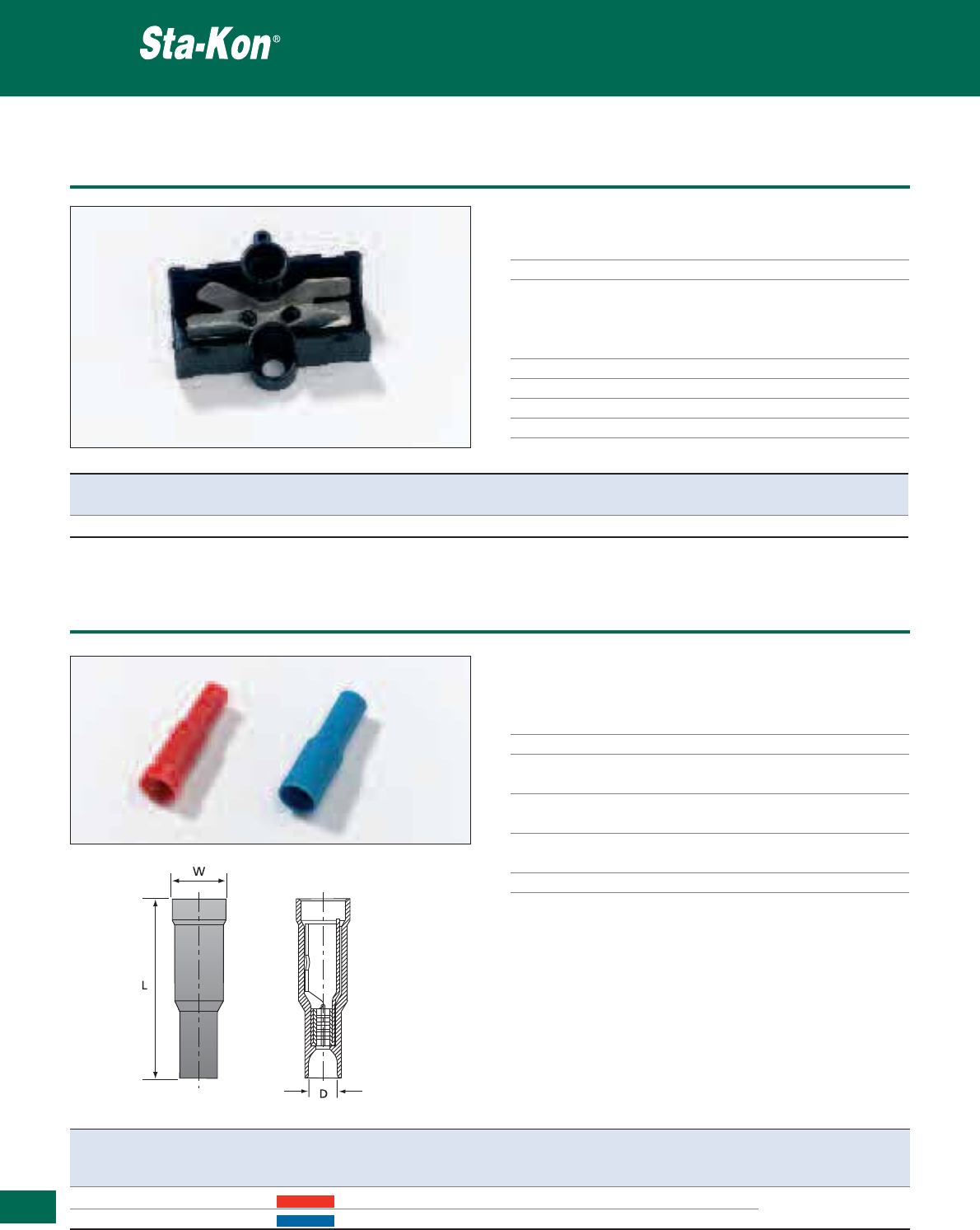
356
Thomas & Betts • www.tnb-europe.com
5.1
Insulated sectional terminal block (6 male tabs)
Technical Information
Material Brass
Plating Tin plated
Insulation PA = Polyamide
Ideal for harsh environments, provides
excellent chemical, impact and abrasion
resistance
Colour Black
Temperature resistance +105°C
Voltage 250V
Flammability rating UL 94 V-2
Insulated terminals
Product Ref. Tab size Mounting method Weight Quantity
[mm x mm] [g/100] [pieces]
MTB1-TB 6 male tabs 6.3 x 0.8 M4 fillister head screw 798 100
Product Ref. Wire size range Colour Dimensions Weight Quantity Crimping
W L D tool*
[mm
2
] [mm] [mm] [mm] [g/100] [pieces]
RAB 0.5 - 1.5 Red 3.9 25.0 4.0 115 100 ERG2000KE
RB5B 1.5 - 2.5 Blue 4.9 26.0 4.3 144 100 ERG2001A, WT2124Y
* Use selection chart to determine appropriate die set (see page 376)
See pages 370 to 376 for tooling specifications
Fully insulated bullet female receptacles
Insulated terminals
Technical Information
Material RAB Phosphor bronze
Material RB5B Brass
Plating Tin plated
Metal barrel: RAB Brazed seam to prevent barrel separation
Metal barrel: RB5B Non brazed, with brass support sleeve
Insulation RAB Polycarbonate
Insulation RB5B PVC
Colour coding of the According to the wire size (DIN)
insulation
Cable insertion Easy entry for RAB
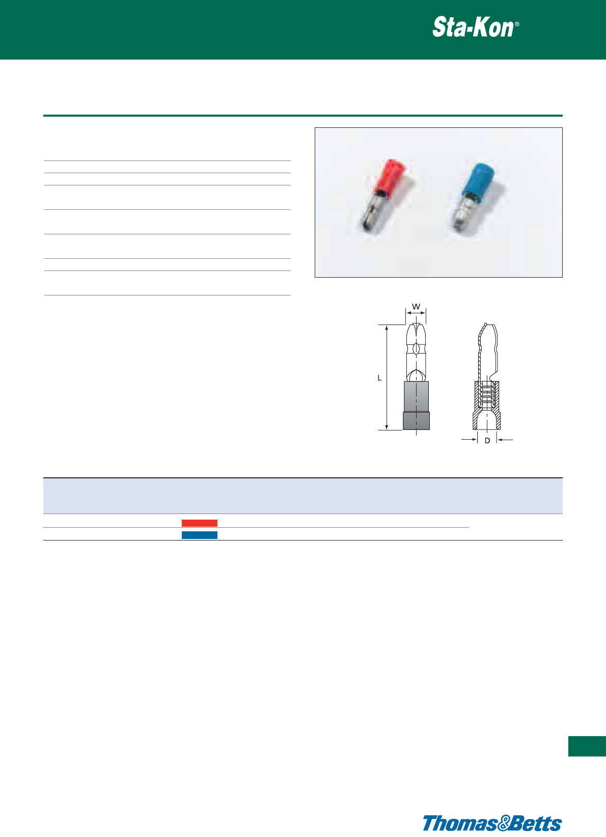
Insulated bullet male disconnects
Technical Information
Material Brass
Plating Tin plated
Metal barrel Brazed seam to prevent barrel separation
Insulation RABM - Polycarbonate
RB5BM - PVC
Temperature resistance RABM: +115°C / +125°C
RB5M: +65°C / +75°C
Colour coding of the According to the wire size (DIN)
insulation
Cable insertion Easy entry except of RB5BM
Flammability rating PVC: UL 94 V-0
PC: UL 94 V-2
Insulated terminals
357
Thomas & Betts • www.tnb-europe.com
5.1
Product Ref. Wire size range Colour Dimensions Weight Quantity Crimping
W L D tool*
[mm
2
] [mm] [mm] [mm] [g/100] [pieces]
RABM 0.5 - 1.5 Red 4.0 22.0 4.0 102 100 ERG2000KE
RB5BM** 1.5 - 2.5 Blue 5.0 20.0 4.3 109 100 ERG2001A, WT2124Y
* Use selection chart to determine appropriate die set (see page 376)
** non brazed, with brass support sleeve
See pages 370 to 376 for tooling specifications
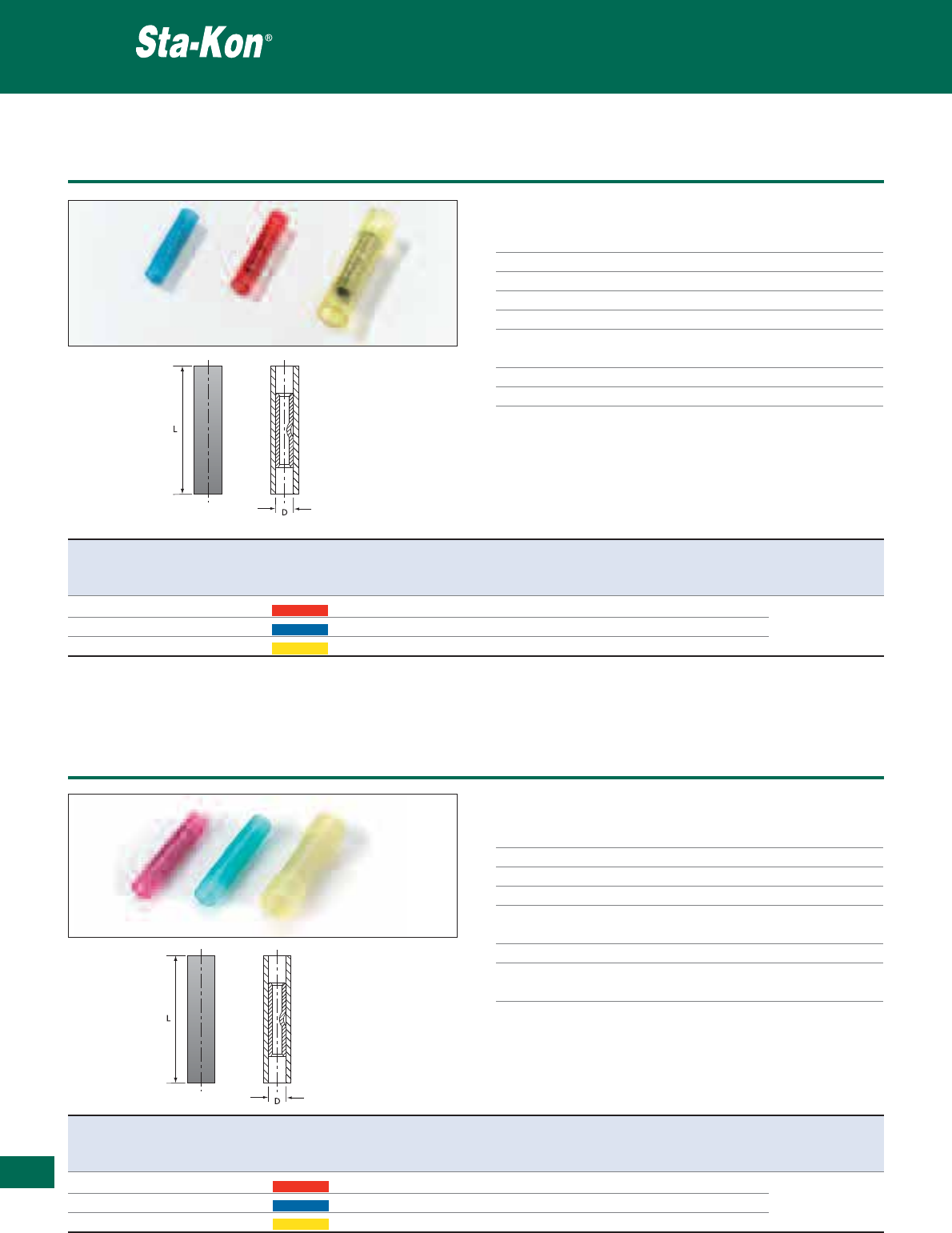
358
Thomas & Betts • www.tnb-europe.com
5.1
Fully insulated butt splices
Technical Information
Material Electrolytic copper
Plating Tin plated
Metal barrel Brazed seam to prevent barrel separation
Insulation PC = Polycarbonate
Temperature resistance +115°C / +125°C
Colour coding of the According to the wire size (DIN)
insulation
Cable insertion Easy entry
Flammability rating UL 94 V-2
Insulated terminals
Product Ref. Wire size range Colour Dimensions Weight Quantity Crimping
L D tool*
[mm
2
] [mm] [mm] [g/100] [pieces]
RAA15 0.5 - 1.5 Red 24.0 3.4 97 100 ERG2000KE
RBB25-EU 1.5 - 2.5 Blue 26.0 4.3 150 100 ERG2001A
RCC6 4.0 - 6.0 Yellow 33.0 6.5 316 50 WT2124Y
* Use selection chart to determine appropriate die set (see page 376)
See pages 370 to 376 for tooling specifications
Product Ref. Wire size Colour Dimensions Weight Quantity Crimping
range L D tool*
[mm
2
] [mm] [mm] [g/100] [pieces]
RAA15SI 0.5 - 1.5 Red 35.0 4.5 100 25 ERG2000KE
RBB25SI 1.5 - 2.5 Blue 35.0 5.4 150 25 ERG2001A
RCC6SI 4.0 - 6.0 Yellow 40.0 6.8 320 25 WT2124Y
* Use selection chart to determine appropriate die set (see page 376)
See pages 370 to 376 for tooling specifications
Requires a hot air tool for heat-shrinkage (see Shrink-Kon
®
section)
Insulated heat shrink butt splices
Insulated terminals
Technical Information
Material Electrolytic copper
Plating Tin plated
Metal barrel Brazed seam to prevent barrel separation
Insulation Halogen free heat shrink insulation material
Colour coding of the According to the wire size (DIN)
insulation
Cable insertion Easy entry
Other properties Halogen free
Waterproof after application (heat shrink)
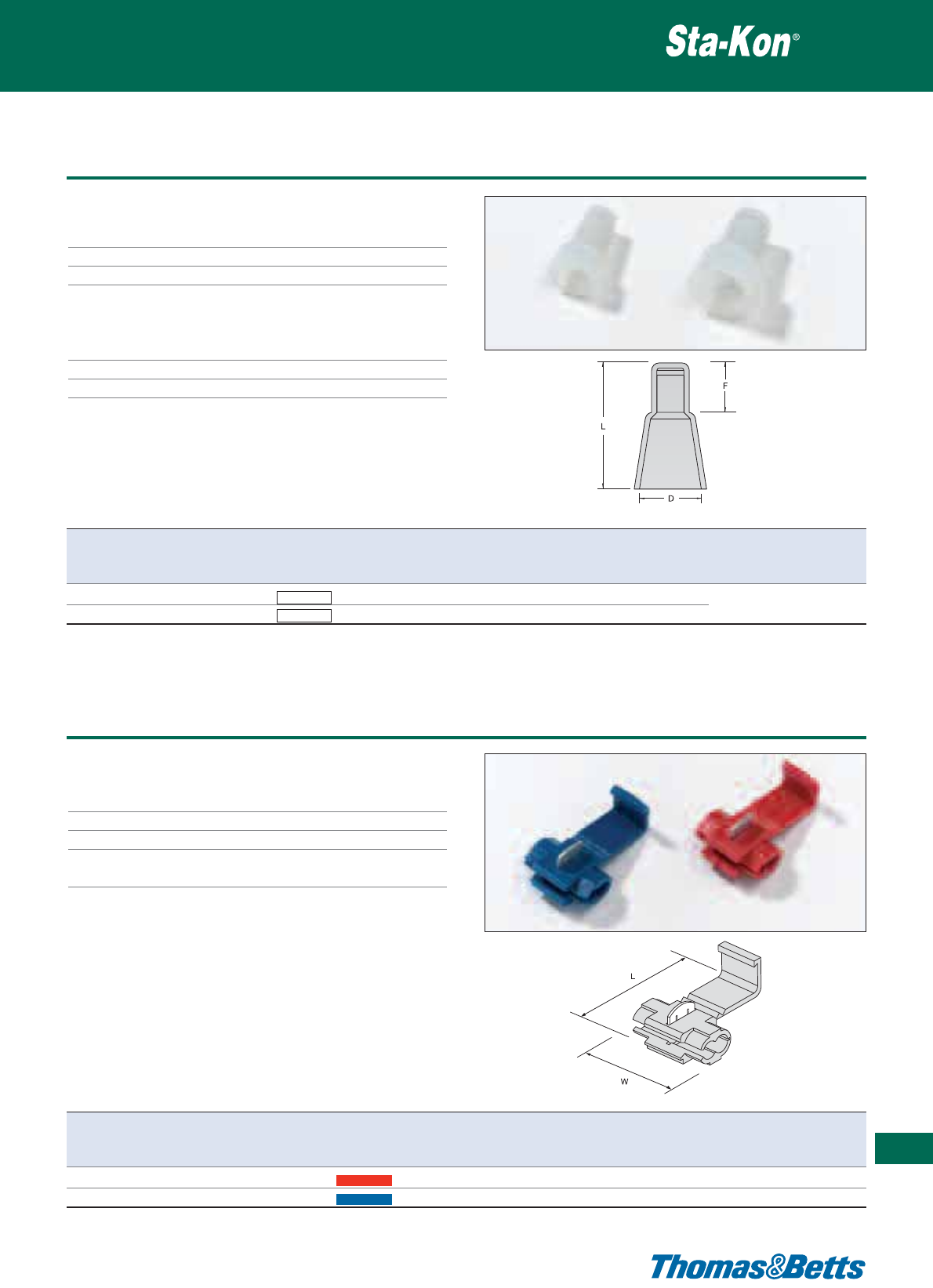
Insulated wire joints
Technical Information
Material Brass
Plating Tin plated
Metal barrel Brazed seam to prevent barrel separation
Insulation PA = Polyamide
Ideal for harsh environments, provides
excellent chemical, impact and abrasion
resistance
Temperature resistance +85°C / +105°C
Flammability rating UL 94 V-2
Insulated terminals
359
Thomas & Betts • www.tnb-europe.com
5.1
Product Ref. Wire size range Colour Dimensions Weight Quantity Crimping
F L D tool*
[mm
2
] [mm] [mm] [mm] [g/100] [pieces]
RBJ 1.0 - 3.0 White 8.0 15.2 6.4 86 100 ERG2000KE, ERG2001A
RCJ 2.0 - 6.0 White 9.0 17.7 9.2 166 50 WT2124Y
* Use selection chart to determine appropriate die set (see page 376)
See pages 370 to 376 for tooling specifications
Product Ref. Wire size range Colour Dimensions Quantity
LW
[mm
2
] [mm] [mm] [pieces]
TRAWT 0.5 - 1.5 Red 31.0 20.0 100
TRBWT 1.5 - 2.5 Blue 31.0 20.0 100
Insulated quick splice
Insulated terminals
Technical Information
Material Brass
Insulation P.P. = Polypropylene
Max. electrical rating +105°C / 600V
Colour coding of the According to the wire size (DIN)
insulation
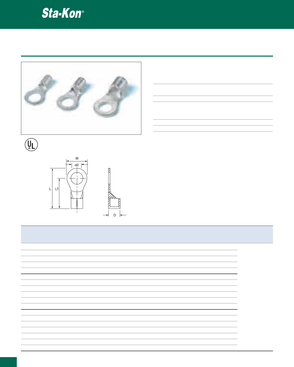
E9809
360
Thomas & Betts • www.tnb-europe.com
5.1
Non-insulated ring terminals
Technical Information
Material Electrolytic copper for very good
conductivity
Plating Electro-tin plating, excellent corrosion
resistance
Metal barrel Brazed seam to prevent barrel separation
Current rating 0.5-1.5 mm
2
= 12 Ampere
1.5-2.5 mm
2
= 27 Ampere
4.0-6.0 mm
2
= 37 Ampere
Marking Diameter and bolt size
Cable insertion Easy entry (chamfered entry edges)
Non-insulated terminals
Product Ref. Wire size range Stud size Dimensions Weight Quantity Crimping
d2 W L D L1 tool*
[mm
2
] [mm] [mm] [mm] [mm] [g/100] [pieces]
K18-6R-M 0.5 - 1.5 M 3.5 6.6 14.4 3.4 11.1 64 1000
K18-8R-M 0.5 - 1.5 M 4 6.6 14.4 3.4 11.1 61 1000
K18-10R-M 0.5 - 1.5 M 5 8.0 15.8 3.4 11.8 66 1000
K18-14R-M 0.5 - 1.5 M 6 11.6 21.8 3.4 15.8 99 1000
K18-516R-M 0.5 - 1.5 M 8 11.6 21.8 3.4 15.8 85 1000
K14-6R-M 1.5 - 2.5 M 3.5 6.6 14.4 4.1 11.1 81 1000
K14-8R-M 1.5 - 2.5 M 4 6.6 14.4 4.1 11.1 71 1000
K14-10R-M 1.5 - 2.5 M 5 8.5 16.8 4.1 12.6 87 1000
K14-14R-M 1.5 - 2.5 M 6 12.0 21.8 4.1 15.8 118 1000 ERG2002E
K14-516R-M 1.5 - 2.5 M 8 12.0 21.8 4.1 15.8 110 1000 ERG2000KE
K14-38R-M 1.5 - 2.5 M 10 13.6 25.5 4.1 18.7 114 1000
K10-6R-M 4.0 - 6.0 M 3.5 7.2 15.7 5.6 12.1 128 1000
K10-8R-M 4.0 - 6.0 M 4 7.2 15.7 5.6 12.1 123 1000
K10-10R-M 4.0 - 6.0 M 5 9.5 19.6 5.6 15.1 155 1000
K10-14R-M 4.0 - 6.0 M 6 12.0 22.5 5.6 16.5 192 1000
K10-516R-M 4.0 - 6.0 M 8 15.0 27.0 5.6 19.5 242 1000
K10-38R-M 4.0 - 6.0 M 10 15.0 27.0 5.6 19.5 207 1000
K10-12R-D 4.0 - 6.0 M 12 19.2 31.6 5.6 22.0 299 500
* Use selection chart to determine appropriate die set (see page 376)
See pages 370 to 376 for tooling specifications
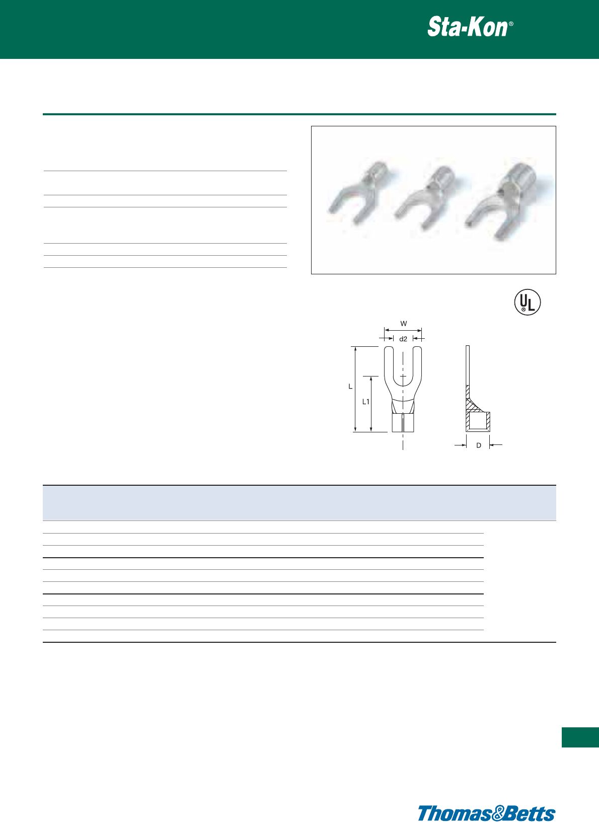
Non-insulated fork terminals
Technical Information
Material Electrolytic copper for very good
conductivity
Plating Electro-tin plating, excellent corrosion
resistance
Metal barrel Brazed seam to prevent barrel separation
Current rating 0.5-1.5 mm
2
= 12 Ampere
1.5-2.5 mm
2
= 27 Ampere
4.0-6.0 mm
2
= 37 Ampere
Marking Diameter and bolt size
Cable insertion Easy entry (chamfered entry edges)
Non-insulated terminals
361
Thomas & Betts • www.tnb-europe.com
5.1
Product Ref. Wire size range Stud size Dimensions Weight Quantity Crimping
d2 W L D L1 tool*
[mm
2
] [mm] [mm] [mm] [mm] [g/100] [pieces]
K18-6F-M 0.5 - 1.5 M 3.5 5.7 16.0 3.4 11.3 66 1000
K18-8F-M 0.5 - 1.5 M 4 6.4 16.0 3.4 11.3 65 1000
K18-10F-M 0.5 - 1.5 M 5 8.1 16.0 3.4 11.3 67 1000
K14-6F-M 1.5 - 2.5 M 3.5 6.0 16.0 4.1 11.3 75 1000
K14-8F-M 1.5 - 2.5 M 4 6.4 16.0 4.1 11.3 75 1000 ERG2002E
K14-10F-M 1.5 - 2.5 M 5 8.1 16.0 4.1 11.3 81 1000 ERG2000KE
K10-6F-M 4.0 - 6.0 M 3.5 7.2 17.4 5.6 13.5 140 1000
K10-8F-M 4.0 - 6.0 M 4 9.0 18.5 5.6 13.0 146 1000
K10-10F-M 4.0 - 6.0 M 5 9.0 18.5 5.6 13.0 142 1000
K10-14F-M 4.0 - 6.0 M 6 9.0 18.5 5.6 13.0 143 1000
* Use selection chart to determine appropriate die set (see page 376)
See pages 370 to 376 for tooling specifications
E9809
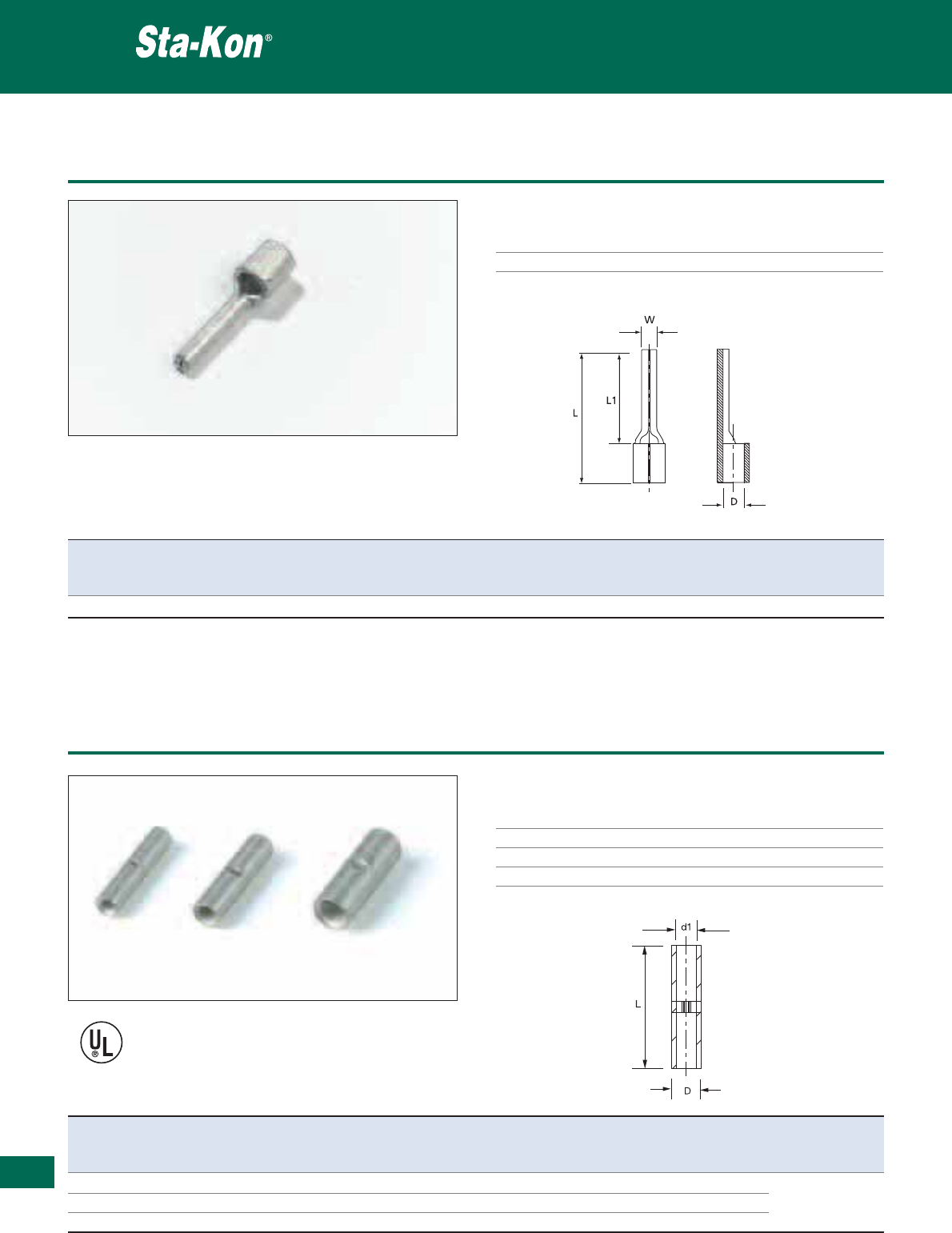
362
Thomas & Betts • www.tnb-europe.com
5.1
Non-insulated pin terminal DIN 46230
Technical Information
Material Electrolytic copper
Plating Tin plated
Non-insulated terminals
Product Ref. Wire size range Dimensions Weight Quantity Crimping
L L1 D W tool*
[mm
2
] [mm] [mm] [mm] [mm] [g/100] [pieces]
B6P 4.0 - 6.0 20.0 14.0 3.4 2.8 160 100 ERG2002E, ERG2000KE
* Use selection chart to determine appropriate die set (see page 376)
See pages 370 to 376 for tooling specifications
Product Ref. Wire size range Dimensions Weight Quantity Crimping
d1 L D tool*
[mm
2
] [mm] [mm] [mm] [g/100] [pieces]
K18-BS-M 0.5 - 1.5 1.7 15.0 3.3 94 1000
K14-BS-M 1.5 - 2.5 2.3 15.0 3.9 112 1000 ERG2002E
K10-BS-M 4.0 - 6.0 3.5 15.0 5.4 183 1000 ERG2000KE
* Use selection chart to determine appropriate die set (see page 376)
See pages 370 to 376 for tooling specifications
E9809
Non-insulated butt splices
Non-insulated terminals
Technical Information
Material Copper
Plating Tin plated
Metal barrel Tubular construction
Cable insertion Easy entry
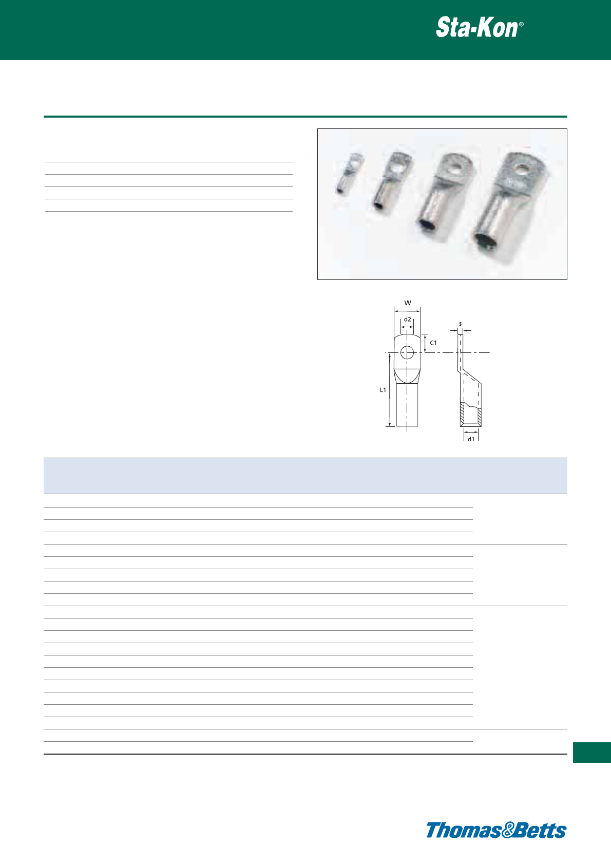
Non-insulated copper tube ring terminals DIN 46235
Technical Information
Material Electrolytic copper
Plating Tin plated
Metal barrel Copper tube
Marking Cable cross-section area and bolt size
Cable insertion Easy entry
Non-insulated terminals
363
Thomas & Betts • www.tnb-europe.com
5.1
Product Ref. Wire Stud Dimensions Weight Quantity Crimping
size size L1 C1 W s d1 d2 tool*
[mm
2
] [mm] [mm] [mm] [mm] [mm] [mm] [kg/100] [pieces]
T 2.5-4** 2.5 M 4 13.0 4.0 7.5 1.2 2.3 4.3 0.14 100
T 4-6** 4.0 M 6 19.0 6.5 10.0 1.2 3.0 6.5 0.21 100 ERG2002E
T 6-5 6.0 M 5 24.0 6.5 8.5 1.5 3.8 5.3 0.34 100
T 6-6 6.0 M 6 24.0 7.5 8.5 1.5 3.8 6.4 0.35 100
T 10-6 10.0 M 6 27.0 7.5 9.0 1.5 4.5 6.4 0.40 100
T 10-8 10.0 M 8 27.0 10.0 13.0 1.3 4.5 8.4 0.41 100 ERG1016
T 16-6 16.0 M 6 36.0 7.5 13.0 2.5 5.5 6.4 1.50 100 WT3165B
T 16-8 16.0 M 8 36.0 10.0 13.0 2.5 5.5 8.4 1.50 100 WTH500 (+Dies)
T 16-10 16.0 M 10 36.0 12.0 17.0 2.5 5.5 10.5 1.50 100
T 25-6 25.0 M 6 38.0 7.5 14.0 3.0 7.0 6.4 2.20 100
T 25-8 25.0 M 8 38.0 10.0 16.0 3.0 7.0 8.4 2.20 100
T 25-10 25.0 M 10 38.0 12.0 17.0 3.0 7.0 10.5 2.20 100
T 25-12 25.0 M 12 38.0 13.0 19.0 3.0 7.0 13.5 2.20 100
T 35-8 35.0 M 8 42.0 10.0 17.0 3.5 8.2 8.4 3.50 100 WT3165B
T 35-10 35.0 M 10 42.0 12.0 19.0 3.5 8.2 10.5 3.50 100 WTH500 (+Dies)
T 50-8 50.0 M 8 52.0 10.0 20.0 4.0 10.0 10.5 4.40 100
T 50-10 50.0 M 10 52.0 12.0 19.0 3.5 10.0 10.5 4.40 100
T 70-10 70.0 M 10 55.0 12.0 24.0 4.5 11.5 10.5 6.20 50
T 95-10 95.0 M 10 65.0 12.0 28.0 5.0 13.5 10.5 8.70 25
T 120-10 120.0 M 10 70.0 15.0 32.0 5.5 15.5 10.5 10.00 25 WT3014E (+Dies)
T 150-12 150.0 M 12 78.0 15.0 34.0 6.0 17.0 10.5 12.00 100
* Use selection chart to determine appropriate die set (see page 376)
** Not according to DIN Ring form with inspection hole
See pages 370 to 376 for tooling specifications
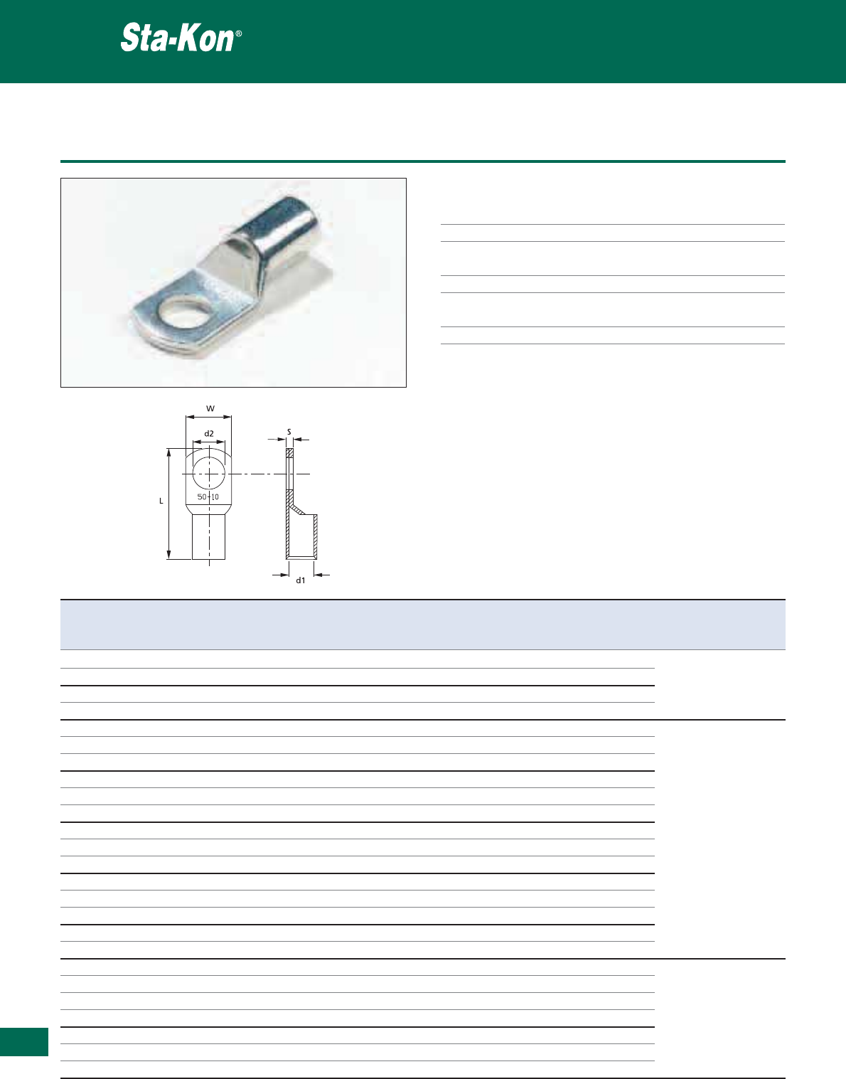
364
Thomas & Betts • www.tnb-europe.com
5.1
Non-insulated copper tube ring terminals with inspection window
Technical Information
Material Electrolytic copper
Plating Tin plated
Metal barrel Copper tube with inspection window
(hole)
Current rating See table
Marking Cable size (cross-section area) and
bolt size
Cable insertion Easy entry
Non-insulated terminals
Product Ref. Wire Stud Dimensions Current Weight Quantity Crimping
size size L W s d1 d2 rating tool*
[mm
2
] [mm] [mm] [mm] [mm] [mm] [Ampere] [kg/100] [pieces]
TW 10-6 10 M6 27.0 12.6 0.85 4.5 6.5 90 0.29 100
TW 10-8 10 M8 27.0 12.6 0.85 4.5 8.4 90 0.27 100
ERG1016
TW 16-6 16 M6 29.5 12.6 0.85 5.5 6.5 125 0.38 100
WT3165B
TW 16-8 16 M8 29.5 12.6 0.85 5.5 8.4 125 0.36 100
WTH500 (+ Dies)
TW 25-6 25 M6 33.0 15.0 1.0 7.0 6.5 160 0.68 100
TW 25-8 25 M8 33.0 15.0 1.0 7.0 8.4 160 0.63 100
TW 25-10 25 M10 33.0 15.0 1.0 7.0 10.5 160 0.59 100
TW 35-6 35 M6 38.0 15.2 2.5 8.2 6.5 200 1.14 100
TW 35-8 35 M8 38.0 15.2 2.5 8.2 8.4 200 1.03 100
TW 35-10 35 M10 38.0 15.2 2.5 8.2 10.5 200 1.00 100
TW 50-8 50 M8 44.5 18.5 2.9 10.0 8.4 250 1.86 100 WT3165B
TW 50-10 50 M10 44.5 18.5 2.9 10.0 10.5 250 1.77 100 WTH500 (+ Dies)
TW 50-12 50 M12 44.5 18.5 2.9 10.0 13.0 250 1.71 100
TW 70-8 70 M8 54.2 21.4 3.5 11.5 8.4 310 3.18 50
TW 70-10 70 M10 54.2 21.4 3.5 11.5 10.5 310 3.08 50
TW 70-12 70 M12 54.2 21.4 3.5 11.5 13.0 310 2.94 50
TW 95-10 95 M10 59.0 25.5 3.9 13.5 10.5 380 4.42 50
TW 95-12 95 M12 59.0 25.5 3.9 13.5 13.0 380 4.26 50
TW 120-10 120 M10 66.7 28.3 4.5 15.5 10.5 440 6.83 25
TW 120-12 120 M12 66.7 28.3 4.5 15.5 13.0 380 6.36 25
TW 120-14 120 M14 66.7 28.3 4.5 15.5 15.0 380 5.93 25
TW 120-16 120 M16 66.7 28.3 4.5 15.5 17.0 380 5.52 25 WT3014E (+ Dies)
TW 150-12 150 M12 74.5 31.0 4.7 17.0 13.0 510 8.34 25
TW 150-14 150 M14 74.5 31.0 4.7 17.0 15.0 510 8.48 25
TW 150-16 150 M16 74.5 31.0 4.7 17.0 17.0 510 8.34 25
* Use selection chart to determine appropriate die set (see page 376)
See pages 370 to 376 for tooling specifications
Other sizes available upon request - please contact your Sales Office
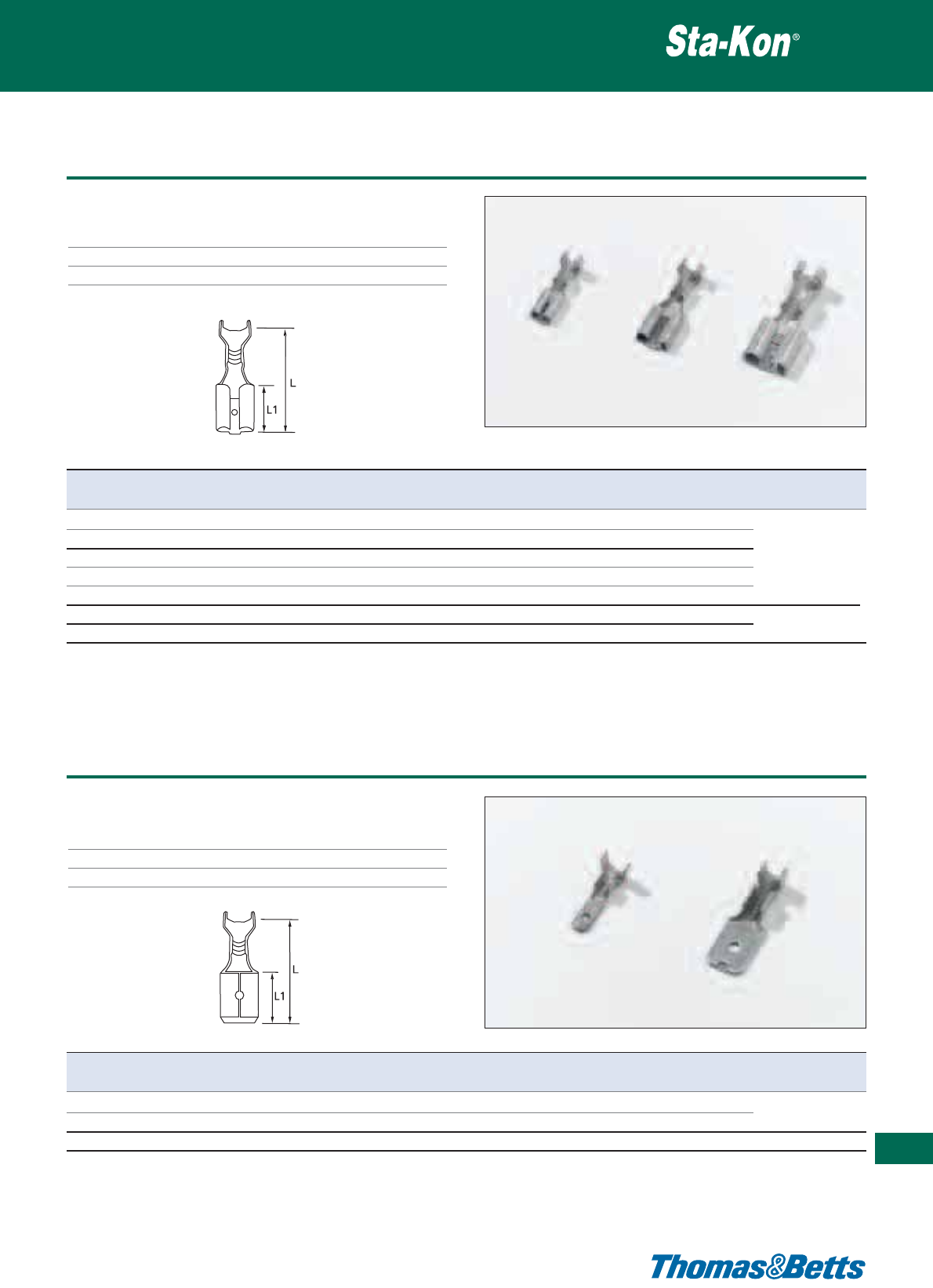
Non-insulated female disconnect terminals
Technical Information
Material Brass with 70% copper
Plating Tin plated
Temperature rating +110°C
Non-insulated terminals
365
Thomas & Betts • www.tnb-europe.com
5.1
Product Ref. Wire size range Male tab size Dimensions [mm] Weight Quantity Crimping
[mm
2
] [mm x mm] L L1 [g/100] [pieces] tool*
BA 285 0.5 - 1.0 2.8 x 0.5 12.7 5.0 21 100
BA 288 0.5 - 1.0 2.8 x 0.8 12.7 5.0 25 100 ERG0560
BA 485 0.75 - 1.5 4.8 x 0.5 16.0 6.4 47 100
BA 488 0.75 - 1.5 4.8 x 0.8 16.0 6.4 47 100 ERG1475
BA 638 0.75 - 1.5 6.3 x 0.8 19.0 7.6 77 100
BB 638 1.5 - 2.5 6.3 x 0.8 19.0 7.6 80 100 ERG0560
BC 638 4.0 - 6.0 6.3 x 0.8 19.0 7.6 86 100
* Use selection chart to determine appropriate die set (see page 376)
See pages 370 to 376 for tooling specifications
Product Ref. Wire size range Male tab size Dimensions [mm] Weight Quantity Crimping
[mm
2
] [mm x mm] L L1 [g/100] [pieces] tool*
BA 288M 0.5 - 1.0 2.8 x 0.8 13.0 5.5 23 100 ERG0560
BA 638M 0.5 - 1.5 6.3 x 0.8 19.0 8.0 57 100 ERG1475
BB 638M 1.5 - 2.5 6.3 x 0.8 20.0 8.0 61 100 ERG0560
* Use selection chart to determine appropriate die set (see page 376)
See pages 370 to 376 for tooling specifications
Non-insulated female disconnect terminals
Non-insulated terminals
Technical Information
Material Brass with 70% copper
Plating Tin plated
Temperature rating +110°C
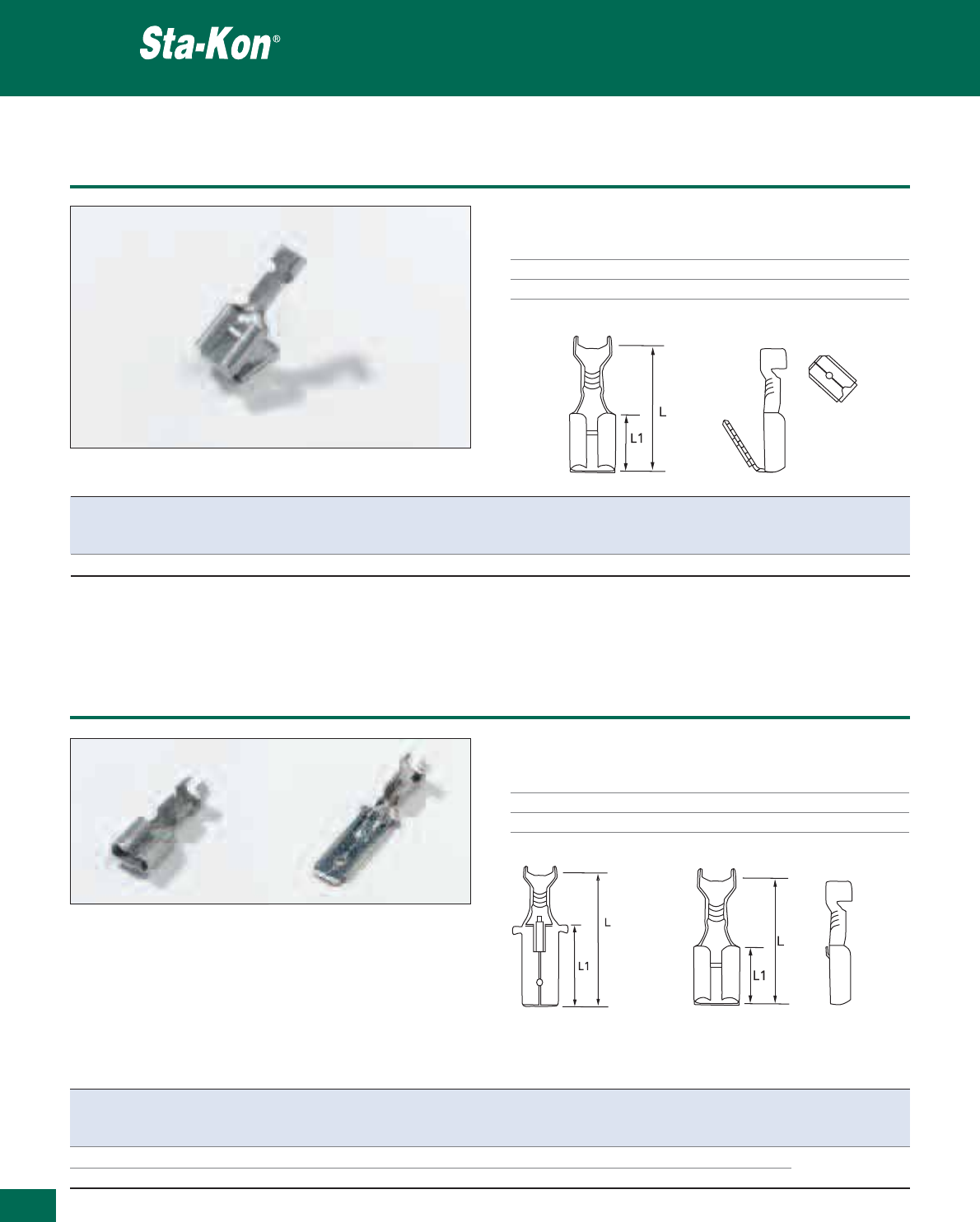
366
Thomas & Betts • www.tnb-europe.com
5.1
Non-insulated Piggy back disconnect terminal
Technical Information
Material Brass with 70% copper
Plating Tin plated
Temperature rating +110°C
Non-insulated terminals
Product Ref. Wire size range For male & female tab size Dimensions Weight Quantity Crimping
L L1 tool*
[mm
2
] [mm x mm] [mm] [mm] [g/100] [pieces]
BA 638T 0.5 - 1.5 6.3 x 0.8 19.0 7.5 108 100 ERG0560, ERG1475
* Use selection chart to determine appropriate die set (see page 376)
See pages 370 to 376 for tooling specifications
Product Ref. Wire size range For tab size Dimensions Weight Quantity Crimping
L L1 tool*
[mm
2
] [mm x mm] [mm] [mm] [g/100] [pieces]
B 638 1.5 - 2.5 6.3 x 0.8 19.0 7.5 74 100 ERG0560
BM 638 1.5 - 2.5 6.3 x 0.8 28.0 16.0 82 100
* Use selection chart to determine appropriate die set (see page 376)
See pages 370 to 376 for tooling specifications
Male: BM638 Female: B 638
Non-insulated disconnect terminals with lock tongues
Non-insulated terminals
Technical Information
Material Brass with 70% copper
Plating Tin plated
Temperature rating +110°C
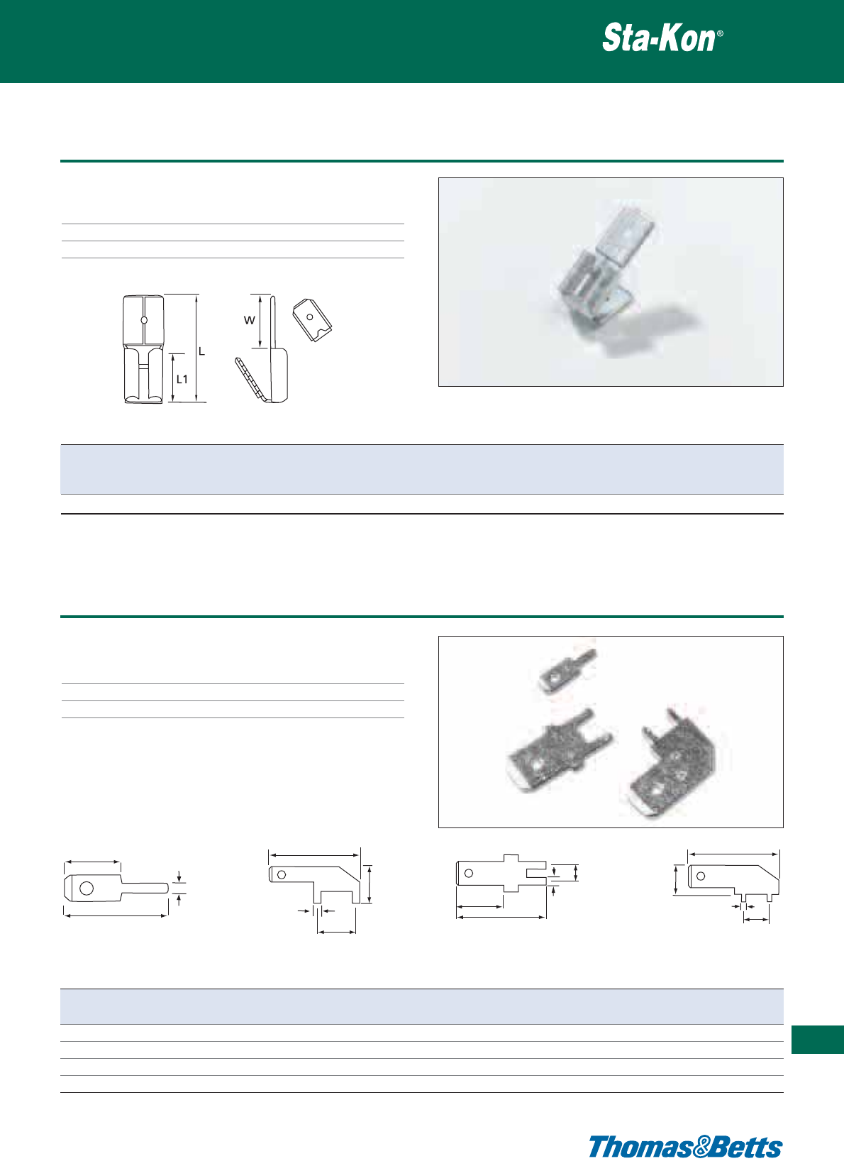
Non-insulated branch off tab
Technical Information
Material Brass with 70% copper
Plating Tin plated
Temperature rating +110°C
Non-insulated terminals
367
Thomas & Betts • www.tnb-europe.com
5.1
Product Ref. Tab size Dimensions Weight Quantity
LWL1
[mm x mm] [mm] [mm] [mm] [g/100] [pieces]
Z 638-2 6.3 x 0.8 18.5 9 7.5 177 100
0.9
10.4
6.2
13.6
5
1.2
17
8.5 1.35
5
16
8
6.2
1.2
6.3
Product Ref. Recommended Tab size Weight Quantity
drill hole Ø [mm] [mm x mm] [g/100] [pieces]
B 288L 1.00 2.8 x 0.8 16 100
B 288LD 1.30 2.8 x 0.8 37 100
B 638L 1.45 6.3 x 0.8 62 100
B 638LW 1.30 6.3 x 0.8 83 100
Non-insulated tabs for soldering DIN 46244
Non-insulated terminals
Technical Information
Material Brass
Plating Tin plated
Temperature rating +110°C
B 288L B 288LD B 638L B 638LW
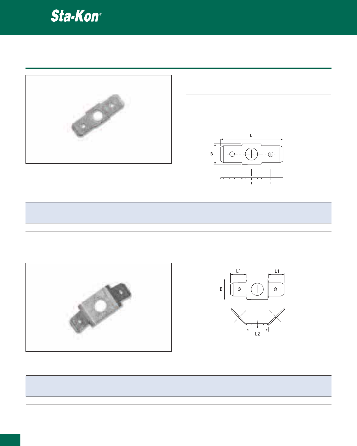
368
Thomas & Betts • www.tnb-europe.com
5.1
Non-insulated screw mounted male disconnect tab terminals DIN 46244
Technical Information
Material Brass
Plating Tin plated
Temperature rating +110°C
Non-insulated terminals
Product Ref. Tab size Dimensions Hole ø Weight Quantity
BL
[mm x mm] [mm] [mm] [mm] [g/100] [pieces]
ZG 638-4 6.3 x 0.8 7.0 23.0 4.2 94 100
Product Ref. Angle Tab size Dimensions Hole ø Weight Quantity
BL1 L2
[mm x mm]
[mm] [mm] [mm] [mm] [g/100] [pieces]
ZG 638-4W 2 x 45° 6.3 x 0.8 8.0 10.0 12.0 4.3 152 100
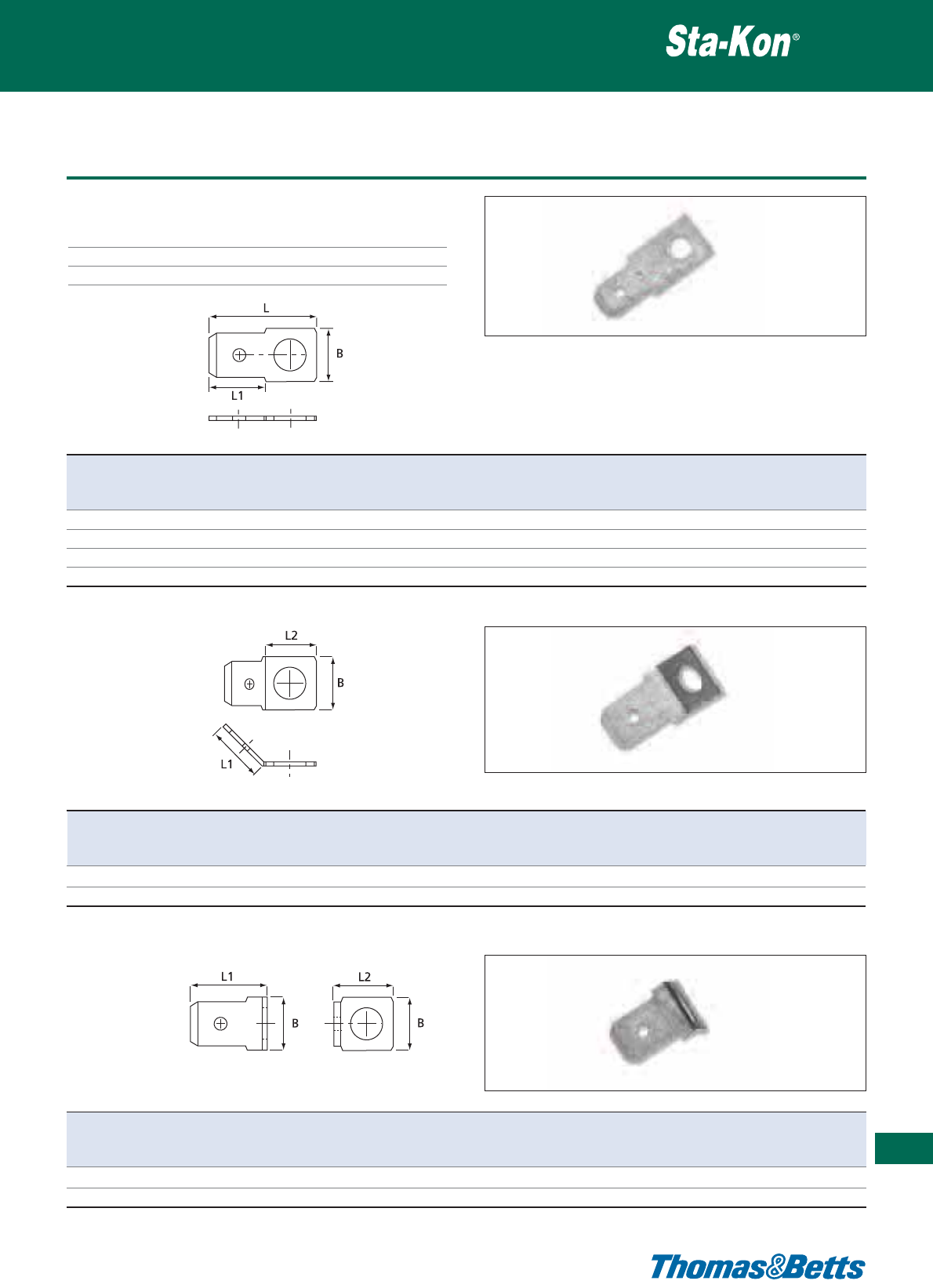
Non-insulated screw mounted male disconnect tab terminals DIN 46244
Technical Information
Material Brass
Plating Tin plated
Temperature rating +110°C
Non-insulated terminals
369
Thomas & Betts • www.tnb-europe.com
5.1
Product Ref. Tab size Dimensions Hole ø Weight Quantity
BL L1
[mm x mm] [mm] [mm] [mm] [mm] [g/100] [pieces]
Z 288-2 2.8 x 0.8 4.5 13.1 5.5 2.8 24 100
Z 488-3 4.8 x 0.8 6.5 17.5 7.0 3.2 68 100
Z 638-4 6.3 x 0.8 8.1 19.1 8.3 4.4 80 100
Z 638-5 6.3 x 0.8 8.0 19.2 8.3 5.4 74 100
Product Ref. Angle Tab size Dimensions Hole ø Weight Quantity
BL1L2
[mm x mm] [mm] [mm] [mm] [mm] [g/100] [pieces]
Z 638-4-4 45° 6.3 x 0.8 8.0 8.0 8.0 4.1 81 100
Z 638-5-4 45° 6.3 x 0.8 8.0 8.0 8.0 5.4 74 100
Product Ref. Angle Tab size Dimensions Hole ø Weight Quantity
BL1L2
[mm x mm] [mm] [mm] [mm] [mm] [g/100] [pieces]
Z 488-3-9 90° 4.8 x 0.8 7.8 8.8 7.5 4.5 59 100
Z 638-4-9 90° 6.3 x 0.8 7.8 8.3 8.8 5.4 76 100
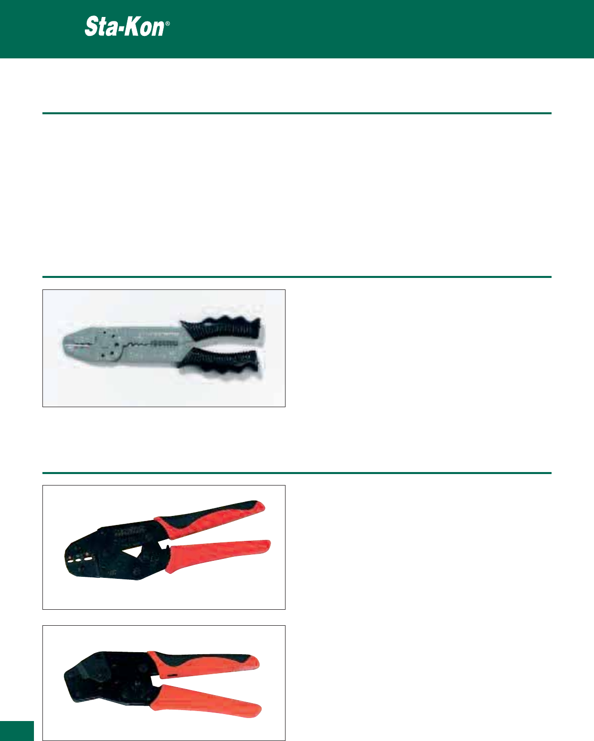
Thomas & Betts • www.tnb-europe.com
Overview
An extensive range of tooling is available, suiting a variety of
requirements, to crimp the following terminals:
• Insulated terminals and bootlace ferrules
• Non-insulated terminals
• Copper tube terminals
Crimping tools
5.1
370
Plier type crimping tools
Crimping tools
Different types of tooling are offered, depending on volume and
application:
• Plier type hand tools for occasional applications (“Do-It-
Yourself” users)
• Standard hand tooling for low to medium volume applications
• Ergonomic hand tooling for low to medium volume applications,
where high, repeatable quality is essential
• Large hand tools
• Hydraulic tooling for heavy-duty applications
Standard crimping tools
Product Ref.: WT2124Y
• Ratchet type hand tool, fixed die
•Forinsulated terminals from:
0.5 to 1.5 mm² red
1.5 to 2.5 mm² blue
4.0 to 6.0 mm² yellow
•Shure-Stake™ mechanism to ensure a full compression
every time
• Length: 228 mm
• Weight: 533 g
Crimping tools
Product Ref.: TBZ3
• Ratchet type hand tool, fixed die
• Front loading
•Forinsulated bootlace ferrules, 0.5 to 6.0 mm²
•Shure-Stake™ mechanism to ensure a full compression
every time
• Length: 195 mm
• Weight: 390 g
Product Ref.: WT52
• Plier type tool
•Forinsulated and non-insulated terminals from0.5to6mm²
• Incorporates wire stripper and bolt cutters
• Recommended for ‘Do-It-Yourself’ applications only
• Length: 225 mm
• Weight: 200 g
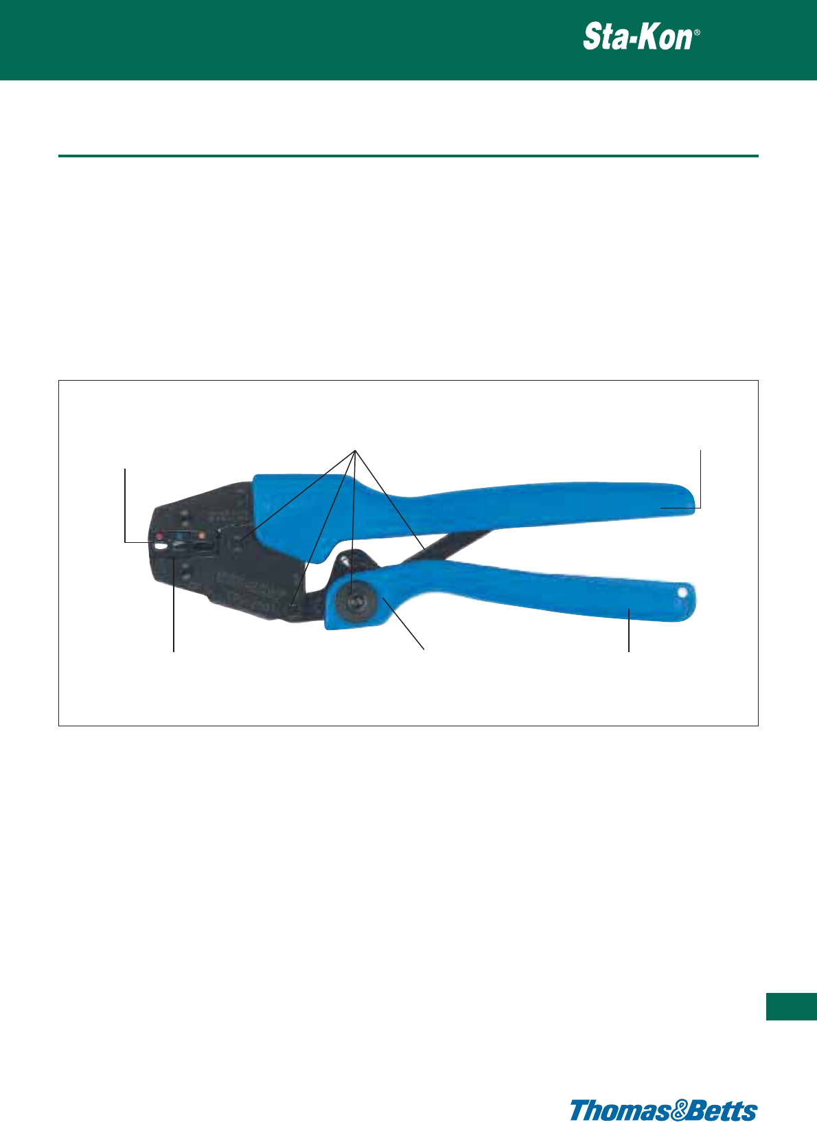
Ergonomic hand tools
• Ergonomic ratchet style hand tools used for installing insulated
and non-insulated terminals
• Specially designed ergonomic handles distribute the crimping
force more evenly across the user’s hands. This helps to reduce
the risk of Carpal Tunnel Syndrome, the cause of almost one in
two industrial injuries
• Ratchet design greatly reduces handle forces over conventional
hand tools and incorporates the Shure-Stake™ mechanism which
ensures a full crimp cycle every time
Crimping tools
Thomas & Betts • www.tnb-europe.com
5.1
371
For easy visual verification
of crimps, integrity dots are
embossed on the top and
bottom of the terminal.
Patent-pending toggle action increases
mechanical gain, which dramatically reduces
handle force - and the stress on your hands.
Advanced ergonomic
design of handle distributes
the force more evenly
across the hand.
Colour-coded die nests on both the right
and left sides of the tool are included for
insulated terminals.
Shure-Stake™ mechanism ensures
a complete crimp cycle before it
releases.
Rubberised thermoplastic handle
combines maximum friction
with a soft, comfortable feel
that reduces muscle tension.
• Most dies incorporate wire range mark for easy inspection (insu-
lated only)
• Colour coded die nests (insulated only) makes terminal and die
nest selection easy
• The product design and engineering results in a long lasting pre-
cision tool
• Exists in 2 versions: with interchangeable dies or with fixed dies
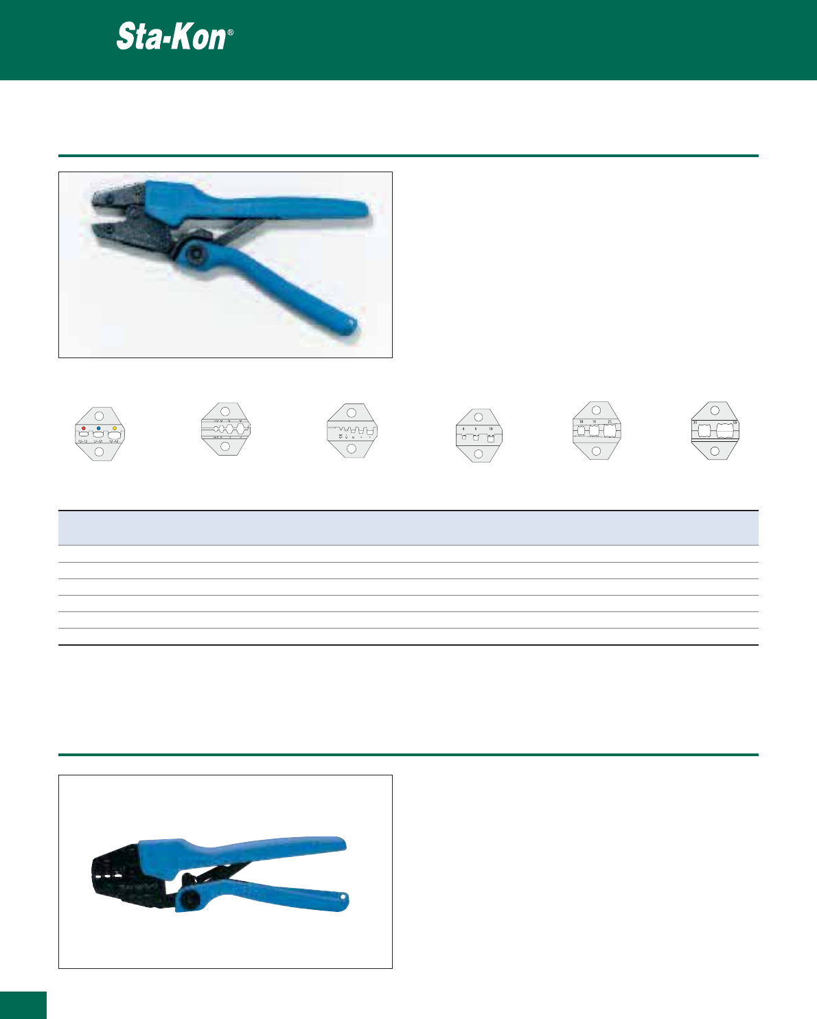
372
Thomas & Betts • www.tnb-europe.com
5.1
Ergonomic hand tools with interchangeable dies
Product Ref.: ERG2000KE
• Ergonomic hand tool with interchangeable dies
• Frame, with the option of interchangeable steel dies
• A versatile tool, one frame with a selection of dies covers a
large range of terminals.
•Shure-Stake™ mechanism to ensure a full compression
every time
• Length: 255 mm
• Weight: 510 g
Crimping tools
Die Product Ref. Terminal description Cross section
[mm
2
]
D-0760DIN Insulated terminal 0.5 - 6.0
D-1060G Non-insulated terminal & Copper tube lug 0.5 - 6.0
D-0560 Insulated bootlace ferrule & Non-insulated bootlace ferrule 0.5 - 6.0
D-4010 Insulated bootlace ferrule & Non-insulated bootlace ferrule 4, 6, 10
D-1025 Insulated bootlace ferrule & Non-insulated bootlace ferrule 10, 16, 25
D-3550 Insulated bootlace ferrule & Non-insulated bootlace ferrule 35, 50
ERG2000KE die selection chart
D-0760DIN D-1060G D-0560 D-4010 D-1025 D-3550
Ergonomic hand tools with fixed die
Crimping tools
Product Ref.: ERG2001A
• Ergonomic fixed die tool, with three colour-coded die nests for
easy selection
•Forinsulated terminals from:
0.5 to 1.5 mm² red
1.5 to 2.5 mm² blue
4.0 to 6.0 mm² yellow
•Shure-Stake™ mechanism to ensure a full compression every
time
• Length: 255 mm
• Weight: 560 g
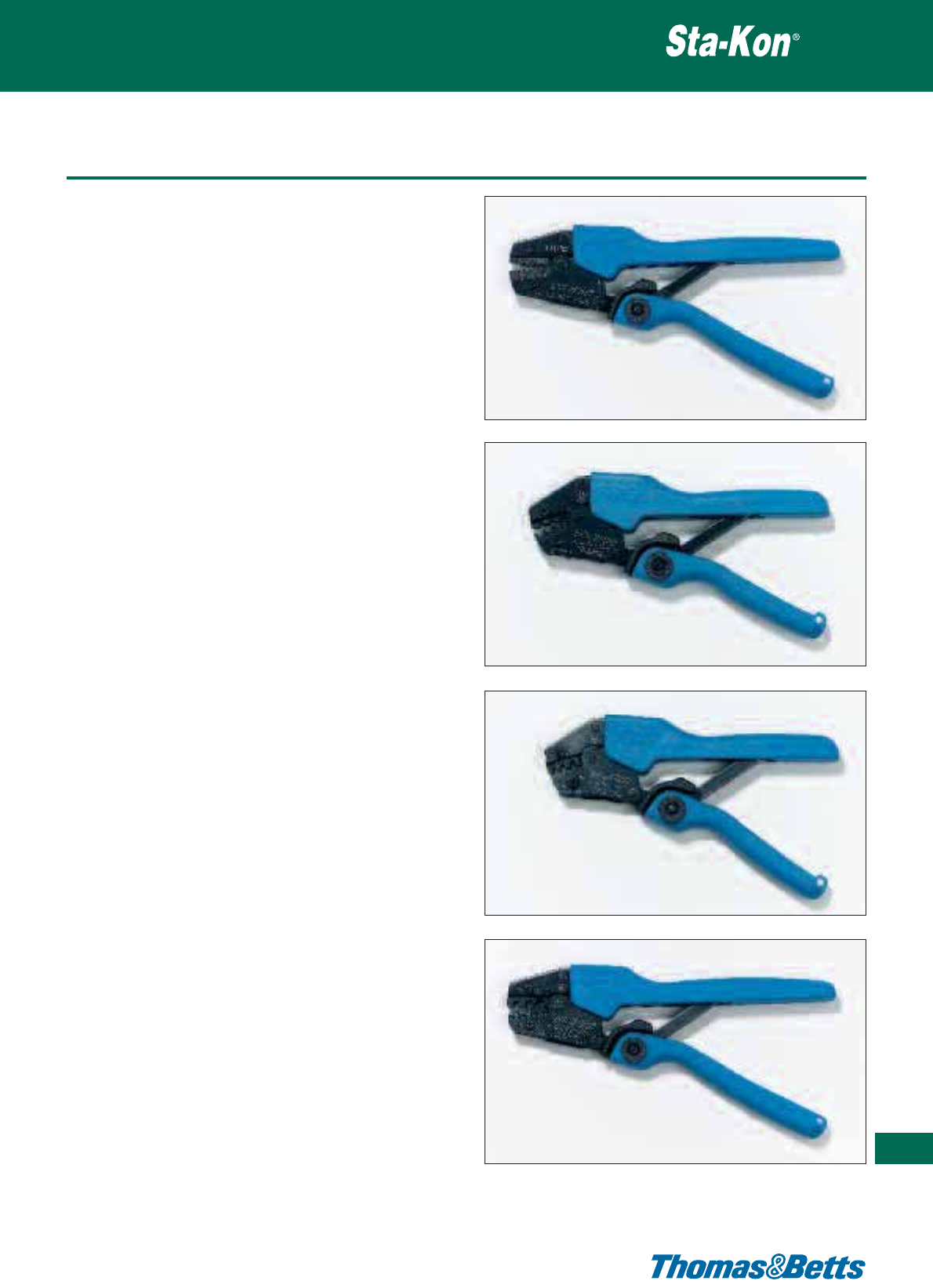
Ergonomic hand tools with fixed die
Product Ref.: ERG2106
• Ergonomic fixed die tool, with 5 die nests
•Forinsulated and non-insulated bootlace ferrules (cord
end terminals) from 0.5 to 6.0 mm²
•Shure-Stake™ mechanism to ensure a full compression
every time
• Length: 255 mm
• Weight: 560 g
Product Ref.: ERG2510
• Ergonomic fixed die tool, with 2 die nests
•Forinsulated terminals from:
0.25 to 0.5 mm²
0.5 to 1.0 mm²
•Shure-Stake™ mechanism to ensure a full compression
every time
• Length: 215 mm
• Weight: 470 g
Product Ref.: ERG1475
• Ergonomic fixed die tool, with 3 die nests
•Fornon-insulated male & female disconnects (F-crimps)
from: 0.1 to 0.5 mm²
0.5 to 1.0 mm²
1.0 to 1.5 mm²
•Shure-Stake™ mechanism to ensure a full compression
every time
• Length: 215 mm
• Weight: 470 g
Product Ref.: ERG0560
• Ergonomic fixed die tool, with 3 die nests
•Fornon-insulated male & female disconnects (F-crimps)
from: 0.5 to 1.5 mm²
1.5 to 2.5 mm²
4.0 to 6.0 mm²
•Shure-Stake™ mechanism to ensure a full compression
every time
• Length: 255 mm
• Weight: 560 g
Crimping tools
373
Thomas & Betts • www.tnb-europe.com
5.1
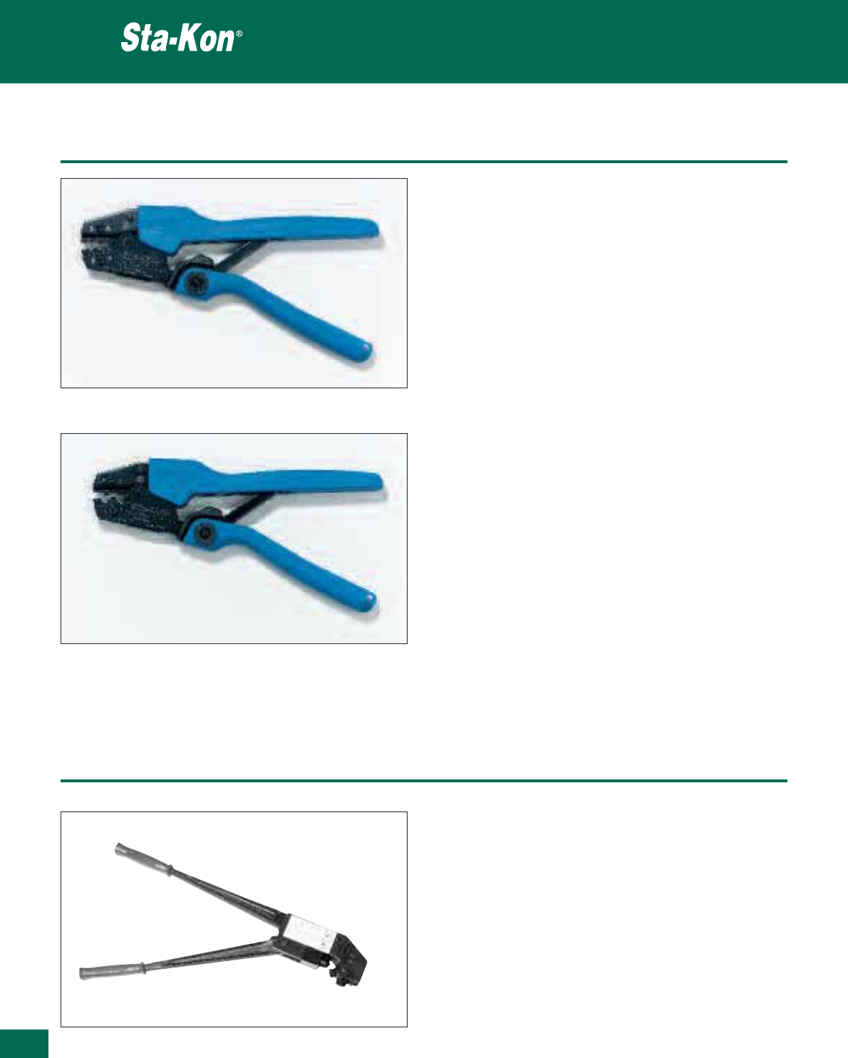
374
Thomas & Betts • www.tnb-europe.com
5.1
Ergonomic hand tools with fixed die
Product Ref.: ERG2002E
• Ergonomic fixed die tool with 3 die nests
•Fornon-insulated terminals and copper tube lugs from:
0.5 to 1.5 mm²
1.5 to 2.5 mm²
4.0 to 6.0 mm²
•Shure-Stake™ mechanism to ensure a full compression
every time
• Length: 255 mm
• Weight: 550 g
Product Ref.: ERG1016
• Ergonomic fixed die tool, with 2 die nests
•Fornon-insulated terminals and copper tube lugs of:
10 mm² and 16 mm²
•Shure-Stake™ mechanism to ensure a full compression
every time
• Length: 255 mm
• Weight: 550 g
Crimping tools
Product Ref.: WT3165B
• Large fixed die tool, with rotating head and 6 nests
•Fornon-insulated terminals and copper tube lugs from:
10 to 95 mm²
• According to DIN, SEN, BS, UL, Mil specifications
•Shure-Stake™ mechanism to ensure a full compression every
time
• Length: 500 mm
• Weight: 2,8 kg
• Max. pressure: 130 kN
Large hand tool
Crimping tools
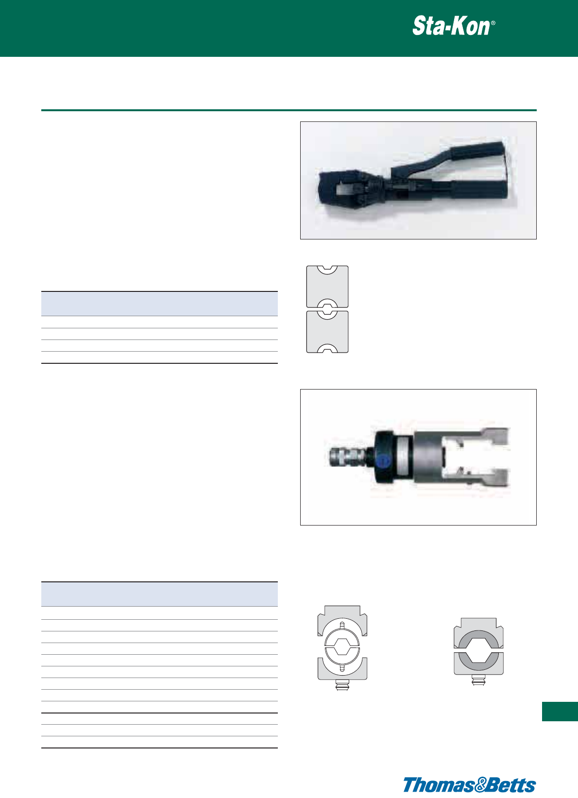
Hydraulic tools
Product Ref.: WTH500
• High quality hydraulic hand tool with interchangeable dies
•Fornon-insulated terminals and copper tube lugs from:
10 to 95 mm²
• 180° rotating head to get into hard to reach places
•Shure-Stake™ mechanism to ensure a full compression
every time
• Complete with plastic carrying case
• Length: 470 mm
• Weight: 3 kg
• Max. performance: 60 kN
WTH500 die selection chart
Crimping tools
375
Thomas & Betts • www.tnb-europe.com
5.1
Product Ref. Terminal description Cross-section
[mm
2
]
TB6-8DIN Copper tube lug 10 - 16
TB10-12DIN Copper tube lug 25 - 35
TB14-16DIN Copper tube lug 50 - 70
TB18DIN Copper tube lug 95
V1318
V1316
Product Ref.: WT3014E
• Hydraulic tool head with interchangeable dies
•Fornon-insulated terminals and copper tube lugs from:
10 to 300 mm²
• Crimping according to DIN46235
• Hand or foot activated switch
• Rapid coupling
• To be used with a hydraulic pump
(10.000 p.s.i.= 690 bar = 69 MPa)
• Length: 295 mm
• Weight: 4 kg
• Output pressure: 15 ton
• Max. performance: 130kN
WT3014E die selection chart
Product Ref. Terminal description Cross-section
(+ Die adapters) [mm
2
]
B6DIN (+V1318, V1316) Copper tube lug 10
B8DIN (+V1318, V1316) Copper tube lug 16
B10DIN (+V1318, V1316) Copper tube lug 25
B12DIN (+V1318, V1316) Copper tube lug 35
B14DIN (+V1318, V1316) Copper tube lug 50
B16DIN (+V1318, V1316) Copper tube lug 70
B18DIN (+V1318, V1316) Copper tube lug 95
B20DIN (+V1318, V1316) Copper tube lug 120
B22DIN (+V1318, V1316) Copper tube lug 150
13B25DIN Copper tube lug 185
13B28DIN Copper tube lug 240
13B32DIN Copper tube lug 300
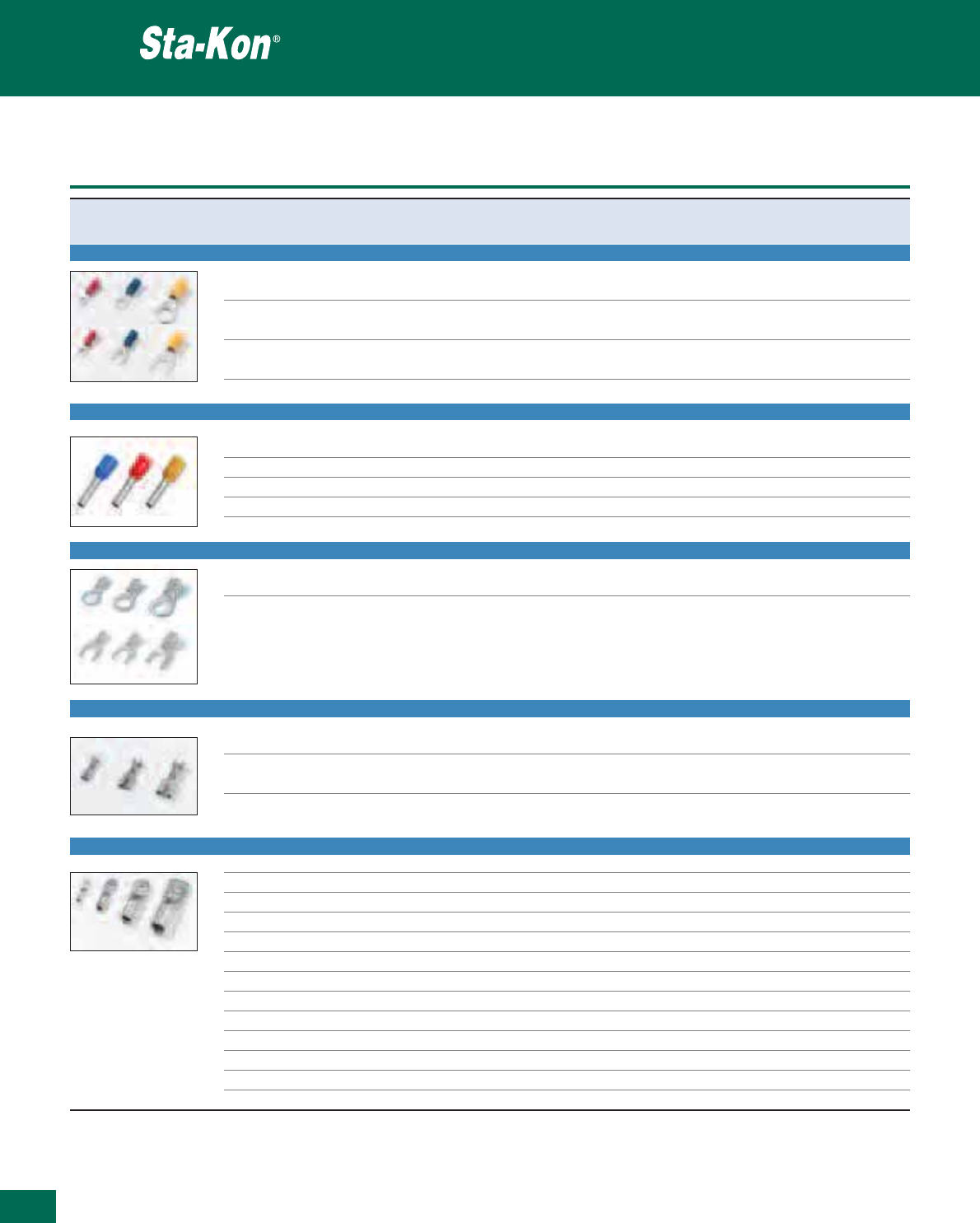
376
Thomas & Betts • www.tnb-europe.com
5.1
Tooling and die selection chart
Crimping tools
Terminal Type Cross section WT52 Fixed die hand tool ERG2000KE WTH500 WT3014E
[mm
2
] Product Ref. Die Product Ref. Die Product Ref. Die Product Ref.
INSULATED TERMINALS AND DISCONNECTS
0.25 - 0.5 ERG2510
0.5 - 1.0 WT52 ERG2510 D-0760DIN
0.5 - 6.0 WT52 WT2124Y, ERG2001A D-0760DIN
INSULATED BOOTLACE FERRULES**
0.5 - 6.0 WT52 ERG2106, TBZ3 D-0560
4, 6, 10 D-4010
10, 16, 25 D-1025
35, 50 D-3550
NON-INSULATED TERMINALS
0.5 - 6.0 WT52 ERG2002E D-1060G
NON-INSULATED DISCONNECTS (F-CRIMPS)
0.1 - 1.5 ERG1475
0.5 - 6.0 ERG0560
NON-INSULATED COPPER TUBE LUGS
0.5 - 6.0 ERG2002E D-1060G
10 ERG1016 , WT3165B TB6-8DIN B6DIN*
16 ERG1016, WT3165B TB6-8DIN B8DIN*
25 WT3165B TB10-12DIN B10DIN*
35 WT3165B TB10-12DIN B12DIN*
50 WT3165B TB14-16DIN B14DIN*
70 WT3165B TB14-16DIN B16DIN*
95 WT3165B TB18DIN B18DIN*
120 B20DIN*
150 B22DIN*
185 13B25DIN
240 13B28DIN
300 13B32DIN
* To be used with a Hydraulic pump, with die adaptors V1316, V1318
** The tools WT52, ERG2106, ERG2000KE can also crimp non-insulated bootlace ferrules
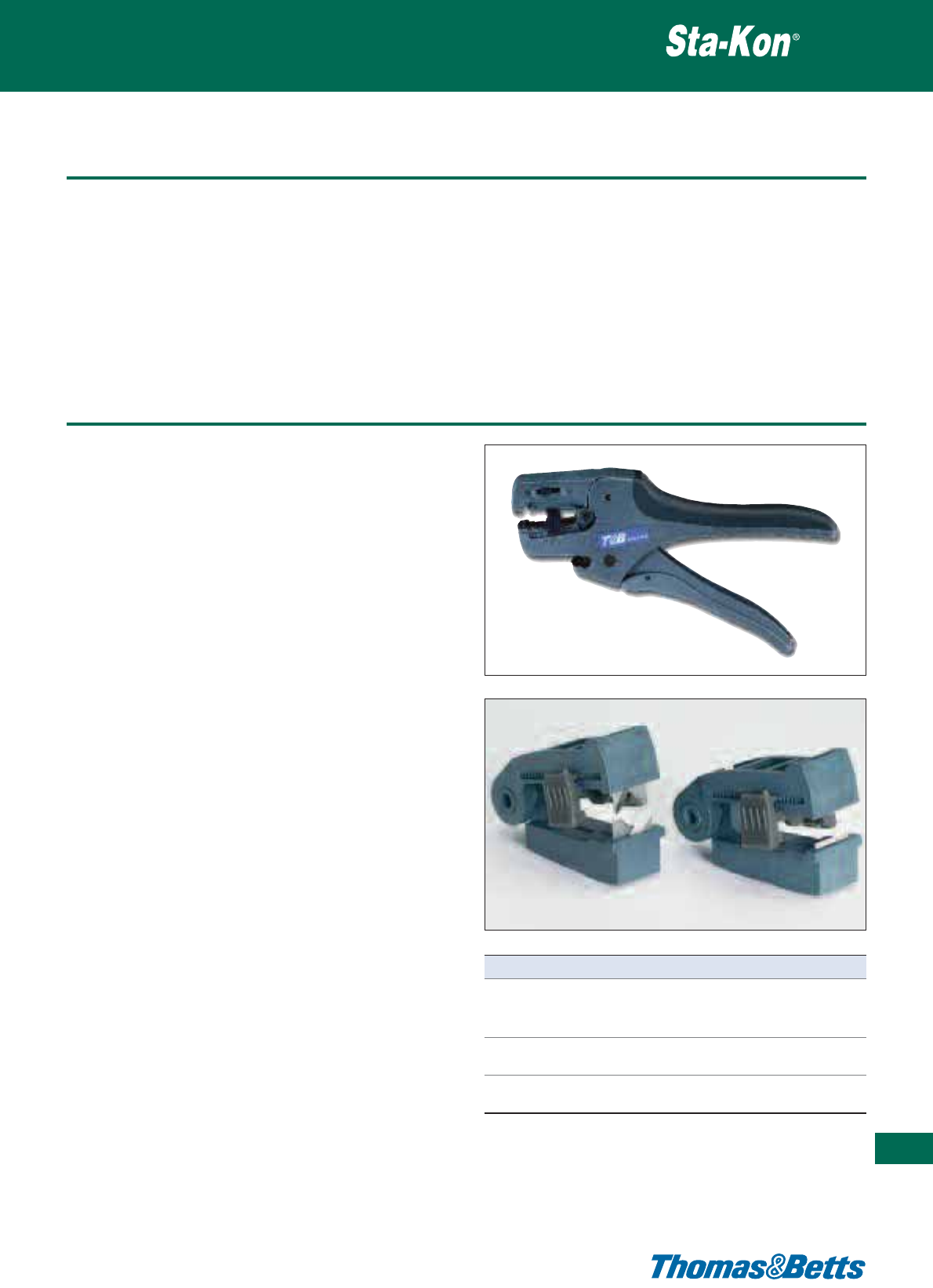
Overview
Thomas & Betts offer a wide variety of specialty tools used most
commonly by electricians. Easy to use, they are convenient to all
kind of job, whether it is new installation or maintenance.
Designed for the professionals, all the stripping and cutting tools
from Thomas & Betts are manufactured from top quality materials
to assure durability and a long usable life. Single purpose and com-
bination function designs are included.
Stripping & cutting tools
377
Thomas & Betts • www.tnb-europe.com
5.1
Product Ref.: ERG1-WS
• Ergonomic, self-adjusting wire stripping & cutting tool
•Thewidest stripping range in the industry for this type of tool:
from 0.02 mm2to 10 mm2insulated wires
• Incorporates interchangeable stripping cassettes for a wide range
of wire insulations
• The lightweight, ergonomic design makes this tool ideal for
higher volume production as well as portable field usage.
• Replaces the ERG1 cutting / stripping tool
Feature & Benefits:
•Versatile - Interchangeable cassettes for stripping a wide range
of insulations without having to change tools. Integral wire cutter,
to cut and strip with the same tool.
•Powerful - V-Blade cassette designed for stripping difficult insu-
lations like PTFE coated wire.
•Safe & Ergonomic - Stationary handle has a soft grip moulded into
the tool for extra comfort. Optimised grip span and lightweight
ensures comfortable operation for the user. Cutting blades are not
exposed so user’s hands are protected.
•Automatic & Precise - Tool automatically strips wire to preset
length. Hard plastic wire-stop allows the user to easily adjust wire
strip length. The fine adjusting slide allows the user to strip thin in-
sulation jackets without damaging conductors.
•Durable & Reliable - Cutting blades manufactured from high
grade hardened steel. Body is moulded in a new high strength
plastic to withstand the harshest working environments. The tool
has been tested to over 150,000 cycles.
• Stripping Capacity
- Straight Blade Cassette (SBC-1): PVC Insulations, 0.02 - 10 mm2
- “V” Blade Cassette (VBC-1): all insulations, 0.02 - 6 mm2
• Cutting Capacity
- Flexible wires: 10 mm2
- Rigid wires: 1.5 mm2
• Dimensions: 191 x 123 x 20 mm
• Weight: 136 g
Ergonomic hand tools
Stripping & cutting tools
Different types of tools are offered, depending on volume and appli-
cation:
•Ergonomic hand tools for medium to high volume applications,
where high, repeatable quality as well as durability and comfort of
use are essential
•Standard hand tools for medium volume applications
•Heavy-duty cable cutters for cables of large cross-section
Product Ref. Description
ERG1-WS Ergonomic Wire Stripping & Cutting Tool,
interchangeable cassettes.
Supplied with 1ea. SBC-1 cassette
SBC-1 Replacement Cassette - Straight blade,
for PVC insulations from 0.02 to 10 mm
2
VBC-1 Replacement Cassette - “V” blade,
for all insulations from 0.02 to 6 mm
2
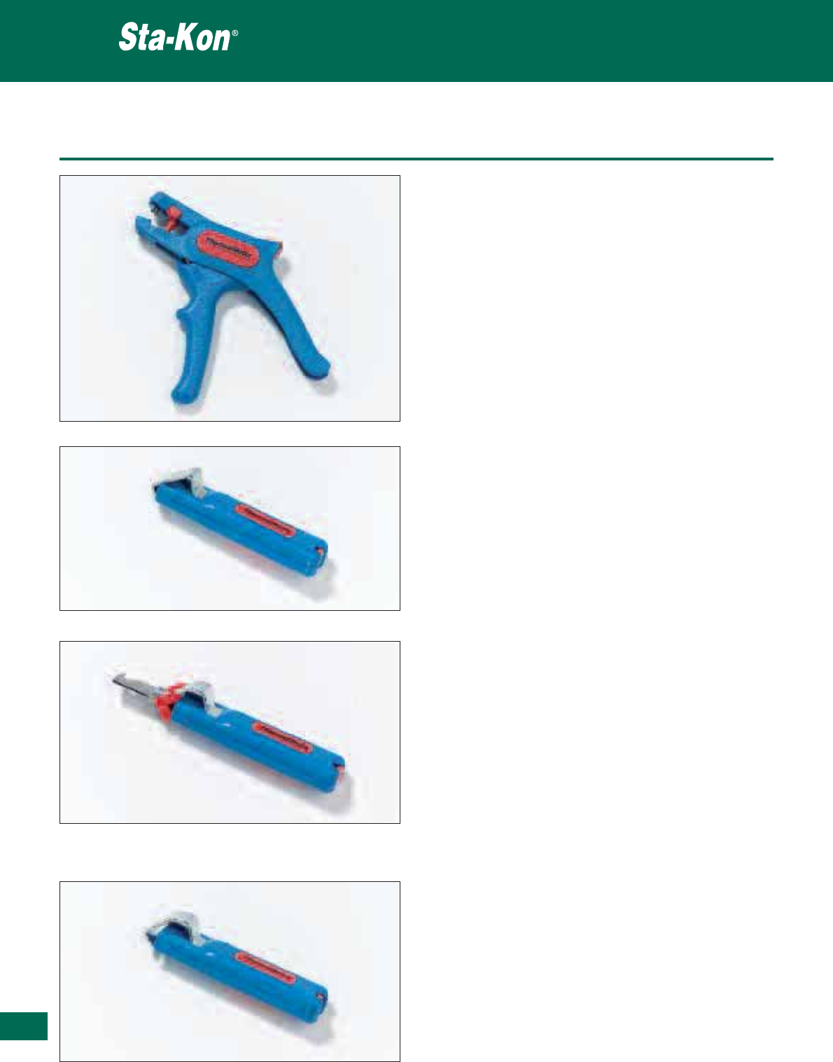
378
Thomas & Betts • www.tnb-europe.com
5.1
Standard hand tools
Product Ref.: Superstrip 5
• Fully insulated automatic wire stripper
• The special scanning system automatically adjusts to the diameter
of the wire and ensures quick and accurate stripping without leaving
witness marks on the insulation, or damage to the conductor
• The ergonomic design and the light weight guarantee fatigue-
free operation
• The slim plier type jaw enables access to wiring in confined spaces
such as in switching cabinets, junction and distribution boxes
•
Type: stranded and solid wires
•
Crosssection:0.2-6.0mm²(24-10AWG)
•
Weight: 105 g
Product Ref.: Cabstrip 4-16
• Accurate, fast and safe stripping
• Removable reducing adapter, made of highly abrasion resistant
plastic (POM)
• No damage of the inner conductors due to infinitely variable ad-
justment of the cutting depth
• Each cable stripper contains a spare swivel-blade inside the handle
•
Type: round cables
•
Diameter:4-16mm
•
Weight:70g
Product Ref.: Cabstrip 4-28H
• Accurate, fast and safe stripping
• Removable reducing adapter, made of highly abrasion resistant
plastic (POM)
• No damage of the inner conductors due to infinitely variable ad-
justment of the cutting depth
• Each cable stripper contains a spare swivel-blade inside the handle
•
Type: round cables
•
Diameter:4-28mm
•
Weight:84g
Product Ref.: Cabstrip 8-27
• Accurate, fast and safe stripping
• Removable reducing adapter, made of highly abrasion resistant
plastic (POM)
• No damage of the inner conductors due to infinitely variable ad-
justment of the cutting depth
• Each cable stripper contains a spare swivel-blade inside the handle
•
Type: round cables
•
Diameter:8-28mm
•
Weight:72g
Stripping & cutting tools
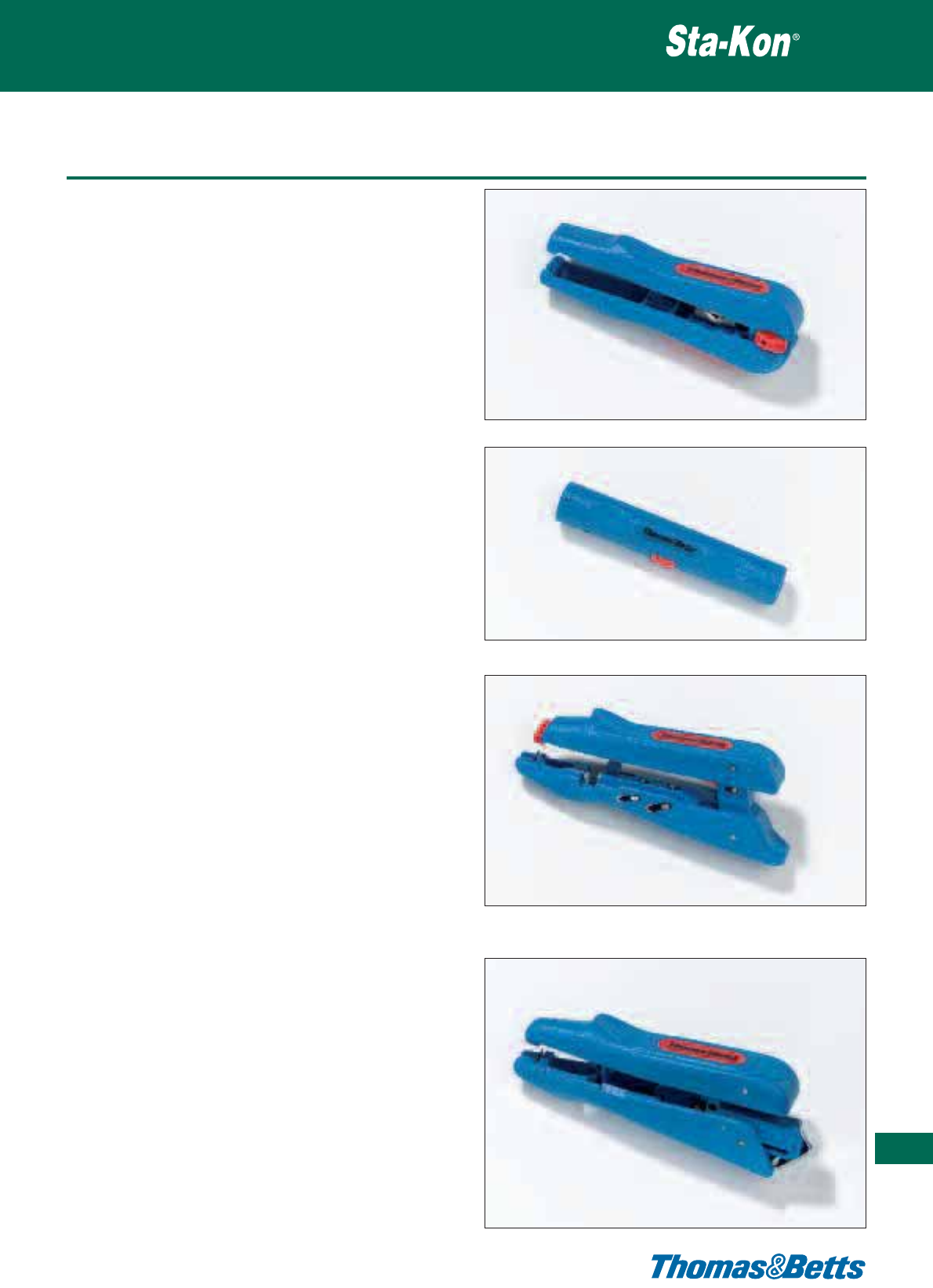
Standard hand tools
Product Ref.: Coaxstrip 3
• Two or three level stripping
• Ergonomic handle, for faster and more convenient stripping
• Needs no adjustment of the cutting depth
• Easily accessible built-in side cutter
•
Type: coaxial cables & flexible cable
•
Size: 4.8 - 7.5 mm diameter (coaxial) & 3 x 0.75 mm², 10 mm² and
16 mm² (flexible)
•
Weight: 55 g
Product Ref.: Coaxstrip 2
• In a few quick operations the braid, the dielectric and the inner
conductor of coaxial cables are set free without damage
•
Type: coaxial cables & flexible cable
•
Size: 4.8 - 7.5 mm diameter (coaxial) & 3 x 0.75 mm², 10 mm² and
16 mm² (flexible)
•
Weight: 24 g
Product Ref.: Duocrimp 300
• Stripping and crimping with only one tool
• The special scanning system automatically adjusts to the wire
diameter and allows fast and accurate stripping
• The insulation is stripped off at a length of 5 mm and remains on
the conductor (this allows proper twisting of stranded wire ends)
• A gauge inside the handle simplifies stripping to a pre-set length
• Two crimping ranges are offered: 0.5 - 2.5 mm² (20 - 13 AWG) &
4.0 - 6.0 mm² (12 - 10 AWG)
• Easily accessible built-in side cutter for max 6.0 mm² (10 AWG) and
solid conductors for 4.0 mm² (12 AWG)
• The blades are made of specially hardened steel
•
Type: wire s
•
Size: 0.5 - 6.0 mm² (20 - 10 AWG)
•
Weight: 116 g
Product Ref.: Duostrip 200
• Professional cable and wire stripping with only one tool
Cable Stripping:
• Allows variable adjustment of the cutting depth
• The cable holder is adjustable for cable diameters from 4 - 16 mm
or16-28mm
• The tool handle contains a spare swivel-blade
Wire Stripping:
• Integrated scale for lengths from 8 - 20 mm
• The special scanning system automatically adjusts to the wire dia-
meter and allows quick and accurate stripping
•
Type: round cables & stranded and solid wires
•
Size:4-28mmdiameter(cables) & 0.5 - 6.0 mm² (20 - 10 AWG)
(wires)
•
Weight: 123 g
Stripping & cutting tools
379
Thomas & Betts • www.tnb-europe.com
5.1
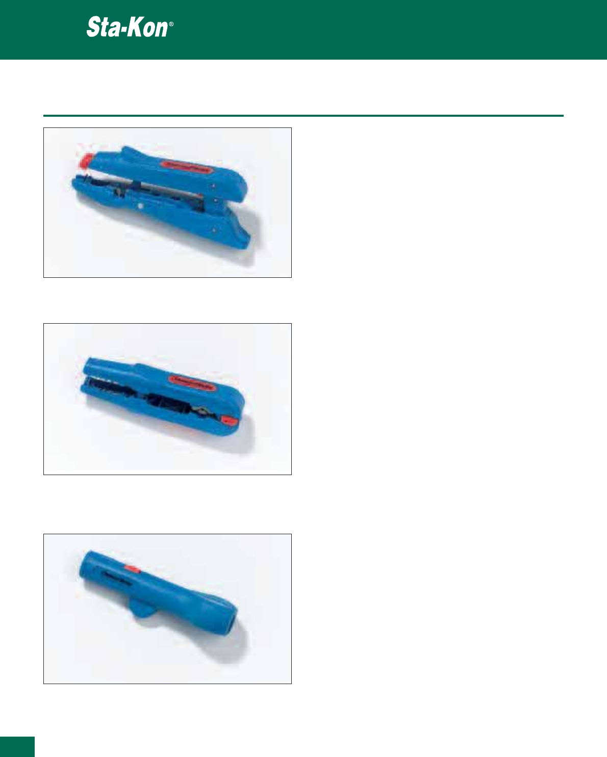
380
Thomas & Betts • www.tnb-europe.com
5.1
Standard hand tools
Product Ref.: Duostrip 150
• Fully insulated automatic wire stripper with integrated scale for
lengths from 8 - 20 mm
• The special scanning system automatically adjusts to the wire
diameter and allows fast and accurate stripping
• Comes with an easily accessible built-in side cutter for stranded
conductors up to 6.0 mm2(10 AWG) and solid conductors up to
4.0 mm² (12 AWG)
•
Type: stranded and solid wires
•
Size: 0.5 - 6.0 mm² (20 - 10 AWG)
•
Weight: 110 g
Product Ref.: Multistrip 400
• Cable and wire stripper
• Allows circular and longitudinal stripping as well as flush strip-
ping in hard-to-reach areas (e.g. ceilings and walls, junction and
distribution boxes, switch cabinets)
• Easily accessible built-in side cutter for flexible conductors of maxi-
mum 6.0 mm
2
(10 AWG) and solid conductors of maximum 4.0 mm
2
(12 AWG)
•
Type: round cables & stranded and solid wires
•
Size: 8 - 13 mm diameter (cables) & 0.5 mm², 4.0 mm² and 6.0 mm²
(20-10AWG)(wires)
•
Weight:78g
Product Ref.: Cabstrip 13
• This tool has been specially designed to remove the outer insula-
tion jacket of round cables in confined spaces
• Enables flush stripping in ceiling and wall areas, junction and
distribution boxes, switch, cabinets, etc.
• The ergonomic tool design provides for a sure grip and comfort
• In only one operation, the cable sheath is cut and pulled off. No
adjustment of cutting depth is necessary
•
Type: round cables
•
Size:8-13mmdiameter
•
Weight:42g
Stripping & cutting tools
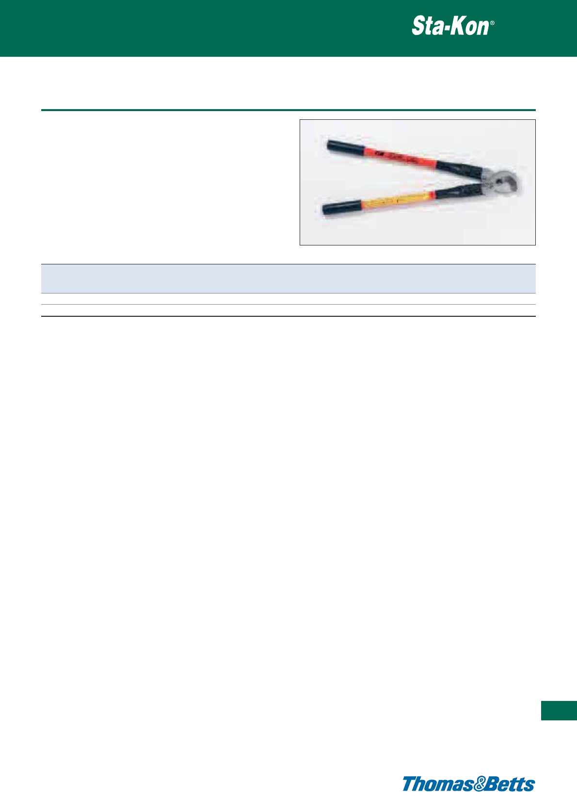
Heavy-duty cable cutters
Stripping & cutting tools
381
Thomas & Betts • www.tnb-europe.com
5.1
Product Ref.: 364RF and 366RF
• For copper and aluminium cable
• Cuts cables up to 500 mm2
• Fiberglass durable handles and carbon steel blades
• Precision circular cutting
• Easy to operate
Product Ref. Max. cable cross-section Max. cable diameter Length Weight Replacement blade reference
[mm
2
] [mm] [cm] [kg] Product Ref.
364RF 250 30 53 1.6 C150001
366RF 500 50 74 3.6 C350001

Thomas & Betts • www.tnb-europe.com
5.2
Color-Keyed®
Solderless compression
connectors for
power cables
382
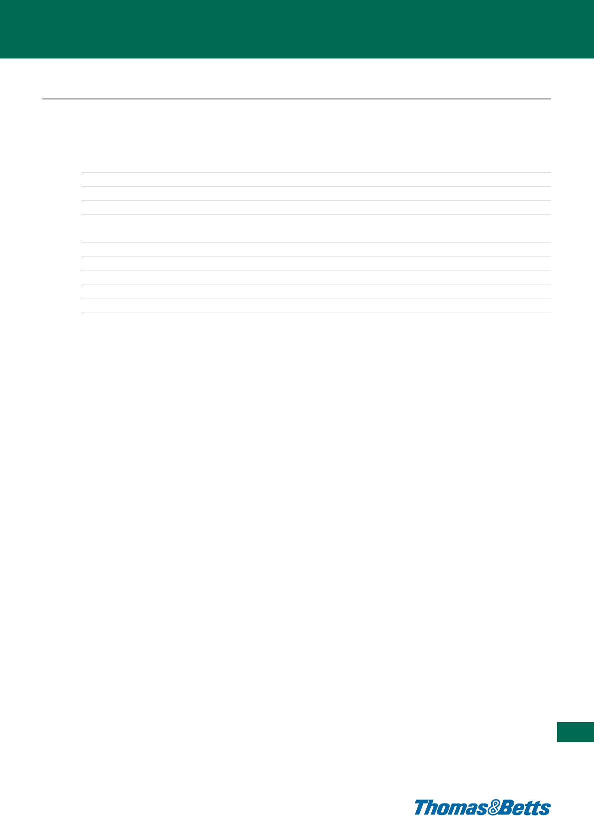
Thomas & Betts • www.tnb-europe.com
5.2
TERMINATION SYSTEMS
5.1 STA-KON®- CRIMP TERMINALS 338
5.2 COLOR-KEYED®- POWER CABLE CONNECTORS 382
Connectors for 600 V to 25 kV applications 386
Overview 386
Splices 387
Lugs 389
Crimping tools 391
Standard hand tool 391
Large hand tools 391
Hydraulic tools 393
Smart tools 394
Tool and die selection chart 395
5.3 DRAGON TOOTH®- MAGNET WIRE TERMINALS 396
5.4 SHIELD-KON®- SHIELDED CABLE CONNECTORS 428
383

Thomas & Betts • www.tnb-europe.com
Color-Keyed®
Solderless compression
connectors for power cables
The better method to install sorderless compression
connectors on power cables.
Designed to provide a tight degree of reliability in electrical
wiring, this method allows electrical workers to make
installations with little effort and considerable savings in
time.
A simple installation method in just three steps:
• First, the appropriate connector is chosen for the conductor
size
• Next, the proper installing die is selected by matching the die
colour to the connector colour
• Last, the die is installed in the tool, and the connector is com-
pressed
384
5.2

385
Thomas & Betts • www.tnb-europe.com
Wide range of copper tube lugs,
splices and installation tools
Color-Keyed®: special lugs for special applications
Thomas & Betts can solve your difficult wire bending and termi-
nating problems in confined power distribution panels, switchgear
and motor control enclosures. We have the design and production
capability to deliver exactly the type of lug you need, shaped the
way you need.
• Straight, 45° and 90° angle
• Stacking or non-stacking
• Narrow tongue or standard
• Tin, silver, lead, nickel plated Thomas & Betts offer an extensive
line of copper Color-Keyed®lugs for flexible and solid cables.
The lug tongues are modified in several different configurations to
meet your exact needs: 45° and 90° bend angles, narrow tongues
to fit into circuit breakers, offset tongues to stack two cables, and
special stud hole drilling.
These special configurations let you:
• run the cable directly to the bus bar with no bending,
• terminate into very narrow spaces, and
• utilise minimal bus bar space.
The specially designed lugs help you “clean up” your cabling in
crowded enclosures.
Customised Color-Keyed®lugs
All customised lugs for Copper Cables can be made to order.
Consult your Sales Office for price and delivery.
5.2
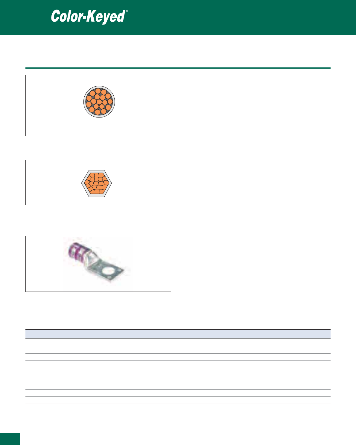
386
Thomas & Betts • www.tnb-europe.com
5.2
Overview
Precision dies form a solid, homogenous mass
The Thomas & Betts method utilising compression tools with matching
dies forms the connector and conductor into a solid, homogenous mass
to provide an optimum electrical bond between connector and conductor.
Color-Keyed®dies are designed to produce a circumferential, hex- or
diamond-shaped compression rather than a simple indent. Precision
dies are an integral part of the Thomas & Betts method.
Each die is designed so that all conductors receive the same amount
of compression force. The circumferential compression creates a
large area of high pressure contact between cable and connector
which, in turn, assures high conductivity, low resistance, and high
pullout values which exceed UL requirements.
These features result in a permanent, low installed cost connection.
You can install it, and forget it.
The Color-Keyed®system from Thomas & Betts tells you
where to place the installing die
Color-Keyed®connectors not only identify the correct installing die
to be used for positive compressions, but also indicate the proper
placement of the die on the connector. This is done by the coloured
rings around the connector which match the colour on the dies.
Compression is made between or on these colour bands. The colour
name is also spelled on the connector as an added means of iden-
tification.
Power cable connectors
Features Benefits
High conductivity electrolytic copper Excellent electrical conductivity thanks to lowest electrical resistance,
associated to superior tensile strength
Tubular construction No seam, ensuring excellent mechanical properties
Electro-tin plated Enhanced corrosion resistance
Colour-coding according to the cross-section of the cable, Easy selection of the connector, the die and the tool according
by marking the connector with coloured rings and to the size of the cable
with the name of the colour Higher level of reliability
Die-code engraved on the surface of the die Easy and reliable inspection
Specifications According to DIN and UL
Air compression by the T&B Method, the cross section looks like this, 100%
metal with virtually no air spaces.
Before compression, a typical cross section of cable and connector consists
of about 75% metal and 25% air.
The die is positioned between colour bands for copper connectors and on the
bands for aluminium connectors.
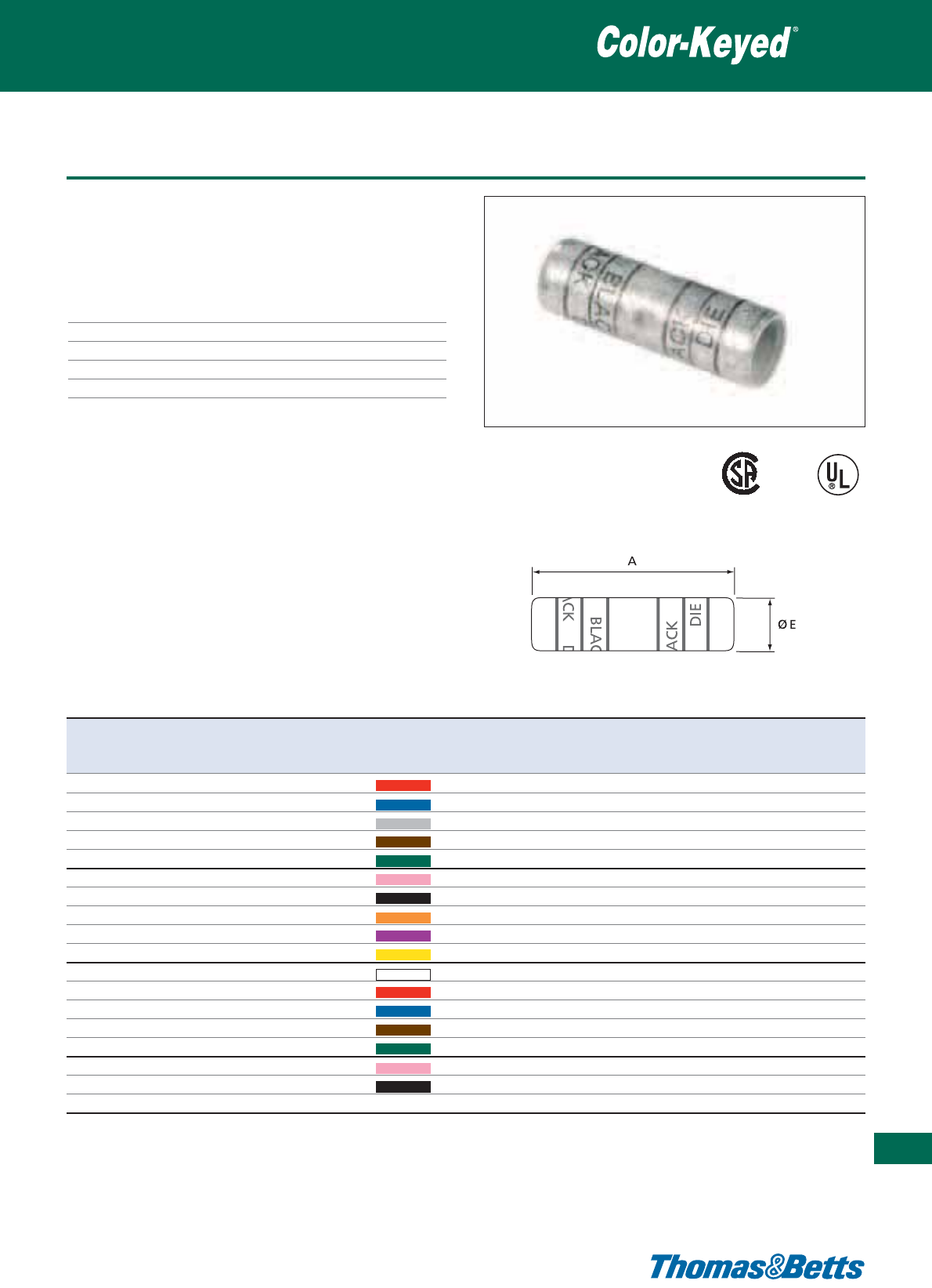
Two-way splice connectors for copper cable - Standard barrel
Connectors for 600 V to 35 kV applications
387
Thomas & Betts • www.tnb-europe.com
5.2
Product Ref. USA Approx. European Colour Tooling Dimensions Weight Quantity
cable size cable size die code A E
[mm
2
] [mm] [mm] [kg/100] [pieces]
54504 # 8 AWG 8 Red 21 25.4 6.9 0.540 50
54505 # 6 AWG 13 Blue 24 25.4 7.6 0.553 50
54506 # 4 AWG 21 Grey 29 25.4 9.4 0.816 50
54507 # 2 AWG 25 - 34 Brown 33 31.8 10.4 1.252 25
54508 # 1 AWG 42 Green 37 38.1 11.9 1.633 20
54509 1/0 AWG 53 Pink 42H 41.4 13.2 2.132 10
54510 2/0 AWG 67 Black 45 44.5 14.5 2.903 10
54511 3/0 AWG 85 Orange 50 44.5 16.0 3.221 10
54512 4/0 AWG 107 Violet 54H 47.8 17.8 4.146 10
54513 250 kcmil 125 Yellow 62 57.2 19.6 4.990 10
54514 300 kcmil 150 White 66 54.1 21.1 6.328 10
54515 350 kcmil 175 Red 71H 57.2 22.9 7.711 10
54516 400 kcmil 200 Blue 76 / 80 69.9 23.6 10.582 6
54518 500 kcmil 250 Brown 87H 69.9 28.2 13.699 6
54520 600 kcmil 300 Green 94H 76.2 30.0 19.577 6
54522-TB 700 kcmil 350 Pink 99H 82.6 31.2 19.654 6
54523-TB 750 kcmil 375 Black 106H 76.2 33.0 22.362 6
54528 1000 kcmil 500 – – 92.2 38.1 36.287 3
For tooling see pages 391 to 395
For American cable size conversion, see table page 427
This represents a small part of the Color-Keyed
®
range, please contact your Sales Office for additional product information
Two-way connectors provide high pullout values, are easy to insulate,
and provide a low resistance connection of high quality and low
installed cost.
Technical Information
Material High conductivity wrought copper
Plating Electro-tin plated
Metal barrel Copper tube
Voltage 600V to 35kV
Marking Colour reference for die and cable size
004503 E9809
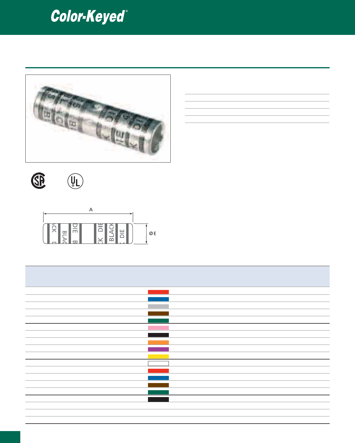
388
Thomas & Betts • www.tnb-europe.com
5.2
Two-way splice connectors for copper cable - Long barrel
Technical Information
Material High conductivity wrought copper
Plating Electro-tin plated
Metal barrel Copper tube
Voltage 600V to 35kV
Marking Colour reference for die and cable size
Connectors for 600 V to 35 kV applications
004503 E9809
Product Ref. USA Approx. European Colour Tooling Dimensions Weight Quantity
cable size cable size die code A E
[mm
2
] [mm] [mm] [kg/100] [pieces]
54804 # 8 AWG 8 Red 21 44.5 6.4 0.789 50
54805 # 6 AWG 13 Blue 24 44.5 7.1 0.916 50
54806 # 4 AWG 21 Grey 29 44.5 9.1 1.315 50
54807 # 2 AWG 25 - 34 Brown 33 47.6 10.3 1.787 25
54808 # 1 AWG 42 Green 37 50.8 11.9 2.041 20
54809 1/0 AWG 53 Pink 42H 50.8 13.5 2.631 10
54810 2/0 AWG 67 Black 45 54.0 14.7 3.130 10
54811 3/0 AWG 85 Orange 50 57.2 15.9 4.014 10
54812 4/0 AWG 107 Violet 54H 69.9 17.9 5.874 10
54813 250 kcmil 125 Yellow 62 85.7 19.5 7.439 10
54814 300 kcmil 150 White 66 88.9 21.5 9.571 10
54815 350 kcmil 175 Red 71H 95.3 23.9 12.837 10
54816 400 kcmil 200 Blue 76 / 80 95.3 24.6 13.227 6
54818 500 kcmil 250 Brown 87H 120.7 27.8 23.678 6
54820 600 kcmil 300 Green 94H 108.0 30.2 25.809 6
54823 750 kcmil 375 Black 106H 120.7 33.7 35.380 6
54828 1000 kcmil 500 – – 142.9 39.3 54.068 3
54833 1500 kcmil 750 – – 165.1 47.6 95.000 3
54839 2000 kcmil 1000 – 106H 179.3 54.0 150.000 3
For tooling see pages 391 to 395
For American cable size conversion, see table page 427
This represents a small part of the Color-Keyed
®
range, please contact your Sales Office for additional product information
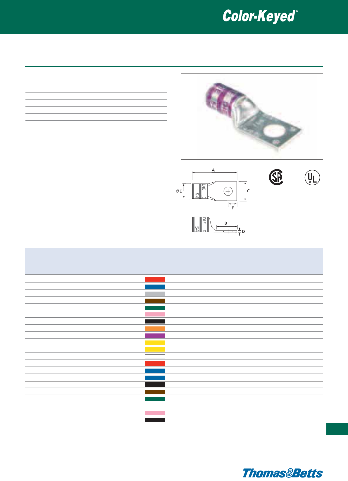
One hole lug for copper cable - Standard barrel
Technical Information
Material High conductivity wrought copper
Plating Electro-tin plated
Metal barrel Copper tube
Voltage 600V to 35kV
Marking Colour reference for die and cable size
Connectors for 600 V to 35 kV applications
389
Thomas & Betts • www.tnb-europe.com
5.2
004503 E9809
Product USA Approx. Stud size Colour Tooling Dimensions Weight Quantity
Ref. cable European USA metric die code A B C D E F
size cable size equivalent
[mm
2
] [mm] [mm] [mm] [mm] [mm] [mm] [kg/100] [pieces]
54132 # 8 AWG 8
3
/
8
M8 Red 21 33.8 16.3 14.2 1.3 6.4 7.1 1.361 50
54136 # 6 AWG 13
3
/
8
M8 Blue 24 35.8 17.0 15.2 1.8 7.9 7.9 0.603 50
54140 # 4 AWG 21
3
/
8
M 8 Grey 29 36.1 16.8 15.5 1.8 9.4 7.9 0.912 50
54145-TB # 2 AWG 25 - 34
1
/
2
M12 Brown 33 48.8 27.4 19.1 2.0 10.4 12.7 1.633 25
54150 # 1 AWG 42
1
/
2
M12 Green 37 53.3 31.8 19.3 2.8 11.9 12.7 2.041 20
54155-TB 1/0 AWG 53
1
/
2
M 12 Pink 42H 55.9 31.8 19.1 3.3 13.2 12.7 3.062 10
54160 2/0 AWG 67
1
/
2
M12 Black 45 57.2 31.8 21.1 3.3 14.5 12.7 3.334 10
54165-TB 3/0 AWG 85
1
/
2
M12 Orange 50 59.7 31.8 23.4 3.3 16.0 12.7 4.082 10
54170 4/0 AWG 107
1
/
2
M12 Violet 54H 63.5 31.8 26.2 3.6 17.8 12.7 5.171 10
54113 250 kcmil 125
1
/
2
M 12 Yellow 62 66.0 31.8 28.7 3.6 19.6 12.7 6.622 10
58165 4/0 Weld –
1
/
2
M 12 Yellow 62 70.1 31.8 31.8 3.8 20.1 12.7 8.210 10
54114 300 kcmil 150
1
/
2
M 12 White 66 68.6 31.8 31.8 3.8 21.6 12.7 8.210 10
58171 300 Weld –
1
/
2
M12 Red 71H 72.4 31.8 34.5 4.6 23.6 12.7 10.705 10
54183 350 kcmil 175
5
/
8
M16 Blue 76 81.5 40.1 34.5 4.6 23.6 15.9 10.909 10
54185 400 kcmil 200
5
/
8
M16 Blue 80 89.7 40.1 35.8 4.3 24.4 15.9 11.340 6
58177 400 Weld –
1
/
2
M12 Black 107H 84.1 31.8 40.9 5.6 26.4 12.7 18.098 6
54187 500 kcmil 250
5
/
8
M16 Brown 87H 92.2 40.1 40.9 5.6 27.9 15.9 19.958 6
58180 500 Weld –
5
/
8
M16 Green 94H 96.3 40.1 44.5 6.1 30.5 15.9 26.195 2
54120 600 kcmil 300
5
/
8
M 16 – – 96.3 40.1 44.5 6.1 30.5 15.9 25.038 6
54122-TB 700 kcmil 350
5
/
8
M 16 Pink 99H 93.5 40.1 46.7 5.8 32.0 15.9 23.283 6
54123-TB 750 kcmil 375
5
/
8
M16 Black 107H 98.3 40.1 49.3 6.9 33.8 15.9 31.661 6
For tooling see pages 391 to 395
For American cable and stud size conversion, see tables page 427
This represents a small part of the Color-Keyed
®
range, please contact your Sales Office for additional product information
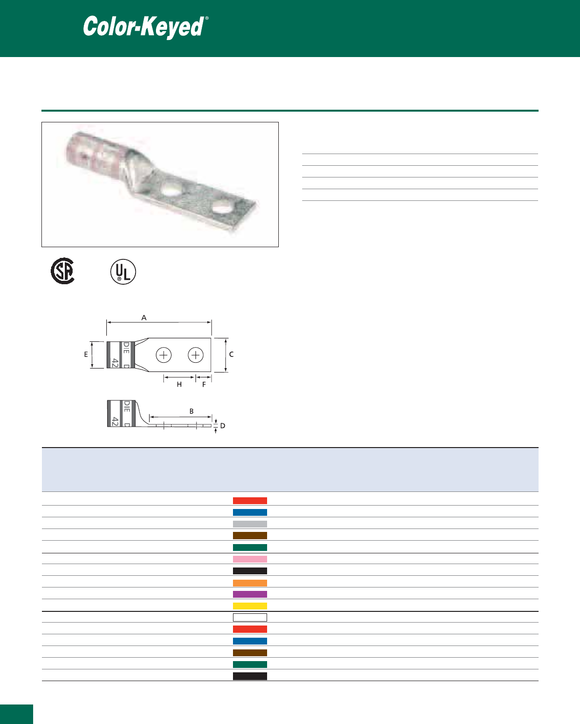
390
Thomas & Betts • www.tnb-europe.com
5.2
Two hole lugs for copper cable - Long barrel
Technical Information
Material High conductivity wrought copper
Plating Electro tin plated
Metal barrel Copper tube
Voltage 600V to 35kV
Marking Colour reference for die and cable size
Connectors for 600 V to 35 kV applications
007222 E9809
Product USA Approx. Stud size Colour Tooling Dimensions Weight Quantity
Ref. cable European USA metric die A B C D E F H
size cable size equivalent code
[mm
2
] [mm] [mm] [mm] [mm] [mm] [mm] [mm] [kg/100] [pieces]
256-30695-1157 # 8 AWG 6 - 8
3
/
8
M8 Red 21 76.2 53.3 14.2 1.5 6.6 9.5 25.4 1.361 10
256-30695-1158 # 6 AWG 10 - 13
3
/
8
M8 Blue 24 74.4 49.0 15.0 1.5 7.6 9.5 25.4 1.588 50
256-30695-1159 # 4 AWG 20 - 25
3
/
8
M 8 Grey 27 79.5 50.3 15.0 2.3 9.4 9.5 25.4 2.177 10
54811 BE # 3-2 AWG 25 - 35
1
/
2
M12 Brown 29 108.7 76.2 22.4 2.8 10.4 12.7 44.5 6.577 10
54857 BE # 1 AWG 40
1
/
2
M12 Green 33 112.5 76.2 22.4 2.8 11.9 12.7 44.5 7.348 10
256-30695-593 1/0 AWG 50
1
/
2
M 12 Pink 37 110.0 76.2 19.1 3.3 13.2 15.9 44.5 5.897 5
54862 BE 2/0 AWG 70
1
/
2
M12 Black 42H 106.7 71.4 21.1 3.3 14.5 12.7 44.5 6.124 10
54864 BE 3/0 AWG 80 - 95
1
/
2
M12 Orange 45 113.8 76.2 23.9 3.3 16.0 12.7 44.5 7.802 10
54866 BE 4/0 AWG 100 - 120
1
/
2
M12 Violet 50 119.4 76.2 26.2 3.6 17.8 12.7 44.5 10.024 10
54868 BE 250 kcmil 125
1
/
2
M 12 Yellow 54H 125.0 76.2 28.7 3.6 19.6 12.7 44.5 11.567 10
54870 BE 300 kcmil 150
1
/
2
M 12 White 66 132.8 76.2 31.8 3.8 21.6 12.7 44.5 15.377 10
54872 BE 350 kcmil 170 - 185
1
/
2
M12 Red 71H 137.2 76.2 34.5 4.6 23.6 12.7 44.5 18.915 10
54874 BE 400 kcmil 200
1
/
2
M12 Blue 76/80 140.0 76.2 35.8 4.3 24.4 12.7 44.5 20.502 6
54876 BE 500 kcmil 250
1
/
2
M12 Brown 87H 152.4 76.2 40.9 5.6 27.9 12.7 44.5 31.797 6
54878 BE 600 kcmil 300
1
/
2
M12 Green 94H 148.1 76.2 44.5 6.1 30.5 12.7 44.5 37.798 6
54880 BE 750 kcmil 400
1
/
2
M12 Black 106H 157.5 76.2 49.3 6.9 33.8 12.7 44.5 47.854 6
For tooling see pages 391 to 395
For American cable and stud size conversion, see tables page 427
This represents a small part of the Color-Keyed
®
range, please contact your Sales Office for additional product information
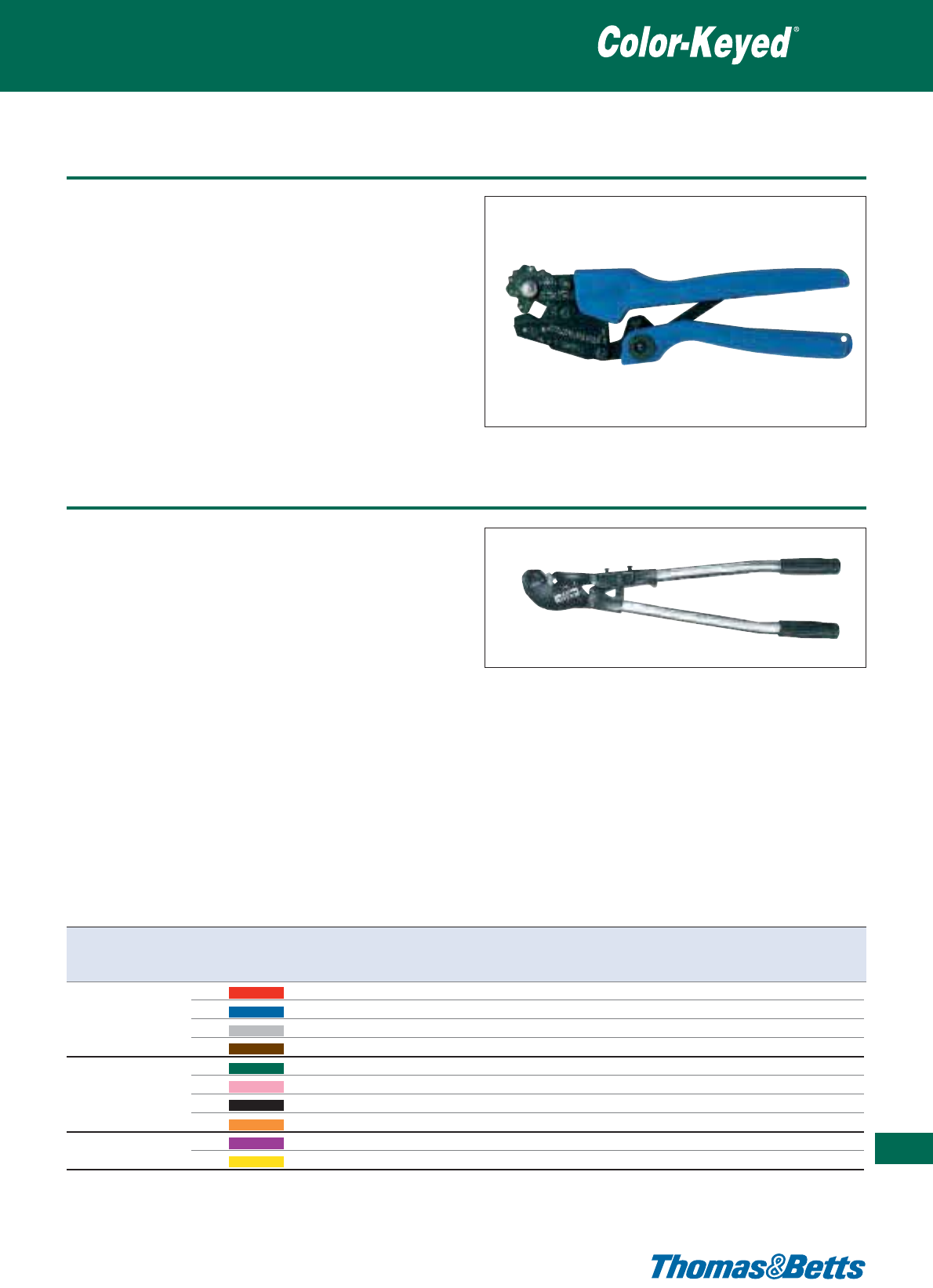
Standard hand tool
Product Ref.: TBM25S
• Fixed die tool, with rotating head and 5 nests
•ForColor-Keyed®copper tube lugs and splices from:
6to35mm
2
•Shure-Stake™ mechanism
• Length: 220 mm
• Weight: 430 g
Crimping tools
391
Thomas & Betts • www.tnb-europe.com
5.2
Product Ref.: TBM5-S
• Large hand tool with interchangeable dies
•ForColor-Keyed®copper tube lugs and splices from:
8 AWG to 250 kcmil (=8.4 to 126.7 mm2) in the case
of copper cables
• Incorporates the Shure-Stake™ mechanism: once the pressing
has commenced, the tool can be re-opened only after successful
completion of the crimping cycle, ensuring a correct crimp every
time
• Furnished complete with carrying case and 5 installing dies
(Product Ref. 13454, 13455, 13456, 13457, 13458)
• Dies are colour-coded and die-code embossed
• Tool length: 650 mm approx.
• Tool weight: 3kg approx.
Die Product Ref. Nest identification Nest identification Copper wire size Copper wire size
colour-code die-code USA conversion to metric cross-section
[mm
2
]
Red 21 8 AWG 8.4
Blue 24 6 AWG 13.3
13454
Grey 29 4 AWG 21.1
Brown 33 2 AWG 33.6
Green 37 1AWG 42.4
Pink 42H 1/0 AWG 53.5
13455
Black 45 2/0 AWG 57.4
Orange 50 3/0 AWG 85.0
Violet 54H 4/0 AWG 107.2
13456
Yellow 60 250 kcmil 126.7
Note: 2 other dies (Product Ref. 13457 and Product Ref. 13458) are available, but for aluminium wire sizes only
Large hand tools
Crimping tools
Product Ref.: TBM5
• Same specifications as Product Ref. TBM5-S but does not incor-
porate the Shure-Stake™ mechanism
Dies for TBM5 and TBM5-S
• Multi-nest dies, to cover a wire size range from: 8 AWG to 250
kcmil (=8.4 to 126.7 mm2) in the case of copper cables
• Each nest is colour-coded and die-code embossed
TBM5 and TBM5S die selection chart
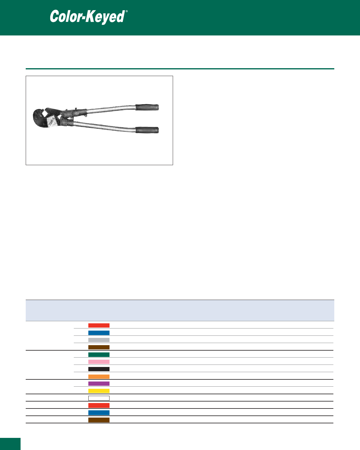
Thomas & Betts • www.tnb-europe.com
Large hand tools
Product Ref.: TBM8S
• Large hand tool with interchangeable dies
•ForColor-Keyed®copper tube lugs and splices from:
8 AWG to 500 kcmil (= 8.4 to 253.4 mm2) in the case of copper
cables
• Incorporates the Shure-Stake™ mechanism: once the pressing
has commenced, the tool can be re-opened only after successful
completion of the crimping cycle, ensuring a correct crimp every
time
• Furnished complete with carrying case and 8 installing dies
(Product ref. 13461, 13462, 13463, 13464, 13465, 13466,
13467, 13468)
• Dies are colour-coded and die-code embossed
• Tool length: 650 mm
• Weight: 9.3 kg
Product Ref.: TBM8
• Same specifications as Product Ref. TBM8S but does not incor-
porate the Shure-Stake™ mechanism
Dies for TBM8 and TBM8S
• Multi-nest dies, to cover a wire size range from: 8 AWG to
500 kcmil (= 8.4 to 253.4 mm2) in the case of copper cables
• Each nest is colour-coded and die-code embossed
Crimping tools
Die Product Ref. Nest identification Nest identification Copper wire size Copper wire size
colour-code die-code USA conversion to metric cross-section
[mm
2
]
Red 21 8 AWG 8.4
Blue 24 6 AWG 13.3
13461
Grey 29 4 AWG 21.1
Brown 33 2 AWG 33.6
Green 37 1AWG 42.4
Pink 42H 1/0 AWG 53.5
13462
Black 45 2/0 AWG 57.4
Orange 50 3/0 AWG 85.0
Violet 54H 4/0 AWG 107.2
13463
Yellow 60 250 kcmil 126.7
13465 White 66 300 kcmil 152.0
13466 Red 71H 350 kcmil 177.3
13467 Blue 76 400 kcmil 202.7
13468 Brown 87H 500 kcmil 253.4
Note: 1 other die (Product Ref. 13464) is available, but for aluminium wire sizes only
392
5.2
TBM8 and TBM8S die selection chart
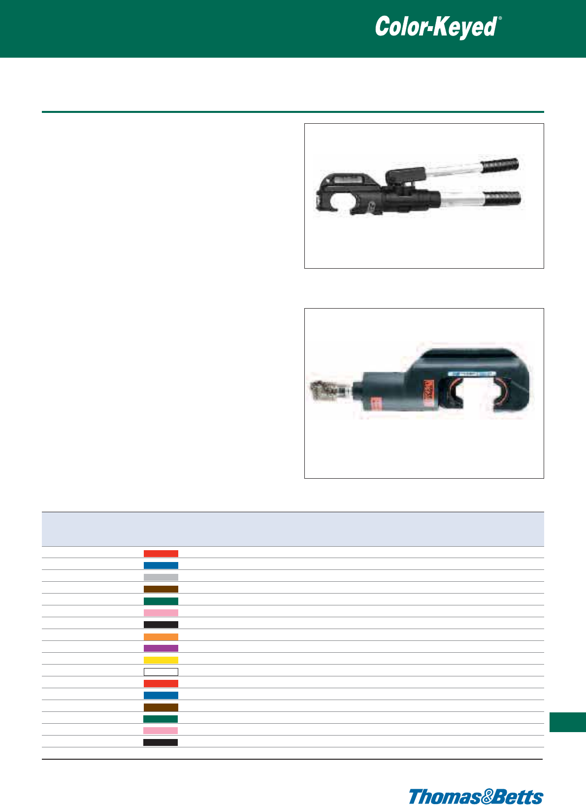
Hydraulic tools
Product Ref.: TBM14M
• Self-contained hydraulic hand tool with colour-coded inter-
changeable dies
•ForColor-Keyed®copper tube lugs and splices from:
6 to 450 mm²
• Incorporates the Shure-Stake™ mechanism: once the pressing
has commenced, the tool can be re-opened only after successful
completion of the crimping cycle, ensuring a correct crimp every
time
• Swiveled “C”- shaped head rotates 180°
• Complete with carrying case
• Weight: 6.8kg
• Output pressure: 14 ton
Product Ref.: TBM15i
• Hydraulic tool head with interchangeable dies
•ForColor-Keyed®copper tube lugs and splices from:
6 to 500 mm2
• New longer, slimmer profile allows easier access into tight spaces
• Wider jaw opening eases crimping of larger connectors
• Available with an insulated head
• Supplied in a carrying case in steel
• Dies to be ordered separately
• Output Force: 15 tons (nominal)
• Operating Pressure: 10,000 psi (nominal) = 690 bar
• Tool weight: 7 kg (without dies)
Crimping tools
393
Thomas & Betts • www.tnb-europe.com
5.2
Die Product Ref. Nest identification Nest identification Copper wire size Copper wire size
colour-code die-code USA conversion to metric cross-section
[mm
2
]
15520 Red 21 8 AWG 8.4
15522 Blue 24 6 AWG 13.3
15527-CK Grey 29 4 AWG 21.1
15528 Brown 33 2 AWG 33.6
15513-CK Green 37 1 AWG 42.4
15508 Pink 42H 1/0 AWG 53.5
15526 Black 45 2/0 AWG 57.4
15530 Orange 50 3/0 AWG 85.0
15511 Violet 54H 4/0 AWG 107.2
15510-CK Yellow 60 250 kcmil 126.7
15534 White 66 300 kcmil 152.0
15514-CK Red 71H 350 kcmil 177.3
15512 Blue 76 400 kcmil 202.7
15506 Brown 87H 500 kcmil 253.4
15611 Green 94H 600 kcmil 304.0
15505 Pink 99H 700 kcmil 354.7
15515-CK Black 106H 750 kcmil 380.0
15603 – 125H 1000 kcmil 506.7
TBM14M and TBM15i die selection chart
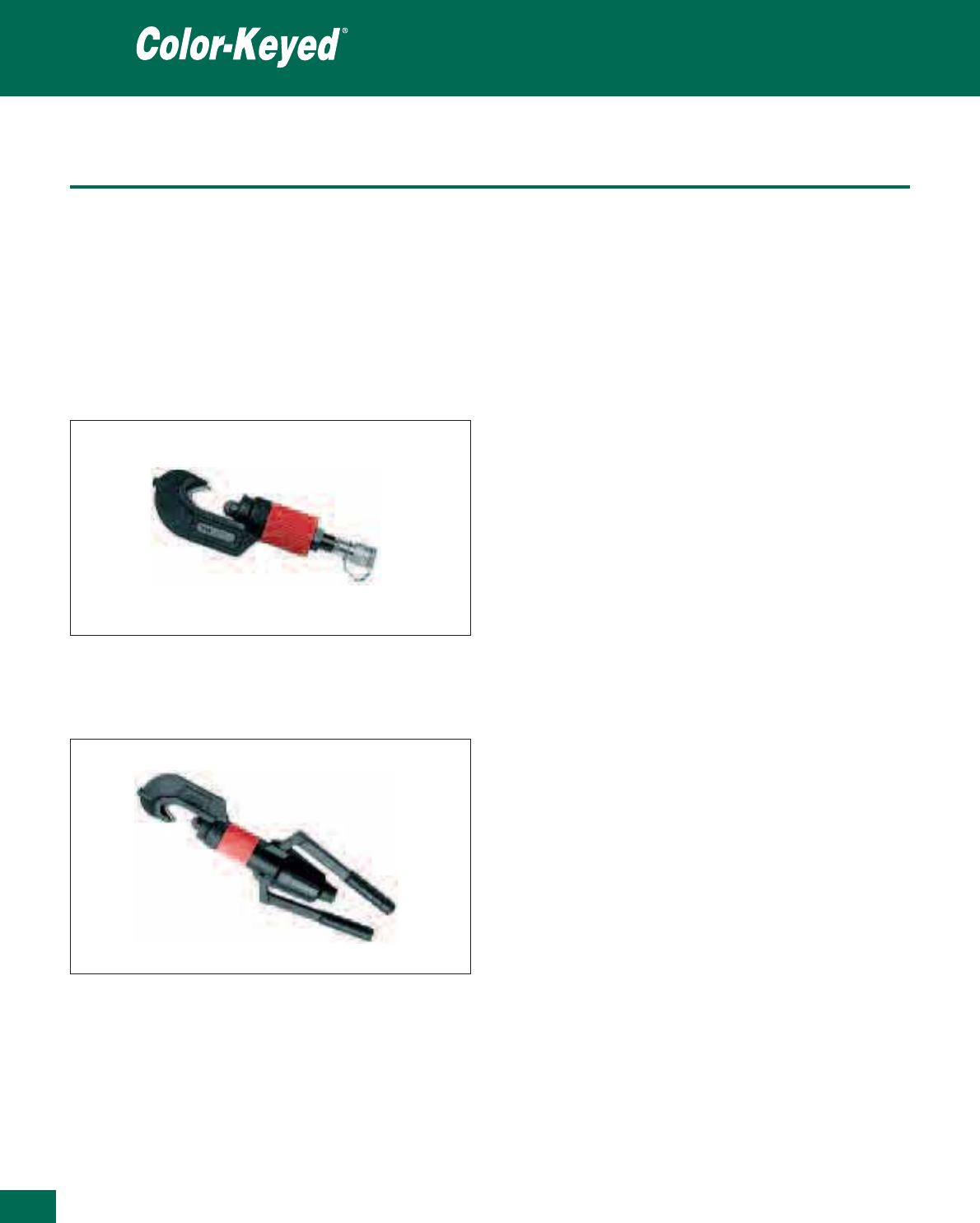
394
Thomas & Betts • www.tnb-europe.com
5.2
Smart tools
Product Ref.: TBM8-750
•
Hydraulic remote tool head
•
For
aluminium
and
copper lugs
from the Color-Keyed®line
from 6 to 400 mm2
•
Operates on standard 10,000 psi (= 690 bar) hydraulic pumps
•
Length: 368 mm
•
Weight: 4kg
•
Output pressure: 12 ton
•
Coupler: Pioneer, female
Product Ref.: TBM8-750M-1
•
Self-contained hydraulic tool
•
For
aluminium
and
copper lugs
from the Color-Keyed®line
from 6 to 400 mm2
•
Length: 538 mm
•
Weight: 5.9kg
•
Output pressure: 12 ton
•
Operating pressure: 9800 psi = 676 bar
Crimping tools
• The SMART tools are designed to give you a uniform high quality
compression connection over a wide connector range
•
It easily installs copper and aluminium lugs from 6 mm2to
400 mm2without changing dies
•
With its built-in intelligence, the tool will sense the barrel
diameter and apply the correct amount of compression force
•
Die selection mistakes are virtually eliminated
•
The tool embosses a T&B mark on the connector for positive
verification that the correct tool was used
•
Tools are made from forged steel, suited to bench or fieldwork.
Their “C”-shaped heads, light weight and compact size make
them easy to use in almost any application

Tool and die selection chart
Crimping tools
395
Thomas & Betts • www.tnb-europe.com
5.2
Copper wire size Nest identification Nest TBM8 TBM5 TBM14M
USA Conversion to colour-code
identification
TBM8S TBM5-S TBM15i
metric cross-section die-code die product die product die product
[mm
2
] references references references
8 AWG 8.4 Red 21 13461 13454 15520
6 AWG 13.3 Blue 24 13461 13454 15522
4 AWG 21.1 Grey 29 13461 13454 15527-CK
2 AWG 33.6 Brown 33 13461 13454 15528
1 AWG 42.4 Green 37 13462 13455 15513-CK
1/0 AWG 53.5 Pink 42H 13462 13455 15508
2/0 AWG 57.4 Black 45 13462 13455 15526
3/0 AWG 85.0 Orange 50 13462 13455 15530
4/0 AWG 107.2 Violet 54H 13463 13456 15511
250 kcmil 126.7 Yellow 60 13463 13456 15510-CK
300 kcmil 152.0 White 66 13465 15534
350 kcmil 177.3 Red 71H 13466 15514-CK
400 kcmil 202.7 Blue 76 13467 15512
500 kcmil 253.4 Brown 87H 13468 15506
600 kcmil 304.0 Green 94H 15611
700 kcmil 354.7 Pink 99H 15505
750 kcmil 380.0 Black 106H 15515-CK
1000 kcmil 506.7 – 125H 15603
1500 kcmil 760.1 –
2000 kcmil 1013.4 Black
For American cable size conversion, see table page 427
Note: This table is based on sizes of copper cable. In the case of aluminium cables, the correspondence between the cable size and the connector colour
code (and therefore the appropriate die) may be different. Please contact your Sales Office for more information on the different possibilities of applications.

396
Thomas & Betts • www.tnb-europe.com
Dragon Tooth®
Insulation piercing
connectors to splice,
tap and terminate
magnet wire
5.3

397
Thomas & Betts • www.tnb-europe.com
5.3
TERMINATION SYSTEMS
5.1 STA-KON®- CRIMP TERMINALS 338
5.2 COLOR-KEYED®- POWER CABLE CONNECTORS 382
5.3 DRAGON TOOTH®- MAGNET WIRE TERMINALS 396
Insulation piercing connectors 400
Overview 400
Splices 401
Ring terminals 408
Fork terminals 413
Disconnect terminals 414
Taps 416
Modular connectors 417
Washers 419
Crimping tools 420
Hand tools 420
Air-operated tools 421
Auto-feed tools for connectors on strip 422
Hydraulic tools 423
Connectors, tool and die selection chart 425
5.4 SHIELD-KON®- SHIELDED CABLE CONNECTORS 428

Thomas & Betts • www.tnb-europe.com
5.3
Dragon Tooth®
The insulation
piercing connector
The Dragon Tooth®insulation piercing connectors for
magnet wire penetrate the insulation and oxide layers to
make a reliable electrical contact, eliminating the need for
stripping, brazing, welding or other methods of joining
magnet wire.
In the conventional methods, different techniques are used to
remove the insulating varnish: scratching, brushing, burning-off,
dissolving. These methods are all costly and time consuming, and
they generally lead to a risk of damage to the conductors and to
a risk of injury of the operator. Health and environmental conside-
rations can also be an issue.
398

399
Thomas & Betts • www.tnb-europe.com
5.3
Dragon Tooth®
Insulation piercing connectors
to splice, tap and terminate
magnet wire
The tough, high temperature insulation on magnet wire used by
electrical motor and transformer manufacturers creates problems
in splicing and terminating. The durability of magnet wire insulation
has made dip-soldering or brazing extremely difficult without
stripping the insulation.
Another splicing and terminating challenge involves the use of
aluminium for magnet applications. A manufacturer connecting
aluminium magnet wire to copper is faced with the problem of
the different coefficients of thermal expansion of the two metals,
galvanic corrosion, cold flow and the rapid formation of oxide film
on the wire surface.
Thomas & Betts offer a solution for a highly reliable connection
method for magnet wire, which eliminates welding, no longer re-
quires removal of insulation and which can be installed in seconds.
No special operator skills are needed. The connector and matching
tooling do the entire job. To meet the essential requirements of
magnet wire connections, Thomas & Betts offer the insulation
piercing Dragon Tooth®compression connector.
The result is a gas-tight, permanent connection with an excep-
tionally low contact resistance, capable of maintaining contact
integrity throughout the life of the connection.
Dragon Tooth®connectors transform the perpendicular compres-
sion force, which would normally contribute to conductor creep,
into distributive forces that effectively resist cold flow.
These connectors are made of copper alloy, tin plated, with a
number of teeth on the inner surface. When the connector is
compressed onto an insulated magnet wire, the sharp hardened
teeth penetrate the insulation and the oxide and bite into the
conductor. An electrically sound, low-resistance connection is
established as a result of the combination of high pressures at the
tip and edges of the teeth and the sliding action between the
teeth and the conductor
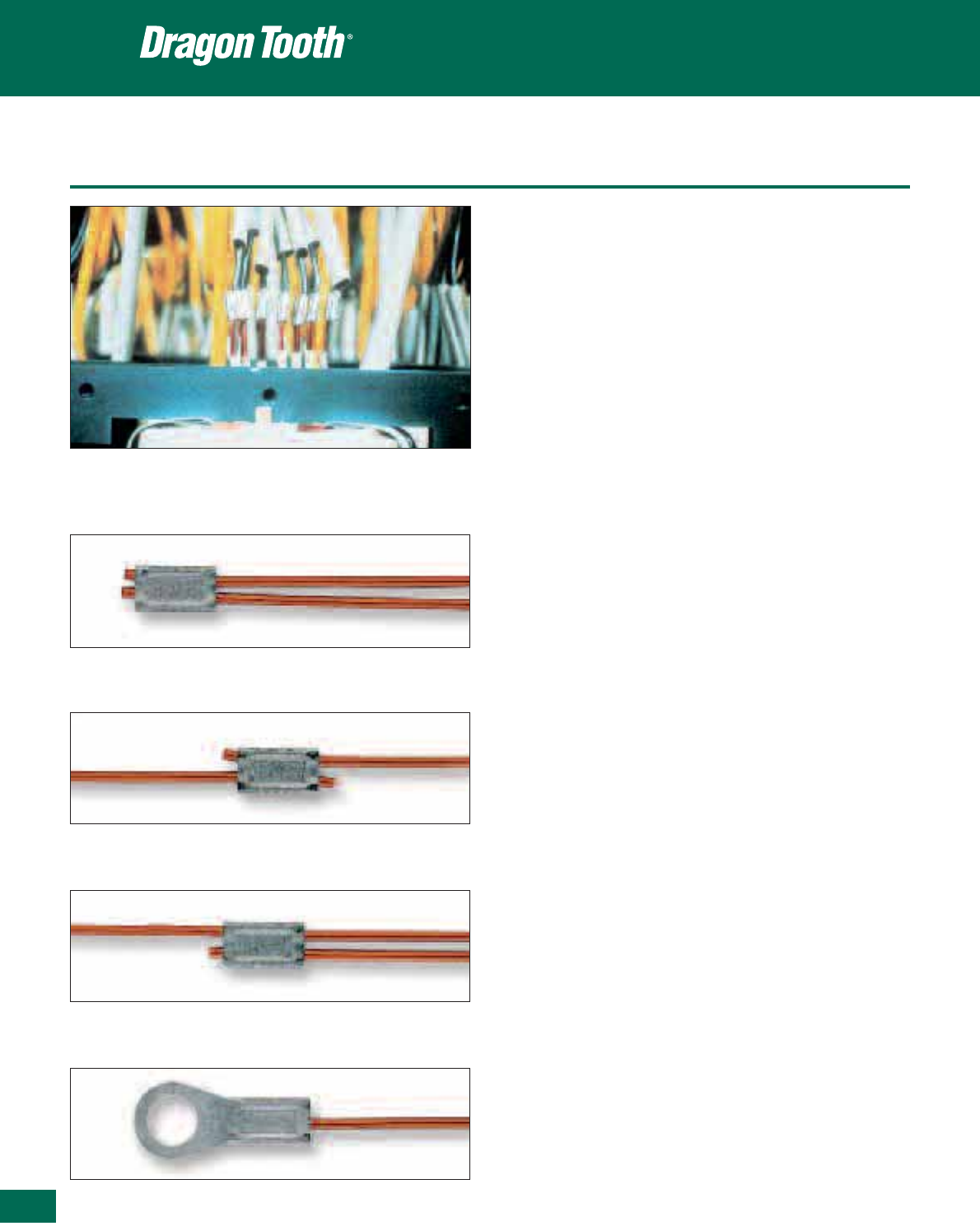
400
Thomas & Betts • www.tnb-europe.com
5.3
Overview
Thomas & Betts Dragon Tooth®connectors and installing tools are
designed to splice, tap and terminate copper magnet wire from
32 AWG to 460,000 CMA (0,03 to 120 mm2) and aluminium
magnet wire from 20 AWG to 460,000 CMA (0,5 to 120 mm2)in
motor and transformer applications.
• Can be installed in seconds
• Requires minimal training for installation.
• Made of copper alloy, tin plated, with a number of teeth on the
inner surface
• Splices and taps have an open side permitting easy access to wire
and makes internal coil tapping possible (mid-span tapping and
splicing)
• For aluminium to copper, aluminium to aluminium, or copper to
copper magnet wire connections
• Ring terminals with bolt holes to accommodate M3 through M12
studs
• Male and female 6.35 mm x 0.8 mm disconnects
• Splices and fork terminals accommodate wire sizes 24 AWG
(0.21 mm2)to12AWG(3.3mm
2) in a variety of combinations,
including combining magnet wire with stripped wire lead.
For solid or stranded wire 20 AWG (0.52 mm2) to 4/0 AWG
(107.2 mm2)
• Larger connectors accommodate circular mil range from 50,000
to 460,000 CMA (25 to 120 mm2)
• Transition washers with teeth to penetrate aluminium and copper
oxides, enabling copper to aluminium connections to be made in
a bolted joint without the use of inhibiting compounds
Transition washers also accommodate the difference in thermal
expansion between copper and aluminium, and enhance the
efficiency of bolted grounding connections
• Connector and matching tooling do the entire job
How to select a connector
1. Define the total cross-section (CMA) of the conductors
2. In the Ordering Information tables, refer to either Round Wire
column, or Rectangular column, depending on the type you are
using, and check any limitations, (such as max. wire i.e.
width/height). If there are limitations, you may have to make a
selection from next larger size.
3. Select the appropriate tool and die
Formula for calculating Circular Mil Area (CMA)
For square or rectangular wire:
Thickness x Width x 1.273 x 106= CMA (for dimensions in inch)
Thickness x Width x 1.973 x 103= CMA (for dimensions in mm)
For round wire:
Diameter2x10
6= CMA (for diameter in inch)
Diameter2x1.55x10
3= CMA (for diameter in mm)
Insulation piercing connectors
Splice
Parallel Splice
Tap
Termination
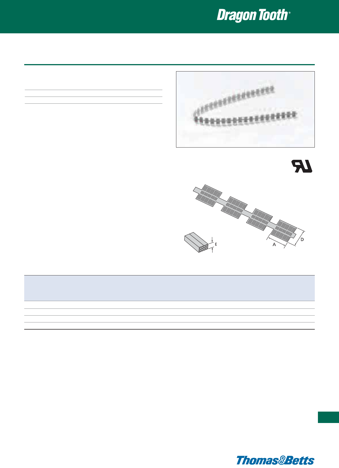
Splices
Technical Information
Material Copper alloy
Plating Tin plated
Colour Metallic
Insulation piercing connectors
401
Thomas & Betts • www.tnb-europe.com
5.3
Product Ref. Dimensions Combined Round Rectangular wire range Tooling
A D E* wire size wire range Thickness Width
min - max min - max min - max
[mm] [mm] [mm] [mm
2
] [mm] [mm] [mm]
220004 4.7 2.8 0.8 0.23 - 0.87 0.20 - 1.00** – – 13676A
220001 8.7 4.4 2.4 0.64 - 3.30 0.40 - 1.45** 0.60 - 1.00 0.60 - 2.30 13678
220006 11.9 6.4 2.4 1.30 - 6.24 1.30 - 2.05 1.30 - 2.05 1.30 - 4.10 13696
220002-TB 8.7 6.4 2.4 1.00 - 3.30 0.50 - 1.40** 0.50 - 1.00 0.50 - 2.30 13679
* Reference dimension (crimped height): see installing die illustration for gauging
** Not recommended for aluminium magnet wire finer than 0.4 mm
2
Pages 420 to 424 for tooling specifications
NOTE: Wire sizes and combinations shown have been tested to and meet or exceed Thomas & Betts specifications. Connectors may be suitable for other wire
sizes or combinations. Thomas & Betts sells these connectors with the understanding that the user will perform necessary tests to determine their suitability
for the intended purpose.
E9809
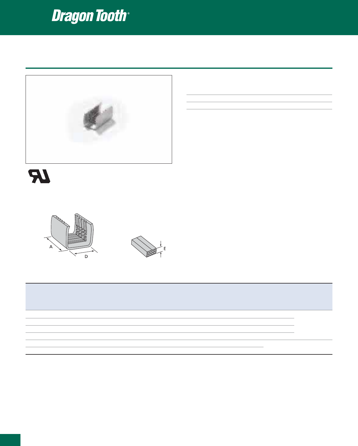
402
Thomas & Betts • www.tnb-europe.com
5.3
Splices
Technical Information
Material Copper alloy
Plating Tin plated
Colour Metallic
Insulation piercing connectors
Product Ref. Dimensions Combined Round Rectangular wire range Tooling
A D E* wire size wire range Thickness Width Hand Power
min - max min - max min - max tool tool***
[mm] [mm] [mm] [mm
2
] [mm] [mm] [mm]
22L004 3.8 2.8 1.3 0.23 - 0.87 0.20 - 1.00** – – ERG1804
22L001 8.1 4.1 2.5 0.20 - 2.10 0.50 - 1.45** 0.50 - 1.25 0.50 - 2.50 ERG1801
11903A
22L002 8.1 6.4 2.5 1.00 - 3.30 0.50 - 1.40** 0.50 - 1.25 0.50 - 2.80 ERG1802
11904A
22L006 11.5 6.4 3.3 1.30 - 6.24 1.30 - 2.05 1.30 - 1.50 1.30 - 4.10 ERG1806
13500
22L008 17.8 12.7 3.8 6.50 - 15.50 1.00 - 1.30 1.00 - 1.60 1.60 - 9.53 – 13100A, 13400
22L009 17.8 14 5.6 18.30 - 43.60 1.30 - 2.58 2.00 - 4.60 2.00 - 9.50 – TBM15i
* Reference dimension (crimped height): see installing die illustration for gauging
** Not recommended for aluminium magnet wire finer than 0.4 mm
2
*** Use selection chart to determine appropriate die set (pages 425 and 426)
Pages 420 to 424 for tooling specifications
NOTE: Wire sizes and combinations shown have been tested to and meet or exceed Thomas & Betts specifications. Connectors may be suitable for other wire
sizes or combinations. Thomas & Betts sells these connectors with the understanding that the user will perform necessary tests to determine their suitability
for the intended purpose.
E9809
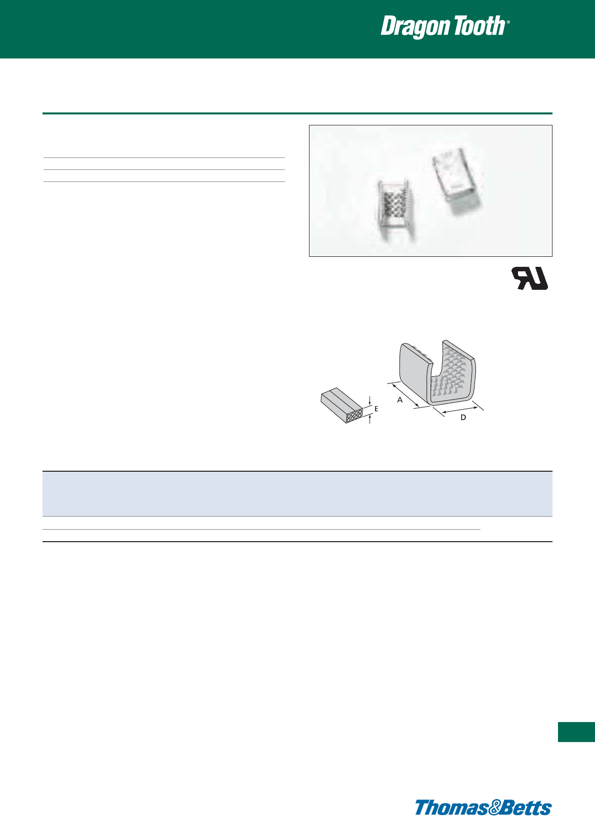
Splices
Technical Information
Material Copper alloy
Plating Tin plated
Colour Metallic
Insulation piercing connectors
403
Thomas & Betts • www.tnb-europe.com
5.3
E9809
Product Ref. Dimensions Combined Round Rectangular wire range Tooling
A D E* wire size wire range Thickness Width
min - max min - max min - max
[mm] [mm] [mm] [mm
2
] [mm] [mm] [mm]
210214S 15.9 9.5 4.3 2.00 - 10.52 1.63 (a) - 2.58 2.00 - 2.30 2.00 - 4.57 13100A, 13400
204210S 17.5 13.5 6.3 5.20 - 26.60 2.05 (b) - 6.54 (c) 2.50 - 4.10 2.50 - 6.35 TBM15i
* Reference dimension (crimped height): see installing die illustration for gauging
(a) Four wires max
(b) Six wires max
(c) Crimping dies may not bottom. Connector height will depend on number and sizes of wires in barrel. Pump must deliver 9800 PSI minimum
Use selection chart to determine appropriate die set (pages 425 and 426)
Pages 420 to 424 for tooling specifications
NOTE: Wire sizes and combinations shown have been tested to and meet or exceed Thomas & Betts specifications. Connectors may be suitable for other wire
sizes or combinations. Thomas & Betts sells these connectors with the understanding that the user will perform necessary tests to determine their suitability
for the intended purpose.
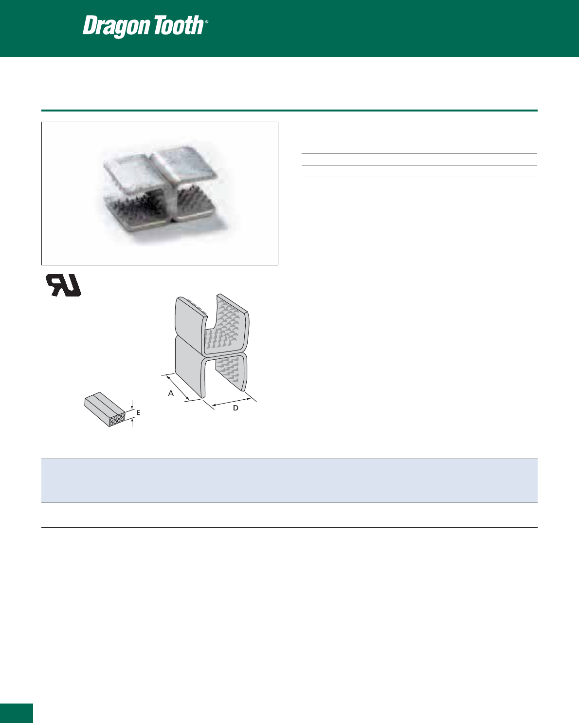
404
Thomas & Betts • www.tnb-europe.com
5.3
Splices
Technical Information
Material Copper alloy
Plating Tin plated
Colour Metallic
Insulation piercing connectors
Product Ref. Dimensions Combined Round Rectangular wire range Tooling
A D E* wire size wire range Thickness Width
min-max min-max min-max
[mm] [mm] [mm] [mm
2
] [mm] [mm] [mm]
204210SH 17.5 13.5 11.9 (5.20 - 26.60) x2 2.05 (a) - 6.5 (b) 2.5 - 4.1 2.5 - 6.6 13100A, 13400
TBM15i
* Reference dimension (crimped height): see installing die illustration for gauging
(a) Six wires max each barrel
(b) Conductors larger than 13 mm
2
require special dies
Use selection chart to determine appropriate die set (pages 425 and 426)
Pages 420 to 424 for tooling specifications
NOTE: Wire sizes and combinations shown have been tested to and meet or exceed Thomas & Betts specifications. Connectors may be suitable for other wire
sizes or combinations. Thomas & Betts sells these connectors with the understanding that the user will perform necessary tests to determine their suitability
for the intended purpose.
E9809
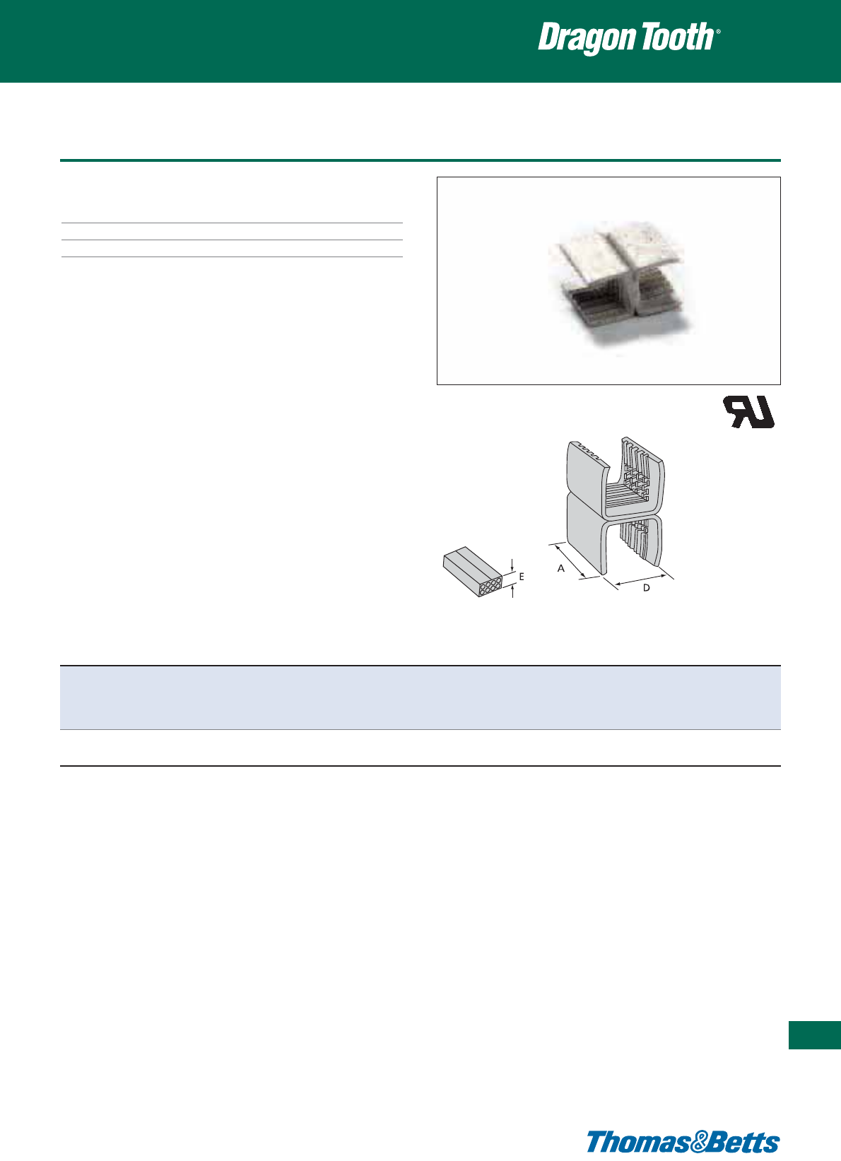
Splices
Technical Information
Material Copper alloy
Plating Tin plated
Colour Metallic
Insulation piercing connectors
405
Thomas & Betts • www.tnb-europe.com
5.3
Product Ref. Dimensions Combined Round Rectangular wire range Tooling
A D E* wire size wire range Thickness Width
min - max min - max min - max
[mm] [mm] [mm] [mm
2
] [mm] [mm] [mm]
22L009H 17.8 13.8 9.7 (18.25 - 33.5) x 2 1.3 - 4.6 2.0 - 4.5 2.0 - 9.7 13100A, 13400
TBM15i
* Reference dimension (crimped height): see installing die illustration for gauging
Use selection chart to determine appropriate die set (pages 425 and 426)
Pages 420 to 424 for tooling specifications
NOTE: Wire sizes and combinations shown have been tested to and meet or exceed Thomas & Betts specifications. Connectors may be suitable for other wire
sizes or combinations. Thomas & Betts sells these connectors with the understanding that the user will perform necessary tests to determine their suitability
for the intended purpose.
E9809
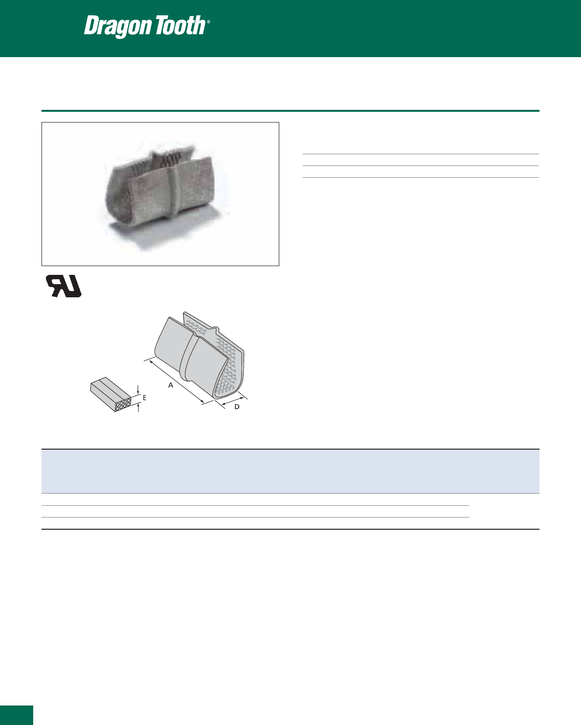
Thomas & Betts • www.tnb-europe.com
Splices
Technical Information
Material Copper alloy
Plating Tin plated
Colour Metallic
Insulation piercing connectors
Product Ref. Dimensions Combined Rectangular wire range Tooling
A D E* wire size Thickness Width
min - max min - max
[mm] [mm] [mm] [mm
2
] [mm] [mm]
220015 38.1 22.5 (a) 25 - 58 2.5 - 4.4 7.6 - 15.9 13100A
220019** 38.1 22.5 (a) 55 - 88 4.4 - 8.3 7.6 - 15.9 TBM15i
220023 44.5 22.5 (a) 55 - 115 4.4 - 8.3 7.6 - 15.9
* Reference dimension (crimped height): see installing die illustration for gauging
** Not UL recognised
(a) Crimping dies may not bottom. Connector height will depend on number and sizes of wires in barrel. Pump must deliver 9.800 psi min.
Use selection chart to determine appropriate die set (pages 425 and 426)
Pages 420 to 424 for tooling specifications
NOTE: Wire sizes and combinations shown have been tested to and meet or exceed Thomas & Betts specifications. Connectors may be suitable for other wire
sizes or combinations. Thomas & Betts sells these connectors with the understanding that the user will perform necessary tests to determine their suitability
for the intended purpose.
E9809
5.3
406
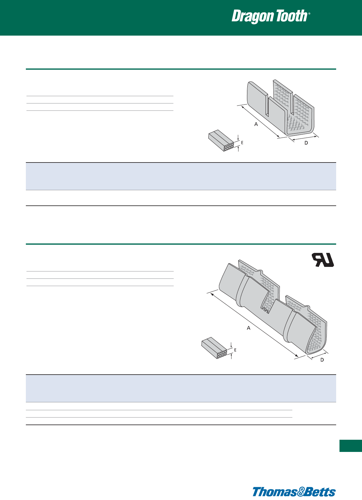
Splices
Technical Information
Material Copper alloy
Plating Tin plated
Colour Metallic
Insulation piercing connectors
Thomas & Betts • www.tnb-europe.com
5.3
407
Product Ref. Dimensions Combined Round Rectangular wire range Tooling
A D E* wire size wire range Thickness Width
min - max min - max min - max
[mm] [mm] [mm] [mm
2
] [mm] [mm] [mm]
314118S 16.0 9.7 3.3 1.65 - 6.25 1.45 - 1.83 1.27 - 1.52 1.27 - 4.57 13100A, 13400,
TBM15i
* Reference dimension (crimped height): see installing die illustration for gauging
Use selection chart to determine appropriate die set (pages 425 and 426)
Pages 420 to 424 for tooling specifications
Product Ref. Dimensions Combined Rectangular wire range Tooling
A D E* wire size Thickness Width
min - max min - max
[mm] [mm] [mm] [mm
2
] [mm] [mm]
220016 79.5 22.5 (a) (25.0 - 58.0) x 2 2.5 - 4.4 7.6 - 15.9 13100A
220020 79.5 22.5 (a) (55.0 - 88.6) x 2 2.5 - 4.4 7.6 - 15.9 TBM15i
220024 92.2 22.5 (a) (55.0 - 116.0) x 2 2.5 - 4.4 7.6 - 15.9
* Reference dimension (crimped height): see installing die illustration for gauging
Use selection chart to determine appropriate die set (pages 425 and 426)
Pages 420 to 424 for tooling specifications
NOTE: Wire sizes and combinations shown have been tested to and meet or exceed Thomas & Betts specifications.
Connectors may be suitable for other wire sizes or combinations. Thomas & Betts sells these connectors with
the understanding that the user will perform necessary tests to determine their suitability for the intended purpose.
E9809
(a) Crimping dies may not bottom
Connector height will depend on number and sizes of wires in barrel
Pump must deliver 9800 PSI minimum
Technical Information
Material Copper alloy
Plating Tin plated
Colour Metallic
Splices
Insulation piercing connectors
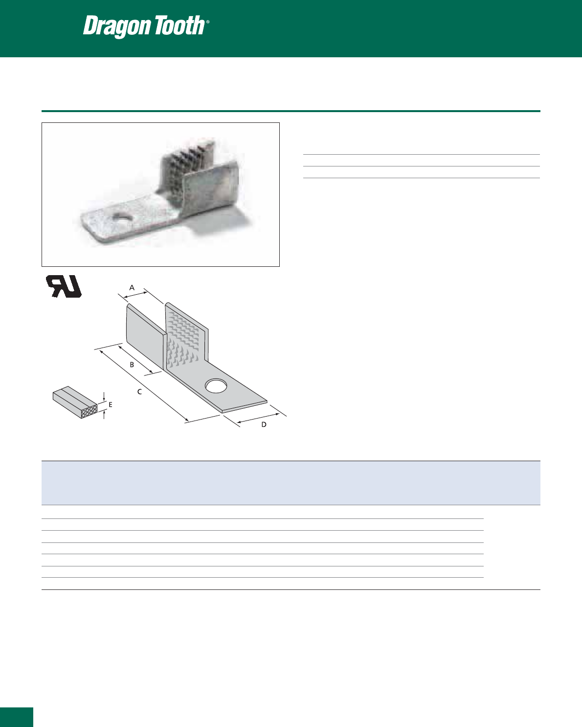
408
Thomas & Betts • www.tnb-europe.com
5.3
Ring terminals
Insulation piercing connectors
Product Ref. USA Dimensions Combined Round Rectangular wire range Tooling
Stud A B C D E* wire size wire range Thickness Width
size** min - max min - max min - max
[mm] [mm] [mm] [mm] [mm] [mm
2
] [mm] [mm] [mm]
210219 8 9.5 14.3 31.0 10.3 4.3 2.1 - 10.5 1.63 (a) - 2.58 2.0 - 2.3 2.0 - 4.5
210217 10 9.5 14.3 31.0 10.3 4.3 2.1 - 10.5 1.63 (a) - 2.58 2.0 - 2.3 2.0 - 4.5
210216
1
/
4
9.5 14.3 31.0 10.3 4.3 2.1 - 10.5 1.63 (a) - 2.58 2.0 - 2.3 2.0 - 4.5 13100A
204217 10 13.5 15.5 40.1 12.7 6.4 5.2 - 26.6 2.05 (b) - 6.5 (c) 2.5 - 4.1 2.5 - 6.35 13400
204212
1
/
4
13.5 15.5 40.1 12.7 6.4 5.2 - 26.6 2.05 (b) - 6.5 (c) 2.5 - 4.1 2.5 - 6.35 TBM15i
314125*** 10 9.7 14.2 31.0 10.3 6.9 1.7 - 6.2 1.45 - 1.83 1.27 - 1.52 1.27 - 4.57
314123***
1
/
4
9.7 14.2 35.7 10.3 6.9 1.7 - 6.2 1.45 - 1.83 1.27 - 1.52 1.27 - 4.57
(a) Four wires max
(b) Six wires max
(c) Conductors larger than 13 mm
2
require special dies
* Reference dimension (crimped height): see installing die illustration for gauging
** USA stud size: see page 427 for metric conversion
*** Not UL recognised
Use selection chart to determine appropriate die set (pages 425 and 426)
Pages 420 to 424 for tooling specifications
NOTE: Wire sizes and combinations shown have been tested to and meet or exceed Thomas & Betts specifications. Connectors may be suitable for other wire
sizes or combinations. Thomas & Betts sells these connectors with the understanding that the user will perform necessary tests to determine their suitability
for the intended purpose.
Technical Information
Material Copper alloy
Plating Tin plated
Colour Metallic
E9809
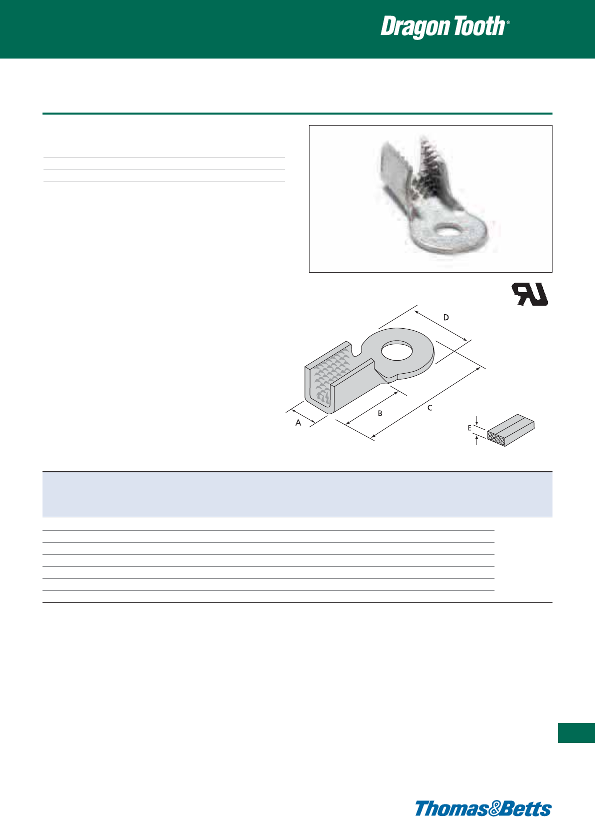
Ring terminals
Technical Information
Material Copper alloy
Plating Tin plated
Colour Metallic
Insulation piercing connectors
409
Thomas & Betts • www.tnb-europe.com
5.3
E9809
Product Ref. USA Dimensions Combined Round Rectangular wire range Tooling
Stud A B C D E* wire size wire range Thickness Width
size** min - max min - max min - max
[mm] [mm] [mm] [mm] [mm] [mm
2
] [mm] [mm] [mm]
210214-1
1
/
4
9.5 14.3 35.7 17.5 4.3 2.0 - 10.5 1.6 (a) - 2.58 2.0 - 2.3 2.0 - 4.6
210214-2
5
/
16
9.5 14.3 35.7 17.5 4.3 2.0 - 10.5 1.6 (a) - 2.58 2.0 - 2.3 2.0 - 4.6
210214-3
3
/
8
9.5 14.3 35.7 17.5 4.3 2.0 - 10.5 1.6 (a) - 2.58 2.0 - 2.3 2.0 - 4.6 13100A
204210-1
1
/
4
13.5 15.5 40.1 20.6 6.3 5.2 - 26.6 2.05 (b) - 6.5 (c) 2.5 - 4.1 2.5 - 6.6 13400
204210-2
5
/
16
13.5 15.5 40.1 20.6 6.3 5.2 - 26.6 2.05 (b) - 6.5 (c) 2.5 - 4.1 2.5 - 6.6 TBM15i
204210-3
3
/
8
13.5 15.5 40.1 20.6 6.3 5.2 - 26.6 2.05 (b) - 6.5 (c) 2.5 - 4.1 2.5 - 6.6
204210-5
1
/
2
13.5 15.5 40.1 20.6 6.3 5.2 - 26.6 2.05 (b) - 6.5 (c) 2.5 - 4.1 2.5 - 6.6
(a) Four wires max
(b) Six wires max
(c) Conductors larger than 13 mm
2
require special dies
* Reference dimension (crimped height): see installing die illustration for gauging
** USA stud size: see page 427 for metric conversion
Use selection chart to determine appropriate die set (pages 425 and 426)
Pages 420 to 424 for tooling specifications
NOTE: Wire sizes and combinations shown have been tested to and meet or exceed Thomas & Betts specifications. Connectors may be suitable for other wire
sizes or combinations. Thomas & Betts sells these connectors with the understanding that the user will perform necessary tests to determine their suitability
for the intended purpose.
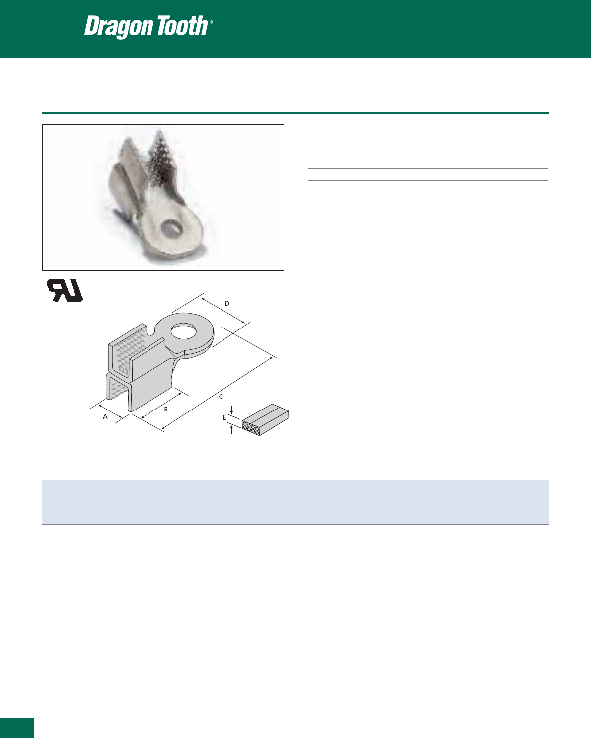
410
Thomas & Betts • www.tnb-europe.com
5.3
Ring terminals
Technical Information
Material Copper alloy
Plating Tin plated
Colour Metallic
Insulation piercing connectors
Product Ref. USA Dimensions Combined Round Rectangular wire range Tooling
Stud A B C D E* wire size wire range Thickness Width
size** min - max min - max min - max
[mm] [mm] [mm] [mm] [mm] [mm
2
] [mm] [mm] [mm]
204210-1H
1
/
4
13.5 15.5 40.1 20.6 11.9 (5.2 - 26.6) x 2 2.05 (b) - 6.54 (c) 2.5 - 4.1 2.5 - 6.6 13100A,13400
204210-3H
3
/
8
13.5 15.5 40.1 20.6 11.9 (5.2 - 26.6) x 2 2.05 (b) - 6.54 (c) 2.5 - 4.1 2.5 - 6.6 TBM15i
(b) Six wires max
(c) Conductors larger than 13 mm
2
require special dies
* Reference dimension (crimped height): see installing die illustration for gauging
** USA stud size: see page 427 for metric conversion
Use selection chart to determine appropriate die set (pages 425 and 426)
Pages 420 to 424 for tooling specifications
NOTE: Wire sizes and combinations shown have been tested to and meet or exceed Thomas & Betts specifications. Connectors may be suitable for other wire
sizes or combinations. Thomas & Betts sells these connectors with the understanding that the user will perform necessary tests to determine their suitability
for the intended purpose.
E9809

Ring terminals
Technical Information
Material Copper alloy
Plating Tin plated
Colour Metallic
Insulation piercing connectors
411
Thomas & Betts • www.tnb-europe.com
5.3
Product Ref. USA Dimensions Combined Rectangular wire range Tooling
Stud size** A B C D E* wire size Thickness Width
min-max min-max
[mm] [mm] [mm] [mm] [mm] [mm
2
] [mm] [mm]
220017
3
/
8
22.4 38.1 70.1 26.9 (a) 25.3 - 58.2 2.5 - 4.4 7.6 - 15.9
220018
1
/
2
22.4 38.1 70.1 26.9 (a) 25.3 - 58.2 2.5 - 4.4 7.6 - 15.9
220021 (b)
3
/
8
22.4 38.1 70.1 26.9 (a) 55.7 - 88.7 4.4 - 6.4 7.6 - 15.9 13100A
220022 (b)
1
/
2
22.4 38.1 70.1 26.9 (a) 55.7 - 88.7 4.4 - 6.4 7.6 - 15.9 TBM15i
220025
3
/
8
22.4 38.1 70.1 26.9 (a) 55.7 - 116.8 4.4 - 8.3 7.6 - 15.9
220026
1
/
2
22.4 38.1 70.1 26.9 (a) 55.7 - 116.8 4.4 - 8.3 7.6 - 15.9
(a) Crimping dies may not bottom. Connector height will depend on number and size of wires in barrel. Pump must deliver 9.800 psi min.
(b) Not UL approved
* Reference dimension (crimped height): see installing die illustration for gauging
** USA stud size: see page 427 for metric conversion
Use selection chart to determine appropriate die set (pages 425 and 426)
Pages 420 to 424 for tooling specifications
NOTE: Wire sizes and combinations shown have been tested to and meet or exceed Thomas & Betts specifications. Connectors may be suitable for other wire
sizes or combinations. Thomas & Betts sells these connectors with the understanding that the user will perform necessary tests to determine their suitability
for the intended purpose.
E9809
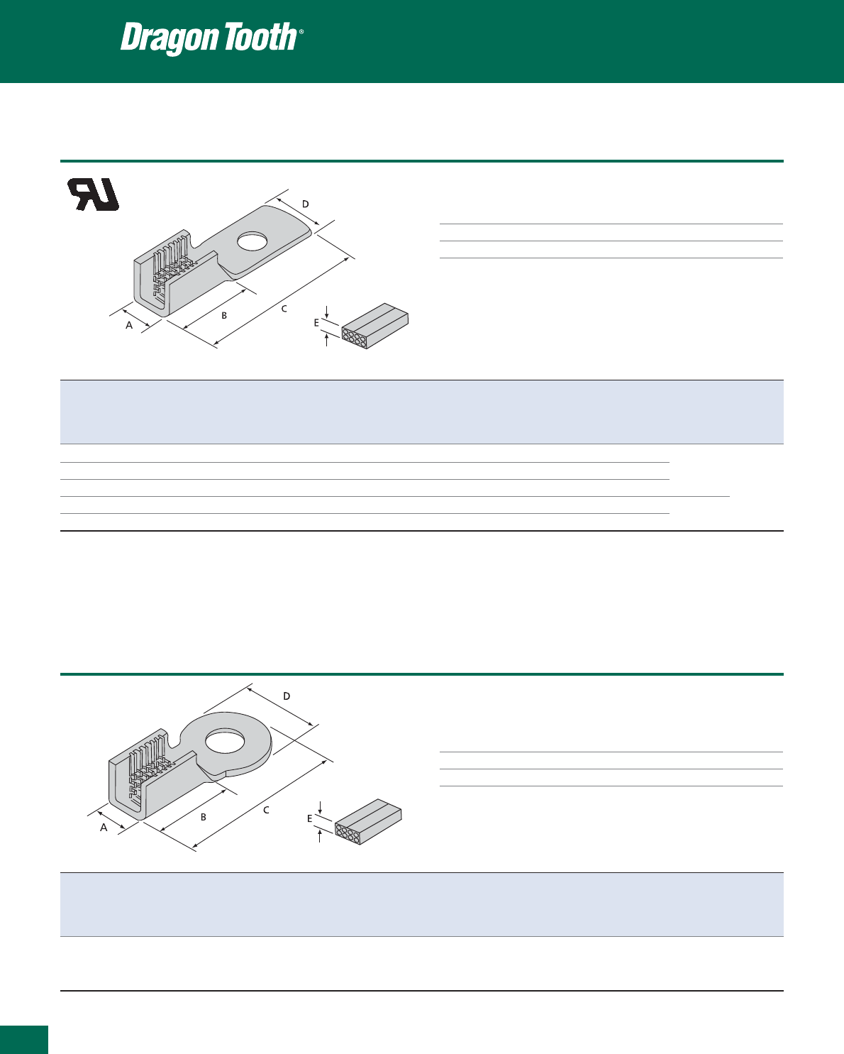
412
Thomas & Betts • www.tnb-europe.com
5.3
Ring terminals
Technical Information
Material Copper alloy
Plating Tin plated
Colour Metallic
Insulation piercing connectors
Product Ref. USA Dimensions Combined Round Rectangular wire range Tooling
Stud size** A B C D E* wire size wire range Thickness Width Hand Power
min - max min - max min - max tool tool
[mm] [mm] [mm] [mm] [mm] [mm
2
] [mm] [mm] [mm]
22R061 6 4.1 8.1 19.8 7.6 2.5 0.2 - 2.1 0.51 - 1.45 (a) 0.51 - 1.27 0.51 - 2.54
22R081 8 4.1 8.1 19.8 7.6 2.5 0.2 - 2.1 0.51 - 1.45 (a) 0.51 - 1.27 0.51 - 2.54 ERG1801 11903A
22R101 10 4.1 8.1 19.8 7.6 2.5 0.2 - 2.1 0.51 - 1.45 (a) 0.51 - 1.27 0.51 - 2.54 11904A
22R086 8 6.4 11.5 23.1 7.6 3.3 1.3 - 6.2 1.29 - 2.05 1.27 - 2.03 1.27 - 4.06 ERG1806 13500
22R106 10 6.4 11.5 23.1 7.6 3.3 1.3 - 6.2 1.29 - 2.05 1.27 - 2.03 1.27 - 4.06
* Reference dimension (crimped height): see installing die illustration for gauging (a) 0.51 - 0.64 mm diameter and equivalent
** USA stud size: see page 427 for metric conversion rectangular wire size, copper only
Use selection chart to determine appropriate die set (pages 425 and 426)
Pages 420 to 424 for tooling specifications
Product Ref. USA Dimensions Combined Round Rectangular wire range Tooling
Stud size** A B C D E* wire size wire range Thickness Width Hand Power
min - max min - max min - max tool tool
[mm] [mm] [mm] [mm] [mm] [mm
2
] [mm] [mm] [mm]
11903A
22R146
1
/
4
6.4 11.5 24.2 10.7 3.3 1.3 - 6.2 1.29 - 2.05 1.27 - 2.03 1.27 - 4.06 ERG1806 11904A
13500
* Reference dimension (crimped height): see installing die illustration for gauging
** USA stud size: see page 427 for metric conversion
Use selection chart to determine appropriate die set (pages 425 and 426)
Pages 420 to 424 for tooling specifications
NOTE: Wire sizes and combinations shown have been tested to and meet or exceed Thomas & Betts specifications. Connectors may be suitable for other wire
sizes or combinations. Thomas & Betts sells these connectors with the understanding that the user will perform necessary tests to determine their suitability
for the intended purpose.
E9809
Ring terminals
Insulation piercing connectors
Technical Information
Material Copper alloy
Plating Tin plated
Colour Metallic
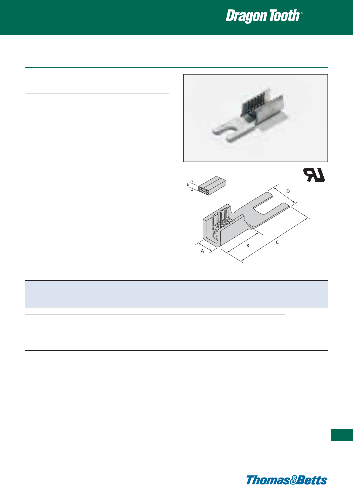
Fork terminals
Technical Information
Material Copper alloy
Plating Tin plated
Colour Metallic
Insulation piercing connectors
413
Thomas & Betts • www.tnb-europe.com
5.3
Product Ref. USA Dimensions Combined Round Rectangular wire range Tooling
Stud size** A B C D E* wire size wire range Thickness Width Hand Power
min - max min - max min - max tool tool
[mm] [mm] [mm] [mm] [mm] [mm
2
] [mm] [mm] [mm]
22F061 6 4.1 8.1 19.8 7.6 2.5 0.2 - 2.1 0.51 - 1.45 (a) 0.51 - 1.27 0.51 - 2.54
22F081 8 4.1 8.1 19.8 7.6 2.5 0.2 - 2.1 0.51 - 1.45 (a) 0.51 - 1.27 0.51 - 2.54 ERG1801 11903A
22F101 10 4.1 8.1 19.8 7.6 2.5 0.2 - 2.1 0.51 - 1.45 (a) 0.51 - 1.27 0.51 - 2.54 11904A
22F066 6 6.4 11.4 23.1 7.6 3.3 1.3 - 6.2 1.29 - 2.05 1.27 - 2.03 1.27 - 4.06 13500
22F086 8 6.4 11.4 23.1 7.6 3.3 1.3 - 6.2 1.29 - 2.05 1.27 - 2.03 1.27 - 4.06 ERG1806
22F106 10 6.4 11.4 23.1 7.6 3.3 1.3 - 6.2 1.29 - 2.05 1.27 - 2.03 1.27 - 4.06
(a) 0.51 - 0.64 mm diameter and equivalent rectangular wire size, copper only
* Reference dimension (crimped height): see installing die illustration for gauging
** USA stud size: see page 427 for metric conversion
Use selection chart to determine appropriate die set (pages 425 and 426)
Pages 420 to 424 for tooling specifications
NOTE: Wire sizes and combinations shown have been tested to and meet or exceed Thomas & Betts specifications. Connectors may be suitable for other wire
sizes or combinations. Thomas & Betts sells these connectors with the understanding that the user will perform necessary tests to determine their suitability
for the intended purpose.
E9809

414
Thomas & Betts • www.tnb-europe.com
5.3
Disconnect terminals
Technical Information
Material Copper alloy
Plating Tin plated
Colour Metallic
Insulation piercing connectors
Product Ref. Male tab Dimensions Combined Round Rectangular wire range Tooling
size A B C D E* wire size wire range Thickness Width Hand Power
min - max min - max min - max tool tool
[mm x mm] [mm] [mm] [mm] [mm] [mm] [mm
2
] [mm] [mm] [mm]
11903A,
22LM01*** 6.35 x 0.8 4.1 8.1 19.3 6.4 2.5 0.2 - 2.1 0.50 - 1.45*** 0.51 - 1.27 0.5 - 2.5 ERG1801 11904A
22LM06 6.35 x 0.8 6.4 11.5 23.0 6.4 3.3 1.3 - 6.2 1.29 - 2.05 1.27 - 2.03 1.3 - 4.1 ERG1806 13500
* Reference dimension (crimped height): see installing die illustration for gauging
Use selection chart to determine appropriate die set (pages 425 and 426)
*** 0.51 - 0.64 mm diameter and equivalent wire size, copper only
Pages 420 to 424 for tooling specifications
NOTE: Wire sizes and combinations shown have been tested to and meet or exceed Thomas & Betts specifications. Connectors may be suitable for other wire
sizes or combinations. Thomas & Betts sells these connectors with the understanding that the user will perform necessary tests to determine their suitability
for the intended purpose.
E9809
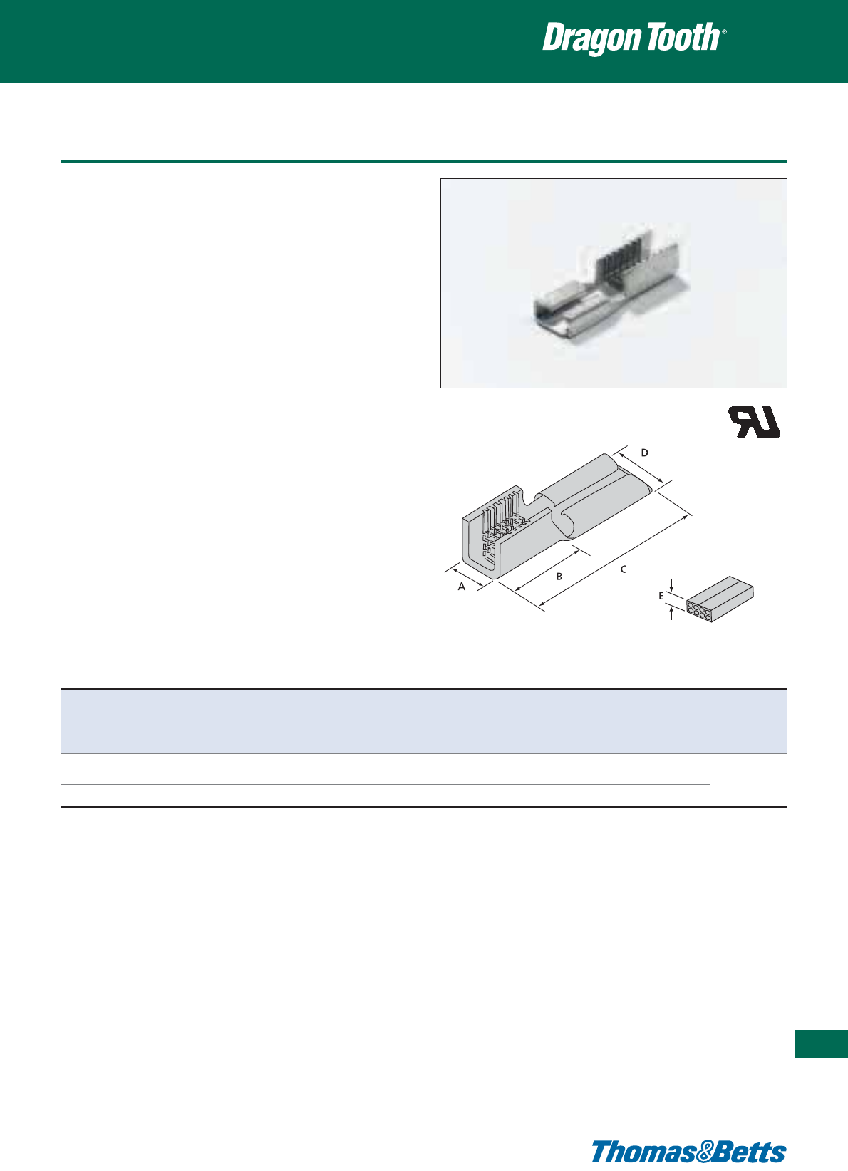
Disconnect terminals
Technical Information
Material Copper alloy
Plating Tin plated
Colour Metallic
Insulation piercing connectors
415
Thomas & Betts • www.tnb-europe.com
5.3
Product Ref. For male Dimensions Combined Round Rectangular wire range Tooling
tab
size A B C D E* wire size wire range Thickness Width Hand Power
min - max min - max min - max tool tool
[mm x mm] [mm] [mm] [mm] [mm] [mm] [mm
2
] [mm] [mm] [mm]
11903A
22LF01*** 6.35 x 0.8 4.1 8.1 20.1 6.4 2.5 0.2 - 2.1 0.50 - 1.45*** 0.51 - 1.27 0.5 - 2.5 ERG1801 11904A
22LF06 6.35 x 0.8 6.4 11.5 23.0 6.4 3.3 1.3 - 6.2 1.29 - 2.05 1.27 - 2.03 1.3 - 4.1 ERG1806 13500
* Reference dimension (crimped height): see installing die illustration for gauging
Use selection chart to determine appropriate die set (pages 425 and 426)
*** 0.51 - 0.64 mm diameter and equivalent wire size, copper only
Pages 420 to 424 for tooling specifications
NOTE: Wire sizes and combinations shown have been tested to and meet or exceed Thomas & Betts specifications. Connectors may be suitable for other wire
sizes or combinations. Thomas & Betts sells these connectors with the understanding that the user will perform necessary tests to determine their suitability
for the intended purpose.
E9809
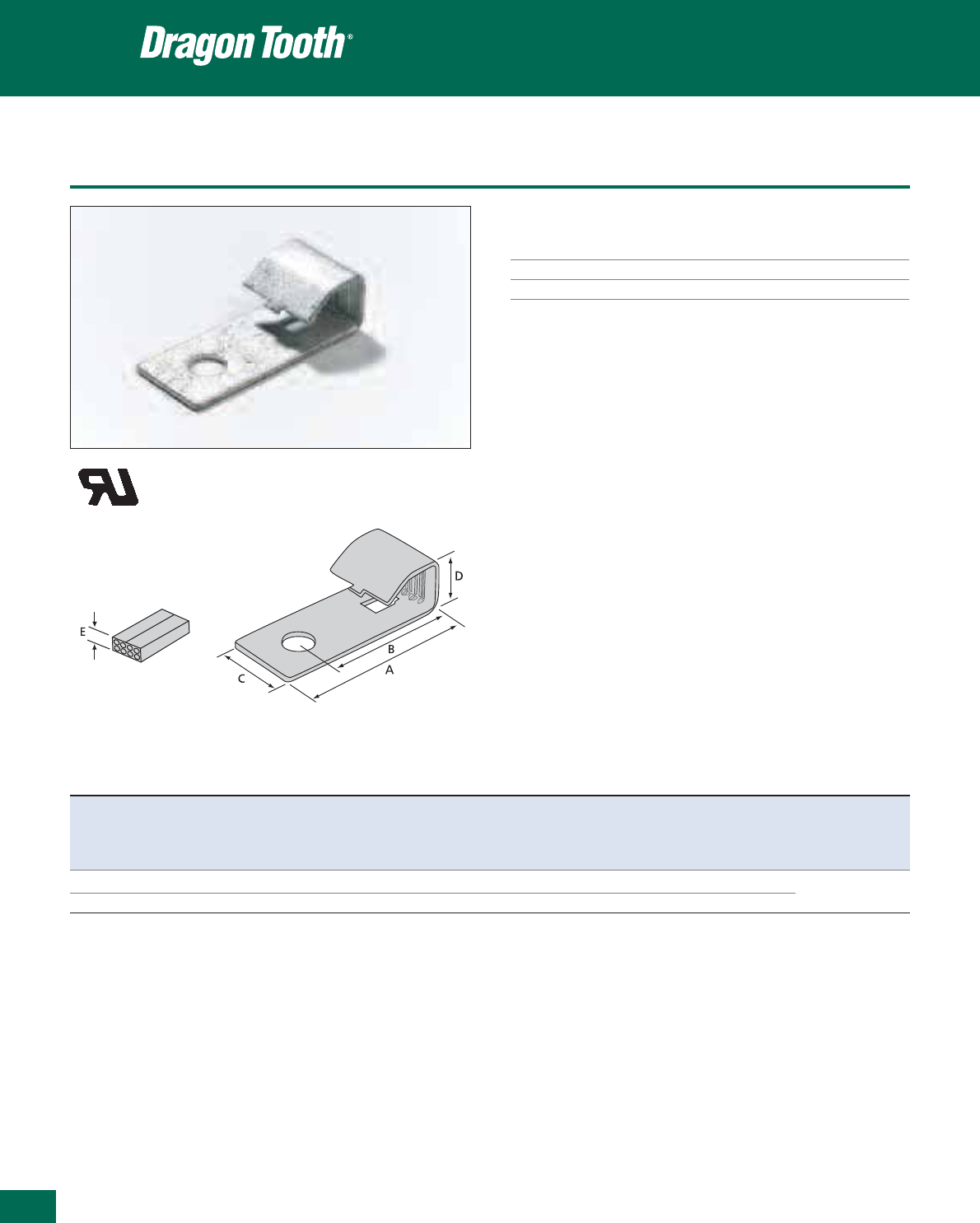
416
Thomas & Betts • www.tnb-europe.com
5.3
Taps
Technical Information
Material Copper alloy
Plating Tin plated
Colour Metallic
Insulation piercing connectors
E9809
Product Ref. USA Dimensions Combined Round Rectangular wire range Tooling
Stud size** A B C D E* wire size wire range Thickness Width
min - max min - max min - max
[mm] [mm] [mm] [mm] [mm] [mm
2
] [mm] [mm] [mm]
204T14
1
/
4
41.2 31.0 17.8 12.7 5.6 5.2 - 26.6 2.58 - 4.1 2.3 - 2.9 2.3 - 8.1 13100A
204T38
3
/
8
41.2 31.0 17.8 12.7 5.6 5.2 - 26.6 2.58 - 4.1 2.3 - 2.9 2.3 - 8.1 TBM15i
* Reference dimension (crimped height): see installing die illustration for gauging
** USA stud size: see page 427 for metric conversion
Use selection chart to determine appropriate die set (pages 425 and 426)
Pages 420 to 424 for tooling specifications
NOTE: Wire sizes and combinations shown have been tested to and meet or exceed Thomas & Betts specifications. Connectors may be suitable for other wire
sizes or combinations. Thomas & Betts sells these connectors with the understanding that the user will perform necessary tests to determine their suitability
for the intended purpose.

Modular connectors
Technical Information
Material Copper alloy
Plating Tin plated
Colour Metallic
Insulation piercing connectors
417
Thomas & Betts • www.tnb-europe.com
5.3
E9809
Product Ref. Dimensions Combined Round Rectangular wire range Tooling
A D E* wire size** wire range Thickness Width
min - max min - max min - max
[mm] [mm] [mm] [mm
2
] [mm] [mm] [mm]
2.0 - 3.8 (upper half) 2.0 - 12.4 (upper half) 13100A
210214MT 16.0 19.1 (a) 10.1 - 53.2 1.8 - 4.62 6.4 max. (lower half) 19.1 max. (lower half) 13400, TBM15i
2.5 - 6.8 (upper half) 2.5 - 23.4 (upper half)
204210MT 23.8 26.2 (a) 45.6 - 108.9 2.6 - 5.84 6.4 max. (lower half) 26.2 max. (lower half) 13400
* Reference dimension (crimped height): see installing die illustration for gauging
(a) Crimping dies may not bottom. Connector height will depend on number and size of wires in barrel. Pump must deliver 9.800 psi min.
** combined wire size is for the whole connector (including upper half and lower half)
Use selection chart to determine appropriate die set (pages 425 and 426)
Pages 420 to 424 for tooling specifications
NOTE: Wire sizes and combinations shown have been tested to and meet or exceed Thomas & Betts specifications. Connectors may be suitable for other wire
sizes or combinations. Thomas & Betts sells these connectors with the understanding that the user will perform necessary tests to determine their suitability
for the intended purpose.
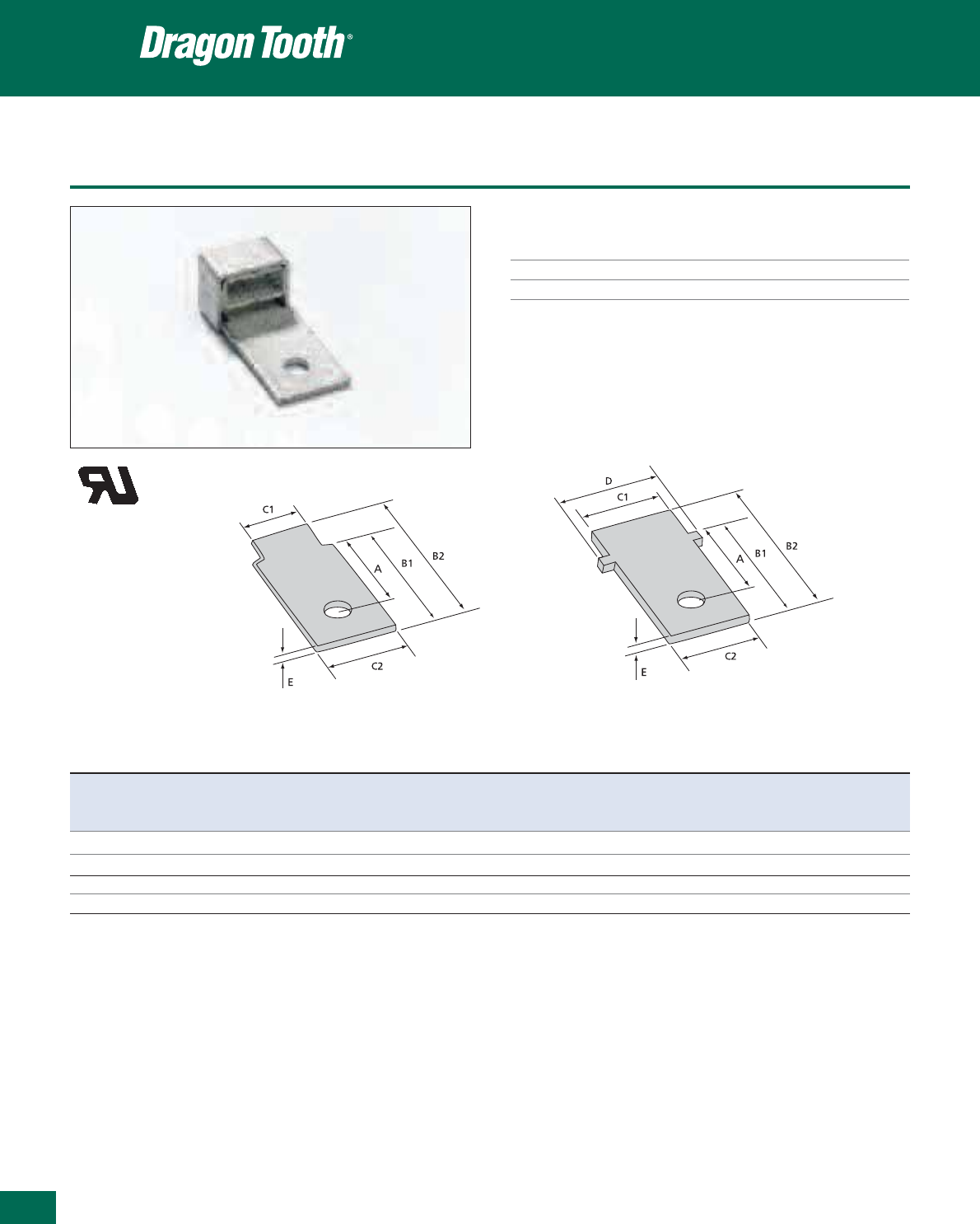
418
Thomas & Betts • www.tnb-europe.com
5.3
Modular connectors
Technical Information
Material Copper alloy
Plating Tin plated
Colour Metallic
Insulation piercing connectors
Product Ref. USA Dimensions Description
Stud size* A B1 B2 C1 C2 D E
[mm] [mm] [mm] [mm] [mm] [mm] [mm]
210MT14
1
/
4
25.4 36.3 52.1 15.9 20.6 - 2.0 Screw-on clip for connectors 210214MT
210MT38
3
/
8
25.4 36.3 52.1 15.9 20.6 - 2.0 Screw-on clip for connectors 210214MT
204MT14
1
/
4
25.4 36.8 55.4 23.2 23.2 28.6 2.5 Screw-on clip for connectors 204210MT
204MT38
3
/
8
25.4 36.8 55.4 23.2 23.2 28.6 2.5 Screw-on clip for connectors 204210MT
* USA stud size: see page 427 for metric conversion
NOTE: Wire sizes and combinations shown have been tested to and meet or exceed Thomas & Betts specifications. Connectors may be suitable for other wire
sizes or combinations. Thomas & Betts sells these connectors with the understanding that the user will perform necessary tests to determine their suitability
for the intended purpose.
E9809
210MT14
210MT38
204MT14
204MT38

Washers
Teeth on the transition washers penetrate aluminium and copper
oxides, enabling copper to aluminium connections to be made in a
bolted joint without the use of inhibiting compounds. Transition
washers also accommodate the difference in thermal expansion
between copper and aluminium, and enhance the efficiency of
bolted grounding connections.
Technical Information
Material Copper alloy
Plating Tin plated
Colour Metallic
Insulation piercing connectors
419
Thomas & Betts • www.tnb-europe.com
5.3
Product Ref. USA stud size* Metric equivalent stud size A B Recommended installing torque
[mm] [mm] [Nm]
FPW14
1
/
4
M6 6.9 17.3 5.5 - 9
FPW516
5
/
16
M8 8.6 25.4 14 - 18
FPW38
3
/
8
M10 10.9 25.4 18 - 27
FPW12
1
/
2
M14 14.2 31.8 44 - 61
FPW58
5
/
8
M16 17.3 35.6 61 - 82.5
* USA stud size: see page 427 for metric conversion
Plain steel washer
Plain steel washer
Lug or bus bar
Steel bolt & nut
Transition washer
Lugorbusbar

420
Thomas & Betts • www.tnb-europe.com
5.3
Hand tools
These manually operated tools are suitable for prototyping and limited
production usage. They are equipped with a Shure-Stake™ mecha-
nism, which requires full closure of the dies before release. Appro-
priate to crimp butt splices, parallel splices, taps and terminations.
Dies are self-contained.
Product Ref. ERG811 and ERG18XX series
• Ergonomic fixed die tool
• Incorporates the ergonomically designed Comfort Crimp™ tool
handles which distribute the force more evenly across the hand
• Shure-Stake™ mechanism ensures a complete crimp cycle before
the tool releases
• Rubberised thermoplastic handles combine maximum friction
with a soft, comfortable feel that reduces muscle tension
• Two-piece movable die nest provides easy connector removal
Crimping tools
Product Ref. Tool gauging Connector
[mm]
ERG1801 1.75 max. 22,F,L,R-1 Series
ERG1802 1.93 max. 22L002
ERG1804 0.86 max. 22L004
ERG1806 2.41 max. 22,F,L,R-6 Series
ERG811 2.62 max. 214420
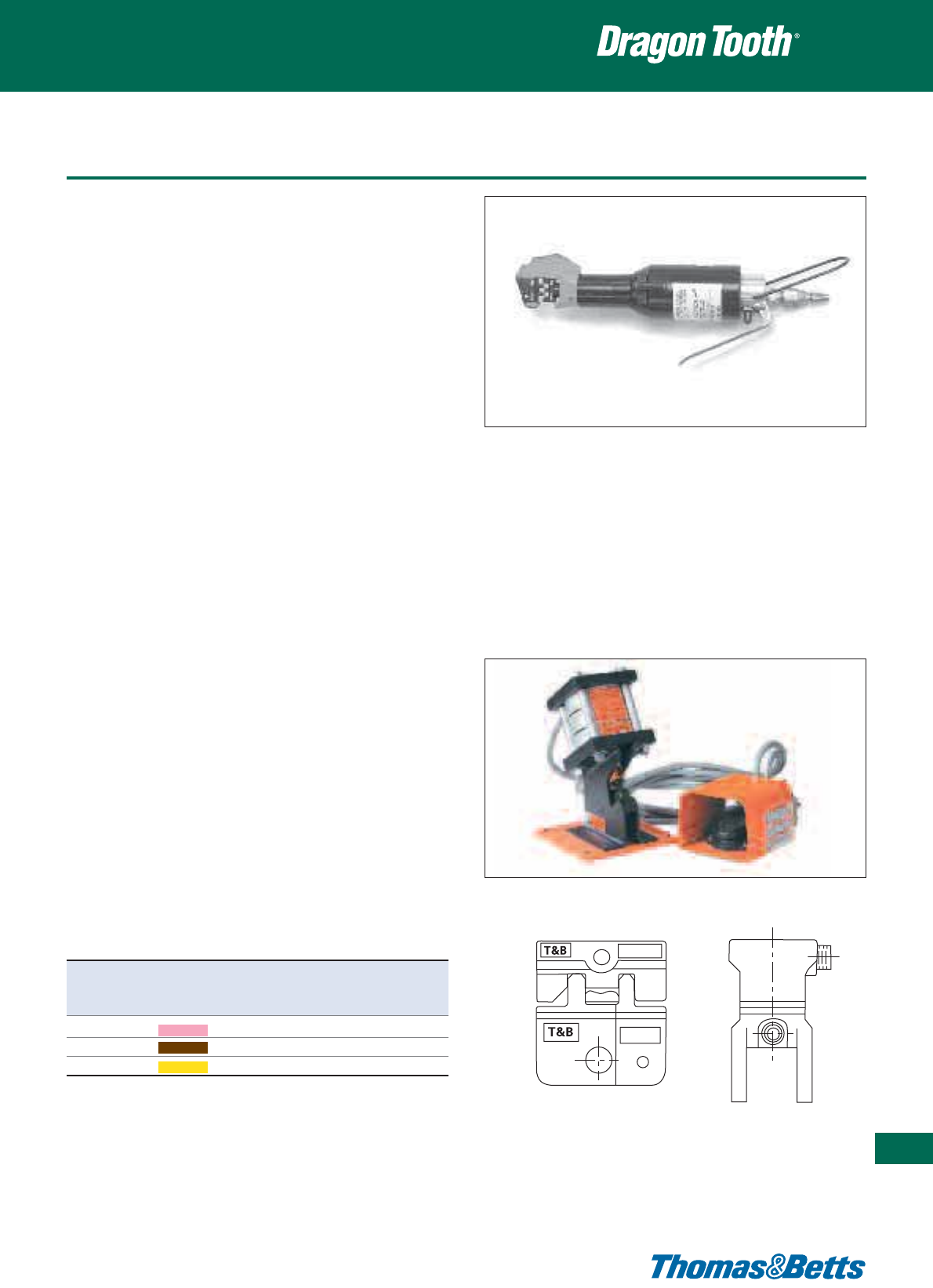
Air-operated tools
Product Ref. 11903A and 11904A
This pneumatic operated hydraulic crimping tool is available in hand
or foot actuated models, with open “C” yoke design.
• The 3 interchangeable dies can crimp the 22xxx1, 22xxx2 and
22xxx6 series terminals and need to be ordered separately
•Product Ref. 11903A: hand-actuated tool (also requires one
Product Ref. 11913 air hose).
•Product Ref. 11904A: foot-actuated tool (also requires two
Product Ref. 11913 air hoses and one Product Ref. 11930 foot
valve).
•
Material: Steel with backed enamel paint finish
•
Overall length: 276 mm
•
Diameter: 57 mm
•
Operating Pressure: 90 - 100 PSI (6.2-6.9 bar)
•
Weight: 1.4 kg
Accessories
•Product Ref. 11913: 2.43 m long air hose with 1/4 NPT male &
female fittings
•Product Ref. 11930: foot valve for 11904A
Product Ref.: 13500
• Heavy-duty air operated tool installs a wide range of
Dragon Tooth®connectors.
• High-speed installation
• 3 interchangeable dies to be ordered separately
• Bench mounted for stability and operator control
• Compact size, all metallic construction
• Includes hoses, foot pedal and air treatment system
• Equipped with Shure-Stake™ mechanism ensuring full crimp
cycle before release
•
Height: 305 mm
•
Base: 203 mm x 203 mm
•
Weight: 7.7 kg
•
Operating Pressure: (85 - 90 PSI) 5.9-6.2 bar
11903A, 11904A and 13500 die selection chart
Crimping tools
421
Thomas & Betts • www.tnb-europe.com
5.3
Product Ref. Colour code Connector Die gauge
max. min.
[mm] [mm]
13201 Pink 22XXX1 SERIES 1.68 1.57
13202 Brown 22XXX2 SERIES 1.83 1.73
13206 Yellow 22XXX6 SERIES 2.29 2.18
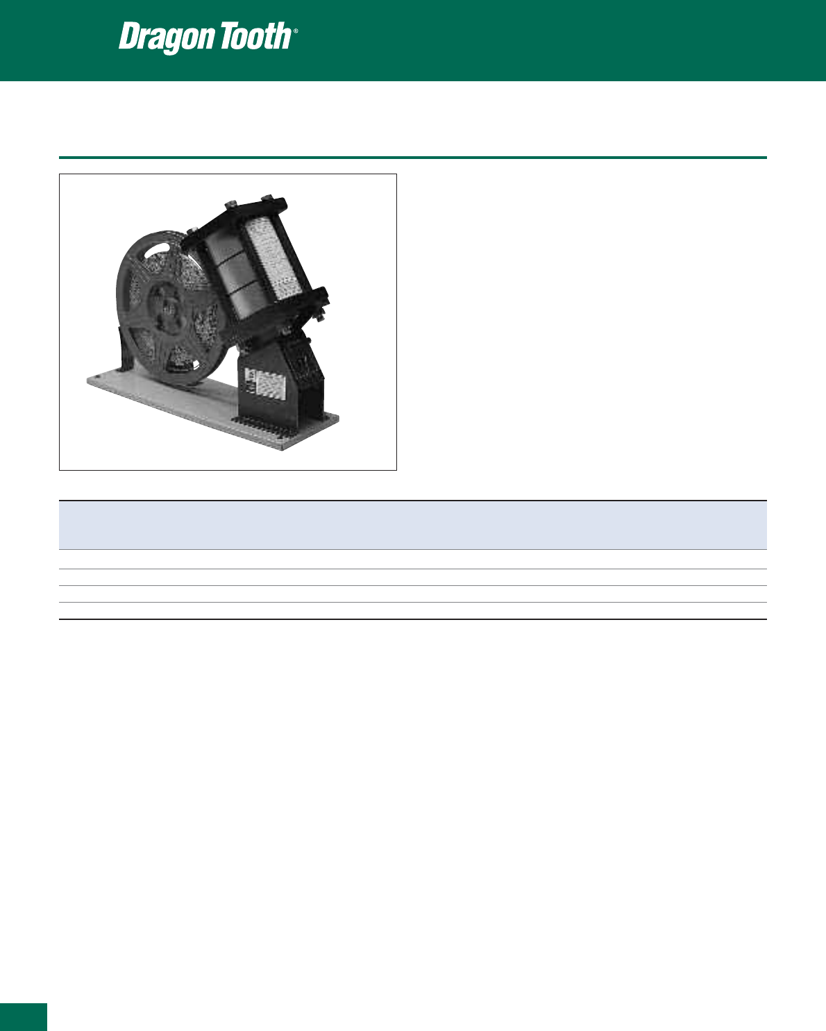
422
Thomas & Betts • www.tnb-europe.com
5.3
Auto-feed tools for connectors on strip
Pneumatic bench mounted foot operated tool for crimping copper
or aluminium magnet wire and copper lead wire, not solder dipped
or bonded.
• Operates on min. 85 psi, 6.0 bar air supply
• Foot pedal contains T&B Shure-Stake™ control mechanism which
ensures a full compression each time
• Insulation piercing connectors are fed on a continuous reel
mounted strip
• Dies are self-contained. Includes foot valve, hoses and air treat-
ment system
Crimping tools
Product Ref. Connector Connector Tool Tool Tool Tool
product ref. qty per reel weight width depth height
[kg] [mm] [mm] [mm]
13676A 220004 9000 8.6 127 356 279
13678 220001 3000 12.7 152 457 356
13679 220002-TB 3000 12.7 152 457 356
13696 220006 2500 14.5 152 457 406
See page 401 for more information about the connectors on strip.

Hydraulic tools
Product Ref.: 13100A
• 14 Ton hydraulic head
• Output: 14 tons (nominal)
• Hydraulic operating pressure: 10,000 psi max., 690 bar
• Length (with coupling): 292 mm
• Width: 108 mm
• Weight (without dies): 4.5 kg
• Dies delivered separately
Product Ref.: TBM15i
• 15 Ton hydraulic head
• New longer, slimmer profile allows easier access into tight spaces
• Wider jaw opening eases crimping of larger connectors
• Available with an insulated head
• Supplied in a carrying case in steel
• Output force: 15 tons (nominal)
• Operating pressure: 10,000 psi (nominal), 690 bar
• Weight: 7 kg (without dies)
• Dies delivered separately
Installing dies for 13100A and TBM15i tool heads
• Material: alloy steel
• For the TBM15i, the 15500TB adapter is required
• The die Nr 13713 is for the TBM15i tool head only
(no adapter required)
• The die Nr 13713B is for the 13100A tool head only
13100A and TBM15i die selection chart
Crimping tools
423
Thomas & Betts • www.tnb-europe.com
5.3
15500-TB Adapter
13713
TBM15i
Product Ref. Colour For Gauge Gauge
code connector max. min.
[mm] [mm]
13670B Red 210xxx series 4.42 4.11
13671B Blue 204xxx series 6.25 5.94
13673B Green 204xxxH series 11.94 11.79
13681B Yellow 210214MT 4.47 4.17
13683B White 22L008 2.84 2.46
13684B Yellow 22L009 4.93 4.55
13686B Orange 22L009H 9.50 9.12
13689B Purple 204Txx series 5.18 4.80
13713 220015 to 220026 2.79 2.03
13713B 220015 to 220026 2.92 2.16
13670B, 13671B, 13673B 13681B 13683B, 13684B, 13686B 13689B 13713 13713B
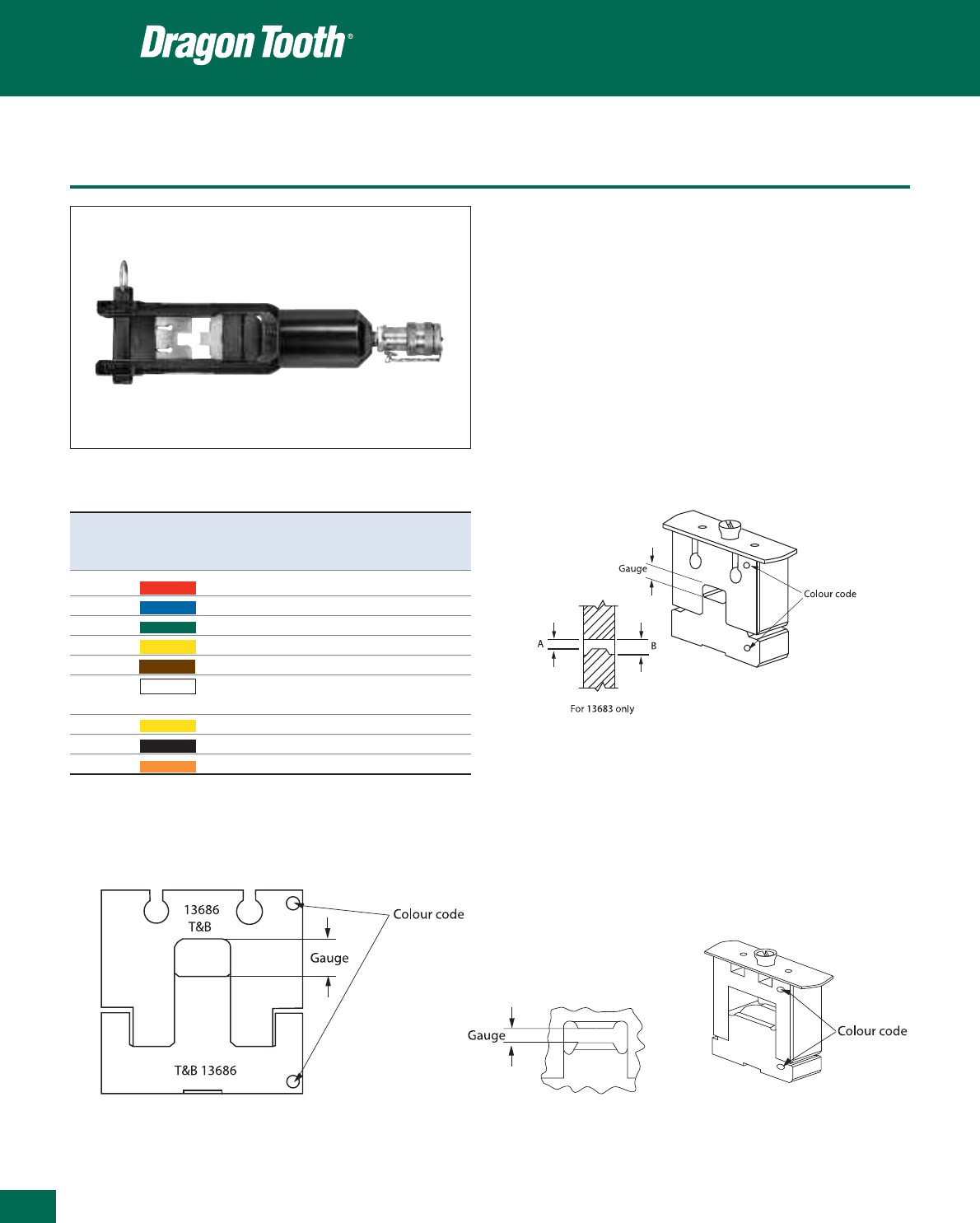
Thomas & Betts • www.tnb-europe.com
5.3
Hydraulic tools
Product Ref.: 13400
• 12 Ton hydraulic head
• Output: 12 tons (nominal)
• Hydraulic operating pressure: 10.000 psi max., 690 bar
• Length (with coupling): 368 mm
• Width:84mm
• Weight (without dies): 6.8 kg
• Dies delivered separately
Installing dies for 13400
• Material: alloy steel
Crimping tools
Product Colour For Gauge Gauge
Ref. code connector max. min.
[mm] [mm]
13670A Red 210xxx series 4.42 4.11
13671A Blue 204xxx series 6.25 5.94
13673 Green 204xxxH series 11.94 11.79
13681 Yellow 210214MT 4.47 4.17
13682 Brown 204210MT 7.65 7.34
13683 White 22L008 A: 2.74 A: 2.59
B: 3.10 B: 2.90
13684 Yellow 22L009 4.83 4.65
13685 Black 314xxx series 3.45 3.15
13686 Orange 22L009H 9.37 9.22
13686
13670A, 13671A, 13673,
13683, 13684, 13685
13681, 13682
424
13400 die selection chart
Connectors, tool and die selection chart
Crimping tools
425
Thomas & Betts • www.tnb-europe.com
5.3
Hand tools Pneumatic tools Auto-feed tool for 14 ton 12 ton 15 ton
(fixed die) 11903A, 11904A magnet wire on hydraulic head hydraulic head hydraulic head
13500 strip 13100A 13400 TBM15i
TERMINALS TOOL DIE TOOL DIE DIE DIE + ADAPTOR
204210MT – – – – 13682 –
204210S – – – 13671B 13671A 13671B with 15500TB
204210SH – – – 13673B 13673 13673B with 15500TB
204210-1 – – – 13671B 13671A 13671B with 15500TB
204210-1H – – – 13673B 13673 13673B with 15500TB
204210-2 – – – 13671B 13671A 13671B with 15500TB
204210-3 – – – 13671B 13671A 13671B with 15500TB
204210-3H – – – 13673B 13673 13673B with 15500TB
204201-5 – – – 13671B 13671A 13671B with 15500TB
204211 – – – 13671B 13671A 13671B with 15500TB
204212 – – – 13671B 13671A 13671B with 15500TB
204217 – – – 13671B 13671A 13671B with 15500TB
204MT14 – – – – – –
204MT38 – – – – – –
204T14 – – – 13689B – 13689B with 15500TB
204T38 – – – 13689B – 13689B with 15500TB
210214MT – – – 13681B 13681 13681B with 15500TB
210214S – – – 13670B 13670A 13670B with 15500TB
210214-2 – – – 13670B 13670A 13670B with 15500TB
210214-3 – – – 13670B 13670A 13670B with 15500TB
210216 – – – 13670B 13670A 13670B with 15500TB
210217 – – – 13670B 13670A 13670B with 15500TB
210219 – – – 13670B 13670A 13670B with 15500TB
210MT14 – – – – – –
210MT38 – – – – – –
214420 ERG811 11956 – – – –
220001 – – 13678 – – –
220002-TB – – 13679 – – –
220004 – – 13676A – – –
220006 – – 13696 – – –
220015 – – – 13713B – 13713
220016 – – – 13713B – 13713
220017 – – – 13713B – 13713
220018 – – – 13713B – 13713
220019 – – – 13713B – 13713
220020 – – – 13713B – 13713
220021 – – – 13713B – 13713
220022 – – – 13713B – 13713
220023 – – – 13713B – 13713
220024 – – – 13713B – 13713
220025 – – – 13713B – 13713
220026 – – – 13713B – 13713
(continued on next page)

426
Thomas & Betts • www.tnb-europe.com
5.3
Connectors, tool and die selection chart
Crimping tools
Hand tools Pneumatic tools Auto-feed tool for 14 ton 12 ton 15 ton
(fixed die) 11903A, 11904A magnet wire on hydraulic head hydraulic head hydraulic head
13500 strip 13100A 13400 TBM15i
TERMINALS TOOL DIE TOOL DIE DIE DIE + ADAPTOR
22F061 ERG1801 13201 – – – –
22F066 ERG1806 13206 – – – –
22F081 ERG1801 13201 – – – –
22F086 ERG1806 13206 – – – –
22F101 ERG1801 13201 – – – –
22F106 ERG1806 13206 – – – –
22L001 ERG1801 13201 – – – –
22L002 ERG1802 13202 – – – –
22L004 ERG1804 – – – – –
22L006 ERG1806 13206 – – – –
22L008 – – – 13683B 13683 13683B with 15500TB
22L009 – – – 13684B 13684 13684B with 15500TB
22L009H – – – 13686B 13686 13686B with 15500TB
22LF01 ERG1801 13201 – – – –
22LF06 ERG1806 13206 – – – –
22LM01 ERG1801 13201 – – – –
22LM06 ERG1806 13206 – – – –
22R061 ERG1801 13201 – – – –
22R106 ERG1806 13206 – – – –
22R146 ERG1806 13206 – – – –
314118S – – – 13685B 13685 13685B with 15500TB
314123 – – – 13685B 13685 13685B with 15500TB
314125 – – – 13685B 13685 13685B with 15500TB
Unit conversion tables
AWG round wire size to diameter and cross-section
Crimping tools
427
Thomas & Betts • www.tnb-europe.com
Wire size Nominal Nominal Cross- CMA
AWG diameter diameter section circular mils
[inch] [mm] [mm
2
] [cmil]
4/0 0.4600 11.684 107.219 211600
3/0 0.4096 10.404 85.011 167800
2/0 0.3648 9.266 67.432 133100
1/0 0.3249 8.252 53.488 105600
1 0.2893 7.348 42.409 83690
2 0.2576 6.543 33.624 66360
3 0.2294 5.827 26.655 52620
4 0.2043 5.189 21.149 41740
5 0.1819 4.620 16.766 33090
6 0.1620 4.115 13.289 26240
7 0.1443 3.665 10.551 20820
8 0.1285 3.264 8.387 16510
9 0.1144 2.906 6.632 13090
10 0.1019 2.588 5.262 10380
11 0.0907 2.304 4.168 8230
12 0.0808 2.052 3.308 6530
13 0.0720 1.829 2.627 5180
14 0.0641 1.628 2.082 4110
Wire size Nominal Nominal Cross- CMA
AWG diameter diameter section circular mils
[inch] [mm] [mm
2
] [cmil]
15 0.0571 1.450 1.652 3260
16 0.0508 1.290 1.308 2580
17 0.0453 1.151 1.040 2050
18 0.0403 1.024 0.823 1620
19 0.0359 0.912 0.653 1290
20 0.0320 0.813 0.519 1020
21 0.0285 0.724 0.412 812
22 0.0253 0.643 0.324 640
23 0.0226 0.574 0.259 511
24 0.0201 0.511 0.205 404
25 0.0179 0.455 0.162 320
26 0.0159 0.404 0.128 253
27 0.0142 0.361 0.104 202
28 0.0126 0.320 0.080 159
29 0.0113 0.287 0.065 128
30 0.0100 0.254 0.051 100
31 0.0089 0.226 0.040 79
32 0.0080 0.203 0.032 64
American bolt sizes
US Min. hole diameter Matching bolt in
Bolt size [mm] [inch] metric size
2 2.337 0.092 M2
4 2.946 0.116 M2.5
6 3.632 0.143 M3
8 4.292 0.169 M4
10 4.978 0.196 M4
1/4 6.655 0.262 M6
5/16 8.204 0.323 M8
3/8 9.855 0.388 M8
7/16 11.506 0.453 M10
1/2 13.106 0.516 M12
5/8 16.510 0.650 M16
3/4 19.685 0.775 M18
5.3
AWG = American Wire Gauge
1inch
2
= 645.16 mm
2
1mm
2
= 0.00155 inch
2
1mm
2
= 1973.51 cmil
1inch
2
= 1 273 230 cmil
1 cmil = 1 circular mil = 0.0005067 mm
2
1 kcmil = 1000 cmil = 0.5067 mm
2

Thomas & Betts • www.tnb-europe.com
Shield-Kon®
Solderless connectors
for grounding shielded
and coaxial cables
428
5.4
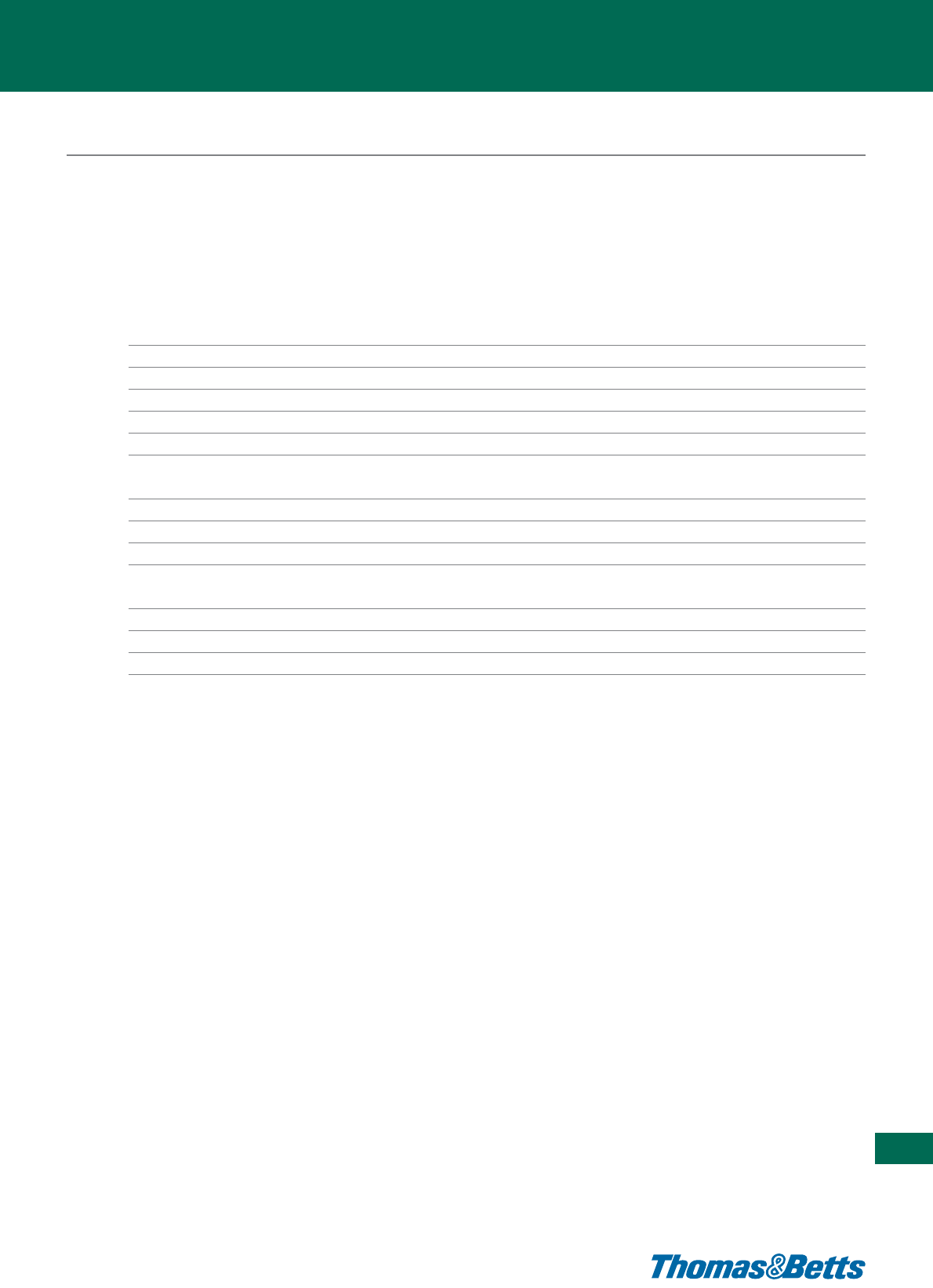
429
Thomas & Betts • www.tnb-europe.com
5.4
TERMINATION SYSTEMS
5.1 STA-KON®- CRIMP TERMINALS 338
5.2 COLOR-KEYED®- POWER CABLE CONNECTORS 382
5.3 DRAGON TOOTH®- MAGNET WIRE TERMINALS 396
5.4 SHIELD-KON®- SHIELDED CABLE CONNECTORS 428
One-piece connector 432
Installation methods and procedures 432
Connectors 433
Selection gauge 434
Accessories: the RSK-FLAG connectors 434
Ergonomic hand tools 435
Two-piece connectors - Hexagonal Range 436
Installation methods 437
Connector and die selection 438
Tooling 439
Two-piece connectors - Circular Range 442
Installation method 442
Connector and die selection 443
Tooling 444

430
Thomas & Betts • www.tnb-europe.com
5.4
Shield-Kon®, the Shield
termination solution
The Shield-Kon®solution from Thomas & Betts involves a
crimp technique for shield termination on shielded cables,
with a proven reliability that has led to a specification for
the aeronautical and space technology industry and for
military applications (MIL-F-21608).
Wherever shielded cables and wires are fitted, there is the problem
of finding a permanent, repeatable, safe and quick connection of
the braided shield.
Conventional connection methods use soldering, which is more
time-consuming and more expensive, and can often result in
damage to the dielectric or to the internal shield conductor
caused by heat. Moreover, the use of lead-based soldering methods
can be in conflict with the latest European regulations.

431
Thomas & Betts • www.tnb-europe.com
5.4
The reliability of Shield-Kon®
terminals has led to a specification
for the aeronautical and
space technology industry and
for military applications
(MIL-F-21608).
Thomas & Betts offer two solutions:
The one-piece Shield-Kon®connector, which is wrapped
around the shield during the crimping process.
This solderless, wraparound connector terminates shielded cable
in seconds with uniform precision. It’s particularly well suited for
production work in aircraft, aerospace, and electronic industries
where size and weight are of importance.
Once crimped, it provides a compact, lightweight, low-resistance,
high-strength connection, which meets and exceeds the per-
formance requirements of MIL-F-21608.
The connector works equally well on braided, wrapped, or foil
shields and has the added advantage of being able to be used as
a mid-span termination.
Only four sizes, which can be easily identified by the colour of
their insulation, are needed to cover a range of shielding diameters
from 1.27 mm to 7.62 mm.
The two-piece Shield-Kon®connector, which consists of two
sleeves, between which the shielded braid and the drain
wire are compressed.
The Shield-Kon®two-piece shield termination system consists of
two cylindrical sleeves: an inner sleeve with a smaller diameter,
and an outer sleeve that has a larger diameter but is shorter and
less hard than the inner sleeve. All inner and outer sleeves are
colour-coded according to their size.
The conductors of the cable are inserted through the inner sleeve,
whereas the shield (braided or foiled) and the drain wire are
inserted between the two sleeves. The crimp operation is done
by compressing the outer sleeve with a tool, while the inner sleeve
ensures a mechanical protection to the inner conductors.
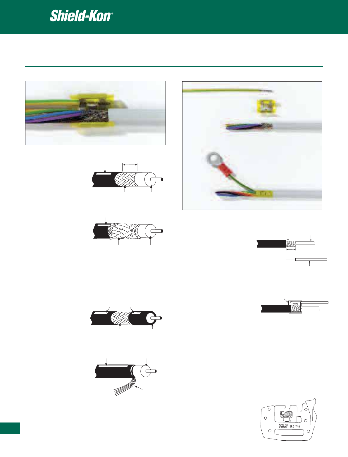
432
Thomas & Betts • www.tnb-europe.com
5.4
Installation methods and procedure
One-piece connector
Step 2
Select the appropriate connector
according to the size of the
shielded cable (see page 433).
Place the drain wire around the
trap hook and the shielded wire
into the bottom of the connector.
When inserting the shielded cable and grounding wire, care must be
taken to ensure that their insulation is overlapped by the connector’s
Polyester insulation film.
100% insulation is possible after crimping when the stripped length of
outer jacket (visible shielding) is 11 mm maximum.
If there is no common
dielectric for several interior
cables but the gaps are
filled by textile threads or
something similar, care
should be taken to ensure
that the insulating thickness of the individual cables is not less than
0.38 mm for PVC, and not less than 0.25 mm for Teflon. If this
insulation thickness falls below this value, fold-back method 1
should be used.
Mid-Span method
Insulation
Shield Cable
Insulation
Shield Cable
11 mm
Insulation
Shield Cable
Insulation
Shield
Cable
Standard method
Fold-back method 1
Fold-back method 2
Allows installation anywhere
along the cable.
Use the standard method
when the shielded cable or
the inner conductors are
embedded in a dielectric.
Fold-back method 2 should
be used if the cable shield is
applied spirally or if a foil
shield is being used.
Step 1
Prepare shielded wire and drain
wire insulation as shown.
If two earth wires are required in a
Shield-Kon
®
connection, twist
both conductors before insertion
into the connector.
Shield Conductors
Jacket 11 mm
Insulation
Butt insulating jackets against metal edge
Connector opening faces away from tool
Installation methods Installation procedures
Step 3
Select the appropriate die set for
the crimp tool, according to the
size of the shielded cable (see page
435) and mount the dies on the
tool. Insert the connector (with the
shielded cable and the drain wire)
between the dies of the tool.
Squeeze the tool handles firmly to
crimp the connector around the
shielding and the drain wire.
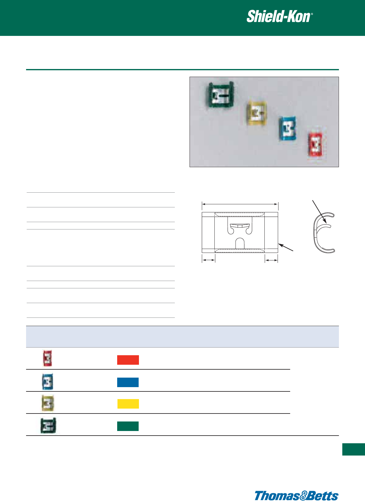
Connectors
• Compact, low profile connector
• One piece “Wrap-around” design
• Inventory savings: only 4 sizes
• Transparent insulation, easily inspected
• MIL specified MIL-F-21608, industry approved technology
• NO HEAT OR POWER REQUIRED to install
• No damage to inner conductor
• Less installation time required
• Uniform, precise connection every time
• Low installed cost
• Mid-span termination possible, eliminating the need to demount
a cable already installed
Technical Information
Material Copper, conform to CDA No. 110
Plating Tin, electro-plated (thickness 3 to 8 m),
in accordance with MIL-T-10727A
Insulation Polyester film, colour coded for size
identification
Temperature -65°C to +125°C
MIL-F-21608 specifications
Voltage drop 9 mV max. at 1 Ampere after environmen-
tal exposure
Insulation 500 VRMS at 60 Hz for one minute
dielectric strength
Corrosion resistance 48 hours in 5% salt fog
Pullout strength 67 N min. with 0.25 mm
2
drain wire and
85N min. with 0.5 mm² drain wire
Vibration 0.76 mm double amplitude between 10
and 55Hz for 6 hours on each of two axis
One-piece connector
433
Thomas & Betts • www.tnb-europe.com
5.4
15.0-16.3mm
2.8 mm 2.8 mm
Ground wire
trap
Insulation
Product Ref. Colour Shield diameter Acceptable drain Quantity Installation
range wire size** tool*
[mm] [pieces]
RSK101 1000
Red 1.27 - 2.28 1 or 2 pieces 0.25mm
2
RSK5101 100
RSK201 1000
Blue 2.29 - 3.65 1 or 2 pieces 0.25mm
2
,
RSK5201 or 1 piece 0.5mm
2
100 ERG740
RSK301 1000
Yellow 3.66 - 5.12 1 or 2 pieces 0.25mm
2
,
RSK5301 or 1 piece 0.5mm
2
100
RSK401 500
Green 5.13 - 7.62 1 or 2 pieces 0.5mm
2
,
RSK5401 or 1 piece 0.75mm
2
100
(*) See page 435 for tooling specifications and for die selection
(**) Alternatively, a special accessory (RSK-flag) can be used in place of the drain wire, with the yellow and the green connectors
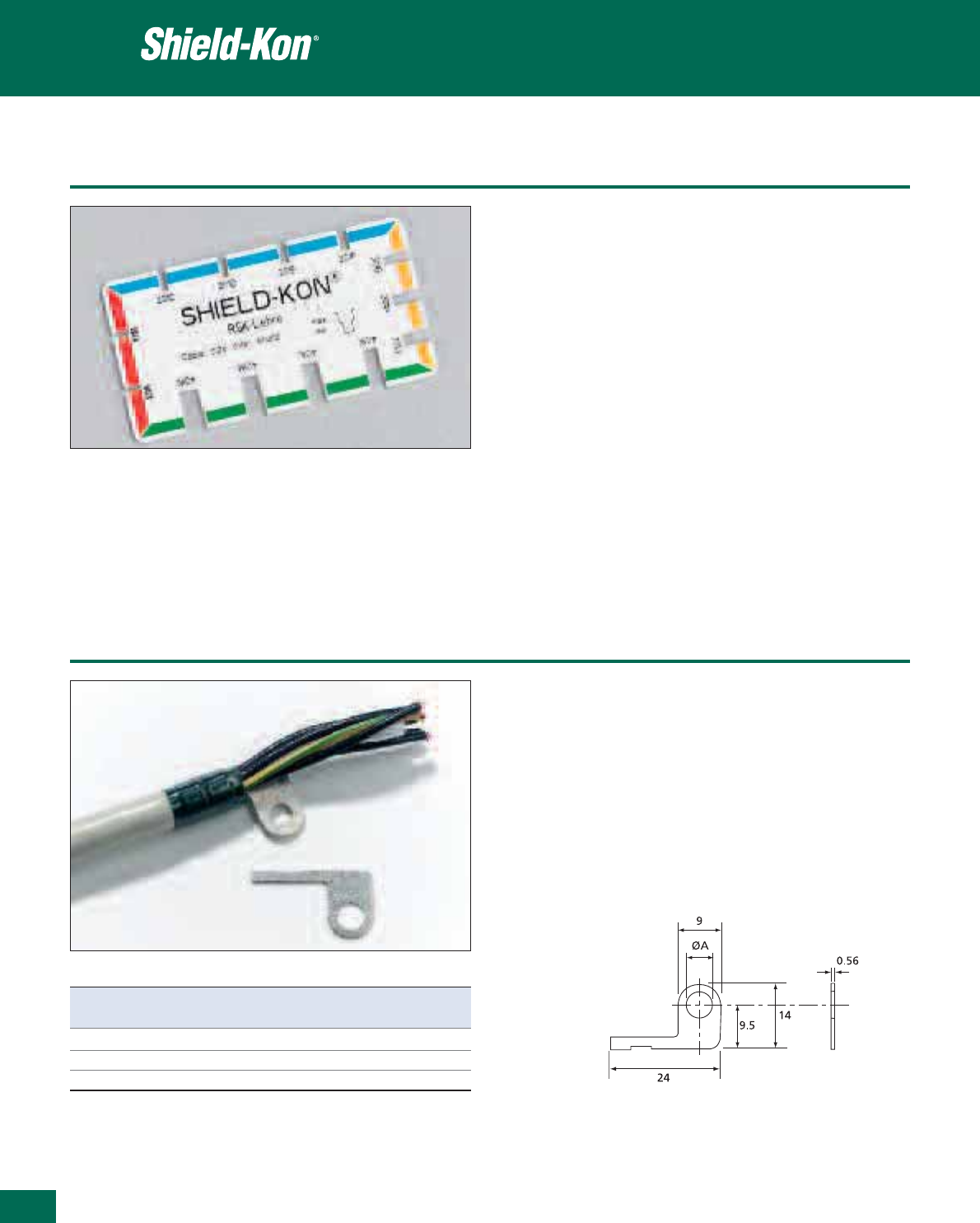
434
Thomas & Betts • www.tnb-europe.com
5.4
Selection gauge
Product Ref.: RSK-LEHRE
The choice of the appropriate connector and die set mainly depends on
the size of the shielded cable.
The selection can be done very quickly with the RSK-LEHRE gauge.
1. Remove the outer jacket from the shielded cable, making the shield-
ing visible
2. Insert this stripped end of the cable into the slots located around the
gauge. The correct slot will be found when the cable can slide only
in the upper part of the slot. If the cable can slide completely to the
bottom of the slot, you should try with the smaller adjacent slot.
3. Once the appropriate slot is found, the corresponding RSK connec-
tor is defined by the colour of the strip around the slot, whereas the
corresponding die set is given by the number marked below the slot
(add prefix “D” to this number)
4. The table on page 433 summarises the different combinations of
connector / die set, as well as the size of drain wire that can be used
One-piece connector
• The RSK-FLAG connector is inserted into the one-piece Shield-Kon
®
connector and replaces the drain-wire
• Easy & direct connection of the RSK-FLAG to a piece of earthed
equipment thanks to the installation hole
• Available in 3 sizes of hole
• To be used with the RSK-301 (yellow) or RSK-401 (green) connectors
• Material: Electrolytic copper
• Plating: Zinc alloy
Product Ref. Termination screw size Weight Quantity
ØA [g/100] [pieces]
RSK-FLAG-B3 M3 75 1000
RSK-FLAG-B4 M4 75 1000
RSK-FLAG-B5 M5 75 1000
Accessories: the RSK-FLAG connectors
One-piece connector
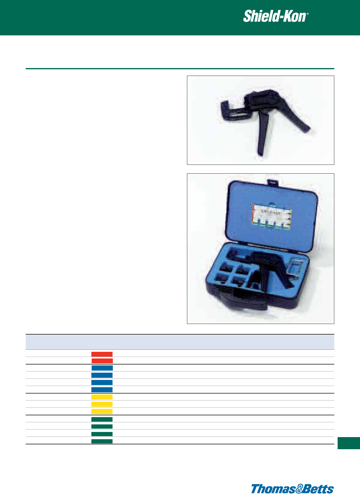
Ergonomic hand tools
Product Ref.: ERG740
• Robust construction: metallic frame, partially covered with plastic
• Dies are easily interchangeable (to be ordered separately)
• Parallel action crimp
• Shure-Stake™ mechanism: once pressing has commenced, the
tool can be re-opened only after successful completion of the
crimping cycle
• Supplied in a plastic case with: 1 tool, 1 bench-mount stand for
easier use in volume production, 1 gauge (Product Ref. RSK-LEHRE)
for instant selection of the die and the connector to be used
• Dimensions of tool (L x W x H): 210 x 155 x 25 mm
• Weight of tool: 470 g
• Dimensions of plastic case (L x W x H): 245 x 210 x 55 mm
• Weight of plastic case with content: 930 g
Product Ref.: ERG740-01
• Same as ERG740, but in addition, supplied with 4 metal dies
(D-101A, D-201D, D-301G, D-401K)
• Dimensions of plastic case (L x W x H): 245 x 210 x 55 mm
• Weight of plastic case with content: 1200 g
Metal Dies for ERG740
• For mass production and medium to high volumes
• Made of hardened steel, does not wear
• The Product Ref. is engraved on the upper part and on the lower
part of the die set and the die is marked with a dot having the
same colour as the corresponding connector
• Packaging: 1 die set in a cardboard box with Euro slot
• Weight: approx. 75 g
• Packaging size (L x W x H): 45 x 45 x 70 mm
One-piece connector
435
Thomas & Betts • www.tnb-europe.com
5.4
Product Ref. Colour Shield diameter For connector
[mm]
D-101A Red 1.27 - 1.79 RSK 101
D-101B Red 1.80 - 2.28 RSK 101
D-201C Blue 2.29 - 2.55 RSK 201
D-201D Blue 2.56 - 3.00 RSK 201
D-201E Blue 3.01 - 3.34 RSK 201
D-201F Blue 3.35 - 3.65 RSK 201
D-301G Yellow 3.66 - 4.13 RSK 301
D-301H Yellow 4.14 - 4.71 RSK 301
D-301J Yellow 4.72 - 5.12 RSK 301
D-401K Green 5.13 - 5.86 RSK 401
D-401L Green 5.87 - 6.36 RSK 401
D-401M Green 6.37 - 7.00 RSK 401
D-401N Green 7.01 - 7.62 RSK 401
ERG740 die selection chart

436
Thomas & Betts • www.tnb-europe.com
5.4
Overview
Two-piece connector - Hexagonal Range
In the “Hexagonal Range” (diameters of dielectric between 1.1 mm
and 9.4 mm), the outer sleeve is crimped with a hand tool and the
result is a hexagonal-shaped crimp.
The choice of the appropriate combination of inner sleeve, outer sleeve
and crimp tool / die will depend on the diameter of the dielectric.
However, a direct correlation with the diameter of the dielectric is
not possible, as several different inner sleeves can be combined with
the same outer sleeve (according to the type of shield).
With the directions shown below, a measuring instrument (calliper)
is all that is required to make the right selection in 3 steps:
1. Selection of the inner sleeve (GSB)
• Strip the outer insulator and remove the shield
• Measure the maximum value of the diameter of the dielectric
(diameter without shield) by gently rotating the cable. When
doing so, it should be possible to turn the cable easily between
the jaws of the calliper
• Add 0.13 mm to the measured value. The sum will give the Inner
Diameter (I.D.) of the GSB inner sleeve
• In the table, select the GSB inner sleeve having this I.D. or the
nearest larger I.D
2. Selection of the outer sleeve (GSC)
Normal method:
• Slide the selected inner sleeve underneath the shield of the cable
• Measure the maximum diameter with the shield over the inner
sleeve
• Add 0.8 mm to the measured value. The sum will give the Inner
Diameter (I.D.) of the GSC sleeve
• In the table, select the GSC sleeve having this I.D. or the nearest
larger I.D.
Quick method:
In most cases, a quicker method can be used to define the correct
GSC outer sleeve:
• Once the appropriate GSB inner sleeve is found, the table will give
the Outer Diameter (O.D.) of this GSB sleeve
• Add 1.5 mm to this O.D. and the sum will give the Inner Diameter
(I.D.) of the GSC sleeve
• In the table, select the GSC sleeve having this I.D. or the nearest
larger I.D.
3. Selection of the die
The Product Ref. for the appropriate die is given in the table here-
after, in the same row as the GSC sleeve that has just been defined
and in the column of the chosen tool.
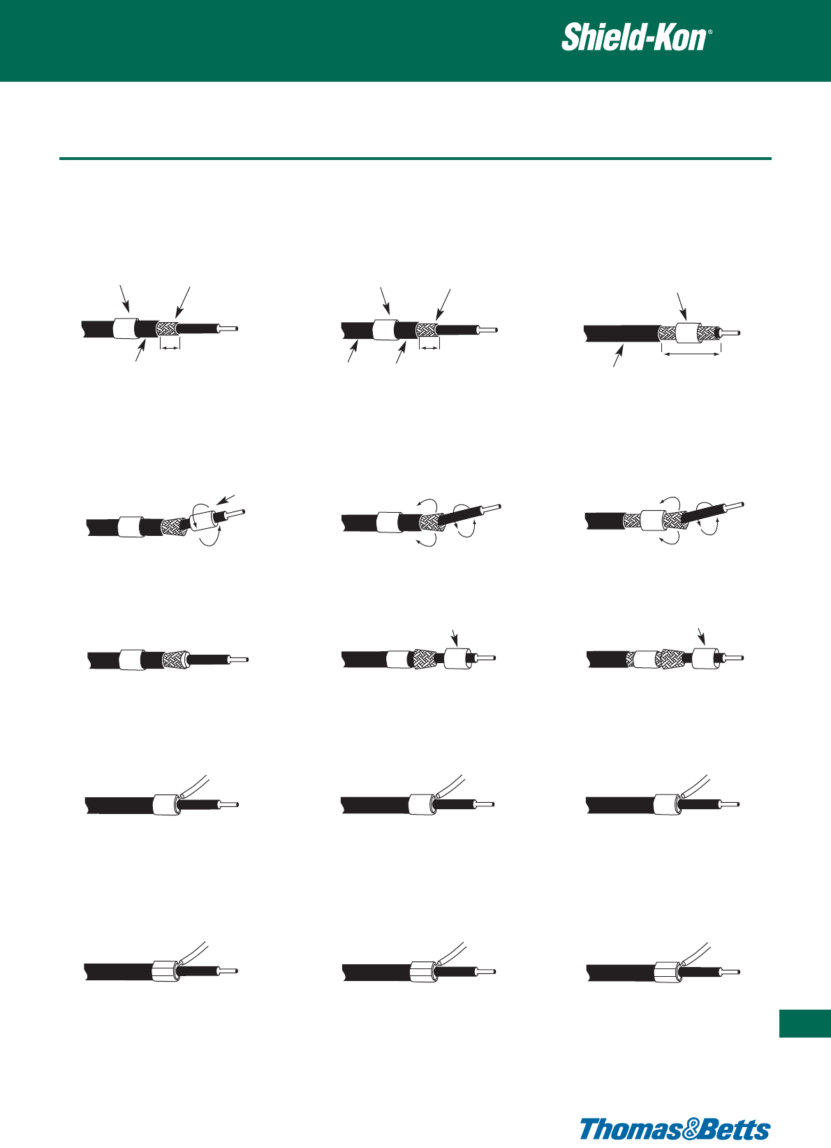
Installation methods
Two-piece connector - Hexagonal Range
437
Thomas & Betts •
www.tnb-europe.com
5.4
Method 1: Standard
A.After stripping the shield (12.7 mm in
length), slip the outer sleeve over the outer
insulation. If this is too big, slip the outer
sleeve on, after method described in Fig. 3.
B. Widen the braided shield by gently rotating
the inner conductor, then slip the inner
sleeve under the braided shield.
C.Position the inner sleeve so that about
1.6 mm protrudes beyond the end of the
braided shield.
D.Slip the drain wire (0.25–0.5 mm
2
)under
the outer sleeve (from the front or behind)
and slip the outer sleeve over the braided
shield.
E. Position the outer sleeve and ensure that
the ends of all wires in the braided shield
and drain wire are covered.
Crimp both sleeves with the correct tool
and tool die. Finished.
Method 2:
A.After stripping the shield (12.7 mm in
length), slip the inner sleeve over the outer
insulation.
B. Widen the braided shield by gently rotating
the inner conductor.
C.Fold back the braided shield over the inner
sleeve and slip the outer sleeve over the
braided shield
D.Slip the drain wire (0.25–0.5 mm
2
) under
the outer sleeve (from the front or behind)
and slip the outer sleeve over the braided
shield.
E. Position the outer sleeve and ensure that
the ends of all wires in the braided shield
and drain wire are covered.
Crimp both sleeves with the correct tool
and tool die. Finished.
Method 3:
A.After stripping the shield (25 mm in
length), slip the inner sleeve over the
braided shield
B. Widen the braided shield by gently rotating
the inner conductor.
C.Fold back the braided shield over the inner
sleeve and slip the outer sleeve over the
braided shield
D.Slip the drain wire (0.25–0.5 mm
2
) under
the outer sleeve (from the front or behind)
and slip the outer sleeve over the braided
shield.
E. Position the outer sleeve and ensure that
the ends of all wires in the braided shield
and drain wire are covered.
Crimp both sleeves with the correct tool
and tool die. Finished.
Three installation methods are possible in the hexagonal range, for a quick, neat and accurately completed termination...at a greatly reduced
production cost.
GSC outer sleeve Shielding
Outer insulator
GSB inner sleeve Shielding
Outer insulator
GSB inner sleeve
Outer insulator
GSB inner sleeve
GSC outer sleeve GSC outer sleeve
12.7 mm 25 mm
12.7 mm

438
Thomas & Betts • www.tnb-europe.com
5.4
Connector and die selection
The Thomas & Betts hexagonal compression (for diameters of
dielectric up to 9.4 mm) is a reliable method for grounding, termi-
nating and insulating shielded and coaxial cable. It has literally
hundreds of millions of installations in communications, aerospace,
electronic, telephone, radio and TV applications.
• Material: Hard bronze (inner sleeve), Soft bronze (outer sleeve)
• Finish***: Tin plated (per MIL-T-10727A)
• Length: 7.9 mm (inner sleeve), 6.4 (outer sleeve)
• Standard packaging quantity: 1000 pcs. For 100 pcs packaging,
add the code ‘5” in the Product Reference just after the “GSB” or
“GSC” code. Example: GSC275 = 1000 pcs packaging, GSC5275
= 100 pcs packaging
Two-piece connector - Hexagonal Range
Product Colour Inner Outer Product Colour Inner Outer Hand Nest Hand tool*
Ref. code diameter Ref. code diameter tool number WT440/WT540
GSB [mm] [mm] GSC [mm] [mm] ERG2000KE MIL - Spec.
INNER SLEEVES OUTER SLEEVES DIES
GSB 046 Silver 1.17 1.90 GSC 101 Silver 2.56 3.16 D-419403 19 4419
GSB 058 Yellow 1.47 2.10 GSC 128 Blue 3.25 3.86 D-419403 00 4400
GSB 063 Red 1.60 2.23 GSC 149 Purple 3.78 4.54 D-419403 01 4401
GSB 071 Green 1.87 2.44 GSC 156 Yellow 3.96 4.90 D-419403 02 4402
GSB 080 Blue 2.00 2.63 GSC 175 Blue 4.45 5.46 D-419403 03 4403
GSB 090 Orange 2.20 2.90 GSC 187 Orange 4.75 5.76 D-406410 06 4406
GSB 096 Purple 2.44 3.02 GSC 194 Red 4.93 5.74 D-406410 06 4406
GSB 101 Yellow 2.56 3.16 GSC 199 Silver 5.05 5.97 D-406410 06 4406
GSB 109 Red 2.76 3.36 GSC 205 Yellow 5.20 6.22 D-406410 08 4408
GSB 115 Silver 2.92 3.70 GSC 219 Green 5.56 6.35 D-406410 08 4408
GSB 124 Green 3.14 3.68 GSC 225 Purple 5.71 6.50 D-406410 09 4409
GSB 128 Silver 3.25 3.86 GSC 232 Orange 5.90 6.70 D-406410 10 4410
GSB 134 Orange 3.40 4.00 GSC 261 Yellow 6.63 7.54 D-411414 11 4411-SK
GSB 149 Blue 3.78 4.54 GSC 275 Silver 6.98 7.77 D-411414 12 4412
GSB 156 Red 3.96 4.90 GSC 281 Purple 7.14 8.40 D-411414 14 4414
GSB 165 Silver 4.20 4.92 GSC 287 Blue 7.29 8.30 D-411414 14 4414
GSB 175 Green 4.44 5.46 GSC 297 Green 7.54 8.50 D-411414 14 4414
GSB 187 Yellow 4.75 5.76 GSC 312 Yellow 7.92 9.20 D-415417 15 4415
GSB 194 Blue 4.93 5.76 GSC 327 Silver 8.30 9.45 D-415417 16 4416
GSB 205 Orange 5.20 6.22 GSC 348 Orange 8.84 9.98 D-415417 17 4417
GSB 219 Silver 5.56 6.35 GSC 359 Purple 9.12 10.13 D-450451 50 5450
GSB 225 Yellow 5.71 6.50 GSC 375 Yellow 9.53 10.31 D-450451 51 5451
GSB 232 Red 5.90 6.70 GSC 405 Red 10.28 11.50 D-452 52 5452
GSB 250 Green 6.35 7.14 GSC 415 Blue 10.54 11.76 D-452 52 5452
GSB 261 Blue 6.63 7.54 GSC 425 Silver 10.80 12.06 D-454 54 5454
GSB 266 Silver 6.75 7.54 GSC 460 Silver 11.68 12.95 ERG5456** 56 5456
GSB 275 Orange 6.98 7.77 GSC 500 Green 12.70 13.97 ERG5457** 57 5457
GSB 281 Yellow 7.14 8.40
GSB 287 Silver 7.29 8.30
GSB 297 Red 7.54 8.50
GSB 312 Purple 7.92 9.20
GSB 348 Orange 8.84 10.20
GSB 375 Blue 9.52 10.30
* Dies 4419 and 4400 to 4417 are for the hand tool WT440. Dies 5450 to 5457 are for the hand tool WT540
** Note: Product Ref. ERG-5456 and ERG-5457 are complete hand tools with pre-mounted die set
*** For Nickel plated terminals, add suffix NP to the Product Reference. Example: GSB128NP, GSC128NP
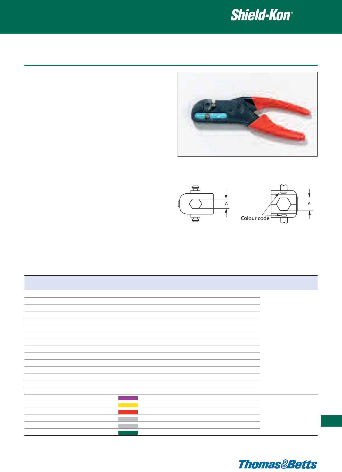
Tooling
Product Ref.: WT440 and WT540
• MIL-specified parallel action hand tool
• A versatile tool, one frame with a selection of interchangeable
dies covers the whole range of shield diameters in the Hexagonal
Range
• Shure-Stake™ mechanism: once pressing has commenced, the
tool can be re-opened only after successful completion of the
crimping cycle
• Packaging: box containing 1 frame (dies to be ordered separately)
• Length: 203 mm (WT440), 264 mm (WT540)
• Weight: 450 g (WT440), 540 g (WT540)
Dies for WT440 and WT540
• Interchangeable dies with single nest
• Hexagonal crimp
• Material: alloy steel
• Finish: black oxide
• 44xx series dies (for WT440 tool): crimping range (outer sleeves):
from GSC101 to GSC348
• 54xx series (for WT540 tool): crimping range (outer sleeves): from
GSC359 to GSC500
• 54xx series dies are marked with the die number and a colour-
coded dot
• Go/no-go gauges are available for inspection
Two-piece connector - Hexagonal Range
439
Thomas & Betts • www.tnb-europe.com
5.4
Dies for WT440 tool
Product
Ref.
Dim. A across flats Colour
code
For
connector
Go / no-go
gauge
Tooling
(+/- 0.10) [mm]
4419 2.67 - GSC101 4419-G
4400 3.25 - GSC128 4400-G
4401 3.84 - GSC149 4401-G
4402 4.06 - GSC156 4402-G
4403 4.52 - GSC175 4403-G
4406 5.00 - GSC187, GSC194, GSC199 4406-G
4408 5.41 - GSC205, GSC219 4408-G
4409 5.54 - GSC225 4409-G WT440
4410 5.87 - GSC232 4410-G
4411-SK 6.48 - GSC261 4411-G
4412 6.81 - GSC275 4412-G
4414 7.37 - GSC281, GSC287, GSC297 4414-G
4415 7.85 - GSC312 4415-G
4416 7.98 - GSC327 4416-G
4417 8.23 - GSC348 4417-G
5450 8.71 Purple GSC359 5450-G
5451 9.12 Yellow GSC375 5451-G
5452 9.75 Red GSC405, GSC415 5452-G WT540
5454 10.90 Silver GSC425 5454-G
5456 11.53 Silver GSC460 5456-G
5457 12.07 Green GSC500 5457-G
Dies for WT540 tool
WT440 and WT540 die selection chart
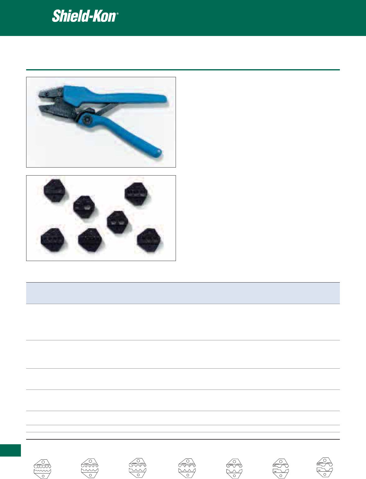
440
Thomas & Betts • www.tnb-europe.com
5.4
Tooling
Product Ref.: ERG2000KE
• Ergonomic hand tool
• A versatile tool, one frame with a selection of interchangeable
dies covers a wide range of shield diameters in the Hexagonal
Range
• Most dies have several nests (identified with a number) to allow
the crimp of several GSC outer sleeves with the same die set.
• Shure-Stake™ mechanism: once pressing has commenced, the
tool can be re-opened only after successful completion of the
crimping cycle
• Length: 252 mm, Weight: 460 g
• Packaging: cardboard box containing 1 frame (dies to be ordered
separately )
Dies for ERG2000KE
• Interchangeable dies (hexagonal crimp), with single or multiple nest
• Material: alloy steel
• The dies are marked with the die number
• Each nest is marked with a number to identify the GSC outer
sleeves that can be crimped (see table)
• Crimping range (outer sleeves): from GSC101 to GSC425
• Packaging: 1 die set in a cardboard box with Euro slot
• Weight: approx. 50 g
• Packaging size (L x W x H): 45 x 45 x 70mm
Two-piece connector - Hexagonal Range
Product Ref. Nest nr. For connector Dimension of the nest Gauge dimensions
Ø Go Ø No-go
[mm] [mm] [mm]
D-419403 19 GSC101 HEX 2.68 2.63 2.73
00 GSC128 HEX 3.24 3.19 3.29
01 GSC149 HEX 3.80 3.75 3.85
02 GSC156 HEX 4.03 3.98 4.08
03 GSC175 HEX 4.50 4.45 4.55
D-406410 6 GSC187, GSC194, GSC199 HEX 5.00 4.95 5.05
8 GSC205, GSC219 HEX 5.36 5.31 5.41
9 GSC225 HEX 5.56 5.51 5.61
10 GSC232 HEX 5.84 5.79 5.89
D-411414 11 GSC261 HEX 6.46 6.41 6.51
12 GSC275 HEX 6.78 6.73 6.83
14 GSC281, GSC287, GSC297 HEX 7.32 7.27 7.37
D-415417 15 GSC312 HEX 7.74 7.69 7.79
16 GSC327 HEX 7.86 7.81 7.91
17 GSC348 HEX 8.32 8.27 8.37
D-450451 50 GSC359 HEX 8.66 8.61 8.71
51 GSC375 HEX 9.10 9.05 9.15
D-452 52 GSC405, GSC415 HEX 9.72 9.67 9.77
D-454 54 GSC425 HEX 10.88 10.83 10.93
D-419403 D-406410 D-411414 D-415417 D-450451 D-452 D-454
ERG2000KE die selection chart
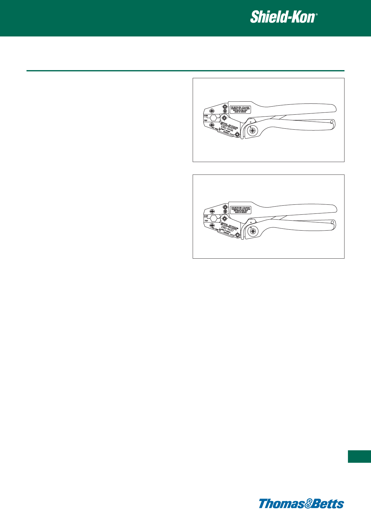
Tooling
Product Ref.: ERG5456
• Fixed die, ergonomic hand tool
• Designed to crimp the GSC460 outer sleeve
• Shure-Stake™ mechanism: once pressing has commenced, the
tool can be re-opened only after successful completion of the
crimping cycle
• Length: 252 mm
• Weight: 460 g
• Packaging: cardboard box containing 1 tool with pre-mounted
die set
Product Ref.: ERG5457
• Fixed die, ergonomic hand tool
• Designed to crimp the GSC500 outer sleeve
• Shure-Stake™ mechanism: once pressing has commenced, the
tool can be re-opened only after successful completion of the
crimping cycle
• Length: 252 mm
• Weight: 460 g
• Packaging: cardboard box containing 1 tool with pre-mounted
die set
Two-piece connector - Hexagonal Range
441
Thomas & Betts • www.tnb-europe.com
5.4

442
Thomas & Betts • www.tnb-europe.com
5.4
Installation method
The “Circular Range”, for Multiple or Overall shielded cables, refers to
larger diameters of dielectric (between 9.5 and 36 mm) and owes its
name to the circular shape of the crimp.
The Shield-Kon®Connector System for multiple-conductor shielded
cable is based on the principle of cold swaging. It uses a two-piece
compression connector, which is colour-coded to match the proper
die. The connector consists of a hard brass collector inner sleeve
(ring) and a soft copper compression outer sleeve (ring). Each set of
rings and matching installing die will connect a minimum of 5 shield-
ing braids with one ground wire. The maximum number of braids is
limited only by the space between the inner and outer rings.
The design advantages are:
1. Positive selection of inner and outer rings and installing die by a
complete colour-coded system.
2. A more reliable grounding termination because only one ground
wire connection is made - conventional daisy chain jumper
method is eliminated.
3. Smaller, more compact bundle is easy to inspect.
4. Only one ground wire is required, however additional ground
wires may be used if needed.
5. Smooth insulator protects conductor insulation.
6. With one stroke of the tool, the interlace die will produce a 360°
compression uniformly securing all individual shields around the
connector.
Installation method:
1. After overall insulation is removed to expose shielded cables, each
conductor must be freed from the shielding braid. The braid is
then folded back until all conductors are freed.
2. Flattened shielding braids are evenly distributed around the periphery
of the GSB inner ring.
3. Position the GSC outer ring over the flattened shielding braid,
locating it over the centre of the GSB inner ring. Braid may be
trimmed even with the edge of the outer compression ring before or
after compression. Ground wire or wires may be inserted between
the outer ring and the shield prior to compression.
Two-piece connector - Circular Range

Connector and die selection
The choice of the appropriate combination of inner ring, outer ring
and crimp tool / die will depend on the overall diameter of the inner
conductors (underneath the shield)
In the case of the Circular range, there is a direct correlation between
the diameter of the inner conductors and the inner and outer rings.
With the directions shown below, a measuring instrument (calliper) is
all that is required to make the right selection.
Selection of the GSB inner ring
• Measure the maximum value of the overall diameter of the inner
conductors (underneath the flattened shield) by gently rotating
the cable. When doing so, it should be possible to turn the cable
easily between the jaws of the calliper
• Add 0.13 mm to the measured value. The sum will give the Inner
Diameter (I.D.) of the GSB inner ring
• In the table, select the GSB inner ring having this I.D. or the nearest
larger I.D
Selection of the GSC outer ring and of the die
Once the appropriate GSB inner ring is found, the table hereafter
immediately gives the corresponding GSC outer ring and the appro-
priate die for the 13640 hydraulic head.
Two-piece connector - Circular Range
443
Thomas & Betts • www.tnb-europe.com
5.4
Product Colour Inner Outer Product Colour Inner Outer Hydraulic crimp head
Ref. code diameter Ref. code diameter 13640
GSB [mm] [mm] GSC [mm] [mm] MIL-Spec.
INNER SLEEVES OUTER SLEEVES DIES
GSB 430 Red 10.92 12.70 GSC 590 Red 14.99 17.02 GS590
GSB 550 Blue 13.97 15.75 GSC 710 Blue 18.03 20.07 GS710
GSB 670 Silver 17.02 19.05 GSC 840 Silver 21.34 23.37 GS840
GSB 810 Brown 20.57 22.35 GSC 1010 Brown 25.65 27.61 GS1010
GSB 920 Green 23.37 25.40 GSC 1130 Green 28.70 30.73 GS1130
GSB 1040 Pink 26.42 28.45 GSC 1250 Pink 31.75 33.78 GS1250
GSB 1122 Orange 28.50 30.28 GSC 1332 Orange 33.83 35.87 GS1332
GSB 1224 Purple 31.09 32.87 GSC 1440 Purple 36.58 38.61 GS1440
GSB 1353 Yellow 34.37 36.14 GSC 1563 Yellow 39.70 41.73 GS1563
GSB 1425 Red 36.20 39.24 GSC 1670 Red 42.42 44.45 GS1670
Standard packaging quantity: 50 pcs
Technical Information Inner sleeve
Material Copper alloy ASTM B135
Finish Electro tin plated (per MIL-T-10727A)
Length 15.2 mm
Technical Information Outer sleeve
Material Copper ASTM B188
Finish Electro tin plated (per MIL-T-10727A)
Length 11.2 mm
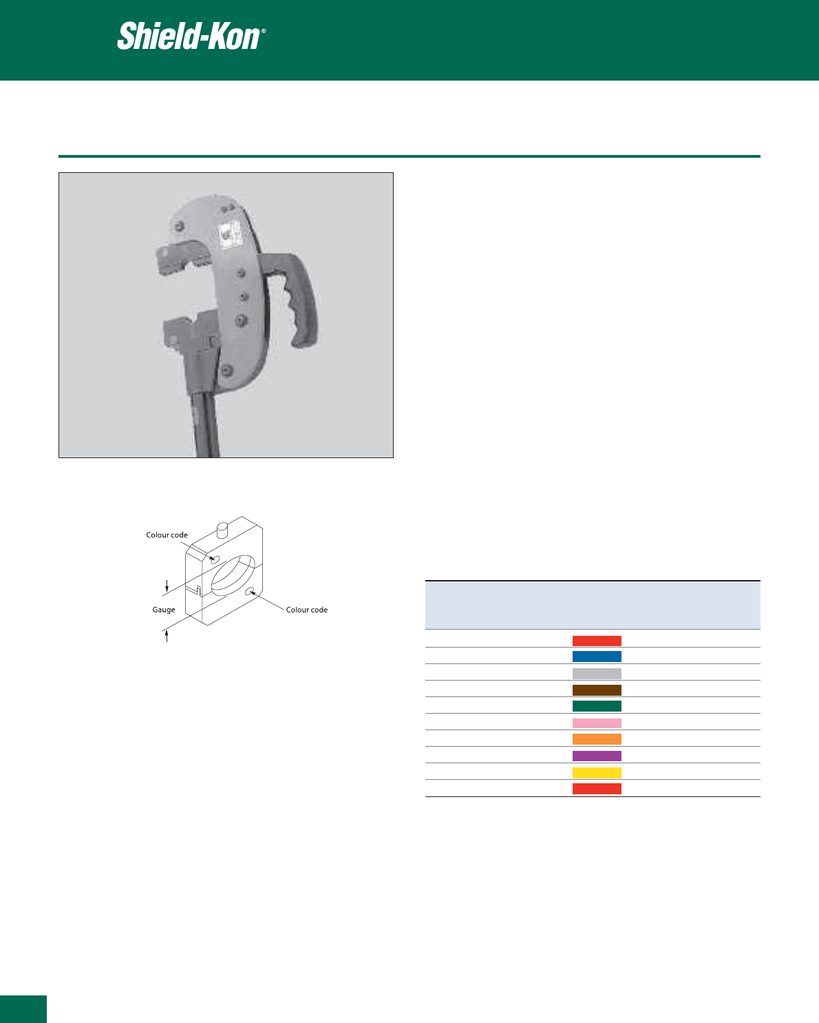
444
Thomas & Betts • www.tnb-europe.com
5.4
Tooling
Product Ref.: 13640
• Hydraulic tool head
• For all 2-piece Shield-Kon®terminals in the circular range
• Quickly interchangeable steel dies (to be ordered separately)
• 3.5 ton nominal pressure (output)
• Pioneer coupling, for quick assembly
• Requires a 9800 PSI (approx. 676 bar) operating service pressure
(input)
• Length: 400 mm approx.
• Weight: 5.5 kg approx.
Dies for 13640
• Interchangeable dies with single nest
• Circular crimp
• Material: alloy steel
• Finish: black oxide
• Marked with the die number and a colour-coded dot
• Crimping range (outer sleeves): from GSC590 to GSC1670
• Go/no-go gauges are available for inspection
13640 die selection chart
Two-piece connector - Circular Range
Product Gauge Ø Colour code For Go / no-go
Ref.
min. max. connector gauge
[mm] [mm]
GS590 14.91 15.16 Red GSC590 GS590-G
GS710 17.96 18.21 Blue GSC710 GS710-G
GS840 21.26 21.51 Grey GSC840 GS840-G
GS1010 24.59 24.84 Brown GSC1010 GS1010-G
GS1130 27.66 27.91 Green GSC1130 GS1130-G
GS1250 30.71 30.96 Pink GSC1250 GS1250-G
GS1332 32.54 32.79 Orange GSC1332 GS1332-G
GS1440 35.13 35.38 Purple GSC1440 GS1440-G
GS1563 38.40 38.66 Yellow GSC1563 GS1563-G
GS1670 41.00 41.25 Red GSC1670 GS1670-G
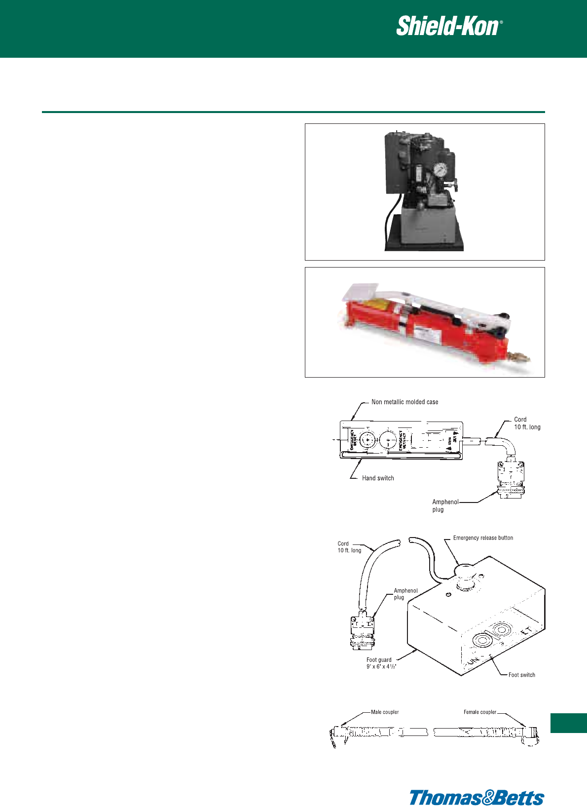
Tooling
A small selection of pumps to operate the 13640 head is shown
below (please contact your Sales Office for availability of other types
of pumps).
Product Ref.: 13810E
• Hydraulic pump, electrical power
• Service pressure (output): 10.000 psi (690 bar)
• Motor power: 1 1/2 HP - 12 Amp
• Voltage & frequency: 230V - 50 Hz
• Capability: 3800 cc / min at 200 psi (13.8 bar) 1000 cc / min at
8000 psi (552 bar)
• Reservoir volume: 7.6 l
• Coupling: Pioneer fitting
• Dimensions (L x W x H): 275 x 381x 522 mm
• Weight: 27 kg without oil
• The Pump 13810E also requires one 13611 hand switch or one
13612 foot switch and one 13613 hydraulic hose
Product Ref.: 13606
• Hydraulic pump, foot (or hand) activated
• Service pressure (output): 10.000 psi (690 bar)
• Over-pressure security valves
• Coupling: Pioneer fitting
• Dimensions (L x W x H): 597 x 133 x 165 mm
• Weight: 10.4 kg
• The pump 13606 also requires one 13613 hydraulic hose
Product Ref.: 13611
• Hand switch
Product Ref.: 13612
• Foot switch
Product Ref.: 13613
• Hydraulic hose 1.82 m long, with Pioneer couplings
Product Ref.: 21061
• Hydraulic oil (0.95l can)
Two-piece connector - Circular Range
445
Thomas & Betts • www.tnb-europe.com
5.4
13611
13613
13612
13606
13810E
